MSP-PR Pitched roof Technical data

Welcome message from author
This document is posted to help you gain knowledge. Please leave a comment to let me know what you think about it! Share it to your friends and learn new things together.
Transcript

MSP-PR Pitched roofTechnical data
MSP-PR MSP-PR
page 2 Technical data MSP-PR pitched roof Technical data MSP-PR pitched roof page 3
1. Basic dimensions and material of components
Spacer plateMSP-PR-SP 10mm
Carrier SectionMSP-PR-CH 6.3mMSP-PR-CH 6mMSP-PR-CH 3.3m
Base plateMSP-PR-BP 39mmMSP-PR-BP 45mm
SleeveMSP-PR-SL
Wood screwMSP-HS 8x100mm A2MSP-HS 8x120mm A2MSP-HS 8x140mm A2MSP-HS 8x160mm A2
Cross connectorMSP-PR-CC
Roof hookMSP-PR-RHF
Roof hookMSP-PR-RHC
Middle ClampMSP-PR-MC 30-50mm
Roof hookMSP-PR-RHA
End ClampMSP-PR-EC 30-50mm
PA66 GF30 EN AW-6063 T66 - EN 755-2
EN AW-6063 T66 – EN 755-2
ChannelEN AW-6063 T66 - EN 755-2
SpringX2CrNiMo17-12-2 (1.4404) - EN 10088-2A2 stainless steel
ClampEN AW-6063 T66 - EN 755-2
ScrewA2-70 - ISO 3506-1
Screw and Nut Clamp (1)EN AW-6060 T66 - EN 755-2
All other Al partsEN AW-6063 T66 - EN 755-2
Screws A2-70 - ISO 3506-1
Nuts A4-70 - ISO 3506-2
Screw and Nut Clamp (1)EN AW-6060 T66 - EN 755-2
All other Al partsEN AW-6063 T66 - EN 755-2
Screws A2-70 - ISO 3506-1
Nuts A4-70 - ISO 3506-2
ClampEN AW-6063 T66 - EN 755-2
ScrewA2-70 - ISO 3506-1
Secure WasherPE-HD
Screw and Nut Clamp (1)EN AW-6060 T66 - EN 755-2
All other Al partsEN AW-6063 T66 - EN 755-2
Screws A2-70 - ISO 3506-1
Nuts A4-70 - ISO 3506-2
ClampEN AW-6063 T66 - EN 755-2
ScrewA2-70 - ISO 3506-1
Secure WasherPE-HD
NutA4-70 - ISO 3506-2
Description DescriptionMaterial composition Material compositionDimensioning* Dimensioning*
* Dimensions rounded to full mm. * Dimensions rounded to full mm.
MSP-PR MSP-PR
page 4 Technical data MSP-PR pitched roof Technical data MSP-PR pitched roof page 5
2. Design resistances of components (ultimate limit states) 2.1 MSP-PR-SP spacer plate, MSP-PR-BP base plate and MSP-HS wood screw
For the resistance verification of MSP-PR pitched roof applications the following component resistances have to be considered individually:
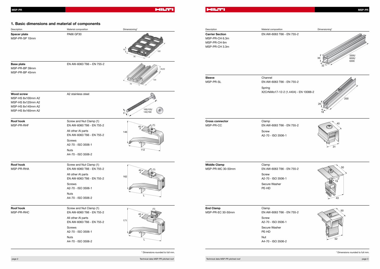
The design resistances stated in Table 1 and Table 2 are valid for MSP-PR-RHF/RHA/RHC roof hook fastened with all different variants of MSP-PR-SP spacer plate, MSP-PR-BP base plate and MSP-HS wood screw, see caption 1. All stated resistances are combined from the individual resistances of the components and transferred to the connection between MSP-PR-RHF/RHA/RHC roof hook and MSP-PR-CH carrier section, resistance coordinates see Figure 1. The resistances are calculated assuming a fixed connection between the MSP-PR-RHF/RHA/RHC roof hook and the MSP-PR-CS carrier section. The resistances with interaction of pressure and shear with resulting angles between 0 and 90° are stated in Table 1. Intermediate resistances can be obtained with linear interpolation. Resistances in pure suction are stated in Table 2.
The structural timber used has to apply to EN 338:2009-10 or DIN EN 14081-1:2011-05 with a strength class of C24 to C40 and a minimum required density ρ of 350 kg/m3. The applied modification factor kmod is 0.8 with the load-duration class middle and the service class of 2.
All resistances are calculated according to the following codes and guidelines:▪ DIN EN 1990:2010-12 (EC1)▪ EN 1999-1-1:2007-05+A1:2009-07 (EC9)▪ VDI 2230 Blatt 1:2003-02 (VDI2230)▪ DIN EN 1995-1-1:2012-12 (EC5)
The resistances are valid as long as the full Hilti MSP-PR system is used and the installation is built according to the MSP-PR pitched roof operating instructions and the MSP-PR pitched roof instructions for use.
Fig.1: Roof hook and roof hook assembly resistance coordinates
▪ Resistance of the roof structure according to relevant codes ▪ By the customer
▪ MSP-PR-SP spacer plate, MSP-PR-BP base plate and MSP-HS wood screw, see 2.1▪ MSP-PR-RHF/RHA/RHC roof hook, see 2.2 ▪ MSP-PR-RHF/RHA/RHC roof hook clamp, see 2.3▪ MSP-PR-CH carrier section, see 2.4 ▪ MSP-PR-CC cross connector, see 2.5▪ MSP-PR-MC/EC middle/end clamp, see 2.6
▪ By Hilti Technical Data Sheet
Table 1: MSP-PR-SP, MSP-PR-BP and MSP-HS design resistances with interaction of pressure and shear
Roof angle [α in °] 0 10 20 30 40 50 60 70 80 90
Pressure design resistance [NRd in kN] 2.43 2.24 2.06 1.88 1.61 1.28 0.95 0.63 0.31 0.00
Shear design resistance [VRd in kN] 0.00 0.39 0.75 1.08 1.35 1.53 1.65 1.72 1.73 1.73
Table 2: MSP-PR-SP, MSP-PR-BP and MSP-HS design resistances with suction
Roof angle [α in °] 0
Pressure design resistance [NRd in kN] -1.66
Shear design resistance [VRd in kN] 0.00
α
max. 35mm
NRd
VRd
The component with lowest resistance limits the application.
MSP-PR MSP-PR
page 6 Technical data MSP-PR pitched roof Technical data MSP-PR pitched roof page 7
2.2 MSP-PR-RHF/RHA/RHC roof hook
Design resistances of MSP-PR-RHF/RHA/RHC roof hook with interaction of pressure and shear with resulting angles between 0 and 90° are stated in Table 3 and Table 4. Intermediate resistances can be obtained with linear interpolation. Resistances in pure suction are stated in Table 5. The design resistances are calculated assuming a fixed connection between the MSP-PR-RHF/RHA/RHC roof hook and the MSP-PR-CH carrier section. The design resistances are calculated with a plasticity factor of 1.47.For utilization calculation under alternating load directions, like pressure and suction, the following equations have to be fulfilled individually:
1. PEd ≤ NRd (Pressure)
2. |SEd| ≤ |NRd (Suction)|
3. |SEd| + PEd ≤ 1.47|NRd (Suction)| + NRd (Pressure)
PEd is the pressure design action and SEd is the suction design action of the governing load combinations.
Table 3: MSP-PR-RHF design resistances with interaction of pressure and shear
Roof angle [α in °] 0 10 20 30 40 50 60 70 80 90
Pressure design resistance [NRd in kN] 2.28 2.09 1.92 1.76 1.58 1.40 1.20 0.87 0.46 0.00
Shear design resistance [VRd in kN] 0.00 0.37 0.69 1.01 1.33 1.67 2.07 2.39 2.60 2.87Table 6: MSP-PR-RHF/RHA/RHC roof hook clamp design resistance with shear
Roof angle [α in °] 0 10 20 30 40 50 60 70 80 90
Shear design resistance [VRd in kN] ∞ 11.3 3.4 2.3 2.0 1.8 1.7 1.6 1.6 1.5Table 4: MSP-PR-RHA and MSP-PR-RHC design resistances with interaction of pressure and shear
Roof angle [α in °] 0 10 20 30 40 50 60 70 80 90
Pressure design resistance [NRd in kN] 2.28 1.97 1.72 1.51 1.31 1.11 0.90 0.67 0.38 0.00
Shear design resistance [VRd in kN] 0.00 0.35 0.63 0.87 1.10 1.32 1.56 1.82 2.12 2.52
Table 5: MSP-PR-RHF/RHA/RHC design resistances with suction
Roof angle [α in °] 0 - 90°
Suction design resistance [NRd in kN] -2.28
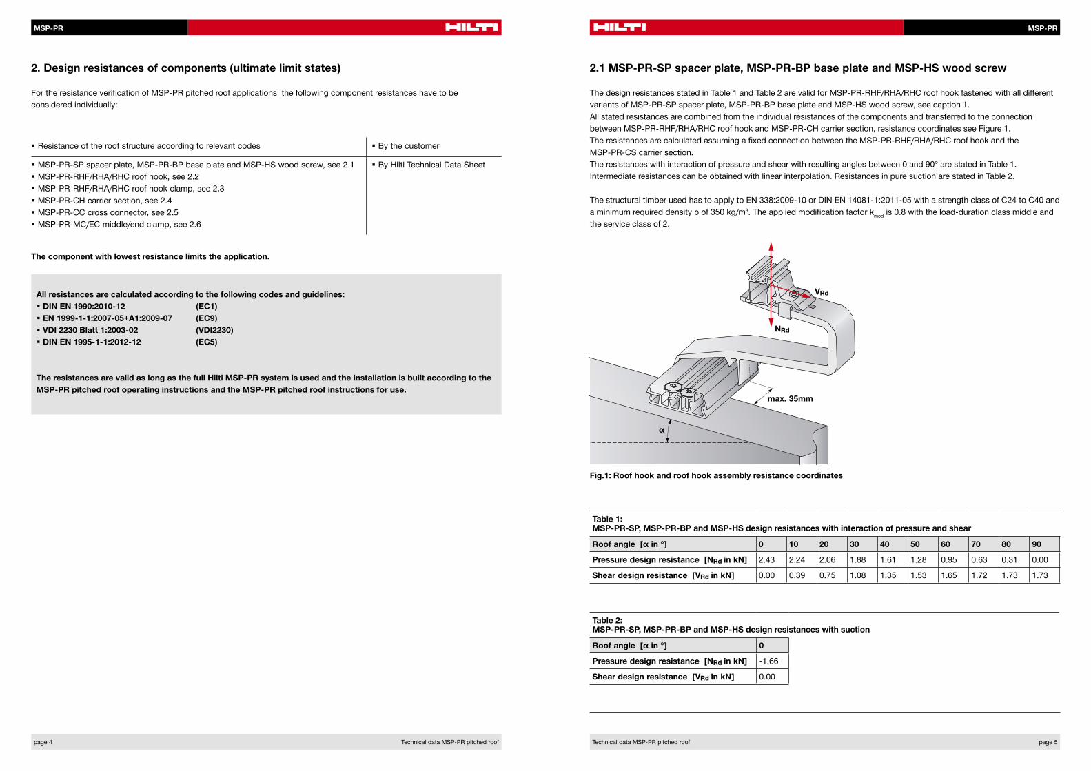
2.3 MSP-PR-RHF/RHA/RHC roof hook clamp
The design resistances of the MSP-PR-RHF/RHA/RHC roof hook clamp, see Figure 2, are stated in Table 6. These values include the design resistance from pre-stress of the screw as well as an additional shear resistance from the normal component of additional pressure from actions.
Fig.2: MSP-PR-RHF/RHA/RHC roof hook clamp resistance coordinates
VRd
MSP-PR MSP-PR
page 8 Technical data MSP-PR pitched roof Technical data MSP-PR pitched roof page 9
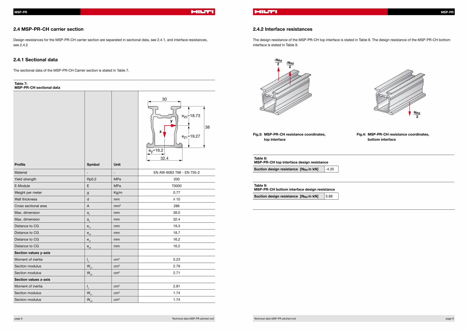
2.4 MSP-PR-CH carrier section
2.4.1 Sectional data
2.4.2 Interface resistances
Design resistances for the MSP-PR-CH carrier section are separated in sectional data, see 2.4.1, and interface resistances, see 2.4.2
The sectional data of the MSP-PR-CH Carrier section is stated in Table 7.
The design resistance of the MSP-PR-CH top interface is stated in Table 8. The design resistance of the MSP-PR-CH bottom interface is stated in Table 9.
Table 7: MSP-PR-CH sectional data
Profile Symbol Unit
Material - - EN AW-6063 T66 - EN 755-2
Yield strength Rp0.2 MPa 200
E-Module E MPa 70000
Weight per meter g Kg/m 0.77
Wall thickness d mm ≤ 10
Cross sectional area A mm2 286
Max. dimension az mm 38.0
Max. dimension ay mm 32.4
Distance to CG ez1 mm 19.3
Distance to CG ez2 mm 18.7
Distance to CG ey1 mm 16.2
Distance to CG ey2 mm 16.2
Section values y-axis
Moment of inertia Iy cm4 5.23
Section modulus Wy1 cm3 2.79
Section modulus Wy2 cm3 2.71
Section values z-axis
Moment of inertia Iz cm4 2.81
Section modulus Wz1 cm3 1.74
Section modulus Wz2 cm3 1.74
Table 8: MSP-PR-CH top interface design resistance
Suction design resistance [NRd in kN] -4.35
Table 9: MSP-PR-CH bottom interface design resistance
Suction design resistance [NRd in kN] 5.88
Fig.3: MSP-PR-CH resistance coordinates, top interface
Fig.4: MSP-PR-CH resistance coordinates, bottom interface
-NRd2 -NRd
2
NRd2
MSP-PR MSP-PR
page 10 Technical data MSP-PR pitched roof Technical data MSP-PR pitched roof page 11
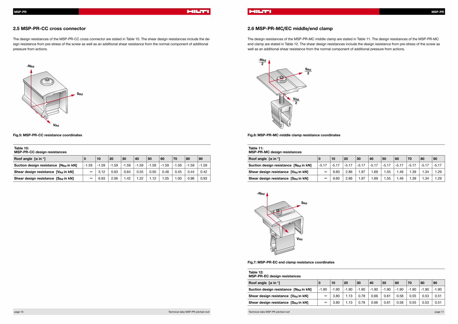
2.5 MSP-PR-CC cross connector 2.6 MSP-PR-MC/EC middle/end clamp
The design resistances of the MSP-PR-CC cross connector are stated in Table 10. The shear design resistances include the de-sign resistance from pre-stress of the screw as well as an additional shear resistance from the normal component of additional pressure from actions.
The design resistances of the MSP-PR-MC middle clamp are stated in Table 11. The design resistances of the MSP-PR-MC end clamp are stated in Table 12. The shear design resistances include the design resistance from pre-stress of the screw as well as an additional shear resistance from the normal component of additional pressure from actions.
Fig.5: MSP-PR-CC resistance coordinates Fig.6: MSP-PR-MC middle clamp resistance coordinates
Fig.7: MSP-PR-EC end clamp resistance coordinates
Table 10: MSP-PR-CC design resistances
Roof angle [α in °] 0 10 20 30 40 50 60 70 80 90
Suction design resistance [NRd in kN] -1.59 -1.59 -1.59 -1.59 -1.59 -1.59 -1.59 -1.59 -1.59 -1.59
Shear design resistance [VRd in kN] ∞ 3.12 0.93 0.64 0.55 0.50 0.48 0.45 0.44 0.42
Shear design resistance [SRd in kN] ∞ 6.93 2.06 1.42 1.22 1.12 1.05 1.00 0.96 0.93
Table 11: MSP-PR-MC design resistances
Roof angle [α in °] 0 10 20 30 40 50 60 70 80 90
Suction design resistance [NRd in kN] -5.17 -5.17 -5.17 -5.17 -5.17 -5.17 -5.17 -5.17 -5.17 -5.17
Shear design resistance [VRd in kN] ∞ 9.60 2.86 1.97 1.69 1.55 1.46 1.39 1.34 1.29
Shear design resistance [SRd in kN] ∞ 9.60 2.86 1.97 1.69 1.55 1.46 1.39 1.34 1.29
Table 12: MSP-PR-EC design resistances
Roof angle [α in °] 0 10 20 30 40 50 60 70 80 90
Suction design resistance [NRd in kN] -1.90 -1.90 -1.90 -1.90 -1.90 -1.90 -1.90 -1.90 -1.90 -1.90
Shear design resistance [VRd in kN] ∞ 3.80 1.13 0.78 0.66 0.61 0.58 0.55 0.53 0.51
Shear design resistance [SRd in kN] ∞ 3.80 1.13 0.78 0.66 0.61 0.58 0.55 0.53 0.51
-NRd2
SRd2
VRd2
-NRd
SRd
VRd
-NRd
SRd
VRd
MSP-PR
Hilt
i = re
gist
ered
trad
emar
k of
Hilt
i Cor
p., S
chaa
n |
W00
00 1
112
0-e
n |
1 P
rinte
d in
Lie
chte
nste
in |
© 2
012
| R
ight
of t
echn
ical
and
pro
gram
me
chan
ges
rese
rved
S. E
. & O
.
Hilti Corporation | 9494 Schaan | Liechtenstein | P +423-234 2111 | F +423-234 2965 | www.hilti.com/solar
Hilti. Outperform. Outlast.
Table 13: MSP-PR-RHF deflection (SLS) with interaction of pressure and shear
Roof angle [α in °] 0 10 20 30 40 50 60 70 80 90
Deflection [d in mm] 3.3 3.3 3.3 3.3 3.2 3.2 3.2 3.0 2.6 2.2
Table 14: MSP-PR-RHA/RHC deflection (SLS) with interaction of pressure and shear
Roof angle [α in °] 0 10 20 30 40 50 60 70 80 90
Deflection [d in mm] 3.3 3.4 3.4 3.4 3.4 3.4 3.5 3.5 3.6 3.6
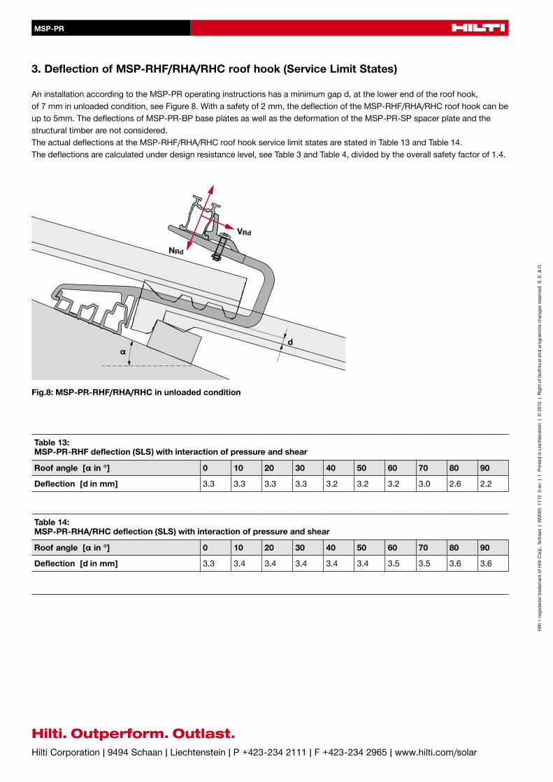
3. Deflection of MSP-RHF/RHA/RHC roof hook (Service Limit States)
An installation according to the MSP-PR operating instructions has a minimum gap d, at the lower end of the roof hook, of 7 mm in unloaded condition, see Figure 8. With a safety of 2 mm, the deflection of the MSP-RHF/RHA/RHC roof hook can be up to 5mm. The deflections of MSP-PR-BP base plates as well as the deformation of the MSP-PR-SP spacer plate and the structural timber are not considered. The actual deflections at the MSP-RHF/RHA/RHC roof hook service limit states are stated in Table 13 and Table 14. The deflections are calculated under design resistance level, see Table 3 and Table 4, divided by the overall safety factor of 1.4.
Fig.8: MSP-PR-RHF/RHA/RHC in unloaded condition
NRd
VRd
αd
Related Documents