HAL Id: inserm-00130038 https://www.hal.inserm.fr/inserm-00130038 Submitted on 5 Apr 2007 HAL is a multi-disciplinary open access archive for the deposit and dissemination of sci- entific research documents, whether they are pub- lished or not. The documents may come from teaching and research institutions in France or abroad, or from public or private research centers. L’archive ouverte pluridisciplinaire HAL, est destinée au dépôt et à la diffusion de documents scientifiques de niveau recherche, publiés ou non, émanant des établissements d’enseignement et de recherche français ou étrangers, des laboratoires publics ou privés. MSCT labelling for pre-operative planning in cardiac resynchronization therapy. Kristell Rioual, Edurne Unanua, Soizic Laguitton, Mireille Garreau, Dominique Boulmier, Pascal Haigron, Christophe Leclercq, Jean-Louis Coatrieux To cite this version: Kristell Rioual, Edurne Unanua, Soizic Laguitton, Mireille Garreau, Dominique Boulmier, et al.. MSCT labelling for pre-operative planning in cardiac resynchronization therapy.. Computerized Med- ical Imaging and Graphics, Elsevier, 2005, 29 (6), pp.431-9. 10.1016/j.compmedimag.2005.04.005. inserm-00130038

Welcome message from author
This document is posted to help you gain knowledge. Please leave a comment to let me know what you think about it! Share it to your friends and learn new things together.
Transcript

HAL Id: inserm-00130038https://www.hal.inserm.fr/inserm-00130038
Submitted on 5 Apr 2007
HAL is a multi-disciplinary open accessarchive for the deposit and dissemination of sci-entific research documents, whether they are pub-lished or not. The documents may come fromteaching and research institutions in France orabroad, or from public or private research centers.
L’archive ouverte pluridisciplinaire HAL, estdestinée au dépôt et à la diffusion de documentsscientifiques de niveau recherche, publiés ou non,émanant des établissements d’enseignement et derecherche français ou étrangers, des laboratoirespublics ou privés.
MSCT labelling for pre-operative planning in cardiacresynchronization therapy.
Kristell Rioual, Edurne Unanua, Soizic Laguitton, Mireille Garreau,Dominique Boulmier, Pascal Haigron, Christophe Leclercq, Jean-Louis
Coatrieux
To cite this version:Kristell Rioual, Edurne Unanua, Soizic Laguitton, Mireille Garreau, Dominique Boulmier, et al..MSCT labelling for pre-operative planning in cardiac resynchronization therapy.. Computerized Med-ical Imaging and Graphics, Elsevier, 2005, 29 (6), pp.431-9. �10.1016/j.compmedimag.2005.04.005�.�inserm-00130038�

- 1 -
MSCT Labelling for Pre-Operative Planning in Cardiac Resynchronization
Therapy
Kristell Riouala, Edurne Unanuaa, Soizic Laguittona, Mireille Garreaua, Dominique Boulmierb,
Pascal Haigrona, Christophe Leclercqb, Jean-Louis Coatrieuxa aLaboratoire Traitement du Signal et de l’Image,INSERM U642, Université de Rennes 1, 35042 Rennes, France.
bCentre Cardio-Pneumologique, CHU Pontchaillou, 35033 Rennes, France.
Corresponding author : Jean-Louis COATRIEUX
Mailing Address : Laboratoire Traitement du Signal et de l’Image,
INSERM U642, Université de Rennes 1,
Campus de Beaulieu, 35042 Rennes Cedex, France
Tel. +33 2 23 23 56 74
Fax. +33 2 23 23 69 17
E-mail address : [email protected]
HA
L author manuscript inserm
-00130038, version 1
HAL author manuscriptComput Med Imaging Graph 09/2005; 29(6): 431-9

- 2 -
Abstract — The objective of this paper is twofold: (i) to show how Multislice Computed
Tomography (MSCT) data sets bring the information required for Cardiac Resynchronisation
Therapy (CRT) planning; (ii) to demonstrate the feasibility of 3-D navigation into the veins
where Left Ventricular leads have to be placed. The former has been achieved by exploring
and labelling the cardiac structures of concern, the latter has been performed by using the
concept of virtual navigation with high resolution surface detection and estimation algorithms.
Keywords — CRT, pre-operative planning, heart labelling, 3-D rendering.
1. Introduction
Cardiac Resynchronization Therapy (CRT) is aimed at the restoration of the
contractile coordination in hearts with severe heart failure (HF), sinus rhythm and ventricular
conduction delay. It is performed by stimulating both the right and the left ventricles, pacing
them simultaneously or with a small delay. Several clinical trials have shown that this
technique is beneficial for acute as well as chronic disorders, improving the heart’s
performance, the capacity of the patient for exercise and reducing the mortality from heart
failure [1—3]. However, these studies point out that the main issue remains to identify and
assess the most effective pacing sites in order to reduce the percentage of non-responding
patients which may reach up to 25 to 30% of recipients. They have shown that LV-lead
positioning (either LV-only pacing or biventricular pacing) is without contest the most
challenging one to implant.
Advances in instrumentation, implantation techniques and selection of appropriate
candidates have to be achieved to increase the success rate of CRT. They can make use of
tissue Doppler, MR tagged imaging or Multislice CT scanner (MSCT). The latter is the only
imaging modality that brings a full 4-D morphological and functional insight into the heart.
HA
L author manuscript inserm
-00130038, version 1

- 3 -
The availability of catheter-based 3D non fluoroscopic contact (Carto, Biosense) and
noncontact mapping (Ensite 3000, Endocardial Solutions, Inc) techniques allows in vivo
assessment of the activation sequence with a relatively high spatial resolution [4—6]. Recent
technological breakthroughs of implantable devices have been achieved: they concern
biventricular pacing (or CRT), cardioverter-defibrillator (ICD, Implantable Cardioverter
Defibrillator) or joint device (CRT-ICD). These systems have several advanced functionalities
including electrical potential sensing, electrical pulse stimulation, reprogramming through bi-
directional wireless communication, event recording, etc. Major efforts were carried out for
miniaturization, energy consuming reduction and therefore higher autonomy, robustness to
environmental perturbations.
Improvements can also be expected from minimally invasive computer assisted
implantation which has been recently proposed [7], based on a direct left ventricular
epicardial approach. However the consequence of chest insuflation and single-lung ventilation
which are used must be evaluated to a larger scale.
The conjunction of electrical data, morphological and mechanical behaviour is very
likely a source of additional progress: insights into electromechanical coupling should
improve the understanding of regional and global abnormalities.
The implantation of such pacing device is image-guided (X-ray angiography) and this
is the target of this work: is it possible, based on MSCT, to better plan this procedure? This
paper is addressing a part of the problem, the pre-operative phase of the whole procedure. It
deals with:
- the labelling of the venous structures of the heart into which the lead implantation
may take place
- the virtual 3-D navigation inside these vessels in order to define the possible paths
that can be followed.
HA
L author manuscript inserm
-00130038, version 1

- 4 -
Section 2 brings more clues on the CRT. The approach that has been followed is
described section 3. Some illustrations of heart labelling are provided section 4 and samples
of virtual images issued from a navigation into the veins are given section 5. They are
discussed in section 6 before concluding with some remarks and prospects.
2. Problem statement
In 1998, Daubert et al [8], from the Hospital of Rennes, proposed a way to overcome
this problem by using a transvenous technique, permitting to stimulate the left ventricle on a
long-term basis. The procedure consists in positioning epicardial leads in the right atrium and
right ventricle, the left ventricle being paced via a lead passed through the coronary sinus to
an epicardial vein on the free wall of the left ventricle (Fig. 1).
This technique, applied today worldwide for biventricular pacing, has however some
limitations [9,10]:
• The implant success rate is around 85% to 92%1, mainly due to:
o Incorrect pacing site or electrode displacements (5-7%)
o The impossibility to access the target vein
o The dissection of the coronary sinus (3%)
o The difficulty to attain an optimal pacing site.
• a typical implant procedure for a biventricular pacemaker can be lengthy ( about
1.5 to 3 hours) with, in average, 0.5 hours of X-ray,
The main objective is thus to assist health professionals in improving and securing the
implant techniques. From a clinical standpoint, it will rely on the study of the patient’s
coronary anatomy to define the target veins, to confirm their accessibility and to minimize the
1 Implant success rate of 92% in MUSTIC [11] and 93% in MIRACLE [12].
HA
L author manuscript inserm
-00130038, version 1

- 5 -
implant time. Pre-operative assistance, as defined in Computer Assisted Therapy [13] and in
Virtual Navigation [14], will consist here to:
• Study the anatomy of the patient’s coronary venous tree so as to define the optimal
access path for the pacing leads.
• Define which catheter and guide type should be used (with different diameters and
curvatures, for example).
• Better define the optimal pacing site, based on the anatomo-functional information
and on the electro-mechanical models of the cardiac activity.
Up to now, there was no image-based planning of the implant procedure because no
imaging source was capable to provide a full, 3-D, time image sequence access to the heart.
CRT is still directly performed by using 2-D venous X-ray coronarography which leads to a
partial and limited access to 3-D anatomy.
The availability of MSCT is dramatically changing this situation: this 4-D functional imaging
CT Scanners can be used to obtain the basic structural and functional features required to
achieve an optimal CRT planning.
The LV can be paced transvenously through a subclavian vein, going successively via
the cava vein, the right atrium, the coronary sinus and the great vein. The target location is a
lateral or posterolateral vein. If lateral vein catheterization failed or in the case of poor pacing
threshold, the LV lead is inserted into the great cardiac vein to pace the anterobasal wall or
into the mid cardiac vein to pace the inferoapical region (see appendix for more details).
Specifically designed coronary sinus leads are used. The injection of contrast medium allows
viewing the venous tree to be explored but it remains difficult to visually analyse due to the
backward blood flow.
HA
L author manuscript inserm
-00130038, version 1

- 6 -
3. Method
The MSCT data provide detailed and effective insights into the structures of the heart
but also new means to track and characterize its hemodynamic behaviour over time. This
advantage has a challenging counterpart: the high complexity of the scene to be analysed both
visually by the physician, and quantitatively through image processing techniques. This is not
true, of course, for the study of the main components (cavities, major vessels, etc.) but it
becomes critical for the complex-shaped objects, with reduced size and low contrast.
Basically, the same difficulties encountered for all slice-based descriptions are found
here. This presentation mode requires a 3-D mental reconstitution of the 3-D shapes from the
2-D planes. They have motivated the development of 3-D segmentation, rendering and
manipulation techniques for more than 30 years (refer to [15] for recent surveys). However, in
many clinical applications, there is a low number of structures of interest with contrast
characteristics such that simple and global solutions (thresholding) can be used for their rough
discrimination. They do not lead to any labelling of the objects but they provide a way for the
radiologist to view, locate, and identify the anatomical structures.
In general, a learning curve is required for the physicians to read the volume data. A
similar situation has to be dealt with for the coronary venous tree. The volume sets must be
explored many times before being capable to name the structures. It is this motivation that
brings us to anatomically label MSCT data sets. The procedure that has been worked out
consists in selecting spatial sequences among 8 angio-scanners at our disposal (with minimal
motion artefacts). The data were acquired on a Siemens Somatom volume zoom 4 detectors.
Identical protocols were used with the following acquisition parameters: collimation of 0.6
mm, table displacement of 1.5 mm/rotation, reconstruction increment of 0.6 mm, size of the
matrix 512x512 with about 200 slices and a pixel size from 0.33x0.33 to 0.4x0.4 mm. The
resolution is 12 bits and the slice thickness of 1.25 mm. Labelling has been independently
HA
L author manuscript inserm
-00130038, version 1

- 7 -
performed by a radiologist and an interventional cardiologist followed by a consensus
decision. One labelled data set will be briefly commented throughout this paper2.
4. A labelled example
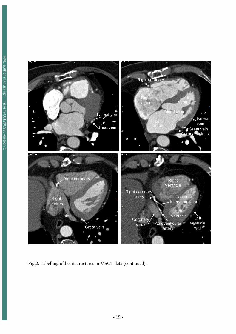
The 2-D slices, together with the labels of coronary veins, are displayed in figure 2. A
subset of slices (over 193) has been selected interactively in order to depict the most relevant
veins of concern. The traversal of the heart is done from top to bottom (but it should be
noticed that the slices correspond to the axial section looked from below, that is, with the right
and left inverted). These structures are of different natures (cavities, arteries, valves, etc.) and
serve as landmarks to visually understand the 3-D locations and complex conformations of the
veins.
The ascending and descending Aorta, the pulmonary trunk and the pulmonary valves
as well as the superior vena cava, right and left pulmonary arteries can be clearly recognized
in the first slice (1/193). The right auricle, starting from the vena cava, on the left side of the
aorta, and the great vein are displayed on the next slice. The latter, appearing twice due to its
arch shape, has a much smaller size and its boundaries are blurred. Left anterior and posterior
pulmonary veins (13/193) will join the right atrium when going down within the slices.
Subsets of the arterial tree ( with the circumflex, the interventricular, the right coronary and
diagonal) together with the great vein can be localized within the slice 30. In continuation
with the vena cava, the superior vena cava appears slice 39 with the lateral circumflex artery.
Major structures like the right and left atrium, left ventricle and coronary sinus are
displayed when going top-down (slices 95 and 144). All the coronary veins flow into the
coronary sinus and its size is enough to get a good rendering of its walls (section 5 below).
The atrioventricular and posterior interventricular arteries, proceeding from the right coronary
2 This data set will be made publicly available at www.ltsi-univ-rennes1.fr with more detailed comments after publication
HA
L author manuscript inserm
-00130038, version 1

- 8 -
artery, are visible on the slice 157/193. The post-lateral veins (slice 161) and the posterior
vein (draining the posterior surface of the left ventricle, slices 164 and 172) point out that,
with their low diameter and contrast, their complex shapes, they will be difficult to render.
This will also be the case of the middle cardiac vein (slice 175/193).
The main difficulties encountered during the travelling, the reading and the labelling
process of the several data sets we have explored are mainly due to (i) the enhancement of all
vessels (ii) the proximity of the arterial and venous trees and (iii) the complexity of 3-D
shapes and geometries. The veins are in general large enough in their proximal segments but
small in their distal parts. And these distal parts are of course the places where the pacemaker
electrodes should be located. The information brought by MSCT may, of course, be used
already to mentally sketch possible access to the veins reaching the LV but 3-D navigation
can highly facilitate this task. These anatomical views can be considered as a preliminary step
to read and understand the contents of MSCT data: they must be complemented by
measurements (diameters, lengths, angles). Such task could be carried out on the way in
preparing the intervention but the fact that the data are seen in 2-D does not lead to precise
estimations.
5. Samples of virtual navigation through left coronary veins
Pre-operative planning can make use of virtual endoscopy techniques in order to
define the candidate paths to reach the most appropriate sites for electrical recoding and
stimulation of the left ventricle. The basics of interactive and active navigation methods have
been reported already in several papers [16—18]. In addition, local measures (lengths,
diameters, angles) can be carried out as shown in [19]. These techniques are of major interest
for pre-operative CRT because several difficulties may arise during the intervention among
which:
HA
L author manuscript inserm
-00130038, version 1

- 9 -
- the insertion of the cannula into the coronary sinus: X-ray image guiding is often
carried out by touching and the internal guide must be sometimes reshaped or changed.
- the access to veins with an adverse angle onto a junction is still a problem and prior
simulation can reduce the number of trials and, accordingly, the risk afferent to them (damage
to vein walls).
- in order to decide if the instruments can go through or not, diameter measures are
required.
- the selection of the optimal veins and sites for lead placement.
The implantation of the right leads do not represent the same difficulties in terms of
access.
The detection of walls during navigation is performed in 3 steps [20]: (1) a standard
ray casting is launched from the observer position through the image screen coupled with a
rough detection algorithm; (2) when an object is detected, an interpolation around the
corresponding voxel is worked out in order to get a higher local sampling of the volume; (3) a
refined detection step is then applied which allows to get a better estimation of the surface
position and orientation (required to have a good shading for 3-D rendering).
It is not possible of course to render in a paper the full navigation sequence performed
on the computer. Fig. 3 shows some image samples computed during traveling into the heart
and the venous tree. They provide the path to the major structures (right atrium, coronary
sinus, great vein, posterolateral and lateral veins), their positions and shapes that the
interventional cardiologist need to know. The detection threshold was set to 60 HU. The
refined detection has been performed using a three-linear operator with 1/5 resolution. It can
be easily seen that the cavity and the vein walls are clearly depicted even when small
structures are explored.
HA
L author manuscript inserm
-00130038, version 1
- 10 -
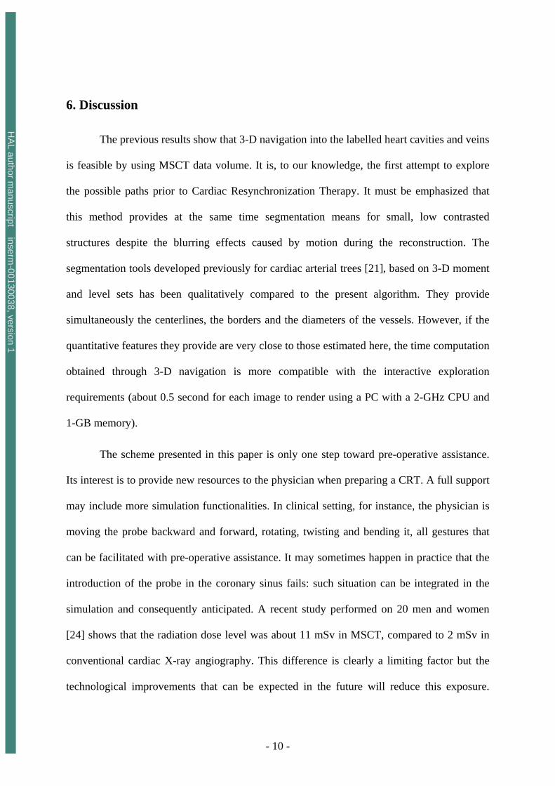
6. Discussion
The previous results show that 3-D navigation into the labelled heart cavities and veins
is feasible by using MSCT data volume. It is, to our knowledge, the first attempt to explore
the possible paths prior to Cardiac Resynchronization Therapy. It must be emphasized that
this method provides at the same time segmentation means for small, low contrasted
structures despite the blurring effects caused by motion during the reconstruction. The
segmentation tools developed previously for cardiac arterial trees [21], based on 3-D moment
and level sets has been qualitatively compared to the present algorithm. They provide
simultaneously the centerlines, the borders and the diameters of the vessels. However, if the
quantitative features they provide are very close to those estimated here, the time computation
obtained through 3-D navigation is more compatible with the interactive exploration
requirements (about 0.5 second for each image to render using a PC with a 2-GHz CPU and
1-GB memory).
The scheme presented in this paper is only one step toward pre-operative assistance.
Its interest is to provide new resources to the physician when preparing a CRT. A full support
may include more simulation functionalities. In clinical setting, for instance, the physician is
moving the probe backward and forward, rotating, twisting and bending it, all gestures that
can be facilitated with pre-operative assistance. It may sometimes happen in practice that the
introduction of the probe in the coronary sinus fails: such situation can be integrated in the
simulation and consequently anticipated. A recent study performed on 20 men and women
[24] shows that the radiation dose level was about 11 mSv in MSCT, compared to 2 mSv in
conventional cardiac X-ray angiography. This difference is clearly a limiting factor but the
technological improvements that can be expected in the future will reduce this exposure.
HA
L author manuscript inserm
-00130038, version 1

- 11 -
Moreover, it can be anticipated that the pre-operative planning of CRT procedure will lead to
a decrease in radiation dose during the interventions.
Another objective could be the construction of a quantitative, fully 3-D atlas of the
heart, as it has been done for the brain. This atlas should include the inter-individual
deviations (structural, morphological) with statistical values as well as diseases. A virtual
representation, computer-based, of an average patient (and exceptions) could be then defined
and have a great interest in training.
The future of such project will rely on generic methods for data collection and
decision making, advanced image processing tools, sophisticated multimodal models (e.g
mechanical, electrical, etc.), particularly to:
• acquire and represent the specific physiological knowledge necessary to choose
the most appropriate CRT for a given patient.
• define new methods for automatic navigation on 3D volumes in a dynamic
environment, so as to define an access path to the optimal pacing site and
propose an electrophysiological exploration protocol.
• model the pacemaker behaviour and to couple it with the cardiac model.
• propose a way to assist operator-based navigation by coupling pre- and intra-
operative images (or volumes).
• model the pacemaker behaviour and to couple it with the cardiac model so as
to simulate the hemodynamic benefit of biventricular pacing, with respect to
the pacing site and to propose patient-specific solutions.
7. Summary
HA
L author manuscript inserm
-00130038, version 1

- 12 -
It has been shown throughout this paper that MSCT data sets offer a major contribution for
preparing interventions dealing with Cardiac Resynchronization Therapy. They provide in
depth insights into the main structures as well as the critical veins of concern. The complexity
of the scene, due to the many entities that it contains, the complicated shapes and the inter-
individual variations that may be observed, requires previous visual exploration and labelling,
advanced image processing tools and efficient 3-D rendering techniques. These new
resources, however, open the road to multiple research developments that can be of major
importance to reduce the time of intervention, to make the procedure safer for the patient and
finally to improve the success rate of CRT.
Acknowledgements
The authors are indebted to B. Le Bruno, from Siemens Medical Division, France, for her
constant support during the collection of MSCT data sets.
HA
L author manuscript inserm
-00130038, version 1

- 13 -
Appendix
Schematically, this new procedure begins with placement of a coronary sinus (CS)
catheter. A long sheath is then passed over this catheter and placed in the CS. The CS catheter
is removed and a balloon-tipped catheter is inserted via the sheath into the CS. The balloon is
inflated, contrast is injected and a CS venogram is made in both the right and left anterior
oblique views. Using both views allows identification of possible target sites for the
permanent pacing lead. The usual site chosen is a lateral coronary vein about midway between
the apex and the base. Next, the balloon catheter is removed and the pacing lead is introduced
through the sheath (soft tines at the tip of the lead enable successful passive fixation in the
coronary sinus). It is manipulated into the target site and pacing measurements are made
(threshold, R wave, slew rate, and impedance). If satisfactory, the lead is left in place. The
optimal site for left ventricular pacing is in the lateral or posterolateral cardiac vein. This is
because pacing from the mid lateral wall or posterior wall results in the best percentage
increase in pulse pressure and left ventricular dP/dt. However, at times, they are too small for
the lead to enter or do not result in a stable position and the lead is then positioned in the
anterior great cardiac vein [22].
Once the left ventricular lead is secured, the right ventricular apex lead and right atrial
lead are then implanted in the usual manner for a dual chamber pacemaker. Where possible,
the RV and LV lead should however be anatomically as far apart as possible, so as to obtain
maximal separation between the right and the left ventricular lead tip in both AP and LAO
views. In patients with left ventricular leads in the great cardiac vein, or in the lateral or
postero-lateral branches of the CS a mid-inferior wall position is chosen for the right
ventricular lead. In those with a posterior or mi-cardiac vein position, the right ventricular
lead is positioned in the right ventricular outflow tract or on the right ventricular septum. The
right atrial leads are routinely positioned in the right atrial appendage [23].
HA
L author manuscript inserm
-00130038, version 1

- 14 -
References
[1] Cazeau S, Leclercq C, Lavergne T et al. Effects of multisite biventricular pacing in patients with heart failure and intraventricular delay, New England Journal of Medicine 2001;344:873-880.
[2] Leclercq C, Kass DA. Re-timing the failing heart: principles and current clinical status of cardiac resynchronization. Journal of the American College of Cardiology 2002;39:194-201.
[3] Kass DA. Predicting cardiac resynchronization response by GRS duration. Journal of the American College of Cardiology 2003;42:2125-2127.
[4] Gepstein L, Hayan G, Ben-Haim SA. A novel method for nonfluoroscopic catheter-based electroanatomical mapping of the heart: in vitro and in vivo accuracy results. Circulation 1997;95:1611-1622.
[5] Schilling RJ, Peters S, Davies DW. Simultaneous endocardial mapping in the left ventricle using a noncontact catheter: comparison of contact and reconstructed electrograms during sinus rhythm. Circulation 1998;98:887-898.
[6] De Bakker JMT, Hauer RNW, Simmens TA. Activation mapping: unipolar versus bipolar recording, In: Zipes D.P, Jalife J Eds, Cardiac Electrophysioloy: from cell to bedsite. 3rd ed. Philadelphia:Saunders, 2000:1068-1078.
[7] DeRose J.J, Ashton R.C, Belsey S et al. Robotically assisted left ventricular epicardial lead implantation for biventricular pacing. Journal of the American College of Cardiology 2003 ;41:1414-1419.
[8] Daubert J, Pitter P, Le Breton H, Gras D, Leclercq C, Lazarus A, Mugica J, Mabo P, Cazeau S. Permanent left ventricular pacing with transvenous leads inserted into the coronary veins. PACE 1998 ;21: 239-245.
[9] Abraham WT. Rationale and design of a randomized clinical trial to assess the safety and efficacy of cardiac resynchronization therapy in patients with advanced heart failure: the Multicenter InSync Randomized Clinical Evaluation (MIRACLE). Journal of Cardiac Failure 2000;6:369-380.
[10] Alonzo C, Leclercq C, d’Allones F.R et al. Six years experience of transvenous left ventricular lead implantation for permanent biventricular pacing in patients with advanced heart failure: technical aspects. Heart 2001;86:405-410.
[11] Cazeau S, Leclercq C, Lavergne T, et al. Effects of multisite biventricular pacing in patients with heart failure and intraventricular conduction delay. The Multisite Stimulation in Cardiomyopathies (MUSTIC) Study Investigators. New England Journal of Medicine 2001;344:873-880.
[12] Abraham WT, Fisher WG, Smith AL, et al, for the MIRACLE Study Group. Cardiac Resynchronization in chronic heart failure. New England Journal of Medicine 2002; 346:1845-1853.
[13] Taylor RH, Lavallée S, Burdea GC, Mösges R. Computer-Integrated Surgery, Technology and Clinical Applications. Cambridge: MIT press, 1996.
[14] Roux C, Coatrieux JL. Contemporary perspectives on Three Dimensional Biomedical Imaging. Amsterdam:IOS Press,1997.
[15] Coatrieux JL, Roux C, Biomedical Imaging IV. IEEE EMBS Series. NJ: IEEE Press, 2002.
[16] Haigron P, Bellemare ME, Acosta O, Goksu C, Kulik C, Rioual K, Lucas A. Depth-Map-Based Scene Analysis for Active Navigation in Virtual Endoscopy. IEEE Transactions on Medical Imaging 2004;23(11):1380-1390.
HA
L author manuscript inserm
-00130038, version 1

- 15 -
[17] Bellemare ME, Haigron P, Coatrieux JL. Toward an active three dimensional navigation system in medical imaging. Proceedings of Computer Vision, Virtual Reality, and Robotics in Medicine and Medical Robotics and Computer Assisted Surgery. Grenoble (France): Springer LNCS 1205, 1997:337-346.
[18] Coatrieux JL. Les bases scientifiques de l’endoscopie virtuelle. Bulletin de l’Académie Nationale de Médecine 1999;183(3):455-464.
[19] Acosta O, Moisan C, Haigron P, Lucas A (2004). Evaluation of Virtual Exploratory Navigation for the Characterization of Stenosis in the Planning of Endovascular Interventions. In: Clough AV, Chen CT, editors. Proceedings of SPIE Medical Imaging. San Diego (California, USA): SPIE 2002;4683:42-53.
[20] Haigron P, Le Berre G, Coatrieux JL. 3-D navigation in medicine. IEEE Engineering in Medicine and Biology 1996;15(2):70-78.
[21] Larralde A, Boldak C, Garreau M, Toumoulin C, Boulmier D, Rolland Y. Evaluation of a 3D Segmentation Software for the Coronary Characterization in Multi-slice Computed Tomography. Proceedings of Functional Imaging and Modeling of the Heart. Lyon(France): Springer LNCS 3674, 2003:39-51.
[22] Teo WS, Kam R, Hsu LF. Treatment of Heart Failure - Role of Biventricular Pacing for Heart Failure Not Responding Well to Drug Therapy. Singapore Medical Journal 2003;44(3): 114-122.
[23] Walker S, Levy T, Rex S, Brant S, Paul V. Initial United Kingdom experience with the use of permanent, biventricular pacemakers: Implantation procedure and technical considerations. Europace 2000;2(3):233-239.
[24] Willmann JK, Weishaupt D, Kobza R, Verdun FR, Seifert B, Marincek B, Boehm T, Coronary artery bypass grafts: ECG-gated multi-detector row CT angiography-influence of image reconstruction interval on graft visibility, Radiology, 2004, 232 (2), 568-577
HA
L author manuscript inserm
-00130038, version 1

- 16 -
List of figures
Fig. 1. Lead paths and positions in transvenous biventricular pacing. Fig.2. Labelling of heart structures in MSCT data. The dataset was acquired at 30% of the cardiac cycle. The subset of slices is composed of 12 labelled slices. The slices, selected to show different anatomical features, are numbered at the top left corner. The level window is between -100 HU and 700 HU. The letters A, P, R and L, that denote respectively anterior, posterior, right and left, are used to indicate the slice position relative to the patient’s body. Fig.3. Virtual fly-through the heart venous structures. The sequence is composed of images selected at four different locations (a: inside the right atrium, close to the coronary sinus, b:at the coronary sinus entrance, c:inside the great vein, and d: inside the lateral vein). For each location, the left part shows the virtual navigation view and the right part shows an arrow representing the pose of the virtual endoscope in the volume image and superimposed on three orthogonal MSCT slices. The location of the MSCT slices corresponds to the origin of the arrow, whereas the viewing axis of the virtual endoscope is represented by the orientation of the arrow.
HA
L author manuscript inserm
-00130038, version 1

- 17 -
Fig. 1. Lead paths and positions in transvenous biventricular pacing.
HA
L author manuscript inserm
-00130038, version 1

- 18 -
Great vein
Great vein
Left ant pulm veinLeft post pulm vein
pulmonary
Pulmonaryvalve
Ascendingaorta
Superiorvena cava Right
artery Left
artery
Pulmonarytrunk
pulmonary
pulmonary
Descendingaorta
Right coronary
Right ventricule
Circumflex
Inter ventricularartery
Great vein
Diagonal
Great vein
Rightatrium
Superiorvena cava
Great vein
Great vein
Lat circumflexartery
Superiorvena cava
Circumflex
Great vein
Great vein
Left ant pulm veinLeft post pulm vein
Great vein
Great vein
Left ant pulm veinLeft post pulm vein
pulmonary
Pulmonaryvalve
Ascendingaorta
Superiorvena cava Right
artery Left
artery
Pulmonarytrunk
pulmonary
pulmonary
Descendingaorta
pulmonary
Pulmonaryvalve
Ascendingaorta
Superiorvena cava Right
artery Left
artery
Pulmonarytrunk
pulmonary
pulmonary
Descendingaorta
Right coronary
Right ventricule
Circumflex
Inter ventricularartery
Great vein
Diagonal
Great vein
Rightatrium
Superiorvena cava
Right coronary
Right ventricule
Circumflex
Inter ventricularartery
Great vein
Diagonal
Great vein
Rightatrium
Superiorvena cava
Great vein
Great vein
Lat circumflexartery
Superiorvena cava
CircumflexGreat vein
Great vein
Lat circumflexartery
Superiorvena cava
Circumflex
Fig.2. Labelling of heart structures in MSCT data. The dataset was acquired at 30% of the cardiac cycle. The subset of slices is composed of 12 labelled slices. The slices, selected to show different anatomical features, are numbered at the top left corner. The level window is between -100 HU and 700 HU. The letters A, P, R and L, that denote respectively anterior, posterior, right and left, are used to indicate the slice position relative to the patient’s body.
HA
L author manuscript inserm
-00130038, version 1
- 19 -
Lateral vein
Great vein
Right coronary
Right atrium
Mitral valve
Leftventricule
Leftatrium
Lateralvein
Great veinCoronary sinus
Right coronary
sinus
Rightatrium
Great vein
Posteriorinterventricular
Right coronaryartery
Coronarysinus
Right Ventricle
LeftVentricle Left
ventriclewall
Atrioventicularartery
Lateral vein
Great vein
Lateral vein
Great vein
Right coronary
Right atrium
Mitral valve
Leftventricule
Leftatrium
Lateralvein
Great veinCoronary sinus
Right coronary
Right atrium
Mitral valve
Leftventricule
Leftatrium
Lateralvein
Great veinCoronary sinus
Right coronary
sinus
Rightatrium
Great vein
Right coronary
sinus
Rightatrium
Great vein
Posteriorinterventricular
Right coronaryartery
Coronarysinus
Right Ventricle
LeftVentricle Left
ventriclewall
Atrioventicularartery
Posteriorinterventricular
Right coronaryartery
Coronarysinus
Right Ventricle
LeftVentricle Left
ventriclewall
Atrioventicularartery
Fig.2. Labelling of heart structures in MSCT data (continued).
HA
L author manuscript inserm
-00130038, version 1

- 20 -
Posterior vein
sinus
Postero lateral vein 1
Middle vein
Posterior vein
Postero-lateral vein 2
Postero-lateral vein 1
Posterior vein
sinus
Posterior vein
sinus
Postero lateral vein 1Postero lateral vein 1
Middle vein
Posterior vein
Middle vein
Posterior vein
Postero-lateral vein 2
Postero-lateral vein 1
Postero-lateral vein 2
Postero-lateral vein 1
Fig.2. Labelling of heart structures in MSCT data (continued).
HA
L author manuscript inserm
-00130038, version 1

- 21 -
(a)
(b)
(c)
(d)
(a)
(b)
(c)
(d)
Fig.3. Virtual fly-through the heart venous structures. The sequence is composed of images selected at four different locations (a: inside the right atrium, close to the coronary sinus, b:at the coronary sinus entrance, c:inside the great vein, and d: inside the lateral vein). For each location, the left part shows the virtual navigation view and the right part shows an arrow representing the pose of the virtual endoscope in the volume image and superimposed on three orthogonal MSCT slices. The location of the MSCT slices corresponds to the origin of the arrow, whereas the viewing axis of the virtual endoscope is represented by the orientation of the arrow.
HA
L author manuscript inserm
-00130038, version 1
Related Documents