User Subroutines and Special Routines MSC.Marc ® Version 2005 Volume D

Welcome message from author
This document is posted to help you gain knowledge. Please leave a comment to let me know what you think about it! Share it to your friends and learn new things together.
Transcript
User Subroutines and Special Routines
MSC.Marc®
Version 2005
Volume D

Copyright 2004 MSC.Software Corporation
All rights reserved. Printed in U.S.A.
Corporate Europe
MSC.Software Corporation MSC.Software GmbH2 MacArthur Place Am MoosfeldSanta Ana, CA 92707 81829 München, GERMANYTelephone: (714) 540-8900 Telephone: (49) (89) 431 987 0Fax: (714) 784-4056 Fax: (49) (89) 436 1716
Asia Pacific Worldwide WebMSC Software Japan Ltd. www.mscsoftware.comShinjuku First West 8F23-7 Nishi Shinjuku1-Chome, Shinjuku-KuTokyo 160-0023, JAPANTelephone: (81) (3)-6911-1200Fax: (81) (3)-6911-1201
Part Number: MA*V2005*Z*Z*Z*DC-VOL-D
This document, and the software described in it, are furnished under license and may be used or copied only in accordance with the terms of such license. Any reproduction or distribution of this document, in whole or in part, without the prior written authorization of MSC.Software Corporation is strictly prohibited.
MSC.Software Corporation reserves the right to make changes in specifications and other information contained in this document without prior notice. The concepts, methods, and examples presented in this document are for illustrative and educational purposes only and are not intended to be exhaustive or to apply to any particular engineering problem or design. THIS DOCUMENT IS PROVIDED ON AN “AS-IS” BASIS AND ALL EXPRESS AND IMPLIED CONDITIONS, REPRESENTATIONS AND WARRANTIES, INCLUDING ANY IMPLIED WARRANTY OF MERCHANTABILITY OR FITNESS FOR A PARTICULAR PURPOSE, ARE DISCLAIMED, EXCEPT TO THE EXTENT THAT SUCH DISCLAIMERS ARE HELD TO BE LEGALLY INVALID.
MSC.Software logo, MSC, MSC., MSC/, MSC.ADAMS, MSC.Dytran, MSC.Marc, MSC.Patran, ADAMS, Dytran, MARC, Mentat, and Patran are trademarks or registered trademarks of MSC.Software Corporation or its subsidiaries in the United States and/or other countries.
NASTRAN is a registered trademark of NASA. MSC.Nastran is an enhanced proprietary version developed and maintained by MSC.Software Corporation. LS-DYNA is a trademark of Livermore Software Technology Corporation. All other trademarks are the property of their respective owners.
This software may contain certain third-party software that is protected by copyright and licensed from MSC.Software suppliers.
METIS is copyrighted by the regents of the University of Minnesota.NT-MPICH is developed by Lehrstuhl für Betriebssysteme der RWTH Aachen. Copyright 1992-2004 Lehrstuhl für Betriebssysteme der RWTH Aachen.
Use, duplication, or disclosure by the U.S. Government is subject to restrictions as set forth in FAR 12.212 (Commercial Computer Software) and DFARS 227.7202 (Commercial Computer Software and Commercial Computer Software Documentation), as applicable.
MSC.Marc Volume D: User Subroutines and Special Routines
Contents
C O N T E N T SMSC.Marc Volume D: User Subroutines and Special Routines
Chapter 1Introduction ■ Common Blocks Description, 1-2
■ Note on Double Precision, 1-2
■ Format, 1-3
■ Element Result Database Utility Routine, 1-5❑ Example, 1-6
■ Nodal Results Database Utility Routine, 1-7
■ Table Evaluation Routine, 1-8
■ MATDAT Common Block, 1-9
■ CONCOM Common Block, 1-11
■ ELMCOM Common Block, 1-17
■ BCLABEL Common Block, 1-20
Chapter 2User-defined Loading, Boundary Conditions, and State Variables User Subroutines List
Chapter 2User-defined Loading, Boundary Conditions, and State Variables User Subroutines
FORCEM — Input of Nonuniform Distributed Loads, 2-7FLUX — Input of Nonuniform Fluxes, 2-12UWELDFLUX — Input of User Defined Welding Flux, 2-14UWELDPATH — Input of User Defined Welding Path, 2-16CUPFLX — Coupling of Inelastic Energy and Internal
Heat Generation, 2-18UINSTR — Input of Initial State of Stresses, 2-19UFOUR — Input of a User-defined Function F(Q) for
Fourier Analysis, 2-20
MSC.Marc Volume D: User Subroutines and Special RoutinesContents
iv
FORCDT — Input of Time Dependent Nodal based Boundary Conditions, 2-22
❑ Stress Analysis, 2-22❑ Heat Transfer Analysis, 2-24❑ Joule Heating Analysis, 2-25❑ Diffusion Analysis, 2-26❑ Electrostatic Analysis, 2-28❑ Magnetostatic Analysis, 2-29
FORCDF — Input of Frequency Dependent Loads or Displacements in Harmonic Analysis, 2-31
❑ Stress Analysis, 2-31❑ Piezoelectric Analysis, 2-32
FILM — Input of Nonuniform Film Coefficients, 2-35FLOW — Input of Mass Flow Rate and Inlet Temperature, 2-37UFOUND — Input of Nonlinear Foundation Stiffness and
Damping, 2-39UFILM — Input of Nonuniform Convective Coefficients, 2-41USINKPT — Input of Sink Point Temperatures, 2-43GAPT — Input of Thermal Contact (Conrad) Gap Temperature, 2-44UFORMS — Definition of Constraint Conditions, 2-45CREDE — Input of Pre-specified State Variables, 2-50INITSV — Initialize State Variable Values, 2-52NEWSV — Input New State Variable Values, 2-53USSD — Input of Spectral Response Density, 2-55USINC — Input of Initial Conditions, 2-56USDATA — Input of Initial Data, 2-57UTIMESTEP — Input of User-defined Time Step, 2-58UVELOC — Generation or Modification of Nodal
Velocity Vectors, 2-59MOTION (2-D) — Definition of Rigid Surface Motion for
2-D Contact, 2-60MOTION (3-D) — Definition of Rigid Surface Motion for
3-D Contact, 2-62UGROWRIGID — Changes the Size of a Rigid Body During the
Analysis, 2-65UFRIC — Definition of Friction Coefficients, 2-66UFRICBBC — Definition of Friction Coefficients for
Beam-to-Beam Contact, 2-68DIGEOM — Definition of 3-D Rigid Surface Patch, 2-70SEPFOR — Definition of Separation Force, 2-71
vMSC.Marc Volume D: User Subroutines and Special RoutinesContents
SEPFORBBC — Definition of Separation Force for Beam-to-Beam Contact, 2-73
SEPSTR — Definition of Separation Stress, 2-75UHTCOE — Definition of Environment Film Coefficient, 2-76UHTCON — Definition of Contact Film Coefficient, 2-79UHTNRC — Definition of Thermal Near Contact Film
Coefficient, 2-81UVTCOE — Definition of Environment Electrical Film
Coefficient, 2-84UVTCON — Definition of Electrical Film Coefficient, 2-87UVTNRC — Definition of Electrical Near Contact Film
Coefficient, 2-89UMDCOE — Definition of Environment Mass Diffusion
Coefficient, 2-91UMDCON — Definition of Contact Mass Diffusion Coefficient, 2-94
❑ Format, 2-94UMDNRC — Definition of Mass Diffusion Coefficients between
Surfaces almost in Contact, 2-96UNORST — Definition of Normal Stress, Flow Stress and Temperature
at Contact Node, 2-98UCONTACT — User-defined Contact Condition, 2-101INITPL — Initialize Equivalent Plastic Strain Values, 2-104INITPO — Initialize Pore Pressure in an Uncoupled
Fluid-Soil Analysis, 2-105NEWPO — Modify Pore Pressure in an Uncoupled
Fluid-Soil Analysis, 2-106UREACB — Definition of Reactive Boundary Coefficients in an
Acoustic Harmonic Analysis, 2-107UCAV — Input of Volume-Dependant Pressure Load
for Cavities, 2-108UOBJFN — Definition of Objective Function and its Gradient, 2-110
MSC.Marc Volume D: User Subroutines and Special RoutinesContents
vi
Chapter 3User-defined Anisotropy and Constitutive Relations User Subroutines List
Chapter 3User-defined Anisotropy and Constitutive Relations User Subroutines
ANELAS — Elastic Anisotropy, 3-5HOOKLW — Anisotropic Elastic Law, 3-15ANPLAS — Anisotropic Yield Surface and Creep Potential, 3-17UFAIL — User-defined Failure Criterion, 3-19ORIENT — Specification of Preferred Orientation, 3-20ANEXP — Anisotropic Thermal Expansion, 3-22ANKOND — Input of Anisotropic Thermal Conductivity Matrix, 3-24UEPS — Input of Anisotropic Permittivity Matrix, 3-26UMU — Input of Anisotropic Permeability Matrix, 3-27USIGMA — Input of Anisotropic Electric Conductivity Matrix, 3-29USPCHT — Definition of Specific Heat, 3-30UCRPLW (Viscoplastic) — Input of Creep Factors for Power Law
Implicit Creep, 3-31CRPLAW — Input of Special Creep Law, 3-33VSWELL — Input of Special Swelling Law, 3-38WKSLP — Work-hardening Slope Definition, 3-41USPRNG — Input of Nonlinear Spring, Dashpot and
Foundation Stiffness, 3-44UCRACK — Input of Ultimate Stress for Cracking Analysis, 3-47TENSOF — Input of Tension Softening Modulus for
Cracking Analysis, 3-49USHRET — Input of Shear Retention Factor for
Cracking Analysis, 3-50UVOID — Definition of the Initial Void Volume Fraction, 3-51UVOIDN — Definition of the Void Nucleation Rate, 3-52UVOIDRT — Definition of the Initial Void Ratio or Initial
Porosity, 3-54UGRAIN — Calculation of Grain Size, 3-55UDAMAG — Prediction of Material Damage, 3-56UPOWDR — Definition of Material Data for Powder
Metallurgy Model, 3-58UPERM — Definition of Permeability, 3-60UMOONY — Mooney-Rivlin Material, 3-61UENERG — Strain Energy Function, 3-62

viiMSC.Marc Volume D: User Subroutines and Special RoutinesContents
UOGDEN — Definition of Ogden Material Parameters, 3-64UELDAM — Definition of Damage Parameters in Ogden Model, 3-66HYPELA2 — User-defined Material Behavior, 3-68UFINITE — Finite Deformation Isotropic Material Models, 3-74UELASTOMER — Generalized Strain Energy Function, 3-77GENSTR — Generalized Stress Strain Law (Shells & Beams), 3-82UBEAM — Input for Nonlinear Beam, 3-84UPHI — Input of PHI Function in Harmonic Analysis, 3-87UCOMPL — Input of Viscous Stress Strain Relationship, 3-89GAPU — Input of Gap Direction And Closure Distance, 3-91USELEM — User-defined Element, 3-93UNEWTN — Input of Viscosity in Flow Analysis, 3-96URPFLO — Rigid-Plastic Flow, 3-97UARRBO — Arruda-Boyce Material Model, 3-99UGENT — Gent Material Model, 3-100UACOUS — Definition of Material Properties for
Acoustic Analysis, 3-101USSUBS — Superelements Not Generated by MSC.Marc, 3-102
■ References, 3-104
Chapter 4Viscoplasticity and Generalized Plasticity User Subroutines List
Chapter 4Viscoplasticity and Generalized Plasticity User Subroutines
UVSCPL — Definition of the Inelastic Strain Rate, 4-3UCRPLW — Input of Creep Factors for Power Law Implicit Creep, 4-5CRPLAW — Input of Explicit Viscoplastic Strain Rate Law, 4-7NASSOC — Input of a Nonassociated Flow Law, 4-9ZERO — Calculation of Equivalent Stress, 4-11YIEL — Calculation of Current Yield, 4-12ASSOC — Input of Associated Flow Law, 4-13SINCER — User Subroutine for Improving Accuracy, 4-14

MSC.Marc Volume D: User Subroutines and Special RoutinesContents
viii
Chapter 5Viscoelasticity User Subroutines List
Chapter 5Viscoelasticity User Subroutines
CRPVIS — Viscoelasticity – Generalized Kelvin Material Behavior, 5-3
TRSFAC — Define a Shift Function for Thermo-Rheologically Simple (T.R.S.) Material Behavior, 5-6
HOOKVI — User-defined Anisotropic Viscoelasticity, 5-8
Chapter 6Geometry Modifications User Subroutines List
Chapter 6Geometry Modifications User Subroutines
UFXORD — Coordinate Generation or Modification, 6-3UFCONN — Connectivity Generation or Modification, 6-4MAP2D — Boundary Node Coordinates Modification in Mesh2D, 6-5USIZEOUTL — Local Refinement Definition for 2-D Remeshing with
Advancing Front Mesher, 6-6UPNOD — Update Nodal Positions in Flow Solutions, 6-7UACTIVE — Activate or Deactivate Elements, 6-9REBAR — Input of Rebar Positions, Areas and Orientations, 6-10UFRORD — Rezoning Coordinate Generation or Modification, 6-11URCONN — Rezoning Connectivity Generation
or Modification, 6-12USPLIT — User-defined Criterion to Split a Two-dimensional
Body, 6-13UCOORD — Relocate Nodes Created During Adaptive Meshing, 6-14UADAP — User-defined Error Criterion, 6-15UADAP2 — User-defined Unrefinement, 6-16UADAPBOX — User-defined Box For Adaptivity, 6-17UTRANS — Implement Local Coordinate System, 6-19USHELL — Modify Thickness of Shell Elements, 6-20SSTRAN — Transformation of Substructures, 6-21UTHICK — User-specified Nodal Thicknesses, 6-22UACTUAT — Prescribe the Length of an Actuator, 6-23
ixMSC.Marc Volume D: User Subroutines and Special RoutinesContents
Chapter 7Output Quantities User Subroutines List
Chapter 7Output Quantities User Subroutines
PLOTV — User-selected Postprocessing of Element Variables, 7-3UPOSTV — User-selected Postprocessing of Nodal Variables, 7-5UPSTNO — User-selected Postprocessing of Nodal Variables, 7-8IMPD — Output of Nodal Quantities, 7-10
❑ Stress Analysis, 7-10❑ Electrostatic Analysis, 7-13❑ Magnetostatic Analysis, 7-14❑ Harmonic Electromagnetic Analysis, 7-15❑ Transient Electromagnetic Analysis, 7-15❑ Acoustic Analysis, 7-16❑ Fluid or Fluid-Thermal Analysis, 7-17
ELEVAR — Output of Element Quantities, 7-18ELEVEC — Output of Element Quantities in Harmonic Analysis, 7-20INTCRD — Output of Integration Point Coordinates, 7-22UBGINC — Beginning of Increment, 7-23UEDINC — End of Increment, 7-24UBGITR — Beginning of Iteration, 7-25UBGPASS — Beginning of Pass in Coupled Analyses, 7-26UELOOP — Beginning of Element Loop, 7-27
Chapter 8Hydrodynamic Lubrication User Subroutines List
Chapter 8Hydrodynamic Lubrication User Subroutines
UBEAR — Input of Spatial Orientation of Lubricant Thickness, 8-3UGROOV — Input of Groove Depths, 8-4URESTR — Input of Nonuniform Restrictor Coefficients, 8-5UTHICK — Generation or Modification of Nodal Thickness or
Thickness Change Field, 8-6UVELOC — Generation or Modification of Nodal
Velocity Vectors, 8-8

MSC.Marc Volume D: User Subroutines and Special RoutinesContents
x
Chapter 9Special Routines — MSC.Marc Post File Processor List
Chapter 9Special Routines —MSC.Marc Post File Processor
PLDUMP2000/PLDUMP — MSC.Marc Post File Processor, 9-2
Chapter 10Utility Routines List
Chapter 10Utility Routines DDOT — Inner Product of Two Vectors, 10-2
GMADD — Matrix Add, 10-3GMPRD — Matrix Product, 10-4GMSUB — Matrix Subtract, 10-5GMTRA — Matrix Transpose, 10-6GTPRD — Transpose Matrix Product, 10-7INVERT — Invert Matrix, 10-8INV3X3 — Invert 3 x 3 Matrix, 10-9MCPY — Matrix Copy, 10-10PRINCV — Find Principle Values, 10-11SCLA — Set Matrix to Value, 10-12
Chapter 11Considerations for Parallel Processing
■ Overview, 11-1
■ Auxiliary Routines, 11-2❑ DOMFLAG, 11-2
■ Reading Input, 11-3
■ Sharing Data, 11-5
Appendix AUser Subroutines, Special Routines and Utility Routines List
Chapter 1 Introduction
CHAPTER
1 Introduction
■ Common Blocks Description
■ Note on Double Precision
■ Format
■ Element Result Database Utility Routine
■ Nodal Results Database Utility Routine
■ Table Evaluation Routine
■ CONCOM Common Block
■ ELMCOM Common Block
■ BCLABEL Common Block
Common Blocks Description MSC.Marc Volume D: User Subroutines and Special RoutinesChapter 1 Introduction
1-2
In MSC.Marc, the user subroutine feature constitutes one of the real strengths of MSC.Marc, allowing the user to substitute his own subroutines for several existing in MSC.Marc. This feature provides the user with a wide latitude for solving nonstandard problems. These routines are easily inserted into MSC.Marc. When such a routine is supplied, the user is simply replacing the one which exists in MSC.Marc program using appropriate control setup. A description of each of the available user subroutines is given in this manual. In addition, discussions of special routines are also included.
Note: The reading of data is not recommended in most of the user subroutines since many of these routines are in the recycling loop for nonlinear analysis, and hence, you cannot know how many times per increment the routine is called.
Common Blocks DescriptionOften, when using a user subroutine, more information is needed than is provided through the call arguments. Almost all information is available through common blocks. Much of the information provided below is already available but occasionally, especially in older subroutines, it is not.
All common blocks can be accessed by the user by “including” them in the user subroutine. The syntax to use in the user subroutine is:
include ’yyy’
where yyy is the name of the common block. Note that the word include must begin after column 6 and that the common block name must be within single quotes. A path to the MSC.Marc installation directory does not need to be provided.
Note on Double PrecisionMSC.Marc is written completely in double precision. Hence, on all machines, an IMPLICIT REAL *8 (A-H, O-Z) statement is required in the user subroutines. This is to ensure that variables passed between MSC.Marc and the user subroutine are compatible and to ensure that any common blocks included are correct.

1-3MSC.Marc Volume D: User Subroutines and Special Routines FormatChapter 1 Introduction
FormatThe following quantities are available in all user subroutines:
TIME AT BEGINNING OF INCREMENT: CPTIMTIME INCREMENT: TIMINCAVAILABLE THROUGH
include ’creeps’
INCREMENT NUMBER: INCSUBINCREMENT NUMBER: INCSUBAVAILABLE THROUGH
include ’concom’
Note: During the output phase, CPTIM has been updated to the time at the end of the increment and TIMINC has been set to zero if the total time for an increment or a series of increments has been reached. If the total time has not yet been reached, TIMINC has been set to the time increment of the next increment.
NUMBER OF ELEMENTS IN MESH: NUMELNUMBER OF NODES IN MESH: NUMNPMAXIMUM NUMBER OF DEGREES OF FREEDOM PER NODE: NDEGMAXIMUM NUMBER OF COORDINATE DIRECTIONS: NCRDAVAILABLE THROUGH
include ’dimen’
In a coupled analysis, reference variable IPASS to determine if the current iteration is a stress or heat transfer iteration:
IPASS = 1 STRESSIPASS = 2 HEAT TRANSFERIPASS = 3 FLUIDSIPASS = 4 JOULE HEATINGIPASS = 5 DIFFUSIONIPASS = 6 ELECTROSTATICSIPASS = 7 MAGNETOSTATICIPASS = 8 ELECTROMAGNETICSAVAILABLE THROUGH
include ’concom’
The following quantities are available in user subroutines which are in an element loop:
ELEMENT NUMBER: MAVAILABLE THROUGH
include ’far’
ELSTO ELEMENT NUMBER: NINTEGRATION POINT NUMBER: NNLAYER NUMBER: KCAVAILABLE IN
include ’lass’
Format MSC.Marc Volume D: User Subroutines and Special RoutinesChapter 1 Introduction
1-4
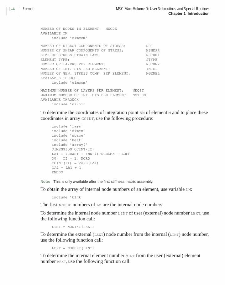
NUMBER OF NODES IN ELEMENT: NNODEAVAILABLE IN
include ’elmcom’
NUMBER OF DIRECT COMPONENTS OF STRESS: NDINUMBER OF SHEAR COMPONENTS OF STRESS: NSHEARSIZE OF STRESS-STRAIN LAW: NSTRM1ELEMENT TYPE: JTYPENUMBER OF LAYERS PER ELEMENT: NSTRM2NUMBER OF INT. PTS PER ELEMENT: INTELNUMBER OF GEN. STRESS COMP. PER ELEMENT: NGENELAVAILABLE THROUGH
include ’elmcom’
MAXIMUM NUMBER OF LAYERS PER ELEMENT: NEQSTMAXIMUM NUMBER OF INT. PTS PER ELEMENT: NSTRESAVAILABLE THROUGH
include ’nzro1’
To determine the coordinates of integration point NN of element M and to place these coordinates in array CCINT, use the following procedure:
include ’lass’include ’dimen’include ’space’include ’heat’include ’array4’DIMENSION CCINT(12)LA1 = ICRXPT + (NN-1)*NCRDMX + LOFRD0 II = 1, NCRDCCINT(II) = VARS(LA1)
LA1 = LA1 + 1ENDDO
Note: This is only available after the first stiffness matrix assembly.
To obtain the array of internal node numbers of an element, use variable LM:
include ’blnk’
The first NNODE numbers of LM are the internal node numbers.
To determine the internal node number LINT of user (external) node number LEXT, use the following function call:
LINT = NODINT(LEXT)
To determine the external (LEXT) node number from the internal (LINT) node number, use the following function call:
LEXT = NODEXT(LINT)
To determine the internal element number MINT from the user (external) element number MEXT, use the following function call:
1-5MSC.Marc Volume D: User Subroutines and Special Routines Element Result Database Utility RoutineChapter 1 Introduction
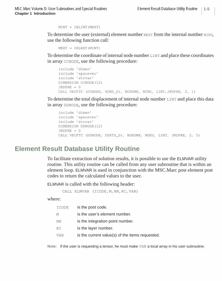
MINT = IELINT(MEXT)
To determine the user (external) element number MEXT from the internal number MINT, use the following function call:
MEXT = IELEXT(MINT)
To determine the coordinate of internal node number LINT and place these coordinates in array CCNODE, use the following procedure:
include ’dimen’include ’spacevec’include ’strvar’DIMENSION CCNODE(12)JRDPRE = 0CALL VECFTC (CCNODE, XORD_D), NCRDMX, NCRD, LINT,JRDPRE, 2, 1)
To determine the total displacement of internal node number LINT and place this data in array DDNODE, use the following procedure:
include ’dimen’include ’spacevec’include ’strvar’DIMENSION DDNODE(12)JRDPRE = 0CALL VECFTC (DDNODE, DSXTS_D), NDEGMX, NDEG, LINT, JRDPRE, 2, 5)
Element Result Database Utility RoutineTo facilitate extraction of solution results, it is possible to use the ELMVAR utility routine. This utility routine can be called from any user subroutine that is within an element loop. ELMVAR is used in conjunction with the MSC.Marc post element post codes to return the calculated values to the user.
ELMVAR is called with the following header:CALL ELMVAR (ICODE,M,NN,KC,VAR)
where:
Note: If the user is requesting a tensor, he must make VAR a local array in his user subroutine.
ICODE is the post code.
M is the user’s element number.
NN is the integration point number.
KC is the layer number.
VAR is the current value(s) of the items requested.
Element Result Database Utility Routine MSC.Marc Volume D: User Subroutines and Special RoutinesChapter 1 Introduction
1-6
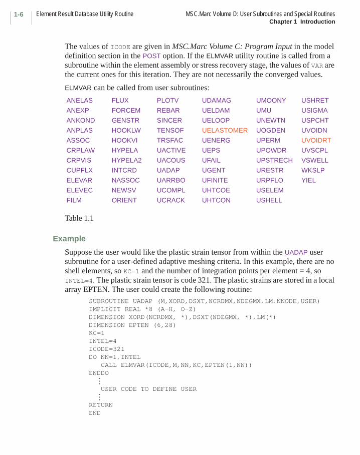
The values of ICODE are given in MSC.Marc Volume C: Program Input in the model definition section in the POST option. If the ELMVAR utility routine is called from a subroutine within the element assembly or stress recovery stage, the values of VAR are the current ones for this iteration. They are not necessarily the converged values.
ELMVAR can be called from user subroutines:
Table 1.1
Example
Suppose the user would like the plastic strain tensor from within the UADAP user subroutine for a user-defined adaptive meshing criteria. In this example, there are no shell elements, so KC=1 and the number of integration points per element = 4, so INTEL=4. The plastic strain tensor is code 321. The plastic strains are stored in a local array EPTEN. The user could create the following routine:
SUBROUTINE UADAP (M,XORD,DSXT,NCRDMX,NDEGMX,LM,NNODE,USER)IMPLICIT REAL *8 (A-H, O-Z)DIMENSION XORD(NCRDMX, *),DSXT(NDEGMX, *),LM(*)DIMENSION EPTEN (6,28)KC=1INTEL=4ICODE=321DO NN=1,INTEL CALL ELMVAR(ICODE,M,NN,KC,EPTEN(1,NN))ENDDO
USER CODE TO DEFINE USER
RETURNEND
ANELAS FLUX PLOTV UDAMAG UMOONY USHRET
ANEXP FORCEM REBAR UELDAM UMU USIGMA
ANKOND GENSTR SINCER UELOOP UNEWTN USPCHT
ANPLAS HOOKLW TENSOF UELASTOMER UOGDEN UVOIDN
ASSOC HOOKVI TRSFAC UENERG UPERM UVOIDRT
CRPLAW HYPELA UACTIVE UEPS UPOWDR UVSCPL
CRPVIS HYPELA2 UACOUS UFAIL UPSTRECH VSWELL
CUPFLX INTCRD UADAP UGENT URESTR WKSLP
ELEVAR NASSOC UARRBO UFINITE URPFLO YIEL
ELEVEC NEWSV UCOMPL UHTCOE USELEM
FILM ORIENT UCRACK UHTCON USHELL
……
1-7MSC.Marc Volume D: User Subroutines and Special Routines Nodal Results Database Utility RoutineChapter 1 Introduction
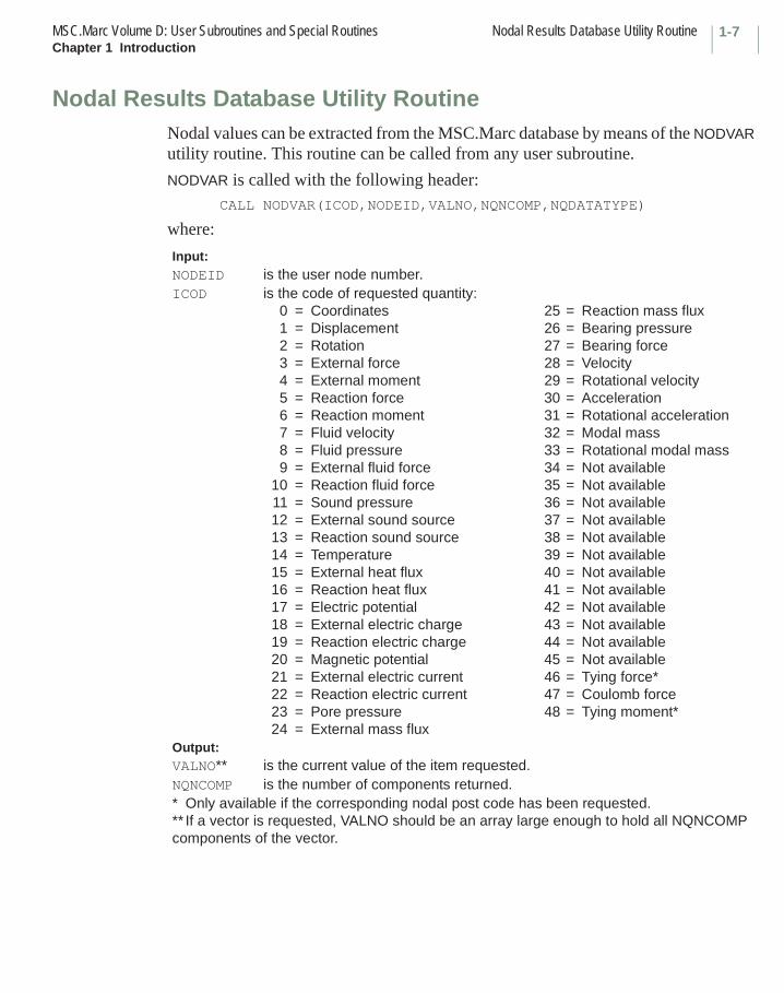
Nodal Results Database Utility RoutineNodal values can be extracted from the MSC.Marc database by means of the NODVAR utility routine. This routine can be called from any user subroutine.
NODVAR is called with the following header:CALL NODVAR(ICOD,NODEID,VALNO,NQNCOMP,NQDATATYPE)
where:
Input:NODEID is the user node number.ICOD is the code of requested quantity:
0 = Coordinates 25 = Reaction mass flux1 = Displacement 26 = Bearing pressure2 = Rotation 27 = Bearing force3 = External force 28 = Velocity4 = External moment 29 = Rotational velocity5 = Reaction force 30 = Acceleration6 = Reaction moment 31 = Rotational acceleration7 = Fluid velocity 32 = Modal mass8 = Fluid pressure 33 = Rotational modal mass9 = External fluid force 34 = Not available
10 = Reaction fluid force 35 = Not available11 = Sound pressure 36 = Not available12 = External sound source 37 = Not available13 = Reaction sound source 38 = Not available14 = Temperature 39 = Not available15 = External heat flux 40 = Not available16 = Reaction heat flux 41 = Not available17 = Electric potential 42 = Not available18 = External electric charge 43 = Not available19 = Reaction electric charge 44 = Not available20 = Magnetic potential 45 = Not available21 = External electric current 46 = Tying force*22 = Reaction electric current 47 = Coulomb force23 = Pore pressure 48 = Tying moment*24 = External mass flux
Output:VALNO** is the current value of the item requested.NQNCOMP is the number of components returned.* Only available if the corresponding nodal post code has been requested.** If a vector is requested, VALNO should be an array large enough to hold all NQNCOMP components of the vector.
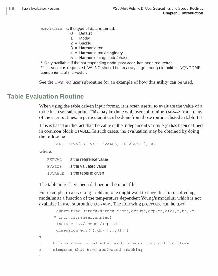
Table Evaluation Routine MSC.Marc Volume D: User Subroutines and Special RoutinesChapter 1 Introduction
1-8
See the UPSTNO user subroutine for an example of how this utility can be used.
Table Evaluation RoutineWhen using the table driven input format, it is often useful to evaluate the value of a table in a user subroutine. This may be done with user subroutine TABVA2 from many of the user routines. In particular, it can be done from those routines listed in table 1.1.
This is based on the fact that the value of the independent variable (s) has been defined in common block CTABLE. In such cases, the evaluation may be obtained by doing the following:
CALL TABVA2(REFVAL, EVALUE, IDTABLE, 0, 0)
where:
The table must have been defined in the input file.
For example, in a cracking problem, one might want to have the strain softening modulus as a function of the temperature dependent Young’s modulus, which is not available in user subroutine UCRACK. The following procedure can be used:
subroutine ucrack(scrack,esoft,ecrush,ecp,dt,dtdl,n,nn,kc,
* inc,ndi,nshear,shrfac)
include '../common/implicit'
dimension ecp(*),dt(*),dtdl(*)
c
c this routine is called at each integration point for those
c elements that have activated cracking
c
NQDATATYPE is the type of data returned.0 = Default1 = Modal2 = Buckle3 = Harmonic real4 = Harmonic real/imaginary5 = Harmonic magnitude/phase
* Only available if the corresponding nodal post code has been requested.** If a vector is requested, VALNO should be an array large enough to hold all NQNCOMP components of the vector.
REFVAL is the reference value
EVALUE is the valuated value
IDTABLE is the table id given
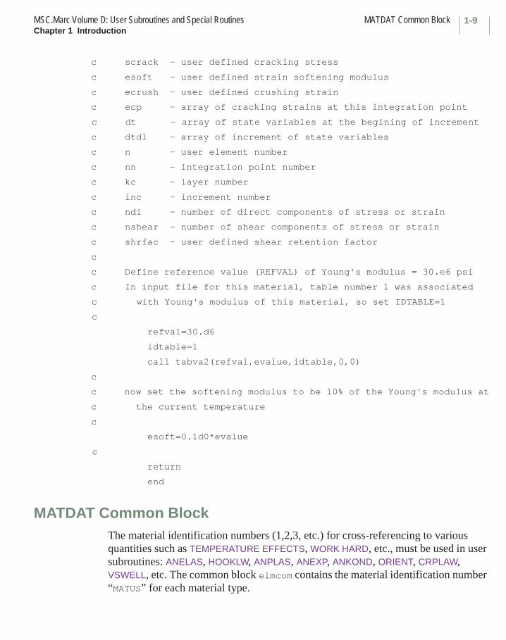
1-9MSC.Marc Volume D: User Subroutines and Special Routines MATDAT Common BlockChapter 1 Introduction
c scrack - user defined cracking stress
c esoft - user defined strain softening modulus
c ecrush - user defined crushing strain
c ecp - array of cracking strains at this integration point
c dt - array of state variables at the begining of increment
c dtdl - array of increment of state variables
c n - user element number
c nn - integration point number
c kc - layer number
c inc - increment number
c ndi - number of direct components of stress or strain
c nshear - number of shear components of stress or strain
c shrfac - user defined shear retention factor
c
c Define reference value (REFVAL) of Young's modulus = 30.e6 psi
c In input file for this material, table number 1 was associated
c with Young's modulus of this material, so set IDTABLE=1
c
refval=30.d6
idtable=1
call tabva2(refval,evalue,idtable,0,0)
c
c now set the softening modulus to be 10% of the Young's modulus at
c the current temperature
c
esoft=0.1d0*evalue
c
return
end
MATDAT Common BlockThe material identification numbers (1,2,3, etc.) for cross-referencing to various quantities such as TEMPERATURE EFFECTS, WORK HARD, etc., must be used in user subroutines: ANELAS, HOOKLW, ANPLAS, ANEXP, ANKOND, ORIENT, CRPLAW, VSWELL, etc. The common block elmcom contains the material identification number “MATUS” for each material type.

MATDAT Common Block MSC.Marc Volume D: User Subroutines and Special RoutinesChapter 1 Introduction
1-10
In addition, the reference values of the material properties as given in the model definition section can be obtained in common block matdat where:
ET(3) Young's moduli
XU(3) Poisson's ratios
RHO mass density
SHRMOD(3) shear moduli
COED(3) coefficient of thermal expansion
YIELD(1) yield stress
YIELD(2) ORNL 10th cycle yield stress
YIELD(3) ORNL reversed plasticity yield stress
YRDR(3) direct ratio's for Hill anisotropic plasticity
YRSR(3) shear ratio's for Hill anisotropic plasticity
CONDU(3) conductivities
SPHT specific heat
CONDV(3) resistivity
RHOHT mass density for heat transfer
EMISV emissivity
COSTPV cost per unit volume
COSTPM cost per unit mass
PERMEAB(3) magnetic permeability
RELUCT(3) reluctance
PERMAIR permeability of air
PERMIT(3) electrical permittivity
ECOND(3) electrical conductivity
VISCOSIT viscosity
TK21 thermal conductivity 21
TK31 thermal conductivity 31
TK32 thermal conductivity 32
R21 electrical resistivity 21
R31 electrical resistivity 31
R32 electrical resistivity 32
C10 Mooney parameter C10
C01 Mooney parameter C01

1-11MSC.Marc Volume D: User Subroutines and Special Routines CONCOM Common BlockChapter 1 Introduction
CONCOM Common BlockTwo common blocks might be particularly useful for advanced usage in MSC.Marc. Common block concom contains most of the program controls in MSC.Marc. The variables and their meaning are given below. Unless otherwise indicated, if the variable has a value of zero, it is false, and a value of one indicates true.
C11 Mooney parameter C11
C20 Mooney parameter C20
C30 Mooney parameter C30
BULK bulk modulus (Mooney, Ogden, Arruda-Boyce, Gent)
AMOHR Amohr
ENTHALPY Enthalpy
FLPERM(3) fluid permeability
PHFRAC1 fraction of phase
CHABPR(10) Chaboche material data
FORMLS forming limit
FLDEN fluid density for diffusion
REFTEMPEN reference temperature for enthalpy
FRCTISO fraction for isotropic hardening
FLBULK bulk modulus of fluid in diffusion analysis
POROS porosity
FLPERM2(3) fluid permeability (21, 31, 32)
OGMU reference (Odgen or Foam)
OGALPHA reference (Ogden or Foam)
OGBETA reference (Foam)
VSCDEVTRM reference deviatoric relaxation time
VSCVOLTRM reference volumetric relaxation time
VSCFUNCT(9) reference viscoelastic values
WGTMOL molecular weight
µαβ
1 iacous acoustic analysis
2 iasmbl reassemble stiffness matrix
3 iautth auto therm or auto therm creep
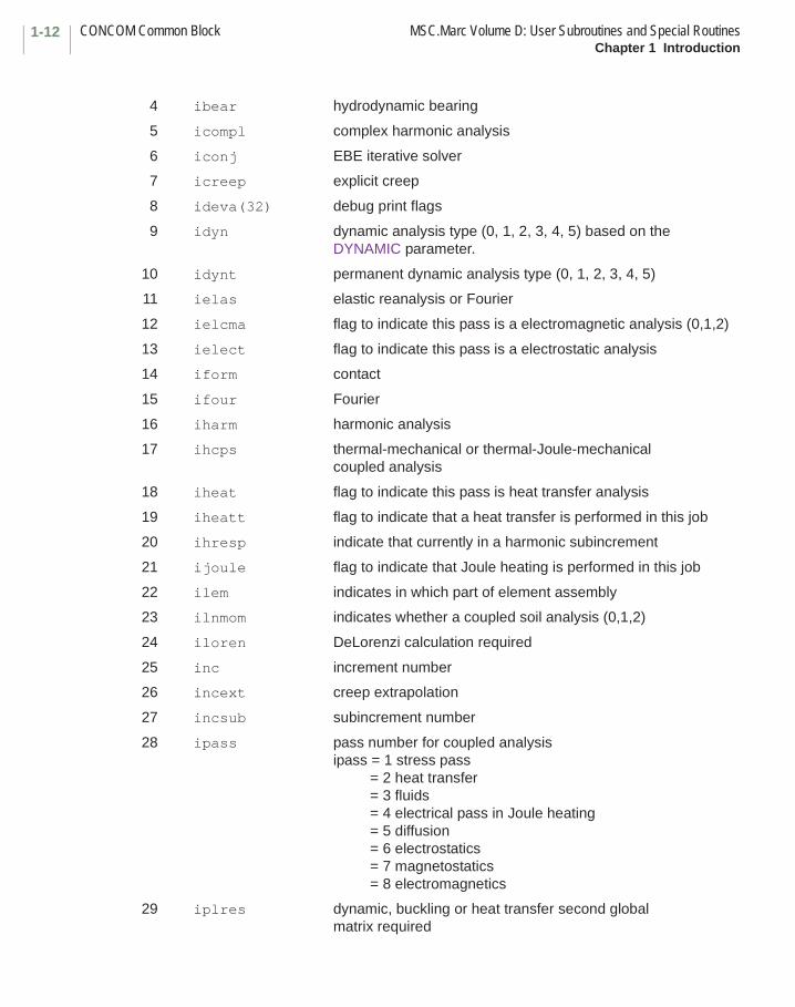
CONCOM Common Block MSC.Marc Volume D: User Subroutines and Special RoutinesChapter 1 Introduction
1-12
4 ibear hydrodynamic bearing
5 icompl complex harmonic analysis
6 iconj EBE iterative solver
7 icreep explicit creep
8 ideva(32) debug print flags
9 idyn dynamic analysis type (0, 1, 2, 3, 4, 5) based on the DYNAMIC parameter.
10 idynt permanent dynamic analysis type (0, 1, 2, 3, 4, 5)
11 ielas elastic reanalysis or Fourier
12 ielcma flag to indicate this pass is a electromagnetic analysis (0,1,2)
13 ielect flag to indicate this pass is a electrostatic analysis
14 iform contact
15 ifour Fourier
16 iharm harmonic analysis
17 ihcps thermal-mechanical or thermal-Joule-mechanical coupled analysis
18 iheat flag to indicate this pass is heat transfer analysis
19 iheatt flag to indicate that a heat transfer is performed in this job
20 ihresp indicate that currently in a harmonic subincrement
21 ijoule flag to indicate that Joule heating is performed in this job
22 ilem indicates in which part of element assembly
23 ilnmom indicates whether a coupled soil analysis (0,1,2)
24 iloren DeLorenzi calculation required
25 inc increment number
26 incext creep extrapolation
27 incsub subincrement number
28 ipass pass number for coupled analysisipass = 1 stress pass = 2 heat transfer = 3 fluids = 4 electrical pass in Joule heating = 5 diffusion = 6 electrostatics = 7 magnetostatics = 8 electromagnetics
29 iplres dynamic, buckling or heat transfer second global matrix required
1-13MSC.Marc Volume D: User Subroutines and Special Routines CONCOM Common BlockChapter 1 Introduction
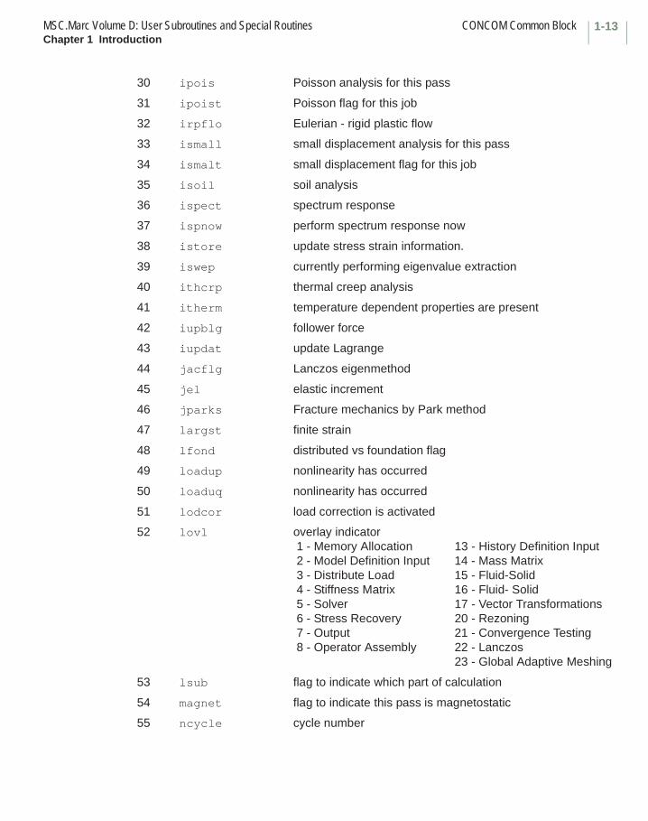
30 ipois Poisson analysis for this pass
31 ipoist Poisson flag for this job
32 irpflo Eulerian - rigid plastic flow
33 ismall small displacement analysis for this pass
34 ismalt small displacement flag for this job
35 isoil soil analysis
36 ispect spectrum response
37 ispnow perform spectrum response now
38 istore update stress strain information.
39 iswep currently performing eigenvalue extraction
40 ithcrp thermal creep analysis
41 itherm temperature dependent properties are present
42 iupblg follower force
43 iupdat update Lagrange
44 jacflg Lanczos eigenmethod
45 jel elastic increment
46 jparks Fracture mechanics by Park method
47 largst finite strain
48 lfond distributed vs foundation flag
49 loadup nonlinearity has occurred
50 loaduq nonlinearity has occurred
51 lodcor load correction is activated
52 lovl overlay indicator 1 - Memory Allocation 13 - History Definition Input 2 - Model Definition Input 14 - Mass Matrix 3 - Distribute Load 15 - Fluid-Solid 4 - Stiffness Matrix 16 - Fluid- Solid 5 - Solver 17 - Vector Transformations 6 - Stress Recovery 20 - Rezoning 7 - Output 21 - Convergence Testing 8 - Operator Assembly 22 - Lanczos
23 - Global Adaptive Meshing
53 lsub flag to indicate which part of calculation
54 magnet flag to indicate this pass is magnetostatic
55 ncycle cycle number
CONCOM Common Block MSC.Marc Volume D: User Subroutines and Special RoutinesChapter 1 Introduction
1-14
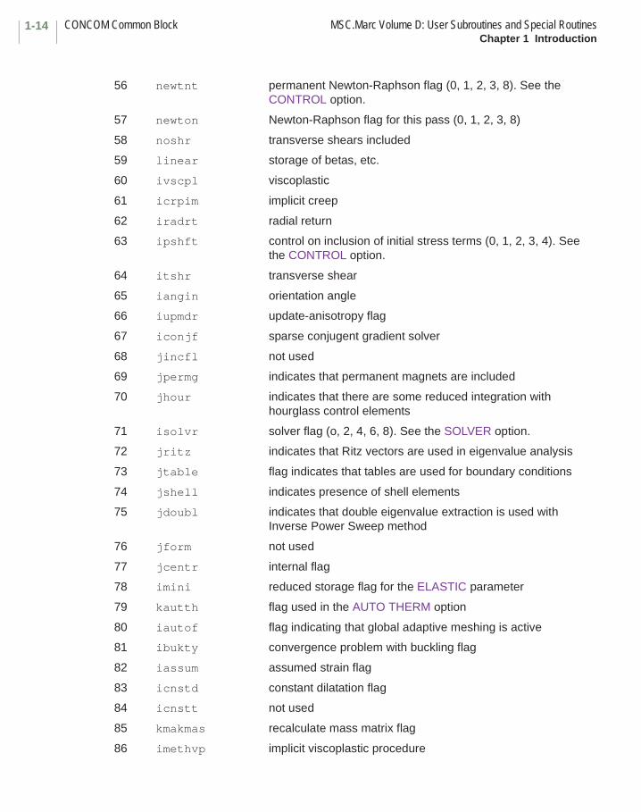
56 newtnt permanent Newton-Raphson flag (0, 1, 2, 3, 8). See the CONTROL option.
57 newton Newton-Raphson flag for this pass (0, 1, 2, 3, 8)
58 noshr transverse shears included
59 linear storage of betas, etc.
60 ivscpl viscoplastic
61 icrpim implicit creep
62 iradrt radial return
63 ipshft control on inclusion of initial stress terms (0, 1, 2, 3, 4). See the CONTROL option.
64 itshr transverse shear
65 iangin orientation angle
66 iupmdr update-anisotropy flag
67 iconjf sparse conjugent gradient solver
68 jincfl not used
69 jpermg indicates that permanent magnets are included
70 jhour indicates that there are some reduced integration with hourglass control elements
71 isolvr solver flag (o, 2, 4, 6, 8). See the SOLVER option.
72 jritz indicates that Ritz vectors are used in eigenvalue analysis
73 jtable flag indicates that tables are used for boundary conditions
74 jshell indicates presence of shell elements
75 jdoubl indicates that double eigenvalue extraction is used with Inverse Power Sweep method
76 jform not used
77 jcentr internal flag
78 imini reduced storage flag for the ELASTIC parameter
79 kautth flag used in the AUTO THERM option
80 iautof flag indicating that global adaptive meshing is active
81 ibukty convergence problem with buckling flag
82 iassum assumed strain flag
83 icnstd constant dilatation flag
84 icnstt not used
85 kmakmas recalculate mass matrix flag
86 imethvp implicit viscoplastic procedure

1-15MSC.Marc Volume D: User Subroutines and Special Routines CONCOM Common BlockChapter 1 Introduction
87 iradrte flag for large strain elastic material
88 iradrtp radial return flag for plastic material
89 iupdate updated Lagrange flag for elastic material
90 iupdatp updated Lagrange flag for elastic-plastic material
91 ncycnt number of times the increment restarted with the first iteration in automatic procedures. This variable is used to stop the analysis with exit 3008 if it becomes to high to prevent infinite loop in the program.
92 marmen = 0 if MSC.Marc used for normal analysis= 1 if MSC.Marc used as reader via MSC.Marc Mentat
93 idynme implicit dynamic analysis= 0 for Newmark-beta= 1 for Single Step Houbolt (SSH)
94 ihavca = 0 if Cauchy stresses not stored separately= 1 if Cauchy stresses stored separately
95 ispf Super Plastic Forming analysis
96 kmini used for minimizing memory headed for element quantities if fast elastic-plastic material libraries of AutoForge are used
97 imixed flag set to 1 in a Rigid Plastic analysis if some part of the material in the model has elasto-plastic material behavior
98 largtt flag to preserve finite strain plasticity flag for the elasto-plastic part of the model while doing the rigid-plastic part
99 kdoela flag to trigger assembly in elastic analysis
100 iautofg flag for analysis with MSC.SuperForm
101 ipshftp flag to save the control for inclusion of the initial stress matrix ipshft during automatic increment restart feature
102 idntrc variable to indicate that the end of an automatic load stepping could not be reached within specified number of increments. The program stops with exit number 3003
103 ipore flag to indicate this pass is a diffusion analysis (not active in 2003)
104 jtablm flag to indicate that tables are to be used for material properties
105 jtablc flag to indicate that tables are to be used for the CONTACT option
106 isnecma flag to indicate expanded film capabilities (not active in 2003)
107 itrnspo flag to indicate steady state transport loadcase

CONCOM Common Block MSC.Marc Volume D: User Subroutines and Special RoutinesChapter 1 Introduction
1-16
108 imsdif flag to indicate this pass is a diffusion analysis (not active in 2003)
109 jtrnspo flag to indicate SS-ROLLING analysis
110 mcnear flag to indicate that near thermal contact behavior is included between two bodies
111 imech flag to indicate this pass is a mechanical analysis
112 imecht flag to indicate that mechanical analysis will be performed in this job
113 ielcmat flag to indicate electromagnetic analysis will be performed in this job
114 ielectt flag to indicate electrostatic analysis will be performed in this job
115 magnett flag to indicate magnetostatic analysis will be performed in this job
116 imsdift flag to indicate diffusion analysis will be performed in this job
117 noplas flag to indicate no material nonlinearity - reduce memory requirements
118 jtabls flag to indicate that tables are to be used for the SPRINGS option
119 jactch flag to indicate elements have been activated or deactivated
120 jtablth flag to indicate that tables are to be used for the GEOMETRY option
121 kgmsto = 1 store geometry in old format,= 2 store geometry based on geometry id
122 jpzo flag to indicate piezoelectric analysis
123 ifricsh flag to indicate that nodal based friction used
124 iremkin flag to indicate gradual removal of kinematic boundary condition (table driven input)
125 iremfor flag to indicate gradual removal of reaction force (table driven input)
126 ishearp flag to indicate that shear panel elements are in the model
127 jspf = 1 first increment of superplastic analysis
128 machining flag to indicate that machining option is active
129 jlshell flag to indicate that shells are present
130 icompsol indicates the presence of composite solids in the mesh
131 iupblgfo follower force point loads used
132 jcondir contact priority is used
1-17MSC.Marc Volume D: User Subroutines and Special Routines ELMCOM Common BlockChapter 1 Introduction
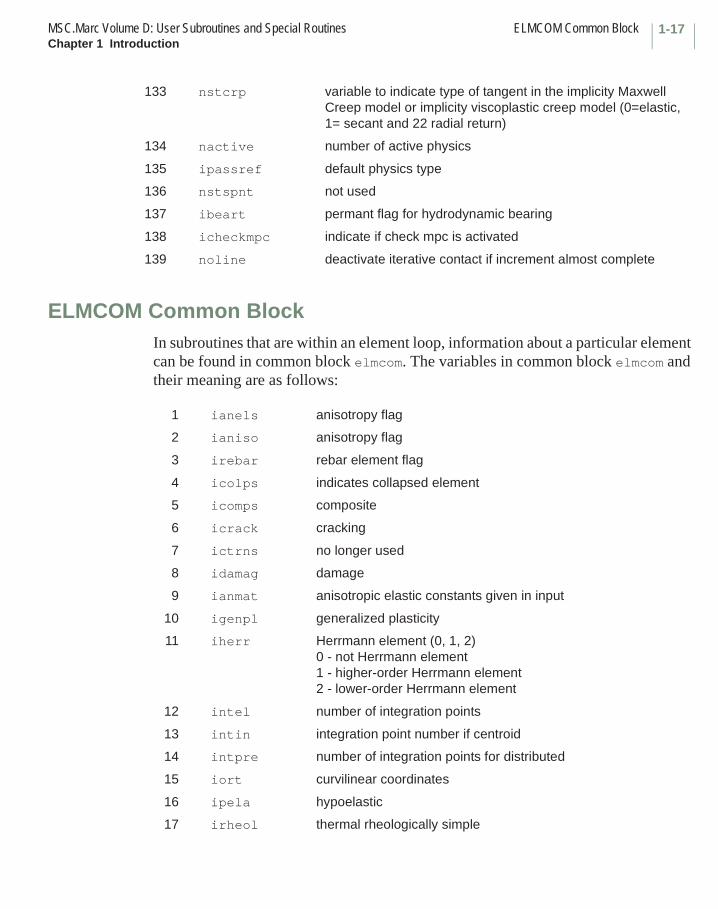
ELMCOM Common BlockIn subroutines that are within an element loop, information about a particular element can be found in common block elmcom. The variables in common block elmcom and their meaning are as follows:
133 nstcrp variable to indicate type of tangent in the implicity Maxwell Creep model or implicity viscoplastic creep model (0=elastic, 1= secant and 22 radial return)
134 nactive number of active physics
135 ipassref default physics type
136 nstspnt not used
137 ibeart permant flag for hydrodynamic bearing
138 icheckmpc indicate if check mpc is activated
139 noline deactivate iterative contact if increment almost complete
1 ianels anisotropy flag
2 ianiso anisotropy flag
3 irebar rebar element flag
4 icolps indicates collapsed element
5 icomps composite
6 icrack cracking
7 ictrns no longer used
8 idamag damage
9 ianmat anisotropic elastic constants given in input
10 igenpl generalized plasticity
11 iherr Herrmann element (0, 1, 2)0 - not Herrmann element1 - higher-order Herrmann element2 - lower-order Herrmann element
12 intel number of integration points
13 intin integration point number if centroid
14 intpre number of integration points for distributed
15 iort curvilinear coordinates
16 ipela hypoelastic
17 irheol thermal rheologically simple
ELMCOM Common Block MSC.Marc Volume D: User Subroutines and Special RoutinesChapter 1 Introduction
1-18
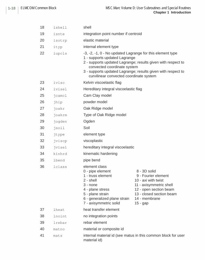
18 ishell shell
19 isnte integration point number if centroid
20 isotrp elastic material
21 ityp internal element type
22 iupcls -3, -2, -1, 0 - No updated Lagrange for this element type1 - supports updated Lagrange2 - supports updated Lagrange; results given with respect to
convected coordinate system3 - supports updated Lagrange; results given with respect to
curvilinear convected coordinate system
23 ivisc Kelvin viscoelastic flag
24 ivisel Hereditary integral viscoelastic flag
25 jcamcl Cam Clay model
26 jhip powder model
27 joakr Oak Ridge model
28 joakrm Type of Oak Ridge model
29 jogden Ogden
30 jsoil Soil
31 jtype element type
32 jviscp viscoplastic
33 jvisel hereditary integral viscoelastic
34 kinhrd kinematic hardening
35 lbend pipe bend
36 lclass element class0 - pipe element 8 - 3D solid1 - truss element 9 - Fourier element2 - shell 10 - axi with twist3 - none 11 - axisymmetric shell4 - plane stress 12 - open section beam5 - plane strain 13 - closed section beam6 - generalized plane strain 14 - membrane7 - axisymmetric solid 15 - gap
37 lheat heat transfer element
38 lnoint no integration points
39 lrebar rebar element
40 matno material or composite id
41 mats internal material id (see matus in this common block for user material id)

1-19MSC.Marc Volume D: User Subroutines and Special Routines ELMCOM Common BlockChapter 1 Introduction
42 mohrc Mohr-Coulomb (0, 1, 2)0 - not Mohr-Coulomb1 - linear Mohr-Coulomb2 - quadratic Mohr-Coulomb
43 mooney Mooney
44 mroz Mroz - not supported
45 ncrdel number of coordinates
46 ndegel number of degrees of freedom
47 ndi number of direct components
48 ngenel number of generalized strains
49 nnode number of nodes
50 nomid mid-increment not used
51 noniso anisotropic
52 kkdum1 dummy
53 nregs pointer to transverse shear
54 nshear number of shears
55 nstran number of strains
56 ntshr number of transverse shears
57 ipgrcr progressive cracking
58 ngens number of generalized strains
59 jparel element running in parallel mode
60 jhoure this element is a reduced integration element with hourglass control
61 jfoam foam model
62 nnodg number of nodes per element, excluding extra nodes for Herrmann and generalized plane strain
63 nstrm1 number of stresses stored per section point
64 nstrm2 number of stress points stored per integration point (layers for shell elements, cross-section point for beam elements, 1 for continuum elements
65 irpfle control flag whether this element needs rigid plastic analysis (irpfle = 1) or not (irpfle = 0)
66 jpowlw control flag for various work hardening models= 1 power law= 2 rate power law= 3 Not Available= 4 Johnson-Cook
BCLABEL Common Block MSC.Marc Volume D: User Subroutines and Special RoutinesChapter 1 Introduction
1-20
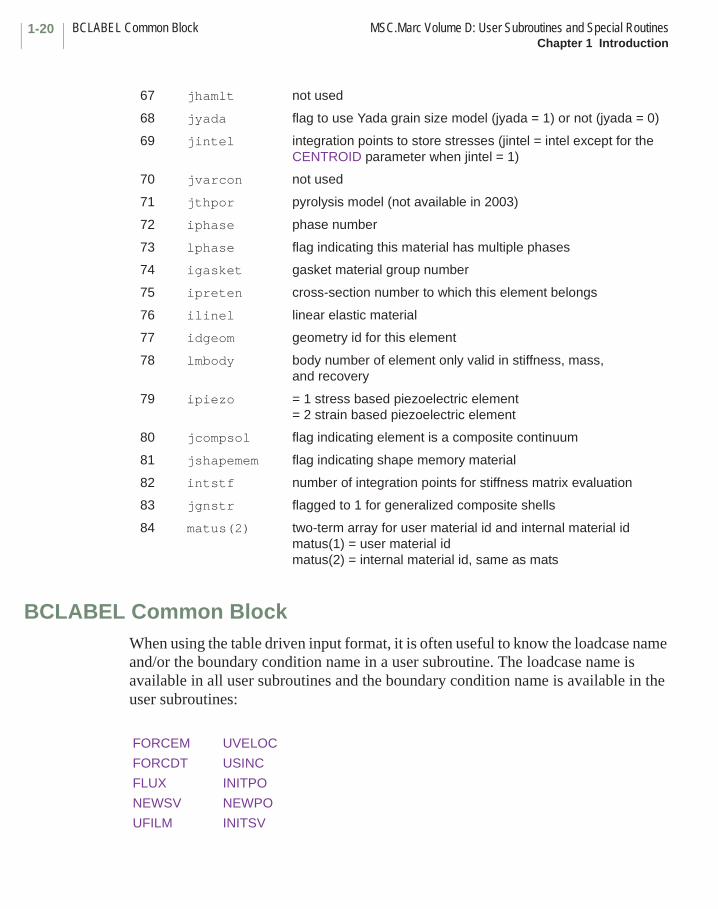
BCLABEL Common BlockWhen using the table driven input format, it is often useful to know the loadcase name and/or the boundary condition name in a user subroutine. The loadcase name is available in all user subroutines and the boundary condition name is available in the user subroutines:
67 jhamlt not used
68 jyada flag to use Yada grain size model (jyada = 1) or not (jyada = 0)
69 jintel integration points to store stresses (jintel = intel except for the CENTROID parameter when jintel = 1)
70 jvarcon not used
71 jthpor pyrolysis model (not available in 2003)
72 iphase phase number
73 lphase flag indicating this material has multiple phases
74 igasket gasket material group number
75 ipreten cross-section number to which this element belongs
76 ilinel linear elastic material
77 idgeom geometry id for this element
78 lmbody body number of element only valid in stiffness, mass, and recovery
79 ipiezo = 1 stress based piezoelectric element= 2 strain based piezoelectric element
80 jcompsol flag indicating element is a composite continuum
81 jshapemem flag indicating shape memory material
82 intstf number of integration points for stiffness matrix evaluation
83 jgnstr flagged to 1 for generalized composite shells
84 matus(2) two-term array for user material id and internal material idmatus(1) = user material idmatus(2) = internal material id, same as mats
FORCEM UVELOC
FORCDT USINC
FLUX INITPO
NEWSV NEWPO
UFILM INITSV
1-21MSC.Marc Volume D: User Subroutines and Special Routines BCLABEL Common BlockChapter 1 Introduction
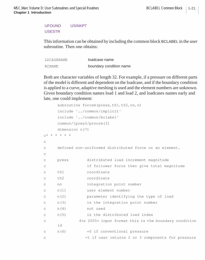
This information can be obtained by including the common block BCLABEL in the user subroutine. Then one obtains:
Both are character variables of length 32. For example, if a pressure on different parts of the model is different and dependent on the loadcase, and if the boundary condition is applied to a curve, adaptive meshing is used and the element numbers are unknown. Given boundary condition names load 1 and load 2, and loadcases names early and late, one could implement:
subroutine forcem(press,th1,th2,nn,n)
include '../common/implicit'
include '../common/bclabel'
common/lpres3/prnorm(3)
dimension n(7)
c* * * * * *
c
c defined non-uniformed distributed force on an element.
c
c press distributed load increment magnitude
c if follower force then give total magnitude
c th1 coordinate
c th2 coordinate
c nn integration point number
c n(1) user element number
c n(2) parameter identifying the type of load
c n(3) is the integration point number
c n(4) not used
c n(5) is the distributed load index
c for 2005+ input format this is the boundary condition id
c n(6) =0 if conventional pressure
c =1 if user returns 2 or 3 components for pressure
UFOUND USINKPT
USESTR
LDCASENAME loadcase name
BCNAME boundary condition name

BCLABEL Common Block MSC.Marc Volume D: User Subroutines and Special RoutinesChapter 1 Introduction
1-22
c in global direction
c n(7) is the internal element number
c
c for distributed load in a given direction
c prnorm is the direction cosine of the direction of the load
c with respect to the global system
c
c* * * * * *
if(ldcasename.eq.'early') then
if(bcname.eq.'load1') then
press=
elseif(bcname.eq.'load2') then
press=
else
write(6,101) n(1),nn,ldcasename,bcname
endif
elseif(ldcasename.eq.'late') then
if(bcname.eq.'load1') then
press=
elseif(bcname.eq.'load2') then
press=
else
write(6,101) n(1),nn,ldcasename,bcname
endif
else
write(6,101) n(1),nn,ldcasename,bcname
endif
101 format(/,'*** warning - forcem for element ',i10,
* ' integration point',i4,' for loadcase ',a,
* ' boundary condition ',a,' is not coded')
return
end
Chapter 2 User-defined Loading, Boundary Conditions, and State Variables User Subroutines List
User Subroutine Page
CREDE . . . . . . . . . . . . . . . . . . . . . . . . . . . . . . . . . . . . . . . . . . . . . . . . . . . . . . . . . 2-50CUPFLX . . . . . . . . . . . . . . . . . . . . . . . . . . . . . . . . . . . . . . . . . . . . . . . . . . . . . . . . . 2-18
DIGEOM. . . . . . . . . . . . . . . . . . . . . . . . . . . . . . . . . . . . . . . . . . . . . . . . . . . . . . . . . 2-70
FILM . . . . . . . . . . . . . . . . . . . . . . . . . . . . . . . . . . . . . . . . . . . . . . . . . . . . . . . . . . . 2-35FLOW . . . . . . . . . . . . . . . . . . . . . . . . . . . . . . . . . . . . . . . . . . . . . . . . . . . . . . . . . . 2-37FLUX . . . . . . . . . . . . . . . . . . . . . . . . . . . . . . . . . . . . . . . . . . . . . . . . . . . . . . . . . . . 2-12FORCDF . . . . . . . . . . . . . . . . . . . . . . . . . . . . . . . . . . . . . . . . . . . . . . . . . . . . . . . . 2-31FORCDT . . . . . . . . . . . . . . . . . . . . . . . . . . . . . . . . . . . . . . . . . . . . . . . . . . . . . . . . 2-22FORCEM . . . . . . . . . . . . . . . . . . . . . . . . . . . . . . . . . . . . . . . . . . . . . . . . . . . . . . . . 2-7
CHAPTER
2 User-defined Loading, Boundary Conditions, and State Variables User Subroutines List
MSC.Marc Volume D: User Subroutines and Special RoutinesChapter 2 User-defined Loading, Boundary Conditions, and State Variables User Subroutines List
2-ii
User Subroutine Page
GAPT . . . . . . . . . . . . . . . . . . . . . . . . . . . . . . . . . . . . . . . . . . . . . . . . . . . . . . . . . . . 2-44
INITPL . . . . . . . . . . . . . . . . . . . . . . . . . . . . . . . . . . . . . . . . . . . . . . . . . . . . . . . . . . 2-104INITPO . . . . . . . . . . . . . . . . . . . . . . . . . . . . . . . . . . . . . . . . . . . . . . . . . . . . . . . . . . 2-105INITSV . . . . . . . . . . . . . . . . . . . . . . . . . . . . . . . . . . . . . . . . . . . . . . . . . . . . . . . . . . 2-52
MOTION (2-D) . . . . . . . . . . . . . . . . . . . . . . . . . . . . . . . . . . . . . . . . . . . . . . . . . . . . 2-60MOTION (3-D) . . . . . . . . . . . . . . . . . . . . . . . . . . . . . . . . . . . . . . . . . . . . . . . . . . . . 2-62
NEWPO . . . . . . . . . . . . . . . . . . . . . . . . . . . . . . . . . . . . . . . . . . . . . . . . . . . . . . . . . 2-106NEWSV . . . . . . . . . . . . . . . . . . . . . . . . . . . . . . . . . . . . . . . . . . . . . . . . . . . . . . . . . 2-53
SEPFOR . . . . . . . . . . . . . . . . . . . . . . . . . . . . . . . . . . . . . . . . . . . . . . . . . . . . . . . . 2-71SEPFORBBC . . . . . . . . . . . . . . . . . . . . . . . . . . . . . . . . . . . . . . . . . . . . . . . . . . . . . 2-73SEPSTR. . . . . . . . . . . . . . . . . . . . . . . . . . . . . . . . . . . . . . . . . . . . . . . . . . . . . . . . . 2-75
UCAV . . . . . . . . . . . . . . . . . . . . . . . . . . . . . . . . . . . . . . . . . . . . . . . . . . . . . . . . . . . 2-108UCONTACT . . . . . . . . . . . . . . . . . . . . . . . . . . . . . . . . . . . . . . . . . . . . . . . . . . . . . . 2-101UFILM . . . . . . . . . . . . . . . . . . . . . . . . . . . . . . . . . . . . . . . . . . . . . . . . . . . . . . . . . . 2-41UFORMS . . . . . . . . . . . . . . . . . . . . . . . . . . . . . . . . . . . . . . . . . . . . . . . . . . . . . . . . 2-45UFOUND . . . . . . . . . . . . . . . . . . . . . . . . . . . . . . . . . . . . . . . . . . . . . . . . . . . . . . . . 2-39UFOUR . . . . . . . . . . . . . . . . . . . . . . . . . . . . . . . . . . . . . . . . . . . . . . . . . . . . . . . . . 2-20UFRIC . . . . . . . . . . . . . . . . . . . . . . . . . . . . . . . . . . . . . . . . . . . . . . . . . . . . . . . . . . 2-66UFRICBBC . . . . . . . . . . . . . . . . . . . . . . . . . . . . . . . . . . . . . . . . . . . . . . . . . . . . . . . 2-68UGROWRIGID . . . . . . . . . . . . . . . . . . . . . . . . . . . . . . . . . . . . . . . . . . . . . . . . . . . . 2-65UHTCOE . . . . . . . . . . . . . . . . . . . . . . . . . . . . . . . . . . . . . . . . . . . . . . . . . . . . . . . . 2-76UHTCON . . . . . . . . . . . . . . . . . . . . . . . . . . . . . . . . . . . . . . . . . . . . . . . . . . . . . . . . 2-79UHTNRC . . . . . . . . . . . . . . . . . . . . . . . . . . . . . . . . . . . . . . . . . . . . . . . . . . . . . . . . 2-81UINSTR . . . . . . . . . . . . . . . . . . . . . . . . . . . . . . . . . . . . . . . . . . . . . . . . . . . . . . . . . 2-19UMDCOE . . . . . . . . . . . . . . . . . . . . . . . . . . . . . . . . . . . . . . . . . . . . . . . . . . . . . . . . 2-91UMDCON . . . . . . . . . . . . . . . . . . . . . . . . . . . . . . . . . . . . . . . . . . . . . . . . . . . . . . . . 2-94UMDNRC . . . . . . . . . . . . . . . . . . . . . . . . . . . . . . . . . . . . . . . . . . . . . . . . . . . . . . . . 2-96UNORST . . . . . . . . . . . . . . . . . . . . . . . . . . . . . . . . . . . . . . . . . . . . . . . . . . . . . . . . 2-98UOBJFN. . . . . . . . . . . . . . . . . . . . . . . . . . . . . . . . . . . . . . . . . . . . . . . . . . . . . . . . . 2-110UREACB . . . . . . . . . . . . . . . . . . . . . . . . . . . . . . . . . . . . . . . . . . . . . . . . . . . . . . . . 2-107USDATA . . . . . . . . . . . . . . . . . . . . . . . . . . . . . . . . . . . . . . . . . . . . . . . . . . . . . . . . . 2-57USINC . . . . . . . . . . . . . . . . . . . . . . . . . . . . . . . . . . . . . . . . . . . . . . . . . . . . . . . . . . 2-56USINKPT . . . . . . . . . . . . . . . . . . . . . . . . . . . . . . . . . . . . . . . . . . . . . . . . . . . . . . . . 2-43USSD . . . . . . . . . . . . . . . . . . . . . . . . . . . . . . . . . . . . . . . . . . . . . . . . . . . . . . . . . . . 2-55

2-iiiMSC.Marc Volume D: User Subroutines and Special RoutinesChapter 2 User-defined Loading, Boundary Conditions, and State Variables User Subroutines List
User Subroutine Page
UTIMESTEP . . . . . . . . . . . . . . . . . . . . . . . . . . . . . . . . . . . . . . . . . . . . . . . . . . . . . . 2-58UVELOC . . . . . . . . . . . . . . . . . . . . . . . . . . . . . . . . . . . . . . . . . . . . . . . . . . . . . . . . 2-59UVTCOE . . . . . . . . . . . . . . . . . . . . . . . . . . . . . . . . . . . . . . . . . . . . . . . . . . . . . . . . 2-84UVTCON . . . . . . . . . . . . . . . . . . . . . . . . . . . . . . . . . . . . . . . . . . . . . . . . . . . . . . . . 2-87UVTNRC . . . . . . . . . . . . . . . . . . . . . . . . . . . . . . . . . . . . . . . . . . . . . . . . . . . . . . . . 2-89UWELDFLUX . . . . . . . . . . . . . . . . . . . . . . . . . . . . . . . . . . . . . . . . . . . . . . . . . . . . . 2-14UWELDPATH . . . . . . . . . . . . . . . . . . . . . . . . . . . . . . . . . . . . . . . . . . . . . . . . . . . . . 2-16

Chapter 2 User-defined Loading, Boundary Conditions, and State Variables User
Subroutines
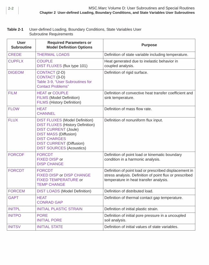
The user subroutines described in this chapter provide an alternative to the standard input file for providing data in the analysis. Many problems have complex boundary conditions due to their spatial variation (such as wind loads) or due to their temporal variation. These routines provide a powerful mechanism to define this behavior in a simple manner. Table 2-1 summarizes these routines and indicates what parameters or model definition options are required to invoke the user subroutine.
CHAPTER
2 User-defined Loading, Boundary Conditions, and State Variables User Subroutines
MSC.Marc Volume D: User Subroutines and Special RoutinesChapter 2 User-defined Loading, Boundary Conditions, and State Variables User Subroutines
2-2
Table 2-1 User-defined Loading, Boundary Conditions, State Variables User Subroutine Requirements
User Subroutine
Required Parameters or Model Definition Options
Purpose
CREDE THERMAL LOADS Definition of state variable including temperature.
CUPFLX COUPLEDIST FLUXES (flux type 101)
Heat generated due to inelastic behavior in coupled analysis.
DIGEOM CONTACT (2-D)CONTACT (3-D)Table 3-9, “User Subroutines for Contact Problems”
Definition of rigid surface.
FILM HEAT or COUPLEFILMS (Model Definition)FILMS (History Definition)
Definition of convective heat transfer coefficient and sink temperature.
FLOW HEATCHANNEL
Definition of mass flow rate.
FLUX DIST FLUXES (Model Definition)DIST FLUXES (History Definition)DIST CURRENT (Joule)DIST MASS (Diffusion)DIST CHARGESDIST CURRENT (Diffusion)DIST SOURCES (Acoustics)
Definition of nonuniform flux input.
FORCDF FORCDTFIXED DISP orDISP CHANGE
Definition of point load or kinematic boundary condition in a harmonic analysis.
FORCDT FORCDTFIXED DISP or DISP CHANGEFIXED TEMPERATURE orTEMP CHANGE
Definition of point load or prescribed displacement in stress analysis. Definition of point flux or prescribed temperature in heat transfer analysis.
FORCEM DIST LOADS (Model Definition) Definition of distributed load.
GAPT HEATCONRAD GAP
Definition of thermal contact gap temperature.
INITPL INITIAL PLASTIC STRAIN Definition of initial plastic strain.
INITPO POREINITIAL PORE
Definition of initial pore pressure in a uncoupled soil analysis.
INITSV INITIAL STATE Definition of initial values of state variables.
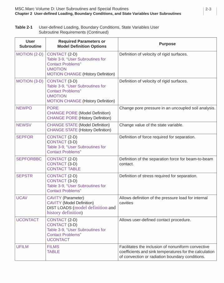
2-3MSC.Marc Volume D: User Subroutines and Special RoutinesChapter 2 User-defined Loading, Boundary Conditions, and State Variables User Subroutines
MOTION (2-D) CONTACT (2-D)Table 3-9, “User Subroutines for Contact Problems” UMOTIONMOTION CHANGE (History Definition)
Definition of velocity of rigid surfaces.
MOTION (3-D) CONTACT (3-D)Table 3-9, “User Subroutines for Contact Problems” UMOTIONMOTION CHANGE (History Definition)
Definition of velocity of rigid surfaces.
NEWPO PORECHANGE PORE (Model Definition)CHANGE PORE (History Definition)
Change pore pressure in an uncoupled soil analysis.
NEWSV CHANGE STATE (Model Definition)CHANGE STATE (History Definition)
Change value of the state variable.
SEPFOR CONTACT (2-D)CONTACT (3-D)Table 3-9, “User Subroutines for Contact Problems”
Definition of force required for separation.
SEPFORBBC CONTACT (2-D)CONTACT (3-D)CONTACT TABLE
Definition of the separation force for beam-to-beam contact.
SEPSTR CONTACT (2-D)CONTACT (3-D)Table 3-9, “User Subroutines for Contact Problems”
Definition of stress required for separation.
UCAV CAVITY (Parameter)CAVITY (Model Definition)DIST LOADS (model definition and history definition)
Allows definition of the pressure load for internal cavities
UCONTACT CONTACT (2-D)CONTACT (3-D)Table 3-9, “User Subroutines for Contact Problems” UCONTACT
Allows user-defined contact procedure.
UFILM FILMSTABLE
Facilitates the inclusion of nonuniform convective coefficients and sink temperatures for the calculation of convection or radiation boundary conditions.
Table 2-1 User-defined Loading, Boundary Conditions, State Variables User Subroutine Requirements (Continued)
User Subroutine
Required Parameters or Model Definition Options
Purpose
MSC.Marc Volume D: User Subroutines and Special RoutinesChapter 2 User-defined Loading, Boundary Conditions, and State Variables User Subroutines
2-4
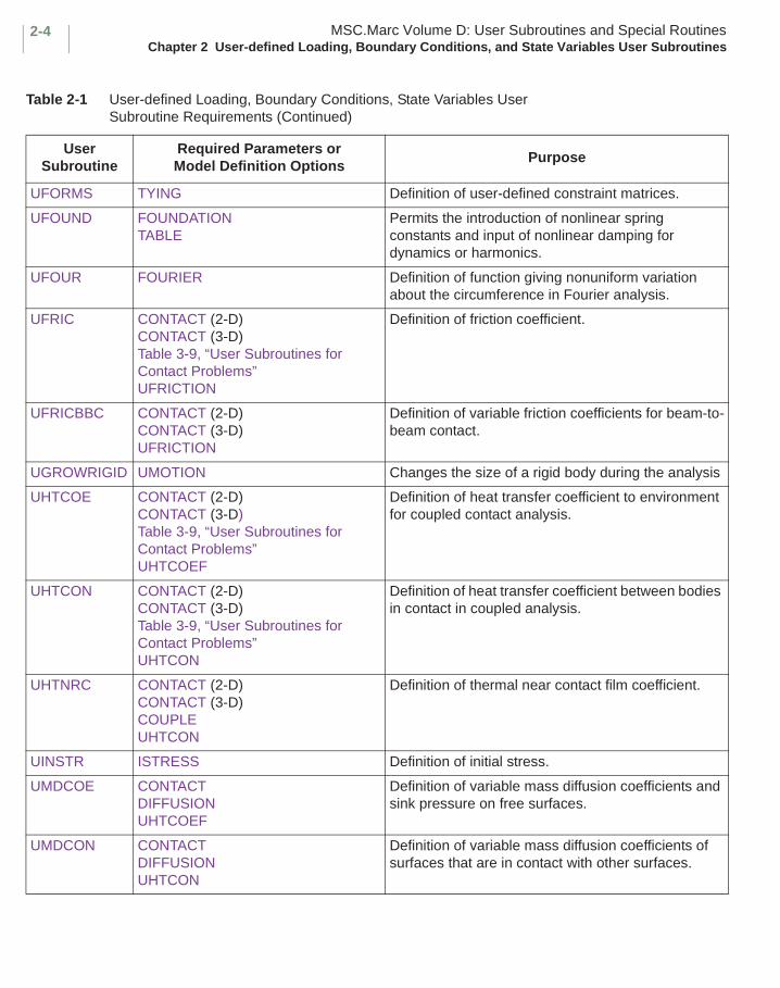
UFORMS TYING Definition of user-defined constraint matrices.
UFOUND FOUNDATIONTABLE
Permits the introduction of nonlinear spring constants and input of nonlinear damping for dynamics or harmonics.
UFOUR FOURIER Definition of function giving nonuniform variation about the circumference in Fourier analysis.
UFRIC CONTACT (2-D)CONTACT (3-D)Table 3-9, “User Subroutines for Contact Problems” UFRICTION
Definition of friction coefficient.
UFRICBBC CONTACT (2-D)CONTACT (3-D)UFRICTION
Definition of variable friction coefficients for beam-to-beam contact.
UGROWRIGID UMOTION Changes the size of a rigid body during the analysis
UHTCOE CONTACT (2-D)CONTACT (3-D)Table 3-9, “User Subroutines for Contact Problems” UHTCOEF
Definition of heat transfer coefficient to environment for coupled contact analysis.
UHTCON CONTACT (2-D)CONTACT (3-D)Table 3-9, “User Subroutines for Contact Problems” UHTCON
Definition of heat transfer coefficient between bodies in contact in coupled analysis.
UHTNRC CONTACT (2-D)CONTACT (3-D)COUPLEUHTCON
Definition of thermal near contact film coefficient.
UINSTR ISTRESS Definition of initial stress.
UMDCOE CONTACTDIFFUSIONUHTCOEF
Definition of variable mass diffusion coefficients and sink pressure on free surfaces.
UMDCON CONTACTDIFFUSIONUHTCON
Definition of variable mass diffusion coefficients of surfaces that are in contact with other surfaces.
Table 2-1 User-defined Loading, Boundary Conditions, State Variables User Subroutine Requirements (Continued)
User Subroutine
Required Parameters or Model Definition Options
Purpose

2-5MSC.Marc Volume D: User Subroutines and Special RoutinesChapter 2 User-defined Loading, Boundary Conditions, and State Variables User Subroutines
UMDNRC UHTCONCONTACTTHERMAL CONTACTCONTACT TABLE
Definition of mass diffusion coefficients between surfaces almost in contact.
UNORST CONTACT (2-D)CONTACT (3-D)Table 3-9, “User Subroutines for Contact Problems” USER
Definition of normal stress for user elements in contact.
UOBJFN DESIGN OPTIMIZATIONDESIGN OBJECTIVE
Allows definition of the objective function and its gradient for design optimization analysis using the current values of the design variables.
UREACB CONTACT (2-D)CONTACT (3-D)
Definition of reactive boundary coefficients in an Acoustic Harmonic Analysis
USDATA USDATA Definition of user-definer constants.
USINC INITIAL DISPINITIAL VELINITIAL TEMP
Definition of initial displacement, initial velocity, or temperature.
USINKPT FILMS (model definition option) Changes the sink point temperatures as a function of time.
USSD DYNAMIC CHANGERESPONSE SPECTRUM
Definition of spectrum displacement density function.
UTIMESTEP AUTO STEP Definition of input for user-defined time step.
UVELOC HEAT Definition of convective velocities.
UVTCOE JOULECONTACT (2-D)CONTACT (3-D)UHTCOEF
Definition of environment electrical film coefficient.
UVTCON JOULECONTACT (2-D)CONTACT (3-D)UHTCOEF
Definition of contact electrical film coefficient.
UVTNRC JOULECONTACT (2-D)CONTACT (3-D)UHTCON
Definition of electrical near contact film coefficient.
Table 2-1 User-defined Loading, Boundary Conditions, State Variables User Subroutine Requirements (Continued)
User Subroutine
Required Parameters or Model Definition Options
Purpose
MSC.Marc Volume D: User Subroutines and Special RoutinesChapter 2 User-defined Loading, Boundary Conditions, and State Variables User Subroutines
2-6
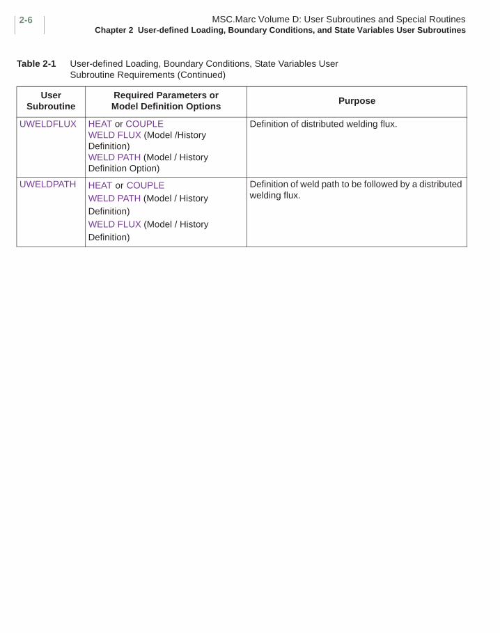
UWELDFLUX HEAT or COUPLEWELD FLUX (Model /History Definition)WELD PATH (Model / History Definition Option)
Definition of distributed welding flux.
UWELDPATH HEAT or COUPLEWELD PATH (Model / History Definition)WELD FLUX (Model / History Definition)
Definition of weld path to be followed by a distributed welding flux.
Table 2-1 User-defined Loading, Boundary Conditions, State Variables User Subroutine Requirements (Continued)
User Subroutine
Required Parameters or Model Definition Options
Purpose

2-7MSC.Marc Volume D: User Subroutines and Special Routines FORCEMChapter 2 User-defined Loading, Boundary Conditions, and State Variables User Subroutines
■ FORCEM
Input of Nonuniform Distributed Loads
Description
This user subroutine allows input of nonuniform distributed loads. This user subroutine can be used to specify the load magnitude as a function of coordinate position and/or time.
The FORCEM user subroutine is called during the calculation of the equivalent nodal loads, at each integration point needed to calculate the loads specified in the DIST LOADS option regardless of the use of the ALL POINTS or CENTROID parameters. When not using table driven input option, the use of this user subroutine is flagged by the appropriate load type in the DIST LOADS input option where the type chosen depends on the element type (see MSC.Marc Volume B: Element Library). When using table driven input format, directly specify if the user subroutine is invoked on the DIST LOADS option.
For three-dimensional magnetostatic analysis, this user subroutine allows surface or body currents to be specified as functions of time, potential, or position. The use of this user subroutine is flagged by the appropriate current type in the DIST CURRENT input option. For two-dimensional magnetostatic analysis, use the FLUX user subroutine.
Format
The definitions in FORCEM depend on the element dimensionality as follows:
For two-dimensional elements:SUBROUTINE FORCEM (P,X1,X2,NN,N)IMPLICIT REAL *8 (A-H, O-Z)
COMMON/LPRES3/PRNORM (3)DIMENSION N(7)
user coding
RETURNEND
FORCEM MSC.Marc Volume D: User Subroutines and Special RoutinesChapter 2 User-defined Loading, Boundary Conditions, and State Variables User Subroutines
2-8
where:
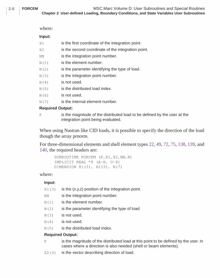
When using Nastran like CID loads, it is possible to specify the direction of the load though the array prnorm.
For three-dimensional elements and shell element types 22, 49, 72, 75, 138, 139, and 140, the required headers are:
SUBROUTINE FORCEM (P,X1,X2,NN,N)IMPLICIT REAL *8 (A-H, O-Z)DIMENSION X1(3), X2(3), N(7)
where:
Input:
X1 is the first coordinate of the integration point.
X2 is the second coordinate of the integration point.
NN is the integration point number.
N(1) is the element number.
N(2) is the parameter identifying the type of load.
N(3) is the integration point number.
N(4) is not used.
N(5) is the distributed load index.
N(6) is not used.
N(7) is the internal element number.
Required Output:
P is the magnitude of the distributed load to be defined by the user at the integration point being evaluated.
Input:
X1(3) is the (x,y,z) position of the integration point.
NN is the integration point number.
N(1) is the element number.
N(2) is the parameter identifying the type of load.
N(3) is not used.
N(4) is not used.
N(5) is the distributed load index.
Required Output:
P is the magnitude of the distributed load at this point to be defined by the user. In cases where a direction is also needed (shell or beam elements).
X2(3) is the vector describing direction of load.
2-9MSC.Marc Volume D: User Subroutines and Special Routines FORCEMChapter 2 User-defined Loading, Boundary Conditions, and State Variables User Subroutines
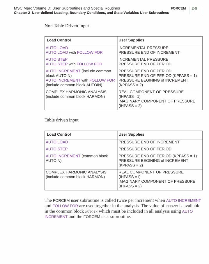
Non Table Driven Input
Table driven input
The FORCEM user subroutine is called twice per increment when AUTO INCREMENT and FOLLOW FOR are used together in the analysis. The value of KPPASS is available in the common block AUTOIN which must be included in all analysis using AUTO INCREMENT and the FORCEM user subroutine.
Load Control User Supplies
AUTO LOADAUTO LOAD with FOLLOW FOR
INCREMENTAL PRESSUREPRESSURE END OF INCREMENT
AUTO STEPAUTO STEP with FOLLOW FOR
INCREMENTAL PRESSUREPRESSURE END OF PERIOD
AUTO INCREMENT (include common block AUTOIN)AUTO INCREMENT with FOLLOW FOR (include common block AUTOIN)
PRESSURE END OF PERIODPRESSURE END OF PERIOD (KPPASS = 1)PRESSURE BEGINING of INCREMENT (KPPASS = 2)
COMPLEX HARMONIC ANALYSIS (include common block HARMON)
REAL COMPONENT OF PRESSURE (IHPASS =1)IMAGINARY COMPONENT OF PRESSURE (IHPASS = 2)
Load Control User Supplies
AUTO LOAD PRESSURE END OF INCREMENT
AUTO STEP PRESSURE END OF PERIOD
AUTO INCREMENT (common block AUTOIN)
PRESSURE END OF PERIOD (KPPASS = 1)PRESSURE BEGINING of INCREMENT (KPPASS = 2)
COMPLEX HARMONIC ANALYSIS (include common block HARMON)
REAL COMPONENT OF PRESSURE (IHPASS =1)IMAGINARY COMPONENT OF PRESSURE (IHPASS = 2)

FORCEM MSC.Marc Volume D: User Subroutines and Special RoutinesChapter 2 User-defined Loading, Boundary Conditions, and State Variables User Subroutines
2-10
For harmonic analysis with complex damping, the FORCEM user subroutine is called two times per integration point for each harmonic sub-increment. The call number is identified by the variable IHPASS which is available in the common block HARMON. For IHPASS = 1, the real component of the pressure should be input while for IHPASS = 2, the imaginary component of the pressure should be input.
The reading of data is not recommended in FORCEM since this user subroutine is in the recycling loop for nonlinear analysis, and the user cannot know how many times per increment it is called.
Note: When FORCEM is used to specify the “incremental pressure” (see above table) in conjunction with a stepping procedure that supports cut-backs, it is necessary that the pressure be specified as a function of time using the variables CPTIM and/or TIMINC available in common block CREEPS. This ensures that correct loads are applied even if the time step is reduced within an increment due to cut-backs.
Examples
It is often useful to have the distributed load vary with time in a dynamic analysis. To obtain the current time and increment of time add:
include ’creeps’
where:
are variables in this common block.
To obtain transient time corresponding to heat transfer analysis where temperatures are read in using the CHANGE STATE/AUTO THERM option, add:
include ’heattm’
where:
To obtain the increment number add:include ’concom’
where:
CPTIM is the time at the beginning of the increment
TIMINC is the increment of time.
CUTIME is transient time at the beginning of the current increment from the heat transfer analysis.
DUTIME is the time increment during the current increment from the heat transfer analysis.
INC is the current increment number.
2-11MSC.Marc Volume D: User Subroutines and Special Routines FORCEMChapter 2 User-defined Loading, Boundary Conditions, and State Variables User Subroutines
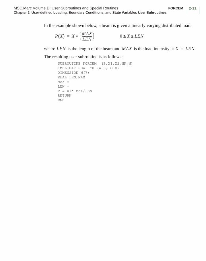
In the example shown below, a beam is given a linearly varying distributed load.
where is the length of the beam and is the load intensity at .
The resulting user subroutine is as follows:SUBROUTINE FORCEM (P,X1,X2,NN,N)IMPLICIT REAL *8 (A-H, O-Z) DIMENSION N(7)REAL LEN,MAXMAX =LEN =P = X1* MAX/LENRETURNEND
P X( ) X * MAXLEN------------- = 0 X LEN≤ ≤
LEN MAX X LEN=

FLUX MSC.Marc Volume D: User Subroutines and Special RoutinesChapter 2 User-defined Loading, Boundary Conditions, and State Variables User Subroutines
2-12
■ FLUX
Input of Nonuniform Fluxes
Description
For heat transfer analysis, this user subroutine allows surface or body fluxes to be specified as functions of time, temperature, or position. When not using the table driven input format, the use of this user subroutine is flagged by the appropriate flux type in the DIST FLUXES input option where the type chosen depends on element type (see MSC.Marc Volume B: Element Library). When using table driven input format, directly specify if the user subroutine is invoked.
This user routine may be used for other Poisson type problems such as Joule heating (DIST CURRENT), diffusion (DIST MASSES), electrostatic (DIST CHARGES), magnetostatic (DIST CURRENT), or acoustic (DIST SOURCES).
Format
User subroutine FLUX is written with the following headers:SUBROUTINE FLUX(F,TS,N,TIME)IMPLICIT REAL *8 (A-H, O-Z) DIMENSION TS(6), N(7)
user coding
RETURNEND
where
F is the surface or volumetric flux, to be defined at this integration point in this user subroutine.
TS(1) is the estimated temperature at the end of the increment.
TS(2) is the current values of the area under the volumetric flux
versus time curve, that is, . This total includes all
uniform and nonuniform volumetric fluxes.
TS(3) is the temperature at the beginning of the increment.
TS(4), TS(5), TS(6) are the integration point coordinates.
N(1) is the element number.
N(2) is the parameter identifying the type of flux.
N(3) is the integration point number.
Qdto
t∫

2-13MSC.Marc Volume D: User Subroutines and Special Routines FLUXChapter 2 User-defined Loading, Boundary Conditions, and State Variables User Subroutines
This user subroutine is called at each time step for each integration point and element listed with an appropriate flux type in the DIST FLUXES or similar input option.
The reading of data is not recommended in FLUX since this user subroutine is in the recycling loop, and the user cannot know how many times per increment it is called.
N(4) is the flux index.
N(5) is not used.
N(6) 1 - heat transfer.2 - joule.3 - bearing.4 - electrostatic.5 - magnetostatic.6 - acoustic.8 - diffusion.
N(7) is the internal element number.
TIME is the current time.
UWELDFLUX MSC.Marc Volume D: User Subroutines and Special RoutinesChapter 2 User-defined Loading, Boundary Conditions, and State Variables User Subroutines
2-14
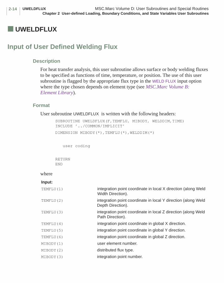
■ UWELDFLUX
Input of User Defined Welding Flux
Description
For heat transfer analysis, this user subroutine allows surface or body welding fluxes to be specified as functions of time, temperature, or position. The use of this user subroutine is flagged by the appropriate flux type in the WELD FLUX input option where the type chosen depends on element type (see MSC.Marc Volume B: Element Library).
Format
User subroutine UWELDFLUX is written with the following headers:SUBROUTINE UWELDFLUX(F,TEMFLU, MIBODY, WELDDIM,TIME)INCLUDE ’../COMMON/IMPLICIT’
DIMENSION MIBODY(*),TEMFLU(*),WELDDIM(*)
user coding
RETURNEND
where
Input:
TEMFLU(1) integration point coordinate in local X direction (along Weld Width Direction).
TEMFLU(2) integration point coordinate in local Y direction (along Weld Depth Direction).
TEMFLU(3) integration point coordinate in local Z direction (along Weld Path Direction).
TEMFLU(4) integration point coordinate in global X direction.
TEMFLU(5) integration point coordinate in global Y direction.
TEMFLU(6) integration point coordinate in global Z direction.
MIBODY(1) user element number.
MIBODY(2) distributed flux type.
MIBODY(3) integration point number.

2-15MSC.Marc Volume D: User Subroutines and Special Routines UWELDFLUXChapter 2 User-defined Loading, Boundary Conditions, and State Variables User Subroutines
This user subroutine is called at each time step for each integration point and element listed with an appropriate load type in the WELD FLUX model definition option. Since this user subroutine is in the recycling loop, the reading of data is not recommended in UWELDFLUX as the user does not know how many times per increment it is called.
The weld path to be followed by the heat source specified in this subroutine can be directly given in the input file or specified through the UWELDPATH user subroutine. This weld path is used to define the local coordinate system at the current position of the weld source. The global integration point coordinates TEMFLU(4 - 6) are then transformed to local integration point coordinates TEMFLU(1 - 3) using the direction cosines of the local coordinate system. Any path offsets in the local X and Y directions are also applied during this process. Both the global and local integration point coordinates are provided as input in the program.
The weld dimensions WELDDIM are optional input. They can be varied as a function of time or arc length using tables. The weld dimensions can be used for defining the weld pool size. The latter can be used for three purposes: for defining the weld flux F in this subroutine; for defining a filler element bounding box which can be used to identify filler elements that are in the weld pool (note that if separate bounding box dimensions are provided, they over-ride the weld pool dimensions); and for defining a moving adaptive box with the heat source that identifies which elements need to be adaptively subdivided.
MIBODY(4) weld flux index.
WELDDIM(1) weld width.
WELDDIM(2) weld depth.
WELDDIM(3) weld forward length.
WELDDIM(4) weld rear length.
TIME time at end of increment.
Required Output:
F is the surface or volumetric welding flux to be defined at this integration point in this user subroutine.
UWELDPATH MSC.Marc Volume D: User Subroutines and Special RoutinesChapter 2 User-defined Loading, Boundary Conditions, and State Variables User Subroutines
2-16
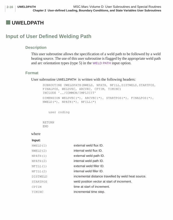
■ UWELDPATH
Input of User Defined Welding Path
Description
This user subroutine allows the specification of a weld path to be followed by a weld heating source. The use of this user subroutine is flagged by the appropriate weld path and arc orientation types (type 5) in the WELD PATH input option.
Format
User subroutine UWELDPATH is written with the following headers:SUBROUTINE UWELDPATH(NWELD, NPATH, NFILL,DISTWELD,STARTPOS, FINALPOS, WELDVEC, ARCVEC, CPTIM, TIMINC)INCLUDE ’../COMMON/IMPLICIT’
DIMENSION WELDVEC(*), ARCVEC(*), STARTPOS(*), FINALPOS(*), NWELD(*), NPATH(*), NFILL(*)
user coding
RETURNEND
where
Input:
NWELD(1) external weld flux ID.
NWELD(2) internal weld flux ID.
NPATH(1) external weld path ID.
NPATH(2) internal weld path ID.
NFILL(1) external weld filler ID.
NFILL(2) internal weld filler ID.
DISTWELD incremental distance travelled by weld heat source.
STARTPOS weld position vector at start of increment.
CPTIM time at start of increment.
TIMINC incremental time step.

2-17MSC.Marc Volume D: User Subroutines and Special Routines UWELDPATHChapter 2 User-defined Loading, Boundary Conditions, and State Variables User Subroutines
This user subroutine is called once at the beginning of each increment or when the time step for the increment is changed due to a cut-back. The position of the weld source at the end of the increment and the corresponding path and orientation vectors are required to be specified by the user. This information is used to construct the local coordinate system at the end of increment position. Note that the specified ARCVEC vector should be perpendicular to the WELDVEC vector. Otherwise, MSC.Marc makes the ARCVEC vector perpendicular to the WELDVEC vector.
The UWELDPATH subroutine should be used in conjunction with a weld heat source that is either directly specified through the WELD FLUX model definition option or through the UWELDFLUX user subroutine. Note that when this subroutine is used to specify the weld path, the position of the associated weld source should be initialized on the WELD FLUX model definition option, else MSC.Marc terminates with exit 20. Also, note that when this subroutine is used to specify the weld path, it is the responsibility of the user to cater to any filler elements that may lie along the path. If the elements are initially deactivated, this can be done by calling the general activation UACTIVE user subroutine at the end of the increment.
Required Output:
FINALPOS weld position vector at end of increment.
WELDVEC weld path vector at end of increment position.
ARCVEC arc orientation vector at end of increment position.

CUPFLX MSC.Marc Volume D: User Subroutines and Special RoutinesChapter 2 User-defined Loading, Boundary Conditions, and State Variables User Subroutines
2-18
■ CUPFLX
Coupling of Inelastic Energy and Internal Heat Generation
Description
This user subroutine allows the user to modify the default routine for the calculation of the internal heat generated due to inelastic energy dissipation. This user subroutine is only used if a coupled thermal-mechanical or thermal-Joule-mechanical analysis is being performed and a DIST FLUXES type 101 is chosen.
Format
User subroutine CUPFLX is written with the following headers:SUBROUTINE CUPFLX (F,TS,N,TIME,TIMINC,TOTPLE,DIFPLE,DEN, FCMECH)IMPLICIT REAL *8 (A-H, O-Z)DIMENSION TS(1), N(1)
user coding
RETURNEND
where
Input:TS(1) is the estimated temperature at the end of the increment.TS(3) is the temperature at the beginning of the increment.TS(4), TS(5), TS(6) are the integration point coordinates.N(1) is the element number.N(2) is 101.N(3) is the integration point number.N(7) is the internal element number.TIME is the time at the beginning of increment.TIMINC is the time increment.TOTPLE is the total plastic strain energy.DIFPLE is the incremental plastic strain energy.DEN is the mass density.FCMECH is the factor entered through the CONVERT model
definition option.Required Output:F is the volumetric flux to be defined by the user.
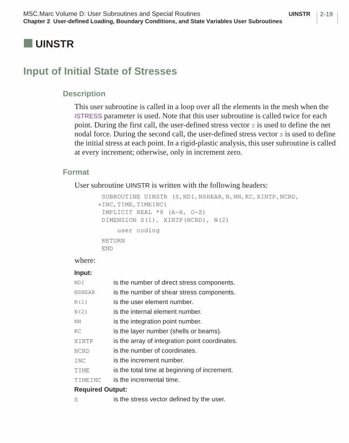
2-19MSC.Marc Volume D: User Subroutines and Special Routines UINSTRChapter 2 User-defined Loading, Boundary Conditions, and State Variables User Subroutines
■ UINSTR
Input of Initial State of Stresses
Description
This user subroutine is called in a loop over all the elements in the mesh when the ISTRESS parameter is used. Note that this user subroutine is called twice for each point. During the first call, the user-defined stress vector S is used to define the net nodal force. During the second call, the user-defined stress vector S is used to define the initial stress at each point. In a rigid-plastic analysis, this user subroutine is called at every increment; otherwise, only in increment zero.
Format
User subroutine UINSTR is written with the following headers: SUBROUTINE UINSTR (S,NDI,NSHEAR,N,NN,KC,XINTP,NCRD,+INC,TIME,TIMEINC) IMPLICIT REAL *8 (A-H, O-Z) DIMENSION S(1), XINTP(NCRD), N(2)
user coding
RETURNEND
where:
Input:NDI is the number of direct stress components.NSHEAR is the number of shear stress components.N(1) is the user element number.N(2) is the internal element number.NN is the integration point number.KC is the layer number (shells or beams).
XINTP is the array of integration point coordinates.
NCRD is the number of coordinates.
INC is the increment number.
TIME is the total time at beginning of increment.
TIMEINC is the incremental time.
Required Output:
S is the stress vector defined by the user.

UFOUR MSC.Marc Volume D: User Subroutines and Special RoutinesChapter 2 User-defined Loading, Boundary Conditions, and State Variables User Subroutines
2-20
■ UFOUR
Input of a User-defined Function F(Θ) for Fourier Analysis
Description
This user subroutine allows input of a function F(Θ) where it can be expressed analytically. The values of F(Θ) are then passed into a MSC.Marc routine that calculates the Fourier expansion coefficients.
Format
User subroutine UFOUR is written with the following headers:SUBROUTINE UFOUR (F,N,NS)IMPLICIT REAL *8 (A-H, O-Z)DIMENSION F(1)
user coding
RETURNEND
where
Example
For example, suppose the following function is to be expanded in a Fourier series:
1 Θ = 135°, 315°F(Θ) = -1 Θ = 45°, 225°
0 elsewhere.
Input:
N The number of stations around the circumference for which the function value F is specified. N is to be defined by the user.
NS The number of the Fourier series.
Required Output:
F The F-array should contain the N values of F (Θ) in sequential order starting at Θ = 0° and ending with Θ = 360°. The user specifies the N values of F(Θ) in degrees sequentially from 0 to 360° in positions N + 1 through 2N of the F-array.
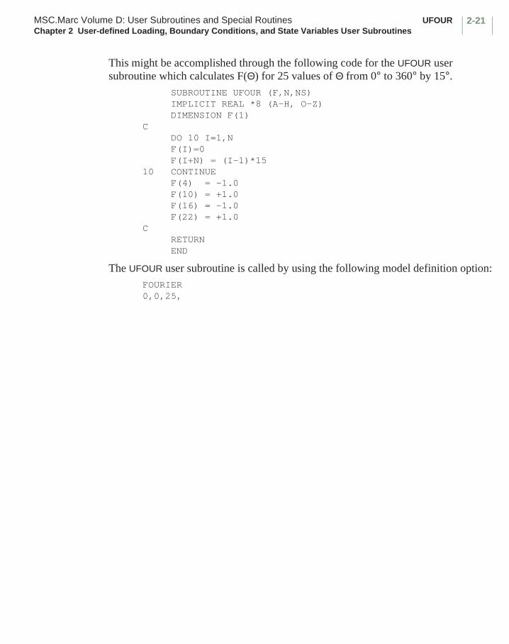
2-21MSC.Marc Volume D: User Subroutines and Special Routines UFOURChapter 2 User-defined Loading, Boundary Conditions, and State Variables User Subroutines
This might be accomplished through the following code for the UFOUR user subroutine which calculates F(Θ) for 25 values of Θ from 0° to 360° by 15°.
SUBROUTINE UFOUR (F,N,NS) IMPLICIT REAL *8 (A-H, O-Z) DIMENSION F(1)
C DO 10 I=1,N F(I)=0 F(I+N) = (I-1)*15
10 CONTINUE F(4) = -1.0 F(10) = +1.0 F(16) = -1.0 F(22) = +1.0
C RETURN END
The UFOUR user subroutine is called by using the following model definition option:FOURIER0,0,25,
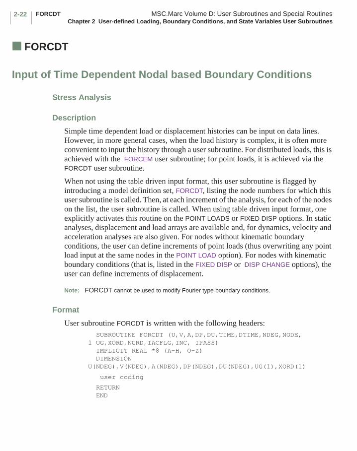
FORCDT MSC.Marc Volume D: User Subroutines and Special RoutinesChapter 2 User-defined Loading, Boundary Conditions, and State Variables User Subroutines
2-22
■ FORCDT
Input of Time Dependent Nodal based Boundary Conditions
Stress Analysis
Description
Simple time dependent load or displacement histories can be input on data lines. However, in more general cases, when the load history is complex, it is often more convenient to input the history through a user subroutine. For distributed loads, this is achieved with the FORCEM user subroutine; for point loads, it is achieved via the FORCDT user subroutine.
When not using the table driven input format, this user subroutine is flagged by introducing a model definition set, FORCDT, listing the node numbers for which this user subroutine is called. Then, at each increment of the analysis, for each of the nodes on the list, the user subroutine is called. When using table driven input format, one explicitly activates this routine on the POINT LOADS or FIXED DISP options. In static analyses, displacement and load arrays are available and, for dynamics, velocity and acceleration analyses are also given. For nodes without kinematic boundary conditions, the user can define increments of point loads (thus overwriting any point load input at the same nodes in the POINT LOAD option). For nodes with kinematic boundary conditions (that is, listed in the FIXED DISP or DISP CHANGE options), the user can define increments of displacement.
Note: FORCDT cannot be used to modify Fourier type boundary conditions.
Format
User subroutine FORCDT is written with the following headers: SUBROUTINE FORCDT (U,V,A,DP,DU,TIME,DTIME,NDEG,NODE, 1 UG,XORD,NCRD,IACFLG,INC, IPASS) IMPLICIT REAL *8 (A-H, O-Z) DIMENSION U(NDEG),V(NDEG),A(NDEG),DP(NDEG),DU(NDEG),UG(1),XORD(1)
user coding
RETURN END
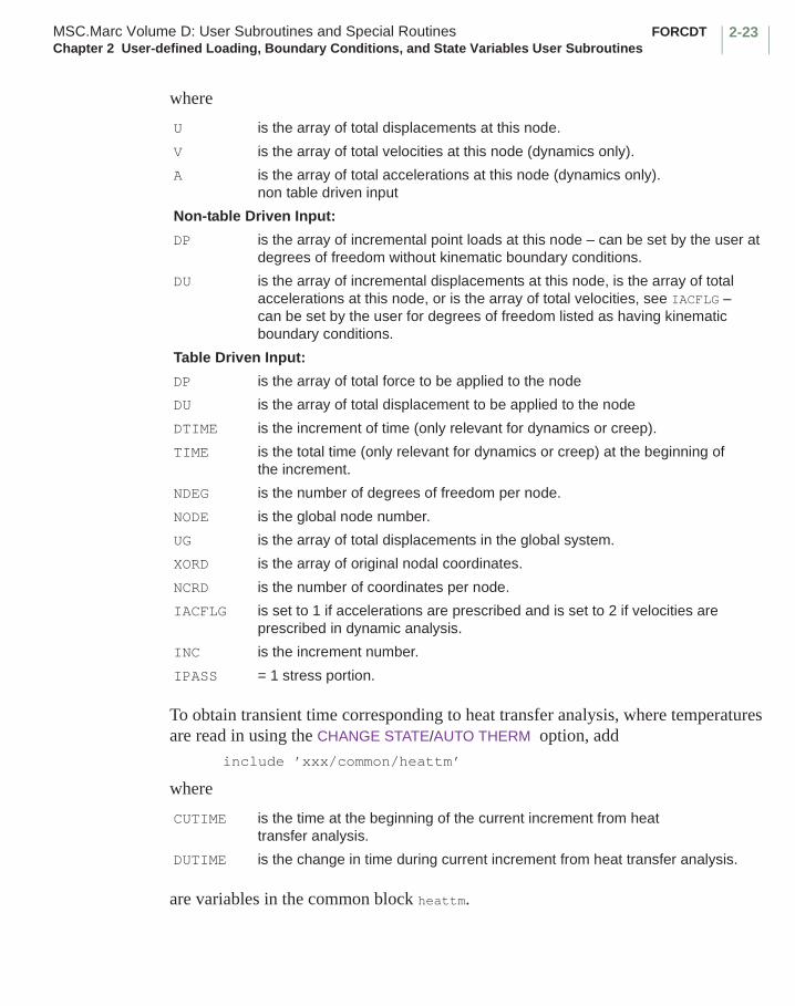
2-23MSC.Marc Volume D: User Subroutines and Special Routines FORCDTChapter 2 User-defined Loading, Boundary Conditions, and State Variables User Subroutines
where
To obtain transient time corresponding to heat transfer analysis, where temperatures are read in using the CHANGE STATE/AUTO THERM option, add
include ’xxx/common/heattm’
where
are variables in the common block heattm.
U is the array of total displacements at this node.
V is the array of total velocities at this node (dynamics only).
A is the array of total accelerations at this node (dynamics only).non table driven input
Non-table Driven Input:
DP is the array of incremental point loads at this node – can be set by the user at degrees of freedom without kinematic boundary conditions.
DU is the array of incremental displacements at this node, is the array of total accelerations at this node, or is the array of total velocities, see IACFLG – can be set by the user for degrees of freedom listed as having kinematic boundary conditions.
Table Driven Input:
DP is the array of total force to be applied to the node
DU is the array of total displacement to be applied to the node
DTIME is the increment of time (only relevant for dynamics or creep).
TIME is the total time (only relevant for dynamics or creep) at the beginning of the increment.
NDEG is the number of degrees of freedom per node.
NODE is the global node number.
UG is the array of total displacements in the global system.
XORD is the array of original nodal coordinates.
NCRD is the number of coordinates per node.
IACFLG is set to 1 if accelerations are prescribed and is set to 2 if velocities are prescribed in dynamic analysis.
INC is the increment number.
IPASS = 1 stress portion.
CUTIME is the time at the beginning of the current increment from heat transfer analysis.
DUTIME is the change in time during current increment from heat transfer analysis.
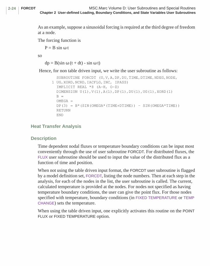
FORCDT MSC.Marc Volume D: User Subroutines and Special RoutinesChapter 2 User-defined Loading, Boundary Conditions, and State Variables User Subroutines
2-24
As an example, suppose a sinusoidal forcing is required at the third degree of freedom at a node.
The forcing function is
P = B sin ω t
so
dp = B(sin ω (t + dt) - sin ω t)
Hence, for non table driven input, we write the user subroutine as follows: SUBROUTINE FORCDT (U,V,A,DP,DU,TIME,DTIME,NDEG,NODE,1 UG,XORD,NCRD,IACFLG,INC, IPASS) IMPLICIT REAL *8 (A-H, O-Z) DIMENSION U(1),V(1),A(1),DP(1),DU(1),UG(1),XORD(1) B = OMEGA = DP(3) = B*(SIN(OMEGA*(TIME+DTIME)) - SIN(OMEGA*TIME)) RETURN END
Heat Transfer Analysis
Description
Time dependent nodal fluxes or temperature boundary conditions can be input most conveniently through the use of user subroutine FORCDT. For distributed fluxes, the FLUX user subroutine should be used to input the value of the distributed flux as a function of time and position.
When not using the table driven input format, the FORCDT user subroutine is flagged by a model definition set, FORCDT, listing the node numbers. Then at each step in the analysis, for each of the nodes in the list, the user subroutine is called. The current, calculated temperature is provided at the nodes. For nodes not specified as having temperature boundary conditions, the user can give the point flux. For those nodes specified with temperature, boundary conditions (in FIXED TEMPERATURE or TEMP CHANGE) sets the temperature.
When using the table driven input, one explicitly activates this routine on the POINT FLUX or FIXED TEMPERATURE option.

2-25MSC.Marc Volume D: User Subroutines and Special Routines FORCDTChapter 2 User-defined Loading, Boundary Conditions, and State Variables User Subroutines
Format
User subroutine FORCDT is written with the following headers: SUBROUTINE FORCDT (X1,X2,X3,F,T,TIME,DTIME,NDEG,NODE,X4, 1 XORD,NCRD,IACFLG,INC,IPASS) IMPLICIT REAL *8 (A-H, O-Z) DIMENSION F(NDEG),T(NDEG),XORD(NCRD)
user coding
RETURN END
where
Joule Heating Analysis
Description
Time dependent nodal currents or voltage boundary conditions can be input most conveniently through the use of user subroutine FORCDT. For distributed current, the FLUX user subroutine should be used to input the value of the distributed current as a function of time and position.
When not using the table driven input format, the FORCDT user subroutine is flagged by a FORCDT model definition set, listing the node numbers. Then, at each step in the analysis, for each of the nodes in the list, the user subroutine is called. The calculated voltage is provided at the nodes. For nodes not specified as having voltage boundary conditions, the user can give the point current. For those nodes specified with voltage,
X1,X2,X3 are not used.F is the array of fluxes at the node – can be re-defined for nodes free of
temperature boundary conditions.T is the array of temperatures at the node – can be redefined for nodes
having temperature boundary conditions.TIME is the total time at the end of the current step.DTIME is the current time increment.NDEG is 1 unless heat transfer shell elements are used.NODE is the global node number.X4 is not used.XORD is the array of nodal coordinates.NCRD is the number of coordinates per node.IACFLG is not used.INC is the increment number. IPASS = 2 heat transfer portion.

FORCDT MSC.Marc Volume D: User Subroutines and Special RoutinesChapter 2 User-defined Loading, Boundary Conditions, and State Variables User Subroutines
2-26
boundary conditions (in VOLTAGE or VOLTAGE CHANGE) sets the voltage. When using table driven input format, one explicitly activates this routine on the POINT CURRENT or FIXED VOLTAGE option.
Format
User subroutine FORCDT is written with the following headers: SUBROUTINE FORCDT (X1,X2,X3,F,T,TIME,DTIME,NDEG,NODE,X4, 1 XORD,NCRD,IACFLG,INC,IPASS) IMPLICIT REAL *8 (A-H, O-Z) DIMENSION F(NDEG),T(NDEG),XORD(NCRD)
user coding
RETURN END
where
Diffusion Analysis
Description
Time dependent nodal mass flux or pressure boundary conditions can be input most conveniently through the use of the FORCDT user subroutine. For distributed mass flux, the FLUX user subroutine should be used to input the value of the distributed mass flux as a function of time and position.
X1,X2,X3 are not used.F is the array of currents at the node – can be re-defined for nodes free of
voltage boundary conditions.T is the array of voltages at the node – can be redefined for nodes having
voltage boundary conditions.TIME is the total time at the end of the current step.DTIME is the current time increment.NDEG is 1 unless heat transfer shell elements are used.NODE is the global node number.X4 is not used.XORD is the array of nodal coordinates.NCRD is the number of coordinates per node.IACFLG is not used.INC is the increment number. IPASS = 4 electrical pass in Joule heating analysis.
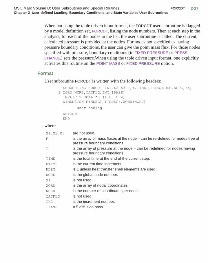
2-27MSC.Marc Volume D: User Subroutines and Special Routines FORCDTChapter 2 User-defined Loading, Boundary Conditions, and State Variables User Subroutines
When not using the table driven input format, the FORCDT user subroutine is flagged by a model definition set, FORCDT, listing the node numbers. Then at each step in the analysis, for each of the nodes in the list, the user subroutine is called. The current, calculated pressure is provided at the nodes. For nodes not specified as having pressure boundary conditions, the user can give the point mass flux. For those nodes specified with pressure, boundary conditions (in FIXED PRESSURE or PRESS CHANGE) sets the pressure.When using the table driven input format, one explicitly activates this routine on the POINT MASS or FIXED PRESSURE option.
Format
User subroutine FORCDT is written with the following headers: SUBROUTINE FORCDT (X1,X2,X3,F,T,TIME,DTIME,NDEG,NODE,X4, 1 XORD,NCRD,IACFLG,INC,IPASS) IMPLICIT REAL *8 (A-H, O-Z) DIMENSION F(NDEG),T(NDEG),XORD(NCRD)
user coding
RETURN END
where
X1,X2,X3 are not used.F is the array of mass fluxes at the node – can be re-defined for nodes free of
pressure boundary conditions.T is the array of pressure at the node – can be redefined for nodes having
pressure boundary conditions.TIME is the total time at the end of the current step.DTIME is the current time increment.NDEG is 1 unless heat transfer shell elements are used.NODE is the global node number.X4 is not used.XORD is the array of nodal coordinates.NCRD is the number of coordinates per node.IACFLG is not used.INC is the increment number. IPASS = 5 diffusion pass.
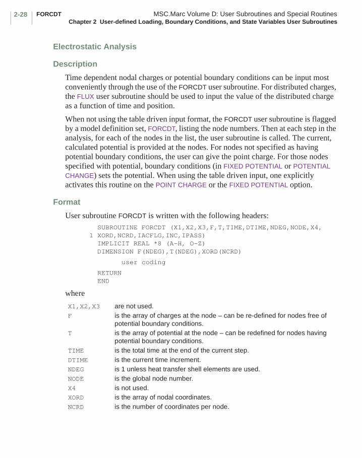
FORCDT MSC.Marc Volume D: User Subroutines and Special RoutinesChapter 2 User-defined Loading, Boundary Conditions, and State Variables User Subroutines
2-28
Electrostatic Analysis
Description
Time dependent nodal charges or potential boundary conditions can be input most conveniently through the use of the FORCDT user subroutine. For distributed charges, the FLUX user subroutine should be used to input the value of the distributed charge as a function of time and position.
When not using the table driven input format, the FORCDT user subroutine is flagged by a model definition set, FORCDT, listing the node numbers. Then at each step in the analysis, for each of the nodes in the list, the user subroutine is called. The current, calculated potential is provided at the nodes. For nodes not specified as having potential boundary conditions, the user can give the point charge. For those nodes specified with potential, boundary conditions (in FIXED POTENTIAL or POTENTIAL CHANGE) sets the potential. When using the table driven input, one explicitly activates this routine on the POINT CHARGE or the FIXED POTENTIAL option.
Format
User subroutine FORCDT is written with the following headers: SUBROUTINE FORCDT (X1,X2,X3,F,T,TIME,DTIME,NDEG,NODE,X4, 1 XORD,NCRD,IACFLG,INC,IPASS) IMPLICIT REAL *8 (A-H, O-Z) DIMENSION F(NDEG),T(NDEG),XORD(NCRD)
user coding
RETURN END
where
X1,X2,X3 are not used.F is the array of charges at the node – can be re-defined for nodes free of
potential boundary conditions.T is the array of potential at the node – can be redefined for nodes having
potential boundary conditions.TIME is the total time at the end of the current step.DTIME is the current time increment.NDEG is 1 unless heat transfer shell elements are used.NODE is the global node number.X4 is not used.XORD is the array of nodal coordinates.NCRD is the number of coordinates per node.
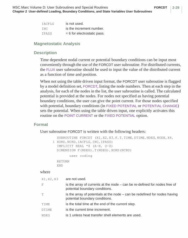
2-29MSC.Marc Volume D: User Subroutines and Special Routines FORCDTChapter 2 User-defined Loading, Boundary Conditions, and State Variables User Subroutines
Magnetostatic Analysis
Description
Time dependent nodal current or potential boundary conditions can be input most conveniently through the use of the FORCDT user subroutine. For distributed currents, the FLUX user subroutine should be used to input the value of the distributed current as a function of time and position.
When not using the table driven input format, the FORCDT user subroutine is flagged by a model definition set, FORCDT, listing the node numbers. Then at each step in the analysis, for each of the nodes in the list, the user subroutine is called. The calculated potential is provided at the nodes. For nodes not specified as having potential boundary conditions, the user can give the point current. For those nodes specified with potential, boundary conditions (in FIXED POTENTIAL or POTENTIAL CHANGE) sets the potential. When using the table driven input, one explicitly activates this routine on the POINT CURRENT or the FIXED POTENTIAL option.
Format
User subroutine FORCDT is written with the following headers: SUBROUTINE FORCDT (X1,X2,X3,F,T,TIME,DTIME,NDEG,NODE,X4, 1 XORD,NCRD,IACFLG,INC,IPASS) IMPLICIT REAL *8 (A-H, O-Z) DIMENSION F(NDEG),T(NDEG),XORD(NCRD)
user coding
RETURN END
where
IACFLG is not used.INC is the increment number. IPASS = 6 for electrostatic pass.
X1,X2,X3 are not used.
F is the array of currents at the node – can be re-defined for nodes free of potential boundary conditions.
T is the array of potentials at the node – can be redefined for nodes having potential boundary conditions.
TIME is the total time at the end of the current step.
DTIME is the current time increment.
NDEG is 1 unless heat transfer shell elements are used.

FORCDT MSC.Marc Volume D: User Subroutines and Special RoutinesChapter 2 User-defined Loading, Boundary Conditions, and State Variables User Subroutines
2-30
NODE is the global node number.
X4 is not used.
XORD is the array of nodal coordinates.
NCRD is the number of coordinates per node.
IACFLG is not used.
INC is the increment number.
IPASS = 7 for magnetostatic pass.
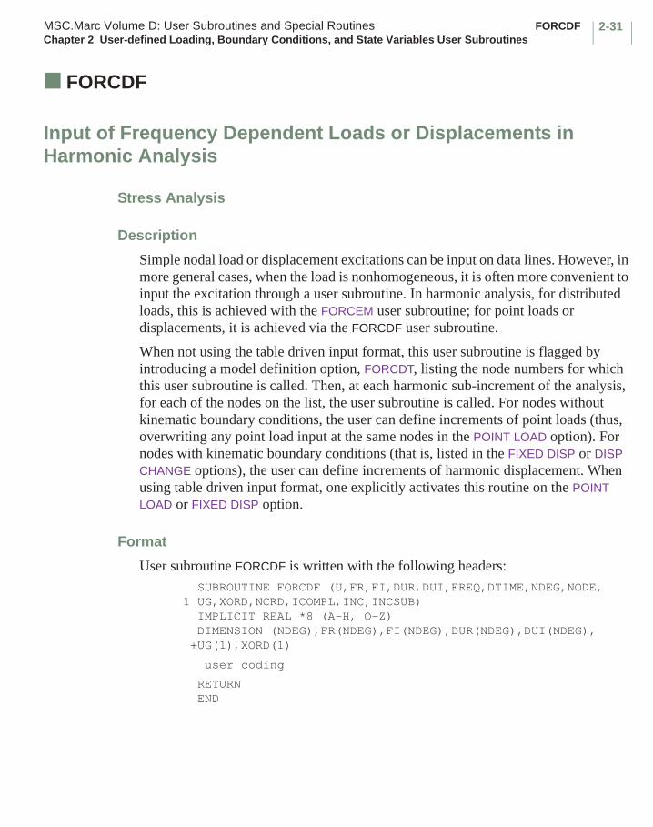
2-31MSC.Marc Volume D: User Subroutines and Special Routines FORCDFChapter 2 User-defined Loading, Boundary Conditions, and State Variables User Subroutines
■ FORCDF
Input of Frequency Dependent Loads or Displacements in Harmonic Analysis
Stress Analysis
Description
Simple nodal load or displacement excitations can be input on data lines. However, in more general cases, when the load is nonhomogeneous, it is often more convenient to input the excitation through a user subroutine. In harmonic analysis, for distributed loads, this is achieved with the FORCEM user subroutine; for point loads or displacements, it is achieved via the FORCDF user subroutine.
When not using the table driven input format, this user subroutine is flagged by introducing a model definition option, FORCDT, listing the node numbers for which this user subroutine is called. Then, at each harmonic sub-increment of the analysis, for each of the nodes on the list, the user subroutine is called. For nodes without kinematic boundary conditions, the user can define increments of point loads (thus, overwriting any point load input at the same nodes in the POINT LOAD option). For nodes with kinematic boundary conditions (that is, listed in the FIXED DISP or DISP CHANGE options), the user can define increments of harmonic displacement. When using table driven input format, one explicitly activates this routine on the POINT LOAD or FIXED DISP option.
Format
User subroutine FORCDF is written with the following headers: SUBROUTINE FORCDF (U,FR,FI,DUR,DUI,FREQ,DTIME,NDEG,NODE, 1 UG,XORD,NCRD,ICOMPL,INC,INCSUB) IMPLICIT REAL *8 (A-H, O-Z) DIMENSION (NDEG),FR(NDEG),FI(NDEG),DUR(NDEG),DUI(NDEG), +UG(1),XORD(1)
user coding
RETURN END

FORCDF MSC.Marc Volume D: User Subroutines and Special RoutinesChapter 2 User-defined Loading, Boundary Conditions, and State Variables User Subroutines
2-32
where
Piezoelectric Analysis
Description
Simple nodal load, charge, displacement, or potential excitations can be input on data lines. However, in more general cases, when the load is nonhomogeneous, it is often more convenient to input the excitation through a user subroutine. For distributed loads, this is achieved with the FORCEM user subroutine; for distributed charge, this is achieved with the FLUX user subroutine; for point loads, point charge, displacements, or potential, this is achieved via the FORCDF user subroutine.
Input:
U is the array of total displacements at this node.
FREQ is the excitation frequency.
DTIME is not used.
NDEG is the number of degrees of freedom per node.
NODE is the global node number.
UG is the array of total displacements in the global system.
XORD is the array of original nodal coordinates.
NCRD is the number of coordinates per node.
ICOMPL is 0 if real analysis; 1 if complex analysis.
INC is the increment number.
Required Output:
FR is the array of the real components of the harmonic point loads.
FI is the array of the imaginary components of the harmonic point loads.
DUR is the array of the real components of the harmonic displacements.
DUI is the array of the imaginary components of the harmonic displacements.
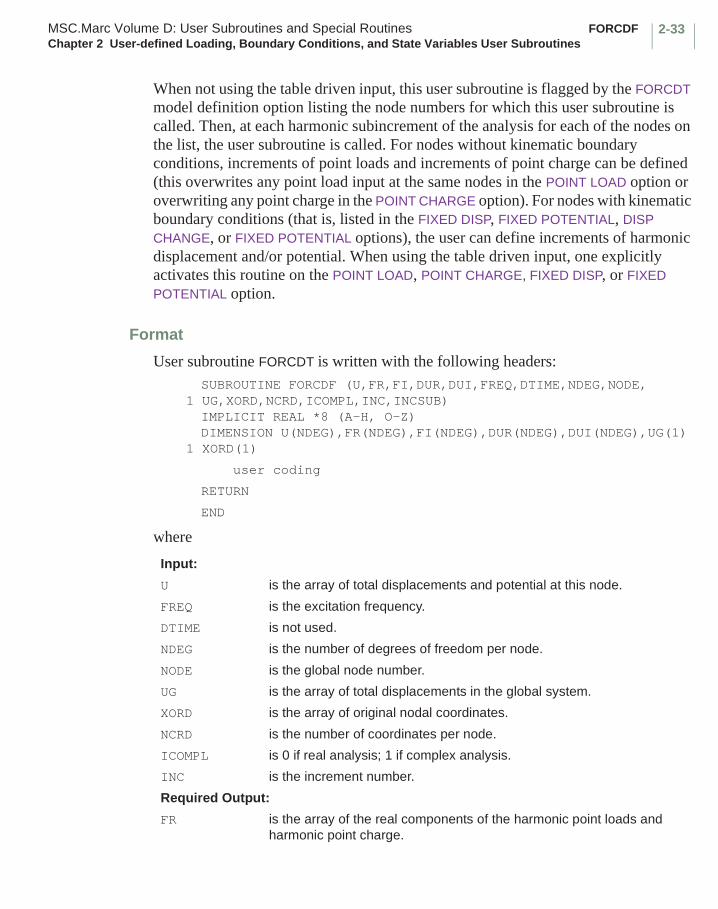
2-33MSC.Marc Volume D: User Subroutines and Special Routines FORCDFChapter 2 User-defined Loading, Boundary Conditions, and State Variables User Subroutines
When not using the table driven input, this user subroutine is flagged by the FORCDT model definition option listing the node numbers for which this user subroutine is called. Then, at each harmonic subincrement of the analysis for each of the nodes on the list, the user subroutine is called. For nodes without kinematic boundary conditions, increments of point loads and increments of point charge can be defined (this overwrites any point load input at the same nodes in the POINT LOAD option or overwriting any point charge in the POINT CHARGE option). For nodes with kinematic boundary conditions (that is, listed in the FIXED DISP, FIXED POTENTIAL, DISP CHANGE, or FIXED POTENTIAL options), the user can define increments of harmonic displacement and/or potential. When using the table driven input, one explicitly activates this routine on the POINT LOAD, POINT CHARGE, FIXED DISP, or FIXED POTENTIAL option.
Format
User subroutine FORCDT is written with the following headers:SUBROUTINE FORCDF (U,FR,FI,DUR,DUI,FREQ,DTIME,NDEG,NODE,
1 UG,XORD,NCRD,ICOMPL,INC,INCSUB)IMPLICIT REAL *8 (A-H, O-Z)DIMENSION U(NDEG),FR(NDEG),FI(NDEG),DUR(NDEG),DUI(NDEG),UG(1)
1 XORD(1)
user coding
RETURN
END
where
Input:
U is the array of total displacements and potential at this node.
FREQ is the excitation frequency.
DTIME is not used.
NDEG is the number of degrees of freedom per node.
NODE is the global node number.
UG is the array of total displacements in the global system.
XORD is the array of original nodal coordinates.
NCRD is the number of coordinates per node.
ICOMPL is 0 if real analysis; 1 if complex analysis.
INC is the increment number.
Required Output:
FR is the array of the real components of the harmonic point loads and harmonic point charge.

FORCDF MSC.Marc Volume D: User Subroutines and Special RoutinesChapter 2 User-defined Loading, Boundary Conditions, and State Variables User Subroutines
2-34
The first ndeg-1 elements of the arrays refer to the structural point loads or displacements.
The ndeg’th element of the arrays refers to the point charge or harmonic potential.
FI is the array of the imaginary components of the harmonic point loads and harmonic point charge.
DUR is the array of the real components of the harmonic displacements and harmonic potential.
DUI is the array of the imaginary components of the harmonic displacements and harmonic potential.
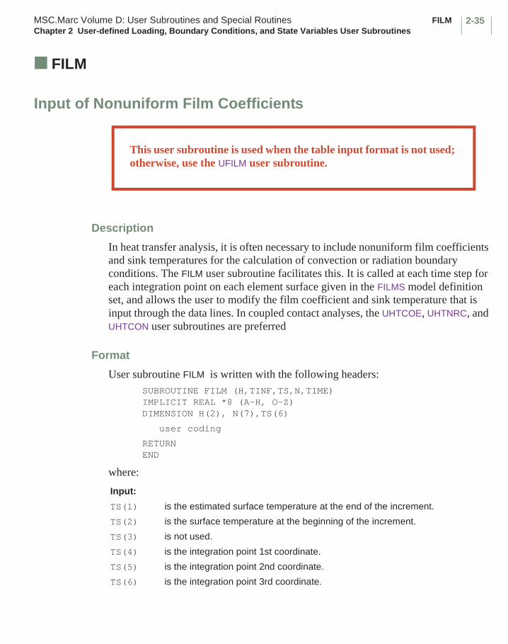
2-35MSC.Marc Volume D: User Subroutines and Special Routines FILMChapter 2 User-defined Loading, Boundary Conditions, and State Variables User Subroutines
■ FILM
Input of Nonuniform Film Coefficients
Description
In heat transfer analysis, it is often necessary to include nonuniform film coefficients and sink temperatures for the calculation of convection or radiation boundary conditions. The FILM user subroutine facilitates this. It is called at each time step for each integration point on each element surface given in the FILMS model definition set, and allows the user to modify the film coefficient and sink temperature that is input through the data lines. In coupled contact analyses, the UHTCOE, UHTNRC, and UHTCON user subroutines are preferred
Format
User subroutine FILM is written with the following headers:SUBROUTINE FILM (H,TINF,TS,N,TIME) IMPLICIT REAL *8 (A-H, O-Z)DIMENSION H(2), N(7),TS(6)
user coding
RETURN END
where:
Input:
TS(1) is the estimated surface temperature at the end of the increment.
TS(2) is the surface temperature at the beginning of the increment.
TS(3) is not used.
TS(4) is the integration point 1st coordinate.
TS(5) is the integration point 2nd coordinate.
TS(6) is the integration point 3rd coordinate.
This user subroutine is used when the table input format is not used; otherwise, use the UFILM user subroutine.
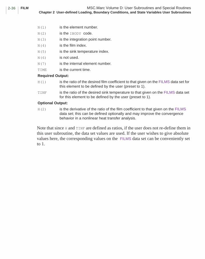
FILM MSC.Marc Volume D: User Subroutines and Special RoutinesChapter 2 User-defined Loading, Boundary Conditions, and State Variables User Subroutines
2-36
Note that since H and TINF are defined as ratios, if the user does not re-define them in this user subroutine, the data set values are used. If the user wishes to give absolute values here, the corresponding values on the FILMS data set can be conveniently set to 1.
N(1) is the element number.
N(2) is the IBODY code.
N(3) is the integration point number.
N(4) is the film index.
N(5) is the sink temperature index.
N(6) is not used.
N(7) is the internal element number.
TIME is the current time.
Required Output:
H(1) is the ratio of the desired film coefficient to that given on the FILMS data set for this element to be defined by the user (preset to 1).
TINF is the ratio of the desired sink temperature to that given on the FILMS data set for this element to be defined by the user (preset to 1).
Optional Output:
H(2) is the derivative of the ratio of the film coefficient to that given on the FILMS data set; this can be defined optionally and may improve the convergence behavior in a nonlinear heat transfer analysis.
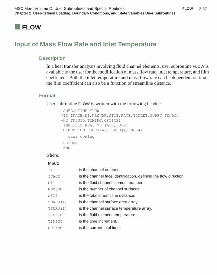
2-37MSC.Marc Volume D: User Subroutines and Special Routines FLOWChapter 2 User-defined Loading, Boundary Conditions, and State Variables User Subroutines
■ FLOW
Input of Mass Flow Rate and Inlet Temperature
Description
In a heat transfer analysis involving fluid channel elements, user subroutine FLOW is available to the user for the modification of mass flow rate, inlet temperature, and film coefficient. Both the inlet temperature and mass flow rate can be dependent on time; the film coefficient can also be a function of streamline distance.
Format
User subroutine FLOW is written with the following header: SUBROUTINE FLOW (II,IFACE,N1,NBSURF,STOT,RATE,TINLET,SURFJ,TSURJ,+HJ,TFLUID,TIMINC,CPTIME) IMPLICIT REAL *8 (A-H, O-Z) DIMENSION SURFJ(4),TSURJ(4),HJ(4)
user coding
RETURN END
where:
Input:
II is the channel number.
IFACE is the channel face identification, defining the flow direction.
N1 is the fluid channel element number.
NBSURF is the number of channel surfaces.
STOT is the total stream line distance.
SURFJ(I) is the channel surface area array.
TSURJ(I) is the channel surface temperature array.
TFLUID is the fluid element temperature.
TIMINC is the time increment.
CPTIME is the current total time.
FLOW MSC.Marc Volume D: User Subroutines and Special RoutinesChapter 2 User-defined Loading, Boundary Conditions, and State Variables User Subroutines
2-38
In two-dimensional analyses, SURFJ(1), SURFJ(2) are the lengths of the edges bordering the channel element. In three-dimensional analyses, SURFJ(1) through SURFJ(4) are the areas on adjacent faces. In a similar manner, TSURJ is the average temperature on adjacent edges (for 2-D) or adjacent faces (for 3-D).
Required Output:
RATE is the mass flow rate (redefined by the user in this user subroutine).
TINLET is the inlet temperature (redefined by the user in this user subroutine).
HJ(I) is the film coefficient of the ith surface (redefined by the user in this user subroutine).
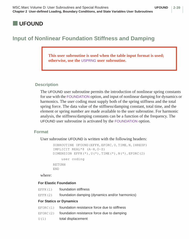
2-39MSC.Marc Volume D: User Subroutines and Special Routines UFOUNDChapter 2 User-defined Loading, Boundary Conditions, and State Variables User Subroutines
■ UFOUND
Input of Nonlinear Foundation Stiffness and Damping
Description
The UFOUND user subroutine permits the introduction of nonlinear spring constants for use with the FOUNDATION option, and input of nonlinear damping for dynamics or harmonics. The user coding must supply both of the spring stiffness and the total spring force. The data value of the stiffness/damping constant, total time, and the element or spring number are made available to the user subroutine. For harmonic analysis, the stiffness/damping constants can be a function of the frequency. The UFOUND user subroutine is activated by the FOUNDATION option.
Format
User subroutine UFOUND is written with the following headers:SUBROUTINE UFOUND(EFFK,EFORC,U,TIME,N,IHRESP)IMPLICIT REAL*8 (A-H,O-Z)DIMENSION EFFK(*),U(*),TIME(*),N(*),EFORC(2)
user coding
RETURNEND
where:
For Elastic Foundation
EFFK(1) foundation stiffness
EFFK(2) foundation damping (dynamics and/or harmonics)
For Statics or Dynamics
EFORC(1) foundation resistance force due to stiffness
EFORC(2) foundation resistance force due to damping
U(1) total displacement
This user subroutine is used when the table input format is used; otherwise, use the USPRNG user subroutine.

UFOUND MSC.Marc Volume D: User Subroutines and Special RoutinesChapter 2 User-defined Loading, Boundary Conditions, and State Variables User Subroutines
2-40
U(2) total velocity
TIME(1) time at beginning of increment
TIME(2) incremental time
For Harmonics
EFORC(1) real component of foundation resistance force
EFORC(2) imaginary component of foundation resistance force
U(1) real component of harmonic displacement
U(2) imaginary component of harmonic displacement
TIME(1) time
TIME(2) frequency
N(1) element number
N(2) face id (ibody)
N(3) integration point number
N(4) boundary condition id
N(5) boundary condition id
N(6) internal element id
IHRESP 0 statics or dynamics1 harmonics
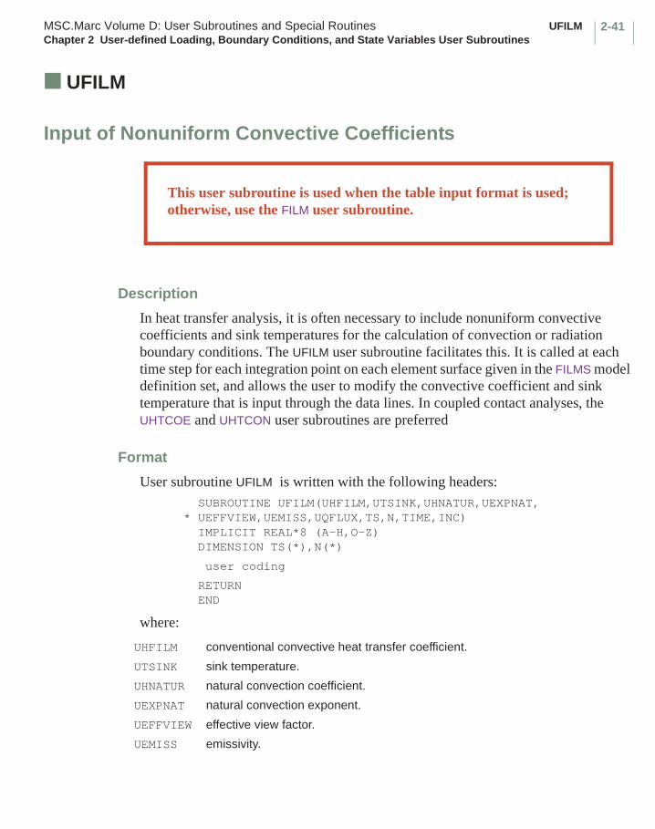
2-41MSC.Marc Volume D: User Subroutines and Special Routines UFILMChapter 2 User-defined Loading, Boundary Conditions, and State Variables User Subroutines
■ UFILM
Input of Nonuniform Convective Coefficients
Description
In heat transfer analysis, it is often necessary to include nonuniform convective coefficients and sink temperatures for the calculation of convection or radiation boundary conditions. The UFILM user subroutine facilitates this. It is called at each time step for each integration point on each element surface given in the FILMS model definition set, and allows the user to modify the convective coefficient and sink temperature that is input through the data lines. In coupled contact analyses, the UHTCOE and UHTCON user subroutines are preferred
Format
User subroutine UFILM is written with the following headers: SUBROUTINE UFILM(UHFILM,UTSINK,UHNATUR,UEXPNAT,* UEFFVIEW,UEMISS,UQFLUX,TS,N,TIME,INC) IMPLICIT REAL*8 (A-H,O-Z) DIMENSION TS(*),N(*)
user coding
RETURN END
where:
UHFILM conventional convective heat transfer coefficient.
UTSINK sink temperature.
UHNATUR natural convection coefficient.
UEXPNAT natural convection exponent.
UEFFVIEW effective view factor.
UEMISS emissivity.
This user subroutine is used when the table input format is used; otherwise, use the FILM user subroutine.
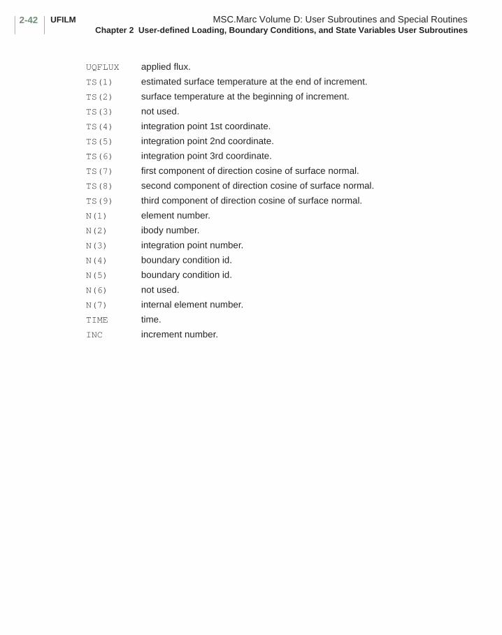
UFILM MSC.Marc Volume D: User Subroutines and Special RoutinesChapter 2 User-defined Loading, Boundary Conditions, and State Variables User Subroutines
2-42
UQFLUX applied flux.
TS(1) estimated surface temperature at the end of increment.
TS(2) surface temperature at the beginning of increment.
TS(3) not used.
TS(4) integration point 1st coordinate.
TS(5) integration point 2nd coordinate.
TS(6) integration point 3rd coordinate.
TS(7) first component of direction cosine of surface normal.
TS(8) second component of direction cosine of surface normal.
TS(9) third component of direction cosine of surface normal.
N(1) element number.
N(2) ibody number.
N(3) integration point number.
N(4) boundary condition id.
N(5) boundary condition id.
N(6) not used.
N(7) internal element number.
TIME time.
INC increment number.

2-43MSC.Marc Volume D: User Subroutines and Special Routines USINKPTChapter 2 User-defined Loading, Boundary Conditions, and State Variables User Subroutines
■ USINKPT
Input of Sink Point Temperatures
Description
The USINKPT user subroutine allows the user to change the sink point temperatures as a function of time. For every integration point associated with an element face defined in the FILMS model definition option, the closest sink point will be determined. This routine will be called for each one of these integration points.
Format
User subroutine USINKPT is written with the following headers:SUBROUTINE USINKPT(M,NN,ISINK,TSINK,TIME,INC,XINT,XSINK,NCRD)IMPLICIT REAL*8 (A-H,O-Z)DIMENSION XINT(NCRD),XSINK(NCRD)
user coding
RETURNEND
where:
Updates Temperature Of Sink Point
M element number.
NN integration point number.
ISINK sink id.
TSINK temperature of sink point - to be updated by the user.
TIME time at the end of the increment.
INC increment number.
XINT coordinates of surface integration point.
XSINK coordinates of sink point.
NCRD number of coordinates.

GAPT MSC.Marc Volume D: User Subroutines and Special RoutinesChapter 2 User-defined Loading, Boundary Conditions, and State Variables User Subroutines
2-44
■ GAPT
Input of Thermal Contact (Conrad) Gap Temperature
Description
In a heat transfer analysis involving thermal contact (CONRAD) gap elements, the gap temperature is compared with a given gap closure temperature for the determination of gap open/closed condition. In MSC.Marc, the gap temperature is
estimated from the average of gap nodal temperatures and the gap closure temperature is entered through the CONRAD GAP model definition option.
The GAPT user subroutine allows for the redefinition of gap temperature (TGAP) based on the nodal temperatures T1 and T2. If the gap temperature (TGAP) is greater than or equal to the gap closure temperature (TCLOSE), the gap is closed. Otherwise, the gap is open. This also influences the electrical contact in a coupled Joule heating analysis.
Format
User subroutine GAPT is written with the following header:SUBROUTINE GAPT(N,I1,I2,T1,T2,TCLOSE,TGAP,INC,TIME,TIMINC)IMPLICIT REAL *8 (A-H, O-Z)
user coding
RETURN END
where:
Input:
N is the gap (tie) number.
I1,I2 are the nodal numbers.
T1,T2 are the nodal temperatures.
TCLOSE is the gap closure temperature.
INC is the increment number.
TIME is the total transient time.
TIMINC is the time increment.
Required Output:
TGAP is the gap temperature (to be defined the user).
0.5∗ T1 T2+( )
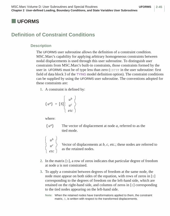
2-45MSC.Marc Volume D: User Subroutines and Special Routines UFORMSChapter 2 User-defined Loading, Boundary Conditions, and State Variables User Subroutines
■ UFORMS
Definition of Constraint Conditions
Description
The UFORMS user subroutine allows the definition of a constraint condition. MSC.Marc's capability for applying arbitrary homogeneous constraints between nodal displacements is used through this user subroutine. To distinguish user constraints from MSC.Marc's built-in constraints, those constraints formed by the user in UFORMS must be of type less than zero (ISTYP in the user subroutine: first field of data block 3 of the TYING model definition option). The constraint conditions can be supplied by using the UFORMS user subroutine. The conventions adopted for these constraints are:
1. A constraint is defined by:
where:
The vector of displacement at node a, referred to as the tied mode.
Vector of displacements at b, c, etc.; these nodes are referred to as the retained nodes.
2. In the matrix [S], a row of zeros indicates that particular degree of freedom at node a is not constrained.
3. To apply a constraint between degrees of freedom at the same node, the node must appear on both sides of the equation, with rows of zeros in [S] corresponding to the degrees of freedom on the left-hand side, which are retained on the right-hand side, and columns of zeros in [S] corresponding to the tied nodes appearing on the left-hand side.
Note: When the retained nodes have transformations applied to them, the constraint matrix, S, is written with respect to the transformed displacements.
ua{ } S[ ]ub
uc
etc
=
ua{ }
ub
uc
etc

UFORMS MSC.Marc Volume D: User Subroutines and Special RoutinesChapter 2 User-defined Loading, Boundary Conditions, and State Variables User Subroutines
2-46
Format
The user subroutine supplying the [S] matrix must have the following headers: SUBROUTINE UFORMS(S,NRETN,LONG,NDEG,ISTYP,ITI,ISTART,ITIE,1 LONGSM,ITIEM,IPASS,NUMNP,DICOS,TRANSM,XORD,NPBT,NBCTRA,2 NCRD,TDICOS,LEVELM,II,LONGTM,DISP,ITYFL) IMPLICIT REAL *8 (A-H, O-Z) DIMENSION S(NDEG,LONGSM),ITI(LONGTM,ITIEM) DIMENSION DICOS(NDEG,NDEG),TRANSM(6,1),1 XORD(NCRD,LONGTM),NPBT(1),TDICOS(NDEG,NDEG),2 DISP(NDEG,LONGTM)
user coding
RETURN END
where:
Input:
NRETN is the number of retained nodes for this type of tying.
LONG is NDEG*NRETN.
NDEG is the number of degrees of freedom at a node.
ISTYP is the type of this constraint equation (given in TYING set of blocks). MSC.Marc adds 1000 to all ISTYP that are less than -1000 before calling UFORMS; any use of ISTYP in UFORMS should account for this.
ITI(1, II) is the node on left-hand side of this (the IIth) constraint equation.
ITI(2,II), ITI(3,II), etc. are the nodes on the right-hand side of this constraint equation.
ISTART is not used.
ITIE is the number of constraint equations.
LONGSM is the size of constraint matrix = ITIEM*NDEG.
ITIEM is the maximum number of constraint equations.
IPASS 1 if stress pass2 if heat pass3 if fluid pass4 if Joule pass5 if diffusion pass6 if electrostatic pass7 if magnetostatic pass8 if electromagnetic pass
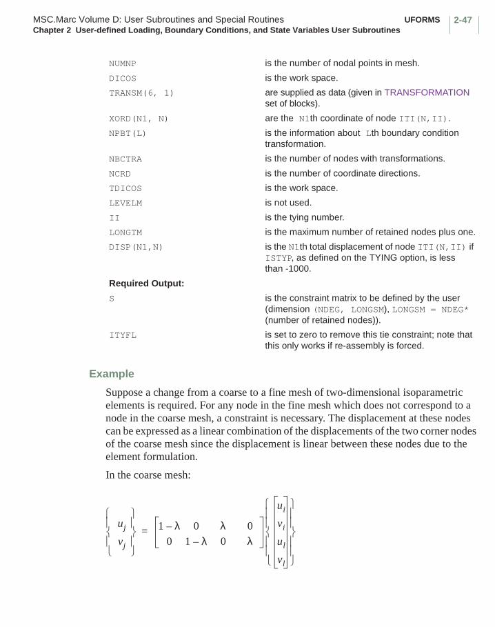
2-47MSC.Marc Volume D: User Subroutines and Special Routines UFORMSChapter 2 User-defined Loading, Boundary Conditions, and State Variables User Subroutines
Example
Suppose a change from a coarse to a fine mesh of two-dimensional isoparametric elements is required. For any node in the fine mesh which does not correspond to a node in the coarse mesh, a constraint is necessary. The displacement at these nodes can be expressed as a linear combination of the displacements of the two corner nodes of the coarse mesh since the displacement is linear between these nodes due to the element formulation.
In the coarse mesh:
NUMNP is the number of nodal points in mesh.
DICOS is the work space.
TRANSM(6, 1) are supplied as data (given in TRANSFORMATION set of blocks).
XORD(N1, N) are the N1th coordinate of node ITI(N,II).
NPBT(L) is the information about Lth boundary condition transformation.
NBCTRA is the number of nodes with transformations.
NCRD is the number of coordinate directions.
TDICOS is the work space.
LEVELM is not used.
II is the tying number.
LONGTM is the maximum number of retained nodes plus one.
DISP(N1,N) is the N1th total displacement of node ITI(N,II) if ISTYP, as defined on the TYING option, is less than -1000.
Required Output:
S is the constraint matrix to be defined by the user (dimension (NDEG, LONGSM), LONGSM = NDEG* (number of retained nodes)).
ITYFL is set to zero to remove this tie constraint; note that this only works if re-assembly is forced.
uj
vj
1 λ– 0 λ 0
0 1 λ– 0 λ
ui
vi
ul
vl
=
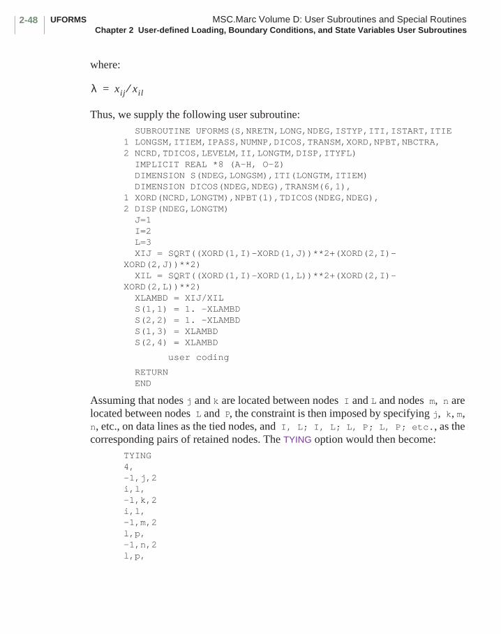
UFORMS MSC.Marc Volume D: User Subroutines and Special RoutinesChapter 2 User-defined Loading, Boundary Conditions, and State Variables User Subroutines
2-48
where:
Thus, we supply the following user subroutine: SUBROUTINE UFORMS(S,NRETN,LONG,NDEG,ISTYP,ITI,ISTART,ITIE1 LONGSM,ITIEM,IPASS,NUMNP,DICOS,TRANSM,XORD,NPBT,NBCTRA,2 NCRD,TDICOS,LEVELM,II,LONGTM,DISP,ITYFL) IMPLICIT REAL *8 (A-H, O-Z) DIMENSION S(NDEG,LONGSM),ITI(LONGTM,ITIEM) DIMENSION DICOS(NDEG,NDEG),TRANSM(6,1),1 XORD(NCRD,LONGTM),NPBT(1),TDICOS(NDEG,NDEG), 2 DISP(NDEG,LONGTM) J=1 I=2 L=3 XIJ = SQRT((XORD(1,I)-XORD(1,J))**2+(XORD(2,I)- XORD(2,J))**2) XIL = SQRT((XORD(1,I)-XORD(1,L))**2+(XORD(2,I)- XORD(2,L))**2) XLAMBD = XIJ/XIL S(1,1) = 1. -XLAMBD S(2,2) = 1. -XLAMBD S(1,3) = XLAMBD S(2,4) = XLAMBD
user coding
RETURN END
Assuming that nodes j and k are located between nodes I and L and nodes m, n are located between nodes L and P, the constraint is then imposed by specifying j, k, m, n, etc., on data lines as the tied nodes, and I, L; I, L; L, P; L, P; etc., as the corresponding pairs of retained nodes. The TYING option would then become:
TYING4,-1,j,2i,l,-1,k,2i,l,-1,m,2l,p,-1,n,2l,p,
λ xij xil⁄=

2-49MSC.Marc Volume D: User Subroutines and Special Routines UFORMSChapter 2 User-defined Loading, Boundary Conditions, and State Variables User Subroutines
Note that this coarse to fine mesh tying constraint is in MSC.Marc as default tying types 31 and 32 for planar elements and as tying type 33 and 34 for three-dimensional brick elements. See MSC.Marc Volume A: User Information for further details.
Figure 2-1 Coarse to Fine Mesh Example
p
n
m
l
k
j
i
xij
xil

CREDE MSC.Marc Volume D: User Subroutines and Special RoutinesChapter 2 User-defined Loading, Boundary Conditions, and State Variables User Subroutines
2-50
■ CREDE
Input of Pre-specified State Variables
Description
The CREDE user subroutine is available to the user for the input of pre-specified state variables. The simplest option allows the specification of temperature increments throughout the mesh. Through the use of the STATE VARS parameter, the number of state variables per point in the structure can be increased. For example, radiation fluxes (in reactor core problems) can be included. MSC.Marc always assumes temperature is the first state variable given at a particular point, since the first state variable is used in conjunction with the tables of temperature dependence input specified in the TEMPERATURE EFFECTS option, and the first state variable is used to compute thermal strains. All state variables are available to all constitutive routines.
THe CREDE user subroutine is called once per element in a loop over the elements when the THERMAL LOADS option is used. Any data blocks required should appear immediately after data block 2 of the THERMAL LOADS option in the input data. If the first field of data block 2 in the THERMAL LOADS option is a 3, total state variable values must be provided at all points of all elements at which constitutive calculations are made. If the first field is a 2, the incremental values are defined. Depending on the inclusion of the CENTROID or ALL POINTS parameters, centroidal values or values at all numerical integration points of an element are expected. For shell elements, the values of state variable increments must be given for each layer through the thickness at every integration point. For beam elements, the values of state variable increments must be given at all points used to define the beam section (16 for default element type 14, 25, 76 or 78; user-defined for element type 13, 77, or 79).
Format
User subroutine CREDE is written with the following headers:SUBROUTINE CREDE (DTDL,M,NSTRES,NEQST,NSTATS)IMPLICIT REAL *8 (A-H, O-Z)DIMENSION DTDL (NSTATS,NEQST,NSTRES)
user coding
RETURNEND

2-51MSC.Marc Volume D: User Subroutines and Special Routines CREDEChapter 2 User-defined Loading, Boundary Conditions, and State Variables User Subroutines
where:
For meshes with several element types, NEQST and NSTRES take on maximum values, but the DTDL array need only be filled as far as necessary for a particular element type.
Example
As an example, suppose a linear gradient through the thickness is to be imposed on a shell with NSTATS = 1. The same gradient is imposed throughout the structure.
The following coding will suffice:SUBROUTINE CREDE (DTDL,M,NSTRES,NEQST,NSTATS)IMPLICIT REAL *8 (A-H, O-Z)DIMENSION DTDL (NSTATS,NEQST,NSTRES)TOUT=500.0
TIN=300.0 T=TIN DT=(TOUT-TIN)/FLOAT(NEQST-1) DO 2 I=1, NEQST DO 1 J=1, NSTRES1 DTDL (1,I,J)=T2 T=T+DT RETURN END
Input:
M is the user element number and must remain unchanged in CREDE. The internal element number is obtained asmint = ielint(m)
NSTRES is the maximum number of integration points per element, if ALL POINTS was included in the parameters, and is 1 if the CENTROID parameter is used.
NEQST is the maximum number of layers per element.
NSTATS is the number of state variables requested by the user in the STATE VARS parameter. (This number equals 1 if only temperature is required).
Required Output:
DTDL is the array of state variable increments or total values (to be defined here by the user).

INITSV MSC.Marc Volume D: User Subroutines and Special RoutinesChapter 2 User-defined Loading, Boundary Conditions, and State Variables User Subroutines
2-52
■ INITSV
Initialize State Variable Values
Description
This user subroutine, allows the user to define initial values of state variables. When not using the table driven input format, it is called in a loop over all the elements in the mesh when the INITIAL STATE option appears in the model definition options with a 2 in the second field of the second data block of that option. When using the table driven input, it is called for those elements specified in the INITIAL STATE model definition option if a 7 is given in the second field of the second data block and the intitial condition is activated by the LOADCASE model definition option.
Format
User subroutine INITSV is written with the following headers:SUBROUTINE INITSV(SV,LAYERS,INTPTS,M,ID)IMPLICIT REAL *8 (A-H, O-Z)DIMENSION SV(LAYERS,INTPTS)
user coding
RETURNEND
where:
Input:
LAYERS is the number of layers through the thickness if this is a shell element, or the number of points in the cross-section if this is a beam element. It is 1 for a continuum element.
INTPTS is the number of integration points in this element if the ALL POINTS parameter is used. If the CENTROID parameter is used, INTPTS = 1.
M is the user element number. The internal element number is obtained asmint = ielint(m)
ID is the state variable number (from columns 1-5 of the second data block of the INITIAL STATE set).
Required Output:
SV is the array of values of this state variable; to be defined here for this element by the user.
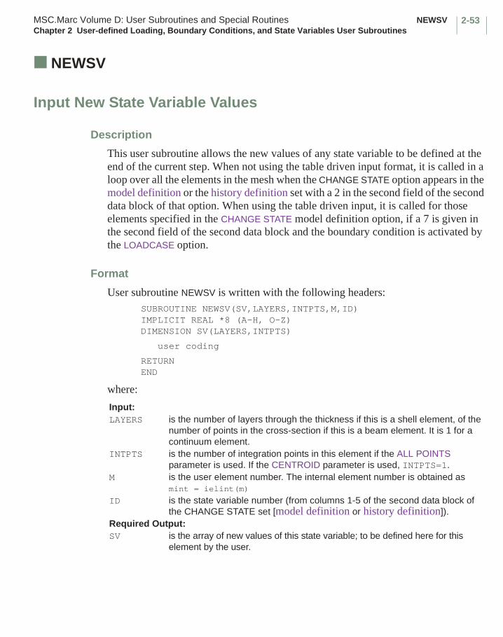
2-53MSC.Marc Volume D: User Subroutines and Special Routines NEWSVChapter 2 User-defined Loading, Boundary Conditions, and State Variables User Subroutines
■ NEWSV
Input New State Variable Values
Description
This user subroutine allows the new values of any state variable to be defined at the end of the current step. When not using the table driven input format, it is called in a loop over all the elements in the mesh when the CHANGE STATE option appears in the model definition or the history definition set with a 2 in the second field of the second data block of that option. When using the table driven input, it is called for those elements specified in the CHANGE STATE model definition option, if a 7 is given in the second field of the second data block and the boundary condition is activated by the LOADCASE option.
Format
User subroutine NEWSV is written with the following headers:SUBROUTINE NEWSV(SV,LAYERS,INTPTS,M,ID)IMPLICIT REAL *8 (A-H, O-Z)DIMENSION SV(LAYERS,INTPTS)
user coding
RETURNEND
where:
Input:LAYERS is the number of layers through the thickness if this is a shell element, of the
number of points in the cross-section if this is a beam element. It is 1 for a continuum element.
INTPTS is the number of integration points in this element if the ALL POINTS parameter is used. If the CENTROID parameter is used, INTPTS=1.
M is the user element number. The internal element number is obtained asmint = ielint(m)
ID is the state variable number (from columns 1-5 of the second data block of the CHANGE STATE set [model definition or history definition]).
Required Output:SV is the array of new values of this state variable; to be defined here for this
element by the user.

NEWSV MSC.Marc Volume D: User Subroutines and Special RoutinesChapter 2 User-defined Loading, Boundary Conditions, and State Variables User Subroutines
2-54
Note: If the user wants to define the state variable values as the function of time, the updated total time is available by adding the include statement in this subroutine. For example:
include ’path/common/creeps’
within ’creeps’:
cptim is the total time at the end of the last step.timinc is the time increment at the current step.
2-55MSC.Marc Volume D: User Subroutines and Special Routines USSDChapter 2 User-defined Loading, Boundary Conditions, and State Variables User Subroutines
■ USSD
Input of Spectral Response Density
Description
The USSD user subroutine allows the user to input the spectral density function for the frequencies required in the spectrum response calculation. These frequencies are obtained by performing a modal analysis.
Format
User subroutine USSD is written with the following headers:SUBROUTINE USSD(SD,OMEG,I)IMPLICIT REAL *8 (A-H, O-Z)
user coding
RETURNEND
where:
Input:
OMEG is the frequency in cycles per time unit.
I is the degree of freedom.
Required Output:
SD is the spectral response density for the Ith degree of freedom to be defined by the user.

USINC MSC.Marc Volume D: User Subroutines and Special RoutinesChapter 2 User-defined Loading, Boundary Conditions, and State Variables User Subroutines
2-56
■ USINC
Input of Initial Conditions
Description
This user subroutine allows the user to input initial displacements, velocities, and accelerations for dynamic stress analysis, initial temperatures for heat transfer analysis or thermal stress analysis, temperature history for thermal stress analysis, or initial pressure. The user must supply the values for all degrees of freedom in vector F. This user subroutine is used with either the INITIAL DISP, INITIAL VEL, INITIAL TEMP, or INIT PRESSURE model definition options, or the POINT TEMP model and history definition options. It is called for every node in the structure if it is used.
Format
User subroutine USINC is written with the following headers:SUBROUTINE USINC(F,N,NDEG,IFLAG)IMPLICIT REAL *8 (A-H, O-Z)DIMENSION F(NDEG)
user coding
RETURNEND
where:
F is the vector of initial conditions or point temperatures to be given by the user.
N is the node number.
NDEG is the number of degrees of freedom per node.
IFLAG is the flag that indicates the type of data that must be supplied.= 1 initial displacement.= 2 initial velocities.= 3 initial temperatures. = 4 initial accelerations.= 5 point temperatures (only for thermal stress analysis).= 7 initial pressure (only for diffusion analysis).

2-57MSC.Marc Volume D: User Subroutines and Special Routines USDATAChapter 2 User-defined Loading, Boundary Conditions, and State Variables User Subroutines
■ USDATA
Input of Initial Data
Description
This user subroutine is a mechanism to allow the user to read data into a user-defined common block. This common block is stored on the restart file, and available in subsequent increments. The common block USDACM must be given the correct length in this user subroutine. This common block can also be used in any other user subroutine.
Format
User subroutine USDATA is written with the following headers:SUBROUTINE USDATA(KIN,KOU,IC)COMMON/USDACM/MYDATAIMPLICIT REAL *8 (A-H, O-Z)
user coding
RETURNEND
where:
Note that the maximum length of USDACM should be defined here. It should agree in length in real *4 words as with that given on the USDATA model definition option.
Input:
KIN is the unit number for input, usually 5.
IC is the reader flag.= 1 pre-reader.= 2 real reader.
Required Output:
KOU is unit number for output, usually 6.
UTIMESTEP MSC.Marc Volume D: User Subroutines and Special RoutinesChapter 2 User-defined Loading, Boundary Conditions, and State Variables User Subroutines
2-58
■ UTIMESTEP
Input of User-defined Time Step
Description
This user subroutine allows the user to specify the time step when the AUTO STEP load stepping scheme is used
Format
User subroutine UTIMESTEP is written with the following headers: SUBROUTINE UTIMESTEP(TIMESTEP,TIMESTEPOLD,ICALL,$ TIME,TIMELOADCASE) IMPLICIT REAL *8 (A-H, O-Z)
user coding
RETURN END
where:
This routine is called right after the time step has (possibly) been updated by the program at different stages in the analysis depending on the value of ICALL. It is allowed, but in general not recommended, to increase the time step during an increment (ICALL=2). Note that only the variable TIMESTEP should be modified in this routine.
Input:
TIMESTEP is the current time step as suggested by the program and which can be modified in this routine.
TIMESTEPOLD is the current time step before it was modified by the program.
ICALL is a flag for when the routine is called.= 1 for setting the initial time step during the reader phase.= 2 if this routine is called during an increment= 3 if this routine is called at the beginning of the increment
TIME time at the start of the current increment
TIMELOADCASE time period of the current load case
Required Output:
TIMESTEP is the current time step as suggested by the program and which can be modified in this routine.
2-59MSC.Marc Volume D: User Subroutines and Special Routines UVELOCChapter 2 User-defined Loading, Boundary Conditions, and State Variables User Subroutines
■ UVELOC
Generation or Modification of Nodal Velocity Vectors
Description
In heat diffusion-convection, it is sometimes necessary to include a position dependent velocity field. The UVELOC user subroutine, which is called for each node, allows the user the specification or redefinition of previously specified nodal velocity vectors. The inclusion of convection is activated on the HEAT parameter. This user subroutine should not be used in a coupled fluid-thermal analysis, as the velocities are calculated by MSC.Marc.
Format
User subroutine UVELOC is written with the following headers:SUBROUTINE UVELOC (VELOC,COORD,NCRD,NODE) IMPLICIT REAL *8 (A-H, O-Z)DIMENSION VELOC (NCRD),COORD(NCRD)
user coding
RETURNEND
where:
Input:
COORD is the array of coordinates at this node.
NCRD is the number of coordinates.
NODE is the node number.
Required Output:
VELOC is the array of nodal velocity components to be defined.

MOTION (2-D) MSC.Marc Volume D: User Subroutines and Special RoutinesChapter 2 User-defined Loading, Boundary Conditions, and State Variables User Subroutines
2-60
■ MOTION (2-D)
Definition of Rigid Surface Motion for 2-D Contact
Description
This user subroutine allows the definition of nonuniform rigid surface motions, in conjunction with the CONTACT option. Its call is triggered by the UMOTION model definition option. This user subroutine should only be used with velocity controlled rigid surfaces.
The MOTION user subroutine is called during the calculations at the beginning of each time increment and the user return the surface velocities for that increment. Imposed displacement increments at nodal points in contact with rigid surfaces are obtained from the velocity multiplied by the time increment. The surface path becomes an explicit forward integration of velocities. Therefore, caution should be taken when there are abrupt changes in surface path direction or abrupt changes in velocity by
CAUTION: Please note that if the coordinates of the center of rotation are defined unconditionally in this routine, they will be set to that same value for all increments of the analysis, causing the rigid surface to rotate around a fixed point in space. On the other hand, if the position of the center of rotation is defined only once in increment 0, as in
if(inc.eq.0) thenx(1)=...etc.
endif
the center of the rotation is updated internally as motion and deformation take place. Obviously, the results will be different for the two cases.
If, at the start of the analysis, a surface is placed apart from the body to be deformed, the MOTION user subroutine is also used in the approaching phase.
If two-dimensional elements are being used, the surfaces have rigid body motions in two dimensions. It is assumed that such motions can be defined by a translation of a point (the center of rotation), plus a rotation around that point.
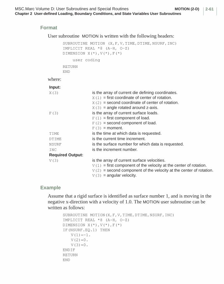
2-61MSC.Marc Volume D: User Subroutines and Special Routines MOTION (2-D)Chapter 2 User-defined Loading, Boundary Conditions, and State Variables User Subroutines
Format
User subroutine MOTION is written with the following headers:SUBROUTINE MOTION (X,F,V,TIME,DTIME,NSURF,INC)IMPLICIT REAL *8 (A-H, O-Z)DIMENSION X(*),V(*),F(*)
user coding
RETURNEND
where:
Example
Assume that a rigid surface is identified as surface number 1, and is moving in the negative x-direction with a velocity of 1.0. The MOTION user subroutine can be written as follows:
SUBROUTINE MOTION(X,F,V,TIME,DTIME,NSURF,INC)IMPLICIT REAL *8 (A-H, O-Z)DIMENSION X(*),V(*),F(*)IF(NSURF.EQ.1) THEN
V(1)=-1.V(2)=0.V(3)=0.
ENDIFRETURNEND
Input:X(3) is the array of current die defining coordinates.
X(1) = first coordinate of center of rotation.X(2) = second coordinate of center of rotation.X(3) = angle rotated around z-axis.
F(3) is the array of current surface loads.F(1) = first component of load.F(2) = second component of load.F(3) = moment.
TIME is the time at which data is requested.DTIME is the current time increment.NSURF is the surface number for which data is requested.INC is the increment number.Required Output:V(3) is the array of current surface velocities.
V(1) = first component of the velocity at the center of rotation.V(2) = second component of the velocity at the center of rotation.V(3) = angular velocity.
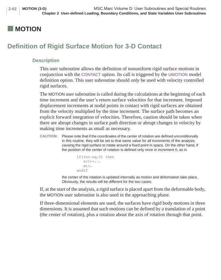
MOTION (3-D) MSC.Marc Volume D: User Subroutines and Special RoutinesChapter 2 User-defined Loading, Boundary Conditions, and State Variables User Subroutines
2-62
■ MOTION (3-D)
Definition of Rigid Surface Motion for 3-D Contact
Description
This user subroutine allows the definition of nonuniform rigid surface motions in conjunction with the CONTACT option. Its call is triggered by the UMOTION model definition option. This user subroutine should only be used with velocity controlled rigid surfaces.
The MOTION user subroutine is called during the calculations at the beginning of each time increment and the user’s return surface velocities for that increment. Imposed displacement increments at nodal points in contact with rigid surfaces are obtained from the velocity multiplied by the time increment. The surface path becomes an explicit forward integration of velocities. Therefore, caution should be taken when there are abrupt changes in surface path direction or abrupt changes in velocity by making time increments as small as necessary.
CAUTION: Please note that if the coordinates of the center of rotation are defined unconditionally in this routine, they will be set to that same value for all increments of the analysis, causing the rigid surface to rotate around a fixed point in space. On the other hand, if the position of the center of rotation is defined only once in increment 0, as in
if(inc.eq.0) thenx(1)=...etc.
endif
the center of the rotation is updated internally as motion and deformation take place. Obviously, the results will be different for the two cases.
If, at the start of the analysis, a rigid surface is placed apart from the deformable body, the MOTION user subroutine is also used in the approaching phase.
If three-dimensional elements are used, the surfaces have rigid body motions in three dimensions. It is assumed that such motions can be defined by a translation of a point (the center of rotation), plus a rotation about the axis of rotation through that point.
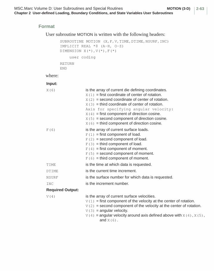
2-63MSC.Marc Volume D: User Subroutines and Special Routines MOTION (3-D)Chapter 2 User-defined Loading, Boundary Conditions, and State Variables User Subroutines
Format
User subroutine MOTION is written with the following headers:SUBROUTINE MOTION (X,F,V,TIME,DTIME,NSURF,INC)IMPLICIT REAL *8 (A-H, O-Z)DIMENSION X(*),V(*),F(*)
user coding
RETURNEND
where:
Input:
X(6) is the array of current die defining coordinates.X(1) = first coordinate of center of rotation.X(2) = second coordinate of center of rotation.X(3) = third coordinate of center of rotation.Axis for specifying angular velocity:X(4) = first component of direction cosine.X(5) = second component of direction cosine.X(6) = third component of direction cosine.
F(6) is the array of current surface loads.F(1) = first component of load.F(2) = second component of load.F(3) = third component of load.F(4) = first component of moment.F(5) = second component of moment.F(6) = third component of moment.
TIME is the time at which data is requested.
DTIME is the current time increment.
NSURF is the surface number for which data is requested.
INC is the increment number.
Required Output:
V(4) is the array of current surface velocities.V(1) = first component of the velocity at the center of rotation.V(2) = second component of the velocity at the center of rotation.V(3) = angular velocity.V(4) = angular velocity around axis defined above with X(4), X(5),
and X(6).
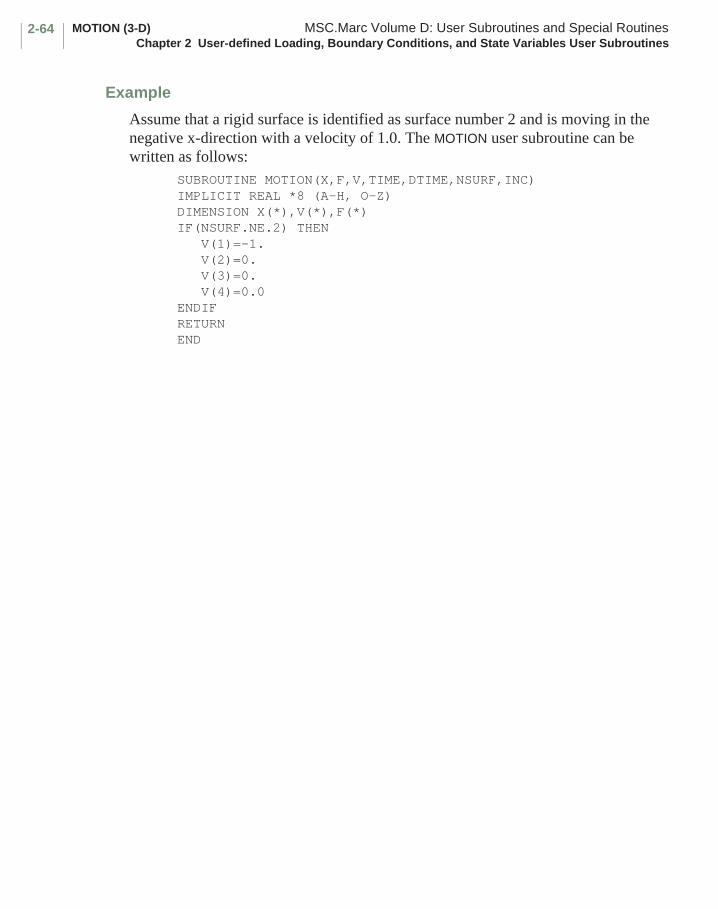
MOTION (3-D) MSC.Marc Volume D: User Subroutines and Special RoutinesChapter 2 User-defined Loading, Boundary Conditions, and State Variables User Subroutines
2-64
Example
Assume that a rigid surface is identified as surface number 2 and is moving in the negative x-direction with a velocity of 1.0. The MOTION user subroutine can be written as follows:
SUBROUTINE MOTION(X,F,V,TIME,DTIME,NSURF,INC)IMPLICIT REAL *8 (A-H, O-Z)DIMENSION X(*),V(*),F(*)IF(NSURF.NE.2) THEN
V(1)=-1.V(2)=0.V(3)=0.V(4)=0.0
ENDIFRETURNEND
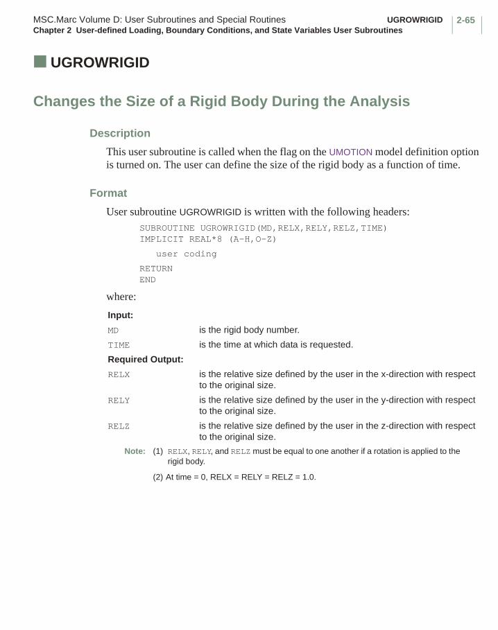
2-65MSC.Marc Volume D: User Subroutines and Special Routines UGROWRIGIDChapter 2 User-defined Loading, Boundary Conditions, and State Variables User Subroutines
■ UGROWRIGID
Changes the Size of a Rigid Body During the Analysis
Description
This user subroutine is called when the flag on the UMOTION model definition option is turned on. The user can define the size of the rigid body as a function of time.
Format
User subroutine UGROWRIGID is written with the following headers:SUBROUTINE UGROWRIGID(MD,RELX,RELY,RELZ,TIME)IMPLICIT REAL*8 (A-H,O-Z)
user coding
RETURNEND
where:
Input:
MD is the rigid body number.
TIME is the time at which data is requested.
Required Output:
RELX is the relative size defined by the user in the x-direction with respect to the original size.
RELY is the relative size defined by the user in the y-direction with respect to the original size.
RELZ is the relative size defined by the user in the z-direction with respect to the original size.
Note: (1) RELX, RELY, and RELZ must be equal to one another if a rotation is applied to the rigid body.
(2) At time = 0, RELX = RELY = RELZ = 1.0.
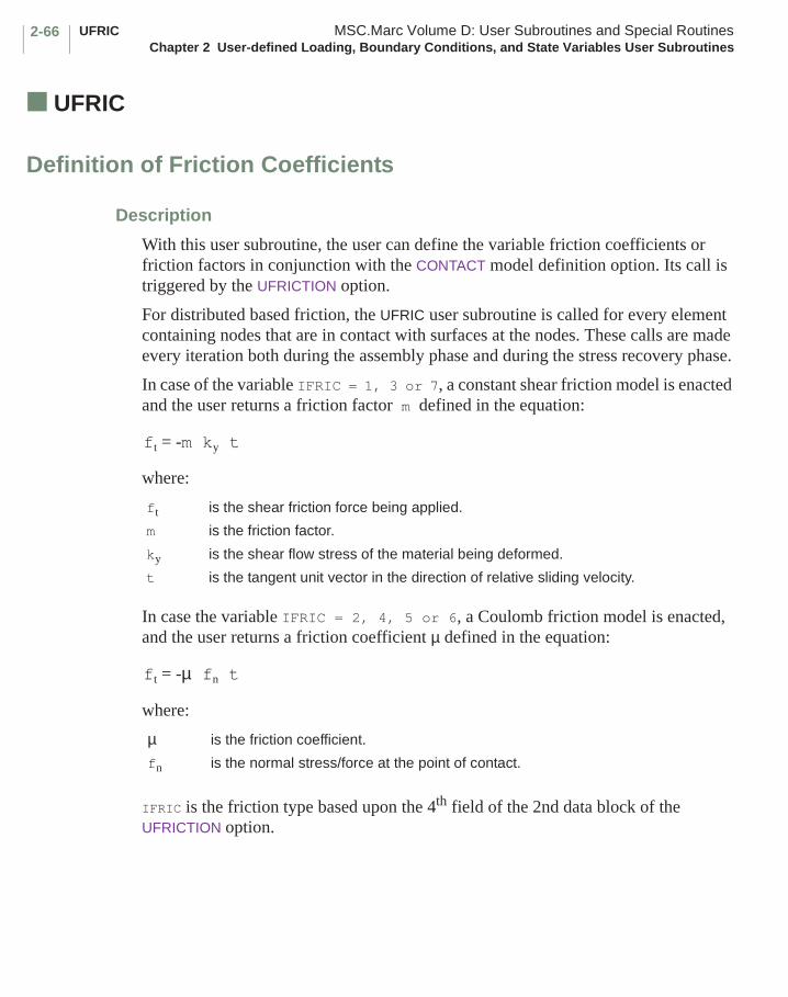
UFRIC MSC.Marc Volume D: User Subroutines and Special RoutinesChapter 2 User-defined Loading, Boundary Conditions, and State Variables User Subroutines
2-66
■ UFRIC
Definition of Friction Coefficients
Description
With this user subroutine, the user can define the variable friction coefficients or friction factors in conjunction with the CONTACT model definition option. Its call is triggered by the UFRICTION option.
For distributed based friction, the UFRIC user subroutine is called for every element containing nodes that are in contact with surfaces at the nodes. These calls are made every iteration both during the assembly phase and during the stress recovery phase.
In case of the variable IFRIC = 1, 3 or 7, a constant shear friction model is enacted and the user returns a friction factor m defined in the equation:
where:
In case the variable IFRIC = 2, 4, 5 or 6, a Coulomb friction model is enacted, and the user returns a friction coefficient µ defined in the equation:
where:
IFRIC is the friction type based upon the 4th field of the 2nd data block of the UFRICTION option.
ft is the shear friction force being applied.
m is the friction factor.
ky is the shear flow stress of the material being deformed.
t is the tangent unit vector in the direction of relative sliding velocity.
µ is the friction coefficient.
fn is the normal stress/force at the point of contact.
ft = -m ky t
ft = -µ fn t
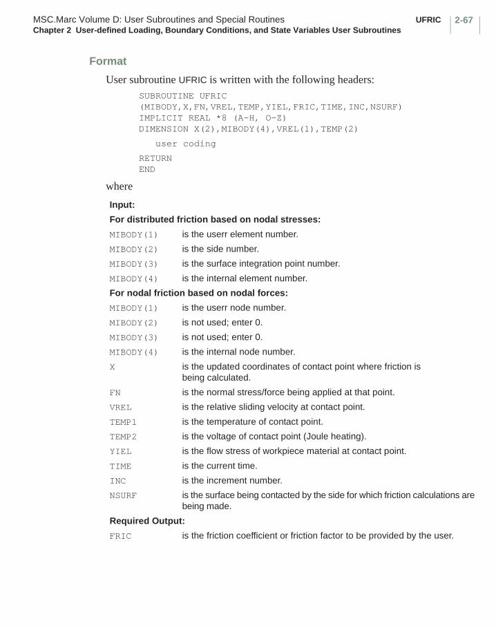
2-67MSC.Marc Volume D: User Subroutines and Special Routines UFRICChapter 2 User-defined Loading, Boundary Conditions, and State Variables User Subroutines
Format
User subroutine UFRIC is written with the following headers:SUBROUTINE UFRIC (MIBODY,X,FN,VREL,TEMP,YIEL,FRIC,TIME,INC,NSURF)IMPLICIT REAL *8 (A-H, O-Z)DIMENSION X(2),MIBODY(4),VREL(1),TEMP(2)
user coding
RETURNEND
where
Input:
For distributed friction based on nodal stresses:
MIBODY(1) is the userr element number.
MIBODY(2) is the side number.
MIBODY(3) is the surface integration point number.
MIBODY(4) is the internal element number.
For nodal friction based on nodal forces:
MIBODY(1) is the userr node number.
MIBODY(2) is not used; enter 0.
MIBODY(3) is not used; enter 0.
MIBODY(4) is the internal node number.
X is the updated coordinates of contact point where friction is being calculated.
FN is the normal stress/force being applied at that point.
VREL is the relative sliding velocity at contact point.
TEMP1 is the temperature of contact point.
TEMP2 is the voltage of contact point (Joule heating).
YIEL is the flow stress of workpiece material at contact point.
TIME is the current time.
INC is the increment number.
NSURF is the surface being contacted by the side for which friction calculations are being made.
Required Output:
FRIC is the friction coefficient or friction factor to be provided by the user.

UFRICBBC MSC.Marc Volume D: User Subroutines and Special RoutinesChapter 2 User-defined Loading, Boundary Conditions, and State Variables User Subroutines
2-68
■ UFRICBBC
Definition of Friction Coefficients for Beam-to-Beam Contact
Description
This user subroutine allows the user to define variable friction coefficients for beam-to-beam contact, similar to the UFRIC user subroutine. Like the UFRIC user subroutine, UFRICBBC is used in conjunction with the CONTACT model definition option and its call is triggered by the UFRICTION model definition option . Unlike the UFRIC user subroutine, however, UFRICBBC is called for every beam or truss element that is in contact with another beam or truss element. These calls are made every iteration both during the assembly phase and during the stress recovery phase. If beam elements contact with other beam elements and some of the nodes of these beam elements contact with rigid surfaces or with the faces of continuum or shell elements, the UFRIC user subroutine is called for every node in contact and the UFRICBBC user subroutine is called for every beam element in contact.
Since only the Coulomb friction model is supported by the beam-to-beam contact option, the subroutine must return the friction coefficient defined by the equation:
where:
Also See
The UFRIC user subroutine.
ft is the friction force at the contact point on the touching element.
µ is the friction coefficient.
fn is the normal force at the contact point on the touching element.
t is -v/|v|, where v is the relative velocity of the contact point on the touching element with respect to the contact point on the touched element.
µ
ft = -µ fn t
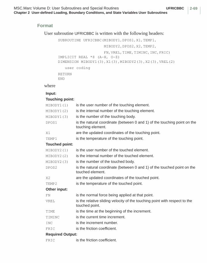
2-69MSC.Marc Volume D: User Subroutines and Special Routines UFRICBBCChapter 2 User-defined Loading, Boundary Conditions, and State Variables User Subroutines
Format
User subroutine UFRICBBC is written with the following headers:SUBROUTINE UFRICBBC(MIBODY1,DPOS1,X1,TEMP1,
MIBODY2,DPOS2,X2,TEMP2,
FN,VREL,TIME,TIMINC,INC,FRIC)IMPLICIT REAL *8 (A-H, O-Z)DIMENSION MIBODY1(3),X1(3),MIBODY2(3),X2(3),VREL(2)
user coding
RETURNEND
where
Input:
Touching point:
MIBODY1(1) is the user number of the touching element.
MIBODY1(2) is the internal number of the touching element.
MIBODY1(3) is the number of the touching body.
DPOS1 is the natural coordinate (between 0 and 1) of the touching point on the touching element.
X1 are the updated coordinates of the touching point.
TEMP1 is the temperature of the touching point.
Touched point:
MIBODY2(1) is the user number of the touched element.
MIBODY2(2) is the internal number of the touched element.
MIBODY2(3) is the number of the touched body.
DPOS2 is the natural coordinate (between 0 and 1) of the touched point on the touched element.
X2 are the updated coordinates of the touched point.
TEMP2 is the temperature of the touched point.
Other input:
FN is the normal force being applied at that point.
VREL is the relative sliding velocity of the touching point with respect to the touched point.
TIME is the time at the beginning of the increment.
TIMINC is the current time increment.
INC is the increment number.
FRIC is the friction coefficient.
Required Output:
FRIC is the friction coefficient.
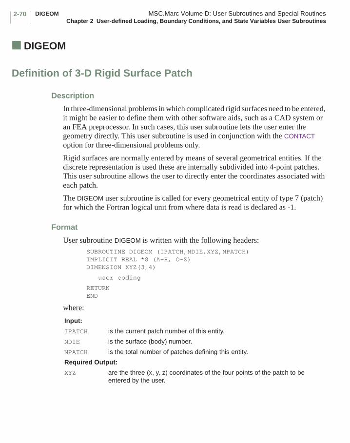
DIGEOM MSC.Marc Volume D: User Subroutines and Special RoutinesChapter 2 User-defined Loading, Boundary Conditions, and State Variables User Subroutines
2-70
■ DIGEOM
Definition of 3-D Rigid Surface Patch
Description
In three-dimensional problems in which complicated rigid surfaces need to be entered, it might be easier to define them with other software aids, such as a CAD system or an FEA preprocessor. In such cases, this user subroutine lets the user enter the geometry directly. This user subroutine is used in conjunction with the CONTACT option for three-dimensional problems only.
Rigid surfaces are normally entered by means of several geometrical entities. If the discrete representation is used these are internally subdivided into 4-point patches. This user subroutine allows the user to directly enter the coordinates associated with each patch.
The DIGEOM user subroutine is called for every geometrical entity of type 7 (patch) for which the Fortran logical unit from where data is read is declared as -1.
Format
User subroutine DIGEOM is written with the following headers:SUBROUTINE DIGEOM (IPATCH,NDIE,XYZ,NPATCH)IMPLICIT REAL *8 (A-H, O-Z)DIMENSION XYZ(3,4)
user coding
RETURNEND
where:
Input:
IPATCH is the current patch number of this entity.
NDIE is the surface (body) number.
NPATCH is the total number of patches defining this entity.
Required Output:
XYZ are the three (x, y, z) coordinates of the four points of the patch to be entered by the user.
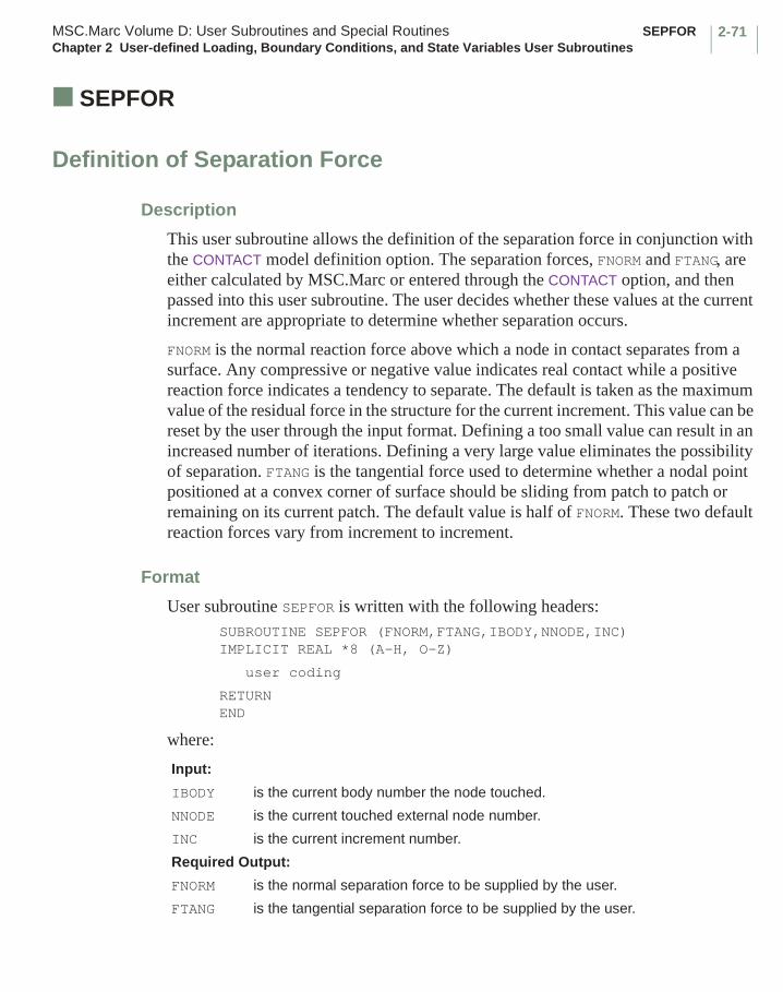
2-71MSC.Marc Volume D: User Subroutines and Special Routines SEPFORChapter 2 User-defined Loading, Boundary Conditions, and State Variables User Subroutines
■ SEPFOR
Definition of Separation Force
Description
This user subroutine allows the definition of the separation force in conjunction with the CONTACT model definition option. The separation forces, FNORM and FTANG, are either calculated by MSC.Marc or entered through the CONTACT option, and then passed into this user subroutine. The user decides whether these values at the current increment are appropriate to determine whether separation occurs.
FNORM is the normal reaction force above which a node in contact separates from a surface. Any compressive or negative value indicates real contact while a positive reaction force indicates a tendency to separate. The default is taken as the maximum value of the residual force in the structure for the current increment. This value can be reset by the user through the input format. Defining a too small value can result in an increased number of iterations. Defining a very large value eliminates the possibility of separation. FTANG is the tangential force used to determine whether a nodal point positioned at a convex corner of surface should be sliding from patch to patch or remaining on its current patch. The default value is half of FNORM. These two default reaction forces vary from increment to increment.
Format
User subroutine SEPFOR is written with the following headers:SUBROUTINE SEPFOR (FNORM,FTANG,IBODY,NNODE,INC)IMPLICIT REAL *8 (A-H, O-Z)
user coding
RETURNEND
where:
Input:
IBODY is the current body number the node touched.
NNODE is the current touched external node number.
INC is the current increment number.
Required Output:
FNORM is the normal separation force to be supplied by the user.
FTANG is the tangential separation force to be supplied by the user.
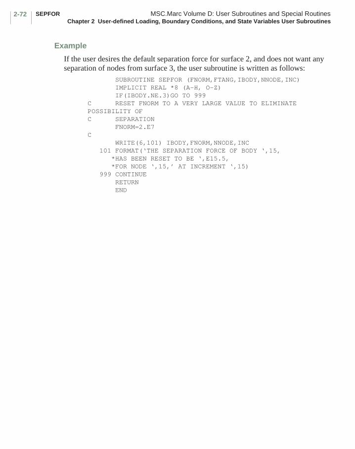
SEPFOR MSC.Marc Volume D: User Subroutines and Special RoutinesChapter 2 User-defined Loading, Boundary Conditions, and State Variables User Subroutines
2-72
Example
If the user desires the default separation force for surface 2, and does not want any separation of nodes from surface 3, the user subroutine is written as follows:
SUBROUTINE SEPFOR (FNORM,FTANG,IBODY,NNODE,INC) IMPLICIT REAL *8 (A-H, O-Z) IF(IBODY.NE.3)GO TO 999 C RESET FNORM TO A VERY LARGE VALUE TO ELIMINATE POSSIBILITY OFC SEPARATION
FNORM=2.E7C WRITE(6,101) IBODY,FNORM,NNODE,INC 101 FORMAT(‘THE SEPARATION FORCE OF BODY ‘,15, *HAS BEEN RESET TO BE ‘,E15.5, *FOR NODE ‘,15,’ AT INCREMENT ‘,15) 999 CONTINUE RETURN END
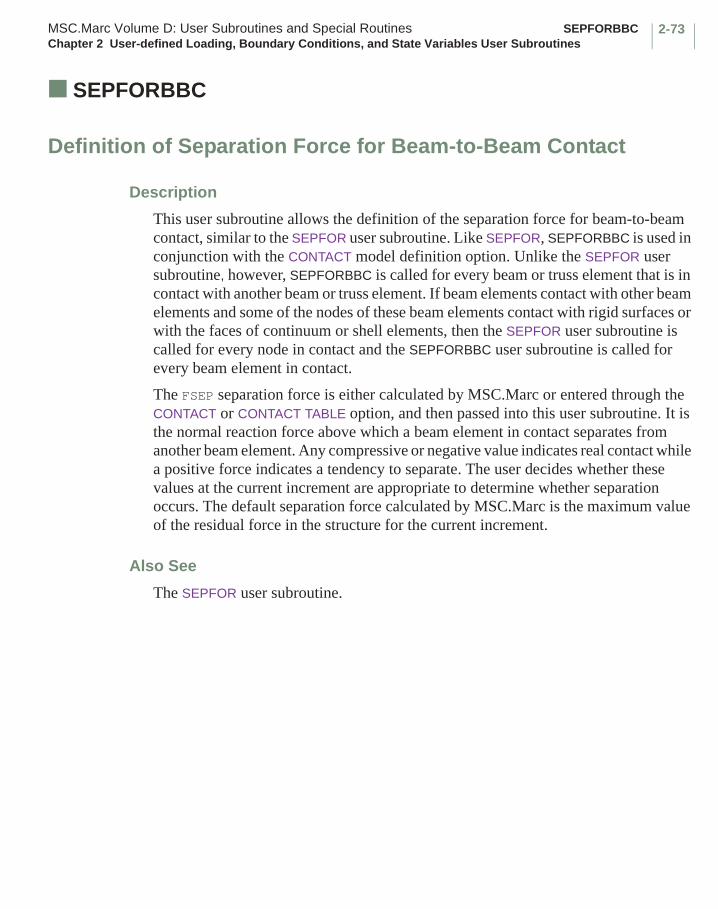
2-73MSC.Marc Volume D: User Subroutines and Special Routines SEPFORBBCChapter 2 User-defined Loading, Boundary Conditions, and State Variables User Subroutines
■ SEPFORBBC
Definition of Separation Force for Beam-to-Beam Contact
Description
This user subroutine allows the definition of the separation force for beam-to-beam contact, similar to the SEPFOR user subroutine. Like SEPFOR, SEPFORBBC is used in conjunction with the CONTACT model definition option. Unlike the SEPFOR user subroutine, however, SEPFORBBC is called for every beam or truss element that is in contact with another beam or truss element. If beam elements contact with other beam elements and some of the nodes of these beam elements contact with rigid surfaces or with the faces of continuum or shell elements, then the SEPFOR user subroutine is called for every node in contact and the SEPFORBBC user subroutine is called for every beam element in contact.
The FSEP separation force is either calculated by MSC.Marc or entered through the CONTACT or CONTACT TABLE option, and then passed into this user subroutine. It is the normal reaction force above which a beam element in contact separates from another beam element. Any compressive or negative value indicates real contact while a positive force indicates a tendency to separate. The user decides whether these values at the current increment are appropriate to determine whether separation occurs. The default separation force calculated by MSC.Marc is the maximum value of the residual force in the structure for the current increment.
Also See
The SEPFOR user subroutine.
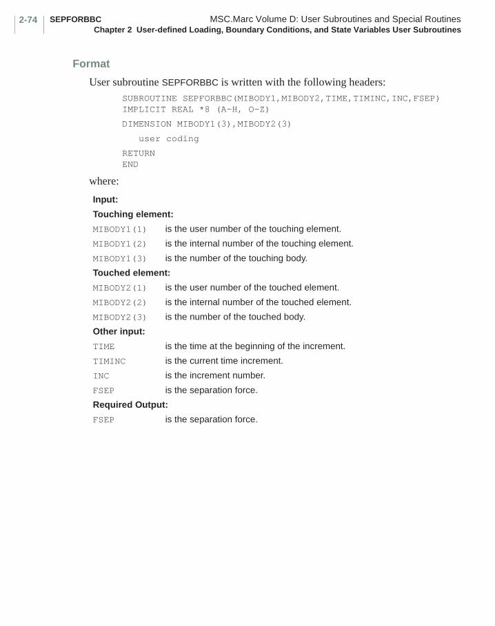
SEPFORBBC MSC.Marc Volume D: User Subroutines and Special RoutinesChapter 2 User-defined Loading, Boundary Conditions, and State Variables User Subroutines
2-74
Format
User subroutine SEPFORBBC is written with the following headers:SUBROUTINE SEPFORBBC(MIBODY1,MIBODY2,TIME,TIMINC,INC,FSEP)IMPLICIT REAL *8 (A-H, O-Z)
DIMENSION MIBODY1(3),MIBODY2(3)
user coding
RETURNEND
where:
Input:
Touching element:
MIBODY1(1) is the user number of the touching element.
MIBODY1(2) is the internal number of the touching element.
MIBODY1(3) is the number of the touching body.
Touched element:
MIBODY2(1) is the user number of the touched element.
MIBODY2(2) is the internal number of the touched element.
MIBODY2(3) is the number of the touched body.
Other input:
TIME is the time at the beginning of the increment.
TIMINC is the current time increment.
INC is the increment number.
FSEP is the separation force.
Required Output:
FSEP is the separation force.
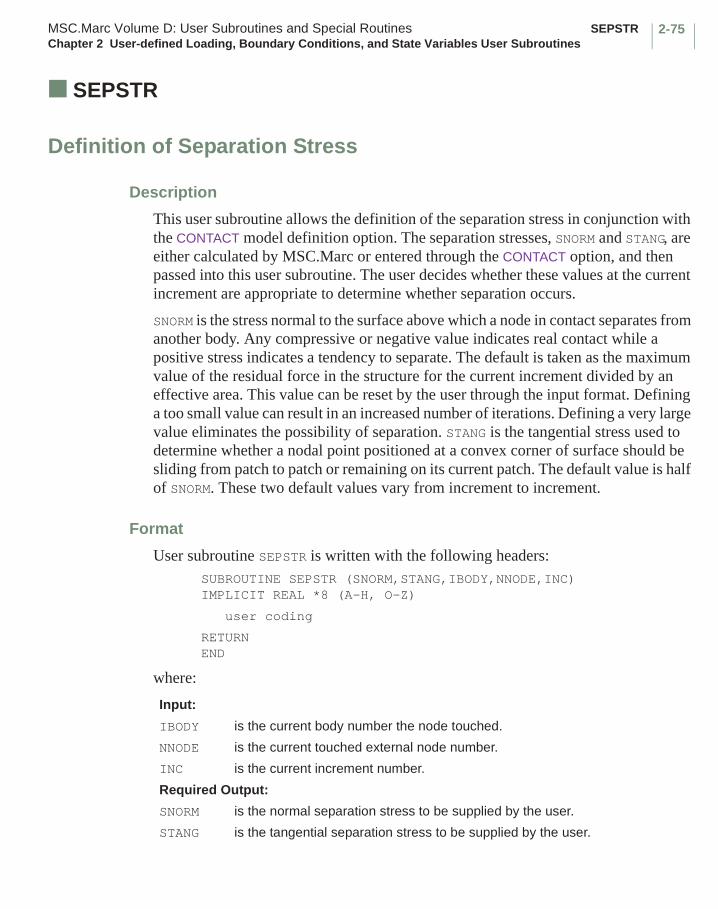
2-75MSC.Marc Volume D: User Subroutines and Special Routines SEPSTRChapter 2 User-defined Loading, Boundary Conditions, and State Variables User Subroutines
■ SEPSTR
Definition of Separation Stress
Description
This user subroutine allows the definition of the separation stress in conjunction with the CONTACT model definition option. The separation stresses, SNORM and STANG, are either calculated by MSC.Marc or entered through the CONTACT option, and then passed into this user subroutine. The user decides whether these values at the current increment are appropriate to determine whether separation occurs.
SNORM is the stress normal to the surface above which a node in contact separates from another body. Any compressive or negative value indicates real contact while a positive stress indicates a tendency to separate. The default is taken as the maximum value of the residual force in the structure for the current increment divided by an effective area. This value can be reset by the user through the input format. Defining a too small value can result in an increased number of iterations. Defining a very large value eliminates the possibility of separation. STANG is the tangential stress used to determine whether a nodal point positioned at a convex corner of surface should be sliding from patch to patch or remaining on its current patch. The default value is half of SNORM. These two default values vary from increment to increment.
Format
User subroutine SEPSTR is written with the following headers:SUBROUTINE SEPSTR (SNORM,STANG,IBODY,NNODE,INC)IMPLICIT REAL *8 (A-H, O-Z)
user coding
RETURNEND
where:
Input:
IBODY is the current body number the node touched.
NNODE is the current touched external node number.
INC is the current increment number.
Required Output:
SNORM is the normal separation stress to be supplied by the user.
STANG is the tangential separation stress to be supplied by the user.
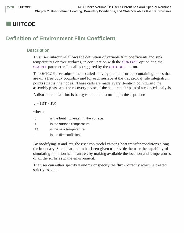
UHTCOE MSC.Marc Volume D: User Subroutines and Special RoutinesChapter 2 User-defined Loading, Boundary Conditions, and State Variables User Subroutines
2-76
■ UHTCOE
Definition of Environment Film Coefficient
Description
This user subroutine allows the definition of variable film coefficients and sink temperatures on free surfaces, in conjunction with the CONTACT option and the COUPLE parameter. Its call is triggered by the UHTCOEF option.
The UHTCOE user subroutine is called at every element surface containing nodes that are on a free body boundary and for each surface at the trapezoidal rule integration points (that is, the nodes). These calls are made every iteration both during the assembly phase and the recovery phase of the heat transfer pass of a coupled analysis.
A distributed heat flux is being calculated according to the equation:
where:
By modifying H and TS, the user can model varying heat transfer conditions along the boundary. Special attention has been given to provide the user the capability of simulating radiation heat transfer, by making available the location and temperatures of all the surfaces in the environment.
The user can either specify H and TS or specify the flux q directly which is treated strictly as such.
q is the heat flux entering the surface.
T is the surface temperature.
TS is the sink temperature.
H is the film coefficient.
q = H(T - TS)

2-77MSC.Marc Volume D: User Subroutines and Special Routines UHTCOEChapter 2 User-defined Loading, Boundary Conditions, and State Variables User Subroutines
Format
User subroutine UHTCOE is written with the following headers:SUBROUTINE UHTCOE(MIBODY,XP,TEMP,IBODY,ICONNO,XORD,XT,DXT,
+ TMPALL,TMPALO,TOTINC,TIMINC,INC,NCRD,+ NDEGS,NDEGH,NCRDMX,NDEGMX,NBCD,NBCN,TSINK,+ HTCOEF,IFLAG) IMPLICIT REAL *8(A-H,O-Z) DIMENSION MIBODY(*),XP(*),ICONNO(*),XORD(*),XT(*),DXT(*),+ TEMP(*),TMPALL(*),NBCD(*),,TSINK(*),TMPALO(*)
user coding
RETURN END
where:
Input
MIBODY(1) is the element number where the surface flux is being calculated.
MIBODY(2) is the side of the element.
MIBODY(3) is the integration point of said side.
MIBODY(4) is the internal element number.
XP(NCRD) are the coordinates of point where calculation is being made; it is updated to end of increment.
TEMP(2) is the current temperature of said point.
TEMP(4) is the current voltage of said point.
TEMP(5) is the pressure of said point.
IBODY is the flexible surface to which point belongs.
ICONNO(*) are the nodal points that make up the boundary of the deformable surfaces declared in the CONTACT option.
NBCN is the upper bound to the number of nodes on a flexible surface boundary.
NBCD(*) is the array of actual number of boundary nodes on flexible surfaces.
XORD(*) is the array of original nodal point coordinates.
XT(*) is the array of nodal point displacements.
DXT(*) is the array of nodal displacement increments.
TMPALL(*) is the array of nodal temperatures (current estimate at end of increment).
TMPALO(*) is the array of nodal temperatures (at beginning of increment).
TOTINC is the current accumulated time.
TIMINC is the time increment.
INC is the increment number.
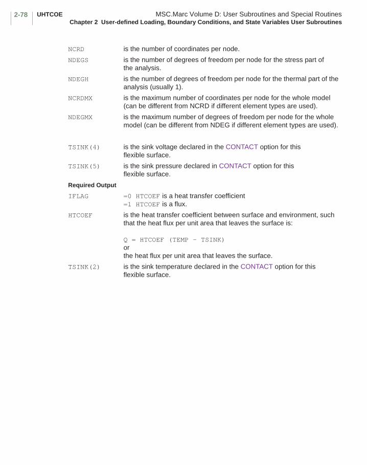
UHTCOE MSC.Marc Volume D: User Subroutines and Special RoutinesChapter 2 User-defined Loading, Boundary Conditions, and State Variables User Subroutines
2-78
NCRD is the number of coordinates per node.
NDEGS is the number of degrees of freedom per node for the stress part of the analysis.
NDEGH is the number of degrees of freedom per node for the thermal part of the analysis (usually 1).
NCRDMX is the maximum number of coordinates per node for the whole model (can be different from NCRD if different element types are used).
NDEGMX is the maximum number of degrees of freedom per node for the whole model (can be different from NDEG if different element types are used).
TSINK(4) is the sink voltage declared in the CONTACT option for this flexible surface.
TSINK(5) is the sink pressure declared in CONTACT option for this flexible surface.
Required Output
IFLAG =0 HTCOEF is a heat transfer coefficient =1 HTCOEF is a flux.
HTCOEF is the heat transfer coefficient between surface and environment, such that the heat flux per unit area that leaves the surface is:
Q = HTCOEF (TEMP - TSINK)orthe heat flux per unit area that leaves the surface.
TSINK(2) is the sink temperature declared in the CONTACT option for this flexible surface.
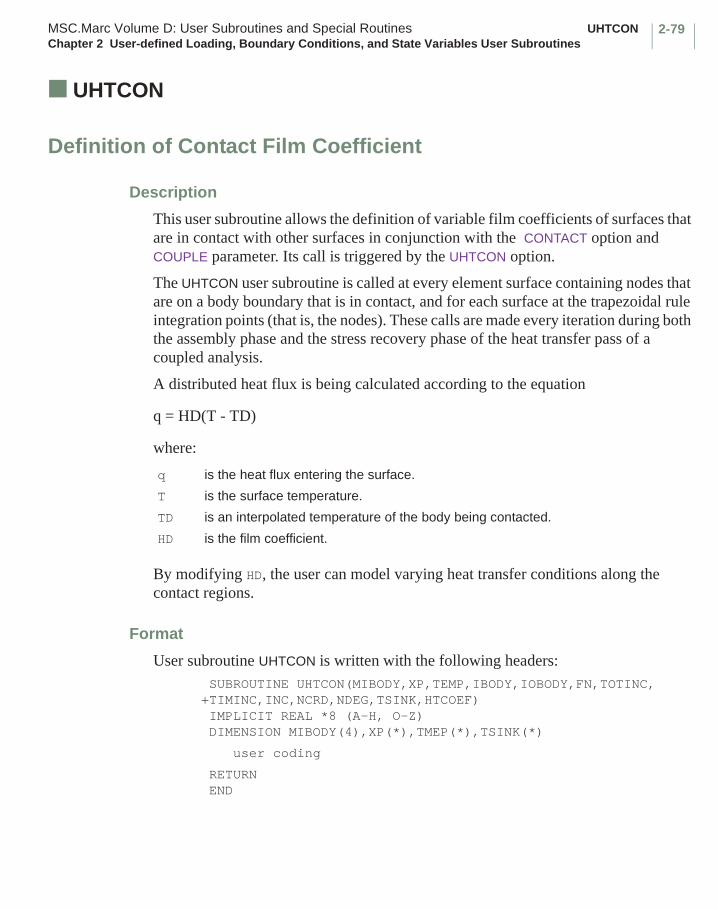
2-79MSC.Marc Volume D: User Subroutines and Special Routines UHTCONChapter 2 User-defined Loading, Boundary Conditions, and State Variables User Subroutines
■ UHTCON
Definition of Contact Film Coefficient
Description
This user subroutine allows the definition of variable film coefficients of surfaces that are in contact with other surfaces in conjunction with the CONTACT option and COUPLE parameter. Its call is triggered by the UHTCON option.
The UHTCON user subroutine is called at every element surface containing nodes that are on a body boundary that is in contact, and for each surface at the trapezoidal rule integration points (that is, the nodes). These calls are made every iteration during both the assembly phase and the stress recovery phase of the heat transfer pass of a coupled analysis.
A distributed heat flux is being calculated according to the equation
q = HD(T - TD)
where:
By modifying HD, the user can model varying heat transfer conditions along the contact regions.
Format
User subroutine UHTCON is written with the following headers: SUBROUTINE UHTCON(MIBODY,XP,TEMP,IBODY,IOBODY,FN,TOTINC,+TIMINC,INC,NCRD,NDEG,TSINK,HTCOEF) IMPLICIT REAL *8 (A-H, O-Z) DIMENSION MIBODY(4),XP(*),TMEP(*),TSINK(*)
user coding
RETURN END
q is the heat flux entering the surface.
T is the surface temperature.
TD is an interpolated temperature of the body being contacted.
HD is the film coefficient.
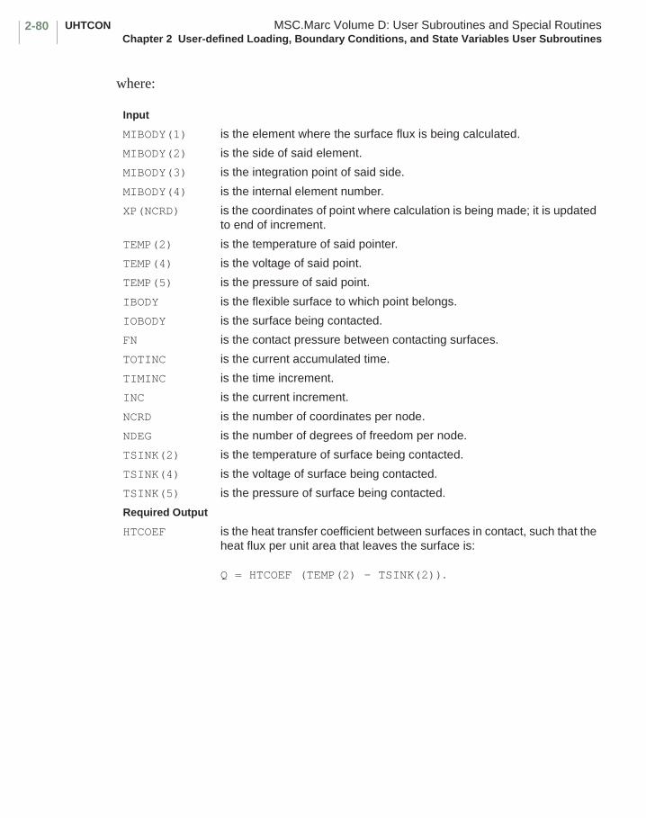
UHTCON MSC.Marc Volume D: User Subroutines and Special RoutinesChapter 2 User-defined Loading, Boundary Conditions, and State Variables User Subroutines
2-80
where:
Input
MIBODY(1) is the element where the surface flux is being calculated.
MIBODY(2) is the side of said element.
MIBODY(3) is the integration point of said side.
MIBODY(4) is the internal element number.
XP(NCRD) is the coordinates of point where calculation is being made; it is updated to end of increment.
TEMP(2) is the temperature of said pointer.
TEMP(4) is the voltage of said point.
TEMP(5) is the pressure of said point.
IBODY is the flexible surface to which point belongs.
IOBODY is the surface being contacted.
FN is the contact pressure between contacting surfaces.
TOTINC is the current accumulated time.
TIMINC is the time increment.
INC is the current increment.
NCRD is the number of coordinates per node.
NDEG is the number of degrees of freedom per node.
TSINK(2) is the temperature of surface being contacted.
TSINK(4) is the voltage of surface being contacted.
TSINK(5) is the pressure of surface being contacted.
Required Output
HTCOEF is the heat transfer coefficient between surfaces in contact, such that the heat flux per unit area that leaves the surface is:
Q = HTCOEF (TEMP(2) - TSINK(2)).
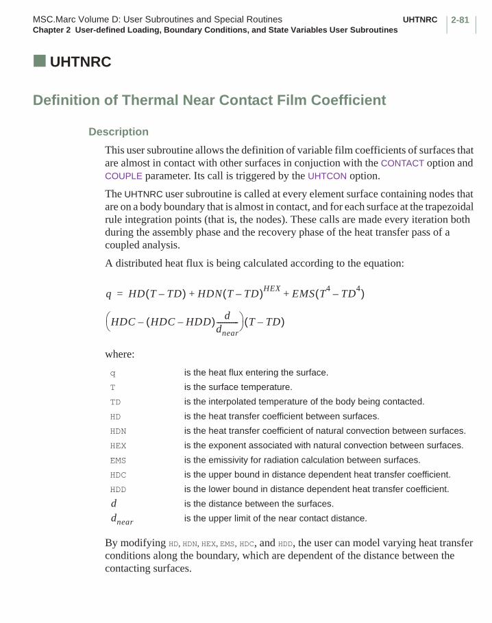
2-81MSC.Marc Volume D: User Subroutines and Special Routines UHTNRCChapter 2 User-defined Loading, Boundary Conditions, and State Variables User Subroutines
■ UHTNRC
Definition of Thermal Near Contact Film Coefficient
Description
This user subroutine allows the definition of variable film coefficients of surfaces that are almost in contact with other surfaces in conjuction with the CONTACT option and COUPLE parameter. Its call is triggered by the UHTCON option.
The UHTNRC user subroutine is called at every element surface containing nodes that are on a body boundary that is almost in contact, and for each surface at the trapezoidal rule integration points (that is, the nodes). These calls are made every iteration both during the assembly phase and the recovery phase of the heat transfer pass of a coupled analysis.
A distributed heat flux is being calculated according to the equation:
where:
By modifying HD, HDN, HEX, EMS, HDC, and HDD, the user can model varying heat transfer conditions along the boundary, which are dependent of the distance between the contacting surfaces.
q is the heat flux entering the surface.
T is the surface temperature.
TD is the interpolated temperature of the body being contacted.
HD is the heat transfer coefficient between surfaces.
HDN is the heat transfer coefficient of natural convection between surfaces.
HEX is the exponent associated with natural convection between surfaces.
EMS is the emissivity for radiation calculation between surfaces.
HDC is the upper bound in distance dependent heat transfer coefficient.
HDD is the lower bound in distance dependent heat transfer coefficient.
is the distance between the surfaces.
is the upper limit of the near contact distance.
q HD T TD–( ) HDN T TD–( )HEXEMS T
4TD
4–( )
HDC HDC HDD–( ) ddnear------------–
T TD–( )
+ +=
ddnear
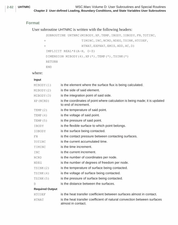
UHTNRC MSC.Marc Volume D: User Subroutines and Special RoutinesChapter 2 User-defined Loading, Boundary Conditions, and State Variables User Subroutines
2-82
Format
User subroutine UHTNRC is written with the following headers: SUBROUTINE UHTNRC(MIBODY,XP,TEMP,IBODY,IOBODY,FN,TOTINC,
+ TIMINC,INC,NCRD,NDEG,TSINK,HTCOEF,
+ HTNAT,EXPNAT,EMIS,HDD,HC,D)
IMPLICIT REAL*8(A-H, O-Z)
DIMENSION MIBODY(4),XP(*),TEMP(*),TSINK(*)
RETURN
END
where:
Input
MIBODY(1) is the element where the surface flux is being calculated.
MIBODY(2) is the side of said element.
MIBODY(3) is the integration point of said side.
XP(NCRD) is the coordinates of point where calculation is being made; it is updated to end of increment.
TEMP(2) is the temperature of said point.
TEMP(4) is the voltage of said point.
TEMP(5) is the pressure of said point.
IBODY is the flexible surface to which point belongs.
IOBODY is the surface being contacted.
FN is the contact pressure between contacting surfaces.
TOTINC is the current accumulated time.
TIMINC is the time increment.
INC is the current increment.
NCRD is the number of coordinates per node.
NDEG is the number of degrees of freedom per node.
TSINK(2) is the temperature of surface being contacted.
TSINK(4) is the voltage of surface being contacted.
TSINK(5) is the pressure of surface being contacted.
D is the distance between the surfaces.
Required Output
HTCOEF is the heat transfer coefficient between surfaces almost in contact.
HTNAT is the heat transfer coefficient of natural convection between surfaces almost in contact.
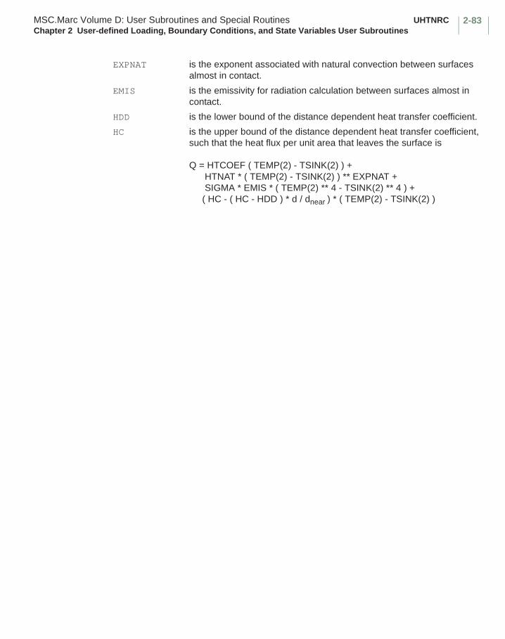
2-83MSC.Marc Volume D: User Subroutines and Special Routines UHTNRCChapter 2 User-defined Loading, Boundary Conditions, and State Variables User Subroutines
EXPNAT is the exponent associated with natural convection between surfaces almost in contact.
EMIS is the emissivity for radiation calculation between surfaces almost in contact.
HDD is the lower bound of the distance dependent heat transfer coefficient.
HC is the upper bound of the distance dependent heat transfer coefficient, such that the heat flux per unit area that leaves the surface is
Q = HTCOEF ( TEMP(2) - TSINK(2) ) + HTNAT * ( TEMP(2) - TSINK(2) ) ** EXPNAT + SIGMA * EMIS * ( TEMP(2) ** 4 - TSINK(2) ** 4 ) + ( HC - ( HC - HDD ) * d / dnear ) * ( TEMP(2) - TSINK(2) )
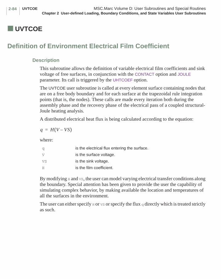
UVTCOE MSC.Marc Volume D: User Subroutines and Special RoutinesChapter 2 User-defined Loading, Boundary Conditions, and State Variables User Subroutines
2-84
■ UVTCOE
Definition of Environment Electrical Film Coefficient
Description
This subroutine allows the definition of variable electrical film coefficients and sink voltage of free surfaces, in conjunction with the CONTACT option and JOULE parameter. Its call is triggered by the UHTCOEF option.
The UVTCOE user subroutine is called at every element surface containing nodes that are on a free body boundary and for each surface at the trapezoidal rule integration points (that is, the nodes). These calls are made every iteration both during the assembly phase and the recovery phase of the electrical pass of a coupled structural-Joule heating analysis.
A distributed electrical heat flux is being calculated according to the equation:
where:
By modifying H and VS, the user can model varying electrical transfer conditions along the boundary. Special attention has been given to provide the user the capability of simulating complex behavior, by making available the location and temperatures of all the surfaces in the environment.
The user can either specify H or VS or specify the flux q directly which is treated strictly as such.
q is the electrical flux entering the surface.
V is the surface voltage.
VS is the sink voltage.
H is the film coefficient.
q H V VS–( )=
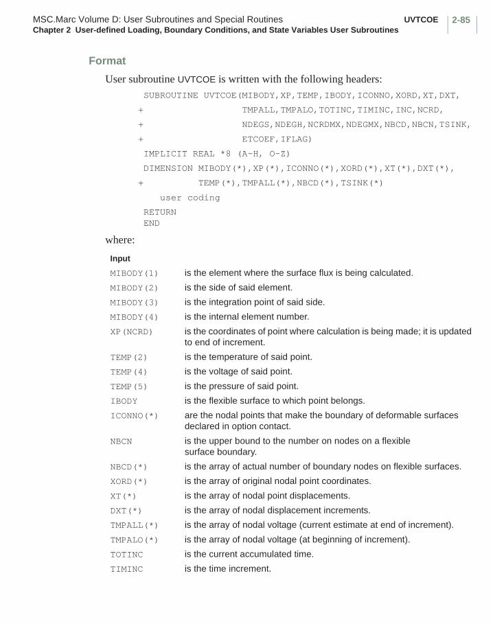
2-85MSC.Marc Volume D: User Subroutines and Special Routines UVTCOEChapter 2 User-defined Loading, Boundary Conditions, and State Variables User Subroutines
Format
User subroutine UVTCOE is written with the following headers: SUBROUTINE UVTCOE(MIBODY,XP,TEMP,IBODY,ICONNO,XORD,XT,DXT,
+ TMPALL,TMPALO,TOTINC,TIMINC,INC,NCRD,
+ NDEGS,NDEGH,NCRDMX,NDEGMX,NBCD,NBCN,TSINK,
+ ETCOEF,IFLAG)
IMPLICIT REAL *8 (A-H, O-Z)
DIMENSION MIBODY(*),XP(*),ICONNO(*),XORD(*),XT(*),DXT(*),
+ TEMP(*),TMPALL(*),NBCD(*),TSINK(*)
user coding
RETURN END
where:
Input
MIBODY(1) is the element where the surface flux is being calculated.
MIBODY(2) is the side of said element.
MIBODY(3) is the integration point of said side.
MIBODY(4) is the internal element number.
XP(NCRD) is the coordinates of point where calculation is being made; it is updated to end of increment.
TEMP(2) is the temperature of said point.
TEMP(4) is the voltage of said point.
TEMP(5) is the pressure of said point.
IBODY is the flexible surface to which point belongs.
ICONNO(*) are the nodal points that make the boundary of deformable surfaces declared in option contact.
NBCN is the upper bound to the number on nodes on a flexible surface boundary.
NBCD(*) is the array of actual number of boundary nodes on flexible surfaces.
XORD(*) is the array of original nodal point coordinates.
XT(*) is the array of nodal point displacements.
DXT(*) is the array of nodal displacement increments.
TMPALL(*) is the array of nodal voltage (current estimate at end of increment).
TMPALO(*) is the array of nodal voltage (at beginning of increment).
TOTINC is the current accumulated time.
TIMINC is the time increment.
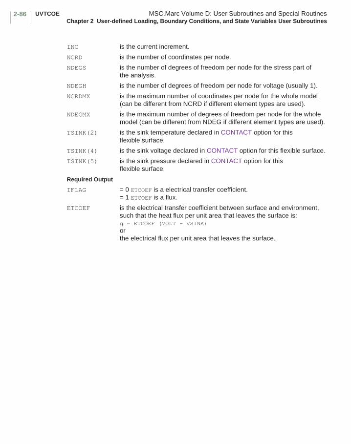
UVTCOE MSC.Marc Volume D: User Subroutines and Special RoutinesChapter 2 User-defined Loading, Boundary Conditions, and State Variables User Subroutines
2-86
INC is the current increment.
NCRD is the number of coordinates per node.
NDEGS is the number of degrees of freedom per node for the stress part of the analysis.
NDEGH is the number of degrees of freedom per node for voltage (usually 1).
NCRDMX is the maximum number of coordinates per node for the whole model (can be different from NCRD if different element types are used).
NDEGMX is the maximum number of degrees of freedom per node for the whole model (can be different from NDEG if different element types are used).
TSINK(2) is the sink temperature declared in CONTACT option for this flexible surface.
TSINK(4) is the sink voltage declared in CONTACT option for this flexible surface.
TSINK(5) is the sink pressure declared in CONTACT option for this flexible surface.
Required Output
IFLAG = 0 ETCOEF is a electrical transfer coefficient.= 1 ETCOEF is a flux.
ETCOEF is the electrical transfer coefficient between surface and environment, such that the heat flux per unit area that leaves the surface is:q = ETCOEF (VOLT - VSINK)orthe electrical flux per unit area that leaves the surface.
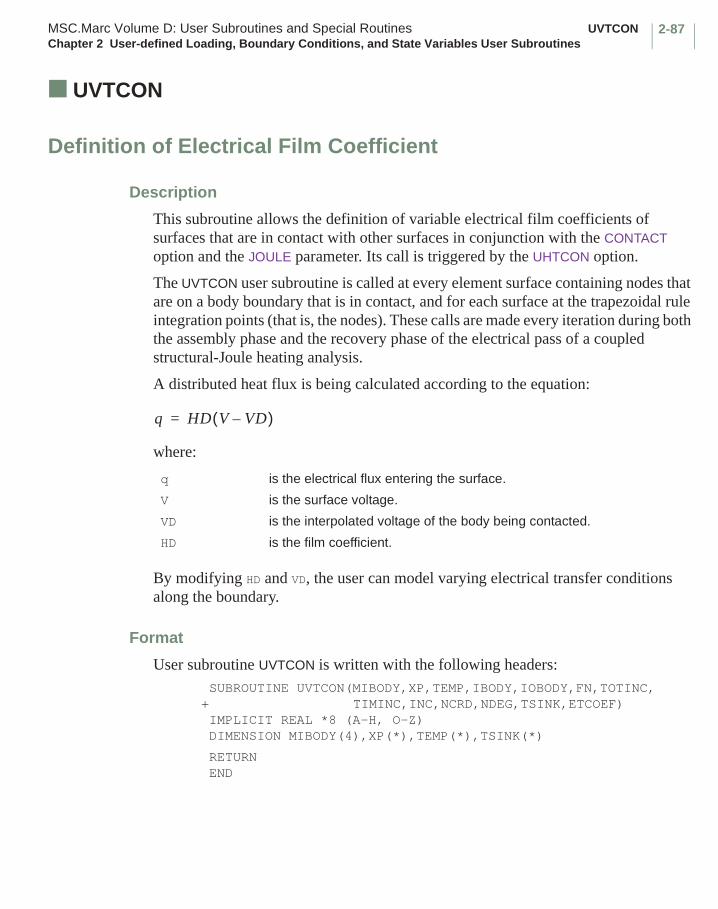
2-87MSC.Marc Volume D: User Subroutines and Special Routines UVTCONChapter 2 User-defined Loading, Boundary Conditions, and State Variables User Subroutines
■ UVTCON
Definition of Electrical Film Coefficient
Description
This subroutine allows the definition of variable electrical film coefficients of surfaces that are in contact with other surfaces in conjunction with the CONTACT option and the JOULE parameter. Its call is triggered by the UHTCON option.
The UVTCON user subroutine is called at every element surface containing nodes that are on a body boundary that is in contact, and for each surface at the trapezoidal rule integration points (that is, the nodes). These calls are made every iteration during both the assembly phase and the recovery phase of the electrical pass of a coupled structural-Joule heating analysis.
A distributed heat flux is being calculated according to the equation:
where:
By modifying HD and VD, the user can model varying electrical transfer conditions along the boundary.
Format
User subroutine UVTCON is written with the following headers: SUBROUTINE UVTCON(MIBODY,XP,TEMP,IBODY,IOBODY,FN,TOTINC,+ TIMINC,INC,NCRD,NDEG,TSINK,ETCOEF) IMPLICIT REAL *8 (A-H, O-Z) DIMENSION MIBODY(4),XP(*),TEMP(*),TSINK(*)
RETURN END
q is the electrical flux entering the surface.
V is the surface voltage.
VD is the interpolated voltage of the body being contacted.
HD is the film coefficient.
q HD V VD–( )=
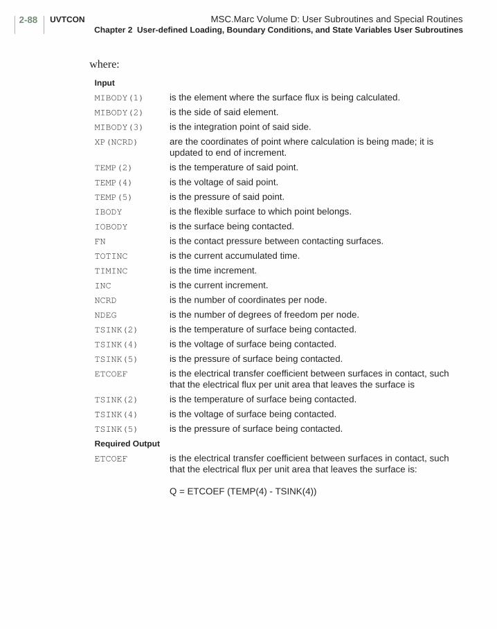
UVTCON MSC.Marc Volume D: User Subroutines and Special RoutinesChapter 2 User-defined Loading, Boundary Conditions, and State Variables User Subroutines
2-88
where:
Input
MIBODY(1) is the element where the surface flux is being calculated.
MIBODY(2) is the side of said element.
MIBODY(3) is the integration point of said side.
XP(NCRD) are the coordinates of point where calculation is being made; it is updated to end of increment.
TEMP(2) is the temperature of said point.
TEMP(4) is the voltage of said point.
TEMP(5) is the pressure of said point.
IBODY is the flexible surface to which point belongs.
IOBODY is the surface being contacted.
FN is the contact pressure between contacting surfaces.
TOTINC is the current accumulated time.
TIMINC is the time increment.
INC is the current increment.
NCRD is the number of coordinates per node.
NDEG is the number of degrees of freedom per node.
TSINK(2) is the temperature of surface being contacted.
TSINK(4) is the voltage of surface being contacted.
TSINK(5) is the pressure of surface being contacted.
ETCOEF is the electrical transfer coefficient between surfaces in contact, such that the electrical flux per unit area that leaves the surface is
TSINK(2) is the temperature of surface being contacted.
TSINK(4) is the voltage of surface being contacted.
TSINK(5) is the pressure of surface being contacted.
Required Output
ETCOEF is the electrical transfer coefficient between surfaces in contact, such that the electrical flux per unit area that leaves the surface is:
Q = ETCOEF (TEMP(4) - TSINK(4))

2-89MSC.Marc Volume D: User Subroutines and Special Routines UVTNRCChapter 2 User-defined Loading, Boundary Conditions, and State Variables User Subroutines
■ UVTNRC
Definition of Electrical Near Contact Film Coefficient
Description
This subroutine allows the definition of variable electrical film coefficients of surfaces that are almost in contact with other surfaces in conjuction with the CONTACT option and the JOULE parameter. Its call is triggered by the UHTCON option.
The UVTNRC user subroutine is called at every element surface containing nodes that are on a body boundary that is almost in contact, and for each surface at the trapezoidal rule integration points (that is, the nodes). These calls are made every iteration both during the assembly phase and the recovery phase of the electrical pass of a coupled structural-Joule heating analysis.
A distributed electrical flux is being calculated according to the equation:
where:
By modifying ET, ETC and EDD, the user can model varying electrical transfer conditions along the boundary, which are dependent of the distance between the contacting surfaces.
q is the electrical flux entering the surface.
V is the surface voltage.
VD is the interpolated voltage of the body being contacted.
ET is the electrical transfer coefficient between surfaces.
ETC is the upper bound in distance dependent electrical transfer coefficient.
EDD is the lower bound in distance dependent electrical transfer coefficient.
is the distance between the surfaces.
is the upper limit of the near contact distance.
q ET V VD–( ) ETC ETC EDD–( ) ddnear------------–
V VD–( )+=
ddnear

UVTNRC MSC.Marc Volume D: User Subroutines and Special RoutinesChapter 2 User-defined Loading, Boundary Conditions, and State Variables User Subroutines
2-90
Format
User subroutine UVTNRC is written with the following headers: SUBROUTINE UVTNRC(MIBODY,XP,TEMP,IBODY,IOBODY,FN,TOTINC,
+ TIMINC,INC,NCRD,NDEG,TEMPO,ETCOEF,ETDD,ETC,D)
IMPLICIT REAL*8 (A-H,O-Z)
DIMENSION MIBODY(4),XP(*),TEMP(*),TEMPO(*)
RETURN
END
where:
Input
MIBODY(1) is the element where the surface flux is being calculated.MIBODY(2) is the side of said element.MIBODY(3) is the integration point of said side.XP(NCRD) is the coordinates of point where calculation is being made; it is updated
to end of increment.TEMP(2) is the temperature of said point.TEMP(4) is the voltage of said point.TEMP(5) is the pressure of said point.IBODY is the flexible surface to which point belongs.IOBODY is the surface being contacted.FN is the contact pressure between contacting surfaces.TOTINC is the current accumulated time.TIMINC is the time increment.INC is the current increment.NCRD is the number of coordinates per node.NDEG is the number of degrees of freedom per node.TEMPO(2) is the temperature of surface being contacted.TEMPO(4) is the voltage of surface being contacted.TEMPO(5) is the pressure of surface being contacted.D is the distance between the surfaces.Required Output
ETCOEF is the electrical transfer coefficient between surfaces in contact.ETDD is the lower bound of the distance dependent electrical
transfer coefficient.ETC is the upper bound of the distance dependent electrical transfer
coefficient, such that the electrical flux per unit area that leaves the surface is
Q = ETCOEF ( TEMP(4) - TEMPO(4) ) + ( ETC - ( ETC - ETDD ) * d / dnear ) * ( TEMP(4) - TEMPO(4) )
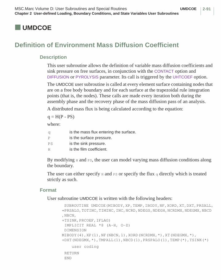
2-91MSC.Marc Volume D: User Subroutines and Special Routines UMDCOEChapter 2 User-defined Loading, Boundary Conditions, and State Variables User Subroutines
■ UMDCOE
Definition of Environment Mass Diffusion Coefficient
Description
This user subroutine allows the definition of variable mass diffusion coefficients and sink pressure on free surfaces, in conjunction with the CONTACT option and DIFFUSION or PYROLYSIS parameter. Its call is triggered by the UHTCOEF option.
The UMDCOE user subroutine is called at every element surface containing nodes that are on a free body boundary and for each surface at the trapezoidal rule integration points (that is, the nodes). These calls are made every iteration both during the assembly phase and the recovery phase of the mass diffusion pass of an analysis.
A distributed mass flux is being calculated according to the equation:
where:
By modifying H and PS, the user can model varying mass diffusion conditions along the boundary.
The user can either specify H and PS or specify the flux q directly which is treated strictly as such.
Format
User subroutine UMDCOE is written with the following headers: SUBROUTINE UMDCOE(MIBODY,XP,TEMP,IBODY,NF,XORD,XT,DXT,PRSALL,+PRSALO,TOTINC,TIMINC,INC,NCRD,NDEGS,NDEGH,NCRDMX,NDEGMX,NBCD,NBCN,+TSINK,PRCOEF,IFLAG) IMPLICIT REAL *8 (A-H, O-Z) DIMENSION MIBODY(4),XP(1),NF(NBCN,1),XORD(NCRDMX,*),XT(NDEGMX,*),+DXT(NDEGMX,*),TMPALL(1),NBCD(1),PRSPALO(1),TEMP(*),TSINK(*)
user coding
RETURN END
q is the mass flux entering the surface.P is the surface pressure.PS is the sink pressure.H is the film coefficient.
q = H(P - PS)
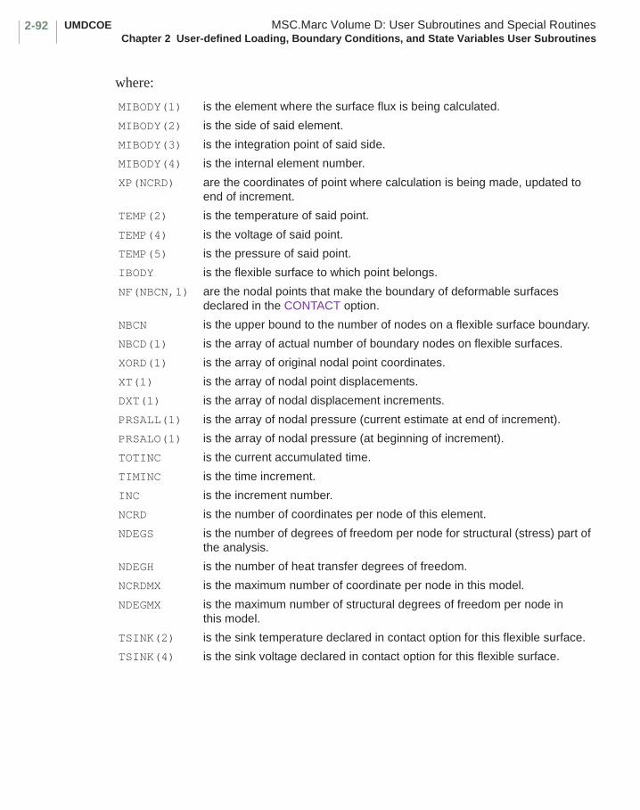
UMDCOE MSC.Marc Volume D: User Subroutines and Special RoutinesChapter 2 User-defined Loading, Boundary Conditions, and State Variables User Subroutines
2-92
where:
MIBODY(1) is the element where the surface flux is being calculated.
MIBODY(2) is the side of said element.
MIBODY(3) is the integration point of said side.
MIBODY(4) is the internal element number.
XP(NCRD) are the coordinates of point where calculation is being made, updated to end of increment.
TEMP(2) is the temperature of said point.
TEMP(4) is the voltage of said point.
TEMP(5) is the pressure of said point.
IBODY is the flexible surface to which point belongs.
NF(NBCN,1) are the nodal points that make the boundary of deformable surfaces declared in the CONTACT option.
NBCN is the upper bound to the number of nodes on a flexible surface boundary.
NBCD(1) is the array of actual number of boundary nodes on flexible surfaces.
XORD(1) is the array of original nodal point coordinates.
XT(1) is the array of nodal point displacements.
DXT(1) is the array of nodal displacement increments.
PRSALL(1) is the array of nodal pressure (current estimate at end of increment).
PRSALO(1) is the array of nodal pressure (at beginning of increment).
TOTINC is the current accumulated time.
TIMINC is the time increment.
INC is the increment number.
NCRD is the number of coordinates per node of this element.
NDEGS is the number of degrees of freedom per node for structural (stress) part of the analysis.
NDEGH is the number of heat transfer degrees of freedom.
NCRDMX is the maximum number of coordinate per node in this model.
NDEGMX is the maximum number of structural degrees of freedom per node in this model.
TSINK(2) is the sink temperature declared in contact option for this flexible surface.
TSINK(4) is the sink voltage declared in contact option for this flexible surface.

2-93MSC.Marc Volume D: User Subroutines and Special Routines UMDCOEChapter 2 User-defined Loading, Boundary Conditions, and State Variables User Subroutines
TSINK(5) is the sink pressure declared in contact option for this flexible surface.
IFLAG =0 PRCOEF is a heat transfer coefficient =1 PRCOEF is a flux.
PRCOEF is the mass diffusion coefficient between surface and environment, such that the mass flux per unit area that leaves the surface is:Q = PRCOEF (TEMP(5) - TSINK(5))
orthe mass flux per unit area that leaves the surface.PRCOEF is to be defined here.

UMDCON MSC.Marc Volume D: User Subroutines and Special RoutinesChapter 2 User-defined Loading, Boundary Conditions, and State Variables User Subroutines
2-94
■ UMDCON
Definition of Contact Mass Diffusion Coefficient
Description
This user subroutine allows the definition of variable mass diffusion coefficients of surfaces that are in contact with other surfaces in conjunction with the CONTACT option and DIFFUSION or PYROLYSIS parameter. Its call is triggered by the UHTCON option.
The UMDCON user subroutine is called at every element surface containing nodes that are on a body boundary that is in contact, and for each surface at the trapezoidal rule integration points (that is, the nodes). These calls are made every iteration both during the assembly phase and the stress recovery phase of the mass diffusion pass of an analysis.
A distributed mass flux is being calculated according to the equation:
where:
By modifying HPD, the user can model varying heat transfer conditions along the contact regions.
Format
User subroutine UMDCON is written with the following headers: SUBROUTINE UMDCON(MIBODY,XP,TEMP,IBODY,IOBODY,FN,TOTINC,TIMINC,+INC,NCRD,NDEG,TSINK,PC) IMPLICIT REAL *8 (A-H, O-Z) DIMENSION MIBODY(4),XP(1),TEMP(*),TSINK(*)
user coding
RETURN END
q is the mass flux entering the surface.
P is the surface pressure.
PD is an interpolated pressure of the body being contacted
PC is the film coefficient.
q = PC(P - PD)

2-95MSC.Marc Volume D: User Subroutines and Special Routines UMDCONChapter 2 User-defined Loading, Boundary Conditions, and State Variables User Subroutines
where:
MIBODY(1) is the element where the surface flux is being calculated.
MIBODY(2) is the side of said element.
MIBODY(3) is the integration point of said side.
MIBODY(4) is the internal element number.
XP(NCRD) are the coordinates of point where calculation is being made, updated to end of increment.
TEMP(2) is the temperature of said point.
TEMP(4) is the voltage of said point.
TEMP(5) is the pressure of said point.
IBODY is the flexible surface to which point belongs.
IOBODY is the surface being contacted.
FN is the contact pressure between contacting surfaces.
TOTINC is the current accumulated time.
TIMINC is the time increment.
INC is the increment number.
NCRD is the number of coordinates per node.
NDEG is the number of degrees of freedom per node.
TSINK(2) is the temperature of surface being contacted.
TSINK(4) is the voltage of surface being contacted.
TSINK(5) is the pressure of surface being contacted.
PC is the heat transfer coefficient between surface in contact, such that the heat flux per unit area that leaves the surface is:Q = PC (P-PD)
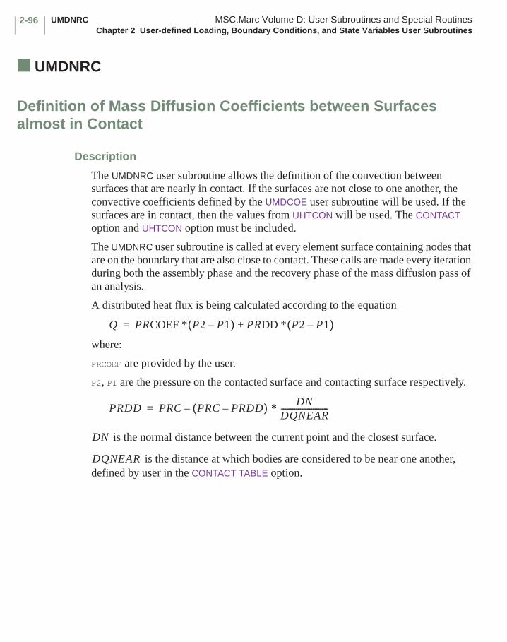
UMDNRC MSC.Marc Volume D: User Subroutines and Special RoutinesChapter 2 User-defined Loading, Boundary Conditions, and State Variables User Subroutines
2-96
■ UMDNRC
Definition of Mass Diffusion Coefficients between Surfaces almost in Contact
Description
The UMDNRC user subroutine allows the definition of the convection between surfaces that are nearly in contact. If the surfaces are not close to one another, the convective coefficients defined by the UMDCOE user subroutine will be used. If the surfaces are in contact, then the values from UHTCON will be used. The CONTACT option and UHTCON option must be included.
The UMDNRC user subroutine is called at every element surface containing nodes that are on the boundary that are also close to contact. These calls are made every iteration during both the assembly phase and the recovery phase of the mass diffusion pass of an analysis.
A distributed heat flux is being calculated according to the equation
where:
PRCOEF are provided by the user.
P2, P1 are the pressure on the contacted surface and contacting surface respectively.
is the normal distance between the current point and the closest surface.
is the distance at which bodies are considered to be near one another, defined by user in the CONTACT TABLE option.
Q PRCOEF * P2 P1–( ) PRDD * P2 P1–( )+=
PRDD PRC PRC PRDD–( ) * DN
DQNEAR-------------------------–=
DN
DQNEAR
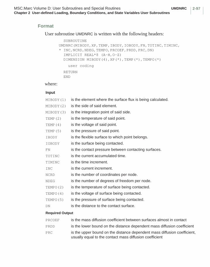
2-97MSC.Marc Volume D: User Subroutines and Special Routines UMDNRCChapter 2 User-defined Loading, Boundary Conditions, and State Variables User Subroutines
Format
User subroutine UMDNRC is written with the following headers: SUBROUTINE UMDNRC(MIBODY,XP,TEMP,IBODY,IOBODY,FN,TOTINC,TIMINC,* INC,NCRD,NDEG,TEMPO,PRCOEF,PRDD,PRC,DN) IMPLICIT REAL*8 (A-H,O-Z) DIMENSION MIBODY(4),XP(*),TEMP(*),TEMPO(*)
user coding
RETURN END
where:
Input
MIBODY(1) is the element where the surface flux is being calculated.
MIBODY(2) is the side of said element.
MIBODY(3) is the integration point of said side.
TEMP(2) is the temperature of said point.
TEMP(4) is the voltage of said point.
TEMP(5) is the pressure of said point.
IBODY is the flexible surface to which point belongs.
IOBODY is the surface being contacted.
FN is the contact pressure between contacting surfaces.
TOTINC is the current accumulated time.
TIMINC is the time increment.
INC is the current increment.
NCRD is the number of coordinates per node.
NDEG is the number of degrees of freedom per node.
TEMPO(2) is the temperature of surface being contacted.
TEMPO(4) is the voltage of surface being contacted.
TEMPO(5) is the pressure of surface being contacted.
DN is the distance to the contact surface.
Required Output
PRCOEF is the mass diffusion coefficient between surfaces almost in contact
PRDD is the lower bound on the distance dependent mass diffusion coefficient
PRC is the upper bound on the distance dependent mass diffusion coefficient, usually equal to the contact mass diffusion coefficient

UNORST MSC.Marc Volume D: User Subroutines and Special RoutinesChapter 2 User-defined Loading, Boundary Conditions, and State Variables User Subroutines
2-98
■ UNORST
Definition of Normal Stress, Flow Stress and Temperature at Contact Node
Description
With this user subroutine, The user can define the normal stress at each node in contact instead of using the extrapolated value from the integration points. It is only called for user-defined elements and is used in the calculation of Coulomb friction for contact analysis. The magnitude of the user-defined normal stress must be in the local system of the patch to which the nodal point is in contact with.
Format
User subroutine UNORST is written with the following headers:SUBROUTINE UNORST(STRINT,USTR,TRANS,NODE,IBODY,KC,
+ NDIE,NODCLS,LMM,NOD,M,N,TIMINC,NDIM,NDEG,NSTRMX,NNODE,INTEL)
IMPLICIT REAL *8 (A-H, O-Z)
CDIMENSION STRINT(8,INTEL),USTR(NDIM,1)DIMENSION LMM(1),NODCLS(1),TRANS(3,3)
user coding C C
RETURNEND
where:
Input
STRINT (1-NSTRMX,INTEL) are the stresses at all integration points.
STRINT (NSTRMX+1,INTEL) is the temperature at all integration points.
STRINT (NSTRMX+2,INTEL) is the flow stress at all integration points.
USTR (2,NODE) is the current sliding velocity in the first local direction.
USTR(NSTRMX+1, NNODE) is the temperature at node.
USTR(NSTRMX+2, NNODE) is the flow stress at node.
USTR(NSTRMX+3, NNODE) is the previous sliding velocity 1.
USTR(NSTRMX+4, NNODE) is the previous sliding velocity 2.
USTR (2,NODE) is the current sliding velocity in the first local direction.
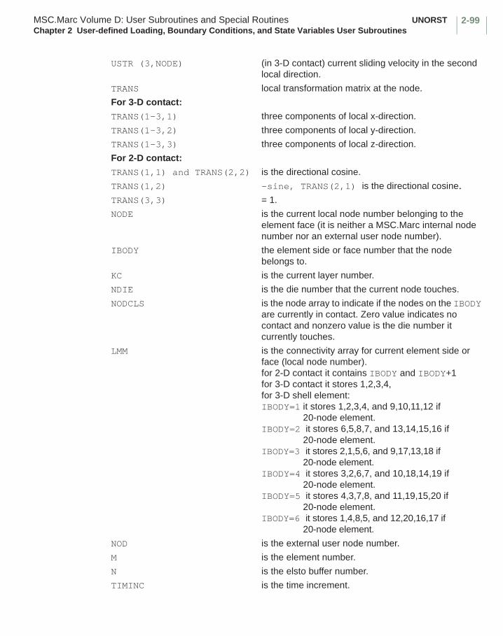
2-99MSC.Marc Volume D: User Subroutines and Special Routines UNORSTChapter 2 User-defined Loading, Boundary Conditions, and State Variables User Subroutines
USTR (3,NODE) (in 3-D contact) current sliding velocity in the second local direction.
TRANS local transformation matrix at the node.
For 3-D contact:
TRANS(1-3,1) three components of local x-direction.
TRANS(1-3,2) three components of local y-direction.
TRANS(1-3,3) three components of local z-direction.
For 2-D contact:
TRANS(1,1) and TRANS(2,2) is the directional cosine.
TRANS(1,2) -sine, TRANS(2,1) is the directional cosine.TRANS(3,3) = 1.
NODE is the current local node number belonging to the element face (it is neither a MSC.Marc internal node number nor an external user node number).
IBODY the element side or face number that the node belongs to.
KC is the current layer number.
NDIE is the die number that the current node touches.
NODCLS is the node array to indicate if the nodes on the IBODY are currently in contact. Zero value indicates no contact and nonzero value is the die number it currently touches.
LMM is the connectivity array for current element side or face (local node number).for 2-D contact it contains IBODY and IBODY+1 for 3-D contact it stores 1,2,3,4, for 3-D shell element:IBODY=1 it stores 1,2,3,4, and 9,10,11,12 if
20-node element.IBODY=2 it stores 6,5,8,7, and 13,14,15,16 if
20-node element.IBODY=3 it stores 2,1,5,6, and 9,17,13,18 if
20-node element.IBODY=4 it stores 3,2,6,7, and 10,18,14,19 if
20-node element.IBODY=5 it stores 4,3,7,8, and 11,19,15,20 if
20-node element.IBODY=6 it stores 1,4,8,5, and 12,20,16,17 if
20-node element.
NOD is the external user node number.
M is the element number.
N is the elsto buffer number.
TIMINC is the time increment.
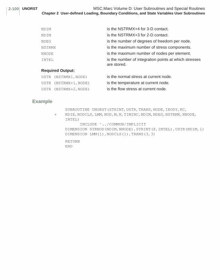
UNORST MSC.Marc Volume D: User Subroutines and Special RoutinesChapter 2 User-defined Loading, Boundary Conditions, and State Variables User Subroutines
2-100
Example
SUBROUTINE UNORST(STRINT,USTR,TRANS,NODE,IBODY,KC,+ NDIE,NODCLS,LMM,NOD,M,N,TIMINC,NDIM,NDEG,NSTRMX,NNODE,
INTEL) INCLUDE ’../COMMON/IMPLICITDIMENSION STRNOD(NDIM,NNODE),STRINT(8,INTEL),USTR(NDIM,1)DIMENSION LMM(1),NODCLS(1),TRANS(3,3)
RETURNEND
NDIM is the NSTRMX+4 for 3-D contact.
NDIM is the NSTRMX+3 for 2-D contact.
NDEG is the number of degrees of freedom per node.
NSTRMX is the maximum number of stress components.
NNODE is the maximum number of nodes per element.
INTEL is the number of integration points at which stresses are stored.
Required Output:
USTR (NSTRMX1,NODE) is the normal stress at current node.
USTR (NSTRMX+1,NODE) is the temperature at current node.
USTR (NSTRMX+2,NODE) is the flow stress at current node.
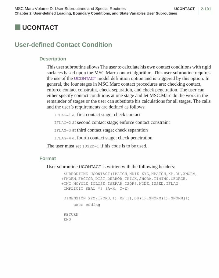
2-101MSC.Marc Volume D: User Subroutines and Special Routines UCONTACTChapter 2 User-defined Loading, Boundary Conditions, and State Variables User Subroutines
■ UCONTACT
User-defined Contact Condition
Description
This user subroutine allows The user to calculate his own contact conditions with rigid surfaces based upon the MSC.Marc contact algorithm. This user subroutine requires the use of the UCONTACT model definition option and is triggered by this option. In general, the four stages in MSC.Marc contact procedures are: checking contact, enforce contact constraint, check separation, and check penetration. The user can either specify contact conditions at one stage and let MSC.Marc do the work in the remainder of stages or the user can substitute his calculations for all stages. The calls and the user’s requirements are defined as follows:
IFLAG=1 at first contact stage; check contact
IFLAG=2 at second contact stage; enforce contact constraint
IFLAG=3 at third contact stage; check separation
IFLAG=4 at fourth contact stage; check penetration
The user must set IUSED=1 if his code is to be used.
Format
User subroutine UCONTACT is written with the following headers: SUBROUTINE UCONTACT(IPATCH,NDIE,XYZ,NPATCH,XP,DU,XNORM,+FNORM,FACTOR,DIST,DERROR,THICK,SNORM,TIMINC,CFORCE, +INC,NCYCLE,ICLOSE,ISEPAR,I2OR3,NODE,IUSED,IFLAG) IMPLICIT REAL *8 (A-H, O-Z)
DIMENSION XYZ(I2OR3,1),XP(1),DU(1),XNORM(1),SNORM(1)
user coding
RETURN END
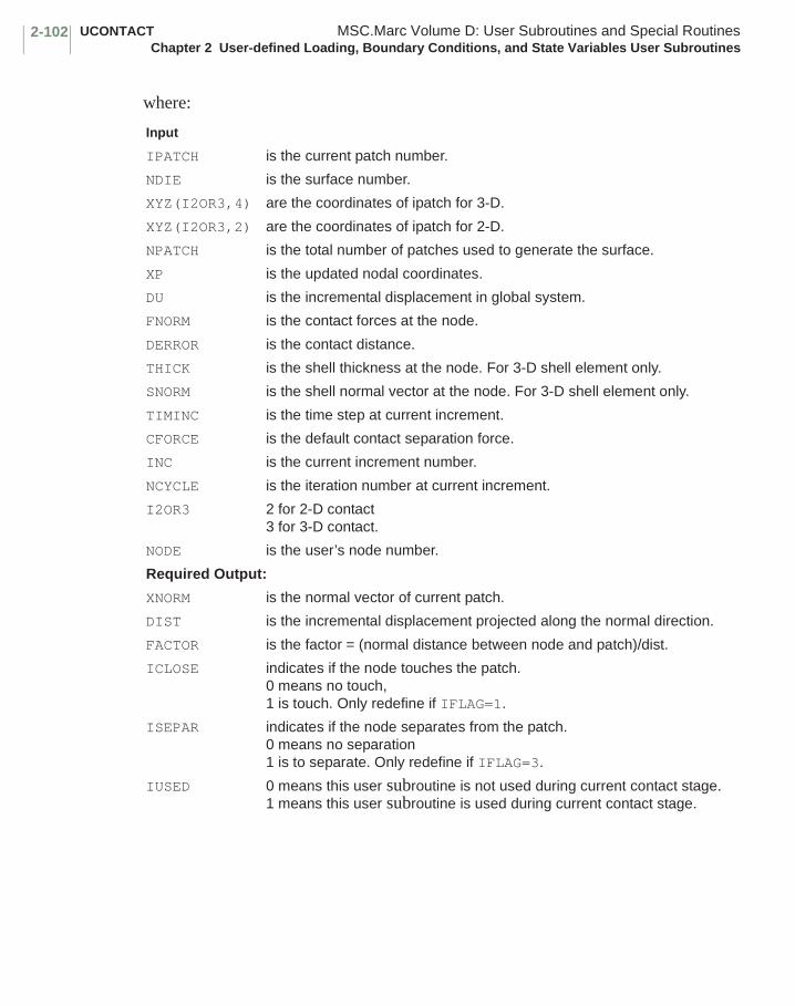
UCONTACT MSC.Marc Volume D: User Subroutines and Special RoutinesChapter 2 User-defined Loading, Boundary Conditions, and State Variables User Subroutines
2-102
where:
Input
IPATCH is the current patch number.
NDIE is the surface number.
XYZ(I2OR3,4) are the coordinates of ipatch for 3-D.
XYZ(I2OR3,2) are the coordinates of ipatch for 2-D.
NPATCH is the total number of patches used to generate the surface.
XP is the updated nodal coordinates.
DU is the incremental displacement in global system.
FNORM is the contact forces at the node.
DERROR is the contact distance.
THICK is the shell thickness at the node. For 3-D shell element only.
SNORM is the shell normal vector at the node. For 3-D shell element only.
TIMINC is the time step at current increment.
CFORCE is the default contact separation force.
INC is the current increment number.
NCYCLE is the iteration number at current increment.
I2OR3 2 for 2-D contact3 for 3-D contact.
NODE is the user’s node number.
Required Output:
XNORM is the normal vector of current patch.
DIST is the incremental displacement projected along the normal direction.
FACTOR is the factor = (normal distance between node and patch)/dist.
ICLOSE indicates if the node touches the patch.0 means no touch, 1 is touch. Only redefine if IFLAG=1.
ISEPAR indicates if the node separates from the patch.0 means no separation1 is to separate. Only redefine if IFLAG=3.
IUSED 0 means this user subroutine is not used during current contact stage.1 means this user subroutine is used during current contact stage.

2-103MSC.Marc Volume D: User Subroutines and Special Routines UCONTACTChapter 2 User-defined Loading, Boundary Conditions, and State Variables User Subroutines
IFLAG 2-D contact:output: iused, iclose and xnorm(1), xnorm(2).3-D contact:output: iused, iclose and xnorm(1), xnorm(2), and xnorm(3).If IFLAG=22-D contact:output: iused, xnorm(1), xnorm(2). The xnorm are normal vector of ipatch.3-D contact:output: iused, xnorm(1), xnorm(2), xnorm(3). xnorm(4), xnorm(5), and xnorm(6).The xnorm(1-3) are the three components of normal vector of ipatch.The xnorm(4-6) are the three components of tangent vector of ipatch to define the local-x direction of transformation system. Those two vectors must be unitized.If IFLAG=3 output: iused, isepar.If IFLAG=4 output: iused, dist, and factor.
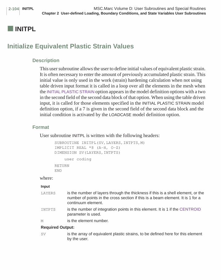
INITPL MSC.Marc Volume D: User Subroutines and Special RoutinesChapter 2 User-defined Loading, Boundary Conditions, and State Variables User Subroutines
2-104
■ INITPL
Initialize Equivalent Plastic Strain Values
Description
This user subroutine allows the user to define initial values of equivalent plastic strain. It is often necessary to enter the amount of previously accumulated plastic strain. This initial value is only used in the work (strain) hardening calculation when not using table driven input format it is called in a loop over all the elements in the mesh when the INITIAL PLASTIC STRAIN option appears in the model definition options with a two in the second field of the second data block of that option. When using the table driven input, it is called for those elements specified in the INITIAL PLASTIC STRAIN model definition option, if a 7 is given in the second field of the second data block and the initial condition is activated by the LOADCASE model definition option.
Format
User subroutine INITPL is written with the following headers:SUBROUTINE INITPL(SV,LAYERS,INTPTS,M) IMPLICIT REAL *8 (A-H, O-Z)DIMENSION SV(LAYERS,INTPTS)
user coding
RETURNEND
where:
Input
LAYERS is the number of layers through the thickness if this is a shell element, or the number of points in the cross section if this is a beam element. It is 1 for a continuum element.
INTPTS is the number of integration points in this element. It is 1 if the CENTROID parameter is used.
M is the element number.
Required Output:
SV is the array of equivalent plastic strains, to be defined here for this element by the user.
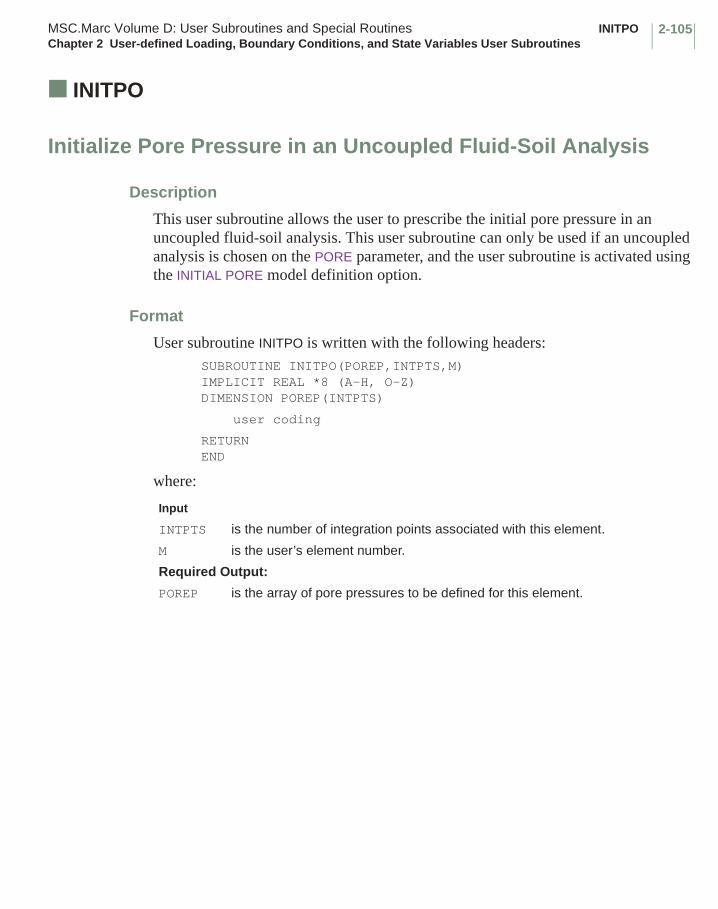
2-105MSC.Marc Volume D: User Subroutines and Special Routines INITPOChapter 2 User-defined Loading, Boundary Conditions, and State Variables User Subroutines
■ INITPO
Initialize Pore Pressure in an Uncoupled Fluid-Soil Analysis
Description
This user subroutine allows the user to prescribe the initial pore pressure in an uncoupled fluid-soil analysis. This user subroutine can only be used if an uncoupled analysis is chosen on the PORE parameter, and the user subroutine is activated using the INITIAL PORE model definition option.
Format
User subroutine INITPO is written with the following headers:SUBROUTINE INITPO(POREP,INTPTS,M) IMPLICIT REAL *8 (A-H, O-Z)DIMENSION POREP(INTPTS)
user coding
RETURNEND
where:
Input
INTPTS is the number of integration points associated with this element.
M is the user’s element number.
Required Output:
POREP is the array of pore pressures to be defined for this element.
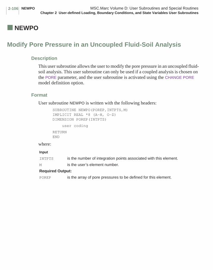
NEWPO MSC.Marc Volume D: User Subroutines and Special RoutinesChapter 2 User-defined Loading, Boundary Conditions, and State Variables User Subroutines
2-106
■ NEWPO
Modify Pore Pressure in an Uncoupled Fluid-Soil Analysis
Description
This user subroutine allows the user to modify the pore pressure in an uncoupled fluid-soil analysis. This user subroutine can only be used if a coupled analysis is chosen on the PORE parameter, and the user subroutine is activated using the CHANGE PORE model definition option.
Format
User subroutine NEWPO is written with the following headers:SUBROUTINE NEWPO(POREP,INTPTS,M) IMPLICIT REAL *8 (A-H, O-Z)DIMENSION POREP(INTPTS)
user coding
RETURNEND
where:
Input
INTPTS is the number of integration points associated with this element.
M is the user’s element number.
Required Output:
POREP is the array of pore pressures to be defined for this element.

2-107MSC.Marc Volume D: User Subroutines and Special Routines UREACBChapter 2 User-defined Loading, Boundary Conditions, and State Variables User Subroutines
■ UREACB
Definition of Reactive Boundary Coefficients in an Acoustic Harmonic Analysis
Description
This user subroutine allows the user to redefine the reactive boundary coefficients as a function of the frequency in a harmonic acoustic analysis. This data is normally entered through the CONTACT (2-D) or (3-D) model definition option.
Format
User subroutine UREACB is written with the following headers: SUBROUTINE UREACB(OXK1,OC1,FREQC,IBODYT,IBODYR)IMPLICIT REAL*8 (A-H,O-Z)
user coding
RETURN END
where:
Note that the complex admittance is defined as , with the
frequency in radians per time and the complex impedance.
Input:
FREQC is the frequency in cycles per time.
IBODYT is the number of the acoustic body.
IBODYR is the number of the boundary body.
Required Output:
OXK1 = 1./k1 where k1 is the coefficient of reactive boundary.
OC1 = 1./c1 where c1 is the coefficient reactive boundary.
1Z ω( )------------
1Z ω( )------------
1c1-----
iωk1------+= ω
Z ω( )
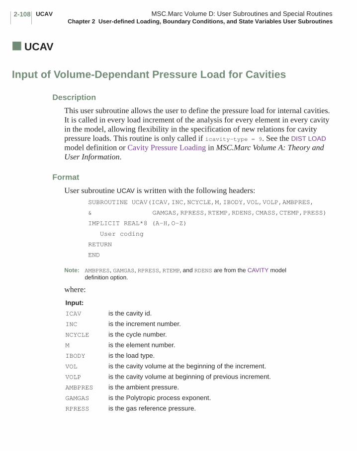
UCAV MSC.Marc Volume D: User Subroutines and Special RoutinesChapter 2 User-defined Loading, Boundary Conditions, and State Variables User Subroutines
2-108
■ UCAV
Input of Volume-Dependant Pressure Load for Cavities
Description
This user subroutine allows the user to define the pressure load for internal cavities. It is called in every load increment of the analysis for every element in every cavity in the model, allowing flexibility in the specification of new relations for cavity pressure loads. This routine is only called if icavity-type = 9. See the DIST LOAD model definition or Cavity Pressure Loading in MSC.Marc Volume A: Theory and User Information.
Format
User subroutine UCAV is written with the following headers:SUBROUTINE UCAV(ICAV,INC,NCYCLE,M,IBODY,VOL,VOLP,AMBPRES,
& GAMGAS,RPRESS,RTEMP,RDENS,CMASS,CTEMP,PRESS)
IMPLICIT REAL*8 (A-H,O-Z)
User coding
RETURN
END
Note: AMBPRES, GAMGAS, RPRESS, RTEMP, and RDENS are from the CAVITY model definition option.
where:
Input:
ICAV is the cavity id.
INC is the increment number.
NCYCLE is the cycle number.
M is the element number.
IBODY is the load type.
VOL is the cavity volume at the beginning of the increment.
VOLP is the cavity volume at beginning of previous increment.
AMBPRES is the ambient pressure.
GAMGAS is the Polytropic process exponent.
RPRESS is the gas reference pressure.
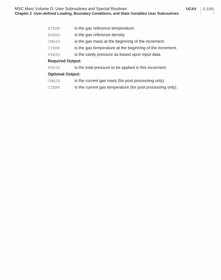
2-109MSC.Marc Volume D: User Subroutines and Special Routines UCAVChapter 2 User-defined Loading, Boundary Conditions, and State Variables User Subroutines
RTEMP is the gas reference temperature.
RDENS is the gas reference density.
CMASS is the gas mass at the beginning of the increment.
CTEMP is the gas temperature at the beginning of the increment.
PRESS is the cavity pressure as based upon input data.
Required Output:
PRESS is the total pressure to be applied in this increment.
Optional Output:
CMASS is the current gas mass (for post processing only).
CTEMP is the current gas temperature (for post processing only).
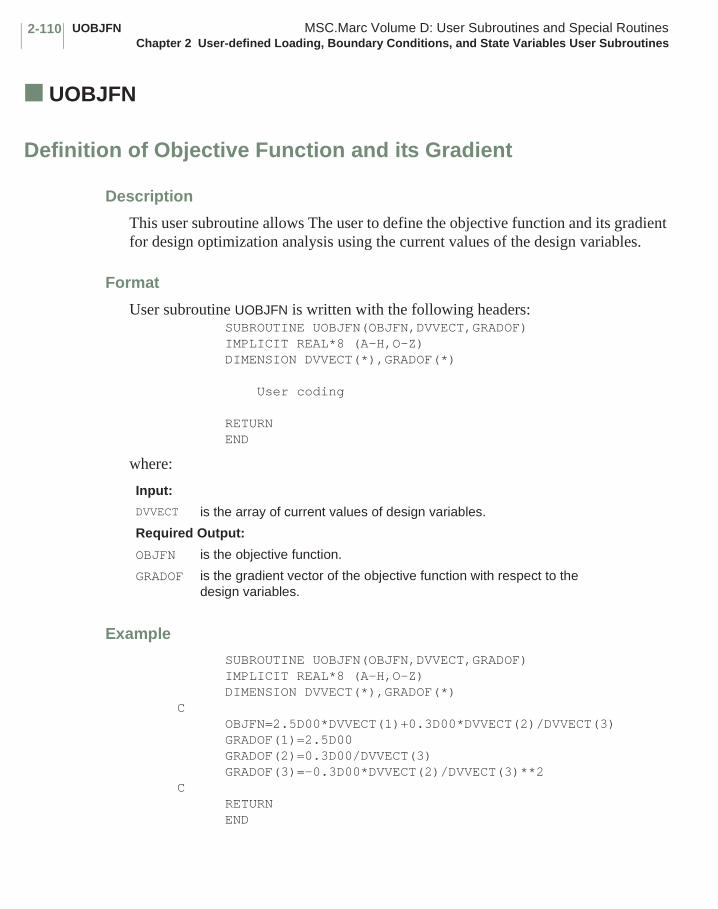
UOBJFN MSC.Marc Volume D: User Subroutines and Special RoutinesChapter 2 User-defined Loading, Boundary Conditions, and State Variables User Subroutines
2-110
■ UOBJFN
Definition of Objective Function and its Gradient
Description
This user subroutine allows The user to define the objective function and its gradient for design optimization analysis using the current values of the design variables.
Format
User subroutine UOBJFN is written with the following headers: SUBROUTINE UOBJFN(OBJFN,DVVECT,GRADOF) IMPLICIT REAL*8 (A-H,O-Z) DIMENSION DVVECT(*),GRADOF(*)
User coding
RETURN END
where:
Example
SUBROUTINE UOBJFN(OBJFN,DVVECT,GRADOF) IMPLICIT REAL*8 (A-H,O-Z) DIMENSION DVVECT(*),GRADOF(*)C OBJFN=2.5D00*DVVECT(1)+0.3D00*DVVECT(2)/DVVECT(3) GRADOF(1)=2.5D00 GRADOF(2)=0.3D00/DVVECT(3) GRADOF(3)=-0.3D00*DVVECT(2)/DVVECT(3)**2C RETURN END
Input:
DVVECT is the array of current values of design variables.
Required Output:
OBJFN is the objective function.
GRADOF is the gradient vector of the objective function with respect to the design variables.
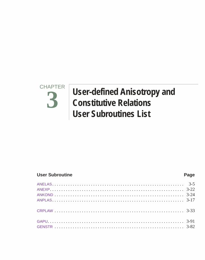
Chapter 3 User-defined Anisotropy and Constitutive Relations User Subroutines List
User Subroutine Page
ANELAS . . . . . . . . . . . . . . . . . . . . . . . . . . . . . . . . . . . . . . . . . . . . . . . . . . . . . . . . . . 3-5ANEXP. . . . . . . . . . . . . . . . . . . . . . . . . . . . . . . . . . . . . . . . . . . . . . . . . . . . . . . . . . . 3-22ANKOND . . . . . . . . . . . . . . . . . . . . . . . . . . . . . . . . . . . . . . . . . . . . . . . . . . . . . . . . . 3-24ANPLAS . . . . . . . . . . . . . . . . . . . . . . . . . . . . . . . . . . . . . . . . . . . . . . . . . . . . . . . . . . 3-17
CRPLAW . . . . . . . . . . . . . . . . . . . . . . . . . . . . . . . . . . . . . . . . . . . . . . . . . . . . . . . . . 3-33
GAPU. . . . . . . . . . . . . . . . . . . . . . . . . . . . . . . . . . . . . . . . . . . . . . . . . . . . . . . . . . . . 3-91GENSTR . . . . . . . . . . . . . . . . . . . . . . . . . . . . . . . . . . . . . . . . . . . . . . . . . . . . . . . . . 3-82
CHAPTER
3 User-defined Anisotropy and Constitutive Relations User Subroutines List

MSC.Marc Volume D: User Subroutines and Special RoutinesChapter 3 User-defined Anisotropy and Constitutive Relations User Subroutines List
3-ii
User Subroutine Page
HOOKLW . . . . . . . . . . . . . . . . . . . . . . . . . . . . . . . . . . . . . . . . . . . . . . . . . . . . . . . . . 3-15HYPELA2 . . . . . . . . . . . . . . . . . . . . . . . . . . . . . . . . . . . . . . . . . . . . . . . . . . . . . . . . . 3-68
ORIENT . . . . . . . . . . . . . . . . . . . . . . . . . . . . . . . . . . . . . . . . . . . . . . . . . . . . . . . . . . 3-20
TENSOF. . . . . . . . . . . . . . . . . . . . . . . . . . . . . . . . . . . . . . . . . . . . . . . . . . . . . . . . . . 3-49
UACOUS . . . . . . . . . . . . . . . . . . . . . . . . . . . . . . . . . . . . . . . . . . . . . . . . . . . . . . . . . 3-101UARRBO . . . . . . . . . . . . . . . . . . . . . . . . . . . . . . . . . . . . . . . . . . . . . . . . . . . . . . . . . 3-99UBEAM . . . . . . . . . . . . . . . . . . . . . . . . . . . . . . . . . . . . . . . . . . . . . . . . . . . . . . . . . . 3-84UCOMPL . . . . . . . . . . . . . . . . . . . . . . . . . . . . . . . . . . . . . . . . . . . . . . . . . . . . . . . . . 3-89UCRACK . . . . . . . . . . . . . . . . . . . . . . . . . . . . . . . . . . . . . . . . . . . . . . . . . . . . . . . . . 3-47UCRPLW (Viscoplastic) . . . . . . . . . . . . . . . . . . . . . . . . . . . . . . . . . . . . . . . . . . . . . . . 3-31UDAMAG . . . . . . . . . . . . . . . . . . . . . . . . . . . . . . . . . . . . . . . . . . . . . . . . . . . . . . . . . 3-56UELASTOMER . . . . . . . . . . . . . . . . . . . . . . . . . . . . . . . . . . . . . . . . . . . . . . . . . . . . . 3-77UELDAM . . . . . . . . . . . . . . . . . . . . . . . . . . . . . . . . . . . . . . . . . . . . . . . . . . . . . . . . . 3-66UENERG . . . . . . . . . . . . . . . . . . . . . . . . . . . . . . . . . . . . . . . . . . . . . . . . . . . . . . . . . 3-62UEPS . . . . . . . . . . . . . . . . . . . . . . . . . . . . . . . . . . . . . . . . . . . . . . . . . . . . . . . . . . . . 3-26UFAIL . . . . . . . . . . . . . . . . . . . . . . . . . . . . . . . . . . . . . . . . . . . . . . . . . . . . . . . . . . . . 3-19UFINITE . . . . . . . . . . . . . . . . . . . . . . . . . . . . . . . . . . . . . . . . . . . . . . . . . . . . . . . . . . 3-74UGENT . . . . . . . . . . . . . . . . . . . . . . . . . . . . . . . . . . . . . . . . . . . . . . . . . . . . . . . . . . 3-100UGRAIN . . . . . . . . . . . . . . . . . . . . . . . . . . . . . . . . . . . . . . . . . . . . . . . . . . . . . . . . . . 3-55UMOONY . . . . . . . . . . . . . . . . . . . . . . . . . . . . . . . . . . . . . . . . . . . . . . . . . . . . . . . . . 3-61UMU . . . . . . . . . . . . . . . . . . . . . . . . . . . . . . . . . . . . . . . . . . . . . . . . . . . . . . . . . . . . 3-27UNEWTN . . . . . . . . . . . . . . . . . . . . . . . . . . . . . . . . . . . . . . . . . . . . . . . . . . . . . . . . . 3-96UOGDEN . . . . . . . . . . . . . . . . . . . . . . . . . . . . . . . . . . . . . . . . . . . . . . . . . . . . . . . . . 3-64UPERM . . . . . . . . . . . . . . . . . . . . . . . . . . . . . . . . . . . . . . . . . . . . . . . . . . . . . . . . . . 3-60UPHI . . . . . . . . . . . . . . . . . . . . . . . . . . . . . . . . . . . . . . . . . . . . . . . . . . . . . . . . . . . . 3-87UPOWDR . . . . . . . . . . . . . . . . . . . . . . . . . . . . . . . . . . . . . . . . . . . . . . . . . . . . . . . . . 3-58URPFLO. . . . . . . . . . . . . . . . . . . . . . . . . . . . . . . . . . . . . . . . . . . . . . . . . . . . . . . . . . 3-97USELEM . . . . . . . . . . . . . . . . . . . . . . . . . . . . . . . . . . . . . . . . . . . . . . . . . . . . . . . . . 3-93USHRET . . . . . . . . . . . . . . . . . . . . . . . . . . . . . . . . . . . . . . . . . . . . . . . . . . . . . . . . . 3-50USIGMA . . . . . . . . . . . . . . . . . . . . . . . . . . . . . . . . . . . . . . . . . . . . . . . . . . . . . . . . . . 3-29USPCHT . . . . . . . . . . . . . . . . . . . . . . . . . . . . . . . . . . . . . . . . . . . . . . . . . . . . . . . . . 3-30USPRNG . . . . . . . . . . . . . . . . . . . . . . . . . . . . . . . . . . . . . . . . . . . . . . . . . . . . . . . . . 3-44USSUBS . . . . . . . . . . . . . . . . . . . . . . . . . . . . . . . . . . . . . . . . . . . . . . . . . . . . . . . . . 3-102UVOID . . . . . . . . . . . . . . . . . . . . . . . . . . . . . . . . . . . . . . . . . . . . . . . . . . . . . . . . . . . 3-51UVOIDN . . . . . . . . . . . . . . . . . . . . . . . . . . . . . . . . . . . . . . . . . . . . . . . . . . . . . . . . . . 3-52UVOIDRT . . . . . . . . . . . . . . . . . . . . . . . . . . . . . . . . . . . . . . . . . . . . . . . . . . . . . . . . . 3-54

3-iiiMSC.Marc Volume D: User Subroutines and Special RoutinesChapter 3 User-defined Anisotropy and Constitutive Relations User Subroutines List
User Subroutine Page
VSWELL. . . . . . . . . . . . . . . . . . . . . . . . . . . . . . . . . . . . . . . . . . . . . . . . . . . . . . . . . . 3-38
WKSLP . . . . . . . . . . . . . . . . . . . . . . . . . . . . . . . . . . . . . . . . . . . . . . . . . . . . . . . . . . 3-41
Chapter 3 User-defined Anisotropy and Constitutive Relations User Subroutines
This chapter describes the user subroutines available to allow you to provide material data to standard MSC.Marc constitutive relations, or for the user to create his own model. The routines in this chapter cover the spectrum of anisotropic elasticity and plasticity, creep, plasticity, rate independent nonlinear elasticity, cracking, electrical, and magnetic materials among others. These routines are, in general, called for each integration point for each element they have been invoked. This provides a powerful method to provide nonhomogeneous, nonlinear material behavior. Table 3-1 summarizes these routines and indicates what parameters or model definition options are required to invoke the user subroutine.
CHAPTER
3 User-defined Anisotropy and Constitutive Relations User Subroutines

MSC.Marc Volume D: User Subroutines and Special RoutinesChapter 3 User-defined Anisotropy and Constitutive Relations User Subroutines
3-2
Table 3-1 User-defined Anisotropy and Constitutive Relations User Subroutine Requirements
User Subroutine
Required Parameters or Model Definition Options
Purpose
ANELAS ORTHOTROPIC orANISOTROPIC
Definition of factors to scale elastic stress strain law.
ANEXP ORTHOTROPIC orANISOTROPIC
Definition of thermal strain increment.
ANKOND ORTHOTROPIC orANISOTROPIC
Definition of thermal conductivity or electrical resistance in Joule heating.
ANPLAS ORTHOTROPIC orANISOTROPIC
Definition of parameters for Hill yield criteria
CRPLAW CREEP Definition of function to describe creep strain rate.
GAPU GAP DATA Definition of contact gap closure distance
GENSTR SHELL SECT Definition of generalized stress-strain law for shells.
HOOKLW ORTHOTROPIC orANISOTROPIC
Definition of elastic stress-strain or compliance relation.
HYPELA2 HYPOELASTIC Definition of nonlinear stress-strain relationship.
ORIENT ORIENTATION Definition of preferred material orientation for orthotropic or anisotropic behavior.
TENSOF ISOTROPICCRACK DATA
Definition of tension softening modulus.
UACOUS ACOUSTICCONTACT (2-D)CONTACT (3-D)
Definition of material properties for an acoustic medium.
UARRBO ARRUDBOYCE Definition of constants in strain energy function.
UBEAM HYPOELASTIC Definition of nonlinear generalized stress-strain law for element types 52 or 98.
UCOMPL HARMONIC Definition of stress-strain rate relationship for harmonic analysis.
UCRACK ISOTROPICCRACK DATA
Definition of ultimate stress for cracking analysis.
UCRPLW CREEP Definition of complex relationships for the factors in the power law expression for the creep strain rate.
UDAMAG DAMAGE Definition of the Kachanov damage factor to be applied to the material properties
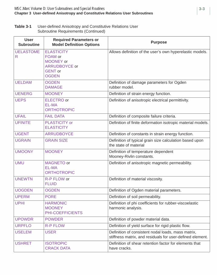
3-3MSC.Marc Volume D: User Subroutines and Special RoutinesChapter 3 User-defined Anisotropy and Constitutive Relations User Subroutines
UELASTOMER
ELASTICITYFOAM orMOONEY orARRUDBOYCE orGENT orOGDEN
Allows definition of the user’s own hyperelastic models.
UELDAM OGDENDAMAGE
Definition of damage parameters for Ogden rubber model.
UENERG MOONEY Definition of strain energy function.
UEPS ELECTRO orEL-MAORTHOTROPIC
Definition of anisotropic electrical permittivity.
UFAIL FAIL DATA Definition of composite failure criteria.
UFINITE PLASTICITY orELASTICITY
Definition of finite deformation isotropic material models.
UGENT ARRUDBOYCE Definition of constants in strain energy function.
UGRAIN GRAIN SIZE Definition of typical grain size calculation based upon the state of material
UMOONY MOONEY Definition of temperature dependent Mooney-Rivlin constants.
UMU MAGNETO orEL-MAORTHOTROPIC
Definition of anisotropic magnetic permeability.
UNEWTN R-P FLOW orFLUID
Definition of material viscosity.
UOGDEN OGDEN Definition of Ogden material parameters.
UPERM PORE Definition of soil permeability.
UPHI HARMONICMOONEYPHI-COEFFICIENTS
Definition of phi coefficients for rubber-viscoelastic harmonic analysis.
UPOWDR POWDER Definition of powder material data.
URPFLO R-P FLOW Definition of yield surface for rigid plastic flow.
USELEM USER Definition of consistent nodal loads, mass matrix, stiffness matrix, and residuals for user-defined element.
USHRET ISOTROPICCRACK DATA
Definition of shear retention factor for elements that have cracks.
Table 3-1 User-defined Anisotropy and Constitutive Relations User Subroutine Requirements (Continued)
User Subroutine
Required Parameters or Model Definition Options
Purpose

MSC.Marc Volume D: User Subroutines and Special RoutinesChapter 3 User-defined Anisotropy and Constitutive Relations User Subroutines
3-4
USIGMA EL-MA Definition of anisotropic electrical conductivity.
USPCHT HEAT orCOUPLE orFLUID
Definition of specific heat.
USPRNG SPRINGS orFOUNDATION
Definition of nonlinear spring or foundation stiffness.
USSUBS SUPERSUPERINPUT
Definition of superelements not generated by MSC.Marc.
UVOID DAMAGE Definition of initial void fraction for Gurson damage model.
UVOIDN DAMAGE Definition of void nucleation for Gurson damage model.
UVOIDRT TABLEINITIAL VOID RATIOINITIAL POROSITY
Definition of the Initial Void Ratio or Initial Porosity
VSWELL CREEP Definition of volumetric swelling.
WKSLP ISOTROPIC orORTHOTROPIC orANISOTROPICWORK HARD
Definition of work hardening or strain hardening data.
Table 3-1 User-defined Anisotropy and Constitutive Relations User Subroutine Requirements (Continued)
User Subroutine
Required Parameters or Model Definition Options
Purpose

3-5MSC.Marc Volume D: User Subroutines and Special Routines ANELASChapter 3 User-defined Anisotropy and Constitutive Relations User Subroutines
■ ANELAS
Elastic Anisotropy
Description
This user subroutine allows the user to define the anisotropic elastic law. In the most generally allowed case, the isothermal stress-strain law in the preferred orientation is:
The arrangement of the {σ},{ε} vectors is defined for each element type in MSC.Marc Volume B: Element Library. Dij are the incremental elastic stress-strain relation calculated by MSC.Marc based on material data given through input data. The rij are supplied by the user in the ANELAS user subroutine. It is often easier to directly specify the stress-strain for compliance relationship in the HOOKLW user subroutine.
This routine is only available for the additive elastic-plastic formulation or small strain incompressible elasticity. It is not available for the FeFp formulation.
Format
User subroutine ANELAS is written with the following headers: SUBROUTINE ANELAS (N,NN,KC,R,IRDIM,NDI,NSHEAR,MATUS,DT,DTDL,+D,RPROPS,IPROPS) IMPLICIT REAL *8 (A-H, O-Z) DIMENSION R (IRDIM,IRDIM),DT(1),DTDL(1),D(IRDIM,IRDIM),N(2), RPROPS(1),IPROPS(1),MATUS(2)
user coding
RETURN END
σ11
σ22
σ33
τ12
τ23
τ31 r11 D11 r12 D12 r13 D13 0 0 0
r22 D22 r23 D23 0 0 0
r33 D33 0 0 0
r44 D44 0 0
r55 D55 0
r66 D66
ε11
ε22
ε33
γ12
γ23
γ31
=Symmetric
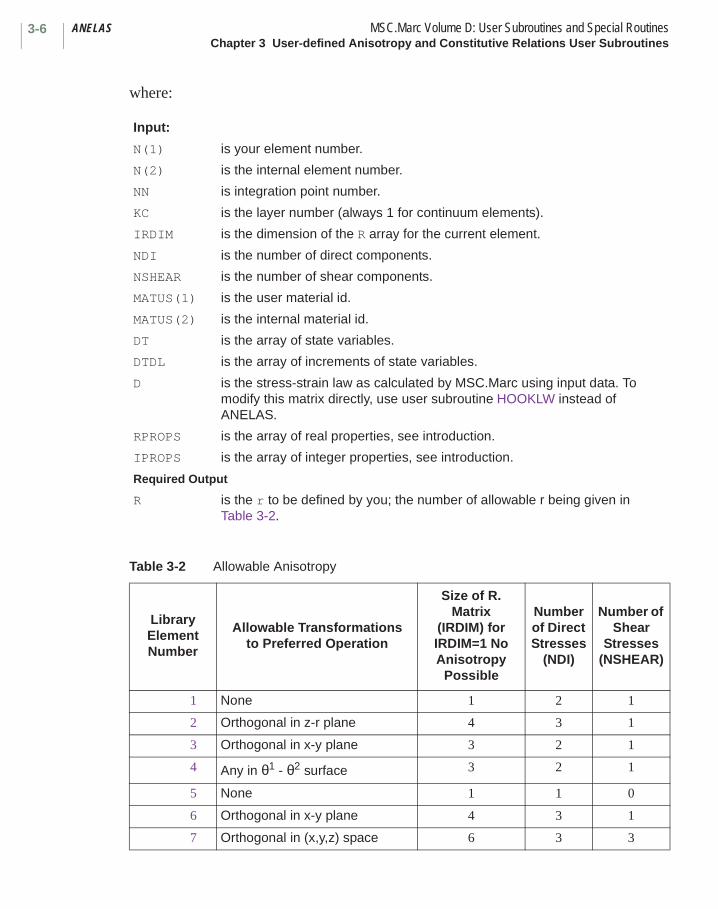
ANELAS MSC.Marc Volume D: User Subroutines and Special RoutinesChapter 3 User-defined Anisotropy and Constitutive Relations User Subroutines
3-6
where:
Input:
N(1) is your element number.
N(2) is the internal element number.
NN is integration point number.
KC is the layer number (always 1 for continuum elements).
IRDIM is the dimension of the R array for the current element.
NDI is the number of direct components.
NSHEAR is the number of shear components.
MATUS(1) is the user material id.
MATUS(2) is the internal material id.
DT is the array of state variables.
DTDL is the array of increments of state variables.
D is the stress-strain law as calculated by MSC.Marc using input data. To modify this matrix directly, use user subroutine HOOKLW instead of ANELAS.
RPROPS is the array of real properties, see introduction.
IPROPS is the array of integer properties, see introduction.
Required Output
R is the r to be defined by you; the number of allowable r being given in Table 3-2.
Table 3-2 Allowable Anisotropy
Library ElementNumber
Allowable Transformations to Preferred Operation
Size of R. Matrix
(IRDIM) forIRDIM=1 No Anisotropy
Possible
Number of Direct Stresses
(NDI)
Number of Shear
Stresses (NSHEAR)
1 None 1 2 1
2 Orthogonal in z-r plane 4 3 1
3 Orthogonal in x-y plane 3 2 1
4 Any in θ1 - θ2 surface 3 2 1
5 None 1 1 0
6 Orthogonal in x-y plane 4 3 1
7 Orthogonal in (x,y,z) space 6 3 3
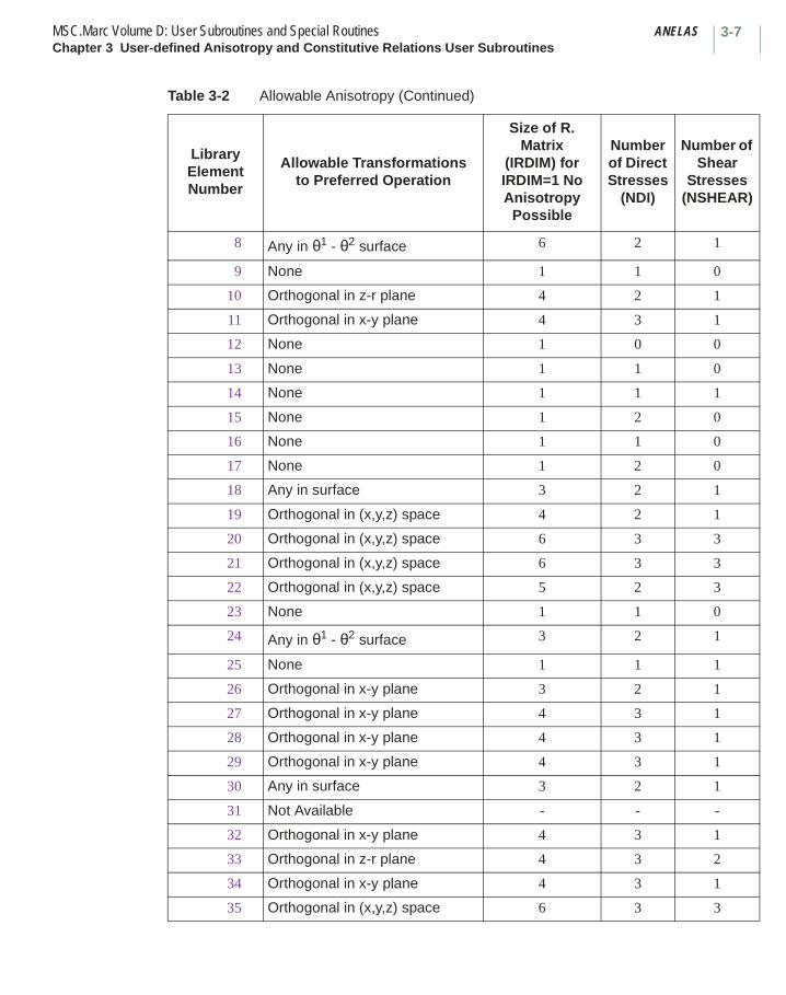
3-7MSC.Marc Volume D: User Subroutines and Special Routines ANELASChapter 3 User-defined Anisotropy and Constitutive Relations User Subroutines
8 Any in θ1 - θ2 surface 6 2 1
9 None 1 1 0
10 Orthogonal in z-r plane 4 2 1
11 Orthogonal in x-y plane 4 3 1
12 None 1 0 0
13 None 1 1 0
14 None 1 1 1
15 None 1 2 0
16 None 1 1 0
17 None 1 2 0
18 Any in surface 3 2 1
19 Orthogonal in (x,y,z) space 4 2 1
20 Orthogonal in (x,y,z) space 6 3 3
21 Orthogonal in (x,y,z) space 6 3 3
22 Orthogonal in (x,y,z) space 5 2 3
23 None 1 1 0
24 Any in θ1 - θ2 surface 3 2 1
25 None 1 1 1
26 Orthogonal in x-y plane 3 2 1
27 Orthogonal in x-y plane 4 3 1
28 Orthogonal in x-y plane 4 3 1
29 Orthogonal in x-y plane 4 3 1
30 Any in surface 3 2 1
31 Not Available - - -
32 Orthogonal in x-y plane 4 3 1
33 Orthogonal in z-r plane 4 3 2
34 Orthogonal in x-y plane 4 3 1
35 Orthogonal in (x,y,z) space 6 3 3
Table 3-2 Allowable Anisotropy (Continued)
Library ElementNumber
Allowable Transformations to Preferred Operation
Size of R. Matrix
(IRDIM) forIRDIM=1 No Anisotropy
Possible
Number of Direct Stresses
(NDI)
Number of Shear
Stresses (NSHEAR)
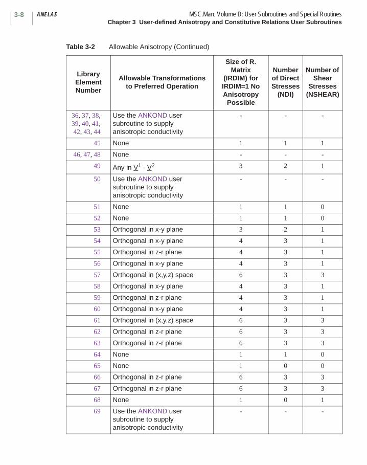
ANELAS MSC.Marc Volume D: User Subroutines and Special RoutinesChapter 3 User-defined Anisotropy and Constitutive Relations User Subroutines
3-8
36, 37, 38,39, 40, 41,42, 43, 44
Use the ANKOND user subroutine to supply anisotropic conductivity
- - -
45 None 1 1 1
46, 47, 48 None - - -
49 Any in V1 - V2 3 2 1
50 Use the ANKOND user subroutine to supply anisotropic conductivity
- - -
51 None 1 1 0
52 None 1 1 0
53 Orthogonal in x-y plane 3 2 1
54 Orthogonal in x-y plane 4 3 1
55 Orthogonal in z-r plane 4 3 1
56 Orthogonal in x-y plane 4 3 1
57 Orthogonal in (x,y,z) space 6 3 3
58 Orthogonal in x-y plane 4 3 1
59 Orthogonal in z-r plane 4 3 1
60 Orthogonal in x-y plane 4 3 1
61 Orthogonal in (x,y,z) space 6 3 3
62 Orthogonal in z-r plane 6 3 3
63 Orthogonal in z-r plane 6 3 3
64 None 1 1 0
65 None 1 0 0
66 Orthogonal in z-r plane 6 3 3
67 Orthogonal in z-r plane 6 3 3
68 None 1 0 1
69 Use the ANKOND user subroutine to supply anisotropic conductivity
- - -
Table 3-2 Allowable Anisotropy (Continued)
Library ElementNumber
Allowable Transformations to Preferred Operation
Size of R. Matrix
(IRDIM) forIRDIM=1 No Anisotropy
Possible
Number of Direct Stresses
(NDI)
Number of Shear
Stresses (NSHEAR)

3-9MSC.Marc Volume D: User Subroutines and Special Routines ANELASChapter 3 User-defined Anisotropy and Constitutive Relations User Subroutines
70 Use the ANKOND user subroutine to supply anisotropic conductivity
- - -
71 Use the ANKOND user subroutine to supply anisotropic conductivity
- - -
72 Orthogonal in V1 - V2 3 2 1
73 Orthogonal in z-r plane 6 3 3
74 Orthogonal in z-r plane 6 3 3
75 Orthogonal in V1 - V2 5 2 3
76 None 1 1 1
77 None 1 1 0
78 None 1 1 1
79 None 1 1 0
80 Orthogonal in x-y plane 4 3 1
81 Orthogonal in x-y plane 4 3 1
82 Orthogonal in z-r plane 4 3 1
83 Orthogonal in z-r plane 4 3 1
84 Orthogonal in (x,y,z) space 6 3 3
85 Use the ANKOND user subroutine to supply anisotropic conductivity
- - -
86 Use the ANKOND user subroutine to supply anisotropic conductivity
- - -
87 Use the ANKOND user subroutine to supply anisotropic conductivity
- - -
88 Use the ANKOND user subroutine to supply anisotropic conductivity
- - -
Table 3-2 Allowable Anisotropy (Continued)
Library ElementNumber
Allowable Transformations to Preferred Operation
Size of R. Matrix
(IRDIM) forIRDIM=1 No Anisotropy
Possible
Number of Direct Stresses
(NDI)
Number of Shear
Stresses (NSHEAR)

ANELAS MSC.Marc Volume D: User Subroutines and Special RoutinesChapter 3 User-defined Anisotropy and Constitutive Relations User Subroutines
3-10
89 None 1 2 1
90 None 1 2 3
91 Orthogonal in x-y plane 4 3 2
92 Orthogonal in z-r plane 4 3 1
93 Orthogonal in x-y plane 4 3 1
94 Orthogonal in z-r plane 4 3 1
95 Orthogonal in z-r plane 6 3 3
96 Orthogonal in z-r plane 6 3 3
97 None 1 0 0
98 None 1 1 2
99 None - - -
100 None - - -
101 Use the ANKOND user subroutine to supply anisotropic conductivity
- - -
102 Use the ANKOND user subroutine to supply anisotropic conductivity
- - -
103 Use the ANKOND user subroutine to supply anisotropic conductivity
- - -
104 Use the ANKOND user subroutine to supply anisotropic conductivity
- - -
105 Use the ANKOND user subroutine to supply anisotropic conductivity
- - -
106 Use the ANKOND user subroutine to supply anisotropic conductivity
- - -
107 Orthogonal in (x,y,z) space 6 3 3
108 Orthogonal in (x, y, z) space 6 3 3
Table 3-2 Allowable Anisotropy (Continued)
Library ElementNumber
Allowable Transformations to Preferred Operation
Size of R. Matrix
(IRDIM) forIRDIM=1 No Anisotropy
Possible
Number of Direct Stresses
(NDI)
Number of Shear
Stresses (NSHEAR)
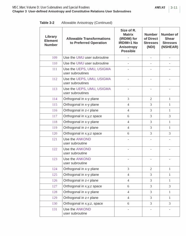
3-11MSC.Marc Volume D: User Subroutines and Special Routines ANELASChapter 3 User-defined Anisotropy and Constitutive Relations User Subroutines
109 Use the UMU user subroutine - - -
110 Use the UMU user subroutine - - -
111 Use the UEPS, UMU, USIGMA user subroutines
- - -
112 Use the UEPS, UMU, USIGMA user subroutines
- - -
113 Use the UEPS, UMU, USIGMA user subroutines
- - -
114 Orthogonal in x-y plane 3 2 1
115 Orthogonal in x-y plane 4 3 1
116 Orthogonal in z-r plane 4 3 1
117 Orthogonal in x,y,z space 6 3 3
118 Orthogonal in x-y plane 4 3 1
119 Orthogonal in z-r plane 4 3 1
120 Orthogonal in x,y,z space 6 3 3
121 Use the ANKOND user subroutine
- - -
122 Use the ANKOND user subroutine
- - -
123 Use the ANKOND user subroutine
- - -
124 Orthogonal in x-y plane 3 2 1
125 Orthogonal in x-y plane 4 3 1
126 Orthogonal in z-r plane 4 3 1
127 Orthogonal in x,y,z space 6 3 3
128 Orthogonal in x-y plane 4 3 1
129 Orthogonal in z-r plane 4 3 1
130 Orthogonal in x,y,z, space 6 3 3
131 Use the ANKOND user subroutine
- - -
Table 3-2 Allowable Anisotropy (Continued)
Library ElementNumber
Allowable Transformations to Preferred Operation
Size of R. Matrix
(IRDIM) forIRDIM=1 No Anisotropy
Possible
Number of Direct Stresses
(NDI)
Number of Shear
Stresses (NSHEAR)
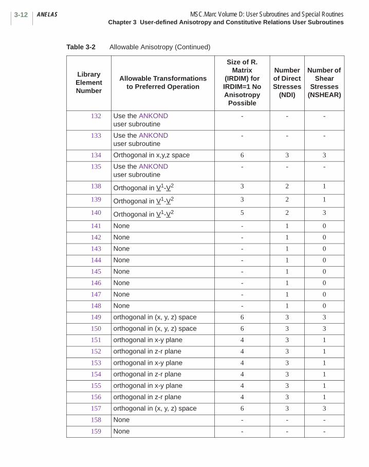
ANELAS MSC.Marc Volume D: User Subroutines and Special RoutinesChapter 3 User-defined Anisotropy and Constitutive Relations User Subroutines
3-12
132 Use the ANKOND user subroutine
- - -
133 Use the ANKOND user subroutine
- - -
134 Orthogonal in x,y,z space 6 3 3
135 Use the ANKOND user subroutine
- - -
138 Orthogonal in V1-V2 3 2 1
139 Orthogonal in V1-V2 3 2 1
140 Orthogonal in V1-V2 5 2 3
141 None - 1 0
142 None - 1 0
143 None - 1 0
144 None - 1 0
145 None - 1 0
146 None - 1 0
147 None - 1 0
148 None - 1 0
149 orthogonal in (x, y, z) space 6 3 3
150 orthogonal in (x, y, z) space 6 3 3
151 orthogonal in x-y plane 4 3 1
152 orthogonal in z-r plane 4 3 1
153 orthogonal in x-y plane 4 3 1
154 orthogonal in z-r plane 4 3 1
155 orthogonal in x-y plane 4 3 1
156 orthogonal in z-r plane 4 3 1
157 orthogonal in (x, y, z) space 6 3 3
158 None - - -
159 None - - -
Table 3-2 Allowable Anisotropy (Continued)
Library ElementNumber
Allowable Transformations to Preferred Operation
Size of R. Matrix
(IRDIM) forIRDIM=1 No Anisotropy
Possible
Number of Direct Stresses
(NDI)
Number of Shear
Stresses (NSHEAR)

3-13MSC.Marc Volume D: User Subroutines and Special Routines ANELASChapter 3 User-defined Anisotropy and Constitutive Relations User Subroutines
All parameters except the R array are defined by MSC.Marc. R must be defined by the user in this user subroutine.
160 Orthogonal in x-y plane 3 2 1
161 Orthogonal in x-y plane 4 3 1
162 Orthogonal in z-r plane 4 3 1
163 Orthogonal in x-y-z space 6 3 3
164 Orthogonal in x-y-z space 6 3 3
165 None 1 1 0
166 None 1 1 0
167 None 1 1 0
168 None 1 1 0
169 None 1 1 0
170 None 1 1 0
171 None 1 0 0
172 None 1 0 0
173 None 1 0 0
174 None 1 0 0
175 Use the ANKOND user subroutine
- - -
176 Use the ANKOND user subroutine
- - -
177 Use the ANKOND user subroutine
- - -
178 Use the ANKOND user subroutine
- - -
179 Use the ANKOND user subroutine
- - -
180 Use the ANKOND user subroutine
- - -
Table 3-2 Allowable Anisotropy (Continued)
Library ElementNumber
Allowable Transformations to Preferred Operation
Size of R. Matrix
(IRDIM) forIRDIM=1 No Anisotropy
Possible
Number of Direct Stresses
(NDI)
Number of Shear
Stresses (NSHEAR)

ANELAS MSC.Marc Volume D: User Subroutines and Special RoutinesChapter 3 User-defined Anisotropy and Constitutive Relations User Subroutines
3-14
Note that the R and D matrices have the dimension appropriate for the number of stress components associated with the particular element (see Table 3-2). Thus, for example, in elements 3 or 18, the R matrix would be of size 3 by 3, and the stress strain law would take the form:
To define an anisotropic stress-strain relation for the Herrmann incompressible elements in MSC.Marc, the ANELAS user subroutine is used in a slightly different manner. The compliance strain-stress relation is given directly in the fourth argument R and is not used in the last argument D. For example, in the most generally allowed case, the compliance relation in the preferred orientation is:
Note: This user subroutine should not be used if you desire that the material constants should be design variables. Use the ORTHOTROPIC option instead.
σ1
σ2
σ12
r11 D11 r12 D12 0
r22 D22 0
r33 D33
ε11
ε22
γ12
=
Symmetric
ε11
ε22
ε33
γ12
γ23
γ31 R11 R12 R13 0 0 0
R22 R23 0 0 0
R33 0 0 0
R44 0 0
R55 0
R66
σ11
σ22
σ33
τ12
τ23
τ31
=
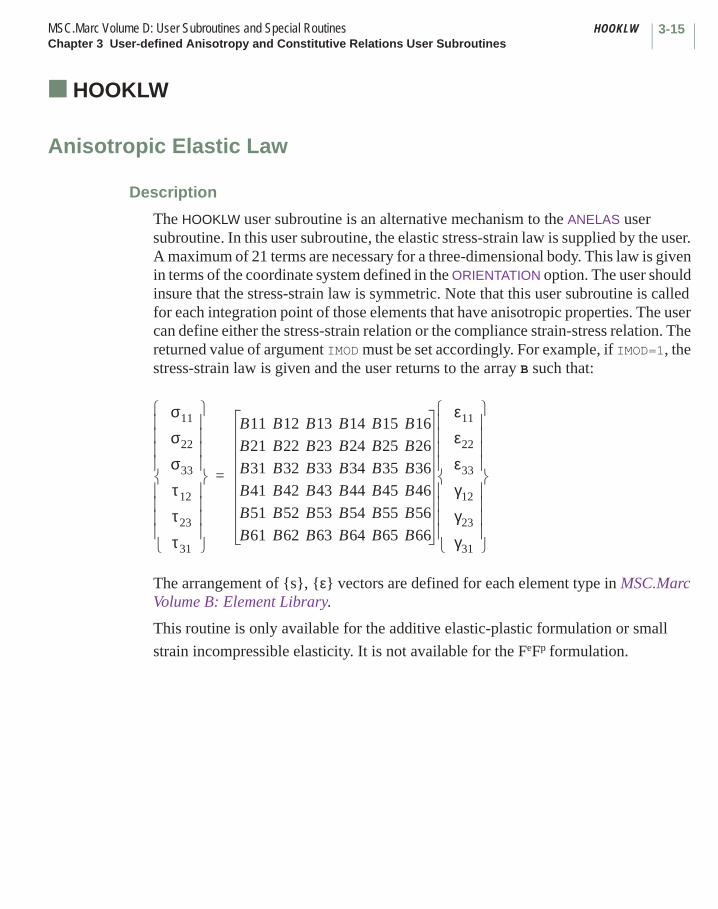
3-15MSC.Marc Volume D: User Subroutines and Special Routines HOOKLWChapter 3 User-defined Anisotropy and Constitutive Relations User Subroutines
■ HOOKLW
Anisotropic Elastic Law
Description
The HOOKLW user subroutine is an alternative mechanism to the ANELAS user subroutine. In this user subroutine, the elastic stress-strain law is supplied by the user. A maximum of 21 terms are necessary for a three-dimensional body. This law is given in terms of the coordinate system defined in the ORIENTATION option. The user should insure that the stress-strain law is symmetric. Note that this user subroutine is called for each integration point of those elements that have anisotropic properties. The user can define either the stress-strain relation or the compliance strain-stress relation. The returned value of argument IMOD must be set accordingly. For example, if IMOD=1, the stress-strain law is given and the user returns to the array B such that:
The arrangement of {s}, {ε} vectors are defined for each element type in MSC.Marc Volume B: Element Library.
This routine is only available for the additive elastic-plastic formulation or small
strain incompressible elasticity. It is not available for the FeFp formulation.
σ11
σ22
σ33
τ12
τ23
τ31
B11 B12 B13 B14 B15 B16
B21 B22 B23 B24 B25 B26
B31 B32 B33 B34 B35 B36
B41 B42 B43 B44 B45 B46
B51 B52 B53 B54 B55 B56
B61 B62 B63 B64 B65 B66
ε11
ε22
ε33
γ12
γ23
γ31
=
HOOKLW MSC.Marc Volume D: User Subroutines and Special RoutinesChapter 3 User-defined Anisotropy and Constitutive Relations User Subroutines
3-16
Format
User subroutine HOOKLW is written with the following headers: SUBROUTINE HOOKLW(M,NN,KC,B,NGENS,DT,DTDL,E,PR,NDI,NSHEAR,+IMOD,RPROPS,IPROPS) IMPLICIT REAL *8 (A-H, O-Z) DIMENSION B(NGENS,NGENS),DT(1),DTDL(1),RPROPS(1),IPROPS(1),+M(2)
user coding
RETURN END
where:
Note that for temperature dependent properties, this user subroutine is called twice for each integration point. The first time to evaluate the stress-strain law at the beginning of the increment; the second time at the end of the increment.
Note: This user subroutine should not be used if the user desires that the material constants should be design variables. Use the ORTHOTROPIC option instead.
Input:
M(1) is the user element number.
M(2) is the internal element number.
NN is the integration point number.
KC is the layer number.
NGENS is the number of stresses and strain components.
DT is the state variables at the beginning of the increment (temperature first).
DTDL is the increment of state variables.
E is the Young’s modulus including temperature effects.
PR is the Poisson’s ratio including temperature effects.
NDI number of direct components of stress.
NSHEAR number of shear components of stress.
RPROPS array of real properties; see Chapter 1 Introduction.
IPROPS array of integer properties; see Chapter 1 Introduction.
Required Output
B is the user-defined stress-strain law if IMOD=1; or the user-defined compliance relation if IMOD=2 to be defined here.
IMOD Set to 0 if the ANELAS user subroutine is used.Set to 1 to indicate that the stress-strain law has been given. Set to 2 to indicate that the compliance strain-stress, relation has been given.
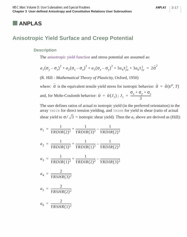
3-17MSC.Marc Volume D: User Subroutines and Special Routines ANPLASChapter 3 User-defined Anisotropy and Constitutive Relations User Subroutines
■ ANPLAS
Anisotropic Yield Surface and Creep Potential
Description
The anisotropic yield function and stress potential are assumed as:
(R. Hill - Mathematical Theory of Plasticity, Oxford, 1950)
where: is the equivalent tensile yield stress for isotropic behavior:
and, for Mohr-Coulomb behavior: ;
The user defines ratios of actual to isotropic yield (in the preferred orientation) in the array YRDIR for direct tension yielding, and YRSHR for yield in shear (ratio of actual
shear yield to = isotropic shear yield). Then the a1 above are derived as (Hill):
a1 σy σz–( )2a2 σz σx–( )2
a3 σx σy–( )23a4τyz
2 3a6τxy2+ +++ 2σ2
=
σ σ σ εP T,( )=
σ σ J1( )= J1
σx σy σz+ +
3------------------------------=
σ 3⁄
a11
YRDIR 2( )2-----------------------------
1YRDIR 3( )2-----------------------------
1YRDIR 2( )2-----------------------------–+=
a21
YRDIR 3( )2-----------------------------
1YRDIR 1( )2-----------------------------
1YRDIR 2( )2-----------------------------–+=
a31
YRDIR 1( )2-----------------------------
1YRDIR 2( )2-----------------------------
YRDIR 3( )2-----------------------------–+=
a42
YRSHR 3( )2------------------------------=
a52
YRSHR 2( )2------------------------------=
a62
YRSHR 1( )2------------------------------=
ANPLAS MSC.Marc Volume D: User Subroutines and Special RoutinesChapter 3 User-defined Anisotropy and Constitutive Relations User Subroutines
3-18
Note that YRDIR and YRSHR should be given in the order appropriate for the element (see Library Element description).
On the output, the von Mises intensity is not affected by these material parameters.
Format
User subroutine ANPLAS is written with the following headers:SUBROUTINE ANPLAS(N,NN,LAYER,NDI,NSHEAR,MATUS,YRDIR,YRSHR)IMPLICIT REAL *8 (A-H, O-Z)DIMENSION YRDIR (1),YRSHR(1),N(2),MATUS(2)
user coding
RETURNEND
where:
All parameters except YRDIR and YRSHR are defined by MSC.Marc. YRDIR and YRSHR are defined by the user in this user subroutine.
Input:
N(1) is your element number.
N(2) is the internal element number.
NN is the integration point number.
LAYER is the layer number (always 1 for continuum elements).
NDI is the number of direct stresses.
NSHEAR is the number of shear stresses.
MATUS(1) is the user material id.
MATUS(2) is the internal material id
Required Output
YRDIR is the array of tensile yield ratios to be defined here.
YRSHR is the array of shear yield ratios to be defined here.
3-19MSC.Marc Volume D: User Subroutines and Special Routines UFAILChapter 3 User-defined Anisotropy and Constitutive Relations User Subroutines
■ UFAIL
User-defined Failure Criterion
Description
The UFAIL user subroutine is provided to allow the user to calculate his own scalar failure criterion. To call the UFAIL user subroutine, the user must specify failure criterion type UFAIL in the FAIL DATA model definition option. UFAIL is then called for every integration point associated with the material id specified in the FAIL DATA option.
This routine may be used with all elastic-plastic materials. Progressive cracking is only available with the additive elastic-plastic model.
Format
User subroutine UFAIL is written with the following headers: SUBROUTINE UFAIL (N,NN,KC,MATUS,1 STRESS,STRAIN,NDI,NSHEAR,FAILCR) IMPLICIT REAL *8 (A-H, O-Z) DIMENSION STRESS(1),STRAIN(1),N(2),MATUS(2)
user coding
RETURN END
where:
Input:
N(1) is the user element number.
N(2) is the internal element number.
NN is the integration point number.
KC is the layer number.
MATUS(1) is the user material identifier.
MATUS(2) is the internal material identifier.
STRESS is the current total stress state.
STRAIN is the current total strain.
NDI is the number of direct stresses.
NSHEAR is the number of shear stresses.
Required Output
FAILCR is your calculated failure criterion.
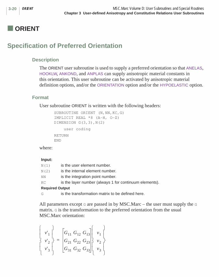
ORIENT MSC.Marc Volume D: User Subroutines and Special RoutinesChapter 3 User-defined Anisotropy and Constitutive Relations User Subroutines
3-20
■ ORIENT
Specification of Preferred Orientation
Description
The ORIENT user subroutine is used to supply a preferred orientation so that ANELAS, HOOKLW, ANKOND, and ANPLAS can supply anisotropic material constants in this orientation. This user subroutine can be activated by anisotropic material definition options, and/or the ORIENTATION option and/or the HYPOELASTIC option.
Format
User subroutine ORIENT is written with the following headers:SUBROUTINE ORIENT (N,NN,KC,G)IMPLICIT REAL *8 (A-H, O-Z)DIMENSION G(3,3),N(2)
user coding
RETURN END
where:
All parameters except G are passed in by MSC.Marc – the user must supply the G matrix. G is the transformation to the preferred orientation from the usual MSC.Marc orientation:
Input:N(1) is the user element number.N(2) is the internal element number.NN is the integration point number.KC is the layer number (always 1 for continuum elements).Required Output
G is the transformation matrix to be defined here.
v'1v'2v'3
G11 G12 G13
G21 G22 G23
G31 G32 G33
v1
v2
v3
=

3-21MSC.Marc Volume D: User Subroutines and Special Routines ORIENTChapter 3 User-defined Anisotropy and Constitutive Relations User Subroutines
where:
For curvilinear systems (for example, element types 4, 8, and 24), G is defined by
G(I,J) = . For planar transformations, G(3,I) = G(I,3) = 0; G(3,3) = 1.0; I = 1,2 must
be given.
Note: This user subroutine should not be used if the user desires that the material orientation be a design variable. Use the COMPOSITE option instead.
v is the vector in the MSC.Marc system.
v' is the vector in the preferred system.
gji
ANEXP MSC.Marc Volume D: User Subroutines and Special RoutinesChapter 3 User-defined Anisotropy and Constitutive Relations User Subroutines
3-22
■ ANEXP
Anisotropic Thermal Expansion
Description
The ANEXP user subroutine is used to specify anisotropic thermal strain increments in the orientation defined by the ORIENTATION option. The user is given the temperature at the beginning of the increment, the temperature increment, and the base value of the thermal expansion coefficients given on the ISOTROPIC or ORTHOTROPIC
options. The user must supply the incremental thermal strain vector ( for
doubly curved shell elements 4, 8, and 24) in the user subroutine. Any components of the incremental thermal strain vector not defined in the user subroutine assume their default program calculated values.
The ANEXP user subroutine is called for all elements at all integration points if the temperature is nonzero for all material models.
Format
User subroutine ANEXP is written with the following headers: SUBROUTINE ANEXP (N,NN,KC,T,TINC,COED,NDI,NSHEAR,EQEXP) IMPLICIT REAL *8 (A-H, O-Z) DIMENSION EQEXP(1),TINC(1),T(1),COED(NDI),N(2)
user coding
RETURN END
where:
Input:
N(1) is the user element number.
N(2) is the internal element number.
NN is the integration point number.
KC is the layer number for shells or beams (always 1 for continuum elements).
T(1) is the total temperature at the beginning of the increment.
T(2) is the total values of other state variables at the beginning of the increment.
TINC(1) is the temperature increment.
∆εijth ∆εth
ij
3-23MSC.Marc Volume D: User Subroutines and Special Routines ANEXPChapter 3 User-defined Anisotropy and Constitutive Relations User Subroutines
TINC(2) etc. are the increments of other state variables.
COED(I) is the base value of the Ith coefficient of thermal expansion as given through the input data. There are NDI coefficients for each element.
NDI is the number of direct components of strain at this point.
NSHEAR is the number of shear components of strain at this point.
Required Output
EQEXP is the thermal strain increment vector, to be defined by the user in this user subroutine.
Note: For the curvilinear coordinate elements (doubly curved shell elements 4, 8, 24) the mixed strain tensor shear components,
ε12, ε2
1, are stored. Otherwise, shear components are
engineering shear strain.

ANKOND MSC.Marc Volume D: User Subroutines and Special RoutinesChapter 3 User-defined Anisotropy and Constitutive Relations User Subroutines
3-24
■ ANKOND
Input of Anisotropic Thermal Conductivity Matrix
Description
For anisotropic heat transfer analysis, this user subroutine allows the user to define an anisotropic conductivity matrix at each integration point in each element. The anisotropic conductivity matrix is defined with respect to the preferred orientation specified in the ORIENTATION option. This user subroutine is also used for anisotropic electrical resistance in a Joule heating analysis.
Format
User subroutine ANKOND is written with the following headers: SUBROUTINE ANKOND (COND,CANISO,N,NN,KC,MATUS,ID,T,DT,TIME,* DELTME,JOULHT) IMPLICIT REAL *8 (A-H, O-Z) DIMENSION COND(ID,ID),CANISO(3),MATUS(2)
user coding
RETURN END
where:
Input:
CANISO are the anisotropic conductivities kij (T) established by the user via data blocks.
N is the element number.
NN is the integration point number.
KC is the layer number.
MATUS(1) is the user material identifier.
MATUS(2) is the internal material identifier.
ID is the size of the COND matrix; that is, the number of derivatives.
T is the temperature at the beginning of the time increment.
DT is the estimated temperature increment.
TIME is the transient time at the beginning of the increment.
DELTME is the increment of time.
∂T∂xj-------

3-25MSC.Marc Volume D: User Subroutines and Special Routines ANKONDChapter 3 User-defined Anisotropy and Constitutive Relations User Subroutines
JOULHT = 0 return thermal conductivity.= 1 return electrical conductivity.
Required Output
COND is the conductivity matrix, kij:
This is to be re-defined as necessary by the user.This matrix is passed in as set-up for anisotropic conductivity. If the user does not re-define it, it remains anisotropic according to kij (T) given on the ISOTROPIC, ORTHOTROPIC, and TEMPERATURE EFFECTS or TABLE options.
qi kij=∂T∂xj-------
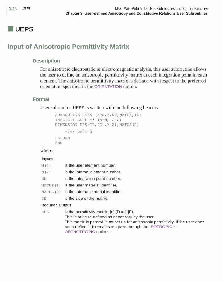
UEPS MSC.Marc Volume D: User Subroutines and Special RoutinesChapter 3 User-defined Anisotropy and Constitutive Relations User Subroutines
3-26
■ UEPS
Input of Anisotropic Permittivity Matrix
Description
For anisotropic electrostatic or electromagnetic analysis, this user subroutine allows the user to define an anisotropic permittivity matrix at each integration point in each element. The anisotropic permittivity matrix is defined with respect to the preferred orientation specified in the ORIENTATION option.
Format
User subroutine UEPS is written with the following headers:SUBROUTINE UEPS (EPS,M,NN,MATUS,ID)IMPLICIT REAL *8 (A-H, O-Z)DIMENSION EPS(ID,ID),M(2),MATUS(2)
user coding
RETURN END
where:
Input:
M(1) is the user element number.
M(2) is the internal element number.
NN is the integration point number.
MATUS(1) is the user material identifier.
MATUS(2) is the internal material identifier.
ID is the size of the matrix.
Required Output
EPS is the permittivity matrix, [ε] (D = [ε]E).This is to be re-defined as necessary by the user. This matrix is passed in as set-up for anisotropic permittivity. If the user does not redefine it, it remains as given through the ISOTROPIC or ORTHOTROPIC options.
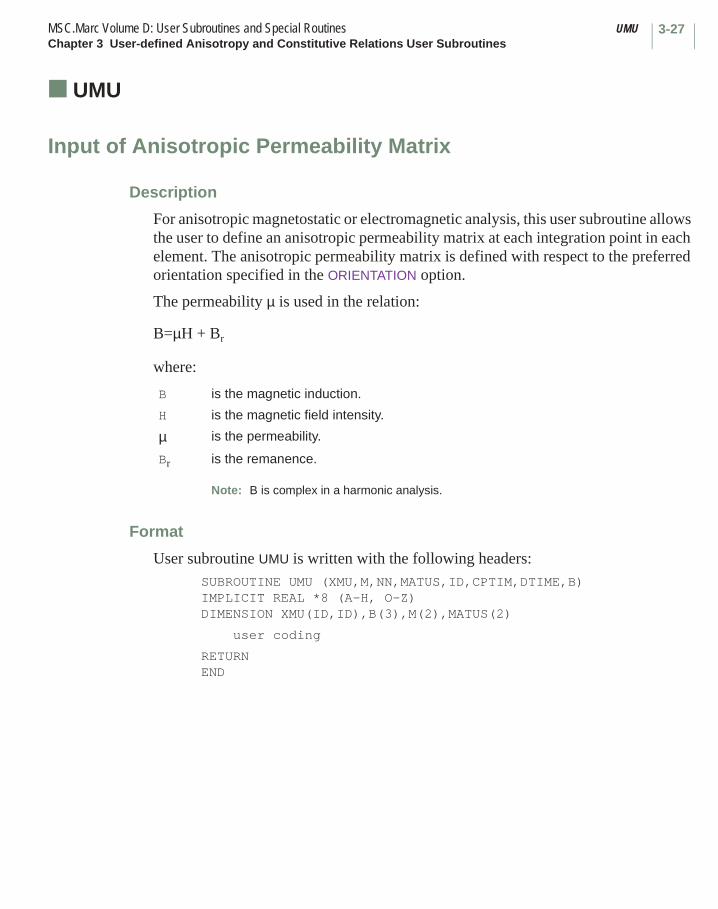
3-27MSC.Marc Volume D: User Subroutines and Special Routines UMUChapter 3 User-defined Anisotropy and Constitutive Relations User Subroutines
■ UMU
Input of Anisotropic Permeability Matrix
Description
For anisotropic magnetostatic or electromagnetic analysis, this user subroutine allows the user to define an anisotropic permeability matrix at each integration point in each element. The anisotropic permeability matrix is defined with respect to the preferred orientation specified in the ORIENTATION option.
The permeability µ is used in the relation:
B=µH + Br
where:
Format
User subroutine UMU is written with the following headers:SUBROUTINE UMU (XMU,M,NN,MATUS,ID,CPTIM,DTIME,B)IMPLICIT REAL *8 (A-H, O-Z)DIMENSION XMU(ID,ID),B(3),M(2),MATUS(2)
user coding
RETURN END
B is the magnetic induction.
H is the magnetic field intensity.
µ is the permeability.
Br is the remanence.
Note: B is complex in a harmonic analysis.
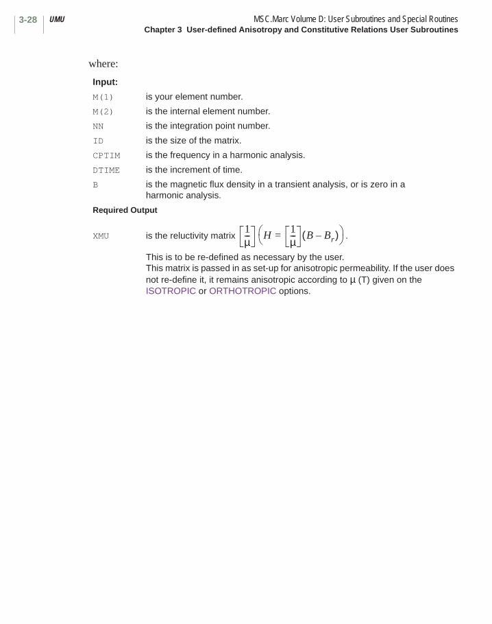
UMU MSC.Marc Volume D: User Subroutines and Special RoutinesChapter 3 User-defined Anisotropy and Constitutive Relations User Subroutines
3-28
where:
Input:
M(1) is your element number.
M(2) is the internal element number.
NN is the integration point number.
ID is the size of the matrix.
CPTIM is the frequency in a harmonic analysis.
DTIME is the increment of time.
B is the magnetic flux density in a transient analysis, or is zero in a harmonic analysis.
Required Output
XMU is the reluctivity matrix .
This is to be re-defined as necessary by the user. This matrix is passed in as set-up for anisotropic permeability. If the user does not re-define it, it remains anisotropic according to µ (T) given on the ISOTROPIC or ORTHOTROPIC options.
1µ--- H
1µ--- B Br–( )=

3-29MSC.Marc Volume D: User Subroutines and Special Routines USIGMAChapter 3 User-defined Anisotropy and Constitutive Relations User Subroutines
■ USIGMA
Input of Anisotropic Electric Conductivity Matrix
Description
For anisotropic electromagnetic analysis, this user subroutine allows the user to define an anisotropic conductivity matrix at each integration point in each element. The anisotropic permittivity matrix is defined with respect to the preferred orientation specified in the ORIENTATION option.
Format
User subroutine USIGMA is written with the following headers:SUBROUTINE USIGMA (SIGMA,M,NN,MATUS,ID,CPTIM,DTIME)IMPLICIT REAL *8 (A-H, O-Z)DIMENSION SIGMA(3,3),M(2),MATUS(2)
user coding
RETURN END
where:
Input:
M(1) is the user element number.
M(2) is the internal element number.
NN is the integration point number.
MATUS(1) is the user material identifier.
MATUS(2) is the internal material identifier.
CPTIM is the transient time at the beginning of the increment; in a harmonic analysis, it is the frequency.
DTIME is the increment of time.
ID is the size of the matrix.
Required Output
SIGMA is the electric conductivity matrix, [σ] (J = [σ]E).This is to be re-defined as necessary by the user. This matrix is passed in as set-up for anisotropic conductivity. If the user does not re-define it, it remains as given through the ISOTROPIC or ORTHOTROPIC options.

USPCHT MSC.Marc Volume D: User Subroutines and Special RoutinesChapter 3 User-defined Anisotropy and Constitutive Relations User Subroutines
3-30
■ USPCHT
Definition of Specific Heat
Description
This user subroutine allows the user to define the specific heat in a heat transfer or coupled analysis. This is an alternative to the use of the ISOTROPIC or ORTHOTROPIC and TEMPERATURE EFFECTS or TABLE options. This user subroutine is called at each increment for every element in the mesh, hence, allowing the user to specify a nonlinear relationship. This is often useful in welding or casting analyses.
Format
User subroutine USPCHT is written with the following headers: SUBROUTINE USPCHT (SPHEAT,M,NN,KC,INC,NCYCLE,MATUS,NSTATS,DT,+DTDL,CPTIM,TIMINC) IMPLICIT REAL *8 (A-H, O-Z) DIMENSION SIGMA(3,3),M(2),DT(NSTATS),DTDL(NSTATS),MATUS(2)
user coding
RETURN END
where:
Input:M(1) is the user element number.M(2) is the internal element number.NN is the integration point number.KC is the layer number.INC is the increment number.NCYCLE is the cycle number.MATUS(1) is the user material identifier.MATUS(2) is the internal material identifier.NSTATS is the number of state variables.DT is the temperature at the start of the increment.DTDL is the estimated increment of temperature.CPTIM is the time at the beginning of the increment.TIMINC is the increment of time.Required Output
SPHEAT is the specific heat per unit mass. This is to be defined by the user.
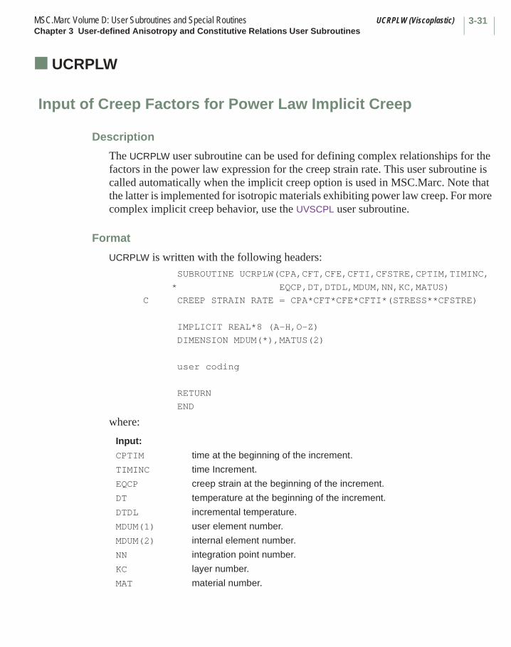
3-31MSC.Marc Volume D: User Subroutines and Special Routines UCRPLW (Viscoplastic)Chapter 3 User-defined Anisotropy and Constitutive Relations User Subroutines
■ UCRPLW (Viscoplastic)
Input of Creep Factors for Power Law Implicit Creep
Description
The UCRPLW user subroutine can be used for defining complex relationships for the factors in the power law expression for the creep strain rate. This user subroutine is called automatically when the implicit creep option is used in MSC.Marc. Note that the latter is implemented for isotropic materials exhibiting power law creep. For more complex implicit creep behavior, use the UVSCPL user subroutine.
Format
UCRPLW is written with the following headers: SUBROUTINE UCRPLW(CPA,CFT,CFE,CFTI,CFSTRE,CPTIM,TIMINC,
* EQCP,DT,DTDL,MDUM,NN,KC,MATUS)
C CREEP STRAIN RATE = CPA*CFT*CFE*CFTI*(STRESS**CFSTRE)
IMPLICIT REAL*8 (A-H,O-Z)
DIMENSION MDUM(*),MATUS(2)
user coding
RETURN
END
where:
Input:
CPTIM time at the beginning of the increment.
TIMINC time Increment.
EQCP creep strain at the beginning of the increment.
DT temperature at the beginning of the increment.
DTDL incremental temperature.
MDUM(1) user element number.
MDUM(2) internal element number.
NN integration point number.
KC layer number.
MAT material number.

UCRPLW (Viscoplastic) MSC.Marc Volume D: User Subroutines and Special RoutinesChapter 3 User-defined Anisotropy and Constitutive Relations User Subroutines
3-32
Required Output
CPA creep constant.
CFT temperature factor.
CFE creep strain factor.
CFTI time factor.
CFSTRE stress exponent.

3-33MSC.Marc Volume D: User Subroutines and Special Routines CRPLAWChapter 3 User-defined Anisotropy and Constitutive Relations User Subroutines
■ CRPLAW
Input of Special Creep Law
Description
The CRPLAW user subroutine allows the user to specify the increment of creep strain.
The use of such a user subroutine is flagged by setting the fifth field of the second block in the CREEP model definition option to zero. This user subroutine is called as required during the analysis because of possible re-cycling due to nonconvergence. The number of times the user subroutine is called in each increment is not fixed.
MSC.Marc allows the user to input his own creep law through the CRPLAW user subroutine.
The assumed form of the law is:
where:
is the equivalent creep strain rate, in uniaxial tension.
is the current equivalent (J) stress, normalized for uniaxial tension.
T is the current total temperature.
t is the current total time.
is the current total equivalent creep strain, normalized for uniaxial tension.
p is the hydrostatic stress.
are the state variables. MSC.Marc requires the user to program his creep law so that an equivalent creep strain increment is defined.
ε· c f σ T t εc p α1 α2 etc, , , , , , ,( )=
ε· c
σ
εc
α1 α2 etc., ,
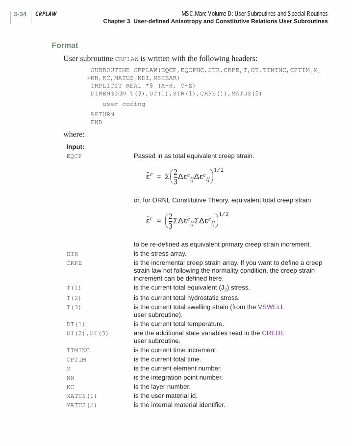
CRPLAW MSC.Marc Volume D: User Subroutines and Special RoutinesChapter 3 User-defined Anisotropy and Constitutive Relations User Subroutines
3-34
Format
User subroutine CRPLAW is written with the following headers: SUBROUTINE CRPLAW(EQCP,EQCPNC,STR,CRPE,T,DT,TIMINC,CPTIM,M,+NN,KC,MATUS,NDI,NSHEAR) IMPLICIT REAL *8 (A-H, O-Z) DIMENSION T(3),DT(1),STR(1),CRPE(1),MATUS(2)
user coding
RETURN END
where:
Input:EQCP Passed in as total equivalent creep strain.
or, for ORNL Constitutive Theory, equivalent total creep strain,
to be re-defined as equivalent primary creep strain increment.STR is the stress array.CRPE is the incremental creep strain array. If you want to define a creep
strain law not following the normality condition, the creep strain increment can be defined here.
T(1) is the current total equivalent (J2) stress.
T(2) is the current total hydrostatic stress.T(3) is the current total swelling strain (from the VSWELL
user subroutine).DT(1) is the current total temperature.DT(2),DT(3) are the additional state variables read in the CREDE
user subroutine. TIMINC is the current time increment.CPTIM is the current total time.M is the current element number.NN is the integration point number.KC is the layer number.MATUS(1) is the user material id.MATUS(2) is the internal material identifier.
εc Σ 23---∆εc
ij∆εcij
1 2⁄=
εc 23---Σ∆εc
ijΣ∆εcij
1 2⁄=

3-35MSC.Marc Volume D: User Subroutines and Special Routines CRPLAWChapter 3 User-defined Anisotropy and Constitutive Relations User Subroutines
The simplest way to define a creep strain increment from a given rate law
is to multiply by ∆t, the time increment:
As an example, suppose we wish to use the creep law (where A and B are constants):
This would be programmed as follows: SUBROUTINE CRPLAW(EQCP,EQCPNC,STR,CRPE,T,DT,TIMINC, +CPTIM,M,NN,KC,MATUS,NDI,NSHEAR) IMPLICIT REAL *8 (A-H, O-Z) DIMENSION T(1),DT(1),STR(1),CRPE(1),MATUS(2)C DEFINE A AND B A = CONSTANT1 B = CONSTANT2 C OBTAIN SINH (T/B) S = T(1) IF (S.EQ.0.) GO TO 1 SINHT = .5*(EXP(S/B)-EXP(-S/B)) GO TO 2 1 SINHT = 0. 2 CONTINUE C NON DEFINE EQCPNC EQCPNC = TIMINC*A*SINHT RETURN END
The ORNL recommendations include the use of a strain hardening creep formulation. The following example of the CRPLAW user subroutine shows a simple technique of numerical solution for a strain hardening formulation based on equivalent total creep strain. The example is based on a Blackburn formulation with a single primary term,
NDI is the number of direct components of strain.NSHEAR is the number of shear components of strain.Required Output
EQCPNC is the equivalent creep strain increment; to be defined by the user in this user subroutine. For ORNL Constitutive Theory, passed in as equivalent total primary creep strain. Otherwise undefined when passed in.Must be redefined by the user as equivalent creep strain increment.
ε· c f σ etc,( )=
∆εc ∆t f σ etc,( )⋅=
ε· c AσB--- sinh=

CRPLAW MSC.Marc Volume D: User Subroutines and Special RoutinesChapter 3 User-defined Anisotropy and Constitutive Relations User Subroutines
3-36
but the technique is general and can be used for more complex formulations. The numerical inversion of the total creep equation for equivalent time is achieved by Newton’s method:
tn is the solution for equivalent time at the nth iteration.
∆t is the correction to t at the nth iteration, and the total creep equation is
with
A tolerance of 10-6 has been placed on .
Practical experience shows this needs about four or five iterations for the creep law in the example. The listing of CRPLAW follows:
SUBROUTINE CRPLAW(EQCP,EQCPNC,STR,CRPE,T,DT,TIMINC,CPTIM, +M,NN,DC,MATUS,NDI,NSHEAR) IMPILCIT *8 (A-H, O-Z) DIMENSION T(1),DT(1),STR(1),CRPE(1),MATUS(2)C THIS ROUTINE FORMULATES THE STRAIN HARDENING FORMULATION OF C THE BLACKBURN CREEP LAW. C EPSILON C DOT=1/TIME SUB CAP T * (EPSILON SUR T - EPSILON SUSUPER T) C + EPSILON DOT SUB M C THE FOLLOWING DEFINITION APPLIES TO THE FUNCTION CODED BELOW C A IS LN(A) C B IS ALPHA*SIGMA C E IS N C C IS Q C C IS T C EPSILON SUB T, T, SUB T AND EPSILON SUB M DOT ARE GIVEN BY A CURVE C FUN + A*SINH TO N OF ALPHA SIGMA TIMES E TO Q/T EXP C IHARD=0 USES STRAIN HARDENING C STRAIN NOW DIMENSIONAL
tn 1+ tn ∆t+=
tεc– f T σ tn, ,( )+
f′– T σ tn, ,( )---------------------------------------=
εc f T σ t, ,( )=
f ′ ∂f∂t----=
∆ttn-----
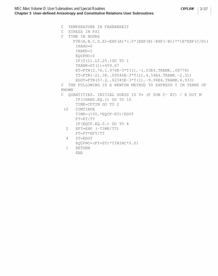
3-37MSC.Marc Volume D: User Subroutines and Special Routines CRPLAWChapter 3 User-defined Anisotropy and Constitutive Relations User Subroutines
C TEMPERATURE IN FAHRENHEIT C STRESS IN PSI C TIME IN HOURS FTN(A,B,C,D,E)=EXP(A)*(.5*(EXP(B)-EXP(-B))**)E*EXP(C/D)) IHARD=0 IHARD=1 EQCPNC=0 IF(T(1).LT.25.)GO TO 1 TRANK=DT(1)+459.67 ET=FTN(2.76,1.976E-3*T(1),-1,03E4,TRANK,.08778) TT=FTN(-21.38,.09546E-3*T(1),4.54E4,TRANK,-2.31) EDOT=FTN(57.2,.02345E-3*T(1),-9.98E4,TRANK,6.933) C THE FOLLOWING IS A NEWTON METHOD TO EXPRESS T IN TERMS OF KNOWN C QUANTITIES. INITIAL GUESS IS T= (F SUB C- ET) / E DOT M IF(IHARD.EQ.1) GO TO 10 TIME=CPTIM GO TO 2 10 CONTINUE TIME=(100.*EQCP-ET)/EDOT FT=ET/TT IF(EQCP.EQ.0.) GO TO 4 2 EFT=EXP (-TIME/TT) FT=FT*EFT/TT 4 ST=EDOT EQCPNC=(FT+ST)*TININC*0.01 1 RETURN END

VSWELL MSC.Marc Volume D: User Subroutines and Special RoutinesChapter 3 User-defined Anisotropy and Constitutive Relations User Subroutines
3-38
■ VSWELL
Input of Special Swelling Law
Description
The VSWELL user subroutine allows the user to include pure swelling (dilatational) creep in MSC.Marc.
Format
User subroutine VSWELL is written with the following headers:SUBROUTINE VSWELL(SWELL,SIG,TEMP,N,NN,KC,CPTIM,TIMINC,MATUS,
+DTEMP) IMPLICIT REAL *8 (A-H, O-Z)DIMENSION SIG(3),TEMP(1),DTEMP(1),MATUS(2)
user coding
RETURNEND
where:
Input:
SIG(1) is the uniaxial equivalent of J2 stress.
SIG(2) is the hydrostatic stress.
SIG(3) is the current total swelling strain (accumulated from this user subroutine).
Note: This is a uniaxial component; that is,
TEMP(1) is the temperature.
TEMP(2),TEMP(3), etc.
are the additional state variables read in through the CREDE user subroutine.
N is the element number.
NN is the integration point number.
KC is the layer number.
CPTIM is the total creep time.
TIMINC is the current time increment.
MATUS(1) is the user material identifier.
MATUS(2) is the internal material identifier.
13---
DVV
--------

3-39MSC.Marc Volume D: User Subroutines and Special Routines VSWELLChapter 3 User-defined Anisotropy and Constitutive Relations User Subroutines
The user defines the increment of dilatational creep by this user subroutine, which is called at each integration point where constitutive calculations are being performed by MSC.Marc. It is called automatically when any CREEP incremental option is used (AUTO CREEP, CREEP INCREMENT, etc.) and can be used alone or in combination with a Mises type creep law(CRPLAW user subroutine). This user subroutine is called as required during the analysis, so that, because of possible re-cycling due to nonconvergence, the number of times the user subroutine is called in each increment is not fixed.
Example
The following is a typical irradiation swelling formulation:
where:
a, b0, b1, b2, c are numerical constants, q is flux, t is time and T is temperature.
Differentiating with respect to time,
so that user subroutine VSWELL becomes:SUBROUTINE VSWELL(SWELL,SIG,TEMP,N,NN,KC,CPTIM,TIMINC,MATUS,DTEMP)IMPLICIT REAL *8 (A-H, O-Z)DIMENSION SIG(3),TEMP(1),DTEMP(1),MATUS(2)C=Q=TEMP(2)A=B0=B1=B2=SWELL=A*C*Q**A*CPTIM**(A-1.)
DTEMP(1) is the temperature increment.
DTEMP(2), etc. are the increments of additional state variables.
Required Output
SWELL is the user-defined increment of volumetric swelling .DVV
--------=
DVV
-------- c q t⋅( )aexp b0
b1
T1-----
b2
T2-----+ +
=
ddt-----
DVV
-------- acqata 1– exp b0
b1
T1-----
b2
T2-----+ +
=

VSWELL MSC.Marc Volume D: User Subroutines and Special RoutinesChapter 3 User-defined Anisotropy and Constitutive Relations User Subroutines
3-40
SWELL=SWELL*EXP(B0+B1/TEMP+B2/TEMP**2)SWELL=SWELL*TIMINCRETURNEND
This assumes flux increments q are entered into the second state variable using CREDE.

3-41MSC.Marc Volume D: User Subroutines and Special Routines WKSLPChapter 3 User-defined Anisotropy and Constitutive Relations User Subroutines
■ WKSLP
Work-hardening Slope Definition
Description
This user subroutine makes it possible for the user to program the yield stress and the corresponding work-hardening slope directly as a function of equivalent plastic strain and temperature. See the WORK HARD model definition option. The user needs to define the value of the slope of the equivalent stress vs. equivalent plastic strain. The current yield stress can be defined also. The specification of the latter is optional. If the value of the current yield is not given here, MSC.Marc calculates it from the initial yield value and the work-hardening slopes defined in this user subroutine.
In order to use this user subroutine instead of the slope-break point data, the user should set the number of work-hardening slopes equal to -1. No work-hardening slope break point data blocks should be included. The user subroutine is called as required by MSC.Marc during the elastic-plastic calculations. The number of times it is called per increment depends on the number of points going plastic, on the nonlinearity of the work-hardening curve, and on temperature dependence.
Format
User subroutine WKSLP is written with the following headers:SUBROUTINE WKSLP(M,NN,KC,MATUS,SLOPE,EBARP,ERAT,STRYT,DT,
+IFIRST)IMPLICIT REAL *8 (A-H, O-Z)DIMENSION MATUS(2)
user coding
RETURNEND
where:
Input:
M is the current user element number.
NN is the integration point number.
KC is the layer number.
MATUS(1) is the user material id.
MATUS(2) is the internal material identifier.
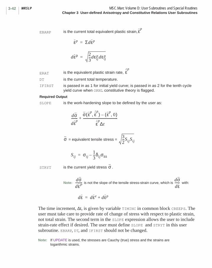
WKSLP MSC.Marc Volume D: User Subroutines and Special RoutinesChapter 3 User-defined Anisotropy and Constitutive Relations User Subroutines
3-42
The time increment, ∆t, is given by variable TIMINC in common block CREEPS. The user must take care to provide rate of change of stress with respect to plastic strain, not total strain. The second term in the SLOPE expression allows the user to include strain-rate effect if desired. The user must define SLOPE and STRYT in this user subroutine. EBARP, DT, and IFIRST should not be changed.
Note: If UPDATE is used, the stresses are Cauchy (true) stress and the strains are logarithmic strains.
EBARP is the current total equivalent plastic strain,
ERAT is the equivalent plastic strain rate,
DT is the current total temperature.
IFIRST is passed in as 1 for initial yield curve; is passed in as 2 for the tenth cycle yield curve when ORNL constitutive theory is flagged.
Required Output
SLOPE is the work-hardening slope to be defined by the user as:
= equivalent tensile stress =
STRYT is the current yield stress .
Note: is not the slope of the tensile stress-strain curve, which is with:
εp
εp Σdεp=
dερ 23---dεij
p dεijp=
ε· p
dσ
dεp--------
σ εp ε· p
,( ) εp0,( )–
ε· p
∆t--------------------------------------------+
σ 32---SijSij
Sij σij13---δijσkk–=
σ
dσdεP---------
dσdε------
dε dεe dεp+=
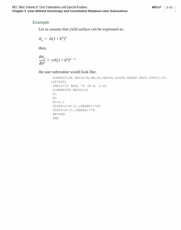
3-43MSC.Marc Volume D: User Subroutines and Special Routines WKSLPChapter 3 User-defined Anisotropy and Constitutive Relations User Subroutines
Example
Let us assume that yield surface can be expressed as:
then,
the user subroutine would look like:SUBROUTINE WKSLP(M,NN,KC,MATUS,SLOPE,EBARP,ERAT,STRYT,DT,
+IFIRST)IMPLICIT REAL *8 (A-H, O-Z)DIMENSION MATUS(2)A=N=N1=n-1SLOPE=n*A*(1.+EBARP)**N1STRYT=A*(1.+EBARP)**NRETURNEND
σy A 1 εp+( )n=
∂σy
∂εp--------- nA 1 εp+( )n 1–=
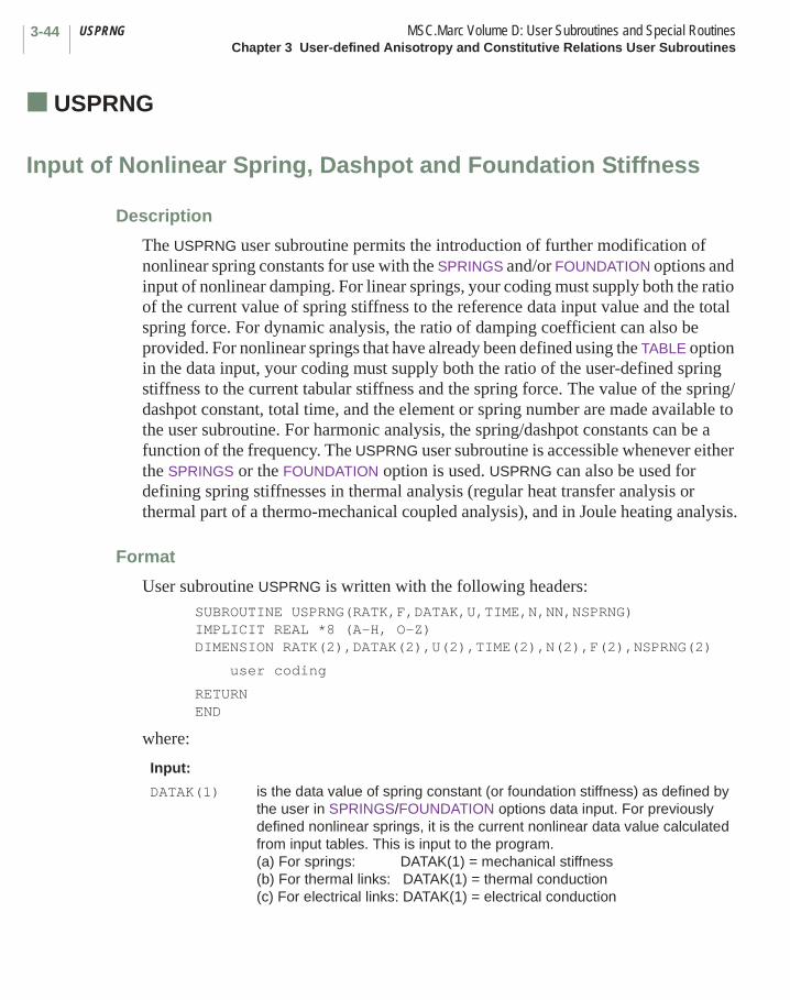
USPRNG MSC.Marc Volume D: User Subroutines and Special RoutinesChapter 3 User-defined Anisotropy and Constitutive Relations User Subroutines
3-44
■ USPRNG
Input of Nonlinear Spring, Dashpot and Foundation Stiffness
Description
The USPRNG user subroutine permits the introduction of further modification of nonlinear spring constants for use with the SPRINGS and/or FOUNDATION options and input of nonlinear damping. For linear springs, your coding must supply both the ratio of the current value of spring stiffness to the reference data input value and the total spring force. For dynamic analysis, the ratio of damping coefficient can also be provided. For nonlinear springs that have already been defined using the TABLE option in the data input, your coding must supply both the ratio of the user-defined spring stiffness to the current tabular stiffness and the spring force. The value of the spring/dashpot constant, total time, and the element or spring number are made available to the user subroutine. For harmonic analysis, the spring/dashpot constants can be a function of the frequency. The USPRNG user subroutine is accessible whenever either the SPRINGS or the FOUNDATION option is used. USPRNG can also be used for defining spring stiffnesses in thermal analysis (regular heat transfer analysis or thermal part of a thermo-mechanical coupled analysis), and in Joule heating analysis.
Format
User subroutine USPRNG is written with the following headers:SUBROUTINE USPRNG(RATK,F,DATAK,U,TIME,N,NN,NSPRNG)IMPLICIT REAL *8 (A-H, O-Z)DIMENSION RATK(2),DATAK(2),U(2),TIME(2),N(2),F(2),NSPRNG(2)
user coding
RETURNEND
where:
Input:
DATAK(1) is the data value of spring constant (or foundation stiffness) as defined by the user in SPRINGS/FOUNDATION options data input. For previously defined nonlinear springs, it is the current nonlinear data value calculated from input tables. This is input to the program. (a) For springs: DATAK(1) = mechanical stiffness(b) For thermal links: DATAK(1) = thermal conduction(c) For electrical links: DATAK(1) = electrical conduction

3-45MSC.Marc Volume D: User Subroutines and Special Routines USPRNGChapter 3 User-defined Anisotropy and Constitutive Relations User Subroutines
DATAK(2) is the data value of the damping constant as defined by you in the SPRINGS option data input. For previously defined nonlinear dashpots, it is the current nonlinear data value calculated from input tables. It is only used for transient mechanical analysis. This is input to the program.
For Elastic Foundation (Only Static Contribution):
U(1) For elastic foundation: U(1) = Un.
(positive in the direction specified by face identification given in the FOUNDATION option).
U(2)-U(4) not used
For Springs/Dashpots (Static and/or Dynamic Contribution):
U(1) For mechanical springs: .
For thermal links:
For electrical links:
U(2) For dynamic spring/dashpot .
U(3)
U(4)
For mechanical springs in coupled analysis and for electrical links in Joule
heating analysis: = Average Temperature of Spring or it is not used.
Not used
For springs/dashpots (harmonic analysis):
U(1) static predeformation
U(2) not used
U(3) real part of harmonic deformation.
U(4) imaginary part of harmonic deformation
TIME(1) is the total time (for dynamic or creep analysis).
TIME(2) is the frequency (for harmonic analysis with spring/dashpot).
N(1) is the element number (for elastic foundation).is the first user-node number (for spring)
N(2) is the face number (for elastic foundation).is the second user-node number (for spring)
NN is the integration point number (only for elastic foundation).
U 1( ) U2 U1–=
U 1( ) T2 T1–=
U 1( ) V2 V1–=
U 2( ) U· 2 U· 1–=
U 3( )
U 1( ) U2 U1–=
U 3( ) U2 U1–=
U 4( ) U2 U1–=

USPRNG MSC.Marc Volume D: User Subroutines and Special RoutinesChapter 3 User-defined Anisotropy and Constitutive Relations User Subroutines
3-46
If the user subroutine is called for an elastic foundation point, NSPRNG(1) and NSPRNG(2) are zero.
If the user subroutine is called for a spring, NN is zero.
Note that if the user prefers to give the absolute value of the spring constant rather than a ratio, the corresponding value in the SPRINGS or FOUNDATION option should be set to 1. The same applies for a damping constant.
Note that for fixed degrees of freedom springs, U(1), U(2), U(3), and U(4) are positive if the motion of the degrees of freedom associated with node 2 is greater than the motion of the degrees of freedom associated with node 1. So, to ensure physically consistent forces, care should be exercised on defining node 1 and node 2 correctly. For true direction springs, U(1), U(2), U(3), and U(4) are positive if the spring is in tension and negative if the spring is in compression.
During a heat transfer run or electrical run (NSPRNG(2) = 2 or 4), springs simply act as links. Only the user-input conduction DATAK(1) comes into the routine and the user needs to return the modified ratio RATK(1). The dashpot is not active. The spring force F the gradient across the spring, U, is not needed and does not need to be defined.
NSPRNG(1)
NSPRNG(2)
is the spring number, the position of the spring in the input data list (only for springs).= 1 mechanical analysis or stress part of coupled analysis (only
for springs)= 2 heat transfer analysis or thermal part of coupled analysis (only
for springs)= 4 electrical analysis (only for springs)
Required Output
RATK(1) is the ratio of the present value of spring stiffness to the data value given in the option input; to be defined by the user.
RATK(2) is the ratio of the present value of the damping coefficient to the data value given in the input; to be defined by the user. This applies to SPRINGS in dynamic analysis only.
F(1) is the force to be defined by the user (only needed for mechanical analysis).(a) For springs: F(1) = spring force.(b) For elastic foundation: F(1) = pressure per unit area.(c) For harmonics: F(1) = real part of harmonic force.
F(2) is the force to be defined by the user (only needed for mechanical analysis).(a) For springs: F(2) = the damping force.(b) For harmonics: F(2) = imaginary part of harmonic force.

3-47MSC.Marc Volume D: User Subroutines and Special Routines UCRACKChapter 3 User-defined Anisotropy and Constitutive Relations User Subroutines
■ UCRACK
Input of Ultimate Stress for Cracking Analysis
Description
This user subroutine allows the user to input a constant or a temperature dependent ultimate stress at each integration point of an element for cracking analysis. In addition, the user can define the strain softening modulus and the crushing strain.
Format
User subroutine UCRACK is written with the following headers: SUBROUTINE UCRACK (SCRACK,ESOFT,ECRUSH,ECP,DT,DTDL,N,NN,KC,1 INC, NDI, NSHEAR, SHRFAC) IMPLICIT REAL *8 (A-H, O-Z) DIMENSION ECP(1), DT(1), DTDL(1)
user coding
RETURN END
where:
Input:
ECP is the array of crack strains.
DT is the array of state variables, temperature first.
DTDL is the array of incremental state variables, temperature first.
N is the element number.
NN is the integration point number.
KC is the layer number.
INC is the increment number.
NDI is the number of direct components.
NSHEAR is the number of shear components.
SHRFAC is the user-defined shear retention factor.
Required Output
SCRACK is the user-defined ultimate cracking stress.
ESOFT is the user-defined strain softening moduli.
ECRUSH is the user-defined strain at which crushing occurs.
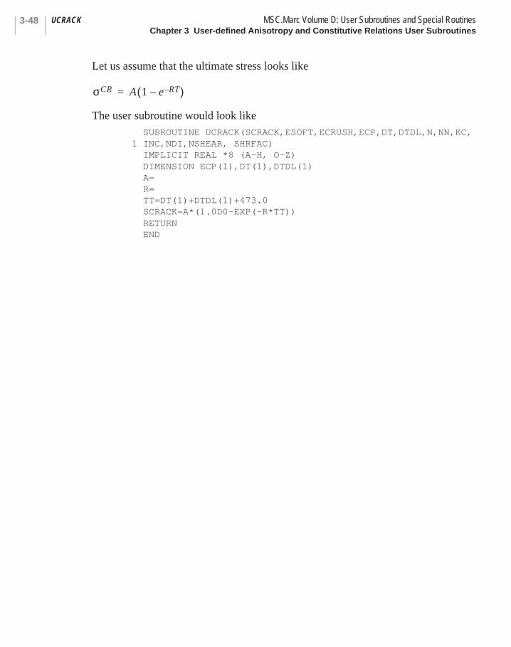
UCRACK MSC.Marc Volume D: User Subroutines and Special RoutinesChapter 3 User-defined Anisotropy and Constitutive Relations User Subroutines
3-48
Let us assume that the ultimate stress looks like
The user subroutine would look like SUBROUTINE UCRACK(SCRACK,ESOFT,ECRUSH,ECP,DT,DTDL,N,NN,KC, 1 INC,NDI,NSHEAR, SHRFAC) IMPLICIT REAL *8 (A-H, O-Z) DIMENSION ECP(1),DT(1),DTDL(1) A= R= TT=DT(1)+DTDL(1)+473.0 SCRACK=A*(1.0D0-EXP(-R*TT)) RETURN END
σCR A 1 e RT––( )=

3-49MSC.Marc Volume D: User Subroutines and Special Routines TENSOFChapter 3 User-defined Anisotropy and Constitutive Relations User Subroutines
■ TENSOF
Input of Tension Softening Modulus for Cracking Analysis
Description
The tension softening modulus defines the post-failure behavior at an integration point. By default in MSC.Marc, the reduction of the cracking stress to zero is a linear function of the crack strain. This user subroutine allows the user to define for instance a nonlinear behavior. The user subroutine is automatically called for every crack in the analysis.
Format
User subroutine TENSOF is written with the following headers:SUBROUTINE TENSOF (D,SP,GFP,DEP,ECP,SCRACK,SOSTR,ETSNEW,
ETSOFT,XH,SPECLN,JSOFT)
where:
Note that the definition of the stiffness D does not need to be exact. The correct definition of the stiffness only determines the speed of the convergence. In fact, in the above user subroutine, a large negative value of the stiffness term should never be used as this would result in convergence problems. The stress definition, however, must be exact; otherwise, the wrong solution is obtained.
Input:GFP is the change in stress due to incremental crack growth.DEP is the current strain increment.ECP is the crack strain at end of increment.SCRACK is the critical cracking stress given in input.SOSTR is the current cracking stress based on previous softening.ETSNEW is the current value of temperature dependent Young’s modulus.ESOFT is the tension softening modulus given in input.XH is the characteristic element length.SPECLN is the test specimen length.Required OutputD is the stiffness in the crack direction term to be defined by you.SP is the stress at end of increment as function of crack strain to be defined by
the user.JSOFT is the status indicator for softening. Used for plotting only.
= 1 inside softening range.= 2 outside softening range.
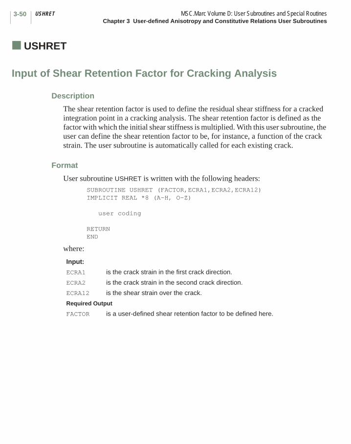
USHRET MSC.Marc Volume D: User Subroutines and Special RoutinesChapter 3 User-defined Anisotropy and Constitutive Relations User Subroutines
3-50
■ USHRET
Input of Shear Retention Factor for Cracking Analysis
Description
The shear retention factor is used to define the residual shear stiffness for a cracked integration point in a cracking analysis. The shear retention factor is defined as the factor with which the initial shear stiffness is multiplied. With this user subroutine, the user can define the shear retention factor to be, for instance, a function of the crack strain. The user subroutine is automatically called for each existing crack.
Format
User subroutine USHRET is written with the following headers:SUBROUTINE USHRET (FACTOR,ECRA1,ECRA2,ECRA12)IMPLICIT REAL *8 (A-H, O-Z)
user coding
RETURNEND
where:
Input:
ECRA1 is the crack strain in the first crack direction.
ECRA2 is the crack strain in the second crack direction.
ECRA12 is the shear strain over the crack.
Required Output
FACTOR is a user-defined shear retention factor to be defined here.
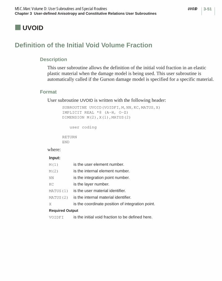
3-51MSC.Marc Volume D: User Subroutines and Special Routines UVOIDChapter 3 User-defined Anisotropy and Constitutive Relations User Subroutines
■ UVOID
Definition of the Initial Void Volume Fraction
Description
This user subroutine allows the definition of the initial void fraction in an elastic plastic material when the damage model is being used. This user subroutine is automatically called if the Gurson damage model is specified for a specific material.
Format
User subroutine UVOID is written with the following header:SUBROUTINE UVOID(VOIDFI,M,NN,KC,MATUS,X)IMPLICIT REAL *8 (A-H, O-Z)DIMENSION M(2),X(1),MATUS(2)
user coding
RETURNEND
where:
Input:
M(1) is the user element number.
M(2) is the internal element number.
NN is the integration point number.
KC is the layer number.
MATUS(1) is the user material identifier.
MATUS(2) is the internal material identifier.
X is the coordinate position of integration point.
Required Output
VOIDFI is the initial void fraction to be defined here.
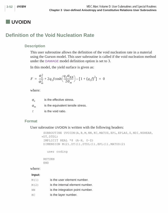
UVOIDN MSC.Marc Volume D: User Subroutines and Special RoutinesChapter 3 User-defined Anisotropy and Constitutive Relations User Subroutines
3-52
■ UVOIDN
Definition of the Void Nucleation Rate
Description
This user subroutine allows the definition of the void nucleation rate in a material using the Gurson model. This user subroutine is called if the void nucleation method under the DAMAGE model definition option is set to 3.
In this model, the yield surface is given as:
where:
Format
User subroutine UVOIDN is written with the following headers: SUBROUTINE UVOIDN(A,B,M,NN,KC,MATUS,EPL,EPLAS,S,NDI,NSHEAR,+DT,DTDL) IMPLICIT REAL *8 (A-H, O-Z) DIMENSION M(2),DT(1),DTDL(1),EPL(1),MATUS(2) user coding RETURN END
where:
σe is the effective stress.
σm is the equivalent tensile stress.
f is the void ratio.
Input:
M(1) is the user element number.
M(2) is the internal element number.
NN is the integration point number.
KC is the layer number.
Fσe
2
σm2
------- 2q1fq2σKK
2σm--------------- cosh 1 q1f( )2
+[ ]–+ 0= =

3-53MSC.Marc Volume D: User Subroutines and Special Routines UVOIDNChapter 3 User-defined Anisotropy and Constitutive Relations User Subroutines
In this user subroutine, the following type of stress controlled nucleation rate can be specified:
where is the von Mises equivalent stress rate, and is the hydrostatic stress rate.
MATUS(1) is the user material identifier.
MATUS(2) is the internal material identifier.
EPL is the plastic strain components.
EPLAS is the equivalent plastic strain.
S is the stress array.
NDI is the number of direct components.
NSHEAR is the number of shear components.
DT is the array of state variables, temperature first.
DTDL is the array of increment of state variables.
Required Output
A is the multiplier as shown below.
B is the multiplier as shown below.
f· Aσ·
Bσ· kk
3--------+=
σ·
σ· kk

UVOIDRT MSC.Marc Volume D: User Subroutines and Special RoutinesChapter 3 User-defined Anisotropy and Constitutive Relations User Subroutines
3-54
■ UVOIDRT
Definition of the Initial Void Ratio or Initial Porosity
Description
The UVOIDRT user subroutine allows the user to define either the initial void ratio or the initial porosity in a soil analysis or a mass diffusion analysis. It may also be used to define a nonhomogeneous distribution of these variables, which in turn are used as independent variables to define other variables through the TABLE option. Whether the void ratio or the porosity is defined is based upon whether the INITIAL VOID RATIO or INITIAL POROSITY option.
Format
User subroutine UVOIDRT is written with the following header: SUBROUTINE UVOIDRT(M,N,NN,KC,MATS,COORD,NCRD,INC,CPTIM,*TIMINC,VALUE,IFLAG) INCLUDE '../COMMON/IMPLICIT' DIMENSION MATUS(2)
user coding
RETURN END
where
Input
M element number.N elsto number.NN integration point number.KC layer number.MATUS(1) user material id.MATUS(2) internal material id.COORD coordinate of integration point.NCRD number of coordinates.INC increment number.CPTIM time at the beginning of the increment.TIMINC time increment.VALUE if iflag = 1 define void ratio.
if iflag = 2 define porosity.IFLAG 1 or 2.
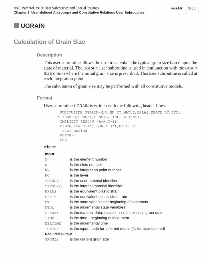
3-55MSC.Marc Volume D: User Subroutines and Special Routines UGRAINChapter 3 User-defined Anisotropy and Constitutive Relations User Subroutines
■ UGRAIN
Calculation of Grain Size
Description
This user subroutine allows the user to calculate the typical grain size based upon the state of material. The UGRAIN user subroutine is used in conjunction with the GRAIN SIZE option where the initial grain size is prescribed. This user subroutine is called at each integration point.
The calculation of grain size may be performed with all constitutive models.
Format
User subroutine UGRAIN is written with the following header lines:SUBROUTINE UGRAIN(M,N,NN,KC,MATUS,EPLAS,ERATE,DT,DTDl,
* IGNMOD,GRNDAT,GRNSIZ,TIME,DELTIME)IMPLICIT REAL*8 (A-H,O-Z)DIMENSION DT(*),GRNDAT(*),MATUS(2) user codingRETURNEND
where:
Input:M is the element numberN is the elsto numberNN is the integration point numberKC is the layerMATUS(1) is the user material identifier.MATUS(2) is the internal material identifier.EPLAS is the equivalent plastic strainERATE is the equivalent plastic strain rateDT is the state variables at beginning of incrementDTDL is the incremental state variablesGRNDAT is the material data, GRNDAT (1) is the initial grain sizeTIME is the time - beginning of incrementDELTIME is the incremental timeIGNMOD is the input mode for different model (-1 for user-defined)Required Output
GRNSIZ is the current grain size
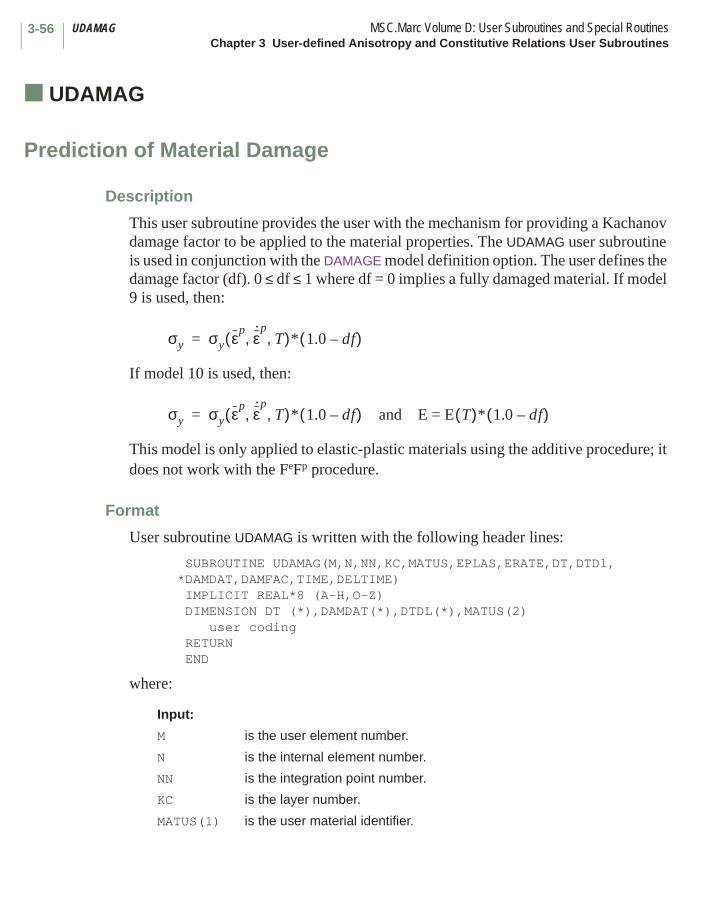
UDAMAG MSC.Marc Volume D: User Subroutines and Special RoutinesChapter 3 User-defined Anisotropy and Constitutive Relations User Subroutines
3-56
■ UDAMAG
Prediction of Material Damage
Description
This user subroutine provides the user with the mechanism for providing a Kachanov damage factor to be applied to the material properties. The UDAMAG user subroutine is used in conjunction with the DAMAGE model definition option. The user defines the damage factor (df). 0 ≤ df ≤ 1 where df = 0 implies a fully damaged material. If model 9 is used, then:
If model 10 is used, then:
This model is only applied to elastic-plastic materials using the additive procedure; it does not work with the FeFp procedure.
Format
User subroutine UDAMAG is written with the following header lines:
SUBROUTINE UDAMAG(M,N,NN,KC,MATUS,EPLAS,ERATE,DT,DTDl,*DAMDAT,DAMFAC,TIME,DELTIME) IMPLICIT REAL*8 (A-H,O-Z) DIMENSION DT (*),DAMDAT(*),DTDL(*),MATUS(2) user coding RETURN END
where:
Input:
M is the user element number.
N is the internal element number.
NN is the integration point number.
KC is the layer number.
MATUS(1) is the user material identifier.
σy σy εp ε· p
T, ,( )* 1.0 df–( )=
σy σy εp ε· p
T, ,( )* 1.0 df–( ) and E = E T( )* 1.0 df–( )=
3-57MSC.Marc Volume D: User Subroutines and Special Routines UDAMAGChapter 3 User-defined Anisotropy and Constitutive Relations User Subroutines
MATUS(2) is the internal material identifier.
EPLAS is the equivalent plastic strain.
ERATE is the equivalent plastic strain rate.
DT is the state variables at beginning of increment.
DTDL is the state variables increment.
DAMDAT is the material data, DAMDAT (1) is the initial damage factor.
TIME is the time at the beginning of increment.
DELTIME is the time increment.
Required Output
DAMFAC is the current damage factor.
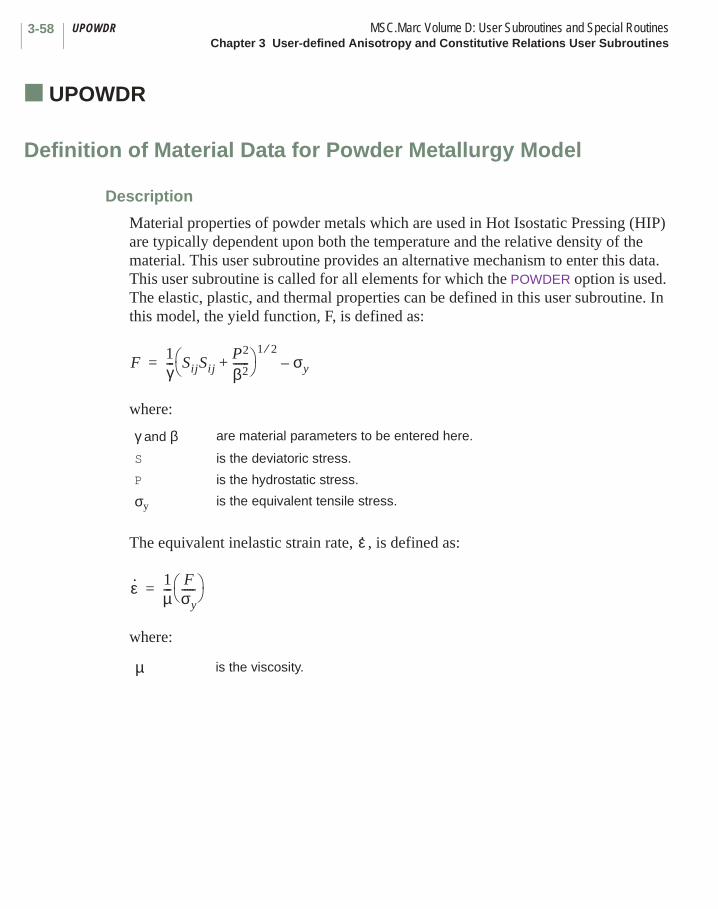
UPOWDR MSC.Marc Volume D: User Subroutines and Special RoutinesChapter 3 User-defined Anisotropy and Constitutive Relations User Subroutines
3-58
■ UPOWDR
Definition of Material Data for Powder Metallurgy Model
Description
Material properties of powder metals which are used in Hot Isostatic Pressing (HIP) are typically dependent upon both the temperature and the relative density of the material. This user subroutine provides an alternative mechanism to enter this data. This user subroutine is called for all elements for which the POWDER option is used. The elastic, plastic, and thermal properties can be defined in this user subroutine. In this model, the yield function, F, is defined as:
where:
The equivalent inelastic strain rate, , is defined as:
where:
γ and β are material parameters to be entered here.
S is the deviatoric stress.
P is the hydrostatic stress.
σy is the equivalent tensile stress.
is the viscosity.
F1γ--- SijSij
P2
β2------+
1 2⁄σy–=
ε·
ε· 1µ---
Fσy----- =
µ
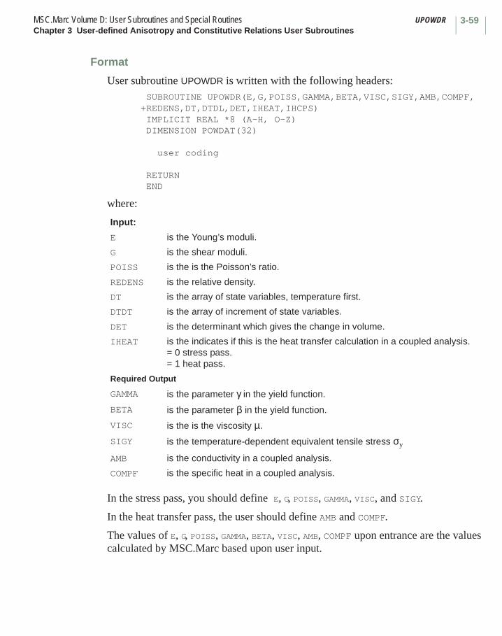
3-59MSC.Marc Volume D: User Subroutines and Special Routines UPOWDRChapter 3 User-defined Anisotropy and Constitutive Relations User Subroutines
Format
User subroutine UPOWDR is written with the following headers: SUBROUTINE UPOWDR(E,G,POISS,GAMMA,BETA,VISC,SIGY,AMB,COMPF,+REDENS,DT,DTDL,DET,IHEAT,IHCPS) IMPLICIT REAL *8 (A-H, O-Z) DIMENSION POWDAT(32)
user coding
RETURN END
where:
In the stress pass, you should define E, G, POISS, GAMMA, VISC, and SIGY.
In the heat transfer pass, the user should define AMB and COMPF.
The values of E, G, POISS, GAMMA, BETA, VISC, AMB, COMPF upon entrance are the values calculated by MSC.Marc based upon user input.
Input:
E is the Young’s moduli.
G is the shear moduli.
POISS is the is the Poisson’s ratio.
REDENS is the relative density.
DT is the array of state variables, temperature first.
DTDT is the array of increment of state variables.
DET is the determinant which gives the change in volume.
IHEAT is the indicates if this is the heat transfer calculation in a coupled analysis.= 0 stress pass.= 1 heat pass.
Required Output
GAMMA is the parameter γ in the yield function.
BETA is the parameter β in the yield function.
VISC is the is the viscosity µ.SIGY is the temperature-dependent equivalent tensile stress σy
AMB is the conductivity in a coupled analysis.
COMPF is the specific heat in a coupled analysis.
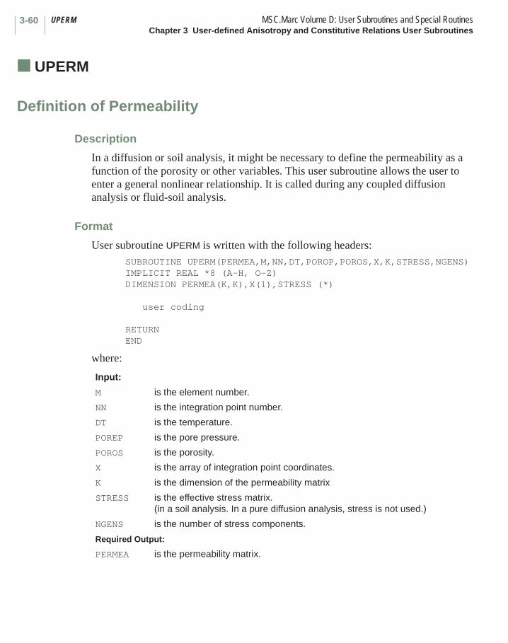
UPERM MSC.Marc Volume D: User Subroutines and Special RoutinesChapter 3 User-defined Anisotropy and Constitutive Relations User Subroutines
3-60
■ UPERM
Definition of Permeability
Description
In a diffusion or soil analysis, it might be necessary to define the permeability as a function of the porosity or other variables. This user subroutine allows the user to enter a general nonlinear relationship. It is called during any coupled diffusion analysis or fluid-soil analysis.
Format
User subroutine UPERM is written with the following headers:SUBROUTINE UPERM(PERMEA,M,NN,DT,POROP,POROS,X,K,STRESS,NGENS)IMPLICIT REAL *8 (A-H, O-Z)DIMENSION PERMEA(K,K),X(1),STRESS (*)
user coding
RETURNEND
where:
Input:
M is the element number.
NN is the integration point number.
DT is the temperature.
POREP is the pore pressure.
POROS is the porosity.
X is the array of integration point coordinates.
K is the dimension of the permeability matrix
STRESS is the effective stress matrix. (in a soil analysis. In a pure diffusion analysis, stress is not used.)
NGENS is the number of stress components.
Required Output:
PERMEA is the permeability matrix.
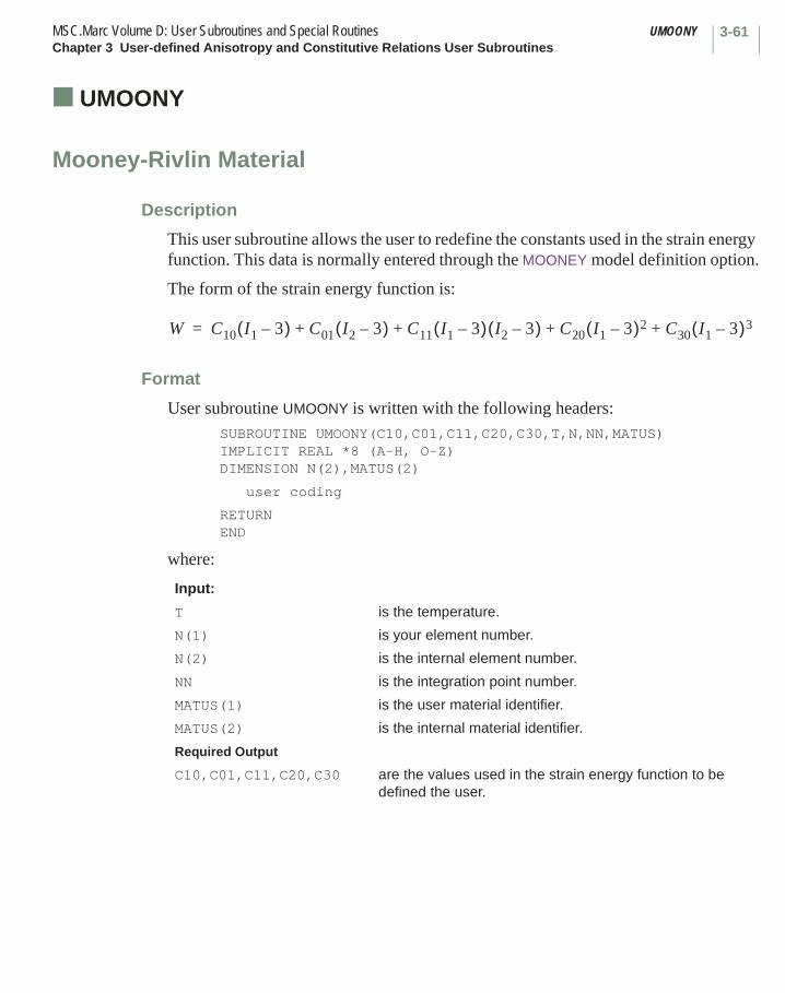
3-61MSC.Marc Volume D: User Subroutines and Special Routines UMOONYChapter 3 User-defined Anisotropy and Constitutive Relations User Subroutines
■ UMOONY
Mooney-Rivlin Material
Description
This user subroutine allows the user to redefine the constants used in the strain energy function. This data is normally entered through the MOONEY model definition option.
The form of the strain energy function is:
Format
User subroutine UMOONY is written with the following headers:SUBROUTINE UMOONY(C10,C01,C11,C20,C30,T,N,NN,MATUS)IMPLICIT REAL *8 (A-H, O-Z)DIMENSION N(2),MATUS(2)
user coding
RETURNEND
where:
Input:
T is the temperature.
N(1) is your element number.
N(2) is the internal element number.
NN is the integration point number.
MATUS(1) is the user material identifier.
MATUS(2) is the internal material identifier.
Required Output
C10,C01,C11,C20,C30 are the values used in the strain energy function to be defined the user.
W C10 I1 3–( ) C01 I2 3–( ) C11 I1 3–( ) I2 3–( ) C20 I1 3–( )2 C30 I1 3–( )3+ + + +=

UENERG MSC.Marc Volume D: User Subroutines and Special RoutinesChapter 3 User-defined Anisotropy and Constitutive Relations User Subroutines
3-62
■ UENERG
Strain Energy Function
Description
This user subroutine allows the user to define his own elastic strain energy function for incompressible materials. Normally, the five constant second-order model is entered using the MOONEY model definition option. This option must still be used to invoke this user subroutine. This user subroutine can be used when either the total Lagrange or updated Lagrange procedure is used. The five material parameters, C10, C01, C11, C20, and C30 must be correctly defined with the MOONEY option for energy calculation.
Format
User subroutine UENERG is written with the following headers: SUBROUTINE UENERG (W,W1,W2,W11,W12,W22,WI1,WI2,C10,C01,C11, +C20,C30,N,NN) IMPLICIT REAL *8 (A-H, O-Z) DIMENSION N(2)
user coding
RETURN END
where:
Input:
WI1 is .
WI2 is .
C10, C01, C11, C20, C30 are the five material parameters of the Mooney formulation.
N(1) is the user element number.
N(2) is the internal element number.
NN is the integration point number.
I2 3–
I2 3–

3-63MSC.Marc Volume D: User Subroutines and Special Routines UENERGChapter 3 User-defined Anisotropy and Constitutive Relations User Subroutines
Required Output
W is the strain energy density.
W1 is .
W2 is .
W11 is .
W12 is .
W22 is .
∂W ∂I1⁄
∂W ∂I2⁄
∂2W ∂I12⁄
∂2W ∂I1∂I2⁄
∂2W ∂I2
2⁄
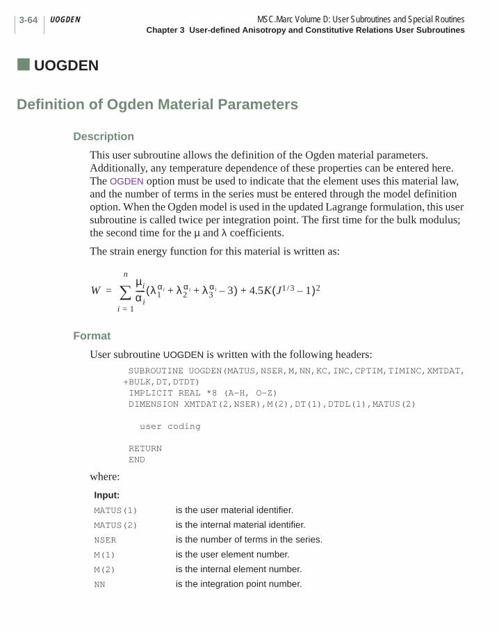
UOGDEN MSC.Marc Volume D: User Subroutines and Special RoutinesChapter 3 User-defined Anisotropy and Constitutive Relations User Subroutines
3-64
■ UOGDEN
Definition of Ogden Material Parameters
Description
This user subroutine allows the definition of the Ogden material parameters. Additionally, any temperature dependence of these properties can be entered here. The OGDEN option must be used to indicate that the element uses this material law, and the number of terms in the series must be entered through the model definition option. When the Ogden model is used in the updated Lagrange formulation, this user subroutine is called twice per integration point. The first time for the bulk modulus; the second time for the µ and λ coefficients.
The strain energy function for this material is written as:
Format
User subroutine UOGDEN is written with the following headers: SUBROUTINE UOGDEN(MATUS,NSER,M,NN,KC,INC,CPTIM,TIMINC,XMTDAT,+BULK,DT,DTDT) IMPLICIT REAL *8 (A-H, O-Z) DIMENSION XMTDAT(2,NSER),M(2),DT(1),DTDL(1),MATUS(2)
user coding
RETURN END
where:
Input:
MATUS(1) is the user material identifier.
MATUS(2) is the internal material identifier.
NSER is the number of terms in the series.
M(1) is the user element number.
M(2) is the internal element number.
NN is the integration point number.
Wµi
α i----- λ1
α i λ2α i λ3
α i 3–+ +( )i 1=
n
∑ 4.5K J1 3/ 1–( )2+=
3-65MSC.Marc Volume D: User Subroutines and Special Routines UOGDENChapter 3 User-defined Anisotropy and Constitutive Relations User Subroutines
KC is the layer number.
INC is the increment number.
CPTIM is the time at the beginning of the increment.
TIMINC is the time step.
DT is the array of state variables, temperature first.
DTDT is the array of increments of state variables.
Required Output
XMTDAT(1,i) is the value of µi.
XMTDAT(2,i) is the value of αi.
BULK is the bulk modulus.

UELDAM MSC.Marc Volume D: User Subroutines and Special RoutinesChapter 3 User-defined Anisotropy and Constitutive Relations User Subroutines
3-66
■ UELDAM
Definition of Damage Parameters in Ogden Model
Description
This user subroutine allows the user to define the damage parameters for the Ogden model. There are two types of damage: one is associated with the deviatoric (shear) behavior, and one is associated with the dilatational (volumetric) behavior (additional details can be found in MSC.Marc Volume A: User Information). This user subroutine is, therefore, called twice per integration point, once for deviatoric behavior and once for volumetric behavior. This user subroutine is called only if the damage type is set to 6 through the DAMAGE model definition option.
Format
User subroutine UELDAM is written with the following headers: SUBROUTINE UELDAM(M,N,NN,KC,INC,LOVL,MATUS,TIMINC,CPTIM,2 TOTEN,DEVEN,TOTEND,TOTENV,SURFC,SURFD,DT,3 DTDL,DAMD,DDAMD) IMPLICIT REAL *8 (A-H, O-Z) DIMENSION DT(1),DTDL(1),MATUS(2)
user coding
RETURN END
where:
Input:
M is the user element number.
N is the internal element/elsto number.
NN is the integration point number.
KC is the layer number.
INC is the increment number.
LOVL is 4 for assembly phase.is 6 for stress recovery phase.
MATUS(1) is the user material identifier.
MATUS(2) is the internal material identifier.
TIMINC is the time increment.
CPTIM is the time at the beginning of the increment.

3-67MSC.Marc Volume D: User Subroutines and Special Routines UELDAMChapter 3 User-defined Anisotropy and Constitutive Relations User Subroutines
TOTEN is the total instantaneous strain energy at the end of the current step excluding damage.
DEVEN is the deviatoric part of the instantaneous strain energy at the end of the current step excluding damage.
TOTEND is the stored deviatoric energy at previous step (including damage).
TOTENV is the stored volumetric energy at previous step (including damage).
SURFC is the current radius of continuous damage surface.
SURFD is the current radius of discontinuous damage surface.
DT is the temperature.
DTDL is the incremental temperature.
Required Output:
DAMD is the value of Kachanov deviatoric damage parameter.
DDAMD is the derivative of the damage parameter with respect to the maximum total strain energy.
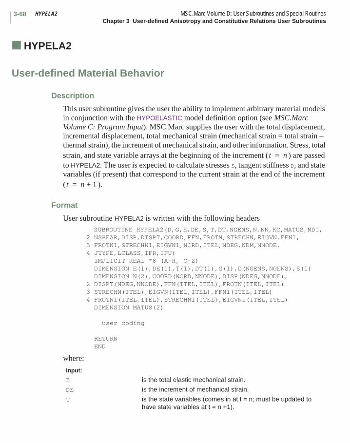
HYPELA2 MSC.Marc Volume D: User Subroutines and Special RoutinesChapter 3 User-defined Anisotropy and Constitutive Relations User Subroutines
3-68
■ HYPELA2
User-defined Material Behavior
Description
This user subroutine gives the user the ability to implement arbitrary material models in conjunction with the HYPOELASTIC model definition option (see MSC.Marc Volume C: Program Input). MSC.Marc supplies the user with the total displacement, incremental displacement, total mechanical strain (mechanical strain = total strain – thermal strain), the increment of mechanical strain, and other information. Stress, total strain, and state variable arrays at the beginning of the increment ( ) are passed to HYPELA2. The user is expected to calculate stresses S, tangent stiffness D, and state variables (if present) that correspond to the current strain at the end of the increment ( ).
Format
User subroutine HYPELA2 is written with the following headers SUBROUTINE HYPELA2(D,G,E,DE,S,T,DT,NGENS,N,NN,KC,MATUS,NDI, 2 NSHEAR,DISP,DISPT,COORD,FFN,FROTN,STRECHN,EIGVN,FFN1,3 FROTN1,STRECHN1,EIGVN1,NCRD,ITEL,NDEG,NDM,NNODE,4 JTYPE,LCLASS,IFR,IFU) IMPLICIT REAL *8 (A-H, O-Z) DIMENSION E(1),DE(1),T(1),DT(1),G(1),D(NGENS,NGENS),S(1)
DIMENSION N(2),COORD(NCRD,NNODE),DISP(NDEG,NNODE),2 DISPT(NDEG,NNODE),FFN(ITEL,ITEL),FROTN(ITEL,ITEL)3 STRECHN(ITEL),EIGVN(ITEL,ITEL),FFN1(ITEL,ITEL)4 FROTN1(ITEL,ITEL),STRECHN1(ITEL),EIGVN1(ITEL,ITEL)
DIMENSION MATUS(2)
user coding
RETURN END
where:
Input:
E is the total elastic mechanical strain.
DE is the increment of mechanical strain.
T is the state variables (comes in at t = n; must be updated to have state variables at t = n +1).
t n=
t n 1+=

3-69MSC.Marc Volume D: User Subroutines and Special Routines HYPELA2Chapter 3 User-defined Anisotropy and Constitutive Relations User Subroutines
DT is the increment of state variables.
NGENS is the size of the stress-strain law.
N is the element number.
NN is the integration point number.
KC is the layer number.
MATUS(1) is the user material identifier.
MATUS(2) is the internal material identifier.
NDI is the number of direct components.
NSHEAR is the number of shear components.
DISP is the incremental displacements.
DISPT is the displacements at t = n (at assembly lovl = 4) and the displacements at t = n +1 (at stress recovery lovl = 6).
COORD is the coordinates.
NCRD Is the number of coordinates.
NDEG is the number of degrees of freedom.
ITEL is the dimension of F and R; 2 for plane-stress and 3 for the rest of the cases.
NNODE is the number of nodes per element.
JTYPE is the element type.
LCLASS is the element class.
IFR is set to 1 if R has been calculated.
IFU is set to 1 if STRECH has been calculated.
At t = n (or the beginning of the increment):
FFN is the deformation gradient.
FROTN is the rotation tensor.
STRECHN is the square of principal stretch ratios, lambda (i).
EIGVN (I,J) I principal direction components for J eigenvalues.
At t = n +1 (or the current time step):
FFN1 is the deformation gradient.
FROTN1 is the rotation tensor.
STRECHN1 is the square of principal stretch ratios, lambda (i).
EIGVN1(I,J) is the I principal direction components for J eigenvalues.
Required Output:
D is the stress strain law to be formed.
G is the change in stress due to temperature effects.
S is the stress to be updated by you.
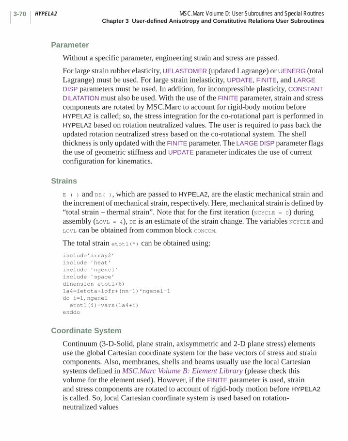
HYPELA2 MSC.Marc Volume D: User Subroutines and Special RoutinesChapter 3 User-defined Anisotropy and Constitutive Relations User Subroutines
3-70
Parameter
Without a specific parameter, engineering strain and stress are passed.
For large strain rubber elasticity, UELASTOMER (updated Lagrange) or UENERG (total Lagrange) must be used. For large strain inelasticity, UPDATE, FINITE, and LARGE DISP parameters must be used. In addition, for incompressible plasticity, CONSTANT DILATATION must also be used. With the use of the FINITE parameter, strain and stress components are rotated by MSC.Marc to account for rigid-body motion before HYPELA2 is called; so, the stress integration for the co-rotational part is performed in HYPELA2 based on rotation neutralized values. The user is required to pass back the updated rotation neutralized stress based on the co-rotational system. The shell thickness is only updated with the FINITE parameter. The LARGE DISP parameter flags the use of geometric stiffness and UPDATE parameter indicates the use of current configuration for kinematics.
Strains
E ( ) and DE( ), which are passed to HYPELA2, are the elastic mechanical strain and the increment of mechanical strain, respectively. Here, mechanical strain is defined by “total strain – thermal strain”. Note that for the first iteration (NCYCLE = 0) during assembly (LOVL = 4), DE is an estimate of the strain change. The variables NCYCLE and LOVL can be obtained from common block CONCOM.
The total strain etotl(*) can be obtained using:
include’array2’include ’heat’include ’ngenel’include ’space’dinension etotl(6)1a4=ietota+lofr+(nn-1)*ngenel-1do i=1,ngenel
etotl(i)=vars(1a4+i)enddo
Coordinate System
Continuum (3-D-Solid, plane strain, axisymmetric and 2-D plane stress) elements use the global Cartesian coordinate system for the base vectors of stress and strain components. Also, membranes, shells and beams usually use the local Cartesian systems defined in MSC.Marc Volume B: Element Library (please check this volume for the element used). However, if the FINITE parameter is used, strain and stress components are rotated to account of rigid-body motion before HYPELA2 is called. So, local Cartesian coordinate system is used based on rotation-neutralized values
3-71MSC.Marc Volume D: User Subroutines and Special Routines HYPELA2Chapter 3 User-defined Anisotropy and Constitutive Relations User Subroutines
If the ORIENTATION model definition option is used, the stress and strain components are stored in the local orientation axis. The basis vectors rotate with the material by rotation tensor (R) and, so the stress and strain are already stored in the rotated orientation axis before HYPELA2 is called.
Stress and Strain Components Order of Storage
The number of strain and stress components is composed of “number of direct components” (NDI) and “number of shear components” (NSHEAR). NDI and NSHEAR are defined in Table 3-2 for each element. For example, 3-D solid elements: ndi=3 and nshear=3, thick shells: ndi=2 and nshear=3, thin shells and membranes: ndi=2 and nshear=1, plane strain and axisymmetric elements: ndi=3 and nshear=1, beams: ndi=1 and shear=0 to 2. The stress and strain are first stored direct components followed by shear components. For full components, (ndi=3, nshear=3), S(11), S(22), S(33), S(12), S(23), S(31) is the right order to store. For Herrmann formulation of elements, the last strain component is the volumetric strain and the last stress component is the mean pressure constant. Thus, in the Herrmann formulation, NGENS = NDI + NSHEAR + 1.
State Variables
If there are any state variables (other than temperature) in the problem, the user can use the array T( ) to update and return these state variables. The increments of the state variables should be calculated and returned as the array DT ( ). T( ) and DT( ) have the size of NSTATS if NSTATS is the number of state variables defined in the PARAMETERS model definition option in the input file. T(1) and DT(1) are reserved for the temperature and the temperature increment, respectively, and calculated by MSC.Marc. You must not change the values of T(1) and DT(1) even in isothermal problems with state variables. All variables T(2) to T(NSTATS) and DT(2) to DT(NSTATS) are accessible to you. If the FINITE parameter is used, any nonscalar state variables (vector or tensor values) need to be rotated by using the rotation tensor (R) provided.
Tangent Stiffness
The user also needs to provide the tangent stiffness D based on the updated stress.
Dij
∂ ∆σi( )∂ ∆εj( )-----------------=

HYPELA2 MSC.Marc Volume D: User Subroutines and Special RoutinesChapter 3 User-defined Anisotropy and Constitutive Relations User Subroutines
3-72
The rate of convergence or a nonlinear problem depends critically on the user supplied tangent stiffness . Before using this user subroutine for large problems, it is recommended that the user check the user subroutine with one-element problems under displacement and load control boundary conditions. The displacement controlled boundary condition problem checks the accuracy of the stress update procedure while the load controlled problem checks the accuracy of the tangent stiffness. A fully consistent exact tangent stiffness provides quadratic convergence of the displacement or residual norm.
Thermal Stress Problems
For thermal stress problems, the user needs to calculate and return the change in stress due to temperature dependent material properties.
where and are the temperatures at time t = n and t = n + 1, respectively
and is strain increment which is passed to HYPELA.
Deformation Gradient (F), Rotation Tensor (R) and Stretch Tensor (U)
For continuum (3-D solid, plane strain, axisymmetric and 2-D plane stress) elements and membranes, the deformation gradient and rotation tensor are passed. For those elements, principal stretch ratio and eigenvectors are also passed to HYPELA2. Based on the information, the user can calculate stretch tensor (U) as follows:
CALL SCLA (UN1, 0.d0, ITEL, ITEL, 1)
DO K=1,3
DO J=1,3
DO K=1,3
UN1 (I,J) = UN1 (I,J)+DSQRT (STRETCH1(K)*EIGVN1(I,K)*EIGVN1(J,K))
ENDDO
ENDDO
ENDDO
In this case, STRECHN1 stores the value of the squares of the stretches, and EIGVN1(I,J) stores the I-th eigenvector component corresponding to the J-th eigenvalue of C, where C is the right Cauchy-Green Tensor at .
For shells and beams, kinematic variables are not available.
D
Gi
Gi Dθn 1+ Dθn–( )ij ∆ε( )j=
θn θn 1+
∆ε( )j
t n 1+=

3-73MSC.Marc Volume D: User Subroutines and Special Routines HYPELA2Chapter 3 User-defined Anisotropy and Constitutive Relations User Subroutines
The total strain etotl(*) can be obtained using:
include’array2’include ’heat’include ’ngenel’include ’space’dinension etotl(6)1a4=ietota+lofr+(nn-1)*ngenel-1do i=1,ngenel
etotl(i)=vars(1a4+i)enddo
UFINITE MSC.Marc Volume D: User Subroutines and Special RoutinesChapter 3 User-defined Anisotropy and Constitutive Relations User Subroutines
3-74
■ UFINITE
Finite Deformation Isotropic Material Models
Description
This user subroutine is used for finite deformation isotropic material models based on principal stretches. Both nonlinear elasticity and large strain plasticity models can be implemented using this user subroutine. This user subroutine requires the use of the PLASTICITY, 5 parameter. The UFINITE user subroutine is available for plane strain, generalized plane strain, axisymmetric, axisymmetric with twist, and 3-D elements.
Format
User subroutine UFINITE is written with the following headers:SUBROUTINE UFINITE(STRECH,EIGV,DETFE,DETFT,DEFGR,DT,
1 DTDL,STRESS,TANGENT,M,NN,GF,D)IMPLICIT REAL *8 (A-H,O-Z)
DIMENSION STRECH(3),STRESS(3),TANGENT(3,3),EIGV(3,3),2 DEFGR(3,3),DIMENSION N(2),COORD(NCRD,NNODE),3 DISP(NDEG,NNODE),BEN(6),DT(1),DTDL(1),GF(1),D(1)
user coding
RETURN END
where
Input:
STRECH is the squares of deviatoric trial elastic principal stretch ratios.
EIGV(I,J) is the I principal direction components for J eigenvalues of the trial elastic left Cauchy-Green tensor (Finger tensor).
DEFGR is the total deformation gradient for continuum elements.
DETFE is the elastic part of the Jacobian.
DETFT is the total Jacobian.
DT is the array of the total state variables (temperature is first).
DTDL is the array of the incremental state variables.
M is the user element number.

3-75MSC.Marc Volume D: User Subroutines and Special Routines UFINITEChapter 3 User-defined Anisotropy and Constitutive Relations User Subroutines
This user subroutine allows the user to implement arbitrary finite elasticity and large strain plasticity models. The user does not need to be concerned with preserving objectivity under large rotations in large strain problems, but must only deal with the small strain problem. The user needs to update principal deviatoric Kirchhoff stresses and provide a consistent deviatoric part of tangent in principal space and calculate any change in stresses due to temperature dependent thermal properties. MSC.Marc calculates the kinematic large strain contributions to the tangent automatically. The user does not need to calculate the pressure or the volumetic part of the tangent. Also, transformation from the principal to global space for both stresses and the tangent is done automatically by MSC.Marc. The user can refer to the UPSTRECH user subroutine for the analogus formulation for elasticity
If there are any state variables in the problem, you can use the array DT() to update and return these state variables. The increments of the state variables must be calculated and returned as the array DTDL(). DT() and DTDL() are the size NSTATS where NSTATS is the number of state variables and is set in the PARAMETERS option in the input file. It must be remembered that DT(1) and DTDL(1) are reserved for the temperature and the temperature increment, respectively and are supplied to you by MSC.Marc. The user must not change the values of DT(1) and DTDL(1) even in isothermal problems. All variables DT(2) to DT(NSTATS) and DTDL(2) to DTDL(NSTATS) are accessible to the user.
D is the array for material properties defined asD(1) = bulk modulus at (DT + DTDL)D(2) = shear modulus at (DT +DTDL)D(3) = initial yield stress (at zero effective plastic strain)D(4) = kinematic hardening modulus at (DT + DTDL)D(5) = portion of isotropic hardeningD(6) = portion of kinematic hardeningD(7) = coefficient of linear thermal expansionD(8) = bulk modulus at DTD(9) = shear modulus at DT.
NN is the integration point number.
Required Output:
STRESS is the principal deviatoric Kirchhoff stress at the end of the increment.
TANGENT is the elasto-plastic material tangent in the principal space; relating the total deviatoric Kirchhoff stress in principal space to the total principal deviatoric logarithmic strains.
GF is the stress change due to temperature dependent properties.

UFINITE MSC.Marc Volume D: User Subroutines and Special RoutinesChapter 3 User-defined Anisotropy and Constitutive Relations User Subroutines
3-76
The framework used in this user subroutine is based on principal stretches of the trial left Cauchy-Green tensor. For more details, please refer to the work of Simo and coworkers.
The rate of convergence of the global residual in this approach is critically dependent on the accuracy of the consistent tangent and the accuracy of the stress update procedure.
3-77MSC.Marc Volume D: User Subroutines and Special Routines UELASTOMERChapter 3 User-defined Anisotropy and Constitutive Relations User Subroutines
■ UELASTOMER
Generalized Strain Energy Function
3 Description
User-defined Anisotropy and Constitutive
Relations User Subroutines
This user subroutine allows definition of the user’s own hyperelastic models. The subroutine is activated by one of the following model definition options: FOAM, MOONEY, ARRUDBOYCE, GENT, and OGDEN. The UELASTOMER user subroutine must be used with the ELASTICITY,2 parameter (large strain, updated Lagrange formulation).
Foam Models
For compressible foam materials, four types of strain energy functions can be defined
using the UELASTOMER user subroutine, depending on the iflag entered in the 4th field
of the 3rd data block of the FOAM model definition option:
1. iflag = 1, Invariant-based model
2. iflag = 2, Principal-stretch-based model
3. iflag = 3, Invariant-based model with volumetric and deviatoric split
4. iflag = 4, Principal-stretch-based model with volumetric and deviatoric split
, , and ( , , and ) are strain invariants (principal stretches), and and
( , , and ) are their deviatoric parts, defined by and
, ; is the determinant of the
deformation gradient.
W W I1 I2 I3, ,( )=
W W λ1 λ2 λ3, ,( )=
W Wdev I1 I2,( ) U J( )+=
W Wdev λ1 λ2 λ3, ,( ) U J( )+=
I1 I2 I3 λ1 λ2 λ3 I1
I2 λ1 λ2 λ3 I1 J 2 3/– I1=
I2 J 4 3/– I2= λ i( J 1 3/– λ i= i 1 2 3 ), ,= J
UELASTOMER MSC.Marc Volume D: User Subroutines and Special RoutinesChapter 3 User-defined Anisotropy and Constitutive Relations User Subroutines
3-78
MSC.Marc uses conventional displacement elements for user-defined compressible foam models (iflag from 1 to 4). No volumetric constraints are taken into account. For incompressible or nearly incompressible rubber-like materials, rubber model with iflag equal to 5 or 6 should be used.
Rubber Models
Because rubber-like materials are nearly incompressible, it is numerically more efficient to split the energy function into a volumetric part and a deviatoric part. A mixed formulation, which treats hydrostatic pressure as an independent variable, is used in MSC.Marc to overcome the numerical difficulties coming from the volumetric constraints. A linear relationship between pressure and volumetric strain is a presupposition in the mixed formulation. This linear relationship should be accurate enough because of the incompressibility. Therefore, only the deviatoric part of energy function needs to be defined in the user subroutine for rubber-like materials.
Invariant-based rubber models can be defined using the UELASTOMER user subroutine if the MOONEY, ARRUDBOYCE, or GENT model definition option is used.
5. iflag = 5, Invariant-based model, deviatoric part only
Principal-stretch-based rubber models can be defined using th UELASTOMERe user
subroutine if a 3 is entered in the 3rd field of the 3rd data block of OGDEN model definition option.
6. iflag = 6, Principal-stretch-based model, deviatoric part only
Note: If iflag=5 or iflag=6, only the deviatoric part of the energy function is defined via the user subroutine UELASTOMER. The volumetric part is calculated internally by MSC.Marc. For this purpose, the bulk modulus MUST be defined with either MOONEY, or ARRUDBOYCE, or GENT, or OGDEN model definition option.
In case of the direct definition of material properties through input deck, if no bulk modulus is given, the default bulk modulus is calculated as 5000 times initial shear modulus. However, if UELASTOMER is used, the inital shear modulus is not explicitly available and the bulk modulus must be directly defined.
Compared to the foam models (iflag from 1 to 4), working only for compressible materials, the rubber-like model (iflag equal to 5 or 6) can be used for both compressible and incompressible materials. However, the foam models allow the user to define a general nonlinear volumetric energy function.
W Wdev I1 I2,( )=
W Wdev λ1 λ2 λ3, ,( )=
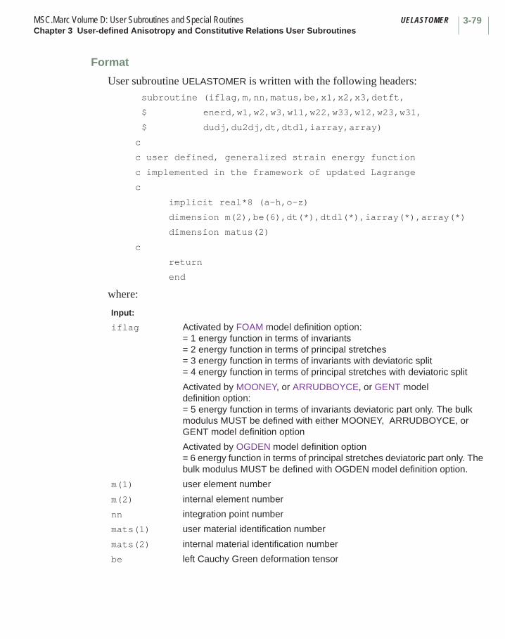
3-79MSC.Marc Volume D: User Subroutines and Special Routines UELASTOMERChapter 3 User-defined Anisotropy and Constitutive Relations User Subroutines
Format
User subroutine UELASTOMER is written with the following headers:subroutine (iflag,m,nn,matus,be,x1,x2,x3,detft,
$ enerd,w1,w2,w3,w11,w22,w33,w12,w23,w31,
$ dudj,du2dj,dt,dtdl,iarray,array)
c
c user defined, generalized strain energy function
c implemented in the framework of updated Lagrange
c
implicit real*8 (a-h,o-z)
dimension m(2),be(6),dt(*),dtdl(*),iarray(*),array(*)
dimension matus(2)
c
return
end
where:
Input:
iflag Activated by FOAM model definition option:= 1 energy function in terms of invariants= 2 energy function in terms of principal stretches= 3 energy function in terms of invariants with deviatoric split= 4 energy function in terms of principal stretches with deviatoric split
Activated by MOONEY, or ARRUDBOYCE, or GENT model definition option:= 5 energy function in terms of invariants deviatoric part only. The bulk modulus MUST be defined with either MOONEY, ARRUDBOYCE, or GENT model definition option
Activated by OGDEN model definition option= 6 energy function in terms of principal stretches deviatoric part only. The bulk modulus MUST be defined with OGDEN model definition option.
m(1) user element number
m(2) internal element number
nn integration point number
mats(1) user material identification number
mats(2) internal material identification number
be left Cauchy Green deformation tensor

UELASTOMER MSC.Marc Volume D: User Subroutines and Special RoutinesChapter 3 User-defined Anisotropy and Constitutive Relations User Subroutines
3-80
x1,x2,x3 if iflag = 1: invariants of beif iflag = 2: principal stretchesif iflag = 3: deviatoric part of invariants of beif iflag = 4: deviatoric principal stretchesif iflag = 5: deviatoric part of invariants of beif iflag = 6: deviatoric principal stretches
detft determinate of deformation gradient
dt array of state variables (temperature at first) at
dtdl incremental state variables
iarray not used
array not used
Required Output:
enerd energy density at
Foam Rubber
iflag = 1 iflag = 2 iflag = 3 iflag = 4 iflag = 5 iflag = 6
W1
W2
W3 N/A N/A
W11
W22
W33 N/A N/A
W12
W23 N/A N/A
tn
tn 1+
∂W∂I1--------
∂W∂λ1---------
∂W
∂I1
--------∂W
∂λ1---------
∂W
∂I1
--------∂W
∂λ1---------
∂W∂I2--------
∂W∂λ2---------
∂W
∂I2
--------∂W
∂λ2---------
∂W
∂I2
--------∂W
∂λ2---------
∂W∂I3--------
∂W∂λ3---------
∂W
∂λ3---------
∂W
∂λ3---------
∂2W
∂I12
----------∂2W
∂λ12
----------∂2W
∂I12
----------∂2W
∂λ12
----------∂2W
∂I12
----------∂2W
∂λ12
----------
∂2W
∂I22
----------∂2W
∂λ22
----------∂2W
∂I22
----------∂2W
∂λ22
----------∂2W
∂I22
----------∂2W
∂λ22
----------
∂2W
∂I32
----------∂2W
∂λ32
----------∂2W
∂λ32
----------∂2W
∂λ32
----------
∂2W∂I1∂I2---------------
∂2W∂λ1∂λ2------------------
∂2W
∂I1∂I2
---------------∂2W
∂λ1∂λ2------------------
∂2W
∂I1∂I2
---------------∂2W
∂λ1∂λ2------------------
∂2W∂I2∂I3---------------
∂2W∂λ2∂λ3------------------
∂2W
∂λ2∂λ3------------------
∂2W
∂λ2∂λ3------------------

3-81MSC.Marc Volume D: User Subroutines and Special Routines UELASTOMERChapter 3 User-defined Anisotropy and Constitutive Relations User Subroutines
W31 N/A N/A
dudj N/A N/A N/A N/A
du2dj N/A N/A N/A N/A
∂2W∂I3∂I1---------------
∂2W∂λ3∂λ1------------------
∂2W
∂λ3∂λ1------------------
∂2W
∂λ3∂λ1------------------
∂U∂J-------
∂U∂J-------
∂2U∂J2----------
∂2U∂J2----------
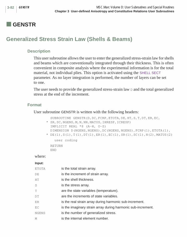
GENSTR MSC.Marc Volume D: User Subroutines and Special RoutinesChapter 3 User-defined Anisotropy and Constitutive Relations User Subroutines
3-82
■ GENSTR
Generalized Stress Strain Law (Shells & Beams)
Description
This user subroutine allows the user to enter the generalized stress-strain law for shells and beams which are conventionally integrated through their thickness. This is often convenient in composite analysis where the experimental information is for the total material, not individual plies. This option is activated using the SHELL SECT parameter. As no layer integration is performed, the number of layers can be set to one.
The user needs to provide the generalized stress-strain law D and the total generalized stress at the end of the increment.
Format
User subroutine GENSTR is written with the following headers: SUBROUTINE GENSTR(D,DC,FCRP,ETOTA,DE,HT,S,T,DT,ER,EC, * SR,SC,NGENS,M,N,NN,MATUS,IHRESP,ICRESP) IMPLICIT REAL *8 (A-H, O-Z) DIMENSION D(NGENS,NGENS),DC(NGENS,NGENS),FCRP(1),ETOTA(1), * DE(1),S(1),T(1),DT(1),ER(1),EC(1),SR(1),SC(1),N(2),MATUS(2)
user coding
RETURN END
where:
Input:
ETOTA is the total strain array.
DE is the increment of strain array.
HT is the shell thickness.
S is the stress array.
T are the state variables (temperature).
DT are the increments of state variables.
ER is the real strain array during harmonic sub-increment.
EC is the imaginary strain array during harmonic sub-increment.
NGENS is the number of generalized stress.
M is the internal element number.
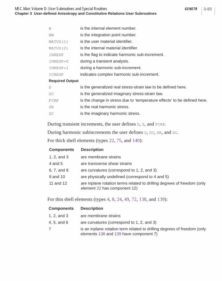
3-83MSC.Marc Volume D: User Subroutines and Special Routines GENSTRChapter 3 User-defined Anisotropy and Constitutive Relations User Subroutines
During transient increments, the user defines D, S, and FCRP.
During harmonic subincrements the user defines D, DC, SR, and SC.
For thick shell elements (types 22, 75, and 140):
For thin shell elements (types 4, 8, 24, 49, 72, 138, and 139):
N is the internal element number.
NN is the integration point number.
MATUS(1) is the user material identifier.
MATUS(2) is the internal material identifier.
IHRESP is the flag to indicate harmonic sub-increment.
IHRESP=0 during a transient analysis.
IHRESP=1 during a harmonic sub-increment.
ICRESP indicates complex harmonic sub-increment.
Required Output:
D is the generalized real stress-strain law to be defined here.
DC is the generalized imaginary stress-strain law.
FCRP is the change in stress due to ‘temperature effects’ to be defined here.
SR is the real harmonic stress.
SC is the imaginary harmonic stress.
Components Description
1, 2, and 3 are membrane strains
4 and 5 are transverse shear strains
6, 7, and 8 are curvatures (correspond to 1, 2, and 3)
9 and 10 are physically undefined (correspond to 4 and 5)
11 and 12 are inplane rotation terms related to drilling degrees of freedom (only element 22 has component 12)
Components Description
1, 2, and 3 are membrane strains
4, 5, and 6 are curvatures (correspond to 1, 2, and 3)
7 is an inplane rotation term related to drilling degrees of freedom (only elements 138 and 139 have component 7)
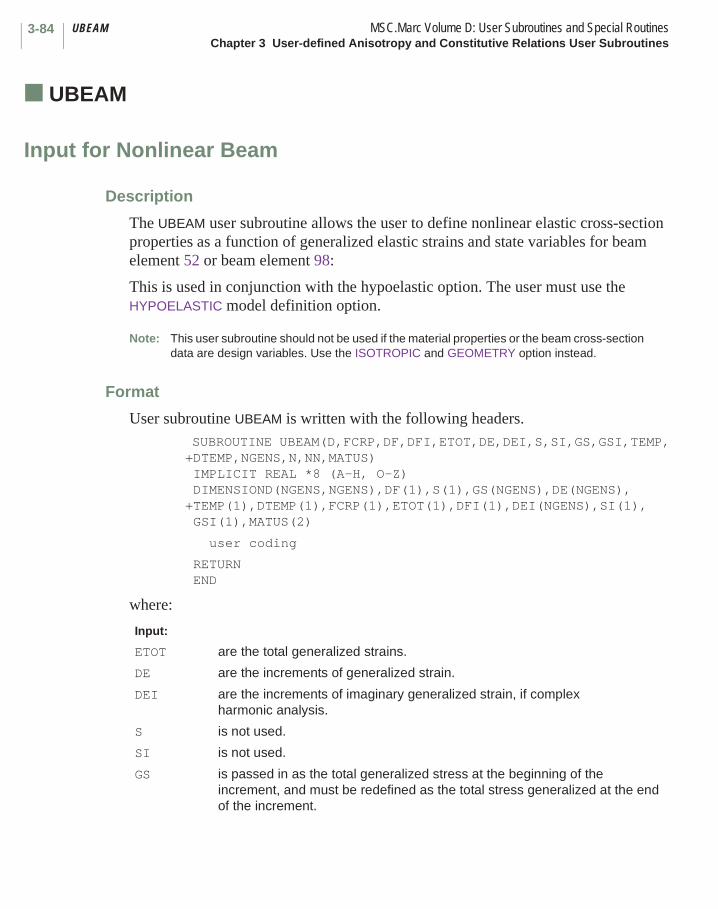
UBEAM MSC.Marc Volume D: User Subroutines and Special RoutinesChapter 3 User-defined Anisotropy and Constitutive Relations User Subroutines
3-84
■ UBEAM
Input for Nonlinear Beam
Description
The UBEAM user subroutine allows the user to define nonlinear elastic cross-section properties as a function of generalized elastic strains and state variables for beam element 52 or beam element 98:
This is used in conjunction with the hypoelastic option. The user must use the HYPOELASTIC model definition option.
Note: This user subroutine should not be used if the material properties or the beam cross-section data are design variables. Use the ISOTROPIC and GEOMETRY option instead.
Format
User subroutine UBEAM is written with the following headers. SUBROUTINE UBEAM(D,FCRP,DF,DFI,ETOT,DE,DEI,S,SI,GS,GSI,TEMP, +DTEMP,NGENS,N,NN,MATUS) IMPLICIT REAL *8 (A-H, O-Z) DIMENSIOND(NGENS,NGENS),DF(1),S(1),GS(NGENS),DE(NGENS), +TEMP(1),DTEMP(1),FCRP(1),ETOT(1),DFI(1),DEI(NGENS),SI(1),
GSI(1),MATUS(2)
user coding
RETURN END
where:
Input:
ETOT are the total generalized strains.
DE are the increments of generalized strain.
DEI are the increments of imaginary generalized strain, if complex harmonic analysis.
S is not used.
SI is not used.
GS is passed in as the total generalized stress at the beginning of the increment, and must be redefined as the total stress generalized at the end of the increment.
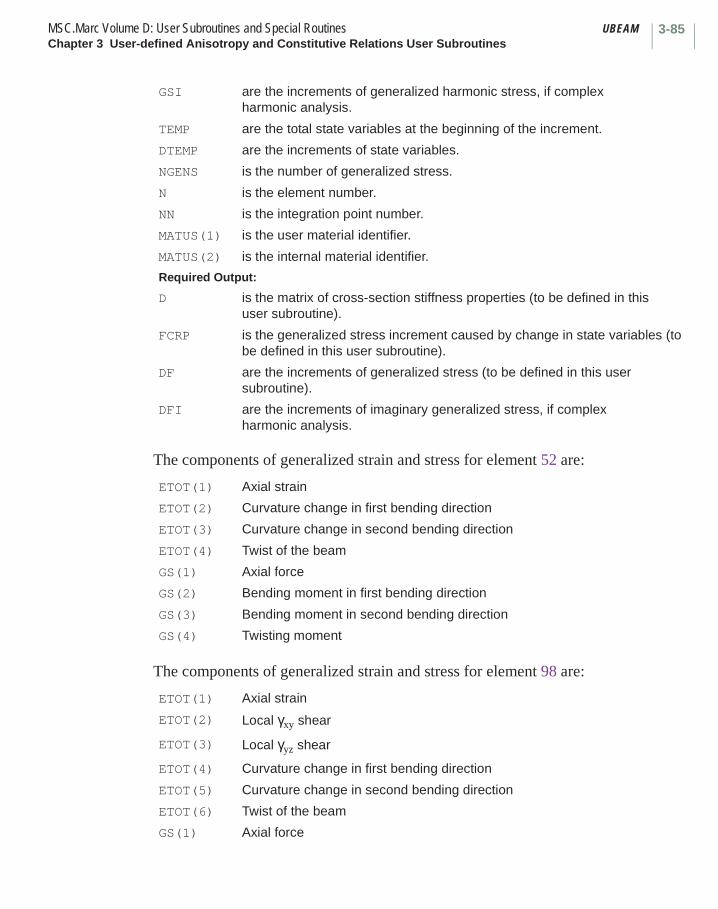
3-85MSC.Marc Volume D: User Subroutines and Special Routines UBEAMChapter 3 User-defined Anisotropy and Constitutive Relations User Subroutines
The components of generalized strain and stress for element 52 are:
The components of generalized strain and stress for element 98 are:
GSI are the increments of generalized harmonic stress, if complex harmonic analysis.
TEMP are the total state variables at the beginning of the increment.
DTEMP are the increments of state variables.
NGENS is the number of generalized stress.
N is the element number.
NN is the integration point number.
MATUS(1) is the user material identifier.
MATUS(2) is the internal material identifier.
Required Output:
D is the matrix of cross-section stiffness properties (to be defined in this user subroutine).
FCRP is the generalized stress increment caused by change in state variables (to be defined in this user subroutine).
DF are the increments of generalized stress (to be defined in this user subroutine).
DFI are the increments of imaginary generalized stress, if complex harmonic analysis.
ETOT(1) Axial strain
ETOT(2) Curvature change in first bending direction
ETOT(3) Curvature change in second bending direction
ETOT(4) Twist of the beam
GS(1) Axial force
GS(2) Bending moment in first bending direction
GS(3) Bending moment in second bending direction
GS(4) Twisting moment
ETOT(1) Axial strain
ETOT(2) Local γxy shear
ETOT(3) Local γyz shear
ETOT(4) Curvature change in first bending direction
ETOT(5) Curvature change in second bending direction
ETOT(6) Twist of the beam
GS(1) Axial force

UBEAM MSC.Marc Volume D: User Subroutines and Special RoutinesChapter 3 User-defined Anisotropy and Constitutive Relations User Subroutines
3-86
GS(2) Local τxy shear
GS(3) Local τyz shear
GS(4) Bending moment in the first bending direction
GS(5) Bending moment in the second bending direction
GS(6) Twisting moment

3-87MSC.Marc Volume D: User Subroutines and Special Routines UPHIChapter 3 User-defined Anisotropy and Constitutive Relations User Subroutines
■ UPHI
Input of PHI Function in Harmonic Analysis
Description
This user subroutine allows the input of PHI functions to be expressed analytically. The values of PHI are then passed into a MSC.Marc user subroutine where they are used in calculation of the Laplace transform for harmonic analysis.
Format
User subroutine UPHI is written with the following headers: SUBROUTINE UPHI(ELCG,FREQ,WI1,WI2,C10,C01,C11,C20,C30,NDI,*NSHEAR,FI0,FI1,FI2,FI11,FI12,FI21,FI22,IFLAG,DERIVS) IMPLICIT REAL *8 (A-H, O-Z) DIMENSION ELCG(1),DERIVS(1) user coding
RETURN END
where:
Input:
ELCG is the left Cauchy-Green strain vector.
FREQ is the excitation frequency in radians/ time unit.
WI1,WI2 are the first and second invariants of ELCG.
C10,C01,C11,C20,C30 are the five material parameters of the Mooney formulation.
NDI is the number of direct strain components.
NSHEAR is the number of shear strain components.
IFLAG = 1: The sine PHI functions should be defined.
IFLAG = 2: The cosine PHI functions should be defined.
DERIVS is the array which contains the variables W, W1, W2, W11, W12, W21, and W22.
Required Output:
FI0,FI1,FI2,FI11,FI12,FI21,FI22 are the seven PHI functions which should be defined in this user subroutine by the user.
UPHI MSC.Marc Volume D: User Subroutines and Special RoutinesChapter 3 User-defined Anisotropy and Constitutive Relations User Subroutines
3-88
where:
W is the strain energy density.
W1 is .
W2 is .
W11 is .
W12 is .
W21 is .
W22 is .
∂W ∂I1⁄
∂W ∂I2⁄
∂2W ∂I
1
2⁄
∂2W ∂I1∂I2⁄
∂2W ∂I2∂I1⁄
∂2W ∂I
22⁄
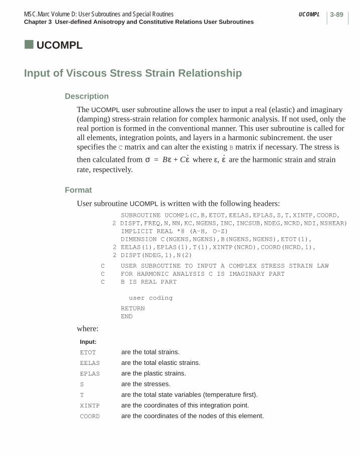
3-89MSC.Marc Volume D: User Subroutines and Special Routines UCOMPLChapter 3 User-defined Anisotropy and Constitutive Relations User Subroutines
■ UCOMPL
Input of Viscous Stress Strain Relationship
Description
The UCOMPL user subroutine allows the user to input a real (elastic) and imaginary (damping) stress-strain relation for complex harmonic analysis. If not used, only the real portion is formed in the conventional manner. This user subroutine is called for all elements, integration points, and layers in a harmonic subincrement. the user specifies the C matrix and can alter the existing B matrix if necessary. The stress is
then calculated from where ε, are the harmonic strain and strain rate, respectively.
Format
User subroutine UCOMPL is written with the following headers: SUBROUTINE UCOMPL(C,B,ETOT,EELAS,EPLAS,S,T,XINTP,COORD, 2 DISPT,FREQ,N,NN,KC,NGENS,INC,INCSUB,NDEG,NCRD,NDI,NSHEAR) IMPLICIT REAL *8 (A-H, O-Z) DIMENSION C(NGENS,NGENS),B(NGENS,NGENS),ETOT(1), 2 EELAS(1),EPLAS(1),T(1),XINTP(NCRD),COORD(NCRD,1), 2 DISPT(NDEG,1),N(2)
C USER SUBROUTINE TO INPUT A COMPLEX STRESS STRAIN LAWC FOR HARMONIC ANALYSIS C IS IMAGINARY PARTC B IS REAL PART
user coding
RETURN END
where:
Input:
ETOT are the total strains.
EELAS are the total elastic strains.
EPLAS are the plastic strains.
S are the stresses.
T are the total state variables (temperature first).
XINTP are the coordinates of this integration point.
COORD are the coordinates of the nodes of this element.
σ Bε Cε·+= ε·

UCOMPL MSC.Marc Volume D: User Subroutines and Special RoutinesChapter 3 User-defined Anisotropy and Constitutive Relations User Subroutines
3-90
DISPT are the total displacements of the nodes of this element.
FREQ is the harmonic frequency in radians/time unit.
N(1) is the user’s element number.
N(2) is the internal element number.
NN is the integration point number.
KC is the layer number.
NGENS is the number of stress-strain components.
INC is the increment number.
INCSUB is the subincrement number.
NDEG is the number of degrees of freedom per node.
NCRD is the number of coordinate directions per node.
NDI is the number of direct component of stress.
NSHEAR is the number of shear components of stress.
Required Output:
C is the imaginary damping part of the stress-strain law.
B is the real elastic part of the stress-strain law.
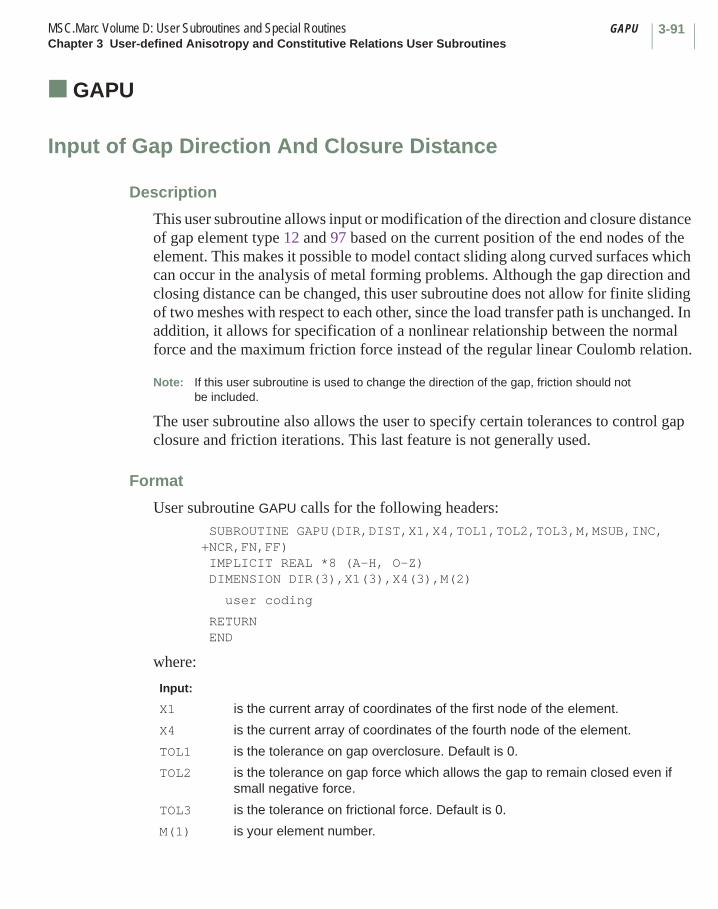
3-91MSC.Marc Volume D: User Subroutines and Special Routines GAPUChapter 3 User-defined Anisotropy and Constitutive Relations User Subroutines
■ GAPU
Input of Gap Direction And Closure Distance
Description
This user subroutine allows input or modification of the direction and closure distance of gap element type 12 and 97 based on the current position of the end nodes of the element. This makes it possible to model contact sliding along curved surfaces which can occur in the analysis of metal forming problems. Although the gap direction and closing distance can be changed, this user subroutine does not allow for finite sliding of two meshes with respect to each other, since the load transfer path is unchanged. In addition, it allows for specification of a nonlinear relationship between the normal force and the maximum friction force instead of the regular linear Coulomb relation.
Note: If this user subroutine is used to change the direction of the gap, friction should not be included.
The user subroutine also allows the user to specify certain tolerances to control gap closure and friction iterations. This last feature is not generally used.
Format
User subroutine GAPU calls for the following headers: SUBROUTINE GAPU(DIR,DIST,X1,X4,TOL1,TOL2,TOL3,M,MSUB,INC,+NCR,FN,FF) IMPLICIT REAL *8 (A-H, O-Z) DIMENSION DIR(3),X1(3),X4(3),M(2)
user coding
RETURN END
where:
Input:
X1 is the current array of coordinates of the first node of the element.
X4 is the current array of coordinates of the fourth node of the element.
TOL1 is the tolerance on gap overclosure. Default is 0.
TOL2 is the tolerance on gap force which allows the gap to remain closed even if small negative force.
TOL3 is the tolerance on frictional force. Default is 0.
M(1) is your element number.
GAPU MSC.Marc Volume D: User Subroutines and Special RoutinesChapter 3 User-defined Anisotropy and Constitutive Relations User Subroutines
3-92
In two dimensional problems, DIR, X1, and X4 have two components; otherwise, DIR, X1, and X4 have three components.
M(2) is the internal element number.
MSUB is the subelement number (only for MSC.Marc element type 97).
INC is the current increment number.
NCR is the dimension of the gap.2 for 2-D problems.3 for 3-D problems.
FN is the current gap force.
Required Output:
DIR is the array of direction cosines of the current gap direction. This can be modified by the user.
DIST is the current closure distance (distance that the nodes must travel to obtain closure), which is to be defined by the user.
FF is the frictional force limit, to be specified by the user.

3-93MSC.Marc Volume D: User Subroutines and Special Routines USELEMChapter 3 User-defined Anisotropy and Constitutive Relations User Subroutines
■ USELEM
User-defined Element
Description
This user subroutine allows the user to calculate his own finite element stiffness or mass matrix. This can also be used as interface with other numerical techniques. In general, in the finite element calculation, several matrices are required; hence, for a particular element, this user subroutine is called a multiple number of times. The calls and the user’s requirements are defined as follows:
To use this option, the USER parameter must be included to define the size of the element stiffness matrix and other critical dimensions and the element type given on the connectivity must be a negative number.
IFLAG=1 Return the equivalent nodal loads (F) given distributed surface or body loads. If the ELASTIC, FOLLOW FOR parameters or the AUTO STEP, AUTO TIME, AUTO INCREMENT options are used, these are total loads or else incremental loads. In a heat transfer analysis, this is the total flux vector.
IFLAG=2 Return the element tangent stiffness matrix (K). For an elastic analysis, this is the usual stiffness. For a heat transfer matrix analysis, this is the conductivity matrix. Also calculate the total internal forces (R). This is not necessary in a linear elastic analysis if the LOAD COR parameter has been turned off.
IFLAG=3 Return the mass matrix (M) for a dynamic analysis or specific heat matrix for a heat transfer problem.
IFLAG=4 Calculate the incremental strains (DE), generalized stresses (GSIGS) and the internal force (R). For a linear elastic solution, if only displacements are required, the user does not need to return any values. In a heat transfer analysis, the thermal gradient and the heat fluxes (both stored via SIGXX) and the internal flux vector (R) need to be calculated.
IFLAG=5 Output element results if so desired.

USELEM MSC.Marc Volume D: User Subroutines and Special RoutinesChapter 3 User-defined Anisotropy and Constitutive Relations User Subroutines
3-94
Format
User subroutine USELEM calls for the following headers: SUBROUTINE USELEM(M,XK,XM,NNODE,NDEG,F,R,* JTYPE,DISPT,DISP,NDI,NSHEAR,IPASS,NSTATS,NGENEL,* INTEL,COORD,NCRD,IFLAG,IDSS,T,DT,ETOTA,GSIGS,DE,* GEOM,JGEOM,SIGXX,NSTRMU)
IMPLICIT REAL *8 (A-H, O-Z) DIMENSION XK(IDSS,IDSS),XM(IDSS,IDSS),DISPT(NDEG,*),DISP(NDEG,*) DIMENSION T(NSTATS,*),DT(NSTATS,*),COORD(NCRD,*) DIMENSION ETOTA(NGENEL,*),GSIGS(NGENEL,*),DE(NGENEL,*) DIMENSION F(NDEG,*),R(NDEG,*),SIGXX(NSTRMU,*),GEOM(*), JGEOM(*)
user coding
RETURN END
where:
Input:
M is the user element number.NNODE is the number of nodes per element.NDEG is the maximum number of degrees of freedom per node.JTYPE is the user element type (negative).DISPT is the total nodal displacements array of this element.
In heat transfer, DISPT is the temperature array at which material properties were last calculated.
DISP is the incremental nodal displacements of this element.In heat transfer, DISP is the total current nodal temperatures of this element.
NDI is the number of direct components of stress/internal heat flux.NSHEAR is the number of shear components of stress.
In heat transfer, NSHEAR is zero.IPASS Flag to indicate which pass for coupled analysis.
= 1 during a stress analysis pass.= 2 during a heat transfer pass.= 3 during a fluid pass.= 4 during a Joule heating pass.= 5 during a pore pressure pass.= 6 during an electrostatic pass.= 7 during a magnetostatic pass.= 8 during an electromagnetic pass.
NSTATS is the number of state variables.NGENEL is the number of generalized strains.
3-95MSC.Marc Volume D: User Subroutines and Special Routines USELEMChapter 3 User-defined Anisotropy and Constitutive Relations User Subroutines
Note that the stiffness matrix is normally symmetric. If a nonsymmetric formulation is used, the SOLVER option should be used to indicate this.
INTEL is the number of integration points.COORD is the original nodal coordinates array.NCRD is the number of coordinates per node.IFLAG indicates what is to be returned by the user.
= 1 Called by OPRESS during formation of load vector. You return F.
= 2 Called by OASEMB during formation of stiffness matrix. You return XK,R.
= 3 Called by OASMAS during formation of mass matrix. The user returns XM.
= 4 Called by OGETST during stress recovery. The user returns R,GSIGS,DE,ETOTA,SIGXX for stress analysis pass.
The user returns R, SIGXX for heat transfer pass.= 5 Called by SCIMP during output phase.
The user prints the results.IDSS is the size of element stiffness matrix.T is the state variables.DT is the increment of state variables.GEOM is the array of the geometric parameters.JGEOM is the array of table ids for the geometric parameters.NSTRMU is the number of stresses/heat fluxes per integration points.Required Output:
XK is the stiffness matrix or conductivity matrix.XM is the mass matrix or specific heat matrix.F is the externally applied equivalent nodal loads/nodal fluxes array.R is the internal forces/fluxes array.ETOTA is the total strain array.
Not used in heat transfer.GSIGS is the generalized stress array.
Not used in heat transfer.DE is the increment of strain array.
Not used in heat transfer.SIGXX is layer stresses for shell elements and is equal to GSIGS for
continuum element.In the heat transfer pass, SIGXX contains the thermal gradients and the heat fluxes.

UNEWTN MSC.Marc Volume D: User Subroutines and Special RoutinesChapter 3 User-defined Anisotropy and Constitutive Relations User Subroutines
3-96
■ UNEWTN
Input of Viscosity in Flow Analysis
Description
It is possible to solve Newtonian and non-Newtonian laminar incompressible steady state fluid analyses using the R-P FLOW parameter in MSC.Marc. The UNEWTN user subroutine is used to define the viscosity at a particular spatial location. An Eulerian approach is then used to solve for the nodal velocities. This user subroutine can also be used to define the nonlinear viscosity in Navier Stokes fluid analysis when the FLUID parameter is used.
Format
User subroutine UNEWTN is written with the following headers:SUBROUTINE UNEWTN (N,NN,V,E,NGENS,DT,DTDL) IMPLICIT REAL *8 (A-H, O-Z)DIMENSION E(NGENS),N(2)
user coding
RETURNEND
where:
Note: If Herrmann elements are used, the last component of E represents a rate of change of volumetric strain.
Input:
N(1) is the user’s element number.
N(2) is the internal element number.
NN is the integration point number.
E are the components of the strain rate.
NGENS is the number of components.
DT is the temperature at the beginning of the increment.
DTDL is the increment of temperature.
Required Output:
V is the viscosity to be defined here.

3-97MSC.Marc Volume D: User Subroutines and Special Routines URPFLOChapter 3 User-defined Anisotropy and Constitutive Relations User Subroutines
■ URPFLO
Rigid-Plastic Flow
Description
This user subroutine allows the user to define the current yield stress as a function of the equivalent strain rate, equivalent strain, temperature, and user-defined state variables. This user subroutine is used in conjunction with the transient R-P FLOW parameter.
Format
User subroutine URPFLO is written with the following headers: SUBROUTINE URPFLO(MDUM,NN,LAYERS,MATUS,INC,NDI,NGENS,NCRD,+NSTAT,CPTIM,TIMINC,EBAR,ERATE,DT,DTDL,STATS,DSTATS,COORD,YD) IMPLICIT REAL *8 (A-H, O-Z) DIMENSION MDUM(2), STATS(NSTAT), DSTATS(NSTAT), COORD(NCRD) DIMENSION MATUS(2)
user coding
RETURN END
where:
Input:
MDUM(1) element number.
MDUM(2) internal element/elsto number.
NN integration point number.
LAYERS layer number.
MATUS(1) user material identification number.
MATUS(2) internal material identification number.
INC increment number.
NDI number of direct components.
NGENS total number of components.
NCRD number of coordinates.
NSTAT number of state variables excluding temperature.
CPTIM time at beginning of increment.
TIMINC incremental time.
DT temperature at beginning of increment.

URPFLO MSC.Marc Volume D: User Subroutines and Special RoutinesChapter 3 User-defined Anisotropy and Constitutive Relations User Subroutines
3-98
DTDL incremental temperature.
EBAR total equivalent strain at beginning of increment.
STATS values of state variables excluding temperature at beginning of increment.
ERATE equivalent strain rate.
COORD integration point coordinates.
Required Output:
YD equivalent stress; if not calculated here, MSC.Marc finds the value of yd from the input data.
DSTATS incremental state variables (excluding temperature).

3-99MSC.Marc Volume D: User Subroutines and Special Routines UARRBOChapter 3 User-defined Anisotropy and Constitutive Relations User Subroutines
■ UARRBO
Arruda-Boyce Material Model
Description
This user subroutine allows the user to redefine the constants used in the strain energy function. This data is normally entered through the ARRUDBOYCE model definition option.
The form of the strain energy function is:
Format
User subroutine UARRBO is written with the following headers: SUBROUTINE UARRBO(A1,A2,T,N,NN,MATUS)IMPLICIT REAL *8 (A-H, O-Z)DIMENSION N(2),MATUS(2)
user coding
RETURN END
where:
Input:
T is the temperature.
N(1) is your element number.
N(2) is the internal element number.
NN is the integration point number.
MATUS(1) is the user material identifier.
MATUS(2) is the internal material identifier.
Required Output:
A1 = nkθ is the linear term (in the strain energy function) to be defined by the user.
A2 = N is the number of statistical links of length l in the chain between chemical crosslinks (in the strain energy function) to be defined by the user.
W nkθ 12--- I1 3–( ) 1
20N---------- I
2
19–
11
1050N2
------------------ I3
127–
19
7000N3
------------------ I4
181–
519
673750N4
------------------------ I5
1243–
…+ + + + +=
UGENT MSC.Marc Volume D: User Subroutines and Special RoutinesChapter 3 User-defined Anisotropy and Constitutive Relations User Subroutines
3-100
■ UGENT
Gent Material Model
Description
This user subroutine allows the user to redefine the constants used in the strain energy function. This data is normally entered through the ARRUDBOYCE model definition option.
The form of the strain energy function is:
Format
User subroutine UGENT is written with the following headers: SUBROUTINE UGENT(E,AI,T,N,NN,MATUS,BUKLM)IMPLICIT REAL *8 (A-H,O-Z)DIMENSION N(2),MATUS(2)
user coding
RETURN END
where:
Input:
T is the temperature.
N(1) is the user’s element number.
N(2) is the internal element number.
NN is the integration point number.
MATUS(1) is the user’s material identifier.
MATUS(2) is the internal material identifier.
Required Output:
E = E is the modulus (used in the strain energy function) to be defined by the user.
AI = Im is the maximum value of first invariant (used in the strain energy function) to be defined by the user.
BUKLM is the bulk modulus K (to be defined); if not defined, BULKM = 10000.*E/6
WE6---– Im 3–( ) 1
I1 3–
Im 3–--------------–
log=
3-101MSC.Marc Volume D: User Subroutines and Special Routines UACOUSChapter 3 User-defined Anisotropy and Constitutive Relations User Subroutines
■ UACOUS
Definition of Material Properties for Acoustic Analysis
Description
This user subroutine allows the user to redefine the material constants of an acoustic medium (fluid) as a function of the frequency in an acoustic harmonic analysis. This data is normally entered through the ACOUSTIC model definition option.
Format
User subroutine UACOUS is written with the following headers: SUBROUTINE UACOUS(MDUM,FREQC,XKF,DRAG,RHOHT)IMPLICIT REAL*8 (A-H,O-Z)DIMENSION MDUM(2)
user coding
RETURN END
where:
Input:
MDUM(1) is the user’s element number.
MDUM(2) is the MSC.Marc element storage number.
FREQC is the frequency in cycles per time.
Required Output:
XKF is the fluid bulk modulus to be defined by the user.
DRAG is the fluid volumetric drag to be defined by the user.
RHOHT is the fluid density to be defined by the user.
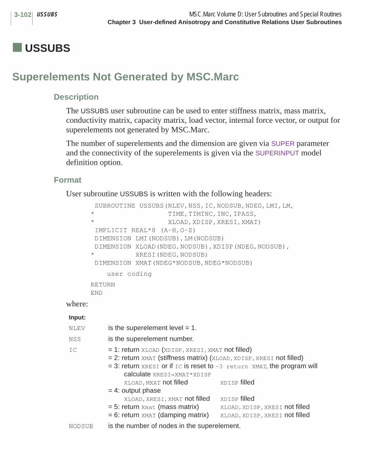
USSUBS MSC.Marc Volume D: User Subroutines and Special RoutinesChapter 3 User-defined Anisotropy and Constitutive Relations User Subroutines
3-102
■ USSUBS
Superelements Not Generated by MSC.Marc
Description
The USSUBS user subroutine can be used to enter stiffness matrix, mass matrix, conductivity matrix, capacity matrix, load vector, internal force vector, or output for superelements not generated by MSC.Marc.
The number of superelements and the dimension are given via SUPER parameter and the connectivity of the superelements is given via the SUPERINPUT model definition option.
Format
User subroutine USSUBS is written with the following headers:SUBROUTINE USSUBS(NLEV,NSS,IC,NODSUB,NDEG,LMI,LM,
* TIME,TIMINC,INC,IPASS,* XLOAD,XDISP,XRESI,XMAT)IMPLICIT REAL*8 (A-H,O-Z)DIMENSION LMI(NODSUB),LM(NODSUB)DIMENSION XLOAD(NDEG,NODSUB),XDISP(NDEG,NODSUB),
* XRESI(NDEG,NODSUB)DIMENSION XMAT(NDEG*NODSUB,NDEG*NODSUB)
user coding
RETURNEND
where:
Input:
NLEV is the superelement level = 1.
NSS is the superelement number.
IC = 1: return XLOAD (XDISP,XRESI,XMAT not filled)= 2: return XMAT (stiffness matrix) (XLOAD,XDISP,XRESI not filled)= 3: return XRESI or if IC is reset to -3 return XMAT, the program will
calculate XRESI=XMAT*XDISP XLOAD,MXAT not filled XDISP filled
= 4: output phase XLOAD,XRESI,XMAT not filled XDISP filled
= 5: return Xmat (mass matrix) XLOAD,XDISP,XRESI not filled= 6: return XMAT (damping matrix) XLOAD,XDISP,XRESI not filled
NODSUB is the number of nodes in the superelement.
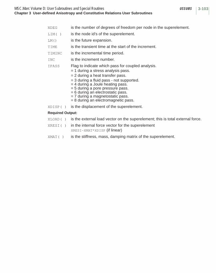
3-103MSC.Marc Volume D: User Subroutines and Special Routines USSUBSChapter 3 User-defined Anisotropy and Constitutive Relations User Subroutines
NDEG is the number of degrees of freedom per node in the superelement.
LIM( ) is the node id’s of the superelement.
LM() is the future expansion.
TIME is the transient time at the start of the increment.
TIMINC is the incremental time period.
INC is the increment number.
IPASS Flag to indicate which pass for coupled analysis.= 1 during a stress analysis pass.= 2 during a heat transfer pass.= 3 during a fluid pass - not supported.= 4 during a Joule heating pass.= 5 during a pore pressure pass.= 6 during an electrostatic pass.= 7 during a magnetostatic pass.= 8 during an electromagnetic pass.
XDISP( ) is the displacement of the superelement.
Required Output:
XLOAD( ) is the external load vector on the superelement; this is total external force.
XRESI( ) in the internal force vector for the superelementXRESI-XMAT*XDISP (if linear)
XMAT( ) is the stiffness, mass, damping matrix of the superelement.
MSC.Marc Volume D: User Subroutines and Special RoutinesChapter 3 User-defined Anisotropy and Constitutive Relations User Subroutines
3-104
References1. Simo, J. C. and Taylor, R. L., “Quasi incompressible finite elasticity in
principal stretches. Continuum basis and numerical algorithms”, Comp. Meth. App. Mech. Engrg., 85, pp. 273-310, 1991.
2. Simo, J. C., “Algorithms for static and dynamic multiplicative plasticity that preserve the classical return mapping schemes of the infinitesimal theory”, Comp. Meth. App. Mech. Engrg., 99, pp. 61-112, 1992.
Chapter 4 Viscoplasticity and Generalized Plasticity User Subroutines List
User Subroutine Page
ASSOC . . . . . . . . . . . . . . . . . . . . . . . . . . . . . . . . . . . . . . . . . . . . . . . . . . . . . . . . . 4-13
CRPLAW . . . . . . . . . . . . . . . . . . . . . . . . . . . . . . . . . . . . . . . . . . . . . . . . . . . . . . . . 4-7
NASSOC . . . . . . . . . . . . . . . . . . . . . . . . . . . . . . . . . . . . . . . . . . . . . . . . . . . . . . . . 4-9
SINCER . . . . . . . . . . . . . . . . . . . . . . . . . . . . . . . . . . . . . . . . . . . . . . . . . . . . . . . . . 4-14
UCRPLW . . . . . . . . . . . . . . . . . . . . . . . . . . . . . . . . . . . . . . . . . . . . . . . . . . . . . . . . 4-5UVSCPL. . . . . . . . . . . . . . . . . . . . . . . . . . . . . . . . . . . . . . . . . . . . . . . . . . . . . . . . . 4-3
YIEL . . . . . . . . . . . . . . . . . . . . . . . . . . . . . . . . . . . . . . . . . . . . . . . . . . . . . . . . . . . . 4-12
ZERO . . . . . . . . . . . . . . . . . . . . . . . . . . . . . . . . . . . . . . . . . . . . . . . . . . . . . . . . . . . 4-11
CHAPTER
4 Viscoplasticity and Generalized Plasticity User Subroutines List

Chapter 4 Viscoplasticity and Generalized Plasticity User Subroutines
The user subroutines in this chapter are used to describe viscoplastic materials or a user-defined general plasticity model. There are two numeric procedures for viscoplasticity: implicit and explicit. This is activated on the CREEP parameter. The implicit method is preferred. The generalized plasticity allows the user to develop a yield surface, equivalent stress, and flow rate that is different from one provided by MSC.Marc. Table 4-1 summarizes these routines and indicates what parameters or model definition options are required to invoke the user subroutine.
CHAPTER
4 Viscoplasticity and Generalized Plasticity User Subroutines
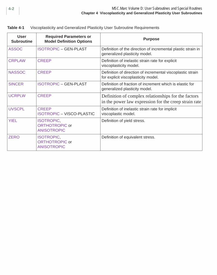
MSC.Marc Volume D: User Subroutines and Special RoutinesChapter 4 Viscoplasticity and Generalized Plasticity User Subroutines
4-2
Table 4-1 Viscoplasticity and Generalized Plasticity User Subroutine Requirements
User Subroutine
Required Parameters or Model Definition Options
Purpose
ASSOC ISOTROPIC – GEN-PLAST Definition of the direction of incremental plastic strain in generalized plasticity model.
CRPLAW CREEP Definition of inelastic strain rate for explicit viscoplasticity model.
NASSOC CREEP Definition of direction of incremental viscoplastic strain for explicit viscoplasticity model.
SINCER ISOTROPIC – GEN-PLAST Definition of fraction of increment which is elastic for generalized plasticity model.
UCRPLW CREEP Definition of complex relationships for the factors in the power law expression for the creep strain rate
UVSCPL CREEPISOTROPIC – VISCO-PLASTIC
Definition of inelastic strain rate for implicit viscoplastic model.
YIEL ISOTROPIC,ORTHOTROPIC orANISOTROPIC
Definition of yield stress.
ZERO ISOTROPIC,ORTHOTROPIC orANISOTROPIC
Definition of equivalent stress.

4-3MSC.Marc Volume D: User Subroutines and Special Routines UVSCPLChapter 4 Viscoplasticity and Generalized Plasticity User Subroutines
■ UVSCPL
Definition of the Inelastic Strain Rate
Description
This user subroutine is used for computing the inelastic strain increment for an elastic-viscoplastic material. This routine allows very general material laws to be entered. The user must define the inelastic strain and the stress increment.
This user subroutine is activated when the implicit creep procedure is used, and VISCO PLAS material is selected on the ISOTROPIC or ORTHOTROPIC option.
Format
User subroutine UVSCPL is written with the following headers: SUBROUTINE UVSCPL(YOUNG,POISS,SHEAR,B,USTRRT,ETOT,E,THMSTI,1 EELAS,S,SINC,GF,EPL,AVGINE,EQCRP,EQCPNC,YD,YD1,VSCPAR,DT,2 DTDL,CPTIM,TIMINC,XINTP,NGENS,M,NN,KC,MATUS,NDI,NSHEAR,NCRD,3 IANISO,NSTATS,INC,NCYCLE,LOVL,NVSPLM) IMPLICIT REAL *8 (A-H, O-Z) DIMENSION POISS(3,2),YOUNG(3,2),B(NGENS,NGENS),1 USTRRT(NGENS),ETOT(NGENS),E(NGENS),THMSTI(NGENS),2 EELAS(NGENS),S(NGENS),SINC(NGENS),GF(NGENS),EPL(NGENS),3 AVGINE(NGENS),DT(NSTATS),DTDL(NSTATS),XINTP(NCRD),
SHEAR(3,2),VSCPAR(NVSPLM),MATUS(2)
user coding
RETURN END
where:
Input:YOUNG is the Young’s modulus.POISS is the Poisson’s modulus.SHEAR is the shear modulus.B is the tangent elastic matrix.ETOT is the accumulated total strain at beginning of increment.E is the current strain increment.THMSTI is the thermal strain increment.EELAS is the accumulated elastic strain at beginning of increment.S is the accumulated stress at beginning of increment.EPL is the accumulated inelastic strain at beginning of increment.
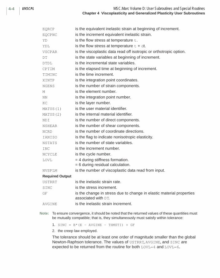
UVSCPL MSC.Marc Volume D: User Subroutines and Special RoutinesChapter 4 Viscoplasticity and Generalized Plasticity User Subroutines
4-4
Note: To ensure convergence, it should be noted that the returned values of these quantities must be mutually compatible; that is, they simultaneously must satisfy within tolerance:
1. SINC = B*(E - AVGINE - THMSTI) + GF
2. the creep law employed.
The tolerance should be at least one order of magnitude smaller than the global Newton-Raphson tolerance. The values of USTRRT, AVGINE, and SINC are expected to be returned from the routine for both LOVL=4 and LOVL=6.
EQRCP is the equivalent inelastic strain at beginning of increment.EQCPNC is the increment equivalent inelastic strain.YD is the flow stress at temperature t.YDL is the flow stress at temperature t + dt.VSCPAR is the viscoplastic data read off isotropic or orthotropic option.DT is the state variables at beginning of increment.DTDL is the incremental state variables.CPTIM is the elapsed time at beginning of increment.TIMINC is the time increment.XINTP is the integration point coordinates.NGENS is the number of strain components.M is the element number.NN is the integration point number.KC is the layer number.MATUS(1) is the user material identifier.MATUS(2) is the internal material identifier.NDI is the number of direct components.NSHEAR is the number of shear components.NCRD is the number of coordinate directions.IANISO is the flag to indicate nonisotropic elasticity.NSTATS is the number of state variables.INC is the increment number.NCYCLE is the cycle number.LOVL = 4 during stiffness formation.
= 6 during residual calculation.NVSPLM is the number of viscoplastic data read from input.Required Output
USTRRT is the inelastic strain rate.SINC is the stress increment.GF is the change in stress due to change in elastic material properties
associated with DT.AVGINE is the inelastic strain increment.
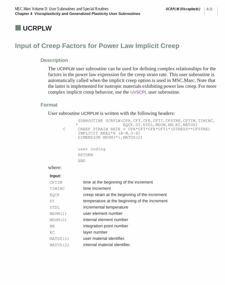
4-5MSC.Marc Volume D: User Subroutines and Special Routines UCRPLW (Viscoplastic)Chapter 4 Viscoplasticity and Generalized Plasticity User Subroutines
■ UCRPLW (Viscoplastic)
Input of Creep Factors for Power Law Implicit Creep
Description
The UCRPLW user subroutine can be used for defining complex relationships for the factors in the power law expression for the creep strain rate. This user subroutine is automatically called when the implicit creep option is used in MSC.Marc. Note that the latter is implemented for isotropic materials exhibiting power law creep. For more complex implicit creep behavior, use the UVSCPL user subroutine.
Format
User subroutine UCRPLW is written with the following headers: SUBROUTINE UCRPLW(CPA,CFT,CFE,CFTI,CFSTRE,CPTIM,TIMINC,
* EQCP,DT,DTDL,MDUM,NN,KC,MATUS) C CREEP STRAIN RATE = CPA*CFT*CFE*CFTI*(STRESS**CFSTRE) IMPLICIT REAL*8 (A-H,O-Z) DIMENSION MDUM(*),MATUS(2)
user coding
RETURN
END
where:
Input:
CPTIM time at the beginning of the increment
TIMINC time Increment
EQCP creep strain at the beginning of the increment
DT temperature at the beginning of the increment
DTDL incremental temperature
MDUM(1) user element number
MDUM(2) internal element number
NN integration point number
KC layer number
MATUS(1) user material identifier.
MATUS(2) internal material identifier.
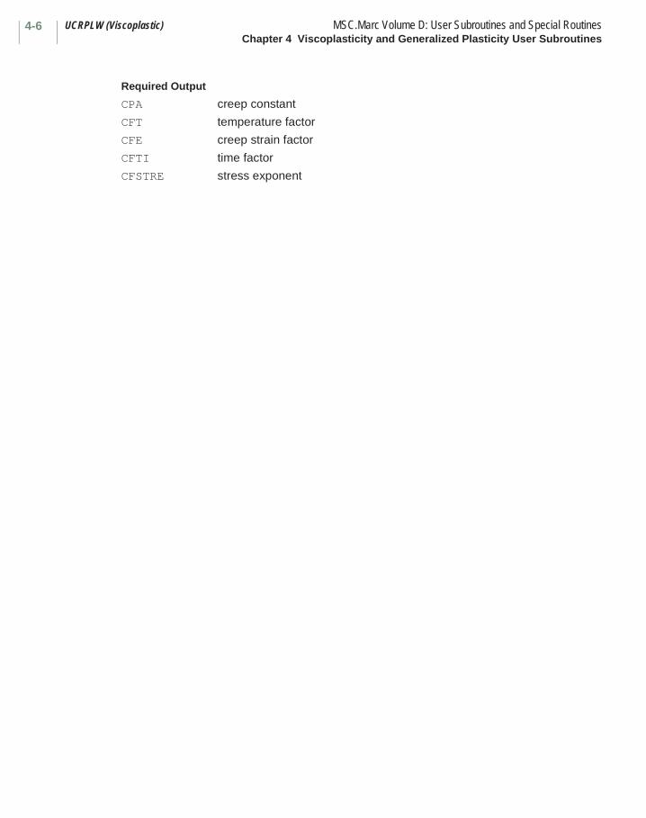
UCRPLW (Viscoplastic) MSC.Marc Volume D: User Subroutines and Special RoutinesChapter 4 Viscoplasticity and Generalized Plasticity User Subroutines
4-6
Required Output
CPA creep constant
CFT temperature factor
CFE creep strain factor
CFTI time factor
CFSTRE stress exponent

4-7MSC.Marc Volume D: User Subroutines and Special Routines CRPLAW (Viscoplastic)Chapter 4 Viscoplasticity and Generalized Plasticity User Subroutines
■ CRPLAW (Viscoplastic)
Input of Explicit Viscoplastic Strain Rate Law
Description
The CRPLAW user subroutine can also be used for calculating the viscoplastic behavior. All the creep quantities are treated as viscoplastic strain quantities when the appropriate flag is set on the CREEP parameter.
The basic information on the use of this subroutine can be found in Chapter 3 of this manual. Additionally, the user can use common block VISCPL.
The variables in common block VISCPL are:
Example
The following is a simple viscoplastic strain rate law that depends on the differences between the current stress state and the static yield stress, raised to the nth power. (Note that T(1), the current equivalent stress also includes Mohr-Coulomb terms when the option is flagged.)
where:
YD is the equivalent stress at first yield.
YD1 is the equivalent yield stress including current work hardening and temperature effects.
YD2 is the equivalent stress for ORNL tenth cycle yield.
YD21 is the equivalent stress including current work hardening and temperature effects for ORNL tenth cycle yield.
YDZER is the equivalent yield stress including Mohr-Coulomb terms (defaults to YD1).
is the current total equivalent stress.
is the current equivalent yield stress including workhardening, temperature effects and Mohr-Coulomb terms.
ε·
c σ σy–( )n=
σ
σy
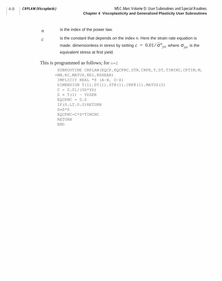
CRPLAW (Viscoplastic) MSC.Marc Volume D: User Subroutines and Special RoutinesChapter 4 Viscoplasticity and Generalized Plasticity User Subroutines
4-8
This is programmed as follows; for n=2 SUBROUTINE CRPLAW(EQCP,EQCPNC,STR,CRPE,T,DT,TIMINC,CPTIM,M,+NN,KC,MATUS,NDI,NSHEAR) IMPLICIT REAL *8 (A-H, O-Z) DIMENSION T(1),DT(1),STR(1),CRPE(1),MATUS(2) C = 0.01/(YD*YD) S = T(1) - YDZER EQCPNC = 0.0 IF(S.LT.0.0)RETURN S=S*S EQCPNC=C*S*TIMINC RETURN END
is the index of the power law.
is the constant that depends on the index n. Here the strain rate equation is
made. dimensionless in stress by setting where is the
equivalent stress at first yield.
n
cc 0.01 σn
yo⁄= σyo
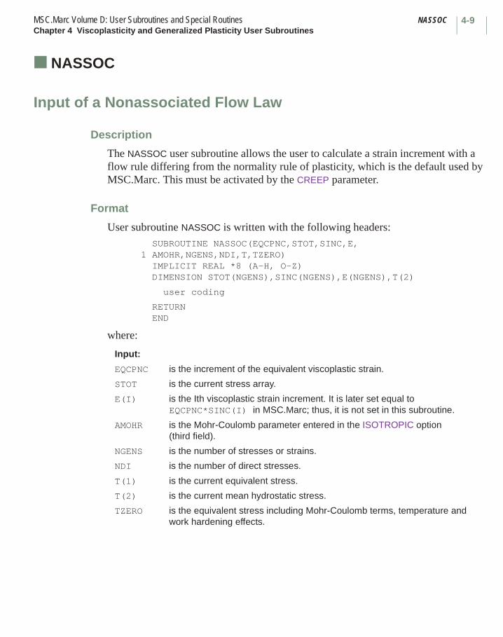
4-9MSC.Marc Volume D: User Subroutines and Special Routines NASSOCChapter 4 Viscoplasticity and Generalized Plasticity User Subroutines
■ NASSOC
Input of a Nonassociated Flow Law
Description
The NASSOC user subroutine allows the user to calculate a strain increment with a flow rule differing from the normality rule of plasticity, which is the default used by MSC.Marc. This must be activated by the CREEP parameter.
Format
User subroutine NASSOC is written with the following headers: SUBROUTINE NASSOC(EQCPNC,STOT,SINC,E,1 AMOHR,NGENS,NDI,T,TZERO) IMPLICIT REAL *8 (A-H, O-Z) DIMENSION STOT(NGENS),SINC(NGENS),E(NGENS),T(2)
user coding
RETURN END
where:
Input:
EQCPNC is the increment of the equivalent viscoplastic strain.
STOT is the current stress array.
E(I) is the Ith viscoplastic strain increment. It is later set equal to EQCPNC*SINC(I) in MSC.Marc; thus, it is not set in this subroutine.
AMOHR is the Mohr-Coulomb parameter entered in the ISOTROPIC option (third field).
NGENS is the number of stresses or strains.
NDI is the number of direct stresses.
T(1) is the current equivalent stress.
T(2) is the current mean hydrostatic stress.
TZERO is the equivalent stress including Mohr-Coulomb terms, temperature and work hardening effects.
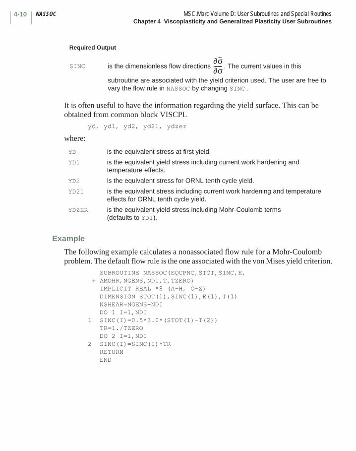
NASSOC MSC.Marc Volume D: User Subroutines and Special RoutinesChapter 4 Viscoplasticity and Generalized Plasticity User Subroutines
4-10
It is often useful to have the information regarding the yield surface. This can be obtained from common block VISCPL
yd, yd1, yd2, yd21, ydzer
where:
Example
The following example calculates a nonassociated flow rule for a Mohr-Coulomb problem. The default flow rule is the one associated with the von Mises yield criterion.
SUBROUTINE NASSOC(EQCPNC,STOT,SINC,E, + AMOHR,NGENS,NDI,T,TZERO) IMPLICIT REAL *8 (A-H, O-Z) DIMENSION STOT(1),SINC(1),E(1),T(1) NSHEAR=NGENS-NDI DO 1 I=1,NDI1 SINC(I)=0.5*3.0*(STOT(1)-T(2)) TR=1./TZERO DO 2 I=1,NDI2 SINC(I)=SINC(I)*TR RETURN END
Required Output
SINC is the dimensionless flow directions . The current values in this
subroutine are associated with the yield criterion used. The user are free to vary the flow rule in NASSOC by changing SINC.
YD is the equivalent stress at first yield.
YD1 is the equivalent yield stress including current work hardening and temperature effects.
YD2 is the equivalent stress for ORNL tenth cycle yield.
YD21 is the equivalent stress including current work hardening and temperature effects for ORNL tenth cycle yield.
YDZER is the equivalent yield stress including Mohr-Coulomb terms (defaults to YD1).
∂σ∂σ------

4-11MSC.Marc Volume D: User Subroutines and Special Routines ZEROChapter 4 Viscoplasticity and Generalized Plasticity User Subroutines
■ ZERO
Calculation of Equivalent Stress
Description
The ZERO user subroutine is used to calculate the equivalent yield stress based on the current total stresses. The ZERO user subroutine in MSC.Marc applies the von Mises yield criterion as a default. The user can substitute another yield criterion by writing a new ZERO user subroutine. Mohr-Coulomb models specified in the ISOTROPIC option should not be used when ZERO user subroutine is used because of the danger of taking into account the effects of hydrostatic pressure twice.
Format
User subroutine ZERO is written with the following headers:REAL*8 FUNCTION ZERO(NDI,NSHEAR,T,IORT,IANISO,YRDIR,YRSHR,AMM,AO)IMPLICIT REAL *8 (A-H, O-Z)DIMENSION T(1),YRDIR(3),YRSHR(3),AMM(3)
user coding
RETURNEND
where:
Input:
NDI is the number of direct components of stress.
NSHEAR is the number of shear components of stress.
T(I) is the Ith component of stress.
IORT is the flag indicating if curvilinear coordinates are used. This is 1 for element types 4, 8, and 24.
IANISO is the flag indicating if anisotropy is used.
YRDIR are the components for Hill’s anisotropic plasticity.
YRSHR are the shear components for Hill’s anisotropic plasticity.
AMM is the metric if curvilinear coordinates are used.
AO is the metric scale factor if curvilinear coordinates are used.
Required Output
ZERO is the equivalent yield stress.
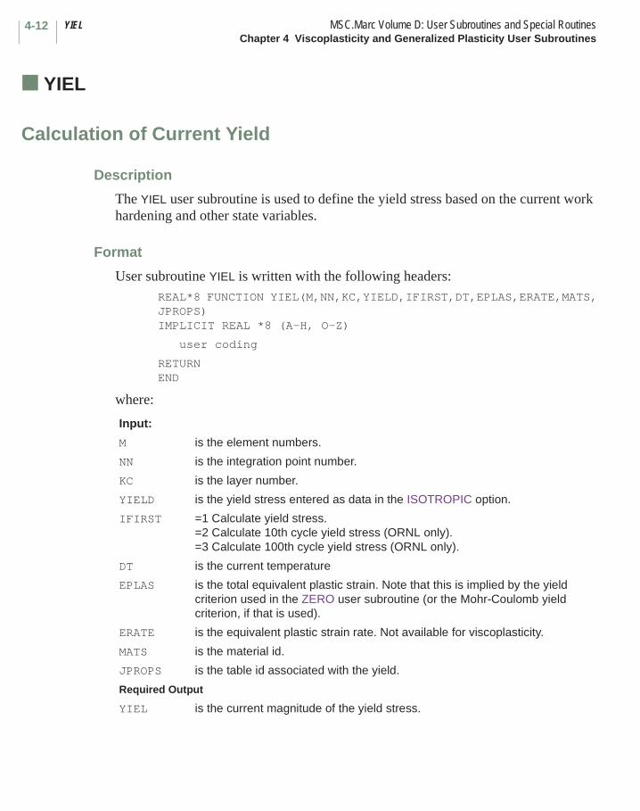
YIEL MSC.Marc Volume D: User Subroutines and Special RoutinesChapter 4 Viscoplasticity and Generalized Plasticity User Subroutines
4-12
■ YIEL
Calculation of Current Yield
Description
The YIEL user subroutine is used to define the yield stress based on the current work hardening and other state variables.
Format
User subroutine YIEL is written with the following headers:REAL*8 FUNCTION YIEL(M,NN,KC,YIELD,IFIRST,DT,EPLAS,ERATE,MATS,JPROPS)IMPLICIT REAL *8 (A-H, O-Z)
user coding
RETURN END
where:
Input:
M is the element numbers.
NN is the integration point number.
KC is the layer number.
YIELD is the yield stress entered as data in the ISOTROPIC option.
IFIRST =1 Calculate yield stress.=2 Calculate 10th cycle yield stress (ORNL only).=3 Calculate 100th cycle yield stress (ORNL only).
DT is the current temperature
EPLAS is the total equivalent plastic strain. Note that this is implied by the yield criterion used in the ZERO user subroutine (or the Mohr-Coulomb yield criterion, if that is used).
ERATE is the equivalent plastic strain rate. Not available for viscoplasticity.
MATS is the material id.
JPROPS is the table id associated with the yield.
Required Output
YIEL is the current magnitude of the yield stress.
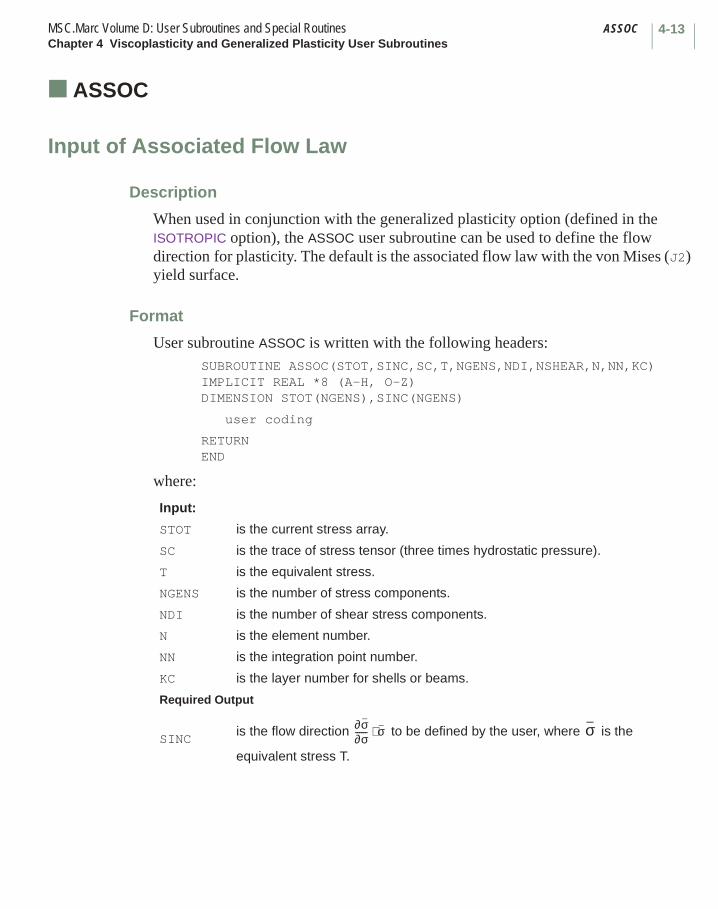
4-13MSC.Marc Volume D: User Subroutines and Special Routines ASSOCChapter 4 Viscoplasticity and Generalized Plasticity User Subroutines
■ ASSOC
Input of Associated Flow Law
Description
When used in conjunction with the generalized plasticity option (defined in the ISOTROPIC option), the ASSOC user subroutine can be used to define the flow direction for plasticity. The default is the associated flow law with the von Mises (J2) yield surface.
Format
User subroutine ASSOC is written with the following headers:SUBROUTINE ASSOC(STOT,SINC,SC,T,NGENS,NDI,NSHEAR,N,NN,KC)IMPLICIT REAL *8 (A-H, O-Z)DIMENSION STOT(NGENS),SINC(NGENS)
user coding
RETURNEND
where:
Input:
STOT is the current stress array.
SC is the trace of stress tensor (three times hydrostatic pressure).
T is the equivalent stress.
NGENS is the number of stress components.
NDI is the number of shear stress components.
N is the element number.
NN is the integration point number.
KC is the layer number for shells or beams.
Required Output
SINCis the flow direction to be defined by the user, where is the
equivalent stress T.
∂σ∂σ------ σ⋅ σ

SINCER MSC.Marc Volume D: User Subroutines and Special RoutinesChapter 4 Viscoplasticity and Generalized Plasticity User Subroutines
4-14
■ SINCER
User Subroutine for Improving Accuracy
Description
The SINCER user subroutine can be used to define how much an “elastic” stress increment exceeds the yield stress. This allows MSC.Marc to accurately take large increments such that the material goes from elastic to elastic-plastic. The user returns the value of FPLAS, which is the fraction of the stress increment beyond the yield surface. This routine should only be used if a yield surface other than the von Mises (J2) is used in conjunction with the generalized plasticity option (defined in the ISOTROPIC option).
Format
User subroutine SINCER is written with the following headers:SUBROUTINE SINCER(FPLAS,SINC,STOT,NGENS)IMPLICIT REAL *8 (A-H, O-Z)DIMENSION SINC(NGENS), STOT(NGENS)
user coding
RETURNEND
where:
Input:
SINC is the estimated elastic increment of stress.
STOT is the stress at the beginning of the increment.
NGENS is the number of stress components.
Required Output
FPLAS is the fraction of stress increment beyond the yield stress to be defined the user.
Chapter 5 Viscoelasticity User Subroutines List
User Subroutine Page
CRPVIS . . . . . . . . . . . . . . . . . . . . . . . . . . . . . . . . . . . . . . . . . . . . . . . . . . . . . . . . . . 5-3
HOOKVI . . . . . . . . . . . . . . . . . . . . . . . . . . . . . . . . . . . . . . . . . . . . . . . . . . . . . . . . . . 5-8
TRSFAC . . . . . . . . . . . . . . . . . . . . . . . . . . . . . . . . . . . . . . . . . . . . . . . . . . . . . . . . . . 5-6
CHAPTER
5 Viscoelasticity User Subroutines List

Chapter 5 Viscoelasticity User Subroutines
This chapter describes user subroutines used for viscoelastic analysis. There are two procedures available. The explicit procedure uses the CRPVIS user subroutine to describe a generalized Kelvin model. The implicit procedure uses a hereditary integral approach and is the preferred choice. Table 5-1 summarizes these routines and indicates what parameters or model definition options are required to invoke the user subroutine.
CHAPTER
5 Viscoelasticity User Subroutines
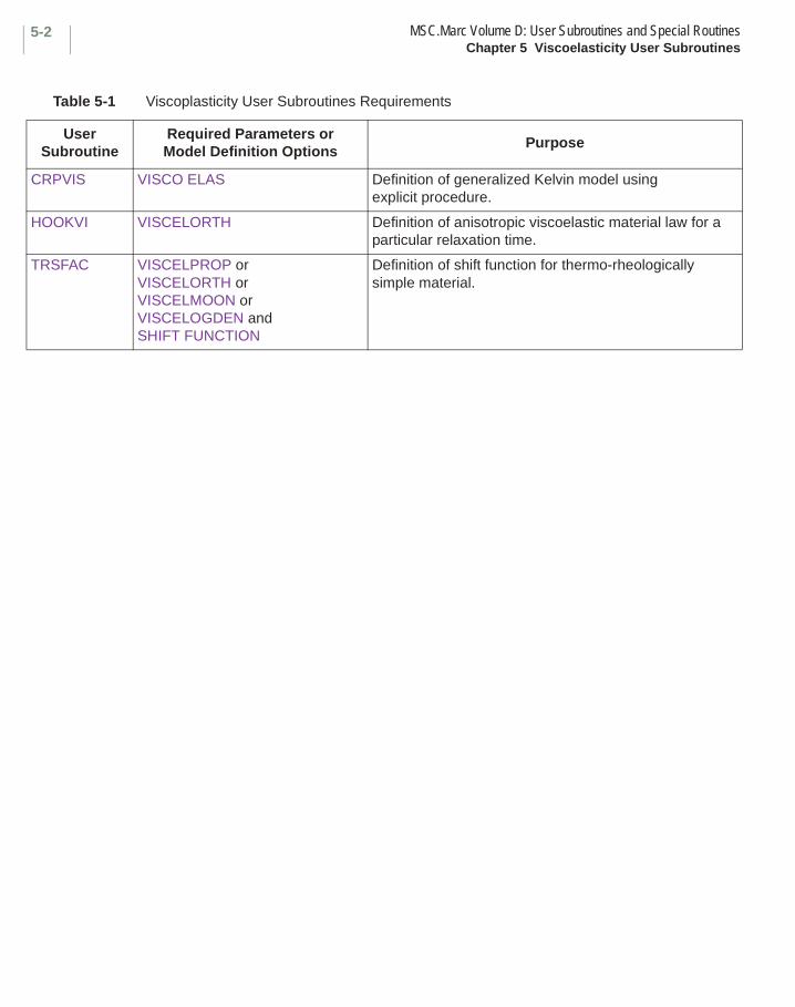
MSC.Marc Volume D: User Subroutines and Special RoutinesChapter 5 Viscoelasticity User Subroutines
5-2
Table 5-1 Viscoplasticity User Subroutines Requirements
User Subroutine
Required Parameters or Model Definition Options
Purpose
CRPVIS VISCO ELAS Definition of generalized Kelvin model using explicit procedure.
HOOKVI VISCELORTH Definition of anisotropic viscoelastic material law for a particular relaxation time.
TRSFAC VISCELPROP orVISCELORTH orVISCELMOON orVISCELOGDEN andSHIFT FUNCTION
Definition of shift function for thermo-rheologically simple material.
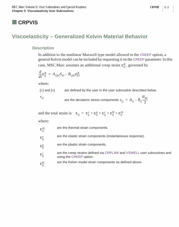
5-3MSC.Marc Volume D: User Subroutines and Special Routines CRPVISChapter 5 Viscoelasticity User Subroutines
■ CRPVIS
Viscoelasticity – Generalized Kelvin Material Behavior
Description
In addition to the nonlinear Maxwell type model allowed in the CREEP option, a general Kelvin model can be included by requesting it on the CREEP parameter. In this
case, MSC.Marc assumes an additional creep strain , governed by
where:
and the total strain is:
where:
[A] and [B] are defined by the user in the user subroutine described below,
are the deviatoric stress components
are the thermal strain components.
are the elastic strain components (instantaneous response).
are the plastic strain components.
are the creep strains defined via CRPLAW and VSWELL user subroutines and using the CREEP option.
are the Kelvin model strain components as defined above.
εijK
ddt-----εij
K AijklSkl BijklεklK–=
sij sij σij δij
σkk
3--------–=
εij εije εij
p εijc εij
K εijth+ + + +=
εijth
εije
εijp
εijc
εijK

CRPVIS MSC.Marc Volume D: User Subroutines and Special RoutinesChapter 5 Viscoelasticity User Subroutines
5-4
Format
User subroutine CRPVIS is written with the following headers: SUBROUTINE CRPVIS(CRPR,TSIG,SINC,AE,BE,NGENS,1 DT,DTDL,N,NN,KC,MATUS,NDI,NSHEAR,TIME,TIMINC) IMPLICIT REAL *8 (A-H, O-Z) DIMENSION CRPR(1),TSIG(1),SINC(1),AE(NGENS,NGENS), 1 BE(NGENS,NGENS),DT(1),DTDL(1),N(2),MATUS(2)
user coding
RETURN END
where:
Input:
CRPR are the Kelvin creep strain components.
TSIG(1) is the second invariant of the deviatoric stress = .
TSIG(2) is the hydrostatic stress = .
SINC are the deviatoric stress components .
NGENS is the number of stress (strain) components.
DT are the total state variables at this point (temperature first).
DTDL are the increments of state variables at this point during this step of the solution.
N(1) is the user’s element number.
N(2) is the internal element number.
NN is the integration point number.
KC is the layer number.
MATUS(1) is the user’s material identifier.
MATUS(2) is the internal material identifier.
NDI is the number of direct components.
NSHEAR is the number of shear components.
TIME is the total time.
TIMINC is the time increment.
32---sijsij 1 2⁄
13---σkk
sij( )
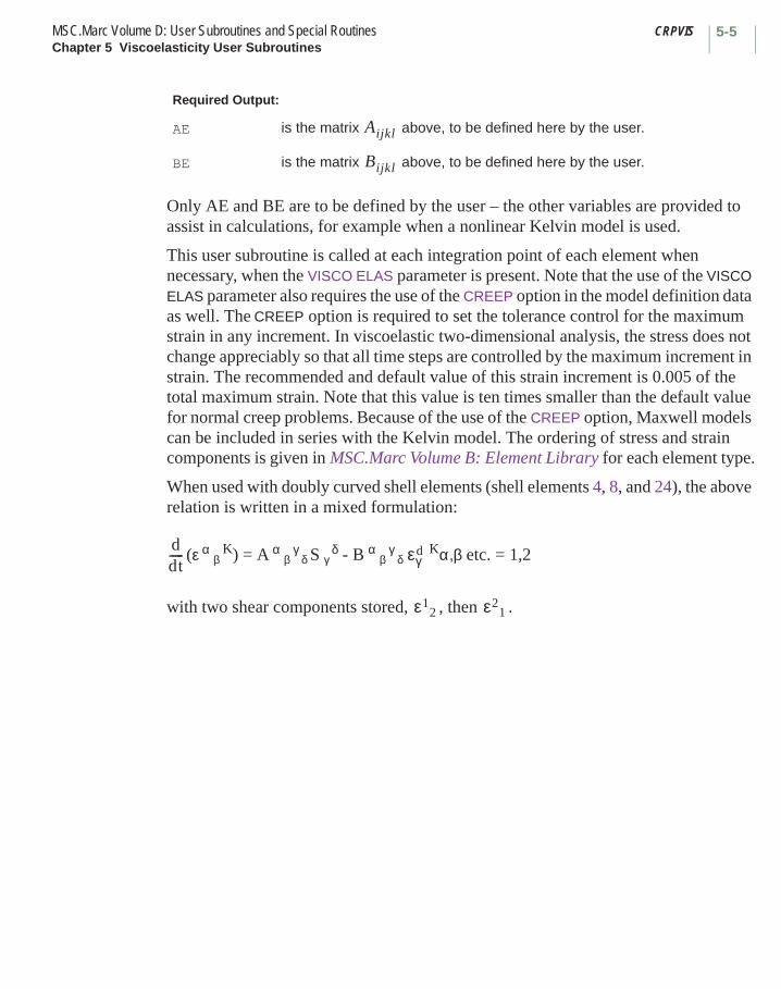
5-5MSC.Marc Volume D: User Subroutines and Special Routines CRPVISChapter 5 Viscoelasticity User Subroutines
Only AE and BE are to be defined by the user – the other variables are provided to assist in calculations, for example when a nonlinear Kelvin model is used.
This user subroutine is called at each integration point of each element when necessary, when the VISCO ELAS parameter is present. Note that the use of the VISCO ELAS parameter also requires the use of the CREEP option in the model definition data as well. The CREEP option is required to set the tolerance control for the maximum strain in any increment. In viscoelastic two-dimensional analysis, the stress does not change appreciably so that all time steps are controlled by the maximum increment in strain. The recommended and default value of this strain increment is 0.005 of the total maximum strain. Note that this value is ten times smaller than the default value for normal creep problems. Because of the use of the CREEP option, Maxwell models can be included in series with the Kelvin model. The ordering of stress and strain components is given in MSC.Marc Volume B: Element Library for each element type.
When used with doubly curved shell elements (shell elements 4, 8, and 24), the above relation is written in a mixed formulation:
(ε α β
K) = A α β
γ δ S γ
δ - B α β
γ δ
Kα,β etc. = 1,2
with two shear components stored, , then .
Required Output:
AE is the matrix above, to be defined here by the user.
BE is the matrix above, to be defined here by the user.
Aijkl
Bijkl
ddt----- εγ
d
ε12 ε2
1

TRSFAC MSC.Marc Volume D: User Subroutines and Special RoutinesChapter 5 Viscoelasticity User Subroutines
5-6
■ TRSFAC
Define a Shift Function for Thermo-Rheologically Simple (T.R.S.) Material Behavior
Description
This user subroutine allows the user to define the shift function for the relaxation function.
A description of T.R.S. material behavior is given in MSC.Marc Volume A: User Information. The user is reminded that this option is only available in conjunction with the hereditary integral form of viscoelastic constitutive representation. The use of this user subroutine to define a shift function for a particular viscoelastic material group is indicated by inserting a negative value in the first field of block 2 in the SHIFT FUNCTION model definition option.
MSC.Marc proceeds to compute the increment of pseudo- or reduced time ∆ε (x, t) according to the relationship:
where the shift factor, B, is a function of the spatially and time dependent temperature, T(x, t). A five-point Simpson’s rule is used to numerically integrate this expression.
In this subroutine, the user is expected to define the shift function, φ, which is the logarithm of the shift factor: that is,
The user subroutine is called five times at each point. These points can be the centroids of the elements or each integrating point if the ALL POINTS parameter has been invoked.
∆ε x t,( ) 10B T x t1,( )[ ] dt1t
t ∆t+( )∫=
φ x t,( )[ ] Log10 B T x t,( )[ ]{ }–=
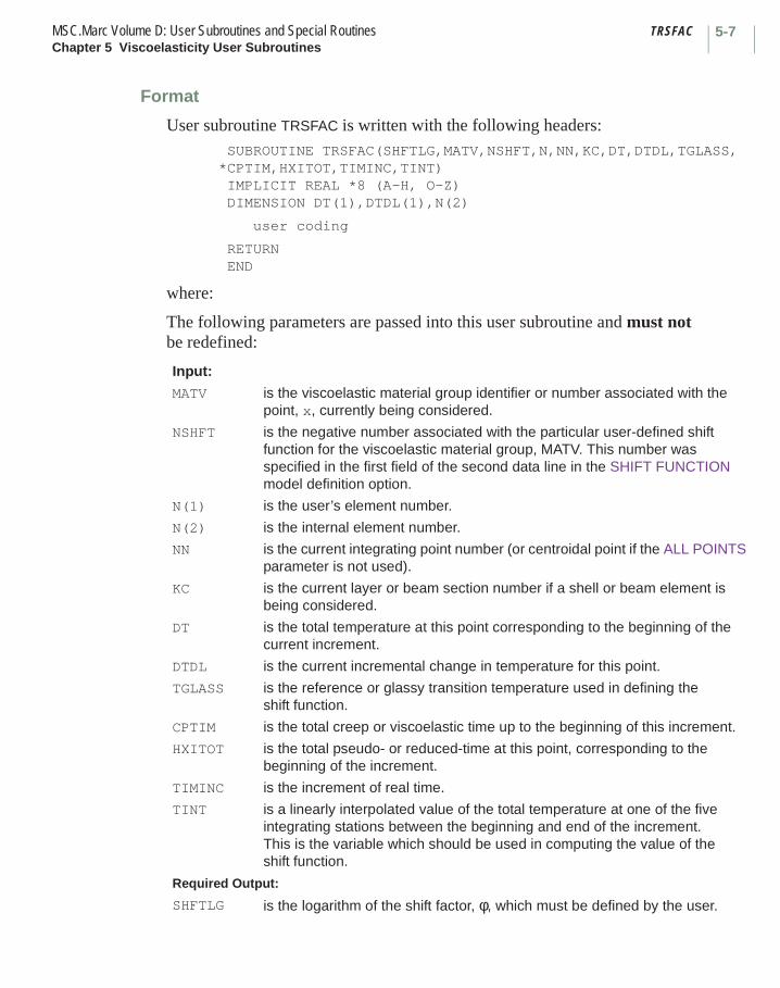
5-7MSC.Marc Volume D: User Subroutines and Special Routines TRSFACChapter 5 Viscoelasticity User Subroutines
Format
User subroutine TRSFAC is written with the following headers: SUBROUTINE TRSFAC(SHFTLG,MATV,NSHFT,N,NN,KC,DT,DTDL,TGLASS,*CPTIM,HXITOT,TIMINC,TINT) IMPLICIT REAL *8 (A-H, O-Z) DIMENSION DT(1),DTDL(1),N(2)
user coding
RETURN END
where:
The following parameters are passed into this user subroutine and must not be redefined:
Input:
MATV is the viscoelastic material group identifier or number associated with the point, x, currently being considered.
NSHFT is the negative number associated with the particular user-defined shift function for the viscoelastic material group, MATV. This number was specified in the first field of the second data line in the SHIFT FUNCTION model definition option.
N(1) is the user’s element number.
N(2) is the internal element number.
NN is the current integrating point number (or centroidal point if the ALL POINTS parameter is not used).
KC is the current layer or beam section number if a shell or beam element is being considered.
DT is the total temperature at this point corresponding to the beginning of the current increment.
DTDL is the current incremental change in temperature for this point.
TGLASS is the reference or glassy transition temperature used in defining the shift function.
CPTIM is the total creep or viscoelastic time up to the beginning of this increment.
HXITOT is the total pseudo- or reduced-time at this point, corresponding to the beginning of the increment.
TIMINC is the increment of real time.
TINT is a linearly interpolated value of the total temperature at one of the five integrating stations between the beginning and end of the increment. This is the variable which should be used in computing the value of the shift function.
Required Output:
SHFTLG is the logarithm of the shift factor, φ, which must be defined by the user.

HOOKVI MSC.Marc Volume D: User Subroutines and Special RoutinesChapter 5 Viscoelasticity User Subroutines
5-8
■ HOOKVI
User-defined Anisotropic Viscoelasticity
Description
The user can specify the time dependent properties of an orthotropic material through the VISCELORTH model definition option. The user can then modify this data by use of the HOOKVI user subroutine which is automatically called for every material defined in that option.
Format
User subroutine HOOKVI is called with the following header codes:SUBROUTINE HOOKVI (M,NN,KC,ITERM,B,DT,DTDL,E,PR,G)IMPLICIT REAL *8 (A-H, O-Z)DIMENSION B(6,6),DT(1),DTDL(1),E(3),PR(3),G(3),M(2)
user coding
RETURN END
where:
Input:
M(1) is the user’s element number.
M(2) is the internal element number.
NN is the integration point number.
KC is the layer number.
ITERM is the viscoelastic series number.
DT is the current temperature.
DTDL is the current increment in temperature.
E is vector of time dependent Young’s moduli input in the VISCELORTH option.
PR is the vector of time dependent Poisson’s ratios input in the VISCELORTH option.
G is the vector of time dependent shear moduli given in the VISCELORTH option.
Required Output:
B is the user-defined 6 x 6 matrix of viscoelastic time dependent constants for this element and series number.

Chapter 6 Geometry Modifications User Subroutines List
User Subroutine Page
MAP2D. . . . . . . . . . . . . . . . . . . . . . . . . . . . . . . . . . . . . . . . . . . . . . . . . . . . . . . . . . . 6-5
REBAR. . . . . . . . . . . . . . . . . . . . . . . . . . . . . . . . . . . . . . . . . . . . . . . . . . . . . . . . . . . 6-10
SSTRAN. . . . . . . . . . . . . . . . . . . . . . . . . . . . . . . . . . . . . . . . . . . . . . . . . . . . . . . . . . 6-21
UACTIVE . . . . . . . . . . . . . . . . . . . . . . . . . . . . . . . . . . . . . . . . . . . . . . . . . . . . . . . . . 6-9UACTUAT. . . . . . . . . . . . . . . . . . . . . . . . . . . . . . . . . . . . . . . . . . . . . . . . . . . . . . . . . 6-23UADAP. . . . . . . . . . . . . . . . . . . . . . . . . . . . . . . . . . . . . . . . . . . . . . . . . . . . . . . . . . . 6-15UADAP2. . . . . . . . . . . . . . . . . . . . . . . . . . . . . . . . . . . . . . . . . . . . . . . . . . . . . . . . . . 6-16UADAPBOX . . . . . . . . . . . . . . . . . . . . . . . . . . . . . . . . . . . . . . . . . . . . . . . . . . . . . . . 6-17UCOORD . . . . . . . . . . . . . . . . . . . . . . . . . . . . . . . . . . . . . . . . . . . . . . . . . . . . . . . . . 6-14UFCONN . . . . . . . . . . . . . . . . . . . . . . . . . . . . . . . . . . . . . . . . . . . . . . . . . . . . . . . . . 6-4
CHAPTER
6 Geometry Modifications User Subroutines List

MSC.Marc Volume D: User Subroutines and Special RoutinesChapter 6 Geometry Modifications User Subroutines List
6-ii
User Subroutine Page
UFRORD . . . . . . . . . . . . . . . . . . . . . . . . . . . . . . . . . . . . . . . . . . . . . . . . . . . . . . . . . 6-11UFXORD . . . . . . . . . . . . . . . . . . . . . . . . . . . . . . . . . . . . . . . . . . . . . . . . . . . . . . . . . 6-3UPNOD . . . . . . . . . . . . . . . . . . . . . . . . . . . . . . . . . . . . . . . . . . . . . . . . . . . . . . . . . . 6-7URCONN . . . . . . . . . . . . . . . . . . . . . . . . . . . . . . . . . . . . . . . . . . . . . . . . . . . . . . . . . 6-12USHELL . . . . . . . . . . . . . . . . . . . . . . . . . . . . . . . . . . . . . . . . . . . . . . . . . . . . . . . . . . 6-20USIZEOUTL . . . . . . . . . . . . . . . . . . . . . . . . . . . . . . . . . . . . . . . . . . . . . . . . . . . . . . . 6-6USPLIT . . . . . . . . . . . . . . . . . . . . . . . . . . . . . . . . . . . . . . . . . . . . . . . . . . . . . . . . . . 6-13UTHICK . . . . . . . . . . . . . . . . . . . . . . . . . . . . . . . . . . . . . . . . . . . . . . . . . . . . . . . . . . 6-22UTRANS . . . . . . . . . . . . . . . . . . . . . . . . . . . . . . . . . . . . . . . . . . . . . . . . . . . . . . . . . 6-19
Chapter 6 Geometry Modifications User Subroutines
The user subroutines described in this section are provided to allow the user to define the initial geometry of the finite element mesh, or to change the mesh due to rezoning or rigid plastic analyses. Often these user subroutines are used to customize already existing meshes. The UTRANS user subroutine is a powerful way to provide transformations to the degrees of freedom of a node. Table 6-1 summarizes these routines and indicates what parameters or model definition options are required to invoke the user subroutine.
CHAPTER
6 Geometry Modifications User Subroutines

MSC.Marc Volume D: User Subroutines and Special RoutinesChapter 6 Geometry Modifications User Subroutines
6-2
Table 6-1 Geometry Modifications User Subroutines Requirements
User Subroutine
Required Parameters or Model Definition Options
Purpose
MAP2D MESH2DMAPPER
Define the coordinates of key boundary nodes for mesh generation.
REBAR ELEMENTS(rebar element types)
Define the orientation and effective thickness of the elements.
SSTRAN SUBSTRUCTURE Define the transformation matrix applied to a superelement.
UACTIVE Activate or deactivate elements.
UACTUAT GEOMETRY Define the length of the actuator element.
UADAP ADAPTIVE (parameter)ADAPTIVE (model definition option)
Define a user-defined error criterion for adaptive meshing.
UADAP2 ADAPTIVE (parameter)ADAPTIVE (model definition option)
Define unrefinement for adaptive meshing.
UADAPBOX ADAPTIVE (parameter)ADAPTIVE (model definition option)
User-definer box for adaptivity.
UCOORD ADAPTIVE (parameter)ADAPTIVE (model definition option)
Describe of the location of newly created nodes.
UFCONN UFCONN Modify the connectivity of an element.
UFRORD REZONINGREZONEUFRORD
Modify the coordinates of a node during rezoning.
UFXORD UFXORD Modify the initial nodal coordinates.
UPNOD R-P FLOW Update the nodal coordinates in a rigid plastic analysis using the Eularian procedure.
URCONN UFCONN Modify the connectivity of an element during rezoning.
USHELL GEOMETRY Define the integration point thickness for shell elements.
USIZEOUTL ADAPT GLOBAL Define refinement boxes with different element edge length on the 2-D outlines for remeshing.
USPLIT ADAPT GLOBAL Define where to split a continuous deformable body into two separate parts.
UTHICK NODAL THICKNESS Define the initial thickness at the nodes for shell elements.
UTRANS UTRANFORM Define a transformation to be applied to the degrees of freedom at a node.

6-3MSC.Marc Volume D: User Subroutines and Special Routines UFXORDChapter 6 Geometry Modifications User Subroutines
■ UFXORD
Coordinate Generation or Modification
Description
The UFXORD user subroutine can be used to modify (or expand) coordinates input through use of the COORDINATES option, or as an internal coordinate generator. The user must input the UFXORD model definition option, followed by a block giving the nodes for which UFXORD is used. MSC.Marc calls UFXORD for each node in the list, so that the coordinates of that node can be modified or generated. The UFXORD option can be repeated as many times as necessary.
Format
User subroutine UFXORD is written with the following headers:SUBROUTINE UFXORD (XORD, NCRD, N)IMPLICIT REAL *8 (A-H, O-Z)DIMENSION XORD (NCRD)
user coding
RETURNEND
where:
This user subroutine is most commonly used with shell or beam elements (for example, elements 4, 8, 13, 15) where the full coordinate set is usually generated on the basis of reduced set of coordinates. See, for example, the description of the FXORD option in MSC.Marc Volume A: User Information. The user can also use this routine to generate special coordinate systems (for example, cylindrical or spherical) or to convert from special coordinate systems to a rectangular system.
Input:
NCRD is the number of coordinates per node.
N is the node number.
Required Output:
XORD is the array of coordinates in the Nth node and is passed in containing coordinates previously generated at the Nth node by COORDINATES, FXORD or UFXORD options.

UFCONN MSC.Marc Volume D: User Subroutines and Special RoutinesChapter 6 Geometry Modifications User Subroutines
6-4
■ UFCONN
Connectivity Generation or Modification
Description
The UFCONN user subroutine can be used to modify (or expand) input given through use of the CONNECTIVITY option, or as an internal connectivity generator. The user must input the UFCONN model definition option, followed by a block giving the elements for which UFCONN is used. MSC.Marc calls UFCONN for each element in the series, so that the connectivity of that element can be modified or generated. The UFCONN option can be repeated as many times as necessary.
Format
User subroutine UFCONN is written with the following headers:SUBROUTINE UFCONN(J,ITYPE,LM,NNODMX)IMPLICIT REAL *8 (A-H, O-Z)DIMENSION LM(1)
user coding
RETURN END
where:
LM is passed in containing the connectivity of the Jth element already generated by previous CONNECTIVITY, UFCONN, or other generators. Similarly, ITYPE is the element type if previously defined. The user can modify or define ITYPE or LM in this routine. Note there is no checking to determine if ITYPE has been defined on the SIZING or ELEMENTS parameter, or if node numbers are in the range
.
Input:
J is the element number.
ITYPE is the element type.
LM is the array of nodes making up the element.
NNODMX is the maximum number of nodes in an element.
Required Output:
ITYPE is the element type.
LM is the array of nodes making up the element.
1 N NUMNP≤ ≤

6-5MSC.Marc Volume D: User Subroutines and Special Routines MAP2DChapter 6 Geometry Modifications User Subroutines
■ MAP2D
Boundary Node Coordinates Modification in Mesh2D
Description
The MAP2D user subroutine can be used to modify coordinates input for the boundary nodes in MESH2D by the BOUNDARY option. The user must input the MAPPER option as part of the two-dimensional mesh generation. MSC.Marc calls MAP2D once, so that the coordinates of all the boundary nodes can be modified or generated.
Format
User subroutine MAP2D is written with the following headers:SUBROUTINE MAP2D(NNO,X,Y)IMPLICIT REAL *8 (A-H, O-Z)DIMENSION X(NNO),Y(NNO)
user coding
RETURNEND
where:
Input:
NNO is the number of boundary nodes.
Required Output:
X and Y are the user-defined coordinates of the boundary nodes.
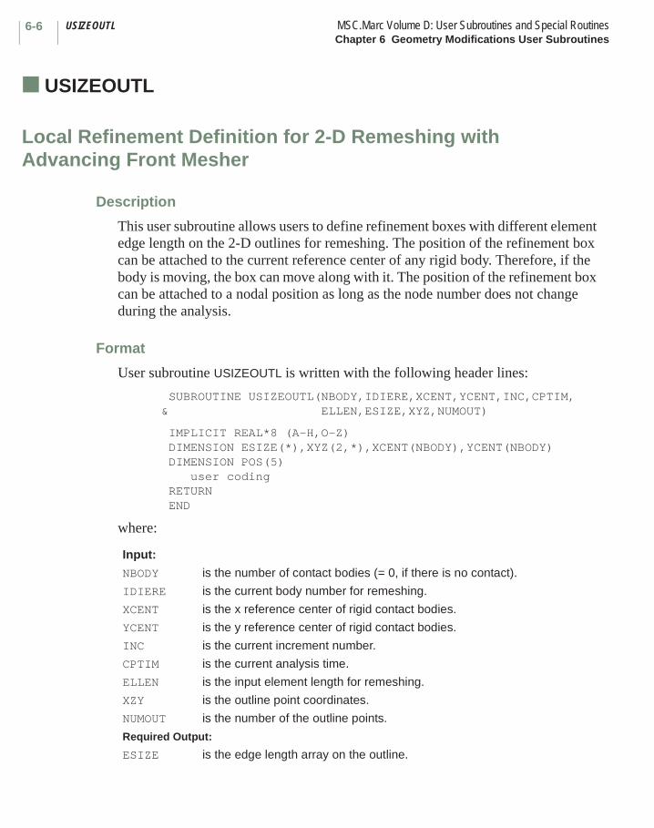
USIZEOUTL MSC.Marc Volume D: User Subroutines and Special RoutinesChapter 6 Geometry Modifications User Subroutines
6-6
■ USIZEOUTL
Local Refinement Definition for 2-D Remeshing with Advancing Front Mesher
C-44 Description
This user subroutine allows users to define refinement boxes with different element edge length on the 2-D outlines for remeshing. The position of the refinement box can be attached to the current reference center of any rigid body. Therefore, if the body is moving, the box can move along with it. The position of the refinement box can be attached to a nodal position as long as the node number does not change during the analysis.
Format
User subroutine USIZEOUTL is written with the following header lines:
SUBROUTINE USIZEOUTL(NBODY,IDIERE,XCENT,YCENT,INC,CPTIM,& ELLEN,ESIZE,XYZ,NUMOUT)
IMPLICIT REAL*8 (A-H,O-Z)DIMENSION ESIZE(*),XYZ(2,*),XCENT(NBODY),YCENT(NBODY)DIMENSION POS(5)
user coding RETURN END
where:
Input:
NBODY is the number of contact bodies (= 0, if there is no contact).
IDIERE is the current body number for remeshing.
XCENT is the x reference center of rigid contact bodies.
YCENT is the y reference center of rigid contact bodies.
INC is the current increment number.
CPTIM is the current analysis time.
ELLEN is the input element length for remeshing.
XZY is the outline point coordinates.
NUMOUT is the number of the outline points.
Required Output:
ESIZE is the edge length array on the outline.
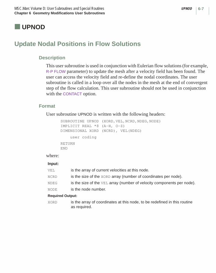
6-7MSC.Marc Volume D: User Subroutines and Special Routines UPNODChapter 6 Geometry Modifications User Subroutines
■ UPNOD
Update Nodal Positions in Flow Solutions
Description
This user subroutine is used in conjunction with Eulerian flow solutions (for example, R-P FLOW parameter) to update the mesh after a velocity field has been found. The user can access the velocity field and re-define the nodal coordinates. The user subroutine is called in a loop over all the nodes in the mesh at the end of convergent step of the flow calculation. This user subroutine should not be used in conjunction with the CONTACT option.
Format
User subroutine UPNOD is written with the following headers:SUBROUTINE UPNOD (XORD,VEL,NCRD,NDEG,NODE)IMPLICIT REAL *8 (A-H, O-Z)DIMENSIONAL XORD (NCRD), VEL(NDEG)
user coding
RETURNEND
where:
Input:
VEL is the array of current velocities at this node.
NCRD is the size of the XORD array (number of coordinates per node).
NDEG is the size of the VEL array (number of velocity components per node).
NODE is the node number.
Required Output:
XORD is the array of coordinates at this node, to be redefined in this routine as required.
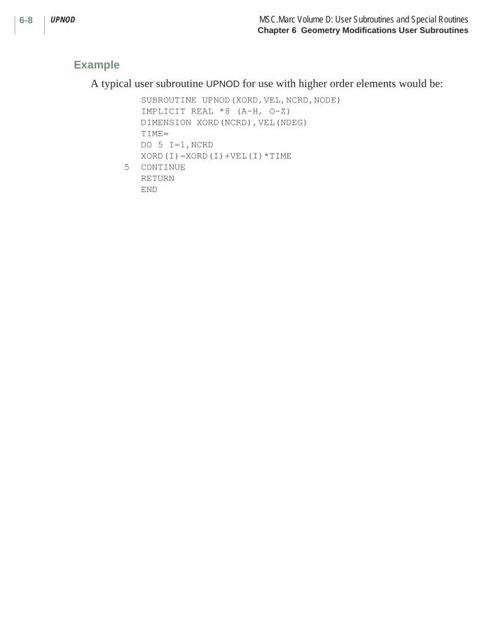
UPNOD MSC.Marc Volume D: User Subroutines and Special RoutinesChapter 6 Geometry Modifications User Subroutines
6-8
Example
A typical user subroutine UPNOD for use with higher order elements would be: SUBROUTINE UPNOD(XORD,VEL,NCRD,NODE) IMPLICIT REAL *8 (A-H, O-Z) DIMENSION XORD(NCRD),VEL(NDEG) TIME= DO 5 I=1,NCRD XORD(I)=XORD(I)+VEL(I)*TIME5 CONTINUE RETURN END
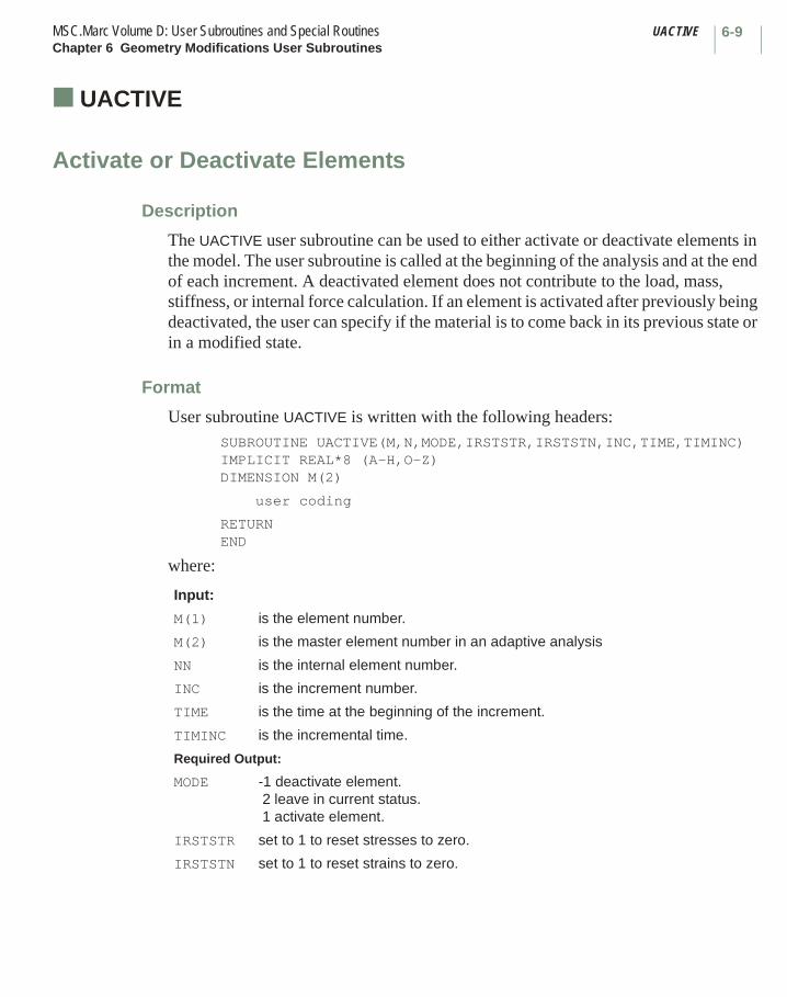
6-9MSC.Marc Volume D: User Subroutines and Special Routines UACTIVEChapter 6 Geometry Modifications User Subroutines
■ UACTIVE
Activate or Deactivate Elements
Description
The UACTIVE user subroutine can be used to either activate or deactivate elements in the model. The user subroutine is called at the beginning of the analysis and at the end of each increment. A deactivated element does not contribute to the load, mass, stiffness, or internal force calculation. If an element is activated after previously being deactivated, the user can specify if the material is to come back in its previous state or in a modified state.
Format
User subroutine UACTIVE is written with the following headers:SUBROUTINE UACTIVE(M,N,MODE,IRSTSTR,IRSTSTN,INC,TIME,TIMINC)IMPLICIT REAL*8 (A-H,O-Z)DIMENSION M(2)
user coding
RETURNEND
where:
Input:
M(1) is the element number.
M(2) is the master element number in an adaptive analysis
NN is the internal element number.
INC is the increment number.
TIME is the time at the beginning of the increment.
TIMINC is the incremental time.
Required Output:
MODE -1 deactivate element.2 leave in current status.1 activate element.
IRSTSTR set to 1 to reset stresses to zero.
IRSTSTN set to 1 to reset strains to zero.

REBAR MSC.Marc Volume D: User Subroutines and Special RoutinesChapter 6 Geometry Modifications User Subroutines
6-10
■ REBAR
Input of Rebar Positions, Areas and Orientations
Description
This user subroutine is used in conjunction with the single strain rebar elements (23, 46, 47, 48, 142-148, 165-170). See the description of these elements for details of the use of this user subroutine. Any nonzero value defined in the this subroutine overwrites the corresponding value defined by the REBAR model definition option if it is used with this user subroutine.
Format
User subroutine REBAR is written with the following headers:SUBROUTINE REBAR (N,NN,T,PR,TR,A)IMPLICIT REAL *8 (A-H, O-Z)DIMENSION A(3),NN(3)
user coding
RETURNEND
where:
Note: Three entries are to be defined in A in all cases.
Input:
N is the element number.
NN(1) is the integration point number.
NN(2) is the layer number.
NN(3) is the integration point number in this layer.
T,PR,TR,A are to be defined by the user.
Required Output:
T is the nominal size in thickness direction.
PR is the relative position of rebar layer with respect to T.MSC.Marc uses the ratio PR/T to position the rebar layer in the thickness direction.
TR is the equivalent thickness of rebar.
A is the direction cosines of the rebar.
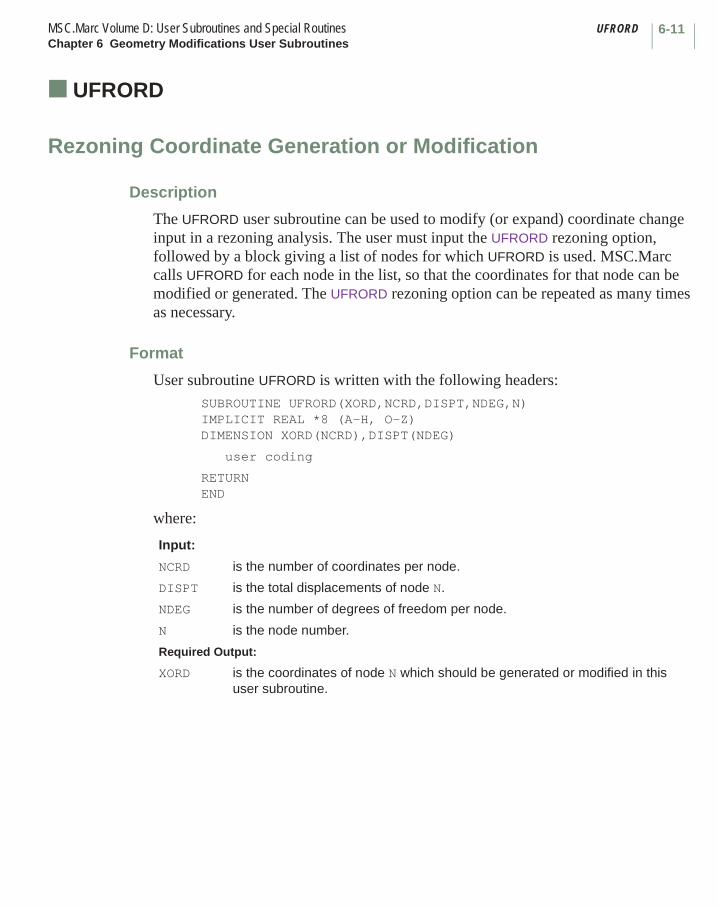
6-11MSC.Marc Volume D: User Subroutines and Special Routines UFRORDChapter 6 Geometry Modifications User Subroutines
■ UFRORD
Rezoning Coordinate Generation or Modification
Description
The UFRORD user subroutine can be used to modify (or expand) coordinate change input in a rezoning analysis. The user must input the UFRORD rezoning option, followed by a block giving a list of nodes for which UFRORD is used. MSC.Marc calls UFRORD for each node in the list, so that the coordinates for that node can be modified or generated. The UFRORD rezoning option can be repeated as many times as necessary.
Format
User subroutine UFRORD is written with the following headers:SUBROUTINE UFRORD(XORD,NCRD,DISPT,NDEG,N)IMPLICIT REAL *8 (A-H, O-Z)DIMENSION XORD(NCRD),DISPT(NDEG)
user coding
RETURNEND
where:
Input:
NCRD is the number of coordinates per node.
DISPT is the total displacements of node N.
NDEG is the number of degrees of freedom per node.
N is the node number.
Required Output:
XORD is the coordinates of node N which should be generated or modified in this user subroutine.

URCONN MSC.Marc Volume D: User Subroutines and Special RoutinesChapter 6 Geometry Modifications User Subroutines
6-12
■ URCONN
Rezoning Connectivity Generation or Modification
Description
The URCONN user subroutine can be used to modify (or expand) input given through use of the CONNECTIVITY CHANGE option, or as an internal connectivity generator. The user must input the URCONN rezoning option, followed by a block giving the elements for which URCONN is used. MSC.Marc calls URCONN for each element in the series, so that the connectivity of that element can be modified or generated.
Format
User subroutine URCONN is written with the following headers:SUBROUTINE URCONN(J,ITYPE,LM,NNODMX)IMPLICIT REAL *8 (A-H, O-Z)DIMENSION LM(1)
user coding
RETURN END
where:
LM is passed in containing the connectivity of the Jth element already generated by previous CONNECTIVITY, UFCONN, CONNECTIVITY CHANGE, or other generators. Similarly, ITYPE is the element type if previously defined. The user can modify or define ITYPE or LM in this routine. Note there is no checking to determine if ITYPE has been defined on the SIZING or ELEMENTS parameter, or if node numbers are in the range .
Input:
J is the element number.
NNODMX is the maximum number of nodes in an element.
Required Output:
ITYPE is the element type.
LM is the array of nodes making up the element.
1 N NUMNP≤ ≤
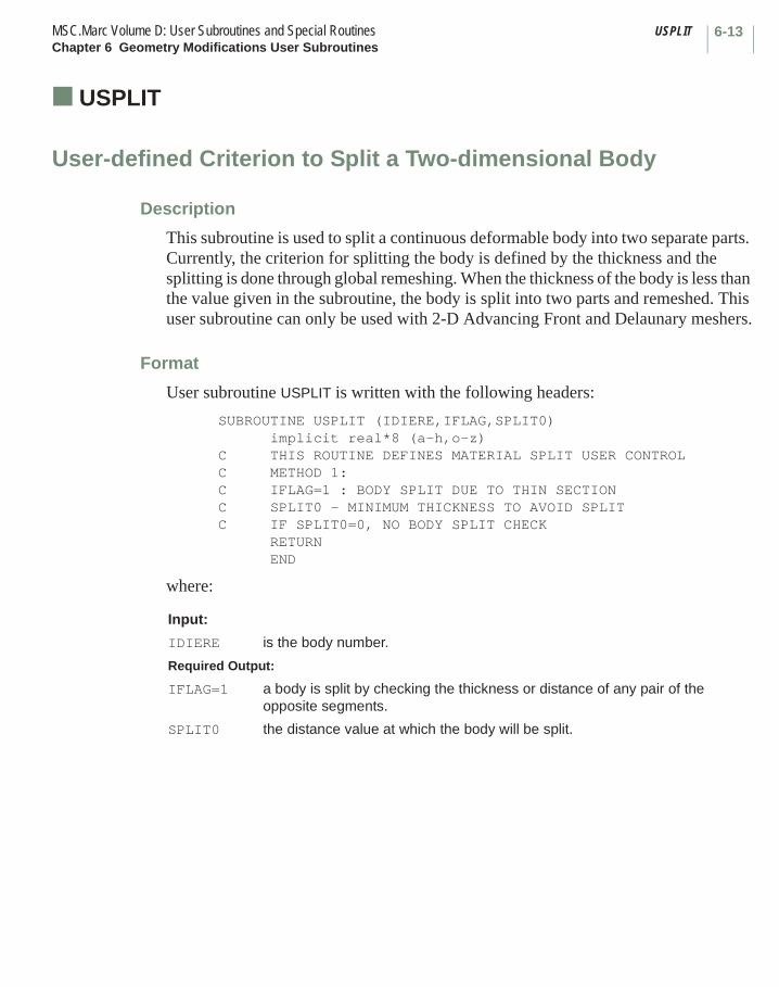
6-13MSC.Marc Volume D: User Subroutines and Special Routines USPLITChapter 6 Geometry Modifications User Subroutines
■ USPLIT
User-defined Criterion to Split a Two-dimensional Body
C-45 Description
This subroutine is used to split a continuous deformable body into two separate parts. Currently, the criterion for splitting the body is defined by the thickness and the splitting is done through global remeshing. When the thickness of the body is less than the value given in the subroutine, the body is split into two parts and remeshed. This user subroutine can only be used with 2-D Advancing Front and Delaunary meshers.
Format
User subroutine USPLIT is written with the following headers:
SUBROUTINE USPLIT (IDIERE,IFLAG,SPLIT0) implicit real*8 (a-h,o-z)C THIS ROUTINE DEFINES MATERIAL SPLIT USER CONTROLC METHOD 1:C IFLAG=1 : BODY SPLIT DUE TO THIN SECTIONC SPLIT0 - MINIMUM THICKNESS TO AVOID SPLITC IF SPLIT0=0, NO BODY SPLIT CHECK RETURN END
where:
Input:
IDIERE is the body number.
Required Output:
IFLAG=1 a body is split by checking the thickness or distance of any pair of the opposite segments.
SPLIT0 the distance value at which the body will be split.

UCOORD MSC.Marc Volume D: User Subroutines and Special RoutinesChapter 6 Geometry Modifications User Subroutines
6-14
■ UCOORD
Relocate Nodes Created During Adaptive Meshing
Description
The UCOORD user subroutine can be used to define the location of a new node created due to local adaptive meshing. The default if this routine is not used is to put the newly created node geometrically half way between the old nodes. This user subroutine is called for each new node created.
Format
User subroutine UCOORD is written with the following headers:SUBROUTINE UCOORD(XORD, NCRD, INOD, LM, NNOD)IMPLICIT REAL *8 (A-H, O-Z)DIMENSION XORD(NCRD,1),LM(1)
user coding
RETURNEND
where:
Update XORD(J,INOD) if desired.
Input:
NCRD is the number of coordinates per node.
INOD is the node number of new node.
LM(I) is the nodes on which INOD is depending.
NNOD is the number of nodes on which INOD is depending.= 2 middle of edge between LM(1) and LM(2).= 3 center of triangle LM(1), LM(2), LM(3).= 4 center of plane LM(1), LM(2), LM(3), LM(4).= 4 center of tetrahedral 4 LM(1), LM(2), LM(3), LM(4).= 8 center of brick LM(1), LM(2), LM(3), LM(4), LM(5), LM(6),
LM(7), LM(8).
Required Output:
XORD(J,I) is the current coordinate j of node i.
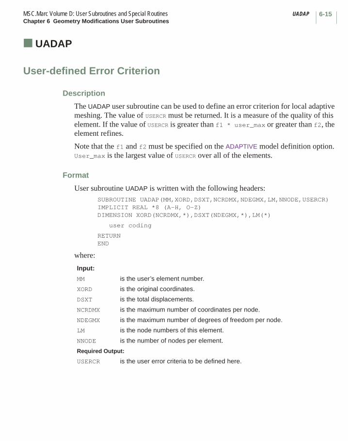
6-15MSC.Marc Volume D: User Subroutines and Special Routines UADAPChapter 6 Geometry Modifications User Subroutines
■ UADAP
User-defined Error Criterion
Description
The UADAP user subroutine can be used to define an error criterion for local adaptive meshing. The value of USERCR must be returned. It is a measure of the quality of this element. If the value of USERCR is greater than f1 * user_max or greater than f2, the element refines.
Note that the f1 and f2 must be specified on the ADAPTIVE model definition option. User_max is the largest value of USERCR over all of the elements.
Format
User subroutine UADAP is written with the following headers:SUBROUTINE UADAP(MM,XORD,DSXT,NCRDMX,NDEGMX,LM,NNODE,USERCR)IMPLICIT REAL *8 (A-H, O-Z)DIMENSION XORD(NCRDMX,*),DSXT(NDEGMX,*),LM(*)
user coding
RETURNEND
where:
Input:
MM is the user’s element number.
XORD is the original coordinates.
DSXT is the total displacements.
NCRDMX is the maximum number of coordinates per node.
NDEGMX is the maximum number of degrees of freedom per node.
LM is the node numbers of this element.
NNODE is the number of nodes per element.
Required Output:
USERCR is the user error criteria to be defined here.
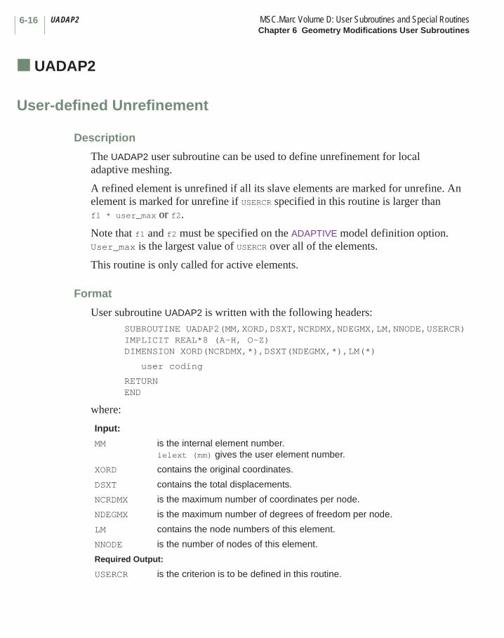
UADAP2 MSC.Marc Volume D: User Subroutines and Special RoutinesChapter 6 Geometry Modifications User Subroutines
6-16
■ UADAP2
User-defined Unrefinement
Description
The UADAP2 user subroutine can be used to define unrefinement for local adaptive meshing.
A refined element is unrefined if all its slave elements are marked for unrefine. An element is marked for unrefine if USERCR specified in this routine is larger than f1 * user_max or f2.
Note that f1 and f2 must be specified on the ADAPTIVE model definition option. User_max is the largest value of USERCR over all of the elements.
This routine is only called for active elements.
Format
User subroutine UADAP2 is written with the following headers:SUBROUTINE UADAP2(MM,XORD,DSXT,NCRDMX,NDEGMX,LM,NNODE,USERCR)IMPLICIT REAL*8 (A-H, O-Z)DIMENSION XORD(NCRDMX,*),DSXT(NDEGMX,*),LM(*)
user coding
RETURNEND
where:
Input:
MM is the internal element number.ielext (mm) gives the user element number.
XORD contains the original coordinates.
DSXT contains the total displacements.
NCRDMX is the maximum number of coordinates per node.
NDEGMX is the maximum number of degrees of freedom per node.
LM contains the node numbers of this element.
NNODE is the number of nodes of this element.
Required Output:
USERCR is the criterion is to be defined in this routine.
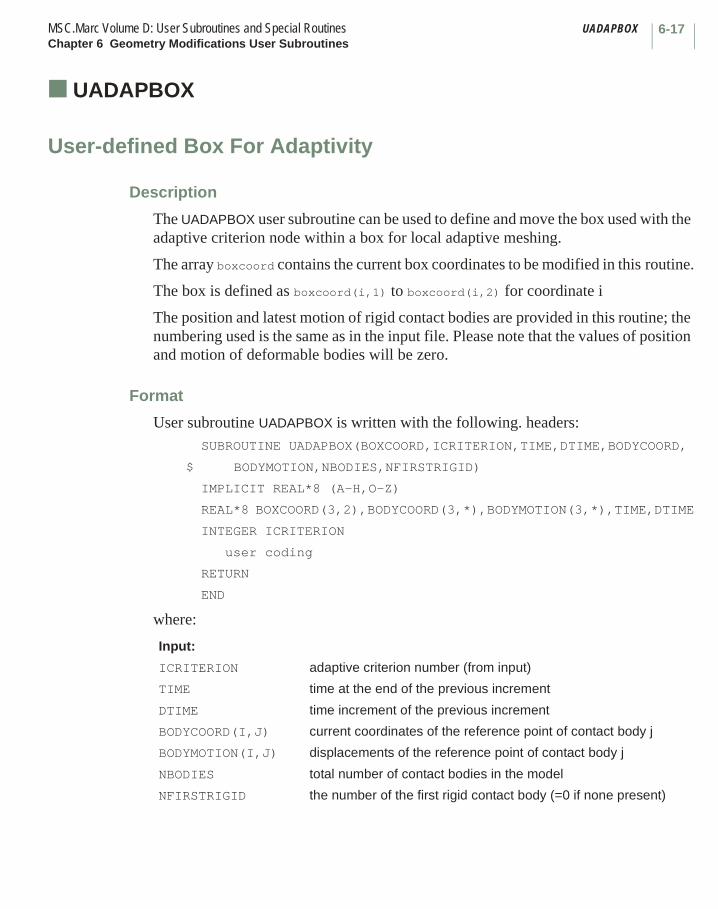
6-17MSC.Marc Volume D: User Subroutines and Special Routines UADAPBOXChapter 6 Geometry Modifications User Subroutines
■ UADAPBOX
User-defined Box For Adaptivity
Description
The UADAPBOX user subroutine can be used to define and move the box used with the adaptive criterion node within a box for local adaptive meshing.
The array boxcoord contains the current box coordinates to be modified in this routine.
The box is defined as boxcoord(i,1) to boxcoord(i,2) for coordinate i
The position and latest motion of rigid contact bodies are provided in this routine; the numbering used is the same as in the input file. Please note that the values of position and motion of deformable bodies will be zero.
Format
User subroutine UADAPBOX is written with the following. headers:SUBROUTINE UADAPBOX(BOXCOORD,ICRITERION,TIME,DTIME,BODYCOORD,
$ BODYMOTION,NBODIES,NFIRSTRIGID)
IMPLICIT REAL*8 (A-H,O-Z)
REAL*8 BOXCOORD(3,2),BODYCOORD(3,*),BODYMOTION(3,*),TIME,DTIME
INTEGER ICRITERION
user coding
RETURN
END
where:
Input:
ICRITERION adaptive criterion number (from input)
TIME time at the end of the previous increment
DTIME time increment of the previous increment
BODYCOORD(I,J) current coordinates of the reference point of contact body j
BODYMOTION(I,J) displacements of the reference point of contact body j
NBODIES total number of contact bodies in the model
NFIRSTRIGID the number of the first rigid contact body (=0 if none present)

UADAPBOX MSC.Marc Volume D: User Subroutines and Special RoutinesChapter 6 Geometry Modifications User Subroutines
6-18
Example
The following code lets the box defined in adaptive criterion 1 follow the motion of rigid body number 2.
IF (ICRITERION.EQ.1) THEN
IBODY=2BOXCOORD(1,1)=BOXCOORD(1,1)+BODYMOTION(1,IBODY)BOXCOORD(1,2)=BOXCOORD(1,2)+BODYMOTION(1,IBODY)BOXCOORD(2,1)=BOXCOORD(2,1)+BODYMOTION(2,IBODY)BOXCOORD(2,2)=BOXCOORD(2,2)+BODYMOTION(2,IBODY)BOXCOORD(3,1)=BOXCOORD(3,1)+BODYMOTION(3,IBODY)BOXCOORD(3,2)=BOXCOORD(3,2)+BODYMOTION(3,IBODY)
ENDIF
Required Output:
BOXCOORD(I,J) box coordinates

6-19MSC.Marc Volume D: User Subroutines and Special Routines UTRANSChapter 6 Geometry Modifications User Subroutines
■ UTRANS
Implement Local Coordinate System
Description
This user subroutine allows the user to specify a local coordinate system for user-specified nodes. The node numbers are given in the UTRANFORM model definition option. This user subroutine is called a multiple number of times for each increment of analysis. The local coordinate system can be modified (updated) at each increment to facilitate the input of complex boundary conditions. Incremental nodal displacements and reaction forces are output in both the local and global coordinate system. All total nodal quantities are output in the global system.
Format
User subroutine UTRANS is written with the following headers:SUBROUTINE UTRANS (DICOS, NDEG, XORD, NCRD, I, N)IMPLICIT REAL *8 (A-H, O-Z)DIMENSION DICOS (NDEG, NDEG), XORD(NCRD)
user coding
RETURN END
where:
Input:
NDEG is the number of degrees of freedom.
XORD is the coordinates of the node updated if either the UPDATE or FOLLOW FOR parameter is used.
NCRD is the number of coordinates per node.
I is the user’s node number.
N is the transformation number.
Required Output:
DICOS is the user-defined rotation matrix from the local to global coordinate system. Note that this matrix must be proper orthogonal.
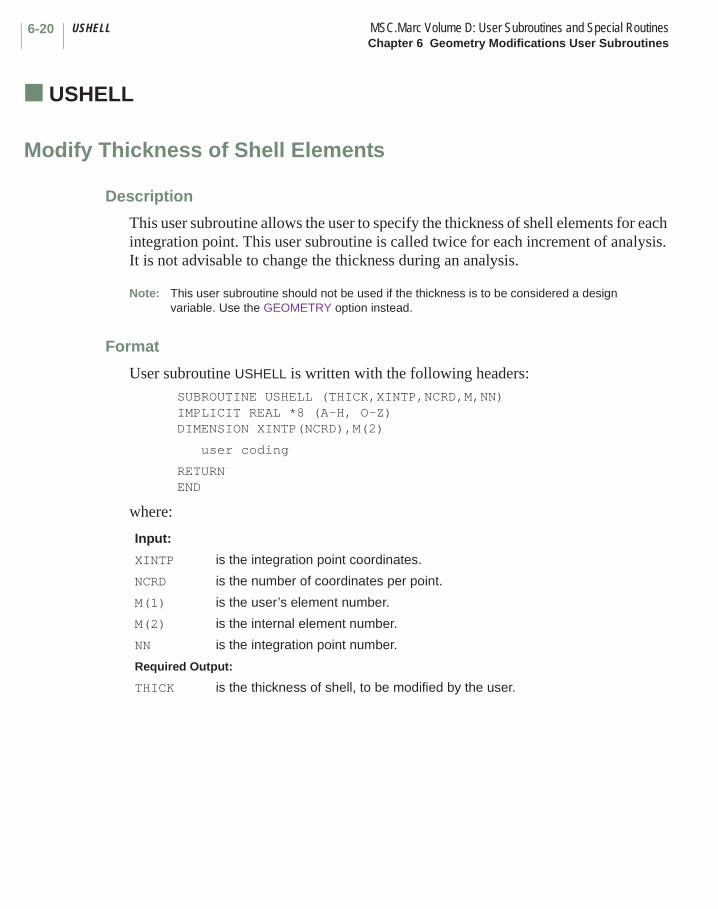
USHELL MSC.Marc Volume D: User Subroutines and Special RoutinesChapter 6 Geometry Modifications User Subroutines
6-20
■ USHELL
Modify Thickness of Shell Elements
Description
This user subroutine allows the user to specify the thickness of shell elements for each integration point. This user subroutine is called twice for each increment of analysis. It is not advisable to change the thickness during an analysis.
Note: This user subroutine should not be used if the thickness is to be considered a design variable. Use the GEOMETRY option instead.
Format
User subroutine USHELL is written with the following headers:SUBROUTINE USHELL (THICK,XINTP,NCRD,M,NN)IMPLICIT REAL *8 (A-H, O-Z)DIMENSION XINTP(NCRD),M(2)
user coding
RETURNEND
where:
Input:
XINTP is the integration point coordinates.
NCRD is the number of coordinates per point.
M(1) is the user’s element number.
M(2) is the internal element number.
NN is the integration point number.
Required Output:
THICK is the thickness of shell, to be modified by the user.
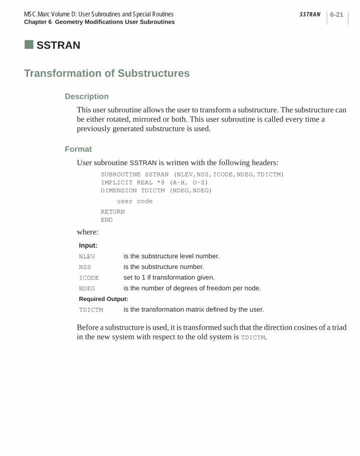
6-21MSC.Marc Volume D: User Subroutines and Special Routines SSTRANChapter 6 Geometry Modifications User Subroutines
■ SSTRAN
Transformation of Substructures
Description
This user subroutine allows the user to transform a substructure. The substructure can be either rotated, mirrored or both. This user subroutine is called every time a previously generated substructure is used.
Format
User subroutine SSTRAN is written with the following headers:SUBROUTINE SSTRAN (NLEV,NSS,ICODE,NDEG,TDICTM)IMPLICIT REAL *8 (A-H, O-Z)DIMENSION TDICTM (NDEG,NDEG)
user code
RETURNEND
where:
Before a substructure is used, it is transformed such that the direction cosines of a triad in the new system with respect to the old system is TDICTM.
Input:
NLEV is the substructure level number.
NSS is the substructure number.
ICODE set to 1 if transformation given.
NDEG is the number of degrees of freedom per node.
Required Output:
TDICTM is the transformation matrix defined by the user.
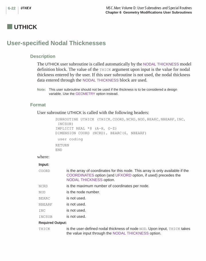
UTHICK MSC.Marc Volume D: User Subroutines and Special RoutinesChapter 6 Geometry Modifications User Subroutines
6-22
■ UTHICK
User-specified Nodal Thicknesses
Description
The UTHICK user subroutine is called automatically by the NODAL THICKNESS model definition block. The value of the THICK argument upon input is the value for nodal thickness entered by the user. If this user subroutine is not used, the nodal thickness data entered through the NODAL THICKNESS block are used.
Note: This user subroutine should not be used if the thickness is to be considered a design variable. Use the GEOMETRY option instead.
Format
User subroutine UTHICK is called with the following headers: SUBROUTINE UTHICK (THICK,COORD,NCRD,NOD,BEARC,NBEARF,INC,
INCSUB) IMPLICIT REAL *8 (A-H, O-Z) DIMENSION COORD (NCRD), BEARC(6, NBEARF)
user coding
RETURN END
where:
Input:
COORD is the array of coordinates for this node. This array is only available if the COORDINATES option (and UFXORD option, if used) precedes the NODAL THICKNESS option.
NCRD is the maximum number of coordinates per node.
NOD is the node number.
BEARC is not used.
NBEARF is not used.
INC is not used.
INCSUB is not used.
Required Output:
THICK is the user-defined nodal thickness of node NOD. Upon input, THICK takes the value input through the NODAL THICKNESS option.
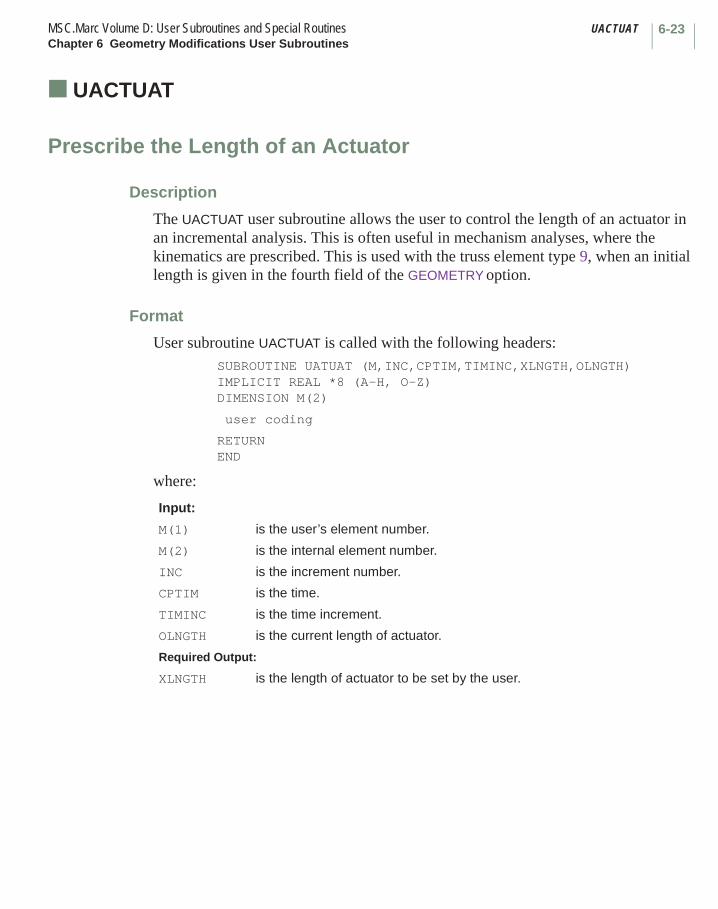
6-23MSC.Marc Volume D: User Subroutines and Special Routines UACTUATChapter 6 Geometry Modifications User Subroutines
■ UACTUAT
Prescribe the Length of an Actuator
Description
The UACTUAT user subroutine allows the user to control the length of an actuator in an incremental analysis. This is often useful in mechanism analyses, where the kinematics are prescribed. This is used with the truss element type 9, when an initial length is given in the fourth field of the GEOMETRY option.
Format
User subroutine UACTUAT is called with the following headers: SUBROUTINE UATUAT (M,INC,CPTIM,TIMINC,XLNGTH,OLNGTH) IMPLICIT REAL *8 (A-H, O-Z) DIMENSION M(2)
user coding
RETURN END
where:
Input:
M(1) is the user’s element number.
M(2) is the internal element number.
INC is the increment number.
CPTIM is the time.
TIMINC is the time increment.
OLNGTH is the current length of actuator.
Required Output:
XLNGTH is the length of actuator to be set by the user.
Chapter 7 Output Quantities User Subroutines List
User Subroutine Page
ELEVAR . . . . . . . . . . . . . . . . . . . . . . . . . . . . . . . . . . . . . . . . . . . . . . . . . . . . . . . . . . 7-18ELEVEC . . . . . . . . . . . . . . . . . . . . . . . . . . . . . . . . . . . . . . . . . . . . . . . . . . . . . . . . . . 7-20
IMPD . . . . . . . . . . . . . . . . . . . . . . . . . . . . . . . . . . . . . . . . . . . . . . . . . . . . . . . . . . . . 7-10INTCRD . . . . . . . . . . . . . . . . . . . . . . . . . . . . . . . . . . . . . . . . . . . . . . . . . . . . . . . . . . 7-22
PLOTV . . . . . . . . . . . . . . . . . . . . . . . . . . . . . . . . . . . . . . . . . . . . . . . . . . . . . . . . . . . 7-3
UBGINC . . . . . . . . . . . . . . . . . . . . . . . . . . . . . . . . . . . . . . . . . . . . . . . . . . . . . . . . . . 7-23UBGITR . . . . . . . . . . . . . . . . . . . . . . . . . . . . . . . . . . . . . . . . . . . . . . . . . . . . . . . . . . 7-25UBGPASS . . . . . . . . . . . . . . . . . . . . . . . . . . . . . . . . . . . . . . . . . . . . . . . . . . . . . . . . 7-26UEDINC . . . . . . . . . . . . . . . . . . . . . . . . . . . . . . . . . . . . . . . . . . . . . . . . . . . . . . . . . . 7-24
CHAPTER
7 Output Quantities User Subroutines List

MSC.Marc Volume D: User Subroutine and Special RoutinesChapter 7 Output Quantities User Subroutines List
7-ii
User Subroutine Page
UELOOP . . . . . . . . . . . . . . . . . . . . . . . . . . . . . . . . . . . . . . . . . . . . . . . . . . . . . . . . . 7-27UPOSTV . . . . . . . . . . . . . . . . . . . . . . . . . . . . . . . . . . . . . . . . . . . . . . . . . . . . . . . . . 7-5UPSTNO . . . . . . . . . . . . . . . . . . . . . . . . . . . . . . . . . . . . . . . . . . . . . . . . . . . . . . . . . 7-8
Chapter 7 Output Quantities User Subroutines
This chapter describes user subroutines which can be used to obtain results from the analysis and manipulate it for postprocessing. There are also four dummy user subroutines that can be used to set parameters for the advanced user. Table 7-1 summarizes these user subroutines and indicates what parameters or model definition options are required to invoke the user subroutine.
CHAPTER
7 Output Quantities User Subroutines
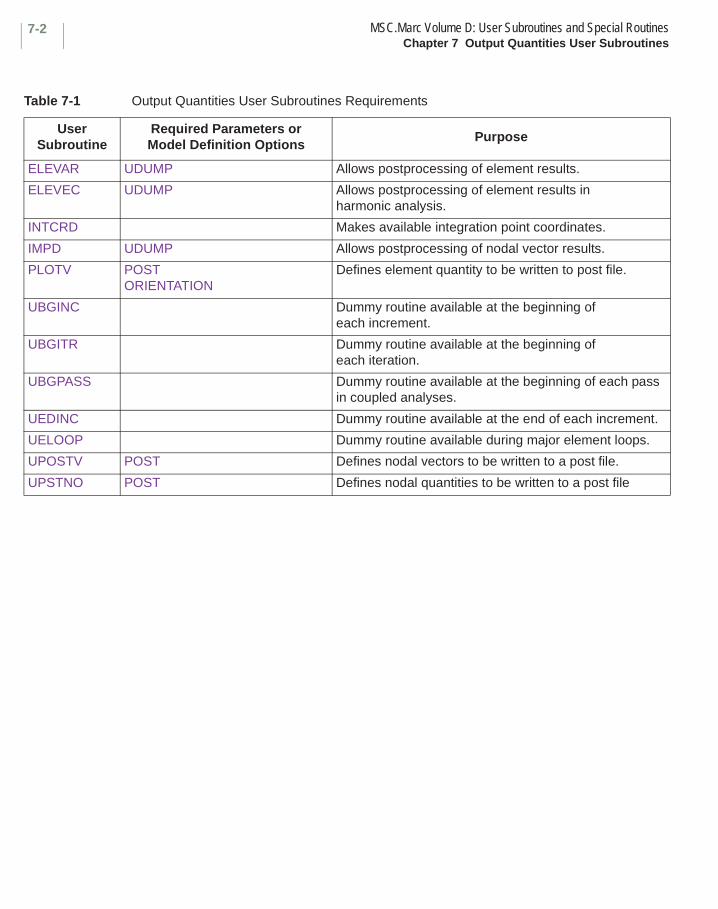
MSC.Marc Volume D: User Subroutines and Special RoutinesChapter 7 Output Quantities User Subroutines
7-2
Table 7-1 Output Quantities User Subroutines Requirements
User Subroutine
Required Parameters or Model Definition Options
Purpose
ELEVAR UDUMP Allows postprocessing of element results.
ELEVEC UDUMP Allows postprocessing of element results in harmonic analysis.
INTCRD Makes available integration point coordinates.
IMPD UDUMP Allows postprocessing of nodal vector results.
PLOTV POSTORIENTATION
Defines element quantity to be written to post file.
UBGINC Dummy routine available at the beginning of each increment.
UBGITR Dummy routine available at the beginning of each iteration.
UBGPASS Dummy routine available at the beginning of each pass in coupled analyses.
UEDINC Dummy routine available at the end of each increment.
UELOOP Dummy routine available during major element loops.
UPOSTV POST Defines nodal vectors to be written to a post file.
UPSTNO POST Defines nodal quantities to be written to a post file
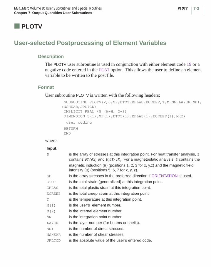
7-3MSC.Marc Volume D: User Subroutines and Special Routines PLOTVChapter 7 Output Quantities User Subroutines
■ PLOTV
User-selected Postprocessing of Element Variables
Description
The PLOTV user subroutine is used in conjunction with either element code 19 or a negative code entered in the POST option. This allows the user to define an element variable to be written to the post file.
Format
User subroutine PLOTV is written with the following headers: SUBROUTINE PLOTV(V,S,SP,ETOT,EPLAS,ECREEP,T,M,NN,LAYER,NDI, +NSHEAR,JPLTCD) IMPLICIT REAL *8 (A-H, O-Z) DIMENSION S(1),SP(1),ETOT(1),EPLAS(1),ECREEP(1),M(2)
user coding
RETURN END
where:
Input:
S is the array of stresses at this integration point. For heat transfer analysis, S contains and . For a magnetostatic analysis, S contains the
magnetic induction (B) (positions 1, 2, 3 for x, y,z) and the magnetic field intensity (H) (positions 5, 6, 7 for x, y, z).
SP is the array stresses in the preferred direction if ORIENTATION is used.
ETOT is the total strain (generalized) at this integration point.
EPLAS is the total plastic strain at this integration point.
ECREEP is the total creep strain at this integration point.
T is the temperature at this integration point.
M(1) is the user’s element number.
M(2) is the internal element number.
NN is the integration point number.
LAYER is the layer number (for beams or shells).
NDI is the number of direct stresses.
NSHEAR is the number of shear stresses.
JPLTCD is the absolute value of the user’s entered code.
∂T ∂Xi⁄ Ki∂T ∂Xi⁄
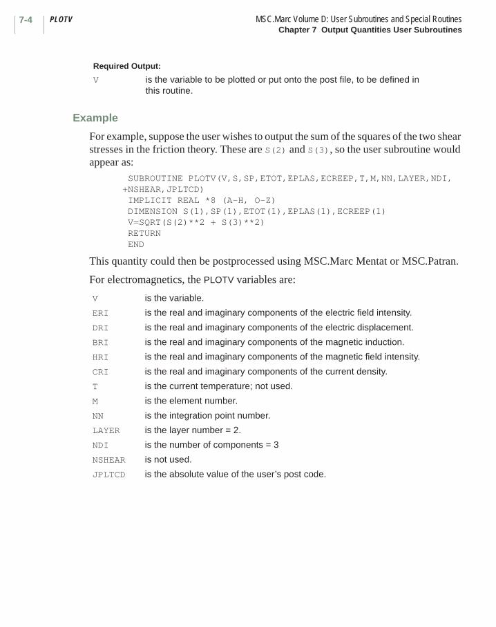
PLOTV MSC.Marc Volume D: User Subroutines and Special RoutinesChapter 7 Output Quantities User Subroutines
7-4
Example
For example, suppose the user wishes to output the sum of the squares of the two shear stresses in the friction theory. These are S(2) and S(3), so the user subroutine would appear as:
SUBROUTINE PLOTV(V,S,SP,ETOT,EPLAS,ECREEP,T,M,NN,LAYER,NDI,+NSHEAR,JPLTCD) IMPLICIT REAL *8 (A-H, O-Z) DIMENSION S(1),SP(1),ETOT(1),EPLAS(1),ECREEP(1) V=SQRT(S(2)**2 + S(3)**2) RETURN END
This quantity could then be postprocessed using MSC.Marc Mentat or MSC.Patran.
For electromagnetics, the PLOTV variables are:
Required Output:
V is the variable to be plotted or put onto the post file, to be defined in this routine.
V is the variable.
ERI is the real and imaginary components of the electric field intensity.
DRI is the real and imaginary components of the electric displacement.
BRI is the real and imaginary components of the magnetic induction.
HRI is the real and imaginary components of the magnetic field intensity.
CRI is the real and imaginary components of the current density.
T is the current temperature; not used.
M is the element number.
NN is the integration point number.
LAYER is the layer number = 2.
NDI is the number of components = 3
NSHEAR is not used.
JPLTCD is the absolute value of the user’s post code.
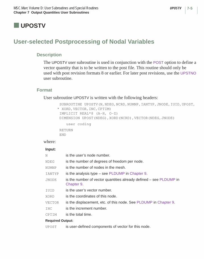
7-5MSC.Marc Volume D: User Subroutines and Special Routines UPOSTVChapter 7 Output Quantities User Subroutines
■ UPOSTV
User-selected Postprocessing of Nodal Variables
Description
The UPOSTV user subroutine is used in conjunction with the POST option to define a vector quantity that is to be written to the post file. This routine should only be used with post revision formats 8 or earlier. For later post revisions, use the UPSTNO user subroutine.
Format
User subroutine UPOSTV is written with the following headers:SUBROUTINE UPOSTV(N,NDEG,NCRD,NUMNP,IANTYP,JNODE,IUID,UPOST,
* XORD,VECTOR,INC,CPTIM) IMPLICIT REAL*8 (A-H, O-Z) DIMENSION UPOST(NDEG),XORD(NCRD),VECTOR(NDEG,JNODE)
user coding
RETURN END
where:
Input:
N is the user’s node number.
NDEG is the number of degrees of freedom per node.
NUMNP is the number of nodes in the mesh.
IANTYP is the analysis type – see PLDUMP in Chapter 9.
JNODE is the number of vector quantities already defined – see PLDUMP in Chapter 9.
IUID is the user’s vector number.
XORD is the coordinates of this node.
VECTOR is the displacement, etc. of this node. See PLDUMP in Chapter 9.
INC is the increment number.
CPTIM is the total time.
Required Output:
UPOST is user-defined components of vector for this node.

UPOSTV MSC.Marc Volume D: User Subroutines and Special RoutinesChapter 7 Output Quantities User Subroutines
7-6
Example
For example, the user would like to postprocess the relative displacement of all nodes with respect to his node 5 for all time. The user would need to obtain the displacement of node 5 and subtract this from the other displacements. This is done as follows:
SUBROUTINE UPOSTV(N,NDEG,NCRD,NUMNP,IANTYP,JNODE,IUID,
* UPOST,XORD,VECTOR,INC,CPTIM)
implicit real*8 (a-h,o-z)
c
c user subroutine to define nodal post variables
c
c n user node number
c ndeg number of degrees of freedom per node
c ncrd number of coordinates per node
c numnp number of nodes in mesh
c iantyp analysis type - see PLDUMP in volume D
c jnode number of vector quantities already defined
c - see PLDUMP in volume D
c iuid user vector number
c upost user defined components of vector for this node
c xord coordinates of this node
c vectors displacement, etc of this node.
c see iantyp/jnode table in PLDUMP section in volume D
c inc increment number
c cptim total time
c
dimension upost(ndeg),xord(ncrd),vector(ndeg,jnode)
include 'space'
include 'array2'
dimension disp5(12)
c set reference node lext=5
lext=5
c get internal node number
lint=nodint (lext)
c get reference displacement and store into disp5
la3=idsxt+(lint-1)*ndeg
call mcpy(vars(la3),disp5,ndeg,1,0)

7-7MSC.Marc Volume D: User Subroutines and Special Routines UPOSTVChapter 7 Output Quantities User Subroutines
c
c get displacement of current node from vector and
c subtract off reference displacement and store back into upost
c
do i=1,ndeg
upost(i)=vector(i,1)-disp5(i)
enddo
c
return
end
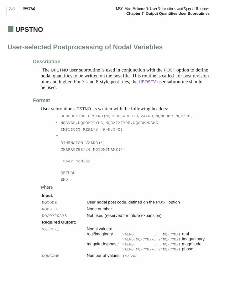
UPSTNO MSC.Marc Volume D: User Subroutines and Special RoutinesChapter 7 Output Quantities User Subroutines
7-8
■ UPSTNO
User-selected Postprocessing of Nodal Variables
Description
The UPSTNO user subroutine is used in conjunction with the POST option to define nodal quantities to be written on the post file. This routine is called for post revision nine and higher. For 7- and 8-style post files, the UPOSTV user subroutine should be used.
Format
User subroutine UPSTNO is written with the following headers:SUBROUTINE UPSTNO(NQCODE,NODEID,VALNO,NQNCOMP,NQTYPE,
* NQAVER,NQCOMPTYPE,NQDATATYPE,NQCOMPNAME)
IMPLICIT REAL*8 (A-H,O-Z)
c
DIMENSION VALNO(*)
CHARACTER*24 NQCOMPNAME(*)
user coding
RETURN
END
where
Input:
NQCODE User nodal post code, defined on the POST option
NODEID Node number
NQCOMPNAME Not used (reserved for future expansion)
Required Output:
VALNO() Nodal values:real/imaginary VALNO( 1: NQNCOMP) real
VALNO(NQNCOMP+1:2*NQNCOMP) imagaginarymagnitude/phase VALNO( 1: NQNCOMP) magnitude
VALNO(NQNCOMP+1:2*NQNCOMP) phase
NQNCOMP Number of values in VALNO
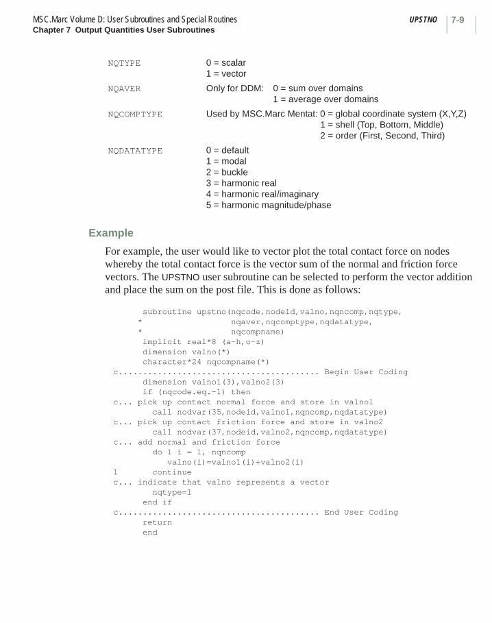
7-9MSC.Marc Volume D: User Subroutines and Special Routines UPSTNOChapter 7 Output Quantities User Subroutines
Example
For example, the user would like to vector plot the total contact force on nodes whereby the total contact force is the vector sum of the normal and friction force vectors. The UPSTNO user subroutine can be selected to perform the vector addition and place the sum on the post file. This is done as follows:
subroutine upstno(nqcode,nodeid,valno,nqncomp,nqtype, * nqaver,nqcomptype,nqdatatype, * nqcompname) implicit real*8 (a-h,o-z) dimension valno(*) character*24 nqcompname(*)c......................................... Begin User Coding dimension valno1(3),valno2(3) if (nqcode.eq.-1) thenc... pick up contact normal force and store in valno1 call nodvar(35,nodeid,valno1,nqncomp,nqdatatype)c... pick up contact friction force and store in valno2 call nodvar(37,nodeid,valno2,nqncomp,nqdatatype)c... add normal and friction force do 1 i = 1, nqncomp valno(i)=valno1(i)+valno2(i)1 continuec... indicate that valno represents a vector nqtype=1 end ifc......................................... End User Coding return end
NQTYPE 0 = scalar1 = vector
NQAVER Only for DDM: 0 = sum over domains1 = average over domains
NQCOMPTYPE Used by MSC.Marc Mentat: 0 = global coordinate system (X,Y,Z)1 = shell (Top, Bottom, Middle)2 = order (First, Second, Third)
NQDATATYPE 0 = default1 = modal2 = buckle3 = harmonic real4 = harmonic real/imaginary5 = harmonic magnitude/phase

IMPD MSC.Marc Volume D: User Subroutines and Special RoutinesChapter 7 Output Quantities User Subroutines
7-10
■ IMPD
Output of Nodal Quantities
Description
The IMPD user subroutine makes the displacements, coordinates, reaction forces, velocities, and accelerations available at the end of each increment so that the user can save them in any form convenient for postprocessing. During harmonic subincrements, IMPD allows the user to obtain the complex displacements and reactions. In heat transfer (or Joule heating) analysis, this user subroutine allows the user to obtain nodal temperatures, fluxes, and voltages for his postprocessing. This user subroutine is used in conjunction with the UDUMP option.
Stress Analysis
Format
User subroutine IMPD is written with the following headers:SUBROUTINE IMPD (LNODE,DD,TD,XORD,F,V,A,NDEG,NCRD)IMPLICIT REAL *8 (A-H, O-Z)DIMENSION DD (NDEG), TD (NDEG), XORD (NCRD),F(NDEG),V(NDEG),A(NDEG), LNODE(2)
user coding
RETURN END
where:
Input:LNODE(1) is the node number (the user subroutine is called once per node
per increment).LNODE(2) = 1DD is the array of displacement increments at this node.TD is the array of total displacements at this node.XORD are the coordinates of this node.F are the reaction forces at prescribed boundary conditions; residual load
correction elsewhere at this node.V is the total velocity at this node.A is the total acceleration at this node.NDEG is the number of degrees of freedom per node (that is, the size of the DD, TD,
V, and A arrays).NCRD is the number of coordinate directions per node (equals the size of the
XORD array).

7-11MSC.Marc Volume D: User Subroutines and Special Routines IMPDChapter 7 Output Quantities User Subroutines
During harmonic subincrements:
Example
For example, suppose the user wishes to write on a file the displaced position of a three-dimensional solid structure for subsequent plotting. A scale factor of 5 is used on the displacements.
SUBROUTINE IMPD (LNODE,DD,TD,XORD,F,V,A,NDEG,NCRD) IMPLICIT REAL *8 (A-H, O-Z) DIMENSION DD(NDEG), TD(NDEG),XORD(NCRD),F(NDEG), 1 V(NDEG), A(NDEG), LNODE(2) DIMENSION TXORD(3)C TXORD WILL BE THE COORDS + 5X TOTAL DISPLACEMENTS DO 1 I = 1,3 1 TXORD(I) = XORD(I) + 5.0*TD(I)C WRITE OUT DISPLACED POSITIONS ON TAPE 20. WRITE (20) LNODE(1), TXORD RETURN END
After each increment, there are NUMNP records (number of nodal points) on logical unit 20; each contains a node number and three adjusted coordinates. Note that any additional file unit must be taken care of with the appropriate machine dependent JCL.
Note: In a coupled thermal-stress analysis, IMPD is called at the end of the stress pass of an increment. If one then wants to have the temperature of a node (or the top, bottom, and middle temperature in the case of shell elements), use can be made of the NODVAR user subroutine as follows:
DIMENSION TXORD(3)C CALL NODVAR (14, N, DDTEMP, N1DUM,N2DUM)
Now DDTEMP contains the temperature(s) of node n.
Input:
DD is the array of real displacements.
TD is the array of imaginary displacements.
F is the array of real reaction forces.
V is the array of imaginary reaction forces.
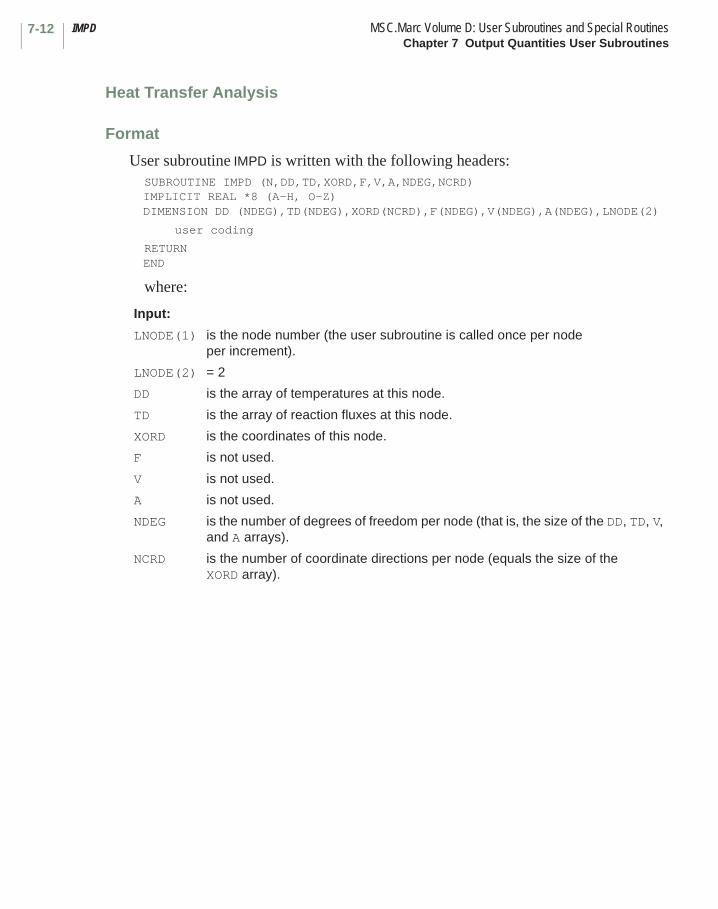
IMPD MSC.Marc Volume D: User Subroutines and Special RoutinesChapter 7 Output Quantities User Subroutines
7-12
Heat Transfer Analysis
Format
User subroutine IMPD is written with the following headers:SUBROUTINE IMPD (N,DD,TD,XORD,F,V,A,NDEG,NCRD) IMPLICIT REAL *8 (A-H, O-Z) DIMENSION DD (NDEG),TD(NDEG),XORD(NCRD),F(NDEG),V(NDEG),A(NDEG),LNODE(2)
user coding
RETURNEND
where:
Input:
LNODE(1) is the node number (the user subroutine is called once per node per increment).
LNODE(2) = 2
DD is the array of temperatures at this node.
TD is the array of reaction fluxes at this node.
XORD is the coordinates of this node.
F is not used.
V is not used.
A is not used.
NDEG is the number of degrees of freedom per node (that is, the size of the DD, TD, V, and A arrays).
NCRD is the number of coordinate directions per node (equals the size of the XORD array).

7-13MSC.Marc Volume D: User Subroutines and Special Routines IMPDChapter 7 Output Quantities User Subroutines
Joule Heating (Current Pass) Analysis
Format
User subroutine IMPD is written with the following headers:SUBROUTINE IMPD (N,DD,TD,XORD,F,V,A,NDEG,NCRD)IMPLICIT REAL *8 (A-H, O-Z)DIMENSION DD (NDEG),TD(NDEG),XORD(NCRD),F(NDEG),V(NDEG),A(NDEG), LNODE(2)
user coding
RETURNEND
where:
Electrostatic Analysis
Format
User subroutine IMPD is written with the following headers:SUBROUTINE IMPD (LNODE,DD,TD,XORD,F,V,A,NDEG,NCRD)IMPLICIT REAL *8 (A-H, O-Z)DIMENSION XORD(NCRD)
user coding
RETURNEND
Input:
LNODE(1) is the node number (the user subroutine is called once per node per increment).
LNODE(2) = 4
DD is the array of voltages at this node.
TD is the array of reaction currents at this node.
XORD is the coordinates of this node.
F is not used.
V is not used.
A is not used.
NDEG is the number of degrees of freedom per node (that is, the size of the DD, TD, V, and A arrays).
NCRD is the number of coordinate directions per node (equals the size of the XORD array).
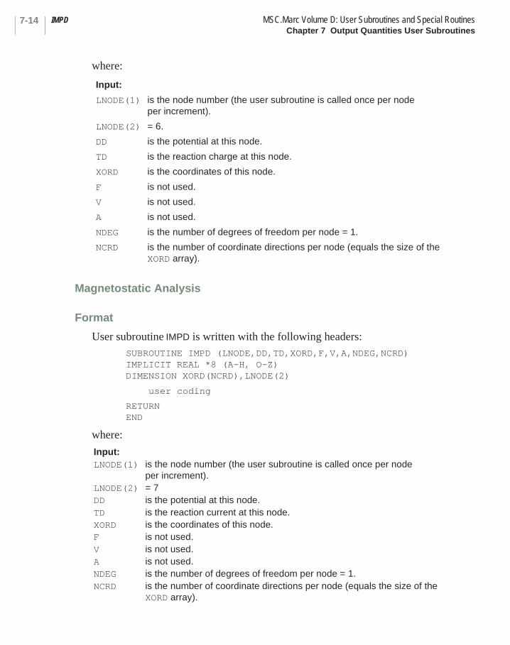
IMPD MSC.Marc Volume D: User Subroutines and Special RoutinesChapter 7 Output Quantities User Subroutines
7-14
where:
Magnetostatic Analysis
Format
User subroutine IMPD is written with the following headers:SUBROUTINE IMPD (LNODE,DD,TD,XORD,F,V,A,NDEG,NCRD)IMPLICIT REAL *8 (A-H, O-Z)DIMENSION XORD(NCRD),LNODE(2)
user coding
RETURNEND
where:
Input:
LNODE(1) is the node number (the user subroutine is called once per node per increment).
LNODE(2) = 6.
DD is the potential at this node.
TD is the reaction charge at this node.
XORD is the coordinates of this node.
F is not used.
V is not used.
A is not used.
NDEG is the number of degrees of freedom per node = 1.
NCRD is the number of coordinate directions per node (equals the size of the XORD array).
Input:LNODE(1) is the node number (the user subroutine is called once per node
per increment).LNODE(2) = 7DD is the potential at this node.TD is the reaction current at this node.XORD is the coordinates of this node.F is not used.V is not used.A is not used.NDEG is the number of degrees of freedom per node = 1.NCRD is the number of coordinate directions per node (equals the size of the
XORD array).
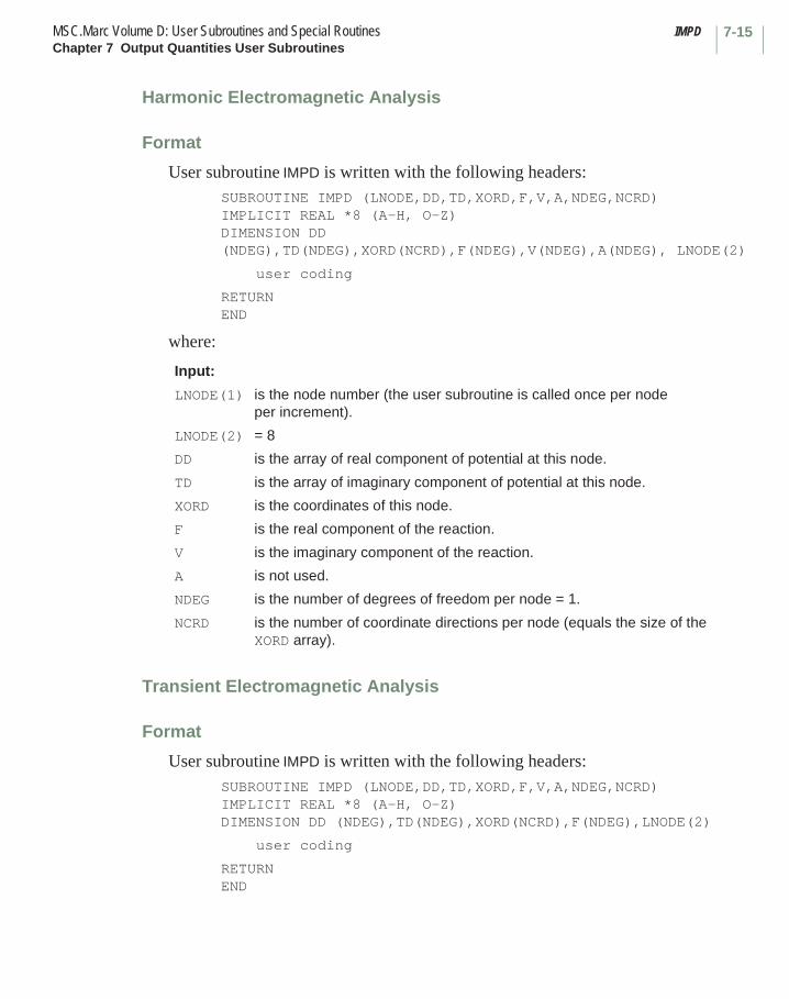
7-15MSC.Marc Volume D: User Subroutines and Special Routines IMPDChapter 7 Output Quantities User Subroutines
Harmonic Electromagnetic Analysis
Format
User subroutine IMPD is written with the following headers:SUBROUTINE IMPD (LNODE,DD,TD,XORD,F,V,A,NDEG,NCRD)IMPLICIT REAL *8 (A-H, O-Z)DIMENSION DD (NDEG),TD(NDEG),XORD(NCRD),F(NDEG),V(NDEG),A(NDEG), LNODE(2)
user coding
RETURNEND
where:
Transient Electromagnetic Analysis
Format
User subroutine IMPD is written with the following headers:SUBROUTINE IMPD (LNODE,DD,TD,XORD,F,V,A,NDEG,NCRD)IMPLICIT REAL *8 (A-H, O-Z)DIMENSION DD (NDEG),TD(NDEG),XORD(NCRD),F(NDEG),LNODE(2)
user coding
RETURNEND
Input:
LNODE(1) is the node number (the user subroutine is called once per node per increment).
LNODE(2) = 8
DD is the array of real component of potential at this node.
TD is the array of imaginary component of potential at this node.
XORD is the coordinates of this node.
F is the real component of the reaction.
V is the imaginary component of the reaction.
A is not used.
NDEG is the number of degrees of freedom per node = 1.
NCRD is the number of coordinate directions per node (equals the size of the XORD array).
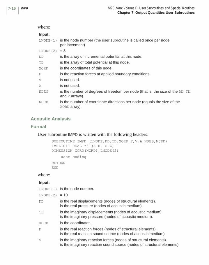
IMPD MSC.Marc Volume D: User Subroutines and Special RoutinesChapter 7 Output Quantities User Subroutines
7-16
where:
Acoustic Analysis
Format
User subroutine IMPD is written with the following headers:SUBROUTINE IMPD (LNODE,DD,TD,XORD,F,V,A,NDEG,NCRD)IMPLICIT REAL *8 (A-H, O-Z)DIMENSION XORD(NCRD),LNODE(2)
user coding
RETURNEND
where:
Input:
LNODE(1) is the node number (the user subroutine is called once per node per increment).
LNODE(2) = 8
DD is the array of incremental potential at this node.
TD is the array of total potential at this node.
XORD is the coordinates of this node.
F is the reaction forces at applied boundary conditions.
V is not used.
A is not used.
NDEG is the number of degrees of freedom per node (that is, the size of the DD, TD, and F arrays).
NCRD is the number of coordinate directions per node (equals the size of the XORD array).
Input:
LNODE(1) is the node number.
LNODE(2) = 10
DD is the real displacements (nodes of structural elements).is the real pressure (nodes of acoustic medium).
TD is the imaginary displacements (nodes of acoustic medium).is the imaginary pressure (nodes of acoustic medium).
XORD is the coordinates.
F is the real reaction forces (nodes of structural elements).is the real reaction sound source (nodes of acoustic medium).
V is the imaginary reaction forces (nodes of structural elements).is the imaginary reaction sound source (nodes of structural elements).
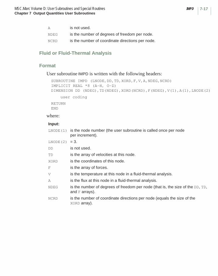
7-17MSC.Marc Volume D: User Subroutines and Special Routines IMPDChapter 7 Output Quantities User Subroutines
Fluid or Fluid-Thermal Analysis
Format
User subroutine IMPD is written with the following headers:SUBROUTINE IMPD (LNODE,DD,TD,XORD,F,V,A,NDEG,NCRD)IMPLICIT REAL *8 (A-H, O-Z)DIMENSION DD (NDEG),TD(NDEG),XORD(NCRD),F(NDEG),V(1),A(1),LNODE(2)
user coding
RETURNEND
where:
A is not used.
NDEG is the number of degrees of freedom per node.
NCRD is the number of coordinate directions per node.
Input:
LNODE(1) is the node number (the user subroutine is called once per node per increment).
LNODE(2) = 3.
DD is not used.
TD is the array of velocities at this node.
XORD is the coordinates of this node.
F is the array of forces.
V is the temperature at this node in a fluid-thermal analysis.
A is the flux at this node in a fluid-thermal analysis.
NDEG is the number of degrees of freedom per node (that is, the size of the DD, TD, and F arrays).
NCRD is the number of coordinate directions per node (equals the size of the XORD array).
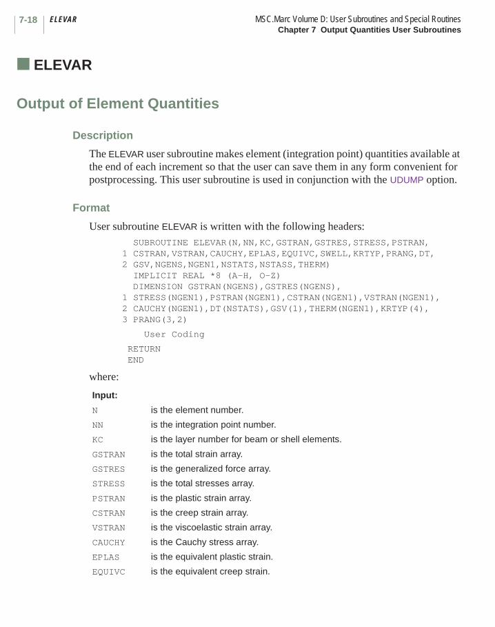
ELEVAR MSC.Marc Volume D: User Subroutines and Special RoutinesChapter 7 Output Quantities User Subroutines
7-18
■ ELEVAR
Output of Element Quantities
Description
The ELEVAR user subroutine makes element (integration point) quantities available at the end of each increment so that the user can save them in any form convenient for postprocessing. This user subroutine is used in conjunction with the UDUMP option.
Format
User subroutine ELEVAR is written with the following headers: SUBROUTINE ELEVAR(N,NN,KC,GSTRAN,GSTRES,STRESS,PSTRAN, 1 CSTRAN,VSTRAN,CAUCHY,EPLAS,EQUIVC,SWELL,KRTYP,PRANG,DT, 2 GSV,NGENS,NGEN1,NSTATS,NSTASS,THERM) IMPLICIT REAL *8 (A-H, O-Z) DIMENSION GSTRAN(NGENS),GSTRES(NGENS),1 STRESS(NGEN1),PSTRAN(NGEN1),CSTRAN(NGEN1),VSTRAN(NGEN1), 2 CAUCHY(NGEN1),DT(NSTATS),GSV(1),THERM(NGEN1),KRTYP(4),3 PRANG(3,2)
User Coding
RETURN END
where:
Input:
N is the element number.
NN is the integration point number.
KC is the layer number for beam or shell elements.
GSTRAN is the total strain array.
GSTRES is the generalized force array.
STRESS is the total stresses array.
PSTRAN is the plastic strain array.
CSTRAN is the creep strain array.
VSTRAN is the viscoelastic strain array.
CAUCHY is the Cauchy stress array.
EPLAS is the equivalent plastic strain.
EQUIVC is the equivalent creep strain.
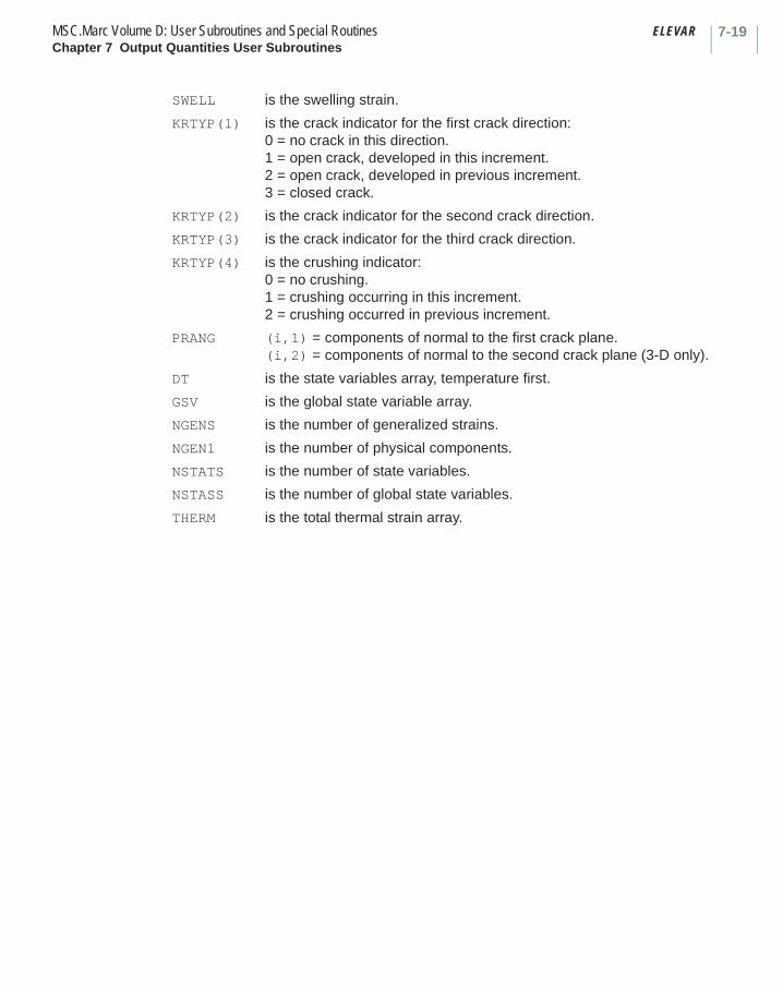
7-19MSC.Marc Volume D: User Subroutines and Special Routines ELEVARChapter 7 Output Quantities User Subroutines
SWELL is the swelling strain.
KRTYP(1) is the crack indicator for the first crack direction:0 = no crack in this direction.1 = open crack, developed in this increment.2 = open crack, developed in previous increment.3 = closed crack.
KRTYP(2) is the crack indicator for the second crack direction.
KRTYP(3) is the crack indicator for the third crack direction.
KRTYP(4) is the crushing indicator:0 = no crushing.1 = crushing occurring in this increment.2 = crushing occurred in previous increment.
PRANG (i,1) = components of normal to the first crack plane.(i,2) = components of normal to the second crack plane (3-D only).
DT is the state variables array, temperature first.
GSV is the global state variable array.
NGENS is the number of generalized strains.
NGEN1 is the number of physical components.
NSTATS is the number of state variables.
NSTASS is the number of global state variables.
THERM is the total thermal strain array.
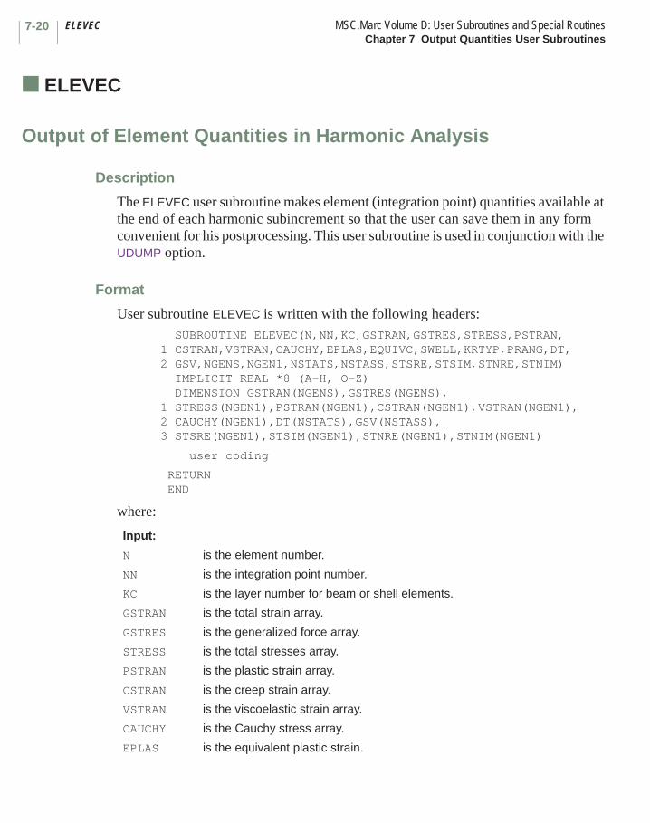
ELEVEC MSC.Marc Volume D: User Subroutines and Special RoutinesChapter 7 Output Quantities User Subroutines
7-20
■ ELEVEC
Output of Element Quantities in Harmonic Analysis
Description
The ELEVEC user subroutine makes element (integration point) quantities available at the end of each harmonic subincrement so that the user can save them in any form convenient for his postprocessing. This user subroutine is used in conjunction with the UDUMP option.
Format
User subroutine ELEVEC is written with the following headers: SUBROUTINE ELEVEC(N,NN,KC,GSTRAN,GSTRES,STRESS,PSTRAN,1 CSTRAN,VSTRAN,CAUCHY,EPLAS,EQUIVC,SWELL,KRTYP,PRANG,DT,2 GSV,NGENS,NGEN1,NSTATS,NSTASS,STSRE,STSIM,STNRE,STNIM) IMPLICIT REAL *8 (A-H, O-Z) DIMENSION GSTRAN(NGENS),GSTRES(NGENS), 1 STRESS(NGEN1),PSTRAN(NGEN1),CSTRAN(NGEN1),VSTRAN(NGEN1), 2 CAUCHY(NGEN1),DT(NSTATS),GSV(NSTASS), 3 STSRE(NGEN1),STSIM(NGEN1),STNRE(NGEN1),STNIM(NGEN1)
user coding
RETURN END
where:
Input:
N is the element number.
NN is the integration point number.
KC is the layer number for beam or shell elements.
GSTRAN is the total strain array.
GSTRES is the generalized force array.
STRESS is the total stresses array.
PSTRAN is the plastic strain array.
CSTRAN is the creep strain array.
VSTRAN is the viscoelastic strain array.
CAUCHY is the Cauchy stress array.
EPLAS is the equivalent plastic strain.
7-21MSC.Marc Volume D: User Subroutines and Special Routines ELEVECChapter 7 Output Quantities User Subroutines
EQUIVC is the equivalent stress.
SWELL is the swelling strain.
KRTYP is the cracking type.
PRANG is the crack angle.
DT is the state variables array, temperature first.
GSV is the global state variable array.
NGENS is the number of generalized strains.
NGEN1 is the number of physical components.
NSTATS is the number of state variables.
NSTASS is the number of global state variables.
STSRE is the real harmonic stress.
STSIM is the imaginary harmonic stress.
STNRE is the real harmonic strain.
STNIN is the imaginary harmonic strain.
INTCRD MSC.Marc Volume D: User Subroutines and Special RoutinesChapter 7 Output Quantities User Subroutines
7-22
■ INTCRD
Output of Integration Point Coordinates
Description
The INTCRD user subroutine makes the integration point coordinates for the stiffness matrix available at each increment. The user can save them in any form convenient for postprocessing.
Format
User subroutine INTCRD is written with the following headers:SUBROUTINE INTCRD(M,NN,XORD,NCRD)IMPLICIT REAL *8 (A-H, O-Z)DIMENSION XORD(NCRD)
user coding
RETURNEND
where:
Input:
M is the element number.
NN is the integration point number.
XORD is the coordinates of this integration point.
NCRD is the number of coordinate directions.

7-23MSC.Marc Volume D: User Subroutines and Special Routines UBGINCChapter 7 Output Quantities User Subroutines
■ UBGINC
Beginning of Increment
Description
The UBGINC user subroutine is called at the beginning of each new increment. It can be used to define or modify data variables stored in common blocks.
Note: No special flag is required in the input file.
Format
User subroutine UBGINC is written with the following headers:SUBROUTINE UBGINC(INC,INCSUB)IMPLICIT REAL *8 (A-H, O-Z)
user coding
RETURNEND
where:
Input:
INC is the increment number.
INCSUB is the subincrement number.

UEDINC MSC.Marc Volume D: User Subroutines and Special RoutinesChapter 7 Output Quantities User Subroutines
7-24
■ UEDINC
End of Increment
Description
The UEDINC user subroutine is called at the end of each increment. It can be used to define or modify data variables stored in common blocks.
Note: No special flag is required in the input file.
Format
User subroutine UEDINC is written with the following headers:SUBROUTINE UEDINC(INC,INCSUB)IMPLICIT REAL *8 (A-H, O-Z)
user coding
RETURNEND
where:
Input:
INC is the increment number.
INCSUB is the subincrement number.

7-25MSC.Marc Volume D: User Subroutines and Special Routines UBGITRChapter 7 Output Quantities User Subroutines
■ UBGITR
Beginning of Iteration
Description
The UBGITR user subroutine is called at the beginning of each iteration in the solution of the nonlinear problem. It can be used to define or modify data variables stored in common blocks.
Note: No special flag is required in the input file.
Format
User subroutine UBGITR is written with the following headers:SUBROUTINE UBGITR(INC,INCSUB,NCYCLE)IMPLICIT REAL *8 (A-H, O-Z)
user coding
RETURNEND
where:
Input:
INC is the increment number.
INCSUB is the subincrement number.
NCYCLE is the iteration number (the first is labeled zero).

UBGPASS MSC.Marc Volume D: User Subroutines and Special RoutinesChapter 7 Output Quantities User Subroutines
7-26
■ UBGPASS
Beginning of Pass in Coupled Analyses
Description
The UBGPASS user subroutine is called at the beginning of each pass of coupled analyses. It can be used to define or modify data variables stored in common blocks.
Note: No special flag is required in the input file.
Format
User subroutine UBGPASS is written with the following headers:SUBROUTINE UBGPASS (INC,INCSUB,IPASS)IMPLICIT REAL *8 (A-H, O-Z)
user coding
RETURNEND
where:
Input:
INC is the increment number.
INCSUB is the subincrement number.
IPASS is the pass identifier:IPASS = 1 - stress passIPASS = 2 - thermal passIPASS = 3 - fluid passIPASS = 4 - Joule heating passIPASS = 5 - pore pressure passIPASS = 6 - electrostatics passIPASS = 7 - magnetostatics pass IPASS = 8 - electromagnetics pass

7-27MSC.Marc Volume D: User Subroutines and Special Routines UELOOPChapter 7 Output Quantities User Subroutines
■ UELOOP
Beginning of Element Loop
Description
The UELOOP user subroutine is called in a loop over the elements. It can be used to define or modify data variables stored in common blocks.
Note: No special flag is required in the input file.
Format
User subroutine UELOOP is written with the following headers:SUBROUTINE UELOOP(M,N,IL)IMPLICIT REAL *8 (A-H, O-Z)
user coding
RETURNEND
where:
Input:
M is the user’s element number.
N is the internal element number.
IL is the loop flag.= 1 form consistent nodal loads from distributed loads.= 2 stiffness matrix formation.= 3 mass matrix formation.= 4 stress recovery.
Chapter 8 Hydrodynamic Lubrication User Subroutines List
User Subroutine Page
UBEAR. . . . . . . . . . . . . . . . . . . . . . . . . . . . . . . . . . . . . . . . . . . . . . . . . . . . . . . . . . . 8-3UGROOV . . . . . . . . . . . . . . . . . . . . . . . . . . . . . . . . . . . . . . . . . . . . . . . . . . . . . . . . . 8-4URESTR . . . . . . . . . . . . . . . . . . . . . . . . . . . . . . . . . . . . . . . . . . . . . . . . . . . . . . . . . 8-5UTHICK . . . . . . . . . . . . . . . . . . . . . . . . . . . . . . . . . . . . . . . . . . . . . . . . . . . . . . . . . . 8-6UVELOC . . . . . . . . . . . . . . . . . . . . . . . . . . . . . . . . . . . . . . . . . . . . . . . . . . . . . . . . . 8-8
CHAPTER
8 Hydrodynamic Lubrication User Subroutines List
Chapter 8 Hydrodynamic Lubrication User Subroutines
This chapter describes user subroutines that can be used to customize a hydrodynamic bearing analysis. In such problems, the geometry can be complicated by grooves in the bearing surface or nonuniform lubricant. The user subroutines provided here facilitate the input of this data. Table 8-1 summarizes these user subroutines and indicates what parameters or model definition options are required to invoke the user subroutine.
CHAPTER
8 Hydrodynamic Lubrication User Subroutines
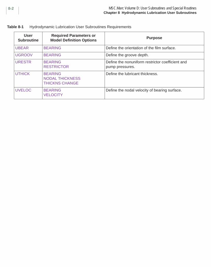
MSC.Marc Volume D: User Subroutines and Special RoutinesChapter 8 Hydrodynamic Lubrication User Subroutines
8-2
Table 8-1 Hydrodynamic Lubrication User Subroutines Requirements
User Subroutine
Required Parameters or Model Definition Options
Purpose
UBEAR BEARING Define the orientation of the film surface.
UGROOV BEARING Define the groove depth.
URESTR BEARINGRESTRICTOR
Define the nonuniform restrictor coefficient and pump pressures.
UTHICK BEARINGNODAL THICKNESSTHICKNS CHANGE
Define the lubricant thickness.
UVELOC BEARINGVELOCITY
Define the nodal velocity of bearing surface.
8-3MSC.Marc Volume D: User Subroutines and Special Routines UBEARChapter 8 Hydrodynamic Lubrication User Subroutines
■ UBEAR
Input of Spatial Orientation of Lubricant Thickness
Description
In bearing analysis, the lubricant is modeled by a planar mesh due to the absence of pressure gradients across the film height. MSC.Marc integrates the obtained pressure distribution over the entire mesh. This yields a set of equivalent consistent nodal forces perpendicular to the lubricant. In order to calculate the load capacity of a particular bearing system, these forces must be transformed to the global coordinate system. For this purpose, information is required about the direction cosines of the lubricant normal. This can be done in the UBEAR user subroutine which is called for each node.
Format
User subroutine UBEAR is written with the following headers:SUBROUTINE UBEAR (COORD,COS,NODE,NCRD)IMPLICIT REAL *8 (A-H, O-Z)DIMENSION COORD (NCRD), COS(3)
user coding
RETURNEND
where:
Input:
COORD is the array of coordinates at this node.
NODE is the node number.
NCRD is the number of coordinates per node.
Required Output:
COS is the array of direction cosines of the vector perpendicular to the lubricant; to be defined in this user subroutine. A default vector (0,0,1) is assumed if not specified.
UGROOV MSC.Marc Volume D: User Subroutines and Special RoutinesChapter 8 Hydrodynamic Lubrication User Subroutines
8-4
■ UGROOV
Input of Groove Depths
Description
In bearing analysis, discontinuous film thicknesses are often applied to increase the load carrying capacity. This is usually done by grooves, which can be defined in the GEOMETRY option. However, this is not possible if position dependent groove depths have to be included. In such situations, the UGROOV user subroutine must be used. It is called at each integration point and allows the user to specify the groove depth at these points. In addition, this user subroutine can be used for selecting elements which are located at grooves if complex groove patterns have to be modeled.
Format
User subroutine UGROOV is written with the following headers:SUBROUTINE UGROOV (THICK,COORD,M,NN,NCRD)IMPLICIT REAL *8 (A-H, O-Z)DIMENSION COORD (NCRD)
user coding
RETURNEND
where:
Input:
COORD is the array of coordinates at this integration point.
M is the element number.
NN is the integration point number.
NCRD is the number of coordinates per node.
Required Output:
THICK is the groove depth magnitude to be specified.
8-5MSC.Marc Volume D: User Subroutines and Special Routines URESTRChapter 8 Hydrodynamic Lubrication User Subroutines
■ URESTR
Input of Nonuniform Restrictor Coefficients
Description
In bearing analysis, it is often necessary to include nonuniform restrictor coefficients and pump pressures. The URESTR user subroutine allows this. It is called at each increment for each integration point on each element surface given in the RESTRICTOR model definition set, and allows the user to modify the restrictor coefficient and pump pressure input on the data blocks.
Format
User subroutine URESTR is written with the following headers:SUBROUTINE URESTR (CR,PP,PS,N,INC) IMPLICIT REAL *8 (A-H, O-Z)DIMENSION N(3)
user coding
RETURNEND
where:
Note that since CR and PP are defined as ratios, if the user does not re-define them in this user subroutine, the data block values are used. If the user wishes to give absolute values here, the corresponding values on the RESTRICTOR data set can be conveniently set to 1.
Input:
PS is the surface pressure at the beginning of the increment.
N(1) is the element number.
N(2) is the face number.
N(3) is the integration point number.
INC is the current increment number.
Required Output:
CR is the ratio of the desired restrictor coefficient to that given on the RESTRICTOR data set for this element to be defined by the user (preset to 1).
PP is the ratio of the desired pump pressure to that given on the RESTRICTOR data set for this element to be defined by the user (preset to 1).

UTHICK (Hydrodynamic Lubrication) MSC.Marc Volume D: User Subroutines and Special RoutinesChapter 8 Hydrodynamic Lubrication User Subroutines
8-6
■ UTHICK (Hydrodynamic Lubrication)
Generation or Modification of Nodal Thickness or Thickness Change Field
Description
In bearing analysis, the film height usually varies over the entire lubricant region. The UTHICK user subroutine allows the user to define, or to redefine previously specified, nodal thicknesses. It is called for each node in the mesh.
In addition, this user subroutine can be used to define thickness increments in incremental analysis or within subincrements when evaluating damping and/or stiffness coefficients. In order to enable the specification of thickness increments as function of previously calculated bearing properties, the user has access to the latter quantities in this user subroutine.
Format
User subroutine UTHICK is written with the following headers:SUBROUTINE UTHICK (THICK,COORD,NCRD,NOD,BEARC,NBEARF,INC,INCSUB) IMPLICIT REAL *8 (A-H, O-Z)DIMENSION COORD (NCRD), BEARC (6,NBEARF)
user coding
RETURNEND
where:
Input:
COORD is the array of coordinates for this node.
NCRD is the number of coordinates per node.
NOD is the node number.
BEARC is the matrix of previously calculated bearing properties. Each column contains three bearing force and three bearing moment components. The quantities calculated in the previous increment are stored in the first column. Each subsequent column contains the properties pertaining to the previous set of subincrements.
NBEARF is the maximum number of subincrements as given on the BEARING parameter.

8-7MSC.Marc Volume D: User Subroutines and Special Routines UTHICK (Hydrodynamic Lubrication)Chapter 8 Hydrodynamic Lubrication User Subroutines
INC is the increment number.
INCSUB is the subincrement number.
Required Output:
THICK is the lubricant thickness or incremental lubricant thickness magnitude to be specified for this node.
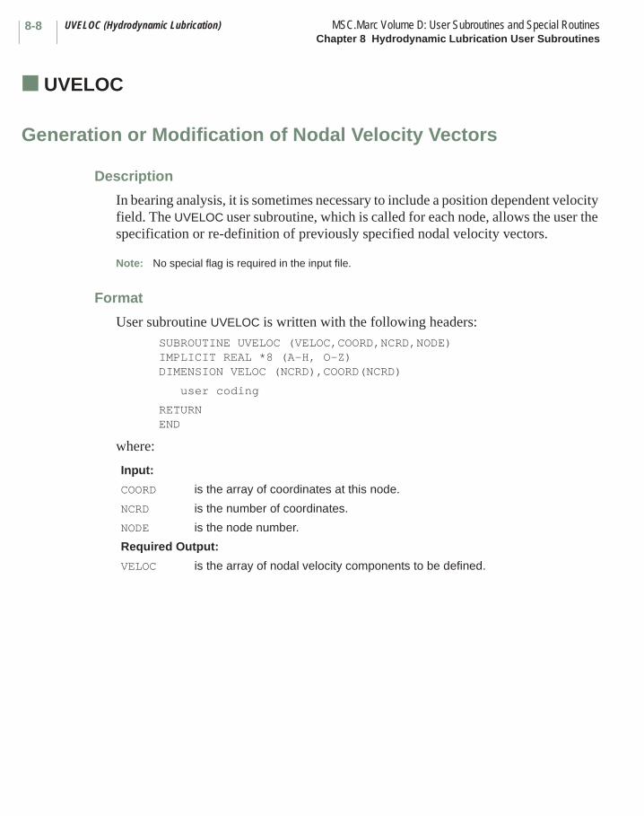
UVELOC (Hydrodynamic Lubrication) MSC.Marc Volume D: User Subroutines and Special RoutinesChapter 8 Hydrodynamic Lubrication User Subroutines
8-8
■ UVELOC (Hydrodynamic Lubrication)
Generation or Modification of Nodal Velocity Vectors
Description
In bearing analysis, it is sometimes necessary to include a position dependent velocity field. The UVELOC user subroutine, which is called for each node, allows the user the specification or re-definition of previously specified nodal velocity vectors.
Note: No special flag is required in the input file.
Format
User subroutine UVELOC is written with the following headers:SUBROUTINE UVELOC (VELOC,COORD,NCRD,NODE) IMPLICIT REAL *8 (A-H, O-Z)DIMENSION VELOC (NCRD),COORD(NCRD)
user coding
RETURNEND
where:
Input:
COORD is the array of coordinates at this node.
NCRD is the number of coordinates.
NODE is the node number.
Required Output:
VELOC is the array of nodal velocity components to be defined.
Chapter 9 Special Routines — MSC.Marc Post File Processor List
Special Subroutine Page
PLDUMP2000/PLDUMP . . . . . . . . . . . . . . . . . . . . . . . . . . . . . . . . . . . . . . . . . . . . . . 9-2
CHAPTER
9 Special Routines — MSC.Marc Post File Processor List
Chapter 9 Special Routines — MSC.Marc Post File Processor
This chapter discusses a stand-alone program that provides examination of the postprocessing file created by the POST option. This allows the user to perform additional calculations based upon results calculated in MSC.Marc, and to create a post file. These results can then be viewed with MSC.Marc Mentat or MSC.Patran.
CHAPTER
9 Special Routines — MSC.Marc Post File Processor

PLDUMP2000/PLDUMP MSC.Marc Volume D: User Subroutines and Special RoutinesChapter 9 Special Routines — MSC.Marc Post File Processor
9-2
■ PLDUMP2000/PLDUMP
MSC.Marc Post File Processor
PLDUMP2000 is a small utility programs which can be used to access, analyze, convert, and process MSC.Marc binary and formatted post files. PLDUMP2000 should be used for post files with revision 9 or greater written by MSC.Marc 2000 and newer versions. The source is supplied at no additional charge to MSC.Marc customers and is available on the MSC.Marc installation media. The user can modify this source as necessary to suit his requirements.
When PLDUMP2000 is executed, the user is asked several questions, as follows (the example answers given in italics show the conversion of 12 increments of a binary post file jobname.t16 into a formatted post file newpost.t19):
1. Dump output file name: for example, post.txt.
The amount of data written into this file depends on the answer to question 2.
2. Write post data to output option: for example, p.
Valid responses are:
n or none – do not write post file to outputp or partial – write analysis control data to outputf or full – write entire post file to output
3. Type of post file to read: for example, b.
Valid responses are:
b or binary – to read a binary filef or formatted – to read a formatted file
4. Name of post file to read: for example, jobname.t16.
5. Type of post file to write: for example, f.
Valid responses are:
n or none – do not write a new post fileb or binary – write a new binary filef or formatted – write a new formatted file
6. New post file name: for example, newpost.t19.

9-3MSC.Marc Volume D: User Subroutines and Special Routines PLDUMP2000/PLDUMPChapter 9 Special Routines — MSC.Marc Post File Processor
7. User data processing option: for example, n.
Valid responses are:
n or no – no user data processing; default pldump2000/pldump is usedy or yes – user data processing; only if the source of pldump2000/pldump
has been modified by the user
8. Number of increments to process: for example, 12.
Processing stops if this number of increments has been processed. To process only non-incremental data, enter a 0.

PLDUMP2000/PLDUMP MSC.Marc Volume D: User Subroutines and Special RoutinesChapter 9 Special Routines — MSC.Marc Post File Processor
9-4
MSC.Marc Post File Layout (Revision 9 or Higher): PLDUMP 2000
The revision 9 (or higher) post file is subdivided into blocks with each block having a unique number and name. For each block, a description is given below, following the Fortran code of PLDUMP2000, both for formatted and binary post files. First, the block number and name are given. Next, the way in which the data is read is shown. Finally, the data read is explained.
The post file for revision 12 has seven new blocks:
53000 - Points
52100 - Curves
53200 - Surfaces
53300 - Attach Nodes
53400 - Attach Edges
53500 - Attach Faces
53600 - Boundary Conditions
BLOCK 501nn - analysis title ****************************
read(formatted,’(a70)’) blkbegin read(formatted,’(a70)’) title(1:70) read(formatted,’( a5)’) blkend
read(binary) (ibeg(ijk),ijk=1,70) write(blkbegin,’(70a1)’) blkbegin read(binary) (ititle(ijk),ijk=1,70) write(title(1:70),’(70a1)’) (ititle(ijk),ijk=1,70) read(binary) (iend(ijk),ijk=1,5) write(blkbegin,’(5a1)’) blkend
blkbegin = =beg=50100 (Analysis Title) title = title of analysis blkend = =end=
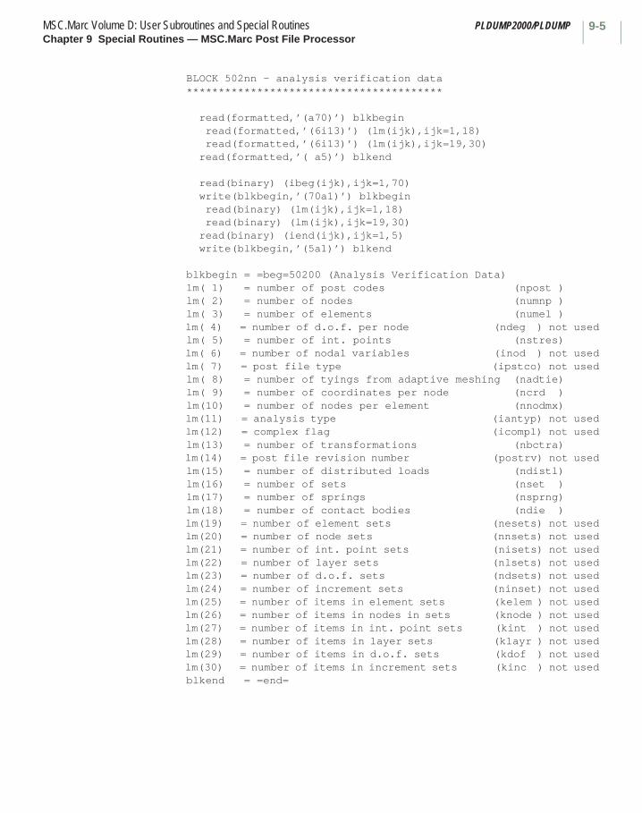
9-5MSC.Marc Volume D: User Subroutines and Special Routines PLDUMP2000/PLDUMPChapter 9 Special Routines — MSC.Marc Post File Processor
BLOCK 502nn - analysis verification data ****************************************
read(formatted,’(a70)’) blkbegin read(formatted,’(6i13)’) (lm(ijk),ijk=1,18) read(formatted,’(6i13)’) (lm(ijk),ijk=19,30) read(formatted,’( a5)’) blkend
read(binary) (ibeg(ijk),ijk=1,70) write(blkbegin,’(70a1)’) blkbegin read(binary) (lm(ijk),ijk=1,18) read(binary) (lm(ijk),ijk=19,30) read(binary) (iend(ijk),ijk=1,5) write(blkbegin,’(5a1)’) blkend
blkbegin = =beg=50200 (Analysis Verification Data) lm( 1) = number of post codes (npost ) lm( 2) = number of nodes (numnp ) lm( 3) = number of elements (numel ) lm( 4) = number of d.o.f. per node (ndeg ) not used lm( 5) = number of int. points (nstres) lm( 6) = number of nodal variables (inod ) not used lm( 7) = post file type (ipstco) not used lm( 8) = number of tyings from adaptive meshing (nadtie) lm( 9) = number of coordinates per node (ncrd ) lm(10) = number of nodes per element (nnodmx) lm(11) = analysis type (iantyp) not used lm(12) = complex flag (icompl) not used lm(13) = number of transformations (nbctra) lm(14) = post file revision number (postrv) not used lm(15) = number of distributed loads (ndistl) lm(16) = number of sets (nset ) lm(17) = number of springs (nsprng) lm(18) = number of contact bodies (ndie ) lm(19) = number of element sets (nesets) not used lm(20) = number of node sets (nnsets) not used lm(21) = number of int. point sets (nisets) not used lm(22) = number of layer sets (nlsets) not used lm(23) = number of d.o.f. sets (ndsets) not used lm(24) = number of increment sets (ninset) not used lm(25) = number of items in element sets (kelem ) not used lm(26) = number of items in nodes in sets (knode ) not used lm(27) = number of items in int. point sets (kint ) not used lm(28) = number of items in layer sets (klayr ) not used lm(29) = number of items in d.o.f. sets (kdof ) not used lm(30) = number of items in increment sets (kinc ) not used blkend = =end=
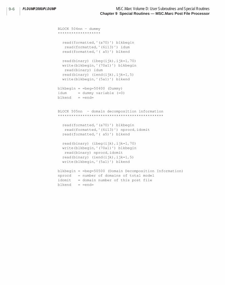
PLDUMP2000/PLDUMP MSC.Marc Volume D: User Subroutines and Special RoutinesChapter 9 Special Routines — MSC.Marc Post File Processor
9-6
BLOCK 504nn - dummy *******************
read(formatted,’(a70)’) blkbegin read(formatted,’(6i13)’) idum read(formatted,’( a5)’) blkend
read(binary) (ibeg(ijk),ijk=1,70) write(blkbegin,’(70a1)’) blkbegin read(binary) idum read(binary) (iend(ijk),ijk=1,5) write(blkbegin,’(5a1)’) blkend
blkbegin = =beg=50400 (Dummy) idum = dummy variable (=0) blkend = =end=
BLOCK 505nn - domain decomposition information ***********************************************
read(formatted,’(a70)’) blkbegin read(formatted,’(6i13)’) nprocd,idomit read(formatted,’( a5)’) blkend
read(binary) (ibeg(ijk),ijk=1,70) write(blkbegin,’(70a1)’) blkbegin read(binary) nprocd,idomit read(binary) (iend(ijk),ijk=1,5) write(blkbegin,’(5a1)’) blkend
blkbegin = =beg=50500 (Domain Decomposition Information) nprocd = number of domains of total model idomit = domain number of this post file blkend = =end=

9-7MSC.Marc Volume D: User Subroutines and Special Routines PLDUMP2000/PLDUMPChapter 9 Special Routines — MSC.Marc Post File Processor
BLOCK 506nn - element variable postcodes **************************************** if(npost.gt.0) then
read(formatted,’(a70)’) blkbegin do ijk=1,npost read(formatted,’(i13,a24)’) ipost,cpost enddo read(formatted,’( a5)’) blkend
read(binary) (ibeg(ijk),ijk=1,70) write(blkbegin,’(70a1)’) blkbegin do ijk=1,npost read(binary) ipost,(iname(ijl),ijl=1,24) write(cpost,’(24a1)’) (iname(ijl),ijl=1,24) enddo read(binary) (iend(ijk),ijk=1,5) write(blkbegin,’(5a1)’) blkend
endif
blkbegin = =beg=50600 (Element Variable Postcodes) npost = number of element post variable (from BLOCK 502nn) ipost = element post code (see manual Volume C model definition option POST) + 1000 * layer number for post variable ijk cpost = character string with name to be given to post variable ijk (see manual Volume C model definition option POST) blkend = =end=
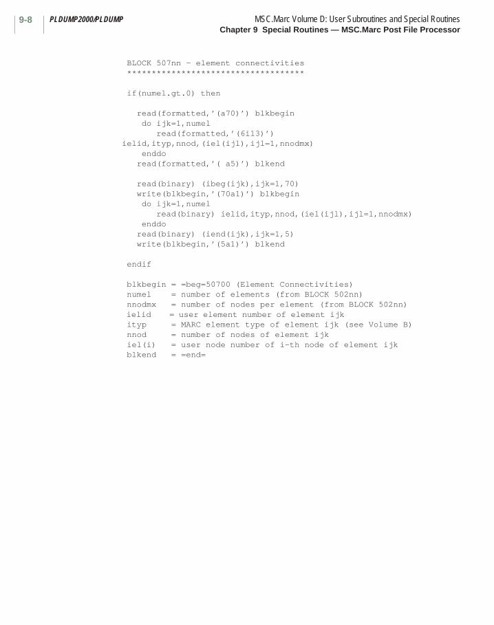
PLDUMP2000/PLDUMP MSC.Marc Volume D: User Subroutines and Special RoutinesChapter 9 Special Routines — MSC.Marc Post File Processor
9-8
BLOCK 507nn - element connectivities ************************************
if(numel.gt.0) then
read(formatted,’(a70)’) blkbegin do ijk=1,numel read(formatted,’(6i13)’) ielid,ityp,nnod,(iel(ijl),ijl=1,nnodmx) enddo read(formatted,’( a5)’) blkend
read(binary) (ibeg(ijk),ijk=1,70) write(blkbegin,’(70a1)’) blkbegin do ijk=1,numel read(binary) ielid,ityp,nnod,(iel(ijl),ijl=1,nnodmx) enddo read(binary) (iend(ijk),ijk=1,5) write(blkbegin,’(5a1)’) blkend
endif
blkbegin = =beg=50700 (Element Connectivities) numel = number of elements (from BLOCK 502nn) nnodmx = number of nodes per element (from BLOCK 502nn) ielid = user element number of element ijk ityp = MARC element type of element ijk (see Volume B) nnod = number of nodes of element ijk iel(i) = user node number of i-th node of element ijk blkend = =end=
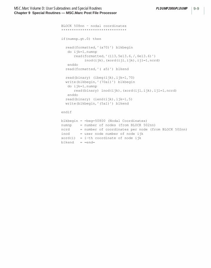
9-9MSC.Marc Volume D: User Subroutines and Special Routines PLDUMP2000/PLDUMPChapter 9 Special Routines — MSC.Marc Post File Processor
BLOCK 508nn - nodal coordinates ******************************* if(numnp.gt.0) then
read(formatted,’(a70)’) blkbegin do ijk=1,numnp read(formatted,’(i13,5e13.6,/,6e13.6)’) inod(ijk),(xord(ijl,ijk),ijl=1,ncrd) enddo read(formatted,’( a5)’) blkend
read(binary) (ibeg(ijk),ijk=1,70) write(blkbegin,’(70a1)’) blkbegin do ijk=1,numnp read(binary) inod(ijk),(xord(ijl,ijk),ijl=1,ncrd) enddo read(binary) (iend(ijk),ijk=1,5) write(blkbegin,’(5a1)’) blkend
endif
blkbegin = =beg=50800 (Nodal Coordinates) numnp = number of nodes (from BLOCK 502nn) ncrd = number of coordinates per node (from BLOCK 502nn) inod = user node number of node ijk xord(i) = i-th coordinate of node ijk blkend = =end=
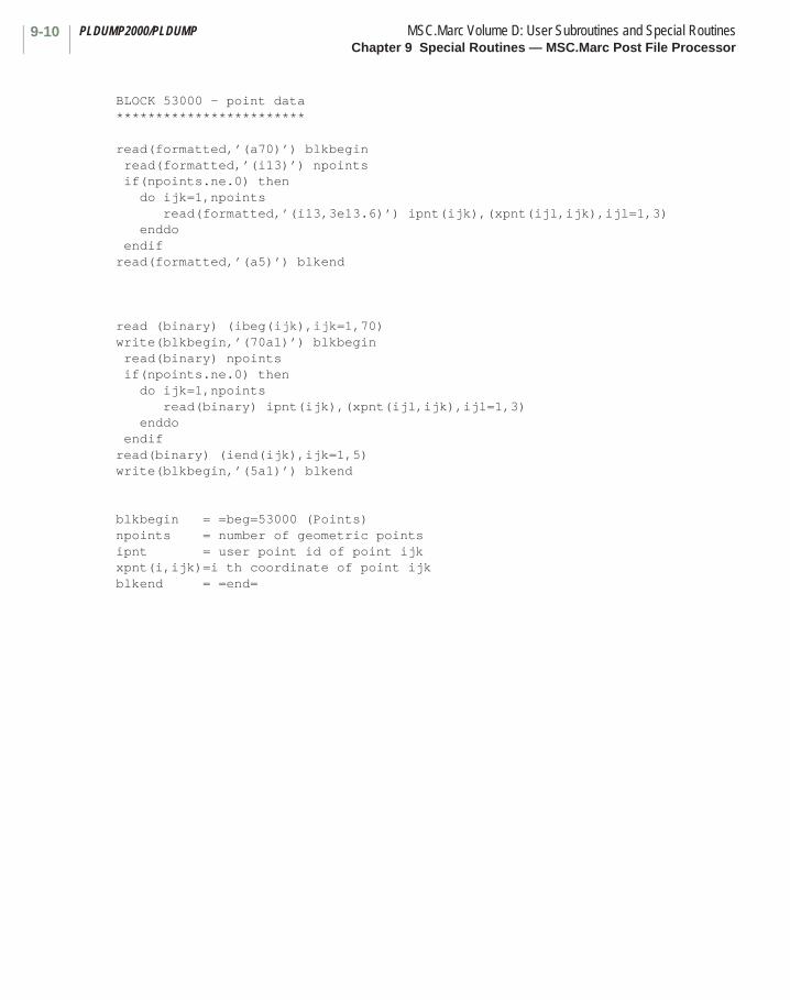
PLDUMP2000/PLDUMP MSC.Marc Volume D: User Subroutines and Special RoutinesChapter 9 Special Routines — MSC.Marc Post File Processor
9-10
BLOCK 53000 - point data************************
read(formatted,’(a70)’) blkbegin read(formatted,’(i13)’) npoints if(npoints.ne.0) then do ijk=1,npoints read(formatted,’(i13,3e13.6)’) ipnt(ijk),(xpnt(ijl,ijk),ijl=1,3) enddo endifread(formatted,’(a5)’) blkend
read (binary) (ibeg(ijk),ijk=1,70)write(blkbegin,’(70a1)’) blkbegin read(binary) npoints if(npoints.ne.0) then do ijk=1,npoints read(binary) ipnt(ijk),(xpnt(ijl,ijk),ijl=1,3) enddo endifread(binary) (iend(ijk),ijk=1,5)write(blkbegin,’(5a1)’) blkend
blkbegin = =beg=53000 (Points) npoints = number of geometric pointsipnt = user point id of point ijkxpnt(i,ijk)=i th coordinate of point ijkblkend = =end=
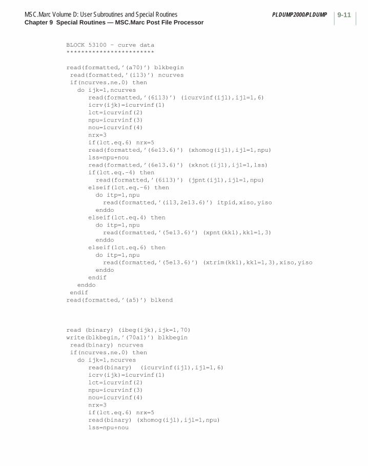
9-11MSC.Marc Volume D: User Subroutines and Special Routines PLDUMP2000/PLDUMPChapter 9 Special Routines — MSC.Marc Post File Processor
BLOCK 53100 - curve data************************
read(formatted,’(a70)’) blkbegin read(formatted,’(i13)’) ncurves if(ncurves.ne.0) then do ijk=1,ncurves read(formatted,’(6i13)’) (icurvinf(ijl),ijl=1,6) icrv(ijk)=icurvinf(1) lct=icurvinf(2) npu=icurvinf(3) nou=icurvinf(4) nrx=3 if(lct.eq.6) nrx=5 read(formatted,’(6e13.6)’) (xhomog(ijl),ijl=1,npu) lss=npu+nou read(formatted,’(6e13.6)’) (xknot(ijl),ijl=1,lss) if(lct.eq.-4) then read(formatted,’(6i13)’) (jpnt(ijl),ijl=1,npu) elseif(lct.eq.-6) then do itp=1,npu read(formatted,’(i13,2e13.6)’) itpid,xiso,yiso enddo elseif(lct.eq.4) then do itp=1,npu read(formatted,’(5e13.6)’) (xpnt(kk1),kk1=1,3) enddo elseif(lct.eq.6) then do itp=1,npu read(formatted,’(5e13.6)’) (xtrim(kk1),kk1=1,3),xiso,yiso enddo endif enddo endifread(formatted,’(a5)’) blkend
read (binary) (ibeg(ijk),ijk=1,70)write(blkbegin,’(70a1)’) blkbegin read(binary) ncurves if(ncurves.ne.0) then do ijk=1,ncurves read(binary) (icurvinf(ijl),ijl=1,6) icrv(ijk)=icurvinf(1) lct=icurvinf(2) npu=icurvinf(3) nou=icurvinf(4) nrx=3 if(lct.eq.6) nrx=5 read(binary) (xhomog(ijl),ijl=1,npu) lss=npu+nou

PLDUMP2000/PLDUMP MSC.Marc Volume D: User Subroutines and Special RoutinesChapter 9 Special Routines — MSC.Marc Post File Processor
9-12
read(binary) (xknot(ijl),ijl=1,lss) if(lct.eq.-4) then read(binary) (jpnt(ijl),ijl=1,npu) elseif(lct.eq.-6) then do itp=1,npu read(binary)itpid,xiso,yiso enddo elseif(lct.eq.4) then do itp=1,npu read(binary) (xpnt(kk1),kk1=1,3) enddo elseif(lct.eq.6) then do itp=1,npu read(binary) (xtrim(kk1),kk1=1,3),xiso,yiso enddo endif enddo endifread(binary) (iend(ijk),ijk=1,5)write(blkbegin,’(5a1)’) blkend blkbegin = =beg=53100 (Curves) ncurves = number of geometric curvesicurvinf(1)= user curve id of curve ijkicurvinf(2)= curve type -4 -NURB curve - referencing previously defined points +4 -NURB curve - not referencing previously defined points -6 -Trimming curve on surface - referencing previously defined points +6 -Trimming curve on surface - not referencing previously defined pointsicurvinf(3)= number of pointsicurvinf(4)= order of curveicurvinf(5)= not usedicurvinf(6)= not usedxhomog = homogeneous coordinates of points on curvexknot = knot vector of curvejpnt = array of point idsxpnt = coordinates of points on curvextrim = real coordinates of points on trimming curvexiso,yiso = isoparametric coordinates of points on trimming curve relative to surfaceitpid = point id of trimming point blkend = =end=
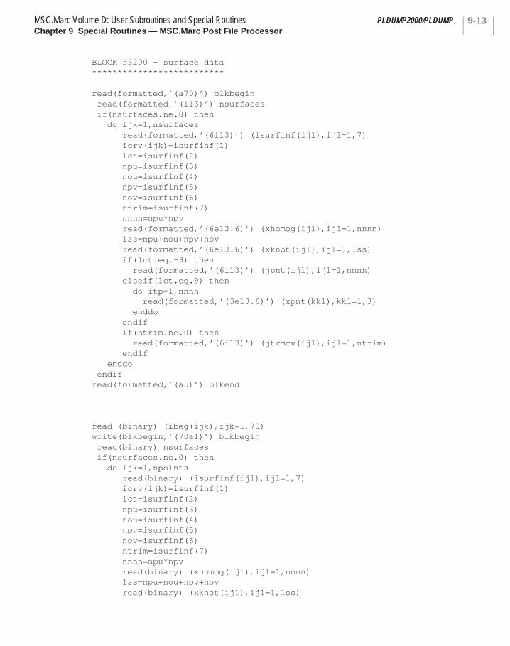
9-13MSC.Marc Volume D: User Subroutines and Special Routines PLDUMP2000/PLDUMPChapter 9 Special Routines — MSC.Marc Post File Processor
BLOCK 53200 - surface data**************************
read(formatted,’(a70)’) blkbegin read(formatted,’(i13)’) nsurfaces if(nsurfaces.ne.0) then do ijk=1,nsurfaces read(formatted,’(6i13)’) (isurfinf(ijl),ijl=1,7) icrv(ijk)=isurfinf(1) lct=isurfinf(2) npu=isurfinf(3) nou=isurfinf(4) npv=isurfinf(5) nov=isurfinf(6) ntrim=isurfinf(7) nnnn=npu*npv read(formatted,’(6e13.6)’) (xhomog(ijl),ijl=1,nnnn) lss=npu+nou+npv+nov read(formatted,’(6e13.6)’) (xknot(ijl),ijl=1,lss) if(lct.eq.-9) then read(formatted,’(6i13)’) (jpnt(ijl),ijl=1,nnnn) elseif(lct.eq.9) then do itp=1,nnnn read(formatted,’(3e13.6)’) (xpnt(kk1),kk1=1,3) enddo endif if(ntrim.ne.0) then read(formatted,’(6i13)’) (jtrmcv(ijl),ijl=1,ntrim) endif enddo endifread(formatted,’(a5)’) blkend
read (binary) (ibeg(ijk),ijk=1,70)write(blkbegin,’(70a1)’) blkbegin read(binary) nsurfaces if(nsurfaces.ne.0) then do ijk=1,npoints read(binary) (isurfinf(ijl),ijl=1,7) icrv(ijk)=isurfinf(1) lct=isurfinf(2) npu=isurfinf(3) nou=isurfinf(4) npv=isurfinf(5) nov=isurfinf(6) ntrim=isurfinf(7) nnnn=npu*npv read(binary) (xhomog(ijl),ijl=1,nnnn) lss=npu+nou+npv+nov read(binary) (xknot(ijl),ijl=1,lss)
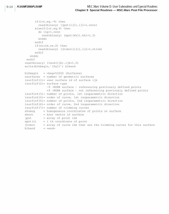
PLDUMP2000/PLDUMP MSC.Marc Volume D: User Subroutines and Special RoutinesChapter 9 Special Routines — MSC.Marc Post File Processor
9-14
if(lct.eq.-9) then read(binary) (jpnt(ijl),ijl=1,nnnn) elseif(lct.eq.9) then do itp=1,nnnn read(binary) (xpnt(kk1),kk1=1,3) enddo endif if(ntrim.ne.0) then read(binary) (jtrmcv(ijl),ijl=1,ntrim) endif enddo endifread(binary) (iend(ijk),ijk=1,5)write(blkbegin,’(5a1)’) blkend blkbegin = =beg=53200 (Surfaces) nsurfaces = number of geometric surfacesisurfinf(1)= user surface id of surface ijkisurfinf(2)= surface type -9 -NURB surface - referencing previously defined points +9 -NURB surface - not referencing previously defined pointsisurfinf(3)= number of points, 1st isoparametric directionisurfinf(4)= order of curve, 1st isoparametric directionisurfinf(5)= number of points, 2nd isoparametric directionisurfinf(6)= order of curve, 2nd isoparametric directionisurfinf(7)= number of trimming curvesxhomog = homogeneous coordinates of points on surfacexknot = knot vector of surfacejpnt = array of point idsxpnt(i) = i th coordinate of point jtrmcv = array of curve ids that are the trimming curves for this surfaceblkend = =end=

9-15MSC.Marc Volume D: User Subroutines and Special Routines PLDUMP2000/PLDUMPChapter 9 Special Routines — MSC.Marc Post File Processor
BLOCK 53300 - attach nodes**************************
read(formatted,’(a70)’) blkbegin read(formatted,’(i13)’) natpts if(natpts.ne.0) then do ijk=1,natpts read(formatted,’(6i13)’) jpoint(ijk),jnode(ijk) enddo endifread(formatted,’(a5)’) blkend
read (binary) (ibeg(ijk),ijk=1,70)write(blkbegin,’(70a1)’) blkbegin read(binary) natpts if(natpts.ne.0) then do ijk=1,natpts read(binary) jpoint(ijk),jnode(ijk) enddo endifread(binary) (iend(ijk),ijk=1,5)write(blkbegin,’(5a1)’) blkend blkbegin = =beg=53300 (Attach Nodes) natpts = number of nodes attached to pointsjpoint(ijk)= point id for ijk th nodejnode(ijk) = node id for ith th nodeblkend = =end=
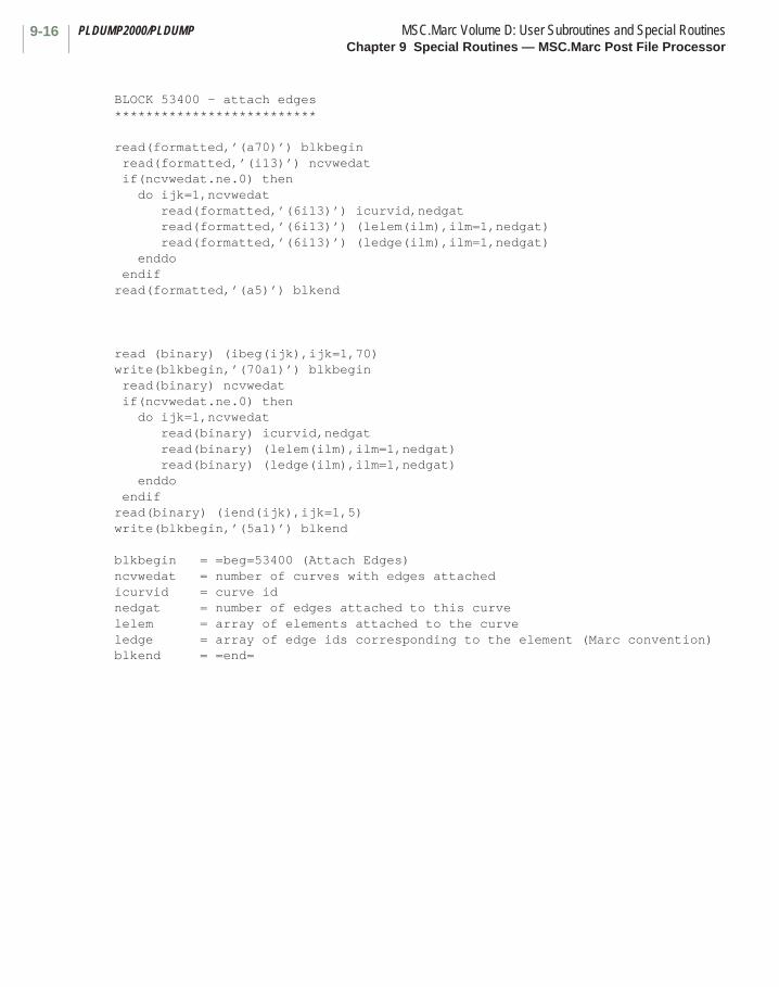
PLDUMP2000/PLDUMP MSC.Marc Volume D: User Subroutines and Special RoutinesChapter 9 Special Routines — MSC.Marc Post File Processor
9-16
BLOCK 53400 - attach edges**************************
read(formatted,’(a70)’) blkbegin read(formatted,’(i13)’) ncvwedat if(ncvwedat.ne.0) then do ijk=1,ncvwedat read(formatted,’(6i13)’) icurvid,nedgat read(formatted,’(6i13)’) (lelem(ilm),ilm=1,nedgat) read(formatted,’(6i13)’) (ledge(ilm),ilm=1,nedgat) enddo endifread(formatted,’(a5)’) blkend
read (binary) (ibeg(ijk),ijk=1,70)write(blkbegin,’(70a1)’) blkbegin read(binary) ncvwedat if(ncvwedat.ne.0) then do ijk=1,ncvwedat read(binary) icurvid,nedgat read(binary) (lelem(ilm),ilm=1,nedgat) read(binary) (ledge(ilm),ilm=1,nedgat) enddo endifread(binary) (iend(ijk),ijk=1,5)write(blkbegin,’(5a1)’) blkend blkbegin = =beg=53400 (Attach Edges) ncvwedat = number of curves with edges attachedicurvid = curve idnedgat = number of edges attached to this curvelelem = array of elements attached to the curveledge = array of edge ids corresponding to the element (Marc convention)blkend = =end=

9-17MSC.Marc Volume D: User Subroutines and Special Routines PLDUMP2000/PLDUMPChapter 9 Special Routines — MSC.Marc Post File Processor
BLOCK 53500 - attach faces**************************
read(formatted,’(a70)’) blkbegin read(formatted,’(i13)’) nsfwfcat if(nsfwfcat.ne.0) then do ijk=1,nsfwfcat read(formatted,’(6i13)’) isurfid,nfaceat read(formatted,’(6i13)’) (lelem(ilm),ilm=1,nfaceat) read(formatted,’(6i13)’) (lface(ilm),ilm=1,nfaceat) enddo endifread(formatted,’(a5)’) blkend
read (binary) (ibeg(ijk),ijk=1,70)write(blkbegin,’(70a1)’) blkbegin read(binary) nsfwfcat if(nsfwfcat.ne.0) then do ijk=1,nsfwfcat read(binary) isurfid,nfaceat read(binary) (lelem(ilm),ilm=1,nfaceat) read(binary) (lface(ilm),ilm=1,nfaceat) enddo endifread(binary) (iend(ijk),ijk=1,5)write(blkbegin,’(5a1)’) blkend blkbegin = =beg=53500 (Attach Faces) nsfwfcat = number of surfaces with faces attachedisurfid = surface idnfaceat = number of faces attached to this surfacelelem = array of elements attached to the surfacelface = array of face ids corresponding to the element (Marc convention)blkend = =end=
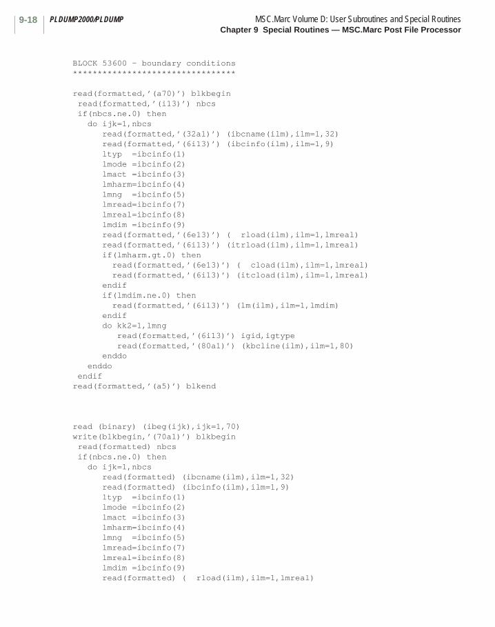
PLDUMP2000/PLDUMP MSC.Marc Volume D: User Subroutines and Special RoutinesChapter 9 Special Routines — MSC.Marc Post File Processor
9-18
BLOCK 53600 - boundary conditions*********************************
read(formatted,’(a70)’) blkbegin read(formatted,’(i13)’) nbcs if(nbcs.ne.0) then do ijk=1,nbcs read(formatted,’(32a1)’) (ibcname(ilm),ilm=1,32) read(formatted,’(6i13)’) (ibcinfo(ilm),ilm=1,9) ltyp =ibcinfo(1) lmode =ibcinfo(2) lmact =ibcinfo(3) lmharm=ibcinfo(4) lmng =ibcinfo(5) lmread=ibcinfo(7) lmreal=ibcinfo(8) lmdim =ibcinfo(9) read(formatted,’(6e13)’) ( rload(ilm),ilm=1,lmreal) read(formatted,’(6i13)’) (itrload(ilm),ilm=1,lmreal) if(lmharm.gt.0) then read(formatted,’(6e13)’) ( cload(ilm),ilm=1,lmreal) read(formatted,’(6i13)’) (itcload(ilm),ilm=1,lmreal) endif if(lmdim.ne.0) then read(formatted,’(6i13)’) (lm(ilm),ilm=1,lmdim) endif do kk2=1,lmng read(formatted,’(6i13)’) igid,igtype read(formatted,’(80a1)’) (kbcline(ilm),ilm=1,80) enddo enddo endifread(formatted,’(a5)’) blkend
read (binary) (ibeg(ijk),ijk=1,70)write(blkbegin,’(70a1)’) blkbegin read(formatted) nbcs if(nbcs.ne.0) then do ijk=1,nbcs read(formatted) (ibcname(ilm),ilm=1,32) read(formatted) (ibcinfo(ilm),ilm=1,9) ltyp =ibcinfo(1) lmode =ibcinfo(2) lmact =ibcinfo(3) lmharm=ibcinfo(4) lmng =ibcinfo(5) lmread=ibcinfo(7) lmreal=ibcinfo(8) lmdim =ibcinfo(9) read(formatted) ( rload(ilm),ilm=1,lmreal)
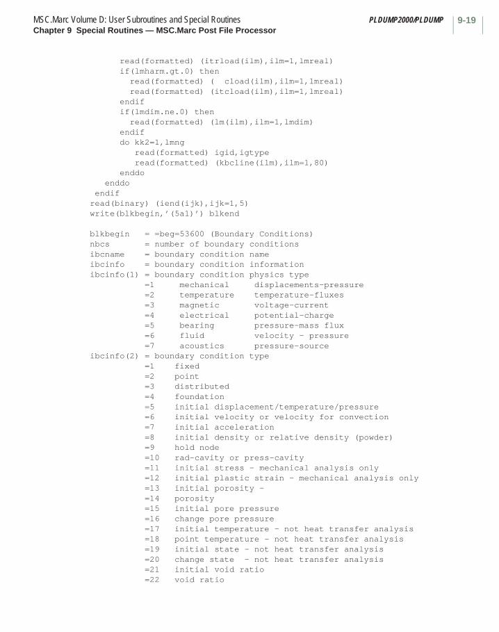
9-19MSC.Marc Volume D: User Subroutines and Special Routines PLDUMP2000/PLDUMPChapter 9 Special Routines — MSC.Marc Post File Processor
read(formatted) (itrload(ilm),ilm=1,lmreal) if(lmharm.gt.0) then read(formatted) ( cload(ilm),ilm=1,lmreal) read(formatted) (itcload(ilm),ilm=1,lmreal) endif if(lmdim.ne.0) then read(formatted) (lm(ilm),ilm=1,lmdim) endif do kk2=1,lmng read(formatted) igid,igtype read(formatted) (kbcline(ilm),ilm=1,80) enddo enddo endifread(binary) (iend(ijk),ijk=1,5)write(blkbegin,’(5a1)’) blkend blkbegin = =beg=53600 (Boundary Conditions) nbcs = number of boundary conditionsibcname = boundary condition nameibcinfo = boundary condition informationibcinfo(1) = boundary condition physics type =1 mechanical displacements-pressure =2 temperature temperature-fluxes =3 magnetic voltage-current =4 electrical potential-charge =5 bearing pressure-mass flux =6 fluid velocity - pressure =7 acoustics pressure-sourceibcinfo(2) = boundary condition type =1 fixed =2 point =3 distributed =4 foundation =5 initial displacement/temperature/pressure =6 initial velocity or velocity for convection =7 initial acceleration =8 initial density or relative density (powder) =9 hold node =10 rad-cavity or press-cavity =11 initial stress - mechanical analysis only =12 initial plastic strain - mechanical analysis only =13 initial porosity - =14 porosity =15 initial pore pressure =16 change pore pressure =17 initial temperature - not heat transfer analysis =18 point temperature - not heat transfer analysis =19 initial state - not heat transfer analysis =20 change state - not heat transfer analysis =21 initial void ratio =22 void ratio

PLDUMP2000/PLDUMP MSC.Marc Volume D: User Subroutines and Special RoutinesChapter 9 Special Routines — MSC.Marc Post File Processor
9-20
=23 initial preconsolidation pressure =24 weld flux (read in readbcweld.f)ibcinfo(3) = active/inactive flagibcinfo(4) = user subroutine used ibcinfo(5) = complex harmonic flag = 0 - real values only = 1 - real and imaginary values = 2 - magnitude and phaseibcinfo(6) = Fourier loading series term (currently always = 0)ibcinfo(7) = Number of geometric typesibcinfo(8) = Number of real data associated with boundary conditionibcinfo(9) = Number of integer data associated with boundary conditionrload = real data associated with boundary conditionitrload = table ids associated with real datacload = imaginary or phase data associated with boundary conditionitcload = table ids associated with imaginary or phase dataigid = geometry numberigtype = geometry type 1= element ids 2= node ids 3= volume 4= surface 5= curve 6= point 7= element set 8= node set 9= polycurve 10= polysurface 11= element-edge 12= element-face 13= elem mn-edge 14= elem mn-face 15= cavity 16= surface-edge 17= curve-face 18= surface mn-edge 19= curve mn-facekbcline = list of location where boundary condition is applied
blkend = =end=

9-21MSC.Marc Volume D: User Subroutines and Special Routines PLDUMP2000/PLDUMPChapter 9 Special Routines — MSC.Marc Post File Processor
BLOCK 509nn - spring data *************************
if(nsprng.gt.0) then
read(formatted,’(a70)’) blkbegin do ijk=1,nsprng read(formatted,’(5i13)’) (ispr(ijl,ijk),ijl=1,5) enddo read(formatted,’( a5)’) blkend
read(binary) (ibeg(ijk),ijk=1,70) write(blkbegin,’(70a1)’) blkbegin do ijk=1,nsprng read(binary) id,node1,idof1,node2,idof2 enddo read(binary) (iend(ijk),ijk=1,5) write(blkbegin,’(5a1)’) blkend
endif
blkbegin = =beg=50900 (Spring Data) nsprng = number of springs (from BLOCK 502nn) id = number of spring ijk node1 = number of first node of spring ijk idof1 = degree of freedom of node1 of spring ijk node2 = number of second node of spring ijk idof2 = degree of freedom of node2 of spring ijk blkend = =end=
BLOCK 510nn - nodal codes and transformation id ***********************************************
read(formatted,’(a70)’) blkbegin read(formatted,’(6i13)’) (inoco(ijl),ijl=1,numnp) read(formatted,’( a5)’) blkend
read(binary) (ibeg(ijk),ijk=1,70) write(blkbegin,’(70a1)’) blkbegin read(binary) (inoco(ijl),ijl=1,numnp) read(binary) (iend(ijk),ijk=1,5) write(blkbegin,’(5a1)’) blkend
blkbegin = =beg=51000 (Nodal Codes and Transformation ID) numnp = number of nodes (from BLOCK 502nn) inoco(i) = nodal code for node i + 1000*transformation number for node i blkend = =end=
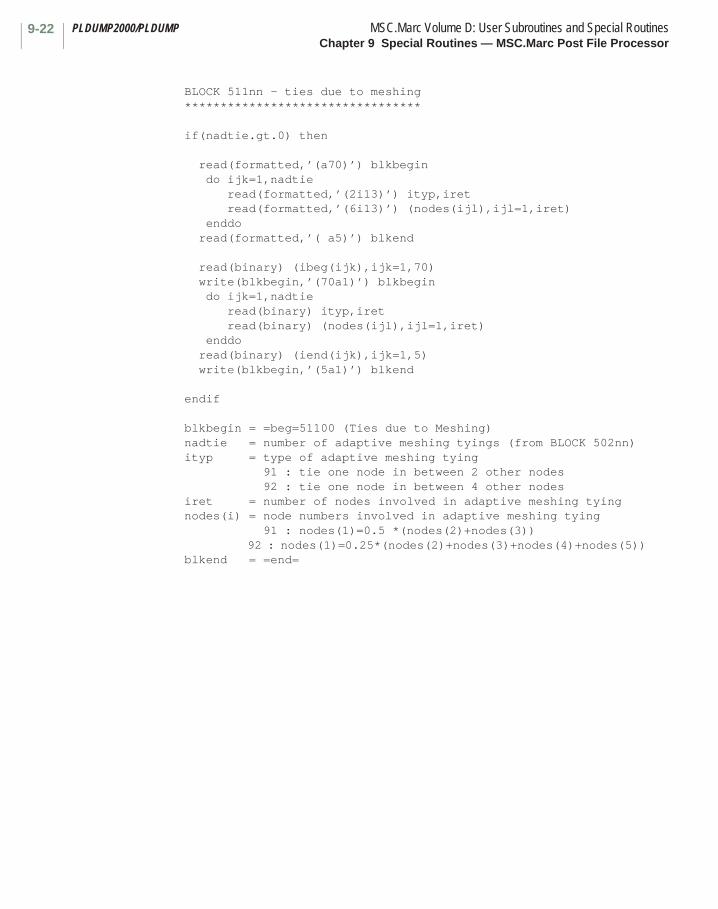
PLDUMP2000/PLDUMP MSC.Marc Volume D: User Subroutines and Special RoutinesChapter 9 Special Routines — MSC.Marc Post File Processor
9-22
BLOCK 511nn - ties due to meshing ********************************* if(nadtie.gt.0) then
read(formatted,’(a70)’) blkbegin do ijk=1,nadtie read(formatted,’(2i13)’) ityp,iret read(formatted,’(6i13)’) (nodes(ijl),ijl=1,iret) enddo read(formatted,’( a5)’) blkend
read(binary) (ibeg(ijk),ijk=1,70) write(blkbegin,’(70a1)’) blkbegin do ijk=1,nadtie read(binary) ityp,iret read(binary) (nodes(ijl),ijl=1,iret) enddo read(binary) (iend(ijk),ijk=1,5) write(blkbegin,’(5a1)’) blkend
endif
blkbegin = =beg=51100 (Ties due to Meshing) nadtie = number of adaptive meshing tyings (from BLOCK 502nn) ityp = type of adaptive meshing tying 91 : tie one node in between 2 other nodes 92 : tie one node in between 4 other nodes iret = number of nodes involved in adaptive meshing tying nodes(i) = node numbers involved in adaptive meshing tying 91 : nodes(1)=0.5 *(nodes(2)+nodes(3)) 92 : nodes(1)=0.25*(nodes(2)+nodes(3)+nodes(4)+nodes(5)) blkend = =end=

9-23MSC.Marc Volume D: User Subroutines and Special Routines PLDUMP2000/PLDUMPChapter 9 Special Routines — MSC.Marc Post File Processor
BLOCK 512nn - transformation matrices ************************************* if(nbctra.gt.0) then
read(formatted,’(a70)’) blkbegin do ijk=1,nbctra read(formatted,’(6e13.6)’) ((d(i1,i2),i1=1,3),i2=1,3) enddo read(formatted,’( a5)’) blkend
read(binary) (ibeg(ijk),ijk=1,70) write(blkbegin,’(70a1)’) blkbegin do ijk=1,nbctra read(binary) ((d(i1,i2),i1=1,3),i2=1,3) enddo read(binary) (iend(ijk),ijk=1,5) write(blkbegin,’(5a1)’) blkend
blkbegin = =beg=51200 (Transformation Matrices) nbctra = number of transformations (from BLOCK 502nn) d(i,j) = transformation matrix for transformation number ijk blkend = =end=
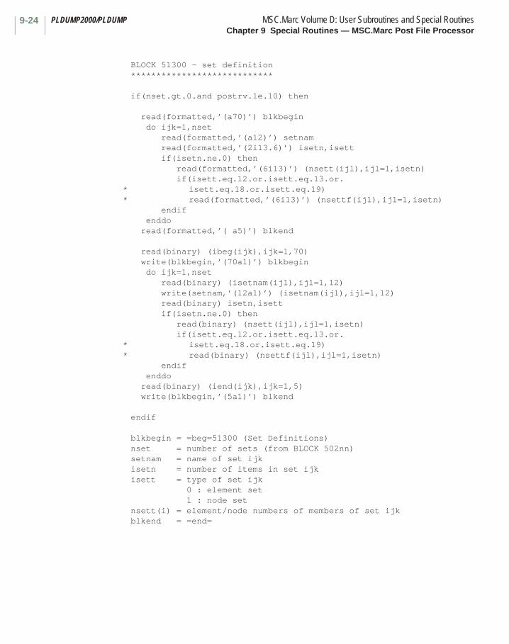
PLDUMP2000/PLDUMP MSC.Marc Volume D: User Subroutines and Special RoutinesChapter 9 Special Routines — MSC.Marc Post File Processor
9-24
BLOCK 51300 - set definition **************************** if(nset.gt.0.and postrv.le.10) then
read(formatted,’(a70)’) blkbegin do ijk=1,nset read(formatted,’(a12)’) setnam read(formatted,’(2i13.6)’) isetn,isett if(isetn.ne.0) then read(formatted,’(6i13)’) (nsett(ijl),ijl=1,isetn) if(isett.eq.12.or.isett.eq.13.or.* isett.eq.18.or.isett.eq.19)* read(formatted,’(6i13)’) (nsettf(ijl),ijl=1,isetn) endif enddo read(formatted,’( a5)’) blkend
read(binary) (ibeg(ijk),ijk=1,70) write(blkbegin,’(70a1)’) blkbegin do ijk=1,nset read(binary) (isetnam(ijl),ijl=1,12) write(setnam,’(12a1)’) (isetnam(ijl),ijl=1,12) read(binary) isetn,isett if(isetn.ne.0) then read(binary) (nsett(ijl),ijl=1,isetn) if(isett.eq.12.or.isett.eq.13.or.* isett.eq.18.or.isett.eq.19)* read(binary) (nsettf(ijl),ijl=1,isetn) endif enddo read(binary) (iend(ijk),ijk=1,5) write(blkbegin,’(5a1)’) blkend
endif
blkbegin = =beg=51300 (Set Definitions) nset = number of sets (from BLOCK 502nn) setnam = name of set ijk isetn = number of items in set ijk isett = type of set ijk 0 : element set 1 : node set nsett(i) = element/node numbers of members of set ijk blkend = =end=
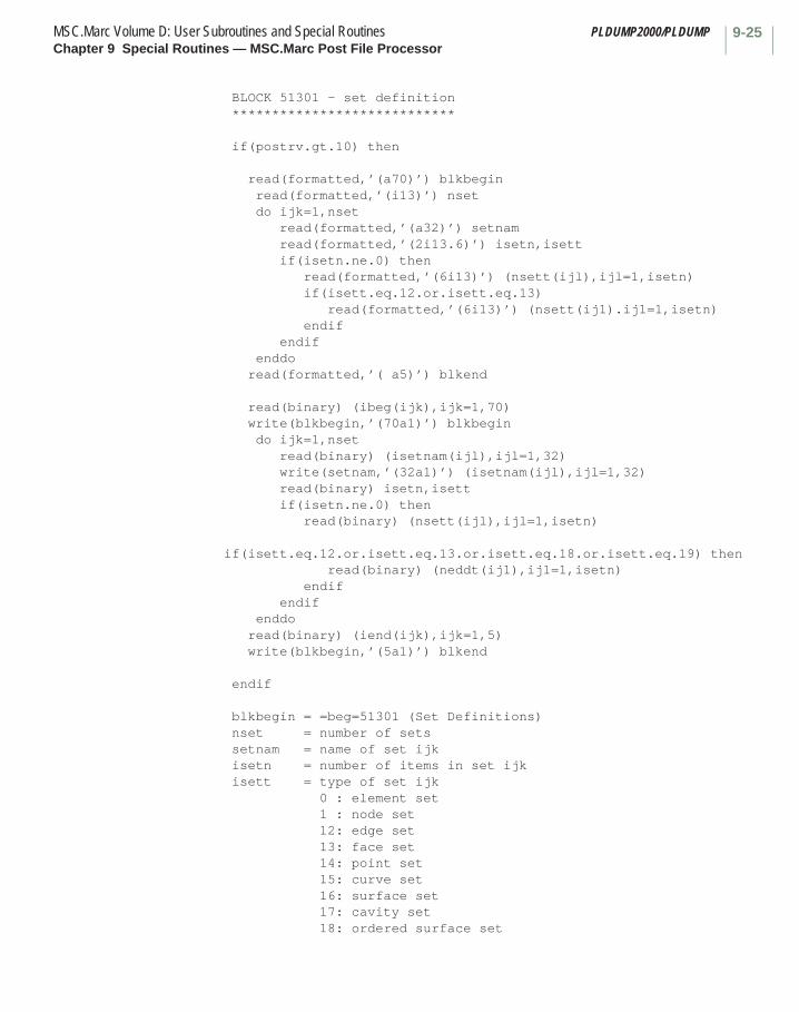
9-25MSC.Marc Volume D: User Subroutines and Special Routines PLDUMP2000/PLDUMPChapter 9 Special Routines — MSC.Marc Post File Processor
BLOCK 51301 - set definition **************************** if(postrv.gt.10) then
read(formatted,’(a70)’) blkbegin read(formatted,’(i13)’) nset do ijk=1,nset read(formatted,’(a32)’) setnam read(formatted,’(2i13.6)’) isetn,isett if(isetn.ne.0) then read(formatted,’(6i13)’) (nsett(ijl),ijl=1,isetn) if(isett.eq.12.or.isett.eq.13) read(formatted,’(6i13)’) (nsett(ij1).ij1=1,isetn) endif endif enddo read(formatted,’( a5)’) blkend
read(binary) (ibeg(ijk),ijk=1,70) write(blkbegin,’(70a1)’) blkbegin do ijk=1,nset read(binary) (isetnam(ijl),ijl=1,32) write(setnam,’(32a1)’) (isetnam(ijl),ijl=1,32) read(binary) isetn,isett if(isetn.ne.0) then read(binary) (nsett(ijl),ijl=1,isetn) if(isett.eq.12.or.isett.eq.13.or.isett.eq.18.or.isett.eq.19) then read(binary) (neddt(ij1),ij1=1,isetn) endif endif enddo read(binary) (iend(ijk),ijk=1,5) write(blkbegin,’(5a1)’) blkend
endif
blkbegin = =beg=51301 (Set Definitions) nset = number of sets setnam = name of set ijk isetn = number of items in set ijk isett = type of set ijk 0 : element set 1 : node set 12: edge set 13: face set 14: point set 15: curve set 16: surface set 17: cavity set 18: ordered surface set

PLDUMP2000/PLDUMP MSC.Marc Volume D: User Subroutines and Special RoutinesChapter 9 Special Routines — MSC.Marc Post File Processor
9-26
19 ordered curve set nsett(i) = element/node numbers of members of set ijk neddt(i) = face/edge number if face/edge set of set ijk blkend = =end=
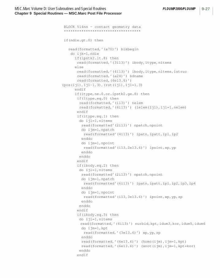
9-27MSC.Marc Volume D: User Subroutines and Special Routines PLDUMP2000/PLDUMPChapter 9 Special Routines — MSC.Marc Post File Processor
BLOCK 514nn - contact geometry data *********************************** if(ndie.gt.0) then
read(formatted,’(a70)’) blkbegin do ijk=1,ndie if(ipstk2.lt.8) then read(formatted,’(3i13)’) ibody,itype,nitems else read(formatted,’(4i13)’) ibody,itype,nitems,istruc
read(formatted,’(a24)’) bdnameread(formatted,(6e13.6)’)
(pos(ij1),ij1-1,3),(rot(ij1),ij1=1,3) endif if(itype,ne.0.or.ipstk2.ge.8) then if(itype.eq.0) then read(formatted,’(i13)’) nelem read(formatted,’(6i13)’) (ielem(ijl),ijl=1,nelem) endif if(itype.eq.1) then do ijl=1,nitems read(formatted’(2i13)’) npatch,npoint do ijm=1,npatch read(formatted’(4i13)’) ipatn,ipatt,ip1,ip2 enddo do ijm=1,npoint read(formatted’(i13,2e13.6)’) ipoint,xp,yp enddo enddo endif if(ibody.eq.2) then do ijl=1,nitems read(formatted’(2i13)’) npatch,npoint do ijm=1,npatch read(formatted’(6i13)’) ipatn,ipatt,ip1,ip2,ip3,ip4 enddo do ijm=1,npoint read(formatted’(i13,3e13.6)’) ipoint,xp,yp,zp enddo enddo endif if(ibody.eq.3) then do ijl=1,nitems read(formatted,’(6i13)’) nurbid,kpt,idum3,kor,idum5,idum6 do ijm=1,kpt read(formatted,’(3e13.6)’) xp,yp,zp enddo read(formatted,’(6e13.6)’) (homo(ijm),ijm=1,kpt) read(formatted,’(6e13.6)’) (xnot(ijm),ijm=1,kpt+kor) enddo endif
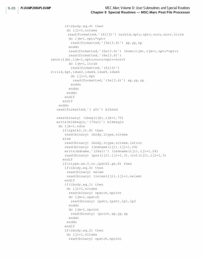
PLDUMP2000/PLDUMP MSC.Marc Volume D: User Subroutines and Special RoutinesChapter 9 Special Routines — MSC.Marc Post File Processor
9-28
if(ibody.eq.4) then do ijl=1,nitems read(formatted,’(6i13)’) nurbid,nptu,nptv,noru,norv,itrim do ijm=1,nptu*nptv read(formatted,’(3e13.6)’) xp,yp,zp enddo read(formatted,’(6e13.6)’) (homo(ijm),ijm=1,nptu*nptv) read(formatted,’(6e13.6)’) (xnot(ijm),ijm=1,nptu+noru+nptv+norv) do ijm=1,itrim read(formatted,’(6i13)’) itriid,kpt,idum3,idum4,idum5,idum6 do ijl=1,kpt read(formatted,’(3e13.6)’) xp,yp,zp enddo enddo enddo endif endif enddo read(formatted,’( a5)’) blkend
read(binary) (ibeg(ijk),ijk=1,70) write(blkbegin,’(70a1)’) blkbegin do ijk=1,ndie if(ipstk2.lt.8) then read(binary) ibody,itype,nitems else read(binary) ibody,itype,nitems,istruc
read(binary) (ibdname(ij1),ij1=1,24)write(bdname,’(24a1)’) (ibdname(ij1),ij1=1,24)read(binary) (pos(ij1),ij1=1,3),(rot(ij1),ij1=1,3)
endif if(itype.ne.0.or.ipstk2.ge.8) then if(ibody.eq.0) then read(binary) nelem read(binary) (ielem(ijl),ijl=1,nelem) endif if(ibody.eq.1) then do ijl=1,nitems read(binary) npatch,npoint do ijm=1,npatch read(binary) ipatn,ipatt,ip1,ip2 enddo do ijm=1,npoint read(binary) ipoint,xp,yp,zp enddo enddo endif if(ibody.eq.2) then do ijl=1,nitems read(binary) npatch,npoint

9-29MSC.Marc Volume D: User Subroutines and Special Routines PLDUMP2000/PLDUMPChapter 9 Special Routines — MSC.Marc Post File Processor
do ijm=1,npatch read(binary) ipatn,ipatt,ip1,ip2,ip3,ip4 enddo do ijm=1,npoint read(binary) ipoint,xp,yp,zp enddo enddo endif if(ibody.eq.3) then do ijl=1,nitems read(binary) nurbid,kpt,idum3,kor,idum5,idum6 do ijm=1,kpt read(binary) xp,yp,zp enddo read(binary) (homo(ijm),ijm=1,kpt) read(binary) (xnot(ijm),ijm=1,kpt+kor) enddo endif if(ibody.eq.4) then do ijl=1,nitems read(binary) nurbid,nptu,nptv,noru,norv,itrim do ijm=1,nptu*nptv read(binary) xp,yp,zp enddo read(binary) (homo(ijm),ijm=1,nptu*nptv) read(binary) (xnot(ijm),ijm=1,nptu+noru+nptv+norv) do ijm=1,itrim read(binary) itriid,kpt,idum3,idum4,idum5,idum6 do ijl=1,kpt read(binary) xp,yp,zp enddo enddo enddo endif endif enddo
endif
blkbegin = =beg=51400 (Contact Geometry Data) ndie = number of contact bodies (from BLOCK 502nn) ibody = number of body ijk itype = type of body ijk 0 : deformable 1 : 2d line elements (type 9) 2 : 3d patch elements (type 18) 3 : 2d curves 4 : 3d surfaces nitems = number of entities in body ijk istruc = physical meaning of body ijk 1 : rigid 2 : deformable structural

PLDUMP2000/PLDUMP MSC.Marc Volume D: User Subroutines and Special RoutinesChapter 9 Special Routines — MSC.Marc Post File Processor
9-30
3 : symmetry 4 : deformable heat-rigid 5 : workpiece (Autoforge only) 6 : deformable acoustic bdnam = name of body ijk pos(i) = position of center of body ijk rot(i) = rotation vector for body ijk nelem = number of elements in deformable body ijk ielem(i) = user element numbers of deformable body ijk npatch = number of patches in body ijk entity ijl npoint = number of points in body ijk entity ijl ipatn = patch number ipatt = patch type (9=line,18=surface) ip1 = first node of patch ip2 = second node of patch ip3 = third node of patch ip4 = fourth node of patch ipoint = point number xp,yp,zp = x-, y- and z-coordinates of point nurbid = identifier of NURBS kpt = number of points for NURBS curve kor = order of NURBS curve nptu = number of points in u-direction for NURBS surface nptv = number of points in v-direction for NURBS surface noru = order of NURBS surface in u-direction norv = order of NURBS surface in v-direction itrim = number of trimming curves of NURBS surface homo(i) = homogeneous coordinates xnot(i) = knot vectors itriid = identifier of trimming curve of NURBS surface blkend = =end=
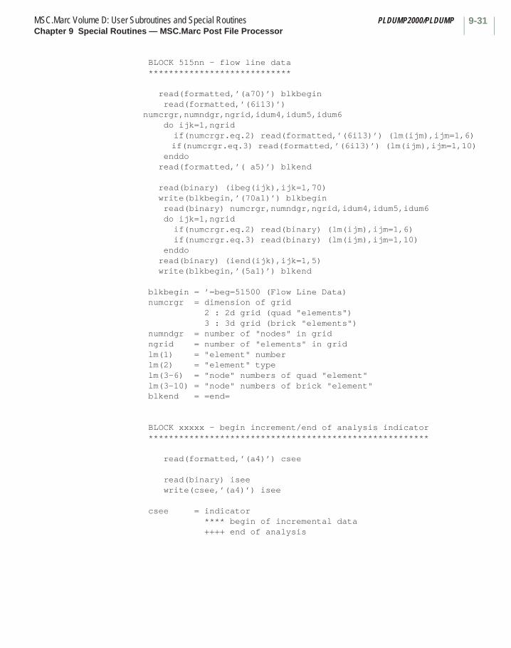
9-31MSC.Marc Volume D: User Subroutines and Special Routines PLDUMP2000/PLDUMPChapter 9 Special Routines — MSC.Marc Post File Processor
BLOCK 515nn - flow line data ****************************
read(formatted,’(a70)’) blkbegin read(formatted,’(6i13)’) numcrgr,numndgr,ngrid,idum4,idum5,idum6 do ijk=1,ngrid if(numcrgr.eq.2) read(formatted,’(6i13)’) (lm(ijm),ijm=1,6) if(numcrgr.eq.3) read(formatted,’(6i13)’) (lm(ijm),ijm=1,10) enddo read(formatted,’( a5)’) blkend
read(binary) (ibeg(ijk),ijk=1,70) write(blkbegin,’(70a1)’) blkbegin read(binary) numcrgr,numndgr,ngrid,idum4,idum5,idum6 do ijk=1,ngrid if(numcrgr.eq.2) read(binary) (lm(ijm),ijm=1,6) if(numcrgr.eq.3) read(binary) (lm(ijm),ijm=1,10) enddo read(binary) (iend(ijk),ijk=1,5) write(blkbegin,’(5a1)’) blkend
blkbegin = ’=beg=51500 (Flow Line Data) numcrgr = dimension of grid 2 : 2d grid (quad "elements") 3 : 3d grid (brick "elements") numndgr = number of "nodes" in grid ngrid = number of "elements" in grid lm(1) = "element" number lm(2) = "element" type lm(3-6) = "node" numbers of quad "element" lm(3-10) = "node" numbers of brick "element" blkend = =end=
BLOCK xxxxx - begin increment/end of analysis indicator *******************************************************
read(formatted,’(a4)’) csee
read(binary) isee write(csee,’(a4)’) isee
csee = indicator **** begin of incremental data ++++ end of analysis
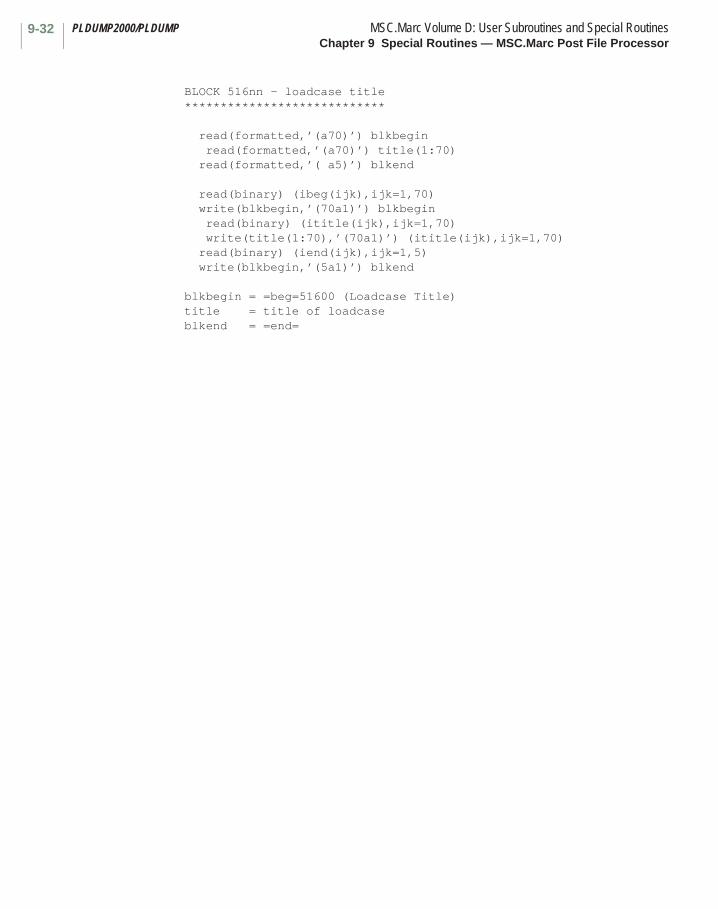
PLDUMP2000/PLDUMP MSC.Marc Volume D: User Subroutines and Special RoutinesChapter 9 Special Routines — MSC.Marc Post File Processor
9-32
BLOCK 516nn - loadcase title ****************************
read(formatted,’(a70)’) blkbegin read(formatted,’(a70)’) title(1:70) read(formatted,’( a5)’) blkend
read(binary) (ibeg(ijk),ijk=1,70) write(blkbegin,’(70a1)’) blkbegin read(binary) (ititle(ijk),ijk=1,70) write(title(1:70),’(70a1)’) (ititle(ijk),ijk=1,70) read(binary) (iend(ijk),ijk=1,5) write(blkbegin,’(5a1)’) blkend
blkbegin = =beg=51600 (Loadcase Title) title = title of loadcase blkend = =end=

9-33MSC.Marc Volume D: User Subroutines and Special Routines PLDUMP2000/PLDUMPChapter 9 Special Routines — MSC.Marc Post File Processor
BLOCK 517nn - integer increment verification data *************************************************
read(formatted,’(a70)’) blkbegin read(formatted,’(6i13)’) (lm(ijk),ijk=1,12) read(formatted,’( a5)’) blkend
read(binary) (ibeg(ijk),ijk=1,70) write(blkbegin,’(70a1)’) blkbegin read(binary) (lm(ijk),ijk=1,12) read(binary) (iend(ijk),ijk=1,5) write(blkbegin,’(5a1)’) blkend
blkbegin = =beg=51701 (Integer Increment Verification Data) lm( 1) = remeshing flag (newmo) 0 : same mesh as before 1 : new mesh lm( 2) = increment number (inc) lm( 3) = sub-increment number (incsub) lm( 4) = analysis type (jantyp) > 100 element variables are written for this increment lm( 5) = number of nodal variables (knod) lm( 6) = number of design variables (ndsvar) lm( 7) = normal/harmonic/modal/buckle flag (ihresp) 0 : normal 1 : modal result 2 : buckle result 3 : real harmonic result 4 : complex harmonic result lm( 8) = number of recycles for this increment lm( 9) = total number of separation recycles lm(10) = total number of cutbacks lm(11) = total number of increment splittings lm(12) = not used blkend = =end=

PLDUMP2000/PLDUMP MSC.Marc Volume D: User Subroutines and Special RoutinesChapter 9 Special Routines — MSC.Marc Post File Processor
9-34
BLOCK 51800 - real increment verification data **********************************************
If post file revision number is 9 (MARC 2000)
read(formatted,’(a70)’) blkbegin read(formatted,’(6e13.6)’) (xlm(ijk),ijk=1,6) read(formatted,’( a5)’) blkend
read(binary) (ibeg(ijk),ijk=1,70) write(blkbegin,’(70a1)’) blkbegin read(binary) (xlm(ijk),ijk=1,6) read(binary) (iend(ijk),ijk=1,5) write(blkbegin,’(5a1)’) blkend
blkbegin = =beg=51800 (Real Increment Verification Data) xlm( 1) = transient time (time) xlm( 2) = modal result : frequency (freq) harmonic result : frequency (freq) buckle result : buckle factor (fact) xlm( 3) = modal result : generalized mass (gmas) xlm( 4) = jantyp = 60 sensitivity check (respon) jantyp = 61 objective function (objec ) xlm( 5) = jantyp = 60 limiting value (rsplim) jantyp = 61 critical constraint (conval) xlm( 6) = not used blkend = =end=
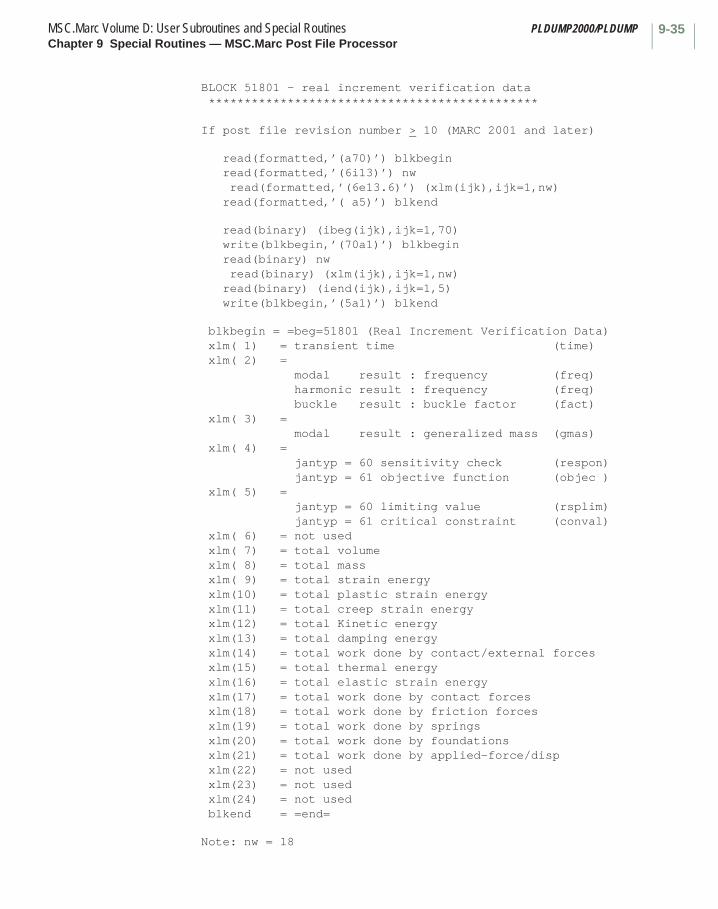
9-35MSC.Marc Volume D: User Subroutines and Special Routines PLDUMP2000/PLDUMPChapter 9 Special Routines — MSC.Marc Post File Processor
BLOCK 51801 - real increment verification data **********************************************
If post file revision number > 10 (MARC 2001 and later)
read(formatted,’(a70)’) blkbegin read(formatted,’(6i13)’) nw
read(formatted,’(6e13.6)’) (xlm(ijk),ijk=1,nw) read(formatted,’( a5)’) blkend
read(binary) (ibeg(ijk),ijk=1,70) write(blkbegin,’(70a1)’) blkbegin
read(binary) nw read(binary) (xlm(ijk),ijk=1,nw) read(binary) (iend(ijk),ijk=1,5) write(blkbegin,’(5a1)’) blkend
blkbegin = =beg=51801 (Real Increment Verification Data) xlm( 1) = transient time (time) xlm( 2) = modal result : frequency (freq) harmonic result : frequency (freq) buckle result : buckle factor (fact) xlm( 3) = modal result : generalized mass (gmas) xlm( 4) = jantyp = 60 sensitivity check (respon) jantyp = 61 objective function (objec ) xlm( 5) = jantyp = 60 limiting value (rsplim) jantyp = 61 critical constraint (conval) xlm( 6) = not used xlm( 7) = total volumexlm( 8) = total massxlm( 9) = total strain energyxlm(10) = total plastic strain energyxlm(11) = total creep strain energyxlm(12) = total Kinetic energyxlm(13) = total damping energyxlm(14) = total work done by contact/external forcesxlm(15) = total thermal energyxlm(16) = total elastic strain energyxlm(17) = total work done by contact forcesxlm(18) = total work done by friction forcesxlm(19) = total work done by springsxlm(20) = total work done by foundationsxlm(21) = total work done by applied-force/dispxlm(22) = not usedxlm(23) = not usedxlm(24) = not usedblkend = =end=
Note: nw = 18
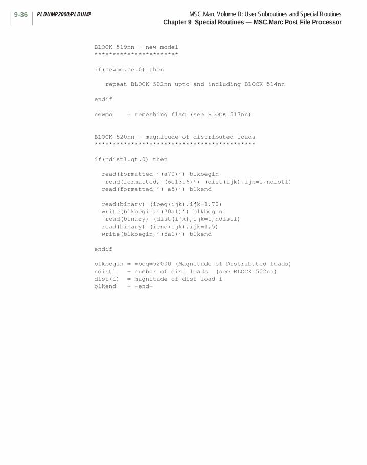
PLDUMP2000/PLDUMP MSC.Marc Volume D: User Subroutines and Special RoutinesChapter 9 Special Routines — MSC.Marc Post File Processor
9-36
BLOCK 519nn - new model ***********************
if(newmo.ne.0) then
repeat BLOCK 502nn upto and including BLOCK 514nn
endif
newmo = remeshing flag (see BLOCK 517nn)
BLOCK 520nn - magnitude of distributed loads ********************************************
if(ndistl.gt.0) then
read(formatted,’(a70)’) blkbegin read(formatted,’(6e13.6)’) (dist(ijk),ijk=1,ndistl) read(formatted,’( a5)’) blkend
read(binary) (ibeg(ijk),ijk=1,70) write(blkbegin,’(70a1)’) blkbegin read(binary) (dist(ijk),ijk=1,ndistl) read(binary) (iend(ijk),ijk=1,5) write(blkbegin,’(5a1)’) blkend
endif
blkbegin = =beg=52000 (Magnitude of Distributed Loads) ndistl = number of dist loads (see BLOCK 502nn) dist(i) = magnitude of dist load i blkend = =end=
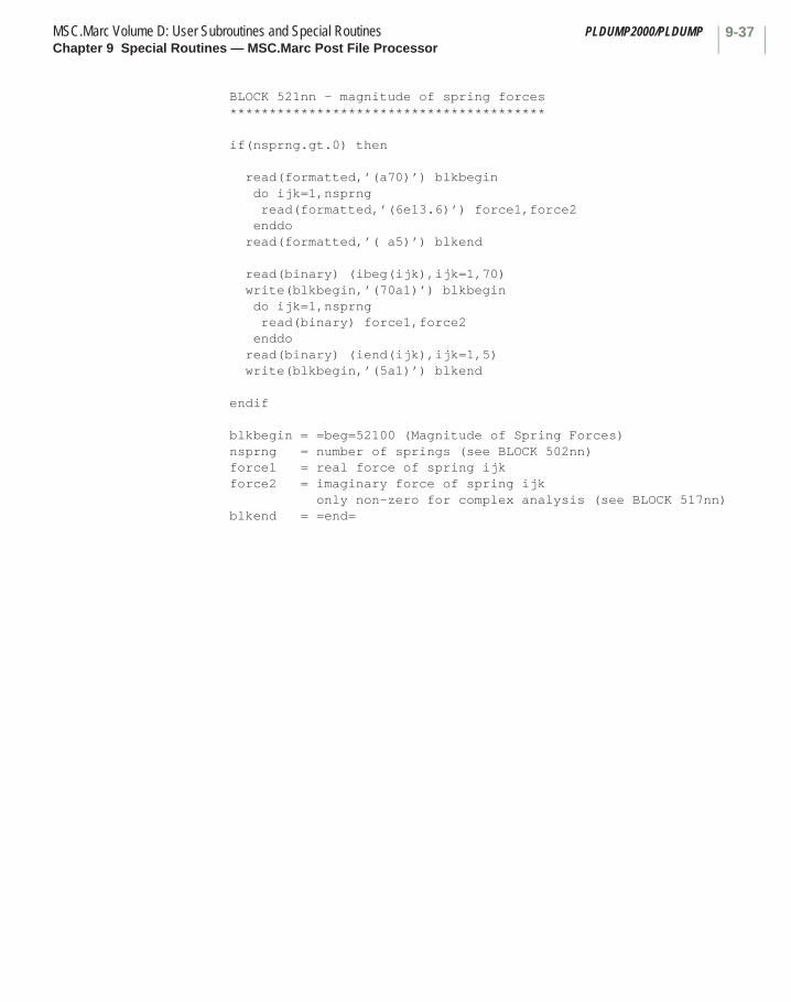
9-37MSC.Marc Volume D: User Subroutines and Special Routines PLDUMP2000/PLDUMPChapter 9 Special Routines — MSC.Marc Post File Processor
BLOCK 521nn - magnitude of spring forces ****************************************
if(nsprng.gt.0) then
read(formatted,’(a70)’) blkbegin do ijk=1,nsprng read(formatted,’(6e13.6)’) force1,force2 enddo read(formatted,’( a5)’) blkend
read(binary) (ibeg(ijk),ijk=1,70) write(blkbegin,’(70a1)’) blkbegin do ijk=1,nsprng read(binary) force1,force2 enddo read(binary) (iend(ijk),ijk=1,5) write(blkbegin,’(5a1)’) blkend
endif
blkbegin = =beg=52100 (Magnitude of Spring Forces) nsprng = number of springs (see BLOCK 502nn) force1 = real force of spring ijk force2 = imaginary force of spring ijk only non-zero for complex analysis (see BLOCK 517nn) blkend = =end=
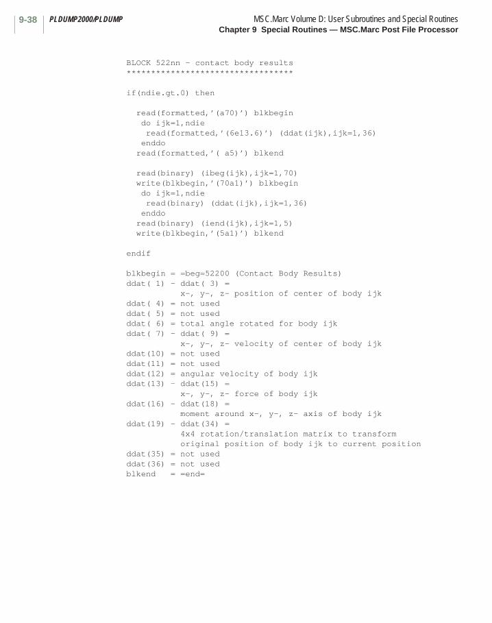
PLDUMP2000/PLDUMP MSC.Marc Volume D: User Subroutines and Special RoutinesChapter 9 Special Routines — MSC.Marc Post File Processor
9-38
BLOCK 522nn - contact body results **********************************
if(ndie.gt.0) then
read(formatted,’(a70)’) blkbegin do ijk=1,ndie read(formatted,’(6e13.6)’) (ddat(ijk),ijk=1,36) enddo read(formatted,’( a5)’) blkend
read(binary) (ibeg(ijk),ijk=1,70) write(blkbegin,’(70a1)’) blkbegin do ijk=1,ndie read(binary) (ddat(ijk),ijk=1,36) enddo read(binary) (iend(ijk),ijk=1,5) write(blkbegin,’(5a1)’) blkend
endif
blkbegin = =beg=52200 (Contact Body Results) ddat( 1) - ddat( 3) = x-, y-, z- position of center of body ijk ddat( 4) = not used ddat( 5) = not used ddat( 6) = total angle rotated for body ijk ddat( 7) - ddat( 9) = x-, y-, z- velocity of center of body ijk ddat(10) = not used ddat(11) = not used ddat(12) = angular velocity of body ijk ddat(13) - ddat(15) = x-, y-, z- force of body ijk ddat(16) - ddat(18) = moment around x-, y-, z- axis of body ijk ddat(19) - ddat(34) = 4x4 rotation/translation matrix to transform original position of body ijk to current position ddat(35) = not used ddat(36) = not used blkend = =end=
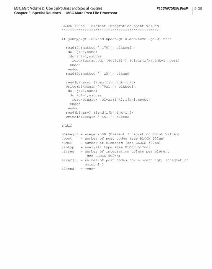
9-39MSC.Marc Volume D: User Subroutines and Special Routines PLDUMP2000/PLDUMPChapter 9 Special Routines — MSC.Marc Post File Processor
BLOCK 523nn - element integration point values **********************************************
if(jantyp.gt.100.and.npost.gt.0.and.numel.gt.0) then
read(formatted,’(a70)’) blkbegin do ijk=1,numel do ijl=1,nstres read(formatted,’(6e13.6)’) (elvar(ijk),ijk=1,npost) enddo enddo read(formatted,’( a5)’) blkend
read(binary) (ibeg(ijk),ijk=1,70) write(blkbegin,’(70a1)’) blkbegin do ijk=1,numel do ijl=1,nstres read(binary) (elvar(ijk),ijk=1,npost) enddo enddo read(binary) (iend(ijk),ijk=1,5) write(blkbegin,’(5a1)’) blkend
endif
blkbegin = =beg=52300 (Element Integration Point Values) npost = number of post codes (see BLOCK 502nn) numel = number of elements (see BLOCK 502nn) jantyp = analysis type (see BLOCK 517nn) nstres = number of integration points per element (see BLOCK 502nn) elvar(i) = values of post codes for element ijk, integration point ijl blkend = =end=

PLDUMP2000/PLDUMP MSC.Marc Volume D: User Subroutines and Special RoutinesChapter 9 Special Routines — MSC.Marc Post File Processor
9-40
BLOCK 524nn - nodal results ***************************
if(jantyp.ne.60.and.jantyp.ne.61.and.knod.gt.0) then
read(formatted,’(a70)’) blkbegin read(formatted,’(6i13)’) nnqnod,nnvnod do ijk=1,nnqnod read(formatted,’(a48)’) cnam read(formatted,’(6i13)’) (ivec(ijk),ijk=1,12) nd=0 if(ivec(7).eq.-1) nd=numnp*ivec(4) if(nd.gt.0) then read(formatted,’(6e13.6)’) (vecr(ijl),ijl=1,nd) if(ivec(6).eq.4.or.ivec(6).eq.5) then read(formatted,’(6e13.6)’) (veci(ijl),ijl=1,nd) endif endif enddo read(formatted,’( a5)’) blkend
read(binary) (ibeg(ijk),ijk=1,70) write(blkbegin,’(70a1)’) blkbegin read(binary) nnqnod,nnvnod do ijk=1,nnqnod read(binary) (inam(ijl),ijl=1,48) write(cnam,’(48a1)’) (inam(ijl),ijl=1,48) read(binary) (ivec(ijk),ijk=1,12) nd=0 if(ivec(7).eq.-1) nd=numnp*ivec(4) if(nd.gt.0) then read(binary) (vecr(ijl),ijl=1,nd) if(ivec(6).eq.4.or.ivec(6).eq.5) then read(binary) (veci(ijl),ijl=1,nd) endif endif read(binary) (iend(ijk),ijk=1,5) write(blkbegin,’(5a1)’) blkend
endif
blkbegin = =beg=52400 (Nodal Results) jantyp = analysis type (see BLOCK 517nn) knod = number of nodal variables (see BLOCK 517nn) numnp = number of nodes (from BLOCK 502nn) nnqnod = number of nodal vectors on post file nnvnod = total number of nodal quantities on post file cnam = name of nodal vector ijk ivec( 1) = quantity identifier for vector ijk (see Table below) ivec( 2) = ivec( 3) = ivec( 4) = number of components per node in vector ijk
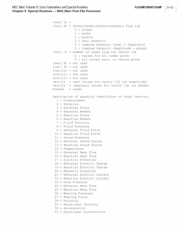
9-41MSC.Marc Volume D: User Subroutines and Special Routines PLDUMP2000/PLDUMPChapter 9 Special Routines — MSC.Marc Post File Processor
ivec( 5) = ivec( 6) = normal/modal/buckle/harmonic flag ijk 0 : normal 1 : modal 2 : buckle 3 : real harmonic 4 : complex harmonic (real + imaginary) 5 : complex harmonic (magnitude + phase) ivec( 7) = number of nodes flag for vector ijk -1 : values for all nodes given 0 : all values zero, no values given ivec( 8) = not used ivec( 9) = not used ivec(10) = not used ivec(11) = not used ivec(11) = not used vecr(i) = real values for vector ijk (or magnitude) veci(i) = imaginary values for vector ijk (or phase) blkend = =end=
Description of quantity identifiers of nodal vectors: 1 = Displacement 2 = Rotation 3 = External Force 4 = External Moment 5 = Reaction Force 6 = Reaction Moment 7 = Fluid Velocity 8 = Fluid Pressure 9 = External Fluid Force 10 = Reaction Fluid Force 11 = Sound Pressure 12 = External Sound Source 13 = Reaction Sound Source 14 = Temperature 15 = External Heat Flux 16 = Reaction Heat Flux 17 = Electric Potential 18 = External Electric Charge 19 = Reaction Electric Charge 20 = Magnetic Potential 21 = External Electric Current 22 = Reaction Electric Current 23 = Pore Pressure 24 = External Mass Flux 25 = Reaction Mass Flux 26 = Bearing Pressure 27 = Bearing Force 28 = Velocity 29 = Rotational Velocity 30 = Acceleration 31 = Rotational Acceleration
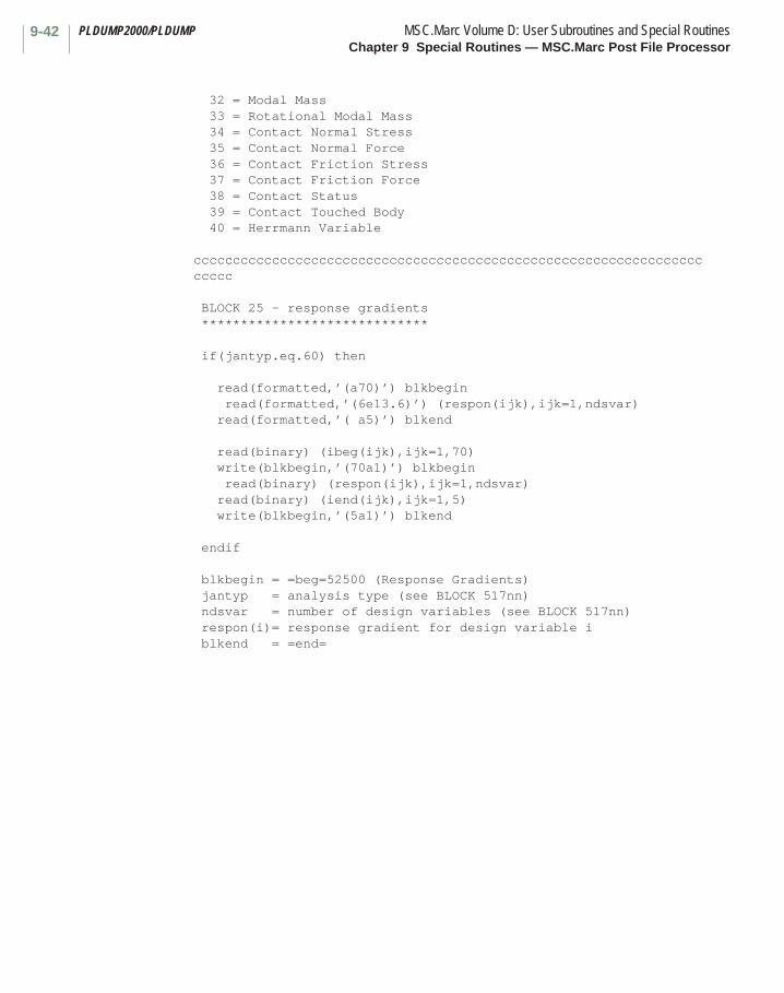
PLDUMP2000/PLDUMP MSC.Marc Volume D: User Subroutines and Special RoutinesChapter 9 Special Routines — MSC.Marc Post File Processor
9-42
32 = Modal Mass 33 = Rotational Modal Mass 34 = Contact Normal Stress 35 = Contact Normal Force 36 = Contact Friction Stress 37 = Contact Friction Force 38 = Contact Status 39 = Contact Touched Body 40 = Herrmann Variable
cccccccccccccccccccccccccccccccccccccccccccccccccccccccccccccccccccccc
BLOCK 25 - response gradients *****************************
if(jantyp.eq.60) then
read(formatted,’(a70)’) blkbegin read(formatted,’(6e13.6)’) (respon(ijk),ijk=1,ndsvar) read(formatted,’( a5)’) blkend
read(binary) (ibeg(ijk),ijk=1,70) write(blkbegin,’(70a1)’) blkbegin read(binary) (respon(ijk),ijk=1,ndsvar) read(binary) (iend(ijk),ijk=1,5) write(blkbegin,’(5a1)’) blkend
endif
blkbegin = =beg=52500 (Response Gradients) jantyp = analysis type (see BLOCK 517nn) ndsvar = number of design variables (see BLOCK 517nn) respon(i)= response gradient for design variable i blkend = =end=
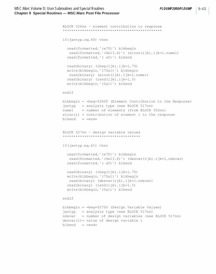
9-43MSC.Marc Volume D: User Subroutines and Special Routines PLDUMP2000/PLDUMPChapter 9 Special Routines — MSC.Marc Post File Processor
BLOCK 526nn - element contribution to response **********************************************
if(jantyp.eq.60) then
read(formatted,’(a70)’) blkbegin read(formatted,’(6e13.6)’) (elcon(ijk),ijk=1,numel) read(formatted,’( a5)’) blkend
read(binary) (ibeg(ijk),ijk=1,70) write(blkbegin,’(70a1)’) blkbegin read(binary) (elcon(ijk),ijk=1,numel) read(binary) (iend(ijk),ijk=1,5) write(blkbegin,’(5a1)’) blkend
endif
blkbegin = =beg=52600 (Element Contribution to the Response) jantyp = analysis type (see BLOCK 517nn) numel = number of elements (from BLOCK 502nn) elcon(i) = contribution of element i to the response blkend = =end=
BLOCK 527nn - design variable values ************************************
if(jantyp.eq.61) then
read(formatted,’(a70)’) blkbegin read(formatted,’(6e13.6)’) (desvar(ijk),ijk=1,ndsvar) read(formatted,’( a5)’) blkend
read(binary) (ibeg(ijk),ijk=1,70) write(blkbegin,’(70a1)’) blkbegin read(binary) (desvar(ijk),ijk=1,ndsvar) read(binary) (iend(ijk),ijk=1,5) write(blkbegin,’(5a1)’) blkend
endif
blkbegin = =beg=52700 (Design Variable Values) jantyp = analysis type (see BLOCK 517nn) ndsvar = number of design variables (see BLOCK 517nn) desvar(i)= value of design variable i blkend = =end=
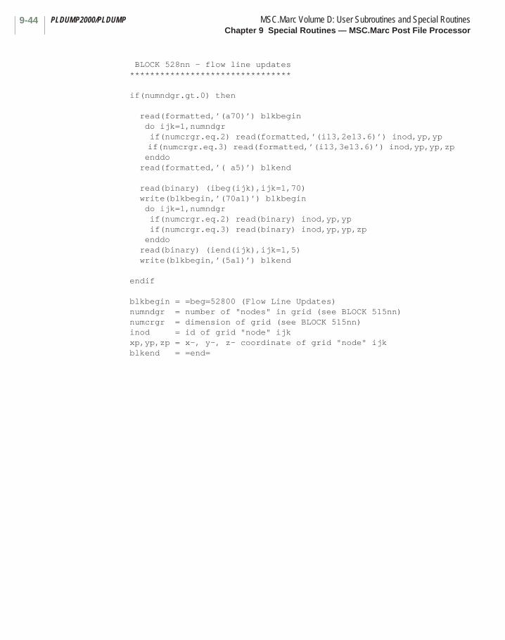
PLDUMP2000/PLDUMP MSC.Marc Volume D: User Subroutines and Special RoutinesChapter 9 Special Routines — MSC.Marc Post File Processor
9-44
BLOCK 528nn - flow line updates ********************************
if(numndgr.gt.0) then
read(formatted,’(a70)’) blkbegin do ijk=1,numndgr if(numcrgr.eq.2) read(formatted,’(i13,2e13.6)’) inod,yp,yp if(numcrgr.eq.3) read(formatted,’(i13,3e13.6)’) inod,yp,yp,zp enddo read(formatted,’( a5)’) blkend
read(binary) (ibeg(ijk),ijk=1,70) write(blkbegin,’(70a1)’) blkbegin do ijk=1,numndgr if(numcrgr.eq.2) read(binary) inod,yp,yp if(numcrgr.eq.3) read(binary) inod,yp,yp,zp enddo read(binary) (iend(ijk),ijk=1,5) write(blkbegin,’(5a1)’) blkend
endif
blkbegin = =beg=52800 (Flow Line Updates) numndgr = number of "nodes" in grid (see BLOCK 515nn) numcrgr = dimension of grid (see BLOCK 515nn) inod = id of grid "node" ijk xp,yp,zp = x-, y-, z- coordinate of grid "node" ijk blkend = =end=

9-45MSC.Marc Volume D: User Subroutines and Special Routines PLDUMP2000/PLDUMPChapter 9 Special Routines — MSC.Marc Post File Processor
BLOCK 529nn - global variables ********************************
if(postrv.ge.11) then
read(formatted,’(a70)’) blkbegin read(formatted,’(2i13)’) inumv,inumt do ijk=1,inumv read(formatted,’(a48)’) globename(ijk) read(formatted,’(6i13)’) ityp,id2,8num,nnum,id5,id6 read(formatted,’(6e13.6)’) (xlm(ijl),ijl=1,nnum) enddo read(formatted,’( a5)’) blkend
read(binary) (ibeg(ijk),ijk=1,70) write(blkbegin,’(70a1)’) blkbegin do ijk=1,inumv read(binary) (inam(ijl)’),ijl=1,48) write(globnam,’48a1)’) (inam(ijl),ijl=1,48) read(binary) ityp,id2,inum,nnum,id5,id6 read(binary) (xlm(ijl)’),ijl=1,nnum) enddo read(binary) (iend(ijk),ijk=1,5) write(blkbegin,’(5a1)’) blkend
endif
blkbegin = =beg=52900 (Flow Line Updates) inumv = number of items in this block inumt = total number of global variables in this block globname = global variable name for this item ityp = global variable type: 1=Cavity Pressure 2=Cavity volume 3=Global State Variable 4=Cavity Mass 5=Cavity Temperature 6=Throat Coordinate 7=Loadcase percentage complete id2 = 0 (for the time being) inum = id for this global variable, e.g. cavity number nnum = 1 (number of variables in this item) id5 = 0 (for the time being) id6 = 0 (for future use) xlm = value of the global variables defined in this item blkend = =end=
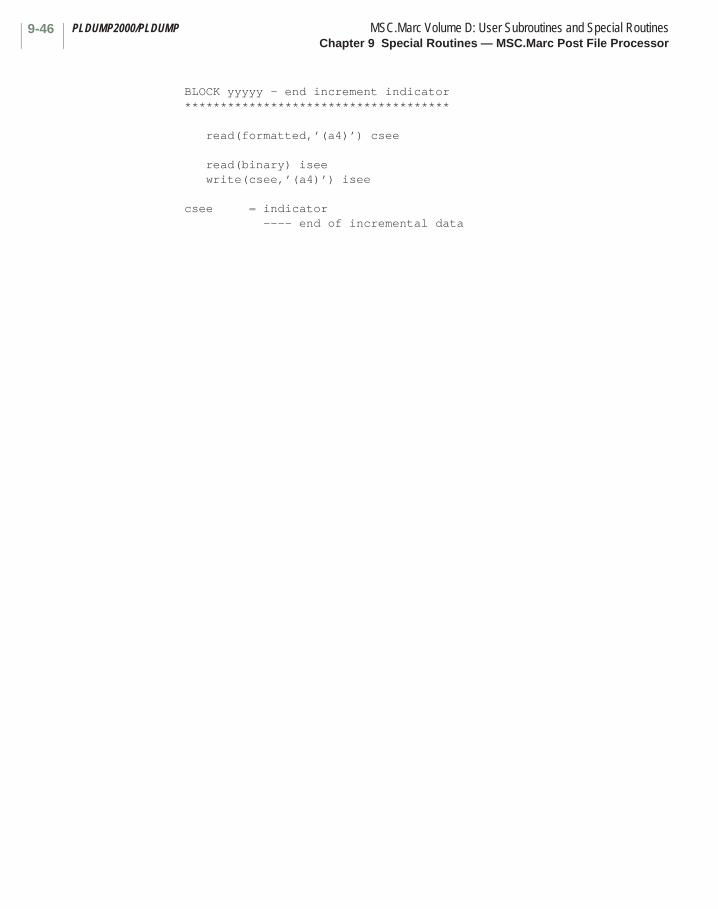
PLDUMP2000/PLDUMP MSC.Marc Volume D: User Subroutines and Special RoutinesChapter 9 Special Routines — MSC.Marc Post File Processor
9-46
BLOCK yyyyy - end increment indicator *************************************
read(formatted,’(a4)’) csee
read(binary) isee write(csee,’(a4)’) isee
csee = indicator ---- end of incremental data

Chapter 10 Mathematical Utility Routines List
Utility Routine Page
DDOT. . . . . . . . . . . . . . . . . . . . . . . . . . . . . . . . . . . . . . . . . . . . . . . . . . . . . . . . . . . 10-2
GMADD . . . . . . . . . . . . . . . . . . . . . . . . . . . . . . . . . . . . . . . . . . . . . . . . . . . . . . . . . 10-3GMPRD . . . . . . . . . . . . . . . . . . . . . . . . . . . . . . . . . . . . . . . . . . . . . . . . . . . . . . . . . 10-4GMSUB . . . . . . . . . . . . . . . . . . . . . . . . . . . . . . . . . . . . . . . . . . . . . . . . . . . . . . . . . 10-5GMTRA . . . . . . . . . . . . . . . . . . . . . . . . . . . . . . . . . . . . . . . . . . . . . . . . . . . . . . . . . 10-6GTPRD. . . . . . . . . . . . . . . . . . . . . . . . . . . . . . . . . . . . . . . . . . . . . . . . . . . . . . . . . . 10-7
INV3X3. . . . . . . . . . . . . . . . . . . . . . . . . . . . . . . . . . . . . . . . . . . . . . . . . . . . . . . . . . 10-9INVERT . . . . . . . . . . . . . . . . . . . . . . . . . . . . . . . . . . . . . . . . . . . . . . . . . . . . . . . . . 10-8
MCPY . . . . . . . . . . . . . . . . . . . . . . . . . . . . . . . . . . . . . . . . . . . . . . . . . . . . . . . . . . 10-10
CHAPTER
10 Utility Routines List

MSC.Marc Volume D: User Subroutines and Special RoutinesChapter 10 Utility Routines List
10-ii
Utility Routine Page
PRINCV . . . . . . . . . . . . . . . . . . . . . . . . . . . . . . . . . . . . . . . . . . . . . . . . . . . . . . . . . 10-11
SCLA . . . . . . . . . . . . . . . . . . . . . . . . . . . . . . . . . . . . . . . . . . . . . . . . . . . . . . . . . . . 10-12

10-1MSC.Marc Volume D: User Subroutines and Special RoutinesChapter 10 Utility Routines
Chapter 10 Mathematical Utility Routines
This chapter discusses a selection of the mathematical utility routines that may be called from any subroutine to simplify the program.
CHAPTER
10 Utility Routines

DDOT MSC.Marc Volume D: User Subroutines and Special RoutinesChapter 10 Utility Routines
10-2
■ DDOT
Inner Product of Two Vectors
Description
Returns the dot product of two vectors.
Format
Utility function DDOT can be used in the following format:ANS=DDOT(NN,A,IA,B,IB)
where:
Note: Vectors A, B, and ANS are real*8 variables.
Input:
NN number of items in each vector to be used
A first input vector
IA stride in vector A
B second input vector
IB stride in vector B
Output:
ANS inner product of vectors A and B
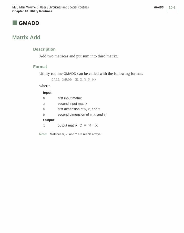
10-3MSC.Marc Volume D: User Subroutines and Special Routines GMADDChapter 10 Utility Routines
■ GMADD
Matrix Add
Description
Add two matrices and put sum into third matrix.
Format
Utility routine GMADD can be called with the following format:CALL GMADD (W,X,Y,N,M)
where:
Note: Matrices W, X, and Y are real*8 arrays.
Input:
W first input matrix
X second input matrix
N first dimension of W, X, and Y
M second dimension of W, X, and Y
Output:
Y output matrix, Y W X+=

GMPRD MSC.Marc Volume D: User Subroutines and Special RoutinesChapter 10 Utility Routines
10-4
■ GMPRD
Matrix Product
Description
Multiply two matrices and put product in third matrix.
Format
Utility routine GMPRD can be called with the following format:CALL GMPRD (W,X,Y,N,M)
where:
Note: Matrices W, X, and Y are real*8 arrays.
Input:
W first input matrix
X second input matrix
N first dimension of W and Y
M second dimension of W and first dimension of X
L second dimension of X and Y
Output:
Y output matrix, Y W * X=

10-5MSC.Marc Volume D: User Subroutines and Special Routines GMSUBChapter 10 Utility Routines
■ GMSUB
Matrix Subtract
Description
Subtract two matrices and put remainder in third matrix.
Format
Utility routine GMSUB can be called with the following format:CALL GMSUB (W,X,Y,N,M)
where:
Note: Matrices W, X, and Y are real*8 arrays.
Input:
W first input matrix
X second input matrix
N first dimension of W, X, and Y
M second dimension of W, X, and Y
Output:
Y output matrix, Y W X–=
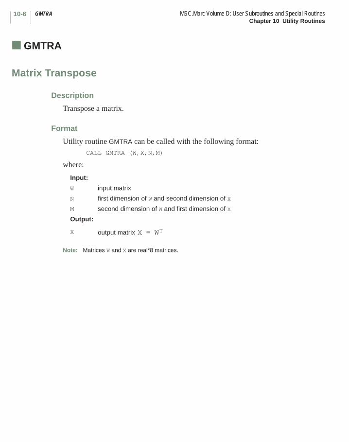
GMTRA MSC.Marc Volume D: User Subroutines and Special RoutinesChapter 10 Utility Routines
10-6
■ GMTRA
Matrix Transpose
Description
Transpose a matrix.
Format
Utility routine GMTRA can be called with the following format:CALL GMTRA (W,X,N,M)
where:
Note: Matrices W and X are real*8 matrices.
Input:
W input matrix
N first dimension of W and second dimension of X
M second dimension of W and first dimension of X
Output:
X output matrix X WT=
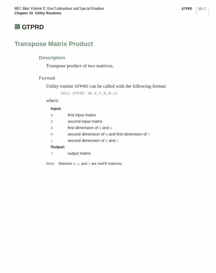
10-7MSC.Marc Volume D: User Subroutines and Special Routines GTPRDChapter 10 Utility Routines
■ GTPRD
Transpose Matrix Product
Description
Transpose product of two matrices.
Format
Utility routine GTPRD can be called with the following format:CALL GTPRD (W,X,Y,N,M.L)
where:
Note: Matrices W, X, and Y are real*8 matrices.
Input:
W first input matrix
X second input matrix
N first dimension of W and X
M second dimension of W and first dimension of Y
L second dimension of X and Y
Output:
Y output matrix
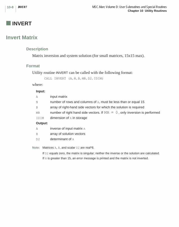
INVERT MSC.Marc Volume D: User Subroutines and Special RoutinesChapter 10 Utility Routines
10-8
■ INVERT
Invert Matrix
Description
Matrix inversion and system solution (for small matrices, 15x15 max).
Format
Utility routine INVERT can be called with the following format:CALL INVERT (A,N,B,MR,D2,IDIM)
where:
Note: Matrices A, B, and scalar D2 are real*8.
If D2 equals zero, the matrix is singular; neither the inverse or the solution are calculated.
If N is greater than 15, an error message is printed and the matrix is not inverted.
Input:
A input matrix
N number of rows and columns of A, must be less than or equal 15
B array of right-hand side vectors for which the solution is required
MR number of right hand side vectors. If , only inversion is performed
IDIM dimension of A in storage
Output:
A inverse of input matrix A
B array of solution vectors
D2 determinant of A
MR 0=
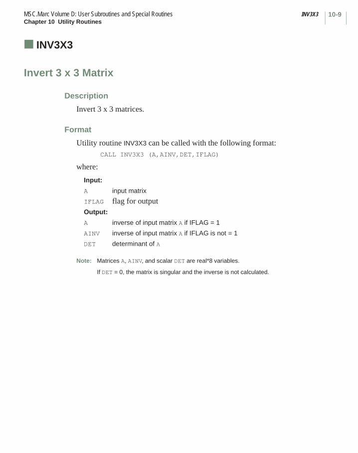
10-9MSC.Marc Volume D: User Subroutines and Special Routines INV3X3Chapter 10 Utility Routines
■ INV3X3
Invert 3 x 3 Matrix
Description
Invert 3 x 3 matrices.
Format
Utility routine INV3X3 can be called with the following format:CALL INV3X3 (A,AINV,DET,IFLAG)
where:
Note: Matrices A, AINV, and scalar DET are real*8 variables.
If DET = 0, the matrix is singular and the inverse is not calculated.
Input:
A input matrix
IFLAG flag for outputOutput:
A inverse of input matrix A if IFLAG = 1
AINV inverse of input matrix A if IFLAG is not = 1
DET determinant of A

MCPY MSC.Marc Volume D: User Subroutines and Special RoutinesChapter 10 Utility Routines
10-10
■ MCPY
Matrix Copy
Description
Copy a matrix.
Format
Utility routine MCPY can be called with the following format:CALL MCPY (W,X,N,M,MS)
where:
Note: Matrices W and X are real*8 arrays.
Input:
W input matrix
N first dimension of W and X
M second dimension of W and X
MS not used
Output:
X output matrix, X W=
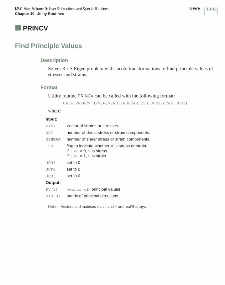
10-11MSC.Marc Volume D: User Subroutines and Special Routines PRINCVChapter 10 Utility Routines
■ PRINCV
Find Principle Values
Description
Solves 3 x 3 Eigen problem with Jacobi transformations to find principle values of stresses and strains.
Format
Utility routine PRINCV can be called with the following format:CALL PRINCV (PV,R,V,NDI,NSHEAR,ISS,JCR1,JCR2,JCR3)
where:
Note: Vectors and matrices PV, R, and V are real*8 arrays.
Input:
V(6) vector of strains or stresses.
NDI number of direct stress or strain components.
NSHEAR number of shear stress or strain components.
ISS flag to indicate whether V is stress or strain.if ISS = 0, V is stressif ISS = 1, V is strain
JCR1 set to 0
JCR2 set to 0
JCR3 set to 0
Output:
PV(3) vector of principal values
R(3,3) matrix of principal directions
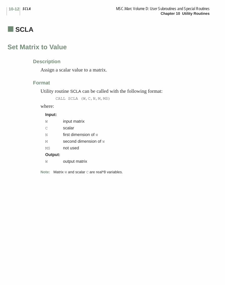
SCLA MSC.Marc Volume D: User Subroutines and Special RoutinesChapter 10 Utility Routines
10-12
■ SCLA
Set Matrix to Value
Description
Assign a scalar value to a matrix.
Format
Utility routine SCLA can be called with the following format:CALL SCLA (W,C,N,M,MS)
where:
Note: Matrix W and scalar C are real*8 variables.
Input:
W input matrix
C scalar
N first dimension of W
M second dimension of W
MS not used
Output:
W output matrix

Chapter 11 Considerations for Parallel Processing
This chapter describes some special considerations that need to be taken into account when writing user subroutines for parallel processing.
OverviewIn a parallel run with MSC.Marc, the finite element mesh is subdivided into domains where each element is part of one domain. Nodes at the boundary between domains are present in all domains sharing that boundary. Each domain is run on one process in the job, normally corresponding to a processor (CPU).
Note: There is a difference between process and processor. A process is run by a processor. A processor can run multiple processes, but in a parallel analysis, each process is normally run by one processor for efficiency.
CHAPTER
11 Considerations for Parallel Processing
■ Overview
■ Auxiliary Routines
■ Sharing Data

MSC.Marc Volume D: User Subroutines and Special RoutinesChapter 11 Considerations for Parallel Processing
11-2
Auxiliary RoutinesThere are a number of auxiliary routines available for parallel applications.
DOMFLAG
The DOMFLAG subroutine is used for sharing variables between domains. The variables can be summed, the maximum taken etc. Suppose the variables num1, r1, and volume have been obtained on each domain. Each domain may have different values of these variables. Now, the user wants to calculate the largest value of num1 and r1 and the variable volume should be summed over the domains. The code for doing this would look like:
include ’cdominfo’
ibuff1(1)=num1dbuff1(1)=r1dbuff1(2)=volumeitest1(1)=1itest2(1)=1itest2(2)=3call domflag(ibuff1,dbuff1,itest1,itest2,1,2)num1=ibuff1(1)r1=dbuff1(1)volume=dbuff1(2)
This code sets num1 and r2 to the maximum over the domains and sets num1 to the sum over the domains. The action taken is controlled by the value set to itest1 and itest2:
= 0: minimum= 1: maximum= 2: average= 3: sum
The last two arguments of DOMFLAG specify the number of integers and reals, respectively, that are involved. The arrays ibuff1, dbuff1, itest1, and itest2 are declared in cdominfo with a range also defined in cdominfo (currently 512). If only one variable is used, one can skip the use of the arrays, for instance
call domflag(int1,ddummy,3,0,1,0)
for summing int1 over the domains.
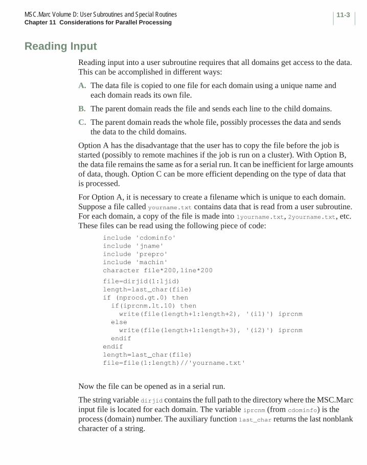
11-3MSC.Marc Volume D: User Subroutines and Special RoutinesChapter 11 Considerations for Parallel Processing
Reading InputReading input into a user subroutine requires that all domains get access to the data. This can be accomplished in different ways:
A. The data file is copied to one file for each domain using a unique name and each domain reads its own file.
B. The parent domain reads the file and sends each line to the child domains.
C. The parent domain reads the whole file, possibly processes the data and sends the data to the child domains.
Option A has the disadvantage that the user has to copy the file before the job is started (possibly to remote machines if the job is run on a cluster). With Option B, the data file remains the same as for a serial run. It can be inefficient for large amounts of data, though. Option C can be more efficient depending on the type of data that is processed.
For Option A, it is necessary to create a filename which is unique to each domain. Suppose a file called yourname.txt contains data that is read from a user subroutine. For each domain, a copy of the file is made into 1yourname.txt, 2yourname.txt, etc. These files can be read using the following piece of code:
include 'cdominfo'include 'jname'include 'prepro'include 'machin'character file*200,line*200
file=dirjid(1:ljid)length=last_char(file)if (nprocd.gt.0) then if(iprcnm.lt.10) then write(file(length+1:length+2), '(i1)') iprcnm else write(file(length+1:length+3), '(i2)') iprcnm endifendiflength=last_char(file)file=file(1:length)//'yourname.txt'
Now the file can be opened as in a serial run.
The string variable dirjid contains the full path to the directory where the MSC.Marc input file is located for each domain. The variable iprcnm (from cdominfo) is the process (domain) number. The auxiliary function last_char returns the last nonblank character of a string.
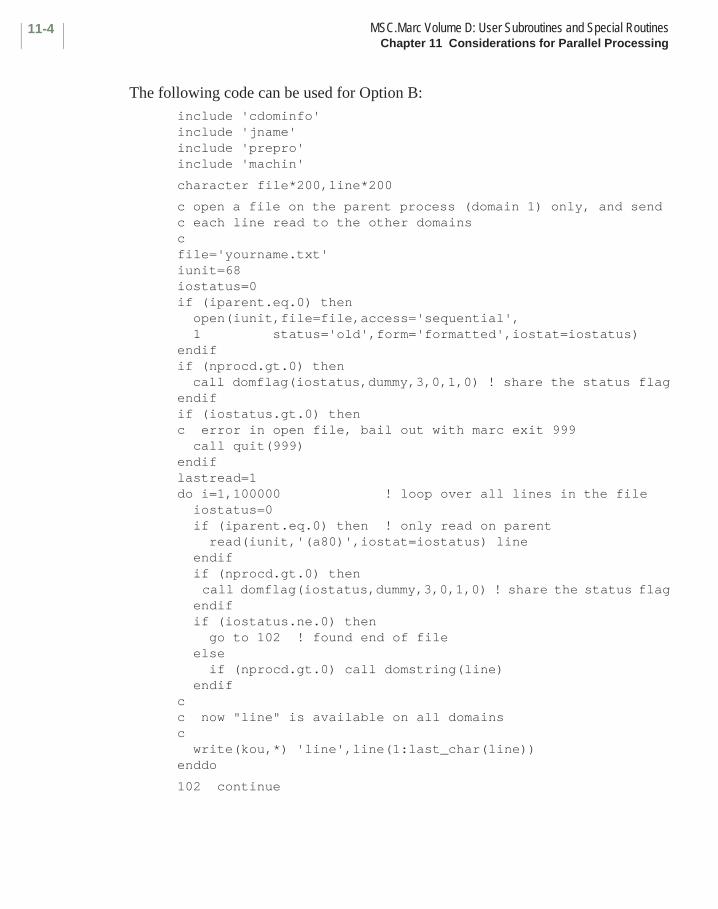
MSC.Marc Volume D: User Subroutines and Special RoutinesChapter 11 Considerations for Parallel Processing
11-4
The following code can be used for Option B:include 'cdominfo'include 'jname'include 'prepro'include 'machin'
character file*200,line*200
c open a file on the parent process (domain 1) only, and send c each line read to the other domainscfile='yourname.txt'iunit=68iostatus=0if (iparent.eq.0) then open(iunit,file=file,access='sequential', 1 status='old',form='formatted',iostat=iostatus)endifif (nprocd.gt.0) then call domflag(iostatus,dummy,3,0,1,0) ! share the status flagendifif (iostatus.gt.0) thenc error in open file, bail out with marc exit 999 call quit(999)endiflastread=1do i=1,100000 ! loop over all lines in the file iostatus=0 if (iparent.eq.0) then ! only read on parent read(iunit,'(a80)',iostat=iostatus) line endif if (nprocd.gt.0) then call domflag(iostatus,dummy,3,0,1,0) ! share the status flag endif if (iostatus.ne.0) then go to 102 ! found end of file else if (nprocd.gt.0) call domstring(line) endifcc now "line" is available on all domainsc write(kou,*) 'line',line(1:last_char(line))enddo
102 continue

11-5MSC.Marc Volume D: User Subroutines and Special RoutinesChapter 11 Considerations for Parallel Processing
The file is only opened if iparent = 0, which is the case in a serial run and for the parent process in a parallel run. The code also makes certain that all processes stop if an error occurs while opening the file. Use is made of the DOMFLAG auxiliary routine to make sure all domains have the same value of iostatus. The DOMSTRING routine broadcasts the line read to all domains.
Sharing DataSince elements are distributed to different domains it is sometimes necessary to share data. Suppose that the total volume is calculated in a user subroutine by integrating over all elements. Each domain would then calculate the volume of the domain. To get the total volume, it is necessary to sum the contributions from all domains. This can be done with the DOMFLAG auxiliary routine :
include ’cdominfo’
c the variable vol contains the volume of each domainif (nprocd.gt.0) call domflag(idummy,vol,0,3,0,1)
It is crucial that all domains call this routine the same number of times. Sharing data should be avoided inside element loops. Apart from being inefficient, it usually causes the job to hang or crash since there are, in general, a different number of elements in the domains. If, for example, the code for calculating the volume is done in an element loop, the calculation of the total volume should be done outside the element loop (for instance, in the UEDINC user subroutine, which is called at the end of the increment).
Dealing with nodal arrays sometimes requires special attention since the nodes on interdomain boundaries are duplicated. One such example is when counting the total number of nodes with a certain property (like being in contact). If this number is summed up in each domain and then later added between domains it will be too large since the interdomain nodes are counted multiple times. This can be handled with the following code:
if (nprocd.gt.0) call domnodmask(mask)num=0do i=1,numnp if (nprocd.gt.0) then if (some_property(i).and.mask(i).eq.1) num=num+1 else if (some_property(i)) num=num+1 endifenddo

MSC.Marc Volume D: User Subroutines and Special RoutinesChapter 11 Considerations for Parallel Processing
11-6
The integer array mask must be allocated with at least the number of nodes in the domain. The subroutine domnodmask returns mask(i) such that mask(i) = 0 if internal node i is also present in another domain and 1 otherwise (for each interdomain node, it is set to one in one domain and to zero in the rest).
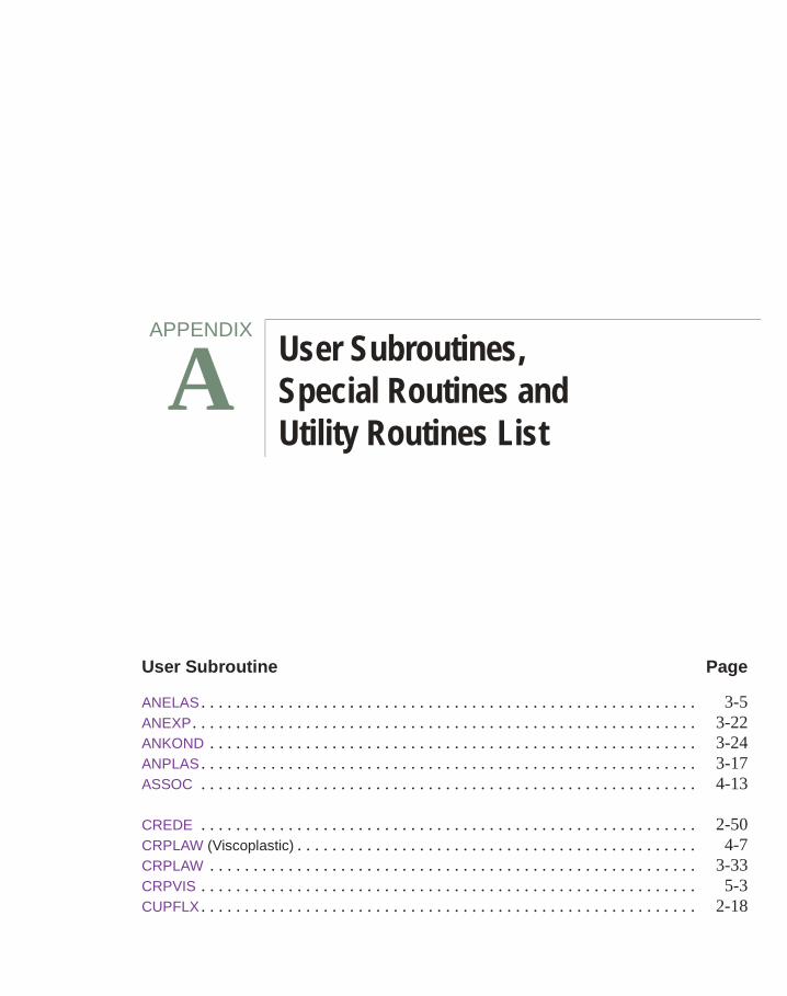
Appendix A User Subroutines and Special Routines List
User Subroutine Page
ANELAS . . . . . . . . . . . . . . . . . . . . . . . . . . . . . . . . . . . . . . . . . . . . . . . . . . . . . . . . . 3-5ANEXP. . . . . . . . . . . . . . . . . . . . . . . . . . . . . . . . . . . . . . . . . . . . . . . . . . . . . . . . . . 3-22ANKOND . . . . . . . . . . . . . . . . . . . . . . . . . . . . . . . . . . . . . . . . . . . . . . . . . . . . . . . . 3-24ANPLAS . . . . . . . . . . . . . . . . . . . . . . . . . . . . . . . . . . . . . . . . . . . . . . . . . . . . . . . . . 3-17ASSOC . . . . . . . . . . . . . . . . . . . . . . . . . . . . . . . . . . . . . . . . . . . . . . . . . . . . . . . . . 4-13
CREDE . . . . . . . . . . . . . . . . . . . . . . . . . . . . . . . . . . . . . . . . . . . . . . . . . . . . . . . . . 2-50CRPLAW (Viscoplastic) . . . . . . . . . . . . . . . . . . . . . . . . . . . . . . . . . . . . . . . . . . . . . . 4-7CRPLAW . . . . . . . . . . . . . . . . . . . . . . . . . . . . . . . . . . . . . . . . . . . . . . . . . . . . . . . . 3-33CRPVIS . . . . . . . . . . . . . . . . . . . . . . . . . . . . . . . . . . . . . . . . . . . . . . . . . . . . . . . . . 5-3CUPFLX . . . . . . . . . . . . . . . . . . . . . . . . . . . . . . . . . . . . . . . . . . . . . . . . . . . . . . . . . 2-18
APPENDIX
A User Subroutines, Special Routines and Utility Routines List

MSC.Marc Volume D: User Subroutines and Special RoutinesAppendix A User Subroutines, Special Routines and Utility Routines List
A-2
User Subroutine Page
DIGEOM. . . . . . . . . . . . . . . . . . . . . . . . . . . . . . . . . . . . . . . . . . . . . . . . . . . . . . . . . 2-70
ELEVAR . . . . . . . . . . . . . . . . . . . . . . . . . . . . . . . . . . . . . . . . . . . . . . . . . . . . . . . . . 7-18ELEVEC . . . . . . . . . . . . . . . . . . . . . . . . . . . . . . . . . . . . . . . . . . . . . . . . . . . . . . . . . 7-20
FILM . . . . . . . . . . . . . . . . . . . . . . . . . . . . . . . . . . . . . . . . . . . . . . . . . . . . . . . . . . . 2-35FLOW . . . . . . . . . . . . . . . . . . . . . . . . . . . . . . . . . . . . . . . . . . . . . . . . . . . . . . . . . . 2-37FLUX . . . . . . . . . . . . . . . . . . . . . . . . . . . . . . . . . . . . . . . . . . . . . . . . . . . . . . . . . . . 2-12FORCDF . . . . . . . . . . . . . . . . . . . . . . . . . . . . . . . . . . . . . . . . . . . . . . . . . . . . . . . . 2-31FORCDT . . . . . . . . . . . . . . . . . . . . . . . . . . . . . . . . . . . . . . . . . . . . . . . . . . . . . . . . 2-22FORCEM . . . . . . . . . . . . . . . . . . . . . . . . . . . . . . . . . . . . . . . . . . . . . . . . . . . . . . . . 2-7
GAPT . . . . . . . . . . . . . . . . . . . . . . . . . . . . . . . . . . . . . . . . . . . . . . . . . . . . . . . . . . . 2-44GAPU. . . . . . . . . . . . . . . . . . . . . . . . . . . . . . . . . . . . . . . . . . . . . . . . . . . . . . . . . . . 3-91GENSTR . . . . . . . . . . . . . . . . . . . . . . . . . . . . . . . . . . . . . . . . . . . . . . . . . . . . . . . . 3-82
HOOKLW . . . . . . . . . . . . . . . . . . . . . . . . . . . . . . . . . . . . . . . . . . . . . . . . . . . . . . . . 3-15HOOKVI . . . . . . . . . . . . . . . . . . . . . . . . . . . . . . . . . . . . . . . . . . . . . . . . . . . . . . . . . 5-8HYPELA2 . . . . . . . . . . . . . . . . . . . . . . . . . . . . . . . . . . . . . . . . . . . . . . . . . . . . . . . . 3-68
IMPD . . . . . . . . . . . . . . . . . . . . . . . . . . . . . . . . . . . . . . . . . . . . . . . . . . . . . . . . . . . 7-10INITPL . . . . . . . . . . . . . . . . . . . . . . . . . . . . . . . . . . . . . . . . . . . . . . . . . . . . . . . . . . 2-104INITPO . . . . . . . . . . . . . . . . . . . . . . . . . . . . . . . . . . . . . . . . . . . . . . . . . . . . . . . . . . 2-105INITSV . . . . . . . . . . . . . . . . . . . . . . . . . . . . . . . . . . . . . . . . . . . . . . . . . . . . . . . . . . 2-52INTCRD . . . . . . . . . . . . . . . . . . . . . . . . . . . . . . . . . . . . . . . . . . . . . . . . . . . . . . . . . 7-22
MAP2D. . . . . . . . . . . . . . . . . . . . . . . . . . . . . . . . . . . . . . . . . . . . . . . . . . . . . . . . . . 6-5MOTION (2-D) . . . . . . . . . . . . . . . . . . . . . . . . . . . . . . . . . . . . . . . . . . . . . . . . . . . . 2-60MOTION (3-D) . . . . . . . . . . . . . . . . . . . . . . . . . . . . . . . . . . . . . . . . . . . . . . . . . . . . 2-62
NASSOC . . . . . . . . . . . . . . . . . . . . . . . . . . . . . . . . . . . . . . . . . . . . . . . . . . . . . . . . 4-9NEWPO . . . . . . . . . . . . . . . . . . . . . . . . . . . . . . . . . . . . . . . . . . . . . . . . . . . . . . . . . 2-106NEWSV . . . . . . . . . . . . . . . . . . . . . . . . . . . . . . . . . . . . . . . . . . . . . . . . . . . . . . . . . 2-53
ORIENT . . . . . . . . . . . . . . . . . . . . . . . . . . . . . . . . . . . . . . . . . . . . . . . . . . . . . . . . . 3-20
PLOTV . . . . . . . . . . . . . . . . . . . . . . . . . . . . . . . . . . . . . . . . . . . . . . . . . . . . . . . . . . 7-3
REBAR. . . . . . . . . . . . . . . . . . . . . . . . . . . . . . . . . . . . . . . . . . . . . . . . . . . . . . . . . . 6-10
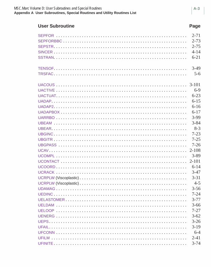
A-3MSC.Marc Volume D: User Subroutines and Special RoutinesAppendix A User Subroutines, Special Routines and Utility Routines List
User Subroutine Page
SEPFOR . . . . . . . . . . . . . . . . . . . . . . . . . . . . . . . . . . . . . . . . . . . . . . . . . . . . . . . . 2-71SEPFORBBC . . . . . . . . . . . . . . . . . . . . . . . . . . . . . . . . . . . . . . . . . . . . . . . . . . . . . 2-73SEPSTR. . . . . . . . . . . . . . . . . . . . . . . . . . . . . . . . . . . . . . . . . . . . . . . . . . . . . . . . . 2-75SINCER . . . . . . . . . . . . . . . . . . . . . . . . . . . . . . . . . . . . . . . . . . . . . . . . . . . . . . . . . 4-14SSTRAN. . . . . . . . . . . . . . . . . . . . . . . . . . . . . . . . . . . . . . . . . . . . . . . . . . . . . . . . . 6-21
TENSOF. . . . . . . . . . . . . . . . . . . . . . . . . . . . . . . . . . . . . . . . . . . . . . . . . . . . . . . . . 3-49TRSFAC . . . . . . . . . . . . . . . . . . . . . . . . . . . . . . . . . . . . . . . . . . . . . . . . . . . . . . . . . 5-6
UACOUS . . . . . . . . . . . . . . . . . . . . . . . . . . . . . . . . . . . . . . . . . . . . . . . . . . . . . . . . 3-101UACTIVE . . . . . . . . . . . . . . . . . . . . . . . . . . . . . . . . . . . . . . . . . . . . . . . . . . . . . . . . 6-9UACTUAT. . . . . . . . . . . . . . . . . . . . . . . . . . . . . . . . . . . . . . . . . . . . . . . . . . . . . . . . 6-23UADAP. . . . . . . . . . . . . . . . . . . . . . . . . . . . . . . . . . . . . . . . . . . . . . . . . . . . . . . . . . 6-15UADAP2. . . . . . . . . . . . . . . . . . . . . . . . . . . . . . . . . . . . . . . . . . . . . . . . . . . . . . . . . 6-16UADAPBOX . . . . . . . . . . . . . . . . . . . . . . . . . . . . . . . . . . . . . . . . . . . . . . . . . . . . . . 6-17UARRBO . . . . . . . . . . . . . . . . . . . . . . . . . . . . . . . . . . . . . . . . . . . . . . . . . . . . . . . . 3-99UBEAM . . . . . . . . . . . . . . . . . . . . . . . . . . . . . . . . . . . . . . . . . . . . . . . . . . . . . . . . . 3-84UBEAR. . . . . . . . . . . . . . . . . . . . . . . . . . . . . . . . . . . . . . . . . . . . . . . . . . . . . . . . . . 8-3UBGINC . . . . . . . . . . . . . . . . . . . . . . . . . . . . . . . . . . . . . . . . . . . . . . . . . . . . . . . . . 7-23UBGITR . . . . . . . . . . . . . . . . . . . . . . . . . . . . . . . . . . . . . . . . . . . . . . . . . . . . . . . . . 7-25UBGPASS . . . . . . . . . . . . . . . . . . . . . . . . . . . . . . . . . . . . . . . . . . . . . . . . . . . . . . . 7-26UCAV . . . . . . . . . . . . . . . . . . . . . . . . . . . . . . . . . . . . . . . . . . . . . . . . . . . . . . . . . . . 2-108UCOMPL . . . . . . . . . . . . . . . . . . . . . . . . . . . . . . . . . . . . . . . . . . . . . . . . . . . . . . . . 3-89UCONTACT . . . . . . . . . . . . . . . . . . . . . . . . . . . . . . . . . . . . . . . . . . . . . . . . . . . . . . 2-101UCOORD . . . . . . . . . . . . . . . . . . . . . . . . . . . . . . . . . . . . . . . . . . . . . . . . . . . . . . . . 6-14UCRACK . . . . . . . . . . . . . . . . . . . . . . . . . . . . . . . . . . . . . . . . . . . . . . . . . . . . . . . . 3-47UCRPLW (Viscoplastic) . . . . . . . . . . . . . . . . . . . . . . . . . . . . . . . . . . . . . . . . . . . . . . 3-31UCRPLW (Viscoplastic) . . . . . . . . . . . . . . . . . . . . . . . . . . . . . . . . . . . . . . . . . . . . . . 4-5UDAMAG . . . . . . . . . . . . . . . . . . . . . . . . . . . . . . . . . . . . . . . . . . . . . . . . . . . . . . . . 3-56UEDINC . . . . . . . . . . . . . . . . . . . . . . . . . . . . . . . . . . . . . . . . . . . . . . . . . . . . . . . . . 7-24UELASTOMER . . . . . . . . . . . . . . . . . . . . . . . . . . . . . . . . . . . . . . . . . . . . . . . . . . . . 3-77UELDAM . . . . . . . . . . . . . . . . . . . . . . . . . . . . . . . . . . . . . . . . . . . . . . . . . . . . . . . . 3-66UELOOP . . . . . . . . . . . . . . . . . . . . . . . . . . . . . . . . . . . . . . . . . . . . . . . . . . . . . . . . 7-27UENERG . . . . . . . . . . . . . . . . . . . . . . . . . . . . . . . . . . . . . . . . . . . . . . . . . . . . . . . . 3-62UEPS . . . . . . . . . . . . . . . . . . . . . . . . . . . . . . . . . . . . . . . . . . . . . . . . . . . . . . . . . . . 3-26UFAIL . . . . . . . . . . . . . . . . . . . . . . . . . . . . . . . . . . . . . . . . . . . . . . . . . . . . . . . . . . . 3-19UFCONN . . . . . . . . . . . . . . . . . . . . . . . . . . . . . . . . . . . . . . . . . . . . . . . . . . . . . . . . 6-4UFILM . . . . . . . . . . . . . . . . . . . . . . . . . . . . . . . . . . . . . . . . . . . . . . . . . . . . . . . . . . 2-41UFINITE . . . . . . . . . . . . . . . . . . . . . . . . . . . . . . . . . . . . . . . . . . . . . . . . . . . . . . . . . 3-74
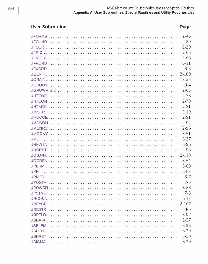
MSC.Marc Volume D: User Subroutines and Special RoutinesAppendix A User Subroutines, Special Routines and Utility Routines List
A-4
User Subroutine Page
UFORMS . . . . . . . . . . . . . . . . . . . . . . . . . . . . . . . . . . . . . . . . . . . . . . . . . . . . . . . . 2-45UFOUND . . . . . . . . . . . . . . . . . . . . . . . . . . . . . . . . . . . . . . . . . . . . . . . . . . . . . . . . 2-39UFOUR . . . . . . . . . . . . . . . . . . . . . . . . . . . . . . . . . . . . . . . . . . . . . . . . . . . . . . . . . 2-20UFRIC . . . . . . . . . . . . . . . . . . . . . . . . . . . . . . . . . . . . . . . . . . . . . . . . . . . . . . . . . . 2-66UFRICBBC . . . . . . . . . . . . . . . . . . . . . . . . . . . . . . . . . . . . . . . . . . . . . . . . . . . . . . . 2-68UFRORD . . . . . . . . . . . . . . . . . . . . . . . . . . . . . . . . . . . . . . . . . . . . . . . . . . . . . . . . 6-11UFXORD . . . . . . . . . . . . . . . . . . . . . . . . . . . . . . . . . . . . . . . . . . . . . . . . . . . . . . . . 6-3UGENT . . . . . . . . . . . . . . . . . . . . . . . . . . . . . . . . . . . . . . . . . . . . . . . . . . . . . . . . . 3-100UGRAIN . . . . . . . . . . . . . . . . . . . . . . . . . . . . . . . . . . . . . . . . . . . . . . . . . . . . . . . . . 3-55UGROOV . . . . . . . . . . . . . . . . . . . . . . . . . . . . . . . . . . . . . . . . . . . . . . . . . . . . . . . . 8-4UGROWRIGID . . . . . . . . . . . . . . . . . . . . . . . . . . . . . . . . . . . . . . . . . . . . . . . . . . . . 2-65UHTCOE . . . . . . . . . . . . . . . . . . . . . . . . . . . . . . . . . . . . . . . . . . . . . . . . . . . . . . . . 2-76UHTCON . . . . . . . . . . . . . . . . . . . . . . . . . . . . . . . . . . . . . . . . . . . . . . . . . . . . . . . . 2-79UHTNRC . . . . . . . . . . . . . . . . . . . . . . . . . . . . . . . . . . . . . . . . . . . . . . . . . . . . . . . . 2-81UINSTR . . . . . . . . . . . . . . . . . . . . . . . . . . . . . . . . . . . . . . . . . . . . . . . . . . . . . . . . . 2-19UMDCOE . . . . . . . . . . . . . . . . . . . . . . . . . . . . . . . . . . . . . . . . . . . . . . . . . . . . . . . . 2-91UMDCON . . . . . . . . . . . . . . . . . . . . . . . . . . . . . . . . . . . . . . . . . . . . . . . . . . . . . . . . 2-94UMDNRC . . . . . . . . . . . . . . . . . . . . . . . . . . . . . . . . . . . . . . . . . . . . . . . . . . . . . . . . 2-96UMOONY . . . . . . . . . . . . . . . . . . . . . . . . . . . . . . . . . . . . . . . . . . . . . . . . . . . . . . . . 3-61UMU . . . . . . . . . . . . . . . . . . . . . . . . . . . . . . . . . . . . . . . . . . . . . . . . . . . . . . . . . . . 3-27UNEWTN . . . . . . . . . . . . . . . . . . . . . . . . . . . . . . . . . . . . . . . . . . . . . . . . . . . . . . . . 3-96UNORST . . . . . . . . . . . . . . . . . . . . . . . . . . . . . . . . . . . . . . . . . . . . . . . . . . . . . . . . 2-98UOBJFN. . . . . . . . . . . . . . . . . . . . . . . . . . . . . . . . . . . . . . . . . . . . . . . . . . . . . . . . . 2-110UOGDEN . . . . . . . . . . . . . . . . . . . . . . . . . . . . . . . . . . . . . . . . . . . . . . . . . . . . . . . . 3-64UPERM . . . . . . . . . . . . . . . . . . . . . . . . . . . . . . . . . . . . . . . . . . . . . . . . . . . . . . . . . 3-60UPHI . . . . . . . . . . . . . . . . . . . . . . . . . . . . . . . . . . . . . . . . . . . . . . . . . . . . . . . . . . . 3-87UPNOD . . . . . . . . . . . . . . . . . . . . . . . . . . . . . . . . . . . . . . . . . . . . . . . . . . . . . . . . . 6-7UPOSTV . . . . . . . . . . . . . . . . . . . . . . . . . . . . . . . . . . . . . . . . . . . . . . . . . . . . . . . . 7-5UPOWDR . . . . . . . . . . . . . . . . . . . . . . . . . . . . . . . . . . . . . . . . . . . . . . . . . . . . . . . . 3-58UPSTNO . . . . . . . . . . . . . . . . . . . . . . . . . . . . . . . . . . . . . . . . . . . . . . . . . . . . . . . . 7-8URCONN . . . . . . . . . . . . . . . . . . . . . . . . . . . . . . . . . . . . . . . . . . . . . . . . . . . . . . . . 6-12UREACB . . . . . . . . . . . . . . . . . . . . . . . . . . . . . . . . . . . . . . . . . . . . . . . . . . . . . . . . 2-107URESTR . . . . . . . . . . . . . . . . . . . . . . . . . . . . . . . . . . . . . . . . . . . . . . . . . . . . . . . . 8-5URPFLO. . . . . . . . . . . . . . . . . . . . . . . . . . . . . . . . . . . . . . . . . . . . . . . . . . . . . . . . . 3-97USDATA . . . . . . . . . . . . . . . . . . . . . . . . . . . . . . . . . . . . . . . . . . . . . . . . . . . . . . . . . 2-57USELEM . . . . . . . . . . . . . . . . . . . . . . . . . . . . . . . . . . . . . . . . . . . . . . . . . . . . . . . . 3-93USHELL . . . . . . . . . . . . . . . . . . . . . . . . . . . . . . . . . . . . . . . . . . . . . . . . . . . . . . . . . 6-20USHRET . . . . . . . . . . . . . . . . . . . . . . . . . . . . . . . . . . . . . . . . . . . . . . . . . . . . . . . . 3-50USIGMA . . . . . . . . . . . . . . . . . . . . . . . . . . . . . . . . . . . . . . . . . . . . . . . . . . . . . . . . . 3-29

A-5MSC.Marc Volume D: User Subroutines and Special RoutinesAppendix A User Subroutines, Special Routines and Utility Routines List
User Subroutine Page
USINC . . . . . . . . . . . . . . . . . . . . . . . . . . . . . . . . . . . . . . . . . . . . . . . . . . . . . . . . . . 2-56USINKPT . . . . . . . . . . . . . . . . . . . . . . . . . . . . . . . . . . . . . . . . . . . . . . . . . . . . . . . . 2-43USIZEOUTL . . . . . . . . . . . . . . . . . . . . . . . . . . . . . . . . . . . . . . . . . . . . . . . . . . . . . . 6-6USPCHT . . . . . . . . . . . . . . . . . . . . . . . . . . . . . . . . . . . . . . . . . . . . . . . . . . . . . . . . 3-30USPLIT . . . . . . . . . . . . . . . . . . . . . . . . . . . . . . . . . . . . . . . . . . . . . . . . . . . . . . . . . 6-13USPRNG . . . . . . . . . . . . . . . . . . . . . . . . . . . . . . . . . . . . . . . . . . . . . . . . . . . . . . . . 3-44USSD . . . . . . . . . . . . . . . . . . . . . . . . . . . . . . . . . . . . . . . . . . . . . . . . . . . . . . . . . . . 2-55USSUBS . . . . . . . . . . . . . . . . . . . . . . . . . . . . . . . . . . . . . . . . . . . . . . . . . . . . . . . . 3-102UTHICK (Hydrodynamic Lubrication) . . . . . . . . . . . . . . . . . . . . . . . . . . . . . . . . . . . . 8-6UTHICK . . . . . . . . . . . . . . . . . . . . . . . . . . . . . . . . . . . . . . . . . . . . . . . . . . . . . . . . . 6-22UTIMESTEP . . . . . . . . . . . . . . . . . . . . . . . . . . . . . . . . . . . . . . . . . . . . . . . . . . . . . . 2-58UTRANS . . . . . . . . . . . . . . . . . . . . . . . . . . . . . . . . . . . . . . . . . . . . . . . . . . . . . . . . 6-19UVELOC (Hydrodynamic Lubrication). . . . . . . . . . . . . . . . . . . . . . . . . . . . . . . . . . . . 8-8UVELOC . . . . . . . . . . . . . . . . . . . . . . . . . . . . . . . . . . . . . . . . . . . . . . . . . . . . . . . . 2-59UVOID . . . . . . . . . . . . . . . . . . . . . . . . . . . . . . . . . . . . . . . . . . . . . . . . . . . . . . . . . . 3-51UVOIDN . . . . . . . . . . . . . . . . . . . . . . . . . . . . . . . . . . . . . . . . . . . . . . . . . . . . . . . . . 3-52UVOIDRT . . . . . . . . . . . . . . . . . . . . . . . . . . . . . . . . . . . . . . . . . . . . . . . . . . . . . . . . 3-54UVSCPL. . . . . . . . . . . . . . . . . . . . . . . . . . . . . . . . . . . . . . . . . . . . . . . . . . . . . . . . . 4-3UVTCOE . . . . . . . . . . . . . . . . . . . . . . . . . . . . . . . . . . . . . . . . . . . . . . . . . . . . . . . . 2-84UVTCON . . . . . . . . . . . . . . . . . . . . . . . . . . . . . . . . . . . . . . . . . . . . . . . . . . . . . . . . 2-87UVTNRC . . . . . . . . . . . . . . . . . . . . . . . . . . . . . . . . . . . . . . . . . . . . . . . . . . . . . . . . 2-89UWELDFLUX . . . . . . . . . . . . . . . . . . . . . . . . . . . . . . . . . . . . . . . . . . . . . . . . . . . . . 2-14UWELDPATH . . . . . . . . . . . . . . . . . . . . . . . . . . . . . . . . . . . . . . . . . . . . . . . . . . . . . 2-16
VSWELL. . . . . . . . . . . . . . . . . . . . . . . . . . . . . . . . . . . . . . . . . . . . . . . . . . . . . . . . . 3-38
WKSLP . . . . . . . . . . . . . . . . . . . . . . . . . . . . . . . . . . . . . . . . . . . . . . . . . . . . . . . . . 3-41
YIEL . . . . . . . . . . . . . . . . . . . . . . . . . . . . . . . . . . . . . . . . . . . . . . . . . . . . . . . . . . . . 4-12
ZERO . . . . . . . . . . . . . . . . . . . . . . . . . . . . . . . . . . . . . . . . . . . . . . . . . . . . . . . . . . . 4-11
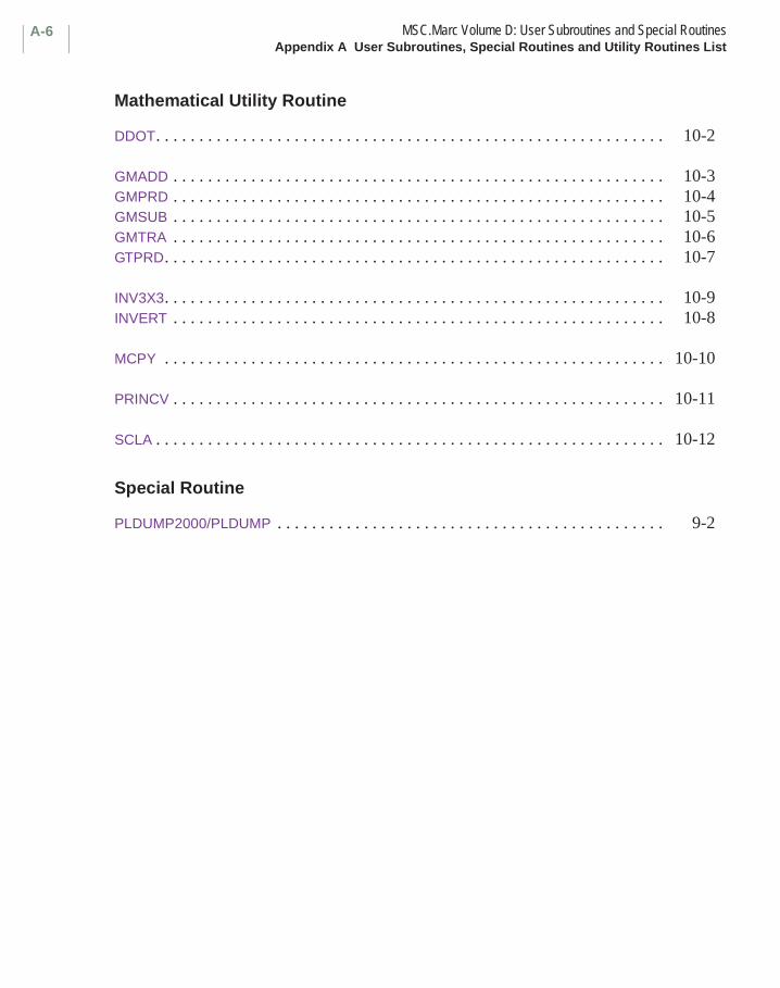
MSC.Marc Volume D: User Subroutines and Special RoutinesAppendix A User Subroutines, Special Routines and Utility Routines List
A-6
Mathematical Utility Routine
DDOT. . . . . . . . . . . . . . . . . . . . . . . . . . . . . . . . . . . . . . . . . . . . . . . . . . . . . . . . . . . 10-2
GMADD . . . . . . . . . . . . . . . . . . . . . . . . . . . . . . . . . . . . . . . . . . . . . . . . . . . . . . . . . 10-3GMPRD . . . . . . . . . . . . . . . . . . . . . . . . . . . . . . . . . . . . . . . . . . . . . . . . . . . . . . . . . 10-4GMSUB . . . . . . . . . . . . . . . . . . . . . . . . . . . . . . . . . . . . . . . . . . . . . . . . . . . . . . . . . 10-5GMTRA . . . . . . . . . . . . . . . . . . . . . . . . . . . . . . . . . . . . . . . . . . . . . . . . . . . . . . . . . 10-6GTPRD. . . . . . . . . . . . . . . . . . . . . . . . . . . . . . . . . . . . . . . . . . . . . . . . . . . . . . . . . . 10-7
INV3X3. . . . . . . . . . . . . . . . . . . . . . . . . . . . . . . . . . . . . . . . . . . . . . . . . . . . . . . . . . 10-9INVERT . . . . . . . . . . . . . . . . . . . . . . . . . . . . . . . . . . . . . . . . . . . . . . . . . . . . . . . . . 10-8
MCPY . . . . . . . . . . . . . . . . . . . . . . . . . . . . . . . . . . . . . . . . . . . . . . . . . . . . . . . . . . 10-10
PRINCV . . . . . . . . . . . . . . . . . . . . . . . . . . . . . . . . . . . . . . . . . . . . . . . . . . . . . . . . . 10-11
SCLA . . . . . . . . . . . . . . . . . . . . . . . . . . . . . . . . . . . . . . . . . . . . . . . . . . . . . . . . . . . 10-12
Special Routine
PLDUMP2000/PLDUMP . . . . . . . . . . . . . . . . . . . . . . . . . . . . . . . . . . . . . . . . . . . . . 9-2
Related Documents