Freescale Semiconductor Application Note © 2010 Freescale Semiconductor, Inc. This document provides a starting guide to some commonly used digital signal processing functions available for use with the Freescale MSC8156EVM board. The example projects are demonstrated in this guide. The objective of this document is to help the users integrate various independent projects using these kernels. 1 Introduction The MSC8156EVM is supported by a collection of commonly used digital signal processing kernels that function with the SC3850 DSP core. The project described in this document provides the kernel library consisting of C and assembly callable kernel applications, as well as their test harnesses. This tutorial guide demonstrates how to use several of the most useful and representative kernel examples such as FIR and IIR filters, FFT, Divide and Matrix Inverse. NOTE Download the kernel software package from the MSC8156EVM Tool Summary Page on www.freescale.com . Document Number: AN4228 Rev. 0, 10/2010 Contents 1 Introduction. . . . . . . . . . . . . . . . . . . . . . . . . . . . . . . . . . . . 1 2 What You Need to Run this Project . . . . . . . . . . . . . . . . . 2 3 Test Procedures . . . . . . . . . . . . . . . . . . . . . . . . . . . . . . . . . 3 4 Common Kernel Example Demonstration . . . . . . . . . . . . 4 4.1 FIR_complex_16x16 . . . . . . . . . . . . . . . . . . . . . . . . . . . 5 4.2 Complex Radix-4 FFT/IFFT 16x16. . . . . . . . . . . . . . . . 6 4.3 Complex Radix-2 and Radix-4 FFT/IFFT 16x16 . . . . . 9 4.4 IIR . . . . . . . . . . . . . . . . . . . . . . . . . . . . . . . . . . . . . . . . 10 4.5 Division 16×16 . . . . . . . . . . . . . . . . . . . . . . . . . . . . . . 12 4.6 Ln . . . . . . . . . . . . . . . . . . . . . . . . . . . . . . . . . . . . . . . . .13 4.7 Matrix Inversion Complex 2×2 . . . . . . . . . . . . . . . . . . 14 4.8 Matrix Inversion Complex 4×4 . . . . . . . . . . . . . . . . . . 15 MSC8156EVM Kernels Starting Guide

Welcome message from author
This document is posted to help you gain knowledge. Please leave a comment to let me know what you think about it! Share it to your friends and learn new things together.
Transcript
Freescale SemiconductorApplication Note
© 2010 Freescale Semiconductor, Inc.
This document provides a starting guide to some commonly used digital signal processing functions available for use with the Freescale MSC8156EVM board. The example projects are demonstrated in this guide. The objective of this document is to help the users integrate various independent projects using these kernels.
1 IntroductionThe MSC8156EVM is supported by a collection of commonly used digital signal processing kernels that function with the SC3850 DSP core. The project described in this document provides the kernel library consisting of C and assembly callable kernel applications, as well as their test harnesses. This tutorial guide demonstrates how to use several of the most useful and representative kernel examples such as FIR and IIR filters, FFT, Divide and Matrix Inverse.
NOTE
Download the kernel software package from the MSC8156EVM Tool Summary Page on www.freescale.com.
Document Number: AN4228Rev. 0, 10/2010
Contents1 Introduction. . . . . . . . . . . . . . . . . . . . . . . . . . . . . . . . . . . .12 What You Need to Run this Project . . . . . . . . . . . . . . . . .23 Test Procedures. . . . . . . . . . . . . . . . . . . . . . . . . . . . . . . . .34 Common Kernel Example Demonstration . . . . . . . . . . . .44.1 FIR_complex_16x16 . . . . . . . . . . . . . . . . . . . . . . . . . . .54.2 Complex Radix-4 FFT/IFFT 16x16. . . . . . . . . . . . . . . .64.3 Complex Radix-2 and Radix-4 FFT/IFFT 16x16 . . . . .94.4 IIR . . . . . . . . . . . . . . . . . . . . . . . . . . . . . . . . . . . . . . . .104.5 Division 16×16 . . . . . . . . . . . . . . . . . . . . . . . . . . . . . .124.6 Ln . . . . . . . . . . . . . . . . . . . . . . . . . . . . . . . . . . . . . . . . .134.7 Matrix Inversion Complex 2×2 . . . . . . . . . . . . . . . . . .144.8 Matrix Inversion Complex 4×4 . . . . . . . . . . . . . . . . . .15
MSC8156EVM Kernels Starting Guide
MSC8156EVM Kernels Starting Guide, Rev. 0
2 Freescale Semiconductor
What You Need to Run this Project
2 What You Need to Run this ProjectRunning the DSP kernels requires the following devices:
• Personal computer (PC) with CodeWarrior for StarCore-Based DSP IDE for the MSC8156EVM board connected to the PC
• MSC8156EVM board
The MSC8156EVM project includes the following kernels:
• FIR_complex_16×16
• Complex Radix-4 FFT/IFFT 16×16
• Complex Radix-4 and Radix-2 FFT/IFFT 16×16
• IIR
• Division
• Ln
• Matrix Inversion complex 2×2
• Matrix Inversion complex 4×4
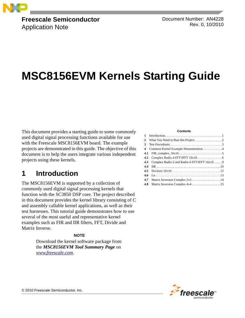
Figure 1 shows the folder directory of all the kernel example projects.
Figure 1. Kernel Example Project Directory
MSC8156EVM Kernels Starting Guide, Rev. 0
Freescale Semiconductor 3
Test Procedures
3 Test ProceduresUse the following steps to prepare for and run the project:
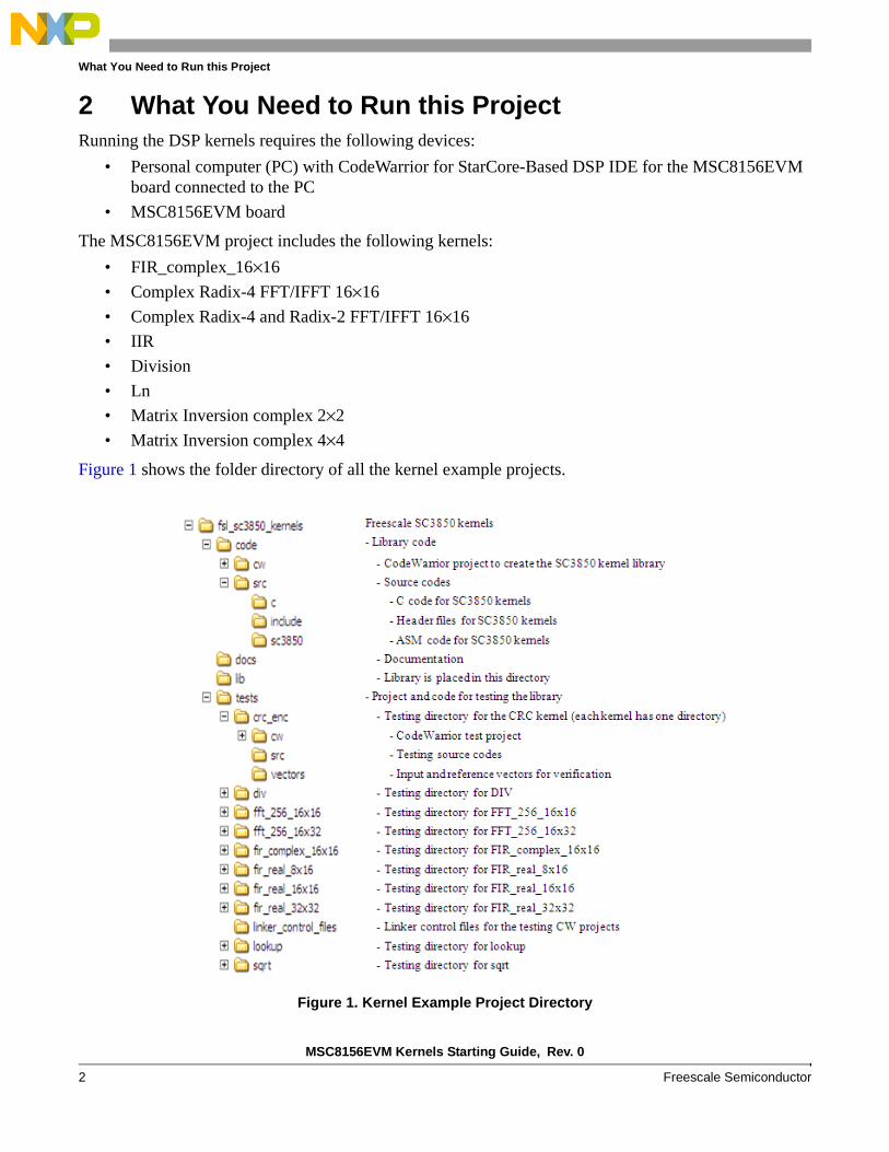
1. Import the SC3850 DSP kernel library by dragging the .project file in \fsl_sc3850_kernels\code\cw\sc3850_kernels to the CodeWarrior project window (Figure 2).
2. Build the kernel by clicking on the build icon .
3. After building the kernel project, .elb files are created in the folder fsl_sc3850_kernels\lib.
4. After the kernel is built, you can run one of the test cases in the \fsl_sc3850_kernels\test\ folder. Import the associated .project of the selected test case and build the project. After building the test case, .eld files are created in the \fsl_sc3850_kernels\tests\<test_case>\cw folder.
5. Load the project by clicking on the debug icon and selecting Debug Configurations.
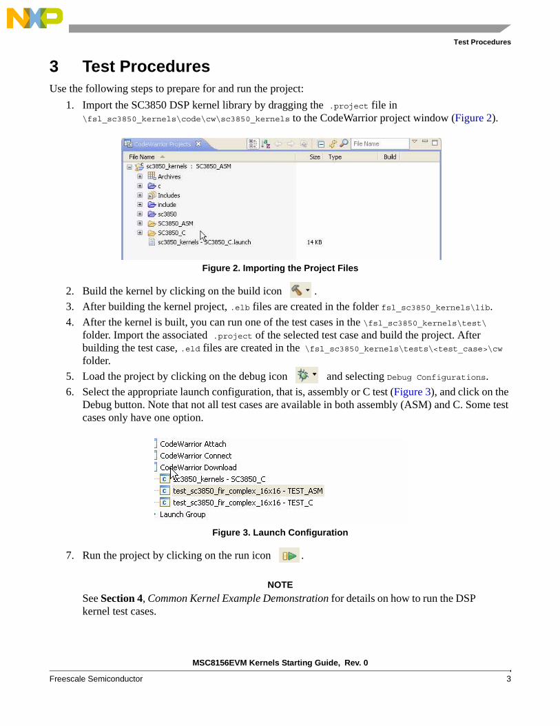
6. Select the appropriate launch configuration, that is, assembly or C test (Figure 3), and click on the Debug button. Note that not all test cases are available in both assembly (ASM) and C. Some test cases only have one option.
7. Run the project by clicking on the run icon .
NOTE
See Section 4, Common Kernel Example Demonstration for details on how to run the DSP kernel test cases.
Figure 2. Importing the Project Files
Figure 3. Launch Configuration
MSC8156EVM Kernels Starting Guide, Rev. 0
4 Freescale Semiconductor
Common Kernel Example Demonstration
4 Common Kernel Example DemonstrationAfter the DSP kernel library is built, the user can run one of the kernel test cases provided with the EVM. This section provides detailed information for each kernel. For each kernel, the listing includes the following:
• Location from which to import the file.
• Function
• ASM Prototype
• C Prototype
• Inputs
• Outputs
• Data alignment requirements (if applicable).
• Performance Measurement
The following notes apply for all kernels:
1. Import the kernel as described in Section 3, Test Procedures.
2. DPU is a defined function that enables cycle measurements
#ifdef DPU
#define INIT_CYCLE InitDPU()
#define GET_CYCLE ReadCountDPU()
#endif
3. The kernel is called twice in the example project. The first call brings the kernel to cache so we can measure the performance of the second call more with warm cache.
4. The test results printed in the CodeWarrior console should show the cycles used to complete the kernel process and check with the reference outputs.
MSC8156EVM Kernels Starting Guide, Rev. 0
Freescale Semiconductor 5
Common Kernel Example Demonstration
4.1 FIR_complex_16x16
Location:fsl_sc3850_kernels\tests\fir_complex_16x16\cw\test_sc3850_fir_complex_16x16
Function: FIR filtering with 16-bit complex inputs and coefficients
ASM Prototype:void sc3850_fir_complex_16x16_asm(Word32 x[], Word32 h[], Word16 y[], Word16 nr, Word16 nh);
C Prototype:Void sc3850_fir_complex_16x16_c(Word32 x[], Word32 h[], Word16 y[], Word16 nr, Word16 nh);
Inputs:Word32 x[]: 32-bit complex inputs, 16 bits for real part and 16 bits for imaginary partWord32 h[]: 32-bit complex coefficients, 16 bits for real and 16 bits for imaginary partWord16 Nr: number of input data samplesWord16 Nh: number of elements in the filter
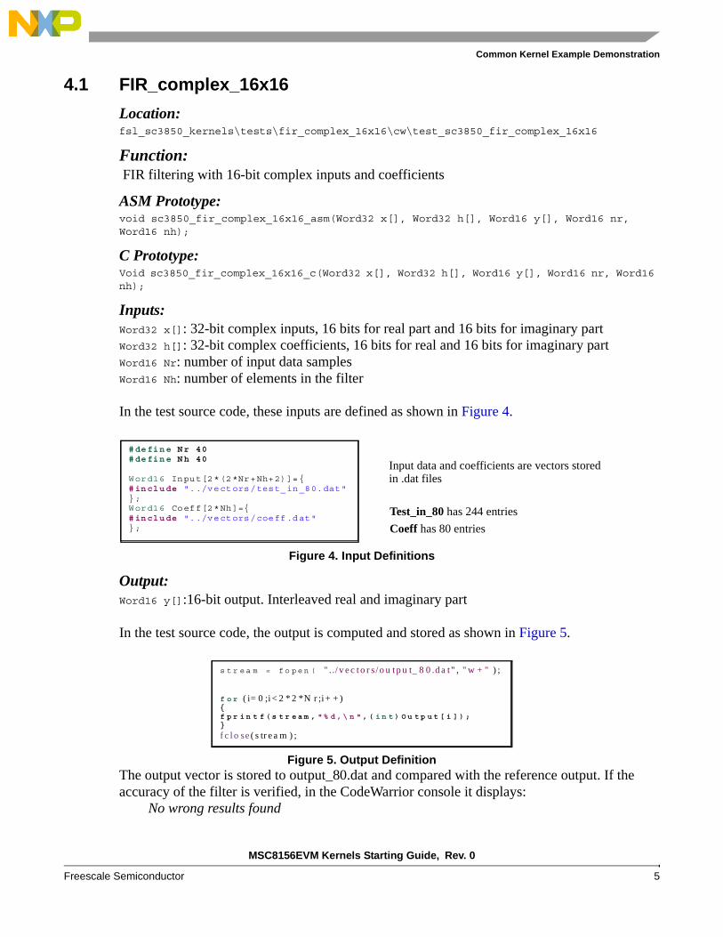
In the test source code, these inputs are defined as shown in Figure 4.
Output:Word16 y[]:16-bit output. Interleaved real and imaginary part
In the test source code, the output is computed and stored as shown in Figure 5.
The output vector is stored to output_80.dat and compared with the reference output. If the accuracy of the filter is verified, in the CodeWarrior console it displays:
No wrong results found
Figure 4. Input Definitions
Figure 5. Output Definition
#define Nr 40 #define Nh 40 Word16 Input[2*(2*Nr+Nh+2)]={ #include "../vectors/test_in_80.dat" }; Word16 Coeff[2*Nh]={ #include "../vectors/coeff.dat" };
Input data and coefficients are vectors stored
Test_in_80 has 244 entries
Coeff has 80 entries
in .dat files
s t r e a m = f o p e n ( " . ./ v e c t o r s / o u t p u t_ 8 0 .d a t " , " w + " ) ;
f o r ( i= 0 ;i < 2 * 2 *N r ;i + + ) { f p r i n t f ( s t r e a m , " % d , \ n " , ( i n t ) O u t p u t [ i ] ) ; }
f c l o se ( s tr e a m ) ;
MSC8156EVM Kernels Starting Guide, Rev. 0
6 Freescale Semiconductor
Common Kernel Example Demonstration
Performance Measurement: Estimated cycle count: (Nr/2)*Nh + overheadMeasured cycle count: 939 cycles for asm 1390 cycles for C
4.2 Complex Radix-4 FFT/IFFT 16x16
Locationfsl_sc3850_kernels\tests\fft_ifft_radix4_16x16\cw\test_sc3850_fft_ifft_radix4_complex_16x16\
Function: Radix-4 complex FFT with 16-bit input and 16-bit output. Input & output complex data are stored in structure of [real][imag]. It supports 64, 256, 1024, and 4096 point FFTs.
ASM Prototype:FFT: void sc3850_fft_radix4_complex_16x16_asm (
Word16 data_buffer[], Word16 wctwiddles[],Word16 wbdtwiddles[],Word16 n, Word16 ln, Word16 Shift_down);
IFFT: void sc3850_ifft_radix4_complex_16x16_asm (
Word16 data_buffer[], Word16 wctwiddles[],Word16 wbdtwiddles[],Word16 n, Word16 ln, Word16 Shift_down);
C Prototype:FFT: void sc3850_fft_radix4_complex_16x16_c (
Word16 data_buffer[], Word16 wctwiddles[],Word16 wbdtwiddles[],Word16 n, Word16 ln, Word16 Shift_down);
IFFT: void sc3850_ifft_radix4_complex_16x16_c (
Word16 data_buffer[], Word16 wctwiddles[],Word16 wbdtwiddles[],Word16 n, Word16 ln, Word16 Shift_down);
MSC8156EVM Kernels Starting Guide, Rev. 0
Freescale Semiconductor 7
Common Kernel Example Demonstration
Inputs: Word16 data_buffer[]: Address of Input and Output Buffer. Input and output share one memory area pointed by data_buffer.Word16 wctwiddles[]: Address of the array of twiddle factor WcWord16 wbdtwiddles[]: Address of the array of twiddle factor Wb and WdWord16 n: FFT pointWord16 ln: Base 4 Log(N). Number of FFT stagesWord16 Shift_down: Scaling down parameter at each stage
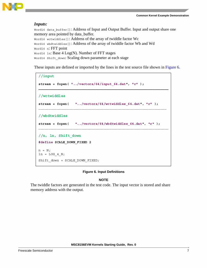
These inputs are defined or imported by the lines in the test source file shown in Figure 6.
NOTE
The twiddle factors are generated in the test code. The input vector is stored and share memory address with the output.
Figure 6. Input Definitions
//input stream = fopen( "../vectors/64/input_64.dat", "r" ); ________________________________________________________________ //wctwiddles stream = fopen( "../vectors/64/wctwiddles_64.dat", "r" ); _______________________________________________________________ //wbdtwiddles stream = fopen( "../vectors/64/wbdtwiddles_64.dat", "r" ); ________________________________________________________________ //n, ln, Shift_down
#define SCALE_DOWN_FIXED 2
n = N; ln = LOG_4_N;
Shift_down = SCALE_DOWN_FIXED;
MSC8156EVM Kernels Starting Guide, Rev. 0
8 Freescale Semiconductor
Common Kernel Example Demonstration
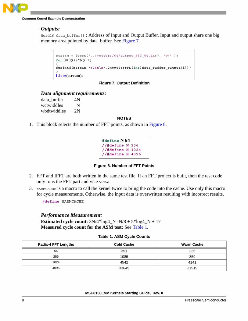
Outputs:Word16 data_buffer[] : Address of Input and Output Buffer. Input and output share one big memory area pointed by data_buffer. See Figure 7.
Data alignment requirements:data_buffer 4Nwctwiddles Nwbdtwiddles 2N
NOTES
1. This block selects the number of FFT points, as shown in Figure 8.
2. FFT and IFFT are both written in the same test file. If an FFT project is built, then the test code only runs the FFT part and vice versa.
3. WARMCACHE is a macro to call the kernel twice to bring the code into the cache. Use only this macro for cycle measurements. Otherwise, the input data is overwritten resulting with incorrect results.
#define WARMCACHE
Performance Measurement: Estimated cycle count: 3N/4*log4_N -N/8 + 5*log4_N + 17Measured cycle count for the ASM test: See Table 1.
Figure 7. Output Definition
Figure 8. Number of FFT Points
Table 1. ASM Cycle Counts
Radix-4 FFT Lengths Cold Cache Warm Cache
64 351 235
256 1085 859
1024 4542 4141
4096 33645 31919
stream = fopen("../vectors/64/output_FFT_64.dat", "w+" );
for (i=0;i<2*N;i++) { fprintf(stream,"%04x\n",0x0000FFFF&(int)data_buffer_output[i]); }
fclose(stream);
#define N 64 //#define N 256 //#define N 1024 //#define N 4096
MSC8156EVM Kernels Starting Guide, Rev. 0
Freescale Semiconductor 9
Common Kernel Example Demonstration
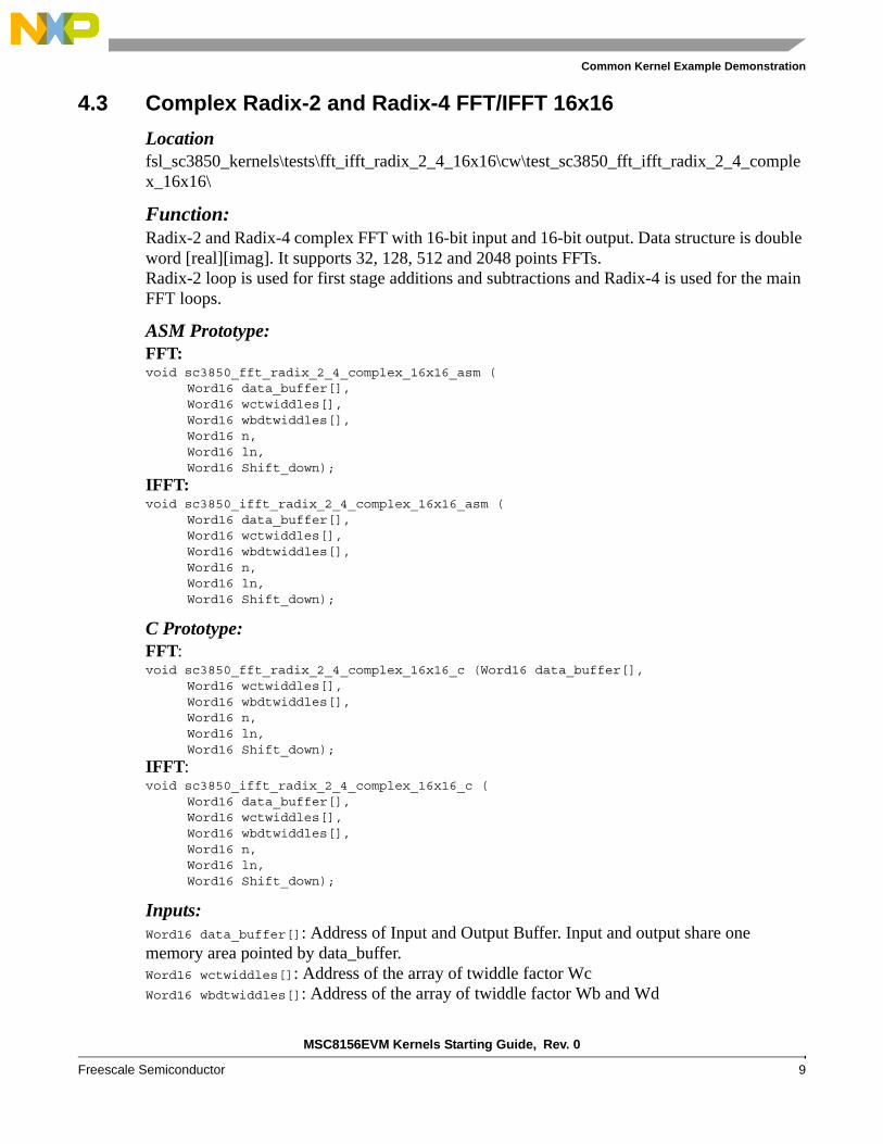
4.3 Complex Radix-2 and Radix-4 FFT/IFFT 16x16
Locationfsl_sc3850_kernels\tests\fft_ifft_radix_2_4_16x16\cw\test_sc3850_fft_ifft_radix_2_4_complex_16x16\
Function: Radix-2 and Radix-4 complex FFT with 16-bit input and 16-bit output. Data structure is double word [real][imag]. It supports 32, 128, 512 and 2048 points FFTs.Radix-2 loop is used for first stage additions and subtractions and Radix-4 is used for the main FFT loops.
ASM Prototype:FFT: void sc3850_fft_radix_2_4_complex_16x16_asm (
Word16 data_buffer[],Word16 wctwiddles[],Word16 wbdtwiddles[],Word16 n, Word16 ln, Word16 Shift_down);
IFFT: void sc3850_ifft_radix_2_4_complex_16x16_asm (
Word16 data_buffer[],Word16 wctwiddles[],Word16 wbdtwiddles[],Word16 n, Word16 ln, Word16 Shift_down);
C Prototype:FFT: void sc3850_fft_radix_2_4_complex_16x16_c (Word16 data_buffer[],
Word16 wctwiddles[],Word16 wbdtwiddles[],Word16 n, Word16 ln, Word16 Shift_down);
IFFT: void sc3850_ifft_radix_2_4_complex_16x16_c (
Word16 data_buffer[], Word16 wctwiddles[],Word16 wbdtwiddles[],Word16 n, Word16 ln, Word16 Shift_down);
Inputs: Word16 data_buffer[]: Address of Input and Output Buffer. Input and output share one memory area pointed by data_buffer.Word16 wctwiddles[]: Address of the array of twiddle factor WcWord16 wbdtwiddles[]: Address of the array of twiddle factor Wb and Wd
MSC8156EVM Kernels Starting Guide, Rev. 0
10 Freescale Semiconductor
Common Kernel Example Demonstration
Word16 n: FFT pointWord16 ln: Base 4 Log(N). Number of FFT stagesWord16 Shift_down: Scaling down parameter at each stage
Outputs:Word16 data_buffer[] : Address of Input and Output Buffer. Input and output share one big memory area pointed by data_buffer.
NOTE
The test example of Radix-4 and Radix2 FFT is very similar to Radix-4 FFT in the previous section, although they use different algorithms in calculation. Please refer to section 3.2 for detailed description on how to implement the kernel
Performance Measurement: Table 2 lists the measured cycle counts:
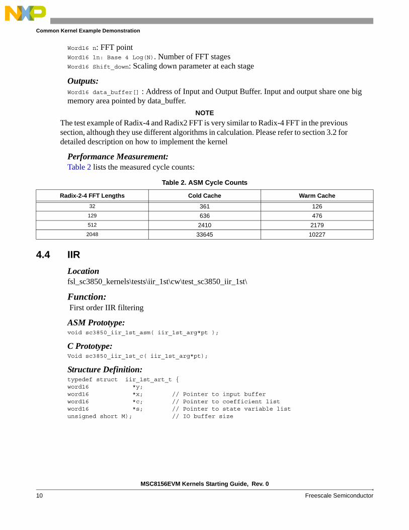
4.4 IIR
Locationfsl_sc3850_kernels\tests\iir_1st\cw\test_sc3850_iir_1st\
Function: First order IIR filtering
ASM Prototype:void sc3850_iir_1st_asm( iir_1st_arg*pt );
C Prototype:Void sc3850_iir_1st_c( iir_1st_arg*pt);
Structure Definition:typedef struct iir_1st_art_t { word16 *y; word16 *x; // Pointer to input bufferword16 *c; // Pointer to coefficient listword16 *s; // Pointer to state variable listunsigned short M); // IO buffer size
Table 2. ASM Cycle Counts
Radix-2-4 FFT Lengths Cold Cache Warm Cache
32 361 126
129 636 476
512 2410 2179
2048 33645 10227
MSC8156EVM Kernels Starting Guide, Rev. 0
Freescale Semiconductor 11
Common Kernel Example Demonstration
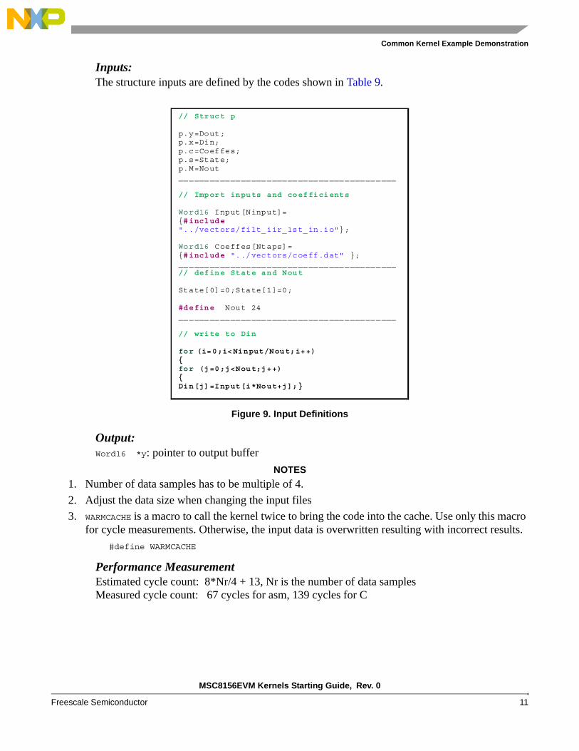
Inputs:The structure inputs are defined by the codes shown in Table 9.
Output:Word16 *y: pointer to output buffer
NOTES
1. Number of data samples has to be multiple of 4.
2. Adjust the data size when changing the input files
3. WARMCACHE is a macro to call the kernel twice to bring the code into the cache. Use only this macro for cycle measurements. Otherwise, the input data is overwritten resulting with incorrect results.
#define WARMCACHE
Performance MeasurementEstimated cycle count: 8*Nr/4 + 13, Nr is the number of data samplesMeasured cycle count: 67 cycles for asm, 139 cycles for C
Figure 9. Input Definitions
// Struct p p.y=Dout; p.x=Din; p.c=Coeffes; p.s=State; p.M=Nout __________________________________________ // Import inputs and coefficients Word16 Input[Ninput]= {#include "../vectors/filt_iir_1st_in.io"}; Word16 Coeffes[Ntaps]= {#include "../vectors/coeff.dat" }; __________________________________________ // define State and Nout State[0]=0;State[1]=0; #define Nout 24 __________________________________________ // write to Din for (i=0;i<Ninput/Nout;i++) { for (j=0;j<Nout;j++) { Din[j]=Input[i*Nout+j];}
MSC8156EVM Kernels Starting Guide, Rev. 0
12 Freescale Semiconductor
Common Kernel Example Demonstration
4.5 Division 16×16
Locationfsl_sc3850_kernels\tests\div\cw\test_sc3850_div\
FunctionCompute y = a/b where a, b are 16 bits real numbers
ASM Prototype:Word16 sc3850_div_16x16_asm(div_arg_16x16*arg)
C Prototype:Word16 sc3850_div_16x16_c(div_arg_16x16*arg)
Structure Definition:typedef struct div_arg_16x16_t { word16 a, word16 b}
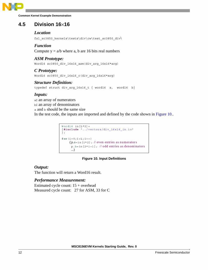
Inputs:a: an array of numeratorsb: an array of denominatorsa and b should be the same sizeIn the test code, the inputs are imported and defined by the code shown in Figure 10..
Output:The function will return a Word16 result.
Performance Measurement:Estimated cycle count: 15 + overheadMeasured cycle count: 27 for ASM, 33 for C
Figure 10. Input Definitions
Word16 in[L*2]= {#include "../vectors/div_16x16_in.io" };
for(i=0;i<L;i++)
{p.a=in[i*2]; // even entries as numerator s p.b=in[2*i+1]; // odd entries as denominators …}
MSC8156EVM Kernels Starting Guide, Rev. 0
Freescale Semiconductor 13
Common Kernel Example Demonstration
4.6 Ln
Locationfsl_sc3850_kernels\tests\Ln\
Function:Computes Ln(x) for every x in the input array and returns the results into the output array.
C Prototype:Word32 sc3850_ln_c( ln_arg_t);
Structure Definition:typedef struct ln_arg_t { Word32 *X, // The array of input values Word32 *Y, // The array of results after computation unsigned Short n}
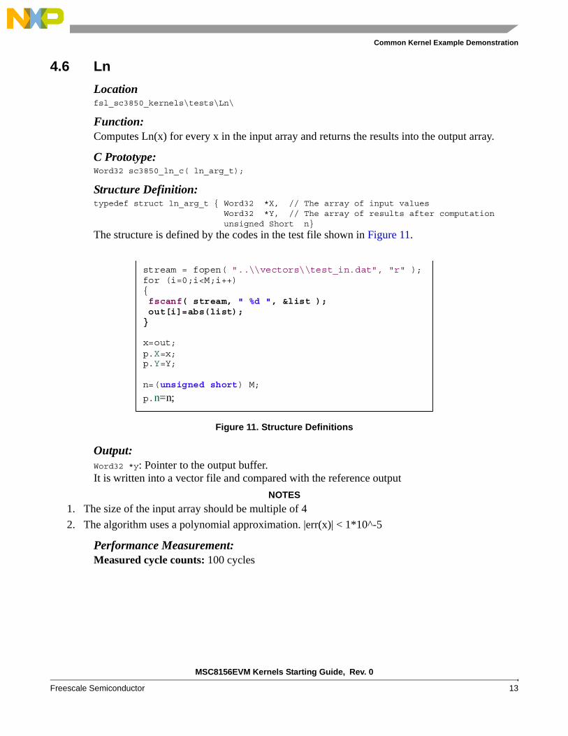
The structure is defined by the codes in the test file shown in Figure 11.
Output:Word32 *y: Pointer to the output buffer.It is written into a vector file and compared with the reference output
NOTES
1. The size of the input array should be multiple of 4
2. The algorithm uses a polynomial approximation. |err(x)| < 1*10^-5
Performance Measurement:Measured cycle counts: 100 cycles
Figure 11. Structure Definitions
stream = fopen( "..\\vectors\\test_in.dat", "r" ); for (i=0;i<M;i++) { fscanf( stream, " %d ", &list ); out[i]=abs(list); } x=out; p.X=x; p.Y=Y; n=(unsigned short) M;
p.n=n;
MSC8156EVM Kernels Starting Guide, Rev. 0
14 Freescale Semiconductor
Common Kernel Example Demonstration
4.7 Matrix Inversion Complex 2×2
Location fsl_sc3850_kernels\tests\matrix_inv_complex_2x2\cw\test_sc3850_mat_inv_complex_2x2\
Function:Computes the inverse of a complex 2x2 matrix, 16-bit signed input, 16-bit signed output.
C Prototype:Complex16 sc3850_matrix_inverse_2x2_complex16_C(
const Complex16 * input, Complex16 * output, Word16 * output_shift_left);
ASM Prototype:Complex16 sc3850_matrix_inverse_2x2_complex16_ASM(
const Complex16 * input, Complex16 * output, Word16 * output_shift_left);
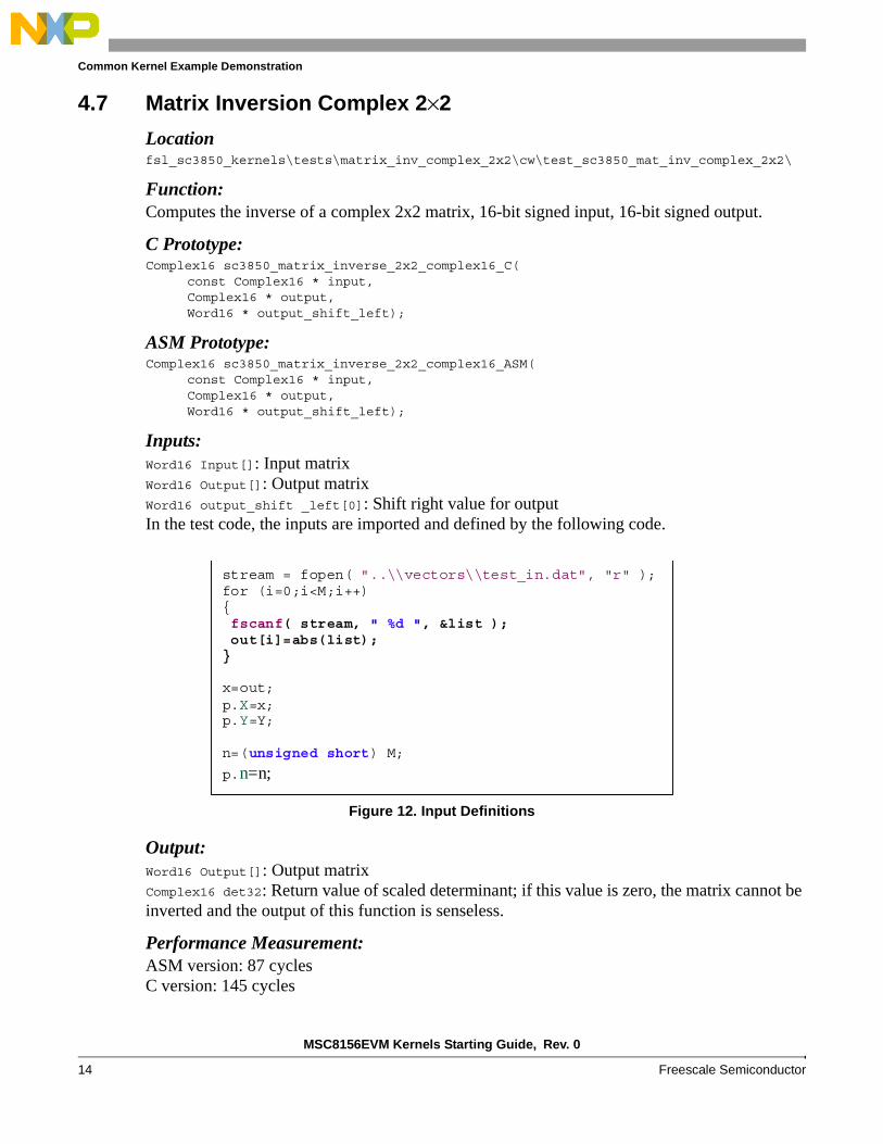
Inputs:Word16 Input[]: Input matrixWord16 Output[]: Output matrixWord16 output_shift _left[0]: Shift right value for outputIn the test code, the inputs are imported and defined by the following code.
Output:Word16 Output[]: Output matrixComplex16 det32: Return value of scaled determinant; if this value is zero, the matrix cannot be inverted and the output of this function is senseless.
Performance Measurement:ASM version: 87 cyclesC version: 145 cycles
Figure 12. Input Definitions
stream = fopen( "..\\vectors\\test_in.dat", "r" ); for (i=0;i<M;i++) { fscanf( stream, " %d ", &list ); out[i]=abs(list); } x=out; p.X=x; p.Y=Y; n=(unsigned short) M;
p.n=n;
MSC8156EVM Kernels Starting Guide, Rev. 0
Freescale Semiconductor 15
Common Kernel Example Demonstration
4.8 Matrix Inversion Complex 4×4
Locationfsl_sc3850_kernels\tests\matrix_inv_complex_4x4\cw\test_sc3850_mat_inv_complex_4x4\
Function:Computes the inverse of a complex 4x4 matrix, 16-bit complex input (16-bit real and 16-bit complex), 32-bit signed output (32-bit real and 32-bit complex).
C Prototype:Word32 sc3850_matrix_inverse_4x4_scale_c(
const Complex16 * source, Word32 * output, Word16 * sf,Word32 det,Word32 input_shift);
ASM Prototype:Word32 sc3850_matrix_inverse_4x4_scale_ASM(
const Complex16 * source, Word32 * output, Word16 * sf,Word32 det,Word32 input_shift);
Inputs:const Complex16* source: Pointer to input matrix, input must be in Complex16 formatWord32 detmin: Determinant threshold used to return an error codeWord32 input_shift: Shift parameter used to scale down the input data to avoid overflowing
Output:Word16 *sf: Pointer to scaling factorWord32 * output: Pointer to output matrix, the output is in Complex32 format
Performance Measurement:ASM version: 294 cyclesOptimized C version: 511 cycles
Document Number: AN4228Rev. 010/2010
Freescale, the Freescale logo, CodeWarrior, and StarCore are trademarks of Freescale Semiconductor, Inc., Reg. U.S. Pat. & Tm. Off. All other product or service names are the property of their respective owners.
© 2010 Freescale Semiconductor, Inc.
Information in this document is provided solely to enable system and software
implementers to use Freescale Semiconductor products. There are no express or
implied copyright licenses granted hereunder to design or fabricate any integrated
circuits or integrated circuits based on the information in this document.
Freescale Semiconductor reserves the right to make changes without further notice to
any products herein. Freescale Semiconductor makes no warranty, representation or
guarantee regarding the suitability of its products for any particular purpose, nor does
Freescale Semiconductor assume any liability arising out of the application or use of
any product or circuit, and specifically disclaims any and all liability, including without
limitation consequential or incidental damages. “Typical” parameters which may be
provided in Freescale Semiconductor data sheets and/or specifications can and do
vary in different applications and actual performance may vary over time. All operating
parameters, including “Typicals” must be validated for each customer application by
customer’s technical experts. Freescale Semiconductor does not convey any license
under its patent rights nor the rights of others. Freescale Semiconductor products are
not designed, intended, or authorized for use as components in systems intended for
surgical implant into the body, or other applications intended to support or sustain life,
or for any other application in which the failure of the Freescale Semiconductor product
could create a situation where personal injury or death may occur. Should Buyer
purchase or use Freescale Semiconductor products for any such unintended or
unauthorized application, Buyer shall indemnify and hold Freescale Semiconductor
and its officers, employees, subsidiaries, affiliates, and distributors harmless against all
claims, costs, damages, and expenses, and reasonable attorney fees arising out of,
directly or indirectly, any claim of personal injury or death associated with such
unintended or unauthorized use, even if such claim alleges that Freescale
Semiconductor was negligent regarding the design or manufacture of the part.
How to Reach Us:
Home Page: www.freescale.com
Web Support: http://www.freescale.com/support
USA/Europe or Locations Not Listed: Freescale Semiconductor, Inc.Technical Information Center, EL5162100 East Elliot Road Tempe, Arizona 85284 +1-800-521-6274 or+1-480-768-2130www.freescale.com/support
Europe, Middle East, and Africa:Freescale Halbleiter Deutschland GmbHTechnical Information CenterSchatzbogen 781829 Muenchen, Germany+44 1296 380 456 (English) +46 8 52200080 (English)+49 89 92103 559 (German)+33 1 69 35 48 48 (French) www.freescale.com/support
Japan: Freescale Semiconductor Japan Ltd. HeadquartersARCO Tower 15F1-8-1, Shimo-Meguro, Meguro-ku Tokyo 153-0064Japan 0120 191014 or+81 3 5437 [email protected]
Asia/Pacific: Freescale Semiconductor China Ltd. Exchange Building 23FNo. 118 Jianguo RoadChaoyang DistrictBeijing 100022China+86 010 5879 [email protected]
For Literature Requests Only:Freescale Semiconductor
Literature Distribution Center +1-800 441-2447 or+1-303-675-2140Fax: +1-303-675-2150LDCForFreescaleSemiconductor
@hibbertgroup.com
Related Documents