S3 - 1 Composites Technology Day, January 2012 Copyright 2012 MSC.Software Corporation Composites Technology Day, February 2012 Copyright 2012 MSC.Software Corporation SECTION 3 Progressive Ply Failure and Delamination Modeling

Welcome message from author
This document is posted to help you gain knowledge. Please leave a comment to let me know what you think about it! Share it to your friends and learn new things together.
Transcript

S3 - 1
Composites Technology Day, January 2012
Copyright 2012 MSC.Software Corporation
Composites Technology Day, February 2012
Copyright 2012 MSC.Software Corporation
SECTION 3
Progressive Ply Failure and
Delamination Modeling

S3 - 2
Composites Technology Day, January 2012
Copyright 2012 MSC.Software Corporation
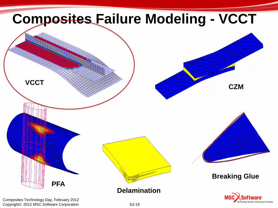
Composites Failure Modeling
• Look at types of problems you can solve today with
MSC’s composite failure technology
• Examples demonstrating how to apply this technology
and how it works

S3-3
Composites Technology Day, February 2012
Copyright 2012 MSC.Software Corporation
Composite Fuselage Example
• Composite aircraft fuselage – Light weight composite components
– Constructed from layered composite
material
– Bonded and/or fastened together
S3-4
Composites Technology Day, February 2012
Copyright 2012 MSC.Software Corporation
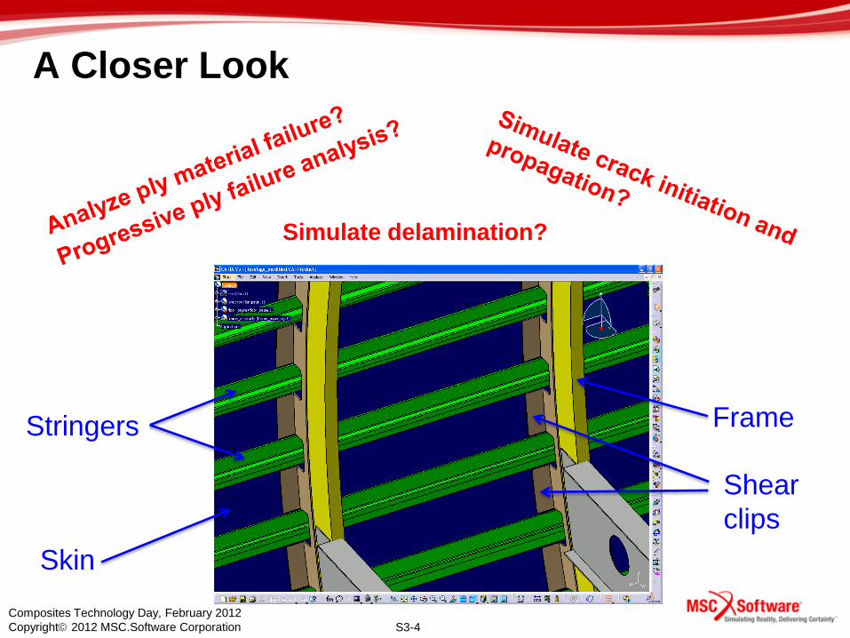
A Closer Look
Skin
Stringers Frame
Shear
clips
Simulate delamination?
S3-5
Composites Technology Day, February 2012
Copyright 2012 MSC.Software Corporation
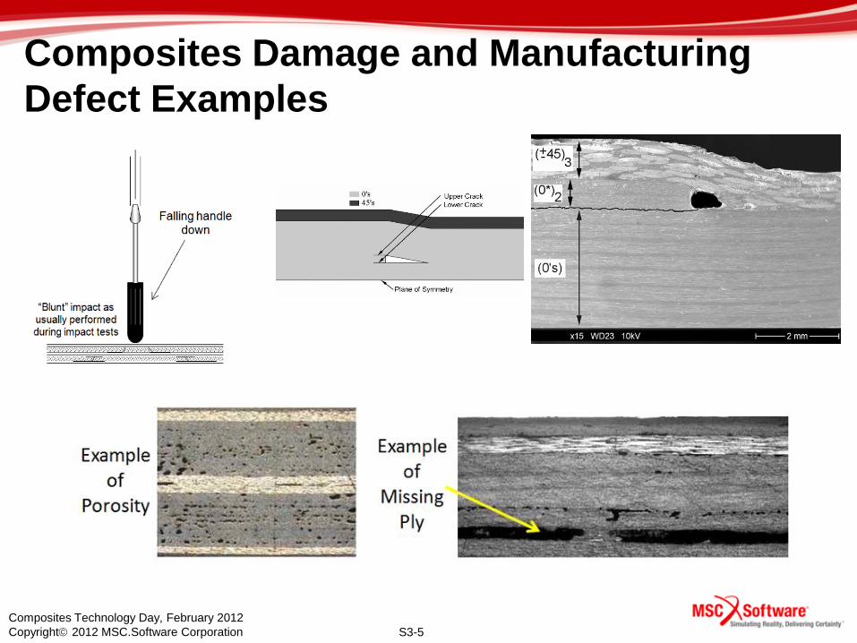
Composites Damage and Manufacturing
Defect Examples

S3-6
Composites Technology Day, February 2012
Copyright 2012 MSC.Software Corporation
Composites Failure Examples

S3-7
Composites Technology Day, February 2012
Copyright 2012 MSC.Software Corporation
First-Ply-Failure Analysis
• First-Ply Failure (FPF) – Linear analysis based on failure theory
– Compute failure index or strength ratio
for the ply material
– Optimization of ply angle/thickness
Critical Margin of Safety

S3-8
Composites Technology Day, February 2012
Copyright 2012 MSC.Software Corporation
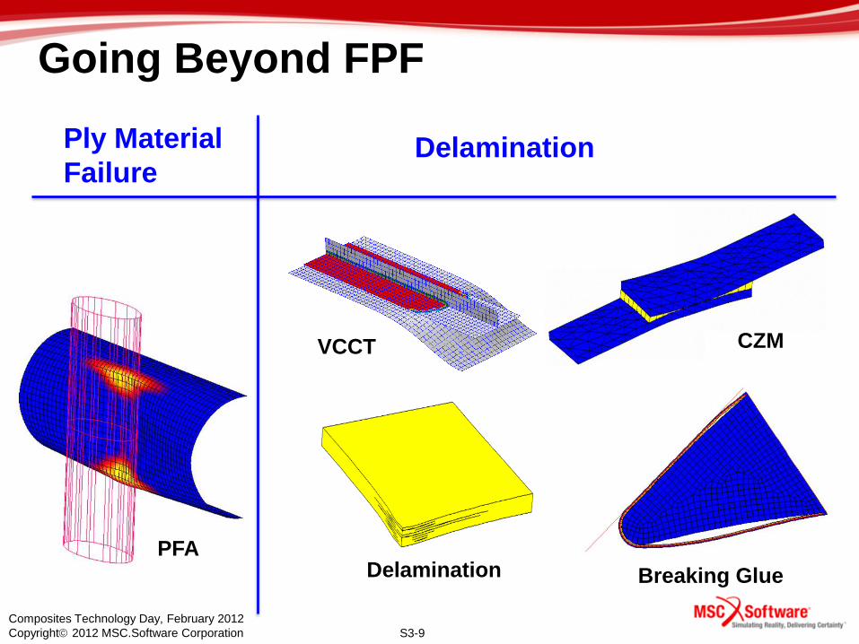
Going Beyond FPF
• Evaluate the load redistribution in a composite
structure as the plies fail progressively
• Simulate delamination growth from initial flaw
• Study crack propagation to design for fail-safe
structures
S3-9
Composites Technology Day, February 2012
Copyright 2012 MSC.Software Corporation
9
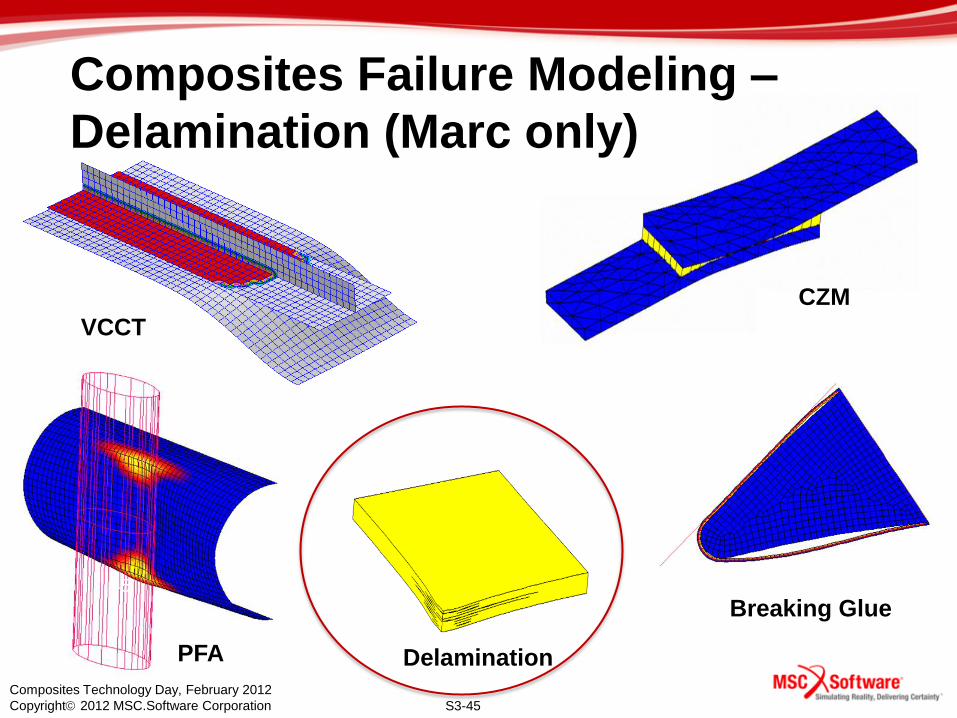
VCCT CZM
Delamination Breaking Glue
PFA
Going Beyond FPF
Ply Material
Failure Delamination

S3-10
Composites Technology Day, February 2012
Copyright 2012 MSC.Software Corporation
Layered Composite
definition
FAQ: What Element types are supported?
• Composite failure modeling is supported in both shell
and solid elements
Shell
element
Solid
element
Solid Shell
element

S3-11
Composites Technology Day, February 2012
Copyright 2012 MSC.Software Corporation
11
VCCT CZM
Delamination
Breaking Glue PFA
Composites Failure Modeling - PFA

S3-12
Composites Technology Day, February 2012
Copyright 2012 MSC.Software Corporation
Progressive Failure Analysis (PFA) • Also known as Progressive Ply Failure (PPF)
• Select a failure criterion
• Select a degradation option
• The composite is failed on a layer by layer basis
• Upon failure, the elastic properties are scaled down
Pin bearing on hole

S3-13
Composites Technology Day, February 2012
Copyright 2012 MSC.Software Corporation
Composite Failure Criteria
Composite Failure
• Most of the criteria are semi-empirical in
nature
Composite Failure on Layer Basis
• Maximum Stress
• Maximum Strain
• Hill
• Hoffman
• Tsai-Wu
• Hashin
• Puck
• Hashin-Tape
• Hashin-Fabric
• User defined (UFAIL)

S3-14
Composites Technology Day, February 2012
Copyright 2012 MSC.Software Corporation
PFA Options
Progressive Composite Failure options
• Flagged through the MATF entry (ITYPE = 2 or 3)
• Up to three failure criteria can be selected
• Only the primary failure criterion is used for PFA
• The other two are only used to calculate failure indices
• The behavior up to the failure point is linear elastic
• Upon failure…
– When failure index is larger than one, degrade material moduli
– Selective degradation – if matrix fails, do not change fiber properties
– Stiffness drops gradually or immediately

S3-15
Composites Technology Day, February 2012
Copyright 2012 MSC.Software Corporation
MSC Nastran Input Data Format
ITYPE: 0 – No PFA; 2 – Gradual Selective; 3 – Immediate Selective
Criterion: 1 – Max. Stress; 2 – Max. Strain; 3 – Hill; 4 – Hoffman; 5 –
Tsai-Wu; 7 – Hashin; 8 – Puck; 10 – Hashin-Tape;11 – Hashin-
Fabric; 13 – User Subroutine
S3-16
Composites Technology Day, February 2012
Copyright 2012 MSC.Software Corporation
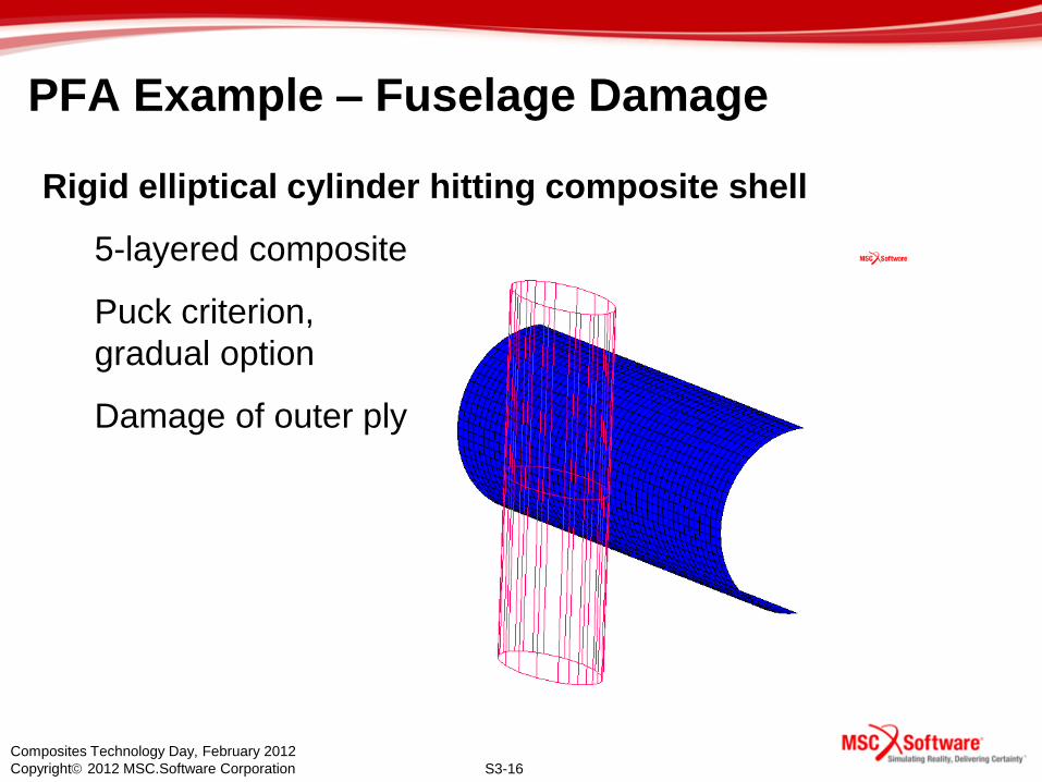
PFA Example – Fuselage Damage
Rigid elliptical cylinder hitting composite shell
5-layered composite
Puck criterion,
gradual option
Damage of outer ply
S3-17
Composites Technology Day, February 2012
Copyright 2012 MSC.Software Corporation 17
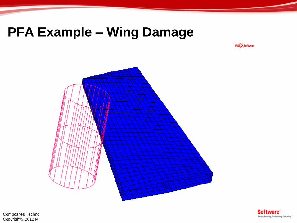
PFA Example – Wing Damage

S3-18
Composites Technology Day, February 2012
Copyright 2012 MSC.Software Corporation
Micromechanical Failure model
• Traditional approach computes
composites failure based on
ply-level failure properties
• The Micromechanical approach
gets down to the fiber and
matrix level and looks at the
failure mechanism at the
constituent level
• MSC has partnered with
Firehole to bring the Helius
MCT micromechanical failure
technology to our users
S3-19
Composites Technology Day, February 2012
Copyright 2012 MSC.Software Corporation
19
VCCT CZM
Delamination
Breaking Glue PFA
Composites Failure Modeling - VCCT

S3-20
Composites Technology Day, February 2012
Copyright 2012 MSC.Software Corporation
VCCT
• In linear fracture mechanics, a crack starts to
grow when
– Total G > Gc
– G is the energy release rate
– Gc is the fracture toughness
• The VCCT is one of the methods used to
compute the energy release rate.

S3-21
Composites Technology Day, February 2012
Copyright 2012 MSC.Software Corporation
VCCT (Virtual Crack Closure Technique)
• FEM approximation: Use consistent nodal force at
tip and crack opening at first crack segment
• Energy release rate:
G = Fu/2a
• Growth method
• Release glued contact
• Grow along element edge
• Remeshing
Marc Only

S3-22
Composites Technology Day, February 2012
Copyright 2012 MSC.Software Corporation
VCCT
• Supported in both Marc and MSC Nastran
• Supported crack types are shown below
line crack – 2D or shell face crack – shell to shell face crack – 3D solid
line crack – shell edge to solid or shell face crack – shell to solid
S3-23
Composites Technology Day, February 2012
Copyright 2012 MSC.Software Corporation
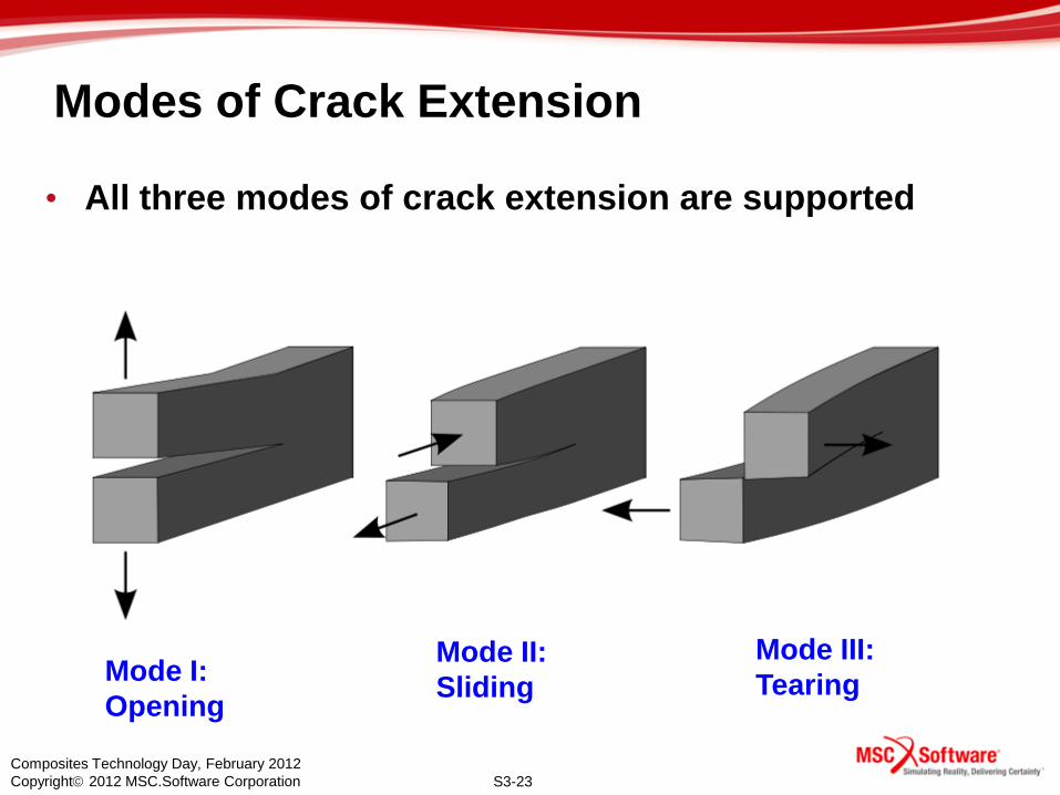
Modes of Crack Extension
• All three modes of crack extension are supported
Mode I:
Opening
Mode II:
Sliding
Mode III:
Tearing

S3-24
Composites Technology Day, February 2012
Copyright 2012 MSC.Software Corporation
VCCT Example – Release glued contact
• Skin-Stringer Delamination – Wagner/Balzani, Computers & Structures 2008
– Stringer glued to skin
initial crack front
fixed stringer push skin downward
stringer
skin Initial
delamination
VCCT key ingredients:
- Initial crack
- Define crack front nodes

S3-25
Composites Technology Day, February 2012
Copyright 2012 MSC.Software Corporation
Animation shows region
released from glued
VCCT Example – Release glued contact
Animation shows glued
region

S3-26
Composites Technology Day, February 2012
Copyright 2012 MSC.Software Corporation
VCCT Example – Release glued contact
• Benchmark Problems
SLB
DCB
DCB
DCB

S3-27
Composites Technology Day, February 2012
Copyright 2012 MSC.Software Corporation
VCCT Example – Release glued contact
F
F
• 4-Ply Composite
modeled with 2
layers of solid
elements
• Defect between
3rd and 4th ply
• Glue parts
together, except
at defect
Embedded circular defect
Buckling Delamination

S3-28
Composites Technology Day, February 2012
Copyright 2012 MSC.Software Corporation
VCCT Example – Release glued contact
S3-29
Composites Technology Day, February 2012
Copyright 2012 MSC.Software Corporation
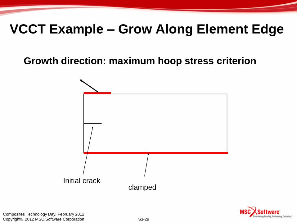
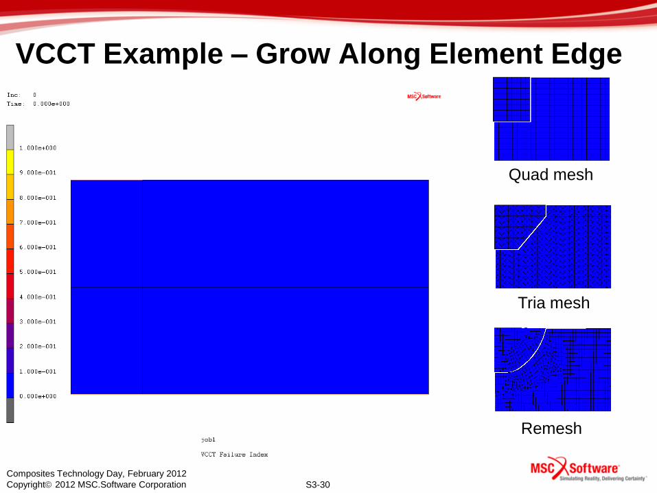
VCCT Example – Grow Along Element Edge
clamped Initial crack
Growth direction: maximum hoop stress criterion
S3-30
Composites Technology Day, February 2012
Copyright 2012 MSC.Software Corporation
Quad mesh
Tria mesh
Remesh
VCCT Example – Grow Along Element Edge

S3-31
Composites Technology Day, February 2012
Copyright 2012 MSC.Software Corporation
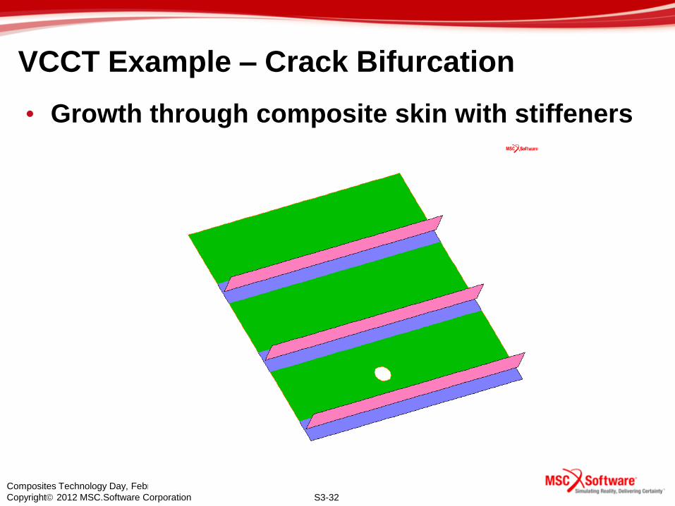
VCCT Example – Crack Bifurcation
glued
shell thickness with offsets
elastic orthotropic material
composite with four layers: [-45/90/0/45]
8 layers
4 layers
• New technology
– Crack tip automatically generated as the crack reaches
the stiffener
S3-32
Composites Technology Day, February 2012
Copyright 2012 MSC.Software Corporation
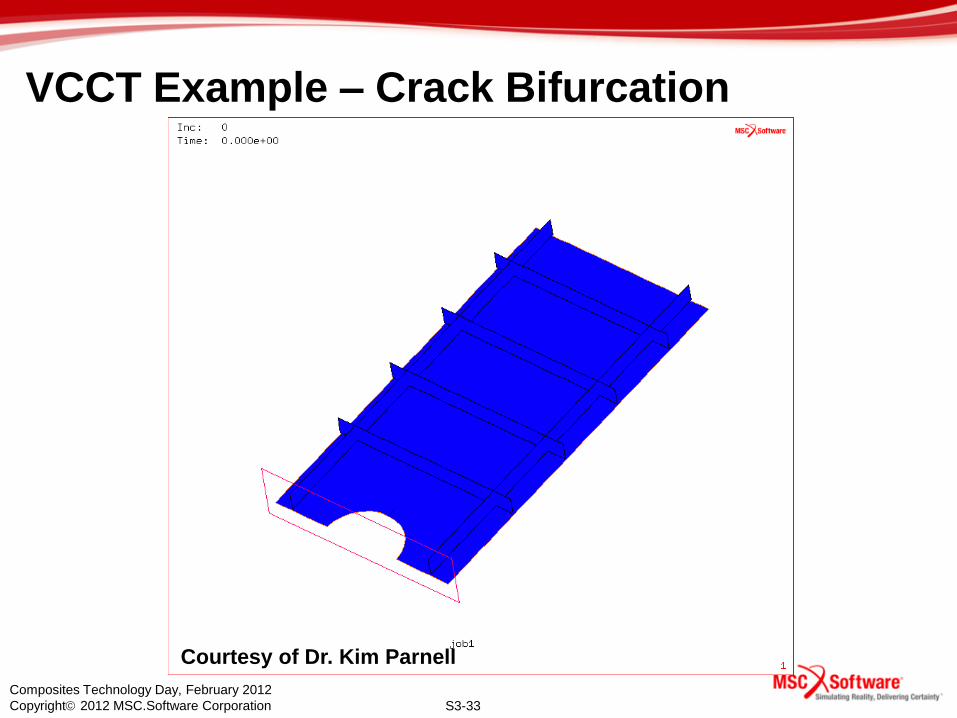
VCCT Example – Crack Bifurcation
• Growth through composite skin with stiffeners
S3-33
Composites Technology Day, February 2012
Copyright 2012 MSC.Software Corporation
VCCT Example – Crack Bifurcation
Courtesy of Dr. Kim Parnell

S3-34
Composites Technology Day, February 2012
Copyright 2012 MSC.Software Corporation
34
VCCT CZM
Delamination
Breaking Glue PFA
Composites Failure Modeling - CZM

S3-35
Composites Technology Day, February 2012
Copyright 2012 MSC.Software Corporation
Cohesive Zone Modeling (CZM)
• Cohesive Zone Modeling (CZM) is a technique
used to simulate delamination growth.
• The implementation of CZM is based on:
• Library of special interface elements
• Material model to characterize the interface behavior
Interface Element

S3-36
Composites Technology Day, February 2012
Copyright 2012 MSC.Software Corporation
Cohesive Zone Modeling (CZM)
• The constitutive behavior of these elements is
expressed in terms of tractions versus relative
displacements between the top and bottom
edge/surface of the elements
• Top and bottom faces may coincide
36
V is the effective opening displacement

S3-37
Composites Technology Day, February 2012
Copyright 2012 MSC.Software Corporation
Cohesive Zone Modeling (CZM)
• Material models
• Bilinear
• Exponential
• Linear-exponential
• Material behavior
• Initially reversible
• Irreversible if v > vc
bottom face
1
2
3
4
5
6
7
8 top face
s
n
t
top and bottom face may coincide (zero thickness)

S3-38
Composites Technology Day, February 2012
Copyright 2012 MSC.Software Corporation
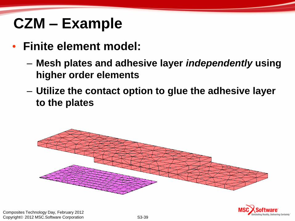
CZM – Example
• Lap-Shear Joint:
• Reference: M.N. Cavalli, M.D. Thouless and Q.D. Yang, Cohesive-Zone
Modeling of the Deformation and Fracture of Weld-Bonded Joints;
Welding Journal Vol. 83, no. 4, 2004
Plates
Adhesive Region
S3-39
Composites Technology Day, February 2012
Copyright 2012 MSC.Software Corporation
CZM – Example
• Finite element model:
– Mesh plates and adhesive layer independently using
higher order elements
– Utilize the contact option to glue the adhesive layer
to the plates

S3-40
Composites Technology Day, February 2012
Copyright 2012 MSC.Software Corporation
CZM – Example

S3-41
Composites Technology Day, February 2012
Copyright 2012 MSC.Software Corporation
41
VCCT
CZM
Delamination
Breaking Glue
PFA
Composites Failure Modeling –
Breaking Glue Contact

S3-42
Composites Technology Day, February 2012
Copyright 2012 MSC.Software Corporation
Breaking Glued Contact
• Release glued contact when the
following stress criterion is met
• Use contact normal and
tangential stresses
• After break, do regular contact
with friction and separation
User specified
User specified

S3-43
Composites Technology Day, February 2012
Copyright 2012 MSC.Software Corporation
Example - Breaking glued contact
• Coating
debonding
• Load with
rigid body

S3-44
Composites Technology Day, February 2012
Copyright 2012 MSC.Software Corporation
Example - Breaking glued contact
• Coating
debonding
• Load with
rigid body
S3-45
Composites Technology Day, February 2012
Copyright 2012 MSC.Software Corporation
PFA
45
VCCT
CZM
Delamination
Breaking Glue
Composites Failure Modeling –
Delamination (Marc only)
S3-46
Composites Technology Day, February 2012
Copyright 2012 MSC.Software Corporation
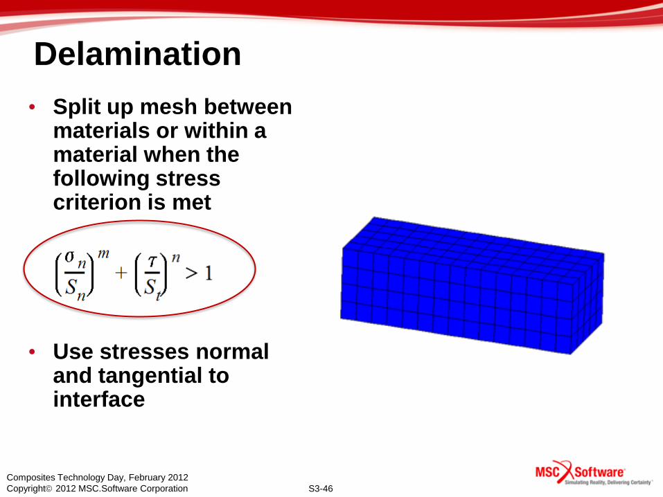
Delamination
• Split up mesh between materials or within a material when the following stress criterion is met
• Use stresses normal and tangential to interface

S3-47
Composites Technology Day, February 2012
Copyright 2012 MSC.Software Corporation
Delamination Examples
S3-48
Composites Technology Day, February 2012
Copyright 2012 MSC.Software Corporation
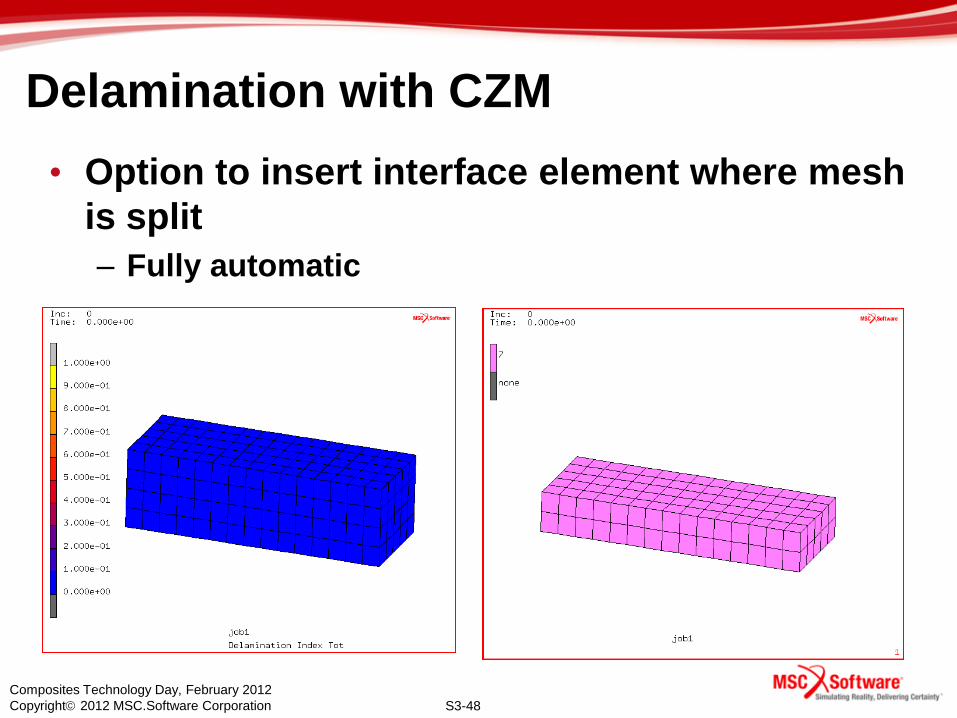
Delamination with CZM
• Option to insert interface element where mesh
is split
– Fully automatic

S3-49
Composites Technology Day, February 2012
Copyright 2012 MSC.Software Corporation
Delamination Example: Plate impact
• Composite plate, 8 layers, [0/45/-45/90]s
• Stacked solid shell elements – One element per layer
– No double nodes
• Clamped edges, prescribed downward motion of circular region in the center

S3-50
Composites Technology Day, February 2012
Copyright 2012 MSC.Software Corporation
Delamination Example: Plate impact
• View quarter
model
• Outline plot
• Delamination
between layers
(mesh
splitting)
• Contact
occurs
between layers

S3-51
Composites Technology Day, February 2012
Copyright 2012 MSC.Software Corporation
Delamination Example: Plate impact
• Automatic
insertion of
interface
elements
• Self contact
not needed
• Show only
interface
elements

S3-52
Composites Technology Day, February 2012
Copyright 2012 MSC.Software Corporation
52
Summary
• Progressive Failure Analysis (PFA)
• Virtual Crack Closure Technique (VCCT)
– Fracture mechanics
• Cohesive Zone Model (CZM)
– Interface elements
• Breaking glued contact
– Stress Criterion
• Delamination
– Stress Criterion

S3-53
Composites Technology Day, February 2012
Copyright 2012 MSC.Software Corporation
End of Section 3
Related Documents