M.Sc. in Communication and Information Systems Thesis Title: “Study and simulation of LTE physical uplink shared channel (PUSCH)” Student Name: Zachos Athanasios RegID: 4 Supervisor Professor: Dr. Dimitrios Efstathiou Serres, December 2013

Welcome message from author
This document is posted to help you gain knowledge. Please leave a comment to let me know what you think about it! Share it to your friends and learn new things together.
Transcript

M.Sc. in Communication and Information Systems
Thesis Title:
“Study and simulation of LTE physical uplink shared channel (PUSCH)”
Student Name:
Zachos Athanasios
RegID: 4
Supervisor Professor:
Dr. Dimitrios Efstathiou
Serres, December 2013

Introduction
• LTE stands for Long Term Evolution
• LTE is based on standards developed by 3rd Generation Partnership Project
(3GPP)
• LTE standards are described in Release 8
• LTE is next stage of mobile communication which will enable things like IP
based voice, high data streaming, on portable devices
• LTE is the first step towards IMT-Advanced (“4G”)

The Need for LTE
• Packet Switched data is becoming more and more dominant
• VoIP is the most efficient method to transfer voice data
• Amount of data is continuously growing
• Need for higher data rates at lower cost and spectral efficiency
• Users demand better quality to accept new services
• Need for cheaper infrastructure
• LTE will enhance the system to satisfy these requirements.

Advantages and Evolution of LTE

What is 3GPP ?
&
What does 3GPP produce?
• 3GPP Stands for 3rd Generation Partnership Project*
• The Partners are Standards Developing Organizations, SDOs:
• 3GPP is a ‘company contribution’ driven organization…companies participate in 3GPP
through their membership of one of the Partner SDOs
• Currently over 350 Individual Members (Operators, Vendors, Regulators)
• 13 Market Representation Partners (giving perspectives on market needs and drivers)
• Technical Specifications and Technical Reports for 3G Mobile (WCDMA, HSPA, LTE) and
4G Mobile (LTE-Advanced) Radio Interfaces and Service Layers. Also, the systems
architecture evolution that goes with it
• Evolved GSM specifications (GPRS, EDGE)
• Revised versions of 3GPP specifications are published following the quarterly Technical
Specification Group plenary meetings *3GPP is not constrained to 3rd Generation. It includes work on both 2nd and 4th generation
technologies.

The 3GPP Specifications for LTE • LTE introduced in Rel 8
• Minor improvements in Rel 9 and Rel 10
• Scalable channel bandwidths of 1.4, 3, 5, 10, 15 and 20 MHz allocations
• Support both paired (FDD) and unpaired (TDD) spectrum as well as half duplex FDD
• IP Packet switched radio interface
• Simplified architecture: The network side of E-UTRAN is composed only of eNodeBs
• Reasonable power consumption for the mobile terminal
• Flexible use of new and existing frequency bands
• Support for inter-operation and co-existence with legacy standards while evolving toward an all-IP network
• Supports at least 200 active users in every 5 MHz cell
• Significantly increased average user throughput and spectrum efficiency
• Downlink target 3-4 times greater than HSDPA Release 6
• Uplink target 2-3 times greater than HSUPA Release 6
• Increased data rates 10 times more than HSPA Release 6 technology
• Downlink Peak Data Rate: 100Mbit/s in a 20MHz downlink spectrum (i.e. 5 bit/s/Hz)
• Uplink: 50Mbit/s in a 20MHz uplink spectrum (i.e. 2.5 bit/s/Hz)
• Significantly reduced latencies
• High level of mobility and security. Optimized for low mobility(0-15km/h) but supports high speed.
• LTE coverage is optimized for cell sizes up to 5 km, works with slight degradation of performance up to 30
km cells. Also cell range up to 100 km not precluded.
• RAN (Radio Access Network) round-trip times of less than 10ms
• Co-existence with legacy standards

Spectrum and Frequency Bands for LTE • Seamless integration with previous mobile systems and new frequency bands that
may be identified
• Support both paired and unpaired spectrum allocations
- FDD for paired spectrum, enables simultaneous transmission on two different sufficiently separated frequencies: one for DL and one for UL.
- TDD for unpaired spectrum, DL and UL transmissions share the same channel and carrier frequency. Transmissions are time multiplexed.
- Half-duplex FDD at the terminal, transmission and reception separated in both frequency and time.
• 29 FDD and 12 TDD Frequency Bands
• High degree of commonality between the bands is desired to enable global roaming.
• WRC ‘07 identified additional frequency bands for IMT, e.g. 450-470MHz, 698-806MHz, 3400-3600MHz
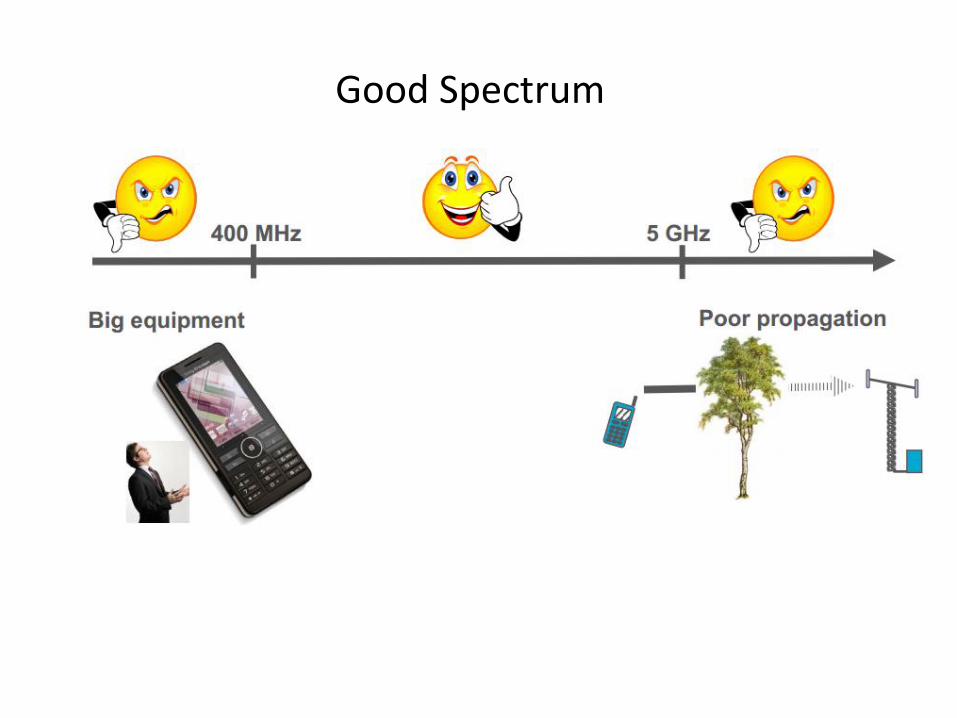
Good Spectrum

LTE Supported Frequency Bands
3GPP TS 36.101 version 11.7.0 Release 11
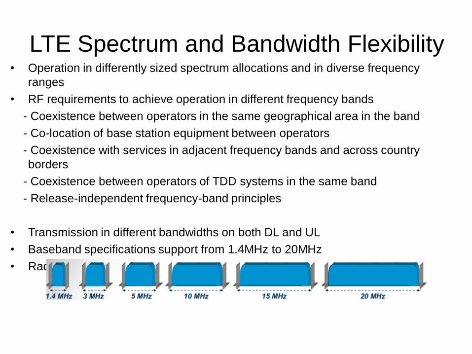
LTE Spectrum and Bandwidth Flexibility • Operation in differently sized spectrum allocations and in diverse frequency
ranges
• RF requirements to achieve operation in different frequency bands
- Coexistence between operators in the same geographical area in the band
- Co-location of base station equipment between operators
- Coexistence with services in adjacent frequency bands and across country
borders
- Coexistence between operators of TDD systems in the same band
- Release-independent frequency-band principles
• Transmission in different bandwidths on both DL and UL
• Baseband specifications support from 1.4MHz to 20MHz
• Radio-frequency requirements set for a limited set of spectrum allocation

Key Features of LTE Downlink: OFDMA
• High spectral efficiency
• Robust against frequency-selectivity / multi-path interference
• Inter-symbol interference contained within cyclic prefix
• Supports flexible bandwidth deployment
• Facilitates frequency-domain scheduling
• Well suited to advanced MIMO techniques
Uplink: SC-FDMA
• Based on OFDMA with DFT precoding
• Common structure of transmission resources compared to downlink
• Cyclic prefix facilitates frequency-domain equalisation at eNodeB
• Low PAPR for efficient transmitter design (mobile power saving)

Frame Structure
Frame Structure Type 1 (FDD and Half-duplex FDD)
Frame Structure Type 2
(TDD)

13
Resource Grid
• One frame is 10ms 10 subframes
• 6 or 7 SC-FDMA symbols in one slot
• One subframe is 1ms 2 slots
• Subcarrier spacing = 15 kHz
• One slot contains N Resource Blocks (6 < N < 110)
• Block of 12 SCs in 1 slot = 1 RB
- 0.5 ms x 180 kHz -Smallest unit of allocation
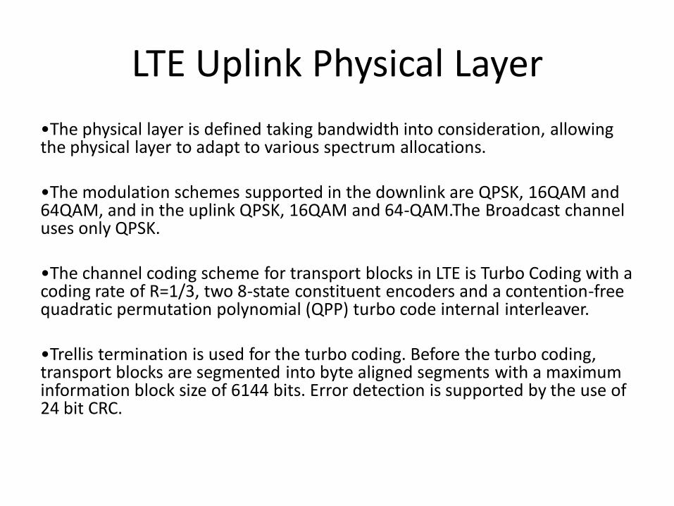
LTE Uplink Physical Layer
•The physical layer is defined taking bandwidth into consideration, allowing the physical layer to adapt to various spectrum allocations.
•The modulation schemes supported in the downlink are QPSK, 16QAM and 64QAM, and in the uplink QPSK, 16QAM and 64-QAM.The Broadcast channel uses only QPSK.
•The channel coding scheme for transport blocks in LTE is Turbo Coding with a coding rate of R=1/3, two 8-state constituent encoders and a contention-free quadratic permutation polynomial (QPP) turbo code internal interleaver.
•Trellis termination is used for the turbo coding. Before the turbo coding, transport blocks are segmented into byte aligned segments with a maximum information block size of 6144 bits. Error detection is supported by the use of 24 bit CRC.
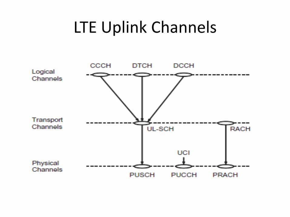
LTE Uplink Channels

LTE Uplink Transport Channels

Uplink Physical Channels

Physical Uplink Shared Channel (PUSCH)
• Data transmissions on Physical Uplink Shared Channel (PUSCH)
- In centre of uplink bandwidth
- Minimizes out-of-band emissions from wide-bandwidth data transmissions
- 1 transport block per TTI
- Same channel coding / rate matching as PDSCH
- Modulation QPSK, 16QAM, 64QAM
• When PUSCH is transmitted, any control signalling is multiplexed with data to
maintain single carrier structure
• When no PUSCH, control signalling is on Physical Uplink Control Channel (PUCCH)
- Usually at edges of system bandwidth
- PUCCH hops from one side of the carrier to the other to maximize frequency
diversity

Control Signalling on PUSCH • PUSCH carries the uplink L1/L2 control signals in the presence of uplink
data
• CQI/PMI transmitted on PUSCH uses the same modulation scheme as data
• ACK/NACK and RI are transmitted so that the
coding/scrambling/modulation maximize the Euclidean distance at the
symbol level. The outermost constellation points are used to signal these for
16-QAM and 64-QAM
• Different channel coding approaches are applied with control signals
transmitted on PUSCH:
- 1-bit ACK/NACK: repetition coding
- 2-bit ACK/NACK/RI: simplex coding
- CQI/PMI < 11 bits: (32,N) Reed-Muller coding
- CQI/PMI > 11 bits: tail-biting convolutional coding (1/3)
• An important issue related to control signaling on PUSCH is how to keep
the performance of control signaling at the target level.

PUSCH Processing

PUSCH Frequency Hopping
• PUSCH Transmission
- Localized transmission w/o frequency hopping
-> Frequency Selective Scheduling Gain
- Distributed transmission with “frequency hopping”
-> Frequency Diversity Gain, Inter-cell Interference Randomization
• Two types of PUSCH frequency hopping
- Sub-band based hopping according to cell-specific hopping patterns
- Hopping based on explicit hopping information in the scheduling UL grant

Uplink Physical Signals
• UL Physical Signals
- An uplink physical signal is used by the physical layer but does not carry information originating from higher layers
• Two types of reference signals
- UL Demodulation Reference Signal (DRS) for PUSCH, PUCCH
- UL Sounding Reference Signal (SRS) not associated with PUSCH, PUCCH transmission

LTE Key Parameters
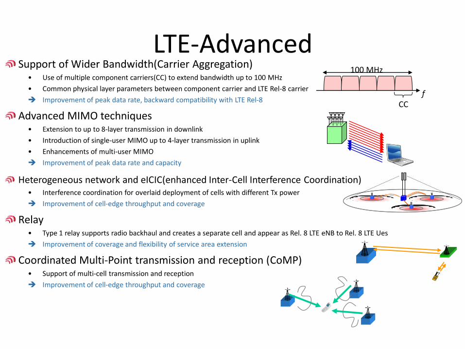
LTE-Advanced Support of Wider Bandwidth(Carrier Aggregation)
• Use of multiple component carriers(CC) to extend bandwidth up to 100 MHz
• Common physical layer parameters between component carrier and LTE Rel-8 carrier
Improvement of peak data rate, backward compatibility with LTE Rel-8
Advanced MIMO techniques • Extension to up to 8-layer transmission in downlink
• Introduction of single-user MIMO up to 4-layer transmission in uplink
• Enhancements of multi-user MIMO
Improvement of peak data rate and capacity
Heterogeneous network and eICIC(enhanced Inter-Cell Interference Coordination) • Interference coordination for overlaid deployment of cells with different Tx power
Improvement of cell-edge throughput and coverage
Relay • Type 1 relay supports radio backhaul and creates a separate cell and appear as Rel. 8 LTE eNB to Rel. 8 LTE Ues
Improvement of coverage and flexibility of service area extension
Coordinated Multi-Point transmission and reception (CoMP) • Support of multi-cell transmission and reception
Improvement of cell-edge throughput and coverage
100 MHz
f CC
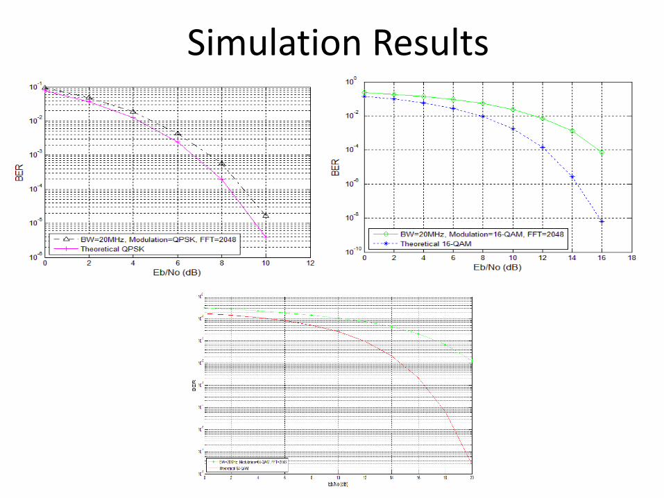
Simulation Results

Related Documents