STANDARDS & INDUSTRIAL RESEARCH INSTITUTE OF MALAYSIA MS 76 : 1972 ICS : 91.100.15 SPECIFICATION FOR BRICKS AND BLOCKS OF FIRED BRICKEARTH, CLAY OR SHALE PART 2 : METRIC UNITS MALAYSIAN STANDARD © Copyright Licensed to KEJURUTERAAN WARISAN TIMUR MAJU SDN BHD / Downloaded on : 25-Jun-2013 04:54:03 PM / Single user license only, copying and networking prohibited

MS 76-1972
Dec 27, 2015
Malaysian Standard
Welcome message from author
This document is posted to help you gain knowledge. Please leave a comment to let me know what you think about it! Share it to your friends and learn new things together.
Transcript
MS ISO/IEC TR 10037 : 1995
STANDARDS & INDUSTRIAL RESEARCH INSTITUTE OF MALAYSIA
MS 76 : 1972ICS : 91.100.15
SPECIFICATION FOR BRICKS AND BLOCKS OF FIREDBRICKEARTH, CLAY OR SHALEPART 2 : METRIC UNITS
MALAYSIANSTANDARD
© Copyright
Lice
nsed
to K
EJU
RU
TE
RA
AN
WA
RIS
AN
TIM
UR
MA
JU S
DN
BH
D /
Dow
nloa
ded
on :
25-J
un-2
013
04:5
4:03
PM
/ S
ingl
e us
er li
cens
e on
ly, c
opyi
ng a
nd n
etw
orki
ng p
rohi
bite
d

© SIRIM. No part of this publication may be photocopied or otherwise reproducedwithout the prior permission in writing of SIRIMLi
cens
ed to
KE
JUR
UT
ER
AA
N W
AR
ISA
N T
IMU
R M
AJU
SD
N B
HD
/ D
ownl
oade
d on
: 25
-Jun
-201
3 04
:54:
03 P
M /
Sin
gle
user
lice
nse
only
, cop
ying
and
net
wor
king
pro
hibi
ted
SPECIFICATION FOR
BRICKS AND BLOCKS OF FIREDBRICKEARTH, CLAY OR SHALE
PART 2. METRIC UNITS
MS 76:1972
© Copyright
Lice
nsed
to K
EJU
RU
TE
RA
AN
WA
RIS
AN
TIM
UR
MA
JU S
DN
BH
D /
Dow
nloa
ded
on :
25-J
un-2
013
04:5
4:03
PM
/ S
ingl
e us
er li
cens
e on
ly, c
opyi
ng a
nd n
etw
orki
ng p
rohi
bite
d

MS 76: 1972
This Malaysian Standard,which had been approvedby the CivilEngineeringand Building ConstructionIndustryStandardsCommitteeandendorsedby the StandardsCouncil, was published under the authorityof the StandardsCouncil in June, 1972.
SIM wishes to draw attention to the fact that this MalaysianStandard does not purport to include all the necessaryprovisions ofa contract.
Malaysian Standards are subject to periodical review to keepabreast of progress in the industries concerned. Suggestionsfor im-provementswill be recorded and in due course brought to the noticeof the Committee chargedwith the revision of the Standardsto whichthey refer,
The following SIM referencesrelate to the work on this standard:
CommitteeReference: SIM/I/7/018
Draft for Comment: D21(ISC7)
2
Lice
nsed
to K
EJU
RU
TE
RA
AN
WA
RIS
AN
TIM
UR
MA
JU S
DN
BH
D /
Dow
nloa
ded
on :
25-J
un-2
013
04:5
4:03
PM
/ S
ingl
e us
er li
cens
e on
ly, c
opyi
ng a
nd n
etw
orki
ng p
rohi
bite
d
MS 76: 1972
CONTENTSPage
Committee Representation... 7
Foreword ... ... ... 8
SPECIFICATIQN
1. Scope 14
Chapter 1. Bricks and Blocks for Walling
Section One: General
2. General ... ... ... ... ... 114
3. Definitions ... ... ... ... ... 14
4. Formats ... ... ... ... ... 16
5. Patterns ... ... ... ... ... 18
6. Compliance for Dimensions (Bricks) ... 18
7. Compliance for Dimensions (Blocks) ... 20
8. Compliance for Out of Squareness(Blocks) 20
9. Compliance for Bowing or Twisting (Blocks) 20
10. Strength and Absorption ... ... ... 21
Section Two: Specific ClausesSub-Section A: Facing and Common Bricks and Blocks of
Ordinary Quality
11. Finish ... ... ... ... 23
12. Strength ... ... ... 23
13. Soluble Salts Content ... 24
14. Liability to Efflorescence ... 24
3
Lice
nsed
to K
EJU
RU
TE
RA
AN
WA
RIS
AN
TIM
UR
MA
JU S
DN
BH
D /
Dow
nloa
ded
on :
25-J
un-2
013
04:5
4:03
PM
/ S
ingl
e us
er li
cens
e on
ly, c
opyi
ng a
nd n
etw
orki
ng p
rohi
bite
d
MS 76: 1972
Sub-Section B: Facing and Common Bricks and. Blocks of
Special Quality
15. Finish ... ... ... ... 24
16. Strength ... ... ... 24
17. Soluble Salts Content ... 25
18. Liability to Efflorescence ... 25
Sub-Section C: Bricks and Blocks for Internal Walls
19. Finish ... ... ... ... 25
20. Strength ... ... ... 25
211. Soluble Salts Content ... 26
22. Liability to Elrlorescence ... 26
Chapter 2. Hollow Blocks for Structural Floors and Roofs.
23. General ... ... ... 26
24. Formats ... ... ... ... 26
25. Compliance for Dimensions ... 28
26. Compliance for Out of Squareness 28
27. Compliance for Bowing or Twisting 28
28. Finish ... ... ... ... 28
29. Strength ... ... ... 29
30. Soluble Salts Content ... 29
31. Liability to Efflorescence ... ... 29
4
Lice
nsed
to K
EJU
RU
TE
RA
AN
WA
RIS
AN
TIM
UR
MA
JU S
DN
BH
D /
Dow
nloa
ded
on :
25-J
un-2
013
04:5
4:03
PM
/ S
ingl
e us
er li
cens
e on
ly, c
opyi
ng a
nd n
etw
orki
ng p
rohi
bite
d
MS 76: 1972
Chapter 3. Sampling Procedure and Test Methods
32. General 29
33. Samples ... ... 29
34. Method of Sampling ... ... ... ... ... 31
35. Determination of Dimension (Bricks) ... ... ... 34
36. Determination of Dimension (Blocks) ... ... ... 34
37. Deterinination of Out of Squareness(Blocks) ... ... 34
38. Determination of Bowing or Twisting (Blocks) ... 35
39. Determination of CompressiveStrength ... ... ... 35
40. Water Absorption Tests ... ... ... ... ... 45
41. Soluble Salts Analysis ... ... ... ... ... 48
42. Elllorcsccnce Test ... ... ... ... ... ... 53
43. Compliance ... ... ... ... ... ... ... 55
44. Procedure in the Event of Dispute ... ... ... 55
45. Cost of Testing ... ... ... ... ... ... 56
Appendix A. Application of Works Quality Control Schemefor Dimensions ... ... ... ... ... 57
Appendix B. Choice of Limits and AcceptanceClauses forDimensions of Bricks ... ... ... ... 64
Table 1. Standard Formats (Bricks) ... ... ... ... 17
Table 2. Standard Formats (Blocks) ... ... ... ... 17
Table 3. Dimensional Tolerances (Bricks) ... ... ... 1 8
Table 4. Dimensional Tolerances (B!ocks) ... ... ... 19
Table 5. Maximum Deviations on Dimensions 21
Table 6. Strength and Absorption ... ... 22
5
Lice
nsed
to K
EJU
RU
TE
RA
AN
WA
RIS
AN
TIM
UR
MA
JU S
DN
BH
D /
Dow
nloa
ded
on :
25-J
un-2
013
04:5
4:03
PM
/ S
ingl
e us
er li
cens
e on
ly, c
opyi
ng a
nd n
etw
orki
ng p
rohi
bite
d
MS 76: 1972
Table 7. Standard Formats (Floor Blocks) ... ... ... 27
Table 8. Limits for Use With Gauge Board ... ... 63
Table 9. Limits for Use With Alternative Scale forGauge Board ... ... ... ... ... ... 63
Figure 1. Arrangementsfor MeasuringClay Building Bricks(a) for Length, (b) for Width, (c) for Depth ... 66
Figure 2. Determination of ‘Out of Squareness’and‘Bowing or Twisting’ of Hollow Blocks ... 67
Figure 3. Apparatus for Vacuum Absorption Test ... 68
Figure 4. Apparatus for EfliorescenceTest ... ... ... 68
Figure 5. Gauge Board for Measuring Bricks ... ... 69
Figure 6. Double Bricks Referred to in Note 3,
Clause 39 (d)(iv) ... ... ... ... ... 70
6
Lice
nsed
to K
EJU
RU
TE
RA
AN
WA
RIS
AN
TIM
UR
MA
JU S
DN
BH
D /
Dow
nloa
ded
on :
25-J
un-2
013
04:5
4:03
PM
/ S
ingl
e us
er li
cens
e on
ly, c
opyi
ng a
nd n
etw
orki
ng p
rohi
bite
d
MS 76: 1972
Committee Representation
The Civil Engineeringand Building Construction Industry Stand-ards Committee under whose supervision this Malaysian Standardwasprepared, comprises representativesfrom the following GovernmentMinistries, trade commerceand manufacturerAssociation and scientificand professional bodies.
Association of Consulting Engineers (Malaysia)
Cement & Concrete Association, Malaysia
Federation of Malaysian Manufacturers
Institution of Engineers (Malaysia)
Institution of Surveyors, Malaysia
Malaysian Institute of Architects
Malaysian Scientific Association
Master Builders Association
Ministry of Agriculture and Lands
Ministry of Commerceand Industry
Ministry of Education
Ministry of Technology Research,& Local Government
Ministry of Works, Posts and Telecommunications(Public Works Department)
United Chambersof Commerce
University of Malaysia
7
Lice
nsed
to K
EJU
RU
TE
RA
AN
WA
RIS
AN
TIM
UR
MA
JU S
DN
BH
D /
Dow
nloa
ded
on :
25-J
un-2
013
04:5
4:03
PM
/ S
ingl
e us
er li
cens
e on
ly, c
opyi
ng a
nd n
etw
orki
ng p
rohi
bite
d

MS 76: 1972
FOREWORD
This Malaysian Standard has been prepared under the authorityof the Civil Engineering and Building Construction Industry StandardsCommittee. It is based on BS 3921: Part 2: 1969 which has beenpublished in metric units, in view of the fact that the country iscontemplatingchanging over to metric. In the interim, however, valuesgiven in imperial units within brackets may be used. But one systemof units should be adhered to throughout for consistency, and thevalues within brackets have been extracted from the correspondingBS 3921 : 1965 which has become Part 1 of the correspondingBritishStandard.
The technical difficulties in the way of a standard which shallgive useful guidance on the quality of all the many varieties of firedclay bricks and blocks are so great that it is still not possible tospecify completely every point of importance. Nevertheless,the com-mittee consideredthat the standard should provide as much guidanceas possible, even though some of the quality clauses will require re-vision in the light of further knowledge. The main issues raised bythis standard are discussedin the following paragraphs.
Attempts to ascertain the quality of clay bricks and blocks byinfrequent sampling and testing to a specification of isolated batchesare subject to uncertainty becausethe properties of clay products, likethose of other manufacturedproducts, are liable to variations over along period, as a result of changesin the naturally variable raw materials,as well as processvariations of products made at any one time, it istherefore good manufacturing technique to sample and test productsregularly and to record the results in the form of control charts onthe principles discussed in BS 2564, ‘Control chart technique whenmanufacturing to a specification’ and in Appendices A and B. Such
8
Lice
nsed
to K
EJU
RU
TE
RA
AN
WA
RIS
AN
TIM
UR
MA
JU S
DN
BH
D /
Dow
nloa
ded
on :
25-J
un-2
013
04:5
4:03
PM
/ S
ingl
e us
er li
cens
e on
ly, c
opyi
ng a
nd n
etw
orki
ng p
rohi
bite
d
MS 76: 1972
charts display the variation of propertieswith time and thus give moreinformation about a product than can be obtained by tests made ona single occasion. It is recommendedthat manufacturersshould maketheir control charts available for inspection by users and that usersshould recognize their value. This recommendationshall not precludeusers from taking samples in accordancewith Clauses33 and 34 fortesting in accordancewith the remaining Clauses of Chapter 3. Anysuch samples that users may require shall be taken before the bricksor blocks are built into work, especially where tests for soluble saltscontent or liability to efflorescenceare in question.
The treatmentof strength in the specific clauses reflects the fact,still not as widely appreciatedas it should be, that strength is notnecessarilyan index of durability and may be very misleading if usedas such. The main use of the strength test is as a guide to permissiblepressurein brickwork.
In the past, the permissible pressureson brickwork have beencalculated, in accordancewith British Standard CPI 11: 1948, ‘Struc-tural recommendationsfor loadbearing walls’, in terms of the meanstrength of samplesof twelve bricks taken at random and of the mortarcomposition. Variation in the strength of bricks and mortar and inworkmanship have been allowed for by using high load factors. Re-cently, calculated loadbearing brickwork has begun to be treated likeother structural engineeringmaterials and designedto finer limits. Wherethis is to be done, it is desirable that the bricks used should bemanufacturedunder a system of quality control on a sound statisticalbasis which enables the manufacturerto satisfy the user that he cansupply consignmentssuch that, when a sample is tested in accordancewith Clause 39, there is a specified probability, normally of not morethan I in 40, that the arithmetic mean of the sample will be belowa specified limit of compressivestrength.
9
Lice
nsed
to K
EJU
RU
TE
RA
AN
WA
RIS
AN
TIM
UR
MA
JU S
DN
BH
D /
Dow
nloa
ded
on :
25-J
un-2
013
04:5
4:03
PM
/ S
ingl
e us
er li
cens
e on
ly, c
opyi
ng a
nd n
etw
orki
ng p
rohi
bite
d

MS 76: 1972
The water absorption test also is given less prominencethan hasoften been accorded to it. A low water absorption figure can be usedin defining engineering bricks and bricks for damp-proof courses butwater absorption, like strength, is not a general index of durability.With many, but not all, clays, the more durable bricks absorb lesswater than those that are not so durable, so long as a single varietyof bricks is considered. No limit can be set, however, that will dis-criminate generally between durable and non-durable bricks. Recentwork has shown that the saturation coefficient, or ratio or 24-howcold absorptionto a total absorption by the boiling or vacuum methods,is less useful as an index of durability than was formerly thought. IIhas not, therefore, been included. The vacuum method has been spe-cified as an alternative to the boiling method, since some laboratoriesregardit as more convenientand the results are approximatelyequivalent.
The method of measuring24-hour cold absorption has also beenincluded in Clause 40, since this may occasionally he found useful forworks control, but no specific requirementsbased on this test are in-cluded in Section Two of Chapter 1.
The committee has given serious consideration to the problemof framing a specification which is basedon the knowledge that brickscontaining undueamountsof calcium, magnesium,potassiumand sodiumsuiphatesare liable to produce complaints about walls built with them.The complaints may be of two kinds: sulphate expansionof Portlandcement mortar and efflorescenceon brickwork.
Although cause and effect have been established broadly, conSsiderable difficulty has arisen when trying to decide what are suitablemaximum limits for the permissible contents or calcium, magnesium,potassium,sodium and sulphate individually or in toto. In some cir-cumstancesit would appear that bricks with a total soluble sulphate
10
Lice
nsed
to K
EJU
RU
TE
RA
AN
WA
RIS
AN
TIM
UR
MA
JU S
DN
BH
D /
Dow
nloa
ded
on :
25-J
un-2
013
04:5
4:03
PM
/ S
ingl
e us
er li
cens
e on
ly, c
opyi
ng a
nd n
etw
orki
ng p
rohi
bite
d
MS 76: 1972
content of well under 1% have given severe trouble in sulphateexpan-sion: in others, bricks with soluble salt contents of as much as threetimes this amount have been used without arousing comment. Thesame sort of evidence has been forthcoming on particular salts, e gpotassiumsulphate. For instance there has been complete absenceofcomplaintsover extendedperiods when bricks containing 0.25% solublepotassium have been used. Elsewhere trouble has arisen with brickscontaining less than 0.25%. In these circumstancesit has been con-sidered unreasonableto set a maximum of 0.25% of soluble potassiumfor bricks in general.
The explanation of this conflicting evidence remains a matterof conjecture. It is well known, for example, that for sulphate ex-pansion to occur it is necessaryto have soluble suiphates, tricalciumaluminate, and water in juxtaposition. Thus, sulphate expansion doesnot occur in brickwork where the bricks have negligible sulphatecontent,or the mortar has a low triealcium aluminate content, as in mortarmade from sulphate-resistingcement,or when water is largely excludedby sound methodsof building construction. Thus it is easy to visualizeservice and other conditions in which bricks of less salt content couldhave performed badly. There are many other factors too, which obscurethis issue.
The incidence of efflorescenceis subject to similar uncertainties.it has, however, beenobservedthat the sulphatesof sodium or magnesiumare more troublesomethan those of calcium or potassium.
Bearing all these factors in mind the committee felt that, forbricks of ordiiiary quality (Clause 3.1 (c)(ii) ), although the etilorescencetest should be retained, it could not recommend the setting of limitsfor the content of soluble salts.
11
Lice
nsed
to K
EJU
RU
TE
RA
AN
WA
RIS
AN
TIM
UR
MA
JU S
DN
BH
D /
Dow
nloa
ded
on :
25-J
un-2
013
04:5
4:03
PM
/ S
ingl
e us
er li
cens
e on
ly, c
opyi
ng a
nd n
etw
orki
ng p
rohi
bite
d

MS 76: 1972
However, for bricks of specialquality (Clause3.! (c)(iii), for whichhigher standardsof manufacturecan be reasonablyexpected, the com-mittee felt that the maximum quantity of soluble salts permissibleshouldbe stated, although the limits must necessarilybe tentative.
The provision in Clause 3.1 (d)(i) that bricks containing up to25% of holes are to be consideredas ‘solid’ requires explanation Ithas been included becauseit is known that bricks with not more thanthis modest degree of perforation can be treated in the same way asbricks without holes when calculating permissible pressureson brick-work from the strengths of the bricks determined in accordancewithClause 39, and this artifice should ensure that such bricks are auto-matically so treated. It need not be concluded that similar relationsbetween the strength of bricks and the strength of brickwork do notsubsist when the bricks contain more than 25% of holes, but wherea designer feels any doubt it is always open to him to require testson walls in accordancewith MS * “Structural Recomniendationsfor LoadbearingWalls”. Possibly on a future revision of the codes itmay be more appropriateto deal with this situation in the code ratherthan in the standard,but on the present occasion the method adoptedhas seemedexpendient.
The method of overall measurementof 24 bricks, which wt~sused in BS 657 in checking conformity with the dimensional clausesof the standard, has been retained for standard bricks and is recom-mended for non-standardbricks.
The minimum strength for blocks for structural floors and roofs,specified in Clause 29, differs from the minimum strength specified forblocks for walling becausethe method of testing and the method ofexpressing the results are different. The limit of 14 MNIm2 (2,000
* In Preparation.
12
Lice
nsed
to K
EJU
RU
TE
RA
AN
WA
RIS
AN
TIM
UR
MA
JU S
DN
BH
D /
Dow
nloa
ded
on :
25-J
un-2
013
04:5
4:03
PM
/ S
ingl
e us
er li
cens
e on
ly, c
opyi
ng a
nd n
etw
orki
ng p
rohi
bite
d

MS 76: 1972
lbf/in2) is one that can reasonablybe attained by most manufacturers.It is lower than the limit 17.0 MN/rn2 (2,500 lbf/in2) set in BS 1190,but it is open to the structural engineerwho wishes to take the strengthof the blocks into consideration in his design to specify a higherstrength where this is likely to be useful.
13
Lice
nsed
to K
EJU
RU
TE
RA
AN
WA
RIS
AN
TIM
UR
MA
JU S
DN
BH
D /
Dow
nloa
ded
on :
25-J
un-2
013
04:5
4:03
PM
/ S
ingl
e us
er li
cens
e on
ly, c
opyi
ng a
nd n
etw
orki
ng p
rohi
bite
d
MS 76: 1972
SPECIFICATION
1. SCOPE
1. This Part of the Malaysian Standardspecifiesbricks and blocksmanufacturedfrom brickearth, clay, or shale.
CHAPTER 1. BRICKS AND BLOCKS FOR WALLING
SECTION ONE: GENERAL
2. GENERAL
2.1 Bricks and blocks for walling are units designed to be laidin a bed of mortar.
3. DEFINITIONS
3.1 For the purposes of this Malaysian Standard the following
definitions apply:
(a) Bricks and blocks.
(I) Brick. A walling unit not exceeding 337.5 mm(131 in) in length, 225 mm (9 in) in width, or112.5 mm (41 in) in height.
(ii) Block. A walling unit exceeding in length, width
or height the dimensions specified for bricks.
(b) Different varieties of brick and block may be more parti-
cularly defined as follows:
(i) Common. Suitable for general building work buthaving no special claim to give an attractiveappearance.
(ii) Facing. Specially made or selected to give anattractive appearancewhen used without rendering
14
Lice
nsed
to K
EJU
RU
TE
RA
AN
WA
RIS
AN
TIM
UR
MA
JU S
DN
BH
D /
Dow
nloa
ded
on :
25-J
un-2
013
04:5
4:03
PM
/ S
ingl
e us
er li
cens
e on
ly, c
opyi
ng a
nd n
etw
orki
ng p
rohi
bite
d
MS 76: 1972
or plaster or other surface treatment of the wall.
(iii) J~ngineering.Having a dense and strong semi-vitreous body conforming to defined limits forabsorption and strength.
(c) Different qualities of brick and block may be definedas follows:
(i) Internal quality. Bricks and blocks suitable forinternal use only.
Note: Bricks and blocks not attaining quality 3.1 (c)(iii)may be suitable for internal use only.
(ii) Ordinary quality. Less durable than special qualitybut normally durable in the external face of abuilding.
(iii) Special quality. Durable even when used in situa-tions of extreme exposure where the structure maybecome saturated, e g retaining walls, sewerageplants or pavings.
Note: Engineeringbricks and blocks normally attain thisstandardof durability. Facing and common bricksor blocks may do so, but this should not beassumed unless claimed by the manufacturer.
(d) Different types of brick and block may be defined asfollows:
(i) Solid. In which small holes passing through, ornearly through, a brick or block do not exceed25%of its volume, or in which frogs (depressionsin thebed faces of a brick) do not exceed 20% of itsvolume. For the purposesof this definition, a small
15
Lice
nsed
to K
EJU
RU
TE
RA
AN
WA
RIS
AN
TIM
UR
MA
JU S
DN
BH
D /
Dow
nloa
ded
on :
25-J
un-2
013
04:5
4:03
PM
/ S
ingl
e us
er li
cens
e on
ly, c
opyi
ng a
nd n
etw
orki
ng p
rohi
bite
d

MS 76: 1972
hole is a hole less than 20 mm (~in) wide or lessthan 500 mm2 (0.8 in2) in area. Up to three largerholes, not exceeding 3250 mm2 (5 in2) each. maybe incorporatedas aids to handling, within the totalof 25%.
(ii) Perforated. In which holes passing through thebrick or block exceed 25% of its volume, and theholes are small as defined in (i) above. Up to threelarger holes, not exceeding3250 iiiiii2 each, may heincorporated as aid to handling.
(iii) Hollow. In which holes passing through the brickor block exceed25% of its volume, and the holesare not small, as defined in (i) above.
(iv) Cellular. In which holes closed at one end exceed20% of the volume of the brick or block.
Note: Cellular bricks and blocks are normally made bypressing, whereas perforated and hollow bricksand blocks are normally made by extrusions. Per-forations and hollows may be either perpendicularto the bed face (V type) or parallel to the bedface (H type).
(v) Special shapes. Shapes other than the normal rec-tangular prism.
(vi) Standard specials. Special shapesthat are in generaluse may be available from stock.
4. FORMATS
4.1 The formats of bricks and blocks shall be designatedin termsof their nominal dimensionswhich, with the exception of thewidths of blocks include the thickness of a mortar joint. Thisis taken, for the purposesof this Standard,as equal to 10 mm
16
Lice
nsed
to K
EJU
RU
TE
RA
AN
WA
RIS
AN
TIM
UR
MA
JU S
DN
BH
D /
Dow
nloa
ded
on :
25-J
un-2
013
04:5
4:03
PM
/ S
ingl
e us
er li
cens
e on
ly, c
opyi
ng a
nd n
etw
orki
ng p
rohi
bite
d

MS 76: 1972
(~in). The standard brick format is given in Table 1 andthe block formats in Table 2. Sonic considerationsaffectingthe design of any additional formats that may be required arementioned in Appendix C.
TABLE 1. STANDARD FORMATS (BRICKS)(Dimensions are in millimetres, inches in brackets)
DesignationActual dimensions
Length Width Height
225 x 112.5 x 75(9 x 41~x 3)
215(8*)
102.5(4k)
65(2*)
Note 1: In accordancewith modern terminology ‘Actual di-
mensions’ should be replaced by ‘Work sizes’.
TABLE 2. STANDARD FORMATS (BLOCKS)
(Dimensions are in millimetres, inches in brackets)
t See Note 1 to Table 1.
DesignationActual dimensioust
Width Height
300 x 62.5 x 225(12 x 21 x 9)
300 x 75 x 225(12 x 3 x 9)
300 x 100 x 225(12 x 4 x 9)
300 x 150 x 225(12 x 6 x 9)
Length
290(11~)290
(1 l~)290
(111)290(1l~)
62.5(2~)75(3)100(4)150(6)
215(8~)215(Q5
215(8k)215(8k)
17
Lice
nsed
to K
EJU
RU
TE
RA
AN
WA
RIS
AN
TIM
UR
MA
JU S
DN
BH
D /
Dow
nloa
ded
on :
25-J
un-2
013
04:5
4:03
PM
/ S
ingl
e us
er li
cens
e on
ly, c
opyi
ng a
nd n
etw
orki
ng p
rohi
bite
d
MS 76: 1972
In addition, half blocks, 140 mm (5~in) long, and three-quarterblocks, 215 mm (8~~in) long, shall be available for bonding.
5. PATTERNS
5.1 Bricks and blocks may be solid, perforated, hollow or cavity.Perforatedand hollow bricks and blocks may be either V-typeor H-type.
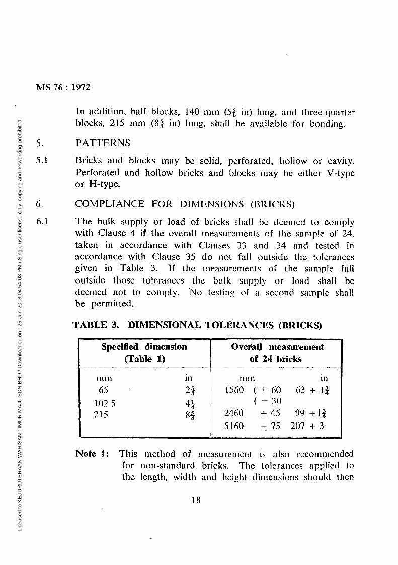
6. COMPLIANCE FOR DIMENSIONS (BRICKS)
6.1 The bulk supply or load of bricks shall be deemedto complywith Clause4 if the overall measurementsof the sampleof 24,taken in accordancewith Clauses 33 and 34 and tested inaccordancewith Clause 35 do not fall outside the tolerancesgiven in Table 3. ‘If the measurementsof the sample falloutside those tolerances the bulk supply or load shall bedeemed not to comply. No testing of a second sample shallbe permitted.
TABLE 3. DIMENSIONAL TOLERANCES (BRICKS)
Specified dimension(Fable 1)
Ovei~alI measurementof 24 bricks
mm in65 ‘ 2*
102.5 4*215 8*
mm in1560 ( + 60 63 ± 1*
( — 302460 ± 45 99 ±l~
5160 ±75 207 ±3
Note 1: This method of measurement is also recommendedfor non-standardbricks. The tolerancesapplied tothe length, width and height dimensionsshould then
18
Lice
nsed
to K
EJU
RU
TE
RA
AN
WA
RIS
AN
TIM
UR
MA
JU S
DN
BH
D /
Dow
nloa
ded
on :
25-J
un-2
013
04:5
4:03
PM
/ S
ingl
e us
er li
cens
e on
ly, c
opyi
ng a
nd n
etw
orki
ng p
rohi
bite
d
MS 76: 1972
be directly proportional to those specified for thecorrespondingdimensionsof the standard brick.
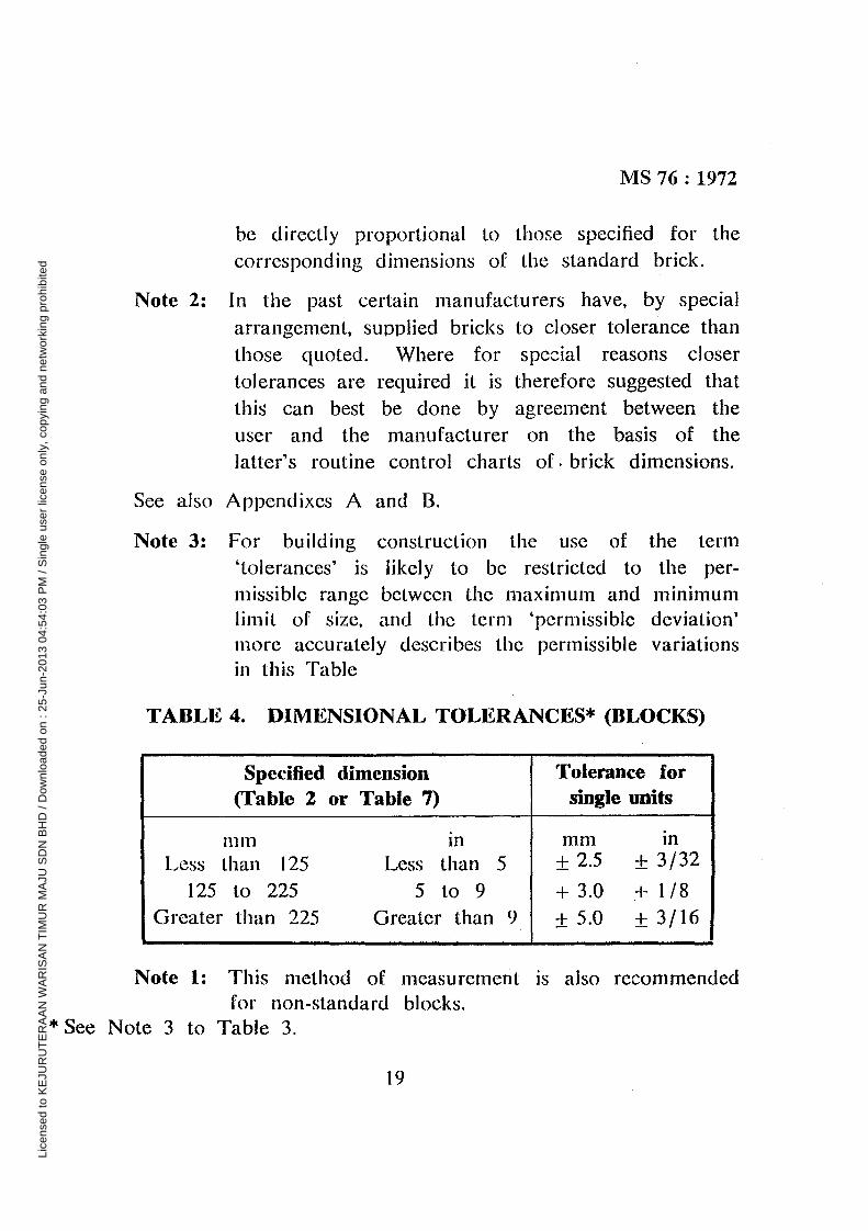
Note 2: In the past certain manufacturers have, by specialarrangement,supplied bricks to closer tolerance thanthose quoted. Where for special reasons closertolerancesare required it is therefore suggestedthatthis can best be done by agreement between theuser and the manufacturer on the basis of thelatter’s routine control charts of. brick dimensions.
See also Appendixes A and B.
Note 3: For building construction the use of the term‘tolerances’ is likely to be restricted to the per-missible range between the maximum and minimumlimit of size, and the term ‘permissible deviation’more accurately describes the permissible variationsin this Table
TABLE 4. DIMENSIONAL TOLERANCES* (BLOCKS)
Specified dimension(Fable 2 or Table 7)
Tolerance forsingle units
mm inLess than 125 Less than 5
125 to 225 5 to 9Greater than 225 Greater than 9,
mm in± 2.5 ± 3/32+ 3.0 ± 1/8
± 5.0 ± 3/16
Note 1: This method of measurementis also recommendedfor non-standardblocks.
*See Note 3 to Table 3.
19
Lice
nsed
to K
EJU
RU
TE
RA
AN
WA
RIS
AN
TIM
UR
MA
JU S
DN
BH
D /
Dow
nloa
ded
on :
25-J
un-2
013
04:5
4:03
PM
/ S
ingl
e us
er li
cens
e on
ly, c
opyi
ng a
nd n
etw
orki
ng p
rohi
bite
d
MS 76: 1972
7. COMPLIANCE FOR DIMENSIONS (BLOCKS)
7.1 If 3 or more of the 10 blocks selected in accordancewithClauses 33 and 34 and tested in accordancewith Clause 36fail to meet the tolerancesspecified in Table 4, the bulk supplyor load shall be deemed not to comply. If 1 or 2 blocksfail to meet the tolerance specified a further 10 blocks shallbe selected from the batch representedand the test repeated.Failure of one of the blocks in the repeat test shall be takento indicate that the bulk supply or load does not comply withthis Standard.
8. COMPLIANCE FOR OUT OF SQUARENESS (BLOCKS)
8.1 Where adjacent faces are intended to be at right angles, theamount by which they deviateshall be measuredin accordancewith Clause 37. The distance between the inner edge of thestraight edge and the face of the block shall not exceed 5 mm(3/16 in) per 300 mm (I ft) run.
The measurementshall be made on 10 blocks, and the methoddescribed in Clause 7 shall be used to determine whether ornot the bulk supply complies.
9. COMPLIANCE FOR BOWING OR TWISTING (BLOCKS)
9.1 When measured in accordancewith Clause 42, the deviationfrom a straight line shall not exceed the figures shown inTable 5. These measurementrefer to the deviations at ornear the centre if the face is concave, and two equal measure-ments between the straight edge and the corners of the block
if the face is convex.
The measurementshall be carried out on 10 blocks and the
20
Lice
nsed
to K
EJU
RU
TE
RA
AN
WA
RIS
AN
TIM
UR
MA
JU S
DN
BH
D /
Dow
nloa
ded
on :
25-J
un-2
013
04:5
4:03
PM
/ S
ingl
e us
er li
cens
e on
ly, c
opyi
ng a
nd n
etw
orki
ng p
rohi
bite
d

MS 76: 1972
method described in Clause 7 shall be used to determinewhether or not the bulk supply complies.
TABLE 5. MAXIMUM DEVIATIONS ON DIMENSIONS
of blockMax. deviation from
.a straight line
mm in225 x 150 (9 inmeasuredfaces 3 1/8
the above but not300 (9 in x 12 in) 5 3/16
225 x 300 (9 in x6 1/4
10. STRENGTH AND ABSORPTION
10.1 In accordancewith MS * or to comply with buildingregulations, the classification given in Table 6 shall apply:
interpolation of classesof Ioadbearingbricks not given in the
above Table’ may be used for bricks having averagecrushingstrengthsintermediatebetween those given in the Table. Thusfor instance ‘Class 4.5’ may be used to describe bricks withan averagestrength of 31.0 MN/rn2 (4500 lbf/in2) and Class 11to describe bricks with an average strength of 76 MN/rn2
(11,000 lbf/in2).
Bricks to 5.2 MN/rn2 (750 lbf/in2) and blocks to 2.8 MN/rn2
(400 lbf/in2) in Clauses12, 17 and 22 can also be loadbearinge g as used in one- and two-storey dwelling houses, the
* MS , “Structural Recommendationsfor Loadbearing Walls”, In
Preparation.
21
Lice
nsed
to K
EJU
RU
TE
RA
AN
WA
RIS
AN
TIM
UR
MA
JU S
DN
BH
D /
Dow
nloa
ded
on :
25-J
un-2
013
04:5
4:03
PM
/ S
ingl
e us
er li
cens
e on
ly, c
opyi
ng a
nd n
etw
orki
ng p
rohi
bite
d
MS 76: 1972
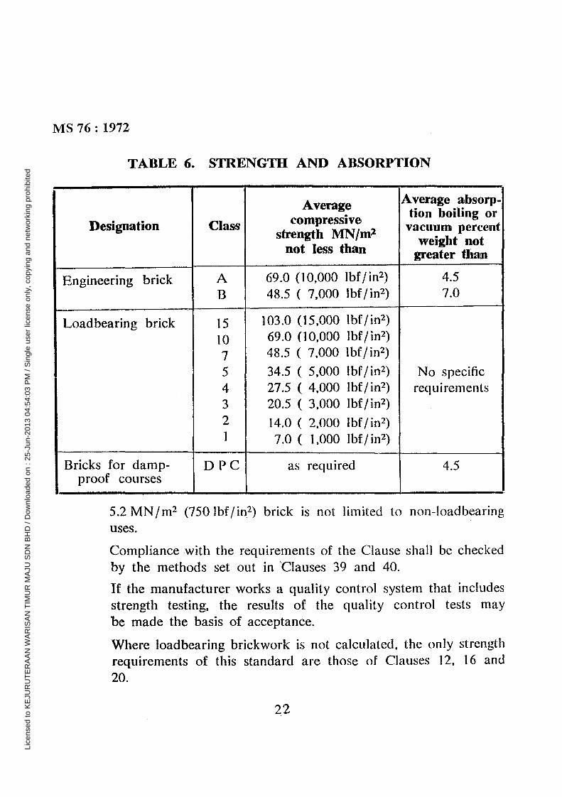
TABLE 6. STRENGTh AND ABSORPTION
Designation Class
Averagecompressive
strength MN/m~not lessth~
Average absorp-tion boiling or
vacuum percentweight not
greater han
Engineering brick AB
69.0 (10,000 lbf/in2)48.5 ( 7,000 lbf/in2)
4.57.0
Loadbearingbrick 15107
54321
103.0 (15,000 lbf/in2)69.0 (10,000 lbf/in2)48.5 ( 7,000 lbf/in2)
34.5 ( 5,000 lbf/in2)27.5 ( 4,000 lbf/in2)20.5 ( 3,000 lbf/in2)
14.0 ( 2,000 Ibf/in2)7.0 (1,000 lbf/in2)
No specificrequirements
Bricks for damp-proof courses
D PC as required 4.5
5.2 MN/rn2 (750 lbf/in2) brick is not limited to non-loadbearinguses.
Compliancewith the requirementsof the Clauseshall be checkedby the methodsset out in ~Clauses39 and 40.
If the manufacturerworks a quality control systemthat includesstrength testing, the results of the quality control tests maybe madethe basis of acceptance.
Where loadbearingbrickwork is not calculated,the only strengthrequirementsof this standardare those of Clauses 12, 16 and20.
22
Lice
nsed
to K
EJU
RU
TE
RA
AN
WA
RIS
AN
TIM
UR
MA
JU S
DN
BH
D /
Dow
nloa
ded
on :
25-J
un-2
013
04:5
4:03
PM
/ S
ingl
e us
er li
cens
e on
ly, c
opyi
ng a
nd n
etw
orki
ng p
rohi
bite
d

MS 76: 1972
SECTION TWO: SPECIFIC CLAUSES
SUB-SECTION 4: FACING AND COMMON BRICKSAND BLOCKS OF ORDI1NARY QUALITY
11. FINISH
11.1 Facing and common bricks and blocks of ordinary quality shallbe well-fired and shall be reasonablyfree from deepor extensivecracks and from damage to edges and corners, from pebblesand expansiveparticles of lime. They shall also, when a cutsurface is examined,show a reasonablyuniform texture.
Note: It is not possible to define ‘well-fired’ in a way thatwould apply unambiguouslyto all types of brick andblocks, though people with experience of particulartypes soon come to recognize what is meant. It isknown that a brick or block has been ‘well-fired’ whenan adequateceramic bond has been formed within thebody, but it is not possible precisely to determine byappearanceor other simple test whether or not sucha bond has been formed, without referenceto the typeof clay, the method of manufacture,and the format.To people very familiar with a specific product, colourcan be a guide when considering that particular pro-duct, but to the layman, colour alone can be completelymisleading. Similarly, hardnessand hence ‘ring’ whenstruck can be a good guide to the expert, but clearlythis criterion cannot be applied to all bodies such as,for example, those of low density.
12. STRENGTH
12.1 Unless a higher strength is agreed in accordancewith Clause
10 the compressivestrength of bricks of ordinary quality when
23
Lice
nsed
to K
EJU
RU
TE
RA
AN
WA
RIS
AN
TIM
UR
MA
JU S
DN
BH
D /
Dow
nloa
ded
on :
25-J
un-2
013
04:5
4:03
PM
/ S
ingl
e us
er li
cens
e on
ly, c
opyi
ng a
nd n
etw
orki
ng p
rohi
bite
d
MS 76: 1972
tested in accordancewith Clause 39, shall be not less than5.2 MN/m2 (750 lbf/in2) and of blocks of ordinary quality shallbe not less than 2.8 MN/rn2 (400 lbf/in2). These minimumstrengths are acceptable provided the bricks and blocks aresatisfactory in other respects.
13. SOLUBLE SALTS CONTENT
13.1 No requirements.
14. LIABILITY TO EFFLORESCENCE
14.1 When tested in accordancewith Clause 42 no sample shalldevelop efflorescenceworse than moderate.
SUB-SECTION B: FACING AND COMMON BRICKSAND BLOCKS OF SPECIAL QUALITY
15. FINISH
15.1 Facing and common bricks and blocks of special quality shallbe hardfired and shall be reasonably free from cracks andfrom damageto edgesand corners,from pebblesand expansiveparticles of lime. They shall also, when a cut surface isexamined, show a reasonably uniform texture with no verycoarseparticles.
Note: In interpreting the qualitative requirementsof Clauses11 and 15, a more exacting standardmay reasonablybe set for bricks of special quality than for those ofordinary quality
16. STRENGTH
16.1 Unless a higher strengthis agreedin accordancewith Clause 10.the compressivestrengthof bricks of special quality, when tested
24
Lice
nsed
to K
EJU
RU
TE
RA
AN
WA
RIS
AN
TIM
UR
MA
JU S
DN
BH
D /
Dow
nloa
ded
on :
25-J
un-2
013
04:5
4:03
PM
/ S
ingl
e us
er li
cens
e on
ly, c
opyi
ng a
nd n
etw
orki
ng p
rohi
bite
d
MS 76: 1972
in accordancewith Clause39, shall be not less than 5.2 MN/m~(750 lbf/in2) and of blocks of special quality shall be not lessthan 2.8 MN/ni2 (400lbf/in2). These minimum strengths areacceptableprovided the bricks and blocks are satisfactory inother respects.
17. SOLUBLE SALTS CONTENT
17.1 When tested in accordancewith Clause 41, the contents byweight percent of soluble sulphate, calcium, magnesium,potassium and sodium radicals shall not exceed respectively0.30, 0.10, 0.03, 0.03 and 0.03%. The sulphate figure to beused for the purpose of this Clause shall be the acid solublesulphate determined in accordancewith Clause 41 (c).
18. LIABILITY TO EFFLORESCENCE
18.1 When tested in accordancewith Clause 42 no sample shall
develop elflorescenceworse than moderate.
SUB-SECTION C: BRICKS AND BLOCKS FORINTERNAL WALLS
19. FINISH
19.1 Bricks and blocks for internal walls (loadbearing)and partitionsshall be reasonablyfree from deep or extensivecracks, fromdamageto edges and corners, and from expansiveparticles oflime. They shall also, when a cut surface is examined, showa reasonably uniform texture.
Note: Such units unless otherwise specified will be suitablefor rendering but not necessarilyfor fair faced work.
20. STRENGTI-I
20.1 Unless a higher strengthis agreedin accordancewith Clause 10,
25
Lice
nsed
to K
EJU
RU
TE
RA
AN
WA
RIS
AN
TIM
UR
MA
JU S
DN
BH
D /
Dow
nloa
ded
on :
25-J
un-2
013
04:5
4:03
PM
/ S
ingl
e us
er li
cens
e on
ly, c
opyi
ng a
nd n
etw
orki
ng p
rohi
bite
d
MS 76: 1972
the compressive strength of bricks for loadbearing internalwalls when tested in accordancewith Clause 39, shall be notless than 5.2 MN/rn2 (750 Ibf/in2) and of blocks for load-bearing internal walls shall be not less than 2.8 MN/m2
(400 lbf/in2). The compressivestrength of bricks and blocksfor non-loadbcaringpartitions shall not be less than 1.4 MN/rn2
(200 Ibf/ in2). These minimum strengths are acceptable pro-vided the bricks and blocks are satisfactory in other respects.
21. SOLUBLE SALTS CONTENT
21.1 No requirements.
22. LIABILITY TO EFFLORESCENCE
22.1 When tested in accordancewith Clause 42 no sample shalldevelop efflorescence worse than moderate.
CHAPTER 2. HOLLOW BLOCKS FORSTRUCTURAL FLOORS AND ROOFS
23. GENERAL
23.1 The hollow blocks for structural floors and roofs covered bythis Standard are blocks designed to be used as filler blocksin reinforced concrete floors.
24. FORMATS
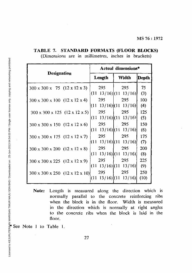
24.1 The formats of blocks for structural floors and roofs shall bedesigned in terms of their nominal dimensions which differfrom their actual dimensionsexcept in the depth. The actuallength and width are 5 mm (3/16 in) less than the nominallength and width. ‘The standardformats are given in Table 7.
26
Lice
nsed
to K
EJU
RU
TE
RA
AN
WA
RIS
AN
TIM
UR
MA
JU S
DN
BH
D /
Dow
nloa
ded
on :
25-J
un-2
013
04:5
4:03
PM
/ S
ingl
e us
er li
cens
e on
ly, c
opyi
ng a
nd n
etw
orki
ng p
rohi
bite
d
MS 76: 1972
TABLE 7. STANDARD FORMATS (FLOOR BLOCKS)(Dimensions are in millimetres, inches in brackets)
DesignationActual climensions*
Length Width Depth
300x 300x 75 (l2x12x3) 295(11 13/16)
295(11 13/16)
75(3)
300x 300x 100 (12x12x4) 295(11 13/16)
295(11 13/16)
100(4)
300 x 300 x 125 (12 x 12 x 5) 295(11 13/16)
295(11 13/16~
125(5)
300 x 300 x 150 (12 x 12 x 6) 295(11 13/16)
, 295(11 13/16)
150(6)
300x 300x 175 (12x12x7) 295(11 13/16)
295(11 13/16)
175(7)
300 x 300 x 200 (12 x 12 x 8) 295(11 13/16)
295(ii 13/16)
200(8)
300x 300x 225 (12x12x9) 295 295 225(11 13/16) (11 13/16) (9)
300x 300x 250 (12x12x10) 295 295 250(11 13/16)(II 13/16) (10)
Note: Length is measured along the direction which isnormally parallel to the concrete reinforcing ribswhen the block is in the floor. Width is measuredin the direction which is normally at right anglesto the concrete ribs when the block is laid in thefloor.
* See Note I to Table I.
27
Lice
nsed
to K
EJU
RU
TE
RA
AN
WA
RIS
AN
TIM
UR
MA
JU S
DN
BH
D /
Dow
nloa
ded
on :
25-J
un-2
013
04:5
4:03
PM
/ S
ingl
e us
er li
cens
e on
ly, c
opyi
ng a
nd n
etw
orki
ng p
rohi
bite
d

MS 76: 1972
25. COMPLIANCE FOR DIMENSIONS
25.1 Blocks for structural floors and roofs shall be measured in-dividually by the method laid down in Clause 36 for blocksfor walling.
The measurementshall be carried out on 10 blocks and themethod described in Clause 7 shall be used to determinewhether or not the bulk supply complies.
26. COMPLIANCE FOR OUT OF SQUARENESS
26.1 Where adjacent faces are intended to be at right angles, theamount by which they deviate shall be measuredin accordancewith Clause 37. The distance between the inner edge of thestraight edgeand the face of the blocks shall not exceed5 mm(3/16 in) per 300 mm (1 ft) run.
The measurementshall be carried out on 10 blocks and themethod of Clause 7 used to determine whether or not thebulk supply complies.
27. COMPLIANCE FOR BOWING OR, TWISTING
27.1 When measuredin accordancewith Clause 38, the deviationfrom a straight edge shall not exceed the figures shown inTable 5. These measurements refer to the deviations at ornear the centre if the face is concave,and two equal measure-ments betweenthe straight edge and the corners of the blockif the face is convex.
The measurementshall be carried out on 10 blocks and themethod of Clause 7 used to determine whether or not thebulk supply complies.
28. FINTSH ~
28.1 Blocks for structural floors and roofs shall be reasonablyfree
28
Lice
nsed
to K
EJU
RU
TE
RA
AN
WA
RIS
AN
TIM
UR
MA
JU S
DN
BH
D /
Dow
nloa
ded
on :
25-J
un-2
013
04:5
4:03
PM
/ S
ingl
e us
er li
cens
e on
ly, c
opyi
ng a
nd n
etw
orki
ng p
rohi
bite
d
MS 76: 1972
from deep or extensive cracks, from damage to edges andcornersand from expansiveparticles of lime. They shall also,when a cut surface is examined, show a reasonablyuniformtexture.
29. STRENGTH
29.1 The compressivestrength of blocks for structural floors androofs, when tested in accordancewith Clause 39, shall be notless than 14.0 MN/rn2 (2000 lbf/in2). Higher strengths maybe agreed between the supplier and the user if it is desiredto make use of the block strength when calculatingthe strengthof the floor for design purposes.
30. SOLUBLE SALTS CONTENT
30.1 No requirements.
31. LIABILITY TO EFFLORESCENCE
31.1 No requirements.
CHAPTER 3. SAMPLING PROCEDURE ANDTEST METhODS
32. GENERAL
32.1 Testing shall be carried out on samples which are taken inaccordancewith Clauses 33 and 34.
33. SAMPLES
33.1 Samples may be required for:
(a) Routine quality control tests carried out by the manufac-turer. For this purpose the number of units to be takenas samplesshall be at the discretion of the manufacturerand shall be based on sound statistical principles*.
* Suitableexpositionsof statistics for this purposeare given in AppendixA and in BS 2564, “Control Chart TechniqueWhen Manufacturing toa Specification”.
29
Lice
nsed
to K
EJU
RU
TE
RA
AN
WA
RIS
AN
TIM
UR
MA
JU S
DN
BH
D /
Dow
nloa
ded
on :
25-J
un-2
013
04:5
4:03
PM
/ S
ingl
e us
er li
cens
e on
ly, c
opyi
ng a
nd n
etw
orki
ng p
rohi
bite
d
MS 76: 1972
(b) Tests carried out by the manufacturer or the customerto determine compliance with specification. For thispurpose the number of units required for specific testsshall be as follows:
(i) Compressivestrength 10
(ii) Water absorption 10
(iii) Soluble salts 10
(iv) Efflorescent testt I 0
40
(v) Dimensionsof bricks 24
(vi) Dimensionsof blocks 10
Since the dimensional test can be carried out on units whichare used subsequentlyfor other tests and since the 10 bricksor blocks used for the water absorption test may be usedsubsequentlyfor the compressivestrength test, the minimumnumber of units required when all tests are to be made is30, but a sample of 50 units provides a reasonablemargin toallow for loss and breakage and for simultaneoustesting.
When it is known that only certain of these tests are to bemade then the appropriate number of units required shall besampled instead of the 50 units.
t When the samplefor soluble salts analysis is preparedby the methodof Clause 33.1(b)(iii), the 10 bricks or blocks from which the samplehas been taken may be used subsequentlyfor the efflorescencetest.
30
Lice
nsed
to K
EJU
RU
TE
RA
AN
WA
RIS
AN
TIM
UR
MA
JU S
DN
BH
D /
Dow
nloa
ded
on :
25-J
un-2
013
04:5
4:03
PM
/ S
ingl
e us
er li
cens
e on
ly, c
opyi
ng a
nd n
etw
orki
ng p
rohi
bite
d
MS 76 : 1972
When dimensional tests only are to be carried out on blocks,since ten additional units may be required under the terms ofClause 7, these must be taken at the same time as the firstsample of ten, unless it is known that the whole delivery willbe available for further sampling when the first part of thetest has been completed.
The required number of units shall be sampledfrom a discretedelivery of not less than 2000 or more than 10,000 bricks,or not less than 500 or more than 2,500 blocks.
When all testsare to be carried out, units for any one specifictest shall be taken at random from the sample of 50 units ifthe latter are originally sampledat random from the delivery,or where statistical representativesampling of the delivery iscarried out the required number of units shall be taken atrandom from each of the representative sub-samples (SeeClause 34, Method of sampling).
Sample units remaining after allocating units for specific testsshall be reservedeither for reference or for other tests whichmay be required.
34. METHOD OF SAMPLiNG
34.1 TI required sample may be drawn by:
(a) Random sampling.
(b) Representativesampling.
In random sampling the sample is taken in such a way thatevery unit in the bulk has an equal chance of appearing inthe sample.
In representativesampling the bulk is divided into convenient
sections (real or imaginary) and the sample is taken so that
31
Lice
nsed
to K
EJU
RU
TE
RA
AN
WA
RIS
AN
TIM
UR
MA
JU S
DN
BH
D /
Dow
nloa
ded
on :
25-J
un-2
013
04:5
4:03
PM
/ S
ingl
e us
er li
cens
e on
ly, c
opyi
ng a
nd n
etw
orki
ng p
rohi
bite
d

MS 76: 1972for each section of the bulk there is a correspondingportionof the sample. The units in each of these portions must betaken in a random manner (See (a) below).
The word Representativeapplied to sampling does not meanthat the sampler is to select units which lie thinks representthe different colours, sizes, strengths, etc., of the bulk supply.Any person bias in selection must be avoided.
The samples shall be taken by one of the methods set outbelow, sampling being arranged SO as to yield the numberof units required.
(a) Sampling in motion. Wheneverpracticablea sample shallbe taken whilst the units are being moved, for exampleduring loading or unloading. 1n this case 2, 3, 4 or5 units shall be taken at random from each of 10 ap-proximately equal sections of the bulk to be tested de-pending on whether one, two, three or four of the tests(i), (ii), (iii), (iv) are to be carried out, with or withouttest (iv).
If only test (v) is to be carried out it will be more con-venient to take 2 units at random from each of 12 ap-proximately equal sections of the bulk.
if test (v) is to be carried out and one, two, three orfour of the tests (i), (ii), (iii), (iv), then 24, 24, 30 or40 is the minimum number of units required. To allowfor loss and breakage the number sampled shall there-fore be 30, 30, 40 or 50. These units shall be obtainedby taking 3, 3, 4 or 5 units at random from each of 10approximately equal sections of the bulk to be tested.The sample of 24 units required for test (v) shall beobtained by taking 2 units at random from each of 6portions selected at random from the tO portions corn-
32
Lice
nsed
to K
EJU
RU
TE
RA
AN
WA
RIS
AN
TIM
UR
MA
JU S
DN
BH
D /
Dow
nloa
ded
on :
25-J
un-2
013
04:5
4:03
PM
/ S
ingl
e us
er li
cens
e on
ly, c
opyi
ng a
nd n
etw
orki
ng p
rohi
bite
d

MS 76: 1972
prising the main sample and 3 units at random fromeach of the remaining 4 portions.
When 2 or more multiples of 10 units are sampled froma bulk supply the sample of 10 units required for onespecific test shall be obtained by taking one unit atrandom from the units in each of the 10 portions ofthe sample. When sampling it will therefore be neces-sary to identify the units in any 1 portion of the sampleby the same letter or mark which should be differentfrom the letters or marks given to the other 9 portionsof the sample.
(b) Sampling from a stack. When it is necessary to take a
sample from a stack the following procedure shall beadopted:
The stack shall be divided into a number of real orimaginary sections and the required number of unitsdrawn from each section as indicated under (a). Forthis purpose units in the upper layers of the stack shallbe moved to enable units to be sampled from placeswithin the stack. Units shall also be sampled fromaccessible sides of sections which are at the edge of thestack.
Sampling from stacks may not be satisfactory whentesting for soluble salts and efflorescence because con-tarnination from the ground and other sources mayoccur.
(c) Sampling from lorries or trucks. When for any reasonsampling cannot be carried out in motion, units shall betaken from a number of sections of the load as indicatedunder (b), reading lorry or truck in place of stack.
33
Lice
nsed
to K
EJU
RU
TE
RA
AN
WA
RIS
AN
TIM
UR
MA
JU S
DN
BH
D /
Dow
nloa
ded
on :
25-J
un-2
013
04:5
4:03
PM
/ S
ingl
e us
er li
cens
e on
ly, c
opyi
ng a
nd n
etw
orki
ng p
rohi
bite
d
MS 76: 1972
35. DETERMINATION OF DIMENSIONS (BRICKS)
35.1 When standard bricks are to be checked for dimensions themethod shall be the overall measurementof 24 bricks placedin contact in a straight line upon a level surface in each ofthe arrangementsindicated in Fig. 1 Any blisters or smallprojections or ‘loose particles of clay adhering to the face of abrick shall be removed before they are assembledfor measure-ment. The overall dimensions of the assembled bricks shallbe measuredwith. a steel tape or other suitable inextensiblemeasure long enough to measure the whole row at once.Measurementby repeatedapplication of a short rule or measureshall not be considered satisfactory.
if for any reason, it is found impracticable to measure 24bricks in one row, the samplesmay be divided into two rowsof 12, or three rows of 8, which shall be measuredseparatelyto the nearest 2 mm and their measurementsadded. Themeasurementof one row of 12 or 8 units and multiplicationby 2 or 3 shall not be considered satisfactory, because ofthe probability that the mean dimensionsof so small a samplediffer appreciablyfrom the meandimensionsof the bulk supply.
36. DETERMINATION OF DIMENSIONS (BLOCKS)
36.1 Standard blocks shall be measured individually, a sample of10 units being measured. Each of the 3 linear dimensionsshall be measuredwith a ruler graduatedat intervals of 1 mm(1/32 in) and the results noted. The measurementsshall becarried out for each of the 10 units in turn.
37. DETERMINATION OF OUT OF SQUARENESS (BLOCKS)
37.1 The amount by which the angle between adjacent faces of
34
Lice
nsed
to K
EJU
RU
TE
RA
AN
WA
RIS
AN
TIM
UR
MA
JU S
DN
BH
D /
Dow
nloa
ded
on :
25-J
un-2
013
04:5
4:03
PM
/ S
ingl
e us
er li
cens
e on
ly, c
opyi
ng a
nd n
etw
orki
ng p
rohi
bite
d
MS 76: 1972
the block differs from a right angle ~haIl be determined byplacing a builder’s steel squareagainst one edge and measuringthe distance between the inner edge of the square and theface of the block (See Fig. 2).
38. DETERMINATION OF BOWiNG OR TWISTING (BLOCKS)
38.1 The blocks shall be placed between two parallel straight edgesrunning diagonally across the two faces of the unit as shownin Fig 2. The distance between the straight edge and theface of the block shall be measuredat a point near the centreon the side which is concave, and two equal measurementsshall be taken between the straight edge and the corners ofthe opposite face of the block on the convex side.
39. DETERMINATION OF COMPRESSIVESTRENGTH
(a) Test specimens. Ten whole units, taken as directed inClauses 33 and 34, shall be used for determining com-pressive strength.
(1) Bed face area. Bricks and blocks for walling. Whentesting bricks and blocks for walling, the overalldimensions of each bed face shall be measuredtothe nearest 1 mm (0.05 m) and the area of the
smaller of the two shall be taken as the area ofthe unit for calculating the compressive strength.This applies to all types of bricks and blocks, in-cluding the divided-joint type, i e, the gap betweenthe twin strips of mortar on which the latter arebedded is included in the overall area.
(ii) Bed face area. Blocks for structural floors and roofs.When testing flooring blocks the ends in which thecavities appear shall be treated as the bed faces.
Lice
nsed
to K
EJU
RU
TE
RA
AN
WA
RIS
AN
TIM
UR
MA
JU S
DN
BH
D /
Dow
nloa
ded
on :
25-J
un-2
013
04:5
4:03
PM
/ S
ingl
e us
er li
cens
e on
ly, c
opyi
ng a
nd n
etw
orki
ng p
rohi
bite
d
MS 76: 1972
The net area of the material in the bed face shallbe obtained by subtracting the area of the cavitiesfrom the overall area of the bed face, and shallbe taken as the area of the block for calculatingthe compressivestrength.
(b) Preparationof specimens.
(i) Solid bricks without frogs, bricks with frogs intendedto be laid frog downwards, perforated bricks andcavity bricks. Bricks of standard size. including solidbricks without frogs, perforated bricks and cavity
bricks, shall be immersed in water at room tem-peraturefor not less than 24 hours or saturatedundervacuum or by boiling, before testing.
The same method shall be used for bricks with
ordinary frogs that are to be laid frog downwards.When, for this purpose, the strength of bricks isdetermined with the frog unfilled, this fact shall beprominently stated in the test report.
(ii) Bricks with frogs intended to be laid frog upwards.Bricks with frogs shall be immersed in water atroom temperature for not less than 24 hours, orsaturated under vacuum or by boiling. They shallthen be removed and allowed to drain for aboutfive minutes, wiped free from surplus moisture, andtheir frogs filled with mortar. (The requirementthatfrogs shall be filled shall not be taken as requiringthe filling of perforations in perforated bricks orof the deep frogs in cavity bricks which are madeto give a lightweight wall when bedded frog down-ward. These are to be prepared as prescribed in
36
Lice
nsed
to K
EJU
RU
TE
RA
AN
WA
RIS
AN
TIM
UR
MA
JU S
DN
BH
D /
Dow
nloa
ded
on :
25-J
un-2
013
04:5
4:03
PM
/ S
ingl
e us
er li
cens
e on
ly, c
opyi
ng a
nd n
etw
orki
ng p
rohi
bite
d
MS 76 : 1972
(h)(i) above). Not less than four, and preferablysix cubes, approximately 75 mm (3 in) on side,shall be made from each batch of mortar and shallhe stored under the same conditions as the bricks.The mix used shall be capable of attaining thestrength specified below and, when set, there shallhe no concavity in the mortar filling (See Note 1).
Singlc-frogged bricks shall be stored under dampsacking or similar material for 24 hours after theirfrogs have been tilled and then immersed in wateruntil they are ready for testing.
Double-froggedbricks shall be preparedin two stagesnot less than four nor more than eight hours beingallowed to elapse after filling the first frog beforefilling the second, using a mortar with the samecomposition as before. They shall be stored underdamp sacking or similar material for 24 hours afterfilling the second frog, and then immersed in wateruntil ready for testing.
Bricks with ‘frogs shall be considered ready fortesting when tests on the cubes show that the com-
pressive strength of the mortar is not less than28.0 MN/rn2 (4000 lbf/in2) and not more than 42.0MN/rn2 (6000lbf/in2). Single cubes may be usedto indicate the growth of mortar strength, but thefinal test shall be made with three cubes for each
batch of mortar, the average strength of the threecubes being taken as the strength of the mortar.
(iii) Hollow blocks, including floor blocks, and brickslarger than 22Sx .112.5 mm (9 x 4~in) (on bed face).The specimensshall be immersed in water at room
37
Lice
nsed
to K
EJU
RU
TE
RA
AN
WA
RIS
AN
TIM
UR
MA
JU S
DN
BH
D /
Dow
nloa
ded
on :
25-J
un-2
013
04:5
4:03
PM
/ S
ingl
e us
er li
cens
e on
ly, c
opyi
ng a
nd n
etw
orki
ng p
rohi
bite
d
MS 76: 1972
temperature for not less than 24 hours, or saturated
under vacuum or by boiling. They shall then beremoved and allowed to drain for about five minutes,wiped free from surplus water and bedded in amortar capable of attaining the strength specifiedbelow (See Note 1). Not less than four, and pre-ferably six, cubes of mortar approximately 75 mm(3 in) side, shall be made from each batch ofmortar and shall be stored under the same con-ditions as the specimens.
The bedding shall be carried out in the followingmanner. Each specimen shall be bedded on asmooth rigid plate, at least 40 mm (13 in) longerand wider than the specimen,which, does not depart
from a true plane surface by more than 0.05 mm(0.002 in) pieces of Plate glass, or machined steelplates, are the most suitable materials. The plateshall be firmly supported with the machined faceuppermost and levelled in two directions at rightangles by means of a spirit level. It shall be coatedwith a film of mould oil to preventmortar adhering,or alternatively a sheet of thin paper can be usedfor the same purpose. A layer of mortar 20 him~ in) and 40 mm(11 in) to 50 mm (2 in) longerand wider than the specimen shall then be placedon the plate and one bed face of the specimenfirmlypressed into it so that the vertical axis of the speci-men is perpendicularto the plane of the plate andso that the bed is approximately 10 mm (~in)thick and nowhere less than 5.0 mm (~in) thick(See Note 2). Th~surplus mortar shall be trimmedoff flush with the sides of the block after it has
38
Lice
nsed
to K
EJU
RU
TE
RA
AN
WA
RIS
AN
TIM
UR
MA
JU S
DN
BH
D /
Dow
nloa
ded
on :
25-J
un-2
013
04:5
4:03
PM
/ S
ingl
e us
er li
cens
e on
ly, c
opyi
ng a
nd n
etw
orki
ng p
rohi
bite
d
MS 76: 1972
hardenedsufficiently (See Note 1). The block shallthen be stoiccl under damp sacking or similar ma-terial for 24 hours before being carefully removedfrom the plate, without damaging the mortar, andinverted.
The second bed face shall then be bedded in thesame way as the first using a mortar with the samecomposition as before. The specimen shall be placedon the bed of mortar and the face now uppermostlevelled in two directions at right angles by meansof a spirit level to ensure that the two mortar-facesare parallel. After bedding the specimenshall againhe covered with damp sacking or similar materialfor 24 hours and then immersed in water until tested.
The specimen shall he considered ready for testingwhen tests on the cubes show that the compressivestrength of the mortar is riot less than 28.0 MN/rn2
(4000 lbf/in2) and not more than 42.0 MN/rn2
(6000 lbf/in2). Single cubes may be used to indicatethe growth of ‘ mortar strength, but the final testshall be made with three cubes for each batch ofmortar, the averagestrength of the three cubesbeingtaken as the strength of the mortar.
(iv) Divided-joint bricks and blocks. Bricks and blocksdesignedto give a single-leaf wall with the mortarjoints divided into two strips (See Note 3) shall beimmersed in water at room temperaturefor not lessthan 24 hours, or saturated under vacuum or byboiling. They shall then be removed and allowedto drain for about five minutes, wiped free fromsurplus water and bedded in mortar. The method
39
Lice
nsed
to K
EJU
RU
TE
RA
AN
WA
RIS
AN
TIM
UR
MA
JU S
DN
BH
D /
Dow
nloa
ded
on :
25-J
un-2
013
04:5
4:03
PM
/ S
ingl
e us
er li
cens
e on
ly, c
opyi
ng a
nd n
etw
orki
ng p
rohi
bite
d
MS 76: 1972
of bedding shall be generally as described in (iii)above, but instead of bedding the whole face ofthe brick or block, the bedding mortar shall beplaced in two parallel strips of a uniform thick-ness of 20 mm (~in) formed with the help ofa simple guide, described below. These strips ofmortar shall correspondwith the parts of the brickor block designed to carry the mortar bed, andthe brick or block shall be accurately placed onthem and presseddown to form a bed as uniformas possible approximately 10 mm (~in) thick andnowhere less than 5.0 mm (~in) thick.
The guide mentioned in the preceding paragraphshall consistof a rectangularstrip of wood of 20 mm(~in) finished thickness, of width equal to the de-signed gap between the mortar strips (for the Vdouble brick shown in Fig. 6. it may be taken as75 mm (3 in) and 50 mm (2 in) to 100 mm (4 in) longerthan the brick. In use, the guide shall be placedacross the machined plate on which the beddingis done, and level mortar strips somewhat longerand wider than their finished dimensionsplaced oneither side of it. The guide shall be carefully re-moved with the least possible disturbance of themortar bed before the brick or block is pressedinto position.
(c) Apparatus. The testing machine shall have adequatecapacity to crush all the test specimensbut the scaleusedshall be such that the ultimate loads on the specimensexceed one-fifth of the full scale reading. The machineshall be provided with a load-pacer or equivalent meansto enable the load to be applied at the rate specified
40
Lice
nsed
to K
EJU
RU
TE
RA
AN
WA
RIS
AN
TIM
UR
MA
JU S
DN
BH
D /
Dow
nloa
ded
on :
25-J
un-2
013
04:5
4:03
PM
/ S
ingl
e us
er li
cens
e on
ly, c
opyi
ng a
nd n
etw
orki
ng p
rohi
bite
d

MS76 : 1972
in (d) (iii). It shall meet the requirementsfor accuracyof Grade B of BS 1610, “Verification of Testing Machines”,Part I. The testing machine shall be equipped with twosteel bearing-platenswith hardenedfaces. The platen thatnormally will bear on the upper surface of the specimenshall be fitted with a ball seating in the form of a portionof a sphere. the centre of which coincides with the centreof the face of the platen. The movable portion of thehall—seated platen shall be held on its scat ‘hut shall hefree to rotate and to tilt through small angles in anydirection. The other platen shall be a plain rigid hearingblock. The bearing faces of both platens shall be atleast as large as, and preferably larger than, the nominalsize of the specimen.The bearing surfacesof the platensshall not depart from a plane by more than 0.05 mm(0.002in). (To meet this requirement, the platens, whennew, should be somewhatmore accurateto allow for wearand should be refaced when they approach this limit.)
(d) Testing procedure.(i) General. When the requirementsof Clause (b) have
been satisfied, the specimensshall be tested immedi-ately on removal from the water.
(ii) Placing specimenin the testing machine. The bearingsurfacesof the testing machine shall be wiped cleanand any loose grit removed from the bed faces ofthe specimen. The load shall be applied to thespecimen in the same direction as in service, andthe axis of the specimen shall be carefully alignedwith the centre of the ball-seated platen. As thelatter is brought to bear on the specimen the niov-able portion shall be guided gently by hand sothat a uniform seating is obtained. Specimenspre-
41
Lice
nsed
to K
EJU
RU
TE
RA
AN
WA
RIS
AN
TIM
UR
MA
JU S
DN
BH
D /
Dow
nloa
ded
on :
25-J
un-2
013
04:5
4:03
PM
/ S
ingl
e us
er li
cens
e on
ly, c
opyi
ng a
nd n
etw
orki
ng p
rohi
bite
d
MS 76: 1972
pared in accordancewith (b)(i) and (b)(ii) shall betested betweentwo 3 mm plywood sheetswhich shallbe at least as long and as wide as the specimenandshall be used once only. Specimens prepared inaccordancewith (b)(iii) and (b)(iv) neednot be testedbetween sheets of plywood.
(iii) Loading. The load shall be applied without shockand increased continuously. Initially the loadingmay be at any convenient rate up to 35.0 MN/m2
(5000 lbf/in2) per minute but, when about half theexpectedmaximum load has been applied, the rateshall be adjusted to 15.0 MN/rn2 (2000 lbf/in2) perminute and maintained until the maximum failingload is reached. With some specimensthe recordedload may fluctuate before the maximum failing loadis reached. This will be indicated by a reduction inload as the specimen yields followed by an increaseto a new maximum as loading is continued. Thistemporary reduction may occur several times beforethe specimen finally fails. The maximum failingload shall be taken as the load at which the specimenno longer produces any further increase in the in-dicator reading (See Note 4).
(iv) Calculation of results. The compressivestrength ofthe specimen shall be calculated by dividing itsmaximum failing load by its area as defined in (a)and shall be expressedin MN/in2 (lbf/in2) to thenearest 0.5 MN/rn2 (70 lbf/in2) for strengths of7.0 MN/rn2 and aboveand to the nearest0.1 MN/rn2
(10 lbf/in2) for strengths less than 7.0 MN/rn2.
The arithmetic mean of the compressive strength
of the ten specimensis the best unbiased estimate
42
Lice
nsed
to K
EJU
RU
TE
RA
AN
WA
RIS
AN
TIM
UR
MA
JU S
DN
BH
D /
Dow
nloa
ded
on :
25-J
un-2
013
04:5
4:03
PM
/ S
ingl
e us
er li
cens
e on
ly, c
opyi
ng a
nd n
etw
orki
ng p
rohi
bite
d

MS 76: 1972
of the true consignment mean and shall be takenas the compressive strength of the consignmentsampled, for purposesof Clauses 10, 12, 16, 20 and29.
It. should be noted that manufacturers who use
quality control schemes for strength testing havedetailed information on the compressivestrength oftheir bricks and their variability, which can be madeavailable to users.
Note ‘1: The strength of mortar required for this test maybe obtained within a reasonabletime (3 to 7 days)by using a I : 1~mix of ordinary Portland cementor rapid-hardeningPortland cement complying withMS ~, with clean well-graded sand, 3 mm(-~ in) down. The water/cement ratio will usuallybe not greater than 0.35 and, if the bricks are ofan open texture so that water drains from themreadily, it may be necessaryto use a lower water/cement ratio
If the sand available is relatively fine and/or contaminatedwith silt or clay, a higher water/cementratio will be requiredto obtain satisfactoryworkability. It will then be difficult toattain the required strength within a reasonabletime whenusing a 1 : l- mix with Portland cement. A 1 : 1 mix withordinary Portland cement or rapid-hardeningPortland cementor a 1 3 mix with a high-alumina cement complying withMS t will then be found more satisfactory.
To obtain the specified strengthwithout difficulty it is necessaryto use cement in fresh condition. This means that, if it is
* MS , “Portland Cement (Ordinary and Rapid-Hardening)”.
t MS , “High Alumina Cement”.
43
Lice
nsed
to K
EJU
RU
TE
RA
AN
WA
RIS
AN
TIM
UR
MA
JU S
DN
BH
D /
Dow
nloa
ded
on :
25-J
un-2
013
04:5
4:03
PM
/ S
ingl
e us
er li
cens
e on
ly, c
opyi
ng a
nd n
etw
orki
ng p
rohi
bite
d
MS 76: 1972
not used very shortly after manufacture,it should be preservedin an airtight container.
When the mixes give the required strength in 3 to 7 days,the mortar is usually sufficiently set to enable reversal of bricksto be carried out in 4 to 8 hours as mentioned in (b)(ii) aboveand trimming in accordancewith (b)(iii) above.
To ensurethat, as required in (b)(ii), there shall be no con-cavity in the mortar filling of frogs, the mortar should not betrowelled off flush with the surface of the brick immediately,but after allowing it to stand for a period judged by experience,usually between two and four hours.
Note 2: When bedding hollow blocks in mortar, (b)(iii), itwill be found an advantage to place a layer ofmortar about twice the required finished thicknessand to shape it so that it is a little thicker in themiddle than at the edges. This will ensure that airis not trapped under the block when it is pressedinto the mortar. Some laboratories have found itconvenient to restrain the flow of the mortar bya removablemetal rim or frame slightly larger thanthe block, but this is not necessaryif the layer ofmortar is initially of the thickness indicated andextendsabout 25 mm beyond the edgesof the blockin all directions.
Note 3: The instructions for bedding divided-joint bricks andblocks in (b)(iv) have been drafted with the doublebricks illustrated in Fig. 6 chiefly in mind. Divided-joint hollow blocks (H blocks) in which the widthof the strips of bedding mortar is defined by de-pressions in the bed faces of the blocks, arc alsomanufactured.Thesecan be prepared for testing by
44
Lice
nsed
to K
EJU
RU
TE
RA
AN
WA
RIS
AN
TIM
UR
MA
JU S
DN
BH
D /
Dow
nloa
ded
on :
25-J
un-2
013
04:5
4:03
PM
/ S
ingl
e us
er li
cens
e on
ly, c
opyi
ng a
nd n
etw
orki
ng p
rohi
bite
d
MS 76: 1972
the method of Clause (b)(iii), the mortar beds beingdivided into two strips by cutting away the surpluswith a strip of nietal when the mortar is trimmed10 the edges of the blocks.
Note 4: Determination of the end point of the test presentsno difficulty to the personexperiencedin the strengthtesting of bricks. The less experienced operatorshould however appreciatethat the indicator needlemay fall back at certain stages during the loadingoperation, before the point of final collapse isreached. Should this occur considerablejudgementis required in resetting the controls of the machinein order to maintain smoothly the specified rate ofloading. At the final point of collapse, the indicatorneedlewill continue to fall back rapidly even thoughevery effort is being made to maintain the loadingspecified. The pattern of final collapse will varywith the type and thickness of the sample beingtested. With solid bricks of 65 mm (2~in) thick-ness, for example, the final collapse occurs by shearand is easily recognizable. With highly vitreousvertically perforated specimens,however, final failureis characterized by a complete shattering of thesampie.
40. WATER ABSORPTION TESTS
40.1 Two alternative standard methods are specified for the deter-mination of water absorption, the 5-hour boiling test (B) andthe vacuum test (V). The two forms of test give acceptableagreementwith the great majority of bricks, and the choiceof method is a matter of convenience. Either method maybe used for the purposes of Clause 10. A method of test
45
Lice
nsed
to K
EJU
RU
TE
RA
AN
WA
RIS
AN
TIM
UR
MA
JU S
DN
BH
D /
Dow
nloa
ded
on :
25-J
un-2
013
04:5
4:03
PM
/ S
ingl
e us
er li
cens
e on
ly, c
opyi
ng a
nd n
etw
orki
ng p
rohi
bite
d

MS 76: 1972
by 24-hour cold immersion(C) is also specified for use as workscontrol test only. The results by this method are alwayslower than, and are not proportional to, those by the standardmethods.
(a) Test specimens. The test specimens shall normally con-sist of whole bricks or’ blocks, but representativeportionsbeing approximatelya half or a quarter of the brick orblock may be used when testing large units. Ten wholespecimens,or representativeportions from each of themshall ‘be tested.
(b) Accuracy of weighings. Specimens shall be weighed toan accuracy.of 0.1% of the weight of the specimen,usinga suitable balance.
(c) Preparation of specimens. The test specimens shall bedried to constant weight in a ventilated oven at I 10°C—115°C. When cool, each Specimen shall be weighcd*.
(d) Procedure for 5-hour boiling test. (B). The Specinlensshall be placed into a tank of water immediately afterweighing so that water can circulate freely on all sides
of them. The tank shall be provided with a grid to ensurefree circulation of water between bricks and the bottomof the tank. The water shall be heated to boiling in
* it can be assumedthat heating f~. at least 48 hours at 110°C will
assureconstantweight, but it should be noted that several hours may berequired before the specimensreach 110°C if they are wet when putinto the oven. The 48 hours shall be reckoned from the time thespecimens reach 110°C. Storage of bricks, unstacked, with spacesbetween them, in a ventilated room for a period of 4 hours, with acurrent of air from an electric fan passingover them continuously for atleast2 hours, will cool the speciniensto approximately room temperature.
46
Lice
nsed
to K
EJU
RU
TE
RA
AN
WA
RIS
AN
TIM
UR
MA
JU S
DN
BH
D /
Dow
nloa
ded
on :
25-J
un-2
013
04:5
4:03
PM
/ S
ingl
e us
er li
cens
e on
ly, c
opyi
ng a
nd n
etw
orki
ng p
rohi
bite
d

MS 76: 1972
approximately one hour, boiled continuously for 5 hours,and then allowed to cool to room temperatureby naturalloss of heat. for not less than 16 or more than 19 hours.The specimens shall be removed, the surfacewater wipedoil with a damp cloth, and the specimenweighed. Whenwiping perforatedbricks, water that might otherwisebe leftin the perforations shall be displaced by shaking.Weighing of any one specimen shall be completed within
2 minutes after its removal from the water.
The test may be carried out either on dry bricks, orfollowing the 24-hour cold immersion test if desired, pro-vided that the specimenswere in the first instance driedand weighed in accordancewith Clauses (b) and (c).
(e) Procedure ~or vacuum test. (V). The apparatusconsistsof a cast-iron or other suitable tank capable of holdingthe required number of specimens connected throughstop-cocks to a vacuum pump and water tank (See Fig3). Greasedground surfaceson the tank and lid ensurean air-tight fit. The dry specimens,which have previouslybeen weighed,shall be placedon end in the tank, separatedfrom the base by a perforated zinc platform or similarmethod, and so arrangedgenerally as to allow free accessto all surface as far as possible.
With stop-cock B closed and stop-cock A open (See Fig.3) the pump shall be started,continuing until the residualpressureis less than 2700 N/rn2 (0.39 lbf/in2) (20 mmHg).Stop-cock A is then closed, and stop-cock B opened.After the bricks have become completely immersed andthe water has ceased to flow, a period of 10 minutesshall be allowed to ensure that penetration is complete.
47
Lice
nsed
to K
EJU
RU
TE
RA
AN
WA
RIS
AN
TIM
UR
MA
JU S
DN
BH
D /
Dow
nloa
ded
on :
25-J
un-2
013
04:5
4:03
PM
/ S
ingl
e us
er li
cens
e on
ly, c
opyi
ng a
nd n
etw
orki
ng p
rohi
bite
d
MS 76: 1972
The lid of the tank shall then be removed, and thebricks wiped and weighed in the manner prescribed for(d).
(f) Procedure for 24-hourFcold immersion test (for workscontrol). (C). The dry specimens,which shall be at roomtemperature,,shall be completely immersed, without zpre-liminary partial immersion, in water at room temperature.The water shall have free access to all surfaces as faras possible. After immersion for 24 ± I hours the speci-mens shall be removed and wiped and weighed in themanner prescribed for (d).
(g) Calculation o. water absorption. The absorption resultsshall be reportedin terms of percentageincreaseby weighton the dry specimens and shall be calculated to thenearest 0.1%.
The arithmetic mean of the absorptionsof the ten speci-inens is the best unbiased estimate of the true consign-ment mean and shall be taken as the absorption of theconsignment.
41. SOLUBLE SALTS ANALYSIS
(a) Preamble. The preparation of a powdered sample ofmineral substancesuch as brick for chemical analysis isa well understood technique, as is the analytical deter-mination of the radicals present in an aqueoussolution.It is the preparation of an aqueoussolution from thepowdered bricks as a preliminary to soluble salts analysisthat calls for standardization, because widely divergentamounts of soluble salts may be taken into solution de-pending on the methods of extraction used.
(b) Preparation of sample. From the bulk sampleof 10 bricks
48
Lice
nsed
to K
EJU
RU
TE
RA
AN
WA
RIS
AN
TIM
UR
MA
JU S
DN
BH
D /
Dow
nloa
ded
on :
25-J
un-2
013
04:5
4:03
PM
/ S
ingl
e us
er li
cens
e on
ly, c
opyi
ng a
nd n
etw
orki
ng p
rohi
bite
d

MS 76: 1972
or blocks a representativeworking sample of about 25 gground to passa 150 micron MS * “Test Sieve” shallbe prepared. The following are the alternative methods:
(i) Fragments representativeof the interior and exteriorof the bricks amounting to at least one-tenthof eachbrick or block are crushed in hardenedsteel equip-ment to produce about 5000 g of material passinga MS * “Test Sieve” with an aperturenot greaterthan 3.35 mm. This is mixed and then reducedby coning and quarteringor other equivalent methodto about 300 g which is then all ground to pass aMS * “Test Sieve” with an aperturenot greaterthan 710 micron. This finer sample is reduced toabout 25 g by coning and quartering or otherequivalent method and all is ground to pass a 150nh,cron MS * “Test Sieve.”
A magnet is used to removeany iron that may havecontaminatedthe sampleduring crushing. The sampleshall then be dried at 110°C.
(ii) Holes are drilled in 10 bricks or blocks with amasonry drill not larger than 7 mm in diameter.The holes are approximately equally spaced overthe bed-faces of each brick or the outer surfaceof the block. They are carried to a depth appro-ximately equal to half the depth of the brick orhalf the thickness of the web of the block. Thenumber of holes is such as to give a sample ofapproximately25 g of powder passinga 150 micronMS * “Test Sieve.” Material from the drillingswhich does not pass the sieve immediately is ground
* MS “Test Sieve.” Under Preparation.
49
Lice
nsed
to K
EJU
RU
TE
RA
AN
WA
RIS
AN
TIM
UR
MA
JU S
DN
BH
D /
Dow
nloa
ded
on :
25-J
un-2
013
04:5
4:03
PM
/ S
ingl
e us
er li
cens
e on
ly, c
opyi
ng a
nd n
etw
orki
ng p
rohi
bite
d

MS 76: 1972
in a suitable mortar until (he whole sample passesthrough.
A magnet is used to remove any iron which mayhave contaminatedthe sample during drilling. Thesample shall be dried at 110°C.
(c) Determination o acid-soluble sulphate. Weigh 2 g of’ thesample and transfer to a 250 ml beaker and cover witha clock glass. Through the lip of the beaker introduce150 ml of hydrochloriê acid (1: 9) and heat to boilingadd half a Whatman ashless tablet or equivalent andboil for 10 minutes, stirring to prevent bumping. Cool,filter through a sintered glass buchner funnel and washthoroughly five or six times with hot distilled water. Addone or two spots of methyl red indicator and ammonia(1 : I) dropwise till just neutral then add immediately25 drops hydrochloric acid (sp gr I . 1 8) followed by 3 mlof bromine water (saturated). Heat to boiling, boil for2 minutes and, while boiling, slowly add from a pipette10 ml of barium chloride solution (10%). Continue boilingfor about 2 minutes, transfer to a steam bath for I hourand allow to cool. Stand overnight and filter through aslow filter papcr**. Wash with hot water until free ofchlorides. Transfer the precipitate and paper to a weighed
platinum crucible, heat gently to dry the residue and charthe paper, and finally ignite to 1000°C for 30 minutes,cool and weigh.
Weight of BaSO4 x 0.4115 = weight of SO4
Note: The ‘acid soluble sulphate’ may be assumed to cor-respond fairly closely to the total quantity of sulphate
** No. 42 Whatman or similar filter paper is suitable.
50
Lice
nsed
to K
EJU
RU
TE
RA
AN
WA
RIS
AN
TIM
UR
MA
JU S
DN
BH
D /
Dow
nloa
ded
on :
25-J
un-2
013
04:5
4:03
PM
/ S
ingl
e us
er li
cens
e on
ly, c
opyi
ng a
nd n
etw
orki
ng p
rohi
bite
d
MS 76: 1972
which could be obtained from the brick sample onlong continued extraction with water. This quantityis therefore relevant to an assessmentof the liabilityof the brick material to cause sulphate expansion inPortland cement
(d) Extraction of water-soluble salts The extractionof solublesalts shall be carried out at room temperature, 10 -i--
0.05 g of the sample shall be weighed and transferredto a 150 ml polythenc bottle,., 100 ml of cold distilledwater shall be added, the bottle closed with a screw-on
polythene top and the bottle shaken for 60 minutes. (Arotary shaker revolving at about 30 revolutions per minuteis suitable or alternatively the contents of the bottle maybe stirred for 60 minutes by a magnetic stirrer using apolythene covered follower). The suspendedsample shallbe filtered and the filtrate collected in a clean dry flask.
The residue on the filter shall not be washed. •Alterna-tively a centrifuge may be used. The filtering meansemployed shall be used dry. The alternatives are either:
(i) Sintered glass buchner funnel1’~, porosity grade 4,with suction.
(ii) Centrifuge.
(iii) Filter candle with suction.
(iv) Ordinary filter with. e g, a No. 42 Whatman orequivalent filter paper.
It is essential that the filtrate shall be clear.
i~BS 1752, “Laboratory Sintered or Fritted Filters”.
51
Lice
nsed
to K
EJU
RU
TE
RA
AN
WA
RIS
AN
TIM
UR
MA
JU S
DN
BH
D /
Dow
nloa
ded
on :
25-J
un-2
013
04:5
4:03
PM
/ S
ingl
e us
er li
cens
e on
ly, c
opyi
ng a
nd n
etw
orki
ng p
rohi
bite
d

MS 76: 1972
(e) Determination of radicles. Recognized analytical methodsshall then be used to determine the following radicles:
Calcium (Ca++), Magnesium (Mg~~)Sodium (Nat), Potassium (K~)
The following analytical procedure has been found con-venient and is recommendedthough it is not mandatory.The results shall be reported to the nearest 0.01% byweight.
Calcium. Pipette a 10 ml aliquot of the soluble saltextract into a 500 ml conical flask. Add 20 drops ofhydrochloric acid (sp gr 1.18), followed by 10 ml ofpotassium hydroxide solution (approximately 4 N), anddilute to about 200 ml with water. Add about 0.015 gof calcein indicators. Titrate with standard EDTAsolution from a 10 ml semi—micro burette, the colourchange being from fluorescent green to pink.
Magnesium. Pipette a 10 ml aliquot of the soluble saltextract into a 500 ml conical flask. Add 20 drops ofhydrochloric acid (sp gr. 1.18), followed by a 10 mlof ammonia solution (sp gr 0.880) and dilute with toabout 200 ml. Add about 0.04 g of methyl thymol bluecomplcxonc indicator. Titrate with the standard EDTAsolution from a 10 ml semi—micro burette, the colourchange being from blue to colourless.
The volume of EDTA used lor the titration ol calciuiuis subtracted from the volume of EDTA used for thistitration. The remainder representsthe volume of EDTArequired for the titration of the magnesium.
~ScreenedMurexide or 2-hydroxyl-I -(2-hydroxy-4-sulpho-I -naphthylazo)-
3-naphthoicacid are also suitable indicators.
52
Lice
nsed
to K
EJU
RU
TE
RA
AN
WA
RIS
AN
TIM
UR
MA
JU S
DN
BH
D /
Dow
nloa
ded
on :
25-J
un-2
013
04:5
4:03
PM
/ S
ingl
e us
er li
cens
e on
ly, c
opyi
ng a
nd n
etw
orki
ng p
rohi
bite
d
MS 76: 1972
Sodium and potassium. Comparea portion of the solublesalt extract with standard solutions containing 5 ppmof sodium, and 10 ppm of potassium in a suitable flamephotometer. Calculatethe sodium and potassiumcontentsby reference to previously prepared calibration graphs.
Standard solutions. Calcium solution (1.0 mg CaO/ml):Dissolve 1.78 g of dried (150°C) calcium carbonatein aslight excessof diluted hydrochloric acid (i), boil to expelcarbon dioxide, cool and dilute to one litre in a calib~atedflask.
Magnesiumsolution (1.0 mg MgO/ml): Dissolve 0.6032 gof magnesium metal in a slight excess o. diluted hydro-chloric acid and dilute to one litre in a calibrated flask.Before weighing, etch the metal ribbon or foil in dilutehydrochloric acid and then dry it with alcohol followedby ether. Adjust the weight with scissors.
Standard EDTA (0.5%): Dissolve 5 g of diaminoe-thane tetra-aceticacid (di-sodium salt dihydrate) in warmwater, filter if necessary,cool, and dilute to I litre. Storein a polythenebottle. Standardizeagainst the standardcal-cium and magnesiumsolutions, calcein and methyl thymolblue complexone, respectively, being used as indicators.
Indicators. Calcein indicator: Mix by grjnding together0.1 g of calcein with 10 g of potassiumchloride.
Methyl thymol blue complexoneindicator: Mix by grind-ing together0.2 g of methyl thymol blue complexonewith20 g of potassiumnitrate.
42. EFFLORESCENCE TEST
42.1 Ten specimensshall be used for the eirlorescencetest. Those
53
Lice
nsed
to K
EJU
RU
TE
RA
AN
WA
RIS
AN
TIM
UR
MA
JU S
DN
BH
D /
Dow
nloa
ded
on :
25-J
un-2
013
04:5
4:03
PM
/ S
ingl
e us
er li
cens
e on
ly, c
opyi
ng a
nd n
etw
orki
ng p
rohi
bite
d

MS 76: 1972
which have been used for the soluble safis analysis (Clause 33)may be found a convenientsamplebut where any doubt exists,ten whole bricks or blocks shall be used. Evaporation fromfaces other than that which will appearas the exposedface inthe work shall be prevented by surrounding them with animpermeablesheet, for example, of polythene. Each specimenshall be placed with its exposed face uppermost and allowedto stand in a warm well-ventilated room. A suitable flaskcontaining distilled water shall be inverted and its mouth placedin contact with the exposedface of the specimen(See Fig. 4).A quantity of distilled water capableof saturatingthe specimenshall be used (See Note). If the distilled water is completelyabsorbedwithin 24 hours a further quantity of distilled watershall be used. After a few days, when the water has beenabsorbedand the specimenappearsto be dry, a similar quantityof distilled water shall be used and a further drying periodallowed. The specimens shall then be examined for effhorc-scence.
The liability to ciflorescenceshall be describedas ‘nil’, ‘slight’,‘moderate’, ‘heavy’, or ‘serious’, in accordancewith the follow-ing definitions:
Nil. No perceptible deposit of efflorescence.
Slight. Not more than 10% of the area of the face covered
with a thin deposit of salts.Moderate. A heavier deposit than ‘slight’ and covering up to50% of the area of the face, but unaccompaniedby powderingor flaking of the surface.
Heavy A heavy deposit of salts covering 50% or more ofthe area of the face but unaccompaniedby powdering or flakingof the surface.
54
Lice
nsed
to K
EJU
RU
TE
RA
AN
WA
RIS
AN
TIM
UR
MA
JU S
DN
BH
D /
Dow
nloa
ded
on :
25-J
un-2
013
04:5
4:03
PM
/ S
ingl
e us
er li
cens
e on
ly, c
opyi
ng a
nd n
etw
orki
ng p
rohi
bite
d
MS 76: 1972
Serious. A heavy deposit of salts accompaniedby powderingand/or flaking of the surface and tending to increase withrepeatedwettings of the specimen.
Note: it is not possible to specify precisely the quantity ofdistilled water to be used since this will dependon the size and porosity of the specimenbeing tested.The object is to usesufficient distilled water to saturatethe specimen,dissolve soluble salts, and allow the saltsto crystallize at the exposed face.
As a guide, for the 225 x 112.5 x 75 (9 x 4~x 3) format, the
quantity of distilled water is about 300 ml. Obviously forlarger sizes, the quantity of distilled water will require to beincreased in proportion to the volume of solid material.
43. COMPLIANCE
43. I Bricks and blocks shall be deemedto comply with the require-ments of this Standard when samples taken in accordancewith Clauses 33 and 34 and tested in accordancewith theappropriate clause for strength, dimensions, soluble salts,elilorcsccncc, or water absorption, satisfy the appropriate re-quirements of Chapter 1 and Chapter 2 of the Standard.
44. PROCEDURE IN THE EVENT OF DISPUTE
44.1 Tt niay not always be convenient, or even necessary,for bothmanufacturerand user to be present at the time of samplingand testing. If in such a case a test result is obtained whichdoes not conform to the requirementsof this Standardsucha result may then, and only then, lead to a dispute. In thisevent sampling and testing shall be repeated, in the presenceof, and to the satisfaction of representativesof both user andmanufacturer, to conform fully with the requirements of this
55
Lice
nsed
to K
EJU
RU
TE
RA
AN
WA
RIS
AN
TIM
UR
MA
JU S
DN
BH
D /
Dow
nloa
ded
on :
25-J
un-2
013
04:5
4:03
PM
/ S
ingl
e us
er li
cens
e on
ly, c
opyi
ng a
nd n
etw
orki
ng p
rohi
bite
d

MS 76: 1972
Standard. The results of this second test, carried out to re-solve the dispute, shall be acceptedby both parties as deter-mining whether or not the consignment complies with thisStandard.
45. COST OF TESTING
45.1 Where the goods have been supplied to conform with therequirements of this Standard, the cost of carrying outthe first test of any one consignment shall be borne by thepurchaser. If a dispute arises, the cost of the second test,made in accordance with the requirements laid down inClauses43 and 44 shall be borneby the manufacturer,providedthat, if the result of this second test meets the requirementsof this Standard, the charge shall then be transferred to, andborne by the purchaser.
56
Lice
nsed
to K
EJU
RU
TE
RA
AN
WA
RIS
AN
TIM
UR
MA
JU S
DN
BH
D /
Dow
nloa
ded
on :
25-J
un-2
013
04:5
4:03
PM
/ S
ingl
e us
er li
cens
e on
ly, c
opyi
ng a
nd n
etw
orki
ng p
rohi
bite
d
MS 76: 1972
APPENDIX A
APPLICATION OF WORKS QUALITY CONTROLSCHEME FOR DIMENSIONS
Al. OBJECT OF SCHEME
Al .1 Compliance with the dimensional requirements of Clause 6ol this Standard is based on the total length, width,and (lepthof 24 bricks: the proposed scheme is intended as an aid toprocCs.s cotitrol Ill order that batches ol bricks shall be un-likely to fail to comply with Clause 6. Samples should there-fore be taken from current production. (It should be notedthat the principles underlying BS 2564: 1 955, “Control ChartTechnique When Manufacturing to a Specification”, cannotreadily be applied here, since BS 2564 envisagesa specificationbased on individual values rather than totals.)
The schcmc assumesthat when production is stable the di-mensionalstandarddeviation within a batch of bricks is roughlyconstant and can be estimated. Batches may fail Clause 6because:
(a) The batch mean has drifted too far from the nominalvalue. In this case, the schemeis designedto give warn-ing of the drift.
(b) There is a sudden change of the batch mean to an un-acceptablevalue. In this case, the schemeis designedtodraw attention to such batches.
(c) The batch standard deviation has increased appreciably.The scheme incorporates a control chart which acts asa check on the stability of the standard deviation.
The scheme is aimed chiefly at controlling a gradual drift,
as in (a). The control limits are set so that when a batch
57
Lice
nsed
to K
EJU
RU
TE
RA
AN
WA
RIS
AN
TIM
UR
MA
JU S
DN
BH
D /
Dow
nloa
ded
on :
25-J
un-2
013
04:5
4:03
PM
/ S
ingl
e us
er li
cens
e on
ly, c
opyi
ng a
nd n
etw
orki
ng p
rohi
bite
d
MS 76: 1972
has a I in 75 chance of rejection by Clause 6, it has appro-ximately a I in 17 chanceof giving a point outside the limitfor means. Similarly when (lie chance of rejection is I in20 by Clause 6, there is approximately a 1 in 8 chance of a
point outside the limit. Hence if the mean is drifting, the
drift should be detectedbefore it causesserious trouble.
The occurrence of a point outside (lie limit is not a causefor rej~ctionof a batch; the latter is the prerogative of thestandard.When a point is outside (lie limit, the processshouldbe examined,action taken if necessary,and in any case sub-sequentpoints should be watched.
It is possible to choose limits that will give more advancedwarning of a drift in the mean, if these are. required, but itis important not to make them so stringent that they frequentlygive false alarms. Such additional limits, known here as ‘warn-ing limits’, have been calculated; their use is optional. A batchwith a I in 75 chance of rejection by Clause 6 would havea I in 5 chance of giving a point outside a warning limit.When the frequency of points outside the warning limits isI in 20, the mean has already drifted a high proportion ofthe way towards producing unsatisfactory material.
A2. CONTROL PROCEDURE:GENERAL
A2.1 The total length, width, and thickness of a group of 6 bricksare measured: this can be done by packing the bricks endto end, side to side, etc and measuring by means of an in-extensiblesteel tape (Fig I) or by means of a gauge board(Fig 5). The gaugeboard method is described in more detailin the next section.
Two random samples,each of 6 bricks, are taken from each
batch that is sampled: it is recommendedthat a number of
58
Lice
nsed
to K
EJU
RU
TE
RA
AN
WA
RIS
AN
TIM
UR
MA
JU S
DN
BH
D /
Dow
nloa
ded
on :
25-J
un-2
013
04:5
4:03
PM
/ S
ingl
e us
er li
cens
e on
ly, c
opyi
ng a
nd n
etw
orki
ng p
rohi
bite
d

MS 76: 1972
batchesshould be sampled daily. For each sample of 6, thetotal length, width, and thickness are measured:and for eachbatch the averageof the two total lengths and the range, ordifference between (lie two total lengths, are Plotted on averageand range charts. Similar charts are plotted for width andthickness. After a period of reasonably stable production,covering at least 20 measuredbatches, the averagerange (W)is calculated. This figure should be revised from time to timeas more results become available.
Control limits for the range charts are then inserted at 2.81W for the I in 40 limit and at 4.12 W for the I in 1000 limit.Provided that the points are not above the I in 40 limit, it iscustomary to assumethat the variability is reasonablystable.Occurrenceof an undue proportion of points above the I in40 limit may indicate that (lie average range fIgure needs tobe revised or that the variability is unstable.
If the variability is stable, the within-batch standarddeviation,
S. may be calculated from the averagerange by the formula:W
S=2.76
This is done separatelyfor each dimension.
Limits may then be inserted on the average charts and theoccurrenceof points outside these limits is interpreted as in-dicated in the first section. It is convenient to give limits tothe nearest 1 mm; if this is done the probability levels givenin the first section are no longer strictly accurate, but aresufficiently close for practical purposes. In any case it isdifficult to achievean accuracybetter than 2 mm in the actualmeasurementof the totals. The control limits in millimetresare:
59
Lice
nsed
to K
EJU
RU
TE
RA
AN
WA
RIS
AN
TIM
UR
MA
JU S
DN
BH
D /
Dow
nloa
ded
on :
25-J
un-2
013
04:5
4:03
PM
/ S
ingl
e us
er li
cens
e on
ly, c
opyi
ng a
nd n
etw
orki
ng p
rohi
bite
d

MS 76: 1972
1271 and I 309 (5 I and 52.50)
604 and 626 (24.30 and 25.20)
382 and 405 (15.30 and 16.20)
The algebraic expressionsfor the warning limits, basedon theappropriate standard deviations, S. are as follows:
Length 1271.25 + 1.27S and 1308.75 — l.27S( 51.00 + 1.27S and 52.500 + 1.27S)
Width 603.75(24.312
++
l.27S1.27S
andand
626.2525.188
—
—
1.27Sl.27S)
Thickness 382.50(15.312
+±
l.27S1.27S
andand
405.0016.188
— l.27Sl.27S)
The position of theselimits is not very sensitiveto small changesin the value of S. Many users may prefer to employ fixedwarning limits calculated by giving S the values assumed inderiving Clause 6, namely 1 .9 mm (0.075 in) l’or length and1 .27 mm (0.05 in) for width and thickness. The fixed warn-ing limits, rounded to 1 mm (1/20 in) are
A3. CONTROL PROCEDURE : USE OF GAUGE BOARD
The measurementof each samp1eof 6 bricks is done by packingthem together, end to end, side to side, etc on a gaugeboardhaving graduated brass plates set in to the frame and flushwith the surface: Each brassplate is graduatedin a convenientunit, such as 2 mm (1 / 10 in), the graduations running from,say, + 15 to — I 5. The plates are positioned so that the zeromark on the scale is at a distancefrom a referencestop at theend of the board corresponding to the nominal total for 6
Length
Width
Thickness
Length
WidthThickness
1274 and 1306 (51.10 and 52.40)
605 and 624 (24.40 and 25.10)384 and 403 (15.40 and 16.10)
A3. I
60
Lice
nsed
to K
EJU
RU
TE
RA
AN
WA
RIS
AN
TIM
UR
MA
JU S
DN
BH
D /
Dow
nloa
ded
on :
25-J
un-2
013
04:5
4:03
PM
/ S
ingl
e us
er li
cens
e on
ly, c
opyi
ng a
nd n
etw
orki
ng p
rohi
bite
d
MS 76: 1972
bricks; 1290 mm (5I~ in) for length, 615 mm (24~in) forwidth, and 390 mm (l5~in) for thickness. Although the limitsare calculated to the nearesthalf unit, it is quite sufficient toread each total for 6 bricks to the nearest unit.
The measurementsare recorded directly in terms of gaugeunits. (Care should be taken when manipulating negativevalues. For example, if the two totals for samplesof 6 bricksare + I and — 4 units, (lie averagetotal is
_____ — I ~ units and the range is I — (—4) = 5 units.2
—1—4If the totals arc — 1 and —- 4 units, the averageis =
2— 2~units and the range is — 1 — (—4) — 1 + 4 = 3 units.Note that the range is always positive.)
If it is desiredto calculatethe standarddeviation S in millimetres,this may be done by dividing the averagerange in gaugeunitsby 1.38. Otherwise no transformation to millimetres need bedone. The control charts can be plotted in terms of gaugeunits and the limits may be determinedfrom the averagerangeW, also in gaugeunits. The control limits for the range chartare 2.81 W, for the 1 in 40 limit and 4.12 W for the 1 in 1000limit. The appropriatevalues for (lie averagecharts, roundedoff to the nearesthalf unit, are:
Length — 9~+ 9~ (— 74 + 7-1-)Width — 54 ± 5-1- (— 4-4 + 4~)Thickness — 4 + 7-4 (— 4~+ 4~)
The warning limits may be calculated from the appropriateaverage range W and are:
Length — 9.4 + 0.46W and 9.4 — 0.46W(7.5) (7.5)
61
Lice
nsed
to K
EJU
RU
TE
RA
AN
WA
RIS
AN
TIM
UR
MA
JU S
DN
BH
D /
Dow
nloa
ded
on :
25-J
un-2
013
04:5
4:03
PM
/ S
ingl
e us
er li
cens
e on
ly, c
opyi
ng a
nd n
etw
orki
ng p
rohi
bite
d
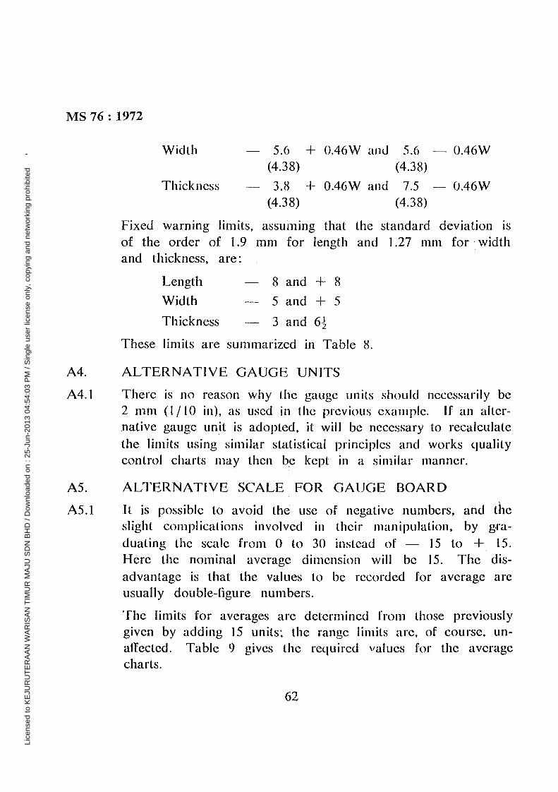
MS 76: 1972
Width — 5.6 + 0.46W and 5.6 — 0.46W(4.38) (4.38)
Thickness — 3.8 + 0.46W and 7.5 — 0.46W(4.38) (4.38)
Fixed warning limits, assuming that (lie standard deviation isof the order of 1.9 mm for length and 1 .27 mm for widthand thickness, are:
Length — 8 and + 8
Width — 5 and + 5
Thickness — 3 and 6
These limits are summarizedin Table 8.
A4. ALTERNATIVE GAUGE UNITS
A4.I There is no reason why (lie gauge units should necessarilybe2 mm (1/10 iii), as used in the previous example. If an alter-native gaugeunit is adopted,it will be necessaryto recalculatethe limits using similar statistical principles and works qualitycontrol charts may then b.c kept in a similar manner.
AS. ALTERNATIVE SCALE FOR GAUGE BOARD
A5.1 It is possible to avoid the use of negative numbers, and theslight complications involved in their manipulation, by g.ra—duating the scale from 0 to 30 instead of — 15 to + 15.Here the nominal average dimension will be 15. The dis-advaiitage is that the values to be recorded for averageareusually double-figure numbers.
The limits for averagesare determined from those previouslygiven by adding 15 units; the range limits are, of course, Un-affected. Table 9 gives (lie required values for the averagecharts.
62
Lice
nsed
to K
EJU
RU
TE
RA
AN
WA
RIS
AN
TIM
UR
MA
JU S
DN
BH
D /
Dow
nloa
ded
on :
25-J
un-2
013
04:5
4:03
PM
/ S
ingl
e us
er li
cens
e on
ly, c
opyi
ng a
nd n
etw
orki
ng p
rohi
bite
d
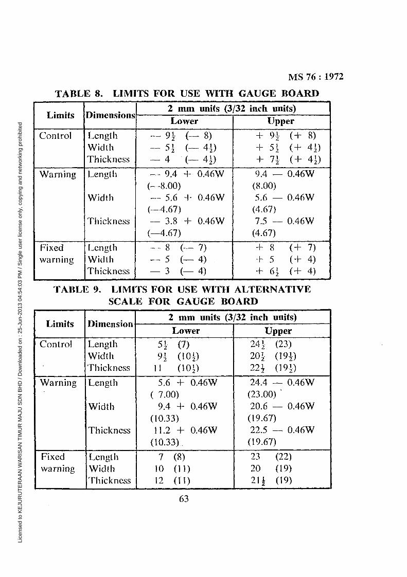
MS 76: 1972TABLE 8. LIMITS FOR USE WITH GAUGE BOARD
• .Limits, •
Dimensions.2 mm units (3Lower
/32 inch units)Upper
Control Length — 95 (— 8) + 95 (+ 8)Width — 51 (— 4-i) + 51 (+ 41)Thickness — 4 (— 44) + 7~ (+ 41)
Warning Length — 9.4 + 0.46W 9.4 — 0.46W(—8.00) (8.00)
Width — 5.6 + 0.46W 5.6 — 0.46W(-----4.67) (4.67)
Thickness — 3.8 + 0.46W 7.5 — 0.46W(—4.67) (4.67)
Fixed Length — 8 (— 7) + 8 (+ 7)warning Width — 5 (— 4) + 5 (+ 4)
Thickness — 3 (— 4) + 61 (+ 4)
TABLE 9. LIMITS FOR USE WITH ALTERNATIVESCALE FOR GAUGE BOARD
•
Ltmits.
, •
Dimenswn2 mm unIts (3/32 inch units)
.Lower Upper
Control Length 5-5 (7) 245 (23)Width 95 (104) 204 (194)Thickness ii (1OD 22~ (191)
Warning Length 5.6 + 0.46W 24.4 — 0.46W( 7.00) (23.00)
Width 9.4 + 0.46W 20.6 — 0.46W(10.33) (19.67)
Thickness Il .2 + 0.46W 22.5 — 0.46W(10.33). (19.67)
Fixed Length 7 (8) 23 (22)warning Width 10 (11) 20 (19)
Thickness 12 (lI) 2I~ (19)
63
Lice
nsed
to K
EJU
RU
TE
RA
AN
WA
RIS
AN
TIM
UR
MA
JU S
DN
BH
D /
Dow
nloa
ded
on :
25-J
un-2
013
04:5
4:03
PM
/ S
ingl
e us
er li
cens
e on
ly, c
opyi
ng a
nd n
etw
orki
ng p
rohi
bite
d
MS 76: 1972
APPENDIX B
CHOICE OF LiMITS AND ACCEPTANCE CLAUSES FORDIMENSIONS OF BRICKS
BS 657, “Dimensions of Common Bricks”, postulated that individualbrick dimensions should not differ from the nominal dimensions bymore than ± ~ in (6.4 mm) on length and ± 5/32 in (4.0 mm) onwidth and thickness. This was a compromise between the require-ments of the manufacturer and the user. The acceptanceclause wasso drafted that ‘Good’ batches, i e with less than 1 % of individualbrick dimensions outside these tolerances, had a very small chanceof rejection. These calculations were based on standard deviations of0.075 in (1.9 mm) for lengths, and 0.05 in (1.27 mm) for width andthickness, obtained from measurementsof individual bricks made atthe British Building Research Station. Since the publication ofBS 657 : 1950 several British manufacturershave carried out measure-ments on a statistical control basis and (lie results obtained indicatethat the original standard deviations are a reasonableestimate of (lieaveragevalue to be found in practice. Some raw materials and pro-cessesenable manufacturersto have smaller standard deviations whilstothers lead to somewhat larger standard deviations. In this respectit is clear that the acceptanceclause of BS 657, requiring measure-ments to be made of total length etc. of a sample of 24 bricks, limitsboth the variability of (lie batch and (lie movemelil of (lie batch averageaway from the nominal dimensions. Manufacturerswho produce batchesof larger variability that correspondsto a standarddeviation of 0.075 in(1.9 mni) for length, etc, are allowed less movement of the batchaverageabout the nominal dimensions. Conversely, the manufacturerwho is able to work with a smaller standard deviation than 0.075 in(1 .9 mm) etc. can allow a greater movement of the batch averageawayfroni the nominal dimensions; however, this amount of movement is
64
Lice
nsed
to K
EJU
RU
TE
RA
AN
WA
RIS
AN
TIM
UR
MA
JU S
DN
BH
D /
Dow
nloa
ded
on :
25-J
un-2
013
04:5
4:03
PM
/ S
ingl
e us
er li
cens
e on
ly, c
opyi
ng a
nd n
etw
orki
ng p
rohi
bite
d
MS 76: 1972
limited and the probability of rejection may become appreciable evenwhen the movement is such as would lead to no more than I % ofthe individual brick dimensions being outside tolerances of either +•~in (6.4 mm) or — .~. in (6.4 mm) on length. etc.
65
Lice
nsed
to K
EJU
RU
TE
RA
AN
WA
RIS
AN
TIM
UR
MA
JU S
DN
BH
D /
Dow
nloa
ded
on :
25-J
un-2
013
04:5
4:03
PM
/ S
ingl
e us
er li
cens
e on
ly, c
opyi
ng a
nd n
etw
orki
ng p
rohi
bite
d
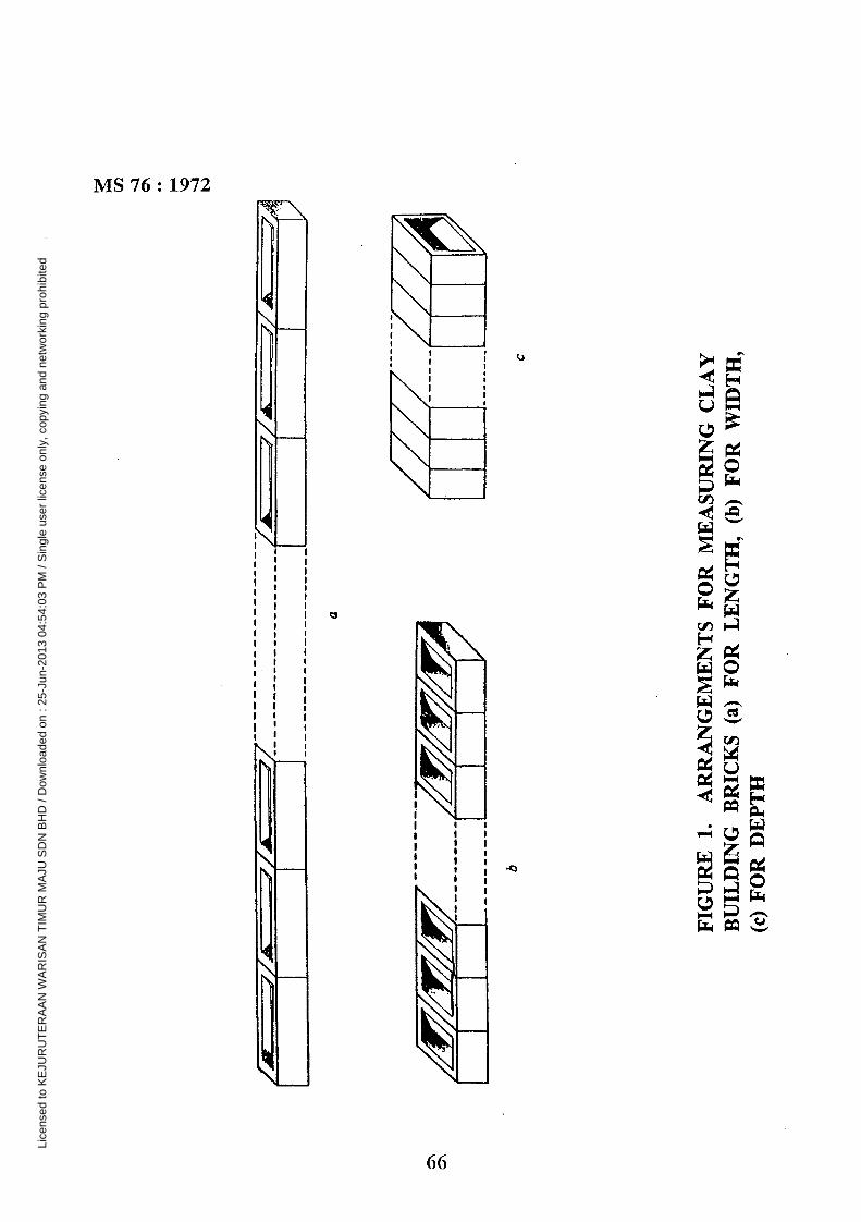
(~
(~
-~
/~~i
L
FIG
UR
E1.
BU
ILD
ING
::::::::::::~
z~-.i’~
~—
~=
‘~
a
AR
RA
NG
EM
EN
TS
FO
RM
EA
SU
RIN
GC
LA
YB
RIC
KS
(a)
FO
RLE
NG
TH
,(b
)F
OR
WID
TH
,
CID
bC
(c)
FO
RD
EP
TH
Lice
nsed
to K
EJU
RU
TE
RA
AN
WA
RIS
AN
TIM
UR
MA
JU S
DN
BH
D /
Dow
nloa
ded
on :
25-J
un-2
013
04:5
4:03
PM
/ S
ingl
e us
er li
cens
e on
ly, c
opyi
ng a
nd n
etw
orki
ng p
rohi
bite
d
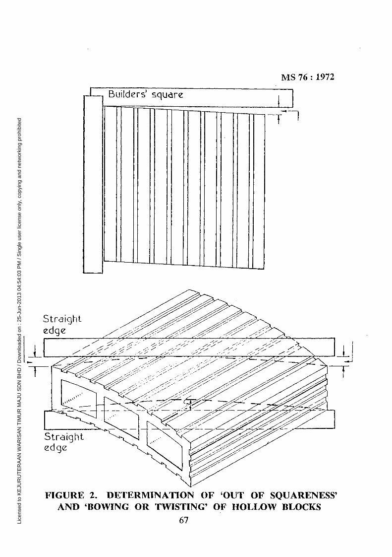
Buitders’ square
MS 76: 1972
I
FIGURE 2. DETERMINATION OF ‘OUT OF SQUARENESS’AND ‘BOWING OR TWiSTING’ 01? HOLLOW BLOCKS
1~~
67Lice
nsed
to K
EJU
RU
TE
RA
AN
WA
RIS
AN
TIM
UR
MA
JU S
DN
BH
D /
Dow
nloa
ded
on :
25-J
un-2
013
04:5
4:03
PM
/ S
ingl
e us
er li
cens
e on
ly, c
opyi
ng a
nd n
etw
orki
ng p
rohi
bite
d
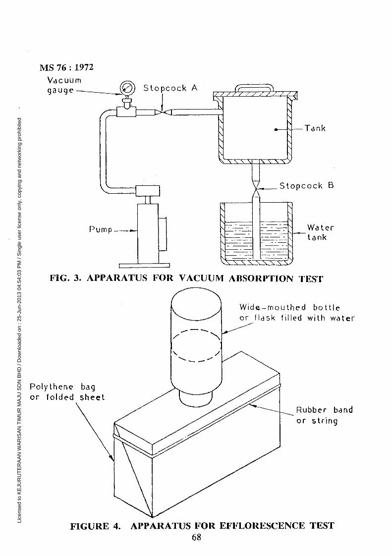
MS 76: 1972Va c U U mgauge
Tank
pcock B
Watertank
Wide—mouthed bottleor flask filled with water
Polythene bagor folded sheet
Rubber bandor strin9
ock A
Pump
FIG. 3. APPARATUS FOR VACUUM ABSORPTION rfl~g~~
FIGURE 4. APPARATUS FOR EFFLORESCENCE TEST68
Lice
nsed
to K
EJU
RU
TE
RA
AN
WA
RIS
AN
TIM
UR
MA
JU S
DN
BH
D /
Dow
nloa
ded
on :
25-J
un-2
013
04:5
4:03
PM
/ S
ingl
e us
er li
cens
e on
ly, c
opyi
ng a
nd n
etw
orki
ng p
rohi
bite
d
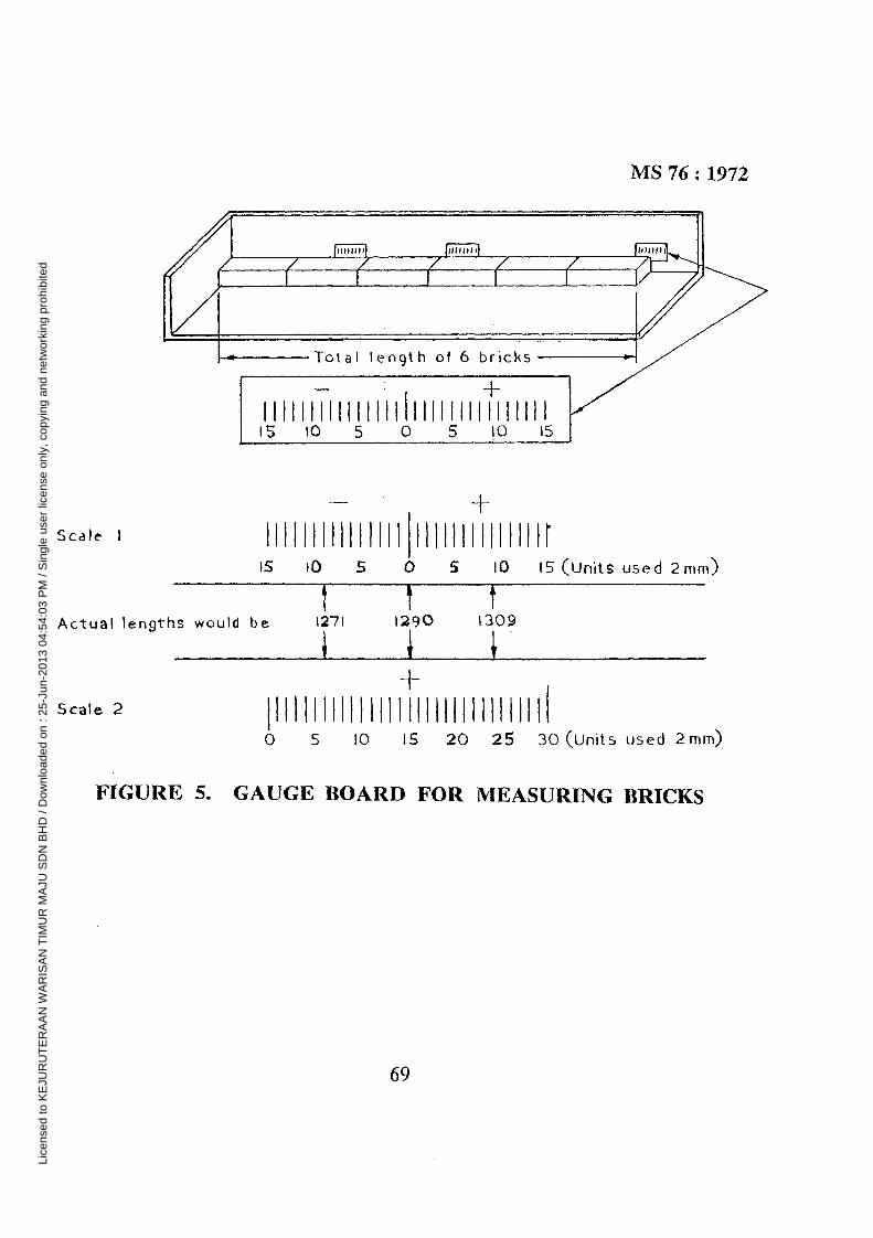
MS 76: 1972
{~~1~T7.Y~( (
-~ Total length of 6 bncks
• +I 111111 H I It H Ii lilt Hi 111111 I KL~ tO 5 0 5 tO ~J
Scale I Ill ill! I filM I MM I illIs tO 5 0 S iO is (units used 2mm)
Actual Ien~ths would be 1271 1290 1309
+Scale 2 I I I I I I I I I I 111 I I I I I I I I I I I I I I I I
0 5 ID iS 20 25 30(Units used 2mm)
FIGURE 5. GAUGE BOARD FOR MEASURING BRICKS
69
Lice
nsed
to K
EJU
RU
TE
RA
AN
WA
RIS
AN
TIM
UR
MA
JU S
DN
BH
D /
Dow
nloa
ded
on :
25-J
un-2
013
04:5
4:03
PM
/ S
ingl
e us
er li
cens
e on
ly, c
opyi
ng a
nd n
etw
orki
ng p
rohi
bite
d

MS 76: 1972
FIGURE 6. DOUBLE BRICKS REFERRED TO IN NOTE 3.CLAUSE 39 (d)(iv)
70
Lice
nsed
to K
EJU
RU
TE
RA
AN
WA
RIS
AN
TIM
UR
MA
JU S
DN
BH
D /
Dow
nloa
ded
on :
25-J
un-2
013
04:5
4:03
PM
/ S
ingl
e us
er li
cens
e on
ly, c
opyi
ng a
nd n
etw
orki
ng p
rohi
bite
d
3
TANDA-TANDA STANDARD SIRIM
Tanda-tanda Standard SIRIM seperti yang tertera di bawah adalah tanda -tanda pengesahan dagangan berdaftar. Tanda-tanda ini hanya boleh digunakan oleh mereka yang dilesenkan di bawah skim tanda pengesahan yang dijalankan oleh SIRIM mengikut nombor Standard Malaysia yang berkaitan. Kewujudan tanda-tanda ini pada atau berkaitan dengan sesuatu barangan adalah sebagai jaminan bahawa barangan tersebut telah dikeluarkan melalui satu sistem penyeliaan, kawalan dan ujian, yang dijalankan semasa pengeluaran. Ini termasuk pemeriksaan berkala kerja-kerja pengeluaran menurut skim tanda pengesahan SIRIM yang dibentuk untuk menentukan bahawa barangan tersebut menepati Standard Malaysia. Keterangan-keterangan lanjut mengenai syarat -syarat lesen boleh didapati dari:
Ketua Pengarah Institut Standard dan Penyelidikan Perindustrian Malaysia
Persiaran Dato’ Menteri, Seksyen 2, Peti Surat 7035 40911 Shah Alam
Selangor Darul Ehsan
SIRIM STANDARD MARKS The SIRIM standard marks shown above are registered certification trade marks. They may be used only by those li censed under the certification marking scheme operated by SIRIM and in conjunction with relevant Malaysian Standard number. The presence of these Marks on or relation to a product is assurance that the goods have been produced under a system of supervision, control and testing, operated during production, and including periodi cal inspection of the producer’s works in accordance with the certification marking scheme of SIRIM designed to ensure compliance with a Malaysian Standard. Further particulars of the terms of license may be obtained from:
Director-General Standards and Industrial Research Institute of Malaysia
Persiaran Dato’ Menteri, Section 2. P.O.Box 7035 40911 Shah Alam
Selangor Darul Ehsan
Lice
nsed
to K
EJU
RU
TE
RA
AN
WA
RIS
AN
TIM
UR
MA
JU S
DN
BH
D /
Dow
nloa
ded
on :
25-J
un-2
013
04:5
4:03
PM
/ S
ingl
e us
er li
cens
e on
ly, c
opyi
ng a
nd n
etw
orki
ng p
rohi
bite
d

INSTITUT STANDARD DAN PENYELIDIKAN PERINDUSTRIAN MALAYSIA
Institut Standard dan Penyelidikan Perindustrian Malaysia (SIRIM) telah ditubuhkan hasil dan cantuman InstitutPiawaian Malaysia (SIM) dengan Institut Negara bagi Penyelidikan Sains dan Perusahaan (NISIR) di bawahUndang-Undang Malaysia Akta 157 pada l6hb. September 1975:Akta Institut Standard dan PenyelidikanPerindustrian Malaysia (Perbadanan) 1975. Institut mi diletakhak dengan kuasa untuk memamju danmenjalankan penyelidikan perindustrian dan untuk menyedia dan memajukan standard-standard bagi barangan-barangan, proses-proses, amalan-amalan dan perkhidmatan-perkhidmatan; dan bagi mengadakan peruntukanbagi perkara-perkara yang bersampingan atau berkaitan dengan maksud-maksud itu.
Satu daripada tugas-tugas Institut mi adalah menyediakan Standard-Standard Malaysia dalam bentukpenentuan-penentuan bagi bahan-bahan, keluaran-keluaran, kaedah-kaedah ujian, kod-kod amalan yangsempurna dan selamat, sistem penamaan dan lain-lain. Standard-Standard Malaysia disediakan olehjawatankuasa-jawatankuasa perwakilan yang menyelaras keupayaan pengilang dan kecekapan pengeluarandengan kehendak-kehendak yang munasabah dan pengguna. Ia menuju ke arah mencapai kesesuaian bagimaksud, memudahkan pengeluaran dan pengedaran, kebolehsalingtukaran gantian dan pelbagai pilihan yangmencukupi tanpa pembaziran.
Standard-Standard Malaysia disediakan hanya setelah penyiasatan yang lengkap menujukkan bahawa sesuatuprojek itu disahkan sebagai yang dikehendaki dan berpadanan dengan usaha yang terlibat. Hasil ml berasaskanpersetujuan sukarela dan memberi pertimbangan kepada kepentingan pengeluar dan pengguna. Standard-Standard Malaysia adalah sukarela kecuali is dimestikan oleh badan-badan berkuasa melalui peraturan-peraturan, undang-undang persekutuan dan tempatan atau cara-cara lain yang sepertinya.
Institut mi beroperasi semata-mata berasaskan tanpa keuntungan. Ia adalah satu badan yang menerima bantuankewangan dan Kerajaan, kumpulan wang dan bayaran keahlian, hasil dan jualan Standard-Standard danterbitan-terbitan lain, bayaran-bayaran ujian dan bayaran-bayaran lesen untuk mengguna Tanda PengesahanSIRIM dan kegiatan-kegiatan lain yang berhubung dengan Penstandardan, Penyelidikan Perindustrian danKhidmat Perunding.
STANDARDS AND INDUSTRIAL RESEARCH INSTITUTE OF MALAYSIA
The Standard and Industrial research Institute of Malaysia (SIRIM) is established with the merger of theStandards Institution of Malaysia (SIM) and the National Institute for Scientific and Industrial Research (NISIR)under the Laws of Malaysia Act 157 on ~ September 1975: Standards and Industrial Research Institute ofMalaysia ~(Incorporation)Act 1975. The Institute is vested with the power to provide for the promotion andundertaking of industrial research and for the preparation and promotion of standards for commodities,processes, practices and services; and to provide for matters incidental to or connected with those purposes.
One Of the functions of the Institute is to prepare Malaysian Standards in the form of specifications for materialsand products, methods of testing, codes of sound and safe practice, nomenclature, etc. Malaysian Standards areprepared by representative committees which co-ordinate manufacturing capacity and production efficiency withthe user’s reasonable needs. They seek to achieve fitness for purpose, simplified production and distributionreplacement interchangeability, and adequate variety of choice withoutwasteful diversify.
Malaysian Standards are prepared only after a full enquiry has shown that the project is endorsed as a desirableone and worth the effort involved. The work is based on voluntary agreement, and recognition of the communityof interest of producer and consumer. The use of Malaysian Standards is voluntary except in so far as they aremade mandatory by statutory authorities by means of regulations, federal and local by-laws or any other similarways.
The Institute operates entirely on a non-profits basis. It is a grant aided body receiving financial aid from theGovernment, funds from membership subscriptions and proceeds from sales of Standards and otherpublications, fees and licence fees for the use of SIRIM Certification Mark and other activities associated withStandardization, Industrial Research and Consultancy Services.
Lice
nsed
to K
EJU
RU
TE
RA
AN
WA
RIS
AN
TIM
UR
MA
JU S
DN
BH
D /
Dow
nloa
ded
on :
25-J
un-2
013
04:5
4:03
PM
/ S
ingl
e us
er li
cens
e on
ly, c
opyi
ng a
nd n
etw
orki
ng p
rohi
bite
d
Related Documents