Dec 2017 MR6K-48X Mid-Rise Scissor Lift 6,000 lbs. Capacity (1,500 lbs. Max per Arm) INSTALLATION & OPERATION MANUAL

Welcome message from author
This document is posted to help you gain knowledge. Please leave a comment to let me know what you think about it! Share it to your friends and learn new things together.
Transcript

Dec 2017
MR6K-48X
Mid-Rise Scissor Lift
6,000 lbs. Capacity (1,500 lbs. Max per Arm)
INSTALLATION & OPERATION
MANUAL

2 MR6K-48X Dec 2017
CONTENT
SAFETY INFORMATION • Note, Caution and Warning • Important Information • Safety Instructions
TECHNICAL INFORMATION • Product Description • Specifications
BEFORE USING • Site Selection • Surface Condition • Operating Condition
INSTALLATION INSTRUCTIONS
• Required Tools • Unloading Lift • Un-banding Lift • Lift Assembly • Starting Up / Testing
OPERATION INSTRUCTIONS • Vehicle Positioning, Lifting & Lowering • Inspection, Maintenance & Cleaning • Trouble-Shooting Guide • Power Unit Priming Procedure
EXPLODED VIEWS & PARTS LIST
LIMITED WARRANTY

3 MR6K-48X Dec 2017
SAFETY INFORMATION
Note, Caution and Warning This document uses the following notations: Note, Caution and Warning – to alert you to special instructions, tips, or hazards for a given procedure. Please familiarize yourself with the notation explanations described below.
Indicates important information that requires speci al attention, such as a procedure for a specific vehicle, or tips on operating the equipmen t. Indicates the potential for damage to equipment, ac cessories or the vehicle unless the instructions or procedure are followed specifically .
Indicates the potential for property damage, person al injury or death due to hazards associated with the equipment, vehicle or environme nt. Do not perform any procedures until you have read and understood the warning inst ructions.
Important Information
1. Read this manual thoroughly before installing, operating or maintaining the lift.
2. This lift is designed for indoor use only and should not be installed in a pit or depression.
3. The lifts have specific electrical requirements as described in the Installation Instructions section of this manual.
4. This lift has a minimum ceiling height requirement as described in the Installation Instructions section of this manual.
5. Failure by the owner to provide the recommended shelter, mounting surface, electrical s upply, and ceiling height could result in unsatisfactory lift performance, property damage or personal injury.
6. The operation of the lift is permitted by authorized persons only.

4 MR6K-48X Dec 2017
Safety Instructions
1. Do not raise a vehicle on the lift until the installation is completed as described in this manual.
2. Technicians should be trained to use and care for the lift by familiarizing themselves with the manual, including Note, Caution and Warning information. The lift should never be operated by an untrained person.
3. Always position the pads properly out of the way before pulling the vehicle into or out of the service bay. Failure to do so could damage the vehicle and/or th e lift .
4. Do not overload the lift. The capacity of the lift is shown on cover of this manual and on the lift’s serial number tag.
5. Positioning the vehicle is very important. Only trained technicians should position the vehicle on the lift. Never allow anyone to stand in the path of the vehi cle as it is being positioned and never raise vehicle with passengers inside.
6. Position the pads to the vehicle manufacturer’s recommended pickup points. Raise the lift until the pads make contact with the vehicle. Make sure the pads have properly engaged the vehicle’s pick-up points before raising the lift to a working height.
7. Keep everyone clear of the lift when the lift is moving, the locking mechanism is disengaged or if the vehicle is in danger of falling.
8. Unauthorized personnel should never be in the shop area when the lift is in use.
9. Inspect the lift daily. The lift should never be operated if it has damaged components or is malfunctioning. Only qualified technicians should service the lift. Replace damaged components with manufacturer’s parts, or equivalent.
10. Keep the area around the lift clear of obstacles.
11. Never override the self-returning lift controls.
12. Avoid excessive rocking of the vehicle when it is on the lift.
13. To reduce the risk of personal injury, keep hair, loose clothing, fingers, and all body parts away from moving parts.
14. To reduce the risk of electric shock, do not use the lift when wet, do not expose the lift to rain.
15. To reduce the risk of fire, do not operate equipment in the vicinity of open containers of flammable liquids (gasoline).
16. Use the lift only as described in this manual, use only manufacturer’s recommended attachments.
17. Unusual vehicles, such as limousines, RV’s, and lon g wheelbase vehicles, may not be suitable for lifting on this equipment. If necessary, consult with the manufacturer or the manufacturer’s representative.
18. The maintenance procedures described in this manual can be done by the lift’s owner/employer. Any other procedure should only be performed by trained lift service personnel. These restricted procedures include, but are not limited to, the fol lowing: cylinder replacement, platform & safety latch replacement and motor replacement.
19. Anyone who will be in the vicinity of the lift when it is in use should familiarize themselves with any Caution, Warning, and Safety related decals supplied with this lift, and replace them if they are illegible or missing.
5 MR6K-48X Dec 2017
TECHNICAL INFORMATION
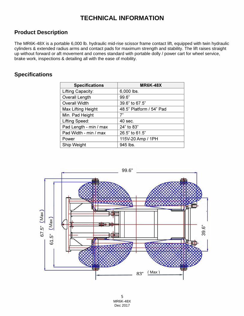
Product Description The MR6K-48X is a portable 6,000 lb. hydraulic mid-rise scissor frame contact lift, equipped with twin hydraulic cylinders & extended radius arms and contact pads for maximum strength and stability. The lift raises straight up without forward or aft movement and comes standard with portable dolly / power cart for wheel service, brake work, inspections & detailing all with the ease of mobility. Specifications
Specifications MR6K-48X Lifting Capacity: 6,000 lbs. Overall Length 99.6” Overall Width 39.6” to 67.5” Max Lifting Height 48.5” Platform / 54” Pad Min. Pad Height 7” Lifting Speed: 40 sec. Pad Length - min / max 24” to 83” Pad Width - min / max 26.5” to 61.5” Power 115V-20 Amp / 1PH Ship Weight 945 lbs.
Important!
99.6”
67.5
”
61.5
” 39.6
”
83” ( Max )

6 MR6K-48X Dec 2017
BEFORE USING
Site Selection The Lift is designed for indoor use only. Application in a room with explosion hazard is not permitted. Placing the lift in a wet place, such as car wash bay, is prohibited. Ensure to check the desired location for possible obstructions such as a low ceiling, overhead lines, adequate working area, access ways and exits. Make sure to allow a minimum space of 12 to 14 feet in front and behind the Lift to accommodate all vehicles. Certain allowances should be made for special vehicle requirements or unusual floor plans.
Surface Condition Do not use the Lift on any type of asphalt or soft surface. Ensure lift is placed on a dry, oil & grease free, level concrete surface capable of supporting the weight of the Lift with a vehicle. Do not use Lift on concrete expansion seams or cracked, defective concrete. Failure to accomplish the foundation requirement may cause lift instability, which could result in personal injury. Operating Condition Lift is not intended for outdoor use and has an operating ambient temperature range of 41º - 104ºF (5º - 40ºC).
70.8”
54”
7”

7 MR6K-48X Dec 2017
INSTALLATION INSTRUCTIONS You will need common hand tools that most homeowner s have, like a hammer, screwdrivers and pliers, but in addition, you may n eed some tools that are not common. Each installation is somewhat different and depends on how much room you have to work around the lift.
Required Tools
1. Fork Lift 2. Metal Shears 3. Socket Wrenches with Ratchet 4. Adjustable Wrench 5. Pliers 6. Flat Blade Screwdriver 7. Gloves
Unloading Lift
You’ll need a forklift that can handle about 2,000 to 2,300 pounds and operate on a smooth surface.
Un-banding Lift
The steel bands which secure the lift parts to the pallets are heavy duty. You’ll need a pair of metal shears or tin snips to cut the steel bands. Be very careful when doing this because the bands will tend to fly apart when they are cut, and the heavy lift parts may shift when freed from the steel bands. Stand to the side of the steel bands when cutting them, while using gloves when removing the cut band s because they have sharp edges.
You can move the large piece to the garage with the forklift. Other smaller pieces can be moved manually.
STEP 1: Assemble Dolly & Lock Release Hand Lever A. Remove dolly components from the carton and assemble together (Fig. 1). B. Mount the Lock Release Hand Lever to the dolly ‘side’ handle (Fig. 2).
Fig. 1 Fig. 2
Dolly Handle Assy.
Dolly Pedestal
Dolly Base
Lock Release Hand Lever

8 MR6K-48X Dec 2017
STEP 2: Mounting Power Unit to Dolly
A. Remove power unit from the carton. B. Use provided nuts & bolts to attach power unit to dolly’s mount plate (Fig. 3).
Fig. 3 Fig. 4
STEP 3: Hydraulic Hose Connection & Filling Reservo ir Tank A. Connect hydraulic hose to the pump’s output port (Fig. 4). B. Remove the black fill cap on reservoir tank and fill with 6 quarts of Non-Detergent / Non-
Foaming Hydraulic Oil - SAE-10, AW 32 or equivalent. Ensure not to fill past the MAX Fill Line on the reservoir tank.
STEP 4: AC Power Supply Connection
A. Connect the 115VAC electrical power to the Power Unit’s three prong electrical plug. Ensure to use proper size extension cord and plug type for 20 Amps (Fig 5.)
B. Ensure power supply incorporates 20 Amp breaker service for safety.
Fig. 5
Power Unit Electrical Cord

9 MR6K-48X Dec 2017
Starting Up / Testing
A. Push the ‘start button’ on the motor pump to prime the hydraulic oil into the cylinders on the lift. The lift will rise up with lock latch passing over the lock ladder (Fig. 6).
B. Release the start button to stop the lift from rising. Press down on the ‘lowering valve lever’
and the lift will lower down and automatically engage the next lower lock height (Fig. 6).
Fig. 6
C. Push the ‘start button’ just 2-3 seconds to slightly raise the frame. The safety latch will
disengage from the lock ladder notch.
D. While holding the ‘lock release handle’ tight, also press down on the power unit’s ‘lowering valve lever’ to lower the lift down to the ground.
If the latch engages the lock ladder while rising o r does not disengage the lock ladder after handle is held tight, adjustment is re quired for the position of the safety latch via the threaded cable adjustment nut (Fig. 7 ).
Fig. 7
Safety Latch
Cable Adjustment
10 MR6K-48X Dec 2017
OPERATION INSTRUCTIONS
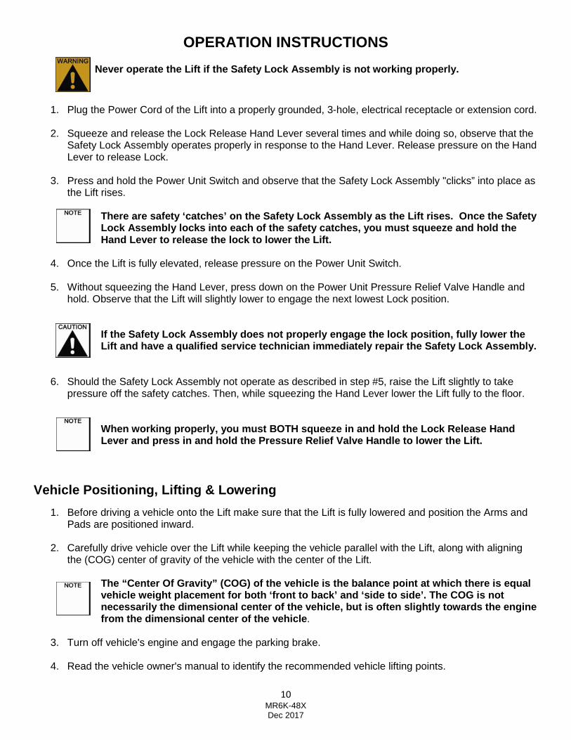
Never operate the Lift if the Safety Lock Assembly is not working properly.
1. Plug the Power Cord of the Lift into a properly grounded, 3-hole, electrical receptacle or extension cord.
2. Squeeze and release the Lock Release Hand Lever several times and while doing so, observe that the Safety Lock Assembly operates properly in response to the Hand Lever. Release pressure on the Hand Lever to release Lock.
3. Press and hold the Power Unit Switch and observe that the Safety Lock Assembly "clicks” into place as the Lift rises.
There are safety ‘catches’ on the Safety Lock Assem bly as the Lift rises. Once the Safety Lock Assembly locks into each of the safety catches , you must squeeze and hold the Hand Lever to release the lock to lower the Lift.
4. Once the Lift is fully elevated, release pressure on the Power Unit Switch.
5. Without squeezing the Hand Lever, press down on the Power Unit Pressure Relief Valve Handle and
hold. Observe that the Lift will slightly lower to engage the next lowest Lock position.
If the Safety Lock Assembly does not properly engag e the lock position, fully lower the Lift and have a qualified service technician immedi ately repair the Safety Lock Assembly.
6. Should the Safety Lock Assembly not operate as described in step #5, raise the Lift slightly to take pressure off the safety catches. Then, while squeezing the Hand Lever lower the Lift fully to the floor.
When working properly, you must BOTH squeeze in and hold the Lock Release Hand Lever and press in and hold the Pressure Relief Val ve Handle to lower the Lift.
Vehicle Positioning, Lifting & Lowering
1. Before driving a vehicle onto the Lift make sure that the Lift is fully lowered and position the Arms and Pads are positioned inward.
2. Carefully drive vehicle over the Lift while keeping the vehicle parallel with the Lift, along with aligning the (COG) center of gravity of the vehicle with the center of the Lift.
The “Center Of Gravity” (COG) of the vehicle is the balance point at which there is equal vehicle weight placement for both ‘front to back’ a nd ‘side to side’. The COG is not necessarily the dimensional center of the vehicle, but is often slightly towards the engine from the dimensional center of the vehicle .
3. Turn off vehicle's engine and engage the parking brake.
4. Read the vehicle owner's manual to identify the recommended vehicle lifting points.

11 MR6K-48X Dec 2017
5. Position the Arms outward and position the Saddle Pads to contact the vehicle lifting points.
6. Do not lift the vehicle if you cannot establish secure and level lifting points. Do not use sub-standard shims or other devices in place of approved and recommended Saddle Pad Adapters. Never use the Lift without the Saddle Pads in place for each Arm.
7. Once the Saddle Pads have been positioned under the vehicle lifting points, push the Power Unit Switch to lift the vehicle slightly, and test to make sure the vehicle is well balanced and the contact between the Saddle Pads and vehicle’s lifting points are secure. Then, proceed to lift the vehicle to the desired height.
8. When the vehicle has been lifted to the desired height, and the Safety Lock Assembly has locked in place, make sure to install proper safety jack stands (not included), under the vehicle once it is lifted to the desired height, as an additional safety measure.
9. Once the repair work to the vehicle is completed make sure to remove all tools, safety jack stands, and materials form under the vehicle and Lift. Also, make sure the work area is clear and it is safe to lower the vehicle.
10. To lower the Lift, use the Power Unit Switch to slightly raise the vehicle to remove pressure off the Safety Lock Assembly.
11. Stand well away from the Lift and vehicle. Then squeeze and hold in the Hand Lever while at the same time pushing in and holding the Pressure Relief Valve Handle to slowly lower the Lift all the way down to the floor.
12. Move the Saddle Pads and Arms inward, out of the path of the vehicle.
13. Disengage the vehicle parking brake. Start the vehicle's engine, and carefully drive the vehicle off the Lift slowly.
Inspection, Maintenance & Cleaning
Always unplug the Power Cord from the electrical ou tlet before performing any inspection, adjustments, maintenance and/or cleanin g.
BEFORE EACH USE: Inspect the general condition of the Lift. Check for loose screws, misalignment or binding of moving parts, broken parts, damaged electrical wiring and hoses, and any other condition that may affect its safe operation. If abnormal noise or vibration occurs, have the problem identified and corrected before further use. Do not use a damaged equipment.
DAILY: With compressed air or vacuum, remove all dirt and debris from the Lift. Also, use a detergent or mild solvent to remove oil and grease from the unit. Then, use a premium quality, machine oil to lubricate all moving parts.
MONTHLY: With the lift fully lowered, check the level of hydraulic oil in the Reservoir Tank is close to the Max Fill Line. If not, remove the Fill Cap and add premium quality hydraulic oil until the level of oil is even with the Max Fill Line. After filling, place the Fill Cap to Reservoir Tank.
Never Add Hydraulic Fluid while Lift is in raised p osition!!

12 MR6K-48X Dec 2017
Trouble-Shooting Guide
1. Motor Does Not Run: A. Breaker or fuse blown............ Call electrician B. Faulty wiring connections...... Call electrician C. Defective start button.............Call electrician D. Defective capacitor................ Call electrician
2. Motor Runs but Will Not Raise:
A. Oil level too low......................Oil level should be at the MAX Fill Line with lift fully lowered. B. Check for proper clearance for the release valve’s stem seat. C. Remove the check valve cover and clean ball and seat. D. A piece of trash is under the Release Valve. Push handle down and push the up button at the
same time. Hold for 10-15 seconds. This should flush the valve out to remove trash.
3. Motor Runs but Will Not Raise Vehicle: A. Motor running on low voltage.............Call electrician B. Lift is overloaded................................Check vehicle’s gross weight C. Defective pressure relief valve.
4. Oil Blows Out Power Unit Fill Cap:
A. Oil reservoir overfilled. B. Lift lowered too quickly while under a heavy load.
5. Motor Hums and Will Not Run:
A. Lift overloaded....................... Remove excessive weight from lift. B. Bad capacitor......................... Call electrician. C. Low voltage............................Call electrician. D. Faulty wiring...........................Call electrician.
6. Lift Jerks Up and Down:
A. Air in hydraulic system........... Raise lift all the way to top and return to floor. Repeat 4-6 times with intervals at least 2 minutes apart. Ensure NOT to overheat the power unit.
7. Oil Leaks: A. Power unit..............................If the power unit leaks hydraulic oil around the tank-mounting
flange, check the oil level in the tank. The fluid level should not be above the MAX Fill Line. B. Rod end of cylinder................ The rod seal of the cylinder is defective. Rebuild or replace the
cylinder. C. Breather end of the cylinder...The piston seal of the cylinder is defective. Rebuild or replace the
cylinder.
8. Lift Makes Excessive Noise: A. Roller assemblies not moving freely..............Inspect and apply grease. B. Check for excessive wear on shafts & pins... Inspect and replace. C. Seals are dry in hydraulic cylinder(s).............Cycle lift as noted in #6.
9. Lift Will Not Lower:
A. Lock Release Cable not properly adjusted....Inspect and adjust. B. Defective Release Valve............................... Inspect and replace. C. Defective safety latch mechanism................. Inspect and replace.

13 MR6K-48X Dec 2017
IMPORTANT
POWER UNIT PRIMING PROCEDURE
THE PROBLEM: Power unit runs fine but will not pump any fluid.
Step 1 – Locate the check valve. It is the plug to the left of the lowering valve.
Step 2 – Using a Hex wrench and shop towel – with shop towel in place to catch fluid – loosen the check valve plug by approximately 2-½ turns and allow fluid to bleed off.
Step 3 – Push the START button for one second, then release for three seconds. Repeat these steps until unit starts pumping fluid.
Step 4 – Tighten the check valve plug.
YOUR POWER UNIT SHOULD NOW BE PRIMED

14 MR6K-48X Dec 2017
EXPLODED DRAWING

15 MR6K-48X Dec 2017
PARTS LIST
ITEM Tux P/N M REF P/N DESCRIPTION QTY
1BX MR6K-48X-001-BX XF01-04000-000 Top Platform 1
2B MR6K-48X-002B Pin 3mm x 40mm 2
3B MR6K-48X-003B Pin 3mm x 40mm 2
4B MR6K-48X-004B Hose fitting from T - HYD 1
5B MR6K-48X-005B QJYJ3-7 Cylinder Hose 2
6B MR6K-48X-006B Hose Fitting to Cylinder 2
7B PU-110V-S-K PU-110V-S-K Power Unit 115VAC 1
8B MR6K-48X-008B Bolt M8 x 25 8
9B MR6K-48X-009B Nut M8 x 25 4
10B MR6K-48X-010B Lock Release Cable 1
11B MR6K-48X-011B QJYJ3-01-1 Dolly Handle 1
12B MR6K-48X-012B Bolt M8 x 25 4
13B MR6K-48X-013B Lock Release Handle 1
14B MR6K-48X-014B Bolt M8 x 25 8
15B MR6K-48X-015B QJYJ3-01-2/1 Dolly Stand - Main 1
16B MR6K-48X-016B Rubber Hand Grip 3
17B MR6K-48X-017B Hose Fitting to PU 1
18B MR6K-48X-018B QJYJ3-2 Hydraulic Hose to PU 155" 1
19B MR6K-48X-019B QJYJ3-6 Check Valve 2
20B MR6K-48X-020B QJYJ3-02-13 Safety Locking Pin - lower 1
21B MR6K-48X-021B Pin 3mm x 40mm 6
23B MR6K-48X-023B QJYJ3-02-8 Scissor Pin 2
24B MR6K-48X-024B QJYJ3-02-1 Outside Scissor 1
25B MR6K-48X-025B QJYJ3-02-4 Inside Scissor 1
26B MR6K-48X-026B QJYJ3-02-10 Large Roller Pin 2
27B MR6K-48X-027B QJYJ3-02-9 Large Roller 2
28B MR6K-48X-028B QJYJ3-02-7 Small Wheel 2
29B MR6K-48X-029B QJYJ3-02-6 Small Wheel Pin 2
30B MR6K-48X-030B QJYJ3-02-5 Platform Pin 2
31B MR6K-48X-031B QJYJ3-02-12 Cylinder Pin 2
32B MR6K-48X-032B QJYJ3-02-11 Safety Lock Pin - upper 1
33B MR6K-48X-033B QJYJ3-5 Bolt M6 1
34B MR6K-48X-034B QJYJ3-4 Nut M6 x 40 1
35B MR6K-48X-035B HQJYJ3-02-2 Cylinder 2
36B MR6K-48X-036B QJYJ3-02-14 Safety Lock Assembly 1

16 MR6K-48X Dec 2017
36B-1C MR6K-48X-036B-1C Lock Pin 1
36B-2C MR6K-48X-036B-2C QJYJ3-02-14/6 Lock Spring 1
36B-3C MR6K-48X-036B-3C QJYJ3-02-14/3 Lock Latch 1
36B-4C MR6K-48X-036B-4C QJYJ3-02-14/1 Lock Bar 1
36B-5C MR6K-48X-036B-5C QJYJ3-02-14/5 Lock Cam 1
36B-9C MR6K-48X-036B-9C QJYJ3-02-14 Lock Tube 1
36B-10C MR6K-48X-036B-10C Washer D8 2
36B-11C MR6K-48X-036B-11C Bolt M8 x 16 2
36B-12C MR6K-48X-036B-12C QJYJ3-02-14/4 T-Valve Hyd 1
37BX MR6K-48X-037BX Pin 4mm x 50mm 2
38B MR6K-48X-038B QJYJ3-03-2 Saddle Pad 4
39BX MR6K-48X-039BX QJYJ-03-3 Rubber Pad 4
40B MR6K-48X-040B Locking Nut M20 4
41B MR6K-48X-041B Washer D20 4
42BX MR6K-48X-042BX QJYJ0-03 Arm Extension Assembly 4
43B MR6K-48X-043B Bolt M10 x 20 4
44B MR6K-48X-044B Pin 3mm x 40mm 2
45B MR6K-48X-045B Dolly Caster 2
46B MR6K-48X-046B Locking Nut M12 2
47BX MR6K-48X-047BX Screw M6x16 2
48B MR6K-48X-048B QJYJ3-01-2/2 Dolly Base Plate 1
49B MR6K-48X-049B Washer D12 2

17 MR6K-48X Dec 2017
LIMITED WARRANTY
Structural Warranty: The following parts and structural components carry a five year warranty: Columns Arms Uprights Swivel Pins Legs Carriages Overhead Beam Tracks Cross Rails Top Rail Beam
Limited One-Year Warranty: Tuxedo Distributors, LLC (Tuxedo) offers a limited one-year warranty to the original purchaser of Lifts and Wheel Service equipment in the United States and Canada. Tuxedo will replace, without charge, any part found defective in materials or workmanship under normal use, for a period of one year after purchase. The purchaser is responsible for all shipping charges. This warranty does not apply to equipment that has been improperly installed or altered or that has not been operated or maintained according to specifications.
Other Limitations: This warranty does not cover:
1. Parts needed for normal maintenance 2. Wear parts, including but not limited to cables, slider blocks, chains, rubber pads and pulleys 3. Replacement of lift and tire changer cylinders after the first 30 days. A seal kit and installation instructions will be
sent for repairs thereafter. 4. On-site labor
Upon receipt, the customer must visually inspect the equipment for any potential freight damage before signing clear on the shipping receipt. Freight damage is not considered a warranty issue and therefore must be noted for any potential recovery with the shipping company. The customer is required to notify Tuxedo of any missing parts within 72 hours. Timely notification must be received to be covered under warranty. Tuxedo will replace any defective part under warranty at no charge as soon as such parts become available from the manufacturer. No guarantee is given as to the immediate availability of replacement parts.
Tuxedo reserves the right to make improvements and/or design changes to its lifts without any obligation to previously sold, assembled or fabricated equipment.
There is no other express warranty on the Tuxedo lifts and this warranty is exclusive of and in lieu of all other warranties, expressed or implied, including all warranties of merchantability and fitness for a particular purpose.
To the fullest extent allowed by law, Tuxedo shall not be liable for loss of use, cost of cover, lost profits, inconvenience, lost time, commercial loss or other incidental or consequential damages.
This Limited Warranty is granted to the original purchaser only and is not transferable or assignable.
Some states do not allow exclusion or limitation of consequential damages or how long an implied warranty lasts, so the above limitations and exclusions may not apply. This warranty gives you specific legal rights and you may have other rights, which may vary from state to state.
1905 N Main St Suite C, Cleburne, TX 76033 Ph. 817-558-9337 / Fax 817-558-9740
Related Documents


