1 July 22, 2019 Project No. Z346.00 Mr. Joseph Spangenberger, P.E. Watermark 175 Cabot Street Lowell, MA 01854 SUBJECT: Geotechnical Engineering Data Report Tanner Street Realignment – Phase I Test Borings Lowell, MA Dear Joe: Northeast Geotechnical, Inc. is pleased to present our geotechnical engineering data report for the proposed Tanner Street realignment project in Lowell, MA. This report summarizes the results of soil test borings performed along portions of the proposed realignment area. This report is subject to the Limitations and Service Constraints attached as Appendix A. Background Our understanding of the existing site conditions and proposed project is based on our correspondence with Watermark, our time on-site during the test borings, and our review of the project documents provided to us including: • “Boring Profile”, B-102, undated, by Watermark; and • “Boring Location Plan”, B-101, Sheet 1 of 1, dated May 8, 2019, by Watermark. The proposed project includes relocation of a portion of Tanner Street in Lowell, MA. The realignment of Tanner Street is proposed to extend from Plain Street to the south, past West London Street and then tie into the existing Tanner Street to the north. The Tanner Street realignment section will also connect to Montreal Street to the east. The proposed project extends over multiple properties that are currently developed. We understand a new sewer line is proposed along the Tanner Street realignment as well as along a portion of West London Street. The proposed sewer invert elevation is roughly Elevation 35± feet (City of Lowell Datum). Watermark developed a subsurface exploratory test boring program to assess the subsurface conditions within the area of the proposed street realignment and new sewer. The program consists of fourteen (14) soil test borings which have been split up in two phases. This report pertains to the Phase I test borings, which include boring nos. B-1 through B-3, and B-10 through B-14.

Welcome message from author
This document is posted to help you gain knowledge. Please leave a comment to let me know what you think about it! Share it to your friends and learn new things together.
Transcript
1
July 22, 2019 Project No. Z346.00 Mr. Joseph Spangenberger, P.E. Watermark 175 Cabot Street Lowell, MA 01854 SUBJECT: Geotechnical Engineering Data Report Tanner Street Realignment – Phase I Test Borings Lowell, MA Dear Joe: Northeast Geotechnical, Inc. is pleased to present our geotechnical engineering data report for the proposed Tanner Street realignment project in Lowell, MA. This report summarizes the results of soil test borings performed along portions of the proposed realignment area. This report is subject to the Limitations and Service Constraints attached as Appendix A. Background Our understanding of the existing site conditions and proposed project is based on our correspondence with Watermark, our time on-site during the test borings, and our review of the project documents provided to us including:
• “Boring Profile”, B-102, undated, by Watermark; and
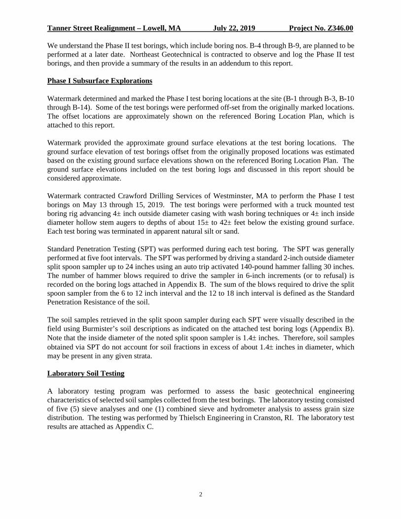
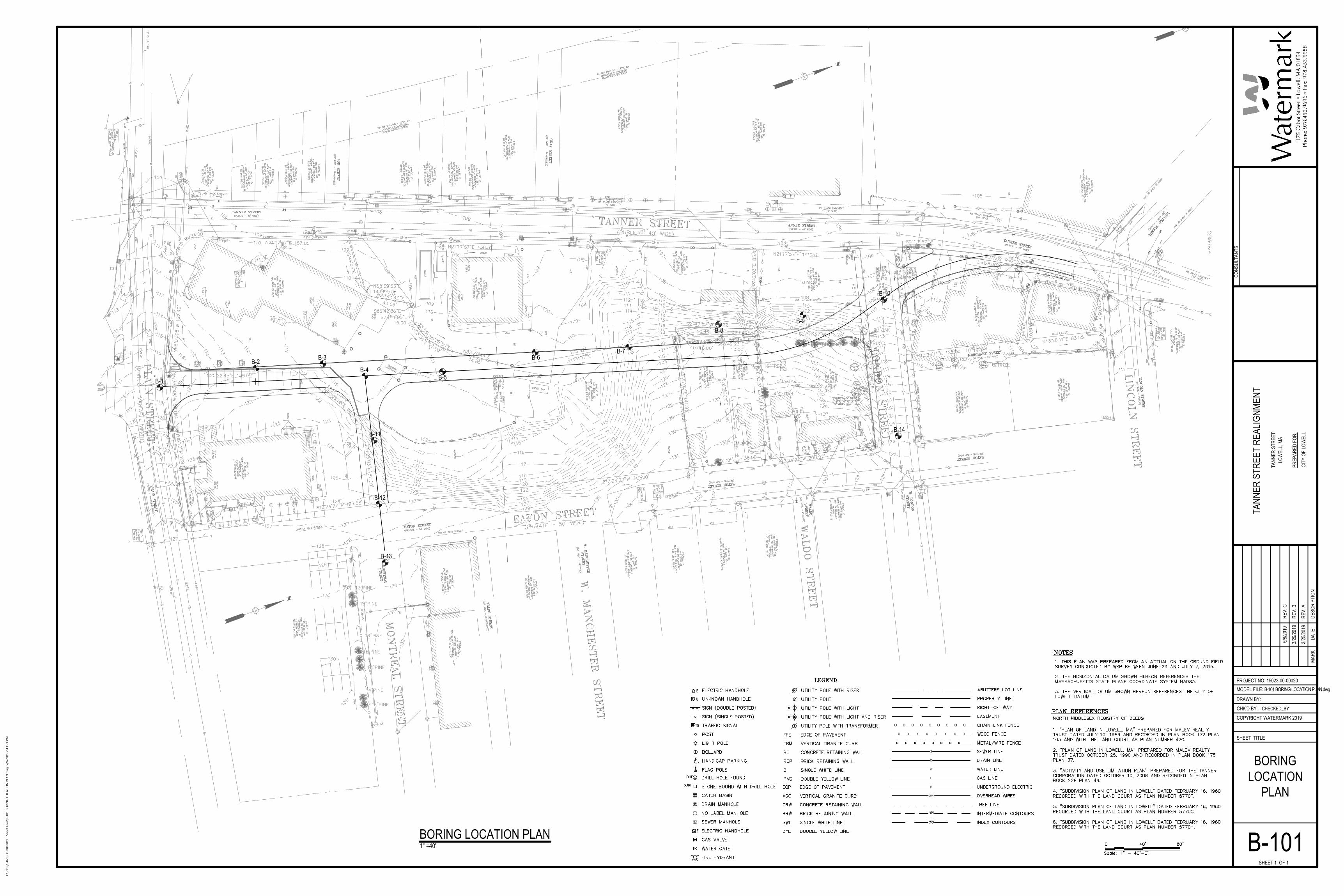
• “Boring Location Plan”, B-101, Sheet 1 of 1, dated May 8, 2019, by Watermark.
The proposed project includes relocation of a portion of Tanner Street in Lowell, MA. The realignment of Tanner Street is proposed to extend from Plain Street to the south, past West London Street and then tie into the existing Tanner Street to the north. The Tanner Street realignment section will also connect to Montreal Street to the east. The proposed project extends over multiple properties that are currently developed.
We understand a new sewer line is proposed along the Tanner Street realignment as well as along a portion of West London Street. The proposed sewer invert elevation is roughly Elevation 35± feet (City of Lowell Datum).
Watermark developed a subsurface exploratory test boring program to assess the subsurface conditions within the area of the proposed street realignment and new sewer. The program consists of fourteen (14) soil test borings which have been split up in two phases. This report pertains to the Phase I test borings, which include boring nos. B-1 through B-3, and B-10 through B-14.
Tanner Street Realignment – Lowell, MA July 22, 2019 Project No. Z346.00
2
We understand the Phase II test borings, which include boring nos. B-4 through B-9, are planned to be performed at a later date. Northeast Geotechnical is contracted to observe and log the Phase II test borings, and then provide a summary of the results in an addendum to this report.
Phase I Subsurface Explorations
Watermark determined and marked the Phase I test boring locations at the site (B-1 through B-3, B-10 through B-14). Some of the test borings were performed off-set from the originally marked locations. The offset locations are approximately shown on the referenced Boring Location Plan, which is attached to this report.
Watermark provided the approximate ground surface elevations at the test boring locations. The ground surface elevation of test borings offset from the originally proposed locations was estimated based on the existing ground surface elevations shown on the referenced Boring Location Plan. The ground surface elevations included on the test boring logs and discussed in this report should be considered approximate.
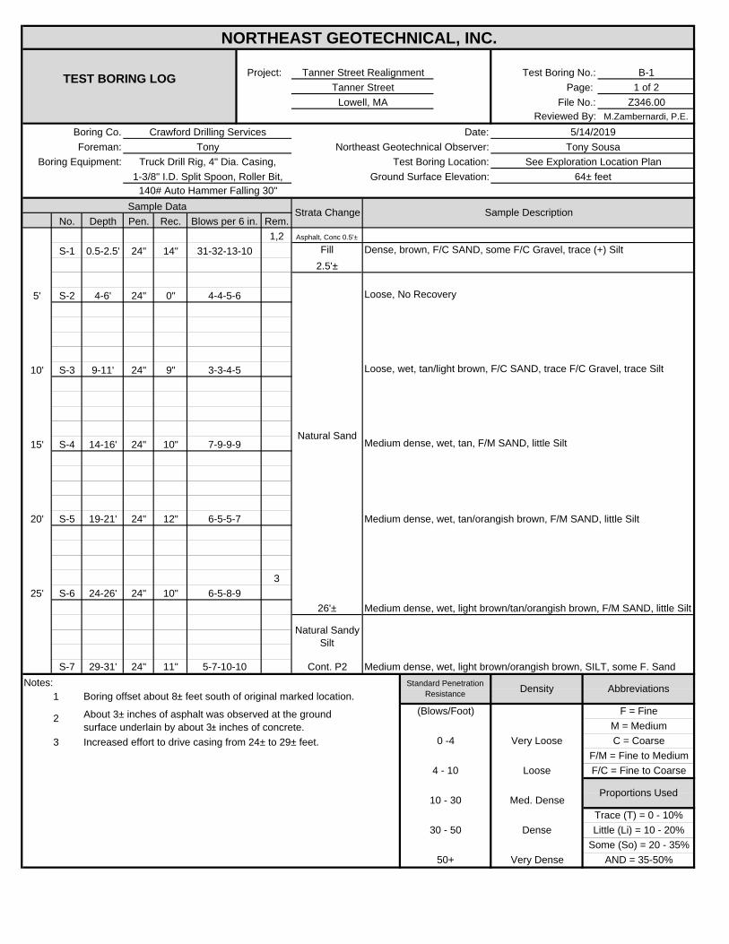
Watermark contracted Crawford Drilling Services of Westminster, MA to perform the Phase I test borings on May 13 through 15, 2019. The test borings were performed with a truck mounted test boring rig advancing 4± inch outside diameter casing with wash boring techniques or 4± inch inside diameter hollow stem augers to depths of about 15± to 42± feet below the existing ground surface. Each test boring was terminated in apparent natural silt or sand.
Standard Penetration Testing (SPT) was performed during each test boring. The SPT was generally performed at five foot intervals. The SPT was performed by driving a standard 2-inch outside diameter split spoon sampler up to 24 inches using an auto trip activated 140-pound hammer falling 30 inches. The number of hammer blows required to drive the sampler in 6-inch increments (or to refusal) is recorded on the boring logs attached in Appendix B. The sum of the blows required to drive the split spoon sampler from the 6 to 12 inch interval and the 12 to 18 inch interval is defined as the Standard Penetration Resistance of the soil.
The soil samples retrieved in the split spoon sampler during each SPT were visually described in the field using Burmister’s soil descriptions as indicated on the attached test boring logs (Appendix B). Note that the inside diameter of the noted split spoon sampler is 1.4± inches. Therefore, soil samples obtained via SPT do not account for soil fractions in excess of about 1.4± inches in diameter, which may be present in any given strata.
Laboratory Soil Testing
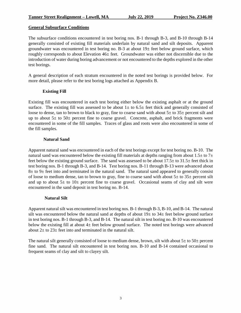
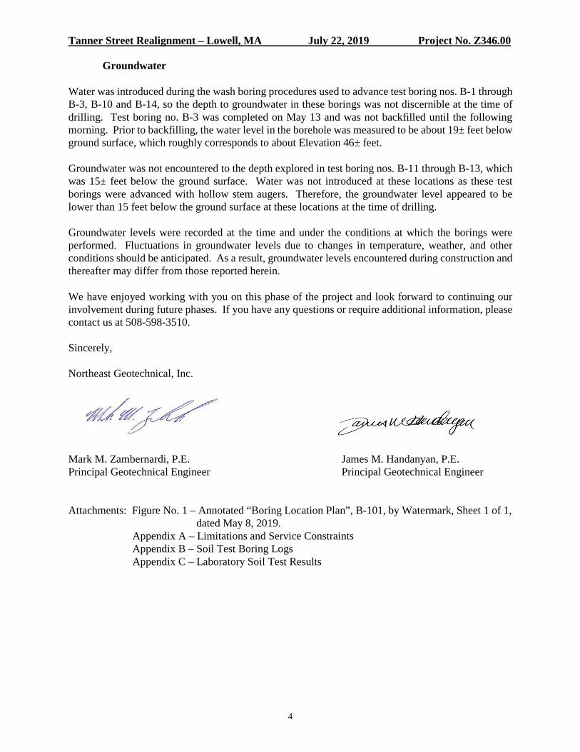
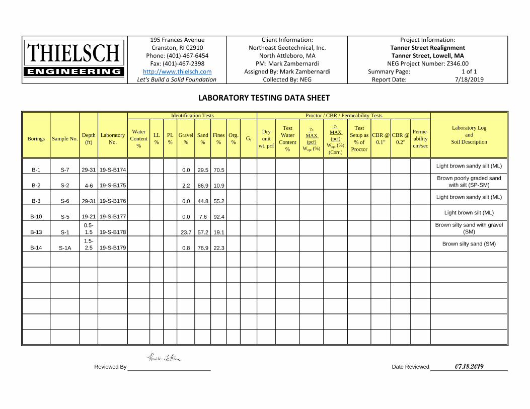
A laboratory testing program was performed to assess the basic geotechnical engineering characteristics of selected soil samples collected from the test borings. The laboratory testing consisted of five (5) sieve analyses and one (1) combined sieve and hydrometer analysis to assess grain size distribution. The testing was performed by Thielsch Engineering in Cranston, RI. The laboratory test results are attached as Appendix C.
Tanner Street Realignment – Lowell, MA July 22, 2019 Project No. Z346.00
3
General Subsurface Conditions
The subsurface conditions encountered in test boring nos. B-1 through B-3, and B-10 through B-14 generally consisted of existing fill materials underlain by natural sand and silt deposits. Apparent groundwater was encountered in test boring no. B-3 at about 19± feet below ground surface, which roughly corresponds to about Elevation 46± feet. Groundwater was either not discernible due to the introduction of water during boring advancement or not encountered to the depths explored in the other test borings.
A general description of each stratum encountered in the noted test borings is provided below. For more detail, please refer to the test boring logs attached as Appendix B.
Existing Fill
Existing fill was encountered in each test boring either below the existing asphalt or at the ground surface. The existing fill was assessed to be about 1± to 6.5± feet thick and generally consisted of loose to dense, tan to brown to black to gray, fine to coarse sand with about 5± to 35± percent silt and up to about 5± to 50± percent fine to coarse gravel. Concrete, asphalt, and brick fragments were encountered in some of the fill samples. Traces of glass and roots were also encountered in some of the fill samples.
Natural Sand
Apparent natural sand was encountered in each of the test borings except for test boring no. B-10. The natural sand was encountered below the existing fill materials at depths ranging from about 1.5± to 7± feet below the existing ground surface. The sand was assessed to be about 17.5± to 31.5± feet thick in test boring nos. B-1 through B-3, and B-14. Test boring nos. B-11 through B-13 were advanced about 8± to 9± feet into and terminated in the natural sand. The natural sand appeared to generally consist of loose to medium dense, tan to brown to gray, fine to coarse sand with about 5± to 35± percent silt and up to about 5± to 10± percent fine to coarse gravel. Occasional seams of clay and silt were encountered in the sand deposit in test boring no. B-14.
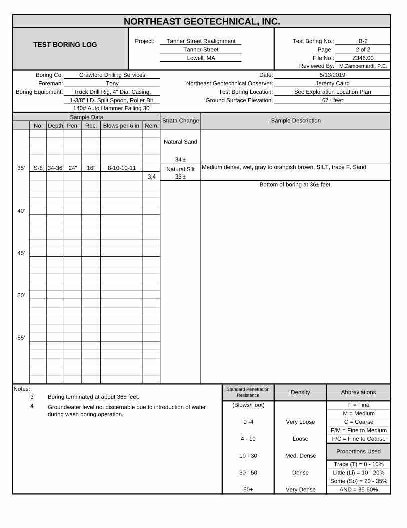
Natural Silt
Apparent natural silt was encountered in test boring nos. B-1 through B-3, B-10, and B-14. The natural silt was encountered below the natural sand at depths of about 19± to 34± feet below ground surface in test boring nos. B-1 through B-3, and B-14. The natural silt in test boring no. B-10 was encountered below the existing fill at about 4± feet below ground surface. The noted test borings were advanced about 2± to 23± feet into and terminated in the natural silt.
The natural silt generally consisted of loose to medium dense, brown, silt with about 5± to 50± percent fine sand. The natural silt encountered in test boring nos. B-10 and B-14 contained occasional to frequent seams of clay and silt to clayey silt.
Tanner Street Realignment – Lowell, MA July 22, 2019 Project No. Z346.00
4
Groundwater Water was introduced during the wash boring procedures used to advance test boring nos. B-1 through B-3, B-10 and B-14, so the depth to groundwater in these borings was not discernible at the time of drilling. Test boring no. B-3 was completed on May 13 and was not backfilled until the following morning. Prior to backfilling, the water level in the borehole was measured to be about 19± feet below ground surface, which roughly corresponds to about Elevation 46± feet.
Groundwater was not encountered to the depth explored in test boring nos. B-11 through B-13, which was 15± feet below the ground surface. Water was not introduced at these locations as these test borings were advanced with hollow stem augers. Therefore, the groundwater level appeared to be lower than 15 feet below the ground surface at these locations at the time of drilling.
Groundwater levels were recorded at the time and under the conditions at which the borings were performed. Fluctuations in groundwater levels due to changes in temperature, weather, and other conditions should be anticipated. As a result, groundwater levels encountered during construction and thereafter may differ from those reported herein.
We have enjoyed working with you on this phase of the project and look forward to continuing our involvement during future phases. If you have any questions or require additional information, please contact us at 508-598-3510.
Sincerely,
Northeast Geotechnical, Inc.
Mark M. Zambernardi, P.E. James M. Handanyan, P.E. Principal Geotechnical Engineer Principal Geotechnical Engineer
Attachments: Figure No. 1 – Annotated “Boring Location Plan”, B-101, by Watermark, Sheet 1 of 1,
dated May 8, 2019. Appendix A – Limitations and Service Constraints
Appendix B – Soil Test Boring Logs Appendix C – Laboratory Soil Test Results

FIGURE
B-2B-4
B-11
B-5
B-10
B-8
B-7B-6B-3
B-12
B-1
B-14
B-13
B-9
BORING LOCATION PLAN1" =40'
S
D
W
G
X X X X X X X X
OHW
E
SHEET TITLE
SHEET 1 OF 1
CONS
ULTA
NTS
DESC
RIPT
ION
PROJECT NO: 15023-00-00020MODEL FILE: B-101 BORING LOCATION PLAN.dwg
DRAWN BY:
CHK'D BY:
COPYRIGHT WATERMARK 2019
MARK
DATE
PREP
ARED
FOR
:
TANN
ER S
TREE
T RE
ALIG
NMEN
TTA
NNER
STR
EET
CITY
OF
LOW
ELL
LOW
ELL,
MA
REV.
A3/2
5/201
9
CHECKED_BY
BORINGLOCATION
PLAN
B-101
E
U
E
REV.
B3/2
9/201
9
REV.
C5/8
/2019
T:\Jo
bs\15023-00-00030\1.0 Sh
eet Files\B
-101 B
OR
IN
G LO
CA
TIO
N P
LA
N.d
wg
, 5/9/2019 2:43:21 P
M
Mark Zambernardi
Oval
Mark Zambernardi
Oval
Mark Zambernardi
Oval
Mark Zambernardi
Oval
Mark Zambernardi
Oval
Mark Zambernardi
Oval
Mark Zambernardi
Polygon
Mark Zambernardi
Polygon
Mark Zambernardi
Polygon
Mark Zambernardi
Polygon
Mark Zambernardi
Polygon
Mark Zambernardi
Polygon
Mark Zambernardi
Polygon
Mark Zambernardi
Polygon
Mark Zambernardi
Callout
Approximate Offset Test Boring Location
Mark Zambernardi
Callout
Indicates Test Boring Performed During Phase I
APPENDIX A
Limitations and Service Constraints
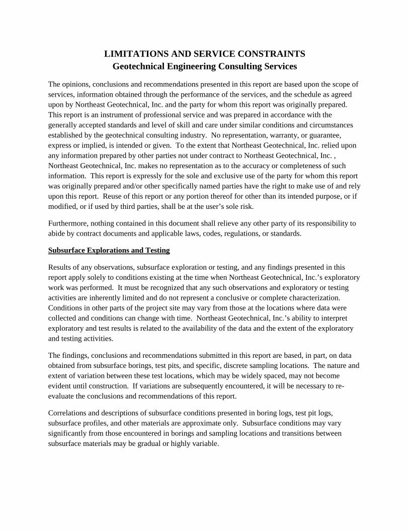
LIMITATIONS AND SERVICE CONSTRAINTS Geotechnical Engineering Consulting Services
The opinions, conclusions and recommendations presented in this report are based upon the scope of services, information obtained through the performance of the services, and the schedule as agreed upon by Northeast Geotechnical, Inc. and the party for whom this report was originally prepared. This report is an instrument of professional service and was prepared in accordance with the generally accepted standards and level of skill and care under similar conditions and circumstances established by the geotechnical consulting industry. No representation, warranty, or guarantee, express or implied, is intended or given. To the extent that Northeast Geotechnical, Inc. relied upon any information prepared by other parties not under contract to Northeast Geotechnical, Inc. , Northeast Geotechnical, Inc. makes no representation as to the accuracy or completeness of such information. This report is expressly for the sole and exclusive use of the party for whom this report was originally prepared and/or other specifically named parties have the right to make use of and rely upon this report. Reuse of this report or any portion thereof for other than its intended purpose, or if modified, or if used by third parties, shall be at the user’s sole risk.
Furthermore, nothing contained in this document shall relieve any other party of its responsibility to abide by contract documents and applicable laws, codes, regulations, or standards.
Subsurface Explorations and Testing
Results of any observations, subsurface exploration or testing, and any findings presented in this report apply solely to conditions existing at the time when Northeast Geotechnical, Inc.’s exploratory work was performed. It must be recognized that any such observations and exploratory or testing activities are inherently limited and do not represent a conclusive or complete characterization. Conditions in other parts of the project site may vary from those at the locations where data were collected and conditions can change with time. Northeast Geotechnical, Inc.’s ability to interpret exploratory and test results is related to the availability of the data and the extent of the exploratory and testing activities.
The findings, conclusions and recommendations submitted in this report are based, in part, on data obtained from subsurface borings, test pits, and specific, discrete sampling locations. The nature and extent of variation between these test locations, which may be widely spaced, may not become evident until construction. If variations are subsequently encountered, it will be necessary to re-evaluate the conclusions and recommendations of this report.
Correlations and descriptions of subsurface conditions presented in boring logs, test pit logs, subsurface profiles, and other materials are approximate only. Subsurface conditions may vary significantly from those encountered in borings and sampling locations and transitions between subsurface materials may be gradual or highly variable.

Conditions at the time water level measurements and other subsurface observations were made are presented in the boring logs or other sampling forms. These field data have been reviewed and interpretations provided in this report. However, groundwater levels may be variable and may fluctuate due to variation in precipitation, temperature, and other factors. Therefore, groundwater levels at the site at any time may be different than stated in this report.
Review
In the event that any change in the nature, design, or location of the proposed structure(s) is planned, the conclusions and recommendations in this report shall not be considered valid unless the changes are reviewed and the conclusions and recommendations of this report are modified or verified in writing.
Northeast Geotechnical, Inc. should be provided the opportunity for a general review of final design plans and specifications to assess that our recommendations have been properly interpreted and included in the design and construction documents.
Construction
To verify conditions presented in this report and modify recommendations based on field conditions encountered in the field, Northeast Geotechnical, Inc. should be retained to provide geotechnical engineering services during the construction phase of the project. This is to observe compliance with design concepts, specifications, and recommendations contained in this report, and to verify and refine our recommendations as necessary in the event that subsurface conditions differ from those anticipated prior to the start of construction.

APPENDIX B
Test Boring Logs
B-11 of 2
Z346.00M.Zambernardi, P.E.
No. Depth Pen. Rec. Rem.1,2
S-1 0.5-2.5' 24" 14"
5' S-2 4-6' 24" 0"
10' S-3 9-11' 24" 9"
15' S-4 14-16' 24" 10"
20' S-5 19-21' 24" 12"
325' S-6 24-26' 24" 10"
S-7 29-31' 24" 11"Notes:
1
3
Natural Sand
Medium dense, wet, light brown/tan/orangish brown, F/M SAND, little Silt
Fill2.5'±
2
Boring offset about 8± feet south of original marked location.
About 3± inches of asphalt was observed at the ground surface underlain by about 3± inches of concrete.
Dense, brown, F/C SAND, some F/C Gravel, trace (+) Silt
Loose, No Recovery
Loose, wet, tan/light brown, F/C SAND, trace F/C Gravel, trace Silt
Medium dense, wet, tan, F/M SAND, little Silt
Medium dense, wet, tan/orangish brown, F/M SAND, little Silt
Medium dense, wet, light brown/orangish brown, SILT, some F. Sand
26'±
M = Medium
6-5-8-9
5-7-10-10
6-5-5-7
Some (So) = 20 - 35%50+ Very Dense AND = 35-50%
Asphalt, Conc 0.5'±
Natural Sandy Silt
Cont. P2
Trace (T) = 0 - 10%30 - 50 Dense Little (Li) = 10 - 20%
4 - 10 Loose F/C = Fine to Coarse
Proportions Used10 - 30 Med. Dense
0 -4 Very Loose C = CoarseF/M = Fine to Medium
Standard Penetration Resistance Density Abbreviations
(Blows/Foot) F = Fine
Increased effort to drive casing from 24± to 29± feet.
7-9-9-9
3-3-4-5
31-32-13-10
4-4-5-6
1-3/8" I.D. Split Spoon, Roller Bit, Ground Surface Elevation: 64± feet140# Auto Hammer Falling 30"
Sample Data Strata Change Sample DescriptionBlows per 6 in.
Boring Equipment: Test Boring Location: See Exploration Location Plan
Lowell, MA File No.:Reviewed By:
Boring Co. Crawford Drilling Services Date: 5/14/2019
Truck Drill Rig, 4" Dia. Casing,
NORTHEAST GEOTECHNICAL, INC.
TEST BORING LOGProject: Tanner Street Realignment Test Boring No.:
Tanner Street Page:
Foreman: Tony Northeast Geotechnical Observer: Tony Sousa

B-12 of 2
Z346.00M.Zambernardi, P.E.
No. Depth Pen. Rec. Rem.4,5
35'
40'
45'
50'
55'
Notes: 45
NORTHEAST GEOTECHNICAL, INC.
TEST BORING LOGProject: Test Boring No.:
Tanner Street Page: Tanner Street Realignment
Boring Equipment: Test Boring Location:Tony SousaTony
Truck Drill Rig, 4" Dia. Casing,
Boring Co. Crawford Drilling Services Date: 5/14/2019Foreman: Northeast Geotechnical Observer:
Nat. Sandy Silt 31'±
See Exploration Location Plan
Lowell, MA File No.:Reviewed By:
1-3/8" I.D. Split Spoon, Roller Bit, Ground Surface Elevation: 64± feet
Sample Data Strata Change Sample DescriptionBlows per 6 in.
140# Auto Hammer Falling 30"
Bottom of boring at 31± feet.
F/M = Fine to Medium
Standard Penetration Resistance Density Abbreviations
Boring terminated at about 31± feet (Blows/Foot) F = Fine
M = Medium0 -4 Very Loose C = Coarse
Groundwater level not discernable due to introduction of water during wash boring operation.
Some (So) = 20 - 35%50+ Very Dense AND = 35-50%
Trace (T) = 0 - 10%30 - 50 Dense Little (Li) = 10 - 20%
4 - 10 Loose F/C = Fine to Coarse
Proportions Used10 - 30 Med. Dense

B-21 of 2
Z346.00M.Zambernardi, P.E.
No. Depth Pen. Rec. Rem.1,2
S-1 0.5-2.5' 24" 10"
5' S-2 4-6' 24" 8"
10' S-3 9-11' 24" 10"
15' S-4 14-16' 24" 8"
20' S-5 19-21' 24" 9"
25' S-6 24-26' 24" 11"
S-7 29-31' 24" 11"Notes:
12
Truck Drill Rig, 4" Dia. Casing,
NORTHEAST GEOTECHNICAL, INC.
TEST BORING LOGProject: Tanner Street Realignment Test Boring No.:
Tanner Street Page:
About 3± inches of asphalt was observed at the ground surface.
Foreman: Tony Northeast Geotechnical Observer: Jeremy CairdBoring Equipment: Test Boring Location: See Exploration Location Plan
Lowell, MA File No.:Reviewed By:
Boring Co. Crawford Drilling Services Date: 5/13/2019
Loose, brown, F/C SAND, trace Silt
Asphalt 0.3'±8-6-2-3 Fill Loose, brown, F/C SAND, some F. Gravel, trace (+) Silt
2.5'±
1-3/8" I.D. Split Spoon, Roller Bit, Ground Surface Elevation: 67± feet140# Auto Hammer Falling 30"
Sample Data Strata Change Sample DescriptionBlows per 6 in.
Loose, gray to light brown, F/M SAND, little (-) Silt, trace F. Gravel
5-6-6-8
4-3-2-3
3-3-6-5
4-5-6-7 Medium dense, wet, light brown, F/M SAND, trace Silt
Medium dense, light brown, F/M SAND, little (+) Silt
6-6-7-8 Medium dense, damp, light brown, F/M SAND, little Silt
F/M = Fine to Medium
(Blows/Foot) F = FineM = Medium
3-6-8-10 Cont. P2 Medium dense, wet, light brown, F/M SAND, little SiltStandard Penetration
Resistance Density AbbreviationsBoring offset about 15± feet northeast of original marked location.
Some (So) = 20 - 35%50+ Very Dense AND = 35-50%
Natural Sand
Trace (T) = 0 - 10%30 - 50 Dense Little (Li) = 10 - 20%
4 - 10 Loose F/C = Fine to Coarse
Proportions Used10 - 30 Med. Dense
0 -4 Very Loose C = Coarse
B-22 of 2
Z346.00M.Zambernardi, P.E.
No. Depth Pen. Rec. Rem.
35' S-8 34-36' 24" 16"3,4
40'
45'
50'
55'
Notes: 34
Natural Sand
34'±
Natural Silt 36'±
Groundwater level not discernable due to introduction of water during wash boring operation.
NORTHEAST GEOTECHNICAL, INC.
TEST BORING LOGProject: Tanner Street Realignment Test Boring No.:
Tanner Street Page: Lowell, MA File No.:
Reviewed By:Boring Co. Crawford Drilling Services Date: 5/13/2019Foreman: Tony Northeast Geotechnical Observer: Jeremy Caird
Strata Change Sample DescriptionBlows per 6 in.
Boring Equipment: Test Boring Location: See Exploration Location PlanGround Surface Elevation: 67± feet
Truck Drill Rig, 4" Dia. Casing,1-3/8" I.D. Split Spoon, Roller Bit,
140# Auto Hammer Falling 30"Sample Data
8-10-10-11
M = Medium
Standard Penetration Resistance Density Abbreviations
Boring terminated at about 36± feet.
F/C = Fine to Coarse
Proportions Used
50+ Very Dense AND = 35-50%
Trace (T) = 0 - 10%30 - 50 Dense Little (Li) = 10 - 20%
Medium dense, wet, gray to orangish brown, SILT, trace F. Sand
Bottom of boring at 36± feet.
Some (So) = 20 - 35%
10 - 30 Med. Dense
0 -4 Very Loose C = CoarseF/M = Fine to Medium
(Blows/Foot) F = Fine
4 - 10 Loose
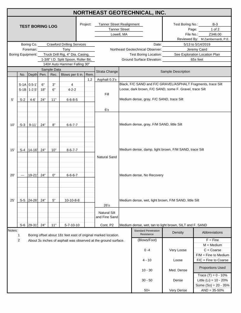
B-31 of 2
Z346.00M.Zambernardi, P.E.
No. Depth Pen. Rec. Rem.1,2
S-1A 0.5-1' 6" 3"S-1B 1-2.5' 18" 6"
5' S-2 4-6' 24" 11"
10' S-3 9-11' 24" 8"
15' S-4 14-16' 24" 10"
20' --- 19-21' 24" 0"
25' S-5 24-26' 24" 5"
S-6 29-31' 24" 11"Notes:
12
Truck Drill Rig, 4" Dia. Casing,
NORTHEAST GEOTECHNICAL, INC.
TEST BORING LOGProject: Tanner Street Realignment Test Boring No.:
Tanner Street Page:
6'±
FillLoose, dark brown, F/C SAND, some F. Gravel, trace Silt
Foreman: Tony Northeast Geotechnical Observer: Jeremy CairdBoring Equipment: Test Boring Location: See Exploration Location Plan
Lowell, MA File No.:Reviewed By:
Boring Co. Crawford Drilling Services Date: 5/13 to 5/14/2019
Asphalt 0.3'±4 Black, F/C SAND and F/C GRAVEL/ASPHALT Fragments, trace Silt
4-2-2
1-3/8" I.D. Split Spoon, Roller Bit, Ground Surface Elevation: 65± feet140# Auto Hammer Falling 30"
Sample Data Strata Change Sample DescriptionBlows per 6 in.
6-6-8-5 Medium dense, gray, F/C SAND, trace Silt
6-6-7-7 Medium dense, gray, F/M SAND, little Silt
Natural Sand
Medium dense, damp, light brown, F/M SAND, trace Silt
6-6-6-7 Medium dense, No Recovery
8-6-7-7
10-10-8-8 Medium dense, wet, light brown, F/M SAND, little Silt26'±
Natural Silt and Fine Sand
(Blows/Foot) F = FineM = Medium
5-7-10-10 Cont. P2 Medium dense, wet, tan to light brown, SILT and F. SANDStandard Penetration
Resistance Density AbbreviationsBoring offset about 18± feet east of original marked location.About 3± inches of asphalt was observed at the ground surface.
Some (So) = 20 - 35%50+ Very Dense AND = 35-50%
Trace (T) = 0 - 10%30 - 50 Dense Little (Li) = 10 - 20%
4 - 10 Loose F/C = Fine to Coarse
Proportions Used10 - 30 Med. Dense
0 -4 Very Loose C = CoarseF/M = Fine to Medium
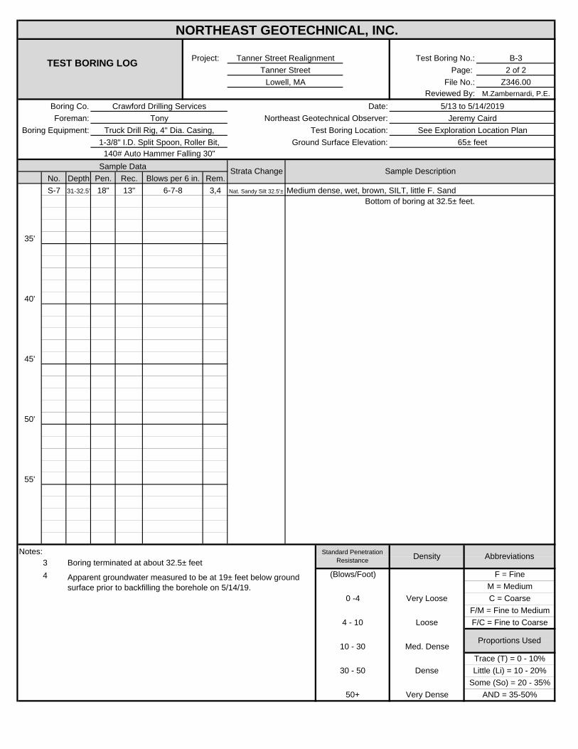
B-32 of 2
Z346.00M.Zambernardi, P.E.
No. Depth Pen. Rec. Rem.S-7 31-32.5' 18" 13" 3,4
35'
40'
45'
50'
55'
Notes: 34 Apparent groundwater measured to be at 19± feet below ground
surface prior to backfilling the borehole on 5/14/19.
NORTHEAST GEOTECHNICAL, INC.
TEST BORING LOGProject: Tanner Street Realignment Test Boring No.:
Tanner Street Page: Lowell, MA File No.:
Reviewed By:Boring Co. Crawford Drilling Services Date: 5/13 to 5/14/2019Foreman: Tony Northeast Geotechnical Observer: Jeremy Caird
Boring Equipment: Test Boring Location: See Exploration Location PlanTruck Drill Rig, 4" Dia. Casing,1-3/8" I.D. Split Spoon, Roller Bit, Ground Surface Elevation: 65± feet
140# Auto Hammer Falling 30"Sample Data Strata Change Sample Description
Blows per 6 in.6-7-8 Nat. Sandy Silt 32.5'±
Bottom of boring at 32.5± feet.
Standard Penetration Resistance Density Abbreviations
Boring terminated at about 32.5± feet (Blows/Foot) F = Fine
M = Medium
Proportions Used10 - 30 Med. Dense
0 -4 Very Loose C = CoarseF/M = Fine to Medium
Some (So) = 20 - 35%50+ Very Dense AND = 35-50%
Medium dense, wet, brown, SILT, little F. Sand
Trace (T) = 0 - 10%30 - 50 Dense Little (Li) = 10 - 20%
4 - 10 Loose F/C = Fine to Coarse
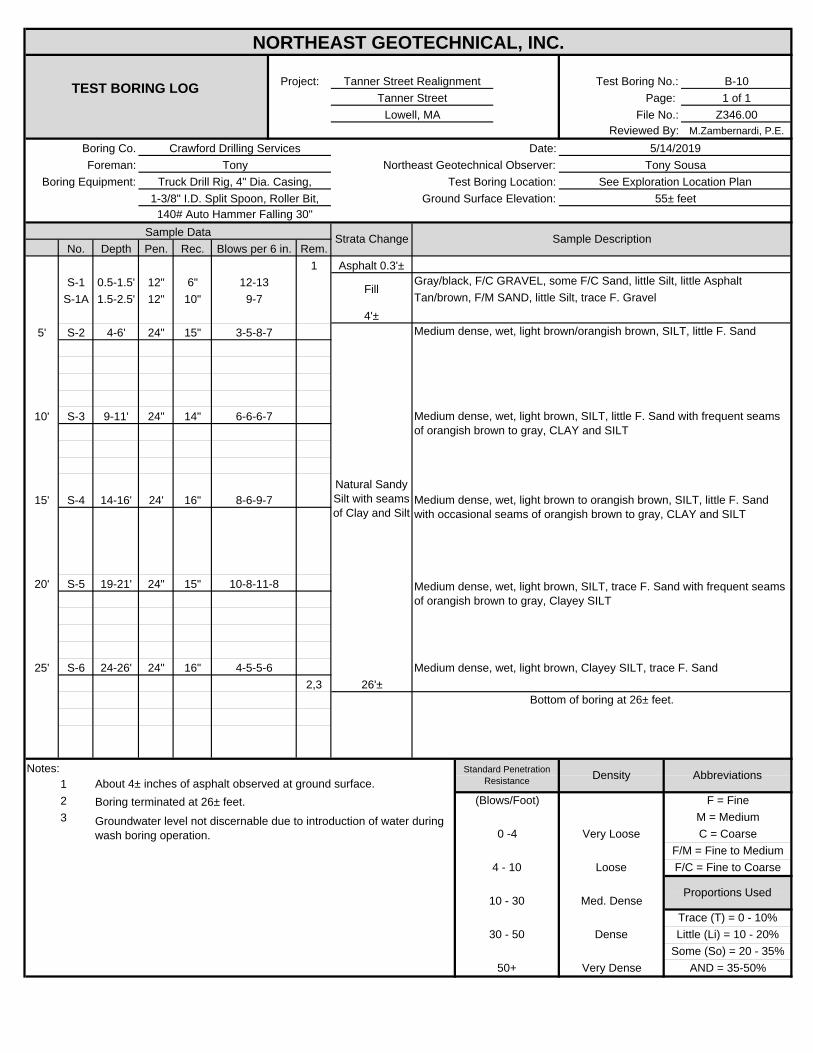
B-101 of 1
Z346.00M.Zambernardi, P.E.
No. Depth Pen. Rec. Rem.1
S-1 0.5-1.5' 12" 6"S-1A 1.5-2.5' 12" 10"
5' S-2 4-6' 24" 15"
10' S-3 9-11' 24" 14"
15' S-4 14-16' 24' 16"
20' S-5 19-21' 24" 15"
25' S-6 24-26' 24" 16"2,3
Notes: 123
50+ Very Dense AND = 35-50%
Asphalt 0.3'±
4'±Medium dense, wet, light brown/orangish brown, SILT, little F. Sand
Tan/brown, F/M SAND, little Silt, trace F. Gravel
Trace (T) = 0 - 10%30 - 50 Dense Little (Li) = 10 - 20%
4 - 10 Loose F/C = Fine to Coarse
Proportions Used
About 4± inches of asphalt observed at ground surface.
Medium dense, wet, light brown, Clayey SILT, trace F. Sand
10 - 30 Med. Dense
Gray/black, F/C GRAVEL, some F/C Sand, little Silt, little Asphalt
F/M = Fine to Medium
Boring terminated at 26± feet. (Blows/Foot) F = Fine
Some (So) = 20 - 35%
Groundwater level not discernable due to introduction of water during wash boring operation.
6-6-6-7
M = Medium0 -4 Very Loose C = Coarse
Medium dense, wet, light brown, SILT, little F. Sand with frequent seams of orangish brown to gray, CLAY and SILT
Medium dense, wet, light brown to orangish brown, SILT, little F. Sand with occasional seams of orangish brown to gray, CLAY and SILT
Medium dense, wet, light brown, SILT, trace F. Sand with frequent seams of orangish brown to gray, Clayey SILT
Standard Penetration Resistance Density Abbreviations
10-8-11-8
12-139-7
3-5-8-7
1-3/8" I.D. Split Spoon, Roller Bit, Ground Surface Elevation:
26'±Bottom of boring at 26± feet.
Natural Sandy Silt with seams of Clay and Silt
8-6-9-7
Fill
4-5-5-6
Sample Data Strata Change Sample DescriptionBlows per 6 in.
Boring Equipment: Test Boring Location: See Exploration Location PlanTruck Drill Rig, 4" Dia. Casing,
NORTHEAST GEOTECHNICAL, INC.
TEST BORING LOGProject: Tanner Street Realignment Test Boring No.:
Tanner Street Page:
55± feet140# Auto Hammer Falling 30"
Foreman: Tony Northeast Geotechnical Observer: Tony Sousa
Lowell, MA File No.:Reviewed By:
Boring Co. Crawford Drilling Services Date: 5/14/2019
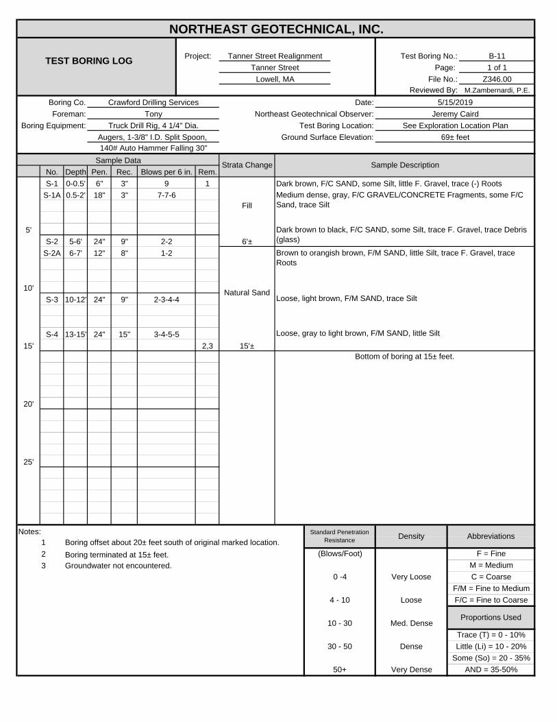
B-111 of 1
Z346.00M.Zambernardi, P.E.
No. Depth Pen. Rec. Rem.S-1 0-0.5' 6" 3" 1
S-1A 0.5-2' 18" 3"
5'S-2 5-6' 24" 9"
S-2A 6-7' 12" 8"
10'S-3 10-12' 24" 9"
S-4 13-15' 24" 15"15' 2,3
20'
25'
Notes: 1 Boring offset about 20± feet south of original marked location.23 Groundwater not encountered.
NORTHEAST GEOTECHNICAL, INC.
TEST BORING LOGProject: Tanner Street Realignment Test Boring No.:
Tanner Street Page:
Fill
Dark brown to black, F/C SAND, some Silt, trace F. Gravel, trace Debris (glass)
Medium dense, gray, F/C GRAVEL/CONCRETE Fragments, some F/C Sand, trace Silt
Foreman: Tony Northeast Geotechnical Observer: Jeremy CairdBoring Equipment: Test Boring Location: See Exploration Location Plan
Lowell, MA File No.:Reviewed By:
Boring Co. Crawford Drilling Services Date: 5/15/2019
Loose, light brown, F/M SAND, trace Silt
Ground Surface Elevation: 69± feet
Sample Data Strata Change Sample DescriptionBlows per 6 in.
Brown to orangish brown, F/M SAND, little Silt, trace F. Gravel, trace Roots
Natural Sand
Loose, gray to light brown, F/M SAND, little Silt
Augers, 1-3/8" I.D. Split Spoon, 140# Auto Hammer Falling 30"
15'±
2-21-2
97-7-6
Truck Drill Rig, 4 1/4" Dia.
2-3-4-4
3-4-5-5
Standard Penetration Resistance Density Abbreviations
F/M = Fine to Medium
Boring terminated at 15± feet. (Blows/Foot) F = FineM = Medium
Bottom of boring at 15± feet.
Some (So) = 20 - 35%50+ Very Dense AND = 35-50%
Dark brown, F/C SAND, some Silt, little F. Gravel, trace (-) Roots
6'±
Trace (T) = 0 - 10%30 - 50 Dense Little (Li) = 10 - 20%
4 - 10 Loose F/C = Fine to Coarse
Proportions Used10 - 30 Med. Dense
0 -4 Very Loose C = Coarse

B-121 of 1
Z346.00M.Zambernardi, P.E.
No. Depth Pen. Rec. Rem.0-0.5' 1,2
S-1 0.5-2.5' 24" 3"
5'S-2 5-7' 24" 4" 3
10'S-3 10-12' 24" 13"
S-4 13-15' 24" 18"15' 4,5,6
20'
25'
Notes: 1234 Bulk sample collected from auger spoils. 5 Boring terminated at 15± feet.6 Groundwater not encountered.
Apparent brick fragment struck in tip of split spoon sampler.
NORTHEAST GEOTECHNICAL, INC.
TEST BORING LOGProject: Tanner Street Realignment Test Boring No.:
Tanner Street Page: Lowell, MA File No.:
Reviewed By:Boring Co. Crawford Drilling Services Date: 5/15/2019
Sample Data Strata Change Sample DescriptionBlows per 6 in.
3-4-4-3Asphalt 0.3'±
Foreman: Tony Northeast Geotechnical Observer: Jeremy CairdBoring Equipment: Test Boring Location: See Exploration Location Plan
Ground Surface Elevation: 73± feetTruck Drill Rig, 4 1/4" Dia.
Augers, 1-3/8" I.D. Split Spoon, 140# Auto Hammer Falling 30"
6-7-5-4
4-3-4-5
Fill
Loose, dark brown to black, F/C SAND, some Silt, little Debris (Brick), trace F. Gravel
Medium dense, dark brown, F/C SAND, little Silt, little Debris (Brick), trace F/C Gravel
Loose, tan to light brown, F/M SAND, trace Silt
2-3-5-4 Loose, tan to gray, F. SAND, trace Silt15'±
Bottom of boring at 15± feet.
Standard Penetration Resistance Density
Boring offset about 5± feet south of original marked location.
F/M = Fine to Medium
Abbreviations
(Blows/Foot) F = FineM = Medium
About 3± inches of asphalt was observed at the ground surface.
Some (So) = 20 - 35%50+ Very Dense AND = 35-50%
7'±
Natural Sand
Trace (T) = 0 - 10%30 - 50 Dense Little (Li) = 10 - 20%
4 - 10 Loose F/C = Fine to Coarse
Proportions Used10 - 30 Med. Dense
0 -4 Very Loose C = Coarse
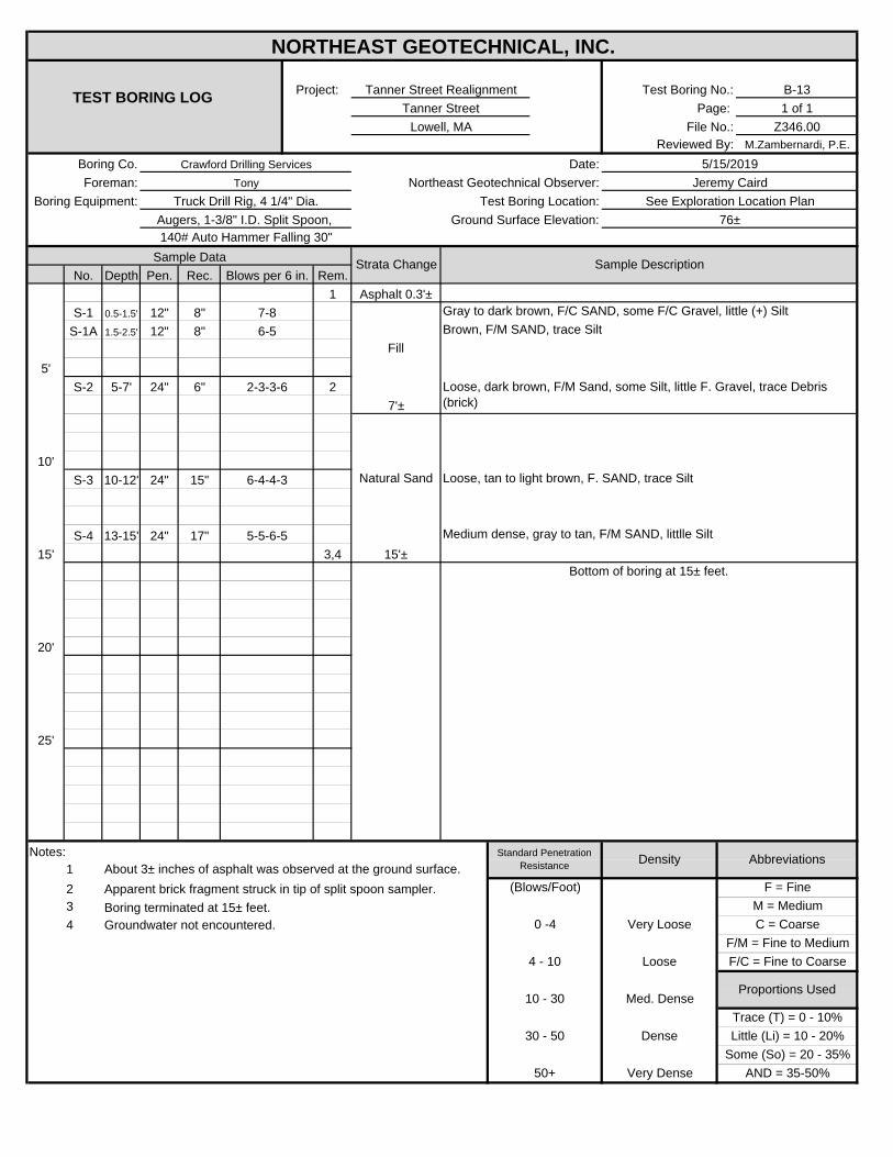
B-131 of 1
Z346.00M.Zambernardi, P.E.
No. Depth Pen. Rec. Rem.1
S-1 0.5-1.5' 12" 8"S-1A 1.5-2.5' 12" 8"
5'S-2 5-7' 24" 6" 2
10'S-3 10-12' 24" 15"
S-4 13-15' 24" 17"15' 3,4
20'
25'
Notes: 123 Boring terminated at 15± feet.4 Groundwater not encountered.
NORTHEAST GEOTECHNICAL, INC.
TEST BORING LOGProject: Tanner Street Realignment Test Boring No.:
Tanner Street Page:
Fill
Loose, dark brown, F/M Sand, some Silt, little F. Gravel, trace Debris (brick)
Foreman: Tony Northeast Geotechnical Observer: Jeremy CairdBoring Equipment: Truck Drill Rig, 4 1/4" Dia. Test Boring Location: See Exploration Location Plan
Lowell, MA File No.:Reviewed By:
Boring Co. Crawford Drilling Services
2-3-3-6
Augers, 1-3/8" I.D. Split Spoon, Ground Surface Elevation: 76±140# Auto Hammer Falling 30"
Sample Data Strata Change Sample DescriptionBlows per 6 in.
Asphalt 0.3'±
Date: 5/15/2019
7-8 Gray to dark brown, F/C SAND, some F/C Gravel, little (+) Silt
Loose, tan to light brown, F. SAND, trace Silt
5-5-6-5 Medium dense, gray to tan, F/M SAND, littlle Silt 15'±
7'±
Natural Sand6-4-4-3
About 3± inches of asphalt was observed at the ground surface.
Bottom of boring at 15± feet.
F/M = Fine to Medium
Abbreviations
(Blows/Foot) F = FineM = Medium
Some (So) = 20 - 35%
Standard Penetration Resistance Density
Apparent brick fragment struck in tip of split spoon sampler.
50+ Very Dense AND = 35-50%
6-5 Brown, F/M SAND, trace Silt
Trace (T) = 0 - 10%30 - 50 Dense Little (Li) = 10 - 20%
4 - 10 Loose F/C = Fine to Coarse
Proportions Used10 - 30 Med. Dense
0 -4 Very Loose C = Coarse
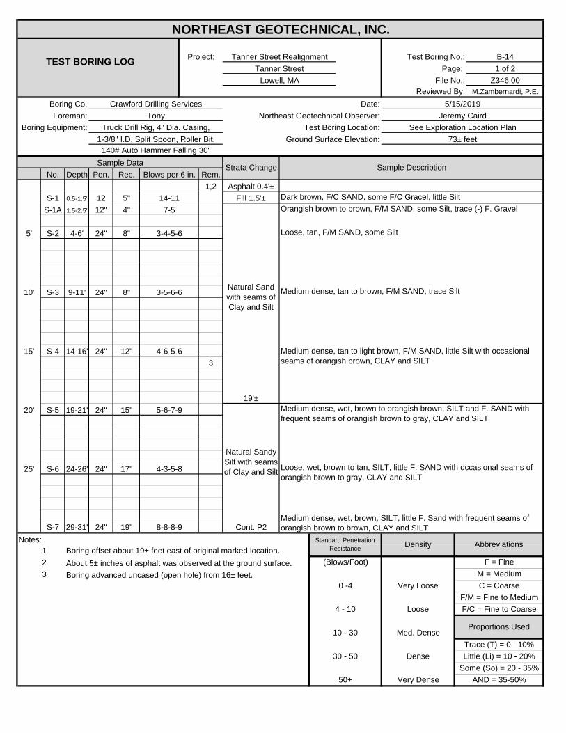
B-141 of 2
Z346.00M.Zambernardi, P.E.
No. Depth Pen. Rec. Rem.1,2
S-1 0.5-1.5' 12 5"S-1A 1.5-2.5' 12" 4"
5' S-2 4-6' 24" 8"
10' S-3 9-11' 24" 8"
15' S-4 14-16' 24" 12"3
20' S-5 19-21' 24" 15"
25' S-6 24-26' 24" 17"
S-7 29-31' 24" 19"Notes:
123
NORTHEAST GEOTECHNICAL, INC.
TEST BORING LOGProject: Tanner Street Realignment Test Boring No.:
Tanner Street Page:
Medium dense, wet, brown, SILT, little F. Sand with frequent seams of orangish brown to brown, CLAY and SILT
19'±
Natural Sand with seams of Clay and Silt
Natural Sandy Silt with seams of Clay and Silt
Foreman: Tony Northeast Geotechnical Observer: Jeremy CairdBoring Equipment: Test Boring Location: See Exploration Location Plan
Lowell, MA File No.:Reviewed By:
Boring Co. Crawford Drilling Services Date: 5/15/2019
Asphalt 0.4'±Fill 1.5'± Dark brown, F/C SAND, some F/C Gracel, little Silt
7-5
1-3/8" I.D. Split Spoon, Roller Bit, Ground Surface Elevation: 73± feet140# Auto Hammer Falling 30"
Sample Data Strata Change Sample DescriptionBlows per 6 in.
Truck Drill Rig, 4" Dia. Casing,
3-4-5-6 Loose, tan, F/M SAND, some Silt
14-11
3-5-6-6 Medium dense, tan to brown, F/M SAND, trace Silt
4-6-5-6
4-3-5-8
5-6-7-9
(Blows/Foot) F = FineM = Medium
Some (So) = 20 - 35%
Boring advanced uncased (open hole) from 16± feet.
8-8-8-9 Cont. P2Standard Penetration
Resistance Density AbbreviationsBoring offset about 19± feet east of original marked location.About 5± inches of asphalt was observed at the ground surface.
0 -4 Very Loose C = Coarse
50+ Very Dense AND = 35-50%
Orangish brown to brown, F/M SAND, some Silt, trace (-) F. Gravel
Medium dense, tan to light brown, F/M SAND, little Silt with occasional seams of orangish brown, CLAY and SILT
Medium dense, wet, brown to orangish brown, SILT and F. SAND with frequent seams of orangish brown to gray, CLAY and SILT
Loose, wet, brown to tan, SILT, little F. SAND with occasional seams of orangish brown to gray, CLAY and SILT
Trace (T) = 0 - 10%30 - 50 Dense Little (Li) = 10 - 20%
4 - 10 Loose F/C = Fine to Coarse
Proportions Used10 - 30 Med. Dense
F/M = Fine to Medium
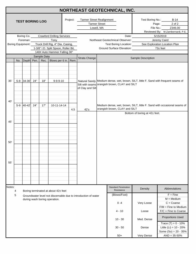
B-142 of 2
Z346.00M.Zambernardi, P.E.
No. Depth Pen. Rec. Rem.
35' S-8 34-36' 24" 18"
40'S-9 40-42' 24" 17"
4,5
45'
50'
55'
Notes: 45
Truck Drill Rig, 4" Dia. Casing,
NORTHEAST GEOTECHNICAL, INC.
TEST BORING LOGProject: Tanner Street Realignment Test Boring No.:
Tanner Street Page: Lowell, MA File No.:
Reviewed By:Boring Co. Crawford Drilling Services Date: 5/15/2019
Strata Change Sample DescriptionBlows per 6 in.
Foreman: Tony Northeast Geotechnical Observer: Jeremy CairdBoring Equipment: Test Boring Location: See Exploration Location Plan
1-3/8" I.D. Split Spoon, Roller Bit, Ground Surface Elevation: 73± feet140# Auto Hammer Falling 30"
Sample Data
9-9-9-10
10-11-14-14
M = Medium
Standard Penetration Resistance Density Abbreviations
Boring terminated at about 42± feet
Groundwater level not discernable due to introduction of water during wash boring operation.
42'±Bottom of boring at 42± feet.
Natural Sandy Silt with seams of Clay and Silt
Medium dense, wet, brown, SILT, little F. Sand with occasional seams of orangish brown, CLAY and SILT
Trace (T) = 0 - 10%
4 - 10 Loose F/C = Fine to Coarse
Proportions Used10 - 30 Med. Dense
0 -4
Some (So) = 20 - 35%50+ Very Dense AND = 35-50%
Medium dense, wet, brown, SILT, little F. Sand with frequent seams of orangish brown, CLAY and SILT
30 - 50 Dense Little (Li) = 10 - 20%
Very Loose C = CoarseF/M = Fine to Medium
(Blows/Foot) F = Fine
APPENDIX C
Laboratory Soil Test Results
1 of 17/18/2019
Borings Sample No.Depth
(ft)
Laboratory
No.
Water
Content
%
LL
%
PL
%
Gravel
%
Sand
%
Fines
%
Org.
%Gs
Dry
unit
wt. pcf
Test
Water
Content
%
gd
MAX
(pcf)
Wopt (%)
gd
MAX
(pcf)
Wopt (%)
(Corr.)
Test
Setup as
% of
Proctor
CBR @
0.1"
CBR @
0.2"
Perme-
ability
cm/sec
B-1 S-7 29-31 19-S-B174 0.0 29.5 70.5Light brown sandy silt (ML)
B-2 S-2 4-6 19-S-B175 2.2 86.9 10.9Brown poorly graded sand
with silt (SP-SM)
B-3 S-6 29-31 19-S-B176 0.0 44.8 55.2Light brown sandy silt (ML)
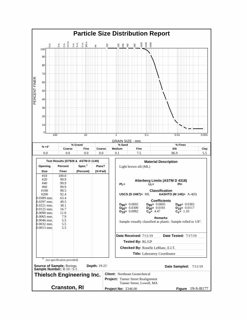
B-10 S-5 19-21 19-S-B177 0.0 7.6 92.4Light brown silt (ML)
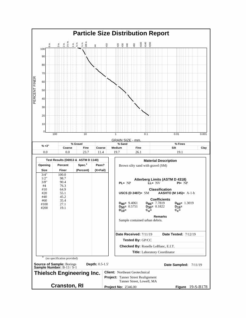
B-13 S-10.5-1.5 19-S-B178 23.7 57.2 19.1
Brown silty sand with gravel (SM)
B-14 S-1A1.5-2.5 19-S-B179 0.8 76.9 22.3
Brown silty sand (SM)
Reviewed By Date Reviewed 07.18.2019
Let's Build a Solid Foundation Collected By: NEG Report Date:
LABORATORY TESTING DATA SHEET
Identification Tests Proctor / CBR / Permeability Tests
Laboratory Log
and
Soil Description
195 Frances Avenue Client Information: Project Information:Cranston, RI 02910 Northeast Geotechnical, Inc. Tanner Street Realignment
Phone: (401)-467-6454 North Attleboro, MA Tanner Street, Lowell, MAFax: (401)-467-2398 PM: Mark Zambernardi NEG Project Number: Z346.00
http://www.thielsch.com Assigned By: Mark Zambernardi Summary Page:

Particle Size Distribution ReportP
ER
CE
NT
FIN
ER
0
10
20
30
40
50
60
70
80
90
100
GRAIN SIZE - mm.
0.0010.010.1110100
% +3"Coarse
% Gravel
Fine Coarse Medium
% Sand
Fine Silt
% Fines
Clay
0.0 0.0 0.0 0.0 0.0 29.5 70.5
6 in.
3 in.
2 in.
1½
in.
1 in.
¾ in.
½ in.
3/8
in.
#4
#10
#20
#30
#40
#60
#100
#140
#200
Test Results (D6913 & ASTM D 1140)
Opening Percent Spec.* Pass?
Size Finer (Percent) (X=Fail)
Material Description
Atterberg Limits (ASTM D 4318)
Classification
Coefficients
Date Received: Date Tested:
Tested By:
Checked By:
Title:
Date Sampled:Source of Sample: Borings Depth: 29-31'Sample Number: B-1 / S-7
Client:
Project:
Project No: Figure
Light brown sandy silt (ML)
#10#20#40#60
#100#200
100.0100.0100.0
99.998.670.5
NP NV NP
ML A-4(0)
0.1126 0.1003
Sample visually classified as plastic. Sample rolled to 1/4".
7/11/19 7/12/19
GP/CC
Ronelle LeBlanc, E.I.T.
Laboratory Coordinator
7/11/19
Northeast Geotechnical
Tanner Street RealignmentTanner Street, Lowell, MA
Z346.00
PL= LL= PI=
USCS (D 2487)= AASHTO (M 145)=
D90= D85= D60=D50= D30= D15=D10= Cu= Cc=
Remarks
* (no specification provided)
Thielsch Engineering Inc.
Cranston, RI 19-S-B174
Particle Size Distribution ReportP
ER
CE
NT
FIN
ER
0
10
20
30
40
50
60
70
80
90
100
GRAIN SIZE - mm.
0.0010.010.1110100
% +3"Coarse
% Gravel
Fine Coarse Medium
% Sand
Fine Silt
% Fines
Clay
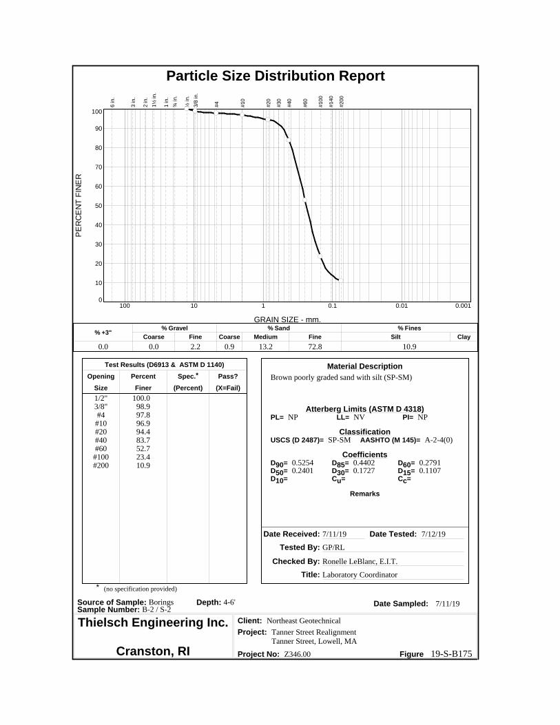
0.0 0.0 2.2 0.9 13.2 72.8 10.9
6 in.
3 in.
2 in.
1½
in.
1 in.
¾ in.
½ in.
3/8
in.
#4
#10
#20
#30
#40
#60
#100
#140
#200
Test Results (D6913 & ASTM D 1140)
Opening Percent Spec.* Pass?
Size Finer (Percent) (X=Fail)
Material Description
Atterberg Limits (ASTM D 4318)
Classification
Coefficients
Date Received: Date Tested:
Tested By:
Checked By:
Title:
Date Sampled:Source of Sample: Borings Depth: 4-6'Sample Number: B-2 / S-2
Client:
Project:
Project No: Figure
Brown poorly graded sand with silt (SP-SM)
1/2"3/8"#4
#10#20#40#60
#100#200
100.098.997.896.994.483.752.723.410.9
NP NV NP
SP-SM A-2-4(0)
0.5254 0.4402 0.27910.2401 0.1727 0.1107
7/11/19 7/12/19
GP/RL
Ronelle LeBlanc, E.I.T.
Laboratory Coordinator
7/11/19
Northeast Geotechnical
Tanner Street RealignmentTanner Street, Lowell, MA
Z346.00
PL= LL= PI=
USCS (D 2487)= AASHTO (M 145)=
D90= D85= D60=D50= D30= D15=D10= Cu= Cc=
Remarks
* (no specification provided)
Thielsch Engineering Inc.
Cranston, RI 19-S-B175
Particle Size Distribution ReportP
ER
CE
NT
FIN
ER
0
10
20
30
40
50
60
70
80
90
100
GRAIN SIZE - mm.
0.0010.010.1110100
% +3"Coarse
% Gravel
Fine Coarse Medium
% Sand
Fine Silt
% Fines
Clay
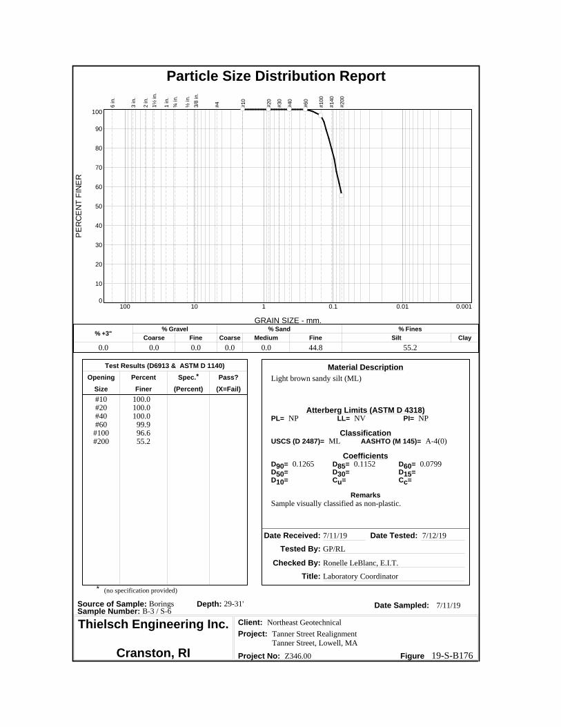
0.0 0.0 0.0 0.0 0.0 44.8 55.2
6 in.
3 in.
2 in.
1½
in.
1 in.
¾ in.
½ in.
3/8
in.
#4
#10
#20
#30
#40
#60
#100
#140
#200
Test Results (D6913 & ASTM D 1140)
Opening Percent Spec.* Pass?
Size Finer (Percent) (X=Fail)
Material Description
Atterberg Limits (ASTM D 4318)
Classification
Coefficients
Date Received: Date Tested:
Tested By:
Checked By:
Title:
Date Sampled:Source of Sample: Borings Depth: 29-31'Sample Number: B-3 / S-6
Client:
Project:
Project No: Figure
Light brown sandy silt (ML)
#10#20#40#60
#100#200
100.0100.0100.0
99.996.655.2
NP NV NP
ML A-4(0)
0.1265 0.1152 0.0799
Sample visually classified as non-plastic.
7/11/19 7/12/19
GP/RL
Ronelle LeBlanc, E.I.T.
Laboratory Coordinator
7/11/19
Northeast Geotechnical
Tanner Street RealignmentTanner Street, Lowell, MA
Z346.00
PL= LL= PI=
USCS (D 2487)= AASHTO (M 145)=
D90= D85= D60=D50= D30= D15=D10= Cu= Cc=
Remarks
* (no specification provided)
Thielsch Engineering Inc.
Cranston, RI 19-S-B176
Particle Size Distribution ReportP
ER
CE
NT
FIN
ER
0
10
20
30
40
50
60
70
80
90
100
GRAIN SIZE - mm.
0.0010.010.1110100
% +3"Coarse
% Gravel
Fine Coarse Medium
% Sand
Fine Silt
% Fines
Clay
0.0 0.0 0.0 0.0 0.1 7.5 86.9 5.5
6 in.
3 in.
2 in.
1½
in.
1 in.
¾ in.
½ in.
3/8
in.
#4
#10
#20
#30
#40
#60
#100
#140
#200
Test Results (D7928 & ASTM D 1140)
Opening Percent Spec.* Pass?
Size Finer (Percent) (X=Fail)
Material Description
Atterberg Limits (ASTM D 4318)
Classification
Coefficients
Date Received: Date Tested:
Tested By:
Checked By:
Title:
Date Sampled:Source of Sample: Borings Depth: 19-21'Sample Number: B-10 / S-5
Client:
Project:
Project No: Figure
Light brown silt (ML)
#10#20#40#60
#100#200
0.0389 mm.0.0297 mm.0.0221 mm.0.0125 mm.0.0090 mm.0.0065 mm.0.0046 mm.0.0032 mm.0.0013 mm.
100.099.999.999.999.592.463.449.538.116.711.0
7.95.55.55.5
NP NV NP
ML A-4(0)
0.0692 0.0605 0.03650.0300 0.0181 0.01170.0082 4.47 1.10
Sample visually classified as plastic. Sample rolled to 1/8".
7/11/19 7/17/19
RL/GP
Ronelle LeBlanc, E.I.T.
Laboratory Coordinator
7/11/19
Northeast Geotechnical
Tanner Street RealignmentTanner Street, Lowell, MA
Z346.00
PL= LL= PI=
USCS (D 2487)= AASHTO (M 145)=
D90= D85= D60=D50= D30= D15=D10= Cu= Cc=
Remarks
* (no specification provided)
Thielsch Engineering Inc.
Cranston, RI 19-S-B177
Particle Size Distribution ReportP
ER
CE
NT
FIN
ER
0
10
20
30
40
50
60
70
80
90
100
GRAIN SIZE - mm.
0.0010.010.1110100
% +3"Coarse
% Gravel
Fine Coarse Medium
% Sand
Fine Silt
% Fines
Clay
0.0 0.0 23.7 11.4 19.7 26.1 19.1
6 in.
3 in.
2 in.
1½
in.
1 in.
¾ in.
½ in.
3/8
in.
#4
#10
#20
#30
#40
#60
#100
#140
#200
Test Results (D6913 & ASTM D 1140)
Opening Percent Spec.* Pass?
Size Finer (Percent) (X=Fail)
Material Description
Atterberg Limits (ASTM D 4318)
Classification
Coefficients
Date Received: Date Tested:
Tested By:
Checked By:
Title:
Date Sampled:Source of Sample: Borings Depth: 0.5-1.5'Sample Number: B-13 / S-1
Client:
Project:
Project No: Figure
Brown silty sand with gravel (SM)
3/4"1/2"3/8"#4
#10#20#40#60
#100#200
100.098.790.476.364.955.145.235.427.119.1
NP NV NP
SM A-1-b
9.4061 7.7819 1.30190.5751 0.1822
Sample contained urban debris.
7/11/19 7/12/19
GP/CC
Ronelle LeBlanc, E.I.T.
Laboratory Coordinator
7/11/19
Northeast Geotechnical
Tanner Street RealignmentTanner Street, Lowell, MA
Z346.00
PL= LL= PI=
USCS (D 2487)= AASHTO (M 145)=
D90= D85= D60=D50= D30= D15=D10= Cu= Cc=
Remarks
* (no specification provided)
Thielsch Engineering Inc.
Cranston, RI 19-S-B178

Particle Size Distribution ReportP
ER
CE
NT
FIN
ER
0
10
20
30
40
50
60
70
80
90
100
GRAIN SIZE - mm.
0.0010.010.1110100
% +3"Coarse
% Gravel
Fine Coarse Medium
% Sand
Fine Silt
% Fines
Clay
0.0 0.0 0.8 1.8 38.7 36.4 22.3
6 in.
3 in.
2 in.
1½
in.
1 in.
¾ in.
½ in.
3/8
in.
#4
#10
#20
#30
#40
#60
#100
#140
#200
Test Results (D6913 & ASTM D 1140)
Opening Percent Spec.* Pass?
Size Finer (Percent) (X=Fail)
Material Description
Atterberg Limits (ASTM D 4318)
Classification
Coefficients
Date Received: Date Tested:
Tested By:
Checked By:
Title:
Date Sampled:Source of Sample: Borings Depth: 1.5-2.5'Sample Number: B-14 / S-1A
Client:
Project:
Project No: Figure
Brown silty sand (SM)
3/8"#4
#10#20#40#60
#100#200
100.099.297.486.258.737.528.422.3
NP NV NP
SM A-2-4(0)
0.9928 0.8166 0.43780.3501 0.1717
Sample visually classified as non-plastic.
7/11/19 7/12/19
GP/CC
Ronelle LeBlanc, E.I.T.
Laboratory Coordinator
7/11/19
Northeast Geotechnical
Tanner Street RealignmentTanner Street, Lowell, MA
Z346.00
PL= LL= PI=
USCS (D 2487)= AASHTO (M 145)=
D90= D85= D60=D50= D30= D15=D10= Cu= Cc=
Remarks
* (no specification provided)
Thielsch Engineering Inc.
Cranston, RI 19-S-B179
Related Documents