September 15, 2003 Mr. John L. Skolds, President Exelon Nuclear Exelon Generation Company, LLC 4300 Winfield Road Warrenville, IL 60555 SUBJECT: DRESDEN NUCLEAR POWER STATION, QUAD CITIES NUCLEAR POWER STATION, NRC LICENSE RENEWAL SCOPING/SCREENING INSPECTION REPORT 50-237/03-04 (DRS); 50-249/03-04 (DRS); 50-254/03-04 (DRS); 50-265/03-04 (DRS) Dear Mr. Skolds: On August 1, 2003, the NRC completed an inspection regarding the application for license renewal for your Dresden and Quad Cities facilities. The enclosed report documents the inspection findings, which were discussed on August 1, 2003, with members of your staff in an exit meeting open for public observation at the Exelon Midwest Regional Operating Group offices in Warrenville, IL. The purpose of this inspection was an examination of activities that support the application for a renewed license for the Dresden and Quad Cities facilities. The inspection consisted of a selected examination of procedures and representative records, and interviews with personnel regarding the process of scoping and screening plant equipment to select equipment subject to an aging management review. The inspection concluded that the scoping and screening portion of license renewal activities were conducted as described in the License Renewal Application and that documentation supporting the application is in an auditable and retrievable form. With the exception of the items identified in this report, your scoping and screening process was successful in identifying those systems, structures, and components required to be considered for aging management. In accordance with 10 CFR 2.790 of the NRC’s "Rules of Practice," a copy of this letter and its enclosure will be available electronically for public inspection in the NRC Public Document Room or from the Publicly Available Records (PARS) component of NRC’s document system (ADAMS). ADAMS is accessible from the NRC Web site at http://www.nrc.gov/reading-rm/adams.html (the Public Electronic Reading Room).

Welcome message from author
This document is posted to help you gain knowledge. Please leave a comment to let me know what you think about it! Share it to your friends and learn new things together.
Transcript

September 15, 2003
Mr. John L. Skolds, PresidentExelon NuclearExelon Generation Company, LLC4300 Winfield RoadWarrenville, IL 60555
SUBJECT: DRESDEN NUCLEAR POWER STATION, QUAD CITIES NUCLEAR POWERSTATION, NRC LICENSE RENEWAL SCOPING/SCREENING INSPECTIONREPORT 50-237/03-04 (DRS); 50-249/03-04 (DRS); 50-254/03-04 (DRS); 50-265/03-04 (DRS)
Dear Mr. Skolds:
On August 1, 2003, the NRC completed an inspection regarding the application for licenserenewal for your Dresden and Quad Cities facilities. The enclosed report documents theinspection findings, which were discussed on August 1, 2003, with members of your staff in anexit meeting open for public observation at the Exelon Midwest Regional Operating Groupoffices in Warrenville, IL.
The purpose of this inspection was an examination of activities that support the application for arenewed license for the Dresden and Quad Cities facilities. The inspection consisted of aselected examination of procedures and representative records, and interviews with personnelregarding the process of scoping and screening plant equipment to select equipment subject toan aging management review.
The inspection concluded that the scoping and screening portion of license renewal activitieswere conducted as described in the License Renewal Application and that documentationsupporting the application is in an auditable and retrievable form. With the exception of theitems identified in this report, your scoping and screening process was successful in identifyingthose systems, structures, and components required to be considered for aging management.
In accordance with 10 CFR 2.790 of the NRC’s "Rules of Practice," a copy of this letter and itsenclosure will be available electronically for public inspection in the NRC Public Document Roomor from the Publicly Available Records (PARS) component of NRC’s document system (ADAMS). ADAMS is accessible from the NRC Web site at http://www.nrc.gov/reading-rm/adams.html (the Public Electronic Reading Room).

J. Skolds -2-
Should you have any questions concerning this inspection, please contact Martin J. Farber at 630-829-9734.
Sincerely,
/RA/
Cynthia D. Pederson, DirectorDivision of Reactor Safety
Docket Nos: 50-237; 50-24950-254; 50-265
License Nos: DPR-19; DPR-25DPR-29; DPR-30
cc: Site Vice President - Dresden Nuclear Power StationSite Vice President - Quad Cities Nuclear Power StationDresden Nuclear Power Station Plant ManagerQuad Cities Nuclear Power Station Plant ManagerRegulatory Assurance Manager - DresdenRegulatory Assurance Manager - Quad CitiesChief Operating OfficerSenior Vice President - Nuclear ServicesSenior Vice President - Mid-West Regional Operating GroupVice President - Mid-West Operations SupportVice President - Licensing and Regulatory AffairsDirector Licensing - Mid-West Regional Operating GroupManager Licensing - Dresden and Quad CitiesSenior Counsel, Nuclear, Mid-West Regional Operating GroupVice President - Law and Regulatory Affairs Mid American Energy CompanyDocument Control Desk - LicensingM. Aguilar, Assistant Attorney GeneralIllinois Department of Nuclear SafetyState Liaison Officer, State of IllinoisState Liaison Officer, State of IowaChairman, Illinois Commerce CommissionW. Leach, Manager of Nuclear MidAmerican Energy CompanyD. Tubbs, Manager of Nuclear MidAmerican Energy Company

J. Skolds -2-
Should you have any questions concerning this inspection, please contact Martin J. Farber at 630-829-9734.
Sincerely,/RA/
Cynthia D. Pederson, DirectorDivision of Reactor Safety
Docket Nos:. 50-237; 50-24950-254; 50-265
License Nos:. DPR-19; DPR-25DPR-29; DPR-30
cc: Site Vice President - Dresden Nuclear Power StationSite Vice President - Quad Cities Nuclear Power StationDresden Nuclear Power Station Plant ManagerQuad Cities Nuclear Power Station Plant ManagerRegulatory Assurance Manager - DresdenRegulatory Assurance Manager - Quad CitiesChief Operating OfficerSenior Vice President - Nuclear ServicesSenior Vice President - Mid-West Regional Operating GroupVice President - Mid-West Operations SupportVice President - Licensing and Regulatory AffairsDirector Licensing - Mid-West Regional Operating GroupManager Licensing - Dresden and Quad CitiesSenior Counsel, Nuclear, Mid-West Regional Operating GroupVice President - Law and Regulatory Affairs Mid American Energy CompanyDocument Control Desk - LicensingM. Aguilar, Assistant Attorney GeneralIllinois Department of Nuclear SafetyState Liaison OfficerChairman, Illinois Commerce CommissionW. Leach, Manager of Nuclear MidAmerican Energy CompanyD. Tubbs, Manager of Nuclear MidAmerican Energy Company
DOCUMENT NAME: C:\ORPCheckout\FileNET\ML032580372.wpdTo receive a copy of this document, indicate in the box: "C" = Copy without attachment/enclosure "E" = Copy with attachment/enclosure "N" = No copy
OFFICE RIII E RIII N RIII E RIIINAME MFarber:tr MFarber for
JLaraMRing CPederson
DATE 09/08/03 09/15/03 09/15/03 09/15/03OFFICIAL RECORD COPY

J. Skolds -3-
ADAMS Distribution:AJM DFT LWRRidsNrrDipmIipbGEGHBCDRC1KKBC. Ariano (hard copy)DRPIIIDRSIIIPLB1JRK1

U. S. NUCLEAR REGULATORY COMMISSION
REGION III
Docket Nos: 50-237; 50-24950-254; 50-265
License Nos: DPR-19; DPR-25DPR-29; DPR-30
Report Nos: 50-237/03-04; 50-249/03-04; 50-254/03-04; 50-265/03-04
Licensee: Exelon Generation Company
Facility: Dresden Nuclear Power Station, Units 2 and 3Quad Cities Nuclear Power Station, Units 1 and 2
Location: 4300 Winfield RoadWarrenville, IL 60555
Dates: July 28 through August 1, 2003
Inspectors: M. J. Farber, Senior Reactor InspectorZ. Falevits, Senior Reactor InspectorM. S. Holmberg, Senior Reactor InspectorV. P. Lougheed, Senior Reactor InspectorJ. E. Neurauter, Reactor InspectorP. R. Pelke, Reactor InspectorT. J. Kim, Senior Project Manager, NRRH. Wang, Senior Operations Engineer, NRRK. Corp, Operations Engineer, NRR
Approved by: Julio Lara, Chief Electrical Engineering BranchDivision of Reactor Safety

TABLE OF CONTENTS
SUMMARY OF FINDINGS . . . . . . . . . . . . . . . . . . . . . . . . . . . . . . . . . . . . . . . . . . . . . . . . . . . . 1
REPORT DETAILS . . . . . . . . . . . . . . . . . . . . . . . . . . . . . . . . . . . . . . . . . . . . . . . . . . . . . . . . . . 2I. Inspection Scope . . . . . . . . . . . . . . . . . . . . . . . . . . . . . . . . . . . . . . . . . . . . . . . . 2II. Findings . . . . . . . . . . . . . . . . . . . . . . . . . . . . . . . . . . . . . . . . . . . . . . . . . . . . . . . 2
A. Evaluation of Scoping and Screening of Mechanical Systems . . . . . . . . 21. Reactor Vessel . . . . . . . . . . . . . . . . . . . . . . . . . . . . . . . . . . . . . 32. Reactor Internals . . . . . . . . . . . . . . . . . . . . . . . . . . . . . . . . . . . . 43. Reactor Vessel Head Vent System . . . . . . . . . . . . . . . . . . . . . . . 54. Head Spray System . . . . . . . . . . . . . . . . . . . . . . . . . . . . . . . . . . 55. Nuclear Boiler Instrumentation System . . . . . . . . . . . . . . . . . . . . 56. Core Spray System . . . . . . . . . . . . . . . . . . . . . . . . . . . . . . . . . . . 67. Residual Heat Removal System . . . . . . . . . . . . . . . . . . . . . . . . . 78. Low Pressure Coolant Injection System . . . . . . . . . . . . . . . . . . . 89. Automatic Depressurization System . . . . . . . . . . . . . . . . . . . . . 1010. Main Steam System . . . . . . . . . . . . . . . . . . . . . . . . . . . . . . . . . 1111. High Pressure Coolant Injection System . . . . . . . . . . . . . . . . . . 1212. Containment Isolation Components and Primary Containment
Piping System . . . . . . . . . . . . . . . . . . . . . . . . . . . . . . . . . . . . . . 1213. Shutdown Cooling System . . . . . . . . . . . . . . . . . . . . . . . . . . . . 1414. Control Rod Drive Hydraulic System . . . . . . . . . . . . . . . . . . . . . 1415. Emergency Diesel Generators and Auxiliary Systems . . . . . . . 1616. Station Blackout System (Diesels and Auxiliaries) . . . . . . . . . . 1617. Security Diesel System . . . . . . . . . . . . . . . . . . . . . . . . . . . . . . . 1718. Diesel Fuel Oil System . . . . . . . . . . . . . . . . . . . . . . . . . . . . . . . 1719. HVAC - Main Control Room . . . . . . . . . . . . . . . . . . . . . . . . . . . 1820. HVAC - Reactor Building . . . . . . . . . . . . . . . . . . . . . . . . . . . . . 1821. HVAC - Primary Containment . . . . . . . . . . . . . . . . . . . . . . . . . . 1922. Service Water System . . . . . . . . . . . . . . . . . . . . . . . . . . . . . . . 1923. Containment Cooling Service Water System . . . . . . . . . . . . . . 1924. Ultimate Heat Sink . . . . . . . . . . . . . . . . . . . . . . . . . . . . . . . . . . 2025. Nitrogen Containment Atmosphere Dilution System . . . . . . . . . 2126. Drywell Nitrogen Inerting System . . . . . . . . . . . . . . . . . . . . . . . 2127. Instrument Air and Drywell Pneumatic Supply System . . . . . . . 2128. Fuel Pool Cooling and Filter Demineralizers System . . . . . . . . . 2229. Condensate and Condensate Storage System . . . . . . . . . . . . . 2230. Extraction Steam System . . . . . . . . . . . . . . . . . . . . . . . . . . . . . 2331. Oxygen Injection - Hydrogen Addition System . . . . . . . . . . . . . 2332. Hypochlorite (Chemical addition) . . . . . . . . . . . . . . . . . . . . . . . 2333. Floor and Equipment Drain Collection System and Liquid
Radwaste System . . . . . . . . . . . . . . . . . . . . . . . . . . . . . . . . . . . 2434. Equipment and Floor Drains System . . . . . . . . . . . . . . . . . . . . . 2435. Dresden Unit 1 Gaseous Monitoring . . . . . . . . . . . . . . . . . . . . . 24
B. Evaluation of Scoping and Screening of Electrical Systems . . . . . . . . . 251. 4160 Vac Switchgear and Distribution . . . . . . . . . . . . . . . . . . . 252. 480 Vac Motor Control Centers, Transformer Switchgear and
Distribution . . . . . . . . . . . . . . . . . . . . . . . . . . . . . . . . . . . . . . . . 25

3. 125 Vdc System . . . . . . . . . . . . . . . . . . . . . . . . . . . . . . . . . . . . 264. Reactor Protection System . . . . . . . . . . . . . . . . . . . . . . . . . . . . 275. Reactor Manual Control System . . . . . . . . . . . . . . . . . . . . . . . . 27
C. Evaluation of Scoping and Screening of Electrical Components . . . . . . 281. Cables and Connections . . . . . . . . . . . . . . . . . . . . . . . . . . . . . . 282. Bus Ducts . . . . . . . . . . . . . . . . . . . . . . . . . . . . . . . . . . . . . . . . . 293. High Voltage Transmission Conductors and Insulators . . . . . . . 294. Electrical Penetrations . . . . . . . . . . . . . . . . . . . . . . . . . . . . . . . 295. Switchyard Buses . . . . . . . . . . . . . . . . . . . . . . . . . . . . . . . . . . . 29
D. Evaluation of Scoping and Screening of Structures . . . . . . . . . . . . . . . 291. Primary Containment . . . . . . . . . . . . . . . . . . . . . . . . . . . . . . . . 292. Reactor Building (secondary containment) . . . . . . . . . . . . . . . . 303. Turbine Buildings . . . . . . . . . . . . . . . . . . . . . . . . . . . . . . . . . . . 304. Dresden Units 2 and 3 Diesel Generator and High Pressure
Coolant Injection Building . . . . . . . . . . . . . . . . . . . . . . . . . . . . . 315. Quad Cities Diesel Generator Room . . . . . . . . . . . . . . . . . . . . . 316. Station Blackout Building . . . . . . . . . . . . . . . . . . . . . . . . . . . . . 317. Radwaste Floor Drain Surge Tank and Foundation . . . . . . . . . 328. Diesel Oil Storage Tanks Foundation . . . . . . . . . . . . . . . . . . . . 329. Contaminated Condensate Storage Tanks Foundation . . . . . . . 3210. Crib House . . . . . . . . . . . . . . . . . . . . . . . . . . . . . . . . . . . . . . . . 3311. Dresden Unit 1 Crib House . . . . . . . . . . . . . . . . . . . . . . . . . . . . 3312. Station Chimney . . . . . . . . . . . . . . . . . . . . . . . . . . . . . . . . . . . . 3313. Miscellaneous Radwaste Buildings . . . . . . . . . . . . . . . . . . . . . . 3314. Miscellaneous Dresden Unit 1 Structures . . . . . . . . . . . . . . . . . 3415. Miscellaneous Transmission and Distribution (T&D) Structures 3416. Offsite Power Structures . . . . . . . . . . . . . . . . . . . . . . . . . . . . . . 35
E. Evaluation of Scoping and Screening of Fire Protection Systems . . . . 35II Exit Meeting Summary . . . . . . . . . . . . . . . . . . . . . . . . . . . . . . . . . . . . . . . . . . . 36
ATTACHMENT 1
SUPPLEMENTAL INFORMATION . . . . . . . . . . . . . . . . . . . . . . . . . . . . . . . . . . . . . . . 37
ATTACHMENT 2
Dresden/Quad Cities
LICENSE RENEWAL INSPECTION PLAN . . . . . . . . . . . . . . . . . . . . . . . . . . . . . . . . . 52
ATTACHMENT 3
LIST OF ACRONYMS USED . . . . . . . . . . . . . . . . . . . . . . . . . . . . . . . . . . . . . . . . . . . 56

Enclosure1
SUMMARY OF FINDINGS
IR 0500237/2003-004 (DRS); 0500249/2003-004 (DRS); 0500254/2003-004 (DRS);0500265/2003-004 (DRS); 07/28/2003 - 08/01/2003; Exelon Generation Company; DresdenNuclear Power Station, Units 2 and 3, Quad Cities Nuclear Power Station, Units 1 and 2;License Renewal Inspection Program, Scoping and Screening.
This inspection of License Renewal (LR) activities was performed by six regional office engineeringinspectors and three staff members from the Office of Nuclear Reactor Regulation (NRR). Theinspection followed NRC Manual Chapter 2516 and NRC Inspection Procedure 71002. Thisinspection did not identify any “findings” as defined in NRC Manual Chapter 0612.
The overall conclusion of this inspection was that there was reasonable assurance that theapplicant had properly conducted license renewal scoping and screening for systems,structures, and components at Dresden and Quad Cities Nuclear Power Stations. Theinspection revealed the following issues:
• The applicant’s methodology for establishing system boundaries where nonsafety-relatedpiping was attached to safety-related piping was not consistent with the guidanceprovided by the NRC staff in the interim staff guidance letter. Specifically, the applicantdeveloped the concept of an “equivalent anchor” which included restraints at multiplelocations rather than the traditional definition of an “anchor” as a three dimensional, six degrees of freedom restraint (pipe displacements and pipe rotations) at the samephysical location. This was considered an open item pending evaluation by the Office ofNuclear Reactor Regulation technical staff.
• At the close of the inspection, the applicant was evaluating the switchyard buses forinclusion within the scope of the rule. The applicant’s decision on this matter will beevaluated during the forthcoming aging management inspection.

Enclosure2
REPORT DETAILS
I. Inspection Scope
This inspection was conducted by NRC Region III inspectors and members of the NRRstaff to interview applicant personnel and to examine a sample of documentation whichsupports the license renewal application (LRA). This inspection reviewed the results ofthe applicant’s scoping of plant systems and screening of components within thosesystems to identify the list of components that need evaluation for aging management. The team selected a sample of plant systems, structures, and components (SSC) fromthe LRA scoping results to verify the adequacy of the applicant’s scoping and screeningdocumentation and implementation activities. For the selected in-scopesystems/structures, the associated boundary drawings, and the active/passive andshort/long lived determinations of the selected SSCs were reviewed to confirm theaccuracy of the applicant’s results. In addition to the in-scope systems and structures,some systems that the applicant had determined not to be in scope for license renewalwere selected for inspection. The inspectors reviewed supporting documentation andinterviewed applicant personnel to confirm the accuracy of the LRA conclusions. TheSSCs selected for review during this inspection are listed in Attachment 2 to this report.
II. Findings
A. Evaluation of Scoping and Screening of Mechanical Systems
The inspectors evaluated the applicant’s scoping and screening process for mechanicalcomponents by reviewing a number of plant systems that the applicant determined to beeither within or out of the scope of license renewal (LR). The applicant performedscoping at the system level by first identifying safety-related (SR) mechanical systemsvia review of current licensing basis documentation. In addition, through walkdowns andreview of other licensing basis information, nonsafety-related (NSR) mechanicalsystems which could adversely affect SR systems were identified as were systemscommitted to support the four NRC-regulated events in 54.4(a)(3).
After system scoping, screening was accomplished by: establishment of LR systemboundaries by creating from official station drawings highlighted license renewalboundary flow diagram drawings; identifying components and component groupssubject to an aging management review (AMR) using a list of all passive, long-lived,mechanical components; and identification of intended function(s) of each mechanicalcomponent. The screening process and results were documented in individual systemLR scoping and screening books.
During the applicant’s scoping and screening effort, additional NRC guidance wasissued for consideration of the effects of NSR systems on SR systems, such as viaspray, leakage, pipe whip, jet impingement, flooding, and displacement/falling. Theinspectors reviewed the applicant’s methodology for inclusion of NSR mechanicalsystems in scope which could affect SR systems. The applicant’s methodologyconsisted of: determining all areas where SR and NSR systems were located;considering all NSR systems within these areas to be in scope for LR; and evaluating
Enclosure3
via documentation and walkdowns which NSR systems could damage SR systems forscreening considerations.
For an NSR system, structure or component that is connected to a SR system, structureor component, NRC guidance is that the NSR system, structure or component should beincluded within the scope of license renewal up to the first seismic anchor past thesafety/non-safety interface. NRC considers an anchor to be a three dimensional, sixdegrees of freedom restraint (pipe displacements and pipe rotations) at the samephysical location. The applicant’s technical instructions, LRTI-16, specified that the NSRpiping be “anchored” in three dimensions past the safety/non-safety interface. Discussions with the applicant’s staff determined: 1) a pipe displacement restraint wasconsidered to be a dimensional anchor; 2) three dimensions of pipe displacementrestraint was considered to be an “equivalent anchor;” and 3) the three dimensions ofpipe displacement restraint need not be at the same physical location. Therefore, forNSR piping physically connected to SR piping, the applicant only included within thescope of license renewal the NSR system, structures and components up to the“equivalent anchor” past the safety/non-safety interface. Further discussions revealedthat this issue had not been previously identified and would require resolution by NRR. This is an open item (50-237/03-04-01; 50-249/03-04-01; 50-254/03-04-01; 50-265/03-04-01).
The following mechanical systems were reviewed:
1. Reactor Vessel
The reactor vessel contains the reactor core, the reactor internals, and the reactor corecoolant-moderator. It serves as a high-integrity barrier against leakage of radioactivematerials to the drywell.
The reactor vessel is a vertical, cylindrical pressure vessel with hemispherical heads.The cylindrical shell and bottom hemispherical head of the reactor vessel are of weldedconstruction and are fabricated of low alloy steel plate. The removable top head isattached to the cylindrical shell flange by bolting. The major safety function for thereactor vessel is to provide a radioactive material barrier. The vessel also provides afloodable core volume, contains the moderator, and provides support for the reactorvessel internals.
The boundary evaluated by the applicant for the reactor vessel included the vessel shelland flange, top head and flange, bottom head, vessel closure studs and nuts, vesselnozzles (recirculation, main steam, feedwater and others), nozzle safe ends, vesselpenetrations (control rod drive (CRD) stub tubes, in-core instrument housings andothers), vessel skirt, vessel shell course welds and vessel attachment welds. Theapplicant considered all of the reactor vessel components to be in scope of LR. Theinspectors reviewed LR boundary drawings, the Updated Final Safety Analysis Report(UFSAR), engineering documentation, and system/structure scoping forms. Theinspectors concluded that the applicant had performed scoping and screening for thereactor vessel and identified the mechanical components subject to aging managementin accordance with the methodology described in the LRA and the rule. However, NRRstaff had identified open questions on the scope of vessel components associated with
Enclosure4
the vessel penetration nozzles (reference NRC letter dated August 4, 2003; ADAMSaccession number ML0321803282).
2. Reactor Internals
Reactor internals are installed to properly distribute the flow of coolant delivered to thevessel, to locate and support the fuel assemblies (evaluated separately) and controlblades (evaluated separately), and to provide an inner volume containing the core thatcan be flooded following a break in the nuclear system process barrier external to thereactor vessel.
The reactor internals include a core shroud, which is a stainless steel cylindersurrounding the reactor core that provides a barrier separating the upward flow of thecoolant through the reactor core from the downward recirculation flow. Bolted on top ofthe shroud is the steam separator assembly which forms the top of the core dischargeplenum. This provides a mixing chamber before the steam-water mixture enters thesteam separator. The recirculation outlet and inlet plenum are separated by the baffleplate (part of the shroud support structure) joining the bottom of the shroud to the vesselwall. The jet pump diffuser sits on, and is welded to, the baffle plate, making the jetpump diffuser section an integral part of the baffle plate. The baffle plate supports carryall the vertical weight of the shroud, steam separator and dryer assembly, top guide andbottom core plate (core grids), peripheral fuel assemblies, and jet pump componentscarried on the shroud. The control rod guide tubes extend up from the CRD housingthrough holes in the core plate. Each tube is designed as a lateral guide for the controlrod and as the vertical support for the fuel support piece which holds the four fuelassemblies surrounding the control rod.
The boundary evaluated by the applicant for the reactor vessel internals included allcomponents that are inside the reactor vessel except the fuel assemblies and thecontrol blades, both of which were short-lived components and evaluated separately. The applicant considered most of the component internal components to be within thescope of LR. Examples of components which were not within the scope of licenserenewal included steam separators, feedwater spargers, shroud head bolts and jetpump sensing lines. The inspectors reviewed LR boundary drawings, the UFSAR andsystem/structure scoping forms. The inspectors concluded that the applicant hadperformed scoping and screening for the reactor vessel internals and identified themechanical components subject to aging management in accordance with themethodology described in the LRA and the rule. However, the NRR staff had identifiedopen questions on the scope of vessel internals components such as thermal sleeves,feedwater spargers and internal standby liquid control piping (reference NRC letterdated August 4, 2003; ADAMS accession number ML0321803282).
The steam separator and dryer assembly provides dry saturated steam for use by themain turbine and the high pressure coolant injection (HPCI) system turbines. Theapplicant evaluated the steam separator assembly and determined that it was not in-scope. However, the applicant had not performed an analysis to demonstrate thatfailure of the separator assembly and resultant moisture carryover, would not impactoperation of the HPCI turbine driven pump. The applicant continued an investigation ofthis issue at the conclusion of the inspection. The applicant’s preliminary conclusion

Enclosure5
was that the scoping of the steam separator and dryer was correct. This conclusion wasbased upon a preliminary evaluation from the nuclear steam supply system vendorbased upon the expected initiation of the HPCI system following a reactor scram. Theapplicant’s vendor had concluded that following a scram, the power level, steam flowthrough the dryer, and differential pressure across the dryer are well below theconditions where high moisture carryover had been observed (e.g., at Quad Citiesfollowing a dryer crack event at full power). Therefore, the applicant’s conclusion wasthat, under these conditions, operation of the HPCI system would not be affected byfailure of the steam dryer assembly. This issue was referred to NRR for review of aapplicant’s analysis of this condition. NRR subsequently concluded that the analysisadequately supported exclusion of the steam separator assembly from the scope of LR.
3. Reactor Vessel Head Vent System
The head reactor vessel head vent (RVHV) system serves to remove non-condensablegases from the steam dome of the reactor vessel. During power operation, a two-inchline provides a vent from the reactor head to the main steam line.
The boundary evaluated by the applicant for the RVHV system extended from the flangeat the vessel head and associated piping to normally shut isolation valves. Nocomponents of this system were outside the scope of LR for Dresden. For Quad Cities,the licensee determined that portions of a nonsafety-related drain line attached to thissystem was outside of the scope of LR based on piping being downstream of an anchorpoint. The inspectors reviewed LR boundary drawings, the UFSAR andsystem/structure scoping forms. The inspectors concluded that the applicant hadperformed scoping and screening for the RVHV system and identified the mechanicalcomponents subject to aging management in accordance with the methodologydescribed in the LRA and the rule.
4. Head Spray System
For Dresden 2 and 3, the reactor vessel head spray (HS) system is used to spray coolwater into the steam bubble, causing condensation of steam and reduction of pressureand temperature in the head region. The HS system can also be used for coldhydrostatic testing.
The boundary evaluated by the applicant for the HS system consisted of selectedcomponents from the CRD system, the head spray line and associated valves and headspray element. The applicant scoped this system into the LR, except for the head spraynozzle and spray element internal to the vessel. The inspectors reviewed LR boundarydrawings, the UFSAR and system/structure scoping forms. The inspectors concludedthat the applicant had performed scoping and screening for HS system and identifiedthe mechanical components subject to aging management in accordance with themethodology described in the LRA and the rule.
5. Nuclear Boiler Instrumentation System
The nuclear boiler instrumentation (NBI) system provides trip signals to the reactorprotection system, emergency core cooling systems (ECCS), primary containment

Enclosure6
isolation logic, recirculation pump trip, and alternate rod insertion. It also provides theoperator with indications of the reactor level, pressure, and temperature during normaland transient operation and for guidance in following emergency procedures andsupporting post-accident operation. Parameters monitored by NBI are reactor vesseltemperature, reactor vessel pressure, reactor vessel water level, reactor internaldifferential pressure, and reactor vessel flange leakage.
The system includes all associated piping, condensing chambers, inline manual isolationglobe valves, flow limiting check valves, local instrument racks, and mountedinstruments for parameters monitored. Also included are all piping associated with thereactor vessel level indication system backfill subsystem, valves, filters, flow regulators,and flow indicators in piping connecting with the CRD water header. The NBI systemscope also includes the thermocouples monitoring vessel temperature and the piping,valves, instruments and controls used for monitoring reactor vessel head leakage. ForQuad Cities only, components associated with the electro-chemical potential probe inthe hydrogen addition system are included with the NBI system.
The inspectors reviewed the LRA, applicable portions of the UFSAR, the systemscoping and screening packages, and the license renewal boundary drawings. Theinspectors sampled components screening and did not identify any componentsimproperly excluded from aging management. The inspectors concluded that theapplicant had performed scoping and screening for the nuclear boiler instrumentationsystem in accordance with the methodology described in the LRA and the rule.
6. Core Spray System
The core spray (CS) system provides core cooling for intermediate and large line breaksizes. Two independent CS loops are provided to ensure adequate core cooling. Eachcore spray loop is designed to operate in conjunction with low pressure coolant injection(HPCI) and either the automatic depressurization system (ADS) or high pressurecoolant injection (HPCI) system to provide adequate core cooling over the entirespectrum of liquid or steam break sizes. The normal water source is supplied from thesuppression chamber (evaluated with the primary containment structure). An alternatewater source is the condensate storage system (evaluated with the condensate andcondensate storage system). The CS system delivers water directly to the reactorvessel (evaluated with the reactor vessel) onto the top of the fuel assemblies throughthe CS spargers (evaluated with reactor internals). Each CS loop is equipped with a testreturn line to the suppression chamber to permit functional testing and a minimum flowbypass line to the suppression chamber for pump protection.
The system evaluation boundary begins with the suction lines from the suppressionchamber and condensate storage system and continues through the pump anddischarge lines from each pump to the point where it interfaces with the reactor vesselnozzles. All associated piping, components and instrumentation, contained within flowpaths and subsystems described above are included in the system evaluation boundary.The discharge path includes a minimum flow bypass line and test return line for eachloop. The emergency core cooling system (ECCS) keep fill system is also included andis comprised of an ECCS keep fill pump with its suction and discharge lines. AtDresden only, the ECCS keep fill boundary includes a safety related isolation valve that

Enclosure7
separates the ECCS keep fill system from the condensate and condensate storage backup supply line. At Quad Cities only, the core spray boundary includes a safety relatedisolation valve from the high radiation sampling system. A room cooler maintains theequipment below the maximum equipment temperature limits. This room cooler isevaluated with the ECCS corner room heating, ventilation and air conditioning (HVAC)system.
The inspectors reviewed the LRA, applicable portions of the UFSAR, the systemscoping and screening packages, and the license renewal boundary drawings. Theinspectors sampled components screening and did not identify any componentsimproperly excluded from aging management. The inspectors concluded that theapplicant had performed scoping and screening for the CS system in accordance withthe methodology described in the LRA and the rule.
7. Residual Heat Removal System
The residual heat removal (RHR) system at Quad Cities has three modes of operation. The Low Pressure Coolant Injection (LPCI) mode of RHR is the only engineered safetyfeature function of the system and operates to restore water level in the reactor vessel. The containment cooling mode furnishes spray to the drywell and suppression chamberto aid in reducing containment pressure following a loss of coolant accident (LOCA). This mode also provides suppression chamber cooling to reduce water temperaturesduring operations that add heat to the suppression chamber and minimizes the amountof heat that the containment will need to accommodate during a LOCA. The shutdowncooling mode removes reactor residual and decay heat for shutdown, refueling andservicing operations.
The RHR system consists of two loops, each loop containing two pumps, one heatexchanger (evaluated with the residual heat removal service water system) and thenecessary valves and piping to connect these components to the reactor vessel via therecirculation system piping, the suppression chamber for spray/cooling and the drywellfor spray. The system piping is maintained full by the ECCS keep fill system (evaluatedwith the CS system). Each loop of the system is equipped a minimum flow bypass lineto the suppression chamber for pump protection. During normal plant operation thesystem is maintained in a lineup to be ready to inject water into either recirculation loopwith all pumps. Process lines that penetrate the primary containment structure containisolation valves. The RHR room coolers are evaluated with the ECCS corner roomHVAC system.
For the LPCI mode of operation, the primary source of water to the RHR system issupplied from the suppression chamber (evaluated with the primary containmentstructure). The backup source of water is the condensate storage tank (CST)(evaluated with the condensate and condensate storage system). For each loop, wateris pumped from the suppression chamber, through the pumps to the heat exchangerand the heat exchanger bypass valve. Upon automatic initiation of the RHR system, theLPCI loop select logic will select the recirculation loop (evaluated with recirculation,recirculation flow control and motor-generator set system) that appears most likely intactand, provided reactor pressure is sufficiently low, will inject to the intact recirculationloop.
Enclosure8
For the containment cooling mode of operation, there are three different uses. Drywellspray takes suction from the suppression chamber and pumps water to two spray nozzleheaders in the drywell. These spray headers may be used during a LOCA to reducedrywell pressure. Suppression chamber spray takes suction from the suppressionchamber and pumps water to spray nozzles in the suppression chamber. This reducessuppression chamber pressure following a LOCA. Suppression chamber cooling takessuction from the suppression chamber and pumps through a RHR heat exchanger,(which rejects heat to the RHR service water system) and pumps the water back to thesuppression chamber. This mode provides a heat sink, external to the containment,which will limit suppression chamber water temperature during conditions such asreactor core isolation cooling (RCIC) operation and minimize the amount of heat that thesuppression chamber will need to accommodate during a LOCA (for pressuresuppression and ECCS pump required suction head).
For the shutdown cooling mode of operation, the RHR pumps take suction from the “B”reactor recirculation system suction piping, pumps water through a RHR heat exchanger(for heat removal via RHR service water system) and returns the water to the reactorvessel via the recirculation system pump discharge line.
The system evaluation boundary begins with the suction lines from the suppressionchamber, CST and reactor recirculation piping. Included are the four pumps anddischarge piping up to the two heat exchangers and minimum flow lines for each loop.Also included are the return lines from each heat exchanger to the point where the RHRpiping interfaces with the reactor vessel via the reactor recirculation piping, spray pipingto the suppression chamber and drywell for each loop, and cooling water return to thesuppression chamber. All associated piping, components and instrumentationcontained within the flow paths and systems described above are included in the systemevaluation boundary.
The inspectors reviewed the LRA, applicable portions of the UFSAR, the systemscoping and screening packages, and the license renewal boundary drawings. Theinspectors sampled components screening and did not identify any componentsimproperly excluded from aging management. The inspectors concluded that theapplicant had performed scoping and screening for the residual heat removal system inaccordance with the methodology described in the LRA and the rule.
8. Low Pressure Coolant Injection System
The LPCI system at Dresden provides core cooling during a LOCA for break sizesranging from those for which the core is adequately cooled by the HPCI system alone,up to and including a design basis accident (DBA). LPCI is capable of injecting largequantities of water into the reactor pressure vessel and provides core cooling bysubmerging the core in water. The system is also designed to supply cooling/spraywater to the primary containment (drywell and suppression chamber) during accidentconditions to maintain containment temperature and pressure below design limits. Thesystem is also the normal means of removing water from the suppression chamber tomaintain the water level in the normal band.

Enclosure9
The system consists of two independent loops, each with two motor driven pumps, aheat exchanger (evaluated with the containment cooling service water (CCSW) system),associated piping, valves, and instrumentation. The normal water source is suppliedfrom the suppression chamber via an ECCS suction header (evaluated with the primarycontainment structure). An alternate source of water to the LPCI pumps is suppliedfrom the CST (evaluated with the condensate and condensate storage system). Thepumps can route water to several discharge paths. The system supplies water to thereactor vessel through the heat exchanger and into the reactor recirculation system(evaluated with the recirculation, recirculation flow control, and motor-generator setsystem) downstream of the reactor recirculation pumps. A motor operated valve (MOV)allows flow to bypass the heat exchanger. Each loop can deliver water to the reactorvessel through its own injection line or through the other loop injection line via a cross tieline. Each loop is equipped with a test return line to the suppression chamber to permitfunctional testing and a minimum flow bypass line to the suppression chamber for pumpprotection. Each loop also has the capability to deliver cooling/spray water to theprimary containment during accident conditions.
The containment cooling mode of operation consists of: (a) drywell spray where thepumps are aligned to pump water from the suppression chamber to headers equippedwith spray nozzles in the drywell (evaluated with the primary containment structure) toreduce containment pressure following a LOCA; (b) suppression chamber spray wherethe pumps are aligned to pump water from the suppression chamber to a headerequipped with spray nozzles (evaluated with the primary containment structure) in thesuppression chamber to reduce containment pressure following a LOCA; and (c)suppression chamber cooling where the pumps are aligned to recirculate water from thesuppression chamber, through the heat exchangers and back to the suppressionchamber.
The system is also the normal means of removing water from the suppression chamberto maintain normal operational level band. Taking suction from the suppressionchamber, the pumps can transfer water from the suppression chamber to the followinglocations: the suppression chamber of the other unit, the main condenser (evaluatedwith main condenser) of either unit, or to the floor drain collector tank (evaluated withradwaste and equipment drains).
The system evaluation boundary begins with the suction lines from the suppressionchamber and condensate storage system. Included are the four pumps and dischargepiping, minimum flow lines for each loop, and the cross tie line connecting the loops.The heat exchangers have been excluded from the evaluation boundary because theyare evaluated with the CCSW system. Also included in the evaluation boundary arereturn lines from each heat exchanger to the point where the piping interfaces with thereactor vessel via the reactor recirculation piping, spray piping to the suppressionchamber and drywell for each loop, and cooling water return lines to the suppressionchamber. The system evaluation boundary includes isolation valves from the highradiation sampling system (HRSS) and their associated instrumentation and manualisolation valves. These valves isolate the safety related LPCI system piping from thenonsafety-related HRSS. Additionally, HRSS grab sample manual isolation valves tothe HRSS panel sample cooler are included. A room cooler maintains the equipment

Enclosure10
below the maximum equipment temperature limits. The LCPI room cooler has beenevaluated with the ECCS corner room HVAC system.
The inspectors reviewed the LRA, applicable portions of the UFSAR, the systemscoping and screening packages, and the license renewal boundary drawings. Theinspectors identified some discrepancies, for which the applicant promptly initiatedlicense renewal change request LRCR No. 2003-204 to change boundary diagramdrawings LR-DRE-M-29-1 and LR-DRE-M-360-1 to incorporate NSR piping and valvesin-scope of the rule. Otherwise, the inspectors concluded that the applicant hadperformed scoping and screening for the low pressure coolant injection system inaccordance with the methodology described in the LRA and the rule.
9. Automatic Depressurization System
The ADS system is designed to act as a backup to the HPCI system and perform thefunction of vessel depressurization for all "small breaks" inside the primary containmentor "small unisolable breaks" outside the containment. ADS is an ECCS and designed tooperate with HPCI and CS to protect the reactor vessel/fuel in situations where thevessel is losing coolant. At Quad Cities, HPCI is an operational mode of the RHRsystem. For small breaks the vessel is depressurized in sufficient time to allow CS orHPCI to provide adequate core cooling. For large breaks the vessel depressurizesthrough the break without assistance.
The system will automatically and rapidly depressurize the reactor pressure vessel(evaluated with reactor pressure vessel) under certain accident conditions. When thelogic circuitry detects an accident condition along with a HPCI pump (evaluated withHPCI system for Dresden and RHR system for Quad Cities) or CS pump (evaluated withCS) running, the circuit sends signals that actuate the reactor vessel’s five relief valvesto perform a rapid vessel depressurization. One of the five relief valves is a safety/reliefvalve. Each relief valve (evaluated with main steam) is connected to a main steam line(evaluated with main steam). When a relief valve opens, it discharges steam to a tailpipe (evaluated with main steam), which directs the steam below the surface of thewater in the suppression chamber (evaluated with primary containment structure),through a tee quencher (evaluated with primary containment structures).
The system evaluation boundary is comprised of the logic relays, timers andinstrumentation that receivs process signal input and provides actuation signals to therelief valves actuated by ADS. The relief valves and the safety/relief valve, their tailpipes and vacuum breaker valves, related solenoids, pressure controllers, positionswitches, and pneumatic air components associated with the safety/relief valve areevaluated with the main steam system.
The inspectors reviewed the LRA, applicable portions of the UFSAR, the systemscoping and screening packages, and the license renewal boundary drawings. Theinspectors sampled components screening and did not identify any componentsimproperly excluded from aging management. The inspectors concluded that theapplicant had performed scoping and screening for the automatic depressurizationsystem in accordance with the methodology described in the LRA and the rule.

Enclosure11
10. Main Steam System
The main steam system delivers steam from the reactor pressure vessel to the mainturbine and balance of plant auxiliary steam loads. The system transports steamgenerated by the reactor through the reactor pressure vessel nozzles to the mainturbine via main steam stop valves in each of four lines. At Quad Cities only, the mainsteam system supplies steam to the HPCI and RCIC systems. Steam can be lined up tobypass the main turbine via bypass valves to the main condenser when required (e.g., during plant startup). Main steam isolation valves (MSIVs) and venturi type flowrestrictors are installed to minimize reactor coolant inventory loss in the event of a mainsteam line break. The MSIVs also limit radiation release rates to prevent exceeding the10 CFR Part 100 guidelines in the event of main steam line break outside the primarycontainment. Relief valves and safety valves located on the main steam piping insideprimary containment are provided for reactor pressure vessel over pressure protection. The relief valves will operate automatically if steam pressure exceeds the relief valvesetpoint or upon receipt of a signal from the automatic depressurization system. Theycan also be operated manually to reduce reactor pressure vessel pressure. The mainsteam system also provides steam to the main turbine gland seals, steam jet airejectors, off-gas pre-heaters and booster air ejectors, as well as the radwaste maximumrecycle re-boiler.
The system evaluation boundary starts at the four steam lines at the reactor pressurevessel nozzles and runs to and includes the turbine stop valves and the turbine bypassvalves via an equalization header. Each line is equipped with safety valves, at least onerelief valve, a venturi type flow restrictor, followed by an MSIV inside and outside theprimary containment. At Quad Cities only, a connection is provided for supplying steamto the HPCI and RCIC turbines, which are evaluated with the HPCI and RCIC systems. Downstream of the inboard and outboard MSIVs are drain lines to the main condenser. The boundary includes piping and components from gland seal for the main turbine,steam jet air ejectors, off-gas preheater and booster air ejectors, and radwastemaximum recycle re-boiler. The evaluation boundary includes piping between thereactor pressure vessel and outboard isolation valve, including the main steam line drainpiping, even though they are considered part of the reactor coolant pressure boundary. All associated piping, components, and instrumentation contained within the flow pathsand systems described above are included in the evaluation boundary. Solenoids,accumulators, pressure controllers, and position switches associated with the automaticdepressurization system and manual isolation valves for instruments associated with thefeedwater level control system are evaluated as part of the main steam system.
The inspectors reviewed the LRA, applicable portions of the UFSAR, the systemscoping and screening packages, and the license renewal boundary drawings. Theinspectors sampled components screening and did not identify any componentsimproperly excluded from aging management. The inspectors concluded that theapplicant had performed scoping and screening for the main steam system inaccordance with the methodology described in the LRA and the rule.

Enclosure12
11. High Pressure Coolant Injection System
The HPCI system ensures that adequate core cooling takes place for all break sizesless than those sizes for which the HPCI or CS subsystems can adequately protect thecore. Operation of the HPCI system in the emergency mode is completely independentof alternating current (AC) power.
The system consists of a steam turbine driving a multi-stage high-pressure main pumpand a gear driven single-stage booster pump, piping, auxiliary support systems, andinstrumentation. The turbine is driven by nuclear steam and exhausts to thesuppression chamber (evaluated with the primary containment structure). The preferredwater source to the booster pump suction is supplied from the condensate storagesystem (evaluated with the condensate and condensate storage system), with a backupsource from the suppression chamber. Water from the main pump is delivered to thereactor vessel (evaluated with the reactor vessel) through the “B” feedwater line(evaluated with the feedwater system) and distributed within the reactor vessel throughthe feedwater sparger (evaluated with reactor internals). The system is equipped with atest line to the condensate storage system to permit functional testing and a minimumflow bypass line to the suppression chamber for pump protection.
The system evaluation boundary for water injection begins with the suction lines fromthe condensate storage system and the suppression chamber and continues throughthe booster pump and main pump. The discharge path runs from the output side of themain pump to the “B” feedwater line connection outside the primary containment. Included are all piping and components that feed the booster pump and the main pump.The discharge path also includes a minimum flow line and a flow test return line. TheHPCI and RCIC systems at Quad Cities share a common flow test return line. Thiscommon line is evaluated for both systems with HPCI. The steam supply to the turbineruns directly from the reactor vessel at Dresden. At Quad Cities, the steam supply isprovided from “B” main steam line on Unit 1 and the “C” main steam line on Unit 2. The turbine exhausts to the suppression chamber. Auxiliary subsystems include gland seal,drain pots, turbine oil, and turbine cooling water. All associated piping, components andinstrumentation, contained within flow paths and subsystems described above areincluded in the system evaluation boundary. The HPCI room cooler maintains the roombelow the maximum equipment temperature limits. The room cooler has beenevaluated with the ECCS corner room HVAC system.
The inspectors reviewed the LRA, applicable portions of the UFSAR, the systemscoping and screening packages, and the license renewal boundary drawings. Theinspectors sampled components screening and did not identify any componentsimproperly excluded from aging management. The inspectors concluded that theapplicant had performed scoping and screening for the high pressure coolant injectionsystem in accordance with the methodology described in the LRA and the rule.
12. Containment Isolation Components and Primary Containment Piping System
The containment isolation components and primary containment piping system is acomposite support system for the primary containment structure. The containmentisolation components and primary containment piping system is comprised of primary

Enclosure13
containment isolation valves, penetrations and piping from nonsafety-related systemsthat perform no intended function except primary containment isolation. It also includessafety related piping, components and instrumentation that directly support intendedfunctions of the primary containment structure and that are not assigned to othersystems in-scope of license renewal. The containment isolation components andprimary containment piping system ensures that the primary containment structure isable to perform its intended functions.
In the event of a nuclear steam supply system piping failure within the drywell (evaluatedwith the primary containment structure) reactor water and/or steam would be releasedinto the drywell. The resulting increased drywell pressure would force a mixture ofradioactive materials, noncondensable gases, steam, and water through the connectingvent lines into the chamber of water in the suppression chamber, which is also called thetorus (evaluated with primary containment structure). The steam would condenserapidly and completely in the suppression chamber resulting in suppression of thepressure increase in the drywell. During this period, the primary containment andsuppression chamber piping isolation valves are relied upon to ensure the containmentof these gases and liquids. Vacuum breakers between the suppression chamber andthe reactor building and between the suppression chamber and the drywell ensure thatventing of non-condensable gases to the suppression chamber together withcondensation of the released steam does not result in exceeding drywell or suppressionchamber external design differential pressure. Instrument air to the traversing in-coreprobe (TIP) tubing ensures a clean, dry environment for the TIP probe while ensuringisolation capability. TIP ball and shear valves ensure tubing isolation, includingsituations where isolation is required concurrent with TIP probes traversing the core oran in-vessel stuck probe. Components associated with atmospheric containmentatmosphere dilution (ACAD) (indication instruments only) and drywell pneumaticsprovide the supply for air operated valves and for maintaining an atmosphere thatinhibits the formation of a combustible gas mixture. Floor and equipment drains providefor the measurement and removal of leakage while maintaining offsite radiologicalconsequences to within acceptable limits, by isolating and maintaining containmentintegrity when required.
The system evaluation boundary consists of: primary containment pressureinstruments; suppression chamber to reactor building vacuum breaker lines; purgesupply and exhaust penetrations (HVAC – primary containment); suppression chamberlevel instrumentation penetrations; local leak rate test (LLRT) penetrations; andcontainment isolation barriers from the following systems: TIP, drywell equipment andfloor drain sumps, ACAD, service air (SA), and instrument air (IA). All associated piping,components and instrumentation contained within the flow paths and systems describedabove are included in the primary containment and suppression chamber piping systemevaluation boundary. The components that provide primary containment isolation forother in-scope systems are included in the overall evaluations for those systems.
The inspectors reviewed the LRA, applicable portions of the UFSAR, the system scopingand screening packages, and the license renewal boundary drawings. The inspectorssampled components screening and did not identify any components improperly excludedfrom aging management. The inspectors concluded that the applicant had performed
Enclosure14
scoping and screening for the containment isolation components and primary containmentpiping system in accordance with the methodology described in the LRA and the rule.
13. Shutdown Cooling System
The shutdown cooling system at Dresden provides cooling of the reactor water when thetemperature and pressure in the reactor fall below the point at which the maincondenser can no longer be used as a heat sink following reactor shutdown. Thesystem can also be used to help cool the fuel pool during refueling outages and to heatreactor water with steam from the plant heating system during startup from coldshutdown.
The system consists of three partial capacity cooling loops, each containing a pump, aheat exchanger, and associated piping, valves and instrumentation. The system takessuction from either reactor recirculation loop (evaluated with the reactor recirculationsystem), delivers the flow through each of the three separate cooling loops, and thendirects it into either of the LPCI injection lines (evaluated with the LPCI system). Capability also exists to permit flow from both reactor recirculation loops to both LPCIinjection lines simultaneously. When used to augment fuel pool cooling (evaluated withthe fuel pool cooling and demineralizer system), only one of the cooling loops isrequired. Each cooling loop is provided with a minimum flow valve to return pumpdischarge flow to the pump suction. The system heat exchangers are cooled by waterfrom the reactor building closed cooling water system (evaluated with the reactorbuilding closed cooling water system) in the cooling mode and heated by steam from theplant heating system (evaluated with the plant heating system) in the heating mode. Provision is also made for chemical sampling, clean-up via the reactor water cleanup(RWCU) system (evaluated with the RWCU system), and system drainage to thereactor building equipment drain system.
The system evaluation boundary begins with the system inlet MOVs that receive primarycoolant from the reactor recirculation piping. The boundary continues through each ofthe system pumps, heat exchangers, and discharge lines to the outlet MOVs that directthe cooled primary coolant back to the reactor via the LPCI injection lines. Allassociated piping, components and instrumentation contained within flow paths andsubsystems described above are included in the system evaluation boundary. Eachcooling loop includes a minimum flow line.
The inspectors reviewed the LRA, applicable portions of the UFSAR, the systemscoping and screening packages, and the license renewal boundary drawings. Theinspectors sampled components screening and did not identify any componentsimproperly excluded from aging management. The inspectors concluded that theapplicant had performed scoping and screening for the shutdown cooling system inaccordance with the methodology described in the LRA and the rule.
14. Control Rod Drive Hydraulic System
The control rod drive hydraulic (CRDH) system controls changes in reactivity byincrementally positioning the control rods in response to signals from the reactor manual

Enclosure15
control system. The system is also used to shut down the reactor quickly by rapidlyinserting control rods into the core in response to a manual or automatic signal.
The system is made up of supply pumps, filters, strainers, control valves, andassociated instrumentation and controllers. It provides water at the required pressuresto the hydraulic control units (HCUs) for cooling and all types of required control rod(evaluated with control blades) motion. The system allows control rod withdrawal orinsertion at a limited rate, one rod at a time, for power level control and flux shapingduring reactor operation. Stored energy available from gas (nitrogen) chargedaccumulators and from reactor pressure provides hydraulic power for rapidsimultaneous insertion (scram) of all control rods for reactor shutdown. The hydraulicsystem is arranged so that the equipment common to each CRD is packaged in modularform into HCUs, one HCU module to each drive. The HCUs are arranged into twobanks, each of which has its own scram discharge volume (SDV), which consists of ascram discharge header and an instrument volume. The SDV is used to limit the loss ofand contain the reactor vessel water from all the drives during a scram. Each CRD hasits own separate control and scram devices. Alternate rod insertion valves are suppliedto provide an alternate means of initiating control rod insertion during an ATWS scramevent (evaluated with the ATWS system). Under normal operation, the CRDH systemsupplies unheated condensate by one of two system pumps to hydraulically position thecontrol rods. These pumps take their suction from the condensate system (evaluatedwith the condensate and condensate storage system) at low pressure and direct itthrough the drive water filters. The discharge from the filters supply the reactorrecirculation pump seal water supply header, the accumulators via the charging header,the HCUs via the drive water header, and the CRDs via the cooling water header. Thepumps are provided with a minimum flow line to the contaminated condensate storagetank (CCST). The reactor recirculation pump seal water supply header supplies filteredand cooled water to the purge the reactor recirculation pump seals. The reactorrecirculation pump seal water supply isolation check valves provide a pressure retainingboundary for the reactor coolant system. The charging header supplies pressurizedwater to maintain the accumulators charged and ready for service in the event of ascram. The drive water header provides the CRDs with motive force for moving thecontrol rods. This header also supplies a continuous low flow to the reactor vessel levelinstrumentation system (RVLIS) backfill system (evaluated with the NBI system). Filtered control air is provided to CRDH system air operated valves from the IA system. Provision is also made (at Dresden) to supply system flow to the reactor recirculationpump seals for hydro purposes.
The CRDH system suction side evaluation boundary begins with the connection to thecondensate reject line to the CCST. The boundary continues through the CRD pumps,the drive water filters, and branches to the reactor recirculation pump seal supplyheader, to the accumulators via the charging header, to the HCUs via the drive waterheader, and to the CRDs via the cooling water header. The evaluation boundaryincludes the suction piping, discharge piping, minimum flow line, filters, CRD pumps,HCUs, HCU manifolds, and the CRDs. Included within the boundary are the reactorrecirculation pump seal water supply isolation check valves, the scram discharge headerand instrument volume and the supply lines to the RVLIS backfill system. The air supplyevaluation boundary starts at the parallel IA supply lines to the CRD air filters andincludes the filters and all piping, instrumentation, and valves necessary to supply air to

Enclosure16
the CRD air operated valves. Included within the evaluation boundary is theaccumulator nitrogen charging system, which includes the nitrogen cylinders, headerpiping, piping, instrumentation, and valves from the cylinders to the HCU accumulators. At Dresden, the RVLIS backfill system supply header isolation valves, and the systemvalves on the CRD hydro supply line to the reactor recirculation pump seals are includedin the evaluation boundary. All associated piping, components and instrumentationcontained within the flow paths and systems described above are included in the systemboundary.
The inspectors reviewed the LRA, applicable portions of the UFSAR, the systemscoping and screening packages, and the license renewal boundary drawings. Theinspectors sampled components screening and did not identify any componentsimproperly excluded from aging management. The inspectors concluded that theapplicant had performed scoping and screening for the control rod drive hydraulicsystem in accordance with the methodology described in the LRA and the rule.
15. Emergency Diesel Generators and Auxiliary Systems
The emergency diesel generator (EDG) system provides an emergency source of ACpower to the ECCS and safe shutdown equipment at each site in the event off-sitepower supply is not available. The EDGs were classified as being in the scope of therule, with the exception of some minor components, such as the air start compressors. The system consists of three emergency diesel generators assemblies per site: oneassembly per unit and a shared assembly. The auxiliaries evaluated with the systeminclude the jacket water system, the lubrication oil system, the air start system, thecombustion air intake and exhaust system, and the room ventilation system. Included inthe scope of the system were the diesel engines and generators, piping, valves,manifolds, starters, turbo-chargers, internal coolers, instrumentation, and otherequipment directly attached to the diesel engines. The auxiliary systems contain heatexchangers, strainers, pumps, filters, coolers, receiver tanks, moisture separators,valves, manifolds, silencers, dampers, fans, along with piping, flexible hoses andinstrumentation.
The inspectors reviewed the UFSAR sections for the diesel generators and the auxiliarysystems, the LR drawings, and the EDG scoping and screening forms. The inspectorssampled components shown on the boundary diagrams or in the component lists andidentified some discrepancies, for which the licensee promptly wrote LR changerequests to correct either the boundary diagram or the scoping and screeningdocuments. The inspectors concluded that the applicant had performed scoping andscreening for the EDG system in accordance with the methodology described in theDresden and Quad Cities LRA and the rule.
16. Station Blackout System (Diesels and Auxiliaries)
The station blackout (SBO) diesel generators (DG) system provides an additional,independent AC power source as a backup to the EDGs for the regulated event ofstation blackout. For Quad Cities, the SBO DGs also provide power during certainAppendix R fires. The SBO DGs were classified as being in the scope of the rule, withthe exception of some minor components, such as the air start compressors. The

Enclosure17
system consists of two DG sets per site. The auxiliaries evaluated with the systeminclude the jacket water system, the lubrication oil system, the air start system, thecombustion air intake and exhaust system, and the room ventilation system. Included inthe scope of the system were the SBO DG sets consisting of two diesel engines and agenerator arranged in tandem, along with directly attached piping, valves, manifolds,starters, turbo-chargers, internal coolers, instrumentation, and other equipment. Theauxiliary systems contained heat exchangers, strainers, pumps, filters, coolers, receivertanks, moisture separators, valves, manifolds, silencers, dampers, fans, along withpiping, flexible hoses and instrumentation.
The inspectors reviewed the UFSAR sections for the SBO DGs and their auxiliarysystems, the LR drawings, and the EDG scoping and screening forms. The inspectorssampled components shown on the boundary diagrams or in the component lists andidentified some discrepancies, for which the licensee promptly wrote LR changerequests to correct either the boundary diagram or the scoping and screeningdocuments. The inspectors concluded that the applicant had performed scoping andscreening for the SBO DG system in accordance with the methodology described in theDresden and Quad Cities LRA and the rule.
17. Security Diesel System
The security diesel system provides backup power to the station’s security system in theevent offsite power is lost. The security diesel was classified as not being in the scopeof the rule, with no exceptions. The inspectors reviewed the UFSAR, and discussed thesystem intent with the applicant. The inspectors concluded that the applicant hadperformed scoping for the security diesel system in accordance with the methodologydescribed in the Dresden and Quad Cities LRA and the rule.
18. Diesel Fuel Oil System
The diesel fuel oil system stores and transfers diesel fuel oil for the EDGs, the SBODGs, the diesel fire pumps, and, at Dresden only, the isolation condenser makeup pumpdiesels. The diesel fuel oil system was classified as being in the scope of the rule, withthe exception of the some non-safety-related instrumentation and some abandonedpiping at Dresden. The system consists of a separate fuel oil storage and transfersystem for each EDG. At Dresden, the Unit 2 EDG fuel oil transfer system also suppliesfuel oil to the isolation condenser makeup pump fuel oil day tanks, and the Unit 3 EDGfuel oil transfer system also supplies fuel oil to the Unit 2/3 diesel fire pump day tank. AtQuad Cities, the Unit 1 and Unit 2 EDG fuel oil transfer systems also supply fuel oil forthe diesel fire pump day tanks. Included in the scope of the system were tanks, pumps,filters, strainers, piping, valves, and instrumentation and controls.
The inspectors reviewed the UFSAR sections for the diesel fuel oil storage and transfersystem, the LR drawings, and the diesel fuel oil system scoping and screening forms. The inspectors sampled components shown on the boundary diagrams or in thecomponent lists and identified some discrepancies, for which the licensee promptlywrote LR change requests to correct either the boundary diagram or the scoping andscreening documents. The inspectors concluded that the applicant had performed
Enclosure18
scoping and screening for the diesel fuel oil system in accordance with the methodologydescribed in the Dresden and Quad Cities LRA and the rule.
19. HVAC - Main Control Room
The purpose of the main control room HVAC system is to provide: (1) a suitableenvironment during normal operation for the control room operators and equipment;(2) a habitable environment after a DBA in which the operators can safely shutdown andmaintain the plant for the duration of the accident; (3) an environment from which theoperators can safely occupy and operate the plant during an onsite or offsite toxicchemical accident; and (4) fire protection to the operators with fire dampers, for firesoutside the control room, and a smoke purge function mode for fires inside the controlroom. The inspectors reviewed the LRA, applicable portions of the UFSAR, the systemscoping and screening packages, and the license renewal boundary drawings. Theinspectors sampled the component screening and identified that the Quad Citiesemergency air filtration unit booster fans (0-9400-104A(B)) were incorrectly classified asactive. Fans that are not a subcomponent of a larger component are classified aspassive for the pressure boundary provided by the associated housings. The applicantidentified five additional fans which were incorrectly classified as active, and threeadditional fans that were incorrectly classified as in scope. License Renewal ChangeRequests 2003-183, 184, and 185 were initiated to correct the classifications. Theinspectors concluded that the applicant had performed scoping and screening for maincontrol room HVAC system in accordance with the methodology described in the LRAand the rule.
20. HVAC - Reactor Building
The reactor building ventilation system provides conditioned air to the reactor buildingand primary containment structures to remove the heat remaining from the primaryprocess and operating equipment, minimize the level of airborne contaminants, makethe plant atmosphere adequate to support the presence of personnel and maintain thereactor building at a negative pressure to minimize the release of radioactivecontaminants to the environment. Emergency isolation dampers are provided to isolatethe reactor building in the event of high radiation. The reactor building ventilationsystem also removes exhaust air from the drywell and suppression chamber purgesystem when the reactor is shutdown and/or whenever primary containment access isrequired. At Quad Cities, the parts of the reactor building ventilation system that arewithin the scope of the rule include: (a) the emergency isolation dampers in the mainsupply duct and main exhaust duct; and (b) the fire damper in the exhaust duct from themain steam pipe area in the turbine building. The remaining parts of the system are notwithin the scope of the rule. At Dresden, all associated piping, components, andinstrumentation contained within the flow paths and systems are a requirement for thedesign basis fuel handling accident during refueling, as described in Section 15.7.3 ofthe Dresden UFSAR, and are included in the reactor building ventilation systemevaluation boundary.
The inspectors reviewed the LRA, applicable portions of the UFSAR, the systemscoping and screening packages, and the license renewal boundary drawings. Theinspectors questioned the significant difference between the Dresden and Quad Cities

Enclosure19
scopes considering the systems are essentially the same. Further review by theapplicant determined the need to bring the Quad Cities ducting from the reactorbuilding-turbine building interface to the reactor building ventilation exhaust damperswithin the scope of the rule. The ducting must remain intact in order to ensure that allreactor building effluent is properly monitored and that there is no potential exhaust paththat bypasses the radiation monitors. The applicant issued License Renewal ChangeRequest No. 2003-208 to include this additional portion of the system in the scope. Theinspectors concluded that the applicant had performed scoping and screening forreactor building HVAC system in accordance with the methodology described in the LRAand the rule.
21. HVAC - Primary Containment
The purpose of the drywell cooling system is to maintain the drywell temperatures lessthan those assumed for DBA initial conditions. The system utilizes seven cooling fanunits which draw the drywell atmosphere through the cooling coils supplied from thereactor building closed cooling water system. The cooled air is distributed throughoutthe drywell by a system of ductwork. The drywell coolers maintain the drywelltemperatures between 135 and 150 degrees F. The inspectors reviewed the LRA,applicable portions of the UFSAR, and the system scoping and screening packages. There were no functions of the system that met the criteria for LR scoping. Theinspectors concluded that there was adequate basis for exclusion of this system fromthe LR scope.
22. Service Water System
The service water (SW) system provides strained river water to cool various loads in thereactor building, turbine building, and auxiliary building. The SW system is a nonsafety-related system that provides cooling water to components required for normaloperation. The SW system was classified as being partially within the scope of the rule. On Quad Cities, portions of the SW system were brought into scope only because ofspatial interactions. On Dresden, the majority of the system was brought into scopebecause the system is relied upon during a regulated event (Appendix R fires). At bothsites, the system consists of an open loop system common to both units. Included inthe scope of the rule for Quad Cities were piping, valves, and some instrumentation. Included in the scope of the rule for Dresden were pumps, strainers, piping, heatexchangers, valves, and instrumentation.
The inspectors reviewed the UFSAR sections for the SW system, the LR drawings, andthe SW scoping and screening forms. The inspectors sampled components shown onthe boundary diagrams or in the component lists and concluded that the applicant hadperformed scoping and screening for the SW system in accordance with themethodology described in the Dresden and Quad Cities LRA and the rule.
23. Containment Cooling Service Water System
The CCSW system at Dresden removes heat from the primary containment by providingcooling water to the HPCI heat exchangers. CCSW, working with HPCI, limitssuppression chamber bulk water temperature assuring: 1) suppression chamber

Enclosure20
hydrodynamic loads during blowdown are limited maintaining structure and equipmentintegrity; 2) complete steam condensation during a LOCA limiting long term primarycontainment pressure; and 3) adequate net positive suction head (NPSH) for ECCSpumps maintaining long term primary containment pressure control. The Unit 2 CCSWloops provide a safety related source of SW to the control room air conditioningcondensers. The CCSW system also supplies a safety related source of river water tothe HPCI and HPCI room coolers as a backup to the SW system.
The system is an open loop system consisting of four pumps, associated valves, piping,and instrumentation and controls. The system removes heat from the LPCI system(evaluated with LPCI system) through the LPCI heat exchangers. The CCSW pumpsdevelop sufficient head to maintain the cooling water heat exchanger tube side outletpressure greater than the HPCI subsystem pressure on the shell side (evaluated withHPCI system). Maintaining this pressure differential prevents reactor water leakage intothe SW and thereby into the river. The Unit 2 CCSW loops provide a SR source of SWto the control room air conditioning condensers (evaluated with control room HVAC). The CCSW system also supplies a SR source of river water to the HPCI and HPCI roomcoolers (evaluated with ECCS corner room HVAC) as a backup to the SW system.
The system evaluation boundary begins with each pair of CCSW pumps taking suctionfrom the crib house via separate supply piping. Two pumps discharge into a commonheader that routes the cooling water to that loop’s associated heat exchanger. At theheat exchanger, heat is transferred from the LPCI subsystem (evaluated with LPCIsystem) to the CCSW system, and subsequently to the river. System piping is arrangedto form two separate, two-pump flow networks (loops) to the piping downstream of thedifferential pressure control valve on the discharge of the heat exchanger. At this point,both piping loops merge into a common discharge line to the SW discharge header(evaluated with the SW system).
The inspectors reviewed the LRA, applicable portions of the UFSAR, the systemscoping and screening packages, and the license renewal boundary drawings. Theinspectors sampled components screening and did not identify any componentsimproperly excluded from aging management. The inspectors concluded that theapplicant had performed scoping and screening for the CCSW system in accordancewith the methodology described in the LRA and the rule.
24. Ultimate Heat Sink
The ultimate heat sink provides a source of safety-related cooling water for the safety-related SW systems whenever the normal heat sink is unavailable (i.e., the riverlevel was below its normal level). The ultimate heat sink was classified as being entirelywithin the scope of the rule. In addition, some components from the circulating watersystem at both sites and from the screen wash system, at Dresden only, were realignedto the ultimate heat sink. The system primarily consists of a topographic basin separatefrom, but connected to the normal heat sink (either the Mississippi or Kankakee Rivers). In addition to the basin, stop logs, pumps (Dresden only), pipes, and valves wereincluded in the scope of the system.
Enclosure21
The inspectors reviewed the UFSAR sections for the ultimate heat sink, the LRdrawings; and the ultimate heat sink, scoping and screening forms. The inspectorssampled components shown on the boundary diagrams or in the component lists andconcluded that the applicant had performed scoping and screening for the ultimate heatsink in accordance with the methodology described in the Dresden and Quad Cities LRAand the rule.
25. Nitrogen Containment Atmosphere Dilution System
The nitrogen containment atmosphere dilution (NCAD) system provides two redundant,single failure proof, independent flow paths for purging the primary containment withnitrogen to provide post-accident combustible gas control. The NCAD system injectsgaseous nitrogen into the primary containment to purge the containment of oxygen andhydrogen to maintain the mixture below combustible levels.
The inspectors reviewed the LRA, applicable portions of the UFSAR, the systemscoping and screening packages, and the license renewal boundary drawings. Theinspectors sampled the component screening and did not identify any componentsimproperly excluded from aging management. The inspectors concluded that theapplicant had performed scoping and screening for the NCAD system in accordancewith the methodology described in the LRA and the rule.
26. Drywell Nitrogen Inerting System
The drywell nitrogen inerting system, also known as the drywell nitrogen purge andinerting system, is provided to maintain the drywell in a nitrogen inerted condition as ameans of inhibiting the formation of a combustible gas mixture under LOCA conditions.The system is not safety related; however, it can be used for post-LOCA hydrogencontrol. The system also serves as a backup to the pump-back system to maintain therequired drywell-to-suppression chamber differential pressure and provide nitrogen tothe NCAD system.
The inspectors reviewed the LRA, applicable portions of the UFSAR, the systemscoping and screening packages, and the license renewal boundary drawings. Theinspectors sampled the component screening and did not identify any componentsimproperly excluded from aging management. The inspectors concluded that theapplicant had performed scoping and screening for the drywell nitrogen inerting systemin accordance with the methodology described in the LRA and the rule.
27. Instrument Air and Drywell Pneumatic Supply System
The purpose of the IA system is to supply clean, dry, compressed air for air-operatedcontrol devices and instruments. The drywell pneumatic supply system has a functionsimilar to the IA system, but it supplies drywell nitrogen (instead of air) to control devicesand instruments in the drywell. The inspectors reviewed the LRA, applicable portions ofthe UFSAR, and the system scoping and screening packages. There were no functionsof the system that met the criteria for LR scoping. The inspectors concluded that therewas adequate basis for exclusion of this system from the LR scope.

Enclosure22
28. Fuel Pool Cooling and Filter Demineralizers System
The purpose of the fuel pool cooling and filter demineralizer system is to remove heatfrom the spent fuel and to maintain fuel storage pool water clarity. During refuelingoperations the system can also be used to maintain the water clarity of the reactorrefueling cavity. The system consists of tanks, pumps, heat exchangers, filters,demineralizers, fuel pool spargers, and the associated piping, components, andinstrumentation. The applicant included some portions of the system at Dresden withinthe scope of license renewal as a result of spatial interactions in accordance with54.4(a)(2). Because of differences in piping layout, none of the system at Quad Citieswas included in the scope. The inspectors reviewed the LRA, applicable portions of theUFSAR, the system scoping and screening packages, and the license renewal boundarydrawings. The inspectors concluded that the applicant had performed scoping andscreening for the fuel pool cooling and filter demineralizer system in accordance with themethodology described in the LRA and the rule.
29. Condensate and Condensate Storage System
The condensate and condensate storage systems (in conjunction with the feedwatersystem) works to provide water of a quality and quantity required for operation of thepower plant. The condensate and condensate booster pump portion of the systemsupply reactor quality water to the suction of the reactor feedwater pumps. Thecondensate storage system’s CCSTs ensure reactor quality water is available formakeup requirements, and are designed to ensure a minimum of 90,000 gallons ofwater is available from each CCST for use by HPCI. The condensate and feedwatersystems’ pumping functions are not credited to support safe shutdown or to perform anyreactor safety function. The CCSTs are also credited for providing makeup to thereactor via the CRD pumps (at Dresden) or the RCIC and safe shutdown makeup pump(SSMP) systems (at Quad Cities) for safe shutdown scenarios in the Fire ProtectionPlan.
The boundary evaluated by the applicant for the condensate and condensate storagesystems extended from the outlet of the condenser hotwell through the condensatepumps and condensate booster pumps up to the inlet of the reactor feedwater pumpsuction piping. The common system boundary evaluation also included the CCSTs,standpipes, associated instrumentation, condensate transfer pumps, associateddistribution piping and valves. For Dresden only, valves in the main condenser systemproviding pressure boundary to CRD pump suction supply are evaluated with thecondensate and condensate storage system, and an isolation valve from thecondensate and condensate storage back up supply line is evaluated with the corespray system. The condensate demineralizers were not included in this evaluation; theywere evaluated separately in auxiliary systems. The applicant determined that theCCSTs, level instruments, and piping components associated with supplying the safetysystems during fire scenarios, station blackout and anticipated transient without scram(ATWS). For Quad Cities the safety systems supplied included HPCI, RCIC and SSMP.For Dresden the safety systems supplied included HPCI and CRD pumps.
The inspectors reviewed LR boundary drawings, the UFSAR and system/structurescoping forms for this system. The inspectors concluded that the applicant had

Enclosure23
performed scoping and screening for the condensate and condensate storage systemsand identified the mechanical components subject to aging management in accordancewith the methodology described in the LRA and the rule with one exception. Theinspectors identified a piping segment (emergency core cooling test return line into theCCSTs), that the applicant had failed to place under the scope of LR. The applicantsubsequently initiated a change request to change the Dresden Station boundarydiagram (LR-DRE-M35-1) to include this piping segment within the scope of the rule(reference LR Change Request 2003-204).
30. Extraction Steam System
The purpose of the extraction steam is to preheat feedwater as it passes through thefeedwater heaters.
The boundary evaluated by the applicant for this system extended from the turbinepiping interface and ended with the feedwater heaters. The applicant determined thatno portions of this system were within the scope of 10 CFR Part 54. The inspectorsreviewed the UFSAR and system/structure scoping forms. The inspectors concludedthat the applicant had performed scoping and screening for this system and excluded itscomponents from aging management in accordance with the methodology described inthe LRA and the rule.
31. Oxygen Injection - Hydrogen Addition System
The purpose of the hydrogen water chemistry system is to inject hydrogen into thereactor coolant to limit the dissolved oxygen concentration. Suppression of dissolvedoxygen, coupled with the high purity reactor coolant, reduces the susceptibility of reactorpiping and materials to intergranular stress corrosion cracking. A hydrogen injectionsystem is used to inject hydrogen into the condensate pump discharge line and onoxygen injector system is used to inject oxygen into the off-gas system to ensure thatthe excess hydrogen is safely recombined.
The boundary evaluated by the applicant for this system extended from the storagetanks through the piping components used for delivery systems. The applicantdetermined that no portions of this system were within the scope of 10 CFR Part 54. The inspectors reviewed the UFSAR and system/structure scoping forms. Theinspectors concluded that the applicant had performed scoping and screening for thissystem and excluded its components from aging management in accordance with themethodology described in the LRA and the rule.
32. Hypochlorite (Chemical addition)
The purpose of the sodium hypochlorite and sodium bromide addition is to provide abiocide used in plant water systems to kill slime-producing bacteria and minimizeaccumulation of algae on heat transfer surfaces. Other chemicals, such as anti-scalants, corrosion inhibitors, and clam inhibitors, are also added using this system. The biocide solution is injected into the circulating water intake bay and into the SWsystems.

Enclosure24
The boundary evaluated by the applicant for this system extended from the chemicalstorage tanks to the point of injection for circulating water and SW systems. Theapplicant determined that no portions of this system were within the scope of 10 CFR Part 54. The inspectors reviewed the UFSAR and system/structure scopingforms. The inspectors concluded that the applicant had performed scoping andscreening for this system and excluded its components from aging management inaccordance with the methodology described in the LRA and the rule.
33. Floor and Equipment Drain Collection System and Liquid Radwaste System
The liquid radioactive waste system collects, separates and processes liquid radioactivewaste from the equipment drain systems without limiting unit or station operation oravailability. It also controls radioactive liquid effluents. The solid radioactive wastesystem processes and packages solid wastes and allows for radioactive decay andtemporary storage prior to shipment offsite. Both the liquid and solid radioactive wastesystems were classified as being outside the scope of the rule.
The inspectors reviewed the UFSAR sections for the radioactive waste systems anddiscussed the system intent with the applicant. The inspectors concluded that theapplicant had correctly scoped for the liquid and solid radioactive waste systems inaccordance with the methodology described in the Dresden and Quad Cities LRA andthe rule.
34. Equipment and Floor Drains System
The equipment and floor drains system provide drainage for radioactive and non-radioactive fluids to prevent flooding of equipment. The system consists of anumber of subsystems, primarily based upon building and type of fluid being collected. The equipment and floor drains system was classified as being outside the scope of therule; however, in order to declare the system as out-of-scope, realignment ofcomponents was necessary. The realigned portions of the system primarily consisted ofpiping and valves.
The inspectors reviewed the UFSAR sections for the equipment and floor drainssystems, the LR drawings; and the Dresden low pressure coolant injection, containmentcooling service, and isolation condenser scoping and screening forms. The inspectorssampled components shown on the boundary diagrams or in the component lists andidentified some discrepancies, for which the licensee promptly wrote LR changerequests to correct the realignment descriptions in the scoping and screening packages. The inspectors concluded that the applicant had performed scoping and screening forthe equipment and floor drains system in accordance with the methodology described inthe Dresden and Quad Cities LRA and the rule.
35. Dresden Unit 1 Gaseous Monitoring
The purpose of the Dresden Unit 1 gaseous monitoring system is to provide a monitoredrelease path from potentially radioactive areas and buildings of Unit 1. Ventilationexhaust from the Unit 1 fuel building and laundry ventilation systems are the onlyremaining inputs into the system which discharge to the Unit 1 chimney. The system

Enclosure25
design objective is to provide a monitored release path for areas having the potential forsignificant radioactive releases on Unit 1. The inspectors reviewed the LRA, applicableportions of the UFSAR, and the system scoping and screening package. There were nofunctions of the system that met the criteria for LR scoping. The inspectors concludedthat there was adequate basis for exclusion of this system from the LR scope.
B. Evaluation of Scoping and Screening of Electrical Systems
A list of electrical and instrumentation and control (I&C) systems was developed asdescribed in Section 2.1.3.7 of the LRA. These electrical and I&C systems were scopedagainst the criteria of 10 CFR 54.4(a). Most of the systems exist at both stations, aresimilarly named, and have many common design features, functions, and componenttypes. At the system level, the scoping methodology utilized for electrical and I&Csystems was identical to the mechanical system-level scoping described in Section 2.1.4.1. The UFSAR descriptions, Maintenance Rule database records, CLBand design basis documents, and system description documents applicable to thesystem were reviewed to determine the system safety classification and to identify all ofthe system functions. All system level functions were evaluated against the criteria of10 CFR 54.4(a)(1), (a)(2)and (a)(3). The supporting systems needed to maintain the in-scope system intended functions were identified and evaluated against the criteria in10 CFR 54.4(a)(2). The inspectors evaluated the scoping of the following electrical andI&C systems:
1. 4160 Vac Switchgear and Distribution
The 4160 V switchgear and distribution system performs the following functions: (1) distributes and controls the power required by the recirculation and feedwaterpumps; (2) provides AC power to station auxiliaries required for plant operation; (3) provides ac power to the other unit via the 4 kV bus tie breaker; and (4) providesoffsite AC power during offsite power restoration as part of an SBO event. The systemis also relied upon for FP, SBO and environmental qualification functions.
The system evaluation boundaries included the 4 kV non-segregated bus duct, and theapplicable 4 kV switchgear buses. The boundary extended up to the respective 4160 Vbus feeder breaker (either from the low side of the supply transformer, or from the DGtie breaker).
The inspectors reviewed the LRA, applicable portions of the UFSAR, the systemscoping and screening packages, and the licenses electrical design drawings. Theinspectors sampled components screening and did not identify any componentsimproperly excluded from aging management. The inspectors concluded that theapplicant had performed scoping and screening for the 4160 Vac Switchgear andDistribution system in accordance with the methodology described in the LRA and therule.
2. 480 Vac Motor Control Centers, Transformer Switchgear and Distribution
The 480 V switchgear distributes power directly to 480 V loads, typically between 50 hpand 200 hp, and 480 V motor control centers (MCCs) which are required for the plant

Enclosure26
operation. The 480 V MCCs distribute power directly to the smaller 480 V electricalloads, typically less than 50 hp, and through distribution transformers to low voltageloads required to operate the plant.
The 480 V system consists of the applicable switchgear buses for each unit. Thesebuses supply large 480 V motors (such as fans) and 480 V MCCs for the control ofsmall 480 V motors (such as valve motors). Each 480 V bus is fed from a 4160 V busvia a 4160 V - 480 V transformer. Each of these transformers is an oil/air typetransformer, which relies on natural convection of both the oil and the air for cooling.
The inspectors reviewed the LRA, applicable portions of the UFSAR, the systemscoping and screening packages, and the licenses electrical design drawings. Theinspectors sampled components screening and did not identify any componentsimproperly excluded from aging management. The inspectors concluded that theapplicant had performed scoping and screening for the 480 V MCCs, transformer,switchgear, and distribution system in accordance with the methodology described in theLRA and the rule.
3. 125 Vdc System
The 125 Vdc system supplies 125 Vdc power for power, control, and indication of thesafety related and nonsafety-related dc equipment. The 125 Vdc system consisted ofthe following: the batteries, the 125 Vdc distribution cabinets, related instrumentation,and battery chargers extending to the upstream or "line" side of the battery charger loadbreaker located at the 480 Vac MCC buses. The system boundary for each 125 Vdcload was at the upstream or "line" side of the 125 Vdc circuit breaker. The breaker andthe load were part of the system associated with the load. Within the boundary were thefollowing: the 125 Vdc bus supply circuit breakers/fuses (from incoming 125 Vdcbatteries); the 125 Vdc bus undervoltage relay and indication schemes, including theassociated circuit breakers/fuses; the 125 Vdc system ground detection schemes,including the associated circuit breakers/fuses; the 125 Vdc temporary-duty alternatebattery; and the 125 Vdc SBO battery system.
The following 125 Vdc switchyard battery system parts were within the scope of the rule:safety related batteries and chargers; 125 Vdc temporary-duty alternate battery; 125 Vdc temporary-duty alternate battery chargers; 125 Vdc battery bus 1; 125 Vdc bus1A; 125 Vdc bus 1A-1; 125 Vdc bus 1A-2; 125 Vdc reserve buses 1B, 1B-1; 125 Vdcreserve bus 1B-2; 125 Vdc SBO battery; and the switchyard 125 Vdc system.
The lift station 125 Vdc battery system was considered outside the scope of the rulebecause the system did not support any safety related functions or one of the fourregulated events.
The inspectors reviewed the LRA, applicable portions of the UFSAR, the systemscoping and screening packages, and the licenses electrical design drawings. Theinspectors sampled components screening and did not identify any componentsimproperly excluded from aging management. The inspectors concluded that theapplicant had performed scoping and screening for the 125 Vdc system in accordancewith the methodology described in the LRA and the rule.

Enclosure27
4. Reactor Protection System
The reactor protection system (RPS) is an instrument and control system intended toinitiate a reactor scram on any one of eleven parameters. The system contains motor-generator sets, electrical protection assemblies, voltage regulators, buses,breakers, fuses, cabling and connectors, sensors, sensing devices, and associatedvalves, and test devices. Components in the main turbine system, associated with thescram signal to the RPS on 10 percent closure of turbine stop valves, were realigned tothe RPS system. The applicant included the majority of the system within the scope ofthe rule; the exclusions were the motor-generator sets, the test devices, and theirassociated cabling and connectors as they were not considered to perform a safety-related function, nor potentially impact the function of another safety system, norprovide a function related to one of the regulated events.
The inspectors reviewed the LRA, applicable portions of the UFSAR, the systemscoping and screening packages, and the license renewal boundary drawings. Theinspectors sampled components screening and did not identify any componentsimproperly excluded from aging management. The inspectors concluded that theapplicant had performed scoping and screening for the RPS in accordance with themethodology described in the LRA and the rule.
5. Reactor Manual Control System
The reactor manual control system provides sequenced electrical signals to position thedirectional control valves for the hydraulic control units to move the control rods asdesired by the operators. The system consists of the pushbutton select matrix, relays,an alarm circuit, and a sequence timer. The applicant included all of the system’scomponents within the scope of the rule; there were no exclusions.
The inspectors reviewed the LRA, applicable portions of the UFSAR, the systemscoping and screening packages, and the license renewal boundary drawings. Theinspectors sampled components screening and did not identify any componentsimproperly excluded from aging management. The inspectors concluded that theapplicant had performed scoping and screening for the reactor manual control system inaccordance with the methodology described in the LRA and the rule.
6. Anticipated Transient Without Scram System
The ATWS system is a logic system that provides signals to reposition valves todepressurize the scram air header and, in the event of an automatic initiation, trip therecirculation pump motor generator field breakers. The system initiates automatically onhigh reactor pressure or low-low reactor water level or can be initiated manually. Thesystem boundaries include the ac and dc power supplies, trip units, trip logic, sensors,transmitters, instrumentation valves and tubing. Because ATWS is a regulated event,the applicant included all components of the system within the scope of the rule; nothingwas excluded.
The inspectors reviewed the LRA, applicable portions of the UFSAR, the systemscoping and screening packages, and the license renewal boundary drawings. The
Enclosure28
inspectors sampled components screening and did not identify any componentsimproperly excluded from aging management. The inspectors concluded that theapplicant had performed scoping and screening for the ATWS system in accordancewith the methodology described in the LRA and the rule.
C. Evaluation of Scoping and Screening of Electrical Components
The inspectors observed that the scoping and screening of electrical componentsemployed significantly different methods than the mechanical or structural disciplines. Unlike mechanical systems, the electrical and I&C components for in-scope systemsthat are in the scope of the rule were evaluated using the “spaces” approach. The“spaces” approach for electrical and I&C components is an approach to both scopingand aging management. The aging management part of the “spaces” approachperforms evaluations of all passive electrical and I&C components in an area of theplant, regardless of whether the components are part of in-scope systems or not.Therefore, the scoping part of the “spaces” approach does not include a detailedscoping review to identify specific electrical and I&C components in each in-scopesystem. Scoping for electrical and I&C components using the “spaces” approachidentifies the electrical and I&C commodity groups that are installed in the plant. Theidentification of these commodity groups was described previously in this section. The AMR using the “spaces” approach determined in which area of the plant thecomponents were located and reviewed how the components age based on theenvironment in each of the areas.
Electrical/I&C component groups associated with electrical, I&C, and mechanicalsystems within the scope of license renewal were identified. This step included acomplete review of design drawings and electrical/I&C component groups in the plantcomponent database. A description and function for each of the electrical/I&Ccomponent groups were identified. The electrical/I&C component groups that performan intended function without moving parts or without a change in configuration orproperties [screening criterion of 10 CFR 54.21(a)(1)(i)] were identified. For theresulting passive electrical/I&C component groups, component groups that are notsubject to replacement based on a qualified life or specified time period [screeningcriterion of 10 CFR 54.21(a)(1)(ii)] were identified as requiring an AMR. Electrical andI&C component groups included in the 10 CFR 50.49 Environmental Qualification (EQ)Program were considered to be subject to replacement based on qualified life, and thuseliminated from the list. Next certain passive, long-lived electrical/I&C componentgroups that do not support license renewal system intended functions were eliminated. Finally the in-scope equipment identified as requiring an AMR were compared to theNRC’s Generic Aging Lessons Learned report to ensure that differences are valid andjustified. The resulting list of electrical and I&C component groups subject to an AMRincluded:
1. Cables and Connections
All electrical cables and connections were evaluated for aging management based onmaterial properties and the applicable environment. Connection components includedsplices, connectors, fuse blocks, and terminal blocks. Some cables and connectors

Enclosure29
were excluded from aging management if they were determined to supply equipmentthat did not perform an intended function.
2. Bus Ducts
The applicant evaluated those bus ducts which were used for safety-related systemsand those used for the 4160 Vac between the reserve auxiliary transformers and theswitchgear.
3. High Voltage Transmission Conductors and Insulators
The applicant evaluated the high voltage conductors and insulators used with theconnection of the switchyard to the reserve auxiliary transformers.
4. Electrical Penetrations
The applicant included all of the electrical penetrations which serve as the containmentboundary for electrical systems. Aging management for electrical functions is controlledby the environmental qualification program and the pressure boundary function iscontrolled by programs associated with the primary containment system.
5. Switchyard Buses
During the inspection the applicant was evaluating scoping and screening for theswitchyard buses. At the close of the inspection, no decision had been reached. Thiswill be examined during the aging management inspection.
D. Evaluation of Scoping and Screening of Structures
1. Primary Containment
The primary containment of both sites is a Mark I design consisting of three steelstructures: the drywell, the vent system, and the torus. The drywell is a steel shell whichencloses the reactor vessel, reactor coolant recirculation system, and branch lines of thereactor coolant system. The vent system consists of vent headers and downcomersconnecting the drywell to the torus. The torus is a toroidal-shaped steel pressuresuppression chamber containing a large volume of water. CDBi-DRE00-DS083, “Primary Containment (Units 2&3),” 4/12/03 for Dresden and CDB1-QDC00-QS094,“Primary Containment (Units 1&2),” 4/7/03 for Quad Cities describe the primarycontainment in detail.
The lower portion of the drywell is embedded in concrete for support. The torus islocated below the drywell and is mounted on supporting structures. The large watervolume of the torus and the air volume of the drywell are designed to absorb the totalenergy from a DBA. This is one of the many intended functions of the primarycontainment.
The primary containment has many other intended functions including providingsupports for safety-related structures and components, providing radiological and

Enclosure30
biological shielding, providing a missile barrier, etc. The scoping boundary of theprimary containment is the entire structure. The applicant determined that the primarycontainment was within the scope of license renewal and nothing has been screenedout. The team concurred with this decision.
2. Reactor Building (secondary containment)
CDB1-QDC00-QS053, “Reactor Building (0020),” 4/7/03 for Quad Cities and CDB1-DRE00-DS051, “Unit 2&3 Reactor Building,” 4/12/03 describe the reactor buildingas a steel and concrete structure which encloses the primary containment. Theevaluation of the reactor building includes the equipment access building, spent fuelpool, new fuel storage vault, and high density spent fuel racks. The reactor building hasthree intended functions: (1) act as secondary containment during normal operation; (2) as primary containment when refueling; and (3) provide support and protection for safety-related structures and components.
The scoping boundary of the structure is the entire structure including both steel andreinforced concrete. The applicant assessed the entire reactor building as within thescope of license renewal except for the Dresden material interlock structure, thenonsafety-related passenger elevator, reactor cavity ladders, and signs of both sitesbecause they do not perform any intended function. The team agreed with thisassessment.
3. Turbine Buildings
The purposes of the turbine buildings are for the protection of plant equipment fromenvironmental hazards and missiles, as well as, provide support for equipment andradiation shielding, as described in CDB1-QDC00-QS074, “Turbine Building (0030),”4/7/03 for Quad Cities and CDB1-DRE00-DS067, “Unit 2/3 Turbine Buildings,” 4/12/03. The turbine buildings (categorized as Class II structures) provide Class I protection inarea where Class I items are located.
The turbine buildings are common structures shared by both units at both sites. AtQuad Cities, the turbine building houses the standby diesel generators 1&2, dieselgenerator cooling water pumps, RHR service water pumps, etc. The main generator,emergency diesel generators 2 and 3, the battery room, the main condenser, etc., arelocated within the turbine building at Dresden. The evaluation boundaries include thefoundations, concrete slabs, structural steel floors, metal siding, anchor bolts, walls androofing structures.
The applicant assessed the entire buildings as within the scope of license renewal with the following exceptions: the offgas recombiner rooms at both sites, and the turbinebuilding roof stack of Dresden because they do not perform any intended functions. The team agreed with this assessment.
Enclosure31
4. Dresden Units 2 and 3 Diesel Generator and High Pressure Coolant Injection Building
The Dresden 2 and 3 diesel generator and HPCI building provide structural support andprotection for the 2/3 (swing) EDG, HPCI system equipment, and other safe shutdownSSCs. The structure is also relied upon for fire protection and station blackout (SBO).
This structure abuts the Unit 3 reactor building, as described in CDB1-DRE00-DS018,“Unit 2/3 Diesel Generator & HPCI Building,” 4/12/03. It is classified as a Class Istructure (safety-related) and contains SSCs required for safe shutdown, fire protection,and SBO. The applicant assessed that the entire building was within the scope oflicense renewal. The only structural element considered outside the scope of licenserenewal was the built-up roofing. The 12-inch reinforced concrete roof slab provides allthe required protection. Therefore, the built-up roofing does not provide any intendedfunction as described in 10 CFR 54.4. The team concurred with this decision.
5. Quad Cities Diesel Generator Room
CDB1-QDC00-QS011, “Diesel Generator Room(s),” 4/7/03 describes that the EDGs (1, 2, and1/2 swing) provide emergency power for safe shutdown and for mitigating theconsequences of a LOCA in the event that the normal offsite power supply is notavailable. The DG room(s) function is to provide structural support and protection of theEDGs, as well as the fire protection of adjacent safety-related structures and the DGroom(s).
The boundaries of evaluation include the three DG rooms. EDG1 in the Southeastcorner of the Unit 1 turbine building, EDG2 in the Northeast corner of the Unit 2 turbinebuilding, and the1/2 (the swing EDG) is centered on the Unit 1&2 reactor buildingoutside along the east wall. The applicant assessed that all three EDG rooms werewithin the scope of license renewal. There is nothing being screened out. The teamagreed with this assessment.
6. Station Blackout Building
The Dresden SBO building, formerly the Unit 1 HPCI building, is a Category I, safety-related, reinforced concrete structure capable of protecting its contents fromenvironmental events that could initiate the SBO event. The building provides supportand protection for safety-related SSCs, including the Unit 2 alternate 125 Vdc batteries,the SBO EDGs, and associated equipments that are required to support an SBO event. CDB1-DRE00-DS017, “Unit 2/3 SBO Building,” 4/12/03 has a more detailed descriptionof this building. The applicant assessed that the entire building was within the scope oflicense renewal and nothing was being screened out.
The Quad Cities SBO building is described in document CDB1-QDC00-QS090, “SBO Building,” 4/7/03. The SBO building is a two-floor structure consisting of areinforced concrete ground-floor slab foundation, steel-framed exterior walls withcorrugated metal siding, a metal deck supported concrete second floor, and aninsulated metal deck roof. The SBO building houses the SBO diesel generators andassociated equipment required to support an SBO event. The applicant assessed thatthe entire structure was within the scope of license renewal, only the stairs, handrails,

Enclosure32
gratings, and ladders were outside the scope because they do not perform any intendedfunctions. The team concurred with this assessment.
7. Radwaste Floor Drain Surge Tank and Foundation
The floor drain surge tanks at both sites are intended to provide the necessary volume(200,000 gallons) for the floor drain system which collects potential radwaste liquids. The floor drain surge tanks are located outside the turbine building and are Class Istructures with thick concrete walls for shielding. The evaluation boundary is from thefoundation to the top of the floor drain surge tank structures including the attachedpump house structures. The applicant assessed that the entire system was within thescope of license renewal. The following items were screened out of the license renewalscope: the built-up roofing, bird screens, equipment supports, and hand rail and laddersbecause they do not support any of the tanks’ intended functions. The team agreedwith this assessment.
8. Diesel Oil Storage Tanks Foundation
The diesel oil storage tanks foundations provide structural supports for three safety- related, 15,000 gallon EDG oil tanks. For Quad Cities, as described in CDB1-QDC00-QS012, “Diesel Oil Tanks Foundation,” 4/7/03, the original unit 1 tank isreplaced with a fiberglass tank and is anchored to two reinforced concrete foundationsand restrained in place by stainless steel straps. The Unit 2 and ½ swing EDG tanksare supported on 4-foot thick concrete pads with 1-inch anchor bolts. All threefoundation pads, including anchorages, were within the scope of license renewal andnothing is being screened out of the scope.
For the Dresden EDG oil tanks foundation, as described in CDB1-DRE00-DS020, “EDGOil Tank Foundation,” 4/12/03, and depicted on Drawing B-481, each tank is supportedon three 3-foot, six-inch-6 thick concrete pads with twelve 1-inch diameter anchor bolts(four per pad). The applicant assessed that all three tank foundations, including anchorbolts were within the scope of license renewal and screened out nothing. The teamconcurred with this decision.
9. Contaminated Condensate Storage Tanks Foundation
The purpose of the two CCST foundations of both sites is to provide structural supportfor the nonsafety-related CCSTs. The CCST foundations are designed as Class IIstructures because they are required for the safety shutdown of the plant under DBAs. The design objective of the condensate storage facilities is to provide water of thequality and quantity required for preoperation and operation of the plant. Thefoundations are reinforced concrete ring- shaped structures with anchor bolts. DrawingsB-480 and B-330 depict the CCST foundations in detail for both Dresden and QuadCities facilities, respectively. The applicant assessed that the entire reinforced concretefoundation structures and anchor bolts for all CCSTs were within the scope of licenserenewal and nothing is being screened out. The team agreed with this assessment.

Enclosure33
10. Crib House
The crib house of Dresden Units 2&3 is described in CDB1-DRE00-DS014, “Unit 2/3Crib House,” 4/12/03 as to provide support and protection of safety related as well asnonsafety-related SSCs. The crib house contains the circulating water pumps, the SWpumps, the diesel driven fire pump, and DG cooling water pumps. It also providessuction for the containment cooling water system pumps. The evaluation boundary ofthe crib house is the entire structure. The applicant assessed that the crib house waswithin the scope of license renewal and only screened out the non-passive componentsand their associated structural components. Trash racks were screened out becausethey do not perform any intended functions. The team agreed with this decision.
The Quad Cities crib house is evaluated in CDB1-QDC00-QS010, “Crib House (Unit1&2),” 4/7/03. The crib house contains the circulating water pumps, the SW pumps, andthe diesel driven fire pump. It also provides suction for the safety related RHR servicewater pumps. The crib house is a reinforced, concrete block and steel structure toprovide support for safety related and nonsafety-related SSCs. The applicant assessedthat the entire crib house to be within the scope of license renewal. The only structuralcomponents that were not in the scope were those components associated with activecomponents. The team agreed with this decision.
11. Dresden Unit 1 Crib House
The Dresden Unit 1 crib house contains one of the two diesel driven fire pumps requiredto support the Units 2&3 fire protection system. The Unit 1 crib house is a reinforcedconcrete structure and provides structural support for the diesel driven fire pump. Theapplicant assessed that the structural components that supporting the diesel driven firepump including the reinforced concrete floor slab, anchor bolts, bearing plate, and groutwere within the scope of license renewal. The remaining structural component of thecrib house is outside of the 10 CFR Part 54 rule requirements and, therefore, is not inscope. The team agreed with this decision.
12. Station Chimney
The station chimneys of both sites are 310 feet tall, reinforced concrete structures thatprovide elevated release points for maximum dispersion of radioactive effluents. Thestation chimney is a plant containment barrier that contains and/or mitigates the releaseof fission products. The station chimney is shared by both units in each site. Thechimney receives its input from many plant systems and components. The applicantassessed that the entire station chimney was within the scope of license renewal andnothing was screened out. The team concurred with this assessment.
13. Miscellaneous Radwaste Buildings
The miscellaneous radwaste buildings of both sites provide structural support andanchorage of nonsafety-related equipment and systems. The radwaste building isamong a group of nonsafety-related structures which provide support to nonsafety-related SSCs that treat, process, and store solid, liquid, and gaseousradwaste materials. As described in CDB1-QDC00-QSMRW, “Miscellaneous Radwaste

Enclosure34
Buildings,” 5/14/03, this structural group at Quad Cities covers the chemical wastesample tank foundation, floor sample tank foundation, laundry sample tank foundation,maximum recycle radwaste building, offgas filter building, radwaste solidificationbuilding, radwaste building and tank farm foundation, stack gas monitoring building,waste sample tanks foundation, high radiation sample building, interim radwaste storagefacility, laundry, tool, and decontamination building, river discharge tank foundation,mausoleum, and dry active waste building.
For Dresden, this structural group is described in CDB1-DRE00-DSMRW,“Miscellaneous Radwaste Buildings,” 5/14/03. This group includes the radwasteupgrade building, mixed waste storage building, solid radwaste process building, Units 2 and 3 offgas filter structure, 2/3 radwaste floor drain sample tank foundation, 2/3 chemistry gas sample house, maximum recycle radwaste building, Units 2 and 3offgas filter building, Units 2 and 3 radwaste building, radwaste waste sample tanksfoundation, radwaste surge tank foundation, Units 2 and 3 high radiation Samplebuilding, and interim radwaste storage facilities. None of the structures listed in thisgroup perform any intended functions of 10 CFR Part 54 rules and the applicantcorrectly assessed them to be outside the license renewal scope. The team agreed withthis assessment.
14. Miscellaneous Dresden Unit 1 Structures
Dresden Unit 1 was shut down approximately 30 years ago. All fuel elements andcontrol rods were removed and stored in the fuel storage pool. It will bedecommissioned when Units 2 and 3 are ready for decommissioning. The Unit 1structures were to provide protection of Unit 1 personnel and nonsafety-related facilities,equipment, and components from the environment. They also provide supports for theUnit 1 safety related and nonsafety-related SSCs for Unit 1.
The Miscellaneous Unit 1 Structures were evaluated in CDB1-DRE00-DSMUI,“Miscellaneous Unit 1 Structures,” 4/12/03 including the heat boiler, laundry area,turning vane storage building, core spray piping building, dry cask storage pad, fuelhandling building, offgas filter building, radwaste building, reactor building, turbinebuilding, HPCI valve building, sphere penetration building, chemical decontaminationbuilding, chimney. All these structures were outside the license renewal scope becausethey do not perform any 10 CFR Part 54 intended functions. The team agreed with thisdetermination.
15. Miscellaneous Transmission and Distribution (T&D) Structures
The Quad Cities miscellaneous T & D structures cover the retired neutralizingtransformer, spare main transformer storage structure, switchgear house, transformerstorage structures, and transmission towers as described in CDB1-QDC00-QSMXM,“Miscellaneous T & D Structures,” 7/23/03. The applicant assessed that thesestructures were outside the scope of license renewal because they do not perform orsupport any of the 10 CFR Part 54 intended functions. Transmission towers andstructural foundations that support offsite power restoration were evaluated separately. The team agreed with this decision.

Enclosure35
As for the Dresden evaluation, CDB1-DRE00-DSMXM, “Miscellaneous T & DStructures,” 7/25/03 lists the following structures: 345 kV dead end structure, 34 kVrelay house, 345 kV switchyard maintenance building, transmission towers, and 138 kVand 345 kV switchyard foundations. The applicant determines that these structureswere not within the scope of license renewal because they were not safety related, notapplicable to 10 CFR 54.4(a)(2), and do not provide a function credited in any of theregulated events identified in 10 CFR 54.4(a)(3). Transmission towers and structurefoundations supporting offsite power restoration were evaluated separately. The teamconcurred with this determination.
16. Offsite Power Structures
The offsite power source is to provide sufficient capacity and capability to start andoperate safety-related equipment. The offsite power structures provide supports of theequipment for normal alternate current restoration path as part of an SBO event. Thisgroup of structures includes dead end structures and foundations, intermediatetransmission towers and foundations, reserve auxiliary transformer (RAT) foundations,and other miscellaneous support structures.
For the Dresden site, the following structural components, as described in CDB1-DRE00-Dsoff,” Offsite Power Structures,” 7/25/03, were included in the scope oflicense renewal: circuit breaker foundations in the switchyard serving the RATs; 345 kVand 138 kV switchyard dead end structures, foundations, and anchorages; intermediatetransmission towers serving the RATs and associated foundations, anchorages, andsteel piles at foundation 101A for RAT 22; RAT 32 and RAT 22 foundations; bus duct,bus duct supports, anchorages, and foundations; 345 kV relay house; and 138 kV relayhouse. All transmission towers that are not serving the RATs were outside the scopebecause they are not required for SBO restoration.
As for the Quad Cities site, the applicant assessed the following structural componentsto be within the scope of license renewal. They include the circuit breaker foundation inthe switchyard for the RATs; 345 kV switchyard dead end structures, foundations, andanchorages serving the RATs; intermediate transmission towers, foundations, andanchorages; bus ducts, bus duct supports, foundations, and anchorages; and 345 kVrelay house. All other transmission towers not serving the RAT were outside the scopebecause they are not required for an SBO event. The team concurred with thesedeterminations.
E. Evaluation of Scoping and Screening of Fire Protection Systems
The fire protection system detects and suppresses fires and provides an alternatesource of makeup water to various critical locations. Fire barriers prevent the spread offire from one space to another. The fire protection system evaluation boundary beginswith the suction of the diesel driven fire pumps from the associated crib house suctionbays. It continues through the common fire protection header to the various wet pipe,preaction and deluge systems as well as hose reels, hydrants, and sprinkler heads. Theevaluation boundary extends to include its interface with the SW system, the isolationcondenser system (at Dresden) and the safe shutdown makeup pump system (at QuadCities). The evaluation boundary also includes fire dampers, the halon suppression

Enclosure36
system and the fire computer system, which includes smoke detectors, heat sensors,pressure/flow sensors, and actuation devices for preaction systems. The fire dampersof the in-scope HVAC systems are evaluated with those systems. All associated piping,components and instrumentation contained within the flow paths and systems areincluded in the fire protection system boundary.
The inspectors reviewed the LRA, applicable portions of the UFSAR, the systemscoping and screening packages, and the license renewal boundary drawings. Theinspectors sampled the component screening and did not identify any componentsimproperly excluded from aging management. The inspectors concluded that theapplicant had performed scoping and screening for the fire protection system inaccordance with the methodology described in the LRA and the rule.
II Exit Meeting Summary
The results of this inspection were discussed on August 1, 2003, with members of theExelon Generation staff in an exit meeting open for public observation at the ExelonMidwest Regional Operating Group offices in Warrenville, IL. The applicant acknowledged the findings presented and presented no dissenting comments.

Enclosure37
ATTACHMENT 1
SUPPLEMENTAL INFORMATION
PARTIAL LIST OF PERSONS CONTACTED
Applicant
A. Fulvio, Senior Project ManagerJ. Hansen, Regulatory Assurance Manager, Dresden Nuclear Power StationM. Hayse, Senior EngineerR. Hunnicut, EngineerR. Jackson, General Electric Project EngineerR. John, Senior EngineerJ. Nalewajka, Dresden License Renewal ManagerJ. Patel, Senior EngineerR. Robey, EngineerP. Simpson, Licensing Manager Mid-West Regional Operating GroupR. Stachniak, Project EngineerC. Tzomes, Quad Cities License Renewal ManagerG. Warner, Engineer (Parsons)
NRC
C. Pederson, RIIIT. Kim, NRRJ. Lara, RIII
LIST OF DOCUMENTS REVIEWED
The following is a list of licensee documents reviewed during the inspection, includingdocuments prepared by others for the licensee. Inclusion on this list does not imply that NRCinspectors reviewed the documents in their entirety, but that selected sections or portions of thedocuments were evaluated as part of the overall inspection effort. Inclusion on this list does notimply NRC acceptance of the document, unless specifically stated in the inspection report.
License Renewal Boundary Drawings
LR-DRE-M-1; Property Diagram (shows Ultimate Heat Sink); Revision 0
LR-DRE-M-12-1; Main Steam Piping; Revision 0
LR-DRE-M-12-2; Main Steam Piping; Revision 0
LR-DRE-M-15; Condensate Piping; Revision 0
LR-DRE-M-22; Service Water Piping; Revision 0

Enclosure38
LR-DRE-M-25; Pressure Suppression Piping; Revision 0
LR-DRE-M-26; Isolation Condenser Piping, Unit 2; Revision 0
LR-DRE-M-26-1; Nuclear Boiler & Reactor Recirculating Piping; Revision 0
LR-DRE-M-26-2; Nuclear Boiler & Reactor Recirculating Piping; Revision 0
LR-DRE-M-26-3; Nuclear Boiler & Reactor Recirculating Piping; Revision 0
LR-DRE-M-27; Core Spray Piping; Revision 0
LR-DRE-M-29-1; L.P. Coolant Injection Piping; Revision 0
LR-DRE-M-29-2; L.P. Coolant Injection Piping; Revision 0
LR-DRE-M-32; Shutdown Reactor Cooling Piping; Revision 0
LR-DRE-M-34-1; Control Rod Drive Hydraulic Piping; Revision 0
LR-DRE-M-34-2; Control Rod Drive Hydraulic; Revision 0
LR-DRE-M-35-1; Demineralized Water System Piping; Revision 0
LR-DRE-M-37-2; Instrument Air Piping; Revision 0
LR-DRE-M-38-2; Service Air Piping 2/3, Sparging Air Compressors, Reactor Buildingand Crib House
LR-DRE-M-39; Reactor Building Equipment Drains; Revision 0
LR-DRE-M-40; Turbine Building Equipment Drains and Diesel Air Intake and Exhaust;Revision 0
LR-DRE-M-41-1; Turbine and Diesel Oil Piping; Sheet 1; Revision 0
LR-DRE-M-41-2; Turbine and Diesel Oil Piping; Sheet 2; Revision 0
LR-DRE-M-51; H.P. Coolant Injection Piping; Revision 0
LR-DRE-M-173; Corrosion Test and Diesel Start Up Air Piping; Revision 0
LR-DRE-M-177-4; Process Sampling Part 1, Turbine Bldg Sample Panel B; Revision 0
LR-DRE-M-272; Radwaste Ventilation; Revision 0
LR-DRE-M-345-1; Main Steam Piping; Revision 0

Enclosure39
LR-DRE-M-345-2; Main Steam Piping; Revision 0
LR-DRE-M-355; Service Water Piping, Unit 3; Revision 0
LR-DRE-M-356; Pressure Suppression Piping; Revision 0
LR-DRE-M-357-1; Nuclear Boiler & Reactor Recirculation Piping; Revision 0
LR-DRE-M-357-2; Nuclear Boiler & Reactor Recirculating Piping; Revision 0
LR-DRE-M-357-3; Nuclear Boiler & Reactor Recirculating Piping; Revision 0
LR-DRE-M-358; Core Spray Piping; Revision 0
LR-DRE-M-359; Isolation Condenser Piping, Unit 3; Revision 0
LR-DRE-M-360-1; L.P. Coolant Injection System; Revision 0
LR-DRE-M-360-2; L.P. Coolant Injection System; Revision 0
LR-DRE-M-363; Shutdown Cooling Piping; Revision 0
LR-DRE-M-365-1; Control Rod Drive Hydraulic Piping; Revision 0
LR-DRE-M-365-2; Control Rod Drive Hydraulic Piping; Revision 0
LR-DRE-M-366; Demineralized Water System Piping; Revision 0
LR-DRE-M-367-2; Instrument Air Piping; Revision 0
LR-DRE-M-368; Service Air Piping; Revision 0
LR-DRE-M-369; Reactor Building Equipment Drains; Revision 0
LR-DRE-M-370; Turbine Building Equipment Drains; Revision 0
LR-DRE-M-374; H.P. Coolant Injection Piping; Revision 0
LR-DRE-M-419-4; Process Sampling Part 1, Turbine Building Sample Panel “B”;Revision 0
LR-DRE-M-478-1; Diesel Generator Lube Oil Piping; Sheet 1; Revision 0
LR-DRE-M-478-2; Diesel Generator Lube Oil Piping; Sheet 2; Revision 0
LR-DRE-M-478-3; Diesel Generator Lube Oil Piping; Sheet 3; Revision 0
LR-DRE-M-517-1; Diesel Generator Engine Cooling Water System; Sheet 1; Revision 0

Enclosure40
LR-DRE-M-517-2; Diesel Generator Engine Cooling Water System; Sheet 2; Revision 0
LR-DRE-M-517-3; Diesel Generator Engine Cooling Water System; Sheet 3; Revision 0
LR-DRE-M-518-1; Diesel Generator Fuel Oil Piping; Sheet 1; Revision 0
LR-DRE-M-518-2; Diesel Generator Fuel Oil Piping; Sheet 2; Revision 0
LR-DRE-M-518-3; Diesel Generator Fuel Oil Piping; Sheet 3; Revision 0
LR-DRE-M-707-1; Atmospheric Containment Atmosphere Dilution System; Revision 0
LR-DRE-M-707-2; Atmospheric Containment Atmosphere Dilution System; Revision 0
LR-DRE-M-722; Concentrator Reboiler and Miscellaneous Equipment Piping; Revision 0
LR-DRE-M-974; Diesel Generator Room Ventilation; Revision 0
LR-DRE-M-1234-1; Liquid Sampling; Revision 0
LR-DRE-M-1239-1; Liquid Sampling; Revision 0
LR-DRE-M-3121; Control Room HVAC; Revision 0
LR-DRE-M-4204; Miscellaneous Systems (Diesel Oil to Isolation Condenser MakeupPumps); Revision 0
LR-DRE-M-4305; Diesel Generator Fuel Oil System Piping, SBO Building; Revision 0
LR-DRE-M-4305A; Diesel Generator Fuel Oil Piping, SBO Building; Sheet A; Revision 0
LR-DRE-M-4305B; Diesel Generator Fuel Oil Piping, SBO Building; Sheet B; Revision 0
LR-DRE-M-4306-1; Diesel Generator Jacket Water Piping, SBO Building; Sheet 1;Revision 0
LR-DRE-M-4306-2; Diesel Generator Jacket Water Piping, SBO Building; Sheet 2;Revision 0
LR-DRE-M-4307; Combustion Air and Exhaust Piping, SBO Building; Revision 0
LR-DRE-M-4308; Diesel Generator Starting Air Piping, SBO Building; Revision 0
LR-DRE-M-4308A; Diesel Generator Starting Air Piping, SBO Building; Sheet A;Revision 0
LR-DRE-M-4308B; Diesel Generator Starting Air Piping, SBO Building; Sheet B;Revision 0

Enclosure41
LR-DRE-M-4308C; Diesel Generator Starting Air Piping, SBO Building; Sheet C;Revision 0
LR-DRE-M-4308D; Diesel Generator Starting Air Piping, SBO Building; Sheet D;Revision 0
LR-DRE-M-4308E; Diesel Generator Air Skid System, SBO Building; Sheet E;Revision 0
LR-DRE-M-4308F; Diesel Generator Air Skid System, SBO Building; Sheet F;Revision 0
LR-DRE-M-4356-1; Electric Equipment Room HVAC System, SBO Building; Sheet 1;Revision 0
LR-DRE-M-4356-2; Electric Equipment Room HVAC System, SBO Building; Sheet 2;Revision 0
LR-DRE-M-4356-3; Electric Equipment Room HVAC System, SBO Building; Sheet 3;Revision 0
LR-DRE-M-4356-4; Diesel Generator Room HVAC System, SBO Building; Revision 0
LR-DRE-M-4356-5; Equipment Room and Storage Area HVAC System, SBO Building;Revision 0
LR-DRE-M-4359-1; Diesel Generator Exhaust and Combustion Air Piping, SBOBuilding; Sheet 1; Revision 0
LR-DRE-M-4359-2; Diesel Generator Exhaust and Combustion Air Piping, SBOBuilding; Sheet 2; Revision 0
LR-DRE-M-4359-3; Diesel Generator Exhaust and Combustion Air Piping, SBOBuilding; Sheet 3; Revision 0
LR-DRE-M-4359-3; Diesel Generator Exhaust and Combustion Air Piping, SBOBuilding; Sheet 3; Revision 0
LR-DRE-M-4360-1; Jacket Water Cooling System, Diesel Engine 2-6620-1A, SBOBuilding; Revision 0
LR-DRE-M-4360-2; Jacket Water Cooling System, SBO Building; Sheet 2; Revision 0
LR-DRE-M-4360-3; Jacket Water Cooling Diesel Engine 2-6620-1B, SBO Building;Revision 0
LR-DRE-M-4360-4; Jacket Water Cooling System, SBO Building; Sheet 4; Revision 0
LR-DRE-FSAR-3.9; Reactor Vessel And Internals; Revision 0

Enclosure42
LR-DRE-002D-M26-1; Reactor Vessel Head Spray-Unit 2; Revision 0
LR-DRE-002D-M357-1; Reactor Vessel Head Spray-Unit 3; Revision 0
LR-DRE-002E-M26-1&2; Reactor Vessel Head Vent- Unit 2; Revision 0
LR-DRE-002E-M357-1&2; Reactor Vessel Head Vent - Unit 3; Revision 0
LR-QDC-CID-13-2; Control & Instrumentation, Main Steam System; Revision 0
LR-QDC-CID-39; RHR System; Revision 0
LR-QDC-CID-60-2; Main Steam System; Revision 0
LR-QDC-CID-81; RHR System; Revision 0
LR-QDC-M-13-1; Main Steam Piping; Revision 0
LR-QDC-M-13-2; Main Steam Piping; Revision 0
LR-QDC-M-16-5; Condensate Piping; Revision 0
LR-QDC-M-24-12; Instrument Air Piping; Revision 0
LR-QDC-M-24-13; Instrument Air Piping; Revision 0
LR-QDC-M-25-1; Service Air Piping; Revision 0
LR-QDC-M-34-1; Pressure Suppression Piping; Revision 0
LR-QDC-M-35-2; Nuclear Boiler & Reactor Recirculating Piping; Revision 0
LR-QDC-M-36; Core Spray Piping; Revision 0
LR-QDC-M-37; RHR Service Water Piping; Revision 0
LR-QDC-M-38; Fuel Pool Cooling Piping; Revision 0
LR-QDC-M-39-1; Residual Heat Removal (RHR) Piping; Revision 0
LR-QDC-M-39-2; Residual Heat Removal (RHR) Piping; Revision 0
LR-QDC-M-39-3; Residual Heat Removal (RHR) Piping; Revision 0
LR-QDC-M-39-4; Residual Heat Removal (RHR) Piping; Revision 0
LR-QDC-M-41-1; Control Rod Drive Hydraulic Piping; Revision 0
LR-QDC-M-41-2; Control Rod Drive Hydraulic Piping; Revision 0

Enclosure43
LR-QDC-M-41-3; Control Rod Drive Hydraulic Piping; Revision 0
LR-QDC-M-41-4; Control Rod Drive Hydraulic Piping; Revision 0
LR-QDC-M-43; Reactor Building Equipment Drains; Revision 0
LR-QDC-M-46-1; High Pressure Coolant Injection (HPCI) Piping; Revision 0
LR-QDC-M-46-2; High Pressure Coolant Injection (HPCI) Piping; Revision 0
LR-QDC-M-46-3; HPCI Turbine Lubricating and Hydraulic Oil System and Pump SealCooler Piping; Revision 0
LR-QDC-M-50-1; Reactor Core Isolation Cooling (RCIC) Piping; Revision 0
LR-QDC-M-60-1; Main Steam Piping; Revision 0
LR-QDC-M-60-2; Main Steam Piping; Revision 0
LR-QDC-M-71-7; Instrument Air Piping, Reactor Building; Revision 0
LR-QDC-M-71-8; Instrument Air Piping, Reactor Building; Revision 0
LR-QDC-M-72-1; Service Air Piping; Revision 0
LR-QDC-M-76-1; Pressure Suppression Piping; Revision 0
LR-QDC-M-77-2; Nuclear Boiler & Reactor Recirculating Piping; Revision 0
LR-QDC-M-78; Core Spray Piping; Revision 0
LR-QDC-M-79; RHR Service Water Piping; Revision 0
LR-QDC-M-80; Fuel Pool Cooling Piping; Revision 0
LR-QDC-M-81-1; Residual Heat Removal (RHR) Piping; Revision 0
LR-QDC-M-81-2; Residual Heat Removal (RHR) Piping; Revision 0
LR-QDC-M-81-3; Residual Heat Removal (RHR) Piping; Revision 0
LR-QDC-M-83-1; Control Rod Drive Hydraulic Piping; Revision 0
LR-QDC-M-83-2; Control Rod Drive Hydraulic Piping; Revision 0
LR-QDC-M-83-3; Control Rod Drive Hydraulic Piping; Revision 0
LR-QDC-M-83-4; Control Rod Drive Hydraulic Piping; Revision 0

Enclosure44
LR-QDC-M-85; Reactor Building Equipment Drains; Revision 0
LR-QDC-M-87-1; High Pressure Coolant Injection (HPCI) Piping; Revision 0
LR-QDC-M-87-2; High Pressure Coolant Injection (HPCI) Piping; Revision 0
LR-QDC-M-87-3; HPCI Turbine Lubricating, Hydraulic Oil System and Pump SealCooler Piping; Revision 0
LR-QDC-M-584-1; Traversing In-Core Probe (TIP) System; Revision 0
LR-QDC-M-584-2; Traversing In-Core Probe (TIP) System; Revision 0
LR-QDC-M-642-1; Atmospheric Containment Atmospheric Dilution System; Revision 0
LR-QDC-M-642-2; Atmospheric Containment Atmospheric Dilution System; Revision 0
LR-QDC-M-1056-1; High Radiation Sampling System Piping & Liquid Sampling;Revision 0
LR-QDC-M-1056-2; Liquid Sampling; Revision 0
LR-QDC-M-1061-1; Liquid Sampling; Revision 0
LR-QDC-M-1061-2; Liquid Sampling; Revision 0
LR-QDC-FSAR-3.9; Reactor Vessel And Internals; Revision 0
LR-QDC-002E-M35-1; Reactor Vessel Head Vent System; Revision 0
LR-QDC-002E-M77-1; Reactor Vessel Head Vent System; Revision 0
Plant Drawings
B-480; Dresden Nuclear Power Station Unit 2 and 3 - Miscellaneous OutdoorFoundations; Sheet 1; Revision B; dated July 1, 1970
B-330; Quad Cities Station Unit 1 - Miscellaneous Yard Foundations Units 1 and 2; Revision C; dated July 25, 1968
B-331; Quad Cities Station Unit 1 and 2 - Miscellaneous Yard Foundations; Sheet 2;Revision A; dated June 4, 1968
B-481; Dresden Power Station Unit 2 and 3 - Miscellaneous Outdoor Foundations; Sheet 2; Revision D; dated January 24, 1974
M-1D; Quad Cities Station Unit 1 and 2 Development Plat; Revision A; dated February 25, 1997

Enclosure45
M-1E; Ultimate Property Plat; Dresden Nuclear Power Station Units 2 and 3; Revision A;dated March 29, 1976
M-4; Dresden Station Unit 2 and 3 - General Arrangement , Ground Floor Plan; Revision AB; dated August 23, 2002
B-331A; Quad Cities Station Unit 1 - Miscellaneous Yard Foundations; Revision A; datedApril 2, 1991
M-5; Quad Cities Station Unit 1 and 2 - General Arrangement, Ground Floor Plan;Revision V; dated May 20, 2002
M-3010; P&ID/Flow Diagram Gaseous Monitoring System; Revision F
4E-2318B; Overall Key Diagram - 125 Vdc Distribution Centers; Revision H
4E-2318; Key Diagram - 125 Vdc Distribution Centers; Revision AD
12E-2322B; Overall Key Diagram - 125 Vdc Distribution Centers; Revision F
12E-2325; Key Diagram - 120 and 120/240 Vac Distribution Essential Service Bus andInst. Bus; Revision AN
4E-6846E; Schematic Diagram - CRD/SDV Control Rod Drive; Revision E
12E-2324; Key Diagram - 48/24 Vdc Distribution for Neutron Monitoring; Revision V
12E-3301; Single Line Diagram; Sheet 1; Revision AG
12E-3301; Single Line Diagram; Sheet 1; Revision AJ
Dresden U3 Single Line Diagram, Sheet 1; Revision AG
Dresden U3 Single Line Diagram, Sheet 2; Revision AJ
Dresden U3 Single Line Diagram, Sheet 3; Revision AH
Dresden U2 Single Line Diagram, Sheet 2; Revision AF
Dresden U2 Single Line Diagram, Sheet 3; Revision AP
License Renewal Procedures
LRTI-4; Review of Contractor Prepared Scoping and Screening Documents, Revision 1;dated April 29, 2003
LRTI-16; Identification of Non Safety-Related Structures and Components WhichSpatially or Structurally Interact With Safety Related Systems; Revision 1; dated May 12, 2003
Enclosure46
GE-NE-LRTI-2000; Scoping and Screening of Systems, Structures, and Componentsfor License Renewal; Revision 5; dated December 20, 2002
PP-DRE&QDC; Active/Passive Classification and Intended Function Determination ofStructures and Components; Revision 2; dated November 16, 2002
Scoping and Screening Packages
002A; Dresden - Reactor Vessel and Internals; dated July 21, 2003
002AI; Dresden - Reactor Vessel and Internals; dated July 21, 2003
002AV; Dresden - Reactor Vessel and Internals; dated July 21, 2003
002D; Dresden - Head Spray; dated April 12, 2003
002E; Dresden - Reactor Vessel Head Vents; dated April 12, 2003
003A; Dresden - Control Rod Drive Hydraulic System; dated April 12, 2003
009; Dresden - Containment Condensate Tank Foundation; dated April 12, 2003
010A; Dresden - Shutdown Cooling System; dated April 12, 2003
013; Dresden - Unit 1 Crib House; dated April 12, 2003
014; Dresden - Unit 2 and 3 Crib House; dated April 12, 2003
014A; Dresden - Core Spray System; dated April 12, 2003
015AD; Dresden - Low Pressure Coolant Injection System; dated April 12, 2003
015BD; Dresden - Containment Cooling Service Water System; dated April 12, 2003
016A; Dresden - Primary Containment and Suppression Pool Piping; dated April 12, 2003
017; Dresden - Unit 2 and 3 SBO Building; dated April 12, 2003
018; Dresden - Unit 2 and 3 Diesel Generator and HPCI Building; dated April 12, 2003
020; Dresden - EDG Oil Tank Foundation; dated April 12, 2003
023A; Dresden - High Pressure Coolant Injection System; dated April 12, 2003
026; Dresden - 2 and 3 Floor Drain Surge Tank; dated April 12, 2003
027B; Dresden - Oxygen Injection - Hydrogen Addition; dated April 12, 2003
030A; Dresden - Main Steam System; dated April 12, 2003

Enclosure47
030B; Dresden - Automatic Depressurization System; dated April 12, 2003
031A; Dresden - Extraction Steam; dated April 12, 2003
034A; Dresden - Condensate And Condensate Booster Pump; dated April 12, 2003
041A; Dresden - Fire Protection
045A; Dresden - Hypochlorite (Chemical Addition); dated April 12, 2003
047A; Dresden - Instrument Air; dated April 12, 2003
051; Dresden - Unit 2 and 3 Reactor Building; dated April 12, 2003
057A; Dresden - HVAC - Main Control Room; dated April 12, 2003
057AE; Dresden - Unit 1 Gaseous Monitoring; dated April 12, 2003
057BHVAC; Dresden - Primary Containment; dated April 12, 2003
057D; Dresden - HVAC - Reactor Building; dated April 5, 2003
064; Dresden - 2 and 3 Station Chimney; dated April 12, 2003
067; Dresden - Units 2and 3 Turbine Building; dated April 12, 2003
067A; Dresden - Unit 2 4160 V Switchgear and Distribution; dated July 23, 2003
067A; Dresden - Unit 3 4160 V Switchgear and Distribution; dated July 23, 2003
078A; Dresden - Unit 2 480 V MCCs, Transformer, Switchgear and Distribution; datedJuly 23, 2003
078A; Dresden - Unit 3 480 V MCCs, Transformer, Switchgear and Distribution; datedJuly 23, 2003
083B; Dresden - Unit 2 125 Vdc System Dresden U2; dated July 23, 2003
083B; Dresden - Unit 3 125 Vdc System Dresden U3; dated July 23, 2003
083; Dresden - Primary Containment (Units 2 and 3); dated April 12, 2003
085A; Dresden - Drywell Nitrogen Inerting; dated April 12, 2003
100A; Dresden - Nitrogen Containment Atomospheric Dilution; dated July 24, 2003
Dsoff; Dresden - Offsite Power Structures; dated July 25, 2003
MRW; Dresden - Miscellaneous Radwaste Building; dated May 14, 2003

Enclosure48
MU1; Dresden - Miscellaneous Unit 1 Structures; dated April 12, 2003
MXM; Dresden - Miscellaneous T & D Structures; dated July 25, 2003
002A; Quad Cities - Reactor Vessel and Internals; dated July 24, 2003
002AI; Quad Cities - Reactor Vessel and Internals; dated July 24, 2003
002AV; Quad Cities - Reactor Vessel and Internals; dated July 24, 2003
002E; Quad Cities - Reactor Vessel Head Vents; date April 5, 2003
003A; Quad Cities - Control Rod Drive Hydraulic System; dated April 5, 2003
006; Quad Cities - Containment Condensate Tank Foundation; dated April 7, 2003
010; Quad Cities - Crib House (Units 1 and 2); dated April 7, 2003
011; Quad Cities - Diesel Generator Room(s); dated April 7, 2003
012; Quad Cities - Diesel Oil Tank Foundation; dated April 7, 2003
014A; Quad Cities - Core Spray System; dated April 5, 2003
015AQ; Quad Cities - Residual Heat Removal System; dated April 5, 2003
016A; Quad Cities - Primary Containment & Suppression Pool Piping; datedApril 5, 2003
023A; Quad Cities - High Pressure Coolant Injection System; dated April 5, 2003
025; Quad Cities - Floor Drain Surge Tank; dated April 7, 2003
027B; Quad Cities - Oxygen Injection- Hydrogen Addition; dated April 5, 2003
030A; Quad Cities - Main Steam System; dated April 5, 2003
030B; Quad Cities - Automatic Depressurization System; dated April 5, 2003
031A; Quad Cities - Extraction Steam; dated April 5, 2003
034A; Quad Cities - Condensate And Condensate Booster Pump; dated April 5, 2003
041A; Quad Cities - Fire Protection
045A; Quad Cities - Hypochlorite (Chemical Addition); dated April 5, 2003.
047A; Quad Cities - Instrument Air; dated April 5, 2003
053; Quad Cities - Reactor Building (0020); dated April 7, 2003

Enclosure49
057A; Quad Cities - HVAC - Main Control Room; dated April 5, 2003
057D; Quad Cities - HVAC - Reactor Building; dated April 12, 2003
57BHVAC; Quad Cities - Primary Containment; dated April 5, 2003
067A; Quad Cities - Unit 1 4160 V Switchgear and Distribution; dated July 23, 2003
067A; Quad Cities - Unit 2 4160 V Switchgear and Distribution; dated July 23, 2003
074; Quad Cities - Turbine Building (0030); dated April 7, 2003
078A; Quad Cities - Unit 1 480 V MCCs, Transformer, Switchgear and Distribution;dated July 23, 2003
078A; Quad Cities - Unit 2 480 V MCCs, Transformer, Switchgear and Distribution;dated July 23, 2003
083B; Quad Cities - Unit 1 125 Vdc System QCs U1; dated July 23, 2003
083B; Quad Cities - Unit 2 125 Vdc System QCs U2; dated July 23, 2003
085A; Quad Cities - Drywell Nitrogen Inerting; dated April 5, 2003
090; Quad Cities - SBO Building; dated April 7, 2003
094; Quad Cities - Primary Containment (Units 1 and 2); dated April 7, 2003
099; Quad Cities - Chimney; dated April 7, 2003
100A; Quad Cities - Nitrogen Containment Atomospheric Dilution; dated July 24, 2003
Qsoff; Quad Cities - Offsite Power Structures; dated July 25, 2003
MRW; Quad Cities - Miscellaneous Radwaste Building; dated May 14, 2003
MXM; Quad Cities - Miscellaneous T & D Structures; dated July 23, 2003
License Renewal Change Requests
2003-172; Revise Screening Package 002A for Vessel Internals; dated July 29, 2003
2003-175; Revise Screening Package 002A for Vessel Internals; dated July 28, 2003
2003-177; Revise Screening Package 002D (Dresden Only) for Head Spray System;dated July 29, 2003.
2003-178; Revise Screening Package 002E for Reactor Vessel Head Vent; datedJuly 30, 2003
Enclosure50
2003-182; Revise Screening Package 034A (QC only), Condensate/CondensateStorage; dated July 30, 2003
2003-186; Corrected License Renewal Designation for Diesel Generator VentilationDampers from Active to Passive; dated July 30, 2003
2003-187; Deleted Station Blackout Components from Emergency Diesel GeneratorComponent List; dated July 30, 2003
2003-188; Corrected License Renewal Designation for a Security Diesel Fan from In toOut of Scope; dated July 30, 2003
2003-189; Corrected License Renewal Designation for a Diesel Generator BoosterPump and Valve from Out of to In Scope; dated July 30, 2003
2003-190; Highlight Pressure Gauge on Drawing LR-QDC-M-813-2; dated July 30, 2003
2003-191; Corrected License Renewal Designation for Internal Bypass Valves fromActive to Passive; dated July 30, 2003
2003-194; Revise Screening Package 002D (Dresden only) Head Spray; dated July 30, 2003
2003-195; Multiple Changes to Diesel Fuel Oil Data Base, Boundary Diagram andScoping and Screening Package for Both Dresden and Quad Cities; dated July 31, 2003
2003-200; Revise Screening Package 002AI & 002AV (QC only) for Vessel Internals;dated July 31, 2003
2003-201; Delete Comment on ECCS Coolers from Service Water Scoping andScreening Package; dated July 31, 2003
2003-203; Revise Realignment Descriptions in Equipment and Floor Drain Scoping andScreening Packages for Systems 015AD and 048A; dated July 31, 2003
2003-204; Revise LR Boundary Drawings for Condensate/Condensate Storage; datedJuly 31, 2003
2003-209; Provide Clarification and Corrections to the Screening of Components TypeFE Flow Elements in Various Scoping and Screening Packages; dated August 6, 2003
2003-210; Provide Clarification and Corrections to the Screening of Components TypeH13 Heating Coils in Various Scoping and Screening Packages; dated August 6, 2003
Plant Procedures
NES-MS-09.01; Diesel Generator Preventive Maintenance Basis Document; Revision 5;Volume 1; Section 2; Updated Fire Hazard Analysis Report, Fire Protection Program;Revision 12

Enclosure51
Support References
--- License Renewal Application, Dresden and Quad Cities Nuclear Power Stations;dated January 3, 2003
--- Letter from Christopher I. Grimes (NRR) to Mr. Alan Nelson (NEI) and Mr. DavidLochbaum (Union of Concerned Scientists); Subject: License Renewal Issue:Guidance on the Identification and Treatment of Structures, Systems, andComponents which Meet 10 CFR 54.4(a)(2); dated March 15, 2002
EPRI TR-105707; Safety Assessment Of BWR Reactor Internals (BWRVIP-06); datedOctober 1995
EPRI TR-107286; BWR Standby Liquid Control System/ Core Plate P Inspection AndFlaw Evaluation Guidelines (BWRVIP-27); dated April 1997
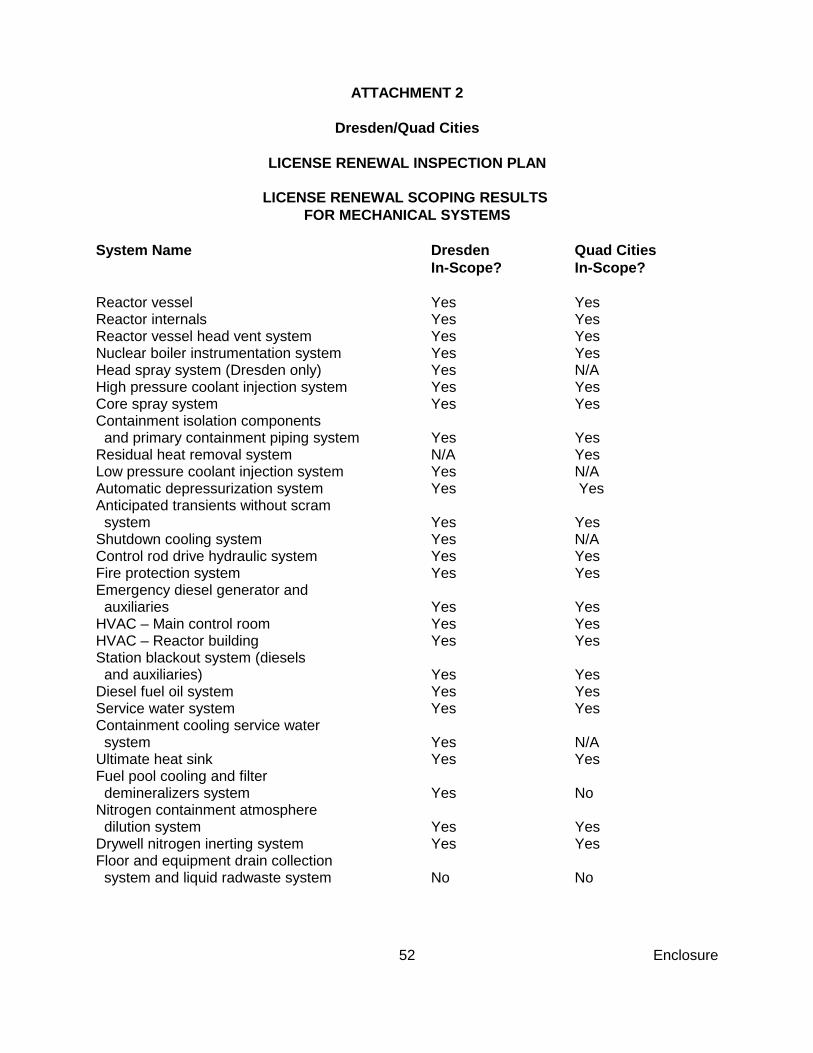
Enclosure52
ATTACHMENT 2
Dresden/Quad Cities
LICENSE RENEWAL INSPECTION PLAN
LICENSE RENEWAL SCOPING RESULTS FOR MECHANICAL SYSTEMS
System Name Dresden Quad CitiesIn-Scope? In-Scope?
Reactor vessel Yes YesReactor internals Yes YesReactor vessel head vent system Yes YesNuclear boiler instrumentation system Yes YesHead spray system (Dresden only) Yes N/AHigh pressure coolant injection system Yes YesCore spray system Yes YesContainment isolation components and primary containment piping system Yes YesResidual heat removal system N/A YesLow pressure coolant injection system Yes N/AAutomatic depressurization system Yes YesAnticipated transients without scram system Yes YesShutdown cooling system Yes N/AControl rod drive hydraulic system Yes YesFire protection system Yes YesEmergency diesel generator and auxiliaries Yes YesHVAC – Main control room Yes YesHVAC – Reactor building Yes YesStation blackout system (diesels and auxiliaries) Yes YesDiesel fuel oil system Yes YesService water system Yes YesContainment cooling service water system Yes N/AUltimate heat sink Yes YesFuel pool cooling and filter demineralizers system Yes NoNitrogen containment atmosphere dilution system Yes Yes Drywell nitrogen inerting system Yes YesFloor and equipment drain collection system and liquid radwaste system No No

Enclosure53
System Name Dresden Quad CitiesIn-Scope? In-Scope?
Reactor building floor and equipment drain system No NoOxygen injection – hydrogen addition system No NoHypochlorite (Chemical addition) No NoInstrument air and drywell pneumatic supply system No NoHVAC – Primary containment No NoDresden Unit 1 gaseous monitoring No N/ASecurity diesel, distribution and auxiliaries No NoCondensate and condensate storage system Yes YesExtraction steam system No No

Enclosure54
Dresden/Quad Cites
LICENSE RENEWAL INSPECTION PLAN
LICENSE RENEWAL SCOPING RESULTS FOR STRUCTURES
Structure Name Dresden Quad CitiesIn-Scope? In-Scope?
Primary containment Yes YesReactor building (secondary containment) Yes YesTurbine buildings Yes YesDresden Unit 2/3 Diesel generator and HPCI building Yes N/AQuad Cities diesel generator room N/A YesStation blackout building Yes YesRadwaste floor drain surge tank and foundation Yes YesDiesel oil storage tanks foundation Yes YesContaminated condensate storage tanks foundation Yes YesCrib house Yes YesDresden Unit 1 crib house Yes N/AStation chimney Yes YesMiscellaneous radwaste buildings No NoMiscellaneous Dresden Unit 1 structures No N/AMiscellaneous transmission and distribution structures No No

Enclosure55
Dresden/Quad Cities
LICENSE RENEWAL INSPECTION PLAN
LICENSE RENEWAL SCOPING RESULTS FOR ELECTRICAL/I&C SYSTEMS
System Name Dresden Quad CitiesIn-Scope? In-Scope?
Reactor protection system Yes YesReactor manual control system Yes Yes4160 V switchgear and distribution Yes Yes480 V motor control centers, transformer switchgear and distribution Yes Yesdc emergency lighting Yes YesEssential service bus Yes Yes120/240 VAC instrument bus Yes Yes250 Vdc system Yes Yes125 Vdc system Yes YesTransformers (Main, Unit, Reserve and Standby) Yes Yes24/48 Vdc system No No12 & 34 kV distribution No N/A13.8 kV distribution N/A No120 Vac distribution, lighting and receptacles No No
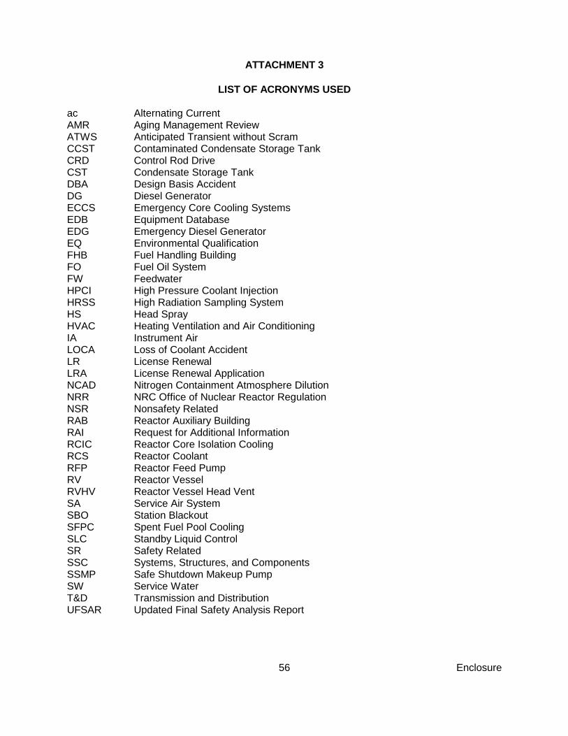
Enclosure56
ATTACHMENT 3
LIST OF ACRONYMS USED
ac Alternating CurrentAMR Aging Management ReviewATWS Anticipated Transient without ScramCCST Contaminated Condensate Storage TankCRD Control Rod DriveCST Condensate Storage TankDBA Design Basis AccidentDG Diesel GeneratorECCS Emergency Core Cooling SystemsEDB Equipment DatabaseEDG Emergency Diesel GeneratorEQ Environmental QualificationFHB Fuel Handling BuildingFO Fuel Oil SystemFW FeedwaterHPCI High Pressure Coolant InjectionHRSS High Radiation Sampling SystemHS Head SprayHVAC Heating Ventilation and Air ConditioningIA Instrument AirLOCA Loss of Coolant AccidentLR License RenewalLRA License Renewal ApplicationNCAD Nitrogen Containment Atmosphere Dilution NRR NRC Office of Nuclear Reactor RegulationNSR Nonsafety RelatedRAB Reactor Auxiliary BuildingRAI Request for Additional InformationRCIC Reactor Core Isolation CoolingRCS Reactor CoolantRFP Reactor Feed PumpRV Reactor VesselRVHV Reactor Vessel Head VentSA Service Air SystemSBO Station BlackoutSFPC Spent Fuel Pool CoolingSLC Standby Liquid ControlSR Safety RelatedSSC Systems, Structures, and ComponentsSSMP Safe Shutdown Makeup PumpSW Service WaterT&D Transmission and DistributionUFSAR Updated Final Safety Analysis Report
Related Documents