MR-JET User's Manual (Function) -MR-JET-_G -MR-JET-_G-N1 Mitsubishi Electric AC Servo System

Welcome message from author
This document is posted to help you gain knowledge. Please leave a comment to let me know what you think about it! Share it to your friends and learn new things together.
Transcript
MR-JETUser's Manual(Function)
-MR-JET-_G-MR-JET-_G-N1
Mitsubishi Electric AC Servo System

SAFETY INSTRUCTIONSPlease read the instructions carefully before using the equipment.To use the equipment correctly, do not attempt to install, operate, maintain, or inspect the equipment until you have read through this manual, installation guide, and appended documents carefully. Do not use the equipment until you have a full knowledge of the equipment, safety information and instructions.In this manual, the safety instruction levels are classified into "WARNING" and "CAUTION".
Note that the CAUTION level may lead to a serious consequence depending on conditions.Please follow the instructions of both levels because they are important to personnel safety.Forbidden actions and required actions are indicated by the following diagrammatic symbols.
In this manual, precautions for hazards that can lead to property damage, instructions for other functions, and other information are shown separately in the "POINT" area.After reading this manual, keep it accessible to the operator.
WARNING Indicates that incorrect handling may cause hazardous conditions, resulting in death or severe injury.
CAUTION Indicates that incorrect handling may cause hazardous conditions, resulting in medium or slight injury.
Indicates a forbidden action. For example, "No Fire" is indicated by .
Indicates a required action. For example, grounding is indicated by .
1
2
[Installation/wiring]
[Setting/adjustment]
[Operation]
[Maintenance]
WARNING● To prevent an electric shock, turn off the power and wait for 15 minutes or more before starting wiring
and/or inspection.● To prevent an electric shock, ground the servo amplifier.● To prevent an electric shock, any person who is involved in wiring should be fully competent to do the
work.● To prevent an electric shock, mount the servo amplifier before wiring.● To prevent an electric shock, connect the protective earth (PE) terminal of the servo amplifier to the
protective earth (PE) of the cabinet, then connect the grounding lead wire to the ground.● To prevent an electric shock, do not touch the conductive parts.
WARNING● To prevent an electric shock, do not operate the switches with wet hands.
WARNING● To prevent an electric shock, do not operate the switches with wet hands.
WARNING● To prevent an electric shock, any person who is involved in inspection should be fully competent to do
the work.● To prevent an electric shock, do not operate the switches with wet hands.
ABOUT THE MANUAL
e-Manuals are Mitsubishi Electric FA electronic book manuals that can be browsed with a dedicated tool.e-Manuals enable the following: • Searching for desired information in multiple manuals at the same time (manual cross searching) • Jumping from a link in a manual to another manual for reference • Browsing for hardware specifications by scrolling over the components shown in product illustrations • Bookmarking frequently referenced information • Copying sample programs to engineering tools
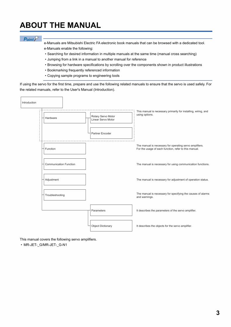
If using the servo for the first time, prepare and use the following related manuals to ensure that the servo is used safely. For the related manuals, refer to the User's Manual (Introduction).
This manual covers the following servo amplifiers. • MR-JET-_G/MR-JET-_G-N1
Rotary Servo MotorLinear Servo Motor
This manual is necessary primarily for installing, wiring, andusing options.
The manual is necessary for adjustment of operation status.
The manual is necessary for using communication functions.
The manual is necessary for specifying the causes of alarmsand warnings.
Partner Encoder
Function
Adjustment
Object Dictionary
Troubleshooting
Introduction
Hardware
Communication Function
Parameters It describes the parameters of the servo amplifier.
It describes the objects for the servo amplifier.
The manual is necessary for operating servo amplifiers.For the usage of each function, refer to this manual.
3
4
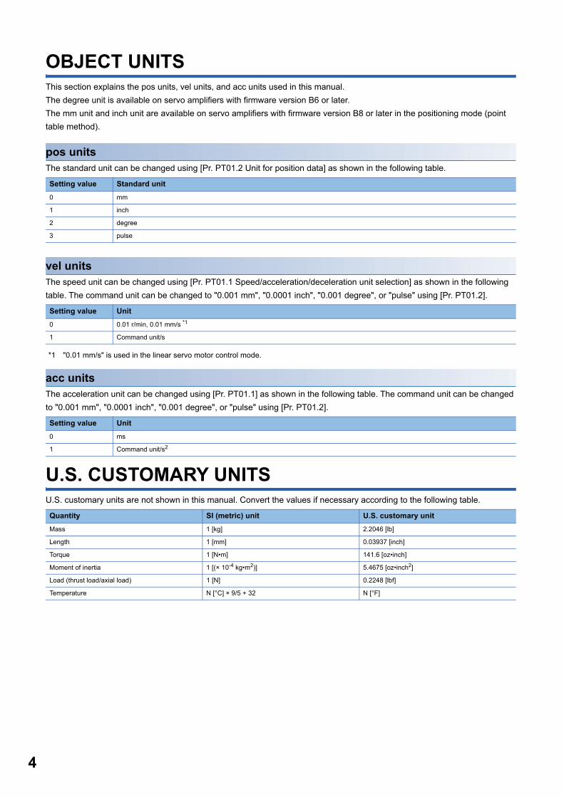
OBJECT UNITSThis section explains the pos units, vel units, and acc units used in this manual.The degree unit is available on servo amplifiers with firmware version B6 or later.The mm unit and inch unit are available on servo amplifiers with firmware version B8 or later in the positioning mode (point table method).
pos unitsThe standard unit can be changed using [Pr. PT01.2 Unit for position data] as shown in the following table.
vel unitsThe speed unit can be changed using [Pr. PT01.1 Speed/acceleration/deceleration unit selection] as shown in the following table. The command unit can be changed to "0.001 mm", "0.0001 inch", "0.001 degree", or "pulse" using [Pr. PT01.2].
*1 "0.01 mm/s" is used in the linear servo motor control mode.
acc unitsThe acceleration unit can be changed using [Pr. PT01.1] as shown in the following table. The command unit can be changed to "0.001 mm", "0.0001 inch", "0.001 degree", or "pulse" using [Pr. PT01.2].
U.S. CUSTOMARY UNITSU.S. customary units are not shown in this manual. Convert the values if necessary according to the following table.
Setting value Standard unit0 mm
1 inch
2 degree
3 pulse
Setting value Unit0 0.01 r/min, 0.01 mm/s *1
1 Command unit/s
Setting value Unit0 ms
1 Command unit/s2
Quantity SI (metric) unit U.S. customary unitMass 1 [kg] 2.2046 [lb]
Length 1 [mm] 0.03937 [inch]
Torque 1 [N•m] 141.6 [oz•inch]
Moment of inertia 1 [(× 10-4 kg•m2)] 5.4675 [oz•inch2]
Load (thrust load/axial load) 1 [N] 0.2248 [lbf]
Temperature N [°C] × 9/5 + 32 N [°F]
CO
NTE
NTS
CONTENTSSAFETY INSTRUCTIONS. . . . . . . . . . . . . . . . . . . . . . . . . . . . . . . . . . . . . . . . . . . . . . . . . . . . . . . . . . . . . . . . . . . .1ABOUT THE MANUAL . . . . . . . . . . . . . . . . . . . . . . . . . . . . . . . . . . . . . . . . . . . . . . . . . . . . . . . . . . . . . . . . . . . . . .3OBJECT UNITS. . . . . . . . . . . . . . . . . . . . . . . . . . . . . . . . . . . . . . . . . . . . . . . . . . . . . . . . . . . . . . . . . . . . . . . . . . . .4U.S. CUSTOMARY UNITS . . . . . . . . . . . . . . . . . . . . . . . . . . . . . . . . . . . . . . . . . . . . . . . . . . . . . . . . . . . . . . . . . . .4
CHAPTER 1 FUNCTION 91.1 Function explanation . . . . . . . . . . . . . . . . . . . . . . . . . . . . . . . . . . . . . . . . . . . . . . . . . . . . . . . . . . . . . . . . . . . . . 9
CHAPTER 2 CONTROL MODE 132.1 Control mode . . . . . . . . . . . . . . . . . . . . . . . . . . . . . . . . . . . . . . . . . . . . . . . . . . . . . . . . . . . . . . . . . . . . . . . . . . . 13
Control switching . . . . . . . . . . . . . . . . . . . . . . . . . . . . . . . . . . . . . . . . . . . . . . . . . . . . . . . . . . . . . . . . . . . . . . . . . 14Cyclic synchronous position mode (csp) . . . . . . . . . . . . . . . . . . . . . . . . . . . . . . . . . . . . . . . . . . . . . . . . . . . . . . . 15Cyclic synchronous velocity mode (csv) . . . . . . . . . . . . . . . . . . . . . . . . . . . . . . . . . . . . . . . . . . . . . . . . . . . . . . . 17Cyclic synchronous torque mode (cst) . . . . . . . . . . . . . . . . . . . . . . . . . . . . . . . . . . . . . . . . . . . . . . . . . . . . . . . . 19Profile position mode (pp) . . . . . . . . . . . . . . . . . . . . . . . . . . . . . . . . . . . . . . . . . . . . . . . . . . . . . . . . . . . . . . . . . . 21Profile velocity mode (pv) . . . . . . . . . . . . . . . . . . . . . . . . . . . . . . . . . . . . . . . . . . . . . . . . . . . . . . . . . . . . . . . . . . 25Profile torque mode (tq). . . . . . . . . . . . . . . . . . . . . . . . . . . . . . . . . . . . . . . . . . . . . . . . . . . . . . . . . . . . . . . . . . . . 29Point table mode (pt) . . . . . . . . . . . . . . . . . . . . . . . . . . . . . . . . . . . . . . . . . . . . . . . . . . . . . . . . . . . . . . . . . . . . . . 32JOG operation mode (jg) . . . . . . . . . . . . . . . . . . . . . . . . . . . . . . . . . . . . . . . . . . . . . . . . . . . . . . . . . . . . . . . . . . . 35Continuous operation to torque control mode (ct) . . . . . . . . . . . . . . . . . . . . . . . . . . . . . . . . . . . . . . . . . . . . . . . . 38Homing mode (hm) . . . . . . . . . . . . . . . . . . . . . . . . . . . . . . . . . . . . . . . . . . . . . . . . . . . . . . . . . . . . . . . . . . . . . . . 43
CHAPTER 3 BASIC FUNCTION 743.1 Outline of servo parameter and object dictionary . . . . . . . . . . . . . . . . . . . . . . . . . . . . . . . . . . . . . . . . . . . . . 74
Servo parameter . . . . . . . . . . . . . . . . . . . . . . . . . . . . . . . . . . . . . . . . . . . . . . . . . . . . . . . . . . . . . . . . . . . . . . . . . 74Object dictionary . . . . . . . . . . . . . . . . . . . . . . . . . . . . . . . . . . . . . . . . . . . . . . . . . . . . . . . . . . . . . . . . . . . . . . . . . 76
3.2 Rotation/travel direction selection. . . . . . . . . . . . . . . . . . . . . . . . . . . . . . . . . . . . . . . . . . . . . . . . . . . . . . . . . . 77Setting methods of functions . . . . . . . . . . . . . . . . . . . . . . . . . . . . . . . . . . . . . . . . . . . . . . . . . . . . . . . . . . . . . . . . 78
3.3 Stroke limit function . . . . . . . . . . . . . . . . . . . . . . . . . . . . . . . . . . . . . . . . . . . . . . . . . . . . . . . . . . . . . . . . . . . . . 81Explanation of the stroke limit signal names . . . . . . . . . . . . . . . . . . . . . . . . . . . . . . . . . . . . . . . . . . . . . . . . . . . . 81Setting methods of functions . . . . . . . . . . . . . . . . . . . . . . . . . . . . . . . . . . . . . . . . . . . . . . . . . . . . . . . . . . . . . . . . 82Stop method at stroke limit detection . . . . . . . . . . . . . . . . . . . . . . . . . . . . . . . . . . . . . . . . . . . . . . . . . . . . . . . . . 85Servo parameter list . . . . . . . . . . . . . . . . . . . . . . . . . . . . . . . . . . . . . . . . . . . . . . . . . . . . . . . . . . . . . . . . . . . . . . 86
3.4 Limit switch release position assessment function. . . . . . . . . . . . . . . . . . . . . . . . . . . . . . . . . . . . . . . . . . . . 87Outline . . . . . . . . . . . . . . . . . . . . . . . . . . . . . . . . . . . . . . . . . . . . . . . . . . . . . . . . . . . . . . . . . . . . . . . . . . . . . . . . . 87Precautions . . . . . . . . . . . . . . . . . . . . . . . . . . . . . . . . . . . . . . . . . . . . . . . . . . . . . . . . . . . . . . . . . . . . . . . . . . . . . 87Setting methods of functions . . . . . . . . . . . . . . . . . . . . . . . . . . . . . . . . . . . . . . . . . . . . . . . . . . . . . . . . . . . . . . . . 87
3.5 Command unit selection function . . . . . . . . . . . . . . . . . . . . . . . . . . . . . . . . . . . . . . . . . . . . . . . . . . . . . . . . . . 88Position command unit selection function . . . . . . . . . . . . . . . . . . . . . . . . . . . . . . . . . . . . . . . . . . . . . . . . . . . . . . 88Speed command unit selection function . . . . . . . . . . . . . . . . . . . . . . . . . . . . . . . . . . . . . . . . . . . . . . . . . . . . . . . 91
3.6 Electronic gear function . . . . . . . . . . . . . . . . . . . . . . . . . . . . . . . . . . . . . . . . . . . . . . . . . . . . . . . . . . . . . . . . . . 92Setting method . . . . . . . . . . . . . . . . . . . . . . . . . . . . . . . . . . . . . . . . . . . . . . . . . . . . . . . . . . . . . . . . . . . . . . . . . . 92Setting example. . . . . . . . . . . . . . . . . . . . . . . . . . . . . . . . . . . . . . . . . . . . . . . . . . . . . . . . . . . . . . . . . . . . . . . . . . 93
3.7 In-position range setting. . . . . . . . . . . . . . . . . . . . . . . . . . . . . . . . . . . . . . . . . . . . . . . . . . . . . . . . . . . . . . . . . 100Setting method . . . . . . . . . . . . . . . . . . . . . . . . . . . . . . . . . . . . . . . . . . . . . . . . . . . . . . . . . . . . . . . . . . . . . . . . . 100
3.8 Assigning I/O devices . . . . . . . . . . . . . . . . . . . . . . . . . . . . . . . . . . . . . . . . . . . . . . . . . . . . . . . . . . . . . . . . . . . 101Setting method . . . . . . . . . . . . . . . . . . . . . . . . . . . . . . . . . . . . . . . . . . . . . . . . . . . . . . . . . . . . . . . . . . . . . . . . . 101
3.9 Regenerative option selection . . . . . . . . . . . . . . . . . . . . . . . . . . . . . . . . . . . . . . . . . . . . . . . . . . . . . . . . . . . . 102
5
6
Regenerative option . . . . . . . . . . . . . . . . . . . . . . . . . . . . . . . . . . . . . . . . . . . . . . . . . . . . . . . . . . . . . . . . . . . . . 1023.10 Alarm function . . . . . . . . . . . . . . . . . . . . . . . . . . . . . . . . . . . . . . . . . . . . . . . . . . . . . . . . . . . . . . . . . . . . . . . . . 103
Operation status at alarm occurrence . . . . . . . . . . . . . . . . . . . . . . . . . . . . . . . . . . . . . . . . . . . . . . . . . . . . . . . . 103Operation status at warning occurrence . . . . . . . . . . . . . . . . . . . . . . . . . . . . . . . . . . . . . . . . . . . . . . . . . . . . . . 103Returning from an alarm . . . . . . . . . . . . . . . . . . . . . . . . . . . . . . . . . . . . . . . . . . . . . . . . . . . . . . . . . . . . . . . . . . 104Returning from a warning . . . . . . . . . . . . . . . . . . . . . . . . . . . . . . . . . . . . . . . . . . . . . . . . . . . . . . . . . . . . . . . . . 104Alarm history . . . . . . . . . . . . . . . . . . . . . . . . . . . . . . . . . . . . . . . . . . . . . . . . . . . . . . . . . . . . . . . . . . . . . . . . . . . 105Stop method at occurrence of alarms/warnings . . . . . . . . . . . . . . . . . . . . . . . . . . . . . . . . . . . . . . . . . . . . . . . . 106Timing chart for alarm occurrence. . . . . . . . . . . . . . . . . . . . . . . . . . . . . . . . . . . . . . . . . . . . . . . . . . . . . . . . . . . 107
3.11 Forced stop deceleration function. . . . . . . . . . . . . . . . . . . . . . . . . . . . . . . . . . . . . . . . . . . . . . . . . . . . . . . . . 109Setting method . . . . . . . . . . . . . . . . . . . . . . . . . . . . . . . . . . . . . . . . . . . . . . . . . . . . . . . . . . . . . . . . . . . . . . . . . 109Timing chart . . . . . . . . . . . . . . . . . . . . . . . . . . . . . . . . . . . . . . . . . . . . . . . . . . . . . . . . . . . . . . . . . . . . . . . . . . . . 110
3.12 Electromagnetic brake interlock function. . . . . . . . . . . . . . . . . . . . . . . . . . . . . . . . . . . . . . . . . . . . . . . . . . . 111Base circuit shut-off delay time function . . . . . . . . . . . . . . . . . . . . . . . . . . . . . . . . . . . . . . . . . . . . . . . . . . . . . . 111Setting method . . . . . . . . . . . . . . . . . . . . . . . . . . . . . . . . . . . . . . . . . . . . . . . . . . . . . . . . . . . . . . . . . . . . . . . . . 111Timing chart . . . . . . . . . . . . . . . . . . . . . . . . . . . . . . . . . . . . . . . . . . . . . . . . . . . . . . . . . . . . . . . . . . . . . . . . . . . . 112
3.13 Vertical axis freefall prevention function . . . . . . . . . . . . . . . . . . . . . . . . . . . . . . . . . . . . . . . . . . . . . . . . . . . 117Setting method . . . . . . . . . . . . . . . . . . . . . . . . . . . . . . . . . . . . . . . . . . . . . . . . . . . . . . . . . . . . . . . . . . . . . . . . . 117Timing chart . . . . . . . . . . . . . . . . . . . . . . . . . . . . . . . . . . . . . . . . . . . . . . . . . . . . . . . . . . . . . . . . . . . . . . . . . . . . 117
3.14 Acceleration/deceleration function . . . . . . . . . . . . . . . . . . . . . . . . . . . . . . . . . . . . . . . . . . . . . . . . . . . . . . . . 118Acceleration/deceleration time constant . . . . . . . . . . . . . . . . . . . . . . . . . . . . . . . . . . . . . . . . . . . . . . . . . . . . . . 118S-pattern acceleration/deceleration time constant . . . . . . . . . . . . . . . . . . . . . . . . . . . . . . . . . . . . . . . . . . . . . . 119Acceleration/deceleration . . . . . . . . . . . . . . . . . . . . . . . . . . . . . . . . . . . . . . . . . . . . . . . . . . . . . . . . . . . . . . . . . 120
3.15 Quick stop . . . . . . . . . . . . . . . . . . . . . . . . . . . . . . . . . . . . . . . . . . . . . . . . . . . . . . . . . . . . . . . . . . . . . . . . . . . . 121Objects for setting . . . . . . . . . . . . . . . . . . . . . . . . . . . . . . . . . . . . . . . . . . . . . . . . . . . . . . . . . . . . . . . . . . . . . . . 121Timing chart . . . . . . . . . . . . . . . . . . . . . . . . . . . . . . . . . . . . . . . . . . . . . . . . . . . . . . . . . . . . . . . . . . . . . . . . . . . . 122
3.16 Halt . . . . . . . . . . . . . . . . . . . . . . . . . . . . . . . . . . . . . . . . . . . . . . . . . . . . . . . . . . . . . . . . . . . . . . . . . . . . . . . . . . 123Objects for setting . . . . . . . . . . . . . . . . . . . . . . . . . . . . . . . . . . . . . . . . . . . . . . . . . . . . . . . . . . . . . . . . . . . . . . . 123Timing chart . . . . . . . . . . . . . . . . . . . . . . . . . . . . . . . . . . . . . . . . . . . . . . . . . . . . . . . . . . . . . . . . . . . . . . . . . . . . 124
CHAPTER 4 APPLICABLE FUNCTIONS 1254.1 Tough drive function . . . . . . . . . . . . . . . . . . . . . . . . . . . . . . . . . . . . . . . . . . . . . . . . . . . . . . . . . . . . . . . . . . . . 126
Vibration tough drive . . . . . . . . . . . . . . . . . . . . . . . . . . . . . . . . . . . . . . . . . . . . . . . . . . . . . . . . . . . . . . . . . . . . . 126Instantaneous power failure tough drive . . . . . . . . . . . . . . . . . . . . . . . . . . . . . . . . . . . . . . . . . . . . . . . . . . . . . . 126
4.2 Machine diagnosis . . . . . . . . . . . . . . . . . . . . . . . . . . . . . . . . . . . . . . . . . . . . . . . . . . . . . . . . . . . . . . . . . . . . . 130Friction vibration estimation function . . . . . . . . . . . . . . . . . . . . . . . . . . . . . . . . . . . . . . . . . . . . . . . . . . . . . . . . . 130
4.3 Drive recorder . . . . . . . . . . . . . . . . . . . . . . . . . . . . . . . . . . . . . . . . . . . . . . . . . . . . . . . . . . . . . . . . . . . . . . . . . 135Specification outline. . . . . . . . . . . . . . . . . . . . . . . . . . . . . . . . . . . . . . . . . . . . . . . . . . . . . . . . . . . . . . . . . . . . . . 137How to use the function . . . . . . . . . . . . . . . . . . . . . . . . . . . . . . . . . . . . . . . . . . . . . . . . . . . . . . . . . . . . . . . . . . . 137Servo parameter/object dictionary. . . . . . . . . . . . . . . . . . . . . . . . . . . . . . . . . . . . . . . . . . . . . . . . . . . . . . . . . . . 140Standard acquisition waveform list . . . . . . . . . . . . . . . . . . . . . . . . . . . . . . . . . . . . . . . . . . . . . . . . . . . . . . . . . . 146Waveform recording inapplicable alarm list . . . . . . . . . . . . . . . . . . . . . . . . . . . . . . . . . . . . . . . . . . . . . . . . . . . . 147List of auxiliary recording data. . . . . . . . . . . . . . . . . . . . . . . . . . . . . . . . . . . . . . . . . . . . . . . . . . . . . . . . . . . . . . 148
4.4 Software reset . . . . . . . . . . . . . . . . . . . . . . . . . . . . . . . . . . . . . . . . . . . . . . . . . . . . . . . . . . . . . . . . . . . . . . . . . 149Software reset in MR Configurator2 . . . . . . . . . . . . . . . . . . . . . . . . . . . . . . . . . . . . . . . . . . . . . . . . . . . . . . . . . 149Software reset via network communication . . . . . . . . . . . . . . . . . . . . . . . . . . . . . . . . . . . . . . . . . . . . . . . . . . . . 149
4.5 Software position limit . . . . . . . . . . . . . . . . . . . . . . . . . . . . . . . . . . . . . . . . . . . . . . . . . . . . . . . . . . . . . . . . . . 150Setting method . . . . . . . . . . . . . . . . . . . . . . . . . . . . . . . . . . . . . . . . . . . . . . . . . . . . . . . . . . . . . . . . . . . . . . . . . 150
4.6 Torque limit . . . . . . . . . . . . . . . . . . . . . . . . . . . . . . . . . . . . . . . . . . . . . . . . . . . . . . . . . . . . . . . . . . . . . . . . . . . 153Setting method . . . . . . . . . . . . . . . . . . . . . . . . . . . . . . . . . . . . . . . . . . . . . . . . . . . . . . . . . . . . . . . . . . . . . . . . . 154
CO
NTE
NTS
Checking "Limiting torque" status . . . . . . . . . . . . . . . . . . . . . . . . . . . . . . . . . . . . . . . . . . . . . . . . . . . . . . . . . . . 1544.7 Speed limit . . . . . . . . . . . . . . . . . . . . . . . . . . . . . . . . . . . . . . . . . . . . . . . . . . . . . . . . . . . . . . . . . . . . . . . . . . . . 155
Setting method . . . . . . . . . . . . . . . . . . . . . . . . . . . . . . . . . . . . . . . . . . . . . . . . . . . . . . . . . . . . . . . . . . . . . . . . . 155Checking "Limiting speed" status . . . . . . . . . . . . . . . . . . . . . . . . . . . . . . . . . . . . . . . . . . . . . . . . . . . . . . . . . . . 155
4.8 Degree unit. . . . . . . . . . . . . . . . . . . . . . . . . . . . . . . . . . . . . . . . . . . . . . . . . . . . . . . . . . . . . . . . . . . . . . . . . . . . 156Summary . . . . . . . . . . . . . . . . . . . . . . . . . . . . . . . . . . . . . . . . . . . . . . . . . . . . . . . . . . . . . . . . . . . . . . . . . . . . . . 156Position-related data when the unit is set to "degree" . . . . . . . . . . . . . . . . . . . . . . . . . . . . . . . . . . . . . . . . . . . . 156Setting method . . . . . . . . . . . . . . . . . . . . . . . . . . . . . . . . . . . . . . . . . . . . . . . . . . . . . . . . . . . . . . . . . . . . . . . . . 157Sequence . . . . . . . . . . . . . . . . . . . . . . . . . . . . . . . . . . . . . . . . . . . . . . . . . . . . . . . . . . . . . . . . . . . . . . . . . . . . . 158
4.9 Infinite feed function . . . . . . . . . . . . . . . . . . . . . . . . . . . . . . . . . . . . . . . . . . . . . . . . . . . . . . . . . . . . . . . . . . . . 162Outline . . . . . . . . . . . . . . . . . . . . . . . . . . . . . . . . . . . . . . . . . . . . . . . . . . . . . . . . . . . . . . . . . . . . . . . . . . . . . . . . 162Setting method . . . . . . . . . . . . . . . . . . . . . . . . . . . . . . . . . . . . . . . . . . . . . . . . . . . . . . . . . . . . . . . . . . . . . . . . . 162When the servo motor rotates 32768 rev or more. . . . . . . . . . . . . . . . . . . . . . . . . . . . . . . . . . . . . . . . . . . . . . . 162When using the infinite feed function with a controller . . . . . . . . . . . . . . . . . . . . . . . . . . . . . . . . . . . . . . . . . . . 162
4.10 Servo amplifier life diagnosis function . . . . . . . . . . . . . . . . . . . . . . . . . . . . . . . . . . . . . . . . . . . . . . . . . . . . . 163Cumulative energization time function. . . . . . . . . . . . . . . . . . . . . . . . . . . . . . . . . . . . . . . . . . . . . . . . . . . . . . . . 163Relay usage count display function . . . . . . . . . . . . . . . . . . . . . . . . . . . . . . . . . . . . . . . . . . . . . . . . . . . . . . . . . . 164
4.11 Encoder communication diagnosis function . . . . . . . . . . . . . . . . . . . . . . . . . . . . . . . . . . . . . . . . . . . . . . . . 165Usage . . . . . . . . . . . . . . . . . . . . . . . . . . . . . . . . . . . . . . . . . . . . . . . . . . . . . . . . . . . . . . . . . . . . . . . . . . . . . . . . 165
4.12 Disconnection/incorrect wiring detection function . . . . . . . . . . . . . . . . . . . . . . . . . . . . . . . . . . . . . . . . . . . 166Output open-phase detection function. . . . . . . . . . . . . . . . . . . . . . . . . . . . . . . . . . . . . . . . . . . . . . . . . . . . . . . . 166
4.13 Overload protection (electronic thermal) function. . . . . . . . . . . . . . . . . . . . . . . . . . . . . . . . . . . . . . . . . . . . 1674.14 Command offset . . . . . . . . . . . . . . . . . . . . . . . . . . . . . . . . . . . . . . . . . . . . . . . . . . . . . . . . . . . . . . . . . . . . . . . 168
CHAPTER 5 MONITORING 1705.1 Explanation of monitor signals . . . . . . . . . . . . . . . . . . . . . . . . . . . . . . . . . . . . . . . . . . . . . . . . . . . . . . . . . . . 170
Name and description of the monitor signals . . . . . . . . . . . . . . . . . . . . . . . . . . . . . . . . . . . . . . . . . . . . . . . . . . 170Signal block diagram . . . . . . . . . . . . . . . . . . . . . . . . . . . . . . . . . . . . . . . . . . . . . . . . . . . . . . . . . . . . . . . . . . . . . 174
5.2 Checking with MR Configurator2. . . . . . . . . . . . . . . . . . . . . . . . . . . . . . . . . . . . . . . . . . . . . . . . . . . . . . . . . . 175"Display All" function . . . . . . . . . . . . . . . . . . . . . . . . . . . . . . . . . . . . . . . . . . . . . . . . . . . . . . . . . . . . . . . . . . . . . 175Graph function . . . . . . . . . . . . . . . . . . . . . . . . . . . . . . . . . . . . . . . . . . . . . . . . . . . . . . . . . . . . . . . . . . . . . . . . . . 175I/O monitor display. . . . . . . . . . . . . . . . . . . . . . . . . . . . . . . . . . . . . . . . . . . . . . . . . . . . . . . . . . . . . . . . . . . . . . . 176System configuration display. . . . . . . . . . . . . . . . . . . . . . . . . . . . . . . . . . . . . . . . . . . . . . . . . . . . . . . . . . . . . . . 177
CHAPTER 6 NETWORK FUNCTION 1786.1 IP address setting . . . . . . . . . . . . . . . . . . . . . . . . . . . . . . . . . . . . . . . . . . . . . . . . . . . . . . . . . . . . . . . . . . . . . . 179
Setting an IP address . . . . . . . . . . . . . . . . . . . . . . . . . . . . . . . . . . . . . . . . . . . . . . . . . . . . . . . . . . . . . . . . . . . . 1796.2 Managing accounts . . . . . . . . . . . . . . . . . . . . . . . . . . . . . . . . . . . . . . . . . . . . . . . . . . . . . . . . . . . . . . . . . . . . . 179
Setting an account. . . . . . . . . . . . . . . . . . . . . . . . . . . . . . . . . . . . . . . . . . . . . . . . . . . . . . . . . . . . . . . . . . . . . . . 180Precautions . . . . . . . . . . . . . . . . . . . . . . . . . . . . . . . . . . . . . . . . . . . . . . . . . . . . . . . . . . . . . . . . . . . . . . . . . . . . 180
6.3 FTP server function. . . . . . . . . . . . . . . . . . . . . . . . . . . . . . . . . . . . . . . . . . . . . . . . . . . . . . . . . . . . . . . . . . . . . 181Restrictions . . . . . . . . . . . . . . . . . . . . . . . . . . . . . . . . . . . . . . . . . . . . . . . . . . . . . . . . . . . . . . . . . . . . . . . . . . . . 181Precautions . . . . . . . . . . . . . . . . . . . . . . . . . . . . . . . . . . . . . . . . . . . . . . . . . . . . . . . . . . . . . . . . . . . . . . . . . . . . 181Directory structure . . . . . . . . . . . . . . . . . . . . . . . . . . . . . . . . . . . . . . . . . . . . . . . . . . . . . . . . . . . . . . . . . . . . . . . 182Steps of accessing the FTP server . . . . . . . . . . . . . . . . . . . . . . . . . . . . . . . . . . . . . . . . . . . . . . . . . . . . . . . . . . 182
6.4 Firmware update . . . . . . . . . . . . . . . . . . . . . . . . . . . . . . . . . . . . . . . . . . . . . . . . . . . . . . . . . . . . . . . . . . . . . . . 182
CHAPTER 7 POSITIONING MODE (POINT TABLE METHOD) (CP) 1837.1 Operation mode and selection method . . . . . . . . . . . . . . . . . . . . . . . . . . . . . . . . . . . . . . . . . . . . . . . . . . . . . 183
Operation mode. . . . . . . . . . . . . . . . . . . . . . . . . . . . . . . . . . . . . . . . . . . . . . . . . . . . . . . . . . . . . . . . . . . . . . . . . 183
7
8
Operation mode selection method. . . . . . . . . . . . . . . . . . . . . . . . . . . . . . . . . . . . . . . . . . . . . . . . . . . . . . . . . . . 1837.2 Point table mode (pt). . . . . . . . . . . . . . . . . . . . . . . . . . . . . . . . . . . . . . . . . . . . . . . . . . . . . . . . . . . . . . . . . . . . 184
Point table mode (pt) . . . . . . . . . . . . . . . . . . . . . . . . . . . . . . . . . . . . . . . . . . . . . . . . . . . . . . . . . . . . . . . . . . . . . 184Point table operation (absolute value command method) . . . . . . . . . . . . . . . . . . . . . . . . . . . . . . . . . . . . . . . . . 185Timing chart of the point table operation . . . . . . . . . . . . . . . . . . . . . . . . . . . . . . . . . . . . . . . . . . . . . . . . . . . . . . 189Positioning function to the home position . . . . . . . . . . . . . . . . . . . . . . . . . . . . . . . . . . . . . . . . . . . . . . . . . . . . . 206
7.3 JOG operation mode (jg) . . . . . . . . . . . . . . . . . . . . . . . . . . . . . . . . . . . . . . . . . . . . . . . . . . . . . . . . . . . . . . . . 207JOG operation . . . . . . . . . . . . . . . . . . . . . . . . . . . . . . . . . . . . . . . . . . . . . . . . . . . . . . . . . . . . . . . . . . . . . . . . . . 207
7.4 How to Set Point Table . . . . . . . . . . . . . . . . . . . . . . . . . . . . . . . . . . . . . . . . . . . . . . . . . . . . . . . . . . . . . . . . . . 211Setting method using MR Configurator2 . . . . . . . . . . . . . . . . . . . . . . . . . . . . . . . . . . . . . . . . . . . . . . . . . . . . . . 211Setting method using objects . . . . . . . . . . . . . . . . . . . . . . . . . . . . . . . . . . . . . . . . . . . . . . . . . . . . . . . . . . . . . . 213
REVISIONS. . . . . . . . . . . . . . . . . . . . . . . . . . . . . . . . . . . . . . . . . . . . . . . . . . . . . . . . . . . . . . . . . . . . . . . . . . . . .214WARRANTY . . . . . . . . . . . . . . . . . . . . . . . . . . . . . . . . . . . . . . . . . . . . . . . . . . . . . . . . . . . . . . . . . . . . . . . . . . . .215TRADEMARKS . . . . . . . . . . . . . . . . . . . . . . . . . . . . . . . . . . . . . . . . . . . . . . . . . . . . . . . . . . . . . . . . . . . . . . . . . .216
1
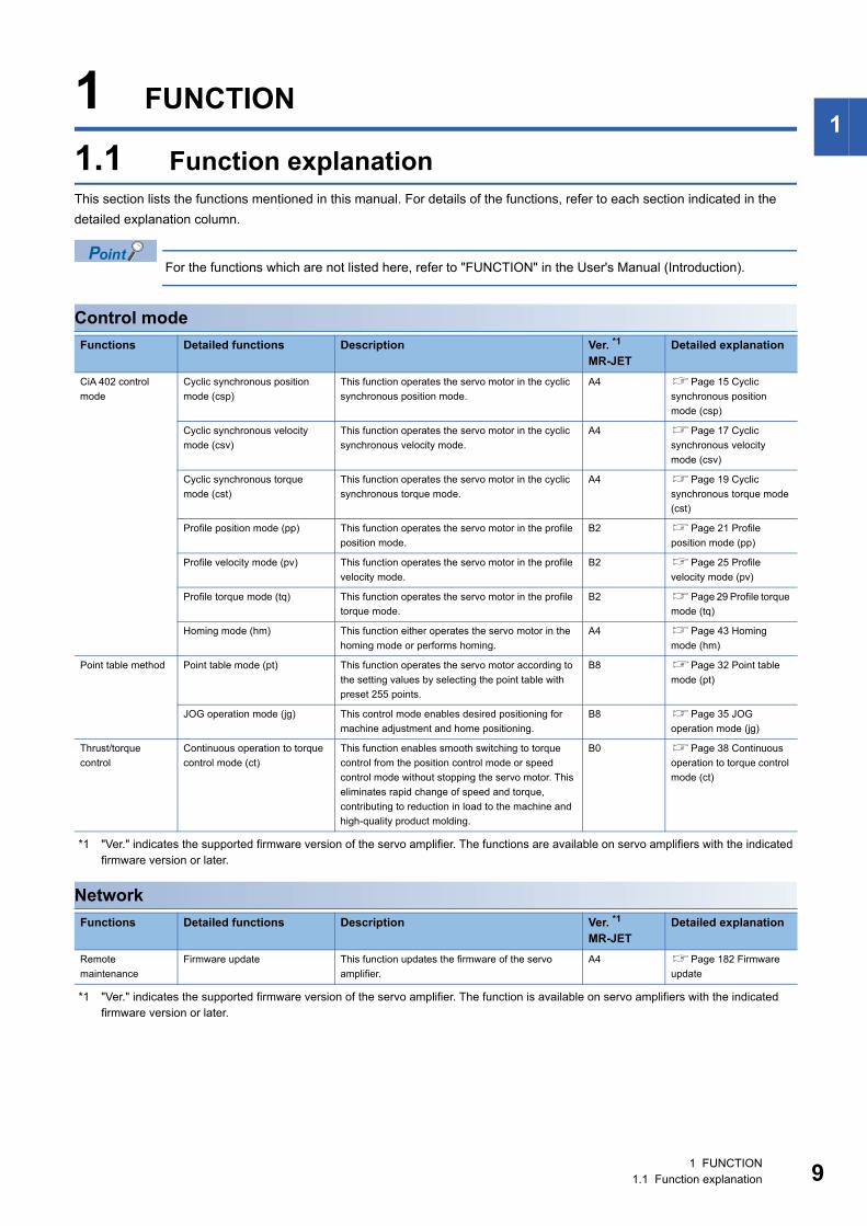
1 FUNCTION1.1 Function explanationThis section lists the functions mentioned in this manual. For details of the functions, refer to each section indicated in the detailed explanation column.
For the functions which are not listed here, refer to "FUNCTION" in the User's Manual (Introduction).
Control mode
*1 "Ver." indicates the supported firmware version of the servo amplifier. The functions are available on servo amplifiers with the indicated firmware version or later.
Network
*1 "Ver." indicates the supported firmware version of the servo amplifier. The function is available on servo amplifiers with the indicated firmware version or later.
Functions Detailed functions Description Ver. *1MR-JET
Detailed explanation
CiA 402 control mode
Cyclic synchronous position mode (csp)
This function operates the servo motor in the cyclic synchronous position mode.
A4 Page 15 Cyclic synchronous position mode (csp)
Cyclic synchronous velocity mode (csv)
This function operates the servo motor in the cyclic synchronous velocity mode.
A4 Page 17 Cyclic synchronous velocity mode (csv)
Cyclic synchronous torque mode (cst)
This function operates the servo motor in the cyclic synchronous torque mode.
A4 Page 19 Cyclic synchronous torque mode (cst)
Profile position mode (pp) This function operates the servo motor in the profile position mode.
B2 Page 21 Profile position mode (pp)
Profile velocity mode (pv) This function operates the servo motor in the profile velocity mode.
B2 Page 25 Profile velocity mode (pv)
Profile torque mode (tq) This function operates the servo motor in the profile torque mode.
B2 Page 29 Profile torque mode (tq)
Homing mode (hm) This function either operates the servo motor in the homing mode or performs homing.
A4 Page 43 Homing mode (hm)
Point table method Point table mode (pt) This function operates the servo motor according to the setting values by selecting the point table with preset 255 points.
B8 Page 32 Point table mode (pt)
JOG operation mode (jg) This control mode enables desired positioning for machine adjustment and home positioning.
B8 Page 35 JOG operation mode (jg)
Thrust/torque control
Continuous operation to torque control mode (ct)
This function enables smooth switching to torque control from the position control mode or speed control mode without stopping the servo motor. This eliminates rapid change of speed and torque, contributing to reduction in load to the machine and high-quality product molding.
B0 Page 38 Continuous operation to torque control mode (ct)
Functions Detailed functions Description Ver. *1MR-JET
Detailed explanation
Remote maintenance
Firmware update This function updates the firmware of the servo amplifier.
A4 Page 182 Firmware update
1 FUNCTION1.1 Function explanation 9
10
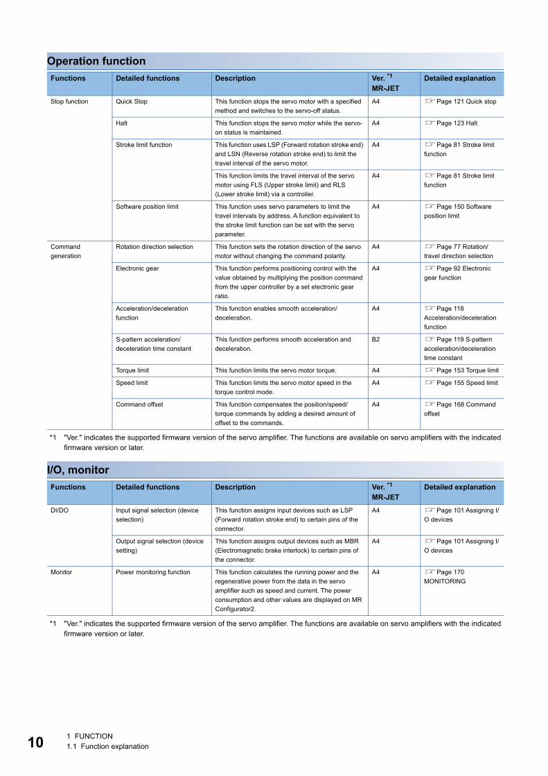
Operation function
*1 "Ver." indicates the supported firmware version of the servo amplifier. The functions are available on servo amplifiers with the indicated firmware version or later.
I/O, monitor
*1 "Ver." indicates the supported firmware version of the servo amplifier. The functions are available on servo amplifiers with the indicated firmware version or later.
Functions Detailed functions Description Ver. *1MR-JET
Detailed explanation
Stop function Quick Stop This function stops the servo motor with a specified method and switches to the servo-off status.
A4 Page 121 Quick stop
Halt This function stops the servo motor while the servo-on status is maintained.
A4 Page 123 Halt
Stroke limit function This function uses LSP (Forward rotation stroke end) and LSN (Reverse rotation stroke end) to limit the travel interval of the servo motor.
A4 Page 81 Stroke limit function
This function limits the travel interval of the servo motor using FLS (Upper stroke limit) and RLS (Lower stroke limit) via a controller.
A4 Page 81 Stroke limit function
Software position limit This function uses servo parameters to limit the travel intervals by address. A function equivalent to the stroke limit function can be set with the servo parameter.
A4 Page 150 Software position limit
Command generation
Rotation direction selection This function sets the rotation direction of the servo motor without changing the command polarity.
A4 Page 77 Rotation/travel direction selection
Electronic gear This function performs positioning control with the value obtained by multiplying the position command from the upper controller by a set electronic gear ratio.
A4 Page 92 Electronic gear function
Acceleration/deceleration function
This function enables smooth acceleration/deceleration.
A4 Page 118 Acceleration/deceleration function
S-pattern acceleration/deceleration time constant
This function performs smooth acceleration and deceleration.
B2 Page 119 S-pattern acceleration/deceleration time constant
Torque limit This function limits the servo motor torque. A4 Page 153 Torque limit
Speed limit This function limits the servo motor speed in the torque control mode.
A4 Page 155 Speed limit
Command offset This function compensates the position/speed/torque commands by adding a desired amount of offset to the commands.
A4 Page 168 Command offset
Functions Detailed functions Description Ver. *1MR-JET
Detailed explanation
DI/DO Input signal selection (device selection)
This function assigns input devices such as LSP (Forward rotation stroke end) to certain pins of the connector.
A4 Page 101 Assigning I/O devices
Output signal selection (device setting)
This function assigns output devices such as MBR (Electromagnetic brake interlock) to certain pins of the connector.
A4 Page 101 Assigning I/O devices
Monitor Power monitoring function This function calculates the running power and the regenerative power from the data in the servo amplifier such as speed and current. The power consumption and other values are displayed on MR Configurator2.
A4 Page 170 MONITORING
1 FUNCTION1.1 Function explanation
1
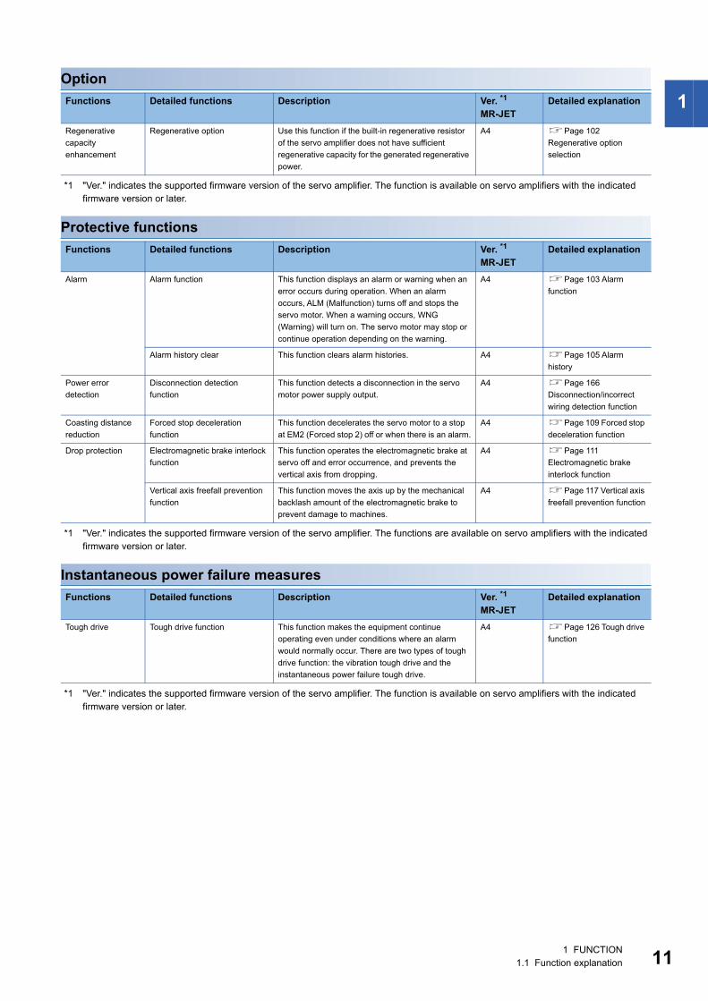
Option*1 "Ver." indicates the supported firmware version of the servo amplifier. The function is available on servo amplifiers with the indicated firmware version or later.
Protective functions
*1 "Ver." indicates the supported firmware version of the servo amplifier. The functions are available on servo amplifiers with the indicated firmware version or later.
Instantaneous power failure measures
*1 "Ver." indicates the supported firmware version of the servo amplifier. The function is available on servo amplifiers with the indicated firmware version or later.
Functions Detailed functions Description Ver. *1MR-JET
Detailed explanation
Regenerative capacity enhancement
Regenerative option Use this function if the built-in regenerative resistor of the servo amplifier does not have sufficient regenerative capacity for the generated regenerative power.
A4 Page 102 Regenerative option selection
Functions Detailed functions Description Ver. *1MR-JET
Detailed explanation
Alarm Alarm function This function displays an alarm or warning when an error occurs during operation. When an alarm occurs, ALM (Malfunction) turns off and stops the servo motor. When a warning occurs, WNG (Warning) will turn on. The servo motor may stop or continue operation depending on the warning.
A4 Page 103 Alarm function
Alarm history clear This function clears alarm histories. A4 Page 105 Alarm history
Power error detection
Disconnection detection function
This function detects a disconnection in the servo motor power supply output.
A4 Page 166 Disconnection/incorrect wiring detection function
Coasting distance reduction
Forced stop deceleration function
This function decelerates the servo motor to a stop at EM2 (Forced stop 2) off or when there is an alarm.
A4 Page 109 Forced stop deceleration function
Drop protection Electromagnetic brake interlock function
This function operates the electromagnetic brake at servo off and error occurrence, and prevents the vertical axis from dropping.
A4 Page 111 Electromagnetic brake interlock function
Vertical axis freefall prevention function
This function moves the axis up by the mechanical backlash amount of the electromagnetic brake to prevent damage to machines.
A4 Page 117 Vertical axis freefall prevention function
Functions Detailed functions Description Ver. *1MR-JET
Detailed explanation
Tough drive Tough drive function This function makes the equipment continue operating even under conditions where an alarm would normally occur. There are two types of tough drive function: the vibration tough drive and the instantaneous power failure tough drive.
A4 Page 126 Tough drive function
1 FUNCTION1.1 Function explanation 11
12
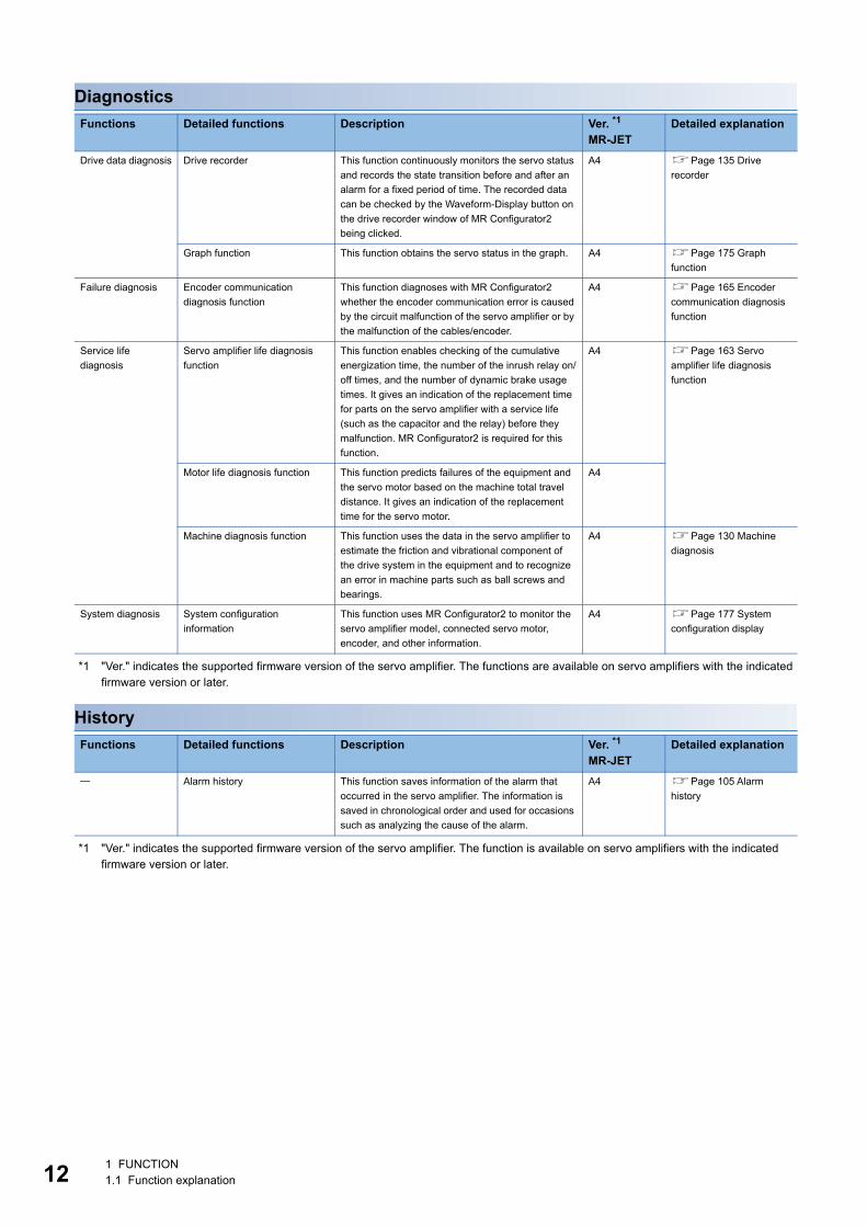
Diagnostics
*1 "Ver." indicates the supported firmware version of the servo amplifier. The functions are available on servo amplifiers with the indicated firmware version or later.
History
*1 "Ver." indicates the supported firmware version of the servo amplifier. The function is available on servo amplifiers with the indicated firmware version or later.
Functions Detailed functions Description Ver. *1MR-JET
Detailed explanation
Drive data diagnosis Drive recorder This function continuously monitors the servo status and records the state transition before and after an alarm for a fixed period of time. The recorded data can be checked by the Waveform-Display button on the drive recorder window of MR Configurator2 being clicked.
A4 Page 135 Drive recorder
Graph function This function obtains the servo status in the graph. A4 Page 175 Graph function
Failure diagnosis Encoder communication diagnosis function
This function diagnoses with MR Configurator2 whether the encoder communication error is caused by the circuit malfunction of the servo amplifier or by the malfunction of the cables/encoder.
A4 Page 165 Encoder communication diagnosis function
Service life diagnosis
Servo amplifier life diagnosis function
This function enables checking of the cumulative energization time, the number of the inrush relay on/off times, and the number of dynamic brake usage times. It gives an indication of the replacement time for parts on the servo amplifier with a service life (such as the capacitor and the relay) before they malfunction. MR Configurator2 is required for this function.
A4 Page 163 Servo amplifier life diagnosis function
Motor life diagnosis function This function predicts failures of the equipment and the servo motor based on the machine total travel distance. It gives an indication of the replacement time for the servo motor.
A4
Machine diagnosis function This function uses the data in the servo amplifier to estimate the friction and vibrational component of the drive system in the equipment and to recognize an error in machine parts such as ball screws and bearings.
A4 Page 130 Machine diagnosis
System diagnosis System configuration information
This function uses MR Configurator2 to monitor the servo amplifier model, connected servo motor, encoder, and other information.
A4 Page 177 System configuration display
Functions Detailed functions Description Ver. *1MR-JET
Detailed explanation
Alarm history This function saves information of the alarm that occurred in the servo amplifier. The information is saved in chronological order and used for occasions such as analyzing the cause of the alarm.
A4 Page 105 Alarm history
1 FUNCTION1.1 Function explanation
2
2 CONTROL MODE
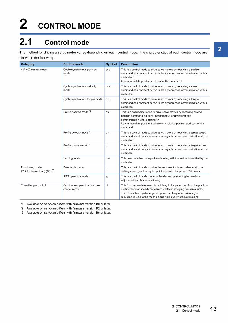
2.1 Control modeThe method for driving a servo motor varies depending on each control mode. The characteristics of each control mode are shown in the following.
*1 Available on servo amplifiers with firmware version B0 or later.*2 Available on servo amplifiers with firmware version B2 or later.*3 Available on servo amplifiers with firmware version B8 or later.
Category Control mode Symbol DescriptionCiA 402 control mode Cyclic synchronous position
modecsp This is a control mode to drive servo motors by receiving a position
command at a constant period in the synchronous communication with a controller.Use an absolute position address for the command.
Cyclic synchronous velocity mode
csv This is a control mode to drive servo motors by receiving a speed command at a constant period in the synchronous communication with a controller.
Cyclic synchronous torque mode cst This is a control mode to drive servo motors by receiving a torque command at a constant period in the synchronous communication with a controller.
Profile position mode *2 pp This is a positioning mode to drive servo motors by receiving an end position command via either synchronous or asynchronous communication with a controller.Use an absolute position address or a relative position address for the command.
Profile velocity mode *2 pv This is a control mode to drive servo motors by receiving a target speed command via either synchronous or asynchronous communication with a controller.
Profile torque mode *2 tq This is a control mode to drive servo motors by receiving a target torque command via either synchronous or asynchronous communication with a controller.
Homing mode hm This is a control mode to perform homing with the method specified by the controller.
Positioning mode(Point table method) (CP) *3
Point table mode pt This is a control mode to drive the servo motor in accordance with the setting value by selecting the point table with the preset 255 points.
JOG operation mode jg This is a control mode that enables desired positioning for machine adjustment and home positioning.
Thrust/torque control Continuous operation to torque control mode *1
ct This function enables smooth switching to torque control from the position control mode or speed control mode without stopping the servo motor. This eliminates rapid change of speed and torque, contributing to reduction in load to the machine and high-quality product molding.
2 CONTROL MODE2.1 Control mode 13
14
Control switching
• The initial control mode setting is the cyclic synchronous position mode. When using the cyclic synchronous position mode, perform position follow-up with the controller at servo-on.
• To use the profile mode, switch to the mode in the servo-off state. After the control mode is switched, turn on the servo-on.
• If the control mode is switched without performing position follow-up, unexpected movements such as sudden acceleration of the servo motor may occur.
The control mode can be switched with [Modes of operation (Obj. 6060h)]. Switching the control modes with [Modes of operation (Obj. 6060h)] applies to the cyclic modes (csp, csv, and cst), profile modes (pp, pv, and tq), homing mode (hm), and continuous operation to torque control mode (ct).For details of the control switching, refer to the User's Manual (Communication Function).The positioning mode (point table method), can be switched to point table mode (pt), JOG operation mode (jg), home position mode (hm).
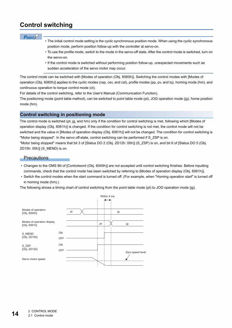
Control switching in positioning modeThe control mode is switched (pt, jg, and hm) only if the condition for control switching is met, following which [Modes of operation display (Obj. 6061h)] is changed. If the condition for control switching is not met, the control mode will not be switched and the value in [Modes of operation display (Obj. 6061h)] will not be changed. The condition for control switching is "Motor being stopped". In the servo off-state, control switching can be performed if S_ZSP is on."Motor being stopped" means that bit 3 of [Status DO 2 (Obj. 2D12h: 00h)] (S_ZSP) is on, and bit 6 of [Status DO 5 (Obj. 2D15h: 00h)] (S_MEND) is on.
Precautions • Changes to the OMS Bit of [Controlword (Obj. 6040h)] are not accepted until control switching finishes. Before inputting
commands, check that the control mode has been switched by referring to [Modes of operation display (Obj. 6061h)]. • Switch the control modes when the start command is turned off. (For example, when "Homing operation start" is turned off
in homing mode (hm).)The following shows a timing chart of control switching from the point table mode (pt) to JOG operation mode (jg).
Modes of operation[Obj. 6060h] pt jg
pt jgModes of operation display[Obj. 6061h]
S_MEND[Obj. 2D15h]
ON
OFF
ON
OFFS_ZSP[Obj. 2D12h]
Within 4 ms
Zero speed level
Servo motor speed
2 CONTROL MODE2.1 Control mode
2
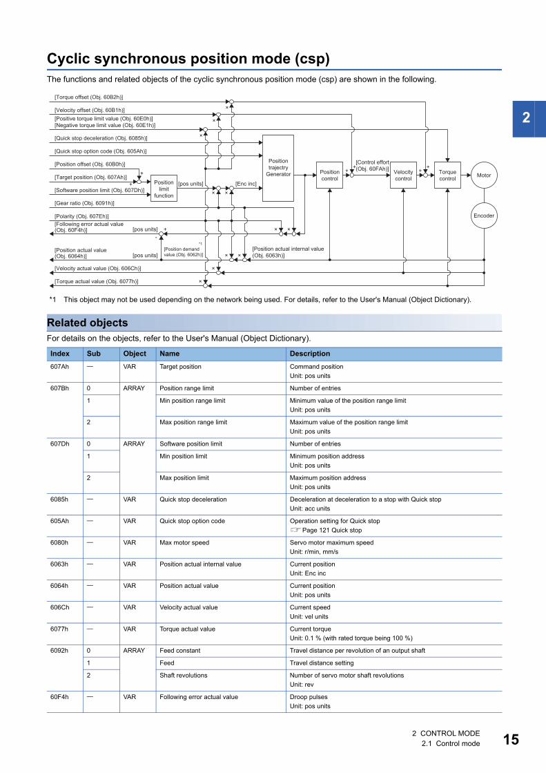
Cyclic synchronous position mode (csp)The functions and related objects of the cyclic synchronous position mode (csp) are shown in the following.
*1 This object may not be used depending on the network being used. For details, refer to the User's Manual (Object Dictionary).
Related objectsFor details on the objects, refer to the User's Manual (Object Dictionary).
Index Sub Object Name Description607Ah VAR Target position Command position
Unit: pos units
607Bh 0 ARRAY Position range limit Number of entries
1 Min position range limit Minimum value of the position range limitUnit: pos units
2 Max position range limit Maximum value of the position range limitUnit: pos units
607Dh 0 ARRAY Software position limit Number of entries
1 Min position limit Minimum position addressUnit: pos units
2 Max position limit Maximum position addressUnit: pos units
6085h VAR Quick stop deceleration Deceleration at deceleration to a stop with Quick stopUnit: acc units
605Ah VAR Quick stop option code Operation setting for Quick stopPage 121 Quick stop
6080h VAR Max motor speed Servo motor maximum speedUnit: r/min, mm/s
6063h VAR Position actual internal value Current positionUnit: Enc inc
6064h VAR Position actual value Current positionUnit: pos units
606Ch VAR Velocity actual value Current speedUnit: vel units
6077h VAR Torque actual value Current torqueUnit: 0.1 % (with rated torque being 100 %)
6092h 0 ARRAY Feed constant Travel distance per revolution of an output shaft
1 Feed Travel distance setting
2 Shaft revolutions Number of servo motor shaft revolutionsUnit: rev
60F4h VAR Following error actual value Droop pulsesUnit: pos units
Positiontrajectry
Generator
[Quick stop deceleration (Obj. 6085h)]
[Quick stop option code (Obj. 605Ah)]
[Torque offset (Obj. 60B2h)]
[Velocity offset (Obj. 60B1h)]
[Position offset (Obj. 60B0h)]
[Target position (Obj. 607Ah)]
[Gear ratio (Obj. 6091h)]
[Polarity (Obj. 607Eh)]
[Position demandvalue (Obj. 6062h)]
[Following error actual value(Obj. 60F4h)]
[Position actual value(Obj. 6064h)]
[Velocity actual value (Obj. 606Ch)]
[Torque actual value (Obj. 6077h)]
[pos units] +
×
×
× ×
×
×
×
×
×-
[pos units]
[Enc inc]
[Control effort(Obj. 60FAh)]
[Position actual internal value(Obj. 6063h)]
Positionlimit
function
Positioncontrol
Velocitycontrol
Torquecontrol Motor
Encoder
[Positive torque limit value (Obj. 60E0h)][Negative torque limit value (Obj. 60E1h)]
[Software position limit (Obj. 607Dh)][pos units]
×
×
+++
+
++
*1
2 CONTROL MODE2.1 Control mode 15
16
*1 This object may not be used depending on the network being used. For details, refer to the User's Manual (Object Dictionary).
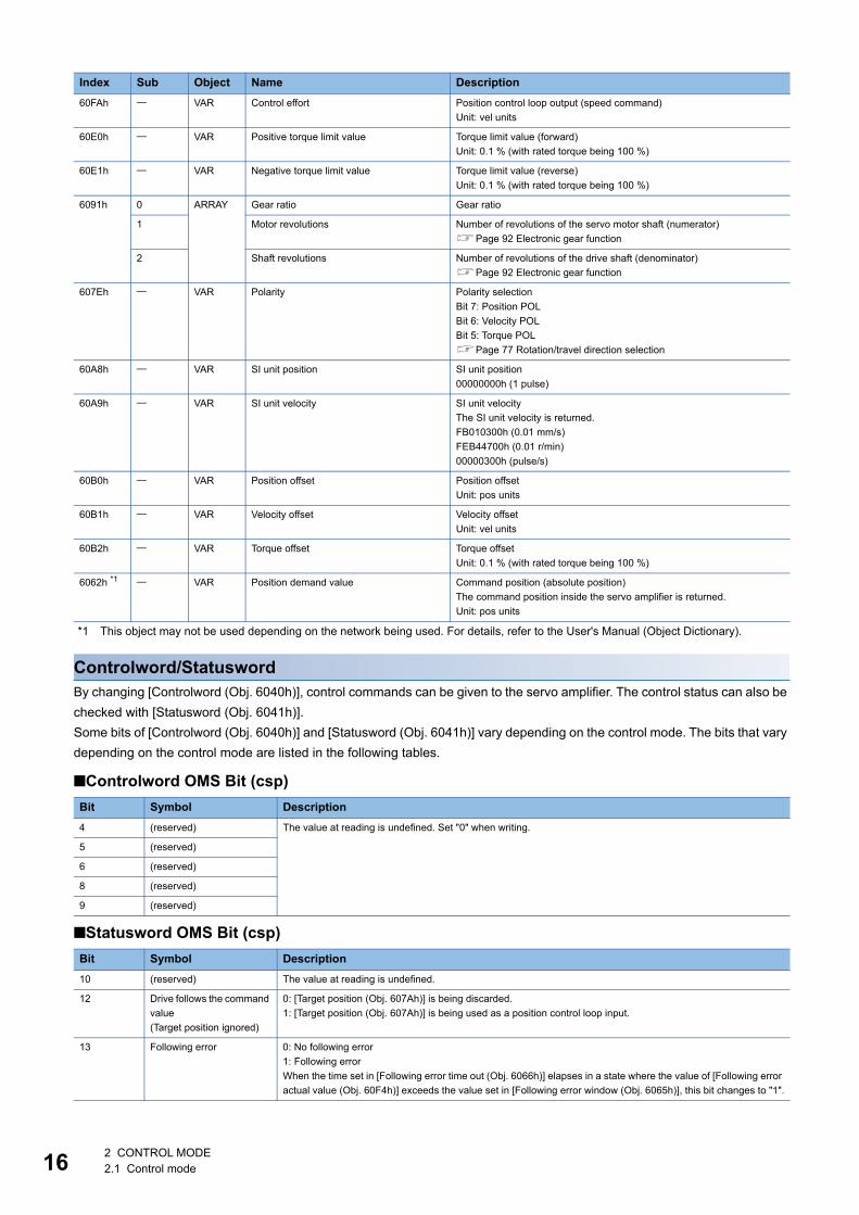
Controlword/StatuswordBy changing [Controlword (Obj. 6040h)], control commands can be given to the servo amplifier. The control status can also be checked with [Statusword (Obj. 6041h)].Some bits of [Controlword (Obj. 6040h)] and [Statusword (Obj. 6041h)] vary depending on the control mode. The bits that vary depending on the control mode are listed in the following tables.
■Controlword OMS Bit (csp)
■Statusword OMS Bit (csp)
60FAh VAR Control effort Position control loop output (speed command)Unit: vel units
60E0h VAR Positive torque limit value Torque limit value (forward)Unit: 0.1 % (with rated torque being 100 %)
60E1h VAR Negative torque limit value Torque limit value (reverse)Unit: 0.1 % (with rated torque being 100 %)
6091h 0 ARRAY Gear ratio Gear ratio
1 Motor revolutions Number of revolutions of the servo motor shaft (numerator)Page 92 Electronic gear function
2 Shaft revolutions Number of revolutions of the drive shaft (denominator)Page 92 Electronic gear function
607Eh VAR Polarity Polarity selectionBit 7: Position POLBit 6: Velocity POLBit 5: Torque POLPage 77 Rotation/travel direction selection
60A8h VAR SI unit position SI unit position00000000h (1 pulse)
60A9h VAR SI unit velocity SI unit velocityThe SI unit velocity is returned.FB010300h (0.01 mm/s)FEB44700h (0.01 r/min)00000300h (pulse/s)
60B0h VAR Position offset Position offsetUnit: pos units
60B1h VAR Velocity offset Velocity offsetUnit: vel units
60B2h VAR Torque offset Torque offsetUnit: 0.1 % (with rated torque being 100 %)
6062h *1 VAR Position demand value Command position (absolute position)The command position inside the servo amplifier is returned.Unit: pos units
Bit Symbol Description4 (reserved) The value at reading is undefined. Set "0" when writing.
5 (reserved)
6 (reserved)
8 (reserved)
9 (reserved)
Bit Symbol Description10 (reserved) The value at reading is undefined.
12 Drive follows the command value(Target position ignored)
0: [Target position (Obj. 607Ah)] is being discarded.1: [Target position (Obj. 607Ah)] is being used as a position control loop input.
13 Following error 0: No following error1: Following errorWhen the time set in [Following error time out (Obj. 6066h)] elapses in a state where the value of [Following error actual value (Obj. 60F4h)] exceeds the value set in [Following error window (Obj. 6065h)], this bit changes to "1".
Index Sub Object Name Description
2 CONTROL MODE2.1 Control mode
2
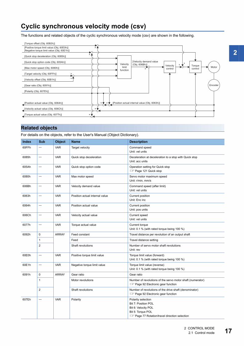
Cyclic synchronous velocity mode (csv)The functions and related objects of the cyclic synchronous velocity mode (csv) are shown in the following.
Related objectsFor details on the objects, refer to the User's Manual (Object Dictionary).
Index Sub Object Name Description60FFh VAR Target velocity Command speed
Unit: vel units
6085h VAR Quick stop deceleration Deceleration at deceleration to a stop with Quick stopUnit: acc units
605Ah VAR Quick stop option code Operation setting for Quick stopPage 121 Quick stop
6080h VAR Max motor speed Servo motor maximum speedUnit: r/min, mm/s
606Bh VAR Velocity demand value Command speed (after limit)Unit: vel units
6063h VAR Position actual internal value Current positionUnit: Enc inc
6064h VAR Position actual value Current positionUnit: pos units
606Ch VAR Velocity actual value Current speedUnit: vel units
6077h VAR Torque actual value Current torqueUnit: 0.1 % (with rated torque being 100 %)
6092h 0 ARRAY Feed constant Travel distance per revolution of an output shaft
1 Feed Travel distance setting
2 Shaft revolutions Number of servo motor shaft revolutionsUnit: rev
60E0h VAR Positive torque limit value Torque limit value (forward)Unit: 0.1 % (with rated torque being 100 %)
60E1h VAR Negative torque limit value Torque limit value (reverse)Unit: 0.1 % (with rated torque being 100 %)
6091h 0 ARRAY Gear ratio Gear ratio
1 Motor revolutions Number of revolutions of the servo motor shaft (numerator)Page 92 Electronic gear function
2 Shaft revolutions Number of revolutions of the drive shaft (denominator)Page 92 Electronic gear function
607Eh VAR Polarity Polarity selectionBit 7: Position POLBit 6: Velocity POLBit 5: Torque POLPage 77 Rotation/travel direction selection
Velocitylimit
function
×
×
×
× ×
×
[Position actual internal value (Obj. 6063h)]
Velocitycontrol
Torquecontrol
[Velocity demand value(Obj. 606Bh)]
[Positive torque limit value (Obj. 60E0h)][Negative torque limit value (Obj. 60E1h)]
[Quick stop deceleration (Obj. 6085h)]
[Torque offset (Obj. 60B2h)]
[Quick stop option code (Obj. 605Ah)]
[Target velocity (Obj. 60FFh)]
[Position actual value (Obj. 6064h)]
[Gear ratio (Obj. 6091h)]
[Velocity offset (Obj. 60B1h)]
[Polarity (Obj. 607Eh)]
[Velocity actual value (Obj. 606Ch)]
[Max motor speed (Obj. 6080h)]
[Torque actual value (Obj. 6077h)]
Encoder
Motor
×
+
+
++
2 CONTROL MODE2.1 Control mode 17
18
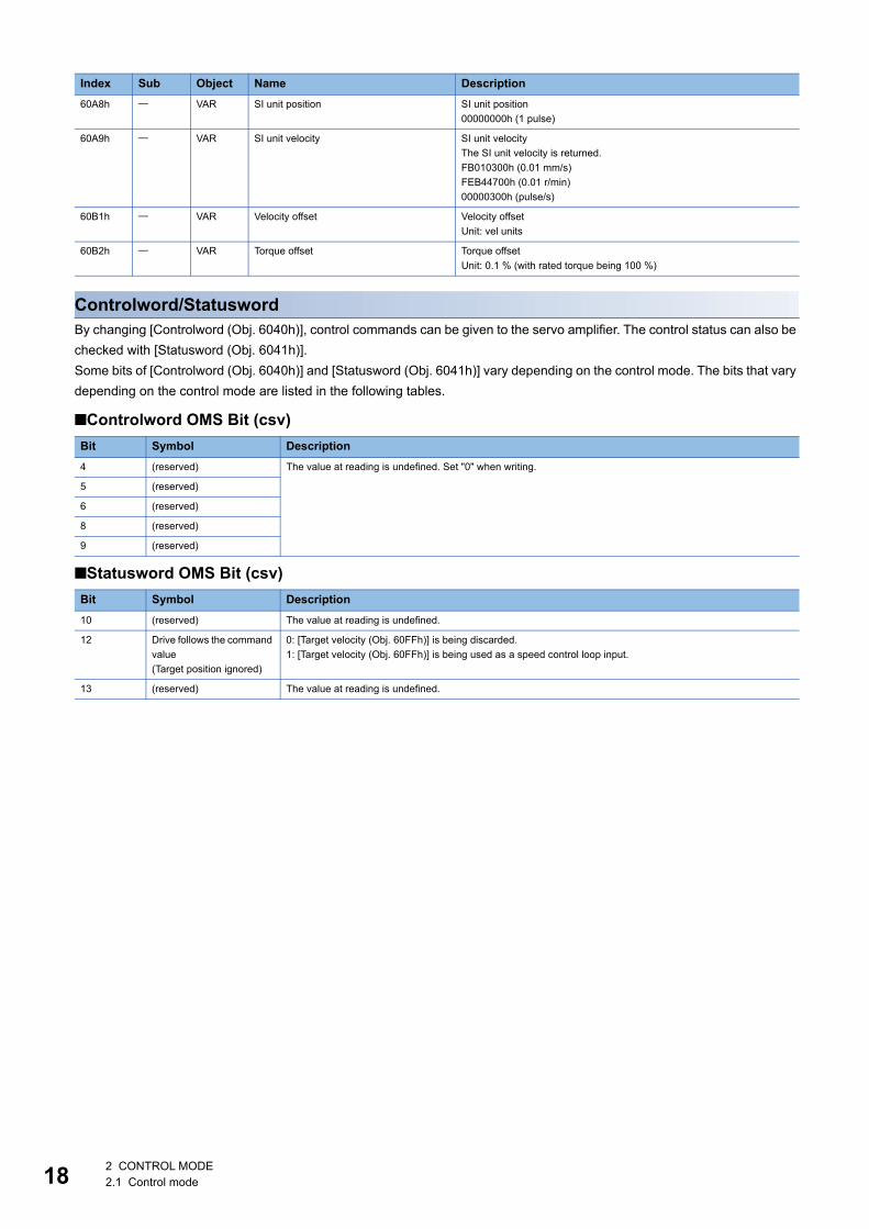
Controlword/StatuswordBy changing [Controlword (Obj. 6040h)], control commands can be given to the servo amplifier. The control status can also be checked with [Statusword (Obj. 6041h)].Some bits of [Controlword (Obj. 6040h)] and [Statusword (Obj. 6041h)] vary depending on the control mode. The bits that vary depending on the control mode are listed in the following tables.
■Controlword OMS Bit (csv)
■Statusword OMS Bit (csv)
60A8h VAR SI unit position SI unit position00000000h (1 pulse)
60A9h VAR SI unit velocity SI unit velocityThe SI unit velocity is returned.FB010300h (0.01 mm/s)FEB44700h (0.01 r/min)00000300h (pulse/s)
60B1h VAR Velocity offset Velocity offsetUnit: vel units
60B2h VAR Torque offset Torque offsetUnit: 0.1 % (with rated torque being 100 %)
Bit Symbol Description4 (reserved) The value at reading is undefined. Set "0" when writing.
5 (reserved)
6 (reserved)
8 (reserved)
9 (reserved)
Bit Symbol Description10 (reserved) The value at reading is undefined.
12 Drive follows the command value(Target position ignored)
0: [Target velocity (Obj. 60FFh)] is being discarded.1: [Target velocity (Obj. 60FFh)] is being used as a speed control loop input.
13 (reserved) The value at reading is undefined.
Index Sub Object Name Description
2 CONTROL MODE2.1 Control mode
2
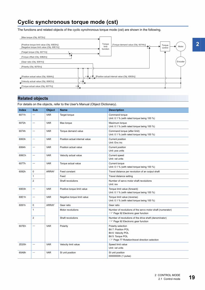
Cyclic synchronous torque mode (cst)The functions and related objects of the cyclic synchronous torque mode (cst) are shown in the following.
Related objectsFor details on the objects, refer to the User's Manual (Object Dictionary).
Index Sub Object Name Description6071h VAR Target torque Command torque
Unit: 0.1 % (with rated torque being 100 %)
6072h VAR Max torque Maximum torqueUnit: 0.1 % (with rated torque being 100 %)
6074h VAR Torque demand value Command torque (after limit)Unit: 0.1 % (with rated torque being 100 %)
6063h VAR Position actual internal value Current positionUnit: Enc inc
6064h VAR Position actual value Current positionUnit: pos units
606Ch VAR Velocity actual value Current speedUnit: vel units
6077h VAR Torque actual value Current torqueUnit: 0.1 % (with rated torque being 100 %)
6092h 0 ARRAY Feed constant Travel distance per revolution of an output shaft
1 Feed Travel distance setting
2 Shaft revolutions Number of servo motor shaft revolutionsUnit: rev
60E0h VAR Positive torque limit value Torque limit value (forward)Unit: 0.1 % (with rated torque being 100 %)
60E1h VAR Negative torque limit value Torque limit value (reverse)Unit: 0.1 % (with rated torque being 100 %)
6091h 0 ARRAY Gear ratio Gear ratio
1 Motor revolutions Number of revolutions of the servo motor shaft (numerator)Page 92 Electronic gear function
2 Shaft revolutions Number of revolutions of the drive shaft (denominator)Page 92 Electronic gear function
607Eh VAR Polarity Polarity selectionBit 7: Position POLBit 6: Velocity POLBit 5: Torque POLPage 77 Rotation/travel direction selection
2D20h VAR Velocity limit value Speed limit valueUnit: vel units
60A8h VAR SI unit position SI unit position00000000h (1 pulse)
Torquelimit
function
×
×
× × [Position actual internal value (Obj. 6063h)]
Torquecontrol
[Torque demand value (Obj. 6074h)]
[Max torque (Obj. 6072h)]
[Target torque (Obj. 6071h)]
[Torque offset (Obj. 60B2h)]
[Position actual value (Obj. 6064h)]
[Gear ratio (Obj. 6091h)]
[Polarity (Obj. 607Eh)]
[Velocity actual value (Obj. 606Ch)]
[Positive torque limit value (Obj. 60E0h)][Negative torque limit value (Obj. 60E1h)]
[Torque actual value (Obj. 6077h)]
Encoder
Motor×
+
+
2 CONTROL MODE2.1 Control mode 19
20
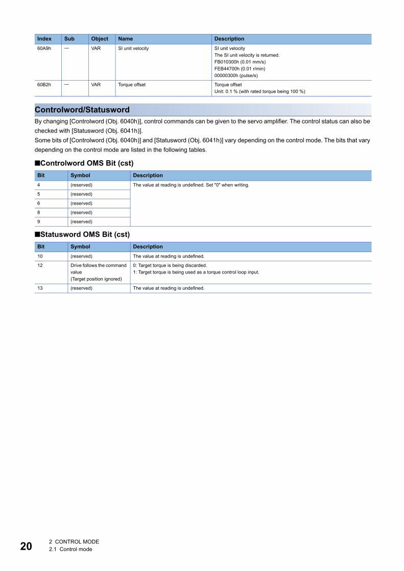
Controlword/StatuswordBy changing [Controlword (Obj. 6040h)], control commands can be given to the servo amplifier. The control status can also be checked with [Statusword (Obj. 6041h)].Some bits of [Controlword (Obj. 6040h)] and [Statusword (Obj. 6041h)] vary depending on the control mode. The bits that vary depending on the control mode are listed in the following tables.
■Controlword OMS Bit (cst)
■Statusword OMS Bit (cst)
60A9h VAR SI unit velocity SI unit velocityThe SI unit velocity is returned.FB010300h (0.01 mm/s)FEB44700h (0.01 r/min)00000300h (pulse/s)
60B2h VAR Torque offset Torque offsetUnit: 0.1 % (with rated torque being 100 %)
Bit Symbol Description4 (reserved) The value at reading is undefined. Set "0" when writing.
5 (reserved)
6 (reserved)
8 (reserved)
9 (reserved)
Bit Symbol Description10 (reserved) The value at reading is undefined.
12 Drive follows the command value(Target position ignored)
0: Target torque is being discarded.1: Target torque is being used as a torque control loop input.
13 (reserved) The value at reading is undefined.
Index Sub Object Name Description
2 CONTROL MODE2.1 Control mode
2
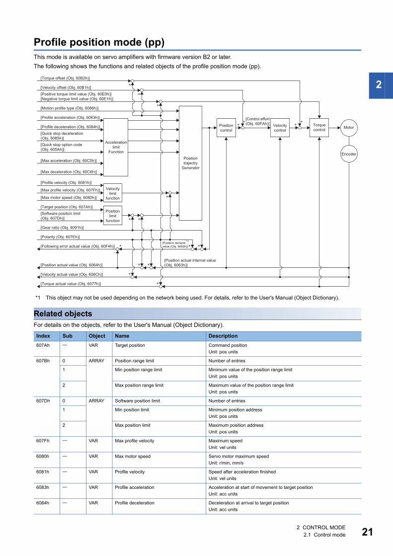
Profile position mode (pp)This mode is available on servo amplifiers with firmware version B2 or later.The following shows the functions and related objects of the profile position mode (pp).
*1 This object may not be used depending on the network being used. For details, refer to the User's Manual (Object Dictionary).
Related objectsFor details on the objects, refer to the User's Manual (Object Dictionary).
Index Sub Object Name Description607Ah VAR Target position Command position
Unit: pos units
607Bh 0 ARRAY Position range limit Number of entries
1 Min position range limit Minimum value of the position range limitUnit: pos units
2 Max position range limit Maximum value of the position range limitUnit: pos units
607Dh 0 ARRAY Software position limit Number of entries
1 Min position limit Minimum position addressUnit: pos units
2 Max position limit Maximum position addressUnit: pos units
607Fh VAR Max profile velocity Maximum speedUnit: vel units
6080h VAR Max motor speed Servo motor maximum speedUnit: r/min, mm/s
6081h VAR Profile velocity Speed after acceleration finishedUnit: vel units
6083h VAR Profile acceleration Acceleration at start of movement to target positionUnit: acc units
6084h VAR Profile deceleration Deceleration at arrival to target positionUnit: acc units
[Positive torque limit value (Obj. 60E0h)][Negative torque limit value (Obj. 60E1h)]
[Motion profile type (Obj. 6086h)]
[Profile acceleration (Obj. 6083h)]
[Torque offset (Obj. 60B2h)]
[Velocity offset (Obj. 60B1h)]
[Profile deceleration (Obj. 6084h)][Quick stop deceleration (Obj. 6085h)]
Accelerationlimit
Function
[Quick stop option code (Obj. 605Ah)]
[Max acceleration (Obj. 60C5h)]
[Max deceleration (Obj. 60C6h)]
[Profile velocity (Obj. 6081h)]
[Max profile velocity (Obj. 607Fh)]
[Max motor speed (Obj. 6080h)]
[Target position (Obj. 607Ah)]
Velocitylimit
function
[Software position limit(Obj. 607Dh)]
Positionlimit
function
[Gear ratio (Obj. 6091h)]
[Polarity (Obj. 607Eh)]
[Following error actual value (Obj. 60F4h)] +-
× ×
×
× ×
×
[Position actual internal value(Obj. 6063h)][Position actual value (Obj. 6064h)]
[Velocity actual value (Obj. 606Ch)]
[Torque actual value (Obj. 6077h)]
×
× ×
Positiontrajectry
Generator
Positioncontrol
[Control effort(Obj. 60FAh)] Velocity
controlTorquecontrol Motor
Encoder
×
×
×
++
++
[Position demandvalue (Obj. 6062h)]
*1
2 CONTROL MODE2.1 Control mode 21
22
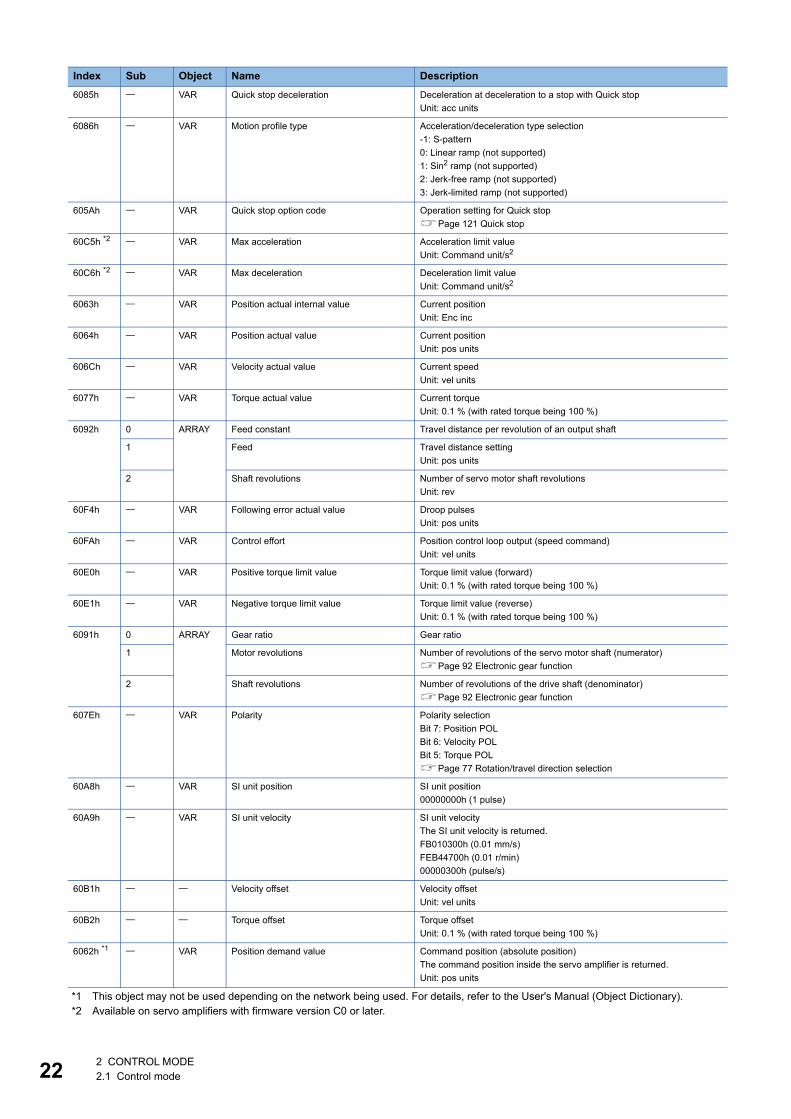
*1 This object may not be used depending on the network being used. For details, refer to the User's Manual (Object Dictionary).*2 Available on servo amplifiers with firmware version C0 or later.
6085h VAR Quick stop deceleration Deceleration at deceleration to a stop with Quick stopUnit: acc units
6086h VAR Motion profile type Acceleration/deceleration type selection-1: S-pattern0: Linear ramp (not supported)1: Sin2 ramp (not supported)2: Jerk-free ramp (not supported)3: Jerk-limited ramp (not supported)
605Ah VAR Quick stop option code Operation setting for Quick stopPage 121 Quick stop
60C5h *2 VAR Max acceleration Acceleration limit valueUnit: Command unit/s2
60C6h *2 VAR Max deceleration Deceleration limit valueUnit: Command unit/s2
6063h VAR Position actual internal value Current positionUnit: Enc inc
6064h VAR Position actual value Current positionUnit: pos units
606Ch VAR Velocity actual value Current speedUnit: vel units
6077h VAR Torque actual value Current torqueUnit: 0.1 % (with rated torque being 100 %)
6092h 0 ARRAY Feed constant Travel distance per revolution of an output shaft
1 Feed Travel distance settingUnit: pos units
2 Shaft revolutions Number of servo motor shaft revolutionsUnit: rev
60F4h VAR Following error actual value Droop pulsesUnit: pos units
60FAh VAR Control effort Position control loop output (speed command)Unit: vel units
60E0h VAR Positive torque limit value Torque limit value (forward)Unit: 0.1 % (with rated torque being 100 %)
60E1h VAR Negative torque limit value Torque limit value (reverse)Unit: 0.1 % (with rated torque being 100 %)
6091h 0 ARRAY Gear ratio Gear ratio
1 Motor revolutions Number of revolutions of the servo motor shaft (numerator)Page 92 Electronic gear function
2 Shaft revolutions Number of revolutions of the drive shaft (denominator)Page 92 Electronic gear function
607Eh VAR Polarity Polarity selectionBit 7: Position POLBit 6: Velocity POLBit 5: Torque POLPage 77 Rotation/travel direction selection
60A8h VAR SI unit position SI unit position00000000h (1 pulse)
60A9h VAR SI unit velocity SI unit velocityThe SI unit velocity is returned.FB010300h (0.01 mm/s)FEB44700h (0.01 r/min)00000300h (pulse/s)
60B1h Velocity offset Velocity offsetUnit: vel units
60B2h Torque offset Torque offsetUnit: 0.1 % (with rated torque being 100 %)
6062h *1 VAR Position demand value Command position (absolute position)The command position inside the servo amplifier is returned.Unit: pos units
Index Sub Object Name Description
2 CONTROL MODE2.1 Control mode
2
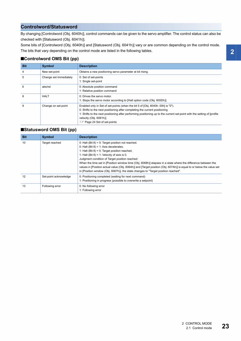
Controlword/StatuswordBy changing [Controlword (Obj. 6040h)], control commands can be given to the servo amplifier. The control status can also be checked with [Statusword (Obj. 6041h)].Some bits of [Controlword (Obj. 6040h)] and [Statusword (Obj. 6041h)] vary or are common depending on the control mode. The bits that vary depending on the control mode are listed in the following tables.
■Controlword OMS Bit (pp)
■Statusword OMS Bit (pp)
Bit Symbol Description4 New set-point Obtains a new positioning servo parameter at bit rising.
5 Change set immediately 0: Set of set-points1: Single set-point
6 abs/rel 0: Absolute position command1: Relative position command
8 HALT 0: Drives the servo motor.1: Stops the servo motor according to [Halt option code (Obj. 605Dh)].
9 Change on set-point Enabled only in Set of set-points (when the bit 5 of [Obj. 6040h: 00h] is "0").0: Shifts to the next positioning after completing the current positioning.1: Shifts to the next positioning after performing positioning up to the current set-point with the setting of [profile velocity (Obj. 6081h)].Page 24 Set of set-points
Bit Symbol Description10 Target reached 0: Halt (Bit 8) = 0: Target position not reached.
0: Halt (Bit 8) = 1: Axis decelerates.1: Halt (Bit 8) = 0: Target position reached.1: Halt (Bit 8) = 1: Velocity of axis is 0.Judgment condition of Target position reached:When the time set in [Position window time (Obj. 6068h)] elapses in a state where the difference between the values in [Position actual value (Obj. 6064h)] and [Target position (Obj. 607Ah)] is equal to or below the value set in [Position window (Obj. 6067h)], the state changes to "Target position reached".
12 Set-point acknowledge 0: Positioning completed (waiting for next command)1: Positioning in progress (possible to overwrite a setpoint)
13 Following error 0: No following error1: Following error
2 CONTROL MODE2.1 Control mode 23
24
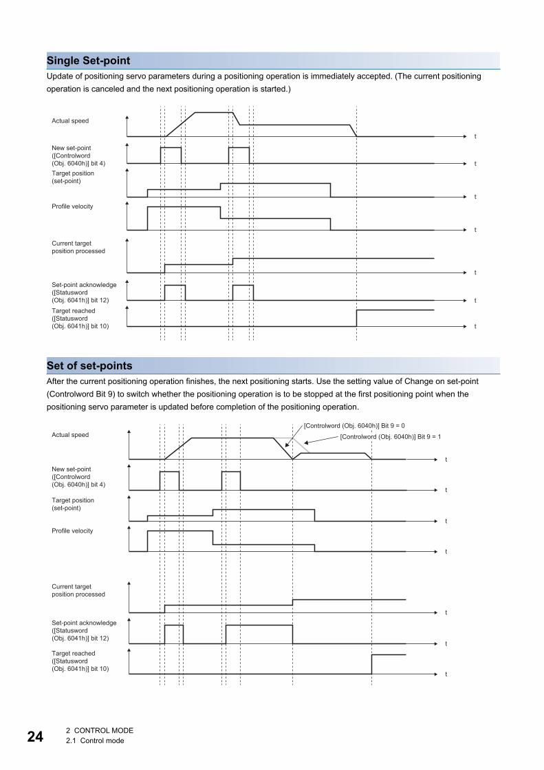
Single Set-pointUpdate of positioning servo parameters during a positioning operation is immediately accepted. (The current positioning operation is canceled and the next positioning operation is started.)
Set of set-pointsAfter the current positioning operation finishes, the next positioning starts. Use the setting value of Change on set-point (Controlword Bit 9) to switch whether the positioning operation is to be stopped at the first positioning point when the positioning servo parameter is updated before completion of the positioning operation.
Target position(set-point)
Profile velocity
Actual speed
Current targetposition processed
New set-point([Controlword (Obj. 6040h)] bit 4)
Set-point acknowledge([Statusword (Obj. 6041h)] bit 12)Target reached([Statusword (Obj. 6041h)] bit 10)
t
t
t
t
t
t
t
Target position(set-point)
Profile velocity
Actual speed
Current targetposition processed
New set-point([Controlword (Obj. 6040h)] bit 4)
Set-point acknowledge([Statusword (Obj. 6041h)] bit 12)
Target reached([Statusword (Obj. 6041h)] bit 10)
t
t
t
t
t
t
t
[Controlword (Obj. 6040h)] Bit 9 = 0
[Controlword (Obj. 6040h)] Bit 9 = 1
2 CONTROL MODE2.1 Control mode
2
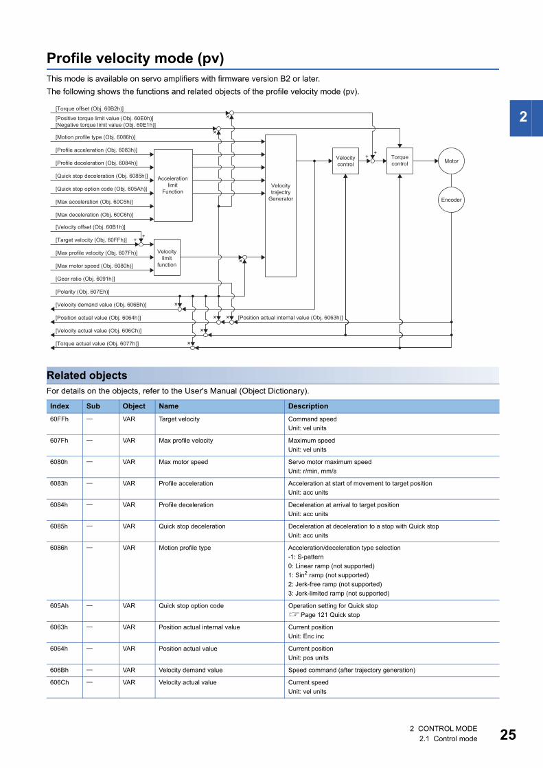
Profile velocity mode (pv)This mode is available on servo amplifiers with firmware version B2 or later.The following shows the functions and related objects of the profile velocity mode (pv).
Related objectsFor details on the objects, refer to the User's Manual (Object Dictionary).
Index Sub Object Name Description60FFh VAR Target velocity Command speed
Unit: vel units
607Fh VAR Max profile velocity Maximum speedUnit: vel units
6080h VAR Max motor speed Servo motor maximum speedUnit: r/min, mm/s
6083h VAR Profile acceleration Acceleration at start of movement to target positionUnit: acc units
6084h VAR Profile deceleration Deceleration at arrival to target positionUnit: acc units
6085h VAR Quick stop deceleration Deceleration at deceleration to a stop with Quick stopUnit: acc units
6086h VAR Motion profile type Acceleration/deceleration type selection-1: S-pattern0: Linear ramp (not supported)1: Sin2 ramp (not supported)2: Jerk-free ramp (not supported)3: Jerk-limited ramp (not supported)
605Ah VAR Quick stop option code Operation setting for Quick stopPage 121 Quick stop
6063h VAR Position actual internal value Current positionUnit: Enc inc
6064h VAR Position actual value Current positionUnit: pos units
606Bh VAR Velocity demand value Speed command (after trajectory generation)
606Ch VAR Velocity actual value Current speedUnit: vel units
[Position actual internal value (Obj. 6063h)]
Velocitylimit
function
Accelerationlimit
Function
Velocitycontrol
Torquecontrol
[Positive torque limit value (Obj. 60E0h)][Negative torque limit value (Obj. 60E1h)]
[Motion profile type (Obj. 6086h)]
[Torque offset (Obj. 60B2h)]
[Profile acceleration (Obj. 6083h)]
[Profile deceleration (Obj. 6084h)]
[Quick stop deceleration (Obj. 6085h)]
[Quick stop option code (Obj. 605Ah)]
[Max acceleration (Obj. 60C5h)]
[Max deceleration (Obj. 60C6h)]
[Target velocity (Obj. 60FFh)]
[Velocity offset (Obj. 60B1h)]
[Max profile velocity (Obj. 607Fh)]
[Max motor speed (Obj. 6080h)]
[Gear ratio (Obj. 6091h)]
[Polarity (Obj. 607Eh)]
[Velocity demand value (Obj. 606Bh)]
[Position actual value (Obj. 6064h)]
[Velocity actual value (Obj. 606Ch)]
[Torque actual value (Obj. 6077h)]
Motor
Encoder
Velocitytrajectry
Generator
×
×
×
×
×
×
×
×
++
++
2 CONTROL MODE2.1 Control mode 25
26
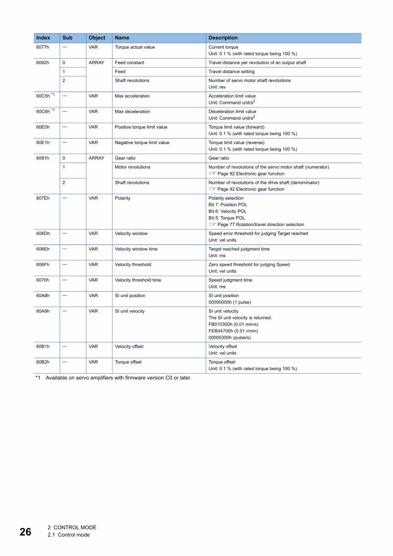
*1 Available on servo amplifiers with firmware version C0 or later.
6077h VAR Torque actual value Current torqueUnit: 0.1 % (with rated torque being 100 %)
6092h 0 ARRAY Feed constant Travel distance per revolution of an output shaft
1 Feed Travel distance setting
2 Shaft revolutions Number of servo motor shaft revolutionsUnit: rev
60C5h *1 VAR Max acceleration Acceleration limit valueUnit: Command unit/s2
60C6h *1 VAR Max deceleration Deceleration limit valueUnit: Command unit/s2
60E0h VAR Positive torque limit value Torque limit value (forward)Unit: 0.1 % (with rated torque being 100 %)
60E1h VAR Negative torque limit value Torque limit value (reverse)Unit: 0.1 % (with rated torque being 100 %)
6091h 0 ARRAY Gear ratio Gear ratio
1 Motor revolutions Number of revolutions of the servo motor shaft (numerator)Page 92 Electronic gear function
2 Shaft revolutions Number of revolutions of the drive shaft (denominator)Page 92 Electronic gear function
607Eh VAR Polarity Polarity selectionBit 7: Position POLBit 6: Velocity POLBit 5: Torque POLPage 77 Rotation/travel direction selection
606Dh VAR Velocity window Speed error threshold for judging Target reachedUnit: vel units
606Eh VAR Velocity window time Target reached judgment timeUnit: ms
606Fh VAR Velocity threshold Zero speed threshold for judging SpeedUnit: vel units
6070h VAR Velocity threshold time Speed judgment timeUnit: ms
60A8h VAR SI unit position SI unit position00000000h (1 pulse)
60A9h VAR SI unit velocity SI unit velocityThe SI unit velocity is returned.FB010300h (0.01 mm/s)FEB44700h (0.01 r/min)00000300h (pulse/s)
60B1h VAR Velocity offset Velocity offsetUnit: vel units
60B2h VAR Torque offset Torque offsetUnit: 0.1 % (with rated torque being 100 %)
Index Sub Object Name Description
2 CONTROL MODE2.1 Control mode
2
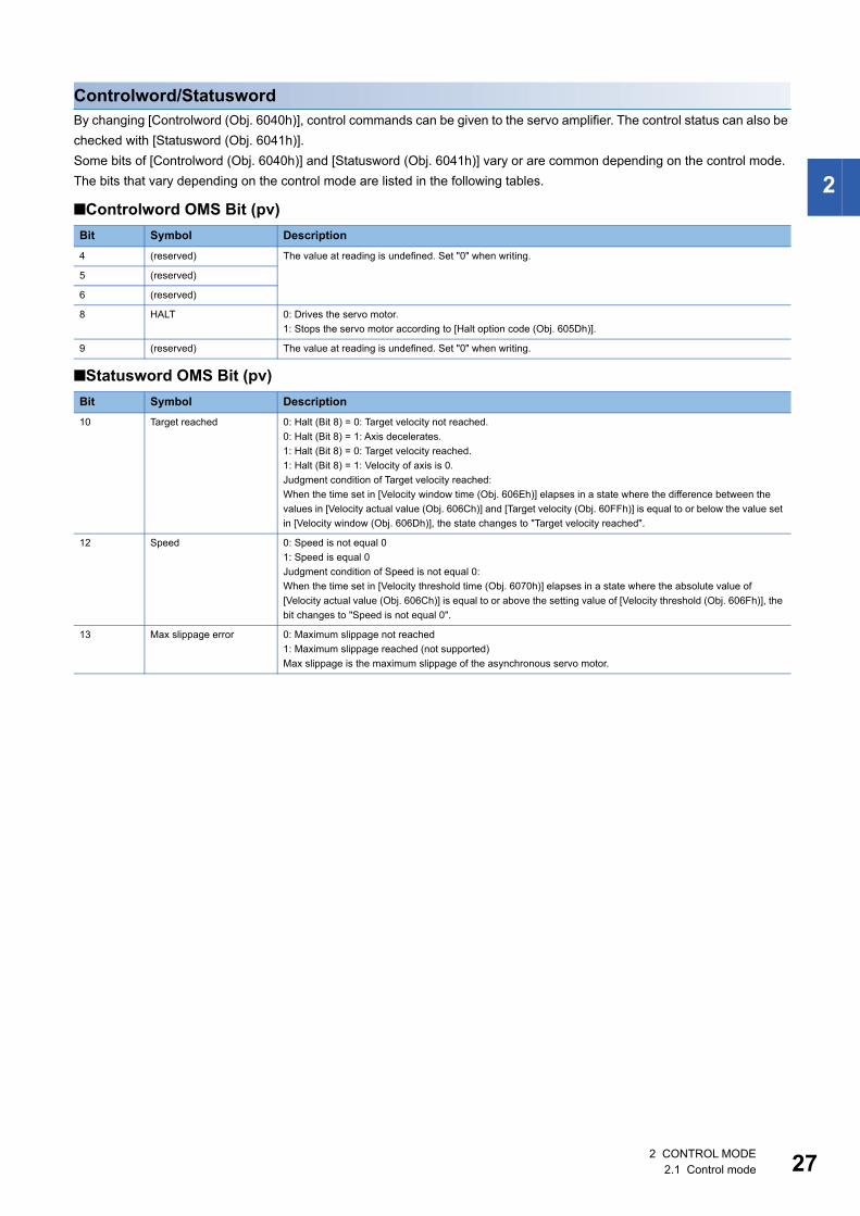
Controlword/StatuswordBy changing [Controlword (Obj. 6040h)], control commands can be given to the servo amplifier. The control status can also be checked with [Statusword (Obj. 6041h)].Some bits of [Controlword (Obj. 6040h)] and [Statusword (Obj. 6041h)] vary or are common depending on the control mode. The bits that vary depending on the control mode are listed in the following tables.
■Controlword OMS Bit (pv)
■Statusword OMS Bit (pv)
Bit Symbol Description4 (reserved) The value at reading is undefined. Set "0" when writing.
5 (reserved)
6 (reserved)
8 HALT 0: Drives the servo motor.1: Stops the servo motor according to [Halt option code (Obj. 605Dh)].
9 (reserved) The value at reading is undefined. Set "0" when writing.
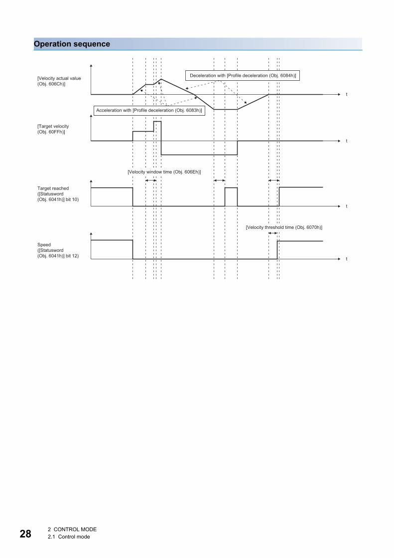
Bit Symbol Description10 Target reached 0: Halt (Bit 8) = 0: Target velocity not reached.
0: Halt (Bit 8) = 1: Axis decelerates.1: Halt (Bit 8) = 0: Target velocity reached.1: Halt (Bit 8) = 1: Velocity of axis is 0.Judgment condition of Target velocity reached:When the time set in [Velocity window time (Obj. 606Eh)] elapses in a state where the difference between the values in [Velocity actual value (Obj. 606Ch)] and [Target velocity (Obj. 60FFh)] is equal to or below the value set in [Velocity window (Obj. 606Dh)], the state changes to "Target velocity reached".
12 Speed 0: Speed is not equal 01: Speed is equal 0Judgment condition of Speed is not equal 0:When the time set in [Velocity threshold time (Obj. 6070h)] elapses in a state where the absolute value of [Velocity actual value (Obj. 606Ch)] is equal to or above the setting value of [Velocity threshold (Obj. 606Fh)], the bit changes to "Speed is not equal 0".
13 Max slippage error 0: Maximum slippage not reached1: Maximum slippage reached (not supported)Max slippage is the maximum slippage of the asynchronous servo motor.
2 CONTROL MODE2.1 Control mode 27
28
Operation sequence
[Velocity actual value (Obj. 606Ch)]
[Target velocity (Obj. 60FFh)]
Speed([Statusword (Obj. 6041h)] bit 12)
Target reached([Statusword (Obj. 6041h)] bit 10)
[Velocity window time (Obj. 606Eh)]
[Velocity threshold time (Obj. 6070h)]
t
t
t
t
Deceleration with [Profile deceleration (Obj. 6084h)]
Acceleration with [Profile deceleration (Obj. 6083h)]
2 CONTROL MODE2.1 Control mode
2
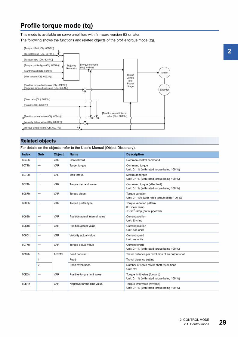
Profile torque mode (tq)This mode is available on servo amplifiers with firmware version B2 or later.The following shows the functions and related objects of the profile torque mode (tq).
Related objectsFor details on the objects, refer to the User's Manual (Object Dictionary).
Index Sub Object Name Description6040h VAR Controlword Common control command
6071h VAR Target torque Command torqueUnit: 0.1 % (with rated torque being 100 %)
6072h VAR Max torque Maximum torqueUnit: 0.1 % (with rated torque being 100 %)
6074h VAR Torque demand value Command torque (after limit)Unit: 0.1 % (with rated torque being 100 %)
6087h VAR Torque slope Torque variationUnit: 0.1 %/s (with rated torque being 100 %)
6088h VAR Torque profile type Torque variation pattern0: Linear ramp1: Sin2 ramp (not supported)
6063h VAR Position actual internal value Current positionUnit: Enc inc
6064h VAR Position actual value Current positionUnit: pos units
606Ch VAR Velocity actual value Current speedUnit: vel units
6077h VAR Torque actual value Current torqueUnit: 0.1 % (with rated torque being 100 %)
6092h 0 ARRAY Feed constant Travel distance per revolution of an output shaft
1 Feed Travel distance setting
2 Shaft revolutions Number of servo motor shaft revolutionsUnit: rev
60E0h VAR Positive torque limit value Torque limit value (forward)Unit: 0.1 % (with rated torque being 100 %)
60E1h VAR Negative torque limit value Torque limit value (reverse)Unit: 0.1 % (with rated torque being 100 %)
TorqueControl
andPowerStage
[Torque demand(Obj. 6074h)]
[Position actual internalvalue (Obj. 6063h)]
TrajectryGenerator
[Target slope (Obj. 6087h)]
[Torque profile type (Obj. 6088h)]
[Torque actual value (Obj. 6077h)]
[Position actual value (Obj. 6064h)]
[Velocity actual value (Obj. 606Ch)]
[Positive torque limit value (Obj. 60E0h)][Negative torque limit value (Obj. 60E1h)]
[Controlword (Obj. 6040h)]
[Max torque (Obj. 6072h)]
[Target torque (Obj. 6071h)]
[Torque offset (Obj. 60B2h)]
[Polarity (Obj. 607Eh)]
[Gear ratio (Obj. 6091h)]
Encoder
Motor
×
×
×
×
× ×
++
2 CONTROL MODE2.1 Control mode 29
30
Controlword/StatuswordBy changing [Controlword (Obj. 6040h)], control commands can be given to the servo amplifier. The control status can also be checked with [Statusword (Obj. 6041h)].Some bits of [Controlword (Obj. 6040h)] and [Statusword (Obj. 6041h)] vary or are common depending on the control mode. The bits that vary depending on the control mode are listed in the following tables.
■Controlword OMS Bit (tq)
■Statusword OMS Bit (tq)
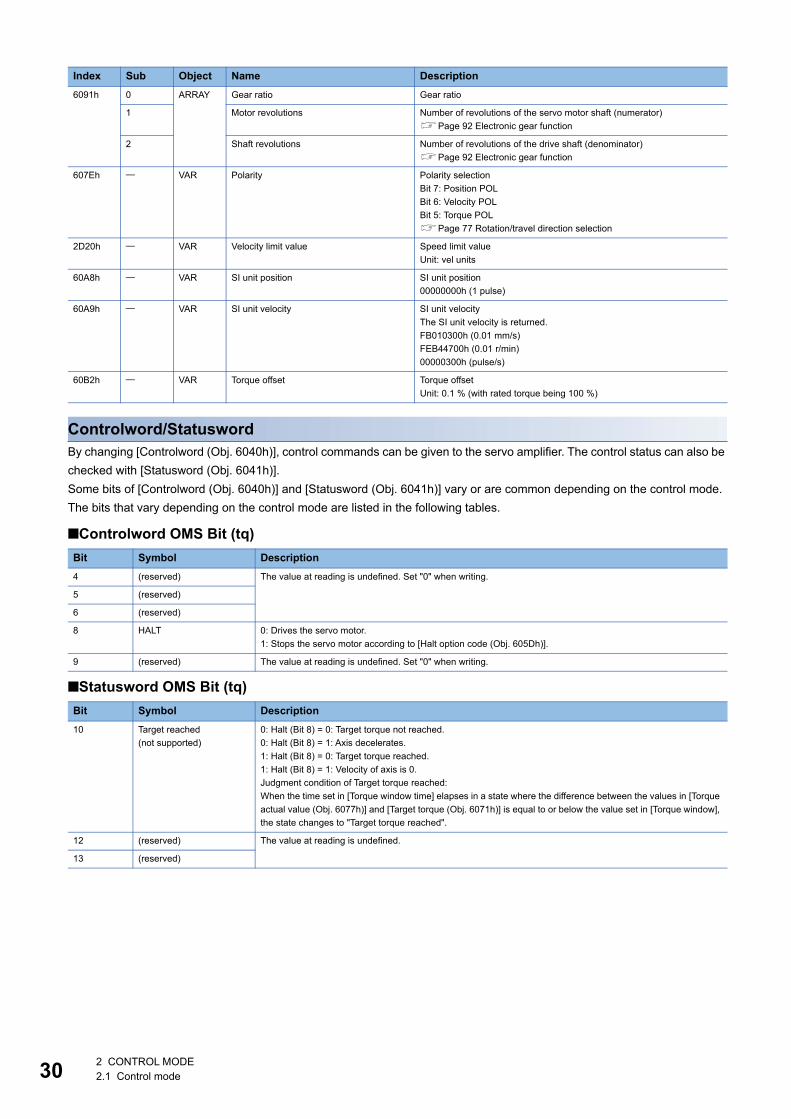
6091h 0 ARRAY Gear ratio Gear ratio
1 Motor revolutions Number of revolutions of the servo motor shaft (numerator)Page 92 Electronic gear function
2 Shaft revolutions Number of revolutions of the drive shaft (denominator)Page 92 Electronic gear function
607Eh VAR Polarity Polarity selectionBit 7: Position POLBit 6: Velocity POLBit 5: Torque POLPage 77 Rotation/travel direction selection
2D20h VAR Velocity limit value Speed limit valueUnit: vel units
60A8h VAR SI unit position SI unit position00000000h (1 pulse)
60A9h VAR SI unit velocity SI unit velocityThe SI unit velocity is returned.FB010300h (0.01 mm/s)FEB44700h (0.01 r/min)00000300h (pulse/s)
60B2h VAR Torque offset Torque offsetUnit: 0.1 % (with rated torque being 100 %)
Bit Symbol Description4 (reserved) The value at reading is undefined. Set "0" when writing.
5 (reserved)
6 (reserved)
8 HALT 0: Drives the servo motor.1: Stops the servo motor according to [Halt option code (Obj. 605Dh)].
9 (reserved) The value at reading is undefined. Set "0" when writing.
Bit Symbol Description10 Target reached
(not supported)0: Halt (Bit 8) = 0: Target torque not reached.0: Halt (Bit 8) = 1: Axis decelerates.1: Halt (Bit 8) = 0: Target torque reached.1: Halt (Bit 8) = 1: Velocity of axis is 0.Judgment condition of Target torque reached:When the time set in [Torque window time] elapses in a state where the difference between the values in [Torque actual value (Obj. 6077h)] and [Target torque (Obj. 6071h)] is equal to or below the value set in [Torque window], the state changes to "Target torque reached".
12 (reserved) The value at reading is undefined.
13 (reserved)
Index Sub Object Name Description
2 CONTROL MODE2.1 Control mode
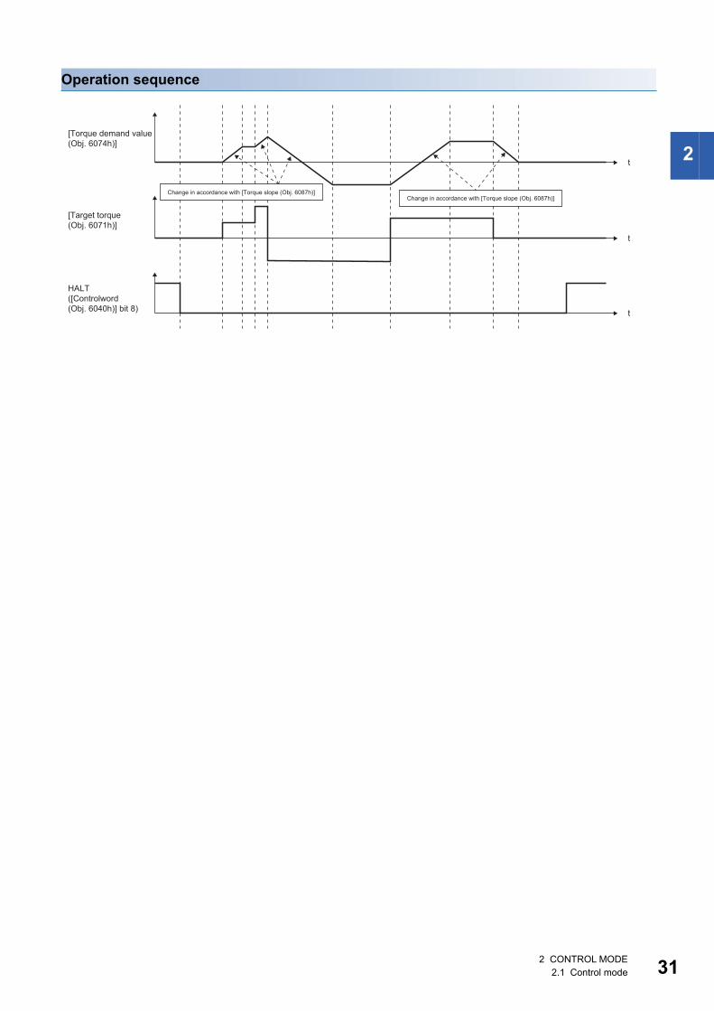
2
Operation sequence
HALT([Controlword (Obj. 6040h)] bit 8)
[Torque demand value (Obj. 6074h)]
[Target torque (Obj. 6071h)]
t
t
t
Change in accordance with [Torque slope (Obj. 6087h)]Change in accordance with [Torque slope (Obj. 6087h)]
2 CONTROL MODE2.1 Control mode 31
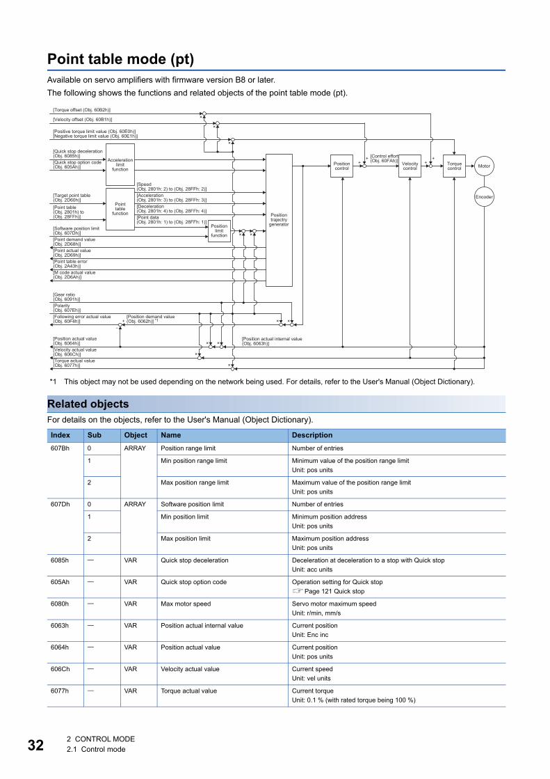
32
Point table mode (pt)Available on servo amplifiers with firmware version B8 or later.The following shows the functions and related objects of the point table mode (pt).
*1 This object may not be used depending on the network being used. For details, refer to the User's Manual (Object Dictionary).
Related objectsFor details on the objects, refer to the User's Manual (Object Dictionary).
Index Sub Object Name Description607Bh 0 ARRAY Position range limit Number of entries
1 Min position range limit Minimum value of the position range limitUnit: pos units
2 Max position range limit Maximum value of the position range limitUnit: pos units
607Dh 0 ARRAY Software position limit Number of entries
1 Min position limit Minimum position addressUnit: pos units
2 Max position limit Maximum position addressUnit: pos units
6085h VAR Quick stop deceleration Deceleration at deceleration to a stop with Quick stopUnit: acc units
605Ah VAR Quick stop option code Operation setting for Quick stopPage 121 Quick stop
6080h VAR Max motor speed Servo motor maximum speedUnit: r/min, mm/s
6063h VAR Position actual internal value Current positionUnit: Enc inc
6064h VAR Position actual value Current positionUnit: pos units
606Ch VAR Velocity actual value Current speedUnit: vel units
6077h VAR Torque actual value Current torqueUnit: 0.1 % (with rated torque being 100 %)
Positiontrajectry
generator
× ×
[Control effort(Obj. 60FAh)]
[Position actual internal value (Obj. 6063h)]×
×
×
×
+
++
++
-
Accelerationlimit
function
Positionlimit
function
Positioncontrol
Velocitycontrol
Torquecontrol
Encoder
Motor
[Positive torque limit value (Obj. 60E0h)][Negative torque limit value (Obj. 60E1h)]
[Quick stop deceleration(Obj. 6085h)]
[Torque offset (Obj. 60B2h)]
[Velocity offset (Obj. 60B1h)]
[Quick stop option code(Obj. 605Ah)]
[Target point table (Obj. 2D60h)]
[Software position limit(Obj. 607Dh)][Point demand value(Obj. 2D68h)]
[Gear ratio(Obj. 6091h)][Polarity(Obj. 607Eh)][Following error actual value(Obj. 60F4h)]
[Position demand value (Obj. 6062h)] *1
[Position actual value(Obj. 6064h)][Velocity actual value(Obj. 606Ch)][Torque actual value(Obj. 6077h)]
[Point table(Obj. 2801h) to(Obj. 28FFh)]
[Point table error(Obj. 2A43h)][M code actual value(Obj. 2D6Ah)]
[Point actual value(Obj. 2D69h)]
×
[Speed(Obj. 2801h: 2) to (Obj. 28FFh: 2)][Acceleration(Obj. 2801h: 3) to (Obj. 28FFh: 3)][Deceleration(Obj. 2801h: 4) to (Obj. 28FFh: 4)][Point data(Obj. 2801h: 1) to (Obj. 28FFh: 1)]
Pointtable
function
× ×
×
×
2 CONTROL MODE2.1 Control mode
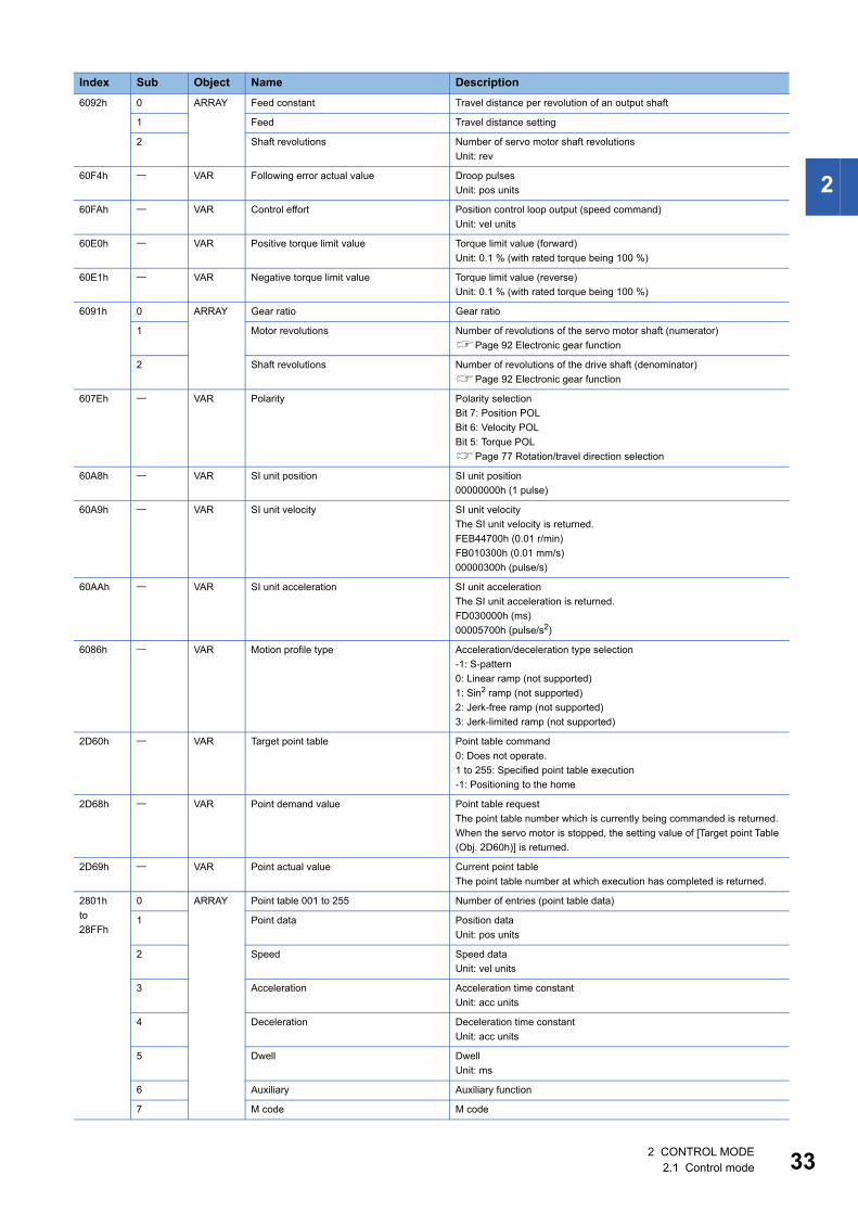
2
6092h 0 ARRAY Feed constant Travel distance per revolution of an output shaft
1 Feed Travel distance setting
2 Shaft revolutions Number of servo motor shaft revolutionsUnit: rev
60F4h VAR Following error actual value Droop pulsesUnit: pos units
60FAh VAR Control effort Position control loop output (speed command)Unit: vel units
60E0h VAR Positive torque limit value Torque limit value (forward)Unit: 0.1 % (with rated torque being 100 %)
60E1h VAR Negative torque limit value Torque limit value (reverse)Unit: 0.1 % (with rated torque being 100 %)
6091h 0 ARRAY Gear ratio Gear ratio
1 Motor revolutions Number of revolutions of the servo motor shaft (numerator)Page 92 Electronic gear function
2 Shaft revolutions Number of revolutions of the drive shaft (denominator)Page 92 Electronic gear function
607Eh VAR Polarity Polarity selectionBit 7: Position POLBit 6: Velocity POLBit 5: Torque POLPage 77 Rotation/travel direction selection
60A8h VAR SI unit position SI unit position00000000h (1 pulse)
60A9h VAR SI unit velocity SI unit velocityThe SI unit velocity is returned.FEB44700h (0.01 r/min)FB010300h (0.01 mm/s)00000300h (pulse/s)
60AAh VAR SI unit acceleration SI unit accelerationThe SI unit acceleration is returned.FD030000h (ms)00005700h (pulse/s2)
6086h VAR Motion profile type Acceleration/deceleration type selection-1: S-pattern0: Linear ramp (not supported)1: Sin2 ramp (not supported)2: Jerk-free ramp (not supported)3: Jerk-limited ramp (not supported)
2D60h VAR Target point table Point table command0: Does not operate.1 to 255: Specified point table execution-1: Positioning to the home
2D68h VAR Point demand value Point table requestThe point table number which is currently being commanded is returned.When the servo motor is stopped, the setting value of [Target point Table (Obj. 2D60h)] is returned.
2D69h VAR Point actual value Current point tableThe point table number at which execution has completed is returned.
2801hto28FFh
0 ARRAY Point table 001 to 255 Number of entries (point table data)
1 Point data Position dataUnit: pos units
2 Speed Speed dataUnit: vel units
3 Acceleration Acceleration time constantUnit: acc units
4 Deceleration Deceleration time constantUnit: acc units
5 Dwell DwellUnit: ms
6 Auxiliary Auxiliary function
7 M code M code
Index Sub Object Name Description
2 CONTROL MODE2.1 Control mode 33
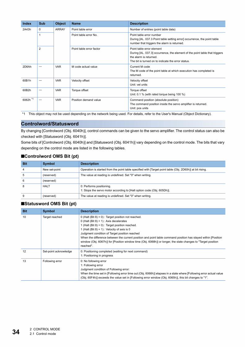
34
*1 This object may not be used depending on the network being used. For details, refer to the User's Manual (Object Dictionary).
Controlword/StatuswordBy changing [Controlword (Obj. 6040h)], control commands can be given to the servo amplifier. The control status can also be checked with [Statusword (Obj. 6041h)].Some bits of [Controlword (Obj. 6040h)] and [Statusword (Obj. 6041h)] vary depending on the control mode. The bits that vary depending on the control mode are listed in the following tables.
■Controlword OMS Bit (pt)
■Statusword OMS Bit (pt)
2A43h 0 ARRAY Point table error Number of entries (point table data)
1 Point table error No. Point table error numberDuring [AL. 037.3 Point table setting error] occurrence, the point table number that triggers the alarm is returned.
2 Point table error factor Point table error elementDuring [AL. 037.3] occurrence, the element of the point table that triggers the alarm is returned.The bit is turned on to indicate the error status.
2D6Ah VAR M code actual value Current M codeThe M code of the point table at which execution has completed is returned.
60B1h VAR Velocity offset Velocity offsetUnit: vel units
60B2h VAR Torque offset Torque offsetUnit: 0.1 % (with rated torque being 100 %)
6062h *1 VAR Position demand value Command position (absolute position)The command position inside the servo amplifier is returned.Unit: pos units
Bit Symbol Description4 New set-point Operation is started from the point table specified with [Target point table (Obj. 2D60h)] at bit rising.
5 (reserved) The value at reading is undefined. Set "0" when writing.
6 (reserved)
8 HALT 0: Performs positioning.1: Stops the servo motor according to [Halt option code (Obj. 605Dh)].
9 (reserved) The value at reading is undefined. Set "0" when writing.
Bit Symbol Description10 Target reached 0 (Halt (Bit 8) = 0) : Target position not reached.
0 (Halt (Bit 8) = 1) : Axis decelerates1 (Halt (Bit 8) = 0) : Target position reached.1 (Halt (Bit 8) = 1) : Velocity of axis is 0Judgment condition of Target position reachedWhen the difference between the current position and point table command position has stayed within [Position window (Obj. 6067h)] for [Position window time (Obj. 6068h)] or longer, the state changes to "Target position reached".
12 Set-point acknowledge 0: Positioning completed (waiting for next command)1: Positioning in progress
13 Following error 0: No following error1: Following errorJudgment condition of Following error:When the time set in [Following error time out (Obj. 6066h)] elapses in a state where [Following error actual value (Obj. 60F4h)] exceeds the value set in [Following error window (Obj. 6065h)], this bit changes to "1".
Index Sub Object Name Description
2 CONTROL MODE2.1 Control mode
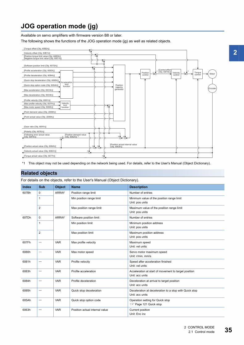
2
JOG operation mode (jg)Available on servo amplifiers with firmware version B8 or later.The following shows the functions of the JOG operation mode (jg) as well as related objects.
*1 This object may not be used depending on the network being used. For details, refer to the User's Manual (Object Dictionary).
Related objectsFor details on the objects, refer to the User's Manual (Object Dictionary).
Index Sub Object Name Description607Bh 0 ARRAY Position range limit Number of entries
1 Min position range limit Minimum value of the position range limitUnit: pos units
2 Max position range limit Maximum value of the position range limitUnit: pos units
607Dh 0 ARRAY Software position limit Number of entries
1 Min position limit Minimum position addressUnit: pos units
2 Max position limit Maximum position addressUnit: pos units
607Fh VAR Max profile velocity Maximum speedUnit: vel units
6080h VAR Max motor speed Servo motor maximum speedUnit: r/min, mm/s
6081h VAR Profile velocity Speed after acceleration finishedUnit: vel units
6083h VAR Profile acceleration Acceleration at start of movement to target positionUnit: acc units
6084h VAR Profile deceleration Deceleration at arrival to target positionUnit: acc units
6085h VAR Quick stop deceleration Deceleration at deceleration to a stop with Quick stopUnit: acc units
605Ah VAR Quick stop option code Operation setting for Quick stopPage 121 Quick stop
6063h VAR Position actual internal value Current positionUnit: Enc inc
Positiontrajectry
generator
××
[Control effort (Obj. 60FAh)]
[Position actual internal value(Obj. 6063h)]×
×
×
×
+-
Velocitylimit
function
Accelerationlimit
function
Positioncontrol
Velocitycontrol
Torquecontrol
Encoder
Motor[Profile acceleration (Obj. 6083h)]
[Profile deceleration (Obj. 6084h)]
[Quick stop deceleration (Obj. 6085h)]
[Quick stop option code (Obj. 605Ah)]
[Max acceleration (Obj. 60C5h)]
[Max deceleration (Obj. 60C6h)]
[Profile velocity (Obj. 6081h)]
[Max motor speed (Obj. 6080h)]
[Software position limit (Obj. 607Dh)]
[Gear ratio (Obj. 6091h)]
[Polarity (Obj. 607Eh)][Following error actual value (Obj. 60F4h)]
[Position demand value (Obj. 6062h)] *1
[Position actual value (Obj. 6064h)]
[Velocity actual value (Obj. 606Ch)]
[Point demand value (Obj. 2D68h)]
[Point actual value (Obj. 2D69h)]
[Torque actual value (Obj. 6077h)]
[Max profile velocity (Obj. 607Fh)]
[Positive torque limit value (Obj. 60E0h)][Negative torque limit value (Obj. 60E1h)]
[Velocity offset (Obj. 60B1h)]
[Torque offset (Obj. 60B2h)]
×
×
×
++ ++
×
×
2 CONTROL MODE2.1 Control mode 35
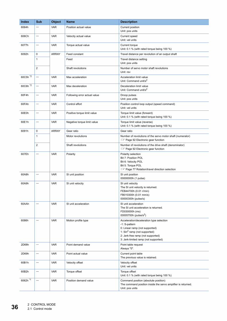
36
6064h VAR Position actual value Current positionUnit: pos units
606Ch VAR Velocity actual value Current speedUnit: vel units
6077h VAR Torque actual value Current torqueUnit: 0.1 % (with rated torque being 100 %)
6092h 0 ARRAY Feed constant Travel distance per revolution of an output shaft
1 Feed Travel distance settingUnit: pos units
2 Shaft revolutions Number of servo motor shaft revolutionsUnit: rev
60C5h *2 VAR Max acceleration Acceleration limit valueUnit: Command unit/s2
60C6h *2 VAR Max deceleration Deceleration limit valueUnit: Command unit/s2
60F4h VAR Following error actual value Droop pulsesUnit: pos units
60FAh VAR Control effort Position control loop output (speed command)Unit: vel units
60E0h VAR Positive torque limit value Torque limit value (forward)Unit: 0.1 % (with rated torque being 100 %)
60E1h VAR Negative torque limit value Torque limit value (reverse)Unit: 0.1 % (with rated torque being 100 %)
6091h 0 ARRAY Gear ratio Gear ratio
1 Motor revolutions Number of revolutions of the servo motor shaft (numerator)Page 92 Electronic gear function
2 Shaft revolutions Number of revolutions of the drive shaft (denominator)Page 92 Electronic gear function
607Eh VAR Polarity Polarity selectionBit 7: Position POLBit 6: Velocity POLBit 5: Torque POLPage 77 Rotation/travel direction selection
60A8h VAR SI unit position SI unit position00000000h (1 pulse)
60A9h VAR SI unit velocity SI unit velocityThe SI unit velocity is returned.FEB44700h (0.01 r/min)FB010300h (0.01 mm/s)00000300h (pulse/s)
60AAh VAR SI unit acceleration SI unit accelerationThe SI unit acceleration is returned.FD030000h (ms)00005700h (pulse/s2)
6086h VAR Motion profile type Acceleration/deceleration type selection-1: S-pattern0: Linear ramp (not supported)1: Sin2 ramp (not supported)2: Jerk-free ramp (not supported)3: Jerk-limited ramp (not supported)
2D68h VAR Point demand value Point table requestAlways "0".
2D69h VAR Point actual value Current point tableThe previous value is retained.
60B1h VAR Velocity offset Velocity offsetUnit: vel units
60B2h VAR Torque offset Torque offsetUnit: 0.1 % (with rated torque being 100 %)
6062h *1 VAR Position demand value Command position (absolute position)The command position inside the servo amplifier is returned.Unit: pos units
Index Sub Object Name Description
2 CONTROL MODE2.1 Control mode
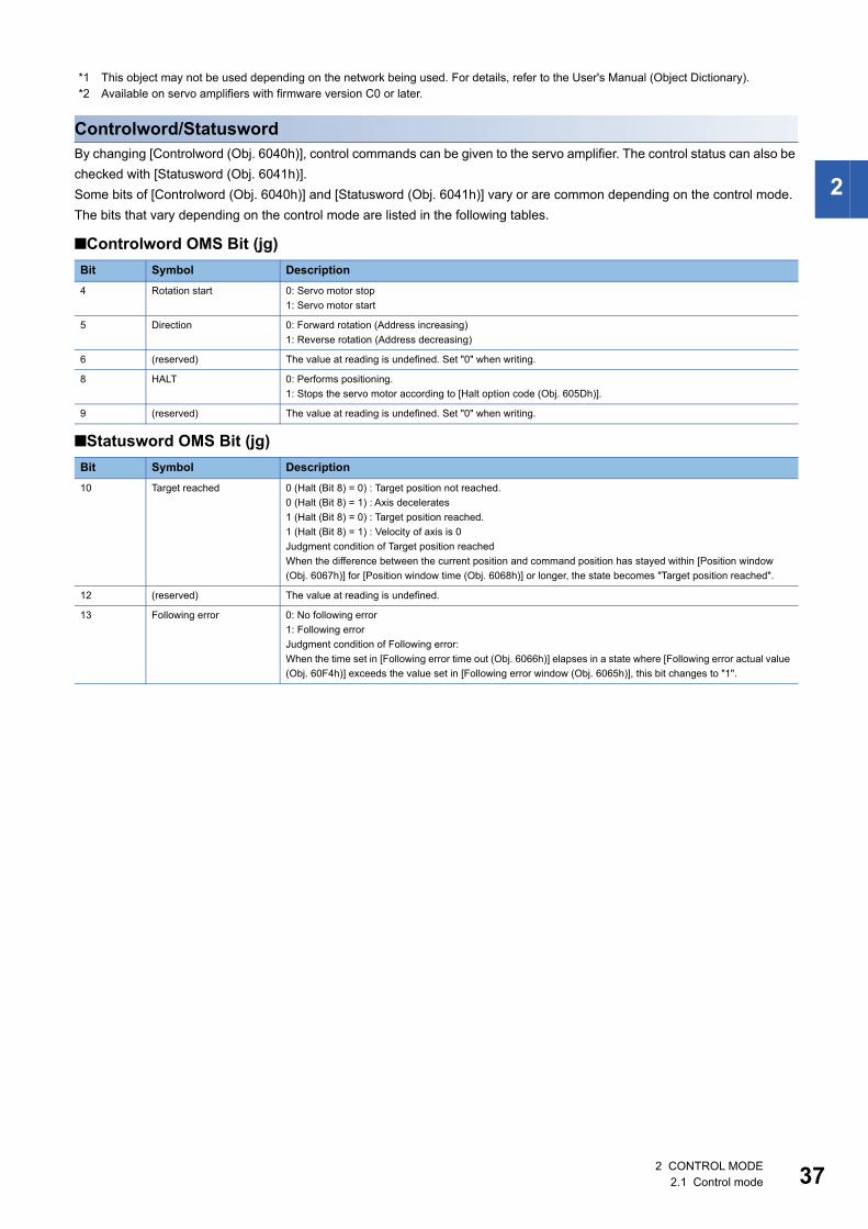
2
*1 This object may not be used depending on the network being used. For details, refer to the User's Manual (Object Dictionary).*2 Available on servo amplifiers with firmware version C0 or later.
Controlword/StatuswordBy changing [Controlword (Obj. 6040h)], control commands can be given to the servo amplifier. The control status can also be checked with [Statusword (Obj. 6041h)].Some bits of [Controlword (Obj. 6040h)] and [Statusword (Obj. 6041h)] vary or are common depending on the control mode. The bits that vary depending on the control mode are listed in the following tables.
■Controlword OMS Bit (jg)
■Statusword OMS Bit (jg)
Bit Symbol Description4 Rotation start 0: Servo motor stop
1: Servo motor start
5 Direction 0: Forward rotation (Address increasing)1: Reverse rotation (Address decreasing)
6 (reserved) The value at reading is undefined. Set "0" when writing.
8 HALT 0: Performs positioning.1: Stops the servo motor according to [Halt option code (Obj. 605Dh)].
9 (reserved) The value at reading is undefined. Set "0" when writing.
Bit Symbol Description10 Target reached 0 (Halt (Bit 8) = 0) : Target position not reached.
0 (Halt (Bit 8) = 1) : Axis decelerates1 (Halt (Bit 8) = 0) : Target position reached.1 (Halt (Bit 8) = 1) : Velocity of axis is 0Judgment condition of Target position reachedWhen the difference between the current position and command position has stayed within [Position window (Obj. 6067h)] for [Position window time (Obj. 6068h)] or longer, the state becomes "Target position reached".
12 (reserved) The value at reading is undefined.
13 Following error 0: No following error1: Following errorJudgment condition of Following error:When the time set in [Following error time out (Obj. 6066h)] elapses in a state where [Following error actual value (Obj. 60F4h)] exceeds the value set in [Following error window (Obj. 6065h)], this bit changes to "1".
2 CONTROL MODE2.1 Control mode 37
38
Continuous operation to torque control mode (ct)This mode is available on servo amplifiers with firmware version B0 or later.
RestrictionsThe following functions are not available in the continuous operation to torque control mode. Therefore, if an alarm occurs, the servo motor will stop using the method DB or EDB, or coast. • Base circuit shut-off delay time function • Forced stop deceleration function • Vertical axis freefall prevention function • Stroke limit function • Software position limit • Auto tuning function • Vibration suppression control 1, 2 • Slight vibration suppression control • One-touch tuning • Quick tuning function
PrecautionsThe relation between the setting value of the command torque and the servo motor torque generation direction can be changed with the setting values of [Pr. PA14 Travel direction selection] and [Pr. PC29.3 Torque POL reflection selection].The servo motor outputs the torque calculated by adding up the command torque and the values set in [Pr. PE47 Unbalanced torque offset] and [Torque offset (Obj. 60B2h)].Switching from the csv mode to the continuous operation to torque control mode while a large value is set in [Velocity offset (Obj. 60B1h)] may cause a shock.In the continuous operation to torque control mode, the response to the torque command is affected. Do not set servo parameters as shown below. • [Pr. PB12 Overshoot amount compensation] is set to a value other than "0". • [Pr. PB24.1 PI-PID switching control selection] is set to "3".
2 CONTROL MODE2.1 Control mode
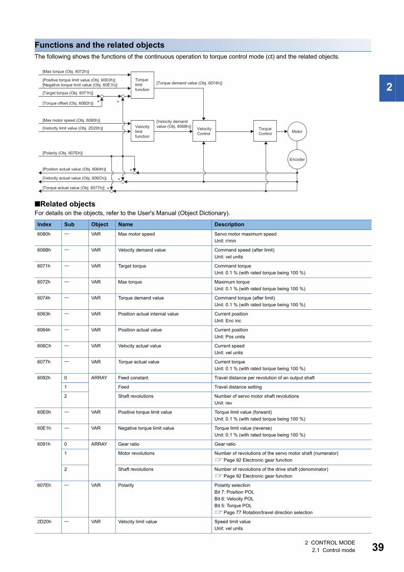
2
Functions and the related objectsThe following shows the functions of the continuous operation to torque control mode (ct) and the related objects.
■Related objectsFor details on the objects, refer to the User's Manual (Object Dictionary).
Index Sub Object Name Description6080h VAR Max motor speed Servo motor maximum speed
Unit: r/min
606Bh VAR Velocity demand value Command speed (after limit)Unit: vel units
6071h VAR Target torque Command torqueUnit: 0.1 % (with rated torque being 100 %)
6072h VAR Max torque Maximum torqueUnit: 0.1 % (with rated torque being 100 %)
6074h VAR Torque demand value Command torque (after limit)Unit: 0.1 % (with rated torque being 100 %)
6063h VAR Position actual internal value Current positionUnit: Enc inc
6064h VAR Position actual value Current positionUnit: Pos units
606Ch VAR Velocity actual value Current speedUnit: vel units
6077h VAR Torque actual value Current torqueUnit: 0.1 % (with rated torque being 100 %)
6092h 0 ARRAY Feed constant Travel distance per revolution of an output shaft
1 Feed Travel distance setting
2 Shaft revolutions Number of servo motor shaft revolutionsUnit: rev
60E0h VAR Positive torque limit value Torque limit value (forward)Unit: 0.1 % (with rated torque being 100 %)
60E1h VAR Negative torque limit value Torque limit value (reverse)Unit: 0.1 % (with rated torque being 100 %)
6091h 0 ARRAY Gear ratio Gear ratio
1 Motor revolutions Number of revolutions of the servo motor shaft (numerator)Page 92 Electronic gear function
2 Shaft revolutions Number of revolutions of the drive shaft (denominator)Page 92 Electronic gear function
607Eh VAR Polarity Polarity selectionBit 7: Position POLBit 6: Velocity POLBit 5: Torque POLPage 77 Rotation/travel direction selection
2D20h VAR Velocity limit value Speed limit valueUnit: vel units
Motor
+
[Max torque (Obj. 6072h)]
[Torque demand value (Obj. 6074h)][Positive torque limit value (Obj. 60E0h)][Negative torque limit value (Obj. 60E1h)]
[Target torque (Obj. 6071h)]
[Torque offset (Obj. 60B2h)]
[Max motor speed (Obj. 6080h)] [Velocity demandvalue (Obj. 6068h)][Velocity limit value (Obj. 2D20h)]
[Polarity (Obj. 607Eh)]
[Position actual value (Obj. 6064h)]
[Velocity actual value (Obj. 606Ch)]
[Torque actual value (Obj. 6077h)]
Encoder
×
×
×
×
Torquelimitfunction
Velocitylimitfunction
VelocityControl
TorqueControl
2 CONTROL MODE2.1 Control mode 39
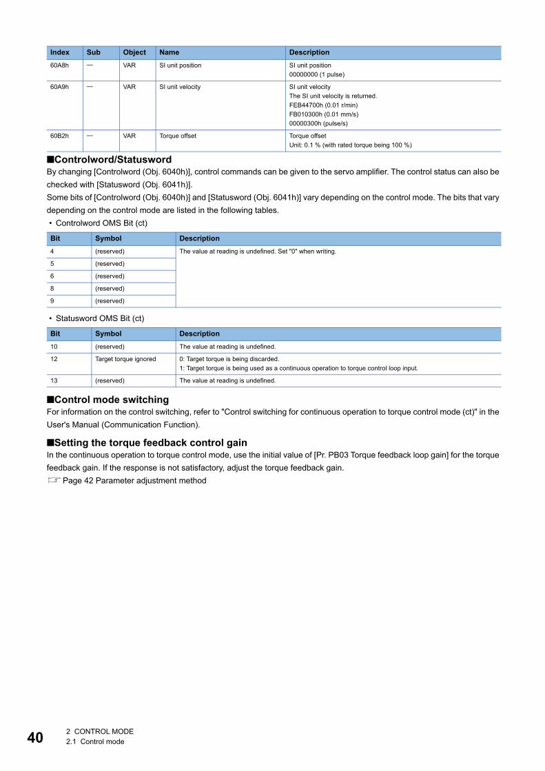
40
■Controlword/StatuswordBy changing [Controlword (Obj. 6040h)], control commands can be given to the servo amplifier. The control status can also be checked with [Statusword (Obj. 6041h)].Some bits of [Controlword (Obj. 6040h)] and [Statusword (Obj. 6041h)] vary depending on the control mode. The bits that vary depending on the control mode are listed in the following tables. • Controlword OMS Bit (ct)
• Statusword OMS Bit (ct)
■Control mode switchingFor information on the control switching, refer to "Control switching for continuous operation to torque control mode (ct)" in the User's Manual (Communication Function).
■Setting the torque feedback control gainIn the continuous operation to torque control mode, use the initial value of [Pr. PB03 Torque feedback loop gain] for the torque feedback gain. If the response is not satisfactory, adjust the torque feedback gain.Page 42 Parameter adjustment method
60A8h VAR SI unit position SI unit position00000000 (1 pulse)
60A9h VAR SI unit velocity SI unit velocityThe SI unit velocity is returned.FEB44700h (0.01 r/min)FB010300h (0.01 mm/s)00000300h (pulse/s)
60B2h VAR Torque offset Torque offsetUnit: 0.1 % (with rated torque being 100 %)
Bit Symbol Description4 (reserved) The value at reading is undefined. Set "0" when writing.
5 (reserved)
6 (reserved)
8 (reserved)
9 (reserved)
Bit Symbol Description10 (reserved) The value at reading is undefined.
12 Target torque ignored 0: Target torque is being discarded.1: Target torque is being used as a continuous operation to torque control loop input.
13 (reserved) The value at reading is undefined.
Index Sub Object Name Description
2 CONTROL MODE2.1 Control mode
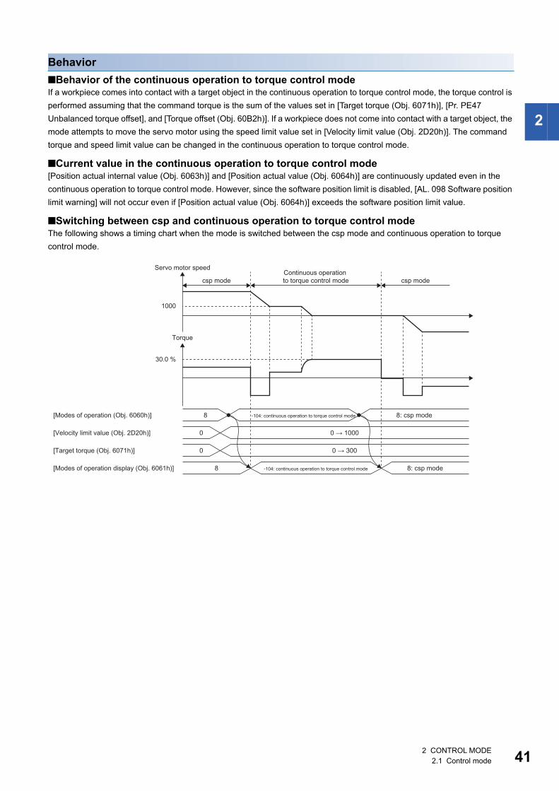
2
Behavior■Behavior of the continuous operation to torque control modeIf a workpiece comes into contact with a target object in the continuous operation to torque control mode, the torque control is performed assuming that the command torque is the sum of the values set in [Target torque (Obj. 6071h)], [Pr. PE47 Unbalanced torque offset], and [Torque offset (Obj. 60B2h)]. If a workpiece does not come into contact with a target object, the mode attempts to move the servo motor using the speed limit value set in [Velocity limit value (Obj. 2D20h)]. The command torque and speed limit value can be changed in the continuous operation to torque control mode.
■Current value in the continuous operation to torque control mode[Position actual internal value (Obj. 6063h)] and [Position actual value (Obj. 6064h)] are continuously updated even in the continuous operation to torque control mode. However, since the software position limit is disabled, [AL. 098 Software position limit warning] will not occur even if [Position actual value (Obj. 6064h)] exceeds the software position limit value.
■Switching between csp and continuous operation to torque control modeThe following shows a timing chart when the mode is switched between the csp mode and continuous operation to torque control mode.
[Modes of operation (Obj. 6060h)]
[Velocity limit value (Obj. 2D20h)]
[Target torque (Obj. 6071h)]
[Modes of operation display (Obj. 6061h)]
8
30.0 %
1000
0
0
8
0 → 1000
0 → 300
Torque
Servo motor speed
csp modeContinuous operation to torque control mode csp mode
-104: continuous operation to torque control mode
-104: continuous operation to torque control mode
8: csp mode
8: csp mode
2 CONTROL MODE2.1 Control mode 41
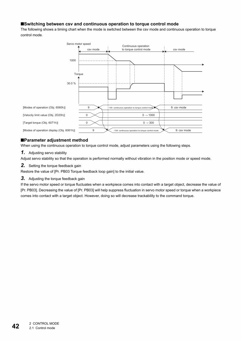
42
■Switching between csv and continuous operation to torque control modeThe following shows a timing chart when the mode is switched between the csv mode and continuous operation to torque control mode.
■Parameter adjustment methodWhen using the continuous operation to torque control mode, adjust parameters using the following steps.
1. Adjusting servo stabilityAdjust servo stability so that the operation is performed normally without vibration in the position mode or speed mode.
2. Setting the torque feedback gainRestore the value of [Pr. PB03 Torque feedback loop gain] to the initial value.
3. Adjusting the torque feedback gainIf the servo motor speed or torque fluctuates when a workpiece comes into contact with a target object, decrease the value of [Pr. PB03]. Decreasing the value of [Pr. PB03] will help suppress fluctuation in servo motor speed or torque when a workpiece comes into contact with a target object. However, doing so will decrease trackability to the command torque.
[Modes of operation (Obj. 6060h)]
[Velocity limit value (Obj. 2D20h)]
[Target torque (Obj. 6071h)]
[Modes of operation display (Obj. 6061h)]
9
30.0 %
1000
0
0
9
0 → 1000
0 → 300
Torque
Servo motor speed
csv modeContinuous operation to torque control mode csv mode
-104: continuous operation to torque control mode
-104: continuous operation to torque control mode
9: csv mode
9: csv mode
2 CONTROL MODE2.1 Control mode
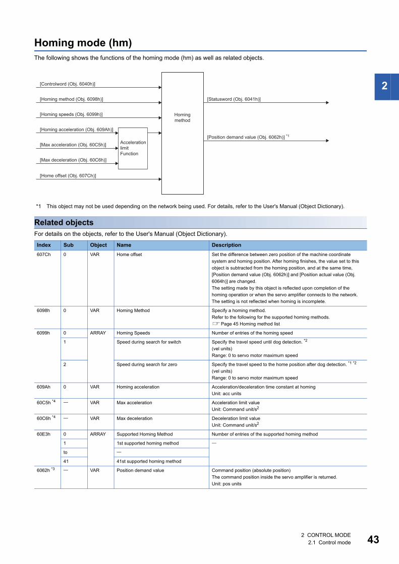
2
Homing mode (hm)The following shows the functions of the homing mode (hm) as well as related objects.
*1 This object may not be used depending on the network being used. For details, refer to the User's Manual (Object Dictionary).
Related objectsFor details on the objects, refer to the User's Manual (Object Dictionary).
Index Sub Object Name Description607Ch 0 VAR Home offset Set the difference between zero position of the machine coordinate
system and homing position. After homing finishes, the value set to this object is subtracted from the homing position, and at the same time, [Position demand value (Obj. 6062h)] and [Position actual value (Obj. 6064h)] are changed.The setting made by this object is reflected upon completion of the homing operation or when the servo amplifier connects to the network. The setting is not reflected when homing is incomplete.
6098h 0 VAR Homing Method Specify a homing method.Refer to the following for the supported homing methods.Page 45 Homing method list
6099h 0 ARRAY Homing Speeds Number of entries of the homing speed
1 Speed during search for switch Specify the travel speed until dog detection. *2
(vel units)Range: 0 to servo motor maximum speed
2 Speed during search for zero Specify the travel speed to the home position after dog detection. *1 *2
(vel units)Range: 0 to servo motor maximum speed
609Ah 0 VAR Homing acceleration Acceleration/deceleration time constant at homingUnit: acc units
60C5h *4 VAR Max acceleration Acceleration limit valueUnit: Command unit/s2
60C6h *4 VAR Max deceleration Deceleration limit valueUnit: Command unit/s2
60E3h 0 ARRAY Supported Homing Method Number of entries of the supported homing method
1 1st supported homing method
to
41 41st supported homing method
6062h *3 VAR Position demand value Command position (absolute position)The command position inside the servo amplifier is returned.Unit: pos units
[Controlword (Obj. 6040h)]
[Homing acceleration (Obj. 609Ah)]
[Homing method (Obj. 6098h)]
[Homing speeds (Obj. 6099h)]
[Home offset (Obj. 607Ch)]
Homingmethod
[Statusword (Obj. 6041h)]
[Position demand value (Obj. 6062h)] *1
[Max acceleration (Obj. 60C5h)] Acceleration limit Function
[Max deceleration (Obj. 60C6h)]
2 CONTROL MODE2.1 Control mode 43
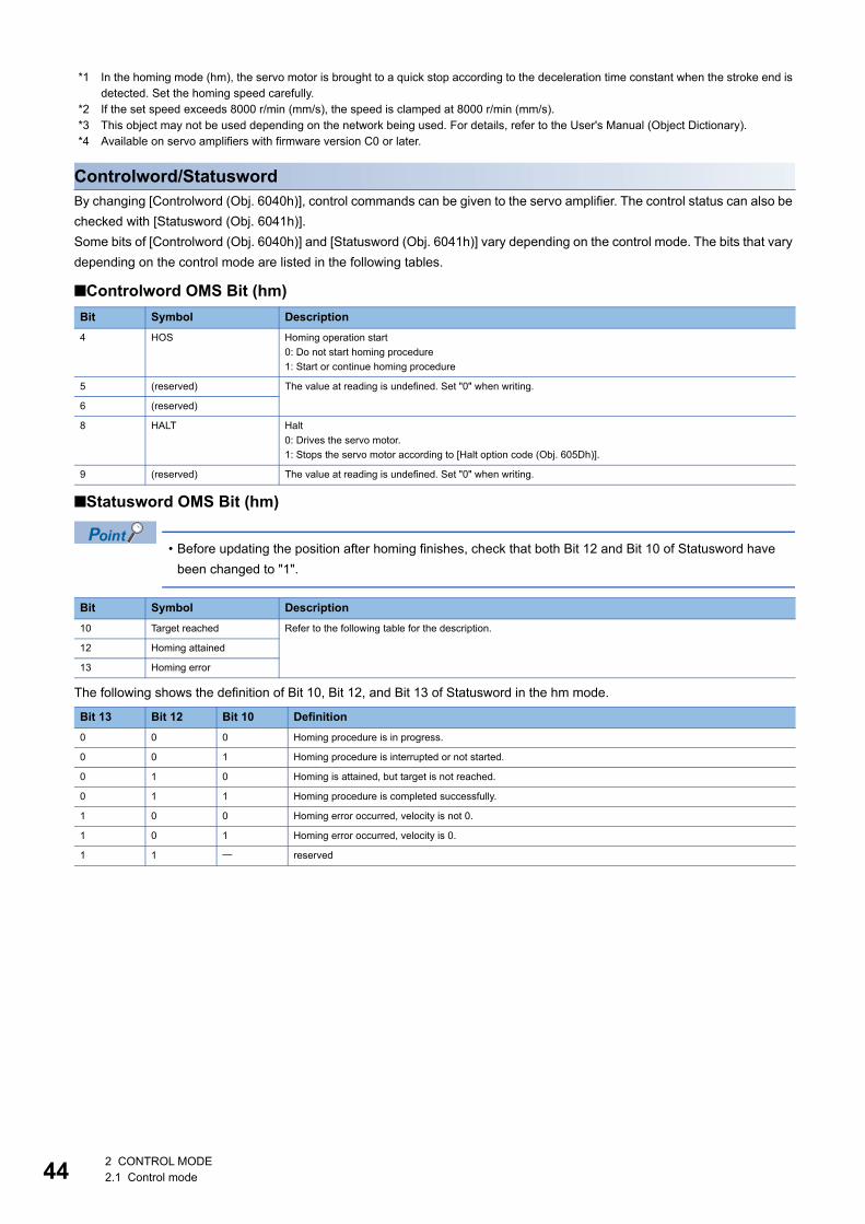
44
*1 In the homing mode (hm), the servo motor is brought to a quick stop according to the deceleration time constant when the stroke end is detected. Set the homing speed carefully.
*2 If the set speed exceeds 8000 r/min (mm/s), the speed is clamped at 8000 r/min (mm/s).*3 This object may not be used depending on the network being used. For details, refer to the User's Manual (Object Dictionary).*4 Available on servo amplifiers with firmware version C0 or later.
Controlword/StatuswordBy changing [Controlword (Obj. 6040h)], control commands can be given to the servo amplifier. The control status can also be checked with [Statusword (Obj. 6041h)].Some bits of [Controlword (Obj. 6040h)] and [Statusword (Obj. 6041h)] vary depending on the control mode. The bits that vary depending on the control mode are listed in the following tables.
■Controlword OMS Bit (hm)
■Statusword OMS Bit (hm)
• Before updating the position after homing finishes, check that both Bit 12 and Bit 10 of Statusword have been changed to "1".
The following shows the definition of Bit 10, Bit 12, and Bit 13 of Statusword in the hm mode.
Bit Symbol Description4 HOS Homing operation start
0: Do not start homing procedure1: Start or continue homing procedure
5 (reserved) The value at reading is undefined. Set "0" when writing.
6 (reserved)
8 HALT Halt0: Drives the servo motor.1: Stops the servo motor according to [Halt option code (Obj. 605Dh)].
9 (reserved) The value at reading is undefined. Set "0" when writing.
Bit Symbol Description10 Target reached Refer to the following table for the description.
12 Homing attained
13 Homing error
Bit 13 Bit 12 Bit 10 Definition0 0 0 Homing procedure is in progress.
0 0 1 Homing procedure is interrupted or not started.
0 1 0 Homing is attained, but target is not reached.
0 1 1 Homing procedure is completed successfully.
1 0 0 Homing error occurred, velocity is not 0.
1 0 1 Homing error occurred, velocity is 0.
1 1 reserved
2 CONTROL MODE2.1 Control mode
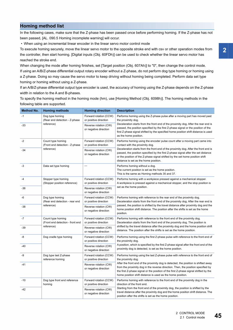
2
Homing method listIn the following cases, make sure that the Z-phase has been passed once before performing homing. If the Z-phase has not been passed, [AL. 090.5 Homing incomplete warning] will occur. • When using an incremental linear encoder in the linear servo motor control modeTo execute homing securely, move the linear servo motor to the opposite stroke end with csv or other operation modes from the controller, then start homing. [Digital inputs (Obj. 60FDh)] can be used to check whether the linear servo motor has reached the stroke end.When changing the mode after homing finishes, set [Target position (Obj. 607Ah)] to "0", then change the control mode.If using an A/B/Z-phase differential output rotary encoder without a Z-phase, do not perform dog type homing or homing using a Z-phase. Doing so may cause the servo motor to keep driving without homing being completed. Perform data set type homing or homing without using a Z-phase.If an A/B/Z-phase differential output type encoder is used, the accuracy of homing using the Z-phase depends on the Z-phase width in relation to the A and B-phases.To specify the homing method in the homing mode (hm), use [Homing Method (Obj. 6098h)]. The homing methods in the following table are supported.
Method No. Homing methods Homing direction Description-1 Dog type homing
(Rear end detection - Z-phase reference)
Forward rotation (CCW) or positive direction
Performs homing using the Z-phase pulse after a moving part has moved past the proximity dog.Deceleration starts from the front end of the proximity dog. After the rear end is passed, the position specified by the first Z-phase signal or the position of the first Z-phase signal shifted by the specified home position shift distance is used as the home position.
-33 Reverse rotation (CW) or negative direction
-2 Count type homing(Front end detection - Z-phase reference)
Forward rotation (CCW) or positive direction
Performs homing using the encoder pulse count after a moving part came into contact with the proximity dog.Deceleration starts from the front end of the proximity dog. After the front end is passed, the position specified by the first Z-phase signal after the set distance or the position of the Z-phase signal shifted by the set home position shift distance is set as the home position.
-34 Reverse rotation (CW) or negative direction
-3 Data set type homing Performs homing without a dog.The current position is set as the home position.This is the same as Homing methods 35 and 37.
-4 Stopper type homing(Stopper position reference)
Forward rotation (CCW) or positive direction
Performs homing with a workpiece pressed against a mechanical stopper.A workpiece is pressed against a mechanical stopper, and the stop position is set as the home position.-36 Reverse rotation (CW)
or negative direction
-6 Dog type homing(Rear end detection - rear end reference)
Forward rotation (CCW) or positive direction
Performs homing with reference to the rear end of the proximity dog.Deceleration starts from the front end of the proximity dog. After the rear end is passed, the position is shifted by the travel distance after proximity dog and the home position shift distance. The position after the shifts is set as the home position.
-38 Reverse rotation (CW) or negative direction
-7 Count type homing(Front end detection - front end reference)
Forward rotation (CCW) or positive direction
Performs homing with reference to the front end of the proximity dog.Deceleration starts from the front end of the proximity dog. The position is shifted by the travel distance after the proximity dog and the home position shift distance. The position after the shifts is set as the home position.
-39 Reverse rotation (CW) or negative direction
-8 Dog cradle type homing Forward rotation (CCW) or positive direction
Performs homing using the first Z-phase pulse with reference to the front end of the proximity dog.A position, which is specified by the first Z-phase signal after the front end of the proximity dog is detected, is set as the home position.
-40 Reverse rotation (CW) or negative direction
-9 Dog type last Z-phase reference homing
Forward rotation (CCW) or positive direction
Performs homing using the last Z-phase pulse with reference to the front end of the proximity dog.After the front end of the proximity dog is detected, the position is shifted away from the proximity dog in the reverse direction. Then, the position specified by the first Z-phase signal or the position of the first Z-phase signal shifted by the home position shift distance is used as the home position.
-41 Reverse rotation (CW) or negative direction
-10 Dog type front end reference homing
Forward rotation (CCW) or positive direction
Performs homing with reference to the front end of the proximity dog in the direction of the front end.Starting from the front end of the proximity dog, the position is shifted by the travel distance after the proximity dog and the home position shift distance. The position after the shifts is set as the home position.
-42 Reverse rotation (CW) or negative direction
2 CONTROL MODE2.1 Control mode 45
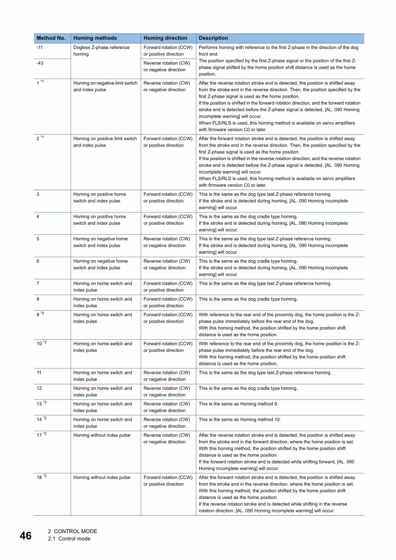
46
-11 Dogless Z-phase reference homing
Forward rotation (CCW) or positive direction
Performs homing with reference to the first Z-phase in the direction of the dog front end.The position specified by the first Z-phase signal or the position of the first Z-phase signal shifted by the home position shift distance is used as the home position.
-43 Reverse rotation (CW) or negative direction
1 *1 Homing on negative limit switch and index pulse
Reverse rotation (CW) or negative direction
After the reverse rotation stroke end is detected, the position is shifted away from the stroke end in the reverse direction. Then, the position specified by the first Z-phase signal is used as the home position.If the position is shifted in the forward rotation direction, and the forward rotation stroke end is detected before the Z-phase signal is detected, [AL. 090 Homing incomplete warning] will occur.When FLS/RLS is used, this homing method is available on servo amplifiers with firmware version C0 or later.
2 *1 Homing on positive limit switch and index pulse
Forward rotation (CCW) or positive direction
After the forward rotation stroke end is detected, the position is shifted away from the stroke end in the reverse direction. Then, the position specified by the first Z-phase signal is used as the home position.If the position is shifted in the reverse rotation direction, and the reverse rotation stroke end is detected before the Z-phase signal is detected, [AL. 090 Homing incomplete warning] will occur.When FLS/RLS is used, this homing method is available on servo amplifiers with firmware version C0 or later.
3 Homing on positive home switch and index pulse
Forward rotation (CCW) or positive direction
This is the same as the dog type last Z-phase reference homing.If the stroke end is detected during homing, [AL. 090 Homing incomplete warning] will occur.
4 Homing on positive home switch and index pulse
Forward rotation (CCW) or positive direction
This is the same as the dog cradle type homing.If the stroke end is detected during homing, [AL. 090 Homing incomplete warning] will occur.
5 Homing on negative home switch and index pulse
Reverse rotation (CW) or negative direction
This is the same as the dog type last Z-phase reference homing.If the stroke end is detected during homing, [AL. 090 Homing incomplete warning] will occur.
6 Homing on negative home switch and index pulse
Reverse rotation (CW) or negative direction
This is the same as the dog cradle type homing.If the stroke end is detected during homing, [AL. 090 Homing incomplete warning] will occur.
7 Homing on home switch and index pulse
Forward rotation (CCW) or positive direction
This is the same as the dog type last Z-phase reference homing.
8 Homing on home switch and index pulse
Forward rotation (CCW) or positive direction
This is the same as the dog cradle type homing.
9 *2 Homing on home switch and index pulse
Forward rotation (CCW) or positive direction
With reference to the rear end of the proximity dog, the home position is the Z-phase pulse immediately before the rear end of the dog.With this homing method, the position shifted by the home position shift distance is used as the home position.
10 *2 Homing on home switch and index pulse
Forward rotation (CCW) or positive direction
With reference to the rear end of the proximity dog, the home position is the Z-phase pulse immediately before the rear end of the dog.With this homing method, the position shifted by the home position shift distance is used as the home position.
11 Homing on home switch and index pulse
Reverse rotation (CW) or negative direction
This is the same as the dog type last Z-phase reference homing.
12 Homing on home switch and index pulse
Reverse rotation (CW) or negative direction
This is the same as the dog cradle type homing.
13 *2 Homing on home switch and index pulse
Reverse rotation (CW) or negative direction
This is the same as Homing method 9.
14 *2 Homing on home switch and index pulse
Reverse rotation (CW) or negative direction
This is the same as Homing method 10.
17 *2 Homing without index pulse Reverse rotation (CW) or negative direction
After the reverse rotation stroke end is detected, the position is shifted away from the stroke end in the forward direction, where the home position is set.With this homing method, the position shifted by the home position shift distance is used as the home position.If the forward rotation stroke end is detected while shifting forward, [AL. 090 Homing incomplete warning] will occur.
18 *2 Homing without index pulse Forward rotation (CCW) or positive direction
After the forward rotation stroke end is detected, the position is shifted away from the stroke end in the reverse direction, where the home position is set.With this homing method, the position shifted by the home position shift distance is used as the home position.If the reverse rotation stroke end is detected while shifting in the reverse rotation direction, [AL. 090 Homing incomplete warning] will occur.
Method No. Homing methods Homing direction Description
2 CONTROL MODE2.1 Control mode
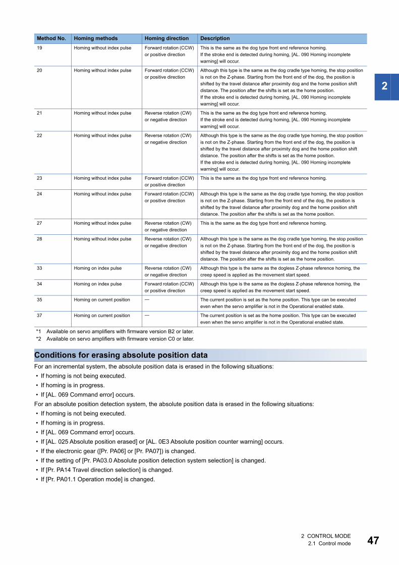
2
*1 Available on servo amplifiers with firmware version B2 or later.*2 Available on servo amplifiers with firmware version C0 or later.
Conditions for erasing absolute position dataFor an incremental system, the absolute position data is erased in the following situations: • If homing is not being executed. • If homing is in progress. • If [AL. 069 Command error] occurs.For an absolute position detection system, the absolute position data is erased in the following situations: • If homing is not being executed. • If homing is in progress. • If [AL. 069 Command error] occurs. • If [AL. 025 Absolute position erased] or [AL. 0E3 Absolute position counter warning] occurs. • If the electronic gear ([Pr. PA06] or [Pr. PA07]) is changed. • If the setting of [Pr. PA03.0 Absolute position detection system selection] is changed. • If [Pr. PA14 Travel direction selection] is changed. • If [Pr. PA01.1 Operation mode] is changed.
19 Homing without index pulse Forward rotation (CCW) or positive direction
This is the same as the dog type front end reference homing.If the stroke end is detected during homing, [AL. 090 Homing incomplete warning] will occur.
20 Homing without index pulse Forward rotation (CCW) or positive direction
Although this type is the same as the dog cradle type homing, the stop position is not on the Z-phase. Starting from the front end of the dog, the position is shifted by the travel distance after proximity dog and the home position shift distance. The position after the shifts is set as the home position.If the stroke end is detected during homing, [AL. 090 Homing incomplete warning] will occur.
21 Homing without index pulse Reverse rotation (CW) or negative direction
This is the same as the dog type front end reference homing.If the stroke end is detected during homing, [AL. 090 Homing incomplete warning] will occur.
22 Homing without index pulse Reverse rotation (CW) or negative direction
Although this type is the same as the dog cradle type homing, the stop position is not on the Z-phase. Starting from the front end of the dog, the position is shifted by the travel distance after proximity dog and the home position shift distance. The position after the shifts is set as the home position.If the stroke end is detected during homing, [AL. 090 Homing incomplete warning] will occur.
23 Homing without index pulse Forward rotation (CCW) or positive direction
This is the same as the dog type front end reference homing.
24 Homing without index pulse Forward rotation (CCW) or positive direction
Although this type is the same as the dog cradle type homing, the stop position is not on the Z-phase. Starting from the front end of the dog, the position is shifted by the travel distance after proximity dog and the home position shift distance. The position after the shifts is set as the home position.
27 Homing without index pulse Reverse rotation (CW) or negative direction
This is the same as the dog type front end reference homing.
28 Homing without index pulse Reverse rotation (CW) or negative direction
Although this type is the same as the dog cradle type homing, the stop position is not on the Z-phase. Starting from the front end of the dog, the position is shifted by the travel distance after proximity dog and the home position shift distance. The position after the shifts is set as the home position.
33 Homing on index pulse Reverse rotation (CW) or negative direction
Although this type is the same as the dogless Z-phase reference homing, the creep speed is applied as the movement start speed.
34 Homing on index pulse Forward rotation (CCW) or positive direction
Although this type is the same as the dogless Z-phase reference homing, the creep speed is applied as the movement start speed.
35 Homing on current position The current position is set as the home position. This type can be executed even when the servo amplifier is not in the Operational enabled state.
37 Homing on current position The current position is set as the home position. This type can be executed even when the servo amplifier is not in the Operational enabled state.
Method No. Homing methods Homing direction Description
2 CONTROL MODE2.1 Control mode 47
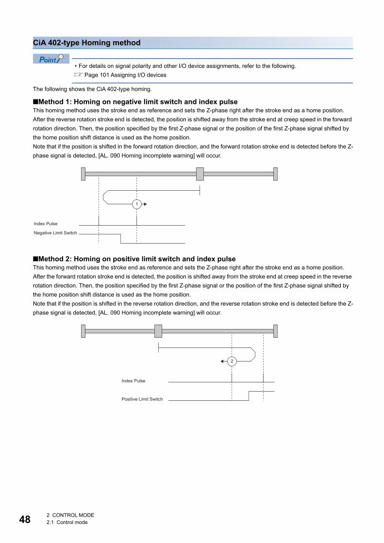
48
CiA 402-type Homing method
• For details on signal polarity and other I/O device assignments, refer to the following.Page 101 Assigning I/O devices
The following shows the CiA 402-type homing.
■Method 1: Homing on negative limit switch and index pulseThis homing method uses the stroke end as reference and sets the Z-phase right after the stroke end as a home position.After the reverse rotation stroke end is detected, the position is shifted away from the stroke end at creep speed in the forward rotation direction. Then, the position specified by the first Z-phase signal or the position of the first Z-phase signal shifted by the home position shift distance is used as the home position.Note that if the position is shifted in the forward rotation direction, and the forward rotation stroke end is detected before the Z-phase signal is detected, [AL. 090 Homing incomplete warning] will occur.
■Method 2: Homing on positive limit switch and index pulseThis homing method uses the stroke end as reference and sets the Z-phase right after the stroke end as a home position.After the forward rotation stroke end is detected, the position is shifted away from the stroke end at creep speed in the reverse rotation direction. Then, the position specified by the first Z-phase signal or the position of the first Z-phase signal shifted by the home position shift distance is used as the home position.Note that if the position is shifted in the reverse rotation direction, and the reverse rotation stroke end is detected before the Z-phase signal is detected, [AL. 090 Homing incomplete warning] will occur.
1
Index Pulse
Negative Limit Switch
2
Index Pulse
Positive Limit Switch
2 CONTROL MODE2.1 Control mode
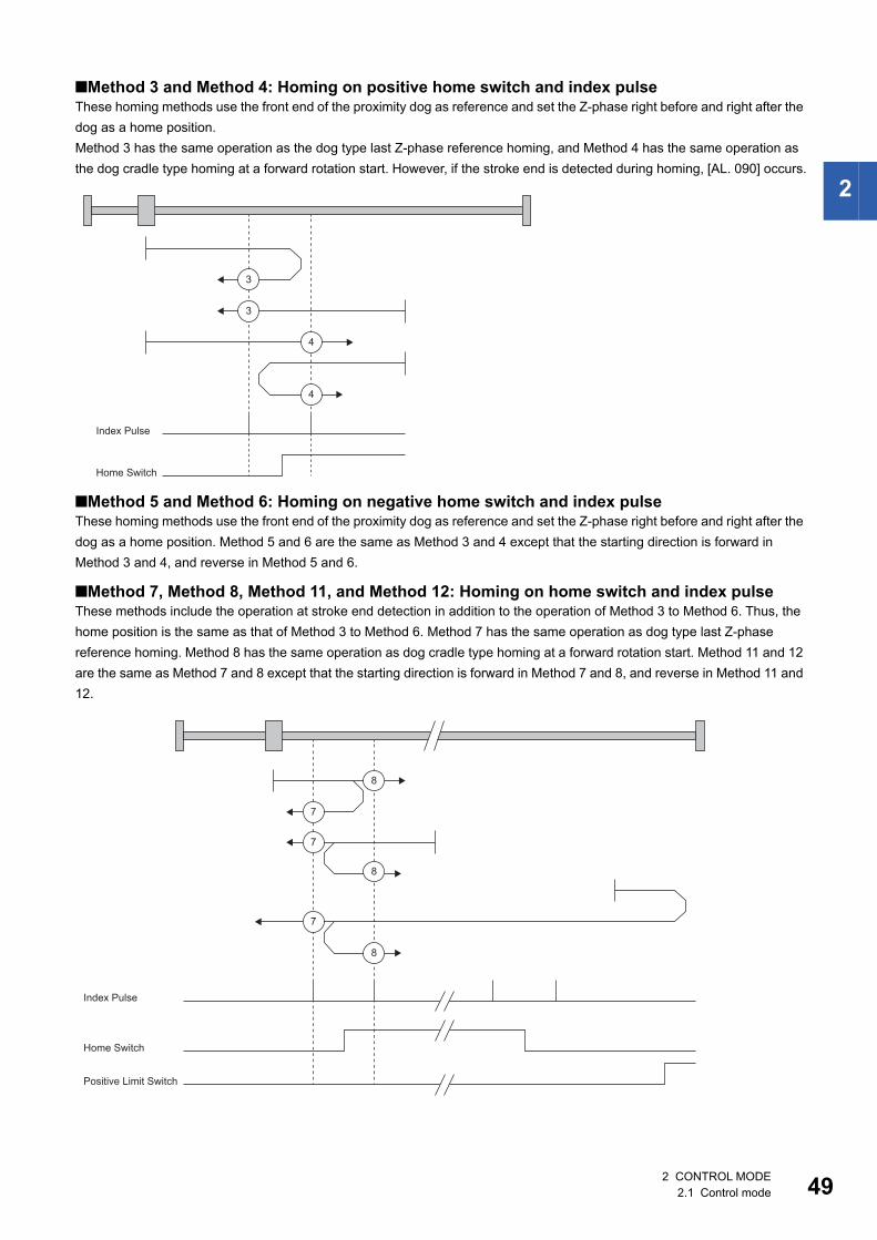
2
■Method 3 and Method 4: Homing on positive home switch and index pulseThese homing methods use the front end of the proximity dog as reference and set the Z-phase right before and right after the dog as a home position.Method 3 has the same operation as the dog type last Z-phase reference homing, and Method 4 has the same operation as the dog cradle type homing at a forward rotation start. However, if the stroke end is detected during homing, [AL. 090] occurs.
■Method 5 and Method 6: Homing on negative home switch and index pulseThese homing methods use the front end of the proximity dog as reference and set the Z-phase right before and right after the dog as a home position. Method 5 and 6 are the same as Method 3 and 4 except that the starting direction is forward in Method 3 and 4, and reverse in Method 5 and 6.
■Method 7, Method 8, Method 11, and Method 12: Homing on home switch and index pulseThese methods include the operation at stroke end detection in addition to the operation of Method 3 to Method 6. Thus, the home position is the same as that of Method 3 to Method 6. Method 7 has the same operation as dog type last Z-phase reference homing. Method 8 has the same operation as dog cradle type homing at a forward rotation start. Method 11 and 12 are the same as Method 7 and 8 except that the starting direction is forward in Method 7 and 8, and reverse in Method 11 and 12.
3
3
4
4
Index Pulse
Home Switch
7
8
7
8
8
7
Index Pulse
Home Switch
Positive Limit Switch
2 CONTROL MODE2.1 Control mode 49
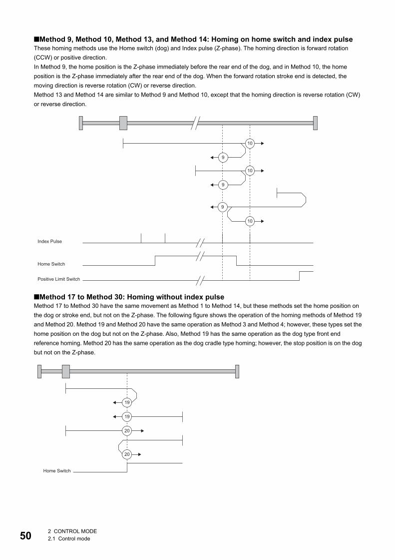
50
■Method 9, Method 10, Method 13, and Method 14: Homing on home switch and index pulseThese homing methods use the Home switch (dog) and Index pulse (Z-phase). The homing direction is forward rotation (CCW) or positive direction.In Method 9, the home position is the Z-phase immediately before the rear end of the dog, and in Method 10, the home position is the Z-phase immediately after the rear end of the dog. When the forward rotation stroke end is detected, the moving direction is reverse rotation (CW) or reverse direction.Method 13 and Method 14 are similar to Method 9 and Method 10, except that the homing direction is reverse rotation (CW) or reverse direction.
■Method 17 to Method 30: Homing without index pulseMethod 17 to Method 30 have the same movement as Method 1 to Method 14, but these methods set the home position on the dog or stroke end, but not on the Z-phase. The following figure shows the operation of the homing methods of Method 19 and Method 20. Method 19 and Method 20 have the same operation as Method 3 and Method 4; however, these types set the home position on the dog but not on the Z-phase. Also, Method 19 has the same operation as the dog type front end reference homing. Method 20 has the same operation as the dog cradle type homing; however, the stop position is on the dog but not on the Z-phase.
9
10
9
10
10
9
Index Pulse
Home Switch
Positive Limit Switch
Home Switch
19
19
20
20
2 CONTROL MODE2.1 Control mode
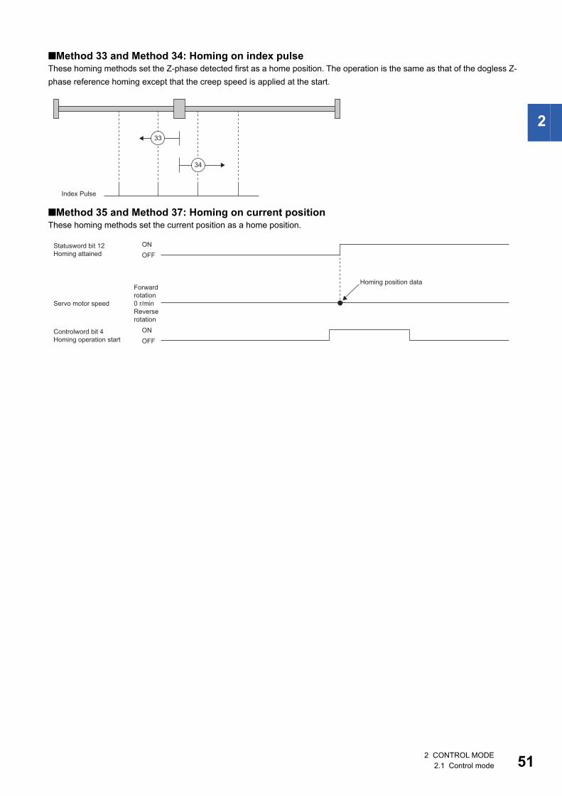
2
■Method 33 and Method 34: Homing on index pulseThese homing methods set the Z-phase detected first as a home position. The operation is the same as that of the dogless Z-phase reference homing except that the creep speed is applied at the start.
■Method 35 and Method 37: Homing on current positionThese homing methods set the current position as a home position.
Index Pulse
33
34
ON
ONStatusword bit 12Homing attained
Controlword bit 4Homing operation start
0 r/min
OFF
OFF
Homing position dataForwardrotation
Reverse rotation
Servo motor speed
2 CONTROL MODE2.1 Control mode 51
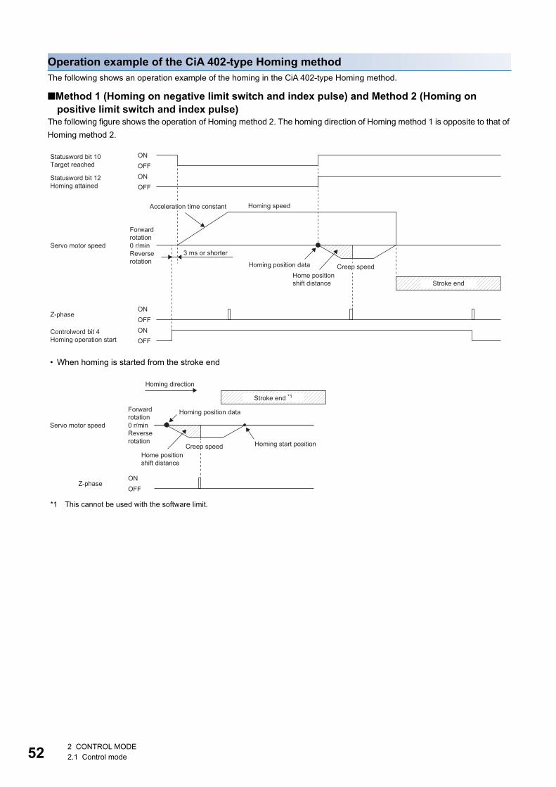
52
Operation example of the CiA 402-type Homing methodThe following shows an operation example of the homing in the CiA 402-type Homing method.
■Method 1 (Homing on negative limit switch and index pulse) and Method 2 (Homing on positive limit switch and index pulse)
The following figure shows the operation of Homing method 2. The homing direction of Homing method 1 is opposite to that of Homing method 2.
• When homing is started from the stroke end
*1 This cannot be used with the software limit.
Statusword bit 10Target reached
ONOFF
ONOFF
Statusword bit 12Homing attained
ONOFF
Controlword bit 4Homing operation start
ONOFF
0 r/min
Homing speedAcceleration time constant
Homing position data
Forward rotation
Servo motor speed3 ms or shorterReverse
rotationCreep speed
Home position shift distance Stroke end
Z-phase
0 r/min
ONOFF
Homing direction
Servo motor speedReverse rotation Homing start position
Stroke end *1
Forward rotation
Z-phase
Homing position data
Creep speedHome position shift distance
2 CONTROL MODE2.1 Control mode
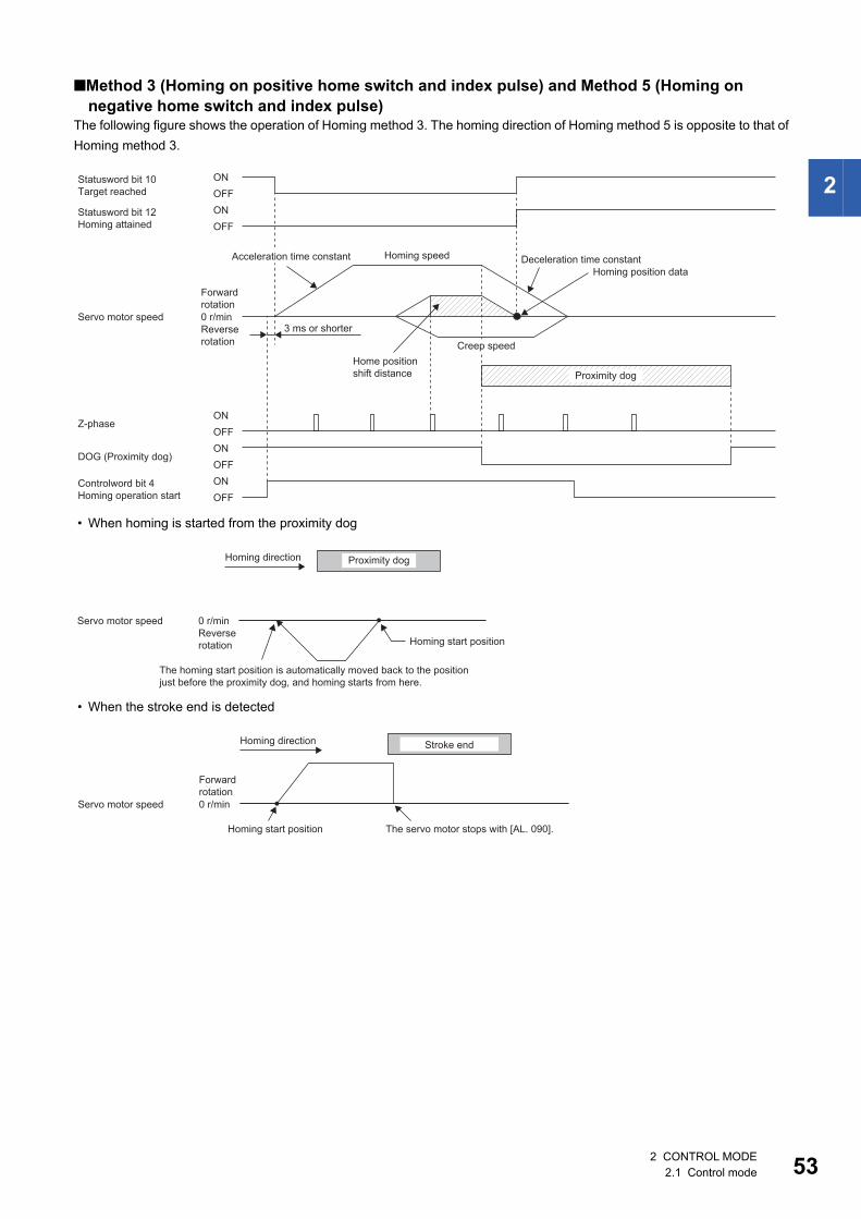
2
■Method 3 (Homing on positive home switch and index pulse) and Method 5 (Homing on negative home switch and index pulse)
The following figure shows the operation of Homing method 3. The homing direction of Homing method 5 is opposite to that of Homing method 3.
• When homing is started from the proximity dog
• When the stroke end is detected
Statusword bit 10Target reached
ONOFF
ONOFF
Statusword bit 12Homing attained
ONOFF
ONOFF
Controlword bit 4Homing operation start
ONOFF
0 r/min
Homing speedAcceleration time constant Deceleration time constantHoming position data
Forward rotation
Servo motor speed3 ms or shorterReverse
rotation Creep speedHome position shift distance Proximity dog
Z-phase
DOG (Proximity dog)
0 r/min
Homing direction Proximity dog
Servo motor speedReverse rotation Homing start position
The homing start position is automatically moved back to the position just before the proximity dog, and homing starts from here.
0 r/min
Homing direction Stroke end
Forward rotation
Servo motor speed
Homing start position The servo motor stops with [AL. 090].
2 CONTROL MODE2.1 Control mode 53
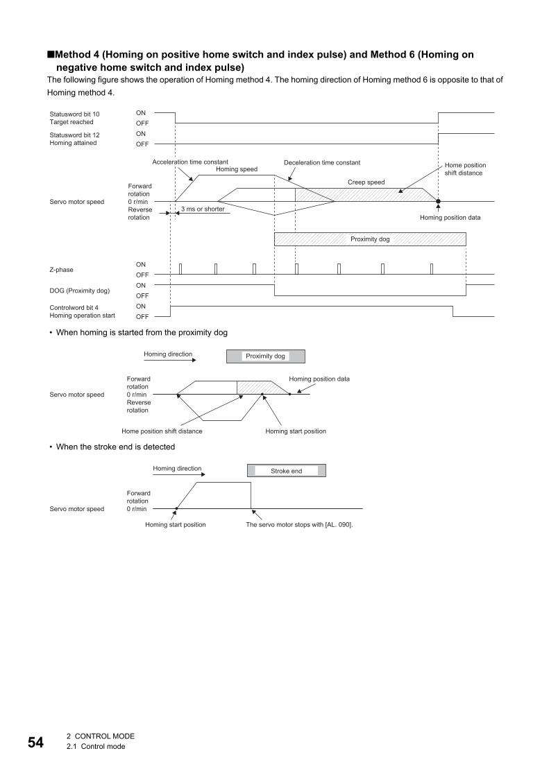
54
■Method 4 (Homing on positive home switch and index pulse) and Method 6 (Homing on negative home switch and index pulse)
The following figure shows the operation of Homing method 4. The homing direction of Homing method 6 is opposite to that of Homing method 4.
• When homing is started from the proximity dog
• When the stroke end is detected
ONOFFONOFF
Controlword bit 4Homing operation start
ONOFF
0 r/min
Statusword bit 10Target reached
ONOFF
Statusword bit 12Homing attained
ONOFF
Acceleration time constant Deceleration time constant Home position shift distanceHoming speed
Creep speedForward rotation
Servo motor speed3 ms or shorterReverse
rotation Homing position data
Proximity dog
Z-phase
DOG (Proximity dog)
0 r/min
Homing direction Proximity dog
Homing position dataForward rotation
Servo motor speedReverse rotation
Home position shift distance Homing start position
0 r/min
Homing direction Stroke end
Forward rotation
Servo motor speed
Homing start position The servo motor stops with [AL. 090].
2 CONTROL MODE2.1 Control mode
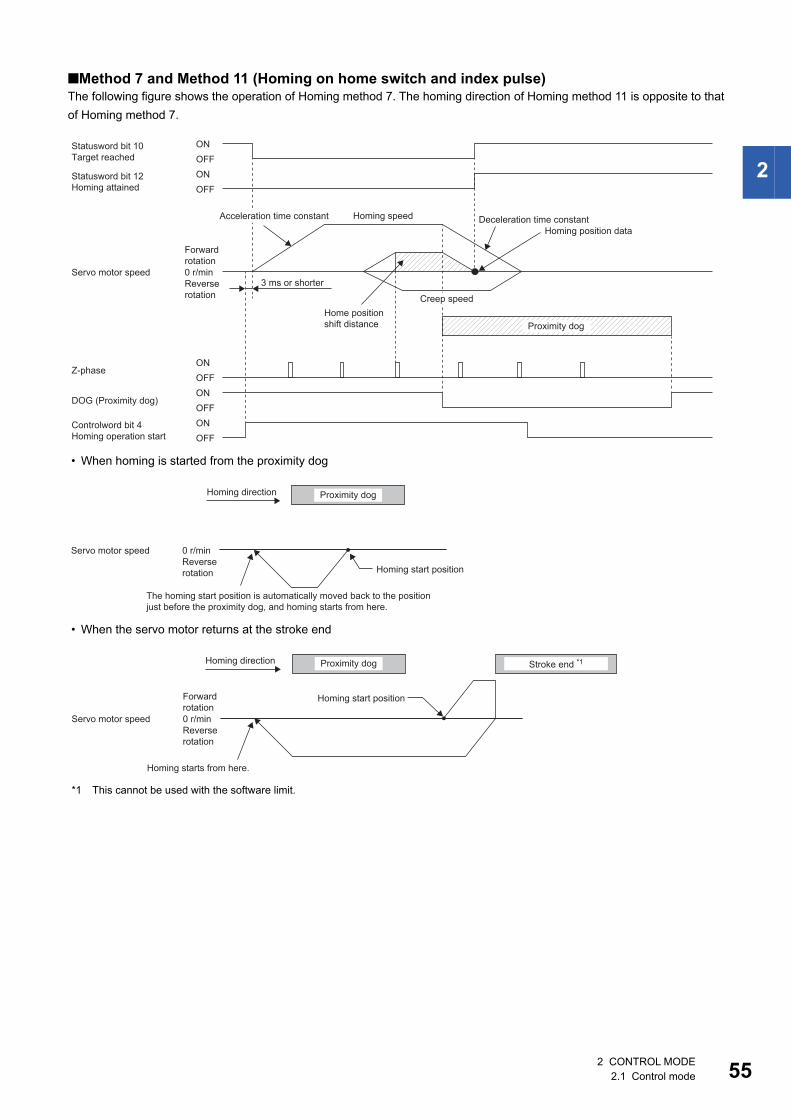
2
■Method 7 and Method 11 (Homing on home switch and index pulse)The following figure shows the operation of Homing method 7. The homing direction of Homing method 11 is opposite to that of Homing method 7.
• When homing is started from the proximity dog
• When the servo motor returns at the stroke end
*1 This cannot be used with the software limit.
Statusword bit 10Target reached
ONOFF
ONOFF
Statusword bit 12Homing attained
ONOFF
ONOFF
Controlword bit 4Homing operation start
ONOFF
0 r/min
Homing speedAcceleration time constant Deceleration time constantHoming position data
Forward rotation
Servo motor speed3 ms or shorterReverse
rotation Creep speedHome position shift distance Proximity dog
Z-phase
DOG (Proximity dog)
0 r/min
Homing direction Proximity dog
Servo motor speedReverse rotation Homing start position
The homing start position is automatically moved back to the position just before the proximity dog, and homing starts from here.
0 r/min
Homing direction Stroke end *1Proximity dog
Homing start positionForward rotation
Servo motor speedReverse rotation
Homing starts from here.
2 CONTROL MODE2.1 Control mode 55
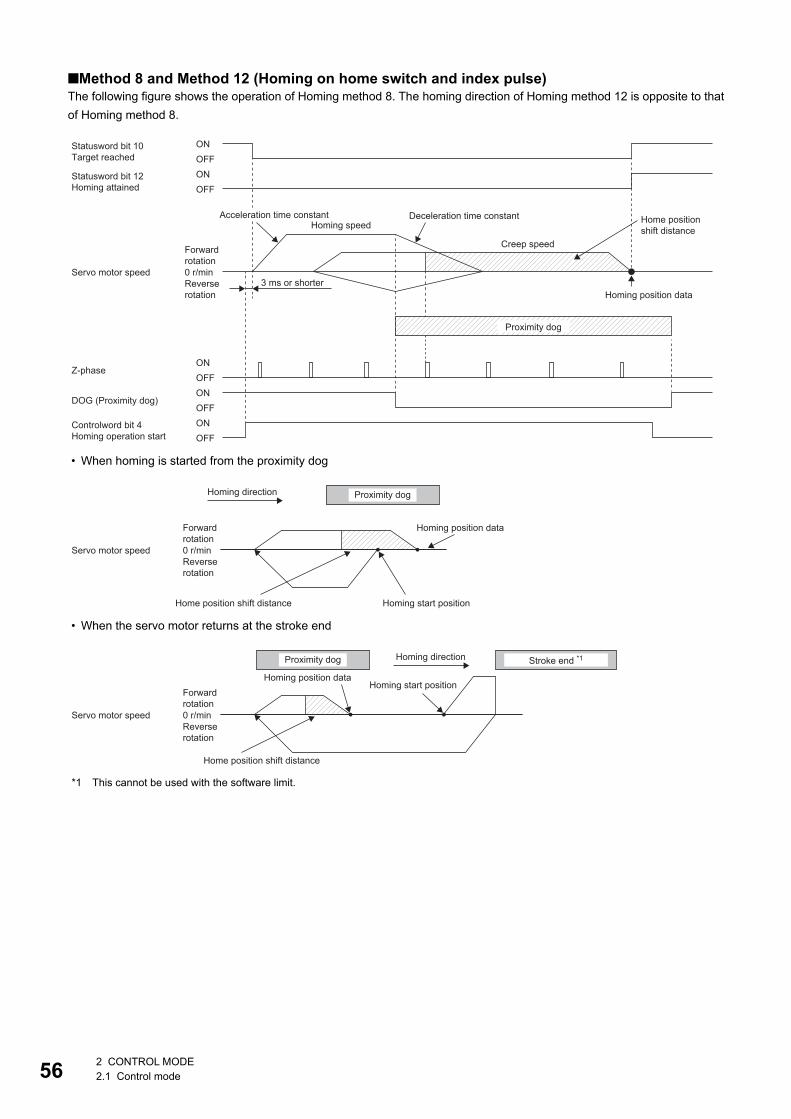
56
■Method 8 and Method 12 (Homing on home switch and index pulse)The following figure shows the operation of Homing method 8. The homing direction of Homing method 12 is opposite to that of Homing method 8.
• When homing is started from the proximity dog
• When the servo motor returns at the stroke end
*1 This cannot be used with the software limit.
ONOFFONOFF
Controlword bit 4Homing operation start
ONOFF
0 r/min
Statusword bit 10Target reached
ONOFF
Statusword bit 12Homing attained
ONOFF
Deceleration time constantAcceleration time constant Home position shift distanceHoming speed
Creep speedForward rotation
Servo motor speed3 ms or shorterReverse
rotation Homing position data
Proximity dog
Z-phase
DOG (Proximity dog)
0 r/min
Homing direction Proximity dog
Homing position dataForward rotation
Servo motor speedReverse rotation
Home position shift distance Homing start position
0 r/min
Homing direction Stroke end *1Proximity dog
Homing position dataHoming start position
Forward rotation
Servo motor speedReverse rotation
Home position shift distance
2 CONTROL MODE2.1 Control mode
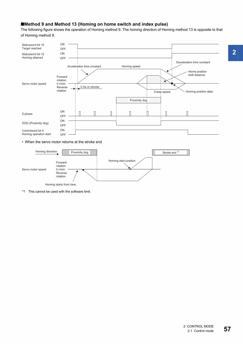
2
■Method 9 and Method 13 (Homing on home switch and index pulse)The following figure shows the operation of Homing method 9. The homing direction of Homing method 13 is opposite to that of Homing method 9.
• When the servo motor returns at the stroke end
*1 This cannot be used with the software limit.
Statusword bit 10Target reached
ONOFF
ONOFF
Statusword bit 12Homing attained
ONOFF
ONOFF
Controlword bit 4Homing operation start
ONOFF
0 r/min
Homing speedAcceleration time constantDeceleration time constant
Homing position data
Forward rotation
Servo motor speed3 ms or shorterReverse
rotation Creep speed
Home position shift distance
Proximity dog
Z-phase
DOG (Proximity dog)
0 r/min
Homing direction Stroke end *1Proximity dog
Homing start positionForward rotation
Servo motor speedReverse rotation
Homing starts from here.
2 CONTROL MODE2.1 Control mode 57
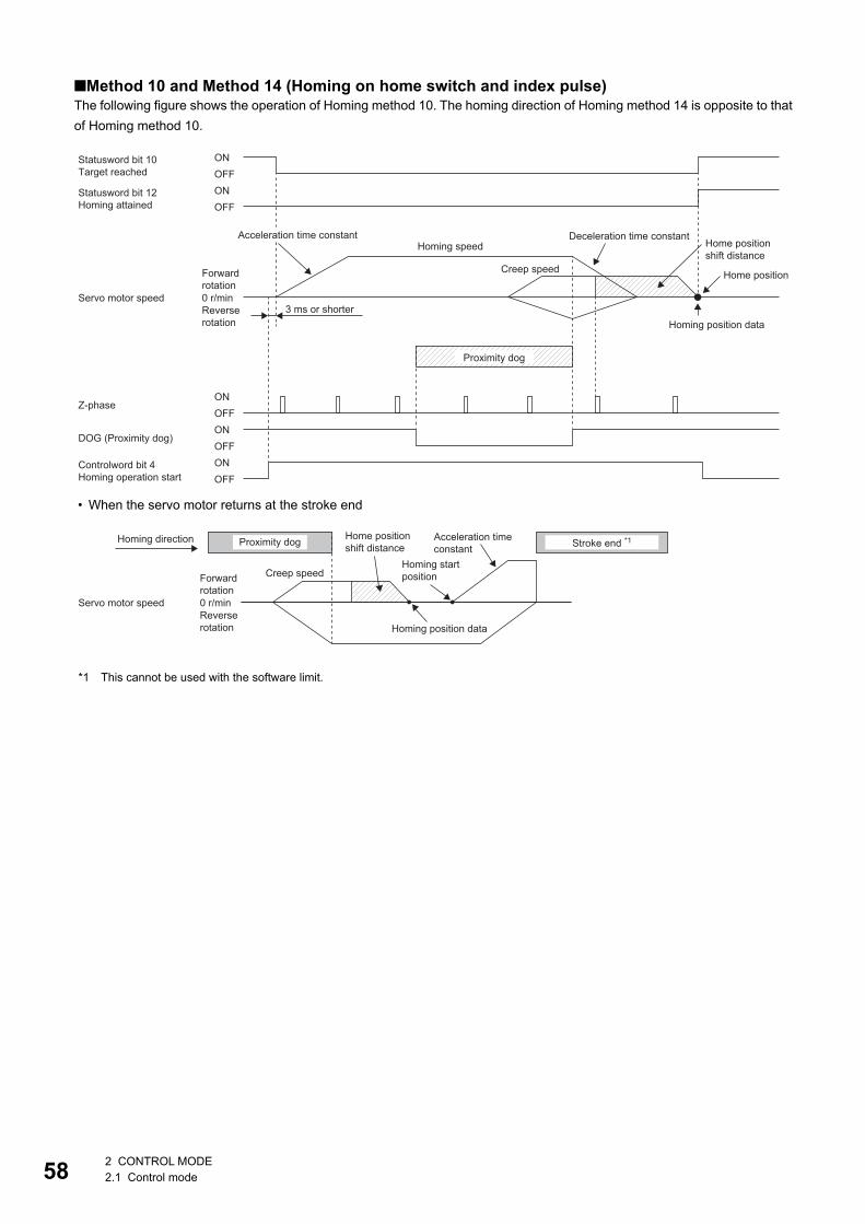
58
■Method 10 and Method 14 (Homing on home switch and index pulse)The following figure shows the operation of Homing method 10. The homing direction of Homing method 14 is opposite to that of Homing method 10.
• When the servo motor returns at the stroke end
*1 This cannot be used with the software limit.
ONOFFONOFF
Controlword bit 4Homing operation start
ONOFF
0 r/min
Statusword bit 10Target reached
ONOFF
Statusword bit 12Homing attained
ONOFF
Deceleration time constantAcceleration time constantHoming speed
Creep speedForward rotation
Servo motor speed3 ms or shorterReverse
rotation Homing position data
Proximity dog
Z-phase
DOG (Proximity dog)
Home position shift distance
Home position
0 r/min
Homing direction Stroke end *1Proximity dog
Homing position data
Homing start positionForward
rotationServo motor speed
Reverse rotation
Home position shift distance
Creep speed
Acceleration time constant
2 CONTROL MODE2.1 Control mode
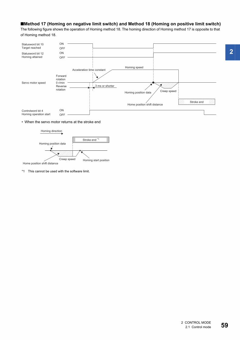
2
■Method 17 (Homing on negative limit switch) and Method 18 (Homing on positive limit switch)The following figure shows the operation of Homing method 18. The homing direction of Homing method 17 is opposite to that of Homing method 18.
• When the servo motor returns at the stroke end
*1 This cannot be used with the software limit.
Statusword bit 10Target reached
Statusword bit 12Homing attained
0 r/min
ONOFF ONOFF
ONOFF
Controlword bit 4Homing operation start
Acceleration time constant
Forward rotation
Servo motor speed3 ms or shorterReverse
rotation Creep speedHoming position data
Home position shift distanceStroke end
Homing speed
Homing position data
Homing start positionHome position shift distance
Creep speed
Stroke end *1
Homing direction
2 CONTROL MODE2.1 Control mode 59
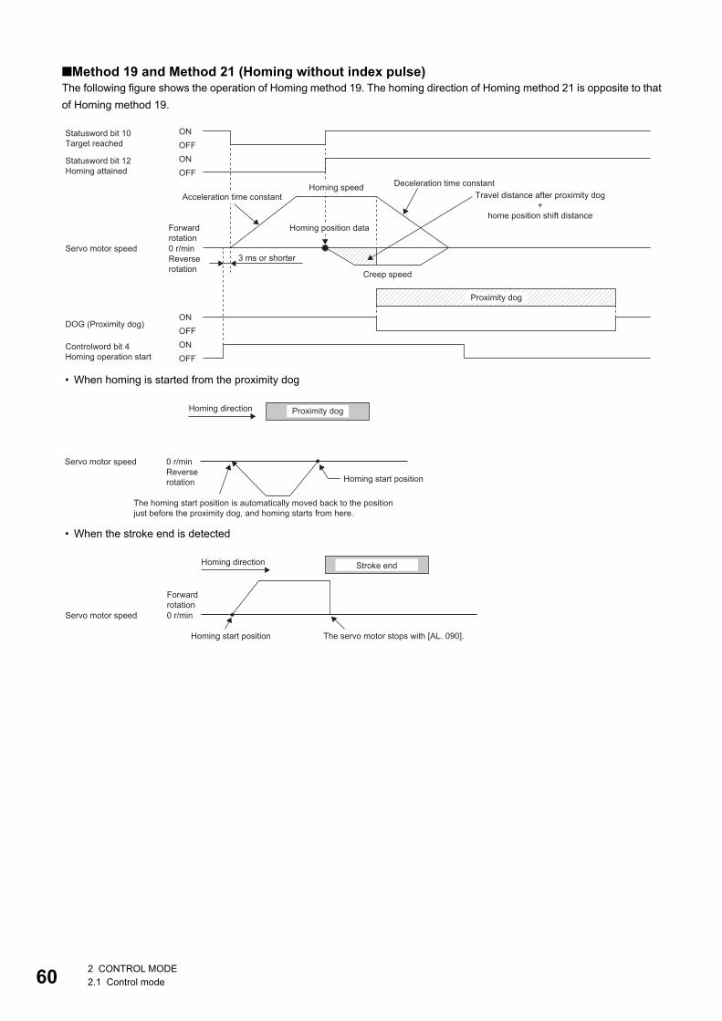
60
■Method 19 and Method 21 (Homing without index pulse)The following figure shows the operation of Homing method 19. The homing direction of Homing method 21 is opposite to that of Homing method 19.
• When homing is started from the proximity dog
• When the stroke end is detected
Statusword bit 10Target reached
Statusword bit 12Homing attained
0 r/min
ONOFF
ONOFF
ONOFF
ONOFF
Controlword bit 4Homing operation start
Deceleration time constantHoming speedTravel distance after proximity dog
+home position shift distance
Acceleration time constant
Homing position dataForward rotation
Servo motor speed3 ms or shorterReverse
rotation Creep speed
Proximity dog
DOG (Proximity dog)
0 r/min
Homing direction Proximity dog
Servo motor speedReverse rotation Homing start position
The homing start position is automatically moved back to the position just before the proximity dog, and homing starts from here.
0 r/min
Homing direction Stroke end
Forward rotation
Servo motor speed
Homing start position The servo motor stops with [AL. 090].
2 CONTROL MODE2.1 Control mode
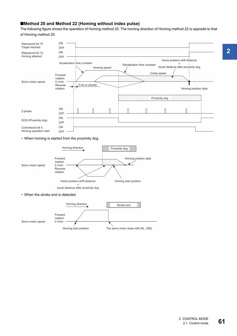
2
■Method 20 and Method 22 (Homing without index pulse)The following figure shows the operation of Homing method 20. The homing direction of Homing method 22 is opposite to that of Homing method 20.
• When homing is started from the proximity dog
• When the stroke end is detected
ONOFFONOFF
Controlword bit 4Homing operation start
ONOFF
0 r/min
Statusword bit 10Target reached
ONOFF
Statusword bit 12Homing attained
ONOFF
Deceleration time constantHoming speed
Creep speedForward rotation
Servo motor speed3 ms or shorterReverse
rotation Homing position data
Proximity dog
Z-phase
DOG (Proximity dog)
Acceleration time constantHome position shift distance
+travel distance after proximity dog
0 r/min
Homing direction Proximity dog
Homing position dataForward rotation
Servo motor speedReverse rotation
Homing start positionHome position shift distance+
travel distance after proximity dog
0 r/min
Homing direction Stroke end
Forward rotation
Servo motor speed
Homing start position The servo motor stops with [AL. 090].
2 CONTROL MODE2.1 Control mode 61
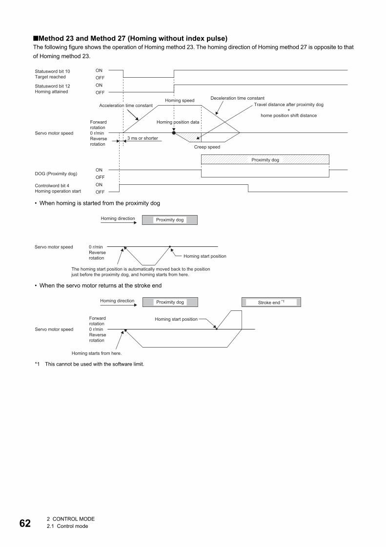
62
■Method 23 and Method 27 (Homing without index pulse)The following figure shows the operation of Homing method 23. The homing direction of Homing method 27 is opposite to that of Homing method 23.
• When homing is started from the proximity dog
• When the servo motor returns at the stroke end
*1 This cannot be used with the software limit.
Statusword bit 10Target reached
Statusword bit 12Homing attained
0 r/min
ONOFF
ONOFF
ONOFF
ONOFF
Controlword bit 4Homing operation start
Acceleration time constantDeceleration time constantHoming speed
Homing position dataForward rotation
Servo motor speed3 ms or shorterReverse
rotation Creep speed
Proximity dog
DOG (Proximity dog)
Travel distance after proximity dog+
home position shift distance
0 r/min
Homing direction Proximity dog
Servo motor speedReverse rotation Homing start position
The homing start position is automatically moved back to the position just before the proximity dog, and homing starts from here.
0 r/min
Homing direction Stroke end *1Proximity dog
Homing start positionForward rotation
Servo motor speedReverse rotation
Homing starts from here.
2 CONTROL MODE2.1 Control mode
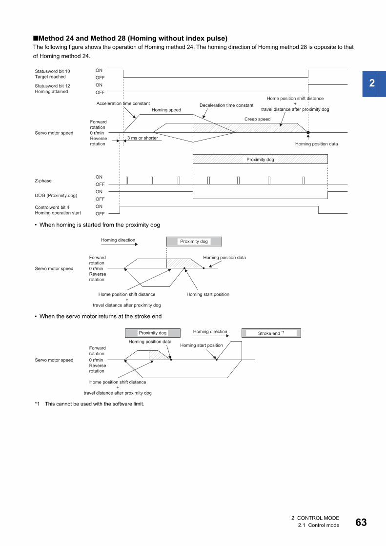
2
■Method 24 and Method 28 (Homing without index pulse)The following figure shows the operation of Homing method 24. The homing direction of Homing method 28 is opposite to that of Homing method 24.
• When homing is started from the proximity dog
• When the servo motor returns at the stroke end
*1 This cannot be used with the software limit.
ONOFFONOFF
Controlword bit 4Homing operation start
ONOFF
0 r/min
Statusword bit 10Target reached
ONOFF
Statusword bit 12Homing attained
ONOFF
Deceleration time constantHoming speed
Creep speedForward rotation
Servo motor speed3 ms or shorterReverse
rotation Homing position data
Proximity dog
Z-phase
DOG (Proximity dog)
Acceleration time constantHome position shift distance
+travel distance after proximity dog
0 r/min
Homing direction Proximity dog
Homing position dataForward rotation
Servo motor speedReverse rotation
Homing start positionHome position shift distance+
travel distance after proximity dog
0 r/min
Homing direction Stroke end *1Proximity dog
Homing position dataHoming start positionForward
rotationServo motor speed
Reverse rotation
Home position shift distance+
travel distance after proximity dog
2 CONTROL MODE2.1 Control mode 63
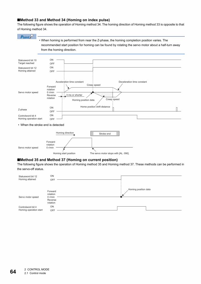
64
■Method 33 and Method 34 (Homing on index pulse)The following figure shows the operation of Homing method 34. The homing direction of Homing method 33 is opposite to that of Homing method 34.
• When homing is performed from near the Z-phase, the homing completion position varies. The recommended start position for homing can be found by rotating the servo motor about a half-turn away from the homing direction.
• When the stroke end is detected
■Method 35 and Method 37 (Homing on current position)The following figure shows the operation of Homing method 35 and Homing method 37. These methods can be performed in the servo-off status.
Statusword bit 10Target reached
Statusword bit 12Homing attained
0 r/min
ONOFF
ONOFF
ONOFF
ONOFF
Controlword bit 4Homing operation start
Acceleration time constant Deceleration time constantCreep speed
Forward rotation
Servo motor speed3 ms or shorterReverse
rotation Creep speedHoming position data
Home position shift distanceZ-phase
0 r/min
Homing direction Stroke end
Forward rotation
Servo motor speed
Homing start position The servo motor stops with [AL. 090].
ONOFF
ONOFF
Statusword bit 12Homing attained
Controlword bit 4Homing operation start
0 r/min
Homing position dataForwardrotation
Servo motor speedReverserotation
2 CONTROL MODE2.1 Control mode
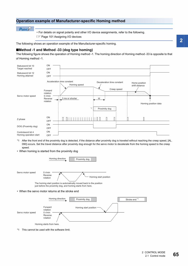
2
Operation example of Manufacturer-specific Homing method
• For details on signal polarity and other I/O device assignments, refer to the following.Page 101 Assigning I/O devices
The following shows an operation example of the Manufacturer-specific homing.
■Method -1 and Method -33 (dog type homing)The following figure shows the operation of Homing method -1. The homing direction of Homing method -33 is opposite to that of Homing method -1.
*1 After the front end of the proximity dog is detected, if the distance after proximity dog is traveled without reaching the creep speed, [AL. 090] occurs. Set the travel distance after proximity dog enough for the servo motor to decelerate from the homing speed to the creep speed.
• When homing is started from the proximity dog
• When the servo motor returns at the stroke end
*1 This cannot be used with the software limit.
Statusword bit 10Target reached
ONOFF
Statusword bit 12Homing attained
ONOFF
0 r/mintd
*1
ONOFFONOFF
Controlword bit 4Homing operation start
ONOFF
Deceleration time constantHoming speed
Home position shift distance
Creep speedForwardrotation
Servo motor speed3 ms or shorterReverse
rotationHoming position data
Proximity dog
Z-phase
DOG (Proximity dog)
Acceleration time constant
0 r/min
Homing direction Proximity dog
Servo motor speedReverse rotation Homing start position
The homing start position is automatically moved back to the position just before the proximity dog, and homing starts from here.
0 r/min
Homing direction Stroke end *1Proximity dog
Homing start positionForward rotation
Servo motor speedReverse rotation
Homing starts from here.
2 CONTROL MODE2.1 Control mode 65
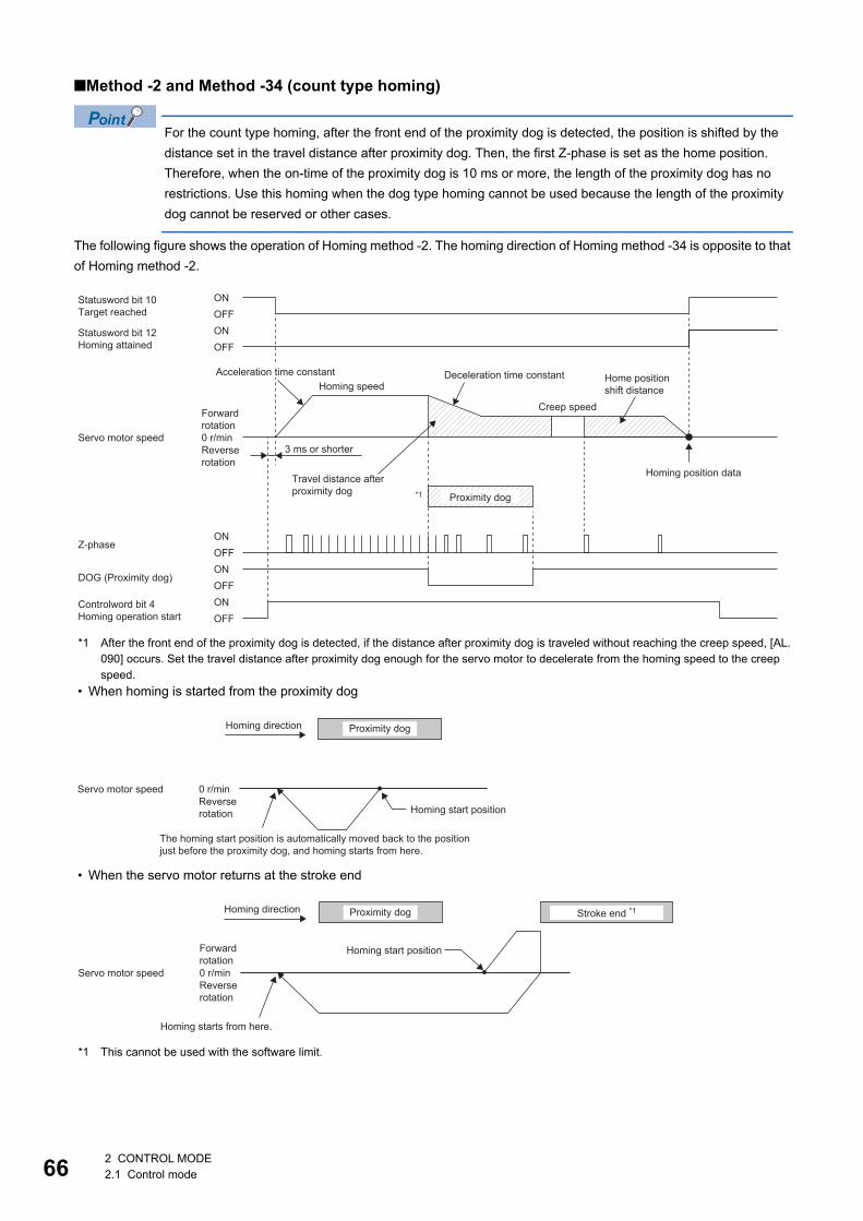
66
■Method -2 and Method -34 (count type homing)
For the count type homing, after the front end of the proximity dog is detected, the position is shifted by the distance set in the travel distance after proximity dog. Then, the first Z-phase is set as the home position. Therefore, when the on-time of the proximity dog is 10 ms or more, the length of the proximity dog has no restrictions. Use this homing when the dog type homing cannot be used because the length of the proximity dog cannot be reserved or other cases.
The following figure shows the operation of Homing method -2. The homing direction of Homing method -34 is opposite to that of Homing method -2.
*1 After the front end of the proximity dog is detected, if the distance after proximity dog is traveled without reaching the creep speed, [AL. 090] occurs. Set the travel distance after proximity dog enough for the servo motor to decelerate from the homing speed to the creep speed.
• When homing is started from the proximity dog
• When the servo motor returns at the stroke end
*1 This cannot be used with the software limit.
Statusword bit 10Target reached
ONOFF
Statusword bit 12Homing attained
ONOFF
0 r/min
*1
ONOFFONOFF
Controlword bit 4Homing operation start
ONOFF
Deceleration time constantHoming speed
Creep speedForwardrotation
Servo motor speed3 ms or shorterReverse
rotationHoming position dataTravel distance after
proximity dog Proximity dog
Z-phase
DOG (Proximity dog)
Acceleration time constant Home position shift distance
0 r/min
Homing direction Proximity dog
Servo motor speedReverse rotation Homing start position
The homing start position is automatically moved back to the position just before the proximity dog, and homing starts from here.
0 r/min
Homing direction Stroke end *1Proximity dog
Homing start positionForward rotation
Servo motor speedReverse rotation
Homing starts from here.
2 CONTROL MODE2.1 Control mode
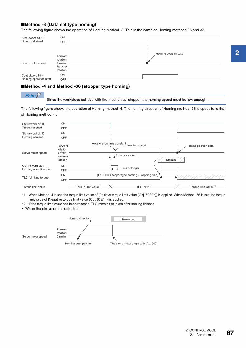
2
■Method -3 (Data set type homing)The following figure shows the operation of Homing method -3. This is the same as Homing methods 35 and 37.
■Method -4 and Method -36 (stopper type homing)
Since the workpiece collides with the mechanical stopper, the homing speed must be low enough.
The following figure shows the operation of Homing method -4. The homing direction of Homing method -36 is opposite to that of Homing method -4.
*1 When Method -4 is set, the torque limit value of [Positive torque limit value (Obj. 60E0h)] is applied. When Method -36 is set, the torque limit value of [Negative torque limit value (Obj. 60E1h)] is applied.
*2 If the torque limit value has been reached, TLC remains on even after homing finishes. • When the stroke end is detected
ONOFF
ONOFF
Statusword bit 12Homing attained
Controlword bit 4Homing operation start
0 r/min
Homing position dataForwardrotation
Servo motor speedReverserotation
Statusword bit 12Homing attained
ONOFF
Controlword bit 4Homing operation start
ONOFF
Statusword bit 10Target reached
ONOFF
ONOFF
[Pr. PT11]
*2
0 r/min
Homing speed Homing position dataForwardrotation
Servo motor speed3 ms or shorterReverse
rotation Stopper
5 ms or longer
[Pr. PT10 Stopper type homing - Stopping time]TLC (Limiting torque)
Torque limit value *1 Torque limit value *1Torque limit value
Acceleration time constant
0 r/min
Homing direction Stroke end
Forward rotation
Servo motor speed
Homing start position The servo motor stops with [AL. 090].
2 CONTROL MODE2.1 Control mode 67
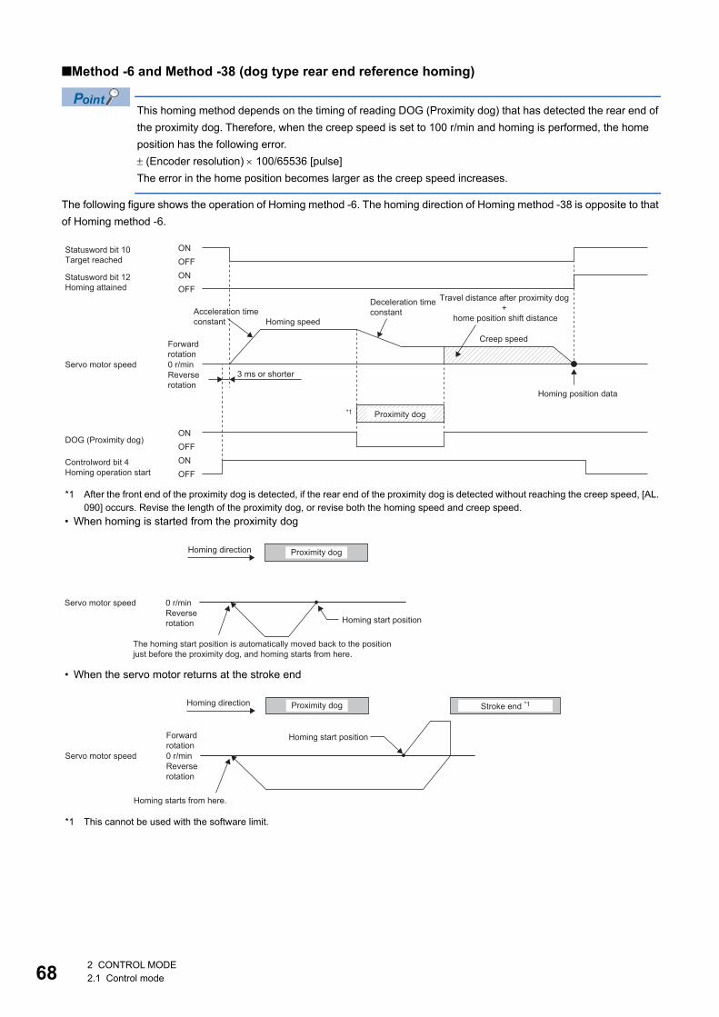
68
■Method -6 and Method -38 (dog type rear end reference homing)
This homing method depends on the timing of reading DOG (Proximity dog) that has detected the rear end of the proximity dog. Therefore, when the creep speed is set to 100 r/min and homing is performed, the home position has the following error. (Encoder resolution) 100/65536 [pulse]The error in the home position becomes larger as the creep speed increases.
The following figure shows the operation of Homing method -6. The homing direction of Homing method -38 is opposite to that of Homing method -6.
*1 After the front end of the proximity dog is detected, if the rear end of the proximity dog is detected without reaching the creep speed, [AL. 090] occurs. Revise the length of the proximity dog, or revise both the homing speed and creep speed.
• When homing is started from the proximity dog
• When the servo motor returns at the stroke end
*1 This cannot be used with the software limit.
Statusword bit 10Target reached
ONOFF
Statusword bit 12Homing attained
ONOFF
0 r/min
ONOFFONOFF
Controlword bit 4Homing operation start
*1
Travel distance after proximity dog +
home position shift distanceAcceleration time constant
Deceleration time constant
Homing speed
Creep speedForward rotation
Servo motor speed3 ms or shorterReverse
rotationHoming position data
Proximity dog
DOG (Proximity dog)
0 r/min
Homing direction Proximity dog
Servo motor speedReverse rotation Homing start position
The homing start position is automatically moved back to the position just before the proximity dog, and homing starts from here.
0 r/min
Homing direction Stroke end *1Proximity dog
Homing start positionForward rotation
Servo motor speedReverse rotation
Homing starts from here.
2 CONTROL MODE2.1 Control mode
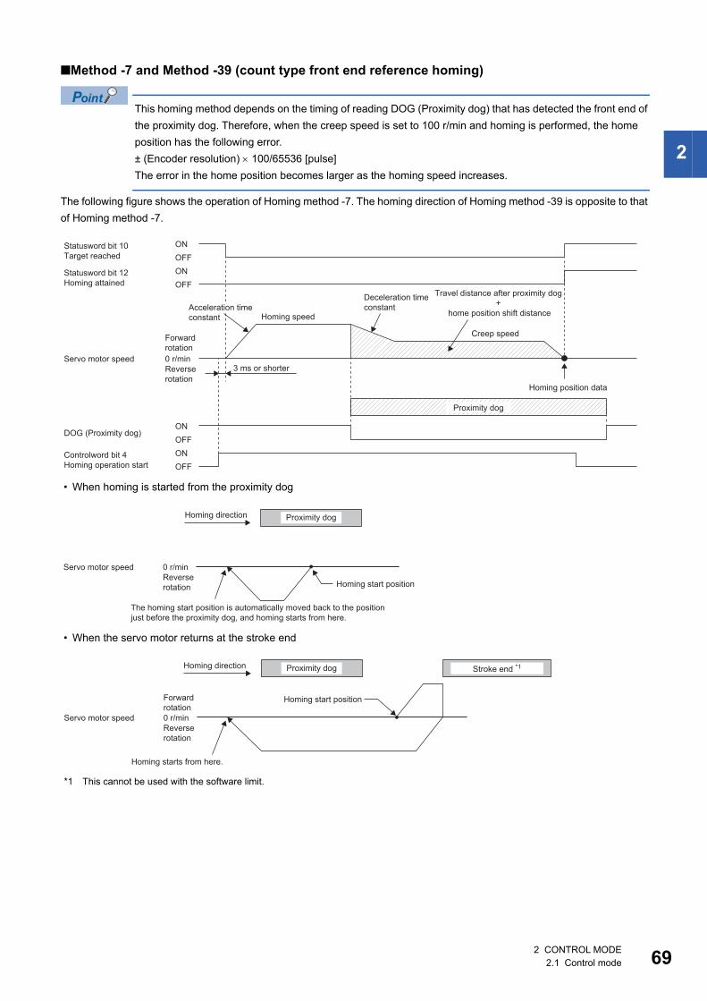
2
■Method -7 and Method -39 (count type front end reference homing)
This homing method depends on the timing of reading DOG (Proximity dog) that has detected the front end of the proximity dog. Therefore, when the creep speed is set to 100 r/min and homing is performed, the home position has the following error.± (Encoder resolution) 100/65536 [pulse]The error in the home position becomes larger as the homing speed increases.
The following figure shows the operation of Homing method -7. The homing direction of Homing method -39 is opposite to that of Homing method -7.
• When homing is started from the proximity dog
• When the servo motor returns at the stroke end
*1 This cannot be used with the software limit.
Statusword bit 10Target reached
ONOFF
Statusword bit 12Homing attained
ONOFF
0 r/min
ONOFFONOFF
Controlword bit 4Homing operation start
Travel distance after proximity dog +
home position shift distanceAcceleration time constant
Deceleration time constant
Homing speed
Creep speedForward rotation
Servo motor speed3 ms or shorterReverse
rotationHoming position data
Proximity dog
DOG (Proximity dog)
0 r/min
Homing direction Proximity dog
Servo motor speedReverse rotation Homing start position
The homing start position is automatically moved back to the position just before the proximity dog, and homing starts from here.
0 r/min
Homing direction Stroke end *1Proximity dog
Homing start positionForward rotation
Servo motor speedReverse rotation
Homing starts from here.
2 CONTROL MODE2.1 Control mode 69
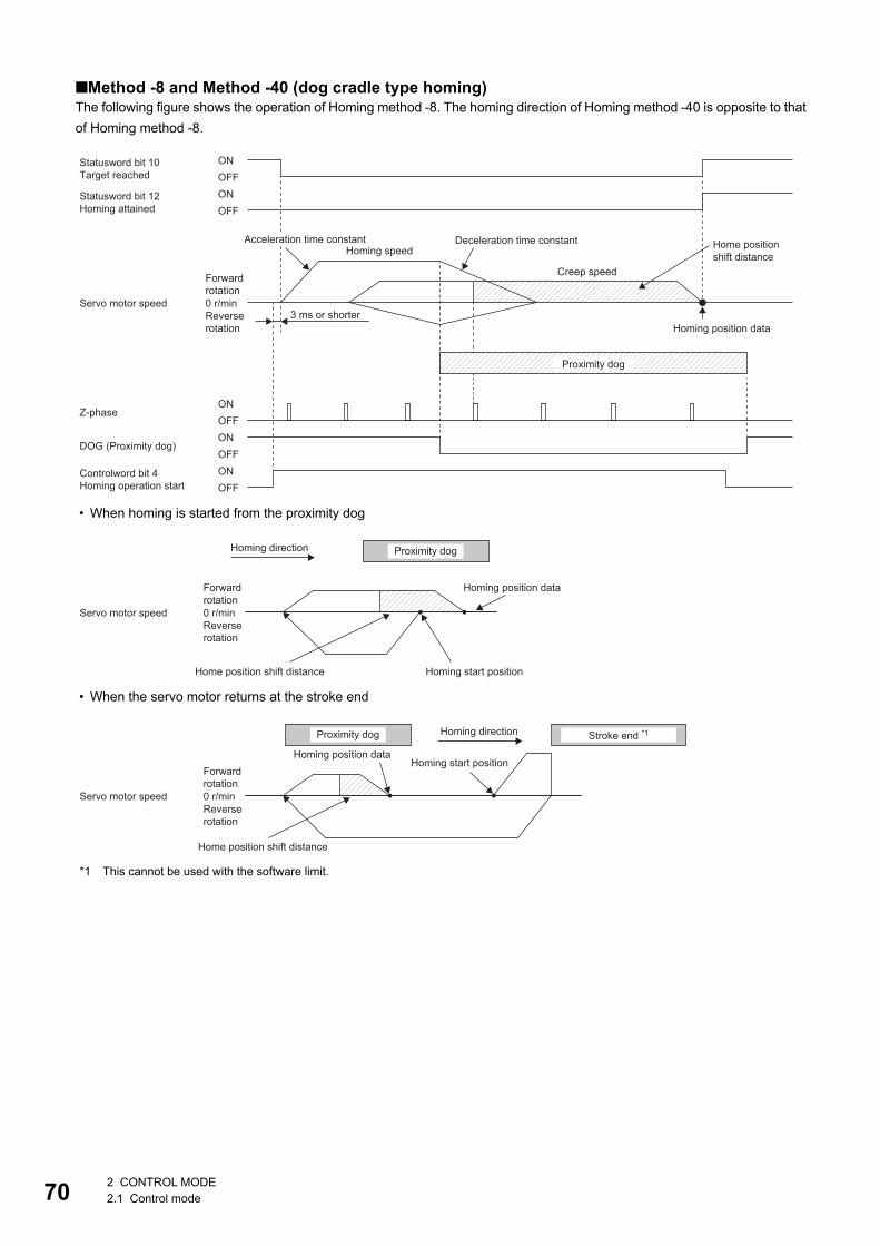
70
■Method -8 and Method -40 (dog cradle type homing)The following figure shows the operation of Homing method -8. The homing direction of Homing method -40 is opposite to that of Homing method -8.
• When homing is started from the proximity dog
• When the servo motor returns at the stroke end
*1 This cannot be used with the software limit.
ONOFFONOFF
Controlword bit 4Homing operation start
ONOFF
0 r/min
Statusword bit 10Target reached
ONOFF
Statusword bit 12Homing attained
ONOFF
Deceleration time constantAcceleration time constant Home position shift distanceHoming speed
Creep speedForward rotation
Servo motor speed3 ms or shorterReverse
rotation Homing position data
Proximity dog
Z-phase
DOG (Proximity dog)
0 r/min
Homing direction Proximity dog
Homing position dataForward rotation
Servo motor speedReverse rotation
Home position shift distance Homing start position
0 r/min
Homing direction Stroke end *1Proximity dog
Homing position dataHoming start position
Forward rotation
Servo motor speedReverse rotation
Home position shift distance
2 CONTROL MODE2.1 Control mode
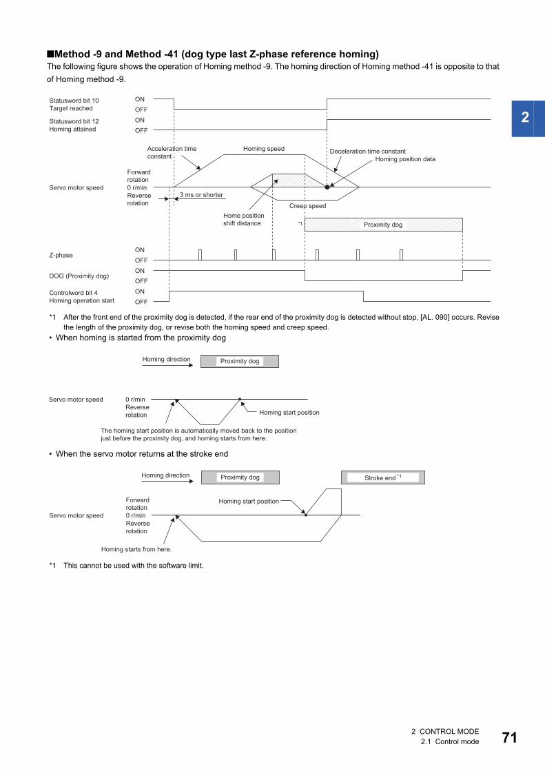
2
■Method -9 and Method -41 (dog type last Z-phase reference homing)The following figure shows the operation of Homing method -9. The homing direction of Homing method -41 is opposite to that of Homing method -9.
*1 After the front end of the proximity dog is detected, if the rear end of the proximity dog is detected without stop, [AL. 090] occurs. Revise the length of the proximity dog, or revise both the homing speed and creep speed.
• When homing is started from the proximity dog
• When the servo motor returns at the stroke end
*1 This cannot be used with the software limit.
Statusword bit 10Target reached
ONOFF
ONOFF
Statusword bit 12Homing attained
ONOFF
ONOFF
Controlword bit 4Homing operation start
ONOFF
0 r/min
*1
Homing speedAcceleration time constant
Deceleration time constantHoming position data
Forward rotation
Servo motor speed3 ms or shorterReverse
rotation Creep speedHome position shift distance Proximity dog
Z-phase
DOG (Proximity dog)
0 r/min
Homing direction Proximity dog
Servo motor speedReverse rotation Homing start position
The homing start position is automatically moved back to the position just before the proximity dog, and homing starts from here.
0 r/min
Homing direction Stroke end *1Proximity dog
Homing start positionForward rotation
Servo motor speedReverse rotation
Homing starts from here.
2 CONTROL MODE2.1 Control mode 71
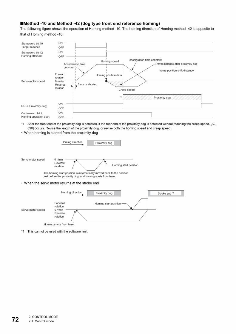
72
■Method -10 and Method -42 (dog type front end reference homing)The following figure shows the operation of Homing method -10. The homing direction of Homing method -42 is opposite to that of Homing method -10.
*1 After the front end of the proximity dog is detected, if the rear end of the proximity dog is detected without reaching the creep speed, [AL. 090] occurs. Revise the length of the proximity dog, or revise both the homing speed and creep speed.
• When homing is started from the proximity dog
• When the servo motor returns at the stroke end
*1 This cannot be used with the software limit.
Statusword bit 10Target reached
Statusword bit 12Homing attained
0 r/min
ONOFF
ONOFF
ONOFF
ONOFF
Controlword bit 4Homing operation start
*1
Deceleration time constantHoming speedTravel distance after proximity dog
+ home position shift distance
Acceleration time constant
Homing position dataForward rotation
Servo motor speed3 ms or shorterReverse
rotation Creep speed
Proximity dog
DOG (Proximity dog)
0 r/min
Homing direction Proximity dog
Servo motor speedReverse rotation Homing start position
The homing start position is automatically moved back to the position just before the proximity dog, and homing starts from here.
0 r/min
Homing direction Stroke end *1Proximity dog
Homing start positionForward rotation
Servo motor speedReverse rotation
Homing starts from here.
2 CONTROL MODE2.1 Control mode
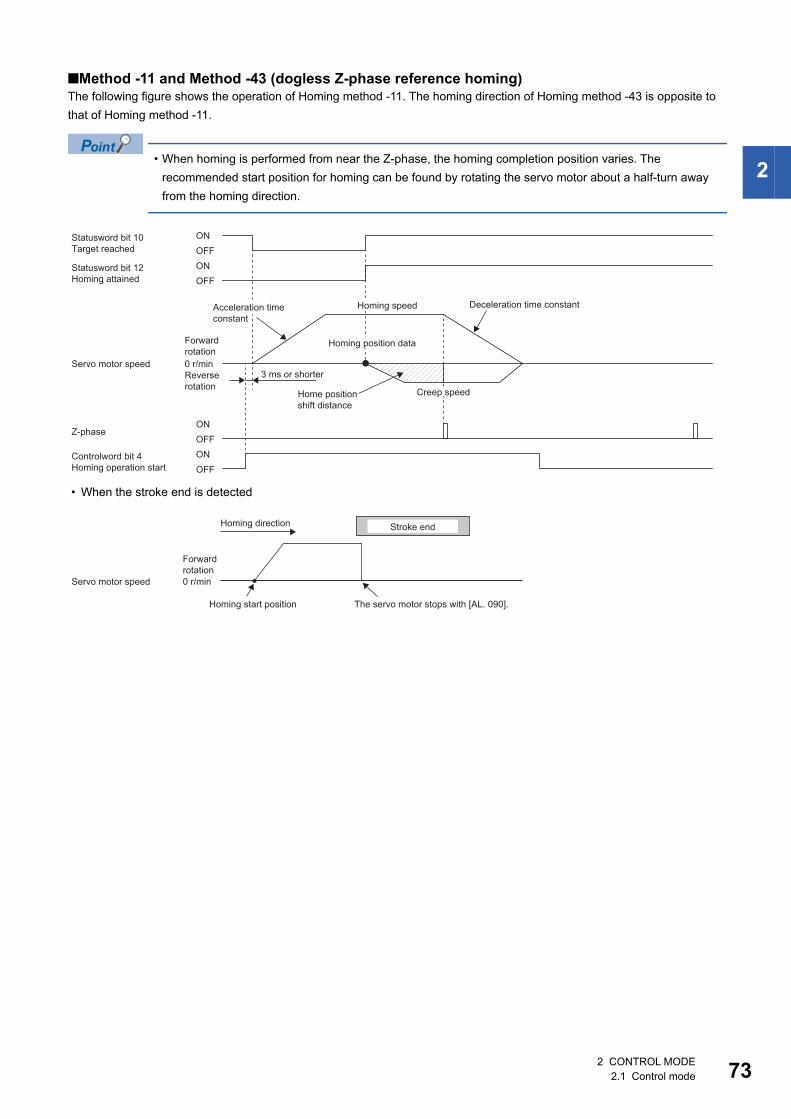
2
■Method -11 and Method -43 (dogless Z-phase reference homing)The following figure shows the operation of Homing method -11. The homing direction of Homing method -43 is opposite to that of Homing method -11.
• When homing is performed from near the Z-phase, the homing completion position varies. The recommended start position for homing can be found by rotating the servo motor about a half-turn away from the homing direction.
• When the stroke end is detected
Statusword bit 10Target reached
Statusword bit 12Homing attained
0 r/min
ONOFF
ONOFF
ONOFF
ONOFF
Controlword bit 4Homing operation start
Deceleration time constantHoming speedAcceleration time constant
Homing position dataForward rotation
Servo motor speed3 ms or shorterReverse
rotation Creep speedHome position shift distance
Z-phase
0 r/min
Homing direction Stroke end
Forward rotation
Servo motor speed
Homing start position The servo motor stops with [AL. 090].
2 CONTROL MODE2.1 Control mode 73

74
3 BASIC FUNCTIONThis chapter explains each function that is used for basic operation of the servo amplifier. Set each function as required. For advanced operation of the servo amplifier, refer to the following.Page 125 APPLICABLE FUNCTIONS
Precautions • To prevent a malfunction and machine damage, on the first operation after setting, check the operating condition with a low
speed command.
3.1 Outline of servo parameter and object dictionaryOn MR-JET servo amplifiers, the functions of the servo amplifiers are set with servo parameters, and objects enable communication of data such as command values and feedback values with controllers.
Servo parameter
For the servo parameters that updates data periodically in the cyclic communication, do not write a value with an engineering tool or other tools, as the values will be overwritten from the controller.
Each function of the servo amplifiers can be set with the servo parameters. The servo parameters are stored in the non-volatile memory in the servo amplifier. Initial values are set for the servo parameters in the factory setting. Change the setting with engineering tools or other methods as necessary.The servo parameters related to the basic functions explained in this manual are shown in the following example.If the servo parameter name is "Travel direction selection" and the number is "PA14"[Pr. PA14 Travel direction selection]
In addition, the servo parameters in which the symbols are preceded by * are enabled by the following conditions. • *: After setting, cycle the power, or reset either the controller or the software. • **: After setting, cycle the power or reset the software.For a servo parameter which uses one particular digit to select a function, the position of its digit indicates the detail number of the servo parameter, and the value in hexadecimal which is set to the digit indicates the selected function.For example, the detail number of the servo parameter in the last digit is expressed as [Pr. PA01.0]. In addition, a servo parameter which uses a combination of several digits to select a function, is expressed using "-" as seen in [Pr. PA01.0-1].
Servo parameter
Symbol Name Outline
PA14 *POL Travel direction selection The rotation direction of the servo motor or the travel direction of the linear servo motor can be set.Initial value: 0 (CCW or positive direction)
3 BASIC FUNCTION3.1 Outline of servo parameter and object dictionary
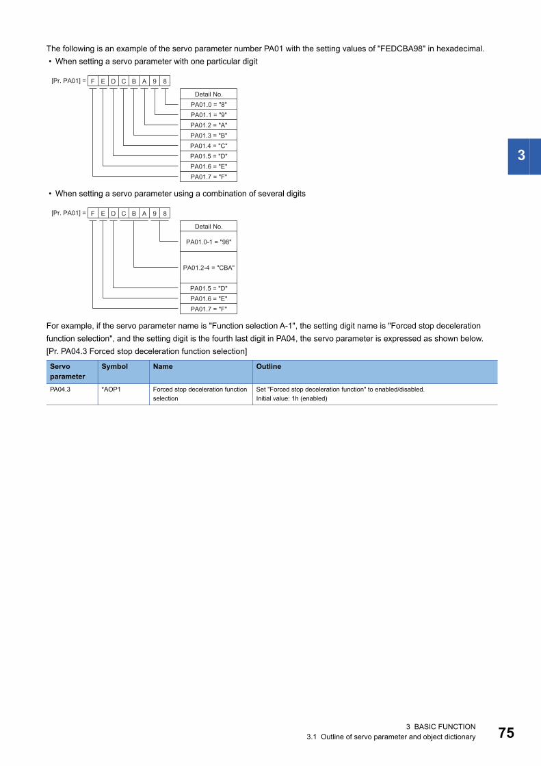
3
The following is an example of the servo parameter number PA01 with the setting values of "FEDCBA98" in hexadecimal. • When setting a servo parameter with one particular digit
• When setting a servo parameter using a combination of several digits
For example, if the servo parameter name is "Function selection A-1", the setting digit name is "Forced stop deceleration function selection", and the setting digit is the fourth last digit in PA04, the servo parameter is expressed as shown below.[Pr. PA04.3 Forced stop deceleration function selection]
Servo parameter
Symbol Name Outline
PA04.3 *AOP1 Forced stop deceleration function selection
Set "Forced stop deceleration function" to enabled/disabled.Initial value: 1h (enabled)
[Pr. PA01] =
PA01.0 = "8"PA01.1 = "9"PA01.2 = "A"PA01.3 = "B"PA01.4 = "C"PA01.5 = "D"
CD BF AE 89
PA01.6 = "E"PA01.7 = "F"
Detail No.
[Pr. PA01] =
PA01.0-1 = "98"
PA01.2-4 = "CBA"
PA01.5 = "D"
CD BF AE 89
PA01.6 = "E"PA01.7 = "F"
Detail No.
3 BASIC FUNCTION3.1 Outline of servo parameter and object dictionary 75
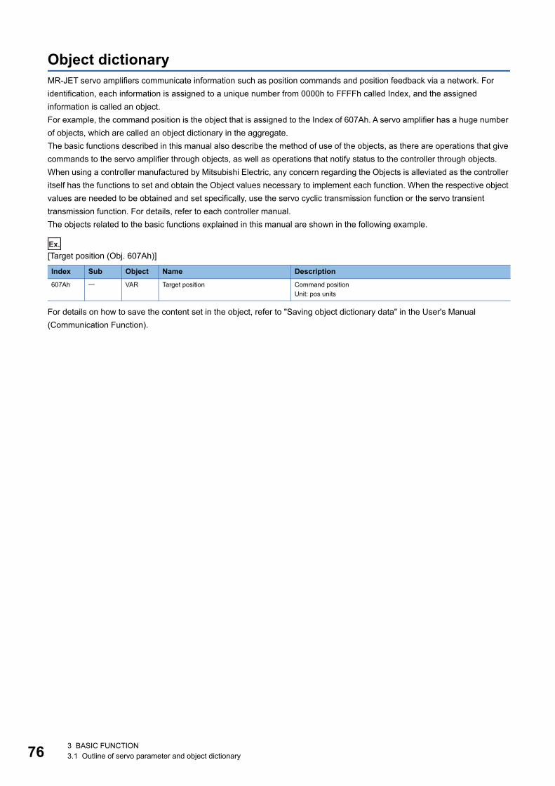
76
Object dictionaryMR-JET servo amplifiers communicate information such as position commands and position feedback via a network. For identification, each information is assigned to a unique number from 0000h to FFFFh called Index, and the assigned information is called an object.For example, the command position is the object that is assigned to the Index of 607Ah. A servo amplifier has a huge number of objects, which are called an object dictionary in the aggregate.The basic functions described in this manual also describe the method of use of the objects, as there are operations that give commands to the servo amplifier through objects, as well as operations that notify status to the controller through objects.When using a controller manufactured by Mitsubishi Electric, any concern regarding the Objects is alleviated as the controller itself has the functions to set and obtain the Object values necessary to implement each function. When the respective object values are needed to be obtained and set specifically, use the servo cyclic transmission function or the servo transient transmission function. For details, refer to each controller manual.The objects related to the basic functions explained in this manual are shown in the following example.
Ex.
[Target position (Obj. 607Ah)]
For details on how to save the content set in the object, refer to "Saving object dictionary data" in the User's Manual (Communication Function).
Index Sub Object Name Description607Ah VAR Target position Command position
Unit: pos units
3 BASIC FUNCTION3.1 Outline of servo parameter and object dictionary
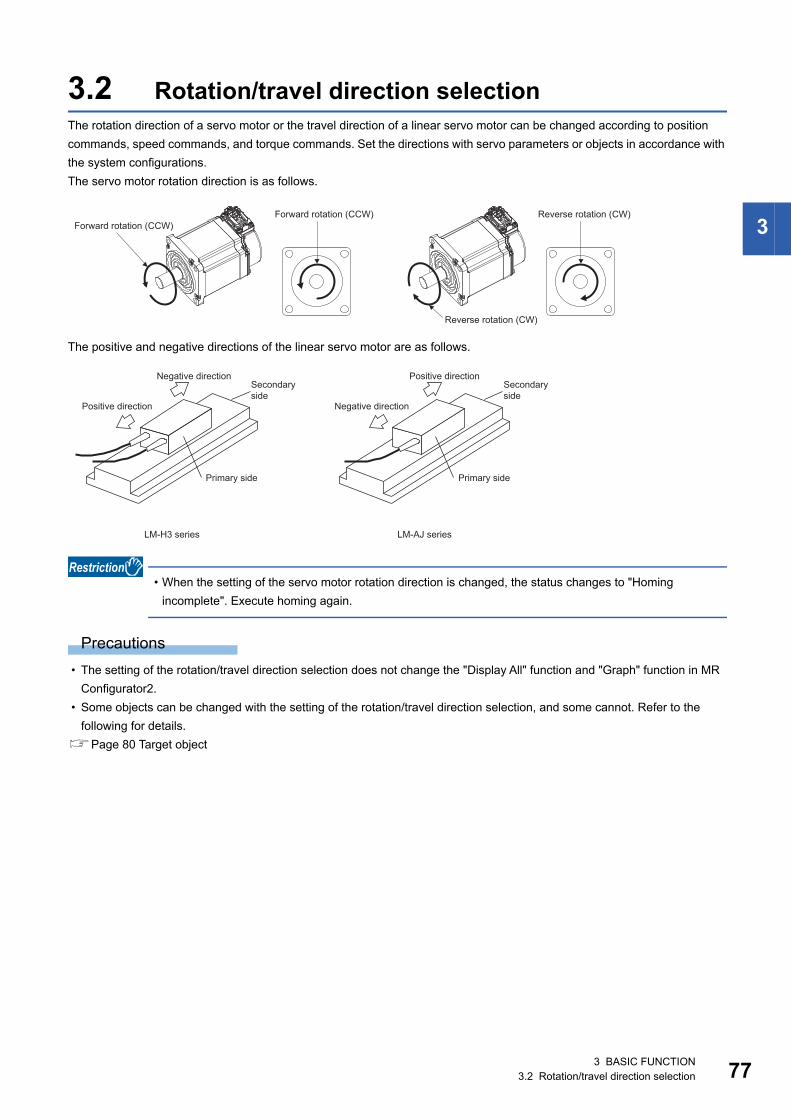
3
3.2 Rotation/travel direction selectionThe rotation direction of a servo motor or the travel direction of a linear servo motor can be changed according to position commands, speed commands, and torque commands. Set the directions with servo parameters or objects in accordance with the system configurations.The servo motor rotation direction is as follows.
The positive and negative directions of the linear servo motor are as follows.
• When the setting of the servo motor rotation direction is changed, the status changes to "Homing incomplete". Execute homing again.
Precautions • The setting of the rotation/travel direction selection does not change the "Display All" function and "Graph" function in MR
Configurator2. • Some objects can be changed with the setting of the rotation/travel direction selection, and some cannot. Refer to the
following for details.Page 80 Target object
Forward rotation (CCW)Forward rotation (CCW)
Reverse rotation (CW)
Reverse rotation (CW)
Secondary side
Primary side
Positive direction
Negative direction
LM-H3 series
Secondary side
Primary side
Negative direction
Positive direction
LM-AJ series
3 BASIC FUNCTION3.2 Rotation/travel direction selection 77
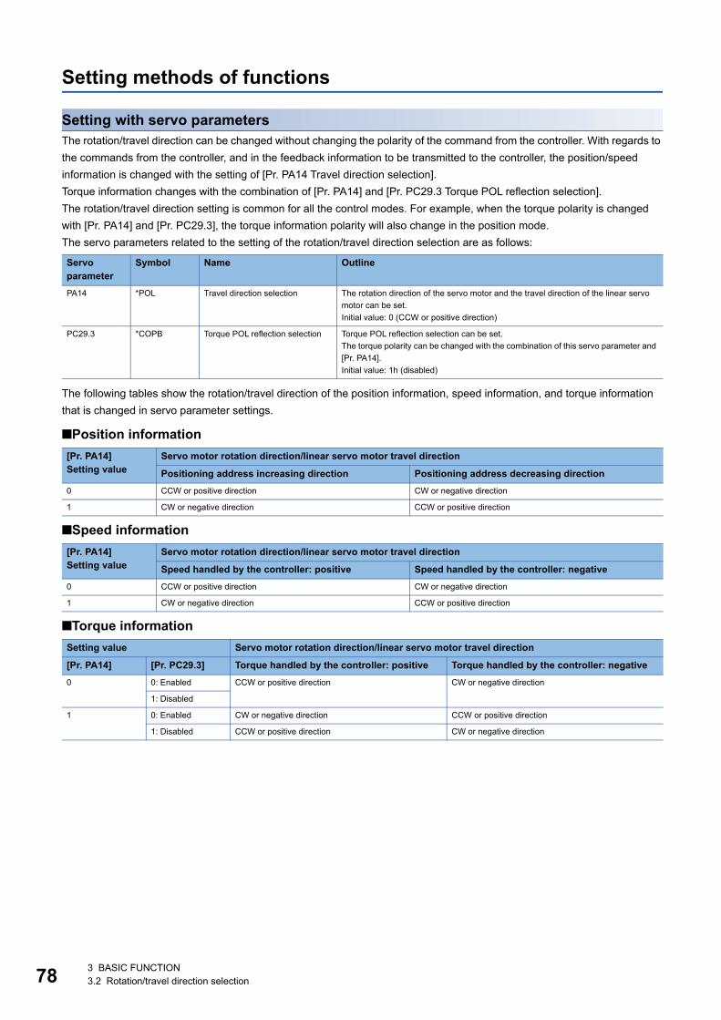
78
Setting methods of functions
Setting with servo parametersThe rotation/travel direction can be changed without changing the polarity of the command from the controller. With regards to the commands from the controller, and in the feedback information to be transmitted to the controller, the position/speed information is changed with the setting of [Pr. PA14 Travel direction selection].Torque information changes with the combination of [Pr. PA14] and [Pr. PC29.3 Torque POL reflection selection].The rotation/travel direction setting is common for all the control modes. For example, when the torque polarity is changed with [Pr. PA14] and [Pr. PC29.3], the torque information polarity will also change in the position mode.The servo parameters related to the setting of the rotation/travel direction selection are as follows:
The following tables show the rotation/travel direction of the position information, speed information, and torque information that is changed in servo parameter settings.
■Position information
■Speed information
■Torque information
Servo parameter
Symbol Name Outline
PA14 *POL Travel direction selection The rotation direction of the servo motor and the travel direction of the linear servo motor can be set.Initial value: 0 (CCW or positive direction)
PC29.3 *COPB Torque POL reflection selection Torque POL reflection selection can be set.The torque polarity can be changed with the combination of this servo parameter and [Pr. PA14].Initial value: 1h (disabled)
[Pr. PA14]Setting value
Servo motor rotation direction/linear servo motor travel direction
Positioning address increasing direction Positioning address decreasing direction0 CCW or positive direction CW or negative direction
1 CW or negative direction CCW or positive direction
[Pr. PA14]Setting value
Servo motor rotation direction/linear servo motor travel direction
Speed handled by the controller: positive Speed handled by the controller: negative0 CCW or positive direction CW or negative direction
1 CW or negative direction CCW or positive direction
Setting value Servo motor rotation direction/linear servo motor travel direction
[Pr. PA14] [Pr. PC29.3] Torque handled by the controller: positive Torque handled by the controller: negative0 0: Enabled CCW or positive direction CW or negative direction
1: Disabled
1 0: Enabled CW or negative direction CCW or positive direction
1: Disabled CCW or positive direction CW or negative direction
3 BASIC FUNCTION3.2 Rotation/travel direction selection
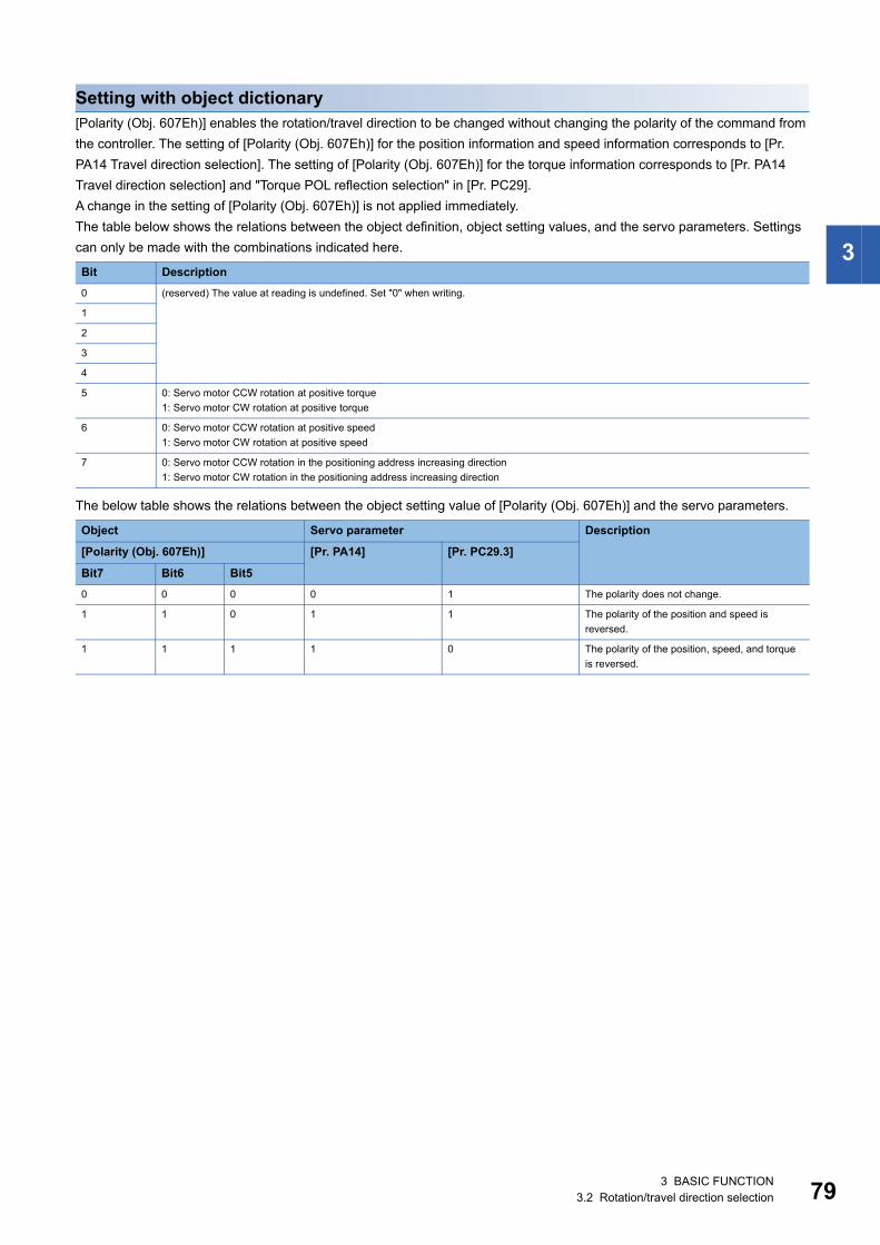
3
Setting with object dictionary[Polarity (Obj. 607Eh)] enables the rotation/travel direction to be changed without changing the polarity of the command from the controller. The setting of [Polarity (Obj. 607Eh)] for the position information and speed information corresponds to [Pr. PA14 Travel direction selection]. The setting of [Polarity (Obj. 607Eh)] for the torque information corresponds to [Pr. PA14 Travel direction selection] and "Torque POL reflection selection" in [Pr. PC29].A change in the setting of [Polarity (Obj. 607Eh)] is not applied immediately.The table below shows the relations between the object definition, object setting values, and the servo parameters. Settings can only be made with the combinations indicated here.
The below table shows the relations between the object setting value of [Polarity (Obj. 607Eh)] and the servo parameters.
Bit Description0 (reserved) The value at reading is undefined. Set "0" when writing.
1
2
3
4
5 0: Servo motor CCW rotation at positive torque1: Servo motor CW rotation at positive torque
6 0: Servo motor CCW rotation at positive speed1: Servo motor CW rotation at positive speed
7 0: Servo motor CCW rotation in the positioning address increasing direction1: Servo motor CW rotation in the positioning address increasing direction
Object Servo parameter Description
[Polarity (Obj. 607Eh)] [Pr. PA14] [Pr. PC29.3]
Bit7 Bit6 Bit50 0 0 0 1 The polarity does not change.
1 1 0 1 1 The polarity of the position and speed is reversed.
1 1 1 1 0 The polarity of the position, speed, and torque is reversed.
3 BASIC FUNCTION3.2 Rotation/travel direction selection 79
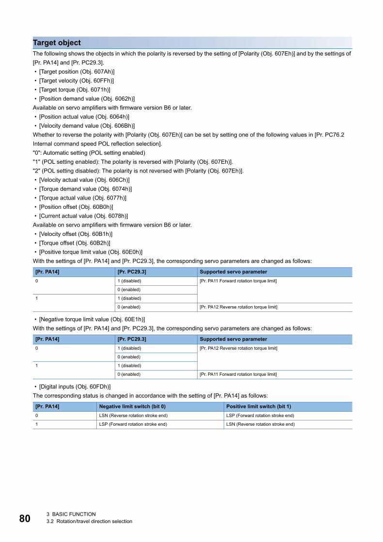
80
Target objectThe following shows the objects in which the polarity is reversed by the setting of [Polarity (Obj. 607Eh)] and by the settings of [Pr. PA14] and [Pr. PC29.3]. • [Target position (Obj. 607Ah)] • [Target velocity (Obj. 60FFh)] • [Target torque (Obj. 6071h)] • [Position demand value (Obj. 6062h)]Available on servo amplifiers with firmware version B6 or later. • [Position actual value (Obj. 6064h)] • [Velocity demand value (Obj. 606Bh)]Whether to reverse the polarity with [Polarity (Obj. 607Eh)] can be set by setting one of the following values in [Pr. PC76.2 Internal command speed POL reflection selection]."0": Automatic setting (POL setting enabled)"1" (POL setting enabled): The polarity is reversed with [Polarity (Obj. 607Eh)]."2" (POL setting disabled): The polarity is not reversed with [Polarity (Obj. 607Eh)]. • [Velocity actual value (Obj. 606Ch)] • [Torque demand value (Obj. 6074h)] • [Torque actual value (Obj. 6077h)] • [Position offset (Obj. 60B0h)] • [Current actual value (Obj. 6078h)]Available on servo amplifiers with firmware version B6 or later. • [Velocity offset (Obj. 60B1h)] • [Torque offset (Obj. 60B2h)] • [Positive torque limit value (Obj. 60E0h)]With the settings of [Pr. PA14] and [Pr. PC29.3], the corresponding servo parameters are changed as follows:
• [Negative torque limit value (Obj. 60E1h)]With the settings of [Pr. PA14] and [Pr. PC29.3], the corresponding servo parameters are changed as follows:
• [Digital inputs (Obj. 60FDh)]The corresponding status is changed in accordance with the setting of [Pr. PA14] as follows:
[Pr. PA14] [Pr. PC29.3] Supported servo parameter0 1 (disabled) [Pr. PA11 Forward rotation torque limit]
0 (enabled)
1 1 (disabled)
0 (enabled) [Pr. PA12 Reverse rotation torque limit]
[Pr. PA14] [Pr. PC29.3] Supported servo parameter0 1 (disabled) [Pr. PA12 Reverse rotation torque limit]
0 (enabled)
1 1 (disabled)
0 (enabled) [Pr. PA11 Forward rotation torque limit]
[Pr. PA14] Negative limit switch (bit 0) Positive limit switch (bit 1)0 LSN (Reverse rotation stroke end) LSP (Forward rotation stroke end)
1 LSP (Forward rotation stroke end) LSN (Reverse rotation stroke end)
3 BASIC FUNCTION3.2 Rotation/travel direction selection
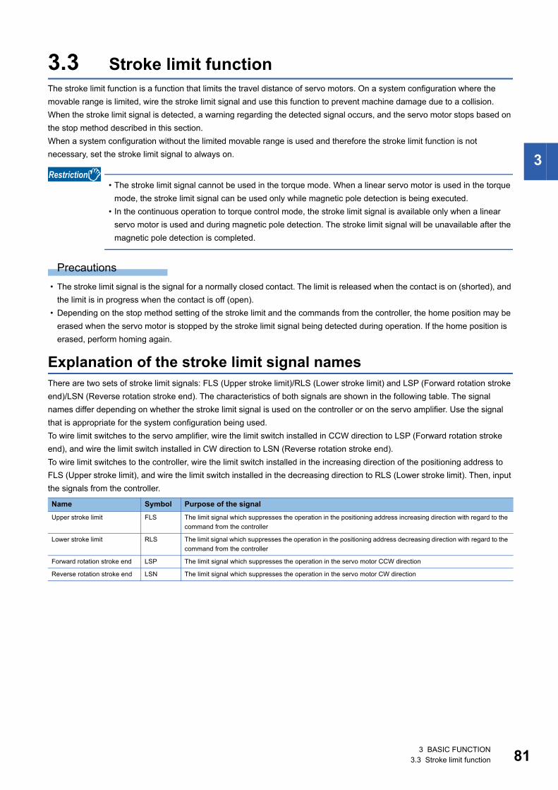
3
3.3 Stroke limit functionThe stroke limit function is a function that limits the travel distance of servo motors. On a system configuration where the movable range is limited, wire the stroke limit signal and use this function to prevent machine damage due to a collision.When the stroke limit signal is detected, a warning regarding the detected signal occurs, and the servo motor stops based on the stop method described in this section.When a system configuration without the limited movable range is used and therefore the stroke limit function is not necessary, set the stroke limit signal to always on.
• The stroke limit signal cannot be used in the torque mode. When a linear servo motor is used in the torque mode, the stroke limit signal can be used only while magnetic pole detection is being executed.
• In the continuous operation to torque control mode, the stroke limit signal is available only when a linear servo motor is used and during magnetic pole detection. The stroke limit signal will be unavailable after the magnetic pole detection is completed.
Precautions • The stroke limit signal is the signal for a normally closed contact. The limit is released when the contact is on (shorted), and
the limit is in progress when the contact is off (open). • Depending on the stop method setting of the stroke limit and the commands from the controller, the home position may be
erased when the servo motor is stopped by the stroke limit signal being detected during operation. If the home position is erased, perform homing again.
Explanation of the stroke limit signal namesThere are two sets of stroke limit signals: FLS (Upper stroke limit)/RLS (Lower stroke limit) and LSP (Forward rotation stroke end)/LSN (Reverse rotation stroke end). The characteristics of both signals are shown in the following table. The signal names differ depending on whether the stroke limit signal is used on the controller or on the servo amplifier. Use the signal that is appropriate for the system configuration being used.To wire limit switches to the servo amplifier, wire the limit switch installed in CCW direction to LSP (Forward rotation stroke end), and wire the limit switch installed in CW direction to LSN (Reverse rotation stroke end).To wire limit switches to the controller, wire the limit switch installed in the increasing direction of the positioning address to FLS (Upper stroke limit), and wire the limit switch installed in the decreasing direction to RLS (Lower stroke limit). Then, input the signals from the controller.
Name Symbol Purpose of the signalUpper stroke limit FLS The limit signal which suppresses the operation in the positioning address increasing direction with regard to the
command from the controller
Lower stroke limit RLS The limit signal which suppresses the operation in the positioning address decreasing direction with regard to the command from the controller
Forward rotation stroke end LSP The limit signal which suppresses the operation in the servo motor CCW direction
Reverse rotation stroke end LSN The limit signal which suppresses the operation in the servo motor CW direction
3 BASIC FUNCTION3.3 Stroke limit function 81
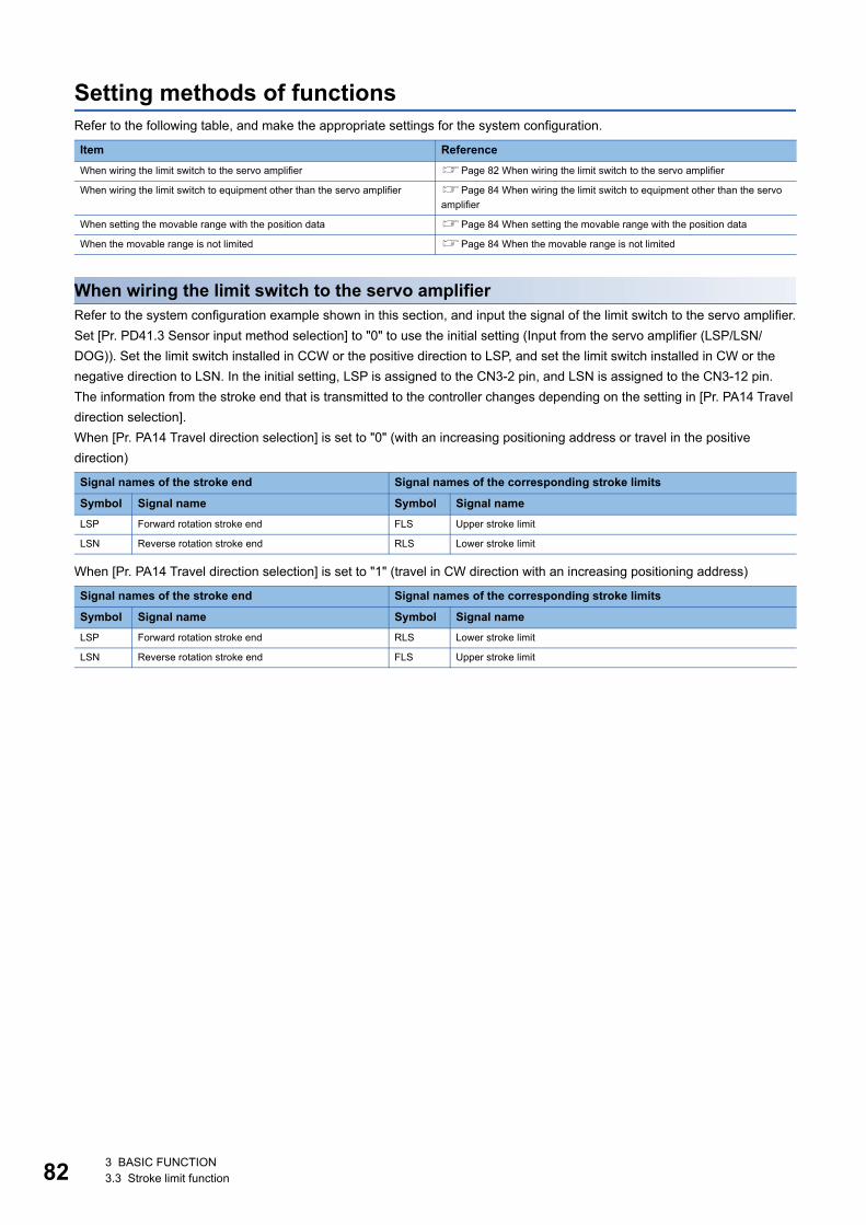
82
Setting methods of functionsRefer to the following table, and make the appropriate settings for the system configuration.
When wiring the limit switch to the servo amplifierRefer to the system configuration example shown in this section, and input the signal of the limit switch to the servo amplifier.Set [Pr. PD41.3 Sensor input method selection] to "0" to use the initial setting (Input from the servo amplifier (LSP/LSN/DOG)). Set the limit switch installed in CCW or the positive direction to LSP, and set the limit switch installed in CW or the negative direction to LSN. In the initial setting, LSP is assigned to the CN3-2 pin, and LSN is assigned to the CN3-12 pin.The information from the stroke end that is transmitted to the controller changes depending on the setting in [Pr. PA14 Travel direction selection].When [Pr. PA14 Travel direction selection] is set to "0" (with an increasing positioning address or travel in the positive direction)
When [Pr. PA14 Travel direction selection] is set to "1" (travel in CW direction with an increasing positioning address)
Item ReferenceWhen wiring the limit switch to the servo amplifier Page 82 When wiring the limit switch to the servo amplifier
When wiring the limit switch to equipment other than the servo amplifier Page 84 When wiring the limit switch to equipment other than the servo amplifier
When setting the movable range with the position data Page 84 When setting the movable range with the position data
When the movable range is not limited Page 84 When the movable range is not limited
Signal names of the stroke end Signal names of the corresponding stroke limits
Symbol Signal name Symbol Signal nameLSP Forward rotation stroke end FLS Upper stroke limit
LSN Reverse rotation stroke end RLS Lower stroke limit
Signal names of the stroke end Signal names of the corresponding stroke limits
Symbol Signal name Symbol Signal nameLSP Forward rotation stroke end RLS Lower stroke limit
LSN Reverse rotation stroke end FLS Upper stroke limit
3 BASIC FUNCTION3.3 Stroke limit function
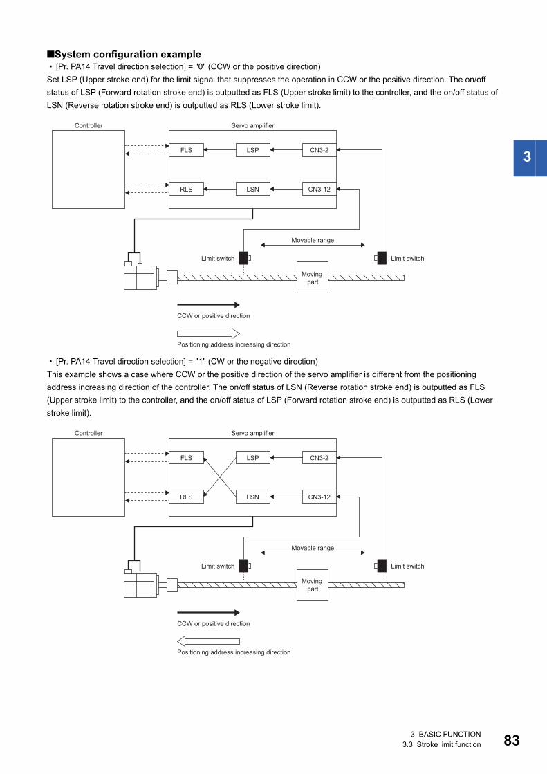
3
■System configuration example • [Pr. PA14 Travel direction selection] = "0" (CCW or the positive direction)Set LSP (Upper stroke end) for the limit signal that suppresses the operation in CCW or the positive direction. The on/off status of LSP (Forward rotation stroke end) is outputted as FLS (Upper stroke limit) to the controller, and the on/off status of LSN (Reverse rotation stroke end) is outputted as RLS (Lower stroke limit).
• [Pr. PA14 Travel direction selection] = "1" (CW or the negative direction)This example shows a case where CCW or the positive direction of the servo amplifier is different from the positioning address increasing direction of the controller. The on/off status of LSN (Reverse rotation stroke end) is outputted as FLS (Upper stroke limit) to the controller, and the on/off status of LSP (Forward rotation stroke end) is outputted as RLS (Lower stroke limit).
CN3-12
FLS
RLS
LSP
LSN
CN3-2
Controller Servo amplifier
Movable range
Limit switch Limit switch
Moving part
Positioning address increasing direction
CCW or positive direction
CN3-12
FLS
RLS
LSP
LSN
CN3-2
Controller Servo amplifier
Movable range
Limit switch Limit switch
Moving part
Positioning address increasing direction
CCW or positive direction
3 BASIC FUNCTION3.3 Stroke limit function 83
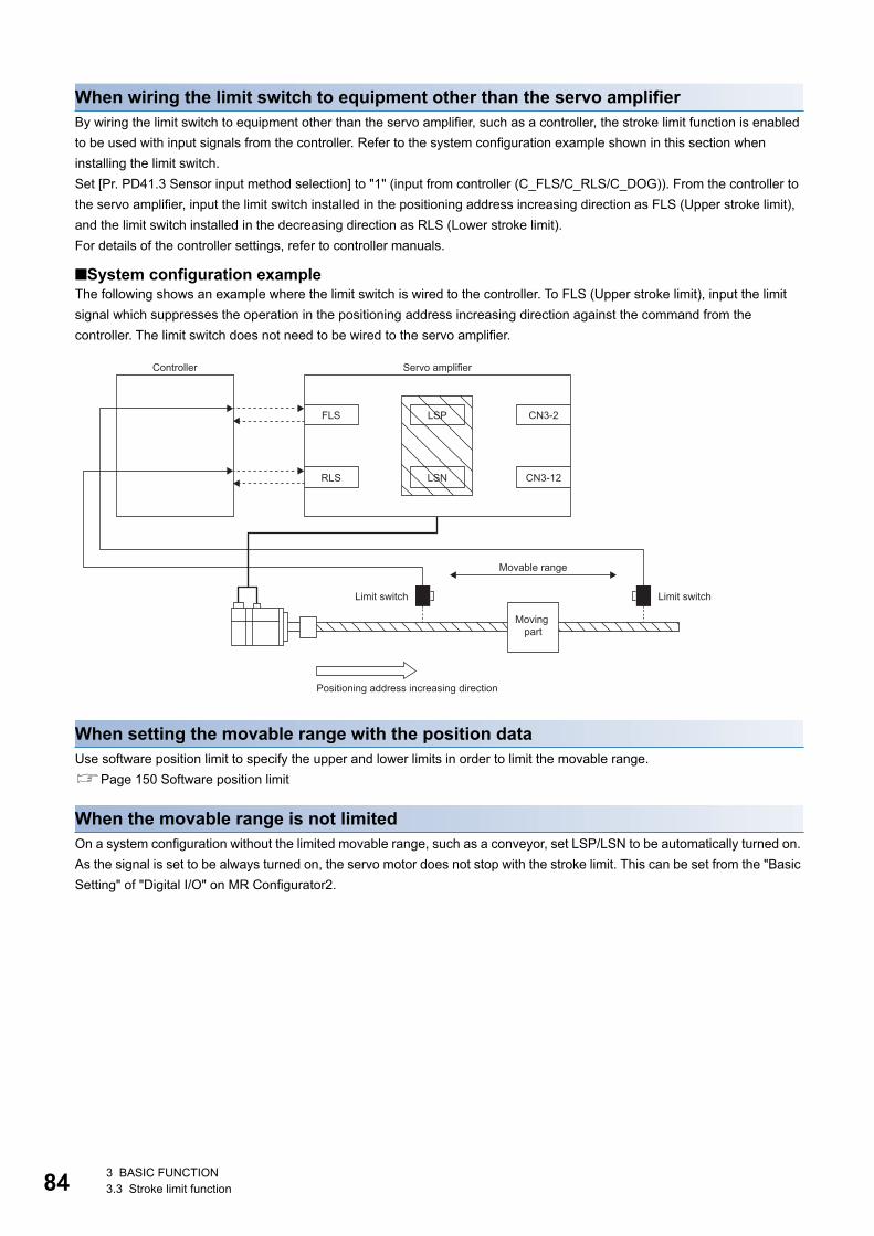
84
When wiring the limit switch to equipment other than the servo amplifierBy wiring the limit switch to equipment other than the servo amplifier, such as a controller, the stroke limit function is enabled to be used with input signals from the controller. Refer to the system configuration example shown in this section when installing the limit switch.Set [Pr. PD41.3 Sensor input method selection] to "1" (input from controller (C_FLS/C_RLS/C_DOG)). From the controller to the servo amplifier, input the limit switch installed in the positioning address increasing direction as FLS (Upper stroke limit), and the limit switch installed in the decreasing direction as RLS (Lower stroke limit).For details of the controller settings, refer to controller manuals.
■System configuration exampleThe following shows an example where the limit switch is wired to the controller. To FLS (Upper stroke limit), input the limit signal which suppresses the operation in the positioning address increasing direction against the command from the controller. The limit switch does not need to be wired to the servo amplifier.
When setting the movable range with the position dataUse software position limit to specify the upper and lower limits in order to limit the movable range.Page 150 Software position limit
When the movable range is not limitedOn a system configuration without the limited movable range, such as a conveyor, set LSP/LSN to be automatically turned on. As the signal is set to be always turned on, the servo motor does not stop with the stroke limit. This can be set from the "Basic Setting" of "Digital I/O" on MR Configurator2.
CN3-12
FLS
RLS
LSP
LSN
CN3-2
Controller Servo amplifier
Movable range
Limit switch Limit switch
Moving part
Positioning address increasing direction
3 BASIC FUNCTION3.3 Stroke limit function
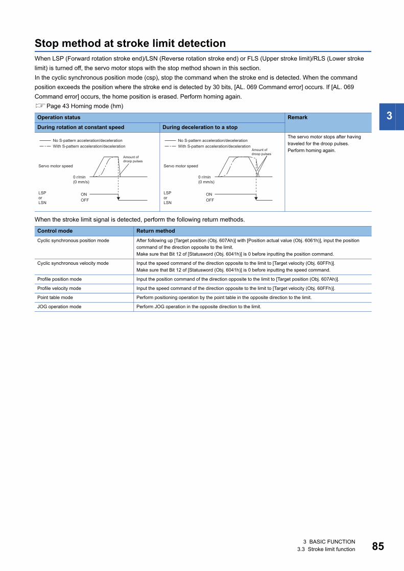
3
Stop method at stroke limit detectionWhen LSP (Forward rotation stroke end)/LSN (Reverse rotation stroke end) or FLS (Upper stroke limit)/RLS (Lower stroke limit) is turned off, the servo motor stops with the stop method shown in this section.In the cyclic synchronous position mode (csp), stop the command when the stroke end is detected. When the command position exceeds the position where the stroke end is detected by 30 bits, [AL. 069 Command error] occurs. If [AL. 069 Command error] occurs, the home position is erased. Perform homing again.Page 43 Homing mode (hm)
When the stroke limit signal is detected, perform the following return methods.
Operation status Remark
During rotation at constant speed During deceleration to a stopThe servo motor stops after having traveled for the droop pulses.Perform homing again.
Control mode Return methodCyclic synchronous position mode After following up [Target position (Obj. 607Ah)] with [Position actual value (Obj. 6061h)], input the position
command of the direction opposite to the limit.Make sure that Bit 12 of [Statusword (Obj. 6041h)] is 0 before inputting the position command.
Cyclic synchronous velocity mode Input the speed command of the direction opposite to the limit to [Target velocity (Obj. 60FFh)].Make sure that Bit 12 of [Statusword (Obj. 6041h)] is 0 before inputting the speed command.
Profile position mode Input the position command of the direction opposite to the limit to [Target position (Obj. 607Ah)].
Profile velocity mode Input the speed command of the direction opposite to the limit to [Target velocity (Obj. 60FFh)].
Point table mode Perform positioning operation by the point table in the opposite direction to the limit.
JOG operation mode Perform JOG operation in the opposite direction to the limit.
0 r/min(0 mm/s)
ONOFF
No S-pattern acceleration/decelerationWith S-pattern acceleration/deceleration
Amount of droop pulses
Servo motor speed
LSP or LSN
0 r/min(0 mm/s)
ONOFF
No S-pattern acceleration/decelerationWith S-pattern acceleration/deceleration
Amount of droop pulses
Servo motor speed
LSP or LSN
3 BASIC FUNCTION3.3 Stroke limit function 85
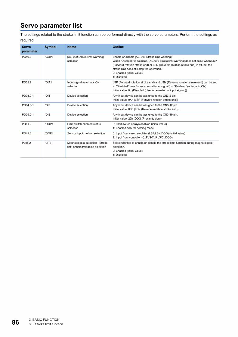
86
Servo parameter listThe settings related to the stroke limit function can be performed directly with the servo parameters. Perform the settings as required.
Servo parameter
Symbol Name Outline
PC19.0 *COP6 [AL. 099 Stroke limit warning] selection
Enable or disable [AL. 099 Stroke limit warning].When "Disabled" is selected, [AL. 099 Stroke limit warning] does not occur when LSP (Forward rotation stroke end) or LSN (Reverse rotation stroke end) is off, but the stroke limit does still stop the operation.0: Enabled (initial value)1: Disabled
PD01.2 *DIA1 Input signal automatic ON selection
LSP (Forward rotation stroke end) and LSN (Reverse rotation stroke end) can be set to "Disabled" (use for an external input signal.) or "Enabled" (automatic ON).Initial value: 0h (Disabled (Use for an external input signal.))
PD03.0-1 *DI1 Device selection Any input device can be assigned to the CN3-2 pin.Initial value: 0Ah (LSP (Forward rotation stroke end))
PD04.0-1 *DI2 Device selection Any input device can be assigned to the CN3-12 pin.Initial value: 0Bh (LSN (Reverse rotation stroke end))
PD05.0-1 *DI3 Device selection Any input device can be assigned to the CN3-19 pin.Initial value: 22h (DOG (Proximity dog))
PD41.2 *DOP4 Limit switch enabled status selection
0: Limit switch always enabled (initial value)1: Enabled only for homing mode
PD41.3 *DOP4 Sensor input method selection 0: Input from servo amplifier (LSP/LSN/DOG) (initial value)1: Input from controller (C_FLS/C_RLS/C_DOG)
PL08.2 *LIT3 Magnetic pole detection - Stroke limit enabled/disabled selection
Select whether to enable or disable the stroke limit function during magnetic pole detection.0: Enabled (initial value)1: Disabled
3 BASIC FUNCTION3.3 Stroke limit function
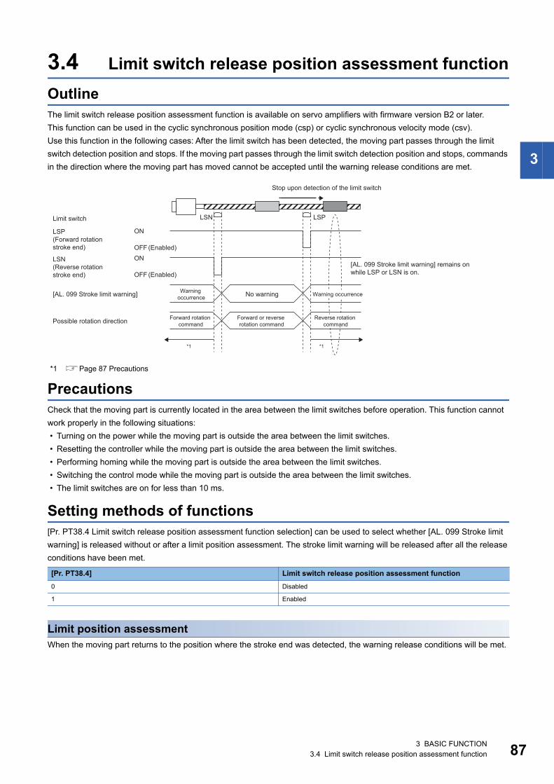
3
3.4 Limit switch release position assessment functionOutlineThe limit switch release position assessment function is available on servo amplifiers with firmware version B2 or later.This function can be used in the cyclic synchronous position mode (csp) or cyclic synchronous velocity mode (csv).Use this function in the following cases: After the limit switch has been detected, the moving part passes through the limit switch detection position and stops. If the moving part passes through the limit switch detection position and stops, commands in the direction where the moving part has moved cannot be accepted until the warning release conditions are met.
*1 Page 87 Precautions
PrecautionsCheck that the moving part is currently located in the area between the limit switches before operation. This function cannot work properly in the following situations: • Turning on the power while the moving part is outside the area between the limit switches. • Resetting the controller while the moving part is outside the area between the limit switches. • Performing homing while the moving part is outside the area between the limit switches. • Switching the control mode while the moving part is outside the area between the limit switches. • The limit switches are on for less than 10 ms.
Setting methods of functions[Pr. PT38.4 Limit switch release position assessment function selection] can be used to select whether [AL. 099 Stroke limit warning] is released without or after a limit position assessment. The stroke limit warning will be released after all the release conditions have been met.
Limit position assessmentWhen the moving part returns to the position where the stroke end was detected, the warning release conditions will be met.
[Pr. PT38.4] Limit switch release position assessment function0 Disabled
1 Enabled
LSN LSP
ON
*1 *1
OFFON
OFF
Limit switch
Stop upon detection of the limit switch
LSP (Forward rotation stroke end)
LSN (Reverse rotation stroke end)
[AL. 099 Stroke limit warning] Warning occurrence Warning occurrenceNo warning
[AL. 099 Stroke limit warning] remains on while LSP or LSN is on.
Forward rotation command
Reverse rotation command
Forward or reverse rotation commandPossible rotation direction
(Enabled)
(Enabled)
3 BASIC FUNCTION3.4 Limit switch release position assessment function 87
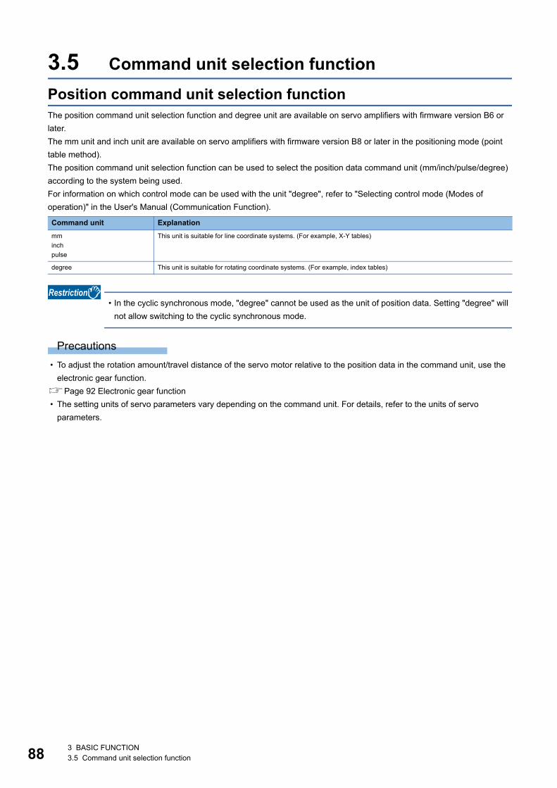
88
3.5 Command unit selection functionPosition command unit selection functionThe position command unit selection function and degree unit are available on servo amplifiers with firmware version B6 or later.The mm unit and inch unit are available on servo amplifiers with firmware version B8 or later in the positioning mode (point table method).The position command unit selection function can be used to select the position data command unit (mm/inch/pulse/degree) according to the system being used.For information on which control mode can be used with the unit "degree", refer to "Selecting control mode (Modes of operation)" in the User's Manual (Communication Function).
• In the cyclic synchronous mode, "degree" cannot be used as the unit of position data. Setting "degree" will not allow switching to the cyclic synchronous mode.
Precautions • To adjust the rotation amount/travel distance of the servo motor relative to the position data in the command unit, use the
electronic gear function.Page 92 Electronic gear function • The setting units of servo parameters vary depending on the command unit. For details, refer to the units of servo
parameters.
Command unit Explanationmminchpulse
This unit is suitable for line coordinate systems. (For example, X-Y tables)
degree This unit is suitable for rotating coordinate systems. (For example, index tables)
3 BASIC FUNCTION3.5 Command unit selection function
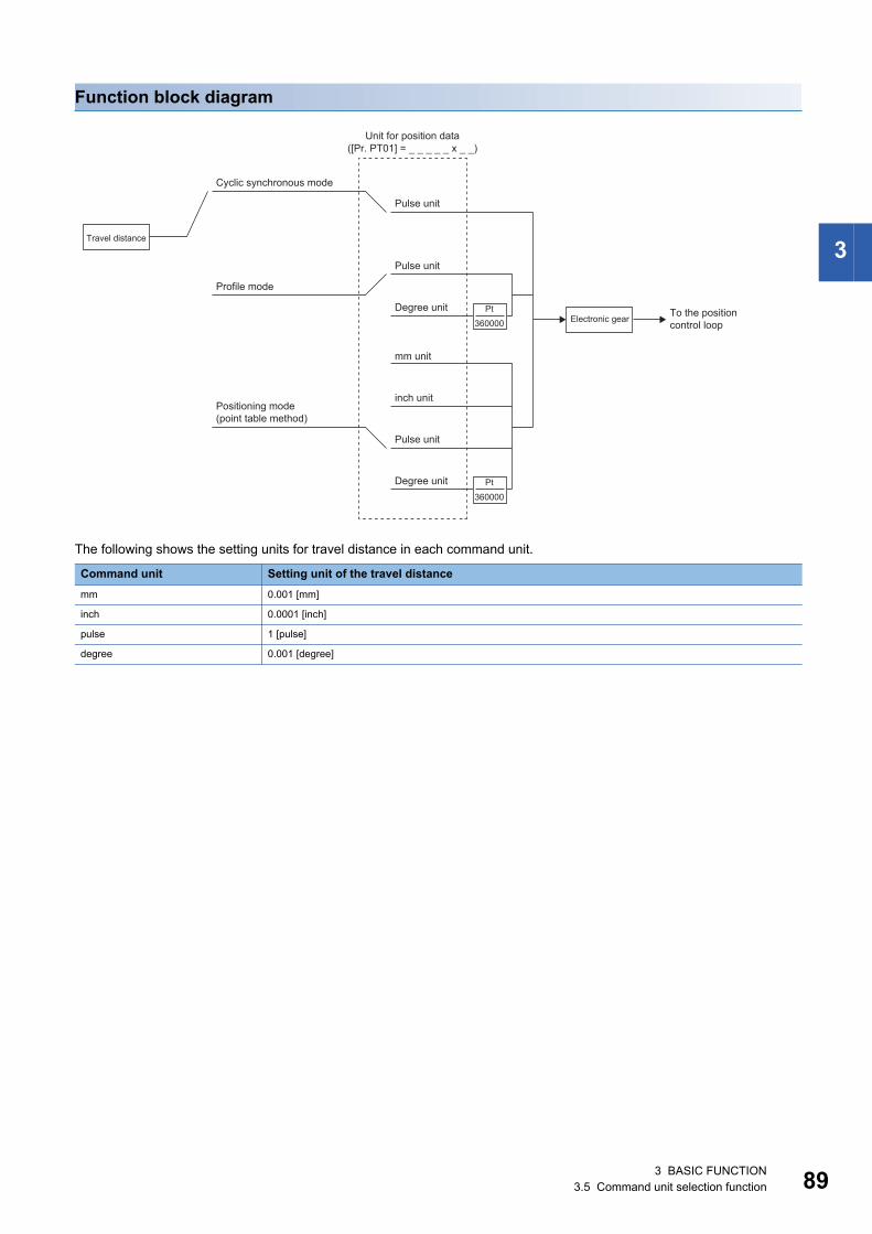
3
Function block diagram
The following shows the setting units for travel distance in each command unit.
Command unit Setting unit of the travel distancemm 0.001 [mm]
inch 0.0001 [inch]
pulse 1 [pulse]
degree 0.001 [degree]
([Pr. PT01] = _ _ _ _ _ x _ _)
Pt360000
Pt360000
Unit for position data
Cyclic synchronous mode
Pulse unit
Travel distance
Profile mode
Electronic gear To the position control loop
Pulse unit
Degree unit
Pulse unit
Degree unit
mm unit
inch unitPositioning mode(point table method)
3 BASIC FUNCTION3.5 Command unit selection function 89
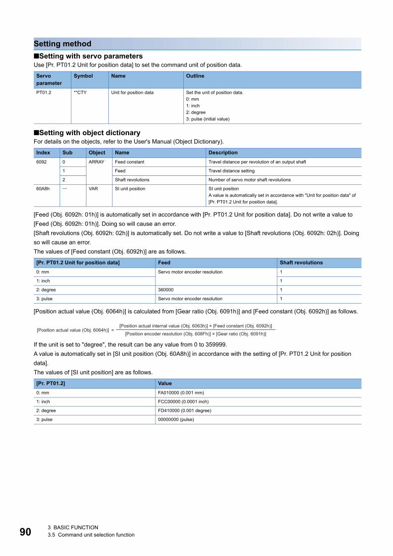
90
Setting method■Setting with servo parametersUse [Pr. PT01.2 Unit for position data] to set the command unit of position data.
■Setting with object dictionaryFor details on the objects, refer to the User's Manual (Object Dictionary).
[Feed (Obj. 6092h: 01h)] is automatically set in accordance with [Pr. PT01.2 Unit for position data]. Do not write a value to [Feed (Obj. 6092h: 01h)]. Doing so will cause an error.[Shaft revolutions (Obj. 6092h: 02h)] is automatically set. Do not write a value to [Shaft revolutions (Obj. 6092h: 02h)]. Doing so will cause an error.The values of [Feed constant (Obj. 6092h)] are as follows.
[Position actual value (Obj. 6064h)] is calculated from [Gear ratio (Obj. 6091h)] and [Feed constant (Obj. 6092h)] as follows.
If the unit is set to "degree", the result can be any value from 0 to 359999.A value is automatically set in [SI unit position (Obj. 60A8h)] in accordance with the setting of [Pr. PT01.2 Unit for position data].The values of [SI unit position] are as follows.
Servo parameter
Symbol Name Outline
PT01.2 **CTY Unit for position data Set the unit of position data.0: mm1: inch2: degree3: pulse (initial value)
Index Sub Object Name Description6092 0 ARRAY Feed constant Travel distance per revolution of an output shaft
1 Feed Travel distance setting
2 Shaft revolutions Number of servo motor shaft revolutions
60A8h VAR SI unit position SI unit positionA value is automatically set in accordance with "Unit for position data" of [Pr. PT01.2 Unit for position data].
[Pr. PT01.2 Unit for position data] Feed Shaft revolutions0: mm Servo motor encoder resolution 1
1: inch 1
2: degree 360000 1
3: pulse Servo motor encoder resolution 1
[Pr. PT01.2] Value0: mm FA010000 (0.001 mm)
1: inch FCC00000 (0.0001 inch)
2: degree FD410000 (0.001 degree)
3: pulse 00000000 (pulse)
[Position actual value (Obj. 6064h)][Position actual internal value (Obj. 6063h)] × [Feed constant (Obj. 6092h)]
[Position encoder resolution (Obj. 608Fh)] × [Gear ratio (Obj. 6091h)] =
3 BASIC FUNCTION3.5 Command unit selection function
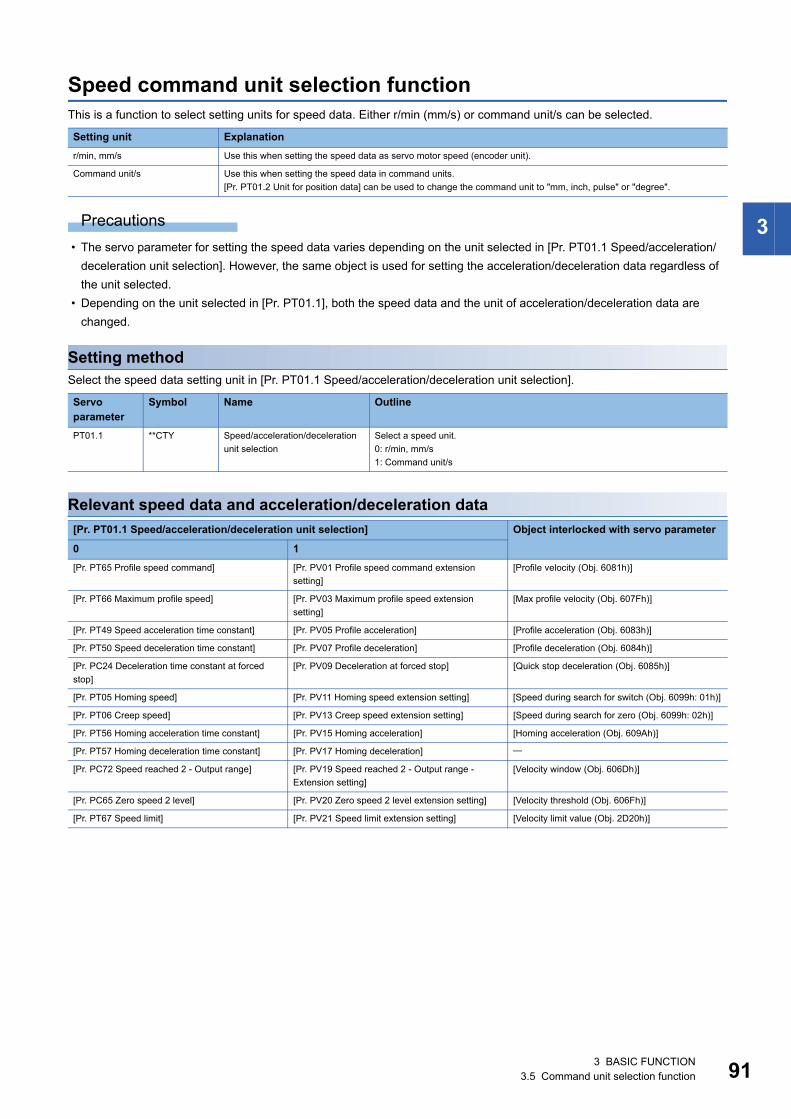
3
Speed command unit selection functionThis is a function to select setting units for speed data. Either r/min (mm/s) or command unit/s can be selected.
Precautions • The servo parameter for setting the speed data varies depending on the unit selected in [Pr. PT01.1 Speed/acceleration/
deceleration unit selection]. However, the same object is used for setting the acceleration/deceleration data regardless of the unit selected.
• Depending on the unit selected in [Pr. PT01.1], both the speed data and the unit of acceleration/deceleration data are changed.
Setting methodSelect the speed data setting unit in [Pr. PT01.1 Speed/acceleration/deceleration unit selection].
Relevant speed data and acceleration/deceleration data
Setting unit Explanationr/min, mm/s Use this when setting the speed data as servo motor speed (encoder unit).
Command unit/s Use this when setting the speed data in command units.[Pr. PT01.2 Unit for position data] can be used to change the command unit to "mm, inch, pulse" or "degree".
Servo parameter
Symbol Name Outline
PT01.1 **CTY Speed/acceleration/deceleration unit selection
Select a speed unit.0: r/min, mm/s1: Command unit/s
[Pr. PT01.1 Speed/acceleration/deceleration unit selection] Object interlocked with servo parameter
0 1[Pr. PT65 Profile speed command] [Pr. PV01 Profile speed command extension
setting][Profile velocity (Obj. 6081h)]
[Pr. PT66 Maximum profile speed] [Pr. PV03 Maximum profile speed extension setting]
[Max profile velocity (Obj. 607Fh)]
[Pr. PT49 Speed acceleration time constant] [Pr. PV05 Profile acceleration] [Profile acceleration (Obj. 6083h)]
[Pr. PT50 Speed deceleration time constant] [Pr. PV07 Profile deceleration] [Profile deceleration (Obj. 6084h)]
[Pr. PC24 Deceleration time constant at forced stop]
[Pr. PV09 Deceleration at forced stop] [Quick stop deceleration (Obj. 6085h)]
[Pr. PT05 Homing speed] [Pr. PV11 Homing speed extension setting] [Speed during search for switch (Obj. 6099h: 01h)]
[Pr. PT06 Creep speed] [Pr. PV13 Creep speed extension setting] [Speed during search for zero (Obj. 6099h: 02h)]
[Pr. PT56 Homing acceleration time constant] [Pr. PV15 Homing acceleration] [Homing acceleration (Obj. 609Ah)]
[Pr. PT57 Homing deceleration time constant] [Pr. PV17 Homing deceleration]
[Pr. PC72 Speed reached 2 - Output range] [Pr. PV19 Speed reached 2 - Output range - Extension setting]
[Velocity window (Obj. 606Dh)]
[Pr. PC65 Zero speed 2 level] [Pr. PV20 Zero speed 2 level extension setting] [Velocity threshold (Obj. 606Fh)]
[Pr. PT67 Speed limit] [Pr. PV21 Speed limit extension setting] [Velocity limit value (Obj. 2D20h)]
3 BASIC FUNCTION3.5 Command unit selection function 91
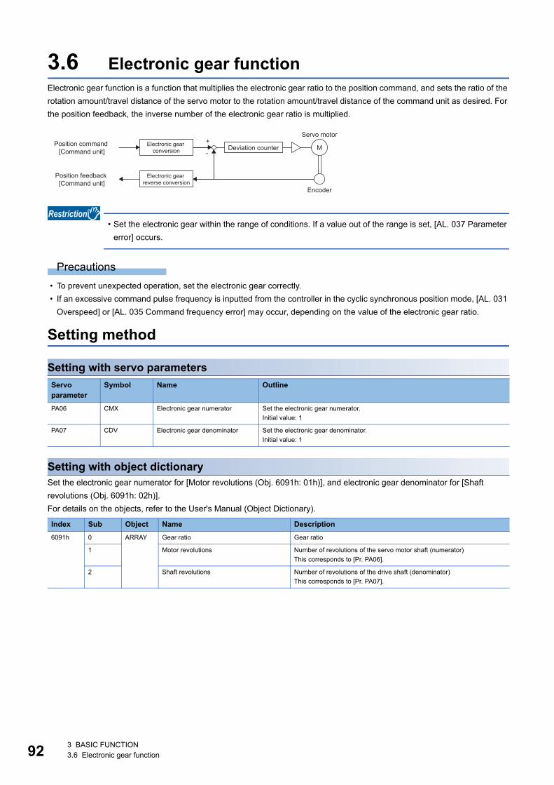
92
3.6 Electronic gear functionElectronic gear function is a function that multiplies the electronic gear ratio to the position command, and sets the ratio of the rotation amount/travel distance of the servo motor to the rotation amount/travel distance of the command unit as desired. For the position feedback, the inverse number of the electronic gear ratio is multiplied.
• Set the electronic gear within the range of conditions. If a value out of the range is set, [AL. 037 Parameter error] occurs.
Precautions • To prevent unexpected operation, set the electronic gear correctly. • If an excessive command pulse frequency is inputted from the controller in the cyclic synchronous position mode, [AL. 031
Overspeed] or [AL. 035 Command frequency error] may occur, depending on the value of the electronic gear ratio.
Setting method
Setting with servo parameters
Setting with object dictionarySet the electronic gear numerator for [Motor revolutions (Obj. 6091h: 01h)], and electronic gear denominator for [Shaft revolutions (Obj. 6091h: 02h)].For details on the objects, refer to the User's Manual (Object Dictionary).
Servo parameter
Symbol Name Outline
PA06 CMX Electronic gear numerator Set the electronic gear numerator.Initial value: 1
PA07 CDV Electronic gear denominator Set the electronic gear denominator.Initial value: 1
Index Sub Object Name Description6091h 0 ARRAY Gear ratio Gear ratio
1 Motor revolutions Number of revolutions of the servo motor shaft (numerator)This corresponds to [Pr. PA06].
2 Shaft revolutions Number of revolutions of the drive shaft (denominator)This corresponds to [Pr. PA07].
+
-M
Servo motorPosition command
[Command unit]Electronic gear
conversion Deviation counter
Position feedback [Command unit]
Electronic gear reverse conversion
Encoder
3 BASIC FUNCTION3.6 Electronic gear function
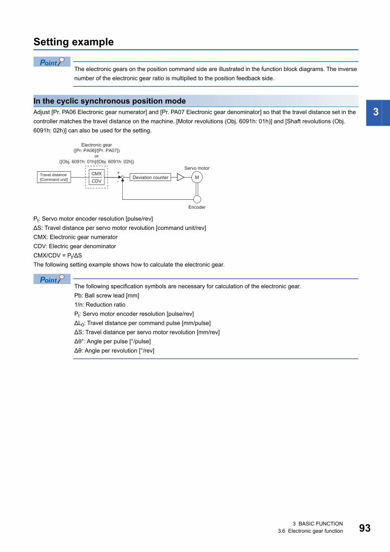
3
Setting example
The electronic gears on the position command side are illustrated in the function block diagrams. The inverse number of the electronic gear ratio is multiplied to the position feedback side.
In the cyclic synchronous position modeAdjust [Pr. PA06 Electronic gear numerator] and [Pr. PA07 Electronic gear denominator] so that the travel distance set in the controller matches the travel distance on the machine. [Motor revolutions (Obj. 6091h: 01h)] and [Shaft revolutions (Obj. 6091h: 02h)] can also be used for the setting.
Pt: Servo motor encoder resolution [pulse/rev]ΔS: Travel distance per servo motor revolution [command unit/rev]CMX: Electronic gear numeratorCDV: Electric gear denominatorCMX/CDV = Pt/ΔSThe following setting example shows how to calculate the electronic gear.
The following specification symbols are necessary for calculation of the electronic gear.Pb: Ball screw lead [mm]1/n: Reduction ratioPt: Servo motor encoder resolution [pulse/rev]ΔL0: Travel distance per command pulse [mm/pulse]ΔS: Travel distance per servo motor revolution [mm/rev]Δθ°: Angle per pulse [°/pulse]Δθ: Angle per revolution [°/rev]
+
-M
CDVCMX
([Pr. PA06]/[Pr. PA07])
([Obj. 6091h: 01h]/[Obj. 6091h: 02h])
Electronic gear
or
Servo motorTravel distance [Command unit] Deviation counter
Encoder
3 BASIC FUNCTION3.6 Electronic gear function 93
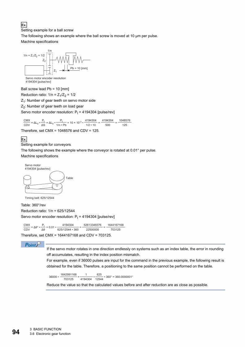
94
Ex.
Setting example for a ball screwThe following shows an example where the ball screw is moved at 10 μm per pulse.Machine specifications
Ball screw lead Pb = 10 [mm]Reduction ratio: 1/n = Z1/Z2 = 1/2Z1: Number of gear teeth on servo motor sideZ2: Number of gear teeth on load gearServo motor encoder resolution: Pt = 4194304 [pulse/rev]
Therefore, set CMX = 1048576 and CDV = 125.
Ex.
Setting example for conveyorsThe following shows the example where the conveyor is rotated at 0.01° per pulse.Machine specifications
Table: 360°/revReduction ratio: 1/n = 625/12544Servo motor encoder resolution: Pt = 4194304 [pulse/rev]
Therefore, set CMX = 1644167168 and CDV = 703125.
If the servo motor rotates in one direction endlessly on systems such as an index table, the error in rounding off accumulates, resulting in the index position mismatch.For example, even if 36000 pulses are input for the command in the previous example, the following result is obtained for the table. Therefore, a positioning to the same position cannot be performed on the table.
Reduce the value so that the calculated values before and after reduction are as close as possible.
4194304 [pulse/rev]
Pb = 10 [mm]Z1
1/n = Z1/Z2 = 1/2Z2
1/n
Servo motor encoder resolution
CMXCDV
= ΔL0 • = ΔL0 •Pt
ΔS = 10 × 10-3 •
Pt
1/n • Pb41943041/2 • 10
=4194304
500 =
1048576125
4194304 [pulse/rev]Servo motor
Table
Timing belt: 625/12544
CMXCDV
= Δθ° • = 0.01 •Pt
Δθ4194304
625/12544 • 360 =
5261334937622500000
=1644167168
703125
36000 • 1642991168
7031251
4194304 • • •
62512544
• 360° = 360.0000001°
3 BASIC FUNCTION3.6 Electronic gear function
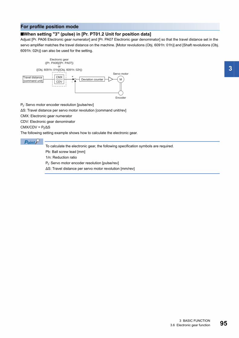
3
For profile position mode■When setting "3" (pulse) in [Pr. PT01.2 Unit for position data]Adjust [Pr. PA06 Electronic gear numerator] and [Pr. PA07 Electronic gear denominator] so that the travel distance set in the servo amplifier matches the travel distance on the machine. [Motor revolutions (Obj. 6091h: 01h)] and [Shaft revolutions (Obj. 6091h: 02h)] can also be used for the setting.
Pt: Servo motor encoder resolution [pulse/rev]ΔS: Travel distance per servo motor revolution [command unit/rev]CMX: Electronic gear numeratorCDV: Electronic gear denominatorCMX/CDV = Pt/ΔSThe following setting example shows how to calculate the electronic gear.
To calculate the electronic gear, the following specification symbols are required.Pb: Ball screw lead [mm]1/n: Reduction ratioPt: Servo motor encoder resolution [pulse/rev]ΔS: Travel distance per servo motor revolution [mm/rev]
+
-M
CDVCMX
([Pr. PA06]/[Pr. PA07])
([Obj. 6091h: 01h]/[Obj. 6091h: 02h])
Deviation counter
Servo motor
Encoder
Electronic gear
Travel distance [command unit]
or
3 BASIC FUNCTION3.6 Electronic gear function 95
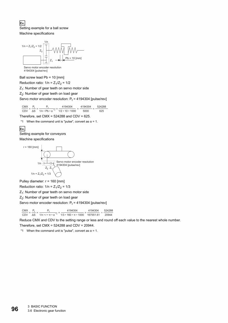
96
Ex.
Setting example for a ball screwMachine specifications
Ball screw lead Pb = 10 [mm]Reduction ratio: 1/n = Z1/Z2 = 1/2Z1: Number of gear teeth on servo motor sideZ2: Number of gear teeth on load gearServo motor encoder resolution: Pt = 4194304 [pulse/rev]
Therefore, set CMX = 524288 and CDV = 625.*1 When the command unit is "pulse", convert as α = 1.
Ex.
Setting example for conveyorsMachine specifications
Pulley diameter: r = 160 [mm]Reduction ratio: 1/n = Z1/Z2 = 1/3Z1: Number of gear teeth on servo motor sideZ2: Number of gear teeth on load gearServo motor encoder resolution: Pt = 4194304 [pulse/rev]
Reduce CMX and CDV to the setting range or less and round off each value to the nearest whole number.Therefore, set CMX = 524288 and CDV = 20944.*1 When the command unit is "pulse", convert as α = 1.
4194304 [pulse/rev]
Pb = 10 [mm]Z1
1/n = Z1/Z2 = 1/2Z2
1/n
Servo motor encoder resolution
CMXCDV
= =Pt
ΔS =
Pt
1/n • Pb • α *14194304
1/2 • 10 • 1000 =
41943045000
=524288
625
4194304 [pulse/rev]Z1Z2
1/n = Z1/Z2 = 1/3
1/n
r = 160 [mm]
Servo motor encoder resolution
CMXCDV
= =Pt
ΔS =
Pt
1/n • r • π • α *14194304
1/3 • 160 • π • 1000 =
4194304167551.61
52428820944
3 BASIC FUNCTION3.6 Electronic gear function
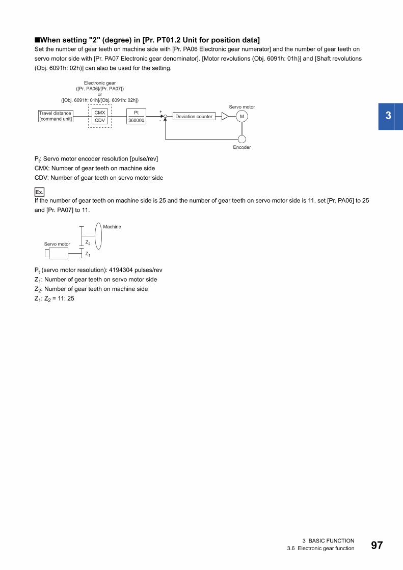
3
■When setting "2" (degree) in [Pr. PT01.2 Unit for position data]Set the number of gear teeth on machine side with [Pr. PA06 Electronic gear numerator] and the number of gear teeth on servo motor side with [Pr. PA07 Electronic gear denominator]. [Motor revolutions (Obj. 6091h: 01h)] and [Shaft revolutions (Obj. 6091h: 02h)] can also be used for the setting.
Pt: Servo motor encoder resolution [pulse/rev]CMX: Number of gear teeth on machine sideCDV: Number of gear teeth on servo motor side
Ex.
If the number of gear teeth on machine side is 25 and the number of gear teeth on servo motor side is 11, set [Pr. PA06] to 25 and [Pr. PA07] to 11.
Pt (servo motor resolution): 4194304 pulses/revZ1: Number of gear teeth on servo motor sideZ2: Number of gear teeth on machine sideZ1: Z2 = 11: 25
+
-M
CDVCMX
360000Pt
([Pr. PA06]/[Pr. PA07])
([Obj. 6091h: 01h]/[Obj. 6091h: 02h])
Deviation counter
Servo motor
Encoder
Electronic gear
Travel distance [command unit]
or
Z1
Z2Servo motor
Machine
3 BASIC FUNCTION3.6 Electronic gear function 97
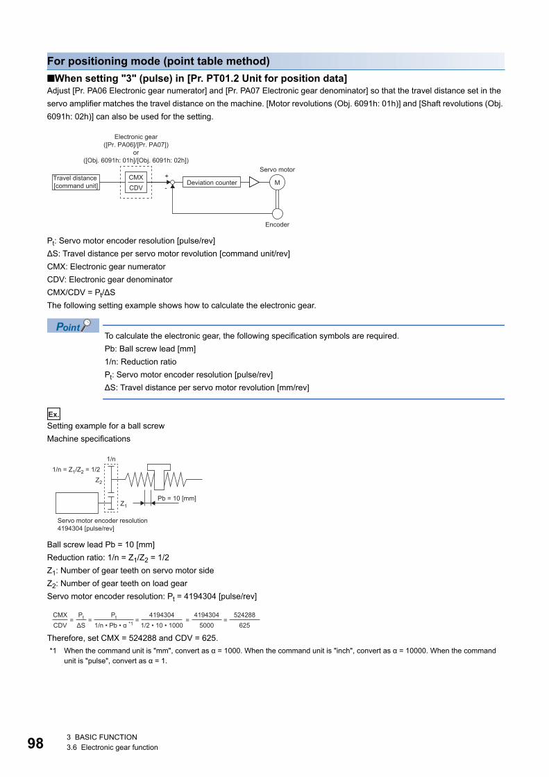
98
For positioning mode (point table method)■When setting "3" (pulse) in [Pr. PT01.2 Unit for position data]Adjust [Pr. PA06 Electronic gear numerator] and [Pr. PA07 Electronic gear denominator] so that the travel distance set in the servo amplifier matches the travel distance on the machine. [Motor revolutions (Obj. 6091h: 01h)] and [Shaft revolutions (Obj. 6091h: 02h)] can also be used for the setting.
Pt: Servo motor encoder resolution [pulse/rev]ΔS: Travel distance per servo motor revolution [command unit/rev]CMX: Electronic gear numeratorCDV: Electronic gear denominatorCMX/CDV = Pt/ΔSThe following setting example shows how to calculate the electronic gear.
To calculate the electronic gear, the following specification symbols are required.Pb: Ball screw lead [mm]1/n: Reduction ratioPt: Servo motor encoder resolution [pulse/rev]ΔS: Travel distance per servo motor revolution [mm/rev]
Ex.
Setting example for a ball screwMachine specifications
Ball screw lead Pb = 10 [mm]Reduction ratio: 1/n = Z1/Z2 = 1/2Z1: Number of gear teeth on servo motor sideZ2: Number of gear teeth on load gearServo motor encoder resolution: Pt = 4194304 [pulse/rev]
Therefore, set CMX = 524288 and CDV = 625.*1 When the command unit is "mm", convert as α = 1000. When the command unit is "inch", convert as α = 10000. When the command
unit is "pulse", convert as α = 1.
+
-M
CDVCMX
([Pr. PA06]/[Pr. PA07])
([Obj. 6091h: 01h]/[Obj. 6091h: 02h])
Deviation counter
Servo motor
Encoder
Electronic gear
Travel distance [command unit]
or
4194304 [pulse/rev]
Pb = 10 [mm]Z1
1/n = Z1/Z2 = 1/2Z2
1/n
Servo motor encoder resolution
CMXCDV
= =Pt
ΔS =
Pt
1/n • Pb • α *14194304
1/2 • 10 • 1000 =
41943045000
=524288
625
3 BASIC FUNCTION3.6 Electronic gear function
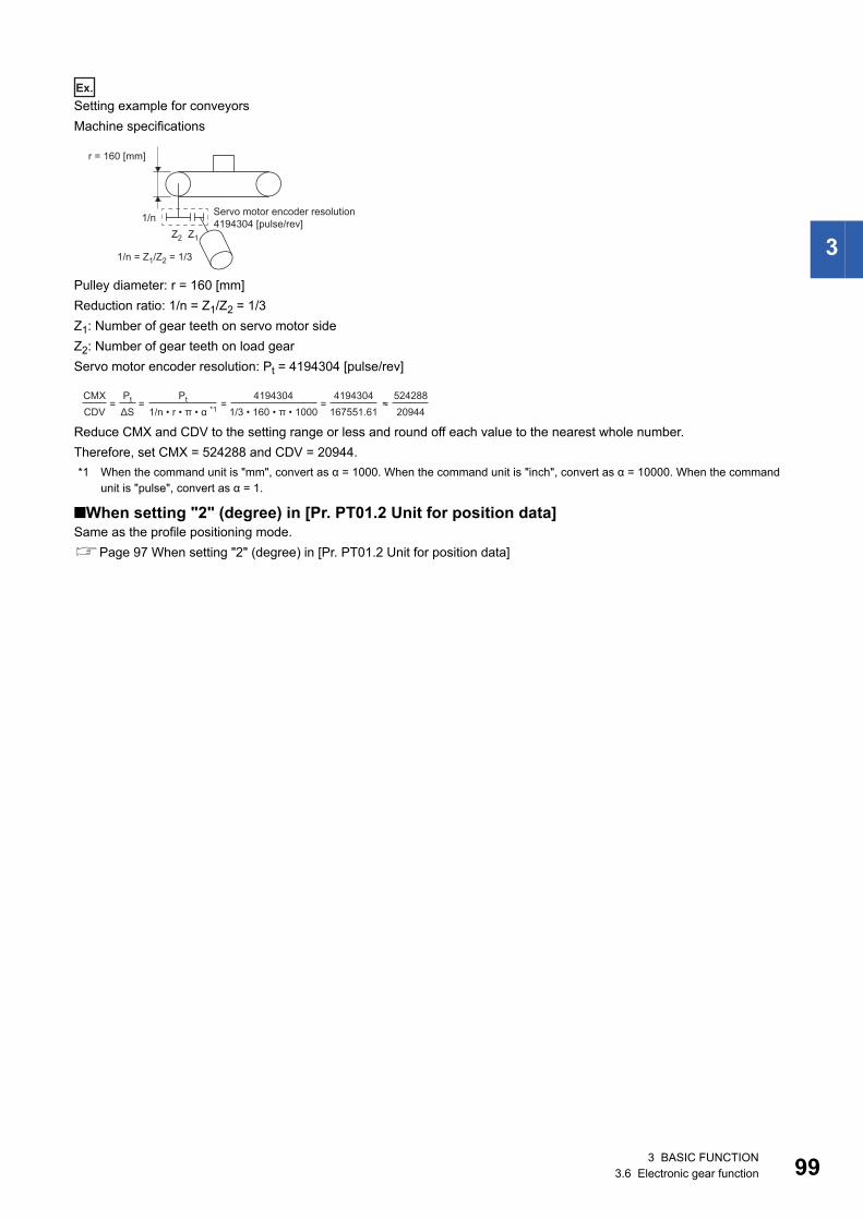
3
Ex.
Setting example for conveyorsMachine specifications
Pulley diameter: r = 160 [mm]Reduction ratio: 1/n = Z1/Z2 = 1/3Z1: Number of gear teeth on servo motor sideZ2: Number of gear teeth on load gearServo motor encoder resolution: Pt = 4194304 [pulse/rev]
Reduce CMX and CDV to the setting range or less and round off each value to the nearest whole number.Therefore, set CMX = 524288 and CDV = 20944.*1 When the command unit is "mm", convert as α = 1000. When the command unit is "inch", convert as α = 10000. When the command
unit is "pulse", convert as α = 1.
■When setting "2" (degree) in [Pr. PT01.2 Unit for position data]Same as the profile positioning mode.Page 97 When setting "2" (degree) in [Pr. PT01.2 Unit for position data]
4194304 [pulse/rev]Z1Z2
1/n = Z1/Z2 = 1/3
1/n
r = 160 [mm]
Servo motor encoder resolution
CMXCDV
= =Pt
ΔS =
Pt
1/n • r • π • α *14194304
1/3 • 160 • π • 1000 =
4194304167551.61
52428820944
≈
3 BASIC FUNCTION3.6 Electronic gear function 99
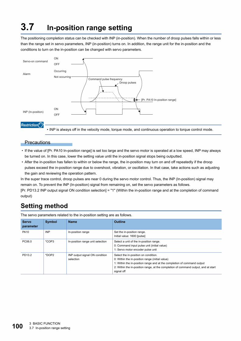
10
3.7 In-position range settingThe positioning completion status can be checked with INP (in-position). When the number of droop pulses falls within or less than the range set in servo parameters, INP (in-position) turns on. In addition, the range unit for the in-position and the conditions to turn on the in-position can be changed with servo parameters.
• INP is always off in the velocity mode, torque mode, and continuous operation to torque control mode.
Precautions • If the value of [Pr. PA10 In-position range] is set too large and the servo motor is operated at a low speed, INP may always
be turned on. In this case, lower the setting value until the in-position signal stops being outputted. • After the in-position has fallen to within or below the range, the in-position may turn on and off repeatedly if the droop
pulses exceed the in-position range due to overshoot, vibration, or oscillation. In that case, take actions such as adjusting the gain and reviewing the operation pattern.
In the super trace control, droop pulses are near 0 during the servo motor control. Thus, the INP (In-position) signal may remain on. To prevent the INP (In-position) signal from remaining on, set the servo parameters as follows.[Pr. PD13.2 INP output signal ON condition selection] = "1" (Within the in-position range and at the completion of command output)
Setting methodThe servo parameters related to the in-position setting are as follows.
Servo parameter
Symbol Name Outline
PA10 INP In-position range Set the in-position range.Initial value: 1600 [pulse]
PC06.0 *COP3 In-position range unit selection Select a unit of the in-position range.0: Command input pulse unit (initial value)1: Servo motor encoder pulse unit
PD13.2 *DOP2 INP output signal ON condition selection
Select the in-position on condition.0: Within the in-position range (initial value)1: Within the in-position range and at the completion of command output2: Within the in-position range, at the completion of command output, and at start signal off
ON
OFF
ON
OFFServo-on command
OccurringAlarm
Not occurringCommand pulse frequency
Droop pulses
[Pr. PA10 In-position range]
INP (In-position)
0 3 BASIC FUNCTION3.7 In-position range setting
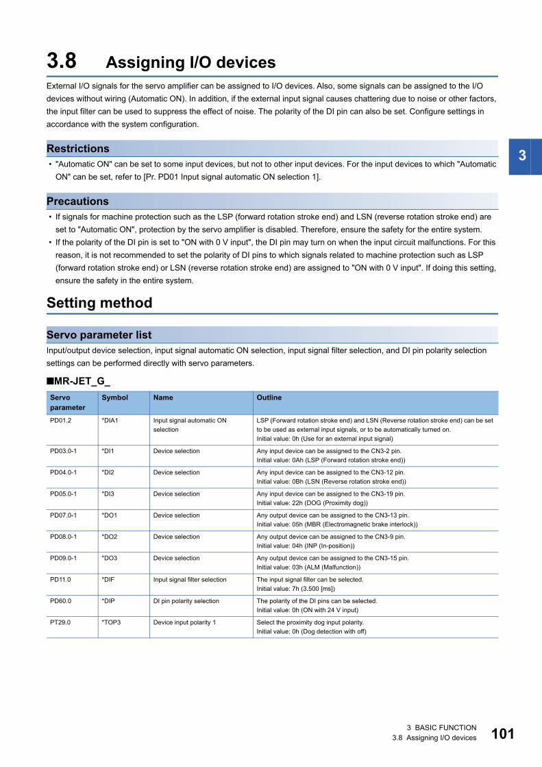
3
3.8 Assigning I/O devicesExternal I/O signals for the servo amplifier can be assigned to I/O devices. Also, some signals can be assigned to the I/O devices without wiring (Automatic ON). In addition, if the external input signal causes chattering due to noise or other factors, the input filter can be used to suppress the effect of noise. The polarity of the DI pin can also be set. Configure settings in accordance with the system configuration.
Restrictions • "Automatic ON" can be set to some input devices, but not to other input devices. For the input devices to which "Automatic
ON" can be set, refer to [Pr. PD01 Input signal automatic ON selection 1].
Precautions • If signals for machine protection such as the LSP (forward rotation stroke end) and LSN (reverse rotation stroke end) are
set to "Automatic ON", protection by the servo amplifier is disabled. Therefore, ensure the safety for the entire system. • If the polarity of the DI pin is set to "ON with 0 V input", the DI pin may turn on when the input circuit malfunctions. For this
reason, it is not recommended to set the polarity of DI pins to which signals related to machine protection such as LSP (forward rotation stroke end) or LSN (reverse rotation stroke end) are assigned to "ON with 0 V input". If doing this setting, ensure the safety in the entire system.
Setting method
Servo parameter listInput/output device selection, input signal automatic ON selection, input signal filter selection, and DI pin polarity selection settings can be performed directly with servo parameters.
■MR-JET_G_Servo parameter
Symbol Name Outline
PD01.2 *DIA1 Input signal automatic ON selection
LSP (Forward rotation stroke end) and LSN (Reverse rotation stroke end) can be set to be used as external input signals, or to be automatically turned on.Initial value: 0h (Use for an external input signal)
PD03.0-1 *DI1 Device selection Any input device can be assigned to the CN3-2 pin.Initial value: 0Ah (LSP (Forward rotation stroke end))
PD04.0-1 *DI2 Device selection Any input device can be assigned to the CN3-12 pin.Initial value: 0Bh (LSN (Reverse rotation stroke end))
PD05.0-1 *DI3 Device selection Any input device can be assigned to the CN3-19 pin.Initial value: 22h (DOG (Proximity dog))
PD07.0-1 *DO1 Device selection Any output device can be assigned to the CN3-13 pin.Initial value: 05h (MBR (Electromagnetic brake interlock))
PD08.0-1 *DO2 Device selection Any output device can be assigned to the CN3-9 pin.Initial value: 04h (INP (In-position))
PD09.0-1 *DO3 Device selection Any output device can be assigned to the CN3-15 pin.Initial value: 03h (ALM (Malfunction))
PD11.0 *DIF Input signal filter selection The input signal filter can be selected.Initial value: 7h (3.500 [ms])
PD60.0 *DIP DI pin polarity selection The polarity of the DI pins can be selected.Initial value: 0h (ON with 24 V input)
PT29.0 *TOP3 Device input polarity 1 Select the proximity dog input polarity.Initial value: 0h (Dog detection with off)
3 BASIC FUNCTION3.8 Assigning I/O devices 101
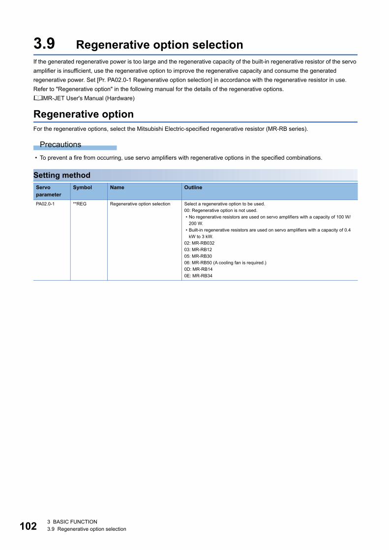
10
3.9 Regenerative option selectionIf the generated regenerative power is too large and the regenerative capacity of the built-in regenerative resistor of the servo amplifier is insufficient, use the regenerative option to improve the regenerative capacity and consume the generated regenerative power. Set [Pr. PA02.0-1 Regenerative option selection] in accordance with the regenerative resistor in use.Refer to "Regenerative option" in the following manual for the details of the regenerative options.MR-JET User's Manual (Hardware)
Regenerative optionFor the regenerative options, select the Mitsubishi Electric-specified regenerative resistor (MR-RB series).
Precautions • To prevent a fire from occurring, use servo amplifiers with regenerative options in the specified combinations.
Setting methodServo parameter
Symbol Name Outline
PA02.0-1 **REG Regenerative option selection Select a regenerative option to be used.00: Regenerative option is not used.• No regenerative resistors are used on servo amplifiers with a capacity of 100 W/
200 W.• Built-in regenerative resistors are used on servo amplifiers with a capacity of 0.4
kW to 3 kW.02: MR-RB03203: MR-RB1205: MR-RB3006: MR-RB50 (A cooling fan is required.)0D: MR-RB140E: MR-RB34
2 3 BASIC FUNCTION3.9 Regenerative option selection
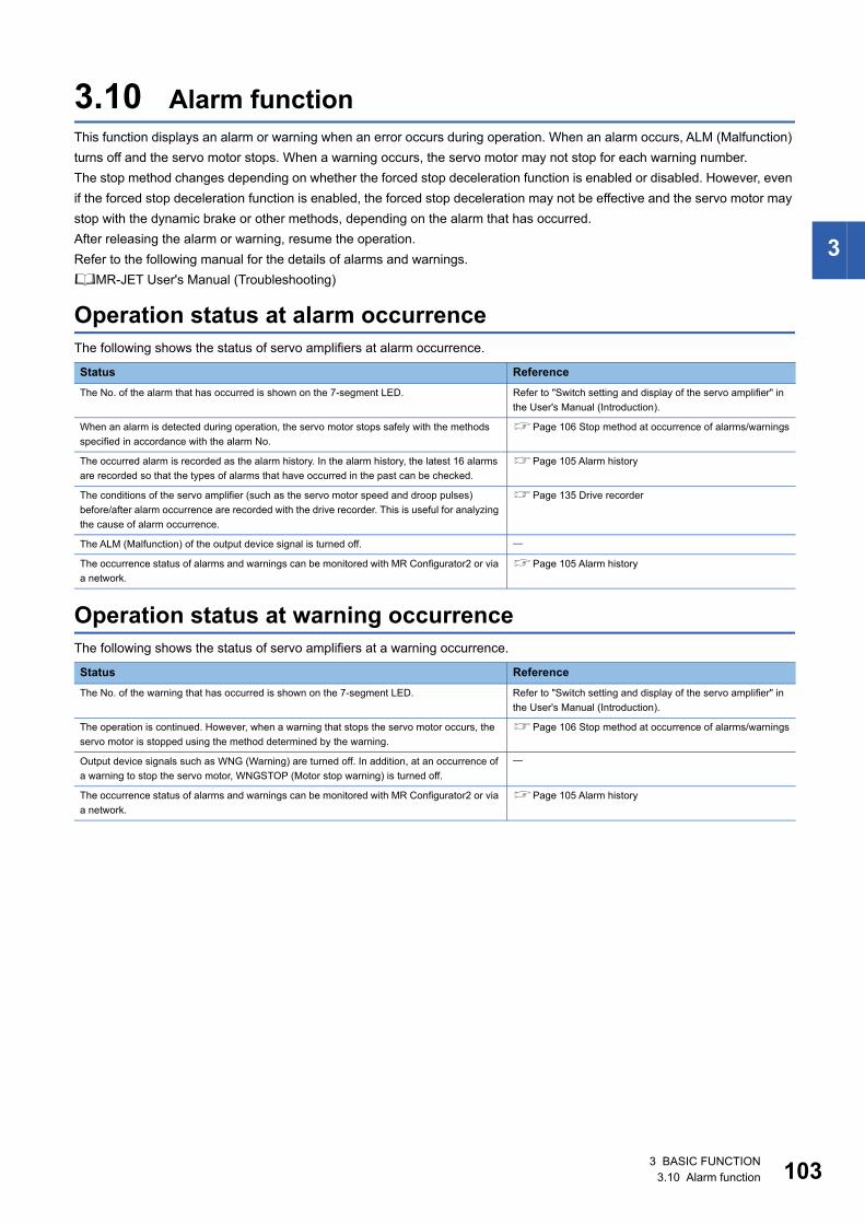
3
3.10 Alarm functionThis function displays an alarm or warning when an error occurs during operation. When an alarm occurs, ALM (Malfunction) turns off and the servo motor stops. When a warning occurs, the servo motor may not stop for each warning number.The stop method changes depending on whether the forced stop deceleration function is enabled or disabled. However, even if the forced stop deceleration function is enabled, the forced stop deceleration may not be effective and the servo motor may stop with the dynamic brake or other methods, depending on the alarm that has occurred.After releasing the alarm or warning, resume the operation.Refer to the following manual for the details of alarms and warnings.MR-JET User's Manual (Troubleshooting)
Operation status at alarm occurrenceThe following shows the status of servo amplifiers at alarm occurrence.
Operation status at warning occurrenceThe following shows the status of servo amplifiers at a warning occurrence.
Status ReferenceThe No. of the alarm that has occurred is shown on the 7-segment LED. Refer to "Switch setting and display of the servo amplifier" in
the User's Manual (Introduction).
When an alarm is detected during operation, the servo motor stops safely with the methods specified in accordance with the alarm No.
Page 106 Stop method at occurrence of alarms/warnings
The occurred alarm is recorded as the alarm history. In the alarm history, the latest 16 alarms are recorded so that the types of alarms that have occurred in the past can be checked.
Page 105 Alarm history
The conditions of the servo amplifier (such as the servo motor speed and droop pulses) before/after alarm occurrence are recorded with the drive recorder. This is useful for analyzing the cause of alarm occurrence.
Page 135 Drive recorder
The ALM (Malfunction) of the output device signal is turned off.
The occurrence status of alarms and warnings can be monitored with MR Configurator2 or via a network.
Page 105 Alarm history
Status ReferenceThe No. of the warning that has occurred is shown on the 7-segment LED. Refer to "Switch setting and display of the servo amplifier" in
the User's Manual (Introduction).
The operation is continued. However, when a warning that stops the servo motor occurs, the servo motor is stopped using the method determined by the warning.
Page 106 Stop method at occurrence of alarms/warnings
Output device signals such as WNG (Warning) are turned off. In addition, at an occurrence of a warning to stop the servo motor, WNGSTOP (Motor stop warning) is turned off.
The occurrence status of alarms and warnings can be monitored with MR Configurator2 or via a network.
Page 105 Alarm history
3 BASIC FUNCTION3.10 Alarm function 103
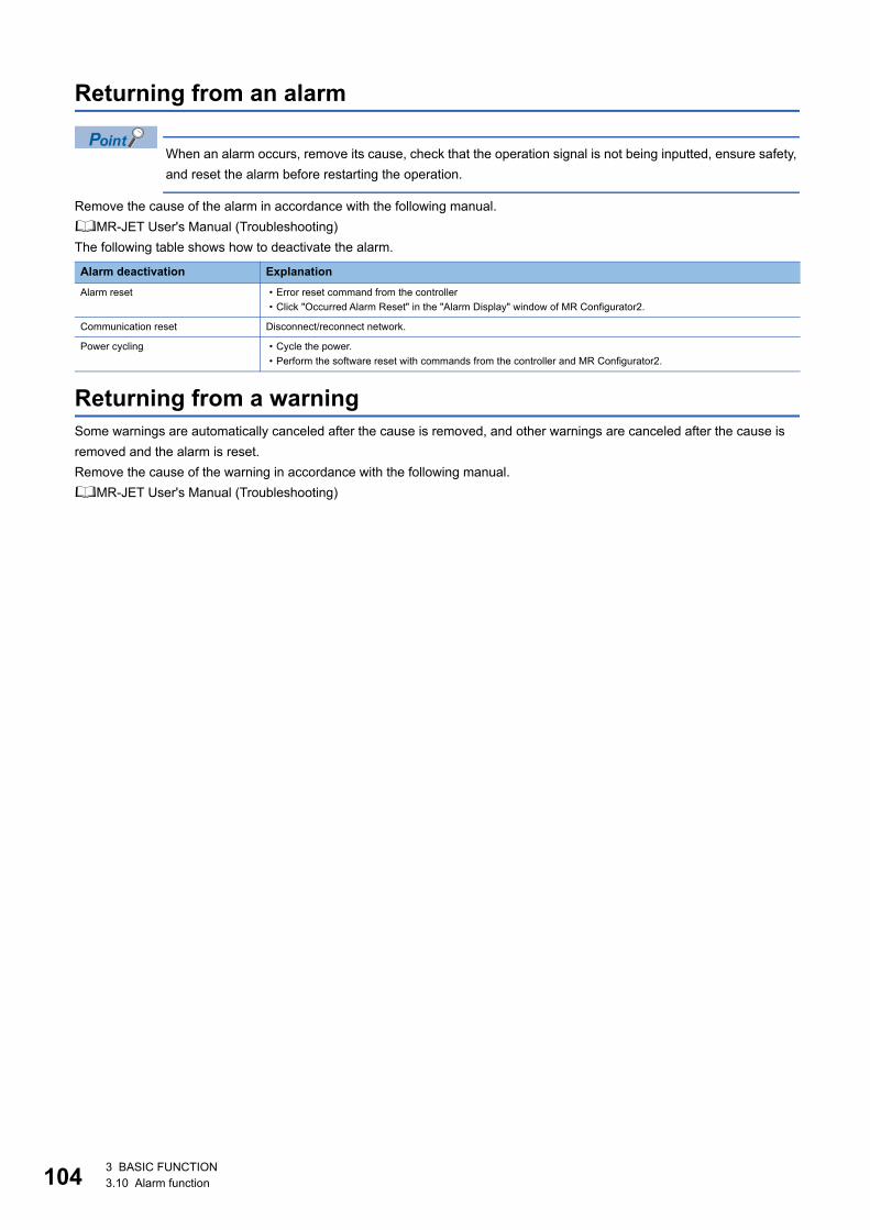
10
Returning from an alarm
When an alarm occurs, remove its cause, check that the operation signal is not being inputted, ensure safety, and reset the alarm before restarting the operation.
Remove the cause of the alarm in accordance with the following manual.MR-JET User's Manual (Troubleshooting)The following table shows how to deactivate the alarm.
Returning from a warningSome warnings are automatically canceled after the cause is removed, and other warnings are canceled after the cause is removed and the alarm is reset.Remove the cause of the warning in accordance with the following manual.MR-JET User's Manual (Troubleshooting)
Alarm deactivation ExplanationAlarm reset • Error reset command from the controller
• Click "Occurred Alarm Reset" in the "Alarm Display" window of MR Configurator2.
Communication reset Disconnect/reconnect network.
Power cycling • Cycle the power.• Perform the software reset with commands from the controller and MR Configurator2.
4 3 BASIC FUNCTION3.10 Alarm function
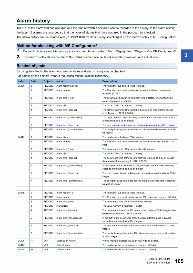
3
Alarm historyThe No. of the alarm that has occurred and the time at which it occurred can be recorded in the history. In the alarm history, the latest 16 alarms are recorded so that the types of alarms that have occurred in the past can be checked.The alarm history can be cleared with [Pr. PC21.0 Alarm clear history selection] or on the alarm display of MR Configurator2.
Method for checking with MR Configurator21. Connect the servo amplifier and a personal computer and select "Alarm Display" from "Diagnosis" in MR Configurator2.
2. The alarm display shows the alarm No., detail number, accumulated time after power-on, and actual time.
Related objectsBy using the objects, the alarm occurrence status and alarm history can be checked.For details on the objects, refer to the User's Manual (Object Dictionary).
Index Sub Object Name Description2A00h 0 RECORD Alarm history newest The number of sub objects (7) is returned.
1 RECORD Alarm number The Alarm No. and detail number of the alarm that has occurred are returned. (32 bits)
2 RECORD Alarm time (Hour) The accumulated power-on time from time of factory shipment until an alarm occurrence is returned.
3 RECORD Alarm2 No. The value "0000h" is returned. (16 bits)
4 RECORD Alarm time (second) The alarm occurrence time is returned as a 32-bit integer (time passed from January 1, 1970, 0:00:00).
5 RECORD Alarm time (nanosecond) The digits after the ones indicating seconds in the alarm occurrence time are returned as a 32-bit integer.
6 RECORD Alarm time (time zone) The time zone at an alarm occurrence time is returned as a 32-bit integer.
7 RECORD Alarm time (summer time) The daylight saving time at an alarm occurrence time is returned as a 32-bit integer.
2A01h 0 RECORD Alarm history 1 The number of sub objects (7) is returned.
1 RECORD Alarm number The Alarm No. and detail number of the second alarm are returned. (32 bits)
2 RECORD Alarm time (Hour) The occurrence time of the second alarm is returned.
3 RECORD Alarm2 No. The value "0000h" is returned. (16 bits)
4 RECORD Alarm time (second) The occurrence time of the second alarm is returned as a 32-bit integer (time passed from January 1, 1970, 0:00:00).
5 RECORD Alarm time (nanosecond) In the second alarm occurrence time, the digits after the ones indicating seconds are returned as a 32-bit integer.
6 RECORD Alarm time (time zone) The time zone at the second alarm occurrence time is returned as a 32-bit integer.
7 RECORD Alarm time (summer time) The daylight saving time at the second alarm occurrence time is returned as a 32-bit integer.
: : : : :
2A0Fh 0 RECORD Alarm history 15 The number of sub objects (7) is returned.
1 RECORD Alarm number The Alarm No. and detail number of the 16th alarm are returned. (32 bits)
2 RECORD Alarm time (Hour) The occurrence time of the 16th alarm is returned.
3 RECORD Alarm2 No. The value "0000h" is returned. (16 bits)
4 RECORD Alarm time (second) The occurrence time of the 16th alarm is returned as a 32-bit integer (time passed from January 1, 1970, 0:00:00).
5 RECORD Alarm time (nanosecond) In the 16th alarm occurrence time, the digits after the ones indicating seconds are returned as a 32-bit integer.
6 RECORD Alarm time (time zone) The time zone at the 16th alarm occurrence time is returned as a 32-bit integer.
7 RECORD Alarm time (summer time) The daylight saving time at the 16th alarm occurrence time is returned as a 32-bit integer.
2A40h VAR Clear alarm history Writing "1EA5h" enables the alarm history to be cleared.
2A41h VAR Current alarm The number of the current alarm is returned. (32 bits)
2A42h VAR Current alarm2 The number of the current alarm is returned. (16 bits)
3 BASIC FUNCTION3.10 Alarm function 105
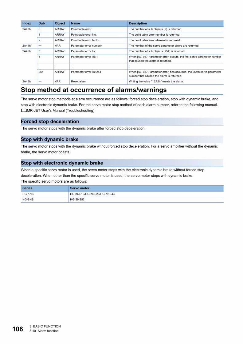
10
Stop method at occurrence of alarms/warningsThe servo motor stop methods at alarm occurrence are as follows: forced stop deceleration, stop with dynamic brake, and stop with electronic dynamic brake. For the servo motor stop method of each alarm number, refer to the following manual.MR-JET User's Manual (Troubleshooting)
Forced stop decelerationThe servo motor stops with the dynamic brake after forced stop deceleration.
Stop with dynamic brakeThe servo motor stops with the dynamic brake without forced stop deceleration. For a servo amplifier without the dynamic brake, the servo motor coasts.
Stop with electronic dynamic brakeWhen a specific servo motor is used, the servo motor stops with the electronic dynamic brake without forced stop deceleration. When other than the specific servo motor is used, the servo motor stops with dynamic brake.The specific servo motors are as follows:
2A43h 0 ARRAY Point table error The number of sub objects (2) is returned.
1 ARRAY Point table error No. The point table error number is returned.
2 ARRAY Point table error factor The point table error element is returned.
2A44h VAR Parameter error number The number of the servo parameter errors are returned.
2A45h 0 ARRAY Parameter error list The number of sub objects (254) is returned.
1 ARRAY Parameter error list 1 When [AL. 037 Parameter error] occurs, the first servo parameter number that caused the alarm is returned.
: : : :
254 ARRAY Parameter error list 254 When [AL. 037 Parameter error] has occurred, the 254th servo parameter number that caused the alarm is returned.
2A46h VAR Reset alarm Writing the value "1EA5h" resets the alarm.
Series Servo motorHG-KNS HG-KNS13/HG-KNS23/HG-KNS43
HG-SNS HG-SNS52
Index Sub Object Name Description
6 3 BASIC FUNCTION3.10 Alarm function

3
Timing chart for alarm occurrence
In the torque mode and continuous operation to torque control mode, the forced stop deceleration function cannot be used.When the servo motor is at a stop due to an alarm or other factors, commands from the controller are not accepted. When restarting the operation in the cyclic synchronous position mode, confirm the position command.
When using the forced stop deceleration function
When [Pr. PA04.3 Forced stop deceleration function selection] is set to "2" (Forced stop deceleration function enabled).
■Stopping with forced stop deceleration functionWhen an alarm is detected, the servo motor stops using forced stop deceleration and MBR and ALM are turned off.
*1 The model speed command is a speed command generated in the servo amplifier for forced stop deceleration of the servo motor.
ON
OFF
ON
OFF
ON
OFF
0 r/min
ALM
Alarm occurrence
Model speed command is 0, and the speed is equal to or less than zero speed
Servo motor speed
Commands from the controller are not accepted.
Base circuit (Energy supply to the servo motor)
Servo amplifier display
No alarm Alarm No.
(No alarm)(Malfunction) (Alarm)
*1
(Electromagnetic brake interlock)
MBR
3 BASIC FUNCTION3.10 Alarm function 107
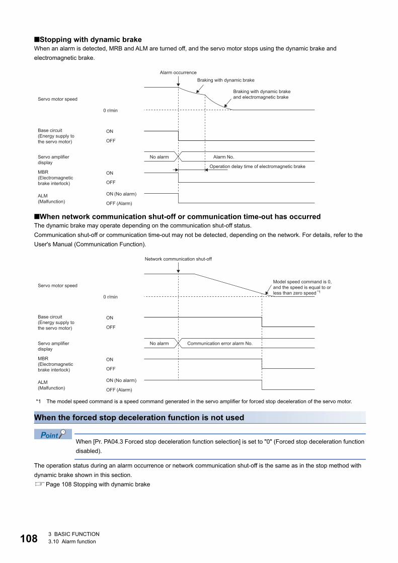
10
■Stopping with dynamic brakeWhen an alarm is detected, MRB and ALM are turned off, and the servo motor stops using the dynamic brake and electromagnetic brake.
■When network communication shut-off or communication time-out has occurredThe dynamic brake may operate depending on the communication shut-off status.Communication shut-off or communication time-out may not be detected, depending on the network. For details, refer to the User's Manual (Communication Function).
*1 The model speed command is a speed command generated in the servo amplifier for forced stop deceleration of the servo motor.
When the forced stop deceleration function is not used
When [Pr. PA04.3 Forced stop deceleration function selection] is set to "0" (Forced stop deceleration function disabled).
The operation status during an alarm occurrence or network communication shut-off is the same as in the stop method with dynamic brake shown in this section.Page 108 Stopping with dynamic brake
ON
OFF
ON
OFF
ON
OFF
0 r/min
ALM
Alarm occurrenceBraking with dynamic brake
Braking with dynamic brakeand electromagnetic brakeServo motor speed
Base circuit (Energy supply to the servo motor)
Servo amplifier display
No alarm Alarm No.
Operation delay time of electromagnetic brake
(No alarm)(Malfunction) (Alarm)
(Electromagnetic brake interlock)
MBR
ON
OFF
ON
OFF
ON
OFF
0 r/min
ALM
Network communication shut-off
Model speed command is 0, and the speed is equal to or less than zero speed
Servo motor speed
Base circuit (Energy supply to the servo motor)
Servo amplifier display
No alarm Communication error alarm No.
(No alarm)(Malfunction) (Alarm)
*1
(Electromagnetic brake interlock)
MBR
8 3 BASIC FUNCTION3.10 Alarm function
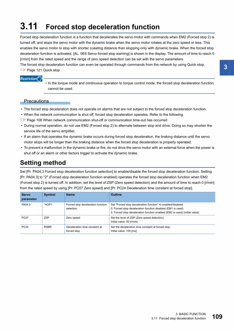
3
3.11 Forced stop deceleration functionForced stop deceleration function is a function that decelerates the servo motor with commands when EM2 (Forced stop 2) is turned off, and stops the servo motor with the dynamic brake when the servo motor rotates at the zero speed or less. This enables the servo motor to stop with shorter coasting distance than stopping only with dynamic brake. When the forced stop deceleration function is activated, [AL. 0E6 Servo forced stop warning] is shown in the display. The amount of time to reach 0 [r/min] from the rated speed and the range of zero speed detection can be set with the servo parameters.The forced stop deceleration function can even be operated through commands from the network by using Quick stop.Page 121 Quick stop
• In the torque mode and continuous operation to torque control mode, the forced stop deceleration function cannot be used.
Precautions • The forced stop deceleration does not operate on alarms that are not subject to the forced stop deceleration function. • When the network communication is shut off, forced stop deceleration operates. Refer to the following.Page 108 When network communication shut-off or communication time-out has occurred • During normal operation, do not use EM2 (Forced stop 2) to alternate between stop and drive. Doing so may shorten the
service life of the servo amplifier. • If an alarm that operates the dynamic brake occurs during forced stop deceleration, the braking distance until the servo
motor stops will be longer than the braking distance when the forced stop deceleration is properly operated. • To prevent a malfunction in the dynamic brake or fire, do not drive the servo motor with an external force when the power is
shut off or an alarm or other factors trigger to activate the dynamic brake.
Setting methodSet [Pr. PA04.3 Forced stop deceleration function selection] to enable/disable the forced stop deceleration function. Setting [Pr. PA04.3] to "2" (Forced stop deceleration function enabled) operates the forced stop deceleration function when EM2 (Forced stop 2) is turned off. In addition, set the level of ZSP (Zero speed detection) and the amount of time to reach 0 [r/min] from the rated speed by using [Pr. PC07 Zero speed] and [Pr. PC24 Deceleration time constant at forced stop].
Servo parameter
Symbol Name Outline
PA04.3 *AOP1 Forced stop deceleration function selection
Set "Forced stop deceleration function" to enabled/disabled.0: Forced stop deceleration function disabled (EM1 is used)2: Forced stop deceleration function enabled (EM2 is used) (initial value)
PC07 ZSP Zero speed Set the level of ZSP (Zero speed detection).Initial value: 50 [r/min]
PC24 RSBR Deceleration time constant at forced stop
Set the deceleration time constant at forced stop.Initial value: 100 [ms]
3 BASIC FUNCTION3.11 Forced stop deceleration function 109
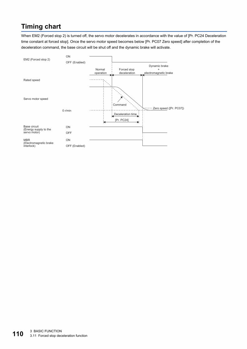
11
Timing chartWhen EM2 (Forced stop 2) is turned off, the servo motor decelerates in accordance with the value of [Pr. PC24 Deceleration time constant at forced stop]. Once the servo motor speed becomes below [Pr. PC07 Zero speed] after completion of the deceleration command, the base circuit will be shut off and the dynamic brake will activate.
ON
OFF
ON
OFF
0 r/min
[Pr. PC24]
ON
OFFEM2 (Forced stop 2)
(Enabled)Dynamic brake
+ electromagnetic brake
Normal operation
Forced stop deceleration
Rated speed
Servo motor speed
CommandZero speed ([Pr. PC07])
Deceleration time
Base circuit (Energy supply to the servo motor)
(Enabled)(Electromagnetic brake interlock)
MBR
0 3 BASIC FUNCTION3.11 Forced stop deceleration function
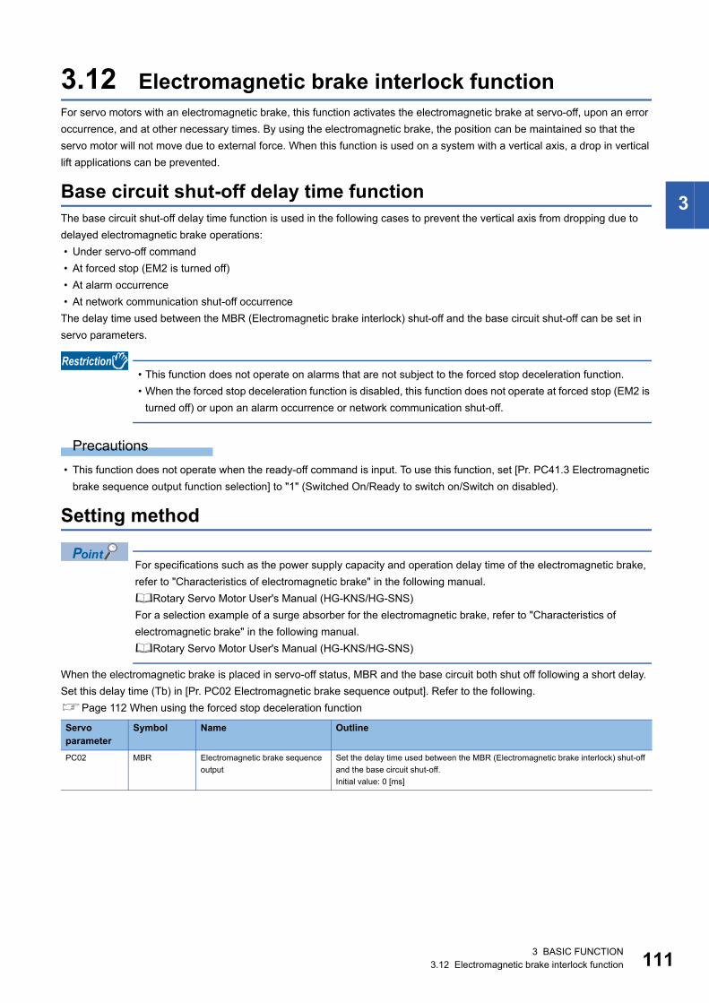
3
3.12 Electromagnetic brake interlock functionFor servo motors with an electromagnetic brake, this function activates the electromagnetic brake at servo-off, upon an error occurrence, and at other necessary times. By using the electromagnetic brake, the position can be maintained so that the servo motor will not move due to external force. When this function is used on a system with a vertical axis, a drop in vertical lift applications can be prevented.
Base circuit shut-off delay time functionThe base circuit shut-off delay time function is used in the following cases to prevent the vertical axis from dropping due to delayed electromagnetic brake operations: • Under servo-off command • At forced stop (EM2 is turned off) • At alarm occurrence • At network communication shut-off occurrenceThe delay time used between the MBR (Electromagnetic brake interlock) shut-off and the base circuit shut-off can be set in servo parameters.
• This function does not operate on alarms that are not subject to the forced stop deceleration function. • When the forced stop deceleration function is disabled, this function does not operate at forced stop (EM2 is
turned off) or upon an alarm occurrence or network communication shut-off.
Precautions • This function does not operate when the ready-off command is input. To use this function, set [Pr. PC41.3 Electromagnetic
brake sequence output function selection] to "1" (Switched On/Ready to switch on/Switch on disabled).
Setting method
For specifications such as the power supply capacity and operation delay time of the electromagnetic brake, refer to "Characteristics of electromagnetic brake" in the following manual.Rotary Servo Motor User's Manual (HG-KNS/HG-SNS)For a selection example of a surge absorber for the electromagnetic brake, refer to "Characteristics of electromagnetic brake" in the following manual.Rotary Servo Motor User's Manual (HG-KNS/HG-SNS)
When the electromagnetic brake is placed in servo-off status, MBR and the base circuit both shut off following a short delay. Set this delay time (Tb) in [Pr. PC02 Electromagnetic brake sequence output]. Refer to the following.Page 112 When using the forced stop deceleration function
Servo parameter
Symbol Name Outline
PC02 MBR Electromagnetic brake sequence output
Set the delay time used between the MBR (Electromagnetic brake interlock) shut-off and the base circuit shut-off.Initial value: 0 [ms]
3 BASIC FUNCTION3.12 Electromagnetic brake interlock function 111
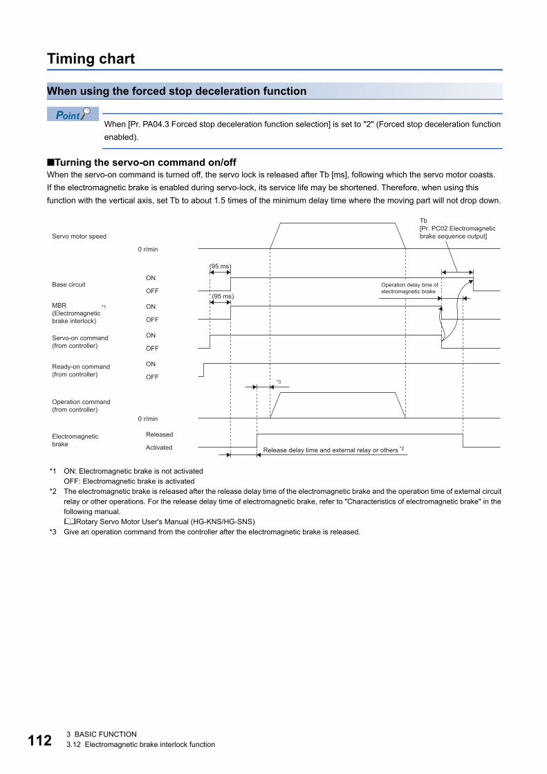
11
Timing chart
When using the forced stop deceleration function
When [Pr. PA04.3 Forced stop deceleration function selection] is set to "2" (Forced stop deceleration function enabled).
■Turning the servo-on command on/offWhen the servo-on command is turned off, the servo lock is released after Tb [ms], following which the servo motor coasts.If the electromagnetic brake is enabled during servo-lock, its service life may be shortened. Therefore, when using this function with the vertical axis, set Tb to about 1.5 times of the minimum delay time where the moving part will not drop down.
*1 ON: Electromagnetic brake is not activatedOFF: Electromagnetic brake is activated
*2 The electromagnetic brake is released after the release delay time of the electromagnetic brake and the operation time of external circuit relay or other operations. For the release delay time of electromagnetic brake, refer to "Characteristics of electromagnetic brake" in the following manual.Rotary Servo Motor User's Manual (HG-KNS/HG-SNS)
*3 Give an operation command from the controller after the electromagnetic brake is released.
ON
OFF
ON
OFF
0 r/min
ON
OFF
0 r/min
ON
OFF
(95 ms)
(95 ms)
*3
Tb[Pr. PC02 Electromagnetic brake sequence output]Servo motor speed
Base circuit Operation delay time of electromagnetic brake
Servo-on command (from controller)
Ready-on command (from controller)
Operation command (from controller)
ReleasedElectromagnetic brake Activated Release delay time and external relay or others *2
*1(Electromagnetic brake interlock)
MBR
2 3 BASIC FUNCTION3.12 Electromagnetic brake interlock function
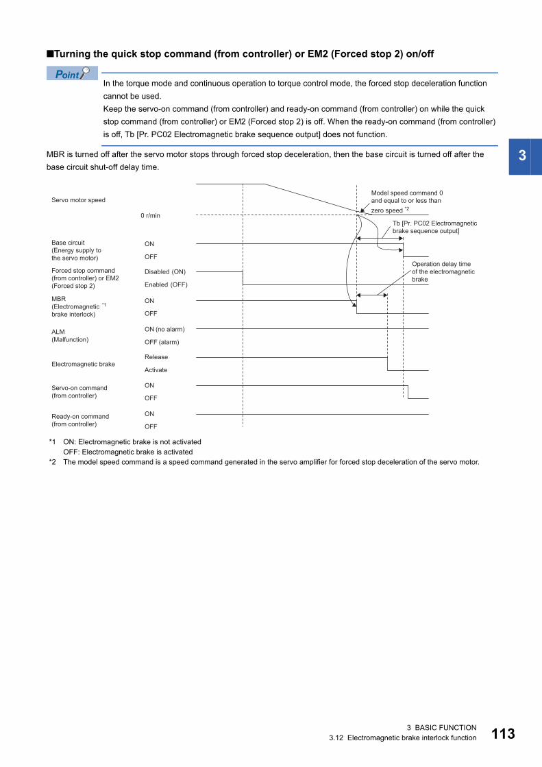
3
■Turning the quick stop command (from controller) or EM2 (Forced stop 2) on/off
In the torque mode and continuous operation to torque control mode, the forced stop deceleration function cannot be used.Keep the servo-on command (from controller) and ready-on command (from controller) on while the quick stop command (from controller) or EM2 (Forced stop 2) is off. When the ready-on command (from controller) is off, Tb [Pr. PC02 Electromagnetic brake sequence output] does not function.
MBR is turned off after the servo motor stops through forced stop deceleration, then the base circuit is turned off after the base circuit shut-off delay time.
*1 ON: Electromagnetic brake is not activatedOFF: Electromagnetic brake is activated
*2 The model speed command is a speed command generated in the servo amplifier for forced stop deceleration of the servo motor.
ON
OFF
ON
OFF
ON
OFF
0 r/min
ALM
ON
OFF
ON
OFF
Model speed command 0and equal to or less thanzero speed *2
Base circuit(Energy supply tothe servo motor)
Forced stop command(from controller) or EM2(Forced stop 2)
Servo motor speed
(no alarm)
(alarm)
Disabled
Enabled
(Electromagneticbrake interlock)
(Malfunction)
Tb [Pr. PC02 Electromagneticbrake sequence output]
Operation delay timeof the electromagneticbrake
Electromagnetic brakeRelease
Activate
Servo-on command(from controller)
Ready-on command(from controller)
(ON)
(OFF)
MBR*1
3 BASIC FUNCTION3.12 Electromagnetic brake interlock function 113
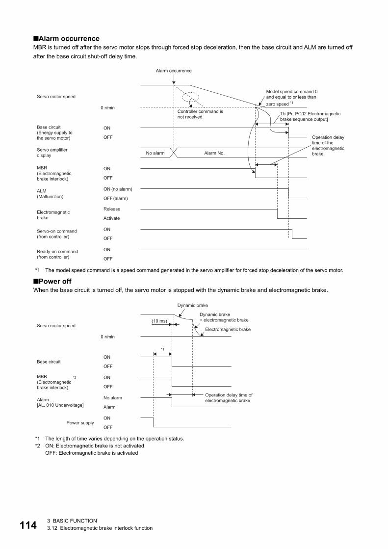
11
■Alarm occurrenceMBR is turned off after the servo motor stops through forced stop deceleration, then the base circuit and ALM are turned off after the base circuit shut-off delay time.
*1 The model speed command is a speed command generated in the servo amplifier for forced stop deceleration of the servo motor.
■Power offWhen the base circuit is turned off, the servo motor is stopped with the dynamic brake and electromagnetic brake.
*1 The length of time varies depending on the operation status.*2 ON: Electromagnetic brake is not activated
OFF: Electromagnetic brake is activated
ON
OFF
ON
OFF
ON
OFF
0 r/min
ALM
ON
OFF
ON
OFF
Controller command isnot received.
Alarm occurrence
Alarm No.No alarm
Model speed command 0and equal to or less thanzero speed *1
Base circuit(Energy supply tothe servo motor)
Servo amplifierdisplay
Servo motor speed
(no alarm)
(alarm)
(Electromagneticbrake interlock)
(Malfunction)
Operation delay time of the electromagneticbrake
Electromagneticbrake
Release
Activate
Servo-on command(from controller)
Ready-on command(from controller)
Tb [Pr. PC02 Electromagneticbrake sequence output]
MBR
ON
OFF
ON
OFF
ON
OFF
0 r/min
(10 ms)
*1
Dynamic brake
Dynamic brake + electromagnetic brake
Servo motor speedElectromagnetic brake
Base circuit
Operation delay time of electromagnetic brakeNo alarmAlarm
[AL. 010 Undervoltage] Alarm
Power supply
(Electromagnetic brake interlock)
*2MBR
4 3 BASIC FUNCTION3.12 Electromagnetic brake interlock function
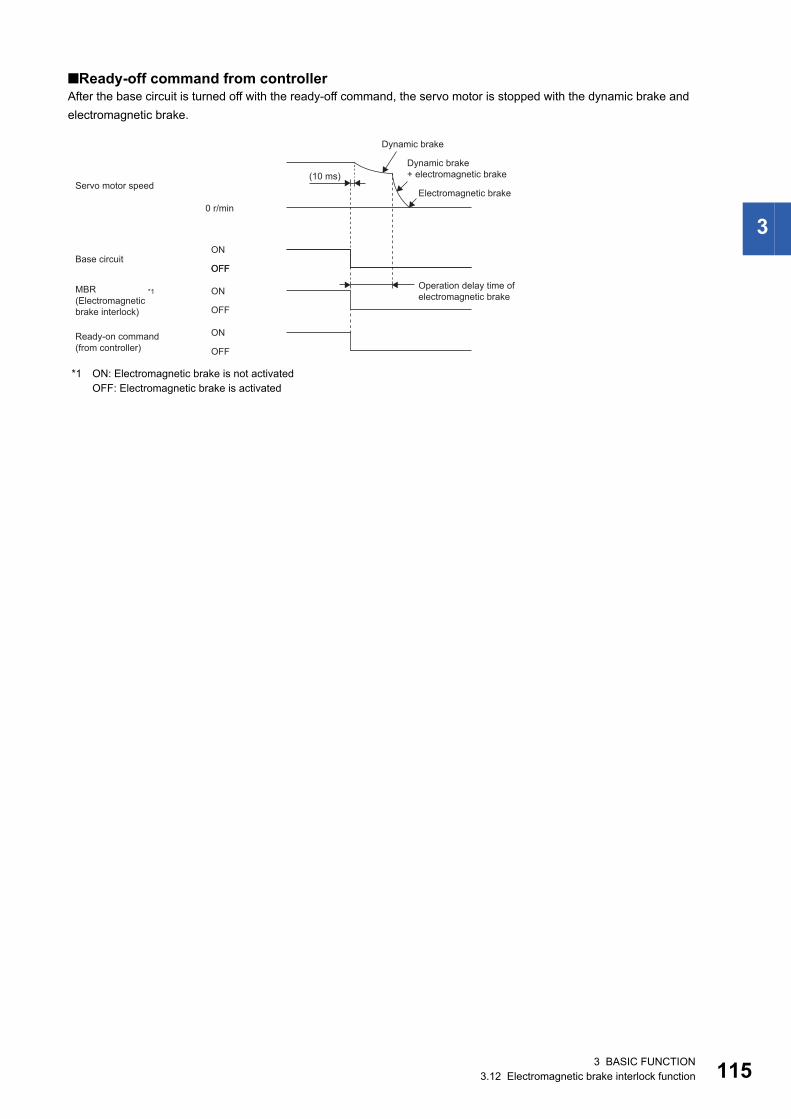
3
■Ready-off command from controllerAfter the base circuit is turned off with the ready-off command, the servo motor is stopped with the dynamic brake and electromagnetic brake.
*1 ON: Electromagnetic brake is not activatedOFF: Electromagnetic brake is activated
OFF
ON
OFF
ON
OFF
0 r/min
(10 ms)
ON
OFF
Dynamic brake
Dynamic brake+ electromagnetic brake
Servo motor speedElectromagnetic brake
Base circuit
Operation delay time of electromagnetic brake
Ready-on command(from controller)
(Electromagnetic brake interlock)
*1MBR
3 BASIC FUNCTION3.12 Electromagnetic brake interlock function 115
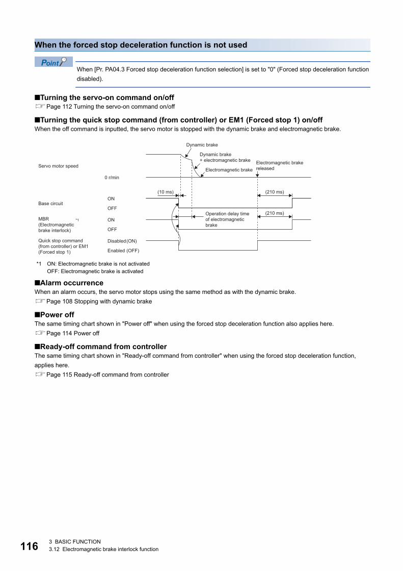
11
When the forced stop deceleration function is not used
When [Pr. PA04.3 Forced stop deceleration function selection] is set to "0" (Forced stop deceleration function disabled).
■Turning the servo-on command on/offPage 112 Turning the servo-on command on/off
■Turning the quick stop command (from controller) or EM1 (Forced stop 1) on/offWhen the off command is inputted, the servo motor is stopped with the dynamic brake and electromagnetic brake.
*1 ON: Electromagnetic brake is not activatedOFF: Electromagnetic brake is activated
■Alarm occurrenceWhen an alarm occurs, the servo motor stops using the same method as with the dynamic brake.Page 108 Stopping with dynamic brake
■Power offThe same timing chart shown in "Power off" when using the forced stop deceleration function also applies here.Page 114 Power off
■Ready-off command from controllerThe same timing chart shown in "Ready-off command from controller" when using the forced stop deceleration function, applies here.Page 115 Ready-off command from controller
ON
OFF
0 r/min
ON
OFF
(10 ms) (210 ms)
(210 ms)
(ON)
(OFF)
Dynamic brake
Dynamic brake+ electromagnetic brake
Servo motor speedElectromagnetic brake releasedElectromagnetic brake
Base circuit
Operation delay time of electromagnetic brake
DisabledQuick stop command (from controller) or EM1 (Forced stop 1) Enabled
(Electromagnetic brake interlock)
*1MBR
6 3 BASIC FUNCTION3.12 Electromagnetic brake interlock function
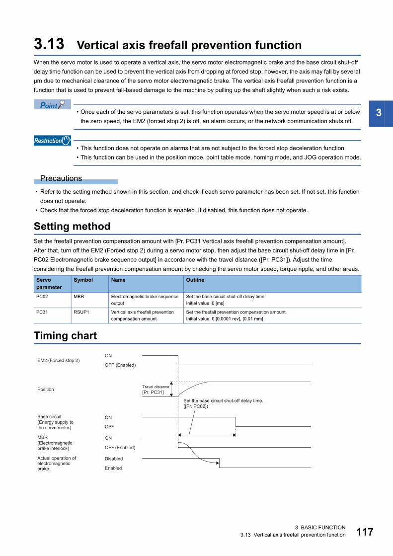
3
3.13 Vertical axis freefall prevention functionWhen the servo motor is used to operate a vertical axis, the servo motor electromagnetic brake and the base circuit shut-off delay time function can be used to prevent the vertical axis from dropping at forced stop; however, the axis may fall by several μm due to mechanical clearance of the servo motor electromagnetic brake. The vertical axis freefall prevention function is a function that is used to prevent fall-based damage to the machine by pulling up the shaft slightly when such a risk exists.
• Once each of the servo parameters is set, this function operates when the servo motor speed is at or below the zero speed, the EM2 (forced stop 2) is off, an alarm occurs, or the network communication shuts off.
• This function does not operate on alarms that are not subject to the forced stop deceleration function. • This function can be used in the position mode, point table mode, homing mode, and JOG operation mode.
Precautions • Refer to the setting method shown in this section, and check if each servo parameter has been set. If not set, this function
does not operate. • Check that the forced stop deceleration function is enabled. If disabled, this function does not operate.
Setting methodSet the freefall prevention compensation amount with [Pr. PC31 Vertical axis freefall prevention compensation amount].After that, turn off the EM2 (Forced stop 2) during a servo motor stop, then adjust the base circuit shut-off delay time in [Pr. PC02 Electromagnetic brake sequence output] in accordance with the travel distance ([Pr. PC31]). Adjust the time considering the freefall prevention compensation amount by checking the servo motor speed, torque ripple, and other areas.
Timing chart
Servo parameter
Symbol Name Outline
PC02 MBR Electromagnetic brake sequence output
Set the base circuit shut-off delay time.Initial value: 0 [ms]
PC31 RSUP1 Vertical axis freefall prevention compensation amount
Set the freefall prevention compensation amount.Initial value: 0 [0.0001 rev], [0.01 mm]
ON
OFF
ON
OFF
ON
OFFEM2
([Pr. PC02])
[Pr. PC31]
(Forced stop 2)(Enabled)
Travel distancePosition
Set the base circuit shut-off delay time.
Base circuit (Energy supply to the servo motor)
(Enabled)
Actual operation of electromagnetic brake
Disabled
Enabled
(Electromagnetic brake interlock)
MBR
3 BASIC FUNCTION3.13 Vertical axis freefall prevention function 117
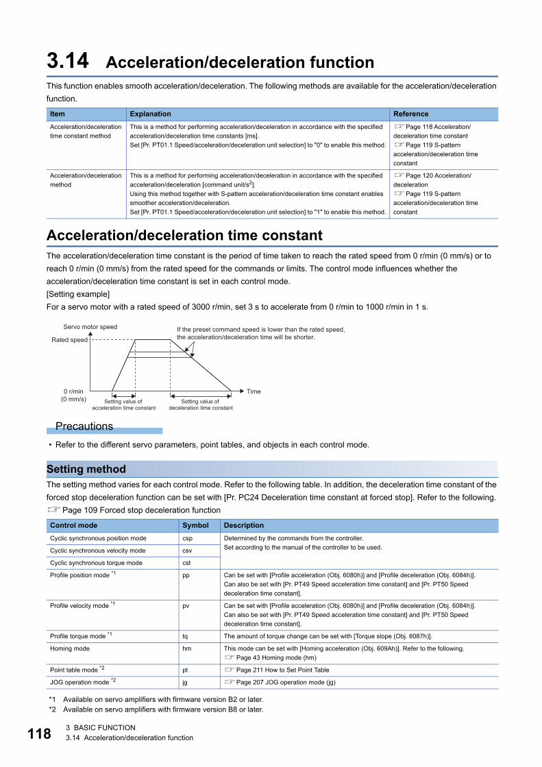
11
3.14 Acceleration/deceleration functionThis function enables smooth acceleration/deceleration. The following methods are available for the acceleration/deceleration function.
Acceleration/deceleration time constantThe acceleration/deceleration time constant is the period of time taken to reach the rated speed from 0 r/min (0 mm/s) or to reach 0 r/min (0 mm/s) from the rated speed for the commands or limits. The control mode influences whether the acceleration/deceleration time constant is set in each control mode.[Setting example]For a servo motor with a rated speed of 3000 r/min, set 3 s to accelerate from 0 r/min to 1000 r/min in 1 s.
Precautions • Refer to the different servo parameters, point tables, and objects in each control mode.
Setting methodThe setting method varies for each control mode. Refer to the following table. In addition, the deceleration time constant of the forced stop deceleration function can be set with [Pr. PC24 Deceleration time constant at forced stop]. Refer to the following.Page 109 Forced stop deceleration function
*1 Available on servo amplifiers with firmware version B2 or later.*2 Available on servo amplifiers with firmware version B8 or later.
Item Explanation ReferenceAcceleration/deceleration time constant method
This is a method for performing acceleration/deceleration in accordance with the specified acceleration/deceleration time constants [ms].Set [Pr. PT01.1 Speed/acceleration/deceleration unit selection] to "0" to enable this method.
Page 118 Acceleration/deceleration time constantPage 119 S-pattern acceleration/deceleration time constant
Acceleration/deceleration method
This is a method for performing acceleration/deceleration in accordance with the specified acceleration/deceleration [command unit/s2].Using this method together with S-pattern acceleration/deceleration time constant enables smoother acceleration/deceleration.Set [Pr. PT01.1 Speed/acceleration/deceleration unit selection] to "1" to enable this method.
Page 120 Acceleration/decelerationPage 119 S-pattern acceleration/deceleration time constant
Control mode Symbol DescriptionCyclic synchronous position mode csp Determined by the commands from the controller.
Set according to the manual of the controller to be used.Cyclic synchronous velocity mode csv
Cyclic synchronous torque mode cst
Profile position mode *1 pp Can be set with [Profile acceleration (Obj. 6080h)] and [Profile deceleration (Obj. 6084h)].Can also be set with [Pr. PT49 Speed acceleration time constant] and [Pr. PT50 Speed deceleration time constant].
Profile velocity mode *1 pv Can be set with [Profile acceleration (Obj. 6080h)] and [Profile deceleration (Obj. 6084h)].Can also be set with [Pr. PT49 Speed acceleration time constant] and [Pr. PT50 Speed deceleration time constant].
Profile torque mode *1 tq The amount of torque change can be set with [Torque slope (Obj. 6087h)].
Homing mode hm This mode can be set with [Homing acceleration (Obj. 609Ah)]. Refer to the following.Page 43 Homing mode (hm)
Point table mode *2 pt Page 211 How to Set Point Table
JOG operation mode *2 jg Page 207 JOG operation mode (jg)
0 r/min(0 mm/s)
Servo motor speed If the preset command speed is lower than the rated speed, the acceleration/deceleration time will be shorter.Rated speed
Time Setting value of
acceleration time constantSetting value of
deceleration time constant
8 3 BASIC FUNCTION3.14 Acceleration/deceleration function
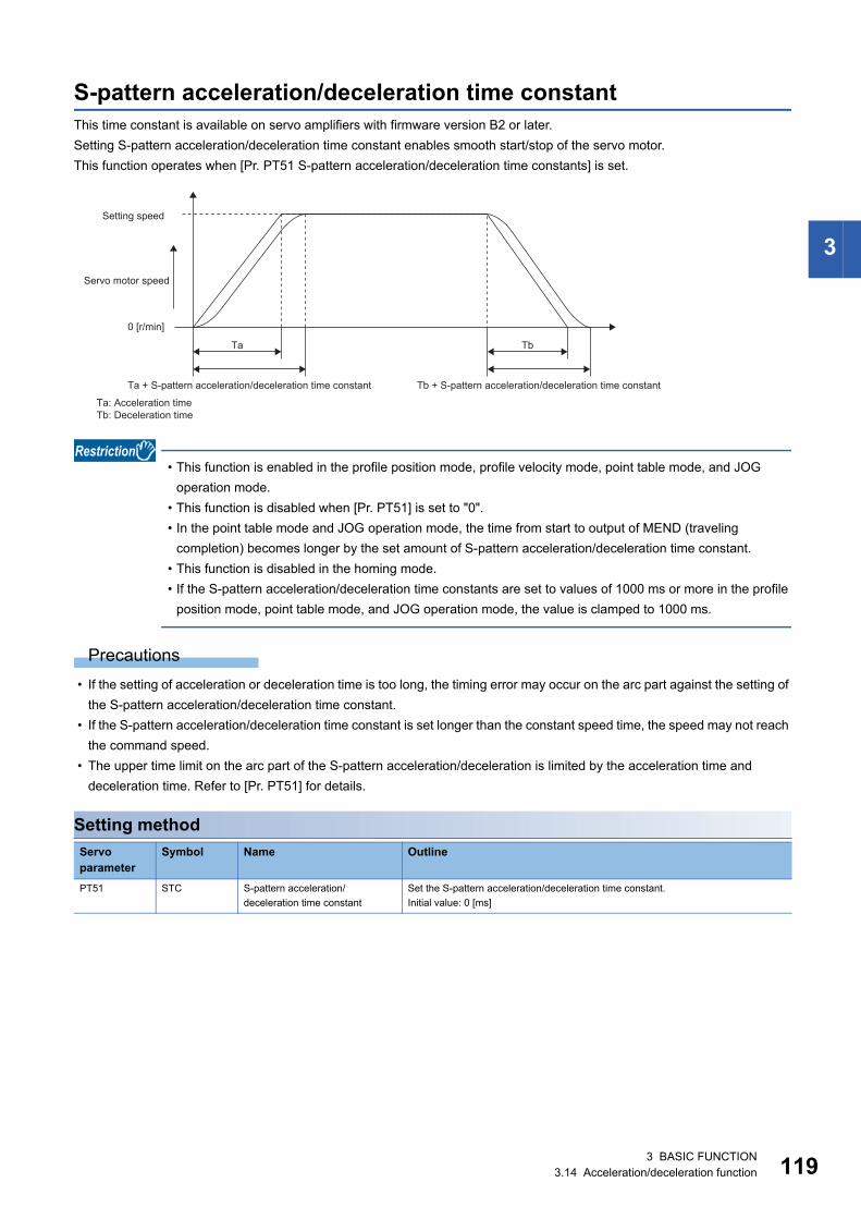
3
S-pattern acceleration/deceleration time constantThis time constant is available on servo amplifiers with firmware version B2 or later.Setting S-pattern acceleration/deceleration time constant enables smooth start/stop of the servo motor.This function operates when [Pr. PT51 S-pattern acceleration/deceleration time constants] is set.
• This function is enabled in the profile position mode, profile velocity mode, point table mode, and JOG operation mode.
• This function is disabled when [Pr. PT51] is set to "0". • In the point table mode and JOG operation mode, the time from start to output of MEND (traveling
completion) becomes longer by the set amount of S-pattern acceleration/deceleration time constant. • This function is disabled in the homing mode. • If the S-pattern acceleration/deceleration time constants are set to values of 1000 ms or more in the profile
position mode, point table mode, and JOG operation mode, the value is clamped to 1000 ms.
Precautions • If the setting of acceleration or deceleration time is too long, the timing error may occur on the arc part against the setting of
the S-pattern acceleration/deceleration time constant. • If the S-pattern acceleration/deceleration time constant is set longer than the constant speed time, the speed may not reach
the command speed. • The upper time limit on the arc part of the S-pattern acceleration/deceleration is limited by the acceleration time and
deceleration time. Refer to [Pr. PT51] for details.
Setting methodServo parameter
Symbol Name Outline
PT51 STC S-pattern acceleration/deceleration time constant
Set the S-pattern acceleration/deceleration time constant.Initial value: 0 [ms]
0 [r/min]
Ta Tb
Setting speed
Ta + S-pattern acceleration/deceleration time constant
Ta: Acceleration timeTb: Deceleration time
Tb + S-pattern acceleration/deceleration time constant
Servo motor speed
3 BASIC FUNCTION3.14 Acceleration/deceleration function 119
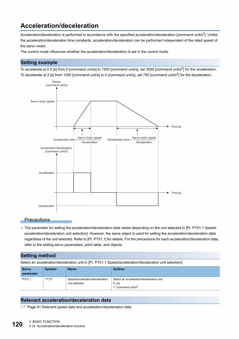
12
Acceleration/decelerationAcceleration/deceleration is performed in accordance with the specified acceleration/deceleration [command unit/s2]. Unlike the acceleration/deceleration time constants, acceleration/deceleration can be performed independent of the rated speed of the servo motor.The control mode influences whether the acceleration/deceleration is set in the control mode.
Setting exampleTo accelerate at 0.5 [s] from 0 [command unit/s] to 1500 [command unit/s], set 3000 [command unit/s2] for the acceleration.To decelerate at 2 [s] from 1500 [command unit/s] to 0 [command unit/s], set 750 [command unit/s2] for the deceleration.
Precautions • The parameter for setting the acceleration/deceleration data varies depending on the unit selected in [Pr. PT01.1 Speed/
acceleration/deceleration unit selection]. However, the same object is used for setting the acceleration/deceleration data regardless of the unit selected. Refer to [Pr. PT01.1] for details. For the precautions for each acceleration/deceleration data, refer to the setting servo parameters, point table, and objects.
Setting methodSelect an acceleration/deceleration unit in [Pr. PT01.1 Speed/acceleration/deceleration unit selection].
Relevant acceleration/deceleration dataPage 91 Relevant speed data and acceleration/deceleration data
Servo parameter
Symbol Name Outline
PT01.1 **CTY Speed/acceleration/deceleration unit selection
Select an acceleration/deceleration unit.0: ms1: Command unit/s2
Servo motor speed
Acceleration
Time [s]
Time [s]
Deceleration
Speed [command unit/s]
Acceleration/deceleration [command unit/s2]
Acceleration time =Servo motor speed
AccelerationDeceleration time =
Servo motor speedDeceleration
0 3 BASIC FUNCTION3.14 Acceleration/deceleration function
3
3.15 Quick stopWith Quick stop defined in CiA 402, the servo motor can be stopped by the forced stop deceleration. For details of the forced stop deceleration, refer to the following.Page 109 Forced stop deceleration functionWhen the Quick stop command in [Controlword (Obj. 6040h)] is turned off, the servo motor decelerates to a stop in accordance with the setting of [Quick stop option code (Obj. 605Ah)], following which the status changes to "Switch On Disabled" (servo-off).
• This function can be used in the cyclic synchronous mode (csp/csv/cst), profile mode (pp/pv/tq), point table mode (pt), JOG operation mode (jg), and homing mode (hm).
• In the torque mode or continuous operation to torque control mode (ct), the servo motor stops with the dynamic brake without deceleration to a stop.
Objects for settingFor details on the objects, refer to the User's Manual (Object Dictionary).
The methods and operations supported in [Quick stop option code (Obj. 605Ah)] are shown in the following table.
Index Sub Object Name Description6085h VAR Quick stop deceleration Deceleration at deceleration to a stop with Quick stop
Unit: acc units
605Ah VAR Quick stop option code Refer to the following table for the description.
Setting value Description1(not supported)
csp/csv: The servo motor decelerates to a stop with [Quick stop deceleration (Obj. 6085h)], and the state shifts to "Switch On Disabled".cst: The state shifts immediately to "Switch On Disabled", and the servo motor stops with the dynamic brake.hm: The servo motor decelerates to a stop in accordance with [Homing acceleration (Obj. 609Ah)] and the state shifts to "Switch On Disabled".
2 In the cyclic synchronous positioning/velocity mode (csp/csv), profile positioning/velocity mode (pp/pv), point table mode (pt), JOG operation mode (jg), and homing mode (hm), the servo motor decelerates to a stop with [Quick stop deceleration (Obj. 6085h)] and the state shifts to Switch On Disabled.In the cyclic synchronous torque mode (cst), the profile torque mode (tq), and the continuous operation to torque control mode (ct), the state immediately shifts to "Switch On Disabled" and the servo motor stops with the dynamic brake.
3(not supported)
The servo motor decelerates by limiting the current, following which the state shifts to "Switch On Disabled".
4(not supported)
The servo motor decelerates by limiting the voltage, following which the state shifts to "Switch On Disabled".
5(not supported)
After deceleration to a stop, the state remains as "Quick Stop Active". (Servo-on is maintained.)
6(not supported)
After deceleration to a stop with [Quick stop deceleration (Obj. 6085h)], the state remains as "Quick Stop Active". (Servo-on is maintained.)
7(not supported)
After deceleration by limiting the current, the state remains as "Quick Stop Active". (Servo-on is maintained.)
8(not supported)
After deceleration by limiting the voltage, the state remains as "Quick Stop Active". (Servo-on is maintained.)
3 BASIC FUNCTION3.15 Quick stop 121
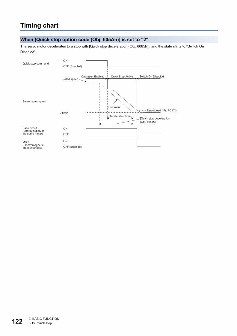
12
Timing chart
When [Quick stop option code (Obj. 605Ah)] is set to "2"The servo motor decelerates to a stop with [Quick stop deceleration (Obj. 6085h)], and the state shifts to "Switch On Disabled".
MBR
ON
OFF
ON
OFF
0 r/min
[Quick stop deceleration(Obj. 6085h)]
ON
OFF
Switch On DisabledQuick Stop ActiveOperation Enabled
Quick stop command(Enabled)
Rated speed
Servo motor speed
CommandZero speed ([Pr. PC17])
Deceleration time
Base circuit (Energy supply to the servo motor)
(Electromagnetic brake interlock) (Enabled)
2 3 BASIC FUNCTION3.15 Quick stop
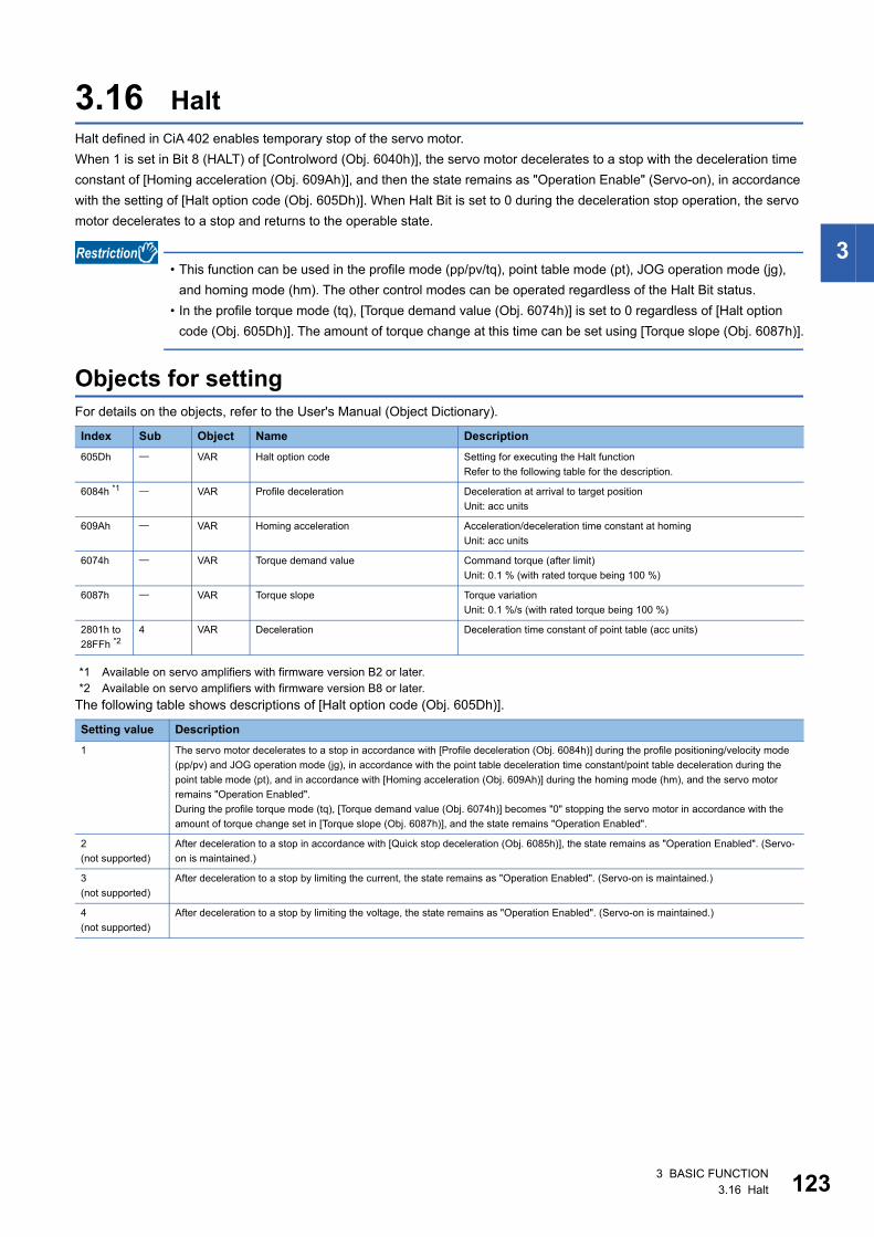
3
3.16 HaltHalt defined in CiA 402 enables temporary stop of the servo motor.When 1 is set in Bit 8 (HALT) of [Controlword (Obj. 6040h)], the servo motor decelerates to a stop with the deceleration time constant of [Homing acceleration (Obj. 609Ah)], and then the state remains as "Operation Enable" (Servo-on), in accordance with the setting of [Halt option code (Obj. 605Dh)]. When Halt Bit is set to 0 during the deceleration stop operation, the servo motor decelerates to a stop and returns to the operable state.
• This function can be used in the profile mode (pp/pv/tq), point table mode (pt), JOG operation mode (jg), and homing mode (hm). The other control modes can be operated regardless of the Halt Bit status.
• In the profile torque mode (tq), [Torque demand value (Obj. 6074h)] is set to 0 regardless of [Halt option code (Obj. 605Dh)]. The amount of torque change at this time can be set using [Torque slope (Obj. 6087h)].
Objects for settingFor details on the objects, refer to the User's Manual (Object Dictionary).
*1 Available on servo amplifiers with firmware version B2 or later.*2 Available on servo amplifiers with firmware version B8 or later.
The following table shows descriptions of [Halt option code (Obj. 605Dh)].
Index Sub Object Name Description605Dh VAR Halt option code Setting for executing the Halt function
Refer to the following table for the description.
6084h *1 VAR Profile deceleration Deceleration at arrival to target positionUnit: acc units
609Ah VAR Homing acceleration Acceleration/deceleration time constant at homingUnit: acc units
6074h VAR Torque demand value Command torque (after limit)Unit: 0.1 % (with rated torque being 100 %)
6087h VAR Torque slope Torque variationUnit: 0.1 %/s (with rated torque being 100 %)
2801h to 28FFh *2
4 VAR Deceleration Deceleration time constant of point table (acc units)
Setting value Description1 The servo motor decelerates to a stop in accordance with [Profile deceleration (Obj. 6084h)] during the profile positioning/velocity mode
(pp/pv) and JOG operation mode (jg), in accordance with the point table deceleration time constant/point table deceleration during the point table mode (pt), and in accordance with [Homing acceleration (Obj. 609Ah)] during the homing mode (hm), and the servo motor remains "Operation Enabled".During the profile torque mode (tq), [Torque demand value (Obj. 6074h)] becomes "0" stopping the servo motor in accordance with the amount of torque change set in [Torque slope (Obj. 6087h)], and the state remains "Operation Enabled".
2(not supported)
After deceleration to a stop in accordance with [Quick stop deceleration (Obj. 6085h)], the state remains as "Operation Enabled". (Servo-on is maintained.)
3(not supported)
After deceleration to a stop by limiting the current, the state remains as "Operation Enabled". (Servo-on is maintained.)
4(not supported)
After deceleration to a stop by limiting the voltage, the state remains as "Operation Enabled". (Servo-on is maintained.)
3 BASIC FUNCTION3.16 Halt 123
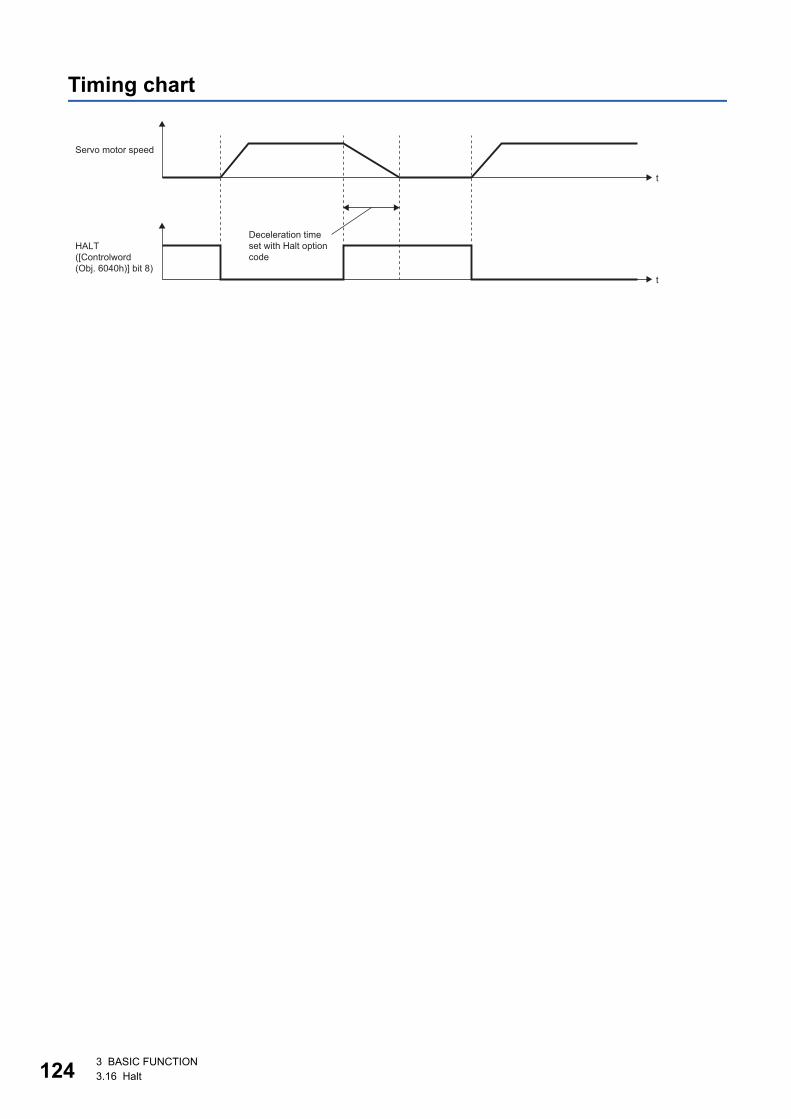
12
Timing chart
HALT([Controlword (Obj. 6040h)] bit 8)
t
t
Servo motor speed
Deceleration time set with Halt option code
4 3 BASIC FUNCTION3.16 Halt
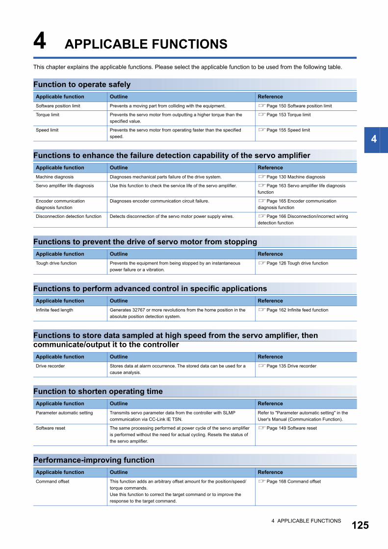
4
4 APPLICABLE FUNCTIONSThis chapter explains the applicable functions. Please select the applicable function to be used from the following table.
Function to operate safely
Functions to enhance the failure detection capability of the servo amplifier
Functions to prevent the drive of servo motor from stopping
Functions to perform advanced control in specific applications
Functions to store data sampled at high speed from the servo amplifier, then communicate/output it to the controller
Function to shorten operating time
Performance-improving function
Applicable function Outline ReferenceSoftware position limit Prevents a moving part from colliding with the equipment. Page 150 Software position limit
Torque limit Prevents the servo motor from outputting a higher torque than the specified value.
Page 153 Torque limit
Speed limit Prevents the servo motor from operating faster than the specified speed.
Page 155 Speed limit
Applicable function Outline ReferenceMachine diagnosis Diagnoses mechanical parts failure of the drive system. Page 130 Machine diagnosis
Servo amplifier life diagnosis Use this function to check the service life of the servo amplifier. Page 163 Servo amplifier life diagnosis function
Encoder communication diagnosis function
Diagnoses encoder communication circuit failure. Page 165 Encoder communication diagnosis function
Disconnection detection function Detects disconnection of the servo motor power supply wires. Page 166 Disconnection/incorrect wiring detection function
Applicable function Outline ReferenceTough drive function Prevents the equipment from being stopped by an instantaneous
power failure or a vibration.Page 126 Tough drive function
Applicable function Outline ReferenceInfinite feed length Generates 32767 or more revolutions from the home position in the
absolute position detection system.Page 162 Infinite feed function
Applicable function Outline ReferenceDrive recorder Stores data at alarm occurrence. The stored data can be used for a
cause analysis.Page 135 Drive recorder
Applicable function Outline ReferenceParameter automatic setting Transmits servo parameter data from the controller with SLMP
communication via CC-Link IE TSN.Refer to "Parameter automatic setting" in the User's Manual (Communication Function).
Software reset The same processing performed at power cycle of the servo amplifier is performed without the need for actual cycling. Resets the status of the servo amplifier.
Page 149 Software reset
Applicable function Outline ReferenceCommand offset This function adds an arbitrary offset amount for the position/speed/
torque commands.Use this function to correct the target command or to improve the response to the target command.
Page 168 Command offset
4 APPLICABLE FUNCTIONS 125
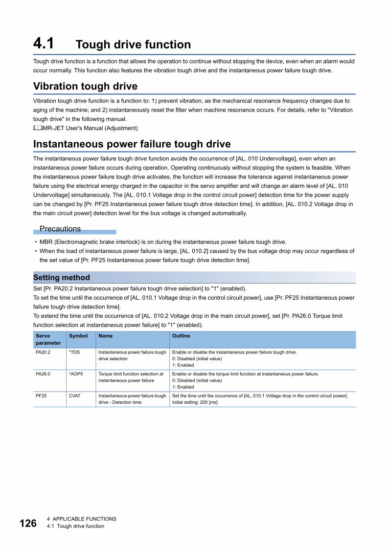
12
4.1 Tough drive functionTough drive function is a function that allows the operation to continue without stopping the device, even when an alarm would occur normally. This function also features the vibration tough drive and the instantaneous power failure tough drive.
Vibration tough driveVibration tough drive function is a function to: 1) prevent vibration, as the mechanical resonance frequency changes due to aging of the machine; and 2) instantaneously reset the filter when machine resonance occurs. For details, refer to "Vibration tough drive" in the following manual.MR-JET User's Manual (Adjustment)
Instantaneous power failure tough driveThe instantaneous power failure tough drive function avoids the occurrence of [AL. 010 Undervoltage], even when an instantaneous power failure occurs during operation. Operating continuously without stopping the system is feasible. When the instantaneous power failure tough drive activates, the function will increase the tolerance against instantaneous power failure using the electrical energy charged in the capacitor in the servo amplifier and will change an alarm level of [AL. 010 Undervoltage] simultaneously. The [AL. 010.1 Voltage drop in the control circuit power] detection time for the power supply can be changed by [Pr. PF25 Instantaneous power failure tough drive detection time]. In addition, [AL. 010.2 Voltage drop in the main circuit power] detection level for the bus voltage is changed automatically.
Precautions • MBR (Electromagnetic brake interlock) is on during the instantaneous power failure tough drive. • When the load of instantaneous power failure is large, [AL. 010.2] caused by the bus voltage drop may occur regardless of
the set value of [Pr. PF25 Instantaneous power failure tough drive detection time].
Setting methodSet [Pr. PA20.2 Instantaneous power failure tough drive selection] to "1" (enabled).To set the time until the occurrence of [AL. 010.1 Voltage drop in the control circuit power], use [Pr. PF25 Instantaneous power failure tough drive detection time].To extend the time until the occurrence of [AL. 010.2 Voltage drop in the main circuit power], set [Pr. PA26.0 Torque limit function selection at instantaneous power failure] to "1" (enabled).
Servo parameter
Symbol Name Outline
PA20.2 *TDS Instantaneous power failure tough drive selection
Enable or disable the instantaneous power failure tough drive.0: Disabled (initial value)1: Enabled
PA26.0 *AOP5 Torque limit function selection at instantaneous power failure
Enable or disable the torque limit function at instantaneous power failure.0: Disabled (initial value)1: Enabled
PF25 CVAT Instantaneous power failure tough drive - Detection time
Set the time until the occurrence of [AL. 010.1 Voltage drop in the control circuit power].Initial setting: 200 [ms]
6 4 APPLICABLE FUNCTIONS4.1 Tough drive function
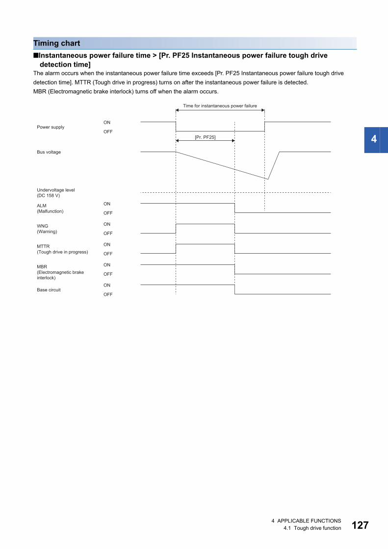
4
Timing chart■Instantaneous power failure time > [Pr. PF25 Instantaneous power failure tough drive
detection time]The alarm occurs when the instantaneous power failure time exceeds [Pr. PF25 Instantaneous power failure tough drive detection time]. MTTR (Tough drive in progress) turns on after the instantaneous power failure is detected.MBR (Electromagnetic brake interlock) turns off when the alarm occurs.
ALM
[Pr. PF25]
MTTR
MBR
ON
OFF
ON
OFF
ON
OFF
WNG ON
OFF
ON
OFF
ON
OFF
(DC 158 V)
Power supply
Bus voltage
Undervoltage level
Time for instantaneous power failure
Base circuit
(Warning)
(Tough drive in progress)
(Electromagnetic brake interlock)
(Malfunction)
4 APPLICABLE FUNCTIONS4.1 Tough drive function 127
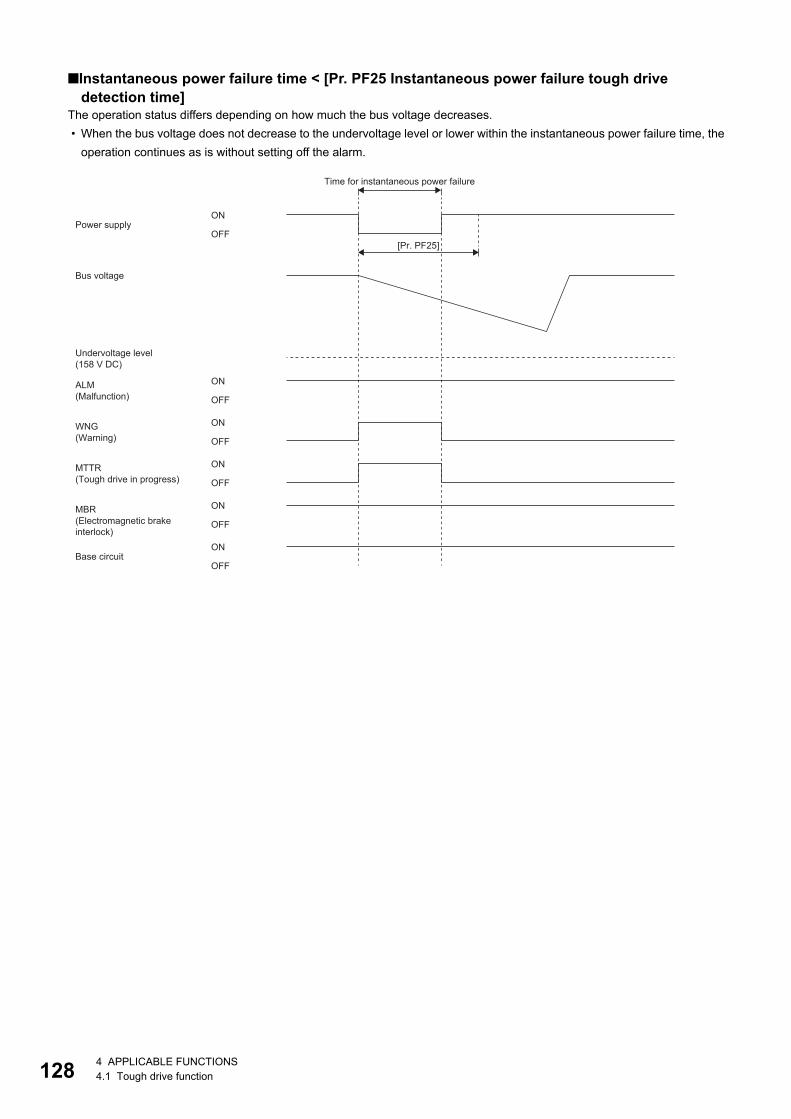
12
■Instantaneous power failure time < [Pr. PF25 Instantaneous power failure tough drive detection time]
The operation status differs depending on how much the bus voltage decreases. • When the bus voltage does not decrease to the undervoltage level or lower within the instantaneous power failure time, the
operation continues as is without setting off the alarm.
ALM
[Pr. PF25]
MTTR
MBR
ON
OFF
ON
OFF
ON
OFF
WNG ON
OFF
ON
OFF
ON
OFF
Power supply
Bus voltage
Undervoltage level
Time for instantaneous power failure
Base circuit
(Warning)
(Tough drive in progress)
(Electromagnetic brake interlock)
(Malfunction)
(158 V DC)
8 4 APPLICABLE FUNCTIONS4.1 Tough drive function
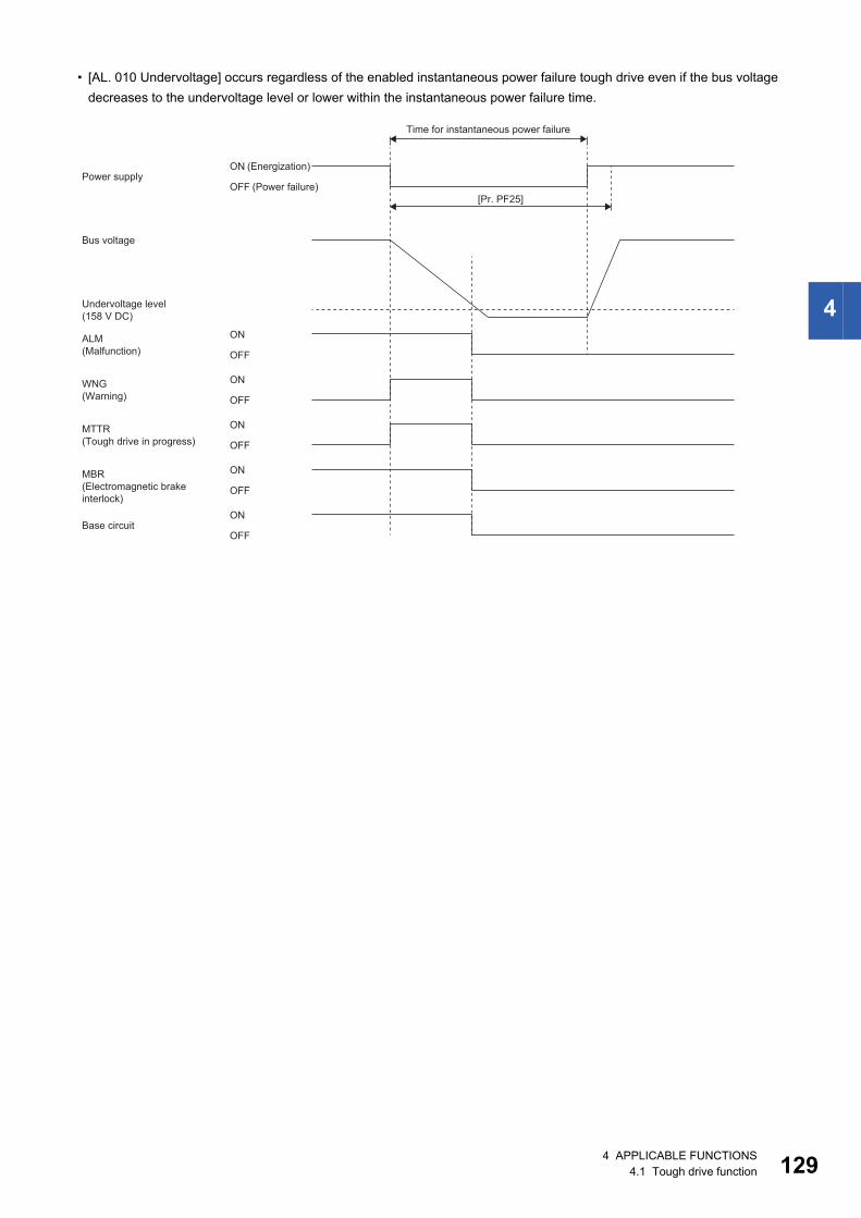
4
• [AL. 010 Undervoltage] occurs regardless of the enabled instantaneous power failure tough drive even if the bus voltage decreases to the undervoltage level or lower within the instantaneous power failure time.
ALM
[Pr. PF25]
MTTR
MBR
ON
OFF
ON
OFF
ON
OFF
WNG ON
OFF
ON
OFF
ON
OFF
Power supply
Bus voltage
Undervoltage level
Time for instantaneous power failure
Base circuit
(Warning)
(Tough drive in progress)
(Electromagnetic brake interlock)
(Malfunction)
(Energization)
(Power failure)
(158 V DC)
4 APPLICABLE FUNCTIONS4.1 Tough drive function 129
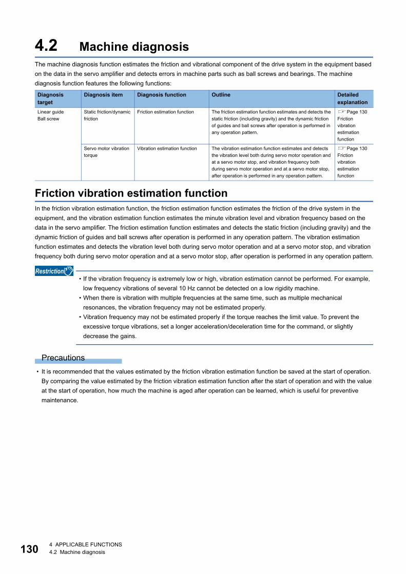
13
4.2 Machine diagnosisThe machine diagnosis function estimates the friction and vibrational component of the drive system in the equipment based on the data in the servo amplifier and detects errors in machine parts such as ball screws and bearings. The machine diagnosis function features the following functions:
Friction vibration estimation functionIn the friction vibration estimation function, the friction estimation function estimates the friction of the drive system in the equipment, and the vibration estimation function estimates the minute vibration level and vibration frequency based on the data in the servo amplifier. The friction estimation function estimates and detects the static friction (including gravity) and the dynamic friction of guides and ball screws after operation is performed in any operation pattern. The vibration estimation function estimates and detects the vibration level both during servo motor operation and at a servo motor stop, and vibration frequency both during servo motor operation and at a servo motor stop, after operation is performed in any operation pattern.
• If the vibration frequency is extremely low or high, vibration estimation cannot be performed. For example, low frequency vibrations of several 10 Hz cannot be detected on a low rigidity machine.
• When there is vibration with multiple frequencies at the same time, such as multiple mechanical resonances, the vibration frequency may not be estimated properly.
• Vibration frequency may not be estimated properly if the torque reaches the limit value. To prevent the excessive torque vibrations, set a longer acceleration/deceleration time for the command, or slightly decrease the gains.
Precautions • It is recommended that the values estimated by the friction vibration estimation function be saved at the start of operation.
By comparing the value estimated by the friction vibration estimation function after the start of operation and with the value at the start of operation, how much the machine is aged after operation can be learned, which is useful for preventive maintenance.
Diagnosis target
Diagnosis item Diagnosis function Outline Detailed explanation
Linear guideBall screw
Static friction/dynamic friction
Friction estimation function The friction estimation function estimates and detects the static friction (including gravity) and the dynamic friction of guides and ball screws after operation is performed in any operation pattern.
Page 130 Friction vibration estimation function
Servo motor vibration torque
Vibration estimation function The vibration estimation function estimates and detects the vibration level both during servo motor operation and at a servo motor stop, and vibration frequency both during servo motor operation and at a servo motor stop, after operation is performed in any operation pattern.
Page 130 Friction vibration estimation function
0 4 APPLICABLE FUNCTIONS4.2 Machine diagnosis
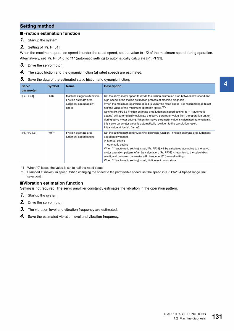
4
Setting method■Friction estimation function1. Startup the system.
2. Setting of [Pr. PF31]When the maximum operation speed is under the rated speed, set the value to 1/2 of the maximum speed during operation. Alternatively, set [Pr. PF34.6] to "1" (automatic setting) to automatically calculate [Pr. PF31].
3. Drive the servo motor.
4. The static friction and the dynamic friction (at rated speed) are estimated.
5. Save the data of the estimated static friction and dynamic friction.
*1 When "0" is set, the value is set to half the rated speed.*2 Clamped at maximum speed. When changing the speed to the permissible speed, set the speed in [Pr. PA28.4 Speed range limit
selection].
■Vibration estimation functionSetting is not required. The servo amplifier constantly estimates the vibration in the operation pattern.
1. Startup the system.
2. Drive the servo motor.
3. The vibration level and vibration frequency are estimated.
4. Save the estimated vibration level and vibration frequency.
Servo parameter
Symbol Name Description
[Pr. PF31] FRIC Machine diagnosis function - Friction estimate area judgment speed at low speed
Set the servo motor speed to divide the friction estimation area between low-speed and high-speed in the friction estimation process of machine diagnosis.When the maximum operation speed is under the rated speed, it is recommended to set half the value of the maximum operation speed.*1*2
Setting [Pr. PF34.6 Friction estimate area judgment speed setting] to "1" (automatic setting) will automatically calculate the servo parameter value from the operation pattern during servo motor driving. When this servo parameter value is calculated automatically, this servo parameter value is automatically rewritten to the calculation result.Initial value: 0 [r/min], [mm/s]
[Pr. PF34.6] *MFP Friction estimate area judgment speed setting
Set the setting method for Machine diagnosis function - Friction estimate area judgment speed at low speed.0: Manual setting1: Automatic settingWhen "1" (automatic setting) is set, [Pr. PF31] will be calculated according to the servo motor operation pattern. After the calculation, [Pr. PF31] is rewritten to the calculation result, and the servo parameter will change to "0" (manual setting).When "1" (automatic setting) is set, friction estimation stops.
4 APPLICABLE FUNCTIONS4.2 Machine diagnosis 131
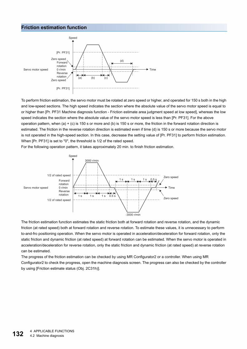
13
Friction estimation function
To perform friction estimation, the servo motor must be rotated at zero speed or higher, and operated for 150 s both in the high and low-speed sections. The high speed indicates the section where the absolute value of the servo motor speed is equal to or higher than [Pr. PF31 Machine diagnosis function - Friction estimate area judgment speed at low speed], whereas the low speed indicates the section where the absolute value of the servo motor speed is less than [Pr. PF31]. For the above operation pattern, when (a) + (c) is 150 s or more and (b) is 150 s or more, the friction in the forward rotation direction is estimated. The friction in the reverse rotation direction is estimated even if time (d) is 150 s or more because the servo motor is not operated in the high-speed section. In this case, decrease the setting value of [Pr. PF31] to perform friction estimation. When [Pr. PF31] is set to "0", the threshold is 1/2 of the rated speed.For the following operation pattern, it takes approximately 20 min. to finish friction estimation.
The friction estimation function estimates the static friction both at forward rotation and reverse rotation, and the dynamic friction (at rated speed) both at forward rotation and reverse rotation. To estimate these values, it is unnecessary to perform to-and-fro positioning operation. When the servo motor is operated in acceleration/deceleration for forward rotation, only the static friction and dynamic friction (at rated speed) at forward rotation can be estimated. When the servo motor is operated in acceleration/deceleration for reverse rotation, only the static friction and dynamic friction (at rated speed) at reverse rotation can be estimated.The progress of the friction estimation can be checked by using MR Configurator2 or a controller. When using MR Configurator2 to check the progress, open the machine diagnosis screen. The progress can also be checked by the controller by using [Friction estimate status (Obj. 2C31h)].
0 r/min
[Pr. PF31]
[Pr. PF31]
(a) (b) (c)
(d)
Speed
Zero speedForward rotation
Servo motor speed TimeReverse rotation
Zero speed
3000 r/min
-3000 r/min
1 s 1 s 1 s 0.5 s
1 s 1 s 1 s 0.5 s
0 r/min
Speed
1/2 of rated speed Zero speedForward rotation
Servo motor speed TimeReverse rotation
Zero speed1/2 of rated speed
2 4 APPLICABLE FUNCTIONS4.2 Machine diagnosis
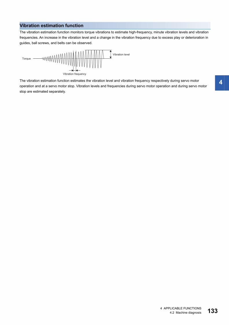
4
Vibration estimation functionThe vibration estimation function monitors torque vibrations to estimate high-frequency, minute vibration levels and vibration frequencies. An increase in the vibration level and a change in the vibration frequency due to excess play or deterioration in guides, ball screws, and belts can be observed.
The vibration estimation function estimates the vibration level and vibration frequency respectively during servo motor operation and at a servo motor stop. Vibration levels and frequencies during servo motor operation and during servo motor stop are estimated separately.
Vibration levelTorque
Vibration frequency
4 APPLICABLE FUNCTIONS4.2 Machine diagnosis 133
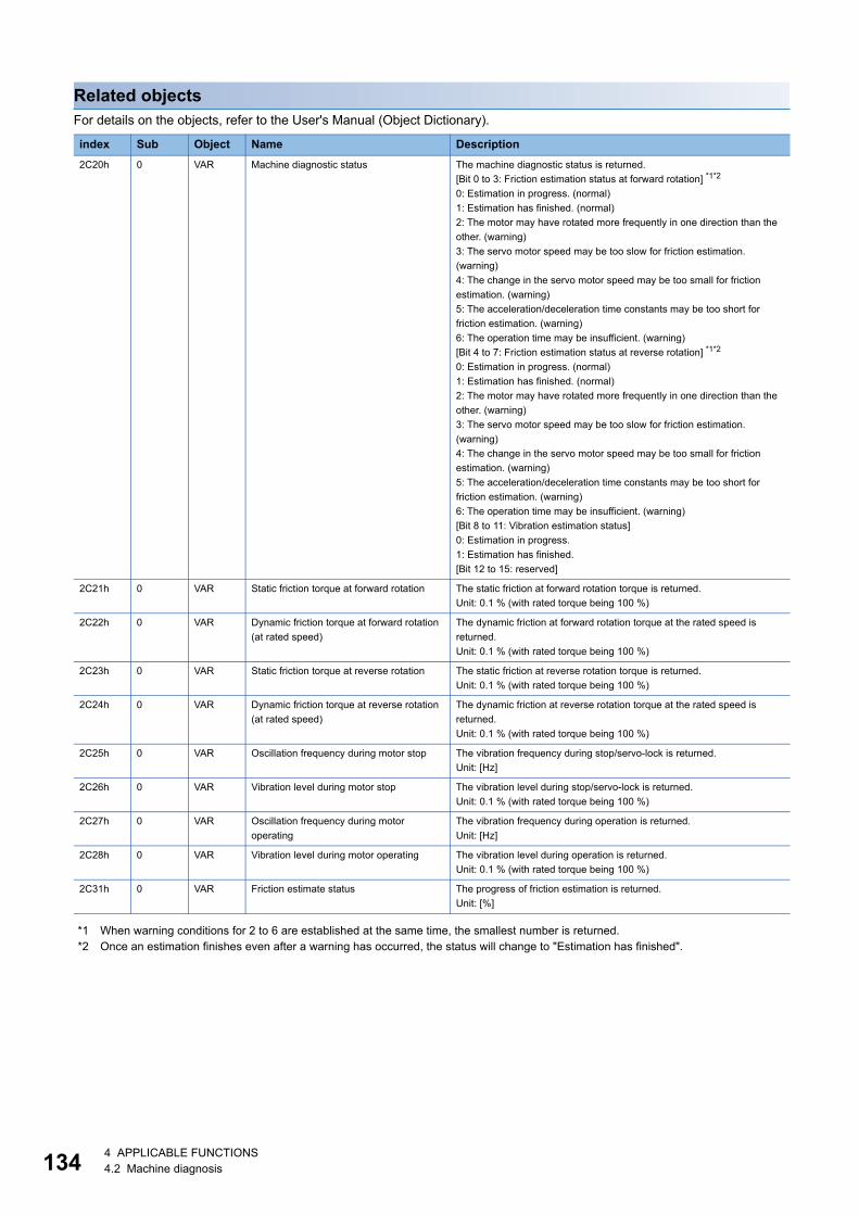
13
Related objectsFor details on the objects, refer to the User's Manual (Object Dictionary).
*1 When warning conditions for 2 to 6 are established at the same time, the smallest number is returned.*2 Once an estimation finishes even after a warning has occurred, the status will change to "Estimation has finished".
index Sub Object Name Description2C20h 0 VAR Machine diagnostic status The machine diagnostic status is returned.
[Bit 0 to 3: Friction estimation status at forward rotation] *1*2
0: Estimation in progress. (normal)1: Estimation has finished. (normal)2: The motor may have rotated more frequently in one direction than the other. (warning)3: The servo motor speed may be too slow for friction estimation. (warning)4: The change in the servo motor speed may be too small for friction estimation. (warning)5: The acceleration/deceleration time constants may be too short for friction estimation. (warning)6: The operation time may be insufficient. (warning)[Bit 4 to 7: Friction estimation status at reverse rotation] *1*2
0: Estimation in progress. (normal)1: Estimation has finished. (normal)2: The motor may have rotated more frequently in one direction than the other. (warning)3: The servo motor speed may be too slow for friction estimation. (warning)4: The change in the servo motor speed may be too small for friction estimation. (warning)5: The acceleration/deceleration time constants may be too short for friction estimation. (warning)6: The operation time may be insufficient. (warning)[Bit 8 to 11: Vibration estimation status]0: Estimation in progress.1: Estimation has finished.[Bit 12 to 15: reserved]
2C21h 0 VAR Static friction torque at forward rotation The static friction at forward rotation torque is returned.Unit: 0.1 % (with rated torque being 100 %)
2C22h 0 VAR Dynamic friction torque at forward rotation (at rated speed)
The dynamic friction at forward rotation torque at the rated speed is returned.Unit: 0.1 % (with rated torque being 100 %)
2C23h 0 VAR Static friction torque at reverse rotation The static friction at reverse rotation torque is returned.Unit: 0.1 % (with rated torque being 100 %)
2C24h 0 VAR Dynamic friction torque at reverse rotation (at rated speed)
The dynamic friction at reverse rotation torque at the rated speed is returned.Unit: 0.1 % (with rated torque being 100 %)
2C25h 0 VAR Oscillation frequency during motor stop The vibration frequency during stop/servo-lock is returned.Unit: [Hz]
2C26h 0 VAR Vibration level during motor stop The vibration level during stop/servo-lock is returned.Unit: 0.1 % (with rated torque being 100 %)
2C27h 0 VAR Oscillation frequency during motor operating
The vibration frequency during operation is returned.Unit: [Hz]
2C28h 0 VAR Vibration level during motor operating The vibration level during operation is returned.Unit: 0.1 % (with rated torque being 100 %)
2C31h 0 VAR Friction estimate status The progress of friction estimation is returned.Unit: [%]
4 4 APPLICABLE FUNCTIONS4.2 Machine diagnosis
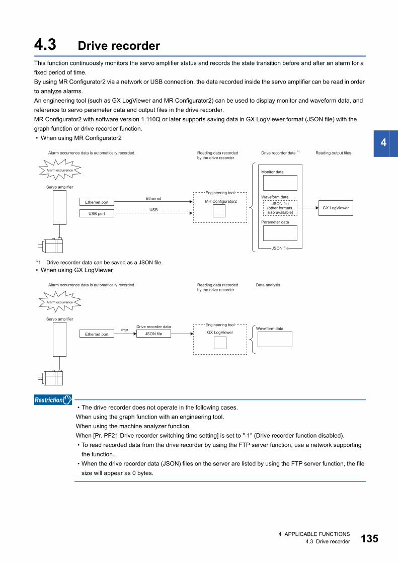
4
4.3 Drive recorderThis function continuously monitors the servo amplifier status and records the state transition before and after an alarm for a fixed period of time.By using MR Configurator2 via a network or USB connection, the data recorded inside the servo amplifier can be read in order to analyze alarms.An engineering tool (such as GX LogViewer and MR Configurator2) can be used to display monitor and waveform data, and reference to servo parameter data and output files in the drive recorder.MR Configurator2 with software version 1.110Q or later supports saving data in GX LogViewer format (JSON file) with the graph function or drive recorder function. • When using MR Configurator2
*1 Drive recorder data can be saved as a JSON file. • When using GX LogViewer
• The drive recorder does not operate in the following cases.When using the graph function with an engineering tool.When using the machine analyzer function.When [Pr. PF21 Drive recorder switching time setting] is set to "-1" (Drive recorder function disabled). • To read recorded data from the drive recorder by using the FTP server function, use a network supporting
the function. • When the drive recorder data (JSON) files on the server are listed by using the FTP server function, the file
size will appear as 0 bytes.
MR Configurator2Ethernet
USB GX LogViewer
Reading data recordedby the drive recorder
Alarm occurrence data is automatically recorded.
Monitor dataAlarm occurrence
Servo amplifier
Waveform dataEngineering tool
Ethernet port
USB port
JSON file(other formats also available)
Drive recorder data *1 Reading output files
Parameter data
JSON file
GX LogViewerFTP
Reading data recordedby the drive recorder
Data analysisAlarm occurrence data is automatically recorded.
Alarm occurrence
Servo amplifier
Waveform dataEngineering tool
Ethernet port
Drive recorder data
JSON file
4 APPLICABLE FUNCTIONS4.3 Drive recorder 135
13
Precautions • When using the graph function with an engineering tool, the drive recorder function cannot be used. To use the drive
recorder function, wait until the time set in [Pr. PF21 Drive recorder switching time setting] passes, cycle the power of the servo amplifier, or perform the software reset after using the graph function.
• If the sampling cycle of an analog trigger or digital trigger is too long, the establishment of the trigger may not be able to be detected. In that case, shorten the sampling cycle.
• If the power supply of the servo amplifier is turned off during data storage of the drive recorder (immediately after alarm occurrence), data at alarm occurrence may not be recorded normally.
• The storage area of the servo amplifier has a limit for the number of writings. When using the manual setting mode with the drive recorder, be sure to consider the number of writings.
• If the drive recorder detects a trigger, the next trigger cannot be detected until the data has been saved. • In the initial settings, recorded data cannot be read from the drive recorder by using the FTP server function. Change the
setting of "drive recorder data readout permission selection" in the network parameter "authorization level". For information on account settings and network parameters, refer to "NETWORK FUNCTION".
Page 178 NETWORK FUNCTION
6 4 APPLICABLE FUNCTIONS4.3 Drive recorder
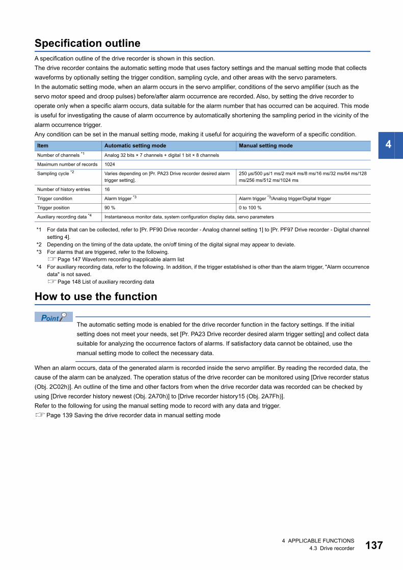
4
Specification outlineA specification outline of the drive recorder is shown in this section.The drive recorder contains the automatic setting mode that uses factory settings and the manual setting mode that collects waveforms by optionally setting the trigger condition, sampling cycle, and other areas with the servo parameters.In the automatic setting mode, when an alarm occurs in the servo amplifier, conditions of the servo amplifier (such as the servo motor speed and droop pulses) before/after alarm occurrence are recorded. Also, by setting the drive recorder to operate only when a specific alarm occurs, data suitable for the alarm number that has occurred can be acquired. This mode is useful for investigating the cause of alarm occurrence by automatically shortening the sampling period in the vicinity of the alarm occurrence trigger.Any condition can be set in the manual setting mode, making it useful for acquiring the waveform of a specific condition.
*1 For data that can be collected, refer to [Pr. PF90 Drive recorder - Analog channel setting 1] to [Pr. PF97 Drive recorder - Digital channel setting 4].
*2 Depending on the timing of the data update, the on/off timing of the digital signal may appear to deviate.*3 For alarms that are triggered, refer to the following.
Page 147 Waveform recording inapplicable alarm list*4 For auxiliary recording data, refer to the following. In addition, if the trigger established is other than the alarm trigger, "Alarm occurrence
data" is not saved.Page 148 List of auxiliary recording data
How to use the function
The automatic setting mode is enabled for the drive recorder function in the factory settings. If the initial setting does not meet your needs, set [Pr. PA23 Drive recorder desired alarm trigger setting] and collect data suitable for analyzing the occurrence factors of alarms. If satisfactory data cannot be obtained, use the manual setting mode to collect the necessary data.
When an alarm occurs, data of the generated alarm is recorded inside the servo amplifier. By reading the recorded data, the cause of the alarm can be analyzed. The operation status of the drive recorder can be monitored using [Drive recorder status (Obj. 2C02h)]. An outline of the time and other factors from when the drive recorder data was recorded can be checked by using [Drive recorder history newest (Obj. 2A70h)] to [Drive recorder history15 (Obj. 2A7Fh)].Refer to the following for using the manual setting mode to record with any data and trigger.Page 139 Saving the drive recorder data in manual setting mode
Item Automatic setting mode Manual setting modeNumber of channels *1 Analog 32 bits × 7 channels + digital 1 bit × 8 channels
Maximum number of records 1024
Sampling cycle *2 Varies depending on [Pr. PA23 Drive recorder desired alarm trigger setting].
250 μs/500 μs/1 ms/2 ms/4 ms/8 ms/16 ms/32 ms/64 ms/128 ms/256 ms/512 ms/1024 ms
Number of history entries 16
Trigger condition Alarm trigger *3 Alarm trigger *3/Analog trigger/Digital trigger
Trigger position 90 % 0 to 100 %
Auxiliary recording data *4 Instantaneous monitor data, system configuration display data, servo parameters
4 APPLICABLE FUNCTIONS4.3 Drive recorder 137
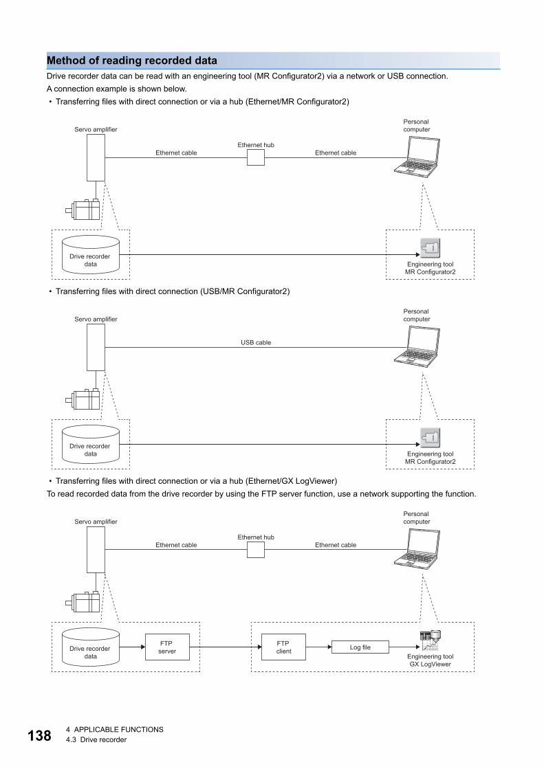
13
Method of reading recorded dataDrive recorder data can be read with an engineering tool (MR Configurator2) via a network or USB connection.A connection example is shown below. • Transferring files with direct connection or via a hub (Ethernet/MR Configurator2)
• Transferring files with direct connection (USB/MR Configurator2)
• Transferring files with direct connection or via a hub (Ethernet/GX LogViewer)To read recorded data from the drive recorder by using the FTP server function, use a network supporting the function.
Engineering toolMR Configurator2
Ethernet hub
Servo amplifier
Drive recorder data
Personal computer
Ethernet cable Ethernet cable
Engineering toolMR Configurator2
Servo amplifier
Drive recorder data
Personal computer
USB cable
Ethernet hub
Drive recorder data
Personal computer
FTP server
FTP client Log file
Engineering toolGX LogViewer
Ethernet cable Ethernet cable
Servo amplifier
8 4 APPLICABLE FUNCTIONS4.3 Drive recorder
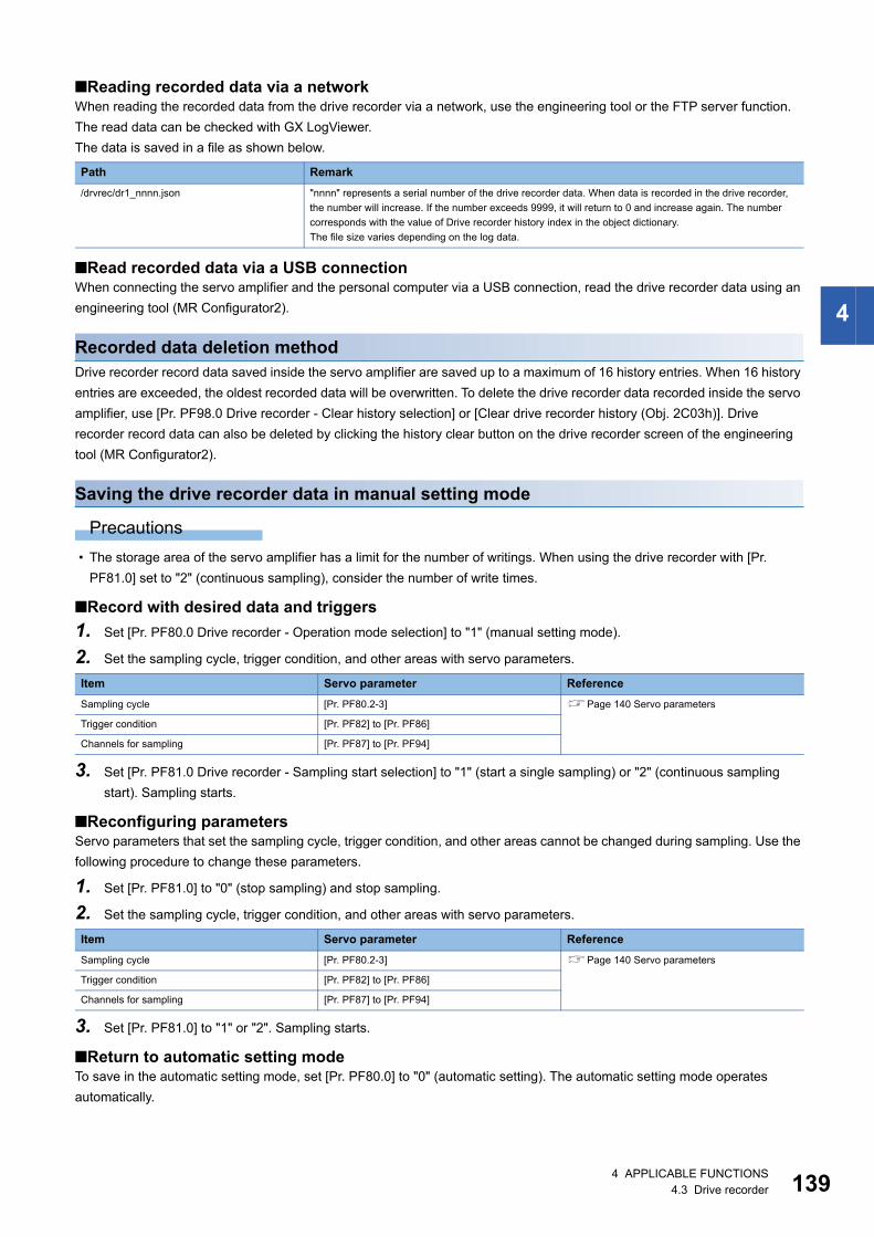
4
■Reading recorded data via a networkWhen reading the recorded data from the drive recorder via a network, use the engineering tool or the FTP server function. The read data can be checked with GX LogViewer.The data is saved in a file as shown below.
■Read recorded data via a USB connectionWhen connecting the servo amplifier and the personal computer via a USB connection, read the drive recorder data using an engineering tool (MR Configurator2).
Recorded data deletion methodDrive recorder record data saved inside the servo amplifier are saved up to a maximum of 16 history entries. When 16 history entries are exceeded, the oldest recorded data will be overwritten. To delete the drive recorder data recorded inside the servo amplifier, use [Pr. PF98.0 Drive recorder - Clear history selection] or [Clear drive recorder history (Obj. 2C03h)]. Drive recorder record data can also be deleted by clicking the history clear button on the drive recorder screen of the engineering tool (MR Configurator2).
Saving the drive recorder data in manual setting mode
Precautions • The storage area of the servo amplifier has a limit for the number of writings. When using the drive recorder with [Pr.
PF81.0] set to "2" (continuous sampling), consider the number of write times.
■Record with desired data and triggers1. Set [Pr. PF80.0 Drive recorder - Operation mode selection] to "1" (manual setting mode).
2. Set the sampling cycle, trigger condition, and other areas with servo parameters.
3. Set [Pr. PF81.0 Drive recorder - Sampling start selection] to "1" (start a single sampling) or "2" (continuous sampling start). Sampling starts.
■Reconfiguring parametersServo parameters that set the sampling cycle, trigger condition, and other areas cannot be changed during sampling. Use the following procedure to change these parameters.
1. Set [Pr. PF81.0] to "0" (stop sampling) and stop sampling.
2. Set the sampling cycle, trigger condition, and other areas with servo parameters.
3. Set [Pr. PF81.0] to "1" or "2". Sampling starts.
■Return to automatic setting modeTo save in the automatic setting mode, set [Pr. PF80.0] to "0" (automatic setting). The automatic setting mode operates automatically.
Path Remark/drvrec/dr1_nnnn.json "nnnn" represents a serial number of the drive recorder data. When data is recorded in the drive recorder,
the number will increase. If the number exceeds 9999, it will return to 0 and increase again. The number corresponds with the value of Drive recorder history index in the object dictionary.The file size varies depending on the log data.
Item Servo parameter ReferenceSampling cycle [Pr. PF80.2-3] Page 140 Servo parameters
Trigger condition [Pr. PF82] to [Pr. PF86]
Channels for sampling [Pr. PF87] to [Pr. PF94]
Item Servo parameter ReferenceSampling cycle [Pr. PF80.2-3] Page 140 Servo parameters
Trigger condition [Pr. PF82] to [Pr. PF86]
Channels for sampling [Pr. PF87] to [Pr. PF94]
4 APPLICABLE FUNCTIONS4.3 Drive recorder 139
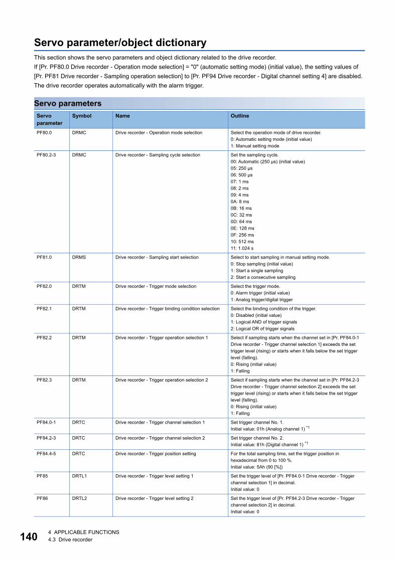
14
Servo parameter/object dictionaryThis section shows the servo parameters and object dictionary related to the drive recorder.If [Pr. PF80.0 Drive recorder - Operation mode selection] = "0" (automatic setting mode) (initial value), the setting values of [Pr. PF81 Drive recorder - Sampling operation selection] to [Pr. PF94 Drive recorder - Digital channel setting 4] are disabled. The drive recorder operates automatically with the alarm trigger.
Servo parametersServo parameter
Symbol Name Outline
PF80.0 DRMC Drive recorder - Operation mode selection Select the operation mode of drive recorder.0: Automatic setting mode (initial value)1: Manual setting mode
PF80.2-3 DRMC Drive recorder - Sampling cycle selection Set the sampling cycle.00: Automatic (250 μs) (initial value)05: 250 μs06: 500 μs07: 1 ms08: 2 ms09: 4 ms0A: 8 ms0B: 16 ms0C: 32 ms0D: 64 ms0E: 128 ms0F: 256 ms10: 512 ms11: 1.024 s
PF81.0 DRMS Drive recorder - Sampling start selection Select to start sampling in manual setting mode.0: Stop sampling (initial value)1: Start a single sampling2: Start a consecutive sampling
PF82.0 DRTM Drive recorder - Trigger mode selection Select the trigger mode.0: Alarm trigger (initial value)1: Analog trigger/digital trigger
PF82.1 DRTM Drive recorder - Trigger binding condition selection Select the binding condition of the trigger.0: Disabled (initial value)1: Logical AND of trigger signals2: Logical OR of trigger signals
PF82.2 DRTM Drive recorder - Trigger operation selection 1 Select if sampling starts when the channel set in [Pr. PF84.0-1 Drive recorder - Trigger channel selection 1] exceeds the set trigger level (rising) or starts when it falls below the set trigger level (falling).0: Rising (initial value)1: Falling
PF82.3 DRTM Drive recorder - Trigger operation selection 2 Select if sampling starts when the channel set in [Pr. PF84.2-3 Drive recorder - Trigger channel selection 2] exceeds the set trigger level (rising) or starts when it falls below the set trigger level (falling).0: Rising (initial value)1: Falling
PF84.0-1 DRTC Drive recorder - Trigger channel selection 1 Set trigger channel No. 1.Initial value: 01h (Analog channel 1) *1
PF84.2-3 DRTC Drive recorder - Trigger channel selection 2 Set trigger channel No. 2.Initial value: 81h (Digital channel 1) *1
PF84.4-5 DRTC Drive recorder - Trigger position setting For the total sampling time, set the trigger position in hexadecimal from 0 to 100 %.Initial value: 5Ah (90 [%])
PF85 DRTL1 Drive recorder - Trigger level setting 1 Set the trigger level of [Pr. PF84.0-1 Drive recorder - Trigger channel selection 1] in decimal.Initial value: 0
PF86 DRTL2 Drive recorder - Trigger level setting 2 Set the trigger level of [Pr. PF84.2-3 Drive recorder - Trigger channel selection 2] in decimal.Initial value: 0
0 4 APPLICABLE FUNCTIONS4.3 Drive recorder
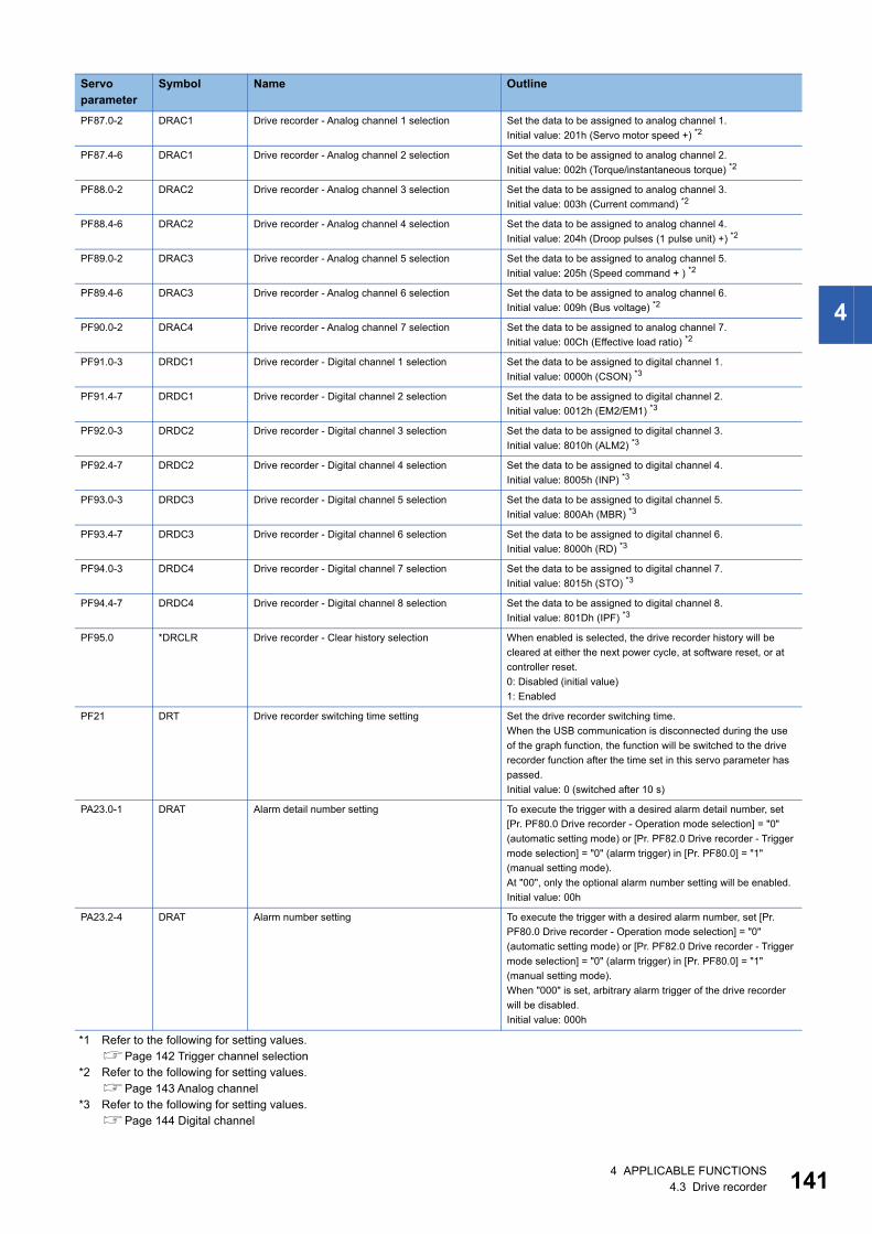
4
*1 Refer to the following for setting values.Page 142 Trigger channel selection
*2 Refer to the following for setting values.Page 143 Analog channel
*3 Refer to the following for setting values.Page 144 Digital channel
PF87.0-2 DRAC1 Drive recorder - Analog channel 1 selection Set the data to be assigned to analog channel 1.Initial value: 201h (Servo motor speed +) *2
PF87.4-6 DRAC1 Drive recorder - Analog channel 2 selection Set the data to be assigned to analog channel 2.Initial value: 002h (Torque/instantaneous torque) *2
PF88.0-2 DRAC2 Drive recorder - Analog channel 3 selection Set the data to be assigned to analog channel 3.Initial value: 003h (Current command) *2
PF88.4-6 DRAC2 Drive recorder - Analog channel 4 selection Set the data to be assigned to analog channel 4.Initial value: 204h (Droop pulses (1 pulse unit) +) *2
PF89.0-2 DRAC3 Drive recorder - Analog channel 5 selection Set the data to be assigned to analog channel 5.Initial value: 205h (Speed command + ) *2
PF89.4-6 DRAC3 Drive recorder - Analog channel 6 selection Set the data to be assigned to analog channel 6.Initial value: 009h (Bus voltage) *2
PF90.0-2 DRAC4 Drive recorder - Analog channel 7 selection Set the data to be assigned to analog channel 7.Initial value: 00Ch (Effective load ratio) *2
PF91.0-3 DRDC1 Drive recorder - Digital channel 1 selection Set the data to be assigned to digital channel 1.Initial value: 0000h (CSON) *3
PF91.4-7 DRDC1 Drive recorder - Digital channel 2 selection Set the data to be assigned to digital channel 2.Initial value: 0012h (EM2/EM1) *3
PF92.0-3 DRDC2 Drive recorder - Digital channel 3 selection Set the data to be assigned to digital channel 3.Initial value: 8010h (ALM2) *3
PF92.4-7 DRDC2 Drive recorder - Digital channel 4 selection Set the data to be assigned to digital channel 4.Initial value: 8005h (INP) *3
PF93.0-3 DRDC3 Drive recorder - Digital channel 5 selection Set the data to be assigned to digital channel 5.Initial value: 800Ah (MBR) *3
PF93.4-7 DRDC3 Drive recorder - Digital channel 6 selection Set the data to be assigned to digital channel 6.Initial value: 8000h (RD) *3
PF94.0-3 DRDC4 Drive recorder - Digital channel 7 selection Set the data to be assigned to digital channel 7.Initial value: 8015h (STO) *3
PF94.4-7 DRDC4 Drive recorder - Digital channel 8 selection Set the data to be assigned to digital channel 8.Initial value: 801Dh (IPF) *3
PF95.0 *DRCLR Drive recorder - Clear history selection When enabled is selected, the drive recorder history will be cleared at either the next power cycle, at software reset, or at controller reset.0: Disabled (initial value)1: Enabled
PF21 DRT Drive recorder switching time setting Set the drive recorder switching time.When the USB communication is disconnected during the use of the graph function, the function will be switched to the drive recorder function after the time set in this servo parameter has passed.Initial value: 0 (switched after 10 s)
PA23.0-1 DRAT Alarm detail number setting To execute the trigger with a desired alarm detail number, set [Pr. PF80.0 Drive recorder - Operation mode selection] = "0" (automatic setting mode) or [Pr. PF82.0 Drive recorder - Trigger mode selection] = "0" (alarm trigger) in [Pr. PF80.0] = "1" (manual setting mode).At "00", only the optional alarm number setting will be enabled.Initial value: 00h
PA23.2-4 DRAT Alarm number setting To execute the trigger with a desired alarm number, set [Pr. PF80.0 Drive recorder - Operation mode selection] = "0" (automatic setting mode) or [Pr. PF82.0 Drive recorder - Trigger mode selection] = "0" (alarm trigger) in [Pr. PF80.0] = "1" (manual setting mode).When "000" is set, arbitrary alarm trigger of the drive recorder will be disabled.Initial value: 000h
Servo parameter
Symbol Name Outline
4 APPLICABLE FUNCTIONS4.3 Drive recorder 141
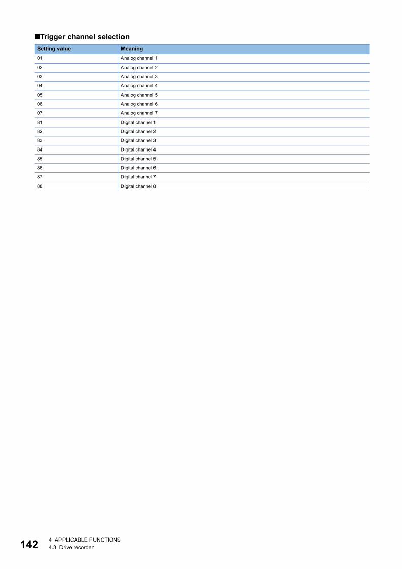
14
■Trigger channel selectionSetting value Meaning01 Analog channel 1
02 Analog channel 2
03 Analog channel 3
04 Analog channel 4
05 Analog channel 5
06 Analog channel 6
07 Analog channel 7
81 Digital channel 1
82 Digital channel 2
83 Digital channel 3
84 Digital channel 4
85 Digital channel 5
86 Digital channel 6
87 Digital channel 7
88 Digital channel 8
2 4 APPLICABLE FUNCTIONS4.3 Drive recorder
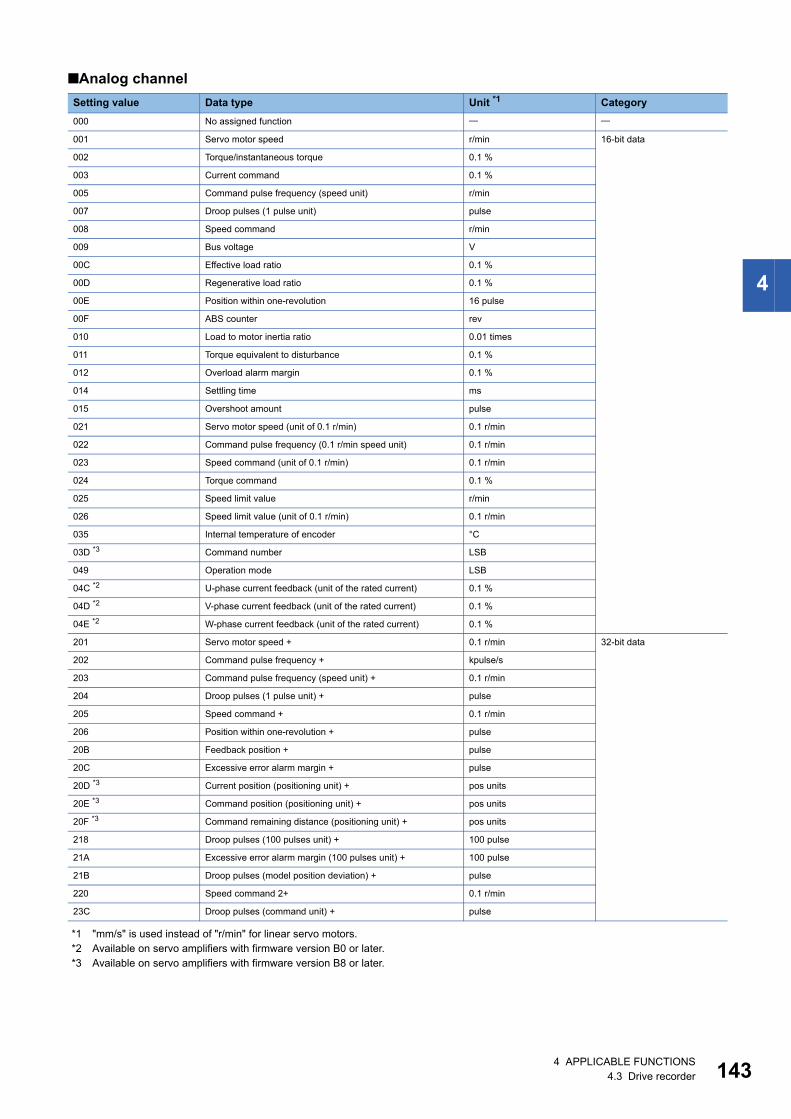
4
■Analog channel
*1 "mm/s" is used instead of "r/min" for linear servo motors.*2 Available on servo amplifiers with firmware version B0 or later.*3 Available on servo amplifiers with firmware version B8 or later.
Setting value Data type Unit *1 Category000 No assigned function
001 Servo motor speed r/min 16-bit data
002 Torque/instantaneous torque 0.1 %
003 Current command 0.1 %
005 Command pulse frequency (speed unit) r/min
007 Droop pulses (1 pulse unit) pulse
008 Speed command r/min
009 Bus voltage V
00C Effective load ratio 0.1 %
00D Regenerative load ratio 0.1 %
00E Position within one-revolution 16 pulse
00F ABS counter rev
010 Load to motor inertia ratio 0.01 times
011 Torque equivalent to disturbance 0.1 %
012 Overload alarm margin 0.1 %
014 Settling time ms
015 Overshoot amount pulse
021 Servo motor speed (unit of 0.1 r/min) 0.1 r/min
022 Command pulse frequency (0.1 r/min speed unit) 0.1 r/min
023 Speed command (unit of 0.1 r/min) 0.1 r/min
024 Torque command 0.1 %
025 Speed limit value r/min
026 Speed limit value (unit of 0.1 r/min) 0.1 r/min
035 Internal temperature of encoder °C
03D *3 Command number LSB
049 Operation mode LSB
04C *2 U-phase current feedback (unit of the rated current) 0.1 %
04D *2 V-phase current feedback (unit of the rated current) 0.1 %
04E *2 W-phase current feedback (unit of the rated current) 0.1 %
201 Servo motor speed + 0.1 r/min 32-bit data
202 Command pulse frequency + kpulse/s
203 Command pulse frequency (speed unit) + 0.1 r/min
204 Droop pulses (1 pulse unit) + pulse
205 Speed command + 0.1 r/min
206 Position within one-revolution + pulse
20B Feedback position + pulse
20C Excessive error alarm margin + pulse
20D *3 Current position (positioning unit) + pos units
20E *3 Command position (positioning unit) + pos units
20F *3 Command remaining distance (positioning unit) + pos units
218 Droop pulses (100 pulses unit) + 100 pulse
21A Excessive error alarm margin (100 pulses unit) + 100 pulse
21B Droop pulses (model position deviation) + pulse
220 Speed command 2+ 0.1 r/min
23C Droop pulses (command unit) + pulse
4 APPLICABLE FUNCTIONS4.3 Drive recorder 143
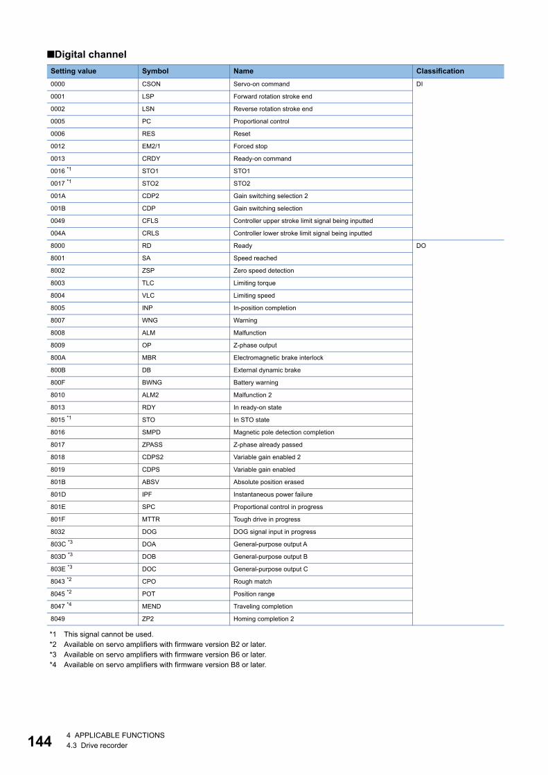
14
■Digital channel
*1 This signal cannot be used.*2 Available on servo amplifiers with firmware version B2 or later.*3 Available on servo amplifiers with firmware version B6 or later.*4 Available on servo amplifiers with firmware version B8 or later.
Setting value Symbol Name Classification0000 CSON Servo-on command DI
0001 LSP Forward rotation stroke end
0002 LSN Reverse rotation stroke end
0005 PC Proportional control
0006 RES Reset
0012 EM2/1 Forced stop
0013 CRDY Ready-on command
0016 *1 STO1 STO1
0017 *1 STO2 STO2
001A CDP2 Gain switching selection 2
001B CDP Gain switching selection
0049 CFLS Controller upper stroke limit signal being inputted
004A CRLS Controller lower stroke limit signal being inputted
8000 RD Ready DO
8001 SA Speed reached
8002 ZSP Zero speed detection
8003 TLC Limiting torque
8004 VLC Limiting speed
8005 INP In-position completion
8007 WNG Warning
8008 ALM Malfunction
8009 OP Z-phase output
800A MBR Electromagnetic brake interlock
800B DB External dynamic brake
800F BWNG Battery warning
8010 ALM2 Malfunction 2
8013 RDY In ready-on state
8015 *1 STO In STO state
8016 SMPD Magnetic pole detection completion
8017 ZPASS Z-phase already passed
8018 CDPS2 Variable gain enabled 2
8019 CDPS Variable gain enabled
801B ABSV Absolute position erased
801D IPF Instantaneous power failure
801E SPC Proportional control in progress
801F MTTR Tough drive in progress
8032 DOG DOG signal input in progress
803C *3 DOA General-purpose output A
803D *3 DOB General-purpose output B
803E *3 DOC General-purpose output C
8043 *2 CPO Rough match
8045 *2 POT Position range
8047 *4 MEND Traveling completion
8049 ZP2 Homing completion 2
4 4 APPLICABLE FUNCTIONS4.3 Drive recorder
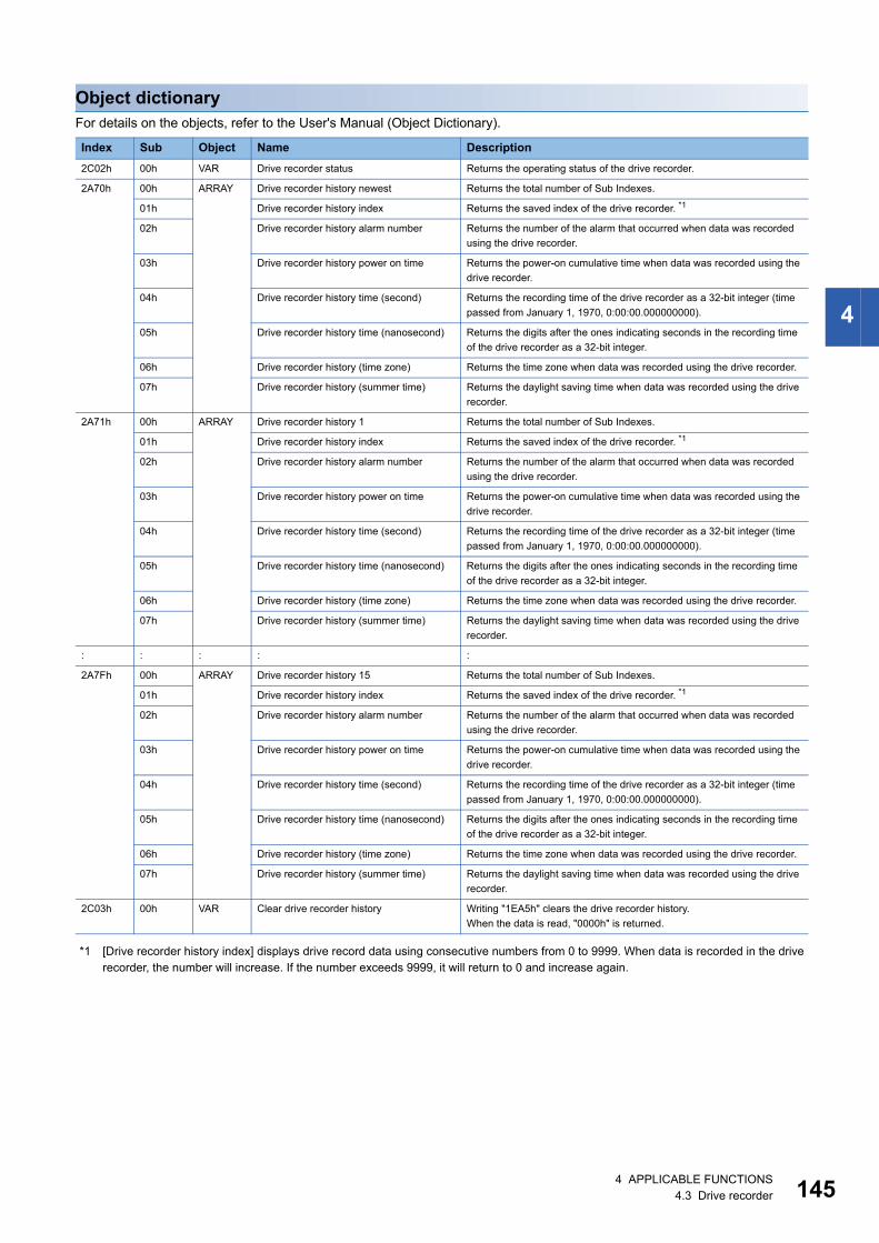
4
Object dictionaryFor details on the objects, refer to the User's Manual (Object Dictionary).
*1 [Drive recorder history index] displays drive record data using consecutive numbers from 0 to 9999. When data is recorded in the drive recorder, the number will increase. If the number exceeds 9999, it will return to 0 and increase again.
Index Sub Object Name Description2C02h 00h VAR Drive recorder status Returns the operating status of the drive recorder.
2A70h 00h ARRAY Drive recorder history newest Returns the total number of Sub Indexes.
01h Drive recorder history index Returns the saved index of the drive recorder. *1
02h Drive recorder history alarm number Returns the number of the alarm that occurred when data was recorded using the drive recorder.
03h Drive recorder history power on time Returns the power-on cumulative time when data was recorded using the drive recorder.
04h Drive recorder history time (second) Returns the recording time of the drive recorder as a 32-bit integer (time passed from January 1, 1970, 0:00:00.000000000).
05h Drive recorder history time (nanosecond) Returns the digits after the ones indicating seconds in the recording time of the drive recorder as a 32-bit integer.
06h Drive recorder history (time zone) Returns the time zone when data was recorded using the drive recorder.
07h Drive recorder history (summer time) Returns the daylight saving time when data was recorded using the drive recorder.
2A71h 00h ARRAY Drive recorder history 1 Returns the total number of Sub Indexes.
01h Drive recorder history index Returns the saved index of the drive recorder. *1
02h Drive recorder history alarm number Returns the number of the alarm that occurred when data was recorded using the drive recorder.
03h Drive recorder history power on time Returns the power-on cumulative time when data was recorded using the drive recorder.
04h Drive recorder history time (second) Returns the recording time of the drive recorder as a 32-bit integer (time passed from January 1, 1970, 0:00:00.000000000).
05h Drive recorder history time (nanosecond) Returns the digits after the ones indicating seconds in the recording time of the drive recorder as a 32-bit integer.
06h Drive recorder history (time zone) Returns the time zone when data was recorded using the drive recorder.
07h Drive recorder history (summer time) Returns the daylight saving time when data was recorded using the drive recorder.
: : : : :
2A7Fh 00h ARRAY Drive recorder history 15 Returns the total number of Sub Indexes.
01h Drive recorder history index Returns the saved index of the drive recorder. *1
02h Drive recorder history alarm number Returns the number of the alarm that occurred when data was recorded using the drive recorder.
03h Drive recorder history power on time Returns the power-on cumulative time when data was recorded using the drive recorder.
04h Drive recorder history time (second) Returns the recording time of the drive recorder as a 32-bit integer (time passed from January 1, 1970, 0:00:00.000000000).
05h Drive recorder history time (nanosecond) Returns the digits after the ones indicating seconds in the recording time of the drive recorder as a 32-bit integer.
06h Drive recorder history (time zone) Returns the time zone when data was recorded using the drive recorder.
07h Drive recorder history (summer time) Returns the daylight saving time when data was recorded using the drive recorder.
2C03h 00h VAR Clear drive recorder history Writing "1EA5h" clears the drive recorder history.When the data is read, "0000h" is returned.
4 APPLICABLE FUNCTIONS4.3 Drive recorder 145
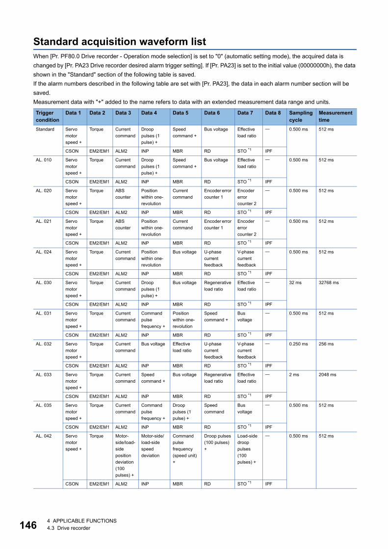
14
Standard acquisition waveform listWhen [Pr. PF80.0 Drive recorder - Operation mode selection] is set to "0" (automatic setting mode), the acquired data is changed by [Pr. PA23 Drive recorder desired alarm trigger setting]. If [Pr. PA23] is set to the initial value (00000000h), the data shown in the "Standard" section of the following table is saved.If the alarm numbers described in the following table are set with [Pr. PA23], the data in each alarm number section will be saved.Measurement data with "+" added to the name refers to data with an extended measurement data range and units.
Trigger condition
Data 1 Data 2 Data 3 Data 4 Data 5 Data 6 Data 7 Data 8 Sampling cycle
Measurement time
Standard Servo motor speed +
Torque Current command
Droop pulses (1 pulse) +
Speed command +
Bus voltage Effective load ratio
0.500 ms 512 ms
CSON EM2/EM1 ALM2 INP MBR RD STO *1 IPF
AL. 010 Servo motor speed +
Torque Current command
Droop pulses (1 pulse) +
Speed command +
Bus voltage Effective load ratio
0.500 ms 512 ms
CSON EM2/EM1 ALM2 INP MBR RD STO *1 IPF
AL. 020 Servo motor speed +
Torque ABS counter
Position within one-revolution
Current command
Encoder error counter 1
Encoder error counter 2
0.500 ms 512 ms
CSON EM2/EM1 ALM2 INP MBR RD STO *1 IPF
AL. 021 Servo motor speed +
Torque ABS counter
Position within one-revolution
Current command
Encoder error counter 1
Encoder error counter 2
0.500 ms 512 ms
CSON EM2/EM1 ALM2 INP MBR RD STO *1 IPF
AL. 024 Servo motor speed +
Torque Current command
Position within one-revolution
Bus voltage U-phase current feedback
V-phase current feedback
0.500 ms 512 ms
CSON EM2/EM1 ALM2 INP MBR RD STO *1 IPF
AL. 030 Servo motor speed +
Torque Current command
Droop pulses (1 pulse) +
Bus voltage Regenerative load ratio
Effective load ratio
32 ms 32768 ms
CSON EM2/EM1 ALM2 INP MBR RD STO *1 IPF
AL. 031 Servo motor speed +
Torque Current command
Command pulse frequency +
Position within one-revolution
Speed command +
Bus voltage
0.500 ms 512 ms
CSON EM2/EM1 ALM2 INP MBR RD STO *1 IPF
AL. 032 Servo motor speed +
Torque Current command
Bus voltage Effective load ratio
U-phase current feedback
V-phase current feedback
0.250 ms 256 ms
CSON EM2/EM1 ALM2 INP MBR RD STO *1 IPF
AL. 033 Servo motor speed +
Torque Current command
Speed command +
Bus voltage Regenerative load ratio
Effective load ratio
2 ms 2048 ms
CSON EM2/EM1 ALM2 INP MBR RD STO *1 IPF
AL. 035 Servo motor speed +
Torque Current command
Command pulse frequency +
Droop pulses (1 pulse) +
Speed command
Bus voltage
0.500 ms 512 ms
CSON EM2/EM1 ALM2 INP MBR RD STO *1 IPF
AL. 042 Servo motor speed +
Torque Motor-side/load-side position deviation (100 pulses) +
Motor-side/load-side speed deviation
Command pulse frequency (speed unit) +
Droop pulses (100 pulses) +
Load-side droop pulses (100 pulses) +
0.500 ms 512 ms
CSON EM2/EM1 ALM2 INP MBR RD STO *1 IPF
6 4 APPLICABLE FUNCTIONS4.3 Drive recorder
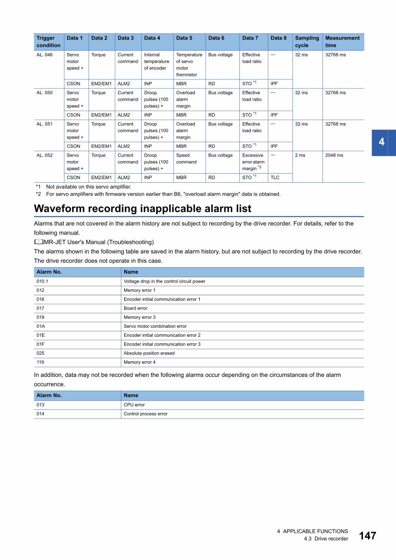
4
*1 Not available on this servo amplifier.*2 For servo amplifiers with firmware version earlier than B6, "overload alarm margin" data is obtained.
Waveform recording inapplicable alarm listAlarms that are not covered in the alarm history are not subject to recording by the drive recorder. For details, refer to the following manual.MR-JET User's Manual (Troubleshooting)The alarms shown in the following table are saved in the alarm history, but are not subject to recording by the drive recorder. The drive recorder does not operate in this case.
In addition, data may not be recorded when the following alarms occur depending on the circumstances of the alarm occurrence.
AL. 046 Servo motor speed +
Torque Current command
Internal temperature of encoder
Temperature of servo motor thermistor
Bus voltage Effective load ratio
32 ms 32768 ms
CSON EM2/EM1 ALM2 INP MBR RD STO *1 IPF
AL. 050 Servo motor speed +
Torque Current command
Droop pulses (100 pulses) +
Overload alarm margin
Bus voltage Effective load ratio
32 ms 32768 ms
CSON EM2/EM1 ALM2 INP MBR RD STO *1 IPF
AL. 051 Servo motor speed +
Torque Current command
Droop pulses (100 pulses) +
Overload alarm margin
Bus voltage Effective load ratio
32 ms 32768 ms
CSON EM2/EM1 ALM2 INP MBR RD STO *1 IPF
AL. 052 Servo motor speed +
Torque Current command
Droop pulses (100 pulses) +
Speed command
Bus voltage Excessive error alarm margin *2
2 ms 2048 ms
CSON EM2/EM1 ALM2 INP MBR RD STO *1 TLC
Alarm No. Name010.1 Voltage drop in the control circuit power
012 Memory error 1
016 Encoder initial communication error 1
017 Board error
019 Memory error 3
01A Servo motor combination error
01E Encoder initial communication error 2
01F Encoder initial communication error 3
025 Absolute position erased
119 Memory error 4
Alarm No. Name013 CPU error
014 Control process error
Trigger condition
Data 1 Data 2 Data 3 Data 4 Data 5 Data 6 Data 7 Data 8 Sampling cycle
Measurement time
4 APPLICABLE FUNCTIONS4.3 Drive recorder 147
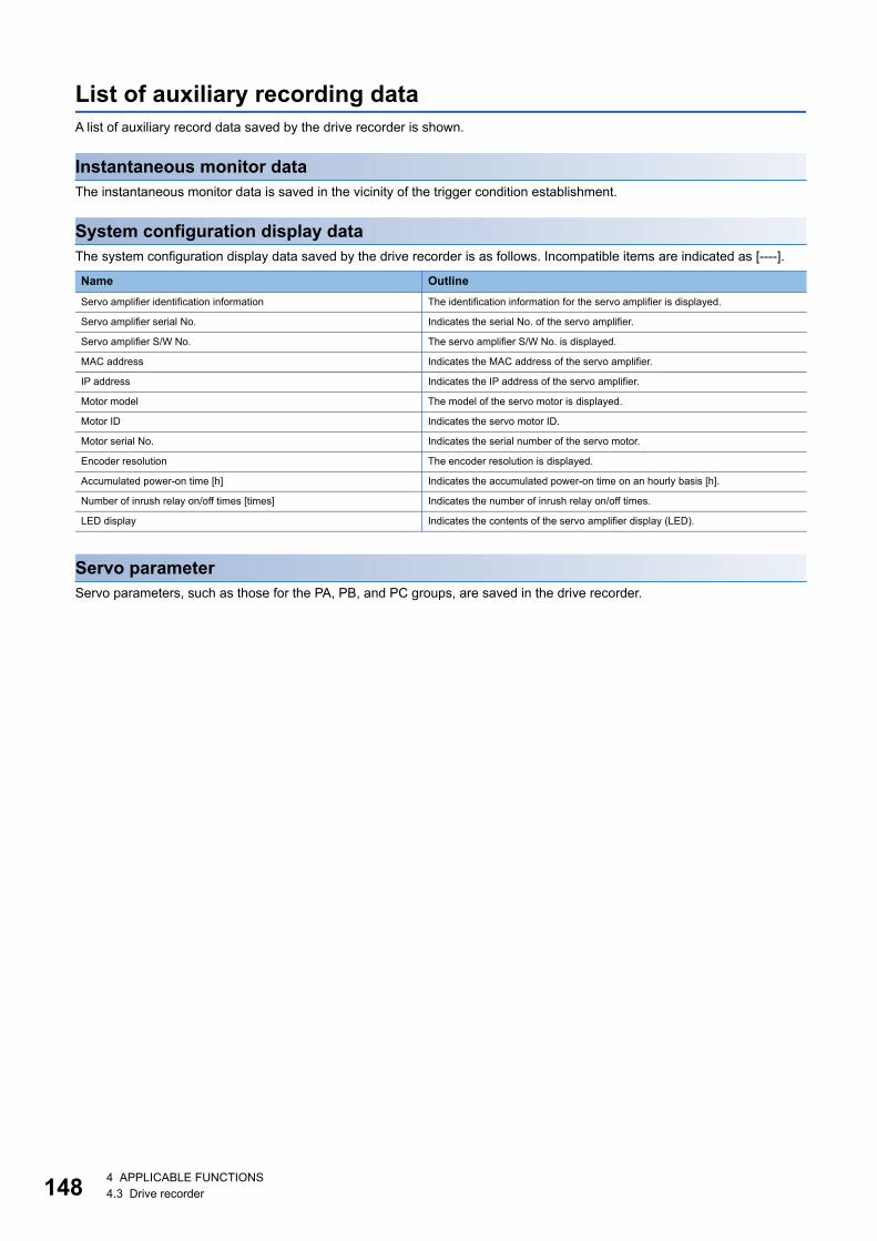
14
List of auxiliary recording dataA list of auxiliary record data saved by the drive recorder is shown.
Instantaneous monitor dataThe instantaneous monitor data is saved in the vicinity of the trigger condition establishment.
System configuration display dataThe system configuration display data saved by the drive recorder is as follows. Incompatible items are indicated as [----].
Servo parameterServo parameters, such as those for the PA, PB, and PC groups, are saved in the drive recorder.
Name OutlineServo amplifier identification information The identification information for the servo amplifier is displayed.
Servo amplifier serial No. Indicates the serial No. of the servo amplifier.
Servo amplifier S/W No. The servo amplifier S/W No. is displayed.
MAC address Indicates the MAC address of the servo amplifier.
IP address Indicates the IP address of the servo amplifier.
Motor model The model of the servo motor is displayed.
Motor ID Indicates the servo motor ID.
Motor serial No. Indicates the serial number of the servo motor.
Encoder resolution The encoder resolution is displayed.
Accumulated power-on time [h] Indicates the accumulated power-on time on an hourly basis [h].
Number of inrush relay on/off times [times] Indicates the number of inrush relay on/off times.
LED display Indicates the contents of the servo amplifier display (LED).
8 4 APPLICABLE FUNCTIONS4.3 Drive recorder
4
4.4 Software resetSoftware reset is a function to reset the internal status of the servo amplifier and obtain the same effect as cycling the power. By performing the software reset, the setting of the servo parameters can be reflected without cycling the power.
• In the case of an alarm caused by hardware failure, thermal protection or other factors, the alarm may not be canceled even if the software reset is performed.
• When MR Configurator2 is connected to the servo amplifier via a network, reconnection may not be possible if the software reset is performed after changing the setting of the network.
Precautions • Canceling alarms is not the main purpose of the software reset function. Use of this function is not recommended for alarms
that would ordinarily be canceled by cycling the power.
Software reset in MR Configurator2The servo amplifier can be reset with the software reset button in MR Configurator2.
Software reset via network communicationA software reset can be performed by using the remote reset of the controller. For details, refer to the following manual.
Network Reference manualCC-Link IE TSN MR-JET-G User's Manual (Communication Function)
CC-Link IE Field Network Basic
4 APPLICABLE FUNCTIONS4.4 Software reset 149
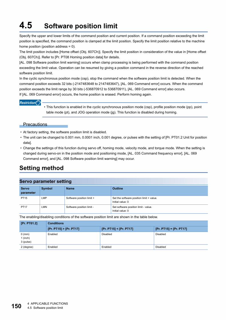
15
4.5 Software position limitSpecify the upper and lower limits of the command position and current position. If a command position exceeding the limit position is specified, the command position is clamped at the limit position. Specify the limit position relative to the machine home position (position address = 0).The limit position includes [Home offset (Obj. 607Ch)]. Specify the limit position in consideration of the value in [Home offset (Obj. 607Ch)]. Refer to [Pr. PT08 Homing position data] for details.[AL. 098 Software position limit warning] occurs when clamp processing is being performed with the command position exceeding the limit value. Operation can be resumed by giving a position command in the reverse direction of the reached software position limit.In the cyclic synchronous position mode (csp), stop the command when the software position limit is detected. When the command position exceeds 32 bits (-2147483648 to 2147483647), [AL. 069 Command error] occurs. When the command position exceeds the limit range by 30 bits (-536870912 to 536870911), [AL. 069 Command error] also occurs.If [AL. 069 Command error] occurs, the home position is erased. Perform homing again.
• This function is enabled in the cyclic synchronous position mode (csp), profile position mode (pp), point table mode (pt), and JOG operation mode (jg). This function is disabled during homing.
Precautions • At factory setting, the software position limit is disabled. • The unit can be changed to 0.001 mm, 0.0001 inch, 0.001 degree, or pulses with the setting of [Pr. PT01.2 Unit for position
data]. • Change the settings of this function during servo off, homing mode, velocity mode, and torque mode. When the setting is
changed during servo-on in the position mode and positioning mode, [AL. 035 Command frequency error], [AL. 069 Command error], and [AL. 098 Software position limit warning] may occur.
Setting method
Servo parameter setting
The enabling/disabling conditions of the software position limit are shown in the table below.
Servo parameter
Symbol Name Outline
PT15 LMP Software position limit + Set the software position limit + value.Initial value: 0
PT17 LMN Software position limit - Set software position limit - value.Initial value: 0
[Pr. PT01.2] Conditions
[Pr. PT15] > [Pr. PT17] [Pr. PT15] < [Pr. PT17] [Pr. PT15] = [Pr. PT17]0 (mm)1 (inch)3 (pulse)
Enabled Disabled Disabled
2 (degree) Enabled Enabled Disabled
0 4 APPLICABLE FUNCTIONS4.5 Software position limit
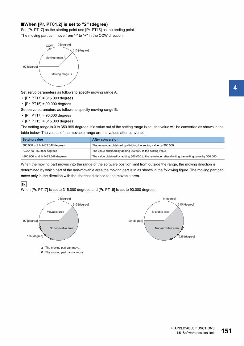
4
■When [Pr. PT01.2] is set to "2" (degree)Set [Pr. PT17] as the starting point and [Pr. PT15] as the ending point.The moving part can move from "-" to "+" in the CCW direction.
Set servo parameters as follows to specify moving range A. • [Pr. PT17] = 315.000 degrees • [Pr. PT15] = 90.000 degreesSet servo parameters as follows to specify moving range B. • [Pr. PT17] = 90.000 degrees • [Pr. PT15] = 315.000 degreesThe setting range is 0 to 359.999 degrees. If a value out of the setting range is set, the value will be converted as shown in the table below. The values of the movable range are the values after conversion.
When the moving part moves into the range of the software position limit from outside the range, the moving direction is determined by which part of the non-movable area the moving part is in as shown in the following figure. The moving part can move only in the direction with the shortest distance to the movable area.
Ex.
When [Pr. PT17] is set to 315.000 degrees and [Pr. PT15] is set to 90.000 degrees:
Setting value After conversion360.000 to 2147483.647 degrees The remainder obtained by dividing the setting value by 360.000
-0.001 to -359.999 degrees The value obtained by adding 360.000 to the setting value
-360.000 to -2147483.648 degrees The value obtained by adding 360.000 to the remainder after dividing the setting value by 360.000
CCW 0 [degree]
90 [degree]
315 [degree]
Moving range A
Moving range B
0 [degree]
90 [degree]
315 [degree]
0 [degree]
90 [degree]
315 [degree]
225 [degree]135 [degree]
Movable area Movable area
Non-movable area Non-movable area
The moving part can move.The moving part cannot move.
4 APPLICABLE FUNCTIONS4.5 Software position limit 151
15
Related objectsThe following table shows the related objects.[Pr. PT15 Software position limit +] is used for [Max position limit (Obj. 607Dh: 02h)]. [Pr. PT17 Software Position Limit -] is used for [Min position limit (Obj. 607Dh: 01h)].For details on the objects, refer to the User's Manual (Object Dictionary).
*1 When [Min position limit (Obj. 607Dh: 01h)] is set to a value greater than [Max position limit (Obj. 607Dh: 02h)], the function of [Software position limit (Obj. 607Dh)] is disabled.
Index Sub Object Name Description607Dh 0 ARRAY Software position limit Number of entries
1 Min position limit *1 Specify the minimum value of the command position and current position relative to the machine home position (position address = 0). If the command position is below the minimum value, it is clamped to the minimum value which is used as the command position.
2 Max position limit *1 Specify the maximum value of the command position and current position relative to the machine home position (position address = 0). If the command position exceeds the maximum value, it is clamped to the maximum value which is used as the command position.
2 4 APPLICABLE FUNCTIONS4.5 Software position limit
4
4.6 Torque limitThe torque limit function limits the torque generated by the servo motor.The following torque limit can be set.
• When setting the torque above the maximum torque of the servo motor, the torque is limited by the maximum torque of the servo motor.
• Servo parameters that are mapped to an object from the controller will overwrite those written from the engineering tool.
Precautions • If the torque limit is canceled during servo-lock, the servo motor may suddenly rotate, depending on the amount of the
position deviation from the command position. • When using the torque limit, check that [Pr. PB06 Load to motor inertia ratio/load to motor mass ratio] is set properly.
Improper settings may cause an unexpected operation such as an overshoot. • When "0.0" is set, no torque is generated.
Item OutlineInternal torque limit The maximum torque is limited by the values of [Pr. PA11 Forward rotation torque limit] and [Pr.
PA12 Reverse rotation torque limit].
Maximum torque limit 1 The maximum torque is limited by the value of [Max torque (Obj. 6072h)] according to the setting of [Pr. PC78.1 Maximum torque limit 1 selection].
4 APPLICABLE FUNCTIONS4.6 Torque limit 153
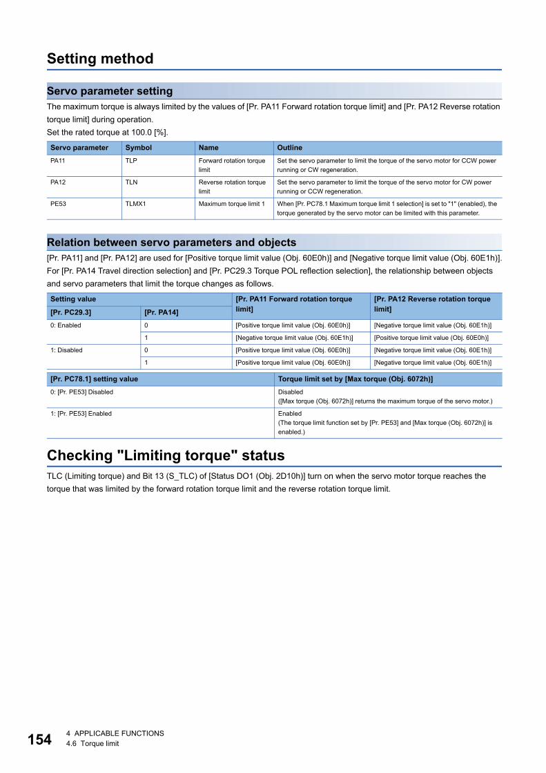
15
Setting method
Servo parameter settingThe maximum torque is always limited by the values of [Pr. PA11 Forward rotation torque limit] and [Pr. PA12 Reverse rotation torque limit] during operation.Set the rated torque at 100.0 [%].
Relation between servo parameters and objects[Pr. PA11] and [Pr. PA12] are used for [Positive torque limit value (Obj. 60E0h)] and [Negative torque limit value (Obj. 60E1h)].For [Pr. PA14 Travel direction selection] and [Pr. PC29.3 Torque POL reflection selection], the relationship between objects and servo parameters that limit the torque changes as follows.
Checking "Limiting torque" statusTLC (Limiting torque) and Bit 13 (S_TLC) of [Status DO1 (Obj. 2D10h)] turn on when the servo motor torque reaches the torque that was limited by the forward rotation torque limit and the reverse rotation torque limit.
Servo parameter Symbol Name OutlinePA11 TLP Forward rotation torque
limitSet the servo parameter to limit the torque of the servo motor for CCW power running or CW regeneration.
PA12 TLN Reverse rotation torque limit
Set the servo parameter to limit the torque of the servo motor for CW power running or CCW regeneration.
PE53 TLMX1 Maximum torque limit 1 When [Pr. PC78.1 Maximum torque limit 1 selection] is set to "1" (enabled), the torque generated by the servo motor can be limited with this parameter.
Setting value [Pr. PA11 Forward rotation torque limit]
[Pr. PA12 Reverse rotation torque limit][Pr. PC29.3] [Pr. PA14]
0: Enabled 0 [Positive torque limit value (Obj. 60E0h)] [Negative torque limit value (Obj. 60E1h)]
1 [Negative torque limit value (Obj. 60E1h)] [Positive torque limit value (Obj. 60E0h)]
1: Disabled 0 [Positive torque limit value (Obj. 60E0h)] [Negative torque limit value (Obj. 60E1h)]
1 [Positive torque limit value (Obj. 60E0h)] [Negative torque limit value (Obj. 60E1h)]
[Pr. PC78.1] setting value Torque limit set by [Max torque (Obj. 6072h)]0: [Pr. PE53] Disabled Disabled
([Max torque (Obj. 6072h)] returns the maximum torque of the servo motor.)
1: [Pr. PE53] Enabled Enabled(The torque limit function set by [Pr. PE53] and [Max torque (Obj. 6072h)] is enabled.)
4 4 APPLICABLE FUNCTIONS4.6 Torque limit
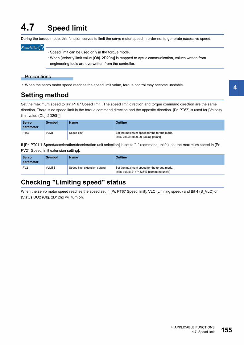
4
4.7 Speed limitDuring the torque mode, this function serves to limit the servo motor speed in order not to generate excessive speed.
• Speed limit can be used only in the torque mode. • When [Velocity limit value (Obj. 2D20h)] is mapped to cyclic communication, values written from
engineering tools are overwritten from the controller.
Precautions • When the servo motor speed reaches the speed limit value, torque control may become unstable.
Setting methodSet the maximum speed to [Pr. PT67 Speed limit]. The speed limit direction and torque command direction are the same direction. There is no speed limit in the torque command direction and the opposite direction. [Pr. PT67] is used for [Velocity limit value (Obj. 2D20h)].
If [Pr. PT01.1 Speed/acceleration/deceleration unit selection] is set to "1" (command unit/s), set the maximum speed in [Pr. PV21 Speed limit extension setting].
Checking "Limiting speed" statusWhen the servo motor speed reaches the speed set in [Pr. PT67 Speed limit], VLC (Limiting speed) and Bit 4 (S_VLC) of [Status DO2 (Obj. 2D12h)] will turn on.
Servo parameter
Symbol Name Outline
PT67 VLMT Speed limit Set the maximum speed for the torque mode.Initial value: 3000.00 [r/min], [mm/s]
Servo parameter
Symbol Name Outline
PV21 VLMTE Speed limit extension setting Set the maximum speed for the torque mode.Initial value: 2147483647 [command unit/s]
4 APPLICABLE FUNCTIONS4.7 Speed limit 155
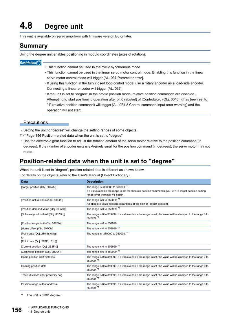
15
4.8 Degree unitThis unit is available on servo amplifiers with firmware version B6 or later.
SummaryUsing the degree unit enables positioning in modulo coordinates (axes of rotation).
• This function cannot be used in the cyclic synchronous mode. • This function cannot be used in the linear servo motor control mode. Enabling this function in the linear
servo motor control mode will trigger [AL. 037 Parameter error]. • If using this function in the fully closed loop control mode, use a rotary encoder as a load-side encoder.
Connecting a linear encoder will trigger [AL. 037]. • If the unit is set to "degree" in the profile position mode, relative position commands are disabled.
Attempting to start positioning operation after bit 6 (abs/rel) of [Controlword (Obj. 6040h)] has been set to "1" (relative position command) will trigger [AL. 0F4.8 Control command input error warning] and the operation will not start.
Precautions • Setting the unit to "degree" will change the setting ranges of some objects.Page 156 Position-related data when the unit is set to "degree" • Use the electronic gear function to adjust the rotation amount of the servo motor relative to the position command (in
degrees). If the number of encoder units is extremely small for the position command (in degrees), the servo motor may not rotate.
Position-related data when the unit is set to "degree"When the unit is set to "degree", position-related data is different as shown below.For details on the objects, refer to the User's Manual (Object Dictionary).
*1 The unit is 0.001 degree.
Data Description[Target position (Obj. 607Ah)] The range is -360000 to 360000. *1
If a value outside the range is set for absolute position commands, [AL. 0F4.4 Target position setting range error warning] will occur.
[Position actual value (Obj. 6064h)] The range is 0 to 359999. *1
An absolute value appears regardless of the sign of [Target position].
[Position demand value (Obj. 6062h)] The range is 0 to 359999. *1
[Software position limit (Obj. 607Dh)] The range is 0 to 359999. If a value outside the range is set, the value will be clamped to the range 0 to 359999. *1
[Position range limit (Obj. 607Bh)] The range is 0 to 359999.
[Home offset (Obj. 607Ch)] The range is 0 to 359999. *1
[Point data (Obj. 2801h: 01h)]to[Point data (Obj. 28FFh: 01h)]
The range is -360000 to 360000. *1
[Current position (Obj. 2B2Fh)] The range is 0 to 359999. *1
[Command position (Obj. 2B30h)] The range is 0 to 359999. *1
Home position shift distance The range is 0 to 359999. If a value outside the range is set, the value will be clamped to the range 0 to 359999. *1
Homing position data The range is 0 to 359999. If a value outside the range is set, the value will be clamped to the range 0 to 359999. *1
Travel distance after proximity dog The range is 0 to 359999. If a value outside the range is set, the value will be clamped to the range 0 to 359999. *1
Position range output address The range is 0 to 359999. If a value outside the range is set, the value will be clamped to the range 0 to 359999. *1
6 4 APPLICABLE FUNCTIONS4.8 Degree unit
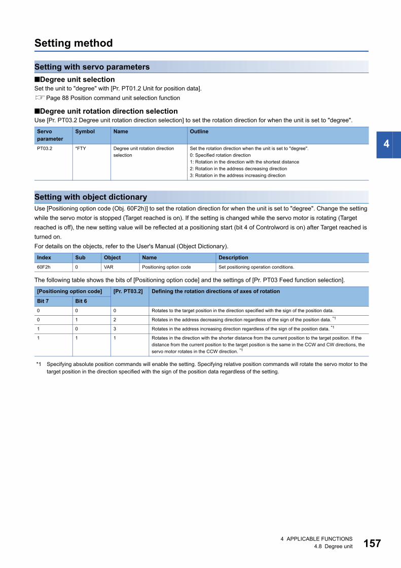
4
Setting method
Setting with servo parameters■Degree unit selectionSet the unit to "degree" with [Pr. PT01.2 Unit for position data].Page 88 Position command unit selection function
■Degree unit rotation direction selectionUse [Pr. PT03.2 Degree unit rotation direction selection] to set the rotation direction for when the unit is set to "degree".
Setting with object dictionaryUse [Positioning option code (Obj. 60F2h)] to set the rotation direction for when the unit is set to "degree". Change the setting while the servo motor is stopped (Target reached is on). If the setting is changed while the servo motor is rotating (Target reached is off), the new setting value will be reflected at a positioning start (bit 4 of Controlword is on) after Target reached is turned on.For details on the objects, refer to the User's Manual (Object Dictionary).
The following table shows the bits of [Positioning option code] and the settings of [Pr. PT03 Feed function selection].
*1 Specifying absolute position commands will enable the setting. Specifying relative position commands will rotate the servo motor to the target position in the direction specified with the sign of the position data regardless of the setting.
Servo parameter
Symbol Name Outline
PT03.2 *FTY Degree unit rotation direction selection
Set the rotation direction when the unit is set to "degree".0: Specified rotation direction1: Rotation in the direction with the shortest distance2: Rotation in the address decreasing direction3: Rotation in the address increasing direction
Index Sub Object Name Description60F2h 0 VAR Positioning option code Set positioning operation conditions.
[Positioning option code] [Pr. PT03.2] Defining the rotation directions of axes of rotation
Bit 7 Bit 60 0 0 Rotates to the target position in the direction specified with the sign of the position data.
0 1 2 Rotates in the address decreasing direction regardless of the sign of the position data. *1
1 0 3 Rotates in the address increasing direction regardless of the sign of the position data. *1
1 1 1 Rotates in the direction with the shorter distance from the current position to the target position. If the distance from the current position to the target position is the same in the CCW and CW directions, the servo motor rotates in the CCW direction. *1
4 APPLICABLE FUNCTIONS4.8 Degree unit 157
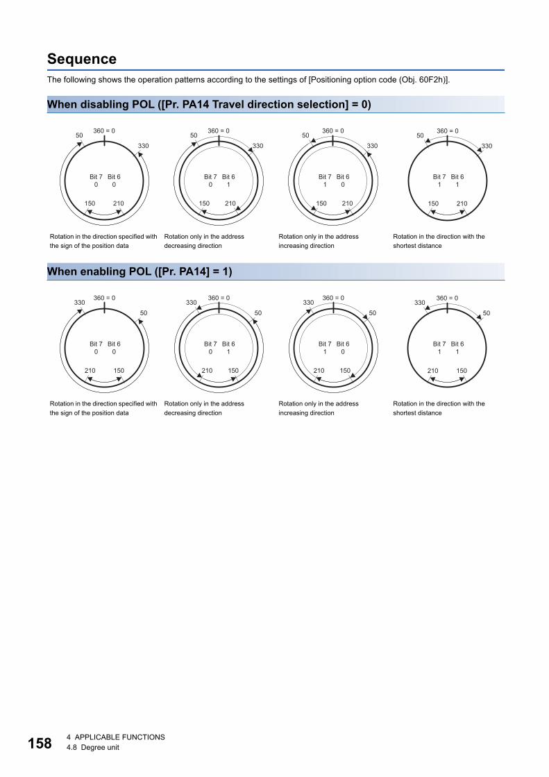
15
SequenceThe following shows the operation patterns according to the settings of [Positioning option code (Obj. 60F2h)].
When disabling POL ([Pr. PA14 Travel direction selection] = 0)
When enabling POL ([Pr. PA14] = 1)
Rotation in the direction specified with the sign of the position data
Rotation only in the address decreasing direction
Rotation only in the address increasing direction
Rotation in the direction with the shortest distance
Rotation in the direction specified with the sign of the position data
Rotation only in the address decreasing direction
Rotation only in the address increasing direction
Rotation in the direction with the shortest distance
150 210
50330
360 = 0
Bit 70
Bit 60
150 210
50330
360 = 0
Bit 70
Bit 61
150 210
50330
360 = 0
Bit 71
Bit 60
150 210
50330
360 = 0
Bit 71
Bit 61
210 150
33050
360 = 0
Bit 70
Bit 60
210 150
33050
360 = 0
Bit 70
Bit 61
210 150
33050
360 = 0
Bit 71
Bit 60
210 150
33050
360 = 0
Bit 71
Bit 61
8 4 APPLICABLE FUNCTIONS4.8 Degree unit
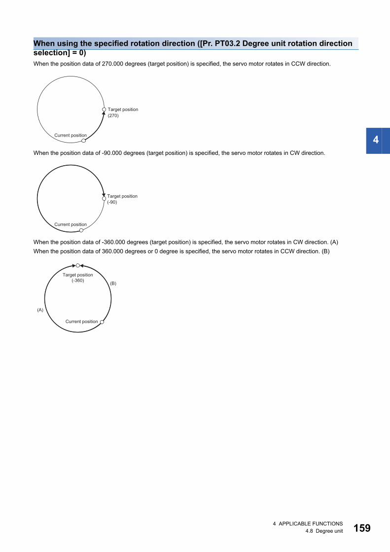
4
When using the specified rotation direction ([Pr. PT03.2 Degree unit rotation direction selection] = 0)When the position data of 270.000 degrees (target position) is specified, the servo motor rotates in CCW direction.
When the position data of -90.000 degrees (target position) is specified, the servo motor rotates in CW direction.
When the position data of -360.000 degrees (target position) is specified, the servo motor rotates in CW direction. (A)When the position data of 360.000 degrees or 0 degree is specified, the servo motor rotates in CCW direction. (B)
(270)Target position
Current position
(-90)Target position
Current position
(-360) (B)
(A)
Target position
Current position
4 APPLICABLE FUNCTIONS4.8 Degree unit 159
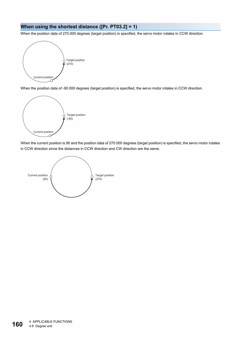
16
When using the shortest distance ([Pr. PT03.2] = 1)When the position data of 270.000 degrees (target position) is specified, the servo motor rotates in CCW direction.
When the position data of -90.000 degrees (target position) is specified, the servo motor rotates in CCW direction.
When the current position is 90 and the position data of 270.000 degrees (target position) is specified, the servo motor rotates in CCW direction since the distances in CCW direction and CW direction are the same.
(270)Target position
Current position
(-90)Target position
Current position
(270)(90)Target positionCurrent position
0 4 APPLICABLE FUNCTIONS4.8 Degree unit
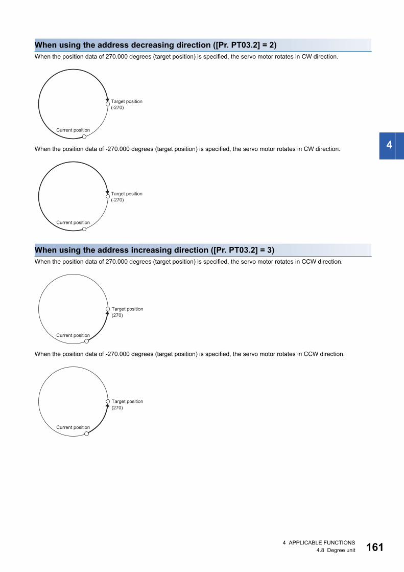
4
When using the address decreasing direction ([Pr. PT03.2] = 2)When the position data of 270.000 degrees (target position) is specified, the servo motor rotates in CW direction.
When the position data of -270.000 degrees (target position) is specified, the servo motor rotates in CW direction.
When using the address increasing direction ([Pr. PT03.2] = 3)When the position data of 270.000 degrees (target position) is specified, the servo motor rotates in CCW direction.
When the position data of -270.000 degrees (target position) is specified, the servo motor rotates in CCW direction.
(-270)Target position
Current position
(-270)Target position
Current position
(270)Target position
Current position
(270)Target position
Current position
4 APPLICABLE FUNCTIONS4.8 Degree unit 161
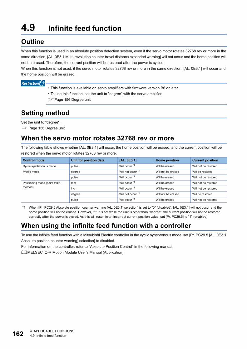
16
4.9 Infinite feed functionOutlineWhen this function is used in an absolute position detection system, even if the servo motor rotates 32768 rev or more in the same direction, [AL. 0E3.1 Multi-revolution counter travel distance exceeded warning] will not occur and the home position will not be erased. Therefore, the current position will be restored after the power is cycled.When this function is not used, if the servo motor rotates 32768 rev or more in the same direction, [AL. 0E3.1] will occur and the home position will be erased.
• This function is available on servo amplifiers with firmware version B6 or later. • To use this function, set the unit to "degree" with the servo amplifier.Page 156 Degree unit
Setting methodSet the unit to "degree".Page 156 Degree unit
When the servo motor rotates 32768 rev or moreThe following table shows whether [AL. 0E3.1] will occur, the home position will be erased, and the current position will be restored when the servo motor rotates 32768 rev or more.
*1 When [Pr. PC29.5 Absolute position counter warning [AL. 0E3.1] selection] is set to "0" (disabled), [AL. 0E3.1] will not occur and the home position will not be erased. However, if "0" is set while the unit is other than "degree", the current position will not be restored correctly after the power is cycled. As this will result in an incorrect current position value, set [Pr. PC29.5] to "1" (enabled).
When using the infinite feed function with a controllerTo use the infinite feed function with a Mitsubishi Electric controller in the cyclic synchronous mode, set [Pr. PC29.5 [AL. 0E3.1 Absolute position counter warning] selection] to disabled.For information on the controller, refer to "Absolute Position Control" in the following manual.MELSEC iQ-R Motion Module User's Manual (Application)
Control mode Unit for position data [AL. 0E3.1] Home position Current positionCyclic synchronous mode pulse Will occur *1 Will be erased Will not be restored
Profile mode degree Will not occur *1 Will not be erased Will be restored
pulse Will occur *1 Will be erased Will not be restored
Positioning mode (point table method)
mm Will occur *1 Will be erased Will not be restored
inch Will occur *1 Will be erased Will not be restored
degree Will not occur *1 Will not be erased Will be restored
pulse Will occur *1 Will be erased Will not be restored
2 4 APPLICABLE FUNCTIONS4.9 Infinite feed function
4
4.10 Servo amplifier life diagnosis functionThe servo amplifier life diagnosis function is a function to diagnose the service life of the servo amplifier itself. The approximate service life of the servo amplifier being used can be determined. The servo amplifier life diagnosis function features the following functions.
Cumulative energization time functionDisplays the cumulative time that the power supply of the servo amplifier has been on for, starting at the time of shipment.
• To acquire the energization time, MR Configurator2 or a controller is required.
Precautions • The interval for recording the cumulative value of energization time is 10 minutes. When turning the servo amplifier off/on
frequently within this time, there is a possibility that the cumulative value of energization time deviates from the actual value.
• This function displays the approximate service life. Since the service life varies by the method of use and environmental conditions, replace the servo amplifier after discovering an error.
Setting methodNo setting is required to use the cumulative energization time function. The servo amplifier always measures the energization time.
Service life check method■How to check with MR Configurator2When confirming the cumulative energization time value using MR Configurator2, open the life diagnosis screen of MR Configurator2. The cumulative energization time of the servo amplifier can be checked from the life diagnosis screen of MR Configurator2.
■How to check with objectsWhen confirming the cumulative energization time value with the controller, obtain the following object.For details on the objects, refer to the User's Manual (Object Dictionary).
Index Sub Object Name Description2C18h 0 VAR Power ON cumulative time Returns the cumulative energization time of the servo amplifier.
Unit: [h]
4 APPLICABLE FUNCTIONS4.10 Servo amplifier life diagnosis function 163
16
Relay usage count display functionDisplays the number of times the inrush relay has been turned on/off from the time of shipment and the usage count of the dynamic brake.
• MR Configurator2 or a controller is required to acquire the number of times the inrush relay has been turned on/off and the usage count of the dynamic brake.
Precautions • The interval for recording the number of on/off times of the inrush relay and the usage count of the dynamic brake is 10
minutes. When turning the servo amplifier off/on frequently within this time, there is a possibility that the number of on/off times of the inrush relay and the usage count of the dynamic brake may deviate from the actual value.
• This function displays the approximate service life. Since the service life varies by the method of use and environmental conditions, replace the servo amplifier after discovering an error.
Setting methodNo setting is required to display the number of times the inrush relay has been turned on/off and the usage count of the dynamic brake. The servo amplifier always measures the number of times the inrush relay has been turned on/off and the number of times the dynamic brake has been used.
Service life check method■How to check with MR Configurator2To check the number of times the inrush relay has been turned on/off and the number of times the dynamic brake has been used with MR Configurator2, open the life diagnosis screen of MR Configurator2. From the life diagnosis screen of MR Configurator2, the number of times the inrush relay has been turned on/off and the number of times the dynamic brake has been used can be checked.
■How to check with objectsWhen checking the number of times the inrush relay has been turned on/off, obtain the following object.For details on the objects, refer to the User's Manual (Object Dictionary).
Index Sub Object Name Description2C19h 0 VAR Number of inrush relay on/off times Returns the number of times the inrush relay of the servo amplifier has
been turned on/off.Unit: [times]
2C1Ah 0 VAR Dynamic relay ON/OFF number The number of times that the dynamic brake of the servo amplifier has been used is returned.Unit: [times]
4 4 APPLICABLE FUNCTIONS4.10 Servo amplifier life diagnosis function
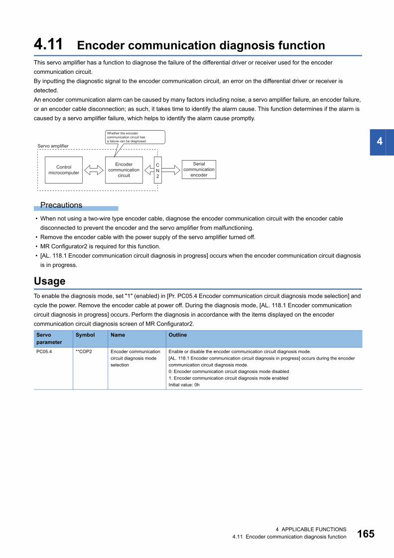
4
4.11 Encoder communication diagnosis functionThis servo amplifier has a function to diagnose the failure of the differential driver or receiver used for the encoder communication circuit.By inputting the diagnostic signal to the encoder communication circuit, an error on the differential driver or receiver is detected.An encoder communication alarm can be caused by many factors including noise, a servo amplifier failure, an encoder failure, or an encoder cable disconnection; as such, it takes time to identify the alarm cause. This function determines if the alarm is caused by a servo amplifier failure, which helps to identify the alarm cause promptly.
Precautions • When not using a two-wire type encoder cable, diagnose the encoder communication circuit with the encoder cable
disconnected to prevent the encoder and the servo amplifier from malfunctioning. • Remove the encoder cable with the power supply of the servo amplifier turned off. • MR Configurator2 is required for this function. • [AL. 118.1 Encoder communication circuit diagnosis in progress] occurs when the encoder communication circuit diagnosis
is in progress.
UsageTo enable the diagnosis mode, set "1" (enabled) in [Pr. PC05.4 Encoder communication circuit diagnosis mode selection] and cycle the power. Remove the encoder cable at power off. During the diagnosis mode, [AL. 118.1 Encoder communication circuit diagnosis in progress] occurs. Perform the diagnosis in accordance with the items displayed on the encoder communication circuit diagnosis screen of MR Configurator2.
Servo parameter
Symbol Name Outline
PC05.4 **COP2 Encoder communication circuit diagnosis mode selection
Enable or disable the encoder communication circuit diagnosis mode.[AL. 118.1 Encoder communication circuit diagnosis in progress] occurs during the encoder communication circuit diagnosis mode.0: Encoder communication circuit diagnosis mode disabled1: Encoder communication circuit diagnosis mode enabledInitial value: 0h
CN2
Whether the encodercommunication circuit hasa failure can be diagnosed.
Servo amplifier
Encodercommunication
circuit
Serialcommunication
encoderControl
microcomputer
4 APPLICABLE FUNCTIONS4.11 Encoder communication diagnosis function 165
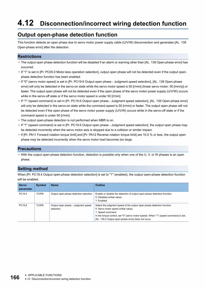
16
4.12 Disconnection/incorrect wiring detection functionOutput open-phase detection functionThis function detects an open phase due to servo motor power supply cable (U/V/W) disconnection and generates [AL. 139 Open-phase error] after the detection.
Restrictions • The output open phase detection function will be disabled if an alarm or warning other than [AL. 139 Open-phase error] has
occurred. • If "1" is set in [Pr. PC05.0 Motor-less operation selection], output open phase will not be detected even if the output open-
phase detection function has been enabled. • If "0" (servo motor speed) is set in [Pr. PC19.6 Output open phase - Judgment speed selection], [AL. 139 Open-phase
error] will only be detected in the servo-on state while the servo motor speed is 50 [r/min] (linear servo motor: 50 [mm/s]) or faster. The output open phase will not be detected even if the open phase of the servo motor power supply (U/V/W) occurs while in the servo-off state or if the servo motor speed is under 50 [r/min].
• If "1" (speed command) is set in [Pr. PC19.6 Output open phase - Judgment speed selection], [AL. 139 Open-phase error] will only be detected in the servo-on state while the command speed is 50 [r/min] or faster. The output open phase will not be detected even if the open phase of the servo motor power supply (U/V/W) occurs while in the servo-off state or if the command speed is under 50 [r/min].
• The output open-phase detection is not performed when MBR is on. • If "1" (speed command) is set in [Pr. PC19.6 Output open phase - Judgment speed selection], the output open phase may
be detected incorrectly when the servo motor axis is stopped due to a collision or similar impact. • If [Pr. PA11 Forward rotation torque limit] and [Pr. PA12 Reverse rotation torque limit] are 10.0 % or less, the output open
phase may be detected incorrectly when the servo motor load becomes too large.
Precautions • With the output open-phase detection function, detection is possible only when one of the U, V, or W phases is an open
phase.
Setting methodWhen [Pr. PC19.4 Output open-phase detection selection] is set to "1" (enabled), the output open-phase detection function will be enabled.
Servo parameter
Symbol Name Outline
PC19.4 *COP6 Output open-phase detection selection Enable or disable the detection of output open-phase detection function.0: Disabled (initial value)1: Enabled
PC19.6 *COP6 Output open phase - Judgment speed selection
Select the judgment speed of the output open-phase detection function.0: Servo motor speed (initial value)1: Speed commandIn the torque control, set "0" (servo motor speed). When "1" (speed command) is set, [AL. 139.2 Output open-phase error] does not occur.
6 4 APPLICABLE FUNCTIONS4.12 Disconnection/incorrect wiring detection function

4
4.13 Overload protection (electronic thermal) functionAn electronic thermal is built in the servo amplifier to protect the servo motor, servo amplifier and servo motor power wires from overloads.[AL. 050 Overload 1] occurs if overload operation performed is above the electronic thermal protection curve. [AL. 051 Overload 2] occurs if the maximum current is applied continuously for several seconds due to a machine collision, etc.
Precautions • After [AL. 050 Overload 1] or [AL. 051 Overload 2] occurs, allow about 30 minutes of cooling time.
4 APPLICABLE FUNCTIONS4.13 Overload protection (electronic thermal) function 167
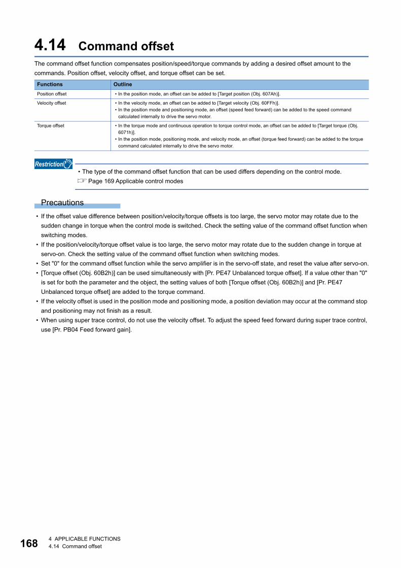
16
4.14 Command offsetThe command offset function compensates position/speed/torque commands by adding a desired offset amount to the commands. Position offset, velocity offset, and torque offset can be set.
• The type of the command offset function that can be used differs depending on the control mode.Page 169 Applicable control modes
Precautions • If the offset value difference between position/velocity/torque offsets is too large, the servo motor may rotate due to the
sudden change in torque when the control mode is switched. Check the setting value of the command offset function when switching modes.
• If the position/velocity/torque offset value is too large, the servo motor may rotate due to the sudden change in torque at servo-on. Check the setting value of the command offset function when switching modes.
• Set "0" for the command offset function while the servo amplifier is in the servo-off state, and reset the value after servo-on. • [Torque offset (Obj. 60B2h)] can be used simultaneously with [Pr. PE47 Unbalanced torque offset]. If a value other than "0"
is set for both the parameter and the object, the setting values of both [Torque offset (Obj. 60B2h)] and [Pr. PE47 Unbalanced torque offset] are added to the torque command.
• If the velocity offset is used in the position mode and positioning mode, a position deviation may occur at the command stop and positioning may not finish as a result.
• When using super trace control, do not use the velocity offset. To adjust the speed feed forward during super trace control, use [Pr. PB04 Feed forward gain].
Functions OutlinePosition offset • In the position mode, an offset can be added to [Target position (Obj. 607Ah)].
Velocity offset • In the velocity mode, an offset can be added to [Target velocity (Obj. 60FFh)].• In the position mode and positioning mode, an offset (speed feed forward) can be added to the speed command
calculated internally to drive the servo motor.
Torque offset • In the torque mode and continuous operation to torque control mode, an offset can be added to [Target torque (Obj. 6071h)].
• In the position mode, positioning mode, and velocity mode, an offset (torque feed forward) can be added to the torque command calculated internally to drive the servo motor.
8 4 APPLICABLE FUNCTIONS4.14 Command offset
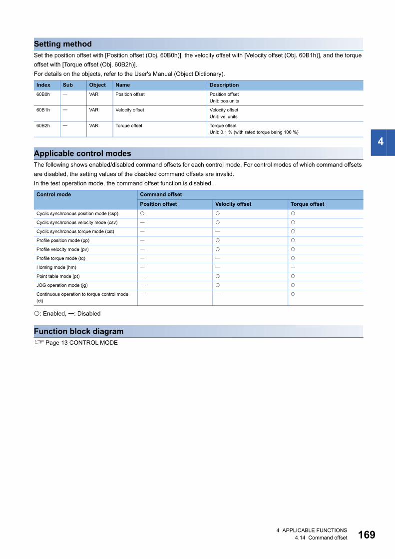
4
Setting methodSet the position offset with [Position offset (Obj. 60B0h)], the velocity offset with [Velocity offset (Obj. 60B1h)], and the torque offset with [Torque offset (Obj. 60B2h)].For details on the objects, refer to the User's Manual (Object Dictionary).
Applicable control modesThe following shows enabled/disabled command offsets for each control mode. For control modes of which command offsets are disabled, the setting values of the disabled command offsets are invalid.In the test operation mode, the command offset function is disabled.
: Enabled, : Disabled
Function block diagramPage 13 CONTROL MODE
Index Sub Object Name Description60B0h VAR Position offset Position offset
Unit: pos units
60B1h VAR Velocity offset Velocity offsetUnit: vel units
60B2h VAR Torque offset Torque offsetUnit: 0.1 % (with rated torque being 100 %)
Control mode Command offset
Position offset Velocity offset Torque offsetCyclic synchronous position mode (csp)
Cyclic synchronous velocity mode (csv)
Cyclic synchronous torque mode (cst)
Profile position mode (pp)
Profile velocity mode (pv)
Profile torque mode (tq)
Homing mode (hm)
Point table mode (pt)
JOG operation mode (jg)
Continuous operation to torque control mode (ct)
4 APPLICABLE FUNCTIONS4.14 Command offset 169
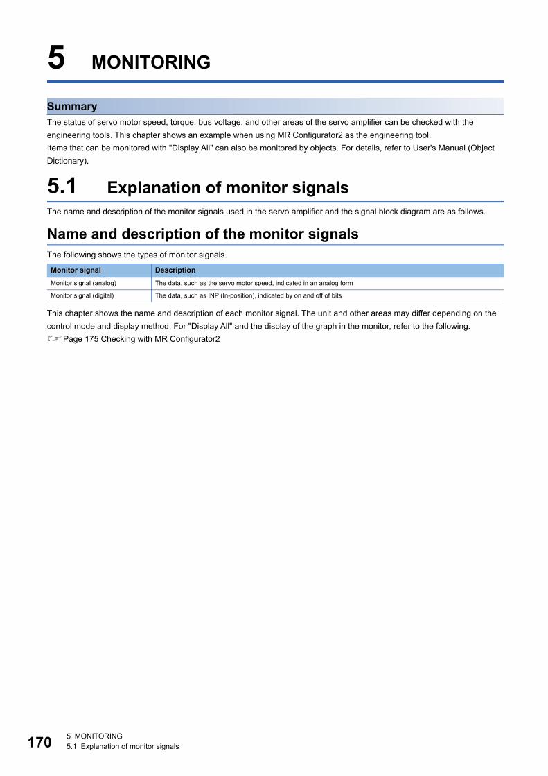
17
5 MONITORING
SummaryThe status of servo motor speed, torque, bus voltage, and other areas of the servo amplifier can be checked with the engineering tools. This chapter shows an example when using MR Configurator2 as the engineering tool.Items that can be monitored with "Display All" can also be monitored by objects. For details, refer to User's Manual (Object Dictionary).
5.1 Explanation of monitor signalsThe name and description of the monitor signals used in the servo amplifier and the signal block diagram are as follows.
Name and description of the monitor signalsThe following shows the types of monitor signals.
This chapter shows the name and description of each monitor signal. The unit and other areas may differ depending on the control mode and display method. For "Display All" and the display of the graph in the monitor, refer to the following.Page 175 Checking with MR Configurator2
Monitor signal DescriptionMonitor signal (analog) The data, such as the servo motor speed, indicated in an analog form
Monitor signal (digital) The data, such as INP (In-position), indicated by on and off of bits
0 5 MONITORING5.1 Explanation of monitor signals
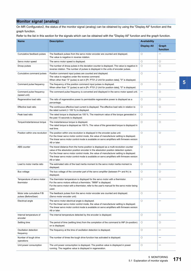
5
Monitor signal (analog)On MR Configurator2, the status of the monitor signal (analog) can be obtained by using the "Display All" function and the graph function.Refer to the list in this section for the signals which can be obtained with the "Display All" function and the graph function.
Name Description Availability
Display All Graph function
Cumulative feedback pulses The feedback pulses from the servo motor encoder are counted and displayed.The value is negative in reverse rotation.
Servo motor speed The servo motor speed is displayed.
Droop pulses The number of droop pulses in the deviation counter is displayed. The value is negative in reverse rotation. The number of pulses is displayed in the units of encoder pulses.
Cumulative command pulses Position command input pulses are counted and displayed.The value is negative under the reverse command.When other than "3" (pulse) is set in [Pr. PT01.2 Unit for position data], "0" is displayed.
Command pulse frequency The frequency of the position command input pulses is displayed.When other than "3" (pulse) is set in [Pr. PT01.2 Unit for position data], "0" is displayed.
Command pulse frequency (speed unit)
The command pulse frequency is converted and displayed in the servo motor speed unit.
Regenerative load ratio The ratio of regenerative power to permissible regenerative power is displayed as a percentage.
Effective load ratio The continuous effective load current is displayed. The effective load ratio in relation to the rated current (= 100 %) is displayed.
Peak load ratio The rated torque is displayed as 100 %. The maximum value of the torque generated in the past 15 seconds is displayed.
Torque/instantaneous torque The instantaneous torque is displayed.The rated torque is displayed as 100 %. The value of the generated torque is displayed in real time.
Position within one-revolution The position within one-revolution is displayed in the encoder pulse unit.For the linear servo motor control mode, the value of manufacturer setting is displayed.The linear servo motor control mode is available on servo amplifiers with firmware version A8 or later.
ABS counter The travel distance from the home position is displayed as a multi-revolution counter value of the absolution position encoder in the absolution position detection system.For the linear servo motor control mode, the value of manufacturer setting is displayed.The linear servo motor control mode is available on servo amplifiers with firmware version A8 or later.
Load to motor inertia ratio The estimated ratio of the load inertia moment to the servo motor inertia moment is displayed.
Bus voltage The bus voltage of the converter part of the servo amplifier (between P+ and N-) is displayed.
Temperature of servo motor thermistor
The thermistor temperature is displayed for the servo motor with a thermistor.For the servo motors without a thermistor, "9999" is displayed.For the servo motor with a thermistor, refer to the user's manual for the servo motor being used.
Motor side cumulative F/B pulses (BeforeGear)
The feedback pulses from the servo motor encoder are counted and displayed.(Servo motor encoder unit)
Electrical angle The servo motor electrical angle is displayed.For the linear servo motor control mode, the value of manufacturer setting is displayed.The linear servo motor control mode is available on servo amplifiers with firmware version A8 or later.
Internal temperature of encoder
The internal temperature detected by the encoder is displayed.
Settling time The period of time (settling time) from the completion of the command to INP (In-position) on is displayed.
Oscillation detection frequency
The frequency at the time of oscillation detection is displayed.
Number of tough drive operations
The number of times the tough drive function has activated is displayed.
Unit power consumption The unit power consumption is displayed. The positive value is displayed in power running. The negative value is displayed in regeneration.
5 MONITORING5.1 Explanation of monitor signals 171
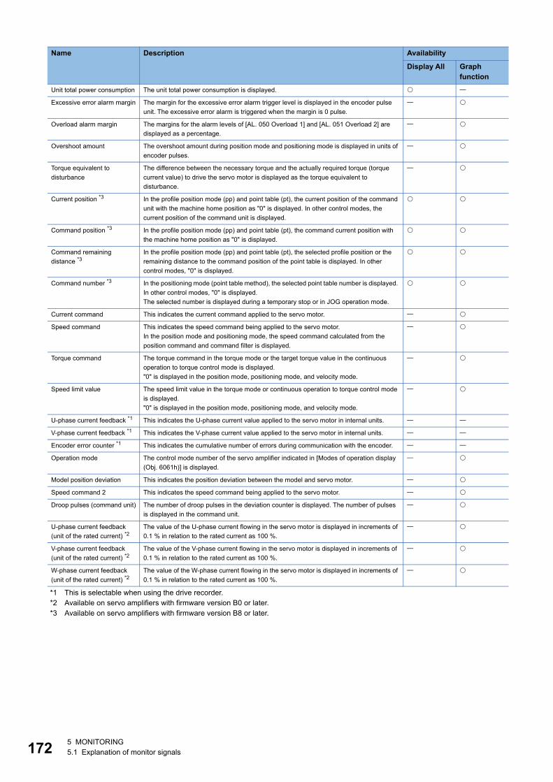
17
*1 This is selectable when using the drive recorder.*2 Available on servo amplifiers with firmware version B0 or later.*3 Available on servo amplifiers with firmware version B8 or later.
Unit total power consumption The unit total power consumption is displayed.
Excessive error alarm margin The margin for the excessive error alarm trigger level is displayed in the encoder pulse unit. The excessive error alarm is triggered when the margin is 0 pulse.
Overload alarm margin The margins for the alarm levels of [AL. 050 Overload 1] and [AL. 051 Overload 2] are displayed as a percentage.
Overshoot amount The overshoot amount during position mode and positioning mode is displayed in units of encoder pulses.
Torque equivalent to disturbance
The difference between the necessary torque and the actually required torque (torque current value) to drive the servo motor is displayed as the torque equivalent to disturbance.
Current position *3 In the profile position mode (pp) and point table (pt), the current position of the command unit with the machine home position as "0" is displayed. In other control modes, the current position of the command unit is displayed.
Command position *3 In the profile position mode (pp) and point table (pt), the command current position with the machine home position as "0" is displayed.
Command remaining distance *3
In the profile position mode (pp) and point table (pt), the selected profile position or the remaining distance to the command position of the point table is displayed. In other control modes, "0" is displayed.
Command number *3 In the positioning mode (point table method), the selected point table number is displayed. In other control modes, "0" is displayed.The selected number is displayed during a temporary stop or in JOG operation mode.
Current command This indicates the current command applied to the servo motor.
Speed command This indicates the speed command being applied to the servo motor.In the position mode and positioning mode, the speed command calculated from the position command and command filter is displayed.
Torque command The torque command in the torque mode or the target torque value in the continuous operation to torque control mode is displayed."0" is displayed in the position mode, positioning mode, and velocity mode.
Speed limit value The speed limit value in the torque mode or continuous operation to torque control mode is displayed."0" is displayed in the position mode, positioning mode, and velocity mode.
U-phase current feedback *1 This indicates the U-phase current value applied to the servo motor in internal units.
V-phase current feedback *1 This indicates the V-phase current value applied to the servo motor in internal units.
Encoder error counter *1 This indicates the cumulative number of errors during communication with the encoder.
Operation mode The control mode number of the servo amplifier indicated in [Modes of operation display (Obj. 6061h)] is displayed.
Model position deviation This indicates the position deviation between the model and servo motor.
Speed command 2 This indicates the speed command being applied to the servo motor.
Droop pulses (command unit) The number of droop pulses in the deviation counter is displayed. The number of pulses is displayed in the command unit.
U-phase current feedback (unit of the rated current) *2
The value of the U-phase current flowing in the servo motor is displayed in increments of 0.1 % in relation to the rated current as 100 %.
V-phase current feedback (unit of the rated current) *2
The value of the V-phase current flowing in the servo motor is displayed in increments of 0.1 % in relation to the rated current as 100 %.
W-phase current feedback (unit of the rated current) *2
The value of the W-phase current flowing in the servo motor is displayed in increments of 0.1 % in relation to the rated current as 100 %.
Name Description Availability
Display All Graph function
2 5 MONITORING5.1 Explanation of monitor signals
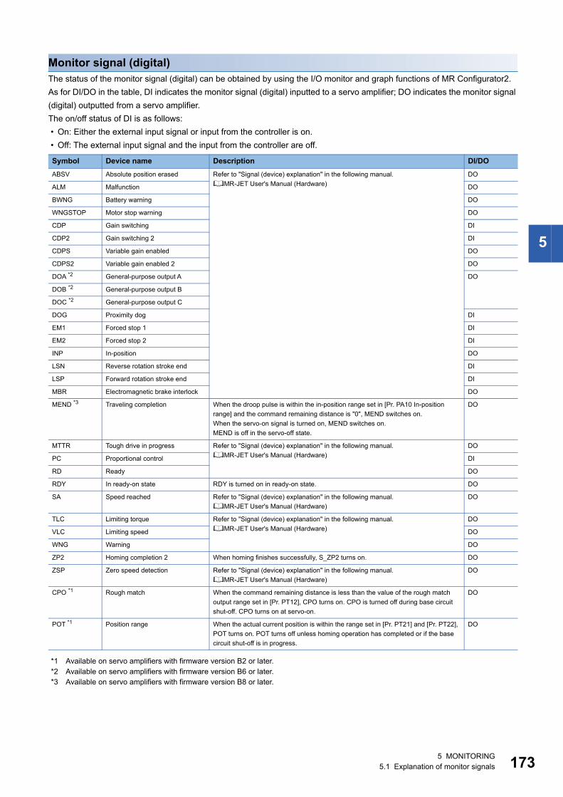
5
Monitor signal (digital)The status of the monitor signal (digital) can be obtained by using the I/O monitor and graph functions of MR Configurator2.As for DI/DO in the table, DI indicates the monitor signal (digital) inputted to a servo amplifier; DO indicates the monitor signal (digital) outputted from a servo amplifier.The on/off status of DI is as follows: • On: Either the external input signal or input from the controller is on. • Off: The external input signal and the input from the controller are off.
*1 Available on servo amplifiers with firmware version B2 or later.*2 Available on servo amplifiers with firmware version B6 or later.*3 Available on servo amplifiers with firmware version B8 or later.
Symbol Device name Description DI/DOABSV Absolute position erased Refer to "Signal (device) explanation" in the following manual.
MR-JET User's Manual (Hardware)DO
ALM Malfunction DO
BWNG Battery warning DO
WNGSTOP Motor stop warning DO
CDP Gain switching DI
CDP2 Gain switching 2 DI
CDPS Variable gain enabled DO
CDPS2 Variable gain enabled 2 DO
DOA *2 General-purpose output A DO
DOB *2 General-purpose output B
DOC *2 General-purpose output C
DOG Proximity dog DI
EM1 Forced stop 1 DI
EM2 Forced stop 2 DI
INP In-position DO
LSN Reverse rotation stroke end DI
LSP Forward rotation stroke end DI
MBR Electromagnetic brake interlock DO
MEND *3 Traveling completion When the droop pulse is within the in-position range set in [Pr. PA10 In-position range] and the command remaining distance is "0", MEND switches on.When the servo-on signal is turned on, MEND switches on.MEND is off in the servo-off state.
DO
MTTR Tough drive in progress Refer to "Signal (device) explanation" in the following manual.MR-JET User's Manual (Hardware)
DO
PC Proportional control DI
RD Ready DO
RDY In ready-on state RDY is turned on in ready-on state. DO
SA Speed reached Refer to "Signal (device) explanation" in the following manual.MR-JET User's Manual (Hardware)
DO
TLC Limiting torque Refer to "Signal (device) explanation" in the following manual.MR-JET User's Manual (Hardware)
DO
VLC Limiting speed DO
WNG Warning DO
ZP2 Homing completion 2 When homing finishes successfully, S_ZP2 turns on. DO
ZSP Zero speed detection Refer to "Signal (device) explanation" in the following manual.MR-JET User's Manual (Hardware)
DO
CPO *1 Rough match When the command remaining distance is less than the value of the rough match output range set in [Pr. PT12], CPO turns on. CPO is turned off during base circuit shut-off. CPO turns on at servo-on.
DO
POT *1 Position range When the actual current position is within the range set in [Pr. PT21] and [Pr. PT22], POT turns on. POT turns off unless homing operation has completed or if the base circuit shut-off is in progress.
DO
5 MONITORING5.1 Explanation of monitor signals 173
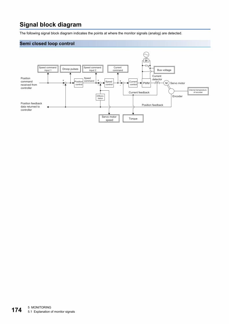
17
Signal block diagramThe following signal block diagram indicates the points at where the monitor signals (analog) are detected.
Semi closed loop control
PWM+
M+--
+-
+Droop pulsesSpeed command
input 1
Position control
Speed control
Current control
Current command Bus voltage
Speed command
Current detector
Servo motor
EncoderCurrent feedback
Position feedback
Position command received from controller
Position feedback data returned to controller
Differen-tiation
Internal temperature of encoder
Servo motor speed Torque
Speed command input 2
4 5 MONITORING5.1 Explanation of monitor signals
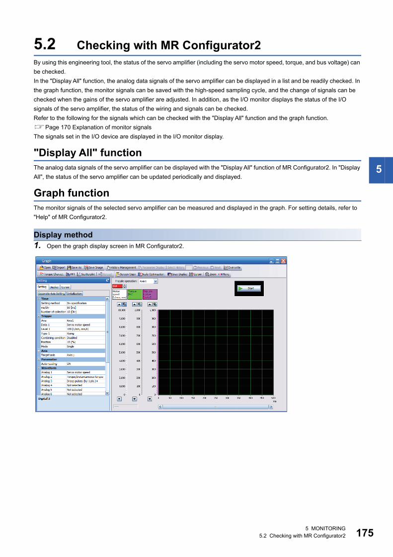
5
5.2 Checking with MR Configurator2By using this engineering tool, the status of the servo amplifier (including the servo motor speed, torque, and bus voltage) can be checked.In the "Display All" function, the analog data signals of the servo amplifier can be displayed in a list and be readily checked. In the graph function, the monitor signals can be saved with the high-speed sampling cycle, and the change of signals can be checked when the gains of the servo amplifier are adjusted. In addition, as the I/O monitor displays the status of the I/O signals of the servo amplifier, the status of the wiring and signals can be checked.Refer to the following for the signals which can be checked with the "Display All" function and the graph function.Page 170 Explanation of monitor signalsThe signals set in the I/O device are displayed in the I/O monitor display.
"Display All" functionThe analog data signals of the servo amplifier can be displayed with the "Display All" function of MR Configurator2. In "Display All", the status of the servo amplifier can be updated periodically and displayed.
Graph functionThe monitor signals of the selected servo amplifier can be measured and displayed in the graph. For setting details, refer to "Help" of MR Configurator2.
Display method1. Open the graph display screen in MR Configurator2.
5 MONITORING5.2 Checking with MR Configurator2 175
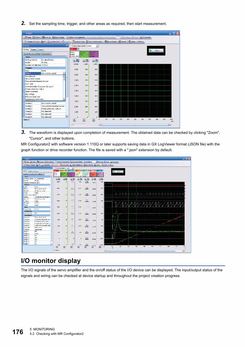
17
2. Set the sampling time, trigger, and other areas as required, then start measurement.
3. The waveform is displayed upon completion of measurement. The obtained data can be checked by clicking "Zoom", "Cursor", and other buttons.
MR Configurator2 with software version 1.110Q or later supports saving data in GX LogViewer format (JSON file) with the graph function or drive recorder function. The file is saved with a ".json" extension by default.
I/O monitor displayThe I/O signals of the servo amplifier and the on/off status of the I/O device can be displayed. The input/output status of the signals and wiring can be checked at device startup and throughout the project creation progress.
6 5 MONITORING5.2 Checking with MR Configurator2
5
System configuration displaySystem information including the serial No. and model of the servo amplifier, servo motor, and other equipment are displayed. The items displayed in the configuration window vary depending on the servo amplifier. When MR Configurator2 is connected to the servo amplifier, the values are displayed.
Displayed itemsThe following items can be checked in the system configuration window. • Servo amplifier identification information • Servo amplifier serial No. • Servo amplifier S/W No. • Optional unit identification information • Optional unit serial No. • Optional unit S/W No. • MAC address • IP address • Motor model • Motor ID • Motor serial No. • Encoder resolution • Encoder maximum multi-revolution [rev] • Accumulated power-on time [h] • Number of inrush relay on/off times [times] • Number of dynamic brake relay on/off times [times] • LED display
5 MONITORING5.2 Checking with MR Configurator2 177
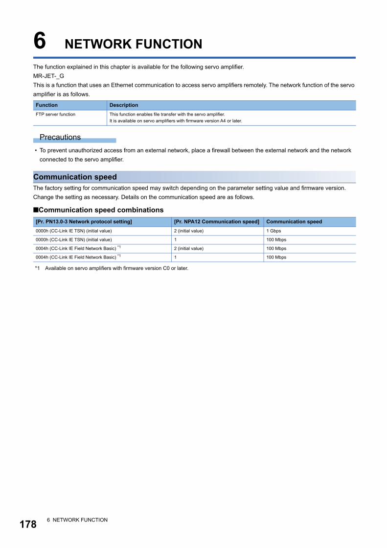
17
6 NETWORK FUNCTIONThe function explained in this chapter is available for the following servo amplifier.MR-JET-_GThis is a function that uses an Ethernet communication to access servo amplifiers remotely. The network function of the servo amplifier is as follows.
Precautions • To prevent unauthorized access from an external network, place a firewall between the external network and the network
connected to the servo amplifier.
Communication speedThe factory setting for communication speed may switch depending on the parameter setting value and firmware version. Change the setting as necessary. Details on the communication speed are as follows.
■Communication speed combinations
*1 Available on servo amplifiers with firmware version C0 or later.
Function DescriptionFTP server function This function enables file transfer with the servo amplifier.
It is available on servo amplifiers with firmware version A4 or later.
[Pr. PN13.0-3 Network protocol setting] [Pr. NPA12 Communication speed] Communication speed0000h (CC-Link IE TSN) (initial value) 2 (initial value) 1 Gbps
0000h (CC-Link IE TSN) (initial value) 1 100 Mbps
0004h (CC-Link IE Field Network Basic) *1 2 (initial value) 100 Mbps
0004h (CC-Link IE Field Network Basic) *1 1 100 Mbps
8 6 NETWORK FUNCTION
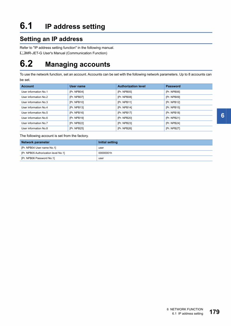
6
6.1 IP address settingSetting an IP addressRefer to "IP address setting function" in the following manual.MR-JET-G User's Manual (Communication Function)
6.2 Managing accountsTo use the network function, set an account. Accounts can be set with the following network parameters. Up to 8 accounts can be set.
The following account is set from the factory.
Account User name Authorization level PasswordUser information No.1 [Pr. NPB04] [Pr. NPB05] [Pr. NPB06]
User information No.2 [Pr. NPB07] [Pr. NPB08] [Pr. NPB09]
User information No.3 [Pr. NPB10] [Pr. NPB11] [Pr. NPB12]
User information No.4 [Pr. NPB13] [Pr. NPB14] [Pr. NPB15]
User information No.5 [Pr. NPB16] [Pr. NPB17] [Pr. NPB18]
User information No.6 [Pr. NPB19] [Pr. NPB20] [Pr. NPB21]
User information No.7 [Pr. NPB22] [Pr. NPB23] [Pr. NPB24]
User information No.8 [Pr. NPB25] [Pr. NPB26] [Pr. NPB27]
Network parameter Initial setting[Pr. NPB04 User name No.1] user
[Pr. NPB05 Authorization level No.1] 00000001h
[Pr. NPB06 Password No.1] user
6 NETWORK FUNCTION6.1 IP address setting 179
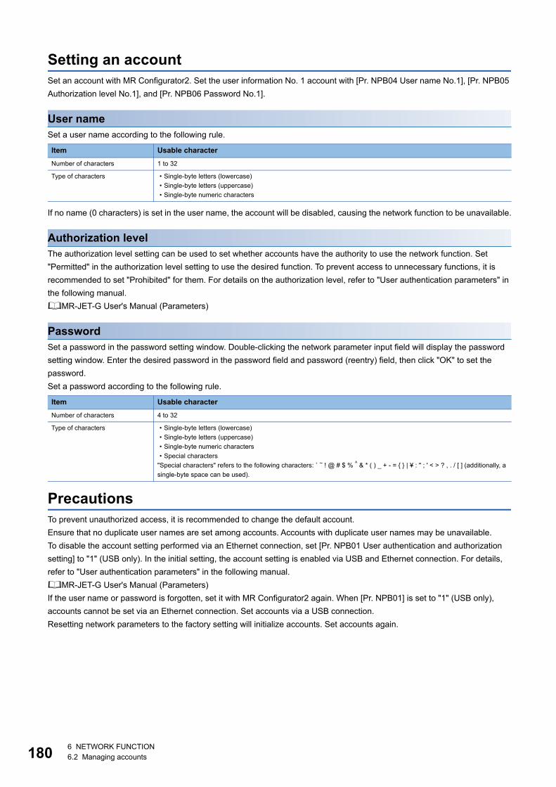
18
Setting an accountSet an account with MR Configurator2. Set the user information No. 1 account with [Pr. NPB04 User name No.1], [Pr. NPB05 Authorization level No.1], and [Pr. NPB06 Password No.1].
User nameSet a user name according to the following rule.
If no name (0 characters) is set in the user name, the account will be disabled, causing the network function to be unavailable.
Authorization levelThe authorization level setting can be used to set whether accounts have the authority to use the network function. Set "Permitted" in the authorization level setting to use the desired function. To prevent access to unnecessary functions, it is recommended to set "Prohibited" for them. For details on the authorization level, refer to "User authentication parameters" in the following manual.MR-JET-G User's Manual (Parameters)
PasswordSet a password in the password setting window. Double-clicking the network parameter input field will display the password setting window. Enter the desired password in the password field and password (reentry) field, then click "OK" to set the password.Set a password according to the following rule.
PrecautionsTo prevent unauthorized access, it is recommended to change the default account.Ensure that no duplicate user names are set among accounts. Accounts with duplicate user names may be unavailable.To disable the account setting performed via an Ethernet connection, set [Pr. NPB01 User authentication and authorization setting] to "1" (USB only). In the initial setting, the account setting is enabled via USB and Ethernet connection. For details, refer to "User authentication parameters" in the following manual.MR-JET-G User's Manual (Parameters)If the user name or password is forgotten, set it with MR Configurator2 again. When [Pr. NPB01] is set to "1" (USB only), accounts cannot be set via an Ethernet connection. Set accounts via a USB connection.Resetting network parameters to the factory setting will initialize accounts. Set accounts again.
Item Usable characterNumber of characters 1 to 32
Type of characters • Single-byte letters (lowercase)• Single-byte letters (uppercase)• Single-byte numeric characters
Item Usable characterNumber of characters 4 to 32
Type of characters • Single-byte letters (lowercase)• Single-byte letters (uppercase)• Single-byte numeric characters• Special characters
"Special characters" refers to the following characters: ` ~ ! @ # $ % ^ & * ( ) _ + - = { } | ¥ : " ; ' < > ? , . / [ ] (additionally, a single-byte space can be used).
0 6 NETWORK FUNCTION6.2 Managing accounts
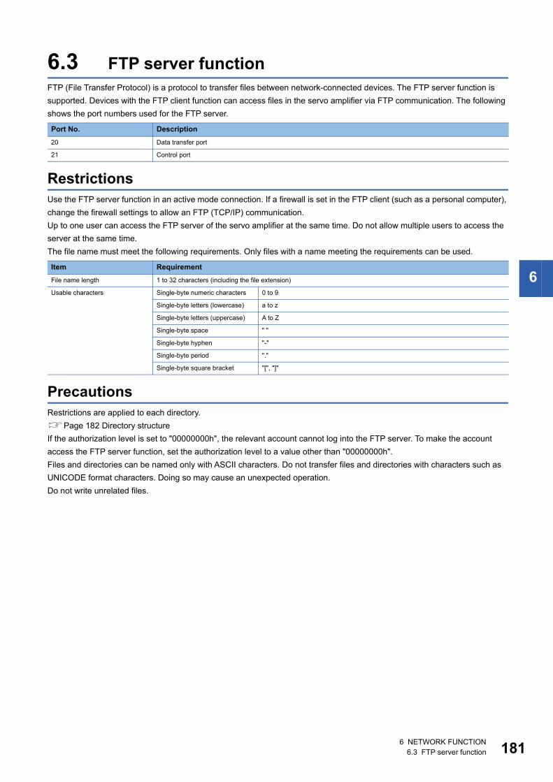
6
6.3 FTP server functionFTP (File Transfer Protocol) is a protocol to transfer files between network-connected devices. The FTP server function is supported. Devices with the FTP client function can access files in the servo amplifier via FTP communication. The following shows the port numbers used for the FTP server.
RestrictionsUse the FTP server function in an active mode connection. If a firewall is set in the FTP client (such as a personal computer), change the firewall settings to allow an FTP (TCP/IP) communication.Up to one user can access the FTP server of the servo amplifier at the same time. Do not allow multiple users to access the server at the same time.The file name must meet the following requirements. Only files with a name meeting the requirements can be used.
PrecautionsRestrictions are applied to each directory.Page 182 Directory structureIf the authorization level is set to "00000000h", the relevant account cannot log into the FTP server. To make the account access the FTP server function, set the authorization level to a value other than "00000000h".Files and directories can be named only with ASCII characters. Do not transfer files and directories with characters such as UNICODE format characters. Doing so may cause an unexpected operation.Do not write unrelated files.
Port No. Description20 Data transfer port
21 Control port
Item RequirementFile name length 1 to 32 characters (including the file extension)
Usable characters Single-byte numeric characters 0 to 9
Single-byte letters (lowercase) a to z
Single-byte letters (uppercase) A to Z
Single-byte space " "
Single-byte hyphen "-"
Single-byte period "."
Single-byte square bracket "[", "]"
6 NETWORK FUNCTION6.3 FTP server function 181
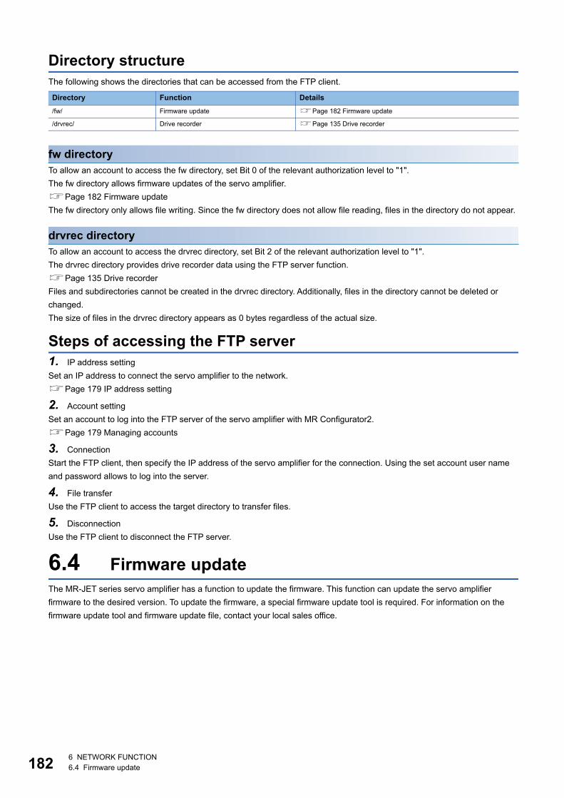
18
Directory structureThe following shows the directories that can be accessed from the FTP client.
fw directoryTo allow an account to access the fw directory, set Bit 0 of the relevant authorization level to "1".The fw directory allows firmware updates of the servo amplifier.Page 182 Firmware updateThe fw directory only allows file writing. Since the fw directory does not allow file reading, files in the directory do not appear.
drvrec directoryTo allow an account to access the drvrec directory, set Bit 2 of the relevant authorization level to "1".The drvrec directory provides drive recorder data using the FTP server function.Page 135 Drive recorderFiles and subdirectories cannot be created in the drvrec directory. Additionally, files in the directory cannot be deleted or changed.The size of files in the drvrec directory appears as 0 bytes regardless of the actual size.
Steps of accessing the FTP server1. IP address settingSet an IP address to connect the servo amplifier to the network.Page 179 IP address setting
2. Account settingSet an account to log into the FTP server of the servo amplifier with MR Configurator2.Page 179 Managing accounts
3. ConnectionStart the FTP client, then specify the IP address of the servo amplifier for the connection. Using the set account user name and password allows to log into the server.
4. File transferUse the FTP client to access the target directory to transfer files.
5. DisconnectionUse the FTP client to disconnect the FTP server.
6.4 Firmware updateThe MR-JET series servo amplifier has a function to update the firmware. This function can update the servo amplifier firmware to the desired version. To update the firmware, a special firmware update tool is required. For information on the firmware update tool and firmware update file, contact your local sales office.
Directory Function Details/fw/ Firmware update Page 182 Firmware update
/drvrec/ Drive recorder Page 135 Drive recorder
2 6 NETWORK FUNCTION6.4 Firmware update
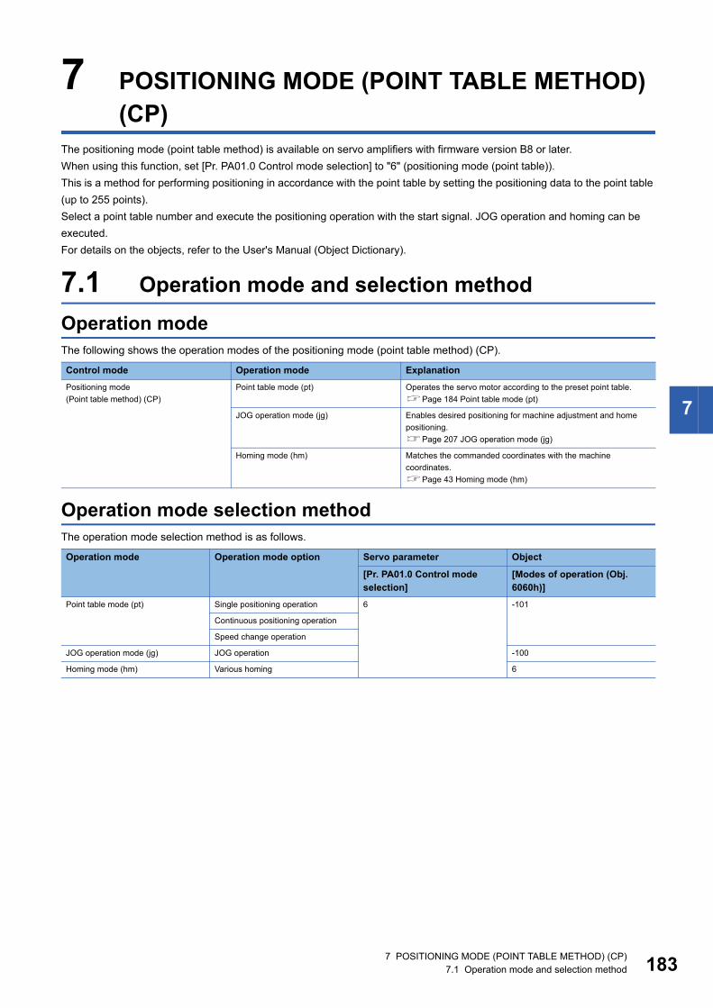
7
7 POSITIONING MODE (POINT TABLE METHOD) (CP)
The positioning mode (point table method) is available on servo amplifiers with firmware version B8 or later.When using this function, set [Pr. PA01.0 Control mode selection] to "6" (positioning mode (point table)).This is a method for performing positioning in accordance with the point table by setting the positioning data to the point table (up to 255 points).Select a point table number and execute the positioning operation with the start signal. JOG operation and homing can be executed.For details on the objects, refer to the User's Manual (Object Dictionary).
7.1 Operation mode and selection methodOperation modeThe following shows the operation modes of the positioning mode (point table method) (CP).
Operation mode selection methodThe operation mode selection method is as follows.
Control mode Operation mode ExplanationPositioning mode(Point table method) (CP)
Point table mode (pt) Operates the servo motor according to the preset point table.Page 184 Point table mode (pt)
JOG operation mode (jg) Enables desired positioning for machine adjustment and home positioning.Page 207 JOG operation mode (jg)
Homing mode (hm) Matches the commanded coordinates with the machine coordinates.Page 43 Homing mode (hm)
Operation mode Operation mode option Servo parameter Object
[Pr. PA01.0 Control mode selection]
[Modes of operation (Obj. 6060h)]
Point table mode (pt) Single positioning operation 6 -101
Continuous positioning operation
Speed change operation
JOG operation mode (jg) JOG operation -100
Homing mode (hm) Various homing 6
7 POSITIONING MODE (POINT TABLE METHOD) (CP)7.1 Operation mode and selection method 183
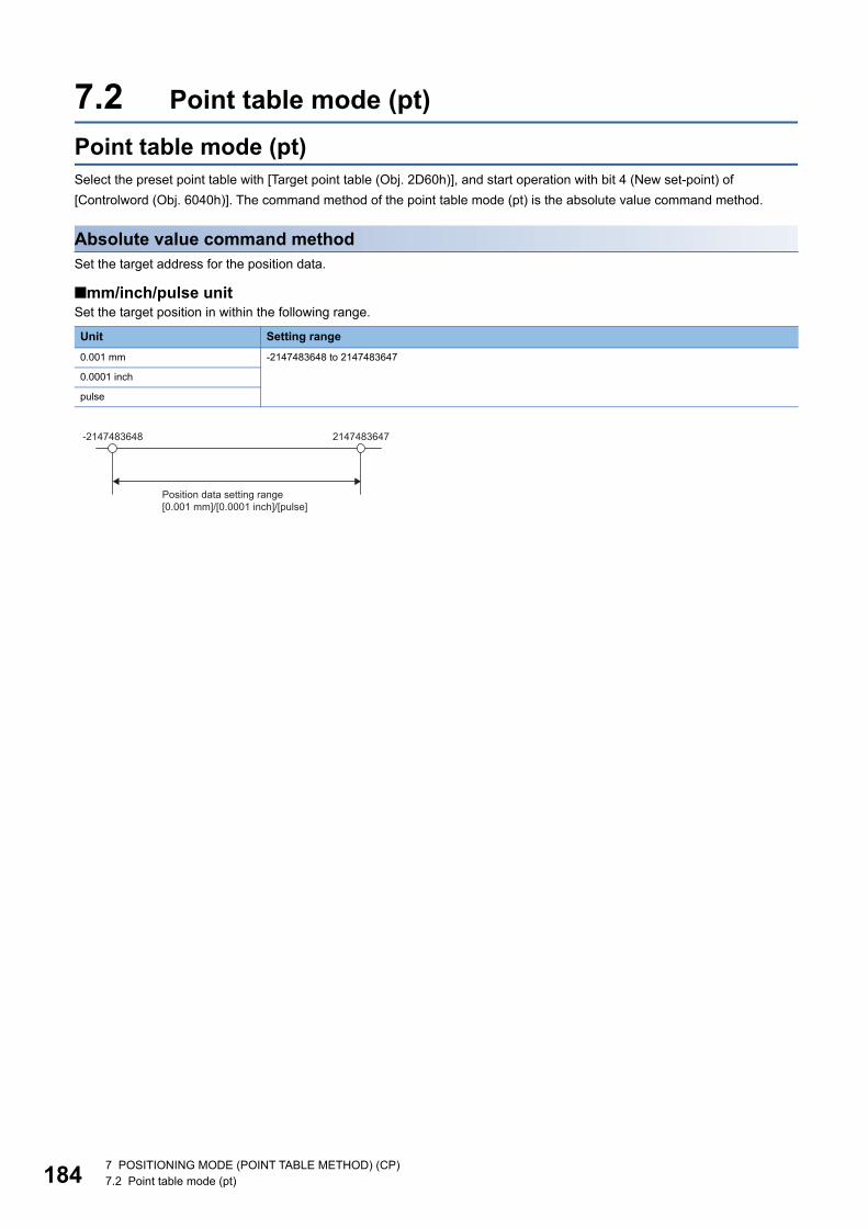
18
7.2 Point table mode (pt)Point table mode (pt)Select the preset point table with [Target point table (Obj. 2D60h)], and start operation with bit 4 (New set-point) of [Controlword (Obj. 6040h)]. The command method of the point table mode (pt) is the absolute value command method.
Absolute value command methodSet the target address for the position data.
■mm/inch/pulse unitSet the target position in within the following range.
Unit Setting range0.001 mm -2147483648 to 2147483647
0.0001 inch
pulse
-2147483648 2147483647
Position data setting range[0.001 mm]/[0.0001 inch]/[pulse]
4 7 POSITIONING MODE (POINT TABLE METHOD) (CP)7.2 Point table mode (pt)
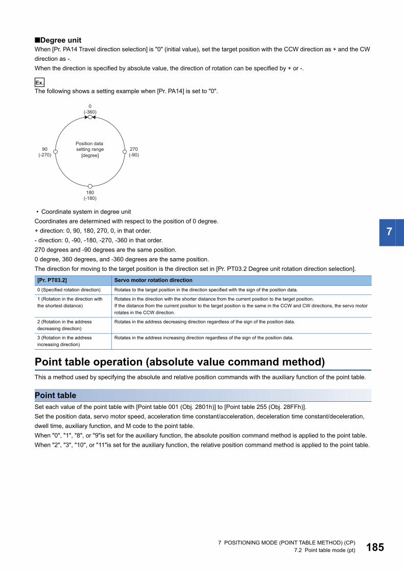
7
■Degree unitWhen [Pr. PA14 Travel direction selection] is "0" (initial value), set the target position with the CCW direction as + and the CW direction as -.When the direction is specified by absolute value, the direction of rotation can be specified by + or -.
Ex.
The following shows a setting example when [Pr. PA14] is set to "0".
• Coordinate system in degree unitCoordinates are determined with respect to the position of 0 degree.+ direction: 0, 90, 180, 270, 0, in that order.- direction: 0, -90, -180, -270, -360 in that order.270 degrees and -90 degrees are the same position.0 degree, 360 degrees, and -360 degrees are the same position.The direction for moving to the target position is the direction set in [Pr. PT03.2 Degree unit rotation direction selection].
Point table operation (absolute value command method)This a method used by specifying the absolute and relative position commands with the auxiliary function of the point table.
Point tableSet each value of the point table with [Point table 001 (Obj. 2801h)] to [Point table 255 (Obj. 28FFh)].Set the position data, servo motor speed, acceleration time constant/acceleration, deceleration time constant/deceleration, dwell time, auxiliary function, and M code to the point table.When "0", "1", "8", or "9"is set for the auxiliary function, the absolute position command method is applied to the point table.When "2", "3", "10", or "11"is set for the auxiliary function, the relative position command method is applied to the point table.
[Pr. PT03.2] Servo motor rotation direction0 (Specified rotation direction) Rotates to the target position in the direction specified with the sign of the position data.
1 (Rotation in the direction with the shortest distance)
Rotates in the direction with the shorter distance from the current position to the target position.If the distance from the current position to the target position is the same in the CCW and CW directions, the servo motor rotates in the CCW direction.
2 (Rotation in the address decreasing direction)
Rotates in the address decreasing direction regardless of the sign of the position data.
3 (Rotation in the address increasing direction)
Rotates in the address increasing direction regardless of the sign of the position data.
0(-360)
180(-180)
90(-270)
270(-90)[degree]
Position data setting range
7 POSITIONING MODE (POINT TABLE METHOD) (CP)7.2 Point table mode (pt) 185
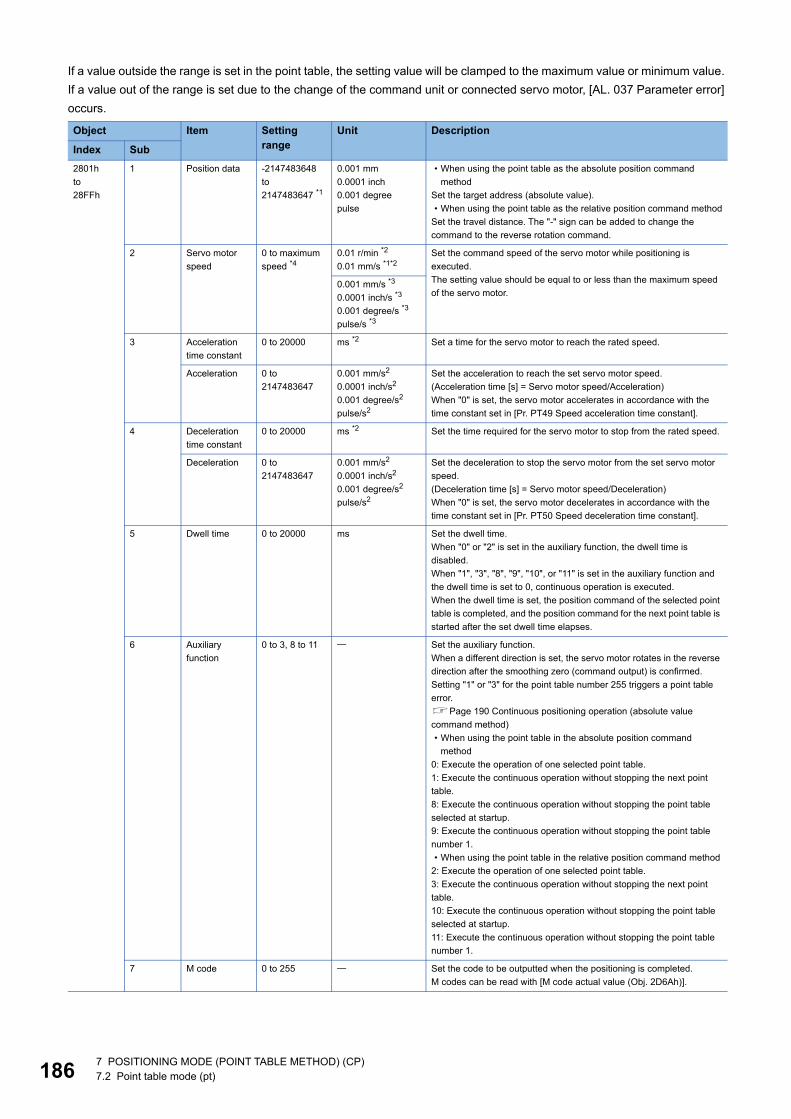
18
If a value outside the range is set in the point table, the setting value will be clamped to the maximum value or minimum value. If a value out of the range is set due to the change of the command unit or connected servo motor, [AL. 037 Parameter error] occurs.
Object Item Setting range
Unit Description
Index Sub2801hto28FFh
1 Position data -2147483648to2147483647 *1
0.001 mm0.0001 inch0.001 degreepulse
• When using the point table as the absolute position command method
Set the target address (absolute value).• When using the point table as the relative position command method
Set the travel distance. The "-" sign can be added to change the command to the reverse rotation command.
2 Servo motor speed
0 to maximum speed *4
0.01 r/min *2
0.01 mm/s *1*2Set the command speed of the servo motor while positioning is executed.The setting value should be equal to or less than the maximum speed of the servo motor.
0.001 mm/s *3
0.0001 inch/s *3
0.001 degree/s *3
pulse/s *3
3 Acceleration time constant
0 to 20000 ms *2 Set a time for the servo motor to reach the rated speed.
Acceleration 0 to 2147483647
0.001 mm/s2
0.0001 inch/s2
0.001 degree/s2
pulse/s2
Set the acceleration to reach the set servo motor speed.(Acceleration time [s] = Servo motor speed/Acceleration)When "0" is set, the servo motor accelerates in accordance with the time constant set in [Pr. PT49 Speed acceleration time constant].
4 Deceleration time constant
0 to 20000 ms *2 Set the time required for the servo motor to stop from the rated speed.
Deceleration 0 to 2147483647
0.001 mm/s2
0.0001 inch/s2
0.001 degree/s2
pulse/s2
Set the deceleration to stop the servo motor from the set servo motor speed.(Deceleration time [s] = Servo motor speed/Deceleration)When "0" is set, the servo motor decelerates in accordance with the time constant set in [Pr. PT50 Speed deceleration time constant].
5 Dwell time 0 to 20000 ms Set the dwell time.When "0" or "2" is set in the auxiliary function, the dwell time is disabled.When "1", "3", "8", "9", "10", or "11" is set in the auxiliary function and the dwell time is set to 0, continuous operation is executed.When the dwell time is set, the position command of the selected point table is completed, and the position command for the next point table is started after the set dwell time elapses.
6 Auxiliary function
0 to 3, 8 to 11 Set the auxiliary function.When a different direction is set, the servo motor rotates in the reverse direction after the smoothing zero (command output) is confirmed.Setting "1" or "3" for the point table number 255 triggers a point table error.Page 190 Continuous positioning operation (absolute value command method)• When using the point table in the absolute position command
method0: Execute the operation of one selected point table.1: Execute the continuous operation without stopping the next point table.8: Execute the continuous operation without stopping the point table selected at startup.9: Execute the continuous operation without stopping the point table number 1.• When using the point table in the relative position command method
2: Execute the operation of one selected point table.3: Execute the continuous operation without stopping the next point table.10: Execute the continuous operation without stopping the point table selected at startup.11: Execute the continuous operation without stopping the point table number 1.
7 M code 0 to 255 Set the code to be outputted when the positioning is completed.M codes can be read with [M code actual value (Obj. 2D6Ah)].
6 7 POSITIONING MODE (POINT TABLE METHOD) (CP)7.2 Point table mode (pt)
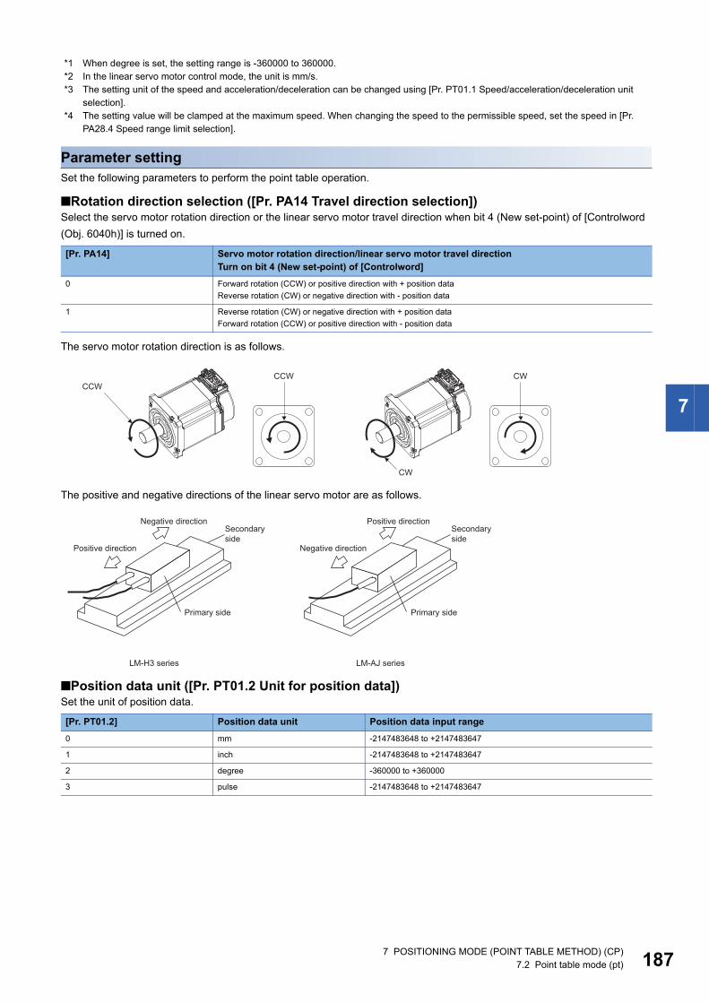
7
*1 When degree is set, the setting range is -360000 to 360000.*2 In the linear servo motor control mode, the unit is mm/s.*3 The setting unit of the speed and acceleration/deceleration can be changed using [Pr. PT01.1 Speed/acceleration/deceleration unit
selection].*4 The setting value will be clamped at the maximum speed. When changing the speed to the permissible speed, set the speed in [Pr.
PA28.4 Speed range limit selection].
Parameter settingSet the following parameters to perform the point table operation.
■Rotation direction selection ([Pr. PA14 Travel direction selection])Select the servo motor rotation direction or the linear servo motor travel direction when bit 4 (New set-point) of [Controlword (Obj. 6040h)] is turned on.
The servo motor rotation direction is as follows.
The positive and negative directions of the linear servo motor are as follows.
■Position data unit ([Pr. PT01.2 Unit for position data])Set the unit of position data.
[Pr. PA14] Servo motor rotation direction/linear servo motor travel directionTurn on bit 4 (New set-point) of [Controlword]
0 Forward rotation (CCW) or positive direction with + position dataReverse rotation (CW) or negative direction with - position data
1 Reverse rotation (CW) or negative direction with + position dataForward rotation (CCW) or positive direction with - position data
[Pr. PT01.2] Position data unit Position data input range0 mm -2147483648 to +2147483647
1 inch -2147483648 to +2147483647
2 degree -360000 to +360000
3 pulse -2147483648 to +2147483647
CCWCCW CW
CW
Secondary side
Primary side
Positive direction
Negative direction
LM-H3 series
Secondary side
Primary side
Negative direction
Positive direction
LM-AJ series
7 POSITIONING MODE (POINT TABLE METHOD) (CP)7.2 Point table mode (pt) 187
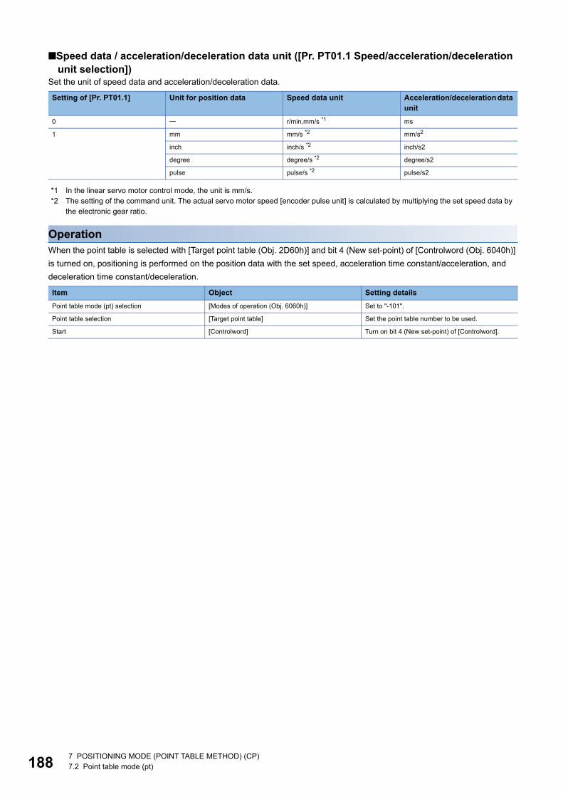
18
■Speed data / acceleration/deceleration data unit ([Pr. PT01.1 Speed/acceleration/deceleration unit selection])
Set the unit of speed data and acceleration/deceleration data.
*1 In the linear servo motor control mode, the unit is mm/s.*2 The setting of the command unit. The actual servo motor speed [encoder pulse unit] is calculated by multiplying the set speed data by
the electronic gear ratio.
OperationWhen the point table is selected with [Target point table (Obj. 2D60h)] and bit 4 (New set-point) of [Controlword (Obj. 6040h)] is turned on, positioning is performed on the position data with the set speed, acceleration time constant/acceleration, and deceleration time constant/deceleration.
Setting of [Pr. PT01.1] Unit for position data Speed data unit Acceleration/deceleration data unit
0 r/min,mm/s *1 ms
1 mm mm/s *2 mm/s2
inch inch/s *2 inch/s2
degree degree/s *2 degree/s2
pulse pulse/s *2 pulse/s2
Item Object Setting detailsPoint table mode (pt) selection [Modes of operation (Obj. 6060h)] Set to "-101".
Point table selection [Target point table] Set the point table number to be used.
Start [Controlword] Turn on bit 4 (New set-point) of [Controlword].
8 7 POSITIONING MODE (POINT TABLE METHOD) (CP)7.2 Point table mode (pt)
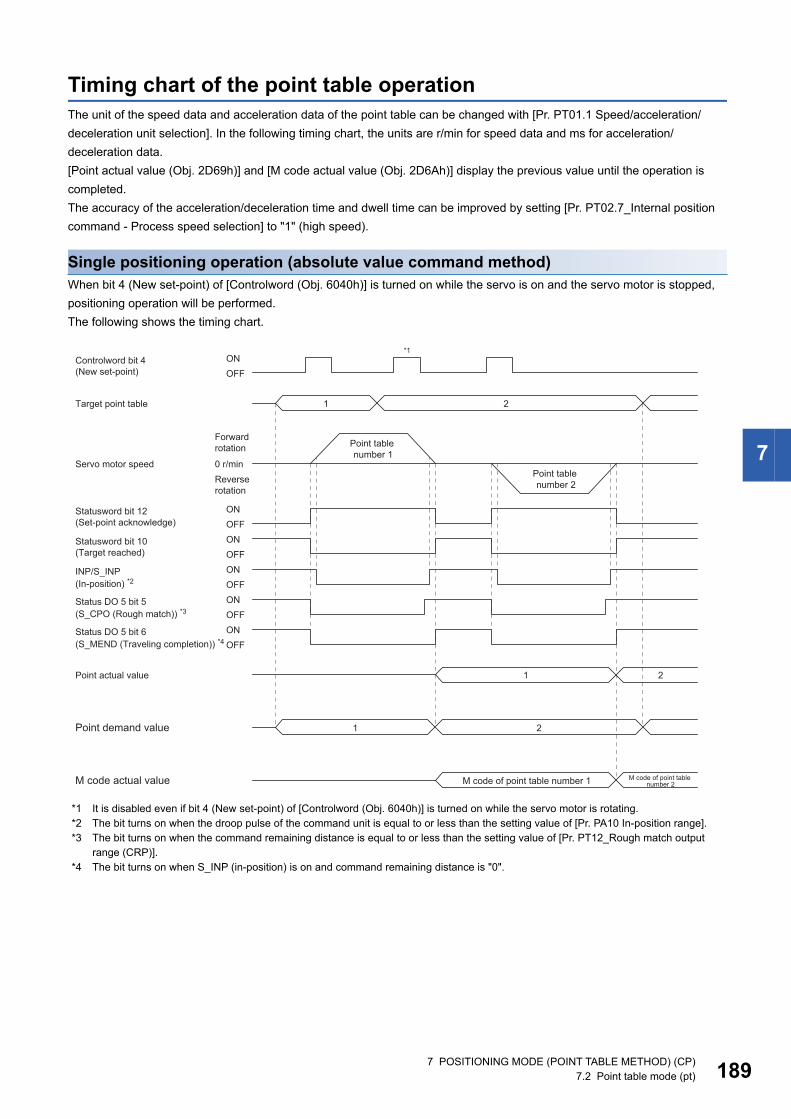
7
Timing chart of the point table operationThe unit of the speed data and acceleration data of the point table can be changed with [Pr. PT01.1 Speed/acceleration/deceleration unit selection]. In the following timing chart, the units are r/min for speed data and ms for acceleration/deceleration data.[Point actual value (Obj. 2D69h)] and [M code actual value (Obj. 2D6Ah)] display the previous value until the operation is completed.The accuracy of the acceleration/deceleration time and dwell time can be improved by setting [Pr. PT02.7_Internal position command - Process speed selection] to "1" (high speed).
Single positioning operation (absolute value command method)When bit 4 (New set-point) of [Controlword (Obj. 6040h)] is turned on while the servo is on and the servo motor is stopped, positioning operation will be performed.The following shows the timing chart.
*1 It is disabled even if bit 4 (New set-point) of [Controlword (Obj. 6040h)] is turned on while the servo motor is rotating.*2 The bit turns on when the droop pulse of the command unit is equal to or less than the setting value of [Pr. PA10 In-position range].*3 The bit turns on when the command remaining distance is equal to or less than the setting value of [Pr. PT12_Rough match output
range (CRP)].*4 The bit turns on when S_INP (in-position) is on and command remaining distance is "0".
Statusword bit 12(Set-point acknowledge)
Controlword bit 4(New set-point)
Target point table
Point actual value
Point demand value
1 2
1
1
2
2
M code actual value
*1
ONOFF
ONOFF
ONOFF
Statusword bit 10(Target reached)
ONOFF
ONOFF
ONOFF
INP/S_INP
Status DO 5 bit 5
Status DO 5 bit 6
0 r/min
Point table number 1
Forward rotation
Servo motor speedPoint table number 2Reverse
rotation
(In-position) *2
(S_CPO (Rough match)) *3
(S_MEND (Traveling completion)) *4
M code of point table number 1 M code of point table number 2
7 POSITIONING MODE (POINT TABLE METHOD) (CP)7.2 Point table mode (pt) 189
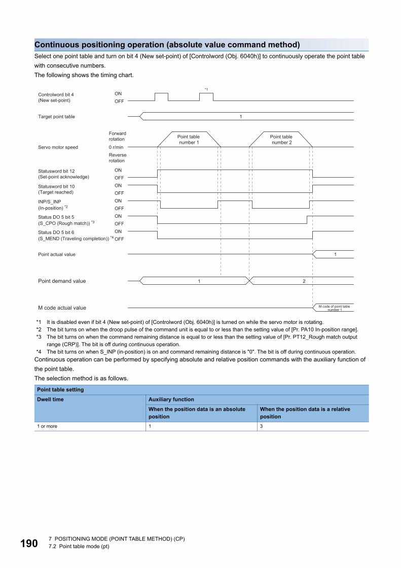
19
Continuous positioning operation (absolute value command method)Select one point table and turn on bit 4 (New set-point) of [Controlword (Obj. 6040h)] to continuously operate the point table with consecutive numbers.The following shows the timing chart.
*1 It is disabled even if bit 4 (New set-point) of [Controlword (Obj. 6040h)] is turned on while the servo motor is rotating.*2 The bit turns on when the droop pulse of the command unit is equal to or less than the setting value of [Pr. PA10 In-position range].*3 The bit turns on when the command remaining distance is equal to or less than the setting value of [Pr. PT12_Rough match output
range (CRP)]. The bit is off during continuous operation.*4 The bit turns on when S_INP (in-position) is on and command remaining distance is "0". The bit is off during continuous operation.
Continuous operation can be performed by specifying absolute and relative position commands with the auxiliary function of the point table.The selection method is as follows.
Point table setting
Dwell time Auxiliary function
When the position data is an absolute position
When the position data is a relative position
1 or more 1 3
Statusword bit 12(Set-point acknowledge)
Controlword bit 4(New set-point)
Point actual value
Point demand value
1
1
1 2
M code actual value
*1
ONOFF
ONOFF
ONOFF
Statusword bit 10(Target reached)
ONOFF
ONOFF
ONOFF
INP/S_INP
Status DO 5 bit 5
Status DO 5 bit 6
0 r/min
Target point table
Point table number 1
Forward rotation
Servo motor speed
Point table number 2
Reverse rotation
(In-position) *2
(S_CPO (Rough match)) *3
(S_MEND (Traveling completion)) *4
M code of point table number 1
0 7 POSITIONING MODE (POINT TABLE METHOD) (CP)7.2 Point table mode (pt)
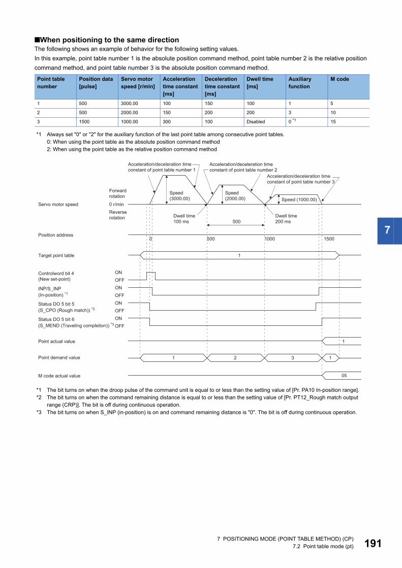
7
■When positioning to the same directionThe following shows an example of behavior for the following setting values.In this example, point table number 1 is the absolute position command method, point table number 2 is the relative position command method, and point table number 3 is the absolute position command method.
*1 Always set "0" or "2" for the auxiliary function of the last point table among consecutive point tables.0: When using the point table as the absolute position command method2: When using the point table as the relative position command method
*1 The bit turns on when the droop pulse of the command unit is equal to or less than the setting value of [Pr. PA10 In-position range].*2 The bit turns on when the command remaining distance is equal to or less than the setting value of [Pr. PT12_Rough match output
range (CRP)]. The bit is off during continuous operation.*3 The bit turns on when S_INP (in-position) is on and command remaining distance is "0". The bit is off during continuous operation.
Point table number
Position data [pulse]
Servo motor speed [r/min]
Acceleration time constant [ms]
Deceleration time constant [ms]
Dwell time [ms]
Auxiliary function
M code
1 500 3000.00 100 150 100 1 5
2 500 2000.00 150 200 200 3 10
3 1500 1000.00 300 100 Disabled 0 *1 15
0 r/min
Target point table
ONOFF
Point actual value
Point demand value
ONOFFONOFFONOFF
Controlword bit 4(New set-point)
INP/S_INP
Status DO 5 bit 5
Status DO 5 bit 6
500
0 500 1000 1500
1
1
11 2 3
M code actual value 05
Acceleration/deceleration time constant of point table number 1
Acceleration/deceleration time constant of point table number 2
Acceleration/deceleration time constant of point table number 3
Speed (3000.00)
Speed (2000.00)
Forward rotation
Speed (1000.00)Servo motor speed
Reverse rotation
Position address
(In-position) *1
(S_CPO (Rough match)) *2
(S_MEND (Traveling completion)) *3
Dwell time100 ms
Dwell time200 ms
7 POSITIONING MODE (POINT TABLE METHOD) (CP)7.2 Point table mode (pt) 191
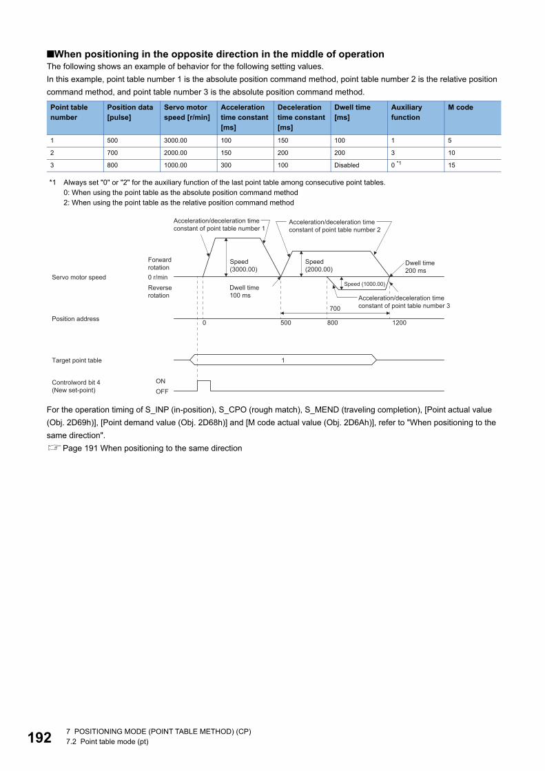
19
■When positioning in the opposite direction in the middle of operationThe following shows an example of behavior for the following setting values.In this example, point table number 1 is the absolute position command method, point table number 2 is the relative position command method, and point table number 3 is the absolute position command method.
*1 Always set "0" or "2" for the auxiliary function of the last point table among consecutive point tables.0: When using the point table as the absolute position command method2: When using the point table as the relative position command method
For the operation timing of S_INP (in-position), S_CPO (rough match), S_MEND (traveling completion), [Point actual value (Obj. 2D69h)], [Point demand value (Obj. 2D68h)] and [M code actual value (Obj. 2D6Ah)], refer to "When positioning to the same direction".Page 191 When positioning to the same direction
Point table number
Position data [pulse]
Servo motor speed [r/min]
Acceleration time constant [ms]
Deceleration time constant [ms]
Dwell time [ms]
Auxiliary function
M code
1 500 3000.00 100 150 100 1 5
2 700 2000.00 150 200 200 3 10
3 800 1000.00 300 100 Disabled 0 *1 15
Target point table
Controlword bit 4(New set-point)
ON
700
0 500 800 1200
1
0 r/min
OFF
Acceleration/deceleration time constant of point table number 1
Acceleration/deceleration time constant of point table number 2
Speed (3000.00)
Speed (2000.00)
Forward rotation
Servo motor speedSpeed (1000.00)Reverse
rotation Acceleration/deceleration time constant of point table number 3
Position address
Dwell time100 ms
Dwell time200 ms
2 7 POSITIONING MODE (POINT TABLE METHOD) (CP)7.2 Point table mode (pt)
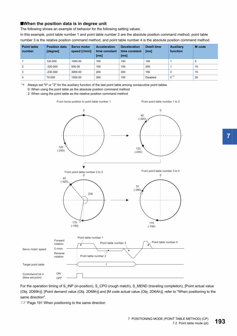
7
■When the position data is in degree unitThe following shows an example of behavior for the following setting values.In this example, point table number 1 and point table number 2 are the absolute position command method, point table number 3 is the relative position command method, and point table number 4 is the absolute position command method.
*1 Always set "0" or "2" for the auxiliary function of the last point table among consecutive point tables.0: When using the point table as the absolute position command method2: When using the point table as the relative position command method
For the operation timing of S_INP (in-position), S_CPO (rough match), S_MEND (traveling completion), [Point actual value (Obj. 2D69h)], [Point demand value (Obj. 2D68h)] and [M code actual value (Obj. 2D6Ah)], refer to "When positioning to the same direction".Page 191 When positioning to the same direction
Point table number
Position data [degree]
Servo motor speed [r/min]
Acceleration time constant [ms]
Deceleration time constant [ms]
Dwell time [ms]
Auxiliary function
M code
1 120.000 1000.00 100 150 100 1 5
2 -320.000 500.00 150 100 200 1 10
3 -230.000 3000.00 200 300 150 3 15
4 70.000 1500.00 300 100 Disabled 0 *1 20
120(-240)
40(-320)
230
170(-190)
70(-290)
170(-190)
120(-240)
40(-320)
0 0
00
From home position to point table number 1
From point table number 2 to 3 From point table number 3 to 4
From point table number 1 to 2
0 r/min
ON
1Target point table
Controlword bit 4(New set-point) OFF
Point table number 1Point table number 4Point table number 3
Forward rotation
Servo motor speedReverse rotation Point table number 2
7 POSITIONING MODE (POINT TABLE METHOD) (CP)7.2 Point table mode (pt) 193
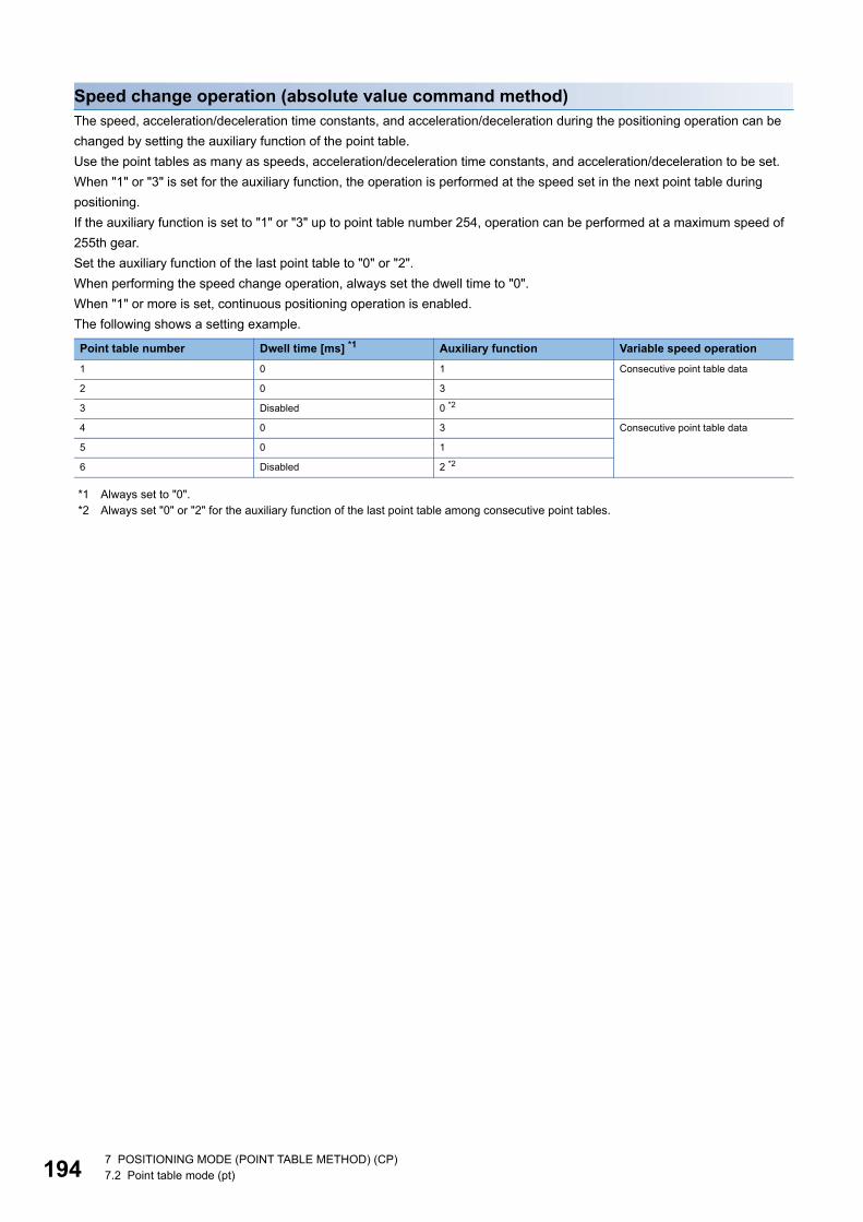
19
Speed change operation (absolute value command method)The speed, acceleration/deceleration time constants, and acceleration/deceleration during the positioning operation can be changed by setting the auxiliary function of the point table.Use the point tables as many as speeds, acceleration/deceleration time constants, and acceleration/deceleration to be set.When "1" or "3" is set for the auxiliary function, the operation is performed at the speed set in the next point table during positioning.If the auxiliary function is set to "1" or "3" up to point table number 254, operation can be performed at a maximum speed of 255th gear.Set the auxiliary function of the last point table to "0" or "2".When performing the speed change operation, always set the dwell time to "0".When "1" or more is set, continuous positioning operation is enabled.The following shows a setting example.
*1 Always set to "0".*2 Always set "0" or "2" for the auxiliary function of the last point table among consecutive point tables.
Point table number Dwell time [ms] *1 Auxiliary function Variable speed operation1 0 1 Consecutive point table data
2 0 3
3 Disabled 0 *2
4 0 3 Consecutive point table data
5 0 1
6 Disabled 2 *2
4 7 POSITIONING MODE (POINT TABLE METHOD) (CP)7.2 Point table mode (pt)

7
■When positioning to the same directionThe following shows an example of behavior for the following setting values.In this example, point table number 1 is the absolute position command method, point table number 2 is the relative position command method, and point table number 3 is the absolute position command method.
*1 Always set to "0".*2 Always set "0" or "2" for the auxiliary function of the last point table among consecutive point tables.
0: When using the point table as the absolute position command method2: When using the point table as the relative position command method
*1 The bit turns on when the droop pulse of the command unit is equal to or less than the setting value of [Pr. PA10 In-position range].*2 The bit turns on when the command remaining distance is equal to or less than the setting value of [Pr. PT12_Rough match output
range (CRP)]. The bit is off during continuous operation.*3 The bit turns on when S_INP (in-position) is on and command remaining distance is "0". The bit is off during continuous operation.
Point table number
Position data [pulse]
Servo motor speed [r/min]
Acceleration time constant [ms]
Deceleration time constant [ms]
Dwell time [ms] *1
Auxiliary function
M code
1 500 3000.00 100 150 0 1 5
2 300 2000.00 10 100 0 3 10
3 1000 1000.00 150 70 0 1 15
4 600 500.00 200 120 Disabled 2 *2 20
0 500 800 1600
300 600
1000
0 r/min
Target point table
ONOFF
1
1
ONOFFONOFFONOFF
Controlword bit 4(New set-point)
Point actual value
INP/S_INP
Status DO 5 bit 5
Status DO 5 bit 6
Point demand value 11 2 3 4
M code actual value 05
Speed (1000.00)Speed
(3000.00) Speed (2000.00)
Speed (500.00)
Forward rotation
Servo motor speedReverse rotation
Position address
(In-position) *1
(S_CPO (Rough match)) *2
(S_MEND (Traveling completion)) *3
Acceleration time constant of point table number 1 (100)
Deceleration time constant of point table number 2 (100) Deceleration time constant of
point table number 3 (70) Deceleration time constant of point table number 4 (120)
7 POSITIONING MODE (POINT TABLE METHOD) (CP)7.2 Point table mode (pt) 195
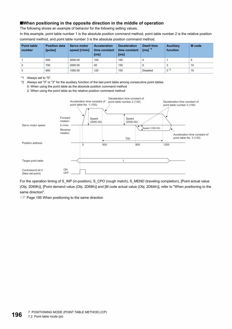
19
■When positioning in the opposite direction in the middle of operationThe following shows an example of behavior for the following setting values.In this example, point table number 1 is the absolute position command method, point table number 2 is the relative position command method, and point table number 3 is the absolute position command method.
*1 Always set to "0".*2 Always set "0" or "2" for the auxiliary function of the last point table among consecutive point tables.
0: When using the point table as the absolute position command method2: When using the point table as the relative position command method
For the operation timing of S_INP (in-position), S_CPO (rough match), S_MEND (traveling completion), [Point actual value (Obj. 2D69h)], [Point demand value (Obj. 2D68h)] and [M code actual value (Obj. 2D6Ah)], refer to "When positioning to the same direction".Page 195 When positioning to the same direction
Point table number
Position data [pulse]
Servo motor speed [r/min]
Acceleration time constant [ms]
Deceleration time constant [ms]
Dwell time [ms] *1
Auxiliary function
M code
1 500 3000.00 100 150 0 1 5
2 700 2000.00 50 130 0 3 10
3 800 1000.00 120 100 Disabled 0 *2 15
Target point table
Controlword bit 4(New set-point)
ONOFF
700
0 500 800 1200
1
0 r/min
Speed (3000.00)
Speed (2000.00)
Forward rotation
Servo motor speedSpeed (1000.00)Reverse
rotation
Position address
Acceleration time constant of point table No. 1 (100)
Acceleration time constant of point table No. 3 (120)
Deceleration time constant of point table number 2 (130) Deceleration time constant of
point table number 3 (100)
6 7 POSITIONING MODE (POINT TABLE METHOD) (CP)7.2 Point table mode (pt)
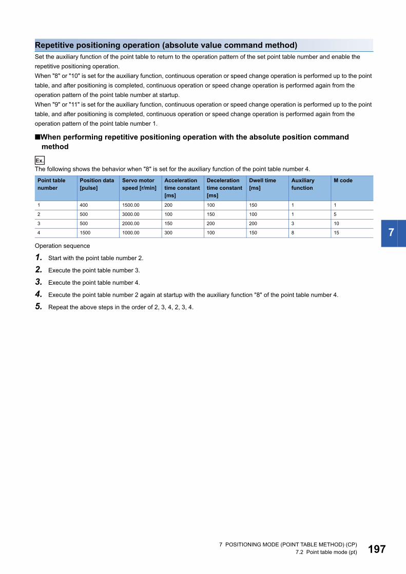
7
Repetitive positioning operation (absolute value command method)Set the auxiliary function of the point table to return to the operation pattern of the set point table number and enable the repetitive positioning operation.When "8" or "10" is set for the auxiliary function, continuous operation or speed change operation is performed up to the point table, and after positioning is completed, continuous operation or speed change operation is performed again from the operation pattern of the point table number at startup.When "9" or "11" is set for the auxiliary function, continuous operation or speed change operation is performed up to the point table, and after positioning is completed, continuous operation or speed change operation is performed again from the operation pattern of the point table number 1.
■When performing repetitive positioning operation with the absolute position command method
Ex.
The following shows the behavior when "8" is set for the auxiliary function of the point table number 4.
Operation sequence
1. Start with the point table number 2.
2. Execute the point table number 3.
3. Execute the point table number 4.
4. Execute the point table number 2 again at startup with the auxiliary function "8" of the point table number 4.
5. Repeat the above steps in the order of 2, 3, 4, 2, 3, 4.
Point table number
Position data [pulse]
Servo motor speed [r/min]
Acceleration time constant [ms]
Deceleration time constant [ms]
Dwell time [ms]
Auxiliary function
M code
1 400 1500.00 200 100 150 1 1
2 500 3000.00 100 150 100 1 5
3 500 2000.00 150 200 200 3 10
4 1500 1000.00 300 100 150 8 15
7 POSITIONING MODE (POINT TABLE METHOD) (CP)7.2 Point table mode (pt) 197
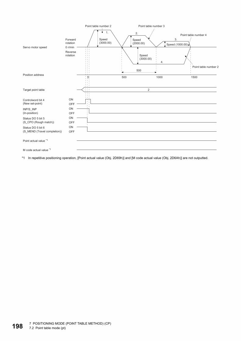
19
*1 In repetitive positioning operation, [Point actual value (Obj. 2D69h)] and [M code actual value (Obj. 2D6Ah)] are not outputted.
500
1. 2.
3.
4.
0 500 1000 1500
2
0 r/min
Target point table
ONOFF
Point actual value *1
M code actual value *1
ONOFFONOFFONOFF
Controlword bit 4(New set-point)
INP/S_INP
Status DO 5 bit 5
Status DO 5 bit 6
Point table number 2 Point table number 3
Point table number 4Speed (3000.00)
Speed (2000.00)
Forward rotation Speed (1000.00)
Servo motor speedReverse rotation Speed
(3000.00)
Point table number 2
Position address
(In-position)
(S_CPO (Rough match))
(S_MEND (Travel completion))
8 7 POSITIONING MODE (POINT TABLE METHOD) (CP)7.2 Point table mode (pt)
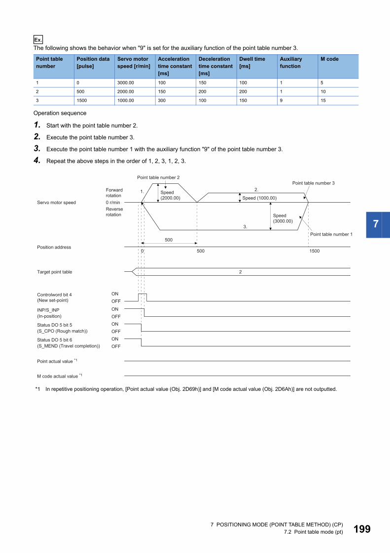
7
Ex.
The following shows the behavior when "9" is set for the auxiliary function of the point table number 3.
Operation sequence
1. Start with the point table number 2.
2. Execute the point table number 3.
3. Execute the point table number 1 with the auxiliary function "9" of the point table number 3.
4. Repeat the above steps in the order of 1, 2, 3, 1, 2, 3.
*1 In repetitive positioning operation, [Point actual value (Obj. 2D69h)] and [M code actual value (Obj. 2D6Ah)] are not outputted.
Point table number
Position data [pulse]
Servo motor speed [r/min]
Acceleration time constant [ms]
Deceleration time constant [ms]
Dwell time [ms]
Auxiliary function
M code
1 0 3000.00 100 150 100 1 5
2 500 2000.00 150 200 200 1 10
3 1500 1000.00 300 100 150 9 15
500
1. 2.
3.
0 500 1500
2
0 r/min
Target point table
ONOFF
Point actual value *1
M code actual value *1
ONOFFONOFFONOFF
Controlword bit 4(New set-point)
INP/S_INP
Status DO 5 bit 5
Status DO 5 bit 6
Point table number 2Point table number 3
Speed (2000.00)
Forward rotation Speed (1000.00)
Servo motor speedReverse rotation Speed
(3000.00)
Point table number 1
Position address
(In-position)
(S_CPO (Rough match))
(S_MEND (Travel completion))
7 POSITIONING MODE (POINT TABLE METHOD) (CP)7.2 Point table mode (pt) 199
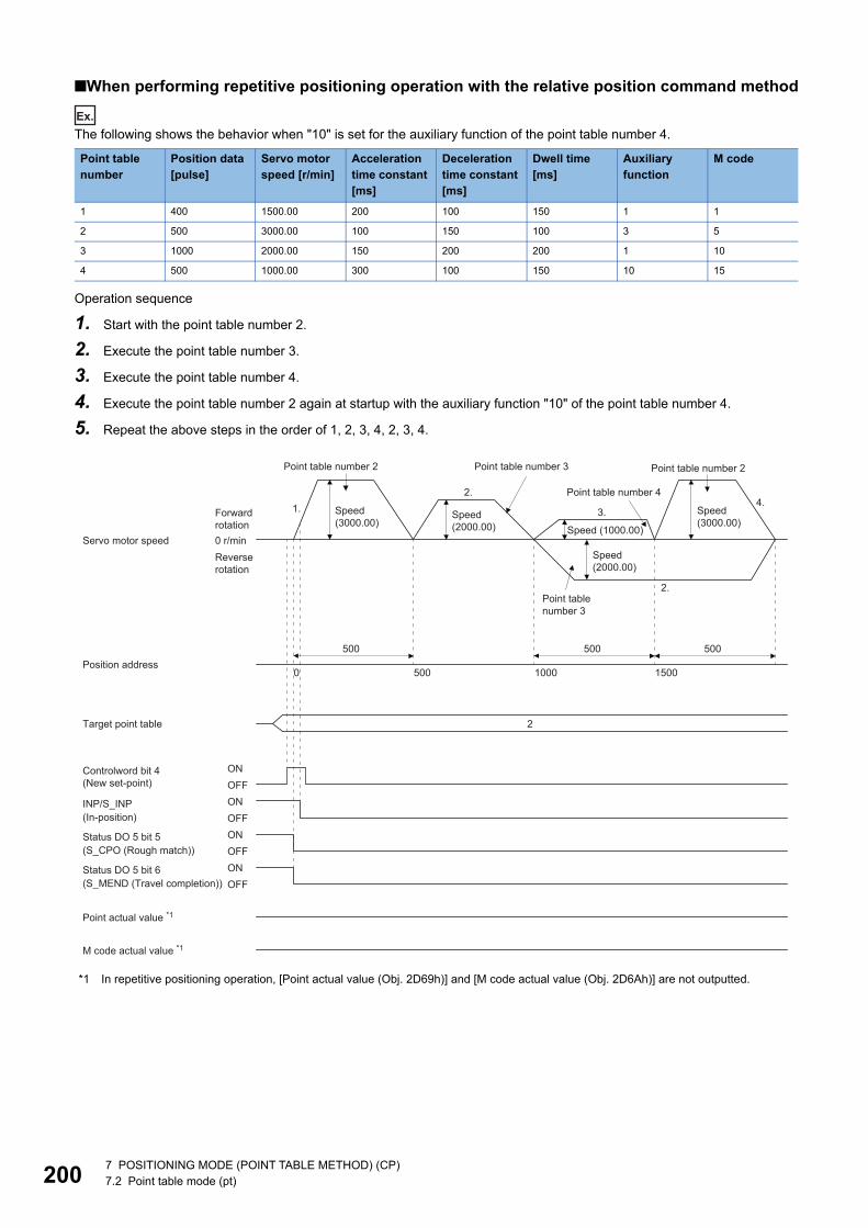
20
■When performing repetitive positioning operation with the relative position command method
Ex.
The following shows the behavior when "10" is set for the auxiliary function of the point table number 4.
Operation sequence
1. Start with the point table number 2.
2. Execute the point table number 3.
3. Execute the point table number 4.
4. Execute the point table number 2 again at startup with the auxiliary function "10" of the point table number 4.
5. Repeat the above steps in the order of 1, 2, 3, 4, 2, 3, 4.
*1 In repetitive positioning operation, [Point actual value (Obj. 2D69h)] and [M code actual value (Obj. 2D6Ah)] are not outputted.
Point table number
Position data [pulse]
Servo motor speed [r/min]
Acceleration time constant [ms]
Deceleration time constant [ms]
Dwell time [ms]
Auxiliary function
M code
1 400 1500.00 200 100 150 1 1
2 500 3000.00 100 150 100 3 5
3 1000 2000.00 150 200 200 1 10
4 500 1000.00 300 100 150 10 15
500
0 500
1.2.
2.
3.4.
1000 1500
500500
2Target point table
Point actual value *1
M code actual value *1
ONOFFONOFFONOFF
Controlword bit 4(New set-point)
INP/S_INP
Status DO 5 bit 5
Status DO 5 bit 6
0 r/min
ONOFF
Point table number 2 Point table number 3 Point table number 2
Point table number 4
Speed (3000.00)
Speed (3000.00)
Speed (2000.00)
Forward rotation Speed (1000.00)
Servo motor speedReverse rotation
Speed (2000.00)
Point table number 3
Position address
(In-position)
(S_CPO (Rough match))
(S_MEND (Travel completion))
0 7 POSITIONING MODE (POINT TABLE METHOD) (CP)7.2 Point table mode (pt)
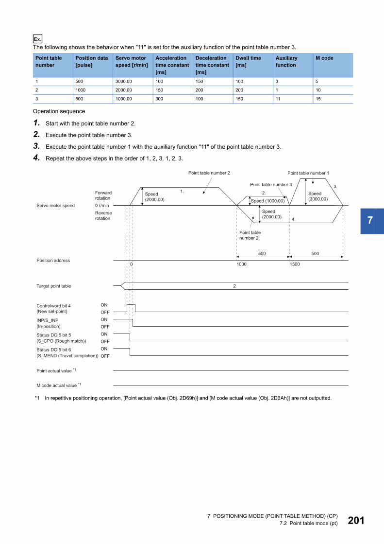
7
Ex.
The following shows the behavior when "11" is set for the auxiliary function of the point table number 3.
Operation sequence
1. Start with the point table number 2.
2. Execute the point table number 3.
3. Execute the point table number 1 with the auxiliary function "11" of the point table number 3.
4. Repeat the above steps in the order of 1, 2, 3, 1, 2, 3.
*1 In repetitive positioning operation, [Point actual value (Obj. 2D69h)] and [M code actual value (Obj. 2D6Ah)] are not outputted.
Point table number
Position data [pulse]
Servo motor speed [r/min]
Acceleration time constant [ms]
Deceleration time constant [ms]
Dwell time [ms]
Auxiliary function
M code
1 500 3000.00 100 150 100 3 5
2 1000 2000.00 150 200 200 1 10
3 500 1000.00 300 100 150 11 15
500
1.
4.
2.3.
0 1000 1500
500
2
0 r/min
Target point table
ONOFF
Point actual value *1
M code actual value *1
ONOFFONOFFONOFF
Controlword bit 4(New set-point)
INP/S_INP
Status DO 5 bit 5
Status DO 5 bit 6
Point table number 2 Point table number 1
Point table number 3
Speed (3000.00)
Speed (2000.00)
Forward rotation Speed (1000.00)
Servo motor speedReverse rotation
Speed (2000.00)
Point table number 2
Position address
(In-position)
(S_CPO (Rough match))
(S_MEND (Travel completion))
7 POSITIONING MODE (POINT TABLE METHOD) (CP)7.2 Point table mode (pt) 201
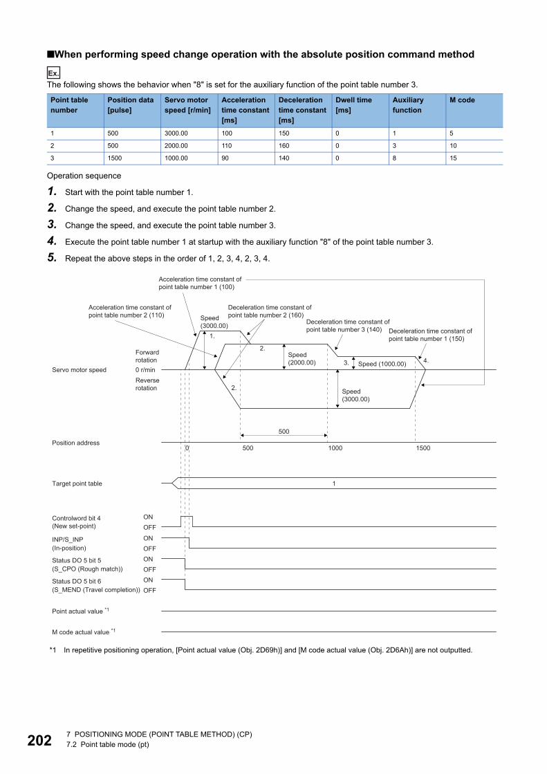
20
■When performing speed change operation with the absolute position command method
Ex.
The following shows the behavior when "8" is set for the auxiliary function of the point table number 3.
Operation sequence
1. Start with the point table number 1.
2. Change the speed, and execute the point table number 2.
3. Change the speed, and execute the point table number 3.
4. Execute the point table number 1 at startup with the auxiliary function "8" of the point table number 3.
5. Repeat the above steps in the order of 1, 2, 3, 4, 2, 3, 4.
*1 In repetitive positioning operation, [Point actual value (Obj. 2D69h)] and [M code actual value (Obj. 2D6Ah)] are not outputted.
Point table number
Position data [pulse]
Servo motor speed [r/min]
Acceleration time constant [ms]
Deceleration time constant [ms]
Dwell time [ms]
Auxiliary function
M code
1 500 3000.00 100 150 0 1 5
2 500 2000.00 110 160 0 3 10
3 1500 1000.00 90 140 0 8 15
500
0 500 1000
1.
3. 4.
1500
2.
2.
1
0 r/min
Target point table
ONOFF
Point actual value *1
M code actual value *1
ONOFFONOFFONOFF
Controlword bit 4(New set-point)
INP/S_INP
Status DO 5 bit 5
Status DO 5 bit 6
Speed (3000.00)
Speed (2000.00)
Forward rotation Speed (1000.00)
Servo motor speedReverse rotation Speed
(3000.00)
Position address
(In-position)
(S_CPO (Rough match))
(S_MEND (Travel completion))
Deceleration time constant of point table number 2 (160)
Acceleration time constant of point table number 2 (110)
Acceleration time constant of point table number 1 (100)
Deceleration time constant of point table number 3 (140) Deceleration time constant of
point table number 1 (150)
2 7 POSITIONING MODE (POINT TABLE METHOD) (CP)7.2 Point table mode (pt)
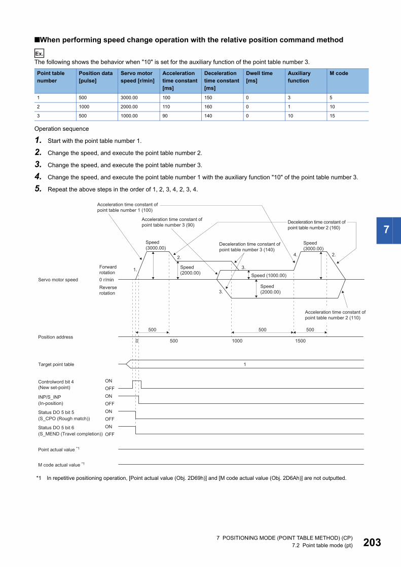
7
■When performing speed change operation with the relative position command method
Ex.
The following shows the behavior when "10" is set for the auxiliary function of the point table number 3.
Operation sequence
1. Start with the point table number 1.
2. Change the speed, and execute the point table number 2.
3. Change the speed, and execute the point table number 3.
4. Change the speed, and execute the point table number 1 with the auxiliary function "10" of the point table number 3.
5. Repeat the above steps in the order of 1, 2, 3, 4, 2, 3, 4.
*1 In repetitive positioning operation, [Point actual value (Obj. 2D69h)] and [M code actual value (Obj. 2D6Ah)] are not outputted.
Point table number
Position data [pulse]
Servo motor speed [r/min]
Acceleration time constant [ms]
Deceleration time constant [ms]
Dwell time [ms]
Auxiliary function
M code
1 500 3000.00 100 150 0 3 5
2 1000 2000.00 110 160 0 1 10
3 500 1000.00 90 140 0 10 15
0 500
1.
2. 4. 2.
3.
3.
1000 1500
500
1
0 r/min
Target point table
ONOFF
Point actual value *1
M code actual value *1
ONOFFONOFFONOFF
Controlword bit 4(New set-point)
INP/S_INP
Status DO 5 bit 5
Status DO 5 bit 6
500 500
Acceleration time constant of point table number 1 (100)
Speed (3000.00)
Speed (2000.00)
Speed (3000.00)
Forward rotation Speed (1000.00)
Servo motor speedSpeed (2000.00)
Reverse rotation
Position address
(In-position)
(S_CPO (Rough match))
(S_MEND (Travel completion))
Acceleration time constant of point table number 3 (90)
Deceleration time constant of point table number 3 (140)
Deceleration time constant of point table number 2 (160)
Acceleration time constant of point table number 2 (110)
7 POSITIONING MODE (POINT TABLE METHOD) (CP)7.2 Point table mode (pt) 203
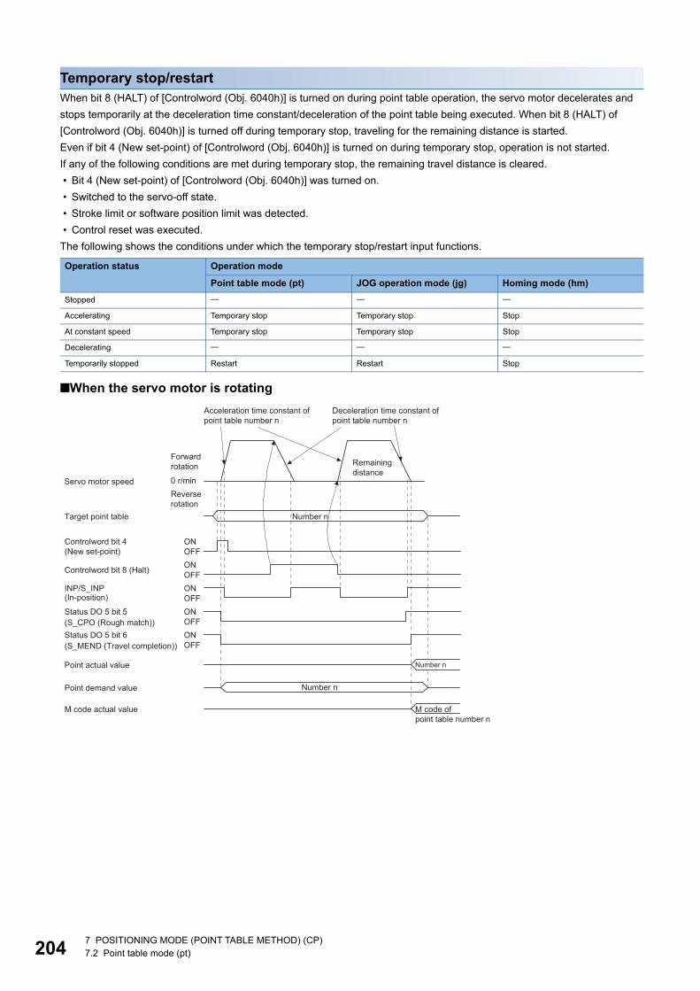
20
Temporary stop/restartWhen bit 8 (HALT) of [Controlword (Obj. 6040h)] is turned on during point table operation, the servo motor decelerates and stops temporarily at the deceleration time constant/deceleration of the point table being executed. When bit 8 (HALT) of [Controlword (Obj. 6040h)] is turned off during temporary stop, traveling for the remaining distance is started.Even if bit 4 (New set-point) of [Controlword (Obj. 6040h)] is turned on during temporary stop, operation is not started.If any of the following conditions are met during temporary stop, the remaining travel distance is cleared. • Bit 4 (New set-point) of [Controlword (Obj. 6040h)] was turned on. • Switched to the servo-off state. • Stroke limit or software position limit was detected. • Control reset was executed.The following shows the conditions under which the temporary stop/restart input functions.
■When the servo motor is rotating
Operation status Operation mode
Point table mode (pt) JOG operation mode (jg) Homing mode (hm)Stopped
Accelerating Temporary stop Temporary stop Stop
At constant speed Temporary stop Temporary stop Stop
Decelerating
Temporarily stopped Restart Restart Stop
ONOFF
ONOFF
OFF
OFF
ON
ON
OFFON
Controlword bit 4(New set-point)
Target point table
Point demand value
Controlword bit 8 (Halt)
Point actual value
M code actual value
INP/S_INP
Status DO 5 bit 5
Status DO 5 bit 6
0 r/min
Acceleration time constant of point table number n
Deceleration time constant of point table number n
Remaining distance
Forward rotation
Servo motor speedReverse rotation
Number n
Number n
(S_CPO (Rough match))
(In-position)
(S_MEND (Travel completion))
Number n
M code of point table number n
4 7 POSITIONING MODE (POINT TABLE METHOD) (CP)7.2 Point table mode (pt)
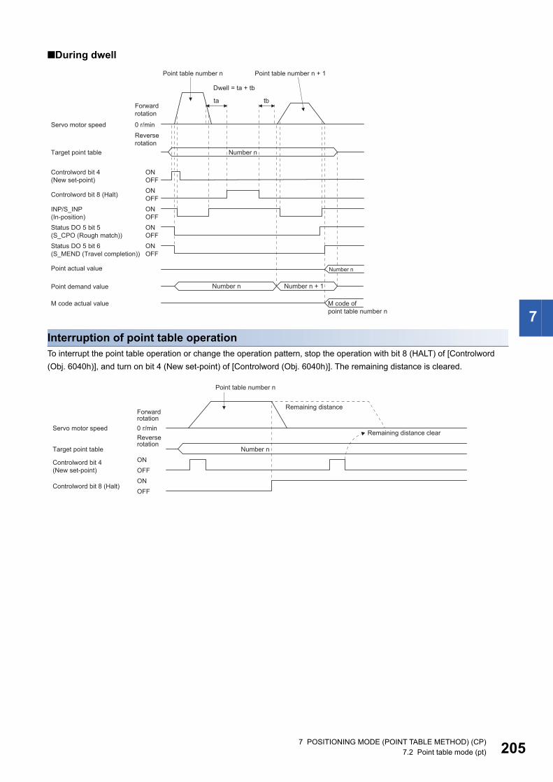
7
■During dwell
Interruption of point table operationTo interrupt the point table operation or change the operation pattern, stop the operation with bit 8 (HALT) of [Controlword (Obj. 6040h)], and turn on bit 4 (New set-point) of [Controlword (Obj. 6040h)]. The remaining distance is cleared.
ONOFF
ONOFF
OFFON
OFFON
ta tb
Controlword bit 4(New set-point)
Target point table
Controlword bit 8 (Halt)
Point actual value
OFFONStatus DO 5 bit 5
INP/S_INP
Status DO 5 bit 6
0 r/min
Point demand value
M code actual value
Point table number n Point table number n + 1
Dwell = ta + tb
Forward rotation
Servo motor speedReverse rotation
Number n
(S_CPO (Rough match))
(In-position)
(S_MEND (Travel completion))
Number n
Number n Number n + 1
M code of point table number n
0 r/min
Controlword bit 4(New set-point)
Target point table
Controlword bit 8 (Halt)
ONOFFONOFF
Point table number n
Remaining distanceForward rotation
Servo motor speedRemaining distance clear
Reverse rotation
Number n
7 POSITIONING MODE (POINT TABLE METHOD) (CP)7.2 Point table mode (pt) 205
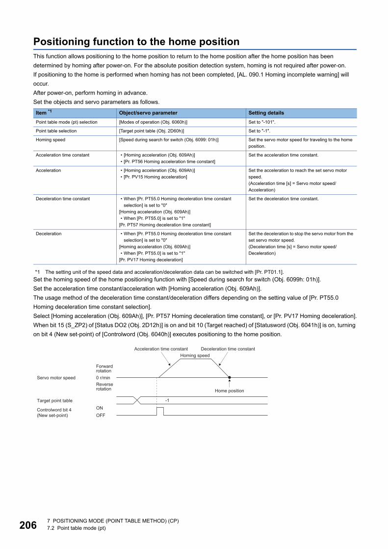
20
Positioning function to the home positionThis function allows positioning to the home position to return to the home position after the home position has been determined by homing after power-on. For the absolute position detection system, homing is not required after power-on.If positioning to the home is performed when homing has not been completed, [AL. 090.1 Homing incomplete warning] will occur.After power-on, perform homing in advance.Set the objects and servo parameters as follows.
*1 The setting unit of the speed data and acceleration/deceleration data can be switched with [Pr. PT01.1].Set the homing speed of the home positioning function with [Speed during search for switch (Obj. 6099h: 01h)].Set the acceleration time constant/acceleration with [Homing acceleration (Obj. 609Ah)].The usage method of the deceleration time constant/deceleration differs depending on the setting value of [Pr. PT55.0 Homing deceleration time constant selection].Select [Homing acceleration (Obj. 609Ah)], [Pr. PT57 Homing deceleration time constant], or [Pr. PV17 Homing deceleration].When bit 15 (S_ZP2) of [Status DO2 (Obj. 2D12h)] is on and bit 10 (Target reached) of [Statusword (Obj. 6041h)] is on, turning on bit 4 (New set-point) of [Controlword (Obj. 6040h)] executes positioning to the home position.
Item *1 Object/servo parameter Setting detailsPoint table mode (pt) selection [Modes of operation (Obj. 6060h)] Set to "-101".
Point table selection [Target point table (Obj. 2D60h)] Set to "-1".
Homing speed [Speed during search for switch (Obj. 6099: 01h)] Set the servo motor speed for traveling to the home position.
Acceleration time constant • [Homing acceleration (Obj. 609Ah)]• [Pr. PT56 Homing acceleration time constant]
Set the acceleration time constant.
Acceleration • [Homing acceleration (Obj. 609Ah)]• [Pr. PV15 Homing acceleration]
Set the acceleration to reach the set servo motor speed.(Acceleration time [s] = Servo motor speed/Acceleration)
Deceleration time constant • When [Pr. PT55.0 Homing deceleration time constant selection] is set to "0"
[Homing acceleration (Obj. 609Ah)]• When [Pr. PT55.0] is set to "1"
[Pr. PT57 Homing deceleration time constant]
Set the deceleration time constant.
Deceleration • When [Pr. PT55.0 Homing deceleration time constant selection] is set to "0"
[Homing acceleration (Obj. 609Ah)]• When [Pr. PT55.0] is set to "1"
[Pr. PV17 Homing deceleration]
Set the deceleration to stop the servo motor from the set servo motor speed.(Deceleration time [s] = Servo motor speed/Deceleration)
0 r/min
Controlword bit 4(New set-point)
Target point tableONOFF
-1
Forward rotation
Servo motor speedReverse rotation
Homing speedAcceleration time constant Deceleration time constant
Home position
6 7 POSITIONING MODE (POINT TABLE METHOD) (CP)7.2 Point table mode (pt)
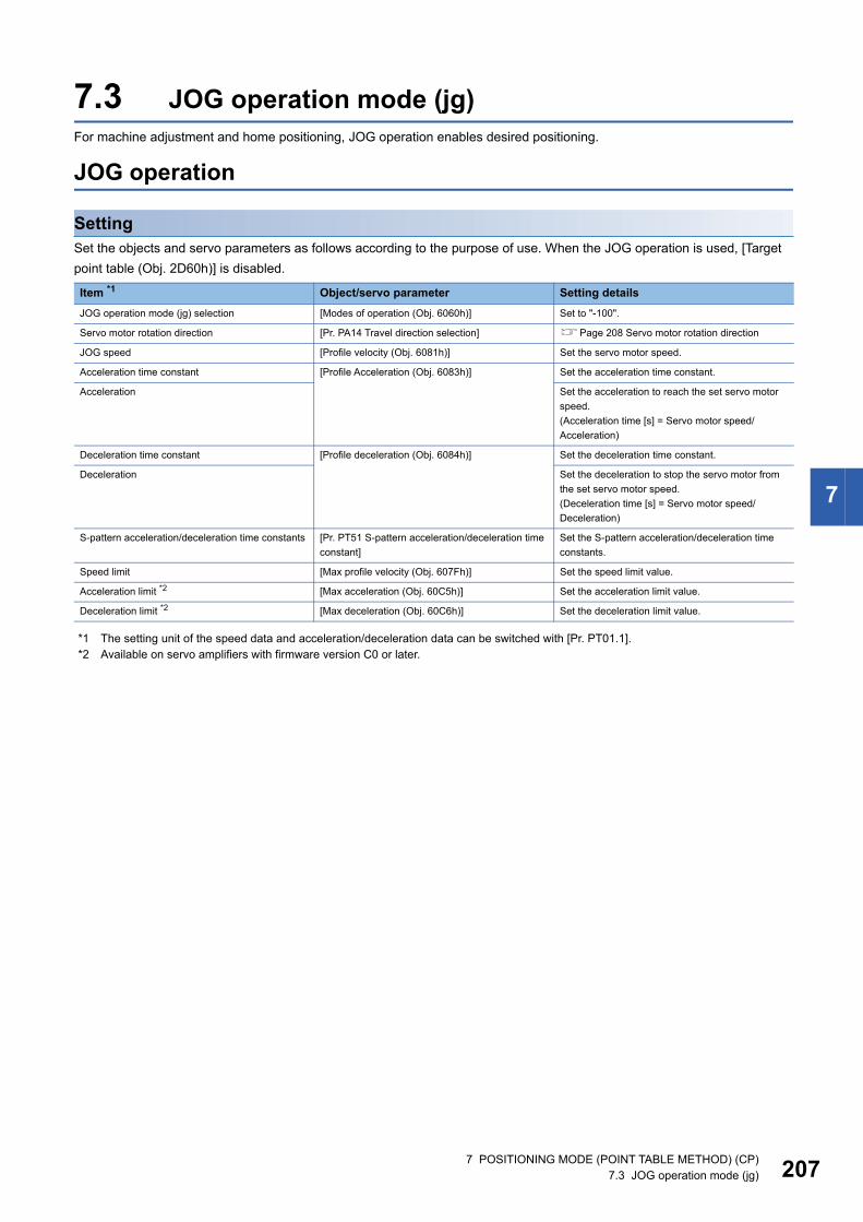
7
7.3 JOG operation mode (jg)For machine adjustment and home positioning, JOG operation enables desired positioning.
JOG operation
SettingSet the objects and servo parameters as follows according to the purpose of use. When the JOG operation is used, [Target point table (Obj. 2D60h)] is disabled.
*1 The setting unit of the speed data and acceleration/deceleration data can be switched with [Pr. PT01.1].*2 Available on servo amplifiers with firmware version C0 or later.
Item *1 Object/servo parameter Setting detailsJOG operation mode (jg) selection [Modes of operation (Obj. 6060h)] Set to "-100".
Servo motor rotation direction [Pr. PA14 Travel direction selection] Page 208 Servo motor rotation direction
JOG speed [Profile velocity (Obj. 6081h)] Set the servo motor speed.
Acceleration time constant [Profile Acceleration (Obj. 6083h)] Set the acceleration time constant.
Acceleration Set the acceleration to reach the set servo motor speed.(Acceleration time [s] = Servo motor speed/Acceleration)
Deceleration time constant [Profile deceleration (Obj. 6084h)] Set the deceleration time constant.
Deceleration Set the deceleration to stop the servo motor from the set servo motor speed.(Deceleration time [s] = Servo motor speed/Deceleration)
S-pattern acceleration/deceleration time constants [Pr. PT51 S-pattern acceleration/deceleration time constant]
Set the S-pattern acceleration/deceleration time constants.
Speed limit [Max profile velocity (Obj. 607Fh)] Set the speed limit value.
Acceleration limit *2 [Max acceleration (Obj. 60C5h)] Set the acceleration limit value.
Deceleration limit *2 [Max deceleration (Obj. 60C6h)] Set the deceleration limit value.
7 POSITIONING MODE (POINT TABLE METHOD) (CP)7.3 JOG operation mode (jg) 207
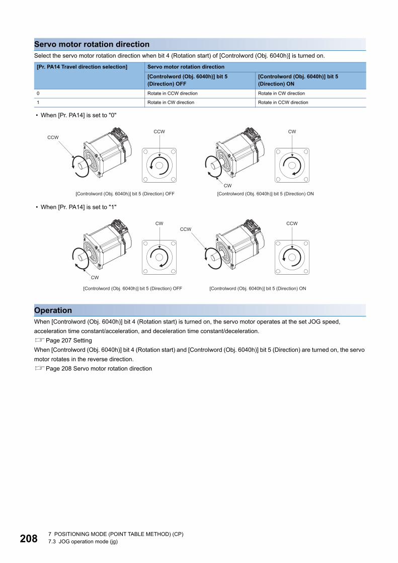
20
Servo motor rotation directionSelect the servo motor rotation direction when bit 4 (Rotation start) of [Controlword (Obj. 6040h)] is turned on.
• When [Pr. PA14] is set to "0"
• When [Pr. PA14] is set to "1"
OperationWhen [Controlword (Obj. 6040h)] bit 4 (Rotation start) is turned on, the servo motor operates at the set JOG speed, acceleration time constant/acceleration, and deceleration time constant/deceleration.Page 207 SettingWhen [Controlword (Obj. 6040h)] bit 4 (Rotation start) and [Controlword (Obj. 6040h)] bit 5 (Direction) are turned on, the servo motor rotates in the reverse direction.Page 208 Servo motor rotation direction
[Pr. PA14 Travel direction selection] Servo motor rotation direction
[Controlword (Obj. 6040h)] bit 5 (Direction) OFF
[Controlword (Obj. 6040h)] bit 5 (Direction) ON
0 Rotate in CCW direction Rotate in CW direction
1 Rotate in CW direction Rotate in CCW direction
CCWCCW CW
CW
[Controlword (Obj. 6040h)] bit 5 (Direction) OFF [Controlword (Obj. 6040h)] bit 5 (Direction) ON
CCWCCWCW
CW
[Controlword (Obj. 6040h)] bit 5 (Direction) ON[Controlword (Obj. 6040h)] bit 5 (Direction) OFF
8 7 POSITIONING MODE (POINT TABLE METHOD) (CP)7.3 JOG operation mode (jg)
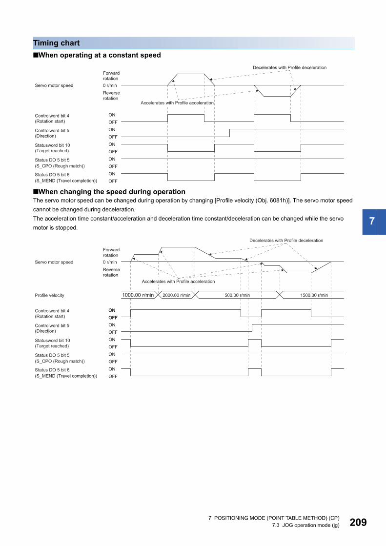
7
Timing chart■When operating at a constant speed
■When changing the speed during operationThe servo motor speed can be changed during operation by changing [Profile velocity (Obj. 6081h)]. The servo motor speed cannot be changed during deceleration.The acceleration time constant/acceleration and deceleration time constant/deceleration can be changed while the servo motor is stopped.
Controlword bit 4(Rotation start)
Controlword bit 5(Direction)
0 r/min
ONOFFONOFF
Statusword bit 10(Target reached)
Status DO 5 bit 5
Status DO 5 bit 6
ONOFFONOFF
ONOFF
Decelerates with Profile decelerationForward rotation
Servo motor speedReverse rotation
Accelerates with Profile acceleration
(S_CPO (Rough match))
(S_MEND (Travel completion))
Profile velocity 2000.00 r/min 1500.00 r/min
Controlword bit 4(Rotation start)
Controlword bit 5(Direction)
Statusword bit 10(Target reached)
Status DO 5 bit 5
Status DO 5 bit 6
0 r/min
ONOFFONOFF
ONOFFON
ONOFFONOFF
OFF
500.00 r/min1000.00 r/min
Decelerates with Profile deceleration
Forward rotation
Servo motor speedReverse rotation
Accelerates with Profile acceleration
(S_CPO (Rough match))
(S_MEND (Travel completion))
7 POSITIONING MODE (POINT TABLE METHOD) (CP)7.3 JOG operation mode (jg) 209
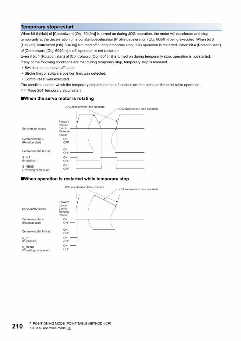
21
Temporary stop/restartWhen bit 8 (Halt) of [Controlword (Obj. 6040h)] is turned on during JOG operation, the motor will decelerate and stop temporarily at the deceleration time constant/deceleration [Profile deceleration (Obj. 6084h)] being executed. When bit 8 (Halt) of [Controlword (Obj. 6040h)] is turned off during temporary stop, JOG operation is restarted. When bit 4 (Rotation start) of [Controlword (Obj. 6040h)] is off, operation is not restarted.Even if bit 4 (Rotation start) of [Controlword (Obj. 6040h)] is turned on during temporarily stop, operation is not started.If any of the following conditions are met during temporary stop, temporary stop is released. • Switched to the servo-off state. • Stroke limit or software position limit was detected. • Control reset was executed.The conditions under which the temporary stop/restart input functions are the same as the point table operation.Page 204 Temporary stop/restart
■When the servo motor is rotating
■When operation is restarted while temporary stop
OFFON
ONOFF
Controlword bit 4(Rotation start)
ONOFFControlword bit 8 (Halt)
OFFONS_INP
0 r/min
Forward rotation
S_MEND (Traveling completion)
Servo motor speedReverse rotation
(In-position)
JOG deceleration time constantJOG acceleration time constant
OFFON
ONOFF
Controlword bit 4(Rotation start)
ONOFFControlword bit 8 (Halt)
OFFONS_INP
0 r/min
Forward rotation
S_MEND (Traveling completion)
Servo motor speedReverse rotation
(In-position)
JOG deceleration time constantJOG acceleration time constant
0 7 POSITIONING MODE (POINT TABLE METHOD) (CP)7.3 JOG operation mode (jg)
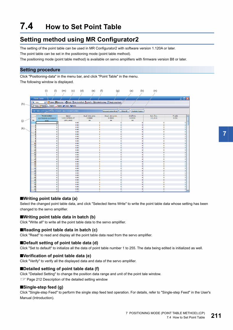
7
7.4 How to Set Point TableSetting method using MR Configurator2The setting of the point table can be used in MR Configurator2 with software version 1.120A or later.The point table can be set in the positioning mode (point table method).The positioning mode (point table method) is available on servo amplifiers with firmware version B8 or later.
Setting procedureClick "Positioning-data" in the menu bar, and click "Point Table" in the menu.The following window is displayed.
■Writing point table data (a)Select the changed point table data, and click "Selected Items Write" to write the point table data whose setting has been changed to the servo amplifier.
■Writing point table data in batch (b)Click "Write all" to write all the point table data to the servo amplifier.
■Reading point table data in batch (c)Click "Read" to read and display all the point table data read from the servo amplifier.
■Default setting of point table data (d)Click "Set to default" to initialize all the data of point table number 1 to 255. The data being edited is initialized as well.
■Verification of point table data (e)Click "Verify" to verify all the displayed data and data of the servo amplifier.
■Detailed setting of point table data (f)Click "Detailed Setting" to change the position data range and unit of the point tale window.Page 212 Description of the detailed setting window
■Single-step feed (g)Click "Single-step Feed" to perform the single step feed test operation. For details, refer to "Single-step Feed" in the User's Manual (Introduction).
(a)(g)(f)(d)(c)(m)(l)(i)
(h)
(j)
(k)
(e) (b) (n)
7 POSITIONING MODE (POINT TABLE METHOD) (CP)7.4 How to Set Point Table 211
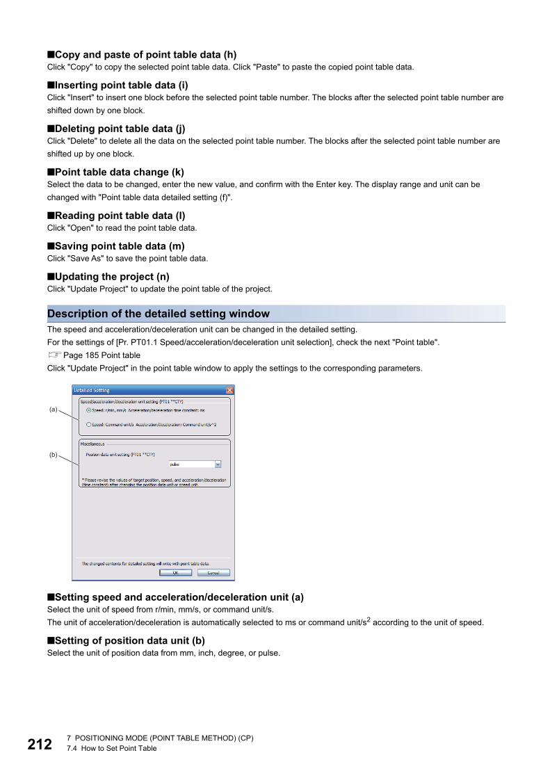
21
■Copy and paste of point table data (h)Click "Copy" to copy the selected point table data. Click "Paste" to paste the copied point table data.
■Inserting point table data (i)Click "Insert" to insert one block before the selected point table number. The blocks after the selected point table number are shifted down by one block.
■Deleting point table data (j)Click "Delete" to delete all the data on the selected point table number. The blocks after the selected point table number are shifted up by one block.
■Point table data change (k)Select the data to be changed, enter the new value, and confirm with the Enter key. The display range and unit can be changed with "Point table data detailed setting (f)".
■Reading point table data (l)Click "Open" to read the point table data.
■Saving point table data (m)Click "Save As" to save the point table data.
■Updating the project (n)Click "Update Project" to update the point table of the project.
Description of the detailed setting windowThe speed and acceleration/deceleration unit can be changed in the detailed setting.For the settings of [Pr. PT01.1 Speed/acceleration/deceleration unit selection], check the next "Point table".Page 185 Point tableClick "Update Project" in the point table window to apply the settings to the corresponding parameters.
■Setting speed and acceleration/deceleration unit (a)Select the unit of speed from r/min, mm/s, or command unit/s.The unit of acceleration/deceleration is automatically selected to ms or command unit/s2 according to the unit of speed.
■Setting of position data unit (b)Select the unit of position data from mm, inch, degree, or pulse.
(a)
(b)
2 7 POSITIONING MODE (POINT TABLE METHOD) (CP)7.4 How to Set Point Table
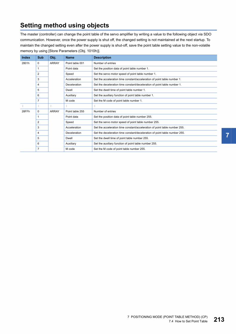
7
Setting method using objectsThe master (controller) can change the point table of the servo amplifier by writing a value to the following object via SDO communication. However, once the power supply is shut off, the changed setting is not maintained at the next startup. To maintain the changed setting even after the power supply is shut-off, save the point table setting value to the non-volatile memory by using [Store Parameters (Obj. 1010h)].
Index Sub Obj. Name Description2801h 0 ARRAY Point table 001 Number of entries
1 Point data Set the position data of point table number 1.
2 Speed Set the servo motor speed of point table number 1.
3 Acceleration Set the acceleration time constant/acceleration of point table number 1.
4 Deceleration Set the deceleration time constant/deceleration of point table number 1.
5 Dwell Set the dwell time of point table number 1.
6 Auxiliary Set the auxiliary function of point table number 1.
7 M code Set the M code of point table number 1.
28FFh 0 ARRAY Point table 255 Number of entries
1 Point data Set the position data of point table number 255.
2 Speed Set the servo motor speed of point table number 255.
3 Acceleration Set the acceleration time constant/acceleration of point table number 255.
4 Deceleration Set the deceleration time constant/deceleration of point table number 255.
5 Dwell Set the dwell time of point table number 255.
6 Auxiliary Set the auxiliary function of point table number 255.
7 M code Set the M code of point table number 255.
7 POSITIONING MODE (POINT TABLE METHOD) (CP)7.4 How to Set Point Table 213
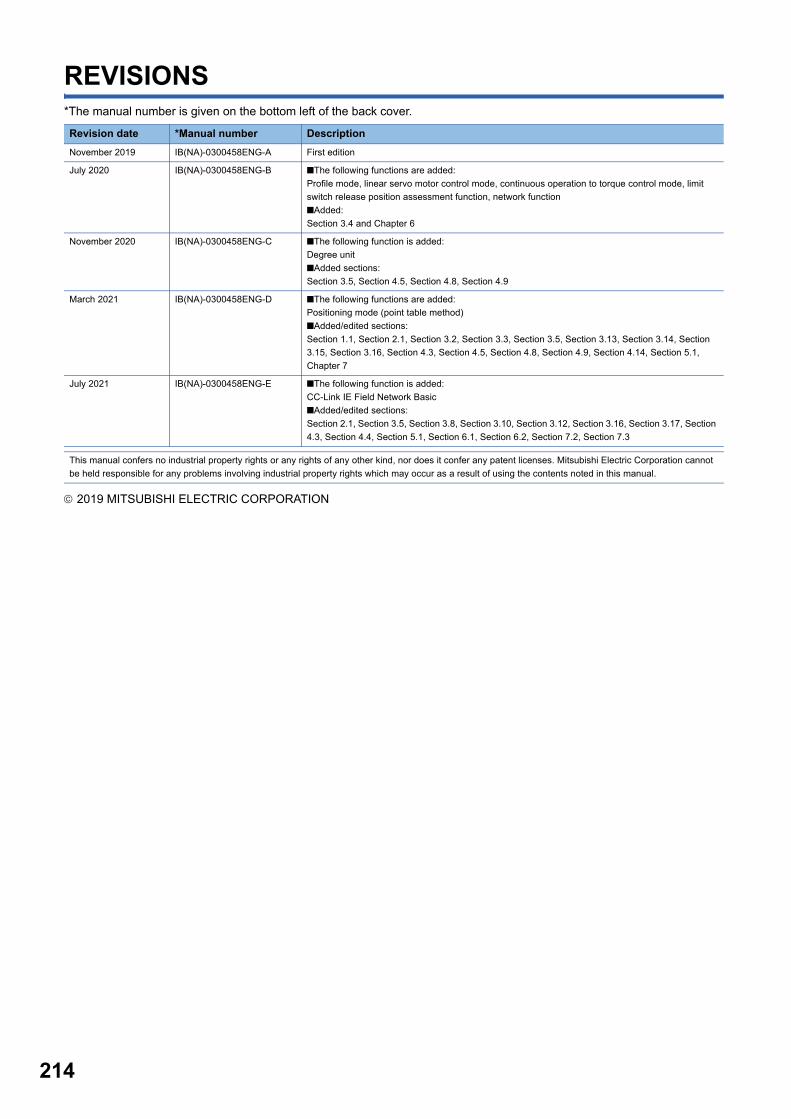
214
REVISIONS*The manual number is given on the bottom left of the back cover.
2019 MITSUBISHI ELECTRIC CORPORATION
Revision date *Manual number DescriptionNovember 2019 IB(NA)-0300458ENG-A First edition
July 2020 IB(NA)-0300458ENG-B ■The following functions are added:Profile mode, linear servo motor control mode, continuous operation to torque control mode, limit switch release position assessment function, network function■Added:Section 3.4 and Chapter 6
November 2020 IB(NA)-0300458ENG-C ■The following function is added:Degree unit■Added sections:Section 3.5, Section 4.5, Section 4.8, Section 4.9
March 2021 IB(NA)-0300458ENG-D ■The following functions are added:Positioning mode (point table method)■Added/edited sections:Section 1.1, Section 2.1, Section 3.2, Section 3.3, Section 3.5, Section 3.13, Section 3.14, Section 3.15, Section 3.16, Section 4.3, Section 4.5, Section 4.8, Section 4.9, Section 4.14, Section 5.1, Chapter 7
July 2021 IB(NA)-0300458ENG-E ■The following function is added:CC-Link IE Field Network Basic■Added/edited sections:Section 2.1, Section 3.5, Section 3.8, Section 3.10, Section 3.12, Section 3.16, Section 3.17, Section 4.3, Section 4.4, Section 5.1, Section 6.1, Section 6.2, Section 7.2, Section 7.3
This manual confers no industrial property rights or any rights of any other kind, nor does it confer any patent licenses. Mitsubishi Electric Corporation cannot be held responsible for any problems involving industrial property rights which may occur as a result of using the contents noted in this manual.
215
WARRANTYWarranty1. Warranty period and coverage
We will repair any failure or defect hereinafter referred to as "failure" in our FA equipment hereinafter referred to as the "Product" arisen during warranty period at no charge due to causes for which we are responsible through the distributor from which you purchased the Product or our service provider. However, we will charge the actual cost of dispatching our engineer for an on-site repair work on request by customer in Japan or overseas countries. We are not responsible for any on-site readjustment and/or trial run that may be required after a defective unit are repaired or replaced.[Term]For terms of warranty, please contact your original place of purchase.[Limitations](1) You are requested to conduct an initial failure diagnosis by yourself, as a general rule.
It can also be carried out by us or our service company upon your request and the actual cost will be charged. However, it will not be charged if we are responsible for the cause of the failure.
(2) This limited warranty applies only when the condition, method, environment, etc. of use are in compliance with the terms and conditions and instructions that are set forth in the instruction manual and user manual for the Product and the caution label affixed to the Product.
(3) Even during the term of warranty, the repair cost will be charged on you in the following cases;1. a failure caused by your improper storing or handling, carelessness or negligence, etc., and a failure caused by your hardware
or software problem2. a failure caused by any alteration, etc. to the Product made on your side without our approval3. a failure which may be regarded as avoidable, if your equipment in which the Product is incorporated is equipped with a safety
device required by applicable laws and has any function or structure considered to be indispensable according to a common sense in the industry
4. a failure which may be regarded as avoidable if consumable parts designated in the instruction manual, etc. are duly maintained and replaced
5. any replacement of consumable parts (battery, fan, smoothing capacitor, etc.)6. a failure caused by external factors such as inevitable accidents, including without limitation fire and abnormal fluctuation of
voltage, and acts of God, including without limitation earthquake, lightning and natural disasters7. a failure generated by an unforeseeable cause with a scientific technology that was not available at the time of the shipment of
the Product from our company8. any other failures which we are not responsible for or which you acknowledge we are not responsible for
2. Term of warranty after the stop of production(1) We may accept the repair at charge for another seven (7) years after the production of the product is discontinued. The
announcement of the stop of production for each model can be seen in our Sales and Service, etc.(2) Please note that the Product (including its spare parts) cannot be ordered after its stop of production.
3. Service in overseas countriesOur regional FA Center in overseas countries will accept the repair work of the Product. However, the terms and conditions of the repair work may differ depending on each FA Center. Please ask your local FA center for details.
4. Exclusion of loss in opportunity and secondary loss from warranty liabilityRegardless of the gratis warranty term, Mitsubishi shall not be liable for compensation to:(1) Damages caused by any cause found not to be the responsibility of Mitsubishi.(2) Loss in opportunity, lost profits incurred to the user by Failures of Mitsubishi products.(3) Special damages and secondary damages whether foreseeable or not, compensation for accidents, and compensation for
damages to products other than Mitsubishi products.(4) Replacement by the user, maintenance of on-site equipment, start-up test run and other tasks.
5. Change of Product specificationsSpecifications listed in our catalogs, manuals or technical documents may be changed without notice.
6. Application and use of the Product(1) For the use of our AC Servo, its applications should be those that may not result in a serious damage even if any failure or
malfunction occurs in AC Servo, and a backup or fail-safe function should operate on an external system to AC Servo when any failure or malfunction occurs.
(2) Our AC Servo is designed and manufactured as a general purpose product for use at general industries.Therefore, applications substantially influential on the public interest for such as atomic power plants and other power plants of electric power companies, and also which require a special quality assurance system, including applications for railway companies and government or public offices are not recommended, and we assume no responsibility for any failure caused by these applications when used.In addition, applications which may be substantially influential to human lives or properties for such as airlines, medical treatments, railway service, incineration and fuel systems, man-operated material handling equipment, entertainment machines, safety machines, etc. are not recommended, and we assume no responsibility for any failure caused by these applications when used. We will review the acceptability of the abovementioned applications, if you agree not to require a specific quality for a specific application. Please contact us for consultation.

216
TRADEMARKSMELSERVO is a trademark or registered trademark of Mitsubishi Electric Corporation in Japan and/or other countries.All other product names and company names are trademarks or registered trademarks of their respective companies.
IB(NA)-0300458ENG-E


IB(NA)-0300458ENG-E(2107)MEEMODEL:MODEL CODE:
Specifications are subject to change without notice.
When exported from Japan, this manual does not require application to theMinistry of Economy, Trade and Industry for service transaction permission.
HEAD OFFICE : TOKYO BUILDING, 2-7-3 MARUNOUCHI, CHIYODA-KU, TOKYO 100-8310, JAPANNAGOYA WORKS : 1-14 , YADA-MINAMI 5-CHOME , HIGASHI-KU, NAGOYA , JAPAN
Related Documents