MR-JET User's Manual (Adjustment) -MR-JET-_G -MR-JET-_G-N1 Mitsubishi Electric AC Servo System

Welcome message from author
This document is posted to help you gain knowledge. Please leave a comment to let me know what you think about it! Share it to your friends and learn new things together.
Transcript
MR-JETUser's Manual(Adjustment)
-MR-JET-_G-MR-JET-_G-N1
Mitsubishi Electric AC Servo System

SAFETY INSTRUCTIONSPlease read the instructions carefully before using the equipment.To use the equipment correctly, do not attempt to install, operate, maintain, or inspect the equipment until you have read through this manual, installation guide, and appended documents carefully. Do not use the equipment until you have a full knowledge of the equipment, safety information and instructions.In this manual, the safety instruction levels are classified into "WARNING" and "CAUTION".
Note that the CAUTION level may lead to a serious consequence depending on conditions.Please follow the instructions of both levels because they are important to personnel safety.Forbidden actions and required actions are indicated by the following diagrammatic symbols.
In this manual, precautions for hazards that can lead to property damage, instructions for other functions, and other information are shown separately in the "POINT" area.After reading this manual, keep it accessible to the operator.
WARNING Indicates that incorrect handling may cause hazardous conditions, resulting in death or severe injury.
CAUTION Indicates that incorrect handling may cause hazardous conditions, resulting in medium or slight injury.
Indicates a forbidden action. For example, "No Fire" is indicated by .
Indicates a required action. For example, grounding is indicated by .
1
2
[Installation/wiring]
[Setting/adjustment]
[Operation]
[Maintenance]
WARNING● To prevent an electric shock, turn off the power and wait for 15 minutes or more before starting wiring
and/or inspection.● To prevent an electric shock, ground the servo amplifier.● To prevent an electric shock, any person who is involved in wiring should be fully competent to do the
work.● To prevent an electric shock, mount the servo amplifier before wiring.● To prevent an electric shock, connect the protective earth (PE) terminal of the servo amplifier to the
protective earth (PE) of the cabinet, then connect the grounding lead wire to the ground.● To prevent an electric shock, do not touch the conductive parts.
WARNING● To prevent an electric shock, do not operate the switches with wet hands.
WARNING● To prevent an electric shock, do not operate the switches with wet hands.
WARNING● To prevent an electric shock, any person who is involved in inspection should be fully competent to do
the work.● To prevent an electric shock, do not operate the switches with wet hands.
ABOUT THE MANUAL
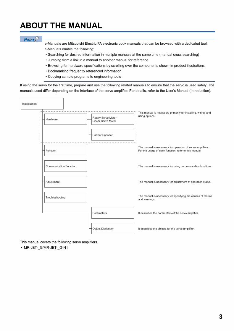
e-Manuals are Mitsubishi Electric FA electronic book manuals that can be browsed with a dedicated tool.e-Manuals enable the following: • Searching for desired information in multiple manuals at the same time (manual cross searching) • Jumping from a link in a manual to another manual for reference • Browsing for hardware specifications by scrolling over the components shown in product illustrations • Bookmarking frequently referenced information • Copying sample programs to engineering tools
If using the servo for the first time, prepare and use the following related manuals to ensure that the servo is used safely. The manuals used differ depending on the interface of the servo amplifier. For details, refer to the User's Manual (Introduction).
This manual covers the following servo amplifiers. • MR-JET-_G/MR-JET-_G-N1
Rotary Servo MotorLinear Servo Motor
This manual is necessary primarily for installing, wiring, andusing options.
The manual is necessary for operation of servo amplifiers.
The manual is necessary for adjustment of operation status.
The manual is necessary for using communication functions.
The manual is necessary for specifying the causes of alarmsand warnings.
Partner Encoder
Function
Adjustment
Object Dictionary
Troubleshooting
Introduction
Hardware
Communication Function
Parameters It describes the parameters of the servo amplifier.
It describes the objects for the servo amplifier.
For the usage of each function, refer to this manual.
3
4
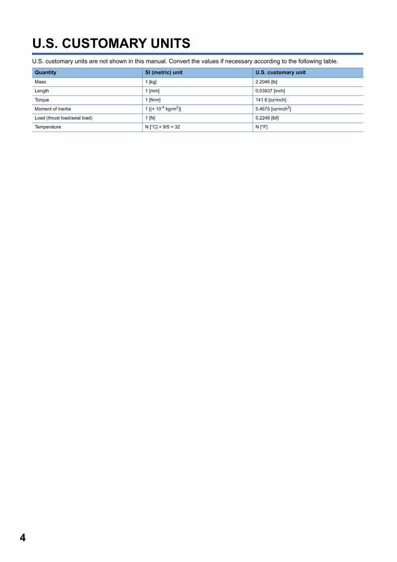
U.S. CUSTOMARY UNITSU.S. customary units are not shown in this manual. Convert the values if necessary according to the following table.
Quantity SI (metric) unit U.S. customary unitMass 1 [kg] 2.2046 [lb]
Length 1 [mm] 0.03937 [inch]
Torque 1 [N•m] 141.6 [oz•inch]
Moment of inertia 1 [(× 10-4 kg•m2)] 5.4675 [oz•inch2]
Load (thrust load/axial load) 1 [N] 0.2248 [lbf]
Temperature N [°C] × 9/5 + 32 N [°F]
CO
NTE
NTS
CONTENTSSAFETY INSTRUCTIONS. . . . . . . . . . . . . . . . . . . . . . . . . . . . . . . . . . . . . . . . . . . . . . . . . . . . . . . . . . . . . . . . . . . .1ABOUT THE MANUAL . . . . . . . . . . . . . . . . . . . . . . . . . . . . . . . . . . . . . . . . . . . . . . . . . . . . . . . . . . . . . . . . . . . . . .3U.S. CUSTOMARY UNITS . . . . . . . . . . . . . . . . . . . . . . . . . . . . . . . . . . . . . . . . . . . . . . . . . . . . . . . . . . . . . . . . . . .3
CHAPTER 1 ADJUSTMENT FUNCTION TYPES 71.1 Adjustment functions available when using the servo amplifier alone . . . . . . . . . . . . . . . . . . . . . . . . . . . . . 7
Functions to automatically adjust machine stability. . . . . . . . . . . . . . . . . . . . . . . . . . . . . . . . . . . . . . . . . . . . . . . . 7Adjustment functions to suppress vibration and to obtain a high level of responsiveness . . . . . . . . . . . . . . . . . . 8Manual adjustment functions to obtain the maximum performance . . . . . . . . . . . . . . . . . . . . . . . . . . . . . . . . . . . 8
1.2 Adjustment functions available in combination with MR Configurator2 . . . . . . . . . . . . . . . . . . . . . . . . . . . . 9
CHAPTER 2 ADJUSTMENT PROCEDURE 10
CHAPTER 3 ADJUSTMENT METHOD 123.1 Quick tuning. . . . . . . . . . . . . . . . . . . . . . . . . . . . . . . . . . . . . . . . . . . . . . . . . . . . . . . . . . . . . . . . . . . . . . . . . . . . 12
Restrictions on quick tuning. . . . . . . . . . . . . . . . . . . . . . . . . . . . . . . . . . . . . . . . . . . . . . . . . . . . . . . . . . . . . . . . . 12Precautions on quick tuning . . . . . . . . . . . . . . . . . . . . . . . . . . . . . . . . . . . . . . . . . . . . . . . . . . . . . . . . . . . . . . . . 12Setting method for quick tuning . . . . . . . . . . . . . . . . . . . . . . . . . . . . . . . . . . . . . . . . . . . . . . . . . . . . . . . . . . . . . . 13Operation of quick tuning. . . . . . . . . . . . . . . . . . . . . . . . . . . . . . . . . . . . . . . . . . . . . . . . . . . . . . . . . . . . . . . . . . . 15Errors in quick tuning. . . . . . . . . . . . . . . . . . . . . . . . . . . . . . . . . . . . . . . . . . . . . . . . . . . . . . . . . . . . . . . . . . . . . . 15
3.2 One-touch tuning. . . . . . . . . . . . . . . . . . . . . . . . . . . . . . . . . . . . . . . . . . . . . . . . . . . . . . . . . . . . . . . . . . . . . . . . 16Restrictions on one-touch tuning . . . . . . . . . . . . . . . . . . . . . . . . . . . . . . . . . . . . . . . . . . . . . . . . . . . . . . . . . . . . . 16Instructions on one-touch tuning . . . . . . . . . . . . . . . . . . . . . . . . . . . . . . . . . . . . . . . . . . . . . . . . . . . . . . . . . . . . . 17One-touch tuning procedure . . . . . . . . . . . . . . . . . . . . . . . . . . . . . . . . . . . . . . . . . . . . . . . . . . . . . . . . . . . . . . . . 18Progress display during one-touch tuning . . . . . . . . . . . . . . . . . . . . . . . . . . . . . . . . . . . . . . . . . . . . . . . . . . . . . . 27Servo parameters adjusted with one-touch tuning . . . . . . . . . . . . . . . . . . . . . . . . . . . . . . . . . . . . . . . . . . . . . . . 28One-touch tuning stop method . . . . . . . . . . . . . . . . . . . . . . . . . . . . . . . . . . . . . . . . . . . . . . . . . . . . . . . . . . . . . . 28One-touch tuning error . . . . . . . . . . . . . . . . . . . . . . . . . . . . . . . . . . . . . . . . . . . . . . . . . . . . . . . . . . . . . . . . . . . . 29Initializing one-touch tuning . . . . . . . . . . . . . . . . . . . . . . . . . . . . . . . . . . . . . . . . . . . . . . . . . . . . . . . . . . . . . . . . . 31
3.3 Auto tuning mode 1. . . . . . . . . . . . . . . . . . . . . . . . . . . . . . . . . . . . . . . . . . . . . . . . . . . . . . . . . . . . . . . . . . . . . . 33Restrictions on auto tuning mode 1 . . . . . . . . . . . . . . . . . . . . . . . . . . . . . . . . . . . . . . . . . . . . . . . . . . . . . . . . . . . 33Precautions on auto tuning mode 1. . . . . . . . . . . . . . . . . . . . . . . . . . . . . . . . . . . . . . . . . . . . . . . . . . . . . . . . . . . 33Adjustment procedure by auto tuning mode 1. . . . . . . . . . . . . . . . . . . . . . . . . . . . . . . . . . . . . . . . . . . . . . . . . . . 34Responsiveness setting in auto tuning mode 1 . . . . . . . . . . . . . . . . . . . . . . . . . . . . . . . . . . . . . . . . . . . . . . . . . . 35Operation of auto tuning mode 1 . . . . . . . . . . . . . . . . . . . . . . . . . . . . . . . . . . . . . . . . . . . . . . . . . . . . . . . . . . . . . 37
3.4 Auto tuning mode 2. . . . . . . . . . . . . . . . . . . . . . . . . . . . . . . . . . . . . . . . . . . . . . . . . . . . . . . . . . . . . . . . . . . . . . 37Precautions on auto tuning mode 2. . . . . . . . . . . . . . . . . . . . . . . . . . . . . . . . . . . . . . . . . . . . . . . . . . . . . . . . . . . 37Adjustment procedure by auto tuning mode 2. . . . . . . . . . . . . . . . . . . . . . . . . . . . . . . . . . . . . . . . . . . . . . . . . . . 37Responsiveness setting in auto tuning mode 2 . . . . . . . . . . . . . . . . . . . . . . . . . . . . . . . . . . . . . . . . . . . . . . . . . . 38Operation of auto tuning mode 2 . . . . . . . . . . . . . . . . . . . . . . . . . . . . . . . . . . . . . . . . . . . . . . . . . . . . . . . . . . . . . 38
3.5 2 gain adjustment mode 1 . . . . . . . . . . . . . . . . . . . . . . . . . . . . . . . . . . . . . . . . . . . . . . . . . . . . . . . . . . . . . . . . 39Adjustment procedure for 2 gain adjustment mode 1 . . . . . . . . . . . . . . . . . . . . . . . . . . . . . . . . . . . . . . . . . . . . . 39Operation of 2 gain adjustment mode 1 . . . . . . . . . . . . . . . . . . . . . . . . . . . . . . . . . . . . . . . . . . . . . . . . . . . . . . . 40
3.6 2 gain adjustment mode 2 . . . . . . . . . . . . . . . . . . . . . . . . . . . . . . . . . . . . . . . . . . . . . . . . . . . . . . . . . . . . . . . . 40Adjustment procedure for 2 gain adjustment mode 2 . . . . . . . . . . . . . . . . . . . . . . . . . . . . . . . . . . . . . . . . . . . . . 40Operation of 2 gain adjustment mode 2 . . . . . . . . . . . . . . . . . . . . . . . . . . . . . . . . . . . . . . . . . . . . . . . . . . . . . . . 40
3.7 Manual mode . . . . . . . . . . . . . . . . . . . . . . . . . . . . . . . . . . . . . . . . . . . . . . . . . . . . . . . . . . . . . . . . . . . . . . . . . . . 41Adjustment procedure for the velocity mode . . . . . . . . . . . . . . . . . . . . . . . . . . . . . . . . . . . . . . . . . . . . . . . . . . . . 41
5
6
Adjustment procedure for the position mode. . . . . . . . . . . . . . . . . . . . . . . . . . . . . . . . . . . . . . . . . . . . . . . . . . . . 433.8 Load to motor inertia ratio monitor mode. . . . . . . . . . . . . . . . . . . . . . . . . . . . . . . . . . . . . . . . . . . . . . . . . . . . 45
Precautions on load to motor inertia ratio monitor mode. . . . . . . . . . . . . . . . . . . . . . . . . . . . . . . . . . . . . . . . . . . 45Adjustment procedure for load to motor inertia ratio monitor mode . . . . . . . . . . . . . . . . . . . . . . . . . . . . . . . . . . 45Operation of load to motor inertia ratio monitor mode. . . . . . . . . . . . . . . . . . . . . . . . . . . . . . . . . . . . . . . . . . . . . 45
CHAPTER 4 VIBRATION SUPPRESSION FUNCTION 464.1 Filter setting . . . . . . . . . . . . . . . . . . . . . . . . . . . . . . . . . . . . . . . . . . . . . . . . . . . . . . . . . . . . . . . . . . . . . . . . . . . . 464.2 Machine resonance suppression filter . . . . . . . . . . . . . . . . . . . . . . . . . . . . . . . . . . . . . . . . . . . . . . . . . . . . . . 46
Machine resonance suppression filter restrictions. . . . . . . . . . . . . . . . . . . . . . . . . . . . . . . . . . . . . . . . . . . . . . . . 47Machine resonance suppression filter precautions . . . . . . . . . . . . . . . . . . . . . . . . . . . . . . . . . . . . . . . . . . . . . . . 47Machine resonance suppression filter setting method . . . . . . . . . . . . . . . . . . . . . . . . . . . . . . . . . . . . . . . . . . . . 47Operation of machine resonance suppression filter . . . . . . . . . . . . . . . . . . . . . . . . . . . . . . . . . . . . . . . . . . . . . . 48
4.3 Adaptive filter II . . . . . . . . . . . . . . . . . . . . . . . . . . . . . . . . . . . . . . . . . . . . . . . . . . . . . . . . . . . . . . . . . . . . . . . . . 49Restrictions on adaptive tuning . . . . . . . . . . . . . . . . . . . . . . . . . . . . . . . . . . . . . . . . . . . . . . . . . . . . . . . . . . . . . . 49Precautions for adaptive filter II . . . . . . . . . . . . . . . . . . . . . . . . . . . . . . . . . . . . . . . . . . . . . . . . . . . . . . . . . . . . . . 49How to set adaptive filter II . . . . . . . . . . . . . . . . . . . . . . . . . . . . . . . . . . . . . . . . . . . . . . . . . . . . . . . . . . . . . . . . . 50Adaptive tuning procedure. . . . . . . . . . . . . . . . . . . . . . . . . . . . . . . . . . . . . . . . . . . . . . . . . . . . . . . . . . . . . . . . . . 50
4.4 Shaft resonance suppression filter . . . . . . . . . . . . . . . . . . . . . . . . . . . . . . . . . . . . . . . . . . . . . . . . . . . . . . . . . 51Shaft resonance suppression filter restrictions . . . . . . . . . . . . . . . . . . . . . . . . . . . . . . . . . . . . . . . . . . . . . . . . . . 51Shaft resonance suppression filter setting method . . . . . . . . . . . . . . . . . . . . . . . . . . . . . . . . . . . . . . . . . . . . . . . 51
4.5 Low-pass filter . . . . . . . . . . . . . . . . . . . . . . . . . . . . . . . . . . . . . . . . . . . . . . . . . . . . . . . . . . . . . . . . . . . . . . . . . . 55Low-pass filter setting method. . . . . . . . . . . . . . . . . . . . . . . . . . . . . . . . . . . . . . . . . . . . . . . . . . . . . . . . . . . . . . . 55Operation of low-pass filter . . . . . . . . . . . . . . . . . . . . . . . . . . . . . . . . . . . . . . . . . . . . . . . . . . . . . . . . . . . . . . . . . 55
4.6 Robust filter . . . . . . . . . . . . . . . . . . . . . . . . . . . . . . . . . . . . . . . . . . . . . . . . . . . . . . . . . . . . . . . . . . . . . . . . . . . . 55Robust filter restrictions . . . . . . . . . . . . . . . . . . . . . . . . . . . . . . . . . . . . . . . . . . . . . . . . . . . . . . . . . . . . . . . . . . . . 55Robust filter setting method. . . . . . . . . . . . . . . . . . . . . . . . . . . . . . . . . . . . . . . . . . . . . . . . . . . . . . . . . . . . . . . . . 55
4.7 Advanced vibration suppression control II. . . . . . . . . . . . . . . . . . . . . . . . . . . . . . . . . . . . . . . . . . . . . . . . . . . 56Advanced vibration suppression control restrictions . . . . . . . . . . . . . . . . . . . . . . . . . . . . . . . . . . . . . . . . . . . . . . 57Advanced vibration suppression control precautions . . . . . . . . . . . . . . . . . . . . . . . . . . . . . . . . . . . . . . . . . . . . . 58Advanced vibration suppression control setting method . . . . . . . . . . . . . . . . . . . . . . . . . . . . . . . . . . . . . . . . . . . 58Advanced vibration suppression control adjustment method . . . . . . . . . . . . . . . . . . . . . . . . . . . . . . . . . . . . . . . 58
4.8 Command notch filter . . . . . . . . . . . . . . . . . . . . . . . . . . . . . . . . . . . . . . . . . . . . . . . . . . . . . . . . . . . . . . . . . . . . 62Command notch filter setting method . . . . . . . . . . . . . . . . . . . . . . . . . . . . . . . . . . . . . . . . . . . . . . . . . . . . . . . . . 63
4.9 Vibration tough drive . . . . . . . . . . . . . . . . . . . . . . . . . . . . . . . . . . . . . . . . . . . . . . . . . . . . . . . . . . . . . . . . . . . . 66Vibration tough drive restrictions . . . . . . . . . . . . . . . . . . . . . . . . . . . . . . . . . . . . . . . . . . . . . . . . . . . . . . . . . . . . . 66Vibration tough drive precautions . . . . . . . . . . . . . . . . . . . . . . . . . . . . . . . . . . . . . . . . . . . . . . . . . . . . . . . . . . . . 66Vibration tough drive setting method . . . . . . . . . . . . . . . . . . . . . . . . . . . . . . . . . . . . . . . . . . . . . . . . . . . . . . . . . . 66Operation of vibration tough drive . . . . . . . . . . . . . . . . . . . . . . . . . . . . . . . . . . . . . . . . . . . . . . . . . . . . . . . . . . . . 67
4.10 Command smoothing filter. . . . . . . . . . . . . . . . . . . . . . . . . . . . . . . . . . . . . . . . . . . . . . . . . . . . . . . . . . . . . . . . 69Restrictions on the command smoothing filter. . . . . . . . . . . . . . . . . . . . . . . . . . . . . . . . . . . . . . . . . . . . . . . . . . . 69Instructions on the command smoothing filter . . . . . . . . . . . . . . . . . . . . . . . . . . . . . . . . . . . . . . . . . . . . . . . . . . . 69How to set the command smoothing filter . . . . . . . . . . . . . . . . . . . . . . . . . . . . . . . . . . . . . . . . . . . . . . . . . . . . . . 69
CHAPTER 5 GAIN SWITCHING FUNCTION 705.1 Restrictions on gain switching . . . . . . . . . . . . . . . . . . . . . . . . . . . . . . . . . . . . . . . . . . . . . . . . . . . . . . . . . . . . 705.2 Precautions on gain switching. . . . . . . . . . . . . . . . . . . . . . . . . . . . . . . . . . . . . . . . . . . . . . . . . . . . . . . . . . . . . 705.3 Setting method for gain switching. . . . . . . . . . . . . . . . . . . . . . . . . . . . . . . . . . . . . . . . . . . . . . . . . . . . . . . . . . 71
Servo parameters for setting the gain switching condition . . . . . . . . . . . . . . . . . . . . . . . . . . . . . . . . . . . . . . . . . 71Servo parameters that are changeable with the gain switching . . . . . . . . . . . . . . . . . . . . . . . . . . . . . . . . . . . . . 72
CO
NTE
NTS
Related objects . . . . . . . . . . . . . . . . . . . . . . . . . . . . . . . . . . . . . . . . . . . . . . . . . . . . . . . . . . . . . . . . . . . . . . . . . . 735.4 Examples of gain switching operation . . . . . . . . . . . . . . . . . . . . . . . . . . . . . . . . . . . . . . . . . . . . . . . . . . . . . . 74
Gain switching by servo motor speed . . . . . . . . . . . . . . . . . . . . . . . . . . . . . . . . . . . . . . . . . . . . . . . . . . . . . . . . . 74Gain switching by signals (CDP/C_CDP/CDP2/C_CDP2) . . . . . . . . . . . . . . . . . . . . . . . . . . . . . . . . . . . . . . . . . 78Gain switching by command directions . . . . . . . . . . . . . . . . . . . . . . . . . . . . . . . . . . . . . . . . . . . . . . . . . . . . . . . . 79Gain switching by servo motor speed and gain switching 2 (C_CDP2) . . . . . . . . . . . . . . . . . . . . . . . . . . . . . . .81When "Time constant disabled at switching" is selected in "Gain switching time constant - Disabling condition selection" . . . . . . . . . . . . . . . . . . . . . . . . . . . . . . . . . . . . . . . . . . . . . . . . . . . . . . . . . . . . . . . 82When "Time constant disabled at return" is selected in "Gain switching time constant - Disabling condition selection" . . . . . . . . . . . . . . . . . . . . . . . . . . . . . . . . . . . . . . . . . . . . . . . . . . . . . . . . . . . . . . . 82
CHAPTER 6 SPEED FEED FORWARD CONTROL FUNCTION 836.1 Method for setting the speed feed forward. . . . . . . . . . . . . . . . . . . . . . . . . . . . . . . . . . . . . . . . . . . . . . . . . . . 83
CHAPTER 7 OVERSHOOT SUPPRESSION CONTROL 857.1 Restrictions on overshoot suppression control . . . . . . . . . . . . . . . . . . . . . . . . . . . . . . . . . . . . . . . . . . . . . . 857.2 Settings of the overshoot suppression control . . . . . . . . . . . . . . . . . . . . . . . . . . . . . . . . . . . . . . . . . . . . . . . 85
CHAPTER 8 SLIGHT VIBRATION SUPPRESSION CONTROL 878.1 Restrictions on the slight vibration suppression control . . . . . . . . . . . . . . . . . . . . . . . . . . . . . . . . . . . . . . . 878.2 Settings of the slight vibration suppression control . . . . . . . . . . . . . . . . . . . . . . . . . . . . . . . . . . . . . . . . . . . 878.3 Operation of slight vibration suppression control. . . . . . . . . . . . . . . . . . . . . . . . . . . . . . . . . . . . . . . . . . . . . 87
CHAPTER 9 UNBALANCED TORQUE OFFSET 899.1 Setting unbalanced torque offset . . . . . . . . . . . . . . . . . . . . . . . . . . . . . . . . . . . . . . . . . . . . . . . . . . . . . . . . . . 89
Automatic setting . . . . . . . . . . . . . . . . . . . . . . . . . . . . . . . . . . . . . . . . . . . . . . . . . . . . . . . . . . . . . . . . . . . . . . . . . 89Manual setting . . . . . . . . . . . . . . . . . . . . . . . . . . . . . . . . . . . . . . . . . . . . . . . . . . . . . . . . . . . . . . . . . . . . . . . . . . . 89
CHAPTER 10 MODEL ADAPTIVE CONTROL 9110.1 Setting model adaptive control . . . . . . . . . . . . . . . . . . . . . . . . . . . . . . . . . . . . . . . . . . . . . . . . . . . . . . . . . . . . 9110.2 Disabling model adaptive control . . . . . . . . . . . . . . . . . . . . . . . . . . . . . . . . . . . . . . . . . . . . . . . . . . . . . . . . . . 91
Instructions on disabling model adaptive control. . . . . . . . . . . . . . . . . . . . . . . . . . . . . . . . . . . . . . . . . . . . . . . . . 91How to disable model adaptive control . . . . . . . . . . . . . . . . . . . . . . . . . . . . . . . . . . . . . . . . . . . . . . . . . . . . . . . . 92
CHAPTER 11 PATH CONTROL FUNCTION 9311.1 Path tracking model adaptive control . . . . . . . . . . . . . . . . . . . . . . . . . . . . . . . . . . . . . . . . . . . . . . . . . . . . . . . 93
Setting the path tracking model adaptive control. . . . . . . . . . . . . . . . . . . . . . . . . . . . . . . . . . . . . . . . . . . . . . . . . 93Operation of path tracking model adaptive control . . . . . . . . . . . . . . . . . . . . . . . . . . . . . . . . . . . . . . . . . . . . . . . 94
11.2 Super trace control . . . . . . . . . . . . . . . . . . . . . . . . . . . . . . . . . . . . . . . . . . . . . . . . . . . . . . . . . . . . . . . . . . . . . . 95Restrictions on super trace control . . . . . . . . . . . . . . . . . . . . . . . . . . . . . . . . . . . . . . . . . . . . . . . . . . . . . . . . . . . 95Instructions on super trace control . . . . . . . . . . . . . . . . . . . . . . . . . . . . . . . . . . . . . . . . . . . . . . . . . . . . . . . . . . . 95Setting the super trace control. . . . . . . . . . . . . . . . . . . . . . . . . . . . . . . . . . . . . . . . . . . . . . . . . . . . . . . . . . . . . . . 95Operation of super trace control . . . . . . . . . . . . . . . . . . . . . . . . . . . . . . . . . . . . . . . . . . . . . . . . . . . . . . . . . . . . . 96
11.3 Lost motion compensation function . . . . . . . . . . . . . . . . . . . . . . . . . . . . . . . . . . . . . . . . . . . . . . . . . . . . . . . . 97Restrictions on the lost motion compensation function . . . . . . . . . . . . . . . . . . . . . . . . . . . . . . . . . . . . . . . . . . . . 97Setting the lost motion compensation function . . . . . . . . . . . . . . . . . . . . . . . . . . . . . . . . . . . . . . . . . . . . . . . . . . 97Adjusting the lost motion compensation . . . . . . . . . . . . . . . . . . . . . . . . . . . . . . . . . . . . . . . . . . . . . . . . . . . . . . . 98
REVISIONS. . . . . . . . . . . . . . . . . . . . . . . . . . . . . . . . . . . . . . . . . . . . . . . . . . . . . . . . . . . . . . . . . . . . . . . . . . . . .100WARRANTY . . . . . . . . . . . . . . . . . . . . . . . . . . . . . . . . . . . . . . . . . . . . . . . . . . . . . . . . . . . . . . . . . . . . . . . . . . . .101TRADEMARKS . . . . . . . . . . . . . . . . . . . . . . . . . . . . . . . . . . . . . . . . . . . . . . . . . . . . . . . . . . . . . . . . . . . . . . . . . .102
7
8
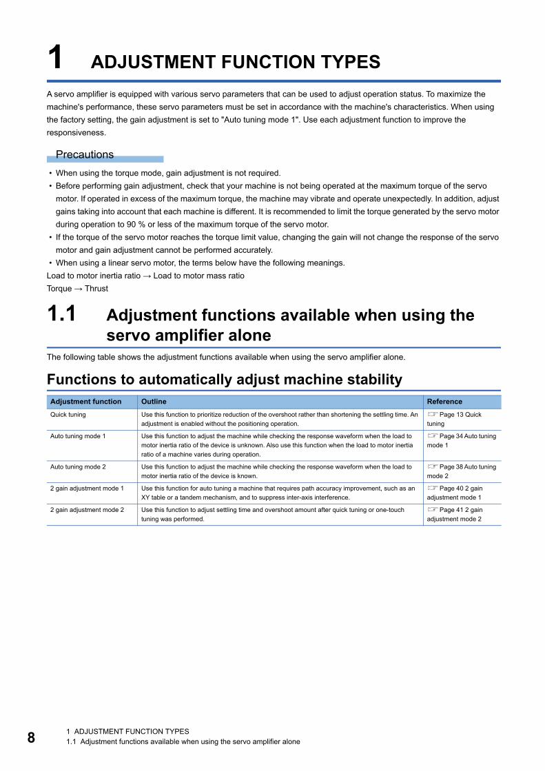
1 ADJUSTMENT FUNCTION TYPESA servo amplifier is equipped with various servo parameters that can be used to adjust operation status. To maximize the machine's performance, these servo parameters must be set in accordance with the machine's characteristics. When using the factory setting, the gain adjustment is set to "Auto tuning mode 1". Use each adjustment function to improve the responsiveness.
Precautions • When using the torque mode, gain adjustment is not required. • Before performing gain adjustment, check that your machine is not being operated at the maximum torque of the servo
motor. If operated in excess of the maximum torque, the machine may vibrate and operate unexpectedly. In addition, adjust gains taking into account that each machine is different. It is recommended to limit the torque generated by the servo motor during operation to 90 % or less of the maximum torque of the servo motor.
• If the torque of the servo motor reaches the torque limit value, changing the gain will not change the response of the servo motor and gain adjustment cannot be performed accurately.
• When using a linear servo motor, the terms below have the following meanings.Load to motor inertia ratio → Load to motor mass ratioTorque → Thrust
1.1 Adjustment functions available when using the servo amplifier alone
The following table shows the adjustment functions available when using the servo amplifier alone.
Functions to automatically adjust machine stabilityAdjustment function Outline ReferenceQuick tuning Use this function to prioritize reduction of the overshoot rather than shortening the settling time. An
adjustment is enabled without the positioning operation.Page 13 Quick tuning
Auto tuning mode 1 Use this function to adjust the machine while checking the response waveform when the load to motor inertia ratio of the device is unknown. Also use this function when the load to motor inertia ratio of a machine varies during operation.
Page 34 Auto tuning mode 1
Auto tuning mode 2 Use this function to adjust the machine while checking the response waveform when the load to motor inertia ratio of the device is known.
Page 38 Auto tuning mode 2
2 gain adjustment mode 1 Use this function for auto tuning a machine that requires path accuracy improvement, such as an XY table or a tandem mechanism, and to suppress inter-axis interference.
Page 40 2 gain adjustment mode 1
2 gain adjustment mode 2 Use this function to adjust settling time and overshoot amount after quick tuning or one-touch tuning was performed.
Page 41 2 gain adjustment mode 2
1 ADJUSTMENT FUNCTION TYPES1.1 Adjustment functions available when using the servo amplifier alone
1
Adjustment functions to suppress vibration and to obtain a high level of responsivenessManual adjustment functions to obtain the maximum performance
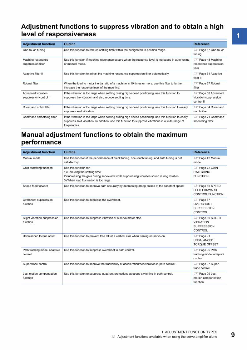
Adjustment function Outline ReferenceOne-touch tuning Use this function to reduce settling time within the designated In-position range. Page 17 One-touch
tuning
Machine resonance suppression filter
Use this function if machine resonance occurs when the response level is increased in auto tuning or manual mode.
Page 48 Machine resonance suppression filter
Adaptive filter II Use this function to adjust the machine resonance suppression filter automatically. Page 51 Adaptive filter II
Robust filter When the load to motor inertia ratio of a machine is 10 times or more, use this filter to further increase the response level of the machine.
Page 57 Robust filter
Advanced vibration suppression control II
If the vibration is too large when settling during high-speed positioning, use this function to suppress the vibration and also reduce settling time.
Page 58 Advanced vibration suppression control II
Command notch filter If the vibration is too large when settling during high-speed positioning, use this function to easily suppress said vibration.
Page 64 Command notch filter
Command smoothing filter If the vibration is too large when settling during high-speed positioning, use this function to easily suppress said vibration. In addition, use this function to suppress vibrations in a wide range of frequencies.
Page 71 Command smoothing filter
Adjustment function Outline ReferenceManual mode Use this function if the performance of quick tuning, one-touch tuning, and auto tuning is not
satisfactory.Page 42 Manual mode
Gain switching function Use this function for:1) Reducing the settling time2) Increasing the gain during servo-lock while suppressing vibration sound during rotation3) When load fluctuation is too large
Page 72 GAIN SWITCHING FUNCTION
Speed feed forward Use this function to improve path accuracy by decreasing droop pulses at the constant speed. Page 85 SPEED FEED FORWARD CONTROL FUNCTION
Overshoot suppression function
Use this function to decrease the overshoot. Page 87 OVERSHOOT SUPPRESSION CONTROL
Slight vibration suppression function
Use this function to suppress vibration at a servo motor stop. Page 89 SLIGHT VIBRATION SUPPRESSION CONTROL
Unbalanced torque offset Use this function to prevent free fall of a vertical axis when turning on servo-on. Page 91 UNBALANCED TORQUE OFFSET
Path tracking model adaptive control
Use this function to suppress overshoot in path control. Page 95 Path tracking model adaptive control
Super trace control Use this function to improve the trackability at acceleration/deceleration in path control. Page 97 Super trace control
Lost motion compensation function
Use this function to suppress quadrant projections at speed switching in path control. Page 99 Lost motion compensation function
1 ADJUSTMENT FUNCTION TYPES1.1 Adjustment functions available when using the servo amplifier alone 9
10
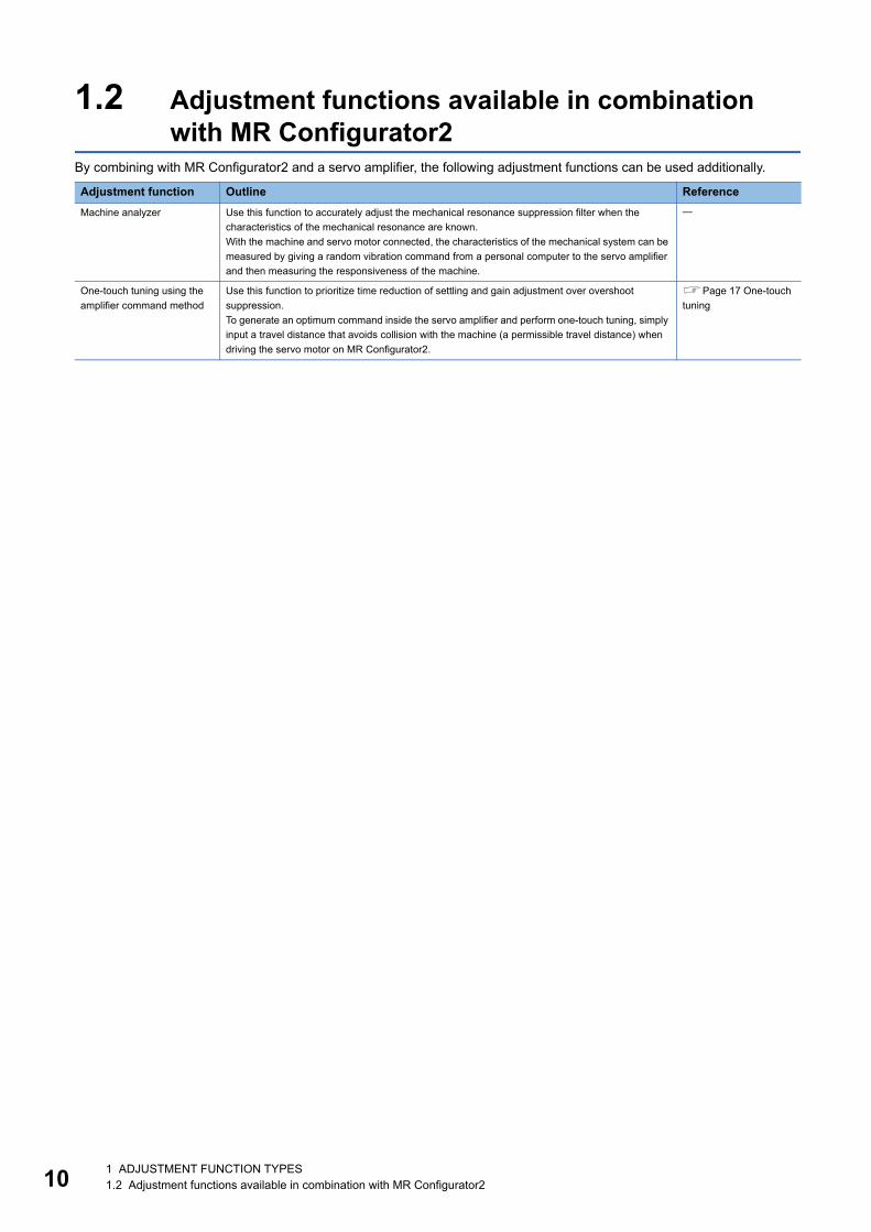
1.2 Adjustment functions available in combination with MR Configurator2
By combining with MR Configurator2 and a servo amplifier, the following adjustment functions can be used additionally.
Adjustment function Outline ReferenceMachine analyzer Use this function to accurately adjust the mechanical resonance suppression filter when the
characteristics of the mechanical resonance are known.With the machine and servo motor connected, the characteristics of the mechanical system can be measured by giving a random vibration command from a personal computer to the servo amplifier and then measuring the responsiveness of the machine.
One-touch tuning using the amplifier command method
Use this function to prioritize time reduction of settling and gain adjustment over overshoot suppression.To generate an optimum command inside the servo amplifier and perform one-touch tuning, simply input a travel distance that avoids collision with the machine (a permissible travel distance) when driving the servo motor on MR Configurator2.
Page 17 One-touch tuning
1 ADJUSTMENT FUNCTION TYPES1.2 Adjustment functions available in combination with MR Configurator2
2
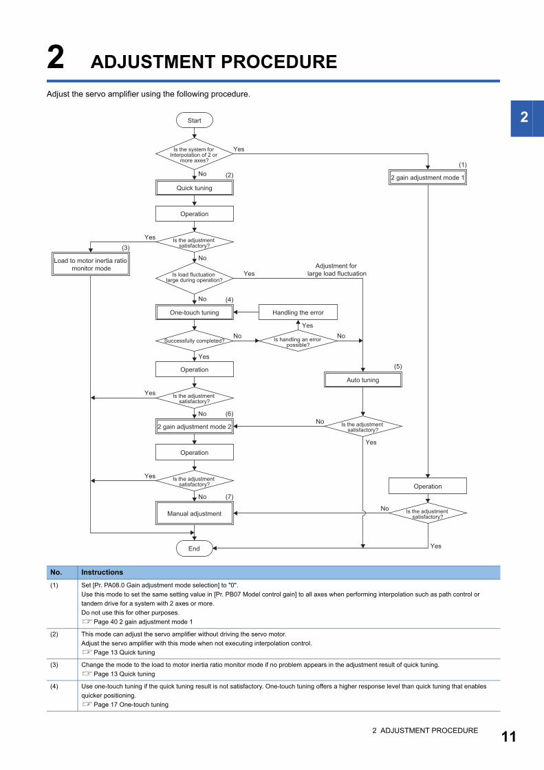
2 ADJUSTMENT PROCEDUREAdjust the servo amplifier using the following procedure.
No. Instructions(1) Set [Pr. PA08.0 Gain adjustment mode selection] to "0".
Use this mode to set the same setting value in [Pr. PB07 Model control gain] to all axes when performing interpolation such as path control or tandem drive for a system with 2 axes or more.Do not use this for other purposes.Page 40 2 gain adjustment mode 1
(2) This mode can adjust the servo amplifier without driving the servo motor.Adjust the servo amplifier with this mode when not executing interpolation control.Page 13 Quick tuning
(3) Change the mode to the load to motor inertia ratio monitor mode if no problem appears in the adjustment result of quick tuning.Page 13 Quick tuning
(4) Use one-touch tuning if the quick tuning result is not satisfactory. One-touch tuning offers a higher response level than quick tuning that enables quicker positioning.Page 17 One-touch tuning
Yes
Yes
No
No
No
No
No
No
No
Yes
Yes
Yes
Yes
Yes
Yes
Yes
No
No (7)
(6)
(5)
(4)
(3)
(2)(1)
Start
Is the system for Interpolation of 2 or
more axes?
2 gain adjustment mode 1Quick tuning
Operation
Is the adjustment satisfactory?
Load to motor inertia ratio monitor mode Adjustment for
large load fluctuationIs load fluctuation large during operation?
One-touch tuning Handling the error
Is handling an error possible?
Successfully completed?
OperationAuto tuning
Is the adjustment satisfactory?
2 gain adjustment mode 2 Is the adjustment satisfactory?
Operation
Is the adjustment satisfactory? Operation
Manual adjustment Is the adjustment satisfactory?
End
2 ADJUSTMENT PROCEDURE 11
12
(5) Set [Pr. PA08.0 Gain adjustment mode selection] to "1" or "2".Page 34 Auto tuning mode 1
(6) [Pr. PA08.0 Gain adjustment mode selection] is automatically set to "4" (2 gain adjustment mode 2) once one-touch tuning is complete.Page 17 One-touch tuning
(7) Set [Pr. PA08.0 Gain adjustment mode selection] to "3".Use the manual adjustment for fast settling or high accuracy path control.Page 42 Manual mode
No. Instructions
2 ADJUSTMENT PROCEDURE
3
3 ADJUSTMENT METHOD
3.1 Quick tuningTo use quick tuning, set [Pr. PA08.0 Gain adjustment mode selection] to "5". Quick tuning performs gain adjustment for the servo amplifier when servo-on is turned on. The characteristics of quick tuning are as follows: • Has the ability to reduce the overshoot regardless of machine type or load size and is effective when reducing the
overshoot is prioritized over shortening the settling time. • Adjustment available without the positioning operation
Restrictions on quick tuningQuick tuning is not available in the following situations: • During one-touch tuning • In the torque mode • In the continuous operation to torque control mode • When using adaptive filter II
Precautions on quick tuning • Do not use quick tuning in a tandem system. • Some noise due to the applied vibration torque may occur during quick tuning, but the noise is not an abnormality. • When the load to motor inertia ratio is more than 100 times, quick tuning cannot adjust the gain appropriately. Adjust the
gain by using an alternative method such as auto tuning. • When quick tuning is enabled (performed), the time until the servo amplifier actually enters the servo-on state after turning
on the servo-on command increases by up to 300 ms. • When the torque limit value is less than 30 % of the rated torque, the torque required for quick tuning cannot be generated,
and quick tuning may fail. Set the torque limit value to exceed 30 % of the rated torque for quick tuning. • If the travel distance for quick tuning exceeds the set value in [Pr. PA34 Quick tuning - Permissible travel distance], quick
tuning will be stopped. • [Pr. PB11 Speed differential compensation] will be changed to the initial value if quick tuning is used. • When friction is 30 % or more of the rated torque, quick tuning may fail. In this case, adjust the gain with one-touch tuning
or auto tuning.
3 ADJUSTMENT METHOD3.1 Quick tuning 13
14
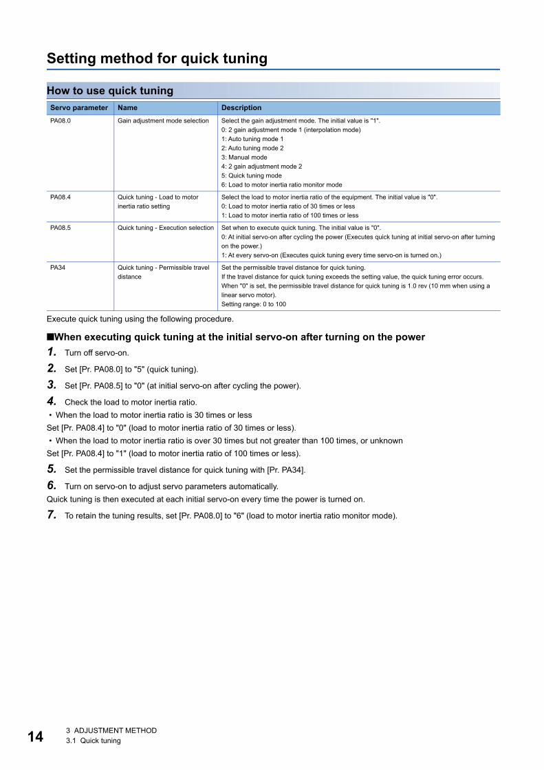
Setting method for quick tuning
How to use quick tuning
Execute quick tuning using the following procedure.
■When executing quick tuning at the initial servo-on after turning on the power1. Turn off servo-on.
2. Set [Pr. PA08.0] to "5" (quick tuning).
3. Set [Pr. PA08.5] to "0" (at initial servo-on after cycling the power).
4. Check the load to motor inertia ratio. • When the load to motor inertia ratio is 30 times or lessSet [Pr. PA08.4] to "0" (load to motor inertia ratio of 30 times or less). • When the load to motor inertia ratio is over 30 times but not greater than 100 times, or unknownSet [Pr. PA08.4] to "1" (load to motor inertia ratio of 100 times or less).
5. Set the permissible travel distance for quick tuning with [Pr. PA34].
6. Turn on servo-on to adjust servo parameters automatically.Quick tuning is then executed at each initial servo-on every time the power is turned on.
7. To retain the tuning results, set [Pr. PA08.0] to "6" (load to motor inertia ratio monitor mode).
Servo parameter Name DescriptionPA08.0 Gain adjustment mode selection Select the gain adjustment mode. The initial value is "1".
0: 2 gain adjustment mode 1 (interpolation mode)1: Auto tuning mode 12: Auto tuning mode 23: Manual mode4: 2 gain adjustment mode 25: Quick tuning mode6: Load to motor inertia ratio monitor mode
PA08.4 Quick tuning - Load to motor inertia ratio setting
Select the load to motor inertia ratio of the equipment. The initial value is "0".0: Load to motor inertia ratio of 30 times or less1: Load to motor inertia ratio of 100 times or less
PA08.5 Quick tuning - Execution selection Set when to execute quick tuning. The initial value is "0".0: At initial servo-on after cycling the power (Executes quick tuning at initial servo-on after turning on the power.)1: At every servo-on (Executes quick tuning every time servo-on is turned on.)
PA34 Quick tuning - Permissible travel distance
Set the permissible travel distance for quick tuning.If the travel distance for quick tuning exceeds the setting value, the quick tuning error occurs.When "0" is set, the permissible travel distance for quick tuning is 1.0 rev (10 mm when using a linear servo motor).Setting range: 0 to 100
3 ADJUSTMENT METHOD3.1 Quick tuning
3
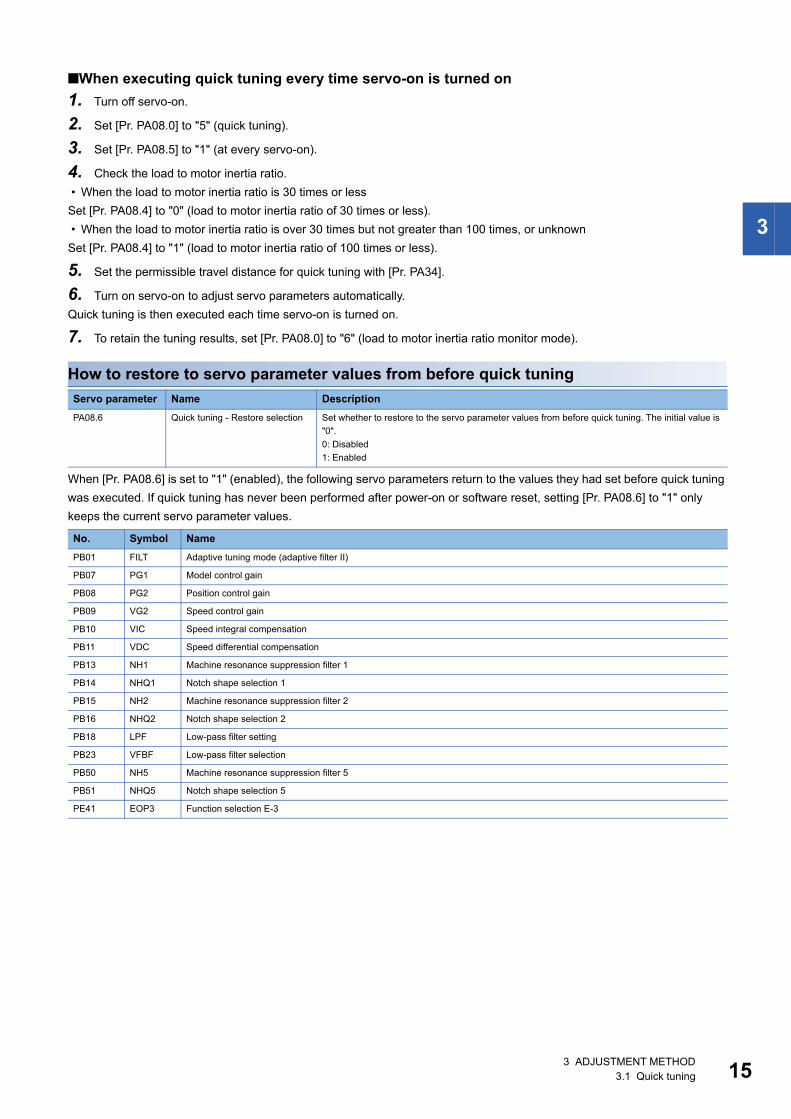
■When executing quick tuning every time servo-on is turned on1. Turn off servo-on.
2. Set [Pr. PA08.0] to "5" (quick tuning).
3. Set [Pr. PA08.5] to "1" (at every servo-on).
4. Check the load to motor inertia ratio. • When the load to motor inertia ratio is 30 times or lessSet [Pr. PA08.4] to "0" (load to motor inertia ratio of 30 times or less). • When the load to motor inertia ratio is over 30 times but not greater than 100 times, or unknownSet [Pr. PA08.4] to "1" (load to motor inertia ratio of 100 times or less).
5. Set the permissible travel distance for quick tuning with [Pr. PA34].
6. Turn on servo-on to adjust servo parameters automatically.Quick tuning is then executed each time servo-on is turned on.
7. To retain the tuning results, set [Pr. PA08.0] to "6" (load to motor inertia ratio monitor mode).
How to restore to servo parameter values from before quick tuning
When [Pr. PA08.6] is set to "1" (enabled), the following servo parameters return to the values they had set before quick tuning was executed. If quick tuning has never been performed after power-on or software reset, setting [Pr. PA08.6] to "1" only keeps the current servo parameter values.
Servo parameter Name DescriptionPA08.6 Quick tuning - Restore selection Set whether to restore to the servo parameter values from before quick tuning. The initial value is
"0".0: Disabled1: Enabled
No. Symbol NamePB01 FILT Adaptive tuning mode (adaptive filter II)
PB07 PG1 Model control gain
PB08 PG2 Position control gain
PB09 VG2 Speed control gain
PB10 VIC Speed integral compensation
PB11 VDC Speed differential compensation
PB13 NH1 Machine resonance suppression filter 1
PB14 NHQ1 Notch shape selection 1
PB15 NH2 Machine resonance suppression filter 2
PB16 NHQ2 Notch shape selection 2
PB18 LPF Low-pass filter setting
PB23 VFBF Low-pass filter selection
PB50 NH5 Machine resonance suppression filter 5
PB51 NHQ5 Notch shape selection 5
PE41 EOP3 Function selection E-3
3 ADJUSTMENT METHOD3.1 Quick tuning 15
16
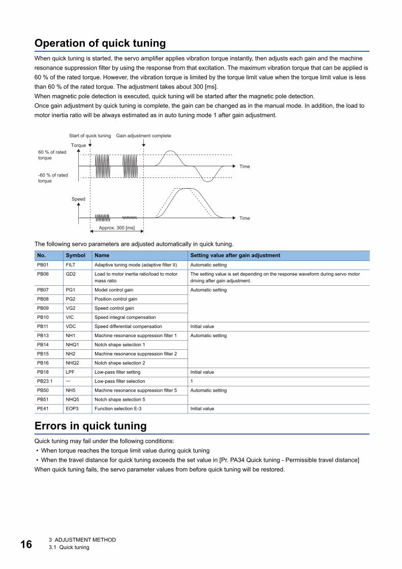
Operation of quick tuningWhen quick tuning is started, the servo amplifier applies vibration torque instantly, then adjusts each gain and the machine resonance suppression filter by using the response from that excitation. The maximum vibration torque that can be applied is 60 % of the rated torque. However, the vibration torque is limited by the torque limit value when the torque limit value is less than 60 % of the rated torque. The adjustment takes about 300 [ms].When magnetic pole detection is executed, quick tuning will be started after the magnetic pole detection.Once gain adjustment by quick tuning is complete, the gain can be changed as in the manual mode. In addition, the load to motor inertia ratio will be always estimated as in auto tuning mode 1 after gain adjustment.
The following servo parameters are adjusted automatically in quick tuning.
Errors in quick tuningQuick tuning may fail under the following conditions: • When torque reaches the torque limit value during quick tuning • When the travel distance for quick tuning exceeds the set value in [Pr. PA34 Quick tuning - Permissible travel distance]When quick tuning fails, the servo parameter values from before quick tuning will be restored.
No. Symbol Name Setting value after gain adjustmentPB01 FILT Adaptive tuning mode (adaptive filter II) Automatic setting
PB06 GD2 Load to motor inertia ratio/load to motor mass ratio
The setting value is set depending on the response waveform during servo motor driving after gain adjustment.
PB07 PG1 Model control gain Automatic setting
PB08 PG2 Position control gain
PB09 VG2 Speed control gain
PB10 VIC Speed integral compensation
PB11 VDC Speed differential compensation Initial value
PB13 NH1 Machine resonance suppression filter 1 Automatic setting
PB14 NHQ1 Notch shape selection 1
PB15 NH2 Machine resonance suppression filter 2
PB16 NHQ2 Notch shape selection 2
PB18 LPF Low-pass filter setting Initial value
PB23.1 Low-pass filter selection 1
PB50 NH5 Machine resonance suppression filter 5 Automatic setting
PB51 NHQ5 Notch shape selection 5
PE41 EOP3 Function selection E-3 Initial value
Start of quick tuning Gain adjustment complete
Torque60 % of rated torque
Time
-60 % of rated torque
Speed
Time
Approx. 300 [ms]
3 ADJUSTMENT METHOD3.1 Quick tuning
3
3.2 One-touch tuningBy turning on one-touch tuning during servo motor operation, one-touch tuning performs an adjustment in accordance with the machine characteristics. One-touch tuning can be performed using either of two methods: the user command method and the amplifier command method.
User command methodThe user command method performs one-touch tuning by inputting commands from outside the servo amplifier. Although it is necessary to input commands from outside of the servo amplifier, an optimum adjustment that takes both mechanical characteristics and commands into account can be made.
Amplifier command methodWith the amplifier command method, simply input a travel distance that avoids collision with the machine (a permissible travel distance) when driving the servo motor to generate an optimum command inside the servo amplifier and perform one-touch tuning. This method allows for one-touch tuning to be performed more easily than with the user command method as it does not require commands to be generated from outside of the servo amplifier. However, MR Configurator2 is required for performing one-touch tuning using the amplifier command method.
Precautions • When the following setting values are set in [Pr. PA08.0 Gain adjustment mode selection], [Pr. PB06 Load to motor inertia
ratio/load to motor mass ratio] is estimated at the start of one-touch tuning."0" (2 gain adjustment mode 1 (interpolation mode))"1" (auto tuning mode 1)"2" (auto tuning mode 2)"4" (2 gain adjustment mode 2)"6" (load to motor inertia ratio monitor mode)
Restrictions on one-touch tuningOne-touch tuning cannot be performed in the following cases.
Common restrictions on user command method and amplifier command method • When [Pr. PA21.0 One-touch tuning function selection] is "0" (disabled) • In the torque mode • In the continuous operation to torque control mode • When an alarm or a warning which disrupts the motor driving occurs • In output signal (DO) forced output and motor-less operation
Restrictions on user command method • One-touch tuning using the user command method cannot be performed at servo-off.
Restrictions on amplifier command method • One-touch tuning using the amplifier command method cannot be started while the servo motor is driven. • One-touch tuning using the amplifier command method cannot be performed when the positioning operation, JOG
operation, program operation, and test operation mode of machine analyzer function are being carried out.
3 ADJUSTMENT METHOD3.2 One-touch tuning 17
18
Instructions on one-touch tuning
Instructions on amplifier command method • Once one-touch tuning using the amplifier command method is performed, control by commands from a controller will not
be available. To enable control from the controller again, reset the controller, cycle the power of the servo amplifier, or reset software.
• Set a permissible travel distance that avoids collision with the machine. In addition, the permissible travel distance may be exceeded because of an overshoot during one-touch tuning. Therefore, set the permissible travel distance with a margin to avoid exceeding the range of a limit switch.
• When the manual mode is selected in [Pr. PA08.0 Gain adjustment mode selection], a load to motor inertia ratio is not estimated. Optimum acceleration/deceleration commands are generated by [Pr. PB06 Load to motor inertia ratio/load to mass ratio] at the start of one-touch tuning. When the load to motor inertia ratio is not accurate, optimum acceleration/deceleration commands may not be generated, causing the tuning to fail.
• When one-touch tuning is started with a USB communication, both the servo motor and the tuning will stop if communication between MR Configurator2 and the servo amplifier is interrupted during the tuning. In addition, the servo parameters return to the status they had at the start of one-touch tuning.
• When one-touch tuning is started during the velocity mode, the mode is switched to the position mode automatically. As a result, the tuning result may differ from the results obtained by using the speed command.
3 ADJUSTMENT METHOD3.2 One-touch tuning
3
One-touch tuning procedure
MR Configurator2 procedure for one-touch tuning using the user command methodPerform one-touch tuning using the following procedure.
1. Start
2. Overshoot permissible level settingSet the overshoot permissible level for one-touch tuning in [Pr. PA25 One-touch tuning - Overshoot permissible level].
3. OperationRotate the servo motor using the controller. In the user command method, one-touch tuning cannot be performed during a servo motor stop.
4. One-touch tuning start, command method selectionOn MR Configurator2, select "One-touch Tuning" from the Adjustment tab of MR Configurator2. Select "User command method".
5. Response mode selectionSelect the response mode (High mode/Basic mode/Low mode) in the one-touch tuning window of MR Configurator2.
6. One-touch tuning executionClick "Start" during servo motor driving.
7. One-touch tuning in progressGains and filters are adjusted automatically. During the process of the tuning, the progress status is displayed in % on MR Configurator2.
8. One-touch tuning completeOnce one-touch tuning is complete, the parameters will be set automatically. If tuning did not complete properly, a tuning error will be displayed.Page 29 Servo parameters adjusted with one-touch tuning
9. Tuning result checkCheck the tuning results.If the tuning result is not satisfactory, the servo parameters can be returned to the value from before one-touch tuning or the initial value.Page 32 Initializing one-touch tuning
10.End
3 ADJUSTMENT METHOD3.2 One-touch tuning 19
20
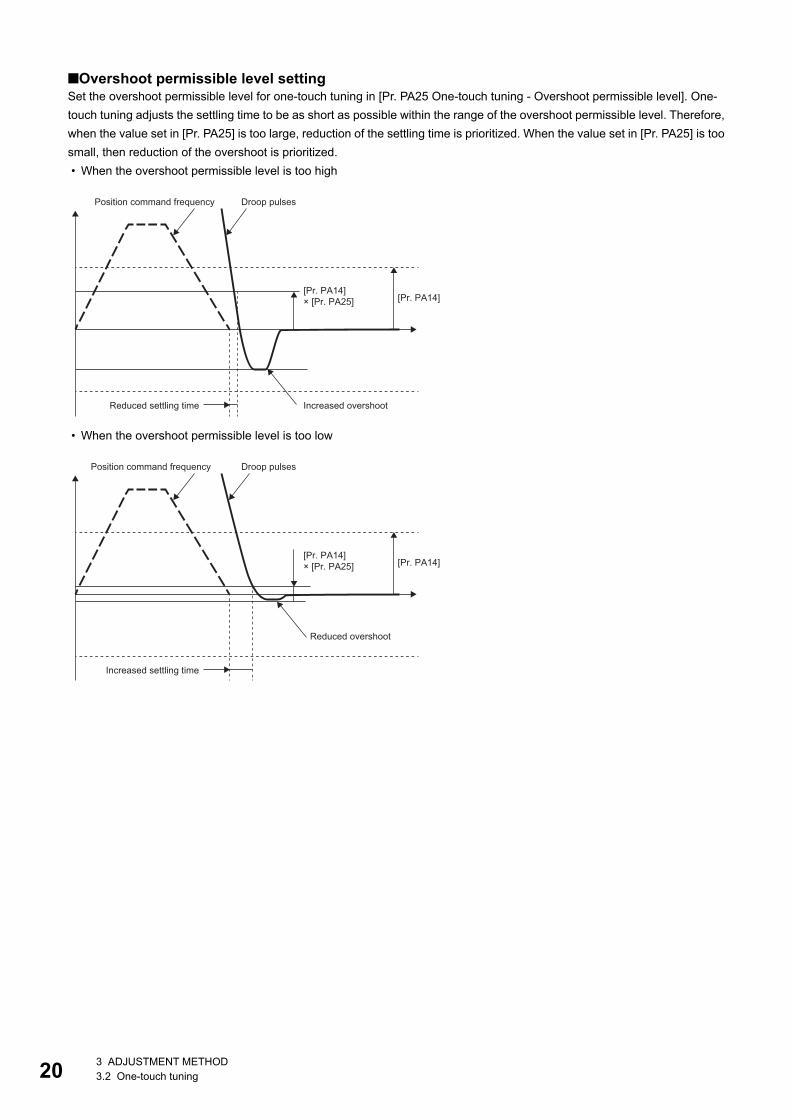
■Overshoot permissible level settingSet the overshoot permissible level for one-touch tuning in [Pr. PA25 One-touch tuning - Overshoot permissible level]. One-touch tuning adjusts the settling time to be as short as possible within the range of the overshoot permissible level. Therefore, when the value set in [Pr. PA25] is too large, reduction of the settling time is prioritized. When the value set in [Pr. PA25] is too small, then reduction of the overshoot is prioritized. • When the overshoot permissible level is too high
• When the overshoot permissible level is too low
[Pr. PA14][Pr. PA14]× [Pr. PA25]
Position command frequency Droop pulses
Reduced settling time Increased overshoot
[Pr. PA14][Pr. PA14]× [Pr. PA25]
Position command frequency Droop pulses
Reduced overshoot
Increased settling time
3 ADJUSTMENT METHOD3.2 One-touch tuning
3
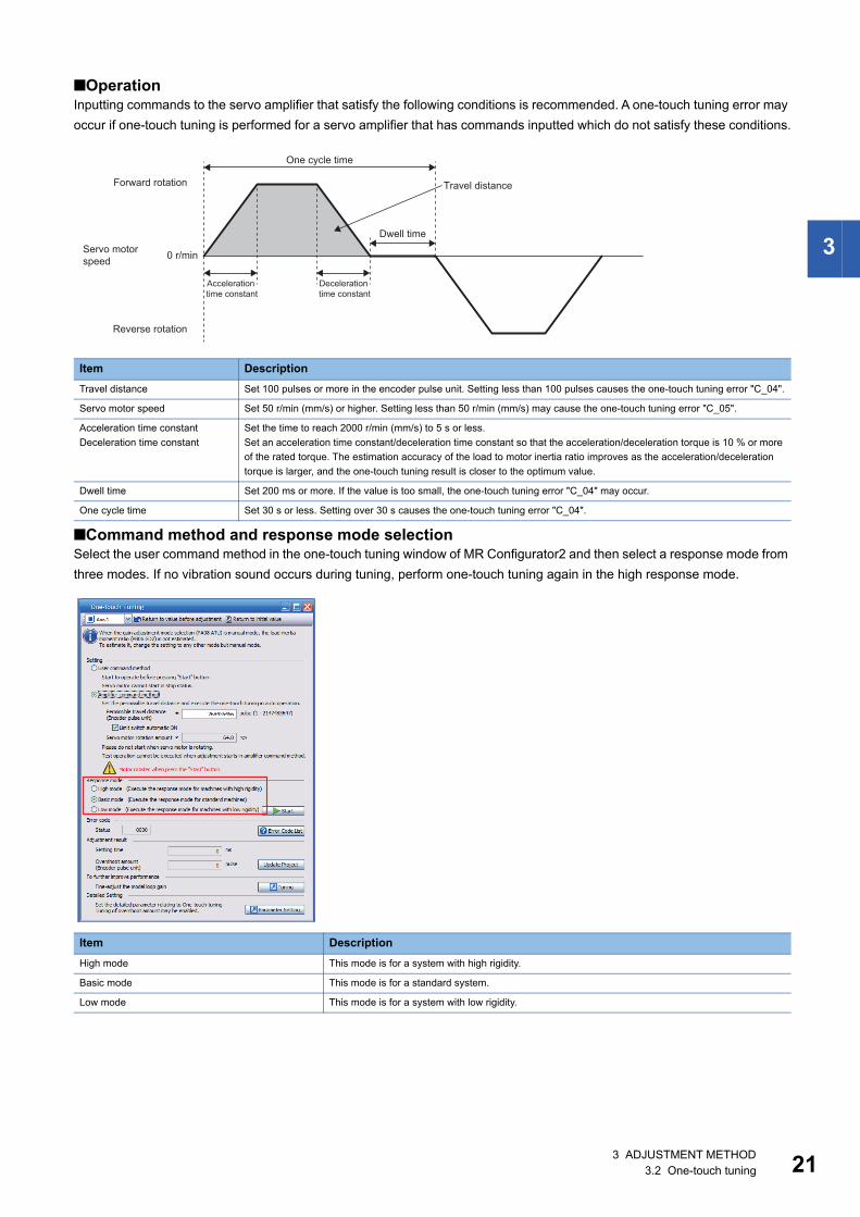
■OperationInputting commands to the servo amplifier that satisfy the following conditions is recommended. A one-touch tuning error may occur if one-touch tuning is performed for a servo amplifier that has commands inputted which do not satisfy these conditions.
■Command method and response mode selectionSelect the user command method in the one-touch tuning window of MR Configurator2 and then select a response mode from three modes. If no vibration sound occurs during tuning, perform one-touch tuning again in the high response mode.
Item DescriptionTravel distance Set 100 pulses or more in the encoder pulse unit. Setting less than 100 pulses causes the one-touch tuning error "C_04".
Servo motor speed Set 50 r/min (mm/s) or higher. Setting less than 50 r/min (mm/s) may cause the one-touch tuning error "C_05".
Acceleration time constantDeceleration time constant
Set the time to reach 2000 r/min (mm/s) to 5 s or less.Set an acceleration time constant/deceleration time constant so that the acceleration/deceleration torque is 10 % or more of the rated torque. The estimation accuracy of the load to motor inertia ratio improves as the acceleration/deceleration torque is larger, and the one-touch tuning result is closer to the optimum value.
Dwell time Set 200 ms or more. If the value is too small, the one-touch tuning error "C_04" may occur.
One cycle time Set 30 s or less. Setting over 30 s causes the one-touch tuning error "C_04".
Item DescriptionHigh mode This mode is for a system with high rigidity.
Basic mode This mode is for a standard system.
Low mode This mode is for a system with low rigidity.
0 r/min
One cycle time
Forward rotation Travel distance
Dwell timeServo motor speed
Acceleration time constant
Deceleration time constant
Reverse rotation
3 ADJUSTMENT METHOD3.2 One-touch tuning 21
22
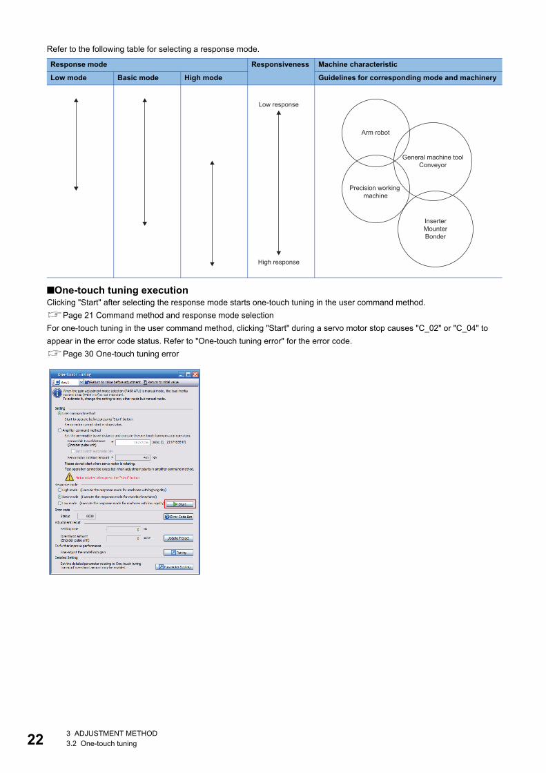
Refer to the following table for selecting a response mode.
■One-touch tuning executionClicking "Start" after selecting the response mode starts one-touch tuning in the user command method.Page 21 Command method and response mode selectionFor one-touch tuning in the user command method, clicking "Start" during a servo motor stop causes "C_02" or "C_04" to appear in the error code status. Refer to "One-touch tuning error" for the error code.Page 30 One-touch tuning error
Response mode Responsiveness Machine characteristic
Low mode Basic mode High mode Guidelines for corresponding mode and machinery
Low response
High response
Arm robot
General machine toolConveyor
Precision working machine
InserterMounterBonder
3 ADJUSTMENT METHOD3.2 One-touch tuning
3
MR Configurator2 procedure for one-touch tuning using the amplifier command methodPerform one-touch tuning using the following procedure.
1. Start
2. Moving to tuning start positionMove the moving part to the center of the movable range.
3. Overshoot permissible level settingSet the overshoot permissible level for one-touch tuning in [Pr. PA25 One-touch tuning - Overshoot permissible level].
4. One-touch tuning start, command method selectionOn MR Configurator2, select "One-touch Tuning" from the Adjustment tab of MR Configurator2. Select "Amplifier command method".
5. Permissible travel distance inputIn the one-touch tuning window of MR Configurator2, input a maximum travel distance to move the moving part at one-touch tuning.
6. Response mode selectionSelect the response mode (High mode/Basic mode/Low mode) in the one-touch tuning window of MR Configurator2.
7. One-touch tuning executionClick the "Start" button to start one-touch tuning during a servo motor stop. Once tuning starts, the servo motor reciprocates automatically. Performing one-touch tuning during a servo motor rotation causes an error. Once performed, one-touch tuning using the amplifier command method cannot be controlled by commands from the controller.
8. One-touch tuning in progressGains and filters are adjusted automatically. During the process of the tuning, the progress status is displayed in % on MR Configurator2.
9. One-touch tuning completeOnce one-touch tuning is complete, the parameters will be set automatically. If tuning did not complete properly, a tuning error will be displayed.Page 29 Servo parameters adjusted with one-touch tuning
10. Tuning result checkCheck the tuning results.If the tuning result is not satisfactory, the servo parameters can be returned to the value from before one-touch tuning or the initial value. Refer to the following.Page 32 Initializing one-touch tuning
11. Controller reset, servo amplifier power cyclingAfter executing one-touch tuning, to restore the control from the controller, reset the controller or cycle the power of the servo amplifier.
12.End
■Overshoot permissible level settingRefer to the following for the settings of the overshoot permissible level.Page 20 Overshoot permissible level setting
3 ADJUSTMENT METHOD3.2 One-touch tuning 23
24
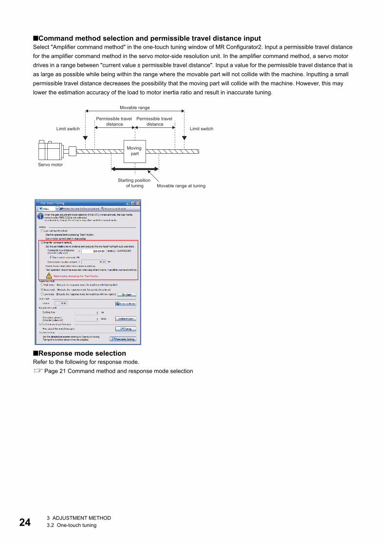
■Command method selection and permissible travel distance inputSelect "Amplifier command method" in the one-touch tuning window of MR Configurator2. Input a permissible travel distance for the amplifier command method in the servo motor-side resolution unit. In the amplifier command method, a servo motor drives in a range between "current value ± permissible travel distance". Input a value for the permissible travel distance that is as large as possible while being within the range where the movable part will not collide with the machine. Inputting a small permissible travel distance decreases the possibility that the moving part will collide with the machine. However, this may lower the estimation accuracy of the load to motor inertia ratio and result in inaccurate tuning.
■Response mode selectionRefer to the following for response mode.Page 21 Command method and response mode selection
Movable range
Permissible travel distance
Permissible travel distance
Limit switch Limit switch
Moving part
Servo motor
Starting position of tuning Movable range at tuning
3 ADJUSTMENT METHOD3.2 One-touch tuning
3
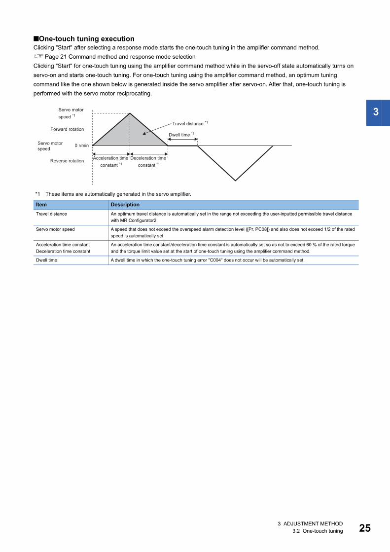
■One-touch tuning executionClicking "Start" after selecting a response mode starts the one-touch tuning in the amplifier command method.Page 21 Command method and response mode selectionClicking "Start" for one-touch tuning using the amplifier command method while in the servo-off state automatically turns on servo-on and starts one-touch tuning. For one-touch tuning using the amplifier command method, an optimum tuning command like the one shown below is generated inside the servo amplifier after servo-on. After that, one-touch tuning is performed with the servo motor reciprocating.
*1 These items are automatically generated in the servo amplifier.
Item DescriptionTravel distance An optimum travel distance is automatically set in the range not exceeding the user-inputted permissible travel distance
with MR Configurator2.
Servo motor speed A speed that does not exceed the overspeed alarm detection level ([Pr. PC08]) and also does not exceed 1/2 of the rated speed is automatically set.
Acceleration time constantDeceleration time constant
An acceleration time constant/deceleration time constant is automatically set so as not to exceed 60 % of the rated torque and the torque limit value set at the start of one-touch tuning using the amplifier command method.
Dwell time A dwell time in which the one-touch tuning error "C004" does not occur will be automatically set.
0 r/min
Servo motor speed *1
Travel distance *1Forward rotation
Dwell time *1
Servo motor speed
Acceleration time constant *1
Deceleration time constant *1
Reverse rotation
3 ADJUSTMENT METHOD3.2 One-touch tuning 25
26
Procedure for one-touch tuning via controllerPerform one-touch tuning using the following procedure.
1. Start
2. Overshoot permissible level settingSet the in-position range for one-touch tuning in [Pr. PA25 One-touch tuning - Overshoot permissible level].
3. OperationRotate the servo motor using the controller. One-touch tuning via a controller cannot be performed during a servo motor stop.
4. Response mode setting, one-touch tuning executionTo perform one-touch tuning, write the value of the response mode (High mode/Basic mode/Low mode) in [One-touch tuning mode (Obj. 2D50h)].
5. One-touch tuning in progressGains and filters are adjusted automatically. During one-touch tuning, the progress is returned to [One-touch tuning Status (Obj. 2D51h)] in %.
6. One-touch tuning completeCheck whether one-touch tuning is completed normally with [One-touch tuning mode (Obj. 2D50h)]. Once one-touch tuning is complete, the parameters will be set automatically. When the tuning is not completed normally, a tuning error is returned in [One-touch tuning Error Code (Obj. 2D54h)]. Refer to the following.Page 32 Initializing one-touch tuning
7. Tuning result checkCheck the tuning results.If the tuning result is not satisfactory, the servo parameters can be returned to the value from before one-touch tuning or the initial value with [One-touch tuning Clear (Obj. 2D53h)]. Refer to the following.Page 32 Initializing one-touch tuning
8. End
3 ADJUSTMENT METHOD3.2 One-touch tuning
3
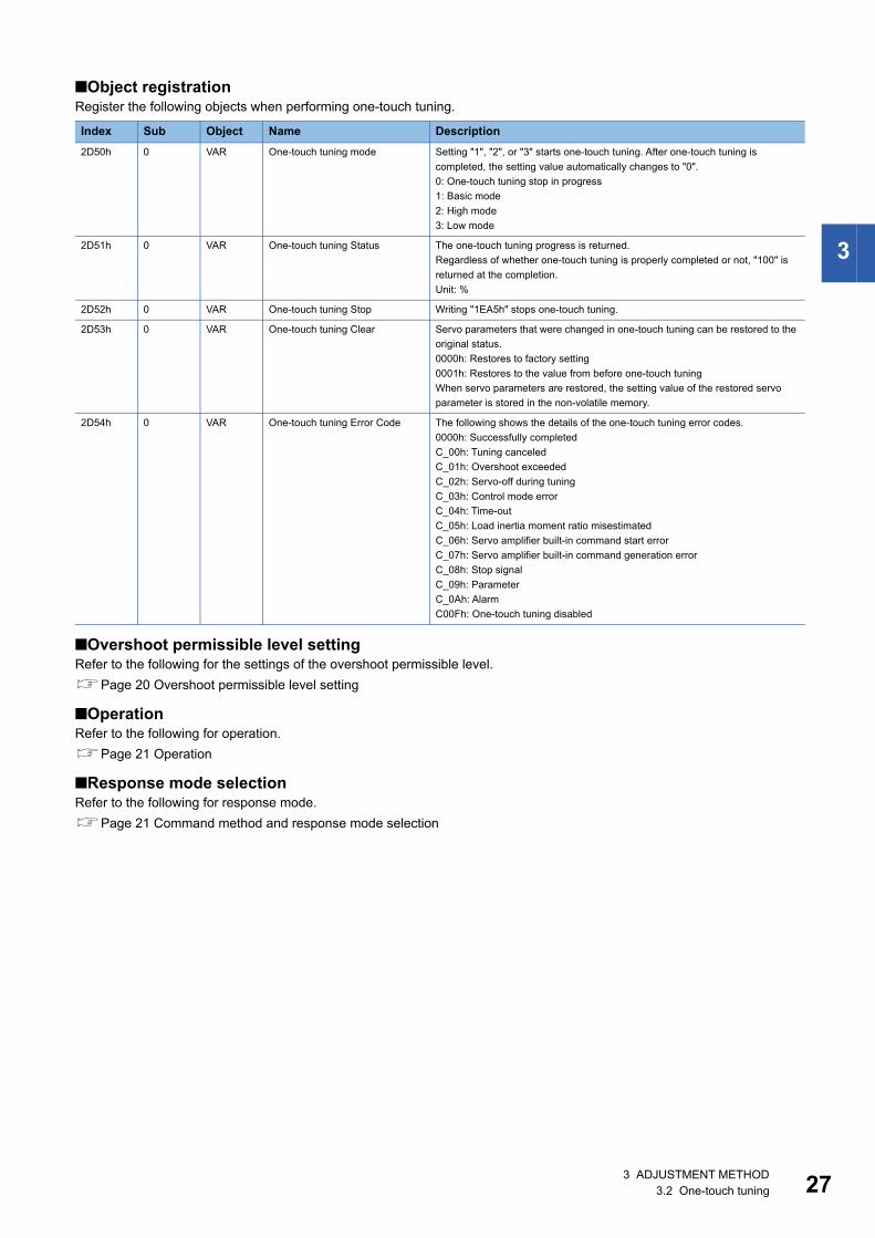
■Object registrationRegister the following objects when performing one-touch tuning.
■Overshoot permissible level settingRefer to the following for the settings of the overshoot permissible level.Page 20 Overshoot permissible level setting
■OperationRefer to the following for operation.Page 21 Operation
■Response mode selectionRefer to the following for response mode.Page 21 Command method and response mode selection
Index Sub Object Name Description2D50h 0 VAR One-touch tuning mode Setting "1", "2", or "3" starts one-touch tuning. After one-touch tuning is
completed, the setting value automatically changes to "0".0: One-touch tuning stop in progress1: Basic mode2: High mode3: Low mode
2D51h 0 VAR One-touch tuning Status The one-touch tuning progress is returned.Regardless of whether one-touch tuning is properly completed or not, "100" is returned at the completion.Unit: %
2D52h 0 VAR One-touch tuning Stop Writing "1EA5h" stops one-touch tuning.
2D53h 0 VAR One-touch tuning Clear Servo parameters that were changed in one-touch tuning can be restored to the original status.0000h: Restores to factory setting0001h: Restores to the value from before one-touch tuningWhen servo parameters are restored, the setting value of the restored servo parameter is stored in the non-volatile memory.
2D54h 0 VAR One-touch tuning Error Code The following shows the details of the one-touch tuning error codes.0000h: Successfully completedC_00h: Tuning canceledC_01h: Overshoot exceededC_02h: Servo-off during tuningC_03h: Control mode errorC_04h: Time-outC_05h: Load inertia moment ratio misestimatedC_06h: Servo amplifier built-in command start errorC_07h: Servo amplifier built-in command generation errorC_08h: Stop signalC_09h: ParameterC_0Ah: AlarmC00Fh: One-touch tuning disabled
3 ADJUSTMENT METHOD3.2 One-touch tuning 27
28
Progress display during one-touch tuning
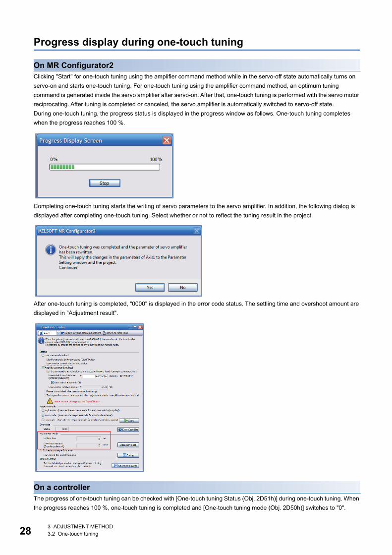
On MR Configurator2Clicking "Start" for one-touch tuning using the amplifier command method while in the servo-off state automatically turns on servo-on and starts one-touch tuning. For one-touch tuning using the amplifier command method, an optimum tuning command is generated inside the servo amplifier after servo-on. After that, one-touch tuning is performed with the servo motor reciprocating. After tuning is completed or canceled, the servo amplifier is automatically switched to servo-off state.During one-touch tuning, the progress status is displayed in the progress window as follows. One-touch tuning completes when the progress reaches 100 %.
Completing one-touch tuning starts the writing of servo parameters to the servo amplifier. In addition, the following dialog is displayed after completing one-touch tuning. Select whether or not to reflect the tuning result in the project.
After one-touch tuning is completed, "0000" is displayed in the error code status. The settling time and overshoot amount are displayed in "Adjustment result".
On a controllerThe progress of one-touch tuning can be checked with [One-touch tuning Status (Obj. 2D51h)] during one-touch tuning. When the progress reaches 100 %, one-touch tuning is completed and [One-touch tuning mode (Obj. 2D50h)] switches to "0".
3 ADJUSTMENT METHOD3.2 One-touch tuning
3
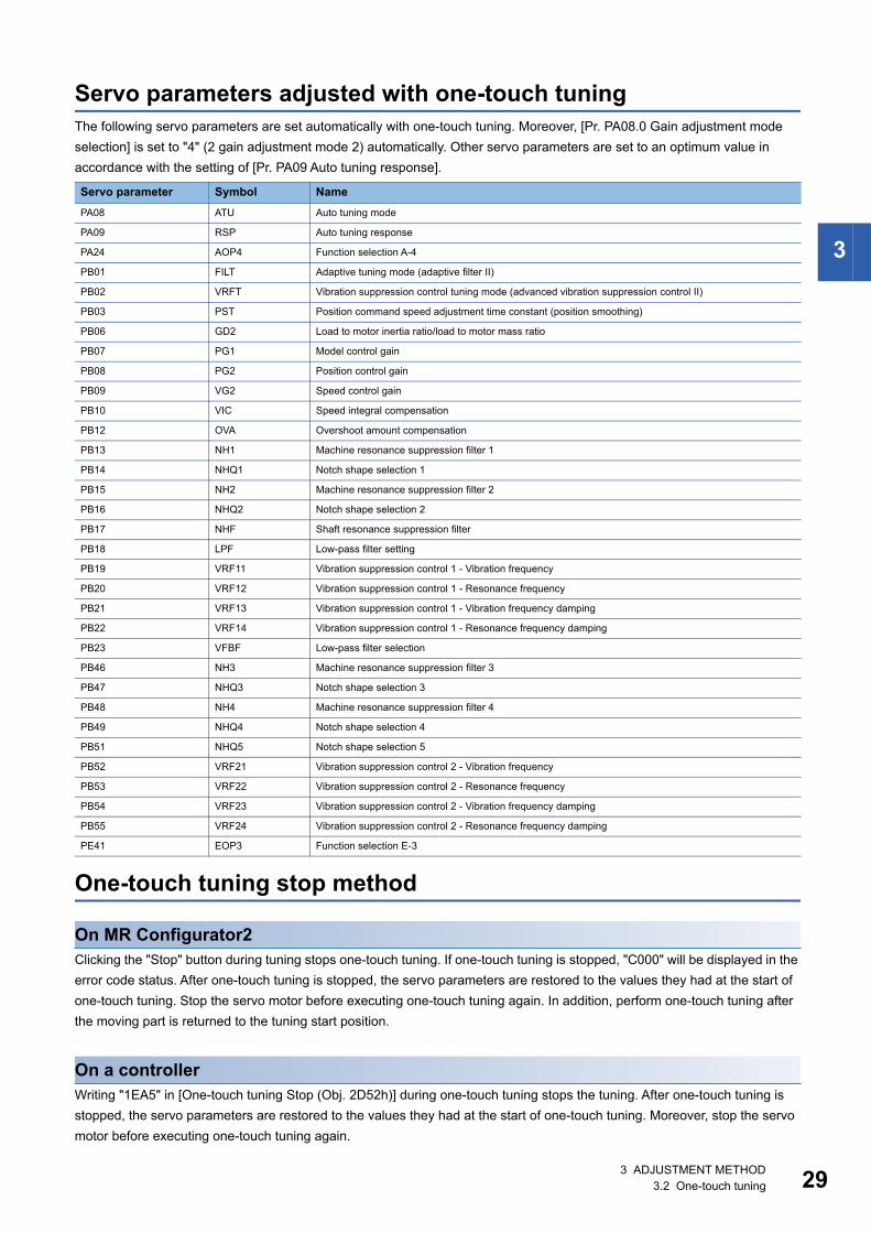
Servo parameters adjusted with one-touch tuningThe following servo parameters are set automatically with one-touch tuning. Moreover, [Pr. PA08.0 Gain adjustment mode selection] is set to "4" (2 gain adjustment mode 2) automatically. Other servo parameters are set to an optimum value in accordance with the setting of [Pr. PA09 Auto tuning response].
One-touch tuning stop method
On MR Configurator2Clicking the "Stop" button during tuning stops one-touch tuning. If one-touch tuning is stopped, "C000" will be displayed in the error code status. After one-touch tuning is stopped, the servo parameters are restored to the values they had at the start of one-touch tuning. Stop the servo motor before executing one-touch tuning again. In addition, perform one-touch tuning after the moving part is returned to the tuning start position.
On a controllerWriting "1EA5" in [One-touch tuning Stop (Obj. 2D52h)] during one-touch tuning stops the tuning. After one-touch tuning is stopped, the servo parameters are restored to the values they had at the start of one-touch tuning. Moreover, stop the servo motor before executing one-touch tuning again.
Servo parameter Symbol NamePA08 ATU Auto tuning mode
PA09 RSP Auto tuning response
PA24 AOP4 Function selection A-4
PB01 FILT Adaptive tuning mode (adaptive filter II)
PB02 VRFT Vibration suppression control tuning mode (advanced vibration suppression control II)
PB03 PST Position command speed adjustment time constant (position smoothing)
PB06 GD2 Load to motor inertia ratio/load to motor mass ratio
PB07 PG1 Model control gain
PB08 PG2 Position control gain
PB09 VG2 Speed control gain
PB10 VIC Speed integral compensation
PB12 OVA Overshoot amount compensation
PB13 NH1 Machine resonance suppression filter 1
PB14 NHQ1 Notch shape selection 1
PB15 NH2 Machine resonance suppression filter 2
PB16 NHQ2 Notch shape selection 2
PB17 NHF Shaft resonance suppression filter
PB18 LPF Low-pass filter setting
PB19 VRF11 Vibration suppression control 1 - Vibration frequency
PB20 VRF12 Vibration suppression control 1 - Resonance frequency
PB21 VRF13 Vibration suppression control 1 - Vibration frequency damping
PB22 VRF14 Vibration suppression control 1 - Resonance frequency damping
PB23 VFBF Low-pass filter selection
PB46 NH3 Machine resonance suppression filter 3
PB47 NHQ3 Notch shape selection 3
PB48 NH4 Machine resonance suppression filter 4
PB49 NHQ4 Notch shape selection 4
PB51 NHQ5 Notch shape selection 5
PB52 VRF21 Vibration suppression control 2 - Vibration frequency
PB53 VRF22 Vibration suppression control 2 - Resonance frequency
PB54 VRF23 Vibration suppression control 2 - Vibration frequency damping
PB55 VRF24 Vibration suppression control 2 - Resonance frequency damping
PE41 EOP3 Function selection E-3
3 ADJUSTMENT METHOD3.2 One-touch tuning 29
30
One-touch tuning error
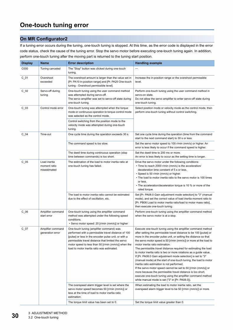
On MR Configurator2If a tuning error occurs during the tuning, one-touch tuning is stopped. At this time, as the error code is displayed in the error code status, check the cause of the tuning error. Stop the servo motor before executing one-touch tuning again. In addition, perform one-touch tuning after the moving part is returned to the tuning start position.
Display Name Error description Handling exampleC000 Tuning canceled The "Stop" button was clicked during one-touch
tuning.
C_01 Overshoot exceeded
The overshoot amount is larger than the value set in [Pr. PA10 In-position range] and [Pr. PA25 One-touch tuning - Overshoot permissible level].
Increase the in-position range or the overshoot permissible level.
C_02 Servo-off during tuning
One-touch tuning using the user command method was attempted during servo-off.The servo amplifier was set to servo-off state during one-touch tuning.
Perform one-touch tuning using the user command method in servo-on state.Do not allow the servo amplifier to enter servo-off state during one-touch tuning.
C_03 Control mode error One-touch tuning was attempted when the torque mode or continuous operation to torque control mode was selected as the control mode.
Select position mode or velocity mode as the control mode, then perform one-touch tuning without control switching.
Control switching from the position mode to the velocity mode was attempted during one-touch tuning.
C_04 Time-out One cycle time during the operation exceeds 30 s. Set one cycle time during the operation (time from the command start to the next command start) to 30 s or less.
The command speed is too slow. Set the servo motor speed to 100 r/min (mm/s) or higher. An error is less likely to occur if the command speed is higher.
The dwell time during continuous operation (stop time between commands) is too short.
Set the dwell time to 200 ms or more.An error is less likely to occur as the setting time is longer.
C_05 Load inertia moment ratio misestimated
The estimation of the load to motor inertia ratio at one-touch tuning has failed.
Drive the servo motor under the following conditions:• Time to reach 2000 r/min (mm/s) is the acceleration/
deceleration time constant of 5 s or less.• Speed is 50 r/min (mm/s) or higher.• The load to motor inertia ratio to the servo motor is 100 times
or less.• The acceleration/deceleration torque is 10 % or more of the
rated torque.
The load to motor inertia ratio cannot be estimated due to the effect of oscillation, etc.
Set [Pr. PA08.0 Gain adjustment mode selection] to "3" (manual mode), and set the correct value of load inertia moment ratio to [Pr. PB06 Load to motor inertia ratio/load to motor mass ratio], then execute one-touch tuning.
C_06 Amplifier command start error
One-touch tuning using the amplifier command method was attempted under the following speed conditions.• Servo motor speed: 20 [r/min (mm/s)] or higher
Perform one-touch tuning using the amplifier command method when the servo motor is at a stop.
C_07 Amplifier command generation error
One-touch tuning (amplifier command) was performed with a permissible travel distance of 100 [pulse] or less in the encoder pulse unit, or with a permissible travel distance that limited the servo motor speed to less than 50 [r/min (mm/s)] when the load to motor inertia ratio was estimated.
Execute one-touch tuning using the amplifier command method after setting the permissible travel distance to be 100 [pulse] or more in the encoder pulse unit, or setting the distance so that the servo motor speed is 50 [r/min (mm/s)] or more at the load to motor inertia ratio estimation.The permissible travel distance required for estimating the load to motor inertia ratio is two or more rotations as a guide value.If [Pr. PA08.0 Gain adjustment mode selection] is set to "3" (manual mode) at the start of one-touch tuning, the load to motor inertia ratio estimation is not performed.If the servo motor speed cannot be set to 50 [r/min (mm/s)] or more because the permissible travel distance is too short, execute one-touch tuning using the amplifier command method while manual mode is set ("3" in [Pr. PA08.0]).
The overspeed alarm trigger level is set where the servo motor speed becomes 50 [r/min (mm/s)] or less at the time of load to motor inertia ratio estimation.
When estimating the load to motor inertia ratio, set the overspeed alarm trigger level to be 50 [r/min (mm/s)] or more.
The torque limit value has been set to 0. Set the torque limit value greater than 0.
3 ADJUSTMENT METHOD3.2 One-touch tuning
3
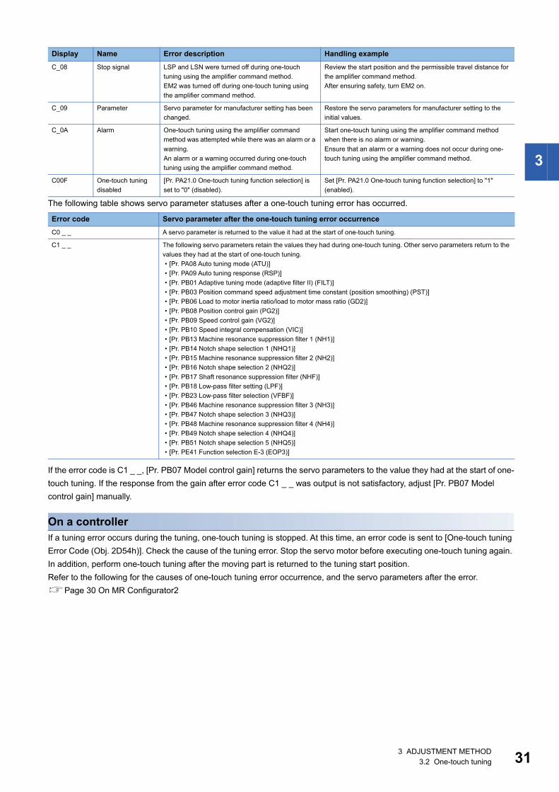
The following table shows servo parameter statuses after a one-touch tuning error has occurred.
If the error code is C1 _ _, [Pr. PB07 Model control gain] returns the servo parameters to the value they had at the start of one-touch tuning. If the response from the gain after error code C1 _ _ was output is not satisfactory, adjust [Pr. PB07 Model control gain] manually.
On a controllerIf a tuning error occurs during the tuning, one-touch tuning is stopped. At this time, an error code is sent to [One-touch tuning Error Code (Obj. 2D54h)]. Check the cause of the tuning error. Stop the servo motor before executing one-touch tuning again. In addition, perform one-touch tuning after the moving part is returned to the tuning start position.Refer to the following for the causes of one-touch tuning error occurrence, and the servo parameters after the error.Page 30 On MR Configurator2
C_08 Stop signal LSP and LSN were turned off during one-touch tuning using the amplifier command method.EM2 was turned off during one-touch tuning using the amplifier command method.
Review the start position and the permissible travel distance for the amplifier command method.After ensuring safety, turn EM2 on.
C_09 Parameter Servo parameter for manufacturer setting has been changed.
Restore the servo parameters for manufacturer setting to the initial values.
C_0A Alarm One-touch tuning using the amplifier command method was attempted while there was an alarm or a warning.An alarm or a warning occurred during one-touch tuning using the amplifier command method.
Start one-touch tuning using the amplifier command method when there is no alarm or warning.Ensure that an alarm or a warning does not occur during one-touch tuning using the amplifier command method.
C00F One-touch tuning disabled
[Pr. PA21.0 One-touch tuning function selection] is set to "0" (disabled).
Set [Pr. PA21.0 One-touch tuning function selection] to "1" (enabled).
Error code Servo parameter after the one-touch tuning error occurrenceC0 _ _ A servo parameter is returned to the value it had at the start of one-touch tuning.
C1 _ _ The following servo parameters retain the values they had during one-touch tuning. Other servo parameters return to the values they had at the start of one-touch tuning.• [Pr. PA08 Auto tuning mode (ATU)]• [Pr. PA09 Auto tuning response (RSP)]• [Pr. PB01 Adaptive tuning mode (adaptive filter II) (FILT)]• [Pr. PB03 Position command speed adjustment time constant (position smoothing) (PST)]• [Pr. PB06 Load to motor inertia ratio/load to motor mass ratio (GD2)]• [Pr. PB08 Position control gain (PG2)]• [Pr. PB09 Speed control gain (VG2)]• [Pr. PB10 Speed integral compensation (VIC)]• [Pr. PB13 Machine resonance suppression filter 1 (NH1)]• [Pr. PB14 Notch shape selection 1 (NHQ1)]• [Pr. PB15 Machine resonance suppression filter 2 (NH2)]• [Pr. PB16 Notch shape selection 2 (NHQ2)]• [Pr. PB17 Shaft resonance suppression filter (NHF)]• [Pr. PB18 Low-pass filter setting (LPF)]• [Pr. PB23 Low-pass filter selection (VFBF)]• [Pr. PB46 Machine resonance suppression filter 3 (NH3)]• [Pr. PB47 Notch shape selection 3 (NHQ3)]• [Pr. PB48 Machine resonance suppression filter 4 (NH4)]• [Pr. PB49 Notch shape selection 4 (NHQ4)]• [Pr. PB51 Notch shape selection 5 (NHQ5)]• [Pr. PE41 Function selection E-3 (EOP3)]
Display Name Error description Handling example
3 ADJUSTMENT METHOD3.2 One-touch tuning 31
32
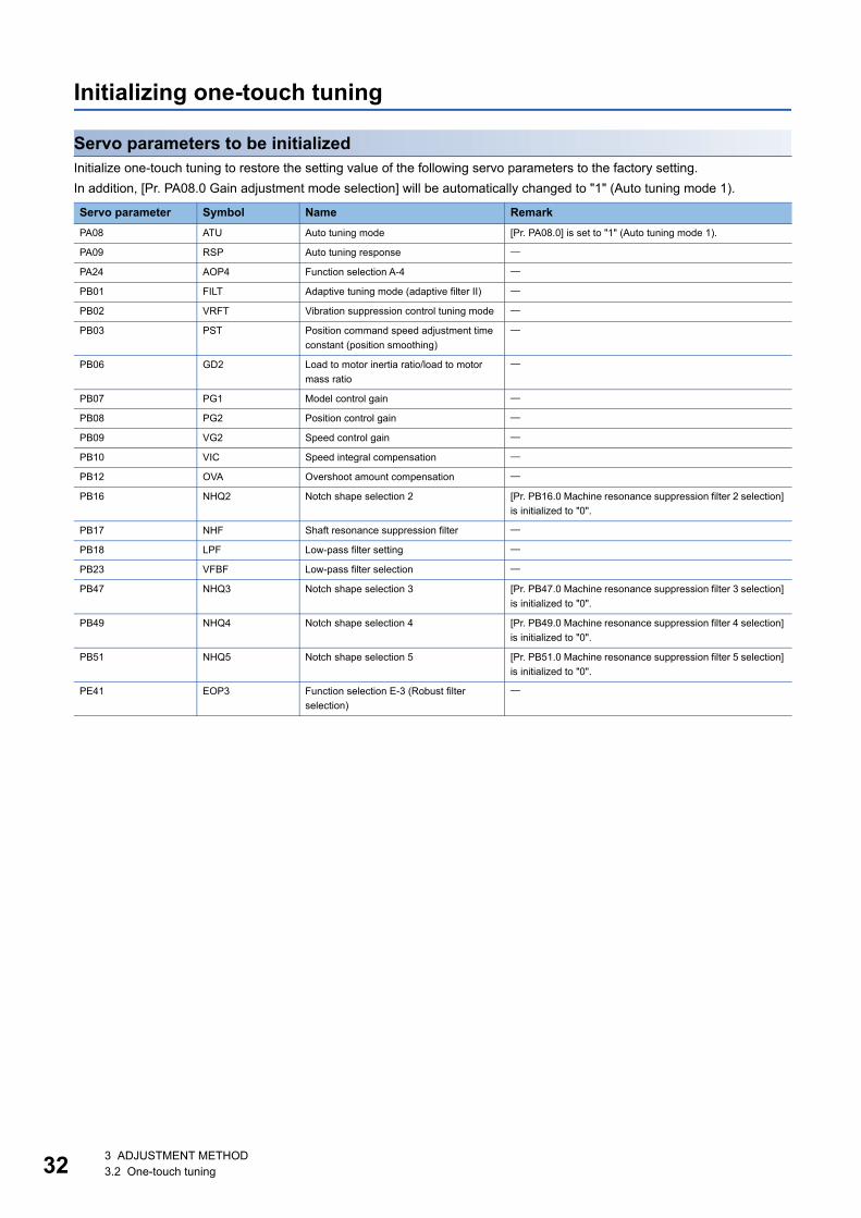
Initializing one-touch tuning
Servo parameters to be initializedInitialize one-touch tuning to restore the setting value of the following servo parameters to the factory setting.In addition, [Pr. PA08.0 Gain adjustment mode selection] will be automatically changed to "1" (Auto tuning mode 1).
Servo parameter Symbol Name RemarkPA08 ATU Auto tuning mode [Pr. PA08.0] is set to "1" (Auto tuning mode 1).
PA09 RSP Auto tuning response
PA24 AOP4 Function selection A-4
PB01 FILT Adaptive tuning mode (adaptive filter II)
PB02 VRFT Vibration suppression control tuning mode
PB03 PST Position command speed adjustment time constant (position smoothing)
PB06 GD2 Load to motor inertia ratio/load to motor mass ratio
PB07 PG1 Model control gain
PB08 PG2 Position control gain
PB09 VG2 Speed control gain
PB10 VIC Speed integral compensation
PB12 OVA Overshoot amount compensation
PB16 NHQ2 Notch shape selection 2 [Pr. PB16.0 Machine resonance suppression filter 2 selection] is initialized to "0".
PB17 NHF Shaft resonance suppression filter
PB18 LPF Low-pass filter setting
PB23 VFBF Low-pass filter selection
PB47 NHQ3 Notch shape selection 3 [Pr. PB47.0 Machine resonance suppression filter 3 selection] is initialized to "0".
PB49 NHQ4 Notch shape selection 4 [Pr. PB49.0 Machine resonance suppression filter 4 selection] is initialized to "0".
PB51 NHQ5 Notch shape selection 5 [Pr. PB51.0 Machine resonance suppression filter 5 selection] is initialized to "0".
PE41 EOP3 Function selection E-3 (Robust filter selection)
3 ADJUSTMENT METHOD3.2 One-touch tuning
3
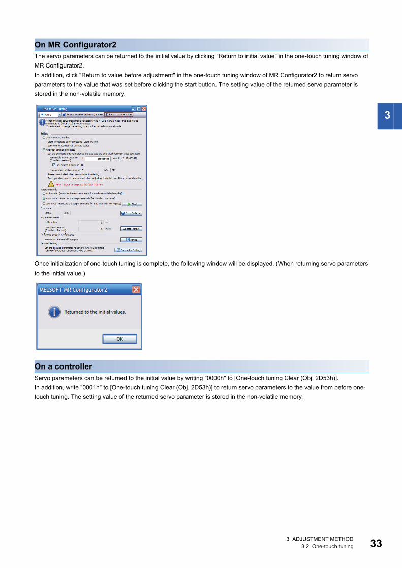
On MR Configurator2The servo parameters can be returned to the initial value by clicking "Return to initial value" in the one-touch tuning window of MR Configurator2.In addition, click "Return to value before adjustment" in the one-touch tuning window of MR Configurator2 to return servo parameters to the value that was set before clicking the start button. The setting value of the returned servo parameter is stored in the non-volatile memory.
Once initialization of one-touch tuning is complete, the following window will be displayed. (When returning servo parameters to the initial value.)
On a controllerServo parameters can be returned to the initial value by writing "0000h" to [One-touch tuning Clear (Obj. 2D53h)].In addition, write "0001h" to [One-touch tuning Clear (Obj. 2D53h)] to return servo parameters to the value from before one-touch tuning. The setting value of the returned servo parameter is stored in the non-volatile memory.
3 ADJUSTMENT METHOD3.2 One-touch tuning 33
34
3.3 Auto tuning mode 1The servo amplifier has a real-time auto tuning function which estimates the machine characteristics (load to motor inertia ratio) in real time and automatically sets the optimum gain according to that value. This function allows easier gain adjustment of the servo amplifier.In auto tuning mode 1, the load to motor inertia ratio of a machine is always estimated, and the optimum gain is automatically set. This mode is the optimum method for adjustment with the response waveform being checked when the load to motor inertia ratio of a device is unknown.
Restrictions on auto tuning mode 1All of the following conditions should be satisfied to use auto tuning mode 1. • The time until the acceleration/deceleration time constant reaches 2000 r/min (mm/s) is 5 s or less. • The servo motor speed is 50 r/min (mm/s) or higher. • The load to the servo motor inertia ratio (the load to mass of the linear servo motor primary-side ratio) is 100 times or less. • The acceleration/deceleration torque is 10 % or more of the rated torque.The auto tuning may not function properly under operating conditions where sudden disturbance torque is applied during acceleration/deceleration, or in machines with low rigidity. In such cases, use auto tuning mode 2 or manual mode to adjust the gain.
Precautions on auto tuning mode 1If sudden disturbance torque is applied during operation, the load to motor inertia ratio may be miscalculated temporarily. In such a case, set [Pr. PA08.0 Gain adjustment mode selection] to "2" (Auto tuning mode 2), and then set the accurate load to motor inertia ratio in [Pr. PB06 Load to motor inertia ratio/load to motor mass ratio].When auto tuning mode 1 is changed to manual mode, the current control gain and the load to motor inertia ratio estimation value are saved in the non-volatile memory.
3 ADJUSTMENT METHOD3.3 Auto tuning mode 1
3
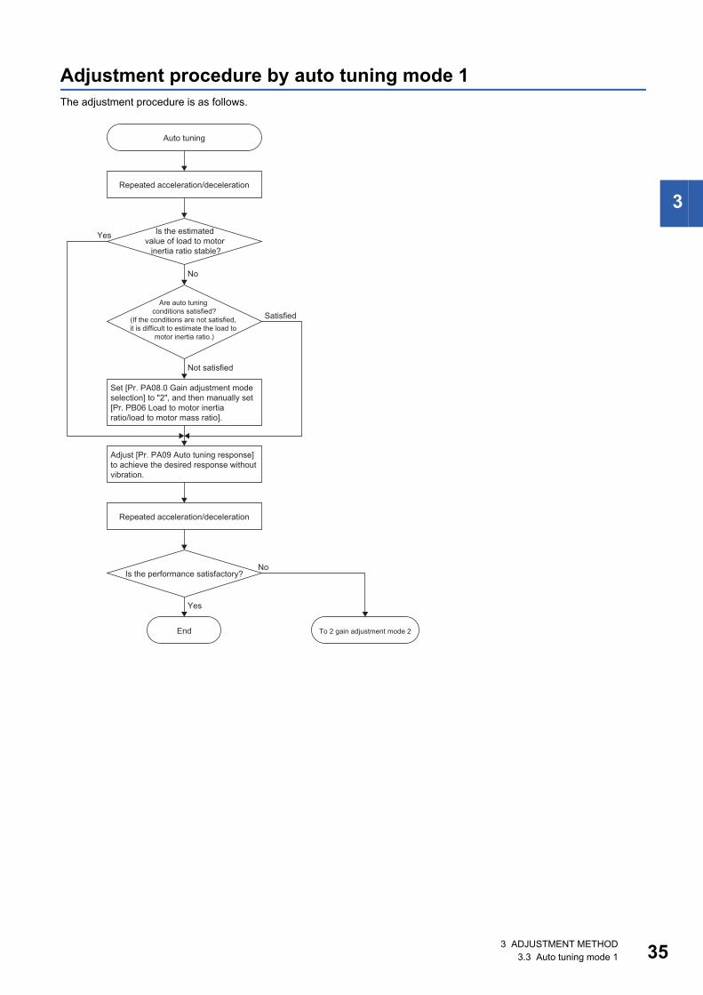
Adjustment procedure by auto tuning mode 1The adjustment procedure is as follows.
Yes
No
No
Yes
Auto tuning
Repeated acceleration/deceleration
Are auto tuning conditions satisfied?
(If the conditions are not satisfied, it is difficult to estimate the load to
motor inertia ratio.)
Is the estimated value of load to motor
inertia ratio stable?
Set [Pr. PA08.0 Gain adjustment mode selection] to "2", and then manually set [Pr. PB06 Load to motor inertia ratio/load to motor mass ratio].
Adjust [Pr. PA09 Auto tuning response] to achieve the desired response without vibration.
To 2 gain adjustment mode 2
Is the performance satisfactory?
End
Repeated acceleration/deceleration
Not satisfied
Satisfied
3 ADJUSTMENT METHOD3.3 Auto tuning mode 1 35
36
Responsiveness setting in auto tuning mode 1Set the response level for the entire servo system with [Pr. PA09]. As the responsiveness setting increases, the trackability to the command improves and the settling time becomes shorter, though vibration is more likely to occur. Therefore, set a value to obtain the desired response within the vibration-free range.If the response level cannot be increased up to the desired level because of machine resonance beyond 100 Hz, the filter tuning mode selection in [Pr. PB01.0] or machine resonance suppression filter in [Pr. PB13] to [Pr. PB16], and [Pr. PB46] to [Pr. PB51] can be used to suppress machine resonance. Suppressing machine resonance may allow the response level to be increased. Refer to the following for the settings of the adaptive tuning mode and the machine resonance suppression filter.Page 48 Machine resonance suppression filterPage 51 Adaptive filter II
3 ADJUSTMENT METHOD3.3 Auto tuning mode 1
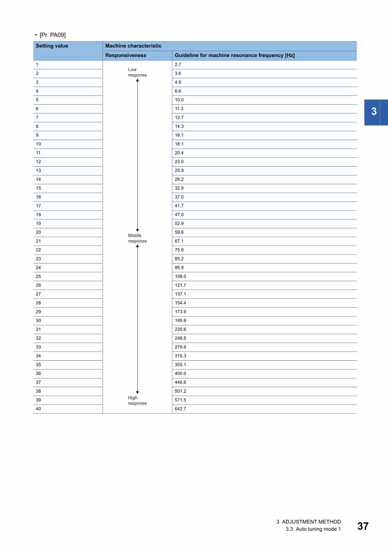
3
• [Pr. PA09]
Setting value Machine characteristic
Responsiveness Guideline for machine resonance frequency [Hz]1 2.7
2 3.6
3 4.9
4 6.6
5 10.0
6 11.3
7 12.7
8 14.3
9 16.1
10 18.1
11 20.4
12 23.0
13 25.9
14 29.2
15 32.9
16 37.0
17 41.7
18 47.0
19 52.9
20 59.6
21 67.1
22 75.6
23 85.2
24 95.9
25 108.0
26 121.7
27 137.1
28 154.4
29 173.9
30 195.9
31 220.6
32 248.5
33 279.9
34 315.3
35 355.1
36 400.0
37 446.6
38 501.2
39 571.5
40 642.7
Low response
Middle response
High response
3 ADJUSTMENT METHOD3.3 Auto tuning mode 1 37
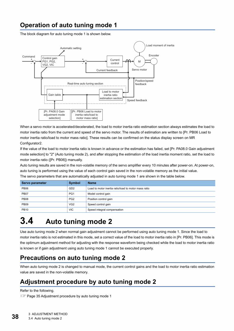
38
Operation of auto tuning mode 1The block diagram for auto tuning mode 1 is shown below.
When a servo motor is accelerated/decelerated, the load to motor inertia ratio estimation section always estimates the load to motor inertia ratio from the current and speed of the servo motor. The results of estimation are written to [Pr. PB06 Load to motor inertia ratio/load to motor mass ratio]. These results can be confirmed on the status display screen on MR Configurator2.If the value of the load to motor inertia ratio is known in advance or the estimation has failed, set [Pr. PA08.0 Gain adjustment mode selection] to "2" (Auto tuning mode 2), and after stopping the estimation of the load inertia moment ratio, set the load to motor inertia ratio ([Pr. PB06]) manually.Auto tuning results are saved in the non-volatile memory of the servo amplifier every 10 minutes after power-on. At power-on, auto tuning is performed using the value of each control gain saved in the non-volatile memory as the initial value.The servo parameters that are automatically adjusted in auto tuning mode 1 are shown in the table below.
3.4 Auto tuning mode 2Use auto tuning mode 2 when normal gain adjustment cannot be performed using auto tuning mode 1. Since the load to motor inertia ratio is not estimated in this mode, set a correct value of the load to motor inertia ratio in [Pr. PB06]. This mode is the optimum adjustment method for adjusting with the response waveform being checked while the load to motor inertia ratio is known or if gain adjustment using auto tuning mode 1 cannot be executed properly.
Precautions on auto tuning mode 2When auto tuning mode 2 is changed to manual mode, the current control gains and the load to motor inertia ratio estimation value are saved in the non-volatile memory.
Adjustment procedure by auto tuning mode 2Refer to the following.Page 35 Adjustment procedure by auto tuning mode 1
Servo parameter Symbol NamePB06 GD2 Load to motor inertia ratio/load to motor mass ratio
PB07 PG1 Model control gain
PB08 PG2 Position control gain
PB09 VG2 Speed control gain
PB10 VIC Speed integral compensation
+-
+- M
Load moment of inertiaAutomatic setting
EncoderControl gainPG1, PG2, VG2, VIC
CommandCurrentcontrol
Servo motorCurrent feedback
Position/speed feedbackReal-time auto tuning section
Load to motor inertia ratio
estimation sectionGain table
Speed feedback
[Pr. PB06 Load to motor inertia ratio/load to motor mass ratio]
[Pr. PA08.0 Gain adjustment mode
selection]
3 ADJUSTMENT METHOD3.4 Auto tuning mode 2
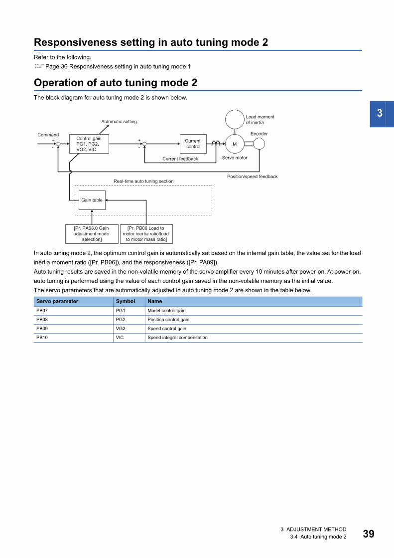
3
Responsiveness setting in auto tuning mode 2Refer to the following.Page 36 Responsiveness setting in auto tuning mode 1
Operation of auto tuning mode 2The block diagram for auto tuning mode 2 is shown below.
In auto tuning mode 2, the optimum control gain is automatically set based on the internal gain table, the value set for the load inertia moment ratio ([Pr. PB06]), and the responsiveness ([Pr. PA09]).Auto tuning results are saved in the non-volatile memory of the servo amplifier every 10 minutes after power-on. At power-on, auto tuning is performed using the value of each control gain saved in the non-volatile memory as the initial value.The servo parameters that are automatically adjusted in auto tuning mode 2 are shown in the table below.
Servo parameter Symbol NamePB07 PG1 Model control gain
PB08 PG2 Position control gain
PB09 VG2 Speed control gain
PB10 VIC Speed integral compensation
+-
+- M
Load moment of inertiaAutomatic setting
EncoderControl gainPG1, PG2, VG2, VIC
CommandCurrent control
Servo motorCurrent feedback
Position/speed feedbackReal-time auto tuning section
Gain table
[Pr. PB06 Load to motor inertia ratio/load
to motor mass ratio]
[Pr. PA08.0 Gain adjustment mode
selection]
3 ADJUSTMENT METHOD3.4 Auto tuning mode 2 39
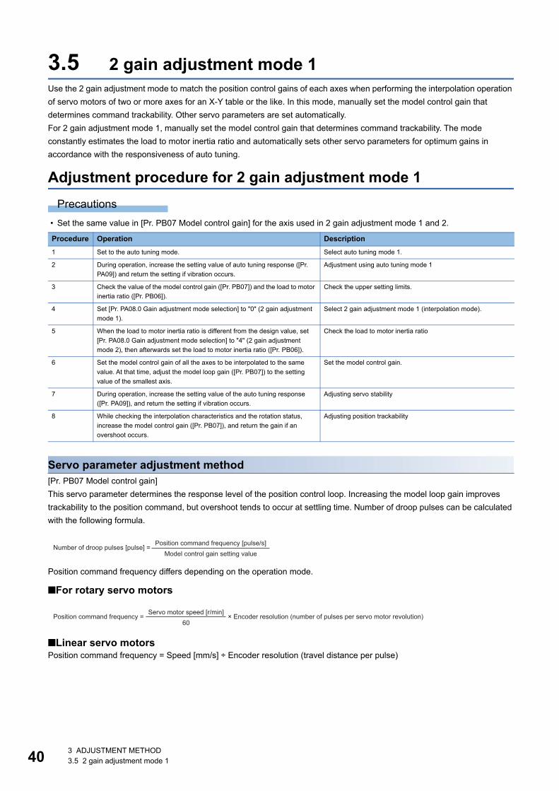
40
3.5 2 gain adjustment mode 1Use the 2 gain adjustment mode to match the position control gains of each axes when performing the interpolation operation of servo motors of two or more axes for an X-Y table or the like. In this mode, manually set the model control gain that determines command trackability. Other servo parameters are set automatically.For 2 gain adjustment mode 1, manually set the model control gain that determines command trackability. The mode constantly estimates the load to motor inertia ratio and automatically sets other servo parameters for optimum gains in accordance with the responsiveness of auto tuning.
Adjustment procedure for 2 gain adjustment mode 1Precautions
• Set the same value in [Pr. PB07 Model control gain] for the axis used in 2 gain adjustment mode 1 and 2.
Servo parameter adjustment method[Pr. PB07 Model control gain]This servo parameter determines the response level of the position control loop. Increasing the model loop gain improves trackability to the position command, but overshoot tends to occur at settling time. Number of droop pulses can be calculated with the following formula.
Position command frequency differs depending on the operation mode.
■For rotary servo motors
■Linear servo motorsPosition command frequency = Speed [mm/s] ÷ Encoder resolution (travel distance per pulse)
Procedure Operation Description1 Set to the auto tuning mode. Select auto tuning mode 1.
2 During operation, increase the setting value of auto tuning response ([Pr. PA09]) and return the setting if vibration occurs.
Adjustment using auto tuning mode 1
3 Check the value of the model control gain ([Pr. PB07]) and the load to motor inertia ratio ([Pr. PB06]).
Check the upper setting limits.
4 Set [Pr. PA08.0 Gain adjustment mode selection] to "0" (2 gain adjustment mode 1).
Select 2 gain adjustment mode 1 (interpolation mode).
5 When the load to motor inertia ratio is different from the design value, set [Pr. PA08.0 Gain adjustment mode selection] to "4" (2 gain adjustment mode 2), then afterwards set the load to motor inertia ratio ([Pr. PB06]).
Check the load to motor inertia ratio
6 Set the model control gain of all the axes to be interpolated to the same value. At that time, adjust the model loop gain ([Pr. PB07]) to the setting value of the smallest axis.
Set the model control gain.
7 During operation, increase the setting value of the auto tuning response ([Pr. PA09]), and return the setting if vibration occurs.
Adjusting servo stability
8 While checking the interpolation characteristics and the rotation status, increase the model control gain ([Pr. PB07]), and return the gain if an overshoot occurs.
Adjusting position trackability
Position command frequency [pulse/s]Number of droop pulses [pulse] = Model control gain setting value
Servo motor speed [r/min]Position command frequency = × Encoder resolution (number of pulses per servo motor revolution)60
3 ADJUSTMENT METHOD3.5 2 gain adjustment mode 1
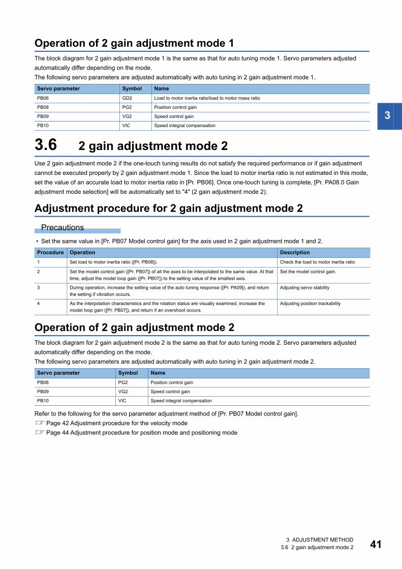
3
Operation of 2 gain adjustment mode 1The block diagram for 2 gain adjustment mode 1 is the same as that for auto tuning mode 1. Servo parameters adjusted automatically differ depending on the mode.The following servo parameters are adjusted automatically with auto tuning in 2 gain adjustment mode 1.
3.6 2 gain adjustment mode 2Use 2 gain adjustment mode 2 if the one-touch tuning results do not satisfy the required performance or if gain adjustment cannot be executed properly by 2 gain adjustment mode 1. Since the load to motor inertia ratio is not estimated in this mode, set the value of an accurate load to motor inertia ratio in [Pr. PB06]. Once one-touch tuning is complete, [Pr. PA08.0 Gain adjustment mode selection] will be automatically set to "4" (2 gain adjustment mode 2).
Adjustment procedure for 2 gain adjustment mode 2Precautions
• Set the same value in [Pr. PB07 Model control gain] for the axis used in 2 gain adjustment mode 1 and 2.
Operation of 2 gain adjustment mode 2The block diagram for 2 gain adjustment mode 2 is the same as that for auto tuning mode 2. Servo parameters adjusted automatically differ depending on the mode.The following servo parameters are adjusted automatically with auto tuning in 2 gain adjustment mode 2.
Refer to the following for the servo parameter adjustment method of [Pr. PB07 Model control gain].Page 42 Adjustment procedure for the velocity modePage 44 Adjustment procedure for position mode and positioning mode
Servo parameter Symbol NamePB06 GD2 Load to motor inertia ratio/load to motor mass ratio
PB08 PG2 Position control gain
PB09 VG2 Speed control gain
PB10 VIC Speed integral compensation
Procedure Operation Description1 Set load to motor inertia ratio ([Pr. PB06]). Check the load to motor inertia ratio
2 Set the model control gain ([Pr. PB07]) of all the axes to be interpolated to the same value. At that time, adjust the model loop gain ([Pr. PB07]) to the setting value of the smallest axis.
Set the model control gain.
3 During operation, increase the setting value of the auto tuning response ([Pr. PA09]), and return the setting if vibration occurs.
Adjusting servo stability
4 As the interpolation characteristics and the rotation status are visually examined, increase the model loop gain ([Pr. PB07]), and return if an overshoot occurs.
Adjusting position trackability
Servo parameter Symbol NamePB08 PG2 Position control gain
PB09 VG2 Speed control gain
PB10 VIC Speed integral compensation
3 ADJUSTMENT METHOD3.6 2 gain adjustment mode 2 41
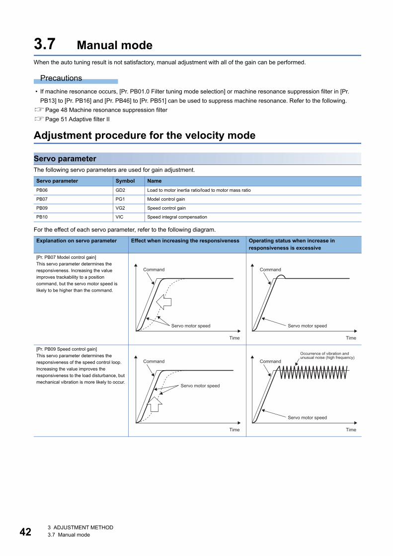
42
3.7 Manual modeWhen the auto tuning result is not satisfactory, manual adjustment with all of the gain can be performed.
Precautions • If machine resonance occurs, [Pr. PB01.0 Filter tuning mode selection] or machine resonance suppression filter in [Pr.
PB13] to [Pr. PB16] and [Pr. PB46] to [Pr. PB51] can be used to suppress machine resonance. Refer to the following.Page 48 Machine resonance suppression filterPage 51 Adaptive filter II
Adjustment procedure for the velocity mode
Servo parameterThe following servo parameters are used for gain adjustment.
For the effect of each servo parameter, refer to the following diagram.
Servo parameter Symbol NamePB06 GD2 Load to motor inertia ratio/load to motor mass ratio
PB07 PG1 Model control gain
PB09 VG2 Speed control gain
PB10 VIC Speed integral compensation
Explanation on servo parameter Effect when increasing the responsiveness Operating status when increase in responsiveness is excessive
[Pr. PB07 Model control gain]This servo parameter determines the responsiveness. Increasing the value improves trackability to a position command, but the servo motor speed is likely to be higher than the command.
[Pr. PB09 Speed control gain]This servo parameter determines the responsiveness of the speed control loop. Increasing the value improves the responsiveness to the load disturbance, but mechanical vibration is more likely to occur.
Command
Servo motor speed
Time
Command
Servo motor speed
Time
Command
Servo motor speed
Time
Occurrence of vibration and unusual noise (high frequency)
Command
Servo motor speed
Time
3 ADJUSTMENT METHOD3.7 Manual mode
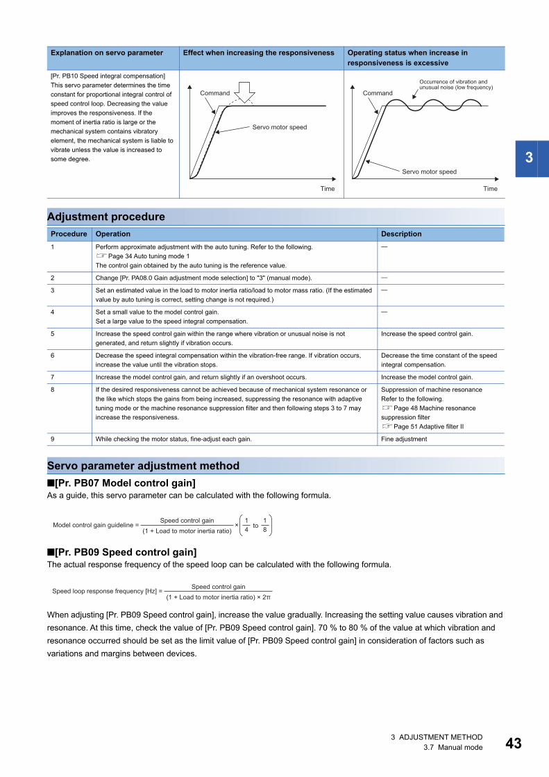
3
Adjustment procedure
Servo parameter adjustment method■[Pr. PB07 Model control gain]As a guide, this servo parameter can be calculated with the following formula.
■[Pr. PB09 Speed control gain]The actual response frequency of the speed loop can be calculated with the following formula.
When adjusting [Pr. PB09 Speed control gain], increase the value gradually. Increasing the setting value causes vibration and resonance. At this time, check the value of [Pr. PB09 Speed control gain]. 70 % to 80 % of the value at which vibration and resonance occurred should be set as the limit value of [Pr. PB09 Speed control gain] in consideration of factors such as variations and margins between devices.
[Pr. PB10 Speed integral compensation]This servo parameter determines the time constant for proportional integral control of speed control loop. Decreasing the value improves the responsiveness. If the moment of inertia ratio is large or the mechanical system contains vibratory element, the mechanical system is liable to vibrate unless the value is increased to some degree.
Procedure Operation Description1 Perform approximate adjustment with the auto tuning. Refer to the following.
Page 34 Auto tuning mode 1The control gain obtained by the auto tuning is the reference value.
2 Change [Pr. PA08.0 Gain adjustment mode selection] to "3" (manual mode).
3 Set an estimated value in the load to motor inertia ratio/load to motor mass ratio. (If the estimated value by auto tuning is correct, setting change is not required.)
4 Set a small value to the model control gain.Set a large value to the speed integral compensation.
5 Increase the speed control gain within the range where vibration or unusual noise is not generated, and return slightly if vibration occurs.
Increase the speed control gain.
6 Decrease the speed integral compensation within the vibration-free range. If vibration occurs, increase the value until the vibration stops.
Decrease the time constant of the speed integral compensation.
7 Increase the model control gain, and return slightly if an overshoot occurs. Increase the model control gain.
8 If the desired responsiveness cannot be achieved because of mechanical system resonance or the like which stops the gains from being increased, suppressing the resonance with adaptive tuning mode or the machine resonance suppression filter and then following steps 3 to 7 may increase the responsiveness.
Suppression of machine resonanceRefer to the following.Page 48 Machine resonance suppression filterPage 51 Adaptive filter II
9 While checking the motor status, fine-adjust each gain. Fine adjustment
Explanation on servo parameter Effect when increasing the responsiveness Operating status when increase in responsiveness is excessive
Command
Servo motor speed
Time
Occurrence of vibration and unusual noise (low frequency)
Command
Servo motor speed
Time
Speed control gainModel control gain guideline = to
(1 + Load to motor inertia ratio) 81
41
×
Speed control gainSpeed loop response frequency [Hz] = (1 + Load to motor inertia ratio) × 2π
3 ADJUSTMENT METHOD3.7 Manual mode 43
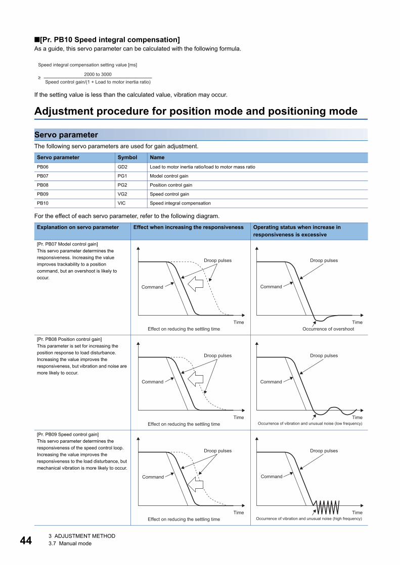
44
■[Pr. PB10 Speed integral compensation]As a guide, this servo parameter can be calculated with the following formula.
If the setting value is less than the calculated value, vibration may occur.
Adjustment procedure for position mode and positioning mode
Servo parameterThe following servo parameters are used for gain adjustment.
For the effect of each servo parameter, refer to the following diagram.
Servo parameter Symbol NamePB06 GD2 Load to motor inertia ratio/load to motor mass ratio
PB07 PG1 Model control gain
PB08 PG2 Position control gain
PB09 VG2 Speed control gain
PB10 VIC Speed integral compensation
Explanation on servo parameter Effect when increasing the responsiveness Operating status when increase in responsiveness is excessive
[Pr. PB07 Model control gain]This servo parameter determines the responsiveness. Increasing the value improves trackability to a position command, but an overshoot is likely to occur.
[Pr. PB08 Position control gain]This parameter is set for increasing the position response to load disturbance. Increasing the value improves the responsiveness, but vibration and noise are more likely to occur.
[Pr. PB09 Speed control gain]This servo parameter determines the responsiveness of the speed control loop. Increasing the value improves the responsiveness to the load disturbance, but mechanical vibration is more likely to occur.
Speed integral compensation setting value [ms]
2000 to 3000≥
Speed control gain/(1 + Load to motor inertia ratio)
Droop pulses
Command
TimeEffect on reducing the settling time
Droop pulses
Command
TimeOccurrence of overshoot
Droop pulses
Command
TimeEffect on reducing the settling time
Droop pulses
Command
TimeOccurrence of vibration and unusual noise (low frequency)
Droop pulses
Command
TimeEffect on reducing the settling time
Droop pulses
Command
TimeOccurrence of vibration and unusual noise (high frequency)
3 ADJUSTMENT METHOD3.7 Manual mode
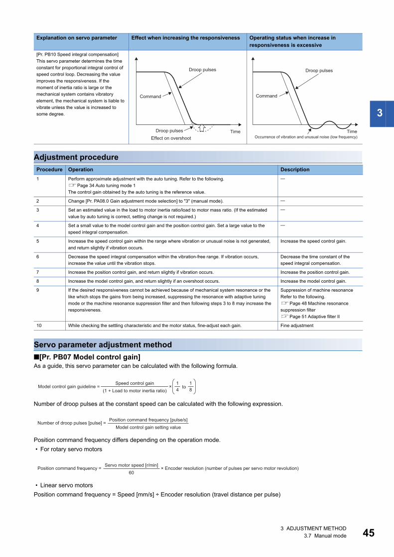
3
Adjustment procedure
Servo parameter adjustment method■[Pr. PB07 Model control gain]As a guide, this servo parameter can be calculated with the following formula.
Number of droop pulses at the constant speed can be calculated with the following expression.
Position command frequency differs depending on the operation mode. • For rotary servo motors
• Linear servo motorsPosition command frequency = Speed [mm/s] ÷ Encoder resolution (travel distance per pulse)
[Pr. PB10 Speed integral compensation]This servo parameter determines the time constant for proportional integral control of speed control loop. Decreasing the value improves the responsiveness. If the moment of inertia ratio is large or the mechanical system contains vibratory element, the mechanical system is liable to vibrate unless the value is increased to some degree.
Procedure Operation Description1 Perform approximate adjustment with the auto tuning. Refer to the following.
Page 34 Auto tuning mode 1The control gain obtained by the auto tuning is the reference value.
2 Change [Pr. PA08.0 Gain adjustment mode selection] to "3" (manual mode).
3 Set an estimated value in the load to motor inertia ratio/load to motor mass ratio. (If the estimated value by auto tuning is correct, setting change is not required.)
4 Set a small value to the model control gain and the position control gain. Set a large value to the speed integral compensation.
5 Increase the speed control gain within the range where vibration or unusual noise is not generated, and return slightly if vibration occurs.
Increase the speed control gain.
6 Decrease the speed integral compensation within the vibration-free range. If vibration occurs, increase the value until the vibration stops.
Decrease the time constant of the speed integral compensation.
7 Increase the position control gain, and return slightly if vibration occurs. Increase the position control gain.
8 Increase the model control gain, and return slightly if an overshoot occurs. Increase the model control gain.
9 If the desired responsiveness cannot be achieved because of mechanical system resonance or the like which stops the gains from being increased, suppressing the resonance with adaptive tuning mode or the machine resonance suppression filter and then following steps 3 to 8 may increase the responsiveness.
Suppression of machine resonanceRefer to the following.Page 48 Machine resonance suppression filterPage 51 Adaptive filter II
10 While checking the settling characteristic and the motor status, fine-adjust each gain. Fine adjustment
Explanation on servo parameter Effect when increasing the responsiveness Operating status when increase in responsiveness is excessive
Droop pulses
Command
Droop pulses TimeEffect on overshoot
Droop pulses
Command
TimeOccurrence of vibration and unusual noise (low frequency)
Speed control gainModel control gain guideline = to
(1 + Load to motor inertia ratio)×
81
41
Position command frequency [pulse/s]Number of droop pulses [pulse] = Model control gain setting value
Servo motor speed [r/min]Position command frequency = × Encoder resolution (number of pulses per servo motor revolution)60
3 ADJUSTMENT METHOD3.7 Manual mode 45
46
■[Pr. PB08 Position control gain]As a guide, this servo parameter can be calculated with the following formula.
■[Pr. PB09 Speed control gain]The actual response frequency of the speed loop can be calculated with the following formula.
When adjusting [Pr. PB09 Speed control gain], increase the value gradually. Increasing the setting value causes vibration and resonance. At this time, check the value of [Pr. PB09 Speed control gain]. 70 % to 80 % of the value at which vibration and resonance occurred should be set as the limit value of [Pr. PB09 Speed control gain] in consideration of factors such as variations and margins between devices.
■[Pr. PB10 Speed integral compensation]As a guide, this servo parameter can be calculated with the following formula.
If the setting value is less than the calculated value, vibration may occur. If the droop pulses vibrate during a stop, increasing the value in [Pr. PB10 Speed integral compensation] is effective.
Speed control gainPosition control gain guideline = to
(1 + Load to motor inertia ratio) 81
41
×
Speed control gainSpeed loop response frequency [Hz] = (1 + Load to motor inertia ratio) × 2π
Speed integral compensation setting value [ms]
2000 to 3000≥
Speed control gain/(1 + Load to motor inertia ratio)
3 ADJUSTMENT METHOD3.7 Manual mode
3
3.8 Load to motor inertia ratio monitor modeThe servo amplifier has a function which estimates the machine characteristic (load to motor inertia ratio) in real time. This mode does not change the set gains, but estimates the load to motor inertia ratio.
Precautions on load to motor inertia ratio monitor mode • Only estimation of the load to motor inertia ratio is executed by this mode. Therefore, the estimated load to motor inertia
ratio is not used in controlling by the servo amplifier, and the responsiveness decreases in comparison with the same setting in the manual mode.
Adjustment procedure for load to motor inertia ratio monitor mode • This mode enables manual adjustment by all the gains. However, use the gains adjusted by quick tuning as a standard.
Refer to the adjustment procedure for manual mode when adjusting the gains with this mode.Page 45 Adjustment procedure
Operation of load to motor inertia ratio monitor mode • The operation of the load to motor inertia ratio estimation performed in this mode is the same as that of auto tuning mode 1.The servo parameter that is automatically adjusted in this mode is shown in the table below.
Servo parameter Symbol NamePB06 GD2 Load to motor inertia ratio/load to motor mass ratio
3 ADJUSTMENT METHOD3.8 Load to motor inertia ratio monitor mode 47
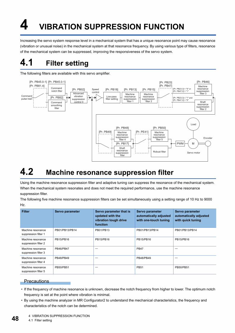
48
4 VIBRATION SUPPRESSION FUNCTIONIncreasing the servo system response level in a mechanical system that has a unique resonance point may cause resonance (vibration or unusual noise) in the mechanical system at that resonance frequency. By using various type of filters, resonance of the mechanical system can be suppressed, improving the responsiveness of the servo system.
4.1 Filter settingThe following filters are available with this servo amplifier.
4.2 Machine resonance suppression filterUsing the machine resonance suppression filter and adaptive tuning can suppress the resonance of the mechanical system. When the mechanical system resonates and does not meet the required performance, use the machine resonance suppression filter.The following five machine resonance suppression filters can be set simultaneously using a setting range of 10 Hz to 9000 Hz.
Precautions • If the frequency of machine resonance is unknown, decrease the notch frequency from higher to lower. The optimum notch
frequency is set at the point where vibration is minimal. • By using the machine analyzer in MR Configurator2 to understand the mechanical characteristics, the frequency and
characteristics of the notch can be determined.
Filter Servo parameter Servo parameter that is updated with the vibration tough drive function
Servo parameter automatically adjusted with one-touch tuning
Servo parameter automatically adjusted with quick tuning
Machine resonance suppression filter 1
PB01/PB13/PB14 PB01/PB13 PB01/PB13/PB14 PB01/PB13/PB14
Machine resonance suppression filter 2
PB15/PB16 PB15/PB16 PB15/PB16 PB15/PB16
Machine resonance suppression filter 3
PB46/PB47 PB47
Machine resonance suppression filter 4
PB48/PB49 PB48/PB49
Machine resonance suppression filter 5
PB50/PB51 PB51 PB50/PB51
PWM M
+-
[Pr. PB48] [Pr. PB50]
[Pr. PB17]
[Pr. PB49] [Pr. PE41]
[Pr. PB46][Pr. PB23][Pr. PB47]
[Pr. PB18][Pr. PB02] [Pr. PB13] [Pr. PB15]
[Pr. PB45.0-1][Pr. PB45.0-1][Pr. PB81.4]
[Pr. PB82]Command pulse train
Low-pass filter setting
Encoder
Servo motor
Load
Machine resonance
suppression filter 1
Machine resonance
suppression filter 2
Command notch filter
Machine resonance
suppression filter 4
Machine resonance
suppression filter 5
Shaft resonance
suppression filter
Robust filter
Speed control
Machine resonance
suppression filter 3
Shaft resonance
suppression filter 2
[Pr. PB23.3] = "0" or [Pr. PB47.0] = "1"
[Pr. PB23.3] = "1" and [Pr. PB47.0] = "0"
Command smoothing
filter
Advanced vibration
suppression control II
4 VIBRATION SUPPRESSION FUNCTION4.1 Filter setting
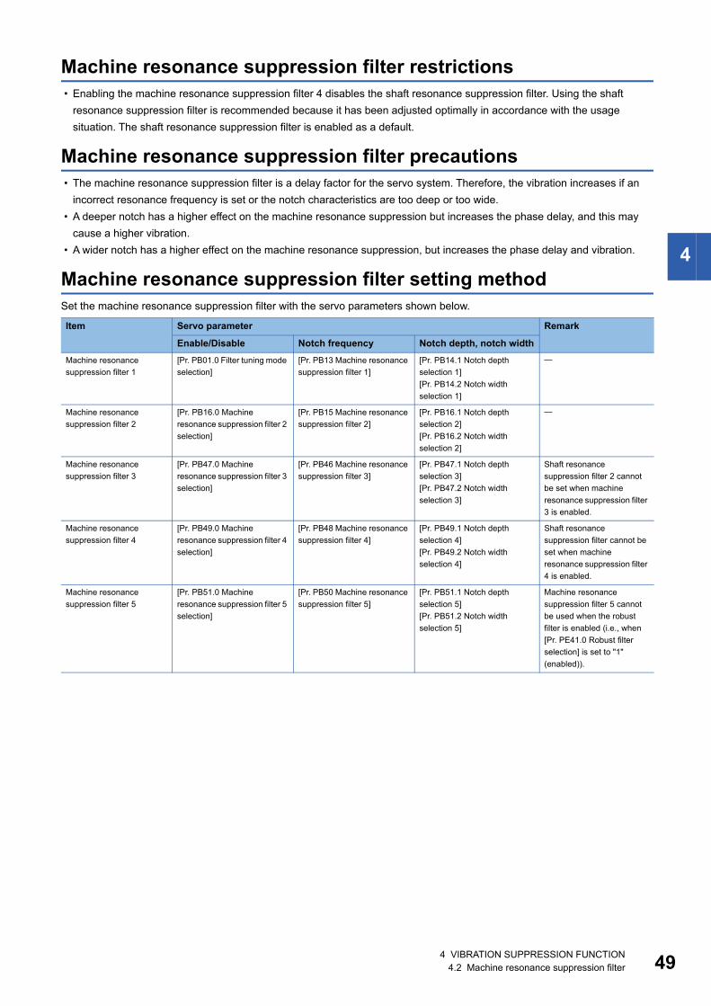
4
Machine resonance suppression filter restrictions • Enabling the machine resonance suppression filter 4 disables the shaft resonance suppression filter. Using the shaft
resonance suppression filter is recommended because it has been adjusted optimally in accordance with the usage situation. The shaft resonance suppression filter is enabled as a default.
Machine resonance suppression filter precautions • The machine resonance suppression filter is a delay factor for the servo system. Therefore, the vibration increases if an
incorrect resonance frequency is set or the notch characteristics are too deep or too wide. • A deeper notch has a higher effect on the machine resonance suppression but increases the phase delay, and this may
cause a higher vibration. • A wider notch has a higher effect on the machine resonance suppression, but increases the phase delay and vibration.
Machine resonance suppression filter setting methodSet the machine resonance suppression filter with the servo parameters shown below.
Item Servo parameter Remark
Enable/Disable Notch frequency Notch depth, notch widthMachine resonance suppression filter 1
[Pr. PB01.0 Filter tuning mode selection]
[Pr. PB13 Machine resonance suppression filter 1]
[Pr. PB14.1 Notch depth selection 1][Pr. PB14.2 Notch width selection 1]
Machine resonance suppression filter 2
[Pr. PB16.0 Machine resonance suppression filter 2 selection]
[Pr. PB15 Machine resonance suppression filter 2]
[Pr. PB16.1 Notch depth selection 2][Pr. PB16.2 Notch width selection 2]
Machine resonance suppression filter 3
[Pr. PB47.0 Machine resonance suppression filter 3 selection]
[Pr. PB46 Machine resonance suppression filter 3]
[Pr. PB47.1 Notch depth selection 3][Pr. PB47.2 Notch width selection 3]
Shaft resonance suppression filter 2 cannot be set when machine resonance suppression filter 3 is enabled.
Machine resonance suppression filter 4
[Pr. PB49.0 Machine resonance suppression filter 4 selection]
[Pr. PB48 Machine resonance suppression filter 4]
[Pr. PB49.1 Notch depth selection 4][Pr. PB49.2 Notch width selection 4]
Shaft resonance suppression filter cannot be set when machine resonance suppression filter 4 is enabled.
Machine resonance suppression filter 5
[Pr. PB51.0 Machine resonance suppression filter 5 selection]
[Pr. PB50 Machine resonance suppression filter 5]
[Pr. PB51.1 Notch depth selection 5][Pr. PB51.2 Notch width selection 5]
Machine resonance suppression filter 5 cannot be used when the robust filter is enabled (i.e., when [Pr. PE41.0 Robust filter selection] is set to "1" (enabled)).
4 VIBRATION SUPPRESSION FUNCTION4.2 Machine resonance suppression filter 49
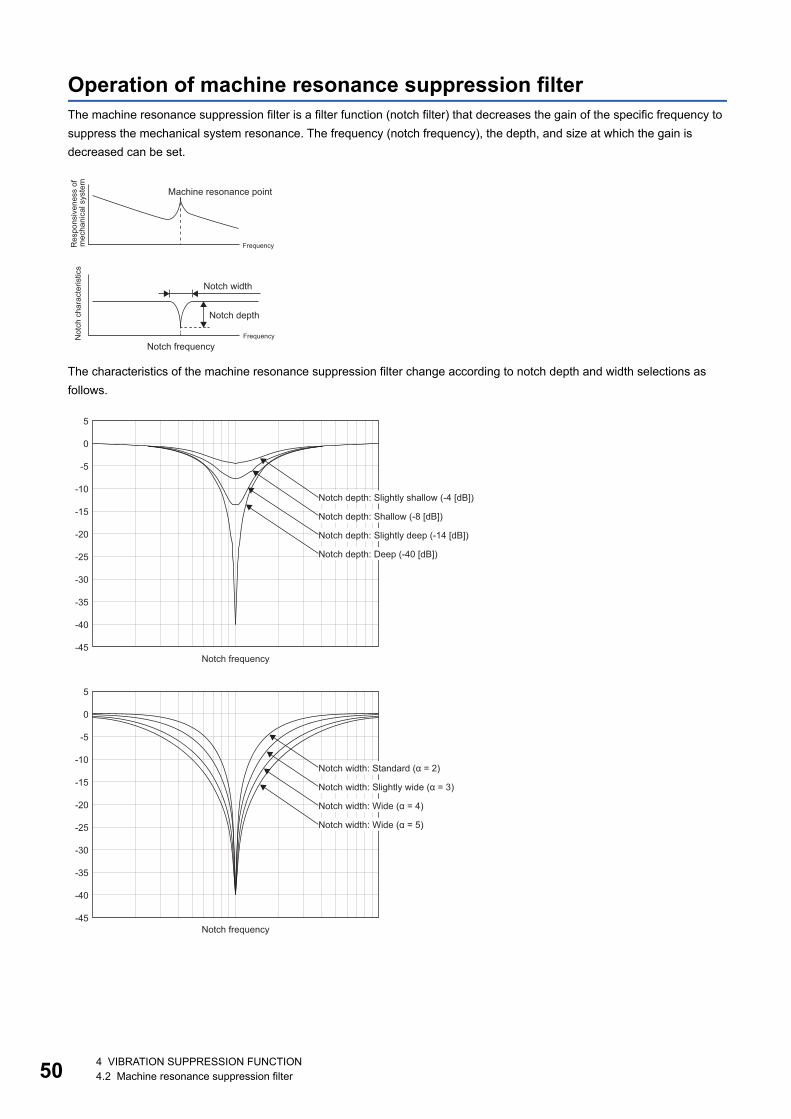
50
Operation of machine resonance suppression filterThe machine resonance suppression filter is a filter function (notch filter) that decreases the gain of the specific frequency to suppress the mechanical system resonance. The frequency (notch frequency), the depth, and size at which the gain is decreased can be set.
The characteristics of the machine resonance suppression filter change according to notch depth and width selections as follows.
Res
pons
iven
ess
of
mec
hani
cal s
yste
m
Machine resonance point
Frequency
Not
ch c
hara
cter
istic
s
Notch width
Notch depth
FrequencyNotch frequency
5
0
-5
-10
-15
-20
-25
-30
-35
-40
-45
Notch depth: Slightly shallow (-4 [dB])
Notch depth: Shallow (-8 [dB])
Notch depth: Slightly deep (-14 [dB])
Notch depth: Deep (-40 [dB])
Notch frequency
5
0
-5
-10
-15
-20
-25
-30
-35
-40
-45
Notch width: Standard (α = 2)
Notch width: Slightly wide (α = 3)
Notch width: Wide (α = 4)
Notch width: Wide (α = 5)
Notch frequency
4 VIBRATION SUPPRESSION FUNCTION4.2 Machine resonance suppression filter
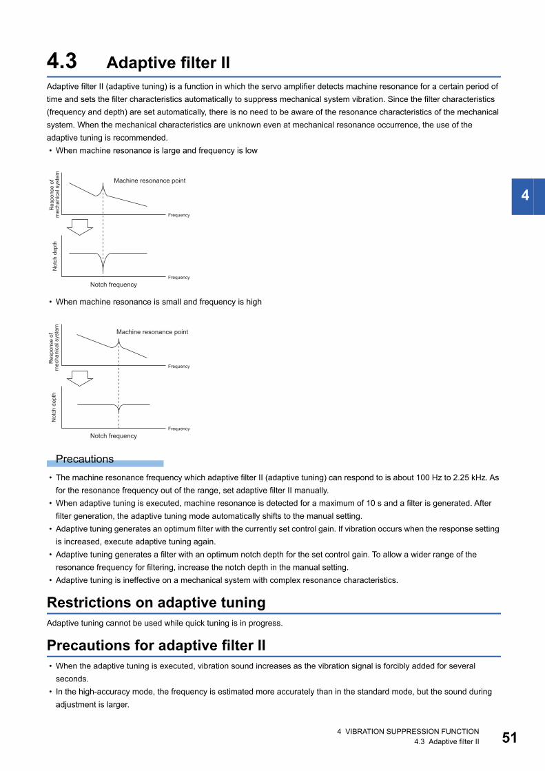
4
4.3 Adaptive filter IIAdaptive filter II (adaptive tuning) is a function in which the servo amplifier detects machine resonance for a certain period of time and sets the filter characteristics automatically to suppress mechanical system vibration. Since the filter characteristics (frequency and depth) are set automatically, there is no need to be aware of the resonance characteristics of the mechanical system. When the mechanical characteristics are unknown even at mechanical resonance occurrence, the use of the adaptive tuning is recommended. • When machine resonance is large and frequency is low
• When machine resonance is small and frequency is high
Precautions • The machine resonance frequency which adaptive filter II (adaptive tuning) can respond to is about 100 Hz to 2.25 kHz. As
for the resonance frequency out of the range, set adaptive filter II manually. • When adaptive tuning is executed, machine resonance is detected for a maximum of 10 s and a filter is generated. After
filter generation, the adaptive tuning mode automatically shifts to the manual setting. • Adaptive tuning generates an optimum filter with the currently set control gain. If vibration occurs when the response setting
is increased, execute adaptive tuning again. • Adaptive tuning generates a filter with an optimum notch depth for the set control gain. To allow a wider range of the
resonance frequency for filtering, increase the notch depth in the manual setting. • Adaptive tuning is ineffective on a mechanical system with complex resonance characteristics.
Restrictions on adaptive tuningAdaptive tuning cannot be used while quick tuning is in progress.
Precautions for adaptive filter II • When the adaptive tuning is executed, vibration sound increases as the vibration signal is forcibly added for several
seconds. • In the high-accuracy mode, the frequency is estimated more accurately than in the standard mode, but the sound during
adjustment is larger.
Res
pons
e of
m
echa
nica
l sys
tem
Machine resonance point
Frequency
Not
ch d
epth
FrequencyNotch frequency
Res
pons
e of
m
echa
nica
l sys
tem
Machine resonance point
Frequency
Not
ch d
epth
FrequencyNotch frequency
4 VIBRATION SUPPRESSION FUNCTION4.3 Adaptive filter II 51
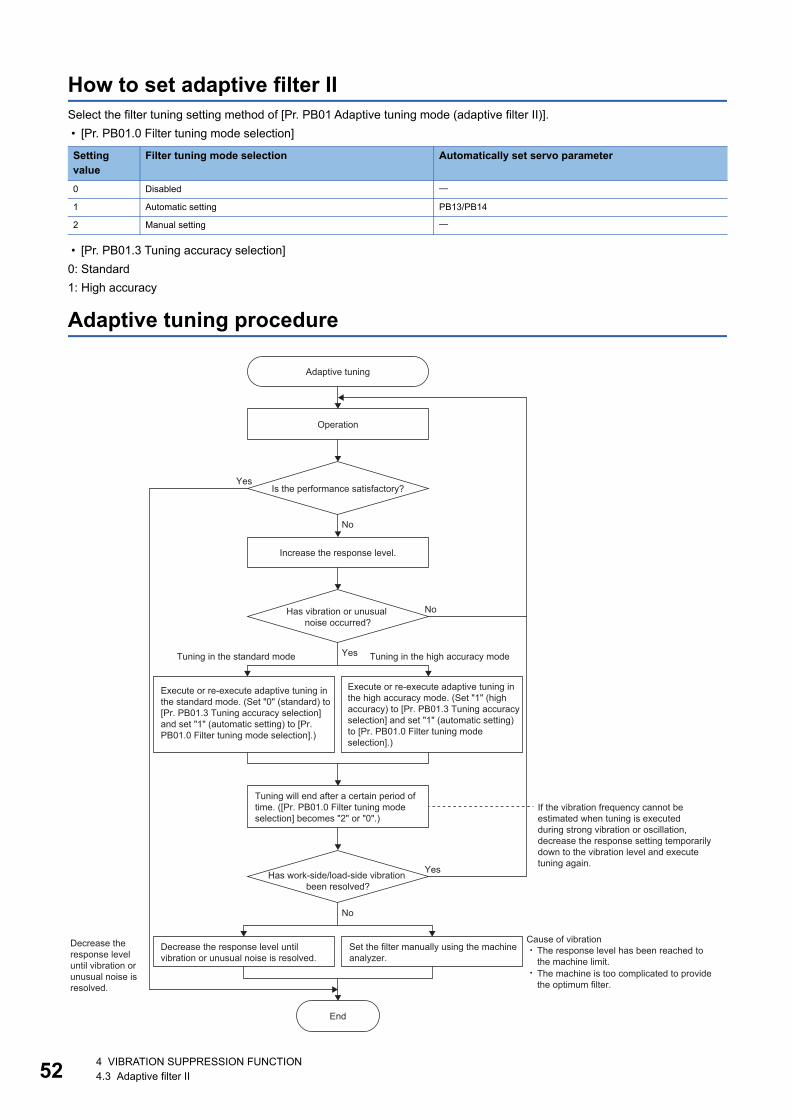
52
How to set adaptive filter IISelect the filter tuning setting method of [Pr. PB01 Adaptive tuning mode (adaptive filter II)]. • [Pr. PB01.0 Filter tuning mode selection]
• [Pr. PB01.3 Tuning accuracy selection]0: Standard1: High accuracy
Adaptive tuning procedure
Setting value
Filter tuning mode selection Automatically set servo parameter
0 Disabled
1 Automatic setting PB13/PB14
2 Manual setting
Yes
No
No
Yes
Yes
No
Adaptive tuning
Operation
Is the performance satisfactory?
Increase the response level.
Has vibration or unusual noise occurred?
Tuning in the standard mode Tuning in the high accuracy mode
Execute or re-execute adaptive tuning in the high accuracy mode. (Set "1" (high accuracy) to [Pr. PB01.3 Tuning accuracy selection] and set "1" (automatic setting) to [Pr. PB01.0 Filter tuning mode selection].)
Execute or re-execute adaptive tuning in the standard mode. (Set "0" (standard) to [Pr. PB01.3 Tuning accuracy selection] and set "1" (automatic setting) to [Pr. PB01.0 Filter tuning mode selection].)
Tuning will end after a certain period of time. ([Pr. PB01.0 Filter tuning mode selection] becomes "2" or "0".)
If the vibration frequency cannot be estimated when tuning is executed during strong vibration or oscillation, decrease the response setting temporarily down to the vibration level and execute tuning again.
Has work-side/load-side vibration been resolved?
Decrease the response level until vibration or unusual noise is resolved.
Set the filter manually using the machine analyzer.
Decrease the response level until vibration or unusual noise is resolved.
End
Cause of vibrationThe response level has been reached to the machine limit.The machine is too complicated to provide the optimum filter.
4 VIBRATION SUPPRESSION FUNCTION4.3 Adaptive filter II
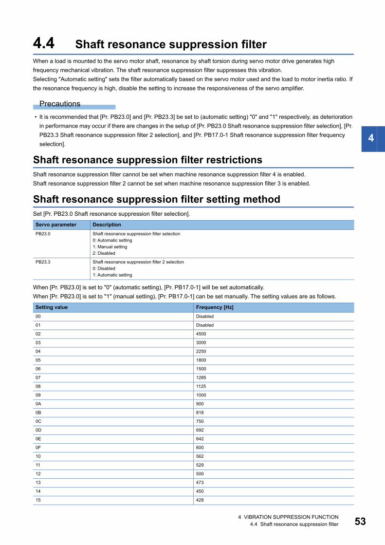
4
4.4 Shaft resonance suppression filterWhen a load is mounted to the servo motor shaft, resonance by shaft torsion during servo motor drive generates high frequency mechanical vibration. The shaft resonance suppression filter suppresses this vibration.Selecting "Automatic setting" sets the filter automatically based on the servo motor used and the load to motor inertia ratio. If the resonance frequency is high, disable the setting to increase the responsiveness of the servo amplifier.
Precautions • It is recommended that [Pr. PB23.0] and [Pr. PB23.3] be set to (automatic setting) "0" and "1" respectively, as deterioration
in performance may occur if there are changes in the setup of [Pr. PB23.0 Shaft resonance suppression filter selection], [Pr. PB23.3 Shaft resonance suppression filter 2 selection], and [Pr. PB17.0-1 Shaft resonance suppression filter frequency selection].
Shaft resonance suppression filter restrictionsShaft resonance suppression filter cannot be set when machine resonance suppression filter 4 is enabled.Shaft resonance suppression filter 2 cannot be set when machine resonance suppression filter 3 is enabled.
Shaft resonance suppression filter setting methodSet [Pr. PB23.0 Shaft resonance suppression filter selection].
When [Pr. PB23.0] is set to "0" (automatic setting), [Pr. PB17.0-1] will be set automatically.When [Pr. PB23.0] is set to "1" (manual setting), [Pr. PB17.0-1] can be set manually. The setting values are as follows.
Servo parameter DescriptionPB23.0 Shaft resonance suppression filter selection
0: Automatic setting1: Manual setting2: Disabled
PB23.3 Shaft resonance suppression filter 2 selection0: Disabled1: Automatic setting
Setting value Frequency [Hz]00 Disabled
01 Disabled
02 4500
03 3000
04 2250
05 1800
06 1500
07 1285
08 1125
09 1000
0A 900
0B 818
0C 750
0D 692
0E 642
0F 600
10 562
11 529
12 500
13 473
14 450
15 428
4 VIBRATION SUPPRESSION FUNCTION4.4 Shaft resonance suppression filter 53
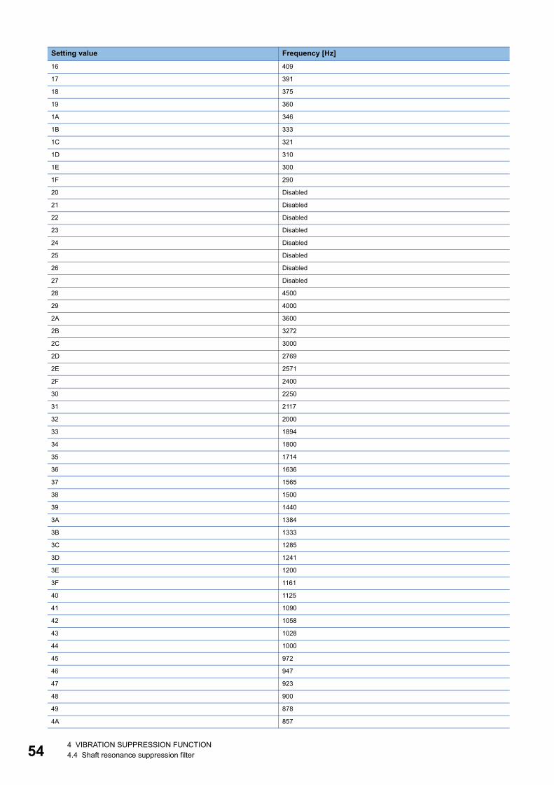
54
16 409
17 391
18 375
19 360
1A 346
1B 333
1C 321
1D 310
1E 300
1F 290
20 Disabled
21 Disabled
22 Disabled
23 Disabled
24 Disabled
25 Disabled
26 Disabled
27 Disabled
28 4500
29 4000
2A 3600
2B 3272
2C 3000
2D 2769
2E 2571
2F 2400
30 2250
31 2117
32 2000
33 1894
34 1800
35 1714
36 1636
37 1565
38 1500
39 1440
3A 1384
3B 1333
3C 1285
3D 1241
3E 1200
3F 1161
40 1125
41 1090
42 1058
43 1028
44 1000
45 972
46 947
47 923
48 900
49 878
4A 857
Setting value Frequency [Hz]
4 VIBRATION SUPPRESSION FUNCTION4.4 Shaft resonance suppression filter
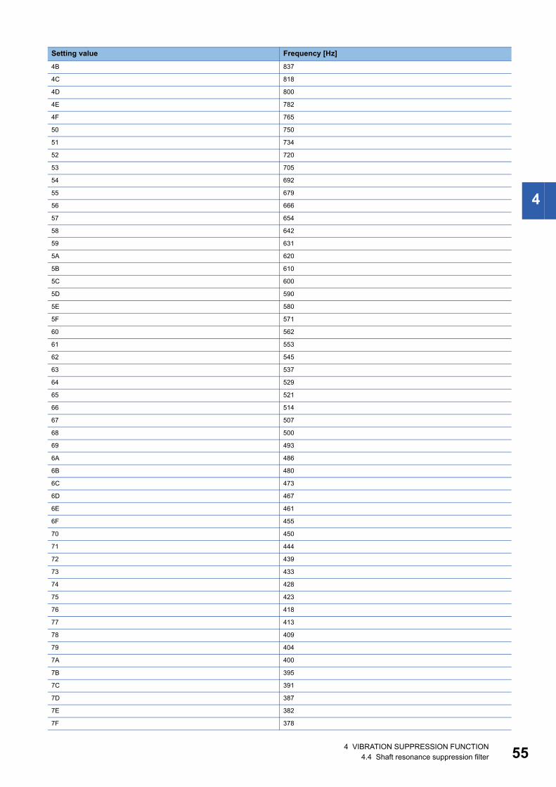
4
4B 837
4C 818
4D 800
4E 782
4F 765
50 750
51 734
52 720
53 705
54 692
55 679
56 666
57 654
58 642
59 631
5A 620
5B 610
5C 600
5D 590
5E 580
5F 571
60 562
61 553
62 545
63 537
64 529
65 521
66 514
67 507
68 500
69 493
6A 486
6B 480
6C 473
6D 467
6E 461
6F 455
70 450
71 444
72 439
73 433
74 428
75 423
76 418
77 413
78 409
79 404
7A 400
7B 395
7C 391
7D 387
7E 382
7F 378
Setting value Frequency [Hz]
4 VIBRATION SUPPRESSION FUNCTION4.4 Shaft resonance suppression filter 55
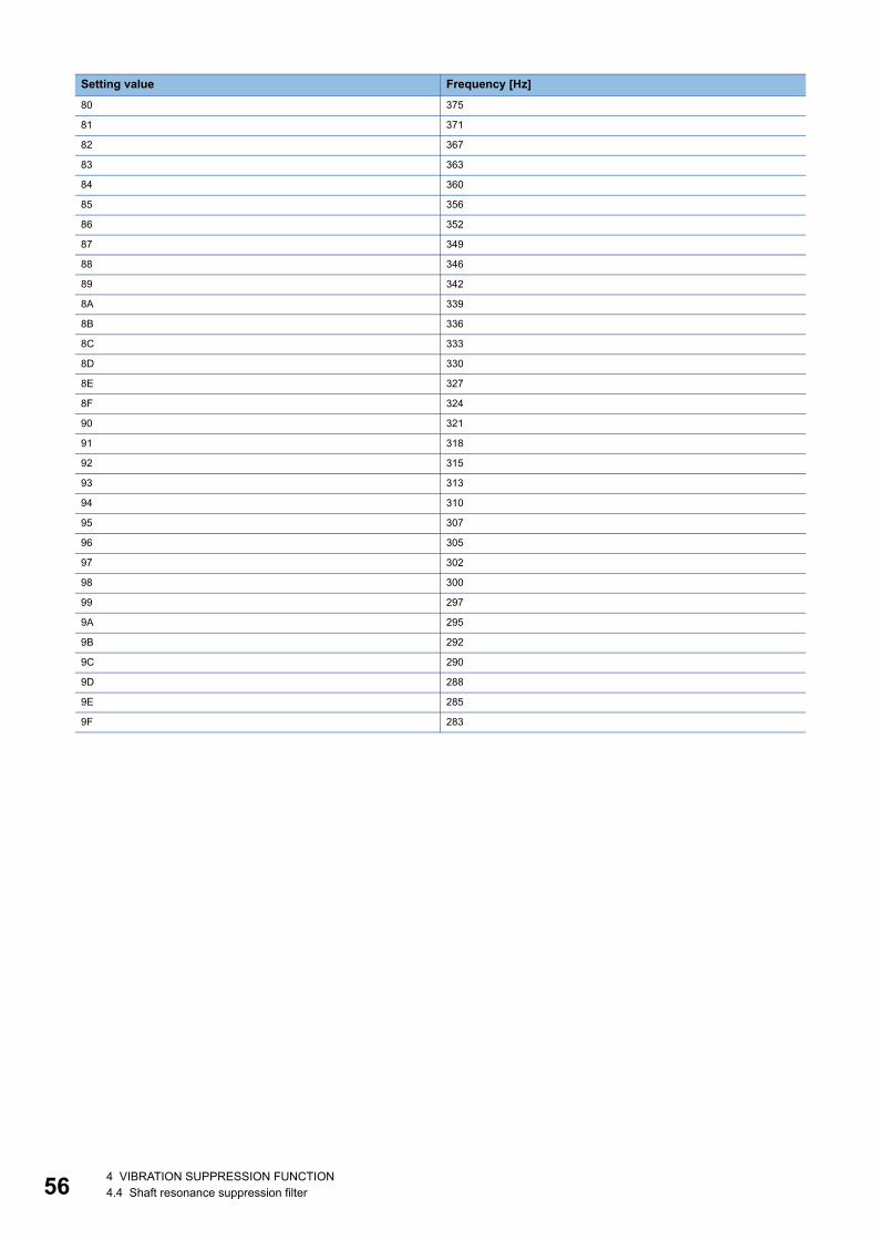
56
80 375
81 371
82 367
83 363
84 360
85 356
86 352
87 349
88 346
89 342
8A 339
8B 336
8C 333
8D 330
8E 327
8F 324
90 321
91 318
92 315
93 313
94 310
95 307
96 305
97 302
98 300
99 297
9A 295
9B 292
9C 290
9D 288
9E 285
9F 283
Setting value Frequency [Hz]
4 VIBRATION SUPPRESSION FUNCTION4.4 Shaft resonance suppression filter
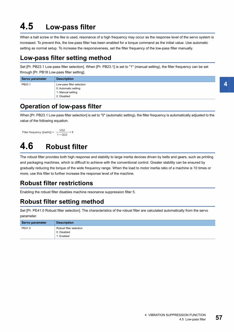
4
4.5 Low-pass filterWhen a ball screw or the like is used, resonance of a high frequency may occur as the response level of the servo system is increased. To prevent this, the low-pass filter has been enabled for a torque command as the initial value. Use automatic setting as normal setup. To increase the responsiveness, set the filter frequency of the low-pass filter manually.
Low-pass filter setting methodSet [Pr. PB23.1 Low-pass filter selection]. When [Pr. PB23.1] is set to "1" (manual setting), the filter frequency can be set through [Pr. PB18 Low-pass filter setting].
Operation of low-pass filterWhen [Pr. PB23.1 Low-pass filter selection] is set to "0" (automatic setting), the filter frequency is automatically adjusted to the value of the following equation.
4.6 Robust filterThe robust filter provides both high response and stability to large inertia devices driven by belts and gears, such as printing and packaging machines, which is difficult to achieve with the conventional control. Greater stability can be ensured by gradually reducing the torque of the wide frequency range. When the load to motor inertia ratio of a machine is 10 times or more, use this filter to further increase the response level of the machine.
Robust filter restrictionsEnabling the robust filter disables machine resonance suppression filter 5.
Robust filter setting methodSet [Pr. PE41.0 Robust filter selection]. The characteristics of the robust filter are calculated automatically from the servo parameter.
Servo parameter DescriptionPB23.1 Low-pass filter selection
0: Automatic setting1: Manual setting2: Disabled
Servo parameter DescriptionPE41.0 Robust filter selection
0: Disabled1: Enabled
Filter frequency ([rad/s]) = × 8VG2
1 + GD2
4 VIBRATION SUPPRESSION FUNCTION4.5 Low-pass filter 57
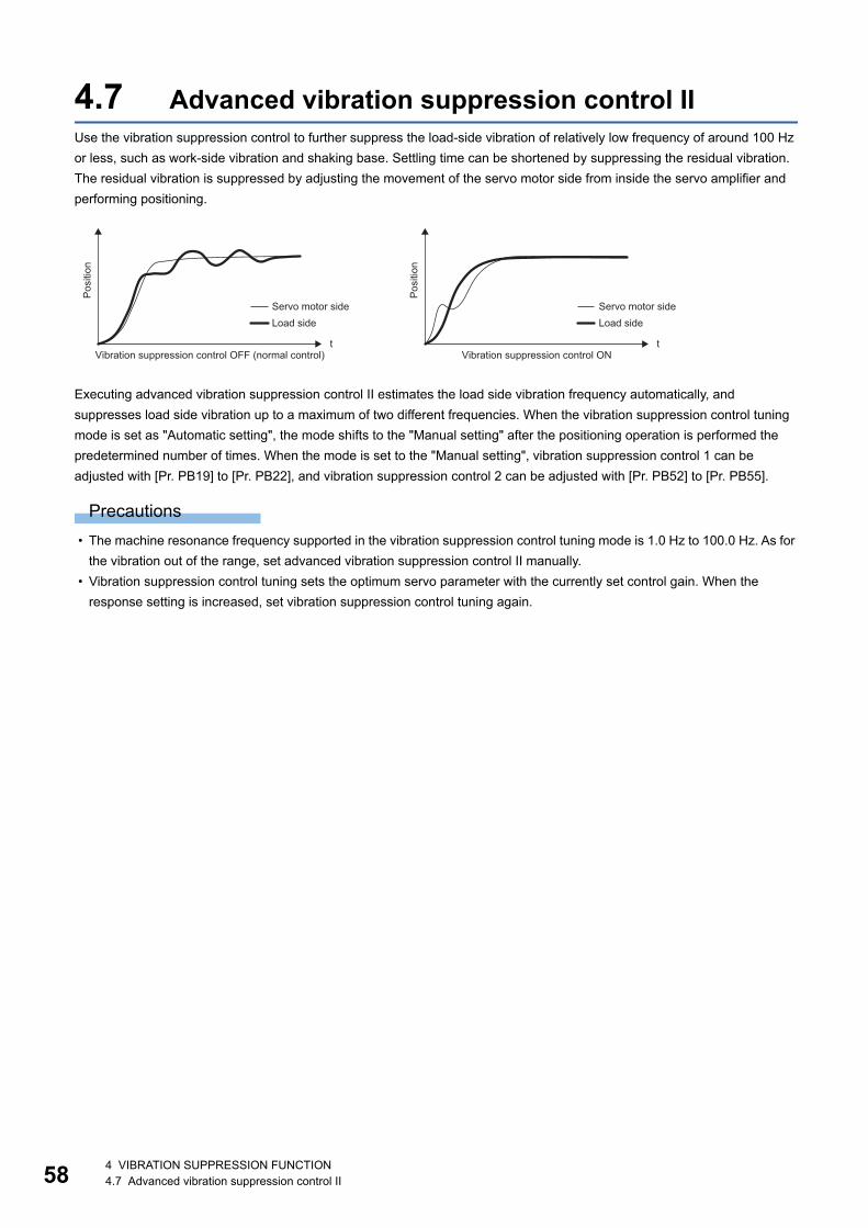
58
4.7 Advanced vibration suppression control IIUse the vibration suppression control to further suppress the load-side vibration of relatively low frequency of around 100 Hz or less, such as work-side vibration and shaking base. Settling time can be shortened by suppressing the residual vibration. The residual vibration is suppressed by adjusting the movement of the servo motor side from inside the servo amplifier and performing positioning.
Executing advanced vibration suppression control II estimates the load side vibration frequency automatically, and suppresses load side vibration up to a maximum of two different frequencies. When the vibration suppression control tuning mode is set as "Automatic setting", the mode shifts to the "Manual setting" after the positioning operation is performed the predetermined number of times. When the mode is set to the "Manual setting", vibration suppression control 1 can be adjusted with [Pr. PB19] to [Pr. PB22], and vibration suppression control 2 can be adjusted with [Pr. PB52] to [Pr. PB55].
Precautions • The machine resonance frequency supported in the vibration suppression control tuning mode is 1.0 Hz to 100.0 Hz. As for
the vibration out of the range, set advanced vibration suppression control II manually. • Vibration suppression control tuning sets the optimum servo parameter with the currently set control gain. When the
response setting is increased, set vibration suppression control tuning again.
t t
Posi
tion
Posi
tion
Servo motor side Servo motor sideLoad sideLoad side
Vibration suppression control OFF (normal control) Vibration suppression control ON
4 VIBRATION SUPPRESSION FUNCTION4.7 Advanced vibration suppression control II
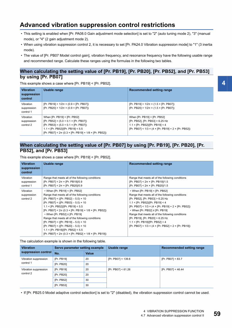
4
Advanced vibration suppression control restrictions • This setting is enabled when [Pr. PA08.0 Gain adjustment mode selection] is set to "2" (auto tuning mode 2), "3" (manual
mode), or "4" (2 gain adjustment mode 2). • When using vibration suppression control 2, it is necessary to set [Pr. PA24.0 Vibration suppression mode] to "1" (3 inertia
mode). • The value of [Pr. PB07 Model control gain], vibration frequency, and resonance frequency have the following usable range
and recommended range. Calculate these ranges using the formulas in the following two tables.
When calculating the setting value of [Pr. PB19], [Pr. PB20], [Pr. PB52], and [Pr. PB53] by using [Pr. PB07]This example shows a case where [Pr. PB19] < [Pr. PB52].
When calculating the setting value of [Pr. PB07] by using [Pr. PB19], [Pr. PB20], [Pr. PB52], and [Pr. PB53]This example shows a case where [Pr. PB19] < [Pr. PB52].
The calculation example is shown in the following table.
• If [Pr. PB25.0 Model adaptive control selection] is set to "2" (disabled), the vibration suppression control cannot be used.
Vibration suppression control
Usable range Recommended setting range
Vibration suppression control 1
[Pr. PB19] > 1/2π × (0.9 × [Pr. PB07])[Pr. PB20] > 1/2π × (0.9 × [Pr. PB07])
[Pr. PB19] > 1/2π × (1.5 × [Pr. PB07])[Pr. PB20] > 1/2π × (1.5 × [Pr. PB07])
Vibration suppression control 2
When [Pr. PB19] < [Pr. PB52][Pr. PB52] > (5.0 + 0.1 × [Pr. PB07])[Pr. PB53] > (5.0 + 0.1 × [Pr. PB07])1.1 < [Pr. PB52]/[Pr. PB19] < 5.5[Pr. PB07] < 2π (0.3 × [Pr. PB19] + 1/8 × [Pr. PB52])
When [Pr. PB19] < [Pr. PB52][Pr. PB52], [Pr. PB53] > 6.25 Hz1.1 < [Pr. PB52]/[Pr. PB19] < 4[Pr. PB07] < 1/3 × (4 × [Pr. PB19] + 2 × [Pr. PB52])
Vibration suppression control
Usable range Recommended setting range
Vibration suppression control 1
Range that meets all of the following conditions[Pr. PB07] < 2π × [Pr. PB19]/0.9[Pr. PB07] < 2π × [Pr. PB20]/0.9
Range that meets all of the following conditions[Pr. PB07] < 2π × [Pr. PB19]/1.5[Pr. PB07] < 2π × [Pr. PB20]/1.5
Vibration suppression control 2
• When [Pr. PB19] < [Pr. PB52]Range that meets all of the following conditions[Pr. PB07] < ([Pr. PB52] – 5.0) × 10[Pr. PB07] < ([Pr. PB53] – 5.0) × 101.1 < [Pr. PB52]/[Pr. PB19] < 5.5[Pr. PB07] < 2π (0.3 × [Pr. PB19] + 1/8 × [Pr. PB52])• When [Pr. PB52] ≤ [Pr. PB19]
Range that meets all of the following conditions[Pr. PB07] < ([Pr. PB19] – 5.0) × 10[Pr. PB07] < ([Pr. PB20] – 5.0) × 101.1 < [Pr. PB19]/[Pr. PB52] < 5.5[Pr. PB07] < 2π (0.3 × [Pr. PB52] + 1/8 × [Pr. PB19])
• When [Pr. PB19] < [Pr. PB52]Range that meets all of the following conditions[Pr. PB52], [Pr. PB53] > 6.25 Hz1.1 < [Pr. PB52]/[Pr. PB19] < 4[Pr. PB07] < 1/3 × (4 × [Pr. PB19] + 2 × [Pr. PB52])• When [Pr. PB52] ≤ [Pr. PB19]
Range that meets all of the following conditions[Pr. PB19], [Pr. PB20] > 6.25 Hz1.1 < [Pr. PB19]/[Pr. PB52] < 4[Pr. PB07] < 1/3 × (4 × [Pr. PB52] + 2 × [Pr. PB19])
Vibration suppression control
Servo parameter setting example Usable range Recommended setting range
No. ValueVibration suppression control 1
[Pr. PB19] 20 [Pr. PB07] < 139.6 [Pr. PB07] < 83.7
[Pr. PB20] 20
Vibration suppression control 2
[Pr. PB19] 20 [Pr. PB07] < 61.26 [Pr. PB07] < 46.44
[Pr. PB20] 20
[Pr. PB52] 30
[Pr. PB53] 30
4 VIBRATION SUPPRESSION FUNCTION4.7 Advanced vibration suppression control II 59
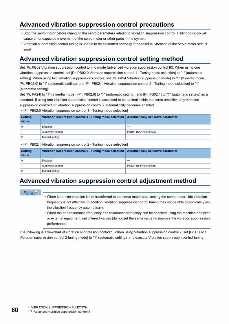
60
Advanced vibration suppression control precautions • Stop the servo motor before changing the servo parameters related to vibration suppression control. Failing to do so will
cause an unexpected movement of the servo motor or other parts in the system. • Vibration suppression control tuning is unable to be estimated normally if the residual vibration at the servo motor side is
small.
Advanced vibration suppression control setting methodSet [Pr. PB02 Vibration suppression control tuning mode (advanced vibration suppression control II)]. When using one vibration suppression control, set [Pr. PB02.0 Vibration suppression control 1 - Tuning mode selection] to "1" (automatic setting). When using two vibration suppression controls, set [Pr. PA24 Vibration suppression mode] to "1" (3 inertia mode), [Pr. PB02.0] to "1" (automatic setting), and [Pr. PB02.1 Vibration suppression control 2 - Tuning mode selection] to "1" (automatic setting).Set [Pr. PA24] to "1" (3 inertia mode), [Pr. PB02.0] to "1" (automatic setting), and [Pr. PB02.1] to "1" (automatic setting) as a standard. If using one vibration suppression control is assessed to be optimal inside the servo amplifier, only vibration suppression control 1 or vibration suppression control 2 automatically becomes enabled. • [Pr. PB02.0 Vibration suppression control 1 - Tuning mode selection]
• [Pr. PB02.1 Vibration suppression control 2 - Tuning mode selection]
Advanced vibration suppression control adjustment method
• When load-side vibration is not transferred to the servo motor-side, setting the servo motor-side vibration frequency is not effective. In addition, vibration suppression control tuning may not be able to accurately set the vibration frequency automatically.
• When the anti-resonance frequency and resonance frequency can be checked using the machine analyzer or external equipment, set different values (do not set the same value) to improve the vibration suppression performance.
The following is a flowchart of vibration suppression control 1. When using Vibration suppression control 2, set [Pr. PB02.1 Vibration suppression control 2 tuning mode] to "1" (automatic setting), and execute Vibration suppression control tuning.
Setting value
Vibration suppression control 1 - Tuning mode selection Automatically set servo parameter
0 Disabled
1 Automatic setting PB19/PB20/PB21/PB22
2 Manual setting
Setting value
Vibration suppression control 2 - Tuning mode selection Automatically set servo parameter
0 Disabled
1 Automatic setting PB52/PB53/PB54/PB55
2 Manual setting
4 VIBRATION SUPPRESSION FUNCTION4.7 Advanced vibration suppression control II
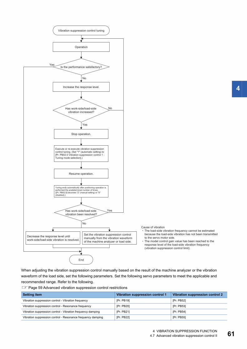
4
When adjusting the vibration suppression control manually based on the result of the machine analyzer or the vibration waveform of the load side, set the following parameters. Set the following servo parameters to meet the applicable and recommended range. Refer to the following.Page 59 Advanced vibration suppression control restrictions
Setting item Vibration suppression control 1 Vibration suppression control 2Vibration suppression control - Vibration frequency [Pr. PB19] [Pr. PB52]
Vibration suppression control - Resonance frequency [Pr. PB20] [Pr. PB53]
Vibration suppression control - Vibration frequency damping [Pr. PB21] [Pr. PB54]
Vibration suppression control - Resonance frequency damping [Pr. PB22] [Pr. PB55]
No
No
No
Yes
Yes
Yes
Vibration suppression control tuning
Operation
Is the performance satisfactory?
Execute or re-execute vibration suppressioncontrol tuning. (Set "1" (automatic setting) to[Pr. PB02.0 Vibration suppression control 1 -Tuning mode selection].)
Decrease the response level untilwork-side/load-side vibration is resolved.
End
Increase the response level.
Has work-side/load-side vibration increased?
Has work-side/load-side vibration been resolved?
Set the vibration suppression control manually from the vibration waveform of the machine analyzer or load side.
Cause of vibration The load-side vibration frequency cannot be estimated because the load-side vibration has not been transmitted to the servo motor side. The model control gain value has been reached to the response level of the load-side vibration frequency (vibration suppression control limit).
Tuning ends automatically after positioning operation is performed the predetermined number of times. ([Pr. PB02.0] becomes "2" (manual setting) or "0" (disabled).)
Stop operation.
Resume operation.
4 VIBRATION SUPPRESSION FUNCTION4.7 Advanced vibration suppression control II 61
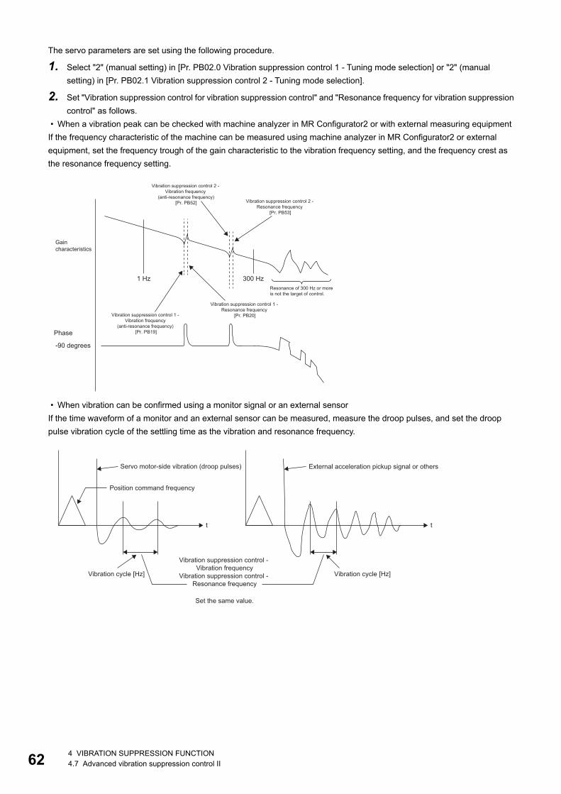
62
The servo parameters are set using the following procedure.
1. Select "2" (manual setting) in [Pr. PB02.0 Vibration suppression control 1 - Tuning mode selection] or "2" (manual setting) in [Pr. PB02.1 Vibration suppression control 2 - Tuning mode selection].
2. Set "Vibration suppression control for vibration suppression control" and "Resonance frequency for vibration suppression control" as follows.
• When a vibration peak can be checked with machine analyzer in MR Configurator2 or with external measuring equipmentIf the frequency characteristic of the machine can be measured using machine analyzer in MR Configurator2 or external equipment, set the frequency trough of the gain characteristic to the vibration frequency setting, and the frequency crest as the resonance frequency setting.
• When vibration can be confirmed using a monitor signal or an external sensorIf the time waveform of a monitor and an external sensor can be measured, measure the droop pulses, and set the droop pulse vibration cycle of the settling time as the vibration and resonance frequency.
1 Hz
-90 degrees
300 Hz
Vibration suppression control 2 - Vibration frequency
(anti-resonance frequency)[Pr. PB52] Vibration suppression control 2 -
Resonance frequency [Pr. PB53]
Gain characteristics
Resonance of 300 Hz or more is not the target of control.
Vibration suppression control 1 - Resonance frequency
[Pr. PB20]Vibration suppression control 1 - Vibration frequency
(anti-resonance frequency) [Pr. PB19]Phase
t t
Servo motor-side vibration (droop pulses) External acceleration pickup signal or others
Position command frequency
Vibration cycle [Hz] Vibration cycle [Hz]
Vibration suppression control - Vibration frequency
Vibration suppression control - Resonance frequency
Set the same value.
4 VIBRATION SUPPRESSION FUNCTION4.7 Advanced vibration suppression control II
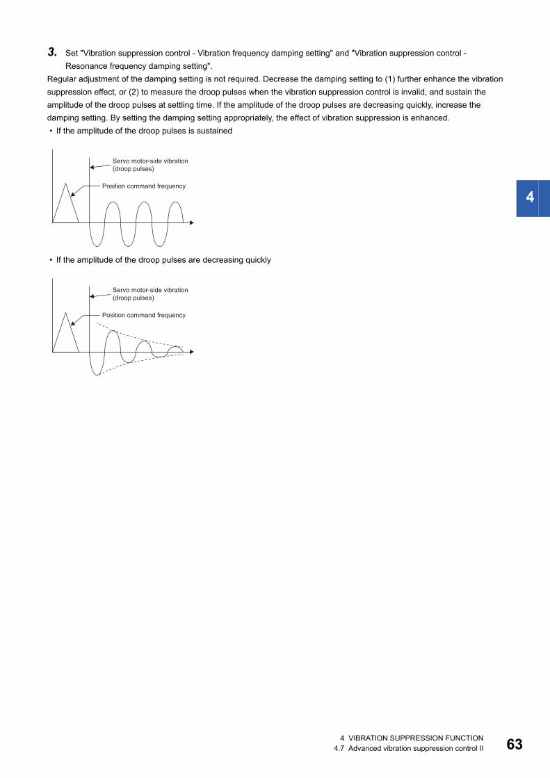
4
3. Set "Vibration suppression control - Vibration frequency damping setting" and "Vibration suppression control - Resonance frequency damping setting".
Regular adjustment of the damping setting is not required. Decrease the damping setting to (1) further enhance the vibration suppression effect, or (2) to measure the droop pulses when the vibration suppression control is invalid, and sustain the amplitude of the droop pulses at settling time. If the amplitude of the droop pulses are decreasing quickly, increase the damping setting. By setting the damping setting appropriately, the effect of vibration suppression is enhanced. • If the amplitude of the droop pulses is sustained
• If the amplitude of the droop pulses are decreasing quickly
Servo motor-side vibration (droop pulses)
Position command frequency
Servo motor-side vibration (droop pulses)
Position command frequency
4 VIBRATION SUPPRESSION FUNCTION4.7 Advanced vibration suppression control II 63
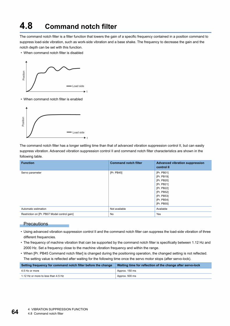
64
4.8 Command notch filterThe command notch filter is a filter function that lowers the gain of a specific frequency contained in a position command to suppress load-side vibration, such as work-side vibration and a base shake. The frequency to decrease the gain and the notch depth can be set with this function. • When command notch filter is disabled
• When command notch filter is enabled
The command notch filter has a longer settling time than that of advanced vibration suppression control II, but can easily suppress vibration. Advanced vibration suppression control II and command notch filter characteristics are shown in the following table.
Precautions • Using advanced vibration suppression control II and the command notch filter can suppress the load-side vibration of three
different frequencies. • The frequency of machine vibration that can be supported by the command notch filter is specifically between 1.12 Hz and
2000 Hz. Set a frequency close to the machine vibration frequency and within the range. • When [Pr. PB45 Command notch filter] is changed during the positioning operation, the changed setting is not reflected.
The setting value is reflected after waiting for the following time once the servo motor stops (after servo-lock).
Function Command notch filter Advanced vibration suppression control II
Servo parameter [Pr. PB45] [Pr. PB01][Pr. PB19][Pr. PB20][Pr. PB21][Pr. PB22][Pr. PB52][Pr. PB53][Pr. PB54][Pr. PB55]
Automatic estimation Not available Available
Restriction on [Pr. PB07 Model control gain] No Yes
Setting frequency for command notch filter before the change Waiting time for reflection of the change after servo-lock4.5 Hz or more Approx. 150 ms
1.12 Hz or more to less than 4.5 Hz Approx. 500 ms
t
Posi
tion
Load side
t
Posi
tion
Load side
4 VIBRATION SUPPRESSION FUNCTION4.8 Command notch filter
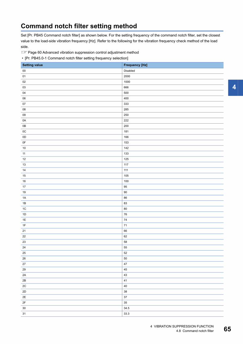
4
Command notch filter setting methodSet [Pr. PB45 Command notch filter] as shown below. For the setting frequency of the command notch filter, set the closest value to the load-side vibration frequency [Hz]. Refer to the following for the vibration frequency check method of the load side.Page 60 Advanced vibration suppression control adjustment method • [Pr. PB45.0-1 Command notch filter setting frequency selection]
Setting value Frequency [Hz]00 Disabled
01 2000
02 1000
03 666
04 500
06 400
07 333
08 285
09 250
0A 222
0B 200
0C 181
0D 166
0F 153
10 142
11 133
12 125
13 117
14 111
15 105
16 100
17 95
19 90
1A 86
1B 83
1C 80
1D 76
1E 74
1F 71
21 66
22 62
23 58
24 55
25 52
26 50
27 47
29 45
2A 43
2B 41
2C 40
2D 38
2E 37
2F 35
30 34.5
31 33.3
4 VIBRATION SUPPRESSION FUNCTION4.8 Command notch filter 65
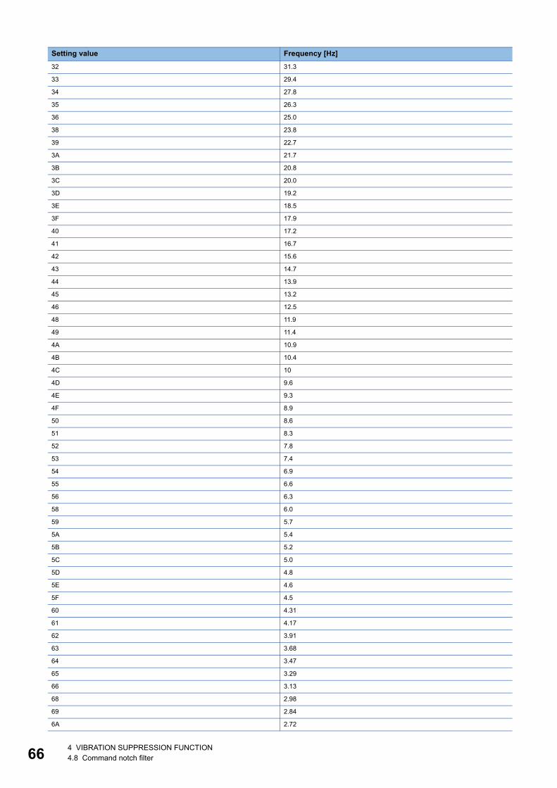
66
32 31.3
33 29.4
34 27.8
35 26.3
36 25.0
38 23.8
39 22.7
3A 21.7
3B 20.8
3C 20.0
3D 19.2
3E 18.5
3F 17.9
40 17.2
41 16.7
42 15.6
43 14.7
44 13.9
45 13.2
46 12.5
48 11.9
49 11.4
4A 10.9
4B 10.4
4C 10
4D 9.6
4E 9.3
4F 8.9
50 8.6
51 8.3
52 7.8
53 7.4
54 6.9
55 6.6
56 6.3
58 6.0
59 5.7
5A 5.4
5B 5.2
5C 5.0
5D 4.8
5E 4.6
5F 4.5
60 4.31
61 4.17
62 3.91
63 3.68
64 3.47
65 3.29
66 3.13
68 2.98
69 2.84
6A 2.72
Setting value Frequency [Hz]
4 VIBRATION SUPPRESSION FUNCTION4.8 Command notch filter
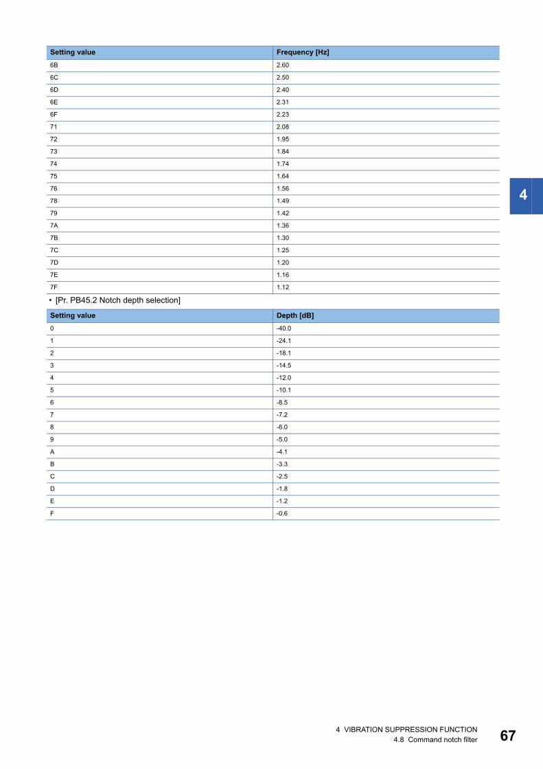
4
• [Pr. PB45.2 Notch depth selection]
6B 2.60
6C 2.50
6D 2.40
6E 2.31
6F 2.23
71 2.08
72 1.95
73 1.84
74 1.74
75 1.64
76 1.56
78 1.49
79 1.42
7A 1.36
7B 1.30
7C 1.25
7D 1.20
7E 1.16
7F 1.12
Setting value Depth [dB]0 -40.0
1 -24.1
2 -18.1
3 -14.5
4 -12.0
5 -10.1
6 -8.5
7 -7.2
8 -6.0
9 -5.0
A -4.1
B -3.3
C -2.5
D -1.8
E -1.2
F -0.6
Setting value Frequency [Hz]
4 VIBRATION SUPPRESSION FUNCTION4.8 Command notch filter 67
68
4.9 Vibration tough driveVibration tough drive function is a function to instantaneously update the machine resonance suppression filter, and to prevent vibration when machine resonance occurs due to the oscillation during adjustment and aging of the machine. By using this function, the equipment continues to operate normally even when an alarm occurs. When continuing operation is required even with an aging machine, the use of this function is recommended.
Vibration tough drive restrictionsThe vibration tough drive function does not detect a vibration of 100 Hz or less.Vibration tough drive can be used in the following cases.
When [Pr. PA20.1 Vibration tough drive selection] is set to "1" (Machine resonance suppression filter change mode) • When machine resonance suppression filter 1 is manually set, and the detected machine resonance frequency is within the
±30 % range of the set value for [Pr. PB13 Machine resonance suppression filter 1] • When machine resonance suppression filter 2 is enabled, and the detected machine resonance frequency is within the ±30
% range of the set value for [Pr. PB15 Machine resonance suppression filter 2]
When [Pr. PA20.1 Vibration tough drive selection] is set to "2" (machine resonance suppression filter automatic setting mode) • When [Pr. PB01.0 Filter tuning mode selection] is set to "0" (disabled), and machine resonance suppression filter 1 has
been disabled • When [Pr. PB16.0 Machine resonance suppression filter 2 selection] is set to "0" (disabled), and machine resonance
suppression filter 2 has been disabled • When machine resonance suppression filter 1 is manually set, and the detected machine resonance frequency is within the
±30 % range of the set value for [Pr. PB13 Machine resonance suppression filter 1] • When machine resonance suppression filter 2 is enabled, and the detected machine resonance frequency is within the ±30
% range of the set value for [Pr. PB15 Machine resonance suppression filter 2]
Vibration tough drive precautions • Although [Pr. PB13] and [Pr. PB15] are constantly updated by the vibration tough drive function, the setting value is only
written to the non-volatile memory once per five minutes. • In vibration tough drive function, [Pr. PB46 Machine resonance suppression filter 3], [Pr. PB48 Machine resonance
suppression filter 4], and [Pr. PB50 Machine resonance suppression filter 5] are not updated.
Vibration tough drive setting methodSetting [Pr. PA20.1 Vibration tough drive selection] to "1" (machine resonance suppression filter change mode) or "2" (machine resonance suppression filter automatic setting mode) causes [Pr. PB13 Machine resonance suppression filter 1] and [Pr. PB15 Machine resonance suppression filter 1] to be automatically set when the oscillation level set in [Pr. PF23 Vibration tough drive - Oscillation detection level] is exceeded. This will suppress the vibration of the equipment.
Servo parameter DescriptionPA20.1 Vibration tough drive selection
0: Disabled1: Machine resonance suppression filter change mode enabled2: Machine resonance suppression filter automatic setting modeWhen using the vibration tough drive, it is recommended to use "2" (machine resonance suppression filter automatic setting mode).
4 VIBRATION SUPPRESSION FUNCTION4.9 Vibration tough drive
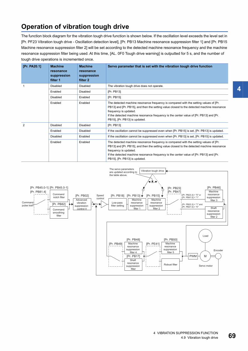
4
Operation of vibration tough driveThe function block diagram for the vibration tough drive function is shown below. If the oscillation level exceeds the level set in [Pr. PF23 Vibration tough drive - Oscillation detection level], [Pr. PB13 Machine resonance suppression filter 1] and [Pr. PB15 Machine resonance suppression filter 2] will be set according to the detected machine resonance frequency and the machine resonance suppression filter being used. At this time, [AL. 0F0 Tough drive warning] is outputted for 5 s, and the number of tough drive operations is incremented once.
[Pr. PA20.1] Machine resonance suppression filter 1
Machine resonance suppression filter 2
Servo parameter that is set with the vibration tough drive function
1 Disabled Disabled The vibration tough drive does not operate.
Enabled Disabled [Pr. PB13]
Disabled Enabled [Pr. PB15]
Enabled Enabled The detected machine resonance frequency is compared with the setting values of [Pr. PB13] and [Pr. PB15], and then the setting value closest to the detected machine resonance frequency is updated.If the detected machine resonance frequency is the center value of [Pr. PB13] and [Pr. PB15], [Pr. PB13] is updated.
2 Disabled Disabled [Pr. PB13]
Enabled Disabled If the oscillation cannot be suppressed even when [Pr. PB15] is set, [Pr. PB13] is updated.
Disabled Enabled If the oscillation cannot be suppressed even when [Pr. PB13] is set, [Pr. PB15] is updated.
Enabled Enabled The detected machine resonance frequency is compared with the setting values of [Pr. PB13] and [Pr. PB15], and then the setting value closest to the detected machine resonance frequency is updated.If the detected machine resonance frequency is the center value of [Pr. PB13] and [Pr. PB15], [Pr. PB13] is updated.
PWM M
+-
[Pr. PB48] [Pr. PB50]
[Pr. PB17]
[Pr. PB49] [Pr. PE41]
[Pr. PB46][Pr. PB23][Pr. PB47]
[Pr. PB18][Pr. PB02] [Pr. PB13] [Pr. PB15]
[Pr. PB45.0-1][Pr. PB45.0-1][Pr. PB81.4]
[Pr. PB82]Command pulse train
Low-pass filter setting
Encoder
Servo motor
Load
Machine resonance
suppression filter 1
Machine resonance
suppression filter 2
Command notch filter
Machine resonance
suppression filter 4
Machine resonance
suppression filter 5
Shaft resonance
suppression filter
Robust filter
Speed control
Machine resonance
suppression filter 3
Shaft resonance
suppression filter 2
[Pr. PB23.3] = "0" or [Pr. PB47.0] = "1"
[Pr. PB23.3] = "1" and [Pr. PB47.0] = "0"
The servo parameters are updated according to the table above.
Vibration tough drive
Command smoothing
filter
Advanced vibration
suppression control II
4 VIBRATION SUPPRESSION FUNCTION4.9 Vibration tough drive 69
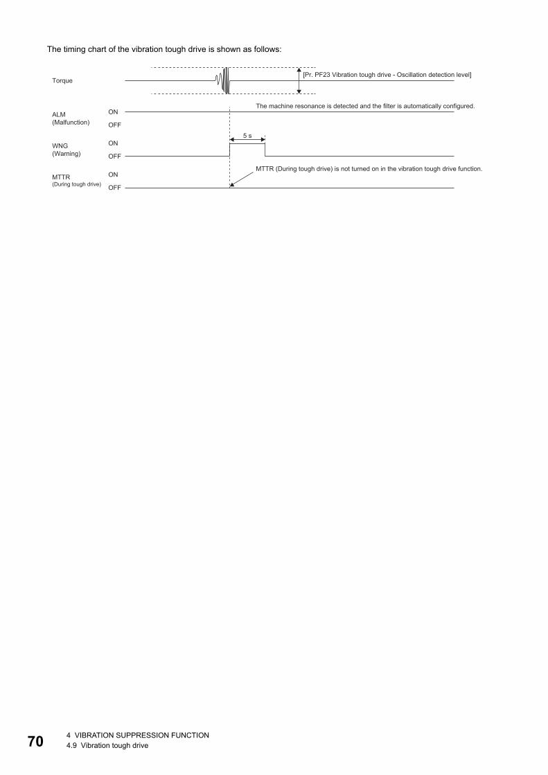
70
The timing chart of the vibration tough drive is shown as follows:
5 s
ON
OFF
ON
OFF
ON
OFF
[Pr. PF23 Vibration tough drive - Oscillation detection level]Torque
The machine resonance is detected and the filter is automatically configured.ALM (Malfunction)
WNG (Warning)
MTTR (During tough drive) is not turned on in the vibration tough drive function.MTTR (During tough drive)
4 VIBRATION SUPPRESSION FUNCTION4.9 Vibration tough drive
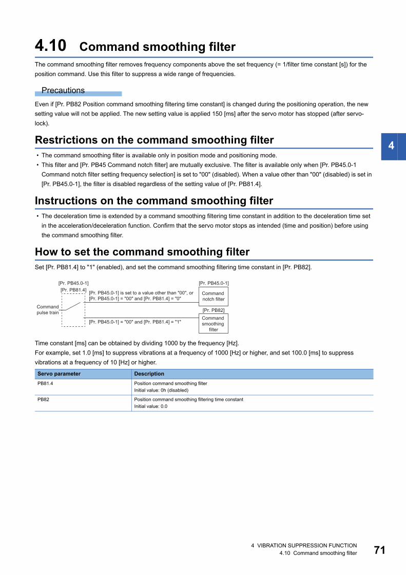
4
4.10 Command smoothing filterThe command smoothing filter removes frequency components above the set frequency (= 1/filter time constant [s]) for the position command. Use this filter to suppress a wide range of frequencies.
PrecautionsEven if [Pr. PB82 Position command smoothing filtering time constant] is changed during the positioning operation, the new setting value will not be applied. The new setting value is applied 150 [ms] after the servo motor has stopped (after servo-lock).
Restrictions on the command smoothing filter • The command smoothing filter is available only in position mode and positioning mode. • This filter and [Pr. PB45 Command notch filter] are mutually exclusive. The filter is available only when [Pr. PB45.0-1
Command notch filter setting frequency selection] is set to "00" (disabled). When a value other than "00" (disabled) is set in [Pr. PB45.0-1], the filter is disabled regardless of the setting value of [Pr. PB81.4].
Instructions on the command smoothing filter • The deceleration time is extended by a command smoothing filtering time constant in addition to the deceleration time set
in the acceleration/deceleration function. Confirm that the servo motor stops as intended (time and position) before using the command smoothing filter.
How to set the command smoothing filterSet [Pr. PB81.4] to "1" (enabled), and set the command smoothing filtering time constant in [Pr. PB82].
Time constant [ms] can be obtained by dividing 1000 by the frequency [Hz].For example, set 1.0 [ms] to suppress vibrations at a frequency of 1000 [Hz] or higher, and set 100.0 [ms] to suppress vibrations at a frequency of 10 [Hz] or higher.
Servo parameter DescriptionPB81.4 Position command smoothing filter
Initial value: 0h (disabled)
PB82 Position command smoothing filtering time constantInitial value: 0.0
[Pr. PB45.0-1][Pr. PB45.0-1][Pr. PB81.4]
[Pr. PB82]Command pulse train
Command notch filter
Command smoothing
filter
[Pr. PB45.0-1] is set to a value other than "00", or [Pr. PB45.0-1] = "00" and [Pr. PB81.4] = "0"
[Pr. PB45.0-1] = "00" and [Pr. PB81.4] = "1"
4 VIBRATION SUPPRESSION FUNCTION4.10 Command smoothing filter 71
72
5 GAIN SWITCHING FUNCTIONThis function enables the gain switching. The gains can be switched depending on whether the motor is in rotation/stop, or on the command directions. Using a control command from a controller can also switch the gains during operation. The gain switching is used when: • Increasing the gain during the servo-lock is required, but decreasing the gains is also needed to suppress drive noise
during rotation. • Increasing the gains during settling is needed in order to shorten the settling time. • Since the load to motor inertia ratio varies greatly during a stop (e.g. a large load is placed on a carrier), switch the gains
using a control command from an input device or a controller to ensure the stability of the servo system.
5.1 Restrictions on gain switching • When [Pr. PA08.0 Gain adjustment mode selection] is set to a value other than "3" (manual mode), the gain switching
cannot be used. • Gain switching vibration suppression control ([Pr. PB33] to [Pr. PB36]/[Pr. PB56] to [Pr. PB59]) and [Pr. PB60 Gain
switching - Model control gain] can be used when the input device (CDP) or Bit 4 (C_CDP) of [Control DI 1 (Obj. 2D01h)] is turned on.
• Gain switching 2 vibration suppression control ([Pr. PB71] to [Pr. PB74]/[Pr. PB75] to [Pr. PB78]) and [Pr. PB79 Gain switching 2 - Model control gain] can be used when the input device (CDP2) or Bit 4 (C_CDP2) of [Control DI5 (Obj. 2D05h)] is turned on.
• Gain switching is enabled in the position mode and positioning mode when the direction command is selected for gain switching and gain switching during a stop is enabled.
• In the continuous operation to torque control mode, the gain cannot be switched by the command direction. • Slight vibration suppression control does not allow switching of the load to motor inertia ratio/load to motor mass ratio, the
model control gain, the position control gain, the speed control gain, and the speed integral compensation.
5.2 Precautions on gain switching • If the gain difference is too large at gain switching, and the value in [Pr. PB28 Gain switching time constant] is too small, the
machine may operate unexpectedly at gain switching. In this case, increase the value in [Pr. PB28 Gain switching time constant].
• When the conditions for "Gain switching" and "Gain switching 2" are established at the same time, "Gain switching 2" is enabled.
5 GAIN SWITCHING FUNCTION5.1 Restrictions on gain switching
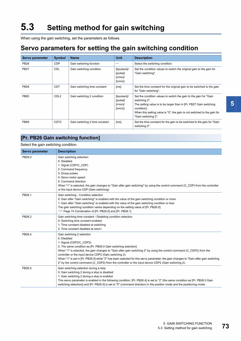
5
5.3 Setting method for gain switchingWhen using the gain switching, set the parameters as follows.
Servo parameters for setting the gain switching condition
[Pr. PB26 Gain switching function]Select the gain switching condition.
Servo parameter Symbol Name Unit DescriptionPB26 CDP Gain switching function Select the switching condition.
PB27 CDL Gain switching condition [kpulse/s]/[pulse]/[r/min]/[mm/s]
Set the condition values to switch the original gain to the gain for "Gain switching".
PB28 CDT Gain switching time constant [ms] Set the time constant for the original gain to be switched to the gain for "Gain switching".
PB65 CDL2 Gain switching 2 condition [kpulse/s]/[pulse]/[r/min]/[mm/s]
Set the condition values to switch the gain to the gain for "Gain switching 2".The setting value is to be larger than in [Pr. PB27 Gain switching condition].When this setting value is "0", the gain is not switched to the gain for "Gain switching 2".
PB66 CDT2 Gain switching 2 time constant [ms] Set the time constant for the gain to be switched to the gain for "Gain switching 2".
Servo parameter DescriptionPB26.0 Gain switching selection
0: Disabled1: Signal (CDP/C_CDP)2: Command frequency3: Droop pulses4: Servo motor speed5: Command directionWhen "1" is selected, the gain changes to "Gain after gain switching" by using the control command (C_CDP) from the controller or the input device CDP (Gain switching).
PB26.1 Gain switching - Condition selection0: Gain after "Gain switching" is enabled with the value of the gain switching condition or more1: Gain after "Gain switching" is enabled with the value of the gain switching condition or lessThe gain switching condition varies depending on the setting value of [Pr. PB26.0].Page 74 Combination of [Pr. PB26.0] and [Pr. PB26.1]
PB26.2 Gain switching time constant - Disabling condition selection0: Switching time constant enabled1: Time constant disabled at switching2: Time constant disabled at return
PB26.4 Gain switching 2 selection0: Disabled1: Signal (CDP2/C_CDP2)2: The same condition as [Pr. PB26.0 Gain switching selection]When "1" is selected, the gain changes to "Gain after gain switching 2" by using the control command (C_CDP2) from the controller or the input device CDP2 (Gain switching 2).When "1" is set in [Pr. PB26.0] while "2" has been selected for this servo parameter, the gain changes to "Gain after gain switching 2" by the control command (C_CDP2) from the controller or the input device CDP2 (Gain switching 2).
PB26.5 Gain switching selection during a stop0: Gain switching 2 during a stop is disabled1: Gain switching 2 during a stop is enabledThis servo parameter is enabled in the following condition: [Pr. PB26.4] is set to "2" (the same condition as [Pr. PB26.0 Gain switching selection]) and [Pr. PB26.0] is set to "5" (command direction) in the position mode and the positioning mode.
5 GAIN SWITCHING FUNCTION5.3 Setting method for gain switching 73
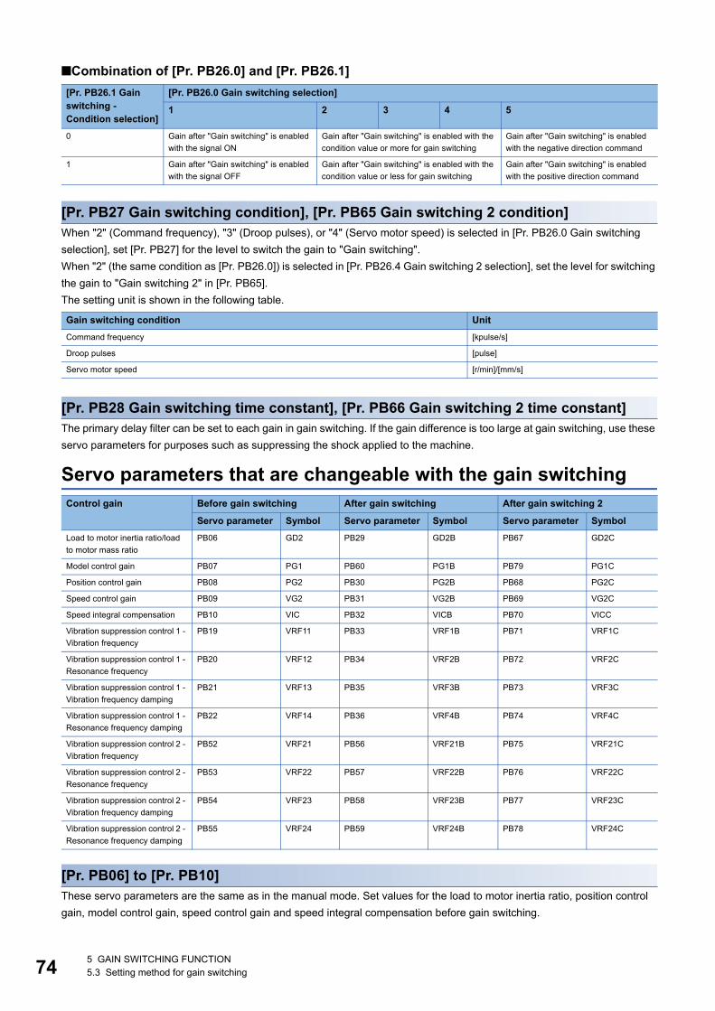
74
■Combination of [Pr. PB26.0] and [Pr. PB26.1]
[Pr. PB27 Gain switching condition], [Pr. PB65 Gain switching 2 condition]When "2" (Command frequency), "3" (Droop pulses), or "4" (Servo motor speed) is selected in [Pr. PB26.0 Gain switching selection], set [Pr. PB27] for the level to switch the gain to "Gain switching".When "2" (the same condition as [Pr. PB26.0]) is selected in [Pr. PB26.4 Gain switching 2 selection], set the level for switching the gain to "Gain switching 2" in [Pr. PB65].The setting unit is shown in the following table.
[Pr. PB28 Gain switching time constant], [Pr. PB66 Gain switching 2 time constant]The primary delay filter can be set to each gain in gain switching. If the gain difference is too large at gain switching, use these servo parameters for purposes such as suppressing the shock applied to the machine.
Servo parameters that are changeable with the gain switching
[Pr. PB06] to [Pr. PB10]These servo parameters are the same as in the manual mode. Set values for the load to motor inertia ratio, position control gain, model control gain, speed control gain and speed integral compensation before gain switching.
[Pr. PB26.1 Gain switching - Condition selection]
[Pr. PB26.0 Gain switching selection]
1 2 3 4 5
0 Gain after "Gain switching" is enabled with the signal ON
Gain after "Gain switching" is enabled with the condition value or more for gain switching
Gain after "Gain switching" is enabled with the negative direction command
1 Gain after "Gain switching" is enabled with the signal OFF
Gain after "Gain switching" is enabled with the condition value or less for gain switching
Gain after "Gain switching" is enabled with the positive direction command
Gain switching condition UnitCommand frequency [kpulse/s]
Droop pulses [pulse]
Servo motor speed [r/min]/[mm/s]
Control gain Before gain switching After gain switching After gain switching 2
Servo parameter Symbol Servo parameter Symbol Servo parameter SymbolLoad to motor inertia ratio/load to motor mass ratio
PB06 GD2 PB29 GD2B PB67 GD2C
Model control gain PB07 PG1 PB60 PG1B PB79 PG1C
Position control gain PB08 PG2 PB30 PG2B PB68 PG2C
Speed control gain PB09 VG2 PB31 VG2B PB69 VG2C
Speed integral compensation PB10 VIC PB32 VICB PB70 VICC
Vibration suppression control 1 - Vibration frequency
PB19 VRF11 PB33 VRF1B PB71 VRF1C
Vibration suppression control 1 - Resonance frequency
PB20 VRF12 PB34 VRF2B PB72 VRF2C
Vibration suppression control 1 - Vibration frequency damping
PB21 VRF13 PB35 VRF3B PB73 VRF3C
Vibration suppression control 1 - Resonance frequency damping
PB22 VRF14 PB36 VRF4B PB74 VRF4C
Vibration suppression control 2 - Vibration frequency
PB52 VRF21 PB56 VRF21B PB75 VRF21C
Vibration suppression control 2 - Resonance frequency
PB53 VRF22 PB57 VRF22B PB76 VRF22C
Vibration suppression control 2 - Vibration frequency damping
PB54 VRF23 PB58 VRF23B PB77 VRF23C
Vibration suppression control 2 - Resonance frequency damping
PB55 VRF24 PB59 VRF24B PB78 VRF24C
5 GAIN SWITCHING FUNCTION5.3 Setting method for gain switching
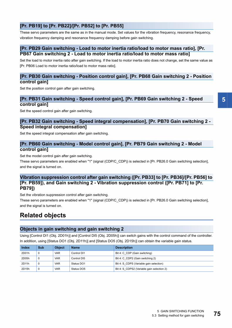
5
[Pr. PB19] to [Pr. PB22]/[Pr. PB52] to [Pr. PB55]These servo parameters are the same as in the manual mode. Set values for the vibration frequency, resonance frequency, vibration frequency damping and resonance frequency damping before gain switching.
[Pr. PB29 Gain switching - Load to motor inertia ratio/load to motor mass ratio], [Pr. PB67 Gain switching 2 - Load to motor inertia ratio/load to motor mass ratio]Set the load to motor inertia ratio after gain switching. If the load to motor inertia ratio does not change, set the same value as [Pr. PB06 Load to motor inertia ratio/load to motor mass ratio].
[Pr. PB30 Gain switching - Position control gain], [Pr. PB68 Gain switching 2 - Position control gain]Set the position control gain after gain switching.
[Pr. PB31 Gain switching - Speed control gain], [Pr. PB69 Gain switching 2 - Speed control gain]Set the speed control gain after gain switching.
[Pr. PB32 Gain switching - Speed integral compensation], [Pr. PB70 Gain switching 2 - Speed integral compensation]Set the speed integral compensation after gain switching.
[Pr. PB60 Gain switching - Model control gain], [Pr. PB79 Gain switching 2 - Model control gain]Set the model control gain after gain switching.These servo parameters are enabled when "1" (signal (CDP/C_CDP)) is selected in [Pr. PB26.0 Gain switching selection], and the signal is turned on.
Vibration suppression control after gain switching ([Pr. PB33] to [Pr. PB36]/[Pr. PB56] to [Pr. PB59]), and Gain switching 2 - Vibration suppression control ([Pr. PB71] to [Pr. PB79])Set the vibration suppression control after gain switching.These servo parameters are enabled when "1" (signal (CDP/C_CDP)) is selected in [Pr. PB26.0 Gain switching selection], and the signal is turned on.
Related objects
Objects in gain switching and gain switching 2Using [Control DI1 (Obj. 2D01h)] and [Control DI5 (Obj. 2D05h)] can switch gains with the control command of the controller. In addition, using [Status DO1 (Obj. 2D11h)] and [Status DO5 (Obj. 2D15h)] can obtain the variable gain status.
Index Sub Object Name Description2D01h 0 VAR Control DI1 Bit 4: C_CDP (Gain switching)
2D05h 0 VAR Control DI5 Bit 4: C_CDP2 (Gain switching 2)
2D11h 0 VAR Status DO1 Bit 4: S_CDPS (Variable gain selection)
2D15h 0 VAR Status DO5 Bit 4: S_CDPS2 (Variable gain selection 2)
5 GAIN SWITCHING FUNCTION5.3 Setting method for gain switching 75
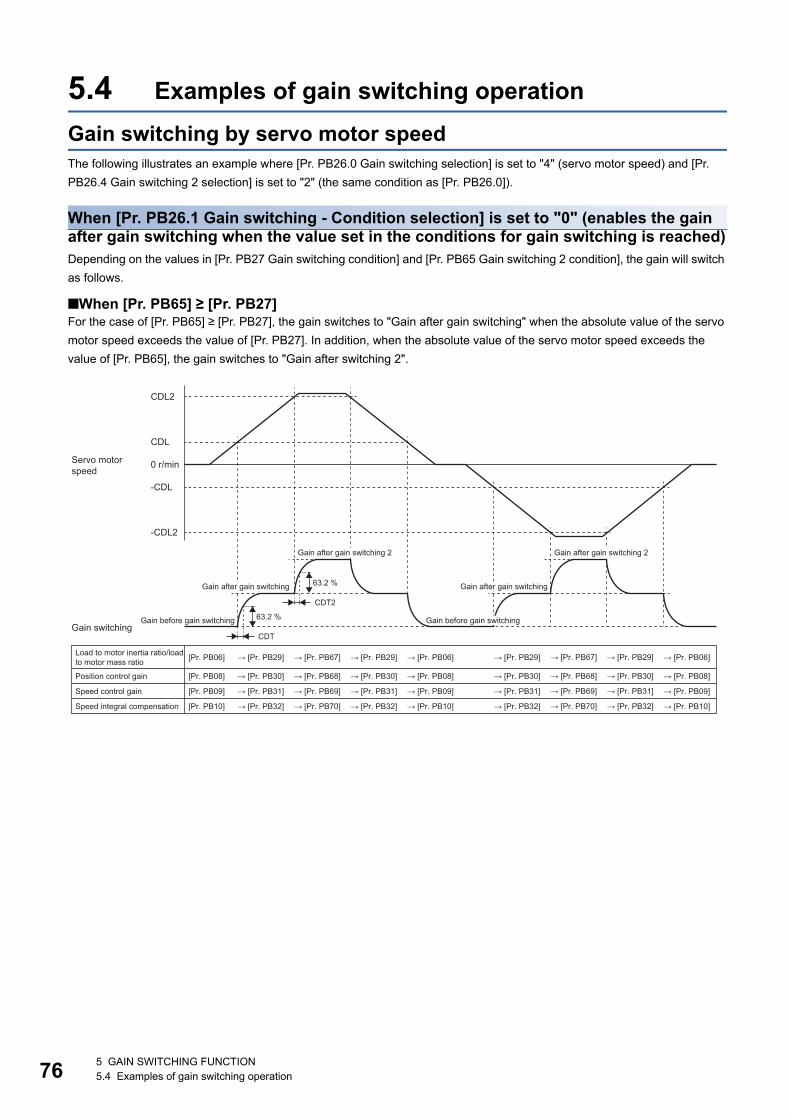
76
5.4 Examples of gain switching operationGain switching by servo motor speedThe following illustrates an example where [Pr. PB26.0 Gain switching selection] is set to "4" (servo motor speed) and [Pr. PB26.4 Gain switching 2 selection] is set to "2" (the same condition as [Pr. PB26.0]).
When [Pr. PB26.1 Gain switching - Condition selection] is set to "0" (enables the gain after gain switching when the value set in the conditions for gain switching is reached)Depending on the values in [Pr. PB27 Gain switching condition] and [Pr. PB65 Gain switching 2 condition], the gain will switch as follows.
■When [Pr. PB65] ≥ [Pr. PB27]For the case of [Pr. PB65] ≥ [Pr. PB27], the gain switches to "Gain after gain switching" when the absolute value of the servo motor speed exceeds the value of [Pr. PB27]. In addition, when the absolute value of the servo motor speed exceeds the value of [Pr. PB65], the gain switches to "Gain after switching 2".
[Pr. PB06]
[Pr. PB08]
[Pr. PB09]
[Pr. PB10]
→ [Pr. PB06] → [Pr. PB29] → [Pr. PB06]
→ [Pr. PB08] → [Pr. PB30] → [Pr. PB08]
→ [Pr. PB09] → [Pr. PB31] → [Pr. PB09]
→ [Pr. PB10]→ [Pr. PB32]→ [Pr. PB10]
CDL
CDL2
0 r/min
-CDL
-CDL2
63.2 %
CDT
→ [Pr. PB29]
→ [Pr. PB30]
→ [Pr. PB31]
→ [Pr. PB32]
→ [Pr. PB67]
→ [Pr. PB68]
→ [Pr. PB69]
→ [Pr. PB70]
→ [Pr. PB29]
→ [Pr. PB30]
→ [Pr. PB31]
→ [Pr. PB32]
63.2 %
CDT2
→ [Pr. PB67]
→ [Pr. PB68]
→ [Pr. PB69]
→ [Pr. PB70]
→ [Pr. PB29]
→ [Pr. PB30]
→ [Pr. PB31]
→ [Pr. PB32]
Servo motor speed
Gain after gain switching 2 Gain after gain switching 2
Gain after gain switchingGain after gain switching
Gain before gain switching Gain before gain switchingGain switching
Load to motor inertia ratio/load to motor mass ratio
Position control gain
Speed control gain
Speed integral compensation
5 GAIN SWITCHING FUNCTION5.4 Examples of gain switching operation
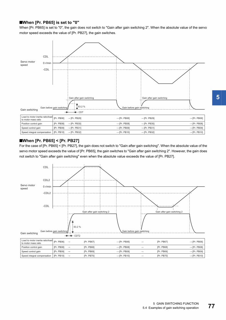
5
■When [Pr. PB65] is set to "0"When [Pr. PB65] is set to "0", the gain does not switch to "Gain after gain switching 2". When the absolute value of the servo motor speed exceeds the value of [Pr. PB27], the gain switches.
■When [Pr. PB65] < [Pr. PB27]For the case of [Pr. PB65] < [Pr. PB27], the gain does not switch to "Gain after gain switching". When the absolute value of the servo motor speed exceeds the value of [Pr. PB65], the gain switches to "Gain after gain switching 2". However, the gain does not switch to "Gain after gain switching" even when the absolute value exceeds the value of [Pr. PB27].
[Pr. PB06]
[Pr. PB08]
[Pr. PB09]
[Pr. PB10]
→ [Pr. PB06] → [Pr. PB29] → [Pr. PB06]
→ [Pr. PB08] → [Pr. PB30] → [Pr. PB08]
→ [Pr. PB09] → [Pr. PB31] → [Pr. PB09]
→ [Pr. PB10]→ [Pr. PB32]→ [Pr. PB10]
CDL
0 r/min
-CDL
63.2 %
CDT
→ [Pr. PB29]
→ [Pr. PB30]
→ [Pr. PB31]
→ [Pr. PB32]
Servo motor speed
Gain after gain switching Gain after gain switching
Gain before gain switching Gain before gain switchingGain switching
Load to motor inertia ratio/load to motor mass ratio
Position control gain
Speed control gain
Speed integral compensation
[Pr. PB06]
[Pr. PB08]
[Pr. PB09]
[Pr. PB10]
→ [Pr. PB06] → → [Pr. PB06]
→ [Pr. PB08] → → [Pr. PB08]
→ [Pr. PB09] → → [Pr. PB09]
→ [Pr. PB10]→→ [Pr. PB10]
CDL2
CDL
0 r/min
-CDL2
-CDL
[Pr. PB67]
[Pr. PB68]
[Pr. PB69]
[Pr. PB70]
[Pr. PB67]
[Pr. PB68]
[Pr. PB69]
[Pr. PB70]
→
→
→
→
63.2 %
CDT2
Servo motor speed
Gain after gain switching 2 Gain after gain switching 2
Gain before gain switching Gain before gain switchingGain switching
Load to motor inertia ratio/load to motor mass ratio
Position control gain
Speed control gain
Speed integral compensation
5 GAIN SWITCHING FUNCTION5.4 Examples of gain switching operation 77
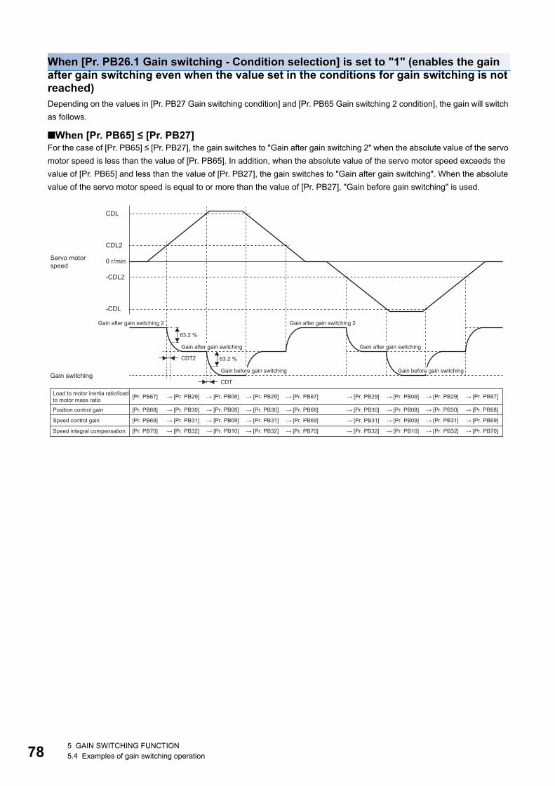
78
When [Pr. PB26.1 Gain switching - Condition selection] is set to "1" (enables the gain after gain switching even when the value set in the conditions for gain switching is not reached)Depending on the values in [Pr. PB27 Gain switching condition] and [Pr. PB65 Gain switching 2 condition], the gain will switch as follows.
■When [Pr. PB65] ≤ [Pr. PB27]For the case of [Pr. PB65] ≤ [Pr. PB27], the gain switches to "Gain after gain switching 2" when the absolute value of the servo motor speed is less than the value of [Pr. PB65]. In addition, when the absolute value of the servo motor speed exceeds the value of [Pr. PB65] and less than the value of [Pr. PB27], the gain switches to "Gain after gain switching". When the absolute value of the servo motor speed is equal to or more than the value of [Pr. PB27], "Gain before gain switching" is used.
[Pr. PB67]
[Pr. PB68]
[Pr. PB69]
[Pr. PB70]
→ [Pr. PB06] → [Pr. PB29] → [Pr. PB06]
→ [Pr. PB08] → [Pr. PB30] → [Pr. PB08]
→ [Pr. PB09] → [Pr. PB31] → [Pr. PB09]
→ [Pr. PB10]→ [Pr. PB32]→ [Pr. PB10]
CDL2
CDL
0 r/min
-CDL2
-CDL
63.2 %
CDT2
→ [Pr. PB29]
→ [Pr. PB30]
→ [Pr. PB31]
→ [Pr. PB32]
→ [Pr. PB67]
→ [Pr. PB68]
→ [Pr. PB69]
→ [Pr. PB70]
→ [Pr. PB29]
→ [Pr. PB30]
→ [Pr. PB31]
→ [Pr. PB32]
63.2 %
CDT
→ [Pr. PB67]
→ [Pr. PB68]
→ [Pr. PB69]
→ [Pr. PB70]
→ [Pr. PB29]
→ [Pr. PB30]
→ [Pr. PB31]
→ [Pr. PB32]
Servo motor speed
Gain after gain switching 2 Gain after gain switching 2
Gain after gain switching Gain after gain switching
Gain before gain switching Gain before gain switchingGain switching
Load to motor inertia ratio/load to motor mass ratio
Position control gain
Speed control gain
Speed integral compensation
5 GAIN SWITCHING FUNCTION5.4 Examples of gain switching operation
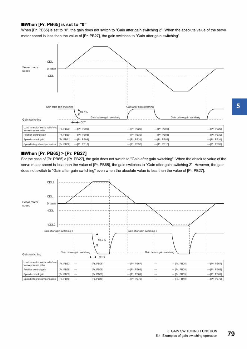
5
■When [Pr. PB65] is set to "0"When [Pr. PB65] is set to "0", the gain does not switch to "Gain after gain switching 2". When the absolute value of the servo motor speed is less than the value of [Pr. PB27], the gain switches to "Gain after gain switching".
■When [Pr. PB65] > [Pr. PB27]For the case of [Pr. PB65] > [Pr. PB27], the gain does not switch to "Gain after gain switching". When the absolute value of the servo motor speed is less than the value of [Pr. PB65], the gain switches to "Gain after gain switching 2". However, the gain does not switch to "Gain after gain switching" even when the absolute value is less than the value of [Pr. PB27].
[Pr. PB29]
[Pr. PB30]
[Pr. PB31]
[Pr. PB32]
→ [Pr. PB29] → [Pr. PB06] → [Pr. PB29]
→ [Pr. PB30] → [Pr. PB08] → [Pr. PB30]
→ [Pr. PB31] → [Pr. PB09] → [Pr. PB31]
→ [Pr. PB32]→ [Pr. PB10]→ [Pr. PB32]
→ [Pr. PB06]
→ [Pr. PB08]
→ [Pr. PB09]
→ [Pr. PB10]
CDL
0 r/min
-CDL
63.2 %
CDT
Servo motor speed
Gain after gain switchingGain after gain switching
Gain before gain switchingGain before gain switchingGain switching
Load to motor inertia ratio/load to motor mass ratio
Position control gain
Speed control gain
Speed integral compensation
[Pr. PB67]
[Pr. PB68]
[Pr. PB69]
[Pr. PB70]
→ [Pr. PB06]
→ [Pr. PB08]
→ [Pr. PB09]
→ [Pr. PB10]
CDL
CDL2
0 r/min
-CDL
63.2 %
-CDL2
CDT2
[Pr. PB06]
[Pr. PB08]
[Pr. PB09]
[Pr. PB10]
→
→
→
→
→
→
→
→
→ [Pr. PB67]
→ [Pr. PB68]
→ [Pr. PB69]
→ [Pr. PB70]
→ [Pr. PB67]
→ [Pr. PB68]
→ [Pr. PB69]
→ [Pr. PB70]
Servo motor speed
Gain after gain switching 2Gain after gain switching 2
Gain before gain switchingGain before gain switchingGain switching
Load to motor inertia ratio/load to motor mass ratio
Position control gain
Speed control gain
Speed integral compensation
5 GAIN SWITCHING FUNCTION5.4 Examples of gain switching operation 79
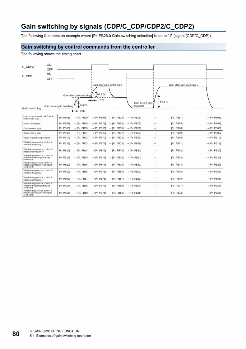
80
Gain switching by signals (CDP/C_CDP/CDP2/C_CDP2)The following illustrates an example where [Pr. PB26.0 Gain switching selection] is set to "1" (signal (CDP/C_CDP)).
Gain switching by control commands from the controllerThe following shows the timing chart.
[Pr. PB06]
[Pr. PB08]
[Pr. PB09]
[Pr. PB10]
→ [Pr. PB06] → → [Pr. PB06]
→ [Pr. PB08] → → [Pr. PB08]
→ [Pr. PB09] → → [Pr. PB09]
→ [Pr. PB10]→→ [Pr. PB10]
63.2 %
CDT
→ [Pr. PB29]
→ [Pr. PB30]
→ [Pr. PB31]
→ [Pr. PB32]
→ [Pr. PB67]
→ [Pr. PB68]
→ [Pr. PB69]
→ [Pr. PB70]
→ [Pr. PB29]
→ [Pr. PB30]
→ [Pr. PB31]
→ [Pr. PB32]
63.2 %
CDT2
[Pr. PB67]
[Pr. PB68]
[Pr. PB07] → [Pr. PB07] → → [Pr. PB07]→ [Pr. PB60] → [Pr. PB79] → [Pr. PB60] [Pr. PB79]
[Pr. PB69]
[Pr. PB70]
63.2 %
ONOFF
C_CDP2
C_CDPONOFF
[Pr. PB19] →→ [Pr. PB19] → [Pr. PB33] → [Pr. PB71]
[Pr. PB20] →→ [Pr. PB20] → [Pr. PB34] → [Pr. PB72]
[Pr. PB21] →→ [Pr. PB21] → [Pr. PB35] → [Pr. PB73]
[Pr. PB22] →→ [Pr. PB22] → [Pr. PB36] → [Pr. PB74]
[Pr. PB52] →→ [Pr. PB52] → [Pr. PB56] → [Pr. PB75]
[Pr. PB53] →→ [Pr. PB53] → [Pr. PB57] → [Pr. PB76]
[Pr. PB54] →→ [Pr. PB54] → [Pr. PB58] → [Pr. PB77]
[Pr. PB55] →→ [Pr. PB55] → [Pr. PB59] → [Pr. PB78]
→ [Pr. PB33]
→ [Pr. PB34]
→ [Pr. PB35]
→ [Pr. PB36]
→ [Pr. PB56]
→ [Pr. PB57]
→ [Pr. PB58]
→ [Pr. PB59]
[Pr. PB71]
[Pr. PB72]
[Pr. PB73]
[Pr. PB74]
[Pr. PB75]
[Pr. PB76]
[Pr. PB77]
[Pr. PB78]
→ [Pr. PB19]
→ [Pr. PB20]
→ [Pr. PB21]
→ [Pr. PB22]
→ [Pr. PB52]
→ [Pr. PB53]
→ [Pr. PB54]
→ [Pr. PB55]
Gain after gain switching 2 Gain after gain switching 2
Gain after gain switching
Gain before gain switchingGain before gain switching
Gain switching
Load to motor inertia ratio/load to motor mass ratio
Model control gain
Position control gain
Speed control gain
Speed integral compensation
Vibration suppression control 1 - Vibration frequency
Vibration suppression control 1 - Resonance frequency
Vibration suppression control 1 - Vibration frequency/damping coefficientVibration suppression control 1 - Resonance frequency/damping coefficientVibration suppression control 2 - Vibration frequency
Vibration suppression control 2 - Resonance frequency
Vibration suppression control 2 - Vibration frequency/damping coefficientVibration suppression control 2 - Resonance frequency/damping coefficient
5 GAIN SWITCHING FUNCTION5.4 Examples of gain switching operation
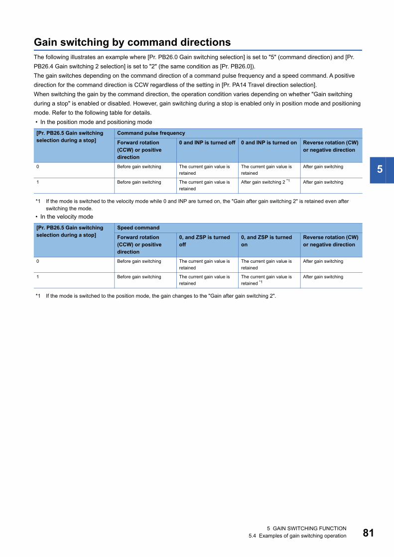
5
Gain switching by command directionsThe following illustrates an example where [Pr. PB26.0 Gain switching selection] is set to "5" (command direction) and [Pr. PB26.4 Gain switching 2 selection] is set to "2" (the same condition as [Pr. PB26.0]).The gain switches depending on the command direction of a command pulse frequency and a speed command. A positive direction for the command direction is CCW regardless of the setting in [Pr. PA14 Travel direction selection].When switching the gain by the command direction, the operation condition varies depending on whether "Gain switching during a stop" is enabled or disabled. However, gain switching during a stop is enabled only in position mode and positioning mode. Refer to the following table for details. • In the position mode and positioning mode
*1 If the mode is switched to the velocity mode while 0 and INP are turned on, the "Gain after gain switching 2" is retained even after switching the mode.
• In the velocity mode
*1 If the mode is switched to the position mode, the gain changes to the "Gain after gain switching 2".
[Pr. PB26.5 Gain switching selection during a stop]
Command pulse frequency
Forward rotation (CCW) or positive direction
0 and INP is turned off 0 and INP is turned on Reverse rotation (CW) or negative direction
0 Before gain switching The current gain value is retained
The current gain value is retained
After gain switching
1 Before gain switching The current gain value is retained
After gain switching 2 *1 After gain switching
[Pr. PB26.5 Gain switching selection during a stop]
Speed command
Forward rotation (CCW) or positive direction
0, and ZSP is turned off
0, and ZSP is turned on
Reverse rotation (CW) or negative direction
0 Before gain switching The current gain value is retained
The current gain value is retained
After gain switching
1 Before gain switching The current gain value is retained
The current gain value is retained *1
After gain switching
5 GAIN SWITCHING FUNCTION5.4 Examples of gain switching operation 81
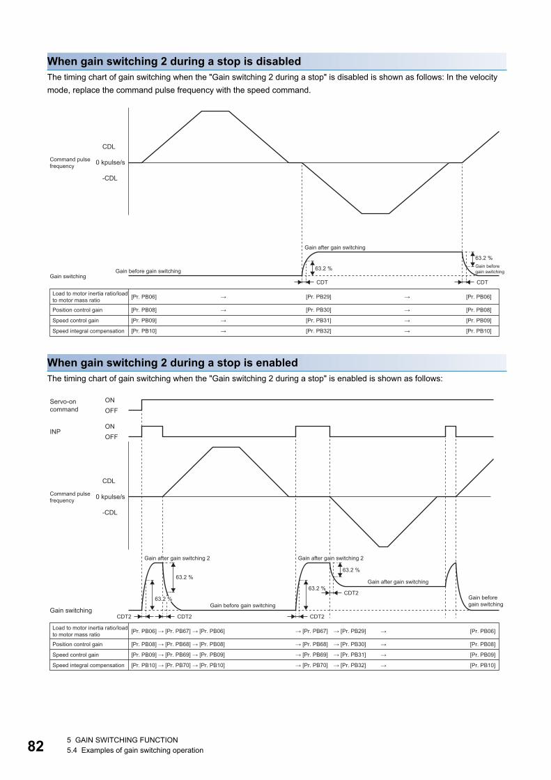
82
When gain switching 2 during a stop is disabledThe timing chart of gain switching when the "Gain switching 2 during a stop" is disabled is shown as follows: In the velocity mode, replace the command pulse frequency with the speed command.
When gain switching 2 during a stop is enabledThe timing chart of gain switching when the "Gain switching 2 during a stop" is enabled is shown as follows:
[Pr. PB06]
[Pr. PB08]
[Pr. PB09]
[Pr. PB10]
[Pr. PB06]
[Pr. PB08]
[Pr. PB09]
[Pr. PB10]
[Pr. PB29]
[Pr. PB30]
[Pr. PB31]
[Pr. PB32]
CDL
0 kpulse/s
-CDL
63.2 %
63.2 %
CDT
→
→
→
→
→
→
→
→
CDT
Command pulse frequency
Gain after gain switching
Gain before gain switchingGain before gain switching
Gain switching
Load to motor inertia ratio/load to motor mass ratio
Position control gain
Speed control gain
Speed integral compensation
[Pr. PB06]
[Pr. PB08]
[Pr. PB09]
[Pr. PB10]
[Pr. PB06]
[Pr. PB08]
[Pr. PB09]
[Pr. PB10]
CDL
0 kpulse/s
-CDL
→
→
→
→
63.2 %
CDT2CDT2
63.2 %
CDT2
63.2 %
CDT2
INP
ONOFF
ONOFF
→ [Pr. PB67]
→ [Pr. PB68]
→ [Pr. PB69]
→ [Pr. PB70]
→ [Pr. PB06]
→ [Pr. PB08]
→ [Pr. PB09]
→ [Pr. PB10]
→ [Pr. PB67]
→ [Pr. PB68]
→ [Pr. PB69]
→ [Pr. PB70]
→ [Pr. PB29]
→ [Pr. PB30]
→ [Pr. PB31]
→ [Pr. PB32]
63.2 %
Servo-on command
Command pulse frequency
Gain after gain switching 2Gain after gain switching 2
Gain after gain switching
Gain before gain switchingGain before gain switching
Gain switching
Load to motor inertia ratio/load to motor mass ratio
Position control gain
Speed control gain
Speed integral compensation
5 GAIN SWITCHING FUNCTION5.4 Examples of gain switching operation
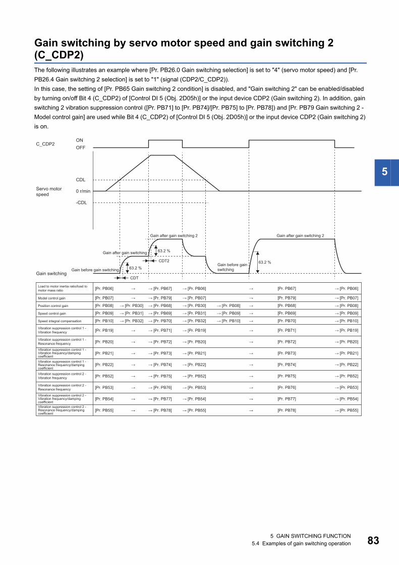
5
Gain switching by servo motor speed and gain switching 2 (C_CDP2)The following illustrates an example where [Pr. PB26.0 Gain switching selection] is set to "4" (servo motor speed) and [Pr. PB26.4 Gain switching 2 selection] is set to "1" (signal (CDP2/C_CDP2)).In this case, the setting of [Pr. PB65 Gain switching 2 condition] is disabled, and "Gain switching 2" can be enabled/disabled by turning on/off Bit 4 (C_CDP2) of [Control DI 5 (Obj. 2D05h)] or the input device CDP2 (Gain switching 2). In addition, gain switching 2 vibration suppression control ([Pr. PB71] to [Pr. PB74]/[Pr. PB75] to [Pr. PB78]) and [Pr. PB79 Gain switching 2 - Model control gain] are used while Bit 4 (C_CDP2) of [Control DI 5 (Obj. 2D05h)] or the input device CDP2 (Gain switching 2) is on.
CDL
0 r/min
-CDL
63.2 %
CDT
63.2 %
CDT2 63.2 %
C_CDP2ONOFF
[Pr. PB06]
[Pr. PB08]
[Pr. PB09]
[Pr. PB10]
→ [Pr. PB06] → → [Pr. PB06]
→ [Pr. PB08] → → [Pr. PB08]
→ [Pr. PB09] → → [Pr. PB09]
→ [Pr. PB10]→→ [Pr. PB10]
→
→ [Pr. PB30]
→ [Pr. PB31]
→ [Pr. PB32]
→ [Pr. PB67]
→ [Pr. PB68]
→ [Pr. PB69]
→ [Pr. PB70]
[Pr. PB67]
[Pr. PB68]
[Pr. PB07] → [Pr. PB07] → → [Pr. PB07]→ → [Pr. PB79] [Pr. PB79]
[Pr. PB69]
[Pr. PB70]
[Pr. PB19] →→ [Pr. PB19] → → [Pr. PB71]
[Pr. PB20] →→ [Pr. PB20] → → [Pr. PB72]
[Pr. PB21] →→ [Pr. PB21] → → [Pr. PB73]
[Pr. PB22] →→ [Pr. PB22] → → [Pr. PB74]
[Pr. PB52] →→ [Pr. PB52] → → [Pr. PB75]
[Pr. PB53] →→ [Pr. PB53] → → [Pr. PB76]
[Pr. PB54] →→ [Pr. PB54] → → [Pr. PB77]
[Pr. PB55] →→ [Pr. PB55] → → [Pr. PB78]
[Pr. PB71]
[Pr. PB72]
[Pr. PB73]
[Pr. PB74]
[Pr. PB75]
[Pr. PB76]
[Pr. PB77]
[Pr. PB78]
→ [Pr. PB19]
→ [Pr. PB20]
→ [Pr. PB21]
→ [Pr. PB22]
→ [Pr. PB52]
→ [Pr. PB53]
→ [Pr. PB54]
→ [Pr. PB55]
→ [Pr. PB30]
→ [Pr. PB31]
→ [Pr. PB32]
Servo motor speed
Gain after gain switching 2 Gain after gain switching 2
Gain after gain switching
Gain before gain switchingGain before gain switching
Gain switching
Load to motor inertia ratio/load to motor mass ratio
Model control gain
Position control gain
Speed control gain
Speed integral compensation
Vibration suppression control 1 - Vibration frequency
Vibration suppression control 1 - Resonance frequency
Vibration suppression control 1 - Vibration frequency/damping coefficient Vibration suppression control 1 - Resonance frequency/damping coefficient Vibration suppression control 2 - Vibration frequency
Vibration suppression control 2 - Resonance frequency
Vibration suppression control 2 - Vibration frequency/damping coefficientVibration suppression control 2 - Resonance frequency/damping coefficient
5 GAIN SWITCHING FUNCTION5.4 Examples of gain switching operation 83
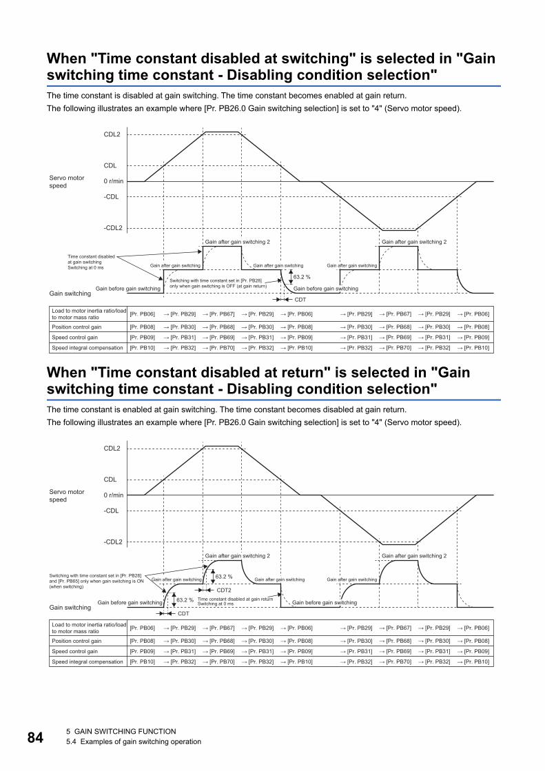
84
When "Time constant disabled at switching" is selected in "Gain switching time constant - Disabling condition selection"The time constant is disabled at gain switching. The time constant becomes enabled at gain return.The following illustrates an example where [Pr. PB26.0 Gain switching selection] is set to "4" (Servo motor speed).
When "Time constant disabled at return" is selected in "Gain switching time constant - Disabling condition selection"The time constant is enabled at gain switching. The time constant becomes disabled at gain return.The following illustrates an example where [Pr. PB26.0 Gain switching selection] is set to "4" (Servo motor speed).
[Pr. PB06]
[Pr. PB08]
[Pr. PB09]
[Pr. PB10]
→ [Pr. PB06] → [Pr. PB29] → [Pr. PB06]
→ [Pr. PB08] → [Pr. PB30] → [Pr. PB08]
→ [Pr. PB09] → [Pr. PB31] → [Pr. PB09]
→ [Pr. PB10]→ [Pr. PB32]→ [Pr. PB10]
CDL
CDL2
0 r/min
-CDL
-CDL2
63.2 %
CDT
→ [Pr. PB29]
→ [Pr. PB30]
→ [Pr. PB31]
→ [Pr. PB32]
→ [Pr. PB67]
→ [Pr. PB68]
→ [Pr. PB69]
→ [Pr. PB70]
→ [Pr. PB29]
→ [Pr. PB30]
→ [Pr. PB31]
→ [Pr. PB32]
→ [Pr. PB67]
→ [Pr. PB68]
→ [Pr. PB69]
→ [Pr. PB70]
→ [Pr. PB29]
→ [Pr. PB30]
→ [Pr. PB31]
→ [Pr. PB32]
Servo motor speed
Gain after gain switching 2 Gain after gain switching 2
Time constant disabled at gain switchingSwitching at 0 ms Gain after gain switching Gain after gain switching Gain after gain switching
Switching with time constant set in [Pr. PB28] only when gain switching is OFF (at gain return)Gain before gain switching Gain before gain switching
Gain switching
Load to motor inertia ratio/load to motor mass ratio
Position control gain
Speed control gain
Speed integral compensation
[Pr. PB06]
[Pr. PB08]
[Pr. PB09]
[Pr. PB10]
→ [Pr. PB06] → [Pr. PB29] → [Pr. PB06]
→ [Pr. PB08] → [Pr. PB30] → [Pr. PB08]
→ [Pr. PB09] → [Pr. PB31] → [Pr. PB09]
→ [Pr. PB10]→ [Pr. PB32]→ [Pr. PB10]
CDL
CDL2
0 r/min
-CDL
-CDL2
63.2 %
CDT
→ [Pr. PB29]
→ [Pr. PB30]
→ [Pr. PB31]
→ [Pr. PB32]
→ [Pr. PB67]
→ [Pr. PB68]
→ [Pr. PB69]
→ [Pr. PB70]
→ [Pr. PB29]
→ [Pr. PB30]
→ [Pr. PB31]
→ [Pr. PB32]
63.2 %
CDT2
→ [Pr. PB67]
→ [Pr. PB68]
→ [Pr. PB69]
→ [Pr. PB70]
→ [Pr. PB29]
→ [Pr. PB30]
→ [Pr. PB31]
→ [Pr. PB32]
Servo motor speed
Gain after gain switching 2 Gain after gain switching 2
Switching with time constant set in [Pr. PB28] and [Pr. PB65] only when gain switching is ON (when switching)
Gain after gain switching Gain after gain switchingGain after gain switching
Time constant disabled at gain returnSwitching at 0 ms Gain before gain switching Gain before gain switching
Gain switching
Load to motor inertia ratio/load to motor mass ratio
Position control gain
Speed control gain
Speed integral compensation
5 GAIN SWITCHING FUNCTION5.4 Examples of gain switching operation
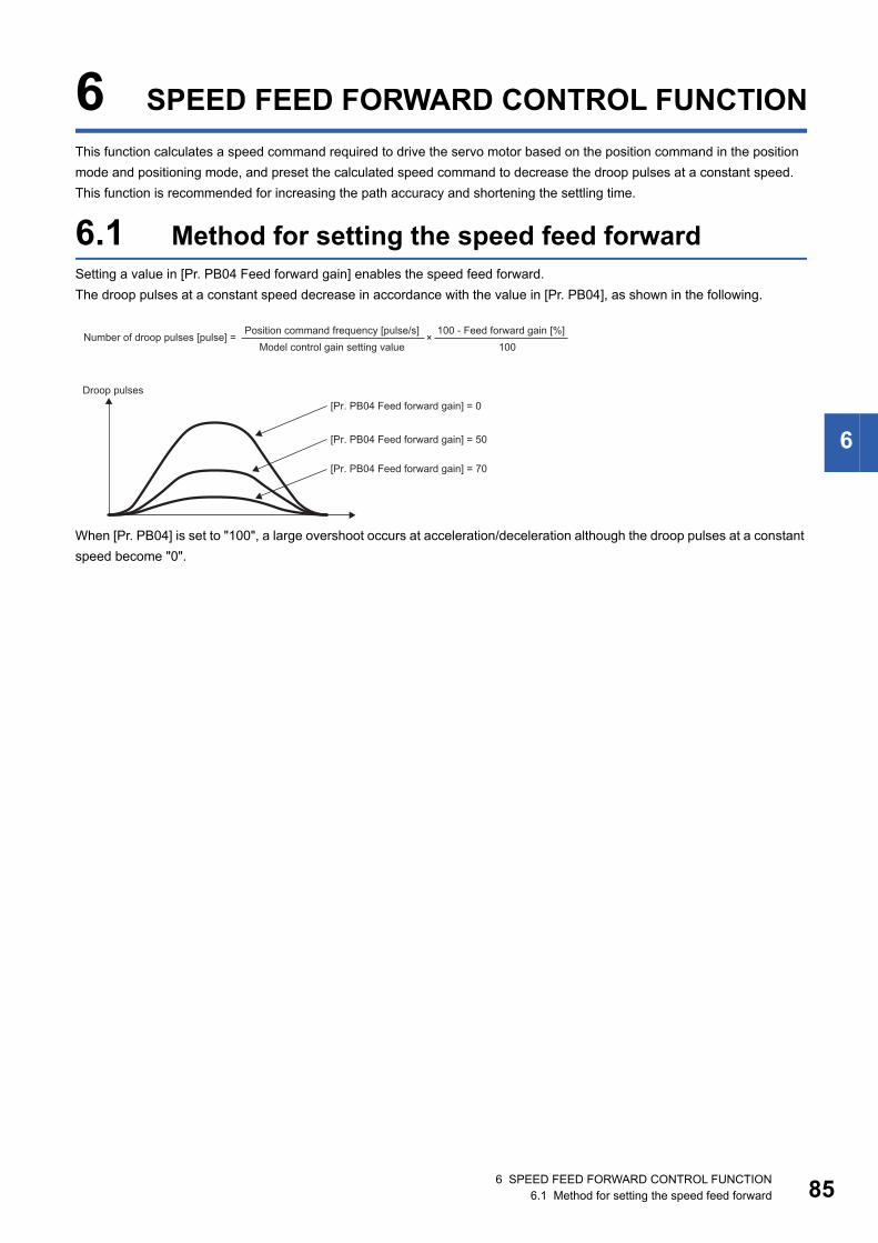
6
6 SPEED FEED FORWARD CONTROL FUNCTIONThis function calculates a speed command required to drive the servo motor based on the position command in the position mode and positioning mode, and preset the calculated speed command to decrease the droop pulses at a constant speed. This function is recommended for increasing the path accuracy and shortening the settling time.
6.1 Method for setting the speed feed forwardSetting a value in [Pr. PB04 Feed forward gain] enables the speed feed forward.The droop pulses at a constant speed decrease in accordance with the value in [Pr. PB04], as shown in the following.
When [Pr. PB04] is set to "100", a large overshoot occurs at acceleration/deceleration although the droop pulses at a constant speed become "0".
Position command frequency [pulse/s] 100 - Feed forward gain [%]Number of droop pulses [pulse] = Model control gain setting value
×100
Droop pulses[Pr. PB04 Feed forward gain] = 0
[Pr. PB04 Feed forward gain] = 50
[Pr. PB04 Feed forward gain] = 70
6 SPEED FEED FORWARD CONTROL FUNCTION6.1 Method for setting the speed feed forward 85

86
MEMO
6 SPEED FEED FORWARD CONTROL FUNCTION6.1 Method for setting the speed feed forward
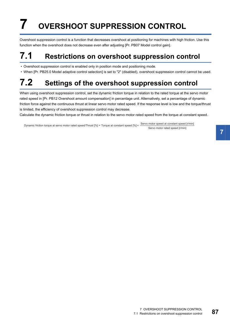
7
7 OVERSHOOT SUPPRESSION CONTROLOvershoot suppression control is a function that decreases overshoot at positioning for machines with high friction. Use this function when the overshoot does not decrease even after adjusting [Pr. PB07 Model control gain].
7.1 Restrictions on overshoot suppression control • Overshoot suppression control is enabled only in position mode and positioning mode. • When [Pr. PB25.0 Model adaptive control selection] is set to "2" (disabled), overshoot suppression control cannot be used.
7.2 Settings of the overshoot suppression controlWhen using overshoot suppression control, set the dynamic friction torque in relation to the rated torque at the servo motor rated speed in [Pr. PB12 Overshoot amount compensation] in percentage unit. Alternatively, set a percentage of dynamic friction force against the continuous thrust at linear servo motor rated speed. If the response level is low and the torque/thrust is limited, the efficiency of overshoot suppression control may decrease.Calculate the dynamic friction torque or thrust in relation to the servo motor rated speed from the torque at constant speed.
Servo motor speed at constant speed [r/min]Dynamic friction torque at servo motor rated speed/Thrust [%] = Torque at constant speed [%]Servo motor rated speed [r/min]
×
7 OVERSHOOT SUPPRESSION CONTROL7.1 Restrictions on overshoot suppression control 87

88
MEMO
7 OVERSHOOT SUPPRESSION CONTROL7.2 Settings of the overshoot suppression control
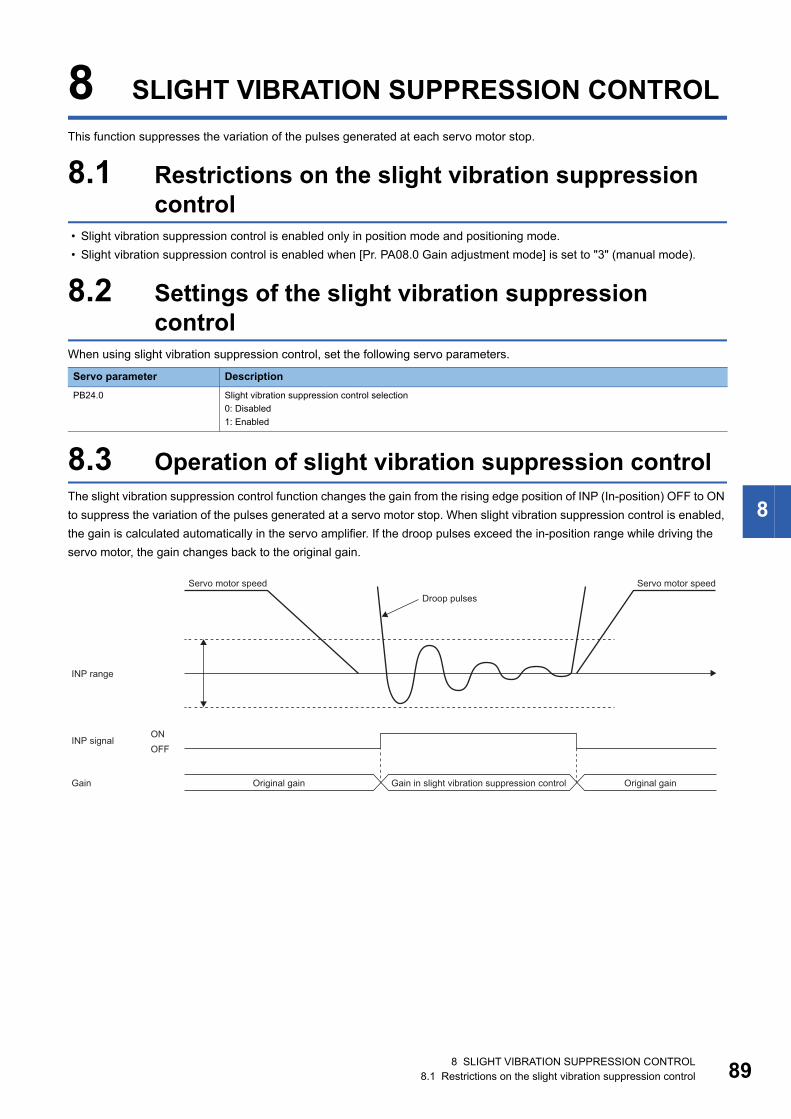
8
8 SLIGHT VIBRATION SUPPRESSION CONTROLThis function suppresses the variation of the pulses generated at each servo motor stop.
8.1 Restrictions on the slight vibration suppression control
• Slight vibration suppression control is enabled only in position mode and positioning mode. • Slight vibration suppression control is enabled when [Pr. PA08.0 Gain adjustment mode] is set to "3" (manual mode).
8.2 Settings of the slight vibration suppression control
When using slight vibration suppression control, set the following servo parameters.
8.3 Operation of slight vibration suppression controlThe slight vibration suppression control function changes the gain from the rising edge position of INP (In-position) OFF to ON to suppress the variation of the pulses generated at a servo motor stop. When slight vibration suppression control is enabled, the gain is calculated automatically in the servo amplifier. If the droop pulses exceed the in-position range while driving the servo motor, the gain changes back to the original gain.
Servo parameter DescriptionPB24.0 Slight vibration suppression control selection
0: Disabled1: Enabled
ONOFF
Servo motor speed Servo motor speedDroop pulses
INP range
INP signal
Gain Original gain Gain in slight vibration suppression control Original gain
8 SLIGHT VIBRATION SUPPRESSION CONTROL8.1 Restrictions on the slight vibration suppression control 89

90
MEMO
8 SLIGHT VIBRATION SUPPRESSION CONTROL8.3 Operation of slight vibration suppression control
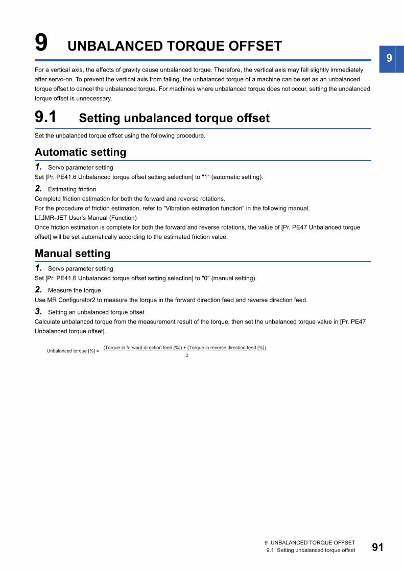
9
9 UNBALANCED TORQUE OFFSETFor a vertical axis, the effects of gravity cause unbalanced torque. Therefore, the vertical axis may fall slightly immediately after servo-on. To prevent the vertical axis from falling, the unbalanced torque of a machine can be set as an unbalanced torque offset to cancel the unbalanced torque. For machines where unbalanced torque does not occur, setting the unbalanced torque offset is unnecessary.9.1 Setting unbalanced torque offsetSet the unbalanced torque offset using the following procedure.
Automatic setting1. Servo parameter settingSet [Pr. PE41.6 Unbalanced torque offset setting selection] to "1" (automatic setting).
2. Estimating frictionComplete friction estimation for both the forward and reverse rotations.For the procedure of friction estimation, refer to "Vibration estimation function" in the following manual.MR-JET User's Manual (Function)Once friction estimation is complete for both the forward and reverse rotations, the value of [Pr. PE47 Unbalanced torque offset] will be set automatically according to the estimated friction value.
Manual setting1. Servo parameter settingSet [Pr. PE41.6 Unbalanced torque offset setting selection] to "0" (manual setting).
2. Measure the torqueUse MR Configurator2 to measure the torque in the forward direction feed and reverse direction feed.
3. Setting an unbalanced torque offsetCalculate unbalanced torque from the measurement result of the torque, then set the unbalanced torque value in [Pr. PE47 Unbalanced torque offset].
(Torque in forward direction feed [%]) + (Torque in reverse direction feed [%])Unbalanced torque [%] =2
9 UNBALANCED TORQUE OFFSET9.1 Setting unbalanced torque offset 91

92
MEMO
9 UNBALANCED TORQUE OFFSET9.1 Setting unbalanced torque offset
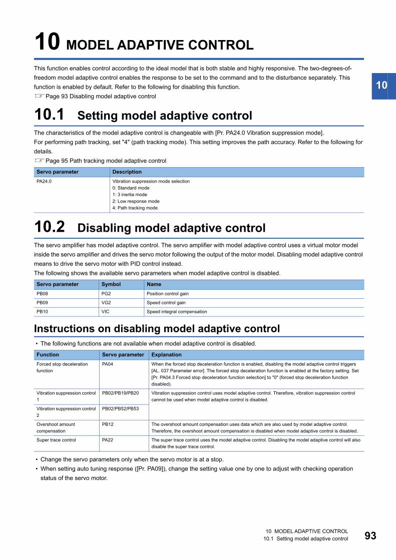
10
10 MODEL ADAPTIVE CONTROLThis function enables control according to the ideal model that is both stable and highly responsive. The two-degrees-of-freedom model adaptive control enables the response to be set to the command and to the disturbance separately. This function is enabled by default. Refer to the following for disabling this function.Page 93 Disabling model adaptive control
10.1 Setting model adaptive controlThe characteristics of the model adaptive control is changeable with [Pr. PA24.0 Vibration suppression mode].For performing path tracking, set "4" (path tracking mode). This setting improves the path accuracy. Refer to the following for details.Page 95 Path tracking model adaptive control
10.2 Disabling model adaptive controlThe servo amplifier has model adaptive control. The servo amplifier with model adaptive control uses a virtual motor model inside the servo amplifier and drives the servo motor following the output of the motor model. Disabling model adaptive control means to drive the servo motor with PID control instead.The following shows the available servo parameters when model adaptive control is disabled.
Instructions on disabling model adaptive control • The following functions are not available when model adaptive control is disabled.
• Change the servo parameters only when the servo motor is at a stop. • When setting auto tuning response ([Pr. PA09]), change the setting value one by one to adjust with checking operation
status of the servo motor.
Servo parameter DescriptionPA24.0 Vibration suppression mode selection
0: Standard mode1: 3 inertia mode2: Low response mode4: Path tracking mode
Servo parameter Symbol NamePB08 PG2 Position control gain
PB09 VG2 Speed control gain
PB10 VIC Speed integral compensation
Function Servo parameter ExplanationForced stop deceleration function
PA04 When the forced stop deceleration function is enabled, disabling the model adaptive control triggers [AL. 037 Parameter error]. The forced stop deceleration function is enabled at the factory setting. Set [Pr. PA04.3 Forced stop deceleration function selection] to "0" (forced stop deceleration function disabled).
Vibration suppression control 1
PB02/PB19/PB20 Vibration suppression control uses model adaptive control. Therefore, vibration suppression control cannot be used when model adaptive control is disabled.
Vibration suppression control 2
PB02/PB52/PB53
Overshoot amount compensation
PB12 The overshoot amount compensation uses data which are also used by model adaptive control. Therefore, the overshoot amount compensation is disabled when model adaptive control is disabled.
Super trace control PA22 The super trace control uses the model adaptive control. Disabling the model adaptive control will also disable the super trace control.
10 MODEL ADAPTIVE CONTROL10.1 Setting model adaptive control 93
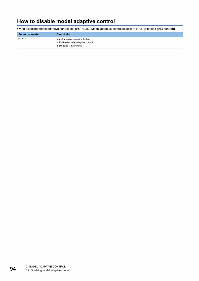
94
How to disable model adaptive controlWhen disabling model adaptive control, set [Pr. PB25.0 Model adaptive control selection] to "2" (disabled (PID control)).
Servo parameter DescriptionPB25.0 Model adaptive control selection
0: Enabled (model adaptive control)2: Disabled (PID control)
10 MODEL ADAPTIVE CONTROL10.2 Disabling model adaptive control
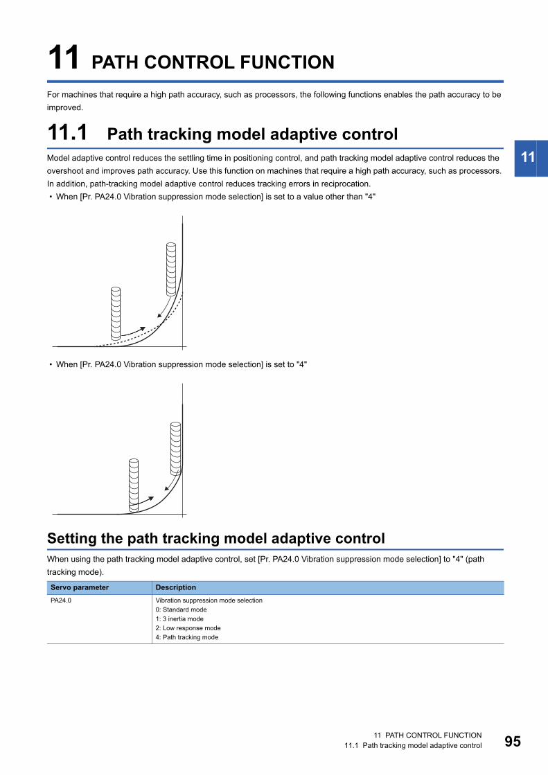
11
11 PATH CONTROL FUNCTIONFor machines that require a high path accuracy, such as processors, the following functions enables the path accuracy to be improved.
11.1 Path tracking model adaptive controlModel adaptive control reduces the settling time in positioning control, and path tracking model adaptive control reduces the overshoot and improves path accuracy. Use this function on machines that require a high path accuracy, such as processors. In addition, path-tracking model adaptive control reduces tracking errors in reciprocation. • When [Pr. PA24.0 Vibration suppression mode selection] is set to a value other than "4"
• When [Pr. PA24.0 Vibration suppression mode selection] is set to "4"
Setting the path tracking model adaptive controlWhen using the path tracking model adaptive control, set [Pr. PA24.0 Vibration suppression mode selection] to "4" (path tracking mode).
Servo parameter DescriptionPA24.0 Vibration suppression mode selection
0: Standard mode1: 3 inertia mode2: Low response mode4: Path tracking mode
11 PATH CONTROL FUNCTION11.1 Path tracking model adaptive control 95
96
Operation of path tracking model adaptive controlIn path tracking model adaptive control, changing the characteristics of model adaptive control enables the overshoot to be suppressed when the servo motor stops. When [Pr. PA24.0 Vibration suppression mode selection] is set to "0" (standard mode), "1" (3 inertia mode), or "2" (low response mode), shortening the settling time during positioning is prioritized; when set to "4" (path tracking mode), path smoothing is prioritized. Setting "4" (path tracking mode) enables the overshoot to be suppressed without a precise adjustment of [Pr. PB07 Model control gain].
11 PATH CONTROL FUNCTION11.1 Path tracking model adaptive control
11
11.2 Super trace controlSuper trace control is a function that uses the ideal model inside the servo amplifier to reduce droop pulses at the uniform acceleration/deceleration to almost 0. Use this function on machines that require a high path accuracy, such as processors.
Restrictions on super trace control • Super trace control is enabled only in position mode and positioning mode. • When [Pr. PB25.0 Model adaptive control selection] is set to "2" (disabled), super trace control cannot be used.
Instructions on super trace control • When using super trace control, use the speed feed forward control function as well. • In super trace control, INP (in-position) may remain on because the droop pulses become close to 0 during the servo motor
control. Change [Pr. PD13.2 INP output signal ON condition selection] to "1" (within the in-position range and at the completion of command output).
• When using super trace control, it is recommended that the acceleration time constant up to the rated speed be set to 1 s or more.
Setting the super trace controlThe adjustment procedure for super trace control is as follows.
Procedure Operation1 Perform gain adjustment with quick tuning, one-touch tuning, auto tuning, or other means.
Page 13 Quick tuningPage 17 One-touch tuningPage 34 Auto tuning mode 1
2 Change [Pr. PA08.0 Gain adjustment mode selection] to "3" (manual mode).
3 Change [Pr. PB04 Feed forward gain] and perform adjustment so that the droop pulses become 0 at the constant speed.
4 Change [Pr. PD13.2 INP output signal ON condition selection] to "1" (within the in-position range and at the completion of command output).
5 Change [Pr. PA22.1 Super trace control function selection] to "2" (enabled).
6 Change [Pr. PB07 Model control gain] to adjust the droop pulses at acceleration/deceleration.
11 PATH CONTROL FUNCTION11.2 Super trace control 97
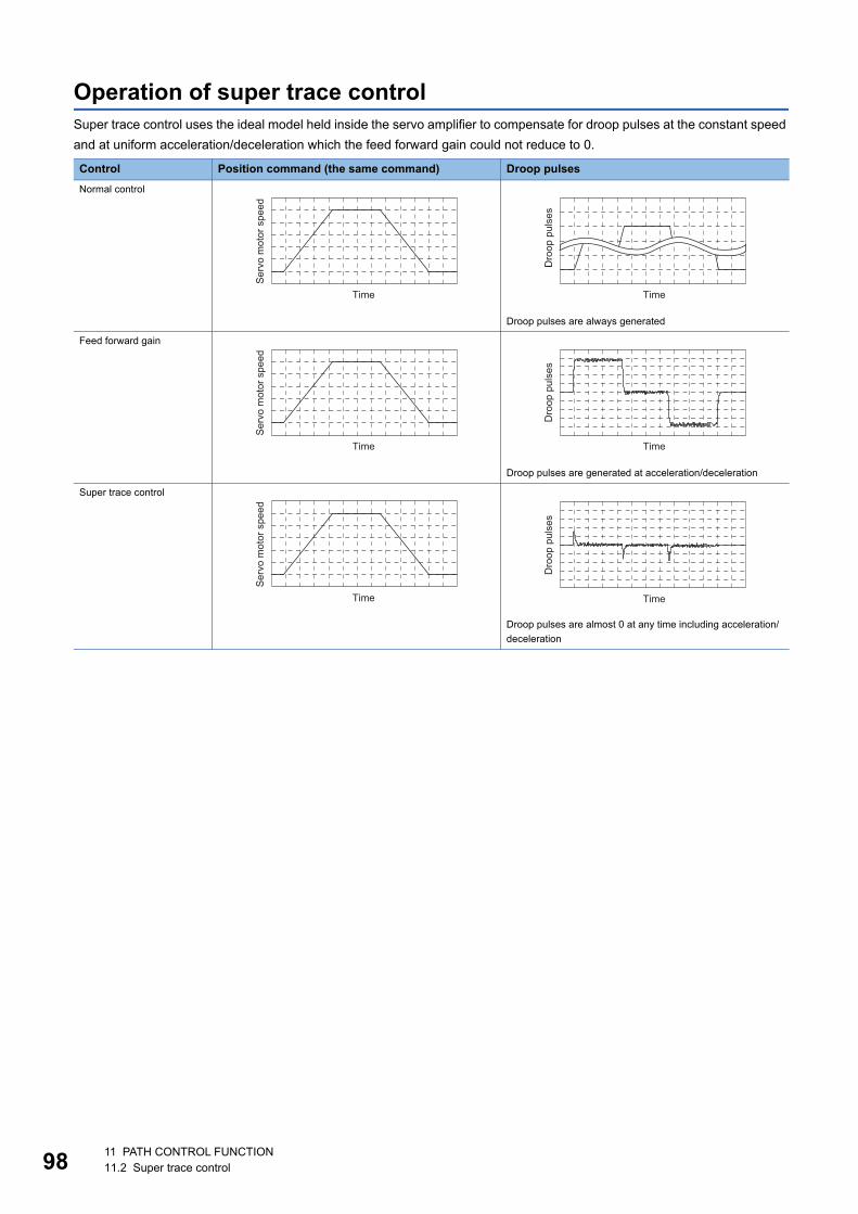
98
Operation of super trace controlSuper trace control uses the ideal model held inside the servo amplifier to compensate for droop pulses at the constant speed and at uniform acceleration/deceleration which the feed forward gain could not reduce to 0.
Control Position command (the same command) Droop pulsesNormal control
Droop pulses are always generated
Feed forward gain
Droop pulses are generated at acceleration/deceleration
Super trace control
Droop pulses are almost 0 at any time including acceleration/deceleration
Serv
o m
otor
spe
ed
Time
Dro
op p
ulse
s
Time
Serv
o m
otor
spe
ed
Time
Dro
op p
ulse
s
Time
Serv
o m
otor
spe
ed
Time
Dro
op p
ulse
s
Time
11 PATH CONTROL FUNCTION11.2 Super trace control
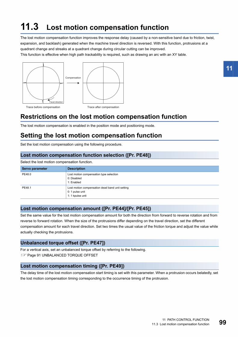
11
11.3 Lost motion compensation functionThe lost motion compensation function improves the response delay (caused by a non-sensitive band due to friction, twist, expansion, and backlash) generated when the machine travel direction is reversed. With this function, protrusions at a quadrant change and streaks at a quadrant change during circular cutting can be improved.This function is effective when high path trackability is required, such as drawing an arc with an XY table.
Restrictions on the lost motion compensation functionThe lost motion compensation is enabled in the position mode and positioning mode.
Setting the lost motion compensation functionSet the lost motion compensation using the following procedure.
Lost motion compensation function selection ([Pr. PE48])Select the lost motion compensation function.
Lost motion compensation amount ([Pr. PE44]/[Pr. PE45])Set the same value for the lost motion compensation amount for both the direction from forward to reverse rotation and from reverse to forward rotation. When the size of the protrusions differ depending on the travel direction, set the different compensation amount for each travel direction. Set two times the usual value of the friction torque and adjust the value while actually checking the protrusions.
Unbalanced torque offset ([Pr. PE47])For a vertical axis, set an unbalanced torque offset by referring to the following.Page 91 UNBALANCED TORQUE OFFSET
Lost motion compensation timing ([Pr. PE49])The delay time of the lost motion compensation start timing is set with this parameter. When a protrusion occurs belatedly, set the lost motion compensation timing corresponding to the occurrence timing of the protrusion.
Servo parameter DescriptionPE48.0 Lost motion compensation type selection
0: Disabled1: Enabled
PE48.1 Lost motion compensation dead band unit setting0: 1 pulse unit1: 1 kpulse unit
Compensation
Travel direction
Trace before compensation Trace after compensation
11 PATH CONTROL FUNCTION11.3 Lost motion compensation function 99
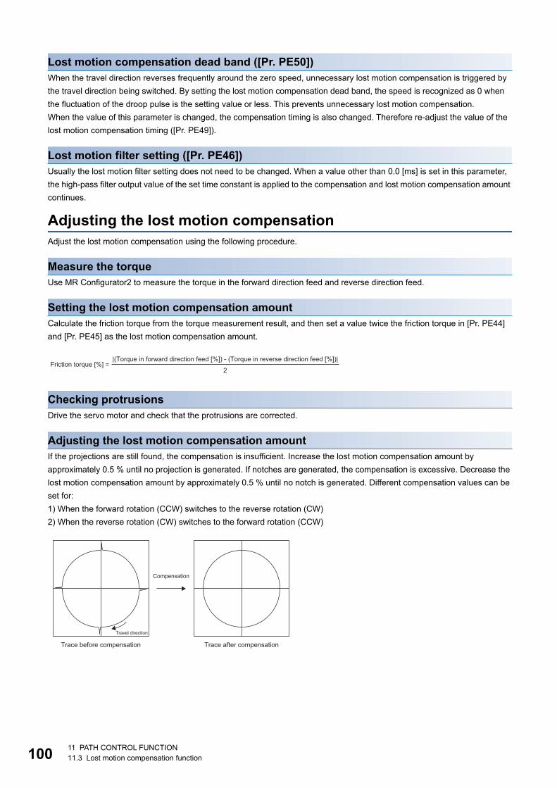
10
Lost motion compensation dead band ([Pr. PE50])When the travel direction reverses frequently around the zero speed, unnecessary lost motion compensation is triggered by the travel direction being switched. By setting the lost motion compensation dead band, the speed is recognized as 0 when the fluctuation of the droop pulse is the setting value or less. This prevents unnecessary lost motion compensation.When the value of this parameter is changed, the compensation timing is also changed. Therefore re-adjust the value of the lost motion compensation timing ([Pr. PE49]).
Lost motion filter setting ([Pr. PE46])Usually the lost motion filter setting does not need to be changed. When a value other than 0.0 [ms] is set in this parameter, the high-pass filter output value of the set time constant is applied to the compensation and lost motion compensation amount continues.
Adjusting the lost motion compensationAdjust the lost motion compensation using the following procedure.
Measure the torqueUse MR Configurator2 to measure the torque in the forward direction feed and reverse direction feed.
Setting the lost motion compensation amountCalculate the friction torque from the torque measurement result, and then set a value twice the friction torque in [Pr. PE44] and [Pr. PE45] as the lost motion compensation amount.
Checking protrusionsDrive the servo motor and check that the protrusions are corrected.
Adjusting the lost motion compensation amountIf the projections are still found, the compensation is insufficient. Increase the lost motion compensation amount by approximately 0.5 % until no projection is generated. If notches are generated, the compensation is excessive. Decrease the lost motion compensation amount by approximately 0.5 % until no notch is generated. Different compensation values can be set for:1) When the forward rotation (CCW) switches to the reverse rotation (CW)2) When the reverse rotation (CW) switches to the forward rotation (CCW)
|(Torque in forward direction feed [%]) - (Torque in reverse direction feed [%])|Friction torque [%] =
2
Compensation
Travel direction
Trace before compensation Trace after compensation
0 11 PATH CONTROL FUNCTION11.3 Lost motion compensation function
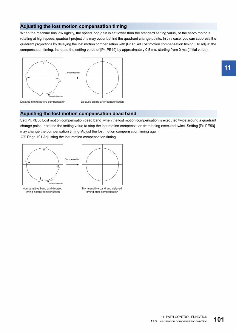
11
Adjusting the lost motion compensation timingWhen the machine has low rigidity, the speed loop gain is set lower than the standard setting value, or the servo motor is rotating at high speed, quadrant projections may occur behind the quadrant change points. In this case, you can suppress the quadrant projections by delaying the lost motion compensation with [Pr. PE49 Lost motion compensation timing]. To adjust the compensation timing, increase the setting value of [Pr. PE49] by approximately 0.5 ms, starting from 0 ms (initial value).
Adjusting the lost motion compensation dead bandSet [Pr. PE50 Lost motion compensation dead band] when the lost motion compensation is executed twice around a quadrant change point. Increase the setting value to stop the lost motion compensation from being executed twice. Setting [Pr. PE50] may change the compensation timing. Adjust the lost motion compensation timing again.Page 101 Adjusting the lost motion compensation timing
Compensation
Travel direction
Delayed timing before compensation Delayed timing after compensation
Compensation
Travel direction
Non-sensitive band and delayed timing before compensation
Non-sensitive band and delayed timing after compensation
11 PATH CONTROL FUNCTION11.3 Lost motion compensation function 101
102
REVISIONS*The manual number is given on the bottom left of the back cover.
2019 MITSUBISHI ELECTRIC CORPORATION
Revision date *Manual number DescriptionNovember 2019 IB(NA)-0300473ENG-A First edition
July 2020 IB(NA)-0300473ENG-B ■The following functions are added:Linear servo motor control mode, continuous operation to torque control mode■Edited sections:Chapter 1, Section 3.1, Section 3.2, Section 3.3, Section 3.7, Section 5.1
March 2021 IB(NA)-0300473ENG-C ■The following function is added:Positioning mode (point table method)■Edited chapter and sections:Section 3.7, Section 4.10, Section 5.1, Section 5.3, Section 5.4, Chapter 6, Section 7.1, Section 8.1, Section 11.2, Section 11.3
This manual confers no industrial property rights or any rights of any other kind, nor does it confer any patent licenses. Mitsubishi Electric Corporation cannot be held responsible for any problems involving industrial property rights which may occur as a result of using the contents noted in this manual.
103
WARRANTYWarranty1. Warranty period and coverage
We will repair any failure or defect hereinafter referred to as "failure" in our FA equipment hereinafter referred to as the "Product" arisen during warranty period at no charge due to causes for which we are responsible through the distributor from which you purchased the Product or our service provider. However, we will charge the actual cost of dispatching our engineer for an on-site repair work on request by customer in Japan or overseas countries. We are not responsible for any on-site readjustment and/or trial run that may be required after a defective unit are repaired or replaced.[Term]For terms of warranty, please contact your original place of purchase.[Limitations](1) You are requested to conduct an initial failure diagnosis by yourself, as a general rule.
It can also be carried out by us or our service company upon your request and the actual cost will be charged. However, it will not be charged if we are responsible for the cause of the failure.
(2) This limited warranty applies only when the condition, method, environment, etc. of use are in compliance with the terms and conditions and instructions that are set forth in the instruction manual and user manual for the Product and the caution label affixed to the Product.
(3) Even during the term of warranty, the repair cost will be charged on you in the following cases;1. a failure caused by your improper storing or handling, carelessness or negligence, etc., and a failure caused by your hardware
or software problem2. a failure caused by any alteration, etc. to the Product made on your side without our approval3. a failure which may be regarded as avoidable, if your equipment in which the Product is incorporated is equipped with a safety
device required by applicable laws and has any function or structure considered to be indispensable according to a common sense in the industry
4. a failure which may be regarded as avoidable if consumable parts designated in the instruction manual, etc. are duly maintained and replaced
5. any replacement of consumable parts (battery, fan, smoothing capacitor, etc.)6. a failure caused by external factors such as inevitable accidents, including without limitation fire and abnormal fluctuation of
voltage, and acts of God, including without limitation earthquake, lightning and natural disasters7. a failure generated by an unforeseeable cause with a scientific technology that was not available at the time of the shipment of
the Product from our company8. any other failures which we are not responsible for or which you acknowledge we are not responsible for
2. Term of warranty after the stop of production(1) We may accept the repair at charge for another seven (7) years after the production of the product is discontinued. The
announcement of the stop of production for each model can be seen in our Sales and Service, etc.(2) Please note that the Product (including its spare parts) cannot be ordered after its stop of production.
3. Service in overseas countriesOur regional FA Center in overseas countries will accept the repair work of the Product. However, the terms and conditions of the repair work may differ depending on each FA Center. Please ask your local FA center for details.
4. Exclusion of loss in opportunity and secondary loss from warranty liabilityRegardless of the gratis warranty term, Mitsubishi shall not be liable for compensation to:(1) Damages caused by any cause found not to be the responsibility of Mitsubishi.(2) Loss in opportunity, lost profits incurred to the user by Failures of Mitsubishi products.(3) Special damages and secondary damages whether foreseeable or not, compensation for accidents, and compensation for
damages to products other than Mitsubishi products.(4) Replacement by the user, maintenance of on-site equipment, start-up test run and other tasks.
5. Change of Product specificationsSpecifications listed in our catalogs, manuals or technical documents may be changed without notice.
6. Application and use of the Product(1) For the use of our AC Servo, its applications should be those that may not result in a serious damage even if any failure or
malfunction occurs in AC Servo, and a backup or fail-safe function should operate on an external system to AC Servo when any failure or malfunction occurs.
(2) Our AC Servo is designed and manufactured as a general purpose product for use at general industries.Therefore, applications substantially influential on the public interest for such as atomic power plants and other power plants of electric power companies, and also which require a special quality assurance system, including applications for railway companies and government or public offices are not recommended, and we assume no responsibility for any failure caused by these applications when used.In addition, applications which may be substantially influential to human lives or properties for such as airlines, medical treatments, railway service, incineration and fuel systems, man-operated material handling equipment, entertainment machines, safety machines, etc. are not recommended, and we assume no responsibility for any failure caused by these applications when used. We will review the acceptability of the abovementioned applications, if you agree not to require a specific quality for a specific application. Please contact us for consultation.

104
TRADEMARKSMELSERVO is a trademark or registered trademark of Mitsubishi Electric Corporation in Japan and/or other countries.All other product names and company names are trademarks or registered trademarks of their respective companies.
IB(NA)-0300473ENG-C


IB(NA)-0300473ENG-C(2103)MEEMODEL:MODEL CODE:
Specifications are subject to change without notice.
When exported from Japan, this manual does not require application to theMinistry of Economy, Trade and Industry for service transaction permission.
HEAD OFFICE : TOKYO BUILDING, 2-7-3 MARUNOUCHI, CHIYODA-KU, TOKYO 100-8310, JAPANNAGOYA WORKS : 1-14 , YADA-MINAMI 5-CHOME , HIGASHI-KU, NAGOYA , JAPAN
Related Documents