SEARCH AND RESCUE ROBOT A Major Qualifying Project Report: submitted to the Faculty of the WORCESTER POLYTECHNIC INSTITUTE in partial fulfillment of the requirements for the Degree of Bachelor of Science by ___________________________________ Kevin Bobrowski ___________________________________ Francisco De Molina Cobo ___________________________________ Christopher D. Korzeniowski Date: April 29, 2007 Approved: ______________________________________ Professor R. James Duckworth, Major Advisor

Welcome message from author
This document is posted to help you gain knowledge. Please leave a comment to let me know what you think about it! Share it to your friends and learn new things together.
Transcript

SEARCH AND RESCUE ROBOT
A Major Qualifying Project Report:
submitted to the Faculty
of the
WORCESTER POLYTECHNIC INSTITUTE
in partial fulfillment of the requirements for the
Degree of Bachelor of Science
by
___________________________________
Kevin Bobrowski
___________________________________
Francisco De Molina Cobo
___________________________________
Christopher D. Korzeniowski
Date: April 29, 2007
Approved:
______________________________________
Professor R. James Duckworth, Major Advisor

Abstract This Major Qualifying Project designed and built a robot prototype of a first response unit for fire emergencies. The robot followed the guidelines and rules of the Trinity College Home Robot Fire Fighting Contest. The robot measured temperatures, distances, and accelerations to find candles and a baby doll that emits a simulated body heat. These operations are performed autonomously.

Acknowledgements This project could not have gotten half as far as it did without the help of several people. First, Professor Duckworth, whose guidance and assistance kept us focused on what was actually important. Next, Brad Miller helped us with general advice on the project. We would also like to thank Bob Boise for his assistance with soldering the complex, tiny surface mount microcontrollers and sensors, and the rest of the Electrical and Computer Engineering staff for all their aid.

Table of Contents Table of Contents................................................................................................................. i Table of Figures .................................................................................................................. ii Table of Tables .................................................................................................................. iv 1. Introduction................................................................................................................. 1 2. Trinity College Fire Fighting Home Robot Competition ........................................... 5 3. Overall Design .......................................................................................................... 10
3.1. Application Requirements ................................................................................ 10 3.2. Design Requirements ........................................................................................ 11
4. Functional Overview................................................................................................. 14 5. Robot Modules.......................................................................................................... 17
5.1. Main Processing Board ..................................................................................... 18 5.1.1. Serial Protocols ......................................................................................... 18 5.1.2. Board Components.................................................................................... 19
5.2. Sensor Systems ................................................................................................. 22 5.2.1. Thermal Array Sensor: The TPA81 Infra Red Sensor.............................. 23 5.2.2. Ultrasonic Rangers: The SRF05 ............................................................... 25 5.2.3. Inertial Navigation System ....................................................................... 28 5.2.4. Sound Activation Module ......................................................................... 31
5.3. Power Distribution............................................................................................ 33 5.4. Mechanical Design............................................................................................ 34
5.4.1. Chassis Design .......................................................................................... 34 5.4.2. Motors ....................................................................................................... 36
5.5. Other Modules .................................................................................................. 37 5.5.1. Extinguisher Module................................................................................. 37 5.5.2. Beacon....................................................................................................... 39
6. Software Development.............................................................................................. 41 6.1. Sensor MSP430................................................................................................. 41 6.2. Master MSP430 ................................................................................................ 45 6.3. Microcontroller Intercommunication................................................................ 50 6.4. PID Usage ......................................................................................................... 52
7. Testing....................................................................................................................... 54 7.1. Simulator........................................................................................................... 54 7.2. Test Arena......................................................................................................... 59
8. Results....................................................................................................................... 62 8.1. Robot Results and Capabilities ......................................................................... 62 8.2. Competition Results.......................................................................................... 64
9. Conclusions and Recommendations ......................................................................... 67 9.1. Processing Unit ................................................................................................. 67 9.2. Sensors .............................................................................................................. 69 9.3. Mechanical System ........................................................................................... 70 9.4. Debug module................................................................................................... 71
10. References............................................................................................................. 72 Appendix A – Main Processor Board Design (PCB)........................................................ 73
i

Table of Figures Figure 1: Floor cleaning robot “Roomba” from iRobot...................................................... 1 Figure 2: Baby Doll ............................................................................................................ 6 Figure 3: An Example First Floor Maze Layout................................................................. 7 Figure 4: First Floor ............................................................................................................ 8 Figure 5: Ramp ................................................................................................................... 8 Figure 6: Overall Maze ....................................................................................................... 9 Figure 7: Functional Block Diagram ................................................................................ 14 Figure 8: Robot Modules: Main Processing Board, Sensors, and Power Modules .......... 17 Figure 9: Robot Modules: Motors and Chassis................................................................. 18 Figure 10: I2C Transmit Protocol ..................................................................................... 19 Figure 11: PCB Layout ..................................................................................................... 22 Figure 12: Main Processing Board ................................................................................... 22 Figure 13: Devantech TPA81 out of the box .................................................................... 23 Figure 14: TPA81 installed in Robot's Chassis ................................................................ 24 Figure 15: SRF05 out of the box....................................................................................... 25 Figure 16: Example Communication between SFR05 and the MSP430.......................... 26 Figure 17: SRF05 mounted on Chassis............................................................................. 26 Figure 18: Ultrasonic Sensor mounted on chassis for testing at an early stage................ 27 Figure 19: INS Computation Flow ................................................................................... 29 Figure 20: INS Transfer .................................................................................................... 30 Figure 21: SPI Request Regularity ................................................................................... 30 Figure 22: Sound Activation module installed on Chassis ............................................... 31 Figure 23: Sound Activation module schematic............................................................... 32 Figure 24: High Power regulation..................................................................................... 33 Figure 25: Low Power regulation 3.3V ............................................................................ 34 Figure 26: Low Power regulation 5V ............................................................................... 34 Figure 27: Chassis and motor configuration at an early stage .......................................... 36 Figure 28: Motor Driver schematic [13]........................................................................... 37 Figure 29: Extinguisher module........................................................................................ 38 Figure 30: Water Pump driver schematic ......................................................................... 39 Figure 31: Beeper.............................................................................................................. 39 Figure 32: Beacon schematic ............................................................................................ 40 Figure 33: Timer Interrupt Procedure ............................................................................... 42 Figure 34: Sensor MSP430 Main Loop ............................................................................ 43 Figure 35: Drive Function Flow ....................................................................................... 47 Figure 36: Serial Cable connected to Debug Port............................................................. 48 Figure 37: Debug Screenshot - Sensor Data ..................................................................... 48 Figure 38: Debug Screenshot - Process ............................................................................ 49 Figure 39: Candle Extinguish Logic ................................................................................. 49 Figure 40: Intercommunication Format ............................................................................ 51 Figure 41: Object Hierarchy ............................................................................................. 55 Figure 42: Main Simulator GUI........................................................................................ 56 Figure 43: Sample Map Data File..................................................................................... 58 Figure 44: Dowel Joining Two Walls............................................................................... 60
ii

Figure 45: Robot in Simple Test Maze ............................................................................. 61 Figure 46: Robot with all modules.................................................................................... 63 Figure 47: A Robot Swarm............................................................................................... 65
iii

Table of Tables Table 1: TPA81 I2C Registers ......................................................................................... 25 Table 2: SFR05 Testing Results ....................................................................................... 27 Table 3: Experimentally Determined Drift Rates ............................................................. 31 Table 4: Eye Hook Heights............................................................................................... 60
iv

1. Introduction Robots are meant to aid people, making a task easier or aiding a person who
wants or needs help. The main use of robots has so far been in the automation of mass
production industries, where the same, definable tasks must be performed repeatedly in
exactly the same fashion. Also, domestic robots are now available that perform simple
tasks such as vacuum cleaning and grass cutting. By the end of 2004 over 1,000,000
vacuum cleaner units had been sold. [1] Figure 1 shows one such robot vacuum cleaner,
the iRobot Roomba.
Figure 1: Floor cleaning robot “Roomba” from iRobot
Recently, there has been interest in sending robots into situations that are too
dangerous to send a person. Some examples of these situations are buildings on fire and
buildings that are partially collapsed after an earthquake. In these situations, it is safer to
send a robot into the building to investigate it, before the rescue team enters. Some other
robots are used in other dangerous situations such as bomb disposal, mining, or cleaning
of toxic waste.
1

In order to control the robot, a tether may be used. The problem with using a
tether is that it can become snagged; the tether may also be heavy or inflexible. For these
reasons, robots could use wireless communication as an alternative. A problem with
wireless communication is that it is not always reliable when attempting to control a
robot from outside a building. For these reasons, robots in these situations need to
operate autonomously. Autonomy is the degree of ability the robot has to make decisions
without external control input but instead use information gathered from onboard sensors.
One situation where an autonomous robot could be a great aid is in fire response.
According to the National Fire Protection Association, nearly five thousand people die
each year because of fires. Children, handicapped people, and the elderly face the most
danger. The first four minutes can mean life or death. [2] Without a quick response, the
fire quickly becomes uncontrollable making the building a very dangerous environment.
The goal of this project was to build a prototype of a first response robot. The
team built a prototype because of the mechanical complexity involved with a full-fledged
first response robot. A first response robot waits until there is an emergency, at which
point it immediately reacts to try to control the situation and assist the rescuers. News of
an emergency can come in many forms, including a sounded alarm. There are many
actions that a robot can perfom to take control of the situation, including identifying
people in danger, or extinguishing flames or other destructive objects. A robot can also
build a map of the dangerous environment and report to an outside authority which areas
are safe for a person to move in.
The team did not enter the competition necessarily to win it, but primarily to
gather good design requirements and test their results. Several competitions for first
2

response fire fighting robots exist. [3] One particular competition is Trinity College Fire
Fighting Home Robot Contest at Trinity College in Hartford, CT. Following the rules of
the competition gave good design parameters and constraints, and provided a solid basis
to begin the project. At the competition, the team was able to compare their robot’s
performance to other robots that had the same requirements.
This project built a fully autonomous robot that navigated a maze that simulated
house, left a marker next to a baby doll that emitted a simulated body heat, and
extinguished a source of flame representing an open fire. The robot stayed in a standby
mode until it recognized a sound signal representing a smoke or fire alarm. In the
simulated house there were candles representing fires and dolls representing babies or
incapacitated people. Light bulbs accompanied the dolls to imitate body heat. The robot
put out the flames in a reasonable time and prepared to leave a beacon next to the baby so
that a human rescuer would know where to go to come to the baby’s aid quickly. This
reduces the risk incurred by rescuers since they know if there is a person and if so where
to find it.
The project had simple design goals. They were to move around, stay idle until it
hears an alarm signal, measure distances to objects, find and extinguish a fire, find and
mark a baby, and keep track of its location in the maze.
In this project, the team built a robot designed to complete the tasks set forth in
the Trinity College Fire Fighting Home Robot Competition. The next section describes
the competition and its rules. This is followed by a description of the application and
design requirements. The section after that provides a broad overview of the modules of
the robot, followed by a section providing very detailed descriptions of the robot. Then
3

the report discusses the software developed for the project. The next two sections
describe the project’s testing equipment and the results of the project. The report’s final
section shares the conclusions of the project.
4

2. Trinity College Fire Fighting Home Robot Competition The team entered the Trinity College Fire Fighting Home Robot Competition to
gather their design requirements and to compare their results to other robots. The annual
competition is a robot competition that takes place at Trinity College in Hartford,
Connecticut. A robot in the Trinity Fire Fighting Home Robot Competition must find a
candle signifying a fire and a marker representing an incapacitated person.[4] The robot
must extinguish the candles and place a beacon next to the baby. The marker
representing a baby has changed form over the years, from a sound source to a heat
source.
Figure 2 shows the current baby used in the competition. The doll is a visual for
humans, but not useful for the robots. The black object is a light bulb painted black in a
socket. This is the heat source that is sensed by competing robots. The reason for a black
light bulb is so the robot must look for an infrared source and not a visible light source.
The former was easier to do.
5

Figure 2: Baby Doll
The competition is open to everyone and has multiple divisions of robot
complexity. In the expert division, there are multiple floors, multiple candles, and the use
of robot swarms is allowed. Another difference from other divisions is the maze is
randomized before each trail. Robots in the swarm can be general purpose or they can
each fulfill a specific purpose, so long as the entire swarm can complete the tasks
required in the expert division. Additionally, there is simulated furniture and clutter
throughout the maze. The furniture can must be avoided and can not be moved around.
The clutter simulates the typical household clutter and possible debris from a damaged
building. Unlike the simulated furniture, the clutter can be moved and driven over.
Figure 3 shows an example maze layout. In the expert division, the maze is
unknown until moments before each round when the maze walls are installed. Due to
this fact, the robot does not know the precise layout of the maze, but it will be similar to
6

Figure 3. In addition, there will be a ramp connecting a robot to a second floor. The
second floor will be 2m by 2m.
Figure 3: An Example First Floor Maze Layout
There are two important types of areas in the maze, a room and a hallway. A
room is defined as an enclosed area of at least two squares by two squares with a
doorway of one square width. Figure 3 shows an example maze with two rooms. The
first room is located in the upper middle and the other room is in the lower left corner.
The robot in the expert division may start in any hall way and in any orientation that the
judge places the robot. Figure 4 shows the first floor of the maze.
7

Figure 4: First Floor
Figure 5: Ramp
In the expert division, the two floors of the maze is connected together by a ramp.
Figure 5 shows this ramp. Figure 6 shows the overall layout of the maze. In this figure,
yellow cylindrical objects can be seen in the rooms. These objects simulate furniture that
is found in the expert division. It cannot be seen clearly in this Figure 6, but there are
also several small items of clutter throughout the maze.
8

Figure 6: Overall Maze
The rules are not complex for the physical attributes of the robot. The robot must
be within 31 cm long by 31 cm wide by 27 cm wide. Any external protrusions count
towards these measurements. There are no restrictions on the materials used or on the
weight of the robot. Any sensor may be used as long as it is deemed safe for use by a
judge; laser-based sensors must be shielded. All robots must be fully autonomous during
their run. The robots allowed to communicate to an external computer for additional
computing power.
The next section discusses the requirements the team developed for the project.
The team based the requirements on the Trinity competition. First the team developed
application requirements and then design requirements.
9

3. Overall Design This section discusses the team’s approach to the design of the fire-fighting robot.
It starts discussing the application requirements of the fire-fighting robot. Then it defines
the design requirements the team developed.
3.1. Application Requirements The team derived the following application requirements based on the rules of the
Trinity Competition:
1. The first and most important is the chassis and mechanical aspect. In order to
complete any of the tasks mentioned before, the robot needed to be capable of
moving around.
2. The robot should be capable of staying in an idle state until an alarm goes off.
This alarm represents a fire or smoke alarm that would indicate the robot that
there is an emergency to be addressed. Prior to the alarm, the robot can gather
data, but cannot actually move.
3. The robot should be able to measure the distances of any object in its
surroundings. Measuring distances is a necessary task in order to navigate the
maze successfully. The robot should be capable of detecting walls and any other
object such as furniture. The distances give the robot a small awareness of the
environment around it.
4. The robot has to be able to locate the different candles in the maze. The candles
represent a real fire. Once the robot has located a fire, it needs to have the
capability to extinguish it. Air-based solutions are inferior because in a real fire,
moving air over a fire will help it to spread.
10

5. The robot needs to be capable of finding and marking the baby. In order to mark
the baby, the robot has to be capable of dropping a beacon in the same room as
the baby is.
6. The robot should keep track of the position in the maze in order to navigate the
maze in a more efficient way. When the robot knows where it is, and where it has
been it can determine if any of the rooms has been search already or not.
3.2. Design Requirements From the application requirements, the team identified technologies and
subsystems that will serve these respective demands:
1. In order for the robot to move around, the robot will have a chassis with two DC
motors, two wheels, and a rear caster to maintain balance.
2. In order to meet the sound activation requirement, the robot will use a module that
has a microphone to detect sounds, and through some signal processing, the
module will determine if the signal falls within the range of frequencies stated in
the rules.
3. The robot will use ultrasonic sensors to measure the distances to the walls and any
other object such as furniture around it. The robot uses these sensors instead of
IR range sensors because in the expert division, there could be pictures, mirrors or
other materials hung on the walls. These objects change the reflectivity of the
wall and may decrease an IR range sensor’s reliability. Three sensors will be
placed in the robot’s frame: one pointing towards the front of the robot, and two
on either side of the robot pointing outwards from the center of the robot. To help
the robot to navigate, it will include a small number of bumpers along the edge of
11

the chassis. The bumpers will help it locate small objects unseen by the
ultrasonic, such as small pieces of clutter. These bumpers will also warn the robot
in case the ultrasonic rangers did not sense a wall or furniture properly.
4. To find the candles as well as the baby, the robot will be equipped with an IR
thermal sensor. The TPA81 is a thermopile array that detects infrared light in the
2um - 22um range, which warm bodies emit. When mounted on a servomotor,
the microcontroller is able to build a thermal image of the frontal 180˚. This
sensor will provide enough information to locate the baby and the candle. Since
the temperature of the baby is not the same as the candle and can be read by the
TPA81, the microcontroller can use it to differentiate beyween the candle and the
baby.
5. The robot will use a pump to spray water over a fire. In order to extinguish the
fire, a water-based extinguisher is a better solution than a fan because of the
penalties in the competition for using these kinds of systems. These penalties
reflect the reality that moving air over a real fire only helps to spread it. The
robot will use a DC powered water pump, such as the ones used in aquariums and
small domestic fountains.
6. Once the robot finds the baby, the robot will drop a beacon to mark the baby’s
position. The beacon will be a small buzzer connected to a timing device to
generate the desired 1 KHz frequency.
7. The robot will include a two-axis accelerometer and a yaw rate sensor. These
two sensors will determine through double integration the position and heading of
the robot within the maze relative to its initial location. The accelerometer and
12

yaw rate sensors are essential to keep track of the robot’s position in order to
navigate the maze in an efficient way.
This chapter outlined the goals and requirements of the fire-fighting robot. The
next chapter will describe the overall functional hardware of the robot. The chapter after
that discusses each module in detail.
13
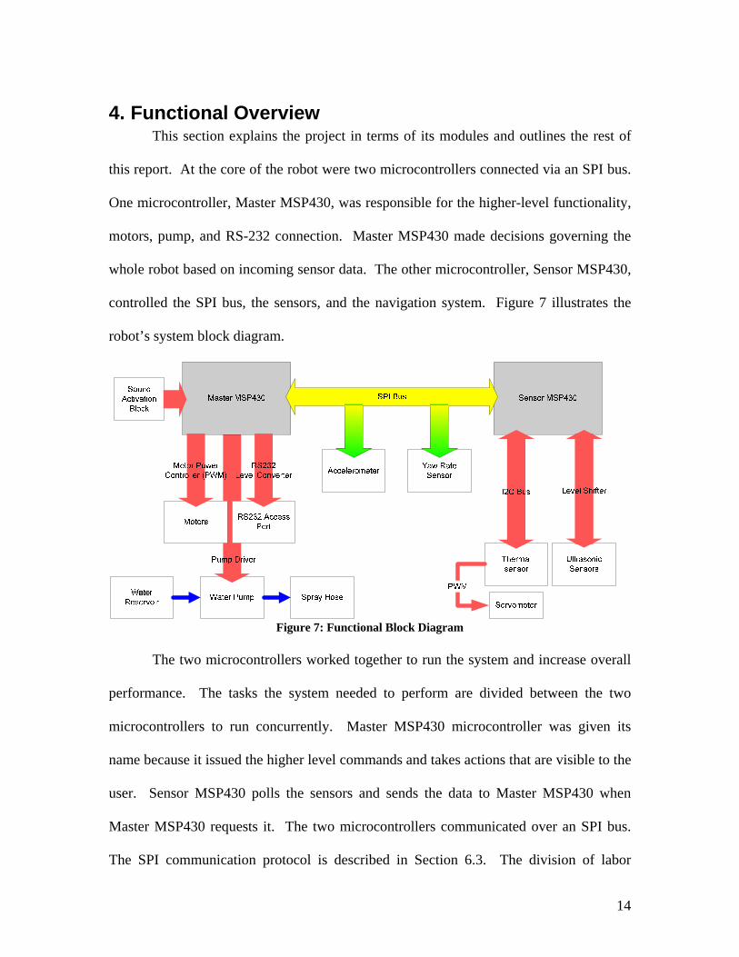
4. Functional Overview This section explains the project in terms of its modules and outlines the rest of
this report. At the core of the robot were two microcontrollers connected via an SPI bus.
One microcontroller, Master MSP430, was responsible for the higher-level functionality,
motors, pump, and RS-232 connection. Master MSP430 made decisions governing the
whole robot based on incoming sensor data. The other microcontroller, Sensor MSP430,
controlled the SPI bus, the sensors, and the navigation system. Figure 7 illustrates the
robot’s system block diagram.
Figure 7: Functional Block Diagram
The two microcontrollers worked together to run the system and increase overall
performance. The tasks the system needed to perform are divided between the two
microcontrollers to run concurrently. Master MSP430 microcontroller was given its
name because it issued the higher level commands and takes actions that are visible to the
user. Sensor MSP430 polls the sensors and sends the data to Master MSP430 when
Master MSP430 requests it. The two microcontrollers communicated over an SPI bus.
The SPI communication protocol is described in Section 6.3. The division of labor
14

between the microcontrollers meant that the sequential command logic of Master
MSP430 was not mixed with Sensor MSP430’s regular polling of sensors. Chapter 6
describes the microcontrollers’ code.
Sensor MSP430 also used the SPI bus to read data from the accelerometer and
yaw rate sensor. It used an I2C bus to read data from the thermal sensor. Sensor
MSP430 also used two pins to connect to each ultrasonic sensor. One pin acted as a
trigger to the sensor and the sensor used the other pin to send a response back. The
sensors were polled continuously while Sensor MSP430 operated.
The accelerometer and yaw rate sensors were used to form the basis of the Inertial
Navigation System. When polled, the two sensors returned the current acceleration and
rate of turn, or yaw rate, acting upon them. The sensor microcontroller performed the
necessary integration to determine the position of the robot relative to where it was
initially powered on. The Inertial Navigation System is further explained in Section
5.2.3.
Master MSP430 made decisions based on the sensor data. This microcontroller
gave the robot autonomy. Once it gathered sensor data, it issued commands to the motor
control circuit that controlled the motors. Master MSP430’s code is explained in Section
6.2 and the motors are explained in Section 0.
The Master MSP430 microcontroller sent RS232 logic signals through the RS232
logic converter, which then sent the signals to a computer for debugging purposes. The
connection provided a window into the “brain” of the robot, allowing the debugger to see
what the sensors were reporting and how Master MSP430 wanted to react to those
stimuli.
15

Finally, the extinguisher unit moved water from the reservoir to the spray nozzle.
The type of pump chosen for the project is normally found inside a car pumping
windshield washer fluid. This type of pump was chosen for its low price and its simple
interface. The pump was turned on or off by the driving circuit. The pump is explained
in Section 5.5.1.
Finally, the system power unit is not shown on the block diagram but it was
connected to every component on the system. The unit is described in Section 5.3. The
unit converts power supplied by a battery into the various levels needed by each unit of
the robot, which usually require 5V or 3.3V. The power unit used efficient switching
regulators where possible, but had less efficient linear regulators for systems that
demanded large amounts of current, such as the servomotors.
This chapter gave an overview of the robot’s modules. The next chapter will
detail the operation of these modules.
16

5. Robot Modules This section describes the modules that comprised the robot. The robot was built
in modules to make the task manageable. This chapter describes the modules in order of
their importance to the project. The Main Processing Unit was the control center of the
robot and all other sensors relied on it. Next, the Sensor systems allowed the Main
Processing to make proper decisions. The Power Distribution module supplied power to
all components of the robot. Finally, the Mechanical Design systems, while important to
the robot, were not a large focus of the project because the project focused upon the
electrical engineering aspects of the robot. This section concludes with the actuators of
the project, the extinguisher and beeper modules. Figure 8 shows the electrical modules
of the robot separated apart. Figure 9 shows the mechanical modules of the robot.
Figure 8: Robot Modules: Main Processing Board, Sensors, and Power Modules
17

Figure 9: Robot Modules: Motors and Chassis
5.1. Main Processing Board The main processing board was the heart of the robot. The board binds together
the sensors and processors into one location and makes the robot neater. The team
designed and built the board specifically for this project. Most of the communication on
the board was in the form of two intercommunication protocols, I2C and SPI.
5.1.1. Serial Protocols I2C is a multi-master serial synchronous computer bus protocol invented by
Philips that is used in to connect some sensors into the main processing unit. The
protocol’s name stands for Inter-Integrated Circuit. The I2C protocol has four main
operations: start a transfer, stop a transfer, receive a byte, and send a byte, as seen in
Figure 10. [5] The I2C bus is held high through pull-up resistors when idle. When in use,
devices drive the lines to a logic low or let the pull-up resistors keep the line high. All
communications start with the start operation and end with the stop operation. Addresses
are made of a seven-bit device identifier and one bit that indicates whether a read or write
to the device is being performed.
18
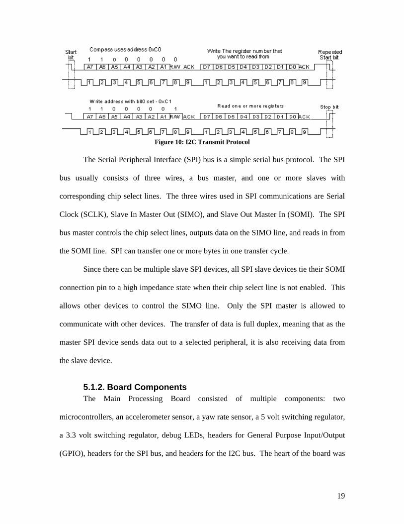
Figure 10: I2C Transmit Protocol
The Serial Peripheral Interface (SPI) bus is a simple serial bus protocol. The SPI
bus usually consists of three wires, a bus master, and one or more slaves with
corresponding chip select lines. The three wires used in SPI communications are Serial
Clock (SCLK), Slave In Master Out (SIMO), and Slave Out Master In (SOMI). The SPI
bus master controls the chip select lines, outputs data on the SIMO line, and reads in from
the SOMI line. SPI can transfer one or more bytes in one transfer cycle.
Since there can be multiple slave SPI devices, all SPI slave devices tie their SOMI
connection pin to a high impedance state when their chip select line is not enabled. This
allows other devices to control the SIMO line. Only the SPI master is allowed to
communicate with other devices. The transfer of data is full duplex, meaning that as the
master SPI device sends data out to a selected peripheral, it is also receiving data from
the slave device.
5.1.2. Board Components The Main Processing Board consisted of multiple components: two
microcontrollers, an accelerometer sensor, a yaw rate sensor, a 5 volt switching regulator,
a 3.3 volt switching regulator, debug LEDs, headers for General Purpose Input/Output
(GPIO), headers for the SPI bus, and headers for the I2C bus. The heart of the board was
19

the two microcontrollers, or more specifically two MSP430F1612s. These two
microcontrollers directed all operations of the robot and formed the main processing unit.
As previously noted in Chapter 4, one of the microcontrollers was named Sensor
MSP430. The other microcontroller was named Master MSP430. The purpose of Sensor
MSP430 was to handle intense computational tasks, specifically calculations related to
the INS, as well as regularly poll the sensors. Sensor MSP430 had little intelligence
otherwise; it returns the status of the sensors to Master MSP430 when asked to do so.
Master MSP430 controlled the motors, pump, debug port, and the higher level processing
of the robot.
The SPI bus was highly important to the operation of the robot. Sensor MSP430
was the master of on the SPI bus, since it needed to communicate with the accelerometer
sensor and yaw rate sensor. Master MSP430 was a slave on the SPI bus. There were
headers on the MISO, MOSI, and SCLK wires lines of the bus to allow for future
expansion and debugging purposes. There were also two other lines running between
Sensor MSP430 and Master MSP430. These lines were the request line and the
acknowledge line. These lines were used to assist in the intercommunication between the
two MSP430s. The request line was used by Master MSP430 to indicate it wanted to
perform an SPI transfer; since it is a bus slave, it cannot initiate the bus transfer itself.
The I2C header was connected to Sensor MSP430, but also had pull-up resistors.
This was an important for correct operation of the I2C bus. Sensor MSP430 also had
specific headers to assist in connecting the ultrasonic sensors to the board. These special
headers included a pinging line, return echo line, 5 volt line, and a ground line. The
ultrasonic sensors ran at 5 volts and raised the return echo line to 5 volts during
20

operation. This voltage level has the potential to damage Sensor MSP430 if it is directly
applied, but a voltage divider is used bring the 5 volts to approximately 3.3 volts. There
were four debug LEDs connected to each of the MSP430s. This allowed simple
diagnostics and helped to determine which state the robot was in and to give an idea
where the robot was in the code.
There was also a 3.3 volt and a 5 volt switching regulator. These provide
regulated power to the low power consumption devices. The particular chip used on the
board was the ADP1111 from Analog Devices. [6] These were simple chips to use, since
they required only a few external components, minimal routing constraints, and came in
an 8-DIP package.
The main processing board is a 4-layer PCB from ExpressPCB. Originally, the
PCB was being designed as a 2-layer board. Professor Duckworth recommended that a
4-layer board be made. The 4-layer board has a ground plane and has a power plane at
3.3 volts. The two outer surfaces have all the signal traces, and several power traces for
the ultrasonic sensors and the switching regulators. The team used ExpressPCB to
manufacture the PCB based on the ease of their software, cost, and time to make the
PCB. Figure 11 shows the layout of the PCB in ExpressPCB with top, bottom, and silk
screen layers. Figure 12 shows the populated PCB.
21

Figure 11: PCB Layout
Figure 12: Main Processing Board
5.2. Sensor Systems The sensors of the robot were very important for its operation. Without many of
these sensors, the robot would not be able to complete needed tasks. The sensors on the
22

robot included a thermal array sensor, accelerometer, yaw rate, microphone, and
ultrasonic sensors.
5.2.1. Thermal Array Sensor: The TPA81 Infra Red Sensor The TPA81 is a thermopile array detecting infrared light in the 2um-22um range.
This is the wavelength of radiant heat. A thermopile array sensor is used in non-contact
infrared thermometers. Although these types of sensors have a very wide field of view,
the TPA81 has a lens to obtain a narrower, more useful field of view of 6° per
thermopile. The TPA81 has an array of eight thermopiles arranged in a column and
therefore can measure the temperature of eight adjacent points simultaneously. The
TPA81 can also control a servo to pan the module and build up a two-dimensional
thermal image.
Figure 13: Devantech TPA81 out of the box
The robot used the TPA81 to sense the temperature of its surroundings to locate
both flames and the baby. The main processing unit, using the sensor, read temperatures
with accuracy depending on the object’s distance and the ambient temperature. The main
processing unit then decided whether the temperature source was a person or a flame
23

based on the temperature reading. The sensor’s servo was used to gather readings from a
full frontal 180-degree radius.
Figure 14: TPA81 installed in Robot's Chassis
The TPA81 was controlled through commands over the I2C bus. Only registers
zero and one can be written to. Register zero was the command register; it was used to
set the servo position and change the TPA81's I2C address. Reading from register zero
returned the TPA81 software revision. Writing to register one set the servo range, but
this function was not used in this project. Reading from register one returned the ambient
temperature. There were nine temperature readings available, all in degrees Celsius (°C).
Register one was the ambient temperature as measured within the sensor. Registers two
through nine were the eight pixel temperatures.
24

Table 1: TPA81 I2C Registers [6]
Register Read Write 0 Software
Revision Command Register
1 Ambient Temperature
°C
Servo Range (V6 or higher only)
2 Pixel 1 Temperature
°C
N/A
3 Pixel 2 N/A 4 Pixel 3 N/A 5 Pixel 4 N/A 6 Pixel 5 N/A 7 Pixel 6 N/A 8 Pixel 7 N/A 9 Pixel 8 N/A
5.2.2. Ultrasonic Rangers: The SRF05 Ultrasonic Rangers are sensors that determine distance through sound pulses.
These sensors were used to determine the distance between the robot and walls or other
relatively big obstacles such as furniture. The sensors worked by transmitting a pulse,
called a ping, which reflects back to the sensor from any object in the path of the
ultrasonic wave. The processing unit estimated the distance between the sensor and the
object by measuring the time between when the ping is sent out and when the echo is
heard. Figure 15 shows the ultrasonic ranger used on the robot.
Figure 15: SRF05 out of the box
The sensors communicated with the main processing unit through a simple two-
line interface. As shown in Figure 16, the main processing unit holds a trigger line high
for a small period of time (at least 10µs). The trigger tells the SFR05 to start the
25

operation. Once the sensor acknowledges operation, it sends a sound ping and pulls the
“echo” line up. This line remains high until the echo comes back. The job of the main
processing unit was to time the duration the echo line is high. The distance to the closest
object is directly proportional to this time. Section 6.1 explains the code used to control
this sensor.
Trigger:
Echo:
Figure 16: Example Communication between SFR05 and the MSP430
Figure 17: SRF05 mounted on Chassis
26

Table 2 shows the results of testing the sensor. The sensor was tested by
measuring controlled distances to a wall perpendicular to the sensor. Table 2 also shows
that the error in reading decreases as the distance to the object and Figure 18 shows the
test environment
Table 2: SFR05 Testing Results
Real Distance Measured Distance Error
1 cm 1.75 cm 43%
2 cm 2.49 cm 20%
3 cm 3.49 cm 15%
4 cm 4.18 cm 5%
5 cm 5.22 cm 3%
10 cm 10.13 cm 1.5%
20 cm 19.61 cm 1.9%
30 cm 30.6 cm 2%
40 cm 40.8 cm 1.9%
50 cm 50.82 cm 1.6%
Figure 18: Ultrasonic Sensor mounted on chassis for testing at an early stage
27

5.2.3. Inertial Navigation System The Inertial Navigation System (INS) was comprised of a +/-5 g dual axis
accelerometer and a 300 degree/sec yaw rate sensor from Analog Devices. The part
numbers are ADIS16006 and ADIS16100, respectively. [8][9] Both of these sensors are
Micro-Electro-Mechanical Systems (MEMS) devices. They require 16-bit SPI bus
transfers. The MSP430 only worked with 8-bit transfers. After reading an application
note [10], the team found that the clock line should default to high. Leaving the clock
line high results in an extended clock high period for a part of a clock cycle, but since the
SPI communications was edge sensitive the devices operated normally.
The accelerometer and yaw rate sensor returned digital samples of the X and Y
accelerations, and the rate of turn. The main processing unit took readings at regular
intervals. The information received was not immediately useful and needed to be
processed.
The first step towards processing the data was the removal of the bias. The
specification sheets for both of the sensors specified that the output from the sensors will
be biased. This bias varies from run to run and must be found each run since the results
of the calculations would quickly become inaccurate if the typical bias was used from the
datasheet. The next step was the filtering of the output of these sensors to remove noise.
A simple moving average of the current and three previous samples was chosen to reduce
the computational load on Sensor MSP430. Other filtering techniques were considered
such as a Finite Impulse Response (FIR) filter and the Kalman filter. The team did not
implement a Kalman filter because of its complexity and computational load. Since the
noise in the signal appears to be not associated in any frequency band, an FIR filter
28

would most likely not produce meaningful benefits or justify the additional
computational load.
In order to find the heading, the output from the yaw rate sensor was integrated.
The accelerations were also integrated to yield the X and Y velocities. The X and Y axes
were oriented to the robot. Since the robot would be turning and moving around, it
needed to rotate the axes so they were oriented to the maze. The orientation was
performed using the velocities, the heading, and trigonometry to rotate the axes. After
this orientation is completed, the new velocities can be integrated to determine the
position. The integration was done by summing the current value multiplied by a
constant and a time factor with all of the previous values. This can lead to significant
errors over time. The sensors and integration results were planned to be frequently reset
to reduce the error. Figure 19 shows the overall flow of the computations.
Figure 19: INS Computation Flow
Figure 20 illustrates sampling of one of the axes on the accelerometer followed by
the sampling of the yaw rate sensor and then followed by the sampling of another axis of
the accelerometer. This figure shows the SCLK, SOMI, and SIMO lines. Additionally
this figure also illustrates the chip select lines that correspond to the chip select on the
29

yaw rate and accelerometer sensors. Figure 21 illustrates that the accelerometer and yaw
rate sensors are being sampled at 100 Hz, or every 10ms.
Figure 20: INS Transfer
Figure 21: SPI Request Regularity
Testing the INS system was initially done with slow floating-point math. The
yaw rate sensor was tested to see its drift rate. All four trials were performed
consecutively, one after the other. Table 3 illustrates the testing results. The most
important result was that the degree error decreases the more time the sensor has
operated. When the INS system was converted to use fixed-point math, the error
increased because the fixed-point numbers were less accurate. The reason for this
decrease in accuracy is that there were less bits being used for the decimal portion.
However, the drift rate still decreases as the sensor is kept powered on.
30

Table 3: Experimentally Determined Drift Rates
Degrees Error Time
(sec) Trial One Trial Two
Trial Three
Trial Four Average
0 0 0 0 0 0 30 2 2 1 1 1.5 60 5 5 2 3 3.75 90 8 7 3 5 5.75
120 12 10 4 6 8 150 15 13 5 7 10 180 19 15 7 8 12.25 210 22 19 9 9 14.75 240 26 21 11 12 17.5 270 29 24 13 14 20 300 32 26 16 17 22.75
5.2.4. Sound Activation Module One of the design requirements was that the robot activates only in the event the
fire or smoke alarms go off. These alarm systems usually beep at frequencies between
3.0 KHz and 4.0 KHz. Once the robot was powered on, the sound activation module is
responsible for determining if there was a fire emergency or not. Figure 22 shows the
Sound Activation module, while Figure 23 shows the unit schematic.
Figure 22: Sound Activation module installed on Chassis
31

Figure 23: Sound Activation module schematic
The module was made out of two main components: the microphone amplifying
circuit and the tone detector. The microphone amplifying circuit was responsible for
amplifying the signal coming from the microphone to a level usable by the tone detector
component. To perform this task a LM386 low voltage audio amplifier was used.
The tone detector component, an LM567, outputs a logic level based on whether a
frequency was present in an incoming analog signal. The tone detector was set up to
have its mid-band frequency at 3.5 KHz and a bandwidth of approximately 15%, which
means that the tone detector would detect the presence of a frequency between
approximately 3 KHz and 4 KHz. To make the system more robust, the signal that comes
out of the LM567 is fed into the microcontroller to perform additional processing. This
additional filtering is necessary due to some false triggering around the desired frequency
detection ranges.
The team wrote a MATLAB function to assist with the testing of the sound
activation module. The function receives as input a frequency in Hz, duration, and
sampling rate. The output of the function is a vector that was used with the sound
function. The vector was also used with MATLAB’s wavwrite function to be written to a
WAV file, so that it could be shared amongst the team.
32

5.3. Power Distribution The robot had a 9.6 Volts NMIH battery as power source. This battery was
selected for its large capacity of 1600 mAh and its reduced price even though its charge
time of eight hours is slow compared to other batteries. The battery was fine for this
project because it was charged overnight. The reduction in price made the tradeoff very
worthwhile. The voltage coming out of the battery was converted to 5V and to 3.3V for
the different modules.
The power stage was divided in high power and low power. The regulation in the
high power module was performed by a LM7805 linear regulator. This device was
selected because of its large output current capabilities. The high power stage powers all
the modules that required a large current, such as the servomotor. The low power stage
was divided in two different voltage references, 3.3V to power the processing unit, the
accelerometers, and a portion of the yaw rate sensor and 5V that powers the ultrasonic
sensors and the yaw rate sensor. In both low power lines, the voltage was converted with
switching regulators. These switching regulators were more efficient than the linear
ones, but they could not supply as much current. Figure 24, Figure 25, and Figure 26
below show the schematics of both the high and low power stages.
Figure 24: High Power regulation
33

Figure 25: Low Power regulation 3.3V
Figure 26: Low Power regulation 5V
5.4. Mechanical Design This section discusses the mechanical aspects of the project. It describes the
chassis in detail. Then it discusses the motors and their PWM control. The team wanted
to keep the mechanical design simple because of their lack of training in this area.
5.4.1. Chassis Design The team developed the chassis with simple goals in mind. They wanted to
prevent the robot from becoming stuck while turning. They also used a cheap, easy to
use material to make the chassis creation as easy as possible. The chassis was divided
into multiple tiers to separate the components and arrange them better.
The chassis was circular shaped at the front and at the back of the robots to
prevent the robot from becoming stuck while turning. The chassis was primarily made
34

out of Lexan. Lexan was selected to be the main chassis material because of its low
price, lightweight, and ease of use. This made Lexan an ideal choice to use since it could
be cut, shaped, and drilled with a band saw and Dremel. One of the advantages of Lexan
is that it does not melt easily while working it like Plexiglas or other plastics do.
Although this material is sold in square shaped panels, it was easily cut to give it a round
shape. This task would have been incredibly more complicated if the team were using
aluminum or any other metal because those materials are harder to cut and join to form a
chassis.
The chassis’s levels were sized so that all the sensors and modules would fit
comfortably. Two of the levels are 30cm by 24cm, while the third level is approximately
10cm by 20cm. Aluminum standoffs attached the three stories together. The first story
held all of the power electronics including the motor driver, pump driver, high power
regulator, and the battery. The underside of this level is where the drive system attached
to the robot. Figure 27 shows the underside of the robot in an early stage The second
story holds the main PCB with the main processing unit, the water tank, as well as all the
sensors. The third story holds the water pump and the debug port.
35

Figure 27: Chassis and motor configuration at an early stage
5.4.2. Motors An important aspect of this design was to select the motors used in the robot. The
robot used a two motor drive system with a rear caster. The motors had internal gearing
and were manufactured and distributed by Lynxmotion. The internal gearboxes
simplified the mechanical design of the robot since the wheels could be directly driven.
The other advantage was that the manufacturer also made wheels, hubs and other needed
materials that were 100% compatible with their motors. The robot used two of these 12V
DC motors, with a 43:1 ratio and an output of 290RPM. [8] The selected wheels were
2.13” diameter neoprene wheels and connected directly to the motor as stated earlier.
This combination wheel-motor lets the robot move at a maximum speed of approximately
80 cm/second, which is more than enough for a robot of this size.
The motor driver that was used to power the motors takes a PWM signal as an
input to drive an internal H-bridge connecting to the leads of the motor. An H-bridge is
36

an arrangement of four transistors that are able to control the direction and speed of the
the motor with appropriate control signals. This circuit is able to drive the two motors at
up to 24 volts and 2 amps per channel. This is more power than needed, but allowed
flexibility in the choice of motors. The team also thought that some extra power would
be good just in case they used a larger motor in the future. The circuit was built around a
L298N, which is a dual full bridge driver. [12] Figure 28 illustrates the driver schematic.
Figure 28: Motor Driver schematic [13]
5.5. Other Modules The robot used other modules to accomplish the firefighting mission. The
extinguisher module sprayed water to put out any candle the robot found. The beeper
could be placed next to the baby and emits an audible tone.
5.5.1. Extinguisher Module This device extinguished candles the robot found in the maze. A water-based
extinguisher was better than blowing air because air, in a full scale environment, would
increase the intensity of the fire. The module uses a DC powered water pump, such as
37

the ones used in a car for windshield wipers. The pump will drive the water through a
hose creating a controlled water stream. Figure 29 shows a picture of the module.
Figure 29: Extinguisher module
The control of the pump required a power MOSFET. This N-channel MOSFET
turns on and off the pump. It was ideal to turn this transistor on by pulling the gate to the
battery voltage. The MSP430 was unable to do this since it can only source 3.3 volts. To
solve this problem, an NPN BJT was used with a resistor to pull the gate of the power
MOSFET high or low. The main processing unit drove the base of the BJT high to
ensure the BJT was on. This resulted in the gate of the MOSFET being pulled low. The
pump was turned on by outputting a zero to the BJT. This resulted in the BJT turning off
and the gate of the MOSFET being pulled high by the resistor, and thus the pump is now
on. A pull-up resistor was needed to ensure the pump was off when the robot started up.
Figure 30 shows the pump’s control schematic.
38

Figure 30: Water Pump driver schematic
5.5.2. Beacon In the event of a fire emergency, there is a chance someone could be
incapacitated, or maybe there is a frightened, hiding child. One of the design
requirements of the project was to locate a baby doll and to mark it with a beacon, so the
rescue teams could find it easily. A picture of the beacon is shown below in Figure 31.
Figure 31: Beeper
Once the robot found the baby, it dropped the beacon and it beeped with a
frequency of 1 KHz for as long as the battery could supply power or until the beeper was
deactivated. The robot prepared to dropped this beacon next to a doll it has found.
39

The beacon was a simple device. It had a small Microchip PIC12F508 that
waited until the main processor told it to start beeping. The PIC controlled the frequency
of the signal, when the beeping begins, as well as the duration of each beep. Figure 32
shows the corresponding schematic of the beacon.
Figure 32: Beacon schematic
This chapter gave a detail overview of the hardware modules of the fire-fighting
robot. The next chapter will detail the software that tied these modules together in detail.
It explains how the main processing unit controlled the modules described in this section.
40

6. Software Development The software of the robot was one of the most important portions of the project.
It controlled every aspect of the robot. The programs for the Sensor and Master
MSP430s are unique to each other, but are structured similarly and have similar startup
sequences. The Sensor MSP430’s program had minimal intelligence, polling the sensors
and performing some processing. The Master MSP430 used this data to make the system
decisions.
6.1. Sensor MSP430 Sensor MSP430 was responsible for gathering sensor data and providing it to
Master MSP430 when asked. It also processed some of the sensor data before sending it
to the other microcontroller to get meaningful results, such as the heading or maximum
temperature sensed.
The central part of Sensor MSP430’s program was the generation of interrupts
from the MSP430’s Timer A. [14] Timer A generated 100 interrupts every second. The
interrupt signaled the program to sample the accelerometer and yaw rate sensors. The
interrupt response also decremented variables that controlled the sampling of the
ultrasonic sensors and the sweeping and sampling of the TPA81 sensor. Figure 33 shows
the overall flow of operation in the Timer A interrupt.
41

Figure 33: Timer Interrupt Procedure
Most computations for the sensors were done in the main loop. This ensured that
the handling of the Timer A interrupt was fast and can service other interrupts. There
were two variables used to trigger the sampling of the ultrasonic sensors and sampling of
the TPA sensor. The operation of these variables was the same. Whenever an interrupt
occurred, the count variable was decremented. The main loop polled this count variable
to see if it was zero. When it was zero, the program executed code to either send a pulse
to an ultrasonic sensor or execute code for the TPA sensor. When executing code for the
TPA sensor, the first step was to read a column of pixels. The next step was to tell the
servo to move to the next position that was to be read on the next read operation. Figure
34 shows the flow of the main loop in Sensor MSP430.
42

Ultra_sample zero?
Sample_IR zero?
New INS samples?
No Yes
No Yes
No Yes
Sample an Ultrasonic sensor
Sample TPA sensor
Perform INS calculations
Figure 34: Sensor MSP430 Main Loop
After the MSP430 had been started up, the first step was to find the bias of each
of the accelerometer axes and the yaw rate sensor. This was done by waiting for a second
and then finding the average value of output from the accelerometer and yaw rate sensors
when the robot was not moving. This value was important for all other calculations.
After this, the program entered the main loop. When an interrupt occurred, the MSP430
sampled the accelerometer and the yaw rate sensor and set a variable to let the
computational portion, which was in the main loop, know that there was new data to
process.
The first step in the computational portion was to remove the bias from the
output. The removal resulted in a number biased around zero. The next step was
calculating a moving average of four samples. Four samples were chosen because a
simple shift right could be used instead of division; the MSP430 does not have a
43

hardware divider. The next step was to perform the first round of integrations to find the
velocities and the heading. The next step was to combine the velocities and heading to
find the position. This step requires the use of sine and cosine. The library
implementations of those functions used floating-point numbers. However, fixed-point
math operations were faster, so custom implementation was used. The sine and cosine
functions were implemented by using a custom function that used a small section lookup
table from 0 to 90 degrees. Using a lookup table only from 0 to 90 degrees provided
more precision while using a smaller table. After this was done, the results were
integrated to find the position.
The code related for the ultrasonic sensor was relatively simple. When it was
time to send a pulse to an ultrasonic sensor, a switch statement was used to decide which
ultrasonic sensor to trigger. The center ultrasonic sensor was chosen twice as often as the
other two ultrasonic sensors. The code in the main loop concerning the ultrasonic sensors
only pings them. The return echo line was connected to an interrupt line. The Sensor
MSP430 received an interrupt on the rising and falling edge of the return echo pulse. The
MSP430 used Timer B to time the length of this pulse. The duration of this pulse was
directly proportional to the distance between the object reflecting the ultrasonic wave and
the ultrasonic sensor. This time duration was divided by a constant to yield the distance
in centimeters.
The sampling process for the TPA sensor was slightly more complicated. There
were two steps to this process; the first step was to read the pixels and the next step was
to tell the servo what the next position is. A time delay was used to ensure the servo was
at the next position before pixels were read and the cycle repeats. The reason for the
44

delay was that Sensor MSP430 did not know when the servo had reached its destination.
There were 32 positions the servo can be in.
When the pixels were being read, each pixel in a column was being read one at a
time. The maximum temperature of the column was then found. This temperature was
compared to the previous maximum temperature for all previous columns. In addition, a
time out variable was needed to ensure that the maximum temperature was not outdated.
This timeout variable was necessary since the robot was operating continuously. This
timeout variable forced a reset of the maximum temperature when the count reaches zero.
The ambient temperature was also read. This value was used to determine if the
maximum temperature was truly a hotspot that needs to be investigated or if it was
simply a warm spot on the wall or other object, as determined by the difference between
the spot’s temperature and the ambient temperature. A hotspot was a reading that
exceeds the ambient temperature by a constant threshold.
6.2. Master MSP430 Master MSP430 controlled all of the higher level functions, but still performed a
few low level functions. The MSP430’s Timer A was also important in the Master
microcontroller’s operation. Timer A generated interrupts at a rate of 93 Hz that signal
Master MSP430 to update variables from Sensor MSP430 without creating an
unnecessary amount of SPI bus traffic. Constant polling of Sensor MSP430 would have
also kept it from performing its needed tasks. Since the heading was being updated one
hundred times a second, the heading could be updated in Master MSP430 every interrupt
signal from Timer A. Other variables such as temperature and ultrasonic sensor readings
were updated at a rate of 19 Hz on Master MSP430.
45

One of the low-level functions that Master MSP430 performed was driving the
motors. This used the MSP430’s Timer B. There was one function to perform all driving
functions. The timer was configured to count continuously from zero to three hundred
and back down repeatedly. Four registers stored a value to compare with the counter.
When the count was greater than what was in the register, the output on a pin was high;
otherwise, the output pin was low.
In order to drive a single motor, two pins were required for full PWM control.
The input to the drive function was the relative velocity forward and the relative turning
speed, much like a joystick. The first step was to mix the two values to find the speed of
each of the motors. The next step was to ensure that these values do not exceed a defined
amount. Since the motors were being underpowered, there was a large dead zone, which
was approximately two-thirds of the range. For this reason, the function corrects for the
dead zone. This correction was done by adding a constant if the value was positive or
subtracting the same value if the value of the motor speed was negative. This correction
eliminated the concern of what minimum value to feed to the drive function to have the
robot move.
The next step to drive the motors was to load the four registers with the correct
values. In order for a motor to move forward, one register needed to be loaded with zero
and the other with the calculated value. In order to move in reverse, the first register
needed to be loaded with the absolute value of the calculated value and the other register
with zero. This operation was needed to fulfill requirements in the datasheet for the
motor controller. [12] Figure 35 shows the four basic steps in the drive function.
46

Figure 35: Drive Function Flow
Another important feature on Master MSP430 was that one of the on-chip UART
units was configured to send and receive data over RS232 cables to a computer. Two
simple functions send and receive data. The implementation did not include the usage of
interrupts. A future implementation would benefit from using an interrupt driven design,
since RS232 communication is slow. The send and receive functions can be used stand-
alone for most anything, but were intended for use with the debug functions.
The there were two high level functions intended for use by the user. The team
developed these functions for debugging purposes. The first function was a simple
function to send a variable to a computer using HyperTerminal and another, more
complex, function mimics <printf()> called <printw()>.
Both of these functions used the same procedure to send data through RS232.
These functions also shared a procedure to convert a fixed-point number to an ASCII
representation. An important feature was that this converter procedure handles fixed-
point numbers. Fixed-point numbers were used in many places in both Master MSP430
and Sensor MSP430. Using appropriate inputs, the procedure could convert any number
represented by an integer type in the program into a human readable format. The simple
variable printing function simple sent the converted number, a newline character, and a
carriage return character.
47

The <printw()> function was a variable argument function developed by the team
for this project. The function imitates the <printf()> function in the C Standard Library.
It sends the output out over RS232. Figure 36 shows a serial cable connected to the robot
for debugging purposes. Figure 37 shows a HyperTerminal screenshot of the robot
outputting the sensor data, and Figure 38, on the following page, shows a screenshot of
the robot outputting its status and relevant sensor data during the different steps taken
when finding a hot spot.
Figure 36: Serial Cable connected to Debug Port
Figure 37: Debug Screenshot - Sensor Data
48

Figure 38: Debug Screenshot - Process
Finding a candle from a stand still was a relatively easy task to accomplish,
particularly once the PID loop for turning a relative amount of degrees was tuned. Figure
39 shows the overall flow of code for finding the hotspot and performing needed
reactions.
Figure 39: Candle Extinguish Logic
The first step was to allow the TPA sensor to sweep and find hot temperatures.
Once the robot had determined that there was a hotspot, the robot turned towards the
49

hotspot and moved forward until it was twenty centimeters away from an object detected
by the ultrasonic ranger. The speed of the robot was proportional to the distance the
robot has to travel to be twenty centimeters away from the object. This allowed for
smoother driving.
Once the hotspot was reacquired, the robot again turned and moved forward
towards the hotspot. The robot moved until it was fifteen centimeters away from the
object this time and took another temperature reading. The robot moved closer so that it
would be close enough to determine if the object was a candle or a baby. It was
important to base this decision off the second reading because the temperature readings
covered a small area directly proportionate to the distance. This means a candle far away
may appear to have the same temperature as the baby closer to the robot. If the hotspot
was from a baby, the robot turned 90 degrees to drop a beacon.
The extinguishing of the candle was slightly more complex. The robot first
turned 180 degrees. After this, the pump was turned on to spray the candle for a short
amount of time. The robot then turned to see if the candle has been extinguished. If the
candle was not extinguished, the robot turns and sprays again. This is relatively time
consuming since the robot needs to turn at least twice and reacquire the hotspot at least
once. It would had been better to have a single directional sensor capable of observing
from the rear of the robot to check to see if the candle had been extinguished.
6.3. Microcontroller Intercommunication Intercommunication between the Sensor MSP430 and Master MSP430
microcontrollers was very important since this communication bound the
microcontrollers together. All operations were initiated by Master MSP430, which
50

activated the request line and waited for an acknowledgement. Sensor MSP430 would
then acknowledge the request and start the intercommunication process. Master MSP430
sent a byte containing the operation code and additional options. Sensor MSP430
recognized the opcode and determined how many bytes will be transferred. All of the
intercommunication functions followed a similar pattern: a handshake occurred, an
opcode is transferred, followed by additional transfers as necessary. All data transfers
followed a common format, making the expansion of the protocol easy. Figure 40 shows
the structure of the intercommunication process.
Figure 40: Intercommunication Format
There were five defined operations in the project: get variable, set variable, zero
variable, transfer a block of data, and make a temperature reading. The code to get a
variable was used to perform a single read of some variable on Sensor MSP430. There
were eleven variables defined over the protocol: three were the acceleration forces read
directly from the accelerometer and yaw rate sensor, two were the velocities that were the
result of the integration of the acceleration, two were the current position on each axis,
51

one was the current heading of the robot, and the final three were the current ultrasonic
readings.
The set variable and zero variable commands were not used in the project. Their
intended function was to reset the sensors and clear accumulated error, particularly in the
INS variables. Block transfer was used to make one request and retrieve all the data
pertaining to the ultrasonic sensors or the INS position. Finally, the temperature reading
command was used to retrieve the temperature information from the TPA sensor. The
transfer of the temperature array could have not been implemented in the get variable
function efficiently since an array of bytes was being transferred. Other control signals
may also be useful for controlling the TPA Sensor MSP430 specifically. For these
reasons, a new opcode was defined just for the TPA sensor.
6.4. PID Usage One of the difficult decisions faced during the project was which sensors should
be used primarily to guide the robot through the maze. Either the ultrasonic sensors or
the yaw rate sensors would have worked for this task. Ultimately, the yaw rate sensor
was used; with the heading, the robot can drive in a straight line and make accurate turns.
To use the heading as a guide, the robot could have used lists of conditional statements
but decided on a more robust PID loop. A properly tuned PID loop provides fine-grained
error correction, but conditional statements can only provide a course grained corrections.
The first PID loop in the robot was used to drive the robot forward at a speed
proportional to the difference between the front ultrasonic reading and the desired
reading. The PID loop smoothed out the robot’s acceleration. It also squelched jerky
stops that had been observed when using conditionals to control the drive.
52

The second PID loop in the robot was used to make accurate turns. The function
makes relative turns to compensate for internal drift. Initially, the robot translated the
amount of degrees to turn into the amount of time spent turning. This approach was
inaccurate because the batteries can decrease in power and thus the translation from
degrees to time was time-variant. The second approach was to use conditionals based on
the current heading. The approach was more accurate but did overshoot randomly. The
third and final approach taken used the PID loop. The PID loop would overshoot but
correct the overshoot before continuing.
The final PID loop was used to drive the robot forward in a straight line. As the
robot drives forward, it turned a small amount due to biases in the motors. These biases
are inherent to all motors; motors will spin faster in one direction than the other. This
PID loop monitored the heading and adjusted the turn command being fed to the motors
to cancel the inherent turning.
This chapter discussed all of the software developed for main processing board. It
explained the flow of the project software and how it interacted with the hardware
modules. The next chapter discusses the equipment the team created for testing.
53

7. Testing The team spent considerable time testing the robot. This section explains the
testing procedures. It describes the tools used to test the robot and gather results.
7.1. Simulator The Simulator component of this project allowed the testing of higher-level
functionality in a virtual arena. The program simulated the sensors and allowed the
development and testing of intelligence functions. This allowed development of high-
level software before the hardware and the hardware interface have been built.
In order to make effective use of time, software and hardware needed to be
developed in parallel. Effective testing of the software required that the developer to be
able to see how it would handle complex scenarios. The simulator allowed a developer to
see the reaction of higher-level software in a given scenario.
The primary goal of the simulator was to create a realistic code environment. A
developer could copy functions written for the simulator directly into the embedded
microcontroller development environment. This reduced the possibility of errors and
increased the likelihood that the simulated results would match real results. Another
important goal was that the simulated environment be malleable and easily defined.
The simulator was developed through object-oriented methodology. Following
this methodology gave the internal engine direction. Every object was in a hierarchy of
inheritance. They were divided into movable objects and non-movable objects. An
example of an immovable object is a wall section and an example moveable object is a
robot being simulated.
54

The simulator was written in the Microsoft .NET environment. The major factor
governing this decision was the ability to write code that can inherit from a binary object
and load classes at runtime from assorted data files. The result was that the source of the
simulator core could be maintained on one computer and a binary version could be
distributed to users. These users could then create new intelligences and sensors that fit
into the simulator, generate binary files from their source code, and distribute those
binary files to other users. In addition, users can write C or C++ code, which was what
the embedded development environment uses, thus meeting the simulator’s primary
design goal. New objects could quickly be added as long as they fit into the hierarchy.
The development environment supported dynamic loading of object from diverse files.
Sensors were also implemented through a common object hierarchy, separate
from the primary object hierarchy. The consequence was that they all use a common
interface and new sensors can be easily added to the simulation environment. Figure 41
shows the overall hierarchy of the objects within the arena.
Figure 41: Object Hierarchy
55

The simulator was a core library that supports separate user interfaces. This
interface can be a GUI or a console application. It was capable of reading arena data and
loading custom intelligence functions placed in files developed separately. This allows
independent development of robots with different intelligence functions testing.
Figure 42 shows the main GUI used for the Simulator. On the left of the GUI are
the initial parameters for the simulation. The top three text boxes are used to specify the
arena layout, the file that contains the robot intelligence function, and which intelligence
function to use. Beneath those text boxes are areas where the user can specify the initial
position and bearing. The right side of the program is used for simulation results. The
lines represent the walls the robot would encounter and sense. The robot is a blue
rectangle; the arrow shows the front of the robot.
Figure 42: Main Simulator GUI
Collision detecting was one of the largest necessary features of the simulator. The
simulator needed to know if robot will pass through a wall. In addition, sensors such at
the distance sensor are implemented using the collision detector. These sensors created
helper objects to tell them about their environment.
56

Collision detection was implemented through the separate axis theorem. The
separate axis states that if projections of two objects collide on each axis orthogonal axis,
then the two objects collide. [14]
As previously discussed, objects for the maze fit within an inheritance hierarchy
and could be loaded from files created after the project had been built. To use a new
robot intelligence or sensor, the simulator only needed to be told to load the file that
contains the new component.
The current simulator user interfaces prompted for the name of the robot file
before they started a simulation and require the robots to load any sensors they require
themselves. This flow was because the user will know which robots they want loaded
into an environment but a robot’s intelligence function knows how to react to only certain
sensors; if a robot were just fed an array of sensors, it would not understand the context.
The simulator loaded arenas from text files. This means that there can be any
number of arenas created to test the robot intelligences. The arena files had a simple
definition format, but this definition format would not be immediately apparent to
someone looking through the maze files. It converts hexadecimal digits into nibbles and
uses the status of the bits to determine the presence of a wall. Figure 43 implements the
map shown in Figure 3, which as the reader may recall is an example first floor of a maze
that may be encountered in the competition. Although the simulator has the capability to
load a second floor, no second floor was contained in the map file and the engine could
not make full use of the second floor if it had been given.
57

000000 0E4408 00A228 0A6008 000808 000808 0000 0000 0000 0000
Figure 43: Sample Map Data File
As work on the simulator progressed, more errors were discovered, and
difficulties were encountered. Progress on the simulator was discontinued so that
progress could be made in other areas. At the time of this decision, the hardware
platform was sufficient that intelligence functions could be moderately tested and the
low-level software demanded the most attention.
The simulator was not meeting its design goals and demanding too much time to
complete. The goal of having code that is compatible between the simulator and
embedded design environments did not appear to be achievable, especially not within a
specific timeframe. Additionally, collision detection, which was so critical to the
simulator, was not working as expected.
The fundamental way the simulator engine was written was the reason the code
would not be compatible. The engine entered the intelligence functions repeatedly; local
variables and state are lost with each run of the function. If the intelligence functions
were allowed to run continuously, the system runs a large risk of freezing or having a
synchronization problem.
The failure of collision detection means that distance sensors behave
unexpectedly and in the event that the simulated robot crashes into a wall, the robot
58

would sometimes pass into and through the wall. These results were reproducible, but
tracking down their source was complex.
The simulator performs rudimentary simulations. Figure 42 is a screenshot of a
simulation in progress. The simulation is not accurate due to the problems in collision
detection. If the simulator were worked on further, it would be good to re-examine the
overall goal. If a different environment is used, the code may not be directly compatible
but the theories and flows of intelligence functions could be tested.
7.2. Test Arena Early in the term, the team worked to build a small version of the Trinity maze to
be used in testing. The goal of the new arena was to be quickly reconfigurable so that
maze layouts could be quickly set up and tested. Additionally, due to the WPI Electrical
and Computer Engineering department’s policies forbidding an open flame, the team
needed a heat source that the department would allow. The team planned the arena,
gathered the materials, and then put the whole system together.
The walls segments of the maze were fifty centimeters long and thirty centimeters
high, to match the arena at the Trinity competition. There were also segments that are
one meter long. The meter long segment could have been produced by connecting two
wall segments together, but having a single board increases the stability of the section.
At each end of the segment there were two eyehooks installed. A dowel was inserted into
the eyehooks to connect the walls together. The dowel connection system is shown in
Figure 44. The dowels were inserted at four heights, meaning that in any intersection a
maximum of walls can be connected. These heights are summarized in Table 4.
59

Figure 44: Dowel Joining Two Walls
Table 4: Eye Hook Heights
Segment Class
Height – Eye 1
Height – Eye 2
A 3.5’ 8.5’ B 3’ 8’ C 4.5’ 9.5’ D 4’ 9’
The team needed to find a heat source that was not an open flame. They decided
to use a soldering iron. The soldering iron provides a large, controlled heat source. The
team used their own hands to simulate the body temperature of the baby. The arena
provided many test runs and aided the team greatly. Figure 45 illustrates the robot
running through the maze. The soldering iron produced heat for the robot to find.
60

Figure 45: Robot in Simple Test Maze
This section discussed the simulator and test arena, two tools developed for this
project to gather results. The following section shares the results obtained using these
tools. That section then reveals the robot’s performance at the Trinity College Fire
Fighting Home Robot Competition.
61

8. Results This section discusses the overall results and capabilities of the robot. The section
first discusses the robot capabilities. Then it discusses the robot’s performance in the
Trinity Competition and compares its results to the other contestants.
8.1. Robot Results and Capabilities Overall, the robot had some very positive results. It could extinguish a fire, find a
baby, and wait for an alarm. Additionally, the navigation and beacon systems, while not
completed, had some very significant components. These can be worked on in future
additions to this project.
The robot was fully capable of extinguishing a candle. Through the temperature
sensor, it could find the hot candle and move towards it using the navigation system.
Then, once the robot was closer, it could turn around and spray the candle out with the
pump. The robot also used the temperature sensor to find an object approximately the
temperature of the human body, move towards it, and move into position to dispense a
beacon. Figure 46, on the next page, shows the robot once all modules were integrated.
62

Figure 46: Robot with all modules
The beacon device itself was fully implemented, but the dispense mechanism was
not implemented. The beacon reliably beeped. However, timing constraints held the
team back from implementing a means of dropping the beacon on the robot.
The navigation system reliably implemented the heading functionality. The robot
knew its orientation relative to its original orientation when it was turned on. The
heading contained the small drift error associated with Inertial Navigation System but the
error was not significant over the maximum six minutes that the robot runs during the
competition. The effects were lessened further by the control functions using the
heading. These functions use a heading that is relative to the heading as of when the
function was called. This means the effects from the drift error in the heading are
minimal because the functions are not active long enough for the drift errors to be seen in
the movement of the robot. The usage of a relative heading means that a turn of a certain
63

amount of degrees was based off the heading at the beginning of a turn. Therefore, a
quick turn would almost always be approximately to the specified amount of degrees
away from its originating point. Sometimes the PID loop used in the relative turning
functions would not perform as expected. In these few occurrences, the robot would
begin spinning out of control. The team eventually added a timeout value that prevented
this spinning from continuing forever.
The navigation system was not able to produce an accurate two-axis coordinate
points relative to the origin. The error that was tolerable for the heading was not
tolerable in the rest of the navigation system. The output from the accelerometers needed
more filtering to produce accurate results. This filtering occurred in Sensor MSP430.
At the start of the project, the use of one MSP430 as the master processor and
using multiple Microchip PIC microprocessors to operate the sensors was strongly
considered. A second MSP430 was used so that there would not be multiple
architectures complicating the system. The team worked through this, but grew frustrated
as intercommunication errors appeared. The most common error was a failure between
the two processors to properly handshake at startup. Towards the end of the project, the
team discovered that without the handshake protocol, the synchronization errors
disappeared.
8.2. Competition Results On the weekend of April 14 and 15th, 2007, the team brought the robot down to
Trinity College in Hartford, CT for the competition. Saturday was spent performing test
runs and gathering information. Sunday was when the actual competition took place.
64

The robot did not need to compete in any qualifying matches on Saturday because
few competing teams showed up to the match. Only nine other competitors were present.
Therefore, Saturday was spent examining other robots and gathering data. This was also
the first time the robot was tested with an actual candle.
The other robots in the competition were interesting. A few other robots used
carbon dioxide solutions to extinguish the fire. All other robots used air. The air-based
solutions managed to extinguish the candle but the carbon dioxide solutions failed. Our
team’s robot, which was the only robot in the expert division that used a water-based
solution, was able to put a candle out when it found it.
Some teams had entered swarms of robots into the expert division. These swarms
were either dumb robots that communicated with a central processor or had very simple
intelligences. The robots shown in Figure 47 are one swarm that uses simple
intelligences to solve the tasks. The robots that communicated with a central processor
failed when background interference interrupted communication.
Figure 47: A Robot Swarm
65

Our team’s robot did not complete its tasks during the main competition.
However, out of all ten robots in the competition, only one reliably completed the tasks,
and two others performed one or two tasks. Therefore, our robot’s performance was
average with the other robots in the competition.
This chapter reviewed the results of the fire-fighting robot. Overall, the team
feels the robot was a success. The next chapter finishes this report with conclusions and
recommendations for future MQPs based off this MQP project.
66

9. Conclusions and Recommendations This Major Qualifying Project successfully implemented a fully autonomous
robot prototype that simulated some operations as a first response device in fire
emergencies.
The team accomplished most of the project’s design goals. The team built a robot
that could navigate through a maze. It could extinguish a candle. In order to fulfill these
objectives a significant number of mandatory tasks were identified and subsequently
carried out. The tasks included mechanical design, for the construction of the chassis; the
design of a printed circuit board, to make a more robust processing unit; integration of a
parallel processing system that divided up the work load between the two processors;
successful integration of all the sensors to gather the necessary data to perform any of the
needed tasks; and the extensive algorithm development written in C, for system control
and artificial intelligence.
However, some of the design goals were not fully implemented. The two most
important ones were the dispense mechanism for the beacon or a precise Inertial
Navigation System. These modules were not fully implemented because of the time
limits every project faces.
The following subsections discuss each of the robot’s major modules and provide
recommendations to further develop the technology associated with this project.
9.1. Processing Unit The main processing board is one of the key hardware units in this project.
Although the multiprocessor platform gave us great flexibility executing concurrent code,
67

it also introduced many difficulties. The microcontroller intercommunication ended up
being much more complex than we had expected.
In future projects based on this design, it would be worthwhile to reconsider the
main processing unit’s design. A single powerful microcontroller would clear up some
problems. For example, a single microcontroller needs to carefully balance the sequential
higher-level system control logic while simultaneously sampling the sensors regularly.
On the other hand, a single processor does not need to worry about processor
intercommunication functions and protocols.
The decision to design and use a custom PCB was a good choice. Although the
design of this board represented a good part of the team’s effort, it provided us with a
reliable platform to work with. A custom PCB alleviated the wiring clutter that would
have resulted from using two evaluation boards. The team believed that reliability in the
wiring was a necessity since we were dealing with a mobile platform. A custom PCB is
also smaller than using multiple MSP430 header boards. This PCB was designed with
the future in mind and included headers to gain access to the busses and ports of the
microcontrollers. This made connecting a logic analyzer much easier for debugging
purposes. In addition, many wires were no longer necessary and as a result, the robot
looked much neater. However, the PCB was not perfect; there were small errors that
prevented the board from operating properly until they were fixed. These errors included
traces crossing and a trace too close to a pad. The team also longed for some features
that would have helped with testing, such as general-purpose switches and a serial port
directly on the board.
68

9.2. Sensors A number of sensors are available in the robot providing it with information to
help it complete the different tasks it faced. However, because of blind spots, more
sensors should be integrated into the robot. More data available to the main processing
unit allows the unit to make better decisions.
In order to find warm objects throughout the maze, the robot used the TPA81
Infrared Thermopile sensor. This sensor was successfully used to read temperatures from
objects placed in front of the robot. The team found that in some situations this
temperature reading might not be good enough to differentiate between the trapped
person and an actual fire. This error in readings increases with as the ambient
temperature rises. Since humans do not emit UV light as flames do, a simple solution
would be to add a UV sensor to help differentiate the fire from a warm person.
Our testing results showed that there are blind spots that result in the robot
becoming stuck in certain situations. More sensors would allow the robot to be more
aware of its environment. The team believes this problem would be fixed with the
addition of at least two ultrasonic rangers pointing the front corners of the chassis. It
would also be highly useful to add a series of bumper sensors in the robot perimeter. The
more sensor data the robot has available, the more it knows about its surroundings.
The Inertial Navigation Unit provided a heading that was used to assist in robot
movements. This allowed the robot to make predictable turns. The usage of timed turns
was unacceptable to perform since they are dependent on external factors such as battery
voltage. The heading was stable enough to be used for this purpose. The drift rate was
relatively small over time and could be kept small by leaving the robot running. This was
done at the competition when the robot was not being tested or put through a trial.
69

The positioning portion of the INS was not ready for it intended usage. The
positioning portion did not need to be accurate for long periods. Using accelerometers to
calculate distance over a long period of time is inaccurate if they are not reset. The team
intended for the robot to only measure distances for a short amount of time and then
correct the position in the map as reference points are found. These reference points are
the corners and doorways in the maze. Although we successfully communicated with the
accelerometer sensor, more firmware work will be needed in order to have this module
successfully working accurately.
9.3. Mechanical System Although the team believes we did a reasonable job designing the chassis, we
encountered some difficulties. An important aspect of this design was to select the
motors used in the robot. The robot used a two 12V DC motor drive system with a rear
caster. These motors had appropriate gearboxes already implemented, which simplified
the mechanical design. The robot used two of these motors, with a 43:1 ratio and an
output of 290RPM. The selected wheels that are connected to the motor are neoprene
wheels with a 2.13” diameter.
Although the robot is capable of moving around, the team found that the selection
of the motors was not fully appropriate. Motors with lower RPM and higher torque
would have performed better because of the amount of power necessary to begin moving.
The motors must overcome the inertial force of the robot. An additional problem
encountered was that these motors were rated for 12V DC and the batteries that robot
carried supplied 9.6V. In order to have maximum efficiency driving the motors, the team
learned this is an important requirement to match.
70

As a general recommendation for future projects, the team would recommend
finding help from the Mechanical Engineering department or from someone with
experience building robot chassis. Although our intuition worked out for the chassis of a
prototype better than we thought it would, it is highly recommendable to get assistance.
9.4. Debug module While the already implemented debug capabilities worked perfectly fine, we
found that wireless capabilities would have been a great help for this project. Wireless
would have also allowed great flexibility in the platform. The robot would have been
able to move about the test maze and feed data back to a console without being tethered
by a wire; the wire limits the distance the robot can travel and the number of rotations it
can perform in a run. In future projects and any expansions upon this project, wireless
communication should be examined with the intent to integrate it into the design.
This project was mostly successful in what it set out to do. The prototype robot
developed in this project could be built upon in future MQPs. They could either work on
improving the modules to make a more competitive robot for the Trinity College Fire
Fighting Home Robot Competition, or develop the ideas we have set forth into a robot
that can tolerate dangerous environments for real firefighting applications.
71

10. References [1] iRobot Corporation: iRobot At a Glance –
http://www.irobot.com/sp.cfm?pageid=204
[2] Firefighter: Sprinklers Provide Best Chance of Surviving a House Fire - http://www.firefighterrobot.com/Sprinklers-Provide-Best-Chance-for-Surviving-a-House-Fire.html
[3] Robot Competition FAQ - http://robots.net/rcfaq.html
[4] Trinity College Fire Fighting Home Robot Competition Rules – Expert Division - http://www.trincoll.edu/events/robot/Rules/default.asp#24
[5] Robot Electronics – Using the I2C Bus - http://www.robot-electronics.co.uk/htm/using_the_i2c_bus.htm
[6] ADP1111 - http://www.analog.com/en/prod/0%2C2877%2CADP1111%2C00.html
[7] Robot Electronics – Using the I2C Bus - http://www.robot-electronics.co.uk/htm/tpa81tech.htm
[8] ADIS16006 - http://www.analog.com/en/prod/0%2C2877%2CADIS16006%2C00.html
[9] ADIS16100 - http://www.analog.com/en/prod/0%2C2877%2CADIS16100%2C00.html
[10] Application note TLC2551 - http://focus.ti.com/lit/an/slaa165/slaa165.pdf
[11] Lynxmotion – Geared Motors - http://www.lynxmotion.com/images/data/ghm06.pdf
[12] ST Microelectronics – L298N - http://www.st.com/stonline/products/literature/ds/1773.pdf
[13] Super Robotica – Two Channel Motor Driver - http://www.superrobotica.com/S310100.htm
[14] TI MSP430 - http://focus.ti.com/mcu/docs/mcuprodoverview.tsp?sectionId=95&tabId=140&familyId=342
[15] N Tutorials – Collision Detection and Response - http://www.harveycartel.org/metanet/tutorials/tutorialA.html
72

Appendix A – Main Processor Board Design (PCB)
73
Related Documents