© 2009 Cisco Systems, Inc. All rights reserved. Cisco Public BRKRST-2504_c2 1 Hierarchical QoS and Policies Aggregation BRKRST-2504

Welcome message from author
This document is posted to help you gain knowledge. Please leave a comment to let me know what you think about it! Share it to your friends and learn new things together.
Transcript
© 2009 Cisco Systems, Inc. All rights reserved. Cisco PublicBRKRST-2504_c2 1
Hierarchical QoS and Policies Aggregation
BRKRST-2504
© 2009 Cisco Systems, Inc. All rights reserved. Cisco PublicBRKRST-2504_c2 2
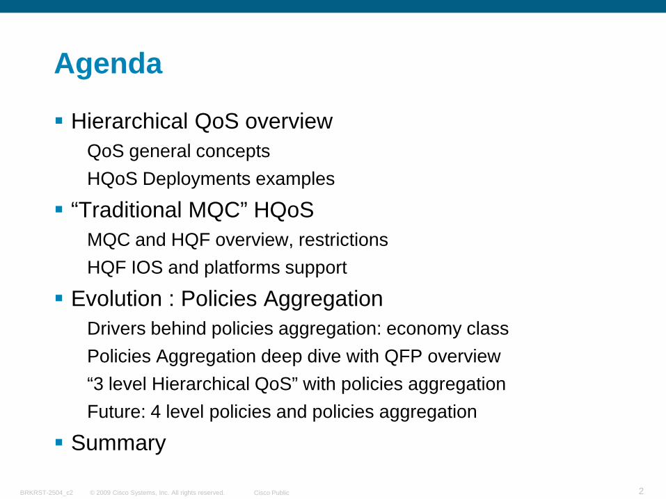
Agenda
Hierarchical QoS overviewQoS general conceptsHQoS Deployments examples
“Traditional MQC” HQoSMQC and HQF overview, restrictions HQF IOS and platforms support
Evolution : Policies AggregationDrivers behind policies aggregation: economy classPolicies Aggregation deep dive with QFP overview“3 level Hierarchical QoS” with policies aggregationFuture: 4 level policies and policies aggregation
Summary
© 2009 Cisco Systems, Inc. All rights reserved. Cisco PublicBRKRST-2504_c2 3
QoS General Concepts
© 2009 Cisco Systems, Inc. All rights reserved. Cisco PublicBRKRST-2504_c2 4
Why Quality of Service (QoS)
Bandwidth optimization for voice, video and data applications
VoIP and Video needs to meet strict SLA on delay and jitter
Critical customers and/or applications prioritizationEnhance delivery and productivity
Financial transactions
More Bandwidth is available but Branch/Hubs/subscribers bottlenecks still exist
Bandwidth sharing is still needed
© 2009 Cisco Systems, Inc. All rights reserved. Cisco PublicBRKRST-2504_c2 5
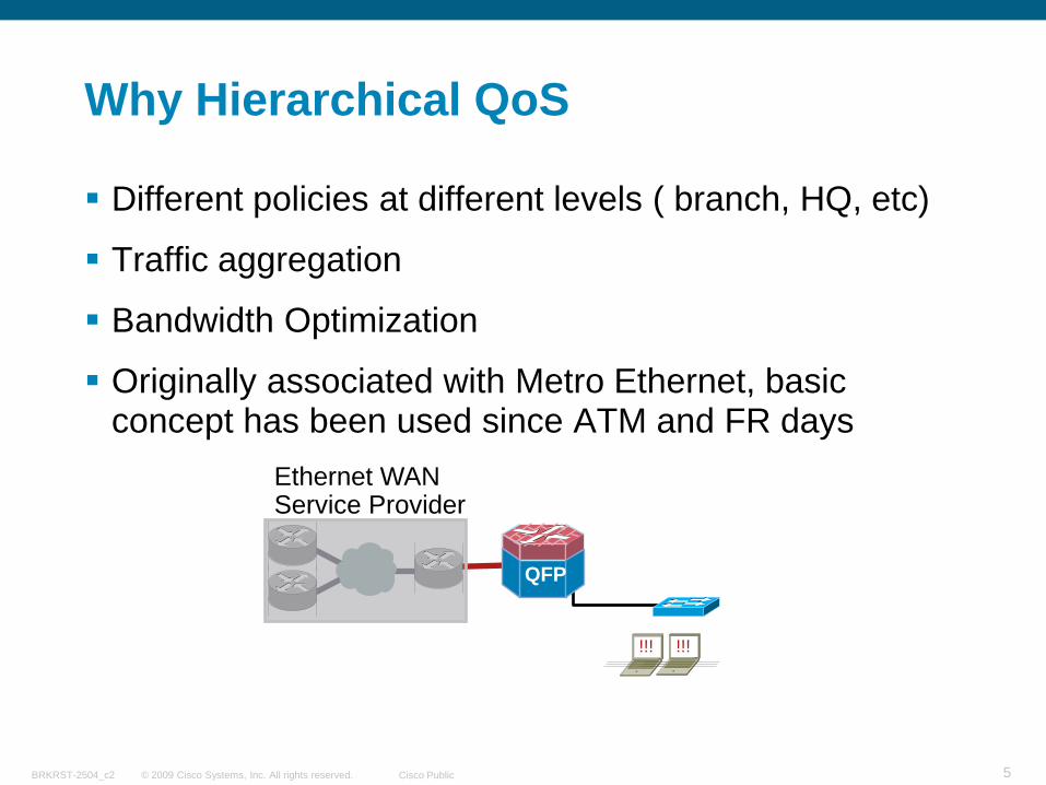
Why Hierarchical QoS
Different policies at different levels ( branch, HQ, etc)
Traffic aggregation
Bandwidth Optimization
Originally associated with Metro Ethernet, basic concept has been used since ATM and FR days
Ethernet WAN Service Provider
QFP
!!! !!!
© 2009 Cisco Systems, Inc. All rights reserved. Cisco PublicBRKRST-2504_c2 6
QoS Components
Classification
Policing
Marking
Shaping*
Queuing*
Link Efficiency (cRTP, fragmentation, etc.)
Congestion management and Scheduling
© 2009 Cisco Systems, Inc. All rights reserved. Cisco PublicBRKRST-2504_c2 7
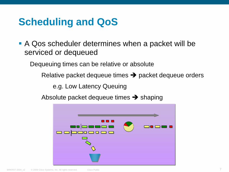
Scheduling and QoS
A Qos scheduler determines when a packet will be serviced or dequeued
Dequeuing times can be relative or absolute
Relative packet dequeue times packet dequeue orders
e.g. Low Latency Queuing
Absolute packet dequeue times shaping
© 2009 Cisco Systems, Inc. All rights reserved. Cisco PublicBRKRST-2504_c2 8
Queuing Parameters
Priority (priority)Packets serviced before any other class
Two levels of priority queuing are possible in certain platforms
Min Bandwidth (bandwidth)Packets are serviced in the order determined by configured bandwidth
Max Bandwidth (Shape)Packets are service at the configured max rate
Excess Bandwidth (bandwidth remaining)Excess packets are service in the order determined by remaining rate
© 2009 Cisco Systems, Inc. All rights reserved. Cisco PublicBRKRST-2504_c2 9
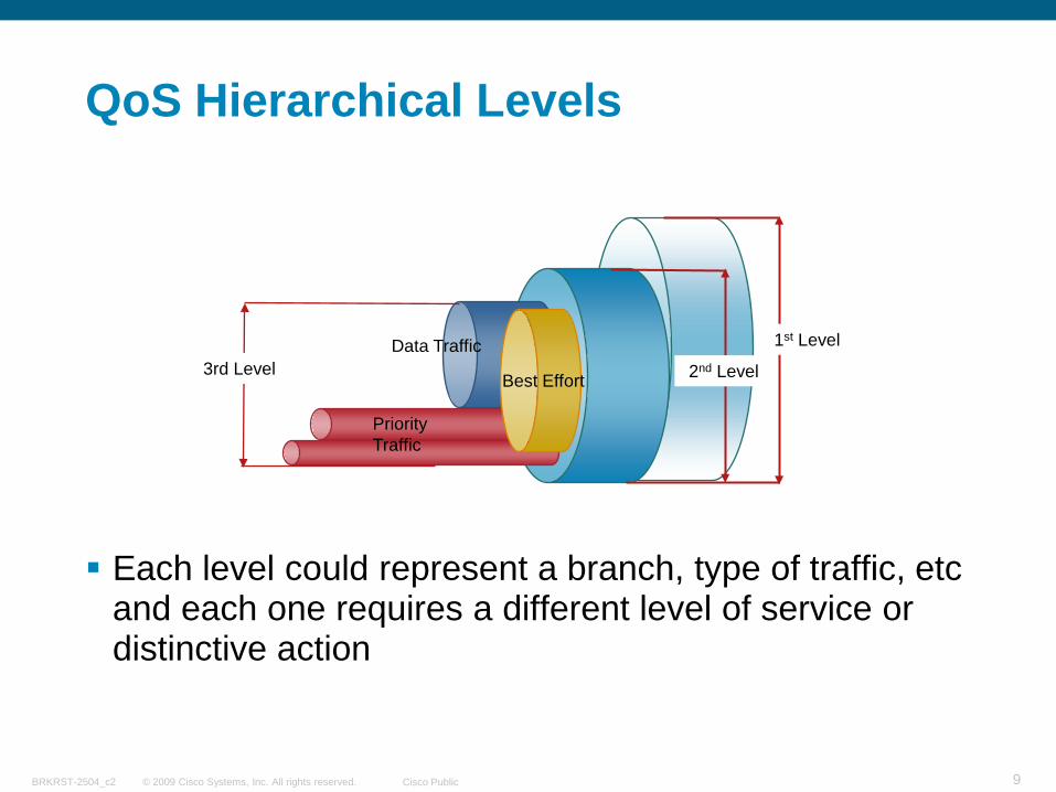
QoS Hierarchical Levels
Each level could represent a branch, type of traffic, etc and each one requires a different level of service or distinctive action
2nd Level
PriorityTraffic
Best Effort
Data Traffic 1st Level3rd Level
© 2009 Cisco Systems, Inc. All rights reserved. Cisco PublicBRKRST-2504_c2 10
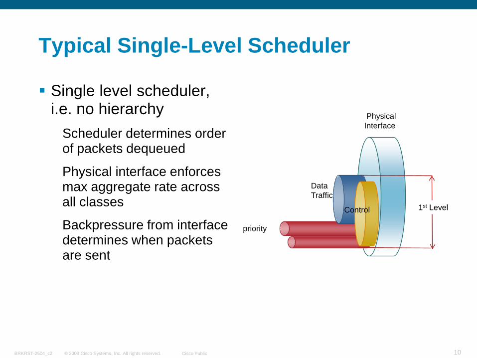
Typical Single-Level Scheduler
Single level scheduler,i.e. no hierarchy
Scheduler determines order of packets dequeued
Physical interface enforces max aggregate rate across all classes
Backpressure from interface determines when packets are sent
priority
Control
Data Traffic
Physical Interface
1st Level
© 2009 Cisco Systems, Inc. All rights reserved. Cisco PublicBRKRST-2504_c2 11
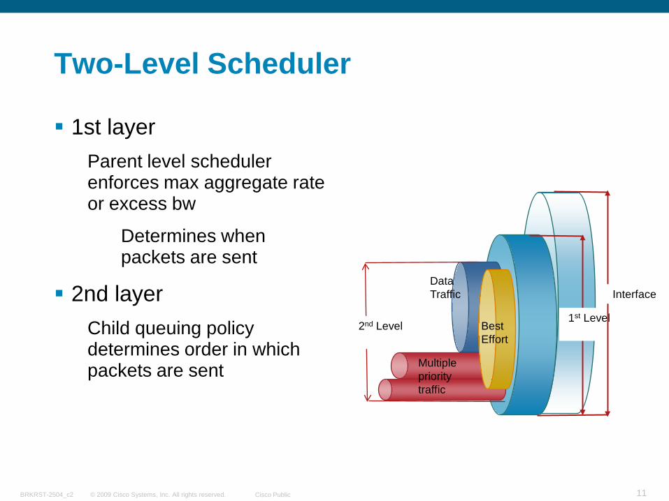
Two-Level Scheduler
1st layerParent level scheduler enforces max aggregate rate or excess bw
Determines when packets are sent
2nd layerChild queuing policy determines order in which packets are sent
1st Level
Multiple priority traffic
Best Effort
Data Traffic Interface
2nd Level
© 2009 Cisco Systems, Inc. All rights reserved. Cisco PublicBRKRST-2504_c2 12
Service Propagation
Behavior defined at one layer in the hierarchy propagates through to upper layers, enforcing SLA at all levels
Service propagation helps overcome the issues of conventional scheduling implementations
Priority Propagation: Parent Scheduler knows that a packet was scheduled from a Priority Entry – Preserves Priority Through Hierarchy
“Available” in software based platforms, until CPU utilization or congestion is too high. Only specialized hardware can really deliver priority at a very high throughput
© 2009 Cisco Systems, Inc. All rights reserved. Cisco PublicBRKRST-2504_c2 13
Typical Hierarchical QoS Deployments
© 2009 Cisco Systems, Inc. All rights reserved. Cisco PublicBRKRST-2504_c2 14
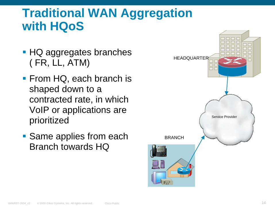
Traditional WAN Aggregation with HQoS
HQ aggregates branches ( FR, LL, ATM)
From HQ, each branch is shaped down to a contracted rate, in which VoIP or applications are prioritized
Same applies from each Branch towards HQ
BRANCH
CPE
Service Provider
HEADQUARTER
© 2009 Cisco Systems, Inc. All rights reserved. Cisco PublicBRKRST-2504_c2 15
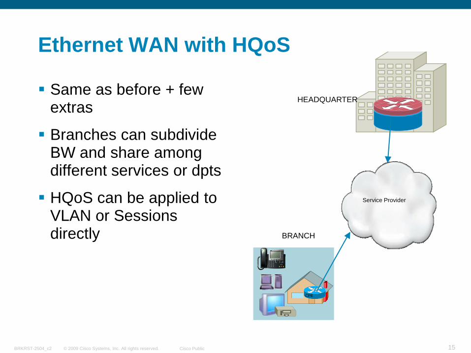
Ethernet WAN with HQoS
Same as before + few extras
Branches can subdivide BW and share among different services or dpts
HQoS can be applied to VLAN or Sessions directly BRANCH
CPE
Service Provider
HEADQUARTER
© 2009 Cisco Systems, Inc. All rights reserved. Cisco PublicBRKRST-2504_c2 16
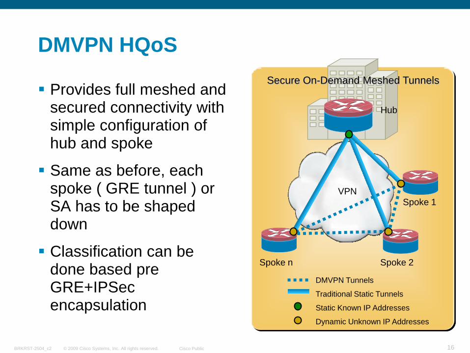
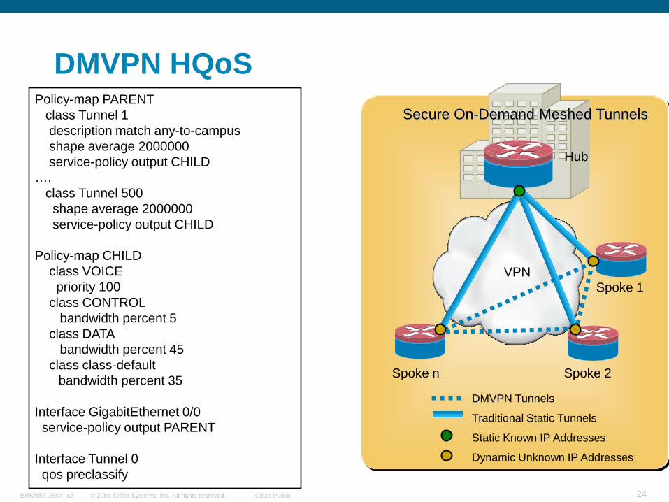
DMVPN HQoS
Provides full meshed and secured connectivity with simple configuration of hub and spoke
Same as before, each spoke ( GRE tunnel ) or SA has to be shaped down
Classification can be done based pre GRE+IPSec encapsulation
Spoke n
Traditional Static Tunnels
DMVPN Tunnels
Static Known IP Addresses
Dynamic Unknown IP Addresses
Hub
VPNSpoke 1
Spoke 2
Secure On-Demand Meshed Tunnels
© 2009 Cisco Systems, Inc. All rights reserved. Cisco PublicBRKRST-2504_c2 17
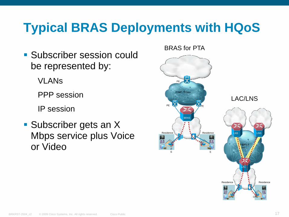
Typical BRAS Deployments with HQoS
Subscriber session could be represented by:
VLANs
PPP session
IP session
Subscriber gets an X Mbps service plus Voice or Video
IP/MPLS Core
Aggregation
Internet
Residence
CPE
Residence
CPE
PE
BRAS
PE
PE
BRAS for PTA
IP/MPLS Core
Aggregation
ISP 1
Residence
CPE
Residence
CPE
ISP 2
LNSLNS
LAC
LAC/LNS
© 2009 Cisco Systems, Inc. All rights reserved. Cisco PublicBRKRST-2504_c2 18
MQC/HQF Overview
© 2009 Cisco Systems, Inc. All rights reserved. Cisco PublicBRKRST-2504_c2 19
QoS with IOS Modular QoS CLI (MQC)
Cisco IOS command syntax for QoSTemplate-based syntax
Separates classification engine fromthe policy
Uniform CLI for QoS features
Cisco Platform independent
Hierarchical Policies are basically configured by calling a “child” policy from within a “parent” policy, etc
© 2009 Cisco Systems, Inc. All rights reserved. Cisco PublicBRKRST-2504_c2 20
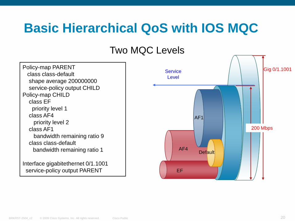
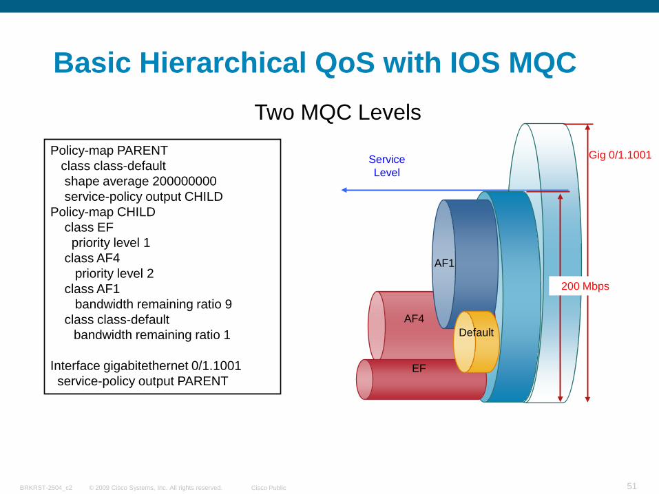
Basic Hierarchical QoS with IOS MQC
EF
AF1
Default
Gig 0/1.1001
200 Mbps
Service Level
Policy-map PARENTclass class-defaultshape average 200000000service-policy output CHILD
Policy-map CHILDclass EFpriority level 1
class AF4priority level 2
class AF1bandwidth remaining ratio 9
class class-defaultbandwidth remaining ratio 1
Interface gigabitethernet 0/1.1001service-policy output PARENT
Two MQC Levels
AF4
© 2009 Cisco Systems, Inc. All rights reserved. Cisco PublicBRKRST-2504_c2 21
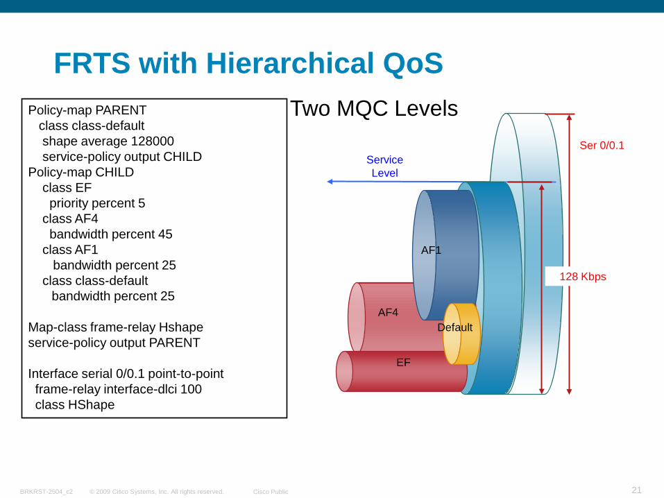
FRTS with Hierarchical QoS
AF4
AF1
Default
Ser 0/0.1
128 Kbps
Service Level
Policy-map PARENTclass class-defaultshape average 128000service-policy output CHILD
Policy-map CHILDclass EFpriority percent 5
class AF4bandwidth percent 45
class AF1bandwidth percent 25
class class-defaultbandwidth percent 25
Map-class frame-relay Hshapeservice-policy output PARENT
Interface serial 0/0.1 point-to-pointframe-relay interface-dlci 100class HShape
Two MQC Levels
EF
© 2009 Cisco Systems, Inc. All rights reserved. Cisco PublicBRKRST-2504_c2 22
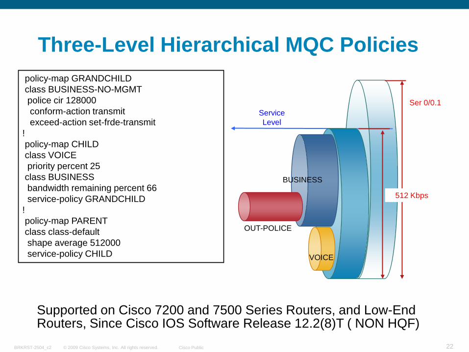
Three-Level Hierarchical MQC Policies
Supported on Cisco 7200 and 7500 Series Routers, and Low-End Routers, Since Cisco IOS Software Release 12.2(8)T ( NON HQF)
policy-map GRANDCHILDclass BUSINESS-NO-MGMTpolice cir 128000conform-action transmit exceed-action set-frde-transmit
!policy-map CHILDclass VOICEpriority percent 25
class BUSINESSbandwidth remaining percent 66service-policy GRANDCHILD
!policy-map PARENTclass class-defaultshape average 512000service-policy CHILD
OUT-POLICE
BUSINESS
VOICE
Ser 0/0.1
512 Kbps
Service Level
© 2009 Cisco Systems, Inc. All rights reserved. Cisco PublicBRKRST-2504_c2 23
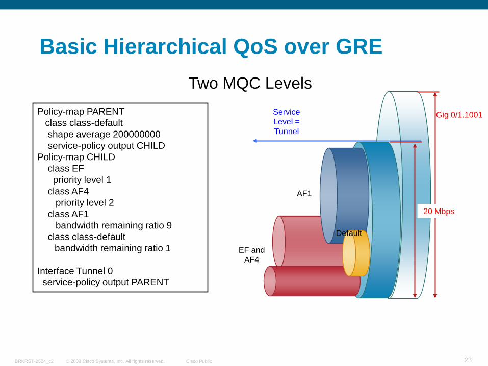
Basic Hierarchical QoS over GRE
EF and AF4
AF1
Default
Gig 0/1.1001
20 Mbps
Service Level = Tunnel
Policy-map PARENTclass class-defaultshape average 200000000service-policy output CHILD
Policy-map CHILDclass EFpriority level 1
class AF4priority level 2
class AF1bandwidth remaining ratio 9
class class-defaultbandwidth remaining ratio 1
Interface Tunnel 0service-policy output PARENT
Two MQC Levels
© 2009 Cisco Systems, Inc. All rights reserved. Cisco PublicBRKRST-2504_c2 24
DMVPN HQoS
Spoke n
Traditional Static Tunnels
DMVPN Tunnels
Static Known IP Addresses
Dynamic Unknown IP Addresses
Hub
VPNSpoke 1
Spoke 2
Secure On-Demand Meshed TunnelsPolicy-map PARENT
class Tunnel 1description match any-to-campusshape average 2000000service-policy output CHILD
….class Tunnel 500shape average 2000000service-policy output CHILD
Policy-map CHILDclass VOICEpriority 100
class CONTROLbandwidth percent 5
class DATAbandwidth percent 45
class class-defaultbandwidth percent 35
Interface GigabitEthernet 0/0service-policy output PARENT
Interface Tunnel 0qos preclassify
© 2009 Cisco Systems, Inc. All rights reserved. Cisco PublicBRKRST-2504_c2 25
QoS Preclassify Review
The use of qos-preclassify depends on which header you need to use for classification and where to apply the QoS Policy
Apply the QoS policy to the tunnel interface without qos-preclassify when you want to classify packets based on the pre-tunnel header.
Apply the QoS policy to the physical interface without qos-preclassify when you want to classify packets based on the post-tunnel header. In addition, apply the policy to the physical interface when you want to shape or police all traffic belonging to a tunnel, and the physical interface supports several tunnels.
Apply the QoS policy to a physical interface and enable qos-preclassify on a tunnel interface when you want to classify packets based on the pre-tunnel header.
© 2009 Cisco Systems, Inc. All rights reserved. Cisco PublicBRKRST-2504_c2 26
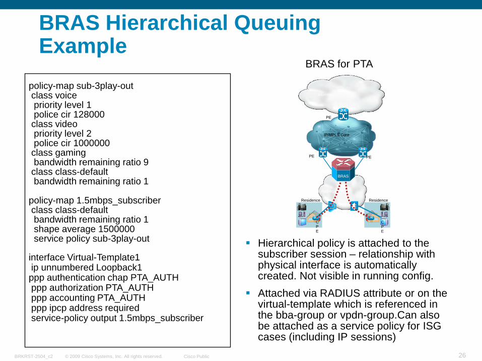
BRAS Hierarchical Queuing Example
Hierarchical policy is attached to the subscriber session – relationship with physical interface is automatically created. Not visible in running config.
Attached via RADIUS attribute or on the virtual-template which is referenced in the bba-group or vpdn-group.Can also be attached as a service policy for ISG cases (including IP sessions)
policy-map sub-3play-outclass voicepriority level 1police cir 128000
class videopriority level 2police cir 1000000
class gamingbandwidth remaining ratio 9
class class-defaultbandwidth remaining ratio 1
policy-map 1.5mbps_subscriberclass class-defaultbandwidth remaining ratio 1shape average 1500000service policy sub-3play-out
interface Virtual-Template1 ip unnumbered Loopback1ppp authentication chap PTA_AUTHppp authorization PTA_AUTHppp accounting PTA_AUTHppp ipcp address requiredservice-policy output 1.5mbps_subscriber
IP/MPLS Core
Aggregation
Internet
Residence
CPE
Residence
CPE
PE
BRAS
PE
PE
BRAS for PTA
© 2009 Cisco Systems, Inc. All rights reserved. Cisco PublicBRKRST-2504_c2 27
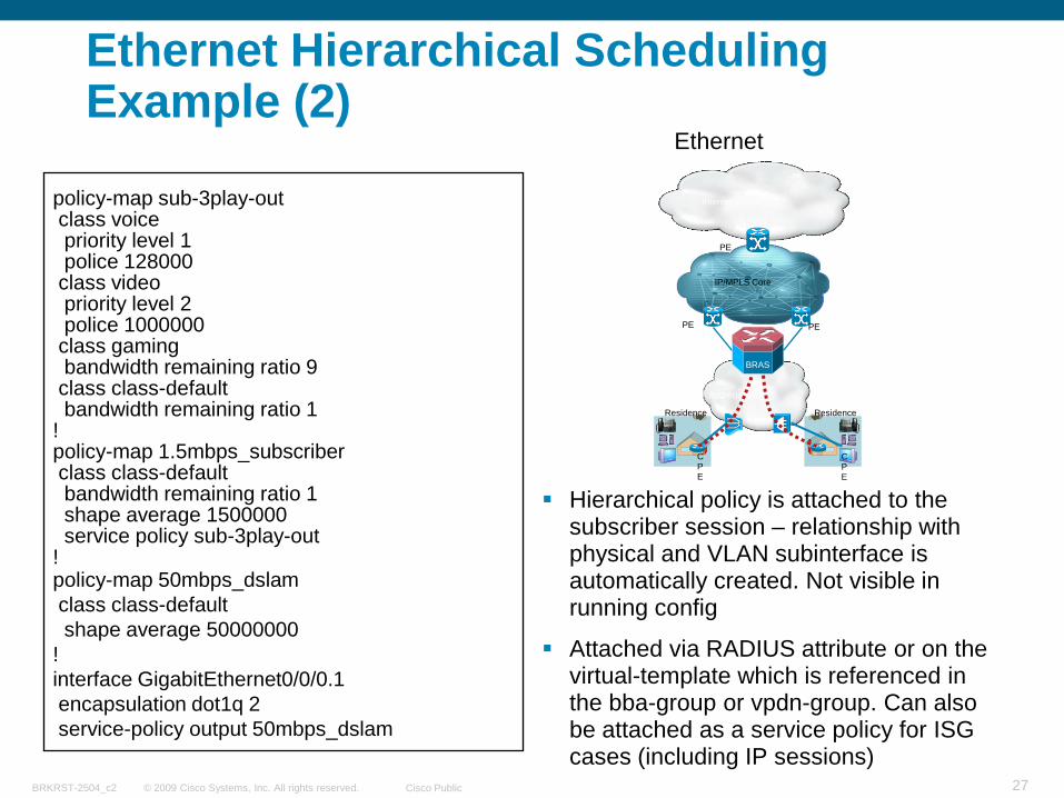
Ethernet Hierarchical Scheduling Example (2)
Hierarchical policy is attached to the subscriber session – relationship with physical and VLAN subinterface is automatically created. Not visible in running config
Attached via RADIUS attribute or on the virtual-template which is referenced in the bba-group or vpdn-group. Can also be attached as a service policy for ISG cases (including IP sessions)
policy-map sub-3play-outclass voicepriority level 1police 128000
class videopriority level 2police 1000000
class gamingbandwidth remaining ratio 9
class class-defaultbandwidth remaining ratio 1
!policy-map 1.5mbps_subscriberclass class-defaultbandwidth remaining ratio 1shape average 1500000service policy sub-3play-out
!policy-map 50mbps_dslamclass class-defaultshape average 50000000
!interface GigabitEthernet0/0/0.1encapsulation dot1q 2service-policy output 50mbps_dslam
IP/MPLS Core
Aggregation
Internet
Residence
CPE
Residence
CPE
PE
BRAS
PE
PE
Ethernet
© 2009 Cisco Systems, Inc. All rights reserved. Cisco PublicBRKRST-2504_c2 28
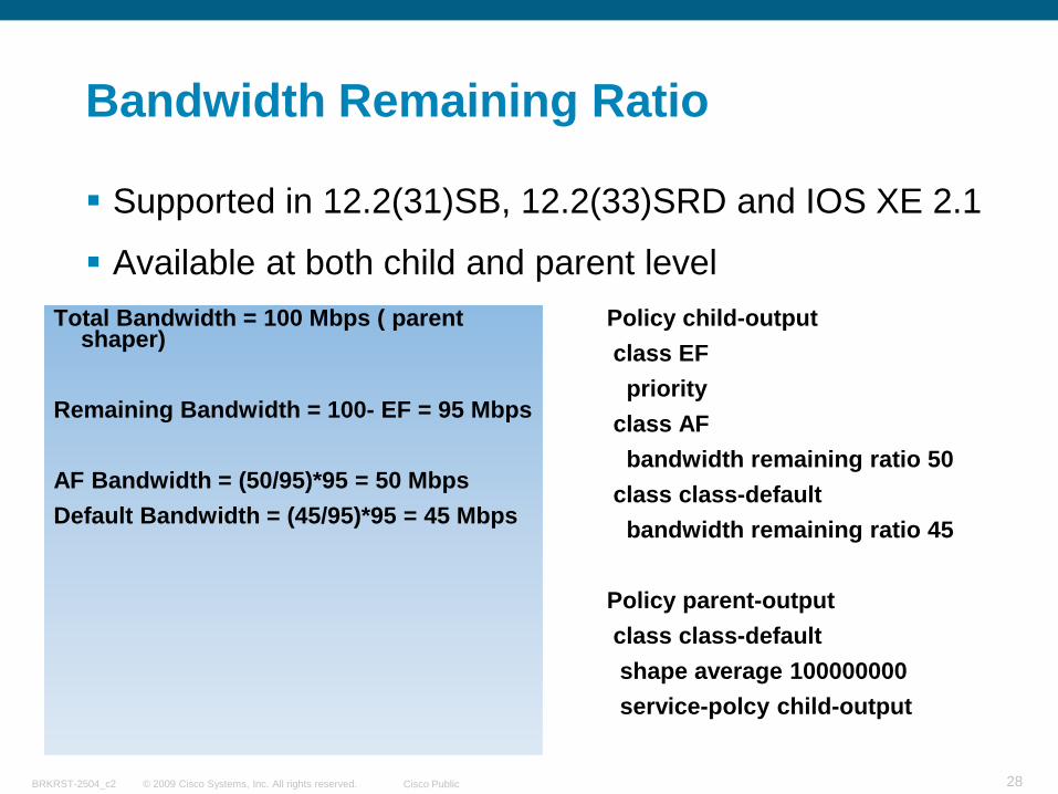
Bandwidth Remaining Ratio
Supported in 12.2(31)SB, 12.2(33)SRD and IOS XE 2.1
Available at both child and parent level Total Bandwidth = 100 Mbps ( parent
shaper)
Remaining Bandwidth = 100- EF = 95 Mbps
AF Bandwidth = (50/95)*95 = 50 MbpsDefault Bandwidth = (45/95)*95 = 45 Mbps
Policy child-outputclass EF
priorityclass AF
bandwidth remaining ratio 50class class-default
bandwidth remaining ratio 45
Policy parent-outputclass class-defaultshape average 100000000service-polcy child-output
© 2009 Cisco Systems, Inc. All rights reserved. Cisco PublicBRKRST-2504_c2 29
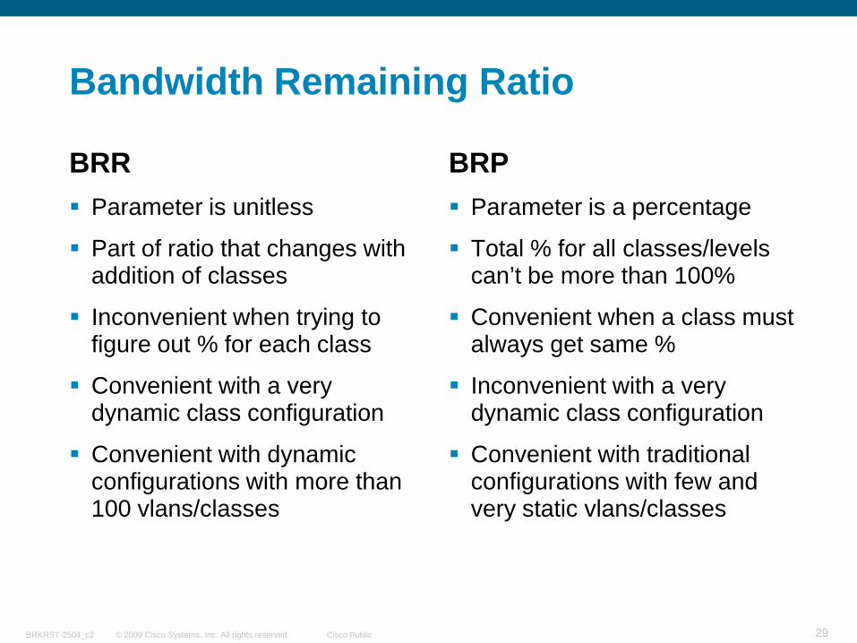
Bandwidth Remaining Ratio
BRR Parameter is unitless
Part of ratio that changes with addition of classes
Inconvenient when trying to figure out % for each class
Convenient with a very dynamic class configuration
Convenient with dynamic configurations with more than 100 vlans/classes
BRP Parameter is a percentage
Total % for all classes/levels can’t be more than 100%
Convenient when a class must always get same %
Inconvenient with a very dynamic class configuration
Convenient with traditional configurations with few and very static vlans/classes
© 2009 Cisco Systems, Inc. All rights reserved. Cisco PublicBRKRST-2504_c2 30
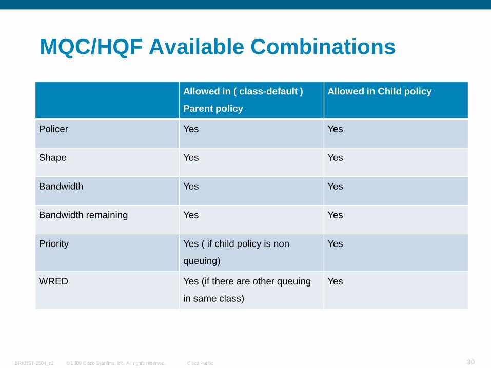
MQC/HQF Available Combinations
Allowed in ( class-default )
Parent policy
Allowed in Child policy
Policer Yes Yes
Shape Yes Yes
Bandwidth Yes Yes
Bandwidth remaining Yes Yes
Priority Yes ( if child policy is non
queuing)
Yes
WRED Yes (if there are other queuing
in same class)
Yes
© 2009 Cisco Systems, Inc. All rights reserved. Cisco PublicBRKRST-2504_c2 31
Hierarchical Queuing Framework (HQF)
Cisco has developed a new way of handling queuingSupported since IOS 12.0(26)S, 12.2(28)SB, IOS XE 2.1 and just recently 12.4(20)T
The objective is to handle hierarchical QoS policies more efficiently and consistently across Cisco platforms
With HQF customers, using any of the IOS releases and specific platforms, will have:
The ability to provide multiple levels of packet scheduling
The ability to support integrated class-based shaping and queuing
© 2009 Cisco Systems, Inc. All rights reserved. Cisco PublicBRKRST-2504_c2 32
Hierarchical Queuing Framework (HQF)
Platforms may implement the framework with different levels of hierarchy and algorithms, with different resulting capabilities and behaviors
Just because two platforms both support HQF does not mean they support the same underlying functionality!!
Bottom line is that HQF is as consistent as possible given the underlying hardware
Next slides are some of the most important HQF enhancements, which as mentioned before, are available since IOS 12.0(26)S, 12.2(28)SB, IOS XE 2.1 and just recently 12.4(20)T
© 2009 Cisco Systems, Inc. All rights reserved. Cisco PublicBRKRST-2504_c2 33
HQF Major Enhancements
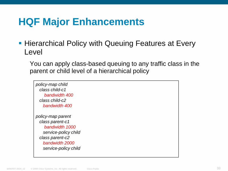
Hierarchical Policy with Queuing Features at Every Level
You can apply class-based queuing to any traffic class in the parent or child level of a hierarchical policy
policy-map childclass child-c1
bandwidth 400class child-c2
bandwidth 400
policy-map parentclass parent-c1
bandwidth 1000service-policy child
class parent-c2bandwidth 2000service-policy child
© 2009 Cisco Systems, Inc. All rights reserved. Cisco PublicBRKRST-2504_c2 34
HQF Major Enhancements
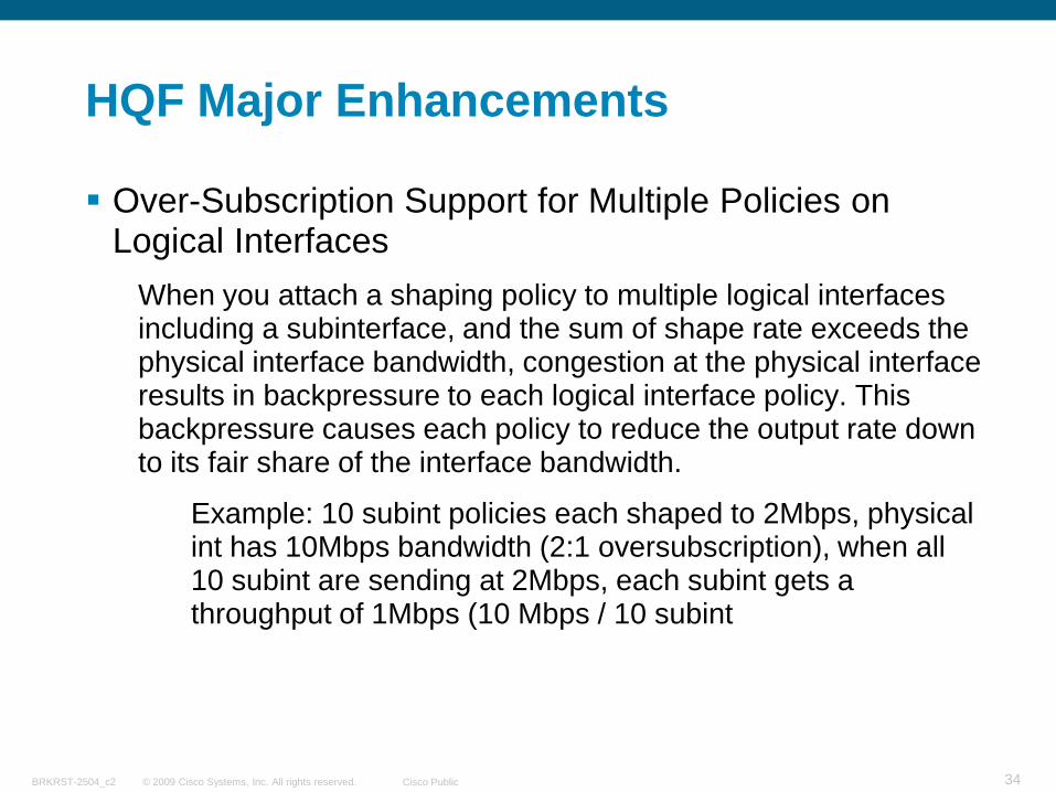
Over-Subscription Support for Multiple Policies on Logical Interfaces
When you attach a shaping policy to multiple logical interfaces including a subinterface, and the sum of shape rate exceeds the physical interface bandwidth, congestion at the physical interface results in backpressure to each logical interface policy. This backpressure causes each policy to reduce the output rate down to its fair share of the interface bandwidth.
Example: 10 subint policies each shaped to 2Mbps, physical int has 10Mbps bandwidth (2:1 oversubscription), when all 10 subint are sending at 2Mbps, each subint gets a throughput of 1Mbps (10 Mbps / 10 subint
© 2009 Cisco Systems, Inc. All rights reserved. Cisco PublicBRKRST-2504_c2 35
HQF Major Enhancements
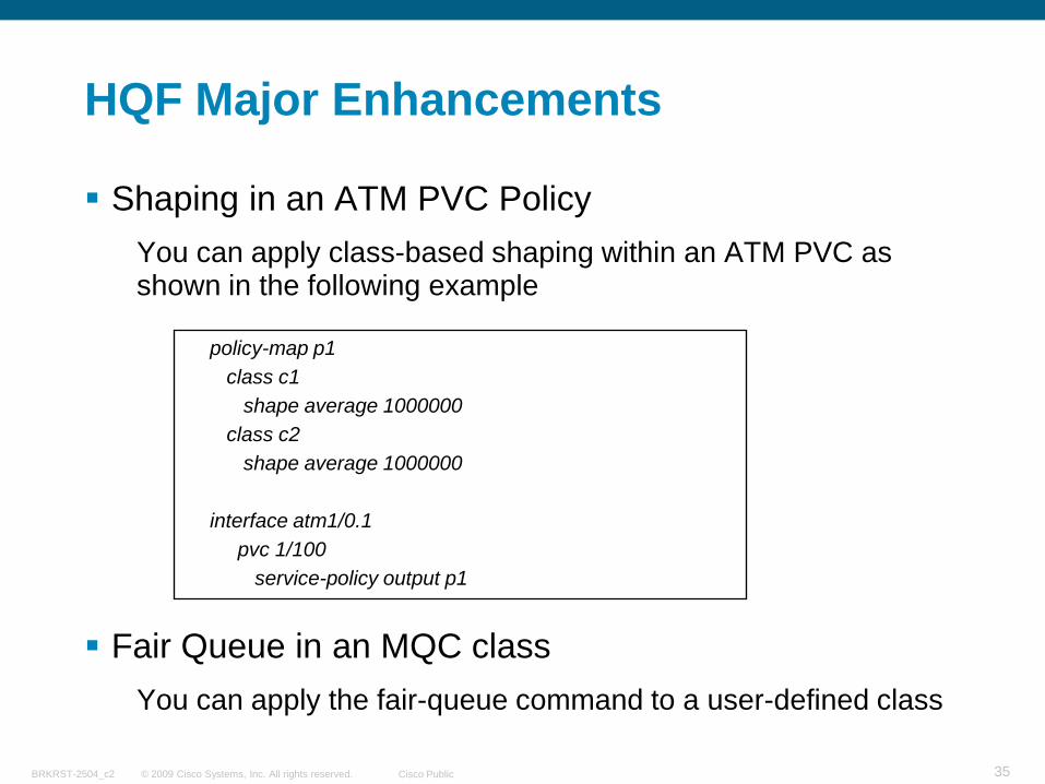
Shaping in an ATM PVC Policy You can apply class-based shaping within an ATM PVC as shown in the following example
Fair Queue in an MQC class You can apply the fair-queue command to a user-defined class
policy-map p1class c1
shape average 1000000class c2
shape average 1000000
interface atm1/0.1pvc 1/100
service-policy output p1
© 2009 Cisco Systems, Inc. All rights reserved. Cisco PublicBRKRST-2504_c2 36
HQF Major Enhancements
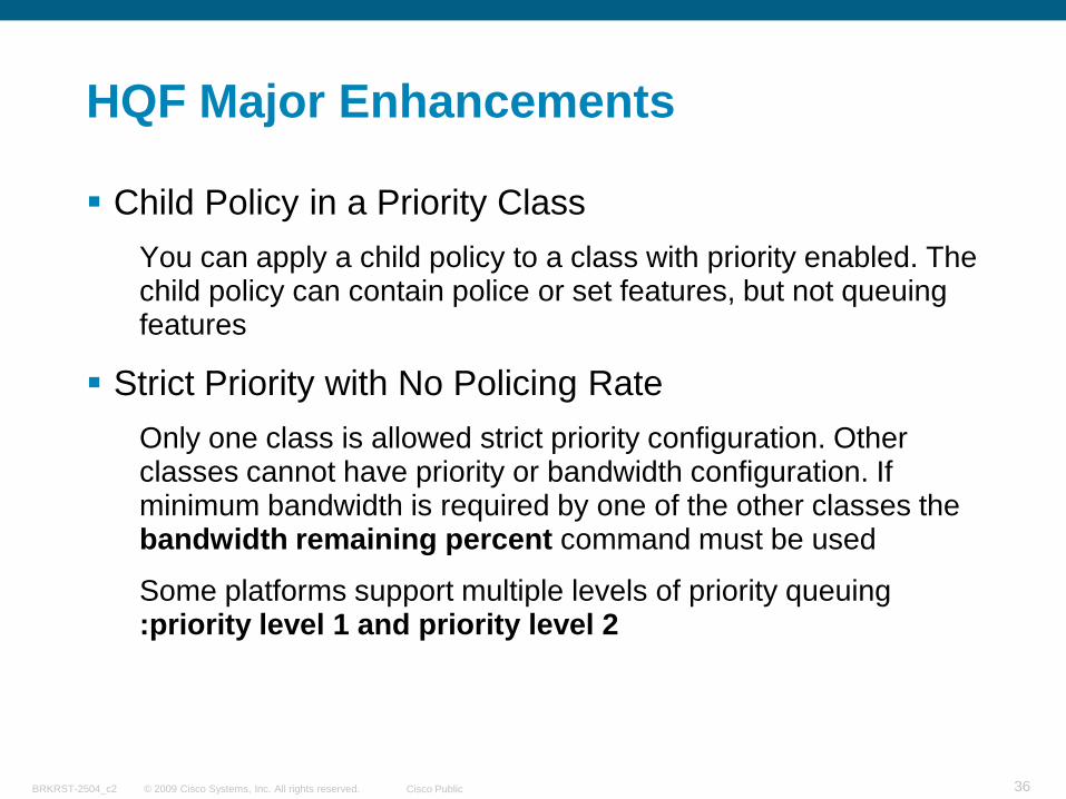
Child Policy in a Priority ClassYou can apply a child policy to a class with priority enabled. The child policy can contain police or set features, but not queuing features
Strict Priority with No Policing RateOnly one class is allowed strict priority configuration. Other classes cannot have priority or bandwidth configuration. If minimum bandwidth is required by one of the other classes the bandwidth remaining percent command must be used
Some platforms support multiple levels of priority queuing :priority level 1 and priority level 2
© 2009 Cisco Systems, Inc. All rights reserved. Cisco PublicBRKRST-2504_c2 37
HQF Behavioral Changes
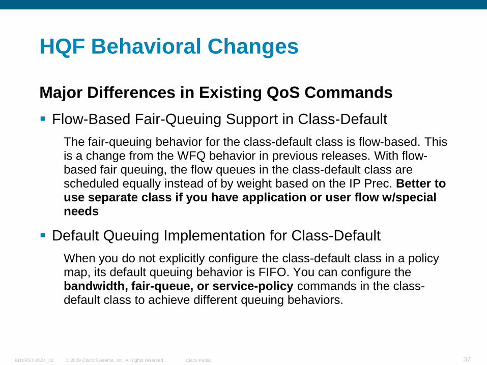
Major Differences in Existing QoS Commands Flow-Based Fair-Queuing Support in Class-Default
The fair-queuing behavior for the class-default class is flow-based. This is a change from the WFQ behavior in previous releases. With flow-based fair queuing, the flow queues in the class-default class are scheduled equally instead of by weight based on the IP Prec. Better to use separate class if you have application or user flow w/special needs
Default Queuing Implementation for Class-DefaultWhen you do not explicitly configure the class-default class in a policy map, its default queuing behavior is FIFO. You can configure the bandwidth, fair-queue, or service-policy commands in the class-default class to achieve different queuing behaviors.
© 2009 Cisco Systems, Inc. All rights reserved. Cisco PublicBRKRST-2504_c2 38
HQF Behavioral Changes
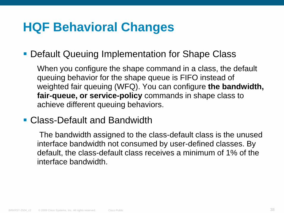
Default Queuing Implementation for Shape Class When you configure the shape command in a class, the default queuing behavior for the shape queue is FIFO instead of weighted fair queuing (WFQ). You can configure the bandwidth, fair-queue, or service-policy commands in shape class to achieve different queuing behaviors.
Class-Default and BandwidthThe bandwidth assigned to the class-default class is the unused interface bandwidth not consumed by user-defined classes. By default, the class-default class receives a minimum of 1% of the interface bandwidth.
© 2009 Cisco Systems, Inc. All rights reserved. Cisco PublicBRKRST-2504_c2 39
HQF Behavioral Changes
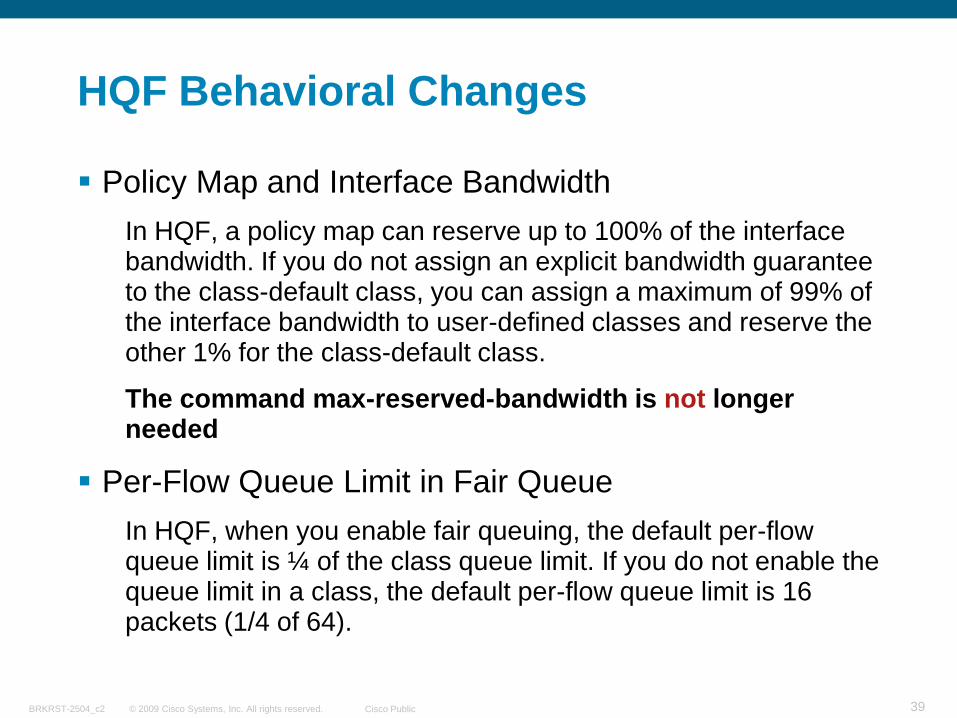
Policy Map and Interface Bandwidth In HQF, a policy map can reserve up to 100% of the interface bandwidth. If you do not assign an explicit bandwidth guarantee to the class-default class, you can assign a maximum of 99% of the interface bandwidth to user-defined classes and reserve the other 1% for the class-default class.
The command max-reserved-bandwidth is not longer needed
Per-Flow Queue Limit in Fair QueueIn HQF, when you enable fair queuing, the default per-flow queue limit is ¼ of the class queue limit. If you do not enable the queue limit in a class, the default per-flow queue limit is 16 packets (1/4 of 64).
© 2009 Cisco Systems, Inc. All rights reserved. Cisco PublicBRKRST-2504_c2 40
HQF Behavioral Changes
Shaping Behavior on GRE TunnelIn HQF, shaping on GRE tunnel is done after encapsulation. This means the shape rate is based on packets with tunnel encapsulation and L2 encapsulation. If you configure IPSEC on the GRE tunnel, shaping occurs after encryption.
Only absolute parent shapers are supported at this time and for the support of GRE and physical policy, see next slide
Change in FRF.12 and FRF.9 Behaviorwhen you enable (FRF.12) on an FR PVC or FR main interface, priority class packets are no longer subject to fragmentation. Priority packets, regardless of the packet size, always interleave among data fragments. When you enable (FRF.9) on an FR PVC or main interface, priority class packets are no longer compressed.
© 2009 Cisco Systems, Inc. All rights reserved. Cisco PublicBRKRST-2504_c2 41
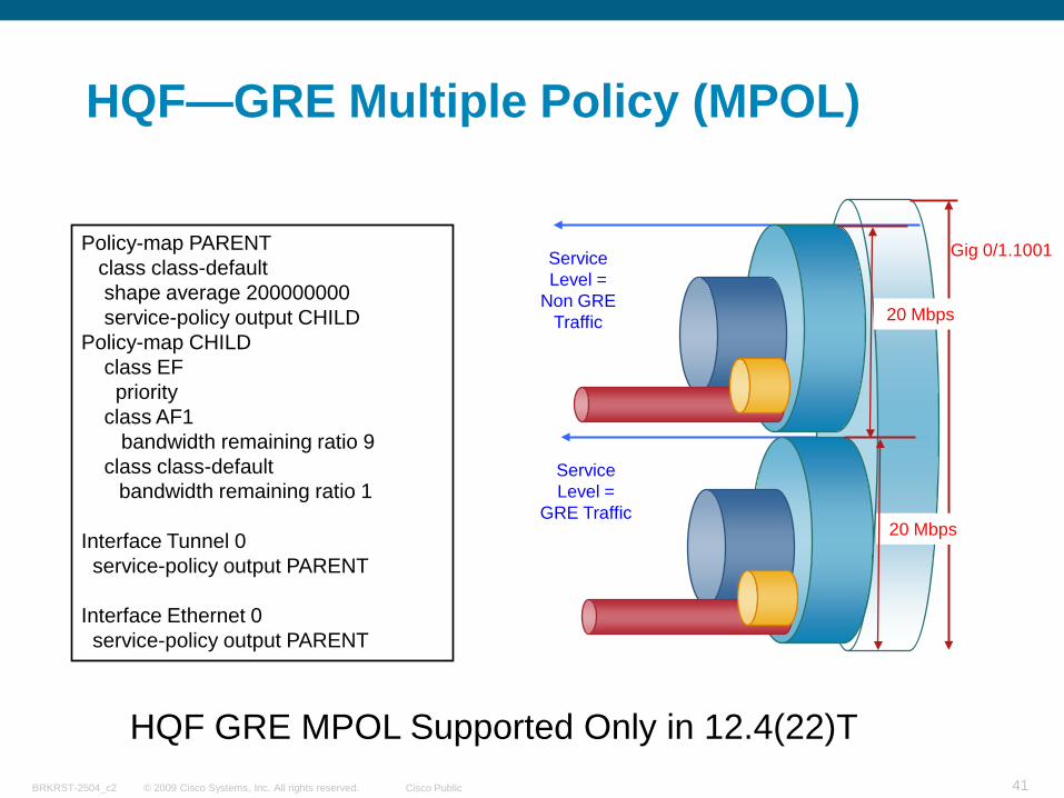
HQF—GRE Multiple Policy (MPOL)
Gig 0/1.1001
20 Mbps
Service Level =
GRE Traffic
Policy-map PARENTclass class-defaultshape average 200000000service-policy output CHILD
Policy-map CHILDclass EFpriority
class AF1bandwidth remaining ratio 9
class class-defaultbandwidth remaining ratio 1
Interface Tunnel 0service-policy output PARENT
Interface Ethernet 0service-policy output PARENT
HQF GRE MPOL Supported Only in 12.4(22)T
20 Mbps
Service Level =
Non GRE Traffic
© 2009 Cisco Systems, Inc. All rights reserved. Cisco PublicBRKRST-2504_c2 42
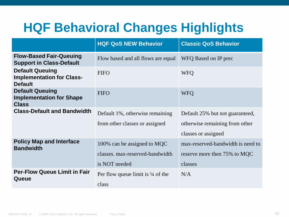
HQF Behavioral Changes HighlightsHQF QoS NEW Behavior Classic QoS Behavior
Flow-Based Fair-Queuing Support in Class-Default
Flow based and all flows are equal WFQ Based on IP prec
Default Queuing Implementation for Class-Default
FIFO WFQ
Default Queuing Implementation for Shape Class
FIFO WFQ
Class-Default and Bandwidth Default 1%, otherwise remaining
from other classes or assigned
Default 25% but not guaranteed,
otherwise remaining from other
classes or assignedPolicy Map and Interface Bandwidth
100% can be assigned to MQC
classes. max-reserved-bandwidth
is NOT needed
max-reserved-bandwidth is need to
reserve more then 75% to MQC
classesPer-Flow Queue Limit in Fair Queue
Per flow queue limit is ¼ of the
class
N/A
© 2009 Cisco Systems, Inc. All rights reserved. Cisco PublicBRKRST-2504_c2 43
HQF Commands Changes
New random-detect Option SupportThe random-detect command supports the atm-clp-based, cos-based, and byte-based options to calculate the probability of dropping a packet
Commands not needed/supportedrandom-detect prec-based replaced by random-detect precedence-based
shape max-buffers replaced by queue-limit
max-reserved-bandwidth not needed
show queuing and show queue Commands replaced by show policy-map interface
shape average Tc is 4 ms by default
© 2009 Cisco Systems, Inc. All rights reserved. Cisco PublicBRKRST-2504_c2 44
HQF IOS and Platforms Support
© 2009 Cisco Systems, Inc. All rights reserved. Cisco PublicBRKRST-2504_c2 45
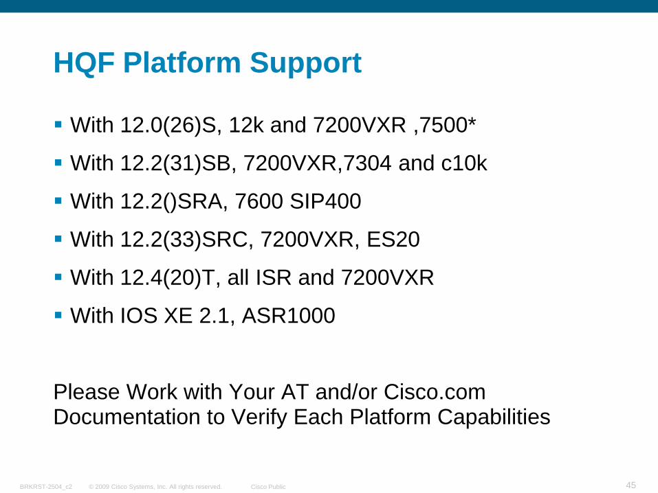
HQF Platform Support
With 12.0(26)S, 12k and 7200VXR ,7500*
With 12.2(31)SB, 7200VXR,7304 and c10k
With 12.2()SRA, 7600 SIP400
With 12.2(33)SRC, 7200VXR, ES20
With 12.4(20)T, all ISR and 7200VXR
With IOS XE 2.1, ASR1000
Please Work with Your AT and/or Cisco.com Documentation to Verify Each Platform Capabilities
© 2009 Cisco Systems, Inc. All rights reserved. Cisco PublicBRKRST-2504_c2 46
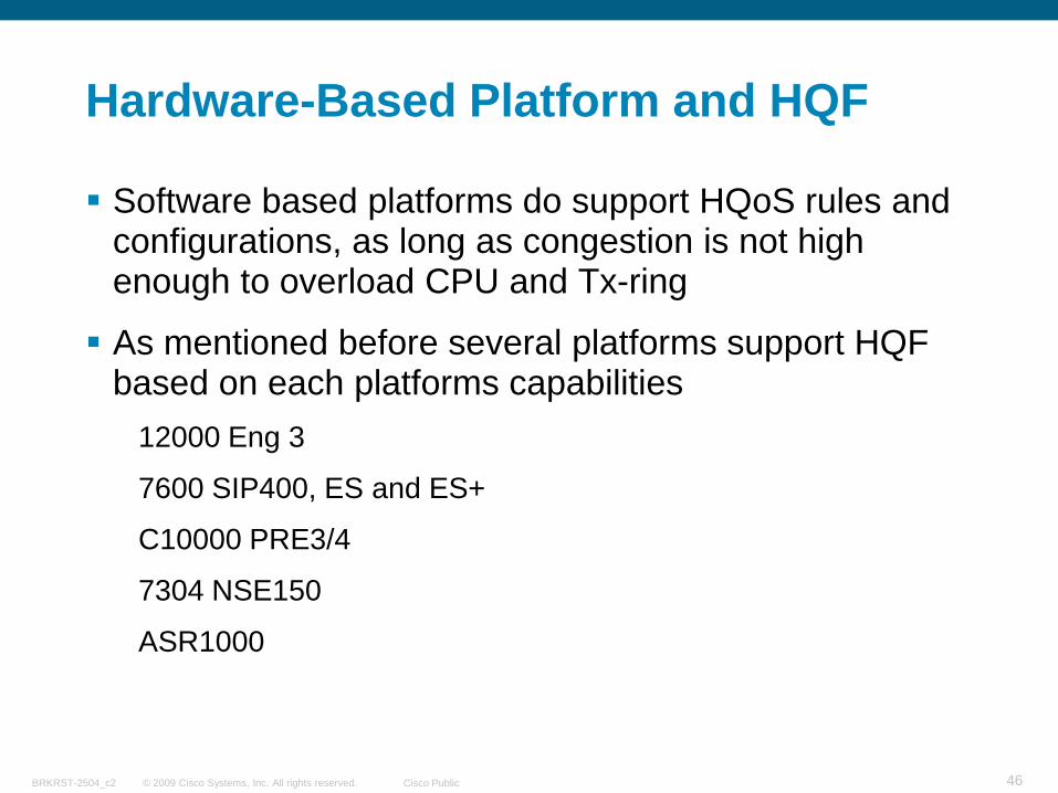
Hardware-Based Platform and HQF
Software based platforms do support HQoS rules and configurations, as long as congestion is not high enough to overload CPU and Tx-ring
As mentioned before several platforms support HQF based on each platforms capabilities
12000 Eng 3
7600 SIP400, ES and ES+
C10000 PRE3/4
7304 NSE150
ASR1000
© 2009 Cisco Systems, Inc. All rights reserved. Cisco PublicBRKRST-2504_c2 47
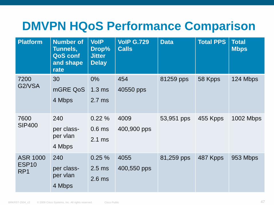
DMVPN HQoS Performance ComparisonPlatform Number of
Tunnels, QoS conf and shape rate
VoIP Drop% Jitter Delay
VoIP G.729 Calls
Data Total PPS Total Mbps
7200 G2/VSA
30
mGRE QoS
4 Mbps
0%
1.3 ms
2.7 ms
454
40550 pps
81259 pps 58 Kpps 124 Mbps
7600 SIP400
240
per class-per vlan
4 Mbps
0.22 %
0.6 ms
2.1 ms
4009
400,900 pps
53,951 pps 455 Kpps 1002 Mbps
ASR 1000 ESP10 RP1
240
per class-per vlan
4 Mbps
0.25 %
2.5 ms
2.6 ms
4055
400,550 pps
81,259 pps 487 Kpps 953 Mbps
© 2009 Cisco Systems, Inc. All rights reserved. Cisco PublicBRKRST-2504_c2 48
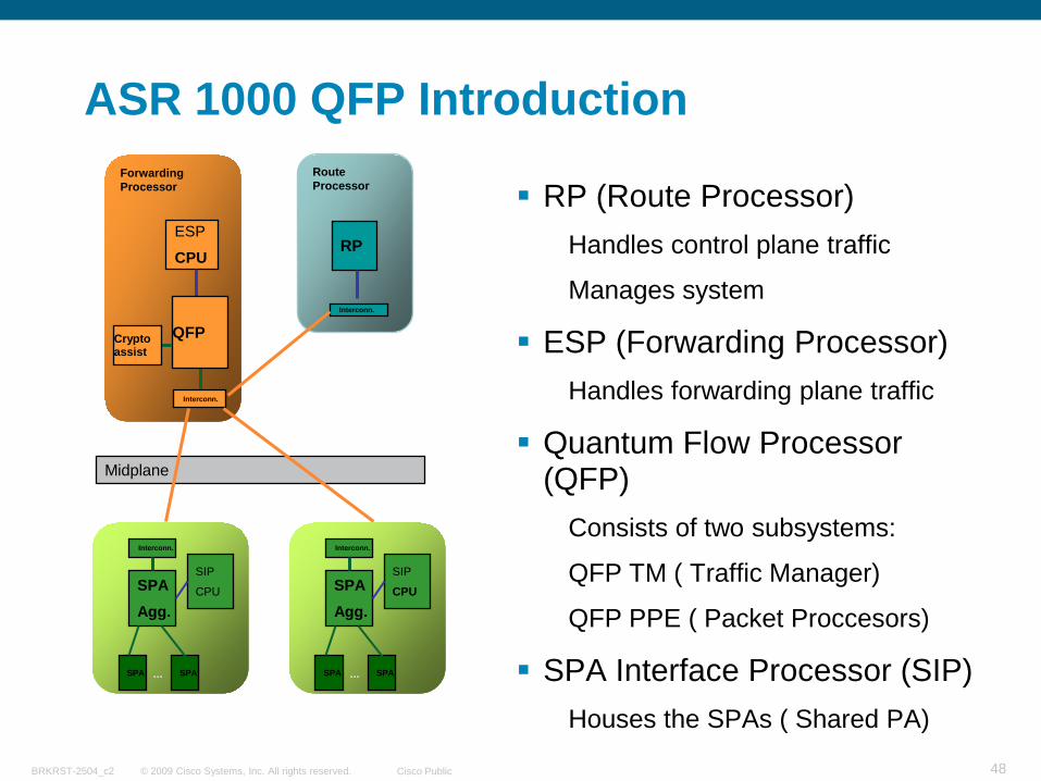
ASR 1000 QFP Introduction
RP (Route Processor)Handles control plane traffic
Manages system
ESP (Forwarding Processor)Handles forwarding plane traffic
Quantum Flow Processor (QFP)
Consists of two subsystems:
QFP TM ( Traffic Manager)
QFP PPE ( Packet Proccesors)
SPA Interface Processor (SIP)Houses the SPAs ( Shared PA)
Forwarding Processor
ESP
CPU
Interconn.
QFPCrypto assist
Midplane
Route Processor
RP
Interconn.
SPASPA
SIP
CPUSPA Agg.
…
Interconn.
SPASPA
SIP
CPUSPA Agg.
…
Interconn.
© 2009 Cisco Systems, Inc. All rights reserved. Cisco PublicBRKRST-2504_c2 49
ASR 1000 QFP and Hierarchical QoS
ASR1000’s QFP was designed specifically to support several scheduling levels
in and outside MQC
QFP’s PPEs are fully dedicated to MQC classification, policing, marking, etc
QFP TM is fully dedicated for Hierarchical QueuingMQC policies are mapped into QFP TM scheduler
Two level of high priority traffic and priority propagation
This capabilities allows the ASR1000 to delivery HQF policies at very high throughput while maintaining LLQ
© 2009 Cisco Systems, Inc. All rights reserved. Cisco PublicBRKRST-2504_c2 50
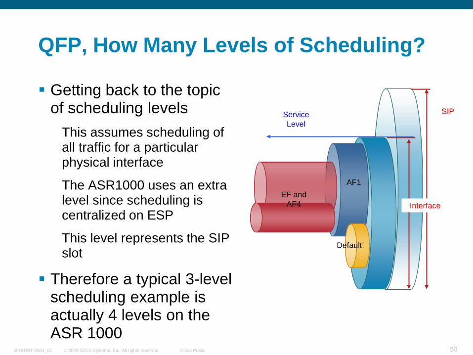
QFP, How Many Levels of Scheduling?
Getting back to the topic of scheduling levels
This assumes scheduling of all traffic for a particular physical interface
The ASR1000 uses an extra level since scheduling is centralized on ESP
This level represents the SIP slot
Therefore a typical 3-level scheduling example is actually 4 levels on the ASR 1000
EF and AF4
AF1
Default
SIP
Interface
Service Level
© 2009 Cisco Systems, Inc. All rights reserved. Cisco PublicBRKRST-2504_c2 51
Basic Hierarchical QoS with IOS MQC
AF4
AF1
Default
Gig 0/1.1001
200 Mbps
Service Level
Policy-map PARENTclass class-defaultshape average 200000000service-policy output CHILD
Policy-map CHILDclass EFpriority level 1
class AF4priority level 2
class AF1bandwidth remaining ratio 9
class class-defaultbandwidth remaining ratio 1
Interface gigabitethernet 0/1.1001service-policy output PARENT
Two MQC Levels
EF
© 2009 Cisco Systems, Inc. All rights reserved. Cisco PublicBRKRST-2504_c2 52
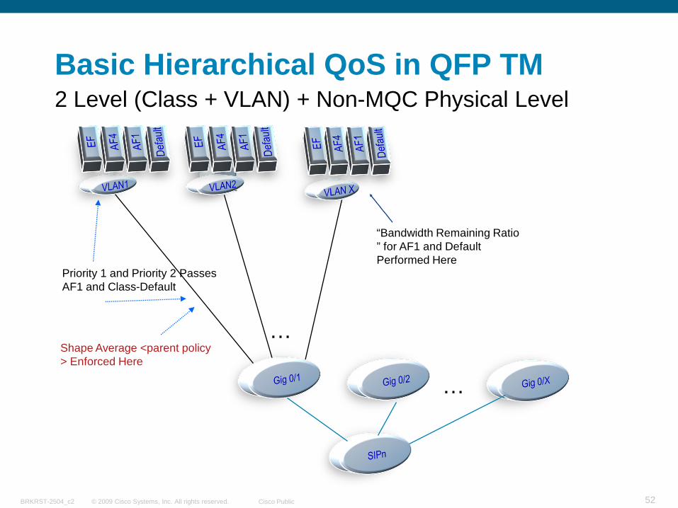
Basic Hierarchical QoS in QFP TM
…
Priority 1 and Priority 2 Passes AF1 and Class-Default
“Bandwidth Remaining Ratio ” for AF1 and Default Performed Here
Shape Average <parent policy > Enforced Here
…
2 Level (Class + VLAN) + Non-MQC Physical Level
© 2009 Cisco Systems, Inc. All rights reserved. Cisco PublicBRKRST-2504_c2 53
Evolution: Policies Aggregation
© 2009 Cisco Systems, Inc. All rights reserved. Cisco PublicBRKRST-2504_c2 54
Why Policies Aggregation
Existing 3-level hierarchy could not handle itNo way to aggregate only data traffic at interface level – interface shaper would shape ALL traffic
Shaper at VLAN level would shape ALL subscriber traffic (Voice/Video/Data), adding extra latency when oversubscribed
Priority queues need to be separated from the Data queues in the hierarchy
Benefit: Priority traffic ( + oversubscribed data) is not capped by logical interface shaper
Introduces the concept of an Economy Class RateThink of airline model: data traffic stays within its assigned class of service all through the hierarchy
First class traffic (like voice/video) is not affected by this rate
Physical & logical interface policies linked via new “fragment CLI”Benefit: Data classes can be linked together to provide both VLAN level and aggregate level service
© 2009 Cisco Systems, Inc. All rights reserved. Cisco PublicBRKRST-2504_c2 55
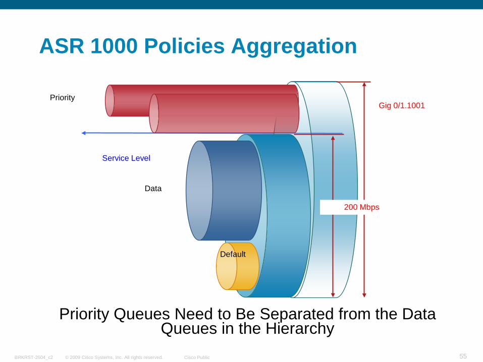
ASR 1000 Policies Aggregation
Priority
Data
Default
Gig 0/1.1001
200 Mbps
Service Level
Priority Queues Need to Be Separated from the Data Queues in the Hierarchy
© 2009 Cisco Systems, Inc. All rights reserved. Cisco PublicBRKRST-2504_c2 56
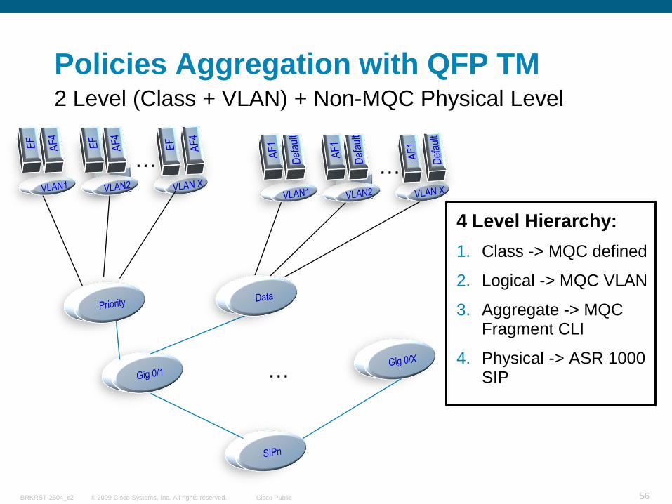
Policies Aggregation with QFP TM
4 Level Hierarchy:1. Class -> MQC defined
2. Logical -> MQC VLAN
3. Aggregate -> MQC Fragment CLI
4. Physical -> ASR 1000 SIP
…
…
…
2 Level (Class + VLAN) + Non-MQC Physical Level
© 2009 Cisco Systems, Inc. All rights reserved. Cisco PublicBRKRST-2504_c2 57
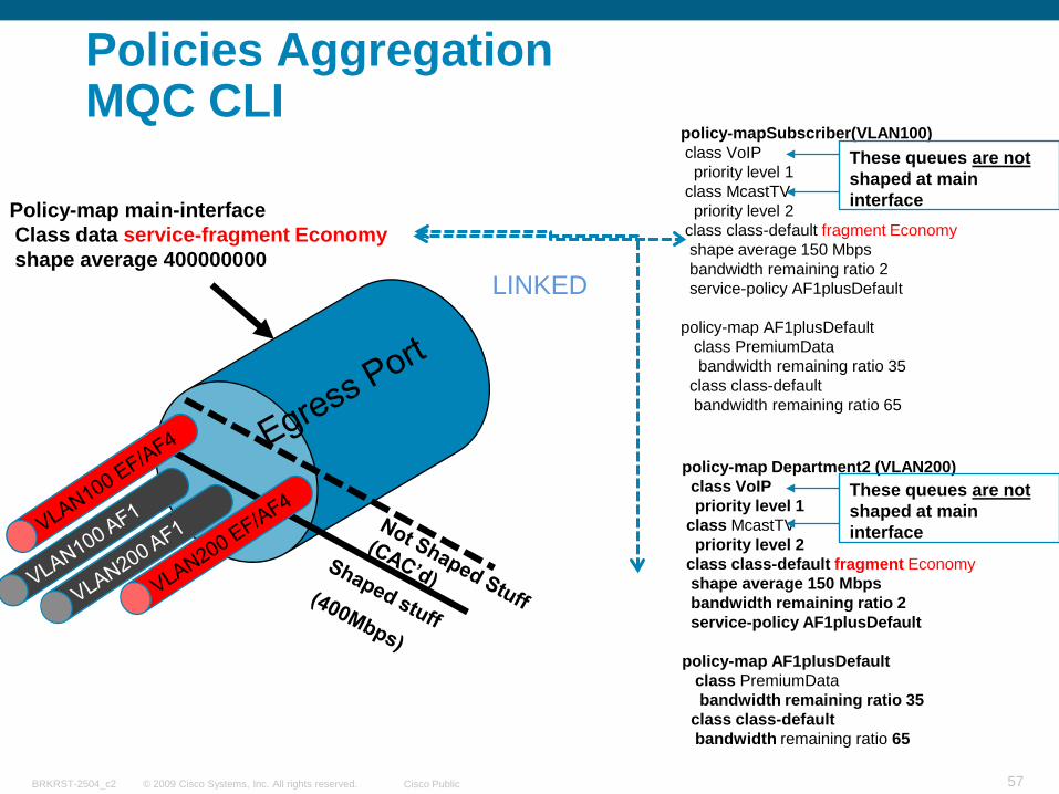
Policies Aggregation MQC CLI
Policy-map main-interfaceClass data service-fragment Economyshape average 400000000
policy-map Department2 (VLAN200)class VoIPpriority level 1
class McastTVpriority level 2
class class-default fragment Economyshape average 150 Mbpsbandwidth remaining ratio 2service-policy AF1plusDefault
policy-map AF1plusDefaultclass PremiumDatabandwidth remaining ratio 35
class class-defaultbandwidth remaining ratio 65
policy-mapSubscriber(VLAN100)class VoIPpriority level 1
class McastTVpriority level 2
class class-default fragment Economyshape average 150 Mbpsbandwidth remaining ratio 2service-policy AF1plusDefault
policy-map AF1plusDefaultclass PremiumDatabandwidth remaining ratio 35
class class-defaultbandwidth remaining ratio 65
These queues are not shaped at main interface
These queues are not shaped at main interface
LINKED
© 2009 Cisco Systems, Inc. All rights reserved. Cisco PublicBRKRST-2504_c2 58
Access SW
IPv4 / IPv6 Dual CoreResidence
CPE NT
AAA/DHCP
Content Servers
SBC
MG
Access SW
ApplicationsRACS
H.248Control
…
LNS
Gq’
Dia
met
er
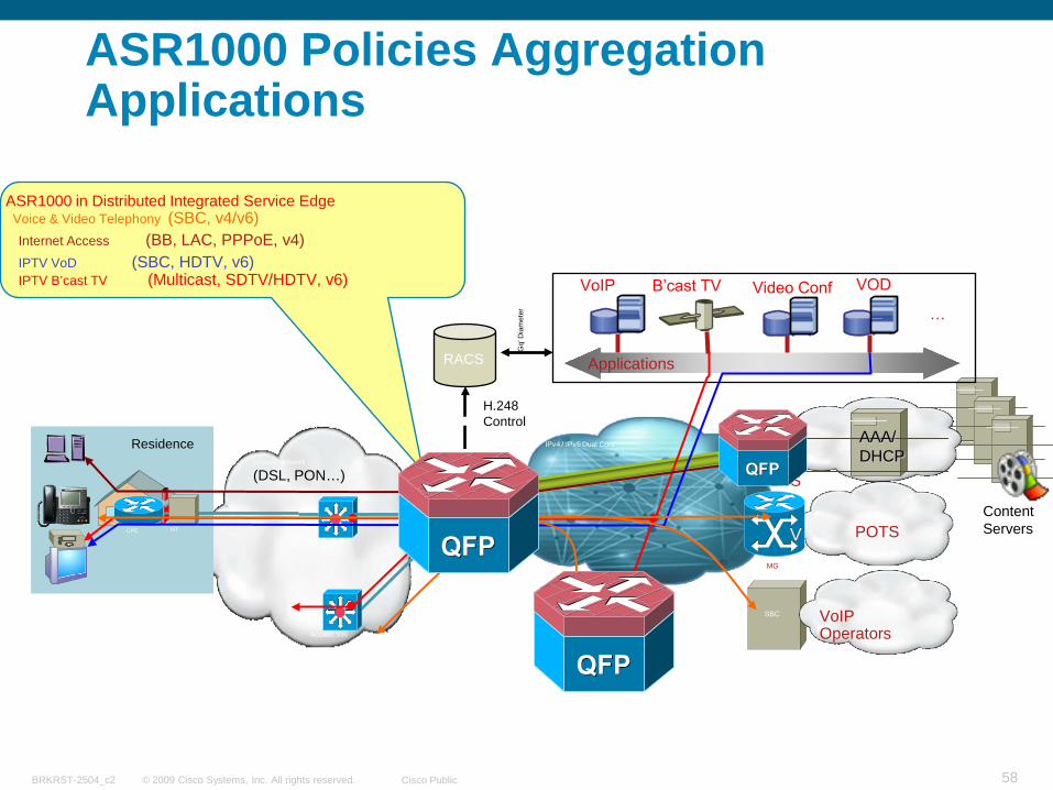
ASR1000 in Distributed Integrated Service EdgeVoice & Video Telephony (SBC, v4/v6)
POTSVV
VoIP Operators
IPTV VoD (SBC, HDTV, v6)Internet Access (BB, LAC, PPPoE, v4)
IPTV B’cast TV (Multicast, SDTV/HDTV, v6)
Access Network
(DSL, PON…)
ASR1000 Policies Aggregation Applications
© 2009 Cisco Systems, Inc. All rights reserved. Cisco PublicBRKRST-2504_c2 59
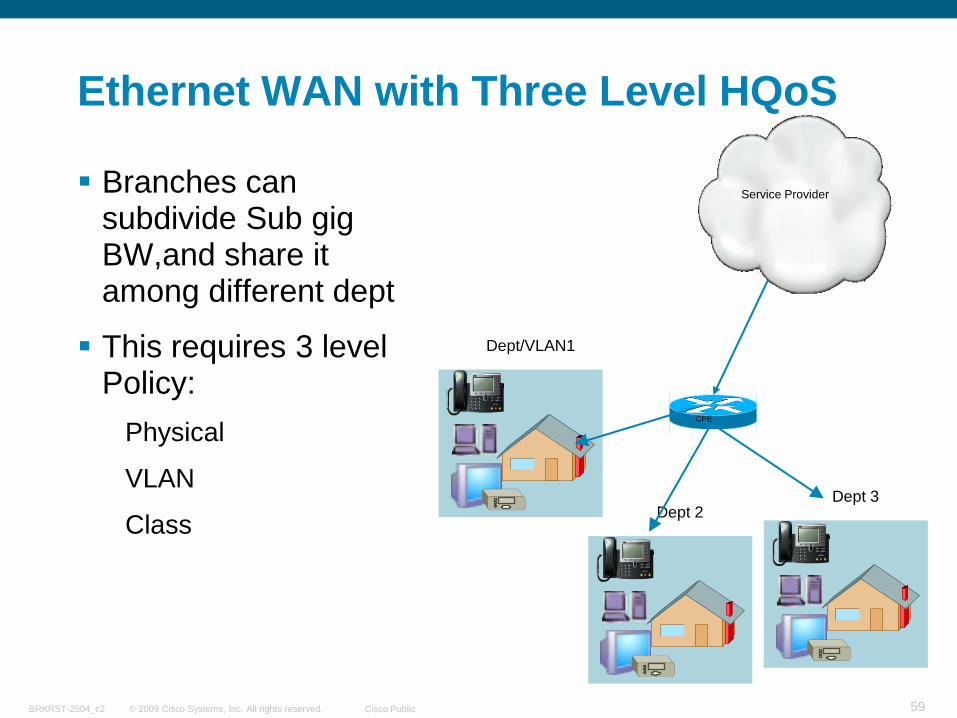
Ethernet WAN with Three Level HQoS
Branches can subdivide Sub gig BW,and share it among different dept
This requires 3 level Policy:
Physical
VLAN
Class
Dept/VLAN1
CPE
Service Provider
Dept 2Dept 3
© 2009 Cisco Systems, Inc. All rights reserved. Cisco PublicBRKRST-2504_c2 60
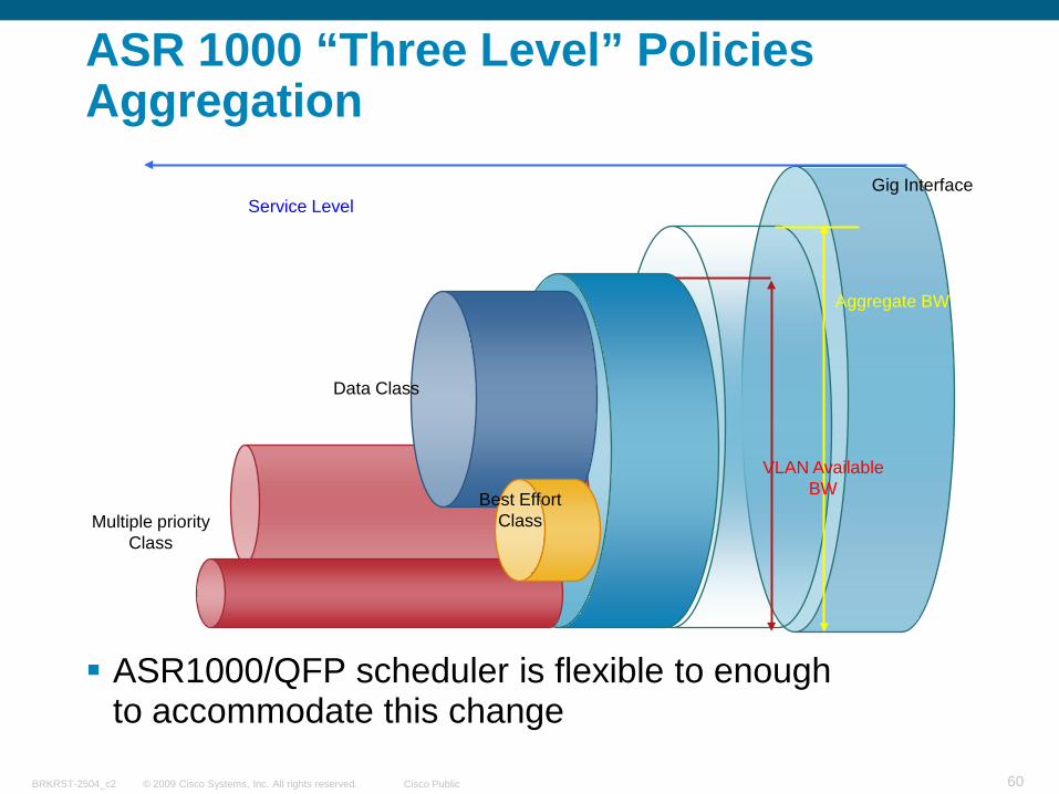
ASR 1000 “Three Level” Policies Aggregation
ASR1000/QFP scheduler is flexible to enough to accommodate this change
Multiple priority Class
Data Class
Best EffortClass
Aggregate BW
VLAN Available BW
Service LevelGig Interface
© 2009 Cisco Systems, Inc. All rights reserved. Cisco PublicBRKRST-2504_c2 61
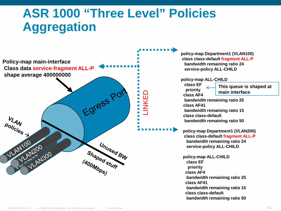
ASR 1000 “Three Level” Policies Aggregation
Policy-map main-interfaceClass data service-fragment ALL-Pshape average 400000000
policy-map Department1 (VLAN100)class class-default fragment ALL-Pbandwidth remaining ratio 24service-policy ALL-CHILD
policy-map ALL-CHILDclass EFpriority
class AF4bandwidth remaining ratio 25class AF41bandwidth remaining ratio 15class class-defaultbandwidth remaining ratio 50
LIN
KE
D
policy-map Department1 (VLAN200)class class-default fragment ALL-Pbandwidth remaining ratio 24service-policy ALL-CHILD
policy-map ALL-CHILDclass EFpriority
class AF4bandwidth remaining ratio 25class AF41bandwidth remaining ratio 15class class-defaultbandwidth remaining ratio 50
This queue is shaped at main interface
© 2009 Cisco Systems, Inc. All rights reserved. Cisco PublicBRKRST-2504_c2 62
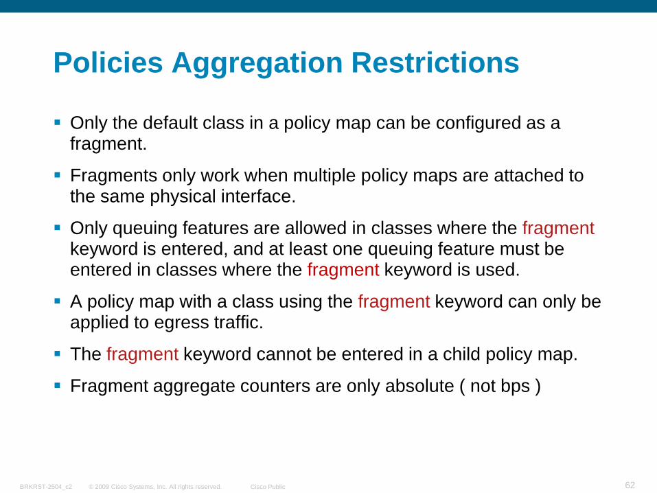
Policies Aggregation Restrictions
Only the default class in a policy map can be configured as a fragment.
Fragments only work when multiple policy maps are attached to the same physical interface.
Only queuing features are allowed in classes where the fragmentkeyword is entered, and at least one queuing feature must be entered in classes where the fragment keyword is used.
A policy map with a class using the fragment keyword can only be applied to egress traffic.
The fragment keyword cannot be entered in a child policy map.
Fragment aggregate counters are only absolute ( not bps )
© 2009 Cisco Systems, Inc. All rights reserved. Cisco PublicBRKRST-2504_c2 63
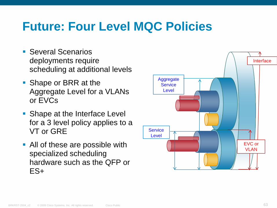
Future: Four Level MQC Policies
Several Scenarios deployments require scheduling at additional levels
Shape or BRR at the Aggregate Level for a VLANs or EVCs
Shape at the Interface Level for a 3 level policy applies to a VT or GRE
All of these are possible with specialized scheduling hardware such as the QFP or ES+
Service Level
Aggregate Service Level
Interface
EVC or VLAN
© 2009 Cisco Systems, Inc. All rights reserved. Cisco PublicBRKRST-2504_c2 64
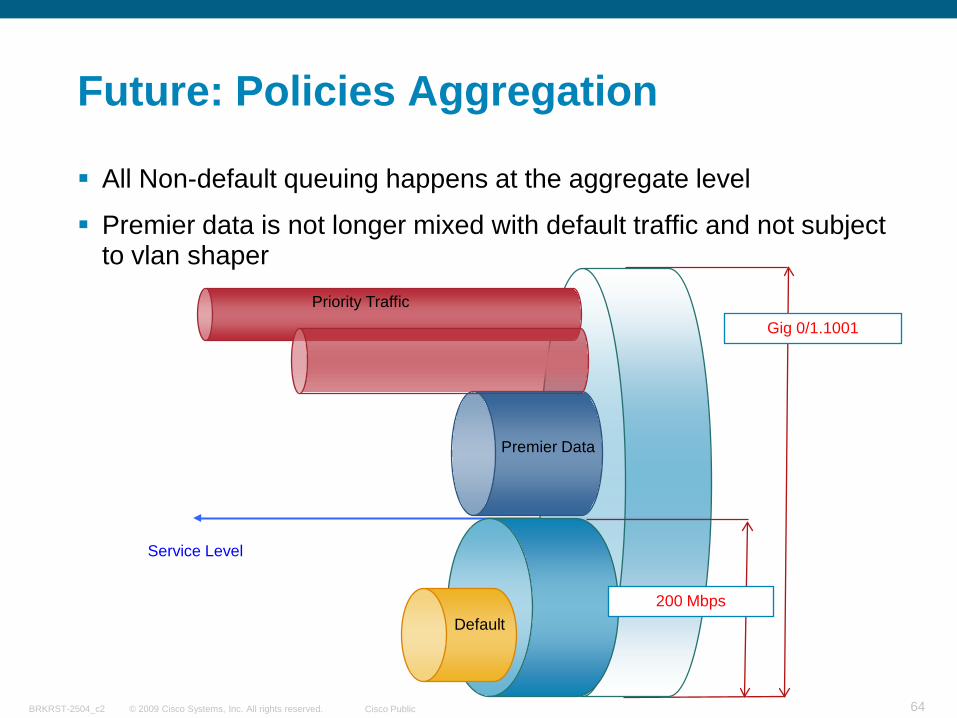
Future: Policies Aggregation
All Non-default queuing happens at the aggregate level
Premier data is not longer mixed with default traffic and not subject to vlan shaper
Priority Traffic
Premier Data
Default
Service Level
Gig 0/1.1001
200 Mbps
© 2009 Cisco Systems, Inc. All rights reserved. Cisco PublicBRKRST-2504_c2 65
Summary
© 2009 Cisco Systems, Inc. All rights reserved. Cisco PublicBRKRST-2504_c2 66
Summary HQoS and Policies Aggregation
Hierarchical QoS gives you great flexibility to distribute and manage bandwidth
Service Providers can overprovision, and basically resell the same bandwidth
Enterprises can redistribute bandwidth according each campus, user or application usage
HQF establishes the foundation to deliver a much more uniform and consistent QoS scheduling behavior
Cisco ASR1000, QFP and its Policies Aggregation, allows for even a greater flexibility in order to satisfy a diverse set of requirements.
© 2009 Cisco Systems, Inc. All rights reserved. Cisco PublicBRKRST-2504_c2 67
HQoS and Policies Aggregation Doc
HQF documentationhttp://www.cisco.com/en/US/prod/collateral/iosswrel/ps6537/ps6558/white_paper_c11-481499.html
Policies Aggregation documentationhttp://www.cisco.com/en/US/docs/ios/ios_xe/qos/configuration/guide/qos_policies_agg_xe_ps9587_TSD_Products_Configuration_Guide_Chapter.html
© 2009 Cisco Systems, Inc. All rights reserved. Cisco PublicBRKRST-2504_c2 68
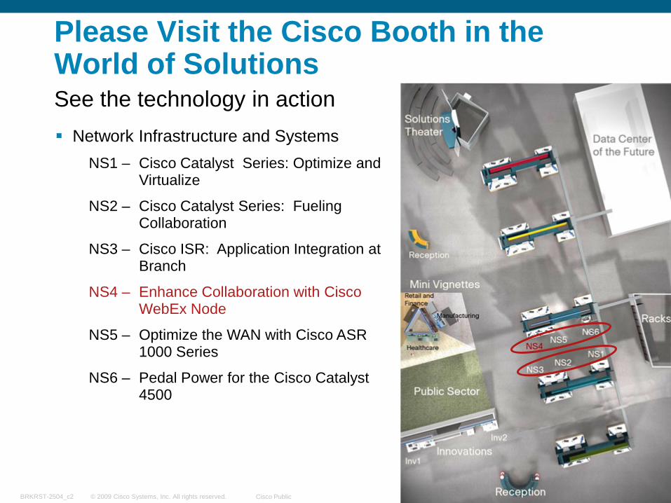
Network Infrastructure and SystemsNS1 – Cisco Catalyst Series: Optimize and
Virtualize
NS2 – Cisco Catalyst Series: Fueling Collaboration
NS3 – Cisco ISR: Application Integration at Branch
NS4 – Enhance Collaboration with Cisco WebEx Node
NS5 – Optimize the WAN with Cisco ASR 1000 Series
NS6 – Pedal Power for the Cisco Catalyst 4500
Please Visit the Cisco Booth in theWorld of SolutionsSee the technology in action
© 2009 Cisco Systems, Inc. All rights reserved. Cisco PublicBRKRST-2504_c2 69
Recommended Reading
End-to-End QoS Network Design: Quality of Service in LANs, WANs, and VPNs, ISBN: 1-58705-176-1
Cisco Catalyst QoS: Quality of Service in Campus Networks, ISBN: 1587051206
QoS for IP/MPLS Networks, ISBN: 1-58705-233-4
© 2009 Cisco Systems, Inc. All rights reserved. Cisco PublicBRKRST-2504_c2 70
Complete Your Online Session Evaluation
Give us your feedback and you could win fabulous prizes. Winners announced daily.
Receive 20 Passport points for each session evaluation you complete.
Complete your session evaluation online now (open a browser through our wireless network to access our portal) or visit one of the Internet stations throughout the Convention Center. Don’t forget to activate your
Cisco Live Virtual account for access to all session material, communities, andon-demand and live activities throughout the year. Activate your account at the Cisco booth in the World of Solutions or visit www.ciscolive.com.
© 2009 Cisco Systems, Inc. All rights reserved. Cisco PublicBRKRST-2504_c2 71
Related Documents