1 Installation and Operating Instructions for MP-ULTRAPRO10 with Autoflush Model #: _______ MPULT10XXFL Twin-Ultra Pro with Autoflush Shipping Carton Description / unit: # of cartons Contents Description 2 Ultrafilter tank Ultrafilter tank 2 MP-MCA UF control valve MP-MCA control valve, and bypass with pipe connections 2 V3070FM No Hard Water Bypass (NHWB) valve normally open (INLET) 2 V3070FM N/C Autoflush valve normally closed (FLUSH)

Welcome message from author
This document is posted to help you gain knowledge. Please leave a comment to let me know what you think about it! Share it to your friends and learn new things together.
Transcript
1
Installation and Operating Instructions for MP-ULTRAPRO10 with Autoflush
Model #: _______ MPULT10XXFL Twin-Ultra Pro with Autoflush Shipping Carton Description / unit:
# of
cartons Contents Description
2 Ultrafilter tank Ultrafilter tank
2 MP-MCA UF control valve
MP-MCA control valve, and bypass with pipe connections
2 V3070FM No Hard Water Bypass (NHWB) valve normally open (INLET)
2 V3070FM N/C Autoflush valve normally closed (FLUSH)
2
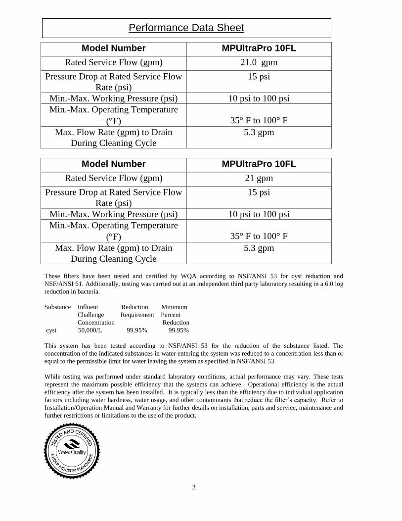
These filters have been tested and certified by WQA according to NSF/ANSI 53 for cyst reduction and
NSF/ANSI 61. Additionally, testing was carried out at an independent third party laboratory resulting in a 6.0 log
reduction in bacteria.
Substance Influent Reduction Minimum
Challenge Requirement Percent
Concentration Reduction
cyst 50,000/L 99.95% 99.95%
This system has been tested according to NSF/ANSI 53 for the reduction of the substance listed. The
concentration of the indicated substances in water entering the system was reduced to a concentration less than or
equal to the permissible limit for water leaving the system as specified in NSF/ANSI 53.
While testing was performed under standard laboratory conditions, actual performance may vary. These tests
represent the maximum possible efficiency that the systems can achieve. Operational efficiency is the actual
efficiency after the system has been installed. It is typically less than the efficiency due to individual application
factors including water hardness, water usage, and other contaminants that reduce the filter’s capacity. Refer to
Installation/Operation Manual and Warranty for further details on installation, parts and service, maintenance and
further restrictions or limitations to the use of the product.
Model Number MPUltraPro 10FL
Rated Service Flow (gpm) 21.0 gpm
Pressure Drop at Rated Service Flow
Rate (psi)
15 psi
Min.-Max. Working Pressure (psi) 10 psi to 100 psi
Min.-Max. Operating Temperature
(F)
35° F to 100° F
Max. Flow Rate (gpm) to Drain
During Cleaning Cycle
5.3 gpm
Model Number MPUltraPro 10FL
Rated Service Flow (gpm) 21 gpm
Pressure Drop at Rated Service Flow
Rate (psi)
15 psi
Min.-Max. Working Pressure (psi) 10 psi to 100 psi
Min.-Max. Operating Temperature
(F)
35° F to 100° F
Max. Flow Rate (gpm) to Drain
During Cleaning Cycle
5.3 gpm
Performance Data Sheet
3
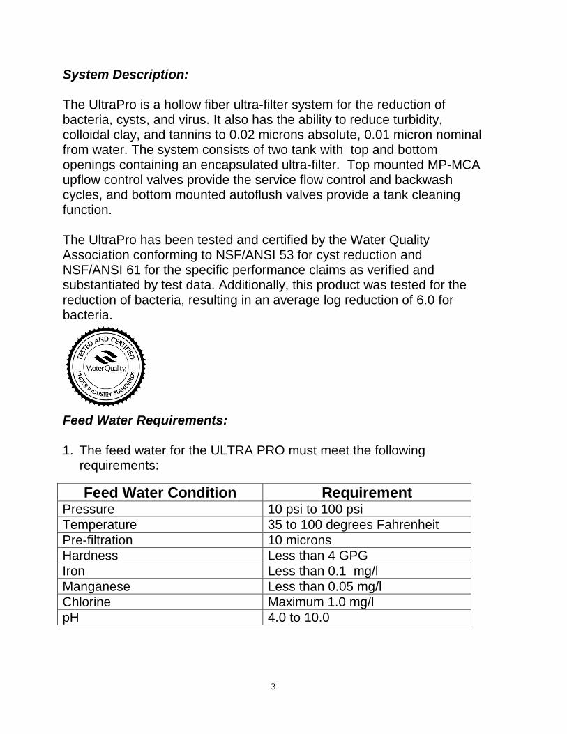
System Description: The UltraPro is a hollow fiber ultra-filter system for the reduction of bacteria, cysts, and virus. It also has the ability to reduce turbidity, colloidal clay, and tannins to 0.02 microns absolute, 0.01 micron nominal from water. The system consists of two tank with top and bottom openings containing an encapsulated ultra-filter. Top mounted MP-MCA upflow control valves provide the service flow control and backwash cycles, and bottom mounted autoflush valves provide a tank cleaning function. The UltraPro has been tested and certified by the Water Quality Association conforming to NSF/ANSI 53 for cyst reduction and NSF/ANSI 61 for the specific performance claims as verified and substantiated by test data. Additionally, this product was tested for the reduction of bacteria, resulting in an average log reduction of 6.0 for bacteria. Feed Water Requirements: 1. The feed water for the ULTRA PRO must meet the following
requirements:
Feed Water Condition Requirement Pressure 10 psi to 100 psi
Temperature 35 to 100 degrees Fahrenheit
Pre-filtration 10 microns
Hardness Less than 4 GPG
Iron Less than 0.1 mg/l
Manganese Less than 0.05 mg/l
Chlorine Maximum 1.0 mg/l
pH 4.0 to 10.0
4
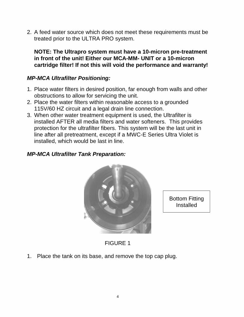
2. A feed water source which does not meet these requirements must be treated prior to the ULTRA PRO system.
NOTE: The Ultrapro system must have a 10-micron pre-treatment
in front of the unit! Either our MCA-MM- UNIT or a 10-micron
cartridge filter! If not this will void the performance and warranty! MP-MCA Ultrafilter Positioning:
1. Place water filters in desired position, far enough from walls and other obstructions to allow for servicing the unit.
2. Place the water filters within reasonable access to a grounded 115V/60 HZ circuit and a legal drain line connection.
3. When other water treatment equipment is used, the Ultrafilter is installed AFTER all media filters and water softeners. This provides protection for the ultrafilter fibers. This system will be the last unit in line after all pretreatment, except if a MWC-E Series Ultra Violet is installed, which would be last in line.
MP-MCA Ultrafilter Tank Preparation:
FIGURE 1 1. Place the tank on its base, and remove the top cap plug.
Bottom Fitting Installed
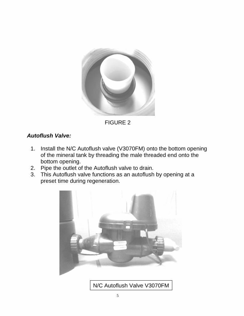
5
FIGURE 2 Autoflush Valve:
1. Install the N/C Autoflush valve (V3070FM) onto the bottom opening of the mineral tank by threading the male threaded end onto the bottom opening.
2. Pipe the outlet of the Autoflush valve to drain. 3. This Autoflush valve functions as an autoflush by opening at a
preset time during regeneration.
N/C Autoflush Valve V3070FM
6
Filling the Ultrafilter with Water: 1. Before threading the control valves onto the Ultrafilter tanks, fill the
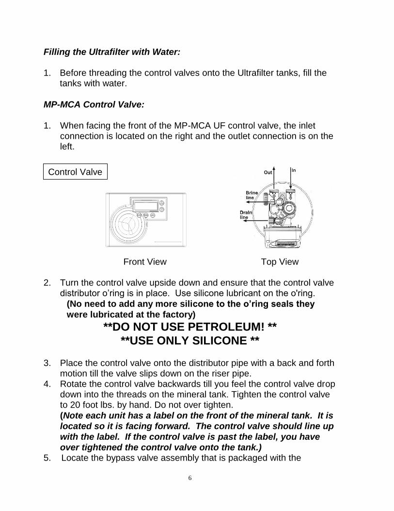
tanks with water. MP-MCA Control Valve: 1. When facing the front of the MP-MCA UF control valve, the inlet
connection is located on the right and the outlet connection is on the left.
Front View Top View 2. Turn the control valve upside down and ensure that the control valve
distributor o’ring is in place. Use silicone lubricant on the o'ring.
(No need to add any more silicone to the o’ring seals they
were lubricated at the factory)
**DO NOT USE PETROLEUM! **
**USE ONLY SILICONE ** 3. Place the control valve onto the distributor pipe with a back and forth
motion till the valve slips down on the riser pipe. 4. Rotate the control valve backwards till you feel the control valve drop
down into the threads on the mineral tank. Tighten the control valve to 20 foot lbs. by hand. Do not over tighten.
(Note each unit has a label on the front of the mineral tank. It is located so it is facing forward. The control valve should line up with the label. If the control valve is past the label, you have over tightened the control valve onto the tank.)
5. Locate the bypass valve assembly that is packaged with the
Control Valve
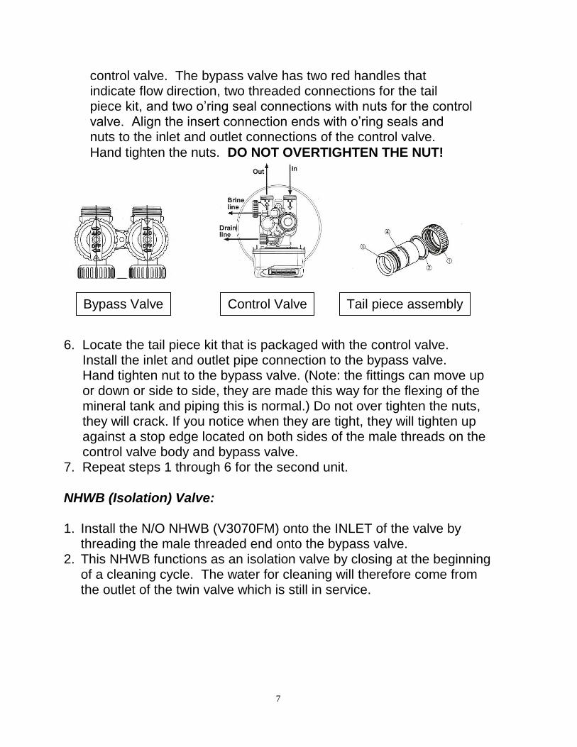
7
control valve. The bypass valve has two red handles that indicate flow direction, two threaded connections for the tail piece kit, and two o’ring seal connections with nuts for the control valve. Align the insert connection ends with o’ring seals and nuts to the inlet and outlet connections of the control valve.
Hand tighten the nuts. DO NOT OVERTIGHTEN THE NUT!
6. Locate the tail piece kit that is packaged with the control valve. Install the inlet and outlet pipe connection to the bypass valve. Hand tighten nut to the bypass valve. (Note: the fittings can move up or down or side to side, they are made this way for the flexing of the mineral tank and piping this is normal.) Do not over tighten the nuts, they will crack. If you notice when they are tight, they will tighten up against a stop edge located on both sides of the male threads on the control valve body and bypass valve. 7. Repeat steps 1 through 6 for the second unit. NHWB (Isolation) Valve: 1. Install the N/O NHWB (V3070FM) onto the INLET of the valve by
threading the male threaded end onto the bypass valve. 2. This NHWB functions as an isolation valve by closing at the beginning
of a cleaning cycle. The water for cleaning will therefore come from the outlet of the twin valve which is still in service.
Control Valve Bypass Valve Tail piece assembly
8
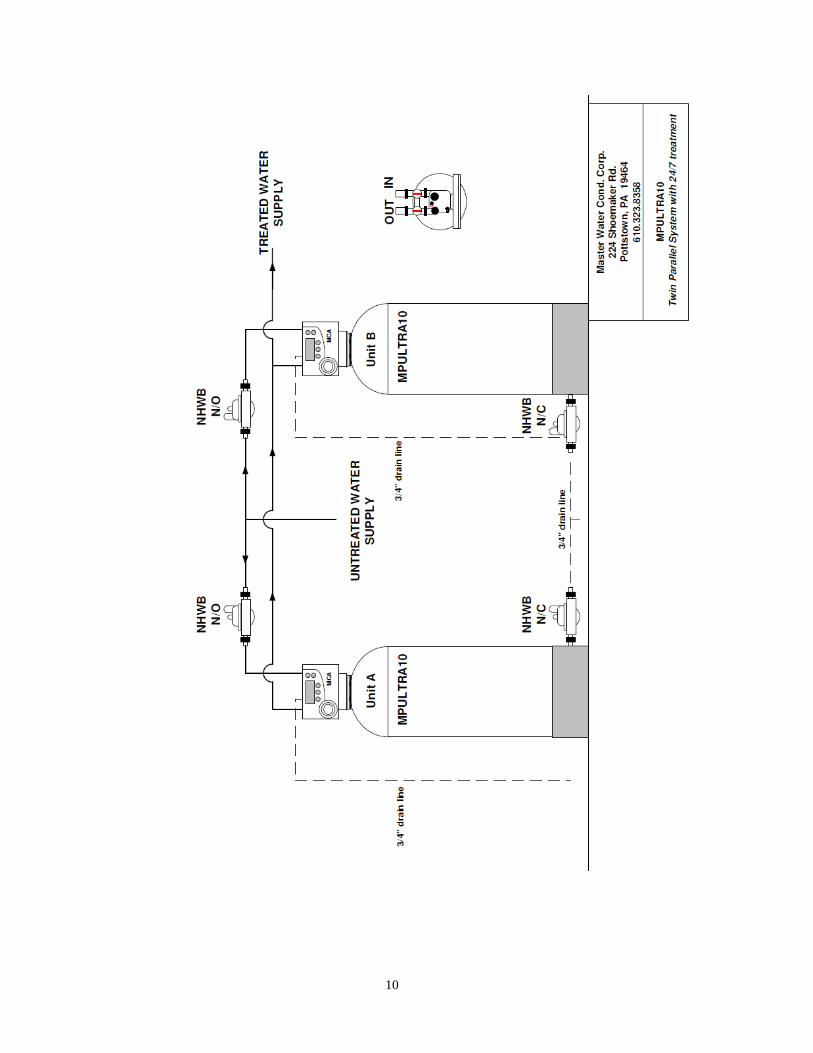
Service and Drain Piping:
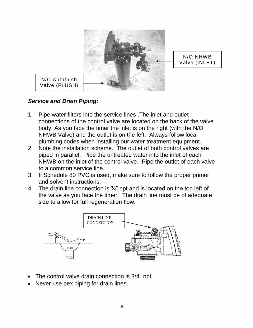
1. Pipe water filters into the service lines .The inlet and outlet
connections of the control valve are located on the back of the valve body. As you face the timer the inlet is on the right (with the N/O NHWB Valve) and the outlet is on the left. Always follow local plumbing codes when installing our water treatment equipment.
2. Note the installation scheme. The outlet of both control valves are piped in parallel. Pipe the untreated water into the inlet of each NHWB on the inlet of the control valve. Pipe the outlet of each valve to a common service line.
3. If Schedule 80 PVC is used, make sure to follow the proper primer and solvent instructions.
4. The drain line connection is ¾” npt and is located on the top left of the valve as you face the timer. The drain line must be of adequate size to allow for full regeneration flow.
The control valve drain connection is 3/4" npt.
Never use pex piping for drain lines.
DRAIN LINE
CONNECTION
N/O NHWB Valve (INLET)
N/C Autof lush Valve (FLUSH)
9
Never decrease the drain piping size to below the drain connection size.
Maximum drain line length is 30 feet with slope the entire length.
Maximum drain line height is 6 feet above the control valve.
The drain line must be piped to an open air gap (See Figure above).
Always follow local plumbing codes.
UNDER NO CIRCUMSTANCES SHOULD THERE BE A DIRECT
CONNECTION WITH SANITARY SEWAGE FACILITIES.
10
11
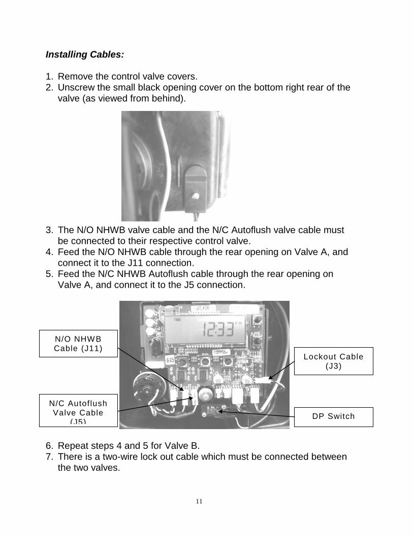
Installing Cables: 1. Remove the control valve covers. 2. Unscrew the small black opening cover on the bottom right rear of the
valve (as viewed from behind).
3. The N/O NHWB valve cable and the N/C Autoflush valve cable must be connected to their respective control valve.
4. Feed the N/O NHWB cable through the rear opening on Valve A, and connect it to the J11 connection.
5. Feed the N/C NHWB Autoflush cable through the rear opening on Valve A, and connect it to the J5 connection.
6. Repeat steps 4 and 5 for Valve B. 7. There is a two-wire lock out cable which must be connected between
the two valves.
N/O NHWB Cable (J11)
N/C Autof lush Valve Cable
(J5)
Lockout Cable (J3)
DP Switch
12
8. Feed the lock out cable from valve A through the rear opening on Valve B.
9. Connect the lock-out cable to the J3 connection (DP SWITCH) on the right side of the circuit board on Valve B.
10. Feed the lock out cable from valve B through the rear opening on Valve A.
11. Connect the lock-out cable to the J3 connection (DP SWITCH) on the right side of the circuit board on Valve A.
12. Replace the black opening cover on the rear of the control valves. 13. Replace the control valve timer covers.
Electrical Requirements: Always follow all local electrical codes when installing our water treatment equipment.
1. Provide an 115v/60Hz properly grounded, dedicated electrical outlet. (It’s very important that the polarity be correct) Avoid using outlets that are switch controlled.
2. Maximum amperage required is 5 amps. 3. Make sure the electrical service provides power 24 hours per day.
We recommend installing a surge protector to protect unit from power surges, which are not covered by warranty. Flushing the Ultrafilter:
1. Connect each MP-MCA UF control valve transformer into an electrical outlet.
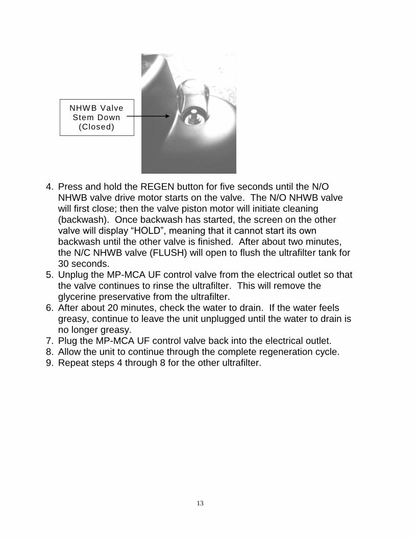
2. The valve screens will be activated. 3. Also note that each N/O NHWB (INLET) valve stem is in the UP
(Open) position, and each N/C Autoflush valve (FLUSH) valve stem is in the DOWN (Closed) position.
13
4. Press and hold the REGEN button for five seconds until the N/O
NHWB valve drive motor starts on the valve. The N/O NHWB valve will first close; then the valve piston motor will initiate cleaning (backwash). Once backwash has started, the screen on the other valve will display “HOLD”, meaning that it cannot start its own backwash until the other valve is finished. After about two minutes, the N/C NHWB valve (FLUSH) will open to flush the ultrafilter tank for 30 seconds.
5. Unplug the MP-MCA UF control valve from the electrical outlet so that the valve continues to rinse the ultrafilter. This will remove the glycerine preservative from the ultrafilter.
6. After about 20 minutes, check the water to drain. If the water feels greasy, continue to leave the unit unplugged until the water to drain is no longer greasy.
7. Plug the MP-MCA UF control valve back into the electrical outlet. 8. Allow the unit to continue through the complete regeneration cycle. 9. Repeat steps 4 through 8 for the other ultrafilter.
NHWB Valve Stem Down
(Closed)
14
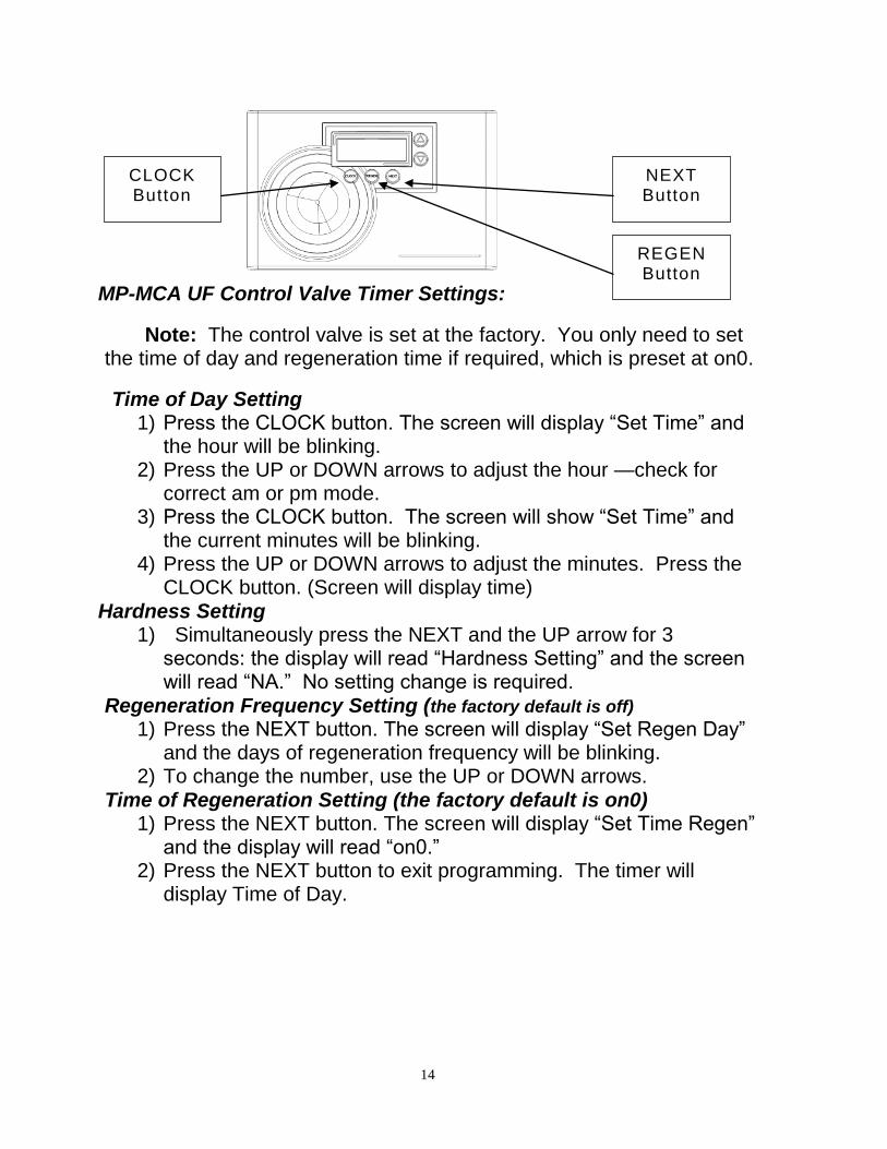
MP-MCA UF Control Valve Timer Settings:
Note: The control valve is set at the factory. You only need to set the time of day and regeneration time if required, which is preset at on0.
Time of Day Setting 1) Press the CLOCK button. The screen will display “Set Time” and
the hour will be blinking. 2) Press the UP or DOWN arrows to adjust the hour —check for
correct am or pm mode. 3) Press the CLOCK button. The screen will show “Set Time” and
the current minutes will be blinking. 4) Press the UP or DOWN arrows to adjust the minutes. Press the
CLOCK button. (Screen will display time) Hardness Setting
1) Simultaneously press the NEXT and the UP arrow for 3 seconds: the display will read “Hardness Setting” and the screen will read “NA.” No setting change is required.
Regeneration Frequency Setting (the factory default is off)
1) Press the NEXT button. The screen will display “Set Regen Day” and the days of regeneration frequency will be blinking.
2) To change the number, use the UP or DOWN arrows. Time of Regeneration Setting (the factory default is on0)
1) Press the NEXT button. The screen will display “Set Time Regen” and the display will read “on0.”
2) Press the NEXT button to exit programming. The timer will display Time of Day.
CLOCK Button
NEXT Button
REGEN Button
15
Final Check: 1. Make sure the drain line connection meets all plumbing codes and
that the drain line size can handle the backwash flow rate of the ultrafilter.
2. Make sure the drain line is properly secured in place. 3. Make sure the Inlet and Outlet on bypass valve are open. 4. Make sure the control valve timer is plugged into an electrical outlet
with power 24 hours per day. 5. Check all piping for leaks.
16
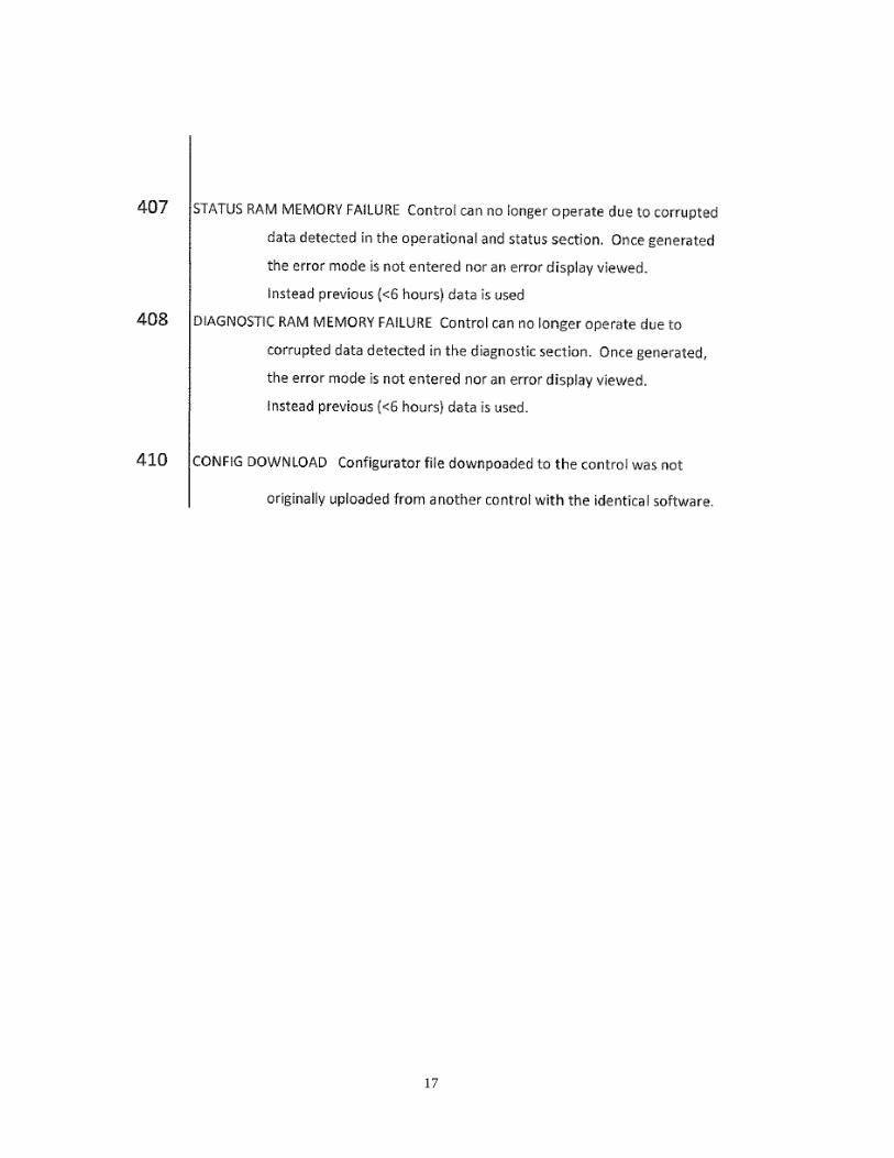
ERROR CODES
17
18
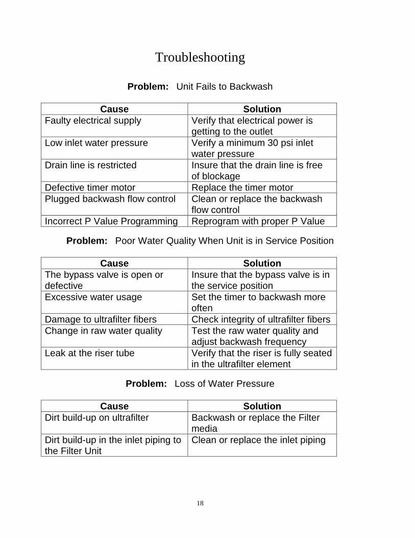
Troubleshooting
Problem: Unit Fails to Backwash
Cause Solution
Faulty electrical supply Verify that electrical power is getting to the outlet
Low inlet water pressure Verify a minimum 30 psi inlet water pressure
Drain line is restricted Insure that the drain line is free of blockage
Defective timer motor Replace the timer motor
Plugged backwash flow control Clean or replace the backwash flow control
Incorrect P Value Programming Reprogram with proper P Value
Problem: Poor Water Quality When Unit is in Service Position
Cause Solution
The bypass valve is open or defective
Insure that the bypass valve is in the service position
Excessive water usage Set the timer to backwash more often
Damage to ultrafilter fibers Check integrity of ultrafilter fibers
Change in raw water quality Test the raw water quality and adjust backwash frequency
Leak at the riser tube Verify that the riser is fully seated in the ultrafilter element
Problem: Loss of Water Pressure
Cause Solution
Dirt build-up on ultrafilter Backwash or replace the Filter media
Dirt build-up in the inlet piping to the Filter Unit
Clean or replace the inlet piping
19
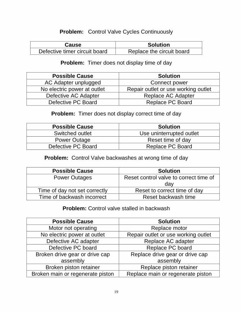
Problem: Control Valve Cycles Continuously
Cause Solution
Defective timer circuit board Replace the circuit board
Problem: Timer does not display time of day
Possible Cause Solution
AC Adapter unplugged Connect power
No electric power at outlet Repair outlet or use working outlet
Defective AC Adapter Replace AC Adapter
Defective PC Board Replace PC Board
Problem: Timer does not display correct time of day
Possible Cause Solution
Switched outlet Use uninterrupted outlet
Power Outage Reset time of day
Defective PC Board Replace PC Board
Problem: Control Valve backwashes at wrong time of day
Possible Cause Solution
Power Outages Reset control valve to correct time of day
Time of day not set correctly Reset to correct time of day
Time of backwash incorrect Reset backwash time
Problem: Control valve stalled in backwash
Possible Cause Solution
Motor not operating Replace motor
No electric power at outlet Repair outlet or use working outlet
Defective AC adapter Replace AC adapter
Defective PC board Replace PC board
Broken drive gear or drive cap assembly
Replace drive gear or drive cap assembly
Broken piston retainer Replace piston retainer
Broken main or regenerate piston Replace main or regenerate piston
20
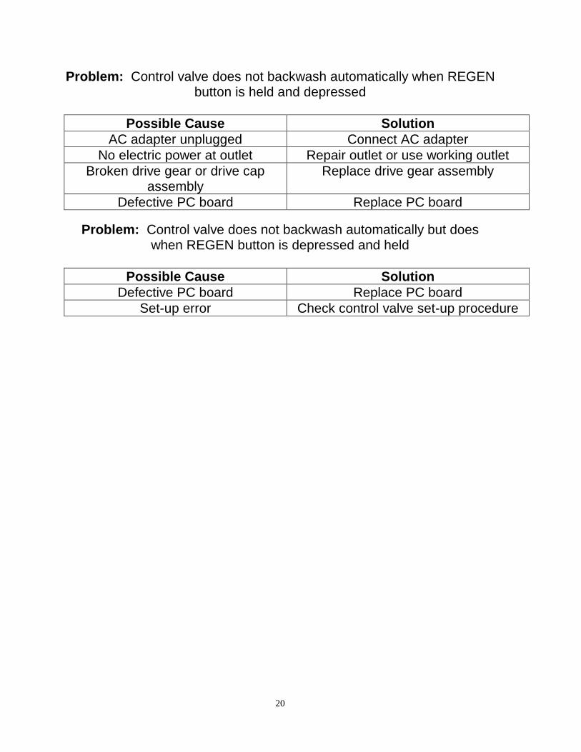
Problem: Control valve does not backwash automatically when REGEN button is held and depressed
Possible Cause Solution
AC adapter unplugged Connect AC adapter
No electric power at outlet Repair outlet or use working outlet
Broken drive gear or drive cap assembly
Replace drive gear assembly
Defective PC board Replace PC board
Problem: Control valve does not backwash automatically but does when REGEN button is depressed and held
Possible Cause Solution
Defective PC board Replace PC board
Set-up error Check control valve set-up procedure
21
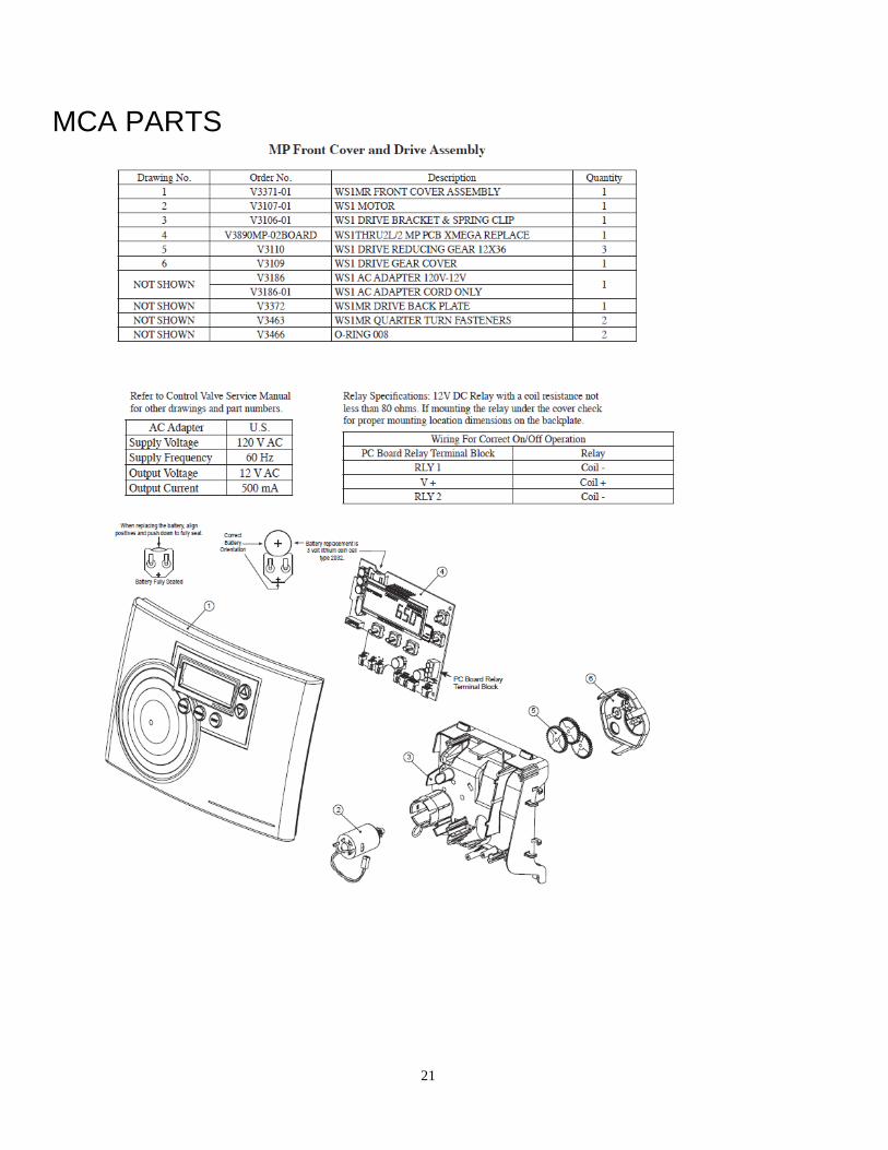
MCA PARTS
22
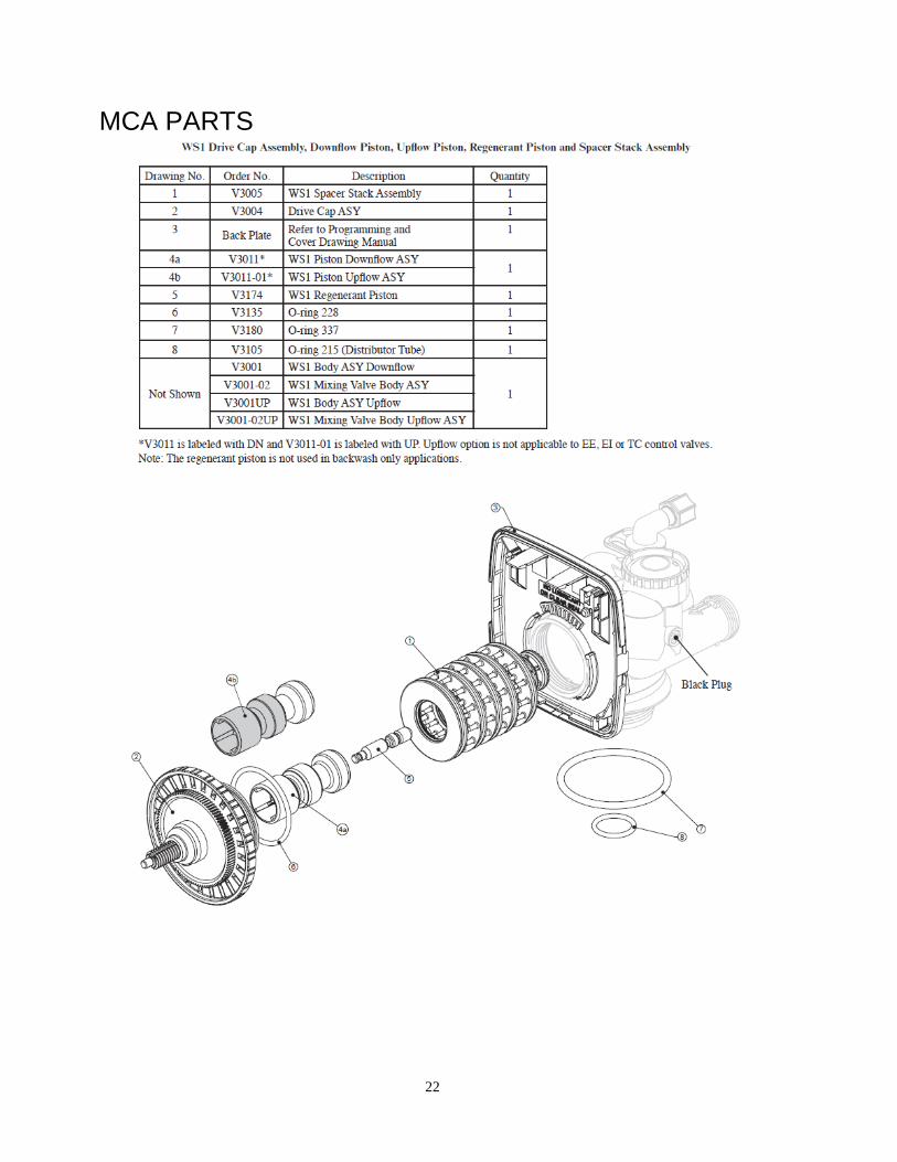
MCA PARTS
23
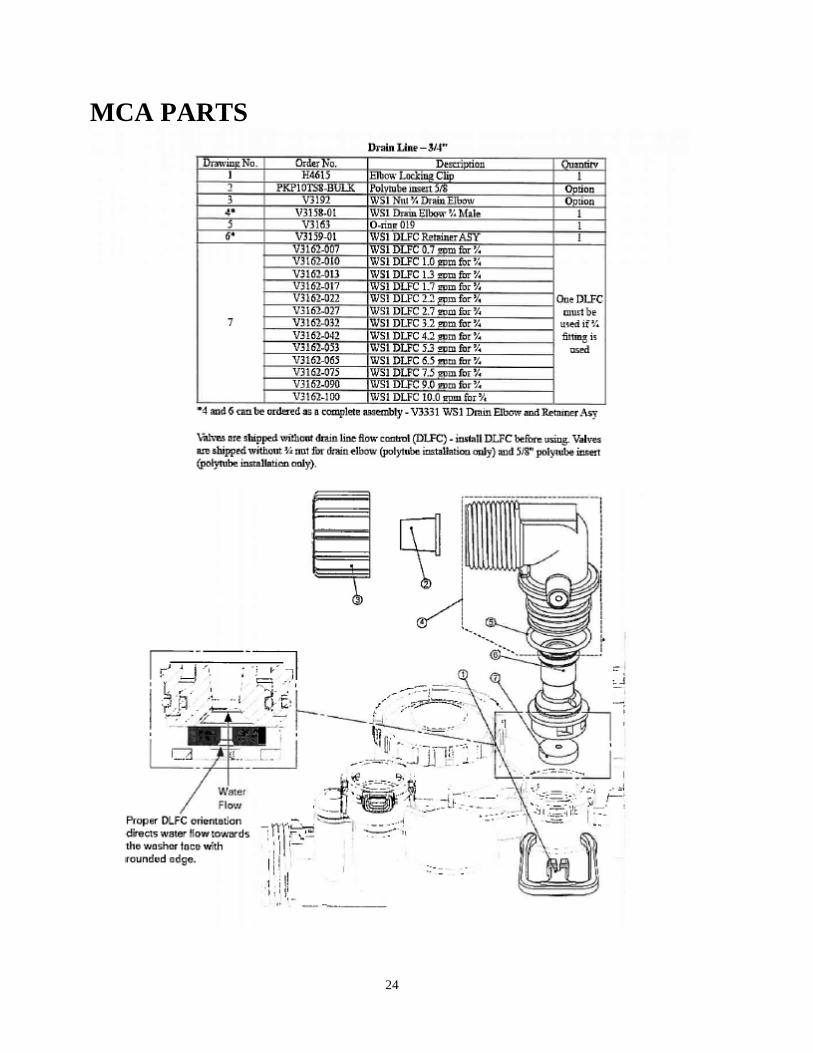
24
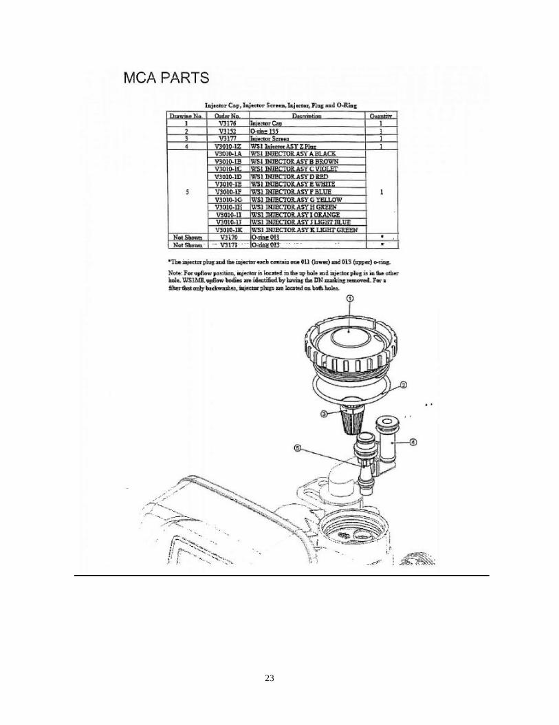
MCA PARTS
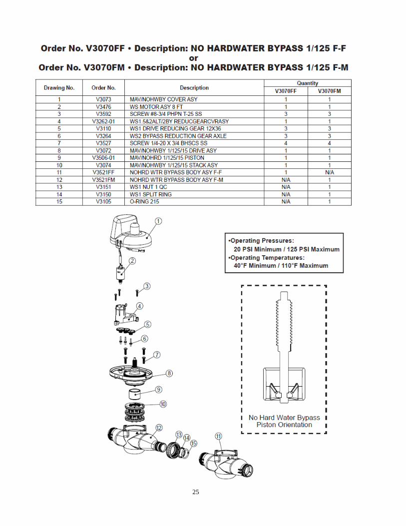
25
26
Table of Contents
Page No.
Topic Description
1
Model # and Packaging Packaging Information
Component Packaging Description Packaging Description
2 Performance Data Sheet Performance Data Sheet
3 System Description System Description
Feed Water Requirements Feed Water Requirements
4 Feed Water Requirements, cont’d Feed Water Requirements, cont’d
Ultra Filter Tank Positioning Ultra Filter Tank Positioning
5 Ultra Filter Tank Positioning, cont’d Ultra Filter Tank Positioning, cont’d
Autoflush Valve Autoflush Valve
6 Ultra Filter Tank Preparation Ultra Filter Tank Preparation
Filling the Ultrafilter with Water Filling the Ultrafilter with Water
MP-MCA UF Control Valve Attaching valve to tank
7 MP-MCA UF Control Valve, cont'd Attaching valve to tank, cont’d
NHWB Valve NHWB Valve
8 NHWB Valve, cont’d NHWB Valve, cont’d
Service and Drain Piping Service and Drain Piping
9 Service and Drain Piping, cont’d Service and Drain Piping, cont’d
10 System Schematic Piping Layout
11 Installing Cables Installing Cables
12 Installing Cables, cont’d Installing Cables
Electrical Supply Electrical Requirements
Flushing the Ultrafilter Flushing the Ultrafilter
13 Flushing the Ultrafilter, cont’d Flushing the Ultrafilter, cont’d
14 MP-MCA UF Control Valve Timer Setting the MP-MCA UF Timer
15 Final Check Final Installation Check
16 Error Code Troubleshooting Problem/ Cause / Solution
17 Error Code Troubleshooting, cont’d Problem/ Cause / Solution, cont’d
18 Troubleshooting Problem/ Cause / Solution
19 Troubleshooting Problem/ Cause / Solution
20 Troubleshooting Problem/ Cause / Solution
21 Valve Parts List Part Numbers List
22 Valve Parts List Part Numbers List
23 Valve Parts List Part Numbers List
24 Valve Parts List Part Numbers List
25 Valve Parts List Part Numbers List
26 Valve Parts List Part Numbers List
Related Documents