MPLS VPN Carrier Supporting Carrier Using LDP and an IGP Multiprotocol Label Switching (MPLS) Virtual Private Network (VPN) Carrier Supporting Carrier (CSC) enables one MPLS VPN-based service provider to allow other service providers to use a segment of its backbone network. This module explains how to configure the MPLS VPN CSC network using MPLS Label Distribution Protocol (LDP) to distribute MPLS labels and an Interior Gateway Protocol (IGP) to distribute routes. • Finding Feature Information, page 1 • Prerequisites for MPLS VPN CSC with LDP and IGP, page 2 • Restrictions for MPLS VPN CSC with LDP and IGP, page 2 • Information About MPLS VPN CSC with LDP and IGP, page 3 • How to Configure MPLS VPN CSC with LDP and IGP, page 9 • Configuration Examples for MPLS VPN CSC with LDP and IGP, page 20 • Additional References for MPLS VPN Carrier Supporting Carrier Using LDP and an IGP, page 61 • Feature Information for MPLS VPN CSC with LDP and IGP, page 62 • Glossary, page 62 Finding Feature Information Your software release may not support all the features documented in this module. For the latest caveats and feature information, see Bug Search Tool and the release notes for your platform and software release. To find information about the features documented in this module, and to see a list of the releases in which each feature is supported, see the feature information table. Use Cisco Feature Navigator to find information about platform support and Cisco software image support. To access Cisco Feature Navigator, go to www.cisco.com/go/cfn. An account on Cisco.com is not required. MPLS Layer 3 VPNs Inter-AS and CSC Configuration Guide 1

Welcome message from author
This document is posted to help you gain knowledge. Please leave a comment to let me know what you think about it! Share it to your friends and learn new things together.
Transcript

MPLS VPN Carrier Supporting Carrier Using LDPand an IGP
Multiprotocol Label Switching (MPLS) Virtual Private Network (VPN) Carrier Supporting Carrier (CSC)enables one MPLS VPN-based service provider to allow other service providers to use a segment of itsbackbone network. This module explains how to configure theMPLSVPNCSC network usingMPLS LabelDistribution Protocol (LDP) to distribute MPLS labels and an Interior Gateway Protocol (IGP) to distributeroutes.
• Finding Feature Information, page 1
• Prerequisites for MPLS VPN CSC with LDP and IGP, page 2
• Restrictions for MPLS VPN CSC with LDP and IGP, page 2
• Information About MPLS VPN CSC with LDP and IGP, page 3
• How to Configure MPLS VPN CSC with LDP and IGP, page 9
• Configuration Examples for MPLS VPN CSC with LDP and IGP, page 20
• Additional References for MPLS VPN Carrier Supporting Carrier Using LDP and an IGP, page 61
• Feature Information for MPLS VPN CSC with LDP and IGP, page 62
• Glossary, page 62
Finding Feature InformationYour software release may not support all the features documented in this module. For the latest caveats andfeature information, see Bug Search Tool and the release notes for your platform and software release. Tofind information about the features documented in this module, and to see a list of the releases in which eachfeature is supported, see the feature information table.
Use Cisco Feature Navigator to find information about platform support and Cisco software image support.To access Cisco Feature Navigator, go to www.cisco.com/go/cfn. An account on Cisco.com is not required.
MPLS Layer 3 VPNs Inter-AS and CSC Configuration Guide 1

Prerequisites for MPLS VPN CSC with LDP and IGP• The provider edge (PE) routers of the backbone carrier require 128 MB of memory.
• The backbone carrier must enable the PE router to check that the packets it receives from the customeredge (CE) router contain only the labels that the PE router advertised to the CE router. This preventsdata spoofing, which occurs when a packet from an unrecognized IP address is sent to a router.
Restrictions for MPLS VPN CSC with LDP and IGPThe following features are not supported with this feature:
• ATMMPLS
• Carrier supporting carrier traffic engineering
• Carrier supporting carrier quality of service (QoS)
• RSVP aggregation
• VPN Multicast between the customer carrier and the backbone carrier network
The following router platforms are supported on the edge of the MPLS VPN:
• Cisco 7200 series
• Cisco 7500 series
• Cisco 12000 series
See the table below for Cisco 12000 series line card support added for Cisco IOS releases.
Table 1: Cisco12000 Series Line Card Support Added for Cisco IOS Releases
Cisco IOS Release AddedLine CardsType
12.0(16)ST
12.0(21)ST
12.0(22)S
4-Port OC-3 POS
1-Port OC-12 POS
8-Port OC-3 POS
16-Port OC-3 POS
4-Port OC-12 POS
1-Port OC-48 POS
4-Port OC-3 POS ISE
8-Port OC-3 POS ISE
16 x OC-3 POS ISE
4 Port OC-12 POS ISE
1-Port OC-48 POS ISE
Packet over SONET (POS)
MPLS Layer 3 VPNs Inter-AS and CSC Configuration Guide2
MPLS VPN Carrier Supporting Carrier Using LDP and an IGPPrerequisites for MPLS VPN CSC with LDP and IGP

Cisco IOS Release AddedLine CardsType
12.0(16)ST
12.0(21)ST
6- Port DS3
12- Port DS3
6-Port E3
Electrical Interface
12.0(22)S4-Port OC-3 ATM
1-Port OC12 ATM
4-Port OC-12 ATM
ATM
12.0(22)S2-Port CHOC-3
6-Port Ch T3 (DS1)
1-Port CHOC-12 (DS3)
1-Port CHOC-12 (OC-3)
4-Port CHOC-12 ISE
1-Port CHOC-48 ISE
Channelized Interface
Information About MPLS VPN CSC with LDP and IGP
MPLS VPN CSC IntroductionCarrier supporting carrier is where one service provider allows another service provider to use a segment ofits backbone network. The service provider that provides the segment of the backbone network to the otherprovider is called the backbone carrier. The service provider that uses the segment of the backbone networkis called the customer carrier.
A backbone carrier offers Border Gateway Protocol and Multiprotocol Label Switching (BGP/MPLS) VPNservices. The customer carrier can be either:
• An Internet service provider (ISP)
• A BGP/MPLS VPN service provider
Benefits of Implementing MPLS VPN CSCTheMPLS VPN CSC network provides the following benefits to service providers who are backbone carriersand to customer carriers.
Benefits to the Backbone Carrier
• The backbone carrier can accommodate many customer carriers and give them access to its backbone.The backbone carrier does not need to create and maintain separate backbones for its customer carriers.Using one backbone network to support multiple customer carriers simplifies the backbone carrier’s
MPLS Layer 3 VPNs Inter-AS and CSC Configuration Guide 3
MPLS VPN Carrier Supporting Carrier Using LDP and an IGPInformation About MPLS VPN CSC with LDP and IGP

VPN operations. The backbone carrier uses a consistent method for managing and maintaining thebackbone network. This is also cheaper and more efficient than maintaining separate backbones.
• The MPLS VPN carrier supporting carrier feature is scalable. Carrier supporting carrier can change theVPN to meet changing bandwidth and connectivity needs. The feature can accommodate unplannedgrowth and changes. The carrier supporting carrier feature enables tens of thousands of VPNs to be setup over the same network, and it allows a service provider to offer both VPN and Internet services.
• The MPLS VPN carrier supporting carrier feature is a flexible solution. The backbone carrier canaccommodate many types of customer carriers. The backbone carrier can accept customer carriers whoare ISPs or VPN service providers or both. The backbone carrier can accommodate customer carriersthat require security and various bandwidths.
Benefits to the Customer Carriers
• The MPLS VPN carrier supporting carrier feature removes from the customer carrier the burden ofconfiguring, operating, and maintaining its own backbone. The customer carrier uses the backbonenetwork of a backbone carrier, but the backbone carrier is responsible for network maintenance andoperation.
• Customer carriers who use the VPN services provided by the backbone carrier receive the same levelof security that Frame Relay or ATM-based VPNs provide. Customer carriers can also use IPSec in theirVPNs for a higher level of security; it is completely transparent to the backbone carrier.
• Customer carriers can use any link layer technology (SONET, DSL, Frame Relay, and so on) to connectthe CE routers to the PE routers and the PE routers to the P routers. The MPLS VPN carrier supportingcarrier feature is link layer independent. The CE routers and PE routers use IP to communicate, and thebackbone carrier uses MPLS.
• The customer carrier can use any addressing scheme and still be supported by a backbone carrier. Thecustomer address space and routing information are independent of the address space and routinginformation of other customer carriers or the backbone provider.
Configuration Options for MPLS VPN CSC with LDP and IGPThe backbone carrier offers BGP and MPLS VPN services. The customer carrier can be one of the two typesof service providers described in the following sections, which explain how the backbone and customer carriersdistribute IPv4 routes and MPLS labels.
Customer Carrier Is an ISPThis section explains how a BGP/MPLS VPN service provider (backbone carrier) can provide a segment ofits backbone network to a customer who is an ISP.
Consider the following example:
MPLS Layer 3 VPNs Inter-AS and CSC Configuration Guide4
MPLS VPN Carrier Supporting Carrier Using LDP and an IGPConfiguration Options for MPLS VPN CSC with LDP and IGP

An ISP has two sites: one in California, the other in Maine. Each site is a point of presence (POP). The ISPwants to connect these sites using a VPN service provided by a backbone carrier. The figure below illustratesthis situation.
Figure 1: Sample BGP/MPLS Backbone Carrier Supporting an ISP
The CE routers in the figures are CE routers to the backbone carrier. However, they are PE routers to thecustomer carrier.
Note
In this example, only the backbone carrier uses MPLS. The customer carrier (ISP) uses only IP. As a result,the backbone carrier must carry all the Internet routes of the customer carrier, which could be as many as100,000 routes. This poses a scalability problem for the backbone carrier. To solve the scalability problem,the backbone carrier is configured as follows:
• The backbone carrier allows only internal routes of the customer carrier (IGP routes) to be exchangedbetween the CE routers of the customer carrier and the PE routers of the backbone carrier.
• MPLS is enabled on the interface between the CE router of the customer carrier and the PE router ofthe backbone carrier.
Internal and external routes are differentiated this way:
• Internal routes go to any of the routers within the ISP.
• External routes go to the Internet.
The number of internal routes is much lower than the number of external routes. Restricting the routes betweenthe CE routers of the customer carrier and the PE routers of the backbone carrier significantly reduces thenumber of routes that the PE router needs to maintain.
Because the PE routers do not have to carry external routes in the VRF routing table, they can use the incominglabel in the packet to forward the customer carrier Internet traffic. Adding MPLS to the routers provides aconsistent method of transporting packets from the customer carrier to the backbone carrier. MPLS allowsthe exchange of an MPLS label between the PE and the CE routers for every internal customer carrier route.The routers in the customer carrier have all the external routes either through internal Border Gateway Protocol
MPLS Layer 3 VPNs Inter-AS and CSC Configuration Guide 5
MPLS VPN Carrier Supporting Carrier Using LDP and an IGPConfiguration Options for MPLS VPN CSC with LDP and IGP

(iBGP) or route redistribution to provide Internet connectivity. The figure below shows how information isexchanged when the network is configured in this manner.
Figure 2: Backbone Carrier Exchanging Routing Information with a Customer Carrier Who Is an ISP
In the figure below, routes are created between the backbone carrier and the customer carrier sites. ASBR2receives an Internet route that originated outside the network. All routers in the ISP sites have all the externalroutes through IBGP connections among them.
Figure 3: Establishing a Route Between a Backbone Carrier and a Customer Carrier Who Is an ISP
The table below describes the process of establishing the route, which can be divided into two distinct steps:
• The backbone carrier propagates the IGP information of the customer carrier, which enables the customercarrier routers to reach all the customer carrier routers in the remote sites.
• Once the routers of the customer carriers in different sites are reachable, external routes can be propagatedin the customer carrier sites, using IBGP without using the backbone carrier routers.
MPLS Layer 3 VPNs Inter-AS and CSC Configuration Guide6
MPLS VPN Carrier Supporting Carrier Using LDP and an IGPConfiguration Options for MPLS VPN CSC with LDP and IGP

Table 2: Establishing a Route Between the Backbone Carrier and the Customer Carrier ISP
DescriptionStep
CSC-CE2 sends the internal routes within site 2 toCSC-PE2. The routes include the route to ASBR2.
1
CSC-PE2 sends the routing information for site 2 toCSC-PE1, using MPLS VPN processes. CSC-PE1gets one label (called L3), which is associated withthe route to theVPN-IP address for ASBR2. CSC-PE1gets another label (called L2), which is associatedwith the route to CSC-PE2.
2
CSC-PE1 sends the routing information associatedwith internal routes from site 2 to CSC-CE1.CSC-PE1 also sends the label binding information.As a result, CSC-CE1 gets the route to ASBR2 withCSC-PE1 as the next hop. The label associated withthat route is called L1.
3
CSC-CE1 distributes the routing information throughsite 1. Every router in site 1 gets a route for everyinternal destination in site 2. Therefore, every routerin site 1 can reach routers in site 2 and learn externalroutes through IBGP.
4
ASBR2 receives an Internet route.5
The IBGP sessions exchange the external routinginformation of the ISP, including a route to theInternet. Every router in site 1 knows a route to theInternet, with ASBR2 as the next hop of that route.
6
Customer Carrier Is a BGP MPLS VPN Service ProviderWhen a backbone carrier and the customer carrier both provide BGP/MPLS VPN services, the method oftransporting data is different from when a customer carrier provides only ISP services. The following listhighlights those differences:
•When a customer carrier provides BGP/MPLS VPN services, its external routes are VPN-IPv4 routes.When a customer carrier is an ISP, its external routes are IP routes.
•When a customer carrier provides BGP/MPLSVPN services, every site within the customer carrier mustuse MPLS. When a customer carrier is an ISP, the sites do not need to use MPLS.
MPLS Layer 3 VPNs Inter-AS and CSC Configuration Guide 7
MPLS VPN Carrier Supporting Carrier Using LDP and an IGPCustomer Carrier Is a BGP MPLS VPN Service Provider

The figure below shows how information is exchanged when MPLS VPN services reside on all customercarrier sites and on the backbone carrier.
Figure 4: Backbone Carrier Exchanging Information with a Customer Carrier Who Is an MPLS VPN Service Provider
In the example shown in the figure below, routes are created between the backbone carrier and the customercarrier sites.
Figure 5: Establishing a Route Between a Backbone Carrier and a Customer Carrier Who Is an MPLS VPN Service Provider
The table below describes the process of establishing the route.
Table 3: Establishing a Route Between the Backbone Carrier and Customer Carrier Site
DescriptionStep
CE2 sends all the internal routes within site 2 toCSC-PE2.
1
MPLS Layer 3 VPNs Inter-AS and CSC Configuration Guide8
MPLS VPN Carrier Supporting Carrier Using LDP and an IGPCustomer Carrier Is a BGP MPLS VPN Service Provider

DescriptionStep
CSC-PE2 sends the routing information for site 2 toCSC-PE1, using MPLS VPN processes. CSC-PE1gets one label (called L3), which is associated withthe route to the VPN-IP address for PE2. CSC-PE1gets another label (called L2), which is associatedwith the route to CSC-PE2.
2
CSC-PE1 sends the routing information associatedwith internal routes from site 2 to CSC-CE1.CSC-PE1 also sends the label binding information.As a result, CSC-CE1 gets the route to PE2 withCSC-PE1 as the next hop. The label associated withthat route is called L1.
3
CE1 distributes the routing and labeling informationthrough site 1. Every router in site 1 gets a route forevery internal destination in site 2. Therefore, PE1can establish an MP-IBGP session with PE2.
4
CE2 advertises the internal routes of MPLSVPN site2 to PE2.
5
PE2 allocates labels for all the VPN routes (regularMPLS VPN functionality) and advertises the labelsto PE1, using MP-IBGP.
6
PE1 can forward traffic from VPN site 1 that isdestined for VPN site 2.
7
How to Configure MPLS VPN CSC with LDP and IGP
Configuring the Backbone Carrier CoreConfiguring the backbone carrier core requires configuring connectivity and routing functions for the CSCcore and the CSC-PE routers.
Configuring and verifying the CSC core (backbone carrier) involves the following tasks:
PrerequisitesBefore you configure a backbone carrier core, configure the following on the CSC core routers:
• An IGP routing protocol--BGP, OSPF, IS-IS, EIGRP, static, and so on. For information, see Configuringa Basic BGPNetwork, Configuring OSPF, Configuring a Basic IS-IS Network, and Configuring EIGRP.
MPLS Layer 3 VPNs Inter-AS and CSC Configuration Guide 9
MPLS VPN Carrier Supporting Carrier Using LDP and an IGPHow to Configure MPLS VPN CSC with LDP and IGP

• Label Distribution Protocol (LDP). For information, see MPLS Label Distribution Protocol.
Verifying IP Connectivity and LDP Configuration in the CSC CorePerform this task to verify IP connectivity and LDP configuration in the CSC core. For a configuration examplefor this task, see the Verifying IP Connectivity and LDP Configuration in the CSC Core, on page 10.
SUMMARY STEPS
1. enable2. ping [protocol] {host-name | system-address}3. trace [protocol] [destination]4. showmpls forwarding-table [network {mask | length} | labels label [-label] | interface interface | next-hop
address | lsp-tunnel [tunnel-id]] [vrf vrf-name] [detail]5. show mpls ldp discovery [vrf vrf-name | all]6. show mpls ldp neighbor [[vrf vrf-name] [address | interface] [detail] | all]7. show ip cef [vrf vrf-name] [network [mask]] [longer-prefixes] [detail]8. show mpls interfaces [[vrf vrf-name] [interface] [detail] |all]9. show ip route10. disable
DETAILED STEPS
PurposeCommand or Action
Enables privileged EXEC mode.enableStep 1
Example:
Router> enable
• Enter your password if prompted.
(Optional) Diagnoses basic network connectivity on AppleTalk,Connectionless Network Service (CLNS), IP, Novell, Apollo, VINES,DECnet, or Xerox Network System (XNS) networks.
ping [protocol] {host-name | system-address}
Example:
Router# ping ip 10.0.0.1
Step 2
• Use the ping ip command to verify the connectivity from oneCSC core router to another.
(Optional) Discovers the routes that packets will actually take whentraveling to their destination.
trace [protocol] [destination]
Example:
Router# trace ip 10.0.0.1
Step 3
• Use the trace command to verify the path that a packet goesthrough before reaching the final destination. The tracecommand can help isolate a trouble spot if two routers cannotcommunicate.
(Optional) Displays the contents of the MPLS label forwardinginformation base (LFIB).
show mpls forwarding-table [network {mask |length} | labels label [-label] | interface interface
Step 4
MPLS Layer 3 VPNs Inter-AS and CSC Configuration Guide10
MPLS VPN Carrier Supporting Carrier Using LDP and an IGPConfiguring the Backbone Carrier Core

PurposeCommand or Action
• Use the show mpls forwarding-table command to verify thatMPLS packets are being forwarded.
| next-hop address | lsp-tunnel [tunnel-id]] [vrfvrf-name] [detail]
Example:
Router# show mpls forwarding-table
(Optional) Displays the status of the LDP discovery process.show mpls ldp discovery [vrf vrf-name | all]Step 5
Example:
Router# show mpls ldp discovery
• Use the show mpls ldp discovery command to verify that LDPis operational in the CSC core.
(Optional) Displays the status of LDP sessions.show mpls ldp neighbor [[vrf vrf-name][address | interface] [detail] | all]
Step 6
• Use theshow mpls ldp neighbor command to verify LDPconfiguration in the CSC core.
Example:
Router# show mpls ldp neighbor
(Optional) Displays entries in the forwarding Information Base (FIB).show ip cef [vrf vrf-name] [network [mask]][longer-prefixes] [detail]
Step 7
• Use the show ip cef command to check the forwarding table(prefixes, next hops, and interfaces).
Example:
Router# show ip cef
(Optional) Displays information about one or more or all interfacesthat are configured for label switching.
showmpls interfaces [[vrf vrf-name] [interface][detail] |all]
Step 8
Example:
Router# show mpls interfaces
• Use theshow mpls interfaces command to verify that theinterfaces are configured to use LDP.
(Optional) Displays IP routing table entries.show ip routeStep 9
Example:
Router# show ip route
• Use the show ip route command to display the entire routingtable, including host IP address, next hop, and interface.
(Optional) Returns to privileged EXEC mode.disable
Example:
Router# disable
Step 10
MPLS Layer 3 VPNs Inter-AS and CSC Configuration Guide 11
MPLS VPN Carrier Supporting Carrier Using LDP and an IGPConfiguring the Backbone Carrier Core

Troubleshooting Tips
You can use the ping and trace commands to verify complete MPLS connectivity in the core. You also getuseful troubleshooting information from the additional show commands.
Configuring VRFs for CSC-PE RoutersPerform this task to configure VPN routing and forwarding (VRF) instances for the backbone carrier edge(CSC-PE) routers.
SUMMARY STEPS
1. enable2. configure terminal3. ip vrf vrf-name4. rd route-distinguisher5. route-target {import | export | both} route-target-ext-community6. import map route-map7. exit8. interface type number9. ip vrf forwarding vrf-name10. end
DETAILED STEPS
PurposeCommand or Action
Enables privileged EXEC mode.enableStep 1
Example:
Router> enable
• Enter your password if prompted.
Enters global configuration mode.configure terminal
Example:
Router# configure terminal
Step 2
Defines the VPN routing instance by assigning a VRF name and entersVRF configuration mode.
ip vrf vrf-name
Example:
Router(config)# ip vrf vpn1
Step 3
• The vrf-name argument is the name assigned to a VRF.
Creates routing and forwarding tables.rd route-distinguisherStep 4
MPLS Layer 3 VPNs Inter-AS and CSC Configuration Guide12
MPLS VPN Carrier Supporting Carrier Using LDP and an IGPConfiguring the Backbone Carrier Core

PurposeCommand or Action
Example:
Router(config-vrf)# rd 100:1
• The route-distinguisher argument adds an 8-byte value to an IPv4prefix to create a VPN-IPv4 prefix. You can enter an RD in eitherof these formats:
• 16-bit AS number: your 32-bit number, for example, 101:3
• 32-bit IP address: your 16-bit number, for example,192.168.122.15:1
Creates a route-target extended community for a VRF.route-target {import | export | both}route-target-ext-community
Step 5
• The import keyword imports routing information from the targetVPN extended community.
Example:
Router(config-vrf)# route-targetimport 100:1
• The export keyword exports routing information to the target VPNextended community.
• The both keyword imports routing information from and exportsrouting information to the target VPN extended community.
• The route-target-ext-community argument adds the route-targetextended community attributes to the VRF’s list of import, export,or both (import and export) route-target extended communities.
(Optional) Configures an import route map for a VRF.import map route-mapStep 6
Example:
Router(config-vrf)# import mapvpn1-route-map
• The route-map argument specifies the route map to be used as animport route map for the VRF.
(Optional) Exits to global configuration mode.exit
Example:
Router(config-vrf)# exit
Step 7
Specifies the interface to configure and enters interface configurationmode.
interface type number
Example:
Router(config)# interface Ethernet5/0
Step 8
• The type argument specifies the type of interface to be configured.
• The number argument specifies the port, connector, or interface cardnumber.
Associates a VRF with the specified interface or subinterface.ip vrf forwarding vrf-nameStep 9
Example:
Router(config-if)# ip vrf forwardingvpn1
• The vrf-name argument is the name assigned to a VRF.
MPLS Layer 3 VPNs Inter-AS and CSC Configuration Guide 13
MPLS VPN Carrier Supporting Carrier Using LDP and an IGPConfiguring the Backbone Carrier Core

PurposeCommand or Action
(Optional) Exits to privileged EXEC mode.end
Example:
Router(config-if)# end
Step 10
Troubleshooting Tips
Enter a show ip vrf detail command and make sure the MPLS VPN is up and associated with the rightinterfaces.
Configuring Multiprotocol BGP for VPN Connectivity in the Backbone CarrierPerform this task to configure Multiprotocol BGP (MP-BGP) connectivity in the backbone carrier.
SUMMARY STEPS
1. enable2. configure terminal3. router bgp as-number4. no bgp default ipv4-unicast5. neighbor {ip-address | peer-group-name} remote-as as-number6. neighbor {ip-address | peer-group-name} update-source interface-type7. address-family vpnv4 [unicast]8. neighbor {ip-address | peer-group-name} send-community extended9. neighbor {ip-address | peer-group-name} activate10. end
DETAILED STEPS
PurposeCommand or Action
Enables privileged EXEC mode.enableStep 1
Example:
Router> enable
• Enter your password if prompted.
Enters global configuration mode.configure terminal
Example:
Router# configure terminal
Step 2
MPLS Layer 3 VPNs Inter-AS and CSC Configuration Guide14
MPLS VPN Carrier Supporting Carrier Using LDP and an IGPConfiguring the Backbone Carrier Core

PurposeCommand or Action
Configures a BGP routing process and enters router configurationmode.router bgp as-numberStep 3
Example:
Router(config)# router bgp 100
• The as-number argument indicates the number of an autonomoussystem that identifies the router to other BGP routers and tags therouting information passed along. Valid numbers are from 0 to65535. Private autonomous system numbers that can be used ininternal networks range from 64512 to 65535.
(Optional) Disables the IPv4 unicast address family on all neighbors.no bgp default ipv4-unicastStep 4
Example:
Router(config-router)# no bgp defaultipv4-unicast
• Use the no bgp default-unicast command if you are using thisneighbor for MPLS routes only.
Adds an entry to the BGP or multiprotocol BGP neighbor table.neighbor {ip-address | peer-group-name}remote-as as-number
Step 5
• The ip-address argument specifies the IP address of the neighbor.
Example:
Router(config-router)# neighbor 10.5.5.5remote-as 100
• The peer-group-name argument specifies the name of a BGP peergroup.
• The as-number argument specifies the autonomous system towhich the neighbor belongs.
Allows BGP sessions to use a specific operational interface for TCPconnections.
neighbor {ip-address | peer-group-name}update-source interface-type
Step 6
Example:
Router(config-router)# neighbor 10.2.0.0update-source loopback0
• The ip-address argument specifies the IP address of theBGP-speaking neighbor.
• The peer-group-name argument specifies the name of a BGP peergroup.
• The interface-type argument specifies the interface to be used asthe source.
Enters address family configuration mode for configuring routingsessions, such as BGP, that use standard VPNv4 address prefixes.
address-family vpnv4 [unicast]
Example:
Router(config-router)# address-familyvpnv4
Step 7
• The optional unicast keyword specifies VPNv4 unicast addressprefixes.
Specifies that a communities attribute should be sent to a BGP neighbor.neighbor {ip-address | peer-group-name}send-community extended
Step 8
• The ip-address argument specifies the IP address of theBGP-speaking neighbor.
Example:
Router(config-router-af)# neighbor10.0.0.1 send-community extended
• The peer-group-name argument specifies the name of a BGP peergroup.
MPLS Layer 3 VPNs Inter-AS and CSC Configuration Guide 15
MPLS VPN Carrier Supporting Carrier Using LDP and an IGPConfiguring the Backbone Carrier Core

PurposeCommand or Action
Enables the exchange of information with a neighboring BGP router.neighbor {ip-address | peer-group-name}activate
Step 9
• The ip-address argument specifies the IP address of the neighbor.
Example:
Router(config-router-af)# neighbor10.4.0.0 activate
• The peer-group-name argument specifies the name of a BGP peergroup.
(Optional) Exits to privileged EXEC mode.end
Example:
Router(config-router-af)# end
Step 10
Troubleshooting Tips
You can enter a show ip bgp neighbor command to verify that the neighbors are up and running. If thiscommand generates an error message, enter a debug ip bgp x.x.x.x events command, where x.x.x.x is the IPaddress of the neighbor.
Configuring the CSC-PE and CSC-CE RoutersTo enable the CSC-PE and CSC-CE routers to distribute routes andMPLS labels, perform the following tasks:
PrerequisitesBefore you configure the CSC-PE and CSC-CE routers, you must configure an IGP on the CSC-PE andCSC-CE routers. A routing protocol is required between the PE and CE routers that connect the backbonecarrier to the customer carrier. The routing protocol enables the customer carrier to exchange IGP routinginformation with the backbone carrier. Use the same routing protocol that the customer carrier uses. You canchoose RIP, OSPF, or static routing as the routing protocol. BGP is not supported. For the configuration steps,see Configuring MPLS Layer 3 VPNs .
Configuring LDP on the CSC-PE and CSC-CE RoutersMPLS LDP is required between the PE and CE routers that connect the backbone carrier to the customercarrier. You can configure LDP as the default label distribution protocol for the entire router or just for thePE-to-CE interface for VRF.
MPLS Layer 3 VPNs Inter-AS and CSC Configuration Guide16
MPLS VPN Carrier Supporting Carrier Using LDP and an IGPConfiguring the CSC-PE and CSC-CE Routers

SUMMARY STEPS
1. enable2. configure terminal3. mpls label protocol ldp4. interface type number5. mpls label protocol ldp6. exit
DETAILED STEPS
PurposeCommand or Action
Enables privileged EXEC mode.enableStep 1
Example:
Router> enable
• Enter your password if prompted.
Enters global configuration mode.configure terminal
Example:
Router# configure terminal
Step 2
Specifies MPLS LDP as the default label distribution protocolfor the router.
mpls label protocol ldp
Example:
Router(config)# mpls label protocol ldp
Step 3
(Optional) Specifies the interface to configure and enters interfaceconfiguration mode.
interface type number
Example:
Router(config)# interface Ethernet5/0
Step 4
• The type argument specifies the type of interface to beconfigured.
• The number argument specifies the port, connector, orinterface card number.
(Optional) Specifies MPLS LDP as the default label distributionprotocol for the interface.
mpls label protocol ldp
Example:
Router(config-if)# mpls label protocol ldp
Step 5
(Optional) Exits to privileged EXEC mode.exit
Example:
Router(config-if)# exit
Step 6
MPLS Layer 3 VPNs Inter-AS and CSC Configuration Guide 17
MPLS VPN Carrier Supporting Carrier Using LDP and an IGPConfiguring the CSC-PE and CSC-CE Routers

Enabling MPLS Encapsulation on the CSC-PE and CSC-CE RoutersEvery packet that crosses the backbone carrier must be encapsulated, so that the packet includesMPLS labels.You can enable MPLS encapsulation for the entire router or just on the interface of the PE or CE router. Toenable the encapsulation of packets, perform the following task.
SUMMARY STEPS
1. enable2. configure terminal3. mpls ip4. interface type number5. mpls ip6. exit
DETAILED STEPS
PurposeCommand or Action
Enables privileged EXEC mode.enableStep 1
Example:
Router> enable
• Enter your password if prompted.
Enters global configuration mode.configure terminal
Example:
Router# configure terminal
Step 2
Enables MPLS encapsulation for the router.mpls ip
Example:
Router(config)# mpls ip
Step 3
(Optional) Specifies the interface to configure and enters interfaceconfiguration mode.
interface type number
Example:
Router(config)# interface Ethernet5/0
Step 4
• The type argument specifies the type of interface to beconfigured.
• The number argument specifies the port, connector, orinterface card number.
MPLS Layer 3 VPNs Inter-AS and CSC Configuration Guide18
MPLS VPN Carrier Supporting Carrier Using LDP and an IGPConfiguring the CSC-PE and CSC-CE Routers

PurposeCommand or Action
(Optional) Enables MPLS encapsulation for the specifiedinterface.
mpls ip
Example:
Router(config-if)# mpls ip
Step 5
(Optional) Exits to privileged EXEC mode.exit
Example:
Router(config-if)# exit
Step 6
Verifying the Carrier Supporting Carrier ConfigurationThe following commands verify the status of LDP sessions that were configured between the backbone carrierand customer carrier. Now the customer carrier ISP sites appear as a VPN customer to the backbone carrier.
SUMMARY STEPS
1. show mpls ldp discovery vrf vrf-name2. show mpls ldp discovery all
DETAILED STEPS
Step 1 show mpls ldp discovery vrf vrf-nameUse this command to show that the LDP sessions are in VRFVPN1 of the PE router of the backbone carrier, for example:
Example:
Router# show mpls ldp discovery vrf vpn1Local LDP Identifier:
10.0.0.0:0Discovery Sources:
Interfaces:Ethernet1/0 (ldp): xmit/recv
LDP Id: 10.0.0.1:0POS6/0 (ldp): xmit
Step 2 show mpls ldp discovery allUse this command to list all LDP sessions in a router, for example:
Example:
Router# show mpls ldp discovery allLocal LDP Identifier:
10.10.10.10:0
MPLS Layer 3 VPNs Inter-AS and CSC Configuration Guide 19
MPLS VPN Carrier Supporting Carrier Using LDP and an IGPVerifying the Carrier Supporting Carrier Configuration
Discovery Sources:Interfaces:
Ethernet1/5 (ldp): xmit/recvLDP Id: 10.5.5.5:0
VRF vpn1: Local LDP Identifier:10.0.0.1:0
Discovery Sources:Interfaces:
Ethernet1/0 (ldp): xmit/recvLDP Id: 10.0.0.1:0
POS6/0 (ldp): xmit
The Local LDP Identifier field shows the LDP identifier for the local label switching router for this session. The Interfacesfield displays the interfaces engaging in LDP discovery activity:
• xmit indicates that the interface is transmitting LDP discovery hello packets.
• recv indicates that the interface is receiving LDP discovery hello packets.
Configuration Examples for MPLS VPN CSC with LDP and IGP
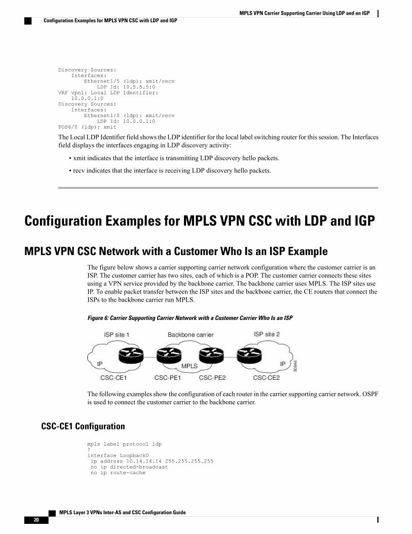
MPLS VPN CSC Network with a Customer Who Is an ISP ExampleThe figure below shows a carrier supporting carrier network configuration where the customer carrier is anISP. The customer carrier has two sites, each of which is a POP. The customer carrier connects these sitesusing a VPN service provided by the backbone carrier. The backbone carrier uses MPLS. The ISP sites useIP. To enable packet transfer between the ISP sites and the backbone carrier, the CE routers that connect theISPs to the backbone carrier run MPLS.
Figure 6: Carrier Supporting Carrier Network with a Customer Carrier Who Is an ISP
The following examples show the configuration of each router in the carrier supporting carrier network. OSPFis used to connect the customer carrier to the backbone carrier.
CSC-CE1 Configuration
mpls label protocol ldp!interface Loopback0ip address 10.14.14.14 255.255.255.255no ip directed-broadcastno ip route-cache
MPLS Layer 3 VPNs Inter-AS and CSC Configuration Guide20
MPLS VPN Carrier Supporting Carrier Using LDP and an IGPConfiguration Examples for MPLS VPN CSC with LDP and IGP
no ip mroute-cache!interface ATM1/0no ip addressno ip directed-broadcastno ip mroute-cacheatm clock INTERNALatm sonet stm-1no atm enable-ilmi-trapno atm ilmi-keepalive!interface ATM1/0.1 point-to-pointip address 10.0.0.2 255.0.0.0no ip directed-broadcastatm pvc 101 0 51 aal5snapno atm enable-ilmi-trapmpls label protocol ldpmpls ip!interface ATM2/0no ip addressno ip directed-broadcastno ip mroute-cacheatm clock INTERNALatm sonet stm-1no atm enable-ilmi-trapno atm ilmi-keepalive!interface ATM2/0.1 point-to-pointip address 10.0.0.2 255.0.0.0no ip directed-broadcastatm pvc 100 0 50 aal5snapno atm enable-ilmi-trapmpls label protocol ldpmpls ip!router ospf 200log-adjacency-changesredistribute connected subnetsnetwork 10.14.14.14 0.0.0.0 area 200network 10.15.0.0 0.255.255.255 area 200network 10.16.0.0 0.255.255.255 area 200
CSC-PE1 Configuration
ip cef distributed!ip vrf vpn1rd 100:0route-target export 100:0route-target import 100:0mpls label protocol ldpno mpls aggregate-statistics!interface Loopback0ip address 10.11.11.11 255.255.255.255no ip directed-broadcastno ip route-cacheno ip mroute-cache!interface Loopback100ip vrf forwarding vpn1ip address 10.19.19.19 255.255.255.255no ip directed-broadcast!interface ATM1/1/0no ip addressno ip directed-broadcastno ip route-cache distributedatm clock INTERNAL
MPLS Layer 3 VPNs Inter-AS and CSC Configuration Guide 21
MPLS VPN Carrier Supporting Carrier Using LDP and an IGPMPLS VPN CSC Network with a Customer Who Is an ISP Example

no atm enable-ilmi-trapno atm ilmi-keepalive!interface ATM1/1/0.1ip address 10.0.0.1 255.0.0.0no ip directed-broadcastatm pvc 100 0 50 aal5snapno atm enable-ilmi-trapmpls label protocol ldpmpls ip!interface ATM3/0/0no ip addressno ip directed-broadcastno ip route-cache distributedatm clock INTERNALatm sonet stm-1no atm enable-ilmi-trapno atm ilmi-keepalive!interface ATM3/0/0.1 point-to-pointip vrf forwarding vpn1ip address 10.0.0.1 255.0.0.0no ip directed-broadcastatm pvc 101 0 51 aal5snapno atm enable-ilmi-trapmpls label protocol ldpmpls ip!router ospf 100log-adjacency-changespassive-interface ATM3/0/0.1passive-interface Loopback100network 10.11.11.11 0.0.0.0 area 100network 10.0.0.0 0.255.255.255 area 100!router ospf 200 vrf vpn1log-adjacency-changesredistribute bgp 100 metric-type 1 subnetsnetwork 10.19.19.19 0.0.0.0 area 200network 10.0.0.0 0.255.255.255 area 200!router bgp 100bgp log-neighbor-changestimers bgp 10 30neighbor 10.12.12.12 remote-as 100neighbor 10.12.12.12 update-source Loopback0!address-family ipv4neighbor 10.12.12.12 activateneighbor 10.12.12.12 send-community extendedno synchronizationexit-address-family!address-family vpnv4neighbor 10.12.12.12 activateneighbor 10.12.12.12 send-community extendedexit-address-family!address-family ipv4 vrf vpn1redistribute ospf 200 match internal external 1 external 2no auto-summaryno synchronizationexit-address-family
CSC-PE2 Configuration
ip cef distributed!ip vrf vpn1
MPLS Layer 3 VPNs Inter-AS and CSC Configuration Guide22
MPLS VPN Carrier Supporting Carrier Using LDP and an IGPMPLS VPN CSC Network with a Customer Who Is an ISP Example

rd 100:0route-target export 100:0route-target import 100:0mpls label protocol ldpno mpls aggregate-statistics!interface Loopback0ip address 10.12.12.12 255.255.255.255no ip directed-broadcastno ip route-cacheno ip mroute-cache!interface Loopback100ip vrf forwarding vpn1ip address 10.20.20.20 255.255.255.255no ip directed-broadcast!interface ATM0/1/0no ip addressno ip directed-broadcastno ip route-cache distributedno ip mroute-cacheatm clock INTERNALatm sonet stm-1no atm enable-ilmi-trapno atm ilmi-keepalive!interface ATM0/1/0.1 point-to-pointip address 10.0.0.2 255.0.0.0no ip directed-broadcastatm pvc 100 0 50 aal5snapno atm enable-ilmi-trapmpls label protocol ldpmpls ip!interface ATM3/0/0no ip addressno ip directed-broadcastno ip route-cache distributedno ip mroute-cacheatm clock INTERNALatm sonet stm-1no atm enable-ilmi-trapno atm ilmi-keepalive!interface ATM3/0/0.1 point-to-pointip vrf forwarding vpn1ip address 10.0.0.1 255.0.0.0no ip directed-broadcastatm pvc 100 0 50 aal5snapno atm enable-ilmi-trapmpls label protocol ldpmpls ip!router ospf 100log-adjacency-changespassive-interface ATM3/0/0.1passive-interface Loopback100network 10.12.12.12 0.0.0.0 area 100network 10.0.0.0 0.255.255.255 area 100!router ospf 200 vrf vpn1log-adjacency-changesredistribute bgp 100 metric-type 1 subnetsnetwork 10.20.20.20 0.0.0.0 area 200network 10.0.0.0 0.255.255.255 area 200!router bgp 100bgp log-neighbor-changestimers bgp 10 30neighbor 10.11.11.11 remote-as 100neighbor 10.11.11.11 update-source Loopback0!
MPLS Layer 3 VPNs Inter-AS and CSC Configuration Guide 23
MPLS VPN Carrier Supporting Carrier Using LDP and an IGPMPLS VPN CSC Network with a Customer Who Is an ISP Example

address-family ipv4neighbor 10.11.11.11 activateneighbor 10.11.11.11 send-community extendedno synchronizationexit-address-family!address-family vpnv4neighbor 10.11.11.11 activateneighbor 10.11.11.11 send-community extendedexit-address-family!address-family ipv4 vrf vpn1redistribute ospf 200 match internal external 1 external 2no auto-summaryno synchronizationexit-address-family
CSC-CE2 Configuration
ip cef!mpls label protocol ldp!interface Loopback0ip address 10.16.16.16 255.255.255.255no ip directed-broadcastno ip route-cacheno ip mroute-cache!interface ATM1/0no ip addressno ip directed-broadcastno ip mroute-cacheatm clock INTERNALatm sonet stm-1no atm enable-ilmi-trapno atm ilmi-keepalive!interface ATM1/0.1 point-to-pointip address 10.0.0.2 255.0.0.0no ip directed-broadcastatm pvc 100 0 50 aal5snapno atm enable-ilmi-trapmpls label protocol ldpmpls ip!interface ATM5/0no ip addressno ip directed-broadcastno ip mroute-cacheatm clock INTERNALatm sonet stm-1no atm enable-ilmi-trapno atm ilmi-keepalive!interface ATM5/0.1 point-to-pointip address 10.0.0.2 255.0.0.0no ip directed-broadcastatm pvc 100 0 50 aal5snapno atm enable-ilmi-trapmpls label protocol ldpmpls ip!router ospf 200log-adjacency-changesredistribute connected subnetsnetwork 10.16.16.16 0.0.0.0 area 200network 10.0.0.0 0.255.255.255 area 200network 10.0.0.0 0.255.255.255 area 200
MPLS Layer 3 VPNs Inter-AS and CSC Configuration Guide24
MPLS VPN Carrier Supporting Carrier Using LDP and an IGPMPLS VPN CSC Network with a Customer Who Is an ISP Example

MPLS VPN CSC Network with a Customer Who Is an MPLS VPN ProviderExample
The figure below shows a carrier supporting carrier network configuration where the customer carrier is anMPLS VPN provider. The customer carrier has two sites. The backbone carrier and the customer carrier useMPLS. The IBGP sessions exchange the external routing information of the ISP.
Figure 7: Carrier Supporting Carrier Network with a Customer Carrier Who Is an MPLS VPN Provider
The following configuration examples show the configuration of each router in the carrier supporting carriernetwork. OSPF is the protocol used to connect the customer carrier to the backbone carrier.
CE1 Configuration
ip cef!interface Loopback0ip address 10.17.17.17 255.255.255.255no ip directed-broadcast!interface Ethernet0/1ip address 10.0.0.2 255.0.0.0no ip directed-broadcast!router ospf 300log-adjacency-changesredistribute bgp 300 subnetspassive-interface Ethernet0/1network 10.17.17.17 0.0.0.0 area 300!router bgp 300no synchronizationbgp log-neighbor-changestimers bgp 10 30redistribute connectedredistribute ospf 300 match internal external 1 external 2neighbor 10.0.0.1 remote-as 200neighbor 10.0.0.1 advertisement-interval 5no auto-summary
MPLS Layer 3 VPNs Inter-AS and CSC Configuration Guide 25
MPLS VPN Carrier Supporting Carrier Using LDP and an IGPMPLS VPN CSC Network with a Customer Who Is an MPLS VPN Provider Example

PE1 Configuration
ip cef!ip vrf vpn2rd 200:1route-target export 200:1route-target import 200:1mpls label protocol ldp!interface Loopback0ip address 10.13.13.13 255.255.255.255no ip directed-broadcastno ip route-cacheno ip mroute-cache!interface ATM1/0no ip addressno ip directed-broadcastno ip mroute-cacheatm clock INTERNALatm sonet stm-1no atm enable-ilmi-trapno atm ilmi-keepalive!interface ATM1/0.1 point-to-pointip address 10.0.0.1 255.0.0.0no ip directed-broadcastatm pvc 100 0 50 aal5snapno atm enable-ilmi-trapmpls label protocol ldpmpls ip!interface Ethernet3/0ip vrf forwarding vpn2ip address 10.0.0.1 255.0.0.0no ip directed-broadcastno ip mroute-cache!router ospf 200log-adjacency-changesredistribute connected subnetspassive-interface Ethernet3/0network 10.13.13.13 0.0.0.0 area 200network 10.0.0.0 0.255.255.255 area 200!router bgp 200no bgp default ipv4-unicastbgp log-neighbor-changestimers bgp 10 30neighbor 10.15.15.15 remote-as 200neighbor 10.15.15.15 update-source Loopback0!address-family ipv4neighbor 10.15.15.15 activateneighbor 10.15.15.15 send-community extendedno synchronizationexit-address-family!address-family vpnv4neighbor 10.15.15.15 activateneighbor 10.15.15.15 send-community extendedexit-address-family!address-family ipv4 vrf vpn2neighbor 10.0.0.2 remote-as 300neighbor 10.0.0.2 activateneighbor 10.0.0.2 as-overrideneighbor 10.0.0.2 advertisement-interval 5no auto-summary
MPLS Layer 3 VPNs Inter-AS and CSC Configuration Guide26
MPLS VPN Carrier Supporting Carrier Using LDP and an IGPMPLS VPN CSC Network with a Customer Who Is an MPLS VPN Provider Example

no synchronizationexit-address-family
CSC-CE1 Configuration
mpls label protocol ldp!interface Loopback0ip address 10.14.14.14 255.255.255.255no ip directed-broadcastno ip route-cacheno ip mroute-cache!interface ATM1/0no ip addressno ip directed-broadcastno ip mroute-cacheatm clock INTERNALatm sonet stm-1no atm enable-ilmi-trapno atm ilmi-keepalive!interface ATM1/0.1 point-to-pointip address 10.0.0.2 255.0.0.0no ip directed-broadcastatm pvc 101 0 51 aal5snapno atm enable-ilmi-trapmpls label protocol ldpmpls ip!interface ATM2/0no ip addressno ip directed-broadcastno ip mroute-cacheatm clock INTERNALatm sonet stm-1no atm enable-ilmi-trapno atm ilmi-keepalive!interface ATM2/0.1 point-to-pointip address 10.0.0.2 255.0.0.0no ip directed-broadcastatm pvc 100 0 50 aal5snapno atm enable-ilmi-trapmpls label protocol ldpmpls ip!router ospf 200log-adjacency-changesredistribute connected subnetsnetwork 10.14.14.14 0.0.0.0 area 200network 10.0.0.0 0.255.255.255 area 200network 10.0.0.0 0.255.255.255 area 200
CSC-PE1 Configuration
ip cef distributed!ip vrf vpn1rd 100:0route-target export 100:0route-target import 100:0mpls label protocol ldpno mpls aggregate-statistics!interface Loopback0ip address 11.11.11.11 255.255.255.255
MPLS Layer 3 VPNs Inter-AS and CSC Configuration Guide 27
MPLS VPN Carrier Supporting Carrier Using LDP and an IGPMPLS VPN CSC Network with a Customer Who Is an MPLS VPN Provider Example
no ip directed-broadcastno ip route-cacheno ip mroute-cache!interface Loopback100ip vrf forwarding vpn1ip address 10.19.19.19 255.255.255.255no ip directed-broadcast!interface ATM1/1/0no ip addressno ip directed-broadcastno ip route-cache distributedatm clock INTERNALno atm enable-ilmi-trapno atm ilmi-keepalive!interface ATM1/1/0.1 point-to-pointip address 10.0.0.1 255.0.0.0no ip directed-broadcastatm pvc 100 0 50 aal5snapno atm enable-ilmi-trapmpls label protocol ldpmpls ip!interface ATM3/0/0no ip addressno ip directed-broadcastno ip route-cache distributedatm clock INTERNALatm sonet stm-1no atm enable-ilmi-trapno atm ilmi-keepalive!interface ATM3/0/0.1 point-to-pointip vrf forwarding vpn1ip address 10.0.0.1 255.0.0.0no ip directed-broadcastatm pvc 101 0 51 aal5snapno atm enable-ilmi-trapmpls label protocol ldpmpls ip!router ospf 100log-adjacency-changespassive-interface ATM3/0/0.1passive-interface Loopback100network 10.11.11.11 0.0.0.0 area 100network 10.0.0.0 0.255.255.255 area 100!router ospf 200 vrf vpn1log-adjacency-changesredistribute bgp 100 metric-type 1 subnetsnetwork 10.19.19.19 0.0.0.0 area 200network 10.0.0.0 0.255.255.255 area 200!router bgp 100bgp log-neighbor-changestimers bgp 10 30neighbor 10.12.12.12 remote-as 100neighbor 10.12.12.12 update-source Loopback0!address-family ipv4neighbor 10.12.12.12 activateneighbor 10.12.12.12 send-community extendedno synchronizationexit-address-family!address-family vpnv4neighbor 10.12.12.12 activateneighbor 10.12.12.12 send-community extendedexit-address-family!
MPLS Layer 3 VPNs Inter-AS and CSC Configuration Guide28
MPLS VPN Carrier Supporting Carrier Using LDP and an IGPMPLS VPN CSC Network with a Customer Who Is an MPLS VPN Provider Example

address-family ipv4 vrf vpn1redistribute ospf 200 match internal external 1 external 2no auto-summaryno synchronizationexit-address-family
CSC-PE2 Configuration
ip cef distributed!ip vrf vpn1rd 100:0route-target export 100:0route-target import 100:0mpls label protocol ldpno mpls aggregate-statistics!interface Loopback0ip address 10.12.12.12 255.255.255.255no ip directed-broadcastno ip route-cacheno ip mroute-cache!interface Loopback100ip vrf forwarding vpn1ip address 10.20.20.20 255.255.255.255no ip directed-broadcast!interface ATM0/1/0no ip addressno ip directed-broadcastno ip route-cache distributedno ip mroute-cacheatm clock INTERNALatm sonet stm-1no atm enable-ilmi-trapno atm ilmi-keepalive!interface ATM0/1/0.1 point-to-pointip address 10.0.0.2 255.0.0.0no ip directed-broadcastatm pvc 100 0 50 aal5snapno atm enable-ilmi-trapmpls label protocol ldpmpls ip!interface ATM3/0/0no ip addressno ip directed-broadcastno ip route-cache distributedno ip mroute-cacheatm clock INTERNALatm sonet stm-1no atm enable-ilmi-trapno atm ilmi-keepalive!interface ATM3/0/0.1 point-to-pointip vrf forwarding vpn1ip address 10.0.0.1 255.0.0.0no ip directed-broadcastatm pvc 100 0 50 aal5snapno atm enable-ilmi-trapmpls label protocol ldpmpls ip!router ospf 100log-adjacency-changespassive-interface ATM3/0/0.1passive-interface Loopback100network 10.12.12.12 0.0.0.0 area 100
MPLS Layer 3 VPNs Inter-AS and CSC Configuration Guide 29
MPLS VPN Carrier Supporting Carrier Using LDP and an IGPMPLS VPN CSC Network with a Customer Who Is an MPLS VPN Provider Example

network 10.0.0.0 0.255.255.255 area 100!router ospf 200 vrf vpn1log-adjacency-changesredistribute bgp 100 metric-type 1 subnetsnetwork 10.20.20.20 0.0.0.0 area 200network 10.0.0.0 0.255.255.255 area 200!router bgp 100bgp log-neighbor-changestimers bgp 10 30neighbor 10.11.11.11 remote-as 100neighbor 10.11.11.11 update-source Loopback0!address-family ipv4neighbor 10.11.11.11 activateneighbor 10.11.11.11 send-community extendedno synchronizationexit-address-family!address-family vpnv4neighbor 10.11.11.11 activateneighbor 10.11.11.11 send-community extendedexit-address-family!address-family ipv4 vrf vpn1redistribute ospf 200 match internal external 1 external 2no auto-summaryno synchronizationexit-address-family
CSC-CE2 Configuration
ip cef!mpls label protocol ldp!interface Loopback0ip address 10.16.16.16 255.255.255.255no ip directed-broadcastno ip route-cacheno ip mroute-cache!interface ATM1/0no ip addressno ip directed-broadcastno ip mroute-cacheatm clock INTERNALatm sonet stm-1no atm enable-ilmi-trapno atm ilmi-keepalive!interface ATM1/0.1 point-to-pointip address 10.0.0.2 255.0.0.0no ip directed-broadcastatm pvc 100 0 50 aal5snapno atm enable-ilmi-trapmpls label protocol ldpmpls ip!interface ATM5/0no ip addressno ip directed-broadcastno ip mroute-cacheatm clock INTERNALatm sonet stm-1no atm enable-ilmi-trapno atm ilmi-keepalive!interface ATM5/0.1 point-to-point
MPLS Layer 3 VPNs Inter-AS and CSC Configuration Guide30
MPLS VPN Carrier Supporting Carrier Using LDP and an IGPMPLS VPN CSC Network with a Customer Who Is an MPLS VPN Provider Example

ip address 10.0.0.2 255.0.0.0no ip directed-broadcastatm pvc 100 0 50 aal5snapno atm enable-ilmi-trapmpls label protocol ldpmpls ip!router ospf 200log-adjacency-changesredistribute connected subnetsnetwork 10.16.16.16 0.0.0.0 area 200network 10.0.0.0 0.255.255.255 area 200network 10.0.0.0 0.255.255.255 area 200
PE2 Configuration
ip cefip cef accounting non-recursive!ip vrf vpn2rd 200:1route-target export 200:1route-target import 200:1mpls label protocol ldp!interface Loopback0ip address 10.15.15.15 255.255.255.255no ip directed-broadcast!interface Ethernet3/0ip vrf forwarding vpn2ip address 10.0.0.1 255.0.0.0no ip directed-broadcast!interface ATM5/0no ip addressno ip directed-broadcastatm clock INTERNALatm sonet stm-1no atm enable-ilmi-trapno atm ilmi-keepalive!interface ATM5/0.1 point-to-pointip address 10.0.0.1 255.0.0.0no ip directed-broadcastatm pvc 100 0 50 aal5snapno atm enable-ilmi-trapmpls label protocol ldpmpls ip!router ospf 200log-adjacency-changesredistribute connected subnetspassive-interface Ethernet3/0network 10.15.15.15 0.0.0.0 area 200network 10.0.0.0 0.255.255.255 area 200!router bgp 200no bgp default ipv4-unicastbgp log-neighbor-changestimers bgp 10 30neighbor 10.13.13.13 remote-as 200neighbor 10.13.13.13 update-source Loopback0!address-family ipv4neighbor 10.13.13.13 activateneighbor 10.13.13.13 send-community extendedno synchronizationexit-address-family!
MPLS Layer 3 VPNs Inter-AS and CSC Configuration Guide 31
MPLS VPN Carrier Supporting Carrier Using LDP and an IGPMPLS VPN CSC Network with a Customer Who Is an MPLS VPN Provider Example

address-family vpnv4neighbor 10.13.13.13 activateneighbor 10.13.13.13 send-community extendedexit-address-family!address-family ipv4 vrf vpn2neighbor 10.0.0.2 remote-as 300neighbor 10.0.0.2 activateneighbor 10.0.0.2 as-overrideneighbor 10.0.0.2 advertisement-interval 5no auto-summaryno synchronizationexit-address-family
CE2 Configuration
ip cef!interface Loopback0ip address 10.18.18.18 255.255.255.255no ip directed-broadcast!interface Ethernet0/1ip address 10.0.0.2 255.0.0.0no ip directed-broadcast!router ospf 300log-adjacency-changesredistribute bgp 300 subnetspassive-interface Ethernet0/1network 10.18.18.18 0.0.0.0 area 300!router bgp 300no synchronizationbgp log-neighbor-changestimers bgp 10 30redistribute connectedredistribute ospf 300 match internal external 1 external 2neighbor 10.0.0.1 remote-as 200neighbor 10.0.0.1 advertisement-interval 5no auto-summary
MPLS Layer 3 VPNs Inter-AS and CSC Configuration Guide32
MPLS VPN Carrier Supporting Carrier Using LDP and an IGPMPLS VPN CSC Network with a Customer Who Is an MPLS VPN Provider Example

MPLS VPN CSC Network That Contains Route Reflectors ExampleThe figure below shows a carrier supporting carrier network configuration that contains route reflectors. Thecustomer carrier has two sites.
Figure 8: Carrier Supporting Carrier Network that Contains Route Reflectors
A connection between route reflectors (RRs) is not necessary.Note
The following configuration examples show the configuration of each router in the carrier supporting carriernetwork. Note the following:
• The router IP addresses are abbreviated for ease of reading. For example, the loopback address for PE1 is 25, which is equivalent to 10.25.25.25.
• The following list shows the loopback addresses for the CSC-PE routers:
• CSC-PE1 (75K-37-3): loopback 0 = 10.15.15.15, loopback 1 = 10.18.18.18
• CSC-PE2 (75K-38-3): loopback 0 = 10.16.16.16, loopback 1 = 10.20.20.20
MPLS Layer 3 VPNs Inter-AS and CSC Configuration Guide 33
MPLS VPN Carrier Supporting Carrier Using LDP and an IGPMPLS VPN CSC Network That Contains Route Reflectors Example

Backbone Carrier Configuration
Route Reflector 1 (72K-37-1) Configuration
interface Loopback0ip address 10.13.13.13 255.255.255.255no ip directed-broadcastno ip route-cacheno ip mroute-cache!interface ATM1/0no ip addressno ip directed-broadcastatm clock INTERNALno atm enable-ilmi-trapno atm ilmi-keepalive!interface ATM1/0.1 mplsip address 10.0.0.2 255.0.0.0no ip directed-broadcastno atm enable-ilmi-trapmpls label protocol ldpmpls atm vpi 2-5mpls ip!interface ATM1/1no ip addressno ip directed-broadcastatm clock INTERNALno atm enable-ilmi-trapno atm ilmi-keepalive!interface ATM1/1.1 mplsip address 10.0.0.1 255.0.0.0no ip directed-broadcastno atm enable-ilmi-trapmpls label protocol ldpmpls atm vpi 2-5mpls ip!router ospf 100auto-cost reference-bandwidth 10000network 10.0.0.0 0.255.255.255 area 100network 10.1.0.0 0.255.255.255 area 100network 10.2.0.0 0.255.255.255 area 100!router bgp 100no synchronizationno bgp default ipv4-unicastbgp cluster-id 1redistribute staticneighbor 10.15.15.15 remote-as 100neighbor 10.15.15.15 update-source Loopback0neighbor 10.16.16.16 remote-as 100neighbor 10.16.16.16 update-source Loopback0!address-family ipv4 vrf vpn1no auto-summaryno synchronizationexit-address-family!address-family vpnv4neighbor 10.15.15.15 activateneighbor 10.15.15.15 route-reflector-clientneighbor 10.15.15.15 send-community extendedneighbor 10.16.16.16 activateneighbor 10.16.16.16 route-reflector-clientneighbor 10.16.16.16 send-community extended
MPLS Layer 3 VPNs Inter-AS and CSC Configuration Guide34
MPLS VPN Carrier Supporting Carrier Using LDP and an IGPMPLS VPN CSC Network That Contains Route Reflectors Example

bgp scan-time import 5exit-address-family
Route Reflector 2 (72K-38-1) Configuration
interface Loopback0ip address 10.14.14.14 255.255.255.255no ip directed-broadcastno ip mroute-cache!interface ATM1/0no ip addressno ip directed-broadcastatm clock INTERNALno atm enable-ilmi-trapno atm ilmi-keepalive!interface ATM1/0.1 mplsip address 10.0.0.1 255.0.0.0no ip directed-broadcastno atm enable-ilmi-trapmpls label protocol ldpmpls atm vpi 2-5mpls ip!interface ATM1/1no ip addressno ip directed-broadcastatm clock INTERNALno atm enable-ilmi-trapno atm ilmi-keepalive!interface ATM1/1.1 mplsip address 10.0.0.2 255.0.0.0no ip directed-broadcastno atm enable-ilmi-trapmpls label protocol ldpmpls atm vpi 2-5mpls ip!router ospf 100auto-cost reference-bandwidth 10000network 10.0.0.0 0.255.255.255 area 100network 10.1.0 0.255.255.255 area 100network 10.2.0.0 0.255.255.255 area 100!router bgp 100no synchronizationno bgp default ipv4-unicastbgp cluster-id 1redistribute staticneighbor 10.15.15.15 remote-as 100neighbor 10.15.15.15 update-source Loopback0neighbor 10.16.16.16 remote-as 100neighbor 10.16.16.16 update-source Loopback0!address-family ipv4 vrf vpn1no auto-summaryno synchronizationexit-address-family!address-family vpnv4neighbor 10.15.15.15 activateneighbor 10.15.15.15 route-reflector-clientneighbor 10.15.15.15 send-community extendedneighbor 10.16.16.16 activateneighbor 10.16.16.16 route-reflector-clientneighbor 10.16.16.16 send-community extendedbgp scan-time import 5exit-address-family
MPLS Layer 3 VPNs Inter-AS and CSC Configuration Guide 35
MPLS VPN Carrier Supporting Carrier Using LDP and an IGPMPLS VPN CSC Network That Contains Route Reflectors Example

CSC-PE1 (75K-37-3) Configuration
ip cef distributed!ip vrf vpn1rd 100:1route-target export 100:1route-target import 100:1!interface Loopback0ip address 10.15.15.15 255.255.255.255no ip directed-broadcast!interface Loopback1ip vrf forwarding vpn1ip address 10.18.18.18 255.255.255.255no ip directed-broadcast!interface Ethernet0/0/1ip vrf forwarding vpn1ip address 10.0.0.2 255.0.0.0no ip directed-broadcastno ip route-cache distributedmpls label protocol ldpmpls ip!interface ATM1/1/0no ip addressno ip directed-broadcastno ip route-cache distributedatm clock INTERNALatm sonet stm-1no atm enable-ilmi-trapno atm ilmi-keepalive!interface ATM1/1/0.1 mplsip address 10.0.0.1 255.0.0.0no ip directed-broadcastno atm enable-ilmi-trapmpls label protocol ldpmpls atm vpi 2-5mpls ip!interface ATM3/0/0no ip addressno ip directed-broadcastno ip route-cache distributedatm clock INTERNALatm sonet stm-1no atm enable-ilmi-trapno atm ilmi-keepalive!interface ATM3/0/0.1 point-to-pointip vrf forwarding vpn1ip address 10.0.0.2 255.0.0.0no ip directed-broadcastatm pvc 100 6 32 aal5snapno atm enable-ilmi-trapmpls label protocol ldpmpls ip!interface ATM3/1/0no ip addressno ip directed-broadcastno ip route-cache distributedatm clock INTERNALatm sonet stm-1no atm enable-ilmi-trapno atm ilmi-keepalive!
MPLS Layer 3 VPNs Inter-AS and CSC Configuration Guide36
MPLS VPN Carrier Supporting Carrier Using LDP and an IGPMPLS VPN CSC Network That Contains Route Reflectors Example

interface ATM3/1/0.1 mplsip address 10.0.0.1 255.0.0.0no ip directed-broadcastno atm enable-ilmi-trapmpls label protocol ldpmpls atm vpi 2-5mpls ip!router ospf 100auto-cost reference-bandwidth 10000network 10.0.0.0 0.255.255.255 area 100network 10.1.0.0 0.255.255.255 area 100network 10.2.0.0 0.255.255.255 area 100network 10.3.0.0 0.255.255.255 area 100network 10.4.0.0 0.255.255.255 area 100!router ospf 1 vrf vpn1redistribute bgp 100 metric-type 1 subnetsnetwork 10.0.0.0 0.255.255.255 area 101network 10.0.0.0 0.255.255.255 area 101network 10.0.0.0 0.255.255.255 area 101network 10.0.0.0 0.255.255.255 area 101!router bgp 100no bgp default ipv4-unicastbgp log-neighbor-changesneighbor 10.13.13.13 remote-as 100neighbor 10.13.13.13 update-source Loopback0neighbor 10.14.14.14 remote-as 100neighbor 10.14.14.14 update-source Loopback0!address-family ipv4redistribute staticno synchronizationexit-address-family!address-family vpnv4neighbor 10.13.13.13 activateneighbor 10.13.13.13 send-community extendedneighbor 10.14.14.14 activateneighbor 10.14.14.14 send-community extendedexit-address-family!address-family ipv4 vrf vpn1redistribute ospf 1 match internal external 1 external 2no auto-summaryno synchronizationexit-address-family
CSC-PE2 (75K-38-3) Configuration
ip cef distributed!ip vrf vpn1rd 100:1route-target export 100:1route-target import 100:1!interface Loopback0ip address 10.16.16.16 255.255.255.255no ip directed-broadcast!interface Loopback1ip vrf forwarding vpn1ip address 10.20.20.20 255.255.255.255no ip directed-broadcast!interface ATM0/1/0no ip addressno ip directed-broadcast
MPLS Layer 3 VPNs Inter-AS and CSC Configuration Guide 37
MPLS VPN Carrier Supporting Carrier Using LDP and an IGPMPLS VPN CSC Network That Contains Route Reflectors Example

no ip route-cache distributedatm clock INTERNALatm sonet stm-1no atm enable-ilmi-trapno atm ilmi-keepalive!interface ATM0/1/0.1 mplsip address 10.0.0.2 255.0.0.0no ip directed-broadcastno atm enable-ilmi-trapmpls label protocol ldpmpls atm vpi 2-5mpls ip!interface ATM2/1/0no ip addressno ip directed-broadcastno ip route-cache distributedatm clock INTERNALatm sonet stm-1no atm enable-ilmi-trapno atm ilmi-keepalive!interface ATM2/1/0.1 mplsip address 10.0.0.2 255.0.0.0no ip directed-broadcastno atm enable-ilmi-trapmpls label protocol ldpmpls atm vpi 2-5mpls ip!interface ATM3/0/0no ip addressno ip directed-broadcastno ip route-cache distributedatm clock INTERNALatm sonet stm-1no atm enable-ilmi-trapno atm ilmi-keepalive!interface ATM3/0/0.1 point-to-pointip vrf forwarding vpn1ip address 10.0.0.1 255.0.0.0no ip directed-broadcastatm pvc 100 6 32 aal5snapno atm enable-ilmi-trapmpls label protocol ldpmpls ip!interface ATM3/1/0no ip addressno ip directed-broadcastno ip route-cache distributedatm clock INTERNALatm sonet stm-1no atm enable-ilmi-trapno atm ilmi-keepalive!interface ATM3/1/0.1 point-to-pointip vrf forwarding vpn1ip address 10.0.0.1 255.0.0.0no ip directed-broadcastatm pvc 101 6 33 aal5snapno atm enable-ilmi-trapmpls label protocol ldpmpls ip!router ospf 100auto-cost reference-bandwidth 10000network 10.0.0.0 0.255.255.255 area 100network 10.0.0.0 0.255.255.255 area 100network 10.0.0.0 0.255.255.255 area 100network 10.0.0.0 0.255.255.255 area 100
MPLS Layer 3 VPNs Inter-AS and CSC Configuration Guide38
MPLS VPN Carrier Supporting Carrier Using LDP and an IGPMPLS VPN CSC Network That Contains Route Reflectors Example

network 10.0.0.0 0.255.255.255 area 100!router ospf 1 vrf vpn1redistribute bgp 100 metric-type 1 subnetsnetwork 10.0.0.0 0.255.255.255 area 101network 10.0.0.0 0.255.255.255 area 101network 10.0.0.0 0.255.255.255 area 101network 10.0.0.0 0.255.255.255 area 101!router bgp 100no bgp default ipv4-unicastbgp log-neighbor-changesneighbor 10.13.13.13 remote-as 100neighbor 10.13.13.13 update-source Loopback0neighbor 10.14.14.14 remote-as 100neighbor 10.14.14.14 update-source Loopback0!address-family ipv4redistribute staticno synchronizationexit-address-family!address-family vpnv4neighbor 10.13.13.13 activateneighbor 10.13.13.13 send-community extendedneighbor 10.14.14.14 activateneighbor 10.14.14.14 send-community extendedexit-address-family!address-family ipv4 vrf vpn1redistribute ospf 1 match internal external 1 external 2no auto-summaryno synchronizationexit-address-family
Customer Carrier Site 1 Configuration
PE1 (72K-36-8) Configuration
ip cef!ip vrf vpn2rd 200:1route-target export 200:1route-target import 200:1no mpls ip propagate-ttl!interface Loopback0ip address 10.25.25.25 255.255.255.255no ip directed-broadcastno ip route-cacheno ip mroute-cache!interface ATM1/0no ip addressno ip directed-broadcastno ip mroute-cacheatm clock INTERNALno atm ilmi-keepalive!interface ATM1/0.1 point-to-pointip address 10.0.0.2 255.0.0.0no ip directed-broadcastatm pvc 100 0 50 aal5snapmpls label protocol ldpmpls ip!interface Ethernet3/0
MPLS Layer 3 VPNs Inter-AS and CSC Configuration Guide 39
MPLS VPN Carrier Supporting Carrier Using LDP and an IGPMPLS VPN CSC Network That Contains Route Reflectors Example

ip vrf forwarding vpn2ip address 10.0.0.1 255.0.0.0no ip directed-broadcastno ip mroute-cache!interface Ethernet3/1ip address 10.0.0.1 255.0.0.0no ip directed-broadcastno ip mroute-cachempls label protocol ldpmpls ip!interface Ethernet3/2ip address 10.0.0.2 255.0.0.0no ip directed-broadcastno ip mroute-cachempls label protocol ldpmpls ip!router ospf 1network 10.0.0.0 0.255.255.255 area 101network 10.0.0.0 0.255.255.255 area 101network 10.0.0.0 0.255.255.255 area 101network 10.0.0.0 0.255.255.255 area 101!router bgp 200neighbor 10.22.22.22 remote-as 200neighbor 10.22.22.22 update-source Loopback0neighbor 10.23.23.23 remote-as 200neighbor 10.23.23.23 update-source Loopback0!address-family ipv4 vrf vpn2redistribute connectedneighbor 10.0.0.2 remote-as 300neighbor 10.0.0.2 activateneighbor 10.0.0.2 as-overrideno auto-summaryno synchronizationexit-address-family!address-family vpnv4neighbor 10.22.22.22 activateneighbor 10.22.22.22 send-community extendedneighbor 10.23.23.23 activateneighbor 10.23.23.23 send-community extendedexit-address-family
CSC-CE1 (72K-36-9) Configuration
ip cefno ip domain-lookup!interface Loopback0ip address 10.11.11.11 255.255.255.255no ip directed-broadcastno ip route-cacheno ip mroute-cache!interface ATM1/0no ip addressno ip directed-broadcastno ip mroute-cacheatm clock INTERNALno atm ilmi-keepalive!interface ATM1/0.1 point-to-pointip address 10.0.0.1 255.0.0.0no ip directed-broadcastatm pvc 100 6 32 aal5snapmpls label protocol ldp
MPLS Layer 3 VPNs Inter-AS and CSC Configuration Guide40
MPLS VPN Carrier Supporting Carrier Using LDP and an IGPMPLS VPN CSC Network That Contains Route Reflectors Example

mpls ip!interface ATM2/0no ip addressno ip directed-broadcastno ip mroute-cacheatm clock INTERNALno atm ilmi-keepalive!interface ATM2/0.1 point-to-pointip address 10.0.0.1 255.0.0.0no ip directed-broadcastatm pvc 100 0 50 aal5snapmpls label protocol ldpmpls ip!interface Ethernet3/0ip address 10.0.0.2 255.0.0.0no ip directed-broadcastno ip mroute-cachempls label protocol ldpmpls ip!interface Ethernet3/1ip address 10.0.0.1 255.0.0.0no ip directed-broadcastno ip mroute-cachempls label protocol ldpmpls ip!router ospf 1network 10.0.0.0 0.255.255.255 area 101network 10.0.0.0 0.255.255.255 area 101network 10.0.0.0 0.255.255.255 area 101network 10.0.0.0 0.255.255.255 area 101network 10.0.0.0 0.255.255.255 area 101
PE2 (72K-36-7) Configuration
ip cef!ip vrf vpn2rd 200:1route-target export 200:1route-target import 200:1no mpls ip propagate-ttl!interface Loopback0ip address 10.24.24.24 255.255.255.255no ip directed-broadcastno ip route-cacheno ip mroute-cache!interface Ethernet3/0ip address 10.0.0.1 255.0.0.0no ip directed-broadcastno ip mroute-cachempls label protocol ldpmpls ip!interface Ethernet3/1ip vrf forwarding vpn2ip address 10.0.0.1 255.0.0.0no ip directed-broadcastno ip mroute-cache!interface Ethernet3/2ip address 10.0.0.2 255.0.0.0no ip directed-broadcastno ip mroute-cache
MPLS Layer 3 VPNs Inter-AS and CSC Configuration Guide 41
MPLS VPN Carrier Supporting Carrier Using LDP and an IGPMPLS VPN CSC Network That Contains Route Reflectors Example

mpls label protocol ldpmpls ip!interface Ethernet3/3ip address 10.0.0.2 255.0.0.0no ip directed-broadcastno ip mroute-cachempls label protocol ldpmpls ip!router ospf 1network 10.0.0.0 0.255.255.255 area 101network 10.0.0.0 0.255.255.255 area 101network 10.0.0.0 0.255.255.255 area 101network 10.0.0.0 0.255.255.255 area 101!router bgp 200neighbor 10.22.22.22 remote-as 200neighbor 10.22.22.22 update-source Loopback0neighbor 10.23.23.23 remote-as 200neighbor 10.23.23.23 update-source Loopback0!address-family ipv4 vrf vpn2neighbor 10.0.0.2 remote-as 300neighbor 10.0.0.2 activateneighbor 10.0.0.2 as-overrideno auto-summaryno synchronizationexit-address-family!address-family vpnv4neighbor 10.22.22.22 activateneighbor 10.22.22.22 send-community extendedneighbor 10.23.23.23 activateneighbor 10.23.23.23 send-community extendedexit-address-family
Route Reflector 3 (36K-38-4) Configuration
ip cef!interface Loopback0ip address 10.23.23.23 255.255.255.255!interface Ethernet1/1ip address 10.0.0.1 255.0.0.0mpls label protocol ldpmpls ip!interface Ethernet1/2ip address 10.0.0.1 255.0.0.0mpls label protocol ldpmpls ip!interface ATM3/0no ip addressno ip mroute-cacheatm clock INTERNALno atm scrambling cell-payloadno atm ilmi-keepalive!interface ATM3/0.1 point-to-pointip address 10.0.0.2 255.0.0.0atm pvc 100 0 55 aal5snapmpls label protocol ldpmpls ip!router ospf 1log-adjacency-changesnetwork 10.0.0.0 0.255.255.255 area 101
MPLS Layer 3 VPNs Inter-AS and CSC Configuration Guide42
MPLS VPN Carrier Supporting Carrier Using LDP and an IGPMPLS VPN CSC Network That Contains Route Reflectors Example
network 10.1.0.0 0.255.255.255 area 101network 10.2.0.0 0.255.255.255 area 101network 10.3.0.0 0.255.255.255 area 101!router bgp 200no synchronizationno bgp default ipv4-unicastbgp cluster-id 2redistribute staticneighbor 10.21.21.21 remote-as 200neighbor 10.21.21.21 update-source Loopback0neighbor 10.24.24.24 remote-as 200neighbor 10.24.24.24 update-source Loopback0neighbor 10.25.25.25 remote-as 200neighbor 10.25.25.25 update-source Loopback0!address-family ipv4 vrf vpn2no auto-summaryno synchronizationexit-address-family!address-family vpnv4neighbor 10.21.21.21 activateneighbor 10.21.21.21 route-reflector-clientneighbor 10.21.21.21 send-community extendedneighbor 10.24.24.24 activateneighbor 10.24.24.24 route-reflector-clientneighbor 10.24.24.24 send-community extendedneighbor 10.25.25.25 activateneighbor 10.25.25.25 route-reflector-clientneighbor 10.25.25.25 send-community extendedexit-address-family
CE1 (36K-36-1) Configuration
ip cef!interface Loopback0ip address 10.28.28.28 255.255.255.255no ip directed-broadcast!interface Ethernet0/1ip address 10.0.0.2 255.0.0.0no ip directed-broadcast!interface Ethernet0/2ip address 10.0.0.2 255.0.0.0no ip directed-broadcast!router bgp 300network 10.0.0.0network 10.0.0.0network 10.0.0.0neighbor 10.0.0.1 remote-as 200neighbor 10.0.0.1 remote-as 200
Customer Carrier Site 2 Configuration
CSC-CE3 (72K-36-6) Configuration
ip cef!interface Loopback0ip address 10.12.12.12 255.255.255.255no ip directed-broadcast
MPLS Layer 3 VPNs Inter-AS and CSC Configuration Guide 43
MPLS VPN Carrier Supporting Carrier Using LDP and an IGPMPLS VPN CSC Network That Contains Route Reflectors Example

no ip route-cacheno ip mroute-cache!interface ATM1/0no ip addressno ip directed-broadcastno ip mroute-cacheatm clock INTERNALno atm ilmi-keepalive!interface ATM1/0.1 point-to-pointip address 10.0.0.2 255.0.0.0no ip directed-broadcastatm pvc 100 6 32 aal5snapmpls label protocol ldpmpls ip!interface POS2/0ip address 10.0.0.2 255.0.0.0no ip directed-broadcastencapsulation pppmpls label protocol ldpmpls ip!interface ATM5/0no ip addressno ip directed-broadcastno ip mroute-cacheatm clock INTERNALno atm ilmi-keepalive!interface ATM5/0.1 point-to-pointip address 10.0.0.1 255.0.0.0no ip directed-broadcastatm pvc 100 0 40 aal5snapmpls ip!router ospf 1network 10.0.0.0 0.255.255.255 area 101network 10.1.0.0 0.255.255.255 area 101network 10.2.0.0 0.255.255.255 area 101network 10.3.0.0 0.255.255.255 area 101
PE3 (72K-36-4) Configuration
ip cef!ip vrf vpn2rd 200:1route-target export 200:1route-target import 200:1!!interface Loopback0ip address 10.21.21.21 255.255.255.255no ip directed-broadcast!interface Ethernet3/0ip vrf forwarding vpn2ip address 10.0.0.1 255.0.0.0no ip directed-broadcast!interface Ethernet3/1ip vrf forwarding vpn2ip address 10.0.0.1 255.0.0.0no ip directed-broadcast!interface Ethernet3/2ip address 10.0.0.1 255.0.0.0no ip directed-broadcast
MPLS Layer 3 VPNs Inter-AS and CSC Configuration Guide44
MPLS VPN Carrier Supporting Carrier Using LDP and an IGPMPLS VPN CSC Network That Contains Route Reflectors Example

mpls label protocol ldpmpls ip!interface ATM5/0no ip addressno ip directed-broadcastatm clock INTERNALno atm ilmi-keepalive!interface ATM5/0.1 point-to-pointip address 10.0.0.2 255.0.0.0no ip directed-broadcastatm pvc 100 0 40 aal5snapmpls label protocol ldpmpls ip!interface ATM6/0no ip addressno ip directed-broadcastatm clock INTERNALno atm ilmi-keepalive!interface ATM6/0.1 point-to-pointip address 10.0.0.2 255.0.0.0no ip directed-broadcastatm pvc 100 0 20 aal5snapmpls label protocol ldpmpls ip!router ospf 1network 10.0.0.0 0.255.255.255 area 101network 10.1.0.0 0.255.255.255 area 101network 10.2.0.0 0.255.255.255 area 101network 10.3.0.0 0.255.255.255 area 101!router bgp 200neighbor 10.22.22.22 remote-as 200neighbor 10.22.22.22 update-source Loopback0neighbor 10.23.23.23 remote-as 200neighbor 10.23.23.23 update-source Loopback0!address-family ipv4 vrf vpn2redistribute connectedneighbor 10.0.0.2 remote-as 300neighbor 10.0.0.2 activateneighbor 10.0.0.2 as-overrideneighbor 10.0.0.2 remote-as 300neighbor 10.0.0.2 activateno auto-summaryno synchronizationexit-address-family!address-family vpnv4neighbor 10.22.22.22 activateneighbor 10.22.22.22 send-community extendedneighbor 10.23.23.23 activateneighbor 10.23.23.23 send-community extendedexit-address-family
CSC-CE4 (72K-36-5) Configuration
ip cef!interface Loopback0ip address 10.10.10.10 255.255.255.255no ip directed-broadcast!interface POS4/0ip address 10.0.0.1 255.0.0.0no ip directed-broadcast
MPLS Layer 3 VPNs Inter-AS and CSC Configuration Guide 45
MPLS VPN Carrier Supporting Carrier Using LDP and an IGPMPLS VPN CSC Network That Contains Route Reflectors Example

encapsulation pppmpls label protocol ldpmpls ipclock source internal!interface ATM5/0no ip addressno ip directed-broadcastatm clock INTERNALno atm ilmi-keepalive!interface ATM5/0.1 point-to-pointip address 10.0.0.1 255.0.0.0no ip directed-broadcastatm pvc 100 0 20 aal5snapmpls label protocol ldpmpls ip!interface ATM6/0no ip addressno ip directed-broadcastatm clock INTERNALno atm ilmi-keepalive!interface ATM6/0.1 point-to-pointip address 10.0.0.2 255.0.0.0no ip directed-broadcastatm pvc 100 6 33 aal5snapmpls label protocol ldpmpls ip!router ospf 1network 10.0.0.0 0.255.255.255 area 101network 10.1.0.0 0.255.255.255 area 101network 10.2.0.0 0.255.255.255 area 101network 10.3.0.0 0.255.255.255 area 101
Route Reflector 4 (36K-38-5) Configuration
ip cef!interface Loopback0ip address 10.22.22.22 255.255.255.255!interface Ethernet0/1ip address 10.0.0.2 255.0.0.0mpls label protocol ldpmpls ip!interface ATM2/0no ip addressno ip mroute-cacheatm clock INTERNALno atm scrambling cell-payloadno atm ilmi-keepalive!interface ATM2/0.1 point-to-pointip address 10.0.0.1 255.0.0.0atm pvc 100 0 55 aal5snapmpls label protocol ldpmpls ip!router ospf 1log-adjacency-changesnetwork 10.0.0.0 0.255.255.255 area 101network 10.1.0.0 0.255.255.255 area 101network 10.2.0.0 0.255.255.255 area 101!router bgp 200no synchronization
MPLS Layer 3 VPNs Inter-AS and CSC Configuration Guide46
MPLS VPN Carrier Supporting Carrier Using LDP and an IGPMPLS VPN CSC Network That Contains Route Reflectors Example

no bgp default ipv4-unicastbgp cluster-id 2redistribute staticneighbor 10.21.21.21 remote-as 200neighbor 10.21.21.21 update-source Loopback0neighbor 10.24.24.24 remote-as 200neighbor 10.24.24.24 update-source Loopback0neighbor 10.25.25.25 remote-as 200neighbor 10.25.25.25 update-source Loopback0!address-family ipv4 vrf vpn2no auto-summaryno synchronizationexit-address-family!address-family vpnv4neighbor 10.21.21.21 activateneighbor 10.21.21.21 route-reflector-clientneighbor 10.21.21.21 send-community extendedneighbor 10.24.24.24 activateneighbor 10.24.24.24 route-reflector-clientneighbor 10.24.24.24 send-community extendedneighbor 10.25.25.25 activateneighbor 10.25.25.25 route-reflector-clientneighbor 10.25.25.25 send-community extendedexit-address-family
CE2 (36K-36-2) Configuration
ip cef!interface Loopback0ip address 10.26.26.26 255.255.255.255no ip directed-broadcast!interface Ethernet0/1ip address 10.0.0.2 255.0.0.0no ip directed-broadcast!interface Ethernet0/2ip address 10.0.0.1 255.0.0.0no ip directed-broadcast!router ospf 300redistribute bgp 300network 10.0.0.0 0.255.255.255 area 300network 10.0.0.0 0.255.255.255 area 300!router bgp 300network 10.0.0.0network 10.1.0.0network 10.2.0.0neighbor 10.0.0.1 remote-as 200
CE3 (36K-36-3) Configuration
ip cef!interface Loopback0ip address 10.27.27.27 255.255.255.255no ip directed-broadcast!interface Ethernet1/1ip address 10.0.0.2 255.0.0.0no ip directed-broadcast!interface Ethernet1/2ip address 10.0.0.2 255.0.0.0
MPLS Layer 3 VPNs Inter-AS and CSC Configuration Guide 47
MPLS VPN Carrier Supporting Carrier Using LDP and an IGPMPLS VPN CSC Network That Contains Route Reflectors Example

no ip directed-broadcast!router ospf 300redistribute bgp 300network 10.0.0.0 0.255.255.255 area 300network 10.0.0.0 0.255.255.255 area 300!router bgp 300network 10.0.0.0network 10.1.0.0network 10.2.0.0neighbor 10.0.0.1 remote-as 200
MPLS VPN CSC Network with a Customer Who Has VPNs at the Network EdgeExample
The figure below shows a carrier supporting carrier network configuration where the customer carrier hasVPNs at the network edge.
Figure 9: Carrier Supporting Carrier Network
MPLS Layer 3 VPNs Inter-AS and CSC Configuration Guide48
MPLS VPN Carrier Supporting Carrier Using LDP and an IGPMPLS VPN CSC Network with a Customer Who Has VPNs at the Network Edge Example

Backbone Carrier Configuration
CSC-PE1 (72K-36-9) Configuration
ip cef!ip vrf vpn1rd 100:0route-target export 100:0route-target import 100:0mpls label protocol ldp!!interface Loopback0ip address 10.14.14.14 255.255.255.255no ip directed-broadcastno ip route-cacheno ip mroute-cache!interface Loopback100ip vrf forwarding vpn1ip address 10.22.22.22 255.255.255.255no ip directed-broadcast!interface ATM1/0no ip addressno ip directed-broadcastno ip mroute-cacheatm clock INTERNALno atm enable-ilmi-trapno atm ilmi-keepalive!interface ATM1/0.1 point-to-pointip address 10.1.0.1 255.255.0.0no ip directed-broadcastatm pvc 100 0 50 aal5snapno atm enable-ilmi-trapmpls label protocol ldptag-switching ip!interface ATM1/0.2 point-to-pointip address 10.2.0.1 255.255.0.0no ip directed-broadcastatm pvc 101 0 51 aal5snapno atm enable-ilmi-trapmpls label protocol ldptag-switching ip!interface ATM1/0.3 point-to-pointip address 10.3.0.1 255.255.0.0no ip directed-broadcastatm pvc 102 0 52 aal5snapno atm enable-ilmi-trapmpls label protocol ldptag-switching ip!interface ATM2/0no ip addressno ip directed-broadcastno ip mroute-cacheatm clock INTERNALno atm enable-ilmi-trapno atm ilmi-keepalive!interface ATM2/0.1 point-to-pointip vrf forwarding vpn1ip address 10.15.0.2 255.255.0.0no ip directed-broadcast
MPLS Layer 3 VPNs Inter-AS and CSC Configuration Guide 49
MPLS VPN Carrier Supporting Carrier Using LDP and an IGPMPLS VPN CSC Network with a Customer Who Has VPNs at the Network Edge Example

atm pvc 100 0 50 aal5snapno atm enable-ilmi-trapmpls label protocol ldptag-switching ip!interface ATM2/0.2 point-to-pointip vrf forwarding vpn1ip address 10.16.0.2 255.255.0.0no ip directed-broadcastatm pvc 101 0 51 aal5snapno atm enable-ilmi-trapmpls label protocol ldptag-switching ip!interface ATM2/0.3 point-to-pointip vrf forwarding vpn1ip address 10.17.0.2 255.255.0.0no ip directed-broadcastatm pvc 102 0 52 aal5snapno atm enable-ilmi-trapmpls label protocol ldptag-switching ip!router ospf 100log-adjacency-changesredistribute connected subnetspassive-interface ATM2/0.1passive-interface ATM2/0.2passive-interface ATM2/0.3passive-interface Loopback100network 10.14.14.14 0.0.0.0 area 100network 10.1.0.0 0.0.255.255 area 100network 10.2.0.0 0.0.255.255 area 100network 10.3.0.0 0.0.255.255 area 100!router ospf 200 vrf vpn1log-adjacency-changesredistribute connected subnetsredistribute bgp 100 metric-type 1 subnetsnetwork 10.22.22.22 0.0.0.0 area 200network 10.15.0.0 0.0.255.255 area 200network 10.16.0.0 0.0.255.255 area 200network 10.17.0.0 0.0.255.255 area 200!router bgp 100bgp log-neighbor-changestimers bgp 10 30neighbor 10.11.11.11 remote-as 100neighbor 10.11.11.11 update-source Loopback0!address-family ipv4neighbor 10.11.11.11 activateneighbor 10.11.11.11 send-community extendedno synchronizationexit-address-family!address-family vpnv4neighbor 10.11.11.11 activateneighbor 10.11.11.11 send-community extendedexit-address-family!address-family ipv4 vrf vpn1redistribute ospf 200 match internal external 1 external 2no auto-summaryno synchronizationexit-address-family
P1 (75K-37-3) Configuration
ip cef distributed
MPLS Layer 3 VPNs Inter-AS and CSC Configuration Guide50
MPLS VPN Carrier Supporting Carrier Using LDP and an IGPMPLS VPN CSC Network with a Customer Who Has VPNs at the Network Edge Example

!mpls label protocol ldp!interface Loopback0ip address 10.12.12.12 255.255.255.255no ip directed-broadcastno ip route-cacheno ip mroute-cache!interface ATM1/1/0no ip addressno ip directed-broadcastip route-cache distributedatm clock INTERNALno atm enable-ilmi-trapno atm ilmi-keepalive!interface ATM1/1/0.1 point-to-pointip address 10.7.0.1 255.255.0.0no ip directed-broadcastatm pvc 103 0 53 aal5snapno atm enable-ilmi-trapmpls label protocol ldptag-switching ip!interface ATM1/1/0.2 point-to-pointip address 10.8.0.1 255.255.0.0no ip directed-broadcastatm pvc 104 0 54 aal5snapno atm enable-ilmi-trapmpls label protocol ldptag-switching ip!interface ATM1/1/0.3 point-to-pointip address 10.9.0.1 255.255.0.0no ip directed-broadcastatm pvc 105 0 55 aal5snapno atm enable-ilmi-trapmpls label protocol ldptag-switching ip!interface ATM3/0/0no ip addressno ip directed-broadcastip route-cache distributedatm clock INTERNALatm sonet stm-1no atm enable-ilmi-trapno atm ilmi-keepalive!interface ATM3/0/0.1 point-to-pointip address 10.1.0.2 255.255.0.0no ip directed-broadcastatm pvc 100 0 50 aal5snapno atm enable-ilmi-trapmpls label protocol ldpmpls accounting experimental inputtag-switching ip!interface ATM3/0/0.2 point-to-pointip address 10.2.0.2 255.255.0.0no ip directed-broadcastatm pvc 101 0 51 aal5snapno atm enable-ilmi-trapmpls label protocol ldptag-switching ip!interface ATM3/0/0.3 point-to-pointip address 10.3.0.2 255.255.0.0no ip directed-broadcastatm pvc 102 0 52 aal5snapno atm enable-ilmi-trapmpls label protocol ldp
MPLS Layer 3 VPNs Inter-AS and CSC Configuration Guide 51
MPLS VPN Carrier Supporting Carrier Using LDP and an IGPMPLS VPN CSC Network with a Customer Who Has VPNs at the Network Edge Example

tag-switching ip!router ospf 100log-adjacency-changesredistribute connected subnetsnetwork 10.12.12.12 0.0.0.0 area 100network 10.1.0.0 0.0.255.255 area 100network 10.2.0.0 0.0.255.255 area 100network 10.3.0.0 0.0.255.255 area 100network 10.7.0.0 0.0.255.255 area 100network 10.8.0.0 0.0.255.255 area 100network 10.9.0.0 0.0.255.255 area 100
P2 (75K-38-3) Configuration
ip cef distributed!mpls label protocol ldp!interface Loopback0ip address 10.13.13.13 255.255.255.255no ip directed-broadcastno ip route-cacheno ip mroute-cache!interface ATM0/1/0no ip addressno ip directed-broadcastip route-cache distributedatm clock INTERNALatm sonet stm-1no atm enable-ilmi-trapno atm ilmi-keepalive!interface ATM0/1/0.1 point-to-pointip address 10.7.0.2 255.255.0.0no ip directed-broadcastatm pvc 103 0 53 aal5snapno atm enable-ilmi-trapmpls label protocol ldptag-switching ip!interface ATM0/1/0.2 point-to-pointip address 10.8.0.2 255.255.0.0no ip directed-broadcastatm pvc 104 0 54 aal5snapno atm enable-ilmi-trapmpls label protocol ldptag-switching ip!interface ATM0/1/0.3 point-to-pointip address 10.9.0.2 255.255.0.0no ip directed-broadcastatm pvc 105 0 55 aal5snapno atm enable-ilmi-trapmpls label protocol ldptag-switching ip!interface ATM3/1/0no ip addressno ip directed-broadcastip route-cache distributedatm clock INTERNALatm sonet stm-1no atm enable-ilmi-trapno atm ilmi-keepalive!interface ATM3/1/0.1 point-to-pointip address 10.4.0.2 255.255.0.0no ip directed-broadcast
MPLS Layer 3 VPNs Inter-AS and CSC Configuration Guide52
MPLS VPN Carrier Supporting Carrier Using LDP and an IGPMPLS VPN CSC Network with a Customer Who Has VPNs at the Network Edge Example

atm pvc 100 0 50 aal5snapno atm enable-ilmi-trapmpls label protocol ldptag-switching ip!interface ATM3/1/0.2 point-to-pointip address 10.5.0.2 255.255.0.0no ip directed-broadcastatm pvc 101 0 51 aal5snapno atm enable-ilmi-trapmpls label protocol ldptag-switching ip!interface ATM3/1/0.3 point-to-pointip address 10.6.0.2 255.255.0.0no ip directed-broadcastatm pvc 102 0 52 aal5snapno atm enable-ilmi-trapmpls label protocol ldptag-switching ip!router ospf 100log-adjacency-changesredistribute connected subnetsnetwork 10.13.13.13 0.0.0.0 area 100network 10.4.0.0 0.0.255.255 area 100network 10.5.0.0 0.0.255.255 area 100network 10.6.0.0 0.0.255.255 area 100network 10.7.0.0 0.0.255.255 area 100network 10.8.0.0 0.0.255.255 area 100network 10.9.0.0 0.0.255.255 area 100!
CSC-PE2 (72K-36-5) Configuration
ip cef!ip vrf vpn1rd 100:0route-target export 100:0route-target import 100:0mpls label protocol ldp!interface Loopback0ip address 10.11.11.11 255.255.255.255no ip directed-broadcastno ip route-cacheno ip mroute-cache!interface Loopback100ip vrf forwarding vpn1ip address 10.23.23.23 255.255.255.255no ip directed-broadcast!interface ATM5/0no ip addressno ip directed-broadcastno ip mroute-cacheatm clock INTERNALatm sonet stm-1no atm enable-ilmi-trapno atm ilmi-keepalive!interface ATM5/0.1 point-to-pointip vrf forwarding vpn1ip address 10.18.0.2 255.255.0.0no ip directed-broadcastatm pvc 100 0 50 aal5snapno atm enable-ilmi-trapmpls label protocol ldp
MPLS Layer 3 VPNs Inter-AS and CSC Configuration Guide 53
MPLS VPN Carrier Supporting Carrier Using LDP and an IGPMPLS VPN CSC Network with a Customer Who Has VPNs at the Network Edge Example
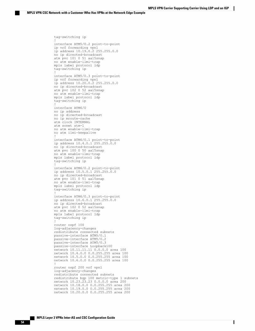
tag-switching ip!interface ATM5/0.2 point-to-pointip vrf forwarding vpn1ip address 10.19.0.2 255.255.0.0no ip directed-broadcastatm pvc 101 0 51 aal5snapno atm enable-ilmi-trapmpls label protocol ldptag-switching ip!interface ATM5/0.3 point-to-pointip vrf forwarding vpn1ip address 10.20.0.2 255.255.0.0no ip directed-broadcastatm pvc 102 0 52 aal5snapno atm enable-ilmi-trapmpls label protocol ldptag-switching ip!interface ATM6/0no ip addressno ip directed-broadcastno ip mroute-cacheatm clock INTERNALatm sonet stm-1no atm enable-ilmi-trapno atm ilmi-keepalive!interface ATM6/0.1 point-to-pointip address 10.4.0.1 255.255.0.0no ip directed-broadcastatm pvc 100 0 50 aal5snapno atm enable-ilmi-trapmpls label protocol ldptag-switching ip!interface ATM6/0.2 point-to-pointip address 10.5.0.1 255.255.0.0no ip directed-broadcastatm pvc 101 0 51 aal5snapno atm enable-ilmi-trapmpls label protocol ldptag-switching ip!interface ATM6/0.3 point-to-pointip address 10.6.0.1 255.255.0.0no ip directed-broadcastatm pvc 102 0 52 aal5snapno atm enable-ilmi-trapmpls label protocol ldptag-switching ip!router ospf 100log-adjacency-changesredistribute connected subnetspassive-interface ATM5/0.1passive-interface ATM5/0.2passive-interface ATM5/0.3passive-interface Loopback100network 10.11.11.11 0.0.0.0 area 100network 10.4.0.0 0.0.255.255 area 100network 10.5.0.0 0.0.255.255 area 100network 10.6.0.0 0.0.255.255 area 100!router ospf 200 vrf vpn1log-adjacency-changesredistribute connected subnetsredistribute bgp 100 metric-type 1 subnetsnetwork 10.23.23.23 0.0.0.0 area 200network 10.18.0.0 0.0.255.255 area 200network 10.19.0.0 0.0.255.255 area 200network 10.20.0.0 0.0.255.255 area 200
MPLS Layer 3 VPNs Inter-AS and CSC Configuration Guide54
MPLS VPN Carrier Supporting Carrier Using LDP and an IGPMPLS VPN CSC Network with a Customer Who Has VPNs at the Network Edge Example

!router bgp 100bgp log-neighbor-changestimers bgp 10 30neighbor 10.14.14.14 remote-as 100neighbor 10.14.14.14 update-source Loopback0!address-family ipv4neighbor 10.14.14.14 activateneighbor 10.14.14.14 send-community extendedno synchronizationexit-address-family!address-family vpnv4neighbor 10.14.14.14 activateneighbor 10.14.14.14 send-community extendedexit-address-family!address-family ipv4 vrf vpn1redistribute ospf 200 match internal external 1 external 2no auto-summaryno synchronizationexit-address-family
Customer Carrier Site 1 Configuration
CSC-CE1 (72K-36-8) Configuration
ip cef!mpls label protocol ldp!interface Loopback0ip address 10.15.15.15 255.255.255.255no ip directed-broadcastno ip route-cacheno ip mroute-cache!interface ATM1/0no ip addressno ip directed-broadcastno ip mroute-cacheatm clock INTERNALatm sonet stm-1no atm enable-ilmi-trapno atm ilmi-keepalive!interface ATM1/0.1 point-to-pointip address 10.15.0.1 255.255.0.0no ip directed-broadcastatm pvc 100 0 50 aal5snapno atm enable-ilmi-trapmpls label protocol ldptag-switching ip!interface ATM1/0.2 point-to-pointip address 10.16.0.1 255.255.0.0no ip directed-broadcastatm pvc 101 0 51 aal5snapno atm enable-ilmi-trapmpls label protocol ldptag-switching ip!interface ATM1/0.3 point-to-pointip address 10.17.0.1 255.255.0.0no ip directed-broadcastatm pvc 102 0 52 aal5snapno atm enable-ilmi-trap
MPLS Layer 3 VPNs Inter-AS and CSC Configuration Guide 55
MPLS VPN Carrier Supporting Carrier Using LDP and an IGPMPLS VPN CSC Network with a Customer Who Has VPNs at the Network Edge Example

mpls label protocol ldptag-switching ip!interface Ethernet3/1ip address 10.10.0.2 255.255.0.0no ip directed-broadcastno ip mroute-cachempls label protocol ldptag-switching ip!router ospf 200log-adjacency-changesredistribute connected subnetsnetwork 10.15.15.15 0.0.0.0 area 200network 10.10.0.0 0.0.255.255 area 200network 10.15.0.0 0.0.255.255 area 200network 10.16.0.0 0.0.255.255 area 200network 10.17.0.0 0.0.255.255 area 200
PE2 (72K-36-7) Configuration
ip cef!ip vrf vpn2rd 200:1route-target export 200:1route-target import 200:1no mpls ip propagate-ttl!interface Loopback0ip address 10.24.24.24 255.255.255.255no ip directed-broadcastno ip route-cacheno ip mroute-cache!interface Ethernet3/0ip address 10.0.0.1 255.0.0.0no ip directed-broadcastno ip mroute-cachempls label protocol ldpmpls ip!interface Ethernet3/1ip vrf forwarding vpn2ip address 10.0.0.1 255.0.0.0no ip directed-broadcastno ip mroute-cache!interface Ethernet3/2ip address 10.0.0.2 255.0.0.0no ip directed-broadcastno ip mroute-cachempls label protocol ldpmpls ip!interface Ethernet3/3ip address 10.0.0.2 255.0.0.0no ip directed-broadcastno ip mroute-cachempls label protocol ldpmpls ip!router ospf 1network 10.0.0.0 0.255.255.255 area 101network 10.0.0.0 0.255.255.255 area 101network 10.0.0.0 0.255.255.255 area 101network 10.0.0.0 0.255.255.255 area 101!router bgp 200neighbor 10.22.22.22 remote-as 200
MPLS Layer 3 VPNs Inter-AS and CSC Configuration Guide56
MPLS VPN Carrier Supporting Carrier Using LDP and an IGPMPLS VPN CSC Network with a Customer Who Has VPNs at the Network Edge Example

neighbor 10.22.22.22 update-source Loopback0neighbor 10.23.23.23 remote-as 200neighbor 10.23.23.23 update-source Loopback0!address-family ipv4 vrf vpn2neighbor 10.0.0.2 remote-as 300neighbor 10.0.0.2 activateneighbor 10.0.0.2 as-overrideno auto-summaryno synchronizationexit-address-family!address-family vpnv4neighbor 10.22.22.22 activateneighbor 10.22.22.22 send-community extendedneighbor 10.23.23.23 activateneighbor 10.23.23.23 send-community extendedexit-address-family
CE1 (36K-36-1) Configuration
ip cef!interface Loopback0ip address 10.19.19.19 255.255.255.255no ip directed-broadcast!interface Ethernet0/2ip address 30.35.0.1 255.255.0.0no ip directed-broadcast!router ospf 300log-adjacency-changesredistribute connected subnetsredistribute bgp 300 subnetspassive-interface Ethernet0/2network 10.19.19.19 0.0.0.0 area 300!router bgp 300no synchronizationbgp log-neighbor-changestimers bgp 10 30redistribute connectedredistribute ospf 300 match internal external 1 external 2neighbor 10.35.0.2 remote-as 200neighbor 10.35.0.2 advertisement-interval 5no auto-summary
Customer Carrier Site 2 Configuration
CSC-CE2 (72K-36-4) Configuration
ip cef!mpls label protocol ldp!interface Loopback0ip address 10.17.17.17 255.255.255.255no ip directed-broadcast!interface ATM5/0no ip addressno ip directed-broadcastatm clock INTERNALatm sonet stm-1
MPLS Layer 3 VPNs Inter-AS and CSC Configuration Guide 57
MPLS VPN Carrier Supporting Carrier Using LDP and an IGPMPLS VPN CSC Network with a Customer Who Has VPNs at the Network Edge Example

no atm enable-ilmi-trapno atm ilmi-keepalive!interface ATM5/0.1 point-to-pointip address 10.11.0.2 255.255.0.0no ip directed-broadcastatm pvc 100 0 50 aal5snapno atm enable-ilmi-trapmpls label protocol ldptag-switching ip!interface ATM5/0.2 point-to-pointip address 10.12.0.2 255.255.0.0no ip directed-broadcastatm pvc 101 0 51 aal5snapno atm enable-ilmi-trapmpls label protocol ldptag-switching ip!interface ATM5/0.3 point-to-pointip address 10.13.0.2 255.255.0.0no ip directed-broadcastatm pvc 102 0 52 aal5snapno atm enable-ilmi-trapmpls label protocol ldptag-switching ip!interface ATM6/0no ip addressno ip directed-broadcastatm clock INTERNALatm sonet stm-1no atm enable-ilmi-trapno atm ilmi-keepalive!interface ATM6/0.1 point-to-pointip address 10.18.0.1 255.255.0.0no ip directed-broadcastatm pvc 100 0 50 aal5snapno atm enable-ilmi-trapmpls label protocol ldptag-switching ip!interface ATM6/0.2 point-to-pointip address 10.19.0.1 255.255.0.0no ip directed-broadcastatm pvc 101 0 51 aal5snapno atm enable-ilmi-trapmpls label protocol ldptag-switching ip!interface ATM6/0.3 point-to-pointip address 10.20.0.1 255.255.0.0no ip directed-broadcastatm pvc 102 0 52 aal5snapno atm enable-ilmi-trapmpls label protocol ldptag-switching ip!router ospf 200log-adjacency-changesredistribute connected subnetsnetwork 10.17.17.17 0.0.0.0 area 200network 10.11.0.0 0.0.255.255 area 200network 10.12.0.0 0.0.255.255 area 200network 10.13.0.0 0.0.255.255 area 200network 10.18.0.0 0.0.255.255 area 200network 10.19.0.0 0.0.255.255 area 200network 10.20.0.0 0.0.255.255 area 200
MPLS Layer 3 VPNs Inter-AS and CSC Configuration Guide58
MPLS VPN Carrier Supporting Carrier Using LDP and an IGPMPLS VPN CSC Network with a Customer Who Has VPNs at the Network Edge Example

PE2 (72K-36-6) Configuration
ip cef!ip vrf customersiterd 200:1route-target export 200:1route-target import 200:1mpls label protocol ldp!interface Loopback0ip address 10.18.18.18 255.255.255.255no ip directed-broadcastno ip route-cacheno ip mroute-cache!interface Ethernet3/0ip vrf forwarding customersiteip address 10.29.0.2 255.255.0.0no ip directed-broadcast!interface Ethernet3/1ip vrf forwarding customersiteip address 10.30.0.2 255.255.0.0no ip directed-broadcast!interface ATM5/0no ip addressno ip directed-broadcastno ip mroute-cacheatm clock INTERNALatm sonet stm-1no atm enable-ilmi-trapno atm ilmi-keepalive!interface ATM5/0.1 point-to-pointip address 10.11.0.1 255.255.0.0no ip directed-broadcastatm pvc 100 0 50 aal5snapno atm enable-ilmi-trapmpls label protocol ldptag-switching ip!interface ATM5/0.2 point-to-pointip address 10.12.0.1 255.255.0.0no ip directed-broadcastatm pvc 101 0 51 aal5snapno atm enable-ilmi-trapmpls label protocol ldptag-switching ip!interface ATM5/0.3 point-to-pointip address 10.13.0.1 255.255.0.0no ip directed-broadcastatm pvc 102 0 52 aal5snapno atm enable-ilmi-trapmpls label protocol ldptag-switching ip!router ospf 200log-adjacency-changesredistribute connected subnetspassive-interface Ethernet3/0passive-interface Ethernet3/1network 10.18.18.18 0.0.0.0 area 200network 10.11.0.0 0.0.255.255 area 200network 10.12.0.0 0.0.255.255 area 200network 10.13.0.0 0.0.255.255 area 200!router bgp 200
MPLS Layer 3 VPNs Inter-AS and CSC Configuration Guide 59
MPLS VPN Carrier Supporting Carrier Using LDP and an IGPMPLS VPN CSC Network with a Customer Who Has VPNs at the Network Edge Example

no bgp default ipv4-unicastbgp log-neighbor-changestimers bgp 10 30neighbor 10.16.16.16 remote-as 200neighbor 10.16.16.16 update-source Loopback0!address-family ipv4neighbor 10.16.16.16 activateneighbor 10.16.16.16 send-community extendedno synchronizationexit-address-family!address-family vpnv4neighbor 10.16.16.16 activateneighbor 10.16.16.16 send-community extendedexit-address-family!address-family ipv4 vrf customersiteneighbor 10.29.0.1 remote-as 300neighbor 10.29.0.1 activateneighbor 10.29.0.1 as-overrideneighbor 10.29.0.1 advertisement-interval 5neighbor 10.30.0.1 remote-as 300neighbor 10.30.0.1 activateneighbor 10.30.0.1 as-overrideneighbor 10.30.0.1 advertisement-interval 5no auto-summaryno synchronizationexit-address-family
CE2 (36K-38-4) Configuration
ip cef!interface Loopback0ip address 10.21.21.21 255.255.255.255!interface Ethernet1/3ip address 10.29.0.1 255.255.0.0!interface Ethernet5/0ip address 10.14.0.1 255.255.0.0!router ospf 300log-adjacency-changesredistribute connected subnetsredistribute bgp 300 subnetspassive-interface Ethernet1/3network 10.21.21.21 0.0.0.0 area 300network 10.14.0.0 0.0.255.255 area 300!router bgp 300no synchronizationtimers bgp 10 30redistribute connectedredistribute ospf 300 match internal external 1 external 2neighbor 10.29.0.2 remote-as 200neighbor 10.29.0.2 advertisement-interval 5no auto-summary
CE3 (36K-38-5) Configuration
ip cef!interface Loopback0ip address 10.20.20.20 255.255.255.255no ip directed-broadcast!
MPLS Layer 3 VPNs Inter-AS and CSC Configuration Guide60
MPLS VPN Carrier Supporting Carrier Using LDP and an IGPMPLS VPN CSC Network with a Customer Who Has VPNs at the Network Edge Example
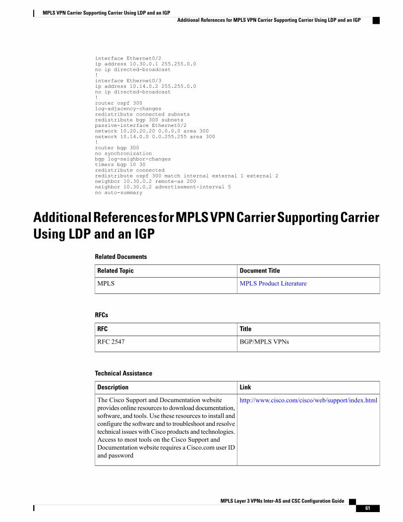
interface Ethernet0/2ip address 10.30.0.1 255.255.0.0no ip directed-broadcast!interface Ethernet0/3ip address 10.14.0.2 255.255.0.0no ip directed-broadcast!router ospf 300log-adjacency-changesredistribute connected subnetsredistribute bgp 300 subnetspassive-interface Ethernet0/2network 10.20.20.20 0.0.0.0 area 300network 10.14.0.0 0.0.255.255 area 300!router bgp 300no synchronizationbgp log-neighbor-changestimers bgp 10 30redistribute connectedredistribute ospf 300 match internal external 1 external 2neighbor 10.30.0.2 remote-as 200neighbor 10.30.0.2 advertisement-interval 5no auto-summary
Additional References for MPLS VPN Carrier Supporting CarrierUsing LDP and an IGP
Related Documents
Document TitleRelated Topic
MPLS Product LiteratureMPLS
RFCs
TitleRFC
BGP/MPLS VPNsRFC 2547
Technical Assistance
LinkDescription
http://www.cisco.com/cisco/web/support/index.htmlThe Cisco Support and Documentation websiteprovides online resources to download documentation,software, and tools. Use these resources to install andconfigure the software and to troubleshoot and resolvetechnical issues with Cisco products and technologies.Access to most tools on the Cisco Support andDocumentation website requires a Cisco.com user IDand password
MPLS Layer 3 VPNs Inter-AS and CSC Configuration Guide 61
MPLS VPN Carrier Supporting Carrier Using LDP and an IGPAdditional References for MPLS VPN Carrier Supporting Carrier Using LDP and an IGP

Feature Information for MPLS VPN CSC with LDP and IGPThe following table provides release information about the feature or features described in this module. Thistable lists only the software release that introduced support for a given feature in a given software releasetrain. Unless noted otherwise, subsequent releases of that software release train also support that feature.
Use Cisco Feature Navigator to find information about platform support and Cisco software image support.To access Cisco Feature Navigator, go to www.cisco.com/go/cfn. An account on Cisco.com is not required.
Table 4: Feature Information for MPLS VPN CSC with LDP and IGP
Feature Configuration InformationReleasesFeature Name
This feature enables you to set upand create an MPLS VPN CSCnetwork that uses LDP to transportMPLS labels and an IGP totransport routes.
In 12.0(14)ST, this feature wasintroduced.
In 12.0(16)ST, this feature wasintegrated.
In 12.2(8)T, this feature wasintegrated.
In 12.0(21)ST, this feature wasintegrated.
In 12.0(22)S, this feature wasintegrated.
In 12.0(23)S, this feature wasintegrated.
In Cisco IOS XE Release 2.2, thisfeature was implemented on theCisco ASR 1000 Series Routers.
This feature uses no new ormodified commands.
12.0(14)ST
12.0(16)ST
12.2(8)T
12.0(21)ST
12.0(22)S
12.0(23)S
Cisco IOS XE Release 2.2
MPLS VPN Carrier SupportingCarrier
GlossaryASBR -- Autonomous System Boundary router. A router that connects one autonomous system to another.
autonomous system --A collection of networks under a common administration sharing a common routingstrategy.
MPLS Layer 3 VPNs Inter-AS and CSC Configuration Guide62
MPLS VPN Carrier Supporting Carrier Using LDP and an IGPFeature Information for MPLS VPN CSC with LDP and IGP
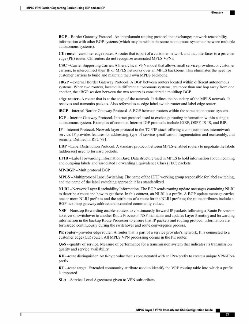
BGP --Border Gateway Protocol. An interdomain routing protocol that exchanges network reachabilityinformation with other BGP systems (which may be within the same autonomous system or between multipleautonomous systems).
CE router--customer edge router. A router that is part of a customer network and that interfaces to a provideredge (PE) router. CE routers do not recognize associated MPLS VPNs.
CSC --Carrier Supporting Carrier. A hierarchical VPNmodel that allows small service providers, or customercarriers, to interconnect their IP or MPLS networks over an MPLS backbone. This eliminates the need forcustomer carriers to build and maintain their own MPLS backbone.
eBGP --external Border Gateway Protocol. A BGP between routers located within different autonomoussystems. When two routers, located in different autonomous systems, are more than one hop away from oneanother, the eBGP session between the two routers is considered a multihop BGP.
edge router--A router that is at the edge of the network. It defines the boundary of the MPLS network. Itreceives and transmits packets. Also referred to as edge label switch router and label edge router.
iBGP --internal Border Gateway Protocol. A BGP between routers within the same autonomous system.
IGP --Interior Gateway Protocol. Internet protocol used to exchange routing information within a singleautonomous system. Examples of common Internet IGP protocols include IGRP, OSPF, IS-IS, and RIP.
IP --Internet Protocol. Network layer protocol in the TCP/IP stack offering a connectionless internetworkservice. IP provides features for addressing, type-of-service specification, fragmentation and reassembly, andsecurity. Defined in RFC 791.
LDP --Label Distribution Protocol. A standard protocol betweenMPLS-enabled routers to negotiate the labels(addresses) used to forward packets.
LFIB --Label Forwarding Information Base. Data structure used inMPLS to hold information about incomingand outgoing labels and associated Forwarding Equivalence Class (FEC) packets.
MP-BGP --Multiprotocol BGP.
MPLS --Multiprotocol Label Switching. The name of the IETFworking group responsible for label switching,and the name of the label switching approach it has standardized.
NLRI --Network Layer Reachability Information. The BGP sends routing update messages containing NLRIto describe a route and how to get there. In this context, an NLRI is a prefix. A BGP update message carriesone or more NLRI prefixes and the attributes of a route for the NLRI prefixes; the route attributes include aBGP next hop gateway address and extended community values.
NSF --Nonstop forwarding enables routers to continuously forward IP packets following a Route Processortakeover or switchover to another Route Processor. NSFmaintains and updates Layer 3 routing and forwardinginformation in the backup Route Processor to ensure that IP packets and routing protocol information areforwarded continuously during the switchover and route convergence process.
PE router--provider edge router. A router that is part of a service provider’s network. It is connected to acustomer edge (CE) router. All MPLS VPN processing occurs in the PE router.
QoS --quality of service. Measure of performance for a transmission system that indicates its transmissionquality and service availability.
RD --route distinguisher. An 8-byte value that is concatenated with an IPv4 prefix to create a unique VPN-IPv4prefix.
RT --route target. Extended community attribute used to identify the VRF routing table into which a prefixis imported.
SLA --Service Level Agreement given to VPN subscribers.
MPLS Layer 3 VPNs Inter-AS and CSC Configuration Guide 63
MPLS VPN Carrier Supporting Carrier Using LDP and an IGPGlossary

VPN --Virtual Private Network. A secureMPLS-based network that shares resources on one or more physicalnetworks (typically implemented by one or more service providers). A VPN contains geographically dispersedsites that can communicate securely over a shared backbone network.
VRF --VPN routing and forwarding instance. Routing information that defines a VPN site that is attached toa PE router. A VRF consists of an IP routing table, a derived forwarding table, a set of interfaces that use theforwarding table, and a set of rules and routing protocols that determine what goes into the forwarding table.
MPLS Layer 3 VPNs Inter-AS and CSC Configuration Guide64
MPLS VPN Carrier Supporting Carrier Using LDP and an IGPGlossary
Related Documents


