MPLS Layer 2 VPNs Configuration Guide, Cisco IOS XE Release 3S First Published: November 08, 2011 Last Modified: July 30, 2013 Americas Headquarters Cisco Systems, Inc. 170 West Tasman Drive San Jose, CA 95134-1706 USA http://www.cisco.com Tel: 408 526-4000 800 553-NETS (6387) Fax: 408 527-0883

Welcome message from author
This document is posted to help you gain knowledge. Please leave a comment to let me know what you think about it! Share it to your friends and learn new things together.
Transcript
MPLS Layer 2 VPNs Configuration Guide, Cisco IOS XE Release 3SFirst Published: November 08, 2011
Last Modified: July 30, 2013
Americas HeadquartersCisco Systems, Inc.170 West Tasman DriveSan Jose, CA 95134-1706USAhttp://www.cisco.comTel: 408 526-4000 800 553-NETS (6387)Fax: 408 527-0883

THE SPECIFICATIONS AND INFORMATION REGARDING THE PRODUCTS IN THIS MANUAL ARE SUBJECT TO CHANGE WITHOUT NOTICE. ALL STATEMENTS,INFORMATION, AND RECOMMENDATIONS IN THIS MANUAL ARE BELIEVED TO BE ACCURATE BUT ARE PRESENTED WITHOUT WARRANTY OF ANY KIND,EXPRESS OR IMPLIED. USERS MUST TAKE FULL RESPONSIBILITY FOR THEIR APPLICATION OF ANY PRODUCTS.
THE SOFTWARE LICENSE AND LIMITEDWARRANTY FOR THE ACCOMPANYING PRODUCT ARE SET FORTH IN THE INFORMATION PACKET THAT SHIPPED WITHTHE PRODUCT AND ARE INCORPORATED HEREIN BY THIS REFERENCE. IF YOU ARE UNABLE TO LOCATE THE SOFTWARE LICENSE OR LIMITED WARRANTY,CONTACT YOUR CISCO REPRESENTATIVE FOR A COPY.
The Cisco implementation of TCP header compression is an adaptation of a program developed by the University of California, Berkeley (UCB) as part of UCB's public domain versionof the UNIX operating system. All rights reserved. Copyright © 1981, Regents of the University of California.
NOTWITHSTANDINGANYOTHERWARRANTYHEREIN, ALL DOCUMENT FILES AND SOFTWARE OF THESE SUPPLIERS ARE PROVIDED “AS IS"WITH ALL FAULTS.CISCO AND THE ABOVE-NAMED SUPPLIERS DISCLAIM ALL WARRANTIES, EXPRESSED OR IMPLIED, INCLUDING, WITHOUT LIMITATION, THOSE OFMERCHANTABILITY, FITNESS FORA PARTICULAR PURPOSEANDNONINFRINGEMENTORARISING FROMACOURSEOFDEALING, USAGE, OR TRADE PRACTICE.
IN NO EVENT SHALL CISCO OR ITS SUPPLIERS BE LIABLE FOR ANY INDIRECT, SPECIAL, CONSEQUENTIAL, OR INCIDENTAL DAMAGES, INCLUDING, WITHOUTLIMITATION, LOST PROFITS OR LOSS OR DAMAGE TO DATA ARISING OUT OF THE USE OR INABILITY TO USE THIS MANUAL, EVEN IF CISCO OR ITS SUPPLIERSHAVE BEEN ADVISED OF THE POSSIBILITY OF SUCH DAMAGES.
Any Internet Protocol (IP) addresses and phone numbers used in this document are not intended to be actual addresses and phone numbers. Any examples, command display output, networktopology diagrams, and other figures included in the document are shown for illustrative purposes only. Any use of actual IP addresses or phone numbers in illustrative content is unintentionaland coincidental.
Cisco and the Cisco logo are trademarks or registered trademarks of Cisco and/or its affiliates in the U.S. and other countries. To view a list of Cisco trademarks, go to this URL: http://www.cisco.com/go/trademarks. Third-party trademarks mentioned are the property of their respective owners. The use of the word partner does not imply a partnershiprelationship between Cisco and any other company. (1110R)
© 2011-2013 Cisco Systems, Inc. All rights reserved.
C O N T E N T S
C H A P T E R 1 L2VPN Protocol-Based CLIs 1
Finding Feature Information 1
Information About L2VPN Protocol-Based CLIs 1
Overview of L2VPN Protocol-Based CLIs 1
Benefits of L2VPN Protocol-Based CLIs 2
L2VPN Protocol-Based CLI Changes 3
MPLS L2VPN Protocol-Based CLI: Examples 7
Additional References 10
Feature Information for L2VPN Protocol-Based CLIs 10
C H A P T E R 2 Any Transport over MPLS 13
Finding Feature Information 13
Prerequisites for Any Transport over MPLS 14
Restrictions for Any Transport over MPLS 14
General Restrictions 14
ATM AAL5 over MPLS Restrictions 14
ATM Cell Relay over MPLS Restrictions 15
Ethernet over MPLS (EoMPLS) Restrictions 15
Per-Subinterface MTU for Ethernet over MPLS Restrictions 15
Frame Relay over MPLS Restrictions 16
HDLC over MPLS Restrictions 16
PPP over MPLS Restrictions 16
Tunnel Selection Restrictions 16
Experimental Bits with AToM Restrictions 17
Remote Ethernet Port Shutdown Restrictions 17
Information About Any Transport over MPLS 17
How AToM Transports Layer 2 Packets 17
MPLS Layer 2 VPNs Configuration Guide, Cisco IOS XE Release 3S iii
How AToM Transports Layer 2 Packets using the commands associated with the L2VPN
Protocol-Based CLIs feature 18
Benefits of AToM 19
MPLS Traffic Engineering Fast Reroute 19
Maximum Transmission Unit Guidelines for Estimating Packet Size 20
Estimating Packet Size Example 21
Per-Subinterface MTU for Ethernet over MPLS 22
Per-Subinterface MTU for Ethernet over MPLS using the commands associated with the
L2VPN Protocol-Based CLIs feature 22
Frame Relay over MPLS and DTE DCE and NNI Connections 23
Local Management Interface and Frame Relay over MPLS 23
How LMI Works 23
QoS Features Supported with AToM 24
OAM Cell Emulation for ATM AAL5 over MPLS 28
OAM Cell Emulation for ATM AAL5 over MPLS in VC Class Configuration
Mode 28
Any Transport over MPLS (AToM) Remote Ethernet Port Shutdown 28
Any Transport over MPLS (AToM) Remote Ethernet Port Shutdown using the commands
associated with the L2VPN Protocol-Based CLIs feature 30
AToM Load Balancing with Single PW 31
Flow-Aware Transport (FAT) Load Balancing 31
How to Configure Any Transport over MPLS 31
Configuring the Pseudowire Class 32
Configuring the Pseudowire Class using the commands associated with the L2VPN
Protocol-Based CLIs feature 33
Changing the Encapsulation Type and Removing a Pseudowire 34
Changing the Encapsulation Type and Removing a Pseudowire using the commands
associated with the L2VPN Protocol-Based CLIs feature 34
Configuring ATM AAL5 over MPLS 35
Configuring ATM AAL5 over MPLS on PVCs 35
Configuring ATM AAL5 over MPLS on PVCs using the commands associated with
the L2VPN Protocol-Based CLIs feature 37
Configuring ATM AAL5 over MPLS in VC Class Configuration Mode 40
Configuring ATM AAL5 over MPLS in VC Class Configuration Mode using the
commands associated with the L2VPN Protocol-Based CLIs feature 42
MPLS Layer 2 VPNs Configuration Guide, Cisco IOS XE Release 3Siv
Contents
Configuring OAM Cell Emulation for ATM AAL5 over MPLS 45
Configuring OAM Cell Emulation for ATM AAL5 over MPLS on PVCs 45
ConfiguringOAMCell Emulation forATMAAL5overMPLSonPVCs using the commands
associated with the L2VPN Protocol-Based CLIs feature 47
Configuring OAMCell Emulation for ATMAAL5 over MPLS in VC Class Configuration
Mode 51
Configuring OAMCell Emulation for ATMAAL5 over MPLS in VC Class Configuration
Mode using the commands associated with the L2VPN Protocol-Based CLIs feature
53
Configuring ATM Cell Relay over MPLS 56
Configuring ATM Cell Relay over MPLS in VC Mode 56
Configuring ATM Cell Relay over MPLS in VC Mode using the commands associated
with the L2VPN Protocol-Based CLIs feature 58
Configuring ATM Cell Relay over MPLS in VC Mode Using VC Class Configuration
Mode 61
Configuring ATM Cell Relay over MPLS in VC Mode Using VC Class Configuration
Mode using the commands associated with the L2VPN Protocol-Based CLIs
feature 63
Configuring ATM Cell Relay over MPLS in PVP Mode 66
Configuring ATM Cell Relay over MPLS in PVP Mode using the commands associated
with the L2VPN Protocol-Based CLIs feature 68
Configuring Ethernet over MPLS 70
Configuring Ethernet over MPLS in VLANMode to Connect Two VLAN Networks That
Are in Different Locations. 70
Configuring Ethernet over MPLS in VLANMode to Connect Two VLAN Networks That
Are in Different Locations using the commands associated with the L2VPN
Protocol-Based CLIs feature 72
Configuring Ethernet over MPLS in Port Mode 74
Configuring Ethernet over MPLS in Port Mode using the commands associated with the
L2VPN Protocol-Based CLIs feature 76
Configuring Ethernet over MPLS with VLAN ID Rewrite 78
Configuring Ethernet over MPLS with VLAN ID Rewrite using the commands associated
with the L2VPN Protocol-Based CLIs feature 81
Configuring per-Subinterface MTU for Ethernet over MPLS 84
MPLS Layer 2 VPNs Configuration Guide, Cisco IOS XE Release 3S v
Contents
Configuring per-Subinterface MTU for Ethernet over MPLS using the commands
associated with the L2VPN Protocol-Based CLIs feature 86
Configuring Frame Relay over MPLS 89
Configuring Frame Relay over MPLS with DLCI-to-DLCI Connections 89
Configuring Frame Relay over MPLS with DLCI-to-DLCI Connections using the
commands associated with the L2VPN Protocol-Based CLIs feature 91
Configuring Frame Relay over MPLS with Port-to-Port Connections 94
Configuring FrameRelay overMPLSwith Port-to-Port Connections using the commands
associated with the L2VPN Protocol-Based CLIs feature 95
Configuring HDLC or PPP over MPLS 97
Configuring HDLC or PPP over MPLS using the commands associated with the L2VPN
Protocol-Based CLIs feature 99
Configuring Tunnel Selection 101
Troubleshooting Tips 103
Configuring Tunnel Selection using the commands associated with the L2VPN
Protocol-Based CLIs feature 104
Troubleshooting Tips using the commands associated with the L2VPN Protocol-Based
CLIs feature 106
Setting Experimental Bits with AToM 107
Enabling the Control Word 109
Enabling the ControlWord using the commands associated with the L2VPN Protocol-Based
CLIs feature 110
Configuring MPLS AToM Remote Ethernet Port Shutdown 111
ConfiguringMPLSAToMRemote Ethernet Port Shutdown using the commands associated
with the L2VPN Protocol-Based CLIs feature 113
Configuring AToM Load Balancing with Single PW 116
Configuring AToM Load Balancing with Single PW using the commands associated with
the L2VPN Protocol-Based CLIs feature 118
Configuring Flow-Aware Transport (FAT) Load Balancing 120
Configuring Flow-Aware Transport (FAT) Load Balancing using a template 124
Configuration Examples for Any Transport over MPLS 128
Example: ATM over MPLS 128
Example: ATMoverMPLS using the commands associatedwith the L2VPNProtocol-Based
CLIs feature 129
Example: Configuring ATM AAL5 over MPLS in VC Class Configuration Mode 131
MPLS Layer 2 VPNs Configuration Guide, Cisco IOS XE Release 3Svi
Contents
Example: Configuring ATM AAL5 over MPLS in VC Class Configuration Mode using the
commands associated with the L2VPN Protocol-Based CLIs feature 131
Example: Ethernet over MPLS with MPLS Traffic Engineering Fast Reroute 131
Example: Ethernet overMPLSwithMPLSTraffic Engineering Fast Reroute using the commands
associated with the L2VPN Protocol-Based CLIs feature 134
Example: Configuring OAM Cell Emulation 137
Example: Configuring OAM Cell Emulation using the commands associated with the L2VPN
Protocol-Based CLIs feature 138
Example: Configuring ATM Cell Relay over MPLS 139
Example: Configuring ATM Cell Relay over MPLS using the commands associated with the
L2VPN Protocol-Based CLIs feature 140
Example: Configuring per-Subinterface MTU for Ethernet over MPLS 141
Example: Configuring per-Subinterface MTU for Ethernet over MPLS using the commands
associated with the L2VPN Protocol-Based CLIs feature 143
Example: Configuring Tunnel Selection 144
Example: Configuring Tunnel Selection using the commands associated with the L2VPN
Protocol-Based CLIs feature 146
Example: Configuring MTU Values in xconnect Configuration Mode for L2VPN
Interworking 148
Example: ConfiguringMTUValues in xconnect ConfigurationMode for L2VPN Interworking
using the commands associated with the L2VPN Protocol-Based CLIs feature 151
Examples: Configuring Any Transport over MPLS (AToM) Remote Ethernet Port
Shutdown 153
Examples: Configuring Any Transport over MPLS (AToM) Remote Ethernet Port Shutdown
using the commands associated with the L2VPN Protocol-Based CLIs feature 154
Additional References for Any Transport over MPLS 155
Feature Information for Any Transport over MPLS 155
C H A P T E R 3 L2VPN Interworking 165
Finding Feature Information 165
Prerequisites for L2VPN Interworking 166
Restrictions for L2VPN Interworking 166
General Restrictions for L2VPN Interworking 166
Restrictions for Routed Interworking 167
Restrictions for PPP Interworking 168
MPLS Layer 2 VPNs Configuration Guide, Cisco IOS XE Release 3S vii
Contents

Restrictions for Ethernet/VLAN-to-ATM AAL5 Interworking 168
Restrictions for Ethernet/VLAN-to-Frame Relay Interworking 169
Restrictions for HDLC-to-Ethernet Interworking 170
Information About L2VPN Interworking 170
Overview of L2VPN Interworking 170
L2VPN Interworking Modes 171
Ethernet or Bridged Interworking 171
IP or Routed Interworking 171
Ethernet VLAN-to-ATM AAL5 Interworking 173
ATM AAL5-to-Ethernet Port AToM--Bridged Interworking 173
ATM AAL5-to-Ethernet VLAN 802.1Q AToM--Bridged Interworking 174
ATM-to-Ethernet--Routed Interworking 175
Ethernet VLAN-to-Frame Relay Interworking 176
Frame Relay DLCI-to-Ethernet Port AToM--Bridged Interworking 176
Frame Relay DLCI-to-Ethernet VLAN 802.1Q AToM--Bridged Interworking 177
Frame Relay DLCI-to-Ethernet VLAN Qot1Q QinQ AToM - Bridged
Interworking 178
HDLC-to-Ethernet Interworking 179
HDLC-to-Ethernet— Ethernet or Bridged Interworking 179
HDLC-to-Ethernet— IP or Routed Interworking 180
ATM Local Switching 181
VC-to-VC Local Switching 181
VP-to-VP Local Switching 182
PPP-to-Ethernet AToM-Routed Interworking 183
PPP-to-Ethernet AToM-Routed Interworking using the commands associated with the
L2VPN Protocol-Based CLIs feature 183
Static IP Addresses for L2VPN Interworking for PPP 184
Static IP Addresses for L2VPN Interworking for PPP using the commands associated with
the L2VPN Protocol-Based CLIs feature 184
How to Configure L2VPN Interworking 185
Configuring L2VPN Interworking 185
Verifying the L2VPN Configuration 186
Configuring L2VPN Interworking using the commands associated with the L2VPN
Protocol-Based CLIs feature 187
MPLS Layer 2 VPNs Configuration Guide, Cisco IOS XE Release 3Sviii
Contents

Verifying the L2VPN Configuration using the commands associated with the L2VPN
Protocol-Based CLIs feature 188
Configuring Ethernet VLAN-to-ATM AAL5 Interworking 189
ATM AAL5-to-Ethernet Port 189
ATM AAL5-to-Ethernet Port using the commands associated with the L2VPN
Protocol-Based CLIs feature 191
ATM AAL5-to-Ethernet Port on a PE2 Router 194
ATM AAL5-to-Ethernet Port on a PE2 Router using the commands associated with the
L2VPN Protocol-Based CLIs feature 197
ATM AAL5-to-Ethernet VLAN 802.1Q on a PE1 Router 200
ATM AAL5-to-Ethernet VLAN 802.1Q on a PE1 Router using the commands associated
with the L2VPN Protocol-Based CLIs feature 202
ATM AAL5-to-Ethernet VLAN 802.1Q on a PE2 router 206
ATM AAL5-to-Ethernet VLAN 802.1Q on a PE2 router using the commands associated
with the L2VPN Protocol-Based CLIs feature 208
Configuring Ethernet VLAN-to-Frame Relay Interworking 212
Frame Relay DLCI-to-Ethernet Port on a PE1 Router 212
Frame Relay DLCI-to-Ethernet Port on a PE1 Router using the commands associated with
the L2VPN Protocol-Based CLIs feature 214
Frame Relay DLCI-to-Ethernet Port on a PE2 router 218
Frame Relay DLCI-to-Ethernet Port on a PE2 router using the commands associated with
the L2VPN Protocol-Based CLIs feature 220
Frame Relay DLCI-to-Ethernet VLAN 802.1Q on a PE1 Router 223
Frame Relay DLCI-to-Ethernet VLAN 802.1Q on a PE1 Router using the commands
associated with the L2VPN Protocol-Based CLIs feature 226
Frame Relay DLCI-to-Ethernet VLAN 802.1Q on a PE2 Router 230
Frame Relay DLCI-to-Ethernet VLAN 802.1Q on a PE2 Router using the commands
associated with the L2VPN Protocol-Based CLIs feature 232
Configuring HDLC-to-Ethernet Interworking 236
HDLC-to-Ethernet Bridged Interworking on a HDLC PE Device 236
HDLC-to-Ethernet Bridged Interworking on a HDLC PE Device Using the Commands
Associated with the L2VPN Protocol-Based CLIs Feature 238
HDLC-to-Ethernet Bridged Interworking (Port Mode) on an Ethernet PE Device 240
HDLC-to-Ethernet Bridged Interworking (Port Mode) on an Ethernet PE Device Using
the Commands Associated with the L2VPN Protocol-Based CLIs Feature 242
MPLS Layer 2 VPNs Configuration Guide, Cisco IOS XE Release 3S ix
Contents

HDLC-to-Ethernet Bridged Interworking (dot1q and QinQ Modes) on an Ethernet PE
Device 245
HDLC-to-Ethernet Bridged Interworking (dot1q and QinQ Modes) on an Ethernet PE
Device Using the Commands Associated with the L2VPN Protocol-Based CLIs
Feature 247
HDLC-to-Ethernet Routed Interworking on a HDLC PE Device 250
HDLC-to-Ethernet Routed Interworking on a HDLC PE Device Using the Commands
Associated with the L2VPN Protocol-Based CLIs Feature 252
HDLC-to-Ethernet Routed Interworking (Port Mode) on an Ethernet PE Device 254
HDLC-to-Ethernet Routed Interworking (Port Mode) on an Ethernet PE Device Using
the Commands Associated with the L2VPN Protocol-Based CLIs Feature 256
HDLC-to-Ethernet Routed Interworking (dot1q and QinQ Modes) on an Ethernet PE
Device 259
HDLC-to-Ethernet Routed Interworking (dot1q and QinQ Modes) on an Ethernet PE
Device Using the Commands Associated with the L2VPN Protocol-Based CLIs
Feature 261
Verifying HDLC-to-Ethernet Interworking (Port Mode) Configuration on a HDLC PE
Device 264
Verifying HDLC-to-Ethernet Interworking (Port Mode) Configuration on an Ethernet
PE Device 266
Verifying HDLC-to-Ethernet Interworking (dot1q Mode) Configuration on a HDLC
PE Device 268
VerifyingHDLC-to-Ethernet Interworking (dot1qMode) Configuration on an Ethernet
PE Device 271
Verifying HDLC-to-Ethernet Interworking (QinQ Mode) Configuration on a HDLC
PE Device 273
Verifying HDLC-to-Ethernet Interworking (QinQMode) Configuration on an Ethernet
PE Device 276
Verifying L2VPN Interworking 278
Verifying L2VPN Interworking using the commands associated with the L2VPN
Protocol-Based CLIs feature 278
Configuration Examples for L2VPN Interworking 279
Frame Relay DLCI-to-Ethernet VLAN 802.1Q Using Bridged Internetworking
Example 279
Frame Relay DLCI-to-Ethernet VLAN 802.1Q Using Bridged Internetworking Example
using the commands associated with the L2VPN Protocol-Based CLIs feature 280
MPLS Layer 2 VPNs Configuration Guide, Cisco IOS XE Release 3Sx
Contents

ATM AAL5-to-Ethernet VLAN 802.1Q Using Bridged Internetworking Example 280
ATM AAL5-to-Ethernet VLAN 802.1Q Using Bridged Internetworking Example using the
commands associated with the L2VPN Protocol-Based CLIs feature 281
ATM AAL5-to-Ethernet Port Using Routed Interworking Example 281
Frame Relay DLCI-to-Ethernet Port Using Routed Interworking Example 282
Frame Relay DLCI-to-Ethernet Port Using Routed Interworking Example using the commands
associated with the L2VPN Protocol-Based CLIs feature 282
Ethernet-to-VLAN over AToM--Bridged Example 283
Ethernet to VLAN over AToM (Bridged) Example using the commands associated with the
L2VPN Protocol-Based CLIs feature 284
VLAN-to-ATM AAL5 over AToM (Bridged) Example 285
VLAN-to-ATM AAL5 over AToM (Bridged) Example using the commands associated with
the L2VPN Protocol-Based CLIs feature 286
Ethernet VLAN-to-PPP over AToM (Routed) Example 288
Ethernet VLAN to PPP over AToM (Routed) Example using the commands associated with
the L2VPN Protocol-Based CLIs feature 289
ATM VC-to-VC Local Switching (Different Port) Example 291
ATM VP-to-VP Local Switching (Different Port) Example 292
Example: Configuring HDLC-to-Ethernet Interworking: Controller Slot on HDLC Devices 293
Example: Configuring HDLC-to-Ethernet Bridged Interworking on HDLC Devices 293
Example: Configuring HDLC-to-Ethernet Bridged Interworking on HDLC Devices Using the
Commands Associated with the L2VPN Protocol-Based CLIs Feature 294
Example: Configuring HDLC-to-Ethernet Bridged Interworking on Ethernet Devices 294
Example: Configuring HDLC-to-Ethernet Bridged Interworking on Ethernet Devices Using
the Commands Associated with the L2VPN Protocol-Based CLIs Feature 295
Example: Configuring HDLC-to-VLAN Bridged Interworking (Port Mode) on Ethernet
Devices 295
Example: Configuring HDLC-to-VLAN Bridged Interworking on Ethernet Devices Using the
Commands Associated with the L2VPN Protocol-Based CLIs Feature 296
Example: Configuring HDLC-to-VLAN Bridged Interworking (dot1q Mode) Using the
Commands Associated with the L2VPN Protocol-Based CLIs Feature 297
Example: Configuring HDLC-to-VLAN Bridged Interworking (QinQ Mode) on Ethernet
Devices 298
MPLS Layer 2 VPNs Configuration Guide, Cisco IOS XE Release 3S xi
Contents
Example: Configuring HDLC-to-VLAN Bridged Interworking (QinQ Mode) on Ethernet
Devices Using the Commands Associated with the L2VPN Protocol-Based CLIs
Feature 299
Additional References for L2VPN Interworking 299
Feature Information for L2VPN Interworking 301
C H A P T E R 4 L2VPN Pseudowire Preferential Forwarding 303
Finding Feature Information 303
Prerequisites for L2VPN—Pseudowire Preferential Forwarding 303
Guidelines and Limitations for L2VPN--Pseudowire Preferential Forwarding 304
Information About L2VPN--Pseudowire Preferential Forwarding 305
Overview of L2VPN--Pseudowire Preferential Forwarding 305
Overview of L2VPN—Pseudowire Preferential Forwarding using the commands associated
with the L2VPN Protocol-Based CLIs feature 305
How to Configure L2VPN--Pseudowire Preferential Forwarding 306
Configuring the Pseudowire Connection Between PE Routers 306
Configuring the Pseudowire Connection Between PE Routers 307
Configuration Examples for L2VPN--Pseudowire Preferential Forwarding 309
Example: L2VPN--Pseudowire Preferential Forwarding Configuration 309
Example: L2VPN--Pseudowire Preferential Forwarding Configuration using the commands
associated with the L2VPN Protocol-Based CLIs feature 309
Example: Displaying the Status of the Pseudowires 310
Additional References 311
Feature Information for L2VPN--Pseudowire Preferential Forwarding 312
C H A P T E R 5 L2VPN Multisegment Pseudowires 315
Finding Feature Information 315
Prerequisites for L2VPN Multisegment Pseudowires 315
Restrictions for L2VPN Multisegment Pseudowires 316
Information About L2VPN Multisegment Pseudowires 316
L2VPN Pseudowire Defined 316
L2VPN Multisegment Pseudowire Defined 316
How to Configure L2VPN Multisegment Pseudowires 317
Configuring L2VPN Multisegment Pseudowires 317
MPLS Layer 2 VPNs Configuration Guide, Cisco IOS XE Release 3Sxii
Contents
Configuring L2VPN Multisegment Pseudowires using the commands associated with the
L2VPN Protocol-Based CLIs feature 319
Displaying Information About the L2VPN Multisegment Pseudowires 321
Displaying Information About the L2VPN Multisegment Pseudowires using the commands
associated with the L2VPN Protocol-Based CLIs feature 322
Performing ping mpls and trace mpls Operations on the L2VPN Multisegment
Pseudowires 324
Additional References 326
Feature Information for L2VPN Multisegment Pseudowires 327
C H A P T E R 6 MPLS Quality of Service 329
Prerequisites for MPLS Quality of Service 329
Information About MPLS Quality of Service 330
MPLS Quality of Service Overview 330
Tag Switching and MPLS Terminology 332
LSRs Used at the Edge of an MPLS Network 332
LSRs Used at the Core of an MPLS Network 333
Benefits of MPLS CoS in IP Backbones 333
How to Configure MPLS Quality of Service 334
Configuring WRED 334
Verifying WRED 335
Configuring CAR 335
Verifying the CAR Configuration 336
Configuring CBWFQ 337
Verifying the CBWFQ Configuration 338
Configuration Examples for MPLS Quality of Service 341
Example: Configuring Cisco Express Forwarding 341
Example: Running IP on Device 1 341
Example: Running MPLS on Device 2 342
Example: Running MPLS on Device 3 342
Example: Running MPLS on Device 4 343
Example: Running MPLS on Device 5 344
Example: Running IP on Device 6 345
Additional References for MPLS Quality of Service 345
Feature Information for MPLS Quality of Service 346
MPLS Layer 2 VPNs Configuration Guide, Cisco IOS XE Release 3S xiii
Contents
C H A P T E R 7 QoS Policy Support on L2VPN ATM PVPs 347
Finding Feature Information 347
Prerequisites for QoS Policy Support on L2VPN ATM PVPs 347
Restrictions for QoS Policy Support on L2VPN ATM PVPs 348
Information About QoS Policy Support on L2VPN ATM PVPs 348
The MQC Structure 348
Elements of a Traffic Class 349
Elements of a Traffic Policy 349
How to Configure QoS Policy Support on L2VPN ATM PVPs 349
Enabling a Service Policy in ATM PVP Mode 349
Enabling a Service Policy in ATM PVP Mode using the commands associated with the
L2VPN Protocol-Based CLIs feature 351
Enabling Traffic Shaping in ATM PVP Mode 353
Enabling Traffic Shaping in ATM PVP Mode using the commands associated with the
L2VPN Protocol-Based CLIs feature 355
Enabling Traffic Shaping in ATM PVP Mode Example using the commands associated
with the L2VPN Protocol-Based CLIs feature 358
Enabling Matching of ATM VCIs 359
Configuration Examples for QoS Policy Support on L2VPN ATM PVPs 360
Example Enabling Traffic Shaping in ATM PVP Mode 360
Example Enabling Traffic Shaping in ATM PVP Mode using the commands associated
with the L2VPN Protocol-Based CLIs feature 360
Additional References 361
Feature Information for QoS Policy Support on L2VPN ATM PVPs 362
C H A P T E R 8 MPLS Pseudowire Status Signaling 365
Finding Feature Information 365
Prerequisites for MPLS Pseudowire Status Signaling 365
Restrictions for MPLS Pseudowire Status Signaling 366
Information About MPLS Pseudowire Status Signaling 366
How MPLS Pseudowire Status Switching Works 366
How MPLS Pseudowire Status Switching Works using the commands associated with the
L2VPN Protocol-Based CLIs feature 366
When One Router Does Not Support MPLS Pseudowire Status Signaling 367
MPLS Layer 2 VPNs Configuration Guide, Cisco IOS XE Release 3Sxiv
Contents
When One Router Does Not Support MPLS Pseudowire Status Signaling using the commands
associated with the L2VPN Protocol-Based CLIs feature 367
Status Messages Indicating That the Attachment Circuit Is Down 368
StatusMessages Indicating That the Attachment Circuit Is Down using the commands associated
with the L2VPN Protocol-Based CLIs feature 368
Message Codes in the Pseudowire Status Messages 369
Message Codes in the Pseudowire Status Messages using the commands associated with the
L2VPN Protocol-Based CLIs feature 369
How to Configure MPLS Pseudowire Status Signaling 370
Enabling MPLS Pseudowire Status Signaling 370
Enabling MPLS Pseudowire Status Signaling using the commands associated with the L2VPN
Protocol-Based CLIs feature 371
Configuration Examples for MPLS Pseudowire Status Signaling 373
Example MPLS Pseudowire Status Signaling 373
Example MPLS Pseudowire Status Signaling using the commands associated with the L2VPN
Protocol-Based CLIs feature 374
Example Verifying That Both Routers Support Pseudowire Status Messages 375
ExampleVerifying That Both Routers Support Pseudowire StatusMessages using the commands
associated with the L2VPN Protocol-Based CLIs feature 375
Additional References 375
Feature Information for 376
C H A P T E R 9 L2VPN VPLS Inter-AS Option B 379
Finding Feature Information 379
Prerequisites for L2VPN VPLS Inter-AS Option B 380
Restrictions for L2VPN VPLS Inter-AS Option B 380
Information About L2VPN VPLS Inter-AS Option B 380
VPLS Functionality and L2VPN VPLS Inter-AS Option B 380
L2VPN VPLS Inter-AS Option B Description 380
L2VPN VPLS Inter-AS Option B Sample Topology 381
Active and Passive PEs in an L2VPN VPLS Inter-AS Option B Configuration 381
Benefits of L2VPN VPLS Inter-AS Option B 382
Private IP Addresses 382
One Targeted LDP Session 382
How to Configure L2VPN VPLS Inter-AS Option B 382
MPLS Layer 2 VPNs Configuration Guide, Cisco IOS XE Release 3S xv
Contents
Modifying the VPLS Autodiscovery Settings for Use with L2VPN VPLS Inter-AS Option
B 382
What to Do Next 384
Modifying the VPLS Autodiscovery Settings for Use with L2VPN VPLS Inter-AS Option
B using the commands associated with the L2VPN Protocol-Based CLIs feature 384
What to Do Next 386
Enabling L2VPN VPLS Inter-AS Option B on the ASBR 386
What to Do Next 389
Enabling L2VPN VPLS Inter-AS Option B on the ASBR using the commands associated
with the L2VPN Protocol-Based CLIs feature 389
What to Do Next 392
Enabling L2VPN VPLS Inter-AS Option B on the Provider Edge (PE) Router 392
What to Do Next 394
Enabling L2VPN VPLS Inter-AS Option B on the Provider Edge (PE) Router using the
commands associated with the L2VPN Protocol-Based CLIs feature 394
What to Do Next 395
Verifying the L2VPN VPLS Inter-AS Option B Configuration 395
Verifying the L2VPNVPLS Inter-ASOptionBConfiguration using the commands associated
with the L2VPN Protocol-Based CLIs feature 396
Configuration Examples for L2VPN VPLS Inter-AS Option B 398
ExampleModifying the VPLSAutodiscovery Settings for Use with L2VPNVPLS Inter-AS
Option B 398
Example:Modifying theVPLSAutodiscovery Settings for Usewith L2VPNVPLS Inter-AS
Option B using the commands associated with the L2VPN Protocol-Based CLIs feature
398
Example Enabling L2VPN VPLS Inter-AS Option B on the ASBR 399
Example Enabling L2VPN VPLS Inter-AS Option B on the PE Router 399
Example Enabling L2VPNVPLS Inter-ASOption B on the PEDevice using the commands
associated with the L2VPN Protocol-Based CLIs feature 399
Example Verifying the L2VPN VPLS Inter-AS Option B Configuration 400
ExampleVerifying the L2VPNVPLS Inter-ASOption BConfiguration using the commands
associated with the L2VPN Protocol-Based CLIs feature 400
Example Sample L2VPN VPLS Inter-AS Option B Configuration 401
Example Sample L2VPN VPLS Inter-AS Option B Configuration using the commands
associated with the L2VPN Protocol-Based CLIs feature 406
MPLS Layer 2 VPNs Configuration Guide, Cisco IOS XE Release 3Sxvi
Contents

Additional References for L2VPN VPLS Inter-AS Option B 410
Feature Information for L2VPN VPLS Inter-AS Option B 412
Glossary 413
C H A P T E R 1 0 IEEE 802.1Q Tunneling (QinQ) for AToM 415
Finding Feature Information 415
Prerequisites for IEEE 802.1Q Tunneling (QinQ) for AToM 415
Restrictions for IEEE 802.1Q Tunneling (QinQ) for AToM 416
Information About IEEE 802.1Q Tunneling (QinQ) for AToM 416
Ethernet VLAN QinQ AToM 416
QinQ Tunneling Based on Inner and Outer VLAN Tags 417
Rewritten Inner and Outer VLAN Tags on QinQ Frames 417
How to Configure IEEE 802.1Q Tunneling (QinQ) for AToM 418
Configuring Unambiguous IEEE 802.1Q Tunneling (QinQ) for AToM 418
Configuring Unambiguous IEEE 802.1Q Tunneling (QinQ) for AToM using the commands
associated with the L2VPN Protocol-Based CLIs feature 419
Configuring Ambiguous IEEE 802.1Q Tunneling (QinQ) for AToM 421
Configuring Ambiguous IEEE 802.1Q Tunneling (QinQ) for AToM using the commands
associated with the L2VPN Protocol-Based CLIs feature 423
Verifying the IEEE 802.1Q Tunneling (QinQ) for ATM Configuration 426
Verifying the IEEE 802.1Q Tunneling (QinQ) for ATM Configuration using the commands
associated with the L2VPN Protocol-Based CLIs feature 426
Configuration Examples for IEEE 801.2 Tunneling (QinQ) for ATM 427
Example Configuring Unambiguous IEEE 802.1Q Tunneling (QinQ) for ATM 427
Example Configuring Unambiguous IEEE 802.1Q Tunneling (QinQ) for ATM using the
commands associated with the L2VPN Protocol-Based CLIs feature 427
Example Configuring Ambiguous IEEE 802.1Q Tunneling (QinQ) for ATM 427
ExampleConfiguringAmbiguous IEEE 802.1QTunneling (QinQ) for ATMusing the commands
associated with the L2VPN Protocol-Based CLIs feature 428
Example Verifying the IEEE 802.1Q Tunneling (QinQ) for ATM Configuration 428
Example Verifying the IEEE 802.1Q Tunneling (QinQ) for ATM Configuration using the
commands associated with the L2VPN Protocol-Based CLIs feature 428
Additional References 429
Feature Information for IEEE 802.1Q Tunneling (QinQ) for AToM 430
MPLS Layer 2 VPNs Configuration Guide, Cisco IOS XE Release 3S xvii
Contents
C H A P T E R 1 1 Configuring the Managed IPv6 Layer 2 Tunnel Protocol Network Server 431
Finding Feature Information 431
Prerequisites for Configuring the Managed IPv6 LNS 431
Information About Configuring the Managed IPv6 LNS 432
L2TP Network Server 432
Tunnel Accounting 432
How to Configure the Managed LNS 434
Configuring a VRF on the LNS 434
Configuring a Virtual Template Interface 436
Assigning a VRF via the RADIUS Server 438
Configuring the LNS to Initiate and Receive L2TP Traffic 440
Limiting the Number of Sessions per Tunnel 442
Configuring RADIUS Attribute Accept or Reject Lists 444
Configuring AAA Accounting Using Named Method Lists 446
Configuring RADIUS Tunnel Authentication Method Lists on the LNS 448
Configuring the LNS for RADIUS Tunnel Authentication 449
Configuring RADIUS Tunnel Authentication Method Lists on the LNS 449
Configuring AAA Authentication Methods 452
Configuration Examples for the Managed IPv6 Layer 2 Tunnel Protocol Network Server 452
Example Managed IPv6 LNS Configuration 452
Example LNS Tunnel Accounting Configuration 456
Example Verifying the User Profile on the RADIUS Server 457
Additional References 458
Feature Information for Configuring Managed IPv6 Layer 2 Tunnel Protocol Network
Server 459
C H A P T E R 1 2 L2VPN Pseudowire Redundancy 461
Finding Feature Information 461
Prerequisites for L2VPN Pseudowire Redundancy 462
Restrictions for L2VPN Pseudowire Redundancy 462
Information About L2VPN Pseudowire Redundancy 463
Introduction to L2VPN Pseudowire Redundancy 463
How to Configure L2VPN Pseudowire Redundancy 464
Configuring the Pseudowire 464
MPLS Layer 2 VPNs Configuration Guide, Cisco IOS XE Release 3Sxviii
Contents

Configuring the Pseudowire using the commands associated with the L2VPN Protocol-Based
CLIs feature 466
Configuring L2VPN Pseudowire Redundancy 467
Configuring L2VPNPseudowire Redundancy using the commands associated with the L2VPN
Protocol-Based CLIs feature 469
Forcing a Manual Switchover to the Backup Pseudowire VC 471
Verifying the L2VPN Pseudowire Redundancy Configuration 472
Verifying the L2VPN Pseudowire Redundancy Configuration using the commands associated
with the L2VPN Protocol-Based CLIs feature 474
Configuration Examples for L2VPN Pseudowire Redundancy 476
Example L2VPN Pseudowire Redundancy and AToM (Like to Like) 476
Example L2VPN Pseudowire Redundancy and L2VPN Interworking 476
Example L2VPN Pseudowire Redundancy with Layer 2 Local Switching 477
Example L2VPN Pseudowire Redundancy and Layer 2 Tunneling Protocol Version 3 477
Configuration Examples for L2VPN Pseudowire Redundancy using the commands associated
with the L2VPN Protocol-Based CLIs feature 478
Example L2VPN Pseudowire Redundancy and AToM (Like to Like) using the commands
associated with the L2VPN Protocol-Based CLIs feature 479
Example L2VPN Pseudowire Redundancy and L2VPN Interworking using the commands
associated with the L2VPN Protocol-Based CLIs feature 479
Example L2VPN Pseudowire Redundancy and Layer 2 Tunneling Protocol Version 3 using
the commands associated with the L2VPN Protocol-Based CLIs feature 480
Additional References 482
Feature Information for L2VPN Pseudowire Redundancy 483
C H A P T E R 1 3 Pseudowire Group Switchover 485
Finding Feature Information 485
Prerequisites for Pseudowire Group Switchover 485
Restrictions for Pseudowire Group Switchover 486
Information About Pseudowire Group Switchover 486
Introduction to Pseudowire Group Switchover 486
How to Configure Predictive Switchover 487
Configuring Predictive Switchover (Global Configuration Mode) 487
Configuring Predictive Switchover (Xconnect Configuration Mode) 488
Verifying a Pseudowire Group Switchover Configuration 489
MPLS Layer 2 VPNs Configuration Guide, Cisco IOS XE Release 3S xix
Contents
Troubleshooting a Pseudowire Group Switchover Configuration 490
Configuration Examples for Predictive Switchover 491
Example: Configuring Predictive Switchover (Global Configuration Mode) 491
Example: Configuring Predictive Switchover (Xconnect Configuration Mode) 491
Additional References 491
Feature Information for Pseudowire Group Switchover 492
C H A P T E R 1 4 L2VPN Pseudowire Switching 493
Finding Feature Information 493
Restrictions for L2VPN Pseudowire Switching 493
Information About L2VPN Pseudowire Switching 494
How L2VPN Pseudowire Switching Works 494
How Packets Are Manipulated at the Aggregation Point 495
How to Configure L2VPN Pseudowire Switching 496
Configuring 496
How to Configure L2VPN Pseudowire Switching using the commands associated with the
L2VPN Protocol-Based CLIs feature 498
Configuring 502
Configuration Examples for L2VPN Pseudowire Switching 505
L2VPN Pseudowire Switching in an Inter-AS Configuration Example 505
Additional References 507
Feature Information for L2VPN Pseudowire Switching 508
C H A P T E R 1 5 Xconnect as a Client of BFD 511
Finding Feature Information 511
Information About Xconnect as a Client of BFD 511
Xconnect as a Client of BFD 511
How to Configure Xconnect as a Client of BFD 512
Configuring Xconnect as a Client of BFD 512
Configuration Examples for Xconnect as a Client of BFD 513
Example: Xconnect as a Client of BFD 513
Additional References 514
Feature Information for Xconnect as a Client of BFD 515
C H A P T E R 1 6 H-VPLS N-PE Redundancy for QinQ Access 517
MPLS Layer 2 VPNs Configuration Guide, Cisco IOS XE Release 3Sxx
Contents

Finding Feature Information 517
Prerequisites for H-VPLS N-PE Redundancy for QinQ Access 517
Restrictions for H-VPLS N-PE Redundancy for QinQ Access 518
Information About H-VPLS N-PE Redundancy for QinQ Access 518
How H-VPLS N-PE Redundancy for QinQ Access Works 518
H-VPLS N-PE Redundancy with QinQ Access Based on MSTP 519
How to Configure H-VPLS N-PE Redundancy for QinQ Access 519
Configuring the VPLS Pseudowire Between the N-PE Devices using the commands associated
with the L2VPN Protocol-Based CLIs feature 519
Configuring the VPLS Pseudowire Between the N-PE Devices using the commands associated
with the L2VPN Protocol-Based CLIs feature 521
Binding the Service Instance to the Bridge-Domain 523
Configuration Examples for H-VPLS N-PE Redundancy for QinQ Access 525
Example: H-VPLS N-PE Redundancy for QinQ Access 525
Example: H-VPLS N-PE Redundancy for MPLS Access using the commands associated with
the L2VPN Protocol-Based CLIs feature 526
Additional References for L2VPN VPLS Inter-AS Option B 527
Feature Information for H-VPLS N-PE Redundancy for QinQ Access 529
Glossary 530
C H A P T E R 1 7 H-VPLS N-PE Redundancy for MPLS Access 533
Finding Feature Information 533
Prerequisites for H-VPLS N-PE Redundancy for MPLS Access 533
Restrictions for H-VPLS N-PE Redundancy for MPLS Access 534
Information About H-VPLS N-PE Redundancy for MPLS Access 534
How H-VPLS N-PE Redundancy for MPLS Access 534
H-VPLS N-PE Redundancy with MPLS Access Based on Pseudowire Redundancy 534
How to Configure H-VPLS N-PE Redundancy for MPLS Access 535
Specifying the Devices in the Layer 2 VPN VFI 535
Specifying the N-PE Devices That Form the Layer 2 VPN Cross Connection With the
U-PE 537
Configuration Examples for H-VPLS N-PE Redundancy for MPLS Access 539
Example: H-VPLS N-PE Redundancy for MPLS Access 539
Additional References for L2VPN VPLS Inter-AS Option B 541
Feature Information for H-VPLS N-PE Redundancy for MPLS Access 542
MPLS Layer 2 VPNs Configuration Guide, Cisco IOS XE Release 3S xxi
Contents
Glossary 543
C H A P T E R 1 8 VPLS MAC Address Withdrawal 545
Finding Feature Information 545
Information About VPLS MAC Address Withdrawal 545
VPLS MAC Address Withdrawal 545
VPLS MAC Address Withdrawal using the commands associated with the L2VPN
Protocol-Based CLIs feature 546
How MAC Address Withdrawal Works with H-VPLS N-PE Redundancy with MPLS
Access 547
How MAC Address Withdrawal Works with H-VPLS N-PE Redundancy with QinQ
Access 547
Additional References for Any Transport over MPLS 547
Feature Information for VPLS MAC Address Withdrawal 548
C H A P T E R 1 9 Configuring Virtual Private LAN Services 549
Finding Feature Information 549
Prerequisites for Virtual Private LAN Services 549
Restrictions for Virtual Private LAN Services 550
Information About Virtual Private LAN Services 550
VPLS Overview 550
Full-Mesh Configuration 551
Static VPLS Configuration 552
H-VPLS 552
Supported Features 552
Multipoint-to-Multipoint Support 552
Non-Transparent Operation 552
Circuit Multiplexing 552
MAC-Address Learning, Forwarding, and Aging 552
Jumbo Frame Support 553
Q-in-Q Support and Q-in-Q to EoMPLS Support 553
VPLS Services 553
Transparent LAN Service 553
Ethernet Virtual Connection Service 553
VPLS Integrated Routing and Bridging 554
MPLS Layer 2 VPNs Configuration Guide, Cisco IOS XE Release 3Sxxii
Contents
How to Configure Virtual Private LAN Services 554
Configuring PE Layer 2 Interfaces on CE Devices 554
Configuring 802.1Q Access Ports for Tagged Traffic from a CE Device 555
Configuring 802.1Q Access Ports for Tagged Traffic from a CE Device: Alternate
Configuration 556
Configuring Access Ports for Untagged Traffic from a CE Device 559
Configuring Access Ports for Untagged Traffic from a CE Device: Alternate
Configuration 560
Configuring Q-in-Q EFP 562
Configuring Q-in-Q EFP: Alternate Configuration 564
Configuring MPLS on a PE Device 566
Configuring a VFI on a PE Device 568
Configuring a VFI on a PE Device: Alternate Configuration 570
Configuring Static Virtual Private LAN Services 571
Configuring a Pseudowire Class for Static VPLS 571
Configuring VFI for Static VPLS 574
Configuring a VFI for Static VPLS: Alternate Configuration 577
Configuring an Attachment Circuit for Static VPLS 579
Configuring an Attachment Circuit for Static VPLS: Alternate Configuration 581
Configuring an MPLS-TP Tunnel for Static VPLS with TP 583
Configuration Examples for Virtual Private LAN Services 586
Example: Configuring 802.1Q Access Ports for Tagged Traffic from a CE Device 586
Example: Configuring 802.1Q Access Ports for Tagged Traffic from a CE Device: Alternate
Configuration 586
Example: Configuring Access Ports for Untagged Traffic from a CE Device 587
Example: Configuring Access Ports for Untagged Traffic from a CE Device: Alternate
Configuration 588
Example: Configuring Q-in-Q EFP 588
Example: Configuring Q-in-Q in EFP: Alternate Configuration 588
Example: Configuring MPLS on a PE Device 589
Example: VFI on a PE Device 589
Example: VFI on a PE Device: Alternate Configuration 590
Example: Full-Mesh VPLS Configuration 591
Example: Full-Mesh Configuration : Alternate Configuration 593
Feature Information for Configuring Virtual Private LAN Services 595
MPLS Layer 2 VPNs Configuration Guide, Cisco IOS XE Release 3S xxiii
Contents
C H A P T E R 2 0 Routed Pseudo-Wire and Routed VPLS 597
Finding Feature Information 597
Configuring Routed Pseudo-Wire and Routed VPLS 597
Feature Information for Routed Pseudo-Wire and Routed VPLS 598
C H A P T E R 2 1 VPLS Autodiscovery BGP Based 599
Finding Feature Information 599
Restrictions for VPLS Autodiscovery BGP Based 599
Information About VPLS Autodiscovery BGP Based 600
How VPLS Works 600
How the VPLS Autodiscovery BGP Based Feature Works 601
How Enabling VPLS Autodiscovery Differs from Manually Configuring VPLS 601
How Enabling VPLS Autodiscovery Differs from Manually Configuring VPLS using the
commands associated with the L2VPN Protocol-Based CLIs feature 602
show Commands Affected by VPLS Autodiscovery BGP Based 602
BGP VPLS Autodiscovery Support on a Route Reflector 603
N-PE Access to VPLS Using MST 603
How to Configure VPLS Autodiscovery BGP Based 604
Enabling VPLS Autodiscovery BGP Based 604
EnablingVPLSAutodiscovery BGPBased using the commands associatedwith the L2VPN
Protocol-Based CLIs feature 605
Configuring BGP to Enable VPLS Autodiscovery 606
Configuring BGP to Enable VPLS Autodiscovery using the commands associated with the
L2VPN Protocol-Based CLIs feature 609
Customizing the VPLS Autodiscovery Settings 612
Customizing the VPLS Autodiscovery Settings using the commands associated with the
L2VPN Protocol-Based CLIs feature 614
Configuring MST on VPLS N-PE Devices 616
ConfiguringMST onVPLSN-PEDevices using the commands associated with the L2VPN
Protocol-Based CLIs feature 618
Configuration Examples for VPLS Autodiscovery BGP Based 620
Example: Enabling VPLS Autodiscovery BGP Based 620
Example: Enabling VPLS Autodiscovery BGP Based using the commands associated with
the L2VPN Protocol-Based CLIs feature 621
MPLS Layer 2 VPNs Configuration Guide, Cisco IOS XE Release 3Sxxiv
Contents

Example: Configuring BGP to Enable VPLS Autodiscovery 621
Example: Configuring BGP to Enable VPLS Autodiscovery using the commands associated
with the L2VPN Protocol-Based CLIs feature 623
Example: Customizing VPLS Autodiscovery Settings 625
Example: Customizing VPLS Autodiscovery Settings using the commands associated with the
L2VPN Protocol-Based CLIs feature 625
Example: Configuring MST on VPLS N-PE Devices 625
Example: Configuring MST on VPLS N-PE Devices using the commands associated with the
L2VPN Protocol-Based CLIs feature 626
Example: BGP VPLS Autodiscovery Support on Route Reflector 627
Additional References for VPLS Autodiscovery BGP Based 627
Feature Information for VPLS Autodiscovery BGP Based 629
C H A P T E R 2 2 N:1 PVC Mapping to PWE with Nonunique VPIs 631
Finding Feature Information 631
Restrictions for N:1 PVC Mapping to PWE with Nonunique VPIs 632
Information About N:1 PVC Mapping to PWE with Nonunique VPIs 632
N:1 PVC Mapping to PWE with Nonunique VPIs Feature Description 632
How to Configure N:1 PVC Mapping to PWE with Nonunique VPIs 633
Configuring N:1 PVC Mapping to PWE with Nonunique VPIs 633
Configuring N:1 PVCMapping to PWE with Nonunique VPIs using the commands associated
with the L2VPN Protocol-Based CLIs feature 635
Configuration Examples for N:1 PVC Mapping to PWE with Nonunique VPIs 638
Example: Configuring N:1 PVC Mapping to PWE with Nonunique VPIs 638
Example: Configuring N:1 PVC Mapping to PWE with Nonunique VPIs using the commands
associated with the L2VPN Protocol-Based CLIs feature 639
Additional References 639
Feature Information for N:1 PVC Mapping to PWE with Nonunique VPIs 640
C H A P T E R 2 3 QoS Policies for VFI Pseudowires 641
Finding Feature Information 641
Restrictions for QoS Policies for VFI Pseudowires 641
Information About QoS Policies for VFI Pseudowires 642
QoS Policies for VFI Pseudowires 642
How to Configure QoS Policies for VFI Pseudowires 642
MPLS Layer 2 VPNs Configuration Guide, Cisco IOS XE Release 3S xxv
Contents
Configuring QoS Policies for Pseudowires 642
Creating a Hierarchical Policy for VFI Pseudowires 651
Attaching a Policy Map to a VFI Pseudowire 655
Configuring VFI with Two Pseudowire Members with Different QoS Policies 658
Configuring VFI with Two Pseudowire Members with the Same QoS Policy 661
Configuring VFI with Auto Discovered Pseudowires 664
Configuration Examples for QoS Policies for VFI Pseudowires 666
Example: Configuring QoS Policies for Pseudowires 666
Example: Configuring VFI with Two Pseudowire Members with Different QoS
Policies 667
Example: Configuring VFI with Two Pseudowire Members with the Same QoS Policy 668
Example: Configuring VFI with Auto Discovered Pseudowires 668
Example: Displaying Pseudowire Policy Map Information 668
Additional References for QoS Policies for VFI Pseudowires 669
Feature Information For QoS Policies for VFI Pseudowires 670
C H A P T E R 2 4 VPLS BGP Signaling L2VPN Inter-AS Option A 671
Finding Feature Information 671
Prerequisites for VPLS BGP Signaling L2VPN Inter-AS Option A 671
Information About VPLS BGP Signaling L2VPN Inter-AS Option A 672
BGP Auto-discovery and Signaling for VPLS 672
BGP L2VPN Signaling with NLRI 672
How to Configure VPLS BGP Signaling L2VPN Inter-AS Option A 673
Enabling BGP Auto-discovery and BGP Signaling 673
Configuring BGP Signaling for VPLS Autodiscovery 675
VPLS BGP Signaling L2VPN Inter-AS Option A: Example 678
Additional References for VPLS Autodiscovery BGP Based 679
Feature Information for VPLS BGP Signaling L2VPN Inter-AS Option A 681
C H A P T E R 2 5 VPLS BGP Signaling L2VPN Inter-AS Option B 683
Finding Feature Information 683
Prerequisites for VPLS BGP Signaling L2VPN Inter-AS Option B 683
Information About VPLS BGP Signaling L2VPN Inter-AS Option B 684
BGP Auto-discovery and Signaling for VPLS 684
BGP L2VPN Signaling with NLRI 684
MPLS Layer 2 VPNs Configuration Guide, Cisco IOS XE Release 3Sxxvi
Contents

How to Configure VPLS BGP Signaling L2VPN Inter-AS Option B 685
Enabling BGP Auto-discovery and BGP Signaling 685
Configuring BGP Signaling for VPLS Autodiscovery 687
Configuration Examples for L2VPN VPLS Inter-AS Option B 690
Example: VPLS BGP Signaling L2VPN Inter-AS Option B 690
Additional References for VPLS BGP Signaling L2VPN Inter-AS Option B 694
Feature Information for VPLS BGP Signaling L2VPN Inter-AS Option B 696
C H A P T E R 2 6 Frame Relay over L2TPv3 697
Finding Feature Information 697
Prerequisites for Configuring Frame Relay over L2TPv3 697
Restrictions for Configuring Frame Relay over L2TPv3 698
Information About Configuring Frame Relay over L2TPv3 698
Frame Relay over L2TPv3 Overview 698
How to Configure Frame Relay over L2TPv3 699
Configuring Frame Relay over L2TPv3 without LMI 699
On CE1 699
On PE1 701
Configuring Frame Relay over L2TPv3 with LMI 703
On CE1 703
On PE1 705
Configuring Frame Relay L2TPv3 Tunnel Marking 707
Verifying Frame Relay over L2TPv3 Configuration 710
Configuration Examples for Frame Relay over L2TPv3 712
Example: Frame Relay over L2TPv3 with LMI 712
Examples: Frame Relay over L2TPv3 without LMI 713
Additional References for Frame Relay over L2TPv3 713
Feature Information for Frame Relay over L2TPv3 714
C H A P T E R 2 7 Loop-Free Alternate Fast Reroute with L2VPN 717
Finding Feature Information 717
Restrictions for Loop-Free Alternate Fast Reroute with L2VPN 717
Information About Loop-Free Alternate Fast Reroute with L2VPN 718
L2VPN Over Loop-Free Alternate Fast Reroute 718
How to Configure Loop-Free Alternate Fast Reroute with L2VPN 718
MPLS Layer 2 VPNs Configuration Guide, Cisco IOS XE Release 3S xxvii
Contents

Verifying Loop-Free Alternate Fast Reroute with L2VPN 718
Configuration Examples for Loop-Free Alternate Fast Reroute with L2VPN 719
Example: Verifying LFA FRR with L2VPN 719
Example: Configuring Remote LFA FRR with VPLS 721
Example: Verifying Remote LFA FRR with VPLS 722
Additional References 725
Feature Information for Loop-Free Alternate Fast Reroute with L2VPN 725
MPLS Layer 2 VPNs Configuration Guide, Cisco IOS XE Release 3Sxxviii
Contents
C H A P T E R 1L2VPN Protocol-Based CLIs
The L2VPN Protocol-Based CLIs feature provides a set of processes and an improved infrastructure fordeveloping and delivering Cisco IOS software on various Cisco platforms. This feature introduces newcommands and modifies or replaces existing commands to achieve a consistent functionality across Ciscoplatforms and provide cross-Operating System (OS) support.
• Finding Feature Information, page 1
• Information About L2VPN Protocol-Based CLIs, page 1
• Additional References, page 10
• Feature Information for L2VPN Protocol-Based CLIs, page 10
Finding Feature InformationYour software release may not support all the features documented in this module. For the latest caveats andfeature information, see Bug Search Tool and the release notes for your platform and software release. Tofind information about the features documented in this module, and to see a list of the releases in which eachfeature is supported, see the feature information table at the end of this module.
Use Cisco Feature Navigator to find information about platform support and Cisco software image support.To access Cisco Feature Navigator, go to www.cisco.com/go/cfn. An account on Cisco.com is not required.
Information About L2VPN Protocol-Based CLIs
Overview of L2VPN Protocol-Based CLIsThe L2VPN Protocol-Based CLIs feature introduces new commands and modifies or replaces existingcommands to achieve a consistent functionality across Cisco platforms and provide cross-Operating System(OS) support.
MPLS Layer 2 VPNs Configuration Guide, Cisco IOS XE Release 3S 1
The new, updated, and replacement commands are available in Cisco IOS XE Release 3.7S and CiscoIOS Release 15.3(1)S. However, the legacy commands that are being replaced will be deprecated in laterreleases.
Note
Benefits of L2VPN Protocol-Based CLIsThe L2VPN Protocol-Based CLIs feature provides the following benefits:
• Consistent user experience across different operating systems.
• Consistent configuration for all Layer 2 VPN (L2VPN) scenarios.
• Enhanced functionality that is achieved by configuring pseudowires as virtual interfaces and monitoringthe pseudowires as physical ports.
• Feature configuration such as quality of service (QoS) service policies on individual pseudowires .
• Redundant pseudowire configuration that is independent of the primary pseudowire to provide enhancedhigh availability.
These benefits are achieved through the following enhancements:
• New service contexts can be created for point-to-point and multipoint Layer 2 services by using the newL2VPN cross connect and L2VPN virtual forwarding interface (VFI) contexts.
• The L2VPN cross connect context is used for configuring point-to-point pseudowires, pseudowirestitching, and local switching (hair pinning). Ethernet interfaces and subinterfaces, Ethernet FlowPoints (EFP), ATM interfaces andWAN interfaces (PPP,HDLC,Serial), and pseudowire interfacescan be defined as members of an L2VPN cross connect context.
• The L2VPN VFI context instantiates Virtual Private LAN Services (VPLS) VFI for multipointscenarios. Pseudowires can be defined as members of an L2VPN VFI context.
• Bridge domains or VLANs are used for multipoint scenarios. EFPs, pseudowires, or VFIs can beconfigured as members of a bridge domain. Pseudowires can be configured as member of a VFI.The VFI can be configured as a member of a VLAN.
• New port contexts can be created (dynamically or manually) for pseudowires by using the pseudowireinterface.
• Pseudowire customization can be achieved using interface templates and pseudowire interfaces that areapplied to L2VPN context members. Pseudowire customizations include following features:
• Encapsulation type
• Control word
• Maximum Transmission Unit (MTU)
• Pseudowire signaling type
• Tunnel selection
MPLS Layer 2 VPNs Configuration Guide, Cisco IOS XE Release 3S2
L2VPN Protocol-Based CLIsBenefits of L2VPN Protocol-Based CLIs
• Interworking and redundancy group service attributes can be configured under the L2VPN servicecontext. The redundancy groups are configured independently from the primary pseudowire, whichhelps achieve zero traffic interruptions while adding, modifying, or deleting backup pseudowires.
L2VPN Protocol-Based CLI ChangesThe following commands are introduced in Cisco IOS XE Release 3.7S, Cisco IOS Release 15.3(1)S, andCisco IOS Release 15.4(1)S:
• debug l2vpn pseudowire
• l2vpn
• l2vpn pseudowire static-oam class
• monitor event-trace l2vpn
• show interface pseudowire
• show l2vpn service
• shutdown (MPLS)
• vc
The following commands are modified in Cisco IOS XE Release 3.7S and Cisco IOS Release 15.3(1)S:
• auto-route-target
• bridge-domain parameterized vlan
• debug condition xconnect fib
• debug condition xconnect interface
• debug condition xconnect peer
• debug condition xconnect segment
• description
• encapsulation (MPLS)
• forward permit l2protocol all
• interworking
• l2vpn subscriber authorization group
• l2vpn xconnect context
• load-balance flow
• monitor event-trace ac
• monitor event-trace atom
• monitor event-trace l2tp
• monitor peer bfd
MPLS Layer 2 VPNs Configuration Guide, Cisco IOS XE Release 3S 3
L2VPN Protocol-Based CLIsL2VPN Protocol-Based CLI Changes
• mtu
• preferred-path
• remote circuit id
• rd (VPLS)
• route-target (VPLS)
• sequencing
• status
• status admin-down disconnect
• status control-plane route-watch
• status decoupled
• status peer topology dual-homed
• status protocol notification static
• status redundancy
• switching tlv
• tlv
• tlv template
• vccv
• vccv bfd status signaling
• vccv bfd template
• vpls-id
• vpn id (MPLS)
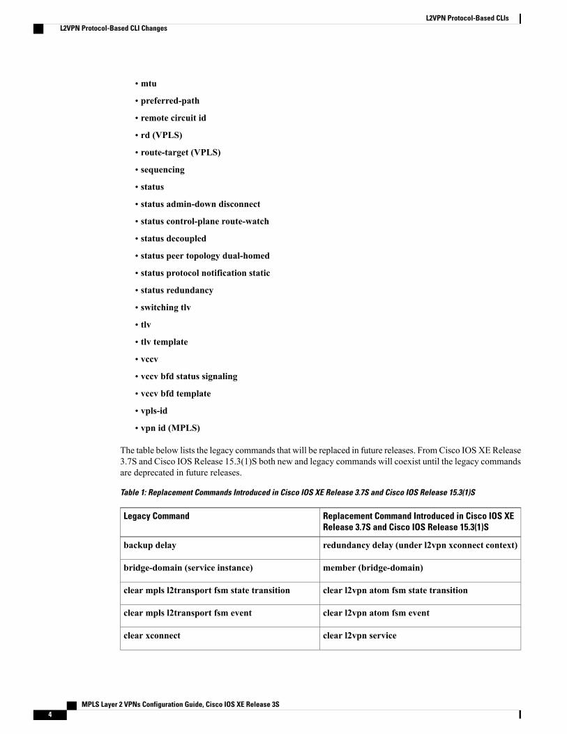
The table below lists the legacy commands that will be replaced in future releases. FromCisco IOSXERelease3.7S and Cisco IOS Release 15.3(1)S both new and legacy commands will coexist until the legacy commandsare deprecated in future releases.
Table 1: Replacement Commands Introduced in Cisco IOS XE Release 3.7S and Cisco IOS Release 15.3(1)S
Replacement Command Introduced in Cisco IOS XERelease 3.7S and Cisco IOS Release 15.3(1)S
Legacy Command
redundancy delay (under l2vpn xconnect context)backup delay
member (bridge-domain)bridge-domain (service instance)
clear l2vpn atom fsm state transitionclear mpls l2transport fsm state transition
clear l2vpn atom fsm eventclear mpls l2transport fsm event
clear l2vpn serviceclear xconnect
MPLS Layer 2 VPNs Configuration Guide, Cisco IOS XE Release 3S4
L2VPN Protocol-Based CLIsL2VPN Protocol-Based CLI Changes
Replacement Command Introduced in Cisco IOS XERelease 3.7S and Cisco IOS Release 15.3(1)S
Legacy Command
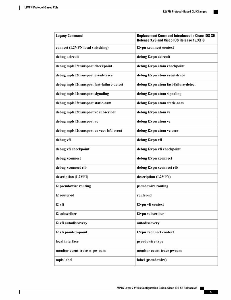
l2vpn xconnect contextconnect (L2VPN local switching)
debug l2vpn acircuitdebug acircuit
debug l2vpn atom checkpointdebug mpls l2transport checkpoint
debug l2vpn atom event-tracedebug mpls l2transport event-trace
debug l2vpn atom fast-failure-detectdebug mpls l2transport fast-failure-detect
debug l2vpn atom signalingdebug mpls l2transport signaling
debug l2vpn atom static-oamdebug mpls l2transport static-oam
debug l2vpn atom vcdebug mpls l2transport vc subscriber
debug l2vpn atom vcdebug mpls l2transport vc
debug l2vpn atom vc vccvdebug mpls l2transport vc vccv bfd event
debug l2vpn vfidebug vfi
debug l2vpn vfi checkpointdebug vfi checkpoint
debug l2vpn xconnectdebug xconnect
debug l2vpn xconnect ribdebug xconnect rib
description (L2VPN)description (L2VFI)
pseudowire routingl2 pseudowire routing
router-idl2 router-id
l2vpn vfi contextl2 vfi
l2vpn subscriberl2 subscriber
autodiscoveryl2 vfi autodiscovery
l2vpn xconnect contextl2 vfi point-to-point
pseudowire typelocal interface
monitor event-trace pwoammonitor event-trace st-pw-oam
label (pseudowire)mpls label
MPLS Layer 2 VPNs Configuration Guide, Cisco IOS XE Release 3S 5
L2VPN Protocol-Based CLIsL2VPN Protocol-Based CLI Changes
Replacement Command Introduced in Cisco IOS XERelease 3.7S and Cisco IOS Release 15.3(1)S
Legacy Command
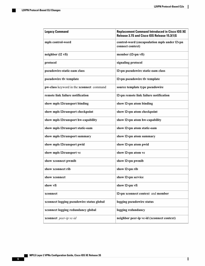
control-word (encapsulation mpls under l2vpnconnect context)
mpls control-word
member (l2vpn vfi)neighbor (l2 vfi)
signaling protocolprotocol
l2vpn pseudowire static-oam classpseudowire-static-oam class
l2vpn pseudowire tlv templatepseudowire tlv template
source template type pseudowirepw-class keyword in the xconnect command
l2vpn remote link failure notificationremote link failure notification
show l2vpn atom bindingshow mpls l2transport binding
show l2vpn atom checkpointshow mpls l2transport checkpoint
show l2vpn atom hw-capabilityshow mpls l2transport hw-capability
show l2vpn atom static-oamshow mpls l2transport static-oam
show l2vpn atom summaryshow mpls l2transport summary
show l2vpn atom pwidshow mpls l2transport pwid
show l2vpn atom vcshow mpls l2transport vc
show l2vpn pwmibshow xconnect pwmib
show l2vpn ribshow xconnect rib
show l2vpn serviceshow xconnect
show l2vpn vfishow vfi
l2vpn xconnect context andmemberxconnect
logging pseudowire statusxconnect logging pseudowire status global
logging redundancyxconnect logging redundancy global
neighbor peer-ip vc-id (xconnect context)xconnect peer-ip vc-id
MPLS Layer 2 VPNs Configuration Guide, Cisco IOS XE Release 3S6
L2VPN Protocol-Based CLIsL2VPN Protocol-Based CLI Changes
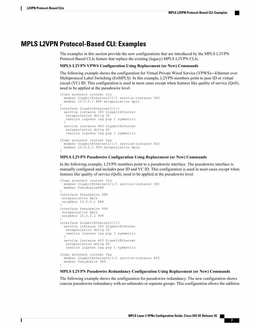
MPLS L2VPN Protocol-Based CLI: ExamplesThe examples in this section provide the new configurations that are introduced by the MPLS L2VPNProtocol-Based CLIs feature that replace the existing (legacy) MPLS L2VPN CLIs.
MPLS L2VPN VPWS Configuration Using Replacement (or New) Commands
The following example shows the configuration for Virtual Private Wired Service (VPWS)—Ethernet overMultiprotocol Label Switching (EoMPLS). In this example, L2VPN members point to peer ID or virtualcircuit (VC) ID. This configuration is used in most cases except when features like quality of service (QoS),need to be applied at the pseudowire level.l2vpn xconnect context foomember GigabitEthernet2/1/1 service-instance 300member 10.0.0.1 888 encapsulation mpls
!interface GigabitEthernet2/1/1service instance 300 GigabitEthernetencapsulation dot1q 30rewrite ingress tag pop 1 symmetric!service instance 400 GigabitEthernetencapsulation dot1q 40rewrite ingress tag pop 1 symmetric
l2vpn xconnect context faamember GigabitEthernet2/1/1 service-instance 400member 10.0.0.1 999 encapsulation mpls
!
MPLS L2VPN Pseudowire Configuration Using Replacement (or New) Commands
In the following example, L2VPN members point to a pseudowire interface. The pseudowire interface ismanually configured and includes peer ID and VC ID. This configuration is used in most cases except whenfeatures like quality of service (QoS), need to be applied at the pseudowire level.l2vpn xconnect context foomember GigabitEthernet2/1/1 service-instance 300member Pseudowire888
!interface Pseudowire 888encapsulation mplsneighbor 10.0.0.1 888!interface Pseudowire 999encapsulation mplsneighbor 10.0.0.1 999!interface GigabitEthernet2/1/1service instance 300 GigabitEthernetencapsulation dot1q 30rewrite ingress tag pop 1 symmetric!service instance 400 GigabitEthernetencapsulation dot1q 40rewrite ingress tag pop 1 symmetric
l2vpn xconnect context faamember GigabitEthernet2/1/1 service-instance 400member Pseudowire 999
!
MPLS L2VPN Pseudowire Redundancy Configuration Using Replacement (or New) Commands
The following example shows the configuration for pseudowire redundancy. The new configuration showsconcise pseudowire redundancy with no submodes or separate groups. This configuration allows the addition
MPLS Layer 2 VPNs Configuration Guide, Cisco IOS XE Release 3S 7
L2VPN Protocol-Based CLIsMPLS L2VPN Protocol-Based CLI: Examples
of redundant members to a service without service disruption. This configuration also allows modifying ordeleting redundant service configurations without service disruption.l2vpn xconnect context sample-pw-redundancymember Ethernet2/1 service-instance 200member 1.1.1.1 180 encap mpls group Denvermember 2.2.2.2 180180 encap mpls group Denver priority 1member 3.3.3.3 180181 encap mpls group Denver priority 2redundancy delay 1 20 group Denver
!interface GigabitEthernet2/1/1service instance 200 GigabitEthernetencapsulation dot1q 100rewrite ingress tag pop 1 symmetric
MPLS L2VPN Static Pseudowire Configuration Using Replacement (or New) Commands
The following configuration is shown for the Provider Edge (PE) 1 router in a network scheme whereCustomer Edge (CE) 1 and PE 1 and PE 2 and CE 2 traverse through a Provider core (P) router (CE 1—PE1—P—PE 2—CE 2).
Note
interface g2/1/1service instance 300 ethernetencapsulation dot1q 300no shutdown!interface pseudowire 100neighbor 10.4.4.4 121encapsulation mplslabel 200 300signaling protocol noneno shutdown!l2vpn xconnect context foomember GigabitEthernet2/1/1 service-instance 300member pseudowire 100
MPLS L2VPN Static Pseudowire Template Configuration Using Replacement (or New) Commands
The following configuration is shown for the Provider Edge (PE) 1 router in a network scheme whereCustomer Edge (CE) 1 and PE 1 and PE 2 and CE 2 traverse through a Provider core (P) router (CE 1—PE1—P—PE 2—CE 2).
Note
template type pseudowire testencapsulation mplssignaling protocol none!interface g2/1/1service instance 300 ethernetencapsulation dot1q 300no shutdown!interface pseudowire 100neighbor 10.4.4.4 121source template type pseudowire testlabel 200 300no shutdown!l2vpn xconnect context foomember GigabitEthernet2/1/1 service-instance 300member pseudowire 100
MPLS Layer 2 VPNs Configuration Guide, Cisco IOS XE Release 3S8
L2VPN Protocol-Based CLIsMPLS L2VPN Protocol-Based CLI: Examples
MPLS L2VPNDynamic Pseudowire Template Configuration Using Replacement (or New) Commands
The following configuration is shown for the Provider Edge (PE) 1 router in a network scheme whereCustomer Edge (CE) 1 and PE 1 and PE 2 and CE 2 traverse through a Provider core (P) router (CE 1—PE1—P—PE 2—CE 2).
Note
template type pseudowire testencapsulation mplssignaling protocol ldp!!interface g2/1/1service instance 300 ethernetencapsulation dot1q 300no shutdown!interface pseudowire 100neighbor 10.4.4.4 121source template type pseudowire testno shutdown!l2vpn xconnect context foomember GigabitEthernet2/1/1 service-instance 300member pseudowire 100
MPLSL2VPNMulti-segment Static-Dynamic Pseudowire Template ConfigurationUsingReplacement(or New) Commands
The following PE router configuration is for a multi-segment static-dynamic pseudowire:l2vpn pseudowire tlv template TLVtlv mtu 1 4 dec 1500!interface pseudowire401source template type pseudowire staticTempl
encapsulation mplsneighbor 10.4.4.4 101signaling protocol nonelabel 4401 4301pseudowire type 4tlv template TLVtlv 1 4 dec 1500tlv vccv-flags C 4 hexstr 0110!interface pseudowire501source template type pseudowire dynTempl
encapsulation mplsneighbor 10.2.2.2 101signaling protocol ldp
DisplayingMPLSL2VPNPseudowire Template ConfigurationUsingReplacement (or New)Commands
The following example displays output from the show interface pseudowire command:PE1#show interface pseudowire 100pseudowire100 is up
Description: Pseudowire InterfaceMTU 1500 bytes, BW 10000000 KbitEncapsulation mplsPeer IP 10.4.4.4, VC ID 121RX21 packets 2623 bytes 0 drops
TX20 packets 2746 bytes 0 drops
The following example displays output from the show template command:PE1#show template
MPLS Layer 2 VPNs Configuration Guide, Cisco IOS XE Release 3S 9
L2VPN Protocol-Based CLIsMPLS L2VPN Protocol-Based CLI: Examples
Template class/type Component(s)ABC owner interface pseudowireBOUND: pw1Sourcing a Template Under an Interface Pseudowire Using Replacement (or New) Commands
The following example configures the interface pseudowire to inherit all attributes defined from a templateon the PE 2 router.PE2(config-subif)#interface pseudowire 100PE2(config-if)#source template type pseudowire testPE2(config-if)#neighbor 10.4.4.4 121PE2(config-if)#no shutdown
Additional ReferencesRelated Documents
Document TitleRelated Topic
Cisco IOS Master Command List, All ReleasesCisco IOS commands
Multiprotocol Label Switching Command ReferenceMPLS commands
Technical Assistance
LinkDescription
http://www.cisco.com/cisco/web/support/index.htmlThe Cisco Support and Documentation websiteprovides online resources to download documentation,software, and tools. Use these resources to install andconfigure the software and to troubleshoot and resolvetechnical issues with Cisco products and technologies.Access to most tools on the Cisco Support andDocumentation website requires a Cisco.com user IDand password.
Feature Information for L2VPN Protocol-Based CLIsThe following table provides release information about the feature or features described in this module. Thistable lists only the software release that introduced support for a given feature in a given software releasetrain. Unless noted otherwise, subsequent releases of that software release train also support that feature.
Use Cisco Feature Navigator to find information about platform support and Cisco software image support.To access Cisco Feature Navigator, go to www.cisco.com/go/cfn. An account on Cisco.com is not required.
MPLS Layer 2 VPNs Configuration Guide, Cisco IOS XE Release 3S10
L2VPN Protocol-Based CLIsAdditional References
Table 2: Feature Information for L2VPN Protocol-Based CLIs
Feature InformationReleasesFeature Name
The L2VPN Protocol-Based CLIs feature provides a set ofprocesses and an improved infrastructure for developingand delivering Cisco IOS software on various Ciscoplatforms. This feature introduces new commands andmodifies or replaces existing commands to achieve aconsistent functionality across Cisco platforms and providecross-Operating System (OS) support.
In Cisco IOS XE Release 3.7S, this feature was introducedon the Cisco ASR 903 Router.
Cisco IOS XE Release3.7S
L2VPNProtocol-Based CLIs
MPLS Layer 2 VPNs Configuration Guide, Cisco IOS XE Release 3S 11
L2VPN Protocol-Based CLIsFeature Information for L2VPN Protocol-Based CLIs

MPLS Layer 2 VPNs Configuration Guide, Cisco IOS XE Release 3S12
L2VPN Protocol-Based CLIsFeature Information for L2VPN Protocol-Based CLIs
C H A P T E R 2Any Transport over MPLS
This module describes how to configure Any Transport over MPLS (AToM) transports data link layer (Layer2) packets over a Multiprotocol Label Switching (MPLS) backbone. AToM enables service providers toconnect customer sites with existing Layer 2 networks by using a single, integrated, packet-based networkinfrastructure--a Cisco MPLS network. Instead of using separate networks with network managementenvironments, service providers can deliver Layer 2 connections over an MPLS backbone. AToM providesa common framework to encapsulate and transport supported Layer 2 traffic types over an MPLS networkcore.
AToM supports the following like-to-like transport types:
• ATM Adaptation Layer Type-5 (AAL5) over MPLS
• ATM Cell Relay over MPLS
• Ethernet over MPLS (VLAN and port modes)
• Finding Feature Information, page 13
• Prerequisites for Any Transport over MPLS, page 14
• Restrictions for Any Transport over MPLS, page 14
• Information About Any Transport over MPLS, page 17
• How to Configure Any Transport over MPLS, page 31
• Configuration Examples for Any Transport over MPLS, page 128
• Additional References for Any Transport over MPLS, page 155
• Feature Information for Any Transport over MPLS, page 155
Finding Feature InformationYour software release may not support all the features documented in this module. For the latest caveats andfeature information, see Bug Search Tool and the release notes for your platform and software release. Tofind information about the features documented in this module, and to see a list of the releases in which eachfeature is supported, see the feature information table at the end of this module.
MPLS Layer 2 VPNs Configuration Guide, Cisco IOS XE Release 3S 13
Use Cisco Feature Navigator to find information about platform support and Cisco software image support.To access Cisco Feature Navigator, go to www.cisco.com/go/cfn. An account on Cisco.com is not required.
Prerequisites for Any Transport over MPLS• IP routing must be configured in the core so that the provider edge (PE) routers can reach each other viaIP.
• MPLS must be configured in the core so that a label-switched path (LSP) exists between the PE routers.
• A loopback interface must be configured for originating and terminating Layer 2 traffic. Ensure that thePE routers can access the other router’s loopback interface. Note that the loopback interface is not neededin all cases. For example, tunnel selection does not need a loopback interface when AToM is directlymapped to a traffic engineering (TE) tunnel.
Restrictions for Any Transport over MPLSGeneral Restrictions
The following general restrictions pertain to all transport types under AToM:
• Address format: Configure the Label Distribution Protocol (LDP) router ID on all PE routers to be aloopback address with a /32 mask. Otherwise, some configurations might not function properly.
Ethernet over MPLS (EoMPLS) Restrictions
The following restrictions pertain to the Ethernet over MPLS feature:
• Ethernet over MPLS supports VLAN packets that conform to the IEEE 802.1Q standard. The 802.1Qspecification establishes a standard method for inserting VLAN membership information into Ethernetframes. The Inter-Switch Link (ISL) protocol is not supported between the PE and CE routers.
• The AToM control word is supported. However, if the peer PE does not support a control word, thecontrol word is disabled. This negotiation is done by LDP label binding.
• Ethernet packets with hardware-level cyclic redundancy check (CRC) errors, framing errors, and runtpackets are discarded on input.
General Restrictions• Address format--Configure the Label Distribution Protocol (LDP) router ID on all PE routers to be aloopback address with a /32 mask. Otherwise, some configurations might not function properly.
ATM AAL5 over MPLS Restrictions• AAL5 over MPLS is supported only in SDU mode.
MPLS Layer 2 VPNs Configuration Guide, Cisco IOS XE Release 3S14
Any Transport over MPLSPrerequisites for Any Transport over MPLS
ATM Cell Relay over MPLS Restrictions• If you have TE tunnels running between the PE routers, you must enable LDP on the tunnel interfaces.
• The F4 end-to-end OAM cells are transparently transported along with the ATM cells.When a permanentvirtual path (PVP) or permanent virtual circuit (PVC) is down on one PE router, the label associatedwith that PVP or PVC is withdrawn. Subsequently, the peer PE router detects the label withdrawal andsends an F4 AIS/RDI signal to its corresponding CE router. The PVP or PVC on the peer PE routerremains in the up state.
• VC class configuration mode is not supported in port mode.
• The AToM control word is supported. However, if a peer PE does not support the control word, it isdisabled.
For configuring ATM cell relay over MPLS in VP mode, the following restrictions apply:
• If a VPI is configured for VP cell relay, you cannot configure a PVC using the same VPI.
• VP trunking (mapping multiple VPs to one emulated VC label) is not supported. Each VP is mapped toone emulated VC.
• VP mode and VC mode drop idle cells.
Ethernet over MPLS (EoMPLS) Restrictions• The subinterfaces between the CE and PE routers that are running Ethernet over MPLS must be in thesame subnet.
• The subinterface on the adjoining CE router must be on the same VLAN as the PE router.
• Ethernet over MPLS supports VLAN packets that conform to the IEEE 802.1Q standard. The 802.1Qspecification establishes a standard method for inserting VLAN membership information into Ethernetframes. The Inter-Switch Link (ISL) protocol is not supported between the PE and CE routers.
• The AToM control word is supported. However, if the peer PE does not support a control word, thecontrol word is disabled.
• Ethernet packets with hardware-level cyclic redundancy check (CRC) errors, framing errors, and runtpackets are discarded on input.
Per-Subinterface MTU for Ethernet over MPLS Restrictions• The following features do not support MTU values in xconnect subinterface configuration mode:
• Layer 2 Tunnel Protocol Version 3 (L2TPv3)
• Virtual Private LAN services (VPLS)
• L2VPN Pseudowire Switching
MPLS Layer 2 VPNs Configuration Guide, Cisco IOS XE Release 3S 15
Any Transport over MPLSATM Cell Relay over MPLS Restrictions
• The MTU value can be configured in xconnect subinterface configuration mode only on the followinginterfaces and subinterfaces:
• Fast Ethernet
• Gigabit Ethernet
• The router uses an MTU validation process for remote VCs established through LDP, which comparestheMTU value configured in xconnect subinterface configuration mode to theMTU value of the remotecustomer interface. If an MTU value has not been configured in xconnect subinterface configurationmode, then the validation process compares the MTU value of the local customer interface to the MTUvalue of the remote xconnect, either explicitly configured or inherited from the underlying interface orsubinterface.
•When you configure the MTU value in xconnect subinterface configuration mode, the specified MTUvalue is not enforced by the dataplane. The dataplane enforces the MTU values of the interface (portmode) or subinterface (VLAN mode).
• Ensure that the interface MTU is larger than the MTU value configured in xconnect subinterfaceconfiguration mode. If the MTU value of the customer-facing subinterface is larger than the MTU valueof the core-facing interface, traffic may not be able to travel across the pseudowire.
Frame Relay over MPLS RestrictionsFrame Relay traffic shaping is not supported with AToM switched VCs.
HDLC over MPLS Restrictions• Asynchronous interfaces are not supported.
• You must configure HDLC over MPLS on router interfaces only. You cannot configure HDLC overMPLS on subinterfaces.
PPP over MPLS Restrictions• Zero hops on one router is not supported. However, you can have back-to-back PE routers.
• Asynchronous interfaces are not supported. The connections between the CE and PE routers on bothends of the backbone must have similar link layer characteristics. The connections between the CE andPE routers must both be synchronous.
• Multilink PPP (MLP) is not supported.
• You must configure PPP on router interfaces only. You cannot configure PPP on subinterfaces.
Tunnel Selection Restrictions• The selected path should be an LSP destined to the peer PE router.
MPLS Layer 2 VPNs Configuration Guide, Cisco IOS XE Release 3S16
Any Transport over MPLSFrame Relay over MPLS Restrictions
• The selected tunnel must be an MPLS TE tunnel.
• If you select a tunnel, the tunnel tailend must be on the remote PE router.
• If you specify an IP address, that address must be the IP address of the loopback interface on the remotePE router. The address must have a /32 mask. There must be an LSP destined to that selected address.The LSP need not be a TE tunnel.
Experimental Bits with AToM Restrictions• You must statically set the experimental (EXP) bits in both the VC label and the LSP tunnel label,because the LSP tunnel label might be removed at the penultimate router.
• For EXP bits and ATM AAL5 over MPLS and for EXP bits and Frame Relay over MPLS, if you do notassign values to the experimental bits, the priority bits in the header’s “tag control information” field areset to zero.
• For EXP bits and ATM Cell Relay over MPLS in VC mode, if you do not assign values to theexperimental bits, the priority bits in the header’s “tag control information” field are set to zero.
• For EXP bits and HDLC overMPLS and PPP overMPLS, if you do not assign values to the experimentalbits, zeros are written into the experimental bit fields.
Remote Ethernet Port Shutdown RestrictionsThis feature is not symmetrical if the remote PE router is running an older version image or is on anotherplatform that does not support the EoMPLS remote Ethernet port shutdown feature and the local PE is runningan image which supports this feature.
Information About Any Transport over MPLSTo configure AToM, you must understand the following concepts:
How AToM Transports Layer 2 PacketsAToM encapsulates Layer 2 frames at the ingress PE and sends them to a corresponding PE at the other endof a pseudowire, which is a connection between the two PE routers. The egress PE removes the encapsulationand sends out the Layer 2 frame.
The successful transmission of the Layer 2 frames between PE routers is due to the configuration of the PErouters. You set up the connection, called a pseudowire, between the routers. You specify the followinginformation on each PE router:
• The type of Layer 2 data that will be transported across the pseudowire, such as Ethernet, Frame Relay,or ATM
• The IP address of the loopback interface of the peer PE router, which enables the PE routers tocommunicate
• A unique combination of peer PE IP address and VC ID that identifies the pseudowire
MPLS Layer 2 VPNs Configuration Guide, Cisco IOS XE Release 3S 17
Any Transport over MPLSExperimental Bits with AToM Restrictions
The following example shows the basic configuration steps on a PE router that enable the transport of Layer2 packets. Each transport type has slightly different steps.
Step 1 defines the interface or subinterface on the PE router:
Router# interfaceinterface-type interface-numberStep 2 specifies the encapsulation type for the interface, such as dot1q:
Router(config-if)# encapsulationencapsulation-typeStep 3 does the following:
• Makes a connection to the peer PE router by specifying the LDP router ID of the peer PE router.
• Specifies a 32-bit unique identifier, called the VC ID, which is shared between the two PE routers.
The combination of the peer router ID and the VC ID must be unique on the router. Two circuits cannot usethe same combination of peer router ID and VC ID.
• Specifies the tunneling method used to encapsulate data in the pseudowire. AToM uses MPLS as thetunneling method.
Router(config-if)# xconnectpeer-router-id vcidencapsulation mplsAs an alternative, you can set up a pseudowire class to specify the tunneling method and other characteristics.For more information, see the Configuring the Pseudowire Class, on page 32.
How AToM Transports Layer 2 Packets using the commands associated withthe L2VPN Protocol-Based CLIs feature
AToM encapsulates Layer 2 frames at the ingress PE and sends them to a corresponding PE at the other endof a pseudowire, which is a connection between the two PE routers. The egress PE removes the encapsulationand sends out the Layer 2 frame.
The successful transmission of the Layer 2 frames between PE routers is due to the configuration of the PErouters. You set up the connection, called a pseudowire, between the routers. You specify the followinginformation on each PE router:
• The type of Layer 2 data that will be transported across the pseudowire, such as Ethernet, Frame Relay,or ATM
• The IP address of the loopback interface of the peer PE router, which enables the PE routers tocommunicate
• A unique combination of peer PE IP address and VC ID that identifies the pseudowire
The following example shows the basic configuration steps on a PE router that enable the transport of Layer2 packets. Each transport type has slightly different steps.
Step 1 defines the interface or subinterface on the PE router:
Router# interfaceinterface-type interface-number
MPLS Layer 2 VPNs Configuration Guide, Cisco IOS XE Release 3S18
Any Transport over MPLSHow AToM Transports Layer 2 Packets using the commands associated with the L2VPN Protocol-Based CLIs feature
Step 2 specifies the encapsulation type for the interface, such as dot1q:
Router(config-if)# encapsulationencapsulation-typeStep 3 does the following:
• Makes a connection to the peer PE router by specifying the LDP router ID of the peer PE router.
• Specifies a 32-bit unique identifier, called the VC ID, which is shared between the two PE routers.
The combination of the peer router ID and the VC ID must be unique on the router. Two circuits cannot usethe same combination of peer router ID and VC ID.
• Specifies the tunneling method used to encapsulate data in the pseudowire. AToM uses MPLS as thetunneling method.
Router(config)# interface pseudowire 100Router(config-if)# encapsulation mplsRouter(config-if)# neighbor 10.0.0.1 123Router(config-if)# exit!Router(config)# l2vpn xconnect context ARouter(config-xconnect)# member pseudowire 100Router(config-xconnect)# member gigabitethernet0/0/0.1Router(config-xconnect)# exitAs an alternative, you can set up a pseudowire class to specify the tunneling method and other characteristics.For more information, see the Configuring the Pseudowire Class, on page 32.
Benefits of AToMThe following list explains some of the benefits of enabling Layer 2 packets to be sent in the MPLS network:
• The AToM product set accommodates many types of Layer 2 packets, including Ethernet and FrameRelay, across multiple Cisco router platforms. This enables the service provider to transport all types oftraffic over the backbone and accommodate all types of customers.
• AToM adheres to the standards developed for transporting Layer 2 packets over MPLS. This benefitsthe service provider that wants to incorporate industry-standard methodologies in the network. OtherLayer 2 solutions are proprietary, which can limit the service provider’s ability to expand the networkand can force the service provider to use only one vendor’s equipment.
• Upgrading to AToM is transparent to the customer. Because the service provider network is separatefrom the customer network, the service provider can upgrade to AToM without disruption of service tothe customer. The customers assume that they are using a traditional Layer 2 backbone.
MPLS Traffic Engineering Fast RerouteAToM can use MPLS traffic engineering (TE) tunnels with fast reroute (FRR) support. AToM VCs can bererouted around a failed link or node at the same time as MPLS and IP prefixes.
Enabling fast reroute on AToM does not require any special commands; you can use standard fast reroutecommands. At the ingress PE, an AToM tunnel is protected by fast reroute when it is routed to an FRR-protectedTE tunnel. Both link and node protection are supported for AToM VCs at the ingress PE.
MPLS Layer 2 VPNs Configuration Guide, Cisco IOS XE Release 3S 19
Any Transport over MPLSBenefits of AToM
In the following example, the primary link is disabled, which causes the backup tunnel (Tunnel 1) to becomethe primary path. The output in boldface font shows the status of the tunnel:
Router# execute-on slot 3 debug mpls l2transport fast-reroute========= Line Card (Slot 3) =========AToM fast reroute debugging is onSLOT 3:Sep 16 17:58:56.346: AToM SMGR: Processing TFIB FRR event for 10.4.0.1SLOT 3:Sep 16 17:58:56.346: AToM SMGR: Finished processing TFIB FRR event for 10.4.0.1SLOT 3:Sep 16 17:58:56.346: AToM SMGR: Processing TFIB FRR event for Tunnel41SLOT 3:Sep 16 17:58:56.346: AToM SMGR: Finished processing TFIB FRR event for Tunnel41Sep 16 17:58:58.342: %LINK-3-UPDOWN: Interface POS0/0/0, changed state to downSep 16 17:58:58.342: %OSPF-5-ADJCHG: Process 1, Nbr 10.0.0.1 on POS0/0 from FULL to DOWN,Neighbor Down: Interface down or detachedSep 16 17:58:59.342: %LINEPROTO-5-UPDOWN: Line protocol on Interface POS0/0/0, changed stateto down
Maximum Transmission Unit Guidelines for Estimating Packet SizeThe following calculation helps you determine the size of the packets traveling through the core network.You set the maximum transmission unit (MTU) on the core-facing interfaces of the P and PE routers toaccommodate packets of this size. The MTU should be greater than or equal to the total bytes of the items inthe following equation:
Core MTU >= (Edge MTU + Transport header + AToM header + (MPLS label stack * MPLS labelsize))
The following sections describe the variables used in the equation.
Edge MTU
The edge MTU is the MTU for the customer-facing interfaces.
Transport Header
The Transport header depends on the transport type. The table below lists the specific sizes of the headers.
Table 3: Header Size of Packets
Packet SizeTransport Type
0-32 bytesAAL5
18 bytesEthernet VLAN
14 bytesEthernet Port
2 bytes for Cisco encapsulation, 8 bytes for InternetEngineering Task Force (IETF) encapsulation
Frame Relay DLCI
4 bytesHDLC
4 bytesPPP
MPLS Layer 2 VPNs Configuration Guide, Cisco IOS XE Release 3S20
Any Transport over MPLSMaximum Transmission Unit Guidelines for Estimating Packet Size
AToM Header
The AToM header is 4 bytes (control word). The control word is optional for Ethernet, PPP, HDLC, and cellrelay transport types. The control word is required for Frame Relay and ATM AAL5 transport types.
MPLS Label Stack
The MPLS label stack size depends on the configuration of the core MPLS network:
• AToM uses one MPLS label to identify the AToM VCs (VC label). Therefore, the minimum MPLSlabel stack is one for directly connected AToM PEs, which are PE routers that do not have a P routerbetween them.
• If LDP is used in the MPLS network, the label stack size is two (the LDP label and the VC label).
• If a TE tunnel instead of LDP is used between PE routers in the MPLS network, the label stack size istwo (the TE label and the VC label).
• If a TE tunnel and LDP are used in the MPLS network (for example, a TE tunnel between P routers orbetween P and PE routers, with LDP on the tunnel), the label stack is three (TE label, LDP label, VClabel).
• If you use MPLS fast reroute in the MPLS network, you add a label to the stack. The maximum MPLSlabel stack in this case is four (FRR label, TE label, LDP label, VC label).
• If AToM is used by the customer carrier in an MPLS VPN Carrier Supporting Carrier environment, youadd a label to the stack. The maximum MPLS label stack in the provider carrier network is five (FRRlabel, TE label, LDP label, VPN label, VC label).
• If an AToM tunnel spans different service providers that exchange MPLS labels using IPv4 BorderGateway Protocol (BGP) (RFC 3107), you add a label to the stack. The maximum MPLS label stack isfive (FRR label, TE label, Border Gateway Protocol (BGP) label, LDP label, VC label).
Other circumstances can increase theMPLS label stack size. Therefore, analyze the complete data path betweenthe AToM tunnel endpoints and determine the maximum MPLS label stack size for your network. Thenmultiply the label stack size by the size of the MPLS label.
Estimating Packet Size ExampleThe estimated packet size in the following example is 1526 bytes, based on the following assumptions:
• The edge MTU is 1500 bytes.
• The transport type is Ethernet VLAN, which designates 18 bytes for the transport header.
• The AToM header is 0, because the control word is not used.
• The MPLS label stack is 2, because LDP is used. The MPLS label is 4 bytes.
Edge MTU + Transport header + AToM header + (MPLS label stack * MPLS label) = Core MTU1500 + 18 + 0 + (2 * 4 ) = 1526You must configure the P and PE routers in the core to accept packets of 1526 bytes.
MPLS Layer 2 VPNs Configuration Guide, Cisco IOS XE Release 3S 21
Any Transport over MPLSMaximum Transmission Unit Guidelines for Estimating Packet Size
Per-Subinterface MTU for Ethernet over MPLSMTUvalues can be specified in xconnect subinterface configurationmode.When you use xconnect subinterfaceconfiguration mode to set the MTU value, you establish a pseudowire connection for situations where theinterfaces have different MTU values that cannot be changed.
If you specify anMTU value in xconnect subinterface configurationmode that is outside the range of supportedMTU values (64 bytes to the maximum number of bytes supported by the interface), the command might berejected. If you specify an MTU value that is out of range in xconnect subinterface configuration mode, therouter enters the command in subinterface configuration mode.
For example, if you specify an MTU of 1501 in xconnect subinterface configuration mode, and that value isout of range, the router enters the command in subinterface configuration mode, where it is accepted:
Router# configure terminalRouter(config)# interface gigabitethernet0/0/2.1Router(config-subif)# xconnect 10.10.10.1 100 encapsulation mplsRouter(config-subif-xconn)# mtu ?<64 - 1500> MTU size in bytesRouter(config-subif-xconn)# mtu 1501 <<================Router(config-subif)# mtu ?<64 - 17940> MTU size in bytesIf the MTU value is not accepted in either xconnect subinterface configuration mode or subinterfaceconfiguration mode, then the command is rejected.
Per-Subinterface MTU for Ethernet over MPLS using the commands associatedwith the L2VPN Protocol-Based CLIs feature
MTU values can be specified in xconnect configuration mode. When you use xconnect configuration modeto set the MTU value, you establish a pseudowire connection for situations where the interfaces have differentMTU values that cannot be changed.
If you specify an MTU value in xconnect configuration mode that is outside the range of supported MTUvalues (64 bytes to the maximum number of bytes supported by the interface), the commandmight be rejected.If you specify anMTU value that is out of range in xconnect configurationmode, the router enters the commandin subinterface configuration mode.
For example, if you specify an MTU of 1501 in xconnect configuration mode, and that value is out of range,the router enters the command in subinterface configuration mode, where it is accepted:
Router# configure terminalRouter(config)# interface gigabitethernet0/0/2.1Router(config)# interface pseudowire 100Router(config-if)# encapsulation mplsRouter(config-if)# neighbor 10.10.10.1 100Router(config-if)# mtu ?<64 - 1500> MTU size in bytesRouter(config-if)# mtu 1501 <<================Router(config-if)# mtu ?<64 - 17940> MTU size in bytesRouter(config-if)# exit!Router(config)# l2vpn xconnect context ARouter(config-xconnect)# member pseudowire 100 RouterRouter(config-xconnect)# member gigabitethernet0/0/2.1Router(config-xconnect)# exit
MPLS Layer 2 VPNs Configuration Guide, Cisco IOS XE Release 3S22
Any Transport over MPLSPer-Subinterface MTU for Ethernet over MPLS
If the MTU value is not accepted in either xconnect configuration mode or subinterface configuration mode,then the command is rejected.
Frame Relay over MPLS and DTE DCE and NNI ConnectionsYou can configure an interface as a DTE device or a DCE switch, or as a switch connected to a switch withnetwork-to-network interface (NNI) connections. Use the following command in interface configurationmode:
frame-relay intf-type [dce | dte | nni]
The keywords are explained in the table below.
Table 4: frame-relay intf-type Command Keywords
DescriptionKeyword
Enables the router or access server to function as aswitch connected to a router.
dce
Enables the router or access server to function as aDTE device. DTE is the default.
dte
Enables the router or access server to function as aswitch connected to a switch.
nni
Local Management Interface and Frame Relay over MPLSLocal Management Interface (LMI) is a protocol that communicates status information about PVCs. When aPVC is added, deleted, or changed, the LMI notifies the endpoint of the status change. LMI also provides apolling mechanism that verifies that a link is up.
How LMI Works
To determine the PVC status, LMI checks that a PVC is available from the reporting device to the FrameRelay end-user device. If a PVC is available, LMI reports that the status is “Active,” which means that allinterfaces, line protocols, and core segments are operational between the reporting device and the Frame Relayend-user device. If any of those components is not available, the LMI reports a status of “Inactive.”
Only the DCE and NNI interface types can report the LMI status.Note
MPLS Layer 2 VPNs Configuration Guide, Cisco IOS XE Release 3S 23
Any Transport over MPLSFrame Relay over MPLS and DTE DCE and NNI Connections
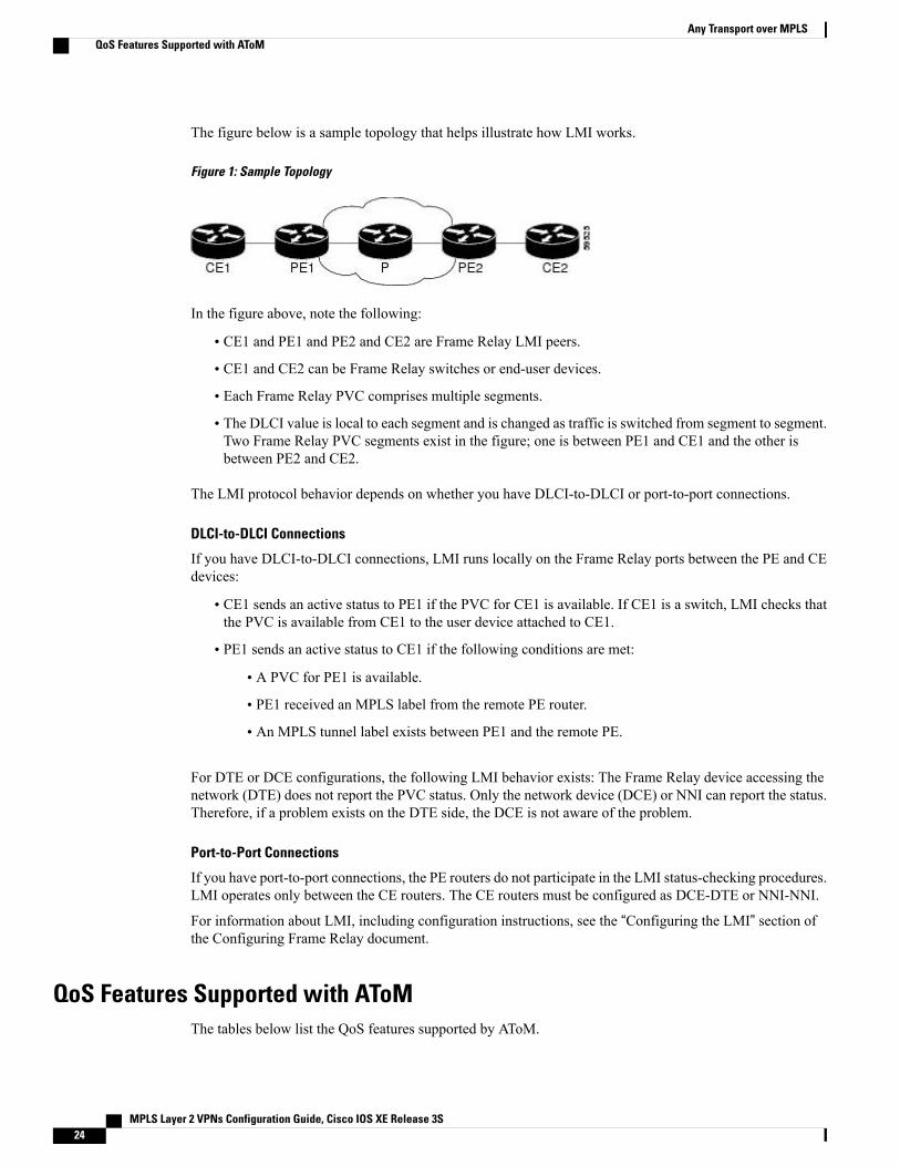
The figure below is a sample topology that helps illustrate how LMI works.
Figure 1: Sample Topology
In the figure above, note the following:
• CE1 and PE1 and PE2 and CE2 are Frame Relay LMI peers.
• CE1 and CE2 can be Frame Relay switches or end-user devices.
• Each Frame Relay PVC comprises multiple segments.
• The DLCI value is local to each segment and is changed as traffic is switched from segment to segment.Two Frame Relay PVC segments exist in the figure; one is between PE1 and CE1 and the other isbetween PE2 and CE2.
The LMI protocol behavior depends on whether you have DLCI-to-DLCI or port-to-port connections.
DLCI-to-DLCI Connections
If you have DLCI-to-DLCI connections, LMI runs locally on the Frame Relay ports between the PE and CEdevices:
• CE1 sends an active status to PE1 if the PVC for CE1 is available. If CE1 is a switch, LMI checks thatthe PVC is available from CE1 to the user device attached to CE1.
• PE1 sends an active status to CE1 if the following conditions are met:
• A PVC for PE1 is available.
• PE1 received an MPLS label from the remote PE router.
• An MPLS tunnel label exists between PE1 and the remote PE.
For DTE or DCE configurations, the following LMI behavior exists: The Frame Relay device accessing thenetwork (DTE) does not report the PVC status. Only the network device (DCE) or NNI can report the status.Therefore, if a problem exists on the DTE side, the DCE is not aware of the problem.
Port-to-Port Connections
If you have port-to-port connections, the PE routers do not participate in the LMI status-checking procedures.LMI operates only between the CE routers. The CE routers must be configured as DCE-DTE or NNI-NNI.
For information about LMI, including configuration instructions, see the “Configuring the LMI” section ofthe Configuring Frame Relay document.
QoS Features Supported with AToMThe tables below list the QoS features supported by AToM.
MPLS Layer 2 VPNs Configuration Guide, Cisco IOS XE Release 3S24
Any Transport over MPLSQoS Features Supported with AToM
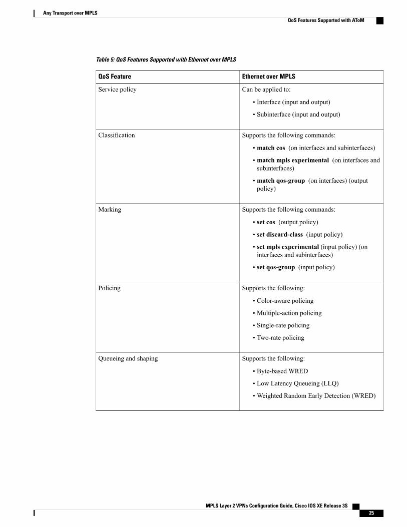
Table 5: QoS Features Supported with Ethernet over MPLS
Ethernet over MPLSQoS Feature
Can be applied to:
• Interface (input and output)
• Subinterface (input and output)
Service policy
Supports the following commands:
• match cos (on interfaces and subinterfaces)
• match mpls experimental (on interfaces andsubinterfaces)
• match qos-group (on interfaces) (outputpolicy)
Classification
Supports the following commands:
• set cos (output policy)
• set discard-class (input policy)
• set mpls experimental (input policy) (oninterfaces and subinterfaces)
• set qos-group (input policy)
Marking
Supports the following:
• Color-aware policing
• Multiple-action policing
• Single-rate policing
• Two-rate policing
Policing
Supports the following:
• Byte-based WRED
• Low Latency Queueing (LLQ)
•Weighted Random Early Detection (WRED)
Queueing and shaping
MPLS Layer 2 VPNs Configuration Guide, Cisco IOS XE Release 3S 25
Any Transport over MPLSQoS Features Supported with AToM
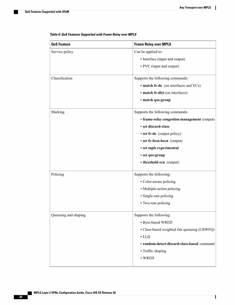
Table 6: QoS Features Supported with Frame Relay over MPLS
Frame Relay over MPLSQoS Feature
Can be applied to:
• Interface (input and output)
• PVC (input and output)
Service policy
Supports the following commands:
• match fr-de (on interfaces and VCs)
• match fr-dlci (on interfaces)
• match qos-group
Classification
Supports the following commands:
• frame-relay congestionmanagement (output)
• set discard-class
• set fr-de (output policy)
• set fr-fecn-becn (output)
• set mpls experimental
• set qos-group
• threshold ecn (output)
Marking
Supports the following:
• Color-aware policing
• Multiple-action policing
• Single-rate policing
• Two-rate policing
Policing
Supports the following:
• Byte-based WRED
• Class-based weighted fair queueing (CBWFQ)
• LLQ
• random-detect discard-class-based command
• Traffic shaping
•WRED
Queueing and shaping
MPLS Layer 2 VPNs Configuration Guide, Cisco IOS XE Release 3S26
Any Transport over MPLSQoS Features Supported with AToM
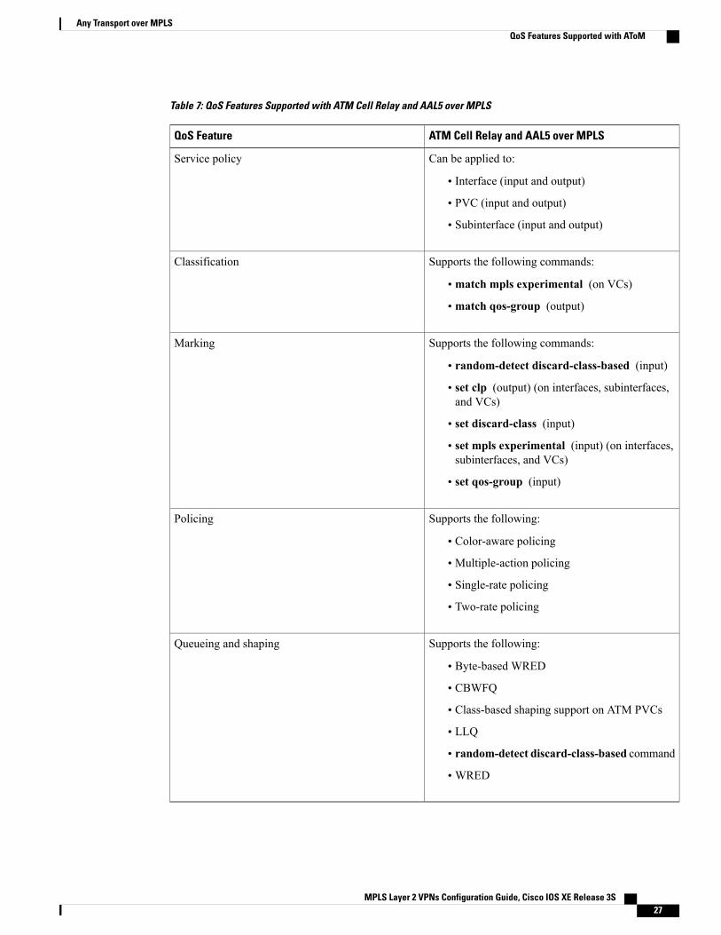
Table 7: QoS Features Supported with ATM Cell Relay and AAL5 over MPLS
ATM Cell Relay and AAL5 over MPLSQoS Feature
Can be applied to:
• Interface (input and output)
• PVC (input and output)
• Subinterface (input and output)
Service policy
Supports the following commands:
• match mpls experimental (on VCs)
• match qos-group (output)
Classification
Supports the following commands:
• random-detect discard-class-based (input)
• set clp (output) (on interfaces, subinterfaces,and VCs)
• set discard-class (input)
• set mpls experimental (input) (on interfaces,subinterfaces, and VCs)
• set qos-group (input)
Marking
Supports the following:
• Color-aware policing
• Multiple-action policing
• Single-rate policing
• Two-rate policing
Policing
Supports the following:
• Byte-based WRED
• CBWFQ
• Class-based shaping support on ATM PVCs
• LLQ
• random-detect discard-class-based command
•WRED
Queueing and shaping
MPLS Layer 2 VPNs Configuration Guide, Cisco IOS XE Release 3S 27
Any Transport over MPLSQoS Features Supported with AToM
OAM Cell Emulation for ATM AAL5 over MPLSIf a PE router does not support the transport of Operation, Administration, and Maintenance (OAM) cellsacross a label switched path (LSP), you can use OAM cell emulation to locally terminate or loop back theOAM cells. You configure OAM cell emulation on both PE routers, which emulates a VC by forming twounidirectional LSPs. You use Cisco software commands on both PE routers to enable OAM cell emulation.
After you enable OAM cell emulation on a router, you can configure and manage the ATM VC in the samemanner as you would a terminated VC. A VC that has been configured with OAM cell emulation can sendloopback cells at configured intervals toward the local CE router. The endpoint can be either of the following:
• End-to-end loopback, which sends OAM cells to the local CE router.
• Segment loopback, which responds to OAM cells to a device along the path between the PE and CErouters.
The OAM cells include the following cells:
• Alarm indication signal (AIS)
• Remote defect indication (RDI)
These cells identify and report defects along a VC.When a physical link or interface failure occurs, intermediatenodes insert OAM AIS cells into all the downstream devices affected by the failure. When a router receivesan AIS cell, it marks the ATM VC down and sends an RDI cell to let the remote end know about the failure.
OAM Cell Emulation for ATM AAL5 over MPLS in VC Class Configuration ModeYou can configure OAM cell emulation as part of a VC class and then apply the VC class to an interface, asubinterface, or a VC. When you configure OAM cell emulation in VC class configuration mode and thenapply the VC class to an interface, the settings in the VC class apply to all the VCs on the interface, unlessyou specify a different OAM cell emulation value at a lower level, such as the subinterface or VC level. Forexample, you can create a VC class that specifies OAM cell emulation and sets the rate of AIS cells to every30 seconds. You can apply the VC class to an interface. Then, for one PVC, you can enable OAM cell emulationand set the rate of AIS cells to every 15 seconds. All the PVCs on the interface use the cell rate of 30 seconds,except for the one PVC that was set to 15 seconds.
Any Transport over MPLS (AToM) Remote Ethernet Port ShutdownThis Cisco IOS XE feature allows a service provider edge (PE) router on the local end of an Ethernet overMPLS (EoMPLS) pseudowire to detect a remote link failure and cause the shutdown of the Ethernet port onthe local customer edge (CE) router. Because the Ethernet port on the local CE router is shut down, the routerdoes not lose data by continuously sending traffic to the failed remote link. This is beneficial if the link isconfigured as a static IP route.
MPLS Layer 2 VPNs Configuration Guide, Cisco IOS XE Release 3S28
Any Transport over MPLSOAM Cell Emulation for ATM AAL5 over MPLS
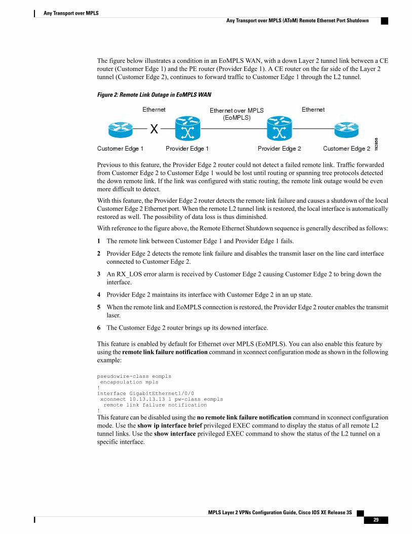
The figure below illustrates a condition in an EoMPLSWAN, with a down Layer 2 tunnel link between a CErouter (Customer Edge 1) and the PE router (Provider Edge 1). A CE router on the far side of the Layer 2tunnel (Customer Edge 2), continues to forward traffic to Customer Edge 1 through the L2 tunnel.
Figure 2: Remote Link Outage in EoMPLS WAN
Previous to this feature, the Provider Edge 2 router could not detect a failed remote link. Traffic forwardedfrom Customer Edge 2 to Customer Edge 1 would be lost until routing or spanning tree protocols detectedthe down remote link. If the link was configured with static routing, the remote link outage would be evenmore difficult to detect.
With this feature, the Provider Edge 2 router detects the remote link failure and causes a shutdown of the localCustomer Edge 2 Ethernet port. When the remote L2 tunnel link is restored, the local interface is automaticallyrestored as well. The possibility of data loss is thus diminished.
With reference to the figure above, the Remote Ethernet Shutdown sequence is generally described as follows:
1 The remote link between Customer Edge 1 and Provider Edge 1 fails.
2 Provider Edge 2 detects the remote link failure and disables the transmit laser on the line card interfaceconnected to Customer Edge 2.
3 An RX_LOS error alarm is received by Customer Edge 2 causing Customer Edge 2 to bring down theinterface.
4 Provider Edge 2 maintains its interface with Customer Edge 2 in an up state.
5 When the remote link and EoMPLS connection is restored, the Provider Edge 2 router enables the transmitlaser.
6 The Customer Edge 2 router brings up its downed interface.
This feature is enabled by default for Ethernet over MPLS (EoMPLS). You can also enable this feature byusing the remote link failure notification command in xconnect configurationmode as shown in the followingexample:
pseudowire-class eomplsencapsulation mpls!interface GigabitEthernet1/0/0xconnect 10.13.13.13 1 pw-class eomplsremote link failure notification
!This feature can be disabled using the no remote link failure notification command in xconnect configurationmode. Use the show ip interface brief privileged EXEC command to display the status of all remote L2tunnel links. Use the show interface privileged EXEC command to show the status of the L2 tunnel on aspecific interface.
MPLS Layer 2 VPNs Configuration Guide, Cisco IOS XE Release 3S 29
Any Transport over MPLSAny Transport over MPLS (AToM) Remote Ethernet Port Shutdown
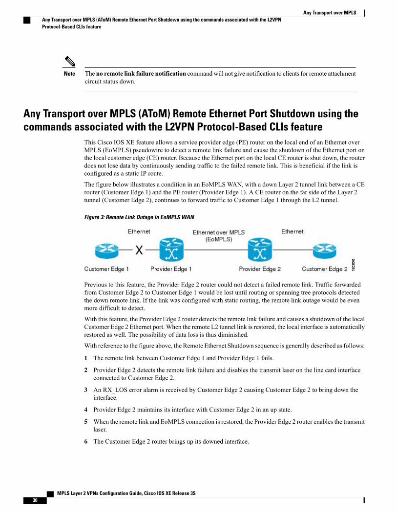
The no remote link failure notification commandwill not give notification to clients for remote attachmentcircuit status down.
Note
Any Transport over MPLS (AToM) Remote Ethernet Port Shutdown using thecommands associated with the L2VPN Protocol-Based CLIs feature
This Cisco IOS XE feature allows a service provider edge (PE) router on the local end of an Ethernet overMPLS (EoMPLS) pseudowire to detect a remote link failure and cause the shutdown of the Ethernet port onthe local customer edge (CE) router. Because the Ethernet port on the local CE router is shut down, the routerdoes not lose data by continuously sending traffic to the failed remote link. This is beneficial if the link isconfigured as a static IP route.
The figure below illustrates a condition in an EoMPLSWAN, with a down Layer 2 tunnel link between a CErouter (Customer Edge 1) and the PE router (Provider Edge 1). A CE router on the far side of the Layer 2tunnel (Customer Edge 2), continues to forward traffic to Customer Edge 1 through the L2 tunnel.
Figure 3: Remote Link Outage in EoMPLS WAN
Previous to this feature, the Provider Edge 2 router could not detect a failed remote link. Traffic forwardedfrom Customer Edge 2 to Customer Edge 1 would be lost until routing or spanning tree protocols detectedthe down remote link. If the link was configured with static routing, the remote link outage would be evenmore difficult to detect.
With this feature, the Provider Edge 2 router detects the remote link failure and causes a shutdown of the localCustomer Edge 2 Ethernet port. When the remote L2 tunnel link is restored, the local interface is automaticallyrestored as well. The possibility of data loss is thus diminished.
With reference to the figure above, the Remote Ethernet Shutdown sequence is generally described as follows:
1 The remote link between Customer Edge 1 and Provider Edge 1 fails.
2 Provider Edge 2 detects the remote link failure and disables the transmit laser on the line card interfaceconnected to Customer Edge 2.
3 An RX_LOS error alarm is received by Customer Edge 2 causing Customer Edge 2 to bring down theinterface.
4 Provider Edge 2 maintains its interface with Customer Edge 2 in an up state.
5 When the remote link and EoMPLS connection is restored, the Provider Edge 2 router enables the transmitlaser.
6 The Customer Edge 2 router brings up its downed interface.
MPLS Layer 2 VPNs Configuration Guide, Cisco IOS XE Release 3S30
Any Transport over MPLSAny Transport over MPLS (AToM) Remote Ethernet Port Shutdown using the commands associated with the L2VPNProtocol-Based CLIs feature
This feature is enabled by default for Ethernet over MPLS (EoMPLS). You can also enable this feature byusing the remote link failure notification command in xconnect configurationmode as shown in the followingexample:
template type pseudowire eomplsencapsulation mpls!interface Pseudowire 100source template type pseudowire testneighbor 10.13.13.13 1interface GigabitEthernet1/0/0service instance 300 ethernetremote link failure notificationl2vpn xconnect context con1member GigabitEthernet1/0/0 service-instance 300member Pseudowire 100!This feature can be disabled using the no remote link failure notification command in xconnect configurationmode. Use the show ip interface brief privileged EXEC command to display the status of all remote L2tunnel links. Use the show interface privileged EXEC command to show the status of the L2 tunnel on aspecific interface.
The no remote link failure notification commandwill not give notification to clients for remote attachmentcircuit status down.
Note
AToM Load Balancing with Single PWThe AToM Load Balancing with Single PW feature enables load balancing for packets within the samepseudowire by further classifying packets within the same pseudowire into different flows based on certainfields in the packet received on an attachment circuit. For example, for Ethernet this load balancing is basedon the source MAC address in the incoming packets.
Flow-Aware Transport (FAT) Load BalancingThe Flow-Aware Transport of MPLS Pseudowires feature enables load balancing of packets within the samepseudowire by further classifying the packets into different flows by adding a flow label at the bottom of theMPLS label stack.
How to Configure Any Transport over MPLSThis section explains how to perform a basic AToM configuration and includes the following procedures:
MPLS Layer 2 VPNs Configuration Guide, Cisco IOS XE Release 3S 31
Any Transport over MPLSAToM Load Balancing with Single PW
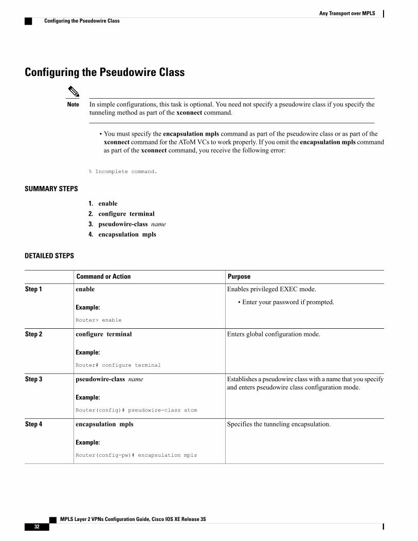
Configuring the Pseudowire Class
In simple configurations, this task is optional. You need not specify a pseudowire class if you specify thetunneling method as part of the xconnect command.
Note
• You must specify the encapsulation mpls command as part of the pseudowire class or as part of thexconnect command for the AToMVCs to work properly. If you omit the encapsulation mpls commandas part of the xconnect command, you receive the following error:
% Incomplete command.
SUMMARY STEPS
1. enable2. configure terminal3. pseudowire-class name4. encapsulation mpls
DETAILED STEPS
PurposeCommand or Action
Enables privileged EXEC mode.enableStep 1
Example:
Router> enable
• Enter your password if prompted.
Enters global configuration mode.configure terminal
Example:
Router# configure terminal
Step 2
Establishes a pseudowire class with a name that you specifyand enters pseudowire class configuration mode.
pseudowire-class name
Example:
Router(config)# pseudowire-class atom
Step 3
Specifies the tunneling encapsulation.encapsulation mpls
Example:
Router(config-pw)# encapsulation mpls
Step 4
MPLS Layer 2 VPNs Configuration Guide, Cisco IOS XE Release 3S32
Any Transport over MPLSConfiguring the Pseudowire Class
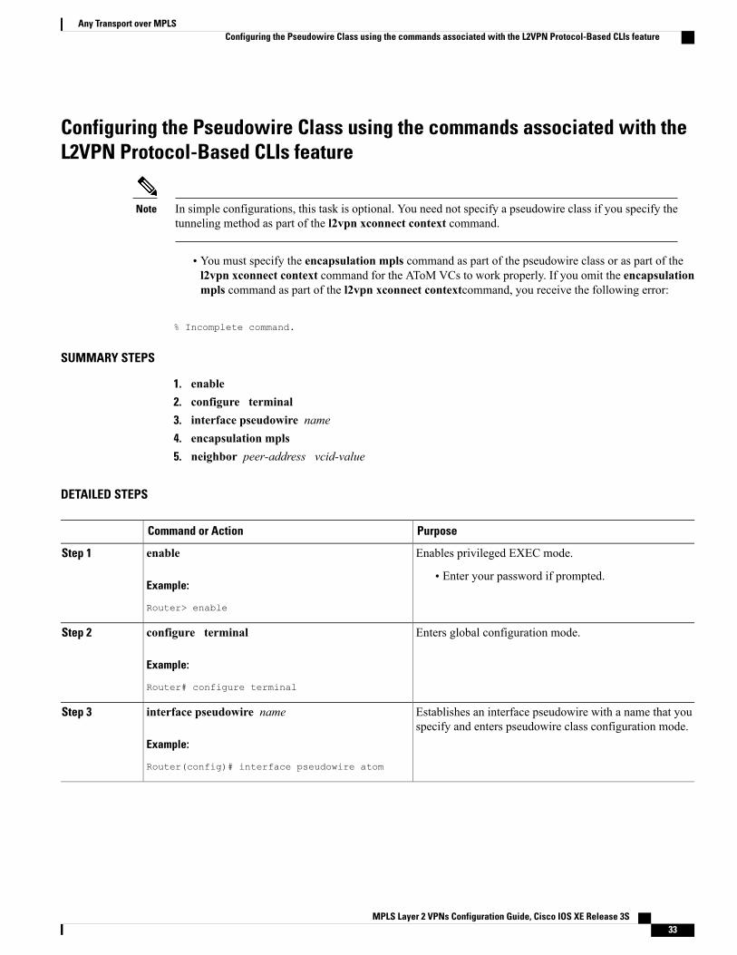
Configuring the Pseudowire Class using the commands associated with theL2VPN Protocol-Based CLIs feature
In simple configurations, this task is optional. You need not specify a pseudowire class if you specify thetunneling method as part of the l2vpn xconnect context command.
Note
• You must specify the encapsulation mpls command as part of the pseudowire class or as part of thel2vpn xconnect context command for the AToM VCs to work properly. If you omit the encapsulationmpls command as part of the l2vpn xconnect contextcommand, you receive the following error:
% Incomplete command.
SUMMARY STEPS
1. enable2. configure terminal3. interface pseudowire name4. encapsulation mpls5. neighbor peer-address vcid-value
DETAILED STEPS
PurposeCommand or Action
Enables privileged EXEC mode.enableStep 1
Example:
Router> enable
• Enter your password if prompted.
Enters global configuration mode.configure terminal
Example:
Router# configure terminal
Step 2
Establishes an interface pseudowire with a name that youspecify and enters pseudowire class configuration mode.
interface pseudowire name
Example:
Router(config)# interface pseudowire atom
Step 3
MPLS Layer 2 VPNs Configuration Guide, Cisco IOS XE Release 3S 33
Any Transport over MPLSConfiguring the Pseudowire Class using the commands associated with the L2VPN Protocol-Based CLIs feature
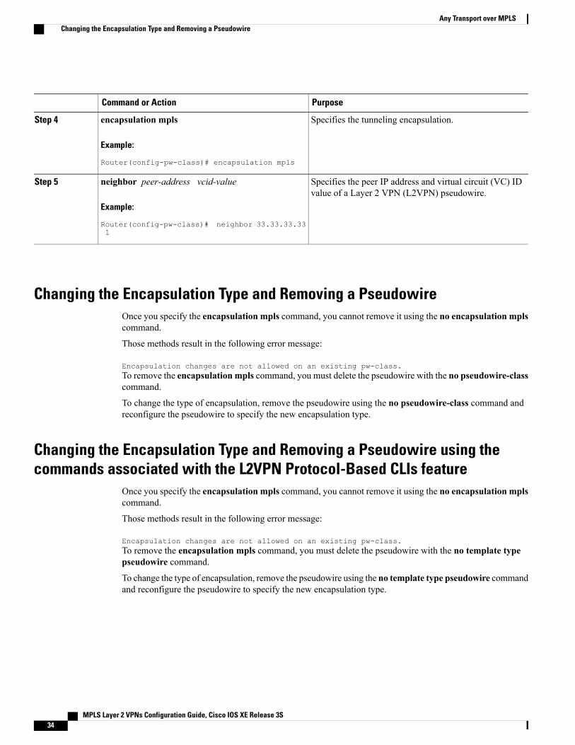
PurposeCommand or Action
Specifies the tunneling encapsulation.encapsulation mpls
Example:
Router(config-pw-class)# encapsulation mpls
Step 4
Specifies the peer IP address and virtual circuit (VC) IDvalue of a Layer 2 VPN (L2VPN) pseudowire.
neighbor peer-address vcid-value
Example:
Router(config-pw-class)# neighbor 33.33.33.331
Step 5
Changing the Encapsulation Type and Removing a PseudowireOnce you specify the encapsulation mpls command, you cannot remove it using the no encapsulation mplscommand.
Those methods result in the following error message:
Encapsulation changes are not allowed on an existing pw-class.To remove the encapsulation mpls command, you must delete the pseudowire with the no pseudowire-classcommand.
To change the type of encapsulation, remove the pseudowire using the no pseudowire-class command andreconfigure the pseudowire to specify the new encapsulation type.
Changing the Encapsulation Type and Removing a Pseudowire using thecommands associated with the L2VPN Protocol-Based CLIs feature
Once you specify the encapsulation mpls command, you cannot remove it using the no encapsulation mplscommand.
Those methods result in the following error message:
Encapsulation changes are not allowed on an existing pw-class.To remove the encapsulation mpls command, you must delete the pseudowire with the no template typepseudowire command.
To change the type of encapsulation, remove the pseudowire using the no template type pseudowire commandand reconfigure the pseudowire to specify the new encapsulation type.
MPLS Layer 2 VPNs Configuration Guide, Cisco IOS XE Release 3S34
Any Transport over MPLSChanging the Encapsulation Type and Removing a Pseudowire
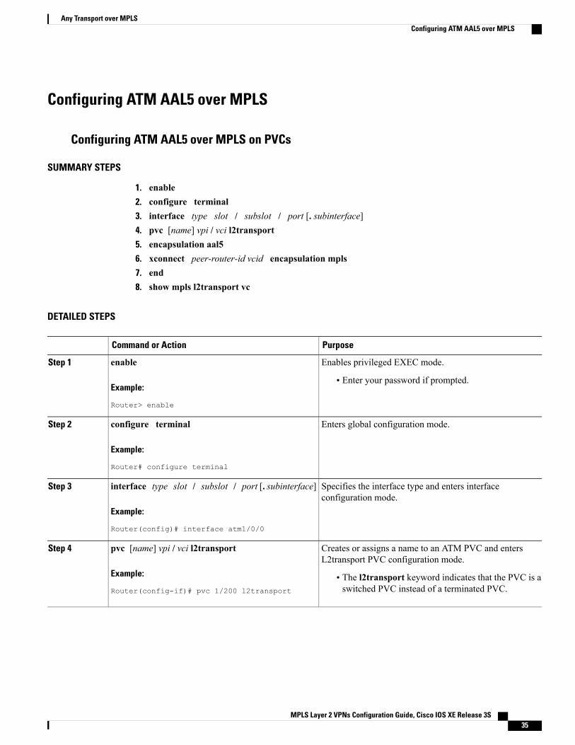
Configuring ATM AAL5 over MPLS
Configuring ATM AAL5 over MPLS on PVCs
SUMMARY STEPS
1. enable2. configure terminal3. interface type slot / subslot / port [. subinterface]4. pvc [name] vpi / vci l2transport5. encapsulation aal56. xconnect peer-router-id vcid encapsulation mpls7. end8. show mpls l2transport vc
DETAILED STEPS
PurposeCommand or Action
Enables privileged EXEC mode.enableStep 1
Example:
Router> enable
• Enter your password if prompted.
Enters global configuration mode.configure terminal
Example:
Router# configure terminal
Step 2
Specifies the interface type and enters interfaceconfiguration mode.
interface type slot / subslot / port [. subinterface]
Example:
Router(config)# interface atm1/0/0
Step 3
Creates or assigns a name to an ATM PVC and entersL2transport PVC configuration mode.
pvc [name] vpi / vci l2transport
Example:
Router(config-if)# pvc 1/200 l2transport
Step 4
• The l2transport keyword indicates that the PVC is aswitched PVC instead of a terminated PVC.
MPLS Layer 2 VPNs Configuration Guide, Cisco IOS XE Release 3S 35
Any Transport over MPLSConfiguring ATM AAL5 over MPLS
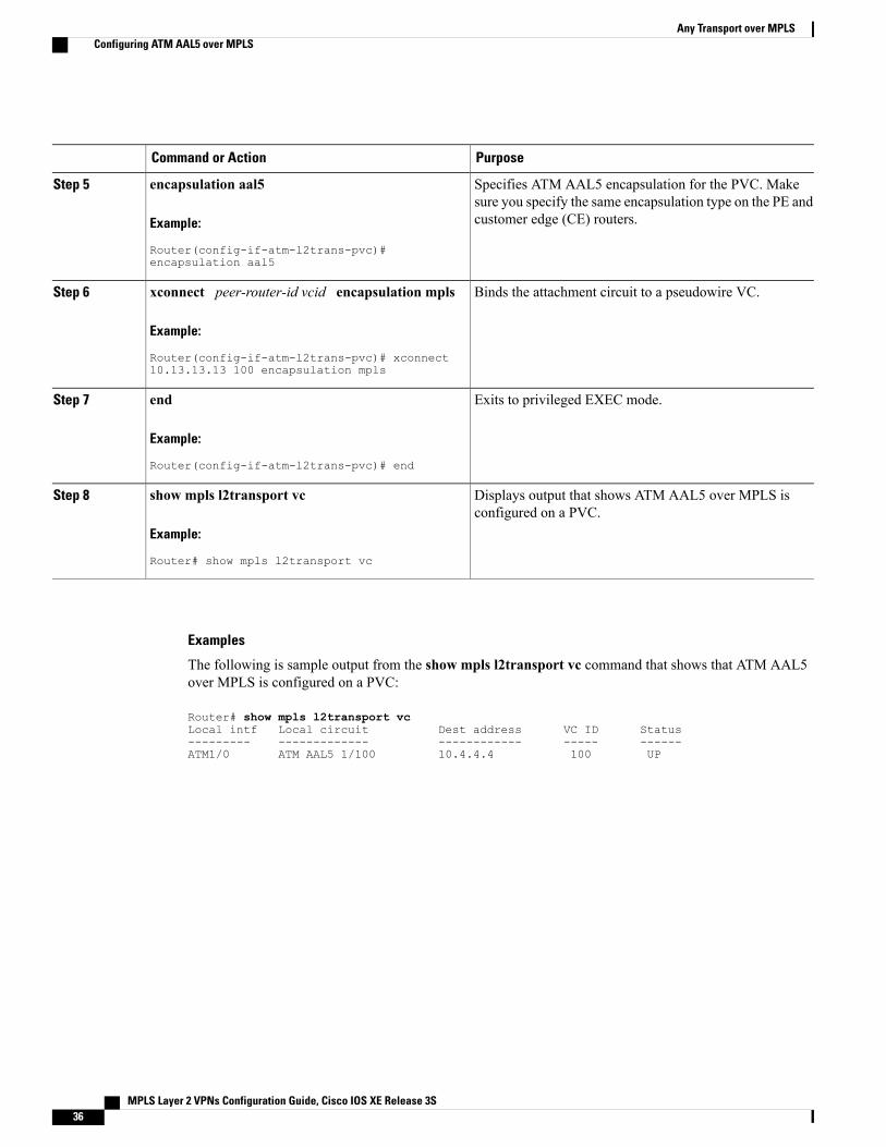
PurposeCommand or Action
Specifies ATM AAL5 encapsulation for the PVC. Makesure you specify the same encapsulation type on the PE andcustomer edge (CE) routers.
encapsulation aal5
Example:
Router(config-if-atm-l2trans-pvc)#encapsulation aal5
Step 5
Binds the attachment circuit to a pseudowire VC.xconnect peer-router-id vcid encapsulation mpls
Example:
Router(config-if-atm-l2trans-pvc)# xconnect10.13.13.13 100 encapsulation mpls
Step 6
Exits to privileged EXEC mode.end
Example:
Router(config-if-atm-l2trans-pvc)# end
Step 7
Displays output that shows ATM AAL5 over MPLS isconfigured on a PVC.
show mpls l2transport vc
Example:
Router# show mpls l2transport vc
Step 8
Examples
The following is sample output from the show mpls l2transport vc command that shows that ATM AAL5over MPLS is configured on a PVC:
Router# show mpls l2transport vcLocal intf Local circuit Dest address VC ID Status--------- ------------- ------------ ----- ------ATM1/0 ATM AAL5 1/100 10.4.4.4 100 UP
MPLS Layer 2 VPNs Configuration Guide, Cisco IOS XE Release 3S36
Any Transport over MPLSConfiguring ATM AAL5 over MPLS
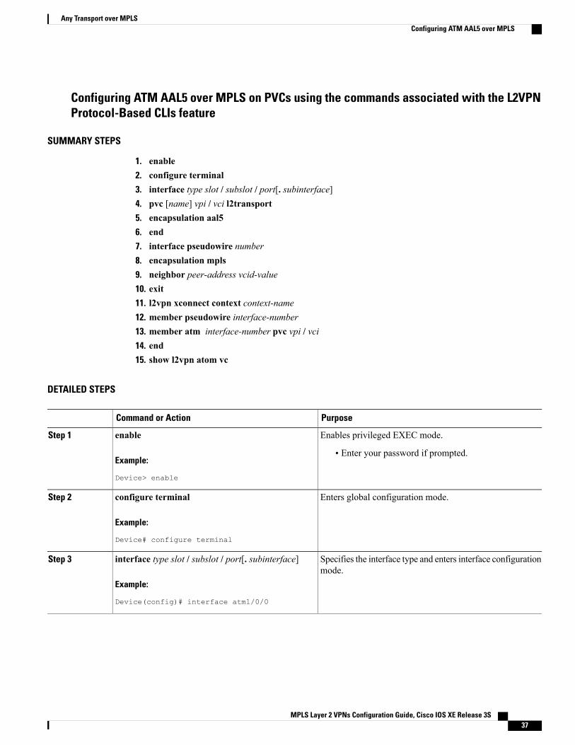
Configuring ATM AAL5 over MPLS on PVCs using the commands associated with the L2VPNProtocol-Based CLIs feature
SUMMARY STEPS
1. enable2. configure terminal3. interface type slot / subslot / port[. subinterface]4. pvc [name] vpi / vci l2transport5. encapsulation aal56. end7. interface pseudowire number8. encapsulation mpls9. neighbor peer-address vcid-value10. exit11. l2vpn xconnect context context-name12. member pseudowire interface-number13. member atm interface-number pvc vpi / vci14. end15. show l2vpn atom vc
DETAILED STEPS
PurposeCommand or Action
Enables privileged EXEC mode.enableStep 1
Example:
Device> enable
• Enter your password if prompted.
Enters global configuration mode.configure terminal
Example:
Device# configure terminal
Step 2
Specifies the interface type and enters interface configurationmode.
interface type slot / subslot / port[. subinterface]
Example:
Device(config)# interface atm1/0/0
Step 3
MPLS Layer 2 VPNs Configuration Guide, Cisco IOS XE Release 3S 37
Any Transport over MPLSConfiguring ATM AAL5 over MPLS
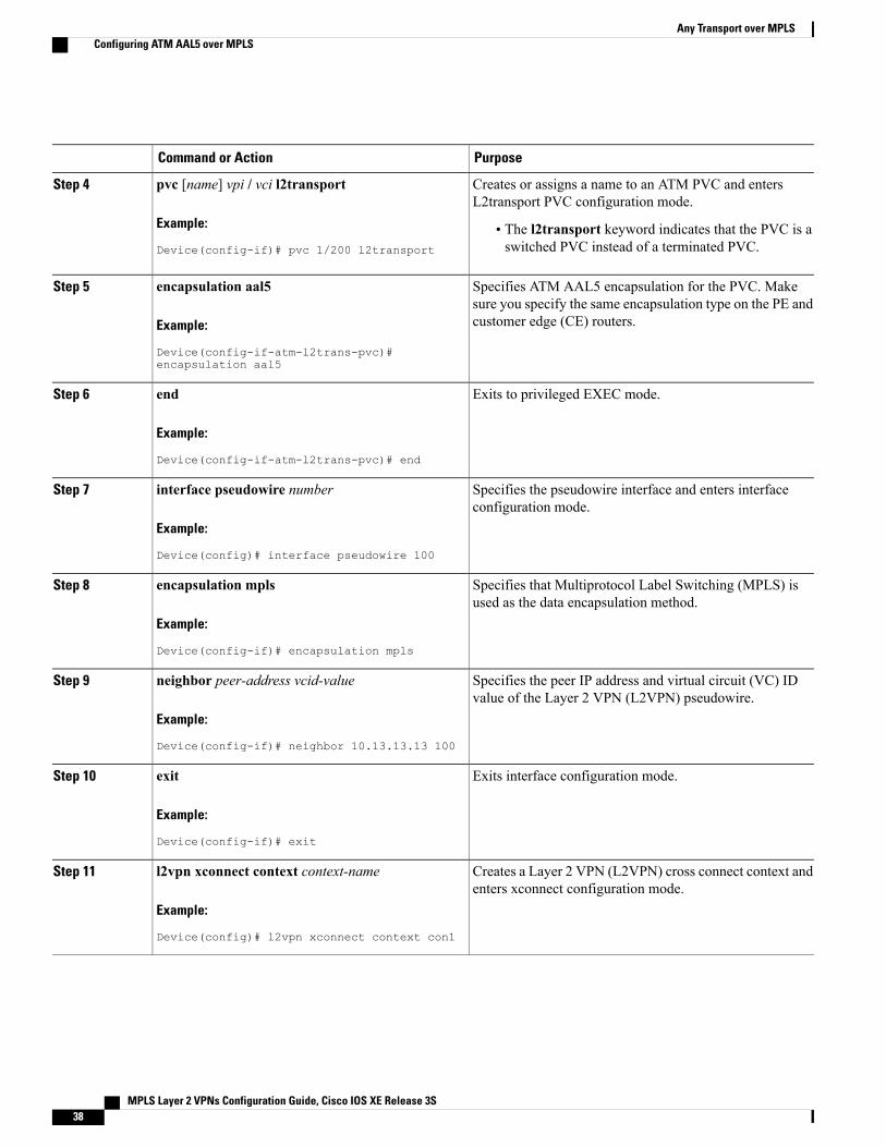
PurposeCommand or Action
Creates or assigns a name to an ATM PVC and entersL2transport PVC configuration mode.
pvc [name] vpi / vci l2transport
Example:
Device(config-if)# pvc 1/200 l2transport
Step 4
• The l2transport keyword indicates that the PVC is aswitched PVC instead of a terminated PVC.
Specifies ATM AAL5 encapsulation for the PVC. Makesure you specify the same encapsulation type on the PE andcustomer edge (CE) routers.
encapsulation aal5
Example:
Device(config-if-atm-l2trans-pvc)#encapsulation aal5
Step 5
Exits to privileged EXEC mode.end
Example:
Device(config-if-atm-l2trans-pvc)# end
Step 6
Specifies the pseudowire interface and enters interfaceconfiguration mode.
interface pseudowire number
Example:
Device(config)# interface pseudowire 100
Step 7
Specifies that Multiprotocol Label Switching (MPLS) isused as the data encapsulation method.
encapsulation mpls
Example:
Device(config-if)# encapsulation mpls
Step 8
Specifies the peer IP address and virtual circuit (VC) IDvalue of the Layer 2 VPN (L2VPN) pseudowire.
neighbor peer-address vcid-value
Example:
Device(config-if)# neighbor 10.13.13.13 100
Step 9
Exits interface configuration mode.exit
Example:
Device(config-if)# exit
Step 10
Creates a Layer 2 VPN (L2VPN) cross connect context andenters xconnect configuration mode.
l2vpn xconnect context context-name
Example:
Device(config)# l2vpn xconnect context con1
Step 11
MPLS Layer 2 VPNs Configuration Guide, Cisco IOS XE Release 3S38
Any Transport over MPLSConfiguring ATM AAL5 over MPLS
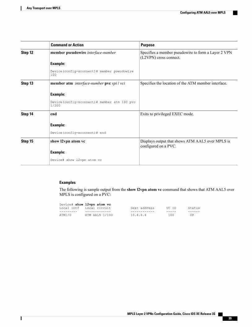
PurposeCommand or Action
Specifies a member pseudowire to form a Layer 2 VPN(L2VPN) cross connect.
member pseudowire interface-number
Example:
Device(config-xconnect)# member pseudowire100
Step 12
Specifies the location of the ATM member interface.member atm interface-number pvc vpi / vci
Example:
Device(config-xconnect)# member atm 100 pvc1/200
Step 13
Exits to privileged EXEC mode.end
Example:
Device(config-xconnect)# end
Step 14
Displays output that shows ATM AAL5 over MPLS isconfigured on a PVC.
show l2vpn atom vc
Example:
Device# show l2vpn atom vc
Step 15
Examples
The following is sample output from the show l2vpn atom vc command that shows that ATM AAL5 overMPLS is configured on a PVC:
Device# show l2vpn atom vcLocal intf Local circuit Dest address VC ID Status--------- ------------- ------------ ----- ------ATM1/0 ATM AAL5 1/100 10.4.4.4 100 UP
MPLS Layer 2 VPNs Configuration Guide, Cisco IOS XE Release 3S 39
Any Transport over MPLSConfiguring ATM AAL5 over MPLS

Configuring ATM AAL5 over MPLS in VC Class Configuration Mode
SUMMARY STEPS
1. enable2. configure terminal3. vc-class atm vc-class-name4. encapsulation layer-type5. exit6. interface type slot / subslot / port [. subinterface]7. class-int vc-class-name8. pvc [name] vpi / vci l2transport9. xconnect peer-router-id vcid encapsulation mpls10. end11. show atm class-links
DETAILED STEPS
PurposeCommand or Action
Enables privileged EXEC mode.enableStep 1
Example:
Router> enable
• Enter your password if prompted.
Enters global configuration mode.configure terminal
Example:
Router# configure terminal
Step 2
Creates a VC class and enters VC class configurationmode.
vc-class atm vc-class-name
Example:
Router(config)# vc-class atm aal5class
Step 3
Configures the AAL and encapsulation type.encapsulation layer-type
Example:
Router(config-vc-class)# encapsulation aal5
Step 4
Exits VC class configuration mode.exit
Example:
Router(config-vc-class)# exit
Step 5
MPLS Layer 2 VPNs Configuration Guide, Cisco IOS XE Release 3S40
Any Transport over MPLSConfiguring ATM AAL5 over MPLS
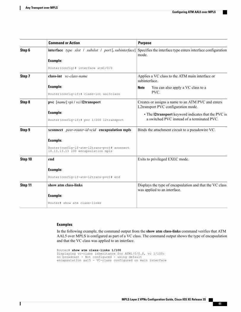
PurposeCommand or Action
Specifies the interface type enters interface configurationmode.
interface type slot / subslot / port [. subinterface]
Example:
Router(config)# interface atm1/0/0
Step 6
Applies a VC class to the ATM main interface orsubinterface.
class-int vc-class-name
Example:
Router(config-if)# class-int aal5class
Step 7
You can also apply a VC class to aPVC.
Note
Creates or assigns a name to an ATM PVC and entersL2transport PVC configuration mode.
pvc [name] vpi / vci l2transport
Example:
Router(config-if)# pvc 1/200 l2transport
Step 8
• The l2transport keyword indicates that the PVC isa switched PVC instead of a terminated PVC.
Binds the attachment circuit to a pseudowire VC.xconnect peer-router-id vcid encapsulation mpls
Example:
Router(config-if-atm-l2trans-pvc)# xconnect10.13.13.13 100 encapsulation mpls
Step 9
Exits to privileged EXEC mode.end
Example:
Router(config-if-atm-l2trans-pvc)# end
Step 10
Displays the type of encapsulation and that the VC classwas applied to an interface.
show atm class-links
Example:
Router# show atm class-links
Step 11
Examples
In the following example, the command output from the show atm class-links command verifies that ATMAAL5 over MPLS is configured as part of a VC class. The command output shows the type of encapsulationand that the VC class was applied to an interface.
Router# show atm class-links 1/100Displaying vc-class inheritance for ATM1/0/0.0, vc 1/100:no broadcast - Not configured - using defaultencapsulation aal5 - VC-class configured on main interface
MPLS Layer 2 VPNs Configuration Guide, Cisco IOS XE Release 3S 41
Any Transport over MPLSConfiguring ATM AAL5 over MPLS
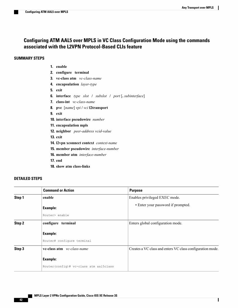
Configuring ATM AAL5 over MPLS in VC Class Configuration Mode using the commandsassociated with the L2VPN Protocol-Based CLIs feature
SUMMARY STEPS
1. enable2. configure terminal3. vc-class atm vc-class-name4. encapsulation layer-type5. exit6. interface type slot / subslot / port [. subinterface]7. class-int vc-class-name8. pvc [name] vpi / vci l2transport9. exit10. interface pseudowire number11. encapsulation mpls12. neighbor peer-address vcid-value13. exit14. l2vpn xconnect context context-name15. member pseudowire interface-number16. member atm interface-number17. end18. show atm class-links
DETAILED STEPS
PurposeCommand or Action
Enables privileged EXEC mode.enableStep 1
Example:
Router> enable
• Enter your password if prompted.
Enters global configuration mode.configure terminal
Example:
Router# configure terminal
Step 2
Creates a VC class and enters VC class configurationmode.vc-class atm vc-class-name
Example:
Router(config)# vc-class atm aal5class
Step 3
MPLS Layer 2 VPNs Configuration Guide, Cisco IOS XE Release 3S42
Any Transport over MPLSConfiguring ATM AAL5 over MPLS
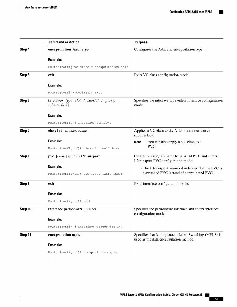
PurposeCommand or Action
Configures the AAL and encapsulation type.encapsulation layer-type
Example:
Router(config-vc-class)# encapsulation aal5
Step 4
Exits VC class configuration mode.exit
Example:
Router(config-vc-class)# exit
Step 5
Specifies the interface type enters interface configurationmode.
interface type slot / subslot / port [.subinterface]
Example:
Router(config)# interface atm1/0/0
Step 6
Applies a VC class to the ATM main interface orsubinterface.
class-int vc-class-name
Example:
Router(config-if)# class-int aal5class
Step 7
You can also apply a VC class to aPVC.
Note
Creates or assigns a name to an ATM PVC and entersL2transport PVC configuration mode.
pvc [name] vpi / vci l2transport
Example:
Router(config-if)# pvc 1/200 l2transport
Step 8
• The l2transport keyword indicates that the PVC isa switched PVC instead of a terminated PVC.
Exits interface configuration mode.exit
Example:
Router(config-if)# exit
Step 9
Specifies the pseudowire interface and enters interfaceconfiguration mode.
interface pseudowire number
Example:
Router(config)# interface pseudowire 100
Step 10
Specifies that Multiprotocol Label Switching (MPLS) isused as the data encapsulation method.
encapsulation mpls
Example:
Router(config-if)# encapsulation mpls
Step 11
MPLS Layer 2 VPNs Configuration Guide, Cisco IOS XE Release 3S 43
Any Transport over MPLSConfiguring ATM AAL5 over MPLS
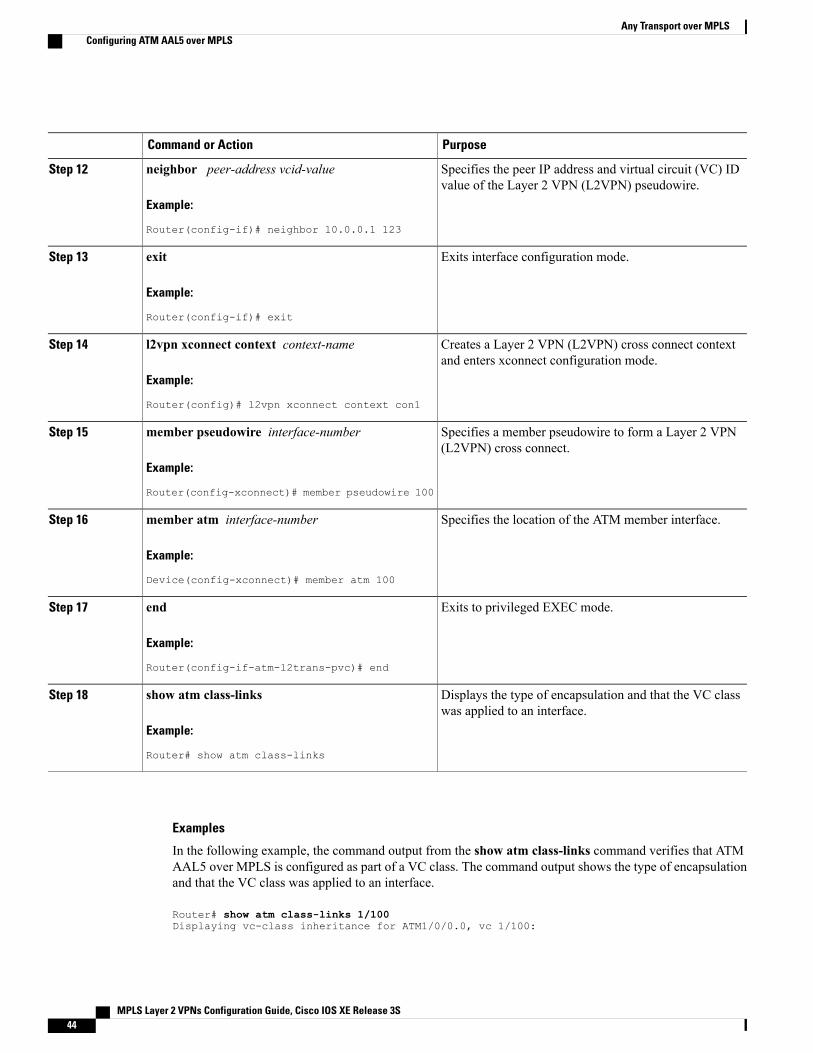
PurposeCommand or Action
Specifies the peer IP address and virtual circuit (VC) IDvalue of the Layer 2 VPN (L2VPN) pseudowire.
neighbor peer-address vcid-value
Example:
Router(config-if)# neighbor 10.0.0.1 123
Step 12
Exits interface configuration mode.exit
Example:
Router(config-if)# exit
Step 13
Creates a Layer 2 VPN (L2VPN) cross connect contextand enters xconnect configuration mode.
l2vpn xconnect context context-name
Example:
Router(config)# l2vpn xconnect context con1
Step 14
Specifies a member pseudowire to form a Layer 2 VPN(L2VPN) cross connect.
member pseudowire interface-number
Example:
Router(config-xconnect)# member pseudowire 100
Step 15
Specifies the location of the ATM member interface.member atm interface-number
Example:
Device(config-xconnect)# member atm 100
Step 16
Exits to privileged EXEC mode.end
Example:
Router(config-if-atm-l2trans-pvc)# end
Step 17
Displays the type of encapsulation and that the VC classwas applied to an interface.
show atm class-links
Example:
Router# show atm class-links
Step 18
Examples
In the following example, the command output from the show atm class-links command verifies that ATMAAL5 over MPLS is configured as part of a VC class. The command output shows the type of encapsulationand that the VC class was applied to an interface.
Router# show atm class-links 1/100Displaying vc-class inheritance for ATM1/0/0.0, vc 1/100:
MPLS Layer 2 VPNs Configuration Guide, Cisco IOS XE Release 3S44
Any Transport over MPLSConfiguring ATM AAL5 over MPLS
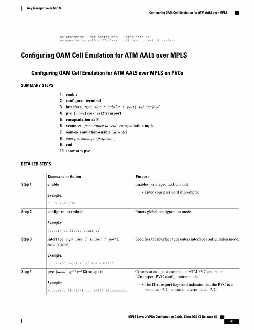
no broadcast - Not configured - using defaultencapsulation aal5 - VC-class configured on main interface
Configuring OAM Cell Emulation for ATM AAL5 over MPLS
Configuring OAM Cell Emulation for ATM AAL5 over MPLS on PVCs
SUMMARY STEPS
1. enable2. configure terminal3. interface type slot / subslot / port [. subinterface]4. pvc [name] vpi / vci l2transport5. encapsulation aal56. xconnect peer-router-id vcid encapsulation mpls7. oam-ac emulation-enable [ais-rate]8. oam-pvc manage [frequency]9. end10. show atm pvc
DETAILED STEPS
PurposeCommand or Action
Enables privileged EXEC mode.enableStep 1
Example:
Router> enable
• Enter your password if prompted.
Enters global configuration mode.configure terminal
Example:
Router# configure terminal
Step 2
Specifies the interface type enters interface configuration mode.interface type slot / subslot / port [.subinterface]
Step 3
Example:
Router(config)# interface atm1/0/0
Creates or assigns a name to an ATM PVC and entersL2transport PVC configuration mode.
pvc [name] vpi / vci l2transport
Example:
Router(config-if)# pvc 1/200 l2transport
Step 4
• The l2transport keyword indicates that the PVC is aswitched PVC instead of a terminated PVC.
MPLS Layer 2 VPNs Configuration Guide, Cisco IOS XE Release 3S 45
Any Transport over MPLSConfiguring OAM Cell Emulation for ATM AAL5 over MPLS
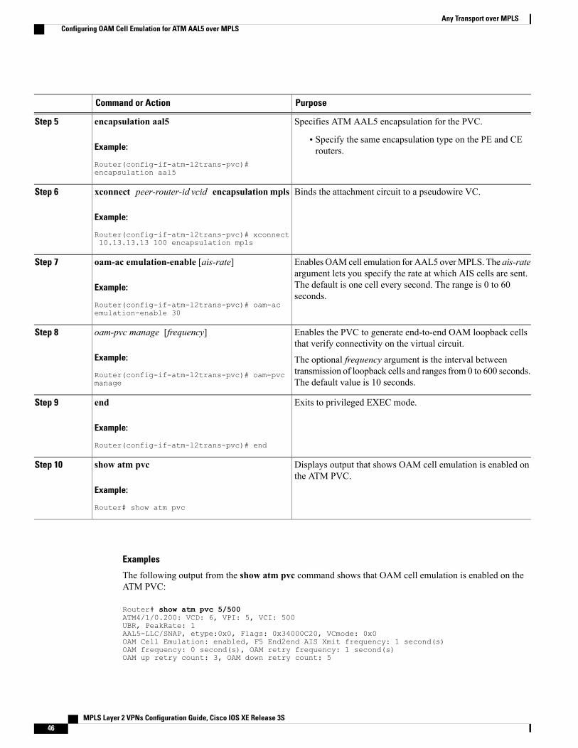
PurposeCommand or Action
Specifies ATM AAL5 encapsulation for the PVC.encapsulation aal5Step 5
Example:
Router(config-if-atm-l2trans-pvc)#encapsulation aal5
• Specify the same encapsulation type on the PE and CErouters.
Binds the attachment circuit to a pseudowire VC.xconnect peer-router-id vcid encapsulationmpls
Example:
Router(config-if-atm-l2trans-pvc)# xconnect10.13.13.13 100 encapsulation mpls
Step 6
EnablesOAMcell emulation for AAL5 overMPLS. The ais-rateargument lets you specify the rate at which AIS cells are sent.
oam-ac emulation-enable [ais-rate]
Example:
Router(config-if-atm-l2trans-pvc)# oam-acemulation-enable 30
Step 7
The default is one cell every second. The range is 0 to 60seconds.
Enables the PVC to generate end-to-end OAM loopback cellsthat verify connectivity on the virtual circuit.
oam-pvc manage [frequency]
Example:
Router(config-if-atm-l2trans-pvc)# oam-pvcmanage
Step 8
The optional frequency argument is the interval betweentransmission of loopback cells and ranges from 0 to 600 seconds.The default value is 10 seconds.
Exits to privileged EXEC mode.end
Example:
Router(config-if-atm-l2trans-pvc)# end
Step 9
Displays output that shows OAM cell emulation is enabled onthe ATM PVC.
show atm pvc
Example:
Router# show atm pvc
Step 10
Examples
The following output from the show atm pvc command shows that OAM cell emulation is enabled on theATM PVC:
Router# show atm pvc 5/500ATM4/1/0.200: VCD: 6, VPI: 5, VCI: 500UBR, PeakRate: 1AAL5-LLC/SNAP, etype:0x0, Flags: 0x34000C20, VCmode: 0x0OAM Cell Emulation: enabled, F5 End2end AIS Xmit frequency: 1 second(s)OAM frequency: 0 second(s), OAM retry frequency: 1 second(s)OAM up retry count: 3, OAM down retry count: 5
MPLS Layer 2 VPNs Configuration Guide, Cisco IOS XE Release 3S46
Any Transport over MPLSConfiguring OAM Cell Emulation for ATM AAL5 over MPLS
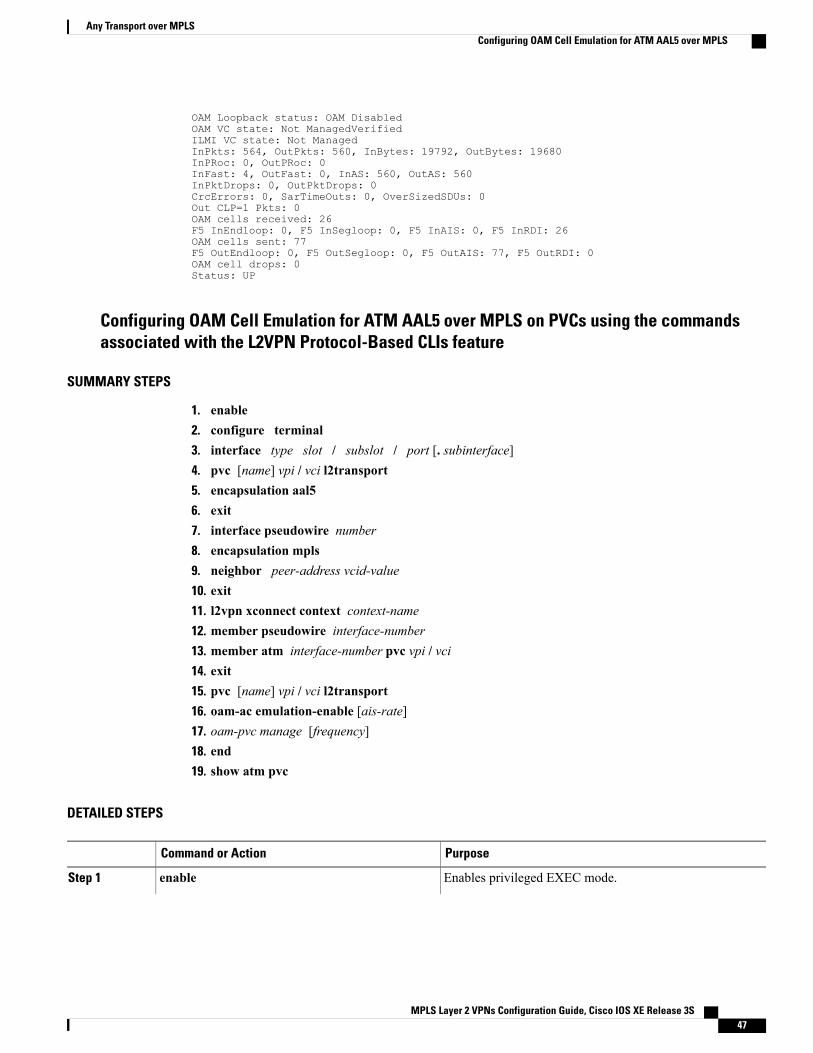
OAM Loopback status: OAM DisabledOAM VC state: Not ManagedVerifiedILMI VC state: Not ManagedInPkts: 564, OutPkts: 560, InBytes: 19792, OutBytes: 19680InPRoc: 0, OutPRoc: 0InFast: 4, OutFast: 0, InAS: 560, OutAS: 560InPktDrops: 0, OutPktDrops: 0CrcErrors: 0, SarTimeOuts: 0, OverSizedSDUs: 0Out CLP=1 Pkts: 0OAM cells received: 26F5 InEndloop: 0, F5 InSegloop: 0, F5 InAIS: 0, F5 InRDI: 26OAM cells sent: 77F5 OutEndloop: 0, F5 OutSegloop: 0, F5 OutAIS: 77, F5 OutRDI: 0OAM cell drops: 0Status: UP
Configuring OAM Cell Emulation for ATM AAL5 over MPLS on PVCs using the commandsassociated with the L2VPN Protocol-Based CLIs feature
SUMMARY STEPS
1. enable2. configure terminal3. interface type slot / subslot / port [. subinterface]4. pvc [name] vpi / vci l2transport5. encapsulation aal56. exit7. interface pseudowire number8. encapsulation mpls9. neighbor peer-address vcid-value10. exit11. l2vpn xconnect context context-name12. member pseudowire interface-number13. member atm interface-number pvc vpi / vci14. exit15. pvc [name] vpi / vci l2transport16. oam-ac emulation-enable [ais-rate]17. oam-pvc manage [frequency]18. end19. show atm pvc
DETAILED STEPS
PurposeCommand or Action
Enables privileged EXEC mode.enableStep 1
MPLS Layer 2 VPNs Configuration Guide, Cisco IOS XE Release 3S 47
Any Transport over MPLSConfiguring OAM Cell Emulation for ATM AAL5 over MPLS
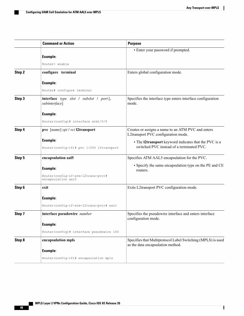
PurposeCommand or Action
Example:
Router> enable
• Enter your password if prompted.
Enters global configuration mode.configure terminal
Example:
Router# configure terminal
Step 2
Specifies the interface type enters interface configurationmode.
interface type slot / subslot / port [.subinterface]
Example:
Router(config)# interface atm1/0/0
Step 3
Creates or assigns a name to an ATM PVC and entersL2transport PVC configuration mode.
pvc [name] vpi / vci l2transport
Example:
Router(config-if)# pvc 1/200 l2transport
Step 4
• The l2transport keyword indicates that the PVC is aswitched PVC instead of a terminated PVC.
Specifies ATM AAL5 encapsulation for the PVC.encapsulation aal5Step 5
Example:
Router(config-if-atm-l2trans-pvc)#encapsulation aal5
• Specify the same encapsulation type on the PE and CErouters.
Exits L2transport PVC configuration mode.exit
Example:
Router(config-if-atm-l2trans-pvc)# exit
Step 6
Specifies the pseudowire interface and enters interfaceconfiguration mode.
interface pseudowire number
Example:
Router(config)# interface pseudowire 100
Step 7
Specifies that Multiprotocol Label Switching (MPLS) is usedas the data encapsulation method.
encapsulation mpls
Example:
Router(config-if)# encapsulation mpls
Step 8
MPLS Layer 2 VPNs Configuration Guide, Cisco IOS XE Release 3S48
Any Transport over MPLSConfiguring OAM Cell Emulation for ATM AAL5 over MPLS
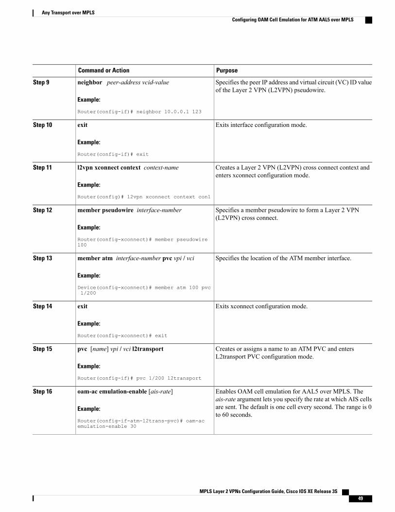
PurposeCommand or Action
Specifies the peer IP address and virtual circuit (VC) ID valueof the Layer 2 VPN (L2VPN) pseudowire.
neighbor peer-address vcid-value
Example:
Router(config-if)# neighbor 10.0.0.1 123
Step 9
Exits interface configuration mode.exit
Example:
Router(config-if)# exit
Step 10
Creates a Layer 2 VPN (L2VPN) cross connect context andenters xconnect configuration mode.
l2vpn xconnect context context-name
Example:
Router(config)# l2vpn xconnect context con1
Step 11
Specifies a member pseudowire to form a Layer 2 VPN(L2VPN) cross connect.
member pseudowire interface-number
Example:
Router(config-xconnect)# member pseudowire100
Step 12
Specifies the location of the ATM member interface.member atm interface-number pvc vpi / vci
Example:
Device(config-xconnect)# member atm 100 pvc1/200
Step 13
Exits xconnect configuration mode.exit
Example:
Router(config-xconnect)# exit
Step 14
Creates or assigns a name to an ATM PVC and entersL2transport PVC configuration mode.
pvc [name] vpi / vci l2transport
Example:
Router(config-if)# pvc 1/200 l2transport
Step 15
Enables OAM cell emulation for AAL5 over MPLS. Theais-rate argument lets you specify the rate at which AIS cells
oam-ac emulation-enable [ais-rate]
Example:
Router(config-if-atm-l2trans-pvc)# oam-acemulation-enable 30
Step 16
are sent. The default is one cell every second. The range is 0to 60 seconds.
MPLS Layer 2 VPNs Configuration Guide, Cisco IOS XE Release 3S 49
Any Transport over MPLSConfiguring OAM Cell Emulation for ATM AAL5 over MPLS
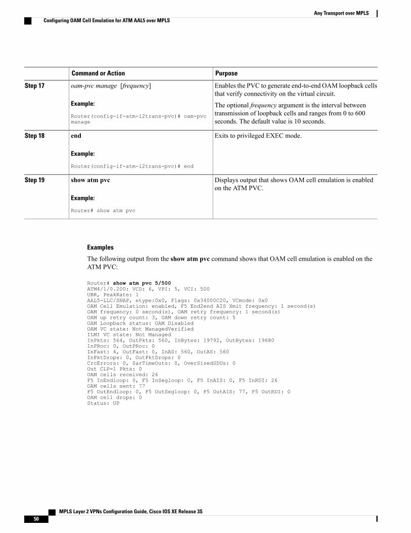
PurposeCommand or Action
Enables the PVC to generate end-to-end OAM loopback cellsthat verify connectivity on the virtual circuit.
oam-pvc manage [frequency]
Example:
Router(config-if-atm-l2trans-pvc)# oam-pvcmanage
Step 17
The optional frequency argument is the interval betweentransmission of loopback cells and ranges from 0 to 600seconds. The default value is 10 seconds.
Exits to privileged EXEC mode.end
Example:
Router(config-if-atm-l2trans-pvc)# end
Step 18
Displays output that shows OAM cell emulation is enabledon the ATM PVC.
show atm pvc
Example:
Router# show atm pvc
Step 19
Examples
The following output from the show atm pvc command shows that OAM cell emulation is enabled on theATM PVC:
Router# show atm pvc 5/500ATM4/1/0.200: VCD: 6, VPI: 5, VCI: 500UBR, PeakRate: 1AAL5-LLC/SNAP, etype:0x0, Flags: 0x34000C20, VCmode: 0x0OAM Cell Emulation: enabled, F5 End2end AIS Xmit frequency: 1 second(s)OAM frequency: 0 second(s), OAM retry frequency: 1 second(s)OAM up retry count: 3, OAM down retry count: 5OAM Loopback status: OAM DisabledOAM VC state: Not ManagedVerifiedILMI VC state: Not ManagedInPkts: 564, OutPkts: 560, InBytes: 19792, OutBytes: 19680InPRoc: 0, OutPRoc: 0InFast: 4, OutFast: 0, InAS: 560, OutAS: 560InPktDrops: 0, OutPktDrops: 0CrcErrors: 0, SarTimeOuts: 0, OverSizedSDUs: 0Out CLP=1 Pkts: 0OAM cells received: 26F5 InEndloop: 0, F5 InSegloop: 0, F5 InAIS: 0, F5 InRDI: 26OAM cells sent: 77F5 OutEndloop: 0, F5 OutSegloop: 0, F5 OutAIS: 77, F5 OutRDI: 0OAM cell drops: 0Status: UP
MPLS Layer 2 VPNs Configuration Guide, Cisco IOS XE Release 3S50
Any Transport over MPLSConfiguring OAM Cell Emulation for ATM AAL5 over MPLS
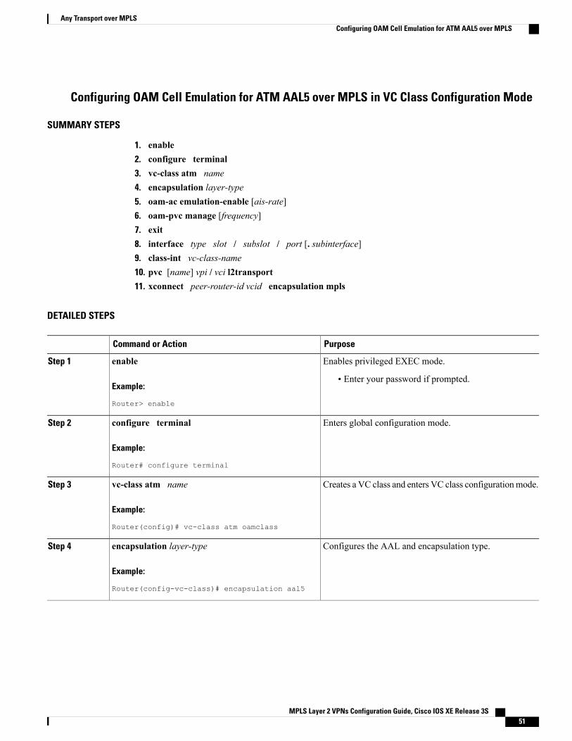
Configuring OAM Cell Emulation for ATM AAL5 over MPLS in VC Class Configuration Mode
SUMMARY STEPS
1. enable2. configure terminal3. vc-class atm name4. encapsulation layer-type5. oam-ac emulation-enable [ais-rate]6. oam-pvc manage [frequency]7. exit8. interface type slot / subslot / port [. subinterface]9. class-int vc-class-name10. pvc [name] vpi / vci l2transport11. xconnect peer-router-id vcid encapsulation mpls
DETAILED STEPS
PurposeCommand or Action
Enables privileged EXEC mode.enableStep 1
Example:
Router> enable
• Enter your password if prompted.
Enters global configuration mode.configure terminal
Example:
Router# configure terminal
Step 2
Creates a VC class and enters VC class configurationmode.vc-class atm name
Example:
Router(config)# vc-class atm oamclass
Step 3
Configures the AAL and encapsulation type.encapsulation layer-type
Example:
Router(config-vc-class)# encapsulation aal5
Step 4
MPLS Layer 2 VPNs Configuration Guide, Cisco IOS XE Release 3S 51
Any Transport over MPLSConfiguring OAM Cell Emulation for ATM AAL5 over MPLS
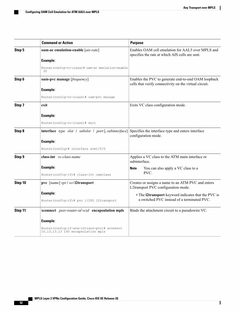
PurposeCommand or Action
Enables OAM cell emulation for AAL5 over MPLS andspecifies the rate at which AIS cells are sent.
oam-ac emulation-enable [ais-rate]
Example:
Router(config-vc-class)# oam-ac emulation-enable30
Step 5
Enables the PVC to generate end-to-end OAM loopbackcells that verify connectivity on the virtual circuit.
oam-pvc manage [frequency]
Example:
Router(config-vc-class)# oam-pvc manage
Step 6
Exits VC class configuration mode.exit
Example:
Router(config-vc-class)# exit
Step 7
Specifies the interface type and enters interfaceconfiguration mode.
interface type slot / subslot / port [. subinterface]
Example:
Router(config)# interface atm1/0/0
Step 8
Applies a VC class to the ATM main interface orsubinterface.
class-int vc-class-name
Example:
Router(config-if)# class-int oamclass
Step 9
You can also apply a VC class to aPVC.
Note
Creates or assigns a name to an ATM PVC and entersL2transport PVC configuration mode.
pvc [name] vpi / vci l2transport
Example:
Router(config-if)# pvc 1/200 l2transport
Step 10
• The l2transport keyword indicates that the PVC isa switched PVC instead of a terminated PVC.
Binds the attachment circuit to a pseudowire VC.xconnect peer-router-id vcid encapsulation mpls
Example:
Router(config-if-atm-l2trans-pvc)# xconnect10.13.13.13 100 encapsulation mpls
Step 11
MPLS Layer 2 VPNs Configuration Guide, Cisco IOS XE Release 3S52
Any Transport over MPLSConfiguring OAM Cell Emulation for ATM AAL5 over MPLS
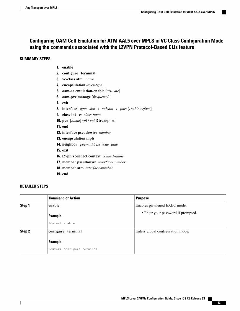
Configuring OAM Cell Emulation for ATM AAL5 over MPLS in VC Class Configuration Modeusing the commands associated with the L2VPN Protocol-Based CLIs feature
SUMMARY STEPS
1. enable2. configure terminal3. vc-class atm name4. encapsulation layer-type5. oam-ac emulation-enable [ais-rate]6. oam-pvc manage [frequency]7. exit8. interface type slot / subslot / port [. subinterface]9. class-int vc-class-name10. pvc [name] vpi / vci l2transport11. end12. interface pseudowire number13. encapsulation mpls14. neighbor peer-address vcid-value15. exit16. l2vpn xconnect context context-name17. member pseudowire interface-number18. member atm interface-number19. end
DETAILED STEPS
PurposeCommand or Action
Enables privileged EXEC mode.enableStep 1
Example:
Router> enable
• Enter your password if prompted.
Enters global configuration mode.configure terminal
Example:
Router# configure terminal
Step 2
MPLS Layer 2 VPNs Configuration Guide, Cisco IOS XE Release 3S 53
Any Transport over MPLSConfiguring OAM Cell Emulation for ATM AAL5 over MPLS
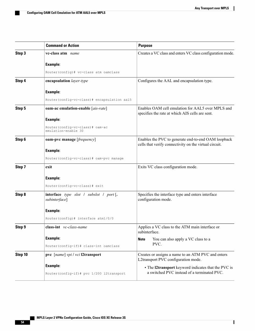
PurposeCommand or Action
Creates a VC class and enters VC class configurationmode.vc-class atm name
Example:
Router(config)# vc-class atm oamclass
Step 3
Configures the AAL and encapsulation type.encapsulation layer-type
Example:
Router(config-vc-class)# encapsulation aal5
Step 4
Enables OAM cell emulation for AAL5 over MPLS andspecifies the rate at which AIS cells are sent.
oam-ac emulation-enable [ais-rate]
Example:
Router(config-vc-class)# oam-acemulation-enable 30
Step 5
Enables the PVC to generate end-to-end OAM loopbackcells that verify connectivity on the virtual circuit.
oam-pvc manage [frequency]
Example:
Router(config-vc-class)# oam-pvc manage
Step 6
Exits VC class configuration mode.exit
Example:
Router(config-vc-class)# exit
Step 7
Specifies the interface type and enters interfaceconfiguration mode.
interface type slot / subslot / port [.subinterface]
Example:
Router(config)# interface atm1/0/0
Step 8
Applies a VC class to the ATM main interface orsubinterface.
class-int vc-class-name
Example:
Router(config-if)# class-int oamclass
Step 9
You can also apply a VC class to aPVC.
Note
Creates or assigns a name to an ATM PVC and entersL2transport PVC configuration mode.
pvc [name] vpi / vci l2transport
Example:
Router(config-if)# pvc 1/200 l2transport
Step 10
• The l2transport keyword indicates that the PVC isa switched PVC instead of a terminated PVC.
MPLS Layer 2 VPNs Configuration Guide, Cisco IOS XE Release 3S54
Any Transport over MPLSConfiguring OAM Cell Emulation for ATM AAL5 over MPLS
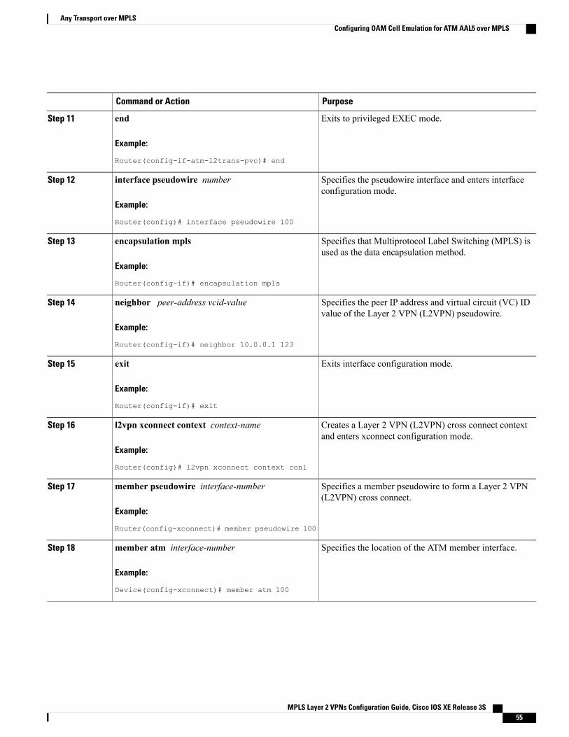
PurposeCommand or Action
Exits to privileged EXEC mode.end
Example:
Router(config-if-atm-l2trans-pvc)# end
Step 11
Specifies the pseudowire interface and enters interfaceconfiguration mode.
interface pseudowire number
Example:
Router(config)# interface pseudowire 100
Step 12
Specifies that Multiprotocol Label Switching (MPLS) isused as the data encapsulation method.
encapsulation mpls
Example:
Router(config-if)# encapsulation mpls
Step 13
Specifies the peer IP address and virtual circuit (VC) IDvalue of the Layer 2 VPN (L2VPN) pseudowire.
neighbor peer-address vcid-value
Example:
Router(config-if)# neighbor 10.0.0.1 123
Step 14
Exits interface configuration mode.exit
Example:
Router(config-if)# exit
Step 15
Creates a Layer 2 VPN (L2VPN) cross connect contextand enters xconnect configuration mode.
l2vpn xconnect context context-name
Example:
Router(config)# l2vpn xconnect context con1
Step 16
Specifies a member pseudowire to form a Layer 2 VPN(L2VPN) cross connect.
member pseudowire interface-number
Example:
Router(config-xconnect)# member pseudowire 100
Step 17
Specifies the location of the ATM member interface.member atm interface-number
Example:
Device(config-xconnect)# member atm 100
Step 18
MPLS Layer 2 VPNs Configuration Guide, Cisco IOS XE Release 3S 55
Any Transport over MPLSConfiguring OAM Cell Emulation for ATM AAL5 over MPLS
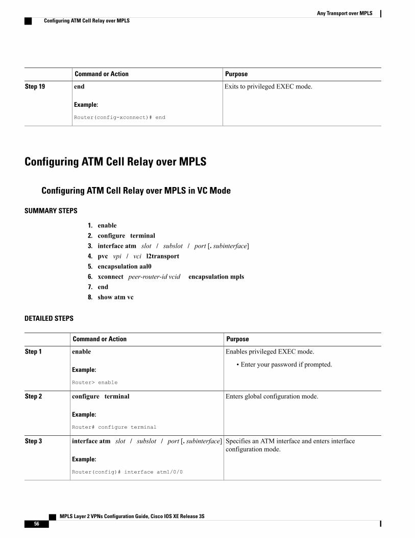
PurposeCommand or Action
Exits to privileged EXEC mode.end
Example:
Router(config-xconnect)# end
Step 19
Configuring ATM Cell Relay over MPLS
Configuring ATM Cell Relay over MPLS in VC Mode
SUMMARY STEPS
1. enable2. configure terminal3. interface atm slot / subslot / port [. subinterface]4. pvc vpi / vci l2transport5. encapsulation aal06. xconnect peer-router-id vcid encapsulation mpls7. end8. show atm vc
DETAILED STEPS
PurposeCommand or Action
Enables privileged EXEC mode.enableStep 1
Example:
Router> enable
• Enter your password if prompted.
Enters global configuration mode.configure terminal
Example:
Router# configure terminal
Step 2
Specifies an ATM interface and enters interfaceconfiguration mode.
interface atm slot / subslot / port [. subinterface]
Example:
Router(config)# interface atm1/0/0
Step 3
MPLS Layer 2 VPNs Configuration Guide, Cisco IOS XE Release 3S56
Any Transport over MPLSConfiguring ATM Cell Relay over MPLS
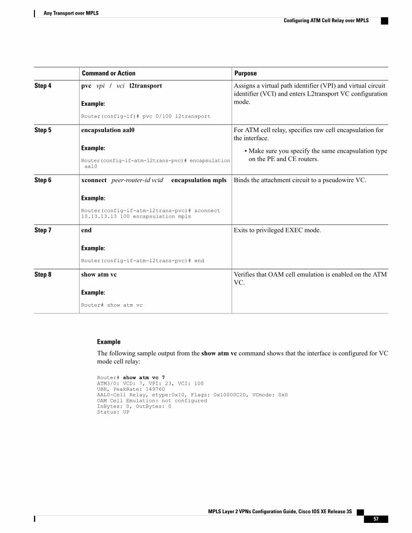
PurposeCommand or Action
Assigns a virtual path identifier (VPI) and virtual circuitidentifier (VCI) and enters L2transport VC configurationmode.
pvc vpi / vci l2transport
Example:
Router(config-if)# pvc 0/100 l2transport
Step 4
For ATM cell relay, specifies raw cell encapsulation forthe interface.
encapsulation aal0
Example:
Router(config-if-atm-l2trans-pvc)# encapsulationaal0
Step 5
• Make sure you specify the same encapsulation typeon the PE and CE routers.
Binds the attachment circuit to a pseudowire VC.xconnect peer-router-id vcid encapsulation mpls
Example:
Router(config-if-atm-l2trans-pvc)# xconnect10.13.13.13 100 encapsulation mpls
Step 6
Exits to privileged EXEC mode.end
Example:
Router(config-if-atm-l2trans-pvc)# end
Step 7
Verifies that OAM cell emulation is enabled on the ATMVC.
show atm vc
Example:
Router# show atm vc
Step 8
Example
The following sample output from the show atm vc command shows that the interface is configured for VCmode cell relay:
Router# show atm vc 7ATM3/0: VCD: 7, VPI: 23, VCI: 100UBR, PeakRate: 149760AAL0-Cell Relay, etype:0x10, Flags: 0x10000C2D, VCmode: 0x0OAM Cell Emulation: not configuredInBytes: 0, OutBytes: 0Status: UP
MPLS Layer 2 VPNs Configuration Guide, Cisco IOS XE Release 3S 57
Any Transport over MPLSConfiguring ATM Cell Relay over MPLS
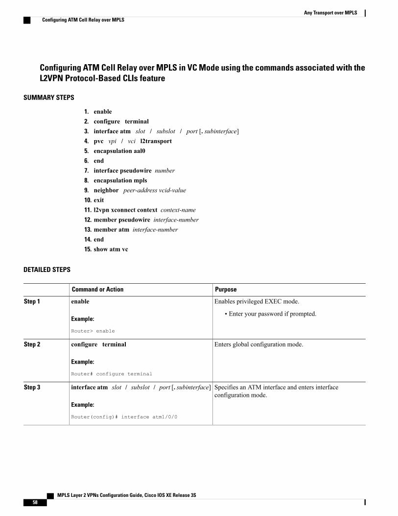
Configuring ATM Cell Relay over MPLS in VC Mode using the commands associated with theL2VPN Protocol-Based CLIs feature
SUMMARY STEPS
1. enable2. configure terminal3. interface atm slot / subslot / port [. subinterface]4. pvc vpi / vci l2transport5. encapsulation aal06. end7. interface pseudowire number8. encapsulation mpls9. neighbor peer-address vcid-value10. exit11. l2vpn xconnect context context-name12. member pseudowire interface-number13. member atm interface-number14. end15. show atm vc
DETAILED STEPS
PurposeCommand or Action
Enables privileged EXEC mode.enableStep 1
Example:
Router> enable
• Enter your password if prompted.
Enters global configuration mode.configure terminal
Example:
Router# configure terminal
Step 2
Specifies an ATM interface and enters interfaceconfiguration mode.
interface atm slot / subslot / port [. subinterface]
Example:
Router(config)# interface atm1/0/0
Step 3
MPLS Layer 2 VPNs Configuration Guide, Cisco IOS XE Release 3S58
Any Transport over MPLSConfiguring ATM Cell Relay over MPLS
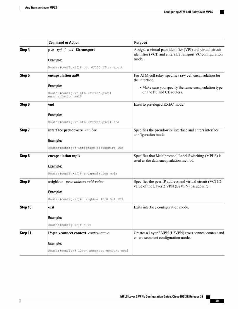
PurposeCommand or Action
Assigns a virtual path identifier (VPI) and virtual circuitidentifier (VCI) and enters L2transport VC configurationmode.
pvc vpi / vci l2transport
Example:
Router(config-if)# pvc 0/100 l2transport
Step 4
For ATM cell relay, specifies raw cell encapsulation forthe interface.
encapsulation aal0
Example:
Router(config-if-atm-l2trans-pvc)#encapsulation aal0
Step 5
• Make sure you specify the same encapsulation typeon the PE and CE routers.
Exits to privileged EXEC mode.end
Example:
Router(config-if-atm-l2trans-pvc)# end
Step 6
Specifies the pseudowire interface and enters interfaceconfiguration mode.
interface pseudowire number
Example:
Router(config)# interface pseudowire 100
Step 7
Specifies that Multiprotocol Label Switching (MPLS) isused as the data encapsulation method.
encapsulation mpls
Example:
Router(config-if)# encapsulation mpls
Step 8
Specifies the peer IP address and virtual circuit (VC) IDvalue of the Layer 2 VPN (L2VPN) pseudowire.
neighbor peer-address vcid-value
Example:
Router(config-if)# neighbor 10.0.0.1 123
Step 9
Exits interface configuration mode.exit
Example:
Router(config-if)# exit
Step 10
Creates a Layer 2 VPN (L2VPN) cross connect context andenters xconnect configuration mode.
l2vpn xconnect context context-name
Example:
Router(config)# l2vpn xconnect context con1
Step 11
MPLS Layer 2 VPNs Configuration Guide, Cisco IOS XE Release 3S 59
Any Transport over MPLSConfiguring ATM Cell Relay over MPLS
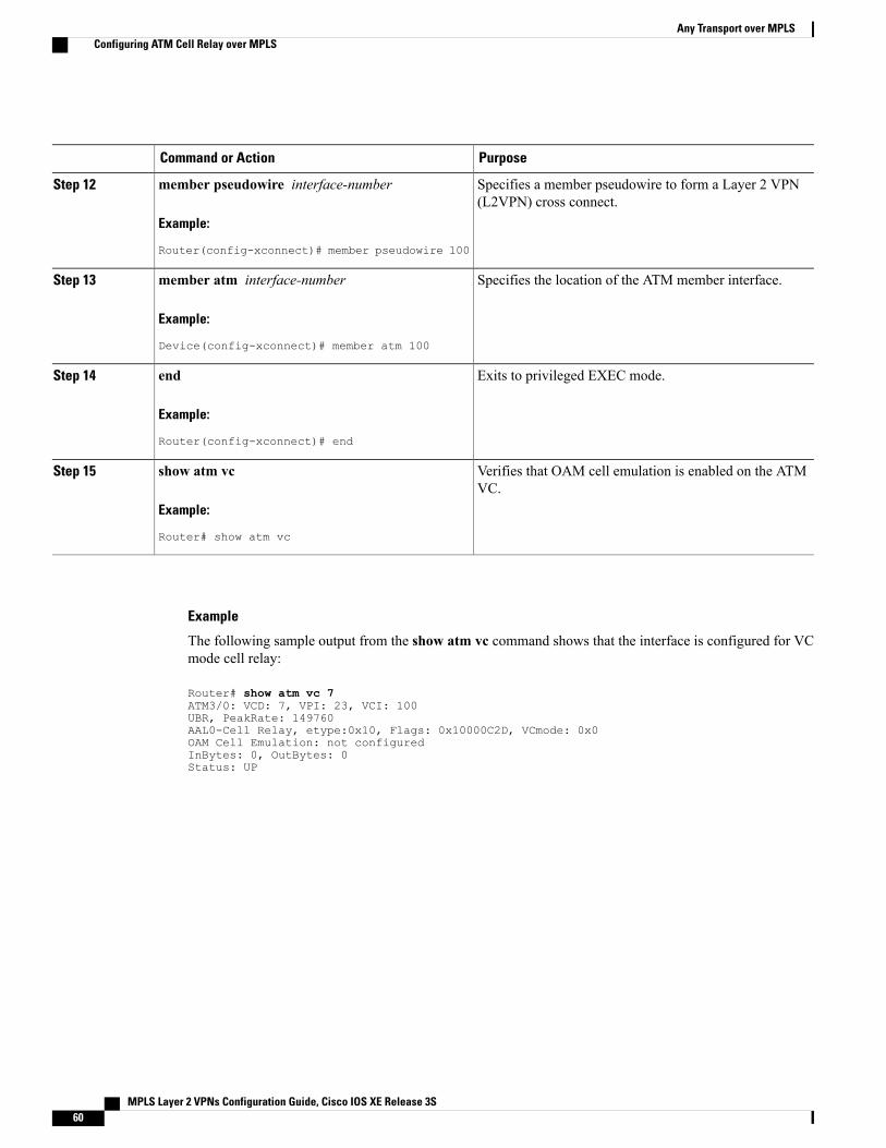
PurposeCommand or Action
Specifies a member pseudowire to form a Layer 2 VPN(L2VPN) cross connect.
member pseudowire interface-number
Example:
Router(config-xconnect)# member pseudowire 100
Step 12
Specifies the location of the ATM member interface.member atm interface-number
Example:
Device(config-xconnect)# member atm 100
Step 13
Exits to privileged EXEC mode.end
Example:
Router(config-xconnect)# end
Step 14
Verifies that OAM cell emulation is enabled on the ATMVC.
show atm vc
Example:
Router# show atm vc
Step 15
Example
The following sample output from the show atm vc command shows that the interface is configured for VCmode cell relay:
Router# show atm vc 7ATM3/0: VCD: 7, VPI: 23, VCI: 100UBR, PeakRate: 149760AAL0-Cell Relay, etype:0x10, Flags: 0x10000C2D, VCmode: 0x0OAM Cell Emulation: not configuredInBytes: 0, OutBytes: 0Status: UP
MPLS Layer 2 VPNs Configuration Guide, Cisco IOS XE Release 3S60
Any Transport over MPLSConfiguring ATM Cell Relay over MPLS
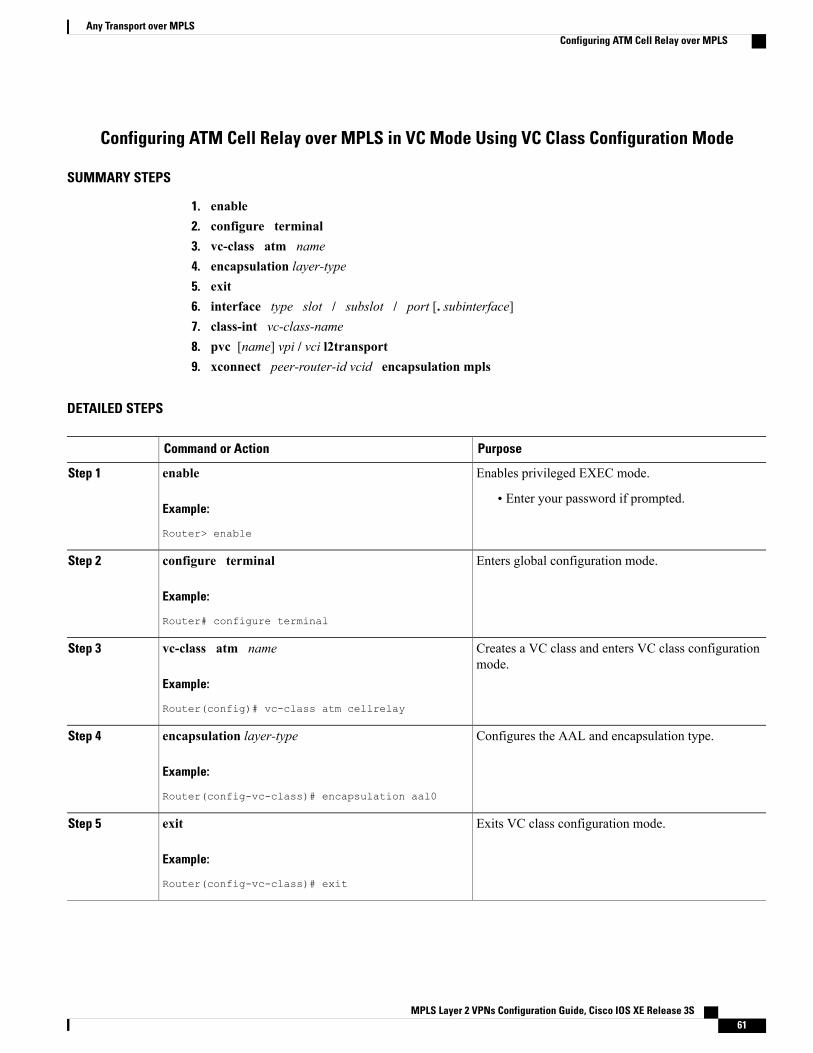
Configuring ATM Cell Relay over MPLS in VC Mode Using VC Class Configuration Mode
SUMMARY STEPS
1. enable2. configure terminal3. vc-class atm name4. encapsulation layer-type5. exit6. interface type slot / subslot / port [. subinterface]7. class-int vc-class-name8. pvc [name] vpi / vci l2transport9. xconnect peer-router-id vcid encapsulation mpls
DETAILED STEPS
PurposeCommand or Action
Enables privileged EXEC mode.enableStep 1
Example:
Router> enable
• Enter your password if prompted.
Enters global configuration mode.configure terminal
Example:
Router# configure terminal
Step 2
Creates a VC class and enters VC class configurationmode.
vc-class atm name
Example:
Router(config)# vc-class atm cellrelay
Step 3
Configures the AAL and encapsulation type.encapsulation layer-type
Example:
Router(config-vc-class)# encapsulation aal0
Step 4
Exits VC class configuration mode.exit
Example:
Router(config-vc-class)# exit
Step 5
MPLS Layer 2 VPNs Configuration Guide, Cisco IOS XE Release 3S 61
Any Transport over MPLSConfiguring ATM Cell Relay over MPLS
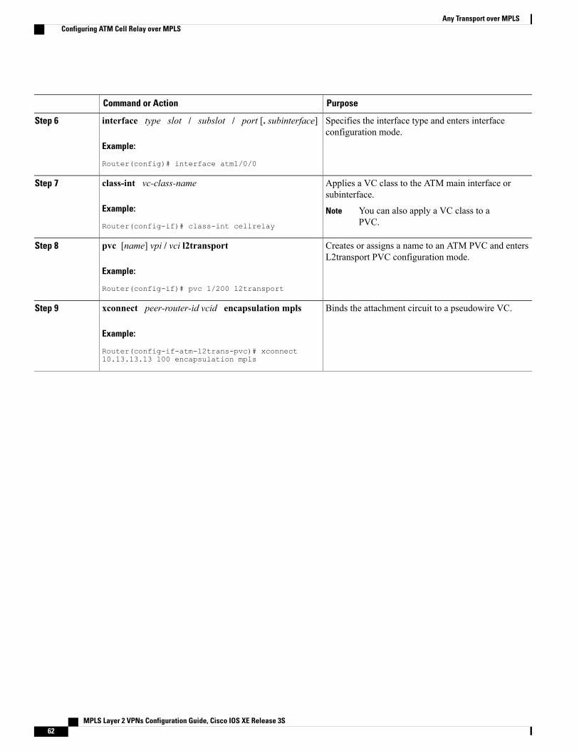
PurposeCommand or Action
Specifies the interface type and enters interfaceconfiguration mode.
interface type slot / subslot / port [. subinterface]
Example:
Router(config)# interface atm1/0/0
Step 6
Applies a VC class to the ATM main interface orsubinterface.
class-int vc-class-name
Example:
Router(config-if)# class-int cellrelay
Step 7
You can also apply a VC class to aPVC.
Note
Creates or assigns a name to an ATM PVC and entersL2transport PVC configuration mode.
pvc [name] vpi / vci l2transport
Example:
Router(config-if)# pvc 1/200 l2transport
Step 8
Binds the attachment circuit to a pseudowire VC.xconnect peer-router-id vcid encapsulation mpls
Example:
Router(config-if-atm-l2trans-pvc)# xconnect10.13.13.13 100 encapsulation mpls
Step 9
MPLS Layer 2 VPNs Configuration Guide, Cisco IOS XE Release 3S62
Any Transport over MPLSConfiguring ATM Cell Relay over MPLS
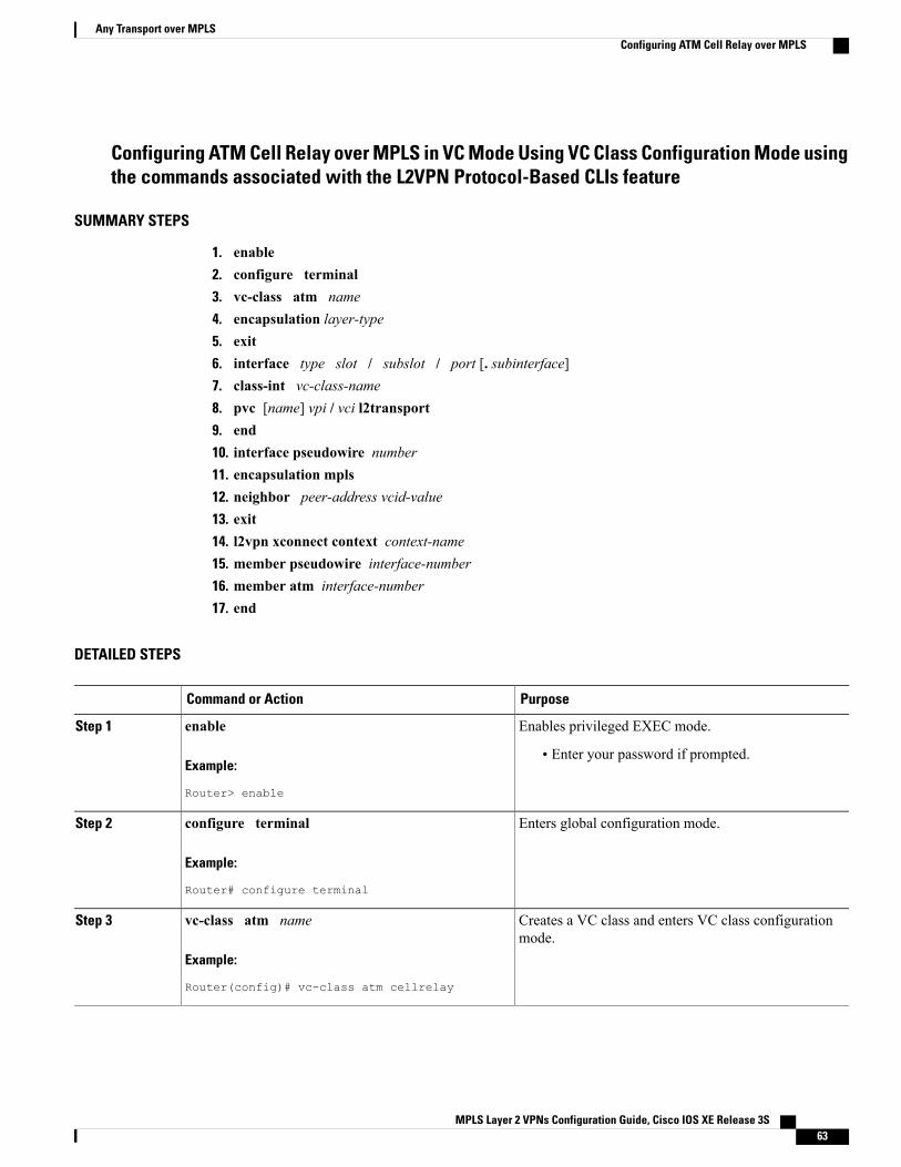
Configuring ATM Cell Relay over MPLS in VC Mode Using VC Class Configuration Mode usingthe commands associated with the L2VPN Protocol-Based CLIs feature
SUMMARY STEPS
1. enable2. configure terminal3. vc-class atm name4. encapsulation layer-type5. exit6. interface type slot / subslot / port [. subinterface]7. class-int vc-class-name8. pvc [name] vpi / vci l2transport9. end10. interface pseudowire number11. encapsulation mpls12. neighbor peer-address vcid-value13. exit14. l2vpn xconnect context context-name15. member pseudowire interface-number16. member atm interface-number17. end
DETAILED STEPS
PurposeCommand or Action
Enables privileged EXEC mode.enableStep 1
Example:
Router> enable
• Enter your password if prompted.
Enters global configuration mode.configure terminal
Example:
Router# configure terminal
Step 2
Creates a VC class and enters VC class configurationmode.
vc-class atm name
Example:
Router(config)# vc-class atm cellrelay
Step 3
MPLS Layer 2 VPNs Configuration Guide, Cisco IOS XE Release 3S 63
Any Transport over MPLSConfiguring ATM Cell Relay over MPLS
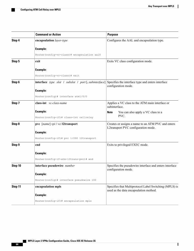
PurposeCommand or Action
Configures the AAL and encapsulation type.encapsulation layer-type
Example:
Router(config-vc-class)# encapsulation aal0
Step 4
Exits VC class configuration mode.exit
Example:
Router(config-vc-class)# exit
Step 5
Specifies the interface type and enters interfaceconfiguration mode.
interface type slot / subslot / port [. subinterface]
Example:
Router(config)# interface atm1/0/0
Step 6
Applies a VC class to the ATM main interface orsubinterface.
class-int vc-class-name
Example:
Router(config-if)# class-int cellrelay
Step 7
You can also apply a VC class to aPVC.
Note
Creates or assigns a name to an ATM PVC and entersL2transport PVC configuration mode.
pvc [name] vpi / vci l2transport
Example:
Router(config-if)# pvc 1/200 l2transport
Step 8
Exits to privileged EXEC mode.end
Example:
Router(config-if-atm-l2trans-pvc)# end
Step 9
Specifies the pseudowire interface and enters interfaceconfiguration mode.
interface pseudowire number
Example:
Router(config)# interface pseudowire 100
Step 10
Specifies that Multiprotocol Label Switching (MPLS) isused as the data encapsulation method.
encapsulation mpls
Example:
Router(config-if)# encapsulation mpls
Step 11
MPLS Layer 2 VPNs Configuration Guide, Cisco IOS XE Release 3S64
Any Transport over MPLSConfiguring ATM Cell Relay over MPLS
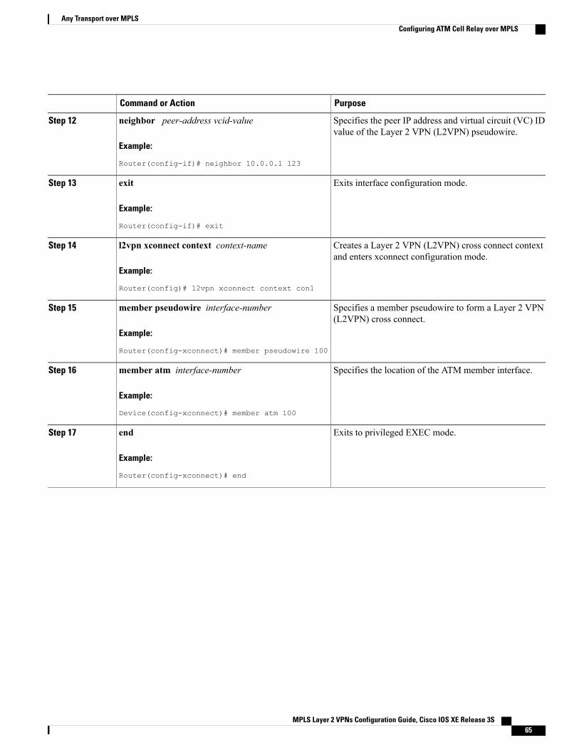
PurposeCommand or Action
Specifies the peer IP address and virtual circuit (VC) IDvalue of the Layer 2 VPN (L2VPN) pseudowire.
neighbor peer-address vcid-value
Example:
Router(config-if)# neighbor 10.0.0.1 123
Step 12
Exits interface configuration mode.exit
Example:
Router(config-if)# exit
Step 13
Creates a Layer 2 VPN (L2VPN) cross connect contextand enters xconnect configuration mode.
l2vpn xconnect context context-name
Example:
Router(config)# l2vpn xconnect context con1
Step 14
Specifies a member pseudowire to form a Layer 2 VPN(L2VPN) cross connect.
member pseudowire interface-number
Example:
Router(config-xconnect)# member pseudowire 100
Step 15
Specifies the location of the ATM member interface.member atm interface-number
Example:
Device(config-xconnect)# member atm 100
Step 16
Exits to privileged EXEC mode.end
Example:
Router(config-xconnect)# end
Step 17
MPLS Layer 2 VPNs Configuration Guide, Cisco IOS XE Release 3S 65
Any Transport over MPLSConfiguring ATM Cell Relay over MPLS
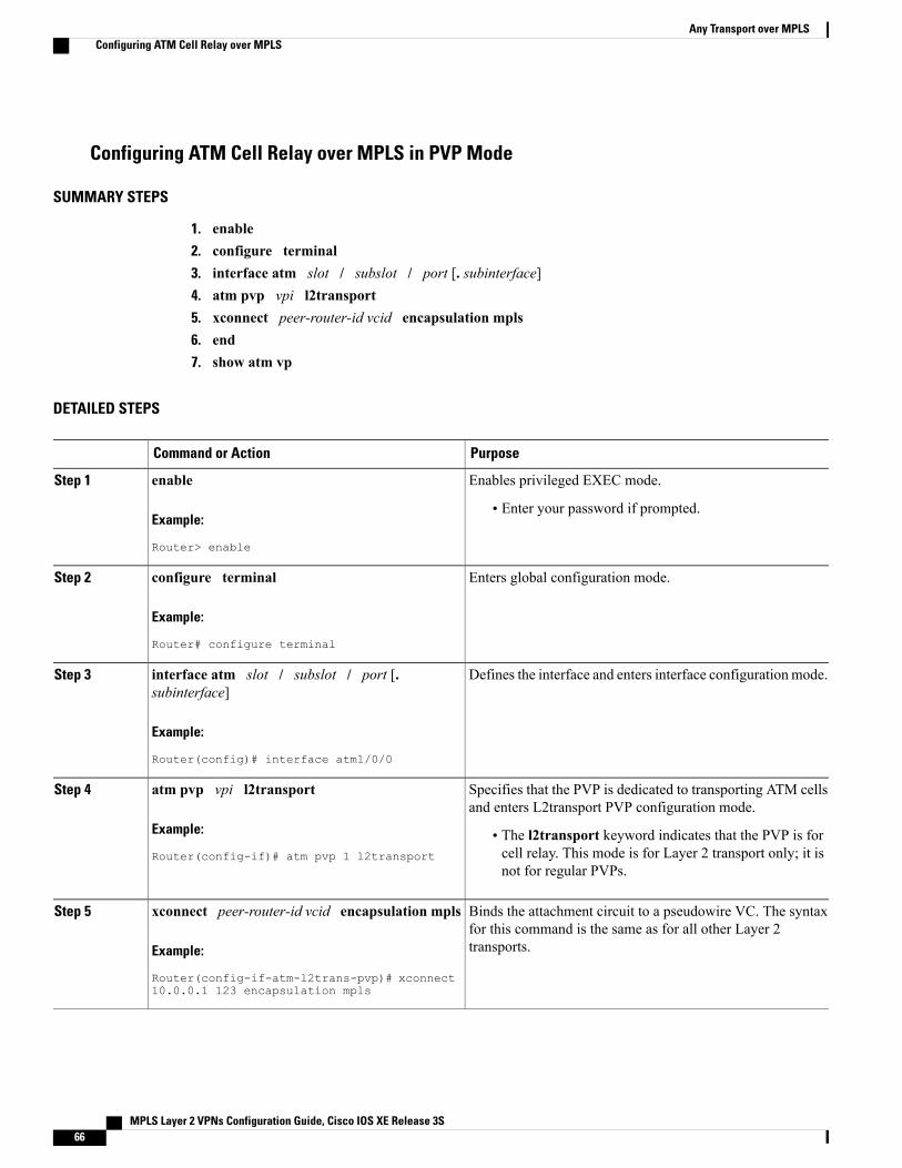
Configuring ATM Cell Relay over MPLS in PVP Mode
SUMMARY STEPS
1. enable2. configure terminal3. interface atm slot / subslot / port [. subinterface]4. atm pvp vpi l2transport5. xconnect peer-router-id vcid encapsulation mpls6. end7. show atm vp
DETAILED STEPS
PurposeCommand or Action
Enables privileged EXEC mode.enableStep 1
Example:
Router> enable
• Enter your password if prompted.
Enters global configuration mode.configure terminal
Example:
Router# configure terminal
Step 2
Defines the interface and enters interface configuration mode.interface atm slot / subslot / port [.subinterface]
Step 3
Example:
Router(config)# interface atm1/0/0
Specifies that the PVP is dedicated to transporting ATM cellsand enters L2transport PVP configuration mode.
atm pvp vpi l2transport
Example:
Router(config-if)# atm pvp 1 l2transport
Step 4
• The l2transport keyword indicates that the PVP is forcell relay. This mode is for Layer 2 transport only; it isnot for regular PVPs.
Binds the attachment circuit to a pseudowire VC. The syntaxfor this command is the same as for all other Layer 2transports.
xconnect peer-router-id vcid encapsulation mpls
Example:
Router(config-if-atm-l2trans-pvp)# xconnect10.0.0.1 123 encapsulation mpls
Step 5
MPLS Layer 2 VPNs Configuration Guide, Cisco IOS XE Release 3S66
Any Transport over MPLSConfiguring ATM Cell Relay over MPLS
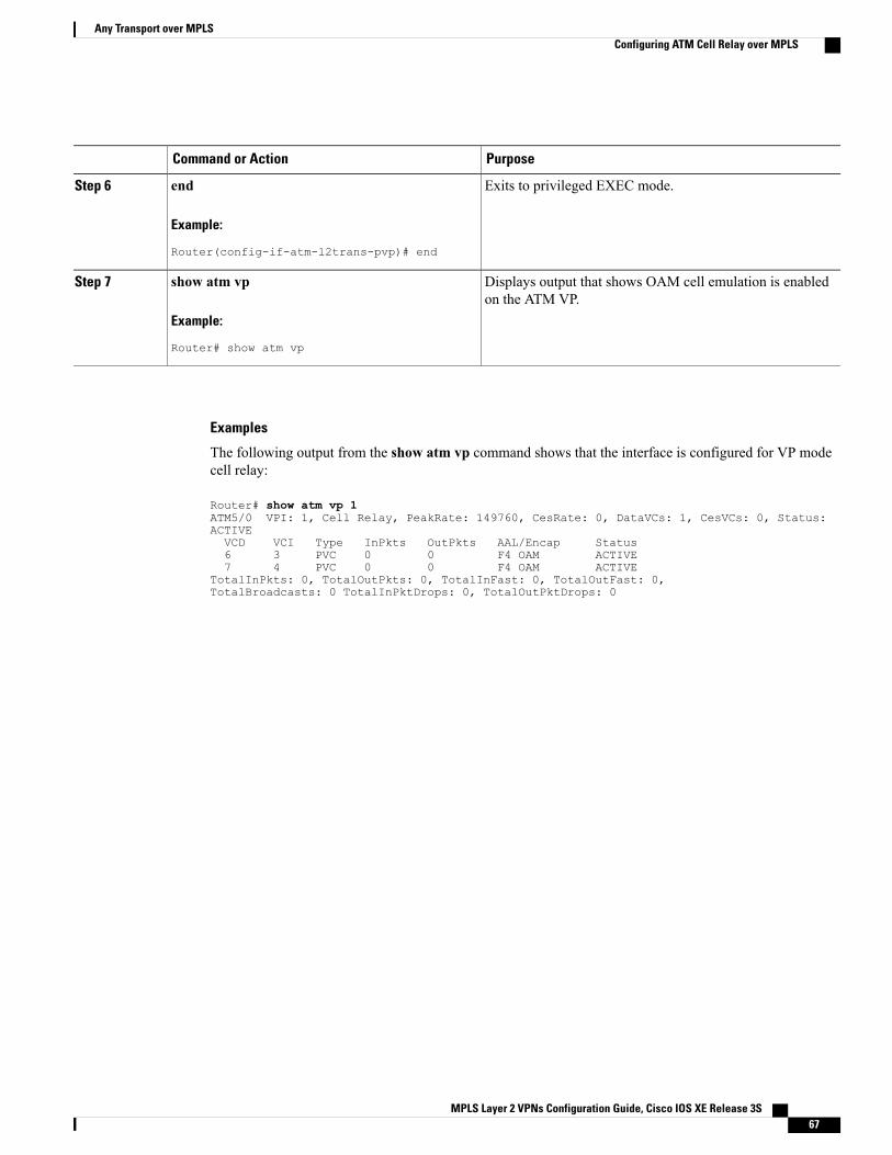
PurposeCommand or Action
Exits to privileged EXEC mode.end
Example:
Router(config-if-atm-l2trans-pvp)# end
Step 6
Displays output that shows OAM cell emulation is enabledon the ATM VP.
show atm vp
Example:
Router# show atm vp
Step 7
Examples
The following output from the show atm vp command shows that the interface is configured for VP modecell relay:
Router# show atm vp 1ATM5/0 VPI: 1, Cell Relay, PeakRate: 149760, CesRate: 0, DataVCs: 1, CesVCs: 0, Status:ACTIVEVCD VCI Type InPkts OutPkts AAL/Encap Status6 3 PVC 0 0 F4 OAM ACTIVE7 4 PVC 0 0 F4 OAM ACTIVE
TotalInPkts: 0, TotalOutPkts: 0, TotalInFast: 0, TotalOutFast: 0,TotalBroadcasts: 0 TotalInPktDrops: 0, TotalOutPktDrops: 0
MPLS Layer 2 VPNs Configuration Guide, Cisco IOS XE Release 3S 67
Any Transport over MPLSConfiguring ATM Cell Relay over MPLS
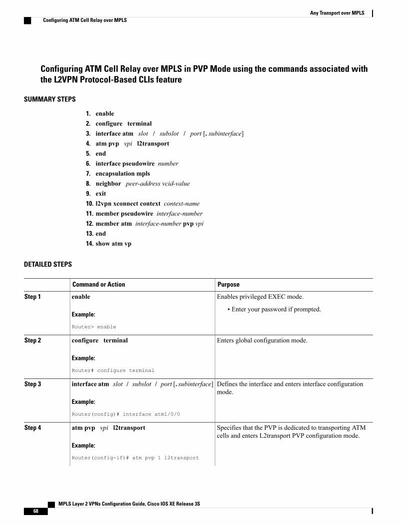
Configuring ATM Cell Relay over MPLS in PVP Mode using the commands associated withthe L2VPN Protocol-Based CLIs feature
SUMMARY STEPS
1. enable2. configure terminal3. interface atm slot / subslot / port [. subinterface]4. atm pvp vpi l2transport5. end6. interface pseudowire number7. encapsulation mpls8. neighbor peer-address vcid-value9. exit10. l2vpn xconnect context context-name11. member pseudowire interface-number12. member atm interface-number pvp vpi13. end14. show atm vp
DETAILED STEPS
PurposeCommand or Action
Enables privileged EXEC mode.enableStep 1
Example:
Router> enable
• Enter your password if prompted.
Enters global configuration mode.configure terminal
Example:
Router# configure terminal
Step 2
Defines the interface and enters interface configurationmode.
interface atm slot / subslot / port [. subinterface]
Example:
Router(config)# interface atm1/0/0
Step 3
Specifies that the PVP is dedicated to transporting ATMcells and enters L2transport PVP configuration mode.
atm pvp vpi l2transport
Example:
Router(config-if)# atm pvp 1 l2transport
Step 4
MPLS Layer 2 VPNs Configuration Guide, Cisco IOS XE Release 3S68
Any Transport over MPLSConfiguring ATM Cell Relay over MPLS
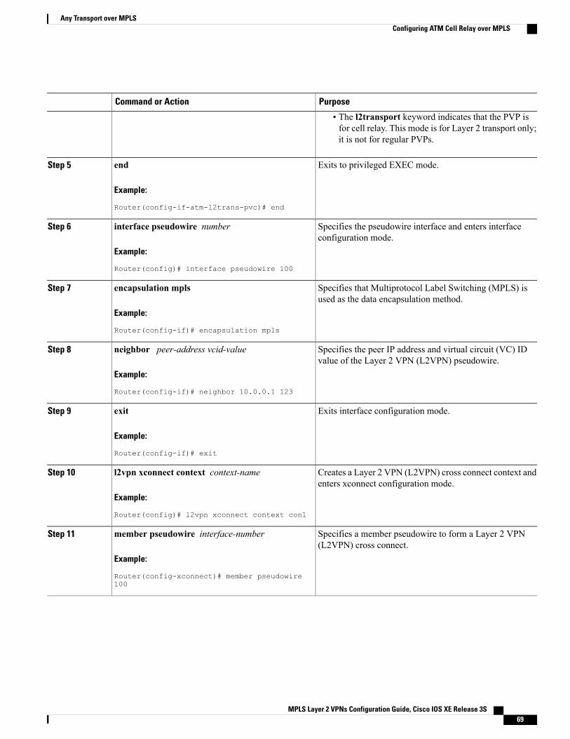
PurposeCommand or Action
• The l2transport keyword indicates that the PVP isfor cell relay. This mode is for Layer 2 transport only;it is not for regular PVPs.
Exits to privileged EXEC mode.end
Example:
Router(config-if-atm-l2trans-pvc)# end
Step 5
Specifies the pseudowire interface and enters interfaceconfiguration mode.
interface pseudowire number
Example:
Router(config)# interface pseudowire 100
Step 6
Specifies that Multiprotocol Label Switching (MPLS) isused as the data encapsulation method.
encapsulation mpls
Example:
Router(config-if)# encapsulation mpls
Step 7
Specifies the peer IP address and virtual circuit (VC) IDvalue of the Layer 2 VPN (L2VPN) pseudowire.
neighbor peer-address vcid-value
Example:
Router(config-if)# neighbor 10.0.0.1 123
Step 8
Exits interface configuration mode.exit
Example:
Router(config-if)# exit
Step 9
Creates a Layer 2 VPN (L2VPN) cross connect context andenters xconnect configuration mode.
l2vpn xconnect context context-name
Example:
Router(config)# l2vpn xconnect context con1
Step 10
Specifies a member pseudowire to form a Layer 2 VPN(L2VPN) cross connect.
member pseudowire interface-number
Example:
Router(config-xconnect)# member pseudowire100
Step 11
MPLS Layer 2 VPNs Configuration Guide, Cisco IOS XE Release 3S 69
Any Transport over MPLSConfiguring ATM Cell Relay over MPLS
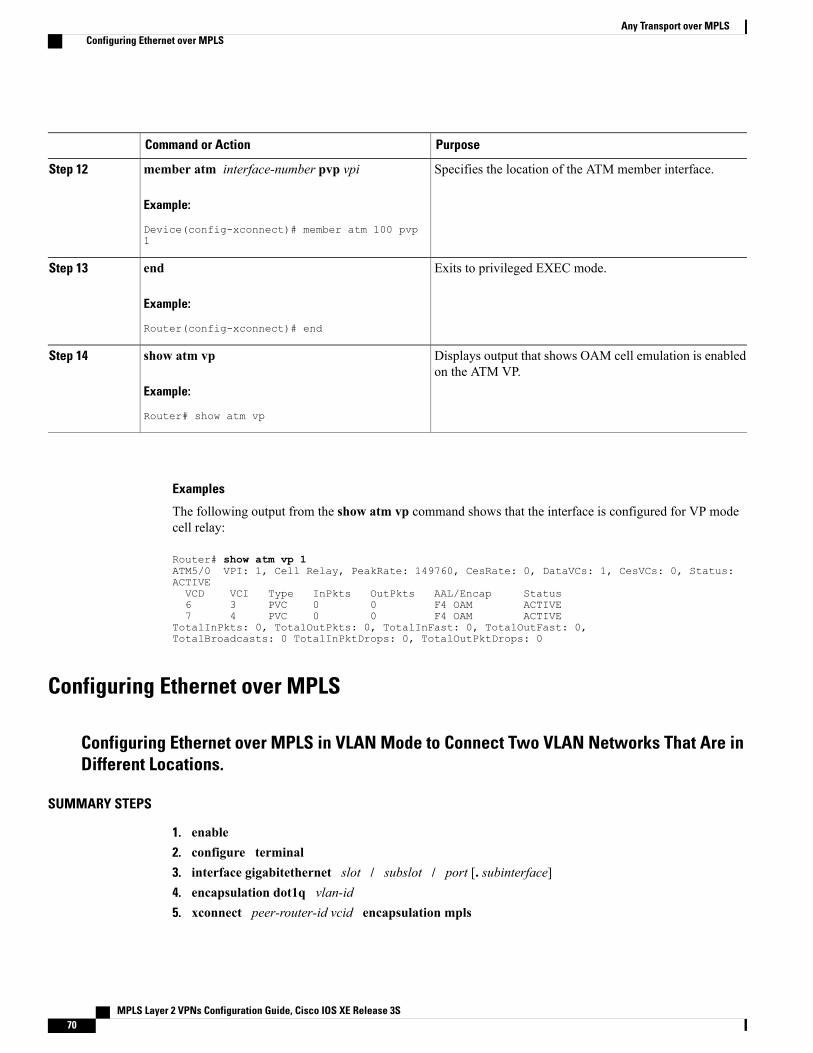
PurposeCommand or Action
Specifies the location of the ATM member interface.member atm interface-number pvp vpi
Example:
Device(config-xconnect)# member atm 100 pvp1
Step 12
Exits to privileged EXEC mode.end
Example:
Router(config-xconnect)# end
Step 13
Displays output that shows OAM cell emulation is enabledon the ATM VP.
show atm vp
Example:
Router# show atm vp
Step 14
Examples
The following output from the show atm vp command shows that the interface is configured for VP modecell relay:
Router# show atm vp 1ATM5/0 VPI: 1, Cell Relay, PeakRate: 149760, CesRate: 0, DataVCs: 1, CesVCs: 0, Status:ACTIVEVCD VCI Type InPkts OutPkts AAL/Encap Status6 3 PVC 0 0 F4 OAM ACTIVE7 4 PVC 0 0 F4 OAM ACTIVE
TotalInPkts: 0, TotalOutPkts: 0, TotalInFast: 0, TotalOutFast: 0,TotalBroadcasts: 0 TotalInPktDrops: 0, TotalOutPktDrops: 0
Configuring Ethernet over MPLS
Configuring Ethernet over MPLS in VLAN Mode to Connect Two VLAN Networks That Are inDifferent Locations.
SUMMARY STEPS
1. enable2. configure terminal3. interface gigabitethernet slot / subslot / port [. subinterface]4. encapsulation dot1q vlan-id5. xconnect peer-router-id vcid encapsulation mpls
MPLS Layer 2 VPNs Configuration Guide, Cisco IOS XE Release 3S70
Any Transport over MPLSConfiguring Ethernet over MPLS
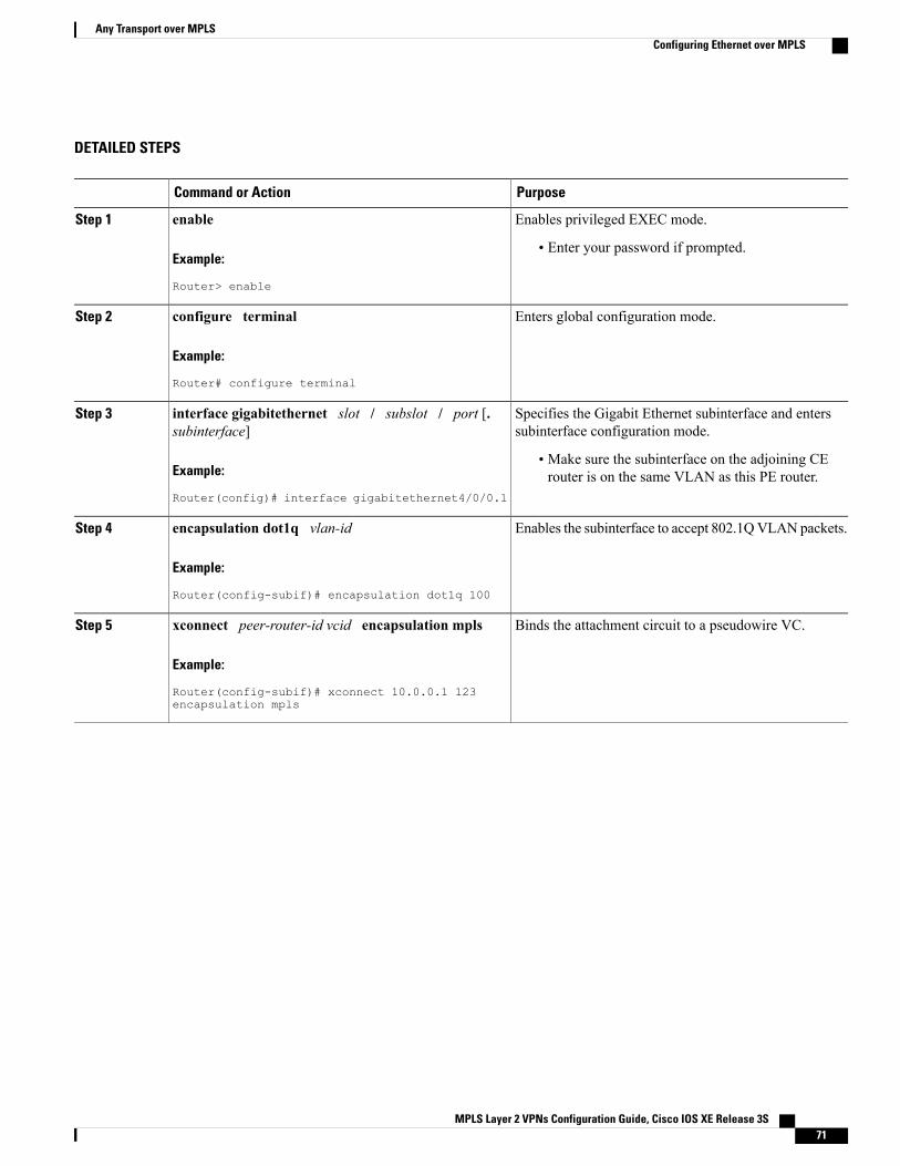
DETAILED STEPS
PurposeCommand or Action
Enables privileged EXEC mode.enableStep 1
Example:
Router> enable
• Enter your password if prompted.
Enters global configuration mode.configure terminal
Example:
Router# configure terminal
Step 2
Specifies the Gigabit Ethernet subinterface and enterssubinterface configuration mode.
interface gigabitethernet slot / subslot / port [.subinterface]
Step 3
Example:
Router(config)# interface gigabitethernet4/0/0.1
• Make sure the subinterface on the adjoining CErouter is on the same VLAN as this PE router.
Enables the subinterface to accept 802.1QVLAN packets.encapsulation dot1q vlan-id
Example:
Router(config-subif)# encapsulation dot1q 100
Step 4
Binds the attachment circuit to a pseudowire VC.xconnect peer-router-id vcid encapsulation mpls
Example:
Router(config-subif)# xconnect 10.0.0.1 123encapsulation mpls
Step 5
MPLS Layer 2 VPNs Configuration Guide, Cisco IOS XE Release 3S 71
Any Transport over MPLSConfiguring Ethernet over MPLS

Configuring Ethernet over MPLS in VLAN Mode to Connect Two VLAN Networks That Are inDifferent Locations using the commands associated with the L2VPN Protocol-Based CLIsfeature
SUMMARY STEPS
1. enable2. configure terminal3. interface gigabitethernet slot / subslot / port [. subinterface]4. encapsulation dot1q vlan-id5. end6. interface pseudowire number7. encapsulation mpls8. neighbor peer-address vcid-value9. exit10. l2vpn xconnect context context-name11. member pseudowire interface-number12. member gigabitethernet interface-number13. end
DETAILED STEPS
PurposeCommand or Action
Enables privileged EXEC mode.enableStep 1
Example:
Router> enable
• Enter your password if prompted.
Enters global configuration mode.configure terminal
Example:
Router# configure terminal
Step 2
Specifies the Gigabit Ethernet subinterface and enterssubinterface configuration mode.
interface gigabitethernet slot / subslot / port [.subinterface]
Step 3
Example:
Router(config)# interfacegigabitethernet4/0/0.1
• Make sure the subinterface on the adjoining CErouter is on the same VLAN as this PE router.
MPLS Layer 2 VPNs Configuration Guide, Cisco IOS XE Release 3S72
Any Transport over MPLSConfiguring Ethernet over MPLS
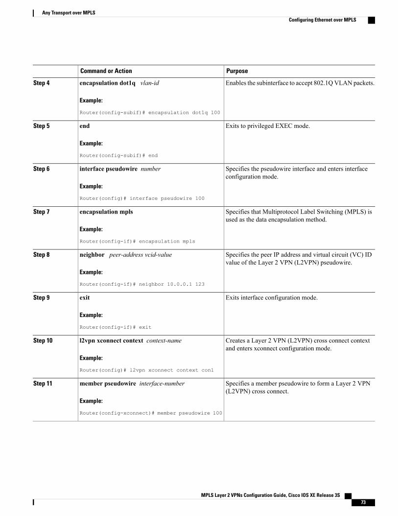
PurposeCommand or Action
Enables the subinterface to accept 802.1QVLAN packets.encapsulation dot1q vlan-id
Example:
Router(config-subif)# encapsulation dot1q 100
Step 4
Exits to privileged EXEC mode.end
Example:
Router(config-subif)# end
Step 5
Specifies the pseudowire interface and enters interfaceconfiguration mode.
interface pseudowire number
Example:
Router(config)# interface pseudowire 100
Step 6
Specifies that Multiprotocol Label Switching (MPLS) isused as the data encapsulation method.
encapsulation mpls
Example:
Router(config-if)# encapsulation mpls
Step 7
Specifies the peer IP address and virtual circuit (VC) IDvalue of the Layer 2 VPN (L2VPN) pseudowire.
neighbor peer-address vcid-value
Example:
Router(config-if)# neighbor 10.0.0.1 123
Step 8
Exits interface configuration mode.exit
Example:
Router(config-if)# exit
Step 9
Creates a Layer 2 VPN (L2VPN) cross connect contextand enters xconnect configuration mode.
l2vpn xconnect context context-name
Example:
Router(config)# l2vpn xconnect context con1
Step 10
Specifies a member pseudowire to form a Layer 2 VPN(L2VPN) cross connect.
member pseudowire interface-number
Example:
Router(config-xconnect)# member pseudowire 100
Step 11
MPLS Layer 2 VPNs Configuration Guide, Cisco IOS XE Release 3S 73
Any Transport over MPLSConfiguring Ethernet over MPLS
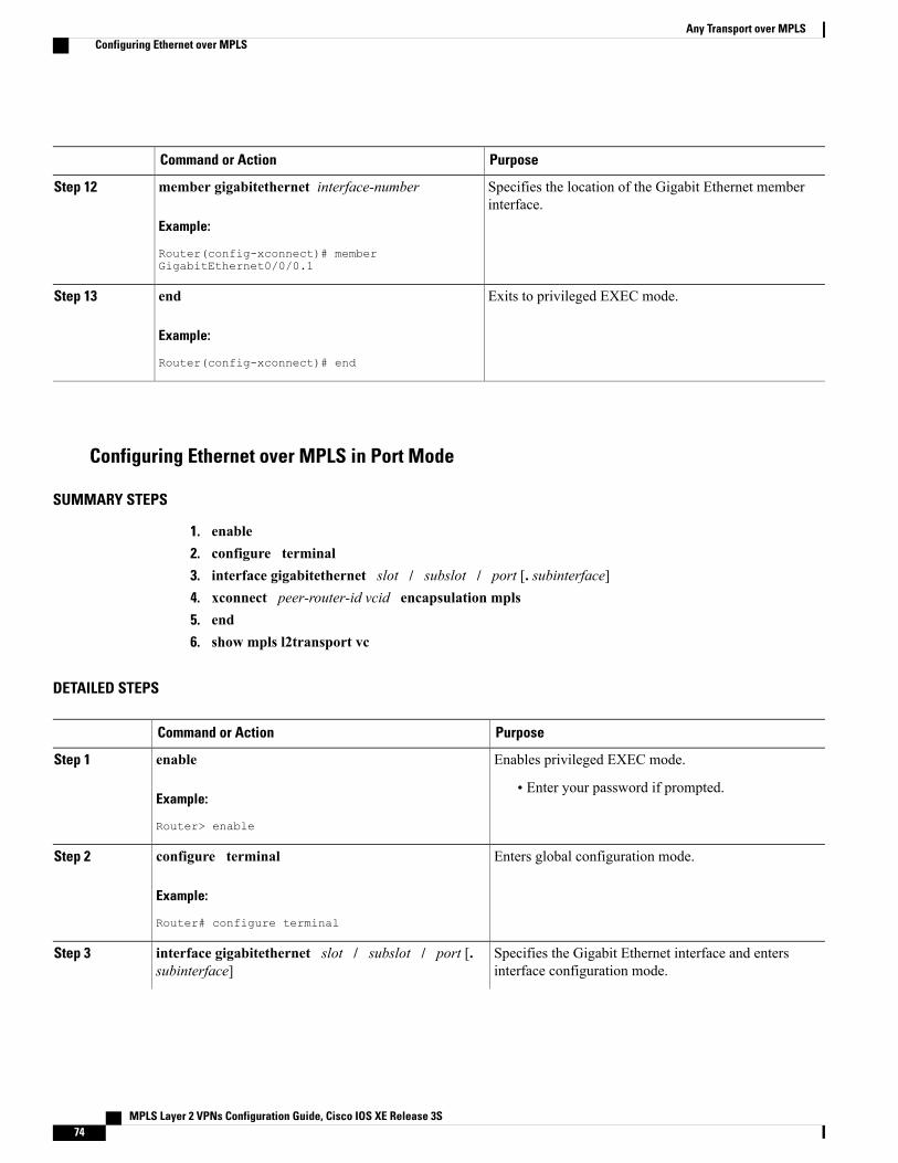
PurposeCommand or Action
Specifies the location of the Gigabit Ethernet memberinterface.
member gigabitethernet interface-number
Example:
Router(config-xconnect)# memberGigabitEthernet0/0/0.1
Step 12
Exits to privileged EXEC mode.end
Example:
Router(config-xconnect)# end
Step 13
Configuring Ethernet over MPLS in Port Mode
SUMMARY STEPS
1. enable2. configure terminal3. interface gigabitethernet slot / subslot / port [. subinterface]4. xconnect peer-router-id vcid encapsulation mpls5. end6. show mpls l2transport vc
DETAILED STEPS
PurposeCommand or Action
Enables privileged EXEC mode.enableStep 1
Example:
Router> enable
• Enter your password if prompted.
Enters global configuration mode.configure terminal
Example:
Router# configure terminal
Step 2
Specifies the Gigabit Ethernet interface and entersinterface configuration mode.
interface gigabitethernet slot / subslot / port [.subinterface]
Step 3
MPLS Layer 2 VPNs Configuration Guide, Cisco IOS XE Release 3S74
Any Transport over MPLSConfiguring Ethernet over MPLS
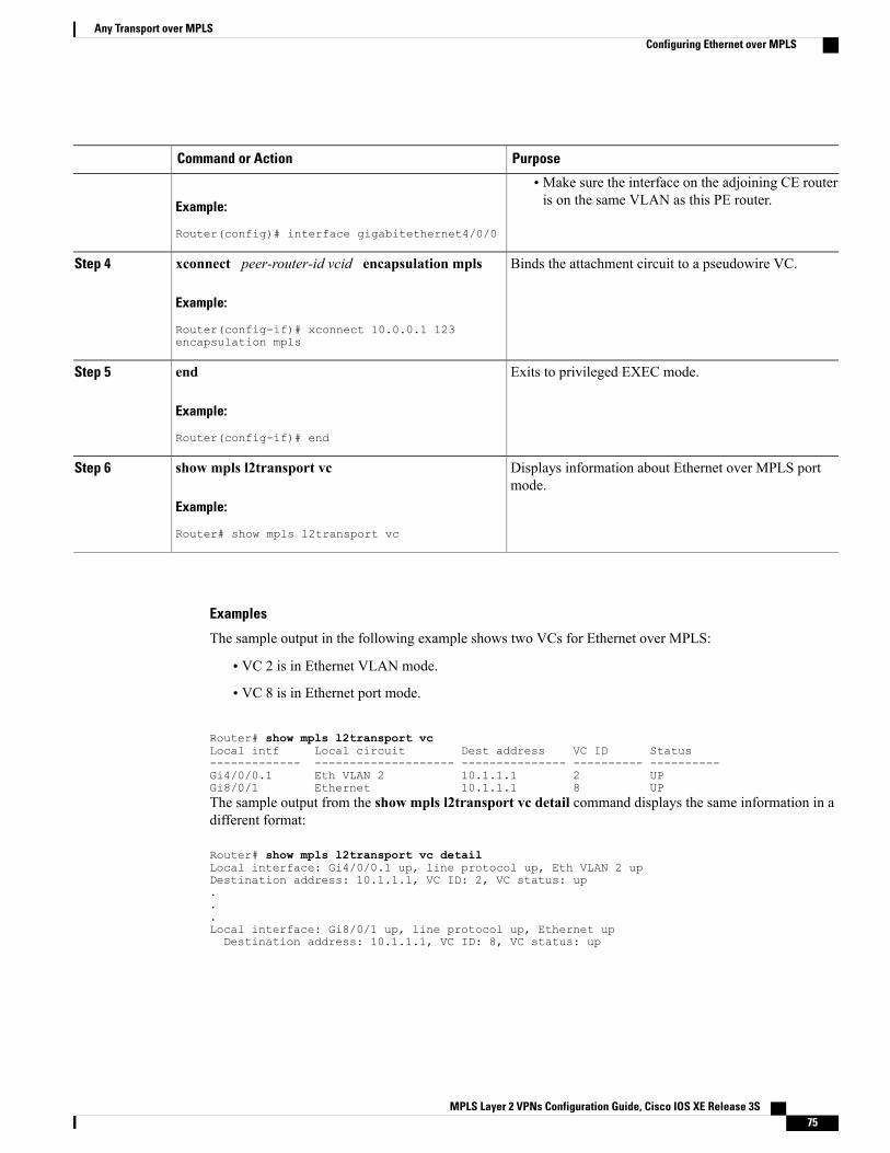
PurposeCommand or Action
Example:
Router(config)# interface gigabitethernet4/0/0
• Make sure the interface on the adjoining CE routeris on the same VLAN as this PE router.
Binds the attachment circuit to a pseudowire VC.xconnect peer-router-id vcid encapsulation mpls
Example:
Router(config-if)# xconnect 10.0.0.1 123encapsulation mpls
Step 4
Exits to privileged EXEC mode.end
Example:
Router(config-if)# end
Step 5
Displays information about Ethernet over MPLS portmode.
show mpls l2transport vc
Example:
Router# show mpls l2transport vc
Step 6
Examples
The sample output in the following example shows two VCs for Ethernet over MPLS:
• VC 2 is in Ethernet VLAN mode.
• VC 8 is in Ethernet port mode.
Router# show mpls l2transport vcLocal intf Local circuit Dest address VC ID Status------------- -------------------- --------------- ---------- ----------Gi4/0/0.1 Eth VLAN 2 10.1.1.1 2 UPGi8/0/1 Ethernet 10.1.1.1 8 UPThe sample output from the show mpls l2transport vc detail command displays the same information in adifferent format:
Router# show mpls l2transport vc detailLocal interface: Gi4/0/0.1 up, line protocol up, Eth VLAN 2 upDestination address: 10.1.1.1, VC ID: 2, VC status: up...Local interface: Gi8/0/1 up, line protocol up, Ethernet upDestination address: 10.1.1.1, VC ID: 8, VC status: up
MPLS Layer 2 VPNs Configuration Guide, Cisco IOS XE Release 3S 75
Any Transport over MPLSConfiguring Ethernet over MPLS
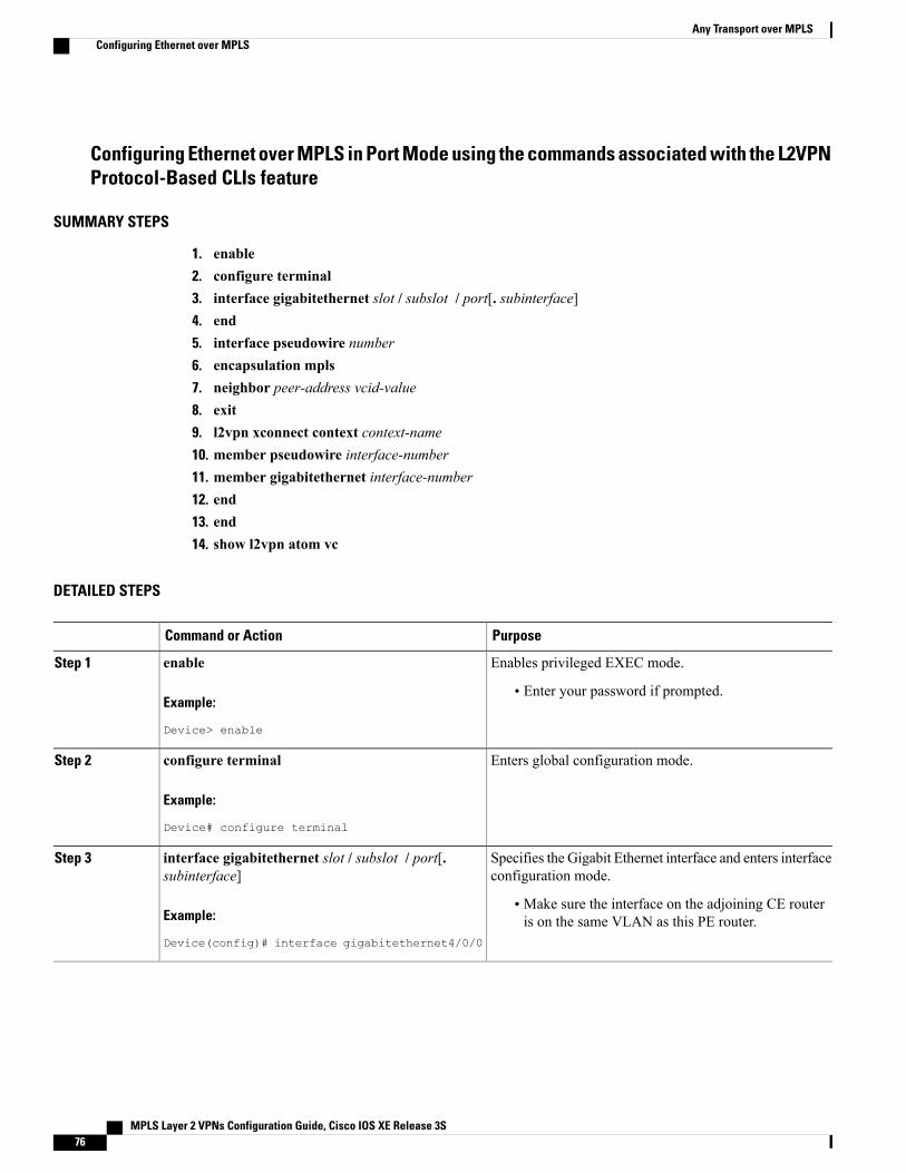
Configuring Ethernet over MPLS in Port Mode using the commands associated with the L2VPNProtocol-Based CLIs feature
SUMMARY STEPS
1. enable2. configure terminal3. interface gigabitethernet slot / subslot / port[. subinterface]4. end5. interface pseudowire number6. encapsulation mpls7. neighbor peer-address vcid-value8. exit9. l2vpn xconnect context context-name10. member pseudowire interface-number11. member gigabitethernet interface-number12. end13. end14. show l2vpn atom vc
DETAILED STEPS
PurposeCommand or Action
Enables privileged EXEC mode.enableStep 1
Example:
Device> enable
• Enter your password if prompted.
Enters global configuration mode.configure terminal
Example:
Device# configure terminal
Step 2
Specifies the Gigabit Ethernet interface and enters interfaceconfiguration mode.
interface gigabitethernet slot / subslot / port[.subinterface]
Step 3
Example:
Device(config)# interface gigabitethernet4/0/0
• Make sure the interface on the adjoining CE routeris on the same VLAN as this PE router.
MPLS Layer 2 VPNs Configuration Guide, Cisco IOS XE Release 3S76
Any Transport over MPLSConfiguring Ethernet over MPLS
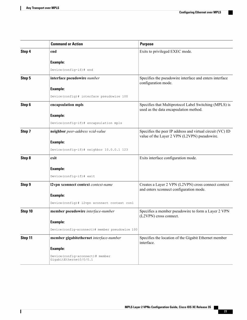
PurposeCommand or Action
Exits to privileged EXEC mode.end
Example:
Device(config-if)# end
Step 4
Specifies the pseudowire interface and enters interfaceconfiguration mode.
interface pseudowire number
Example:
Device(config)# interface pseudowire 100
Step 5
Specifies that Multiprotocol Label Switching (MPLS) isused as the data encapsulation method.
encapsulation mpls
Example:
Device(config-if)# encapsulation mpls
Step 6
Specifies the peer IP address and virtual circuit (VC) IDvalue of the Layer 2 VPN (L2VPN) pseudowire.
neighbor peer-address vcid-value
Example:
Device(config-if)# neighbor 10.0.0.1 123
Step 7
Exits interface configuration mode.exit
Example:
Device(config-if)# exit
Step 8
Creates a Layer 2 VPN (L2VPN) cross connect contextand enters xconnect configuration mode.
l2vpn xconnect context context-name
Example:
Device(config)# l2vpn xconnect context con1
Step 9
Specifies a member pseudowire to form a Layer 2 VPN(L2VPN) cross connect.
member pseudowire interface-number
Example:
Device(config-xconnect)# member pseudowire 100
Step 10
Specifies the location of the Gigabit Ethernet memberinterface.
member gigabitethernet interface-number
Example:
Device(config-xconnect)# memberGigabitEthernet0/0/0.1
Step 11
MPLS Layer 2 VPNs Configuration Guide, Cisco IOS XE Release 3S 77
Any Transport over MPLSConfiguring Ethernet over MPLS
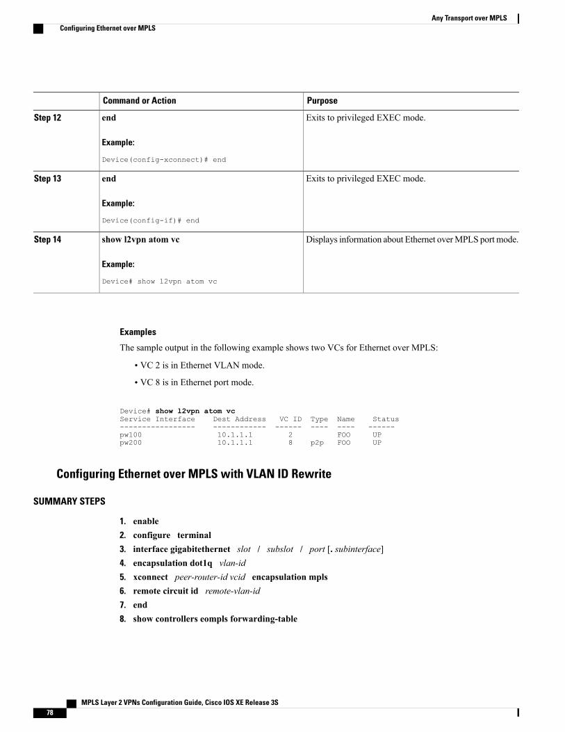
PurposeCommand or Action
Exits to privileged EXEC mode.end
Example:
Device(config-xconnect)# end
Step 12
Exits to privileged EXEC mode.end
Example:
Device(config-if)# end
Step 13
Displays information about Ethernet overMPLS port mode.show l2vpn atom vc
Example:
Device# show l2vpn atom vc
Step 14
Examples
The sample output in the following example shows two VCs for Ethernet over MPLS:
• VC 2 is in Ethernet VLAN mode.
• VC 8 is in Ethernet port mode.
Device# show l2vpn atom vcService Interface Dest Address VC ID Type Name Status----------------- ------------ ------ ---- ---- ------pw100 10.1.1.1 2 FOO UPpw200 10.1.1.1 8 p2p FOO UP
Configuring Ethernet over MPLS with VLAN ID Rewrite
SUMMARY STEPS
1. enable2. configure terminal3. interface gigabitethernet slot / subslot / port [. subinterface]4. encapsulation dot1q vlan-id5. xconnect peer-router-id vcid encapsulation mpls6. remote circuit id remote-vlan-id7. end8. show controllers eompls forwarding-table
MPLS Layer 2 VPNs Configuration Guide, Cisco IOS XE Release 3S78
Any Transport over MPLSConfiguring Ethernet over MPLS
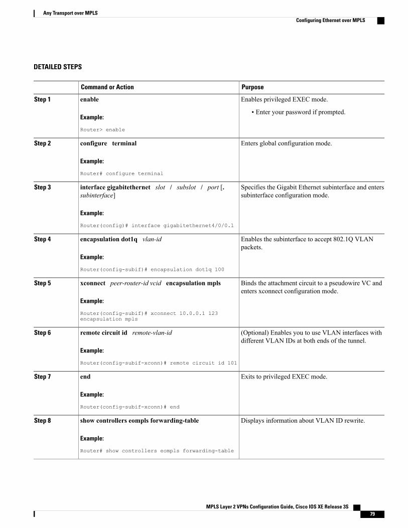
DETAILED STEPS
PurposeCommand or Action
Enables privileged EXEC mode.enableStep 1
Example:
Router> enable
• Enter your password if prompted.
Enters global configuration mode.configure terminal
Example:
Router# configure terminal
Step 2
Specifies the Gigabit Ethernet subinterface and enterssubinterface configuration mode.
interface gigabitethernet slot / subslot / port [.subinterface]
Example:
Router(config)# interface gigabitethernet4/0/0.1
Step 3
Enables the subinterface to accept 802.1Q VLANpackets.
encapsulation dot1q vlan-id
Example:
Router(config-subif)# encapsulation dot1q 100
Step 4
Binds the attachment circuit to a pseudowire VC andenters xconnect configuration mode.
xconnect peer-router-id vcid encapsulation mpls
Example:
Router(config-subif)# xconnect 10.0.0.1 123encapsulation mpls
Step 5
(Optional) Enables you to use VLAN interfaces withdifferent VLAN IDs at both ends of the tunnel.
remote circuit id remote-vlan-id
Example:
Router(config-subif-xconn)# remote circuit id 101
Step 6
Exits to privileged EXEC mode.end
Example:
Router(config-subif-xconn)# end
Step 7
Displays information about VLAN ID rewrite.show controllers eompls forwarding-table
Example:
Router# show controllers eompls forwarding-table
Step 8
MPLS Layer 2 VPNs Configuration Guide, Cisco IOS XE Release 3S 79
Any Transport over MPLSConfiguring Ethernet over MPLS
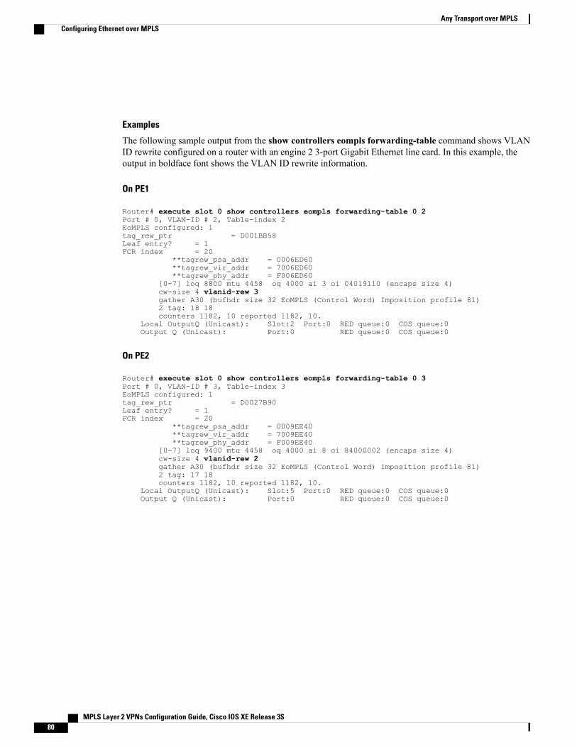
Examples
The following sample output from the show controllers eompls forwarding-table command shows VLANID rewrite configured on a router with an engine 2 3-port Gigabit Ethernet line card. In this example, theoutput in boldface font shows the VLAN ID rewrite information.
On PE1
Router# execute slot 0 show controllers eompls forwarding-table 0 2Port # 0, VLAN-ID # 2, Table-index 2EoMPLS configured: 1tag_rew_ptr = D001BB58Leaf entry? = 1FCR index = 20
**tagrew_psa_addr = 0006ED60**tagrew_vir_addr = 7006ED60**tagrew_phy_addr = F006ED60
[0-7] loq 8800 mtu 4458 oq 4000 ai 3 oi 04019110 (encaps size 4)cw-size 4 vlanid-rew 3gather A30 (bufhdr size 32 EoMPLS (Control Word) Imposition profile 81)2 tag: 18 18counters 1182, 10 reported 1182, 10.
Local OutputQ (Unicast): Slot:2 Port:0 RED queue:0 COS queue:0Output Q (Unicast): Port:0 RED queue:0 COS queue:0
On PE2
Router# execute slot 0 show controllers eompls forwarding-table 0 3Port # 0, VLAN-ID # 3, Table-index 3EoMPLS configured: 1tag_rew_ptr = D0027B90Leaf entry? = 1FCR index = 20
**tagrew_psa_addr = 0009EE40**tagrew_vir_addr = 7009EE40**tagrew_phy_addr = F009EE40
[0-7] loq 9400 mtu 4458 oq 4000 ai 8 oi 84000002 (encaps size 4)cw-size 4 vlanid-rew 2gather A30 (bufhdr size 32 EoMPLS (Control Word) Imposition profile 81)2 tag: 17 18counters 1182, 10 reported 1182, 10.
Local OutputQ (Unicast): Slot:5 Port:0 RED queue:0 COS queue:0Output Q (Unicast): Port:0 RED queue:0 COS queue:0
MPLS Layer 2 VPNs Configuration Guide, Cisco IOS XE Release 3S80
Any Transport over MPLSConfiguring Ethernet over MPLS
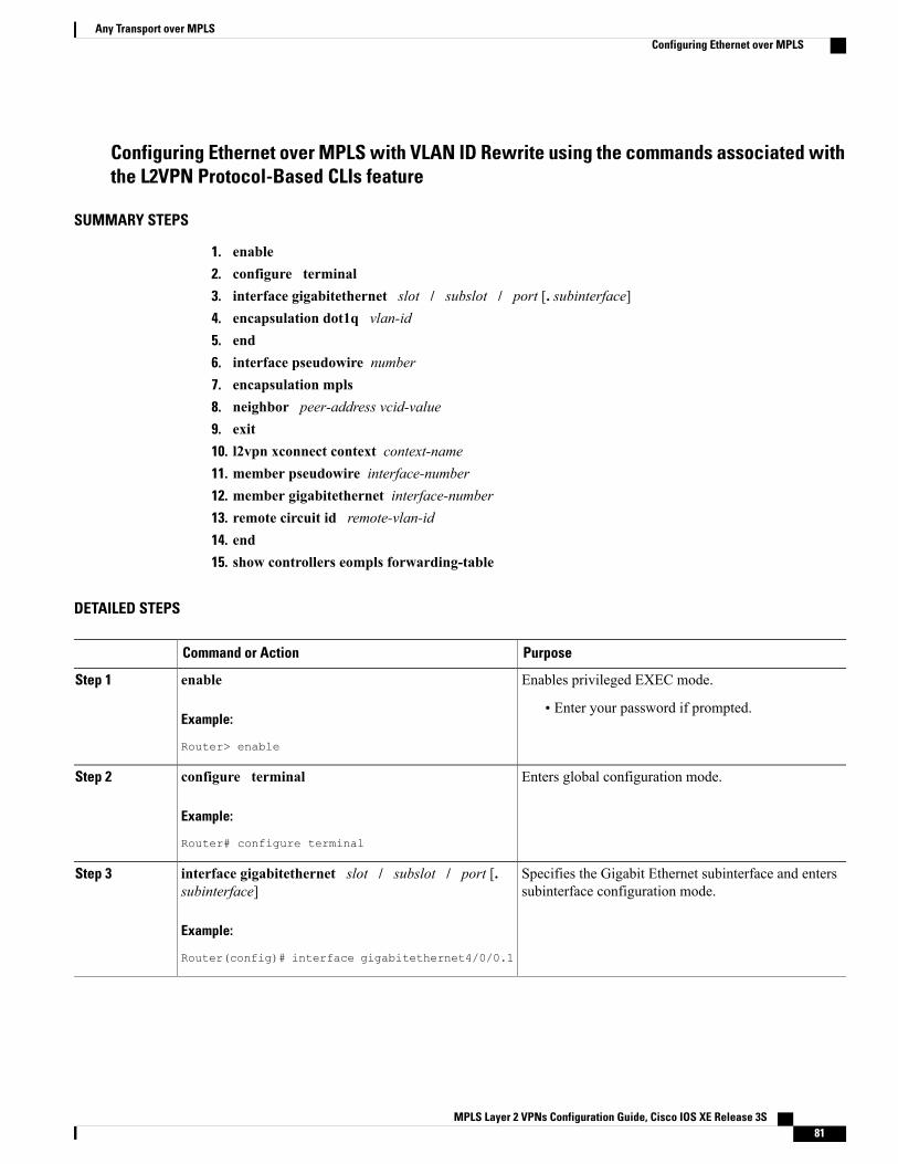
Configuring Ethernet over MPLS with VLAN ID Rewrite using the commands associated withthe L2VPN Protocol-Based CLIs feature
SUMMARY STEPS
1. enable2. configure terminal3. interface gigabitethernet slot / subslot / port [. subinterface]4. encapsulation dot1q vlan-id5. end6. interface pseudowire number7. encapsulation mpls8. neighbor peer-address vcid-value9. exit10. l2vpn xconnect context context-name11. member pseudowire interface-number12. member gigabitethernet interface-number13. remote circuit id remote-vlan-id14. end15. show controllers eompls forwarding-table
DETAILED STEPS
PurposeCommand or Action
Enables privileged EXEC mode.enableStep 1
Example:
Router> enable
• Enter your password if prompted.
Enters global configuration mode.configure terminal
Example:
Router# configure terminal
Step 2
Specifies the Gigabit Ethernet subinterface and enterssubinterface configuration mode.
interface gigabitethernet slot / subslot / port [.subinterface]
Example:
Router(config)# interface gigabitethernet4/0/0.1
Step 3
MPLS Layer 2 VPNs Configuration Guide, Cisco IOS XE Release 3S 81
Any Transport over MPLSConfiguring Ethernet over MPLS
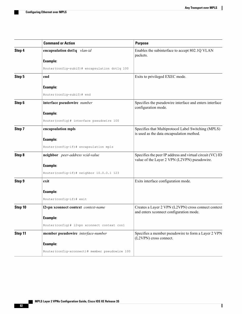
PurposeCommand or Action
Enables the subinterface to accept 802.1Q VLANpackets.
encapsulation dot1q vlan-id
Example:
Router(config-subif)# encapsulation dot1q 100
Step 4
Exits to privileged EXEC mode.end
Example:
Router(config-subif)# end
Step 5
Specifies the pseudowire interface and enters interfaceconfiguration mode.
interface pseudowire number
Example:
Router(config)# interface pseudowire 100
Step 6
Specifies that Multiprotocol Label Switching (MPLS)is used as the data encapsulation method.
encapsulation mpls
Example:
Router(config-if)# encapsulation mpls
Step 7
Specifies the peer IP address and virtual circuit (VC) IDvalue of the Layer 2 VPN (L2VPN) pseudowire.
neighbor peer-address vcid-value
Example:
Router(config-if)# neighbor 10.0.0.1 123
Step 8
Exits interface configuration mode.exit
Example:
Router(config-if)# exit
Step 9
Creates a Layer 2 VPN (L2VPN) cross connect contextand enters xconnect configuration mode.
l2vpn xconnect context context-name
Example:
Router(config)# l2vpn xconnect context con1
Step 10
Specifies a member pseudowire to form a Layer 2 VPN(L2VPN) cross connect.
member pseudowire interface-number
Example:
Router(config-xconnect)# member pseudowire 100
Step 11
MPLS Layer 2 VPNs Configuration Guide, Cisco IOS XE Release 3S82
Any Transport over MPLSConfiguring Ethernet over MPLS
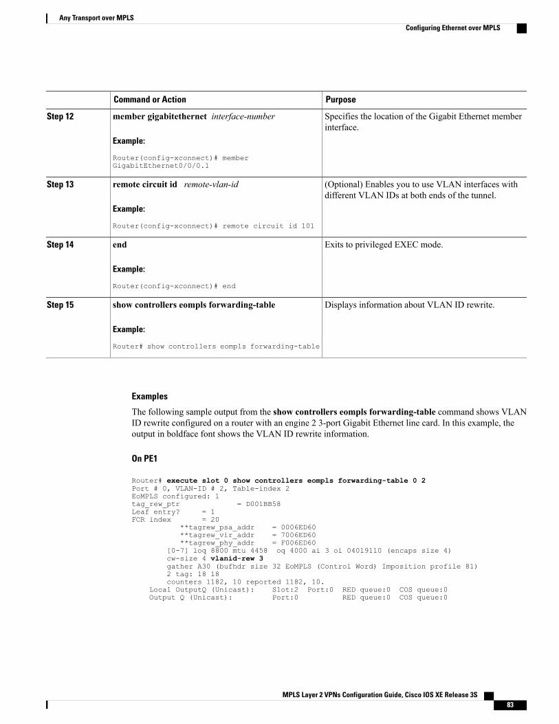
PurposeCommand or Action
Specifies the location of the Gigabit Ethernet memberinterface.
member gigabitethernet interface-number
Example:
Router(config-xconnect)# memberGigabitEthernet0/0/0.1
Step 12
(Optional) Enables you to use VLAN interfaces withdifferent VLAN IDs at both ends of the tunnel.
remote circuit id remote-vlan-id
Example:
Router(config-xconnect)# remote circuit id 101
Step 13
Exits to privileged EXEC mode.end
Example:
Router(config-xconnect)# end
Step 14
Displays information about VLAN ID rewrite.show controllers eompls forwarding-table
Example:
Router# show controllers eompls forwarding-table
Step 15
Examples
The following sample output from the show controllers eompls forwarding-table command shows VLANID rewrite configured on a router with an engine 2 3-port Gigabit Ethernet line card. In this example, theoutput in boldface font shows the VLAN ID rewrite information.
On PE1
Router# execute slot 0 show controllers eompls forwarding-table 0 2Port # 0, VLAN-ID # 2, Table-index 2EoMPLS configured: 1tag_rew_ptr = D001BB58Leaf entry? = 1FCR index = 20
**tagrew_psa_addr = 0006ED60**tagrew_vir_addr = 7006ED60**tagrew_phy_addr = F006ED60
[0-7] loq 8800 mtu 4458 oq 4000 ai 3 oi 04019110 (encaps size 4)cw-size 4 vlanid-rew 3gather A30 (bufhdr size 32 EoMPLS (Control Word) Imposition profile 81)2 tag: 18 18counters 1182, 10 reported 1182, 10.
Local OutputQ (Unicast): Slot:2 Port:0 RED queue:0 COS queue:0Output Q (Unicast): Port:0 RED queue:0 COS queue:0
MPLS Layer 2 VPNs Configuration Guide, Cisco IOS XE Release 3S 83
Any Transport over MPLSConfiguring Ethernet over MPLS
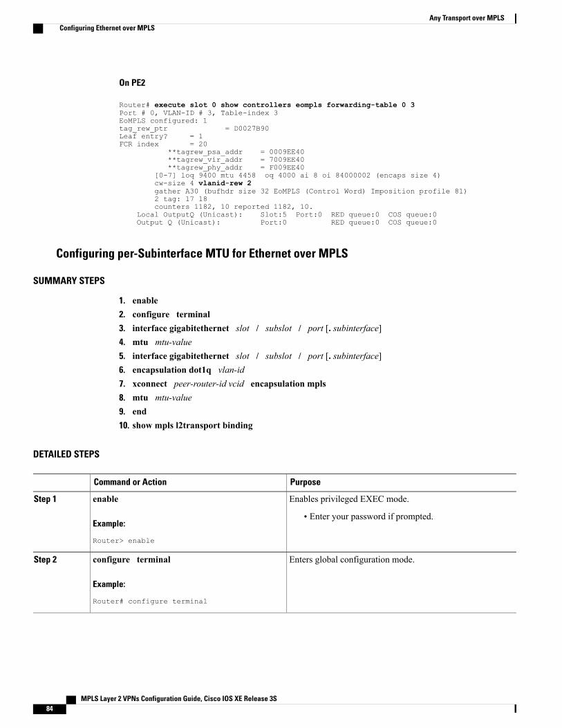
On PE2
Router# execute slot 0 show controllers eompls forwarding-table 0 3Port # 0, VLAN-ID # 3, Table-index 3EoMPLS configured: 1tag_rew_ptr = D0027B90Leaf entry? = 1FCR index = 20
**tagrew_psa_addr = 0009EE40**tagrew_vir_addr = 7009EE40**tagrew_phy_addr = F009EE40
[0-7] loq 9400 mtu 4458 oq 4000 ai 8 oi 84000002 (encaps size 4)cw-size 4 vlanid-rew 2gather A30 (bufhdr size 32 EoMPLS (Control Word) Imposition profile 81)2 tag: 17 18counters 1182, 10 reported 1182, 10.
Local OutputQ (Unicast): Slot:5 Port:0 RED queue:0 COS queue:0Output Q (Unicast): Port:0 RED queue:0 COS queue:0
Configuring per-Subinterface MTU for Ethernet over MPLS
SUMMARY STEPS
1. enable2. configure terminal3. interface gigabitethernet slot / subslot / port [. subinterface]4. mtu mtu-value5. interface gigabitethernet slot / subslot / port [. subinterface]6. encapsulation dot1q vlan-id7. xconnect peer-router-id vcid encapsulation mpls8. mtu mtu-value9. end10. show mpls l2transport binding
DETAILED STEPS
PurposeCommand or Action
Enables privileged EXEC mode.enableStep 1
Example:
Router> enable
• Enter your password if prompted.
Enters global configuration mode.configure terminal
Example:
Router# configure terminal
Step 2
MPLS Layer 2 VPNs Configuration Guide, Cisco IOS XE Release 3S84
Any Transport over MPLSConfiguring Ethernet over MPLS
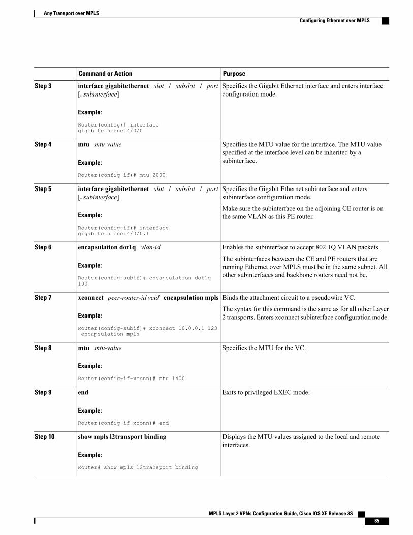
PurposeCommand or Action
Specifies the Gigabit Ethernet interface and enters interfaceconfiguration mode.
interface gigabitethernet slot / subslot / port[. subinterface]
Example:
Router(config)# interfacegigabitethernet4/0/0
Step 3
Specifies the MTU value for the interface. The MTU valuespecified at the interface level can be inherited by asubinterface.
mtu mtu-value
Example:
Router(config-if)# mtu 2000
Step 4
Specifies the Gigabit Ethernet subinterface and enterssubinterface configuration mode.
interface gigabitethernet slot / subslot / port[. subinterface]
Step 5
Example:
Router(config-if)# interfacegigabitethernet4/0/0.1
Make sure the subinterface on the adjoining CE router is onthe same VLAN as this PE router.
Enables the subinterface to accept 802.1Q VLAN packets.encapsulation dot1q vlan-idStep 6
Example:
Router(config-subif)# encapsulation dot1q100
The subinterfaces between the CE and PE routers that arerunning Ethernet over MPLS must be in the same subnet. Allother subinterfaces and backbone routers need not be.
Binds the attachment circuit to a pseudowire VC.xconnect peer-router-id vcid encapsulation mplsStep 7
Example:
Router(config-subif)# xconnect 10.0.0.1 123encapsulation mpls
The syntax for this command is the same as for all other Layer2 transports. Enters xconnect subinterface configuration mode.
Specifies the MTU for the VC.mtu mtu-value
Example:
Router(config-if-xconn)# mtu 1400
Step 8
Exits to privileged EXEC mode.end
Example:
Router(config-if-xconn)# end
Step 9
Displays the MTU values assigned to the local and remoteinterfaces.
show mpls l2transport binding
Example:
Router# show mpls l2transport binding
Step 10
MPLS Layer 2 VPNs Configuration Guide, Cisco IOS XE Release 3S 85
Any Transport over MPLSConfiguring Ethernet over MPLS
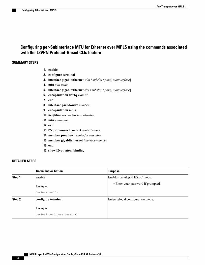
Configuring per-Subinterface MTU for Ethernet over MPLS using the commands associatedwith the L2VPN Protocol-Based CLIs feature
SUMMARY STEPS
1. enable2. configure terminal3. interface gigabitethernet slot / subslot / port[. subinterface]4. mtu mtu-value5. interface gigabitethernet slot / subslot / port[. subinterface]6. encapsulation dot1q vlan-id7. end8. interface pseudowire number9. encapsulation mpls10. neighbor peer-address vcid-value11. mtu mtu-value12. exit13. l2vpn xconnect context context-name14. member pseudowire interface-number15. member gigabitethernet interface-number16. end17. show l2vpn atom binding
DETAILED STEPS
PurposeCommand or Action
Enables privileged EXEC mode.enableStep 1
Example:
Device> enable
• Enter your password if prompted.
Enters global configuration mode.configure terminal
Example:
Device# configure terminal
Step 2
MPLS Layer 2 VPNs Configuration Guide, Cisco IOS XE Release 3S86
Any Transport over MPLSConfiguring Ethernet over MPLS
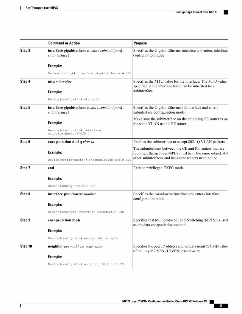
PurposeCommand or Action
Specifies the Gigabit Ethernet interface and enters interfaceconfiguration mode.
interface gigabitethernet slot / subslot / port[.subinterface]
Example:
Device(config)# interface gigabitethernet4/0/0
Step 3
Specifies the MTU value for the interface. The MTU valuespecified at the interface level can be inherited by asubinterface.
mtu mtu-value
Example:
Device(config-if)# mtu 2000
Step 4
Specifies the Gigabit Ethernet subinterface and enterssubinterface configuration mode.
interface gigabitethernet slot / subslot / port[.subinterface]
Step 5
Example:
Device(config-if)# interfacegigabitethernet4/0/0.1
Make sure the subinterface on the adjoining CE router is onthe same VLAN as this PE router.
Enables the subinterface to accept 802.1Q VLAN packets.encapsulation dot1q vlan-idStep 6
Example:
Device(config-subif)# encapsulation dot1q 100
The subinterfaces between the CE and PE routers that arerunning Ethernet overMPLSmust be in the same subnet. Allother subinterfaces and backbone routers need not be.
Exits to privileged EXEC mode.end
Example:
Device(config-subif)# end
Step 7
Specifies the pseudowire interface and enters interfaceconfiguration mode.
interface pseudowire number
Example:
Device(config)# interface pseudowire 100
Step 8
Specifies thatMultiprotocol Label Switching (MPLS) is usedas the data encapsulation method.
encapsulation mpls
Example:
Device(config-if)# encapsulation mpls
Step 9
Specifies the peer IP address and virtual circuit (VC) ID valueof the Layer 2 VPN (L2VPN) pseudowire.
neighbor peer-address vcid-value
Example:
Device(config-if)# neighbor 10.0.0.1 123
Step 10
MPLS Layer 2 VPNs Configuration Guide, Cisco IOS XE Release 3S 87
Any Transport over MPLSConfiguring Ethernet over MPLS
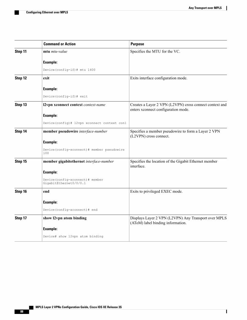
PurposeCommand or Action
Specifies the MTU for the VC.mtu mtu-value
Example:
Device(config-if)# mtu 1400
Step 11
Exits interface configuration mode.exit
Example:
Device(config-if)# exit
Step 12
Creates a Layer 2 VPN (L2VPN) cross connect context andenters xconnect configuration mode.
l2vpn xconnect context context-name
Example:
Device(config)# l2vpn xconnect context con1
Step 13
Specifies a member pseudowire to form a Layer 2 VPN(L2VPN) cross connect.
member pseudowire interface-number
Example:
Device(config-xconnect)# member pseudowire100
Step 14
Specifies the location of the Gigabit Ethernet memberinterface.
member gigabitethernet interface-number
Example:
Device(config-xconnect)# memberGigabitEthernet0/0/0.1
Step 15
Exits to privileged EXEC mode.end
Example:
Device(config-xconnect)# end
Step 16
Displays Layer 2 VPN (L2VPN) Any Transport over MPLS(AToM) label binding information.
show l2vpn atom binding
Example:
Device# show l2vpn atom binding
Step 17
MPLS Layer 2 VPNs Configuration Guide, Cisco IOS XE Release 3S88
Any Transport over MPLSConfiguring Ethernet over MPLS
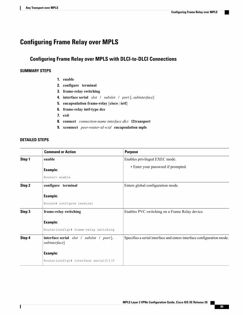
Configuring Frame Relay over MPLS
Configuring Frame Relay over MPLS with DLCI-to-DLCI Connections
SUMMARY STEPS
1. enable2. configure terminal3. frame-relay switching4. interface serial slot / subslot / port [. subinterface]5. encapsulation frame-relay [cisco | ietf]6. frame-relay intf-type dce7. exit8. connect connection-name interface dlci l2transport9. xconnect peer-router-id vcid encapsulation mpls
DETAILED STEPS
PurposeCommand or Action
Enables privileged EXEC mode.enableStep 1
Example:
Router> enable
• Enter your password if prompted.
Enters global configuration mode.configure terminal
Example:
Router# configure terminal
Step 2
Enables PVC switching on a Frame Relay device.frame-relay switching
Example:
Router(config)# frame-relay switching
Step 3
Specifies a serial interface and enters interface configuration mode.interface serial slot / subslot / port [.subinterface]
Step 4
Example:
Router(config)# interface serial3/1/0
MPLS Layer 2 VPNs Configuration Guide, Cisco IOS XE Release 3S 89
Any Transport over MPLSConfiguring Frame Relay over MPLS
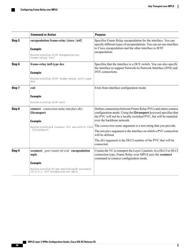
PurposeCommand or Action
Specifies Frame Relay encapsulation for the interface. You canspecify different types of encapsulations. You can set one interface
encapsulation frame-relay [cisco | ietf]
Example:
Router(config-if)# encapsulationframe-relay ietf
Step 5
to Cisco encapsulation and the other interface to IETFencapsulation.
Specifies that the interface is a DCE switch. You can also specifythe interface to support Network-to-Network Interface (NNI) andDTE connections.
frame-relay intf-type dce
Example:
Router(config-if)# frame-relay intf-typedce
Step 6
Exits from interface configuration mode.exit
Example:
Router(config-if)# exit
Step 7
Defines connections between FrameRelay PVCs and enters connectconfiguration mode. Using the l2transport keyword specifies that
connect connection-name interface dlcil2transport
Step 8
the PVC will not be a locally switched PVC, but will be tunneledover the backbone network.Example:
Router(config)# connect fr1 serial5/0 1000l2transport
The connection-name argument is a text string that you provide.
The interface argument is the interface on which a PVC connectionwill be defined.
The dlci argument is the DLCI number of the PVC that will beconnected.
Creates the VC to transport the Layer 2 packets. In a DLCI-to DLCIconnection type, Frame Relay over MPLS uses the xconnectcommand in connect configuration mode.
xconnect peer-router-id vcid encapsulationmpls
Example:
Router(config-fr-pw-switching)# xconnect10.0.0.1 123 encapsulation mpls
Step 9
MPLS Layer 2 VPNs Configuration Guide, Cisco IOS XE Release 3S90
Any Transport over MPLSConfiguring Frame Relay over MPLS
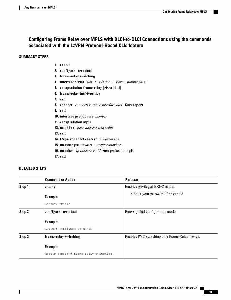
Configuring Frame Relay over MPLS with DLCI-to-DLCI Connections using the commandsassociated with the L2VPN Protocol-Based CLIs feature
SUMMARY STEPS
1. enable2. configure terminal3. frame-relay switching4. interface serial slot / subslot / port [. subinterface]5. encapsulation frame-relay [cisco | ietf]6. frame-relay intf-type dce7. exit8. connect connection-name interface dlci l2transport9. end10. interface pseudowire number11. encapsulation mpls12. neighbor peer-address vcid-value13. exit14. l2vpn xconnect context context-name15. member pseudowire interface-number16. member ip-address vc-id encapsulation mpls17. end
DETAILED STEPS
PurposeCommand or Action
Enables privileged EXEC mode.enableStep 1
Example:
Router> enable
• Enter your password if prompted.
Enters global configuration mode.configure terminal
Example:
Router# configure terminal
Step 2
Enables PVC switching on a Frame Relay device.frame-relay switching
Example:
Router(config)# frame-relay switching
Step 3
MPLS Layer 2 VPNs Configuration Guide, Cisco IOS XE Release 3S 91
Any Transport over MPLSConfiguring Frame Relay over MPLS
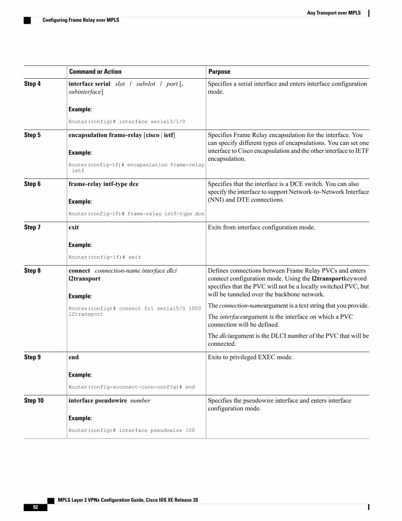
PurposeCommand or Action
Specifies a serial interface and enters interface configurationmode.
interface serial slot / subslot / port [.subinterface]
Example:
Router(config)# interface serial3/1/0
Step 4
Specifies Frame Relay encapsulation for the interface. Youcan specify different types of encapsulations. You can set one
encapsulation frame-relay [cisco | ietf]
Example:
Router(config-if)# encapsulation frame-relayietf
Step 5
interface to Cisco encapsulation and the other interface to IETFencapsulation.
Specifies that the interface is a DCE switch. You can alsospecify the interface to support Network-to-Network Interface(NNI) and DTE connections.
frame-relay intf-type dce
Example:
Router(config-if)# frame-relay intf-type dce
Step 6
Exits from interface configuration mode.exit
Example:
Router(config-if)# exit
Step 7
Defines connections between Frame Relay PVCs and entersconnect configuration mode. Using the l2transportkeyword
connect connection-name interface dlcil2transport
Step 8
specifies that the PVC will not be a locally switched PVC, butwill be tunneled over the backbone network.Example:
Router(config)# connect fr1 serial5/0 1000l2transport
The connection-nameargument is a text string that you provide.
The interfaceargument is the interface on which a PVCconnection will be defined.
The dlciargument is the DLCI number of the PVC that will beconnected.
Exits to privileged EXEC mode.end
Example:
Router(config-xconnect-conn-config)# end
Step 9
Specifies the pseudowire interface and enters interfaceconfiguration mode.
interface pseudowire number
Example:
Router(config)# interface pseudowire 100
Step 10
MPLS Layer 2 VPNs Configuration Guide, Cisco IOS XE Release 3S92
Any Transport over MPLSConfiguring Frame Relay over MPLS
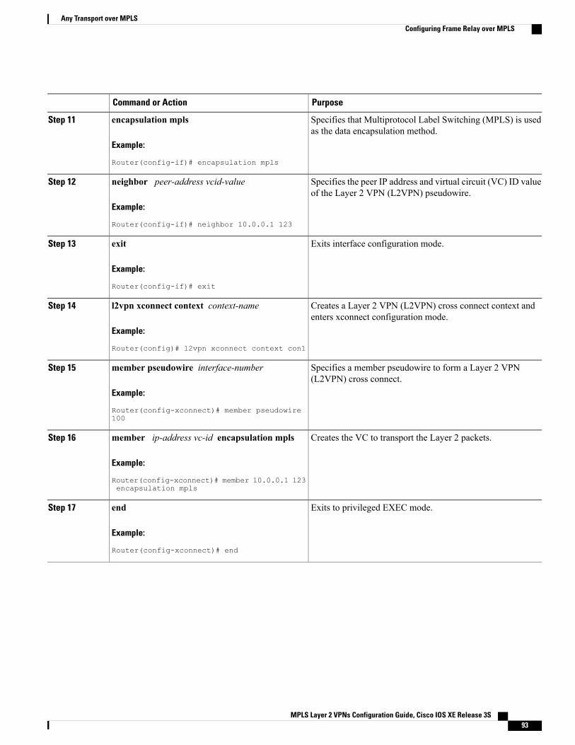
PurposeCommand or Action
Specifies that Multiprotocol Label Switching (MPLS) is usedas the data encapsulation method.
encapsulation mpls
Example:
Router(config-if)# encapsulation mpls
Step 11
Specifies the peer IP address and virtual circuit (VC) ID valueof the Layer 2 VPN (L2VPN) pseudowire.
neighbor peer-address vcid-value
Example:
Router(config-if)# neighbor 10.0.0.1 123
Step 12
Exits interface configuration mode.exit
Example:
Router(config-if)# exit
Step 13
Creates a Layer 2 VPN (L2VPN) cross connect context andenters xconnect configuration mode.
l2vpn xconnect context context-name
Example:
Router(config)# l2vpn xconnect context con1
Step 14
Specifies a member pseudowire to form a Layer 2 VPN(L2VPN) cross connect.
member pseudowire interface-number
Example:
Router(config-xconnect)# member pseudowire100
Step 15
Creates the VC to transport the Layer 2 packets.member ip-address vc-id encapsulation mpls
Example:
Router(config-xconnect)# member 10.0.0.1 123encapsulation mpls
Step 16
Exits to privileged EXEC mode.end
Example:
Router(config-xconnect)# end
Step 17
MPLS Layer 2 VPNs Configuration Guide, Cisco IOS XE Release 3S 93
Any Transport over MPLSConfiguring Frame Relay over MPLS
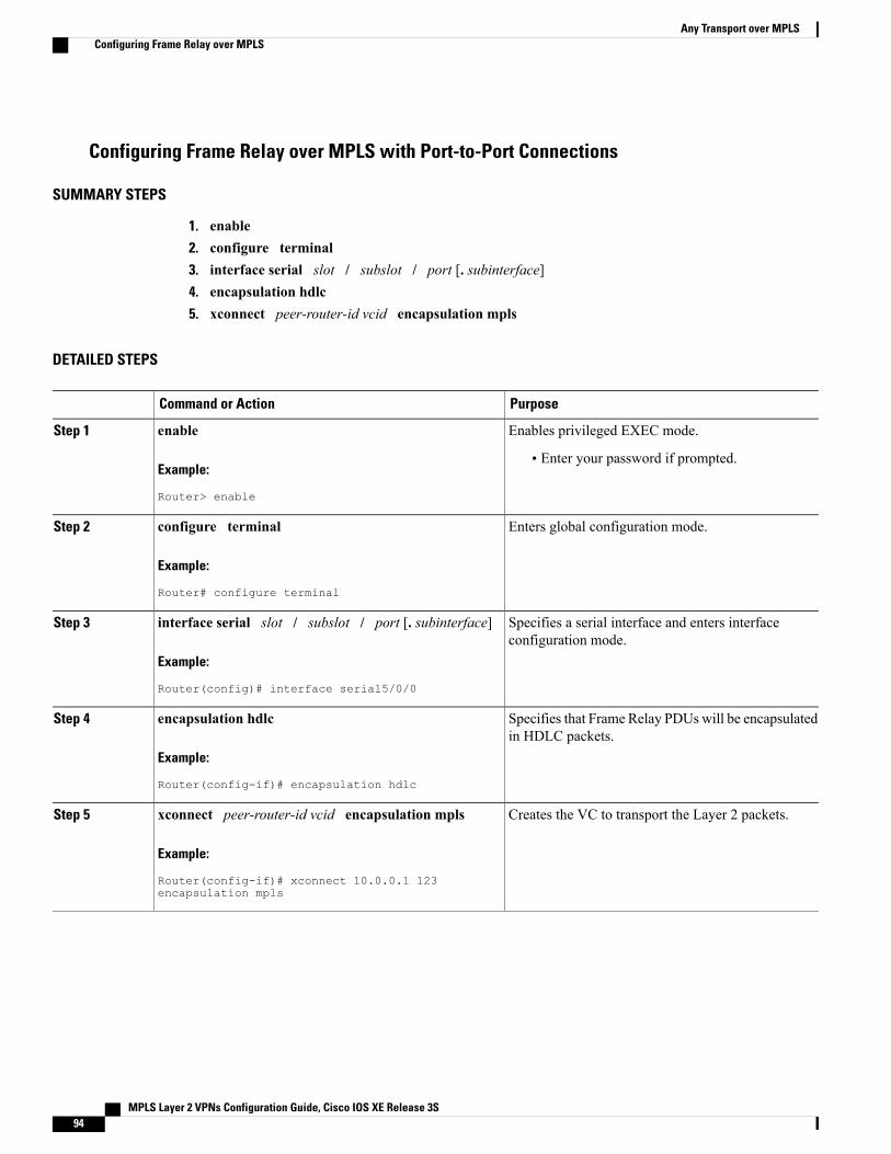
Configuring Frame Relay over MPLS with Port-to-Port Connections
SUMMARY STEPS
1. enable2. configure terminal3. interface serial slot / subslot / port [. subinterface]4. encapsulation hdlc5. xconnect peer-router-id vcid encapsulation mpls
DETAILED STEPS
PurposeCommand or Action
Enables privileged EXEC mode.enableStep 1
Example:
Router> enable
• Enter your password if prompted.
Enters global configuration mode.configure terminal
Example:
Router# configure terminal
Step 2
Specifies a serial interface and enters interfaceconfiguration mode.
interface serial slot / subslot / port [. subinterface]
Example:
Router(config)# interface serial5/0/0
Step 3
Specifies that Frame Relay PDUs will be encapsulatedin HDLC packets.
encapsulation hdlc
Example:
Router(config-if)# encapsulation hdlc
Step 4
Creates the VC to transport the Layer 2 packets.xconnect peer-router-id vcid encapsulation mplsStep 5
Example:
Router(config-if)# xconnect 10.0.0.1 123encapsulation mpls
MPLS Layer 2 VPNs Configuration Guide, Cisco IOS XE Release 3S94
Any Transport over MPLSConfiguring Frame Relay over MPLS
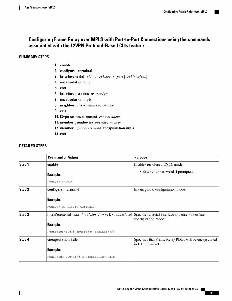
Configuring Frame Relay over MPLS with Port-to-Port Connections using the commandsassociated with the L2VPN Protocol-Based CLIs feature
SUMMARY STEPS
1. enable2. configure terminal3. interface serial slot / subslot / port [. subinterface]4. encapsulation hdlc5. end6. interface pseudowire number7. encapsulation mpls8. neighbor peer-address vcid-value9. exit10. l2vpn xconnect context context-name11. member pseudowire interface-number12. member ip-address vc-id encapsulation mpls13. end
DETAILED STEPS
PurposeCommand or Action
Enables privileged EXEC mode.enableStep 1
Example:
Router> enable
• Enter your password if prompted.
Enters global configuration mode.configure terminal
Example:
Router# configure terminal
Step 2
Specifies a serial interface and enters interfaceconfiguration mode.
interface serial slot / subslot / port [. subinterface]
Example:
Router(config)# interface serial5/0/0
Step 3
Specifies that Frame Relay PDUs will be encapsulatedin HDLC packets.
encapsulation hdlc
Example:
Router(config-if)# encapsulation hdlc
Step 4
MPLS Layer 2 VPNs Configuration Guide, Cisco IOS XE Release 3S 95
Any Transport over MPLSConfiguring Frame Relay over MPLS
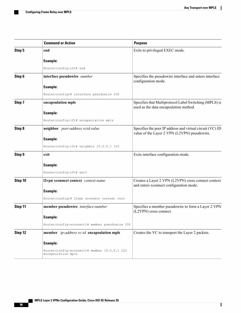
PurposeCommand or Action
Exits to privileged EXEC mode.end
Example:
Router(config-if)# end
Step 5
Specifies the pseudowire interface and enters interfaceconfiguration mode.
interface pseudowire number
Example:
Router(config)# interface pseudowire 100
Step 6
Specifies that Multiprotocol Label Switching (MPLS) isused as the data encapsulation method.
encapsulation mpls
Example:
Router(config-if)# encapsulation mpls
Step 7
Specifies the peer IP address and virtual circuit (VC) IDvalue of the Layer 2 VPN (L2VPN) pseudowire.
neighbor peer-address vcid-value
Example:
Router(config-if)# neighbor 10.0.0.1 123
Step 8
Exits interface configuration mode.exit
Example:
Router(config-if)# exit
Step 9
Creates a Layer 2 VPN (L2VPN) cross connect contextand enters xconnect configuration mode.
l2vpn xconnect context context-name
Example:
Router(config)# l2vpn xconnect context con1
Step 10
Specifies a member pseudowire to form a Layer 2 VPN(L2VPN) cross connect.
member pseudowire interface-number
Example:
Router(config-xconnect)# member pseudowire 100
Step 11
Creates the VC to transport the Layer 2 packets.member ip-address vc-id encapsulation mpls
Example:
Router(config-xconnect)# member 10.0.0.1 123encapsulation mpls
Step 12
MPLS Layer 2 VPNs Configuration Guide, Cisco IOS XE Release 3S96
Any Transport over MPLSConfiguring Frame Relay over MPLS
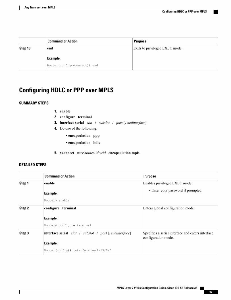
PurposeCommand or Action
Exits to privileged EXEC mode.end
Example:
Router(config-xconnect)# end
Step 13
Configuring HDLC or PPP over MPLS
SUMMARY STEPS
1. enable2. configure terminal3. interface serial slot / subslot / port [. subinterface]4. Do one of the following:
• encapsulation ppp
• encapsulation hdlc
5. xconnect peer-router-id vcid encapsulation mpls
DETAILED STEPS
PurposeCommand or Action
Enables privileged EXEC mode.enableStep 1
Example:
Router> enable
• Enter your password if prompted.
Enters global configuration mode.configure terminal
Example:
Router# configure terminal
Step 2
Specifies a serial interface and enters interfaceconfiguration mode.
interface serial slot / subslot / port [. subinterface]
Example:
Router(config)# interface serial5/0/0
Step 3
MPLS Layer 2 VPNs Configuration Guide, Cisco IOS XE Release 3S 97
Any Transport over MPLSConfiguring HDLC or PPP over MPLS
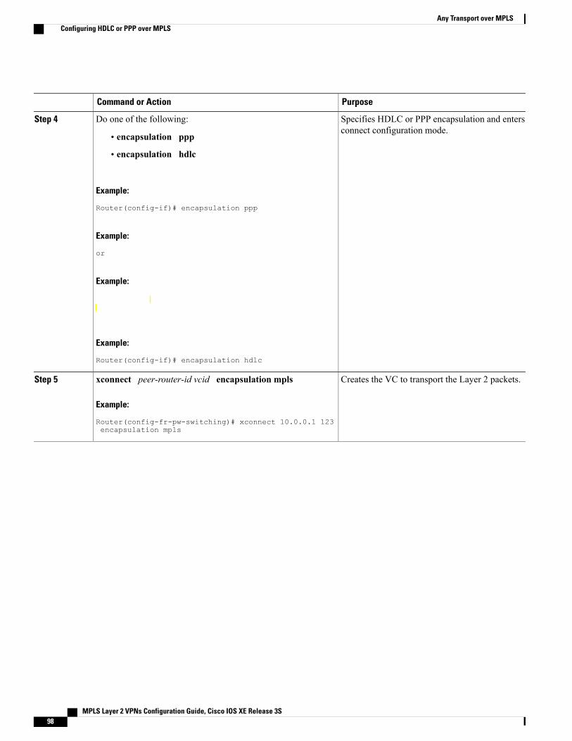
PurposeCommand or Action
Specifies HDLC or PPP encapsulation and entersconnect configuration mode.
Do one of the following:Step 4
• encapsulation ppp
• encapsulation hdlc
Example:
Router(config-if)# encapsulation ppp
Example:
or
Example:
Example:
Router(config-if)# encapsulation hdlc
Creates the VC to transport the Layer 2 packets.xconnect peer-router-id vcid encapsulation mpls
Example:
Router(config-fr-pw-switching)# xconnect 10.0.0.1 123encapsulation mpls
Step 5
MPLS Layer 2 VPNs Configuration Guide, Cisco IOS XE Release 3S98
Any Transport over MPLSConfiguring HDLC or PPP over MPLS
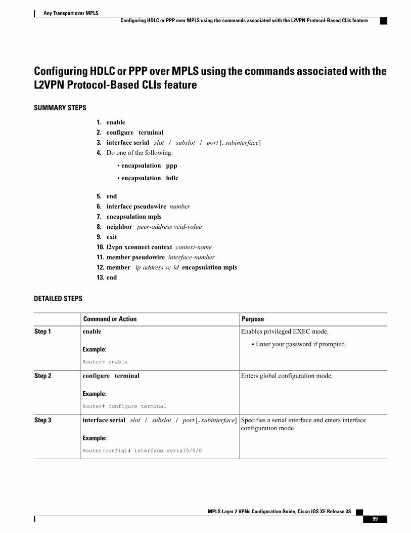
Configuring HDLC or PPP over MPLS using the commands associated with theL2VPN Protocol-Based CLIs feature
SUMMARY STEPS
1. enable2. configure terminal3. interface serial slot / subslot / port [. subinterface]4. Do one of the following:
• encapsulation ppp
• encapsulation hdlc
5. end6. interface pseudowire number7. encapsulation mpls8. neighbor peer-address vcid-value9. exit10. l2vpn xconnect context context-name11. member pseudowire interface-number12. member ip-address vc-id encapsulation mpls13. end
DETAILED STEPS
PurposeCommand or Action
Enables privileged EXEC mode.enableStep 1
Example:
Router> enable
• Enter your password if prompted.
Enters global configuration mode.configure terminal
Example:
Router# configure terminal
Step 2
Specifies a serial interface and enters interfaceconfiguration mode.
interface serial slot / subslot / port [. subinterface]
Example:
Router(config)# interface serial5/0/0
Step 3
MPLS Layer 2 VPNs Configuration Guide, Cisco IOS XE Release 3S 99
Any Transport over MPLSConfiguring HDLC or PPP over MPLS using the commands associated with the L2VPN Protocol-Based CLIs feature
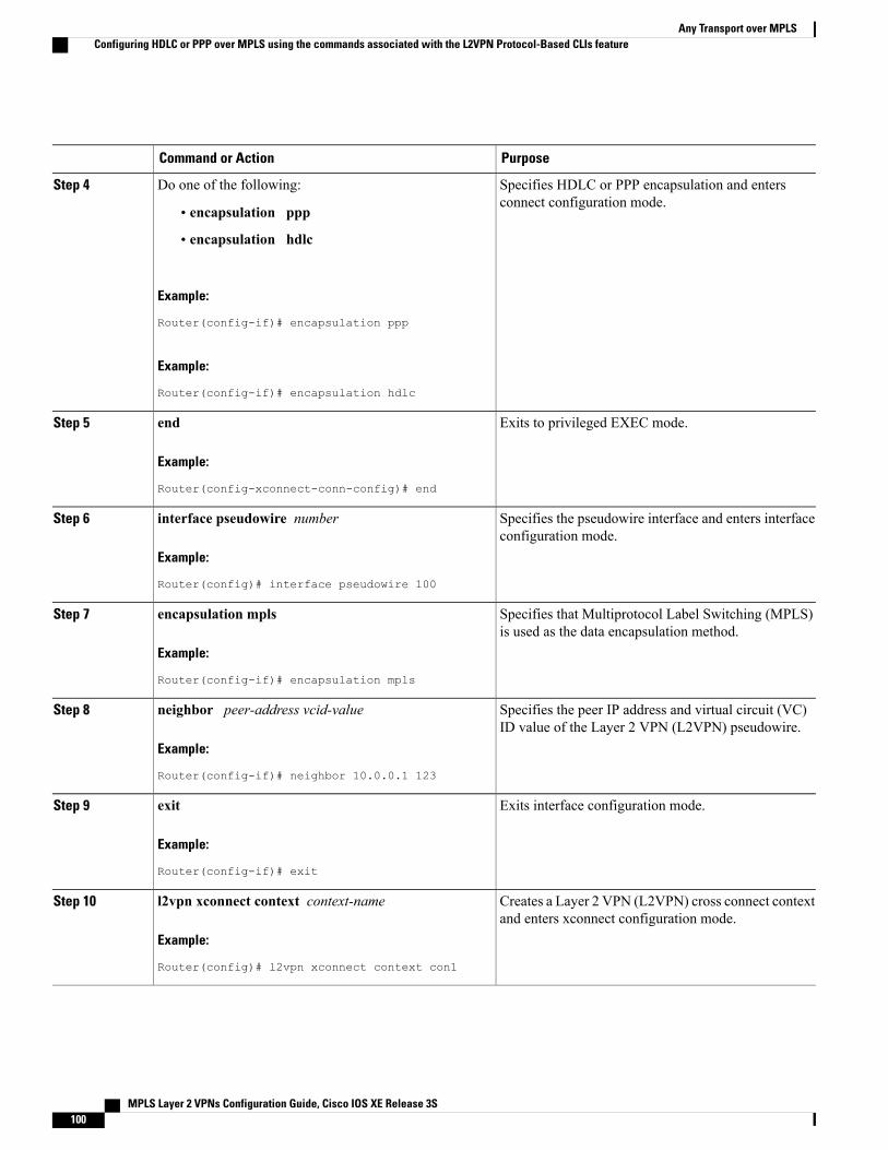
PurposeCommand or Action
Specifies HDLC or PPP encapsulation and entersconnect configuration mode.
Do one of the following:Step 4
• encapsulation ppp
• encapsulation hdlc
Example:
Router(config-if)# encapsulation ppp
Example:
Router(config-if)# encapsulation hdlc
Exits to privileged EXEC mode.end
Example:
Router(config-xconnect-conn-config)# end
Step 5
Specifies the pseudowire interface and enters interfaceconfiguration mode.
interface pseudowire number
Example:
Router(config)# interface pseudowire 100
Step 6
Specifies that Multiprotocol Label Switching (MPLS)is used as the data encapsulation method.
encapsulation mpls
Example:
Router(config-if)# encapsulation mpls
Step 7
Specifies the peer IP address and virtual circuit (VC)ID value of the Layer 2 VPN (L2VPN) pseudowire.
neighbor peer-address vcid-value
Example:
Router(config-if)# neighbor 10.0.0.1 123
Step 8
Exits interface configuration mode.exit
Example:
Router(config-if)# exit
Step 9
Creates a Layer 2 VPN (L2VPN) cross connect contextand enters xconnect configuration mode.
l2vpn xconnect context context-name
Example:
Router(config)# l2vpn xconnect context con1
Step 10
MPLS Layer 2 VPNs Configuration Guide, Cisco IOS XE Release 3S100
Any Transport over MPLSConfiguring HDLC or PPP over MPLS using the commands associated with the L2VPN Protocol-Based CLIs feature
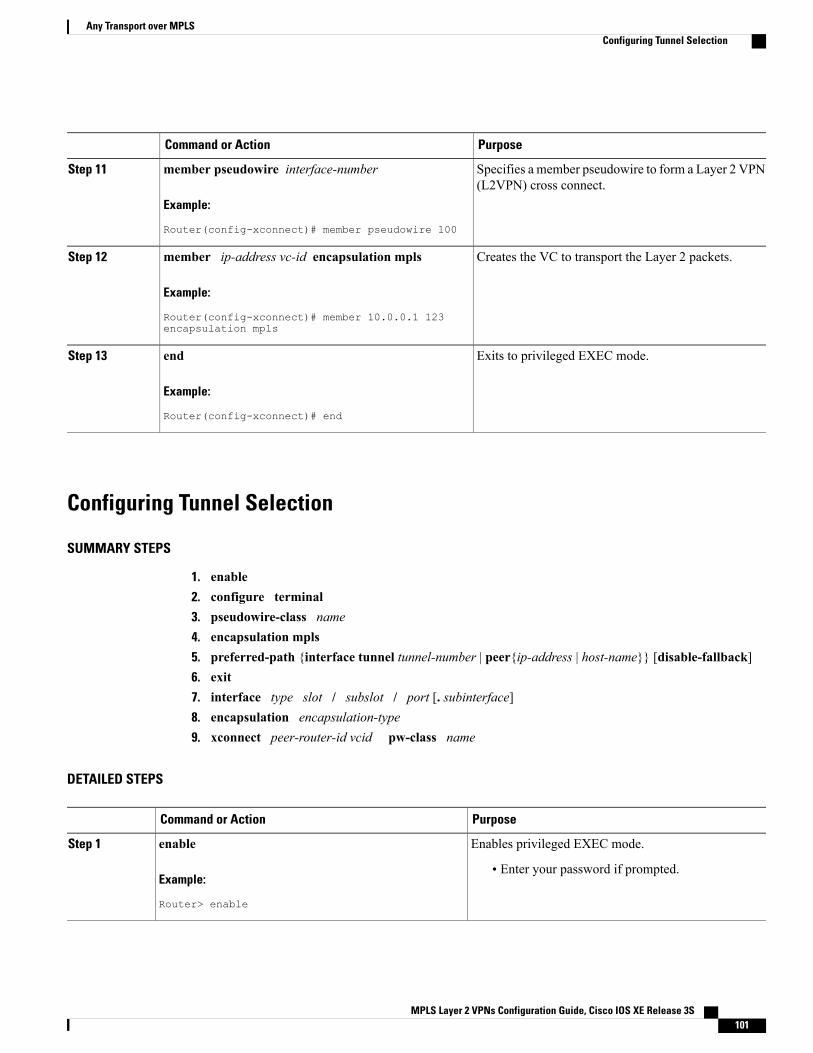
PurposeCommand or Action
Specifies a member pseudowire to form a Layer 2 VPN(L2VPN) cross connect.
member pseudowire interface-number
Example:
Router(config-xconnect)# member pseudowire 100
Step 11
Creates the VC to transport the Layer 2 packets.member ip-address vc-id encapsulation mpls
Example:
Router(config-xconnect)# member 10.0.0.1 123encapsulation mpls
Step 12
Exits to privileged EXEC mode.end
Example:
Router(config-xconnect)# end
Step 13
Configuring Tunnel Selection
SUMMARY STEPS
1. enable2. configure terminal3. pseudowire-class name4. encapsulation mpls5. preferred-path {interface tunnel tunnel-number | peer{ip-address | host-name}} [disable-fallback]6. exit7. interface type slot / subslot / port [. subinterface]8. encapsulation encapsulation-type9. xconnect peer-router-id vcid pw-class name
DETAILED STEPS
PurposeCommand or Action
Enables privileged EXEC mode.enableStep 1
Example:
Router> enable
• Enter your password if prompted.
MPLS Layer 2 VPNs Configuration Guide, Cisco IOS XE Release 3S 101
Any Transport over MPLSConfiguring Tunnel Selection
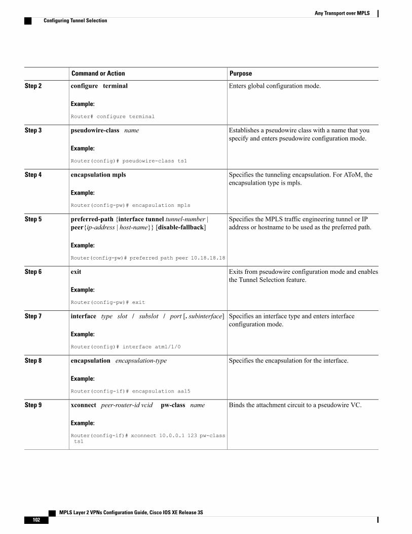
PurposeCommand or Action
Enters global configuration mode.configure terminal
Example:
Router# configure terminal
Step 2
Establishes a pseudowire class with a name that youspecify and enters pseudowire configuration mode.
pseudowire-class name
Example:
Router(config)# pseudowire-class ts1
Step 3
Specifies the tunneling encapsulation. For AToM, theencapsulation type is mpls.
encapsulation mpls
Example:
Router(config-pw)# encapsulation mpls
Step 4
Specifies the MPLS traffic engineering tunnel or IPaddress or hostname to be used as the preferred path.
preferred-path {interface tunnel tunnel-number |peer{ip-address | host-name}} [disable-fallback]
Example:
Router(config-pw)# preferred path peer 10.18.18.18
Step 5
Exits from pseudowire configuration mode and enablesthe Tunnel Selection feature.
exit
Example:
Router(config-pw)# exit
Step 6
Specifies an interface type and enters interfaceconfiguration mode.
interface type slot / subslot / port [. subinterface]
Example:
Router(config)# interface atm1/1/0
Step 7
Specifies the encapsulation for the interface.encapsulation encapsulation-type
Example:
Router(config-if)# encapsulation aal5
Step 8
Binds the attachment circuit to a pseudowire VC.xconnect peer-router-id vcid pw-class name
Example:
Router(config-if)# xconnect 10.0.0.1 123 pw-classts1
Step 9
MPLS Layer 2 VPNs Configuration Guide, Cisco IOS XE Release 3S102
Any Transport over MPLSConfiguring Tunnel Selection
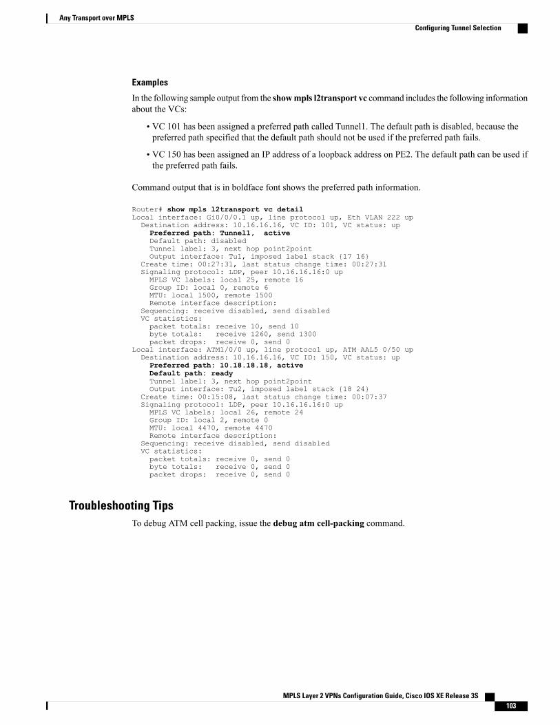
Examples
In the following sample output from the showmpls l2transport vc command includes the following informationabout the VCs:
• VC 101 has been assigned a preferred path called Tunnel1. The default path is disabled, because thepreferred path specified that the default path should not be used if the preferred path fails.
• VC 150 has been assigned an IP address of a loopback address on PE2. The default path can be used ifthe preferred path fails.
Command output that is in boldface font shows the preferred path information.
Router# show mpls l2transport vc detailLocal interface: Gi0/0/0.1 up, line protocol up, Eth VLAN 222 upDestination address: 10.16.16.16, VC ID: 101, VC status: upPreferred path: Tunnel1, activeDefault path: disabledTunnel label: 3, next hop point2pointOutput interface: Tu1, imposed label stack {17 16}
Create time: 00:27:31, last status change time: 00:27:31Signaling protocol: LDP, peer 10.16.16.16:0 upMPLS VC labels: local 25, remote 16Group ID: local 0, remote 6MTU: local 1500, remote 1500Remote interface description:
Sequencing: receive disabled, send disabledVC statistics:packet totals: receive 10, send 10byte totals: receive 1260, send 1300packet drops: receive 0, send 0
Local interface: ATM1/0/0 up, line protocol up, ATM AAL5 0/50 upDestination address: 10.16.16.16, VC ID: 150, VC status: upPreferred path: 10.18.18.18, activeDefault path: readyTunnel label: 3, next hop point2pointOutput interface: Tu2, imposed label stack {18 24}
Create time: 00:15:08, last status change time: 00:07:37Signaling protocol: LDP, peer 10.16.16.16:0 upMPLS VC labels: local 26, remote 24Group ID: local 2, remote 0MTU: local 4470, remote 4470Remote interface description:
Sequencing: receive disabled, send disabledVC statistics:packet totals: receive 0, send 0byte totals: receive 0, send 0packet drops: receive 0, send 0
Troubleshooting TipsTo debug ATM cell packing, issue the debug atm cell-packing command.
MPLS Layer 2 VPNs Configuration Guide, Cisco IOS XE Release 3S 103
Any Transport over MPLSConfiguring Tunnel Selection
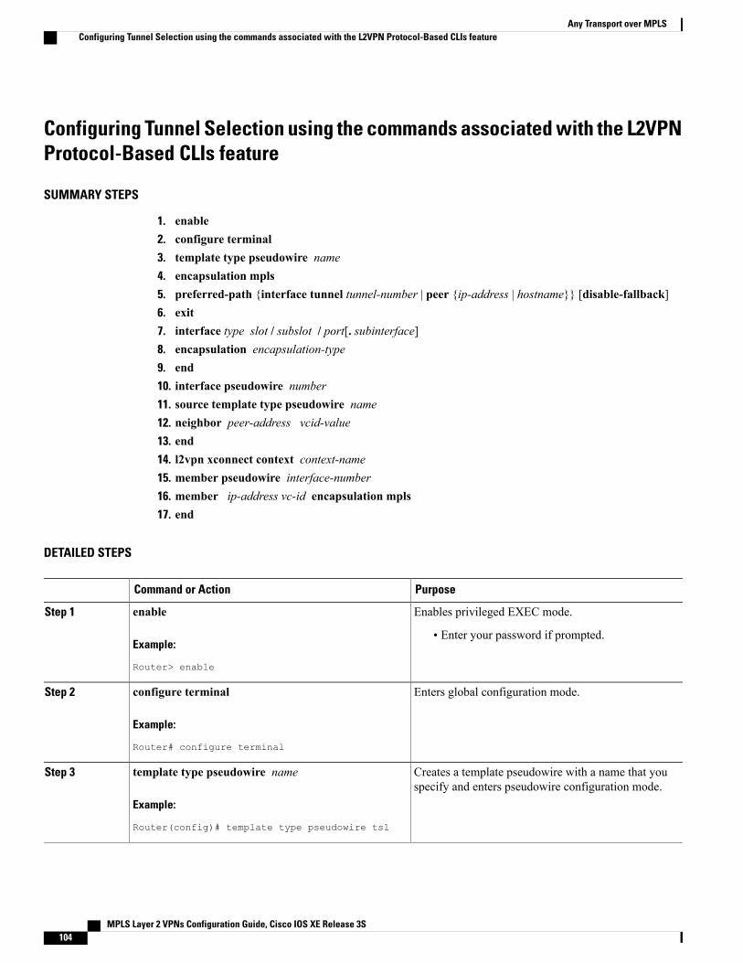
Configuring Tunnel Selection using the commands associated with the L2VPNProtocol-Based CLIs feature
SUMMARY STEPS
1. enable2. configure terminal3. template type pseudowire name4. encapsulation mpls5. preferred-path {interface tunnel tunnel-number | peer {ip-address | hostname}} [disable-fallback]6. exit7. interface type slot / subslot / port[. subinterface]8. encapsulation encapsulation-type9. end10. interface pseudowire number11. source template type pseudowire name12. neighbor peer-address vcid-value13. end14. l2vpn xconnect context context-name15. member pseudowire interface-number16. member ip-address vc-id encapsulation mpls17. end
DETAILED STEPS
PurposeCommand or Action
Enables privileged EXEC mode.enableStep 1
Example:
Router> enable
• Enter your password if prompted.
Enters global configuration mode.configure terminal
Example:
Router# configure terminal
Step 2
Creates a template pseudowire with a name that youspecify and enters pseudowire configuration mode.
template type pseudowire name
Example:
Router(config)# template type pseudowire ts1
Step 3
MPLS Layer 2 VPNs Configuration Guide, Cisco IOS XE Release 3S104
Any Transport over MPLSConfiguring Tunnel Selection using the commands associated with the L2VPN Protocol-Based CLIs feature
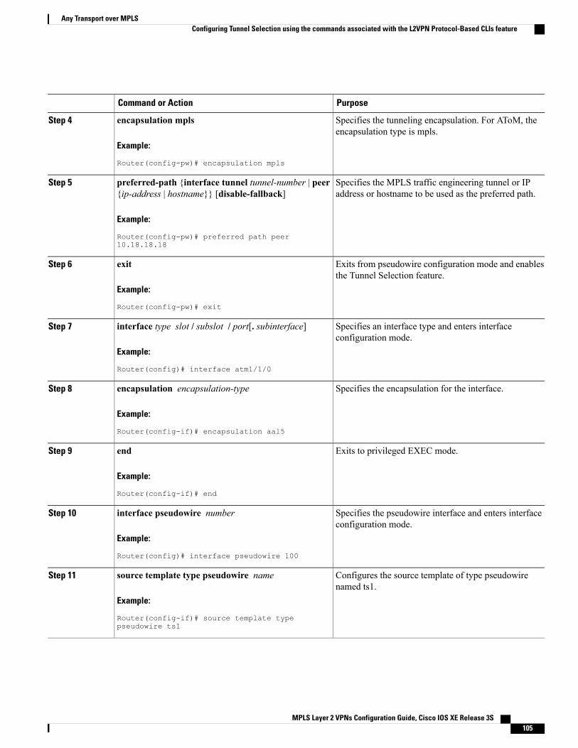
PurposeCommand or Action
Specifies the tunneling encapsulation. For AToM, theencapsulation type is mpls.
encapsulation mpls
Example:
Router(config-pw)# encapsulation mpls
Step 4
Specifies the MPLS traffic engineering tunnel or IPaddress or hostname to be used as the preferred path.
preferred-path {interface tunnel tunnel-number | peer{ip-address | hostname}} [disable-fallback]
Example:
Router(config-pw)# preferred path peer10.18.18.18
Step 5
Exits from pseudowire configuration mode and enablesthe Tunnel Selection feature.
exit
Example:
Router(config-pw)# exit
Step 6
Specifies an interface type and enters interfaceconfiguration mode.
interface type slot / subslot / port[. subinterface]
Example:
Router(config)# interface atm1/1/0
Step 7
Specifies the encapsulation for the interface.encapsulation encapsulation-type
Example:
Router(config-if)# encapsulation aal5
Step 8
Exits to privileged EXEC mode.end
Example:
Router(config-if)# end
Step 9
Specifies the pseudowire interface and enters interfaceconfiguration mode.
interface pseudowire number
Example:
Router(config)# interface pseudowire 100
Step 10
Configures the source template of type pseudowirenamed ts1.
source template type pseudowire name
Example:
Router(config-if)# source template typepseudowire ts1
Step 11
MPLS Layer 2 VPNs Configuration Guide, Cisco IOS XE Release 3S 105
Any Transport over MPLSConfiguring Tunnel Selection using the commands associated with the L2VPN Protocol-Based CLIs feature
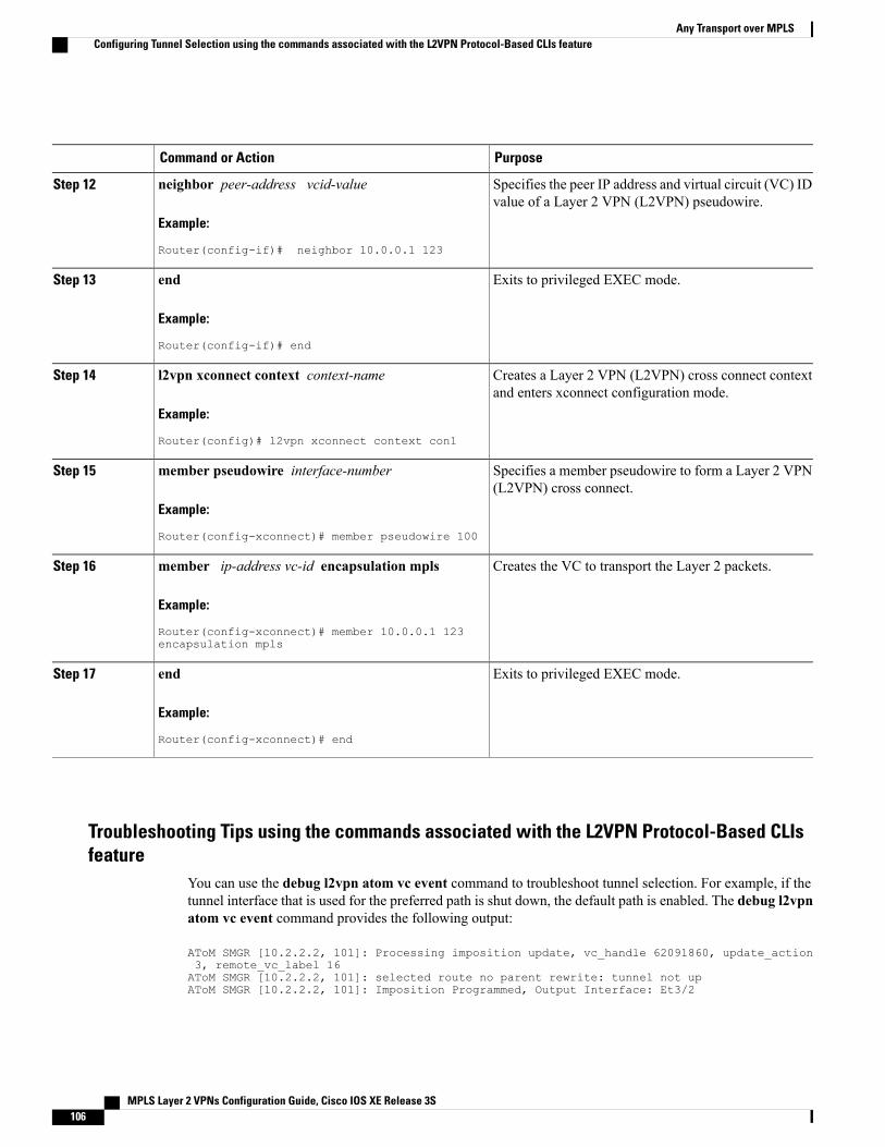
PurposeCommand or Action
Specifies the peer IP address and virtual circuit (VC) IDvalue of a Layer 2 VPN (L2VPN) pseudowire.
neighbor peer-address vcid-value
Example:
Router(config-if)# neighbor 10.0.0.1 123
Step 12
Exits to privileged EXEC mode.end
Example:
Router(config-if)# end
Step 13
Creates a Layer 2 VPN (L2VPN) cross connect contextand enters xconnect configuration mode.
l2vpn xconnect context context-name
Example:
Router(config)# l2vpn xconnect context con1
Step 14
Specifies a member pseudowire to form a Layer 2 VPN(L2VPN) cross connect.
member pseudowire interface-number
Example:
Router(config-xconnect)# member pseudowire 100
Step 15
Creates the VC to transport the Layer 2 packets.member ip-address vc-id encapsulation mpls
Example:
Router(config-xconnect)# member 10.0.0.1 123encapsulation mpls
Step 16
Exits to privileged EXEC mode.end
Example:
Router(config-xconnect)# end
Step 17
Troubleshooting Tips using the commands associated with the L2VPN Protocol-Based CLIsfeature
You can use the debug l2vpn atom vc event command to troubleshoot tunnel selection. For example, if thetunnel interface that is used for the preferred path is shut down, the default path is enabled. The debug l2vpnatom vc event command provides the following output:
AToM SMGR [10.2.2.2, 101]: Processing imposition update, vc_handle 62091860, update_action3, remote_vc_label 16AToM SMGR [10.2.2.2, 101]: selected route no parent rewrite: tunnel not upAToM SMGR [10.2.2.2, 101]: Imposition Programmed, Output Interface: Et3/2
MPLS Layer 2 VPNs Configuration Guide, Cisco IOS XE Release 3S106
Any Transport over MPLSConfiguring Tunnel Selection using the commands associated with the L2VPN Protocol-Based CLIs feature
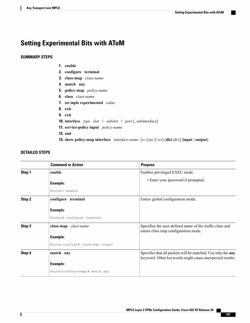
Setting Experimental Bits with AToM
SUMMARY STEPS
1. enable2. configure terminal3. class-map class-name4. match any5. policy-map policy-name6. class class-name7. set mpls experimental value8. exit9. exit10. interface type slot / subslot / port [. subinterface]11. service-policy input policy-name12. end13. show policy-map interface interface-name [vc [vpi /] vci] [dlci dlci] [input | output]
DETAILED STEPS
PurposeCommand or Action
Enables privileged EXEC mode.enableStep 1
Example:
Router> enable
• Enter your password if prompted.
Enters global configuration mode.configure terminal
Example:
Router# configure terminal
Step 2
Specifies the user-defined name of the traffic class andenters class map configuration mode.
class-map class-name
Example:
Router(config)# class-map class1
Step 3
Specifies that all packets will be matched. Use only the anykeyword. Other keywords might cause unexpected results.
match any
Example:
Router(config-cmap)# match any
Step 4
MPLS Layer 2 VPNs Configuration Guide, Cisco IOS XE Release 3S 107
Any Transport over MPLSSetting Experimental Bits with AToM

PurposeCommand or Action
Specifies the name of the traffic policy to configure andenters policy-map configuration mode.
policy-map policy-name
Example:
Router(config-cmap)# policy-map policy1
Step 5
Specifies the name of a predefined traffic class, which wasconfigured with the class-map command, used to classify
class class-name
Example:
Router(config-pmap)# class class1
Step 6
traffic to the traffic policy and enters policy-map classconfiguration mode.
Designates the value to which the MPLS bits are set if thepackets match the specified policy map.
set mpls experimental value
Example:
Router(config-pmap-c)# set mpls experimental7
Step 7
Exits policy-map class configuration mode.exit
Example:
Router(config-pmap-c)# exit
Step 8
Exits policy-map configuration mode.exit
Example:
Router(config-pmap)# exit
Step 9
Specifies the interface type and enters interfaceconfiguration mode.
interface type slot / subslot / port [.subinterface]
Example:
Router(config)# interface atm1/0/0
Step 10
Attaches a traffic policy to an interface.service-policy input policy-name
Example:
Router(config-if)# service-policy input policy1
Step 11
Exits to privileged EXEC mode.end
Example:
Router(config-if)# end
Step 12
MPLS Layer 2 VPNs Configuration Guide, Cisco IOS XE Release 3S108
Any Transport over MPLSSetting Experimental Bits with AToM
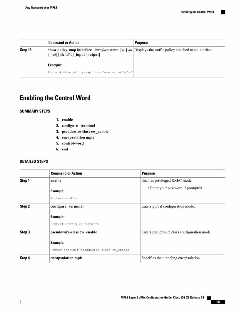
PurposeCommand or Action
Displays the traffic policy attached to an interface.show policy-map interface interface-name [vc [vpi/] vci] [dlci dlci] [input | output]
Step 13
Example:
Router# show policy-map interface serial3/0/0
Enabling the Control Word
SUMMARY STEPS
1. enable2. configure terminal3. pseudowire-class cw_enable4. encapsulation mpls5. control-word6. end
DETAILED STEPS
PurposeCommand or Action
Enables privileged EXEC mode.enableStep 1
Example:
Router> enable
• Enter your password if prompted.
Enters global configuration mode.configure terminal
Example:
Router# configure terminal
Step 2
Enters pseudowire class configuration mode.pseudowire-class cw_enable
Example:
Router(config)# pseudowire-class cw_enable
Step 3
Specifies the tunneling encapsulation.encapsulation mplsStep 4
MPLS Layer 2 VPNs Configuration Guide, Cisco IOS XE Release 3S 109
Any Transport over MPLSEnabling the Control Word
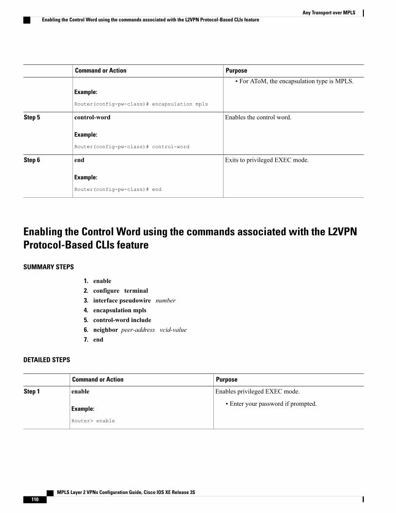
PurposeCommand or Action
Example:
Router(config-pw-class)# encapsulation mpls
• For AToM, the encapsulation type is MPLS.
Enables the control word.control-word
Example:
Router(config-pw-class)# control-word
Step 5
Exits to privileged EXEC mode.end
Example:
Router(config-pw-class)# end
Step 6
Enabling the Control Word using the commands associated with the L2VPNProtocol-Based CLIs feature
SUMMARY STEPS
1. enable2. configure terminal3. interface pseudowire number4. encapsulation mpls5. control-word include6. neighbor peer-address vcid-value7. end
DETAILED STEPS
PurposeCommand or Action
Enables privileged EXEC mode.enableStep 1
Example:
Router> enable
• Enter your password if prompted.
MPLS Layer 2 VPNs Configuration Guide, Cisco IOS XE Release 3S110
Any Transport over MPLSEnabling the Control Word using the commands associated with the L2VPN Protocol-Based CLIs feature
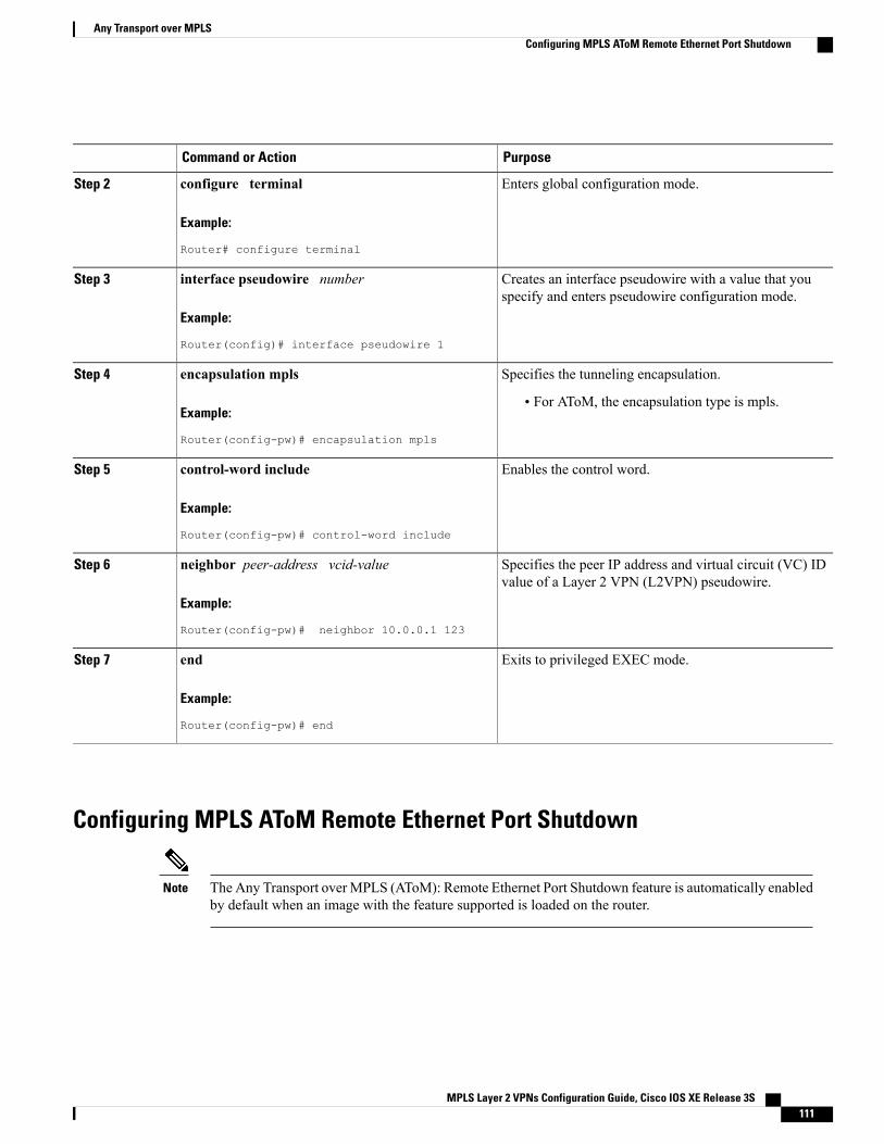
PurposeCommand or Action
Enters global configuration mode.configure terminal
Example:
Router# configure terminal
Step 2
Creates an interface pseudowire with a value that youspecify and enters pseudowire configuration mode.
interface pseudowire number
Example:
Router(config)# interface pseudowire 1
Step 3
Specifies the tunneling encapsulation.encapsulation mplsStep 4
Example:
Router(config-pw)# encapsulation mpls
• For AToM, the encapsulation type is mpls.
Enables the control word.control-word include
Example:
Router(config-pw)# control-word include
Step 5
Specifies the peer IP address and virtual circuit (VC) IDvalue of a Layer 2 VPN (L2VPN) pseudowire.
neighbor peer-address vcid-value
Example:
Router(config-pw)# neighbor 10.0.0.1 123
Step 6
Exits to privileged EXEC mode.end
Example:
Router(config-pw)# end
Step 7
Configuring MPLS AToM Remote Ethernet Port Shutdown
The Any Transport over MPLS (AToM): Remote Ethernet Port Shutdown feature is automatically enabledby default when an image with the feature supported is loaded on the router.
Note
MPLS Layer 2 VPNs Configuration Guide, Cisco IOS XE Release 3S 111
Any Transport over MPLSConfiguring MPLS AToM Remote Ethernet Port Shutdown
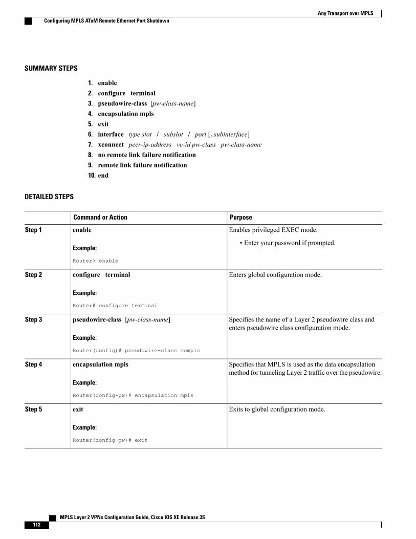
SUMMARY STEPS
1. enable2. configure terminal3. pseudowire-class [pw-class-name]4. encapsulation mpls5. exit6. interface type slot / subslot / port [. subinterface]7. xconnect peer-ip-address vc-id pw-class pw-class-name8. no remote link failure notification9. remote link failure notification10. end
DETAILED STEPS
PurposeCommand or Action
Enables privileged EXEC mode.enableStep 1
Example:
Router> enable
• Enter your password if prompted.
Enters global configuration mode.configure terminal
Example:
Router# configure terminal
Step 2
Specifies the name of a Layer 2 pseudowire class andenters pseudowire class configuration mode.
pseudowire-class [pw-class-name]
Example:
Router(config)# pseudowire-class eompls
Step 3
Specifies that MPLS is used as the data encapsulationmethod for tunneling Layer 2 traffic over the pseudowire.
encapsulation mpls
Example:
Router(config-pw)# encapsulation mpls
Step 4
Exits to global configuration mode.exit
Example:
Router(config-pw)# exit
Step 5
MPLS Layer 2 VPNs Configuration Guide, Cisco IOS XE Release 3S112
Any Transport over MPLSConfiguring MPLS AToM Remote Ethernet Port Shutdown
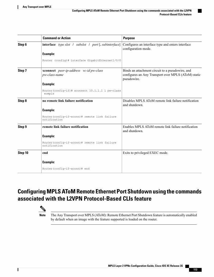
PurposeCommand or Action
Configures an interface type and enters interfaceconfiguration mode.
interface type slot / subslot / port [. subinterface]
Example:
Router (config)# interface GigabitEthernet1/0/0
Step 6
Binds an attachment circuit to a pseudowire, andconfigures an Any Transport over MPLS (AToM) staticpseudowire.
xconnect peer-ip-address vc-id pw-classpw-class-name
Example:
Router(config-if)# xconnect 10.1.1.1 1 pw-classeompls
Step 7
Disables MPLS AToM remote link failure notificationand shutdown.
no remote link failure notification
Example:
Router(config-if-xconn)# remote link failurenotification
Step 8
Enables MPLS AToM remote link failure notificationand shutdown.
remote link failure notification
Example:
Router(config-if-xconn)# remote link failurenotification
Step 9
Exits to privileged EXEC mode.end
Example:
Router(config-if-xconn)# end
Step 10
Configuring MPLS AToM Remote Ethernet Port Shutdown using the commandsassociated with the L2VPN Protocol-Based CLIs feature
The Any Transport over MPLS (AToM): Remote Ethernet Port Shutdown feature is automatically enabledby default when an image with the feature supported is loaded on the router.
Note
MPLS Layer 2 VPNs Configuration Guide, Cisco IOS XE Release 3S 113
Any Transport over MPLSConfiguring MPLS AToM Remote Ethernet Port Shutdown using the commands associated with the L2VPN
Protocol-Based CLIs feature
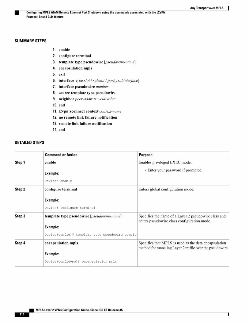
SUMMARY STEPS
1. enable2. configure terminal3. template type pseudowire [pseudowire-name]4. encapsulation mpls5. exit6. interface type slot / subslot / port[. subinterface]7. interface pseudowire number8. source template type pseudowire9. neighbor peer-address vcid-value10. end11. l2vpn xconnect context context-name12. no remote link failure notification13. remote link failure notification14. end
DETAILED STEPS
PurposeCommand or Action
Enables privileged EXEC mode.enableStep 1
Example:
Device> enable
• Enter your password if prompted.
Enters global configuration mode.configure terminal
Example:
Device# configure terminal
Step 2
Specifies the name of a Layer 2 pseudowire class andenters pseudowire class configuration mode.
template type pseudowire [pseudowire-name]
Example:
Device(config)# template type pseudowire eompls
Step 3
Specifies that MPLS is used as the data encapsulationmethod for tunneling Layer 2 traffic over the pseudowire.
encapsulation mpls
Example:
Device(config-pw)# encapsulation mpls
Step 4
MPLS Layer 2 VPNs Configuration Guide, Cisco IOS XE Release 3S114
Any Transport over MPLSConfiguring MPLS AToM Remote Ethernet Port Shutdown using the commands associated with the L2VPNProtocol-Based CLIs feature
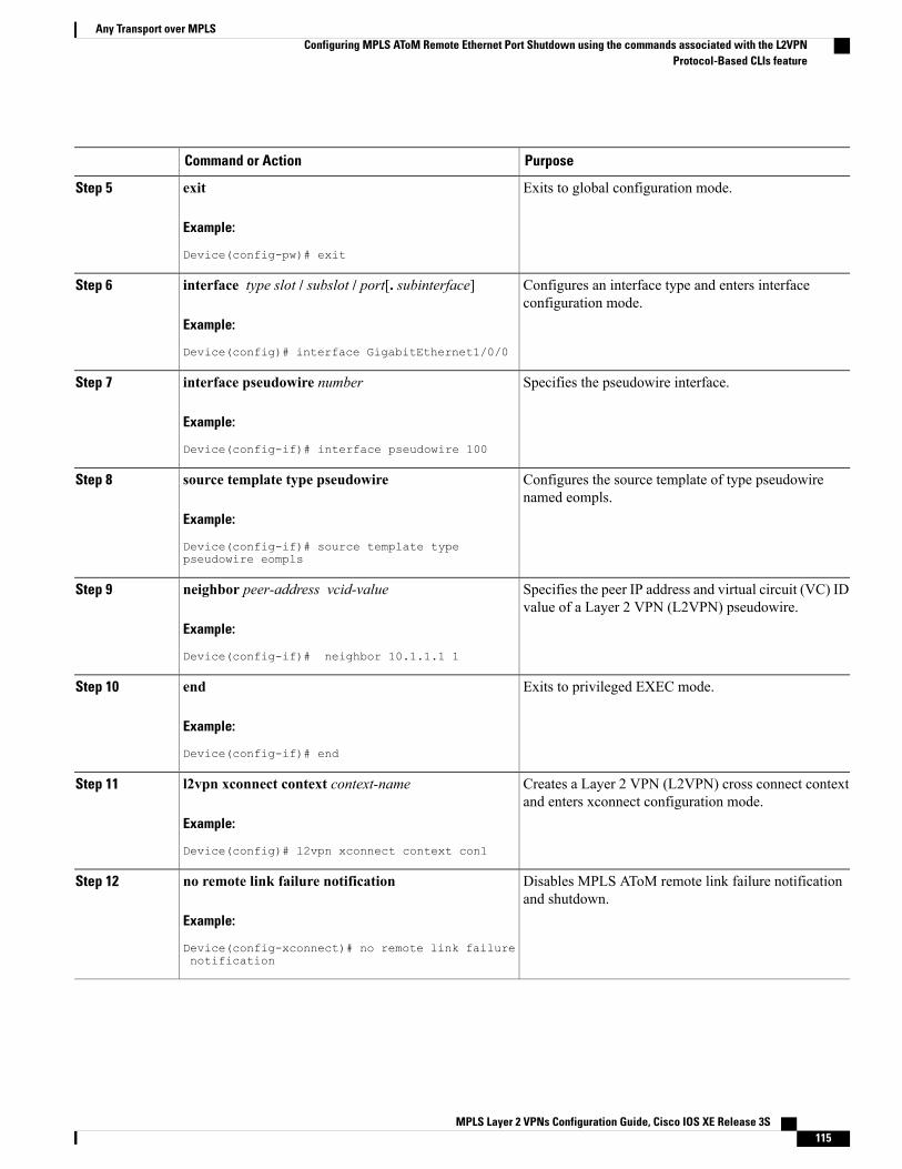
PurposeCommand or Action
Exits to global configuration mode.exit
Example:
Device(config-pw)# exit
Step 5
Configures an interface type and enters interfaceconfiguration mode.
interface type slot / subslot / port[. subinterface]
Example:
Device(config)# interface GigabitEthernet1/0/0
Step 6
Specifies the pseudowire interface.interface pseudowire number
Example:
Device(config-if)# interface pseudowire 100
Step 7
Configures the source template of type pseudowirenamed eompls.
source template type pseudowire
Example:
Device(config-if)# source template typepseudowire eompls
Step 8
Specifies the peer IP address and virtual circuit (VC) IDvalue of a Layer 2 VPN (L2VPN) pseudowire.
neighbor peer-address vcid-value
Example:
Device(config-if)# neighbor 10.1.1.1 1
Step 9
Exits to privileged EXEC mode.end
Example:
Device(config-if)# end
Step 10
Creates a Layer 2 VPN (L2VPN) cross connect contextand enters xconnect configuration mode.
l2vpn xconnect context context-name
Example:
Device(config)# l2vpn xconnect context con1
Step 11
Disables MPLS AToM remote link failure notificationand shutdown.
no remote link failure notification
Example:
Device(config-xconnect)# no remote link failurenotification
Step 12
MPLS Layer 2 VPNs Configuration Guide, Cisco IOS XE Release 3S 115
Any Transport over MPLSConfiguring MPLS AToM Remote Ethernet Port Shutdown using the commands associated with the L2VPN
Protocol-Based CLIs feature
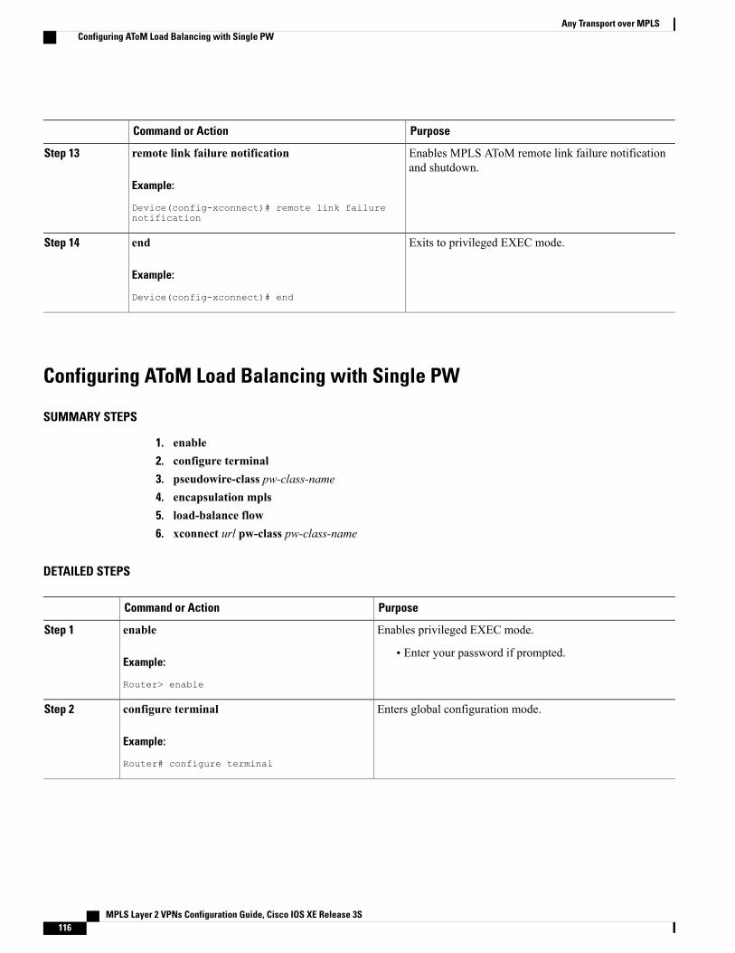
PurposeCommand or Action
Enables MPLS AToM remote link failure notificationand shutdown.
remote link failure notification
Example:
Device(config-xconnect)# remote link failurenotification
Step 13
Exits to privileged EXEC mode.end
Example:
Device(config-xconnect)# end
Step 14
Configuring AToM Load Balancing with Single PW
SUMMARY STEPS
1. enable2. configure terminal3. pseudowire-class pw-class-name4. encapsulation mpls5. load-balance flow6. xconnect url pw-class pw-class-name
DETAILED STEPS
PurposeCommand or Action
Enables privileged EXEC mode.enableStep 1
Example:
Router> enable
• Enter your password if prompted.
Enters global configuration mode.configure terminal
Example:
Router# configure terminal
Step 2
MPLS Layer 2 VPNs Configuration Guide, Cisco IOS XE Release 3S116
Any Transport over MPLSConfiguring AToM Load Balancing with Single PW
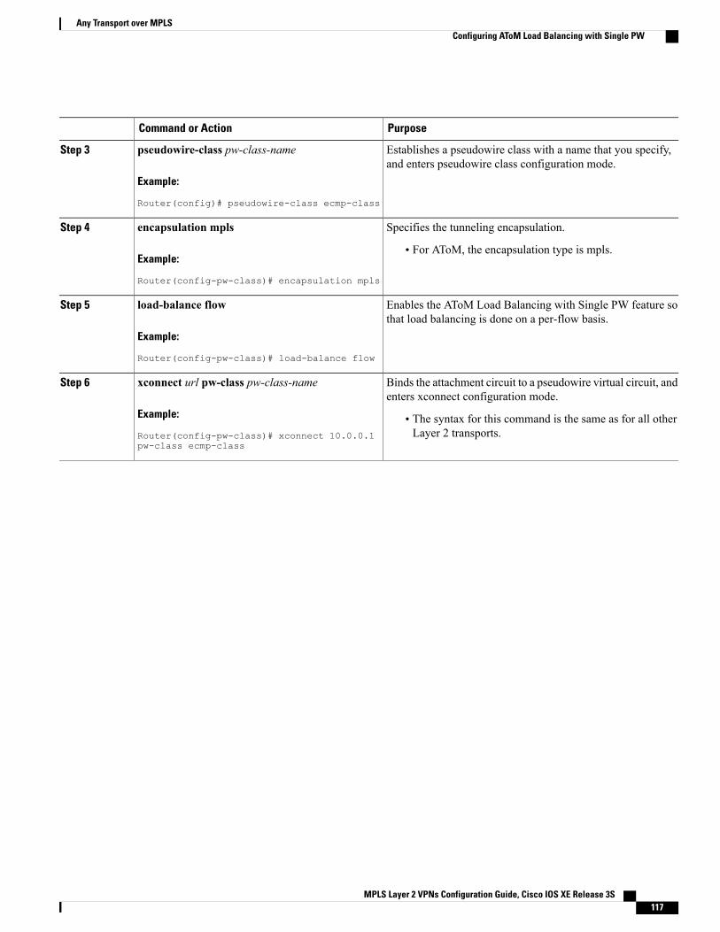
PurposeCommand or Action
Establishes a pseudowire class with a name that you specify,and enters pseudowire class configuration mode.
pseudowire-class pw-class-name
Example:
Router(config)# pseudowire-class ecmp-class
Step 3
Specifies the tunneling encapsulation.encapsulation mpls
Example:
Router(config-pw-class)# encapsulation mpls
Step 4
• For AToM, the encapsulation type is mpls.
Enables the AToM Load Balancing with Single PW feature sothat load balancing is done on a per-flow basis.
load-balance flow
Example:
Router(config-pw-class)# load-balance flow
Step 5
Binds the attachment circuit to a pseudowire virtual circuit, andenters xconnect configuration mode.
xconnect url pw-class pw-class-name
Example:
Router(config-pw-class)# xconnect 10.0.0.1pw-class ecmp-class
Step 6
• The syntax for this command is the same as for all otherLayer 2 transports.
MPLS Layer 2 VPNs Configuration Guide, Cisco IOS XE Release 3S 117
Any Transport over MPLSConfiguring AToM Load Balancing with Single PW
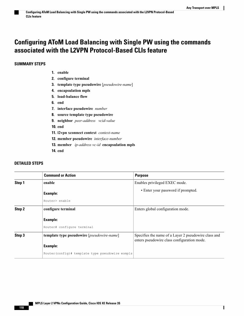
Configuring AToM Load Balancing with Single PW using the commandsassociated with the L2VPN Protocol-Based CLIs feature
SUMMARY STEPS
1. enable2. configure terminal3. template type pseudowire [pseudowire-name]4. encapsulation mpls5. load-balance flow6. end7. interface pseudowire number8. source template type pseudowire9. neighbor peer-address vcid-value10. end11. l2vpn xconnect context context-name12. member pseudowire interface-number13. member ip-address vc-id encapsulation mpls14. end
DETAILED STEPS
PurposeCommand or Action
Enables privileged EXEC mode.enableStep 1
Example:
Router> enable
• Enter your password if prompted.
Enters global configuration mode.configure terminal
Example:
Router# configure terminal
Step 2
Specifies the name of a Layer 2 pseudowire class andenters pseudowire class configuration mode.
template type pseudowire [pseudowire-name]
Example:
Router(config)# template type pseudowire eompls
Step 3
MPLS Layer 2 VPNs Configuration Guide, Cisco IOS XE Release 3S118
Any Transport over MPLSConfiguring AToM Load Balancing with Single PW using the commands associated with the L2VPN Protocol-BasedCLIs feature
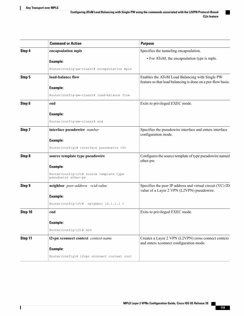
PurposeCommand or Action
Specifies the tunneling encapsulation.encapsulation mpls
Example:
Router(config-pw-class)# encapsulation mpls
Step 4
• For AToM, the encapsulation type is mpls.
Enables the AToM Load Balancing with Single PWfeature so that load balancing is done on a per-flow basis.
load-balance flow
Example:
Router(config-pw-class)# load-balance flow
Step 5
Exits to privileged EXEC mode.end
Example:
Router(config-pw-class)# end
Step 6
Specifies the pseudowire interface and enters interfaceconfiguration mode.
interface pseudowire number
Example:
Router(config)# interface pseudowire 100
Step 7
Configures the source template of type pseudowire namedether-pw.
source template type pseudowire
Example:
Router(config-if)# source template typepseudowire ether-pw
Step 8
Specifies the peer IP address and virtual circuit (VC) IDvalue of a Layer 2 VPN (L2VPN) pseudowire.
neighbor peer-address vcid-value
Example:
Router(config-if)# neighbor 10.1.1.1 1
Step 9
Exits to privileged EXEC mode.end
Example:
Router(config-if)# end
Step 10
Creates a Layer 2 VPN (L2VPN) cross connect contextand enters xconnect configuration mode.
l2vpn xconnect context context-name
Example:
Router(config)# l2vpn xconnect context con1
Step 11
MPLS Layer 2 VPNs Configuration Guide, Cisco IOS XE Release 3S 119
Any Transport over MPLSConfiguring AToM Load Balancing with Single PW using the commands associated with the L2VPN Protocol-Based
CLIs feature
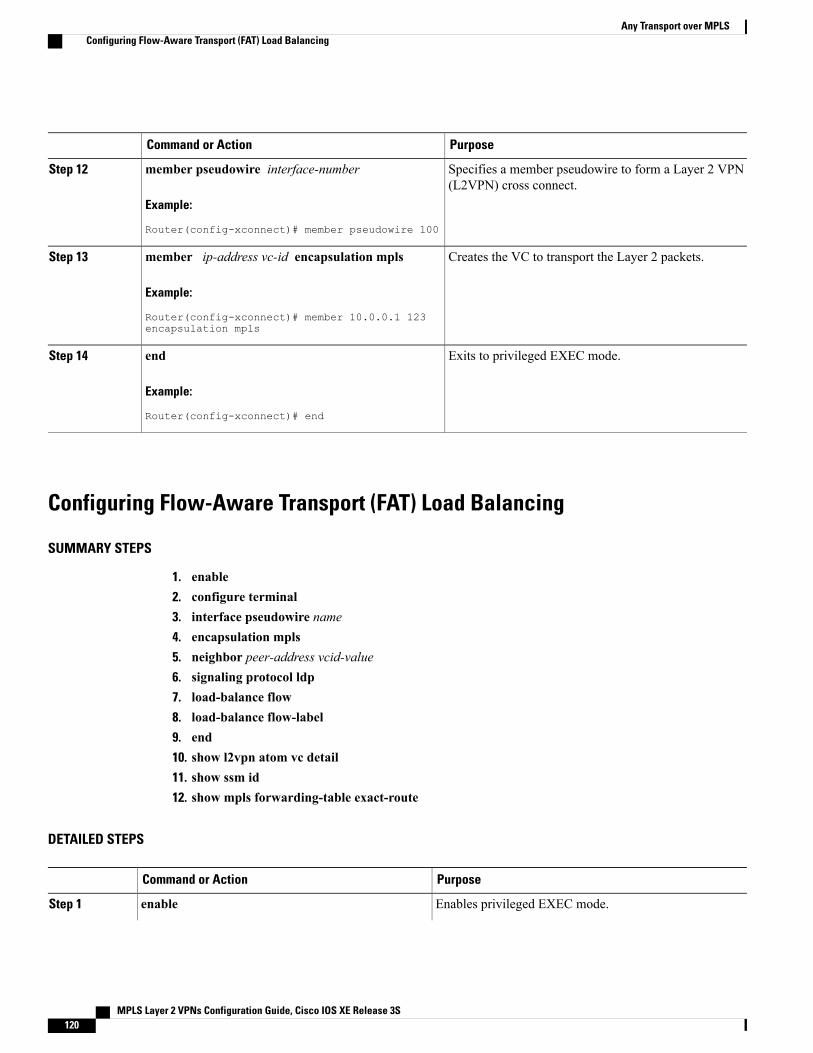
PurposeCommand or Action
Specifies a member pseudowire to form a Layer 2 VPN(L2VPN) cross connect.
member pseudowire interface-number
Example:
Router(config-xconnect)# member pseudowire 100
Step 12
Creates the VC to transport the Layer 2 packets.member ip-address vc-id encapsulation mpls
Example:
Router(config-xconnect)# member 10.0.0.1 123encapsulation mpls
Step 13
Exits to privileged EXEC mode.end
Example:
Router(config-xconnect)# end
Step 14
Configuring Flow-Aware Transport (FAT) Load Balancing
SUMMARY STEPS
1. enable2. configure terminal3. interface pseudowire name4. encapsulation mpls5. neighbor peer-address vcid-value6. signaling protocol ldp7. load-balance flow8. load-balance flow-label9. end10. show l2vpn atom vc detail11. show ssm id12. show mpls forwarding-table exact-route
DETAILED STEPS
PurposeCommand or Action
Enables privileged EXEC mode.enableStep 1
MPLS Layer 2 VPNs Configuration Guide, Cisco IOS XE Release 3S120
Any Transport over MPLSConfiguring Flow-Aware Transport (FAT) Load Balancing
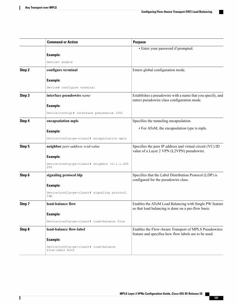
PurposeCommand or Action
Example:
Device> enable
• Enter your password if prompted.
Enters global configuration mode.configure terminal
Example:
Device# configure terminal
Step 2
Establishes a pseudowire with a name that you specify, andenters pseudowire class configuration mode.
interface pseudowire name
Example:
Device(config)# interface pseudowire 1001
Step 3
Specifies the tunneling encapsulation.encapsulation mplsStep 4
Example:
Device(config-pw-class)# encapsulation mpls
• For AToM, the encapsulation type is mpls.
Specifies the peer IP address and virtual circuit (VC) IDvalue of a Layer 2 VPN (L2VPN) pseudowire.
neighbor peer-address vcid-value
Example:
Device(config-pw-class)# neighbor 10.1.1.200200
Step 5
Specifies that the Label Distribution Protocol (LDP) isconfigured for the pseudowire class.
signaling protocol ldp
Example:
Device(config-pw-class)# signaling protocolldp
Step 6
Enables the AToM Load Balancing with Single PW featureso that load balancing is done on a per-flow basis.
load-balance flow
Example:
Device(config-pw-class)# load-balance flow
Step 7
Enables the Flow-Aware Transport of MPLS Pseudowiresfeature and specifies how flow labels are to be used.
load-balance flow-label
Example:
Device(config-pw-class)# load-balanceflow-label both
Step 8
MPLS Layer 2 VPNs Configuration Guide, Cisco IOS XE Release 3S 121
Any Transport over MPLSConfiguring Flow-Aware Transport (FAT) Load Balancing
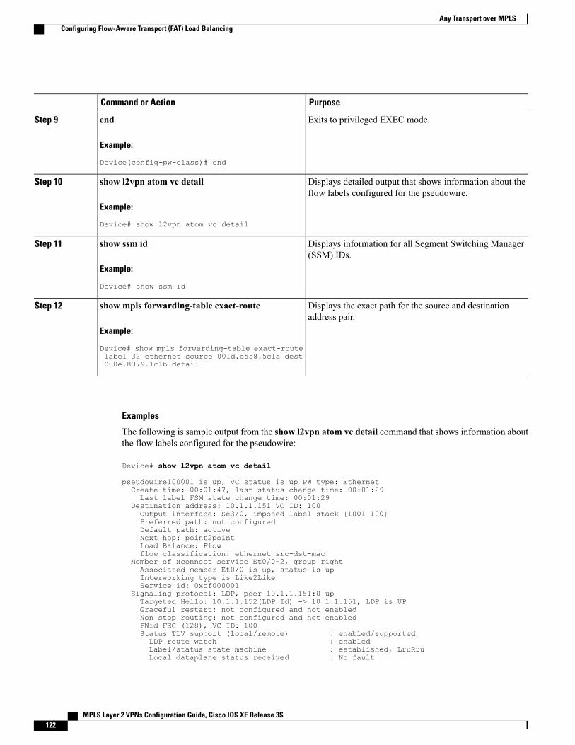
PurposeCommand or Action
Exits to privileged EXEC mode.end
Example:
Device(config-pw-class)# end
Step 9
Displays detailed output that shows information about theflow labels configured for the pseudowire.
show l2vpn atom vc detail
Example:
Device# show l2vpn atom vc detail
Step 10
Displays information for all Segment Switching Manager(SSM) IDs.
show ssm id
Example:
Device# show ssm id
Step 11
Displays the exact path for the source and destinationaddress pair.
show mpls forwarding-table exact-route
Example:
Device# show mpls forwarding-table exact-route
Step 12
label 32 ethernet source 001d.e558.5c1a dest000e.8379.1c1b detail
Examples
The following is sample output from the show l2vpn atom vc detail command that shows information aboutthe flow labels configured for the pseudowire:
Device# show l2vpn atom vc detail
pseudowire100001 is up, VC status is up PW type: EthernetCreate time: 00:01:47, last status change time: 00:01:29Last label FSM state change time: 00:01:29
Destination address: 10.1.1.151 VC ID: 100Output interface: Se3/0, imposed label stack {1001 100}Preferred path: not configuredDefault path: activeNext hop: point2pointLoad Balance: Flowflow classification: ethernet src-dst-mac
Member of xconnect service Et0/0-2, group rightAssociated member Et0/0 is up, status is upInterworking type is Like2LikeService id: 0xcf000001
Signaling protocol: LDP, peer 10.1.1.151:0 upTargeted Hello: 10.1.1.152(LDP Id) -> 10.1.1.151, LDP is UPGraceful restart: not configured and not enabledNon stop routing: not configured and not enabledPWid FEC (128), VC ID: 100Status TLV support (local/remote) : enabled/supportedLDP route watch : enabledLabel/status state machine : established, LruRruLocal dataplane status received : No fault
MPLS Layer 2 VPNs Configuration Guide, Cisco IOS XE Release 3S122
Any Transport over MPLSConfiguring Flow-Aware Transport (FAT) Load Balancing
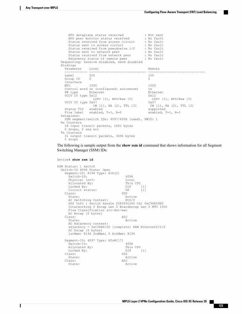
BFD dataplane status received : Not sentBFD peer monitor status received : No faultStatus received from access circuit : No faultStatus sent to access circuit : No faultStatus received from pseudowire i/f : No faultStatus sent to network peer : No faultStatus received from network peer : No faultAdjacency status of remote peer : No fault
Sequencing: receive disabled, send disabledBindingsParameter Local Remote------------ ------------------------------ ------------------------------Label 200 100Group ID 0 0InterfaceMTU 1500 1500Control word on (configured: autosense) onPW type Ethernet EthernetVCCV CV type 0x12 0x12
LSPV [2], BFD/Raw [5] LSPV [2], BFD/Raw [5]VCCV CC type 0x07 0x07
CW [1], RA [2], TTL [3] CW [1], RA [2], TTL [3]Status TLV enabled supportedFlow label enabled, T=1, R=0 enabled, T=1, R=1
Dataplane:SSM segment/switch IDs: 4097/4096 (used), PWID: 1
Rx Counters28 input transit packets, 2602 bytes0 drops, 0 seq err
Tx Counters31 output transit packets, 3694 bytes0 drops
The following is sample output from the show ssm id command that shows information for all SegmentSwitching Manager (SSM) IDs:
Device# show ssm id
SSM Status: 1 switchSwitch-ID 4096 State: OpenSegment-ID: 8194 Type: Eth[2]Switch-ID: 4096Physical intf: LocalAllocated By: This CPULocked By: SIP [1]Circuit status: UP [1]
Class: SSSState: ActiveAC Switching Context: Et0/0SSS Info : Switch Handle 2583691265 Ckt 0xC36A59E0Interworking 0 Encap Len 0 Boardencap Len 0 MTU 1500Flow Classification src-dst-macAC Encap [0 bytes]
Class: ADJState: ActiveAC Adjacency context:adjacency = 0xC36B6100 [complete] RAW Ethernet0/0:0AC Encap [0 bytes]1stMem: 8194 2ndMem: 0 ActMem: 8194
Segment-ID: 4097 Type: AToM[17]Switch-ID: 4096Allocated By: This CPULocked By: SIP [1]
Class: SSSState: Active
Class: ADJState: Active
MPLS Layer 2 VPNs Configuration Guide, Cisco IOS XE Release 3S 123
Any Transport over MPLSConfiguring Flow-Aware Transport (FAT) Load Balancing
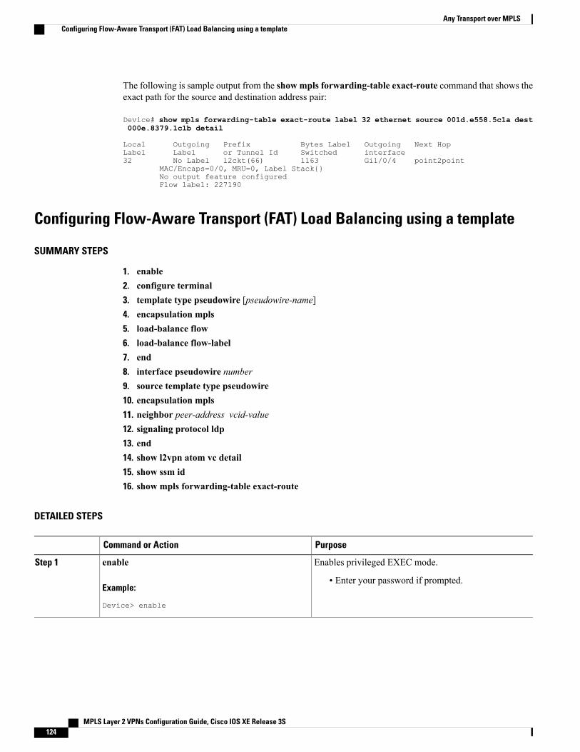
The following is sample output from the show mpls forwarding-table exact-route command that shows theexact path for the source and destination address pair:
Device# show mpls forwarding-table exact-route label 32 ethernet source 001d.e558.5c1a dest000e.8379.1c1b detail
Local Outgoing Prefix Bytes Label Outgoing Next HopLabel Label or Tunnel Id Switched interface32 No Label l2ckt(66) 1163 Gi1/0/4 point2point
MAC/Encaps=0/0, MRU=0, Label Stack{}No output feature configuredFlow label: 227190
Configuring Flow-Aware Transport (FAT) Load Balancing using a template
SUMMARY STEPS
1. enable2. configure terminal3. template type pseudowire [pseudowire-name]4. encapsulation mpls5. load-balance flow6. load-balance flow-label7. end8. interface pseudowire number9. source template type pseudowire10. encapsulation mpls11. neighbor peer-address vcid-value12. signaling protocol ldp13. end14. show l2vpn atom vc detail15. show ssm id16. show mpls forwarding-table exact-route
DETAILED STEPS
PurposeCommand or Action
Enables privileged EXEC mode.enableStep 1
Example:
Device> enable
• Enter your password if prompted.
MPLS Layer 2 VPNs Configuration Guide, Cisco IOS XE Release 3S124
Any Transport over MPLSConfiguring Flow-Aware Transport (FAT) Load Balancing using a template
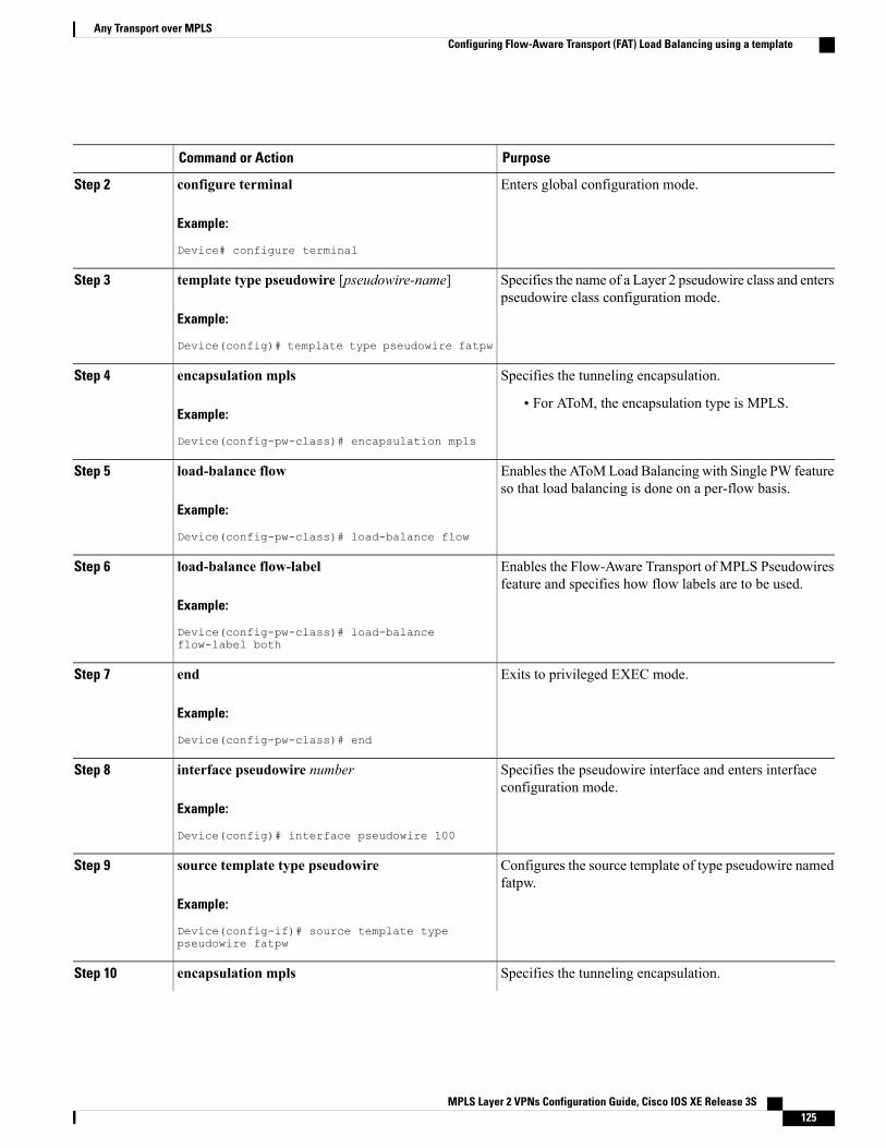
PurposeCommand or Action
Enters global configuration mode.configure terminal
Example:
Device# configure terminal
Step 2
Specifies the name of a Layer 2 pseudowire class and enterspseudowire class configuration mode.
template type pseudowire [pseudowire-name]
Example:
Device(config)# template type pseudowire fatpw
Step 3
Specifies the tunneling encapsulation.encapsulation mpls
Example:
Device(config-pw-class)# encapsulation mpls
Step 4
• For AToM, the encapsulation type is MPLS.
Enables the AToMLoad Balancing with Single PW featureso that load balancing is done on a per-flow basis.
load-balance flow
Example:
Device(config-pw-class)# load-balance flow
Step 5
Enables the Flow-Aware Transport of MPLS Pseudowiresfeature and specifies how flow labels are to be used.
load-balance flow-label
Example:
Device(config-pw-class)# load-balanceflow-label both
Step 6
Exits to privileged EXEC mode.end
Example:
Device(config-pw-class)# end
Step 7
Specifies the pseudowire interface and enters interfaceconfiguration mode.
interface pseudowire number
Example:
Device(config)# interface pseudowire 100
Step 8
Configures the source template of type pseudowire namedfatpw.
source template type pseudowire
Example:
Device(config-if)# source template typepseudowire fatpw
Step 9
Specifies the tunneling encapsulation.encapsulation mplsStep 10
MPLS Layer 2 VPNs Configuration Guide, Cisco IOS XE Release 3S 125
Any Transport over MPLSConfiguring Flow-Aware Transport (FAT) Load Balancing using a template
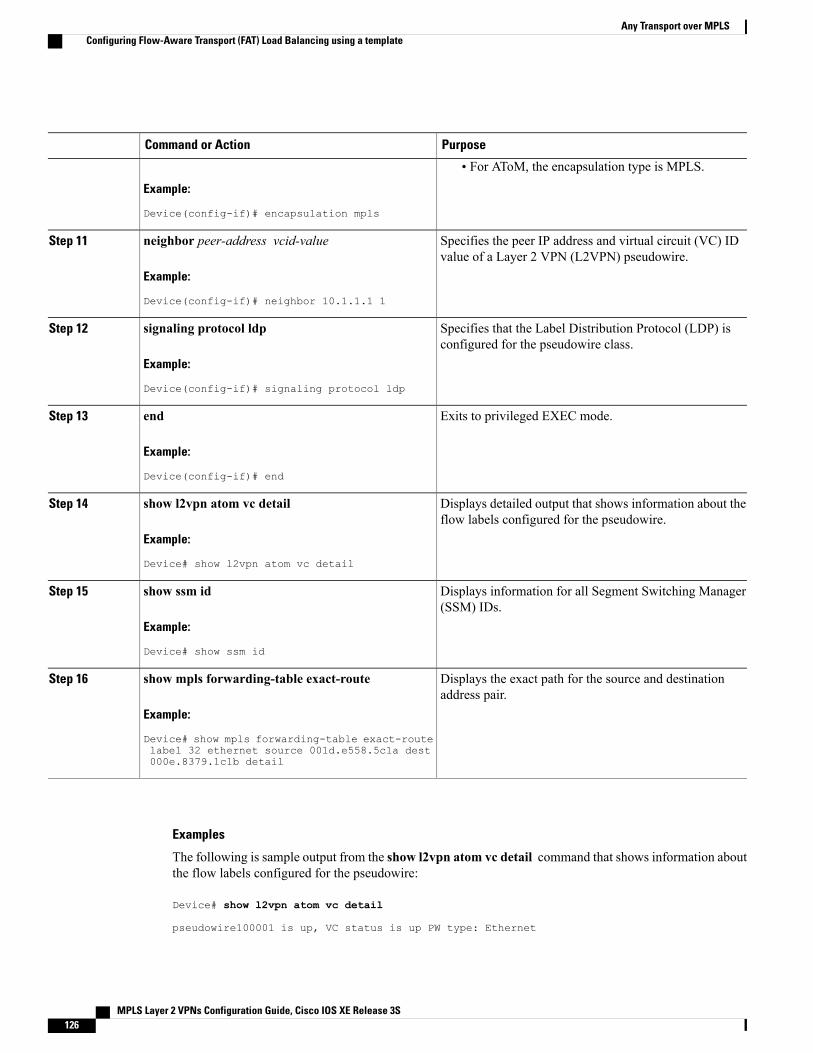
PurposeCommand or Action
Example:
Device(config-if)# encapsulation mpls
• For AToM, the encapsulation type is MPLS.
Specifies the peer IP address and virtual circuit (VC) IDvalue of a Layer 2 VPN (L2VPN) pseudowire.
neighbor peer-address vcid-value
Example:
Device(config-if)# neighbor 10.1.1.1 1
Step 11
Specifies that the Label Distribution Protocol (LDP) isconfigured for the pseudowire class.
signaling protocol ldp
Example:
Device(config-if)# signaling protocol ldp
Step 12
Exits to privileged EXEC mode.end
Example:
Device(config-if)# end
Step 13
Displays detailed output that shows information about theflow labels configured for the pseudowire.
show l2vpn atom vc detail
Example:
Device# show l2vpn atom vc detail
Step 14
Displays information for all Segment Switching Manager(SSM) IDs.
show ssm id
Example:
Device# show ssm id
Step 15
Displays the exact path for the source and destinationaddress pair.
show mpls forwarding-table exact-route
Example:
Device# show mpls forwarding-table exact-route
Step 16
label 32 ethernet source 001d.e558.5c1a dest000e.8379.1c1b detail
Examples
The following is sample output from the show l2vpn atom vc detail command that shows information aboutthe flow labels configured for the pseudowire:
Device# show l2vpn atom vc detail
pseudowire100001 is up, VC status is up PW type: Ethernet
MPLS Layer 2 VPNs Configuration Guide, Cisco IOS XE Release 3S126
Any Transport over MPLSConfiguring Flow-Aware Transport (FAT) Load Balancing using a template
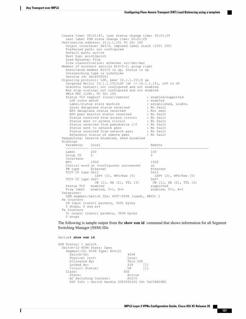
Create time: 00:01:47, last status change time: 00:01:29Last label FSM state change time: 00:01:29
Destination address: 10.1.1.151 VC ID: 100Output interface: Se3/0, imposed label stack {1001 100}Preferred path: not configuredDefault path: activeNext hop: point2pointLoad Balance: Flowflow classification: ethernet src-dst-mac
Member of xconnect service Et0/0-2, group rightAssociated member Et0/0 is up, status is upInterworking type is Like2LikeService id: 0xcf000001
Signaling protocol: LDP, peer 10.1.1.151:0 upTargeted Hello: 10.1.1.152(LDP Id) -> 10.1.1.151, LDP is UPGraceful restart: not configured and not enabledNon stop routing: not configured and not enabledPWid FEC (128), VC ID: 100Status TLV support (local/remote) : enabled/supportedLDP route watch : enabledLabel/status state machine : established, LruRruLocal dataplane status received : No faultBFD dataplane status received : Not sentBFD peer monitor status received : No faultStatus received from access circuit : No faultStatus sent to access circuit : No faultStatus received from pseudowire i/f : No faultStatus sent to network peer : No faultStatus received from network peer : No faultAdjacency status of remote peer : No fault
Sequencing: receive disabled, send disabledBindingsParameter Local Remote------------ ------------------------------ ------------------------------Label 200 100Group ID 0 0InterfaceMTU 1500 1500Control word on (configured: autosense) onPW type Ethernet EthernetVCCV CV type 0x12 0x12
LSPV [2], BFD/Raw [5] LSPV [2], BFD/Raw [5]VCCV CC type 0x07 0x07
CW [1], RA [2], TTL [3] CW [1], RA [2], TTL [3]Status TLV enabled supportedFlow label enabled, T=1, R=0 enabled, T=1, R=1
Dataplane:SSM segment/switch IDs: 4097/4096 (used), PWID: 1
Rx Counters28 input transit packets, 2602 bytes0 drops, 0 seq err
Tx Counters31 output transit packets, 3694 bytes0 drops
The following is sample output from the show ssm id command that shows information for all SegmentSwitching Manager (SSM) IDs:
Device# show ssm id
SSM Status: 1 switchSwitch-ID 4096 State: OpenSegment-ID: 8194 Type: Eth[2]Switch-ID: 4096Physical intf: LocalAllocated By: This CPULocked By: SIP [1]Circuit status: UP [1]
Class: SSSState: ActiveAC Switching Context: Et0/0SSS Info : Switch Handle 2583691265 Ckt 0xC36A59E0
MPLS Layer 2 VPNs Configuration Guide, Cisco IOS XE Release 3S 127
Any Transport over MPLSConfiguring Flow-Aware Transport (FAT) Load Balancing using a template
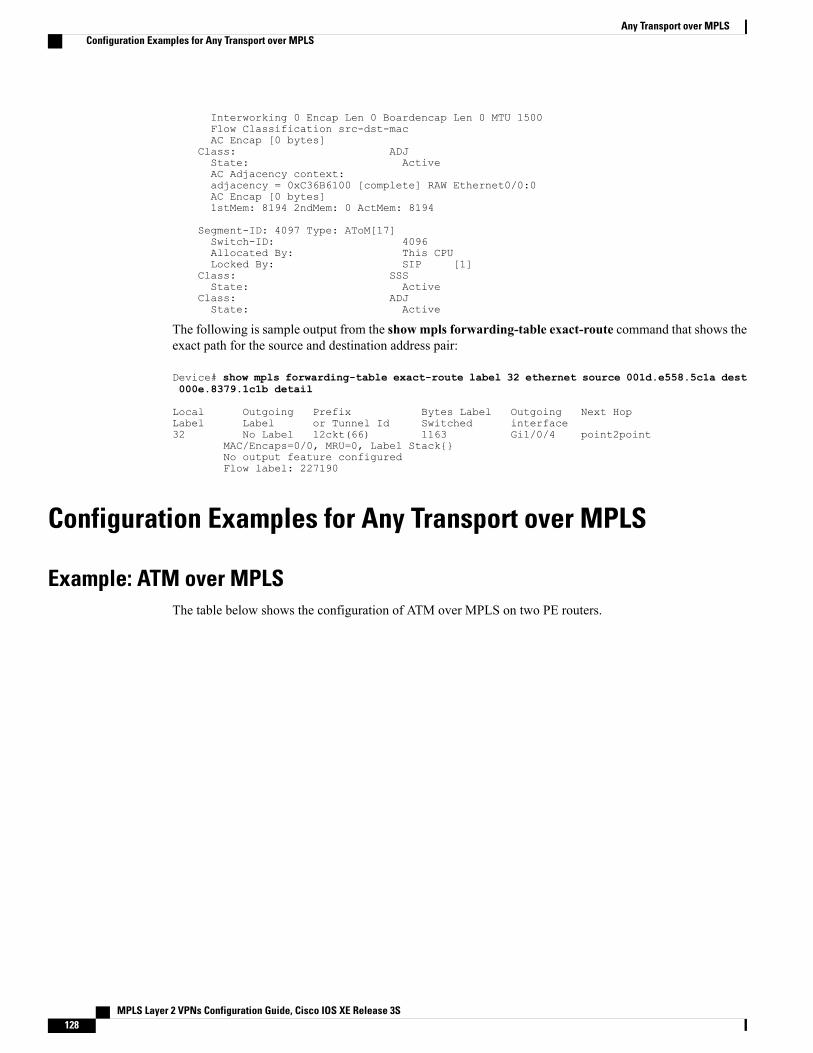
Interworking 0 Encap Len 0 Boardencap Len 0 MTU 1500Flow Classification src-dst-macAC Encap [0 bytes]
Class: ADJState: ActiveAC Adjacency context:adjacency = 0xC36B6100 [complete] RAW Ethernet0/0:0AC Encap [0 bytes]1stMem: 8194 2ndMem: 0 ActMem: 8194
Segment-ID: 4097 Type: AToM[17]Switch-ID: 4096Allocated By: This CPULocked By: SIP [1]
Class: SSSState: Active
Class: ADJState: Active
The following is sample output from the show mpls forwarding-table exact-route command that shows theexact path for the source and destination address pair:
Device# show mpls forwarding-table exact-route label 32 ethernet source 001d.e558.5c1a dest000e.8379.1c1b detail
Local Outgoing Prefix Bytes Label Outgoing Next HopLabel Label or Tunnel Id Switched interface32 No Label l2ckt(66) 1163 Gi1/0/4 point2point
MAC/Encaps=0/0, MRU=0, Label Stack{}No output feature configuredFlow label: 227190
Configuration Examples for Any Transport over MPLS
Example: ATM over MPLSThe table below shows the configuration of ATM over MPLS on two PE routers.
MPLS Layer 2 VPNs Configuration Guide, Cisco IOS XE Release 3S128
Any Transport over MPLSConfiguration Examples for Any Transport over MPLS
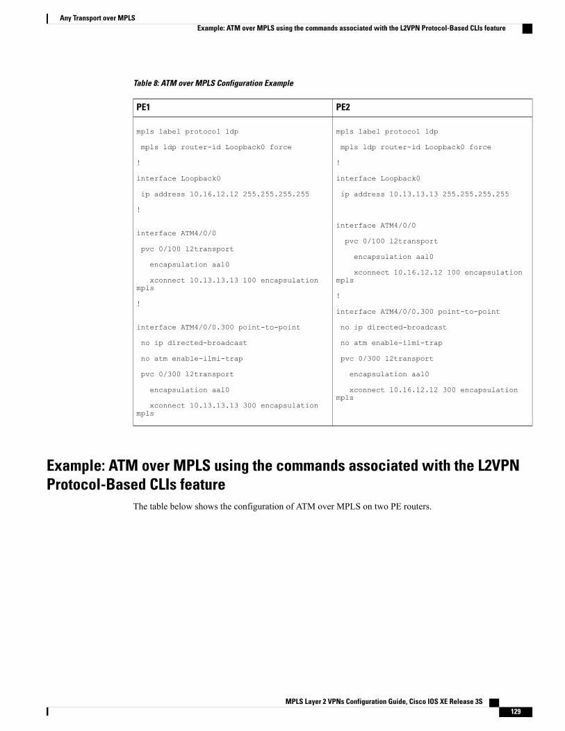
Table 8: ATM over MPLS Configuration Example
PE2PE1
mpls label protocol ldp
mpls ldp router-id Loopback0 force
!
interface Loopback0
ip address 10.13.13.13 255.255.255.255
interface ATM4/0/0
pvc 0/100 l2transport
encapsulation aal0
xconnect 10.16.12.12 100 encapsulationmpls
!
interface ATM4/0/0.300 point-to-point
no ip directed-broadcast
no atm enable-ilmi-trap
pvc 0/300 l2transport
encapsulation aal0
xconnect 10.16.12.12 300 encapsulationmpls
mpls label protocol ldp
mpls ldp router-id Loopback0 force
!
interface Loopback0
ip address 10.16.12.12 255.255.255.255
!
interface ATM4/0/0
pvc 0/100 l2transport
encapsulation aal0
xconnect 10.13.13.13 100 encapsulationmpls
!
interface ATM4/0/0.300 point-to-point
no ip directed-broadcast
no atm enable-ilmi-trap
pvc 0/300 l2transport
encapsulation aal0
xconnect 10.13.13.13 300 encapsulationmpls
Example: ATM over MPLS using the commands associated with the L2VPNProtocol-Based CLIs feature
The table below shows the configuration of ATM over MPLS on two PE routers.
MPLS Layer 2 VPNs Configuration Guide, Cisco IOS XE Release 3S 129
Any Transport over MPLSExample: ATM over MPLS using the commands associated with the L2VPN Protocol-Based CLIs feature
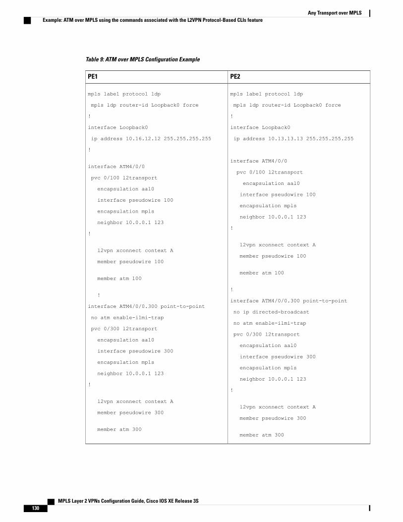
Table 9: ATM over MPLS Configuration Example
PE2PE1
mpls label protocol ldp
mpls ldp router-id Loopback0 force
!
interface Loopback0
ip address 10.13.13.13 255.255.255.255
interface ATM4/0/0
pvc 0/100 l2transport
encapsulation aal0
interface pseudowire 100
encapsulation mpls
neighbor 10.0.0.1 123
!
l2vpn xconnect context A
member pseudowire 100
member atm 100
!
interface ATM4/0/0.300 point-to-point
no ip directed-broadcast
no atm enable-ilmi-trap
pvc 0/300 l2transport
encapsulation aal0
interface pseudowire 300
encapsulation mpls
neighbor 10.0.0.1 123
!
l2vpn xconnect context A
member pseudowire 300
member atm 300
mpls label protocol ldp
mpls ldp router-id Loopback0 force
!
interface Loopback0
ip address 10.16.12.12 255.255.255.255
!
interface ATM4/0/0
pvc 0/100 l2transport
encapsulation aal0
interface pseudowire 100
encapsulation mpls
neighbor 10.0.0.1 123
!
l2vpn xconnect context A
member pseudowire 100
member atm 100
!
interface ATM4/0/0.300 point-to-point
no atm enable-ilmi-trap
pvc 0/300 l2transport
encapsulation aal0
interface pseudowire 300
encapsulation mpls
neighbor 10.0.0.1 123
!
l2vpn xconnect context A
member pseudowire 300
member atm 300
MPLS Layer 2 VPNs Configuration Guide, Cisco IOS XE Release 3S130
Any Transport over MPLSExample: ATM over MPLS using the commands associated with the L2VPN Protocol-Based CLIs feature
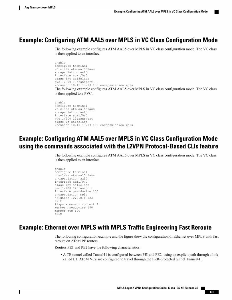
Example: Configuring ATM AAL5 over MPLS in VC Class Configuration ModeThe following example configures ATM AAL5 over MPLS in VC class configuration mode. The VC classis then applied to an interface.
enableconfigure terminalvc-class atm aal5classencapsulation aal5interface atm1/0/0class-int aal5classpvc 1/200 l2transportxconnect 10.13.13.13 100 encapsulation mplsThe following example configures ATM AAL5 over MPLS in VC class configuration mode. The VC classis then applied to a PVC.
enableconfigure terminalvc-class atm aal5classencapsulation aal5interface atm1/0/0pvc 1/200 l2transportclass-vc aal5classxconnect 10.13.13.13 100 encapsulation mpls
Example: Configuring ATM AAL5 over MPLS in VC Class Configuration Modeusing the commands associated with the L2VPN Protocol-Based CLIs feature
The following example configures ATM AAL5 over MPLS in VC class configuration mode. The VC classis then applied to an interface.
enableconfigure terminalvc-class atm aal5classencapsulation aal5interface atm1/0/0class-int aal5classpvc 1/200 l2transportinterface pseudowire 100encapsulation mplsneighbor 10.0.0.1 123exitl2vpn xconnect context Amember pseudowire 100member atm 100exit
Example: Ethernet over MPLS with MPLS Traffic Engineering Fast RerouteThe following configuration example and the figure show the configuration of Ethernet over MPLS with fastreroute on AToM PE routers.
Routers PE1 and PE2 have the following characteristics:
• A TE tunnel called Tunnel41 is configured between PE1and PE2, using an explicit path through a linkcalled L1. AToM VCs are configured to travel through the FRR-protected tunnel Tunnel41.
MPLS Layer 2 VPNs Configuration Guide, Cisco IOS XE Release 3S 131
Any Transport over MPLSExample: Configuring ATM AAL5 over MPLS in VC Class Configuration Mode
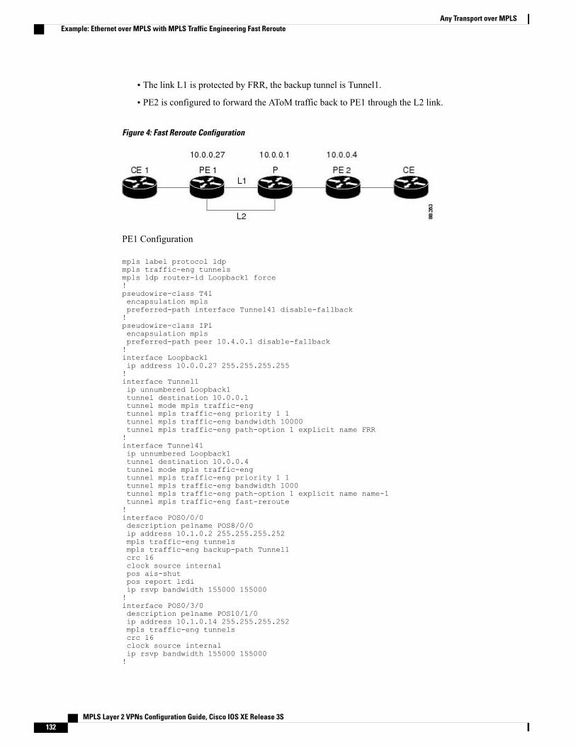
• The link L1 is protected by FRR, the backup tunnel is Tunnel1.
• PE2 is configured to forward the AToM traffic back to PE1 through the L2 link.
Figure 4: Fast Reroute Configuration
PE1 Configuration
mpls label protocol ldpmpls traffic-eng tunnelsmpls ldp router-id Loopback1 force!pseudowire-class T41encapsulation mplspreferred-path interface Tunnel41 disable-fallback!pseudowire-class IP1encapsulation mplspreferred-path peer 10.4.0.1 disable-fallback!interface Loopback1ip address 10.0.0.27 255.255.255.255!interface Tunnel1ip unnumbered Loopback1tunnel destination 10.0.0.1tunnel mode mpls traffic-engtunnel mpls traffic-eng priority 1 1tunnel mpls traffic-eng bandwidth 10000tunnel mpls traffic-eng path-option 1 explicit name FRR!interface Tunnel41ip unnumbered Loopback1tunnel destination 10.0.0.4tunnel mode mpls traffic-engtunnel mpls traffic-eng priority 1 1tunnel mpls traffic-eng bandwidth 1000tunnel mpls traffic-eng path-option 1 explicit name name-1tunnel mpls traffic-eng fast-reroute!interface POS0/0/0description pe1name POS8/0/0ip address 10.1.0.2 255.255.255.252mpls traffic-eng tunnelsmpls traffic-eng backup-path Tunnel1crc 16clock source internalpos ais-shutpos report lrdiip rsvp bandwidth 155000 155000!interface POS0/3/0description pe1name POS10/1/0ip address 10.1.0.14 255.255.255.252mpls traffic-eng tunnelscrc 16clock source internalip rsvp bandwidth 155000 155000!
MPLS Layer 2 VPNs Configuration Guide, Cisco IOS XE Release 3S132
Any Transport over MPLSExample: Ethernet over MPLS with MPLS Traffic Engineering Fast Reroute
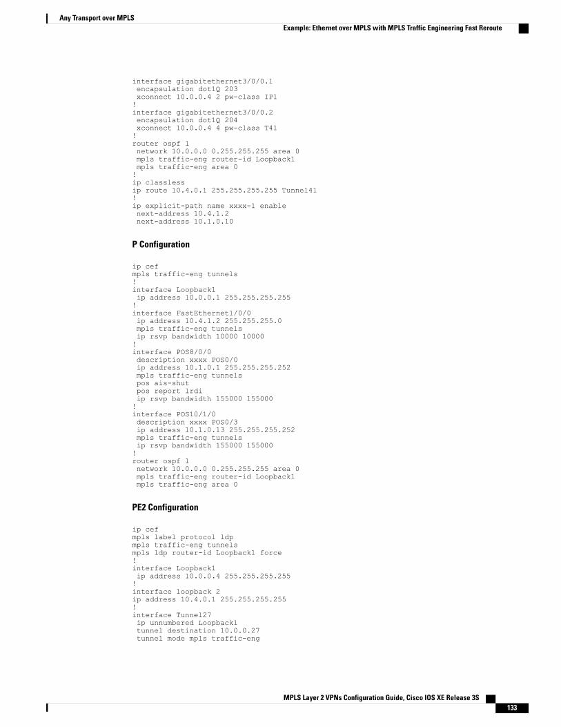
interface gigabitethernet3/0/0.1encapsulation dot1Q 203xconnect 10.0.0.4 2 pw-class IP1!interface gigabitethernet3/0/0.2encapsulation dot1Q 204xconnect 10.0.0.4 4 pw-class T41!router ospf 1network 10.0.0.0 0.255.255.255 area 0mpls traffic-eng router-id Loopback1mpls traffic-eng area 0!ip classlessip route 10.4.0.1 255.255.255.255 Tunnel41!ip explicit-path name xxxx-1 enablenext-address 10.4.1.2next-address 10.1.0.10
P Configuration
ip cefmpls traffic-eng tunnels!interface Loopback1ip address 10.0.0.1 255.255.255.255!interface FastEthernet1/0/0ip address 10.4.1.2 255.255.255.0mpls traffic-eng tunnelsip rsvp bandwidth 10000 10000!interface POS8/0/0description xxxx POS0/0ip address 10.1.0.1 255.255.255.252mpls traffic-eng tunnelspos ais-shutpos report lrdiip rsvp bandwidth 155000 155000!interface POS10/1/0description xxxx POS0/3ip address 10.1.0.13 255.255.255.252mpls traffic-eng tunnelsip rsvp bandwidth 155000 155000!router ospf 1network 10.0.0.0 0.255.255.255 area 0mpls traffic-eng router-id Loopback1mpls traffic-eng area 0
PE2 Configuration
ip cefmpls label protocol ldpmpls traffic-eng tunnelsmpls ldp router-id Loopback1 force!interface Loopback1ip address 10.0.0.4 255.255.255.255!interface loopback 2ip address 10.4.0.1 255.255.255.255!interface Tunnel27ip unnumbered Loopback1tunnel destination 10.0.0.27tunnel mode mpls traffic-eng
MPLS Layer 2 VPNs Configuration Guide, Cisco IOS XE Release 3S 133
Any Transport over MPLSExample: Ethernet over MPLS with MPLS Traffic Engineering Fast Reroute
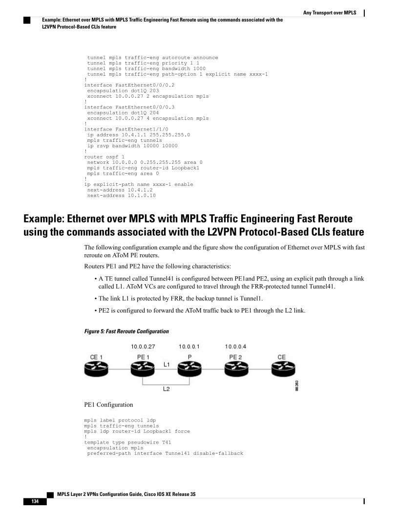
tunnel mpls traffic-eng autoroute announcetunnel mpls traffic-eng priority 1 1tunnel mpls traffic-eng bandwidth 1000tunnel mpls traffic-eng path-option 1 explicit name xxxx-1!interface FastEthernet0/0/0.2encapsulation dot1Q 203xconnect 10.0.0.27 2 encapsulation mpls!interface FastEthernet0/0/0.3encapsulation dot1Q 204xconnect 10.0.0.27 4 encapsulation mpls!interface FastEthernet1/1/0ip address 10.4.1.1 255.255.255.0mpls traffic-eng tunnelsip rsvp bandwidth 10000 10000!router ospf 1network 10.0.0.0 0.255.255.255 area 0mpls traffic-eng router-id Loopback1mpls traffic-eng area 0!ip explicit-path name xxxx-1 enablenext-address 10.4.1.2next-address 10.1.0.10
Example: Ethernet over MPLS with MPLS Traffic Engineering Fast Rerouteusing the commands associated with the L2VPN Protocol-Based CLIs feature
The following configuration example and the figure show the configuration of Ethernet over MPLS with fastreroute on AToM PE routers.
Routers PE1 and PE2 have the following characteristics:
• A TE tunnel called Tunnel41 is configured between PE1and PE2, using an explicit path through a linkcalled L1. AToM VCs are configured to travel through the FRR-protected tunnel Tunnel41.
• The link L1 is protected by FRR, the backup tunnel is Tunnel1.
• PE2 is configured to forward the AToM traffic back to PE1 through the L2 link.
Figure 5: Fast Reroute Configuration
PE1 Configuration
mpls label protocol ldpmpls traffic-eng tunnelsmpls ldp router-id Loopback1 force!template type pseudowire T41encapsulation mplspreferred-path interface Tunnel41 disable-fallback
MPLS Layer 2 VPNs Configuration Guide, Cisco IOS XE Release 3S134
Any Transport over MPLSExample: Ethernet over MPLS with MPLS Traffic Engineering Fast Reroute using the commands associated with theL2VPN Protocol-Based CLIs feature
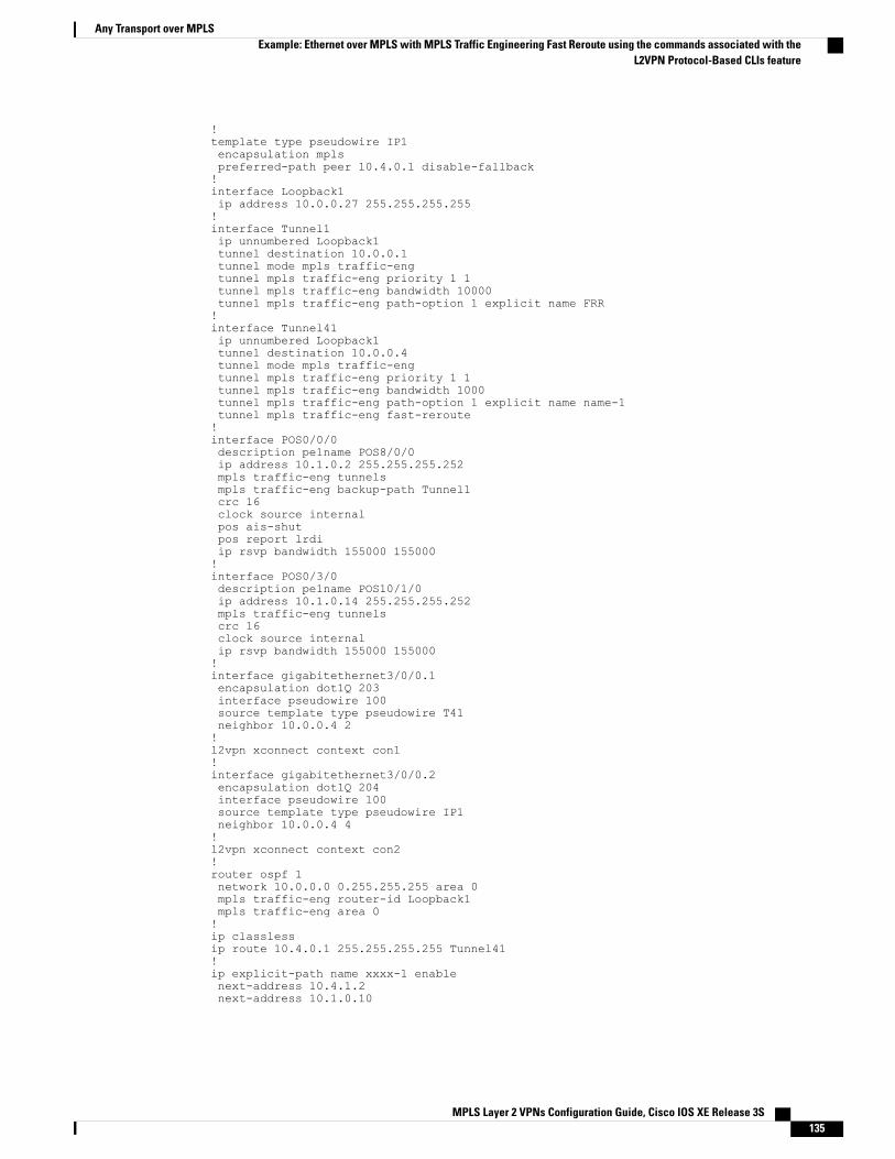
!template type pseudowire IP1encapsulation mplspreferred-path peer 10.4.0.1 disable-fallback!interface Loopback1ip address 10.0.0.27 255.255.255.255!interface Tunnel1ip unnumbered Loopback1tunnel destination 10.0.0.1tunnel mode mpls traffic-engtunnel mpls traffic-eng priority 1 1tunnel mpls traffic-eng bandwidth 10000tunnel mpls traffic-eng path-option 1 explicit name FRR!interface Tunnel41ip unnumbered Loopback1tunnel destination 10.0.0.4tunnel mode mpls traffic-engtunnel mpls traffic-eng priority 1 1tunnel mpls traffic-eng bandwidth 1000tunnel mpls traffic-eng path-option 1 explicit name name-1tunnel mpls traffic-eng fast-reroute!interface POS0/0/0description pe1name POS8/0/0ip address 10.1.0.2 255.255.255.252mpls traffic-eng tunnelsmpls traffic-eng backup-path Tunnel1crc 16clock source internalpos ais-shutpos report lrdiip rsvp bandwidth 155000 155000!interface POS0/3/0description pe1name POS10/1/0ip address 10.1.0.14 255.255.255.252mpls traffic-eng tunnelscrc 16clock source internalip rsvp bandwidth 155000 155000!interface gigabitethernet3/0/0.1encapsulation dot1Q 203interface pseudowire 100source template type pseudowire T41neighbor 10.0.0.4 2!l2vpn xconnect context con1!interface gigabitethernet3/0/0.2encapsulation dot1Q 204interface pseudowire 100source template type pseudowire IP1neighbor 10.0.0.4 4!l2vpn xconnect context con2!router ospf 1network 10.0.0.0 0.255.255.255 area 0mpls traffic-eng router-id Loopback1mpls traffic-eng area 0!ip classlessip route 10.4.0.1 255.255.255.255 Tunnel41!ip explicit-path name xxxx-1 enablenext-address 10.4.1.2next-address 10.1.0.10
MPLS Layer 2 VPNs Configuration Guide, Cisco IOS XE Release 3S 135
Any Transport over MPLSExample: Ethernet over MPLS with MPLS Traffic Engineering Fast Reroute using the commands associated with the
L2VPN Protocol-Based CLIs feature
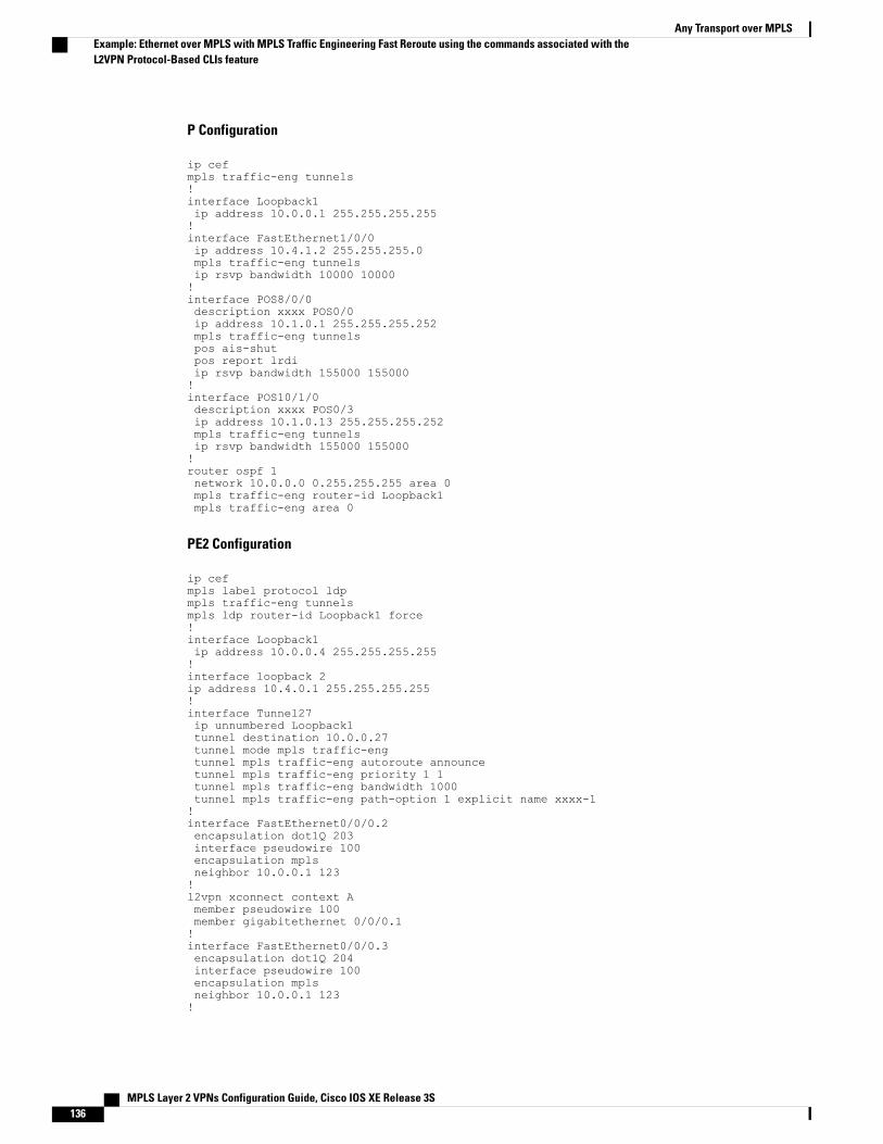
P Configuration
ip cefmpls traffic-eng tunnels!interface Loopback1ip address 10.0.0.1 255.255.255.255!interface FastEthernet1/0/0ip address 10.4.1.2 255.255.255.0mpls traffic-eng tunnelsip rsvp bandwidth 10000 10000!interface POS8/0/0description xxxx POS0/0ip address 10.1.0.1 255.255.255.252mpls traffic-eng tunnelspos ais-shutpos report lrdiip rsvp bandwidth 155000 155000!interface POS10/1/0description xxxx POS0/3ip address 10.1.0.13 255.255.255.252mpls traffic-eng tunnelsip rsvp bandwidth 155000 155000!router ospf 1network 10.0.0.0 0.255.255.255 area 0mpls traffic-eng router-id Loopback1mpls traffic-eng area 0
PE2 Configuration
ip cefmpls label protocol ldpmpls traffic-eng tunnelsmpls ldp router-id Loopback1 force!interface Loopback1ip address 10.0.0.4 255.255.255.255!interface loopback 2ip address 10.4.0.1 255.255.255.255!interface Tunnel27ip unnumbered Loopback1tunnel destination 10.0.0.27tunnel mode mpls traffic-engtunnel mpls traffic-eng autoroute announcetunnel mpls traffic-eng priority 1 1tunnel mpls traffic-eng bandwidth 1000tunnel mpls traffic-eng path-option 1 explicit name xxxx-1!interface FastEthernet0/0/0.2encapsulation dot1Q 203interface pseudowire 100encapsulation mplsneighbor 10.0.0.1 123!l2vpn xconnect context Amember pseudowire 100member gigabitethernet 0/0/0.1!interface FastEthernet0/0/0.3encapsulation dot1Q 204interface pseudowire 100encapsulation mplsneighbor 10.0.0.1 123!
MPLS Layer 2 VPNs Configuration Guide, Cisco IOS XE Release 3S136
Any Transport over MPLSExample: Ethernet over MPLS with MPLS Traffic Engineering Fast Reroute using the commands associated with theL2VPN Protocol-Based CLIs feature

l2vpn xconnect context Amember pseudowire 100member gigabitethernet 0/0/0.1!interface FastEthernet1/1/0ip address 10.4.1.1 255.255.255.0mpls traffic-eng tunnelsip rsvp bandwidth 10000 10000!router ospf 1network 10.0.0.0 0.255.255.255 area 0mpls traffic-eng router-id Loopback1mpls traffic-eng area 0!ip explicit-path name xxxx-1 enablenext-address 10.4.1.2next-address 10.1.0.10
Example: Configuring OAM Cell EmulationThe following example shows how to enable OAM cell emulation on an ATM PVC:
interface ATM 1/0/0pvc 1/200 l2transportencapsulation aal5xconnect 10.13.13.13 100 encapsulation mplsoam-ac emulation-enableoam-pvc manage
The following example shows how to set the rate at which an AIS cell is sent every 30 seconds:
interface ATM 1/0/0pvc 1/200 l2transportencapsulation aal5xconnect 10.13.13.13 100 encapsulation mplsoam-ac emulation-enable 30oam-pvc manage
The following example shows how to configure OAM cell emulation for ATMAAL5 over MPLS in VC classconfiguration mode. The VC class is then applied to an interface.
enableconfigure terminalvc-class atm oamclassencapsulation aal5oam-ac emulation-enable 30oam-pvc manageinterface atm1/0/0class-int oamclasspvc 1/200 l2transportxconnect 10.13.13.13 100 encapsulation mplsThe following example shows how to configure OAM cell emulation for ATMAAL5 over MPLS in VC classconfiguration mode. The VC class is then applied to a PVC.
enableconfigure terminalvc-class atm oamclassencapsulation aal5oam-ac emulation-enable 30oam-pvc manageinterface atm1/0/0pvc 1/200 l2transportclass-vc oamclassxconnect 10.13.13.13 100 encapsulation mpls
MPLS Layer 2 VPNs Configuration Guide, Cisco IOS XE Release 3S 137
Any Transport over MPLSExample: Configuring OAM Cell Emulation
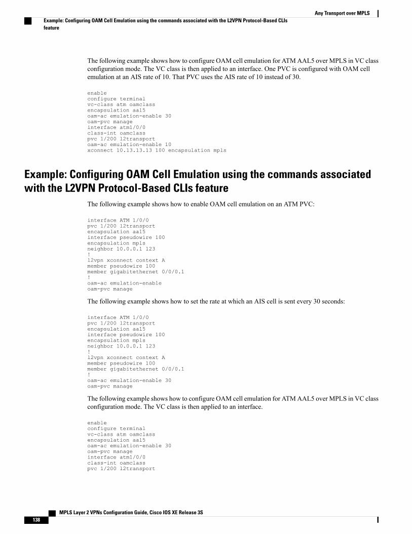
The following example shows how to configure OAM cell emulation for ATMAAL5 over MPLS in VC classconfiguration mode. The VC class is then applied to an interface. One PVC is configured with OAM cellemulation at an AIS rate of 10. That PVC uses the AIS rate of 10 instead of 30.
enableconfigure terminalvc-class atm oamclassencapsulation aal5oam-ac emulation-enable 30oam-pvc manageinterface atm1/0/0class-int oamclasspvc 1/200 l2transportoam-ac emulation-enable 10xconnect 10.13.13.13 100 encapsulation mpls
Example: Configuring OAM Cell Emulation using the commands associatedwith the L2VPN Protocol-Based CLIs feature
The following example shows how to enable OAM cell emulation on an ATM PVC:
interface ATM 1/0/0pvc 1/200 l2transportencapsulation aal5interface pseudowire 100encapsulation mplsneighbor 10.0.0.1 123!l2vpn xconnect context Amember pseudowire 100member gigabitethernet 0/0/0.1!oam-ac emulation-enableoam-pvc manage
The following example shows how to set the rate at which an AIS cell is sent every 30 seconds:
interface ATM 1/0/0pvc 1/200 l2transportencapsulation aal5interface pseudowire 100encapsulation mplsneighbor 10.0.0.1 123!l2vpn xconnect context Amember pseudowire 100member gigabitethernet 0/0/0.1!oam-ac emulation-enable 30oam-pvc manage
The following example shows how to configure OAM cell emulation for ATMAAL5 over MPLS in VC classconfiguration mode. The VC class is then applied to an interface.
enableconfigure terminalvc-class atm oamclassencapsulation aal5oam-ac emulation-enable 30oam-pvc manageinterface atm1/0/0class-int oamclasspvc 1/200 l2transport
MPLS Layer 2 VPNs Configuration Guide, Cisco IOS XE Release 3S138
Any Transport over MPLSExample: Configuring OAM Cell Emulation using the commands associated with the L2VPN Protocol-Based CLIsfeature
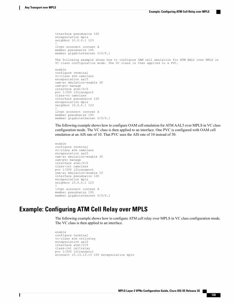
interface pseudowire 100encapsulation mplsneighbor 10.0.0.1 123!l2vpn xconnect context Amember pseudowire 100member gigabitethernet 0/0/0.1
The following example shows how to configure OAM cell emulation for ATM AAL5 over MPLS inVC class configuration mode. The VC class is then applied to a PVC.
enableconfigure terminalvc-class atm oamclassencapsulation aal5oam-ac emulation-enable 30oam-pvc manageinterface atm1/0/0pvc 1/200 l2transportclass-vc oamclassinterface pseudowire 100encapsulation mplsneighbor 10.0.0.1 123!l2vpn xconnect context Amember pseudowire 100member gigabitethernet 0/0/0.1
The following example shows how to configure OAM cell emulation for ATMAAL5 over MPLS in VC classconfiguration mode. The VC class is then applied to an interface. One PVC is configured with OAM cellemulation at an AIS rate of 10. That PVC uses the AIS rate of 10 instead of 30.
enableconfigure terminalvc-class atm oamclassencapsulation aal5oam-ac emulation-enable 30oam-pvc manageinterface atm1/0/0class-int oamclasspvc 1/200 l2transportoam-ac emulation-enable 10interface pseudowire 100encapsulation mplsneighbor 10.0.0.1 123!l2vpn xconnect context Amember pseudowire 100member gigabitethernet 0/0/0.1
Example: Configuring ATM Cell Relay over MPLSThe following example shows how to configure ATM cell relay over MPLS in VC class configuration mode.The VC class is then applied to an interface.
enableconfigure terminalvc-class atm cellrelayencapsulation aal0interface atm1/0/0class-int cellrelaypvc 1/200 l2transportxconnect 10.13.13.13 100 encapsulation mpls
MPLS Layer 2 VPNs Configuration Guide, Cisco IOS XE Release 3S 139
Any Transport over MPLSExample: Configuring ATM Cell Relay over MPLS
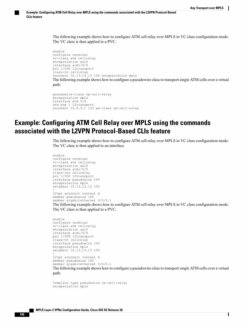
The following example shows how to configure ATM cell relay over MPLS in VC class configuration mode.The VC class is then applied to a PVC.
enableconfigure terminalvc-class atm cellrelayencapsulation aal0interface atm1/0/0pvc 1/200 l2transportclass-vc cellrelayxconnect 10.13.13.13 100 encapsulation mplsThe following example shows how to configure a pseudowire class to transport single ATM cells over a virtualpath:
pseudowire-class vp-cell-relayencapsulation mplsinterface atm 5/0atm pvp 1 l2transportxconnect 10.0.0.1 123 pw-class vp-cell-relay
Example: Configuring ATM Cell Relay over MPLS using the commandsassociated with the L2VPN Protocol-Based CLIs feature
The following example shows how to configure ATM cell relay over MPLS in VC class configuration mode.The VC class is then applied to an interface.
enableconfigure terminalvc-class atm cellrelayencapsulation aal0interface atm1/0/0class-int cellrelaypvc 1/200 l2transportinterface pseudowire 100encapsulation mplsneighbor 10.13.13.13 100!l2vpn xconnect context Amember pseudowire 100member gigabitethernet 0/0/0.1The following example shows how to configure ATM cell relay over MPLS in VC class configuration mode.The VC class is then applied to a PVC.
enableconfigure terminalvc-class atm cellrelayencapsulation aal0interface atm1/0/0pvc 1/200 l2transportclass-vc cellrelayinterface pseudowire 100encapsulation mplsneighbor 10.13.13.13 100!l2vpn xconnect context Amember pseudowire 100member gigabitethernet 0/0/0.1The following example shows how to configure a pseudowire class to transport single ATM cells over a virtualpath:
template type pseudowire vp-cell-relayencapsulation mpls
MPLS Layer 2 VPNs Configuration Guide, Cisco IOS XE Release 3S140
Any Transport over MPLSExample: Configuring ATM Cell Relay over MPLS using the commands associated with the L2VPN Protocol-BasedCLIs feature
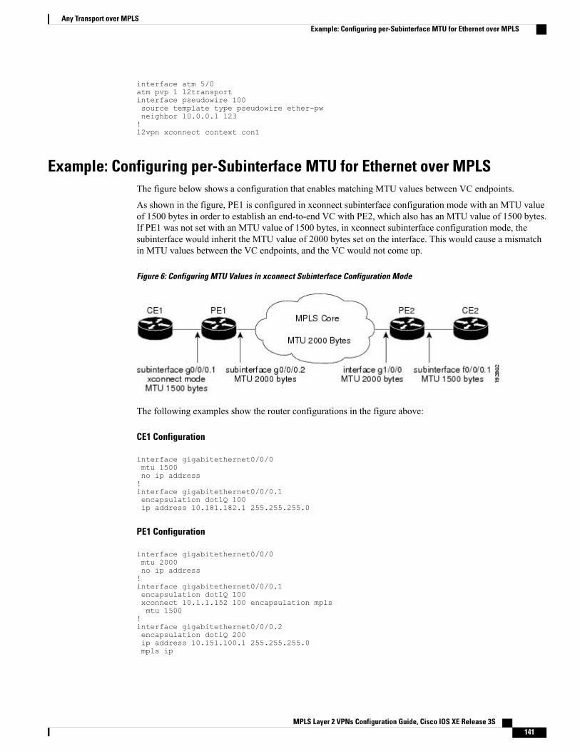
interface atm 5/0atm pvp 1 l2transportinterface pseudowire 100source template type pseudowire ether-pwneighbor 10.0.0.1 123!l2vpn xconnect context con1
Example: Configuring per-Subinterface MTU for Ethernet over MPLSThe figure below shows a configuration that enables matching MTU values between VC endpoints.
As shown in the figure, PE1 is configured in xconnect subinterface configuration mode with an MTU valueof 1500 bytes in order to establish an end-to-end VC with PE2, which also has an MTU value of 1500 bytes.If PE1 was not set with an MTU value of 1500 bytes, in xconnect subinterface configuration mode, thesubinterface would inherit the MTU value of 2000 bytes set on the interface. This would cause a mismatchin MTU values between the VC endpoints, and the VC would not come up.
Figure 6: Configuring MTU Values in xconnect Subinterface Configuration Mode
The following examples show the router configurations in the figure above:
CE1 Configuration
interface gigabitethernet0/0/0mtu 1500no ip address!interface gigabitethernet0/0/0.1encapsulation dot1Q 100ip address 10.181.182.1 255.255.255.0
PE1 Configuration
interface gigabitethernet0/0/0mtu 2000no ip address!interface gigabitethernet0/0/0.1encapsulation dot1Q 100xconnect 10.1.1.152 100 encapsulation mplsmtu 1500
!interface gigabitethernet0/0/0.2encapsulation dot1Q 200ip address 10.151.100.1 255.255.255.0mpls ip
MPLS Layer 2 VPNs Configuration Guide, Cisco IOS XE Release 3S 141
Any Transport over MPLSExample: Configuring per-Subinterface MTU for Ethernet over MPLS
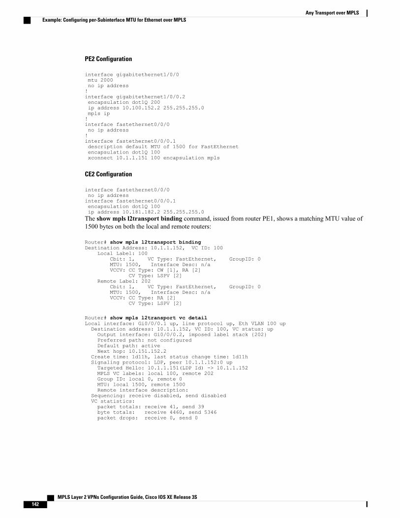
PE2 Configuration
interface gigabitethernet1/0/0mtu 2000no ip address!interface gigabitethernet1/0/0.2encapsulation dot1Q 200ip address 10.100.152.2 255.255.255.0mpls ip!interface fastethernet0/0/0no ip address!interface fastethernet0/0/0.1description default MTU of 1500 for FastEthernetencapsulation dot1Q 100xconnect 10.1.1.151 100 encapsulation mpls
CE2 Configuration
interface fastethernet0/0/0no ip addressinterface fastethernet0/0/0.1encapsulation dot1Q 100ip address 10.181.182.2 255.255.255.0The show mpls l2transport binding command, issued from router PE1, shows a matching MTU value of1500 bytes on both the local and remote routers:
Router# show mpls l2transport bindingDestination Address: 10.1.1.152, VC ID: 100
Local Label: 100Cbit: 1, VC Type: FastEthernet, GroupID: 0MTU: 1500, Interface Desc: n/aVCCV: CC Type: CW [1], RA [2]
CV Type: LSPV [2]Remote Label: 202
Cbit: 1, VC Type: FastEthernet, GroupID: 0MTU: 1500, Interface Desc: n/aVCCV: CC Type: RA [2]
CV Type: LSPV [2]
Router# show mpls l2transport vc detailLocal interface: Gi0/0/0.1 up, line protocol up, Eth VLAN 100 upDestination address: 10.1.1.152, VC ID: 100, VC status: upOutput interface: Gi0/0/0.2, imposed label stack {202}Preferred path: not configuredDefault path: activeNext hop: 10.151.152.2
Create time: 1d11h, last status change time: 1d11hSignaling protocol: LDP, peer 10.1.1.152:0 upTargeted Hello: 10.1.1.151(LDP Id) -> 10.1.1.152MPLS VC labels: local 100, remote 202Group ID: local 0, remote 0MTU: local 1500, remote 1500Remote interface description:
Sequencing: receive disabled, send disabledVC statistics:packet totals: receive 41, send 39byte totals: receive 4460, send 5346packet drops: receive 0, send 0
MPLS Layer 2 VPNs Configuration Guide, Cisco IOS XE Release 3S142
Any Transport over MPLSExample: Configuring per-Subinterface MTU for Ethernet over MPLS
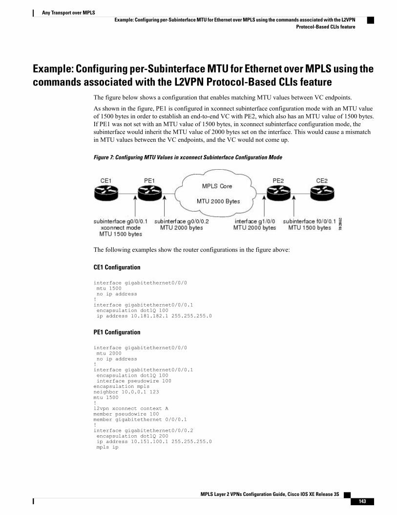
Example: Configuring per-Subinterface MTU for Ethernet over MPLS using thecommands associated with the L2VPN Protocol-Based CLIs feature
The figure below shows a configuration that enables matching MTU values between VC endpoints.
As shown in the figure, PE1 is configured in xconnect subinterface configuration mode with an MTU valueof 1500 bytes in order to establish an end-to-end VC with PE2, which also has an MTU value of 1500 bytes.If PE1 was not set with an MTU value of 1500 bytes, in xconnect subinterface configuration mode, thesubinterface would inherit the MTU value of 2000 bytes set on the interface. This would cause a mismatchin MTU values between the VC endpoints, and the VC would not come up.
Figure 7: Configuring MTU Values in xconnect Subinterface Configuration Mode
The following examples show the router configurations in the figure above:
CE1 Configuration
interface gigabitethernet0/0/0mtu 1500no ip address!interface gigabitethernet0/0/0.1encapsulation dot1Q 100ip address 10.181.182.1 255.255.255.0
PE1 Configuration
interface gigabitethernet0/0/0mtu 2000no ip address!interface gigabitethernet0/0/0.1encapsulation dot1Q 100interface pseudowire 100encapsulation mplsneighbor 10.0.0.1 123mtu 1500!l2vpn xconnect context Amember pseudowire 100member gigabitethernet 0/0/0.1!interface gigabitethernet0/0/0.2encapsulation dot1Q 200ip address 10.151.100.1 255.255.255.0mpls ip
MPLS Layer 2 VPNs Configuration Guide, Cisco IOS XE Release 3S 143
Any Transport over MPLSExample: Configuring per-Subinterface MTU for Ethernet over MPLS using the commands associated with the L2VPN
Protocol-Based CLIs feature
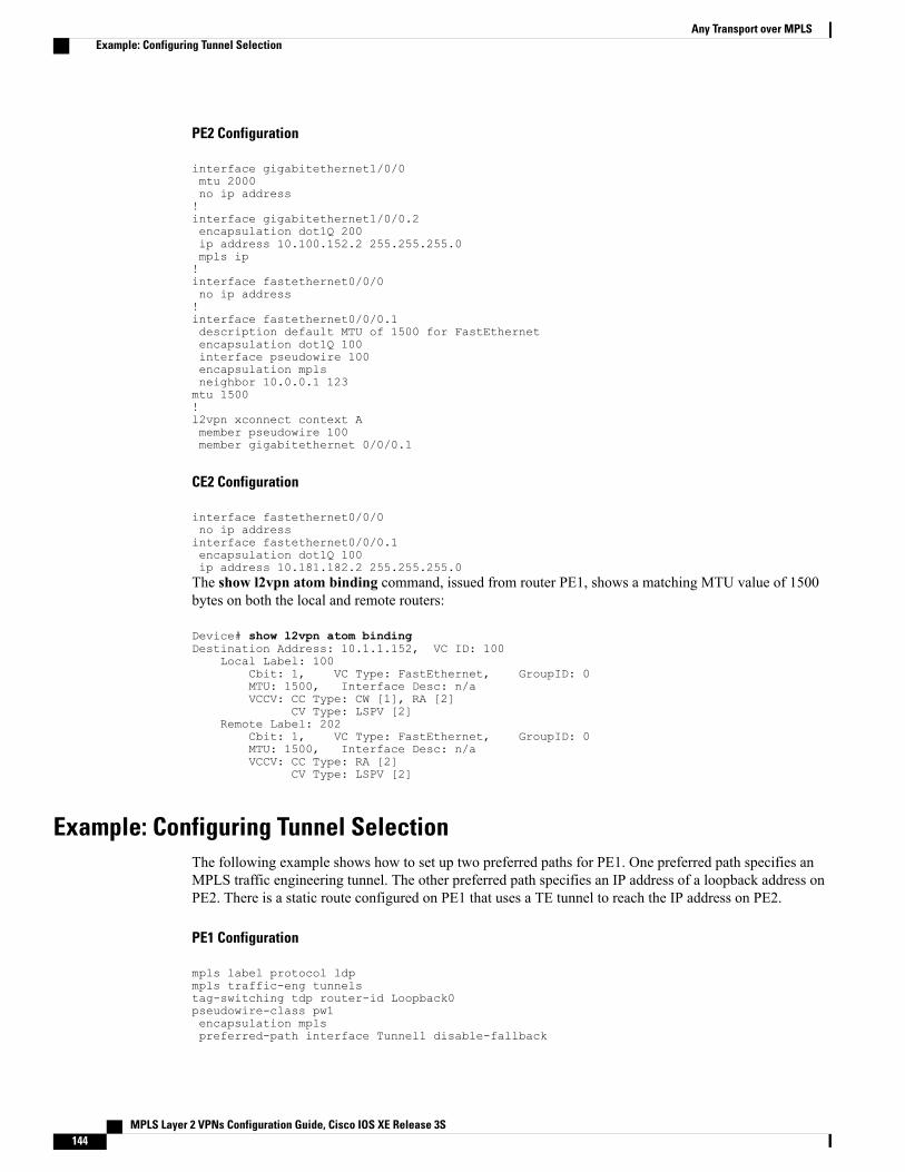
PE2 Configuration
interface gigabitethernet1/0/0mtu 2000no ip address!interface gigabitethernet1/0/0.2encapsulation dot1Q 200ip address 10.100.152.2 255.255.255.0mpls ip!interface fastethernet0/0/0no ip address!interface fastethernet0/0/0.1description default MTU of 1500 for FastEthernetencapsulation dot1Q 100interface pseudowire 100encapsulation mplsneighbor 10.0.0.1 123mtu 1500!l2vpn xconnect context Amember pseudowire 100member gigabitethernet 0/0/0.1
CE2 Configuration
interface fastethernet0/0/0no ip addressinterface fastethernet0/0/0.1encapsulation dot1Q 100ip address 10.181.182.2 255.255.255.0The show l2vpn atom binding command, issued from router PE1, shows a matching MTU value of 1500bytes on both the local and remote routers:
Device# show l2vpn atom bindingDestination Address: 10.1.1.152, VC ID: 100
Local Label: 100Cbit: 1, VC Type: FastEthernet, GroupID: 0MTU: 1500, Interface Desc: n/aVCCV: CC Type: CW [1], RA [2]
CV Type: LSPV [2]Remote Label: 202
Cbit: 1, VC Type: FastEthernet, GroupID: 0MTU: 1500, Interface Desc: n/aVCCV: CC Type: RA [2]
CV Type: LSPV [2]
Example: Configuring Tunnel SelectionThe following example shows how to set up two preferred paths for PE1. One preferred path specifies anMPLS traffic engineering tunnel. The other preferred path specifies an IP address of a loopback address onPE2. There is a static route configured on PE1 that uses a TE tunnel to reach the IP address on PE2.
PE1 Configuration
mpls label protocol ldpmpls traffic-eng tunnelstag-switching tdp router-id Loopback0pseudowire-class pw1encapsulation mplspreferred-path interface Tunnel1 disable-fallback
MPLS Layer 2 VPNs Configuration Guide, Cisco IOS XE Release 3S144
Any Transport over MPLSExample: Configuring Tunnel Selection
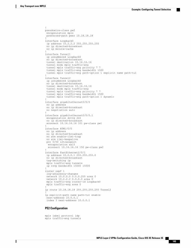
!pseudowire-class pw2encapsulation mplspreferred-path peer 10.18.18.18!interface Loopback0ip address 10.2.2.2 255.255.255.255no ip directed-broadcastno ip mroute-cache!interface Tunnel1ip unnumbered Loopback0no ip directed-broadcasttunnel destination 10.16.16.16tunnel mode mpls traffic-engtunnel mpls traffic-eng priority 7 7tunnel mpls traffic-eng bandwidth 1500tunnel mpls traffic-eng path-option 1 explicit name path-tu1!interface Tunnel2ip unnumbered Loopback0no ip directed-broadcasttunnel destination 10.16.16.16tunnel mode mpls traffic-engtunnel mpls traffic-eng priority 7 7tunnel mpls traffic-eng bandwidth 1500tunnel mpls traffic-eng path-option 1 dynamic!interface gigabitethernet0/0/0no ip addressno ip directed-broadcastno negotiation auto!interface gigabitethernet0/0/0.1encapsulation dot1Q 222no ip directed-broadcastxconnect 10.16.16.16 101 pw-class pw1!interface ATM1/0/0no ip addressno ip directed-broadcastno atm enable-ilmi-trapno atm ilmi-keepalivepvc 0/50 l2transportencapsulation aal5xconnect 10.16.16.16 150 pw-class pw2
!interface FastEthernet2/0/1ip address 10.0.0.1 255.255.255.0no ip directed-broadcasttag-switching ipmpls traffic-eng tunnelsip rsvp bandwidth 15000 15000!router ospf 1log-adjacency-changesnetwork 10.0.0.0 0.0.0.255 area 0network 10.2.2.2 0.0.0.0 area 0mpls traffic-eng router-id Loopback0mpls traffic-eng area 0!ip route 10.18.18.18 255.255.255.255 Tunnel2!ip explicit-path name path-tu1 enablenext-address 10.0.0.1index 3 next-address 10.0.0.1
PE2 Configuration
mpls label protocol ldpmpls traffic-eng tunnels
MPLS Layer 2 VPNs Configuration Guide, Cisco IOS XE Release 3S 145
Any Transport over MPLSExample: Configuring Tunnel Selection
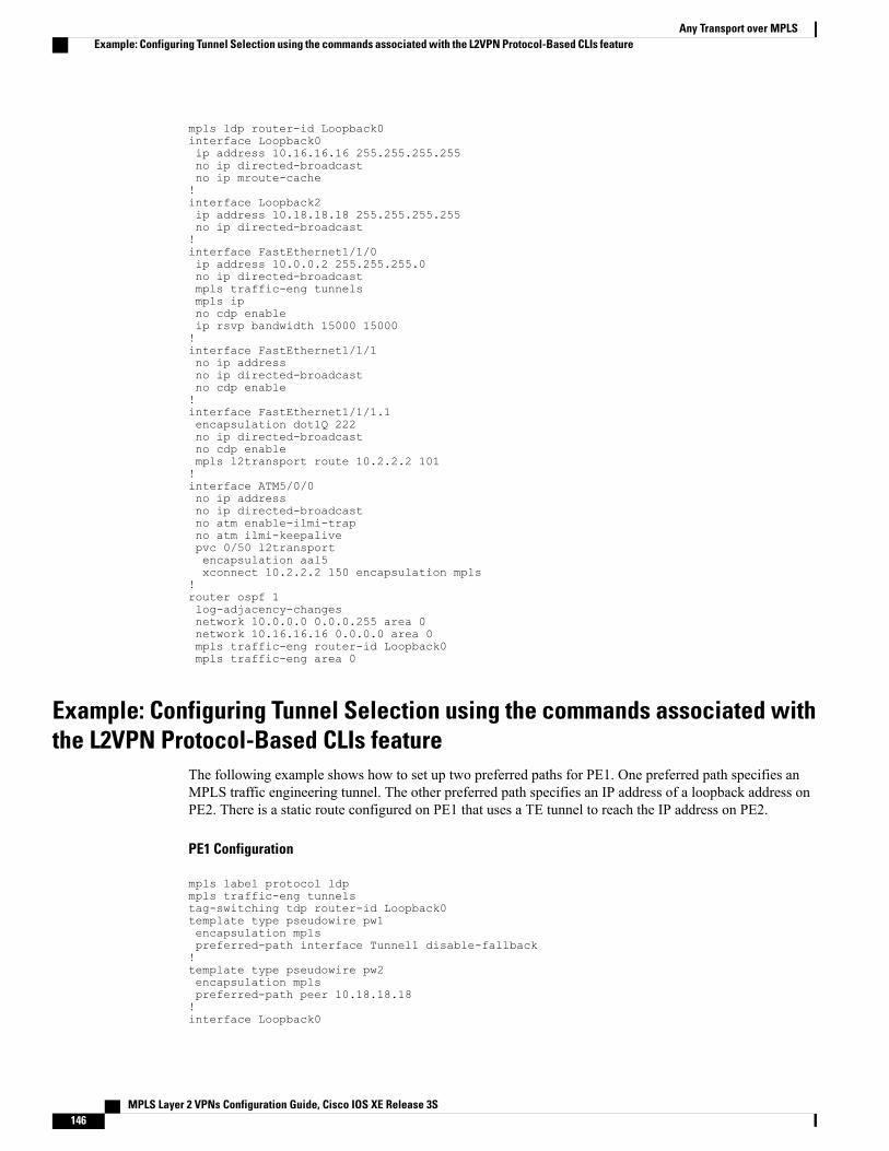
mpls ldp router-id Loopback0interface Loopback0ip address 10.16.16.16 255.255.255.255no ip directed-broadcastno ip mroute-cache!interface Loopback2ip address 10.18.18.18 255.255.255.255no ip directed-broadcast!interface FastEthernet1/1/0ip address 10.0.0.2 255.255.255.0no ip directed-broadcastmpls traffic-eng tunnelsmpls ipno cdp enableip rsvp bandwidth 15000 15000!interface FastEthernet1/1/1no ip addressno ip directed-broadcastno cdp enable!interface FastEthernet1/1/1.1encapsulation dot1Q 222no ip directed-broadcastno cdp enablempls l2transport route 10.2.2.2 101!interface ATM5/0/0no ip addressno ip directed-broadcastno atm enable-ilmi-trapno atm ilmi-keepalivepvc 0/50 l2transportencapsulation aal5xconnect 10.2.2.2 150 encapsulation mpls
!router ospf 1log-adjacency-changesnetwork 10.0.0.0 0.0.0.255 area 0network 10.16.16.16 0.0.0.0 area 0mpls traffic-eng router-id Loopback0mpls traffic-eng area 0
Example: Configuring Tunnel Selection using the commands associated withthe L2VPN Protocol-Based CLIs feature
The following example shows how to set up two preferred paths for PE1. One preferred path specifies anMPLS traffic engineering tunnel. The other preferred path specifies an IP address of a loopback address onPE2. There is a static route configured on PE1 that uses a TE tunnel to reach the IP address on PE2.
PE1 Configuration
mpls label protocol ldpmpls traffic-eng tunnelstag-switching tdp router-id Loopback0template type pseudowire pw1encapsulation mplspreferred-path interface Tunnel1 disable-fallback!template type pseudowire pw2encapsulation mplspreferred-path peer 10.18.18.18!interface Loopback0
MPLS Layer 2 VPNs Configuration Guide, Cisco IOS XE Release 3S146
Any Transport over MPLSExample: Configuring Tunnel Selection using the commands associated with the L2VPN Protocol-Based CLIs feature
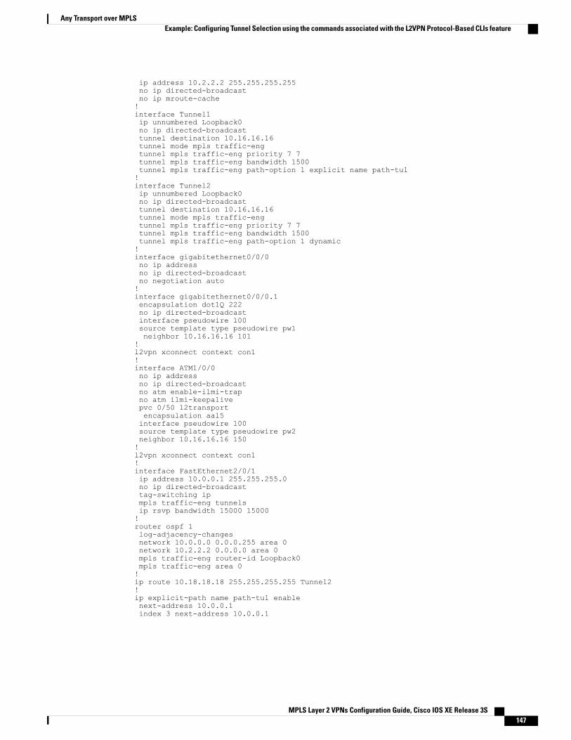
ip address 10.2.2.2 255.255.255.255no ip directed-broadcastno ip mroute-cache!interface Tunnel1ip unnumbered Loopback0no ip directed-broadcasttunnel destination 10.16.16.16tunnel mode mpls traffic-engtunnel mpls traffic-eng priority 7 7tunnel mpls traffic-eng bandwidth 1500tunnel mpls traffic-eng path-option 1 explicit name path-tu1!interface Tunnel2ip unnumbered Loopback0no ip directed-broadcasttunnel destination 10.16.16.16tunnel mode mpls traffic-engtunnel mpls traffic-eng priority 7 7tunnel mpls traffic-eng bandwidth 1500tunnel mpls traffic-eng path-option 1 dynamic!interface gigabitethernet0/0/0no ip addressno ip directed-broadcastno negotiation auto!interface gigabitethernet0/0/0.1encapsulation dot1Q 222no ip directed-broadcastinterface pseudowire 100source template type pseudowire pw1neighbor 10.16.16.16 101
!l2vpn xconnect context con1!interface ATM1/0/0no ip addressno ip directed-broadcastno atm enable-ilmi-trapno atm ilmi-keepalivepvc 0/50 l2transportencapsulation aal5interface pseudowire 100source template type pseudowire pw2neighbor 10.16.16.16 150!l2vpn xconnect context con1!interface FastEthernet2/0/1ip address 10.0.0.1 255.255.255.0no ip directed-broadcasttag-switching ipmpls traffic-eng tunnelsip rsvp bandwidth 15000 15000!router ospf 1log-adjacency-changesnetwork 10.0.0.0 0.0.0.255 area 0network 10.2.2.2 0.0.0.0 area 0mpls traffic-eng router-id Loopback0mpls traffic-eng area 0!ip route 10.18.18.18 255.255.255.255 Tunnel2!ip explicit-path name path-tu1 enablenext-address 10.0.0.1index 3 next-address 10.0.0.1
MPLS Layer 2 VPNs Configuration Guide, Cisco IOS XE Release 3S 147
Any Transport over MPLSExample: Configuring Tunnel Selection using the commands associated with the L2VPN Protocol-Based CLIs feature
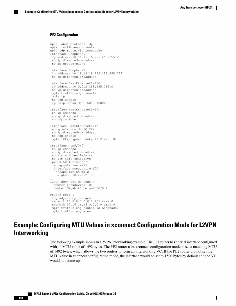
PE2 Configuration
mpls label protocol ldpmpls traffic-eng tunnelsmpls ldp router-id Loopback0interface Loopback0ip address 10.16.16.16 255.255.255.255no ip directed-broadcastno ip mroute-cache!interface Loopback2ip address 10.18.18.18 255.255.255.255no ip directed-broadcast!interface FastEthernet1/1/0ip address 10.0.0.2 255.255.255.0no ip directed-broadcastmpls traffic-eng tunnelsmpls ipno cdp enableip rsvp bandwidth 15000 15000!interface FastEthernet1/1/1no ip addressno ip directed-broadcastno cdp enable!interface FastEthernet1/1/1.1encapsulation dot1Q 222no ip directed-broadcastno cdp enablempls l2transport route 10.2.2.2 101!interface ATM5/0/0no ip addressno ip directed-broadcastno atm enable-ilmi-trapno atm ilmi-keepalivepvc 0/50 l2transportencapsulation aal5interface pseudowire 100encapsulation mplsneighbor 10.2.2.2 150
!l2vpn xconnect context Amember pseudowire 100member GigabitEthernet0/0/0.1
!router ospf 1log-adjacency-changesnetwork 10.0.0.0 0.0.0.255 area 0network 10.16.16.16 0.0.0.0 area 0mpls traffic-eng router-id Loopback0mpls traffic-eng area 0
Example: Configuring MTU Values in xconnect Configuration Mode for L2VPNInterworking
The following example shows an L2VPN Interworking example. The PE1 router has a serial interface configuredwith an MTU value of 1492 bytes. The PE2 router uses xconnect configuration mode to set a matching MTUof 1492 bytes, which allows the two routers to form an interworking VC. If the PE2 router did not set theMTU value in xconnect configuration mode, the interface would be set to 1500 bytes by default and the VCwould not come up.
MPLS Layer 2 VPNs Configuration Guide, Cisco IOS XE Release 3S148
Any Transport over MPLSExample: Configuring MTU Values in xconnect Configuration Mode for L2VPN Interworking
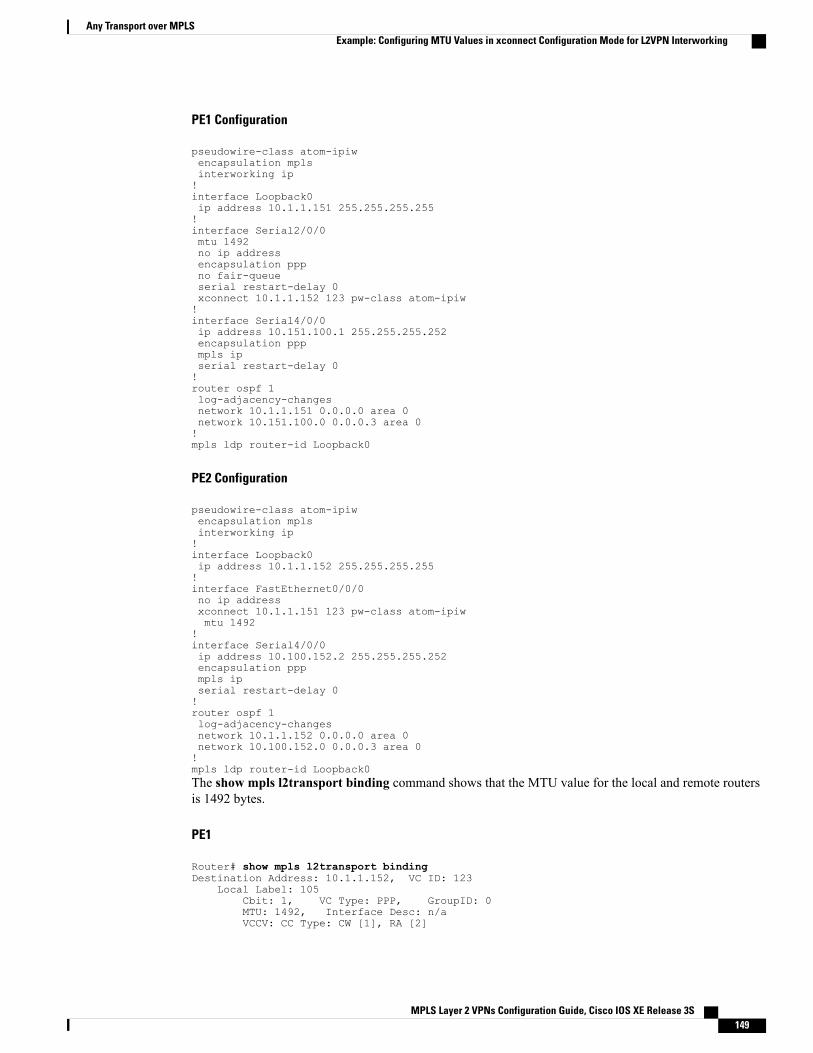
PE1 Configuration
pseudowire-class atom-ipiwencapsulation mplsinterworking ip!interface Loopback0ip address 10.1.1.151 255.255.255.255!interface Serial2/0/0mtu 1492no ip addressencapsulation pppno fair-queueserial restart-delay 0xconnect 10.1.1.152 123 pw-class atom-ipiw!interface Serial4/0/0ip address 10.151.100.1 255.255.255.252encapsulation pppmpls ipserial restart-delay 0!router ospf 1log-adjacency-changesnetwork 10.1.1.151 0.0.0.0 area 0network 10.151.100.0 0.0.0.3 area 0!mpls ldp router-id Loopback0
PE2 Configuration
pseudowire-class atom-ipiwencapsulation mplsinterworking ip!interface Loopback0ip address 10.1.1.152 255.255.255.255!interface FastEthernet0/0/0no ip addressxconnect 10.1.1.151 123 pw-class atom-ipiwmtu 1492
!interface Serial4/0/0ip address 10.100.152.2 255.255.255.252encapsulation pppmpls ipserial restart-delay 0!router ospf 1log-adjacency-changesnetwork 10.1.1.152 0.0.0.0 area 0network 10.100.152.0 0.0.0.3 area 0!mpls ldp router-id Loopback0The show mpls l2transport binding command shows that the MTU value for the local and remote routersis 1492 bytes.
PE1
Router# show mpls l2transport bindingDestination Address: 10.1.1.152, VC ID: 123
Local Label: 105Cbit: 1, VC Type: PPP, GroupID: 0MTU: 1492, Interface Desc: n/aVCCV: CC Type: CW [1], RA [2]
MPLS Layer 2 VPNs Configuration Guide, Cisco IOS XE Release 3S 149
Any Transport over MPLSExample: Configuring MTU Values in xconnect Configuration Mode for L2VPN Interworking
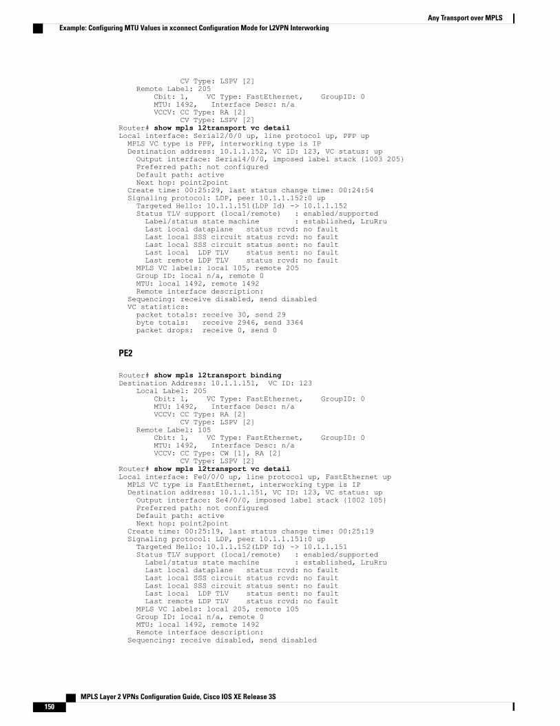
CV Type: LSPV [2]Remote Label: 205
Cbit: 1, VC Type: FastEthernet, GroupID: 0MTU: 1492, Interface Desc: n/aVCCV: CC Type: RA [2]
CV Type: LSPV [2]Router# show mpls l2transport vc detailLocal interface: Serial2/0/0 up, line protocol up, PPP upMPLS VC type is PPP, interworking type is IPDestination address: 10.1.1.152, VC ID: 123, VC status: upOutput interface: Serial4/0/0, imposed label stack {1003 205}Preferred path: not configuredDefault path: activeNext hop: point2point
Create time: 00:25:29, last status change time: 00:24:54Signaling protocol: LDP, peer 10.1.1.152:0 upTargeted Hello: 10.1.1.151(LDP Id) -> 10.1.1.152Status TLV support (local/remote) : enabled/supportedLabel/status state machine : established, LruRruLast local dataplane status rcvd: no faultLast local SSS circuit status rcvd: no faultLast local SSS circuit status sent: no faultLast local LDP TLV status sent: no faultLast remote LDP TLV status rcvd: no fault
MPLS VC labels: local 105, remote 205Group ID: local n/a, remote 0MTU: local 1492, remote 1492Remote interface description:
Sequencing: receive disabled, send disabledVC statistics:packet totals: receive 30, send 29byte totals: receive 2946, send 3364packet drops: receive 0, send 0
PE2
Router# show mpls l2transport bindingDestination Address: 10.1.1.151, VC ID: 123
Local Label: 205Cbit: 1, VC Type: FastEthernet, GroupID: 0MTU: 1492, Interface Desc: n/aVCCV: CC Type: RA [2]
CV Type: LSPV [2]Remote Label: 105
Cbit: 1, VC Type: FastEthernet, GroupID: 0MTU: 1492, Interface Desc: n/aVCCV: CC Type: CW [1], RA [2]
CV Type: LSPV [2]Router# show mpls l2transport vc detailLocal interface: Fe0/0/0 up, line protocol up, FastEthernet upMPLS VC type is FastEthernet, interworking type is IPDestination address: 10.1.1.151, VC ID: 123, VC status: upOutput interface: Se4/0/0, imposed label stack {1002 105}Preferred path: not configuredDefault path: activeNext hop: point2point
Create time: 00:25:19, last status change time: 00:25:19Signaling protocol: LDP, peer 10.1.1.151:0 upTargeted Hello: 10.1.1.152(LDP Id) -> 10.1.1.151Status TLV support (local/remote) : enabled/supportedLabel/status state machine : established, LruRruLast local dataplane status rcvd: no faultLast local SSS circuit status rcvd: no faultLast local SSS circuit status sent: no faultLast local LDP TLV status sent: no faultLast remote LDP TLV status rcvd: no fault
MPLS VC labels: local 205, remote 105Group ID: local n/a, remote 0MTU: local 1492, remote 1492Remote interface description:
Sequencing: receive disabled, send disabled
MPLS Layer 2 VPNs Configuration Guide, Cisco IOS XE Release 3S150
Any Transport over MPLSExample: Configuring MTU Values in xconnect Configuration Mode for L2VPN Interworking
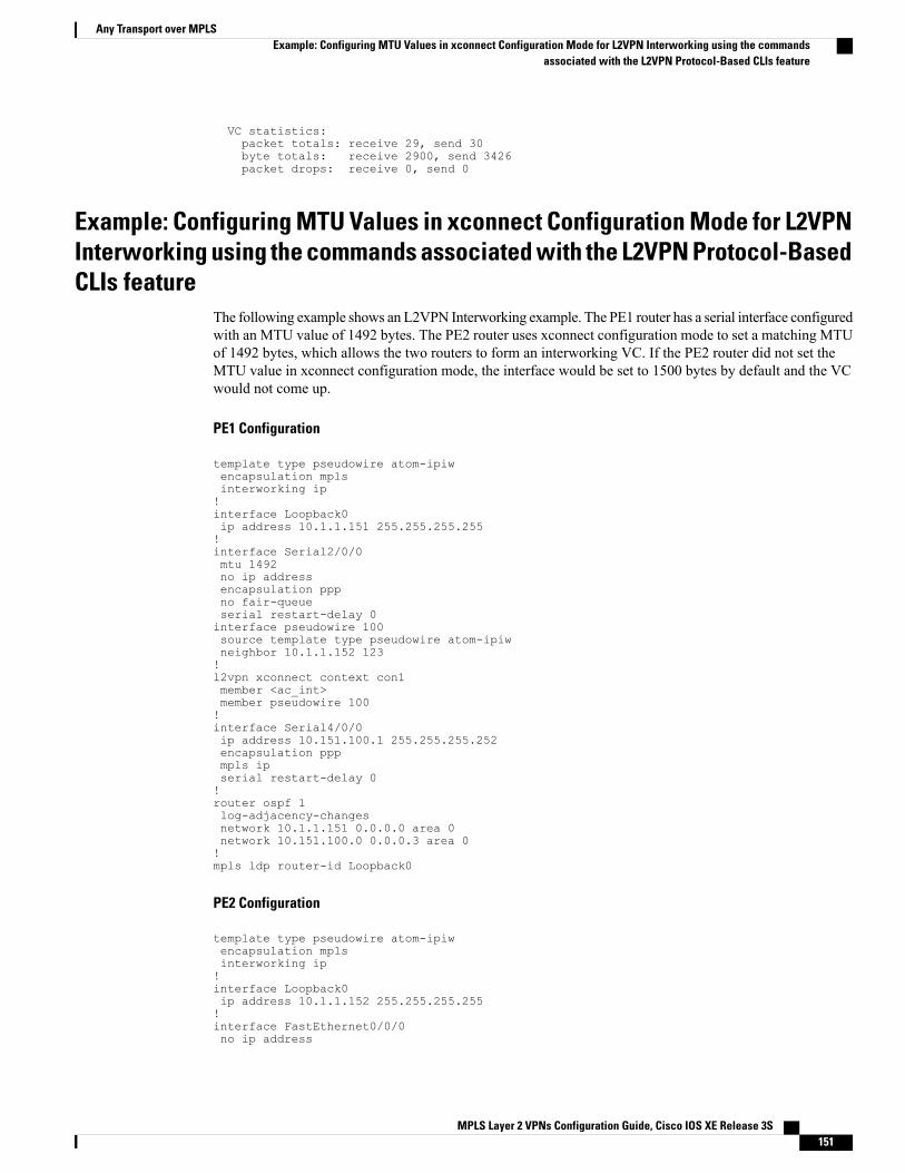
VC statistics:packet totals: receive 29, send 30byte totals: receive 2900, send 3426packet drops: receive 0, send 0
Example: Configuring MTU Values in xconnect Configuration Mode for L2VPNInterworking using the commands associated with the L2VPN Protocol-BasedCLIs feature
The following example shows an L2VPN Interworking example. The PE1 router has a serial interface configuredwith an MTU value of 1492 bytes. The PE2 router uses xconnect configuration mode to set a matching MTUof 1492 bytes, which allows the two routers to form an interworking VC. If the PE2 router did not set theMTU value in xconnect configuration mode, the interface would be set to 1500 bytes by default and the VCwould not come up.
PE1 Configuration
template type pseudowire atom-ipiwencapsulation mplsinterworking ip!interface Loopback0ip address 10.1.1.151 255.255.255.255!interface Serial2/0/0mtu 1492no ip addressencapsulation pppno fair-queueserial restart-delay 0interface pseudowire 100source template type pseudowire atom-ipiwneighbor 10.1.1.152 123!l2vpn xconnect context con1member <ac_int>member pseudowire 100!interface Serial4/0/0ip address 10.151.100.1 255.255.255.252encapsulation pppmpls ipserial restart-delay 0!router ospf 1log-adjacency-changesnetwork 10.1.1.151 0.0.0.0 area 0network 10.151.100.0 0.0.0.3 area 0!mpls ldp router-id Loopback0
PE2 Configuration
template type pseudowire atom-ipiwencapsulation mplsinterworking ip!interface Loopback0ip address 10.1.1.152 255.255.255.255!interface FastEthernet0/0/0no ip address
MPLS Layer 2 VPNs Configuration Guide, Cisco IOS XE Release 3S 151
Any Transport over MPLSExample: Configuring MTU Values in xconnect Configuration Mode for L2VPN Interworking using the commands
associated with the L2VPN Protocol-Based CLIs feature
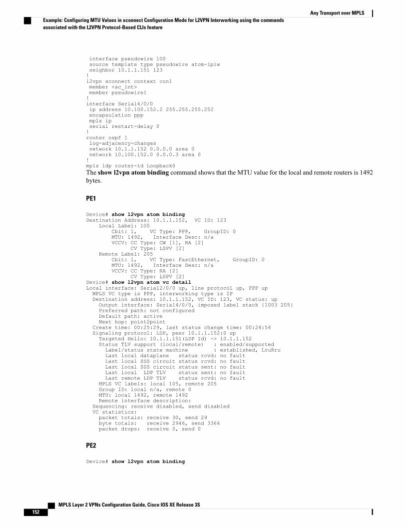
interface pseudowire 100source template type pseudowire atom-ipiwneighbor 10.1.1.151 123!l2vpn xconnect context con1member <ac_int>member pseudowire1!interface Serial4/0/0ip address 10.100.152.2 255.255.255.252encapsulation pppmpls ipserial restart-delay 0!router ospf 1log-adjacency-changesnetwork 10.1.1.152 0.0.0.0 area 0network 10.100.152.0 0.0.0.3 area 0!mpls ldp router-id Loopback0The show l2vpn atom binding command shows that the MTU value for the local and remote routers is 1492bytes.
PE1
Device# show l2vpn atom bindingDestination Address: 10.1.1.152, VC ID: 123
Local Label: 105Cbit: 1, VC Type: PPP, GroupID: 0MTU: 1492, Interface Desc: n/aVCCV: CC Type: CW [1], RA [2]
CV Type: LSPV [2]Remote Label: 205
Cbit: 1, VC Type: FastEthernet, GroupID: 0MTU: 1492, Interface Desc: n/aVCCV: CC Type: RA [2]
CV Type: LSPV [2]Device# show l2vpn atom vc detailLocal interface: Serial2/0/0 up, line protocol up, PPP upMPLS VC type is PPP, interworking type is IPDestination address: 10.1.1.152, VC ID: 123, VC status: upOutput interface: Serial4/0/0, imposed label stack {1003 205}Preferred path: not configuredDefault path: activeNext hop: point2point
Create time: 00:25:29, last status change time: 00:24:54Signaling protocol: LDP, peer 10.1.1.152:0 upTargeted Hello: 10.1.1.151(LDP Id) -> 10.1.1.152Status TLV support (local/remote) : enabled/supportedLabel/status state machine : established, LruRruLast local dataplane status rcvd: no faultLast local SSS circuit status rcvd: no faultLast local SSS circuit status sent: no faultLast local LDP TLV status sent: no faultLast remote LDP TLV status rcvd: no fault
MPLS VC labels: local 105, remote 205Group ID: local n/a, remote 0MTU: local 1492, remote 1492Remote interface description:
Sequencing: receive disabled, send disabledVC statistics:packet totals: receive 30, send 29byte totals: receive 2946, send 3364packet drops: receive 0, send 0
PE2
Device# show l2vpn atom binding
MPLS Layer 2 VPNs Configuration Guide, Cisco IOS XE Release 3S152
Any Transport over MPLSExample: Configuring MTU Values in xconnect Configuration Mode for L2VPN Interworking using the commandsassociated with the L2VPN Protocol-Based CLIs feature

Destination Address: 10.1.1.151, VC ID: 123Local Label: 205
Cbit: 1, VC Type: FastEthernet, GroupID: 0MTU: 1492, Interface Desc: n/aVCCV: CC Type: RA [2]
CV Type: LSPV [2]Remote Label: 105
Cbit: 1, VC Type: FastEthernet, GroupID: 0MTU: 1492, Interface Desc: n/aVCCV: CC Type: CW [1], RA [2]
CV Type: LSPV [2]Device# show l2vpn atom vc detailLocal interface: Fe0/0/0 up, line protocol up, FastEthernet upMPLS VC type is FastEthernet, interworking type is IPDestination address: 10.1.1.151, VC ID: 123, VC status: upOutput interface: Se4/0/0, imposed label stack {1002 105}Preferred path: not configuredDefault path: activeNext hop: point2point
Create time: 00:25:19, last status change time: 00:25:19Signaling protocol: LDP, peer 10.1.1.151:0 upTargeted Hello: 10.1.1.152(LDP Id) -> 10.1.1.151Status TLV support (local/remote) : enabled/supportedLabel/status state machine : established, LruRruLast local dataplane status rcvd: no faultLast local SSS circuit status rcvd: no faultLast local SSS circuit status sent: no faultLast local LDP TLV status sent: no faultLast remote LDP TLV status rcvd: no fault
MPLS VC labels: local 205, remote 105Group ID: local n/a, remote 0MTU: local 1492, remote 1492Remote interface description:
Sequencing: receive disabled, send disabledVC statistics:packet totals: receive 29, send 30byte totals: receive 2900, send 3426packet drops: receive 0, send 0
Examples: Configuring Any Transport over MPLS (AToM) Remote Ethernet PortShutdown
The following example shows how to enable remote Ethernet port shutdown:
configure terminal!pseudowire-class eomplsencapsulation mpls!interface GigabitEthernet1/0/0xconnect 10.1.1.1 1 pw-class eomplsremote link failure notification
The following example shows how to disable remote Ethernet port shutdown:
configure terminal!pseudowire-class eomplsencapsulation mpls!interface GigabitEthernet1/0/0xconnect 10.1.1.1 1 pw-class eomplsno remote link failure notification
The related show command output reports operational status for all remote L2 Tunnels by interface.
Router# show interface G1/0/0GigabitEthernet1/0/0 is L2 Tunnel remote down, line protocol is up
MPLS Layer 2 VPNs Configuration Guide, Cisco IOS XE Release 3S 153
Any Transport over MPLSExamples: Configuring Any Transport over MPLS (AToM) Remote Ethernet Port Shutdown
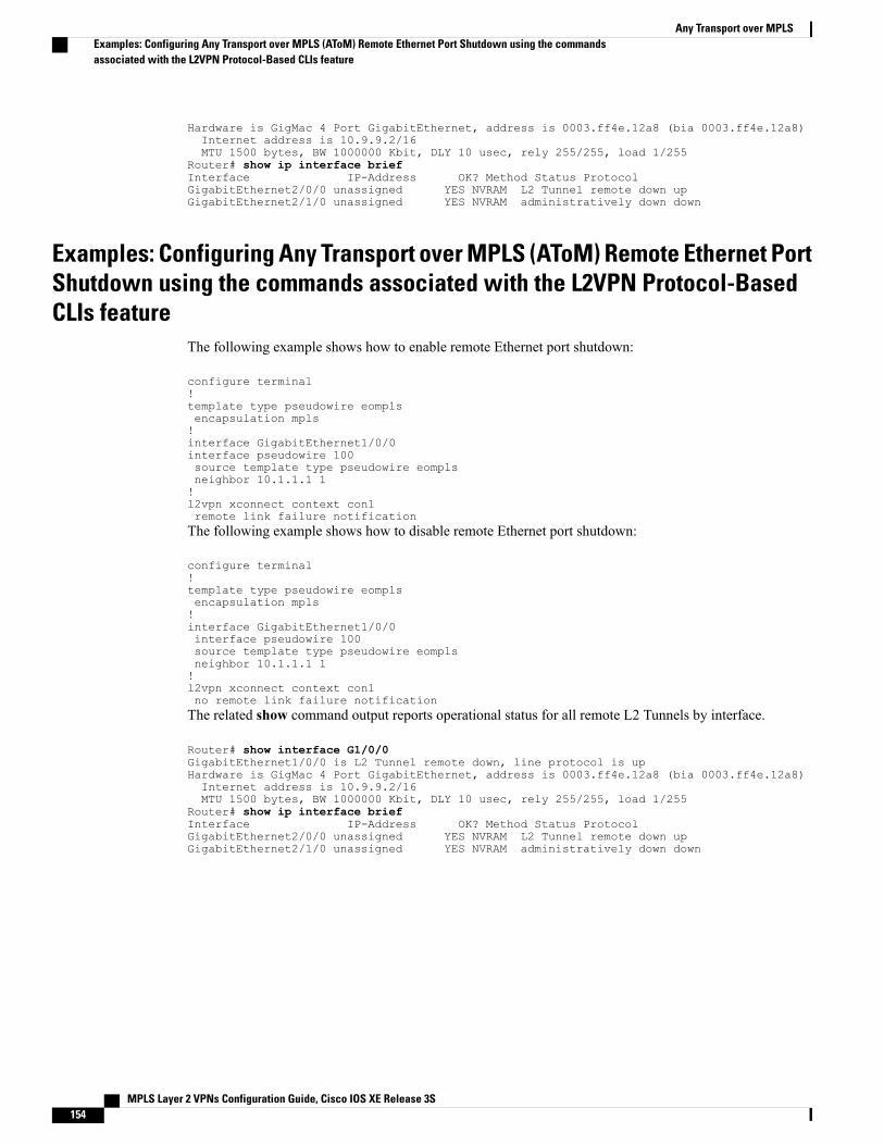
Hardware is GigMac 4 Port GigabitEthernet, address is 0003.ff4e.12a8 (bia 0003.ff4e.12a8)Internet address is 10.9.9.2/16MTU 1500 bytes, BW 1000000 Kbit, DLY 10 usec, rely 255/255, load 1/255
Router# show ip interface briefInterface IP-Address OK? Method Status ProtocolGigabitEthernet2/0/0 unassigned YES NVRAM L2 Tunnel remote down upGigabitEthernet2/1/0 unassigned YES NVRAM administratively down down
Examples: Configuring Any Transport over MPLS (AToM) Remote Ethernet PortShutdown using the commands associated with the L2VPN Protocol-BasedCLIs feature
The following example shows how to enable remote Ethernet port shutdown:
configure terminal!template type pseudowire eomplsencapsulation mpls!interface GigabitEthernet1/0/0interface pseudowire 100source template type pseudowire eomplsneighbor 10.1.1.1 1!l2vpn xconnect context con1remote link failure notificationThe following example shows how to disable remote Ethernet port shutdown:
configure terminal!template type pseudowire eomplsencapsulation mpls!interface GigabitEthernet1/0/0interface pseudowire 100source template type pseudowire eomplsneighbor 10.1.1.1 1!l2vpn xconnect context con1no remote link failure notificationThe related show command output reports operational status for all remote L2 Tunnels by interface.
Router# show interface G1/0/0GigabitEthernet1/0/0 is L2 Tunnel remote down, line protocol is upHardware is GigMac 4 Port GigabitEthernet, address is 0003.ff4e.12a8 (bia 0003.ff4e.12a8)Internet address is 10.9.9.2/16MTU 1500 bytes, BW 1000000 Kbit, DLY 10 usec, rely 255/255, load 1/255
Router# show ip interface briefInterface IP-Address OK? Method Status ProtocolGigabitEthernet2/0/0 unassigned YES NVRAM L2 Tunnel remote down upGigabitEthernet2/1/0 unassigned YES NVRAM administratively down down
MPLS Layer 2 VPNs Configuration Guide, Cisco IOS XE Release 3S154
Any Transport over MPLSExamples: Configuring Any Transport over MPLS (AToM) Remote Ethernet Port Shutdown using the commandsassociated with the L2VPN Protocol-Based CLIs feature
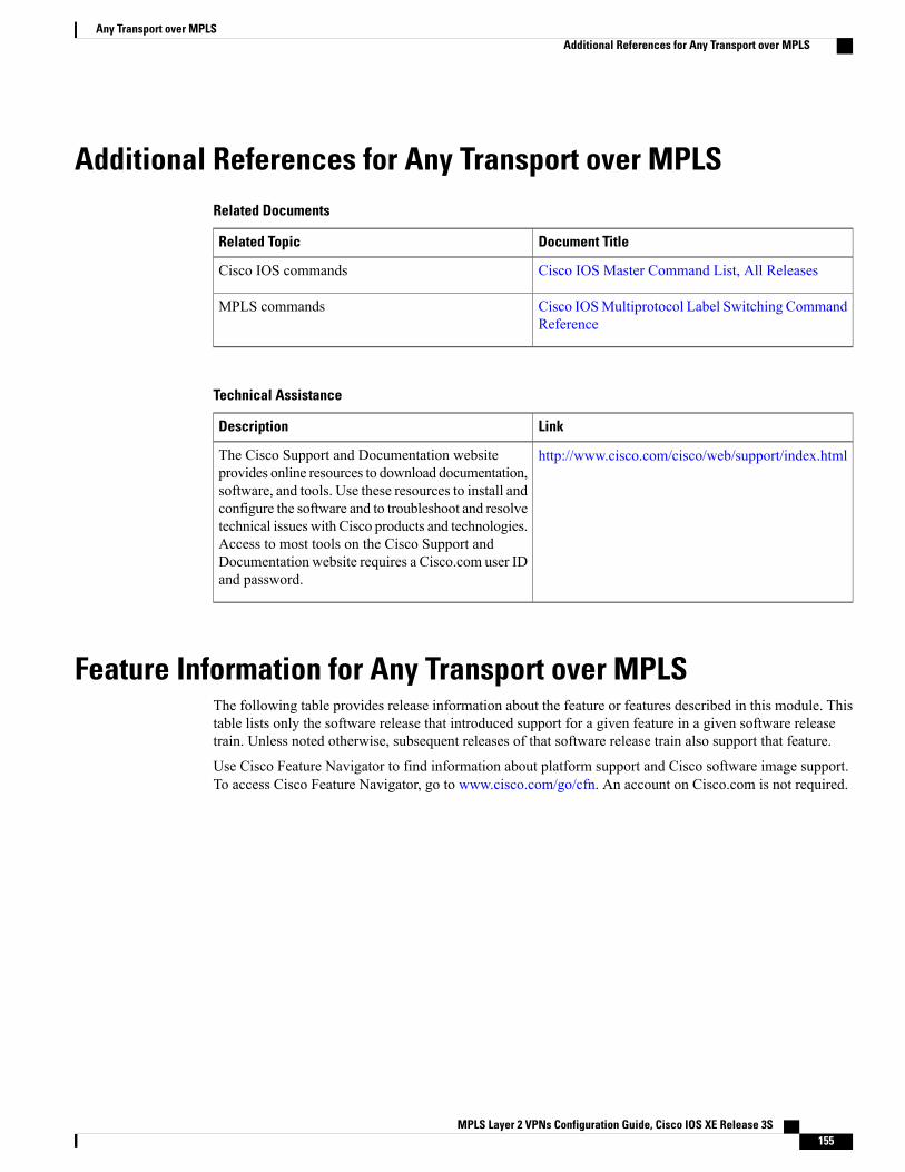
Additional References for Any Transport over MPLSRelated Documents
Document TitleRelated Topic
Cisco IOS Master Command List, All ReleasesCisco IOS commands
Cisco IOSMultiprotocol Label Switching CommandReference
MPLS commands
Technical Assistance
LinkDescription
http://www.cisco.com/cisco/web/support/index.htmlThe Cisco Support and Documentation websiteprovides online resources to download documentation,software, and tools. Use these resources to install andconfigure the software and to troubleshoot and resolvetechnical issues with Cisco products and technologies.Access to most tools on the Cisco Support andDocumentation website requires a Cisco.com user IDand password.
Feature Information for Any Transport over MPLSThe following table provides release information about the feature or features described in this module. Thistable lists only the software release that introduced support for a given feature in a given software releasetrain. Unless noted otherwise, subsequent releases of that software release train also support that feature.
Use Cisco Feature Navigator to find information about platform support and Cisco software image support.To access Cisco Feature Navigator, go to www.cisco.com/go/cfn. An account on Cisco.com is not required.
MPLS Layer 2 VPNs Configuration Guide, Cisco IOS XE Release 3S 155
Any Transport over MPLSAdditional References for Any Transport over MPLS
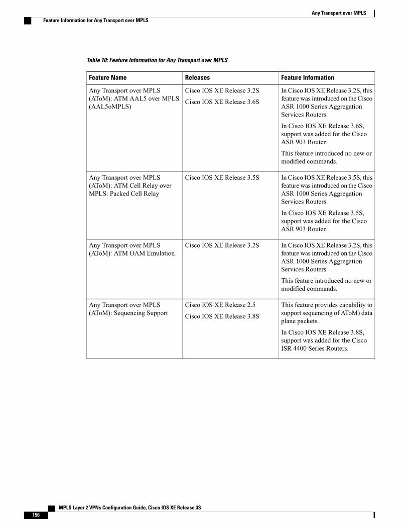
Table 10: Feature Information for Any Transport over MPLS
Feature InformationReleasesFeature Name
In Cisco IOSXERelease 3.2S, thisfeature was introduced on the CiscoASR 1000 Series AggregationServices Routers.
In Cisco IOS XE Release 3.6S,support was added for the CiscoASR 903 Router.
This feature introduced no new ormodified commands.
Cisco IOS XE Release 3.2S
Cisco IOS XE Release 3.6S
Any Transport over MPLS(AToM): ATM AAL5 over MPLS(AAL5oMPLS)
In Cisco IOSXERelease 3.5S, thisfeature was introduced on the CiscoASR 1000 Series AggregationServices Routers.
In Cisco IOS XE Release 3.5S,support was added for the CiscoASR 903 Router.
Cisco IOS XE Release 3.5SAny Transport over MPLS(AToM): ATM Cell Relay overMPLS: Packed Cell Relay
In Cisco IOSXERelease 3.2S, thisfeature was introduced on the CiscoASR 1000 Series AggregationServices Routers.
This feature introduced no new ormodified commands.
Cisco IOS XE Release 3.2SAny Transport over MPLS(AToM): ATM OAM Emulation
This feature provides capability tosupport sequencing of AToM) dataplane packets.
In Cisco IOS XE Release 3.8S,support was added for the CiscoISR 4400 Series Routers.
Cisco IOS XE Release 2.5
Cisco IOS XE Release 3.8S
Any Transport over MPLS(AToM): Sequencing Support
MPLS Layer 2 VPNs Configuration Guide, Cisco IOS XE Release 3S156
Any Transport over MPLSFeature Information for Any Transport over MPLS
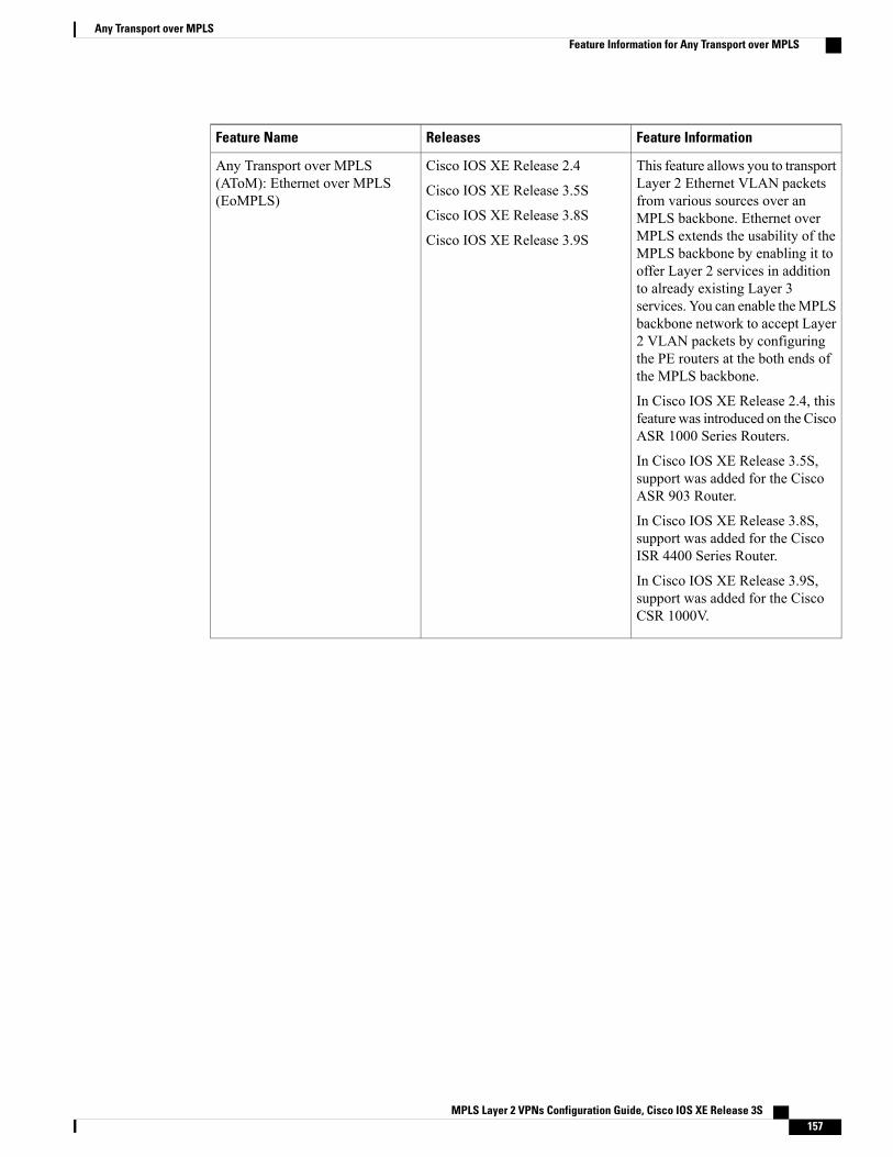
Feature InformationReleasesFeature Name
This feature allows you to transportLayer 2 Ethernet VLAN packetsfrom various sources over anMPLS backbone. Ethernet overMPLS extends the usability of theMPLS backbone by enabling it tooffer Layer 2 services in additionto already existing Layer 3services. You can enable theMPLSbackbone network to accept Layer2 VLAN packets by configuringthe PE routers at the both ends ofthe MPLS backbone.
In Cisco IOS XE Release 2.4, thisfeature was introduced on the CiscoASR 1000 Series Routers.
In Cisco IOS XE Release 3.5S,support was added for the CiscoASR 903 Router.
In Cisco IOS XE Release 3.8S,support was added for the CiscoISR 4400 Series Router.
In Cisco IOS XE Release 3.9S,support was added for the CiscoCSR 1000V.
Cisco IOS XE Release 2.4
Cisco IOS XE Release 3.5S
Cisco IOS XE Release 3.8S
Cisco IOS XE Release 3.9S
Any Transport over MPLS(AToM): Ethernet over MPLS(EoMPLS)
MPLS Layer 2 VPNs Configuration Guide, Cisco IOS XE Release 3S 157
Any Transport over MPLSFeature Information for Any Transport over MPLS
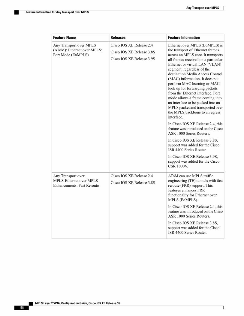
Feature InformationReleasesFeature Name
Ethernet over MPLS (EoMPLS) isthe transport of Ethernet framesacross an MPLS core. It transportsall frames received on a particularEthernet or virtual LAN (VLAN)segment, regardless of thedestination Media Access Control(MAC) information. It does notperform MAC learning or MAClook up for forwarding packetsfrom the Ethernet interface. Portmode allows a frame coming intoan interface to be packed into anMPLS packet and transported overthe MPLS backbone to an egressinterface.
In Cisco IOS XE Release 2.4, thisfeature was introduced on the CiscoASR 1000 Series Routers.
In Cisco IOS XE Release 3.8S,support was added for the CiscoISR 4400 Series Router.
In Cisco IOS XE Release 3.9S,support was added for the CiscoCSR 1000V.
Cisco IOS XE Release 2.4
Cisco IOS XE Release 3.8S
Cisco IOS XE Release 3.9S
Any Transport over MPLS(AToM): Ethernet over MPLS:Port Mode (EoMPLS)
AToM can use MPLS trafficengineering (TE) tunnels with fastreroute (FRR) support. Thisfeatures enhances FRRfunctionality for Ethernet overMPLS (EoMPLS).
In Cisco IOS XE Release 2.4, thisfeature was introduced on the CiscoASR 1000 Series Routers.
In Cisco IOS XE Release 3.8S,support was added for the CiscoISR 4400 Series Router.
Cisco IOS XE Release 2.4
Cisco IOS XE Release 3.8S
Any Transport overMPLS-Ethernet over MPLSEnhancements: Fast Reroute
MPLS Layer 2 VPNs Configuration Guide, Cisco IOS XE Release 3S158
Any Transport over MPLSFeature Information for Any Transport over MPLS
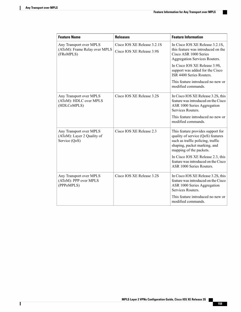
Feature InformationReleasesFeature Name
In Cisco IOS XE Release 3.2.1S,this feature was introduced on theCisco ASR 1000 SeriesAggregation Services Routers.
In Cisco IOS XE Release 3.9S,support was added for the CiscoISR 4400 Series Routers.
This feature introduced no new ormodified commands.
Cisco IOS XE Release 3.2.1S
Cisco IOS XE Release 3.9S
Any Transport over MPLS(AToM): Frame Relay over MPLS(FRoMPLS)
In Cisco IOSXERelease 3.2S, thisfeature was introduced on the CiscoASR 1000 Series AggregationServices Routers.
This feature introduced no new ormodified commands.
Cisco IOS XE Release 3.2SAny Transport over MPLS(AToM): HDLC over MPLS(HDLCoMPLS)
This feature provides support forquality of service (QoS) featuressuch as traffic policing, trafficshaping, packet marking, andmapping of the packets.
In Cisco IOS XE Release 2.3, thisfeature was introduced on the CiscoASR 1000 Series Routers.
Cisco IOS XE Release 2.3Any Transport over MPLS(AToM): Layer 2 Quality ofService (QoS)
In Cisco IOSXERelease 3.2S, thisfeature was introduced on the CiscoASR 1000 Series AggregationServices Routers.
This feature introduced no new ormodified commands.
Cisco IOS XE Release 3.2SAny Transport over MPLS(AToM): PPP over MPLS(PPPoMPLS)
MPLS Layer 2 VPNs Configuration Guide, Cisco IOS XE Release 3S 159
Any Transport over MPLSFeature Information for Any Transport over MPLS
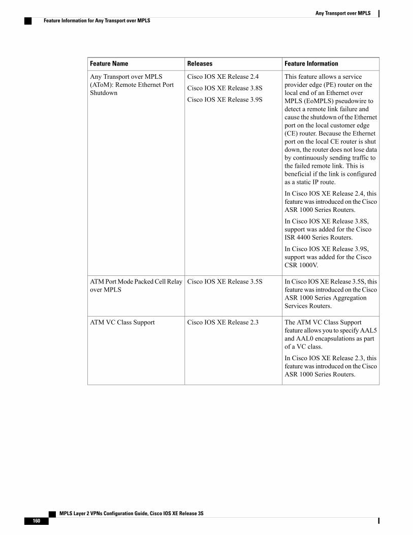
Feature InformationReleasesFeature Name
This feature allows a serviceprovider edge (PE) router on thelocal end of an Ethernet overMPLS (EoMPLS) pseudowire todetect a remote link failure andcause the shutdown of the Ethernetport on the local customer edge(CE) router. Because the Ethernetport on the local CE router is shutdown, the router does not lose databy continuously sending traffic tothe failed remote link. This isbeneficial if the link is configuredas a static IP route.
In Cisco IOS XE Release 2.4, thisfeature was introduced on the CiscoASR 1000 Series Routers.
In Cisco IOS XE Release 3.8S,support was added for the CiscoISR 4400 Series Routers.
In Cisco IOS XE Release 3.9S,support was added for the CiscoCSR 1000V.
Cisco IOS XE Release 2.4
Cisco IOS XE Release 3.8S
Cisco IOS XE Release 3.9S
Any Transport over MPLS(AToM): Remote Ethernet PortShutdown
In Cisco IOSXERelease 3.5S, thisfeature was introduced on the CiscoASR 1000 Series AggregationServices Routers.
Cisco IOS XE Release 3.5SATMPortMode PackedCell Relayover MPLS
The ATM VC Class Supportfeature allows you to specifyAAL5and AAL0 encapsulations as partof a VC class.
In Cisco IOS XE Release 2.3, thisfeature was introduced on the CiscoASR 1000 Series Routers.
Cisco IOS XE Release 2.3ATM VC Class Support
MPLS Layer 2 VPNs Configuration Guide, Cisco IOS XE Release 3S160
Any Transport over MPLSFeature Information for Any Transport over MPLS
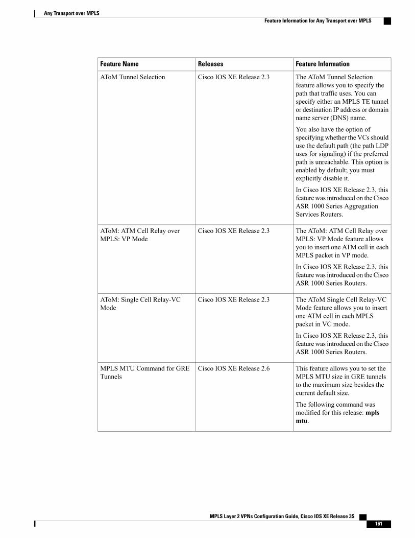
Feature InformationReleasesFeature Name
The AToM Tunnel Selectionfeature allows you to specify thepath that traffic uses. You canspecify either an MPLS TE tunnelor destination IP address or domainname server (DNS) name.
You also have the option ofspecifying whether the VCs shoulduse the default path (the path LDPuses for signaling) if the preferredpath is unreachable. This option isenabled by default; you mustexplicitly disable it.
In Cisco IOS XE Release 2.3, thisfeature was introduced on the CiscoASR 1000 Series AggregationServices Routers.
Cisco IOS XE Release 2.3AToM Tunnel Selection
The AToM: ATM Cell Relay overMPLS: VP Mode feature allowsyou to insert one ATM cell in eachMPLS packet in VP mode.
In Cisco IOS XE Release 2.3, thisfeature was introduced on the CiscoASR 1000 Series Routers.
Cisco IOS XE Release 2.3AToM: ATM Cell Relay overMPLS: VP Mode
The AToM Single Cell Relay-VCMode feature allows you to insertone ATM cell in each MPLSpacket in VC mode.
In Cisco IOS XE Release 2.3, thisfeature was introduced on the CiscoASR 1000 Series Routers.
Cisco IOS XE Release 2.3AToM: Single Cell Relay-VCMode
This feature allows you to set theMPLS MTU size in GRE tunnelsto the maximum size besides thecurrent default size.
The following command wasmodified for this release:mplsmtu.
Cisco IOS XE Release 2.6MPLS MTU Command for GRETunnels
MPLS Layer 2 VPNs Configuration Guide, Cisco IOS XE Release 3S 161
Any Transport over MPLSFeature Information for Any Transport over MPLS
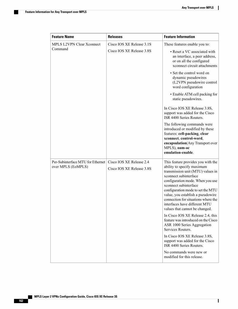
Feature InformationReleasesFeature Name
These features enable you to:
• Reset a VC associated withan interface, a peer address,or on all the configuredxconnect circuit attachments
• Set the control word ondynamic pseudowires(L2VPN pseudowire controlword configuration
• Enable ATM cell packing forstatic pseudowires.
In Cisco IOS XE Release 3.8S,support was added for the CiscoISR 4400 Series Routers.
The following commands wereintroduced or modified by thesefeatures: cell-packing, clearxconnect, control-word,encapsulation(Any Transport overMPLS), oam-acemulation-enable.
Cisco IOS XE Release 3.1S
Cisco IOS XE Release 3.8S
MPLS L2VPN Clear XconnectCommand
This feature provides you with theability to specify maximumtransmission unit (MTU) values inxconnect subinterfaceconfigurationmode.When you usexconnect subinterfaceconfigurationmode to set theMTUvalue, you establish a pseudowireconnection for situations where theinterfaces have different MTUvalues that cannot be changed.
In Cisco IOS XE Release 2.4, thisfeature was introduced on the CiscoASR 1000 Series AggregationServices Routers.
In Cisco IOS XE Release 3.8S,support was added for the CiscoISR 4400 Series Routers.
No commands were new ormodified for this release.
Cisco IOS XE Release 2.4
Cisco IOS XE Release 3.8S
Per-SubinterfaceMTU for Ethernetover MPLS (EoMPLS)
MPLS Layer 2 VPNs Configuration Guide, Cisco IOS XE Release 3S162
Any Transport over MPLSFeature Information for Any Transport over MPLS
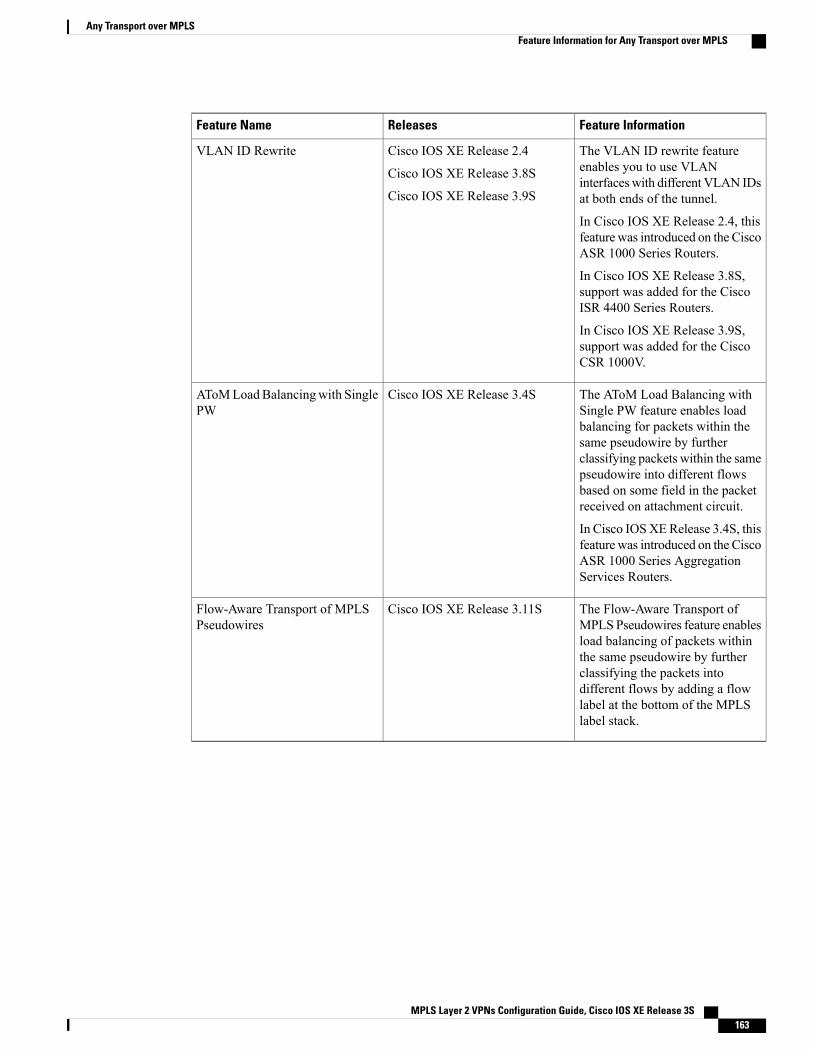
Feature InformationReleasesFeature Name
The VLAN ID rewrite featureenables you to use VLANinterfaceswith different VLAN IDsat both ends of the tunnel.
In Cisco IOS XE Release 2.4, thisfeature was introduced on the CiscoASR 1000 Series Routers.
In Cisco IOS XE Release 3.8S,support was added for the CiscoISR 4400 Series Routers.
In Cisco IOS XE Release 3.9S,support was added for the CiscoCSR 1000V.
Cisco IOS XE Release 2.4
Cisco IOS XE Release 3.8S
Cisco IOS XE Release 3.9S
VLAN ID Rewrite
The AToM Load Balancing withSingle PW feature enables loadbalancing for packets within thesame pseudowire by furtherclassifying packets within the samepseudowire into different flowsbased on some field in the packetreceived on attachment circuit.
In Cisco IOSXERelease 3.4S, thisfeature was introduced on the CiscoASR 1000 Series AggregationServices Routers.
Cisco IOS XE Release 3.4SAToMLoadBalancingwith SinglePW
The Flow-Aware Transport ofMPLS Pseudowires feature enablesload balancing of packets withinthe same pseudowire by furtherclassifying the packets intodifferent flows by adding a flowlabel at the bottom of the MPLSlabel stack.
Cisco IOS XE Release 3.11SFlow-Aware Transport of MPLSPseudowires
MPLS Layer 2 VPNs Configuration Guide, Cisco IOS XE Release 3S 163
Any Transport over MPLSFeature Information for Any Transport over MPLS

MPLS Layer 2 VPNs Configuration Guide, Cisco IOS XE Release 3S164
Any Transport over MPLSFeature Information for Any Transport over MPLS
C H A P T E R 3L2VPN Interworking
Interworking is a transforming function that is required to interconnect two heterogeneous attachment circuits(ACs). Several types of interworking functions exist. The function that is used would depend on the type ofACs being used, the type of data being carried, and the level of functionality required. The two main Layer2 Virtual Private Network (L2VPN) interworking functions supported in Cisco IOS XE software are bridgedand routed interworking.
Layer 2 (L2) transport over multiprotocol label switching (MPLS) and IP already exists for like-to-like ACs,such as Ethernet-to-Ethernet or Point-to-Point Protocol (PPP)-to-PPP. L2VPN Interworking builds on thisfunctionality by allowing disparate ACs to be connected. An interworking function facilitates the translationbetween different L2 encapsulations.
• Finding Feature Information, page 165
• Prerequisites for L2VPN Interworking, page 166
• Restrictions for L2VPN Interworking, page 166
• Information About L2VPN Interworking, page 170
• How to Configure L2VPN Interworking, page 185
• Configuration Examples for L2VPN Interworking, page 279
• Additional References for L2VPN Interworking, page 299
• Feature Information for L2VPN Interworking, page 301
Finding Feature InformationYour software release may not support all the features documented in this module. For the latest caveats andfeature information, see Bug Search Tool and the release notes for your platform and software release. Tofind information about the features documented in this module, and to see a list of the releases in which eachfeature is supported, see the feature information table at the end of this module.
Use Cisco Feature Navigator to find information about platform support and Cisco software image support.To access Cisco Feature Navigator, go to www.cisco.com/go/cfn. An account on Cisco.com is not required.
MPLS Layer 2 VPNs Configuration Guide, Cisco IOS XE Release 3S 165
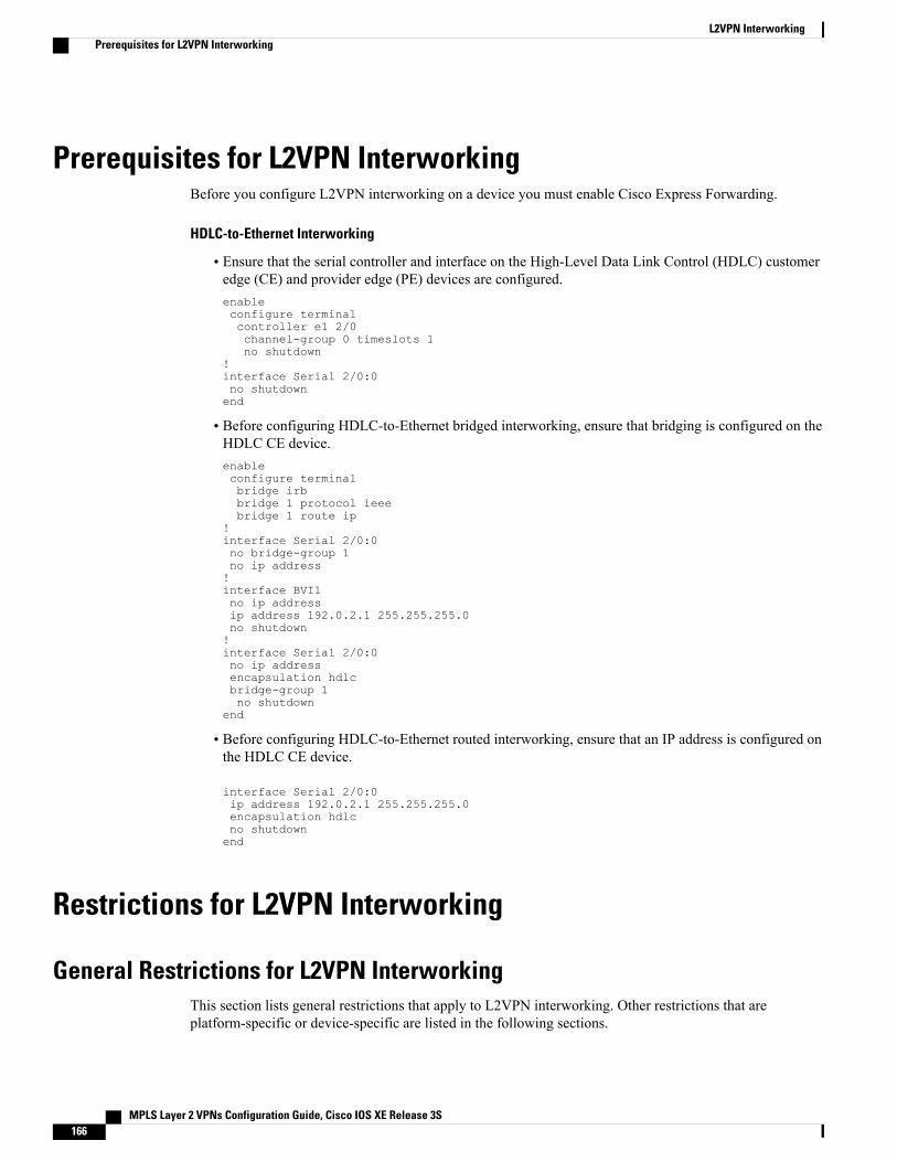
Prerequisites for L2VPN InterworkingBefore you configure L2VPN interworking on a device you must enable Cisco Express Forwarding.
HDLC-to-Ethernet Interworking
• Ensure that the serial controller and interface on the High-Level Data Link Control (HDLC) customeredge (CE) and provider edge (PE) devices are configured.enableconfigure terminalcontroller e1 2/0channel-group 0 timeslots 1no shutdown
!interface Serial 2/0:0no shutdownend
• Before configuring HDLC-to-Ethernet bridged interworking, ensure that bridging is configured on theHDLC CE device.enableconfigure terminalbridge irbbridge 1 protocol ieeebridge 1 route ip
!interface Serial 2/0:0no bridge-group 1no ip address!interface BVI1no ip addressip address 192.0.2.1 255.255.255.0no shutdown!interface Serial 2/0:0no ip addressencapsulation hdlcbridge-group 1no shutdown
end
• Before configuring HDLC-to-Ethernet routed interworking, ensure that an IP address is configured onthe HDLC CE device.
interface Serial 2/0:0ip address 192.0.2.1 255.255.255.0encapsulation hdlcno shutdownend
Restrictions for L2VPN Interworking
General Restrictions for L2VPN InterworkingThis section lists general restrictions that apply to L2VPN interworking. Other restrictions that areplatform-specific or device-specific are listed in the following sections.
MPLS Layer 2 VPNs Configuration Guide, Cisco IOS XE Release 3S166
L2VPN InterworkingPrerequisites for L2VPN Interworking
• MTU configured on the AC should not exceed theMTU in the core of the network because fragmentationis not supported.
• The interworking type on one provider edge (PE) router must match the interworking type on the peerPE router.
• IP interworking with native VLANs is not supported.
• Ethernet VLAN (Type 4) interworking is not supported.
• Only the following quality of service (QoS) features are supported with L2VPN interworking:
• Static IP type of service (ToS) or MPLS experimental bit (EXP) setting in tunnel header
• One-to-one mapping of VLAN priority bits to MPLS EXP bits
Restrictions for Routed InterworkingRouted interworking has the following restrictions:
• Multipoint Frame Relay (FR) is not supported.
• QoS classification on IP ToS, DSCP and other IP header fields is not supported.
• Security access control list (ACL) and other features based on IP header fields parsing are not supported.
• In routed mode, only one customer edge (CE) router can be attached to an Ethernet PE router.
• There must be a one-to-one relationship between an AC and the pseudowire. Point-to-multipoint ormultipoint-to-point configurations are not supported.
• You must configure routing protocols for point-to-point operation on the CE routers when configuringan Ethernet to non-Ethernet setup.
• In the IP interworking mode, the IPv4 (0800) translation is supported. The PE router captures AddressResolution Protocol (ARP) (0806) packets and responds with its own MAC address (proxy ARP).Everything else is dropped.
• The Ethernet must contain only two IP devices: PE router and CE router. The PE router performs proxyARP and responds to all ARP requests it receives. Therefore, only one CE router and one PE routershould be on the Ethernet segment.
• If the CE routers are doing static routing, you can perform the following tasks:
• The PE router needs to learn the MAC address of the CE router to correctly forward traffic to it.The Ethernet PE router sends an Internet Control Message Protocol (ICMP) Router DiscoveryProtocol (RDP) solicitation message with the source IP address as zero. The Ethernet CE routerresponds to this solicitation message. To configure the Cisco CE router’s Ethernet interface torespond to the ICMPRDP solicitationmessage, issue the ip irdp command in interface configurationmode. If you do not configure the CE router, traffic is dropped until the CE router sends traffictoward the PE router.
• To disable the CE routers from running the router discovery protocol, issue the ip irdpmaxadvertinterval 0 command in interface configuration mode.
MPLS Layer 2 VPNs Configuration Guide, Cisco IOS XE Release 3S 167
L2VPN InterworkingRestrictions for Routed Interworking
•When you change the interworking configuration on an Ethernet PE router, clear the ARP entry on theadjacent CE router so that it can learn the new MAC address. Otherwise, you might experience trafficdrops.
Restrictions for PPP InterworkingThe following restrictions apply to PPP interworking:
• There must be a one-to-one relationship between a PPP session and the pseudowire. Multiplexing ofmultiple PPP sessions over the pseudowire is not supported.
• Only IP (IPv4 (0021) interworking is supported. Link Control Protocol (LCP) packets and InternetProtocol Control Protocol (IPCP) packets are terminated at the PE router. Everything else is dropped.
• By default, the PE router assumes that the CE router knows the remote CE router’s IP address.
• Password Authentication Protocol (PAP) and Challenge-Handshake Authentication Protocol (CHAP)authentication are supported.
Restrictions for Ethernet/VLAN-to-ATM AAL5 InterworkingThe Ethernet/VLAN to ATM AAL5 Any Transport over MPLS (AToM) has the following restrictions:
• Only the following translations are supported; other translations are dropped:
• Ethernet without LAN FCS (AAAA030080C200070000)
• Spanning tree (AAAA030080C2000E)
• The ATM encapsulation type supported for bridged interworking is aal5snap. However, ATMencapsulation types supported for routed interworking are aal5snap and aal5mux.
• The existing QoS functionality for ATM is supported, including setting the ATM CLP bit.
• Only ATM AAL5 VC mode is supported. ATM VP and port mode are not supported.
• SVCs are not supported.
• Individual AAL5 ATM cells are assembled into frames before being sent across the pseudowire.
• Non-AAL5 traffic, (such as Operation, Administration, and Maintenance (OAM) cells) is punted to beprocessed at the route processor (RP) level. A VC that has been configured with OAM cell emulationon the ATM PE router (using the oam-ac emulation-enable CLI command) can send end-to-end F5loopback cells at configured intervals toward the CE router.
•When the pseudowire is down, an F5 end-to-end segment alarm indication signal/remote defect indication(AIS/RDI) is sent from the PE router to the CE router.
MPLS Layer 2 VPNs Configuration Guide, Cisco IOS XE Release 3S168
L2VPN InterworkingRestrictions for PPP Interworking
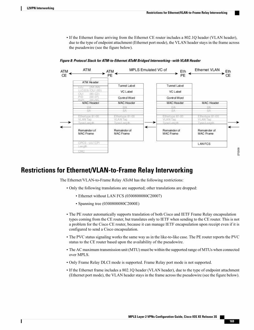
• If the Ethernet frame arriving from the Ethernet CE router includes a 802.1Q header (VLAN header),due to the type of endpoint attachment (Ethernet port mode), the VLAN header stays in the frame acrossthe pseudowire (see the figure below).
Figure 8: Protocol Stack for ATM-to-Ethernet AToM Bridged Interworking--with VLAN Header
Restrictions for Ethernet/VLAN-to-Frame Relay InterworkingThe Ethernet/VLAN-to-Frame Relay AToM has the following restrictions:
• Only the following translations are supported; other translations are dropped:
• Ethernet without LAN FCS (0300800080C20007)
• Spanning tree (0300800080C2000E)
• The PE router automatically supports translation of both Cisco and IETF Frame Relay encapsulationtypes coming from the CE router, but translates only to IETF when sending to the CE router. This is nota problem for the Cisco CE router, because it can manage IETF encapsulation upon receipt even if it isconfigured to send a Cisco encapsulation.
• The PVC status signaling works the same way as in the like-to-like case. The PE router reports the PVCstatus to the CE router based upon the availability of the pseudowire.
• TheACmaximum transmission unit (MTU)must be within the supported range ofMTUswhen connectedover MPLS.
• Only Frame Relay DLCI mode is supported. Frame Relay port mode is not supported.
• If the Ethernet frame includes a 802.1Q header (VLAN header), due to the type of endpoint attachment(Ethernet port mode), the VLAN header stays in the frame across the pseudowire (see the figure below).
MPLS Layer 2 VPNs Configuration Guide, Cisco IOS XE Release 3S 169
L2VPN InterworkingRestrictions for Ethernet/VLAN-to-Frame Relay Interworking
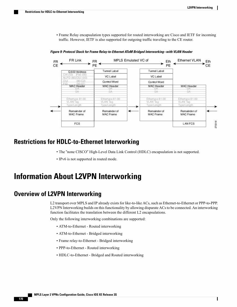
• Frame Relay encapsulation types supported for routed interworking are Cisco and IETF for incomingtraffic. However, IETF is also supported for outgoing traffic traveling to the CE router.
Figure 9: Protocol Stack for Frame Relay-to-Ethernet AToM Bridged Interworking--with VLAN Header
Restrictions for HDLC-to-Ethernet Interworking• The “none CISCO” High-Level Data Link Control (HDLC) encapsulation is not supported.
• IPv6 is not supported in routed mode.
Information About L2VPN Interworking
Overview of L2VPN InterworkingL2 transport overMPLS and IP already exists for like-to-like ACs, such as Ethernet-to-Ethernet or PPP-to-PPP.L2VPN Interworking builds on this functionality by allowing disparate ACs to be connected. An interworkingfunction facilitates the translation between the different L2 encapsulations.
Only the following interworking combinations are supported:
• ATM-to-Ethernet - Routed interworking
• ATM-to-Ethernet - Bridged interworking
• Frame relay-to-Ethernet - Bridged interworking
• PPP-to-Ethernet - Routed interworking
• HDLC-to-Ethernet - Bridged and Routed interworking
MPLS Layer 2 VPNs Configuration Guide, Cisco IOS XE Release 3S170
L2VPN InterworkingRestrictions for HDLC-to-Ethernet Interworking
L2VPN Interworking ModesL2VPN interworking works in either Ethernet (bridged) mode or IP (routed) mode. L2VPN interworking doesnot support Ethernet VLAN (Type 4) mode. You specify the mode in the following ways:
• If using the older legacy CLI commands, you can use the interworking {ethernet | ip} command inpseudowire-class configuration mode.
• If using the newer L2VPN protocol-based CLI commands, you can use the interworking {ethernet |ip} command in xconnect configuration mode.
The interworking command causes the ACs to be terminated locally. The two keywords perform the followingfunctions:
• The ethernet keyword causes Ethernet frames to be extracted from the AC and sent over the pseudowire.Ethernet end-to-end transmission is resumed. AC frames that are not Ethernet are dropped. In the caseof VLAN, the VLAN tag is removed, leaving an untagged Ethernet frame.
• The ip keyword causes IP packets to be extracted from the AC and sent over the pseudowire. AC framesthat do not contain IPv4 packets are dropped.
The following sections explain more about Ethernet and IP interworking modes.
Ethernet or Bridged InterworkingEthernet interworking is also called bridged interworking. Ethernet frames are bridged across the pseudowire.The CE routers could be natively bridging Ethernet or could be routing using a bridged encapsulation model,such as Bridge Virtual Interface (BVI) or Routed Bridge Encapsulation (RBE). The PE routers operate inEthernet like-to-like mode.
This mode is used to offer the following services:
• LAN services--An example is an enterprise that has several sites, where some sites have Ethernetconnectivity to the service provider (SP) network and others have ATM connectivity. If the enterprisewants LAN connectivity to all its sites, traffic from the Ethernet or VLAN of one site can be sent throughthe IP/MPLS network and encapsulated as bridged traffic over an ATM VC of another site.
• Connectivity services--An example is an enterprise that has different sites that are running an InternalGateway Protocol (IGP) routing protocol, which has incompatible procedures on broadcast andnonbroadcast links. The enterprise has several sites that are running an IGP, such as Open Shortest PathFirst (OSPF) or Intermediate System-to-Intermediate System (IS-IS), between the sites. In this scenario,some of the procedures (such as route advertisement or designated router) depend on the underlying L2protocol and are different for a point-to-point ATM connection versus a broadcast Ethernet connection.Therefore, the bridged encapsulation over ATM can be used to achieve homogenous Ethernet connectivitybetween the CE routers running the IGP.
IP or Routed InterworkingIP interworking is also called routed interworking. The CE routers encapsulate the IP on the link between theCE router and PE router. A new VC type is used to signal the IP pseudowire in MPLS. Translation betweenthe L2 and IP encapsulations across the pseudowire is required. Special consideration needs to be given to
MPLS Layer 2 VPNs Configuration Guide, Cisco IOS XE Release 3S 171
L2VPN InterworkingL2VPN Interworking Modes
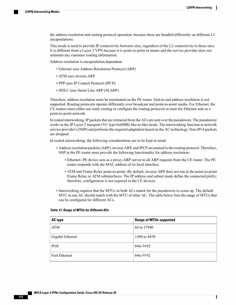
the address resolution and routing protocol operation, because these are handled differently on different L2encapsulations.
This mode is used to provide IP connectivity between sites, regardless of the L2 connectivity to these sites.It is different from a Layer 3 VPN because it is point-to-point in nature and the service provider does notmaintain any customer routing information.
Address resolution is encapsulation dependent:
• Ethernet uses Address Resolution Protocol (ARP)
• ATM uses inverse ARP
• PPP uses IP Control Protocol (IPCP)
• HDLC uses Serial Line ARP (SLARP)
Therefore, address resolution must be terminated on the PE router. End-to-end address resolution is notsupported. Routing protocols operate differently over broadcast and point-to-point media. For Ethernet, theCE routers must either use static routing or configure the routing protocols to treat the Ethernet side as apoint-to-point network.
In routed interworking, IP packets that are extracted from the ACs are sent over the pseudowire. The pseudowireworks in the IP Layer 2 transport (VC type 0x000B) like-to-like mode. The interworking function at networkservice provider’s (NSP) end performs the required adaptation based on the AC technology. Non-IPv4 packetsare dropped.
In routed interworking, the following considerations are to be kept in mind:
• Address resolution packets (ARP), inverse ARP, and IPCP are punted to the routing protocol. Therefore,NSP at the PE router must provide the following functionality for address resolution:
• Ethernet--PE device acts as a proxy-ARP server to all ARP requests from the CE router. The PErouter responds with the MAC address of its local interface.
• ATM and Frame Relay point-to-point--By default, inverse ARP does not run in the point-to-pointFrame Relay or ATM subinterfaces. The IP address and subnet mask define the connected prefix;therefore, configuration is not required in the CE devices.
• Interworking requires that the MTUs in both ACs match for the pseudowire to come up. The defaultMTU in one AC should match with the MTU of other AC. The table below lists the range of MTUs thatcan be configured for different ACs.
Table 11: Range of MTUs for Different ACs
Range of MTUs supportedAC type
64 to 17940ATM
1500 to 4470Gigabit Ethernet
64to 9102POS
64to 9192Fast Ethernet
MPLS Layer 2 VPNs Configuration Guide, Cisco IOS XE Release 3S172
L2VPN InterworkingL2VPN Interworking Modes
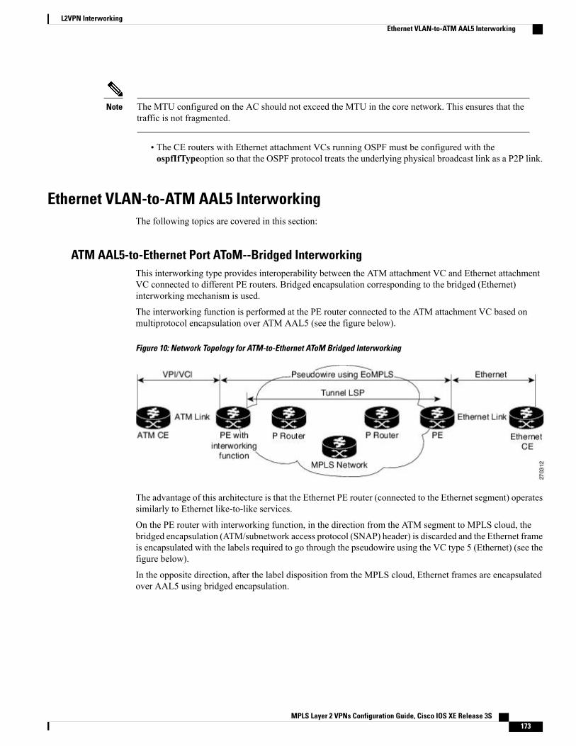
The MTU configured on the AC should not exceed the MTU in the core network. This ensures that thetraffic is not fragmented.
Note
• The CE routers with Ethernet attachment VCs running OSPF must be configured with theospfIfTypeoption so that the OSPF protocol treats the underlying physical broadcast link as a P2P link.
Ethernet VLAN-to-ATM AAL5 InterworkingThe following topics are covered in this section:
ATM AAL5-to-Ethernet Port AToM--Bridged InterworkingThis interworking type provides interoperability between the ATM attachment VC and Ethernet attachmentVC connected to different PE routers. Bridged encapsulation corresponding to the bridged (Ethernet)interworking mechanism is used.
The interworking function is performed at the PE router connected to the ATM attachment VC based onmultiprotocol encapsulation over ATM AAL5 (see the figure below).
Figure 10: Network Topology for ATM-to-Ethernet AToM Bridged Interworking
The advantage of this architecture is that the Ethernet PE router (connected to the Ethernet segment) operatessimilarly to Ethernet like-to-like services.
On the PE router with interworking function, in the direction from the ATM segment to MPLS cloud, thebridged encapsulation (ATM/subnetwork access protocol (SNAP) header) is discarded and the Ethernet frameis encapsulated with the labels required to go through the pseudowire using the VC type 5 (Ethernet) (see thefigure below).
In the opposite direction, after the label disposition from the MPLS cloud, Ethernet frames are encapsulatedover AAL5 using bridged encapsulation.
MPLS Layer 2 VPNs Configuration Guide, Cisco IOS XE Release 3S 173
L2VPN InterworkingEthernet VLAN-to-ATM AAL5 Interworking
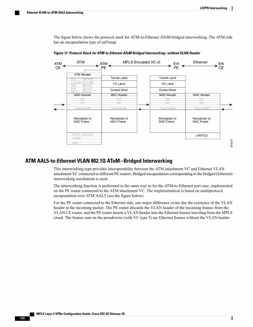
The figure below shows the protocol stack for ATM-to-Ethernet AToM bridged interworking. The ATM sidehas an encapsulation type of aal5snap.
Figure 11: Protocol Stack for ATM-to-Ethernet AToM Bridged Interworking--without VLAN Header
ATM AAL5-to-Ethernet VLAN 802.1Q AToM--Bridged InterworkingThis interworking type provides interoperability between the ATM attachment VC and Ethernet VLANattachment VC connected to different PE routers. Bridged encapsulation corresponding to the bridged (Ethernet)interworking mechanism is used.
The interworking function is performed in the same way as for the ATM-to-Ethernet port case, implementedon the PE router connected to the ATM attachment VC. The implementation is based on multiprotocolencapsulation over ATM AAL5 (see the figure below).
For the PE router connected to the Ethernet side, one major difference exists due the existence of the VLANheader in the incoming packet. The PE router discards the VLAN header of the incoming frames from theVLANCE router, and the PE router inserts a VLAN header into the Ethernet frames traveling from theMPLScloud. The frames sent on the pseudowire (with VC type 5) are Ethernet frames without the VLAN header.
MPLS Layer 2 VPNs Configuration Guide, Cisco IOS XE Release 3S174
L2VPN InterworkingEthernet VLAN-to-ATM AAL5 Interworking
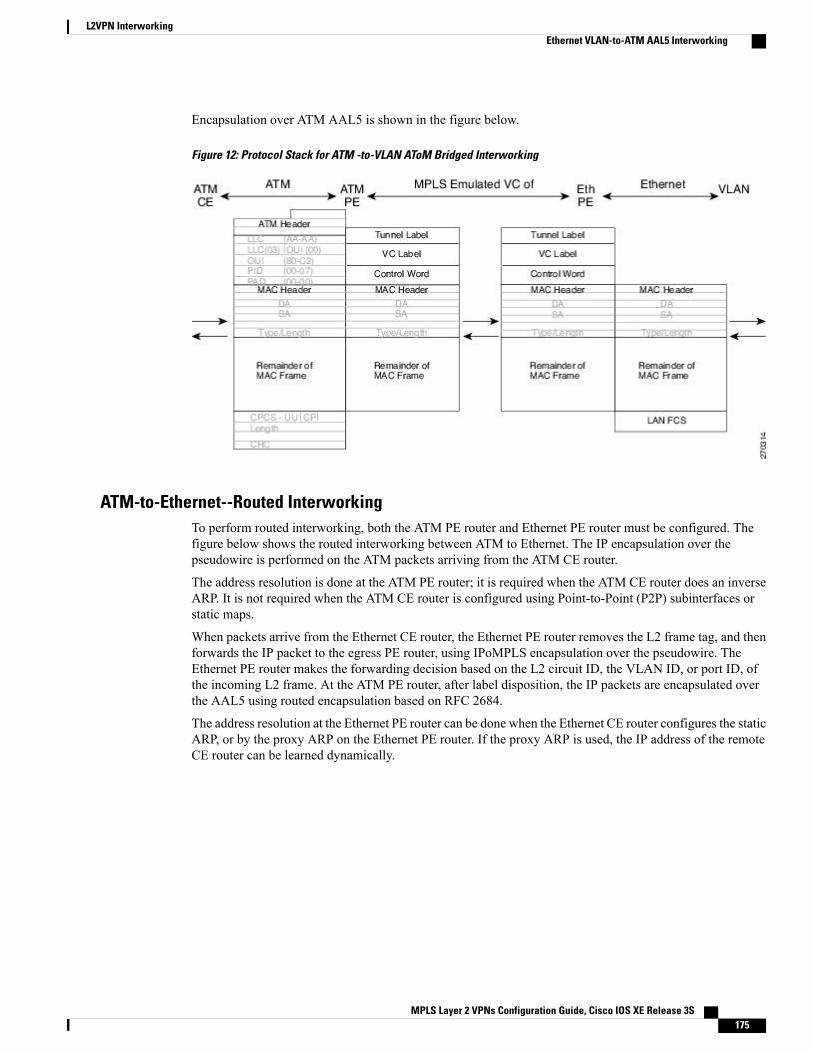
Encapsulation over ATM AAL5 is shown in the figure below.
Figure 12: Protocol Stack for ATM -to-VLAN AToM Bridged Interworking
ATM-to-Ethernet--Routed InterworkingTo perform routed interworking, both the ATM PE router and Ethernet PE router must be configured. Thefigure below shows the routed interworking between ATM to Ethernet. The IP encapsulation over thepseudowire is performed on the ATM packets arriving from the ATM CE router.
The address resolution is done at the ATM PE router; it is required when the ATM CE router does an inverseARP. It is not required when the ATM CE router is configured using Point-to-Point (P2P) subinterfaces orstatic maps.
When packets arrive from the Ethernet CE router, the Ethernet PE router removes the L2 frame tag, and thenforwards the IP packet to the egress PE router, using IPoMPLS encapsulation over the pseudowire. TheEthernet PE router makes the forwarding decision based on the L2 circuit ID, the VLAN ID, or port ID, ofthe incoming L2 frame. At the ATM PE router, after label disposition, the IP packets are encapsulated overthe AAL5 using routed encapsulation based on RFC 2684.
The address resolution at the Ethernet PE router can be done when the Ethernet CE router configures the staticARP, or by the proxy ARP on the Ethernet PE router. If the proxy ARP is used, the IP address of the remoteCE router can be learned dynamically.
MPLS Layer 2 VPNs Configuration Guide, Cisco IOS XE Release 3S 175
L2VPN InterworkingEthernet VLAN-to-ATM AAL5 Interworking
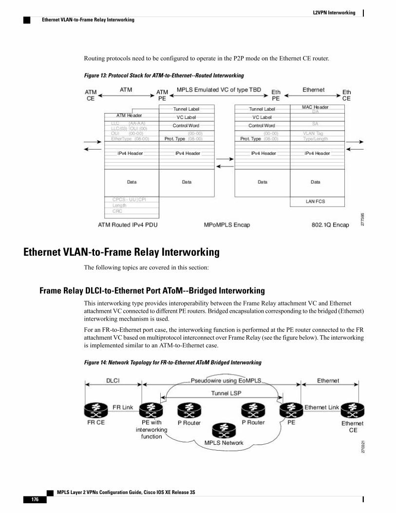
Routing protocols need to be configured to operate in the P2P mode on the Ethernet CE router.
Figure 13: Protocol Stack for ATM-to-Ethernet--Routed Interworking
Ethernet VLAN-to-Frame Relay InterworkingThe following topics are covered in this section:
Frame Relay DLCI-to-Ethernet Port AToM--Bridged InterworkingThis interworking type provides interoperability between the Frame Relay attachment VC and Ethernetattachment VC connected to different PE routers. Bridged encapsulation corresponding to the bridged (Ethernet)interworking mechanism is used.
For an FR-to-Ethernet port case, the interworking function is performed at the PE router connected to the FRattachment VC based onmultiprotocol interconnect over Frame Relay (see the figure below). The interworkingis implemented similar to an ATM-to-Ethernet case.
Figure 14: Network Topology for FR-to-Ethernet AToM Bridged Interworking
MPLS Layer 2 VPNs Configuration Guide, Cisco IOS XE Release 3S176
L2VPN InterworkingEthernet VLAN-to-Frame Relay Interworking
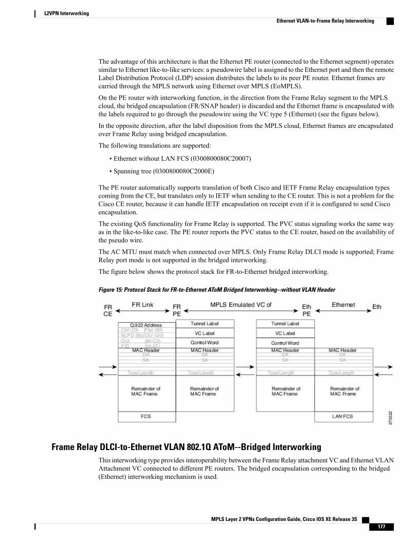
The advantage of this architecture is that the Ethernet PE router (connected to the Ethernet segment) operatessimilar to Ethernet like-to-like services: a pseudowire label is assigned to the Ethernet port and then the remoteLabel Distribution Protocol (LDP) session distributes the labels to its peer PE router. Ethernet frames arecarried through the MPLS network using Ethernet over MPLS (EoMPLS).
On the PE router with interworking function, in the direction from the Frame Relay segment to the MPLScloud, the bridged encapsulation (FR/SNAP header) is discarded and the Ethernet frame is encapsulated withthe labels required to go through the pseudowire using the VC type 5 (Ethernet) (see the figure below).
In the opposite direction, after the label disposition from the MPLS cloud, Ethernet frames are encapsulatedover Frame Relay using bridged encapsulation.
The following translations are supported:
• Ethernet without LAN FCS (0300800080C20007)
• Spanning tree (0300800080C2000E)
The PE router automatically supports translation of both Cisco and IETF Frame Relay encapsulation typescoming from the CE, but translates only to IETF when sending to the CE router. This is not a problem for theCisco CE router, because it can handle IETF encapsulation on receipt even if it is configured to send Ciscoencapsulation.
The existing QoS functionality for Frame Relay is supported. The PVC status signaling works the same wayas in the like-to-like case. The PE router reports the PVC status to the CE router, based on the availability ofthe pseudo wire.
The AC MTU must match when connected over MPLS. Only Frame Relay DLCI mode is supported; FrameRelay port mode is not supported in the bridged interworking.
The figure below shows the protocol stack for FR-to-Ethernet bridged interworking.
Figure 15: Protocol Stack for FR-to-Ethernet AToM Bridged Interworking--without VLAN Header
Frame Relay DLCI-to-Ethernet VLAN 802.1Q AToM--Bridged InterworkingThis interworking type provides interoperability between the Frame Relay attachment VC and Ethernet VLANAttachment VC connected to different PE routers. The bridged encapsulation corresponding to the bridged(Ethernet) interworking mechanism is used.
MPLS Layer 2 VPNs Configuration Guide, Cisco IOS XE Release 3S 177
L2VPN InterworkingEthernet VLAN-to-Frame Relay Interworking
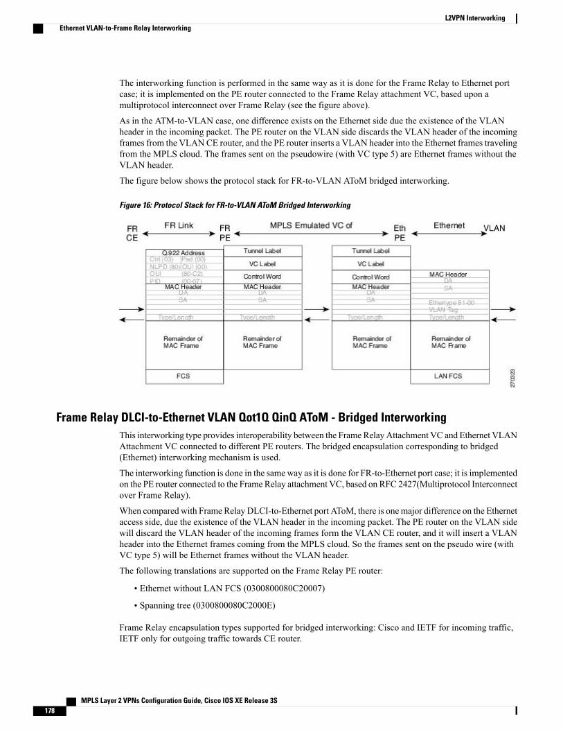
The interworking function is performed in the same way as it is done for the Frame Relay to Ethernet portcase; it is implemented on the PE router connected to the Frame Relay attachment VC, based upon amultiprotocol interconnect over Frame Relay (see the figure above).
As in the ATM-to-VLAN case, one difference exists on the Ethernet side due the existence of the VLANheader in the incoming packet. The PE router on the VLAN side discards the VLAN header of the incomingframes from the VLANCE router, and the PE router inserts a VLAN header into the Ethernet frames travelingfrom the MPLS cloud. The frames sent on the pseudowire (with VC type 5) are Ethernet frames without theVLAN header.
The figure below shows the protocol stack for FR-to-VLAN AToM bridged interworking.
Figure 16: Protocol Stack for FR-to-VLAN AToM Bridged Interworking
Frame Relay DLCI-to-Ethernet VLAN Qot1Q QinQ AToM - Bridged InterworkingThis interworking type provides interoperability between the Frame Relay Attachment VC and Ethernet VLANAttachment VC connected to different PE routers. The bridged encapsulation corresponding to bridged(Ethernet) interworking mechanism is used.
The interworking function is done in the sameway as it is done for FR-to-Ethernet port case; it is implementedon the PE router connected to the Frame Relay attachment VC, based on RFC 2427(Multiprotocol Interconnectover Frame Relay).
When compared with Frame Relay DLCI-to-Ethernet port AToM, there is one major difference on the Ethernetaccess side, due the existence of the VLAN header in the incoming packet. The PE router on the VLAN sidewill discard the VLAN header of the incoming frames form the VLAN CE router, and it will insert a VLANheader into the Ethernet frames coming from the MPLS cloud. So the frames sent on the pseudo wire (withVC type 5) will be Ethernet frames without the VLAN header.
The following translations are supported on the Frame Relay PE router:
• Ethernet without LAN FCS (0300800080C20007)
• Spanning tree (0300800080C2000E)
Frame Relay encapsulation types supported for bridged interworking: Cisco and IETF for incoming traffic,IETF only for outgoing traffic towards CE router.
MPLS Layer 2 VPNs Configuration Guide, Cisco IOS XE Release 3S178
L2VPN InterworkingEthernet VLAN-to-Frame Relay Interworking
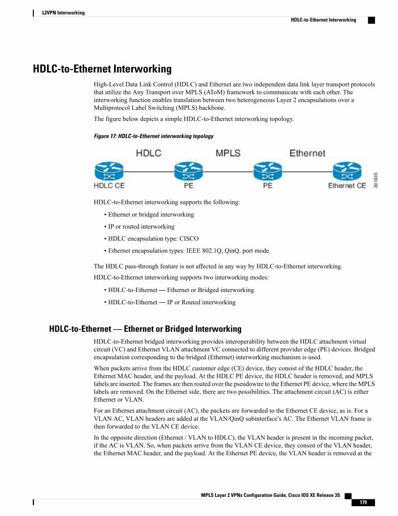
HDLC-to-Ethernet InterworkingHigh-Level Data Link Control (HDLC) and Ethernet are two independent data link layer transport protocolsthat utilize the Any Transport over MPLS (AToM) framework to communicate with each other. Theinterworking function enables translation between two heterogeneous Layer 2 encapsulations over aMultiprotocol Label Switching (MPLS) backbone.
The figure below depicts a simple HDLC-to-Ethernet interworking topology.
Figure 17: HDLC-to-Ethernet interworking topology
HDLC-to-Ethernet interworking supports the following:
• Ethernet or bridged interworking
• IP or routed interworking
• HDLC encapsulation type: CISCO
• Ethernet encapsulation types: IEEE 802.1Q, QinQ, port mode
The HDLC pass-through feature is not affected in any way by HDLC-to-Ethernet interworking.
HDLC-to-Ethernet interworking supports two interworking modes:
• HDLC-to-Ethernet— Ethernet or Bridged interworking
• HDLC-to-Ethernet— IP or Routed interworking
HDLC-to-Ethernet — Ethernet or Bridged InterworkingHDLC-to-Ethernet bridged interworking provides interoperability between the HDLC attachment virtualcircuit (VC) and Ethernet VLAN attachment VC connected to different provider edge (PE) devices. Bridgedencapsulation corresponding to the bridged (Ethernet) interworking mechanism is used.
When packets arrive from the HDLC customer edge (CE) device, they consist of the HDLC header, theEthernet MAC header, and the payload. At the HDLC PE device, the HDLC header is removed, and MPLSlabels are inserted. The frames are then routed over the pseudowire to the Ethernet PE device, where theMPLSlabels are removed. On the Ethernet side, there are two possibilities. The attachment circuit (AC) is eitherEthernet or VLAN.
For an Ethernet attachment circuit (AC), the packets are forwarded to the Ethernet CE device, as is. For aVLAN AC, VLAN headers are added at the VLAN/QinQ subinterface’s AC. The Ethernet VLAN frame isthen forwarded to the VLAN CE device.
In the opposite direction (Ethernet / VLAN to HDLC), the VLAN header is present in the incoming packet,if the AC is VLAN. So, when packets arrive from the VLAN CE device, they consist of the VLAN header,the Ethernet MAC header, and the payload. At the Ethernet PE device, the VLAN header is removed at the
MPLS Layer 2 VPNs Configuration Guide, Cisco IOS XE Release 3S 179
L2VPN InterworkingHDLC-to-Ethernet Interworking
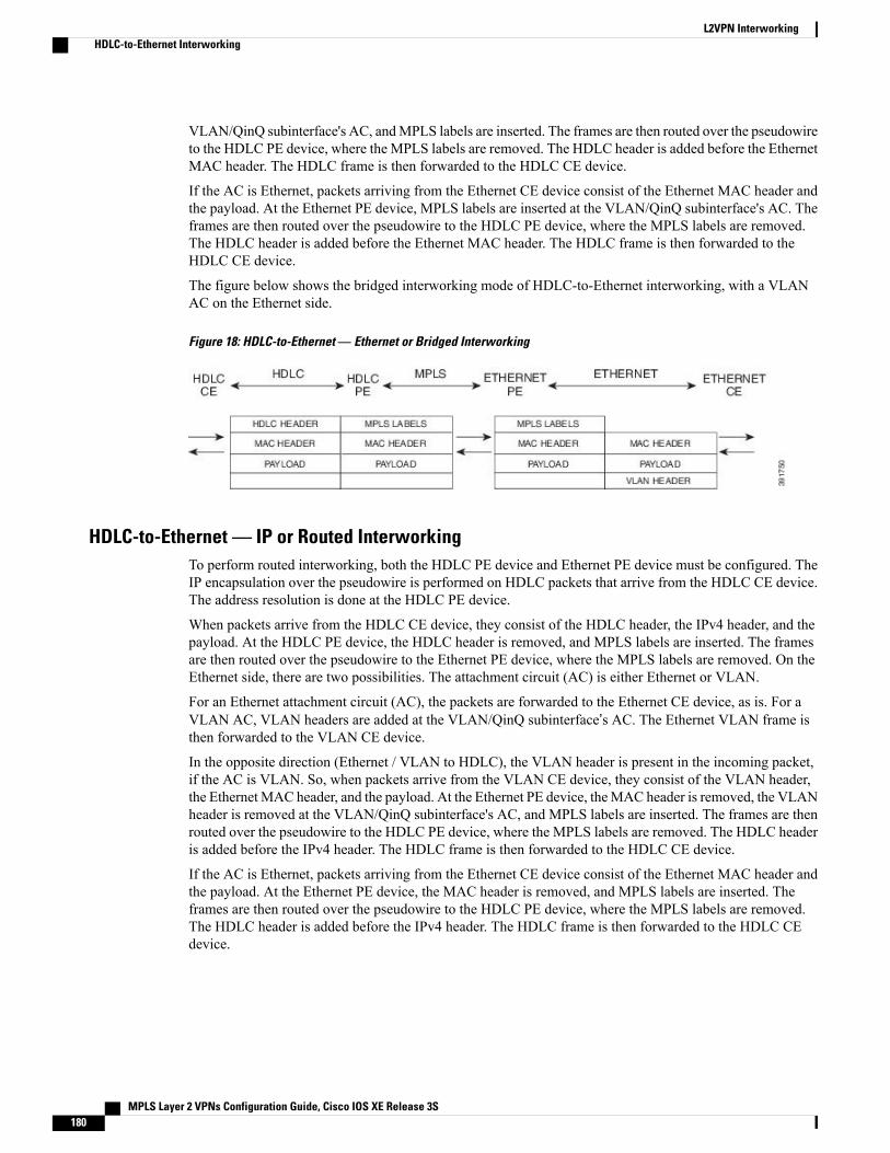
VLAN/QinQ subinterface's AC, andMPLS labels are inserted. The frames are then routed over the pseudowireto the HDLC PE device, where the MPLS labels are removed. The HDLC header is added before the EthernetMAC header. The HDLC frame is then forwarded to the HDLC CE device.
If the AC is Ethernet, packets arriving from the Ethernet CE device consist of the Ethernet MAC header andthe payload. At the Ethernet PE device, MPLS labels are inserted at the VLAN/QinQ subinterface's AC. Theframes are then routed over the pseudowire to the HDLC PE device, where the MPLS labels are removed.The HDLC header is added before the Ethernet MAC header. The HDLC frame is then forwarded to theHDLC CE device.
The figure below shows the bridged interworking mode of HDLC-to-Ethernet interworking, with a VLANAC on the Ethernet side.
Figure 18: HDLC-to-Ethernet — Ethernet or Bridged Interworking
HDLC-to-Ethernet — IP or Routed InterworkingTo perform routed interworking, both the HDLC PE device and Ethernet PE device must be configured. TheIP encapsulation over the pseudowire is performed on HDLC packets that arrive from the HDLC CE device.The address resolution is done at the HDLC PE device.
When packets arrive from the HDLC CE device, they consist of the HDLC header, the IPv4 header, and thepayload. At the HDLC PE device, the HDLC header is removed, and MPLS labels are inserted. The framesare then routed over the pseudowire to the Ethernet PE device, where the MPLS labels are removed. On theEthernet side, there are two possibilities. The attachment circuit (AC) is either Ethernet or VLAN.
For an Ethernet attachment circuit (AC), the packets are forwarded to the Ethernet CE device, as is. For aVLAN AC, VLAN headers are added at the VLAN/QinQ subinterface’s AC. The Ethernet VLAN frame isthen forwarded to the VLAN CE device.
In the opposite direction (Ethernet / VLAN to HDLC), the VLAN header is present in the incoming packet,if the AC is VLAN. So, when packets arrive from the VLAN CE device, they consist of the VLAN header,the EthernetMAC header, and the payload. At the Ethernet PE device, theMAC header is removed, the VLANheader is removed at the VLAN/QinQ subinterface's AC, and MPLS labels are inserted. The frames are thenrouted over the pseudowire to the HDLC PE device, where the MPLS labels are removed. The HDLC headeris added before the IPv4 header. The HDLC frame is then forwarded to the HDLC CE device.
If the AC is Ethernet, packets arriving from the Ethernet CE device consist of the Ethernet MAC header andthe payload. At the Ethernet PE device, the MAC header is removed, and MPLS labels are inserted. Theframes are then routed over the pseudowire to the HDLC PE device, where the MPLS labels are removed.The HDLC header is added before the IPv4 header. The HDLC frame is then forwarded to the HDLC CEdevice.
MPLS Layer 2 VPNs Configuration Guide, Cisco IOS XE Release 3S180
L2VPN InterworkingHDLC-to-Ethernet Interworking
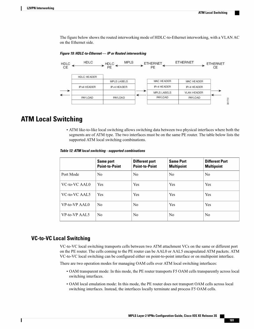
The figure below shows the routed interworking mode of HDLC-to-Ethernet interworking, with a VLAN ACon the Ethernet side.
Figure 19: HDLC-to-Ethernet — IP or Routed interworking
ATM Local Switching• ATM like-to-like local switching allows switching data between two physical interfaces where both thesegments are of ATM type. The two interfaces must be on the same PE router. The table below lists thesupported ATM local switching combinations.
Table 12: ATM local switching - supported combinations
Different PortMultipoint
Same PortMultipoint
Different portPoint-to-Point
Same portPoint-to-Point
NoNoNoNoPort Mode
YesYesYesYesVC-to-VC AAL0
YesYesYesYesVC-to-VC AAL5
YesYesNoNoVP-to-VP AAL0
NoNoNoNoVP-to-VP AAL5
VC-to-VC Local SwitchingVC-to-VC local switching transports cells between two ATM attachment VCs on the same or different porton the PE router. The cells coming to the PE router can be AAL0 or AAL5 encapsulated ATM packets. ATMVC-to-VC local switching can be configured either on point-to-point interface or on multipoint interface.
There are two operation modes for managing OAM cells over ATM local switching interfaces:
• OAM transparent mode: In this mode, the PE router transports F5 OAM cells transparently across localswitching interfaces.
• OAM local emulation mode: In this mode, the PE router does not transport OAM cells across localswitching interfaces. Instead, the interfaces locally terminate and process F5 OAM cells.
MPLS Layer 2 VPNs Configuration Guide, Cisco IOS XE Release 3S 181
L2VPN InterworkingATM Local Switching
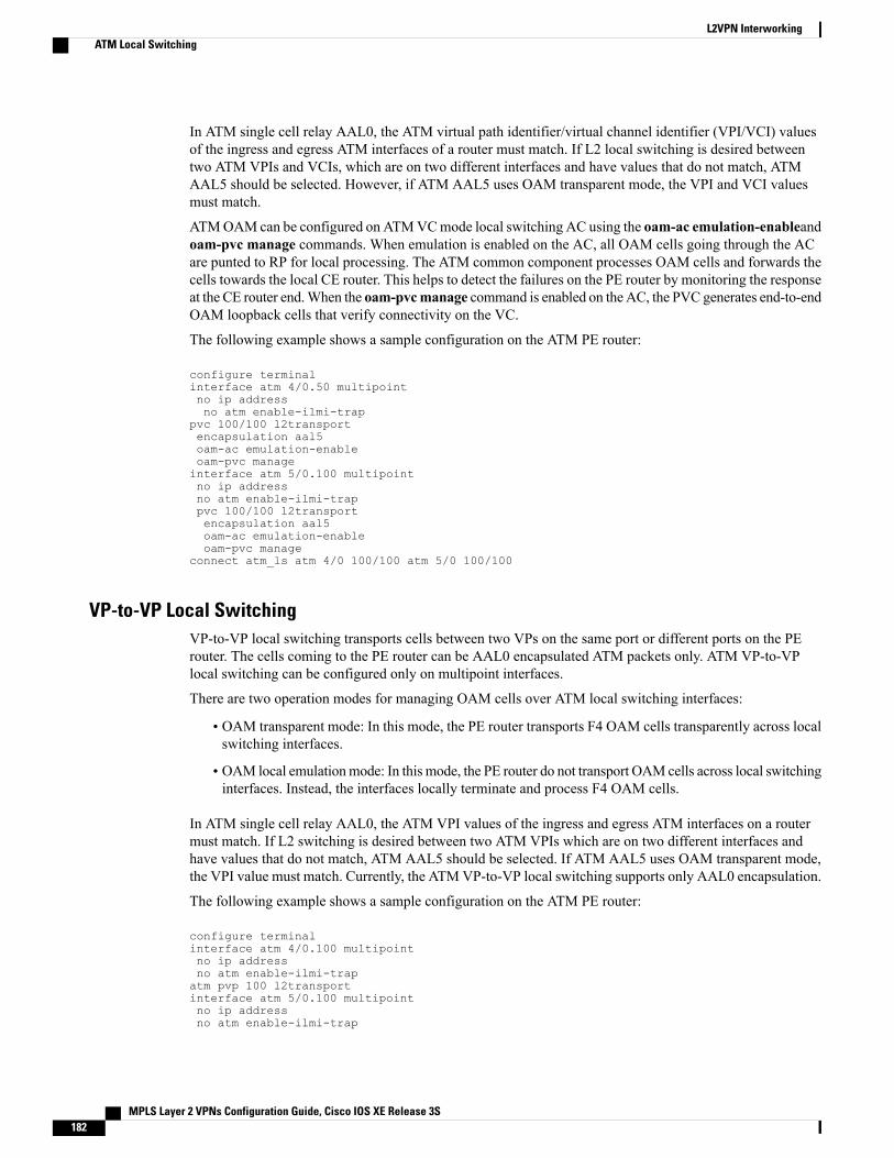
In ATM single cell relay AAL0, the ATM virtual path identifier/virtual channel identifier (VPI/VCI) valuesof the ingress and egress ATM interfaces of a router must match. If L2 local switching is desired betweentwo ATM VPIs and VCIs, which are on two different interfaces and have values that do not match, ATMAAL5 should be selected. However, if ATM AAL5 uses OAM transparent mode, the VPI and VCI valuesmust match.
ATMOAM can be configured on ATMVCmode local switching AC using the oam-ac emulation-enableandoam-pvc manage commands. When emulation is enabled on the AC, all OAM cells going through the ACare punted to RP for local processing. The ATM common component processes OAM cells and forwards thecells towards the local CE router. This helps to detect the failures on the PE router by monitoring the responseat the CE router end.When the oam-pvcmanage command is enabled on the AC, the PVC generates end-to-endOAM loopback cells that verify connectivity on the VC.
The following example shows a sample configuration on the ATM PE router:
configure terminalinterface atm 4/0.50 multipointno ip addressno atm enable-ilmi-trap
pvc 100/100 l2transportencapsulation aal5oam-ac emulation-enableoam-pvc manageinterface atm 5/0.100 multipointno ip addressno atm enable-ilmi-trappvc 100/100 l2transportencapsulation aal5oam-ac emulation-enableoam-pvc manage
connect atm_ls atm 4/0 100/100 atm 5/0 100/100
VP-to-VP Local SwitchingVP-to-VP local switching transports cells between two VPs on the same port or different ports on the PErouter. The cells coming to the PE router can be AAL0 encapsulated ATM packets only. ATM VP-to-VPlocal switching can be configured only on multipoint interfaces.
There are two operation modes for managing OAM cells over ATM local switching interfaces:
• OAM transparent mode: In this mode, the PE router transports F4 OAM cells transparently across localswitching interfaces.
• OAM local emulationmode: In this mode, the PE router do not transport OAMcells across local switchinginterfaces. Instead, the interfaces locally terminate and process F4 OAM cells.
In ATM single cell relay AAL0, the ATM VPI values of the ingress and egress ATM interfaces on a routermust match. If L2 switching is desired between two ATM VPIs which are on two different interfaces andhave values that do not match, ATM AAL5 should be selected. If ATM AAL5 uses OAM transparent mode,the VPI value must match. Currently, the ATMVP-to-VP local switching supports only AAL0 encapsulation.
The following example shows a sample configuration on the ATM PE router:
configure terminalinterface atm 4/0.100 multipointno ip addressno atm enable-ilmi-trapatm pvp 100 l2transportinterface atm 5/0.100 multipointno ip addressno atm enable-ilmi-trap
MPLS Layer 2 VPNs Configuration Guide, Cisco IOS XE Release 3S182
L2VPN InterworkingATM Local Switching
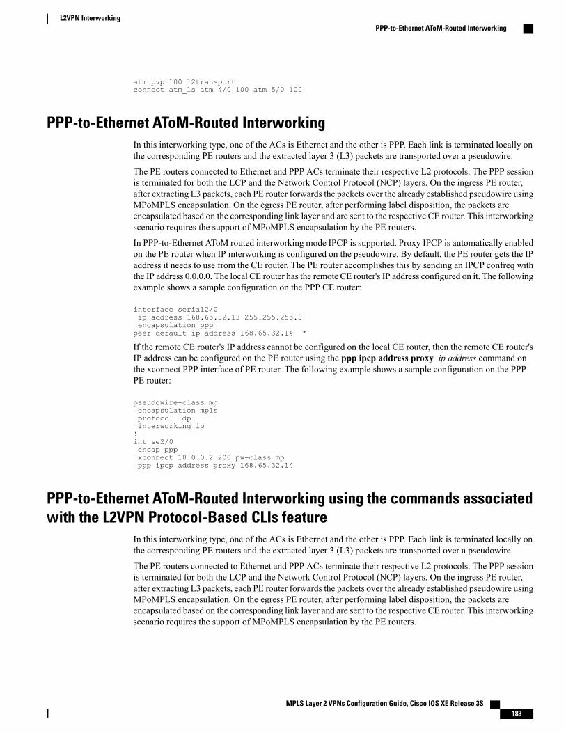
atm pvp 100 l2transportconnect atm_ls atm 4/0 100 atm 5/0 100
PPP-to-Ethernet AToM-Routed InterworkingIn this interworking type, one of the ACs is Ethernet and the other is PPP. Each link is terminated locally onthe corresponding PE routers and the extracted layer 3 (L3) packets are transported over a pseudowire.
The PE routers connected to Ethernet and PPP ACs terminate their respective L2 protocols. The PPP sessionis terminated for both the LCP and the Network Control Protocol (NCP) layers. On the ingress PE router,after extracting L3 packets, each PE router forwards the packets over the already established pseudowire usingMPoMPLS encapsulation. On the egress PE router, after performing label disposition, the packets areencapsulated based on the corresponding link layer and are sent to the respective CE router. This interworkingscenario requires the support of MPoMPLS encapsulation by the PE routers.
In PPP-to-Ethernet AToM routed interworking mode IPCP is supported. Proxy IPCP is automatically enabledon the PE router when IP interworking is configured on the pseudowire. By default, the PE router gets the IPaddress it needs to use from the CE router. The PE router accomplishes this by sending an IPCP confreq withthe IP address 0.0.0.0. The local CE router has the remote CE router's IP address configured on it. The followingexample shows a sample configuration on the PPP CE router:
interface serial2/0ip address 168.65.32.13 255.255.255.0encapsulation ppppeer default ip address 168.65.32.14 *
If the remote CE router's IP address cannot be configured on the local CE router, then the remote CE router'sIP address can be configured on the PE router using the ppp ipcp address proxy ip address command onthe xconnect PPP interface of PE router. The following example shows a sample configuration on the PPPPE router:
pseudowire-class mpencapsulation mplsprotocol ldpinterworking ip!int se2/0encap pppxconnect 10.0.0.2 200 pw-class mpppp ipcp address proxy 168.65.32.14
PPP-to-Ethernet AToM-Routed Interworking using the commands associatedwith the L2VPN Protocol-Based CLIs feature
In this interworking type, one of the ACs is Ethernet and the other is PPP. Each link is terminated locally onthe corresponding PE routers and the extracted layer 3 (L3) packets are transported over a pseudowire.
The PE routers connected to Ethernet and PPP ACs terminate their respective L2 protocols. The PPP sessionis terminated for both the LCP and the Network Control Protocol (NCP) layers. On the ingress PE router,after extracting L3 packets, each PE router forwards the packets over the already established pseudowire usingMPoMPLS encapsulation. On the egress PE router, after performing label disposition, the packets areencapsulated based on the corresponding link layer and are sent to the respective CE router. This interworkingscenario requires the support of MPoMPLS encapsulation by the PE routers.
MPLS Layer 2 VPNs Configuration Guide, Cisco IOS XE Release 3S 183
L2VPN InterworkingPPP-to-Ethernet AToM-Routed Interworking
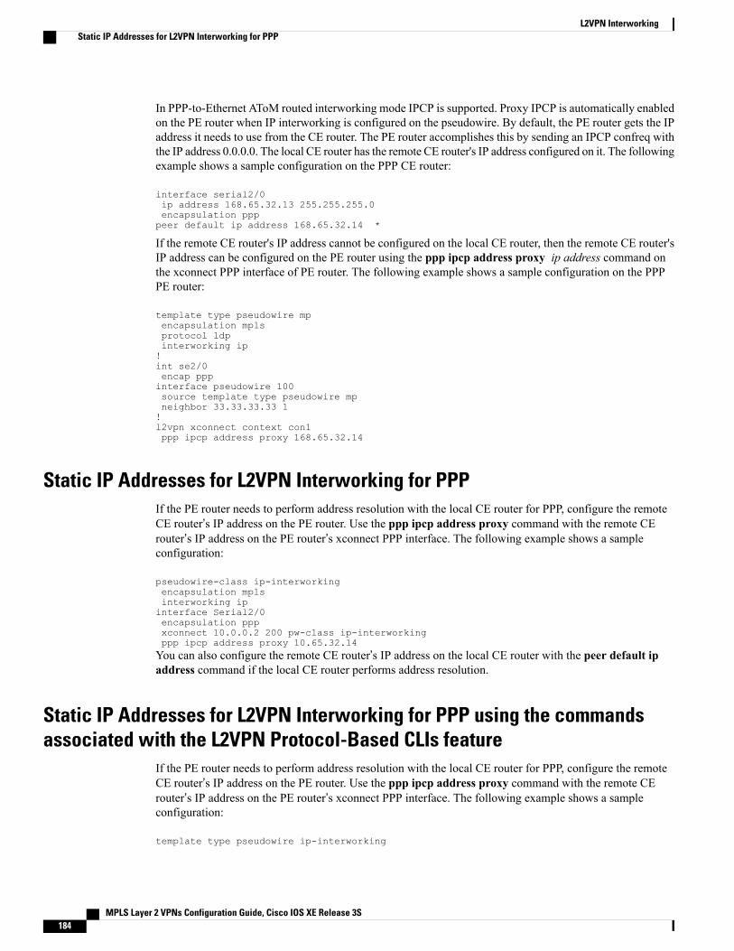
In PPP-to-Ethernet AToM routed interworking mode IPCP is supported. Proxy IPCP is automatically enabledon the PE router when IP interworking is configured on the pseudowire. By default, the PE router gets the IPaddress it needs to use from the CE router. The PE router accomplishes this by sending an IPCP confreq withthe IP address 0.0.0.0. The local CE router has the remote CE router's IP address configured on it. The followingexample shows a sample configuration on the PPP CE router:
interface serial2/0ip address 168.65.32.13 255.255.255.0encapsulation ppppeer default ip address 168.65.32.14 *
If the remote CE router's IP address cannot be configured on the local CE router, then the remote CE router'sIP address can be configured on the PE router using the ppp ipcp address proxy ip address command onthe xconnect PPP interface of PE router. The following example shows a sample configuration on the PPPPE router:
template type pseudowire mpencapsulation mplsprotocol ldpinterworking ip!int se2/0encap pppinterface pseudowire 100source template type pseudowire mpneighbor 33.33.33.33 1!l2vpn xconnect context con1ppp ipcp address proxy 168.65.32.14
Static IP Addresses for L2VPN Interworking for PPPIf the PE router needs to perform address resolution with the local CE router for PPP, configure the remoteCE router’s IP address on the PE router. Use the ppp ipcp address proxy command with the remote CErouter’s IP address on the PE router’s xconnect PPP interface. The following example shows a sampleconfiguration:
pseudowire-class ip-interworkingencapsulation mplsinterworking ipinterface Serial2/0encapsulation pppxconnect 10.0.0.2 200 pw-class ip-interworkingppp ipcp address proxy 10.65.32.14You can also configure the remote CE router’s IP address on the local CE router with the peer default ipaddress command if the local CE router performs address resolution.
Static IP Addresses for L2VPN Interworking for PPP using the commandsassociated with the L2VPN Protocol-Based CLIs feature
If the PE router needs to perform address resolution with the local CE router for PPP, configure the remoteCE router’s IP address on the PE router. Use the ppp ipcp address proxy command with the remote CErouter’s IP address on the PE router’s xconnect PPP interface. The following example shows a sampleconfiguration:
template type pseudowire ip-interworking
MPLS Layer 2 VPNs Configuration Guide, Cisco IOS XE Release 3S184
L2VPN InterworkingStatic IP Addresses for L2VPN Interworking for PPP
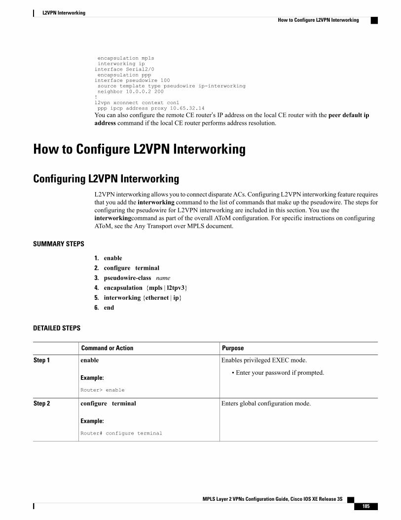
encapsulation mplsinterworking ipinterface Serial2/0encapsulation pppinterface pseudowire 100source template type pseudowire ip-interworkingneighbor 10.0.0.2 200!l2vpn xconnect context con1ppp ipcp address proxy 10.65.32.14You can also configure the remote CE router’s IP address on the local CE router with the peer default ipaddress command if the local CE router performs address resolution.
How to Configure L2VPN Interworking
Configuring L2VPN InterworkingL2VPN interworking allows you to connect disparate ACs. Configuring L2VPN interworking feature requiresthat you add the interworking command to the list of commands that make up the pseudowire. The steps forconfiguring the pseudowire for L2VPN interworking are included in this section. You use theinterworkingcommand as part of the overall AToM configuration. For specific instructions on configuringAToM, see the Any Transport over MPLS document.
SUMMARY STEPS
1. enable2. configure terminal3. pseudowire-class name4. encapsulation {mpls | l2tpv3}5. interworking {ethernet | ip}6. end
DETAILED STEPS
PurposeCommand or Action
Enables privileged EXEC mode.enableStep 1
Example:
Router> enable
• Enter your password if prompted.
Enters global configuration mode.configure terminal
Example:
Router# configure terminal
Step 2
MPLS Layer 2 VPNs Configuration Guide, Cisco IOS XE Release 3S 185
L2VPN InterworkingHow to Configure L2VPN Interworking
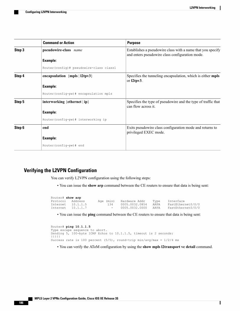
PurposeCommand or Action
Establishes a pseudowire class with a name that you specifyand enters pseudowire class configuration mode.
pseudowire-class name
Example:
Router(config)# pseudowire-class class1
Step 3
Specifies the tunneling encapsulation, which is eithermplsor l2tpv3.
encapsulation {mpls | l2tpv3}
Example:
Router(config-pw)# encapsulation mpls
Step 4
Specifies the type of pseudowire and the type of traffic thatcan flow across it.
interworking {ethernet | ip}
Example:
Router(config-pw)# interworking ip
Step 5
Exits pseudowire class configuration mode and returns toprivileged EXEC mode.
end
Example:
Router(config-pw)# end
Step 6
Verifying the L2VPN ConfigurationYou can verify L2VPN configuration using the following steps:
• You can issue the show arp command between the CE routers to ensure that data is being sent:
Router# show arpProtocol Address Age (min) Hardware Addr Type InterfaceInternet 10.1.1.5 134 0005.0032.0854 ARPA FastEthernet0/0/0Internet 10.1.1.7 - 0005.0032.0000 ARPA FastEthernet0/0/0
• You can issue the ping command between the CE routers to ensure that data is being sent:
Router# ping 10.1.1.5Type escape sequence to abort.Sending 5, 100-byte ICMP Echos to 10.1.1.5, timeout is 2 seconds:!!!!!Success rate is 100 percent (5/5), round-trip min/avg/max = 1/2/4 ms
• You can verify the AToM configuration by using the show mpls l2transport vc detail command.
MPLS Layer 2 VPNs Configuration Guide, Cisco IOS XE Release 3S186
L2VPN InterworkingConfiguring L2VPN Interworking
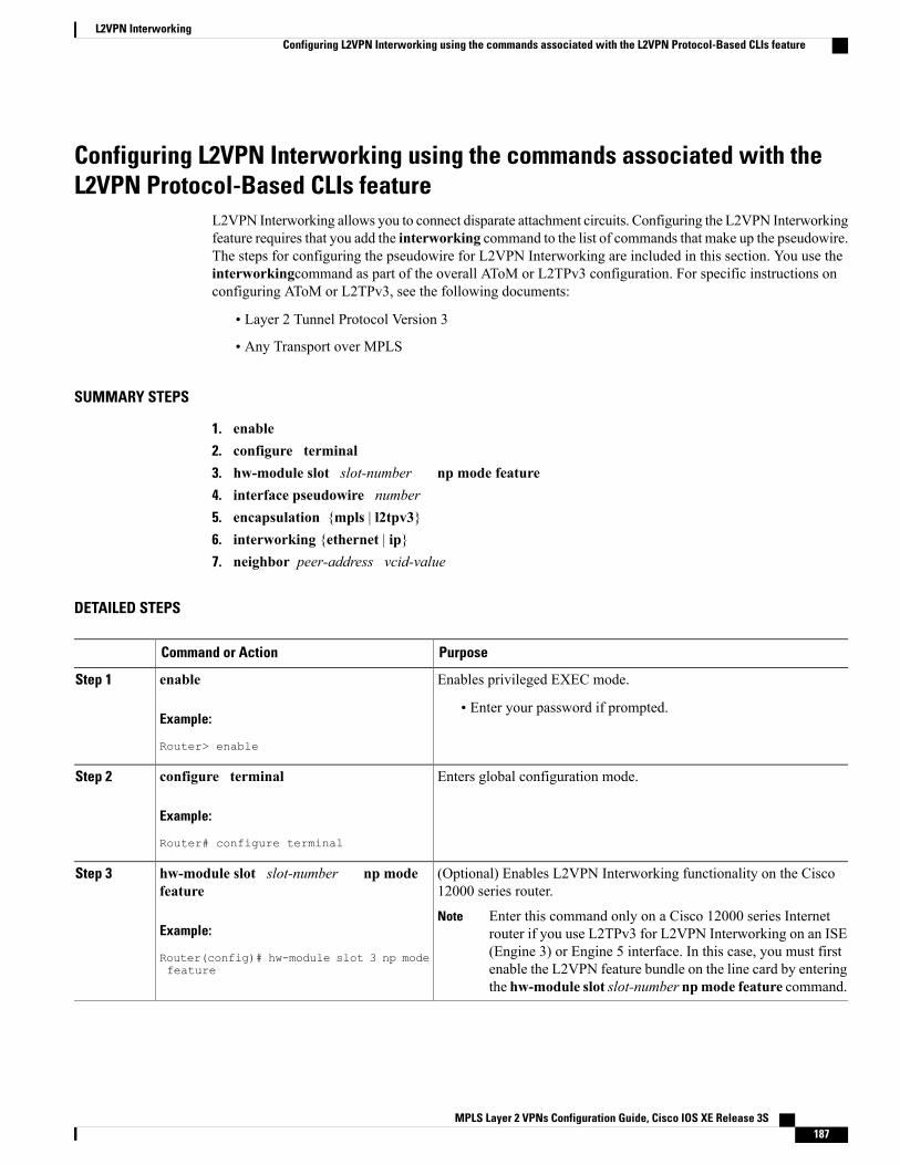
Configuring L2VPN Interworking using the commands associated with theL2VPN Protocol-Based CLIs feature
L2VPN Interworking allows you to connect disparate attachment circuits. Configuring the L2VPN Interworkingfeature requires that you add the interworking command to the list of commands that make up the pseudowire.The steps for configuring the pseudowire for L2VPN Interworking are included in this section. You use theinterworkingcommand as part of the overall AToM or L2TPv3 configuration. For specific instructions onconfiguring AToM or L2TPv3, see the following documents:
• Layer 2 Tunnel Protocol Version 3
• Any Transport over MPLS
SUMMARY STEPS
1. enable2. configure terminal3. hw-module slot slot-number np mode feature4. interface pseudowire number5. encapsulation {mpls | l2tpv3}6. interworking {ethernet | ip}7. neighbor peer-address vcid-value
DETAILED STEPS
PurposeCommand or Action
Enables privileged EXEC mode.enableStep 1
Example:
Router> enable
• Enter your password if prompted.
Enters global configuration mode.configure terminal
Example:
Router# configure terminal
Step 2
(Optional) Enables L2VPN Interworking functionality on the Cisco12000 series router.
hw-module slot slot-number np modefeature
Step 3
Example:
Router(config)# hw-module slot 3 np modefeature
Enter this command only on a Cisco 12000 series Internetrouter if you use L2TPv3 for L2VPN Interworking on an ISE(Engine 3) or Engine 5 interface. In this case, you must firstenable the L2VPN feature bundle on the line card by enteringthe hw-module slot slot-number npmode feature command.
Note
MPLS Layer 2 VPNs Configuration Guide, Cisco IOS XE Release 3S 187
L2VPN InterworkingConfiguring L2VPN Interworking using the commands associated with the L2VPN Protocol-Based CLIs feature
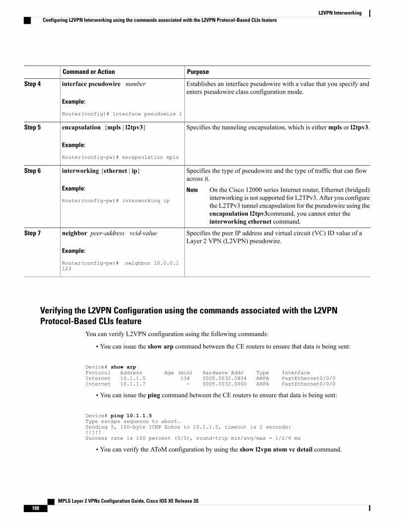
PurposeCommand or Action
Establishes an interface pseudowire with a value that you specify andenters pseudowire class configuration mode.
interface pseudowire number
Example:
Router(config)# interface pseudowire 1
Step 4
Specifies the tunneling encapsulation, which is eithermpls or l2tpv3.encapsulation {mpls | l2tpv3}
Example:
Router(config-pw)# encapsulation mpls
Step 5
Specifies the type of pseudowire and the type of traffic that can flowacross it.
interworking {ethernet | ip}
Example:
Router(config-pw)# interworking ip
Step 6
On the Cisco 12000 series Internet router, Ethernet (bridged)interworking is not supported for L2TPv3. After you configurethe L2TPv3 tunnel encapsulation for the pseudowire using theencapsulation l2tpv3command, you cannot enter theinterworking ethernet command.
Note
Specifies the peer IP address and virtual circuit (VC) ID value of aLayer 2 VPN (L2VPN) pseudowire.
neighbor peer-address vcid-value
Example:
Router(config-pw)# neighbor 10.0.0.1123
Step 7
Verifying the L2VPN Configuration using the commands associated with the L2VPNProtocol-Based CLIs feature
You can verify L2VPN configuration using the following commands:
• You can issue the show arp command between the CE routers to ensure that data is being sent:
Device# show arpProtocol Address Age (min) Hardware Addr Type InterfaceInternet 10.1.1.5 134 0005.0032.0854 ARPA FastEthernet0/0/0Internet 10.1.1.7 - 0005.0032.0000 ARPA FastEthernet0/0/0
• You can issue the ping command between the CE routers to ensure that data is being sent:
Device# ping 10.1.1.5Type escape sequence to abort.Sending 5, 100-byte ICMP Echos to 10.1.1.5, timeout is 2 seconds:!!!!!Success rate is 100 percent (5/5), round-trip min/avg/max = 1/2/4 ms
• You can verify the AToM configuration by using the show l2vpn atom vc detail command.
MPLS Layer 2 VPNs Configuration Guide, Cisco IOS XE Release 3S188
L2VPN InterworkingConfiguring L2VPN Interworking using the commands associated with the L2VPN Protocol-Based CLIs feature
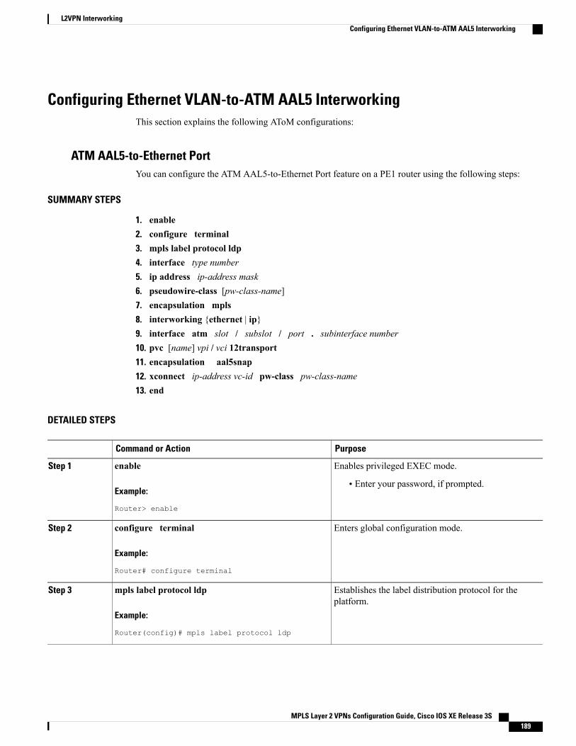
Configuring Ethernet VLAN-to-ATM AAL5 InterworkingThis section explains the following AToM configurations:
ATM AAL5-to-Ethernet PortYou can configure the ATM AAL5-to-Ethernet Port feature on a PE1 router using the following steps:
SUMMARY STEPS
1. enable2. configure terminal3. mpls label protocol ldp4. interface type number5. ip address ip-address mask6. pseudowire-class [pw-class-name]7. encapsulation mpls8. interworking {ethernet | ip}9. interface atm slot / subslot / port . subinterface number10. pvc [name] vpi / vci 12transport11. encapsulation aal5snap12. xconnect ip-address vc-id pw-class pw-class-name13. end
DETAILED STEPS
PurposeCommand or Action
Enables privileged EXEC mode.enableStep 1
Example:
Router> enable
• Enter your password, if prompted.
Enters global configuration mode.configure terminal
Example:
Router# configure terminal
Step 2
Establishes the label distribution protocol for theplatform.
mpls label protocol ldp
Example:
Router(config)# mpls label protocol ldp
Step 3
MPLS Layer 2 VPNs Configuration Guide, Cisco IOS XE Release 3S 189
L2VPN InterworkingConfiguring Ethernet VLAN-to-ATM AAL5 Interworking

PurposeCommand or Action
Configure an interface type and enters interfaceconfiguration mode.
interface type number
Example:
Router(config)# interface loopback 100
Step 4
Sets the primary or secondary IP address for an interface.ip address ip-address mask
Example:
Router(config-if)# ip address 10.0.0.100255.255.255.255
Step 5
Establishes a pseudowire class with a name that youspecify and enters pseudowire class configuration mode.
pseudowire-class [pw-class-name]
Example:
Router(config-if)# pseudowire-class atm-eth
Step 6
Specifies the tunneling encapsulation.encapsulation mpls
Example:
Router(config-pw)# encapsulation mpls
Step 7
Specifies the type of pseudowire and the type of trafficthat can flow across it.
interworking {ethernet | ip}
Example:
Router(config-pw)# interworking ip
Step 8
Configures an ATM interface and enters interfaceconfiguration mode.
interface atm slot / subslot / port . subinterfacenumber
Example:
Router(config-pw)# interface atm 2/0/0.1
Step 9
Assigns a name to an ATM permanent virtual circuit(PVC) and enters ATM virtual circuit configurationmode.
pvc [name] vpi / vci 12transport
Example:
Router(config-subif)# pvc 0/200 l2transport
Step 10
Configures the ATM AAL and encapsulation type foran ATM VC.
encapsulation aal5snap
Example:
Router(config-if-atm-member)# encapsulationaal5snap
Step 11
MPLS Layer 2 VPNs Configuration Guide, Cisco IOS XE Release 3S190
L2VPN InterworkingConfiguring Ethernet VLAN-to-ATM AAL5 Interworking
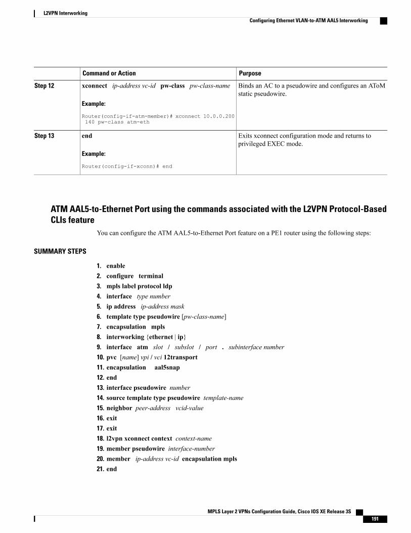
PurposeCommand or Action
Binds an AC to a pseudowire and configures an AToMstatic pseudowire.
xconnect ip-address vc-id pw-class pw-class-name
Example:
Router(config-if-atm-member)# xconnect 10.0.0.200140 pw-class atm-eth
Step 12
Exits xconnect configuration mode and returns toprivileged EXEC mode.
end
Example:
Router(config-if-xconn)# end
Step 13
ATM AAL5-to-Ethernet Port using the commands associated with the L2VPN Protocol-BasedCLIs feature
You can configure the ATM AAL5-to-Ethernet Port feature on a PE1 router using the following steps:
SUMMARY STEPS
1. enable2. configure terminal3. mpls label protocol ldp4. interface type number5. ip address ip-address mask6. template type pseudowire [pw-class-name]7. encapsulation mpls8. interworking {ethernet | ip}9. interface atm slot / subslot / port . subinterface number10. pvc [name] vpi / vci 12transport11. encapsulation aal5snap12. end13. interface pseudowire number14. source template type pseudowire template-name15. neighbor peer-address vcid-value16. exit17. exit18. l2vpn xconnect context context-name19. member pseudowire interface-number20. member ip-address vc-id encapsulation mpls21. end
MPLS Layer 2 VPNs Configuration Guide, Cisco IOS XE Release 3S 191
L2VPN InterworkingConfiguring Ethernet VLAN-to-ATM AAL5 Interworking
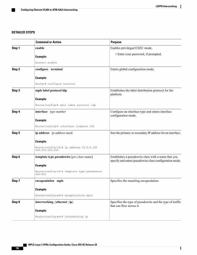
DETAILED STEPS
PurposeCommand or Action
Enables privileged EXEC mode.enableStep 1
Example:
Router> enable
• Enter your password, if prompted.
Enters global configuration mode.configure terminal
Example:
Router# configure terminal
Step 2
Establishes the label distribution protocol for theplatform.
mpls label protocol ldp
Example:
Router(config)# mpls label protocol ldp
Step 3
Configure an interface type and enters interfaceconfiguration mode.
interface type number
Example:
Router(config)# interface loopback 100
Step 4
Sets the primary or secondary IP address for an interface.ip address ip-address mask
Example:
Router(config-if)# ip address 10.0.0.100255.255.255.255
Step 5
Establishes a pseudowire class with a name that youspecify and enters pseudowire class configurationmode.
template type pseudowire [pw-class-name]
Example:
Router(config-if)# template type pseudowireatm-eth
Step 6
Specifies the tunneling encapsulation.encapsulation mpls
Example:
Router(config-pw)# encapsulation mpls
Step 7
Specifies the type of pseudowire and the type of trafficthat can flow across it.
interworking {ethernet | ip}
Example:
Router(config-pw)# interworking ip
Step 8
MPLS Layer 2 VPNs Configuration Guide, Cisco IOS XE Release 3S192
L2VPN InterworkingConfiguring Ethernet VLAN-to-ATM AAL5 Interworking
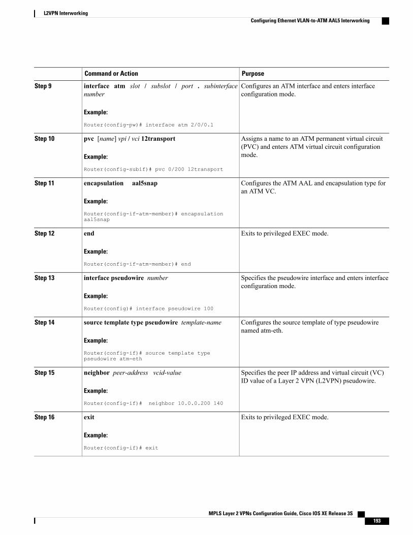
PurposeCommand or Action
Configures an ATM interface and enters interfaceconfiguration mode.
interface atm slot / subslot / port . subinterfacenumber
Example:
Router(config-pw)# interface atm 2/0/0.1
Step 9
Assigns a name to an ATM permanent virtual circuit(PVC) and enters ATM virtual circuit configurationmode.
pvc [name] vpi / vci 12transport
Example:
Router(config-subif)# pvc 0/200 l2transport
Step 10
Configures the ATM AAL and encapsulation type foran ATM VC.
encapsulation aal5snap
Example:
Router(config-if-atm-member)# encapsulationaal5snap
Step 11
Exits to privileged EXEC mode.end
Example:
Router(config-if-atm-member)# end
Step 12
Specifies the pseudowire interface and enters interfaceconfiguration mode.
interface pseudowire number
Example:
Router(config)# interface pseudowire 100
Step 13
Configures the source template of type pseudowirenamed atm-eth.
source template type pseudowire template-name
Example:
Router(config-if)# source template typepseudowire atm-eth
Step 14
Specifies the peer IP address and virtual circuit (VC)ID value of a Layer 2 VPN (L2VPN) pseudowire.
neighbor peer-address vcid-value
Example:
Router(config-if)# neighbor 10.0.0.200 140
Step 15
Exits to privileged EXEC mode.exit
Example:
Router(config-if)# exit
Step 16
MPLS Layer 2 VPNs Configuration Guide, Cisco IOS XE Release 3S 193
L2VPN InterworkingConfiguring Ethernet VLAN-to-ATM AAL5 Interworking
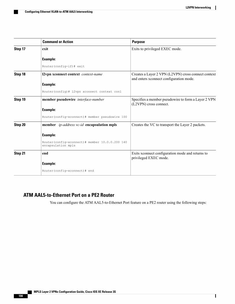
PurposeCommand or Action
Exits to privileged EXEC mode.exit
Example:
Router(config-if)# exit
Step 17
Creates a Layer 2 VPN (L2VPN) cross connect contextand enters xconnect configuration mode.
l2vpn xconnect context context-name
Example:
Router(config)# l2vpn xconnect context con1
Step 18
Specifies a member pseudowire to form a Layer 2 VPN(L2VPN) cross connect.
member pseudowire interface-number
Example:
Router(config-xconnect)# member pseudowire 100
Step 19
Creates the VC to transport the Layer 2 packets.member ip-address vc-id encapsulation mpls
Example:
Router(config-xconnect)# member 10.0.0.200 140encapsulation mpls
Step 20
Exits xconnect configuration mode and returns toprivileged EXEC mode.
end
Example:
Router(config-xconnect)# end
Step 21
ATM AAL5-to-Ethernet Port on a PE2 RouterYou can configure the ATM AAL5-to-Ethernet Port feature on a PE2 router using the following steps:
MPLS Layer 2 VPNs Configuration Guide, Cisco IOS XE Release 3S194
L2VPN InterworkingConfiguring Ethernet VLAN-to-ATM AAL5 Interworking
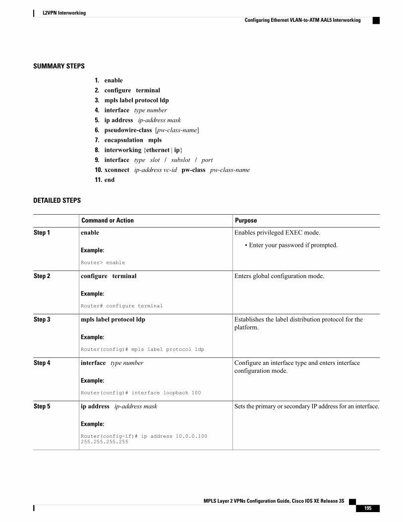
SUMMARY STEPS
1. enable2. configure terminal3. mpls label protocol ldp4. interface type number5. ip address ip-address mask6. pseudowire-class [pw-class-name]7. encapsulation mpls8. interworking {ethernet | ip}9. interface type slot / subslot / port10. xconnect ip-address vc-id pw-class pw-class-name11. end
DETAILED STEPS
PurposeCommand or Action
Enables privileged EXEC mode.enableStep 1
Example:
Router> enable
• Enter your password if prompted.
Enters global configuration mode.configure terminal
Example:
Router# configure terminal
Step 2
Establishes the label distribution protocol for theplatform.
mpls label protocol ldp
Example:
Router(config)# mpls label protocol ldp
Step 3
Configure an interface type and enters interfaceconfiguration mode.
interface type number
Example:
Router(config)# interface loopback 100
Step 4
Sets the primary or secondary IP address for an interface.ip address ip-address mask
Example:
Router(config-if)# ip address 10.0.0.100255.255.255.255
Step 5
MPLS Layer 2 VPNs Configuration Guide, Cisco IOS XE Release 3S 195
L2VPN InterworkingConfiguring Ethernet VLAN-to-ATM AAL5 Interworking
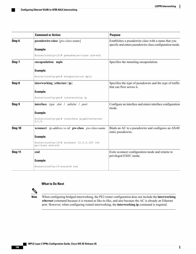
PurposeCommand or Action
Establishes a pseudowire class with a name that youspecify and enters pseudowire class configurationmode.
pseudowire-class [pw-class-name]
Example:
Router(config-if)# pseudowire-class atm-eth
Step 6
Specifies the tunneling encapsulation.encapsulation mpls
Example:
Router(config-pw)# encapsulation mpls
Step 7
Specifies the type of pseudowire and the type of trafficthat can flow across it.
interworking {ethernet | ip}
Example:
Router(config-pw)# interworking ip
Step 8
Configure an interface and enters interface configurationmode.
interface type slot / subslot / port
Example:
Router(config-pw)# interface gigabitethernet5/1/0
Step 9
Binds an AC to a pseudowire and configures an AToMstatic pseudowire.
xconnect ip-address vc-id pw-class pw-class-name
Example:
Router(config-if)# xconnect 10.0.0.100 140pw-class atm-eth
Step 10
Exits xconnect configuration mode and returns toprivileged EXEC mode.
end
Example:
Router(config-if-xconn)# end
Step 11
What to Do Next
When configuring bridged interworking, the PE2 router configuration does not include the interworkingethernet command because it is treated as like-to-like, and also because the AC is already an Ethernetport. However, when configuring routed interworking, the interworking ip command is required.
Note
MPLS Layer 2 VPNs Configuration Guide, Cisco IOS XE Release 3S196
L2VPN InterworkingConfiguring Ethernet VLAN-to-ATM AAL5 Interworking

ATM AAL5-to-Ethernet Port on a PE2 Router using the commands associated with the L2VPNProtocol-Based CLIs feature
You can configure the ATM AAL5-to-Ethernet Port feature on a PE2 router using the following steps:
SUMMARY STEPS
1. enable2. configure terminal3. mpls label protocol ldp4. interface type number5. ip address ip-address mask6. template type pseudowire [pseudowire-name]7. encapsulation mpls8. interworking {ethernet | ip}9. interface type slot / subslot / port10. end11. interface pseudowire number12. source template type pseudowire template-name13. neighbor peer-address vcid-value14. exit15. l2vpn xconnect context context-name16. member pseudowire interface-number17. member ip-address vc-id encapsulation mpls18. end
DETAILED STEPS
PurposeCommand or Action
Enables privileged EXEC mode.enableStep 1
Example:
Router> enable
• Enter your password if prompted.
Enters global configuration mode.configure terminal
Example:
Router# configure terminal
Step 2
MPLS Layer 2 VPNs Configuration Guide, Cisco IOS XE Release 3S 197
L2VPN InterworkingConfiguring Ethernet VLAN-to-ATM AAL5 Interworking
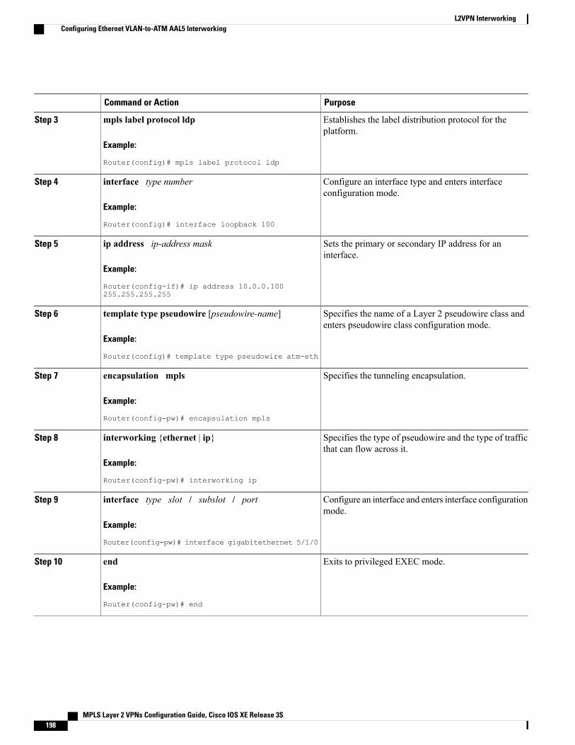
PurposeCommand or Action
Establishes the label distribution protocol for theplatform.
mpls label protocol ldp
Example:
Router(config)# mpls label protocol ldp
Step 3
Configure an interface type and enters interfaceconfiguration mode.
interface type number
Example:
Router(config)# interface loopback 100
Step 4
Sets the primary or secondary IP address for aninterface.
ip address ip-address mask
Example:
Router(config-if)# ip address 10.0.0.100255.255.255.255
Step 5
Specifies the name of a Layer 2 pseudowire class andenters pseudowire class configuration mode.
template type pseudowire [pseudowire-name]
Example:
Router(config)# template type pseudowire atm-eth
Step 6
Specifies the tunneling encapsulation.encapsulation mpls
Example:
Router(config-pw)# encapsulation mpls
Step 7
Specifies the type of pseudowire and the type of trafficthat can flow across it.
interworking {ethernet | ip}
Example:
Router(config-pw)# interworking ip
Step 8
Configure an interface and enters interface configurationmode.
interface type slot / subslot / port
Example:
Router(config-pw)# interface gigabitethernet 5/1/0
Step 9
Exits to privileged EXEC mode.end
Example:
Router(config-pw)# end
Step 10
MPLS Layer 2 VPNs Configuration Guide, Cisco IOS XE Release 3S198
L2VPN InterworkingConfiguring Ethernet VLAN-to-ATM AAL5 Interworking

PurposeCommand or Action
Specifies the pseudowire interface and enters interfaceconfiguration mode.
interface pseudowire number
Example:
Router(config)# interface pseudowire 100
Step 11
Configures the source template of type pseudowirenamed atm-eth
source template type pseudowire template-name
Example:
Router(config-if)# source template type pseudowireatm-eth
Step 12
Specifies the peer IP address and virtual circuit (VC)ID value of a Layer 2 VPN (L2VPN) pseudowire.
neighbor peer-address vcid-value
Example:
Router(config-if)# neighbor 10.0.0.100 140
Step 13
Exits to privileged EXEC mode.exit
Example:
Router(config-if)# exit
Step 14
Creates a Layer 2 VPN (L2VPN) cross connect contextand enters xconnect configuration mode.
l2vpn xconnect context context-name
Example:
Router(config)# l2vpn xconnect context con1
Step 15
Specifies a member pseudowire to form a Layer 2 VPN(L2VPN) cross connect.
member pseudowire interface-number
Example:
Router(config-xconnect)# member pseudowire 100
Step 16
Creates the VC to transport the Layer 2 packets.member ip-address vc-id encapsulation mpls
Example:
Router(config-xconnect)# member 10.0.0.100 140encapsulation mpls
Step 17
Exits xconnect configuration mode and returns toprivileged EXEC mode.
end
Example:
Router(config-xconnect)# end
Step 18
MPLS Layer 2 VPNs Configuration Guide, Cisco IOS XE Release 3S 199
L2VPN InterworkingConfiguring Ethernet VLAN-to-ATM AAL5 Interworking
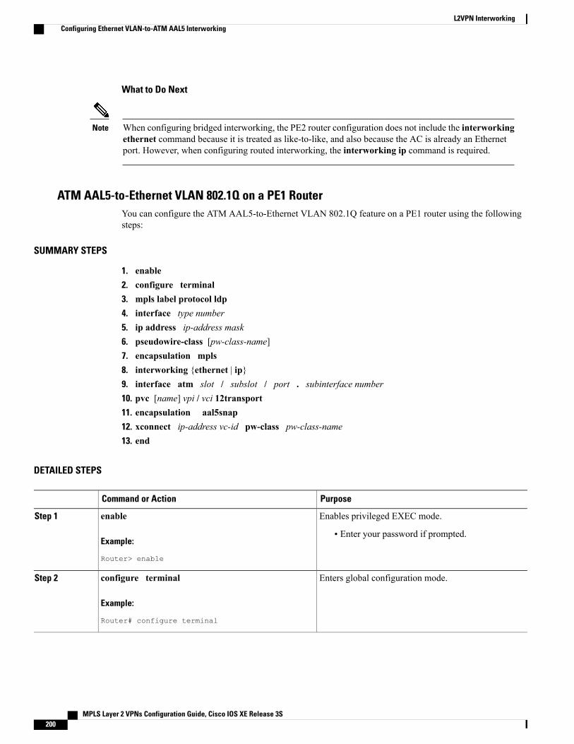
What to Do Next
When configuring bridged interworking, the PE2 router configuration does not include the interworkingethernet command because it is treated as like-to-like, and also because the AC is already an Ethernetport. However, when configuring routed interworking, the interworking ip command is required.
Note
ATM AAL5-to-Ethernet VLAN 802.1Q on a PE1 RouterYou can configure the ATM AAL5-to-Ethernet VLAN 802.1Q feature on a PE1 router using the followingsteps:
SUMMARY STEPS
1. enable2. configure terminal3. mpls label protocol ldp4. interface type number5. ip address ip-address mask6. pseudowire-class [pw-class-name]7. encapsulation mpls8. interworking {ethernet | ip}9. interface atm slot / subslot / port . subinterface number10. pvc [name] vpi / vci 12transport11. encapsulation aal5snap12. xconnect ip-address vc-id pw-class pw-class-name13. end
DETAILED STEPS
PurposeCommand or Action
Enables privileged EXEC mode.enableStep 1
Example:
Router> enable
• Enter your password if prompted.
Enters global configuration mode.configure terminal
Example:
Router# configure terminal
Step 2
MPLS Layer 2 VPNs Configuration Guide, Cisco IOS XE Release 3S200
L2VPN InterworkingConfiguring Ethernet VLAN-to-ATM AAL5 Interworking
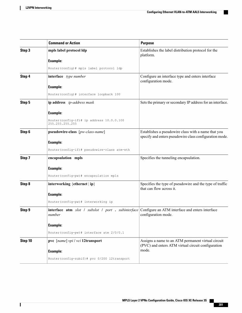
PurposeCommand or Action
Establishes the label distribution protocol for theplatform.
mpls label protocol ldp
Example:
Router(config)# mpls label protocol ldp
Step 3
Configure an interface type and enters interfaceconfiguration mode.
interface type number
Example:
Router(config)# interface loopback 100
Step 4
Sets the primary or secondary IP address for an interface.ip address ip-address mask
Example:
Router(config-if)# ip address 10.0.0.100255.255.255.255
Step 5
Establishes a pseudowire class with a name that youspecify and enters pseudowire class configuration mode.
pseudowire-class [pw-class-name]
Example:
Router(config-if)# pseudowire-class atm-eth
Step 6
Specifies the tunneling encapsulation.encapsulation mpls
Example:
Router(config-pw)# encapsulation mpls
Step 7
Specifies the type of pseudowire and the type of trafficthat can flow across it.
interworking {ethernet | ip}
Example:
Router(config-pw)# interworking ip
Step 8
Configure an ATM interface and enters interfaceconfiguration mode.
interface atm slot / subslot / port . subinterfacenumber
Example:
Router(config-pw)# interface atm 2/0/0.1
Step 9
Assigns a name to an ATM permanent virtual circuit(PVC) and enters ATM virtual circuit configurationmode.
pvc [name] vpi / vci 12transport
Example:
Router(config-subif)# pvc 0/200 l2transport
Step 10
MPLS Layer 2 VPNs Configuration Guide, Cisco IOS XE Release 3S 201
L2VPN InterworkingConfiguring Ethernet VLAN-to-ATM AAL5 Interworking
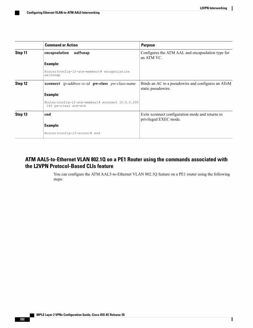
PurposeCommand or Action
Configures the ATM AAL and encapsulation type foran ATM VC.
encapsulation aal5snap
Example:
Router(config-if-atm-member)# encapsulationaal5snap
Step 11
Binds an AC to a pseudowire and configures an AToMstatic pseudowire.
xconnect ip-address vc-id pw-class pw-class-name
Example:
Router(config-if-atm-member)# xconnect 10.0.0.200140 pw-class atm-eth
Step 12
Exits xconnect configuration mode and returns toprivileged EXEC mode.
end
Example:
Router(config-if-xconn)# end
Step 13
ATM AAL5-to-Ethernet VLAN 802.1Q on a PE1 Router using the commands associated withthe L2VPN Protocol-Based CLIs feature
You can configure the ATM AAL5-to-Ethernet VLAN 802.1Q feature on a PE1 router using the followingsteps:
MPLS Layer 2 VPNs Configuration Guide, Cisco IOS XE Release 3S202
L2VPN InterworkingConfiguring Ethernet VLAN-to-ATM AAL5 Interworking
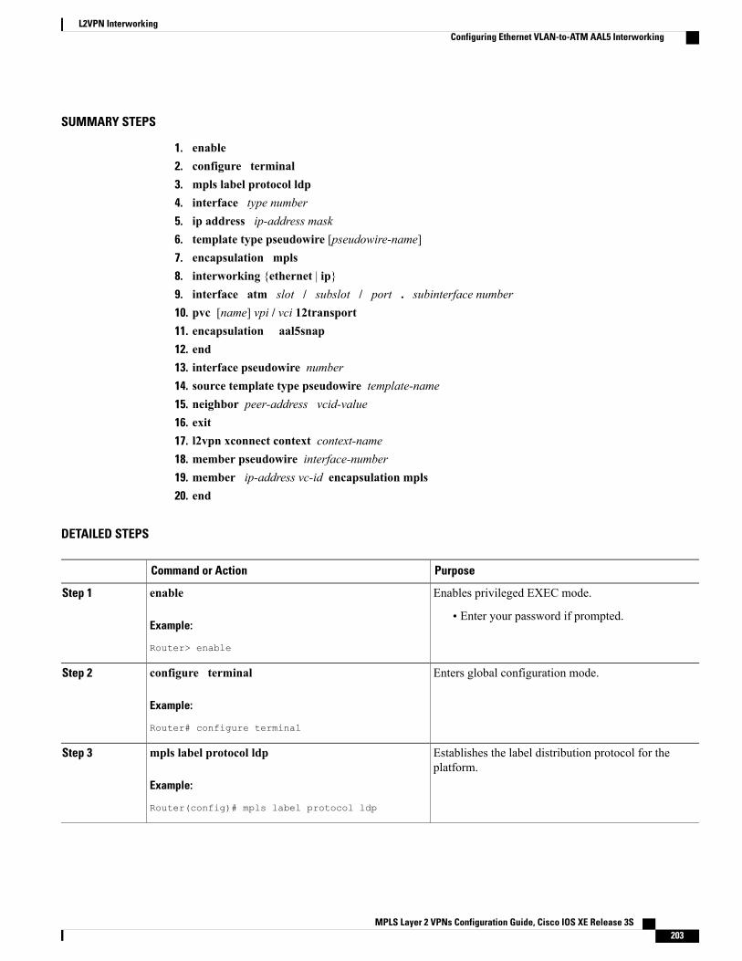
SUMMARY STEPS
1. enable2. configure terminal3. mpls label protocol ldp4. interface type number5. ip address ip-address mask6. template type pseudowire [pseudowire-name]7. encapsulation mpls8. interworking {ethernet | ip}9. interface atm slot / subslot / port . subinterface number10. pvc [name] vpi / vci 12transport11. encapsulation aal5snap12. end13. interface pseudowire number14. source template type pseudowire template-name15. neighbor peer-address vcid-value16. exit17. l2vpn xconnect context context-name18. member pseudowire interface-number19. member ip-address vc-id encapsulation mpls20. end
DETAILED STEPS
PurposeCommand or Action
Enables privileged EXEC mode.enableStep 1
Example:
Router> enable
• Enter your password if prompted.
Enters global configuration mode.configure terminal
Example:
Router# configure terminal
Step 2
Establishes the label distribution protocol for theplatform.
mpls label protocol ldp
Example:
Router(config)# mpls label protocol ldp
Step 3
MPLS Layer 2 VPNs Configuration Guide, Cisco IOS XE Release 3S 203
L2VPN InterworkingConfiguring Ethernet VLAN-to-ATM AAL5 Interworking
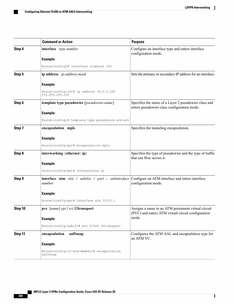
PurposeCommand or Action
Configure an interface type and enters interfaceconfiguration mode.
interface type number
Example:
Router(config)# interface loopback 100
Step 4
Sets the primary or secondary IP address for an interface.ip address ip-address mask
Example:
Router(config-if)# ip address 10.0.0.100255.255.255.255
Step 5
Specifies the name of a Layer 2 pseudowire class andenters pseudowire class configuration mode.
template type pseudowire [pseudowire-name]
Example:
Router(config)# template type pseudowire atm-eth
Step 6
Specifies the tunneling encapsulation.encapsulation mpls
Example:
Router(config-pw)# encapsulation mpls
Step 7
Specifies the type of pseudowire and the type of trafficthat can flow across it.
interworking {ethernet | ip}
Example:
Router(config-pw)# interworking ip
Step 8
Configure an ATM interface and enters interfaceconfiguration mode.
interface atm slot / subslot / port . subinterfacenumber
Example:
Router(config-pw)# interface atm 2/0/0.1
Step 9
Assigns a name to an ATM permanent virtual circuit(PVC) and enters ATM virtual circuit configurationmode.
pvc [name] vpi / vci 12transport
Example:
Router(config-subif)# pvc 0/200 l2transport
Step 10
Configures the ATM AAL and encapsulation type foran ATM VC.
encapsulation aal5snap
Example:
Router(config-if-atm-member)# encapsulationaal5snap
Step 11
MPLS Layer 2 VPNs Configuration Guide, Cisco IOS XE Release 3S204
L2VPN InterworkingConfiguring Ethernet VLAN-to-ATM AAL5 Interworking
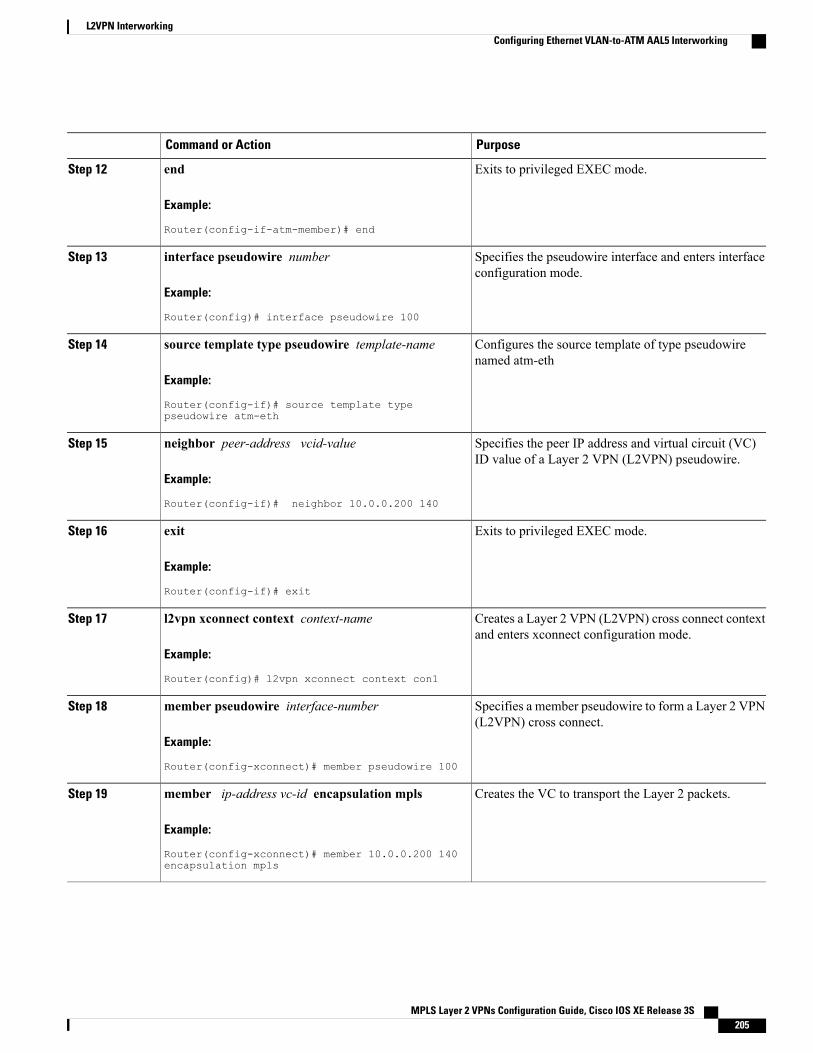
PurposeCommand or Action
Exits to privileged EXEC mode.end
Example:
Router(config-if-atm-member)# end
Step 12
Specifies the pseudowire interface and enters interfaceconfiguration mode.
interface pseudowire number
Example:
Router(config)# interface pseudowire 100
Step 13
Configures the source template of type pseudowirenamed atm-eth
source template type pseudowire template-name
Example:
Router(config-if)# source template typepseudowire atm-eth
Step 14
Specifies the peer IP address and virtual circuit (VC)ID value of a Layer 2 VPN (L2VPN) pseudowire.
neighbor peer-address vcid-value
Example:
Router(config-if)# neighbor 10.0.0.200 140
Step 15
Exits to privileged EXEC mode.exit
Example:
Router(config-if)# exit
Step 16
Creates a Layer 2 VPN (L2VPN) cross connect contextand enters xconnect configuration mode.
l2vpn xconnect context context-name
Example:
Router(config)# l2vpn xconnect context con1
Step 17
Specifies a member pseudowire to form a Layer 2 VPN(L2VPN) cross connect.
member pseudowire interface-number
Example:
Router(config-xconnect)# member pseudowire 100
Step 18
Creates the VC to transport the Layer 2 packets.member ip-address vc-id encapsulation mpls
Example:
Router(config-xconnect)# member 10.0.0.200 140encapsulation mpls
Step 19
MPLS Layer 2 VPNs Configuration Guide, Cisco IOS XE Release 3S 205
L2VPN InterworkingConfiguring Ethernet VLAN-to-ATM AAL5 Interworking
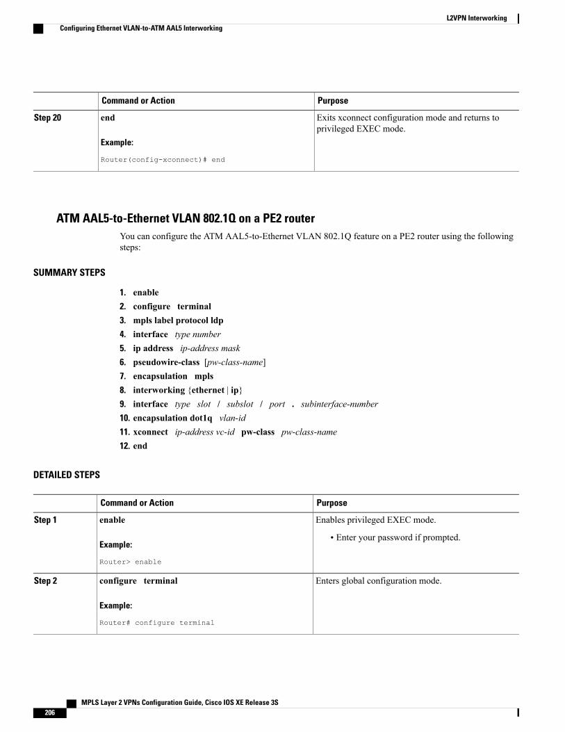
PurposeCommand or Action
Exits xconnect configuration mode and returns toprivileged EXEC mode.
end
Example:
Router(config-xconnect)# end
Step 20
ATM AAL5-to-Ethernet VLAN 802.1Q on a PE2 routerYou can configure the ATM AAL5-to-Ethernet VLAN 802.1Q feature on a PE2 router using the followingsteps:
SUMMARY STEPS
1. enable2. configure terminal3. mpls label protocol ldp4. interface type number5. ip address ip-address mask6. pseudowire-class [pw-class-name]7. encapsulation mpls8. interworking {ethernet | ip}9. interface type slot / subslot / port . subinterface-number10. encapsulation dot1q vlan-id11. xconnect ip-address vc-id pw-class pw-class-name12. end
DETAILED STEPS
PurposeCommand or Action
Enables privileged EXEC mode.enableStep 1
Example:
Router> enable
• Enter your password if prompted.
Enters global configuration mode.configure terminal
Example:
Router# configure terminal
Step 2
MPLS Layer 2 VPNs Configuration Guide, Cisco IOS XE Release 3S206
L2VPN InterworkingConfiguring Ethernet VLAN-to-ATM AAL5 Interworking
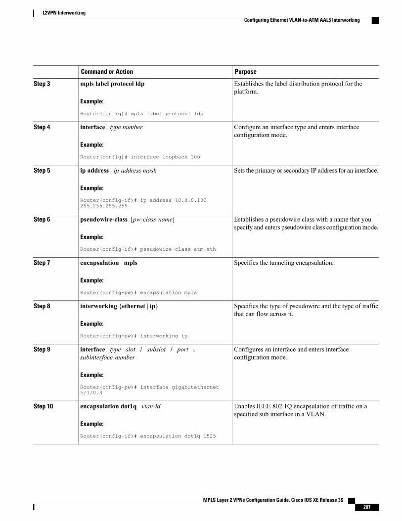
PurposeCommand or Action
Establishes the label distribution protocol for theplatform.
mpls label protocol ldp
Example:
Router(config)# mpls label protocol ldp
Step 3
Configure an interface type and enters interfaceconfiguration mode.
interface type number
Example:
Router(config)# interface loopback 100
Step 4
Sets the primary or secondary IP address for an interface.ip address ip-address mask
Example:
Router(config-if)# ip address 10.0.0.100255.255.255.255
Step 5
Establishes a pseudowire class with a name that youspecify and enters pseudowire class configurationmode.
pseudowire-class [pw-class-name]
Example:
Router(config-if)# pseudowire-class atm-eth
Step 6
Specifies the tunneling encapsulation.encapsulation mpls
Example:
Router(config-pw)# encapsulation mpls
Step 7
Specifies the type of pseudowire and the type of trafficthat can flow across it.
interworking {ethernet | ip}
Example:
Router(config-pw)# interworking ip
Step 8
Configures an interface and enters interfaceconfiguration mode.
interface type slot / subslot / port .subinterface-number
Example:
Router(config-pw)# interface gigabitethernet5/1/0.3
Step 9
Enables IEEE 802.1Q encapsulation of traffic on aspecified sub interface in a VLAN.
encapsulation dot1q vlan-id
Example:
Router(config-if)# encapsulation dot1q 1525
Step 10
MPLS Layer 2 VPNs Configuration Guide, Cisco IOS XE Release 3S 207
L2VPN InterworkingConfiguring Ethernet VLAN-to-ATM AAL5 Interworking
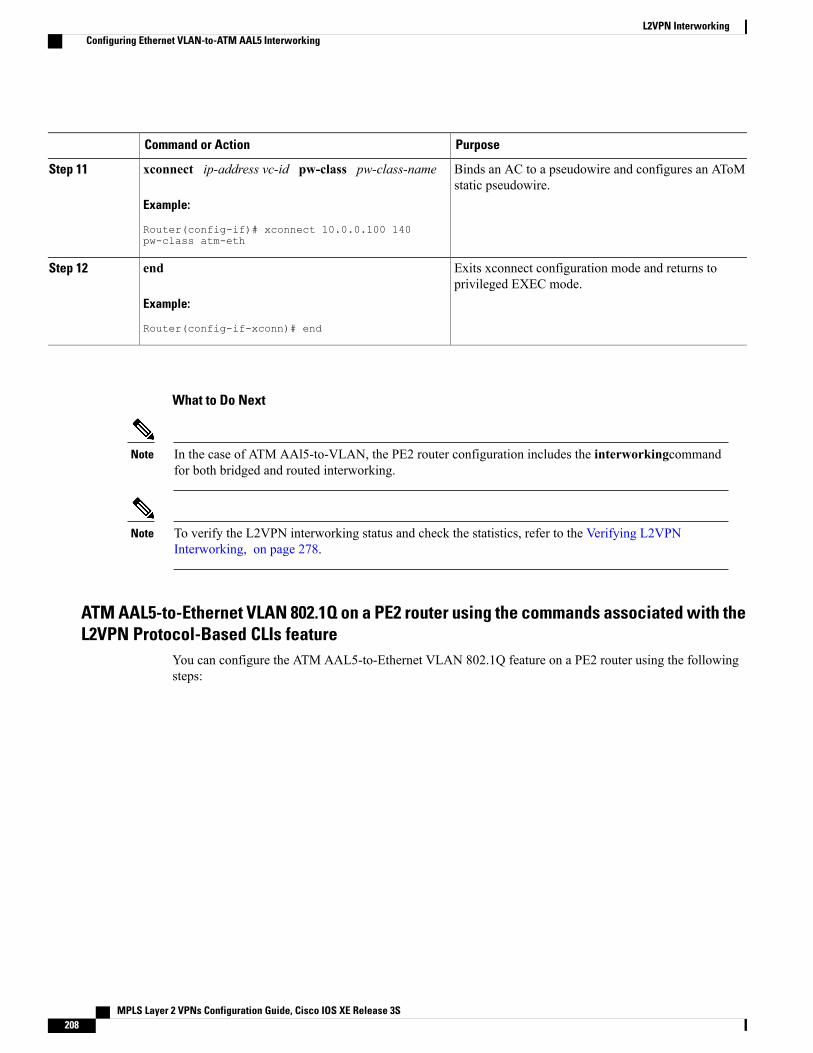
PurposeCommand or Action
Binds an AC to a pseudowire and configures an AToMstatic pseudowire.
xconnect ip-address vc-id pw-class pw-class-name
Example:
Router(config-if)# xconnect 10.0.0.100 140pw-class atm-eth
Step 11
Exits xconnect configuration mode and returns toprivileged EXEC mode.
end
Example:
Router(config-if-xconn)# end
Step 12
What to Do Next
In the case of ATM AAl5-to-VLAN, the PE2 router configuration includes the interworkingcommandfor both bridged and routed interworking.
Note
To verify the L2VPN interworking status and check the statistics, refer to the Verifying L2VPNInterworking, on page 278.
Note
ATM AAL5-to-Ethernet VLAN 802.1Q on a PE2 router using the commands associated with theL2VPN Protocol-Based CLIs feature
You can configure the ATM AAL5-to-Ethernet VLAN 802.1Q feature on a PE2 router using the followingsteps:
MPLS Layer 2 VPNs Configuration Guide, Cisco IOS XE Release 3S208
L2VPN InterworkingConfiguring Ethernet VLAN-to-ATM AAL5 Interworking
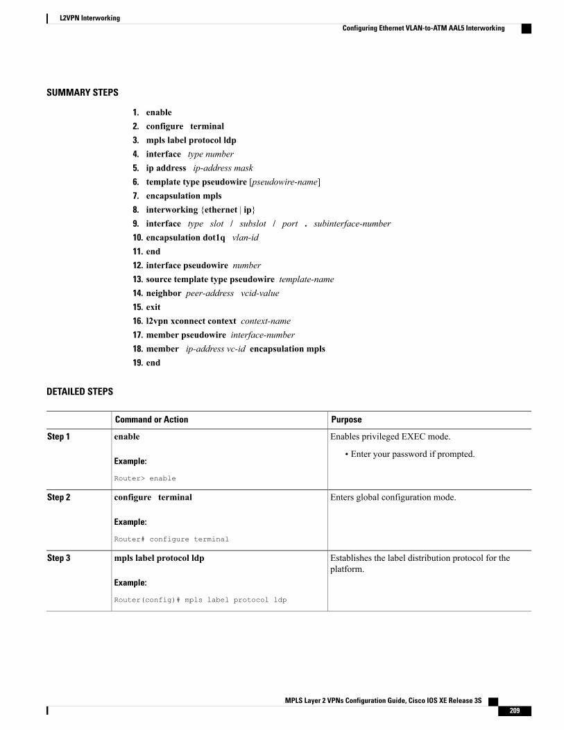
SUMMARY STEPS
1. enable2. configure terminal3. mpls label protocol ldp4. interface type number5. ip address ip-address mask6. template type pseudowire [pseudowire-name]7. encapsulation mpls8. interworking {ethernet | ip}9. interface type slot / subslot / port . subinterface-number10. encapsulation dot1q vlan-id11. end12. interface pseudowire number13. source template type pseudowire template-name14. neighbor peer-address vcid-value15. exit16. l2vpn xconnect context context-name17. member pseudowire interface-number18. member ip-address vc-id encapsulation mpls19. end
DETAILED STEPS
PurposeCommand or Action
Enables privileged EXEC mode.enableStep 1
Example:
Router> enable
• Enter your password if prompted.
Enters global configuration mode.configure terminal
Example:
Router# configure terminal
Step 2
Establishes the label distribution protocol for theplatform.
mpls label protocol ldp
Example:
Router(config)# mpls label protocol ldp
Step 3
MPLS Layer 2 VPNs Configuration Guide, Cisco IOS XE Release 3S 209
L2VPN InterworkingConfiguring Ethernet VLAN-to-ATM AAL5 Interworking
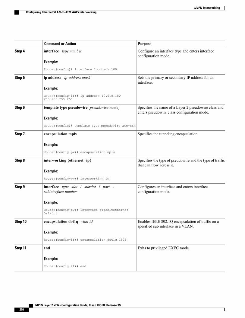
PurposeCommand or Action
Configure an interface type and enters interfaceconfiguration mode.
interface type number
Example:
Router(config)# interface loopback 100
Step 4
Sets the primary or secondary IP address for aninterface.
ip address ip-address mask
Example:
Router(config-if)# ip address 10.0.0.100255.255.255.255
Step 5
Specifies the name of a Layer 2 pseudowire class andenters pseudowire class configuration mode.
template type pseudowire [pseudowire-name]
Example:
Router(config)# template type pseudowire atm-eth
Step 6
Specifies the tunneling encapsulation.encapsulation mpls
Example:
Router(config-pw)# encapsulation mpls
Step 7
Specifies the type of pseudowire and the type of trafficthat can flow across it.
interworking {ethernet | ip}
Example:
Router(config-pw)# interworking ip
Step 8
Configures an interface and enters interfaceconfiguration mode.
interface type slot / subslot / port .subinterface-number
Example:
Router(config-pw)# interface gigabitethernet5/1/0.3
Step 9
Enables IEEE 802.1Q encapsulation of traffic on aspecified sub interface in a VLAN.
encapsulation dot1q vlan-id
Example:
Router(config-if)# encapsulation dot1q 1525
Step 10
Exits to privileged EXEC mode.end
Example:
Router(config-if)# end
Step 11
MPLS Layer 2 VPNs Configuration Guide, Cisco IOS XE Release 3S210
L2VPN InterworkingConfiguring Ethernet VLAN-to-ATM AAL5 Interworking
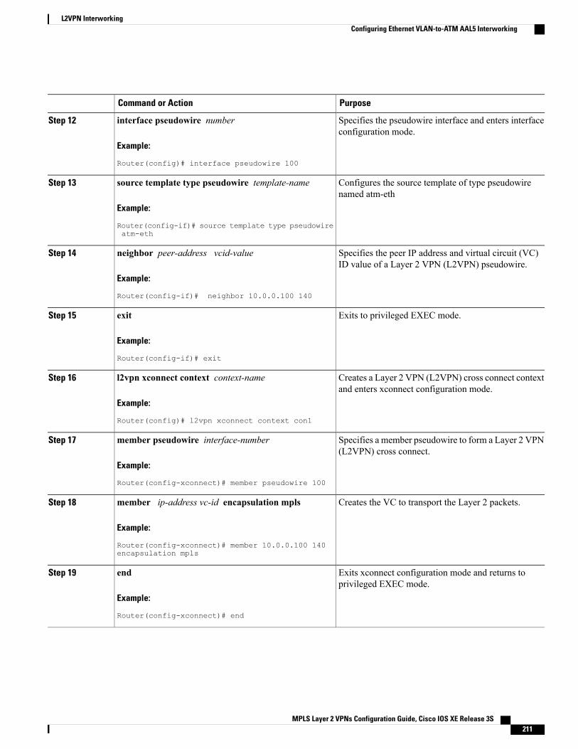
PurposeCommand or Action
Specifies the pseudowire interface and enters interfaceconfiguration mode.
interface pseudowire number
Example:
Router(config)# interface pseudowire 100
Step 12
Configures the source template of type pseudowirenamed atm-eth
source template type pseudowire template-name
Example:
Router(config-if)# source template type pseudowireatm-eth
Step 13
Specifies the peer IP address and virtual circuit (VC)ID value of a Layer 2 VPN (L2VPN) pseudowire.
neighbor peer-address vcid-value
Example:
Router(config-if)# neighbor 10.0.0.100 140
Step 14
Exits to privileged EXEC mode.exit
Example:
Router(config-if)# exit
Step 15
Creates a Layer 2 VPN (L2VPN) cross connect contextand enters xconnect configuration mode.
l2vpn xconnect context context-name
Example:
Router(config)# l2vpn xconnect context con1
Step 16
Specifies a member pseudowire to form a Layer 2 VPN(L2VPN) cross connect.
member pseudowire interface-number
Example:
Router(config-xconnect)# member pseudowire 100
Step 17
Creates the VC to transport the Layer 2 packets.member ip-address vc-id encapsulation mpls
Example:
Router(config-xconnect)# member 10.0.0.100 140encapsulation mpls
Step 18
Exits xconnect configuration mode and returns toprivileged EXEC mode.
end
Example:
Router(config-xconnect)# end
Step 19
MPLS Layer 2 VPNs Configuration Guide, Cisco IOS XE Release 3S 211
L2VPN InterworkingConfiguring Ethernet VLAN-to-ATM AAL5 Interworking
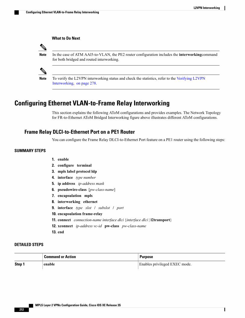
What to Do Next
In the case of ATM AAl5-to-VLAN, the PE2 router configuration includes the interworkingcommandfor both bridged and routed interworking.
Note
To verify the L2VPN interworking status and check the statistics, refer to the Verifying L2VPNInterworking, on page 278.
Note
Configuring Ethernet VLAN-to-Frame Relay InterworkingThis section explains the following AToM configurations and provides examples. The Network Topologyfor FR-to-Ethernet AToM Bridged Interworking figure above illustrates different AToM configurations.
Frame Relay DLCI-to-Ethernet Port on a PE1 RouterYou can configure the Frame Relay DLCI-to-Ethernet Port feature on a PE1 router using the following steps:
SUMMARY STEPS
1. enable2. configure terminal3. mpls label protocol ldp4. interface type number5. ip address ip-address mask6. pseudowire-class [pw-class-name]7. encapsulation mpls8. interworking ethernet9. interface type slot / subslot / port10. encapsulation frame-relay11. connect connection-name interface dlci {interface dlci | l2transport}12. xconnect ip-address vc-id pw-class pw-class-name13. end
DETAILED STEPS
PurposeCommand or Action
Enables privileged EXEC mode.enableStep 1
MPLS Layer 2 VPNs Configuration Guide, Cisco IOS XE Release 3S212
L2VPN InterworkingConfiguring Ethernet VLAN-to-Frame Relay Interworking
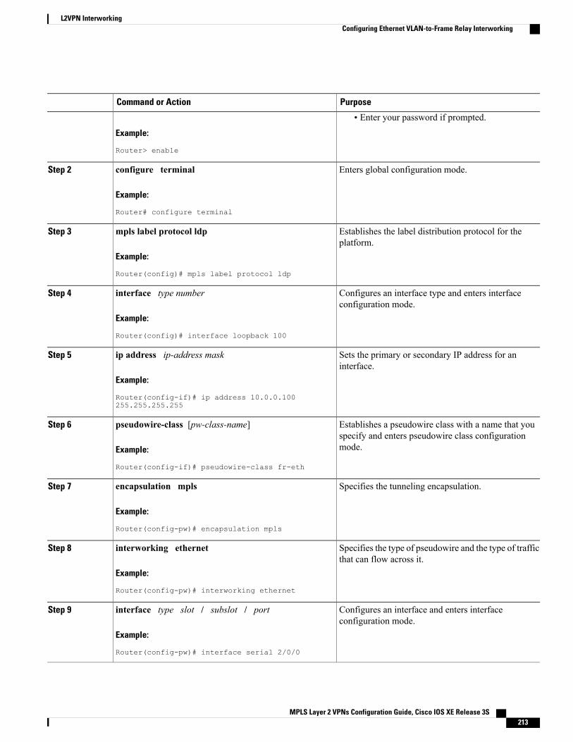
PurposeCommand or Action
Example:
Router> enable
• Enter your password if prompted.
Enters global configuration mode.configure terminal
Example:
Router# configure terminal
Step 2
Establishes the label distribution protocol for theplatform.
mpls label protocol ldp
Example:
Router(config)# mpls label protocol ldp
Step 3
Configures an interface type and enters interfaceconfiguration mode.
interface type number
Example:
Router(config)# interface loopback 100
Step 4
Sets the primary or secondary IP address for aninterface.
ip address ip-address mask
Example:
Router(config-if)# ip address 10.0.0.100255.255.255.255
Step 5
Establishes a pseudowire class with a name that youspecify and enters pseudowire class configurationmode.
pseudowire-class [pw-class-name]
Example:
Router(config-if)# pseudowire-class fr-eth
Step 6
Specifies the tunneling encapsulation.encapsulation mpls
Example:
Router(config-pw)# encapsulation mpls
Step 7
Specifies the type of pseudowire and the type of trafficthat can flow across it.
interworking ethernet
Example:
Router(config-pw)# interworking ethernet
Step 8
Configures an interface and enters interfaceconfiguration mode.
interface type slot / subslot / port
Example:
Router(config-pw)# interface serial 2/0/0
Step 9
MPLS Layer 2 VPNs Configuration Guide, Cisco IOS XE Release 3S 213
L2VPN InterworkingConfiguring Ethernet VLAN-to-Frame Relay Interworking
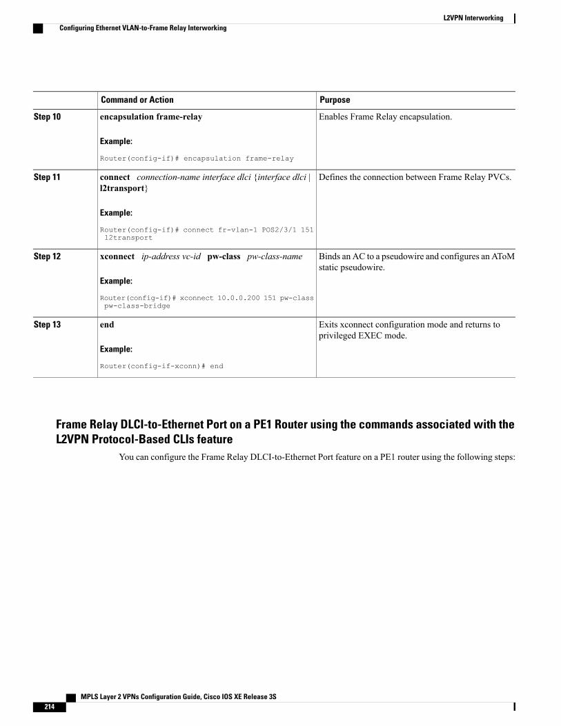
PurposeCommand or Action
Enables Frame Relay encapsulation.encapsulation frame-relay
Example:
Router(config-if)# encapsulation frame-relay
Step 10
Defines the connection between Frame Relay PVCs.connect connection-name interface dlci {interface dlci |l2transport}
Step 11
Example:
Router(config-if)# connect fr-vlan-1 POS2/3/1 151l2transport
Binds an AC to a pseudowire and configures an AToMstatic pseudowire.
xconnect ip-address vc-id pw-class pw-class-name
Example:
Router(config-if)# xconnect 10.0.0.200 151 pw-classpw-class-bridge
Step 12
Exits xconnect configuration mode and returns toprivileged EXEC mode.
end
Example:
Router(config-if-xconn)# end
Step 13
Frame Relay DLCI-to-Ethernet Port on a PE1 Router using the commands associated with theL2VPN Protocol-Based CLIs feature
You can configure the Frame Relay DLCI-to-Ethernet Port feature on a PE1 router using the following steps:
MPLS Layer 2 VPNs Configuration Guide, Cisco IOS XE Release 3S214
L2VPN InterworkingConfiguring Ethernet VLAN-to-Frame Relay Interworking
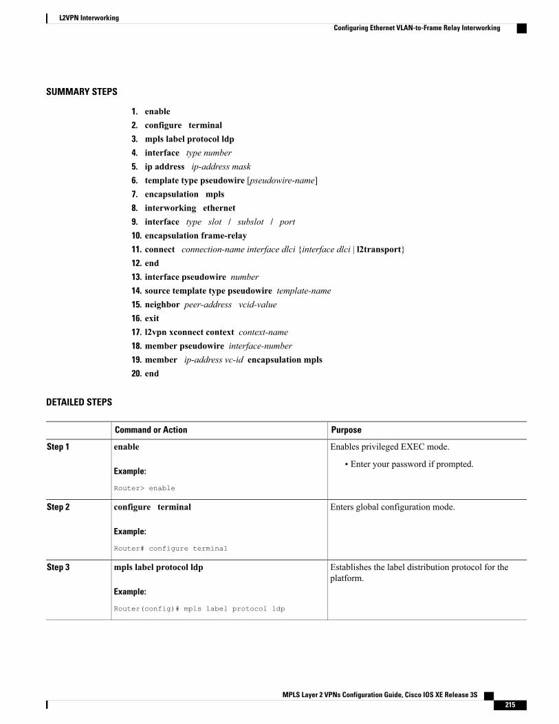
SUMMARY STEPS
1. enable2. configure terminal3. mpls label protocol ldp4. interface type number5. ip address ip-address mask6. template type pseudowire [pseudowire-name]7. encapsulation mpls8. interworking ethernet9. interface type slot / subslot / port10. encapsulation frame-relay11. connect connection-name interface dlci {interface dlci | l2transport}12. end13. interface pseudowire number14. source template type pseudowire template-name15. neighbor peer-address vcid-value16. exit17. l2vpn xconnect context context-name18. member pseudowire interface-number19. member ip-address vc-id encapsulation mpls20. end
DETAILED STEPS
PurposeCommand or Action
Enables privileged EXEC mode.enableStep 1
Example:
Router> enable
• Enter your password if prompted.
Enters global configuration mode.configure terminal
Example:
Router# configure terminal
Step 2
Establishes the label distribution protocol for theplatform.
mpls label protocol ldp
Example:
Router(config)# mpls label protocol ldp
Step 3
MPLS Layer 2 VPNs Configuration Guide, Cisco IOS XE Release 3S 215
L2VPN InterworkingConfiguring Ethernet VLAN-to-Frame Relay Interworking
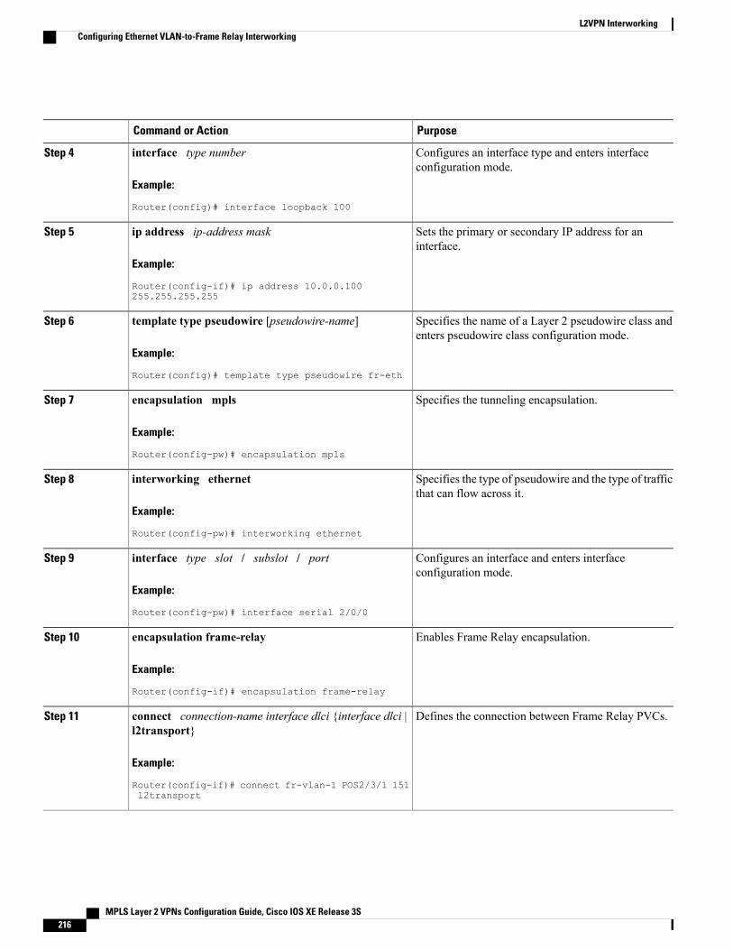
PurposeCommand or Action
Configures an interface type and enters interfaceconfiguration mode.
interface type number
Example:
Router(config)# interface loopback 100
Step 4
Sets the primary or secondary IP address for aninterface.
ip address ip-address mask
Example:
Router(config-if)# ip address 10.0.0.100255.255.255.255
Step 5
Specifies the name of a Layer 2 pseudowire class andenters pseudowire class configuration mode.
template type pseudowire [pseudowire-name]
Example:
Router(config)# template type pseudowire fr-eth
Step 6
Specifies the tunneling encapsulation.encapsulation mpls
Example:
Router(config-pw)# encapsulation mpls
Step 7
Specifies the type of pseudowire and the type of trafficthat can flow across it.
interworking ethernet
Example:
Router(config-pw)# interworking ethernet
Step 8
Configures an interface and enters interfaceconfiguration mode.
interface type slot / subslot / port
Example:
Router(config-pw)# interface serial 2/0/0
Step 9
Enables Frame Relay encapsulation.encapsulation frame-relay
Example:
Router(config-if)# encapsulation frame-relay
Step 10
Defines the connection between Frame Relay PVCs.connect connection-name interface dlci {interface dlci |l2transport}
Step 11
Example:
Router(config-if)# connect fr-vlan-1 POS2/3/1 151l2transport
MPLS Layer 2 VPNs Configuration Guide, Cisco IOS XE Release 3S216
L2VPN InterworkingConfiguring Ethernet VLAN-to-Frame Relay Interworking
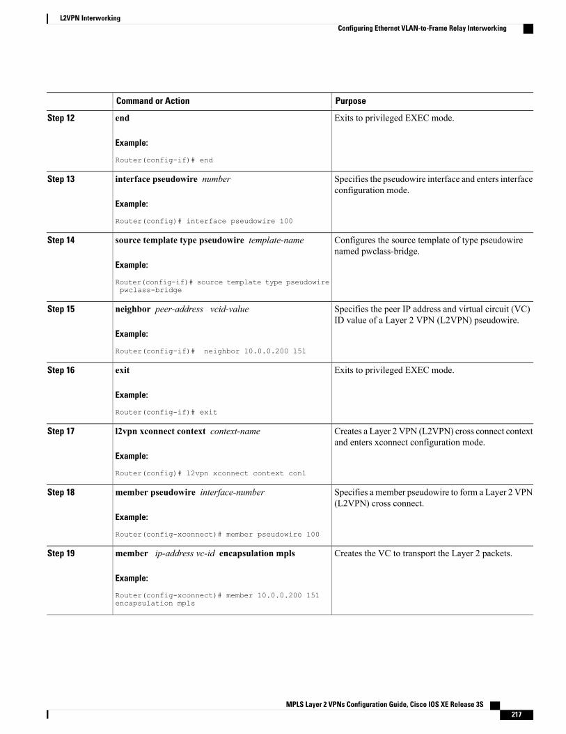
PurposeCommand or Action
Exits to privileged EXEC mode.end
Example:
Router(config-if)# end
Step 12
Specifies the pseudowire interface and enters interfaceconfiguration mode.
interface pseudowire number
Example:
Router(config)# interface pseudowire 100
Step 13
Configures the source template of type pseudowirenamed pwclass-bridge.
source template type pseudowire template-name
Example:
Router(config-if)# source template type pseudowirepwclass-bridge
Step 14
Specifies the peer IP address and virtual circuit (VC)ID value of a Layer 2 VPN (L2VPN) pseudowire.
neighbor peer-address vcid-value
Example:
Router(config-if)# neighbor 10.0.0.200 151
Step 15
Exits to privileged EXEC mode.exit
Example:
Router(config-if)# exit
Step 16
Creates a Layer 2 VPN (L2VPN) cross connect contextand enters xconnect configuration mode.
l2vpn xconnect context context-name
Example:
Router(config)# l2vpn xconnect context con1
Step 17
Specifies a member pseudowire to form a Layer 2 VPN(L2VPN) cross connect.
member pseudowire interface-number
Example:
Router(config-xconnect)# member pseudowire 100
Step 18
Creates the VC to transport the Layer 2 packets.member ip-address vc-id encapsulation mpls
Example:
Router(config-xconnect)# member 10.0.0.200 151encapsulation mpls
Step 19
MPLS Layer 2 VPNs Configuration Guide, Cisco IOS XE Release 3S 217
L2VPN InterworkingConfiguring Ethernet VLAN-to-Frame Relay Interworking
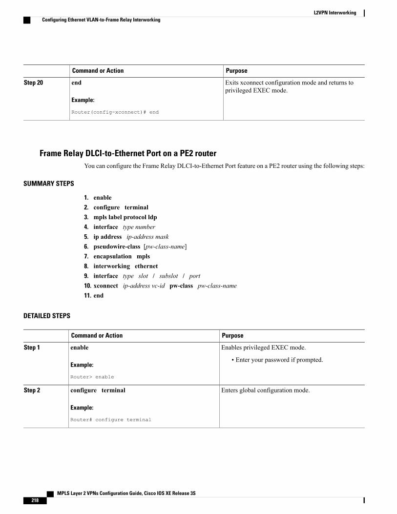
PurposeCommand or Action
Exits xconnect configuration mode and returns toprivileged EXEC mode.
end
Example:
Router(config-xconnect)# end
Step 20
Frame Relay DLCI-to-Ethernet Port on a PE2 routerYou can configure the Frame Relay DLCI-to-Ethernet Port feature on a PE2 router using the following steps:
SUMMARY STEPS
1. enable2. configure terminal3. mpls label protocol ldp4. interface type number5. ip address ip-address mask6. pseudowire-class [pw-class-name]7. encapsulation mpls8. interworking ethernet9. interface type slot / subslot / port10. xconnect ip-address vc-id pw-class pw-class-name11. end
DETAILED STEPS
PurposeCommand or Action
Enables privileged EXEC mode.enableStep 1
Example:
Router> enable
• Enter your password if prompted.
Enters global configuration mode.configure terminal
Example:
Router# configure terminal
Step 2
MPLS Layer 2 VPNs Configuration Guide, Cisco IOS XE Release 3S218
L2VPN InterworkingConfiguring Ethernet VLAN-to-Frame Relay Interworking
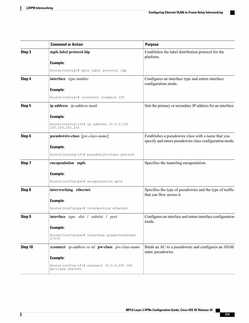
PurposeCommand or Action
Establishes the label distribution protocol for theplatform.
mpls label protocol ldp
Example:
Router(config)# mpls label protocol ldp
Step 3
Configures an interface type and enters interfaceconfiguration mode.
interface type number
Example:
Router(config)# interface loopback 100
Step 4
Sets the primary or secondary IP address for an interface.ip address ip-address mask
Example:
Router(config-if)# ip address 10.0.0.100255.255.255.255
Step 5
Establishes a pseudowire class with a name that youspecify and enters pseudowire class configuration mode.
pseudowire-class [pw-class-name]
Example:
Router(config-if)# pseudowire-class atm-eth
Step 6
Specifies the tunneling encapsulation.encapsulation mpls
Example:
Router(config-pw)# encapsulation mpls
Step 7
Specifies the type of pseudowire and the type of trafficthat can flow across it.
interworking ethernet
Example:
Router(config-pw)# interworking ethernet
Step 8
Configures an interface and enters interface configurationmode.
interface type slot / subslot / port
Example:
Router(config-pw)# interface gigabitethernet2/0/0
Step 9
Binds an AC to a pseudowire and configures an AToMstatic pseudowire.
xconnect ip-address vc-id pw-class pw-class-name
Example:
Router(config-if)# xconnect 10.0.0.200 140pw-class atm-eth
Step 10
MPLS Layer 2 VPNs Configuration Guide, Cisco IOS XE Release 3S 219
L2VPN InterworkingConfiguring Ethernet VLAN-to-Frame Relay Interworking
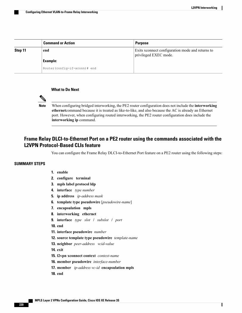
PurposeCommand or Action
Exits xconnect configuration mode and returns toprivileged EXEC mode.
end
Example:
Router(config-if-xconn)# end
Step 11
What to Do Next
When configuring bridged interworking, the PE2 router configuration does not include the interworkingethernetcommand because it is treated as like-to-like, and also because the AC is already an Ethernetport. However, when configuring routed interworking, the PE2 router configuration does include theinterworking ip command.
Note
Frame Relay DLCI-to-Ethernet Port on a PE2 router using the commands associated with theL2VPN Protocol-Based CLIs feature
You can configure the Frame Relay DLCI-to-Ethernet Port feature on a PE2 router using the following steps:
SUMMARY STEPS
1. enable2. configure terminal3. mpls label protocol ldp4. interface type number5. ip address ip-address mask6. template type pseudowire [pseudowire-name]7. encapsulation mpls8. interworking ethernet9. interface type slot / subslot / port10. end11. interface pseudowire number12. source template type pseudowire template-name13. neighbor peer-address vcid-value14. exit15. l2vpn xconnect context context-name16. member pseudowire interface-number17. member ip-address vc-id encapsulation mpls18. end
MPLS Layer 2 VPNs Configuration Guide, Cisco IOS XE Release 3S220
L2VPN InterworkingConfiguring Ethernet VLAN-to-Frame Relay Interworking
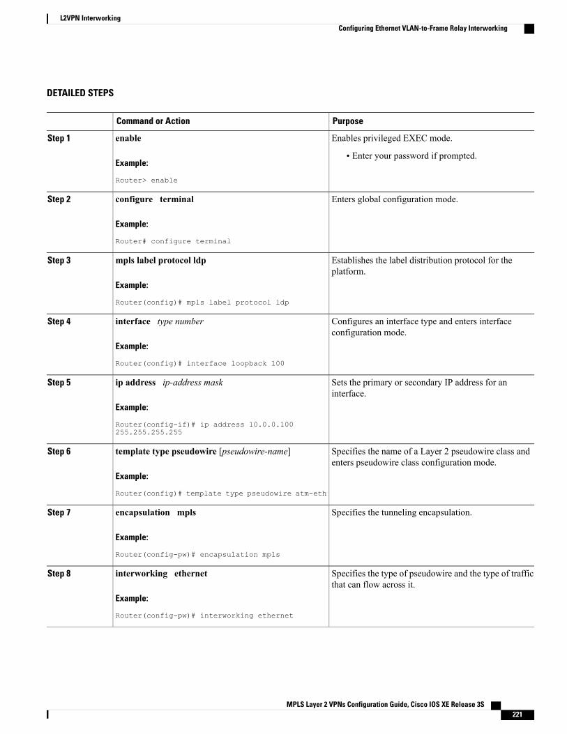
DETAILED STEPS
PurposeCommand or Action
Enables privileged EXEC mode.enableStep 1
Example:
Router> enable
• Enter your password if prompted.
Enters global configuration mode.configure terminal
Example:
Router# configure terminal
Step 2
Establishes the label distribution protocol for theplatform.
mpls label protocol ldp
Example:
Router(config)# mpls label protocol ldp
Step 3
Configures an interface type and enters interfaceconfiguration mode.
interface type number
Example:
Router(config)# interface loopback 100
Step 4
Sets the primary or secondary IP address for aninterface.
ip address ip-address mask
Example:
Router(config-if)# ip address 10.0.0.100255.255.255.255
Step 5
Specifies the name of a Layer 2 pseudowire class andenters pseudowire class configuration mode.
template type pseudowire [pseudowire-name]
Example:
Router(config)# template type pseudowire atm-eth
Step 6
Specifies the tunneling encapsulation.encapsulation mpls
Example:
Router(config-pw)# encapsulation mpls
Step 7
Specifies the type of pseudowire and the type of trafficthat can flow across it.
interworking ethernet
Example:
Router(config-pw)# interworking ethernet
Step 8
MPLS Layer 2 VPNs Configuration Guide, Cisco IOS XE Release 3S 221
L2VPN InterworkingConfiguring Ethernet VLAN-to-Frame Relay Interworking
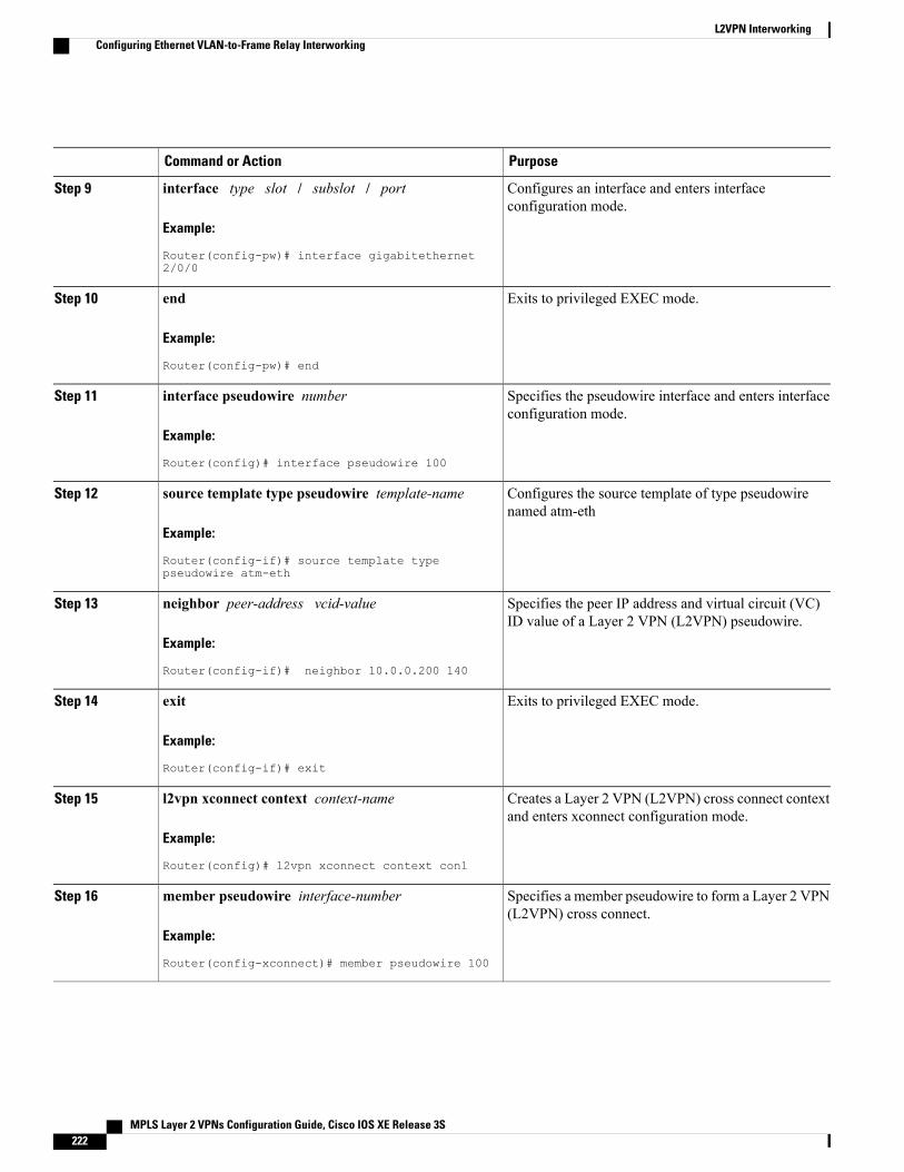
PurposeCommand or Action
Configures an interface and enters interfaceconfiguration mode.
interface type slot / subslot / port
Example:
Router(config-pw)# interface gigabitethernet2/0/0
Step 9
Exits to privileged EXEC mode.end
Example:
Router(config-pw)# end
Step 10
Specifies the pseudowire interface and enters interfaceconfiguration mode.
interface pseudowire number
Example:
Router(config)# interface pseudowire 100
Step 11
Configures the source template of type pseudowirenamed atm-eth
source template type pseudowire template-name
Example:
Router(config-if)# source template typepseudowire atm-eth
Step 12
Specifies the peer IP address and virtual circuit (VC)ID value of a Layer 2 VPN (L2VPN) pseudowire.
neighbor peer-address vcid-value
Example:
Router(config-if)# neighbor 10.0.0.200 140
Step 13
Exits to privileged EXEC mode.exit
Example:
Router(config-if)# exit
Step 14
Creates a Layer 2 VPN (L2VPN) cross connect contextand enters xconnect configuration mode.
l2vpn xconnect context context-name
Example:
Router(config)# l2vpn xconnect context con1
Step 15
Specifies a member pseudowire to form a Layer 2 VPN(L2VPN) cross connect.
member pseudowire interface-number
Example:
Router(config-xconnect)# member pseudowire 100
Step 16
MPLS Layer 2 VPNs Configuration Guide, Cisco IOS XE Release 3S222
L2VPN InterworkingConfiguring Ethernet VLAN-to-Frame Relay Interworking
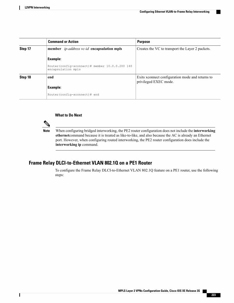
PurposeCommand or Action
Creates the VC to transport the Layer 2 packets.member ip-address vc-id encapsulation mpls
Example:
Router(config-xconnect)# member 10.0.0.200 140encapsulation mpls
Step 17
Exits xconnect configuration mode and returns toprivileged EXEC mode.
end
Example:
Router(config-xconnect)# end
Step 18
What to Do Next
When configuring bridged interworking, the PE2 router configuration does not include the interworkingethernetcommand because it is treated as like-to-like, and also because the AC is already an Ethernetport. However, when configuring routed interworking, the PE2 router configuration does include theinterworking ip command.
Note
Frame Relay DLCI-to-Ethernet VLAN 802.1Q on a PE1 RouterTo configure the Frame Relay DLCI-to-Ethernet VLAN 802.1Q feature on a PE1 router, use the followingsteps:
MPLS Layer 2 VPNs Configuration Guide, Cisco IOS XE Release 3S 223
L2VPN InterworkingConfiguring Ethernet VLAN-to-Frame Relay Interworking
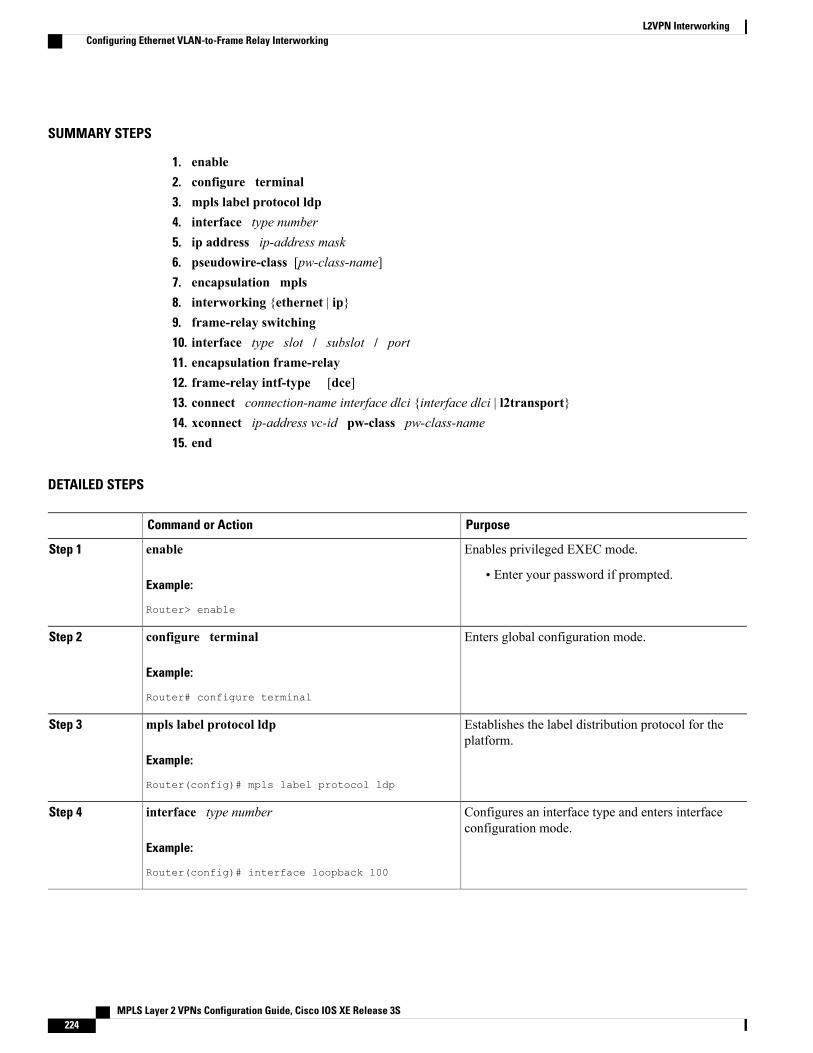
SUMMARY STEPS
1. enable2. configure terminal3. mpls label protocol ldp4. interface type number5. ip address ip-address mask6. pseudowire-class [pw-class-name]7. encapsulation mpls8. interworking {ethernet | ip}9. frame-relay switching10. interface type slot / subslot / port11. encapsulation frame-relay12. frame-relay intf-type [dce]13. connect connection-name interface dlci {interface dlci | l2transport}14. xconnect ip-address vc-id pw-class pw-class-name15. end
DETAILED STEPS
PurposeCommand or Action
Enables privileged EXEC mode.enableStep 1
Example:
Router> enable
• Enter your password if prompted.
Enters global configuration mode.configure terminal
Example:
Router# configure terminal
Step 2
Establishes the label distribution protocol for theplatform.
mpls label protocol ldp
Example:
Router(config)# mpls label protocol ldp
Step 3
Configures an interface type and enters interfaceconfiguration mode.
interface type number
Example:
Router(config)# interface loopback 100
Step 4
MPLS Layer 2 VPNs Configuration Guide, Cisco IOS XE Release 3S224
L2VPN InterworkingConfiguring Ethernet VLAN-to-Frame Relay Interworking
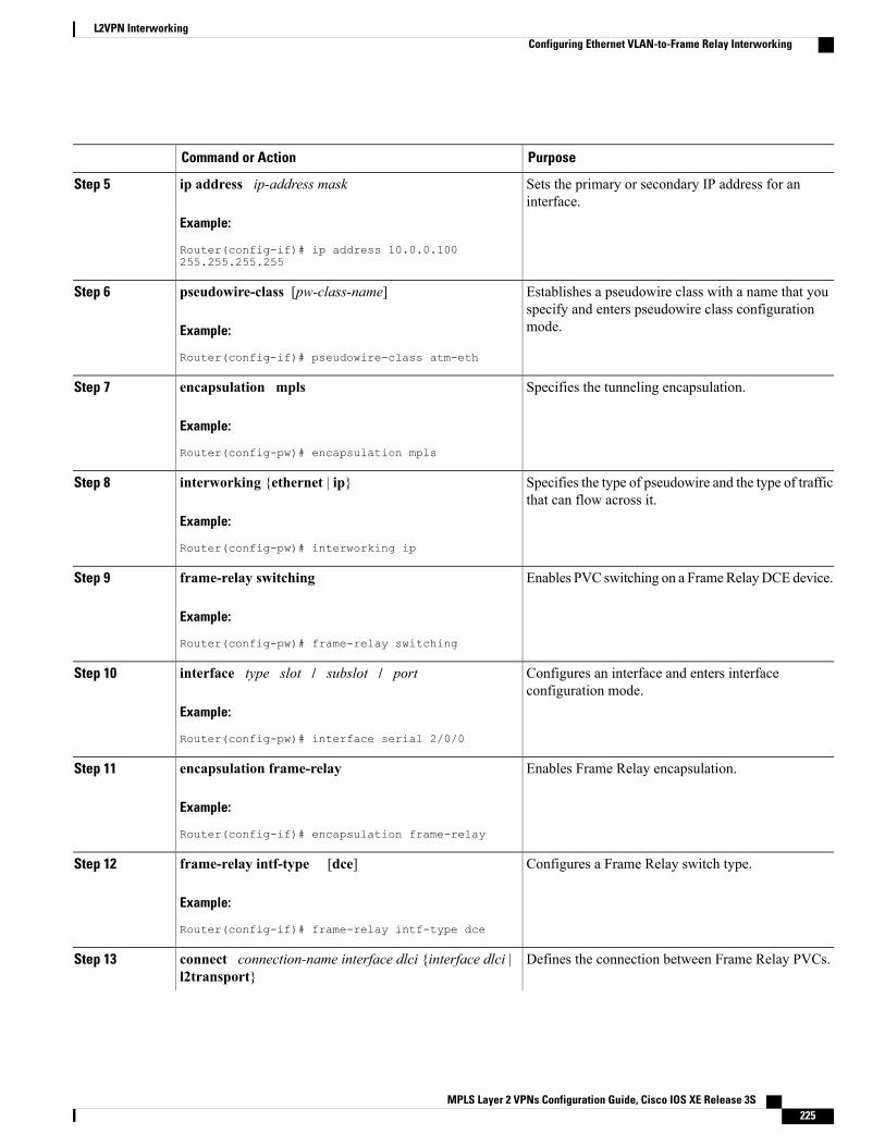
PurposeCommand or Action
Sets the primary or secondary IP address for aninterface.
ip address ip-address mask
Example:
Router(config-if)# ip address 10.0.0.100255.255.255.255
Step 5
Establishes a pseudowire class with a name that youspecify and enters pseudowire class configurationmode.
pseudowire-class [pw-class-name]
Example:
Router(config-if)# pseudowire-class atm-eth
Step 6
Specifies the tunneling encapsulation.encapsulation mpls
Example:
Router(config-pw)# encapsulation mpls
Step 7
Specifies the type of pseudowire and the type of trafficthat can flow across it.
interworking {ethernet | ip}
Example:
Router(config-pw)# interworking ip
Step 8
Enables PVC switching on a FrameRelayDCE device.frame-relay switching
Example:
Router(config-pw)# frame-relay switching
Step 9
Configures an interface and enters interfaceconfiguration mode.
interface type slot / subslot / port
Example:
Router(config-pw)# interface serial 2/0/0
Step 10
Enables Frame Relay encapsulation.encapsulation frame-relay
Example:
Router(config-if)# encapsulation frame-relay
Step 11
Configures a Frame Relay switch type.frame-relay intf-type [dce]
Example:
Router(config-if)# frame-relay intf-type dce
Step 12
Defines the connection between Frame Relay PVCs.connect connection-name interface dlci {interface dlci |l2transport}
Step 13
MPLS Layer 2 VPNs Configuration Guide, Cisco IOS XE Release 3S 225
L2VPN InterworkingConfiguring Ethernet VLAN-to-Frame Relay Interworking
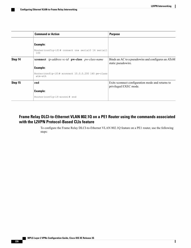
PurposeCommand or Action
Example:
Router(config-if)# connect one serial0 16 serial1100
Binds an AC to a pseudowire and configures an AToMstatic pseudowire.
xconnect ip-address vc-id pw-class pw-class-name
Example:
Router(config-if)# xconnect 10.0.0.200 140 pw-classatm-eth
Step 14
Exits xconnect configuration mode and returns toprivileged EXEC mode.
end
Example:
Router(config-if-xconn)# end
Step 15
Frame Relay DLCI-to-Ethernet VLAN 802.1Q on a PE1 Router using the commands associatedwith the L2VPN Protocol-Based CLIs feature
To configure the Frame Relay DLCI-to-Ethernet VLAN 802.1Q feature on a PE1 router, use the followingsteps:
MPLS Layer 2 VPNs Configuration Guide, Cisco IOS XE Release 3S226
L2VPN InterworkingConfiguring Ethernet VLAN-to-Frame Relay Interworking
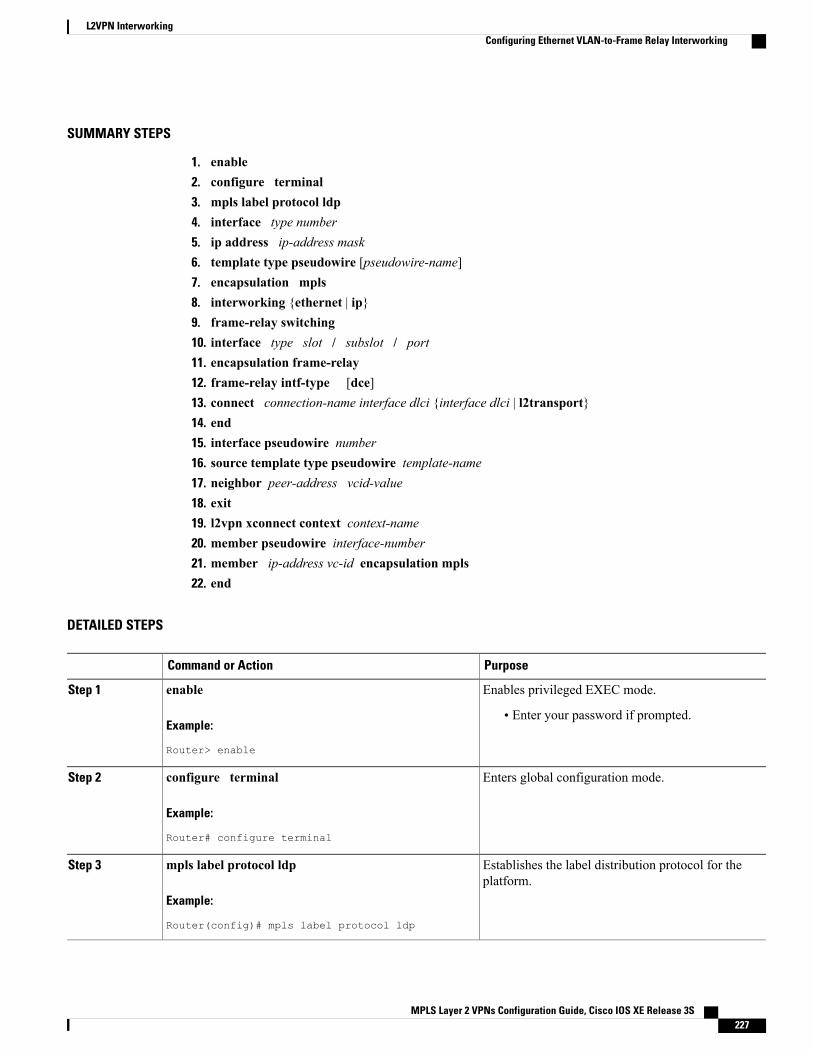
SUMMARY STEPS
1. enable2. configure terminal3. mpls label protocol ldp4. interface type number5. ip address ip-address mask6. template type pseudowire [pseudowire-name]7. encapsulation mpls8. interworking {ethernet | ip}9. frame-relay switching10. interface type slot / subslot / port11. encapsulation frame-relay12. frame-relay intf-type [dce]13. connect connection-name interface dlci {interface dlci | l2transport}14. end15. interface pseudowire number16. source template type pseudowire template-name17. neighbor peer-address vcid-value18. exit19. l2vpn xconnect context context-name20. member pseudowire interface-number21. member ip-address vc-id encapsulation mpls22. end
DETAILED STEPS
PurposeCommand or Action
Enables privileged EXEC mode.enableStep 1
Example:
Router> enable
• Enter your password if prompted.
Enters global configuration mode.configure terminal
Example:
Router# configure terminal
Step 2
Establishes the label distribution protocol for theplatform.
mpls label protocol ldp
Example:
Router(config)# mpls label protocol ldp
Step 3
MPLS Layer 2 VPNs Configuration Guide, Cisco IOS XE Release 3S 227
L2VPN InterworkingConfiguring Ethernet VLAN-to-Frame Relay Interworking
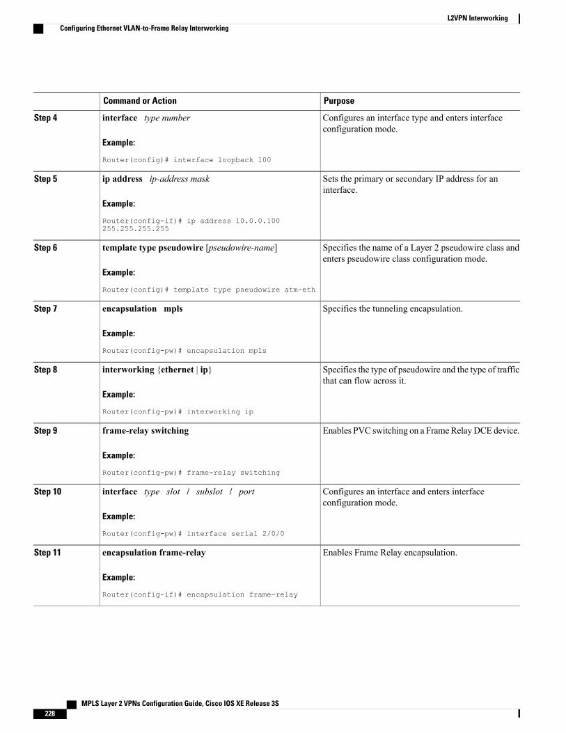
PurposeCommand or Action
Configures an interface type and enters interfaceconfiguration mode.
interface type number
Example:
Router(config)# interface loopback 100
Step 4
Sets the primary or secondary IP address for aninterface.
ip address ip-address mask
Example:
Router(config-if)# ip address 10.0.0.100255.255.255.255
Step 5
Specifies the name of a Layer 2 pseudowire class andenters pseudowire class configuration mode.
template type pseudowire [pseudowire-name]
Example:
Router(config)# template type pseudowire atm-eth
Step 6
Specifies the tunneling encapsulation.encapsulation mpls
Example:
Router(config-pw)# encapsulation mpls
Step 7
Specifies the type of pseudowire and the type of trafficthat can flow across it.
interworking {ethernet | ip}
Example:
Router(config-pw)# interworking ip
Step 8
Enables PVC switching on a FrameRelayDCE device.frame-relay switching
Example:
Router(config-pw)# frame-relay switching
Step 9
Configures an interface and enters interfaceconfiguration mode.
interface type slot / subslot / port
Example:
Router(config-pw)# interface serial 2/0/0
Step 10
Enables Frame Relay encapsulation.encapsulation frame-relay
Example:
Router(config-if)# encapsulation frame-relay
Step 11
MPLS Layer 2 VPNs Configuration Guide, Cisco IOS XE Release 3S228
L2VPN InterworkingConfiguring Ethernet VLAN-to-Frame Relay Interworking
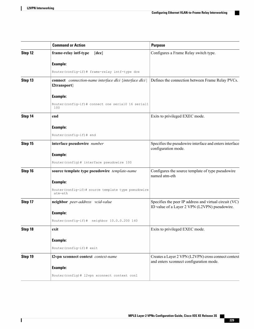
PurposeCommand or Action
Configures a Frame Relay switch type.frame-relay intf-type [dce]
Example:
Router(config-if)# frame-relay intf-type dce
Step 12
Defines the connection between Frame Relay PVCs.connect connection-name interface dlci {interface dlci |l2transport}
Step 13
Example:
Router(config-if)# connect one serial0 16 serial1100
Exits to privileged EXEC mode.end
Example:
Router(config-if)# end
Step 14
Specifies the pseudowire interface and enters interfaceconfiguration mode.
interface pseudowire number
Example:
Router(config)# interface pseudowire 100
Step 15
Configures the source template of type pseudowirenamed atm-eth
source template type pseudowire template-name
Example:
Router(config-if)# source template type pseudowireatm-eth
Step 16
Specifies the peer IP address and virtual circuit (VC)ID value of a Layer 2 VPN (L2VPN) pseudowire.
neighbor peer-address vcid-value
Example:
Router(config-if)# neighbor 10.0.0.200 140
Step 17
Exits to privileged EXEC mode.exit
Example:
Router(config-if)# exit
Step 18
Creates a Layer 2 VPN (L2VPN) cross connect contextand enters xconnect configuration mode.
l2vpn xconnect context context-name
Example:
Router(config)# l2vpn xconnect context con1
Step 19
MPLS Layer 2 VPNs Configuration Guide, Cisco IOS XE Release 3S 229
L2VPN InterworkingConfiguring Ethernet VLAN-to-Frame Relay Interworking
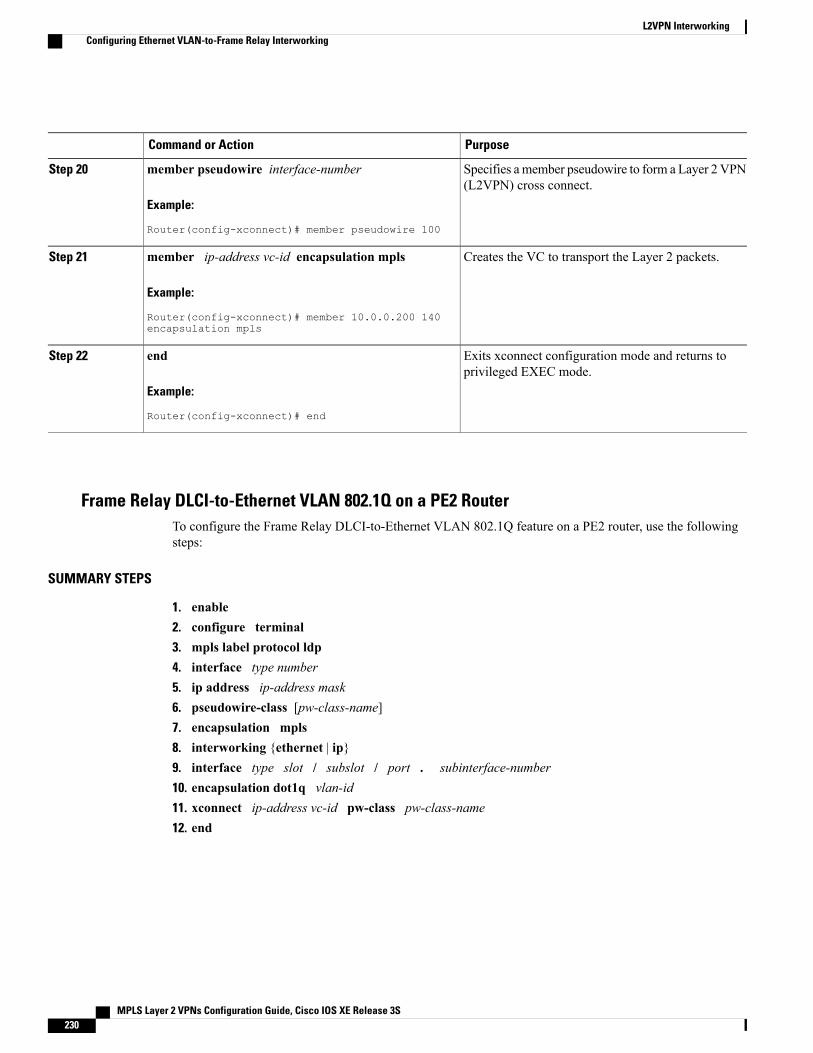
PurposeCommand or Action
Specifies amember pseudowire to form a Layer 2 VPN(L2VPN) cross connect.
member pseudowire interface-number
Example:
Router(config-xconnect)# member pseudowire 100
Step 20
Creates the VC to transport the Layer 2 packets.member ip-address vc-id encapsulation mpls
Example:
Router(config-xconnect)# member 10.0.0.200 140encapsulation mpls
Step 21
Exits xconnect configuration mode and returns toprivileged EXEC mode.
end
Example:
Router(config-xconnect)# end
Step 22
Frame Relay DLCI-to-Ethernet VLAN 802.1Q on a PE2 RouterTo configure the Frame Relay DLCI-to-Ethernet VLAN 802.1Q feature on a PE2 router, use the followingsteps:
SUMMARY STEPS
1. enable2. configure terminal3. mpls label protocol ldp4. interface type number5. ip address ip-address mask6. pseudowire-class [pw-class-name]7. encapsulation mpls8. interworking {ethernet | ip}9. interface type slot / subslot / port . subinterface-number10. encapsulation dot1q vlan-id11. xconnect ip-address vc-id pw-class pw-class-name12. end
MPLS Layer 2 VPNs Configuration Guide, Cisco IOS XE Release 3S230
L2VPN InterworkingConfiguring Ethernet VLAN-to-Frame Relay Interworking
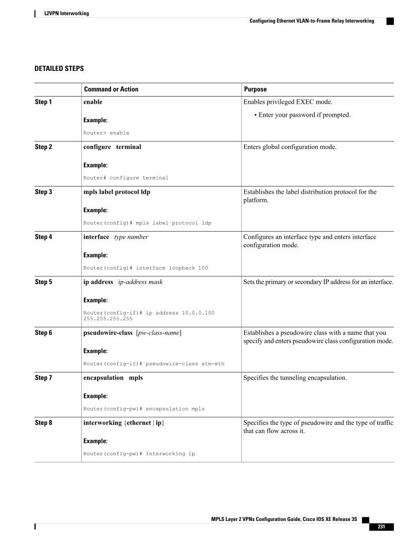
DETAILED STEPS
PurposeCommand or Action
Enables privileged EXEC mode.enableStep 1
Example:
Router> enable
• Enter your password if prompted.
Enters global configuration mode.configure terminal
Example:
Router# configure terminal
Step 2
Establishes the label distribution protocol for theplatform.
mpls label protocol ldp
Example:
Router(config)# mpls label protocol ldp
Step 3
Configures an interface type and enters interfaceconfiguration mode.
interface type number
Example:
Router(config)# interface loopback 100
Step 4
Sets the primary or secondary IP address for an interface.ip address ip-address mask
Example:
Router(config-if)# ip address 10.0.0.100255.255.255.255
Step 5
Establishes a pseudowire class with a name that youspecify and enters pseudowire class configurationmode.
pseudowire-class [pw-class-name]
Example:
Router(config-if)# pseudowire-class atm-eth
Step 6
Specifies the tunneling encapsulation.encapsulation mpls
Example:
Router(config-pw)# encapsulation mpls
Step 7
Specifies the type of pseudowire and the type of trafficthat can flow across it.
interworking {ethernet | ip}
Example:
Router(config-pw)# interworking ip
Step 8
MPLS Layer 2 VPNs Configuration Guide, Cisco IOS XE Release 3S 231
L2VPN InterworkingConfiguring Ethernet VLAN-to-Frame Relay Interworking
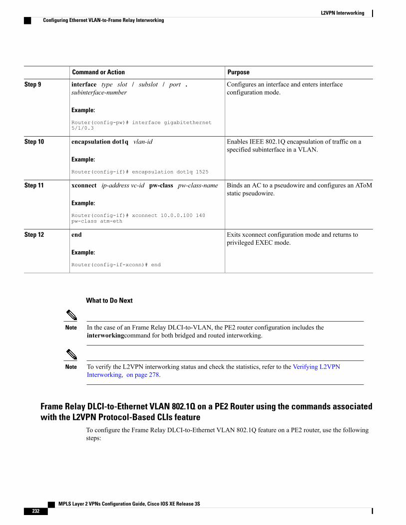
PurposeCommand or Action
Configures an interface and enters interfaceconfiguration mode.
interface type slot / subslot / port .subinterface-number
Example:
Router(config-pw)# interface gigabitethernet5/1/0.3
Step 9
Enables IEEE 802.1Q encapsulation of traffic on aspecified subinterface in a VLAN.
encapsulation dot1q vlan-id
Example:
Router(config-if)# encapsulation dot1q 1525
Step 10
Binds an AC to a pseudowire and configures an AToMstatic pseudowire.
xconnect ip-address vc-id pw-class pw-class-name
Example:
Router(config-if)# xconnect 10.0.0.100 140pw-class atm-eth
Step 11
Exits xconnect configuration mode and returns toprivileged EXEC mode.
end
Example:
Router(config-if-xconn)# end
Step 12
What to Do Next
In the case of an Frame Relay DLCI-to-VLAN, the PE2 router configuration includes theinterworkingcommand for both bridged and routed interworking.
Note
To verify the L2VPN interworking status and check the statistics, refer to the Verifying L2VPNInterworking, on page 278.
Note
Frame Relay DLCI-to-Ethernet VLAN 802.1Q on a PE2 Router using the commands associatedwith the L2VPN Protocol-Based CLIs feature
To configure the Frame Relay DLCI-to-Ethernet VLAN 802.1Q feature on a PE2 router, use the followingsteps:
MPLS Layer 2 VPNs Configuration Guide, Cisco IOS XE Release 3S232
L2VPN InterworkingConfiguring Ethernet VLAN-to-Frame Relay Interworking
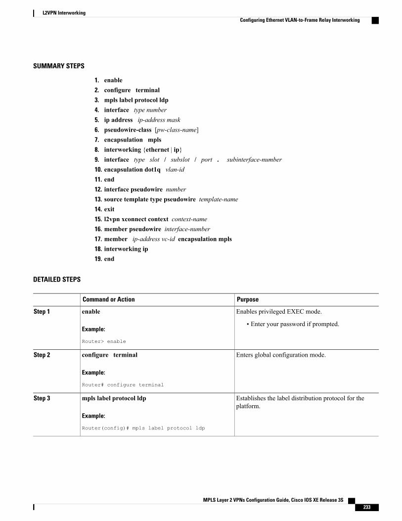
SUMMARY STEPS
1. enable2. configure terminal3. mpls label protocol ldp4. interface type number5. ip address ip-address mask6. pseudowire-class [pw-class-name]7. encapsulation mpls8. interworking {ethernet | ip}9. interface type slot / subslot / port . subinterface-number10. encapsulation dot1q vlan-id11. end12. interface pseudowire number13. source template type pseudowire template-name14. exit15. l2vpn xconnect context context-name16. member pseudowire interface-number17. member ip-address vc-id encapsulation mpls18. interworking ip19. end
DETAILED STEPS
PurposeCommand or Action
Enables privileged EXEC mode.enableStep 1
Example:
Router> enable
• Enter your password if prompted.
Enters global configuration mode.configure terminal
Example:
Router# configure terminal
Step 2
Establishes the label distribution protocol for theplatform.
mpls label protocol ldp
Example:
Router(config)# mpls label protocol ldp
Step 3
MPLS Layer 2 VPNs Configuration Guide, Cisco IOS XE Release 3S 233
L2VPN InterworkingConfiguring Ethernet VLAN-to-Frame Relay Interworking
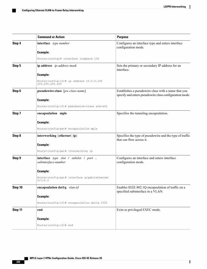
PurposeCommand or Action
Configures an interface type and enters interfaceconfiguration mode.
interface type number
Example:
Router(config)# interface loopback 100
Step 4
Sets the primary or secondary IP address for aninterface.
ip address ip-address mask
Example:
Router(config-if)# ip address 10.0.0.100255.255.255.255
Step 5
Establishes a pseudowire class with a name that youspecify and enters pseudowire class configurationmode.
pseudowire-class [pw-class-name]
Example:
Router(config-if)# pseudowire-class atm-eth
Step 6
Specifies the tunneling encapsulation.encapsulation mpls
Example:
Router(config-pw)# encapsulation mpls
Step 7
Specifies the type of pseudowire and the type of trafficthat can flow across it.
interworking {ethernet | ip}
Example:
Router(config-pw)# interworking ip
Step 8
Configures an interface and enters interfaceconfiguration mode.
interface type slot / subslot / port .subinterface-number
Example:
Router(config-pw)# interface gigabitethernet5/1/0.3
Step 9
Enables IEEE 802.1Q encapsulation of traffic on aspecified subinterface in a VLAN.
encapsulation dot1q vlan-id
Example:
Router(config-if)# encapsulation dot1q 1525
Step 10
Exits to privileged EXEC mode.end
Example:
Router(config-if)# end
Step 11
MPLS Layer 2 VPNs Configuration Guide, Cisco IOS XE Release 3S234
L2VPN InterworkingConfiguring Ethernet VLAN-to-Frame Relay Interworking
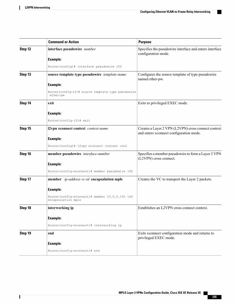
PurposeCommand or Action
Specifies the pseudowire interface and enters interfaceconfiguration mode.
interface pseudowire number
Example:
Router(config)# interface pseudowire 100
Step 12
Configures the source template of type pseudowirenamed ether-pw.
source template type pseudowire template-name
Example:
Router(config-if)# source template type pseudowireether-pw
Step 13
Exits to privileged EXEC mode.exit
Example:
Router(config-if)# exit
Step 14
Creates a Layer 2 VPN (L2VPN) cross connect contextand enters xconnect configuration mode.
l2vpn xconnect context context-name
Example:
Router(config)# l2vpn xconnect context con1
Step 15
Specifies a member pseudowire to form a Layer 2 VPN(L2VPN) cross connect.
member pseudowire interface-number
Example:
Router(config-xconnect)# member pseudowire 100
Step 16
Creates the VC to transport the Layer 2 packets.member ip-address vc-id encapsulation mpls
Example:
Router(config-xconnect)# member 10.0.0.100 140encapsulation mpls
Step 17
Establishes an L2VPN cross connect context.interworking ip
Example:
Router(config-xconnect)# interworking ip
Step 18
Exits xconnect configuration mode and returns toprivileged EXEC mode.
end
Example:
Router(config-xconnect)# end
Step 19
MPLS Layer 2 VPNs Configuration Guide, Cisco IOS XE Release 3S 235
L2VPN InterworkingConfiguring Ethernet VLAN-to-Frame Relay Interworking
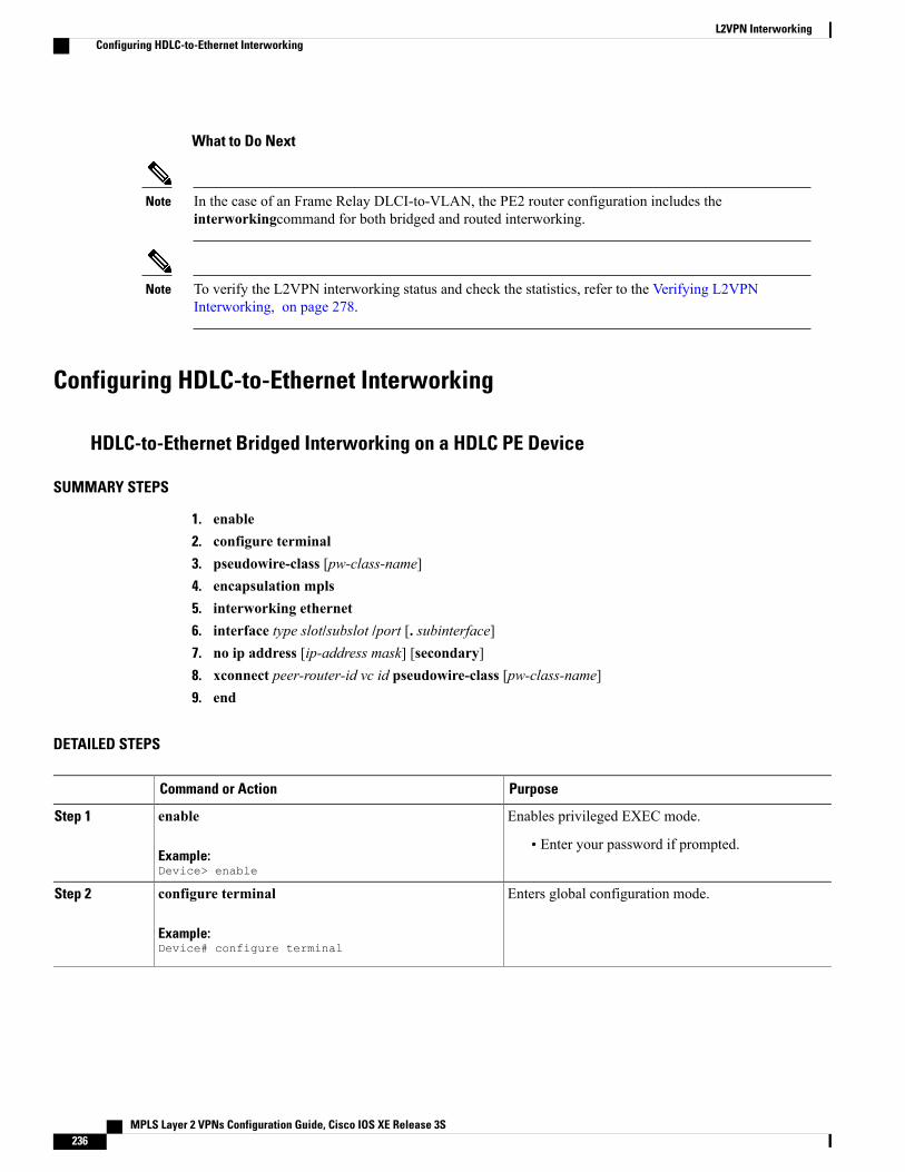
What to Do Next
In the case of an Frame Relay DLCI-to-VLAN, the PE2 router configuration includes theinterworkingcommand for both bridged and routed interworking.
Note
To verify the L2VPN interworking status and check the statistics, refer to the Verifying L2VPNInterworking, on page 278.
Note
Configuring HDLC-to-Ethernet Interworking
HDLC-to-Ethernet Bridged Interworking on a HDLC PE Device
SUMMARY STEPS
1. enable2. configure terminal3. pseudowire-class [pw-class-name]4. encapsulation mpls5. interworking ethernet6. interface type slot/subslot /port [. subinterface]7. no ip address [ip-address mask] [secondary]8. xconnect peer-router-id vc id pseudowire-class [pw-class-name]9. end
DETAILED STEPS
PurposeCommand or Action
Enables privileged EXEC mode.enableStep 1
Example:Device> enable
• Enter your password if prompted.
Enters global configuration mode.configure terminal
Example:Device# configure terminal
Step 2
MPLS Layer 2 VPNs Configuration Guide, Cisco IOS XE Release 3S236
L2VPN InterworkingConfiguring HDLC-to-Ethernet Interworking
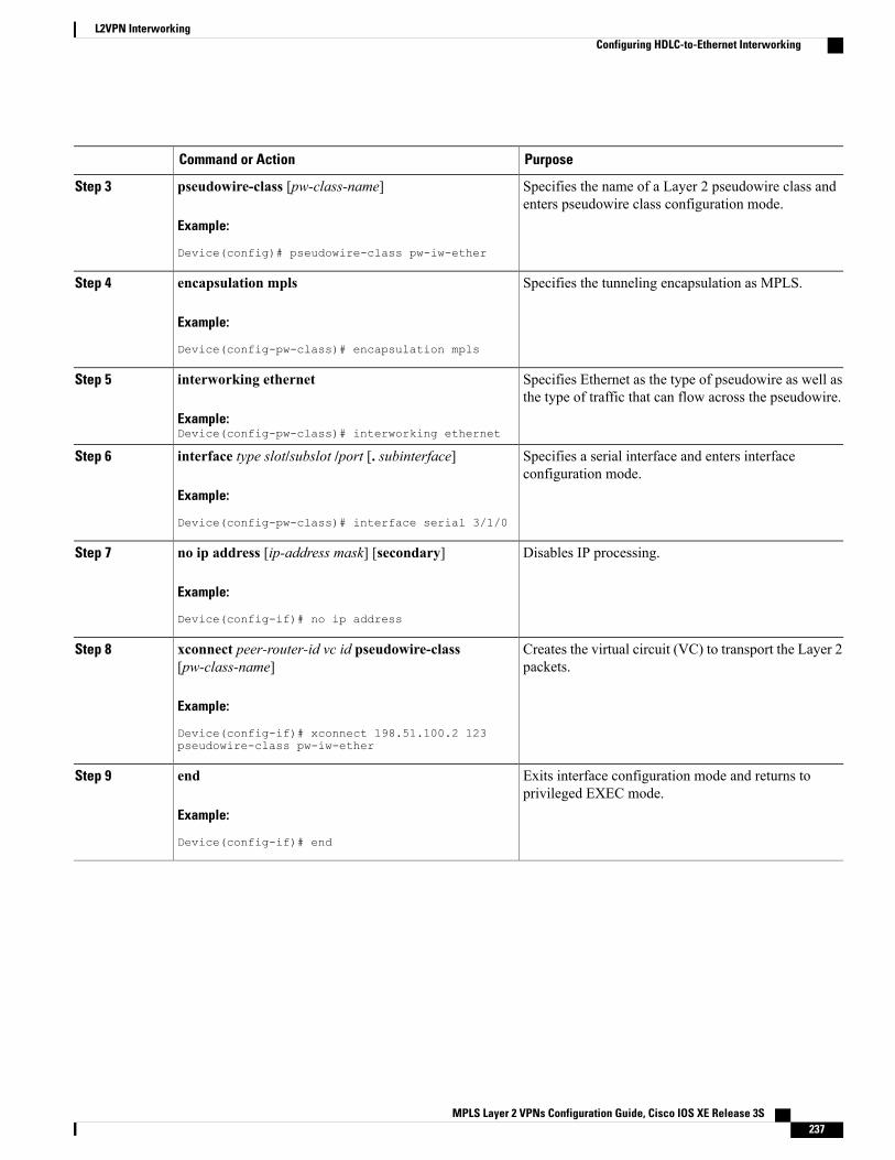
PurposeCommand or Action
Specifies the name of a Layer 2 pseudowire class andenters pseudowire class configuration mode.
pseudowire-class [pw-class-name]
Example:
Device(config)# pseudowire-class pw-iw-ether
Step 3
Specifies the tunneling encapsulation as MPLS.encapsulation mpls
Example:
Device(config-pw-class)# encapsulation mpls
Step 4
Specifies Ethernet as the type of pseudowire as well asthe type of traffic that can flow across the pseudowire.
interworking ethernet
Example:Device(config-pw-class)# interworking ethernet
Step 5
Specifies a serial interface and enters interfaceconfiguration mode.
interface type slot/subslot /port [. subinterface]
Example:
Device(config-pw-class)# interface serial 3/1/0
Step 6
Disables IP processing.no ip address [ip-address mask] [secondary]
Example:
Device(config-if)# no ip address
Step 7
Creates the virtual circuit (VC) to transport the Layer 2packets.
xconnect peer-router-id vc id pseudowire-class[pw-class-name]
Example:
Device(config-if)# xconnect 198.51.100.2 123pseudowire-class pw-iw-ether
Step 8
Exits interface configuration mode and returns toprivileged EXEC mode.
end
Example:
Device(config-if)# end
Step 9
MPLS Layer 2 VPNs Configuration Guide, Cisco IOS XE Release 3S 237
L2VPN InterworkingConfiguring HDLC-to-Ethernet Interworking
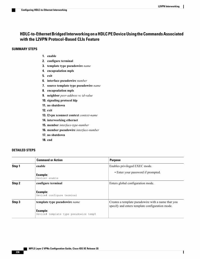
HDLC-to-Ethernet Bridged Interworking on a HDLC PE Device Using the Commands Associatedwith the L2VPN Protocol-Based CLIs Feature
SUMMARY STEPS
1. enable2. configure terminal3. template type pseudowire name4. encapsulation mpls5. exit6. interface pseudowire number7. source template type pseudowire name8. encapsulation mpls9. neighbor peer-address vc id-value10. signaling protocol ldp11. no shutdown12. exit13. l2vpn xconnect context context-name14. interworking ethernet15. member interface-type-number16. member pseudowire interface-number17. no shutdown18. end
DETAILED STEPS
PurposeCommand or Action
Enables privileged EXEC mode.enableStep 1
Example:Device> enable
• Enter your password if prompted.
Enters global configuration mode.configure terminal
Example:Device# configure terminal
Step 2
Creates a template pseudowire with a name that youspecify and enters template configuration mode.
template type pseudowire name
Example:Device# template type pseudowire temp5
Step 3
MPLS Layer 2 VPNs Configuration Guide, Cisco IOS XE Release 3S238
L2VPN InterworkingConfiguring HDLC-to-Ethernet Interworking

PurposeCommand or Action
Specifies the tunneling encapsulation as MPLS.encapsulation mpls
Example:
Device(config-template)# encapsulation mpls
Step 4
Exits template configuration mode and returns to globalconfiguration mode.
exit
Example:Device(config-template)# exit
Step 5
Establishes an interface pseudowire with a value that youspecify and enters interface configuration mode.
interface pseudowire number
Example:Device(config)# interface pseudowire 107
Step 6
Configures the source template of type pseudowire namedtemp5.
source template type pseudowire name
Example:Device(config-if)# source template typepseudowire temp5
Step 7
Specifies the tunneling encapsulation as MPLS.encapsulation mpls
Example:
Device(config-if)# encapsulation mpls
Step 8
Specifies the peer IP address and virtual circuit (VC) IDvalue of an L2VPN pseudowire.
neighbor peer-address vc id-value
Example:Device(config-if)# neighbor 10.0.0.11 107
Step 9
Specifies that the Label Distribution Protocol (LDP) isconfigured for the pseudowire class.
signaling protocol ldp
Example:Device(config-if)# signaling protocol ldp
Step 10
Restarts the interface pseudowire.no shutdown
Example:Device(config-if)# no shutdown
Step 11
Exits interface configuration mode and returns to globalconfiguration mode.
exit
Example:Device(config-if)# exit
Step 12
MPLS Layer 2 VPNs Configuration Guide, Cisco IOS XE Release 3S 239
L2VPN InterworkingConfiguring HDLC-to-Ethernet Interworking

PurposeCommand or Action
Creates an L2VPN cross-connect context and entersxconnect configuration mode.
l2vpn xconnect context context-name
Example:Device(config)# l2vpn xconnect context con1
Step 13
Specifies Ethernet as the type of pseudowire as well asthe type of traffic that can flow across the pseudowire.
interworking ethernet
Example:Device(config-xconnect)# interworking ethernet
Step 14
Specifies the location of the member interface.member interface-type-number
Example:Device(config-xconnect)# member serial 0/1/0:0
Step 15
Specifies a member pseudowire to form an L2VPN crossconnect.
member pseudowire interface-number
Example:Device(config-xconnect)# member pseudowire 107
Step 16
Restarts the member interface.no shutdown
Example:Device(config-xconnect)# no shutdown
Step 17
Exits xconnect configuration mode and returns toprivileged EXEC mode.
end
Example:
Device(config-xconnect)# end
Step 18
HDLC-to-Ethernet Bridged Interworking (Port Mode) on an Ethernet PE Device
SUMMARY STEPS
1. enable2. configure terminal3. pseudowire-class [pw-class-name]4. encapsulation mpls5. interworking ethernet6. interface type slot/subslot /port [. subinterface]7. encapsulation mpls8. xconnect peer-router-id vc id pseudowire-class [pw-class-name]9. end
MPLS Layer 2 VPNs Configuration Guide, Cisco IOS XE Release 3S240
L2VPN InterworkingConfiguring HDLC-to-Ethernet Interworking
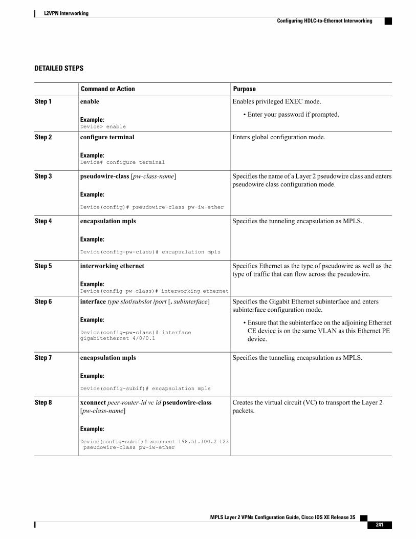
DETAILED STEPS
PurposeCommand or Action
Enables privileged EXEC mode.enableStep 1
Example:Device> enable
• Enter your password if prompted.
Enters global configuration mode.configure terminal
Example:Device# configure terminal
Step 2
Specifies the name of a Layer 2 pseudowire class and enterspseudowire class configuration mode.
pseudowire-class [pw-class-name]
Example:
Device(config)# pseudowire-class pw-iw-ether
Step 3
Specifies the tunneling encapsulation as MPLS.encapsulation mpls
Example:
Device(config-pw-class)# encapsulation mpls
Step 4
Specifies Ethernet as the type of pseudowire as well as thetype of traffic that can flow across the pseudowire.
interworking ethernet
Example:Device(config-pw-class)# interworking ethernet
Step 5
Specifies the Gigabit Ethernet subinterface and enterssubinterface configuration mode.
interface type slot/subslot /port [. subinterface]
Example:
Device(config-pw-class)# interfacegigabitethernet 4/0/0.1
Step 6
• Ensure that the subinterface on the adjoining EthernetCE device is on the same VLAN as this Ethernet PEdevice.
Specifies the tunneling encapsulation as MPLS.encapsulation mpls
Example:
Device(config-subif)# encapsulation mpls
Step 7
Creates the virtual circuit (VC) to transport the Layer 2packets.
xconnect peer-router-id vc id pseudowire-class[pw-class-name]
Example:
Device(config-subif)# xconnect 198.51.100.2 123pseudowire-class pw-iw-ether
Step 8
MPLS Layer 2 VPNs Configuration Guide, Cisco IOS XE Release 3S 241
L2VPN InterworkingConfiguring HDLC-to-Ethernet Interworking
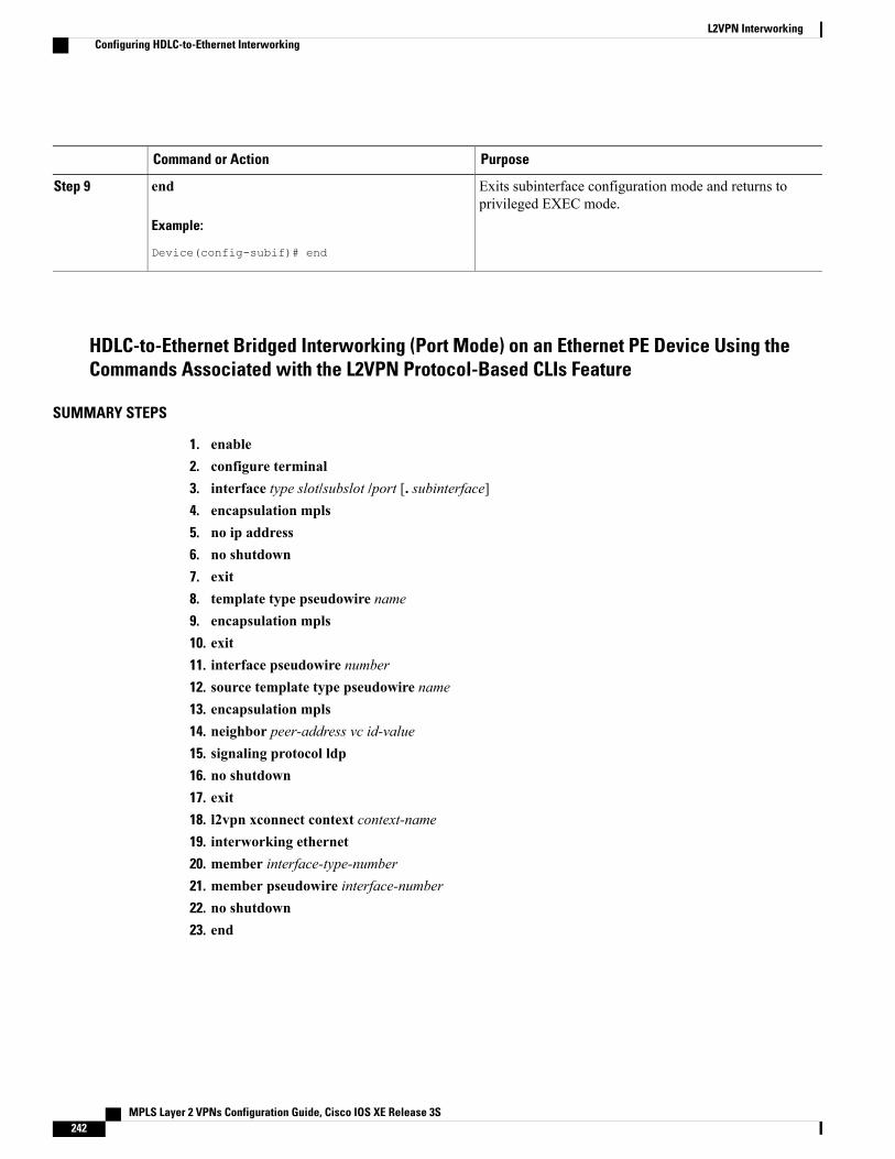
PurposeCommand or Action
Exits subinterface configuration mode and returns toprivileged EXEC mode.
end
Example:
Device(config-subif)# end
Step 9
HDLC-to-Ethernet Bridged Interworking (Port Mode) on an Ethernet PE Device Using theCommands Associated with the L2VPN Protocol-Based CLIs Feature
SUMMARY STEPS
1. enable2. configure terminal3. interface type slot/subslot /port [. subinterface]4. encapsulation mpls5. no ip address6. no shutdown7. exit8. template type pseudowire name9. encapsulation mpls10. exit11. interface pseudowire number12. source template type pseudowire name13. encapsulation mpls14. neighbor peer-address vc id-value15. signaling protocol ldp16. no shutdown17. exit18. l2vpn xconnect context context-name19. interworking ethernet20. member interface-type-number21. member pseudowire interface-number22. no shutdown23. end
MPLS Layer 2 VPNs Configuration Guide, Cisco IOS XE Release 3S242
L2VPN InterworkingConfiguring HDLC-to-Ethernet Interworking
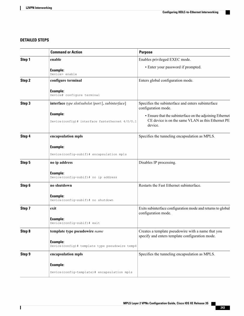
DETAILED STEPS
PurposeCommand or Action
Enables privileged EXEC mode.enableStep 1
Example:Device> enable
• Enter your password if prompted.
Enters global configuration mode.configure terminal
Example:Device# configure terminal
Step 2
Specifies the subinterface and enters subinterfaceconfiguration mode.
interface type slot/subslot /port [. subinterface]
Example:
Device(config)# interface fastethernet 4/0/0.1
Step 3
• Ensure that the subinterface on the adjoining EthernetCE device is on the same VLAN as this Ethernet PEdevice.
Specifies the tunneling encapsulation as MPLS.encapsulation mpls
Example:
Device(config-subif)# encapsulation mpls
Step 4
Disables IP processing.no ip address
Example:Device(config-subif)# no ip address
Step 5
Restarts the Fast Ethernet subinterface.no shutdown
Example:Device(config-subif)# no shutdown
Step 6
Exits subinterface configurationmode and returns to globalconfiguration mode.
exit
Example:Device(config-subif)# exit
Step 7
Creates a template pseudowire with a name that youspecify and enters template configuration mode.
template type pseudowire name
Example:Device(config)# template type pseudowire temp4
Step 8
Specifies the tunneling encapsulation as MPLS.encapsulation mpls
Example:
Device(config-template)# encapsulation mpls
Step 9
MPLS Layer 2 VPNs Configuration Guide, Cisco IOS XE Release 3S 243
L2VPN InterworkingConfiguring HDLC-to-Ethernet Interworking

PurposeCommand or Action
Exits template configuration mode and returns to globalconfiguration mode.
exit
Example:Device(config-template)# exit
Step 10
Establishes an interface pseudowire with a value that youspecify and enters interface configuration mode.
interface pseudowire number
Example:Device(config)# interface pseudowire 109
Step 11
Configures the source template of type pseudowire namedtemp4.
source template type pseudowire name
Example:Device(config-if)# source template typepseudowire temp4
Step 12
Specifies the tunneling encapsulation as MPLS.encapsulation mpls
Example:
Device(config-if)# encapsulation mpls
Step 13
Specifies the peer IP address and virtual circuit (VC) IDvalue of an L2VPN pseudowire.
neighbor peer-address vc id-value
Example:Device(config-if)# neighbor 10.0.0.15 109
Step 14
Specifies that the Label Distribution Protocol (LDP) isconfigured for the pseudowire class.
signaling protocol ldp
Example:Device(config-if)# signaling protocol ldp
Step 15
Restarts the interface pseudowire.no shutdown
Example:Device(config-if)# no shutdown
Step 16
Exits interface configuration mode and returns to globalconfiguration mode.
exit
Example:Device(config-if)# exit
Step 17
Creates an L2VPN cross-connect context and entersxconnect configuration mode.
l2vpn xconnect context context-name
Example:Device(config)# l2vpn xconnect context con2
Step 18
Specifies Ethernet as the type of pseudowire as well as thetype of traffic that can flow across the pseudowire.
interworking ethernet
Example:Device(config-xconnect)# interworking ethernet
Step 19
MPLS Layer 2 VPNs Configuration Guide, Cisco IOS XE Release 3S244
L2VPN InterworkingConfiguring HDLC-to-Ethernet Interworking

PurposeCommand or Action
Specifies the location of the member interface.member interface-type-number
Example:Device(config-xconnect)# member fastethernet4/0/0.1
Step 20
Specifies a member pseudowire to form an L2VPN crossconnect.
member pseudowire interface-number
Example:Device(config-xconnect)# member pseudowire 109
Step 21
Restarts the member interface.no shutdown
Example:Device(config-xconnect)# no shutdown
Step 22
Exits xconnect configuration mode and returns toprivileged EXEC mode.
end
Example:
Device(config-xconnect)# end
Step 23
HDLC-to-Ethernet Bridged Interworking (dot1q and QinQ Modes) on an Ethernet PE Device
SUMMARY STEPS
1. enable2. configure terminal3. pseudowire-class [pw-class-name]4. encapsulation mpls5. interworking ethernet6. interface type slot/subslot /port [. subinterface]7. encapsulation dot1q vlan-idsecond dot1q vlan-id8. xconnect peer-router-id vc id pseudowire-class [pw-class-name]9. end
DETAILED STEPS
PurposeCommand or Action
Enables privileged EXEC mode.enableStep 1
Example:Device> enable
• Enter your password if prompted.
MPLS Layer 2 VPNs Configuration Guide, Cisco IOS XE Release 3S 245
L2VPN InterworkingConfiguring HDLC-to-Ethernet Interworking
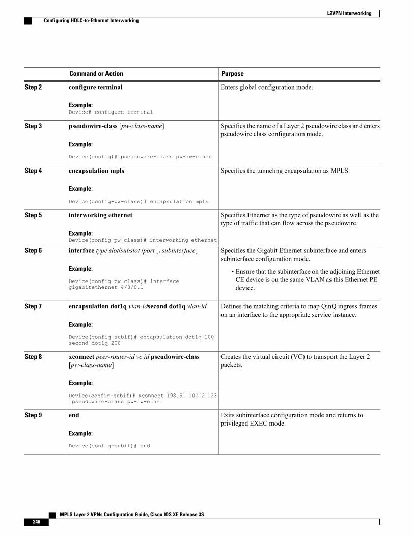
PurposeCommand or Action
Enters global configuration mode.configure terminal
Example:Device# configure terminal
Step 2
Specifies the name of a Layer 2 pseudowire class and enterspseudowire class configuration mode.
pseudowire-class [pw-class-name]
Example:
Device(config)# pseudowire-class pw-iw-ether
Step 3
Specifies the tunneling encapsulation as MPLS.encapsulation mpls
Example:
Device(config-pw-class)# encapsulation mpls
Step 4
Specifies Ethernet as the type of pseudowire as well as thetype of traffic that can flow across the pseudowire.
interworking ethernet
Example:Device(config-pw-class)# interworking ethernet
Step 5
Specifies the Gigabit Ethernet subinterface and enterssubinterface configuration mode.
interface type slot/subslot /port [. subinterface]
Example:
Device(config-pw-class)# interfacegigabitethernet 4/0/0.1
Step 6
• Ensure that the subinterface on the adjoining EthernetCE device is on the same VLAN as this Ethernet PEdevice.
Defines the matching criteria to map QinQ ingress frameson an interface to the appropriate service instance.
encapsulation dot1q vlan-idsecond dot1q vlan-id
Example:
Device(config-subif)# encapsulation dot1q 100second dot1q 200
Step 7
Creates the virtual circuit (VC) to transport the Layer 2packets.
xconnect peer-router-id vc id pseudowire-class[pw-class-name]
Example:
Device(config-subif)# xconnect 198.51.100.2 123pseudowire-class pw-iw-ether
Step 8
Exits subinterface configuration mode and returns toprivileged EXEC mode.
end
Example:
Device(config-subif)# end
Step 9
MPLS Layer 2 VPNs Configuration Guide, Cisco IOS XE Release 3S246
L2VPN InterworkingConfiguring HDLC-to-Ethernet Interworking
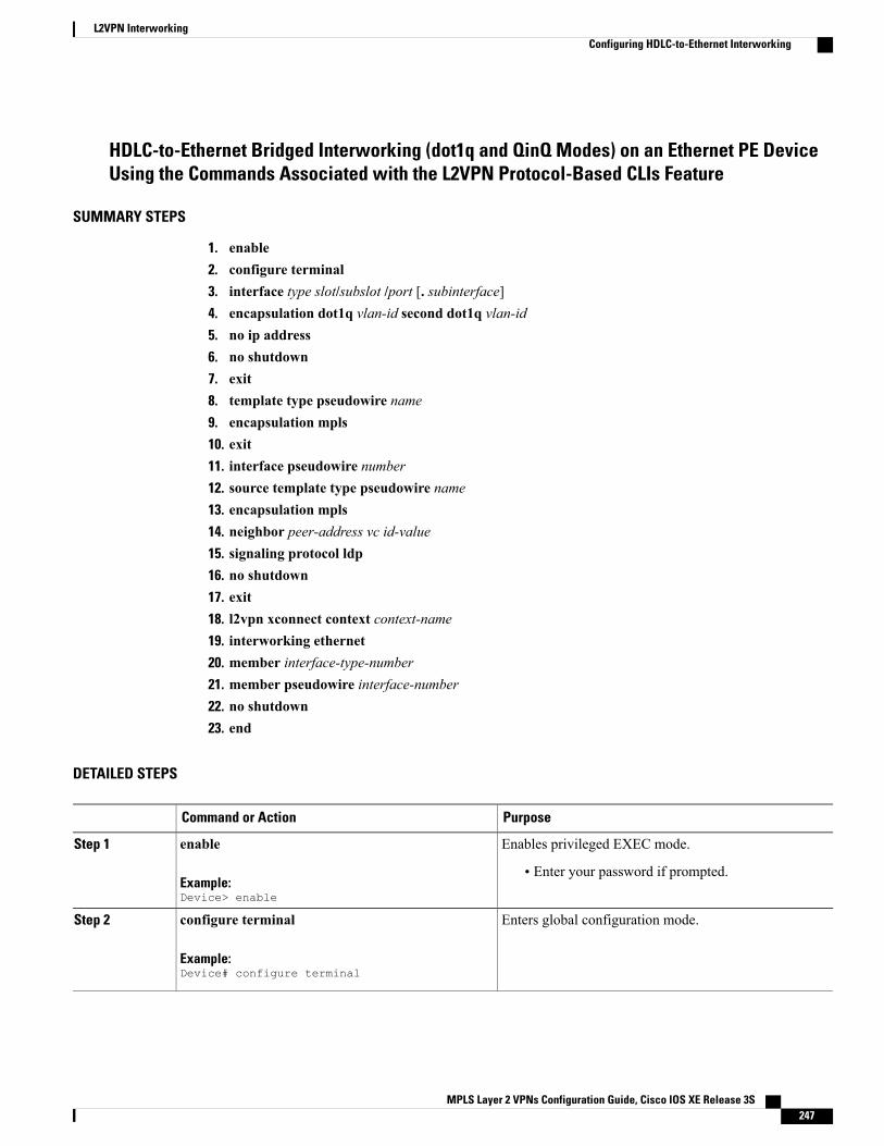
HDLC-to-Ethernet Bridged Interworking (dot1q and QinQ Modes) on an Ethernet PE DeviceUsing the Commands Associated with the L2VPN Protocol-Based CLIs Feature
SUMMARY STEPS
1. enable2. configure terminal3. interface type slot/subslot /port [. subinterface]4. encapsulation dot1q vlan-id second dot1q vlan-id5. no ip address6. no shutdown7. exit8. template type pseudowire name9. encapsulation mpls10. exit11. interface pseudowire number12. source template type pseudowire name13. encapsulation mpls14. neighbor peer-address vc id-value15. signaling protocol ldp16. no shutdown17. exit18. l2vpn xconnect context context-name19. interworking ethernet20. member interface-type-number21. member pseudowire interface-number22. no shutdown23. end
DETAILED STEPS
PurposeCommand or Action
Enables privileged EXEC mode.enableStep 1
Example:Device> enable
• Enter your password if prompted.
Enters global configuration mode.configure terminal
Example:Device# configure terminal
Step 2
MPLS Layer 2 VPNs Configuration Guide, Cisco IOS XE Release 3S 247
L2VPN InterworkingConfiguring HDLC-to-Ethernet Interworking

PurposeCommand or Action
Specifies the subinterface and enters subinterfaceconfiguration mode.
interface type slot/subslot /port [. subinterface]
Example:
Device(config)# interface fastethernet 4/0/0.1
Step 3
• Ensure that the subinterface on the adjoining EthernetCE device is on the same VLAN as this Ethernet PEdevice.
Defines the matching criteria to map QinQ ingress frameson an interface to the appropriate service instance.
encapsulation dot1q vlan-id second dot1q vlan-id
Example:
Device(config-subif)# encapsulation dot1q 100second dot1q 200
Step 4
Disables IP processing.no ip address
Example:Device(config-subif)# no ip address
Step 5
Restarts the Fast Ethernet subinterface.no shutdown
Example:Device(config-subif)# no shutdown
Step 6
Exits subinterface configurationmode and returns to globalconfiguration mode.
exit
Example:Device(config-subif)# exit
Step 7
Creates a template pseudowire with a name that you specifyand enters template configuration mode.
template type pseudowire name
Example:Device(config)# template type pseudowire temp4
Step 8
Specifies the tunneling encapsulation as MPLS.encapsulation mpls
Example:
Device(config-template)# encapsulation mpls
Step 9
Exits template configuration mode and returns to globalconfiguration mode.
exit
Example:Device(config-template)# exit
Step 10
Establishes an interface pseudowire with a value that youspecify and enters interface configuration mode.
interface pseudowire number
Example:Device(config)# interface pseudowire 109
Step 11
MPLS Layer 2 VPNs Configuration Guide, Cisco IOS XE Release 3S248
L2VPN InterworkingConfiguring HDLC-to-Ethernet Interworking
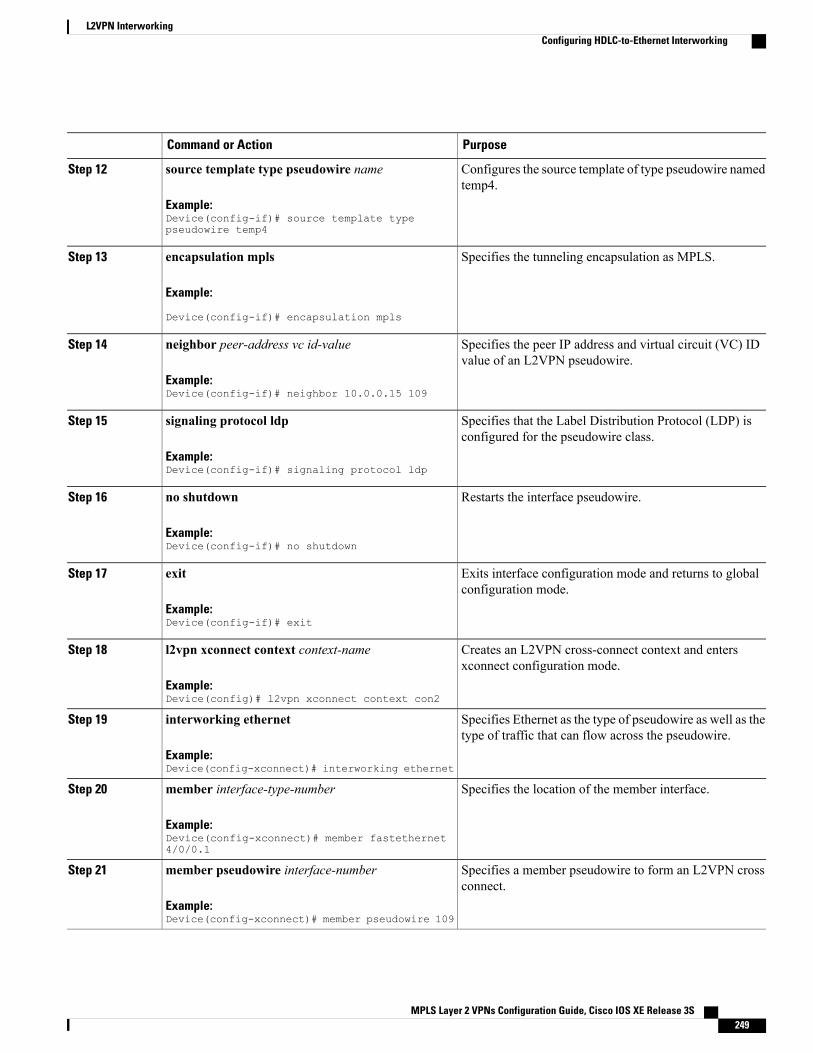
PurposeCommand or Action
Configures the source template of type pseudowire namedtemp4.
source template type pseudowire name
Example:Device(config-if)# source template typepseudowire temp4
Step 12
Specifies the tunneling encapsulation as MPLS.encapsulation mpls
Example:
Device(config-if)# encapsulation mpls
Step 13
Specifies the peer IP address and virtual circuit (VC) IDvalue of an L2VPN pseudowire.
neighbor peer-address vc id-value
Example:Device(config-if)# neighbor 10.0.0.15 109
Step 14
Specifies that the Label Distribution Protocol (LDP) isconfigured for the pseudowire class.
signaling protocol ldp
Example:Device(config-if)# signaling protocol ldp
Step 15
Restarts the interface pseudowire.no shutdown
Example:Device(config-if)# no shutdown
Step 16
Exits interface configuration mode and returns to globalconfiguration mode.
exit
Example:Device(config-if)# exit
Step 17
Creates an L2VPN cross-connect context and entersxconnect configuration mode.
l2vpn xconnect context context-name
Example:Device(config)# l2vpn xconnect context con2
Step 18
Specifies Ethernet as the type of pseudowire as well as thetype of traffic that can flow across the pseudowire.
interworking ethernet
Example:Device(config-xconnect)# interworking ethernet
Step 19
Specifies the location of the member interface.member interface-type-number
Example:Device(config-xconnect)# member fastethernet4/0/0.1
Step 20
Specifies a member pseudowire to form an L2VPN crossconnect.
member pseudowire interface-number
Example:Device(config-xconnect)# member pseudowire 109
Step 21
MPLS Layer 2 VPNs Configuration Guide, Cisco IOS XE Release 3S 249
L2VPN InterworkingConfiguring HDLC-to-Ethernet Interworking
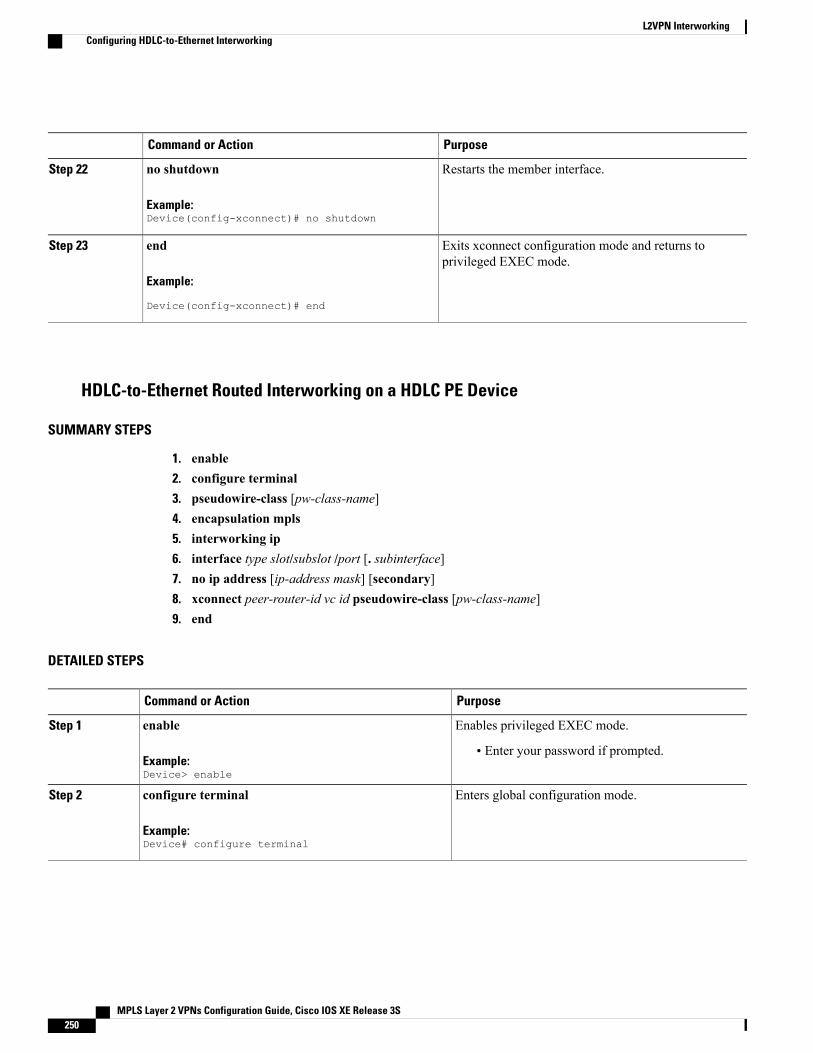
PurposeCommand or Action
Restarts the member interface.no shutdown
Example:Device(config-xconnect)# no shutdown
Step 22
Exits xconnect configuration mode and returns toprivileged EXEC mode.
end
Example:
Device(config-xconnect)# end
Step 23
HDLC-to-Ethernet Routed Interworking on a HDLC PE Device
SUMMARY STEPS
1. enable2. configure terminal3. pseudowire-class [pw-class-name]4. encapsulation mpls5. interworking ip6. interface type slot/subslot /port [. subinterface]7. no ip address [ip-address mask] [secondary]8. xconnect peer-router-id vc id pseudowire-class [pw-class-name]9. end
DETAILED STEPS
PurposeCommand or Action
Enables privileged EXEC mode.enableStep 1
Example:Device> enable
• Enter your password if prompted.
Enters global configuration mode.configure terminal
Example:Device# configure terminal
Step 2
MPLS Layer 2 VPNs Configuration Guide, Cisco IOS XE Release 3S250
L2VPN InterworkingConfiguring HDLC-to-Ethernet Interworking
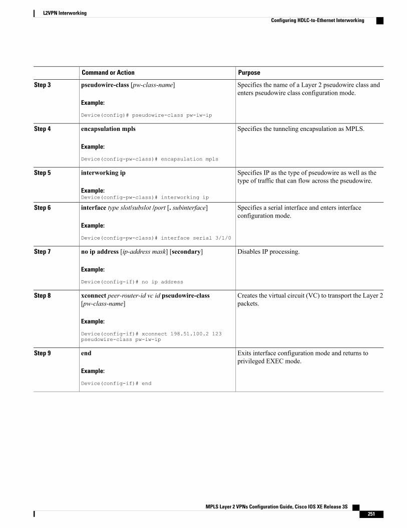
PurposeCommand or Action
Specifies the name of a Layer 2 pseudowire class andenters pseudowire class configuration mode.
pseudowire-class [pw-class-name]
Example:
Device(config)# pseudowire-class pw-iw-ip
Step 3
Specifies the tunneling encapsulation as MPLS.encapsulation mpls
Example:
Device(config-pw-class)# encapsulation mpls
Step 4
Specifies IP as the type of pseudowire as well as thetype of traffic that can flow across the pseudowire.
interworking ip
Example:Device(config-pw-class)# interworking ip
Step 5
Specifies a serial interface and enters interfaceconfiguration mode.
interface type slot/subslot /port [. subinterface]
Example:
Device(config-pw-class)# interface serial 3/1/0
Step 6
Disables IP processing.no ip address [ip-address mask] [secondary]
Example:
Device(config-if)# no ip address
Step 7
Creates the virtual circuit (VC) to transport the Layer 2packets.
xconnect peer-router-id vc id pseudowire-class[pw-class-name]
Example:
Device(config-if)# xconnect 198.51.100.2 123pseudowire-class pw-iw-ip
Step 8
Exits interface configuration mode and returns toprivileged EXEC mode.
end
Example:
Device(config-if)# end
Step 9
MPLS Layer 2 VPNs Configuration Guide, Cisco IOS XE Release 3S 251
L2VPN InterworkingConfiguring HDLC-to-Ethernet Interworking

HDLC-to-Ethernet Routed Interworking on a HDLC PE Device Using the Commands Associatedwith the L2VPN Protocol-Based CLIs Feature
SUMMARY STEPS
1. enable2. configure terminal3. template type pseudowire name4. encapsulation mpls5. exit6. interface pseudowire number7. source template type pseudowire name8. encapsulation mpls9. neighbor peer-address vc id-value10. signaling protocol ldp11. no shutdown12. exit13. l2vpn xconnect context context-name14. interworking ip15. member interface-type-number16. member pseudowire interface-number17. no shutdown18. end
DETAILED STEPS
PurposeCommand or Action
Enables privileged EXEC mode.enableStep 1
Example:Device> enable
• Enter your password if prompted.
Enters global configuration mode.configure terminal
Example:Device# configure terminal
Step 2
Creates a template pseudowire with a name that youspecify and enters template configuration mode.
template type pseudowire name
Example:Device# template type pseudowire temp5
Step 3
MPLS Layer 2 VPNs Configuration Guide, Cisco IOS XE Release 3S252
L2VPN InterworkingConfiguring HDLC-to-Ethernet Interworking
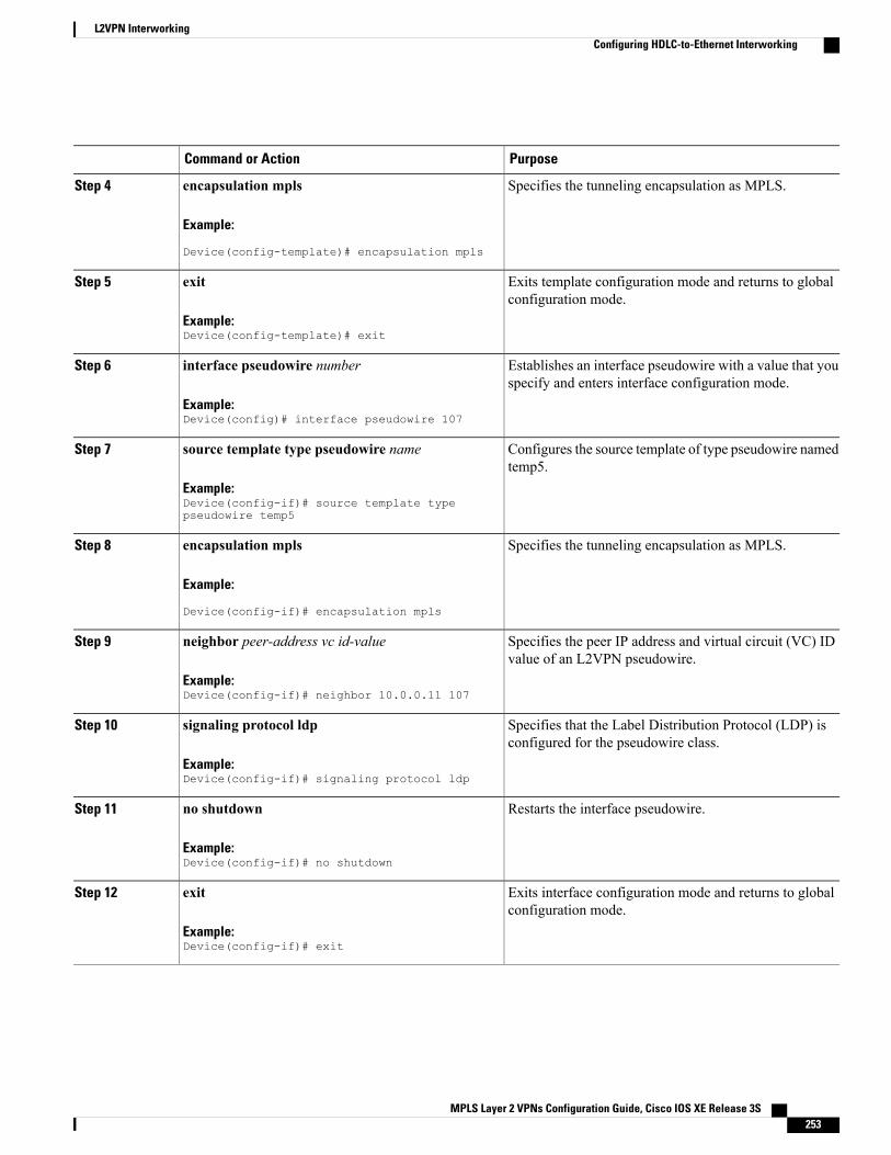
PurposeCommand or Action
Specifies the tunneling encapsulation as MPLS.encapsulation mpls
Example:
Device(config-template)# encapsulation mpls
Step 4
Exits template configuration mode and returns to globalconfiguration mode.
exit
Example:Device(config-template)# exit
Step 5
Establishes an interface pseudowire with a value that youspecify and enters interface configuration mode.
interface pseudowire number
Example:Device(config)# interface pseudowire 107
Step 6
Configures the source template of type pseudowire namedtemp5.
source template type pseudowire name
Example:Device(config-if)# source template typepseudowire temp5
Step 7
Specifies the tunneling encapsulation as MPLS.encapsulation mpls
Example:
Device(config-if)# encapsulation mpls
Step 8
Specifies the peer IP address and virtual circuit (VC) IDvalue of an L2VPN pseudowire.
neighbor peer-address vc id-value
Example:Device(config-if)# neighbor 10.0.0.11 107
Step 9
Specifies that the Label Distribution Protocol (LDP) isconfigured for the pseudowire class.
signaling protocol ldp
Example:Device(config-if)# signaling protocol ldp
Step 10
Restarts the interface pseudowire.no shutdown
Example:Device(config-if)# no shutdown
Step 11
Exits interface configuration mode and returns to globalconfiguration mode.
exit
Example:Device(config-if)# exit
Step 12
MPLS Layer 2 VPNs Configuration Guide, Cisco IOS XE Release 3S 253
L2VPN InterworkingConfiguring HDLC-to-Ethernet Interworking
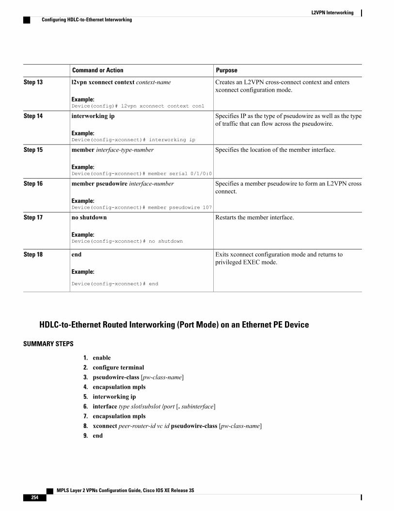
PurposeCommand or Action
Creates an L2VPN cross-connect context and entersxconnect configuration mode.
l2vpn xconnect context context-name
Example:Device(config)# l2vpn xconnect context con1
Step 13
Specifies IP as the type of pseudowire as well as the typeof traffic that can flow across the pseudowire.
interworking ip
Example:Device(config-xconnect)# interworking ip
Step 14
Specifies the location of the member interface.member interface-type-number
Example:Device(config-xconnect)# member serial 0/1/0:0
Step 15
Specifies a member pseudowire to form an L2VPN crossconnect.
member pseudowire interface-number
Example:Device(config-xconnect)# member pseudowire 107
Step 16
Restarts the member interface.no shutdown
Example:Device(config-xconnect)# no shutdown
Step 17
Exits xconnect configuration mode and returns toprivileged EXEC mode.
end
Example:
Device(config-xconnect)# end
Step 18
HDLC-to-Ethernet Routed Interworking (Port Mode) on an Ethernet PE Device
SUMMARY STEPS
1. enable2. configure terminal3. pseudowire-class [pw-class-name]4. encapsulation mpls5. interworking ip6. interface type slot/subslot /port [. subinterface]7. encapsulation mpls8. xconnect peer-router-id vc id pseudowire-class [pw-class-name]9. end
MPLS Layer 2 VPNs Configuration Guide, Cisco IOS XE Release 3S254
L2VPN InterworkingConfiguring HDLC-to-Ethernet Interworking
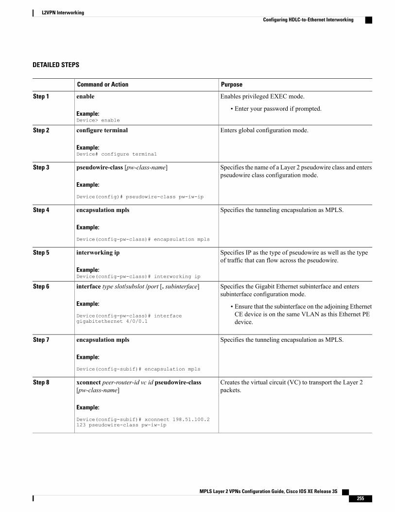
DETAILED STEPS
PurposeCommand or Action
Enables privileged EXEC mode.enableStep 1
Example:Device> enable
• Enter your password if prompted.
Enters global configuration mode.configure terminal
Example:Device# configure terminal
Step 2
Specifies the name of a Layer 2 pseudowire class and enterspseudowire class configuration mode.
pseudowire-class [pw-class-name]
Example:
Device(config)# pseudowire-class pw-iw-ip
Step 3
Specifies the tunneling encapsulation as MPLS.encapsulation mpls
Example:
Device(config-pw-class)# encapsulation mpls
Step 4
Specifies IP as the type of pseudowire as well as the typeof traffic that can flow across the pseudowire.
interworking ip
Example:Device(config-pw-class)# interworking ip
Step 5
Specifies the Gigabit Ethernet subinterface and enterssubinterface configuration mode.
interface type slot/subslot /port [. subinterface]
Example:
Device(config-pw-class)# interfacegigabitethernet 4/0/0.1
Step 6
• Ensure that the subinterface on the adjoining EthernetCE device is on the same VLAN as this Ethernet PEdevice.
Specifies the tunneling encapsulation as MPLS.encapsulation mpls
Example:
Device(config-subif)# encapsulation mpls
Step 7
Creates the virtual circuit (VC) to transport the Layer 2packets.
xconnect peer-router-id vc id pseudowire-class[pw-class-name]
Example:
Device(config-subif)# xconnect 198.51.100.2123 pseudowire-class pw-iw-ip
Step 8
MPLS Layer 2 VPNs Configuration Guide, Cisco IOS XE Release 3S 255
L2VPN InterworkingConfiguring HDLC-to-Ethernet Interworking
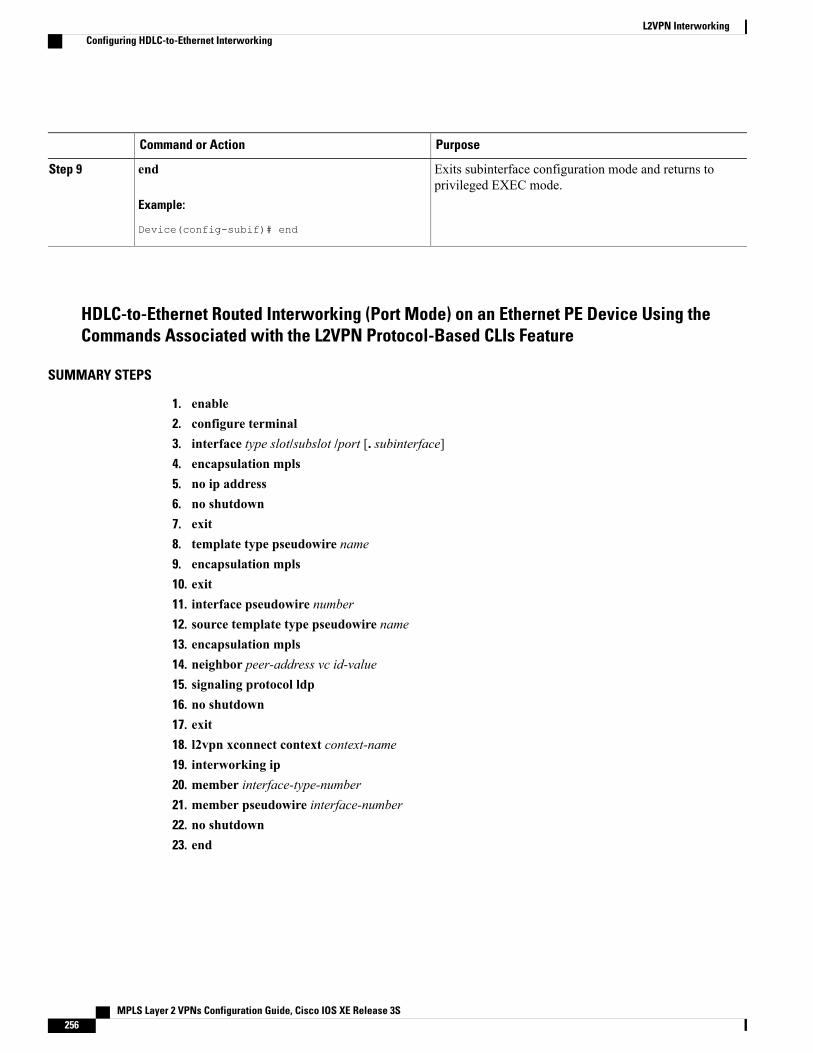
PurposeCommand or Action
Exits subinterface configuration mode and returns toprivileged EXEC mode.
end
Example:
Device(config-subif)# end
Step 9
HDLC-to-Ethernet Routed Interworking (Port Mode) on an Ethernet PE Device Using theCommands Associated with the L2VPN Protocol-Based CLIs Feature
SUMMARY STEPS
1. enable2. configure terminal3. interface type slot/subslot /port [. subinterface]4. encapsulation mpls5. no ip address6. no shutdown7. exit8. template type pseudowire name9. encapsulation mpls10. exit11. interface pseudowire number12. source template type pseudowire name13. encapsulation mpls14. neighbor peer-address vc id-value15. signaling protocol ldp16. no shutdown17. exit18. l2vpn xconnect context context-name19. interworking ip20. member interface-type-number21. member pseudowire interface-number22. no shutdown23. end
MPLS Layer 2 VPNs Configuration Guide, Cisco IOS XE Release 3S256
L2VPN InterworkingConfiguring HDLC-to-Ethernet Interworking
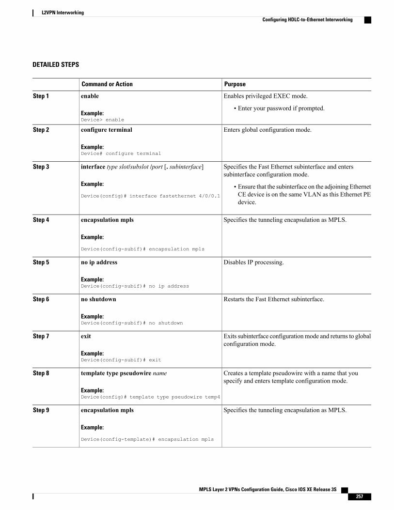
DETAILED STEPS
PurposeCommand or Action
Enables privileged EXEC mode.enableStep 1
Example:Device> enable
• Enter your password if prompted.
Enters global configuration mode.configure terminal
Example:Device# configure terminal
Step 2
Specifies the Fast Ethernet subinterface and enterssubinterface configuration mode.
interface type slot/subslot /port [. subinterface]
Example:
Device(config)# interface fastethernet 4/0/0.1
Step 3
• Ensure that the subinterface on the adjoining EthernetCE device is on the same VLAN as this Ethernet PEdevice.
Specifies the tunneling encapsulation as MPLS.encapsulation mpls
Example:
Device(config-subif)# encapsulation mpls
Step 4
Disables IP processing.no ip address
Example:Device(config-subif)# no ip address
Step 5
Restarts the Fast Ethernet subinterface.no shutdown
Example:Device(config-subif)# no shutdown
Step 6
Exits subinterface configurationmode and returns to globalconfiguration mode.
exit
Example:Device(config-subif)# exit
Step 7
Creates a template pseudowire with a name that youspecify and enters template configuration mode.
template type pseudowire name
Example:Device(config)# template type pseudowire temp4
Step 8
Specifies the tunneling encapsulation as MPLS.encapsulation mpls
Example:
Device(config-template)# encapsulation mpls
Step 9
MPLS Layer 2 VPNs Configuration Guide, Cisco IOS XE Release 3S 257
L2VPN InterworkingConfiguring HDLC-to-Ethernet Interworking
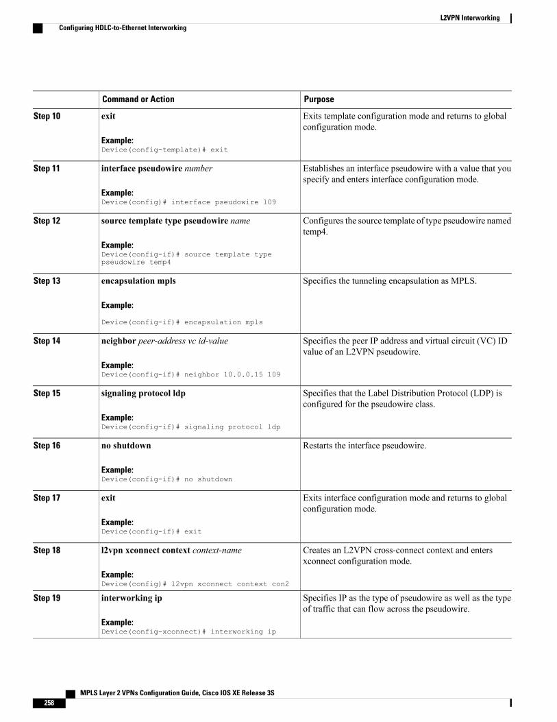
PurposeCommand or Action
Exits template configuration mode and returns to globalconfiguration mode.
exit
Example:Device(config-template)# exit
Step 10
Establishes an interface pseudowire with a value that youspecify and enters interface configuration mode.
interface pseudowire number
Example:Device(config)# interface pseudowire 109
Step 11
Configures the source template of type pseudowire namedtemp4.
source template type pseudowire name
Example:Device(config-if)# source template typepseudowire temp4
Step 12
Specifies the tunneling encapsulation as MPLS.encapsulation mpls
Example:
Device(config-if)# encapsulation mpls
Step 13
Specifies the peer IP address and virtual circuit (VC) IDvalue of an L2VPN pseudowire.
neighbor peer-address vc id-value
Example:Device(config-if)# neighbor 10.0.0.15 109
Step 14
Specifies that the Label Distribution Protocol (LDP) isconfigured for the pseudowire class.
signaling protocol ldp
Example:Device(config-if)# signaling protocol ldp
Step 15
Restarts the interface pseudowire.no shutdown
Example:Device(config-if)# no shutdown
Step 16
Exits interface configuration mode and returns to globalconfiguration mode.
exit
Example:Device(config-if)# exit
Step 17
Creates an L2VPN cross-connect context and entersxconnect configuration mode.
l2vpn xconnect context context-name
Example:Device(config)# l2vpn xconnect context con2
Step 18
Specifies IP as the type of pseudowire as well as the typeof traffic that can flow across the pseudowire.
interworking ip
Example:Device(config-xconnect)# interworking ip
Step 19
MPLS Layer 2 VPNs Configuration Guide, Cisco IOS XE Release 3S258
L2VPN InterworkingConfiguring HDLC-to-Ethernet Interworking
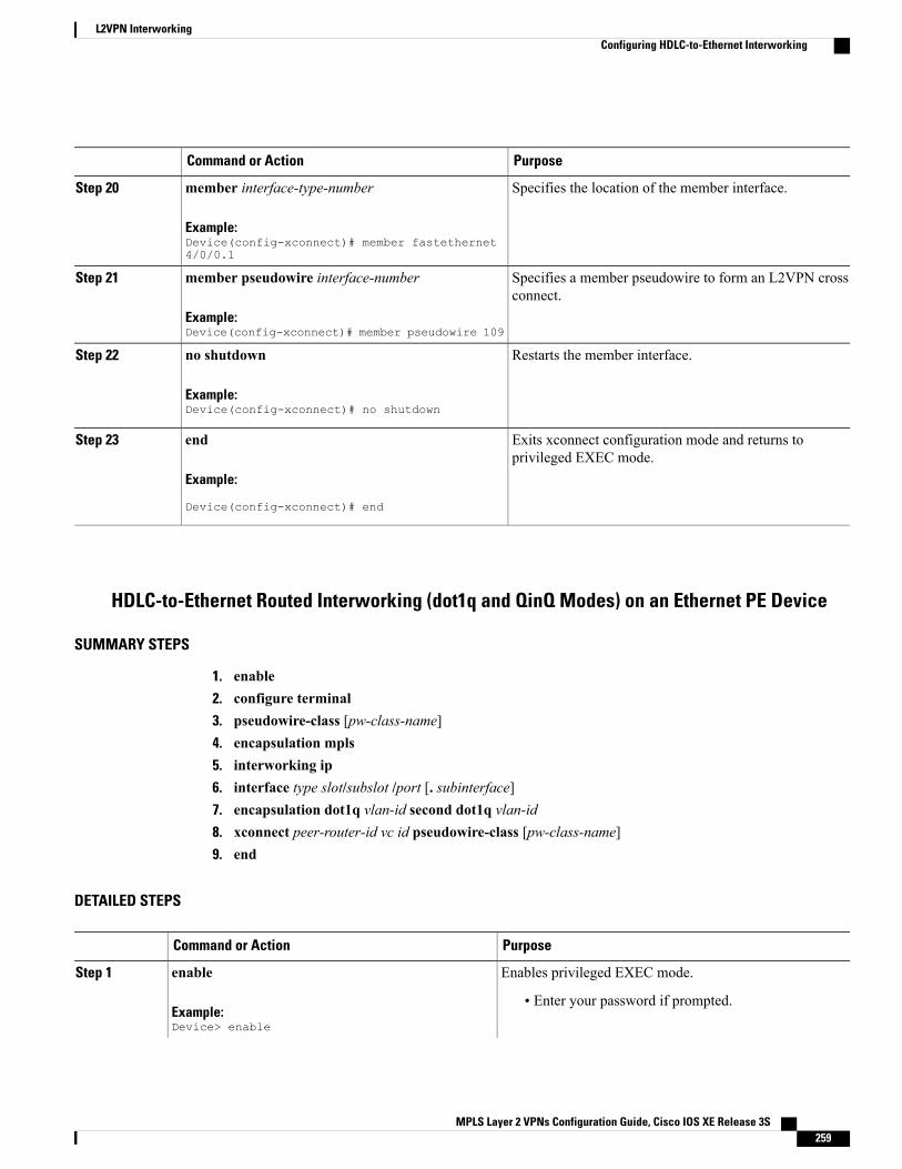
PurposeCommand or Action
Specifies the location of the member interface.member interface-type-number
Example:Device(config-xconnect)# member fastethernet4/0/0.1
Step 20
Specifies a member pseudowire to form an L2VPN crossconnect.
member pseudowire interface-number
Example:Device(config-xconnect)# member pseudowire 109
Step 21
Restarts the member interface.no shutdown
Example:Device(config-xconnect)# no shutdown
Step 22
Exits xconnect configuration mode and returns toprivileged EXEC mode.
end
Example:
Device(config-xconnect)# end
Step 23
HDLC-to-Ethernet Routed Interworking (dot1q and QinQ Modes) on an Ethernet PE Device
SUMMARY STEPS
1. enable2. configure terminal3. pseudowire-class [pw-class-name]4. encapsulation mpls5. interworking ip6. interface type slot/subslot /port [. subinterface]7. encapsulation dot1q vlan-id second dot1q vlan-id8. xconnect peer-router-id vc id pseudowire-class [pw-class-name]9. end
DETAILED STEPS
PurposeCommand or Action
Enables privileged EXEC mode.enableStep 1
Example:Device> enable
• Enter your password if prompted.
MPLS Layer 2 VPNs Configuration Guide, Cisco IOS XE Release 3S 259
L2VPN InterworkingConfiguring HDLC-to-Ethernet Interworking
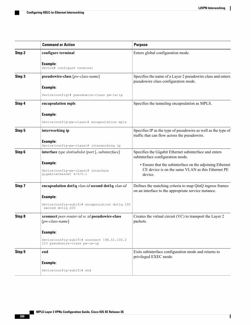
PurposeCommand or Action
Enters global configuration mode.configure terminal
Example:Device# configure terminal
Step 2
Specifies the name of a Layer 2 pseudowire class and enterspseudowire class configuration mode.
pseudowire-class [pw-class-name]
Example:
Device(config)# pseudowire-class pw-iw-ip
Step 3
Specifies the tunneling encapsulation as MPLS.encapsulation mpls
Example:
Device(config-pw-class)# encapsulation mpls
Step 4
Specifies IP as the type of pseudowire as well as the type oftraffic that can flow across the pseudowire.
interworking ip
Example:Device(config-pw-class)# interworking ip
Step 5
Specifies the Gigabit Ethernet subinterface and enterssubinterface configuration mode.
interface type slot/subslot /port [. subinterface]
Example:
Device(config-pw-class)# interfacegigabitethernet 4/0/0.1
Step 6
• Ensure that the subinterface on the adjoining EthernetCE device is on the same VLAN as this Ethernet PEdevice.
Defines the matching criteria to map QinQ ingress frameson an interface to the appropriate service instance.
encapsulation dot1q vlan-id second dot1q vlan-id
Example:
Device(config-subif)# encapsulation dot1q 100second dot1q 200
Step 7
Creates the virtual circuit (VC) to transport the Layer 2packets.
xconnect peer-router-id vc id pseudowire-class[pw-class-name]
Example:
Device(config-subif)# xconnect 198.51.100.2123 pseudowire-class pw-iw-ip
Step 8
Exits subinterface configuration mode and returns toprivileged EXEC mode.
end
Example:
Device(config-subif)# end
Step 9
MPLS Layer 2 VPNs Configuration Guide, Cisco IOS XE Release 3S260
L2VPN InterworkingConfiguring HDLC-to-Ethernet Interworking
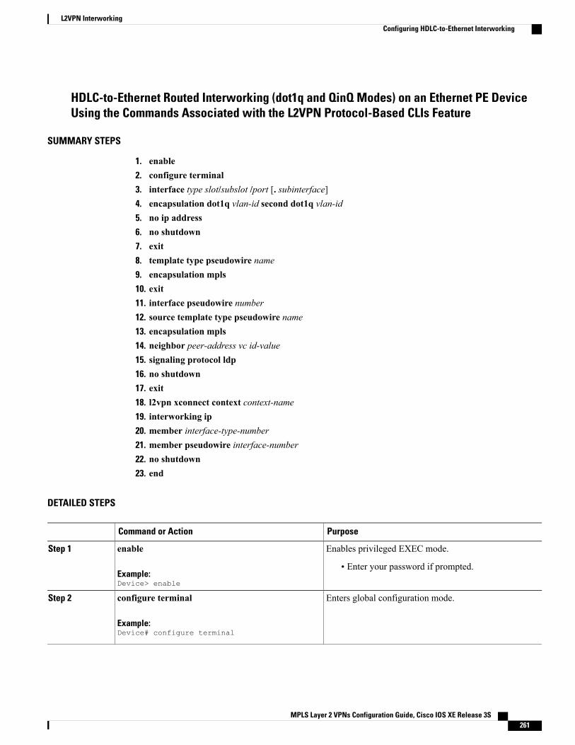
HDLC-to-Ethernet Routed Interworking (dot1q and QinQ Modes) on an Ethernet PE DeviceUsing the Commands Associated with the L2VPN Protocol-Based CLIs Feature
SUMMARY STEPS
1. enable2. configure terminal3. interface type slot/subslot /port [. subinterface]4. encapsulation dot1q vlan-id second dot1q vlan-id5. no ip address6. no shutdown7. exit8. template type pseudowire name9. encapsulation mpls10. exit11. interface pseudowire number12. source template type pseudowire name13. encapsulation mpls14. neighbor peer-address vc id-value15. signaling protocol ldp16. no shutdown17. exit18. l2vpn xconnect context context-name19. interworking ip20. member interface-type-number21. member pseudowire interface-number22. no shutdown23. end
DETAILED STEPS
PurposeCommand or Action
Enables privileged EXEC mode.enableStep 1
Example:Device> enable
• Enter your password if prompted.
Enters global configuration mode.configure terminal
Example:Device# configure terminal
Step 2
MPLS Layer 2 VPNs Configuration Guide, Cisco IOS XE Release 3S 261
L2VPN InterworkingConfiguring HDLC-to-Ethernet Interworking
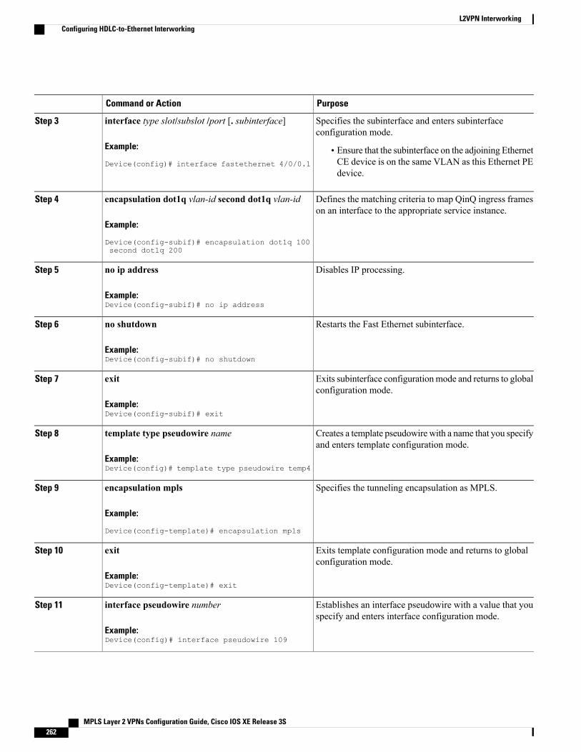
PurposeCommand or Action
Specifies the subinterface and enters subinterfaceconfiguration mode.
interface type slot/subslot /port [. subinterface]
Example:
Device(config)# interface fastethernet 4/0/0.1
Step 3
• Ensure that the subinterface on the adjoining EthernetCE device is on the same VLAN as this Ethernet PEdevice.
Defines the matching criteria to map QinQ ingress frameson an interface to the appropriate service instance.
encapsulation dot1q vlan-id second dot1q vlan-id
Example:
Device(config-subif)# encapsulation dot1q 100second dot1q 200
Step 4
Disables IP processing.no ip address
Example:Device(config-subif)# no ip address
Step 5
Restarts the Fast Ethernet subinterface.no shutdown
Example:Device(config-subif)# no shutdown
Step 6
Exits subinterface configurationmode and returns to globalconfiguration mode.
exit
Example:Device(config-subif)# exit
Step 7
Creates a template pseudowire with a name that you specifyand enters template configuration mode.
template type pseudowire name
Example:Device(config)# template type pseudowire temp4
Step 8
Specifies the tunneling encapsulation as MPLS.encapsulation mpls
Example:
Device(config-template)# encapsulation mpls
Step 9
Exits template configuration mode and returns to globalconfiguration mode.
exit
Example:Device(config-template)# exit
Step 10
Establishes an interface pseudowire with a value that youspecify and enters interface configuration mode.
interface pseudowire number
Example:Device(config)# interface pseudowire 109
Step 11
MPLS Layer 2 VPNs Configuration Guide, Cisco IOS XE Release 3S262
L2VPN InterworkingConfiguring HDLC-to-Ethernet Interworking

PurposeCommand or Action
Configures the source template of type pseudowire namedtemp4.
source template type pseudowire name
Example:Device(config-if)# source template typepseudowire temp4
Step 12
Specifies the tunneling encapsulation as MPLS.encapsulation mpls
Example:
Device(config-if)# encapsulation mpls
Step 13
Specifies the peer IP address and virtual circuit (VC) IDvalue of an L2VPN pseudowire.
neighbor peer-address vc id-value
Example:Device(config-if)# neighbor 10.0.0.15 109
Step 14
Specifies that the Label Distribution Protocol (LDP) isconfigured for the pseudowire class.
signaling protocol ldp
Example:Device(config-if)# signaling protocol ldp
Step 15
Restarts the interface pseudowire.no shutdown
Example:Device(config-if)# no shutdown
Step 16
Exits interface configuration mode and returns to globalconfiguration mode.
exit
Example:Device(config-if)# exit
Step 17
Creates an L2VPN cross-connect context and entersxconnect configuration mode.
l2vpn xconnect context context-name
Example:Device(config)# l2vpn xconnect context con2
Step 18
Specifies IP as the type of pseudowire as well as the typeof traffic that can flow across the pseudowire.
interworking ip
Example:Device(config-xconnect)# interworking ip
Step 19
Specifies the location of the member interface.member interface-type-number
Example:Device(config-xconnect)# member fastethernet4/0/0.1
Step 20
Specifies a member pseudowire to form an L2VPN crossconnect.
member pseudowire interface-number
Example:Device(config-xconnect)# member pseudowire 109
Step 21
MPLS Layer 2 VPNs Configuration Guide, Cisco IOS XE Release 3S 263
L2VPN InterworkingConfiguring HDLC-to-Ethernet Interworking
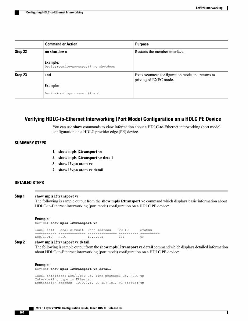
PurposeCommand or Action
Restarts the member interface.no shutdown
Example:Device(config-xconnect)# no shutdown
Step 22
Exits xconnect configuration mode and returns toprivileged EXEC mode.
end
Example:
Device(config-xconnect)# end
Step 23
Verifying HDLC-to-Ethernet Interworking (Port Mode) Configuration on a HDLC PE DeviceYou can use show commands to view information about a HDLC-to-Ethernet interworking (port mode)configuration on a HDLC provider edge (PE) device.
SUMMARY STEPS
1. show mpls l2transport vc2. show mpls l2transport vc detail3. show l2vpn atom vc4. show l2vpn atom vc detail
DETAILED STEPS
Step 1 show mpls l2transport vcThe following is sample output from the show mpls l2transport vc command which displays basic information aboutHDLC-to-Ethernet interworking (port mode) configuration on a HDLC PE device:
Example:Device# show mpls l2transport vc
Local intf Local circuit Dest address VC ID Status----------- -------------- --------------- ---------- ----------Se0/1/0:0 HDLC 10.0.0.1 101 UP
Step 2 show mpls l2transport vc detailThe following is sample output from the showmpls l2transport vc detail commandwhich displays detailed informationabout HDLC-to-Ethernet interworking (port mode) configuration on a HDLC PE device:
Example:Device# show mpls l2transport vc detail
Local interface: Se0/1/0:0 up, line protocol up, HDLC upInterworking type is EthernetDestination address: 10.0.0.1, VC ID: 101, VC status: up
MPLS Layer 2 VPNs Configuration Guide, Cisco IOS XE Release 3S264
L2VPN InterworkingConfiguring HDLC-to-Ethernet Interworking
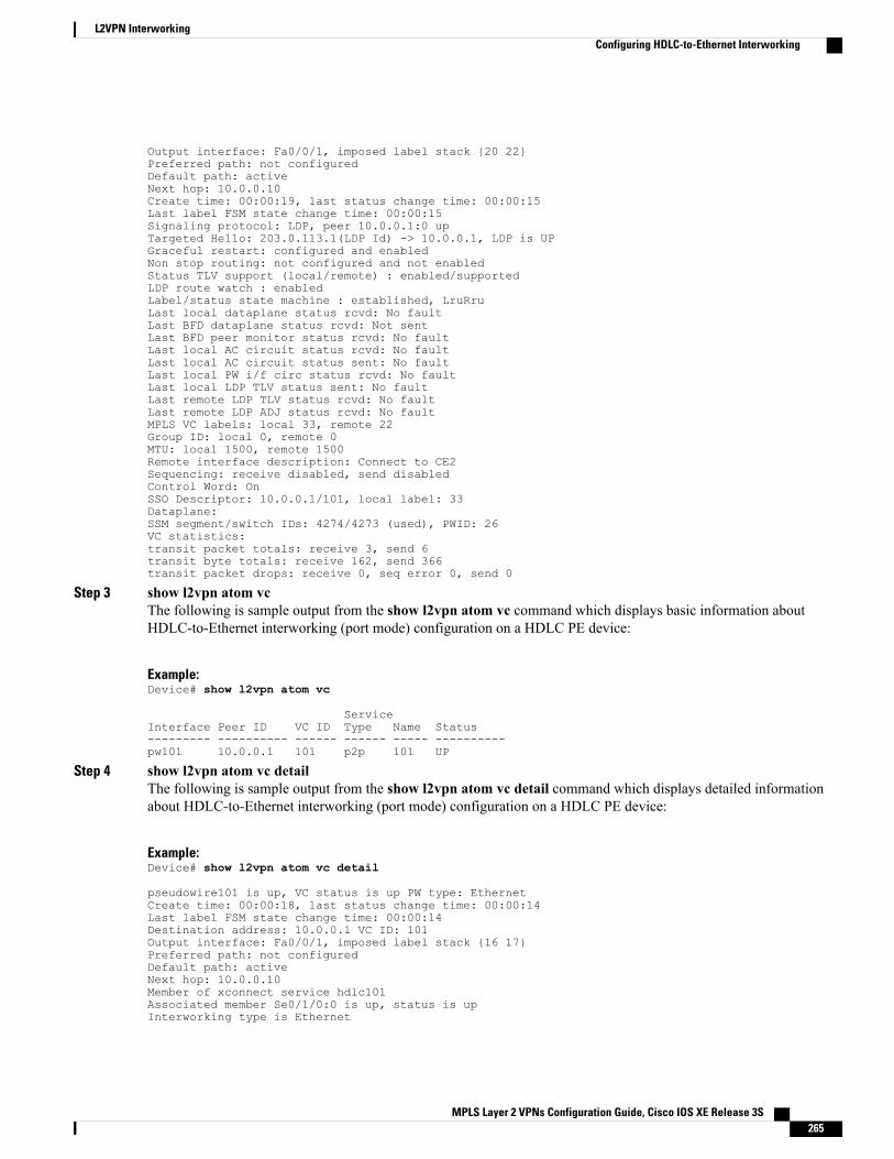
Output interface: Fa0/0/1, imposed label stack {20 22}Preferred path: not configuredDefault path: activeNext hop: 10.0.0.10Create time: 00:00:19, last status change time: 00:00:15Last label FSM state change time: 00:00:15Signaling protocol: LDP, peer 10.0.0.1:0 upTargeted Hello: 203.0.113.1(LDP Id) -> 10.0.0.1, LDP is UPGraceful restart: configured and enabledNon stop routing: not configured and not enabledStatus TLV support (local/remote) : enabled/supportedLDP route watch : enabledLabel/status state machine : established, LruRruLast local dataplane status rcvd: No faultLast BFD dataplane status rcvd: Not sentLast BFD peer monitor status rcvd: No faultLast local AC circuit status rcvd: No faultLast local AC circuit status sent: No faultLast local PW i/f circ status rcvd: No faultLast local LDP TLV status sent: No faultLast remote LDP TLV status rcvd: No faultLast remote LDP ADJ status rcvd: No faultMPLS VC labels: local 33, remote 22Group ID: local 0, remote 0MTU: local 1500, remote 1500Remote interface description: Connect to CE2Sequencing: receive disabled, send disabledControl Word: OnSSO Descriptor: 10.0.0.1/101, local label: 33Dataplane:SSM segment/switch IDs: 4274/4273 (used), PWID: 26VC statistics:transit packet totals: receive 3, send 6transit byte totals: receive 162, send 366transit packet drops: receive 0, seq error 0, send 0
Step 3 show l2vpn atom vcThe following is sample output from the show l2vpn atom vc command which displays basic information aboutHDLC-to-Ethernet interworking (port mode) configuration on a HDLC PE device:
Example:Device# show l2vpn atom vc
ServiceInterface Peer ID VC ID Type Name Status--------- ---------- ------ ------ ----- ----------pw101 10.0.0.1 101 p2p 101 UP
Step 4 show l2vpn atom vc detailThe following is sample output from the show l2vpn atom vc detail command which displays detailed informationabout HDLC-to-Ethernet interworking (port mode) configuration on a HDLC PE device:
Example:Device# show l2vpn atom vc detail
pseudowire101 is up, VC status is up PW type: EthernetCreate time: 00:00:18, last status change time: 00:00:14Last label FSM state change time: 00:00:14Destination address: 10.0.0.1 VC ID: 101Output interface: Fa0/0/1, imposed label stack {16 17}Preferred path: not configuredDefault path: activeNext hop: 10.0.0.10Member of xconnect service hdlc101Associated member Se0/1/0:0 is up, status is upInterworking type is Ethernet
MPLS Layer 2 VPNs Configuration Guide, Cisco IOS XE Release 3S 265
L2VPN InterworkingConfiguring HDLC-to-Ethernet Interworking
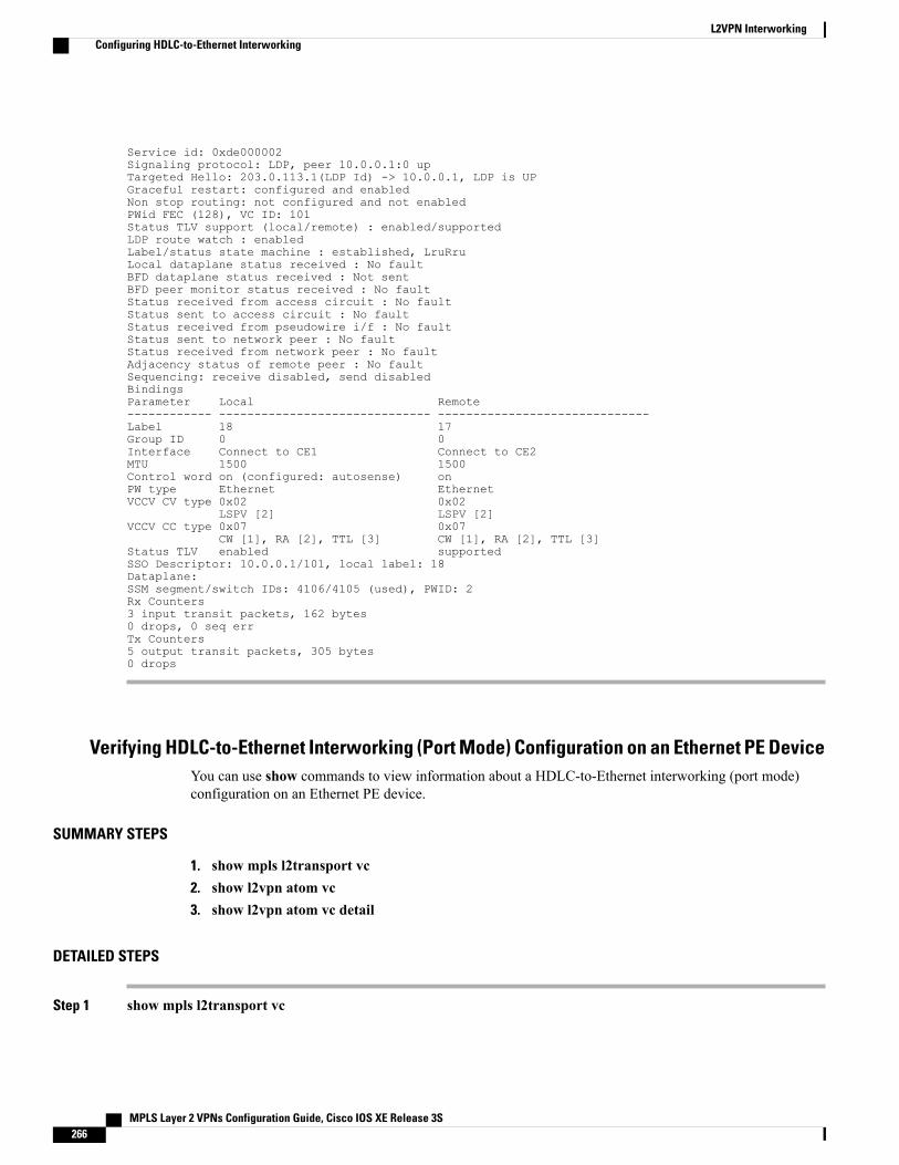
Service id: 0xde000002Signaling protocol: LDP, peer 10.0.0.1:0 upTargeted Hello: 203.0.113.1(LDP Id) -> 10.0.0.1, LDP is UPGraceful restart: configured and enabledNon stop routing: not configured and not enabledPWid FEC (128), VC ID: 101Status TLV support (local/remote) : enabled/supportedLDP route watch : enabledLabel/status state machine : established, LruRruLocal dataplane status received : No faultBFD dataplane status received : Not sentBFD peer monitor status received : No faultStatus received from access circuit : No faultStatus sent to access circuit : No faultStatus received from pseudowire i/f : No faultStatus sent to network peer : No faultStatus received from network peer : No faultAdjacency status of remote peer : No faultSequencing: receive disabled, send disabledBindingsParameter Local Remote------------ ------------------------------ ------------------------------Label 18 17Group ID 0 0Interface Connect to CE1 Connect to CE2MTU 1500 1500Control word on (configured: autosense) onPW type Ethernet EthernetVCCV CV type 0x02 0x02
LSPV [2] LSPV [2]VCCV CC type 0x07 0x07
CW [1], RA [2], TTL [3] CW [1], RA [2], TTL [3]Status TLV enabled supportedSSO Descriptor: 10.0.0.1/101, local label: 18Dataplane:SSM segment/switch IDs: 4106/4105 (used), PWID: 2Rx Counters3 input transit packets, 162 bytes0 drops, 0 seq errTx Counters5 output transit packets, 305 bytes0 drops
Verifying HDLC-to-Ethernet Interworking (Port Mode) Configuration on an Ethernet PE DeviceYou can use show commands to view information about a HDLC-to-Ethernet interworking (port mode)configuration on an Ethernet PE device.
SUMMARY STEPS
1. show mpls l2transport vc2. show l2vpn atom vc3. show l2vpn atom vc detail
DETAILED STEPS
Step 1 show mpls l2transport vc
MPLS Layer 2 VPNs Configuration Guide, Cisco IOS XE Release 3S266
L2VPN InterworkingConfiguring HDLC-to-Ethernet Interworking
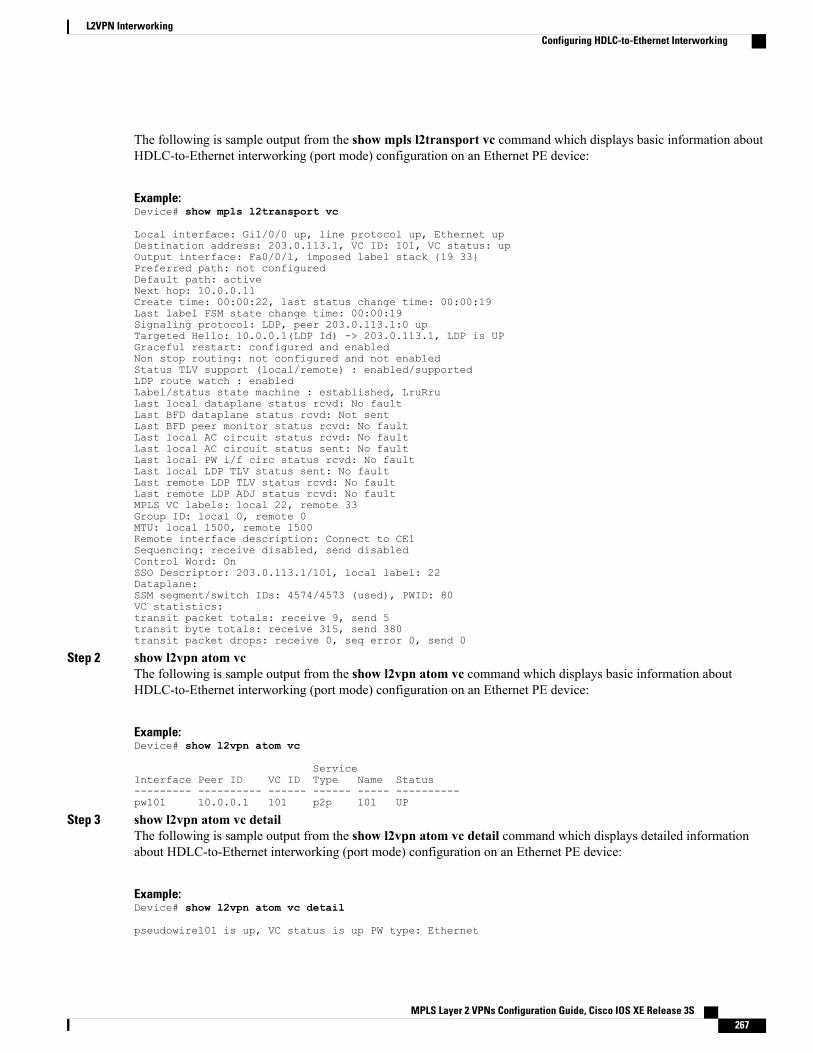
The following is sample output from the show mpls l2transport vc command which displays basic information aboutHDLC-to-Ethernet interworking (port mode) configuration on an Ethernet PE device:
Example:Device# show mpls l2transport vc
Local interface: Gi1/0/0 up, line protocol up, Ethernet upDestination address: 203.0.113.1, VC ID: 101, VC status: upOutput interface: Fa0/0/1, imposed label stack {19 33}Preferred path: not configuredDefault path: activeNext hop: 10.0.0.11Create time: 00:00:22, last status change time: 00:00:19Last label FSM state change time: 00:00:19Signaling protocol: LDP, peer 203.0.113.1:0 upTargeted Hello: 10.0.0.1(LDP Id) -> 203.0.113.1, LDP is UPGraceful restart: configured and enabledNon stop routing: not configured and not enabledStatus TLV support (local/remote) : enabled/supportedLDP route watch : enabledLabel/status state machine : established, LruRruLast local dataplane status rcvd: No faultLast BFD dataplane status rcvd: Not sentLast BFD peer monitor status rcvd: No faultLast local AC circuit status rcvd: No faultLast local AC circuit status sent: No faultLast local PW i/f circ status rcvd: No faultLast local LDP TLV status sent: No faultLast remote LDP TLV status rcvd: No faultLast remote LDP ADJ status rcvd: No faultMPLS VC labels: local 22, remote 33Group ID: local 0, remote 0MTU: local 1500, remote 1500Remote interface description: Connect to CE1Sequencing: receive disabled, send disabledControl Word: OnSSO Descriptor: 203.0.113.1/101, local label: 22Dataplane:SSM segment/switch IDs: 4574/4573 (used), PWID: 80VC statistics:transit packet totals: receive 9, send 5transit byte totals: receive 315, send 380transit packet drops: receive 0, seq error 0, send 0
Step 2 show l2vpn atom vcThe following is sample output from the show l2vpn atom vc command which displays basic information aboutHDLC-to-Ethernet interworking (port mode) configuration on an Ethernet PE device:
Example:Device# show l2vpn atom vc
ServiceInterface Peer ID VC ID Type Name Status--------- ---------- ------ ------ ----- ----------pw101 10.0.0.1 101 p2p 101 UP
Step 3 show l2vpn atom vc detailThe following is sample output from the show l2vpn atom vc detail command which displays detailed informationabout HDLC-to-Ethernet interworking (port mode) configuration on an Ethernet PE device:
Example:Device# show l2vpn atom vc detail
pseudowire101 is up, VC status is up PW type: Ethernet
MPLS Layer 2 VPNs Configuration Guide, Cisco IOS XE Release 3S 267
L2VPN InterworkingConfiguring HDLC-to-Ethernet Interworking
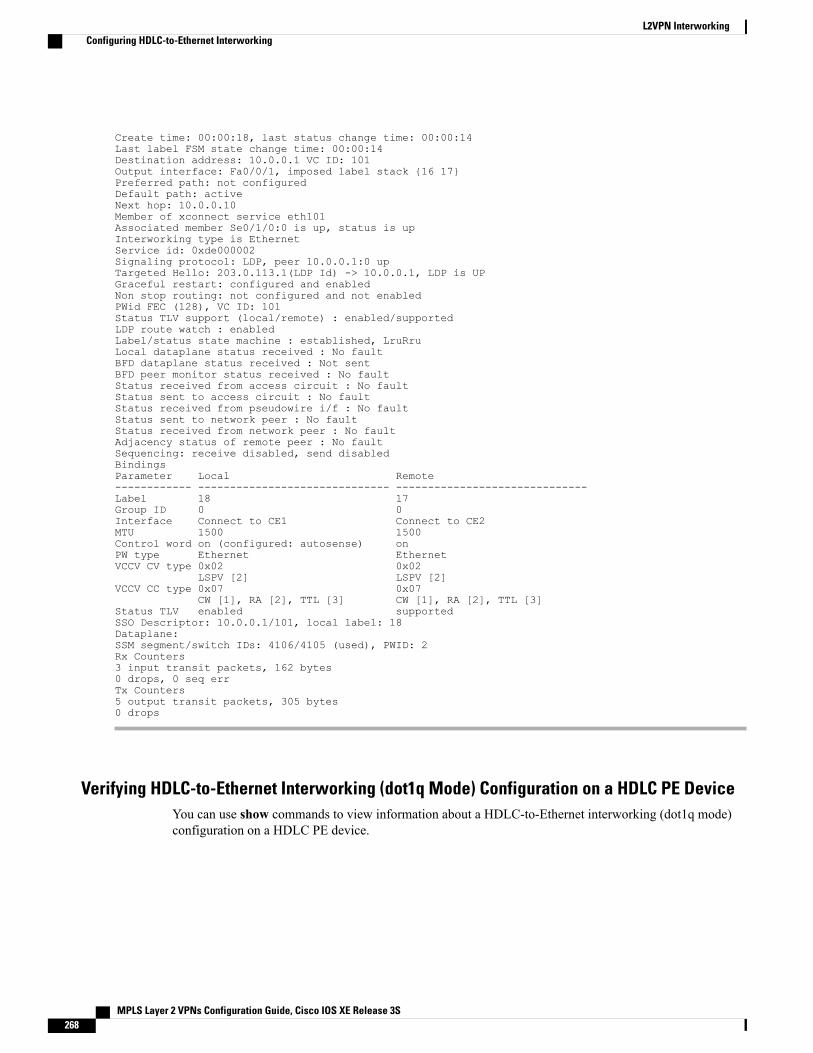
Create time: 00:00:18, last status change time: 00:00:14Last label FSM state change time: 00:00:14Destination address: 10.0.0.1 VC ID: 101Output interface: Fa0/0/1, imposed label stack {16 17}Preferred path: not configuredDefault path: activeNext hop: 10.0.0.10Member of xconnect service eth101Associated member Se0/1/0:0 is up, status is upInterworking type is EthernetService id: 0xde000002Signaling protocol: LDP, peer 10.0.0.1:0 upTargeted Hello: 203.0.113.1(LDP Id) -> 10.0.0.1, LDP is UPGraceful restart: configured and enabledNon stop routing: not configured and not enabledPWid FEC (128), VC ID: 101Status TLV support (local/remote) : enabled/supportedLDP route watch : enabledLabel/status state machine : established, LruRruLocal dataplane status received : No faultBFD dataplane status received : Not sentBFD peer monitor status received : No faultStatus received from access circuit : No faultStatus sent to access circuit : No faultStatus received from pseudowire i/f : No faultStatus sent to network peer : No faultStatus received from network peer : No faultAdjacency status of remote peer : No faultSequencing: receive disabled, send disabledBindingsParameter Local Remote------------ ------------------------------ ------------------------------Label 18 17Group ID 0 0Interface Connect to CE1 Connect to CE2MTU 1500 1500Control word on (configured: autosense) onPW type Ethernet EthernetVCCV CV type 0x02 0x02
LSPV [2] LSPV [2]VCCV CC type 0x07 0x07
CW [1], RA [2], TTL [3] CW [1], RA [2], TTL [3]Status TLV enabled supportedSSO Descriptor: 10.0.0.1/101, local label: 18Dataplane:SSM segment/switch IDs: 4106/4105 (used), PWID: 2Rx Counters3 input transit packets, 162 bytes0 drops, 0 seq errTx Counters5 output transit packets, 305 bytes0 drops
Verifying HDLC-to-Ethernet Interworking (dot1q Mode) Configuration on a HDLC PE DeviceYou can use show commands to view information about a HDLC-to-Ethernet interworking (dot1q mode)configuration on a HDLC PE device.
MPLS Layer 2 VPNs Configuration Guide, Cisco IOS XE Release 3S268
L2VPN InterworkingConfiguring HDLC-to-Ethernet Interworking
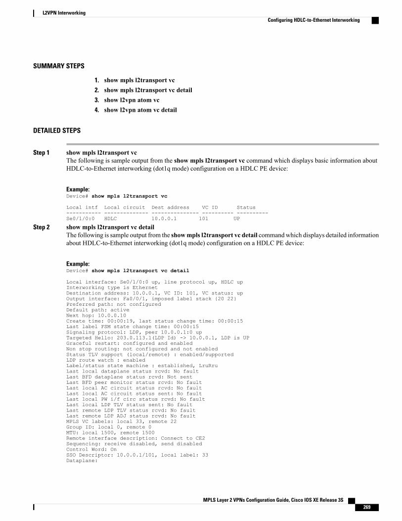
SUMMARY STEPS
1. show mpls l2transport vc2. show mpls l2transport vc detail3. show l2vpn atom vc4. show l2vpn atom vc detail
DETAILED STEPS
Step 1 show mpls l2transport vcThe following is sample output from the show mpls l2transport vc command which displays basic information aboutHDLC-to-Ethernet interworking (dot1q mode) configuration on a HDLC PE device:
Example:Device# show mpls l2transport vc
Local intf Local circuit Dest address VC ID Status----------- -------------- --------------- ---------- ----------Se0/1/0:0 HDLC 10.0.0.1 101 UP
Step 2 show mpls l2transport vc detailThe following is sample output from the showmpls l2transport vc detail commandwhich displays detailed informationabout HDLC-to-Ethernet interworking (dot1q mode) configuration on a HDLC PE device:
Example:Device# show mpls l2transport vc detail
Local interface: Se0/1/0:0 up, line protocol up, HDLC upInterworking type is EthernetDestination address: 10.0.0.1, VC ID: 101, VC status: upOutput interface: Fa0/0/1, imposed label stack {20 22}Preferred path: not configuredDefault path: activeNext hop: 10.0.0.10Create time: 00:00:19, last status change time: 00:00:15Last label FSM state change time: 00:00:15Signaling protocol: LDP, peer 10.0.0.1:0 upTargeted Hello: 203.0.113.1(LDP Id) -> 10.0.0.1, LDP is UPGraceful restart: configured and enabledNon stop routing: not configured and not enabledStatus TLV support (local/remote) : enabled/supportedLDP route watch : enabledLabel/status state machine : established, LruRruLast local dataplane status rcvd: No faultLast BFD dataplane status rcvd: Not sentLast BFD peer monitor status rcvd: No faultLast local AC circuit status rcvd: No faultLast local AC circuit status sent: No faultLast local PW i/f circ status rcvd: No faultLast local LDP TLV status sent: No faultLast remote LDP TLV status rcvd: No faultLast remote LDP ADJ status rcvd: No faultMPLS VC labels: local 33, remote 22Group ID: local 0, remote 0MTU: local 1500, remote 1500Remote interface description: Connect to CE2Sequencing: receive disabled, send disabledControl Word: OnSSO Descriptor: 10.0.0.1/101, local label: 33Dataplane:
MPLS Layer 2 VPNs Configuration Guide, Cisco IOS XE Release 3S 269
L2VPN InterworkingConfiguring HDLC-to-Ethernet Interworking

SSM segment/switch IDs: 4274/4273 (used), PWID: 26VC statistics:transit packet totals: receive 3, send 6transit byte totals: receive 162, send 366transit packet drops: receive 0, seq error 0, send 0
Step 3 show l2vpn atom vcThe following is sample output from the show l2vpn atom vc command which displays basic information aboutHDLC-to-Ethernet interworking (dot1q mode) configuration on a HDLC PE device:
Example:Device# show l2vpn atom vc
ServiceInterface Peer ID VC ID Type Name Status--------- ---------- ------ ------ ----- ----------pw101 10.0.0.1 101 p2p 101 UP
Step 4 show l2vpn atom vc detailThe following is sample output from the show l2vpn atom vc detail command which displays detailed informationabout HDLC-to-Ethernet interworking (dot1q mode) configuration on a HDLC PE device:
Example:Device# show l2vpn atom vc detail
pseudowire101 is up, VC status is up PW type: EthernetCreate time: 00:00:18, last status change time: 00:00:14Last label FSM state change time: 00:00:14Destination address: 10.0.0.1 VC ID: 101Output interface: Fa0/0/1, imposed label stack {16 17}Preferred path: not configuredDefault path: activeNext hop: 10.0.0.10Member of xconnect service hdlc101Associated member Se0/1/0:0 is up, status is upInterworking type is EthernetService id: 0xde000002Signaling protocol: LDP, peer 10.0.0.1:0 upTargeted Hello: 203.0.113.1(LDP Id) -> 10.0.0.1, LDP is UPGraceful restart: configured and enabledNon stop routing: not configured and not enabledPWid FEC (128), VC ID: 101Status TLV support (local/remote) : enabled/supportedLDP route watch : enabledLabel/status state machine : established, LruRruLocal dataplane status received : No faultBFD dataplane status received : Not sentBFD peer monitor status received : No faultStatus received from access circuit : No faultStatus sent to access circuit : No faultStatus received from pseudowire i/f : No faultStatus sent to network peer : No faultStatus received from network peer : No faultAdjacency status of remote peer : No faultSequencing: receive disabled, send disabledBindingsParameter Local Remote------------ ------------------------------ ------------------------------Label 18 17Group ID 0 0Interface Connect to CE1 Connect to CE2MTU 1500 1500Control word on (configured: autosense) onPW type Ethernet EthernetVCCV CV type 0x02 0x02
LSPV [2] LSPV [2]
MPLS Layer 2 VPNs Configuration Guide, Cisco IOS XE Release 3S270
L2VPN InterworkingConfiguring HDLC-to-Ethernet Interworking
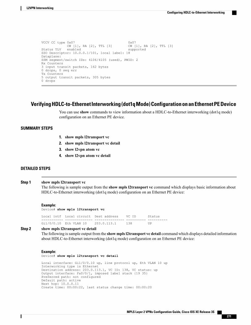
VCCV CC type 0x07 0x07CW [1], RA [2], TTL [3] CW [1], RA [2], TTL [3]
Status TLV enabled supportedSSO Descriptor: 10.0.0.1/101, local label: 18Dataplane:SSM segment/switch IDs: 4106/4105 (used), PWID: 2Rx Counters3 input transit packets, 162 bytes0 drops, 0 seq errTx Counters5 output transit packets, 305 bytes0 drops
Verifying HDLC-to-Ethernet Interworking (dot1q Mode) Configuration on an Ethernet PE DeviceYou can use show commands to view information about a HDLC-to-Ethernet interworking (dot1q mode)configuration on an Ethernet PE device.
SUMMARY STEPS
1. show mpls l2transport vc2. show mpls l2transport vc detail3. show l2vpn atom vc4. show l2vpn atom vc detail
DETAILED STEPS
Step 1 show mpls l2transport vcThe following is sample output from the show mpls l2transport vc command which displays basic information aboutHDLC-to-Ethernet interworking (dot1q mode) configuration on an Ethernet PE device:
Example:Device# show mpls l2transport vc
Local intf Local circuit Dest address VC ID Status----------- -------------- --------------- ---------- ----------Gi1/0/0.10 Eth VLAN 10 203.0.113.1 138 UP
Step 2 show mpls l2transport vc detailThe following is sample output from the showmpls l2transport vc detail commandwhich displays detailed informationabout HDLC-to-Ethernet interworking (dot1q mode) configuration on an Ethernet PE device:
Example:Device# show mpls l2transport vc detail
Local interface: Gi1/0/0.10 up, line protocol up, Eth VLAN 10 upInterworking type is EthernetDestination address: 203.0.113.1, VC ID: 138, VC status: upOutput interface: Fa0/0/1, imposed label stack {19 35}Preferred path: not configuredDefault path: activeNext hop: 10.0.0.11Create time: 00:00:22, last status change time: 00:00:20
MPLS Layer 2 VPNs Configuration Guide, Cisco IOS XE Release 3S 271
L2VPN InterworkingConfiguring HDLC-to-Ethernet Interworking
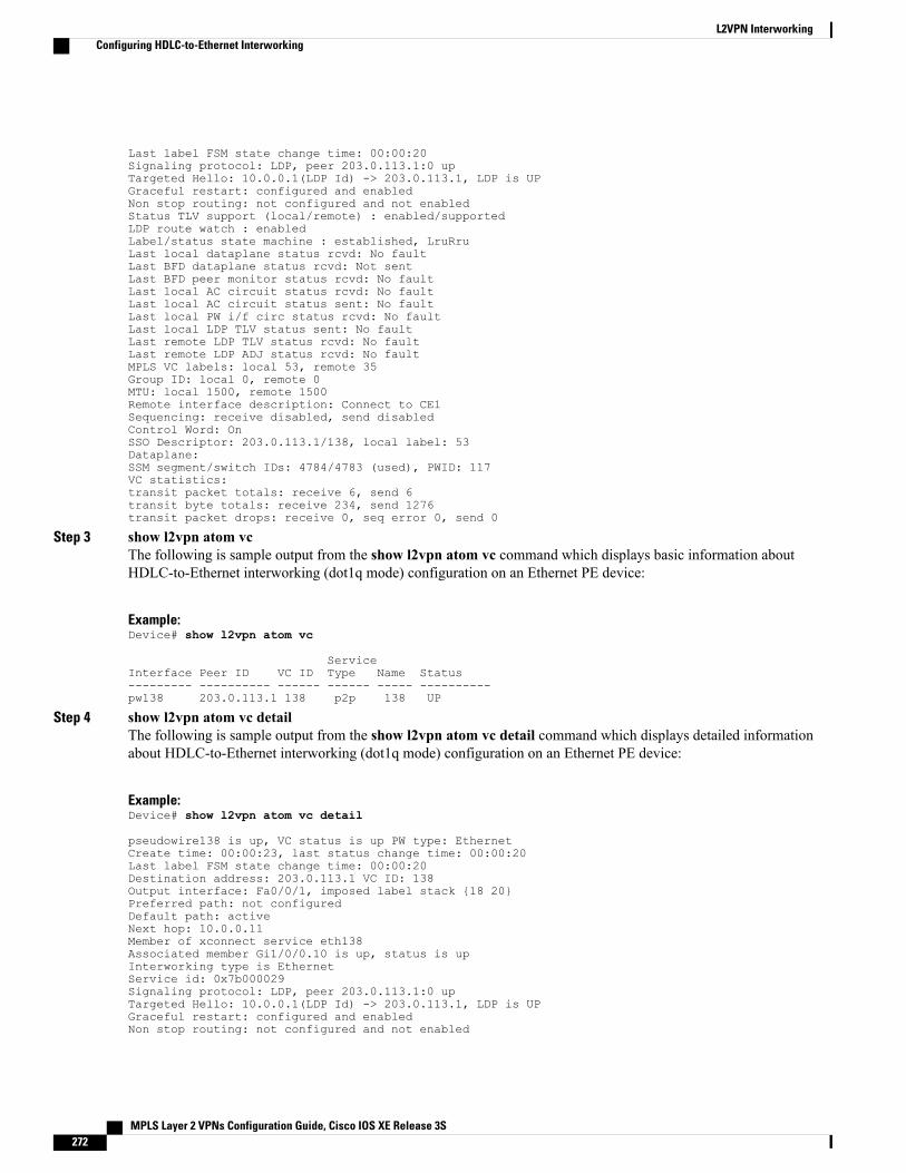
Last label FSM state change time: 00:00:20Signaling protocol: LDP, peer 203.0.113.1:0 upTargeted Hello: 10.0.0.1(LDP Id) -> 203.0.113.1, LDP is UPGraceful restart: configured and enabledNon stop routing: not configured and not enabledStatus TLV support (local/remote) : enabled/supportedLDP route watch : enabledLabel/status state machine : established, LruRruLast local dataplane status rcvd: No faultLast BFD dataplane status rcvd: Not sentLast BFD peer monitor status rcvd: No faultLast local AC circuit status rcvd: No faultLast local AC circuit status sent: No faultLast local PW i/f circ status rcvd: No faultLast local LDP TLV status sent: No faultLast remote LDP TLV status rcvd: No faultLast remote LDP ADJ status rcvd: No faultMPLS VC labels: local 53, remote 35Group ID: local 0, remote 0MTU: local 1500, remote 1500Remote interface description: Connect to CE1Sequencing: receive disabled, send disabledControl Word: OnSSO Descriptor: 203.0.113.1/138, local label: 53Dataplane:SSM segment/switch IDs: 4784/4783 (used), PWID: 117VC statistics:transit packet totals: receive 6, send 6transit byte totals: receive 234, send 1276transit packet drops: receive 0, seq error 0, send 0
Step 3 show l2vpn atom vcThe following is sample output from the show l2vpn atom vc command which displays basic information aboutHDLC-to-Ethernet interworking (dot1q mode) configuration on an Ethernet PE device:
Example:Device# show l2vpn atom vc
ServiceInterface Peer ID VC ID Type Name Status--------- ---------- ------ ------ ----- ----------pw138 203.0.113.1 138 p2p 138 UP
Step 4 show l2vpn atom vc detailThe following is sample output from the show l2vpn atom vc detail command which displays detailed informationabout HDLC-to-Ethernet interworking (dot1q mode) configuration on an Ethernet PE device:
Example:Device# show l2vpn atom vc detail
pseudowire138 is up, VC status is up PW type: EthernetCreate time: 00:00:23, last status change time: 00:00:20Last label FSM state change time: 00:00:20Destination address: 203.0.113.1 VC ID: 138Output interface: Fa0/0/1, imposed label stack {18 20}Preferred path: not configuredDefault path: activeNext hop: 10.0.0.11Member of xconnect service eth138Associated member Gi1/0/0.10 is up, status is upInterworking type is EthernetService id: 0x7b000029Signaling protocol: LDP, peer 203.0.113.1:0 upTargeted Hello: 10.0.0.1(LDP Id) -> 203.0.113.1, LDP is UPGraceful restart: configured and enabledNon stop routing: not configured and not enabled
MPLS Layer 2 VPNs Configuration Guide, Cisco IOS XE Release 3S272
L2VPN InterworkingConfiguring HDLC-to-Ethernet Interworking
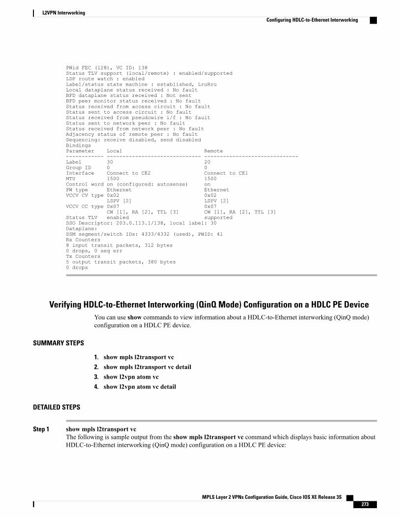
PWid FEC (128), VC ID: 138Status TLV support (local/remote) : enabled/supportedLDP route watch : enabledLabel/status state machine : established, LruRruLocal dataplane status received : No faultBFD dataplane status received : Not sentBFD peer monitor status received : No faultStatus received from access circuit : No faultStatus sent to access circuit : No faultStatus received from pseudowire i/f : No faultStatus sent to network peer : No faultStatus received from network peer : No faultAdjacency status of remote peer : No faultSequencing: receive disabled, send disabledBindingsParameter Local Remote------------ ------------------------------ ------------------------------Label 30 20Group ID 0 0Interface Connect to CE2 Connect to CE1MTU 1500 1500Control word on (configured: autosense) onPW type Ethernet EthernetVCCV CV type 0x02 0x02
LSPV [2] LSPV [2]VCCV CC type 0x07 0x07
CW [1], RA [2], TTL [3] CW [1], RA [2], TTL [3]Status TLV enabled supportedSSO Descriptor: 203.0.113.1/138, local label: 30Dataplane:SSM segment/switch IDs: 4333/4332 (used), PWID: 41Rx Counters8 input transit packets, 312 bytes0 drops, 0 seq errTx Counters5 output transit packets, 380 bytes0 drops
Verifying HDLC-to-Ethernet Interworking (QinQ Mode) Configuration on a HDLC PE DeviceYou can use show commands to view information about a HDLC-to-Ethernet interworking (QinQ mode)configuration on a HDLC PE device.
SUMMARY STEPS
1. show mpls l2transport vc2. show mpls l2transport vc detail3. show l2vpn atom vc4. show l2vpn atom vc detail
DETAILED STEPS
Step 1 show mpls l2transport vcThe following is sample output from the show mpls l2transport vc command which displays basic information aboutHDLC-to-Ethernet interworking (QinQ mode) configuration on a HDLC PE device:
MPLS Layer 2 VPNs Configuration Guide, Cisco IOS XE Release 3S 273
L2VPN InterworkingConfiguring HDLC-to-Ethernet Interworking
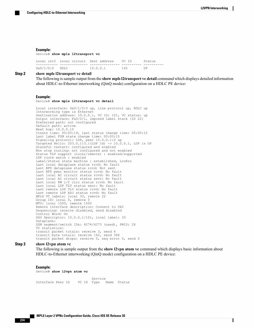
Example:Device# show mpls l2transport vc
Local intf Local circuit Dest address VC ID Status----------- -------------- --------------- ---------- ----------Se0/1/0:0 HDLC 10.0.0.1 145 UP
Step 2 show mpls l2transport vc detailThe following is sample output from the showmpls l2transport vc detail commandwhich displays detailed informationabout HDLC-to-Ethernet interworking (QinQ mode) configuration on a HDLC PE device:
Example:Device# show mpls l2transport vc detail
Local interface: Se0/1/0:0 up, line protocol up, HDLC upInterworking type is EthernetDestination address: 10.0.0.1, VC ID: 101, VC status: upOutput interface: Fa0/0/1, imposed label stack {20 22}Preferred path: not configuredDefault path: activeNext hop: 10.0.0.10Create time: 00:00:19, last status change time: 00:00:15Last label FSM state change time: 00:00:15Signaling protocol: LDP, peer 10.0.0.1:0 upTargeted Hello: 203.0.113.1(LDP Id) -> 10.0.0.1, LDP is UPGraceful restart: configured and enabledNon stop routing: not configured and not enabledStatus TLV support (local/remote) : enabled/supportedLDP route watch : enabledLabel/status state machine : established, LruRruLast local dataplane status rcvd: No faultLast BFD dataplane status rcvd: Not sentLast BFD peer monitor status rcvd: No faultLast local AC circuit status rcvd: No faultLast local AC circuit status sent: No faultLast local PW i/f circ status rcvd: No faultLast local LDP TLV status sent: No faultLast remote LDP TLV status rcvd: No faultLast remote LDP ADJ status rcvd: No faultMPLS VC labels: local 33, remote 22Group ID: local 0, remote 0MTU: local 1500, remote 1500Remote interface description: Connect to CE2Sequencing: receive disabled, send disabledControl Word: OnSSO Descriptor: 10.0.0.1/101, local label: 33Dataplane:SSM segment/switch IDs: 4274/4273 (used), PWID: 26VC statistics:transit packet totals: receive 3, send 6transit byte totals: receive 162, send 366transit packet drops: receive 0, seq error 0, send 0
Step 3 show l2vpn atom vcThe following is sample output from the show l2vpn atom vc command which displays basic information aboutHDLC-to-Ethernet interworking (QinQ mode) configuration on a HDLC PE device:
Example:Device# show l2vpn atom vc
ServiceInterface Peer ID VC ID Type Name Status
MPLS Layer 2 VPNs Configuration Guide, Cisco IOS XE Release 3S274
L2VPN InterworkingConfiguring HDLC-to-Ethernet Interworking
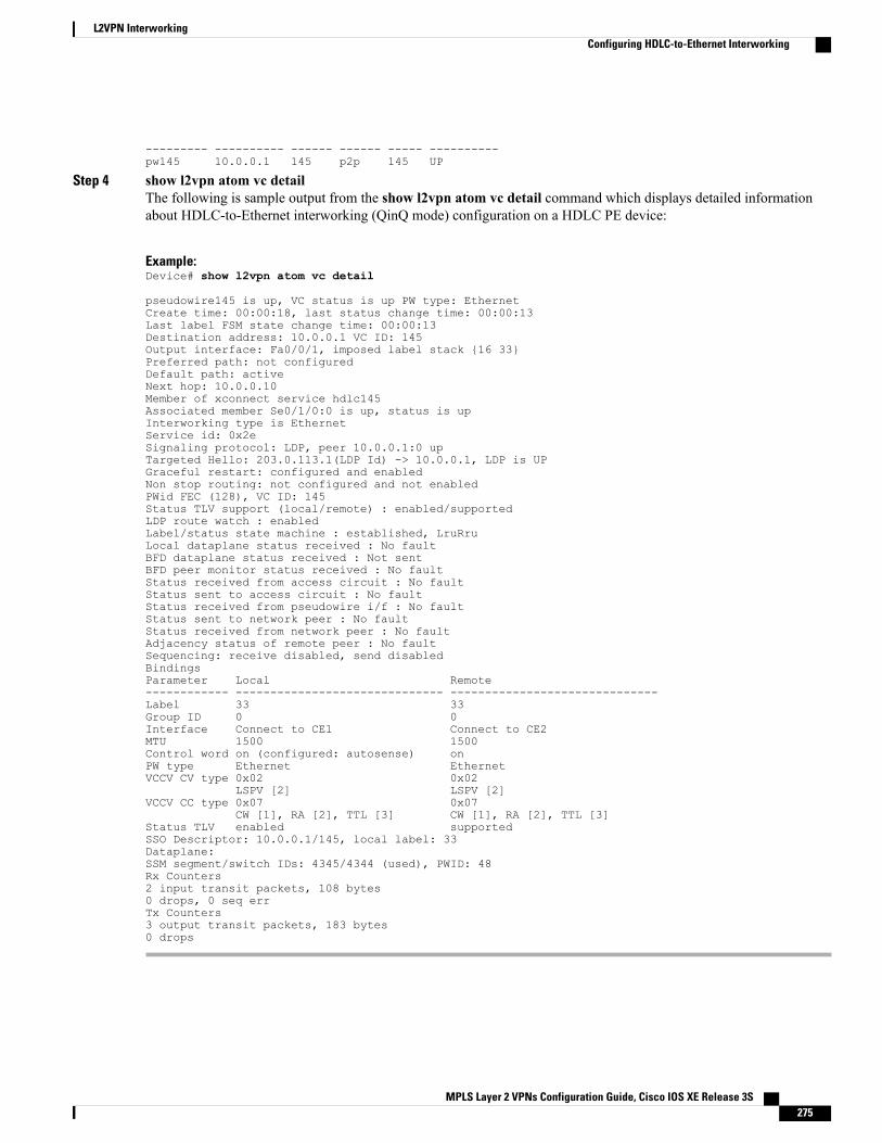
--------- ---------- ------ ------ ----- ----------pw145 10.0.0.1 145 p2p 145 UP
Step 4 show l2vpn atom vc detailThe following is sample output from the show l2vpn atom vc detail command which displays detailed informationabout HDLC-to-Ethernet interworking (QinQ mode) configuration on a HDLC PE device:
Example:Device# show l2vpn atom vc detail
pseudowire145 is up, VC status is up PW type: EthernetCreate time: 00:00:18, last status change time: 00:00:13Last label FSM state change time: 00:00:13Destination address: 10.0.0.1 VC ID: 145Output interface: Fa0/0/1, imposed label stack {16 33}Preferred path: not configuredDefault path: activeNext hop: 10.0.0.10Member of xconnect service hdlc145Associated member Se0/1/0:0 is up, status is upInterworking type is EthernetService id: 0x2eSignaling protocol: LDP, peer 10.0.0.1:0 upTargeted Hello: 203.0.113.1(LDP Id) -> 10.0.0.1, LDP is UPGraceful restart: configured and enabledNon stop routing: not configured and not enabledPWid FEC (128), VC ID: 145Status TLV support (local/remote) : enabled/supportedLDP route watch : enabledLabel/status state machine : established, LruRruLocal dataplane status received : No faultBFD dataplane status received : Not sentBFD peer monitor status received : No faultStatus received from access circuit : No faultStatus sent to access circuit : No faultStatus received from pseudowire i/f : No faultStatus sent to network peer : No faultStatus received from network peer : No faultAdjacency status of remote peer : No faultSequencing: receive disabled, send disabledBindingsParameter Local Remote------------ ------------------------------ ------------------------------Label 33 33Group ID 0 0Interface Connect to CE1 Connect to CE2MTU 1500 1500Control word on (configured: autosense) onPW type Ethernet EthernetVCCV CV type 0x02 0x02
LSPV [2] LSPV [2]VCCV CC type 0x07 0x07
CW [1], RA [2], TTL [3] CW [1], RA [2], TTL [3]Status TLV enabled supportedSSO Descriptor: 10.0.0.1/145, local label: 33Dataplane:SSM segment/switch IDs: 4345/4344 (used), PWID: 48Rx Counters2 input transit packets, 108 bytes0 drops, 0 seq errTx Counters3 output transit packets, 183 bytes0 drops
MPLS Layer 2 VPNs Configuration Guide, Cisco IOS XE Release 3S 275
L2VPN InterworkingConfiguring HDLC-to-Ethernet Interworking
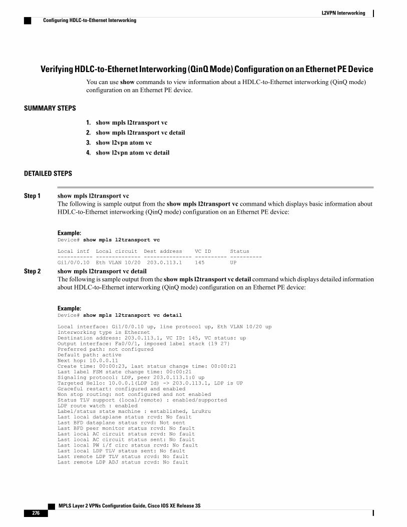
Verifying HDLC-to-Ethernet Interworking (QinQ Mode) Configuration on an Ethernet PE DeviceYou can use show commands to view information about a HDLC-to-Ethernet interworking (QinQ mode)configuration on an Ethernet PE device.
SUMMARY STEPS
1. show mpls l2transport vc2. show mpls l2transport vc detail3. show l2vpn atom vc4. show l2vpn atom vc detail
DETAILED STEPS
Step 1 show mpls l2transport vcThe following is sample output from the show mpls l2transport vc command which displays basic information aboutHDLC-to-Ethernet interworking (QinQ mode) configuration on an Ethernet PE device:
Example:Device# show mpls l2transport vc
Local intf Local circuit Dest address VC ID Status----------- -------------- --------------- ---------- ----------Gi1/0/0.10 Eth VLAN 10/20 203.0.113.1 145 UP
Step 2 show mpls l2transport vc detailThe following is sample output from the showmpls l2transport vc detail commandwhich displays detailed informationabout HDLC-to-Ethernet interworking (QinQ mode) configuration on an Ethernet PE device:
Example:Device# show mpls l2transport vc detail
Local interface: Gi1/0/0.10 up, line protocol up, Eth VLAN 10/20 upInterworking type is EthernetDestination address: 203.0.113.1, VC ID: 145, VC status: upOutput interface: Fa0/0/1, imposed label stack {19 27}Preferred path: not configuredDefault path: activeNext hop: 10.0.0.11Create time: 00:00:23, last status change time: 00:00:21Last label FSM state change time: 00:00:21Signaling protocol: LDP, peer 203.0.113.1:0 upTargeted Hello: 10.0.0.1(LDP Id) -> 203.0.113.1, LDP is UPGraceful restart: configured and enabledNon stop routing: not configured and not enabledStatus TLV support (local/remote) : enabled/supportedLDP route watch : enabledLabel/status state machine : established, LruRruLast local dataplane status rcvd: No faultLast BFD dataplane status rcvd: Not sentLast BFD peer monitor status rcvd: No faultLast local AC circuit status rcvd: No faultLast local AC circuit status sent: No faultLast local PW i/f circ status rcvd: No faultLast local LDP TLV status sent: No faultLast remote LDP TLV status rcvd: No faultLast remote LDP ADJ status rcvd: No fault
MPLS Layer 2 VPNs Configuration Guide, Cisco IOS XE Release 3S276
L2VPN InterworkingConfiguring HDLC-to-Ethernet Interworking
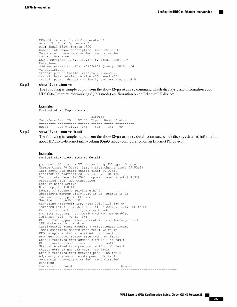
MPLS VC labels: local 25, remote 27Group ID: local 0, remote 0MTU: local 1500, remote 1500Remote interface description: Connect to CE1Sequencing: receive disabled, send disabledControl Word: OnSSO Descriptor: 203.0.113.1/145, local label: 25Dataplane:SSM segment/switch IDs: 4815/4814 (used), PWID: 124VC statistics:transit packet totals: receive 10, send 6transit byte totals: receive 430, send 456transit packet drops: receive 0, seq error 0, send 0
Step 3 show l2vpn atom vcThe following is sample output from the show l2vpn atom vc command which displays basic information aboutHDLC-to-Ethernet interworking (QinQ mode) configuration on an Ethernet PE device:
Example:Device# show l2vpn atom vc
ServiceInterface Peer ID VC ID Type Name Status--------- ---------- ------ ------ ----- ----------pw145 203.0.113.1 145 p2p 145 UP
Step 4 show l2vpn atom vc detailThe following is sample output from the show l2vpn atom vc detail command which displays detailed informationabout HDLC-to-Ethernet interworking (QinQ mode) configuration on an Ethernet PE device:
Example:Device# show l2vpn atom vc detail
pseudowire145 is up, VC status is up PW type: EthernetCreate time: 00:00:23, last status change time: 00:00:19Last label FSM state change time: 00:00:19Destination address: 203.0.113.1 VC ID: 145Output interface: Fa0/0/1, imposed label stack {18 33}Preferred path: not configuredDefault path: activeNext hop: 10.0.0.11Member of xconnect service eth145Associated member Gi1/0/0.10 is up, status is upInterworking type is EthernetService id: 0xed000030Signaling protocol: LDP, peer 203.0.113.1:0 upTargeted Hello: 10.0.0.1(LDP Id) -> 203.0.113.1, LDP is UPGraceful restart: configured and enabledNon stop routing: not configured and not enabledPWid FEC (128), VC ID: 145Status TLV support (local/remote) : enabled/supportedLDP route watch : enabledLabel/status state machine : established, LruRruLocal dataplane status received : No faultBFD dataplane status received : Not sentBFD peer monitor status received : No faultStatus received from access circuit : No faultStatus sent to access circuit : No faultStatus received from pseudowire i/f : No faultStatus sent to network peer : No faultStatus received from network peer : No faultAdjacency status of remote peer : No faultSequencing: receive disabled, send disabledBindingsParameter Local Remote------------ ------------------------------ ------------------------------
MPLS Layer 2 VPNs Configuration Guide, Cisco IOS XE Release 3S 277
L2VPN InterworkingConfiguring HDLC-to-Ethernet Interworking
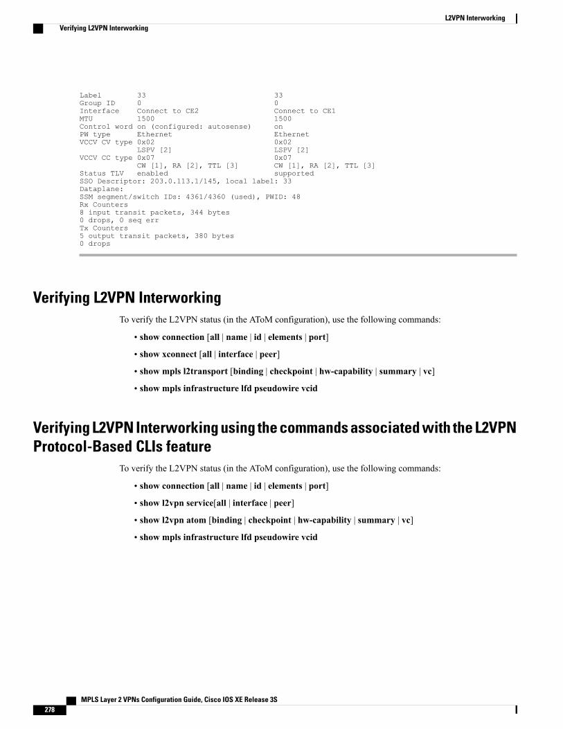
Label 33 33Group ID 0 0Interface Connect to CE2 Connect to CE1MTU 1500 1500Control word on (configured: autosense) onPW type Ethernet EthernetVCCV CV type 0x02 0x02
LSPV [2] LSPV [2]VCCV CC type 0x07 0x07
CW [1], RA [2], TTL [3] CW [1], RA [2], TTL [3]Status TLV enabled supportedSSO Descriptor: 203.0.113.1/145, local label: 33Dataplane:SSM segment/switch IDs: 4361/4360 (used), PWID: 48Rx Counters8 input transit packets, 344 bytes0 drops, 0 seq errTx Counters5 output transit packets, 380 bytes0 drops
Verifying L2VPN InterworkingTo verify the L2VPN status (in the AToM configuration), use the following commands:
• show connection [all | name | id | elements | port]
• show xconnect [all | interface | peer]
• show mpls l2transport [binding | checkpoint | hw-capability | summary | vc]
• show mpls infrastructure lfd pseudowire vcid
Verifying L2VPN Interworking using the commands associated with the L2VPNProtocol-Based CLIs feature
To verify the L2VPN status (in the AToM configuration), use the following commands:
• show connection [all | name | id | elements | port]
• show l2vpn service[all | interface | peer]
• show l2vpn atom [binding | checkpoint | hw-capability | summary | vc]
• show mpls infrastructure lfd pseudowire vcid
MPLS Layer 2 VPNs Configuration Guide, Cisco IOS XE Release 3S278
L2VPN InterworkingVerifying L2VPN Interworking
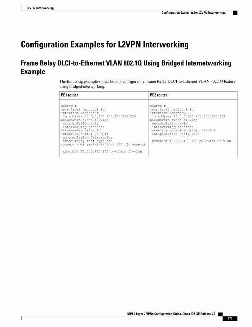
Configuration Examples for L2VPN Interworking
Frame Relay DLCI-to-Ethernet VLAN 802.1Q Using Bridged InternetworkingExample
The following example shows how to configure the Frame Relay DLCI-to-Ethernet VLAN 802.1Q featureusing bridged interworking:
PE2 routerPE1 router
config tmpls label protocol ldpinterface Loopback200ip address 10.0.0.200 255.255.255.255pseudowire-class fr-vlanencapsulation mplsinterworking ethernetinterface gigabitethernet 5/1/0.3encapsulation dot1q 1525
xconnect 10.0.0.100 150 pw-class fr-vlan
config tmpls label protocol ldpinterface Loopback100ip address 10.0.0.100 255.255.255.255pseudowire-class fr-vlanencapsulation mplsinterworking ethernetframe-relay switchinginterface serial 2/0/0:1encapsulation frame-relayframe-relay intf-type dceconnect mpls serial 2/0/0:1 567 l2transport
xconnect 10.0.0.200 150 pw-class fr-vlan
MPLS Layer 2 VPNs Configuration Guide, Cisco IOS XE Release 3S 279
L2VPN InterworkingConfiguration Examples for L2VPN Interworking
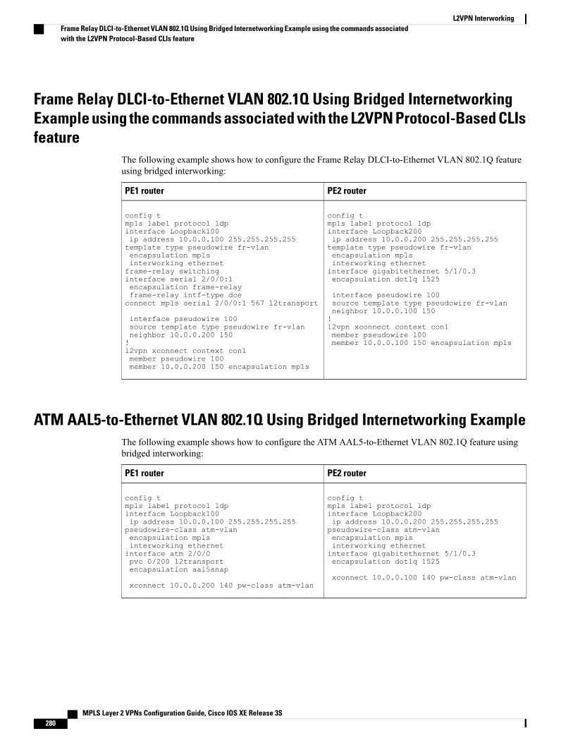
Frame Relay DLCI-to-Ethernet VLAN 802.1Q Using Bridged InternetworkingExample using the commands associated with the L2VPN Protocol-Based CLIsfeature
The following example shows how to configure the Frame Relay DLCI-to-Ethernet VLAN 802.1Q featureusing bridged interworking:
PE2 routerPE1 router
config tmpls label protocol ldpinterface Loopback200ip address 10.0.0.200 255.255.255.255template type pseudowire fr-vlanencapsulation mplsinterworking ethernetinterface gigabitethernet 5/1/0.3encapsulation dot1q 1525
interface pseudowire 100source template type pseudowire fr-vlanneighbor 10.0.0.100 150!l2vpn xconnect context con1member pseudowire 100member 10.0.0.100 150 encapsulation mpls
config tmpls label protocol ldpinterface Loopback100ip address 10.0.0.100 255.255.255.255template type pseudowire fr-vlanencapsulation mplsinterworking ethernetframe-relay switchinginterface serial 2/0/0:1encapsulation frame-relayframe-relay intf-type dceconnect mpls serial 2/0/0:1 567 l2transport
interface pseudowire 100source template type pseudowire fr-vlanneighbor 10.0.0.200 150!l2vpn xconnect context con1member pseudowire 100member 10.0.0.200 150 encapsulation mpls
ATM AAL5-to-Ethernet VLAN 802.1Q Using Bridged Internetworking ExampleThe following example shows how to configure the ATM AAL5-to-Ethernet VLAN 802.1Q feature usingbridged interworking:
PE2 routerPE1 router
config tmpls label protocol ldpinterface Loopback200ip address 10.0.0.200 255.255.255.255pseudowire-class atm-vlanencapsulation mplsinterworking ethernetinterface gigabitethernet 5/1/0.3encapsulation dot1q 1525
xconnect 10.0.0.100 140 pw-class atm-vlan
config tmpls label protocol ldpinterface Loopback100ip address 10.0.0.100 255.255.255.255pseudowire-class atm-vlanencapsulation mplsinterworking ethernetinterface atm 2/0/0pvc 0/200 l2transportencapsulation aal5snap
xconnect 10.0.0.200 140 pw-class atm-vlan
MPLS Layer 2 VPNs Configuration Guide, Cisco IOS XE Release 3S280
L2VPN InterworkingFrame Relay DLCI-to-Ethernet VLAN 802.1Q Using Bridged Internetworking Example using the commands associatedwith the L2VPN Protocol-Based CLIs feature
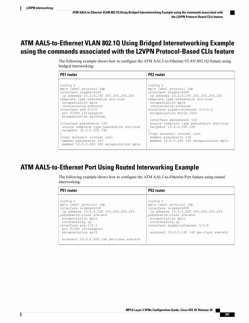
ATM AAL5-to-Ethernet VLAN 802.1Q Using Bridged Internetworking Exampleusing the commands associated with the L2VPN Protocol-Based CLIs feature
The following example shows how to configure the ATM AAL5-to-Ethernet VLAN 802.1Q feature usingbridged interworking:
PE2 routerPE1 router
config tmpls label protocol ldpinterface Loopback200ip address 10.0.0.200 255.255.255.255template type pseudowire atm-vlanencapsulation mplsinterworking ethernetinterface gigabitethernet 5/1/0.3encapsulation dot1q 1525
interface pseudowire 100source template type pseudowire atm-vlanneighbor 10.0.0.100 140!l2vpn xconnect context con1member pseudowire 100member 10.0.0.200 140 encapsulation mpls
config tmpls label protocol ldpinterface Loopback100ip address 10.0.0.100 255.255.255.255template type pseudowire atm-vlanencapsulation mplsinterworking ethernetinterface atm 2/0/0pvc 0/200 l2transportencapsulation aal5snap
interface pseudowire 100source template type pseudowire atm-vlanneighbor 10.0.0.200 140!l2vpn xconnect context con1member pseudowire 100member 10.0.0.200 140 encapsulation mpls
ATM AAL5-to-Ethernet Port Using Routed Interworking ExampleThe following example shows how to configure the ATM AAL5-to-Ethernet Port feature using routedinterworking:
PE2 routerPE1 router
config tmpls label protocol ldpinterface Loopback200ip address 10.0.0.200 255.255.255.255pseudowire-class atm-ethencapsulation mplsinterworking ipinterface gigabitethernet 5/1/0
xconnect 10.0.0.100 140 pw-class atm-eth
config tmpls label protocol ldpinterface Loopback100ip address 10.0.0.100 255.255.255.255pseudowire-class atm-ethencapsulation mplsinterworking ipinterface atm 2/0.1pvc 0/200 l2transportencapsulation aal5
xconnect 10.0.0.200 140 pw-class atm-eth
MPLS Layer 2 VPNs Configuration Guide, Cisco IOS XE Release 3S 281
L2VPN InterworkingATM AAL5-to-Ethernet VLAN 802.1Q Using Bridged Internetworking Example using the commands associated with
the L2VPN Protocol-Based CLIs feature
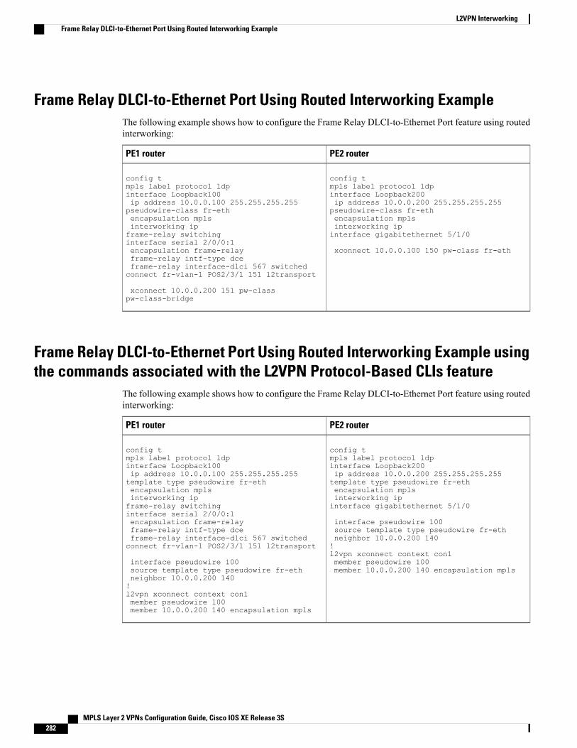
Frame Relay DLCI-to-Ethernet Port Using Routed Interworking ExampleThe following example shows how to configure the Frame Relay DLCI-to-Ethernet Port feature using routedinterworking:
PE2 routerPE1 router
config tmpls label protocol ldpinterface Loopback200ip address 10.0.0.200 255.255.255.255pseudowire-class fr-ethencapsulation mplsinterworking ipinterface gigabitethernet 5/1/0
xconnect 10.0.0.100 150 pw-class fr-eth
config tmpls label protocol ldpinterface Loopback100ip address 10.0.0.100 255.255.255.255pseudowire-class fr-ethencapsulation mplsinterworking ipframe-relay switchinginterface serial 2/0/0:1encapsulation frame-relayframe-relay intf-type dceframe-relay interface-dlci 567 switchedconnect fr-vlan-1 POS2/3/1 151 l2transport
xconnect 10.0.0.200 151 pw-classpw-class-bridge
Frame Relay DLCI-to-Ethernet Port Using Routed Interworking Example usingthe commands associated with the L2VPN Protocol-Based CLIs feature
The following example shows how to configure the Frame Relay DLCI-to-Ethernet Port feature using routedinterworking:
PE2 routerPE1 router
config tmpls label protocol ldpinterface Loopback200ip address 10.0.0.200 255.255.255.255template type pseudowire fr-ethencapsulation mplsinterworking ipinterface gigabitethernet 5/1/0
interface pseudowire 100source template type pseudowire fr-ethneighbor 10.0.0.200 140!l2vpn xconnect context con1member pseudowire 100member 10.0.0.200 140 encapsulation mpls
config tmpls label protocol ldpinterface Loopback100ip address 10.0.0.100 255.255.255.255template type pseudowire fr-ethencapsulation mplsinterworking ipframe-relay switchinginterface serial 2/0/0:1encapsulation frame-relayframe-relay intf-type dceframe-relay interface-dlci 567 switchedconnect fr-vlan-1 POS2/3/1 151 l2transport
interface pseudowire 100source template type pseudowire fr-ethneighbor 10.0.0.200 140!l2vpn xconnect context con1member pseudowire 100member 10.0.0.200 140 encapsulation mpls
MPLS Layer 2 VPNs Configuration Guide, Cisco IOS XE Release 3S282
L2VPN InterworkingFrame Relay DLCI-to-Ethernet Port Using Routed Interworking Example

Ethernet-to-VLAN over AToM--Bridged ExampleThe following example shows how to configure Ethernet-to-VLAN over AToM in a PE router:
PE2 routerPE1 router
ip cef
!
mpls label protocol ldp
mpls ldp router-id Loopback0 force
!
pseudowire-class atom-eth-iw
encapsulation mpls
interworking ethernet
!
interface Loopback0
ip address 10.8.8.8 255.255.255.255
!
interface FastEthernet1/0.1
encapsulation dot1q 100
xconnect 10.9.9.9 123 pw-class atom-eth-iw
ip cef
!
mpls label protocol ldp
mpls ldp router-id Loopback0 force
!
pseudowire-class atom
encapsulation mpls
!
interface Loopback0
ip address 10.9.9.9 255.255.255.255
!
interface FastEthernet0/0
no ip address
!
interface FastEthernet1/0
xconnect 10.8.8.8 123 pw-class atom
MPLS Layer 2 VPNs Configuration Guide, Cisco IOS XE Release 3S 283
L2VPN InterworkingEthernet-to-VLAN over AToM--Bridged Example
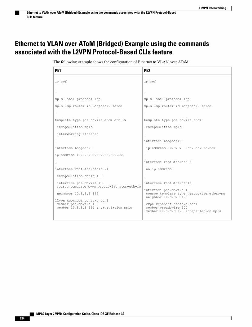
Ethernet to VLAN over AToM (Bridged) Example using the commandsassociated with the L2VPN Protocol-Based CLIs feature
The following example shows the configuration of Ethernet to VLAN over AToM:
PE2PE1
ip cef
!
mpls label protocol ldp
mpls ldp router-id Loopback0 force
!
template type pseudowire atom
encapsulation mpls
!
interface Loopback0
ip address 10.9.9.9 255.255.255.255
!
interface FastEthernet0/0
no ip address
!
interface FastEthernet1/0
interface pseudowire 100source template type pseudowire ether-pwneighbor 10.9.9.9 123!l2vpn xconnect context con1member pseudowire 100member 10.9.9.9 123 encapsulation mpls
ip cef
!
mpls label protocol ldp
mpls ldp router-id Loopback0 force
!
template type pseudowire atom-eth-iw
encapsulation mpls
interworking ethernet
!
interface Loopback0
ip address 10.8.8.8 255.255.255.255
!
interface FastEthernet1/0.1
encapsulation dot1q 100
interface pseudowire 100source template type pseudowire atom-eth-iw
neighbor 10.8.8.8 123!l2vpn xconnect context con1member pseudowire 100member 10.8.8.8 123 encapsulation mpls
MPLS Layer 2 VPNs Configuration Guide, Cisco IOS XE Release 3S284
L2VPN InterworkingEthernet to VLAN over AToM (Bridged) Example using the commands associated with the L2VPN Protocol-BasedCLIs feature
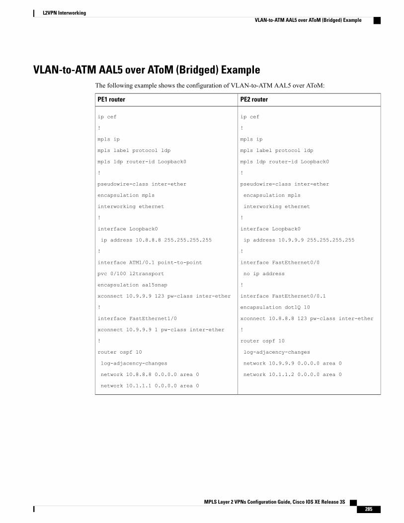
VLAN-to-ATM AAL5 over AToM (Bridged) ExampleThe following example shows the configuration of VLAN-to-ATM AAL5 over AToM:
PE2 routerPE1 router
ip cef
!
mpls ip
mpls label protocol ldp
mpls ldp router-id Loopback0
!
pseudowire-class inter-ether
encapsulation mpls
interworking ethernet
!
interface Loopback0
ip address 10.9.9.9 255.255.255.255
!
interface FastEthernet0/0
no ip address
!
interface FastEthernet0/0.1
encapsulation dot1Q 10
xconnect 10.8.8.8 123 pw-class inter-ether
!
router ospf 10
log-adjacency-changes
network 10.9.9.9 0.0.0.0 area 0
network 10.1.1.2 0.0.0.0 area 0
ip cef
!
mpls ip
mpls label protocol ldp
mpls ldp router-id Loopback0
!
pseudowire-class inter-ether
encapsulation mpls
interworking ethernet
!
interface Loopback0
ip address 10.8.8.8 255.255.255.255
!
interface ATM1/0.1 point-to-point
pvc 0/100 l2transport
encapsulation aal5snap
xconnect 10.9.9.9 123 pw-class inter-ether
!
interface FastEthernet1/0
xconnect 10.9.9.9 1 pw-class inter-ether
!
router ospf 10
log-adjacency-changes
network 10.8.8.8 0.0.0.0 area 0
network 10.1.1.1 0.0.0.0 area 0
MPLS Layer 2 VPNs Configuration Guide, Cisco IOS XE Release 3S 285
L2VPN InterworkingVLAN-to-ATM AAL5 over AToM (Bridged) Example
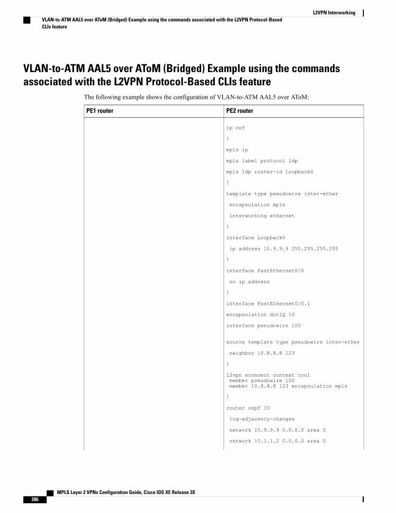
VLAN-to-ATM AAL5 over AToM (Bridged) Example using the commandsassociated with the L2VPN Protocol-Based CLIs feature
The following example shows the configuration of VLAN-to-ATM AAL5 over AToM:
PE2 routerPE1 router
ip cef
!
mpls ip
mpls label protocol ldp
mpls ldp router-id Loopback0
!
template type pseudowire inter-ether
encapsulation mpls
interworking ethernet
!
interface Loopback0
ip address 10.9.9.9 255.255.255.255
!
interface FastEthernet0/0
no ip address
!
interface FastEthernet0/0.1
encapsulation dot1Q 10
interface pseudowire 100
source template type pseudowire inter-ether
neighbor 10.8.8.8 123
!
l2vpn xconnect context con1member pseudowire 100member 10.8.8.8 123 encapsulation mpls
!
router ospf 10
log-adjacency-changes
network 10.9.9.9 0.0.0.0 area 0
network 10.1.1.2 0.0.0.0 area 0
MPLS Layer 2 VPNs Configuration Guide, Cisco IOS XE Release 3S286
L2VPN InterworkingVLAN-to-ATM AAL5 over AToM (Bridged) Example using the commands associated with the L2VPN Protocol-BasedCLIs feature
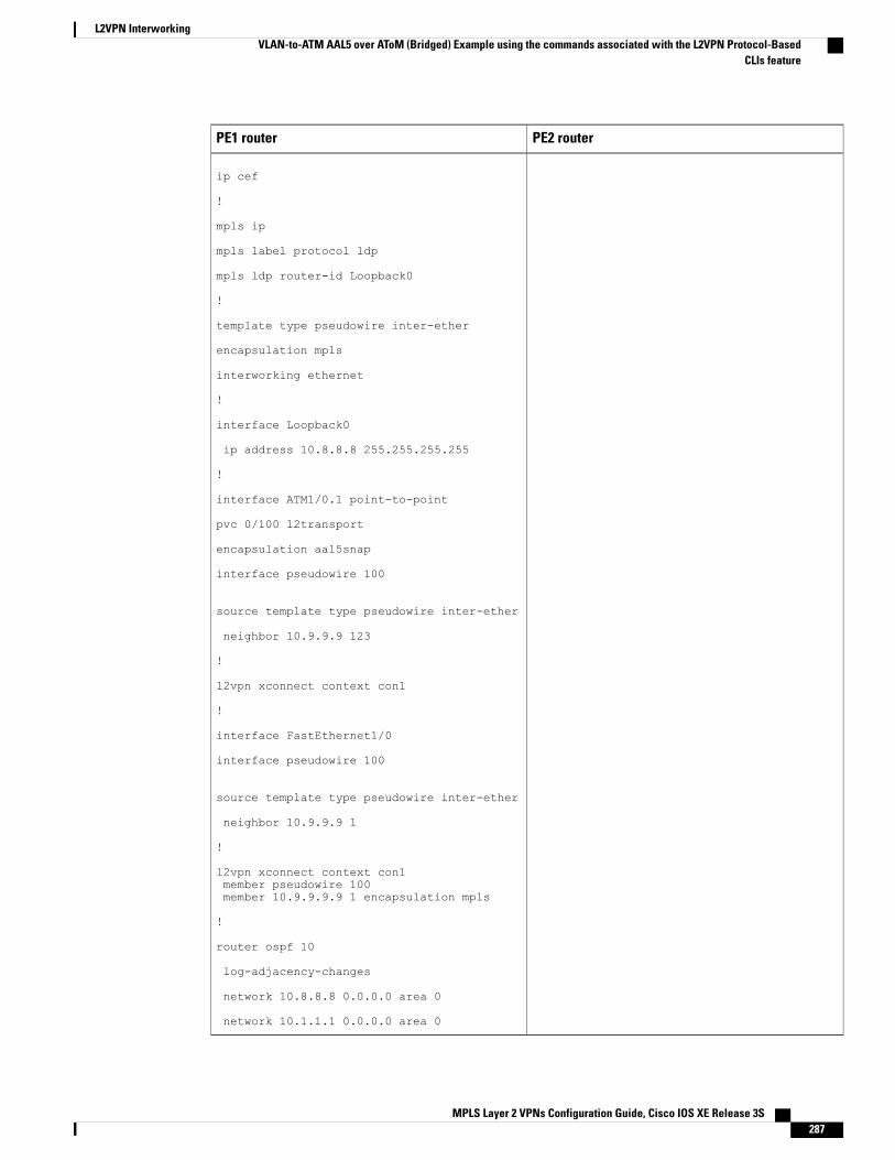
PE2 routerPE1 router
ip cef
!
mpls ip
mpls label protocol ldp
mpls ldp router-id Loopback0
!
template type pseudowire inter-ether
encapsulation mpls
interworking ethernet
!
interface Loopback0
ip address 10.8.8.8 255.255.255.255
!
interface ATM1/0.1 point-to-point
pvc 0/100 l2transport
encapsulation aal5snap
interface pseudowire 100
source template type pseudowire inter-ether
neighbor 10.9.9.9 123
!
l2vpn xconnect context con1
!
interface FastEthernet1/0
interface pseudowire 100
source template type pseudowire inter-ether
neighbor 10.9.9.9 1
!
l2vpn xconnect context con1member pseudowire 100member 10.9.9.9.9 1 encapsulation mpls
!
router ospf 10
log-adjacency-changes
network 10.8.8.8 0.0.0.0 area 0
network 10.1.1.1 0.0.0.0 area 0
MPLS Layer 2 VPNs Configuration Guide, Cisco IOS XE Release 3S 287
L2VPN InterworkingVLAN-to-ATM AAL5 over AToM (Bridged) Example using the commands associated with the L2VPN Protocol-Based
CLIs feature
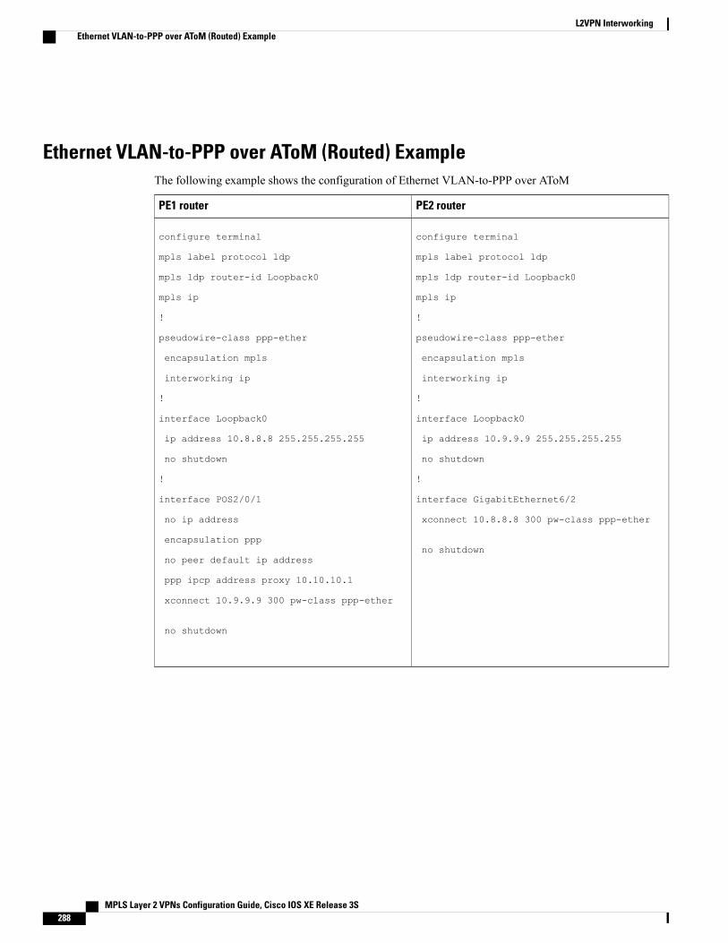
Ethernet VLAN-to-PPP over AToM (Routed) ExampleThe following example shows the configuration of Ethernet VLAN-to-PPP over AToM
PE2 routerPE1 router
configure terminal
mpls label protocol ldp
mpls ldp router-id Loopback0
mpls ip
!
pseudowire-class ppp-ether
encapsulation mpls
interworking ip
!
interface Loopback0
ip address 10.9.9.9 255.255.255.255
no shutdown
!
interface GigabitEthernet6/2
xconnect 10.8.8.8 300 pw-class ppp-ether
no shutdown
configure terminal
mpls label protocol ldp
mpls ldp router-id Loopback0
mpls ip
!
pseudowire-class ppp-ether
encapsulation mpls
interworking ip
!
interface Loopback0
ip address 10.8.8.8 255.255.255.255
no shutdown
!
interface POS2/0/1
no ip address
encapsulation ppp
no peer default ip address
ppp ipcp address proxy 10.10.10.1
xconnect 10.9.9.9 300 pw-class ppp-ether
no shutdown
MPLS Layer 2 VPNs Configuration Guide, Cisco IOS XE Release 3S288
L2VPN InterworkingEthernet VLAN-to-PPP over AToM (Routed) Example
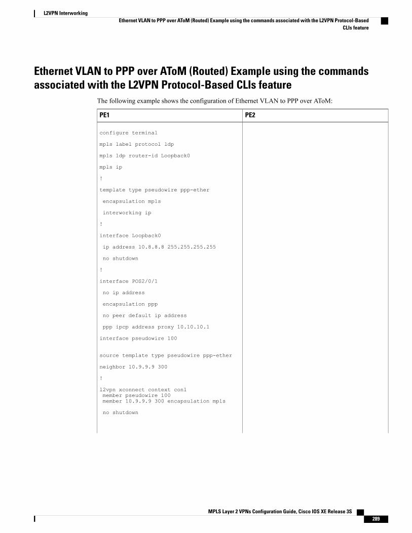
Ethernet VLAN to PPP over AToM (Routed) Example using the commandsassociated with the L2VPN Protocol-Based CLIs feature
The following example shows the configuration of Ethernet VLAN to PPP over AToM:
PE2PE1
configure terminal
mpls label protocol ldp
mpls ldp router-id Loopback0
mpls ip
!
template type pseudowire ppp-ether
encapsulation mpls
interworking ip
!
interface Loopback0
ip address 10.8.8.8 255.255.255.255
no shutdown
!
interface POS2/0/1
no ip address
encapsulation ppp
no peer default ip address
ppp ipcp address proxy 10.10.10.1
interface pseudowire 100
source template type pseudowire ppp-ether
neighbor 10.9.9.9 300
!
l2vpn xconnect context con1member pseudowire 100member 10.9.9.9 300 encapsulation mpls
no shutdown
MPLS Layer 2 VPNs Configuration Guide, Cisco IOS XE Release 3S 289
L2VPN InterworkingEthernet VLAN to PPP over AToM (Routed) Example using the commands associated with the L2VPN Protocol-Based
CLIs feature
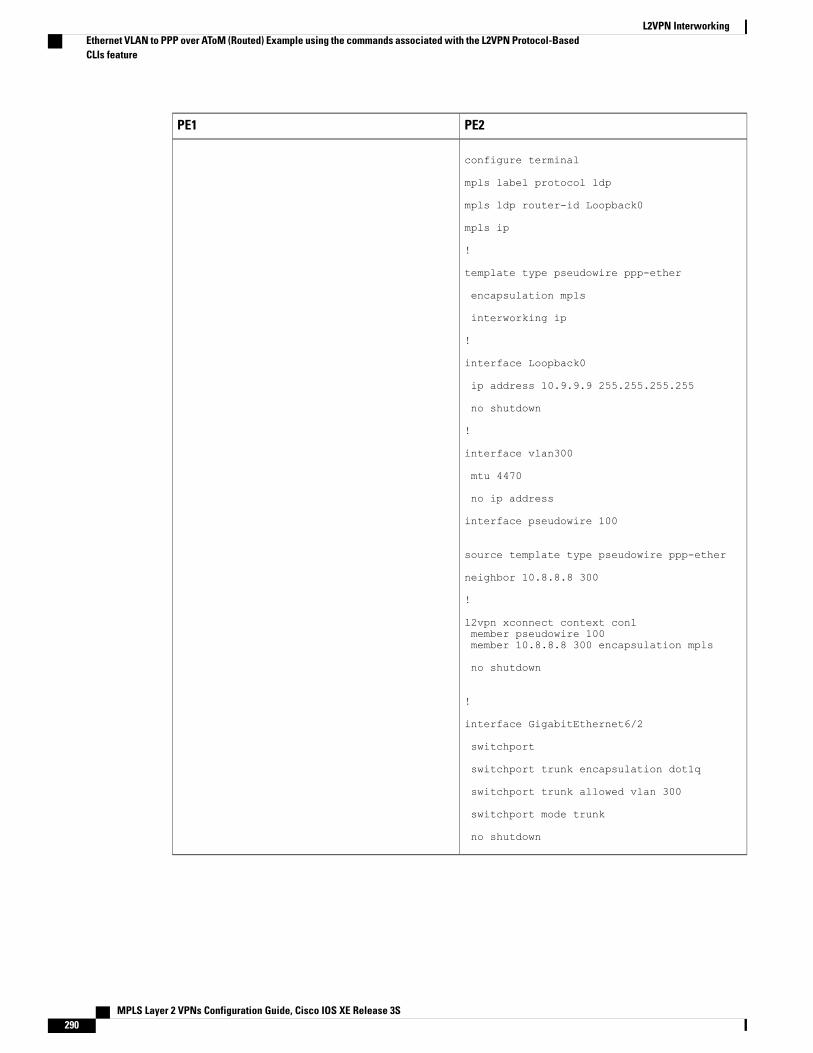
PE2PE1
configure terminal
mpls label protocol ldp
mpls ldp router-id Loopback0
mpls ip
!
template type pseudowire ppp-ether
encapsulation mpls
interworking ip
!
interface Loopback0
ip address 10.9.9.9 255.255.255.255
no shutdown
!
interface vlan300
mtu 4470
no ip address
interface pseudowire 100
source template type pseudowire ppp-ether
neighbor 10.8.8.8 300
!
l2vpn xconnect context con1member pseudowire 100member 10.8.8.8 300 encapsulation mpls
no shutdown
!
interface GigabitEthernet6/2
switchport
switchport trunk encapsulation dot1q
switchport trunk allowed vlan 300
switchport mode trunk
no shutdown
MPLS Layer 2 VPNs Configuration Guide, Cisco IOS XE Release 3S290
L2VPN InterworkingEthernet VLAN to PPP over AToM (Routed) Example using the commands associated with the L2VPN Protocol-BasedCLIs feature
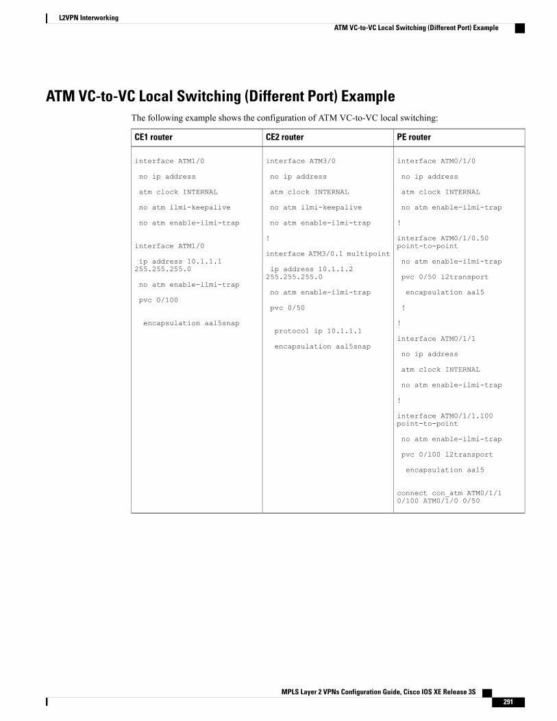
ATM VC-to-VC Local Switching (Different Port) ExampleThe following example shows the configuration of ATM VC-to-VC local switching:
PE routerCE2 routerCE1 router
interface ATM0/1/0
no ip address
atm clock INTERNAL
no atm enable-ilmi-trap
!
interface ATM0/1/0.50point-to-point
no atm enable-ilmi-trap
pvc 0/50 l2transport
encapsulation aal5
!
!
interface ATM0/1/1
no ip address
atm clock INTERNAL
no atm enable-ilmi-trap
!
interface ATM0/1/1.100point-to-point
no atm enable-ilmi-trap
pvc 0/100 l2transport
encapsulation aal5
connect con_atm ATM0/1/10/100 ATM0/1/0 0/50
interface ATM3/0
no ip address
atm clock INTERNAL
no atm ilmi-keepalive
no atm enable-ilmi-trap
!
interface ATM3/0.1 multipoint
ip address 10.1.1.2255.255.255.0
no atm enable-ilmi-trap
pvc 0/50
protocol ip 10.1.1.1
encapsulation aal5snap
interface ATM1/0
no ip address
atm clock INTERNAL
no atm ilmi-keepalive
no atm enable-ilmi-trap
interface ATM1/0
ip address 10.1.1.1255.255.255.0
no atm enable-ilmi-trap
pvc 0/100
encapsulation aal5snap
MPLS Layer 2 VPNs Configuration Guide, Cisco IOS XE Release 3S 291
L2VPN InterworkingATM VC-to-VC Local Switching (Different Port) Example
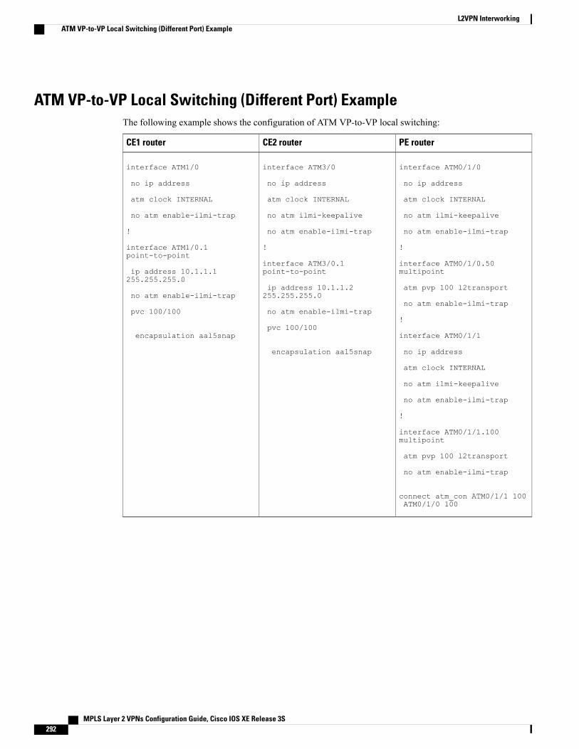
ATM VP-to-VP Local Switching (Different Port) ExampleThe following example shows the configuration of ATM VP-to-VP local switching:
PE routerCE2 routerCE1 router
interface ATM0/1/0
no ip address
atm clock INTERNAL
no atm ilmi-keepalive
no atm enable-ilmi-trap
!
interface ATM0/1/0.50multipoint
atm pvp 100 l2transport
no atm enable-ilmi-trap
!
interface ATM0/1/1
no ip address
atm clock INTERNAL
no atm ilmi-keepalive
no atm enable-ilmi-trap
!
interface ATM0/1/1.100multipoint
atm pvp 100 l2transport
no atm enable-ilmi-trap
connect atm_con ATM0/1/1 100ATM0/1/0 100
interface ATM3/0
no ip address
atm clock INTERNAL
no atm ilmi-keepalive
no atm enable-ilmi-trap
!
interface ATM3/0.1point-to-point
ip address 10.1.1.2255.255.255.0
no atm enable-ilmi-trap
pvc 100/100
encapsulation aal5snap
interface ATM1/0
no ip address
atm clock INTERNAL
no atm enable-ilmi-trap
!
interface ATM1/0.1point-to-point
ip address 10.1.1.1255.255.255.0
no atm enable-ilmi-trap
pvc 100/100
encapsulation aal5snap
MPLS Layer 2 VPNs Configuration Guide, Cisco IOS XE Release 3S292
L2VPN InterworkingATM VP-to-VP Local Switching (Different Port) Example
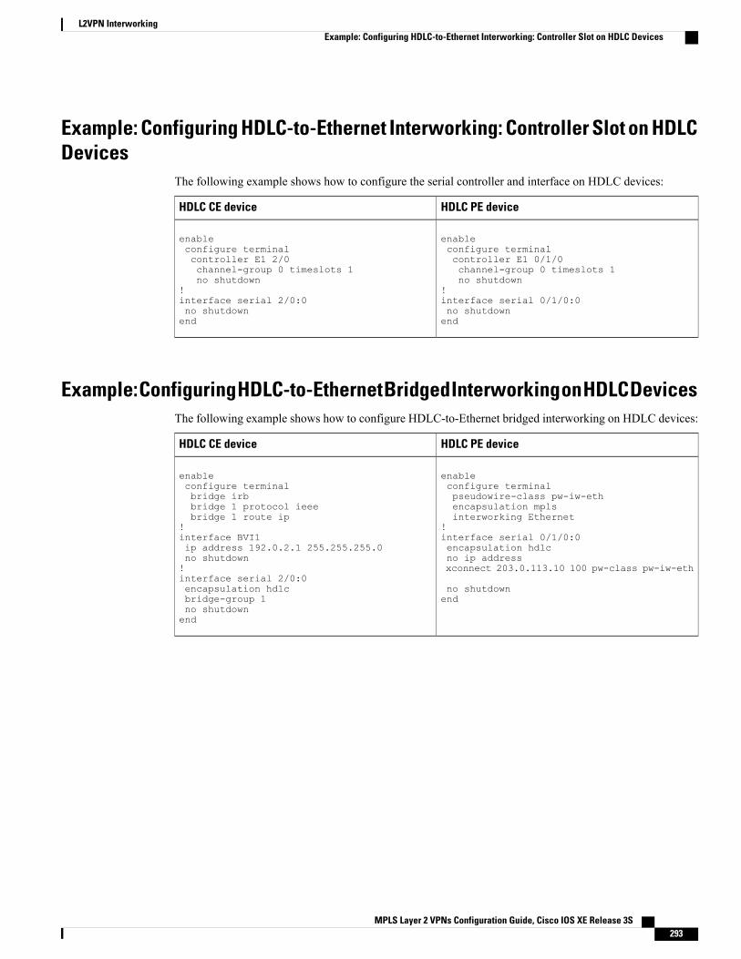
Example: Configuring HDLC-to-Ethernet Interworking: Controller Slot on HDLCDevices
The following example shows how to configure the serial controller and interface on HDLC devices:
HDLC PE deviceHDLC CE device
enableconfigure terminalcontroller E1 0/1/0channel-group 0 timeslots 1no shutdown
!interface serial 0/1/0:0no shutdownend
enableconfigure terminalcontroller E1 2/0channel-group 0 timeslots 1no shutdown
!interface serial 2/0:0no shutdownend
Example: Configuring HDLC-to-Ethernet Bridged Interworking on HDLC DevicesThe following example shows how to configure HDLC-to-Ethernet bridged interworking on HDLC devices:
HDLC PE deviceHDLC CE device
enableconfigure terminalpseudowire-class pw-iw-ethencapsulation mplsinterworking Ethernet
!interface serial 0/1/0:0encapsulation hdlcno ip addressxconnect 203.0.113.10 100 pw-class pw-iw-eth
no shutdownend
enableconfigure terminalbridge irbbridge 1 protocol ieeebridge 1 route ip
!interface BVI1ip address 192.0.2.1 255.255.255.0no shutdown!interface serial 2/0:0encapsulation hdlcbridge-group 1no shutdownend
MPLS Layer 2 VPNs Configuration Guide, Cisco IOS XE Release 3S 293
L2VPN InterworkingExample: Configuring HDLC-to-Ethernet Interworking: Controller Slot on HDLC Devices
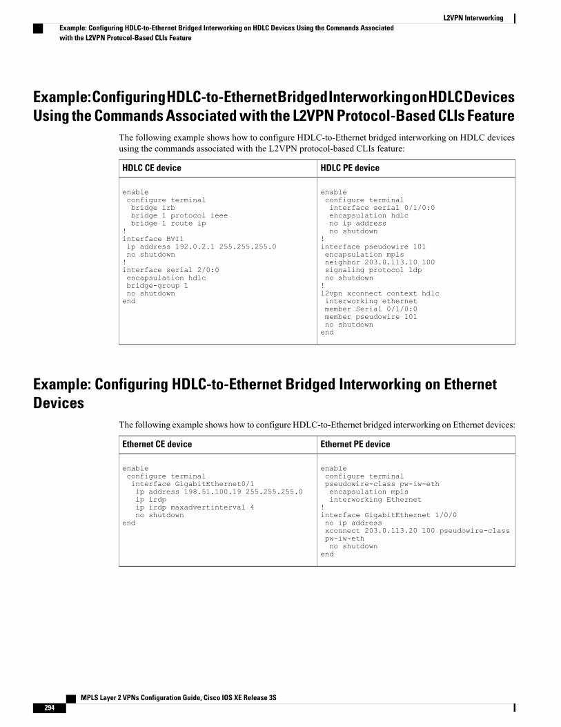
Example: Configuring HDLC-to-Ethernet Bridged Interworking on HDLC DevicesUsing the Commands Associated with the L2VPN Protocol-Based CLIs Feature
The following example shows how to configure HDLC-to-Ethernet bridged interworking on HDLC devicesusing the commands associated with the L2VPN protocol-based CLIs feature:
HDLC PE deviceHDLC CE device
enableconfigure terminalinterface serial 0/1/0:0encapsulation hdlcno ip addressno shutdown
!interface pseudowire 101encapsulation mplsneighbor 203.0.113.10 100signaling protocol ldpno shutdown!l2vpn xconnect context hdlcinterworking ethernetmember Serial 0/1/0:0member pseudowire 101no shutdownend
enableconfigure terminalbridge irbbridge 1 protocol ieeebridge 1 route ip
!interface BVI1ip address 192.0.2.1 255.255.255.0no shutdown!interface serial 2/0:0encapsulation hdlcbridge-group 1no shutdownend
Example: Configuring HDLC-to-Ethernet Bridged Interworking on EthernetDevices
The following example shows how to configure HDLC-to-Ethernet bridged interworking on Ethernet devices:
Ethernet PE deviceEthernet CE device
enableconfigure terminalpseudowire-class pw-iw-ethencapsulation mplsinterworking Ethernet
!interface GigabitEthernet 1/0/0no ip addressxconnect 203.0.113.20 100 pseudowire-classpw-iw-ethno shutdown
end
enableconfigure terminalinterface GigabitEthernet0/1ip address 198.51.100.19 255.255.255.0ip irdpip irdp maxadvertinterval 4no shutdown
end
MPLS Layer 2 VPNs Configuration Guide, Cisco IOS XE Release 3S294
L2VPN InterworkingExample: Configuring HDLC-to-Ethernet Bridged Interworking on HDLC Devices Using the Commands Associatedwith the L2VPN Protocol-Based CLIs Feature
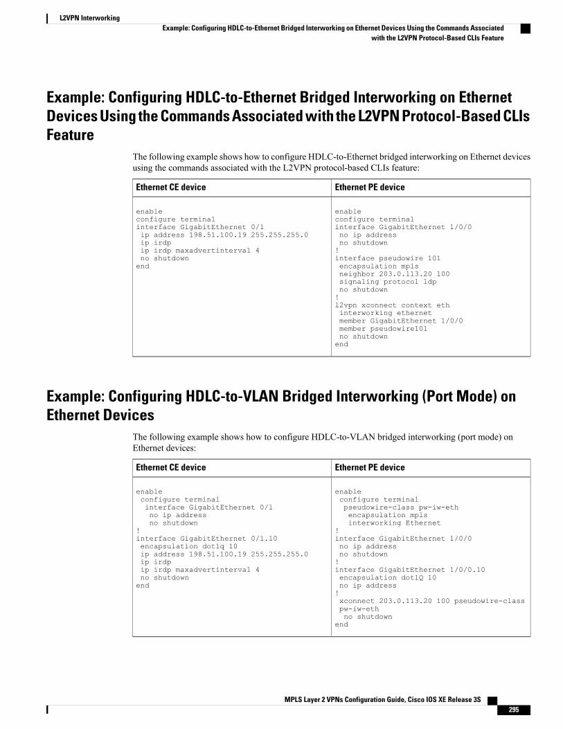
Example: Configuring HDLC-to-Ethernet Bridged Interworking on EthernetDevices Using the Commands Associated with the L2VPN Protocol-Based CLIsFeature
The following example shows how to configure HDLC-to-Ethernet bridged interworking on Ethernet devicesusing the commands associated with the L2VPN protocol-based CLIs feature:
Ethernet PE deviceEthernet CE device
enableconfigure terminalinterface GigabitEthernet 1/0/0no ip addressno shutdown!interface pseudowire 101encapsulation mplsneighbor 203.0.113.20 100signaling protocol ldpno shutdown!l2vpn xconnect context ethinterworking ethernetmember GigabitEthernet 1/0/0member pseudowire101no shutdownend
enableconfigure terminalinterface GigabitEthernet 0/1ip address 198.51.100.19 255.255.255.0ip irdpip irdp maxadvertinterval 4no shutdownend
Example: Configuring HDLC-to-VLAN Bridged Interworking (Port Mode) onEthernet Devices
The following example shows how to configure HDLC-to-VLAN bridged interworking (port mode) onEthernet devices:
Ethernet PE deviceEthernet CE device
enableconfigure terminalpseudowire-class pw-iw-ethencapsulation mplsinterworking Ethernet
!interface GigabitEthernet 1/0/0no ip addressno shutdown!interface GigabitEthernet 1/0/0.10encapsulation dot1Q 10no ip address!xconnect 203.0.113.20 100 pseudowire-classpw-iw-ethno shutdown
end
enableconfigure terminalinterface GigabitEthernet 0/1no ip addressno shutdown
!interface GigabitEthernet 0/1.10encapsulation dot1q 10ip address 198.51.100.19 255.255.255.0ip irdpip irdp maxadvertinterval 4no shutdownend
MPLS Layer 2 VPNs Configuration Guide, Cisco IOS XE Release 3S 295
L2VPN InterworkingExample: Configuring HDLC-to-Ethernet Bridged Interworking on Ethernet Devices Using the Commands Associated
with the L2VPN Protocol-Based CLIs Feature
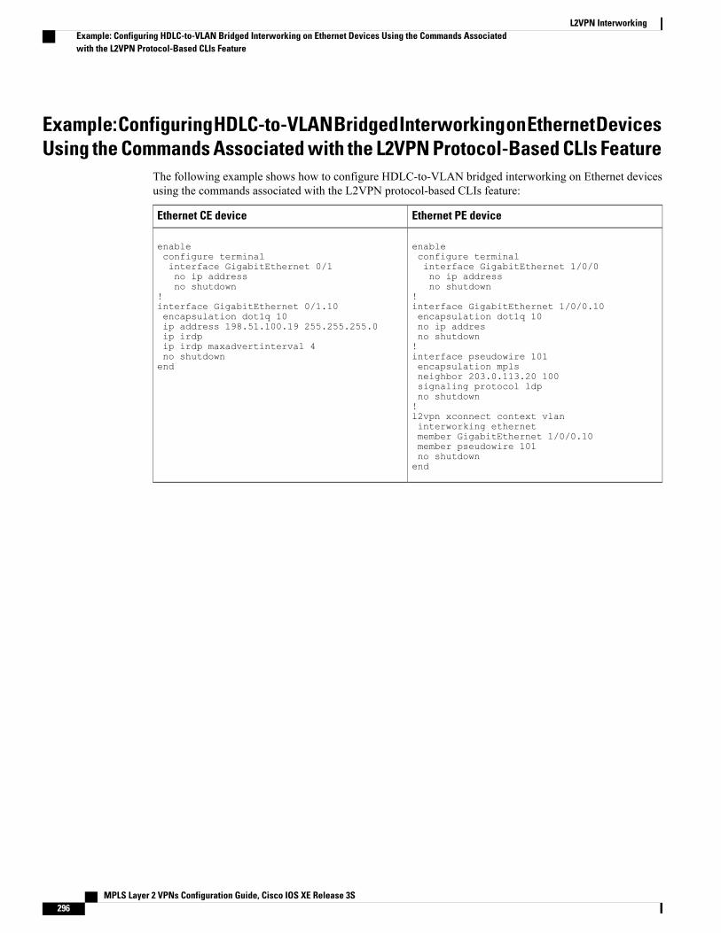
Example: Configuring HDLC-to-VLAN Bridged Interworking on Ethernet DevicesUsing the Commands Associated with the L2VPN Protocol-Based CLIs Feature
The following example shows how to configure HDLC-to-VLAN bridged interworking on Ethernet devicesusing the commands associated with the L2VPN protocol-based CLIs feature:
Ethernet PE deviceEthernet CE device
enableconfigure terminalinterface GigabitEthernet 1/0/0no ip addressno shutdown
!interface GigabitEthernet 1/0/0.10encapsulation dot1q 10no ip addresno shutdown!interface pseudowire 101encapsulation mplsneighbor 203.0.113.20 100signaling protocol ldpno shutdown!l2vpn xconnect context vlaninterworking ethernetmember GigabitEthernet 1/0/0.10member pseudowire 101no shutdownend
enableconfigure terminalinterface GigabitEthernet 0/1no ip addressno shutdown
!interface GigabitEthernet 0/1.10encapsulation dot1q 10ip address 198.51.100.19 255.255.255.0ip irdpip irdp maxadvertinterval 4no shutdownend
MPLS Layer 2 VPNs Configuration Guide, Cisco IOS XE Release 3S296
L2VPN InterworkingExample: Configuring HDLC-to-VLAN Bridged Interworking on Ethernet Devices Using the Commands Associatedwith the L2VPN Protocol-Based CLIs Feature
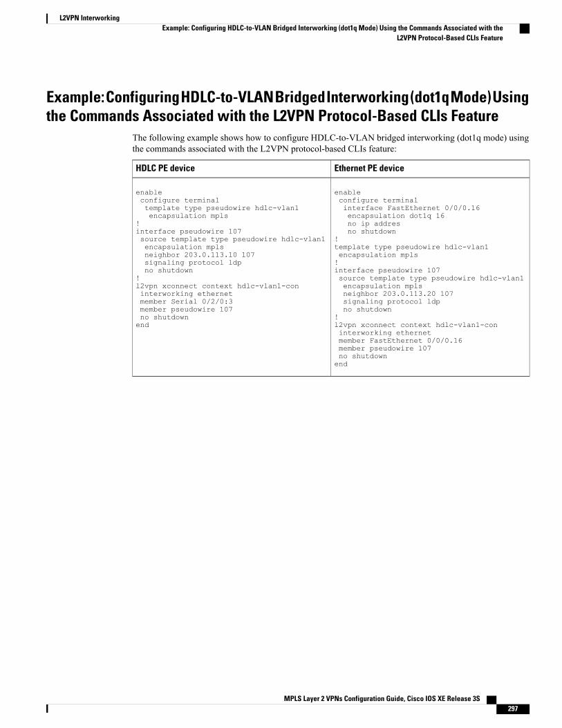
Example: Configuring HDLC-to-VLAN Bridged Interworking (dot1q Mode) Usingthe Commands Associated with the L2VPN Protocol-Based CLIs Feature
The following example shows how to configure HDLC-to-VLAN bridged interworking (dot1q mode) usingthe commands associated with the L2VPN protocol-based CLIs feature:
Ethernet PE deviceHDLC PE device
enableconfigure terminalinterface FastEthernet 0/0/0.16encapsulation dot1q 16no ip addresno shutdown
!template type pseudowire hdlc-vlan1encapsulation mpls!interface pseudowire 107source template type pseudowire hdlc-vlan1encapsulation mplsneighbor 203.0.113.20 107signaling protocol ldpno shutdown
!l2vpn xconnect context hdlc-vlan1-coninterworking ethernetmember FastEthernet 0/0/0.16member pseudowire 107no shutdownend
enableconfigure terminaltemplate type pseudowire hdlc-vlan1encapsulation mpls
!interface pseudowire 107source template type pseudowire hdlc-vlan1encapsulation mplsneighbor 203.0.113.10 107signaling protocol ldpno shutdown
!l2vpn xconnect context hdlc-vlan1-coninterworking ethernetmember Serial 0/2/0:3member pseudowire 107no shutdownend
MPLS Layer 2 VPNs Configuration Guide, Cisco IOS XE Release 3S 297
L2VPN InterworkingExample: Configuring HDLC-to-VLAN Bridged Interworking (dot1q Mode) Using the Commands Associated with the
L2VPN Protocol-Based CLIs Feature
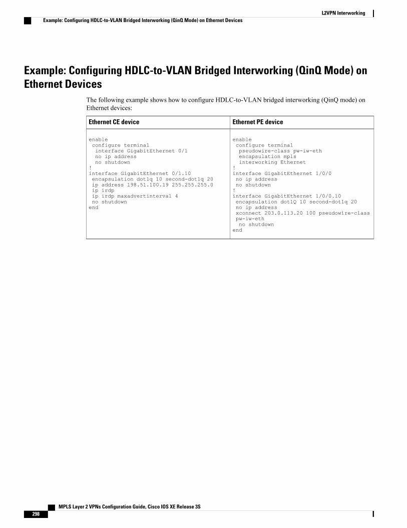
Example: Configuring HDLC-to-VLAN Bridged Interworking (QinQ Mode) onEthernet Devices
The following example shows how to configure HDLC-to-VLAN bridged interworking (QinQ mode) onEthernet devices:
Ethernet PE deviceEthernet CE device
enableconfigure terminalpseudowire-class pw-iw-ethencapsulation mplsinterworking Ethernet
!interface GigabitEthernet 1/0/0no ip addressno shutdown!interface GigabitEthernet 1/0/0.10encapsulation dot1Q 10 second-dot1q 20no ip addressxconnect 203.0.113.20 100 pseudowire-classpw-iw-ethno shutdown
end
enableconfigure terminalinterface GigabitEthernet 0/1no ip addressno shutdown
!interface GigabitEthernet 0/1.10encapsulation dot1q 10 second-dot1q 20ip address 198.51.100.19 255.255.255.0ip irdpip irdp maxadvertinterval 4no shutdownend
MPLS Layer 2 VPNs Configuration Guide, Cisco IOS XE Release 3S298
L2VPN InterworkingExample: Configuring HDLC-to-VLAN Bridged Interworking (QinQ Mode) on Ethernet Devices
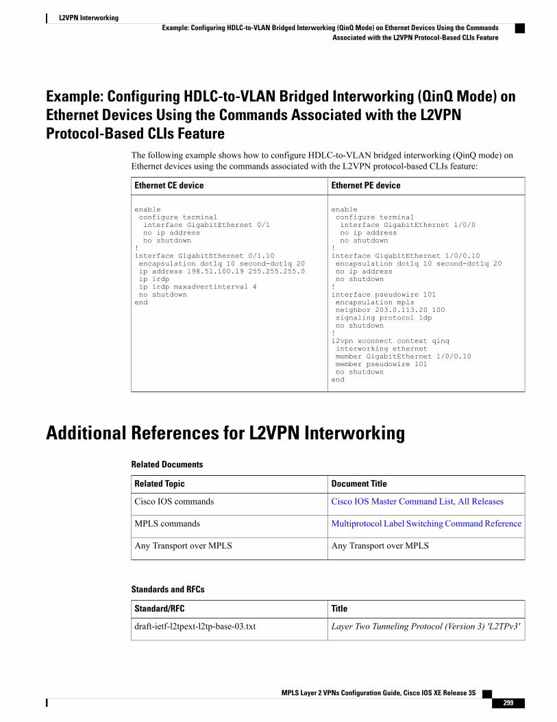
Example: Configuring HDLC-to-VLAN Bridged Interworking (QinQ Mode) onEthernet Devices Using the Commands Associated with the L2VPNProtocol-Based CLIs Feature
The following example shows how to configure HDLC-to-VLAN bridged interworking (QinQ mode) onEthernet devices using the commands associated with the L2VPN protocol-based CLIs feature:
Ethernet PE deviceEthernet CE device
enableconfigure terminalinterface GigabitEthernet 1/0/0no ip addressno shutdown
!interface GigabitEthernet 1/0/0.10encapsulation dot1q 10 second-dot1q 20no ip addressno shutdown!interface pseudowire 101encapsulation mplsneighbor 203.0.113.20 100signaling protocol ldpno shutdown!l2vpn xconnect context qinqinterworking ethernetmember GigabitEthernet 1/0/0.10member pseudowire 101no shutdownend
enableconfigure terminalinterface GigabitEthernet 0/1no ip addressno shutdown
!interface GigabitEthernet 0/1.10encapsulation dot1q 10 second-dot1q 20ip address 198.51.100.19 255.255.255.0ip irdpip irdp maxadvertinterval 4no shutdownend
Additional References for L2VPN InterworkingRelated Documents
Document TitleRelated Topic
Cisco IOS Master Command List, All ReleasesCisco IOS commands
Multiprotocol Label Switching Command ReferenceMPLS commands
Any Transport over MPLSAny Transport over MPLS
Standards and RFCs
TitleStandard/RFC
Layer Two Tunneling Protocol (Version 3) 'L2TPv3'draft-ietf-l2tpext-l2tp-base-03.txt
MPLS Layer 2 VPNs Configuration Guide, Cisco IOS XE Release 3S 299
L2VPN InterworkingExample: Configuring HDLC-to-VLAN Bridged Interworking (QinQ Mode) on Ethernet Devices Using the Commands
Associated with the L2VPN Protocol-Based CLIs Feature
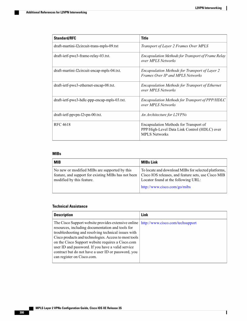
TitleStandard/RFC
Transport of Layer 2 Frames Over MPLSdraft-martini-l2circuit-trans-mpls-09.txt
EncapsulationMethods for Transport of Frame Relayover MPLS Networks
draft-ietf-pwe3-frame-relay-03.txt.
Encapsulation Methods for Transport of Layer 2Frames Over IP and MPLS Networks
draft-martini-l2circuit-encap-mpls-04.txt.
Encapsulation Methods for Transport of Ethernetover MPLS Networks
draft-ietf-pwe3-ethernet-encap-08.txt.
Encapsulation Methods for Transport of PPP/HDLCover MPLS Networks
draft-ietf-pwe3-hdlc-ppp-encap-mpls-03.txt.
An Architecture for L2VPNsdraft-ietf-ppvpn-l2vpn-00.txt.
Encapsulation Methods for Transport ofPPP/High-Level Data Link Control (HDLC) overMPLS Networks
RFC 4618
MIBs
MIBs LinkMIB
To locate and downloadMIBs for selected platforms,Cisco IOS releases, and feature sets, use Cisco MIBLocator found at the following URL:
http://www.cisco.com/go/mibs
No new or modified MIBs are supported by thisfeature, and support for existing MIBs has not beenmodified by this feature.
Technical Assistance
LinkDescription
http://www.cisco.com/techsupportThe Cisco Support website provides extensive onlineresources, including documentation and tools fortroubleshooting and resolving technical issues withCisco products and technologies. Access to most toolson the Cisco Support website requires a Cisco.comuser ID and password. If you have a valid servicecontract but do not have a user ID or password, youcan register on Cisco.com.
MPLS Layer 2 VPNs Configuration Guide, Cisco IOS XE Release 3S300
L2VPN InterworkingAdditional References for L2VPN Interworking
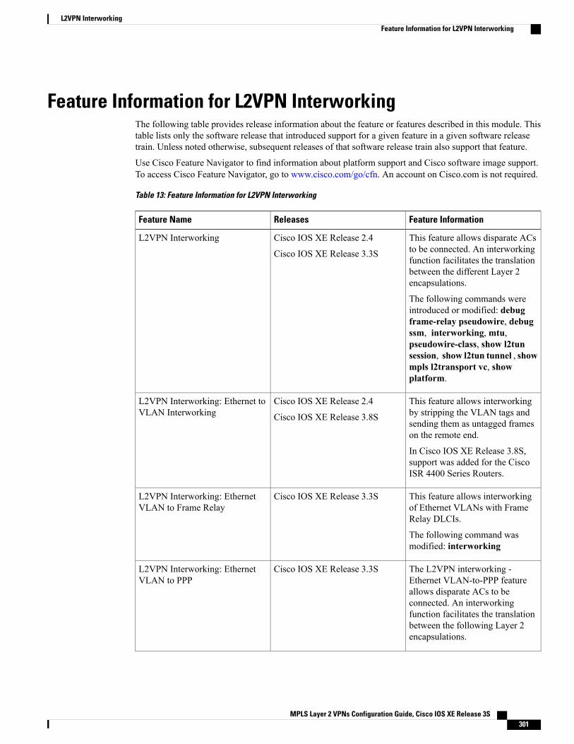
Feature Information for L2VPN InterworkingThe following table provides release information about the feature or features described in this module. Thistable lists only the software release that introduced support for a given feature in a given software releasetrain. Unless noted otherwise, subsequent releases of that software release train also support that feature.
Use Cisco Feature Navigator to find information about platform support and Cisco software image support.To access Cisco Feature Navigator, go to www.cisco.com/go/cfn. An account on Cisco.com is not required.
Table 13: Feature Information for L2VPN Interworking
Feature InformationReleasesFeature Name
This feature allows disparate ACsto be connected. An interworkingfunction facilitates the translationbetween the different Layer 2encapsulations.
The following commands wereintroduced or modified: debugframe-relay pseudowire, debugssm, interworking, mtu,pseudowire-class, show l2tunsession, show l2tun tunnel , showmpls l2transport vc, showplatform.
Cisco IOS XE Release 2.4
Cisco IOS XE Release 3.3S
L2VPN Interworking
This feature allows interworkingby stripping the VLAN tags andsending them as untagged frameson the remote end.
In Cisco IOS XE Release 3.8S,support was added for the CiscoISR 4400 Series Routers.
Cisco IOS XE Release 2.4
Cisco IOS XE Release 3.8S
L2VPN Interworking: Ethernet toVLAN Interworking
This feature allows interworkingof Ethernet VLANs with FrameRelay DLCIs.
The following command wasmodified: interworking
Cisco IOS XE Release 3.3SL2VPN Interworking: EthernetVLAN to Frame Relay
The L2VPN interworking -Ethernet VLAN-to-PPP featureallows disparate ACs to beconnected. An interworkingfunction facilitates the translationbetween the following Layer 2encapsulations.
Cisco IOS XE Release 3.3SL2VPN Interworking: EthernetVLAN to PPP
MPLS Layer 2 VPNs Configuration Guide, Cisco IOS XE Release 3S 301
L2VPN InterworkingFeature Information for L2VPN Interworking
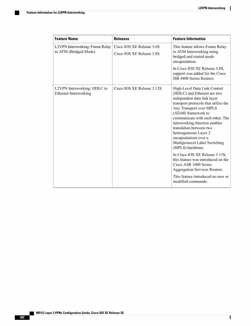
Feature InformationReleasesFeature Name
This feature allows Frame Relayto ATM Interworking usingbridged and routed modeencapsulation.
In Cisco IOS XE Release 3.8S,support was added for the CiscoISR 4400 Series Routers.
Cisco IOS XE Release 3.6S
Cisco IOS XE Release 3.8S
L2VPN Interworking: FrameRelayto ATM (Bridged Mode)
High-Level Data Link Control(HDLC) and Ethernet are twoindependent data link layertransport protocols that utilize theAny Transport over MPLS(AToM) framework tocommunicate with each other. Theinterworking function enablestranslation between twoheterogeneous Layer 2encapsulations over aMultiprotocol Label Switching(MPLS) backbone.
In Cisco IOS XE Release 3.13S,this feature was introduced on theCisco ASR 1000 SeriesAggregation Services Routers.
This feature introduced no new ormodified commands.
Cisco IOS XE Release 3.13SL2VPN Interworking: HDLC toEthernet Interworking
MPLS Layer 2 VPNs Configuration Guide, Cisco IOS XE Release 3S302
L2VPN InterworkingFeature Information for L2VPN Interworking
C H A P T E R 4L2VPN Pseudowire Preferential Forwarding
The L2VPN: Pseudowire Preferential Forwarding feature allows you to configure the pseudowires so thatyou can use ping and show commands to find status information for the pseudowires before, during, andafter a switchover.
• Finding Feature Information, page 303
• Prerequisites for L2VPN—Pseudowire Preferential Forwarding, page 303
• Guidelines and Limitations for L2VPN--Pseudowire Preferential Forwarding, page 304
• Information About L2VPN--Pseudowire Preferential Forwarding, page 305
• How to Configure L2VPN--Pseudowire Preferential Forwarding, page 306
• Configuration Examples for L2VPN--Pseudowire Preferential Forwarding, page 309
• Additional References, page 311
• Feature Information for L2VPN--Pseudowire Preferential Forwarding, page 312
Finding Feature InformationYour software release may not support all the features documented in this module. For the latest caveats andfeature information, see Bug Search Tool and the release notes for your platform and software release. Tofind information about the features documented in this module, and to see a list of the releases in which eachfeature is supported, see the feature information table at the end of this module.
Use Cisco Feature Navigator to find information about platform support and Cisco software image support.To access Cisco Feature Navigator, go to www.cisco.com/go/cfn. An account on Cisco.com is not required.
Prerequisites for L2VPN—Pseudowire Preferential Forwarding• Before configuring the L2VPN: Pseudowire Preferential Forwarding feature, you should understand theconcepts in the following documents:
• Preferential Forwarding Status Bit Definition (draft-ietf-pwe3-redundancy-bit-xx.txt)
• MPLS Pseudowire Status Signaling
MPLS Layer 2 VPNs Configuration Guide, Cisco IOS XE Release 3S 303
• L2VPN Pseudowire Redundancy
• NSF/SSO--Any Transport over MPLS and AToM Graceful Restart
• MPLS LSP Ping/Traceroute for LDP/TE, and LSP Ping for VCCV
• The PE routers must be configured with the following features:
• L2VPN Pseudowire Redundancy
• NSF/SSO--Any Transport over MPLS and AToM Graceful Restart
• The L2VPN: Pseudowire Preferential Forwarding feature requires that the following mechanisms be inplace to enable you to detect a failure in the network:
• Label switched paths (LSPs) Ping/Traceroute and Any Transport over MPLS Virtual CircuitConnection Verification (AToM VCCV)
• Local Management Interface (LMI)
• Operation, Administration, and Maintenance (OAM)
Guidelines and Limitations for L2VPN--Pseudowire PreferentialForwarding
• Only ATM attachment circuits are supported.
• The following features are not supported:
• Port mode cell relay
• Any Transport over MPLS: AAL5 over MPLS
• VC cell packing
• OAM emulation
• ILMI/PVC-D
• Permanent virtual circuit (PVC) Range
• L2TPv3 Pseudowire Redundancy
• Local switching
• Multiple backup pseudowires
• Static pseudowires
MPLS Layer 2 VPNs Configuration Guide, Cisco IOS XE Release 3S304
L2VPN Pseudowire Preferential ForwardingGuidelines and Limitations for L2VPN--Pseudowire Preferential Forwarding
Information About L2VPN--Pseudowire Preferential Forwarding
Overview of L2VPN--Pseudowire Preferential ForwardingThe L2VPN: Pseudowire Preferential Forwarding feature allows you to configure pseudowires so that youcan use ping , traceroute , and show commands to find status information before, during, and after aswitchover. The implementation of this feature is based on Preferential Forwarding Status Bit Definition(draft-ietf-pwe3-redundancy-bit-xx.txt). The L2VPN: Pseudowire Preferential Forwarding feature providesthe following enhancements for displaying information about the pseudowires:
• You can issue ping mpls commands on the backup pseudowires.
• You can display status of the pseudowires before, during, and after a switchover using the show xconnectand show mpls l2transport vc commands.
In a single-segment pseudowire, the PE routers at each end of the pseudowire serve as the terminationpoints. In multisegment pseudowires, the terminating PE routers serve as the termination points.
Note
Overview of L2VPN—Pseudowire Preferential Forwarding using the commandsassociated with the L2VPN Protocol-Based CLIs feature
The L2VPN: Pseudowire Preferential Forwarding feature allows you to configure pseudowires so that youcan use ping, traceroute, and show commands to find status information before, during, and after aswitchover. The implementation of this feature is based on Preferential Forwarding Status Bit Definition(draft-ietf-pwe3-redundancy-bit-xx.txt). The L2VPN: Pseudowire Preferential Forwarding feature providesthe following enhancements for displaying information about the pseudowires:
• You can issue ping mpls commands on the backup pseudowires.
• You can display status of the pseudowires before, during, and after a switchover using the show l2vpnservice and show l2vpn atom vc commands.
In a single-segment pseudowire, the PE routers at each end of the pseudowire serve as the terminationpoints. In multisegment pseudowires, the terminating PE routers serve as the termination points.
Note
MPLS Layer 2 VPNs Configuration Guide, Cisco IOS XE Release 3S 305
L2VPN Pseudowire Preferential ForwardingInformation About L2VPN--Pseudowire Preferential Forwarding
How to Configure L2VPN--Pseudowire Preferential Forwarding
Configuring the Pseudowire Connection Between PE RoutersYou set up a connection called a pseudowire between the routers to transmit Layer 2 frames between PErouters.
As part of the pseudowire configuration, issue the status redundancymaster command to make it the master.This enables the L2VPN: Pseudowire Preferential Forwarding feature to display the status of the active andbackup pseudowires. By default, the PE router is in slave mode.
One pseudowiremust be themaster, and the other must be the slave. You cannot configure both pseudowiresas master or slave.
Note
Youmust specify the encapsulationmpls command as part of the pseudowire class in order for the AToMVCs to work properly. If you omit the encapsulation mpls command, you receive the following error:% Incomplete command.
Note
Before You Begin
The PE routers must be configured for the L2VPN Pseudowire Redundancy and NSF/SSO--Any Transportover MPLS and AToMGraceful Restart features. See the following documents for configuration instructions.
• L2VPN Pseudowire Redundancy
• NSF/SSO--Any Transport over MPLS and AToM Graceful Restart
SUMMARY STEPS
1. configure terminal2. pseudowire-class name3. encapsulation mpls4. status redundancy {master| slave}5. interworking {ethernet | ip}
DETAILED STEPS
PurposeCommand or Action
Enters global configuration mode.configure terminal
Example:
switch# configure terminal
Step 1
MPLS Layer 2 VPNs Configuration Guide, Cisco IOS XE Release 3S306
L2VPN Pseudowire Preferential ForwardingHow to Configure L2VPN--Pseudowire Preferential Forwarding
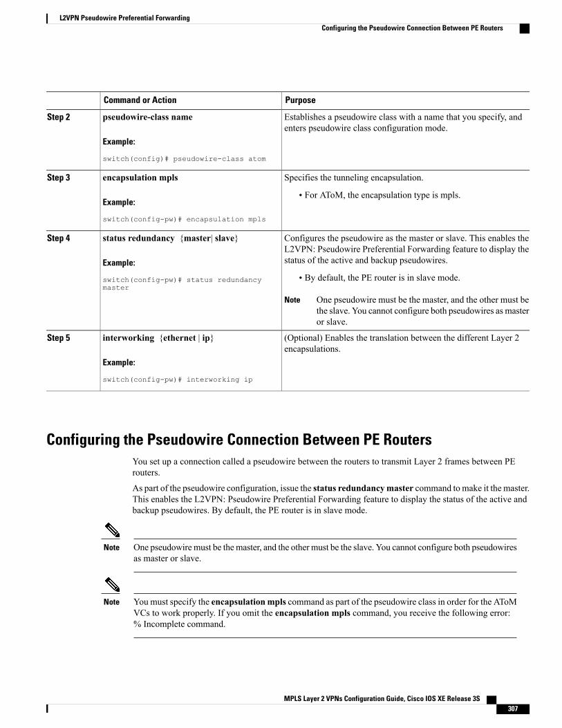
PurposeCommand or Action
Establishes a pseudowire class with a name that you specify, andenters pseudowire class configuration mode.
pseudowire-class name
Example:
switch(config)# pseudowire-class atom
Step 2
Specifies the tunneling encapsulation.encapsulation mplsStep 3
Example:
switch(config-pw)# encapsulation mpls
• For AToM, the encapsulation type is mpls.
Configures the pseudowire as the master or slave. This enables theL2VPN: Pseudowire Preferential Forwarding feature to display thestatus of the active and backup pseudowires.
status redundancy {master| slave}
Example:
switch(config-pw)# status redundancymaster
Step 4
• By default, the PE router is in slave mode.
One pseudowire must be the master, and the other must bethe slave. You cannot configure both pseudowires as masteror slave.
Note
(Optional) Enables the translation between the different Layer 2encapsulations.
interworking {ethernet | ip}
Example:
switch(config-pw)# interworking ip
Step 5
Configuring the Pseudowire Connection Between PE RoutersYou set up a connection called a pseudowire between the routers to transmit Layer 2 frames between PErouters.
As part of the pseudowire configuration, issue the status redundancymaster command to make it the master.This enables the L2VPN: Pseudowire Preferential Forwarding feature to display the status of the active andbackup pseudowires. By default, the PE router is in slave mode.
One pseudowiremust be themaster, and the other must be the slave. You cannot configure both pseudowiresas master or slave.
Note
Youmust specify the encapsulationmpls command as part of the pseudowire class in order for the AToMVCs to work properly. If you omit the encapsulation mpls command, you receive the following error:% Incomplete command.
Note
MPLS Layer 2 VPNs Configuration Guide, Cisco IOS XE Release 3S 307
L2VPN Pseudowire Preferential ForwardingConfiguring the Pseudowire Connection Between PE Routers
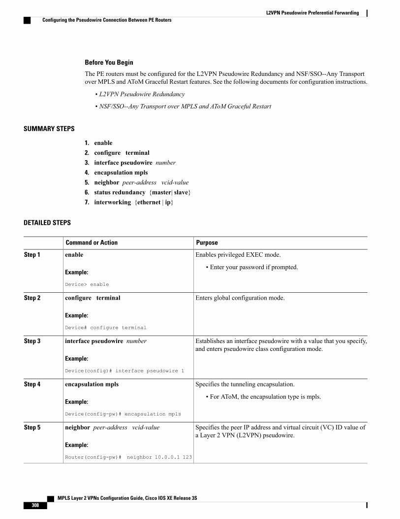
Before You Begin
The PE routers must be configured for the L2VPN Pseudowire Redundancy and NSF/SSO--Any Transportover MPLS and AToMGraceful Restart features. See the following documents for configuration instructions.
• L2VPN Pseudowire Redundancy
• NSF/SSO--Any Transport over MPLS and AToM Graceful Restart
SUMMARY STEPS
1. enable2. configure terminal3. interface pseudowire number4. encapsulation mpls5. neighbor peer-address vcid-value6. status redundancy {master| slave}7. interworking {ethernet | ip}
DETAILED STEPS
PurposeCommand or Action
Enables privileged EXEC mode.enableStep 1
Example:
Device> enable
• Enter your password if prompted.
Enters global configuration mode.configure terminal
Example:
Device# configure terminal
Step 2
Establishes an interface pseudowire with a value that you specify,and enters pseudowire class configuration mode.
interface pseudowire number
Example:
Device(config)# interface pseudowire 1
Step 3
Specifies the tunneling encapsulation.encapsulation mplsStep 4
Example:
Device(config-pw)# encapsulation mpls
• For AToM, the encapsulation type is mpls.
Specifies the peer IP address and virtual circuit (VC) ID value ofa Layer 2 VPN (L2VPN) pseudowire.
neighbor peer-address vcid-value
Example:
Router(config-pw)# neighbor 10.0.0.1 123
Step 5
MPLS Layer 2 VPNs Configuration Guide, Cisco IOS XE Release 3S308
L2VPN Pseudowire Preferential ForwardingConfiguring the Pseudowire Connection Between PE Routers
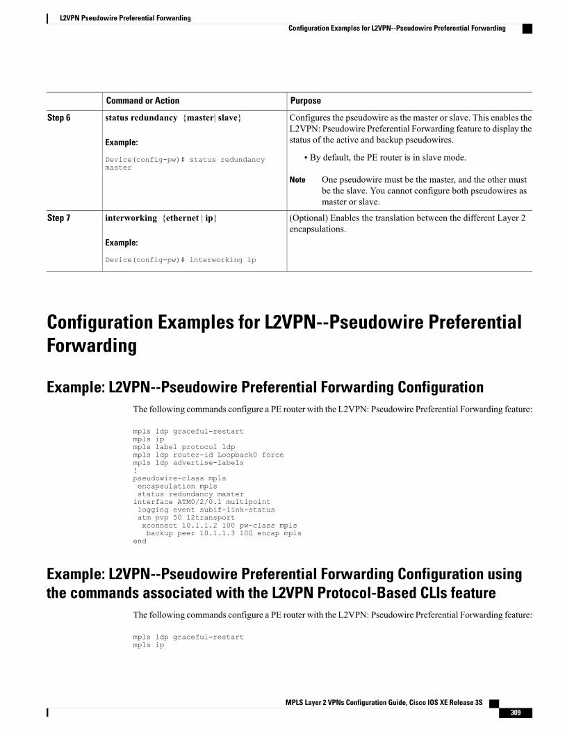
PurposeCommand or Action
Configures the pseudowire as the master or slave. This enables theL2VPN: Pseudowire Preferential Forwarding feature to display thestatus of the active and backup pseudowires.
status redundancy {master| slave}
Example:
Device(config-pw)# status redundancymaster
Step 6
• By default, the PE router is in slave mode.
One pseudowire must be the master, and the other mustbe the slave. You cannot configure both pseudowires asmaster or slave.
Note
(Optional) Enables the translation between the different Layer 2encapsulations.
interworking {ethernet | ip}
Example:
Device(config-pw)# interworking ip
Step 7
Configuration Examples for L2VPN--Pseudowire PreferentialForwarding
Example: L2VPN--Pseudowire Preferential Forwarding ConfigurationThe following commands configure a PE router with the L2VPN: Pseudowire Preferential Forwarding feature:
mpls ldp graceful-restartmpls ipmpls label protocol ldpmpls ldp router-id Loopback0 forcempls ldp advertise-labels!pseudowire-class mplsencapsulation mplsstatus redundancy masterinterface ATM0/2/0.1 multipointlogging event subif-link-statusatm pvp 50 l2transportxconnect 10.1.1.2 100 pw-class mplsbackup peer 10.1.1.3 100 encap mpls
end
Example: L2VPN--Pseudowire Preferential Forwarding Configuration usingthe commands associated with the L2VPN Protocol-Based CLIs feature
The following commands configure a PE router with the L2VPN: Pseudowire Preferential Forwarding feature:
mpls ldp graceful-restartmpls ip
MPLS Layer 2 VPNs Configuration Guide, Cisco IOS XE Release 3S 309
L2VPN Pseudowire Preferential ForwardingConfiguration Examples for L2VPN--Pseudowire Preferential Forwarding
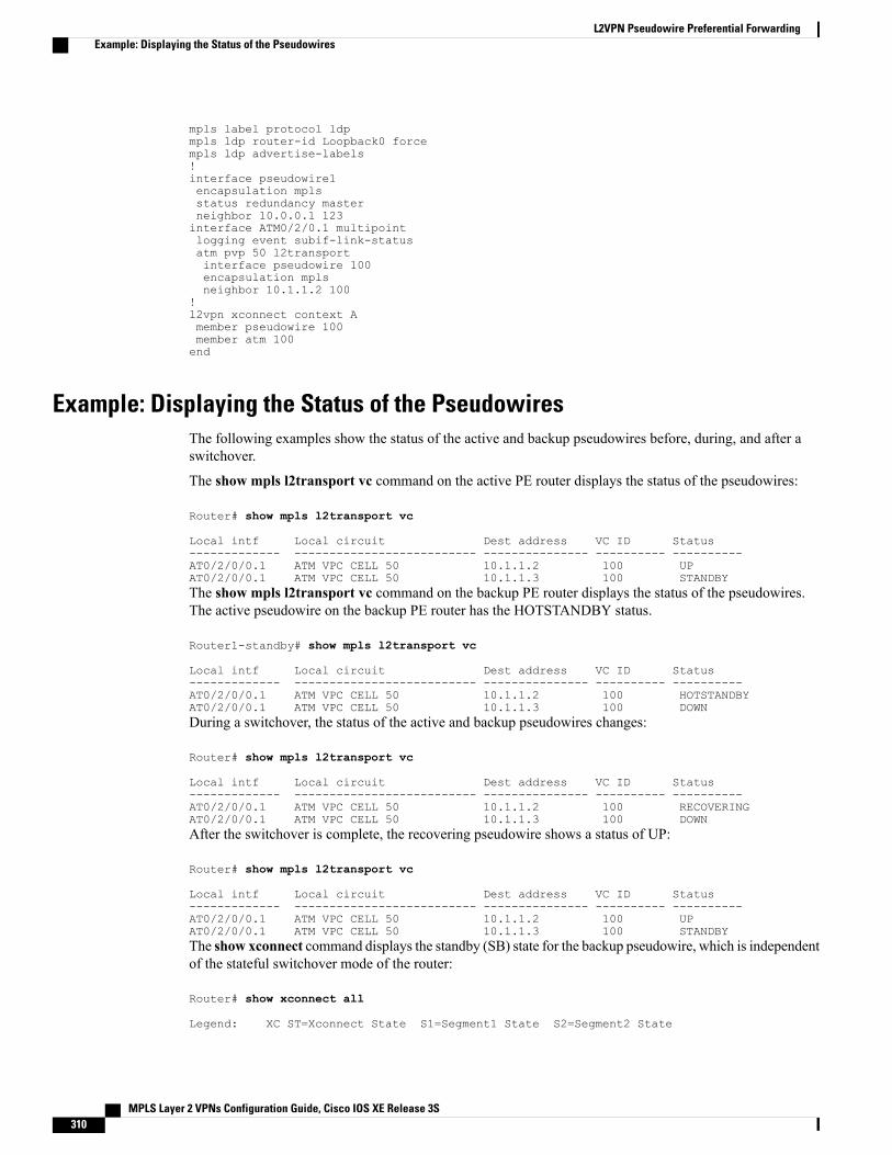
mpls label protocol ldpmpls ldp router-id Loopback0 forcempls ldp advertise-labels!interface pseudowire1encapsulation mplsstatus redundancy masterneighbor 10.0.0.1 123interface ATM0/2/0.1 multipointlogging event subif-link-statusatm pvp 50 l2transportinterface pseudowire 100encapsulation mplsneighbor 10.1.1.2 100
!l2vpn xconnect context Amember pseudowire 100member atm 100end
Example: Displaying the Status of the PseudowiresThe following examples show the status of the active and backup pseudowires before, during, and after aswitchover.
The show mpls l2transport vc command on the active PE router displays the status of the pseudowires:
Router# show mpls l2transport vc
Local intf Local circuit Dest address VC ID Status------------- -------------------------- --------------- ---------- ----------AT0/2/0/0.1 ATM VPC CELL 50 10.1.1.2 100 UPAT0/2/0/0.1 ATM VPC CELL 50 10.1.1.3 100 STANDBYThe show mpls l2transport vc command on the backup PE router displays the status of the pseudowires.The active pseudowire on the backup PE router has the HOTSTANDBY status.
Router1-standby# show mpls l2transport vc
Local intf Local circuit Dest address VC ID Status------------- -------------------------- --------------- ---------- ----------AT0/2/0/0.1 ATM VPC CELL 50 10.1.1.2 100 HOTSTANDBYAT0/2/0/0.1 ATM VPC CELL 50 10.1.1.3 100 DOWNDuring a switchover, the status of the active and backup pseudowires changes:
Router# show mpls l2transport vc
Local intf Local circuit Dest address VC ID Status------------- -------------------------- --------------- ---------- ----------AT0/2/0/0.1 ATM VPC CELL 50 10.1.1.2 100 RECOVERINGAT0/2/0/0.1 ATM VPC CELL 50 10.1.1.3 100 DOWNAfter the switchover is complete, the recovering pseudowire shows a status of UP:
Router# show mpls l2transport vc
Local intf Local circuit Dest address VC ID Status------------- -------------------------- --------------- ---------- ----------AT0/2/0/0.1 ATM VPC CELL 50 10.1.1.2 100 UPAT0/2/0/0.1 ATM VPC CELL 50 10.1.1.3 100 STANDBYThe show xconnect command displays the standby (SB) state for the backup pseudowire, which is independentof the stateful switchover mode of the router:
Router# show xconnect all
Legend: XC ST=Xconnect State S1=Segment1 State S2=Segment2 State
MPLS Layer 2 VPNs Configuration Guide, Cisco IOS XE Release 3S310
L2VPN Pseudowire Preferential ForwardingExample: Displaying the Status of the Pseudowires
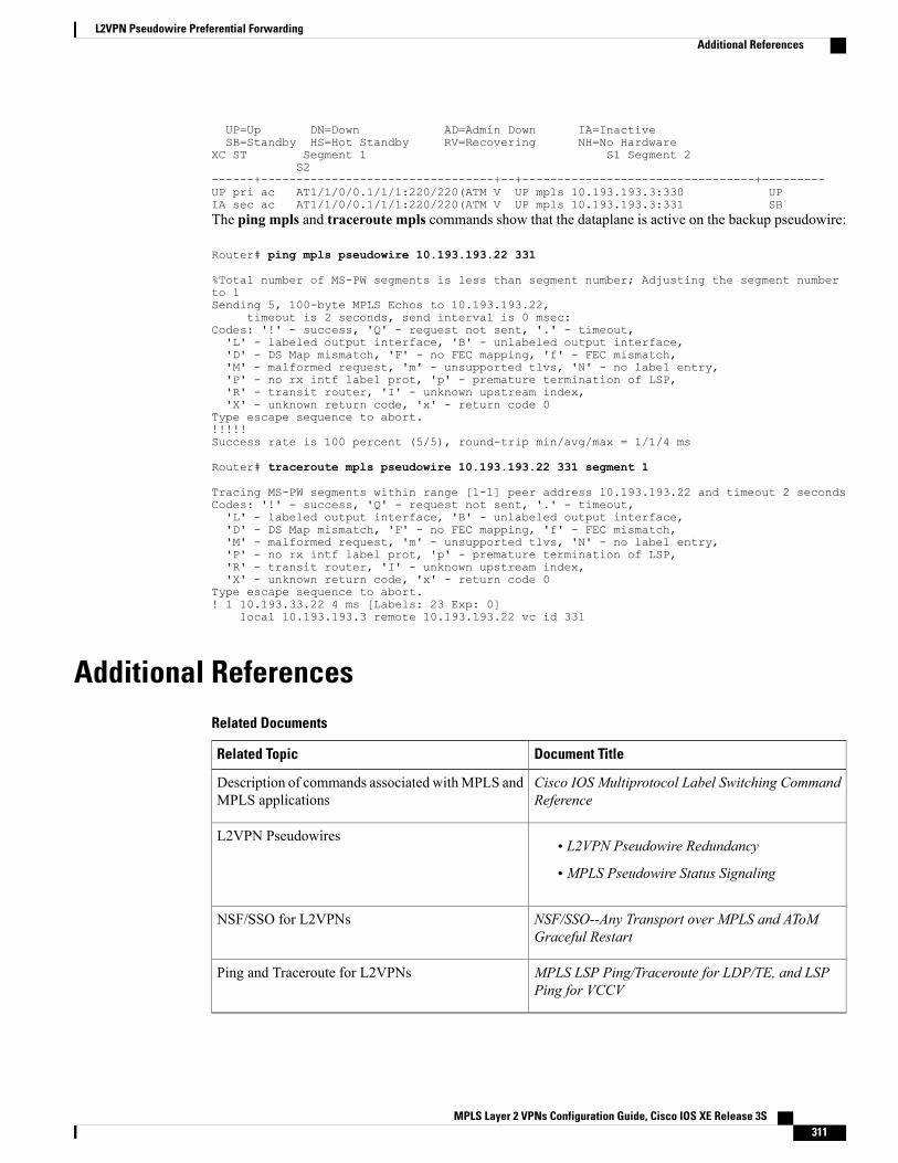
UP=Up DN=Down AD=Admin Down IA=InactiveSB=Standby HS=Hot Standby RV=Recovering NH=No Hardware
XC ST Segment 1 S1 Segment 2S2
------+---------------------------------+--+---------------------------------+---------UP pri ac AT1/1/0/0.1/1/1:220/220(ATM V UP mpls 10.193.193.3:330 UPIA sec ac AT1/1/0/0.1/1/1:220/220(ATM V UP mpls 10.193.193.3:331 SBThe ping mpls and traceroute mpls commands show that the dataplane is active on the backup pseudowire:
Router# ping mpls pseudowire 10.193.193.22 331
%Total number of MS-PW segments is less than segment number; Adjusting the segment numberto 1Sending 5, 100-byte MPLS Echos to 10.193.193.22,
timeout is 2 seconds, send interval is 0 msec:Codes: '!' - success, 'Q' - request not sent, '.' - timeout,'L' - labeled output interface, 'B' - unlabeled output interface,'D' - DS Map mismatch, 'F' - no FEC mapping, 'f' - FEC mismatch,'M' - malformed request, 'm' - unsupported tlvs, 'N' - no label entry,'P' - no rx intf label prot, 'p' - premature termination of LSP,'R' - transit router, 'I' - unknown upstream index,'X' - unknown return code, 'x' - return code 0
Type escape sequence to abort.!!!!!Success rate is 100 percent (5/5), round-trip min/avg/max = 1/1/4 ms
Router# traceroute mpls pseudowire 10.193.193.22 331 segment 1
Tracing MS-PW segments within range [1-1] peer address 10.193.193.22 and timeout 2 secondsCodes: '!' - success, 'Q' - request not sent, '.' - timeout,'L' - labeled output interface, 'B' - unlabeled output interface,'D' - DS Map mismatch, 'F' - no FEC mapping, 'f' - FEC mismatch,'M' - malformed request, 'm' - unsupported tlvs, 'N' - no label entry,'P' - no rx intf label prot, 'p' - premature termination of LSP,'R' - transit router, 'I' - unknown upstream index,'X' - unknown return code, 'x' - return code 0
Type escape sequence to abort.! 1 10.193.33.22 4 ms [Labels: 23 Exp: 0]
local 10.193.193.3 remote 10.193.193.22 vc id 331
Additional ReferencesRelated Documents
Document TitleRelated Topic
Cisco IOS Multiprotocol Label Switching CommandReference
Description of commands associated withMPLS andMPLS applications
• L2VPN Pseudowire Redundancy
• MPLS Pseudowire Status Signaling
L2VPN Pseudowires
NSF/SSO--Any Transport over MPLS and AToMGraceful Restart
NSF/SSO for L2VPNs
MPLS LSP Ping/Traceroute for LDP/TE, and LSPPing for VCCV
Ping and Traceroute for L2VPNs
MPLS Layer 2 VPNs Configuration Guide, Cisco IOS XE Release 3S 311
L2VPN Pseudowire Preferential ForwardingAdditional References
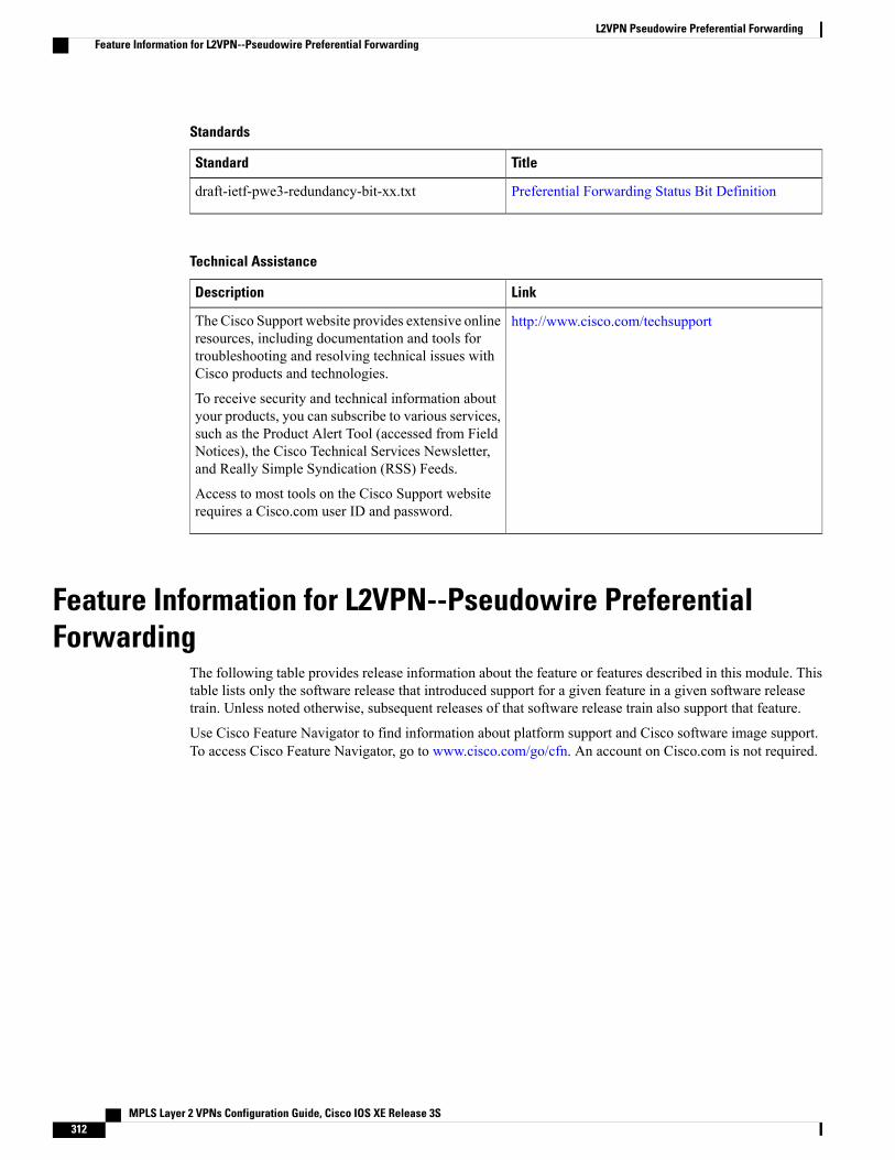
Standards
TitleStandard
Preferential Forwarding Status Bit Definitiondraft-ietf-pwe3-redundancy-bit-xx.txt
Technical Assistance
LinkDescription
http://www.cisco.com/techsupportThe Cisco Support website provides extensive onlineresources, including documentation and tools fortroubleshooting and resolving technical issues withCisco products and technologies.
To receive security and technical information aboutyour products, you can subscribe to various services,such as the Product Alert Tool (accessed from FieldNotices), the Cisco Technical Services Newsletter,and Really Simple Syndication (RSS) Feeds.
Access to most tools on the Cisco Support websiterequires a Cisco.com user ID and password.
Feature Information for L2VPN--Pseudowire PreferentialForwarding
The following table provides release information about the feature or features described in this module. Thistable lists only the software release that introduced support for a given feature in a given software releasetrain. Unless noted otherwise, subsequent releases of that software release train also support that feature.
Use Cisco Feature Navigator to find information about platform support and Cisco software image support.To access Cisco Feature Navigator, go to www.cisco.com/go/cfn. An account on Cisco.com is not required.
MPLS Layer 2 VPNs Configuration Guide, Cisco IOS XE Release 3S312
L2VPN Pseudowire Preferential ForwardingFeature Information for L2VPN--Pseudowire Preferential Forwarding
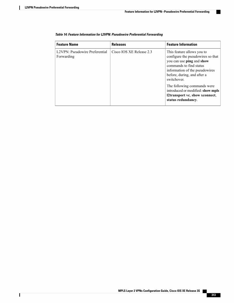
Table 14: Feature Information for L2VPN: Pseudowire Preferential Forwarding
Feature InformationReleasesFeature Name
This feature allows you toconfigure the pseudowires so thatyou can use ping and showcommands to find statusinformation of the pseudowiresbefore, during, and after aswitchover.
The following commands wereintroduced ormodified: showmplsl2transport vc, show xconnect,status redundancy.
Cisco IOS XE Release 2.3L2VPN: Pseudowire PreferentialForwarding
MPLS Layer 2 VPNs Configuration Guide, Cisco IOS XE Release 3S 313
L2VPN Pseudowire Preferential ForwardingFeature Information for L2VPN--Pseudowire Preferential Forwarding

MPLS Layer 2 VPNs Configuration Guide, Cisco IOS XE Release 3S314
L2VPN Pseudowire Preferential ForwardingFeature Information for L2VPN--Pseudowire Preferential Forwarding
C H A P T E R 5L2VPN Multisegment Pseudowires
The L2VPN Multisegment Pseudowires feature enables you to configure two or more Layer 2 pseudowiresegments that function as a single pseudowire. The L2VPNMultisegment Pseudowires feature spanmultiplecores or autonomous systems of the same or different carrier networks.
• Finding Feature Information, page 315
• Prerequisites for L2VPN Multisegment Pseudowires, page 315
• Restrictions for L2VPN Multisegment Pseudowires, page 316
• Information About L2VPN Multisegment Pseudowires, page 316
• How to Configure L2VPN Multisegment Pseudowires, page 317
• Additional References, page 326
• Feature Information for L2VPN Multisegment Pseudowires, page 327
Finding Feature InformationYour software release may not support all the features documented in this module. For the latest caveats andfeature information, see Bug Search Tool and the release notes for your platform and software release. Tofind information about the features documented in this module, and to see a list of the releases in which eachfeature is supported, see the feature information table at the end of this module.
Use Cisco Feature Navigator to find information about platform support and Cisco software image support.To access Cisco Feature Navigator, go to www.cisco.com/go/cfn. An account on Cisco.com is not required.
Prerequisites for L2VPN Multisegment PseudowiresBefore configuring this feature, see the following documents:
• Any Transport over MPLS
• L2VPN Pseudowire Switching
• MPLS LSP Ping/Traceroute for LDP/TE, and LSP Ping for VCCV
MPLS Layer 2 VPNs Configuration Guide, Cisco IOS XE Release 3S 315
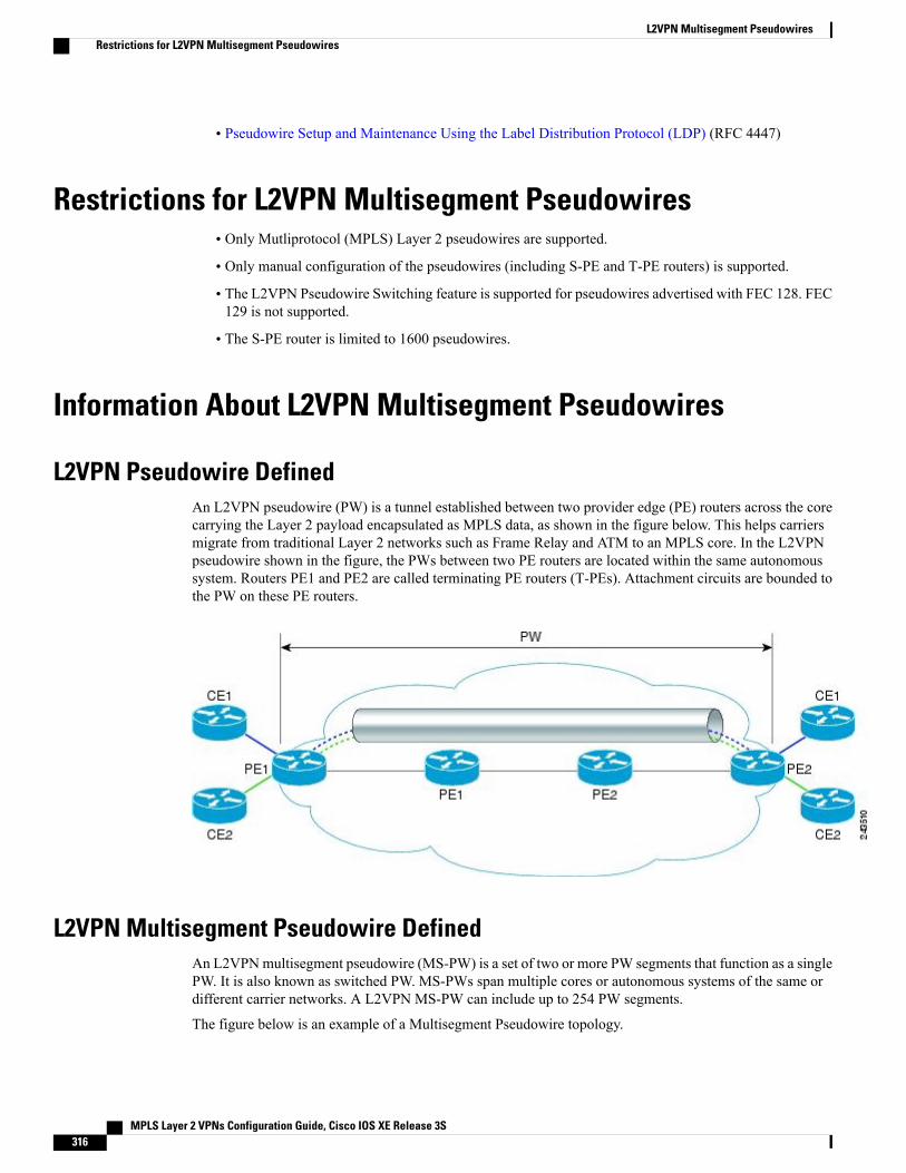
• Pseudowire Setup and Maintenance Using the Label Distribution Protocol (LDP) (RFC 4447)
Restrictions for L2VPN Multisegment Pseudowires• Only Mutliprotocol (MPLS) Layer 2 pseudowires are supported.
• Only manual configuration of the pseudowires (including S-PE and T-PE routers) is supported.
• The L2VPN Pseudowire Switching feature is supported for pseudowires advertised with FEC 128. FEC129 is not supported.
• The S-PE router is limited to 1600 pseudowires.
Information About L2VPN Multisegment Pseudowires
L2VPN Pseudowire DefinedAn L2VPN pseudowire (PW) is a tunnel established between two provider edge (PE) routers across the corecarrying the Layer 2 payload encapsulated as MPLS data, as shown in the figure below. This helps carriersmigrate from traditional Layer 2 networks such as Frame Relay and ATM to an MPLS core. In the L2VPNpseudowire shown in the figure, the PWs between two PE routers are located within the same autonomoussystem. Routers PE1 and PE2 are called terminating PE routers (T-PEs). Attachment circuits are bounded tothe PW on these PE routers.
L2VPN Multisegment Pseudowire DefinedAn L2VPNmultisegment pseudowire (MS-PW) is a set of two or more PW segments that function as a singlePW. It is also known as switched PW. MS-PWs span multiple cores or autonomous systems of the same ordifferent carrier networks. A L2VPN MS-PW can include up to 254 PW segments.
The figure below is an example of a Multisegment Pseudowire topology.
MPLS Layer 2 VPNs Configuration Guide, Cisco IOS XE Release 3S316
L2VPN Multisegment PseudowiresRestrictions for L2VPN Multisegment Pseudowires
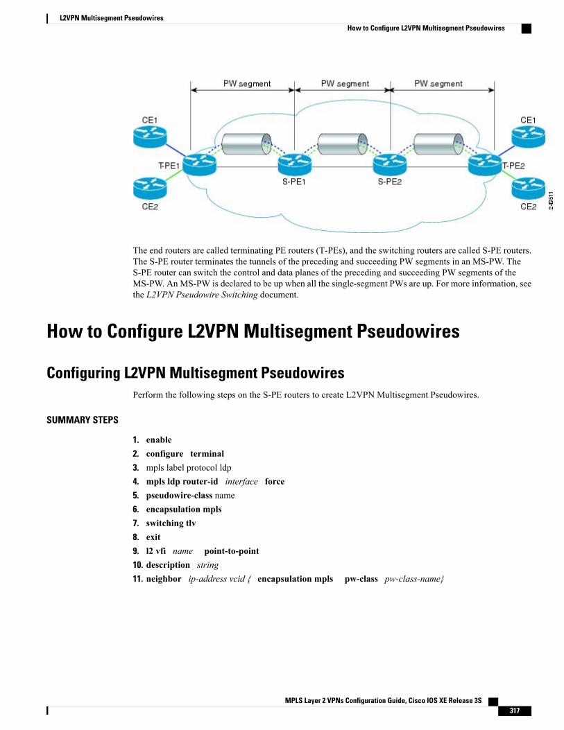
The end routers are called terminating PE routers (T-PEs), and the switching routers are called S-PE routers.The S-PE router terminates the tunnels of the preceding and succeeding PW segments in an MS-PW. TheS-PE router can switch the control and data planes of the preceding and succeeding PW segments of theMS-PW. An MS-PW is declared to be up when all the single-segment PWs are up. For more information, seethe L2VPN Pseudowire Switching document.
How to Configure L2VPN Multisegment Pseudowires
Configuring L2VPN Multisegment PseudowiresPerform the following steps on the S-PE routers to create L2VPN Multisegment Pseudowires.
SUMMARY STEPS
1. enable2. configure terminal3. mpls label protocol ldp4. mpls ldp router-id interface force5. pseudowire-class name6. encapsulation mpls7. switching tlv8. exit9. l2 vfi name point-to-point10. description string11. neighbor ip-address vcid { encapsulation mpls pw-class pw-class-name}
MPLS Layer 2 VPNs Configuration Guide, Cisco IOS XE Release 3S 317
L2VPN Multisegment PseudowiresHow to Configure L2VPN Multisegment Pseudowires
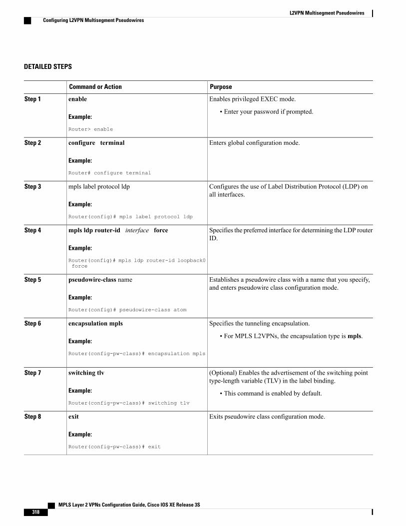
DETAILED STEPS
PurposeCommand or Action
Enables privileged EXEC mode.enableStep 1
Example:
Router> enable
• Enter your password if prompted.
Enters global configuration mode.configure terminal
Example:
Router# configure terminal
Step 2
Configures the use of Label Distribution Protocol (LDP) onall interfaces.
mpls label protocol ldp
Example:
Router(config)# mpls label protocol ldp
Step 3
Specifies the preferred interface for determining the LDP routerID.
mpls ldp router-id interface force
Example:
Router(config)# mpls ldp router-id loopback0force
Step 4
Establishes a pseudowire class with a name that you specify,and enters pseudowire class configuration mode.
pseudowire-class name
Example:
Router(config)# pseudowire-class atom
Step 5
Specifies the tunneling encapsulation.encapsulation mplsStep 6
Example:
Router(config-pw-class)# encapsulation mpls
• For MPLS L2VPNs, the encapsulation type ismpls.
(Optional) Enables the advertisement of the switching pointtype-length variable (TLV) in the label binding.
switching tlv
Example:
Router(config-pw-class)# switching tlv
Step 7
• This command is enabled by default.
Exits pseudowire class configuration mode.exit
Example:
Router(config-pw-class)# exit
Step 8
MPLS Layer 2 VPNs Configuration Guide, Cisco IOS XE Release 3S318
L2VPN Multisegment PseudowiresConfiguring L2VPN Multisegment Pseudowires
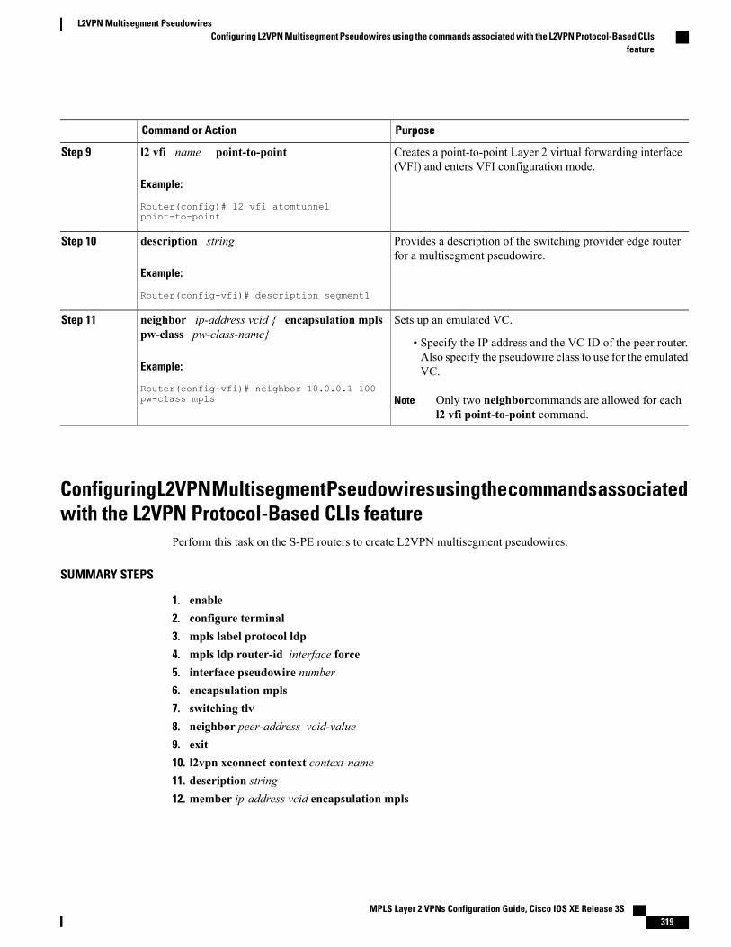
PurposeCommand or Action
Creates a point-to-point Layer 2 virtual forwarding interface(VFI) and enters VFI configuration mode.
l2 vfi name point-to-point
Example:
Router(config)# l2 vfi atomtunnelpoint-to-point
Step 9
Provides a description of the switching provider edge routerfor a multisegment pseudowire.
description string
Example:
Router(config-vfi)# description segment1
Step 10
Sets up an emulated VC.neighbor ip-address vcid { encapsulation mplspw-class pw-class-name}
Step 11
• Specify the IP address and the VC ID of the peer router.Also specify the pseudowire class to use for the emulatedVC.Example:
Router(config-vfi)# neighbor 10.0.0.1 100pw-class mpls Only two neighborcommands are allowed for each
l2 vfi point-to-point command.Note
Configuring L2VPN Multisegment Pseudowires using the commands associatedwith the L2VPN Protocol-Based CLIs feature
Perform this task on the S-PE routers to create L2VPN multisegment pseudowires.
SUMMARY STEPS
1. enable2. configure terminal3. mpls label protocol ldp4. mpls ldp router-id interface force5. interface pseudowire number6. encapsulation mpls7. switching tlv8. neighbor peer-address vcid-value9. exit10. l2vpn xconnect context context-name11. description string12. member ip-address vcid encapsulation mpls
MPLS Layer 2 VPNs Configuration Guide, Cisco IOS XE Release 3S 319
L2VPN Multisegment PseudowiresConfiguring L2VPN Multisegment Pseudowires using the commands associated with the L2VPN Protocol-Based CLIs
feature
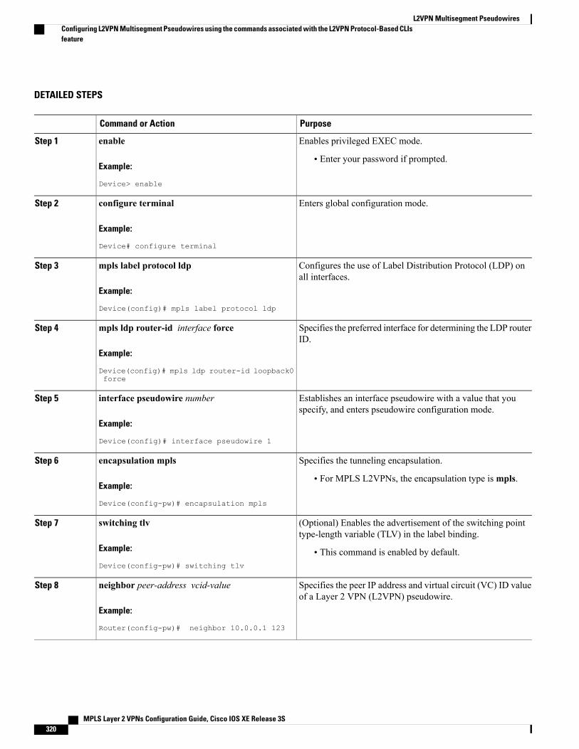
DETAILED STEPS
PurposeCommand or Action
Enables privileged EXEC mode.enableStep 1
Example:
Device> enable
• Enter your password if prompted.
Enters global configuration mode.configure terminal
Example:
Device# configure terminal
Step 2
Configures the use of Label Distribution Protocol (LDP) onall interfaces.
mpls label protocol ldp
Example:
Device(config)# mpls label protocol ldp
Step 3
Specifies the preferred interface for determining the LDP routerID.
mpls ldp router-id interface force
Example:
Device(config)# mpls ldp router-id loopback0force
Step 4
Establishes an interface pseudowire with a value that youspecify, and enters pseudowire configuration mode.
interface pseudowire number
Example:
Device(config)# interface pseudowire 1
Step 5
Specifies the tunneling encapsulation.encapsulation mplsStep 6
Example:
Device(config-pw)# encapsulation mpls
• For MPLS L2VPNs, the encapsulation type ismpls.
(Optional) Enables the advertisement of the switching pointtype-length variable (TLV) in the label binding.
switching tlv
Example:
Device(config-pw)# switching tlv
Step 7
• This command is enabled by default.
Specifies the peer IP address and virtual circuit (VC) ID valueof a Layer 2 VPN (L2VPN) pseudowire.
neighbor peer-address vcid-value
Example:
Router(config-pw)# neighbor 10.0.0.1 123
Step 8
MPLS Layer 2 VPNs Configuration Guide, Cisco IOS XE Release 3S320
L2VPN Multisegment PseudowiresConfiguring L2VPN Multisegment Pseudowires using the commands associated with the L2VPN Protocol-Based CLIsfeature
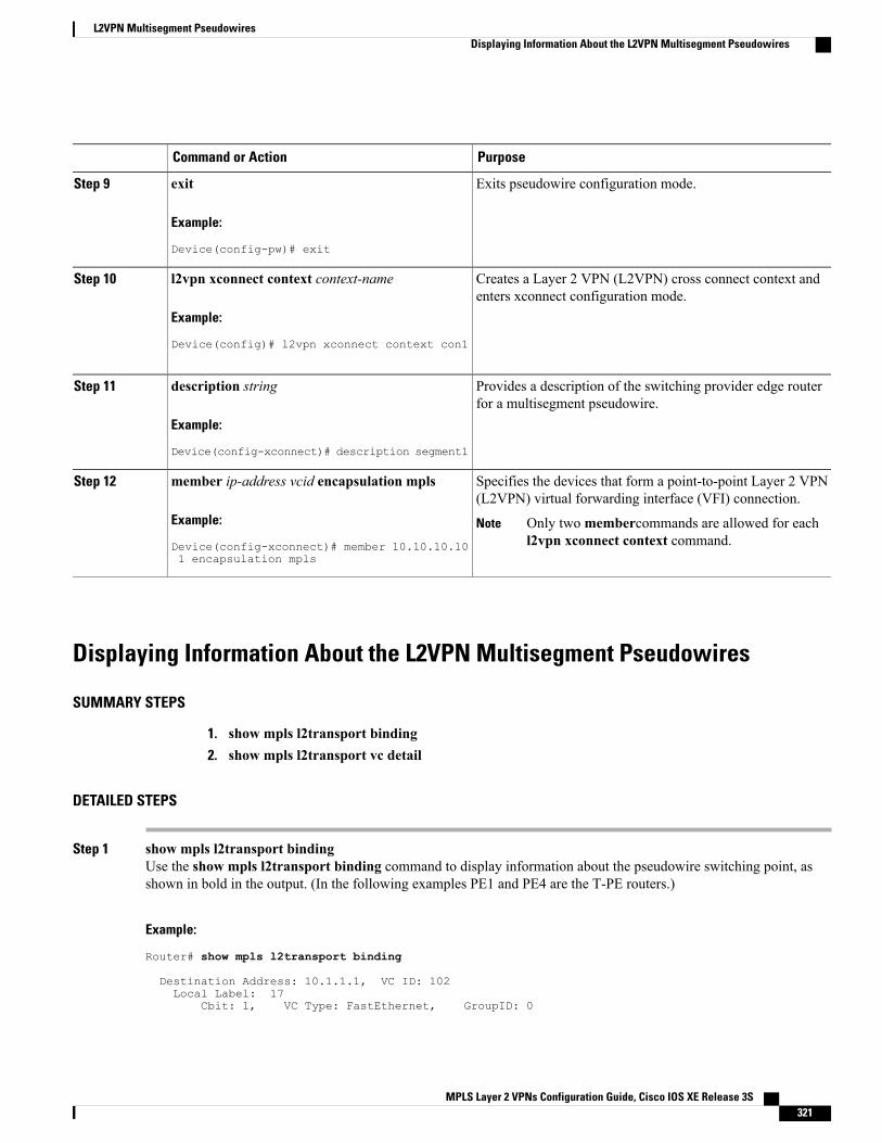
PurposeCommand or Action
Exits pseudowire configuration mode.exit
Example:
Device(config-pw)# exit
Step 9
Creates a Layer 2 VPN (L2VPN) cross connect context andenters xconnect configuration mode.
l2vpn xconnect context context-name
Example:
Device(config)# l2vpn xconnect context con1
Step 10
Provides a description of the switching provider edge routerfor a multisegment pseudowire.
description string
Example:
Device(config-xconnect)# description segment1
Step 11
Specifies the devices that form a point-to-point Layer 2 VPN(L2VPN) virtual forwarding interface (VFI) connection.
member ip-address vcid encapsulation mpls
Example:
Device(config-xconnect)# member 10.10.10.101 encapsulation mpls
Step 12
Only twomembercommands are allowed for eachl2vpn xconnect context command.
Note
Displaying Information About the L2VPN Multisegment Pseudowires
SUMMARY STEPS
1. show mpls l2transport binding2. show mpls l2transport vc detail
DETAILED STEPS
Step 1 show mpls l2transport bindingUse the show mpls l2transport binding command to display information about the pseudowire switching point, asshown in bold in the output. (In the following examples PE1 and PE4 are the T-PE routers.)
Example:
Router# show mpls l2transport binding
Destination Address: 10.1.1.1, VC ID: 102Local Label: 17
Cbit: 1, VC Type: FastEthernet, GroupID: 0
MPLS Layer 2 VPNs Configuration Guide, Cisco IOS XE Release 3S 321
L2VPN Multisegment PseudowiresDisplaying Information About the L2VPN Multisegment Pseudowires
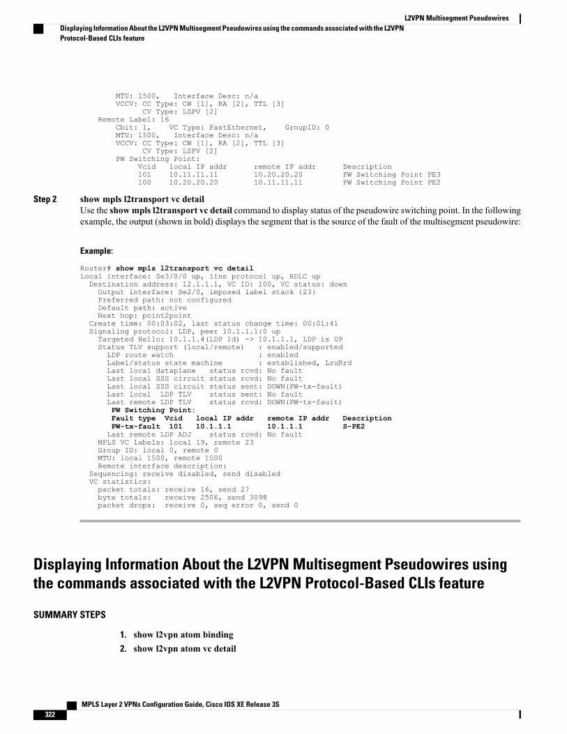
MTU: 1500, Interface Desc: n/aVCCV: CC Type: CW [1], RA [2], TTL [3]
CV Type: LSPV [2]Remote Label: 16
Cbit: 1, VC Type: FastEthernet, GroupID: 0MTU: 1500, Interface Desc: n/aVCCV: CC Type: CW [1], RA [2], TTL [3]
CV Type: LSPV [2]PW Switching Point:
Vcid local IP addr remote IP addr Description101 10.11.11.11 10.20.20.20 PW Switching Point PE3100 10.20.20.20 10.11.11.11 PW Switching Point PE2
Step 2 show mpls l2transport vc detailUse the showmpls l2transport vc detail command to display status of the pseudowire switching point. In the followingexample, the output (shown in bold) displays the segment that is the source of the fault of the multisegment pseudowire:
Example:
Router# show mpls l2transport vc detailLocal interface: Se3/0/0 up, line protocol up, HDLC upDestination address: 12.1.1.1, VC ID: 100, VC status: downOutput interface: Se2/0, imposed label stack {23}Preferred path: not configuredDefault path: activeNext hop: point2point
Create time: 00:03:02, last status change time: 00:01:41Signaling protocol: LDP, peer 10.1.1.1:0 upTargeted Hello: 10.1.1.4(LDP Id) -> 10.1.1.1, LDP is UPStatus TLV support (local/remote) : enabled/supportedLDP route watch : enabledLabel/status state machine : established, LruRrdLast local dataplane status rcvd: No faultLast local SSS circuit status rcvd: No faultLast local SSS circuit status sent: DOWN(PW-tx-fault)Last local LDP TLV status sent: No faultLast remote LDP TLV status rcvd: DOWN(PW-tx-fault)PW Switching Point:Fault type Vcid local IP addr remote IP addr DescriptionPW-tx-fault 101 10.1.1.1 10.1.1.1 S-PE2Last remote LDP ADJ status rcvd: No fault
MPLS VC labels: local 19, remote 23Group ID: local 0, remote 0MTU: local 1500, remote 1500Remote interface description:
Sequencing: receive disabled, send disabledVC statistics:packet totals: receive 16, send 27byte totals: receive 2506, send 3098packet drops: receive 0, seq error 0, send 0
Displaying Information About the L2VPN Multisegment Pseudowires usingthe commands associated with the L2VPN Protocol-Based CLIs feature
SUMMARY STEPS
1. show l2vpn atom binding2. show l2vpn atom vc detail
MPLS Layer 2 VPNs Configuration Guide, Cisco IOS XE Release 3S322
L2VPN Multisegment PseudowiresDisplaying Information About the L2VPN Multisegment Pseudowires using the commands associated with the L2VPNProtocol-Based CLIs feature
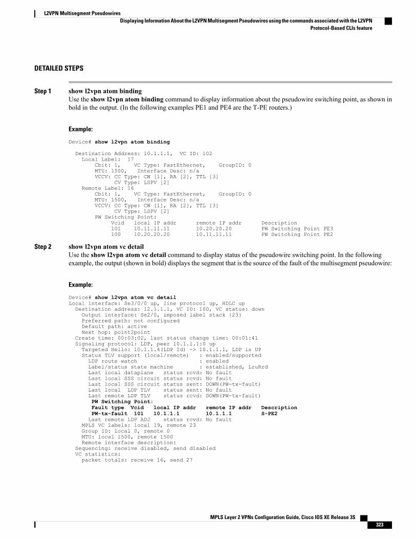
DETAILED STEPS
Step 1 show l2vpn atom bindingUse the show l2vpn atom binding command to display information about the pseudowire switching point, as shown inbold in the output. (In the following examples PE1 and PE4 are the T-PE routers.)
Example:
Device# show l2vpn atom binding
Destination Address: 10.1.1.1, VC ID: 102Local Label: 17
Cbit: 1, VC Type: FastEthernet, GroupID: 0MTU: 1500, Interface Desc: n/aVCCV: CC Type: CW [1], RA [2], TTL [3]
CV Type: LSPV [2]Remote Label: 16
Cbit: 1, VC Type: FastEthernet, GroupID: 0MTU: 1500, Interface Desc: n/aVCCV: CC Type: CW [1], RA [2], TTL [3]
CV Type: LSPV [2]PW Switching Point:
Vcid local IP addr remote IP addr Description101 10.11.11.11 10.20.20.20 PW Switching Point PE3100 10.20.20.20 10.11.11.11 PW Switching Point PE2
Step 2 show l2vpn atom vc detailUse the show l2vpn atom vc detail command to display status of the pseudowire switching point. In the followingexample, the output (shown in bold) displays the segment that is the source of the fault of the multisegment pseudowire:
Example:
Device# show l2vpn atom vc detailLocal interface: Se3/0/0 up, line protocol up, HDLC upDestination address: 12.1.1.1, VC ID: 100, VC status: downOutput interface: Se2/0, imposed label stack {23}Preferred path: not configuredDefault path: activeNext hop: point2point
Create time: 00:03:02, last status change time: 00:01:41Signaling protocol: LDP, peer 10.1.1.1:0 upTargeted Hello: 10.1.1.4(LDP Id) -> 10.1.1.1, LDP is UPStatus TLV support (local/remote) : enabled/supportedLDP route watch : enabledLabel/status state machine : established, LruRrdLast local dataplane status rcvd: No faultLast local SSS circuit status rcvd: No faultLast local SSS circuit status sent: DOWN(PW-tx-fault)Last local LDP TLV status sent: No faultLast remote LDP TLV status rcvd: DOWN(PW-tx-fault)PW Switching Point:Fault type Vcid local IP addr remote IP addr DescriptionPW-tx-fault 101 10.1.1.1 10.1.1.1 S-PE2Last remote LDP ADJ status rcvd: No fault
MPLS VC labels: local 19, remote 23Group ID: local 0, remote 0MTU: local 1500, remote 1500Remote interface description:
Sequencing: receive disabled, send disabledVC statistics:packet totals: receive 16, send 27
MPLS Layer 2 VPNs Configuration Guide, Cisco IOS XE Release 3S 323
L2VPN Multisegment PseudowiresDisplaying Information About the L2VPN Multisegment Pseudowires using the commands associated with the L2VPN
Protocol-Based CLIs feature
byte totals: receive 2506, send 3098packet drops: receive 0, seq error 0, send 0
Performing ping mpls and trace mpls Operations on the L2VPN MultisegmentPseudowires
You can use the pingmpls and tracemplscommands to verify that all the segments of theMPLSmultisegmentpseudowire are operating.
You can use the ping mpls command to verify connectivity at the following pseudowire points:
• From one end of the pseudowire to the other
• From one of the pseudowires to a specific segment
• The segment between two adjacent S-PE routers
You can use the trace mplscommand to verify connectivity at the following pseudowire points:
• From one end of the pseudowire to the other
• From one of the pseudowires to a specific segment
• The segment between two adjacent S-PE routers
• A range of segments
SUMMARY STEPS
1. ping mpls pseudowire destination-address vc-id [segment segment-number]2. trace mpls pseudowire destination-address vc-id segment segment-number segment-number
DETAILED STEPS
Step 1 ping mpls pseudowire destination-address vc-id [segment segment-number]Where:
• destination-address is the address of the S-PE router, which is the end of the segment from the direction of thesource.
• vc-id is the VC ID of the segment from the source to the next PE router.
• segment segment-number is optional and specifies the segment you want to ping.
The following examples use the topology shown in the second figure above :
• To perform an end-to-end ping operation from T-PE1 to T-PE2, enter the following command:
ping mpls pseudowire <addr-of-S-PE1> <vc-id between T-PE1 and S-PE1>
MPLS Layer 2 VPNs Configuration Guide, Cisco IOS XE Release 3S324
L2VPN Multisegment PseudowiresPerforming ping mpls and trace mpls Operations on the L2VPN Multisegment Pseudowires
• To perform a ping operation from T-PE1 to segment 2, enter the following command:
ping mpls pseudowire <addr-of-S-PE1> <vc-id between T-PE1 and S-PE1> segment 2
Example:
Step 2 trace mpls pseudowire destination-address vc-id segment segment-number segment-numberWhere:
• destination-address is the address of the next S-PE router from the original of the trace.
• vc-id is the VC ID of the segment from which the trace command is issued.
• segment-number indicates the segment upon which the trace operation will act. If you enter two segment numbers,the traceroute operation will perform a trace on that range of routers.
The following examples use the topology shown in the second figure above :
• To perform a trace operation from T-PE1 to segment 2 of the multisegment pseudowire, enter the followingcommand:
trace mpls pseudowire <addr-of-S-PE1> <vc-id between T-PE1 and S-PE1> segment 2
This example performs a trace from T-PE1 to S-PE2.
• To perform a trace operation on a range of segments, enter the following command. This example performs a tracefrom S-PE2 to T-PE2.
trace mpls pseudowire <addr-of-S-PE1> <vc-id between T-PE1 and S-PE1> segment 2 4
The following command performs a trace operation on S-PE router 10.10.10.9, on segment 1 and then on segment 2:
Example:
router# trace mpls pseudowire 10.10.10.9 220 segment 1Tracing MS-PW segments within range [1-1] peer address 10.10.10.9 and timeout 2 secondsCodes: '!' - success, 'Q' - request not sent, '.' - timeout,'L' - labeled output interface, 'B' - unlabeled output interface,'D' - DS Map mismatch, 'F' - no FEC mapping, 'f' - FEC mismatch,'M' - malformed request, 'm' - unsupported tlvs, 'N' - no label entry,'P' - no rx intf label prot, 'p' - premature termination of LSP,'R' - transit router, 'I' - unknown upstream index,'X' - unknown return code, 'x' - return code 0
Type escape sequence to abort.L 1 10.10.9.9 0 ms [Labels: 18 Exp: 0]
local 10.10.10.22 remote 10.10.10.9 vc id 220router# trace mpls pseudowire 10.10.10.9 220 segment 2Tracing MS-PW segments within range [1-2] peer address 10.10.10.9 and timeout 2 secondsCodes: '!' - success, 'Q' - request not sent, '.' - timeout,'L' - labeled output interface, 'B' - unlabeled output interface,'D' - DS Map mismatch, 'F' - no FEC mapping, 'f' - FEC mismatch,'M' - malformed request, 'm' - unsupported tlvs, 'N' - no label entry,'P' - no rx intf label prot, 'p' - premature termination of LSP,'R' - transit router, 'I' - unknown upstream index,'X' - unknown return code, 'x' - return code 0
Type escape sequence to abort.L 1 10.10.9.9 4 ms [Labels: 18 Exp: 0]
local 10.10.10.22 remote 10.10.10.9 vc id 220
MPLS Layer 2 VPNs Configuration Guide, Cisco IOS XE Release 3S 325
L2VPN Multisegment PseudowiresPerforming ping mpls and trace mpls Operations on the L2VPN Multisegment Pseudowires
! 2 10.10.3.3 4 ms [Labels: 16 Exp: 0]local 10.10.10.9 remote 10.10.10.3 vc id 220
Additional ReferencesRelated Documents
Document TitleRelated Topic
Cisco IOS Master Commands List, All ReleasesCisco IOS commands
Cisco IOS Multiprotocol Label Switching CommandReference
Description of commands associated withMPLS andMPLS applications
• Any Transport over MPLS
• L2VPN Pseudowire Switching
• MPLS LSP Ping/Traceroute for LDP/TE, andLSP Ping for VCCV
Layer 2 VPNS
Standards
TitleStandard
Pseudowire Setup and Maintenance Using the LabelDistribution Protocol (LDP)
RFC 4777
MIBs
MIBs LinkMIB
To locate and downloadMIBs for selected platforms,Cisco software releases, and feature sets, use CiscoMIB Locator found at the following URL:
http://www.cisco.com/go/mibs
No new or modified MIBs are supported by thisfeature, and support for existing MIBs has not beenmodified by this feature.
MPLS Layer 2 VPNs Configuration Guide, Cisco IOS XE Release 3S326
L2VPN Multisegment PseudowiresAdditional References
RFCs
TitleRFC
--No new or modified RFCs are supported by thisfeature, and support for existing RFCs has not beenmodified by this feature.
Technical Assistance
LinkDescription
http://www.cisco.com/cisco/web/support/index.htmlThe Cisco Support and Documentation websiteprovides online resources to download documentation,software, and tools. Use these resources to install andconfigure the software and to troubleshoot and resolvetechnical issues with Cisco products and technologies.Access to most tools on the Cisco Support andDocumentation website requires a Cisco.com user IDand password.
Feature Information for L2VPN Multisegment PseudowiresThe following table provides release information about the feature or features described in this module. Thistable lists only the software release that introduced support for a given feature in a given software releasetrain. Unless noted otherwise, subsequent releases of that software release train also support that feature.
Use Cisco Feature Navigator to find information about platform support and Cisco software image support.To access Cisco Feature Navigator, go to www.cisco.com/go/cfn. An account on Cisco.com is not required.
MPLS Layer 2 VPNs Configuration Guide, Cisco IOS XE Release 3S 327
L2VPN Multisegment PseudowiresFeature Information for L2VPN Multisegment Pseudowires
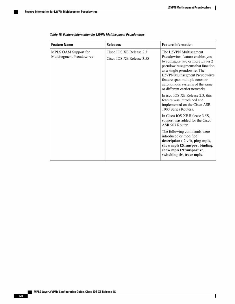
Table 15: Feature Information for L2VPN Multisegment Pseudowires
Feature InformationReleasesFeature Name
The L2VPN MultisegmentPseudowires feature enables youto configure two or more Layer 2pseudowire segments that functionas a single pseudowire. TheL2VPNMultisegment Pseudowiresfeature span multiple cores orautonomous systems of the sameor different carrier networks.
In isco IOS XE Release 2.3, thisfeature was introduced andimplemented on the Cisco ASR1000 Series Routers.
In Cisco IOS XE Release 3.5S,support was added for the CiscoASR 903 Router.
The following commands wereintroduced or modified:description (l2 vfi), ping mpls,show mpls l2transport binding,show mpls l2transport vc,switching tlv, trace mpls.
Cisco IOS XE Release 2.3
Cisco IOS XE Release 3.5S
MPLS OAM Support forMultisegment Pseudowires
MPLS Layer 2 VPNs Configuration Guide, Cisco IOS XE Release 3S328
L2VPN Multisegment PseudowiresFeature Information for L2VPN Multisegment Pseudowires
C H A P T E R 6MPLS Quality of Service
The MPLS Quality of Service feature (formerly named as the MPLS CoS feature) enables you to providedifferentiated services across an MPLS network. To satisfy a wide range of networking requirements, youcan specify the class of service applicable to each transmitted IP packet. Different classes of service can beestablished for IP packets by setting the IP precedence bit in the header of each packet.
• Prerequisites for MPLS Quality of Service, page 329
• Information About MPLS Quality of Service, page 330
• How to Configure MPLS Quality of Service, page 334
• Configuration Examples for MPLS Quality of Service, page 341
• Additional References for MPLS Quality of Service, page 345
• Feature Information for MPLS Quality of Service, page 346
Prerequisites for MPLS Quality of ServiceTo use MPLS CoS to full advantage in your network, the following functionality must be supported:
• Multiprotocol Label Switching (MPLS)—MPLS is the standardized label switching protocol definedby the Internet Engineering Task Force (IETF).
• Cisco Express Forwarding—Cisco Express Forwarding is an advanced Layer 3 IP switching technologythat optimizes performance and scalability in networks that handle large volumes of traffic and thatexhibit dynamic traffic patterns.
• Asynchronous Transfer Mode (ATM)—ATM signaling support is required if you are using ATMinterfaces in your network.
If you are using only packet interfaces in your network, ATM functionality is not needed.
• QoS features:
◦Weighted fair queueing (WFQ)—Used on non-GSR platforms, WFQ is a dynamic schedulingmethod that allocates bandwidth fairly to all network traffic.
MPLS Layer 2 VPNs Configuration Guide, Cisco IOS XE Release 3S 329
WFQ applies priorities, or weights, to traffic to classify the traffic into flows and determine howmuch bandwidth to allow each flow. WFQ moves interactive traffic to the front of a queue toreduce response time and fairly shares the remaining bandwidth among high-bandwidth flows.
◦Weighted random early detection (WRED)—WRED is a congestion avoidance mechanism thatextends RED functionality by allowing different RED parameters to be configured per IP precedencevalue.
IP precedence bits, contained in the type of service (ToS) octet in the IP packet header, are usedto denote the relative importance or priority of an IP packet. WRED uses these IP precedencevalues to classify packets into different discard priorities or classes of service.
◦Modified deficit round robin (MDRR)—Used only on GSR platforms, MDRR is a traffic classprioritization mechanism that incorporates emission priority as a facet of quality of service. MDRRis similar in function to WFQ on non-GSR platforms.
InMDRR, IP traffic is mapped to different classes of service queues. A group of queues is assignedto each traffic destination. On the transmit side of the platform, a group of queues is defined on aper-interface basis; on the receive side of the platform, a group of queues is defined on aper-destination basis. IP packets are then mapped to these queues, based on their IP precedencevalue.
These queues are serviced on a round-robin basis, except for a queue that has been defined to runin either of two ways: strict priority mode or alternate priority mode.
In strict priority mode, the high priority queue is serviced whenever it is not empty; this ensuresthe lowest possible delay for high priority traffic. In this mode, however, the possibility exists thatother traffic might not be serviced for long periods of time if the high priority queue is consumingmost of the available bandwidth.
In alternate priority mode, the traffic queues are serviced in turn, alternating between the highpriority queue and the remaining queues.
◦Committed access rate (CAR)—CAR is a QoS feature that limits the input or output transmissionrate on an interface and classifies packets by setting the IP precedence value or the QoS group inthe IP packet header.
Information About MPLS Quality of Service
MPLS Quality of Service OverviewMPLS CoS functionality enables network administrators to provide differentiated services across an MPLSnetwork. Network administrators can satisfy a wide range of networking requirements by specifying the classof service applicable to each transmitted IP packet. Different classes of service can be established for IPpackets by setting the IP precedence bit in the header of each packet.
MPLS CoS supports the following differentiated services in an MPLS network:
• Packet classification
• Congestion avoidance
• Congestion management
MPLS Layer 2 VPNs Configuration Guide, Cisco IOS XE Release 3S330
MPLS Quality of ServiceInformation About MPLS Quality of Service
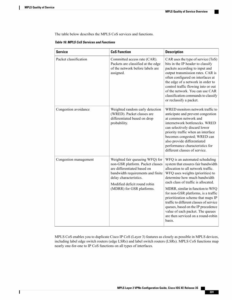
The table below describes the MPLS CoS services and functions.
Table 16: MPLS CoS Services and Functions
DescriptionCoS FunctionService
CAR uses the type of service (ToS)bits in the IP header to classifypackets according to input andoutput transmission rates. CAR isoften configured on interfaces atthe edge of a network in order tocontrol traffic flowing into or outof the network. You can use CARclassification commands to classifyor reclassify a packet.
Committed access rate (CAR).Packets are classified at the edgeof the network before labels areassigned.
Packet classification
WREDmonitors network traffic toanticipate and prevent congestionat common network andinternetwork bottlenecks. WREDcan selectively discard lowerpriority traffic when an interfacebecomes congested; WRED canalso provide differentiatedperformance characteristics fordifferent classes of service.
Weighted random early detection(WRED). Packet classes aredifferentiated based on dropprobability.
Congestion avoidance
WFQ is an automated schedulingsystem that ensures fair bandwidthallocation to all network traffic.WFQ uses weights (priorities) todetermine how much bandwidtheach class of traffic is allocated.
MDRR, similar in function toWFQfor non-GSR platforms, is a trafficprioritization scheme that maps IPtraffic to different classes of servicequeues, based on the IP precedencevalue of each packet. The queuesare then serviced on a round-robinbasis.
Weighted fair queueing WFQ) fornon-GSR platform. Packet classesare differentiated based onbandwidth requirements and finitedelay characteristics.
Modified deficit round robin(MDRR) for GSR platforms.
Congestion management
MPLS CoS enables you to duplicate Cisco IP CoS (Layer 3) features as closely as possible in MPLS devices,including label edge switch routers (edge LSRs) and label switch routers (LSRs). MPLS CoS functions mapnearly one-for-one to IP CoS functions on all types of interfaces.
MPLS Layer 2 VPNs Configuration Guide, Cisco IOS XE Release 3S 331
MPLS Quality of ServiceMPLS Quality of Service Overview
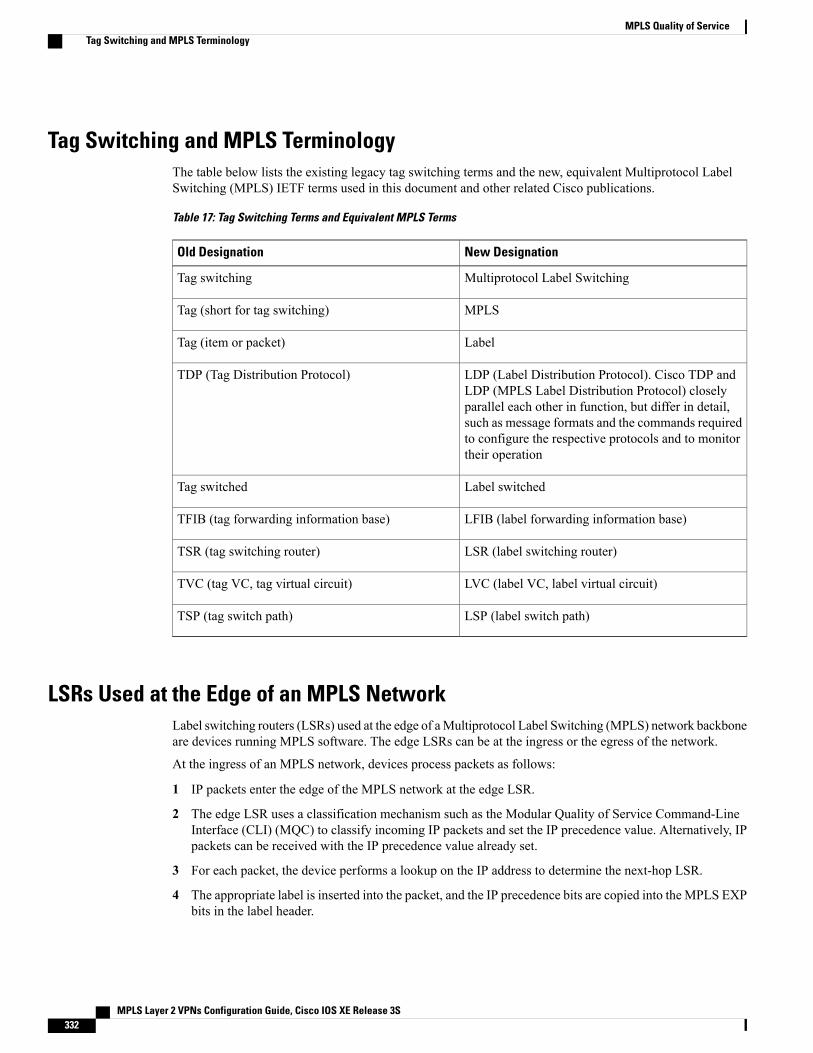
Tag Switching and MPLS TerminologyThe table below lists the existing legacy tag switching terms and the new, equivalent Multiprotocol LabelSwitching (MPLS) IETF terms used in this document and other related Cisco publications.
Table 17: Tag Switching Terms and Equivalent MPLS Terms
New DesignationOld Designation
Multiprotocol Label SwitchingTag switching
MPLSTag (short for tag switching)
LabelTag (item or packet)
LDP (Label Distribution Protocol). Cisco TDP andLDP (MPLS Label Distribution Protocol) closelyparallel each other in function, but differ in detail,such as message formats and the commands requiredto configure the respective protocols and to monitortheir operation
TDP (Tag Distribution Protocol)
Label switchedTag switched
LFIB (label forwarding information base)TFIB (tag forwarding information base)
LSR (label switching router)TSR (tag switching router)
LVC (label VC, label virtual circuit)TVC (tag VC, tag virtual circuit)
LSP (label switch path)TSP (tag switch path)
LSRs Used at the Edge of an MPLS NetworkLabel switching routers (LSRs) used at the edge of aMultiprotocol Label Switching (MPLS) network backboneare devices running MPLS software. The edge LSRs can be at the ingress or the egress of the network.
At the ingress of an MPLS network, devices process packets as follows:
1 IP packets enter the edge of the MPLS network at the edge LSR.
2 The edge LSR uses a classification mechanism such as the Modular Quality of Service Command-LineInterface (CLI) (MQC) to classify incoming IP packets and set the IP precedence value. Alternatively, IPpackets can be received with the IP precedence value already set.
3 For each packet, the device performs a lookup on the IP address to determine the next-hop LSR.
4 The appropriate label is inserted into the packet, and the IP precedence bits are copied into the MPLS EXPbits in the label header.
MPLS Layer 2 VPNs Configuration Guide, Cisco IOS XE Release 3S332
MPLS Quality of ServiceTag Switching and MPLS Terminology
5 The labeled packets are forwarded to the appropriate output interface for processing.
6 The packets are differentiated by class according to one of the following:
• Drop probability—Weighted random early detection (WRED)
• Bandwidth allocation and delay—Class-based weighted fair queueing (CBWFQ)
In either case, LSRs enforce the defined differentiation by continuing to employWRED or CBWFQ on everyingress device.
At the egress of an MPLS network, devices process packets as follows:
1 MPLS-labeled packets enter the edge LSR from the MPLS network backbone.
2 The MPLS labels are removed and IP packets may be (re)classified.
3 For each packet, the device performs a lookup on the IP address to determine the packet’s destination andforwards the packet to the destination interface for processing.
4 The packets are differentiated by the IP precedence values and treated appropriately, depending on theWRED or CBWFQ drop probability configuration.
LSRs Used at the Core of an MPLS NetworkLabel switching routers (LSRs) used at the core of a Multiprotocol Label Switching (MPLS) network aredevices running MPLS software. These devices at the core of an MPLS network process packets as follows:
1 MPLS labeled packets coming from the edge devices or other core devices enter the core device.
2 A lookup is done at the core device to determine the next hop LSR.
3 An appropriate label is placed (swapped) on the packet and the MPLS EXP bits are copied.
4 The labeled packet is then forwarded to the output interface for processing.
5 The packets are differentiated by the MPLS EXP field marking and treated appropriately, depending onthe weighted early random detection (WRED) and class-based weighted fair queueing (CBWFQ)configuration.
Benefits of MPLS CoS in IP BackbonesYou realize the following benefits when you use MPLS CoS in a backbone consisting of IP devices runningMultiprotocol Label Switching (MPLS):
• Efficient resource allocation—Weighted fair queueing (WFQ) is used to allocate bandwidth on a per-classand per-link basis, thereby guaranteeing a percentage of link bandwidth for network traffic.
• Packet differentiation—When IP packets traverse an MPLS network, packets are differentiated bymapping the IP precedence bits of the IP packets to the MPLS CoS bits in the MPLS EXP field. Thismapping of bits enables the service provider to maintain end-to-end network guarantees and meet theprovisions of customer service level agreements (SLAs).
• Future service enhancements—MPLS CoS provides building blocks for future service enhancements(such as virtual leased lines) by meeting bandwidth requirements.
MPLS Layer 2 VPNs Configuration Guide, Cisco IOS XE Release 3S 333
MPLS Quality of ServiceLSRs Used at the Core of an MPLS Network
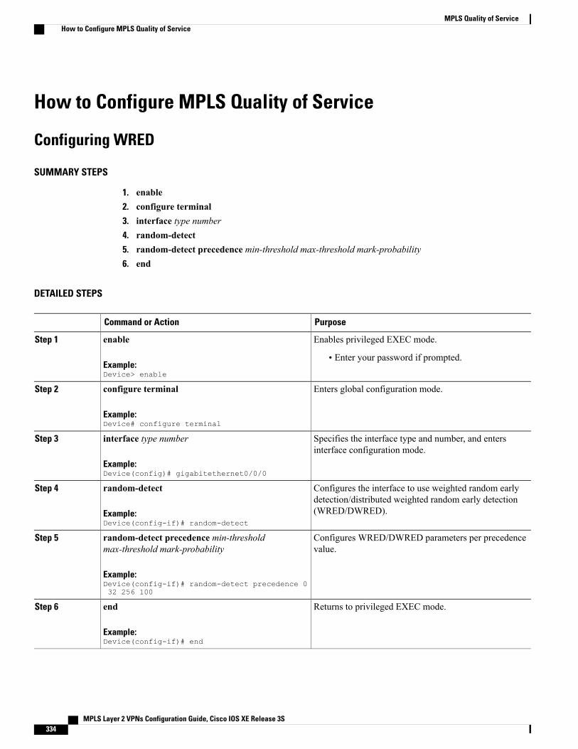
How to Configure MPLS Quality of Service
Configuring WRED
SUMMARY STEPS
1. enable2. configure terminal3. interface type number4. random-detect5. random-detect precedence min-threshold max-threshold mark-probability6. end
DETAILED STEPS
PurposeCommand or Action
Enables privileged EXEC mode.enableStep 1
Example:Device> enable
• Enter your password if prompted.
Enters global configuration mode.configure terminal
Example:Device# configure terminal
Step 2
Specifies the interface type and number, and entersinterface configuration mode.
interface type number
Example:Device(config)# gigabitethernet0/0/0
Step 3
Configures the interface to use weighted random earlydetection/distributed weighted random early detection(WRED/DWRED).
random-detect
Example:Device(config-if)# random-detect
Step 4
Configures WRED/DWRED parameters per precedencevalue.
random-detect precedence min-thresholdmax-threshold mark-probability
Example:Device(config-if)# random-detect precedence 032 256 100
Step 5
Returns to privileged EXEC mode.end
Example:Device(config-if)# end
Step 6
MPLS Layer 2 VPNs Configuration Guide, Cisco IOS XE Release 3S334
MPLS Quality of ServiceHow to Configure MPLS Quality of Service
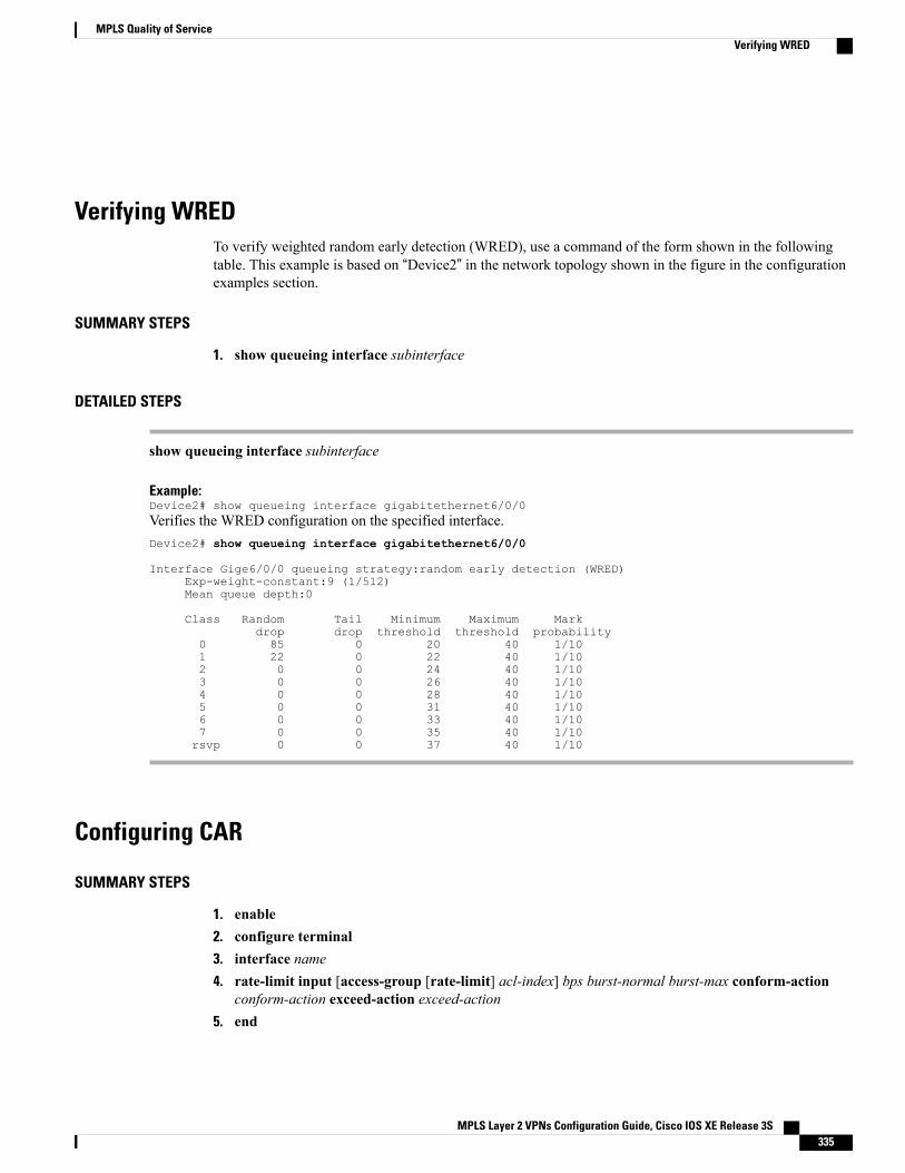
Verifying WREDTo verify weighted random early detection (WRED), use a command of the form shown in the followingtable. This example is based on “Device2” in the network topology shown in the figure in the configurationexamples section.
SUMMARY STEPS
1. show queueing interface subinterface
DETAILED STEPS
show queueing interface subinterface
Example:Device2# show queueing interface gigabitethernet6/0/0Verifies the WRED configuration on the specified interface.Device2# show queueing interface gigabitethernet6/0/0
Interface Gige6/0/0 queueing strategy:random early detection (WRED)Exp-weight-constant:9 (1/512)Mean queue depth:0
Class Random Tail Minimum Maximum Markdrop drop threshold threshold probability
0 85 0 20 40 1/101 22 0 22 40 1/102 0 0 24 40 1/103 0 0 26 40 1/104 0 0 28 40 1/105 0 0 31 40 1/106 0 0 33 40 1/107 0 0 35 40 1/10rsvp 0 0 37 40 1/10
Configuring CAR
SUMMARY STEPS
1. enable2. configure terminal3. interface name4. rate-limit input [access-group [rate-limit] acl-index] bps burst-normal burst-max conform-action
conform-action exceed-action exceed-action5. end
MPLS Layer 2 VPNs Configuration Guide, Cisco IOS XE Release 3S 335
MPLS Quality of ServiceVerifying WRED
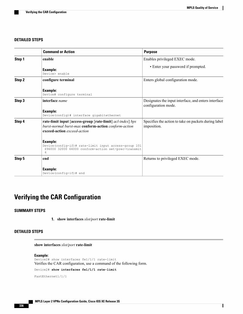
DETAILED STEPS
PurposeCommand or Action
Enables privileged EXEC mode.enableStep 1
Example:Device> enable
• Enter your password if prompted.
Enters global configuration mode.configure terminal
Example:Device# configure terminal
Step 2
Designates the input interface, and enters interfaceconfiguration mode.
interface name
Example:Device(config)# interface gigabitethernet
Step 3
Specifies the action to take on packets during labelimposition.
rate-limit input [access-group [rate-limit] acl-index] bpsburst-normal burst-max conform-action conform-actionexceed-action exceed-action
Step 4
Example:Device(config-if)# rate-limit input access-group 101496000 32000 64000 conform-action set-prec-transmit4
Returns to privileged EXEC mode.end
Example:Device(config-if)# end
Step 5
Verifying the CAR Configuration
SUMMARY STEPS
1. show interfaces slot/port rate-limit
DETAILED STEPS
show interfaces slot/port rate-limit
Example:Device2# show interfaces fe1/1/1 rate-limitVerifies the CAR configuration, use a command of the following form.Device2# show interfaces fe1/1/1 rate-limit
FastEthernet1/1/1
MPLS Layer 2 VPNs Configuration Guide, Cisco IOS XE Release 3S336
MPLS Quality of ServiceVerifying the CAR Configuration
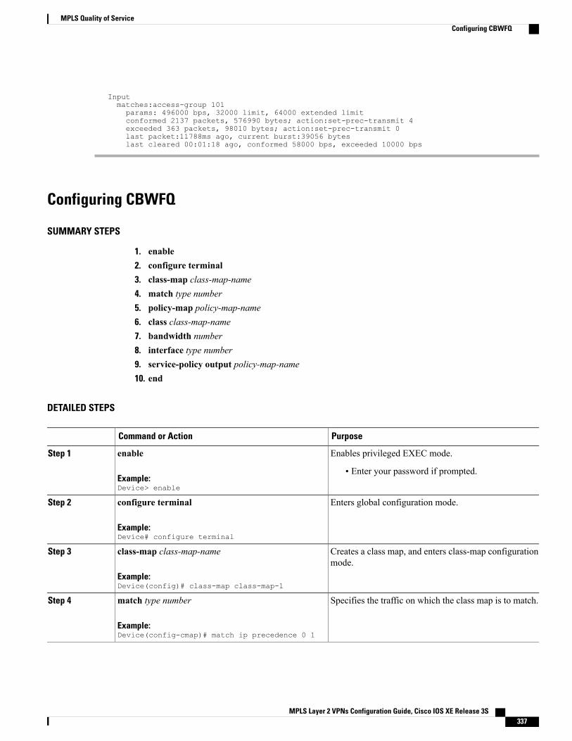
Inputmatches:access-group 101params: 496000 bps, 32000 limit, 64000 extended limitconformed 2137 packets, 576990 bytes; action:set-prec-transmit 4exceeded 363 packets, 98010 bytes; action:set-prec-transmit 0last packet:11788ms ago, current burst:39056 byteslast cleared 00:01:18 ago, conformed 58000 bps, exceeded 10000 bps
Configuring CBWFQ
SUMMARY STEPS
1. enable2. configure terminal3. class-map class-map-name4. match type number5. policy-map policy-map-name6. class class-map-name7. bandwidth number8. interface type number9. service-policy output policy-map-name10. end
DETAILED STEPS
PurposeCommand or Action
Enables privileged EXEC mode.enableStep 1
Example:Device> enable
• Enter your password if prompted.
Enters global configuration mode.configure terminal
Example:Device# configure terminal
Step 2
Creates a class map, and enters class-map configurationmode.
class-map class-map-name
Example:Device(config)# class-map class-map-1
Step 3
Specifies the traffic on which the class map is to match.match type number
Example:Device(config-cmap)# match ip precedence 0 1
Step 4
MPLS Layer 2 VPNs Configuration Guide, Cisco IOS XE Release 3S 337
MPLS Quality of ServiceConfiguring CBWFQ
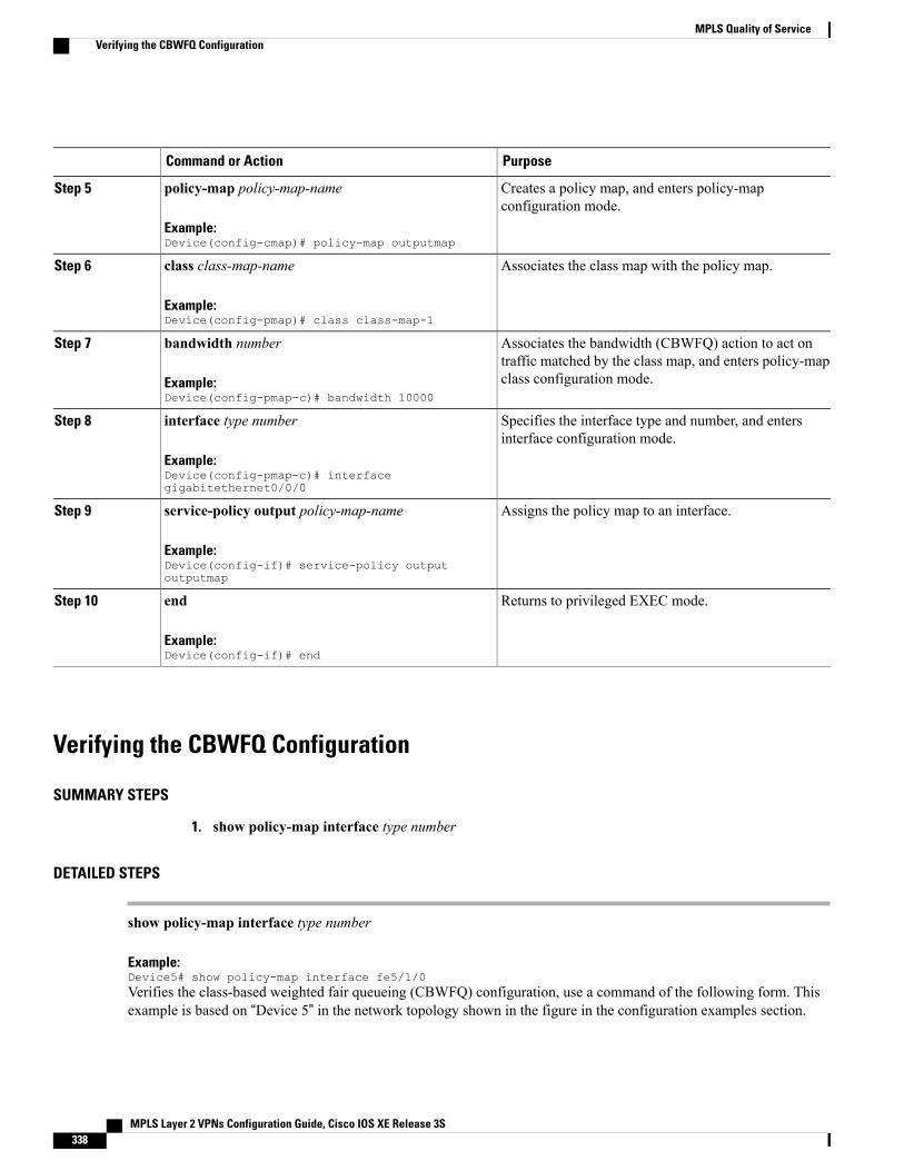
PurposeCommand or Action
Creates a policy map, and enters policy-mapconfiguration mode.
policy-map policy-map-name
Example:Device(config-cmap)# policy-map outputmap
Step 5
Associates the class map with the policy map.class class-map-name
Example:Device(config-pmap)# class class-map-1
Step 6
Associates the bandwidth (CBWFQ) action to act ontraffic matched by the class map, and enters policy-mapclass configuration mode.
bandwidth number
Example:Device(config-pmap-c)# bandwidth 10000
Step 7
Specifies the interface type and number, and entersinterface configuration mode.
interface type number
Example:Device(config-pmap-c)# interfacegigabitethernet0/0/0
Step 8
Assigns the policy map to an interface.service-policy output policy-map-name
Example:Device(config-if)# service-policy outputoutputmap
Step 9
Returns to privileged EXEC mode.end
Example:Device(config-if)# end
Step 10
Verifying the CBWFQ Configuration
SUMMARY STEPS
1. show policy-map interface type number
DETAILED STEPS
show policy-map interface type number
Example:Device5# show policy-map interface fe5/1/0Verifies the class-based weighted fair queueing (CBWFQ) configuration, use a command of the following form. Thisexample is based on “Device 5” in the network topology shown in the figure in the configuration examples section.
MPLS Layer 2 VPNs Configuration Guide, Cisco IOS XE Release 3S338
MPLS Quality of ServiceVerifying the CBWFQ Configuration
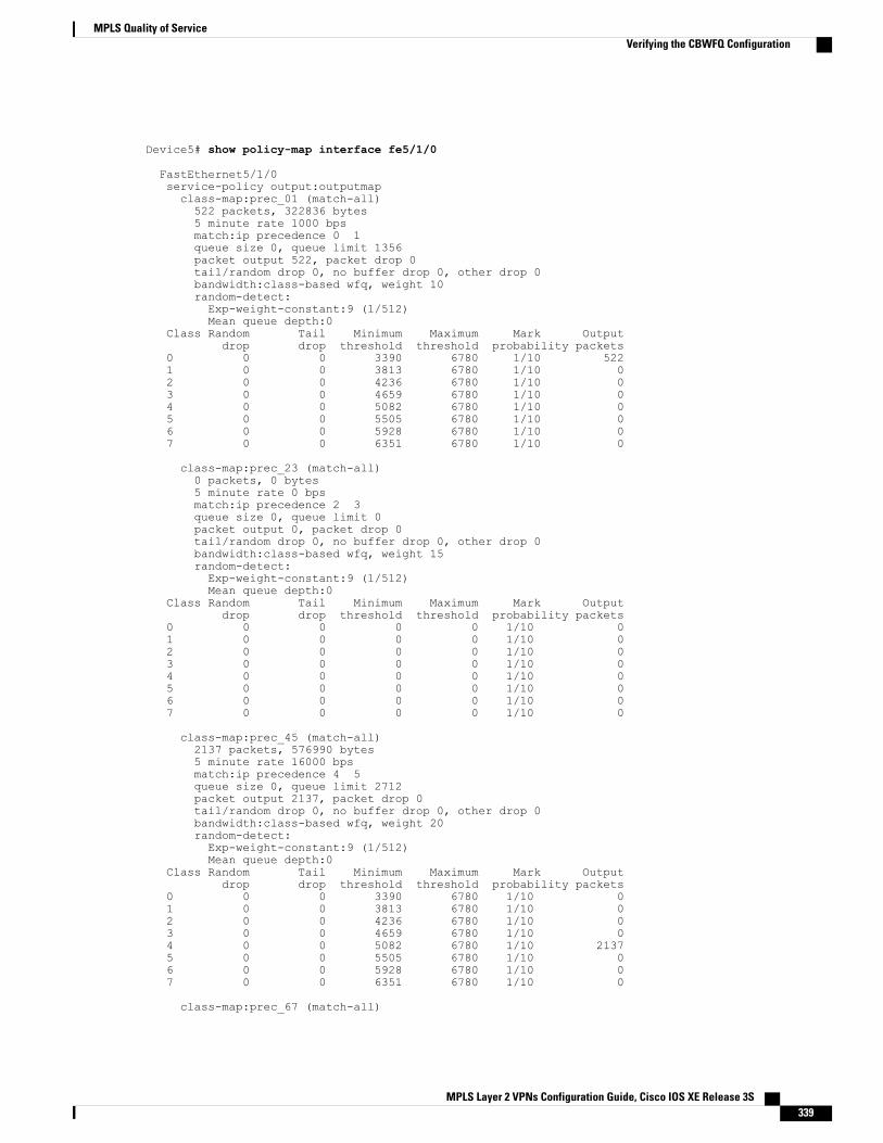
Device5# show policy-map interface fe5/1/0
FastEthernet5/1/0service-policy output:outputmapclass-map:prec_01 (match-all)522 packets, 322836 bytes5 minute rate 1000 bpsmatch:ip precedence 0 1queue size 0, queue limit 1356packet output 522, packet drop 0tail/random drop 0, no buffer drop 0, other drop 0bandwidth:class-based wfq, weight 10random-detect:Exp-weight-constant:9 (1/512)Mean queue depth:0
Class Random Tail Minimum Maximum Mark Outputdrop drop threshold threshold probability packets
0 0 0 3390 6780 1/10 5221 0 0 3813 6780 1/10 02 0 0 4236 6780 1/10 03 0 0 4659 6780 1/10 04 0 0 5082 6780 1/10 05 0 0 5505 6780 1/10 06 0 0 5928 6780 1/10 07 0 0 6351 6780 1/10 0
class-map:prec_23 (match-all)0 packets, 0 bytes5 minute rate 0 bpsmatch:ip precedence 2 3queue size 0, queue limit 0packet output 0, packet drop 0tail/random drop 0, no buffer drop 0, other drop 0bandwidth:class-based wfq, weight 15random-detect:Exp-weight-constant:9 (1/512)Mean queue depth:0
Class Random Tail Minimum Maximum Mark Outputdrop drop threshold threshold probability packets
0 0 0 0 0 1/10 01 0 0 0 0 1/10 02 0 0 0 0 1/10 03 0 0 0 0 1/10 04 0 0 0 0 1/10 05 0 0 0 0 1/10 06 0 0 0 0 1/10 07 0 0 0 0 1/10 0
class-map:prec_45 (match-all)2137 packets, 576990 bytes5 minute rate 16000 bpsmatch:ip precedence 4 5queue size 0, queue limit 2712packet output 2137, packet drop 0tail/random drop 0, no buffer drop 0, other drop 0bandwidth:class-based wfq, weight 20random-detect:Exp-weight-constant:9 (1/512)Mean queue depth:0
Class Random Tail Minimum Maximum Mark Outputdrop drop threshold threshold probability packets
0 0 0 3390 6780 1/10 01 0 0 3813 6780 1/10 02 0 0 4236 6780 1/10 03 0 0 4659 6780 1/10 04 0 0 5082 6780 1/10 21375 0 0 5505 6780 1/10 06 0 0 5928 6780 1/10 07 0 0 6351 6780 1/10 0
class-map:prec_67 (match-all)
MPLS Layer 2 VPNs Configuration Guide, Cisco IOS XE Release 3S 339
MPLS Quality of ServiceVerifying the CBWFQ Configuration
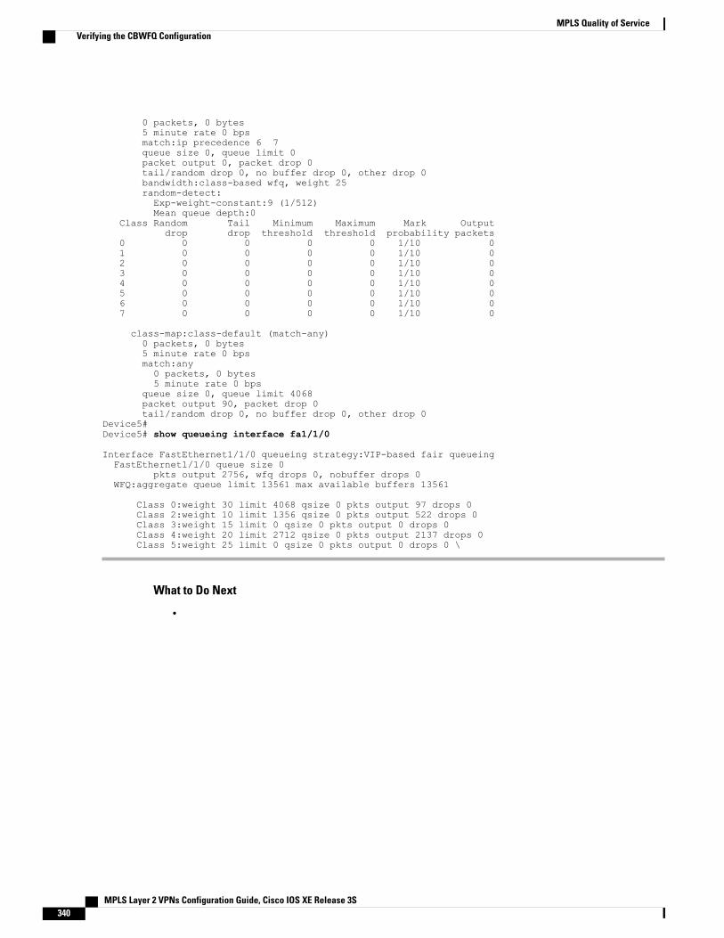
0 packets, 0 bytes5 minute rate 0 bpsmatch:ip precedence 6 7queue size 0, queue limit 0packet output 0, packet drop 0tail/random drop 0, no buffer drop 0, other drop 0bandwidth:class-based wfq, weight 25random-detect:Exp-weight-constant:9 (1/512)Mean queue depth:0
Class Random Tail Minimum Maximum Mark Outputdrop drop threshold threshold probability packets
0 0 0 0 0 1/10 01 0 0 0 0 1/10 02 0 0 0 0 1/10 03 0 0 0 0 1/10 04 0 0 0 0 1/10 05 0 0 0 0 1/10 06 0 0 0 0 1/10 07 0 0 0 0 1/10 0
class-map:class-default (match-any)0 packets, 0 bytes5 minute rate 0 bpsmatch:any0 packets, 0 bytes5 minute rate 0 bps
queue size 0, queue limit 4068packet output 90, packet drop 0tail/random drop 0, no buffer drop 0, other drop 0
Device5#Device5# show queueing interface fa1/1/0
Interface FastEthernet1/1/0 queueing strategy:VIP-based fair queueingFastEthernet1/1/0 queue size 0
pkts output 2756, wfq drops 0, nobuffer drops 0WFQ:aggregate queue limit 13561 max available buffers 13561
Class 0:weight 30 limit 4068 qsize 0 pkts output 97 drops 0Class 2:weight 10 limit 1356 qsize 0 pkts output 522 drops 0Class 3:weight 15 limit 0 qsize 0 pkts output 0 drops 0Class 4:weight 20 limit 2712 qsize 0 pkts output 2137 drops 0Class 5:weight 25 limit 0 qsize 0 pkts output 0 drops 0 \
What to Do Next
•
MPLS Layer 2 VPNs Configuration Guide, Cisco IOS XE Release 3S340
MPLS Quality of ServiceVerifying the CBWFQ Configuration
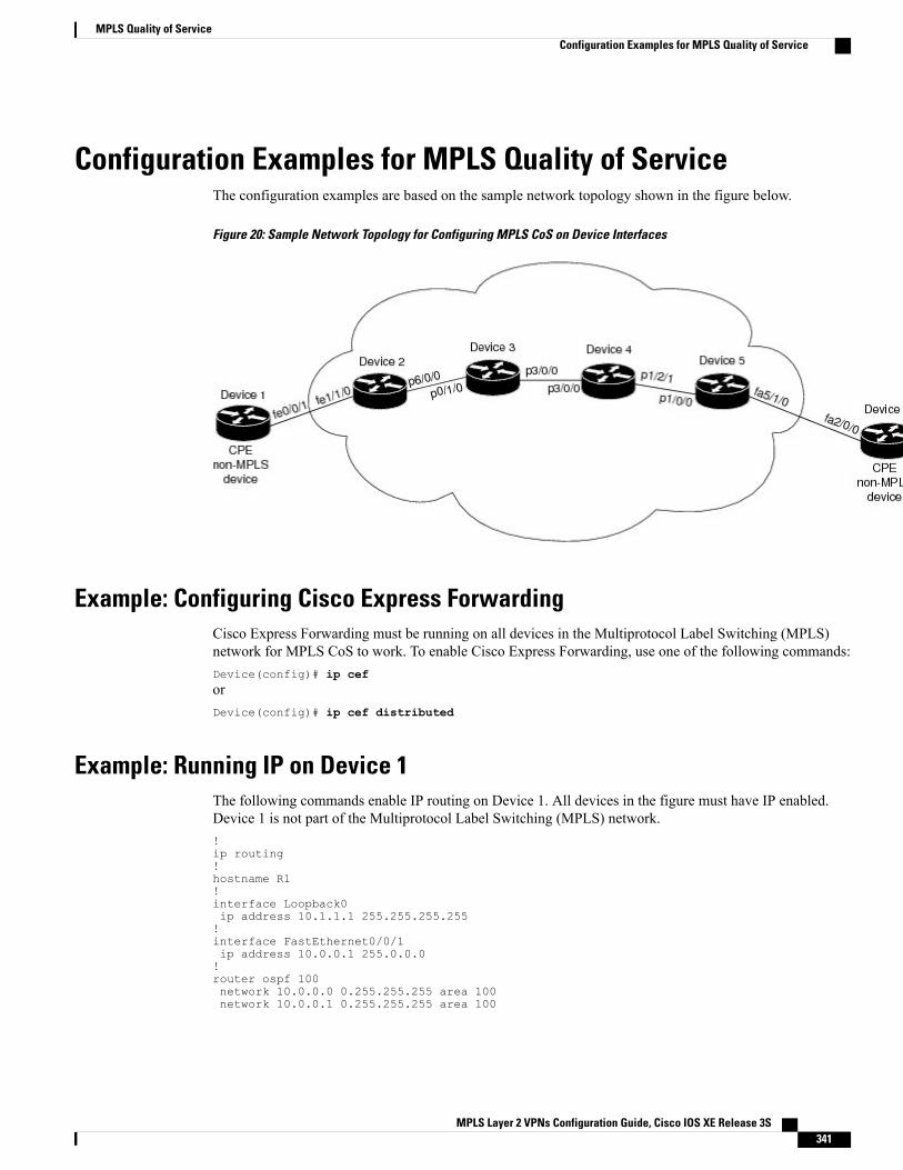
Configuration Examples for MPLS Quality of ServiceThe configuration examples are based on the sample network topology shown in the figure below.
Figure 20: Sample Network Topology for Configuring MPLS CoS on Device Interfaces
Example: Configuring Cisco Express ForwardingCisco Express Forwarding must be running on all devices in the Multiprotocol Label Switching (MPLS)network for MPLS CoS to work. To enable Cisco Express Forwarding, use one of the following commands:Device(config)# ip ceforDevice(config)# ip cef distributed
Example: Running IP on Device 1The following commands enable IP routing on Device 1. All devices in the figure must have IP enabled.Device 1 is not part of the Multiprotocol Label Switching (MPLS) network.!ip routing!hostname R1!interface Loopback0ip address 10.1.1.1 255.255.255.255!interface FastEthernet0/0/1ip address 10.0.0.1 255.0.0.0!router ospf 100network 10.0.0.0 0.255.255.255 area 100network 10.0.0.1 0.255.255.255 area 100
MPLS Layer 2 VPNs Configuration Guide, Cisco IOS XE Release 3S 341
MPLS Quality of ServiceConfiguration Examples for MPLS Quality of Service
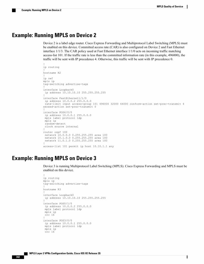
Example: Running MPLS on Device 2Device 2 is a label edge router. Cisco Express Forwarding and Multiprotocol Label Switching (MPLS) mustbe enabled on this device. Committed access rate (CAR) is also configured on Device 2 and Fast Ethernetinterface 1/1/3. The CAR policy used at Fast Ethernet interface 1/1/0 acts on incoming traffic matchingaccess-list 101. If the traffic rate is less than the committed information rate (in this example, 496000), thetraffic will be sent with IP precedence 4. Otherwise, this traffic will be sent with IP precedence 0.!ip routing!hostname R2!ip cefmpls iptag-switching advertise-tags!interface Loopback0ip address 10.10.10.10 255.255.255.255!interface FastEthernet1/1/0ip address 10.0.0.2 255.0.0.0rate-limit input access-group 101 496000 32000 64000 conform-action set-prec-transmit 4exceed-action set-prec-transmit 0!interface POS6/0/0ip address 10.0.0.1 255.0.0.0mpls label protocol ldpmpls iprandom-detectclock source internal!router ospf 100network 10.0.0.0 0.255.255.255 area 100network 10.1.0.0 0.255.255.255 area 100network 11.0.1.0 0.255.255.255 area 100!access-list 101 permit ip host 10.10.1.1 any
Example: Running MPLS on Device 3Device 3 is running Multiprotocol Label Switching (MPLS). Cisco Express Forwarding and MPLS must beenabled on this device.!ip routingmpls iptag-switching advertise-tags!hostname R3!interface Loopback0ip address 10.10.10.10 255.255.255.255!interface POS0/1/0ip address 10.0.0.2 255.0.0.0mpls label protocol ldpmpls ipcrc 16!interface POS3/0/0ip address 10.0.0.1 255.0.0.0mpls label protocol ldpmpls ipcrc 16
MPLS Layer 2 VPNs Configuration Guide, Cisco IOS XE Release 3S342
MPLS Quality of ServiceExample: Running MPLS on Device 2
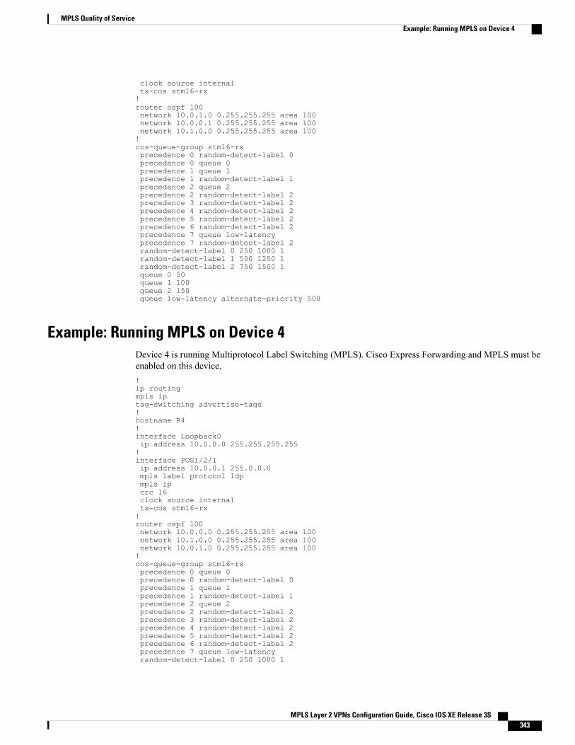
clock source internaltx-cos stm16-rx!router ospf 100network 10.0.1.0 0.255.255.255 area 100network 10.0.0.1 0.255.255.255 area 100network 10.1.0.0 0.255.255.255 area 100!cos-queue-group stm16-rxprecedence 0 random-detect-label 0precedence 0 queue 0precedence 1 queue 1precedence 1 random-detect-label 1precedence 2 queue 2precedence 2 random-detect-label 2precedence 3 random-detect-label 2precedence 4 random-detect-label 2precedence 5 random-detect-label 2precedence 6 random-detect-label 2precedence 7 queue low-latencyprecedence 7 random-detect-label 2random-detect-label 0 250 1000 1random-detect-label 1 500 1250 1random-detect-label 2 750 1500 1queue 0 50queue 1 100queue 2 150queue low-latency alternate-priority 500
Example: Running MPLS on Device 4Device 4 is running Multiprotocol Label Switching (MPLS). Cisco Express Forwarding and MPLS must beenabled on this device.!ip routingmpls iptag-switching advertise-tags!hostname R4!interface Loopback0ip address 10.0.0.0 255.255.255.255!interface POS1/2/1ip address 10.0.0.1 255.0.0.0mpls label protocol ldpmpls ipcrc 16clock source internaltx-cos stm16-rx!router ospf 100network 10.0.0.0 0.255.255.255 area 100network 10.1.0.0 0.255.255.255 area 100network 10.0.1.0 0.255.255.255 area 100!cos-queue-group stm16-rxprecedence 0 queue 0precedence 0 random-detect-label 0precedence 1 queue 1precedence 1 random-detect-label 1precedence 2 queue 2precedence 2 random-detect-label 2precedence 3 random-detect-label 2precedence 4 random-detect-label 2precedence 5 random-detect-label 2precedence 6 random-detect-label 2precedence 7 queue low-latencyrandom-detect-label 0 250 1000 1
MPLS Layer 2 VPNs Configuration Guide, Cisco IOS XE Release 3S 343
MPLS Quality of ServiceExample: Running MPLS on Device 4
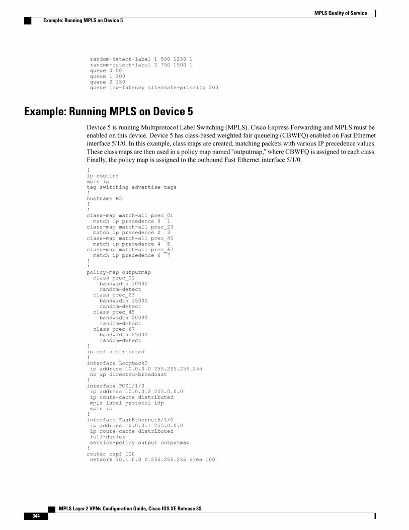
random-detect-label 1 500 1250 1random-detect-label 2 750 1500 1queue 0 50queue 1 100queue 2 150queue low-latency alternate-priority 200
Example: Running MPLS on Device 5Device 5 is running Multiprotocol Label Switching (MPLS). Cisco Express Forwarding and MPLS must beenabled on this device. Device 5 has class-based weighted fair queueing (CBWFQ) enabled on Fast Ethernetinterface 5/1/0. In this example, class maps are created, matching packets with various IP precedence values.These class maps are then used in a policy map named “outputmap,”where CBWFQ is assigned to each class.Finally, the policy map is assigned to the outbound Fast Ethernet interface 5/1/0.!ip routingmpls iptag-switching advertise-tags!hostname R5!!class-map match-all prec_01match ip precedence 0 1
class-map match-all prec_23match ip precedence 2 3
class-map match-all prec_45match ip precedence 4 5
class-map match-all prec_67match ip precedence 6 7
!!policy-map outputmapclass prec_01bandwidth 10000random-detect
class prec_23bandwidth 15000random-detect
class prec_45bandwidth 20000random-detect
class prec_67bandwidth 25000random-detect
!ip cef distributed!interface Loopback0ip address 10.0.0.0 255.255.255.255no ip directed-broadcast!interface POS1/1/0ip address 10.0.0.2 255.0.0.0ip route-cache distributedmpls label protocol ldpmpls ip!interface FastEthernet5/1/0ip address 10.0.0.1 255.0.0.0ip route-cache distributedfull-duplexservice-policy output outputmap!router ospf 100network 10.1.0.0 0.255.255.255 area 100
MPLS Layer 2 VPNs Configuration Guide, Cisco IOS XE Release 3S344
MPLS Quality of ServiceExample: Running MPLS on Device 5
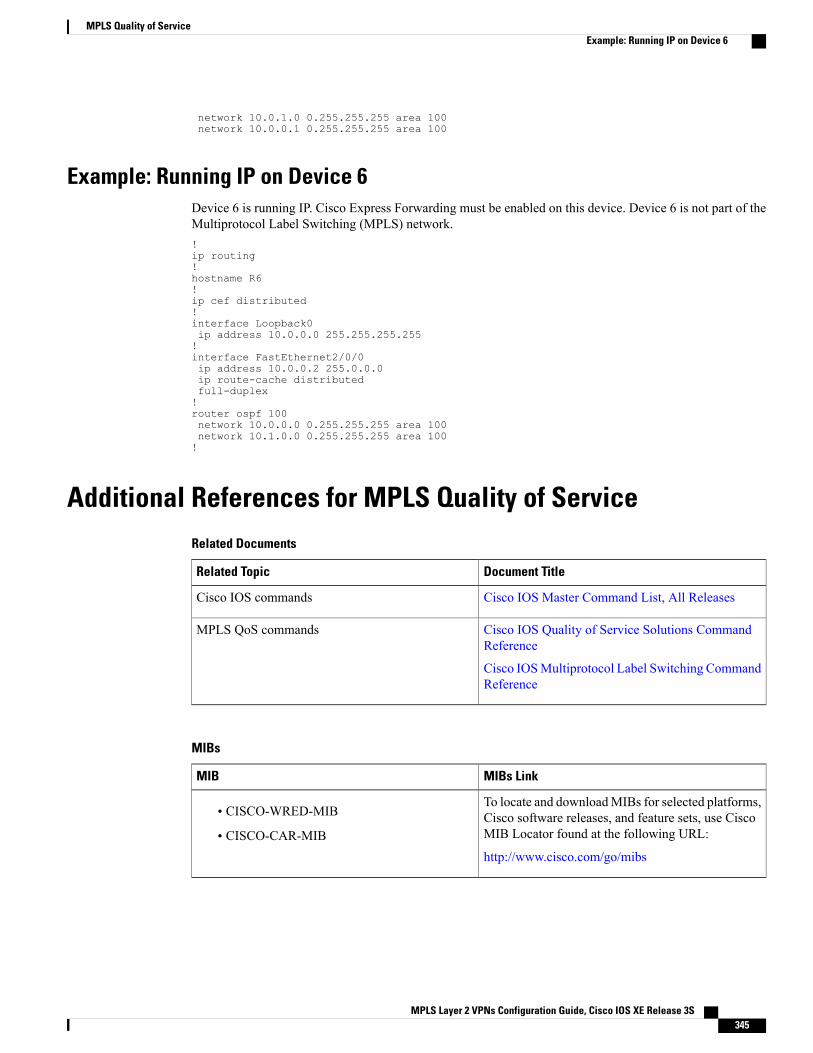
network 10.0.1.0 0.255.255.255 area 100network 10.0.0.1 0.255.255.255 area 100
Example: Running IP on Device 6Device 6 is running IP. Cisco Express Forwarding must be enabled on this device. Device 6 is not part of theMultiprotocol Label Switching (MPLS) network.!ip routing!hostname R6!ip cef distributed!interface Loopback0ip address 10.0.0.0 255.255.255.255!interface FastEthernet2/0/0ip address 10.0.0.2 255.0.0.0ip route-cache distributedfull-duplex!router ospf 100network 10.0.0.0 0.255.255.255 area 100network 10.1.0.0 0.255.255.255 area 100!
Additional References for MPLS Quality of ServiceRelated Documents
Document TitleRelated Topic
Cisco IOS Master Command List, All ReleasesCisco IOS commands
Cisco IOS Quality of Service Solutions CommandReference
Cisco IOSMultiprotocol Label Switching CommandReference
MPLS QoS commands
MIBs
MIBs LinkMIB
To locate and downloadMIBs for selected platforms,Cisco software releases, and feature sets, use CiscoMIB Locator found at the following URL:
http://www.cisco.com/go/mibs
• CISCO-WRED-MIB
• CISCO-CAR-MIB
MPLS Layer 2 VPNs Configuration Guide, Cisco IOS XE Release 3S 345
MPLS Quality of ServiceExample: Running IP on Device 6
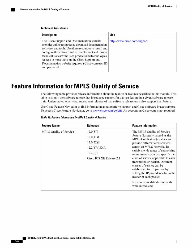
Technical Assistance
LinkDescription
http://www.cisco.com/supportThe Cisco Support and Documentation websiteprovides online resources to download documentation,software, and tools. Use these resources to install andconfigure the software and to troubleshoot and resolvetechnical issues with Cisco products and technologies.Access to most tools on the Cisco Support andDocumentation website requires a Cisco.com user IDand password.
Feature Information for MPLS Quality of ServiceThe following table provides release information about the feature or features described in this module. Thistable lists only the software release that introduced support for a given feature in a given software releasetrain. Unless noted otherwise, subsequent releases of that software release train also support that feature.
Use Cisco Feature Navigator to find information about platform support and Cisco software image support.To access Cisco Feature Navigator, go to www.cisco.com/go/cfn. An account on Cisco.com is not required.
Table 18: Feature Information for MPLS Quality of Service
Feature InformationReleasesFeature Name
The MPLS Quality of Servicefeature (formerly named as theMPLS CoS feature) enables you toprovide differentiated servicesacross an MPLS network. Tosatisfy a wide range of networkingrequirements, you can specify theclass of service applicable to eachtransmitted IP packet. Differentclasses of service can beestablished for IP packets bysetting the IP precedence bit in theheader of each packet
No new or modified commandswere introduced.
12.0(5)T
12.0(11)T
12.0(22)S
12.2(17b)SXA
12.2(8)T
Cisco IOS XE Release 2.1
MPLS Quality of Service
MPLS Layer 2 VPNs Configuration Guide, Cisco IOS XE Release 3S346
MPLS Quality of ServiceFeature Information for MPLS Quality of Service

C H A P T E R 7QoS Policy Support on L2VPN ATM PVPs
This feature enables you to configure Quality of Service (QoS) service policies in ATM permanent virtualpath (PVP) mode for Layer 2 Virtual Private Networks (L2VPNs).
• Finding Feature Information, page 347
• Prerequisites for QoS Policy Support on L2VPN ATM PVPs, page 347
• Restrictions for QoS Policy Support on L2VPN ATM PVPs, page 348
• Information About QoS Policy Support on L2VPN ATM PVPs, page 348
• How to Configure QoS Policy Support on L2VPN ATM PVPs, page 349
• Configuration Examples for QoS Policy Support on L2VPN ATM PVPs, page 360
• Additional References, page 361
• Feature Information for QoS Policy Support on L2VPN ATM PVPs, page 362
Finding Feature InformationYour software release may not support all the features documented in this module. For the latest caveats andfeature information, see Bug Search Tool and the release notes for your platform and software release. Tofind information about the features documented in this module, and to see a list of the releases in which eachfeature is supported, see the feature information table at the end of this module.
Use Cisco Feature Navigator to find information about platform support and Cisco software image support.To access Cisco Feature Navigator, go to www.cisco.com/go/cfn. An account on Cisco.com is not required.
Prerequisites for QoS Policy Support on L2VPN ATM PVPsBefore configuring QoS policies on L2VPNATMPVPs, you should understand the concepts and configurationinstructions in the following documents:
• Any Transport over MPLS
• Applying QoS Features Using the MQC
MPLS Layer 2 VPNs Configuration Guide, Cisco IOS XE Release 3S 347
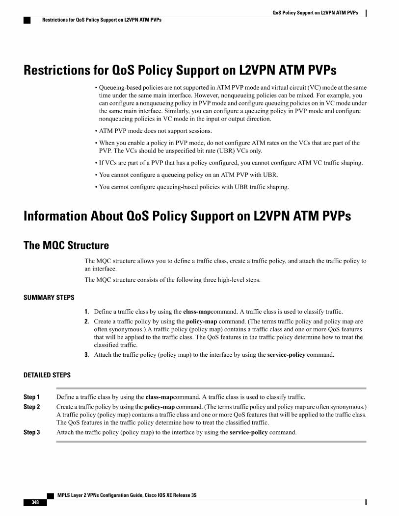
Restrictions for QoS Policy Support on L2VPN ATM PVPs• Queueing-based policies are not supported in ATM PVPmode and virtual circuit (VC) mode at the sametime under the same main interface. However, nonqueueing policies can be mixed. For example, youcan configure a nonqueueing policy in PVPmode and configure queueing policies on in VCmode underthe same main interface. Similarly, you can configure a queueing policy in PVP mode and configurenonqueueing policies in VC mode in the input or output direction.
• ATM PVP mode does not support sessions.
•When you enable a policy in PVP mode, do not configure ATM rates on the VCs that are part of thePVP. The VCs should be unspecified bit rate (UBR) VCs only.
• If VCs are part of a PVP that has a policy configured, you cannot configure ATM VC traffic shaping.
• You cannot configure a queueing policy on an ATM PVP with UBR.
• You cannot configure queueing-based policies with UBR traffic shaping.
Information About QoS Policy Support on L2VPN ATM PVPs
The MQC StructureThe MQC structure allows you to define a traffic class, create a traffic policy, and attach the traffic policy toan interface.
The MQC structure consists of the following three high-level steps.
SUMMARY STEPS
1. Define a traffic class by using the class-mapcommand. A traffic class is used to classify traffic.2. Create a traffic policy by using the policy-map command. (The terms traffic policy and policy map are
often synonymous.) A traffic policy (policy map) contains a traffic class and one or more QoS featuresthat will be applied to the traffic class. The QoS features in the traffic policy determine how to treat theclassified traffic.
3. Attach the traffic policy (policy map) to the interface by using the service-policy command.
DETAILED STEPS
Step 1 Define a traffic class by using the class-mapcommand. A traffic class is used to classify traffic.Step 2 Create a traffic policy by using the policy-map command. (The terms traffic policy and policymap are often synonymous.)
A traffic policy (policy map) contains a traffic class and one or more QoS features that will be applied to the traffic class.The QoS features in the traffic policy determine how to treat the classified traffic.
Step 3 Attach the traffic policy (policy map) to the interface by using the service-policy command.
MPLS Layer 2 VPNs Configuration Guide, Cisco IOS XE Release 3S348
QoS Policy Support on L2VPN ATM PVPsRestrictions for QoS Policy Support on L2VPN ATM PVPs
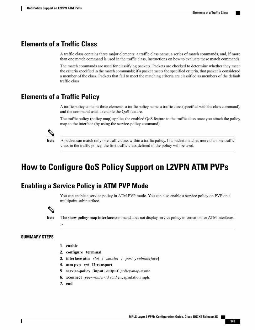
Elements of a Traffic ClassA traffic class contains three major elements: a traffic class name, a series of match commands, and, if morethan one match command is used in the traffic class, instructions on how to evaluate these match commands.
The match commands are used for classifying packets. Packets are checked to determine whether they meetthe criteria specified in the match commands; if a packet meets the specified criteria, that packet is considereda member of the class. Packets that fail to meet the matching criteria are classified as members of the defaulttraffic class.
Elements of a Traffic PolicyA traffic policy contains three elements: a traffic policy name, a traffic class (specified with the class command),and the command used to enable the QoS feature.
The traffic policy (policy map) applies the enabled QoS feature to the traffic class once you attach the policymap to the interface (by using the service-policy command).
A packet can match only one traffic class within a traffic policy. If a packet matches more than one trafficclass in the traffic policy, the first traffic class defined in the policy will be used.
Note
How to Configure QoS Policy Support on L2VPN ATM PVPs
Enabling a Service Policy in ATM PVP ModeYou can enable a service policy in ATM PVP mode. You can also enable a service policy on PVP on amultipoint subinterface.
The show policy-map interface command does not display service policy information for ATM interfaces.
>
Note
SUMMARY STEPS
1. enable2. configure terminal3. interface atm slot / subslot / port [. subinterface]4. atm pvp vpi l2transport5. service-policy [input | output] policy-map-name6. xconnect peer-router-id vcid encapsulation mpls7. end
MPLS Layer 2 VPNs Configuration Guide, Cisco IOS XE Release 3S 349
QoS Policy Support on L2VPN ATM PVPsElements of a Traffic Class
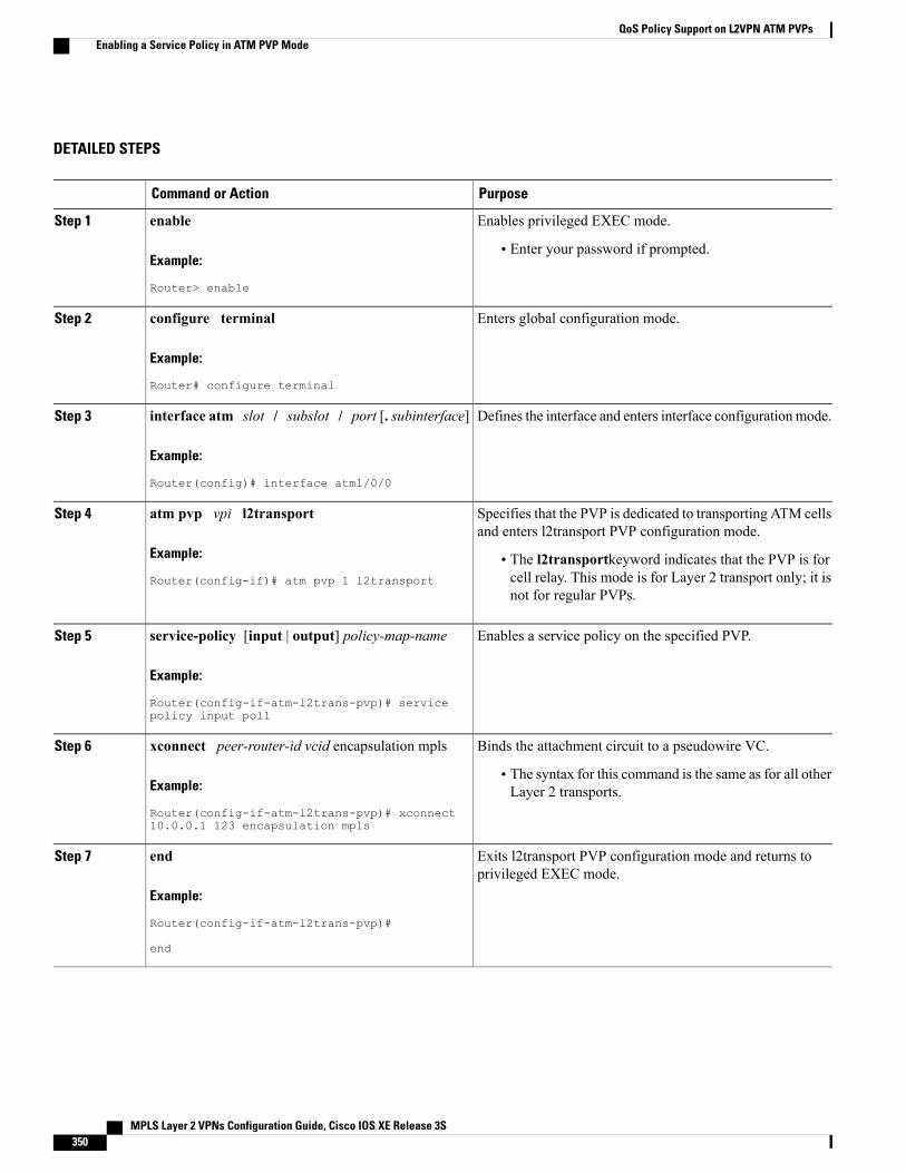
DETAILED STEPS
PurposeCommand or Action
Enables privileged EXEC mode.enableStep 1
Example:
Router> enable
• Enter your password if prompted.
Enters global configuration mode.configure terminal
Example:
Router# configure terminal
Step 2
Defines the interface and enters interface configurationmode.interface atm slot / subslot / port [. subinterface]
Example:
Router(config)# interface atm1/0/0
Step 3
Specifies that the PVP is dedicated to transporting ATM cellsand enters l2transport PVP configuration mode.
atm pvp vpi l2transport
Example:
Router(config-if)# atm pvp 1 l2transport
Step 4
• The l2transportkeyword indicates that the PVP is forcell relay. This mode is for Layer 2 transport only; it isnot for regular PVPs.
Enables a service policy on the specified PVP.service-policy [input | output] policy-map-name
Example:
Router(config-if-atm-l2trans-pvp)# servicepolicy input pol1
Step 5
Binds the attachment circuit to a pseudowire VC.xconnect peer-router-id vcid encapsulation mplsStep 6
Example:
Router(config-if-atm-l2trans-pvp)# xconnect10.0.0.1 123 encapsulation mpls
• The syntax for this command is the same as for all otherLayer 2 transports.
Exits l2transport PVP configuration mode and returns toprivileged EXEC mode.
end
Example:
Router(config-if-atm-l2trans-pvp)#
Step 7
end
MPLS Layer 2 VPNs Configuration Guide, Cisco IOS XE Release 3S350
QoS Policy Support on L2VPN ATM PVPsEnabling a Service Policy in ATM PVP Mode
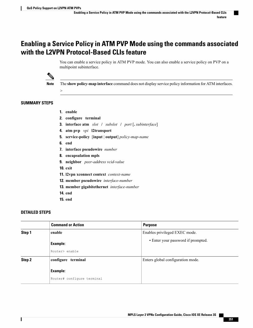
Enabling a Service Policy in ATM PVP Mode using the commands associatedwith the L2VPN Protocol-Based CLIs feature
You can enable a service policy in ATM PVP mode. You can also enable a service policy on PVP on amultipoint subinterface.
The show policy-map interface command does not display service policy information for ATM interfaces.
>
Note
SUMMARY STEPS
1. enable2. configure terminal3. interface atm slot / subslot / port [. subinterface]4. atm pvp vpi l2transport5. service-policy [input | output] policy-map-name6. end7. interface pseudowire number8. encapsulation mpls9. neighbor peer-address vcid-value10. exit11. l2vpn xconnect context context-name12. member pseudowire interface-number13. member gigabitethernet interface-number14. end15. end
DETAILED STEPS
PurposeCommand or Action
Enables privileged EXEC mode.enableStep 1
Example:
Router> enable
• Enter your password if prompted.
Enters global configuration mode.configure terminal
Example:
Router# configure terminal
Step 2
MPLS Layer 2 VPNs Configuration Guide, Cisco IOS XE Release 3S 351
QoS Policy Support on L2VPN ATM PVPsEnabling a Service Policy in ATM PVP Mode using the commands associated with the L2VPN Protocol-Based CLIs
feature
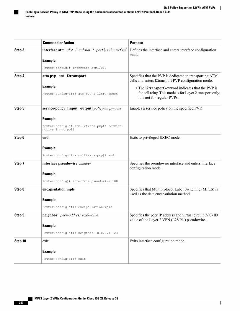
PurposeCommand or Action
Defines the interface and enters interface configurationmode.
interface atm slot / subslot / port [. subinterface]
Example:
Router(config)# interface atm1/0/0
Step 3
Specifies that the PVP is dedicated to transporting ATMcells and enters l2transport PVP configuration mode.
atm pvp vpi l2transport
Example:
Router(config-if)# atm pvp 1 l2transport
Step 4
• The l2transportkeyword indicates that the PVP isfor cell relay. This mode is for Layer 2 transport only;it is not for regular PVPs.
Enables a service policy on the specified PVP.service-policy [input | output] policy-map-name
Example:
Router(config-if-atm-l2trans-pvp)# servicepolicy input pol1
Step 5
Exits to privileged EXEC mode.end
Example:
Router(config-if-atm-l2trans-pvp)# end
Step 6
Specifies the pseudowire interface and enters interfaceconfiguration mode.
interface pseudowire number
Example:
Router(config)# interface pseudowire 100
Step 7
Specifies that Multiprotocol Label Switching (MPLS) isused as the data encapsulation method.
encapsulation mpls
Example:
Router(config-if)# encapsulation mpls
Step 8
Specifies the peer IP address and virtual circuit (VC) IDvalue of the Layer 2 VPN (L2VPN) pseudowire.
neighbor peer-address vcid-value
Example:
Router(config-if)# neighbor 10.0.0.1 123
Step 9
Exits interface configuration mode.exit
Example:
Router(config-if)# exit
Step 10
MPLS Layer 2 VPNs Configuration Guide, Cisco IOS XE Release 3S352
QoS Policy Support on L2VPN ATM PVPsEnabling a Service Policy in ATM PVP Mode using the commands associated with the L2VPN Protocol-Based CLIsfeature
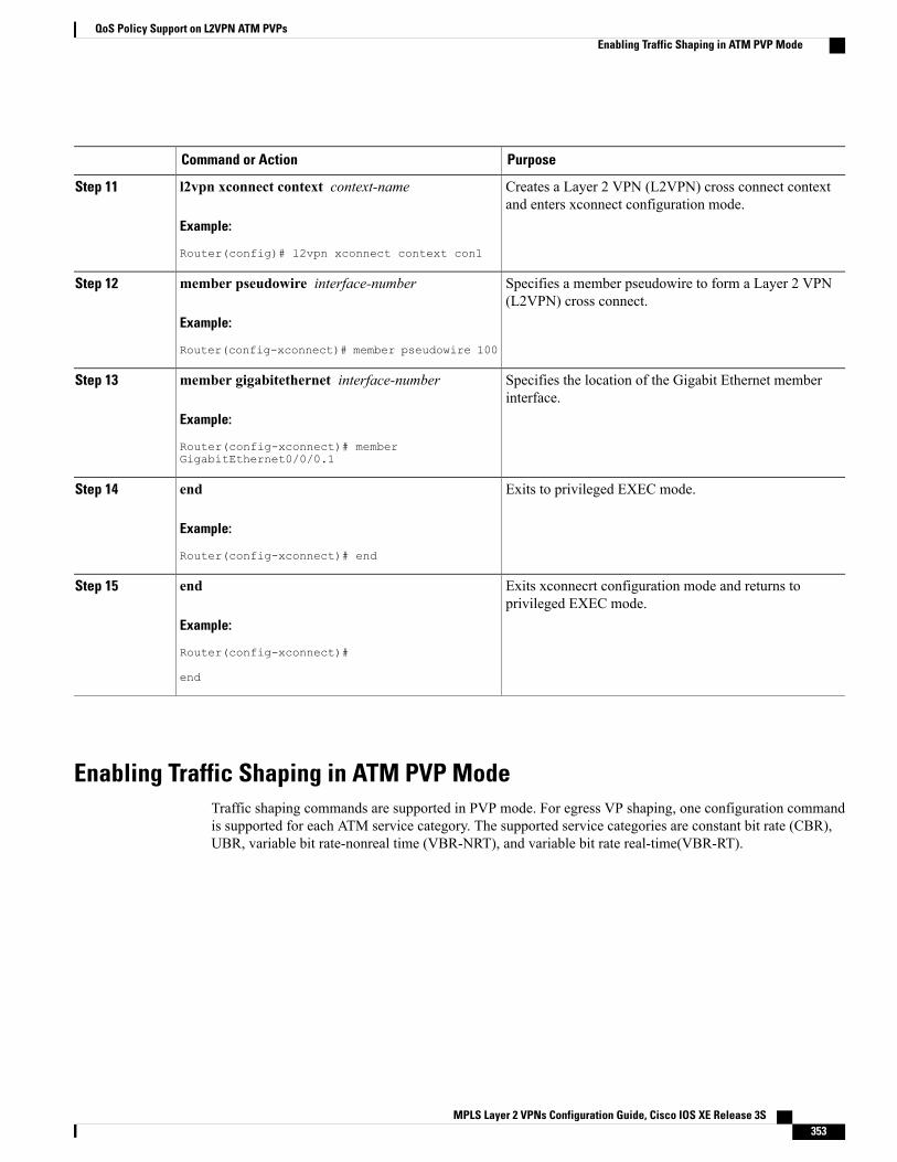
PurposeCommand or Action
Creates a Layer 2 VPN (L2VPN) cross connect contextand enters xconnect configuration mode.
l2vpn xconnect context context-name
Example:
Router(config)# l2vpn xconnect context con1
Step 11
Specifies a member pseudowire to form a Layer 2 VPN(L2VPN) cross connect.
member pseudowire interface-number
Example:
Router(config-xconnect)# member pseudowire 100
Step 12
Specifies the location of the Gigabit Ethernet memberinterface.
member gigabitethernet interface-number
Example:
Router(config-xconnect)# memberGigabitEthernet0/0/0.1
Step 13
Exits to privileged EXEC mode.end
Example:
Router(config-xconnect)# end
Step 14
Exits xconnecrt configuration mode and returns toprivileged EXEC mode.
end
Example:
Router(config-xconnect)#
Step 15
end
Enabling Traffic Shaping in ATM PVP ModeTraffic shaping commands are supported in PVP mode. For egress VP shaping, one configuration commandis supported for each ATM service category. The supported service categories are constant bit rate (CBR),UBR, variable bit rate-nonreal time (VBR-NRT), and variable bit rate real-time(VBR-RT).
MPLS Layer 2 VPNs Configuration Guide, Cisco IOS XE Release 3S 353
QoS Policy Support on L2VPN ATM PVPsEnabling Traffic Shaping in ATM PVP Mode
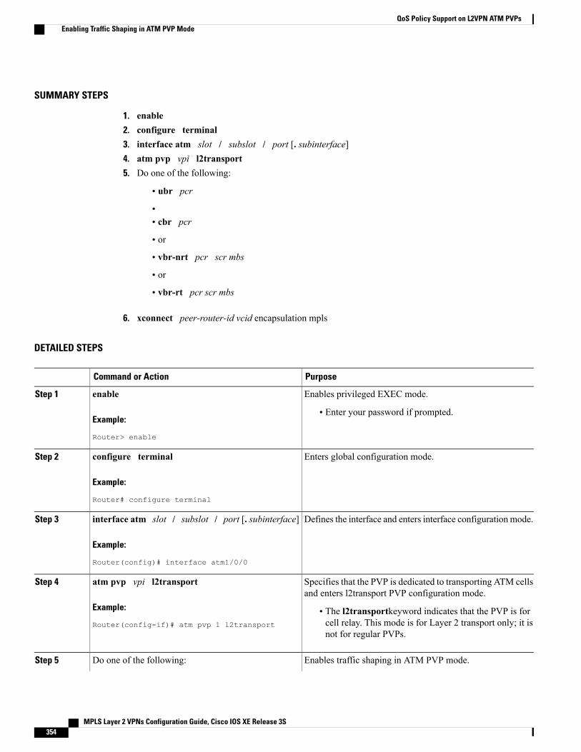
SUMMARY STEPS
1. enable2. configure terminal3. interface atm slot / subslot / port [. subinterface]4. atm pvp vpi l2transport5. Do one of the following:
• ubr pcr
•• cbr pcr
• or
• vbr-nrt pcr scr mbs
• or
• vbr-rt pcr scr mbs
6. xconnect peer-router-id vcid encapsulation mpls
DETAILED STEPS
PurposeCommand or Action
Enables privileged EXEC mode.enableStep 1
Example:
Router> enable
• Enter your password if prompted.
Enters global configuration mode.configure terminal
Example:
Router# configure terminal
Step 2
Defines the interface and enters interface configuration mode.interface atm slot / subslot / port [. subinterface]
Example:
Router(config)# interface atm1/0/0
Step 3
Specifies that the PVP is dedicated to transporting ATM cellsand enters l2transport PVP configuration mode.
atm pvp vpi l2transport
Example:
Router(config-if)# atm pvp 1 l2transport
Step 4
• The l2transportkeyword indicates that the PVP is forcell relay. This mode is for Layer 2 transport only; it isnot for regular PVPs.
Enables traffic shaping in ATM PVP mode.Do one of the following:Step 5
MPLS Layer 2 VPNs Configuration Guide, Cisco IOS XE Release 3S354
QoS Policy Support on L2VPN ATM PVPsEnabling Traffic Shaping in ATM PVP Mode
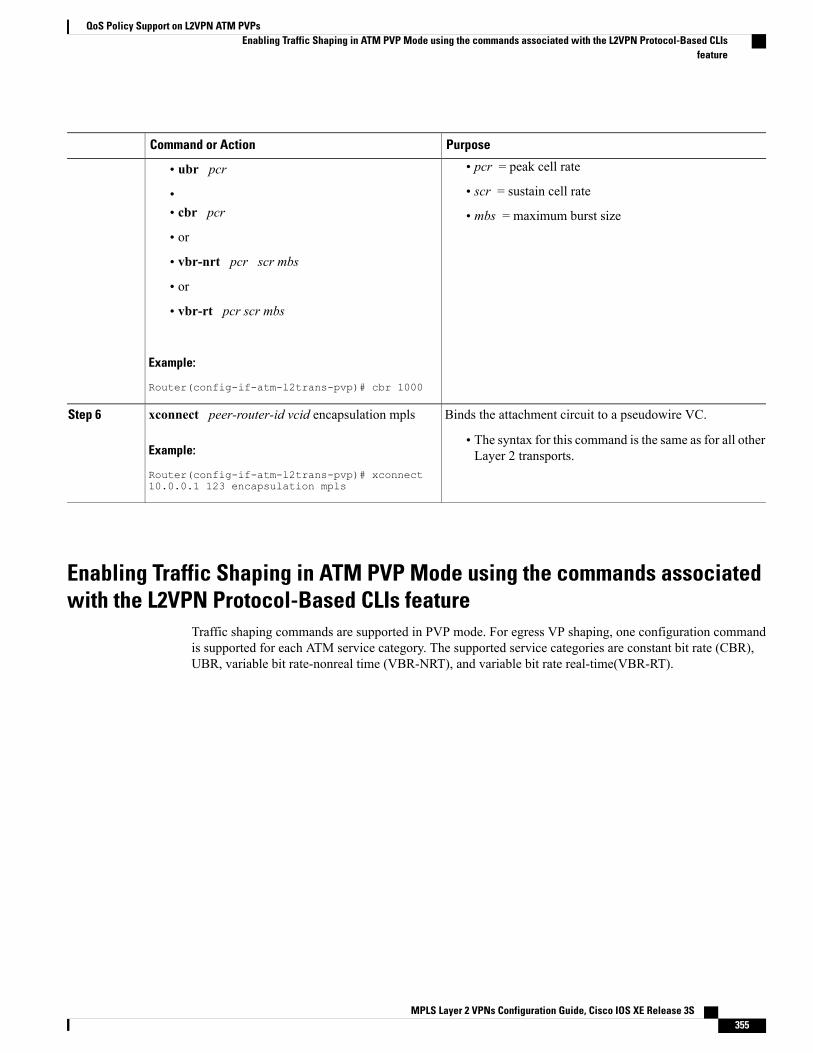
PurposeCommand or Action
• pcr = peak cell rate• ubr pcr
• scr = sustain cell rate•• cbr pcr • mbs = maximum burst size• or
• vbr-nrt pcr scr mbs
• or
• vbr-rt pcr scr mbs
Example:
Router(config-if-atm-l2trans-pvp)# cbr 1000
Binds the attachment circuit to a pseudowire VC.xconnect peer-router-id vcid encapsulation mplsStep 6
Example:
Router(config-if-atm-l2trans-pvp)# xconnect10.0.0.1 123 encapsulation mpls
• The syntax for this command is the same as for all otherLayer 2 transports.
Enabling Traffic Shaping in ATM PVP Mode using the commands associatedwith the L2VPN Protocol-Based CLIs feature
Traffic shaping commands are supported in PVP mode. For egress VP shaping, one configuration commandis supported for each ATM service category. The supported service categories are constant bit rate (CBR),UBR, variable bit rate-nonreal time (VBR-NRT), and variable bit rate real-time(VBR-RT).
MPLS Layer 2 VPNs Configuration Guide, Cisco IOS XE Release 3S 355
QoS Policy Support on L2VPN ATM PVPsEnabling Traffic Shaping in ATM PVP Mode using the commands associated with the L2VPN Protocol-Based CLIs
feature
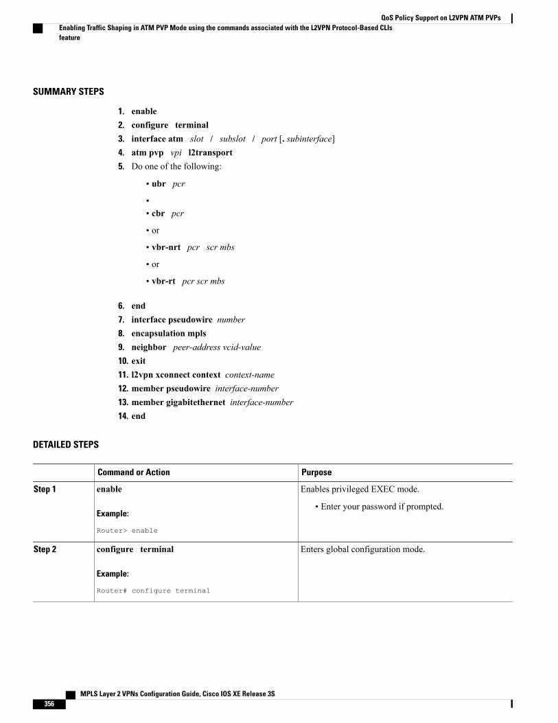
SUMMARY STEPS
1. enable2. configure terminal3. interface atm slot / subslot / port [. subinterface]4. atm pvp vpi l2transport5. Do one of the following:
• ubr pcr
•• cbr pcr
• or
• vbr-nrt pcr scr mbs
• or
• vbr-rt pcr scr mbs
6. end7. interface pseudowire number8. encapsulation mpls9. neighbor peer-address vcid-value10. exit11. l2vpn xconnect context context-name12. member pseudowire interface-number13. member gigabitethernet interface-number14. end
DETAILED STEPS
PurposeCommand or Action
Enables privileged EXEC mode.enableStep 1
Example:
Router> enable
• Enter your password if prompted.
Enters global configuration mode.configure terminal
Example:
Router# configure terminal
Step 2
MPLS Layer 2 VPNs Configuration Guide, Cisco IOS XE Release 3S356
QoS Policy Support on L2VPN ATM PVPsEnabling Traffic Shaping in ATM PVP Mode using the commands associated with the L2VPN Protocol-Based CLIsfeature
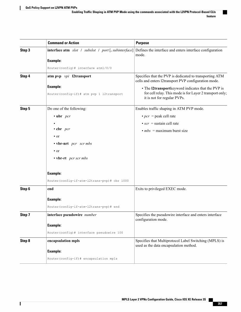
PurposeCommand or Action
Defines the interface and enters interface configurationmode.
interface atm slot / subslot / port [. subinterface]
Example:
Router(config)# interface atm1/0/0
Step 3
Specifies that the PVP is dedicated to transporting ATMcells and enters l2transport PVP configuration mode.
atm pvp vpi l2transport
Example:
Router(config-if)# atm pvp 1 l2transport
Step 4
• The l2transportkeyword indicates that the PVP isfor cell relay. This mode is for Layer 2 transport only;it is not for regular PVPs.
Enables traffic shaping in ATM PVP mode.Do one of the following:Step 5
• ubr pcr • pcr = peak cell rate
• scr = sustain cell rate•• cbr pcr • mbs = maximum burst size• or
• vbr-nrt pcr scr mbs
• or
• vbr-rt pcr scr mbs
Example:
Router(config-if-atm-l2trans-pvp)# cbr 1000
Exits to privileged EXEC mode.end
Example:
Router(config-if-atm-l2trans-pvp)# end
Step 6
Specifies the pseudowire interface and enters interfaceconfiguration mode.
interface pseudowire number
Example:
Router(config)# interface pseudowire 100
Step 7
Specifies that Multiprotocol Label Switching (MPLS) isused as the data encapsulation method.
encapsulation mpls
Example:
Router(config-if)# encapsulation mpls
Step 8
MPLS Layer 2 VPNs Configuration Guide, Cisco IOS XE Release 3S 357
QoS Policy Support on L2VPN ATM PVPsEnabling Traffic Shaping in ATM PVP Mode using the commands associated with the L2VPN Protocol-Based CLIs
feature
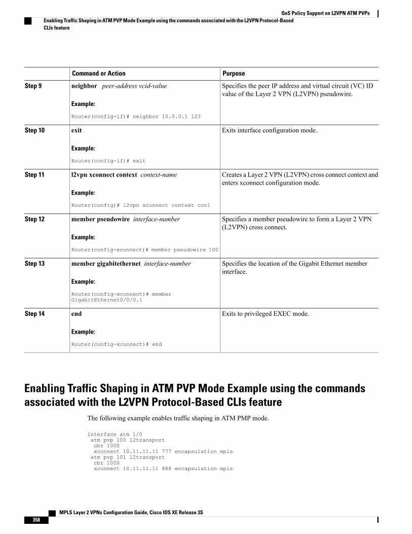
PurposeCommand or Action
Specifies the peer IP address and virtual circuit (VC) IDvalue of the Layer 2 VPN (L2VPN) pseudowire.
neighbor peer-address vcid-value
Example:
Router(config-if)# neighbor 10.0.0.1 123
Step 9
Exits interface configuration mode.exit
Example:
Router(config-if)# exit
Step 10
Creates a Layer 2 VPN (L2VPN) cross connect context andenters xconnect configuration mode.
l2vpn xconnect context context-name
Example:
Router(config)# l2vpn xconnect context con1
Step 11
Specifies a member pseudowire to form a Layer 2 VPN(L2VPN) cross connect.
member pseudowire interface-number
Example:
Router(config-xconnect)# member pseudowire 100
Step 12
Specifies the location of the Gigabit Ethernet memberinterface.
member gigabitethernet interface-number
Example:
Router(config-xconnect)# memberGigabitEthernet0/0/0.1
Step 13
Exits to privileged EXEC mode.end
Example:
Router(config-xconnect)# end
Step 14
Enabling Traffic Shaping in ATM PVP Mode Example using the commandsassociated with the L2VPN Protocol-Based CLIs feature
The following example enables traffic shaping in ATM PMP mode.
interface atm 1/0atm pvp 100 l2transportubr 1000xconnect 10.11.11.11 777 encapsulation mplsatm pvp 101 l2transportcbr 1000xconnect 10.11.11.11 888 encapsulation mpls
MPLS Layer 2 VPNs Configuration Guide, Cisco IOS XE Release 3S358
QoS Policy Support on L2VPN ATM PVPsEnabling Traffic Shaping in ATM PVP Mode Example using the commands associated with the L2VPN Protocol-BasedCLIs feature
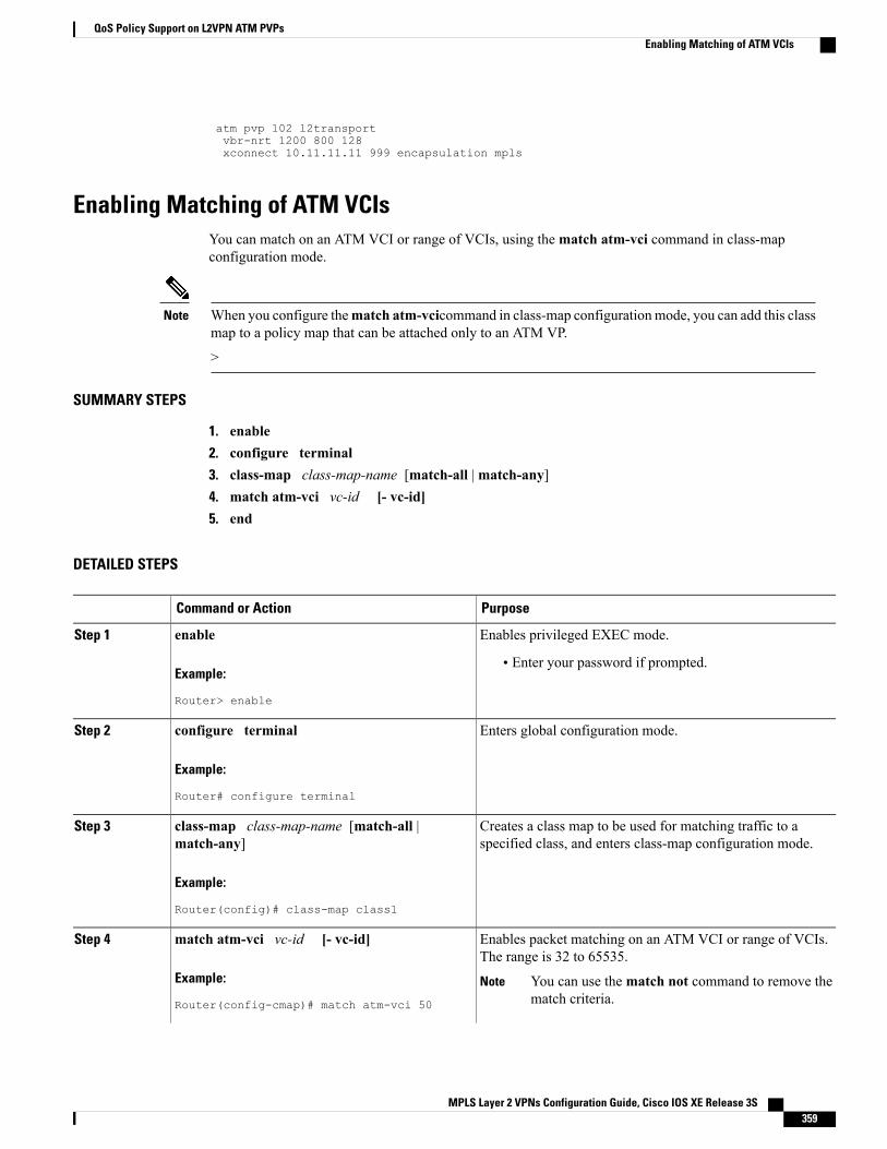
atm pvp 102 l2transportvbr-nrt 1200 800 128xconnect 10.11.11.11 999 encapsulation mpls
Enabling Matching of ATM VCIsYou can match on an ATM VCI or range of VCIs, using thematch atm-vci command in class-mapconfiguration mode.
When you configure thematch atm-vcicommand in class-map configurationmode, you can add this classmap to a policy map that can be attached only to an ATM VP.
>
Note
SUMMARY STEPS
1. enable2. configure terminal3. class-map class-map-name [match-all |match-any]4. match atm-vci vc-id [- vc-id]5. end
DETAILED STEPS
PurposeCommand or Action
Enables privileged EXEC mode.enableStep 1
Example:
Router> enable
• Enter your password if prompted.
Enters global configuration mode.configure terminal
Example:
Router# configure terminal
Step 2
Creates a class map to be used for matching traffic to aspecified class, and enters class-map configuration mode.
class-map class-map-name [match-all |match-any]
Step 3
Example:
Router(config)# class-map class1
Enables packet matching on an ATM VCI or range of VCIs.The range is 32 to 65535.
match atm-vci vc-id [- vc-id]
Example:
Router(config-cmap)# match atm-vci 50
Step 4
You can use thematch not command to remove thematch criteria.
Note
MPLS Layer 2 VPNs Configuration Guide, Cisco IOS XE Release 3S 359
QoS Policy Support on L2VPN ATM PVPsEnabling Matching of ATM VCIs
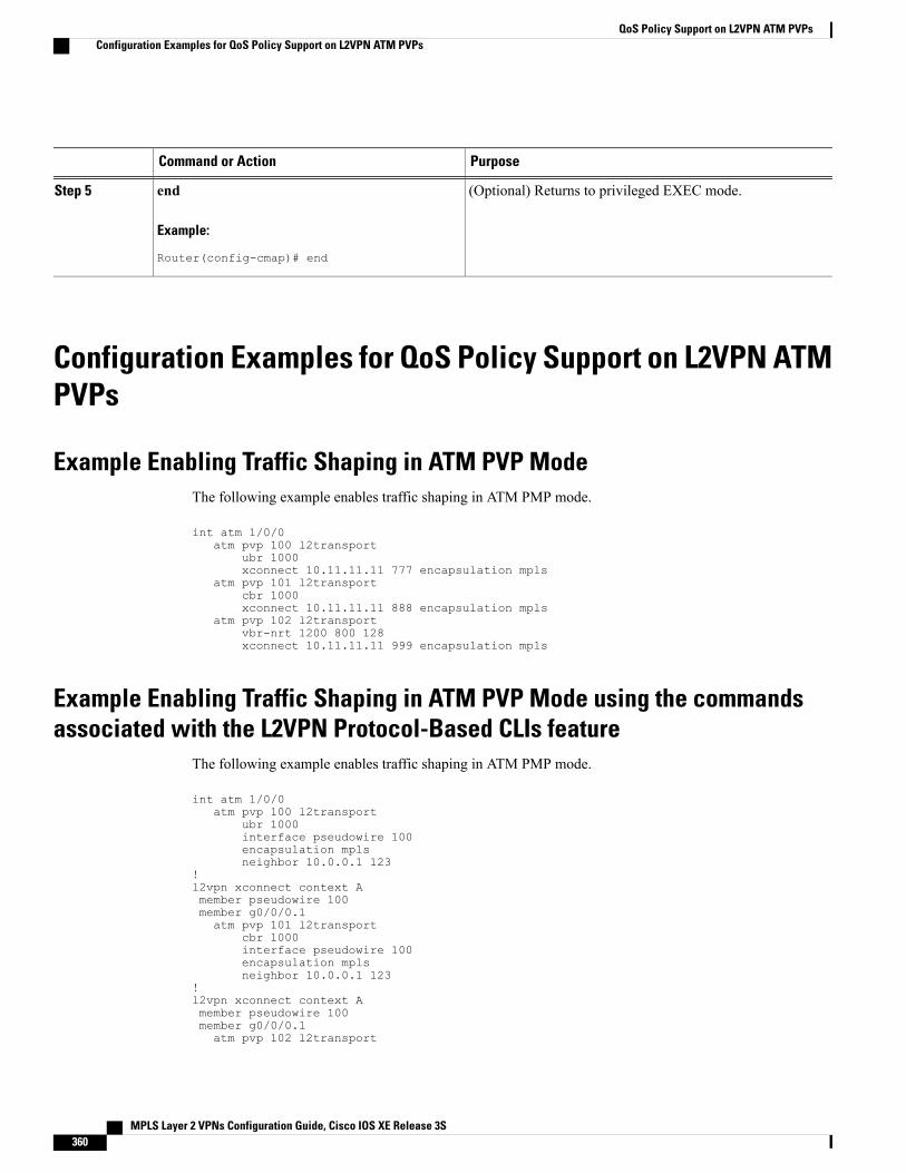
PurposeCommand or Action
(Optional) Returns to privileged EXEC mode.end
Example:
Router(config-cmap)# end
Step 5
Configuration Examples for QoS Policy Support on L2VPN ATMPVPs
Example Enabling Traffic Shaping in ATM PVP ModeThe following example enables traffic shaping in ATM PMP mode.
int atm 1/0/0atm pvp 100 l2transport
ubr 1000xconnect 10.11.11.11 777 encapsulation mpls
atm pvp 101 l2transportcbr 1000xconnect 10.11.11.11 888 encapsulation mpls
atm pvp 102 l2transportvbr-nrt 1200 800 128xconnect 10.11.11.11 999 encapsulation mpls
Example Enabling Traffic Shaping in ATM PVP Mode using the commandsassociated with the L2VPN Protocol-Based CLIs feature
The following example enables traffic shaping in ATM PMP mode.
int atm 1/0/0atm pvp 100 l2transport
ubr 1000interface pseudowire 100encapsulation mplsneighbor 10.0.0.1 123
!l2vpn xconnect context Amember pseudowire 100member g0/0/0.1atm pvp 101 l2transport
cbr 1000interface pseudowire 100encapsulation mplsneighbor 10.0.0.1 123
!l2vpn xconnect context Amember pseudowire 100member g0/0/0.1atm pvp 102 l2transport
MPLS Layer 2 VPNs Configuration Guide, Cisco IOS XE Release 3S360
QoS Policy Support on L2VPN ATM PVPsConfiguration Examples for QoS Policy Support on L2VPN ATM PVPs
vbr-nrt 1200 800 128interface pseudowire 100encapsulation mplsneighbor 10.0.0.1 123
!l2vpn xconnect context Amember pseudowire 100member g0/0/0.1
Additional ReferencesRelated Documents
Document TitleRelated Topic
Cisco IOS Master Commands List, All ReleasesCisco IOS commands
Cisco IOS Multiprotocol Label Switching CommandReference
Description of commands associated withMPLS andMPLS applications
Applying QoS Features Using the MQCModular Quality of Service (QoS) Command-LineInterface (CLI) (MQC)
Any Transport over MPLSAny Transport over MPLS
Standards
TitleStandard
--No new or modified standards are supported by thisfeature, and support for existing standards has notbeen modified by this feature.
MIBs
MIBs LinkMIB
To locate and downloadMIBs for selected platforms,Cisco software releases, and feature sets, use CiscoMIB Locator found at the following URL:
http://www.cisco.com/go/mibs
No new or modified MIBs are supported by thisfeature, and support for existing MIBs has not beenmodified by this feature.
MPLS Layer 2 VPNs Configuration Guide, Cisco IOS XE Release 3S 361
QoS Policy Support on L2VPN ATM PVPsAdditional References
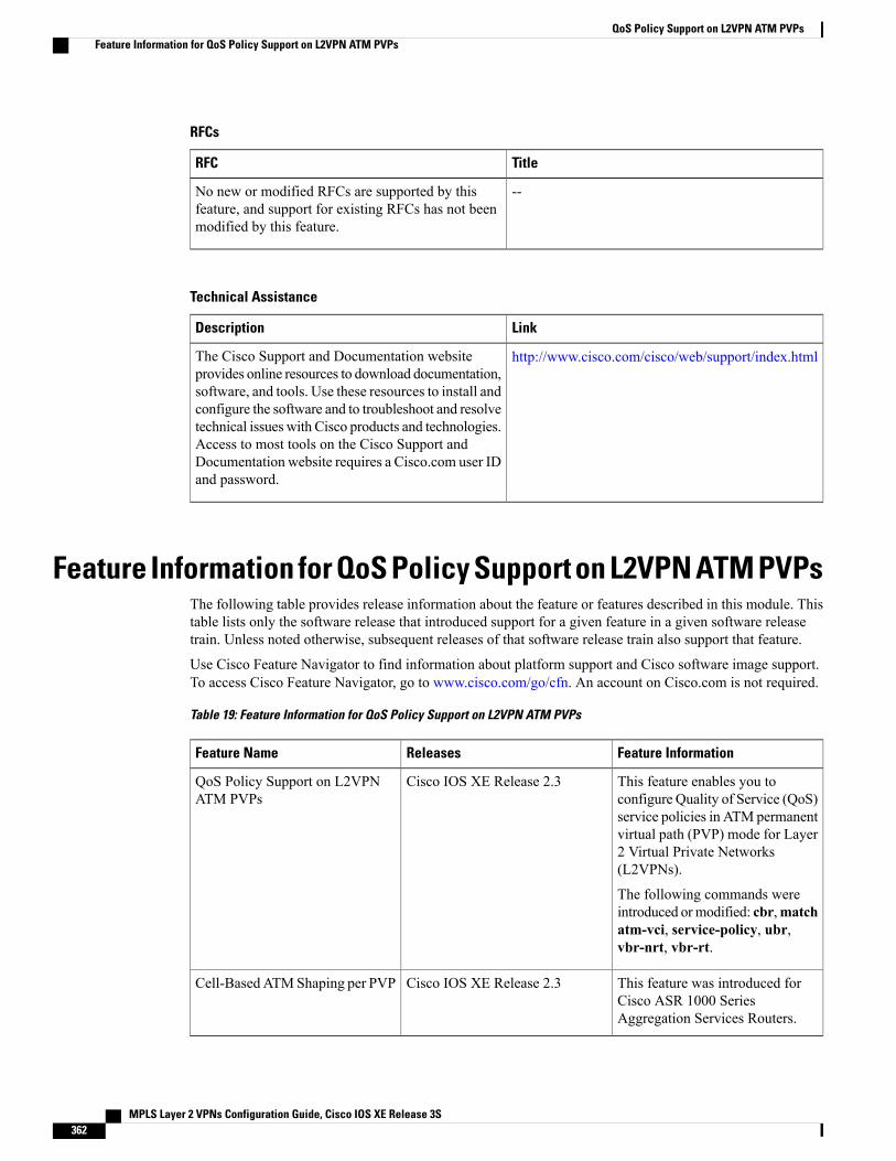
RFCs
TitleRFC
--No new or modified RFCs are supported by thisfeature, and support for existing RFCs has not beenmodified by this feature.
Technical Assistance
LinkDescription
http://www.cisco.com/cisco/web/support/index.htmlThe Cisco Support and Documentation websiteprovides online resources to download documentation,software, and tools. Use these resources to install andconfigure the software and to troubleshoot and resolvetechnical issues with Cisco products and technologies.Access to most tools on the Cisco Support andDocumentation website requires a Cisco.com user IDand password.
Feature Information for QoS Policy Support on L2VPN ATM PVPsThe following table provides release information about the feature or features described in this module. Thistable lists only the software release that introduced support for a given feature in a given software releasetrain. Unless noted otherwise, subsequent releases of that software release train also support that feature.
Use Cisco Feature Navigator to find information about platform support and Cisco software image support.To access Cisco Feature Navigator, go to www.cisco.com/go/cfn. An account on Cisco.com is not required.
Table 19: Feature Information for QoS Policy Support on L2VPN ATM PVPs
Feature InformationReleasesFeature Name
This feature enables you toconfigure Quality of Service (QoS)service policies in ATM permanentvirtual path (PVP) mode for Layer2 Virtual Private Networks(L2VPNs).
The following commands wereintroduced ormodified: cbr,matchatm-vci, service-policy, ubr,vbr-nrt, vbr-rt.
Cisco IOS XE Release 2.3QoS Policy Support on L2VPNATM PVPs
This feature was introduced forCisco ASR 1000 SeriesAggregation Services Routers.
Cisco IOS XE Release 2.3Cell-BasedATMShaping per PVP
MPLS Layer 2 VPNs Configuration Guide, Cisco IOS XE Release 3S362
QoS Policy Support on L2VPN ATM PVPsFeature Information for QoS Policy Support on L2VPN ATM PVPs

MPLS Layer 2 VPNs Configuration Guide, Cisco IOS XE Release 3S 363
QoS Policy Support on L2VPN ATM PVPsFeature Information for QoS Policy Support on L2VPN ATM PVPs

MPLS Layer 2 VPNs Configuration Guide, Cisco IOS XE Release 3S364
QoS Policy Support on L2VPN ATM PVPsFeature Information for QoS Policy Support on L2VPN ATM PVPs

C H A P T E R 8MPLS Pseudowire Status Signaling
TheMPLS Pseudowire Status Signaling feature enables you to configure the router so it can send pseudowirestatus to a peer router, even when the attachment circuit is down.
• Finding Feature Information, page 365
• Prerequisites for MPLS Pseudowire Status Signaling, page 365
• Restrictions for MPLS Pseudowire Status Signaling, page 366
• Information About MPLS Pseudowire Status Signaling, page 366
• How to Configure MPLS Pseudowire Status Signaling, page 370
• Configuration Examples for MPLS Pseudowire Status Signaling, page 373
• Additional References, page 375
• Feature Information for, page 376
Finding Feature InformationYour software release may not support all the features documented in this module. For the latest caveats andfeature information, see Bug Search Tool and the release notes for your platform and software release. Tofind information about the features documented in this module, and to see a list of the releases in which eachfeature is supported, see the feature information table at the end of this module.
Use Cisco Feature Navigator to find information about platform support and Cisco software image support.To access Cisco Feature Navigator, go to www.cisco.com/go/cfn. An account on Cisco.com is not required.
Prerequisites for MPLS Pseudowire Status Signaling• Before configuring this feature, make sure that both peer routers are capable of sending and receivingpseudowire status messages.
MPLS Layer 2 VPNs Configuration Guide, Cisco IOS XE Release 3S 365
Restrictions for MPLS Pseudowire Status Signaling• Both peer routers must support the ability to send and receive pseudowire status messages in labeladvertisement and label notification messages. If both peer routers do not support pseudowire statusmessages, Cisco recommends that you disable the messages with the no status command.
• This feature is not integrated with Any Transport over MPLS (AToM) Virtual Circuit ConnectionVerification (VCCV).
• This feature is not integrated with Bidirectional Forwarding Detection (BFD).
• The standby and required switchover values from IETF draft-muley-pwe3-redundancy-02.txt are notsupported.
Information About MPLS Pseudowire Status Signaling
How MPLS Pseudowire Status Switching WorksThe pseudowire status messages are sent in label advertisement and label notification messages if the peeralso supports the MPLS Pseudowire Status Signaling feature. You can issue the show mpls l2transport vcdetail command to show that both the local and remote routers support pseudowire status messages. Thefollowing example shows the line of output to look for:
Router# show mpls l2transport vc detail
.
.
.
status TLV support (local/remote): enabled/supported
How MPLS Pseudowire Status Switching Works using the commandsassociated with the L2VPN Protocol-Based CLIs feature
The pseudowire status messages are sent in label advertisement and label notification messages if the peeralso supports the MPLS Pseudowire Status Signaling feature. You can issue the show l2vpn atom vc detailcommand to show that both the local and remote routers support pseudowire status messages. The followingexample shows the line of output to look for:
Device# show l2vpn atom vc detail
.
.
.
status TLV support (local/remote): enabled/supported
MPLS Layer 2 VPNs Configuration Guide, Cisco IOS XE Release 3S366
MPLS Pseudowire Status SignalingRestrictions for MPLS Pseudowire Status Signaling
When One Router Does Not Support MPLS Pseudowire Status SignalingThe peer routers must support the ability to send and receive pseudowire status messages in label advertisementand label notificationmessages. If one router does not support pseudowire status messages, Cisco recommendsthat you disable the messages with the no status command. This returns the router to label withdraw mode.
If the peer does not support the MPLS Pseudowire Status Signaling feature, the local router changes its modeof operation to label withdraw mode. You can issue the show mpls l2transport vc detail command to showthat the remote router does not support pseudowire status messages. The following example shows the lineof output to look for:
Router# show mpls l2transport vc detail
.
.
.
status TLV support (local/remote): enabled/not supported
When you issue the following debug mpls l2transport vccommands, the messages show that the peer routerdoes not supporttheMPLS Pseudowire Status Signaling feature and that the local router is changing to withdrawmode, as shown in bold in the following example:
Router# debug mpls l2transport vc event Router# debug mpls l2transport vc status event Router# debugmpls l2transport vc status fsm Router# debug mpls l2transport vc ldp
*Feb 26 13:41:40.707: AToM LDP [10.1.1.2]: Sending label withdraw msg *Feb 26 13:41:40.707: AToMLDP [10.1.1.2]: VC Type 5, mtu 1500 *Feb 26 13:41:40.707: AToM LDP [10.1.1.2]: VC ID 100, label 18*Feb 26 13:41:40.707: AToM LDP [10.1.1.2]: Status 0x0000000A [PW Status NOT supported]
When One Router Does Not Support MPLS Pseudowire Status Signaling usingthe commands associated with the L2VPN Protocol-Based CLIs feature
The peer routers must support the ability to send and receive pseudowire status messages in label advertisementand label notification messages. If one router does not support pseudowire status messages, we recommendthat you disable the messages with the no status command. This returns the router to label withdraw mode.
If the peer does not support the MPLS Pseudowire Status Signaling feature, the local router changes its modeof operation to label withdraw mode. You can issue the show l2vpn atom vc detail command to show thatthe remote router does not support pseudowire status messages. The following example shows the line ofoutput to look for:
Device# show l2vpn atom vc detail
.
.
.
status TLV support (local/remote): enabled/not supported
MPLS Layer 2 VPNs Configuration Guide, Cisco IOS XE Release 3S 367
MPLS Pseudowire Status SignalingWhen One Router Does Not Support MPLS Pseudowire Status Signaling
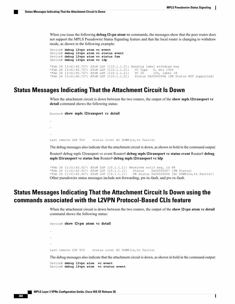
When you issue the following debug l2vpn atom vc commands, the messages show that the peer router doesnot support the MPLS Pseudowire Status Signaling feature and that the local router is changing to withdrawmode, as shown in the following example:Device# debug l2vpn atom vc eventDevice# debug l2vpn atom vc status eventDevice# debug l2vpn atom vc status fsmDevice# debug l2vpn atom vc ldp
*Feb 26 13:41:40.707: AToM LDP [110.1.1.2]: Sending label withdraw msg*Feb 26 13:41:40.707: AToM LDP [110.1.1.2]: VC Type 5, mtu 1500*Feb 26 13:41:40.707: AToM LDP [110.1.1.2]: VC ID 100, label 18*Feb 26 13:41:40.707: AToM LDP [110.1.1.2]: Status 0x0000000A [PW Status NOT supported]
Status Messages Indicating That the Attachment Circuit Is DownWhen the attachment circuit is down between the two routers, the output of the show mpls l2transport vcdetail command shows the following status:
Router# show mpls l2transport vc detail
.
.
.
Last remote LDP TLV status rcvd: AC DOWN(rx,tx faults)
The debugmessages also indicate that the attachment circuit is down, as shown in bold in the command output:
Router# debug mpls l2transport vc event Router# debug mpls l2transport vc status event Router# debugmpls l2transport vc status fsm Router# debug mpls l2transport vc ldp
*Feb 26 11:51:42.427: AToM LDP [10.1.1.1]: Received notif msg, id 88*Feb 26 11:51:42.427: AToM LDP [10.1.1.1]: Status 0x00000007 [PW Status]*Feb 26 11:51:42.427: AToM LDP [10.1.1.1]: PW Status 0x00000006 [AC DOWN(rx,tx faults)]Other pseudowire status messages include not-forwarding, pw-tx-fault, and pw-rx-fault.
Status Messages Indicating That the Attachment Circuit Is Down using thecommands associated with the L2VPN Protocol-Based CLIs feature
When the attachment circuit is down between the two routers, the output of the show l2vpn atom vc detailcommand shows the following status:
Device# show l2vpn atom vc detail
.
.
.
Last remote LDP TLV status rcvd: AC DOWN(rx,tx faults)
The debugmessages also indicate that the attachment circuit is down, as shown in bold in the command output:Device# debug l2vpn atom vc eventDevice# debug l2vpn atom vc status event
MPLS Layer 2 VPNs Configuration Guide, Cisco IOS XE Release 3S368
MPLS Pseudowire Status SignalingStatus Messages Indicating That the Attachment Circuit Is Down
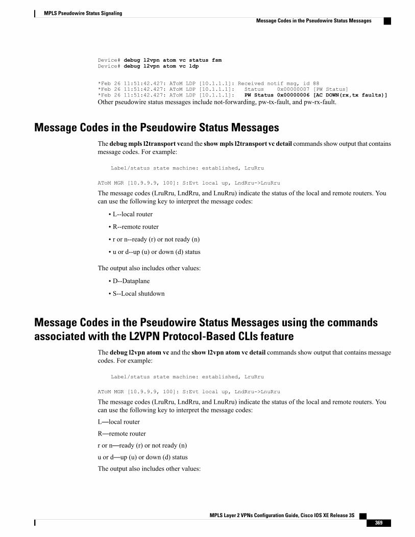
Device# debug l2vpn atom vc status fsmDevice# debug l2vpn atom vc ldp
*Feb 26 11:51:42.427: AToM LDP [10.1.1.1]: Received notif msg, id 88*Feb 26 11:51:42.427: AToM LDP [10.1.1.1]: Status 0x00000007 [PW Status]*Feb 26 11:51:42.427: AToM LDP [10.1.1.1]: PW Status 0x00000006 [AC DOWN(rx,tx faults)]Other pseudowire status messages include not-forwarding, pw-tx-fault, and pw-rx-fault.
Message Codes in the Pseudowire Status MessagesThe debugmpls l2transport vcand the showmpls l2transport vc detail commands show output that containsmessage codes. For example:
Label/status state machine: established, LruRru
AToM MGR [10.9.9.9, 100]: S:Evt local up, LndRru->LnuRru
The message codes (LruRru, LndRru, and LnuRru) indicate the status of the local and remote routers. Youcan use the following key to interpret the message codes:
• L--local router
• R--remote router
• r or n--ready (r) or not ready (n)
• u or d--up (u) or down (d) status
The output also includes other values:
• D--Dataplane
• S--Local shutdown
Message Codes in the Pseudowire Status Messages using the commandsassociated with the L2VPN Protocol-Based CLIs feature
The debug l2vpn atom vc and the show l2vpn atom vc detail commands show output that contains messagecodes. For example:
Label/status state machine: established, LruRru
AToM MGR [10.9.9.9, 100]: S:Evt local up, LndRru->LnuRru
The message codes (LruRru, LndRru, and LnuRru) indicate the status of the local and remote routers. Youcan use the following key to interpret the message codes:
L—local router
R—remote router
r or n—ready (r) or not ready (n)
u or d—up (u) or down (d) status
The output also includes other values:
MPLS Layer 2 VPNs Configuration Guide, Cisco IOS XE Release 3S 369
MPLS Pseudowire Status SignalingMessage Codes in the Pseudowire Status Messages
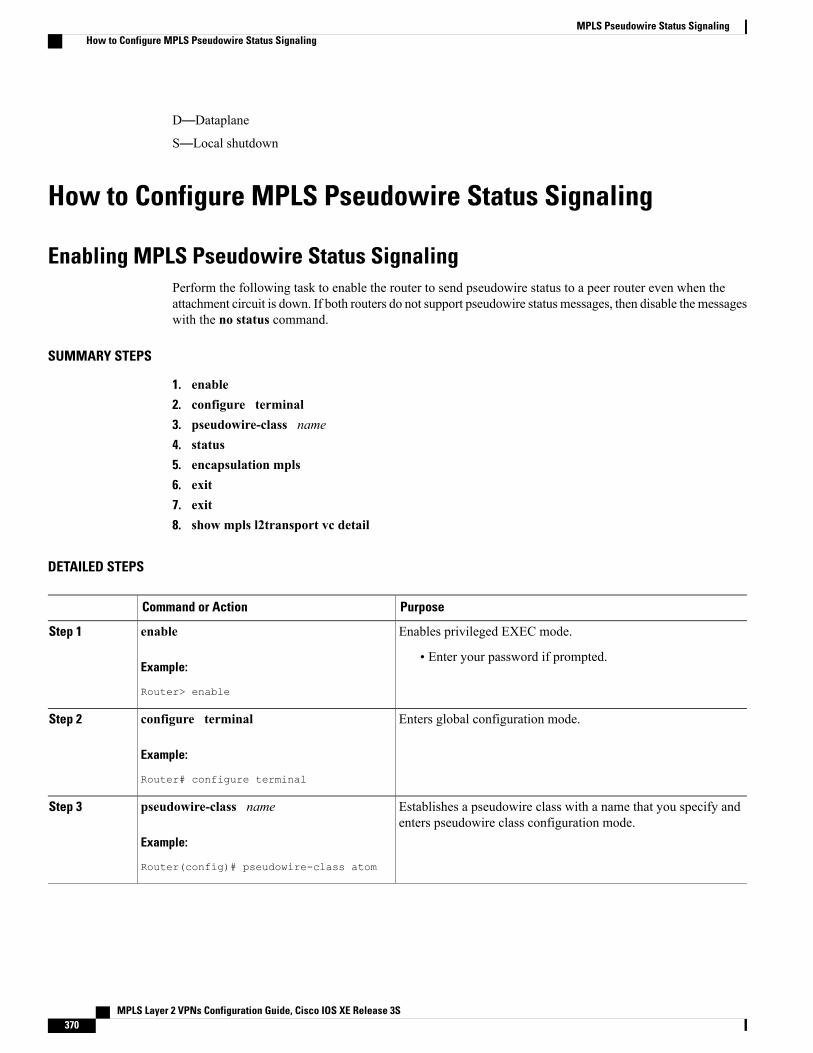
D—Dataplane
S—Local shutdown
How to Configure MPLS Pseudowire Status Signaling
Enabling MPLS Pseudowire Status SignalingPerform the following task to enable the router to send pseudowire status to a peer router even when theattachment circuit is down. If both routers do not support pseudowire status messages, then disable themessageswith the no status command.
SUMMARY STEPS
1. enable2. configure terminal3. pseudowire-class name4. status5. encapsulation mpls6. exit7. exit8. show mpls l2transport vc detail
DETAILED STEPS
PurposeCommand or Action
Enables privileged EXEC mode.enableStep 1
Example:
Router> enable
• Enter your password if prompted.
Enters global configuration mode.configure terminal
Example:
Router# configure terminal
Step 2
Establishes a pseudowire class with a name that you specify andenters pseudowire class configuration mode.
pseudowire-class name
Example:
Router(config)# pseudowire-class atom
Step 3
MPLS Layer 2 VPNs Configuration Guide, Cisco IOS XE Release 3S370
MPLS Pseudowire Status SignalingHow to Configure MPLS Pseudowire Status Signaling
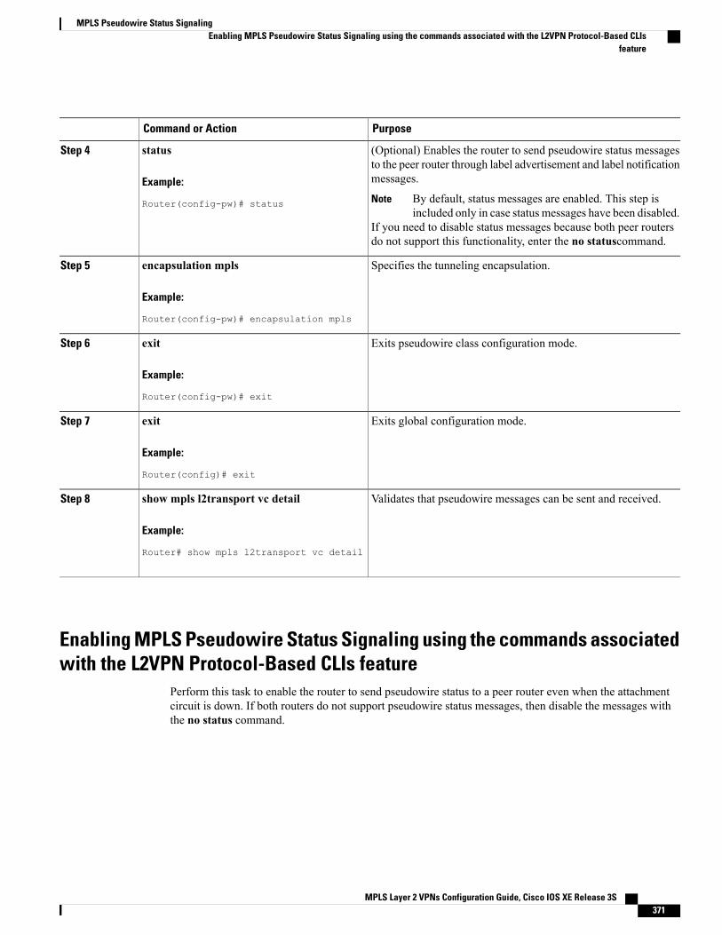
PurposeCommand or Action
(Optional) Enables the router to send pseudowire status messagesto the peer router through label advertisement and label notificationmessages.
status
Example:
Router(config-pw)# status
Step 4
By default, status messages are enabled. This step isincluded only in case status messages have been disabled.
Note
If you need to disable status messages because both peer routersdo not support this functionality, enter the no statuscommand.
Specifies the tunneling encapsulation.encapsulation mpls
Example:
Router(config-pw)# encapsulation mpls
Step 5
Exits pseudowire class configuration mode.exit
Example:
Router(config-pw)# exit
Step 6
Exits global configuration mode.exit
Example:
Router(config)# exit
Step 7
Validates that pseudowire messages can be sent and received.show mpls l2transport vc detail
Example:
Router# show mpls l2transport vc detail
Step 8
Enabling MPLS Pseudowire Status Signaling using the commands associatedwith the L2VPN Protocol-Based CLIs feature
Perform this task to enable the router to send pseudowire status to a peer router even when the attachmentcircuit is down. If both routers do not support pseudowire status messages, then disable the messages withthe no status command.
MPLS Layer 2 VPNs Configuration Guide, Cisco IOS XE Release 3S 371
MPLS Pseudowire Status SignalingEnabling MPLS Pseudowire Status Signaling using the commands associated with the L2VPN Protocol-Based CLIs
feature
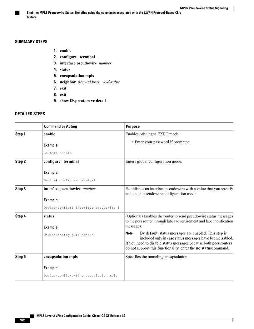
SUMMARY STEPS
1. enable2. configure terminal3. interface pseudowire number4. status5. encapsulation mpls6. neighbor peer-address vcid-value7. exit8. exit9. show l2vpn atom vc detail
DETAILED STEPS
PurposeCommand or Action
Enables privileged EXEC mode.enableStep 1
Example:
Router> enable
• Enter your password if prompted.
Enters global configuration mode.configure terminal
Example:
Device# configure terminal
Step 2
Establishes an interface pseudowire with a value that you specifyand enters pseudowire configuration mode.
interface pseudowire number
Example:
Device(config)# interface pseudowire 1
Step 3
(Optional) Enables the router to send pseudowire status messagesto the peer router through label advertisement and label notificationmessages.
status
Example:
Device(config-pw)# status
Step 4
By default, status messages are enabled. This step isincluded only in case status messages have been disabled.
Note
If you need to disable status messages because both peer routersdo not support this functionality, enter the no statuscommand.
Specifies the tunneling encapsulation.encapsulation mpls
Example:
Device(config-pw)# encapsulation mpls
Step 5
MPLS Layer 2 VPNs Configuration Guide, Cisco IOS XE Release 3S372
MPLS Pseudowire Status SignalingEnabling MPLS Pseudowire Status Signaling using the commands associated with the L2VPN Protocol-Based CLIsfeature
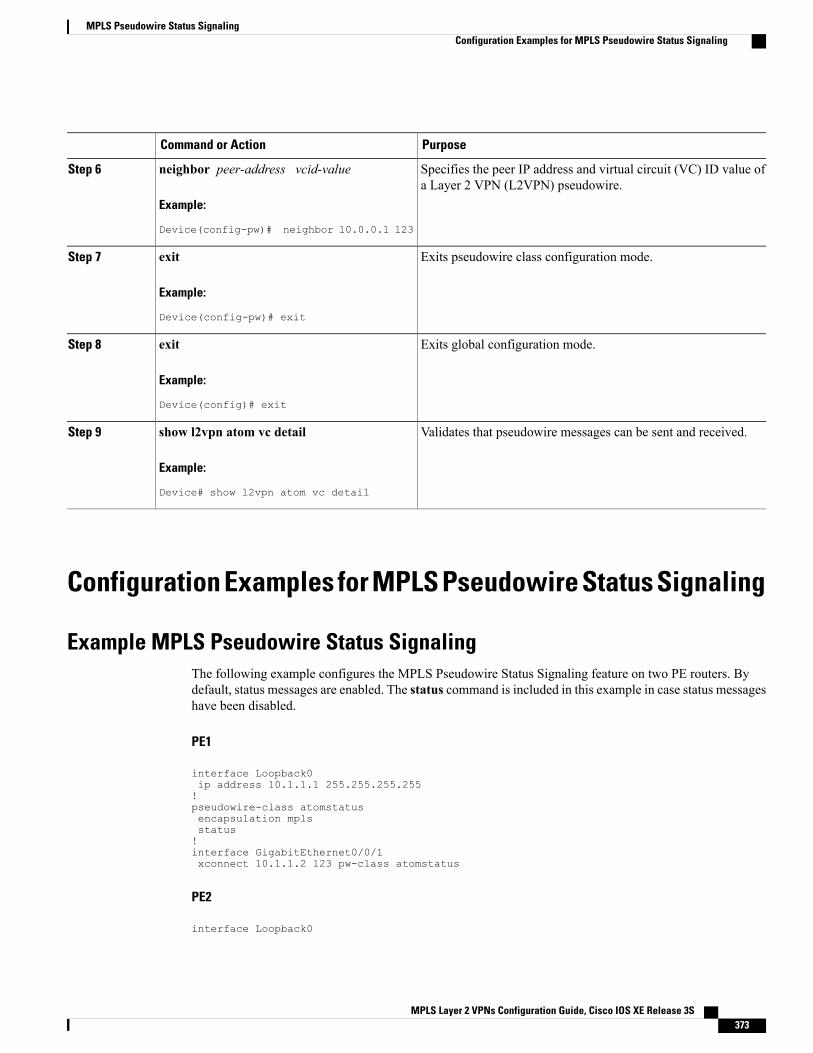
PurposeCommand or Action
Specifies the peer IP address and virtual circuit (VC) ID value ofa Layer 2 VPN (L2VPN) pseudowire.
neighbor peer-address vcid-value
Example:
Device(config-pw)# neighbor 10.0.0.1 123
Step 6
Exits pseudowire class configuration mode.exit
Example:
Device(config-pw)# exit
Step 7
Exits global configuration mode.exit
Example:
Device(config)# exit
Step 8
Validates that pseudowire messages can be sent and received.show l2vpn atom vc detail
Example:
Device# show l2vpn atom vc detail
Step 9
Configuration Examples for MPLS Pseudowire Status Signaling
Example MPLS Pseudowire Status SignalingThe following example configures the MPLS Pseudowire Status Signaling feature on two PE routers. Bydefault, status messages are enabled. The status command is included in this example in case status messageshave been disabled.
PE1
interface Loopback0ip address 10.1.1.1 255.255.255.255!pseudowire-class atomstatusencapsulation mplsstatus!interface GigabitEthernet0/0/1xconnect 10.1.1.2 123 pw-class atomstatus
PE2
interface Loopback0
MPLS Layer 2 VPNs Configuration Guide, Cisco IOS XE Release 3S 373
MPLS Pseudowire Status SignalingConfiguration Examples for MPLS Pseudowire Status Signaling
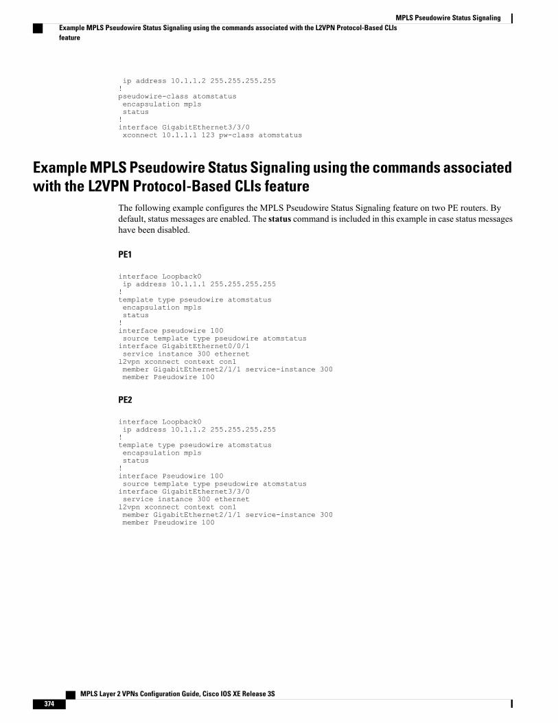
ip address 10.1.1.2 255.255.255.255!pseudowire-class atomstatusencapsulation mplsstatus!interface GigabitEthernet3/3/0xconnect 10.1.1.1 123 pw-class atomstatus
Example MPLS Pseudowire Status Signaling using the commands associatedwith the L2VPN Protocol-Based CLIs feature
The following example configures the MPLS Pseudowire Status Signaling feature on two PE routers. Bydefault, status messages are enabled. The status command is included in this example in case status messageshave been disabled.
PE1
interface Loopback0ip address 10.1.1.1 255.255.255.255!template type pseudowire atomstatusencapsulation mplsstatus!interface pseudowire 100source template type pseudowire atomstatusinterface GigabitEthernet0/0/1service instance 300 ethernetl2vpn xconnect context con1member GigabitEthernet2/1/1 service-instance 300member Pseudowire 100
PE2
interface Loopback0ip address 10.1.1.2 255.255.255.255!template type pseudowire atomstatusencapsulation mplsstatus!interface Pseudowire 100source template type pseudowire atomstatusinterface GigabitEthernet3/3/0service instance 300 ethernetl2vpn xconnect context con1member GigabitEthernet2/1/1 service-instance 300member Pseudowire 100
MPLS Layer 2 VPNs Configuration Guide, Cisco IOS XE Release 3S374
MPLS Pseudowire Status SignalingExample MPLS Pseudowire Status Signaling using the commands associated with the L2VPN Protocol-Based CLIsfeature
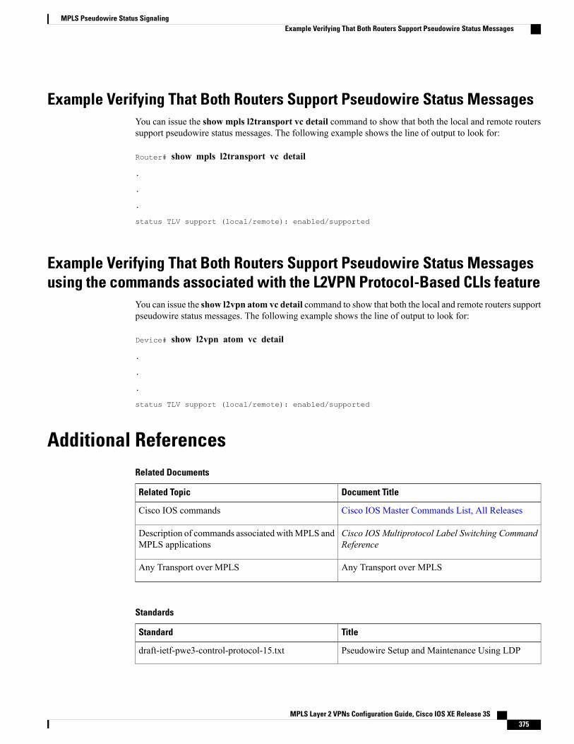
Example Verifying That Both Routers Support Pseudowire Status MessagesYou can issue the show mpls l2transport vc detail command to show that both the local and remote routerssupport pseudowire status messages. The following example shows the line of output to look for:
Router# show mpls l2transport vc detail
.
.
.
status TLV support (local/remote): enabled/supported
Example Verifying That Both Routers Support Pseudowire Status Messagesusing the commands associated with the L2VPN Protocol-Based CLIs feature
You can issue the show l2vpn atom vc detail command to show that both the local and remote routers supportpseudowire status messages. The following example shows the line of output to look for:
Device# show l2vpn atom vc detail
.
.
.
status TLV support (local/remote): enabled/supported
Additional ReferencesRelated Documents
Document TitleRelated Topic
Cisco IOS Master Commands List, All ReleasesCisco IOS commands
Cisco IOS Multiprotocol Label Switching CommandReference
Description of commands associated withMPLS andMPLS applications
Any Transport over MPLSAny Transport over MPLS
Standards
TitleStandard
Pseudowire Setup and Maintenance Using LDPdraft-ietf-pwe3-control-protocol-15.txt
MPLS Layer 2 VPNs Configuration Guide, Cisco IOS XE Release 3S 375
MPLS Pseudowire Status SignalingExample Verifying That Both Routers Support Pseudowire Status Messages
TitleStandard
IANA Allocations for Pseudo Wire Edge to EdgeEmulation (PWE3)
draft-ietf-pwe3-iana-allocation-08.txt
Pseudo Wire Switchingdraft-martini-pwe3-pw-switching-03.txt
MIBs
MIBs LinkMIB
To locate and downloadMIBs for selected platforms,Cisco software releases, and feature sets, use CiscoMIB Locator found at the following URL:
http://www.cisco.com/go/mibs
Pseudowire Emulation Edge-to-Edge MIBs forEthernet, Frame Relay, and ATM Services
RFCs
TitleRFC
--No new or modified RFCs are supported by thisfeature, and support for existing RFCs has not beenmodified by this feature.
Technical Assistance
LinkDescription
http://www.cisco.com/cisco/web/support/index.htmlThe Cisco Support and Documentation websiteprovides online resources to download documentation,software, and tools. Use these resources to install andconfigure the software and to troubleshoot and resolvetechnical issues with Cisco products and technologies.Access to most tools on the Cisco Support andDocumentation website requires a Cisco.com user IDand password.
Feature Information forThe following table provides release information about the feature or features described in this module. Thistable lists only the software release that introduced support for a given feature in a given software releasetrain. Unless noted otherwise, subsequent releases of that software release train also support that feature.
MPLS Layer 2 VPNs Configuration Guide, Cisco IOS XE Release 3S376
MPLS Pseudowire Status SignalingFeature Information for
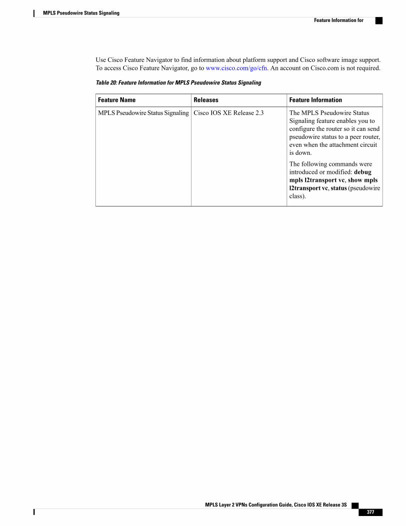
Use Cisco Feature Navigator to find information about platform support and Cisco software image support.To access Cisco Feature Navigator, go to www.cisco.com/go/cfn. An account on Cisco.com is not required.
Table 20: Feature Information for MPLS Pseudowire Status Signaling
Feature InformationReleasesFeature Name
The MPLS Pseudowire StatusSignaling feature enables you toconfigure the router so it can sendpseudowire status to a peer router,even when the attachment circuitis down.
The following commands wereintroduced or modified: debugmpls l2transport vc, show mplsl2transport vc, status (pseudowireclass).
Cisco IOS XE Release 2.3MPLSPseudowire Status Signaling
MPLS Layer 2 VPNs Configuration Guide, Cisco IOS XE Release 3S 377
MPLS Pseudowire Status SignalingFeature Information for

MPLS Layer 2 VPNs Configuration Guide, Cisco IOS XE Release 3S378
MPLS Pseudowire Status SignalingFeature Information for
C H A P T E R 9L2VPN VPLS Inter-AS Option B
The L2VPNVPLS Inter-ASOption B feature expands the existing features of VPLS autodiscovery to operateacross multiple Border Gateway Protocol (BGP) autonomous systems. Using BGP-based autodiscovery asthe underlying framework, the L2VPN VPLS Inter-AS Option B feature creates a dynamic multisegmentedpseudowire (PW) configuration between neighboring Autonomous System Boundary Routers (ASBRs.)
• Finding Feature Information, page 379
• Prerequisites for L2VPN VPLS Inter-AS Option B, page 380
• Restrictions for L2VPN VPLS Inter-AS Option B, page 380
• Information About L2VPN VPLS Inter-AS Option B, page 380
• How to Configure L2VPN VPLS Inter-AS Option B, page 382
• Configuration Examples for L2VPN VPLS Inter-AS Option B, page 398
• Additional References for L2VPN VPLS Inter-AS Option B, page 410
• Feature Information for L2VPN VPLS Inter-AS Option B, page 412
• Glossary, page 413
Finding Feature InformationYour software release may not support all the features documented in this module. For the latest caveats andfeature information, see Bug Search Tool and the release notes for your platform and software release. Tofind information about the features documented in this module, and to see a list of the releases in which eachfeature is supported, see the feature information table at the end of this module.
Use Cisco Feature Navigator to find information about platform support and Cisco software image support.To access Cisco Feature Navigator, go to www.cisco.com/go/cfn. An account on Cisco.com is not required.
MPLS Layer 2 VPNs Configuration Guide, Cisco IOS XE Release 3S 379
Prerequisites for L2VPN VPLS Inter-AS Option BThe L2VPN VPLS Inter-AS Option B feature extends the functionality of the VPLS Autodiscovery: BGPBased feature. For example, as a result of L2VPNVPLS Inter-ASOption B feature, stateful switchover (SSO)and nonstop forwarding (NSF) are supported in a standard VPLS Autodiscovery configuration.
Before you configure the L2VPN VPLS Inter-AS Option B feature, enable the VPLS Autodiscovery: BGPBased feature and complete the steps described in the Modifying the VPLS Autodiscovery Settings for Usewith L2VPN VPLS Inter-AS Option B, on page 382.
For more information about the VPLS Autodiscovery: BGP Based feature, see the “VPLS Autodiscovery:BGP” module.
Restrictions for L2VPN VPLS Inter-AS Option BIntroduced in Cisco IOS Release 15.1(1)S, the L2VPN VPLS Inter-AS Option B feature is supported only ona Cisco 7600 series router that is equipped with a line card capable of running Virtual Private LAN Switching(VPLS).
Information About L2VPN VPLS Inter-AS Option B
VPLS Functionality and L2VPN VPLS Inter-AS Option BVPLS is a multipoint Layer 2 VPN (L2VPN) that connects two or more customer devices using Ethernet overMultiprotocol Label Switching (EoMPLS) bridging techniques.
VPLS Inter-AS support exists in a number of variations or options (for example, Option A, B, C, and D). TheL2VPN VPLS Inter-AS Option B feature supports Option B only and is in compliance with RFC 4364,BGP/MPLS IP Virtual Private Networks (VPNs) .
For more information about VPLS, see the “VPLS Overview” section in the ConfiguringMultiprotocol LabelSwitching on the Optical Services Modules document.
L2VPN VPLS Inter-AS Option B DescriptionThe L2VPN VPLS Inter-AS Option B feature extends VPLS across multiple autonomous system boundariesby dynamically creating multisegment pseudowires across the ASBRs.
When a router with external BGP (eBGP) advertises routes to its BGP neighbors, the router uses the sourceIP address as the next hop of the advertised routes.
When a router with internal BGP (iBGP) advertises routes to its BGP neighbors, the router does not changethe next hop designation of the route advertised. For the L2VPN VPLS Inter-AS Option B feature, enter theneighbor next-hop-self command at the ASBRs. This forces the pseudowires to be targeted to the ASBRand not targeted to the provider edge (PE) routers. The net result is that a pseudowire for the first autonomoussystem is stitched to a pseudowire for the second autonomous system by means of a third pseudowire betweenthe ASBRs. This creates a multisegmented pseudowire. For more information about multisegmentedpseudowires, see the “L2VPN Multisegment Pseudowires” module.
MPLS Layer 2 VPNs Configuration Guide, Cisco IOS XE Release 3S380
L2VPN VPLS Inter-AS Option BPrerequisites for L2VPN VPLS Inter-AS Option B
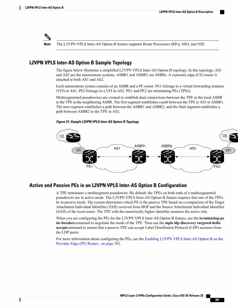
The L2VPN VPLS Inter-AS Option B feature supports Route Processors (RPs), SSO, and NSF.Note
L2VPN VPLS Inter-AS Option B Sample TopologyThe figure below illustrates a simplified L2VPN VPLS Inter-AS Option B topology. In this topology, AS1and AS2 are the autonomous systems. ASBR1 and ASBR2 are ASBRs. A customer edge (CE) router isattached to both AS1 and AS2.
Each autonomous system consists of an ASBR and a PE router. PE1 belongs to a virtual forwarding instance(VFI) in AS1. PE2 belongs to a VFI in AS2. PE1 and PE2 are terminating PEs (TPEs).
Multisegmented pseudowires are created to establish dual connections between the TPE in the local ASBRto the TPE in the neighboring ASBR. The first segment establishes a path between the TPE in AS1 to ASBR1.The next segment establishes a path between the ASBR1 and ASBR2, and the final segment establishes apath between ASBR2 to the TPE in AS2.
Figure 21: Sample L2VPN VPLS Inter-AS Option B Topology
Active and Passive PEs in an L2VPN VPLS Inter-AS Option B ConfigurationA TPE terminates a multisegment pseudowire. By default, the TPEs on both ends of a multisegmentedpseudowire are in active mode. The L2VPN VPLS Inter-AS Option B feature requires that one of the TPEsbe in passive mode. The system determines which PE is the passive TPE based on a comparison of the TargetAttachment Individual Identifier (TAII) received from BGP and the Source Attachment Individual Identifier(SAII) of the local router. The TPE with the numerically higher identifier assumes the active role.
When you are configuring the PEs for the L2VPN VPLS Inter-AS Option B feature, use the terminating-petie-breakercommand to negotiate the mode of the TPE. Then use thempls ldp discovery targeted-helloacceptcommand to ensure that a passive TPE can accept Label Distribution Protocol (LDP) sessions fromthe LDP peers.
For more information about configuring the PEs, see the Enabling L2VPN VPLS Inter-AS Option B on theProvider Edge (PE) Router, on page 392.
MPLS Layer 2 VPNs Configuration Guide, Cisco IOS XE Release 3S 381
L2VPN VPLS Inter-AS Option BL2VPN VPLS Inter-AS Option B Description
Benefits of L2VPN VPLS Inter-AS Option B
Private IP AddressesWhile a large number of pseudowires are required, IPv4 reachability is maintained within the ASBR and,therefore, IP addresses are private.
One Targeted LDP SessionWith the L2VPN VPLS Inter-AS Option B feature, only one targeted Label Distribution Protocol (LDP)session is created between the autonomous systems. Since only one targeted LDP session between autonomoussystems is created, service providers can apply tighter security policies for control plane traffic going acrossthe autonomous system.
How to Configure L2VPN VPLS Inter-AS Option B
Modifying the VPLS Autodiscovery Settings for Use with L2VPN VPLS Inter-ASOption B
Before you configure the L2VPN VPLS Inter-AS Option B feature, you must enable the VPLSAutodiscovery: BGP Based feature. Make sure you have enabled the VPLS Autodiscovery: BGP Basedfeature before proceeding with this task.
Note
For the L2VPNVPLS Inter-AS Option B feature to function properly, you must configure the VPLS ID valueand the route-target value for each PE router in the virtual forwarding instance (VFI). To modify these values,complete the following steps at each PE router.
SUMMARY STEPS
1. enable2. configure terminal3. l2 vfi vfi-name autodiscovery4. vpn id vpn-id5. vpls-id {autonomous-system-number : nn | ip-address : nn}6. route-target [import | export | both] {autonomous-system-number : nn | ip-address : nn}7. exit
MPLS Layer 2 VPNs Configuration Guide, Cisco IOS XE Release 3S382
L2VPN VPLS Inter-AS Option BBenefits of L2VPN VPLS Inter-AS Option B
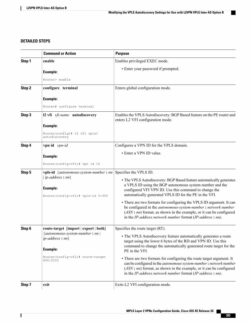
DETAILED STEPS
PurposeCommand or Action
Enables privileged EXEC mode.enableStep 1
Example:
Router> enable
• Enter your password if prompted.
Enters global configuration mode.configure terminal
Example:
Router# configure terminal
Step 2
Enables the VPLSAutodiscovery: BGPBased feature on the PE router andenters L2 VFI configuration mode.
l2 vfi vfi-name autodiscovery
Example:
Router(config)# l2 vfi vpls1autodiscovery
Step 3
Configures a VPN ID for the VPLS domain.vpn id vpn-idStep 4
Example:
Router(config-vfi)# vpn id 10
• Enter a VPN ID value.
Specifies the VPLS ID.vpls-id {autonomous-system-number : nn| ip-address : nn}
Step 5
• TheVPLSAutodiscovery: BGPBased feature automatically generatesa VPLS ID using the BGP autonomous system number and the
Example:
Router(config-vfi)# vpls-id 5:300
configured VFI VPN ID. Use this command to change theautomatically generated VPLS ID for the PE in the VFI.
• There are two formats for configuring the VPLS ID argument. It canbe configured in the autonomous-system-number : network number(ASN : nn) format, as shown in the example, or it can be configuredin the IP-address:network number format (IP-address : nn).
Specifies the route target (RT).route-target [import | export | both]{autonomous-system-number : nn |ip-address : nn}
Step 6
• The VPLS Autodiscovery feature automatically generates a routetarget using the lower 6 bytes of the RD and VPN ID. Use this
Example:
Router(config-vfi)# route-target600:2222
command to change the automatically generated route target for thePE in the VFI.
• There are two formats for configuring the route target argument. Itcan be configured in the autonomous-system-number : network number(ASN : nn) format, as shown in the example, or it can be configuredin the IP-address:network number format (IP-address : nn).
Exits L2 VFI configuration mode.exitStep 7
MPLS Layer 2 VPNs Configuration Guide, Cisco IOS XE Release 3S 383
L2VPN VPLS Inter-AS Option BModifying the VPLS Autodiscovery Settings for Use with L2VPN VPLS Inter-AS Option B
PurposeCommand or Action
Example:
Router(config-vfi)# exit
• Commands take effect after the router exits L2 VFI configurationmode.
What to Do NextRepeat the steps in the Modifying the VPLS Autodiscovery Settings for Use with L2VPN VPLS Inter-ASOption B, on page 382 at each PE in the autonomous system. Then proceed to the Enabling L2VPN VPLSInter-AS Option B on the ASBR, on page 386.
Modifying the VPLS Autodiscovery Settings for Use with L2VPN VPLS Inter-ASOption B using the commands associated with the L2VPN Protocol-Based CLIsfeature
Before you configure the L2VPN VPLS Inter-AS Option B feature, you must enable the VPLSAutodiscovery: BGP Based feature. Make sure you have enabled the VPLS Autodiscovery: BGP Basedfeature before proceeding with this task.
Note
For the L2VPNVPLS Inter-AS Option B feature to function properly, you must configure the VPLS ID valueand the route-target value for each PE router in the virtual forwarding instance (VFI). To modify these values,complete the following steps at each PE router.
SUMMARY STEPS
1. enable2. configure terminal3. l2vpn vfi context vfi-name4. vpn id vpn-id5. autodiscovery bgp signaling ldp6. vpls-id {autonomous-system-number : nn | ip-address : nn}7. route-target [import | export | both] {autonomous-system-number : nn | ip-address : nn}8. exit
MPLS Layer 2 VPNs Configuration Guide, Cisco IOS XE Release 3S384
L2VPN VPLS Inter-AS Option BModifying the VPLS Autodiscovery Settings for Use with L2VPN VPLS Inter-AS Option B using the commands associatedwith the L2VPN Protocol-Based CLIs feature
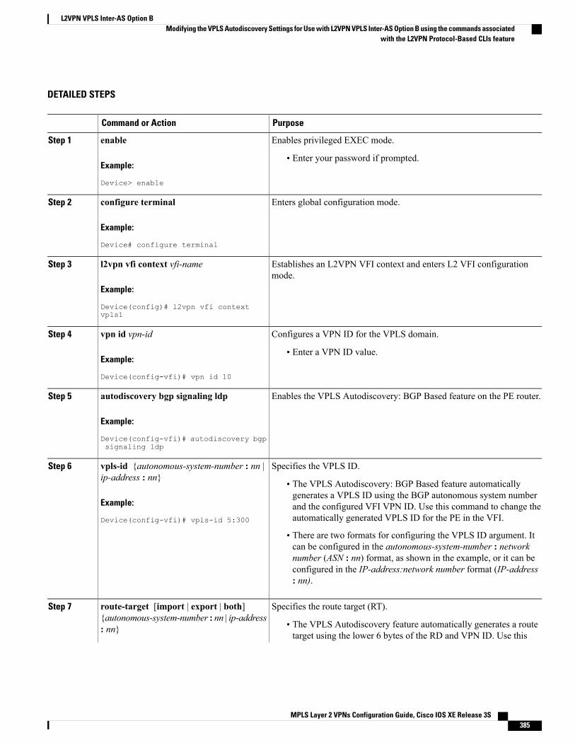
DETAILED STEPS
PurposeCommand or Action
Enables privileged EXEC mode.enableStep 1
Example:
Device> enable
• Enter your password if prompted.
Enters global configuration mode.configure terminal
Example:
Device# configure terminal
Step 2
Establishes an L2VPN VFI context and enters L2 VFI configurationmode.
l2vpn vfi context vfi-name
Example:
Device(config)# l2vpn vfi contextvpls1
Step 3
Configures a VPN ID for the VPLS domain.vpn id vpn-idStep 4
Example:
Device(config-vfi)# vpn id 10
• Enter a VPN ID value.
Enables the VPLS Autodiscovery: BGP Based feature on the PE router.autodiscovery bgp signaling ldp
Example:
Device(config-vfi)# autodiscovery bgpsignaling ldp
Step 5
Specifies the VPLS ID.vpls-id {autonomous-system-number : nn |ip-address : nn}
Step 6
• The VPLS Autodiscovery: BGP Based feature automaticallygenerates a VPLS ID using the BGP autonomous system number
Example:
Device(config-vfi)# vpls-id 5:300
and the configured VFI VPN ID. Use this command to change theautomatically generated VPLS ID for the PE in the VFI.
• There are two formats for configuring the VPLS ID argument. Itcan be configured in the autonomous-system-number : networknumber (ASN : nn) format, as shown in the example, or it can beconfigured in the IP-address:network number format (IP-address: nn).
Specifies the route target (RT).route-target [import | export | both]{autonomous-system-number : nn | ip-address: nn}
Step 7
• The VPLS Autodiscovery feature automatically generates a routetarget using the lower 6 bytes of the RD and VPN ID. Use this
MPLS Layer 2 VPNs Configuration Guide, Cisco IOS XE Release 3S 385
L2VPN VPLS Inter-AS Option BModifying the VPLS Autodiscovery Settings for Use with L2VPN VPLS Inter-AS Option B using the commands associated
with the L2VPN Protocol-Based CLIs feature
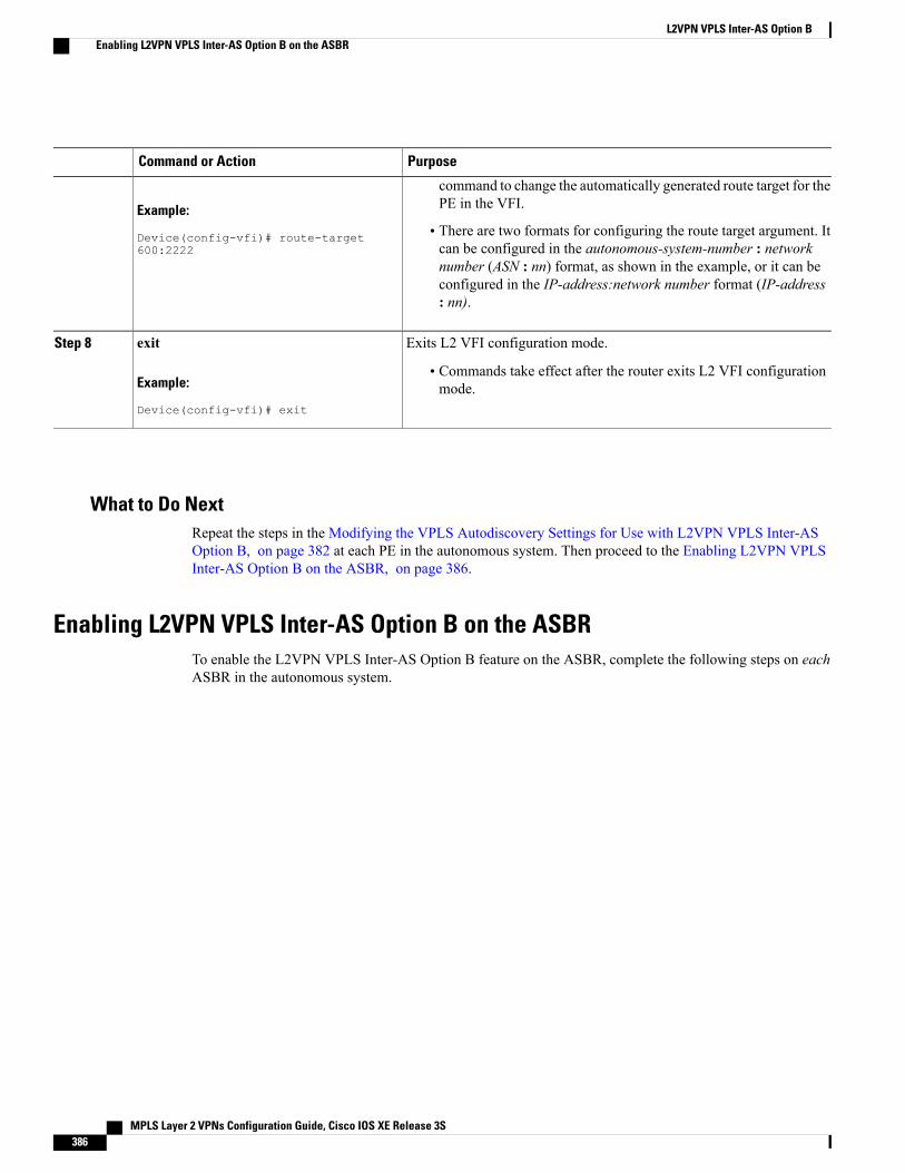
PurposeCommand or Action
Example:
Device(config-vfi)# route-target600:2222
command to change the automatically generated route target for thePE in the VFI.
• There are two formats for configuring the route target argument. Itcan be configured in the autonomous-system-number : networknumber (ASN : nn) format, as shown in the example, or it can beconfigured in the IP-address:network number format (IP-address: nn).
Exits L2 VFI configuration mode.exitStep 8
Example:
Device(config-vfi)# exit
• Commands take effect after the router exits L2 VFI configurationmode.
What to Do NextRepeat the steps in the Modifying the VPLS Autodiscovery Settings for Use with L2VPN VPLS Inter-ASOption B, on page 382 at each PE in the autonomous system. Then proceed to the Enabling L2VPN VPLSInter-AS Option B on the ASBR, on page 386.
Enabling L2VPN VPLS Inter-AS Option B on the ASBRTo enable the L2VPN VPLS Inter-AS Option B feature on the ASBR, complete the following steps on eachASBR in the autonomous system.
MPLS Layer 2 VPNs Configuration Guide, Cisco IOS XE Release 3S386
L2VPN VPLS Inter-AS Option BEnabling L2VPN VPLS Inter-AS Option B on the ASBR
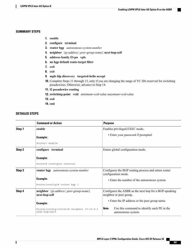
SUMMARY STEPS
1. enable2. configure terminal3. router bgp autonomous-system-number4. neighbor {ip-address | peer-group-name} next-hop-self5. address-family l2vpn vpls6. no bgp default route-target filter7. exit8. exit9. mpls ldp discovery targeted-hello accept10. Complete Steps 11 through 13, only if you are changing the range of VC IDs reserved for switching
pseudowires. Otherwise, advance to Step 14.11. l2 pseudowire routing12. switching-point vcid minimum-vcid-value maximum-vcid-value13. exit14. end
DETAILED STEPS
PurposeCommand or Action
Enables privileged EXEC mode.enableStep 1
Example:
Router> enable
• Enter your password if prompted.
Enters global configuration mode.configure terminal
Example:
Router# configure terminal
Step 2
Configures the BGP routing process and enters routerconfiguration mode.
router bgp autonomous-system-number
Example:
Router(config)# router bgp 1
Step 3
• Enter the number of the autonomous system.
Configures the ASBR as the next hop for a BGP-speakingneighbor or peer group.
neighbor {ip-address | peer-group-name}next-hop-self
Step 4
Example:
Router(config-router)# neighbor 10.10.0.1next-hop-self
• Enter the IP address or the peer group name.
Use this command to identify each PE in theautonomous system.
Note
MPLS Layer 2 VPNs Configuration Guide, Cisco IOS XE Release 3S 387
L2VPN VPLS Inter-AS Option BEnabling L2VPN VPLS Inter-AS Option B on the ASBR
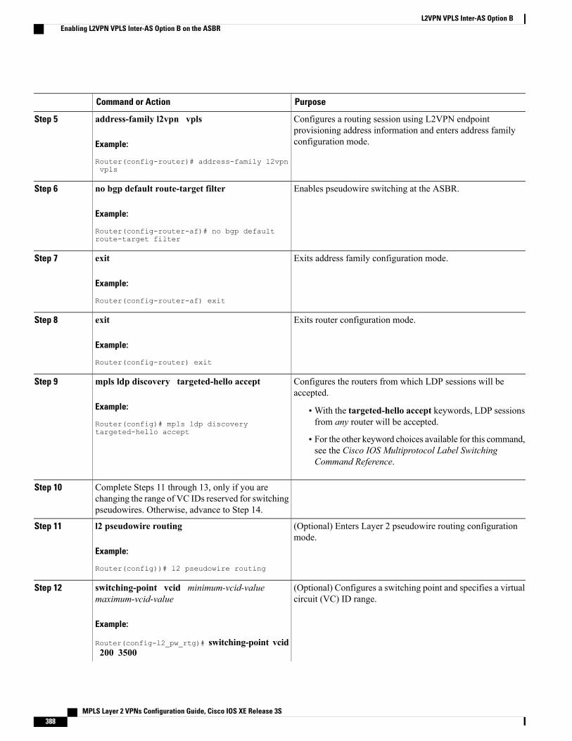
PurposeCommand or Action
Configures a routing session using L2VPN endpointprovisioning address information and enters address familyconfiguration mode.
address-family l2vpn vpls
Example:
Router(config-router)# address-family l2vpnvpls
Step 5
Enables pseudowire switching at the ASBR.no bgp default route-target filter
Example:
Router(config-router-af)# no bgp defaultroute-target filter
Step 6
Exits address family configuration mode.exit
Example:
Router(config-router-af) exit
Step 7
Exits router configuration mode.exit
Example:
Router(config-router) exit
Step 8
Configures the routers from which LDP sessions will beaccepted.
mpls ldp discovery targeted-hello accept
Example:
Router(config)# mpls ldp discoverytargeted-hello accept
Step 9
•With the targeted-hello accept keywords, LDP sessionsfrom any router will be accepted.
• For the other keyword choices available for this command,see the Cisco IOS Multiprotocol Label SwitchingCommand Reference.
Complete Steps 11 through 13, only if you arechanging the range of VC IDs reserved for switchingpseudowires. Otherwise, advance to Step 14.
Step 10
(Optional) Enters Layer 2 pseudowire routing configurationmode.
l2 pseudowire routing
Example:
Router(config))# l2 pseudowire routing
Step 11
(Optional) Configures a switching point and specifies a virtualcircuit (VC) ID range.
switching-point vcid minimum-vcid-valuemaximum-vcid-value
Step 12
Example:
Router(config-l2_pw_rtg)# switching-point vcid200 3500
MPLS Layer 2 VPNs Configuration Guide, Cisco IOS XE Release 3S388
L2VPN VPLS Inter-AS Option BEnabling L2VPN VPLS Inter-AS Option B on the ASBR
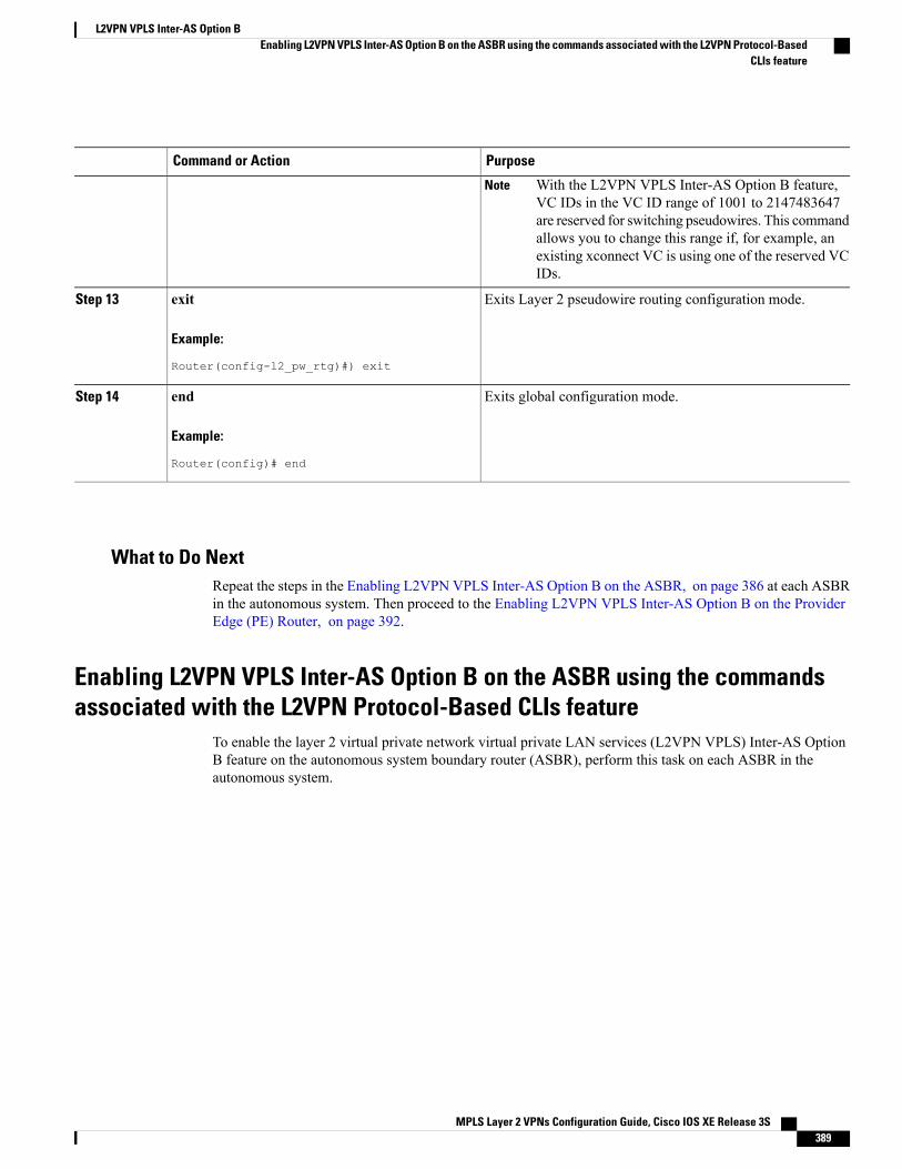
PurposeCommand or Action
With the L2VPN VPLS Inter-AS Option B feature,VC IDs in the VC ID range of 1001 to 2147483647are reserved for switching pseudowires. This commandallows you to change this range if, for example, anexisting xconnect VC is using one of the reserved VCIDs.
Note
Exits Layer 2 pseudowire routing configuration mode.exit
Example:
Router(config-l2_pw_rtg)#) exit
Step 13
Exits global configuration mode.end
Example:
Router(config)# end
Step 14
What to Do NextRepeat the steps in the Enabling L2VPN VPLS Inter-AS Option B on the ASBR, on page 386 at each ASBRin the autonomous system. Then proceed to the Enabling L2VPN VPLS Inter-AS Option B on the ProviderEdge (PE) Router, on page 392.
Enabling L2VPN VPLS Inter-AS Option B on the ASBR using the commandsassociated with the L2VPN Protocol-Based CLIs feature
To enable the layer 2 virtual private network virtual private LAN services (L2VPN VPLS) Inter-AS OptionB feature on the autonomous system boundary router (ASBR), perform this task on each ASBR in theautonomous system.
MPLS Layer 2 VPNs Configuration Guide, Cisco IOS XE Release 3S 389
L2VPN VPLS Inter-AS Option BEnabling L2VPN VPLS Inter-AS Option B on the ASBR using the commands associated with the L2VPN Protocol-Based
CLIs feature
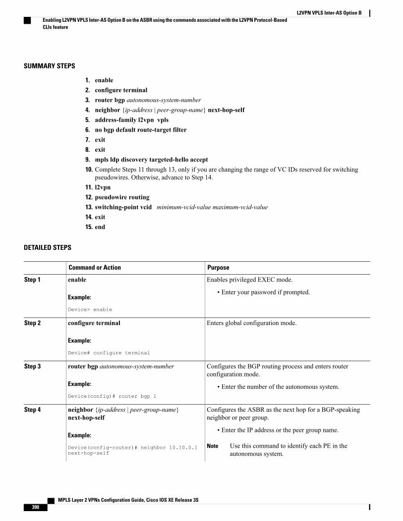
SUMMARY STEPS
1. enable2. configure terminal3. router bgp autonomous-system-number4. neighbor {ip-address | peer-group-name} next-hop-self5. address-family l2vpn vpls6. no bgp default route-target filter7. exit8. exit9. mpls ldp discovery targeted-hello accept10. Complete Steps 11 through 13, only if you are changing the range of VC IDs reserved for switching
pseudowires. Otherwise, advance to Step 14.11. l2vpn12. pseudowire routing13. switching-point vcid minimum-vcid-value maximum-vcid-value14. exit15. end
DETAILED STEPS
PurposeCommand or Action
Enables privileged EXEC mode.enableStep 1
Example:
Device> enable
• Enter your password if prompted.
Enters global configuration mode.configure terminal
Example:
Device# configure terminal
Step 2
Configures the BGP routing process and enters routerconfiguration mode.
router bgp autonomous-system-number
Example:
Device(config)# router bgp 1
Step 3
• Enter the number of the autonomous system.
Configures the ASBR as the next hop for a BGP-speakingneighbor or peer group.
neighbor {ip-address | peer-group-name}next-hop-self
Step 4
Example:
Device(config-router)# neighbor 10.10.0.1next-hop-self
• Enter the IP address or the peer group name.
Use this command to identify each PE in theautonomous system.
Note
MPLS Layer 2 VPNs Configuration Guide, Cisco IOS XE Release 3S390
L2VPN VPLS Inter-AS Option BEnabling L2VPN VPLS Inter-AS Option B on the ASBR using the commands associated with the L2VPN Protocol-BasedCLIs feature
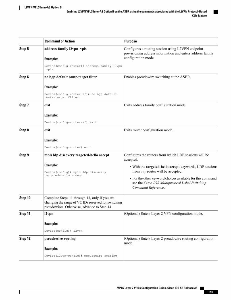
PurposeCommand or Action
Configures a routing session using L2VPN endpointprovisioning address information and enters address familyconfiguration mode.
address-family l2vpn vpls
Example:
Device(config-router)# address-family l2vpnvpls
Step 5
Enables pseudowire switching at the ASBR.no bgp default route-target filter
Example:
Device(config-router-af)# no bgp defaultroute-target filter
Step 6
Exits address family configuration mode.exit
Example:
Device(config-router-af) exit
Step 7
Exits router configuration mode.exit
Example:
Device(config-router) exit
Step 8
Configures the routers from which LDP sessions will beaccepted.
mpls ldp discovery targeted-hello accept
Example:
Device(config)# mpls ldp discoverytargeted-hello accept
Step 9
•With the targeted-hello accept keywords, LDP sessionsfrom any router will be accepted.
• For the other keyword choices available for this command,see the Cisco IOS Multiprotocol Label SwitchingCommand Reference.
Complete Steps 11 through 13, only if you arechanging the range of VC IDs reserved for switchingpseudowires. Otherwise, advance to Step 14.
Step 10
(Optional) Enters Layer 2 VPN configuration mode.l2vpnStep 11
Example:
Device(config)# l2vpn
(Optional) Enters Layer 2 pseudowire routing configurationmode.
pseudowire routing
Example:
Device(l2vpn-config)# pseudowire routing
Step 12
MPLS Layer 2 VPNs Configuration Guide, Cisco IOS XE Release 3S 391
L2VPN VPLS Inter-AS Option BEnabling L2VPN VPLS Inter-AS Option B on the ASBR using the commands associated with the L2VPN Protocol-Based
CLIs feature
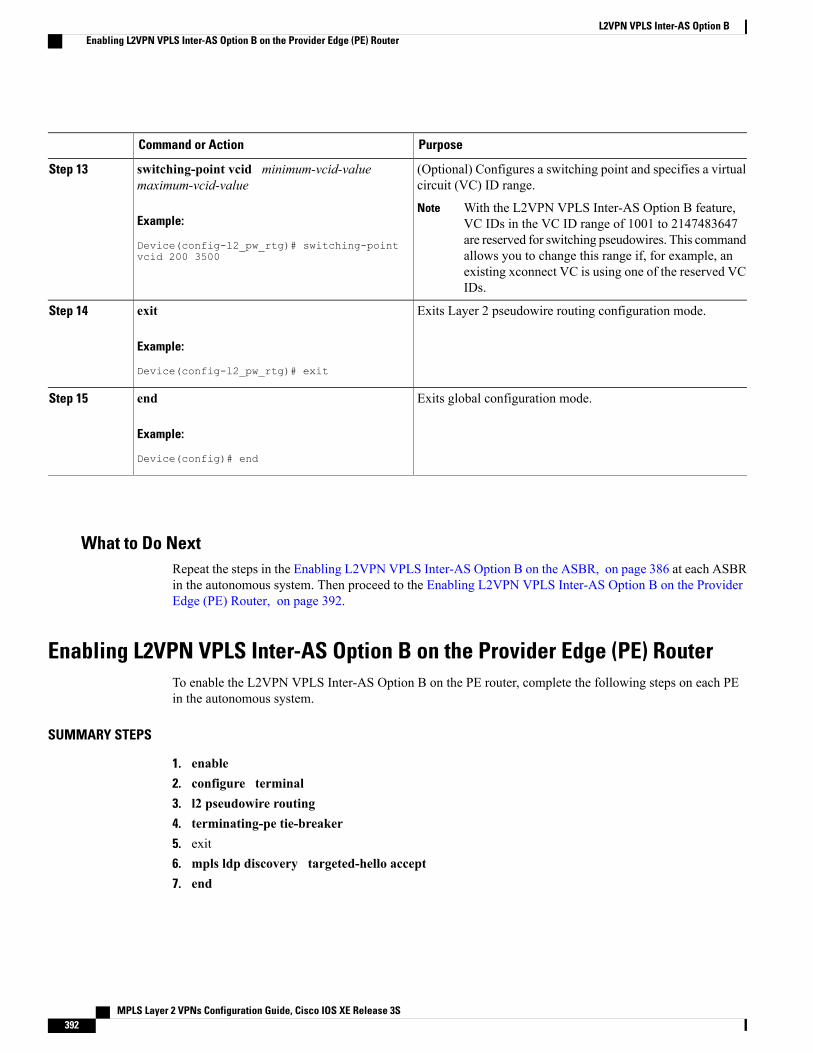
PurposeCommand or Action
(Optional) Configures a switching point and specifies a virtualcircuit (VC) ID range.
switching-point vcid minimum-vcid-valuemaximum-vcid-value
Step 13
Example:
Device(config-l2_pw_rtg)# switching-pointvcid 200 3500
With the L2VPN VPLS Inter-AS Option B feature,VC IDs in the VC ID range of 1001 to 2147483647are reserved for switching pseudowires. This commandallows you to change this range if, for example, anexisting xconnect VC is using one of the reserved VCIDs.
Note
Exits Layer 2 pseudowire routing configuration mode.exit
Example:
Device(config-l2_pw_rtg)# exit
Step 14
Exits global configuration mode.end
Example:
Device(config)# end
Step 15
What to Do NextRepeat the steps in the Enabling L2VPN VPLS Inter-AS Option B on the ASBR, on page 386 at each ASBRin the autonomous system. Then proceed to the Enabling L2VPN VPLS Inter-AS Option B on the ProviderEdge (PE) Router, on page 392.
Enabling L2VPN VPLS Inter-AS Option B on the Provider Edge (PE) RouterTo enable the L2VPN VPLS Inter-AS Option B on the PE router, complete the following steps on each PEin the autonomous system.
SUMMARY STEPS
1. enable2. configure terminal3. l2 pseudowire routing4. terminating-pe tie-breaker5. exit6. mpls ldp discovery targeted-hello accept7. end
MPLS Layer 2 VPNs Configuration Guide, Cisco IOS XE Release 3S392
L2VPN VPLS Inter-AS Option BEnabling L2VPN VPLS Inter-AS Option B on the Provider Edge (PE) Router
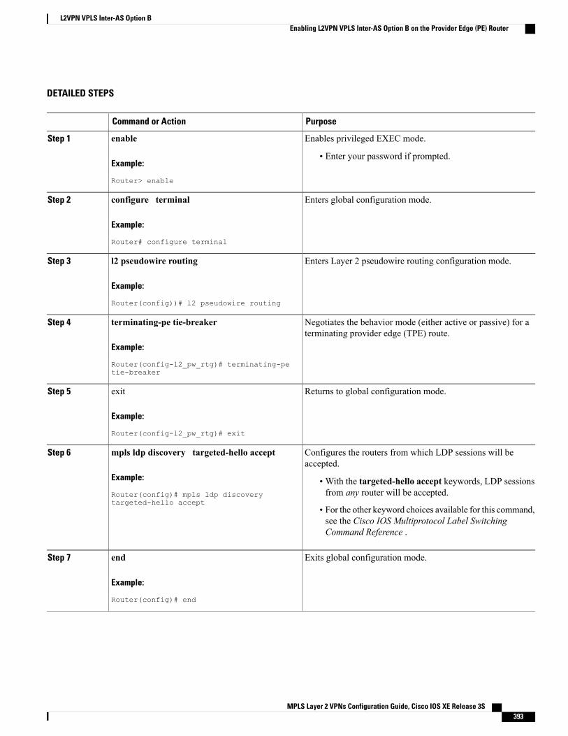
DETAILED STEPS
PurposeCommand or Action
Enables privileged EXEC mode.enableStep 1
Example:
Router> enable
• Enter your password if prompted.
Enters global configuration mode.configure terminal
Example:
Router# configure terminal
Step 2
Enters Layer 2 pseudowire routing configuration mode.l2 pseudowire routing
Example:
Router(config))# l2 pseudowire routing
Step 3
Negotiates the behavior mode (either active or passive) for aterminating provider edge (TPE) route.
terminating-pe tie-breaker
Example:
Router(config-l2_pw_rtg)# terminating-petie-breaker
Step 4
Returns to global configuration mode.exit
Example:
Router(config-l2_pw_rtg)# exit
Step 5
Configures the routers from which LDP sessions will beaccepted.
mpls ldp discovery targeted-hello accept
Example:
Router(config)# mpls ldp discoverytargeted-hello accept
Step 6
•With the targeted-hello accept keywords, LDP sessionsfrom any router will be accepted.
• For the other keyword choices available for this command,see the Cisco IOS Multiprotocol Label SwitchingCommand Reference .
Exits global configuration mode.end
Example:
Router(config)# end
Step 7
MPLS Layer 2 VPNs Configuration Guide, Cisco IOS XE Release 3S 393
L2VPN VPLS Inter-AS Option BEnabling L2VPN VPLS Inter-AS Option B on the Provider Edge (PE) Router
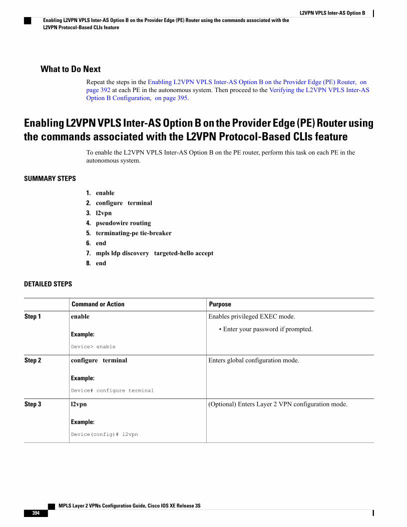
What to Do NextRepeat the steps in the Enabling L2VPN VPLS Inter-AS Option B on the Provider Edge (PE) Router, onpage 392 at each PE in the autonomous system. Then proceed to the Verifying the L2VPN VPLS Inter-ASOption B Configuration, on page 395.
Enabling L2VPN VPLS Inter-AS Option B on the Provider Edge (PE) Router usingthe commands associated with the L2VPN Protocol-Based CLIs feature
To enable the L2VPN VPLS Inter-AS Option B on the PE router, perform this task on each PE in theautonomous system.
SUMMARY STEPS
1. enable2. configure terminal3. l2vpn4. pseudowire routing5. terminating-pe tie-breaker6. end7. mpls ldp discovery targeted-hello accept8. end
DETAILED STEPS
PurposeCommand or Action
Enables privileged EXEC mode.enableStep 1
Example:
Device> enable
• Enter your password if prompted.
Enters global configuration mode.configure terminal
Example:
Device# configure terminal
Step 2
(Optional) Enters Layer 2 VPN configuration mode.l2vpnStep 3
Example:
Device(config)# l2vpn
MPLS Layer 2 VPNs Configuration Guide, Cisco IOS XE Release 3S394
L2VPN VPLS Inter-AS Option BEnabling L2VPN VPLS Inter-AS Option B on the Provider Edge (PE) Router using the commands associated with theL2VPN Protocol-Based CLIs feature
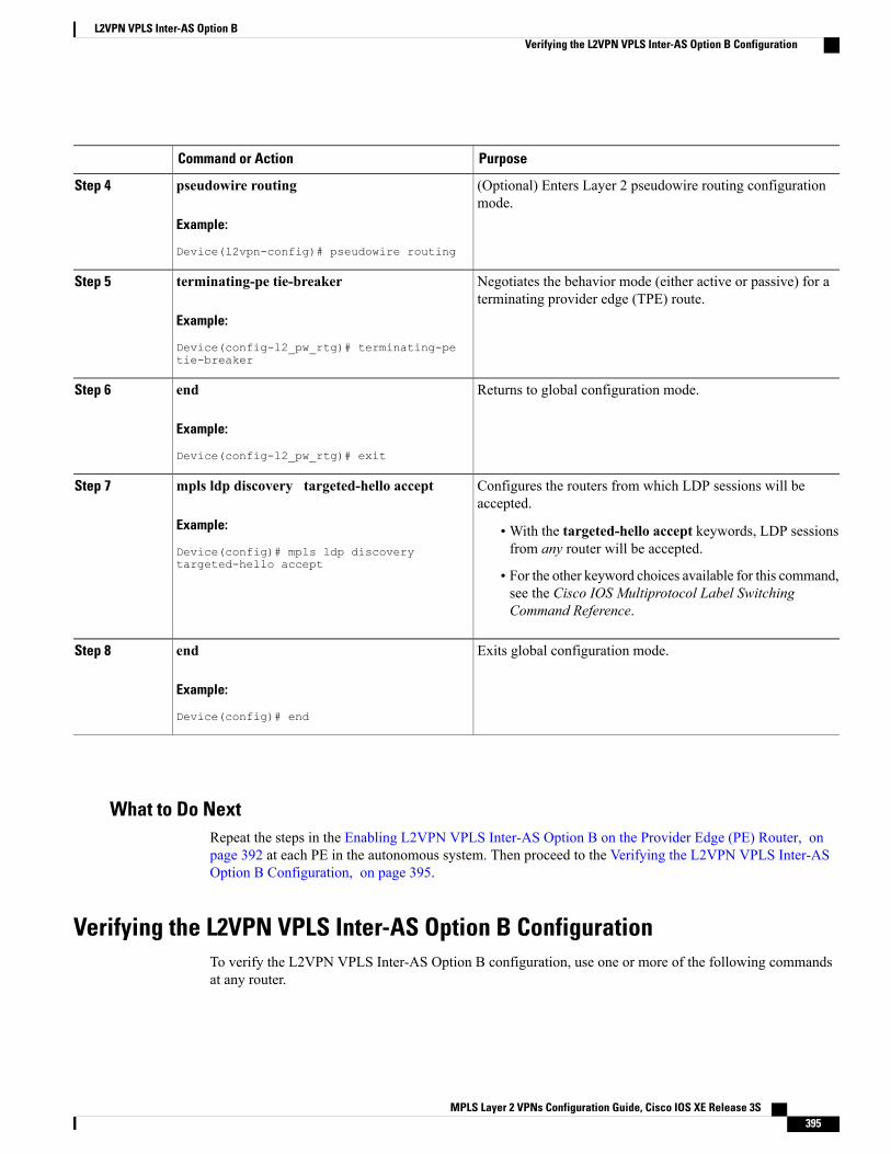
PurposeCommand or Action
(Optional) Enters Layer 2 pseudowire routing configurationmode.
pseudowire routing
Example:
Device(l2vpn-config)# pseudowire routing
Step 4
Negotiates the behavior mode (either active or passive) for aterminating provider edge (TPE) route.
terminating-pe tie-breaker
Example:
Device(config-l2_pw_rtg)# terminating-petie-breaker
Step 5
Returns to global configuration mode.end
Example:
Device(config-l2_pw_rtg)# exit
Step 6
Configures the routers from which LDP sessions will beaccepted.
mpls ldp discovery targeted-hello accept
Example:
Device(config)# mpls ldp discoverytargeted-hello accept
Step 7
•With the targeted-hello accept keywords, LDP sessionsfrom any router will be accepted.
• For the other keyword choices available for this command,see the Cisco IOS Multiprotocol Label SwitchingCommand Reference.
Exits global configuration mode.end
Example:
Device(config)# end
Step 8
What to Do NextRepeat the steps in the Enabling L2VPN VPLS Inter-AS Option B on the Provider Edge (PE) Router, onpage 392 at each PE in the autonomous system. Then proceed to the Verifying the L2VPN VPLS Inter-ASOption B Configuration, on page 395.
Verifying the L2VPN VPLS Inter-AS Option B ConfigurationTo verify the L2VPN VPLS Inter-AS Option B configuration, use one or more of the following commandsat any router.
MPLS Layer 2 VPNs Configuration Guide, Cisco IOS XE Release 3S 395
L2VPN VPLS Inter-AS Option BVerifying the L2VPN VPLS Inter-AS Option B Configuration
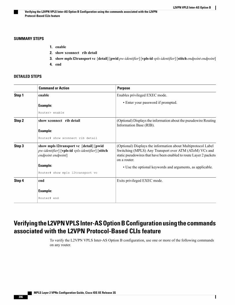
SUMMARY STEPS
1. enable2. show xconnect rib detail3. showmpls l2transport vc [detail] [pwid pw-identifier] [vpls-id vpls-identifier] [stitch endpoint endpoint]4. end
DETAILED STEPS
PurposeCommand or Action
Enables privileged EXEC mode.enableStep 1
Example:
Router> enable
• Enter your password if prompted.
(Optional) Displays the information about the pseudowire RoutingInformation Base (RIB).
show xconnect rib detail
Example:
Router# show xconnect rib detail
Step 2
(Optional) Displays the information about Multiprotocol LabelSwitching (MPLS) Any Transport over ATM (AToM) VCs and
show mpls l2transport vc [detail] [pwidpw-identifier] [vpls-id vpls-identifier] [stitchendpoint endpoint]
Step 3
static pseudowires that have been enabled to route Layer 2 packetson a router.
Example:
Router# show mpls l2transport vc
• Use the optional keywords and arguments, as applicable.
Exits privileged EXEC mode.end
Example:
Router# end
Step 4
Verifying the L2VPN VPLS Inter-AS Option B Configuration using the commandsassociated with the L2VPN Protocol-Based CLIs feature
To verify the L2VPN VPLS Inter-AS Option B configuration, use one or more of the following commandson any router.
MPLS Layer 2 VPNs Configuration Guide, Cisco IOS XE Release 3S396
L2VPN VPLS Inter-AS Option BVerifying the L2VPN VPLS Inter-AS Option B Configuration using the commands associated with the L2VPNProtocol-Based CLIs feature
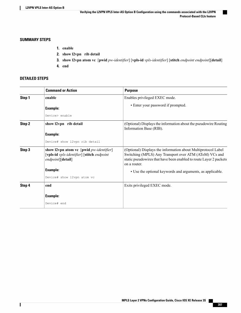
SUMMARY STEPS
1. enable2. show l2vpn rib detail3. show l2vpn atom vc [pwid pw-identifier] [vpls-id vpls-identifier] [stitch endpoint endpoint][detail]4. end
DETAILED STEPS
PurposeCommand or Action
Enables privileged EXEC mode.enableStep 1
Example:
Device> enable
• Enter your password if prompted.
(Optional) Displays the information about the pseudowire RoutingInformation Base (RIB).
show l2vpn rib detail
Example:
Device# show l2vpn rib detail
Step 2
(Optional) Displays the information about Multiprotocol LabelSwitching (MPLS) Any Transport over ATM (AToM) VCs and
show l2vpn atom vc [pwid pw-identifier][vpls-id vpls-identifier] [stitch endpointendpoint][detail]
Step 3
static pseudowires that have been enabled to route Layer 2 packetson a router.
Example:
Device# show l2vpn atom vc
• Use the optional keywords and arguments, as applicable.
Exits privileged EXEC mode.end
Example:
Device# end
Step 4
MPLS Layer 2 VPNs Configuration Guide, Cisco IOS XE Release 3S 397
L2VPN VPLS Inter-AS Option BVerifying the L2VPN VPLS Inter-AS Option B Configuration using the commands associated with the L2VPN
Protocol-Based CLIs feature
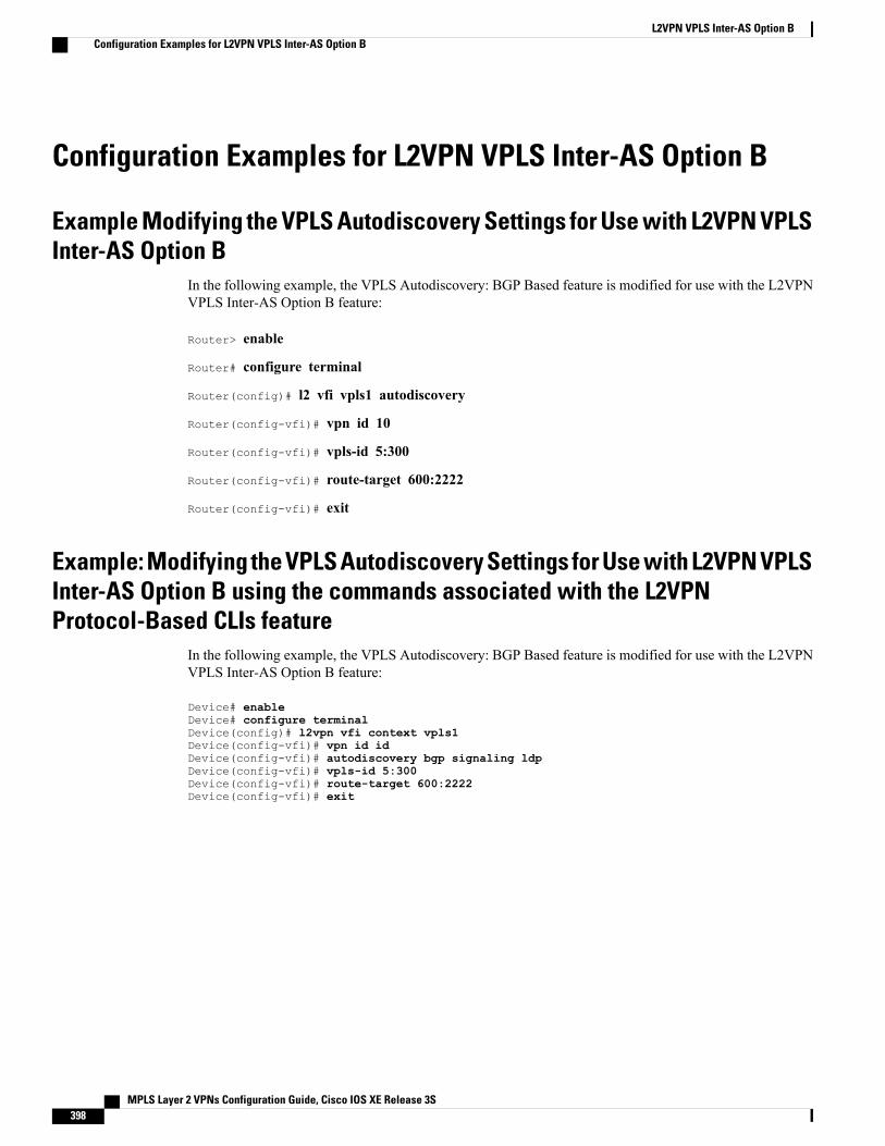
Configuration Examples for L2VPN VPLS Inter-AS Option B
Example Modifying the VPLS Autodiscovery Settings for Use with L2VPN VPLSInter-AS Option B
In the following example, the VPLS Autodiscovery: BGP Based feature is modified for use with the L2VPNVPLS Inter-AS Option B feature:
Router> enable
Router# configure terminal
Router(config)# l2 vfi vpls1 autodiscovery
Router(config-vfi)# vpn id 10
Router(config-vfi)# vpls-id 5:300
Router(config-vfi)# route-target 600:2222
Router(config-vfi)# exit
Example: Modifying the VPLS Autodiscovery Settings for Use with L2VPN VPLSInter-AS Option B using the commands associated with the L2VPNProtocol-Based CLIs feature
In the following example, the VPLS Autodiscovery: BGP Based feature is modified for use with the L2VPNVPLS Inter-AS Option B feature:
Device# enableDevice# configure terminalDevice(config)# l2vpn vfi context vpls1Device(config-vfi)# vpn id idDevice(config-vfi)# autodiscovery bgp signaling ldpDevice(config-vfi)# vpls-id 5:300Device(config-vfi)# route-target 600:2222Device(config-vfi)# exit
MPLS Layer 2 VPNs Configuration Guide, Cisco IOS XE Release 3S398
L2VPN VPLS Inter-AS Option BConfiguration Examples for L2VPN VPLS Inter-AS Option B
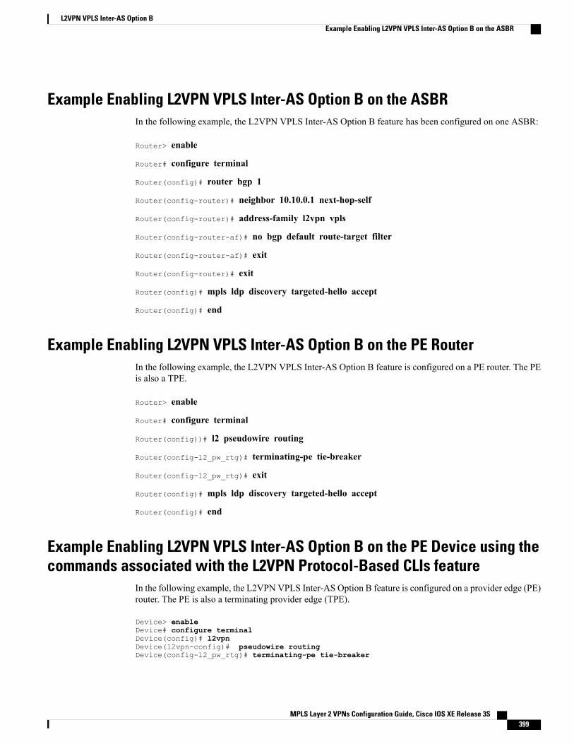
Example Enabling L2VPN VPLS Inter-AS Option B on the ASBRIn the following example, the L2VPN VPLS Inter-AS Option B feature has been configured on one ASBR:
Router> enable
Router# configure terminal
Router(config)# router bgp 1
Router(config-router)# neighbor 10.10.0.1 next-hop-self
Router(config-router)# address-family l2vpn vpls
Router(config-router-af)# no bgp default route-target filter
Router(config-router-af)# exit
Router(config-router)# exit
Router(config)# mpls ldp discovery targeted-hello accept
Router(config)# end
Example Enabling L2VPN VPLS Inter-AS Option B on the PE RouterIn the following example, the L2VPN VPLS Inter-AS Option B feature is configured on a PE router. The PEis also a TPE.
Router> enable
Router# configure terminal
Router(config))# l2 pseudowire routing
Router(config-l2_pw_rtg)# terminating-pe tie-breaker
Router(config-l2_pw_rtg)# exit
Router(config)# mpls ldp discovery targeted-hello accept
Router(config)# end
Example Enabling L2VPN VPLS Inter-AS Option B on the PE Device using thecommands associated with the L2VPN Protocol-Based CLIs feature
In the following example, the L2VPN VPLS Inter-AS Option B feature is configured on a provider edge (PE)router. The PE is also a terminating provider edge (TPE).
Device> enableDevice# configure terminalDevice(config)# l2vpnDevice(l2vpn-config)# pseudowire routingDevice(config-l2_pw_rtg)# terminating-pe tie-breaker
MPLS Layer 2 VPNs Configuration Guide, Cisco IOS XE Release 3S 399
L2VPN VPLS Inter-AS Option BExample Enabling L2VPN VPLS Inter-AS Option B on the ASBR
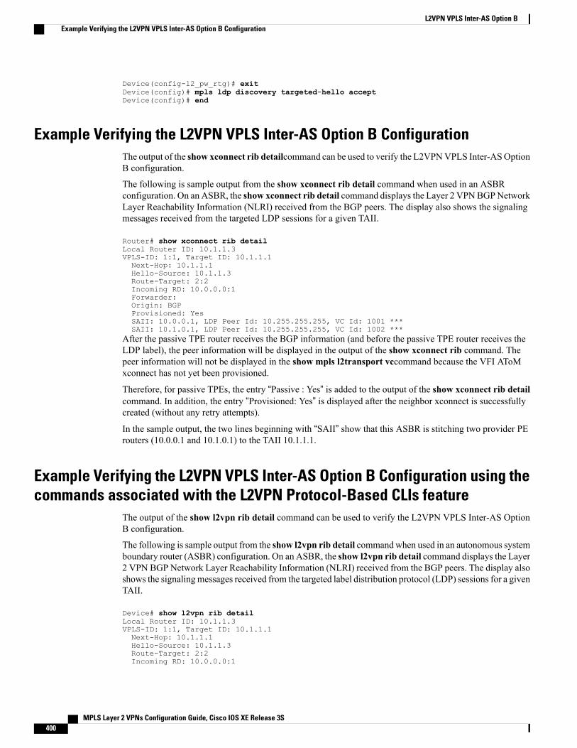
Device(config-l2_pw_rtg)# exitDevice(config)# mpls ldp discovery targeted-hello acceptDevice(config)# end
Example Verifying the L2VPN VPLS Inter-AS Option B ConfigurationThe output of the show xconnect rib detailcommand can be used to verify the L2VPNVPLS Inter-ASOptionB configuration.
The following is sample output from the show xconnect rib detail command when used in an ASBRconfiguration. On an ASBR, the show xconnect rib detail command displays the Layer 2 VPNBGPNetworkLayer Reachability Information (NLRI) received from the BGP peers. The display also shows the signalingmessages received from the targeted LDP sessions for a given TAII.
Router# show xconnect rib detailLocal Router ID: 10.1.1.3VPLS-ID: 1:1, Target ID: 10.1.1.1Next-Hop: 10.1.1.1Hello-Source: 10.1.1.3Route-Target: 2:2Incoming RD: 10.0.0.0:1Forwarder:Origin: BGPProvisioned: YesSAII: 10.0.0.1, LDP Peer Id: 10.255.255.255, VC Id: 1001 ***SAII: 10.1.0.1, LDP Peer Id: 10.255.255.255, VC Id: 1002 ***
After the passive TPE router receives the BGP information (and before the passive TPE router receives theLDP label), the peer information will be displayed in the output of the show xconnect rib command. Thepeer information will not be displayed in the show mpls l2transport vccommand because the VFI AToMxconnect has not yet been provisioned.
Therefore, for passive TPEs, the entry “Passive : Yes” is added to the output of the show xconnect rib detailcommand. In addition, the entry “Provisioned: Yes” is displayed after the neighbor xconnect is successfullycreated (without any retry attempts).
In the sample output, the two lines beginning with “SAII” show that this ASBR is stitching two provider PErouters (10.0.0.1 and 10.1.0.1) to the TAII 10.1.1.1.
Example Verifying the L2VPN VPLS Inter-AS Option B Configuration using thecommands associated with the L2VPN Protocol-Based CLIs feature
The output of the show l2vpn rib detail command can be used to verify the L2VPN VPLS Inter-AS OptionB configuration.
The following is sample output from the show l2vpn rib detail command when used in an autonomous systemboundary router (ASBR) configuration. On an ASBR, the show l2vpn rib detail command displays the Layer2 VPN BGP Network Layer Reachability Information (NLRI) received from the BGP peers. The display alsoshows the signalingmessages received from the targeted label distribution protocol (LDP) sessions for a givenTAII.
Device# show l2vpn rib detailLocal Router ID: 10.1.1.3VPLS-ID: 1:1, Target ID: 10.1.1.1Next-Hop: 10.1.1.1Hello-Source: 10.1.1.3Route-Target: 2:2Incoming RD: 10.0.0.0:1
MPLS Layer 2 VPNs Configuration Guide, Cisco IOS XE Release 3S400
L2VPN VPLS Inter-AS Option BExample Verifying the L2VPN VPLS Inter-AS Option B Configuration
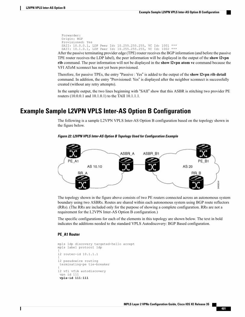
Forwarder:Origin: BGPProvisioned: YesSAII: 10.0.0.1, LDP Peer Id: 10.255.255.255, VC Id: 1001 ***SAII: 10.1.0.1, LDP Peer Id: 10.255.255.255, VC Id: 1002 ***
After the passive terminating provider edge (TPE) router receives the BGP information (and before the passiveTPE router receives the LDP label), the peer information will be displayed in the output of the show l2vpnrib command. The peer information will not be displayed in the show l2vpn atom vc command because theVFI AToM xconnect has not yet been provisioned.
Therefore, for passive TPEs, the entry “Passive : Yes” is added to the output of the show l2vpn rib detailcommand. In addition, the entry “Provisioned: Yes” is displayed after the neighbor xconnect is successfullycreated (without any retry attempts).
In the sample output, the two lines beginning with “SAII” show that this ASBR is stitching two provider PErouters (10.0.0.1 and 10.1.0.1) to the TAII 10.1.1.1.
Example Sample L2VPN VPLS Inter-AS Option B ConfigurationThe following is a sample L2VPN VPLS Inter-AS Option B configuration based on the topology shown inthe figure below.
Figure 22: L2VPN VPLS Inter-AS Option B Topology Used for Configuration Example
The topology shown in the figure above consists of two PE routers connected across an autonomous systemboundary using two ASBRs. Routes are shared within each autonomous system using BGP route reflectors(RRs). (The RRs are included only for the purpose of showing a complete configuration. RRs are not arequirement for the L2VPN Inter-AS Option B configuration.)
The specific configurations for each of the elements in this topology are shown below. The text in boldindicates the additions needed to the standard VPLS Autodiscovery: BGP Based configuration.
PE_A1 Router
mpls ldp discovery targeted-hello acceptmpls label protocol ldp!l2 router-id 10.1.1.1!l2 pseudowire routingterminating-pe tie-breaker!l2 vfi vfiA autodiscoveryvpn id 111vpls-id 111:111
MPLS Layer 2 VPNs Configuration Guide, Cisco IOS XE Release 3S 401
L2VPN VPLS Inter-AS Option BExample Sample L2VPN VPLS Inter-AS Option B Configuration
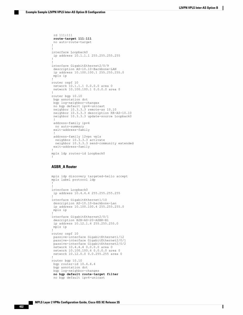
rd 111:111route-target 111:111no auto-route-target!!interface Loopback0ip address 10.1.1.1 255.255.255.255!!interface GigabitEthernet2/0/9description AS-10.10-Backbone-LANip address 10.100.100.1 255.255.255.0mpls ip!router ospf 10network 10.1.1.1 0.0.0.0 area 0network 10.100.100.1 0.0.0.0 area 0!router bgp 10.10bgp asnotation dotbgp log-neighbor-changesno bgp default ipv4-unicastneighbor 10.3.3.3 remote-as 10.10neighbor 10.3.3.3 description RR-AS-10.10neighbor 10.3.3.3 update-source Loopback0!address-family ipv4no auto-summaryexit-address-family!address-family l2vpn vplsneighbor 10.3.3.3 activateneighbor 10.3.3.3 send-community extendedexit-address-family!mpls ldp router-id Loopback0!
ASBR_A Router
mpls ldp discovery targeted-hello acceptmpls label protocol ldp!!interface Loopback0ip address 10.4.4.4 255.255.255.255!interface GigabitEthernet1/10description AS-10.10-backbone-Lanip address 10.100.100.4 255.255.255.0mpls ip!interface GigabitEthernet2/0/1description B2B-AS-20-ASBR-B1ip address 10.12.1.4 255.255.255.0mpls ip!router ospf 10passive-interface GigabitEthernet1/12passive-interface GigabitEthernet2/0/1passive-interface GigabitEthernet2/0/2network 10.4.4.4 0.0.0.0 area 0network 10.100.100.4 0.0.0.0 area 0network 10.12.0.0 0.0.255.255 area 0!router bgp 10.10bgp router-id 10.4.4.4bgp asnotation dotbgp log-neighbor-changesno bgp default route-target filterno bgp default ipv4-unicast
MPLS Layer 2 VPNs Configuration Guide, Cisco IOS XE Release 3S402
L2VPN VPLS Inter-AS Option BExample Sample L2VPN VPLS Inter-AS Option B Configuration
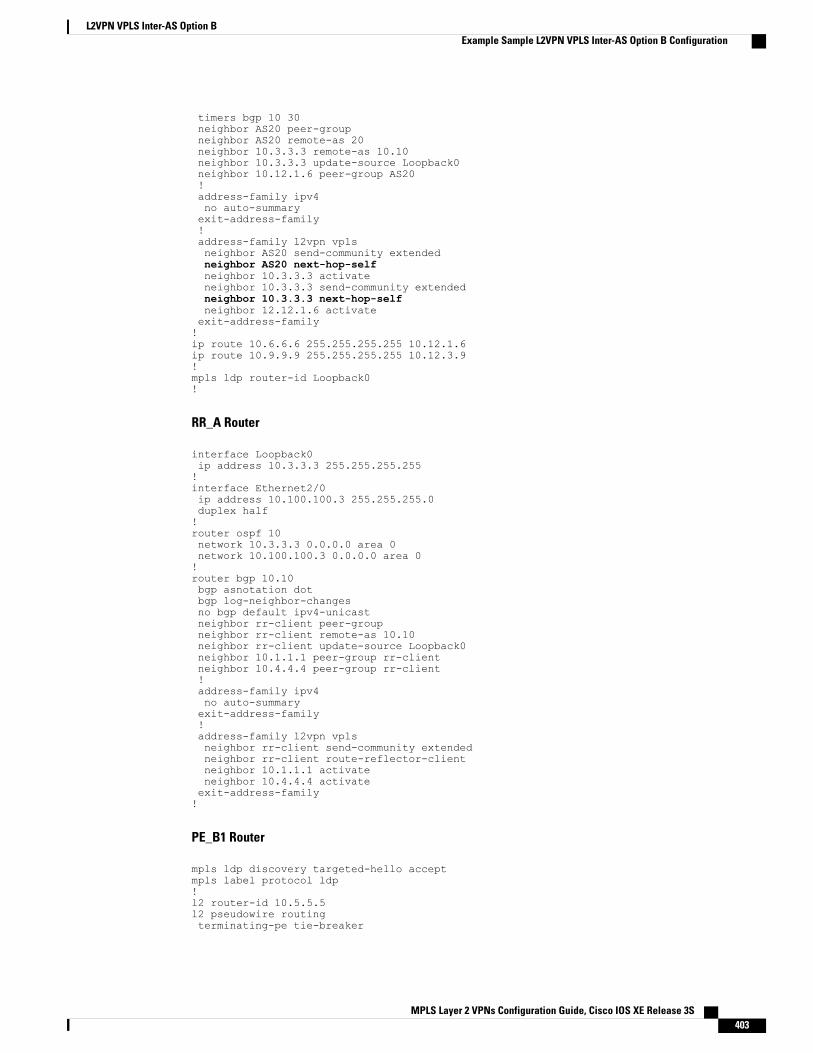
timers bgp 10 30neighbor AS20 peer-groupneighbor AS20 remote-as 20neighbor 10.3.3.3 remote-as 10.10neighbor 10.3.3.3 update-source Loopback0neighbor 10.12.1.6 peer-group AS20!address-family ipv4no auto-summaryexit-address-family!address-family l2vpn vplsneighbor AS20 send-community extendedneighbor AS20 next-hop-selfneighbor 10.3.3.3 activateneighbor 10.3.3.3 send-community extendedneighbor 10.3.3.3 next-hop-selfneighbor 12.12.1.6 activateexit-address-family!ip route 10.6.6.6 255.255.255.255 10.12.1.6ip route 10.9.9.9 255.255.255.255 10.12.3.9!mpls ldp router-id Loopback0!
RR_A Router
interface Loopback0ip address 10.3.3.3 255.255.255.255!interface Ethernet2/0ip address 10.100.100.3 255.255.255.0duplex half!router ospf 10network 10.3.3.3 0.0.0.0 area 0network 10.100.100.3 0.0.0.0 area 0!router bgp 10.10bgp asnotation dotbgp log-neighbor-changesno bgp default ipv4-unicastneighbor rr-client peer-groupneighbor rr-client remote-as 10.10neighbor rr-client update-source Loopback0neighbor 10.1.1.1 peer-group rr-clientneighbor 10.4.4.4 peer-group rr-client!address-family ipv4no auto-summaryexit-address-family!address-family l2vpn vplsneighbor rr-client send-community extendedneighbor rr-client route-reflector-clientneighbor 10.1.1.1 activateneighbor 10.4.4.4 activateexit-address-family!
PE_B1 Router
mpls ldp discovery targeted-hello acceptmpls label protocol ldp!l2 router-id 10.5.5.5l2 pseudowire routingterminating-pe tie-breaker
MPLS Layer 2 VPNs Configuration Guide, Cisco IOS XE Release 3S 403
L2VPN VPLS Inter-AS Option BExample Sample L2VPN VPLS Inter-AS Option B Configuration
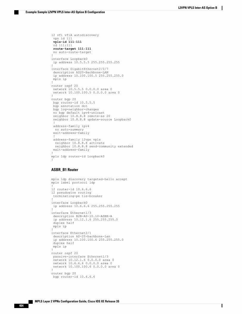
l2 vfi vfiA autodiscoveryvpn id 111vpls-id 111:111rd 111:111route-target 111:111no auto-route-target!interface Loopback0ip address 10.5.5.5 255.255.255.255!interface GigabitEthernet2/0/7description AS20-Backbone-LANip address 10.100.100.5 255.255.255.0mpls ip!router ospf 20network 10.5.5.5 0.0.0.0 area 0network 10.100.100.5 0.0.0.0 area 0!router bgp 20bgp router-id 10.5.5.5bgp asnotation dotbgp log-neighbor-changesno bgp default ipv4-unicastneighbor 10.8.8.8 remote-as 20neighbor 10.8.8.8 update-source Loopback0!address-family ipv4no auto-summaryexit-address-family!address-family l2vpn vplsneighbor 10.8.8.8 activateneighbor 10.8.8.8 send-community extendedexit-address-family!mpls ldp router-id Loopback0!
ASBR_B1 Router
mpls ldp discovery targeted-hello acceptmpls label protocol ldp!l2 router-id 10.6.6.6l2 pseudowire routingterminating-pe tie-breaker!interface Loopback0ip address 10.6.6.6 255.255.255.255!interface Ethernet1/3description B2B-AS-10.10-ASBR-Aip address 10.12.1.6 255.255.255.0duplex halfmpls ip!interface Ethernet2/1description AS-20-backbone-Lanip address 10.100.100.6 255.255.255.0duplex halfmpls ip!router ospf 20passive-interface Ethernet1/3network 10.12.1.6 0.0.0.0 area 0network 10.6.6.6 0.0.0.0 area 0network 10.100.100.6 0.0.0.0 area 0!router bgp 20bgp router-id 10.6.6.6
MPLS Layer 2 VPNs Configuration Guide, Cisco IOS XE Release 3S404
L2VPN VPLS Inter-AS Option BExample Sample L2VPN VPLS Inter-AS Option B Configuration
bgp asnotation dotbgp log-neighbor-changesno bgp default ipv4-unicasttimers bgp 10 30neighbor 10.12.1.4 remote-as 10.10neighbor 10.12.1.4 ebgp-multihop 255neighbor 10.8.8.8 remote-as 20neighbor 10.8.8.8 update-source Loopback0!address-family ipv4no auto-summaryexit-address-family!address-family l2vpn vplsno bgp default route-target filterneighbor 10.12.1.4 activateneighbor 10.12.1.4 send-community extendedneighbor 10.12.1.4 next-hop-selfneighbor 10.8.8.8 activateneighbor 10.8.8.8 send-community extendedneighbor 10.8.8.8 next-hop-selfexit-address-family!
RR_B Router
interface Loopback0ip address 10.8.8.8 255.255.255.255!interface Ethernet2/1ip address 10.100.100.8 255.255.255.0duplex half!router ospf 20network 10.8.8.8 0.0.0.0 area 0network 10.100.100.8 0.0.0.0 area 0!router bgp 20bgp log-neighbor-changesno bgp default ipv4-unicastneighbor rrc peer-groupneighbor rrc remote-as 20neighbor rrc update-source Loopback0neighbor 10.5.5.5 peer-group rrcneighbor 10.6.6.6 peer-group rrcneighbor 10.9.9.9 peer-group rrcneighbor 10.9.9.9 shutdown!address-family ipv4no auto-summaryexit-address-family!address-family l2vpn vplsneighbor rrc send-community extendedneighbor rrc route-reflector-clientneighbor 10.5.5.5 activateneighbor 10.6.6.6 activateneighbor 10.9.9.9 activateexit-address-family!
MPLS Layer 2 VPNs Configuration Guide, Cisco IOS XE Release 3S 405
L2VPN VPLS Inter-AS Option BExample Sample L2VPN VPLS Inter-AS Option B Configuration
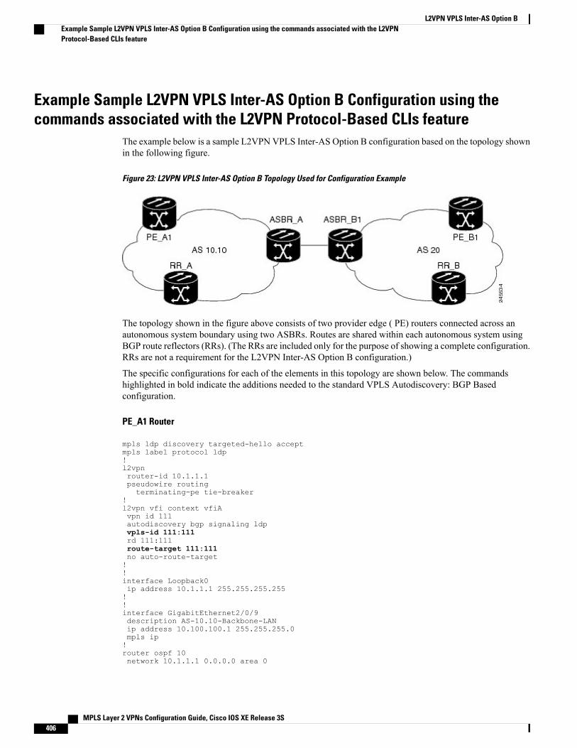
Example Sample L2VPN VPLS Inter-AS Option B Configuration using thecommands associated with the L2VPN Protocol-Based CLIs feature
The example below is a sample L2VPN VPLS Inter-AS Option B configuration based on the topology shownin the following figure.
Figure 23: L2VPN VPLS Inter-AS Option B Topology Used for Configuration Example
The topology shown in the figure above consists of two provider edge ( PE) routers connected across anautonomous system boundary using two ASBRs. Routes are shared within each autonomous system usingBGP route reflectors (RRs). (The RRs are included only for the purpose of showing a complete configuration.RRs are not a requirement for the L2VPN Inter-AS Option B configuration.)
The specific configurations for each of the elements in this topology are shown below. The commandshighlighted in bold indicate the additions needed to the standard VPLS Autodiscovery: BGP Basedconfiguration.
PE_A1 Router
mpls ldp discovery targeted-hello acceptmpls label protocol ldp!l2vpnrouter-id 10.1.1.1pseudowire routingterminating-pe tie-breaker
!l2vpn vfi context vfiAvpn id 111autodiscovery bgp signaling ldpvpls-id 111:111rd 111:111route-target 111:111no auto-route-target!!interface Loopback0ip address 10.1.1.1 255.255.255.255!!interface GigabitEthernet2/0/9description AS-10.10-Backbone-LANip address 10.100.100.1 255.255.255.0mpls ip!router ospf 10network 10.1.1.1 0.0.0.0 area 0
MPLS Layer 2 VPNs Configuration Guide, Cisco IOS XE Release 3S406
L2VPN VPLS Inter-AS Option BExample Sample L2VPN VPLS Inter-AS Option B Configuration using the commands associated with the L2VPNProtocol-Based CLIs feature
network 10.100.100.1 0.0.0.0 area 0!router bgp 10.10bgp asnotation dotbgp log-neighbor-changesno bgp default ipv4-unicastneighbor 10.3.3.3 remote-as 10.10neighbor 10.3.3.3 description RR-AS-10.10neighbor 10.3.3.3 update-source Loopback0!address-family ipv4no auto-summaryexit-address-family!address-family l2vpn vplsneighbor 10.3.3.3 activateneighbor 10.3.3.3 send-community extendedexit-address-family!mpls ldp router-id Loopback0!
ASBR_A Router
mpls ldp discovery targeted-hello acceptmpls label protocol ldp!!interface Loopback0ip address 10.4.4.4 255.255.255.255!interface GigabitEthernet1/10description AS-10.10-backbone-Lanip address 10.100.100.4 255.255.255.0mpls ip!interface GigabitEthernet2/0/1description B2B-AS-20-ASBR-B1ip address 10.12.1.4 255.255.255.0mpls ip!router ospf 10passive-interface GigabitEthernet1/12passive-interface GigabitEthernet2/0/1passive-interface GigabitEthernet2/0/2network 10.4.4.4 0.0.0.0 area 0network 10.100.100.4 0.0.0.0 area 0network 10.12.0.0 0.0.255.255 area 0!router bgp 10.10bgp router-id 10.4.4.4bgp asnotation dotbgp log-neighbor-changesno bgp default route-target filterno bgp default ipv4-unicasttimers bgp 10 30neighbor AS20 peer-groupneighbor AS20 remote-as 20neighbor 10.3.3.3 remote-as 10.10neighbor 10.3.3.3 update-source Loopback0neighbor 10.12.1.6 peer-group AS20!address-family ipv4no auto-summaryexit-address-family!address-family l2vpn vplsneighbor AS20 send-community extendedneighbor AS20 next-hop-selfneighbor 10.3.3.3 activateneighbor 10.3.3.3 send-community extended
MPLS Layer 2 VPNs Configuration Guide, Cisco IOS XE Release 3S 407
L2VPN VPLS Inter-AS Option BExample Sample L2VPN VPLS Inter-AS Option B Configuration using the commands associated with the L2VPN
Protocol-Based CLIs feature
neighbor 10.3.3.3 next-hop-selfneighbor 12.12.1.6 activateexit-address-family!ip route 10.6.6.6 255.255.255.255 10.12.1.6ip route 10.9.9.9 255.255.255.255 10.12.3.9!mpls ldp router-id Loopback0!
RR_A Router
interface Loopback0ip address 10.3.3.3 255.255.255.255!interface Ethernet2/0ip address 10.100.100.3 255.255.255.0duplex half!router ospf 10network 10.3.3.3 0.0.0.0 area 0network 10.100.100.3 0.0.0.0 area 0!router bgp 10.10bgp asnotation dotbgp log-neighbor-changesno bgp default ipv4-unicastneighbor rr-client peer-groupneighbor rr-client remote-as 10.10neighbor rr-client update-source Loopback0neighbor 10.1.1.1 peer-group rr-clientneighbor 10.4.4.4 peer-group rr-client!address-family ipv4no auto-summaryexit-address-family!address-family l2vpn vplsneighbor rr-client send-community extendedneighbor rr-client route-reflector-clientneighbor 10.1.1.1 activateneighbor 10.4.4.4 activateexit-address-family!
PE_B1 Router
mpls ldp discovery targeted-hello acceptmpls label protocol ldp!l2vpnrouter-id 10.5.5.5pseudowire routingterminating-pe tie-breaker
l2vpn vfi context vfiAvpn id 111autodiscovery bgp signaling ldpvpls-id 111:111rd 111:111route-target 111:111no auto-route-target!interface Loopback0ip address 10.5.5.5 255.255.255.255!interface GigabitEthernet2/0/7description AS20-Backbone-LANip address 10.100.100.5 255.255.255.0mpls ip
MPLS Layer 2 VPNs Configuration Guide, Cisco IOS XE Release 3S408
L2VPN VPLS Inter-AS Option BExample Sample L2VPN VPLS Inter-AS Option B Configuration using the commands associated with the L2VPNProtocol-Based CLIs feature
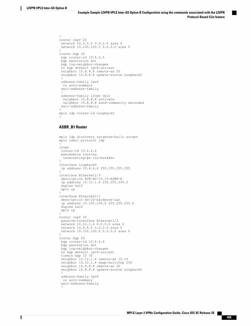
!router ospf 20network 10.5.5.5 0.0.0.0 area 0network 10.100.100.5 0.0.0.0 area 0!router bgp 20bgp router-id 10.5.5.5bgp asnotation dotbgp log-neighbor-changesno bgp default ipv4-unicastneighbor 10.8.8.8 remote-as 20neighbor 10.8.8.8 update-source Loopback0!address-family ipv4no auto-summaryexit-address-family!address-family l2vpn vplsneighbor 10.8.8.8 activateneighbor 10.8.8.8 send-community extendedexit-address-family!mpls ldp router-id Loopback0!
ASBR_B1 Router
mpls ldp discovery targeted-hello acceptmpls label protocol ldp!l2vpnrouter-id 10.6.6.6pseudowire routingterminating-pe tie-breaker
!interface Loopback0ip address 10.6.6.6 255.255.255.255!interface Ethernet1/3description B2B-AS-10.10-ASBR-Aip address 10.12.1.6 255.255.255.0duplex halfmpls ip!interface Ethernet2/1description AS-20-backbone-Lanip address 10.100.100.6 255.255.255.0duplex halfmpls ip!router ospf 20passive-interface Ethernet1/3network 10.12.1.6 0.0.0.0 area 0network 10.6.6.6 0.0.0.0 area 0network 10.100.100.6 0.0.0.0 area 0!router bgp 20bgp router-id 10.6.6.6bgp asnotation dotbgp log-neighbor-changesno bgp default ipv4-unicasttimers bgp 10 30neighbor 10.12.1.4 remote-as 10.10neighbor 10.12.1.4 ebgp-multihop 255neighbor 10.8.8.8 remote-as 20neighbor 10.8.8.8 update-source Loopback0!address-family ipv4no auto-summaryexit-address-family!
MPLS Layer 2 VPNs Configuration Guide, Cisco IOS XE Release 3S 409
L2VPN VPLS Inter-AS Option BExample Sample L2VPN VPLS Inter-AS Option B Configuration using the commands associated with the L2VPN
Protocol-Based CLIs feature
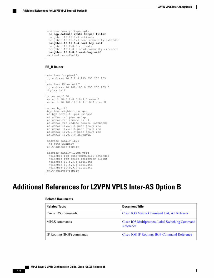
address-family l2vpn vplsno bgp default route-target filterneighbor 10.12.1.4 activateneighbor 10.12.1.4 send-community extendedneighbor 10.12.1.4 next-hop-selfneighbor 10.8.8.8 activateneighbor 10.8.8.8 send-community extendedneighbor 10.8.8.8 next-hop-selfexit-address-family!
RR_B Router
interface Loopback0ip address 10.8.8.8 255.255.255.255!interface Ethernet2/1ip address 10.100.100.8 255.255.255.0duplex half!router ospf 20network 10.8.8.8 0.0.0.0 area 0network 10.100.100.8 0.0.0.0 area 0!router bgp 20bgp log-neighbor-changesno bgp default ipv4-unicastneighbor rrc peer-groupneighbor rrc remote-as 20neighbor rrc update-source Loopback0neighbor 10.5.5.5 peer-group rrcneighbor 10.6.6.6 peer-group rrcneighbor 10.9.9.9 peer-group rrcneighbor 10.9.9.9 shutdown!address-family ipv4no auto-summaryexit-address-family!address-family l2vpn vplsneighbor rrc send-community extendedneighbor rrc route-reflector-clientneighbor 10.5.5.5 activateneighbor 10.6.6.6 activateneighbor 10.9.9.9 activateexit-address-family!
Additional References for L2VPN VPLS Inter-AS Option BRelated Documents
Document TitleRelated Topic
Cisco IOS Master Command List, All ReleasesCisco IOS commands
Cisco IOSMultiprotocol Label Switching CommandReference
MPLS commands
Cisco IOS IP Routing: BGP Command ReferenceIP Routing (BGP) commands
MPLS Layer 2 VPNs Configuration Guide, Cisco IOS XE Release 3S410
L2VPN VPLS Inter-AS Option BAdditional References for L2VPN VPLS Inter-AS Option B
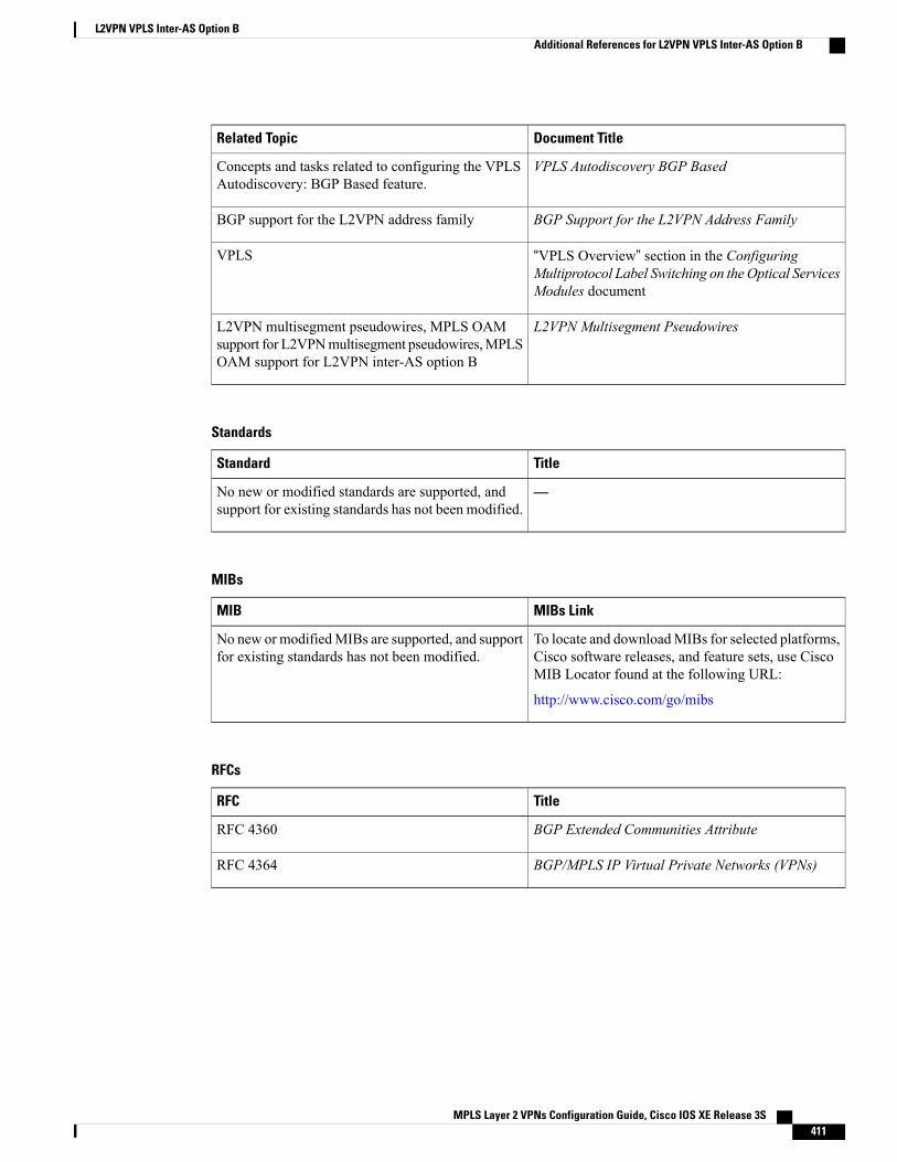
Document TitleRelated Topic
VPLS Autodiscovery BGP BasedConcepts and tasks related to configuring the VPLSAutodiscovery: BGP Based feature.
BGP Support for the L2VPN Address FamilyBGP support for the L2VPN address family
“VPLS Overview” section in the ConfiguringMultiprotocol Label Switching on the Optical ServicesModules document
VPLS
L2VPN Multisegment PseudowiresL2VPN multisegment pseudowires, MPLS OAMsupport for L2VPNmultisegment pseudowires,MPLSOAM support for L2VPN inter-AS option B
Standards
TitleStandard
—No new or modified standards are supported, andsupport for existing standards has not been modified.
MIBs
MIBs LinkMIB
To locate and downloadMIBs for selected platforms,Cisco software releases, and feature sets, use CiscoMIB Locator found at the following URL:
http://www.cisco.com/go/mibs
No new or modifiedMIBs are supported, and supportfor existing standards has not been modified.
RFCs
TitleRFC
BGP Extended Communities AttributeRFC 4360
BGP/MPLS IP Virtual Private Networks (VPNs)RFC 4364
MPLS Layer 2 VPNs Configuration Guide, Cisco IOS XE Release 3S 411
L2VPN VPLS Inter-AS Option BAdditional References for L2VPN VPLS Inter-AS Option B
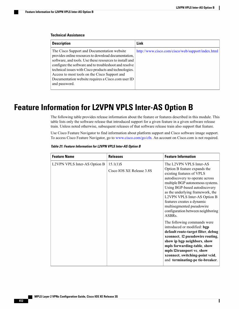
Technical Assistance
LinkDescription
http://www.cisco.com/cisco/web/support/index.htmlThe Cisco Support and Documentation websiteprovides online resources to download documentation,software, and tools. Use these resources to install andconfigure the software and to troubleshoot and resolvetechnical issues with Cisco products and technologies.Access to most tools on the Cisco Support andDocumentation website requires a Cisco.com user IDand password.
Feature Information for L2VPN VPLS Inter-AS Option BThe following table provides release information about the feature or features described in this module. Thistable lists only the software release that introduced support for a given feature in a given software releasetrain. Unless noted otherwise, subsequent releases of that software release train also support that feature.
Use Cisco Feature Navigator to find information about platform support and Cisco software image support.To access Cisco Feature Navigator, go to www.cisco.com/go/cfn. An account on Cisco.com is not required.
Table 21: Feature Information for L2VPN VPLS Inter-AS Option B
Feature InformationReleasesFeature Name
The L2VPN VPLS Inter-ASOption B feature expands theexisting features of VPLSautodiscovery to operate acrossmultipleBGP autonomous systems.Using BGP-based autodiscoveryas the underlying framework, theL2VPN VPLS Inter-AS Option Bfeatures creates a dynamicmultisegmented pseudowireconfiguration between neighboringASBRs.
The following commands wereintroduced or modified: bgpdefault route-target filter, debugxconnect, l2 pseudowire routing,show ip bgp neighbors, showmpls forwarding-table, showmpls l2transport vc, showxconnect, switching-point vcid,and terminating-pe tie-breaker.
15.1(1)S
Cisco IOS XE Release 3.8S
L2VPN VPLS Inter-AS Option B
MPLS Layer 2 VPNs Configuration Guide, Cisco IOS XE Release 3S412
L2VPN VPLS Inter-AS Option BFeature Information for L2VPN VPLS Inter-AS Option B
GlossaryAGI—Attachment Group Identifier. An identifier common to a group of pseudowires that may be connected.
AII—Attachment individual identifier.
ASBR—Autonomous System Boundary Router.
PE—provider edge router.
NLRI—Network Layer Reachability Information.
SAII—Source Attachment Individual Identifier.
SPE—switching PE.
TAII—Target Attachment Individual Identifier.
TPE—terminating PE.
VFI—virtual forwarding instance. This identifies a group of pseudowires that are associated with a VSI.
VSI—virtual switching instance. This identifies the bridge domain within a single PE. In a single VPLSnetwork, each participating PE has a VSI.
MPLS Layer 2 VPNs Configuration Guide, Cisco IOS XE Release 3S 413
L2VPN VPLS Inter-AS Option BGlossary

MPLS Layer 2 VPNs Configuration Guide, Cisco IOS XE Release 3S414
L2VPN VPLS Inter-AS Option BGlossary
C H A P T E R 10IEEE 802.1Q Tunneling (QinQ) for AToM
This feature allows you to configure IEEE 802.1Q Tunneling (QinQ) for AToM. It also permits the rewritingof QinQ tags for Multiple Protocol Label Switching (MPLS) Layer 2 VPNs (L2VPNs).
• Finding Feature Information, page 415
• Prerequisites for IEEE 802.1Q Tunneling (QinQ) for AToM, page 415
• Restrictions for IEEE 802.1Q Tunneling (QinQ) for AToM, page 416
• Information About IEEE 802.1Q Tunneling (QinQ) for AToM, page 416
• How to Configure IEEE 802.1Q Tunneling (QinQ) for AToM, page 418
• Configuration Examples for IEEE 801.2 Tunneling (QinQ) for ATM, page 427
• Additional References, page 429
• Feature Information for IEEE 802.1Q Tunneling (QinQ) for AToM, page 430
Finding Feature InformationYour software release may not support all the features documented in this module. For the latest caveats andfeature information, see Bug Search Tool and the release notes for your platform and software release. Tofind information about the features documented in this module, and to see a list of the releases in which eachfeature is supported, see the feature information table at the end of this module.
Use Cisco Feature Navigator to find information about platform support and Cisco software image support.To access Cisco Feature Navigator, go to www.cisco.com/go/cfn. An account on Cisco.com is not required.
Prerequisites for IEEE 802.1Q Tunneling (QinQ) for AToMThe QinQ (short for 802.1Q-in-802.1Q) tunneling and tag rewrite feature is supported on the following linecards:
• 8-port Fast Ethernet line card (ESR-HH-8FE-TX)
• 2-port half-height Gigabit Ethernet line card (ESR-HH-1GE)
MPLS Layer 2 VPNs Configuration Guide, Cisco IOS XE Release 3S 415

• 1-port full-height Gigabit Ethernet line card (ESR-1GE)
Restrictions for IEEE 802.1Q Tunneling (QinQ) for AToM• Up to a maximum of 447 outer-VLAN IDs and up to 4095 inner VLAN IDs can be supported by thisfeature.
• Only Unambiguous VLAN tagged Ethernet QinQ interfaces are supported in this release. That is, theEthernet VLANQinQ rewrite of both VLANTags capability is supported only on Ethernet subinterfaceswith a QinQ encapsulation and explicit pair of VLAN IDs defined.
Ambiguous inner VLAN IDs are not supported in this release.Note
Information About IEEE 802.1Q Tunneling (QinQ) for AToM
Ethernet VLAN QinQ AToMInMetro Ethernet deployment, in which CE routers and PE routers are connected through an Ethernet switchedaccess network, packets that arrive at PE routers can contain up to two IEEE 802.1q VLAN tags (one innerVLAN tag which identifies the customer; and another outer VLAN tag which denotes the customer's serviceprovider). This technique of allowing multiple VLAN tagging on the same Ethernet packet and creating astack of VLAN IDs is known as QinQ (short for 802.1Q-in-802.1Q). The figure below shows how differentedge devices can do L2 switching on the different levels of the VLAN stack.
Figure 24: Ethernet VLAN QinQ
When the outer VLAN tag is the service-delimiting VLAN tag, QinQ packets are processed similar to theones with one VLAN tag (case previously named Ethernet VLANQ-in-Qmodified, which is already supportedin the 12.2(31) SB release). However, when a customer must use a combination of the outer and inner VLANtags to delimit service for customers, the edge device should be able to choose a unique pseudowire based on
MPLS Layer 2 VPNs Configuration Guide, Cisco IOS XE Release 3S416
IEEE 802.1Q Tunneling (QinQ) for AToMRestrictions for IEEE 802.1Q Tunneling (QinQ) for AToM
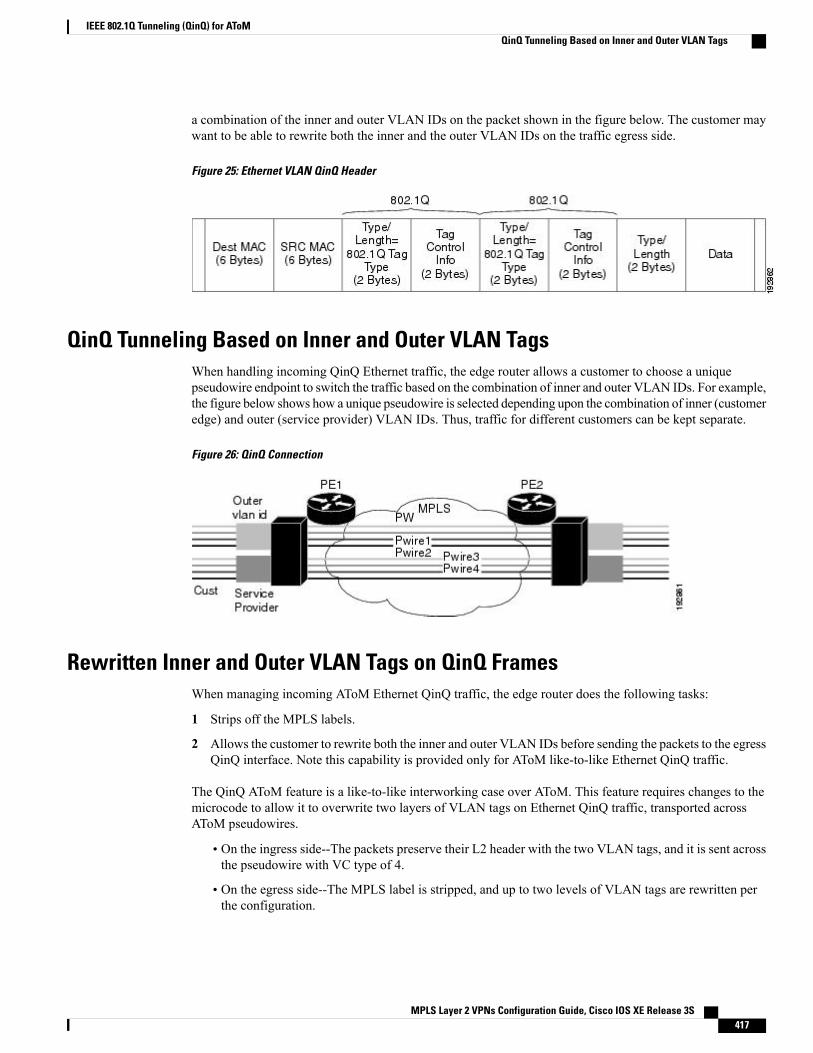
a combination of the inner and outer VLAN IDs on the packet shown in the figure below. The customer maywant to be able to rewrite both the inner and the outer VLAN IDs on the traffic egress side.
Figure 25: Ethernet VLAN QinQ Header
QinQ Tunneling Based on Inner and Outer VLAN TagsWhen handling incoming QinQ Ethernet traffic, the edge router allows a customer to choose a uniquepseudowire endpoint to switch the traffic based on the combination of inner and outer VLAN IDs. For example,the figure below shows how a unique pseudowire is selected depending upon the combination of inner (customeredge) and outer (service provider) VLAN IDs. Thus, traffic for different customers can be kept separate.
Figure 26: QinQ Connection
Rewritten Inner and Outer VLAN Tags on QinQ FramesWhen managing incoming AToM Ethernet QinQ traffic, the edge router does the following tasks:
1 Strips off the MPLS labels.
2 Allows the customer to rewrite both the inner and outer VLAN IDs before sending the packets to the egressQinQ interface. Note this capability is provided only for AToM like-to-like Ethernet QinQ traffic.
The QinQ AToM feature is a like-to-like interworking case over AToM. This feature requires changes to themicrocode to allow it to overwrite two layers of VLAN tags on Ethernet QinQ traffic, transported acrossAToM pseudowires.
• On the ingress side--The packets preserve their L2 header with the two VLAN tags, and it is sent acrossthe pseudowire with VC type of 4.
• On the egress side--The MPLS label is stripped, and up to two levels of VLAN tags are rewritten perthe configuration.
MPLS Layer 2 VPNs Configuration Guide, Cisco IOS XE Release 3S 417
IEEE 802.1Q Tunneling (QinQ) for AToMQinQ Tunneling Based on Inner and Outer VLAN Tags
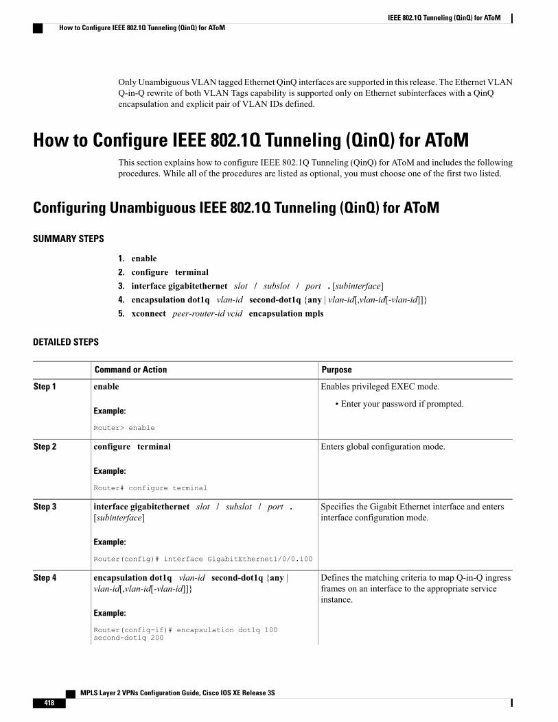
Only Unambiguous VLAN tagged Ethernet QinQ interfaces are supported in this release. The Ethernet VLANQ-in-Q rewrite of both VLAN Tags capability is supported only on Ethernet subinterfaces with a QinQencapsulation and explicit pair of VLAN IDs defined.
How to Configure IEEE 802.1Q Tunneling (QinQ) for AToMThis section explains how to configure IEEE 802.1Q Tunneling (QinQ) for AToM and includes the followingprocedures. While all of the procedures are listed as optional, you must choose one of the first two listed.
Configuring Unambiguous IEEE 802.1Q Tunneling (QinQ) for AToM
SUMMARY STEPS
1. enable2. configure terminal3. interface gigabitethernet slot / subslot / port . [subinterface]4. encapsulation dot1q vlan-id second-dot1q {any | vlan-id[,vlan-id[-vlan-id]]}5. xconnect peer-router-id vcid encapsulation mpls
DETAILED STEPS
PurposeCommand or Action
Enables privileged EXEC mode.enableStep 1
Example:
Router> enable
• Enter your password if prompted.
Enters global configuration mode.configure terminal
Example:
Router# configure terminal
Step 2
Specifies the Gigabit Ethernet interface and entersinterface configuration mode.
interface gigabitethernet slot / subslot / port .[subinterface]
Example:
Router(config)# interface GigabitEthernet1/0/0.100
Step 3
Defines the matching criteria to map Q-in-Q ingressframes on an interface to the appropriate serviceinstance.
encapsulation dot1q vlan-id second-dot1q {any |vlan-id[,vlan-id[-vlan-id]]}
Example:
Router(config-if)# encapsulation dot1q 100second-dot1q 200
Step 4
MPLS Layer 2 VPNs Configuration Guide, Cisco IOS XE Release 3S418
IEEE 802.1Q Tunneling (QinQ) for AToMHow to Configure IEEE 802.1Q Tunneling (QinQ) for AToM
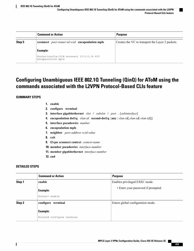
PurposeCommand or Action
Creates the VC to transport the Layer 2 packets.xconnect peer-router-id vcid encapsulation mpls
Example:
Router(config-if)# xconnect 10.0.0.16 410encapsulation mpls
Step 5
Configuring Unambiguous IEEE 802.1Q Tunneling (QinQ) for AToM using thecommands associated with the L2VPN Protocol-Based CLIs feature
SUMMARY STEPS
1. enable2. configure terminal3. interface gigabitethernet slot / subslot / port . [subinterface]4. encapsulation dot1q vlan-id second-dot1q {any | vlan-id[,vlan-id[-vlan-id]]}5. interface pseudowire number6. encapsulation mpls7. neighbor peer-address vcid-value8. exit9. l2vpn xconnect context context-name10. member pseudowire interface-number11. member gigabitethernet interface-number12. end
DETAILED STEPS
PurposeCommand or Action
Enables privileged EXEC mode.enableStep 1
Example:
Router> enable
• Enter your password if prompted.
Enters global configuration mode.configure terminal
Example:
Router# configure terminal
Step 2
MPLS Layer 2 VPNs Configuration Guide, Cisco IOS XE Release 3S 419
IEEE 802.1Q Tunneling (QinQ) for AToMConfiguring Unambiguous IEEE 802.1Q Tunneling (QinQ) for AToM using the commands associated with the L2VPN
Protocol-Based CLIs feature
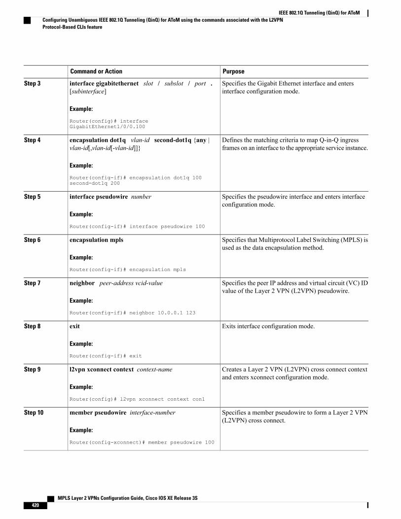
PurposeCommand or Action
Specifies the Gigabit Ethernet interface and entersinterface configuration mode.
interface gigabitethernet slot / subslot / port .[subinterface]
Example:
Router(config)# interfaceGigabitEthernet1/0/0.100
Step 3
Defines the matching criteria to map Q-in-Q ingressframes on an interface to the appropriate service instance.
encapsulation dot1q vlan-id second-dot1q {any |vlan-id[,vlan-id[-vlan-id]]}
Example:
Router(config-if)# encapsulation dot1q 100second-dot1q 200
Step 4
Specifies the pseudowire interface and enters interfaceconfiguration mode.
interface pseudowire number
Example:
Router(config-if)# interface pseudowire 100
Step 5
Specifies that Multiprotocol Label Switching (MPLS) isused as the data encapsulation method.
encapsulation mpls
Example:
Router(config-if)# encapsulation mpls
Step 6
Specifies the peer IP address and virtual circuit (VC) IDvalue of the Layer 2 VPN (L2VPN) pseudowire.
neighbor peer-address vcid-value
Example:
Router(config-if)# neighbor 10.0.0.1 123
Step 7
Exits interface configuration mode.exit
Example:
Router(config-if)# exit
Step 8
Creates a Layer 2 VPN (L2VPN) cross connect contextand enters xconnect configuration mode.
l2vpn xconnect context context-name
Example:
Router(config)# l2vpn xconnect context con1
Step 9
Specifies a member pseudowire to form a Layer 2 VPN(L2VPN) cross connect.
member pseudowire interface-number
Example:
Router(config-xconnect)# member pseudowire 100
Step 10
MPLS Layer 2 VPNs Configuration Guide, Cisco IOS XE Release 3S420
IEEE 802.1Q Tunneling (QinQ) for AToMConfiguring Unambiguous IEEE 802.1Q Tunneling (QinQ) for AToM using the commands associated with the L2VPNProtocol-Based CLIs feature
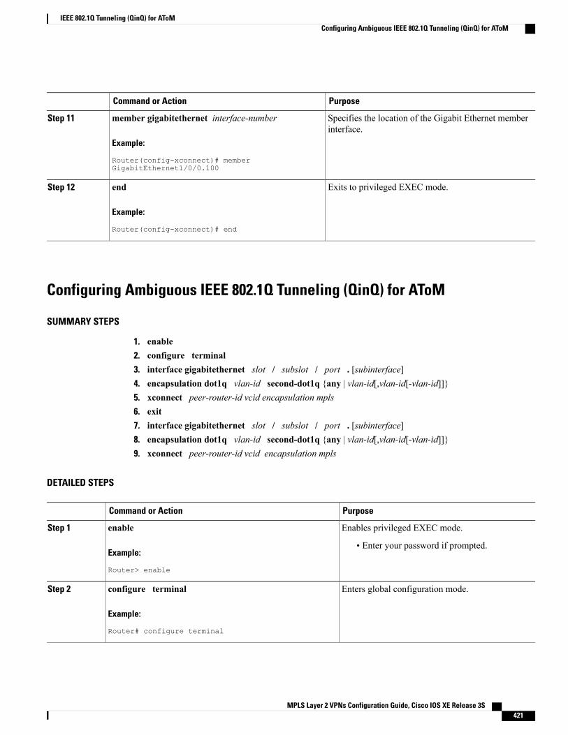
PurposeCommand or Action
Specifies the location of the Gigabit Ethernet memberinterface.
member gigabitethernet interface-number
Example:
Router(config-xconnect)# memberGigabitEthernet1/0/0.100
Step 11
Exits to privileged EXEC mode.end
Example:
Router(config-xconnect)# end
Step 12
Configuring Ambiguous IEEE 802.1Q Tunneling (QinQ) for AToM
SUMMARY STEPS
1. enable2. configure terminal3. interface gigabitethernet slot / subslot / port . [subinterface]4. encapsulation dot1q vlan-id second-dot1q {any | vlan-id[,vlan-id[-vlan-id]]}5. xconnect peer-router-id vcid encapsulation mpls6. exit7. interface gigabitethernet slot / subslot / port . [subinterface]8. encapsulation dot1q vlan-id second-dot1q {any | vlan-id[,vlan-id[-vlan-id]]}9. xconnect peer-router-id vcid encapsulation mpls
DETAILED STEPS
PurposeCommand or Action
Enables privileged EXEC mode.enableStep 1
Example:
Router> enable
• Enter your password if prompted.
Enters global configuration mode.configure terminal
Example:
Router# configure terminal
Step 2
MPLS Layer 2 VPNs Configuration Guide, Cisco IOS XE Release 3S 421
IEEE 802.1Q Tunneling (QinQ) for AToMConfiguring Ambiguous IEEE 802.1Q Tunneling (QinQ) for AToM
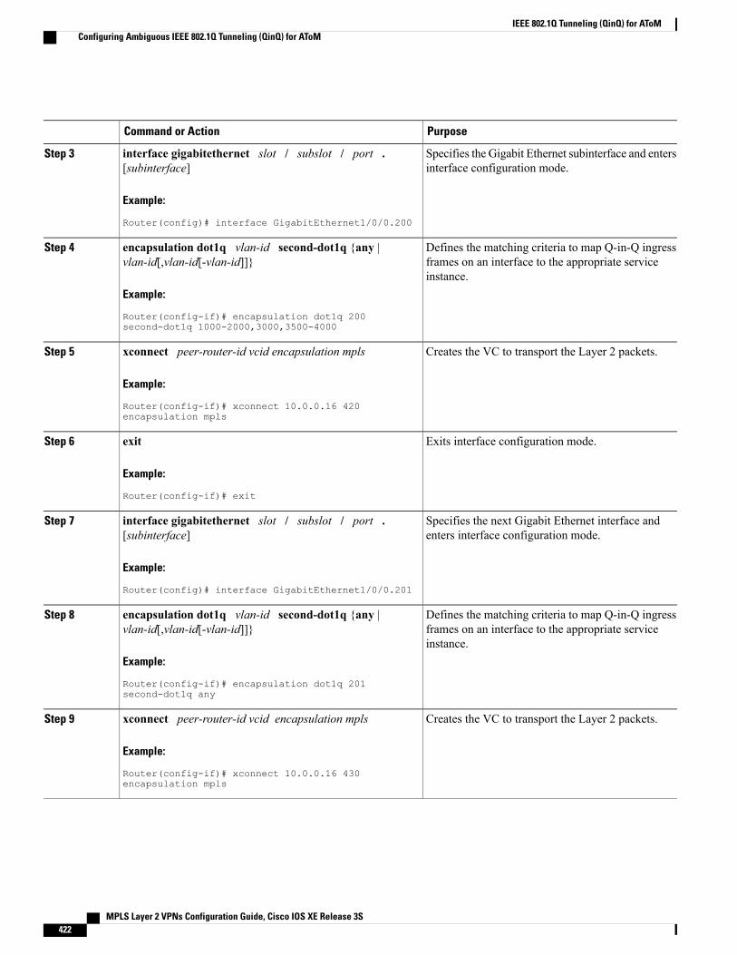
PurposeCommand or Action
Specifies the Gigabit Ethernet subinterface and entersinterface configuration mode.
interface gigabitethernet slot / subslot / port .[subinterface]
Example:
Router(config)# interface GigabitEthernet1/0/0.200
Step 3
Defines the matching criteria to map Q-in-Q ingressframes on an interface to the appropriate serviceinstance.
encapsulation dot1q vlan-id second-dot1q {any |vlan-id[,vlan-id[-vlan-id]]}
Example:
Router(config-if)# encapsulation dot1q 200second-dot1q 1000-2000,3000,3500-4000
Step 4
Creates the VC to transport the Layer 2 packets.xconnect peer-router-id vcid encapsulation mplsStep 5
Example:
Router(config-if)# xconnect 10.0.0.16 420encapsulation mpls
Exits interface configuration mode.exit
Example:
Router(config-if)# exit
Step 6
Specifies the next Gigabit Ethernet interface andenters interface configuration mode.
interface gigabitethernet slot / subslot / port .[subinterface]
Example:
Router(config)# interface GigabitEthernet1/0/0.201
Step 7
Defines the matching criteria to map Q-in-Q ingressframes on an interface to the appropriate serviceinstance.
encapsulation dot1q vlan-id second-dot1q {any |vlan-id[,vlan-id[-vlan-id]]}
Example:
Router(config-if)# encapsulation dot1q 201second-dot1q any
Step 8
Creates the VC to transport the Layer 2 packets.xconnect peer-router-id vcid encapsulation mplsStep 9
Example:
Router(config-if)# xconnect 10.0.0.16 430encapsulation mpls
MPLS Layer 2 VPNs Configuration Guide, Cisco IOS XE Release 3S422
IEEE 802.1Q Tunneling (QinQ) for AToMConfiguring Ambiguous IEEE 802.1Q Tunneling (QinQ) for AToM
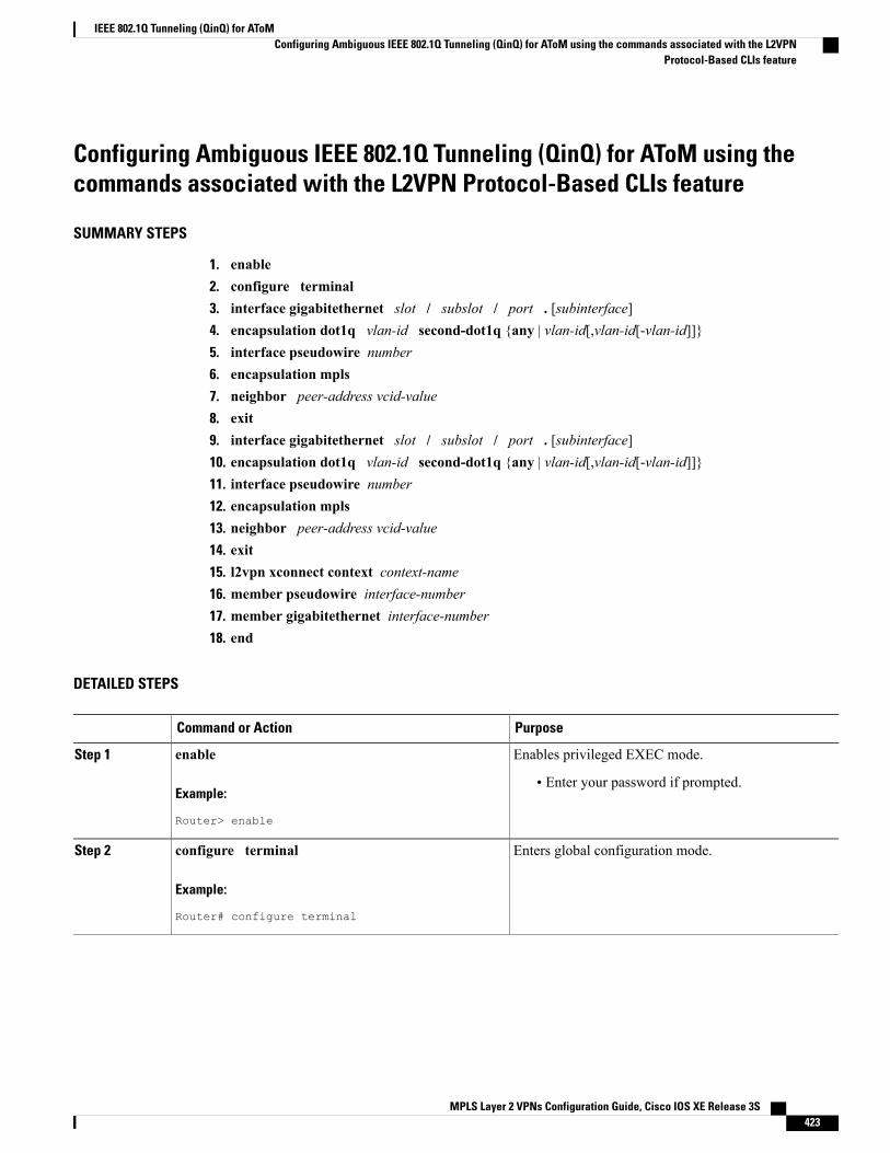
Configuring Ambiguous IEEE 802.1Q Tunneling (QinQ) for AToM using thecommands associated with the L2VPN Protocol-Based CLIs feature
SUMMARY STEPS
1. enable2. configure terminal3. interface gigabitethernet slot / subslot / port . [subinterface]4. encapsulation dot1q vlan-id second-dot1q {any | vlan-id[,vlan-id[-vlan-id]]}5. interface pseudowire number6. encapsulation mpls7. neighbor peer-address vcid-value8. exit9. interface gigabitethernet slot / subslot / port . [subinterface]10. encapsulation dot1q vlan-id second-dot1q {any | vlan-id[,vlan-id[-vlan-id]]}11. interface pseudowire number12. encapsulation mpls13. neighbor peer-address vcid-value14. exit15. l2vpn xconnect context context-name16. member pseudowire interface-number17. member gigabitethernet interface-number18. end
DETAILED STEPS
PurposeCommand or Action
Enables privileged EXEC mode.enableStep 1
Example:
Router> enable
• Enter your password if prompted.
Enters global configuration mode.configure terminal
Example:
Router# configure terminal
Step 2
MPLS Layer 2 VPNs Configuration Guide, Cisco IOS XE Release 3S 423
IEEE 802.1Q Tunneling (QinQ) for AToMConfiguring Ambiguous IEEE 802.1Q Tunneling (QinQ) for AToM using the commands associated with the L2VPN
Protocol-Based CLIs feature
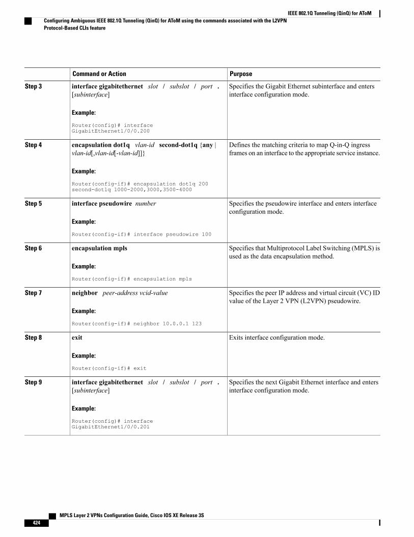
PurposeCommand or Action
Specifies the Gigabit Ethernet subinterface and entersinterface configuration mode.
interface gigabitethernet slot / subslot / port .[subinterface]
Example:
Router(config)# interfaceGigabitEthernet1/0/0.200
Step 3
Defines the matching criteria to map Q-in-Q ingressframes on an interface to the appropriate service instance.
encapsulation dot1q vlan-id second-dot1q {any |vlan-id[,vlan-id[-vlan-id]]}
Example:
Router(config-if)# encapsulation dot1q 200second-dot1q 1000-2000,3000,3500-4000
Step 4
Specifies the pseudowire interface and enters interfaceconfiguration mode.
interface pseudowire number
Example:
Router(config-if)# interface pseudowire 100
Step 5
Specifies that Multiprotocol Label Switching (MPLS) isused as the data encapsulation method.
encapsulation mpls
Example:
Router(config-if)# encapsulation mpls
Step 6
Specifies the peer IP address and virtual circuit (VC) IDvalue of the Layer 2 VPN (L2VPN) pseudowire.
neighbor peer-address vcid-value
Example:
Router(config-if)# neighbor 10.0.0.1 123
Step 7
Exits interface configuration mode.exit
Example:
Router(config-if)# exit
Step 8
Specifies the next Gigabit Ethernet interface and entersinterface configuration mode.
interface gigabitethernet slot / subslot / port .[subinterface]
Example:
Router(config)# interfaceGigabitEthernet1/0/0.201
Step 9
MPLS Layer 2 VPNs Configuration Guide, Cisco IOS XE Release 3S424
IEEE 802.1Q Tunneling (QinQ) for AToMConfiguring Ambiguous IEEE 802.1Q Tunneling (QinQ) for AToM using the commands associated with the L2VPNProtocol-Based CLIs feature
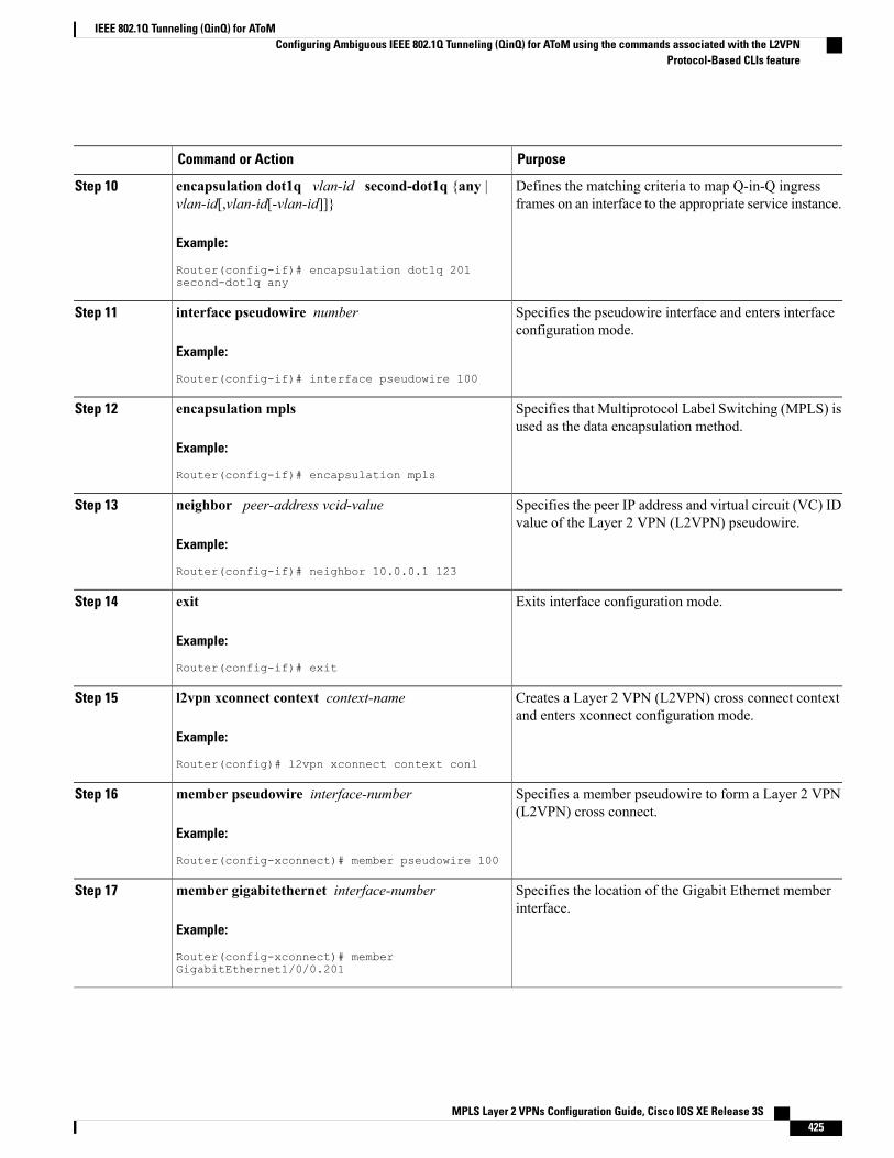
PurposeCommand or Action
Defines the matching criteria to map Q-in-Q ingressframes on an interface to the appropriate service instance.
encapsulation dot1q vlan-id second-dot1q {any |vlan-id[,vlan-id[-vlan-id]]}
Example:
Router(config-if)# encapsulation dot1q 201second-dot1q any
Step 10
Specifies the pseudowire interface and enters interfaceconfiguration mode.
interface pseudowire number
Example:
Router(config-if)# interface pseudowire 100
Step 11
Specifies that Multiprotocol Label Switching (MPLS) isused as the data encapsulation method.
encapsulation mpls
Example:
Router(config-if)# encapsulation mpls
Step 12
Specifies the peer IP address and virtual circuit (VC) IDvalue of the Layer 2 VPN (L2VPN) pseudowire.
neighbor peer-address vcid-value
Example:
Router(config-if)# neighbor 10.0.0.1 123
Step 13
Exits interface configuration mode.exit
Example:
Router(config-if)# exit
Step 14
Creates a Layer 2 VPN (L2VPN) cross connect contextand enters xconnect configuration mode.
l2vpn xconnect context context-name
Example:
Router(config)# l2vpn xconnect context con1
Step 15
Specifies a member pseudowire to form a Layer 2 VPN(L2VPN) cross connect.
member pseudowire interface-number
Example:
Router(config-xconnect)# member pseudowire 100
Step 16
Specifies the location of the Gigabit Ethernet memberinterface.
member gigabitethernet interface-number
Example:
Router(config-xconnect)# memberGigabitEthernet1/0/0.201
Step 17
MPLS Layer 2 VPNs Configuration Guide, Cisco IOS XE Release 3S 425
IEEE 802.1Q Tunneling (QinQ) for AToMConfiguring Ambiguous IEEE 802.1Q Tunneling (QinQ) for AToM using the commands associated with the L2VPN
Protocol-Based CLIs feature
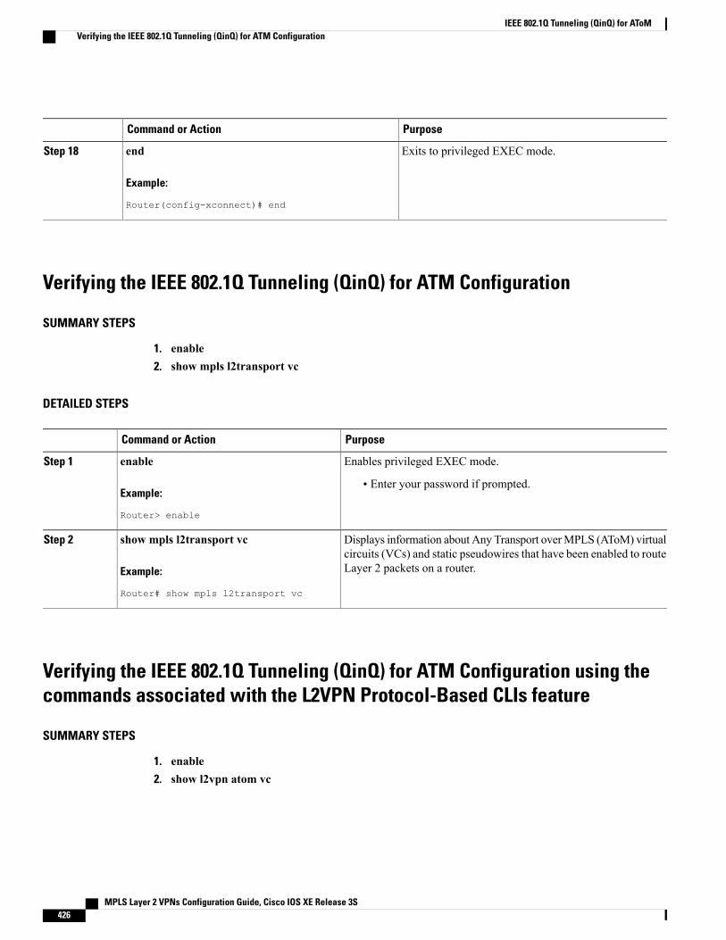
PurposeCommand or Action
Exits to privileged EXEC mode.end
Example:
Router(config-xconnect)# end
Step 18
Verifying the IEEE 802.1Q Tunneling (QinQ) for ATM Configuration
SUMMARY STEPS
1. enable2. show mpls l2transport vc
DETAILED STEPS
PurposeCommand or Action
Enables privileged EXEC mode.enableStep 1
Example:
Router> enable
• Enter your password if prompted.
Displays information about Any Transport overMPLS (AToM) virtualcircuits (VCs) and static pseudowires that have been enabled to routeLayer 2 packets on a router.
show mpls l2transport vc
Example:
Router# show mpls l2transport vc
Step 2
Verifying the IEEE 802.1Q Tunneling (QinQ) for ATM Configuration using thecommands associated with the L2VPN Protocol-Based CLIs feature
SUMMARY STEPS
1. enable2. show l2vpn atom vc
MPLS Layer 2 VPNs Configuration Guide, Cisco IOS XE Release 3S426
IEEE 802.1Q Tunneling (QinQ) for AToMVerifying the IEEE 802.1Q Tunneling (QinQ) for ATM Configuration

DETAILED STEPS
PurposeCommand or Action
Enables privileged EXEC mode.enableStep 1
Example:
Device> enable
• Enter your password if prompted.
Displays information about Any Transport overMPLS (AToM) virtualcircuits (VCs) and static pseudowires that have been enabled to routeLayer 2 packets on a router.
show l2vpn atom vc
Example:
Device# show l2vpn atom vc
Step 2
Configuration Examples for IEEE 801.2 Tunneling (QinQ) for ATM
Example Configuring Unambiguous IEEE 802.1Q Tunneling (QinQ) for ATM
Router> enableRouter# configure terminalRouter(config)# interface GigabitEthernet1/0/0.100Router(config-if)# encapsulation dot1q 100 second-dot1q 200Router(config-if)# xconnect 10.0.0.16 410 encapsulation mpls
Example Configuring Unambiguous IEEE 802.1Q Tunneling (QinQ) for ATMusing the commands associated with the L2VPN Protocol-Based CLIs feature
Router> enableRouter# configure terminalRouter(config)# interface GigabitEthernet1/0/0.100Router(config-if)# encapsulation dot1q 100 second-dot1q 200Router(config-if)# interface pseudowire 100Router(config-if)# encapsulation mplsRouter(config-if)# neighbor 10.0.0.1 123Router(config-if)# exitRouter(config)# l2vpn xconnect context ARouter(config-xconnect)# member pseudowire 100Router(config-xconnect)# member GigabitEthernet1/0/0.100
Example Configuring Ambiguous IEEE 802.1Q Tunneling (QinQ) for ATMThe following is an example of an ambiguous IEEE 802.1Q Tunneling (QinQ) for ATM configuration.
Router> enable
MPLS Layer 2 VPNs Configuration Guide, Cisco IOS XE Release 3S 427
IEEE 802.1Q Tunneling (QinQ) for AToMConfiguration Examples for IEEE 801.2 Tunneling (QinQ) for ATM
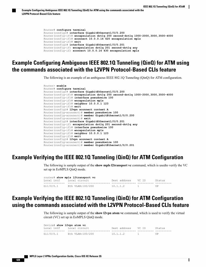
Router# configure terminalRouter(config)# interface GigabitEthernet1/0/0.200Router(config-if)# encapsulation dot1q 200 second-dot1q 1000-2000,3000,3500-4000Router(config-if)# xconnect 10.0.0.16 420 encapsulation mplsRouter(config-if)# exitRouter(config)# interface GigabitEthernet1/0/0.201Router(config-if) encapsulation dot1q 201 second-dot1q anyRouter(config-if) xconnect 10.0.0.16 430 encapsulation mpls
Example Configuring Ambiguous IEEE 802.1Q Tunneling (QinQ) for ATM usingthe commands associated with the L2VPN Protocol-Based CLIs feature
The following is an example of an ambiguous IEEE 802.1Q Tunneling (QinQ) for ATM configuration.
Router> enableRouter# configure terminalRouter(config)# interface GigabitEthernet1/0/0.200Router(config-if)# encapsulation dot1q 200 second-dot1q 1000-2000,3000,3500-4000Router(config-if)# interface pseudowire 100Router(config-if)# encapsulation mplsRouter(config-if)# neighbor 10.0.0.1 123Router(config-if)# exitRouter(config)# l2vpn xconnect context ARouter(config-xconnect)# member pseudowire 100Router(config-xconnect)# member GigabitEthernet1/0/0.200Router(config-xconnect)# exitRouter(config)# interface GigabitEthernet1/0/0.201Router(config-if) encapsulation dot1q 201 second-dot1q anyRouter(config-if)# interface pseudowire 100Router(config-if)# encapsulation mplsRouter(config-if)# neighbor 10.0.0.1 123Router(config-if)# exitRouter(config)# l2vpn xconnect context ARouter(config-xconnect)# member pseudowire 100Router(config-xconnect)# member GigabitEthernet1/0/0.201
Example Verifying the IEEE 802.1Q Tunneling (QinQ) for ATM ConfigurationThe following is sample output of the show mpls l2transport vc command, which is usedto verify the VCset up in EoMPLS QinQ mode.
router# show mpls l2transport vcLocal intf Local circuit Dest address VC ID Status------------- -------------------------- --------------- ---------- ----------Gi1/0/0.1 Eth VLAN:100/200 10.1.1.2 1 UP
Example Verifying the IEEE 802.1Q Tunneling (QinQ) for ATM Configurationusing the commands associated with the L2VPN Protocol-Based CLIs feature
The following is sample output of the show l2vpn atom vc command, which is used to verify the virtualcircuit (VC) set up in EoMPLS QinQ mode.
Device# show l2vpn atom vcLocal intf Local circuit Dest address VC ID Status------------- -------------------------- --------------- ---------- ----------Gi1/0/0.1 Eth VLAN:100/200 10.1.1.2 1 UP
MPLS Layer 2 VPNs Configuration Guide, Cisco IOS XE Release 3S428
IEEE 802.1Q Tunneling (QinQ) for AToMExample Configuring Ambiguous IEEE 802.1Q Tunneling (QinQ) for ATM using the commands associated with theL2VPN Protocol-Based CLIs feature
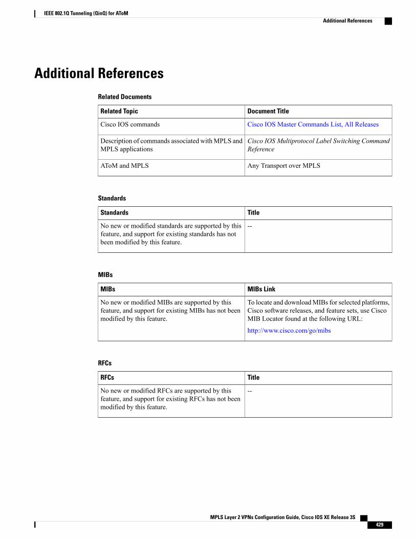
Additional ReferencesRelated Documents
Document TitleRelated Topic
Cisco IOS Master Commands List, All ReleasesCisco IOS commands
Cisco IOS Multiprotocol Label Switching CommandReference
Description of commands associated withMPLS andMPLS applications
Any Transport over MPLSAToM and MPLS
Standards
TitleStandards
--No new or modified standards are supported by thisfeature, and support for existing standards has notbeen modified by this feature.
MIBs
MIBs LinkMIBs
To locate and downloadMIBs for selected platforms,Cisco software releases, and feature sets, use CiscoMIB Locator found at the following URL:
http://www.cisco.com/go/mibs
No new or modified MIBs are supported by thisfeature, and support for existing MIBs has not beenmodified by this feature.
RFCs
TitleRFCs
--No new or modified RFCs are supported by thisfeature, and support for existing RFCs has not beenmodified by this feature.
MPLS Layer 2 VPNs Configuration Guide, Cisco IOS XE Release 3S 429
IEEE 802.1Q Tunneling (QinQ) for AToMAdditional References
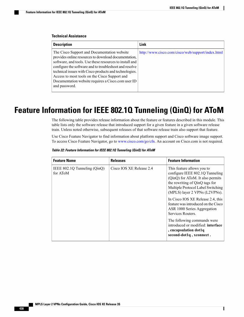
Technical Assistance
LinkDescription
http://www.cisco.com/cisco/web/support/index.htmlThe Cisco Support and Documentation websiteprovides online resources to download documentation,software, and tools. Use these resources to install andconfigure the software and to troubleshoot and resolvetechnical issues with Cisco products and technologies.Access to most tools on the Cisco Support andDocumentation website requires a Cisco.com user IDand password.
Feature Information for IEEE 802.1Q Tunneling (QinQ) for AToMThe following table provides release information about the feature or features described in this module. Thistable lists only the software release that introduced support for a given feature in a given software releasetrain. Unless noted otherwise, subsequent releases of that software release train also support that feature.
Use Cisco Feature Navigator to find information about platform support and Cisco software image support.To access Cisco Feature Navigator, go to www.cisco.com/go/cfn. An account on Cisco.com is not required.
Table 22: Feature Information for IEEE 802.1Q Tunneling (QinQ) for AToM
Feature InformationReleasesFeature Name
This feature allows you toconfigure IEEE 802.1Q Tunneling(QinQ) for AToM. It also permitsthe rewriting of QinQ tags forMultiple Protocol Label Switching(MPLS) layer 2 VPNs (L2VPNs).
In Cisco IOS XE Release 2.4, thisfeature was introduced on the CiscoASR 1000 Series AggregationServices Routers.
The following commands wereintroduced or modified: interface, encapsulation dot1qsecond-dot1q , xconnect .
Cisco IOS XE Release 2.4IEEE 802.1Q Tunneling (QinQ)for AToM
MPLS Layer 2 VPNs Configuration Guide, Cisco IOS XE Release 3S430
IEEE 802.1Q Tunneling (QinQ) for AToMFeature Information for IEEE 802.1Q Tunneling (QinQ) for AToM
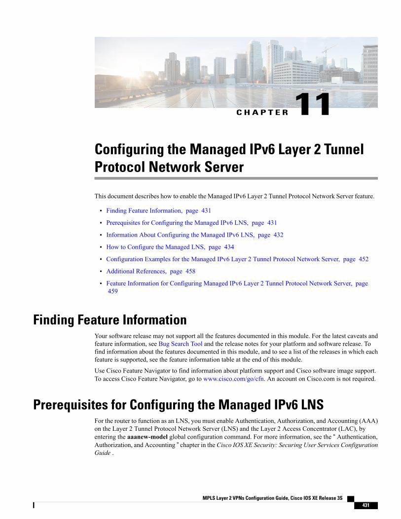
C H A P T E R 11Configuring the Managed IPv6 Layer 2 TunnelProtocol Network Server
This document describes how to enable the Managed IPv6 Layer 2 Tunnel Protocol Network Server feature.
• Finding Feature Information, page 431
• Prerequisites for Configuring the Managed IPv6 LNS, page 431
• Information About Configuring the Managed IPv6 LNS, page 432
• How to Configure the Managed LNS, page 434
• Configuration Examples for the Managed IPv6 Layer 2 Tunnel Protocol Network Server, page 452
• Additional References, page 458
• Feature Information for Configuring Managed IPv6 Layer 2 Tunnel Protocol Network Server, page459
Finding Feature InformationYour software release may not support all the features documented in this module. For the latest caveats andfeature information, see Bug Search Tool and the release notes for your platform and software release. Tofind information about the features documented in this module, and to see a list of the releases in which eachfeature is supported, see the feature information table at the end of this module.
Use Cisco Feature Navigator to find information about platform support and Cisco software image support.To access Cisco Feature Navigator, go to www.cisco.com/go/cfn. An account on Cisco.com is not required.
Prerequisites for Configuring the Managed IPv6 LNSFor the router to function as an LNS, you must enable Authentication, Authorization, and Accounting (AAA)on the Layer 2 Tunnel Protocol Network Server (LNS) and the Layer 2 Access Concentrator (LAC), byentering the aaanew-model global configuration command. For more information, see the “ Authentication,Authorization, and Accounting ” chapter in the Cisco IOS XE Security: Securing User Services ConfigurationGuide .
MPLS Layer 2 VPNs Configuration Guide, Cisco IOS XE Release 3S 431
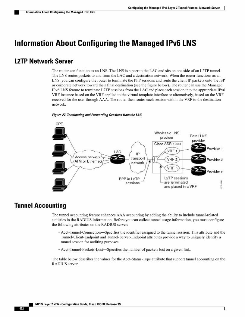
Information About Configuring the Managed IPv6 LNS
L2TP Network ServerThe router can function as an LNS. The LNS is a peer to the LAC and sits on one side of an L2TP tunnel.The LNS routes packets to and from the LAC and a destination network. When the router functions as anLNS, you can configure the router to terminate the PPP sessions and route the client IP packets onto the ISPor corporate network toward their final destination (see the figure below). The router can use the ManagedIPv6 LNS feature to terminate L2TP sessions from the LAC and place each session into the appropriate IPv6VRF instance based on the VRF applied to the virtual template interface or alternatively, based on the VRFreceived for the user through AAA. The router then routes each session within the VRF to the destinationnetwork.
Figure 27: Terminating and Forwarding Sessions from the LAC
Tunnel AccountingThe tunnel accounting feature enhances AAA accounting by adding the ability to include tunnel-relatedstatistics in the RADIUS information. Before you can collect tunnel usage information, you must configurethe following attributes on the RADIUS server:
• Acct-Tunnel-Connection—Specifies the identifier assigned to the tunnel session. This attribute and theTunnel-Client-Endpoint and Tunnel-Server-Endpoint attributes provide a way to uniquely identify atunnel session for auditing purposes.
• Acct-Tunnel-Packets-Lost—Specifies the number of packets lost on a given link.
The table below describes the values for the Acct-Status-Type attribute that support tunnel accounting on theRADIUS server.
MPLS Layer 2 VPNs Configuration Guide, Cisco IOS XE Release 3S432
Configuring the Managed IPv6 Layer 2 Tunnel Protocol Network ServerInformation About Configuring the Managed IPv6 LNS
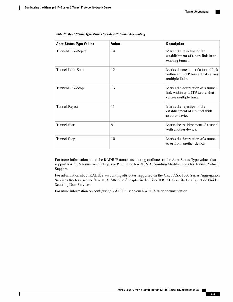
Table 23: Acct-Status-Type Values for RADIUS Tunnel Accounting
DescriptionValueAcct-Status-Type Values
Marks the rejection of theestablishment of a new link in anexisting tunnel.
14Tunnel-Link-Reject
Marks the creation of a tunnel linkwithin an L2TP tunnel that carriesmultiple links.
12Tunnel-Link-Start
Marks the destruction of a tunnellink within an L2TP tunnel thatcarries multiple links.
13Tunnel-Link-Stop
Marks the rejection of theestablishment of a tunnel withanother device.
11Tunnel-Reject
Marks the establishment of a tunnelwith another device.
9Tunnel-Start
Marks the destruction of a tunnelto or from another device.
10Tunnel-Stop
For more information about the RADIUS tunnel accounting attributes or the Acct-Status-Type values thatsupport RADIUS tunnel accounting, see RFC 2867, RADIUS Accounting Modifications for Tunnel ProtocolSupport.
For information about RADIUS accounting attributes supported on the Cisco ASR 1000 Series AggregationServices Routers, see the “RADIUS Attributes” chapter in the Cisco IOS XE Security Configuration Guide:Securing User Services.
For more information on configuring RADIUS, see your RADIUS user documentation.
MPLS Layer 2 VPNs Configuration Guide, Cisco IOS XE Release 3S 433
Configuring the Managed IPv6 Layer 2 Tunnel Protocol Network ServerTunnel Accounting
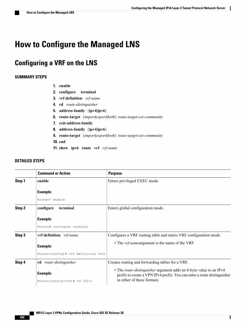
How to Configure the Managed LNS
Configuring a VRF on the LNS
SUMMARY STEPS
1. enable2. configure terminal3. vrf definition vrf-name4. rd route-distinguisher5. address-family {ipv4|ipv6}6. route-target {import|export|both} route-target-ext-community7. exit-address-family8. address-family {ipv4|ipv6}9. route-target {import|export|both} route-target-ext-community10. end11. show ipv6 route vrf vrf-name
DETAILED STEPS
PurposeCommand or Action
Enters privileged EXEC mode.enable
Example:
Router> enable
Step 1
Enters global configuration mode.configure terminal
Example:
Router# configure terminal
Step 2
Configures a VRF routing table and enters VRF configuration mode.vrf definition vrf-nameStep 3
Example:
Router(config)# vrf definition vrf1
• The vrf-nameargument is the name of the VRF.
Creates routing and forwarding tables for a VRF.rd route-distinguisherStep 4
Example:
Router(config-vrf)# rd 100:1
• The route-distinguisher argument adds an 8-byte value to an IPv4prefix to create a VPN IPv4 prefix. You can enter a route distinguisherin either of these formats:
MPLS Layer 2 VPNs Configuration Guide, Cisco IOS XE Release 3S434
Configuring the Managed IPv6 Layer 2 Tunnel Protocol Network ServerHow to Configure the Managed LNS
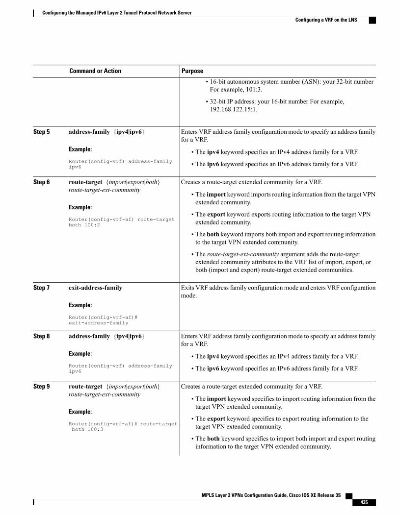
PurposeCommand or Action
• 16-bit autonomous system number (ASN): your 32-bit numberFor example, 101:3.
• 32-bit IP address: your 16-bit number For example,192.168.122.15:1.
Enters VRF address family configuration mode to specify an address familyfor a VRF.
address-family {ipv4|ipv6}
Example:
Router(config-vrf) address-familyipv6
Step 5
• The ipv4 keyword specifies an IPv4 address family for a VRF.
• The ipv6 keyword specifies an IPv6 address family for a VRF.
Creates a route-target extended community for a VRF.route-target {import|export|both}route-target-ext-community
Step 6
• The import keyword imports routing information from the target VPNextended community.
Example:
Router(config-vrf-af) route-targetboth 100:2
• The export keyword exports routing information to the target VPNextended community.
• The both keyword imports both import and export routing informationto the target VPN extended community.
• The route-target-ext-community argument adds the route-targetextended community attributes to the VRF list of import, export, orboth (import and export) route-target extended communities.
Exits VRF address family configuration mode and enters VRF configurationmode.
exit-address-family
Example:
Router(config-vrf-af)#exit-address-family
Step 7
Enters VRF address family configuration mode to specify an address familyfor a VRF.
address-family {ipv4|ipv6}
Example:
Router(config-vrf) address-familyipv6
Step 8
• The ipv4 keyword specifies an IPv4 address family for a VRF.
• The ipv6 keyword specifies an IPv6 address family for a VRF.
Creates a route-target extended community for a VRF.route-target {import|export|both}route-target-ext-community
Step 9
• The import keyword specifies to import routing information from thetarget VPN extended community.
Example:
Router(config-vrf-af)# route-targetboth 100:3
• The export keyword specifies to export routing information to thetarget VPN extended community.
• The both keyword specifies to import both import and export routinginformation to the target VPN extended community.
MPLS Layer 2 VPNs Configuration Guide, Cisco IOS XE Release 3S 435
Configuring the Managed IPv6 Layer 2 Tunnel Protocol Network ServerConfiguring a VRF on the LNS
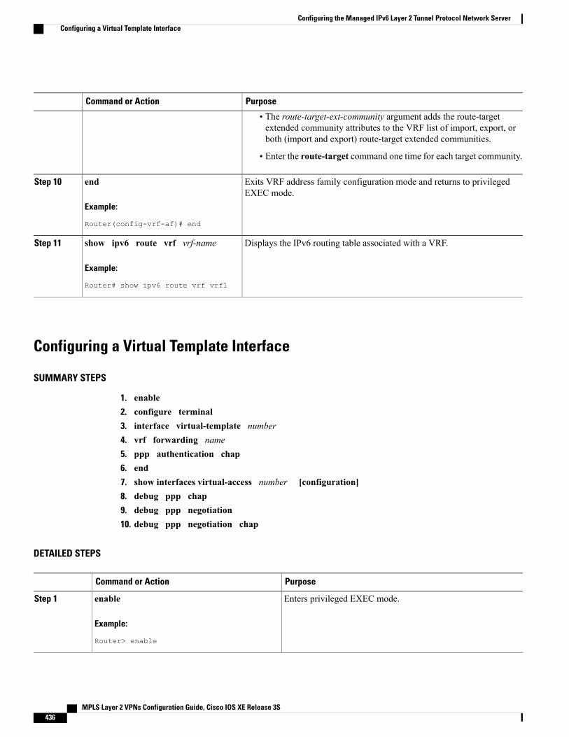
PurposeCommand or Action
• The route-target-ext-community argument adds the route-targetextended community attributes to the VRF list of import, export, orboth (import and export) route-target extended communities.
• Enter the route-target command one time for each target community.
Exits VRF address family configuration mode and returns to privilegedEXEC mode.
end
Example:
Router(config-vrf-af)# end
Step 10
Displays the IPv6 routing table associated with a VRF.show ipv6 route vrf vrf-name
Example:
Router# show ipv6 route vrf vrf1
Step 11
Configuring a Virtual Template Interface
SUMMARY STEPS
1. enable2. configure terminal3. interface virtual-template number4. vrf forwarding name5. ppp authentication chap6. end7. show interfaces virtual-access number [configuration]8. debug ppp chap9. debug ppp negotiation10. debug ppp negotiation chap
DETAILED STEPS
PurposeCommand or Action
Enters privileged EXEC mode.enable
Example:
Router> enable
Step 1
MPLS Layer 2 VPNs Configuration Guide, Cisco IOS XE Release 3S436
Configuring the Managed IPv6 Layer 2 Tunnel Protocol Network ServerConfiguring a Virtual Template Interface
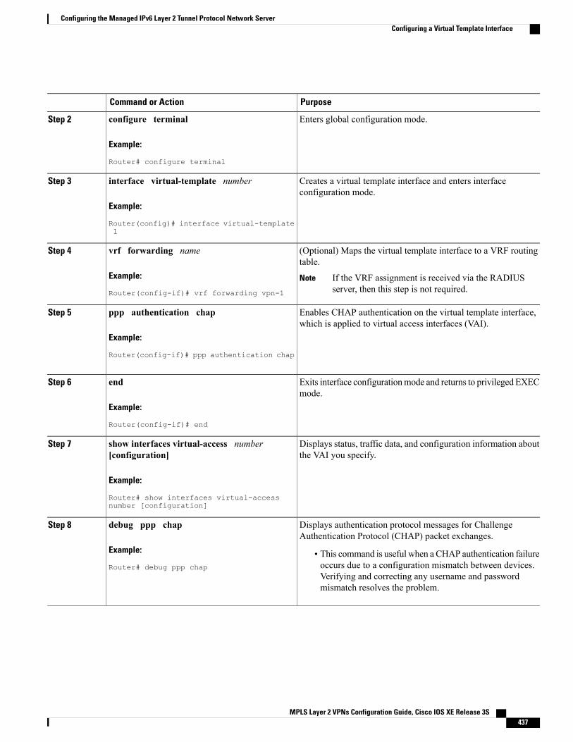
PurposeCommand or Action
Enters global configuration mode.configure terminal
Example:
Router# configure terminal
Step 2
Creates a virtual template interface and enters interfaceconfiguration mode.
interface virtual-template number
Example:
Router(config)# interface virtual-template1
Step 3
(Optional) Maps the virtual template interface to a VRF routingtable.
vrf forwarding name
Example:
Router(config-if)# vrf forwarding vpn-1
Step 4
If the VRF assignment is received via the RADIUSserver, then this step is not required.
Note
Enables CHAP authentication on the virtual template interface,which is applied to virtual access interfaces (VAI).
ppp authentication chap
Example:
Router(config-if)# ppp authentication chap
Step 5
Exits interface configurationmode and returns to privileged EXECmode.
end
Example:
Router(config-if)# end
Step 6
Displays status, traffic data, and configuration information aboutthe VAI you specify.
show interfaces virtual-access number[configuration]
Example:
Router# show interfaces virtual-accessnumber [configuration]
Step 7
Displays authentication protocol messages for ChallengeAuthentication Protocol (CHAP) packet exchanges.
debug ppp chap
Example:
Router# debug ppp chap
Step 8
• This command is useful when a CHAP authentication failureoccurs due to a configuration mismatch between devices.Verifying and correcting any username and passwordmismatch resolves the problem.
MPLS Layer 2 VPNs Configuration Guide, Cisco IOS XE Release 3S 437
Configuring the Managed IPv6 Layer 2 Tunnel Protocol Network ServerConfiguring a Virtual Template Interface
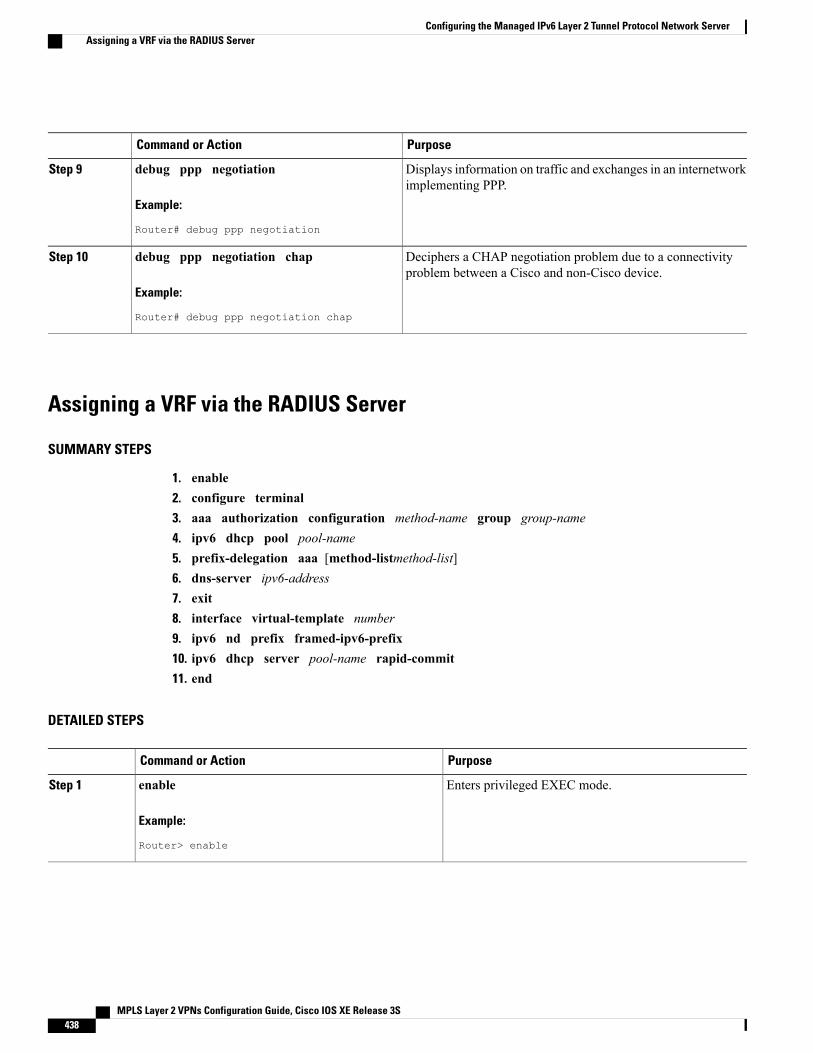
PurposeCommand or Action
Displays information on traffic and exchanges in an internetworkimplementing PPP.
debug ppp negotiation
Example:
Router# debug ppp negotiation
Step 9
Deciphers a CHAP negotiation problem due to a connectivityproblem between a Cisco and non-Cisco device.
debug ppp negotiation chap
Example:
Router# debug ppp negotiation chap
Step 10
Assigning a VRF via the RADIUS Server
SUMMARY STEPS
1. enable2. configure terminal3. aaa authorization configuration method-name group group-name4. ipv6 dhcp pool pool-name5. prefix-delegation aaa [method-listmethod-list]6. dns-server ipv6-address7. exit8. interface virtual-template number9. ipv6 nd prefix framed-ipv6-prefix10. ipv6 dhcp server pool-name rapid-commit11. end
DETAILED STEPS
PurposeCommand or Action
Enters privileged EXEC mode.enable
Example:
Router> enable
Step 1
MPLS Layer 2 VPNs Configuration Guide, Cisco IOS XE Release 3S438
Configuring the Managed IPv6 Layer 2 Tunnel Protocol Network ServerAssigning a VRF via the RADIUS Server
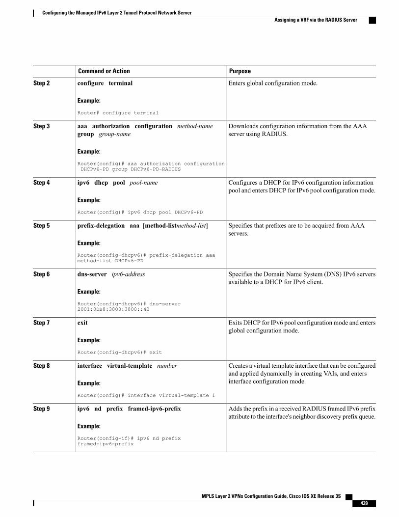
PurposeCommand or Action
Enters global configuration mode.configure terminal
Example:
Router# configure terminal
Step 2
Downloads configuration information from the AAAserver using RADIUS.
aaa authorization configuration method-namegroup group-name
Example:
Router(config)# aaa authorization configurationDHCPv6-PD group DHCPv6-PD-RADIUS
Step 3
Configures a DHCP for IPv6 configuration informationpool and enters DHCP for IPv6 pool configuration mode.
ipv6 dhcp pool pool-name
Example:
Router(config)# ipv6 dhcp pool DHCPv6-PD
Step 4
Specifies that prefixes are to be acquired from AAAservers.
prefix-delegation aaa [method-listmethod-list]
Example:
Router(config-dhcpv6)# prefix-delegation aaamethod-list DHCPv6-PD
Step 5
Specifies the Domain Name System (DNS) IPv6 serversavailable to a DHCP for IPv6 client.
dns-server ipv6-address
Example:
Router(config-dhcpv6)# dns-server2001:0DB8:3000:3000::42
Step 6
Exits DHCP for IPv6 pool configuration mode and entersglobal configuration mode.
exit
Example:
Router(config-dhcpv6)# exit
Step 7
Creates a virtual template interface that can be configuredand applied dynamically in creating VAIs, and entersinterface configuration mode.
interface virtual-template number
Example:
Router(config)# interface virtual-template 1
Step 8
Adds the prefix in a received RADIUS framed IPv6 prefixattribute to the interface's neighbor discovery prefix queue.
ipv6 nd prefix framed-ipv6-prefix
Example:
Router(config-if)# ipv6 nd prefixframed-ipv6-prefix
Step 9
MPLS Layer 2 VPNs Configuration Guide, Cisco IOS XE Release 3S 439
Configuring the Managed IPv6 Layer 2 Tunnel Protocol Network ServerAssigning a VRF via the RADIUS Server
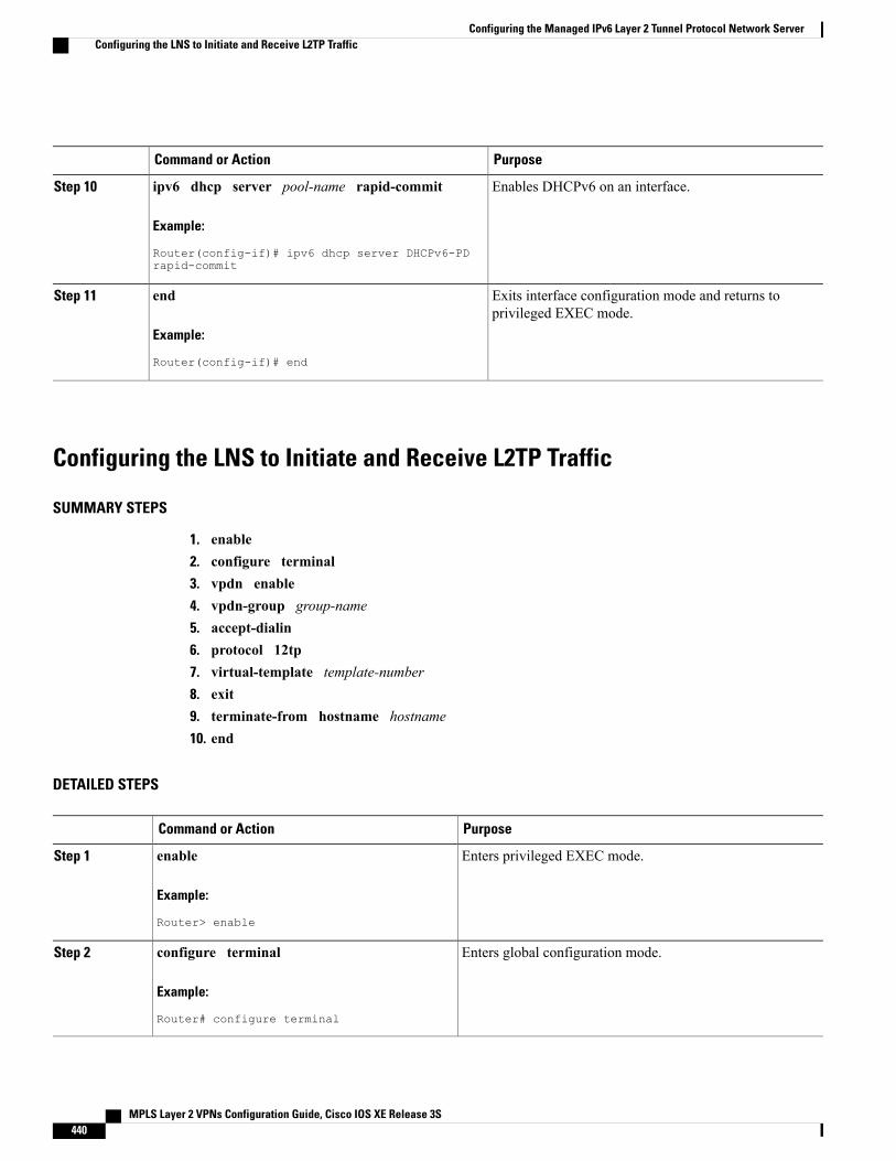
PurposeCommand or Action
Enables DHCPv6 on an interface.ipv6 dhcp server pool-name rapid-commit
Example:
Router(config-if)# ipv6 dhcp server DHCPv6-PDrapid-commit
Step 10
Exits interface configuration mode and returns toprivileged EXEC mode.
end
Example:
Router(config-if)# end
Step 11
Configuring the LNS to Initiate and Receive L2TP Traffic
SUMMARY STEPS
1. enable2. configure terminal3. vpdn enable4. vpdn-group group-name5. accept-dialin6. protocol 12tp7. virtual-template template-number8. exit9. terminate-from hostname hostname10. end
DETAILED STEPS
PurposeCommand or Action
Enters privileged EXEC mode.enable
Example:
Router> enable
Step 1
Enters global configuration mode.configure terminal
Example:
Router# configure terminal
Step 2
MPLS Layer 2 VPNs Configuration Guide, Cisco IOS XE Release 3S440
Configuring the Managed IPv6 Layer 2 Tunnel Protocol Network ServerConfiguring the LNS to Initiate and Receive L2TP Traffic
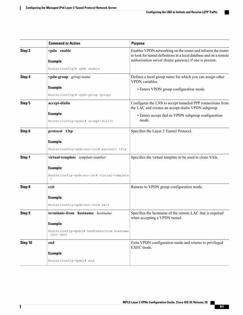
PurposeCommand or Action
Enables VPDN networking on the router and informs the routerto look for tunnel definitions in a local database and on a remoteauthorization server (home gateway) if one is present.
vpdn enable
Example:
Router(config)# vpdn enable
Step 3
Defines a local group name for which you can assign otherVPDN variables.
vpdn-group group-name
Example:
Router(config)# vpdn-group group1
Step 4
• Enters VPDN group configuration mode.
Configures the LNS to accept tunneled PPP connections fromthe LAC and creates an accept-dialin VPDN subgroup.
accept-dialin
Example:
Router(config-vpdn)# accept-dialin
Step 5
• Enters accept dial-in VPDN subgroup configurationmode.
Specifies the Layer 2 Tunnel Protocol.protocol 12tp
Example:
Router(config-vpdn-acc-in)# protocol 12tp
Step 6
Specifies the virtual template to be used to clone VAIs.virtual-template template-number
Example:
Router(config-vpdn-acc-in)# virtual-template1
Step 7
Returns to VPDN group configuration mode.exit
Example:
Router(config-vpdn-acc-in)# exit
Step 8
Specifies the hostname of the remote LAC that is requiredwhen accepting a VPDN tunnel.
terminate-from hostname hostname
Example:
Router(config-vpdn)# terminate-from hostnamelac1-vpn1
Step 9
Exits VPDN configuration mode and returns to privilegedEXEC mode.
end
Example:
Router(config-vpdn)# end
Step 10
MPLS Layer 2 VPNs Configuration Guide, Cisco IOS XE Release 3S 441
Configuring the Managed IPv6 Layer 2 Tunnel Protocol Network ServerConfiguring the LNS to Initiate and Receive L2TP Traffic
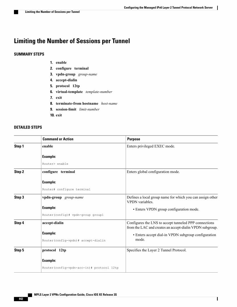
Limiting the Number of Sessions per Tunnel
SUMMARY STEPS
1. enable2. configure terminal3. vpdn-group group-name4. accept-dialin5. protocol 12tp6. virtual-template template-number7. exit8. terminate-from hostname host-name9. session-limit limit-number10. exit
DETAILED STEPS
PurposeCommand or Action
Enters privileged EXEC mode.enable
Example:
Router> enable
Step 1
Enters global configuration mode.configure terminal
Example:
Router# configure terminal
Step 2
Defines a local group name for which you can assign otherVPDN variables.
vpdn-group group-name
Example:
Router(config)# vpdn-group group1
Step 3
• Enters VPDN group configuration mode.
Configures the LNS to accept tunneled PPP connectionsfrom the LAC and creates an accept-dialin VPDN subgroup.
accept-dialin
Example:
Router(config-vpdn)# accept-dialin
Step 4
• Enters accept dial-in VPDN subgroup configurationmode.
Specifies the Layer 2 Tunnel Protocol.protocol 12tp
Example:
Router(config-vpdn-acc-in)# protocol 12tp
Step 5
MPLS Layer 2 VPNs Configuration Guide, Cisco IOS XE Release 3S442
Configuring the Managed IPv6 Layer 2 Tunnel Protocol Network ServerLimiting the Number of Sessions per Tunnel
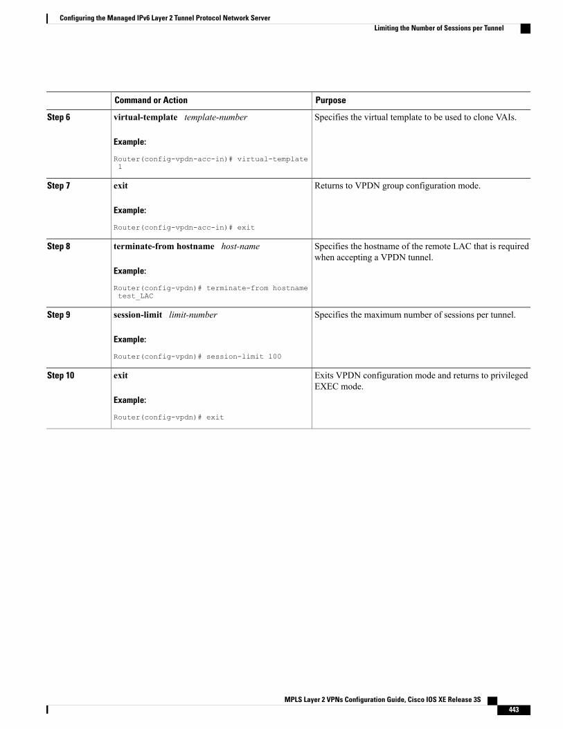
PurposeCommand or Action
Specifies the virtual template to be used to clone VAIs.virtual-template template-number
Example:
Router(config-vpdn-acc-in)# virtual-template1
Step 6
Returns to VPDN group configuration mode.exit
Example:
Router(config-vpdn-acc-in)# exit
Step 7
Specifies the hostname of the remote LAC that is requiredwhen accepting a VPDN tunnel.
terminate-from hostname host-name
Example:
Router(config-vpdn)# terminate-from hostnametest_LAC
Step 8
Specifies the maximum number of sessions per tunnel.session-limit limit-number
Example:
Router(config-vpdn)# session-limit 100
Step 9
Exits VPDN configuration mode and returns to privilegedEXEC mode.
exit
Example:
Router(config-vpdn)# exit
Step 10
MPLS Layer 2 VPNs Configuration Guide, Cisco IOS XE Release 3S 443
Configuring the Managed IPv6 Layer 2 Tunnel Protocol Network ServerLimiting the Number of Sessions per Tunnel
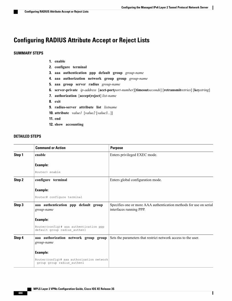
Configuring RADIUS Attribute Accept or Reject Lists
SUMMARY STEPS
1. enable2. configure terminal3. aaa authentication ppp default group group-name4. aaa authorization network group group group-name5. aaa group server radius group-name6. server-private ip-address [acct-portport-number][timeoutseconds] [retransmitretries] [keystring]7. authorization [accept|reject] list-name8. exit9. radius-server attribute list listname10. attribute value1 [value2 [value3...]]11. end12. show accounting
DETAILED STEPS
PurposeCommand or Action
Enters privileged EXEC mode.enable
Example:
Router> enable
Step 1
Enters global configuration mode.configure terminal
Example:
Router# configure terminal
Step 2
Specifies one or more AAA authentication methods for use on serialinterfaces running PPP.
aaa authentication ppp default groupgroup-name
Example:
Router(config)# aaa authentication pppdefault group radius_authen1
Step 3
Sets the parameters that restrict network access to the user.aaa authorization network group groupgroup-name
Step 4
Example:
Router(config)# aaa authorization networkgroup group radius_authen1
MPLS Layer 2 VPNs Configuration Guide, Cisco IOS XE Release 3S444
Configuring the Managed IPv6 Layer 2 Tunnel Protocol Network ServerConfiguring RADIUS Attribute Accept or Reject Lists
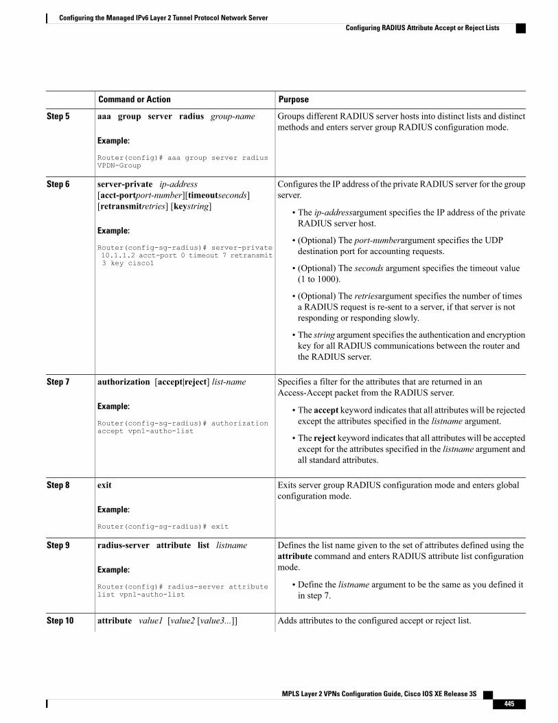
PurposeCommand or Action
Groups different RADIUS server hosts into distinct lists and distinctmethods and enters server group RADIUS configuration mode.
aaa group server radius group-name
Example:
Router(config)# aaa group server radiusVPDN-Group
Step 5
Configures the IP address of the private RADIUS server for the groupserver.
server-private ip-address[acct-portport-number][timeoutseconds][retransmitretries] [keystring]
Step 6
• The ip-addressargument specifies the IP address of the privateRADIUS server host.
Example:
Router(config-sg-radius)# server-private• (Optional) The port-numberargument specifies the UDPdestination port for accounting requests.10.1.1.2 acct-port 0 timeout 7 retransmit
3 key cisco1 • (Optional) The seconds argument specifies the timeout value(1 to 1000).
• (Optional) The retriesargument specifies the number of timesa RADIUS request is re-sent to a server, if that server is notresponding or responding slowly.
• The string argument specifies the authentication and encryptionkey for all RADIUS communications between the router andthe RADIUS server.
Specifies a filter for the attributes that are returned in anAccess-Accept packet from the RADIUS server.
authorization [accept|reject] list-name
Example:
Router(config-sg-radius)# authorizationaccept vpn1-autho-list
Step 7
• The accept keyword indicates that all attributes will be rejectedexcept the attributes specified in the listname argument.
• The reject keyword indicates that all attributes will be acceptedexcept for the attributes specified in the listname argument andall standard attributes.
Exits server group RADIUS configuration mode and enters globalconfiguration mode.
exit
Example:
Router(config-sg-radius)# exit
Step 8
Defines the list name given to the set of attributes defined using theattribute command and enters RADIUS attribute list configurationmode.
radius-server attribute list listname
Example:
Router(config)# radius-server attributelist vpn1-autho-list
Step 9
• Define the listname argument to be the same as you defined itin step 7.
Adds attributes to the configured accept or reject list.attribute value1 [value2 [value3...]]Step 10
MPLS Layer 2 VPNs Configuration Guide, Cisco IOS XE Release 3S 445
Configuring the Managed IPv6 Layer 2 Tunnel Protocol Network ServerConfiguring RADIUS Attribute Accept or Reject Lists
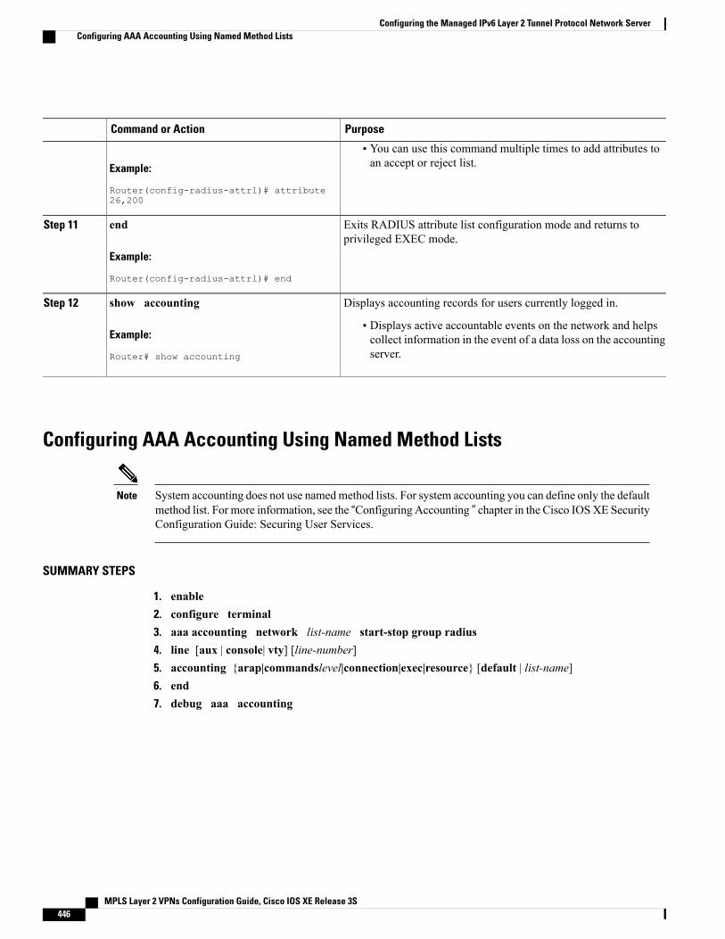
PurposeCommand or Action
Example:
Router(config-radius-attrl)# attribute26,200
• You can use this command multiple times to add attributes toan accept or reject list.
Exits RADIUS attribute list configuration mode and returns toprivileged EXEC mode.
end
Example:
Router(config-radius-attrl)# end
Step 11
Displays accounting records for users currently logged in.show accountingStep 12
Example:
Router# show accounting
• Displays active accountable events on the network and helpscollect information in the event of a data loss on the accountingserver.
Configuring AAA Accounting Using Named Method Lists
System accounting does not use namedmethod lists. For system accounting you can define only the defaultmethod list. For more information, see the “Configuring Accounting ” chapter in the Cisco IOSXE SecurityConfiguration Guide: Securing User Services.
Note
SUMMARY STEPS
1. enable2. configure terminal3. aaa accounting network list-name start-stop group radius4. line [aux | console| vty] [line-number]5. accounting {arap|commandslevel|connection|exec|resource} [default | list-name]6. end7. debug aaa accounting
MPLS Layer 2 VPNs Configuration Guide, Cisco IOS XE Release 3S446
Configuring the Managed IPv6 Layer 2 Tunnel Protocol Network ServerConfiguring AAA Accounting Using Named Method Lists
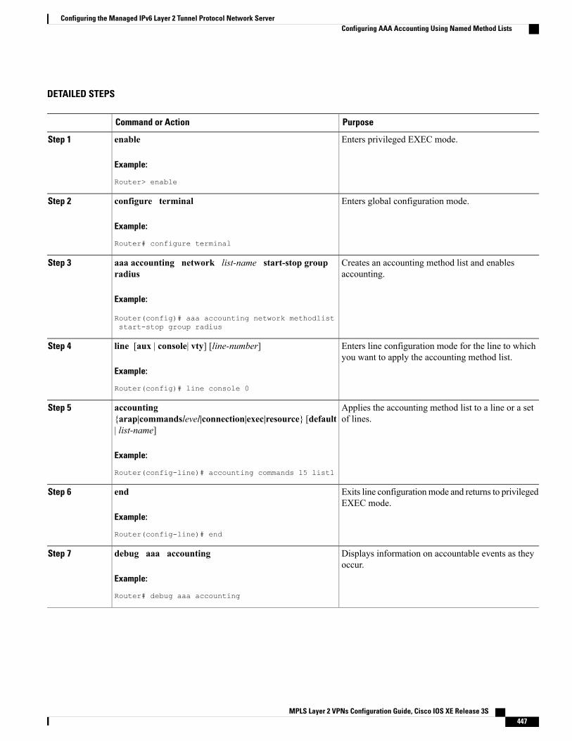
DETAILED STEPS
PurposeCommand or Action
Enters privileged EXEC mode.enable
Example:
Router> enable
Step 1
Enters global configuration mode.configure terminal
Example:
Router# configure terminal
Step 2
Creates an accounting method list and enablesaccounting.
aaa accounting network list-name start-stop groupradius
Example:
Router(config)# aaa accounting network methodliststart-stop group radius
Step 3
Enters line configuration mode for the line to whichyou want to apply the accounting method list.
line [aux | console| vty] [line-number]
Example:
Router(config)# line console 0
Step 4
Applies the accounting method list to a line or a setof lines.
accounting{arap|commandslevel|connection|exec|resource} [default| list-name]
Step 5
Example:
Router(config-line)# accounting commands 15 list1
Exits line configurationmode and returns to privilegedEXEC mode.
end
Example:
Router(config-line)# end
Step 6
Displays information on accountable events as theyoccur.
debug aaa accounting
Example:
Router# debug aaa accounting
Step 7
MPLS Layer 2 VPNs Configuration Guide, Cisco IOS XE Release 3S 447
Configuring the Managed IPv6 Layer 2 Tunnel Protocol Network ServerConfiguring AAA Accounting Using Named Method Lists
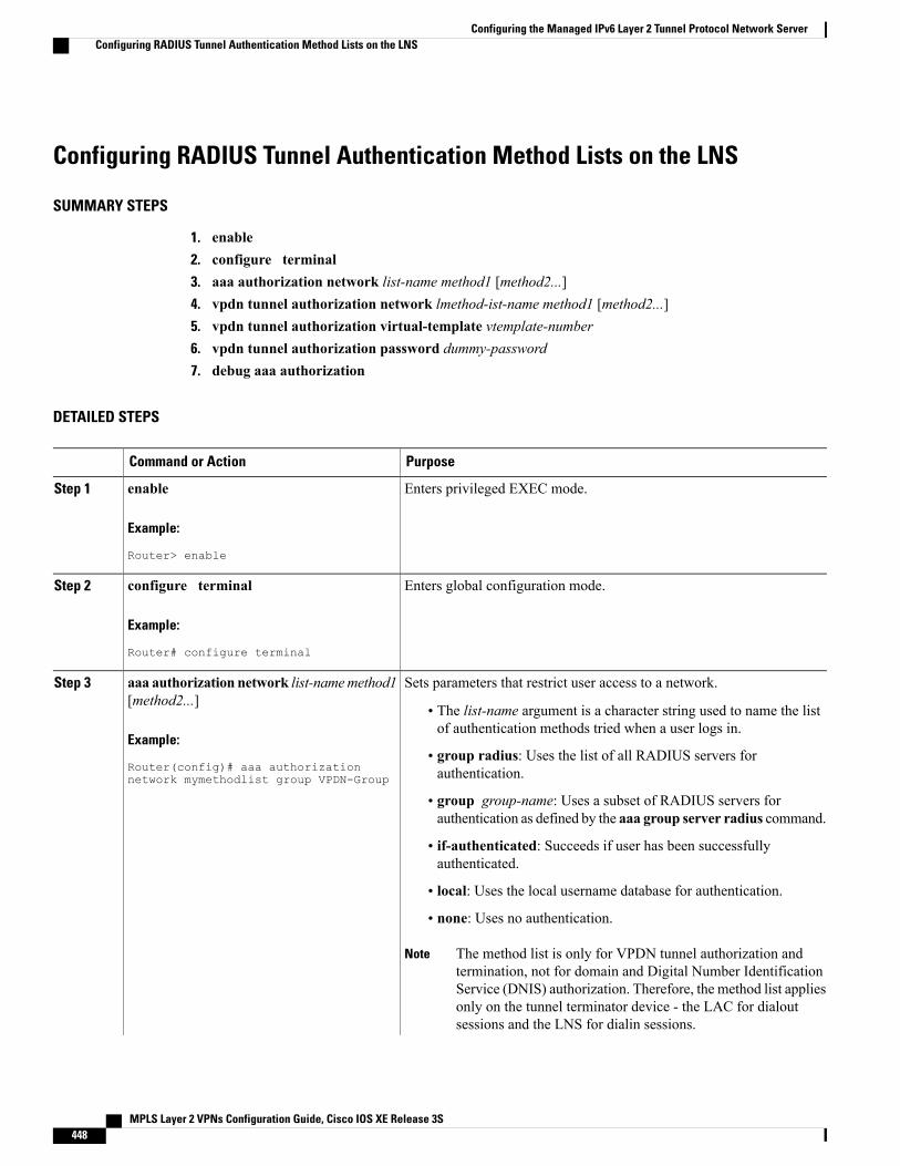
Configuring RADIUS Tunnel Authentication Method Lists on the LNS
SUMMARY STEPS
1. enable2. configure terminal3. aaa authorization network list-name method1 [method2...]4. vpdn tunnel authorization network lmethod-ist-name method1 [method2...]5. vpdn tunnel authorization virtual-template vtemplate-number6. vpdn tunnel authorization password dummy-password7. debug aaa authorization
DETAILED STEPS
PurposeCommand or Action
Enters privileged EXEC mode.enable
Example:
Router> enable
Step 1
Enters global configuration mode.configure terminal
Example:
Router# configure terminal
Step 2
Sets parameters that restrict user access to a network.aaa authorization network list-namemethod1[method2...]
Step 3
• The list-name argument is a character string used to name the listof authentication methods tried when a user logs in.
Example:
Router(config)# aaa authorizationnetwork mymethodlist group VPDN-Group
• group radius: Uses the list of all RADIUS servers forauthentication.
• group group-name: Uses a subset of RADIUS servers forauthentication as defined by the aaa group server radius command.
• if-authenticated: Succeeds if user has been successfullyauthenticated.
• local: Uses the local username database for authentication.
• none: Uses no authentication.
The method list is only for VPDN tunnel authorization andtermination, not for domain and Digital Number IdentificationService (DNIS) authorization. Therefore, the method list appliesonly on the tunnel terminator device - the LAC for dialoutsessions and the LNS for dialin sessions.
Note
MPLS Layer 2 VPNs Configuration Guide, Cisco IOS XE Release 3S448
Configuring the Managed IPv6 Layer 2 Tunnel Protocol Network ServerConfiguring RADIUS Tunnel Authentication Method Lists on the LNS
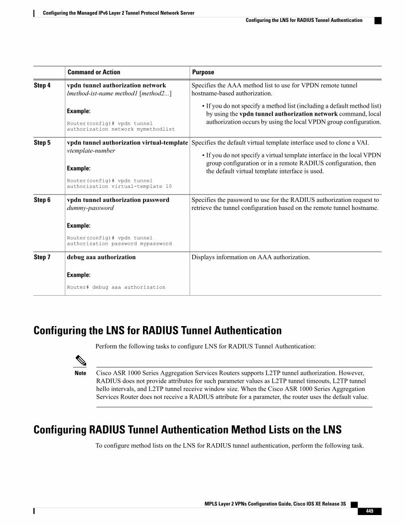
PurposeCommand or Action
Specifies the AAA method list to use for VPDN remote tunnelhostname-based authorization.
vpdn tunnel authorization networklmethod-ist-name method1 [method2...]
Step 4
Example:
Router(config)# vpdn tunnelauthorization network mymethodlist
• If you do not specify a method list (including a default method list)by using the vpdn tunnel authorization network command, localauthorization occurs by using the local VPDN group configuration.
Specifies the default virtual template interface used to clone a VAI.vpdn tunnel authorization virtual-templatevtemplate-number
Step 5
• If you do not specify a virtual template interface in the local VPDNgroup configuration or in a remote RADIUS configuration, thenthe default virtual template interface is used.Example:
Router(config)# vpdn tunnelauthorization virtual-template 10
Specifies the password to use for the RADIUS authorization request toretrieve the tunnel configuration based on the remote tunnel hostname.
vpdn tunnel authorization passworddummy-password
Example:
Router(config)# vpdn tunnelauthorization password mypassword
Step 6
Displays information on AAA authorization.debug aaa authorization
Example:
Router# debug aaa authorization
Step 7
Configuring the LNS for RADIUS Tunnel AuthenticationPerform the following tasks to configure LNS for RADIUS Tunnel Authentication:
Cisco ASR 1000 Series Aggregation Services Routers supports L2TP tunnel authorization. However,RADIUS does not provide attributes for such parameter values as L2TP tunnel timeouts, L2TP tunnelhello intervals, and L2TP tunnel receive window size. When the Cisco ASR 1000 Series AggregationServices Router does not receive a RADIUS attribute for a parameter, the router uses the default value.
Note
Configuring RADIUS Tunnel Authentication Method Lists on the LNSTo configure method lists on the LNS for RADIUS tunnel authentication, perform the following task.
MPLS Layer 2 VPNs Configuration Guide, Cisco IOS XE Release 3S 449
Configuring the Managed IPv6 Layer 2 Tunnel Protocol Network ServerConfiguring the LNS for RADIUS Tunnel Authentication
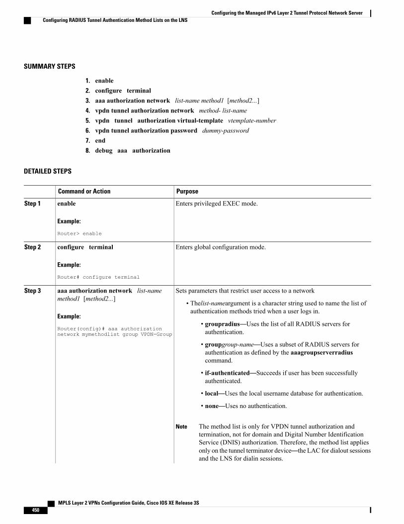
SUMMARY STEPS
1. enable2. configure terminal3. aaa authorization network list-name method1 [method2...]4. vpdn tunnel authorization network method- list-name5. vpdn tunnel authorization virtual-template vtemplate-number6. vpdn tunnel authorization password dummy-password7. end8. debug aaa authorization
DETAILED STEPS
PurposeCommand or Action
Enters privileged EXEC mode.enable
Example:
Router> enable
Step 1
Enters global configuration mode.configure terminal
Example:
Router# configure terminal
Step 2
Sets parameters that restrict user access to a networkaaa authorization network list-namemethod1 [method2...]
Step 3
• Thelist-nameargument is a character string used to name the list ofauthentication methods tried when a user logs in.
Example:
Router(config)# aaa authorizationnetwork mymethodlist group VPDN-Group
• groupradius—Uses the list of all RADIUS servers forauthentication.
• groupgroup-name—Uses a subset of RADIUS servers forauthentication as defined by the aaagroupserverradiuscommand.
• if-authenticated—Succeeds if user has been successfullyauthenticated.
• local—Uses the local username database for authentication.
• none—Uses no authentication.
The method list is only for VPDN tunnel authorization andtermination, not for domain and Digital Number IdentificationService (DNIS) authorization. Therefore, the method list appliesonly on the tunnel terminator device—the LAC for dialout sessionsand the LNS for dialin sessions.
Note
MPLS Layer 2 VPNs Configuration Guide, Cisco IOS XE Release 3S450
Configuring the Managed IPv6 Layer 2 Tunnel Protocol Network ServerConfiguring RADIUS Tunnel Authentication Method Lists on the LNS
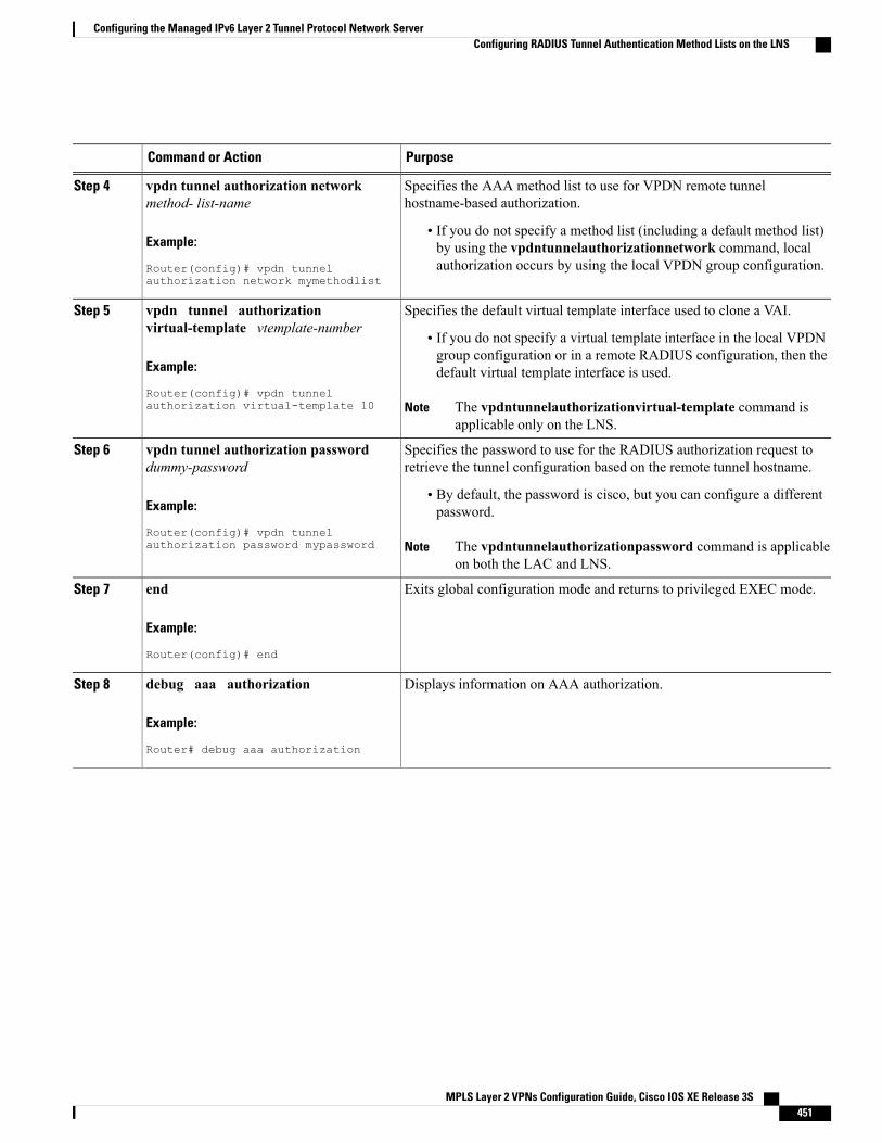
PurposeCommand or Action
Specifies the AAA method list to use for VPDN remote tunnelhostname-based authorization.
vpdn tunnel authorization networkmethod- list-name
Step 4
Example:
Router(config)# vpdn tunnelauthorization network mymethodlist
• If you do not specify a method list (including a default method list)by using the vpdntunnelauthorizationnetwork command, localauthorization occurs by using the local VPDN group configuration.
Specifies the default virtual template interface used to clone a VAI.vpdn tunnel authorizationvirtual-template vtemplate-number
Step 5
• If you do not specify a virtual template interface in the local VPDNgroup configuration or in a remote RADIUS configuration, then thedefault virtual template interface is used.Example:
Router(config)# vpdn tunnelauthorization virtual-template 10 The vpdntunnelauthorizationvirtual-template command is
applicable only on the LNS.Note
Specifies the password to use for the RADIUS authorization request toretrieve the tunnel configuration based on the remote tunnel hostname.
vpdn tunnel authorization passworddummy-password
Step 6
Example:
Router(config)# vpdn tunnelauthorization password mypassword
• By default, the password is cisco, but you can configure a differentpassword.
The vpdntunnelauthorizationpassword command is applicableon both the LAC and LNS.
Note
Exits global configuration mode and returns to privileged EXEC mode.end
Example:
Router(config)# end
Step 7
Displays information on AAA authorization.debug aaa authorization
Example:
Router# debug aaa authorization
Step 8
MPLS Layer 2 VPNs Configuration Guide, Cisco IOS XE Release 3S 451
Configuring the Managed IPv6 Layer 2 Tunnel Protocol Network ServerConfiguring RADIUS Tunnel Authentication Method Lists on the LNS
Configuring AAA Authentication Methods
SUMMARY STEPS
1. enable2. configure terminal3. aaa new-model4. Configure RADIUS security protocol parameters. For more information about RADIUS, see the
“Configuring RADIUS” chapter in the Cisco IOSXE Security Configuration Guide: Securing User Services.
5. aaa authentication6. Apply the authentication method lists to an interface, a line, or a set of lines as required. For more
information about authentication method lists, see the “Configuring Authentication” chapter in the CiscoIOS XE Security Configuration Guide: Securing User Services .
7. end
DETAILED STEPS
Step 1 enableStep 2 configure terminalStep 3 aaa new-model
Enter this command in global configuration mode to enable AAA.
Step 4 Configure RADIUS security protocol parameters. For more information about RADIUS, see the “Configuring RADIUS”chapter in the Cisco IOS XE Security Configuration Guide: Securing User Services .
Step 5 aaa authenticationEnter this command to define the authentication method lists.
Step 6 Apply the authentication method lists to an interface, a line, or a set of lines as required. For more information aboutauthentication method lists, see the “Configuring Authentication” chapter in the Cisco IOS XE Security ConfigurationGuide: Securing User Services .
Step 7 end
Configuration Examples for the Managed IPv6 Layer 2 TunnelProtocol Network Server
Example Managed IPv6 LNS ConfigurationThe following example shows how to configure Managed IPv6 LNS features on the router. In this example,the router terminates the tunnel from the LAC and associates the VRFs with the interfaces and the virtual
MPLS Layer 2 VPNs Configuration Guide, Cisco IOS XE Release 3S452
Configuring the Managed IPv6 Layer 2 Tunnel Protocol Network ServerConfiguring AAA Authentication Methods
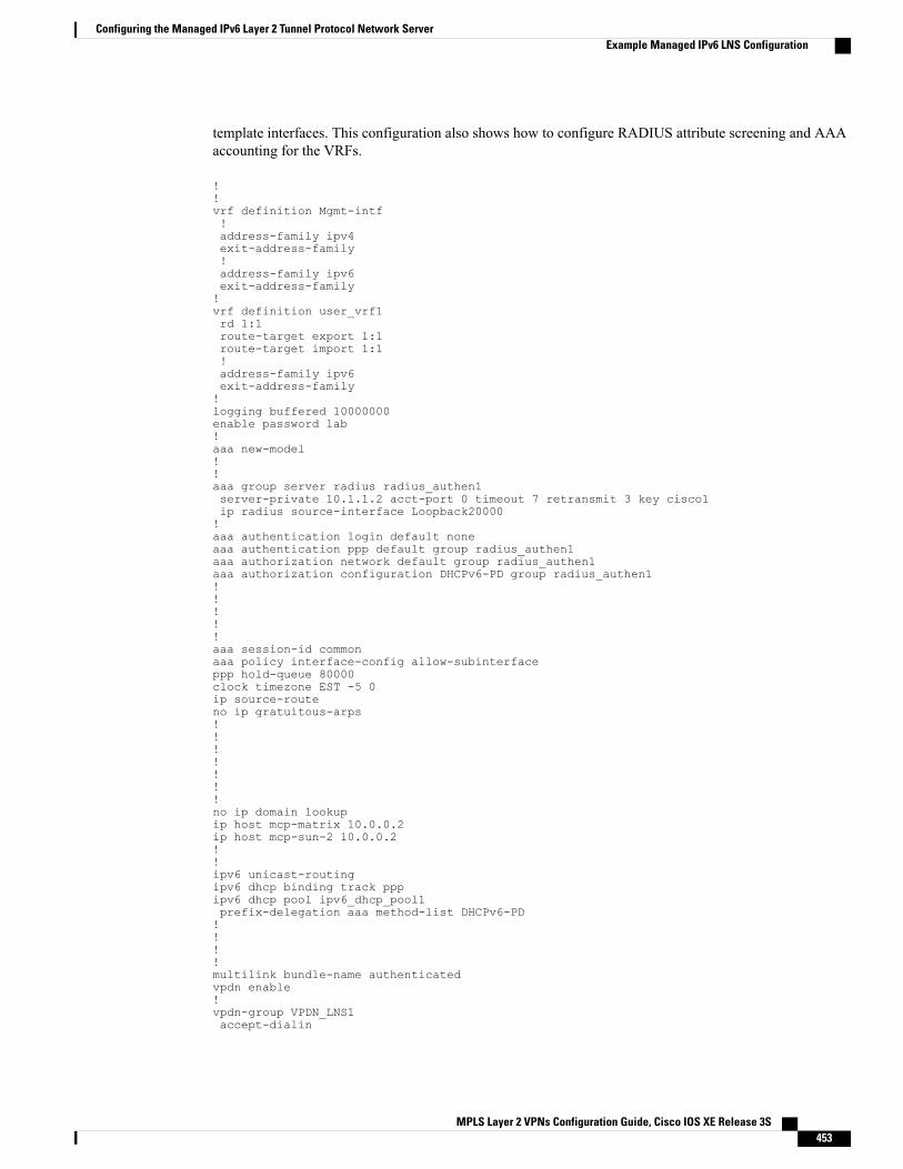
template interfaces. This configuration also shows how to configure RADIUS attribute screening and AAAaccounting for the VRFs.
!!vrf definition Mgmt-intf!address-family ipv4exit-address-family!address-family ipv6exit-address-family!vrf definition user_vrf1rd 1:1route-target export 1:1route-target import 1:1!address-family ipv6exit-address-family!logging buffered 10000000enable password lab!aaa new-model!!aaa group server radius radius_authen1server-private 10.1.1.2 acct-port 0 timeout 7 retransmit 3 key cisco1ip radius source-interface Loopback20000!aaa authentication login default noneaaa authentication ppp default group radius_authen1aaa authorization network default group radius_authen1aaa authorization configuration DHCPv6-PD group radius_authen1!!!!!aaa session-id commonaaa policy interface-config allow-subinterfaceppp hold-queue 80000clock timezone EST -5 0ip source-routeno ip gratuitous-arps!!!!!!!no ip domain lookupip host mcp-matrix 10.0.0.2ip host mcp-sun-2 10.0.0.2!!ipv6 unicast-routingipv6 dhcp binding track pppipv6 dhcp pool ipv6_dhcp_pool1prefix-delegation aaa method-list DHCPv6-PD!!!!multilink bundle-name authenticatedvpdn enable!vpdn-group VPDN_LNS1accept-dialin
MPLS Layer 2 VPNs Configuration Guide, Cisco IOS XE Release 3S 453
Configuring the Managed IPv6 Layer 2 Tunnel Protocol Network ServerExample Managed IPv6 LNS Configuration
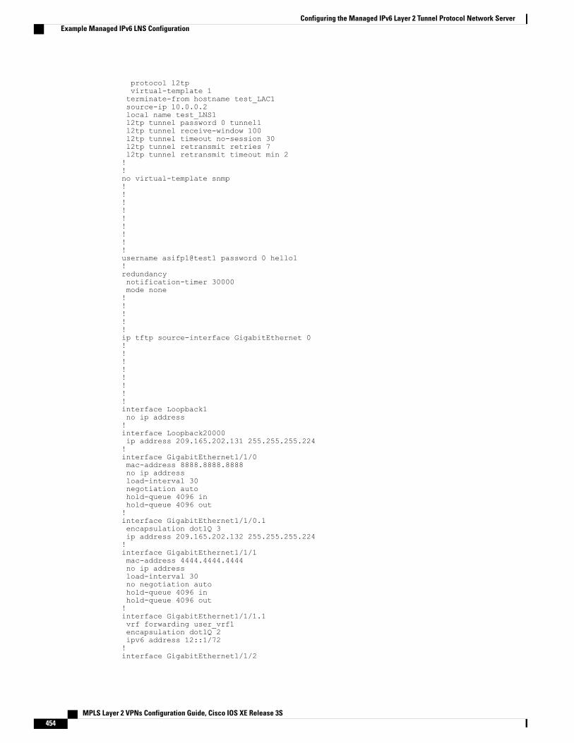
protocol l2tpvirtual-template 1terminate-from hostname test_LAC1source-ip 10.0.0.2local name test_LNS1l2tp tunnel password 0 tunnel1l2tp tunnel receive-window 100l2tp tunnel timeout no-session 30l2tp tunnel retransmit retries 7l2tp tunnel retransmit timeout min 2!!no virtual-template snmp!!!!!!!!!username asifp1@test1 password 0 hello1!redundancynotification-timer 30000mode none!!!!!ip tftp source-interface GigabitEthernet 0!!!!!!!!interface Loopback1no ip address!interface Loopback20000ip address 209.165.202.131 255.255.255.224!interface GigabitEthernet1/1/0mac-address 8888.8888.8888no ip addressload-interval 30negotiation autohold-queue 4096 inhold-queue 4096 out!interface GigabitEthernet1/1/0.1encapsulation dot1Q 3ip address 209.165.202.132 255.255.255.224!interface GigabitEthernet1/1/1mac-address 4444.4444.4444no ip addressload-interval 30no negotiation autohold-queue 4096 inhold-queue 4096 out!interface GigabitEthernet1/1/1.1vrf forwarding user_vrf1encapsulation dot1Q 2ipv6 address 12::1/72!interface GigabitEthernet1/1/2
MPLS Layer 2 VPNs Configuration Guide, Cisco IOS XE Release 3S454
Configuring the Managed IPv6 Layer 2 Tunnel Protocol Network ServerExample Managed IPv6 LNS Configuration
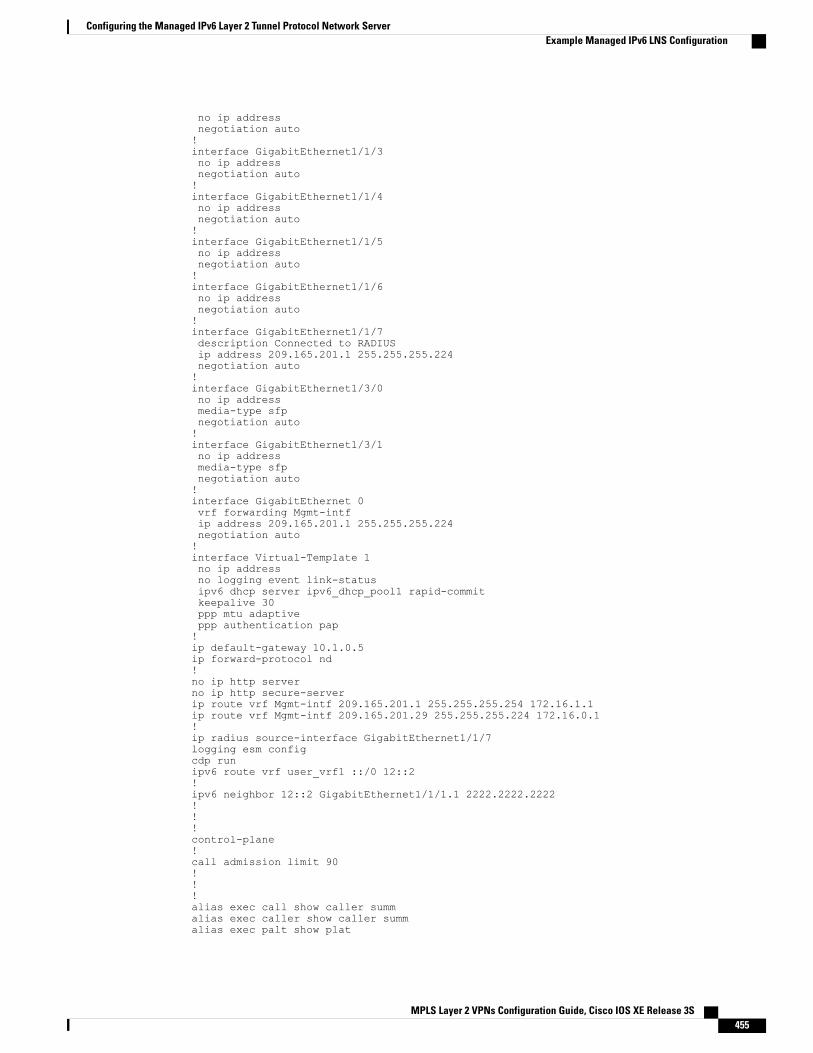
no ip addressnegotiation auto!interface GigabitEthernet1/1/3no ip addressnegotiation auto!interface GigabitEthernet1/1/4no ip addressnegotiation auto!interface GigabitEthernet1/1/5no ip addressnegotiation auto!interface GigabitEthernet1/1/6no ip addressnegotiation auto!interface GigabitEthernet1/1/7description Connected to RADIUSip address 209.165.201.1 255.255.255.224negotiation auto!interface GigabitEthernet1/3/0no ip addressmedia-type sfpnegotiation auto!interface GigabitEthernet1/3/1no ip addressmedia-type sfpnegotiation auto!interface GigabitEthernet 0vrf forwarding Mgmt-intfip address 209.165.201.1 255.255.255.224negotiation auto!interface Virtual-Template 1no ip addressno logging event link-statusipv6 dhcp server ipv6_dhcp_pool1 rapid-commitkeepalive 30ppp mtu adaptiveppp authentication pap!ip default-gateway 10.1.0.5ip forward-protocol nd!no ip http serverno ip http secure-serverip route vrf Mgmt-intf 209.165.201.1 255.255.255.254 172.16.1.1ip route vrf Mgmt-intf 209.165.201.29 255.255.255.224 172.16.0.1!ip radius source-interface GigabitEthernet1/1/7logging esm configcdp runipv6 route vrf user_vrf1 ::/0 12::2!ipv6 neighbor 12::2 GigabitEthernet1/1/1.1 2222.2222.2222!!!control-plane!call admission limit 90!!!alias exec call show caller summalias exec caller show caller summalias exec palt show plat
MPLS Layer 2 VPNs Configuration Guide, Cisco IOS XE Release 3S 455
Configuring the Managed IPv6 Layer 2 Tunnel Protocol Network ServerExample Managed IPv6 LNS Configuration
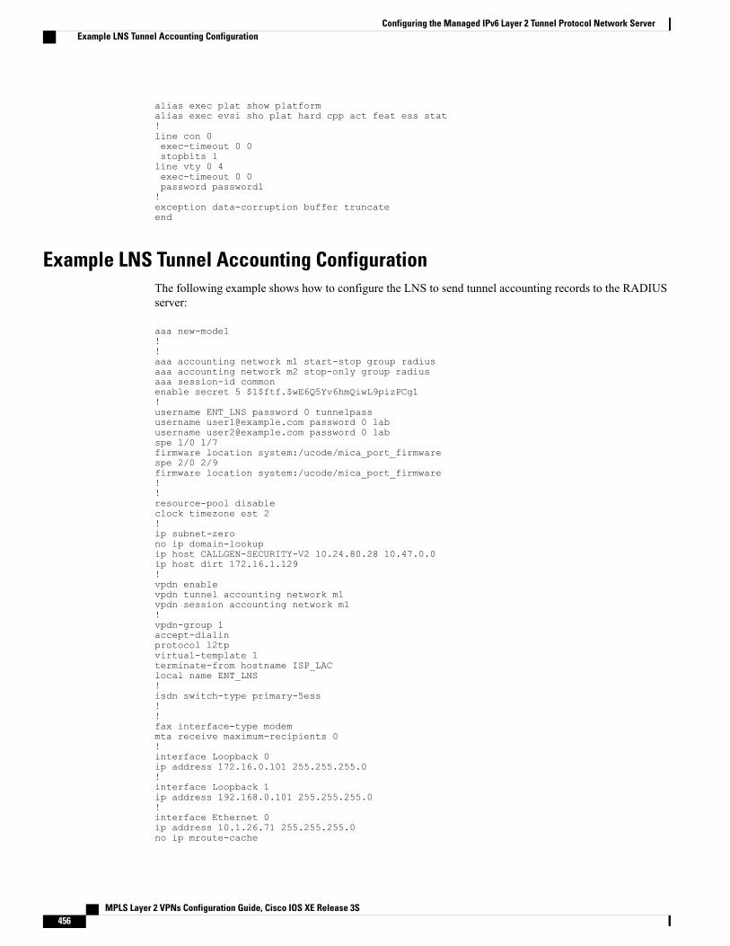
alias exec plat show platformalias exec evsi sho plat hard cpp act feat ess stat!line con 0exec-timeout 0 0stopbits 1line vty 0 4exec-timeout 0 0password password1!exception data-corruption buffer truncateend
Example LNS Tunnel Accounting ConfigurationThe following example shows how to configure the LNS to send tunnel accounting records to the RADIUSserver:
aaa new-model!!aaa accounting network m1 start-stop group radiusaaa accounting network m2 stop-only group radiusaaa session-id commonenable secret 5 $1$ftf.$wE6Q5Yv6hmQiwL9pizPCg1!username ENT_LNS password 0 tunnelpassusername [email protected] password 0 labusername [email protected] password 0 labspe 1/0 1/7firmware location system:/ucode/mica_port_firmwarespe 2/0 2/9firmware location system:/ucode/mica_port_firmware!!resource-pool disableclock timezone est 2!ip subnet-zerono ip domain-lookupip host CALLGEN-SECURITY-V2 10.24.80.28 10.47.0.0ip host dirt 172.16.1.129!vpdn enablevpdn tunnel accounting network m1vpdn session accounting network m1!vpdn-group 1accept-dialinprotocol l2tpvirtual-template 1terminate-from hostname ISP_LAClocal name ENT_LNS!isdn switch-type primary-5ess!!fax interface-type modemmta receive maximum-recipients 0!interface Loopback 0ip address 172.16.0.101 255.255.255.0!interface Loopback 1ip address 192.168.0.101 255.255.255.0!interface Ethernet 0ip address 10.1.26.71 255.255.255.0no ip mroute-cache
MPLS Layer 2 VPNs Configuration Guide, Cisco IOS XE Release 3S456
Configuring the Managed IPv6 Layer 2 Tunnel Protocol Network ServerExample LNS Tunnel Accounting Configuration
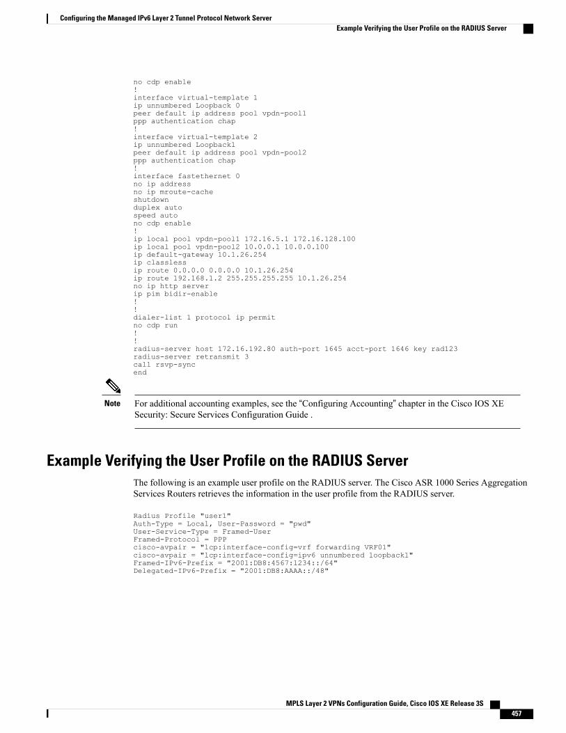
no cdp enable!interface virtual-template 1ip unnumbered Loopback 0peer default ip address pool vpdn-pool1ppp authentication chap!interface virtual-template 2ip unnumbered Loopback1peer default ip address pool vpdn-pool2ppp authentication chap!interface fastethernet 0no ip addressno ip mroute-cacheshutdownduplex autospeed autono cdp enable!ip local pool vpdn-pool1 172.16.5.1 172.16.128.100ip local pool vpdn-pool2 10.0.0.1 10.0.0.100ip default-gateway 10.1.26.254ip classlessip route 0.0.0.0 0.0.0.0 10.1.26.254ip route 192.168.1.2 255.255.255.255 10.1.26.254no ip http serverip pim bidir-enable!!dialer-list 1 protocol ip permitno cdp run!!radius-server host 172.16.192.80 auth-port 1645 acct-port 1646 key rad123radius-server retransmit 3call rsvp-syncend
For additional accounting examples, see the “Configuring Accounting” chapter in the Cisco IOS XESecurity: Secure Services Configuration Guide .
Note
Example Verifying the User Profile on the RADIUS ServerThe following is an example user profile on the RADIUS server. The Cisco ASR 1000 Series AggregationServices Routers retrieves the information in the user profile from the RADIUS server.
Radius Profile "user1"Auth-Type = Local, User-Password = "pwd"User-Service-Type = Framed-UserFramed-Protocol = PPPcisco-avpair = "lcp:interface-config=vrf forwarding VRF01"cisco-avpair = "lcp:interface-config=ipv6 unnumbered loopback1"Framed-IPv6-Prefix = "2001:DB8:4567:1234::/64"Delegated-IPv6-Prefix = "2001:DB8:AAAA::/48"
MPLS Layer 2 VPNs Configuration Guide, Cisco IOS XE Release 3S 457
Configuring the Managed IPv6 Layer 2 Tunnel Protocol Network ServerExample Verifying the User Profile on the RADIUS Server
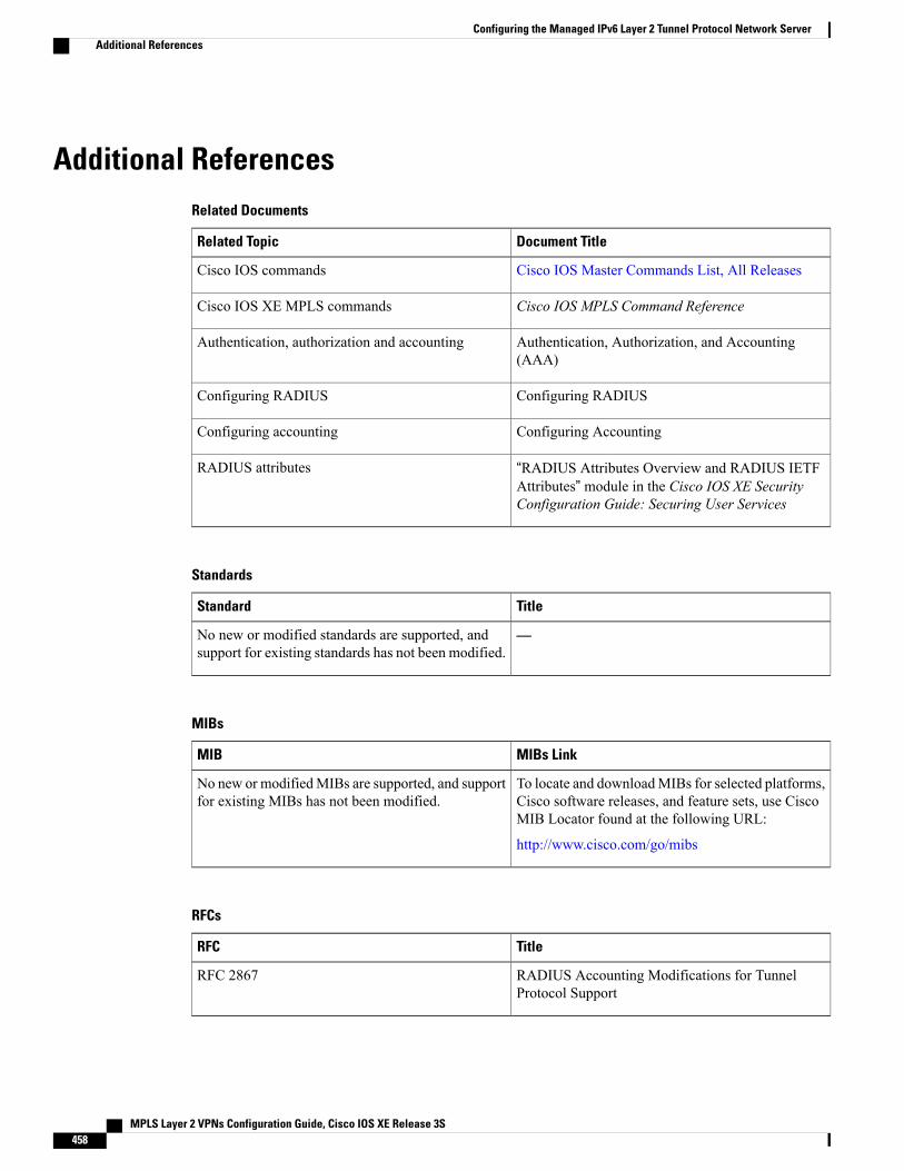
Additional ReferencesRelated Documents
Document TitleRelated Topic
Cisco IOS Master Commands List, All ReleasesCisco IOS commands
Cisco IOS MPLS Command ReferenceCisco IOS XE MPLS commands
Authentication, Authorization, and Accounting(AAA)
Authentication, authorization and accounting
Configuring RADIUSConfiguring RADIUS
Configuring AccountingConfiguring accounting
“RADIUS Attributes Overview and RADIUS IETFAttributes” module in the Cisco IOS XE SecurityConfiguration Guide: Securing User Services
RADIUS attributes
Standards
TitleStandard
—No new or modified standards are supported, andsupport for existing standards has not been modified.
MIBs
MIBs LinkMIB
To locate and downloadMIBs for selected platforms,Cisco software releases, and feature sets, use CiscoMIB Locator found at the following URL:
http://www.cisco.com/go/mibs
No new or modifiedMIBs are supported, and supportfor existing MIBs has not been modified.
RFCs
TitleRFC
RADIUS Accounting Modifications for TunnelProtocol Support
RFC 2867
MPLS Layer 2 VPNs Configuration Guide, Cisco IOS XE Release 3S458
Configuring the Managed IPv6 Layer 2 Tunnel Protocol Network ServerAdditional References
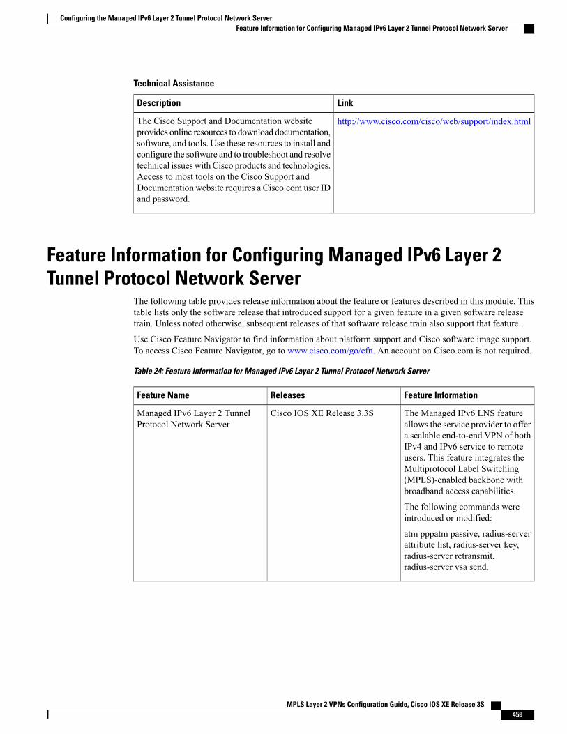
Technical Assistance
LinkDescription
http://www.cisco.com/cisco/web/support/index.htmlThe Cisco Support and Documentation websiteprovides online resources to download documentation,software, and tools. Use these resources to install andconfigure the software and to troubleshoot and resolvetechnical issues with Cisco products and technologies.Access to most tools on the Cisco Support andDocumentation website requires a Cisco.com user IDand password.
Feature Information for Configuring Managed IPv6 Layer 2Tunnel Protocol Network Server
The following table provides release information about the feature or features described in this module. Thistable lists only the software release that introduced support for a given feature in a given software releasetrain. Unless noted otherwise, subsequent releases of that software release train also support that feature.
Use Cisco Feature Navigator to find information about platform support and Cisco software image support.To access Cisco Feature Navigator, go to www.cisco.com/go/cfn. An account on Cisco.com is not required.
Table 24: Feature Information for Managed IPv6 Layer 2 Tunnel Protocol Network Server
Feature InformationReleasesFeature Name
The Managed IPv6 LNS featureallows the service provider to offera scalable end-to-end VPN of bothIPv4 and IPv6 service to remoteusers. This feature integrates theMultiprotocol Label Switching(MPLS)-enabled backbone withbroadband access capabilities.
The following commands wereintroduced or modified:
atm pppatm passive, radius-serverattribute list, radius-server key,radius-server retransmit,radius-server vsa send.
Cisco IOS XE Release 3.3SManaged IPv6 Layer 2 TunnelProtocol Network Server
MPLS Layer 2 VPNs Configuration Guide, Cisco IOS XE Release 3S 459
Configuring the Managed IPv6 Layer 2 Tunnel Protocol Network ServerFeature Information for Configuring Managed IPv6 Layer 2 Tunnel Protocol Network Server
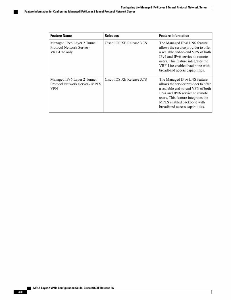
Feature InformationReleasesFeature Name
The Managed IPv6 LNS featureallows the service provider to offera scalable end-to-end VPN of bothIPv4 and IPv6 service to remoteusers. This feature integrates theVRF-Lite enabled backbone withbroadband access capabilities.
Cisco IOS XE Release 3.3SManaged IPv6 Layer 2 TunnelProtocol Network Server -VRF-Lite only
The Managed IPv6 LNS featureallows the service provider to offera scalable end-to-end VPN of bothIPv4 and IPv6 service to remoteusers. This feature integrates theMPLS enabled backbone withbroadband access capabilities.
Cisco IOS XE Release 3.7SManaged IPv6 Layer 2 TunnelProtocol Network Server - MPLSVPN
MPLS Layer 2 VPNs Configuration Guide, Cisco IOS XE Release 3S460
Configuring the Managed IPv6 Layer 2 Tunnel Protocol Network ServerFeature Information for Configuring Managed IPv6 Layer 2 Tunnel Protocol Network Server

C H A P T E R 12L2VPN Pseudowire Redundancy
The L2VPN Pseudowire Redundancy feature lets you configure your network to detect a failure in thenetwork and reroute the Layer 2 (L2) service to another endpoint that can continue to provide service. Thisfeature provides the ability to recover from a failure either of the remote provider edge (PE) router or of thelink between the PE and customer edge (CE) routers.
• Finding Feature Information, page 461
• Prerequisites for L2VPN Pseudowire Redundancy, page 462
• Restrictions for L2VPN Pseudowire Redundancy, page 462
• Information About L2VPN Pseudowire Redundancy, page 463
• How to Configure L2VPN Pseudowire Redundancy, page 464
• Configuration Examples for L2VPN Pseudowire Redundancy, page 476
• Configuration Examples for L2VPN Pseudowire Redundancy using the commands associated with theL2VPN Protocol-Based CLIs feature, page 478
• Additional References, page 482
• Feature Information for L2VPN Pseudowire Redundancy, page 483
Finding Feature InformationYour software release may not support all the features documented in this module. For the latest caveats andfeature information, see Bug Search Tool and the release notes for your platform and software release. Tofind information about the features documented in this module, and to see a list of the releases in which eachfeature is supported, see the feature information table at the end of this module.
Use Cisco Feature Navigator to find information about platform support and Cisco software image support.To access Cisco Feature Navigator, go to www.cisco.com/go/cfn. An account on Cisco.com is not required.
MPLS Layer 2 VPNs Configuration Guide, Cisco IOS XE Release 3S 461
Prerequisites for L2VPN Pseudowire Redundancy• This feature module requires that you understand how to configure basic L2 virtual private networks(VPNs).
• Any Transport over MPLS
• L2 VPN Interworking
• Layer 2 Tunneling Protocol Version 3 (L2TPv3)
• The L2VPN Pseudowire Redundancy feature requires that the following mechanisms be in place toenable you to detect a failure in the network:
• Label-switched paths (LSP) Ping/Traceroute and Any Transport over MPLS Virtual CircuitConnection Verification (AToM VCCV)
• Local Management Interface (LMI)
• Operation, Administration, and Maintenance (OAM)
Restrictions for L2VPN Pseudowire Redundancy• The default Label Distribution Protocol (LDP) session hold-down timer will enable the software to detectfailures in about 180 seconds. That time can be configured so that the software can detect failures morequickly. See thempls ldp holdtime command for more information.
• L2VPN Pseudowire Redundancy does not support pseudowire interworking mode with L2TPv3. Theconnectivity between CEs may be impacted if you have interworking IP configured in the pseudowireclass.
• The primary and backup pseudowires must run the same type of transport service. The primary andbackup pseudowires must be configured with AToM or L2TPv3.
• The backup peer can only be configured for nonstatic L2TPv3 sessions. The backup L2TPv3 sessioncannot be static L2TPv3 session. The encapsulation type of primary and backup pseudowire must bethe same.
• If you use L2VPN Pseudowire Redundancy with L2VPN Interworking, the interworking method mustbe the same for the primary and backup pseudowires.
• L2VPN Pseudowire Redundancy does support setting the experimental (EXP) bit on the MultiprotocolLabel Switching (MPLS) pseudowire.
• L2VPN Pseudowire Redundancy does not support different pseudowire encapsulation types on theMPLS pseudowire.
• Thempls l2transport route command is not supported. Use the xconnect command instead.
• The ability to have the backup pseudowire fully operational at the same time that the primary pseudowireis operational is not supported. The backup pseudowire becomes active only after the primary pseudowirefails.
• The AToM VCCV feature is supported only on the active pseudowire.
MPLS Layer 2 VPNs Configuration Guide, Cisco IOS XE Release 3S462
L2VPN Pseudowire RedundancyPrerequisites for L2VPN Pseudowire Redundancy
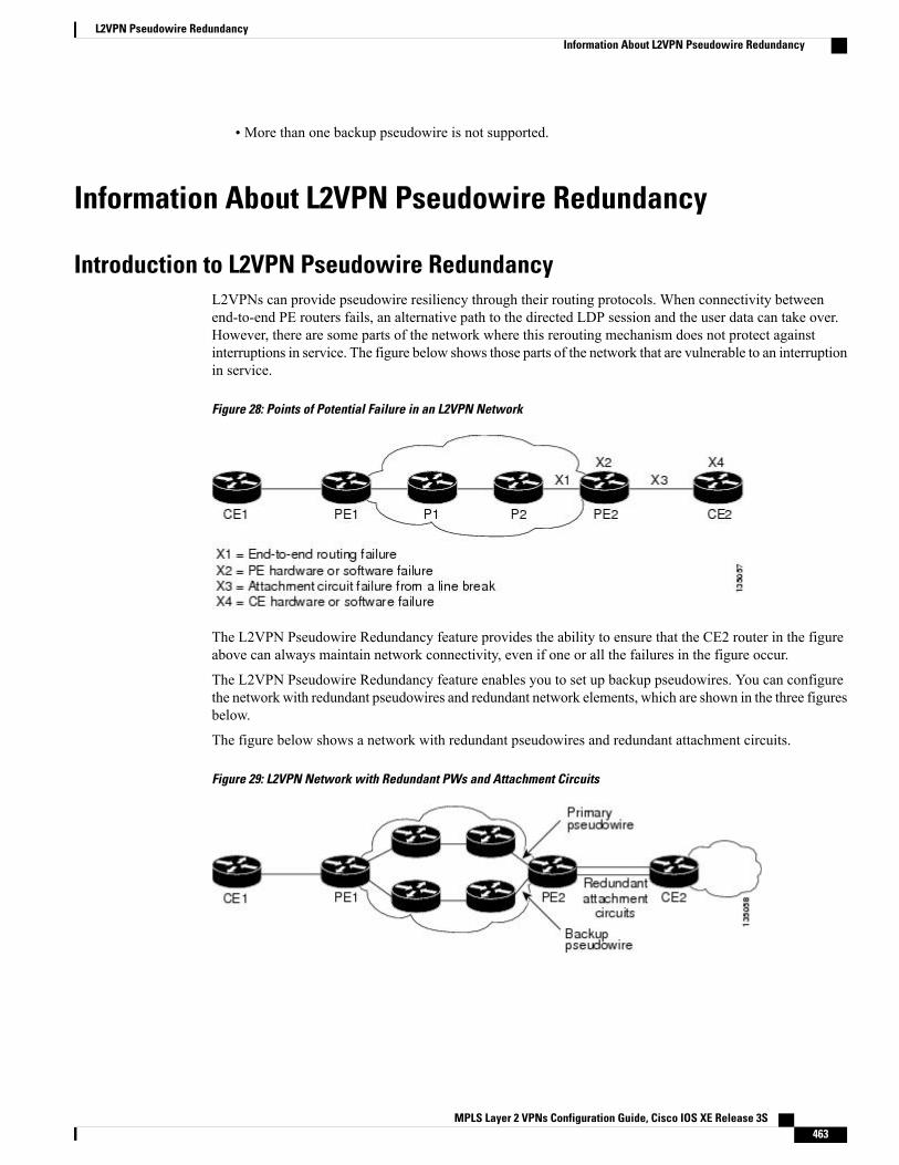
• More than one backup pseudowire is not supported.
Information About L2VPN Pseudowire Redundancy
Introduction to L2VPN Pseudowire RedundancyL2VPNs can provide pseudowire resiliency through their routing protocols. When connectivity betweenend-to-end PE routers fails, an alternative path to the directed LDP session and the user data can take over.However, there are some parts of the network where this rerouting mechanism does not protect againstinterruptions in service. The figure below shows those parts of the network that are vulnerable to an interruptionin service.
Figure 28: Points of Potential Failure in an L2VPN Network
The L2VPN Pseudowire Redundancy feature provides the ability to ensure that the CE2 router in the figureabove can always maintain network connectivity, even if one or all the failures in the figure occur.
The L2VPN Pseudowire Redundancy feature enables you to set up backup pseudowires. You can configurethe network with redundant pseudowires and redundant network elements, which are shown in the three figuresbelow.
The figure below shows a network with redundant pseudowires and redundant attachment circuits.
Figure 29: L2VPN Network with Redundant PWs and Attachment Circuits
MPLS Layer 2 VPNs Configuration Guide, Cisco IOS XE Release 3S 463
L2VPN Pseudowire RedundancyInformation About L2VPN Pseudowire Redundancy
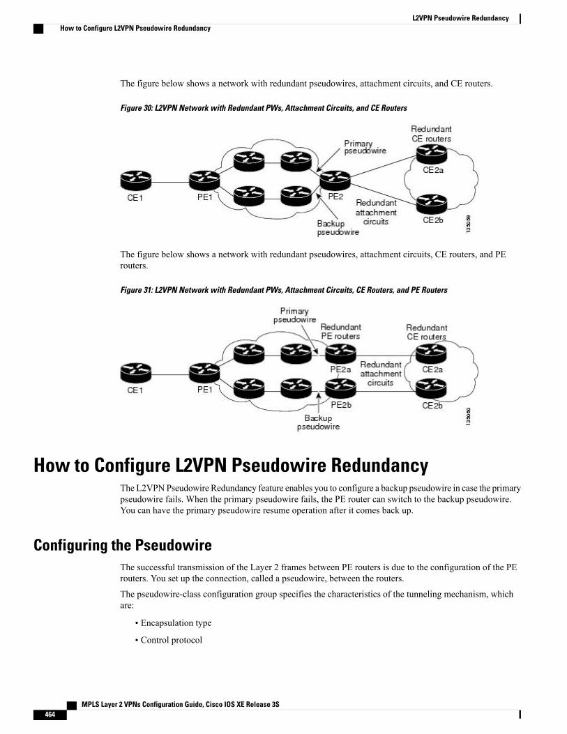
The figure below shows a network with redundant pseudowires, attachment circuits, and CE routers.
Figure 30: L2VPN Network with Redundant PWs, Attachment Circuits, and CE Routers
The figure below shows a network with redundant pseudowires, attachment circuits, CE routers, and PErouters.
Figure 31: L2VPN Network with Redundant PWs, Attachment Circuits, CE Routers, and PE Routers
How to Configure L2VPN Pseudowire RedundancyThe L2VPNPseudowire Redundancy feature enables you to configure a backup pseudowire in case the primarypseudowire fails. When the primary pseudowire fails, the PE router can switch to the backup pseudowire.You can have the primary pseudowire resume operation after it comes back up.
Configuring the PseudowireThe successful transmission of the Layer 2 frames between PE routers is due to the configuration of the PErouters. You set up the connection, called a pseudowire, between the routers.
The pseudowire-class configuration group specifies the characteristics of the tunneling mechanism, whichare:
• Encapsulation type
• Control protocol
MPLS Layer 2 VPNs Configuration Guide, Cisco IOS XE Release 3S464
L2VPN Pseudowire RedundancyHow to Configure L2VPN Pseudowire Redundancy
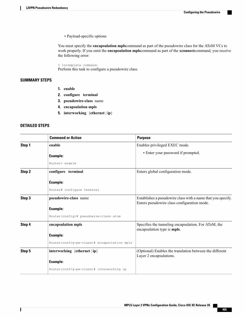
• Payload-specific options
You must specify the encapsulation mplscommand as part of the pseudowire class for the AToM VCs towork properly. If you omit the encapsulation mplscommand as part of the xconnectcommand, you receivethe following error:
% Incomplete command.Perform this task to configure a pseudowire class.
SUMMARY STEPS
1. enable2. configure terminal3. pseudowire-class name4. encapsulation mpls5. interworking {ethernet | ip}
DETAILED STEPS
PurposeCommand or Action
Enables privileged EXEC mode.enableStep 1
Example:
Router> enable
• Enter your password if prompted.
Enters global configuration mode.configure terminal
Example:
Router# configure terminal
Step 2
Establishes a pseudowire class with a name that you specify.Enters pseudowire class configuration mode.
pseudowire-class name
Example:
Router(config)# pseudowire-class atom
Step 3
Specifies the tunneling encapsulation. For AToM, theencapsulation type ismpls.
encapsulation mpls
Example:
Router(config-pw-class)# encapsulation mpls
Step 4
(Optional) Enables the translation between the differentLayer 2 encapsulations.
interworking {ethernet | ip}
Example:
Router(config-pw-class)# interworking ip
Step 5
MPLS Layer 2 VPNs Configuration Guide, Cisco IOS XE Release 3S 465
L2VPN Pseudowire RedundancyConfiguring the Pseudowire
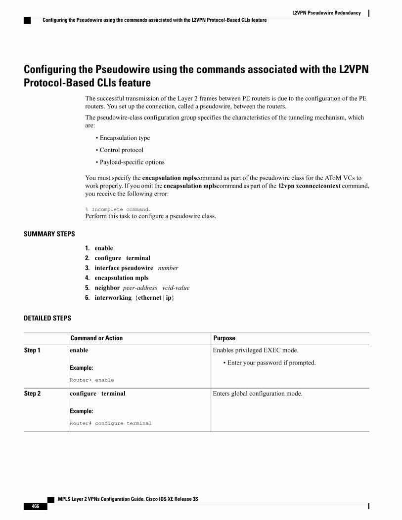
Configuring the Pseudowire using the commands associated with the L2VPNProtocol-Based CLIs feature
The successful transmission of the Layer 2 frames between PE routers is due to the configuration of the PErouters. You set up the connection, called a pseudowire, between the routers.
The pseudowire-class configuration group specifies the characteristics of the tunneling mechanism, whichare:
• Encapsulation type
• Control protocol
• Payload-specific options
You must specify the encapsulation mplscommand as part of the pseudowire class for the AToM VCs towork properly. If you omit the encapsulationmplscommand as part of the l2vpn xconnectcontext command,you receive the following error:
% Incomplete command.Perform this task to configure a pseudowire class.
SUMMARY STEPS
1. enable2. configure terminal3. interface pseudowire number4. encapsulation mpls5. neighbor peer-address vcid-value6. interworking {ethernet | ip}
DETAILED STEPS
PurposeCommand or Action
Enables privileged EXEC mode.enableStep 1
Example:
Router> enable
• Enter your password if prompted.
Enters global configuration mode.configure terminal
Example:
Router# configure terminal
Step 2
MPLS Layer 2 VPNs Configuration Guide, Cisco IOS XE Release 3S466
L2VPN Pseudowire RedundancyConfiguring the Pseudowire using the commands associated with the L2VPN Protocol-Based CLIs feature
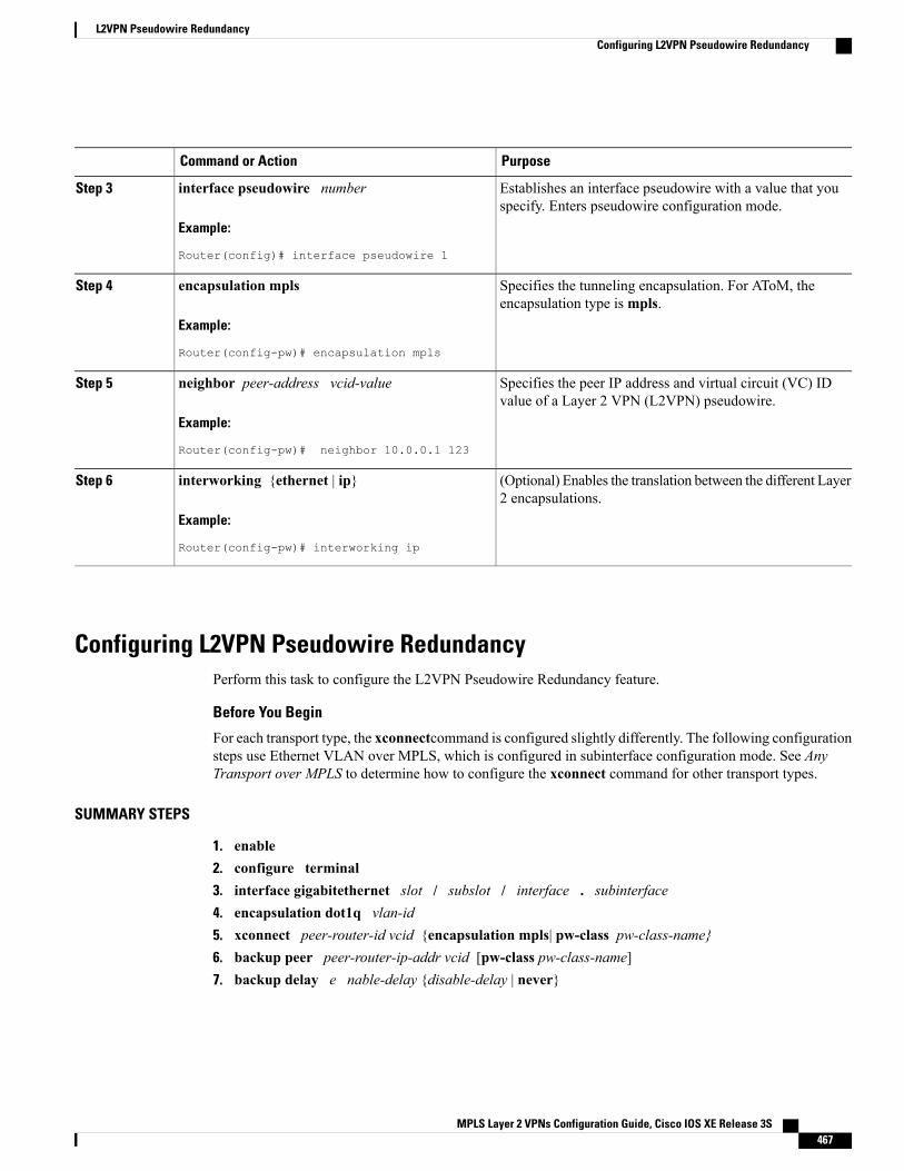
PurposeCommand or Action
Establishes an interface pseudowire with a value that youspecify. Enters pseudowire configuration mode.
interface pseudowire number
Example:
Router(config)# interface pseudowire 1
Step 3
Specifies the tunneling encapsulation. For AToM, theencapsulation type ismpls.
encapsulation mpls
Example:
Router(config-pw)# encapsulation mpls
Step 4
Specifies the peer IP address and virtual circuit (VC) IDvalue of a Layer 2 VPN (L2VPN) pseudowire.
neighbor peer-address vcid-value
Example:
Router(config-pw)# neighbor 10.0.0.1 123
Step 5
(Optional) Enables the translation between the different Layer2 encapsulations.
interworking {ethernet | ip}
Example:
Router(config-pw)# interworking ip
Step 6
Configuring L2VPN Pseudowire RedundancyPerform this task to configure the L2VPN Pseudowire Redundancy feature.
Before You Begin
For each transport type, the xconnectcommand is configured slightly differently. The following configurationsteps use Ethernet VLAN over MPLS, which is configured in subinterface configuration mode. See AnyTransport over MPLS to determine how to configure the xconnect command for other transport types.
SUMMARY STEPS
1. enable2. configure terminal3. interface gigabitethernet slot / subslot / interface . subinterface4. encapsulation dot1q vlan-id5. xconnect peer-router-id vcid {encapsulation mpls| pw-class pw-class-name}6. backup peer peer-router-ip-addr vcid [pw-class pw-class-name]7. backup delay e nable-delay {disable-delay | never}
MPLS Layer 2 VPNs Configuration Guide, Cisco IOS XE Release 3S 467
L2VPN Pseudowire RedundancyConfiguring L2VPN Pseudowire Redundancy
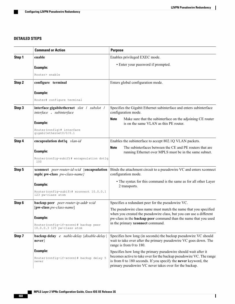
DETAILED STEPS
PurposeCommand or Action
Enables privileged EXEC mode.enableStep 1
Example:
Router> enable
• Enter your password if prompted.
Enters global configuration mode.configure terminal
Example:
Router# configure terminal
Step 2
Specifies the Gigabit Ethernet subinterface and enters subinterfaceconfiguration mode.
interface gigabitethernet slot / subslot /interface . subinterface
Step 3
Example:
Router(config)# interfacegigabitethernet0/0/0.1
Make sure that the subinterface on the adjoining CE routeris on the same VLAN as this PE router.
Note
Enables the subinterface to accept 802.1Q VLAN packets.encapsulation dot1q vlan-idStep 4
Example:
Router(config-subif)# encapsulation dot1q100
The subinterfaces between the CE and PE routers that arerunning Ethernet over MPLS must be in the same subnet.
Note
Binds the attachment circuit to a pseudowire VC and enters xconnectconfiguration mode.
xconnect peer-router-id vcid {encapsulationmpls| pw-class pw-class-name}
Step 5
Example:
Router(config-subif)# xconnect 10.0.0.1123 pw-class atom
• The syntax for this command is the same as for all other Layer2 transports.
Specifies a redundant peer for the pseudowire VC.backup peer peer-router-ip-addr vcid[pw-class pw-class-name]
Step 6
The pseudowire class name must match the name that you specifiedwhen you created the pseudowire class, but you can use a different
Example:
Router(config-if-xconn)# backup peer10.0.0.3 125 pw-class atom
pw-class in the backup peer command than the name that you usedin the primary xconnect command.
Specifies how long (in seconds) the backup pseudowire VC shouldwait to take over after the primary pseudowire VC goes down. Therange is from 0 to 180.
backup delay e nable-delay {disable-delay |never}
Example:
Router(config-if-xconn)# backup delay 5never
Step 7
Specifies how long the primary pseudowire should wait after itbecomes active to take over for the backup pseudowire VC. The rangeis from 0 to 180 seconds. If you specify the never keyword, theprimary pseudowire VC never takes over for the backup.
MPLS Layer 2 VPNs Configuration Guide, Cisco IOS XE Release 3S468
L2VPN Pseudowire RedundancyConfiguring L2VPN Pseudowire Redundancy
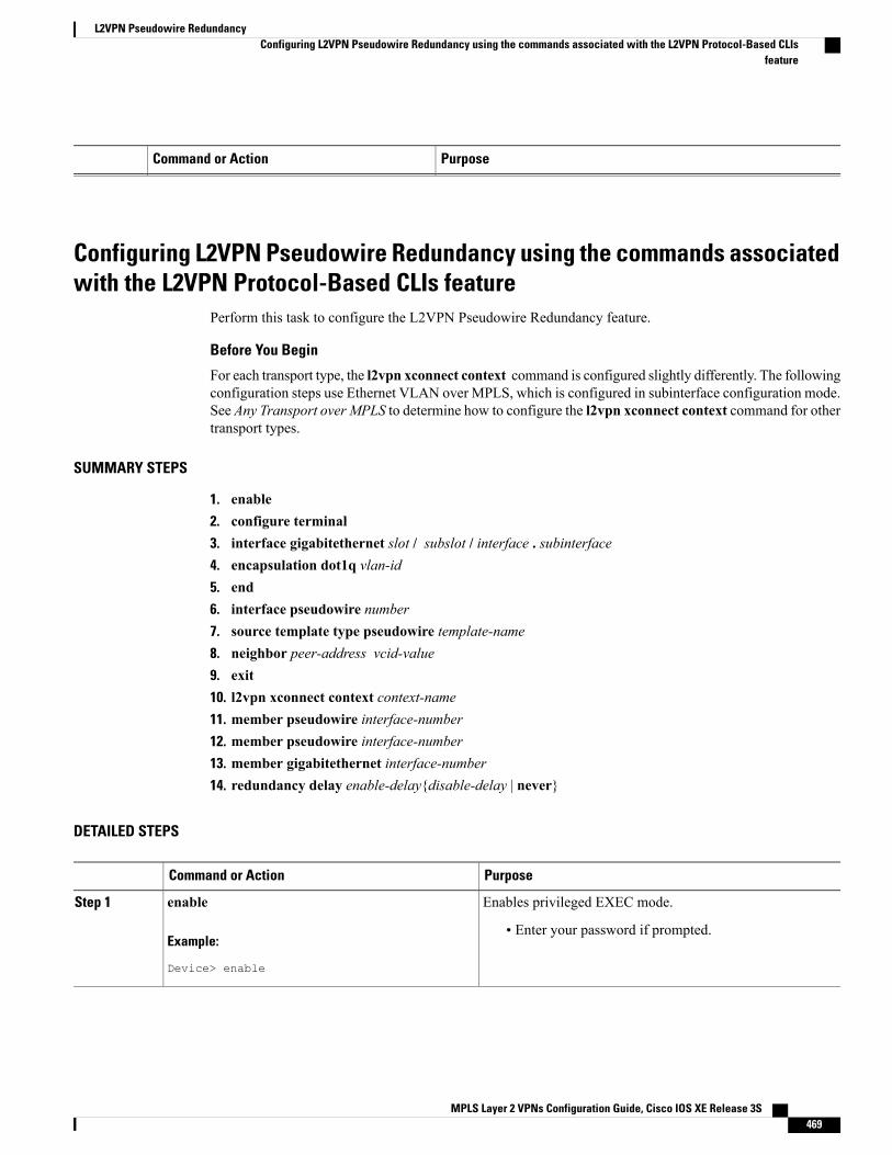
PurposeCommand or Action
Configuring L2VPN Pseudowire Redundancy using the commands associatedwith the L2VPN Protocol-Based CLIs feature
Perform this task to configure the L2VPN Pseudowire Redundancy feature.
Before You Begin
For each transport type, the l2vpn xconnect context command is configured slightly differently. The followingconfiguration steps use Ethernet VLAN over MPLS, which is configured in subinterface configuration mode.See Any Transport over MPLS to determine how to configure the l2vpn xconnect context command for othertransport types.
SUMMARY STEPS
1. enable2. configure terminal3. interface gigabitethernet slot / subslot / interface . subinterface4. encapsulation dot1q vlan-id5. end6. interface pseudowire number7. source template type pseudowire template-name8. neighbor peer-address vcid-value9. exit10. l2vpn xconnect context context-name11. member pseudowire interface-number12. member pseudowire interface-number13. member gigabitethernet interface-number14. redundancy delay enable-delay{disable-delay | never}
DETAILED STEPS
PurposeCommand or Action
Enables privileged EXEC mode.enableStep 1
Example:
Device> enable
• Enter your password if prompted.
MPLS Layer 2 VPNs Configuration Guide, Cisco IOS XE Release 3S 469
L2VPN Pseudowire RedundancyConfiguring L2VPN Pseudowire Redundancy using the commands associated with the L2VPN Protocol-Based CLIs
feature
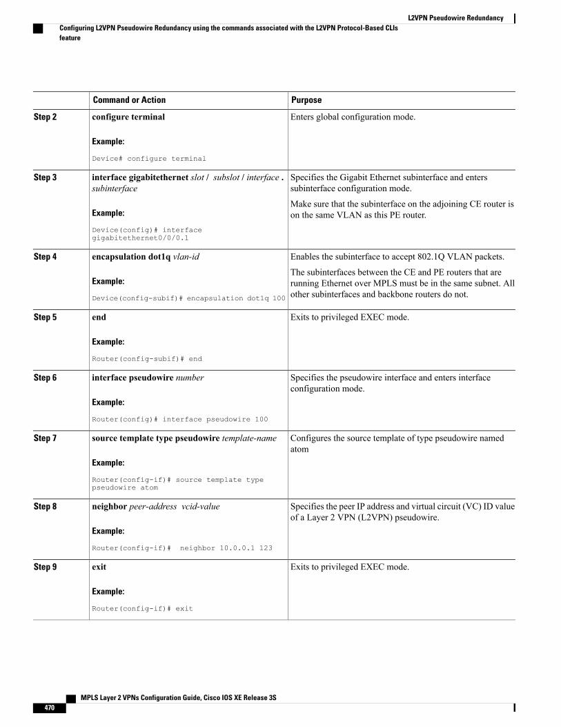
PurposeCommand or Action
Enters global configuration mode.configure terminal
Example:
Device# configure terminal
Step 2
Specifies the Gigabit Ethernet subinterface and enterssubinterface configuration mode.
interface gigabitethernet slot / subslot / interface .subinterface
Step 3
Example:
Device(config)# interfacegigabitethernet0/0/0.1
Make sure that the subinterface on the adjoining CE router ison the same VLAN as this PE router.
Enables the subinterface to accept 802.1Q VLAN packets.encapsulation dot1q vlan-idStep 4
Example:
Device(config-subif)# encapsulation dot1q 100
The subinterfaces between the CE and PE routers that arerunning Ethernet over MPLS must be in the same subnet. Allother subinterfaces and backbone routers do not.
Exits to privileged EXEC mode.end
Example:
Router(config-subif)# end
Step 5
Specifies the pseudowire interface and enters interfaceconfiguration mode.
interface pseudowire number
Example:
Router(config)# interface pseudowire 100
Step 6
Configures the source template of type pseudowire namedatom
source template type pseudowire template-name
Example:
Router(config-if)# source template typepseudowire atom
Step 7
Specifies the peer IP address and virtual circuit (VC) ID valueof a Layer 2 VPN (L2VPN) pseudowire.
neighbor peer-address vcid-value
Example:
Router(config-if)# neighbor 10.0.0.1 123
Step 8
Exits to privileged EXEC mode.exit
Example:
Router(config-if)# exit
Step 9
MPLS Layer 2 VPNs Configuration Guide, Cisco IOS XE Release 3S470
L2VPN Pseudowire RedundancyConfiguring L2VPN Pseudowire Redundancy using the commands associated with the L2VPN Protocol-Based CLIsfeature
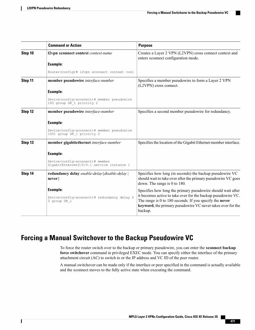
PurposeCommand or Action
Creates a Layer 2 VPN (L2VPN) cross connect context andenters xconnect configuration mode.
l2vpn xconnect context context-name
Example:
Router(config)# l2vpn xconnect context con1
Step 10
Specifies a member pseudowire to form a Layer 2 VPN(L2VPN) cross connect.
member pseudowire interface-number
Example:
Device(config-xconnect)# member pseudowire100 group GR_1 priority 2
Step 11
Specifies a second member pseudowire for redundancy.member pseudowire interface-number
Example:
Device(config-xconnect)# member pseudowire1001 group GR_1 priority 2
Step 12
Specifies the location of the Gigabit Ethernet member interface.member gigabitethernet interface-number
Example:
Device(config-xconnect)# memberGigabitEthernet0/0/0.1 service instance 1
Step 13
Specifies how long (in seconds) the backup pseudowire VCshould wait to take over after the primary pseudowire VC goesdown. The range is 0 to 180.
redundancy delay enable-delay{disable-delay |never}
Example:
Device(config-xconnect)# redundancy delay 00 group GR_1
Step 14
Specifies how long the primary pseudowire should wait afterit becomes active to take over for the backup pseudowire VC.The range is 0 to 180 seconds. If you specify the neverkeyword, the primary pseudowire VC never takes over for thebackup.
Forcing a Manual Switchover to the Backup Pseudowire VCTo force the router switch over to the backup or primary pseudowire, you can enter the xconnect backupforce switchover command in privileged EXEC mode. You can specify either the interface of the primaryattachment circuit (AC) to switch to or the IP address and VC ID of the peer router.
A manual switchover can be made only if the interface or peer specified in the command is actually availableand the xconnect moves to the fully active state when executing the command.
MPLS Layer 2 VPNs Configuration Guide, Cisco IOS XE Release 3S 471
L2VPN Pseudowire RedundancyForcing a Manual Switchover to the Backup Pseudowire VC
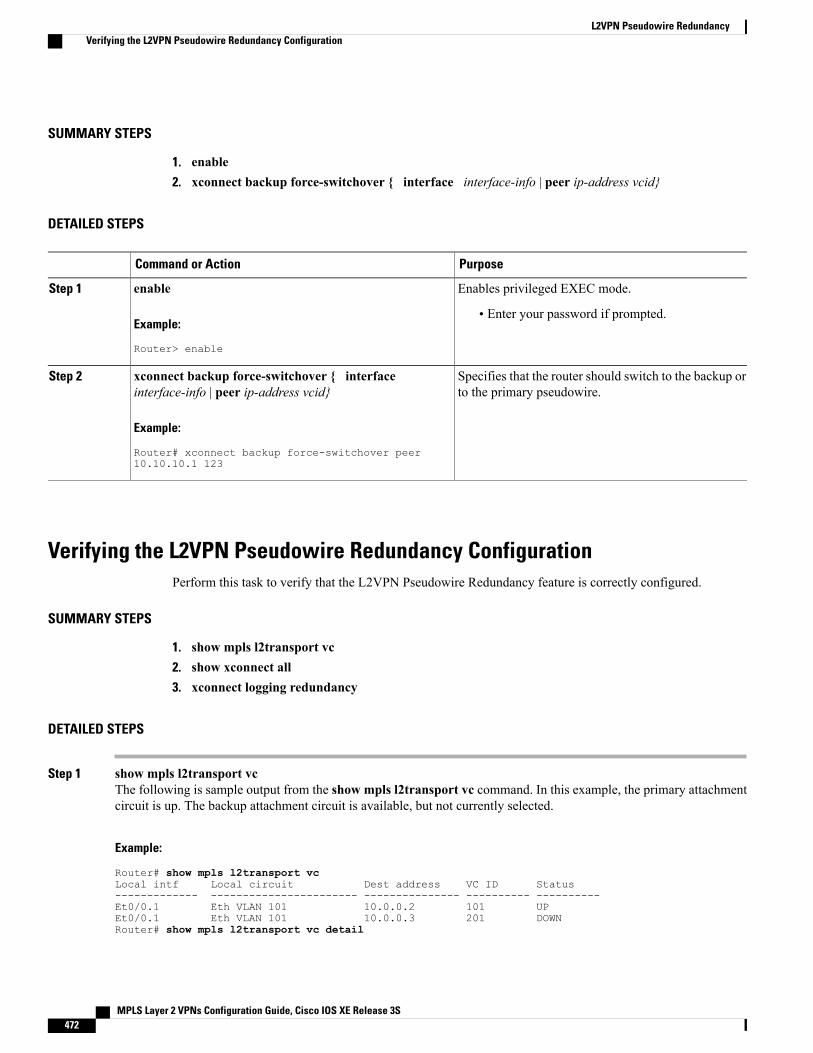
SUMMARY STEPS
1. enable2. xconnect backup force-switchover { interface interface-info | peer ip-address vcid}
DETAILED STEPS
PurposeCommand or Action
Enables privileged EXEC mode.enableStep 1
Example:
Router> enable
• Enter your password if prompted.
Specifies that the router should switch to the backup orto the primary pseudowire.
xconnect backup force-switchover { interfaceinterface-info | peer ip-address vcid}
Example:
Router# xconnect backup force-switchover peer10.10.10.1 123
Step 2
Verifying the L2VPN Pseudowire Redundancy ConfigurationPerform this task to verify that the L2VPN Pseudowire Redundancy feature is correctly configured.
SUMMARY STEPS
1. show mpls l2transport vc2. show xconnect all3. xconnect logging redundancy
DETAILED STEPS
Step 1 show mpls l2transport vcThe following is sample output from the show mpls l2transport vc command. In this example, the primary attachmentcircuit is up. The backup attachment circuit is available, but not currently selected.
Example:
Router# show mpls l2transport vcLocal intf Local circuit Dest address VC ID Status------------- ----------------------- --------------- ---------- ----------Et0/0.1 Eth VLAN 101 10.0.0.2 101 UPEt0/0.1 Eth VLAN 101 10.0.0.3 201 DOWNRouter# show mpls l2transport vc detail
MPLS Layer 2 VPNs Configuration Guide, Cisco IOS XE Release 3S472
L2VPN Pseudowire RedundancyVerifying the L2VPN Pseudowire Redundancy Configuration
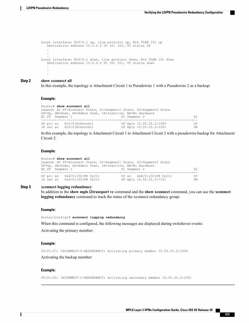
Local interface: Et0/0.1 up, line protocol up, Eth VLAN 101 upDestination address 10.0.0.2 VC ID: 101, VC status UP...
Local interface: Et0/0.1 down, line protocol down, Eth VLAN 101 downDestination address 10.0.0.3 VC ID: 201, VC status down...
Step 2 show xconnect allIn this example, the topology is Attachment Circuit 1 to Pseudowire 1 with a Pseudowire 2 as a backup:
Example:
Router# show xconnect allLegend: XC ST=Xconnect State, S1=Segment1 State, S2=Segment2 StateUP=Up, DN=Down, AD=Admin Down, IA=Inactive, NH=No HardwareXC ST Segment 1 S1 Segment 2 S2------+---------------------------------+--+---------------------------------+--UP pri ac Et0/0(Ethernet) UP mpls 10.55.55.2:1000 UPIA sec ac Et0/0(Ethernet) UP mpls 10.55.55.3:1001 DN
In this example, the topology is Attachment Circuit 1 to Attachment Circuit 2 with a pseudowire backup for AttachmentCircuit 2:
Example:
Router# show xconnect allLegend: XC ST=Xconnect State, S1=Segment1 State, S2=Segment2 StateUP=Up, DN=Down, AD=Admin Down, IA=Inactive, NH=No HardwareXC ST Segment 1 S1 Segment 2 S2------+---------------------------------+--+---------------------------------+--UP pri ac Se6/0:150(FR DLCI) UP ac Se8/0:150(FR DLCI) UPIA sec ac Se6/0:150(FR DLCI) UP mpls 10.55.55.3:7151 DN
Step 3 xconnect logging redundancyIn addition to the show mpls l2transport vc command and the show xconnect command, you can use the xconnectlogging redundancy command to track the status of the xconnect redundancy group:
Example:
Router(config)# xconnect logging redundancy
When this command is configured, the following messages are displayed during switchover events:
Activating the primary member:
Example:
00:01:07: %XCONNECT-5-REDUNDANCY: Activating primary member 10.55.55.2:1000
Activating the backup member:
Example:
00:01:05: %XCONNECT-5-REDUNDANCY: Activating secondary member 10.55.55.3:1001
MPLS Layer 2 VPNs Configuration Guide, Cisco IOS XE Release 3S 473
L2VPN Pseudowire RedundancyVerifying the L2VPN Pseudowire Redundancy Configuration
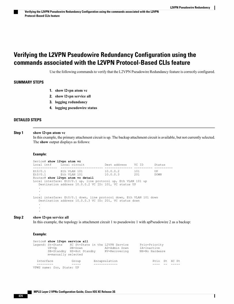
Verifying the L2VPN Pseudowire Redundancy Configuration using thecommands associated with the L2VPN Protocol-Based CLIs feature
Use the following commands to verify that the L2VPN Pseudowire Redundancy feature is correctly configured.
SUMMARY STEPS
1. show l2vpn atom vc2. show l2vpn service all3. logging redundancy4. logging pseudowire status
DETAILED STEPS
Step 1 show l2vpn atom vcIn this example, the primary attachment circuit is up. The backup attachment circuit is available, but not currently selected.The show output displays as follows:
Example:
Device# show l2vpn atom vcLocal intf Local circuit Dest address VC ID Status------------- ----------------------- --------------- ---------- ----------Et0/0.1 Eth VLAN 101 10.0.0.2 101 UPEt0/0.1 Eth VLAN 101 10.0.0.3 201 DOWNRouter# show l2vpn atom vc detailLocal interface: Et0/0.1 up, line protocol up, Eth VLAN 101 up
Destination address 10.0.0.2 VC ID: 101, VC status UP...
Local interface: Et0/0.1 down, line protocol down, Eth VLAN 101 downDestination address 10.0.0.3 VC ID: 201, VC status down...
Step 2 show l2vpn service allIn this example, the topology is attachment circuit 1 to pseudowire 1 with apPseudowire 2 as a backup:
Example:
Device# show l2vpn service allLegend: St=State XC St=State in the L2VPN Service Prio=Priority
UP=Up DN=Down AD=Admin Down IA=InactiveSB=Standby HS=Hot Standby RV=Recovering NH=No Hardwarem=manually selected
Interface Group Encapsulation Prio St XC St--------- ----- ------------- ---- -- -----
VPWS name: foo, State: UP
MPLS Layer 2 VPNs Configuration Guide, Cisco IOS XE Release 3S474
L2VPN Pseudowire RedundancyVerifying the L2VPN Pseudowire Redundancy Configuration using the commands associated with the L2VPNProtocol-Based CLIs feature
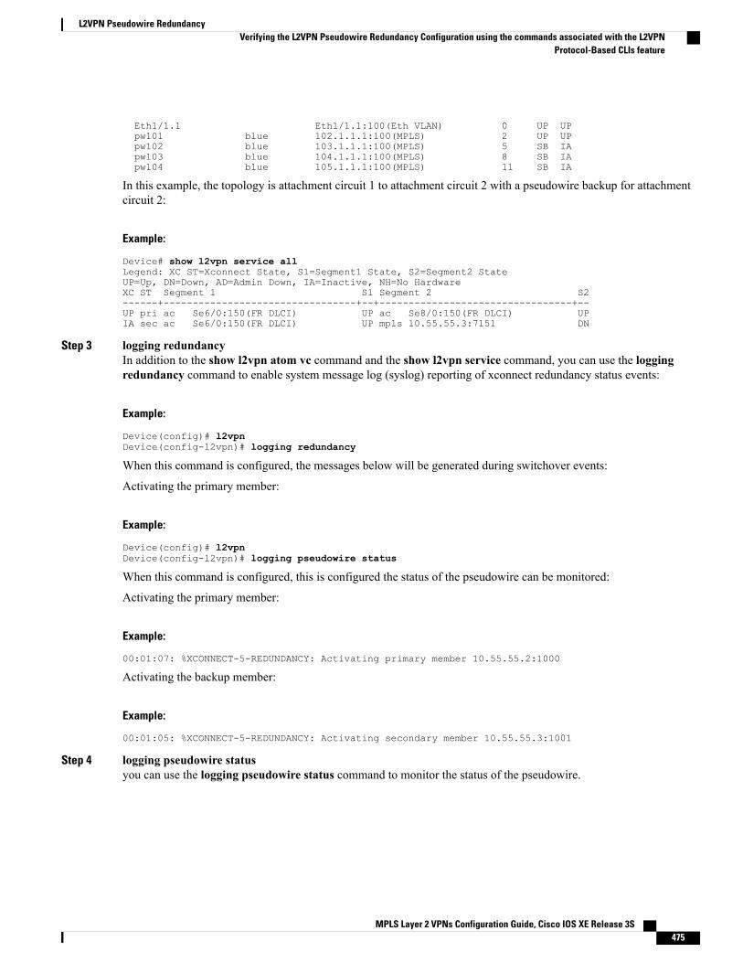
Eth1/1.1 Eth1/1.1:100(Eth VLAN) 0 UP UPpw101 blue 102.1.1.1:100(MPLS) 2 UP UPpw102 blue 103.1.1.1:100(MPLS) 5 SB IApw103 blue 104.1.1.1:100(MPLS) 8 SB IApw104 blue 105.1.1.1:100(MPLS) 11 SB IA
In this example, the topology is attachment circuit 1 to attachment circuit 2 with a pseudowire backup for attachmentcircuit 2:
Example:
Device# show l2vpn service allLegend: XC ST=Xconnect State, S1=Segment1 State, S2=Segment2 StateUP=Up, DN=Down, AD=Admin Down, IA=Inactive, NH=No HardwareXC ST Segment 1 S1 Segment 2 S2------+---------------------------------+--+---------------------------------+--UP pri ac Se6/0:150(FR DLCI) UP ac Se8/0:150(FR DLCI) UPIA sec ac Se6/0:150(FR DLCI) UP mpls 10.55.55.3:7151 DN
Step 3 logging redundancyIn addition to the show l2vpn atom vc command and the show l2vpn service command, you can use the loggingredundancy command to enable system message log (syslog) reporting of xconnect redundancy status events:
Example:
Device(config)# l2vpnDevice(config-l2vpn)# logging redundancy
When this command is configured, the messages below will be generated during switchover events:
Activating the primary member:
Example:
Device(config)# l2vpnDevice(config-l2vpn)# logging pseudowire status
When this command is configured, this is configured the status of the pseudowire can be monitored:
Activating the primary member:
Example:
00:01:07: %XCONNECT-5-REDUNDANCY: Activating primary member 10.55.55.2:1000
Activating the backup member:
Example:
00:01:05: %XCONNECT-5-REDUNDANCY: Activating secondary member 10.55.55.3:1001
Step 4 logging pseudowire statusyou can use the logging pseudowire status command to monitor the status of the pseudowire.
MPLS Layer 2 VPNs Configuration Guide, Cisco IOS XE Release 3S 475
L2VPN Pseudowire RedundancyVerifying the L2VPN Pseudowire Redundancy Configuration using the commands associated with the L2VPN
Protocol-Based CLIs feature
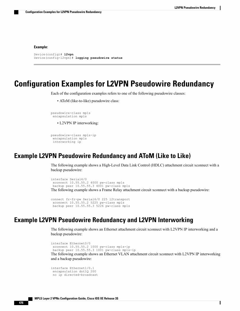
Example:
Device(config)# l2vpnDevice(config-l2vpn)# logging pseudowire status
Configuration Examples for L2VPN Pseudowire RedundancyEach of the configuration examples refers to one of the following pseudowire classes:
• AToM (like-to-like) pseudowire class:
pseudowire-class mplsencapsulation mpls
• L2VPN IP interworking:
pseudowire-class mpls-ipencapsulation mplsinterworking ip
Example L2VPN Pseudowire Redundancy and AToM (Like to Like)The following example shows a High-Level Data Link Control (HDLC) attachment circuit xconnect with abackup pseudowire:
interface Serial4/0xconnect 10.55.55.2 4000 pw-class mplsbackup peer 10.55.55.3 4001 pw-class mplsThe following example shows a Frame Relay attachment circuit xconnect with a backup pseudowire:
connect fr-fr-pw Serial6/0 225 l2transportxconnect 10.55.55.2 5225 pw-class mplsbackup peer 10.55.55.3 5226 pw-class mpls
Example L2VPN Pseudowire Redundancy and L2VPN InterworkingThe following example shows an Ethernet attachment circuit xconnect with L2VPN IP interworking and abackup pseudowire:
interface Ethernet0/0xconnect 10.55.55.2 1000 pw-class mpls-ipbackup peer 10.55.55.3 1001 pw-class mpls-ipThe following example shows an Ethernet VLAN attachment circuit xconnect with L2VPN IP interworkingand a backup pseudowire:
interface Ethernet1/0.1encapsulation dot1Q 200no ip directed-broadcast
MPLS Layer 2 VPNs Configuration Guide, Cisco IOS XE Release 3S476
L2VPN Pseudowire RedundancyConfiguration Examples for L2VPN Pseudowire Redundancy
xconnect 10.55.55.2 5200 pw-class mpls-ipbackup peer 10.55.55.3 5201 pw-class mpls-ipThe following example shows a Frame Relay attachment circuit xconnect with L2VPN IP interworking anda backup pseudowire:
connect fr-ppp-pw Serial6/0 250 l2transportxconnect 10.55.55.2 8250 pw-class mpls-ipbackup peer 10.55.55.3 8251 pw-class mpls-ipThe following example shows a PPP attachment circuit xconnect with L2VPN IP interworking and a backuppseudowire:
interface Serial7/0encapsulation pppxconnect 10.55.55.2 2175 pw-class mpls-ipbackup peer 10.55.55.3 2176 pw-class mpls-ip
Example L2VPN Pseudowire Redundancy with Layer 2 Local SwitchingThe following example shows an Ethernet VLAN-VLAN local switching xconnect with a pseudowire backupfor Ethernet segment E2/0.2. If the subinterface associated with E2/0.2 goes down, the backup pseudowire isactivated:
connect vlan-vlan Ethernet1/0.2 Ethernet2/0.2backup peer 10.55.55.3 1101 pw-class mplsThe following example shows a Frame Relay-to-Frame Relay local switching connect with a pseudowirebackup for Frame Relay segment S8/0 150. If data-link connection identifier (DLCI) 150 on S8/0 goes down,the backup pseudowire is activated:
connect fr-fr-ls Serial6/0 150 Serial8/0 150backup peer 10.55.55.3 7151 pw-class mpls
Example L2VPN Pseudowire Redundancy and Layer 2 Tunneling ProtocolVersion 3
The following example shows how to configure a backup peer for an xconnect session:
pseudowire-class 773encapsulation l2tpv3ip local interface GigabitEthernet0/0/0.773!pseudowire-class 774encapsulation l2tpv3ip local interface GigabitEthernet0/0/1.774!interface GigabitEthernet0/0/0.780encapsulation dot1Q 780xconnect 10.22.73.14 100 pw-class 773backup peer 10.22.74.14 101 pw-class 774backup delay 0 0
The following example shows how to configure a Gigabit Ethernet port with L2VPN pseudowire redundancyand L2TPv3:
interface GigabitEthernet0/0/2xconnect 10.22.70.83 50 pw-class pe1-pw-primarybackup peer 20.22.70.85 51 pw-class pe1-pw-secondary
MPLS Layer 2 VPNs Configuration Guide, Cisco IOS XE Release 3S 477
L2VPN Pseudowire RedundancyExample L2VPN Pseudowire Redundancy with Layer 2 Local Switching
The following example shows how to configure a Gigabit Ethernet VLANwith L2VPN pseudowire redundancyand L2TPv3:
interface GigabitEthernet0/0/0.100encapsulation dot1q 100xconnect 10.22.70.83 60 pw-class pe1-pw-primarybackup peer 10.22.70.85 61 pw-class pe1-pw-secondaryThe following example shows how to configure a Gigabit Ethernet Q-in-Qwith L2VPN pseudowire redundancyand L2TPv3:
interface GigabitEthernet0/0/0.200encapsulation dot1q 200 second-dot1q 400xconnect 10.22.70.83 70 pw-class pe1-pw-primarybackup peer 10.22.70.85 71 pw-class pe1-pw-secondaryThe following example shows how to configure a Gigabit Ethernet Q-in-any with L2VPN pseudowireredundancy and L2TPv3:
interface GigabitEthernet0/0/0.300encapsulation dot1q 300 second-dot1q anyxconnect 10.22.70.83 80 pw-class pe1-pw-primarybackup peer 10.22.70.85 81 pw-class pe1-pw-secondaryThe following example shows how to configure an HDLC with L2VPN pseudowire redundancy and L2TPv3
interface Serial0/2/0:0no ip addressxconnect 10.22.71.83 40 pw-class pe1-pw-hdlcbackup peer 10.22.70.85 41 pw-class pe1-pw-hdlc-2
Configuration Examples for L2VPN Pseudowire Redundancyusing the commands associated with the L2VPN Protocol-BasedCLIs feature
Each of the configuration examples refers to one of the following interface pseudowires:
• AToM (like-to-like) interface pseudowire:
interface pseudowire 1encapsulation mplsneighbor 33.33.33.33 1
• L2VPN IP interworking:
interface pseudowire 1encapsulation mplsneighbor 33.33.33.33 1interworking ip
MPLS Layer 2 VPNs Configuration Guide, Cisco IOS XE Release 3S478
L2VPN Pseudowire RedundancyConfiguration Examples for L2VPN Pseudowire Redundancy using the commands associated with the L2VPNProtocol-Based CLIs feature
Example L2VPN Pseudowire Redundancy and AToM (Like to Like) using thecommands associated with the L2VPN Protocol-Based CLIs feature
The following example shows a High-Level Data Link Control (HDLC) attachment circuit xconnect with abackup pseudowire:
interface Serial4/0interface pseudowire 100source template type pseudowire ether-pwneighbor 10.55.55.3 4001!l2vpn xconnect context con1member pseudowire 100 group GR_1 priority 1member pseudowire 1001 group GR_1 priority 2member GigabitEthernet0/0/2 service-instance 1redundancy delay 0 0 group GR_1The following example shows a Frame Relay attachment circuit xconnect with a backup pseudowire:
connect fr-fr-pw Serial6/0 225 l2transportinterface pseudowire 100source template type pseudowire ether-pwneighbor 10.55.55.3 5226!l2vpn xconnect context con1member pseudowire 100 group GR_1 priority 1member pseudowire 1001 group GR_1 priority 2member GigabitEthernet0/0/2 service-instance 1redundancy delay 0 0 group GR_1
Example L2VPN Pseudowire Redundancy and L2VPN Interworking using thecommands associated with the L2VPN Protocol-Based CLIs feature
The following example shows an Ethernet attachment circuit xconnect with L2VPN IP interworking and abackup pseudowire:
interface Ethernet0/0interface pseudowire 100source template type pseudowire ether-pw!l2vpn xconnect context con1member pseudowrire 100 group GR_1 priority 1member pseudowire 1001 group GR_1 priority 2member GigabitEthernet0/0/2 service-instance 1redundancy delay 0 0 group GR_1interworking ipThe following example shows an Ethernet VLAN attachment circuit xconnect with L2VPN IP interworkingand a backup pseudowire:
interface Ethernet1/0.1encapsulation dot1Q 200no ip directed-broadcastinterface pseudowire 100source template type pseudowire ether-pw!l2vpn xconnect context con1member pseudowrire 100 group GR_1 priority 1member pseudowire 1001 group GR_1 priority 2member GigabitEthernet0/0/2 service-instance 1
MPLS Layer 2 VPNs Configuration Guide, Cisco IOS XE Release 3S 479
L2VPN Pseudowire RedundancyExample L2VPN Pseudowire Redundancy and AToM (Like to Like) using the commands associated with the L2VPN
Protocol-Based CLIs feature
redundancy delay 0 0 group GR_1interworking ipThe following example shows a Frame Relay attachment circuit xconnect with L2VPN IP interworking anda backup pseudowire:
connect fr-ppp-pw Serial6/0 250 l2transportinterface pseudowire 100source template type pseudowire ether-pw!l2vpn xconnect context con1member pseudowrire 100 group GR_1 priority 1member pseudowire 1001 group GR_1 priority 2member GigabitEthernet0/0/2 service-instance 1redundancy delay 0 0 group GR_1interworking ipThe following example shows a PPP attachment circuit xconnect with L2VPN IP interworking and a backuppseudowire:
interface Serial7/0encapsulation pppinterface pseudowire 100source template type pseudowire ether-pw!l2vpn xconnect context con1member pseudowire 100 group GR_1 priority 1member pseudowire 1001 group GR_1 priority 2member GigabitEthernet0/0/2 service-instance 1redundancy delay 0 0 group GR_1interworking ip
Example L2VPN Pseudowire Redundancy and Layer 2 Tunneling ProtocolVersion 3 using the commands associated with the L2VPN Protocol-BasedCLIs feature
The following example shows how to configure a backup peer for an xconnect session:
interface pseudowire 773encapsulation l2tpv3ip local interface GigabitEthernet0/0/0.773!interface pseudowire 774encapsulation l2tpv3ip local interface GigabitEthernet0/0/1.774!interface GigabitEthernet0/0/0.780encapsulation dot1Q 780interface pseudowire 100source template type pseudowire ether-pwneighbor 10.22.73.14 100!l2vpn xconnect context con1member pseudowire 100 group GR_1 priority 1member pseudowire 1001 group GR_1 priority 2member GigabitEthernet0/0/2 service-instance 1redundancy delay 0 0 group GR_1interworking ipThe following example shows how to configure a Gigabit Ethernet port with L2VPN pseudowire redundancyand L2TPv3:
interface GigabitEthernet0/0/2interface pseudowire 100source template type pseudowire ether-pw
MPLS Layer 2 VPNs Configuration Guide, Cisco IOS XE Release 3S480
L2VPN Pseudowire RedundancyExample L2VPN Pseudowire Redundancy and Layer 2 Tunneling Protocol Version 3 using the commands associatedwith the L2VPN Protocol-Based CLIs feature
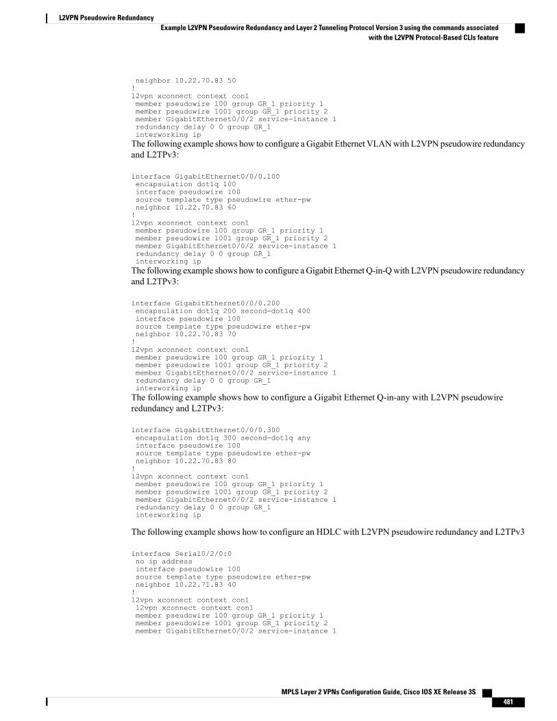
neighbor 10.22.70.83 50!l2vpn xconnect context con1member pseudowire 100 group GR_1 priority 1member pseudowire 1001 group GR_1 priority 2member GigabitEthernet0/0/2 service-instance 1redundancy delay 0 0 group GR_1interworking ipThe following example shows how to configure a Gigabit Ethernet VLANwith L2VPN pseudowire redundancyand L2TPv3:
interface GigabitEthernet0/0/0.100encapsulation dot1q 100interface pseudowire 100source template type pseudowire ether-pwneighbor 10.22.70.83 60!l2vpn xconnect context con1member pseudowire 100 group GR_1 priority 1member pseudowire 1001 group GR_1 priority 2member GigabitEthernet0/0/2 service-instance 1redundancy delay 0 0 group GR_1interworking ipThe following example shows how to configure a Gigabit Ethernet Q-in-Qwith L2VPN pseudowire redundancyand L2TPv3:
interface GigabitEthernet0/0/0.200encapsulation dot1q 200 second-dot1q 400interface pseudowire 100source template type pseudowire ether-pwneighbor 10.22.70.83 70!l2vpn xconnect context con1member pseudowire 100 group GR_1 priority 1member pseudowire 1001 group GR_1 priority 2member GigabitEthernet0/0/2 service-instance 1redundancy delay 0 0 group GR_1interworking ipThe following example shows how to configure a Gigabit Ethernet Q-in-any with L2VPN pseudowireredundancy and L2TPv3:
interface GigabitEthernet0/0/0.300encapsulation dot1q 300 second-dot1q anyinterface pseudowire 100source template type pseudowire ether-pwneighbor 10.22.70.83 80!l2vpn xconnect context con1member pseudowire 100 group GR_1 priority 1member pseudowire 1001 group GR_1 priority 2member GigabitEthernet0/0/2 service-instance 1redundancy delay 0 0 group GR_1interworking ip
The following example shows how to configure an HDLC with L2VPN pseudowire redundancy and L2TPv3
interface Serial0/2/0:0no ip addressinterface pseudowire 100source template type pseudowire ether-pwneighbor 10.22.71.83 40!l2vpn xconnect context con1l2vpn xconnect context con1member pseudowire 100 group GR_1 priority 1member pseudowire 1001 group GR_1 priority 2member GigabitEthernet0/0/2 service-instance 1
MPLS Layer 2 VPNs Configuration Guide, Cisco IOS XE Release 3S 481
L2VPN Pseudowire RedundancyExample L2VPN Pseudowire Redundancy and Layer 2 Tunneling Protocol Version 3 using the commands associated
with the L2VPN Protocol-Based CLIs feature
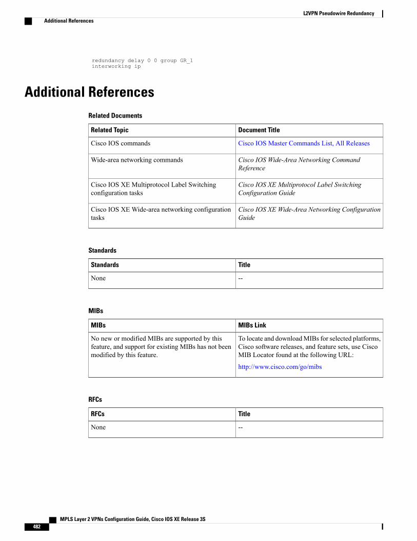
redundancy delay 0 0 group GR_1interworking ip
Additional ReferencesRelated Documents
Document TitleRelated Topic
Cisco IOS Master Commands List, All ReleasesCisco IOS commands
Cisco IOS Wide-Area Networking CommandReference
Wide-area networking commands
Cisco IOS XE Multiprotocol Label SwitchingConfiguration Guide
Cisco IOS XE Multiprotocol Label Switchingconfiguration tasks
Cisco IOS XE Wide-Area Networking ConfigurationGuide
Cisco IOS XE Wide-area networking configurationtasks
Standards
TitleStandards
--None
MIBs
MIBs LinkMIBs
To locate and downloadMIBs for selected platforms,Cisco software releases, and feature sets, use CiscoMIB Locator found at the following URL:
http://www.cisco.com/go/mibs
No new or modified MIBs are supported by thisfeature, and support for existing MIBs has not beenmodified by this feature.
RFCs
TitleRFCs
--None
MPLS Layer 2 VPNs Configuration Guide, Cisco IOS XE Release 3S482
L2VPN Pseudowire RedundancyAdditional References
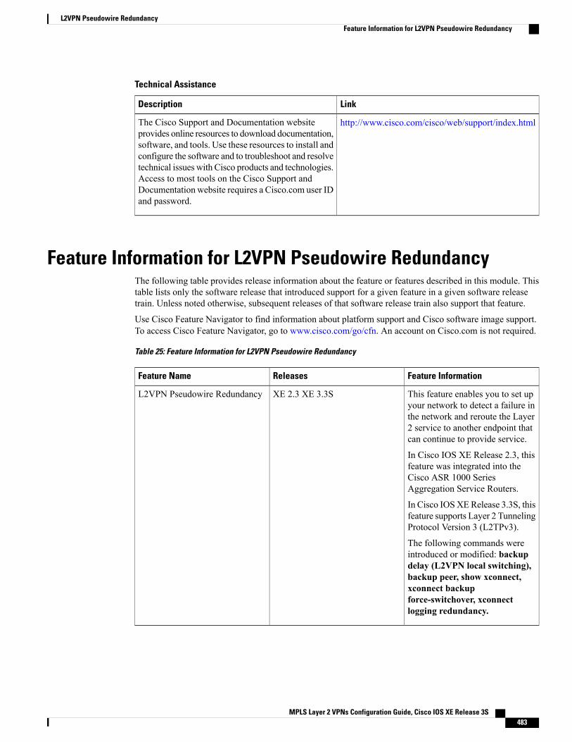
Technical Assistance
LinkDescription
http://www.cisco.com/cisco/web/support/index.htmlThe Cisco Support and Documentation websiteprovides online resources to download documentation,software, and tools. Use these resources to install andconfigure the software and to troubleshoot and resolvetechnical issues with Cisco products and technologies.Access to most tools on the Cisco Support andDocumentation website requires a Cisco.com user IDand password.
Feature Information for L2VPN Pseudowire RedundancyThe following table provides release information about the feature or features described in this module. Thistable lists only the software release that introduced support for a given feature in a given software releasetrain. Unless noted otherwise, subsequent releases of that software release train also support that feature.
Use Cisco Feature Navigator to find information about platform support and Cisco software image support.To access Cisco Feature Navigator, go to www.cisco.com/go/cfn. An account on Cisco.com is not required.
Table 25: Feature Information for L2VPN Pseudowire Redundancy
Feature InformationReleasesFeature Name
This feature enables you to set upyour network to detect a failure inthe network and reroute the Layer2 service to another endpoint thatcan continue to provide service.
In Cisco IOS XE Release 2.3, thisfeature was integrated into theCisco ASR 1000 SeriesAggregation Service Routers.
In Cisco IOSXERelease 3.3S, thisfeature supports Layer 2 TunnelingProtocol Version 3 (L2TPv3).
The following commands wereintroduced or modified: backupdelay (L2VPN local switching),backup peer, show xconnect,xconnect backupforce-switchover, xconnectlogging redundancy.
XE 2.3 XE 3.3SL2VPN Pseudowire Redundancy
MPLS Layer 2 VPNs Configuration Guide, Cisco IOS XE Release 3S 483
L2VPN Pseudowire RedundancyFeature Information for L2VPN Pseudowire Redundancy

MPLS Layer 2 VPNs Configuration Guide, Cisco IOS XE Release 3S484
L2VPN Pseudowire RedundancyFeature Information for L2VPN Pseudowire Redundancy
C H A P T E R 13Pseudowire Group Switchover
The Pseudowire Group Switchover feature allows all pseudowires in a group to be quickly switched over tobackup pseudowires. This group switchover is triggered by a single “group down” status message receivedfrom a remote peer.
• Finding Feature Information, page 485
• Prerequisites for Pseudowire Group Switchover , page 485
• Restrictions for Pseudowire Group Switchover, page 486
• Information About Pseudowire Group Switchover, page 486
• How to Configure Predictive Switchover, page 487
• Verifying a Pseudowire Group Switchover Configuration, page 489
• Troubleshooting a Pseudowire Group Switchover Configuration, page 490
• Configuration Examples for Predictive Switchover, page 491
• Additional References, page 491
• Feature Information for Pseudowire Group Switchover, page 492
Finding Feature InformationYour software release may not support all the features documented in this module. For the latest caveats andfeature information, see Bug Search Tool and the release notes for your platform and software release. Tofind information about the features documented in this module, and to see a list of the releases in which eachfeature is supported, see the feature information table at the end of this module.
Use Cisco Feature Navigator to find information about platform support and Cisco software image support.To access Cisco Feature Navigator, go to www.cisco.com/go/cfn. An account on Cisco.com is not required.
Prerequisites for Pseudowire Group Switchover• The remote provider edge (PE) router must be capable of sending group status messages.
MPLS Layer 2 VPNs Configuration Guide, Cisco IOS XE Release 3S 485
• Label Distribution Protocol (LDP) must be implemented on the network.
• Each xconnect must have a backup pseudowire configured.
Restrictions for Pseudowire Group SwitchoverThe Pseudowire Group Switchover feature is supported on Cisco IOS XE Release 3.10S and later releases.This feature is supported on Cisco ASR 903 Series routers on the following attachment circuits:
• Ethernet VLAN
• Asynchronous Transfer Mode (ATM)
• Circuit Emulation over MPLS (CEM)
Information About Pseudowire Group Switchover
Introduction to Pseudowire Group SwitchoverThe Pseudowire Group Switchover feature allows you to reduce the switchover time from main pseudowiresto backup pseudowires when a fault is encountered. The reduced switchover time is achieved by groupingLabel Distribution Protocol (LDP) status messages and internal interprocess communication (IPC) messages.
When the remote peer detects an attachment circuit failure, it sends an LDP status message. When this statusmessage is received, the designated backup pseudowires take over. Packets are then routed through the backuppseudowires.
Pseudowires can be grouped together by assigning a group ID. When an LDP status message is received bya pseudowire group, the entire group switches over, thus reducing switchover time.
MPLS Layer 2 VPNs Configuration Guide, Cisco IOS XE Release 3S486
Pseudowire Group SwitchoverRestrictions for Pseudowire Group Switchover
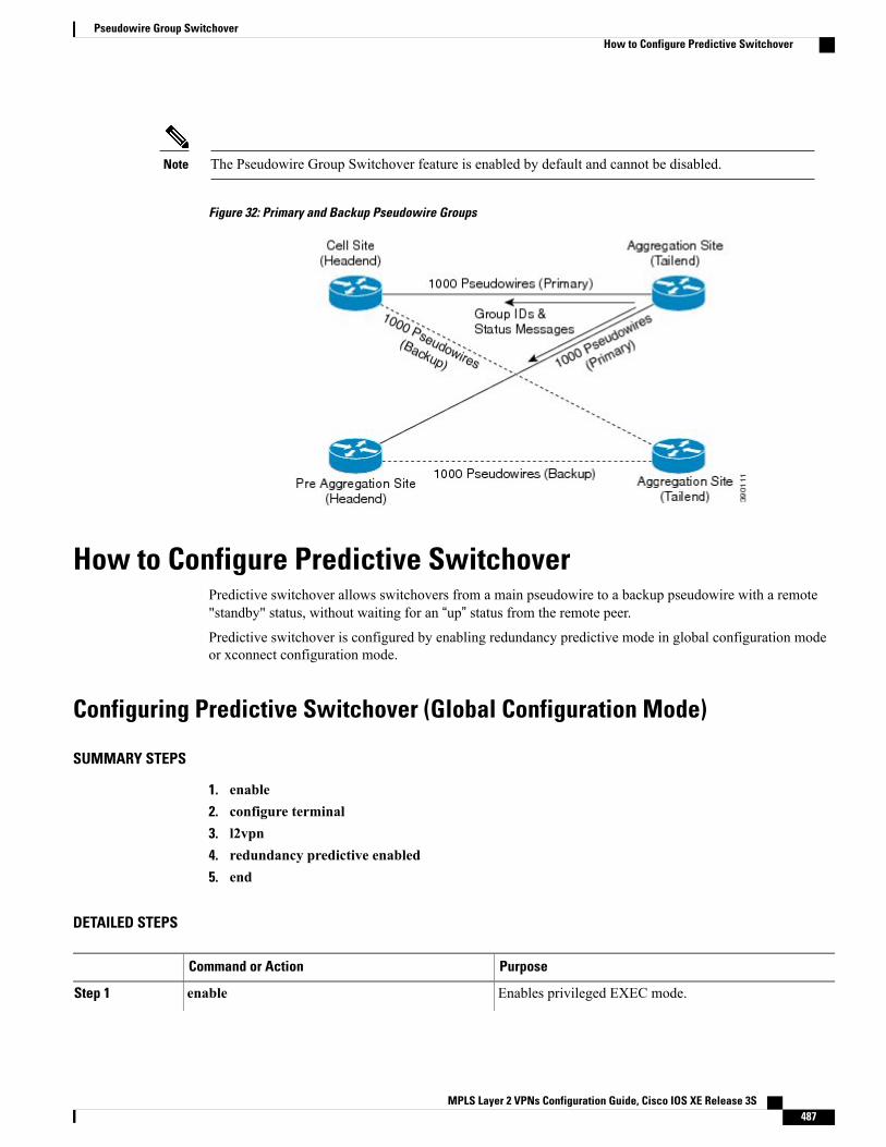
The Pseudowire Group Switchover feature is enabled by default and cannot be disabled.Note
Figure 32: Primary and Backup Pseudowire Groups
How to Configure Predictive SwitchoverPredictive switchover allows switchovers from a main pseudowire to a backup pseudowire with a remote"standby" status, without waiting for an “up” status from the remote peer.
Predictive switchover is configured by enabling redundancy predictive mode in global configuration modeor xconnect configuration mode.
Configuring Predictive Switchover (Global Configuration Mode)
SUMMARY STEPS
1. enable2. configure terminal3. l2vpn4. redundancy predictive enabled5. end
DETAILED STEPS
PurposeCommand or Action
Enables privileged EXEC mode.enableStep 1
MPLS Layer 2 VPNs Configuration Guide, Cisco IOS XE Release 3S 487
Pseudowire Group SwitchoverHow to Configure Predictive Switchover
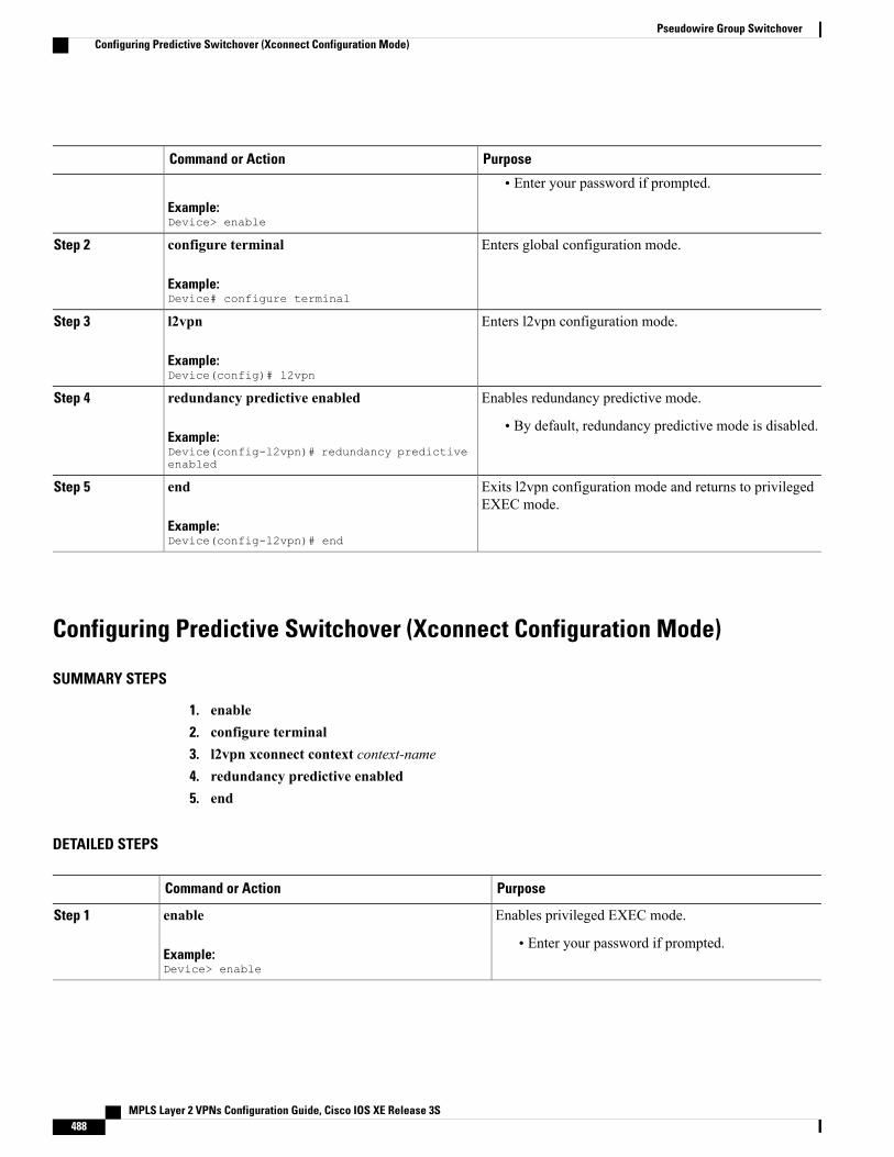
PurposeCommand or Action
Example:Device> enable
• Enter your password if prompted.
Enters global configuration mode.configure terminal
Example:Device# configure terminal
Step 2
Enters l2vpn configuration mode.l2vpn
Example:Device(config)# l2vpn
Step 3
Enables redundancy predictive mode.redundancy predictive enabledStep 4
Example:Device(config-l2vpn)# redundancy predictiveenabled
• By default, redundancy predictive mode is disabled.
Exits l2vpn configuration mode and returns to privilegedEXEC mode.
end
Example:Device(config-l2vpn)# end
Step 5
Configuring Predictive Switchover (Xconnect Configuration Mode)
SUMMARY STEPS
1. enable2. configure terminal3. l2vpn xconnect context context-name4. redundancy predictive enabled5. end
DETAILED STEPS
PurposeCommand or Action
Enables privileged EXEC mode.enableStep 1
Example:Device> enable
• Enter your password if prompted.
MPLS Layer 2 VPNs Configuration Guide, Cisco IOS XE Release 3S488
Pseudowire Group SwitchoverConfiguring Predictive Switchover (Xconnect Configuration Mode)
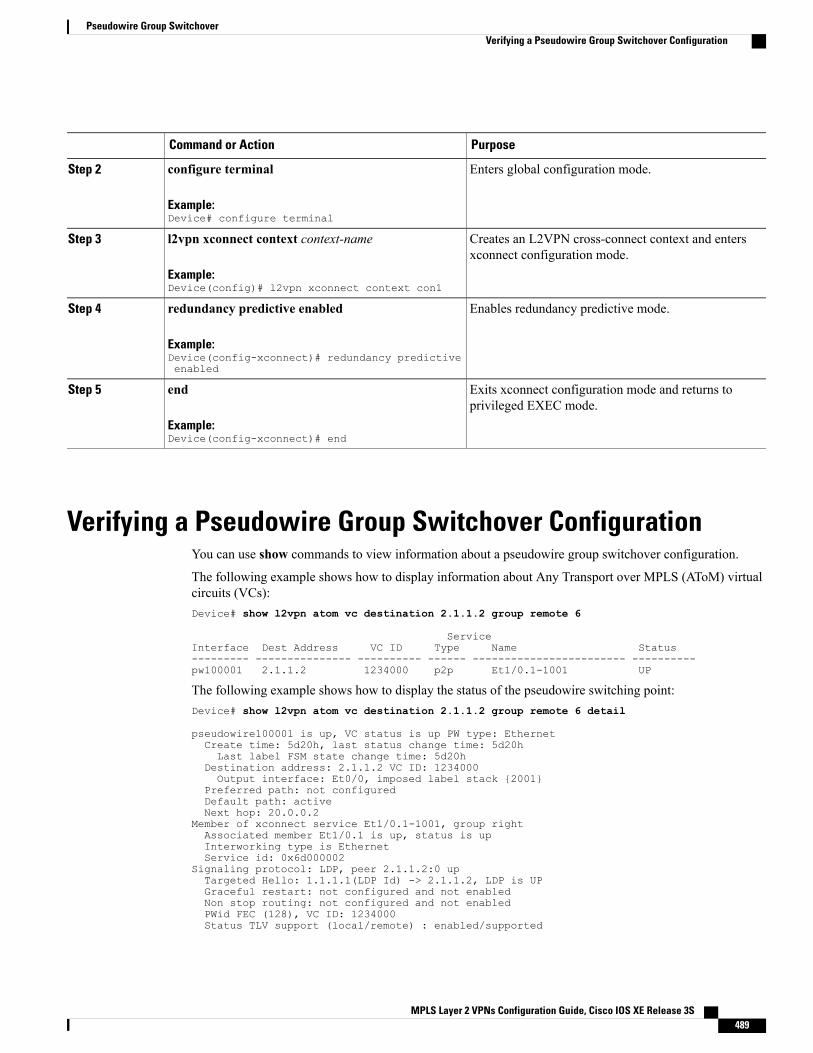
PurposeCommand or Action
Enters global configuration mode.configure terminal
Example:Device# configure terminal
Step 2
Creates an L2VPN cross-connect context and entersxconnect configuration mode.
l2vpn xconnect context context-name
Example:Device(config)# l2vpn xconnect context con1
Step 3
Enables redundancy predictive mode.redundancy predictive enabled
Example:Device(config-xconnect)# redundancy predictiveenabled
Step 4
Exits xconnect configuration mode and returns toprivileged EXEC mode.
end
Example:Device(config-xconnect)# end
Step 5
Verifying a Pseudowire Group Switchover ConfigurationYou can use show commands to view information about a pseudowire group switchover configuration.
The following example shows how to display information about Any Transport over MPLS (AToM) virtualcircuits (VCs):Device# show l2vpn atom vc destination 2.1.1.2 group remote 6
ServiceInterface Dest Address VC ID Type Name Status--------- --------------- ---------- ------ ------------------------ ----------pw100001 2.1.1.2 1234000 p2p Et1/0.1-1001 UP
The following example shows how to display the status of the pseudowire switching point:Device# show l2vpn atom vc destination 2.1.1.2 group remote 6 detail
pseudowire100001 is up, VC status is up PW type: EthernetCreate time: 5d20h, last status change time: 5d20hLast label FSM state change time: 5d20h
Destination address: 2.1.1.2 VC ID: 1234000Output interface: Et0/0, imposed label stack {2001}
Preferred path: not configuredDefault path: activeNext hop: 20.0.0.2
Member of xconnect service Et1/0.1-1001, group rightAssociated member Et1/0.1 is up, status is upInterworking type is EthernetService id: 0x6d000002
Signaling protocol: LDP, peer 2.1.1.2:0 upTargeted Hello: 1.1.1.1(LDP Id) -> 2.1.1.2, LDP is UPGraceful restart: not configured and not enabledNon stop routing: not configured and not enabledPWid FEC (128), VC ID: 1234000Status TLV support (local/remote) : enabled/supported
MPLS Layer 2 VPNs Configuration Guide, Cisco IOS XE Release 3S 489
Pseudowire Group SwitchoverVerifying a Pseudowire Group Switchover Configuration
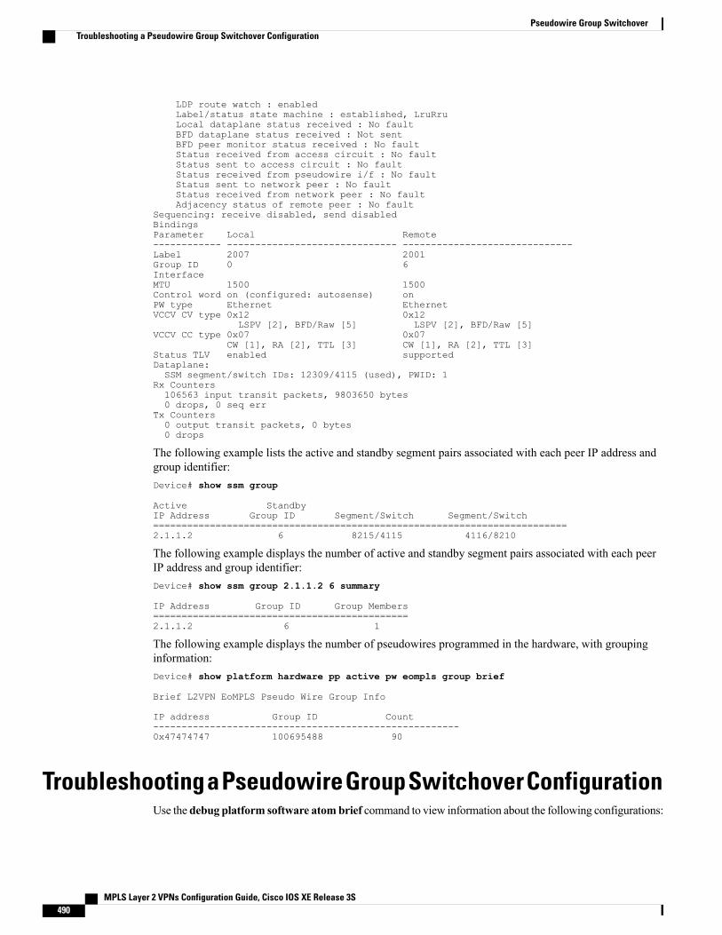
LDP route watch : enabledLabel/status state machine : established, LruRruLocal dataplane status received : No faultBFD dataplane status received : Not sentBFD peer monitor status received : No faultStatus received from access circuit : No faultStatus sent to access circuit : No faultStatus received from pseudowire i/f : No faultStatus sent to network peer : No faultStatus received from network peer : No faultAdjacency status of remote peer : No fault
Sequencing: receive disabled, send disabledBindingsParameter Local Remote------------ ------------------------------ ------------------------------Label 2007 2001Group ID 0 6InterfaceMTU 1500 1500Control word on (configured: autosense) onPW type Ethernet EthernetVCCV CV type 0x12 0x12
LSPV [2], BFD/Raw [5] LSPV [2], BFD/Raw [5]VCCV CC type 0x07 0x07
CW [1], RA [2], TTL [3] CW [1], RA [2], TTL [3]Status TLV enabled supportedDataplane:SSM segment/switch IDs: 12309/4115 (used), PWID: 1
Rx Counters106563 input transit packets, 9803650 bytes0 drops, 0 seq err
Tx Counters0 output transit packets, 0 bytes0 drops
The following example lists the active and standby segment pairs associated with each peer IP address andgroup identifier:Device# show ssm group
Active StandbyIP Address Group ID Segment/Switch Segment/Switch=========================================================================2.1.1.2 6 8215/4115 4116/8210
The following example displays the number of active and standby segment pairs associated with each peerIP address and group identifier:Device# show ssm group 2.1.1.2 6 summary
IP Address Group ID Group Members=============================================2.1.1.2 6 1
The following example displays the number of pseudowires programmed in the hardware, with groupinginformation:Device# show platform hardware pp active pw eompls group brief
Brief L2VPN EoMPLS Pseudo Wire Group Info
IP address Group ID Count------------------------------------------------------0x47474747 100695488 90
Troubleshooting a Pseudowire Group Switchover ConfigurationUse the debug platform software atombrief command to view information about the following configurations:
MPLS Layer 2 VPNs Configuration Guide, Cisco IOS XE Release 3S490
Pseudowire Group SwitchoverTroubleshooting a Pseudowire Group Switchover Configuration
• Add Group
• Delete From Group
• Group Switchovers
We recommend that you use the debug platform software atom brief command only under CiscoTechnical Assistance Center (TAC) supervision.
Note
Configuration Examples for Predictive Switchover
Example: Configuring Predictive Switchover (Global Configuration Mode)Device> enableDevice# configure terminalDevice(config)# l2vpnDevice(config-l2vpn)# redundancy predictive enabledDevice(config-l2vpn)# end
Example: Configuring Predictive Switchover (Xconnect Configuration Mode)Device> enableDevice# configure terminalDevice(config)# l2vpn xconnect context con1Device(config-xconnect)# redundancy predictive enabledDevice(config-xconnect)# end
Additional ReferencesRelated Documents
Document TitleRelated Topic
Cisco IOS Master Command List, All ReleasesCisco IOS commands
Cisco IOSMultiprotocol Label Switching CommandReference
MPLS commands
Standards and RFCs
TitleStandard/RFC
Pseudowire Setup and Maintenance Using the LabelDistribution Protocol (LDP)
RFC 4447
MPLS Layer 2 VPNs Configuration Guide, Cisco IOS XE Release 3S 491
Pseudowire Group SwitchoverConfiguration Examples for Predictive Switchover
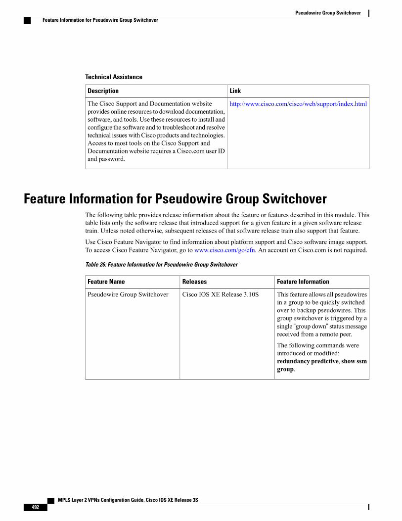
Technical Assistance
LinkDescription
http://www.cisco.com/cisco/web/support/index.htmlThe Cisco Support and Documentation websiteprovides online resources to download documentation,software, and tools. Use these resources to install andconfigure the software and to troubleshoot and resolvetechnical issues with Cisco products and technologies.Access to most tools on the Cisco Support andDocumentation website requires a Cisco.com user IDand password.
Feature Information for Pseudowire Group SwitchoverThe following table provides release information about the feature or features described in this module. Thistable lists only the software release that introduced support for a given feature in a given software releasetrain. Unless noted otherwise, subsequent releases of that software release train also support that feature.
Use Cisco Feature Navigator to find information about platform support and Cisco software image support.To access Cisco Feature Navigator, go to www.cisco.com/go/cfn. An account on Cisco.com is not required.
Table 26: Feature Information for Pseudowire Group Switchover
Feature InformationReleasesFeature Name
This feature allows all pseudowiresin a group to be quickly switchedover to backup pseudowires. Thisgroup switchover is triggered by asingle “group down” statusmessagereceived from a remote peer.
The following commands wereintroduced or modified:redundancy predictive, show ssmgroup.
Cisco IOS XE Release 3.10SPseudowire Group Switchover
MPLS Layer 2 VPNs Configuration Guide, Cisco IOS XE Release 3S492
Pseudowire Group SwitchoverFeature Information for Pseudowire Group Switchover
C H A P T E R 14L2VPN Pseudowire Switching
This feature module explains how to configure L2VPN Pseudowire Switching, which extends layer 2 virtualprivate network (L2VPN) pseudowires across an interautonomous system (inter-AS) boundary or acrosstwo separate multiprotocol label switching (MPLS) networks.
• Finding Feature Information, page 493
• Restrictions for L2VPN Pseudowire Switching, page 493
• Information About L2VPN Pseudowire Switching, page 494
• How to Configure L2VPN Pseudowire Switching, page 496
• How to Configure L2VPN Pseudowire Switching using the commands associated with the L2VPNProtocol-Based CLIs feature, page 498
• Configuration Examples for L2VPN Pseudowire Switching, page 505
• Additional References, page 507
• Feature Information for L2VPN Pseudowire Switching, page 508
Finding Feature InformationYour software release may not support all the features documented in this module. For the latest caveats andfeature information, see Bug Search Tool and the release notes for your platform and software release. Tofind information about the features documented in this module, and to see a list of the releases in which eachfeature is supported, see the feature information table at the end of this module.
Use Cisco Feature Navigator to find information about platform support and Cisco software image support.To access Cisco Feature Navigator, go to www.cisco.com/go/cfn. An account on Cisco.com is not required.
Restrictions for L2VPN Pseudowire Switching• In Cisco IOS XE Release 2.4, Pseudowire Switching is supported on Ethernet over MPLS attachmentcircuits.
• L2VPN Pseudowire Switching is supported with AToM.
MPLS Layer 2 VPNs Configuration Guide, Cisco IOS XE Release 3S 493
• Only static, on-box provisioning is supported.
• Sequencing numbers in AToM packets are not processed by L2VPN Pseudowire Switching. The featureblindly passes the sequencing data through the xconnect packet paths, a process that is called transparentsequencing. The endpoint PE-CE connections enforce the sequencing.
• You can ping the adjacent next-hop PE router. End-to-end LSP pings are not supported.
• Do not configure IP or Ethernet interworking on a router where L2VPN Pseudowire Switching is enabled.Instead, configure interworking on the routers at the edge PEs of the network.
• The control word negotiation results must match. If either segment does not negotiate the control word,the control word is disabled for both segments.
• AToM Graceful Restart is negotiated independently on each pseudowire segment. If there is a transientloss of the LDP session between two AToM PE routers, packets continue to flow.
• Per-pseudowire quality of service (QoS) is not supported. Traffic Engineering (TE) tunnel selection issupported.
• Attachment circuit interworking is not supported.
Information About L2VPN Pseudowire Switching
How L2VPN Pseudowire Switching WorksL2VPN Pseudowire Switching allows the user to extend L2VPN pseudowires across an inter-AS boundaryor across two separateMPLS networks, as shown in the figures below. L2VPN Pseudowire Switching connectstwo or more contiguous pseudowire segments to form an end-to-end multihop pseudowire. This end-to-endpseudowire functions as a single point-to-point pseudowire.
As shown in the second figure below, L2VPN Pseudowire Switching enables you to keep the IP addresses ofthe edge PE routers private across inter-AS boundaries. You can use the IP address of the autonomous systemboundary routers (ASBRs) and treat them as pseudowire aggregation (PE-agg) routers. The ASBRs join thepseudowires of the two domains.
MPLS Layer 2 VPNs Configuration Guide, Cisco IOS XE Release 3S494
L2VPN Pseudowire SwitchingInformation About L2VPN Pseudowire Switching
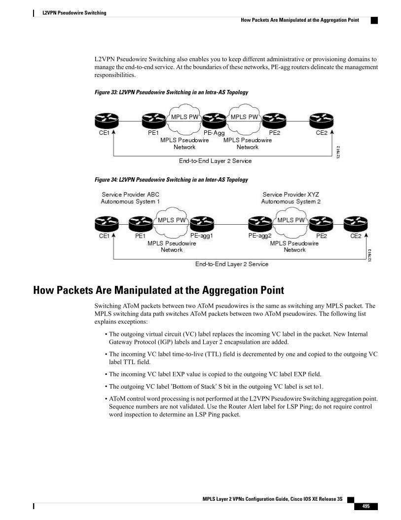
L2VPN Pseudowire Switching also enables you to keep different administrative or provisioning domains tomanage the end-to-end service. At the boundaries of these networks, PE-agg routers delineate the managementresponsibilities.
Figure 33: L2VPN Pseudowire Switching in an Intra-AS Topology
Figure 34: L2VPN Pseudowire Switching in an Inter-AS Topology
How Packets Are Manipulated at the Aggregation PointSwitching AToM packets between two AToM pseudowires is the same as switching any MPLS packet. TheMPLS switching data path switches AToM packets between two AToM pseudowires. The following listexplains exceptions:
• The outgoing virtual circuit (VC) label replaces the incoming VC label in the packet. New InternalGateway Protocol (IGP) labels and Layer 2 encapsulation are added.
• The incoming VC label time-to-live (TTL) field is decremented by one and copied to the outgoing VClabel TTL field.
• The incoming VC label EXP value is copied to the outgoing VC label EXP field.
• The outgoing VC label ‘Bottom of Stack’ S bit in the outgoing VC label is set to1.
• AToM control word processing is not performed at the L2VPN Pseudowire Switching aggregation point.Sequence numbers are not validated. Use the Router Alert label for LSP Ping; do not require controlword inspection to determine an LSP Ping packet.
MPLS Layer 2 VPNs Configuration Guide, Cisco IOS XE Release 3S 495
L2VPN Pseudowire SwitchingHow Packets Are Manipulated at the Aggregation Point
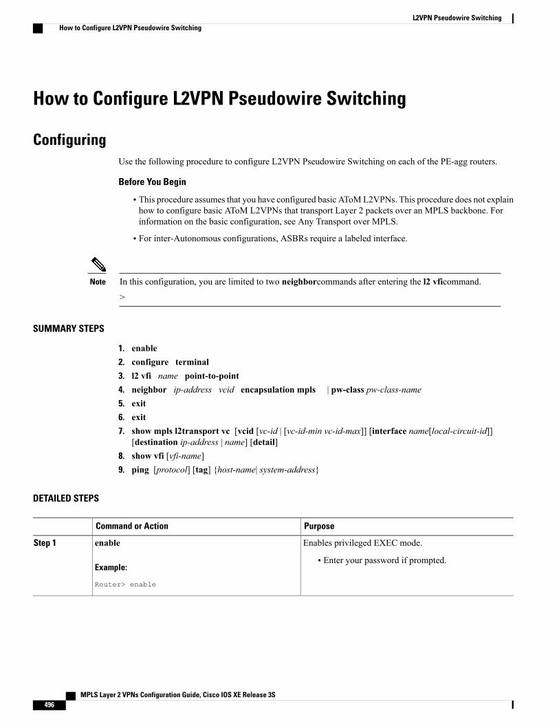
How to Configure L2VPN Pseudowire Switching
ConfiguringUse the following procedure to configure L2VPN Pseudowire Switching on each of the PE-agg routers.
Before You Begin
• This procedure assumes that you have configured basic AToML2VPNs. This procedure does not explainhow to configure basic AToM L2VPNs that transport Layer 2 packets over an MPLS backbone. Forinformation on the basic configuration, see Any Transport over MPLS.
• For inter-Autonomous configurations, ASBRs require a labeled interface.
In this configuration, you are limited to two neighborcommands after entering the l2 vficommand.
>
Note
SUMMARY STEPS
1. enable2. configure terminal3. l2 vfi name point-to-point4. neighbor ip-address vcid encapsulation mpls | pw-class pw-class-name5. exit6. exit7. show mpls l2transport vc [vcid [vc-id | [vc-id-min vc-id-max]] [interface name[local-circuit-id]]
[destination ip-address | name] [detail]8. show vfi [vfi-name]9. ping [protocol] [tag] {host-name| system-address}
DETAILED STEPS
PurposeCommand or Action
Enables privileged EXEC mode.enableStep 1
Example:
Router> enable
• Enter your password if prompted.
MPLS Layer 2 VPNs Configuration Guide, Cisco IOS XE Release 3S496
L2VPN Pseudowire SwitchingHow to Configure L2VPN Pseudowire Switching
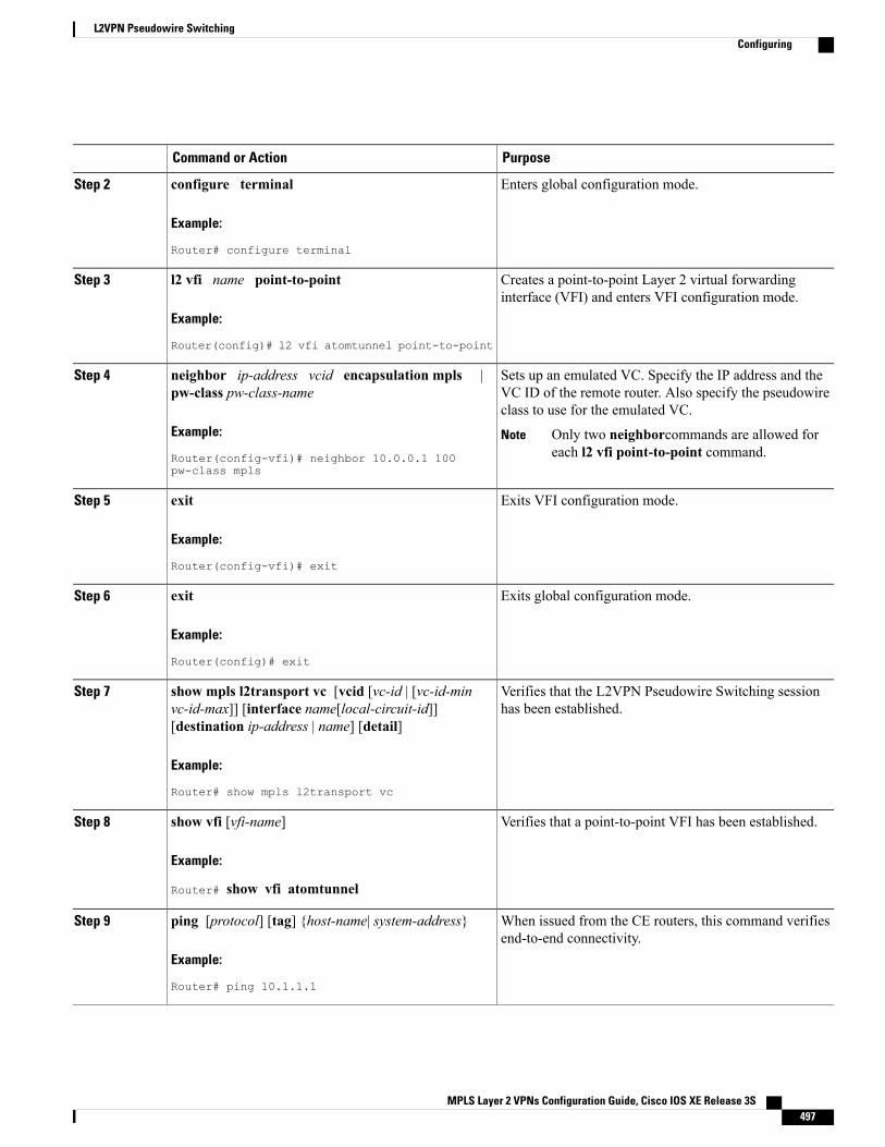
PurposeCommand or Action
Enters global configuration mode.configure terminal
Example:
Router# configure terminal
Step 2
Creates a point-to-point Layer 2 virtual forwardinginterface (VFI) and enters VFI configuration mode.
l2 vfi name point-to-point
Example:
Router(config)# l2 vfi atomtunnel point-to-point
Step 3
Sets up an emulated VC. Specify the IP address and theVC ID of the remote router. Also specify the pseudowireclass to use for the emulated VC.
neighbor ip-address vcid encapsulation mpls |pw-class pw-class-name
Example:
Router(config-vfi)# neighbor 10.0.0.1 100pw-class mpls
Step 4
Only two neighborcommands are allowed foreach l2 vfi point-to-point command.
Note
Exits VFI configuration mode.exit
Example:
Router(config-vfi)# exit
Step 5
Exits global configuration mode.exit
Example:
Router(config)# exit
Step 6
Verifies that the L2VPN Pseudowire Switching sessionhas been established.
show mpls l2transport vc [vcid [vc-id | [vc-id-minvc-id-max]] [interface name[local-circuit-id]][destination ip-address | name] [detail]
Step 7
Example:
Router# show mpls l2transport vc
Verifies that a point-to-point VFI has been established.show vfi [vfi-name]
Example:
Router# show vfi atomtunnel
Step 8
When issued from the CE routers, this command verifiesend-to-end connectivity.
ping [protocol] [tag] {host-name| system-address}
Example:
Router# ping 10.1.1.1
Step 9
MPLS Layer 2 VPNs Configuration Guide, Cisco IOS XE Release 3S 497
L2VPN Pseudowire SwitchingConfiguring
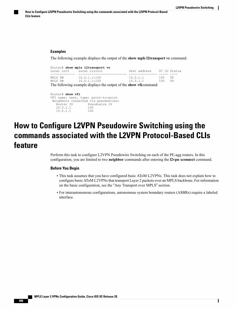
Examples
The following example displays the output of the show mpls l2transport vc command:
Router# show mpls l2transport vcLocal intf Local circuit Dest address VC ID Status------------- -------------------------- --------------- ----- ----MPLS PW 10.0.1.1:100 10.0.1.1 100 UPMPLS PW 10.0.1.1:100 10.0.1.1 100 UPThe following example displays the output of the show vficommand:
Router# show vfiVFI name: test, type: point-to-pointNeighbors connected via pseudowires:Router ID Pseudowire ID10.0.1.1 10010.0.1.1 100
How to Configure L2VPN Pseudowire Switching using thecommands associated with the L2VPN Protocol-Based CLIsfeature
Perform this task to configure L2VPN Pseudowire Switching on each of the PE-agg routers. In thisconfiguration, you are limited to two neighbor commands after entering the l2vpn xconnect command.
Before You Begin
• This task assumes that you have configured basic AToM L2VPNs. This task does not explain how toconfigure basic AToML2VPNs that transport Layer 2 packets over anMPLS backbone. For informationon the basic configuration, see the “Any Transport over MPLS” section.
• For interautonomous configurations, autonomous system boundary routers (ASBRs) require a labeledinterface.
MPLS Layer 2 VPNs Configuration Guide, Cisco IOS XE Release 3S498
L2VPN Pseudowire SwitchingHow to Configure L2VPN Pseudowire Switching using the commands associated with the L2VPN Protocol-BasedCLIs feature
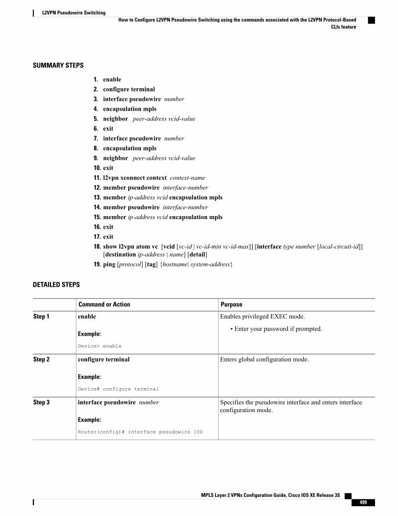
SUMMARY STEPS
1. enable2. configure terminal3. interface pseudowire number4. encapsulation mpls5. neighbor peer-address vcid-value6. exit7. interface pseudowire number8. encapsulation mpls9. neighbor peer-address vcid-value10. exit11. l2vpn xconnect context context-name12. member pseudowire interface-number13. member ip-address vcid encapsulation mpls14. member pseudowire interface-number15. member ip-address vcid encapsulation mpls16. exit17. exit18. show l2vpn atom vc [vcid [vc-id | vc-id-min vc-id-max]] [interface type number [local-circuit-id]]
[destination ip-address | name] [detail]19. ping [protocol] [tag] {hostname| system-address}
DETAILED STEPS
PurposeCommand or Action
Enables privileged EXEC mode.enableStep 1
Example:
Device> enable
• Enter your password if prompted.
Enters global configuration mode.configure terminal
Example:
Device# configure terminal
Step 2
Specifies the pseudowire interface and enters interfaceconfiguration mode.
interface pseudowire number
Example:
Router(config)# interface pseudowire 100
Step 3
MPLS Layer 2 VPNs Configuration Guide, Cisco IOS XE Release 3S 499
L2VPN Pseudowire SwitchingHow to Configure L2VPN Pseudowire Switching using the commands associated with the L2VPN Protocol-Based
CLIs feature
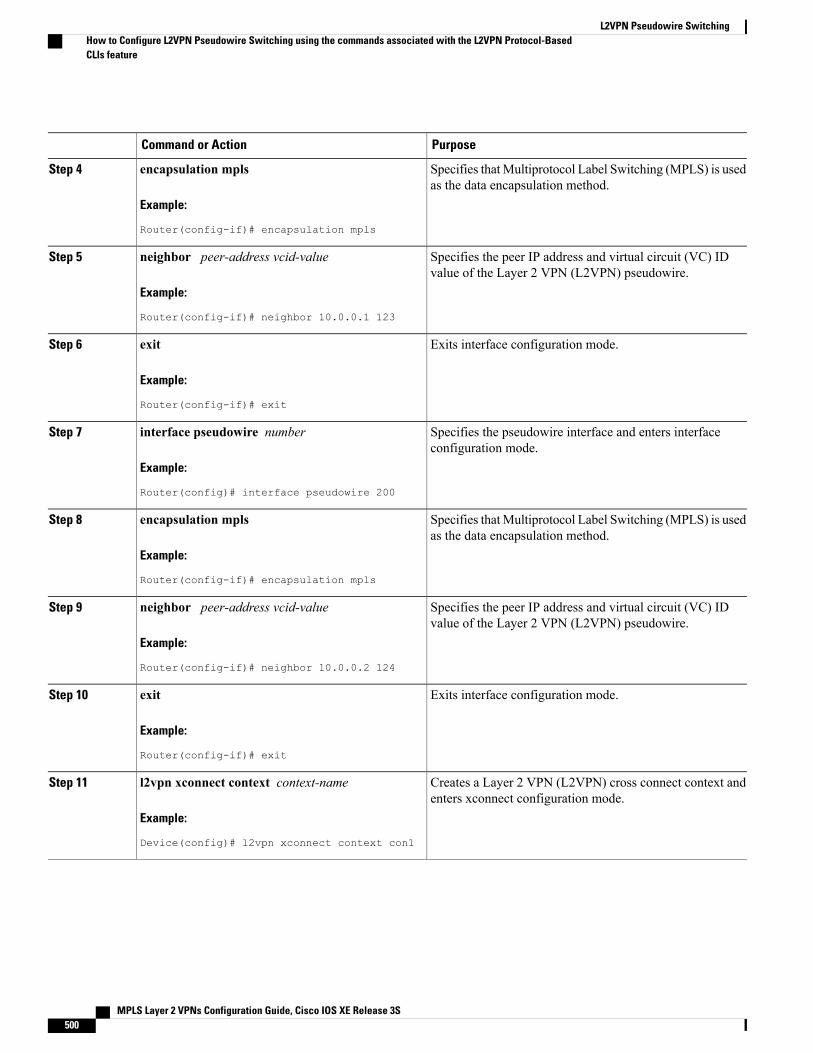
PurposeCommand or Action
Specifies thatMultiprotocol Label Switching (MPLS) is usedas the data encapsulation method.
encapsulation mpls
Example:
Router(config-if)# encapsulation mpls
Step 4
Specifies the peer IP address and virtual circuit (VC) IDvalue of the Layer 2 VPN (L2VPN) pseudowire.
neighbor peer-address vcid-value
Example:
Router(config-if)# neighbor 10.0.0.1 123
Step 5
Exits interface configuration mode.exit
Example:
Router(config-if)# exit
Step 6
Specifies the pseudowire interface and enters interfaceconfiguration mode.
interface pseudowire number
Example:
Router(config)# interface pseudowire 200
Step 7
Specifies thatMultiprotocol Label Switching (MPLS) is usedas the data encapsulation method.
encapsulation mpls
Example:
Router(config-if)# encapsulation mpls
Step 8
Specifies the peer IP address and virtual circuit (VC) IDvalue of the Layer 2 VPN (L2VPN) pseudowire.
neighbor peer-address vcid-value
Example:
Router(config-if)# neighbor 10.0.0.2 124
Step 9
Exits interface configuration mode.exit
Example:
Router(config-if)# exit
Step 10
Creates a Layer 2 VPN (L2VPN) cross connect context andenters xconnect configuration mode.
l2vpn xconnect context context-name
Example:
Device(config)# l2vpn xconnect context con1
Step 11
MPLS Layer 2 VPNs Configuration Guide, Cisco IOS XE Release 3S500
L2VPN Pseudowire SwitchingHow to Configure L2VPN Pseudowire Switching using the commands associated with the L2VPN Protocol-BasedCLIs feature
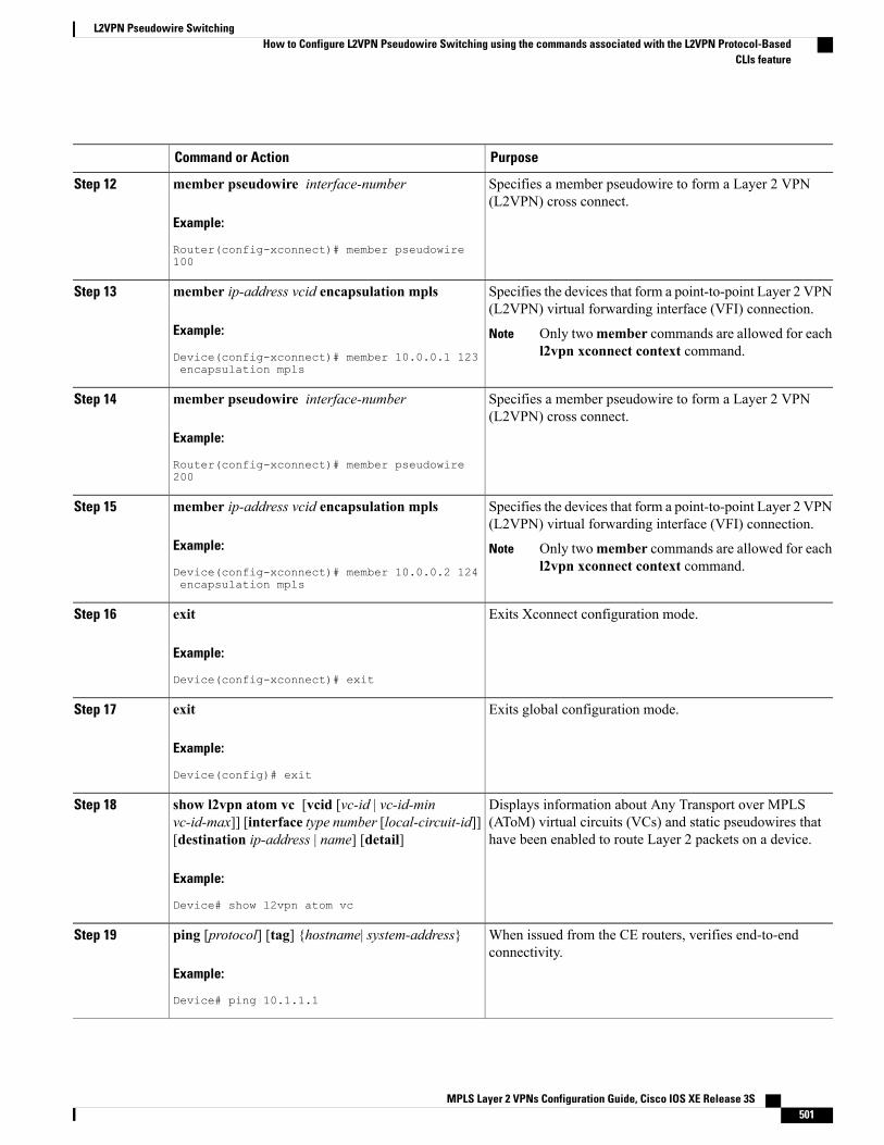
PurposeCommand or Action
Specifies a member pseudowire to form a Layer 2 VPN(L2VPN) cross connect.
member pseudowire interface-number
Example:
Router(config-xconnect)# member pseudowire100
Step 12
Specifies the devices that form a point-to-point Layer 2 VPN(L2VPN) virtual forwarding interface (VFI) connection.
member ip-address vcid encapsulation mpls
Example:
Device(config-xconnect)# member 10.0.0.1 123encapsulation mpls
Step 13
Only twomember commands are allowed for eachl2vpn xconnect context command.
Note
Specifies a member pseudowire to form a Layer 2 VPN(L2VPN) cross connect.
member pseudowire interface-number
Example:
Router(config-xconnect)# member pseudowire200
Step 14
Specifies the devices that form a point-to-point Layer 2 VPN(L2VPN) virtual forwarding interface (VFI) connection.
member ip-address vcid encapsulation mpls
Example:
Device(config-xconnect)# member 10.0.0.2 124encapsulation mpls
Step 15
Only twomember commands are allowed for eachl2vpn xconnect context command.
Note
Exits Xconnect configuration mode.exit
Example:
Device(config-xconnect)# exit
Step 16
Exits global configuration mode.exit
Example:
Device(config)# exit
Step 17
Displays information about Any Transport over MPLS(AToM) virtual circuits (VCs) and static pseudowires thathave been enabled to route Layer 2 packets on a device.
show l2vpn atom vc [vcid [vc-id | vc-id-minvc-id-max]] [interface type number [local-circuit-id]][destination ip-address | name] [detail]
Example:
Device# show l2vpn atom vc
Step 18
When issued from the CE routers, verifies end-to-endconnectivity.
ping [protocol] [tag] {hostname| system-address}
Example:
Device# ping 10.1.1.1
Step 19
MPLS Layer 2 VPNs Configuration Guide, Cisco IOS XE Release 3S 501
L2VPN Pseudowire SwitchingHow to Configure L2VPN Pseudowire Switching using the commands associated with the L2VPN Protocol-Based
CLIs feature
ConfiguringUse the following procedure to configure L2VPN Pseudowire Switching on each of the PE-agg routers.
Before You Begin
• This procedure assumes that you have configured basic AToML2VPNs. This procedure does not explainhow to configure basic AToM L2VPNs that transport Layer 2 packets over an MPLS backbone. Forinformation on the basic configuration, see Any Transport over MPLS.
• For inter-Autonomous configurations, ASBRs require a labeled interface.
In this configuration, you are limited to two neighborcommands after entering the l2 vficommand.
>
Note
SUMMARY STEPS
1. enable2. configure terminal3. l2 vfi name point-to-point4. neighbor ip-address vcid encapsulation mpls | pw-class pw-class-name5. exit6. exit7. show mpls l2transport vc [vcid [vc-id | [vc-id-min vc-id-max]] [interface name[local-circuit-id]]
[destination ip-address | name] [detail]8. show vfi [vfi-name]9. ping [protocol] [tag] {host-name| system-address}
DETAILED STEPS
PurposeCommand or Action
Enables privileged EXEC mode.enableStep 1
Example:
Router> enable
• Enter your password if prompted.
Enters global configuration mode.configure terminal
Example:
Router# configure terminal
Step 2
MPLS Layer 2 VPNs Configuration Guide, Cisco IOS XE Release 3S502
L2VPN Pseudowire SwitchingConfiguring
PurposeCommand or Action
Creates a point-to-point Layer 2 virtual forwardinginterface (VFI) and enters VFI configuration mode.
l2 vfi name point-to-point
Example:
Router(config)# l2 vfi atomtunnel point-to-point
Step 3
Sets up an emulated VC. Specify the IP address and theVC ID of the remote router. Also specify the pseudowireclass to use for the emulated VC.
neighbor ip-address vcid encapsulation mpls |pw-class pw-class-name
Example:
Router(config-vfi)# neighbor 10.0.0.1 100pw-class mpls
Step 4
Only two neighborcommands are allowed foreach l2 vfi point-to-point command.
Note
Exits VFI configuration mode.exit
Example:
Router(config-vfi)# exit
Step 5
Exits global configuration mode.exit
Example:
Router(config)# exit
Step 6
Verifies that the L2VPN Pseudowire Switching sessionhas been established.
show mpls l2transport vc [vcid [vc-id | [vc-id-minvc-id-max]] [interface name[local-circuit-id]][destination ip-address | name] [detail]
Step 7
Example:
Router# show mpls l2transport vc
Verifies that a point-to-point VFI has been established.show vfi [vfi-name]
Example:
Router# show vfi atomtunnel
Step 8
When issued from the CE routers, this command verifiesend-to-end connectivity.
ping [protocol] [tag] {host-name| system-address}
Example:
Router# ping 10.1.1.1
Step 9
MPLS Layer 2 VPNs Configuration Guide, Cisco IOS XE Release 3S 503
L2VPN Pseudowire SwitchingConfiguring
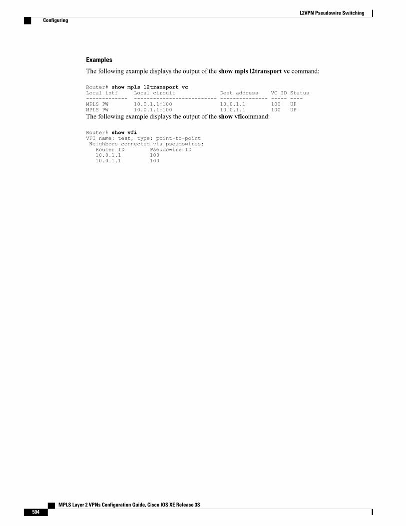
Examples
The following example displays the output of the show mpls l2transport vc command:
Router# show mpls l2transport vcLocal intf Local circuit Dest address VC ID Status------------- -------------------------- --------------- ----- ----MPLS PW 10.0.1.1:100 10.0.1.1 100 UPMPLS PW 10.0.1.1:100 10.0.1.1 100 UPThe following example displays the output of the show vficommand:
Router# show vfiVFI name: test, type: point-to-pointNeighbors connected via pseudowires:Router ID Pseudowire ID10.0.1.1 10010.0.1.1 100
MPLS Layer 2 VPNs Configuration Guide, Cisco IOS XE Release 3S504
L2VPN Pseudowire SwitchingConfiguring
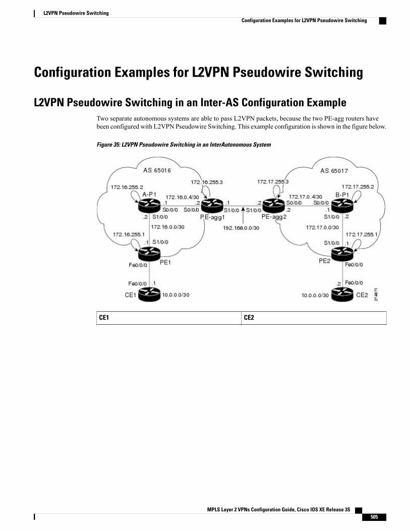
Configuration Examples for L2VPN Pseudowire Switching
L2VPN Pseudowire Switching in an Inter-AS Configuration ExampleTwo separate autonomous systems are able to pass L2VPN packets, because the two PE-agg routers havebeen configured with L2VPN Pseudowire Switching. This example configuration is shown in the figure below.
Figure 35: L2VPN Pseudowire Switching in an InterAutonomous System
CE2CE1
MPLS Layer 2 VPNs Configuration Guide, Cisco IOS XE Release 3S 505
L2VPN Pseudowire SwitchingConfiguration Examples for L2VPN Pseudowire Switching
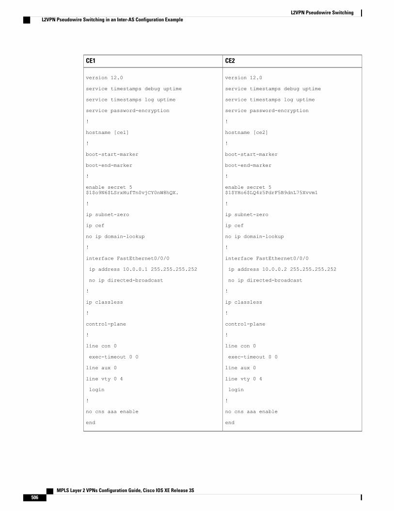
CE2CE1
version 12.0
service timestamps debug uptime
service timestamps log uptime
service password-encryption
!
hostname [ce1]
!
boot-start-marker
boot-end-marker
!
enable secret 5$1$o9N6$LSrxHufTn0vjCY0nW8hQX.
!
ip subnet-zero
ip cef
no ip domain-lookup
!
interface FastEthernet0/0/0
ip address 10.0.0.1 255.255.255.252
no ip directed-broadcast
!
ip classless
!
control-plane
!
line con 0
exec-timeout 0 0
line aux 0
line vty 0 4
login
!
no cns aaa enable
end
version 12.0
service timestamps debug uptime
service timestamps log uptime
service password-encryption
!
hostname [ce2]
!
boot-start-marker
boot-end-marker
!
enable secret 5$1$YHo6$LQ4z5PdrF5B9dnL75Xvvm1
!
ip subnet-zero
ip cef
no ip domain-lookup
!
interface FastEthernet0/0/0
ip address 10.0.0.2 255.255.255.252
no ip directed-broadcast
!
ip classless
!
control-plane
!
line con 0
exec-timeout 0 0
line aux 0
line vty 0 4
login
!
no cns aaa enable
end
MPLS Layer 2 VPNs Configuration Guide, Cisco IOS XE Release 3S506
L2VPN Pseudowire SwitchingL2VPN Pseudowire Switching in an Inter-AS Configuration Example
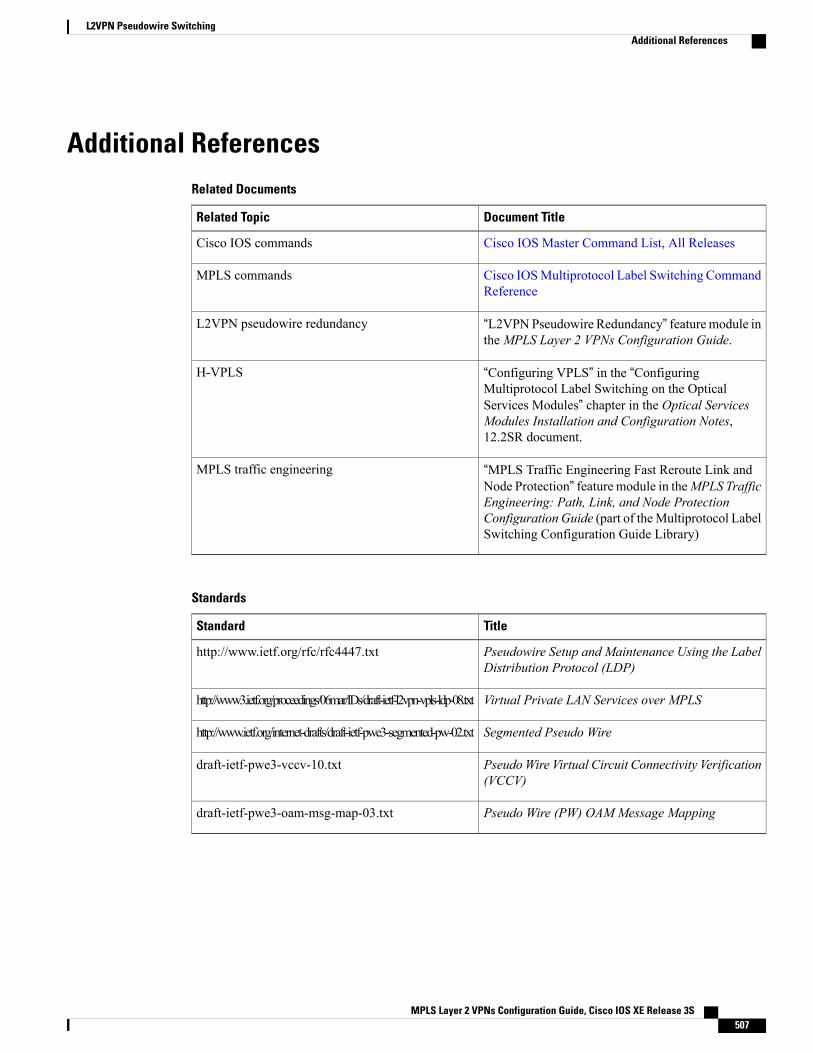
Additional ReferencesRelated Documents
Document TitleRelated Topic
Cisco IOS Master Command List, All ReleasesCisco IOS commands
Cisco IOSMultiprotocol Label Switching CommandReference
MPLS commands
“L2VPNPseudowire Redundancy” featuremodule intheMPLS Layer 2 VPNs Configuration Guide.
L2VPN pseudowire redundancy
“Configuring VPLS” in the “ConfiguringMultiprotocol Label Switching on the OpticalServices Modules” chapter in the Optical ServicesModules Installation and Configuration Notes,12.2SR document.
H-VPLS
“MPLS Traffic Engineering Fast Reroute Link andNode Protection” feature module in theMPLS TrafficEngineering: Path, Link, and Node ProtectionConfiguration Guide (part of theMultiprotocol LabelSwitching Configuration Guide Library)
MPLS traffic engineering
Standards
TitleStandard
Pseudowire Setup and Maintenance Using the LabelDistribution Protocol (LDP)
http://www.ietf.org/rfc/rfc4447.txt
Virtual Private LAN Services over MPLShttp://www3.ietf.org/proceedings/06mar/IDs/draft-ietf-l2vpn-vpls-ldp-08.txt
Segmented Pseudo Wirehttp://www.ietf.org/internet-drafts/draft-ietf-pwe3-segmented-pw-02.txt
PseudoWire Virtual Circuit Connectivity Verification(VCCV)
draft-ietf-pwe3-vccv-10.txt
Pseudo Wire (PW) OAM Message Mappingdraft-ietf-pwe3-oam-msg-map-03.txt
MPLS Layer 2 VPNs Configuration Guide, Cisco IOS XE Release 3S 507
L2VPN Pseudowire SwitchingAdditional References
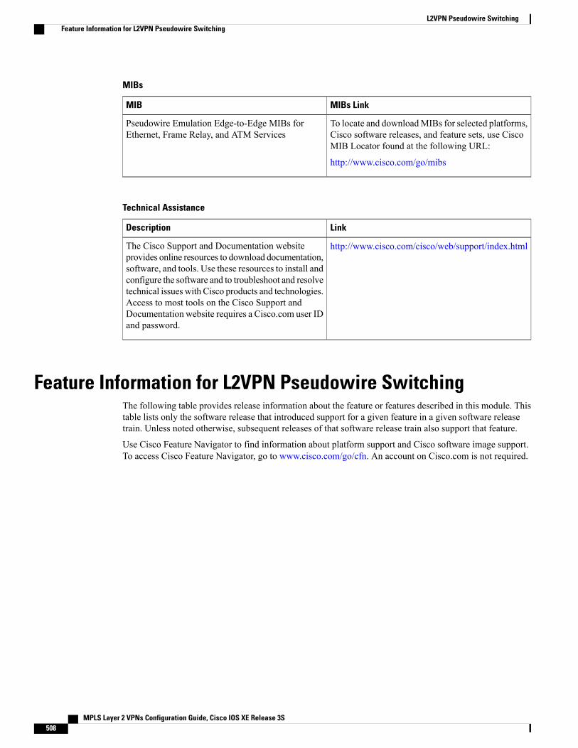
MIBs
MIBs LinkMIB
To locate and downloadMIBs for selected platforms,Cisco software releases, and feature sets, use CiscoMIB Locator found at the following URL:
http://www.cisco.com/go/mibs
Pseudowire Emulation Edge-to-Edge MIBs forEthernet, Frame Relay, and ATM Services
Technical Assistance
LinkDescription
http://www.cisco.com/cisco/web/support/index.htmlThe Cisco Support and Documentation websiteprovides online resources to download documentation,software, and tools. Use these resources to install andconfigure the software and to troubleshoot and resolvetechnical issues with Cisco products and technologies.Access to most tools on the Cisco Support andDocumentation website requires a Cisco.com user IDand password.
Feature Information for L2VPN Pseudowire SwitchingThe following table provides release information about the feature or features described in this module. Thistable lists only the software release that introduced support for a given feature in a given software releasetrain. Unless noted otherwise, subsequent releases of that software release train also support that feature.
Use Cisco Feature Navigator to find information about platform support and Cisco software image support.To access Cisco Feature Navigator, go to www.cisco.com/go/cfn. An account on Cisco.com is not required.
MPLS Layer 2 VPNs Configuration Guide, Cisco IOS XE Release 3S508
L2VPN Pseudowire SwitchingFeature Information for L2VPN Pseudowire Switching
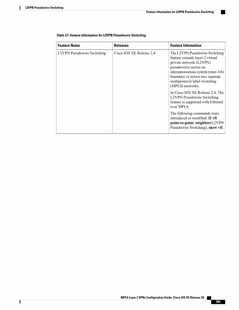
Table 27: Feature Information for L2VPN Pseudowire Switching
Feature InformationReleasesFeature Name
The L2VPNPseudowire Switchingfeature extends layer 2 virtualprivate network (L2VPN)pseudowires across aninterautonomous system (inter-AS)boundary or across two separatemultiprotocol label switching(MPLS) networks.
In Cisco IOS XE Release 2.4, TheL2VPN Pseudowire Switchingfeature is supported with Ethernetover MPLS.
The following commands wereintroduced or modified: l2 vfipoint-to-point, neighbor(L2VPNPseudowire Switching), show vfi.
Cisco IOS XE Release 2.4L2VPN Pseudowire Switching
MPLS Layer 2 VPNs Configuration Guide, Cisco IOS XE Release 3S 509
L2VPN Pseudowire SwitchingFeature Information for L2VPN Pseudowire Switching

MPLS Layer 2 VPNs Configuration Guide, Cisco IOS XE Release 3S510
L2VPN Pseudowire SwitchingFeature Information for L2VPN Pseudowire Switching
C H A P T E R 15Xconnect as a Client of BFD
TheXconnect as a Client of Bidirectional Forwarding Detection (BFD) feature provides a trigger for redundantpseudowire switchover based on BFD’s fast failure detection capabilities.
• Finding Feature Information, page 511
• Information About Xconnect as a Client of BFD, page 511
• How to Configure Xconnect as a Client of BFD, page 512
• Configuration Examples for Xconnect as a Client of BFD, page 513
• Additional References, page 514
• Feature Information for Xconnect as a Client of BFD, page 515
Finding Feature InformationYour software release may not support all the features documented in this module. For the latest caveats andfeature information, see Bug Search Tool and the release notes for your platform and software release. Tofind information about the features documented in this module, and to see a list of the releases in which eachfeature is supported, see the feature information table at the end of this module.
Use Cisco Feature Navigator to find information about platform support and Cisco software image support.To access Cisco Feature Navigator, go to www.cisco.com/go/cfn. An account on Cisco.com is not required.
Information About Xconnect as a Client of BFD
Xconnect as a Client of BFDRedundant pseudowires are deployed to provide fault tolerance and resiliency to L2VPN-backhauledconnections. The speed at which a system recovers from failures, especially when scaled to large numbers ofpseudowires, is critical to many service providers and service level agreements (SLAs). The configuration ofa trigger for redundant pseudowire switchover reduces the time that it takes a large number of pseudowiresto failover. A fundamental component of bidirectional forwarding detection (BFD) capability is enabled byfast-failure detection (FFD).
MPLS Layer 2 VPNs Configuration Guide, Cisco IOS XE Release 3S 511
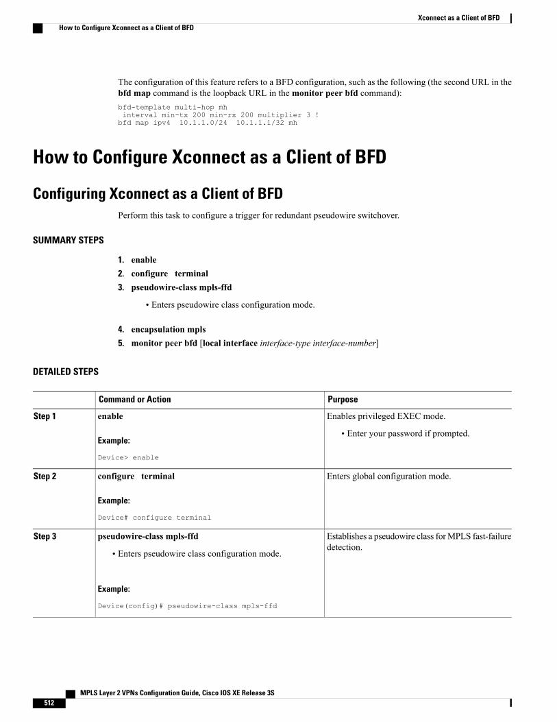
The configuration of this feature refers to a BFD configuration, such as the following (the second URL in thebfd map command is the loopback URL in themonitor peer bfd command):bfd-template multi-hop mhinterval min-tx 200 min-rx 200 multiplier 3 !bfd map ipv4 10.1.1.0/24 10.1.1.1/32 mh
How to Configure Xconnect as a Client of BFD
Configuring Xconnect as a Client of BFDPerform this task to configure a trigger for redundant pseudowire switchover.
SUMMARY STEPS
1. enable2. configure terminal3. pseudowire-class mpls-ffd
• Enters pseudowire class configuration mode.
4. encapsulation mpls5. monitor peer bfd [local interface interface-type interface-number]
DETAILED STEPS
PurposeCommand or Action
Enables privileged EXEC mode.enableStep 1
Example:
Device> enable
• Enter your password if prompted.
Enters global configuration mode.configure terminal
Example:
Device# configure terminal
Step 2
Establishes a pseudowire class forMPLS fast-failuredetection.
pseudowire-class mpls-ffdStep 3
• Enters pseudowire class configuration mode.
Example:
Device(config)# pseudowire-class mpls-ffd
MPLS Layer 2 VPNs Configuration Guide, Cisco IOS XE Release 3S512
Xconnect as a Client of BFDHow to Configure Xconnect as a Client of BFD

PurposeCommand or Action
Specifies the tunneling encapsulation to be MPLS.encapsulation mpls
Example:
Device(config-pw-class)# encapsulation mpls
Step 4
Enables the pseudowire fast-failure detectioncapability.
monitor peer bfd [local interface interface-typeinterface-number]
Example:
Device(config-pw-class)# monitor peer bfd localinterface loopback 0
Step 5
Configuration Examples for Xconnect as a Client of BFD
Example: Xconnect as a Client of BFD
Pseudowire Class Configuration
The following example shows pseudowire fast-failure detection enabled for a pseudowire class:pseudowire-class mpls-ffdencapsulation mplsmonitor peer bfd local interface Loopback0
Template Configuration
The following example shows pseudowire fast-failure detection enabled in a template:template type pseudowire 1encapsulation mplsmonitor peer bfd local interface Ethernet0/1
Interface Configuration
The following example shows pseudowire fast-failure detection enabled for an interface:interface pseudowire100encapsulation mplsneighbor 10.10.1.1 21190monitor peer bfd local interface Ethernet0/1
MPLS Layer 2 VPNs Configuration Guide, Cisco IOS XE Release 3S 513
Xconnect as a Client of BFDConfiguration Examples for Xconnect as a Client of BFD
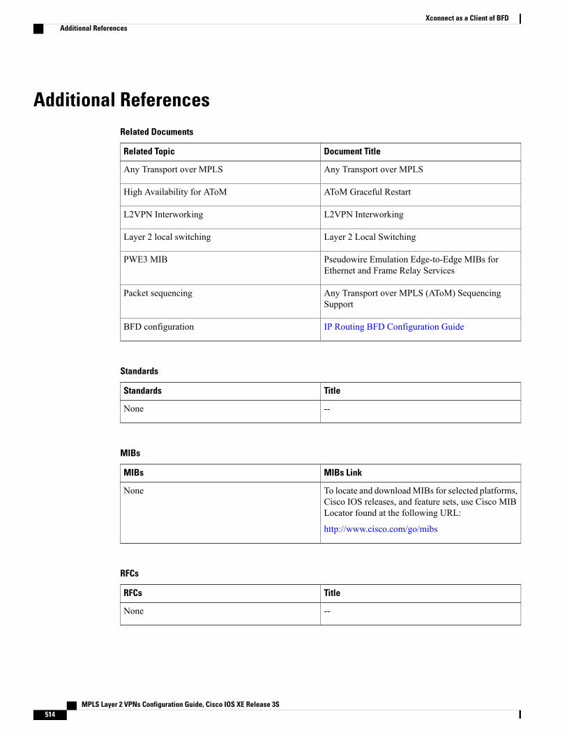
Additional ReferencesRelated Documents
Document TitleRelated Topic
Any Transport over MPLSAny Transport over MPLS
AToM Graceful RestartHigh Availability for AToM
L2VPN InterworkingL2VPN Interworking
Layer 2 Local SwitchingLayer 2 local switching
Pseudowire Emulation Edge-to-Edge MIBs forEthernet and Frame Relay Services
PWE3 MIB
Any Transport over MPLS (AToM) SequencingSupport
Packet sequencing
IP Routing BFD Configuration GuideBFD configuration
Standards
TitleStandards
--None
MIBs
MIBs LinkMIBs
To locate and downloadMIBs for selected platforms,Cisco IOS releases, and feature sets, use Cisco MIBLocator found at the following URL:
http://www.cisco.com/go/mibs
None
RFCs
TitleRFCs
--None
MPLS Layer 2 VPNs Configuration Guide, Cisco IOS XE Release 3S514
Xconnect as a Client of BFDAdditional References
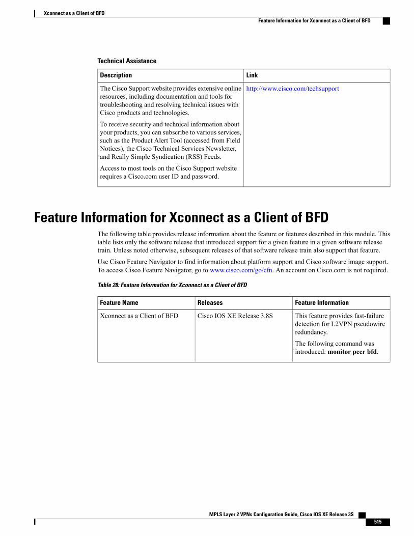
Technical Assistance
LinkDescription
http://www.cisco.com/techsupportThe Cisco Support website provides extensive onlineresources, including documentation and tools fortroubleshooting and resolving technical issues withCisco products and technologies.
To receive security and technical information aboutyour products, you can subscribe to various services,such as the Product Alert Tool (accessed from FieldNotices), the Cisco Technical Services Newsletter,and Really Simple Syndication (RSS) Feeds.
Access to most tools on the Cisco Support websiterequires a Cisco.com user ID and password.
Feature Information for Xconnect as a Client of BFDThe following table provides release information about the feature or features described in this module. Thistable lists only the software release that introduced support for a given feature in a given software releasetrain. Unless noted otherwise, subsequent releases of that software release train also support that feature.
Use Cisco Feature Navigator to find information about platform support and Cisco software image support.To access Cisco Feature Navigator, go to www.cisco.com/go/cfn. An account on Cisco.com is not required.
Table 28: Feature Information for Xconnect as a Client of BFD
Feature InformationReleasesFeature Name
This feature provides fast-failuredetection for L2VPN pseudowireredundancy.
The following command wasintroduced:monitor peer bfd.
Cisco IOS XE Release 3.8SXconnect as a Client of BFD
MPLS Layer 2 VPNs Configuration Guide, Cisco IOS XE Release 3S 515
Xconnect as a Client of BFDFeature Information for Xconnect as a Client of BFD

MPLS Layer 2 VPNs Configuration Guide, Cisco IOS XE Release 3S516
Xconnect as a Client of BFDFeature Information for Xconnect as a Client of BFD

C H A P T E R 16H-VPLS N-PE Redundancy for QinQ Access
TheH-VPLSN-PERedundancy for QinQAccess feature enables two network provider edge (N-PE) devicesto provide failover services to a user provider edge (U-PE) device in a hierarchical virtual private LANservice (H-VPLS). Having redundant N-PE devices provides improved stability and reliability against linkand node failures.
• Finding Feature Information, page 517
• Prerequisites for H-VPLS N-PE Redundancy for QinQ Access, page 517
• Restrictions for H-VPLS N-PE Redundancy for QinQ Access, page 518
• Information About H-VPLS N-PE Redundancy for QinQ Access, page 518
• How to Configure H-VPLS N-PE Redundancy for QinQ Access, page 519
• Configuration Examples for H-VPLS N-PE Redundancy for QinQ Access, page 525
• Additional References for L2VPN VPLS Inter-AS Option B, page 527
• Feature Information for H-VPLS N-PE Redundancy for QinQ Access, page 529
• Glossary, page 530
Finding Feature InformationYour software release may not support all the features documented in this module. For the latest caveats andfeature information, see Bug Search Tool and the release notes for your platform and software release. Tofind information about the features documented in this module, and to see a list of the releases in which eachfeature is supported, see the feature information table at the end of this module.
Use Cisco Feature Navigator to find information about platform support and Cisco software image support.To access Cisco Feature Navigator, go to www.cisco.com/go/cfn. An account on Cisco.com is not required.
Prerequisites for H-VPLS N-PE Redundancy for QinQ Access• Before configuring this feature, configure your hierarchical virtual private LAN service (H-VPLS)network and make sure it is operating correctly.
MPLS Layer 2 VPNs Configuration Guide, Cisco IOS XE Release 3S 517

• Make sure that the PE-to-customer edge (CE) interface is configured with a list of allowed VLANs.
• To provide faster convergence, you can enable the MPLS Traffic Engineering—Fast Reroute feature inthe Multiprotocol Label Switching (MPLS) core.
• Enable the L2VPN Pseudowire Redundancy feature on the user provider edge (U-PE) devices forMPLSaccess.
•When configuring Multiple Spanning Tree Protocol (MSTP), specify that one of the network provideredge (N-PE) devices is the root by assigning it the lowest priority using the spanning-treemst instance-idpriority priority command.
•When configuring MSTP, make sure that each device participating in the spanning tree is in the sameregion and is the same revision by issuing the revision, name, and instance commands in MSTconfiguration mode.
Restrictions for H-VPLS N-PE Redundancy for QinQ Access• This feature cannot be used with the VPLS Autodiscovery feature on pseudowires that attach to networkprovider edge (N-PE) devices. When you create the virtual private LAN service (VPLS), you canmanually create the virtual forwarding instance (VFI).
• You cannot configure more than one pseudowire to carry the bridge protocol data unit (BPDU) packetsbetween two redundant network provider edge (N-PE) devices on the same Virtual Private LAN service(VPLS) site.
• You cannot configure a local loopback address as a neighbor when you configure the H-VPLS N-PERedundancy feature on N-PE devices. If you do so, the following error message is displayed:
VPLS local switching to peer address not supported
• Only two N-PE devices can be connected to each U-PE device.
• The spanning-tree mode must be Multiple Spanning Tree Protocol (MSTP) for the H-VPLS N-PERedundancy feature. If the spanning-tree mode changes, the H-VPLS N-PE Redundancy feature mightnot work correctly, even though the pseudowire that carries the BPDU packet still exists and the H-VPLSN-PE Redundancy feature is still configured.
Information About H-VPLS N-PE Redundancy for QinQ Access
How H-VPLS N-PE Redundancy for QinQ Access WorksIn a network configured with the H-VPLS N-PE Redundancy feature, the user provider edge (U-PE) deviceis connected to two network provider edge (N-PE) devices. This feature provides a level of redundancy thatcan tolerate both link and device faults. If a failure occurs in the network that disables one N-PE device fromtransmitting data, the other N-PE device takes over. This feature works with both QinQ access based onMultiple Spanning Tree Protocol (MSTP) and Multiprotocol Label Switching (MPLS) access based onpseudowire redundancy.
MPLS Layer 2 VPNs Configuration Guide, Cisco IOS XE Release 3S518
H-VPLS N-PE Redundancy for QinQ AccessRestrictions for H-VPLS N-PE Redundancy for QinQ Access
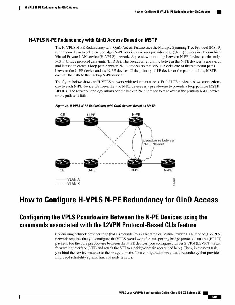
H-VPLS N-PE Redundancy with QinQ Access Based on MSTPThe H-VPLSN-PE Redundancy with QinQAccess feature uses theMultiple Spanning Tree Protocol (MSTP)running on the network provider edge (N-PE) devices and user provider edge (U-PE) devices in a hierarchicalVirtual Private LAN service (H-VPLS) network. A pseudowire running between N-PE devices carries onlyMSTP bridge protocol data units (BPDUs). The pseudowire running between the N-PE devices is always upand is used to create a loop path between N-PE devices so that MSTP blocks one of the redundant pathsbetween the U-PE device and the N-PE devices. If the primary N-PE device or the path to it fails, MSTPenables the path to the backup N-PE device.
The figure below shows an H-VPLS network with redundant access. Each U-PE device has two connections,one to each N-PE device. Between the two N-PE devices is a pseudowire to provide a loop path for MSTPBPDUs. The network topology allows for the backup N-PE device to take over if the primary N-PE deviceor the path to it fails.
Figure 36: H-VPLS N-PE Redundancy with QinQ Access Based on MSTP
How to Configure H-VPLS N-PE Redundancy for QinQ Access
Configuring the VPLS Pseudowire Between the N-PE Devices using thecommands associated with the L2VPN Protocol-Based CLIs feature
Configuring network provider edge (N-PE) redundancy in a hierarchical Virtual Private LAN service (H-VPLS)network requires that you configure the VPLS pseudowire for transporting bridge protocol data unit (BPDU)packets. For the core pseudowire between the N-PE devices, you configure a Layer 2 VPN (L2VPN) virtualforwarding interface (VFI) and attach the VFI to a bridge-domain (described here). Then, in the next task,you bind the service instance to the bridge-domain. This configuration provides a redundancy that providesimproved reliability against link and node failures.
MPLS Layer 2 VPNs Configuration Guide, Cisco IOS XE Release 3S 519
H-VPLS N-PE Redundancy for QinQ AccessHow to Configure H-VPLS N-PE Redundancy for QinQ Access
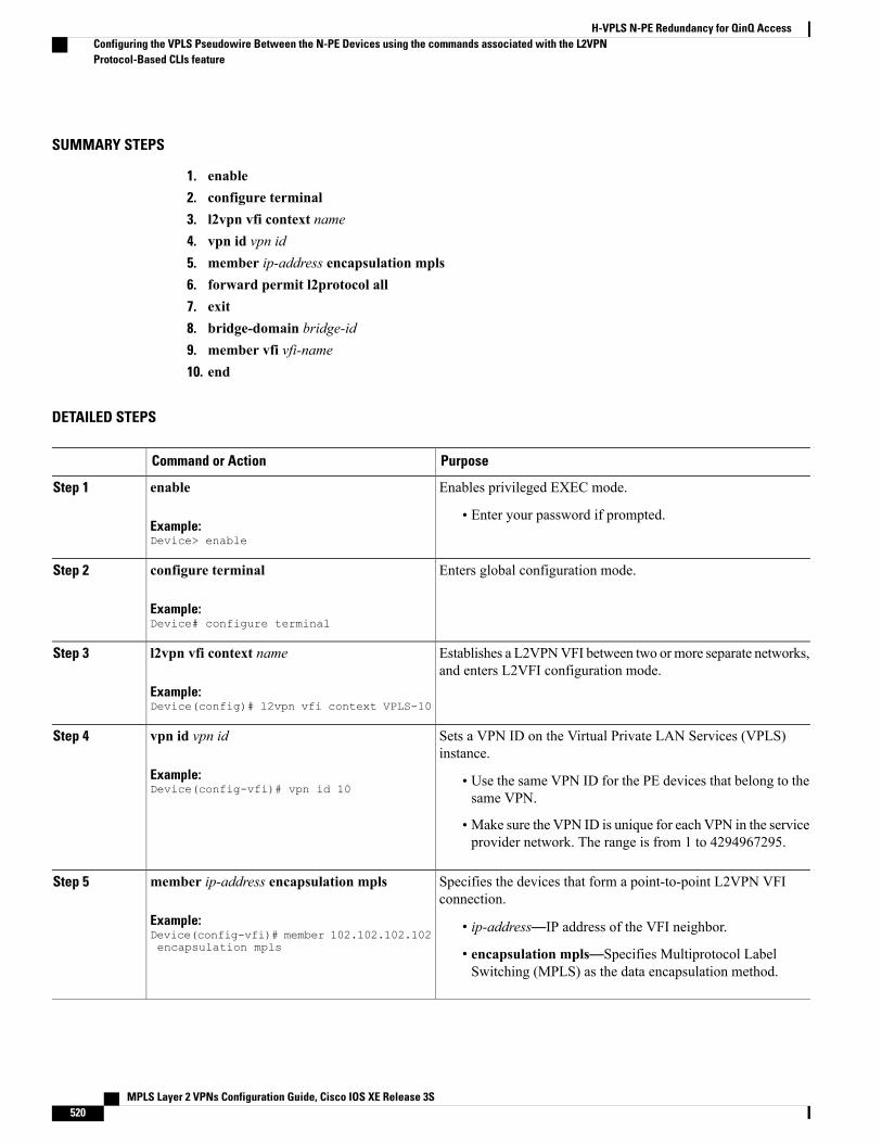
SUMMARY STEPS
1. enable2. configure terminal3. l2vpn vfi context name4. vpn id vpn id5. member ip-address encapsulation mpls6. forward permit l2protocol all7. exit8. bridge-domain bridge-id9. member vfi vfi-name10. end
DETAILED STEPS
PurposeCommand or Action
Enables privileged EXEC mode.enableStep 1
Example:Device> enable
• Enter your password if prompted.
Enters global configuration mode.configure terminal
Example:Device# configure terminal
Step 2
Establishes a L2VPNVFI between two ormore separate networks,and enters L2VFI configuration mode.
l2vpn vfi context name
Example:Device(config)# l2vpn vfi context VPLS-10
Step 3
Sets a VPN ID on the Virtual Private LAN Services (VPLS)instance.
vpn id vpn id
Example:Device(config-vfi)# vpn id 10
Step 4
• Use the same VPN ID for the PE devices that belong to thesame VPN.
• Make sure the VPN ID is unique for each VPN in the serviceprovider network. The range is from 1 to 4294967295.
Specifies the devices that form a point-to-point L2VPN VFIconnection.
member ip-address encapsulation mpls
Example:Device(config-vfi)# member 102.102.102.102encapsulation mpls
Step 5
• ip-address—IP address of the VFI neighbor.
• encapsulation mpls—Specifies Multiprotocol LabelSwitching (MPLS) as the data encapsulation method.
MPLS Layer 2 VPNs Configuration Guide, Cisco IOS XE Release 3S520
H-VPLS N-PE Redundancy for QinQ AccessConfiguring the VPLS Pseudowire Between the N-PE Devices using the commands associated with the L2VPNProtocol-Based CLIs feature
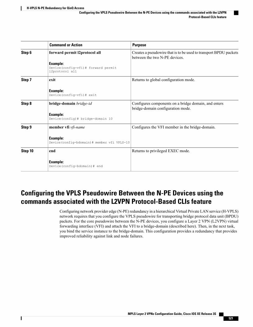
PurposeCommand or Action
Creates a pseudowire that is to be used to transport BPDU packetsbetween the two N-PE devices.
forward permit l2protocol all
Example:Device(config-vfi)# forward permitl2protocol all
Step 6
Returns to global configuration mode.exit
Example:Device(config-vfi)# exit
Step 7
Configures components on a bridge domain, and entersbridge-domain configuration mode.
bridge-domain bridge-id
Example:Device(config)# bridge-domain 10
Step 8
Configures the VFI member in the bridge-domain.member vfi vfi-name
Example:Device(config-bdomain)# member vfi VPLS-10
Step 9
Returns to privileged EXEC mode.end
Example:Device(config-bdomain)# end
Step 10
Configuring the VPLS Pseudowire Between the N-PE Devices using thecommands associated with the L2VPN Protocol-Based CLIs feature
Configuring network provider edge (N-PE) redundancy in a hierarchical Virtual Private LAN service (H-VPLS)network requires that you configure the VPLS pseudowire for transporting bridge protocol data unit (BPDU)packets. For the core pseudowire between the N-PE devices, you configure a Layer 2 VPN (L2VPN) virtualforwarding interface (VFI) and attach the VFI to a bridge-domain (described here). Then, in the next task,you bind the service instance to the bridge-domain. This configuration provides a redundancy that providesimproved reliability against link and node failures.
MPLS Layer 2 VPNs Configuration Guide, Cisco IOS XE Release 3S 521
H-VPLS N-PE Redundancy for QinQ AccessConfiguring the VPLS Pseudowire Between the N-PE Devices using the commands associated with the L2VPN
Protocol-Based CLIs feature

SUMMARY STEPS
1. enable2. configure terminal3. l2vpn vfi context name4. vpn id vpn id5. member ip-address encapsulation mpls6. forward permit l2protocol all7. exit8. bridge-domain bridge-id9. member vfi vfi-name10. end
DETAILED STEPS
PurposeCommand or Action
Enables privileged EXEC mode.enableStep 1
Example:Device> enable
• Enter your password if prompted.
Enters global configuration mode.configure terminal
Example:Device# configure terminal
Step 2
Establishes a L2VPNVFI between two ormore separate networks,and enters L2VFI configuration mode.
l2vpn vfi context name
Example:Device(config)# l2vpn vfi context VPLS-10
Step 3
Sets a VPN ID on the Virtual Private LAN Services (VPLS)instance.
vpn id vpn id
Example:Device(config-vfi)# vpn id 10
Step 4
• Use the same VPN ID for the PE devices that belong to thesame VPN.
• Make sure the VPN ID is unique for each VPN in the serviceprovider network. The range is from 1 to 4294967295.
Specifies the devices that form a point-to-point L2VPN VFIconnection.
member ip-address encapsulation mpls
Example:Device(config-vfi)# member 102.102.102.102encapsulation mpls
Step 5
• ip-address—IP address of the VFI neighbor.
• encapsulation mpls—Specifies Multiprotocol LabelSwitching (MPLS) as the data encapsulation method.
MPLS Layer 2 VPNs Configuration Guide, Cisco IOS XE Release 3S522
H-VPLS N-PE Redundancy for QinQ AccessConfiguring the VPLS Pseudowire Between the N-PE Devices using the commands associated with the L2VPNProtocol-Based CLIs feature
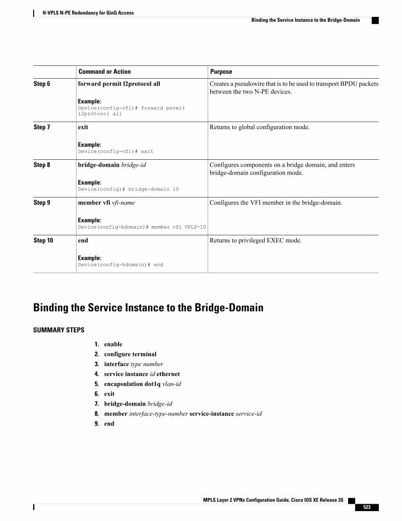
PurposeCommand or Action
Creates a pseudowire that is to be used to transport BPDU packetsbetween the two N-PE devices.
forward permit l2protocol all
Example:Device(config-vfi)# forward permitl2protocol all
Step 6
Returns to global configuration mode.exit
Example:Device(config-vfi)# exit
Step 7
Configures components on a bridge domain, and entersbridge-domain configuration mode.
bridge-domain bridge-id
Example:Device(config)# bridge-domain 10
Step 8
Configures the VFI member in the bridge-domain.member vfi vfi-name
Example:Device(config-bdomain)# member vfi VPLS-10
Step 9
Returns to privileged EXEC mode.end
Example:Device(config-bdomain)# end
Step 10
Binding the Service Instance to the Bridge-Domain
SUMMARY STEPS
1. enable2. configure terminal3. interface type number4. service instance id ethernet5. encapsulation dot1q vlan-id6. exit7. bridge-domain bridge-id8. member interface-type-number service-instance service-id9. end
MPLS Layer 2 VPNs Configuration Guide, Cisco IOS XE Release 3S 523
H-VPLS N-PE Redundancy for QinQ AccessBinding the Service Instance to the Bridge-Domain
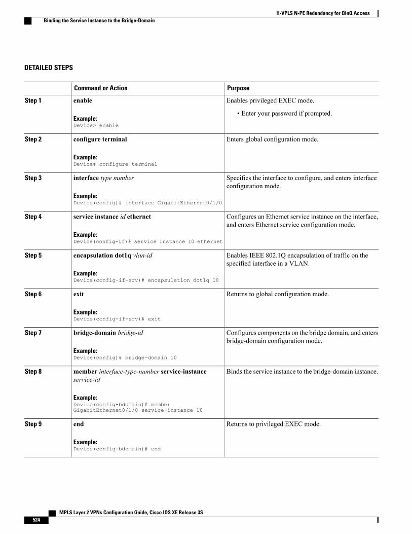
DETAILED STEPS
PurposeCommand or Action
Enables privileged EXEC mode.enableStep 1
Example:Device> enable
• Enter your password if prompted.
Enters global configuration mode.configure terminal
Example:Device# configure terminal
Step 2
Specifies the interface to configure, and enters interfaceconfiguration mode.
interface type number
Example:Device(config)# interface GigabitEthernet0/1/0
Step 3
Configures an Ethernet service instance on the interface,and enters Ethernet service configuration mode.
service instance id ethernet
Example:Device(config-if)# service instance 10 ethernet
Step 4
Enables IEEE 802.1Q encapsulation of traffic on thespecified interface in a VLAN.
encapsulation dot1q vlan-id
Example:Device(config-if-srv)# encapsulation dot1q 10
Step 5
Returns to global configuration mode.exit
Example:Device(config-if-srv)# exit
Step 6
Configures components on the bridge domain, and entersbridge-domain configuration mode.
bridge-domain bridge-id
Example:Device(config)# bridge-domain 10
Step 7
Binds the service instance to the bridge-domain instance.member interface-type-number service-instanceservice-id
Step 8
Example:Device(config-bdomain)# memberGigabitEthernet0/1/0 service-instance 10
Returns to privileged EXEC mode.end
Example:Device(config-bdomain)# end
Step 9
MPLS Layer 2 VPNs Configuration Guide, Cisco IOS XE Release 3S524
H-VPLS N-PE Redundancy for QinQ AccessBinding the Service Instance to the Bridge-Domain
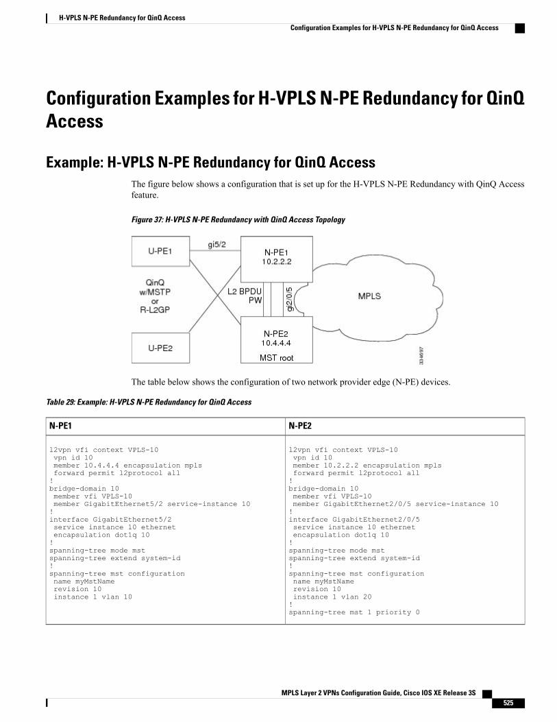
Configuration Examples for H-VPLS N-PE Redundancy for QinQAccess
Example: H-VPLS N-PE Redundancy for QinQ AccessThe figure below shows a configuration that is set up for the H-VPLS N-PE Redundancy with QinQ Accessfeature.
Figure 37: H-VPLS N-PE Redundancy with QinQ Access Topology
The table below shows the configuration of two network provider edge (N-PE) devices.
Table 29: Example: H-VPLS N-PE Redundancy for QinQ Access
N-PE2N-PE1
l2vpn vfi context VPLS-10vpn id 10member 10.2.2.2 encapsulation mplsforward permit l2protocol all!bridge-domain 10member vfi VPLS-10member GigabitEthernet2/0/5 service-instance 10!interface GigabitEthernet2/0/5service instance 10 ethernetencapsulation dot1q 10!spanning-tree mode mstspanning-tree extend system-id!spanning-tree mst configurationname myMstNamerevision 10instance 1 vlan 20!spanning-tree mst 1 priority 0
l2vpn vfi context VPLS-10vpn id 10member 10.4.4.4 encapsulation mplsforward permit l2protocol all!bridge-domain 10member vfi VPLS-10member GigabitEthernet5/2 service-instance 10!interface GigabitEthernet5/2service instance 10 ethernetencapsulation dot1q 10!spanning-tree mode mstspanning-tree extend system-id!spanning-tree mst configurationname myMstNamerevision 10instance 1 vlan 10
MPLS Layer 2 VPNs Configuration Guide, Cisco IOS XE Release 3S 525
H-VPLS N-PE Redundancy for QinQ AccessConfiguration Examples for H-VPLS N-PE Redundancy for QinQ Access
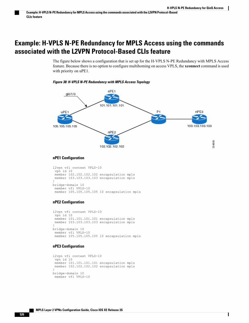
Example: H-VPLS N-PE Redundancy for MPLS Access using the commandsassociated with the L2VPN Protocol-Based CLIs feature
The figure below shows a configuration that is set up for the H-VPLS N-PE Redundancy with MPLS Accessfeature. Because there is no option to configure multihoming on access VPLS, the xconnect command is usedwith priority on uPE1.
Figure 38: H-VPLS N-PE Redundancy with MPLS Access Topology
nPE1 Configuration
l2vpn vfi context VPLS-10vpn id 10member 102.102.102.102 encapsulation mplsmember 103.103.103.103 encapsulation mpls!bridge-domain 10member vfi VPLS-10member 105.105.105.105 10 encapsulation mpls
nPE2 Configuration
l2vpn vfi context VPLS-10vpn id 10member 101.101.101.101 encapsulation mplsmember 103.103.103.103 encapsulation mpls!bridge-domain 10member vfi VPLS-10member 105.105.105.105 10 encapsulation mpls
nPE3 Configuration
l2vpn vfi context VPLS-10vpn id 10member 101.101.101.101 encapsulation mplsmember 102.102.102.102 encapsulation mpls!bridge-domain 10member vfi VPLS-10
MPLS Layer 2 VPNs Configuration Guide, Cisco IOS XE Release 3S526
H-VPLS N-PE Redundancy for QinQ AccessExample: H-VPLS N-PE Redundancy for MPLS Access using the commands associated with the L2VPN Protocol-BasedCLIs feature
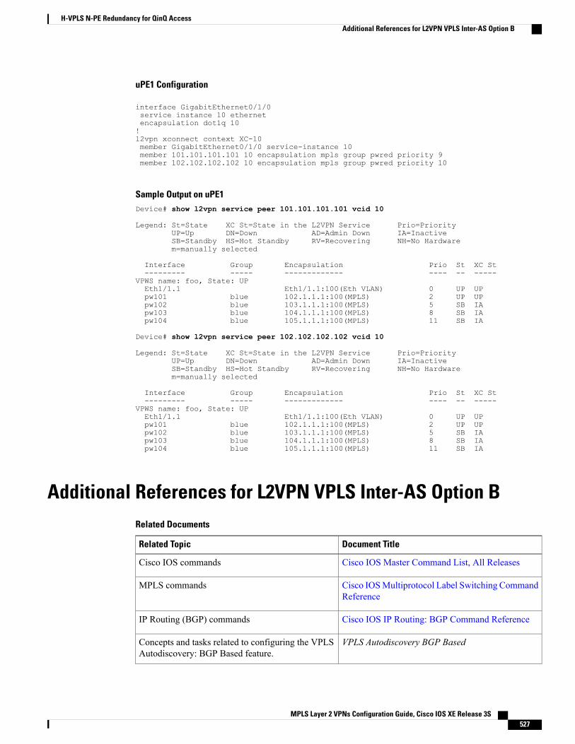
uPE1 Configuration
interface GigabitEthernet0/1/0service instance 10 ethernetencapsulation dot1q 10!l2vpn xconnect context XC-10member GigabitEthernet0/1/0 service-instance 10member 101.101.101.101 10 encapsulation mpls group pwred priority 9member 102.102.102.102 10 encapsulation mpls group pwred priority 10
Sample Output on uPE1Device# show l2vpn service peer 101.101.101.101 vcid 10
Legend: St=State XC St=State in the L2VPN Service Prio=PriorityUP=Up DN=Down AD=Admin Down IA=InactiveSB=Standby HS=Hot Standby RV=Recovering NH=No Hardwarem=manually selected
Interface Group Encapsulation Prio St XC St--------- ----- ------------- ---- -- -----
VPWS name: foo, State: UPEth1/1.1 Eth1/1.1:100(Eth VLAN) 0 UP UPpw101 blue 102.1.1.1:100(MPLS) 2 UP UPpw102 blue 103.1.1.1:100(MPLS) 5 SB IApw103 blue 104.1.1.1:100(MPLS) 8 SB IApw104 blue 105.1.1.1:100(MPLS) 11 SB IA
Device# show l2vpn service peer 102.102.102.102 vcid 10
Legend: St=State XC St=State in the L2VPN Service Prio=PriorityUP=Up DN=Down AD=Admin Down IA=InactiveSB=Standby HS=Hot Standby RV=Recovering NH=No Hardwarem=manually selected
Interface Group Encapsulation Prio St XC St--------- ----- ------------- ---- -- -----
VPWS name: foo, State: UPEth1/1.1 Eth1/1.1:100(Eth VLAN) 0 UP UPpw101 blue 102.1.1.1:100(MPLS) 2 UP UPpw102 blue 103.1.1.1:100(MPLS) 5 SB IApw103 blue 104.1.1.1:100(MPLS) 8 SB IApw104 blue 105.1.1.1:100(MPLS) 11 SB IA
Additional References for L2VPN VPLS Inter-AS Option BRelated Documents
Document TitleRelated Topic
Cisco IOS Master Command List, All ReleasesCisco IOS commands
Cisco IOSMultiprotocol Label Switching CommandReference
MPLS commands
Cisco IOS IP Routing: BGP Command ReferenceIP Routing (BGP) commands
VPLS Autodiscovery BGP BasedConcepts and tasks related to configuring the VPLSAutodiscovery: BGP Based feature.
MPLS Layer 2 VPNs Configuration Guide, Cisco IOS XE Release 3S 527
H-VPLS N-PE Redundancy for QinQ AccessAdditional References for L2VPN VPLS Inter-AS Option B
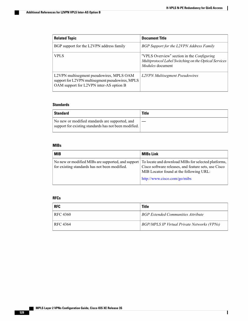
Document TitleRelated Topic
BGP Support for the L2VPN Address FamilyBGP support for the L2VPN address family
“VPLS Overview” section in the ConfiguringMultiprotocol Label Switching on the Optical ServicesModules document
VPLS
L2VPN Multisegment PseudowiresL2VPN multisegment pseudowires, MPLS OAMsupport for L2VPNmultisegment pseudowires,MPLSOAM support for L2VPN inter-AS option B
Standards
TitleStandard
—No new or modified standards are supported, andsupport for existing standards has not been modified.
MIBs
MIBs LinkMIB
To locate and downloadMIBs for selected platforms,Cisco software releases, and feature sets, use CiscoMIB Locator found at the following URL:
http://www.cisco.com/go/mibs
No new or modifiedMIBs are supported, and supportfor existing standards has not been modified.
RFCs
TitleRFC
BGP Extended Communities AttributeRFC 4360
BGP/MPLS IP Virtual Private Networks (VPNs)RFC 4364
MPLS Layer 2 VPNs Configuration Guide, Cisco IOS XE Release 3S528
H-VPLS N-PE Redundancy for QinQ AccessAdditional References for L2VPN VPLS Inter-AS Option B
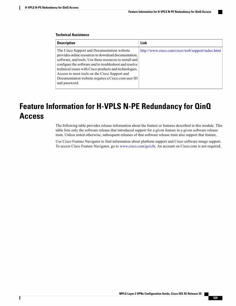
Technical Assistance
LinkDescription
http://www.cisco.com/cisco/web/support/index.htmlThe Cisco Support and Documentation websiteprovides online resources to download documentation,software, and tools. Use these resources to install andconfigure the software and to troubleshoot and resolvetechnical issues with Cisco products and technologies.Access to most tools on the Cisco Support andDocumentation website requires a Cisco.com user IDand password.
Feature Information for H-VPLS N-PE Redundancy for QinQAccess
The following table provides release information about the feature or features described in this module. Thistable lists only the software release that introduced support for a given feature in a given software releasetrain. Unless noted otherwise, subsequent releases of that software release train also support that feature.
Use Cisco Feature Navigator to find information about platform support and Cisco software image support.To access Cisco Feature Navigator, go to www.cisco.com/go/cfn. An account on Cisco.com is not required.
MPLS Layer 2 VPNs Configuration Guide, Cisco IOS XE Release 3S 529
H-VPLS N-PE Redundancy for QinQ AccessFeature Information for H-VPLS N-PE Redundancy for QinQ Access
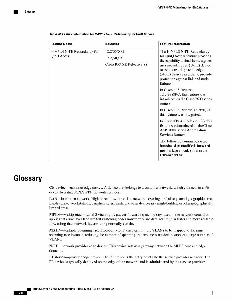
Table 30: Feature Information for H-VPLS N-PE Redundancy for QinQ Access
Feature InformationReleasesFeature Name
The H-VPLS N-PE Redundancyfor QinQ Access feature providesthe capability to dual-home a givenuser provider edge (U-PE) deviceto two network provide edge(N-PE) devices in order to provideprotection against link and nodefailures.
In Cisco IOS Release12.2(33)SRC, this feature wasintroduced on the Cisco 7600 seriesrouters.
In Cisco IOS Release 12.2(50)SY,this feature was integrated.
In Cisco IOSXERelease 3.8S, thisfeature was introduced on the CiscoASR 1000 Series AggregationServices Routers.
The following commands wereintroduced or modified: forwardpermit l2protocol, show mplsl2transport vc.
12.2(33)SRC
12.2(50)SY
Cisco IOS XE Release 3.8S
H-VPLS N-PE Redundancy forQinQ Access
GlossaryCE device—customer edge device. A device that belongs to a customer network, which connects to a PEdevice to utilize MPLS VPN network services.
LAN—local-area network. High-speed, low-error data network covering a relatively small geographic area.LANs connect workstations, peripherals, terminals, and other devices in a single building or other geographicallylimited areas.
MPLS—Multiprotocol Label Switching. A packet-forwarding technology, used in the network core, thatapplies data link layer labels to tell switching nodes how to forward data, resulting in faster and more scalableforwarding than network layer routing normally can do.
MSTP—Multiple Spanning Tree Protocol. MSTP enables multiple VLANs to be mapped to the samespanning-tree instance, reducing the number of spanning-tree instances needed to support a large number ofVLANs.
N-PE—network provider edge device. This device acts as a gateway between the MPLS core and edgedomains.
PE device—provider edge device. The PE device is the entry point into the service provider network. ThePE device is typically deployed on the edge of the network and is administered by the service provider.
MPLS Layer 2 VPNs Configuration Guide, Cisco IOS XE Release 3S530
H-VPLS N-PE Redundancy for QinQ AccessGlossary
pseudowire—A pseudowire is a virtual connection that, in the context of VPLS, connects two SVIs. It is amechanism that carries the elements of an emulated service from one PE device to one or more PE devicesover a packet switched network (PSN). A pseudowire is bidirectional and consists of a pair of unidirectionalMPLS virtual circuits (VCs). A pseudowire can be used to connect a point-to-point circuit.
QinQ—An IEEE 802.1QVLAN tunnel. Amechanism for constructingmultipoint Layer 2 VPN using Ethernetswitches.
redundancy—The duplication of devices, services, or connections so that, in the event of a failure, they canperform the work of those that failed.
router—A network layer device that uses one or more metrics to determine the optimal path along whichnetwork traffic should be forwarded. Routers forward packets from one network to another based on networklayer information.
spanning tree—Loop-free subset of a network topology.
U-PE—user provider edge device. This device connects CE devices to the service.
VFI—virtual forwarding instance. AVFI is a collection of data structures used by the data plane, software-basedor hardware-based, to forward packets to one or more VCs.
VLAN—Virtual LAN. Group of devices on one or more LANs that are configured (using managementsoftware) so that they can communicate as if they were attached to the same wire, when in fact they are locatedon a number of different LAN segments.
VPLS—Virtual Private LAN Service. VPLS describes an architecture that delivers Layer 2 service thatemulates an Ethernet LAN across a wide-area network (WAN) and inherits the scaling characteristics of aLAN.
VPLS redundancy—Also called N-PE redundancy. Allows U-PEs to be dual-honed (to their N-PEs) in aloop-free topology with MPLS or QinQ as the access or aggregation domain.
VPN—Virtual Private Network. Allows IP traffic to travel securely over public TCP/IP networks and theInternet by encapsulating and encrypting all IP packets. VPN uses a tunnel to encrypt all information at theIP level.
MPLS Layer 2 VPNs Configuration Guide, Cisco IOS XE Release 3S 531
H-VPLS N-PE Redundancy for QinQ AccessGlossary

MPLS Layer 2 VPNs Configuration Guide, Cisco IOS XE Release 3S532
H-VPLS N-PE Redundancy for QinQ AccessGlossary
C H A P T E R 17H-VPLS N-PE Redundancy for MPLS Access
TheH-VPLSN-PERedundancy forMPLSAccess feature enables two network provider edge (N-PE) devicesto provide failover services to a user provider edge (U-PE) device in a hierarchical virtual private LANservice (H-VPLS). Having redundant N-PE devices provides improved stability and reliability against linkand node failures.
• Finding Feature Information, page 533
• Prerequisites for H-VPLS N-PE Redundancy for MPLS Access, page 533
• Restrictions for H-VPLS N-PE Redundancy for MPLS Access, page 534
• Information About H-VPLS N-PE Redundancy for MPLS Access, page 534
• How to Configure H-VPLS N-PE Redundancy for MPLS Access, page 535
• Configuration Examples for H-VPLS N-PE Redundancy for MPLS Access, page 539
• Additional References for L2VPN VPLS Inter-AS Option B, page 541
• Feature Information for H-VPLS N-PE Redundancy for MPLS Access, page 542
• Glossary, page 543
Finding Feature InformationYour software release may not support all the features documented in this module. For the latest caveats andfeature information, see Bug Search Tool and the release notes for your platform and software release. Tofind information about the features documented in this module, and to see a list of the releases in which eachfeature is supported, see the feature information table at the end of this module.
Use Cisco Feature Navigator to find information about platform support and Cisco software image support.To access Cisco Feature Navigator, go to www.cisco.com/go/cfn. An account on Cisco.com is not required.
Prerequisites for H-VPLS N-PE Redundancy for MPLS Access• Before configuring this feature, configure your hierarchical virtual private LAN service (H-VPLS)network and make sure it is operating correctly.
MPLS Layer 2 VPNs Configuration Guide, Cisco IOS XE Release 3S 533
• Make sure that the PE-to-customer edge (CE) interface is configured with a list of allowed VLANs.
• To provide faster convergence, you can enable the MPLS Traffic Engineering—Fast Reroute feature inthe Multiprotocol Label Switching (MPLS) core.
• Enable the L2VPN Pseudowire Redundancy feature on the user provider edge (U-PE) devices forMPLSaccess.
Restrictions for H-VPLS N-PE Redundancy for MPLS Access• This feature cannot be used with the VPLS Autodiscovery feature on pseudowires that attach to userprovider edge (U-PE) devices. When you create the virtual private LAN service (VPLS), you canmanually create the virtual forwarding interface (VFI).
• You cannot configuremore than one pseudowire to carry the bridge protocol data unit (BPDU) informationbetween the network provider edge (N-PE) devices.
• You cannot configure a local loopback address as a neighbor when you configure the H-VPLS N-PERedundancy feature on N-PE devices.
• Only two N-PE devices can be connected to each U-PE device.
Information About H-VPLS N-PE Redundancy for MPLS Access
How H-VPLS N-PE Redundancy for MPLS AccessIn a network configured with the H-VPLS N-PE Redundancy feature, the user provider edge (U-PE) deviceis connected to two network provider edge (N-PE) devices. This feature provides a level of redundancy thatcan tolerate both link and device faults. If a failure occurs in the network that disables one N-PE device fromtransmitting data, the other N-PE device takes over.
H-VPLS N-PE Redundancy with MPLS Access Based on PseudowireRedundancy
For the H-VPLS Redundancy with MPLS Access feature based on pseudowire redundancy, the MultiprotocolLabel Switching (MPLS) network has pseudowires to the virtual private LAN service (VPLS) core networkprovider edge (N-PE) devices.
MPLS Layer 2 VPNs Configuration Guide, Cisco IOS XE Release 3S534
H-VPLS N-PE Redundancy for MPLS AccessRestrictions for H-VPLS N-PE Redundancy for MPLS Access
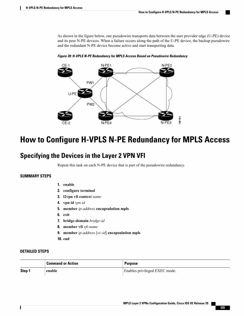
As shown in the figure below, one pseudowire transports data between the user provider edge (U-PE) deviceand its peer N-PE devices. When a failure occurs along the path of the U-PE device, the backup pseudowireand the redundant N-PE device become active and start transporting data.
Figure 39: H-VPLS N-PE Redundancy for MPLS Access Based on Pseudowire Redundancy
How to Configure H-VPLS N-PE Redundancy for MPLS Access
Specifying the Devices in the Layer 2 VPN VFIRepeat this task on each N-PE device that is part of the pseudowire redundancy.
SUMMARY STEPS
1. enable2. configure terminal3. l2vpn vfi context name4. vpn id vpn id5. member ip-address encapsulation mpls6. exit7. bridge-domain bridge-id8. member vfi vfi-name9. member ip-address [vc-id] encapsulation mpls10. end
DETAILED STEPS
PurposeCommand or Action
Enables privileged EXEC mode.enableStep 1
MPLS Layer 2 VPNs Configuration Guide, Cisco IOS XE Release 3S 535
H-VPLS N-PE Redundancy for MPLS AccessHow to Configure H-VPLS N-PE Redundancy for MPLS Access
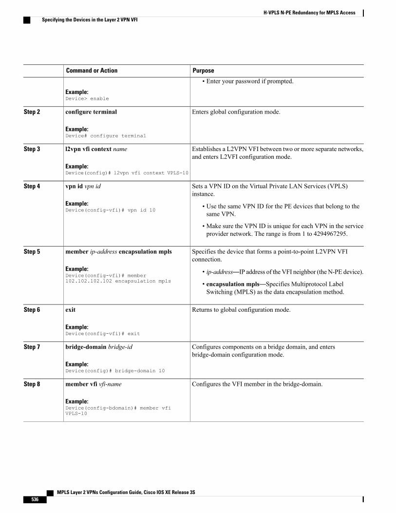
PurposeCommand or Action
Example:Device> enable
• Enter your password if prompted.
Enters global configuration mode.configure terminal
Example:Device# configure terminal
Step 2
Establishes a L2VPN VFI between two or more separate networks,and enters L2VFI configuration mode.
l2vpn vfi context name
Example:Device(config)# l2vpn vfi context VPLS-10
Step 3
Sets a VPN ID on the Virtual Private LAN Services (VPLS)instance.
vpn id vpn id
Example:Device(config-vfi)# vpn id 10
Step 4
• Use the same VPN ID for the PE devices that belong to thesame VPN.
• Make sure the VPN ID is unique for each VPN in the serviceprovider network. The range is from 1 to 4294967295.
Specifies the device that forms a point-to-point L2VPN VFIconnection.
member ip-address encapsulation mpls
Example:Device(config-vfi)# member102.102.102.102 encapsulation mpls
Step 5
• ip-address—IP address of the VFI neighbor (the N-PE device).
• encapsulation mpls—Specifies Multiprotocol LabelSwitching (MPLS) as the data encapsulation method.
Returns to global configuration mode.exit
Example:Device(config-vfi)# exit
Step 6
Configures components on a bridge domain, and entersbridge-domain configuration mode.
bridge-domain bridge-id
Example:Device(config)# bridge-domain 10
Step 7
Configures the VFI member in the bridge-domain.member vfi vfi-name
Example:Device(config-bdomain)# member vfiVPLS-10
Step 8
MPLS Layer 2 VPNs Configuration Guide, Cisco IOS XE Release 3S536
H-VPLS N-PE Redundancy for MPLS AccessSpecifying the Devices in the Layer 2 VPN VFI
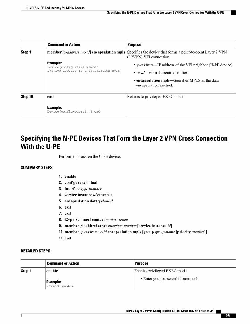
PurposeCommand or Action
Specifies the device that forms a point-to-point Layer 2 VPN(L2VPN) VFI connection.
member ip-address [vc-id] encapsulationmpls
Example:Device(config-vfi)# member105.105.105.105 10 encapsulation mpls
Step 9
• ip-address—IP address of the VFI neighbor (U-PE device).
• vc-id—Virtual circuit identifier.
• encapsulation mpls—Specifies MPLS as the dataencapsulation method.
Returns to privileged EXEC mode.end
Example:Device(config-bdomain)# end
Step 10
Specifying the N-PE Devices That Form the Layer 2 VPN Cross ConnectionWith the U-PE
Perform this task on the U-PE device.
SUMMARY STEPS
1. enable2. configure terminal3. interface type number4. service instance id ethernet5. encapsulation dot1q vlan-id6. exit7. exit8. l2vpn xconnect context context-name9. member gigabitethernet interface-number [service-instance id]10. member ip-address vc-id encapsulation mpls [group group-name [priority number]]11. end
DETAILED STEPS
PurposeCommand or Action
Enables privileged EXEC mode.enableStep 1
Example:Device> enable
• Enter your password if prompted.
MPLS Layer 2 VPNs Configuration Guide, Cisco IOS XE Release 3S 537
H-VPLS N-PE Redundancy for MPLS AccessSpecifying the N-PE Devices That Form the Layer 2 VPN Cross Connection With the U-PE
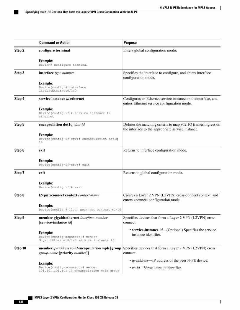
PurposeCommand or Action
Enters global configuration mode.configure terminal
Example:Device# configure terminal
Step 2
Specifies the interface to configure, and enters interfaceconfiguration mode.
interface type number
Example:Device(config)# interfaceGigabitEthernet0/1/0
Step 3
Configures an Ethernet service instance on theinterface, andenters Ethernet service configuration mode.
service instance id ethernet
Example:Device(config-if)# service instance 10ethernet
Step 4
Defines the matching criteria to map 802.1Q frames ingress onthe interface to the appropriate service instance.
encapsulation dot1q vlan-id
Example:Device(config-if-srv)# encapsulation dot1q10
Step 5
Returns to interface configuration mode.exit
Example:Device(config-if-srv)# exit
Step 6
Returns to global configuration mode.exit
Example:Device(config-if)# exit
Step 7
Creates a Layer 2 VPN (L2VPN) cross-connect context, andenters xconnect configuration mode.
l2vpn xconnect context context-name
Example:Device(config)# l2vpn xconnect context XC-10
Step 8
Specifies devices that form a Layer 2 VPN (L2VPN) crossconnect.
member gigabitethernet interface-number[service-instance id]
Step 9
Example:Device(config-xconnect)# memberGigabitEthernet0/1/0 service-instance 10
• service-instance id—(Optional) Specifies the serviceinstance identifier.
Specifies devices that form a Layer 2 VPN (L2VPN) crossconnect.
member ip-address vc-id encapsulationmpls [groupgroup-name [priority number]]
Step 10
Example:Device(config-xconnect)# member101.101.101.101 10 encapsulation mpls group
• ip-address—IP address of the peer N-PE device.
• vc-id—Virtual circuit identifier.
MPLS Layer 2 VPNs Configuration Guide, Cisco IOS XE Release 3S538
H-VPLS N-PE Redundancy for MPLS AccessSpecifying the N-PE Devices That Form the Layer 2 VPN Cross Connection With the U-PE
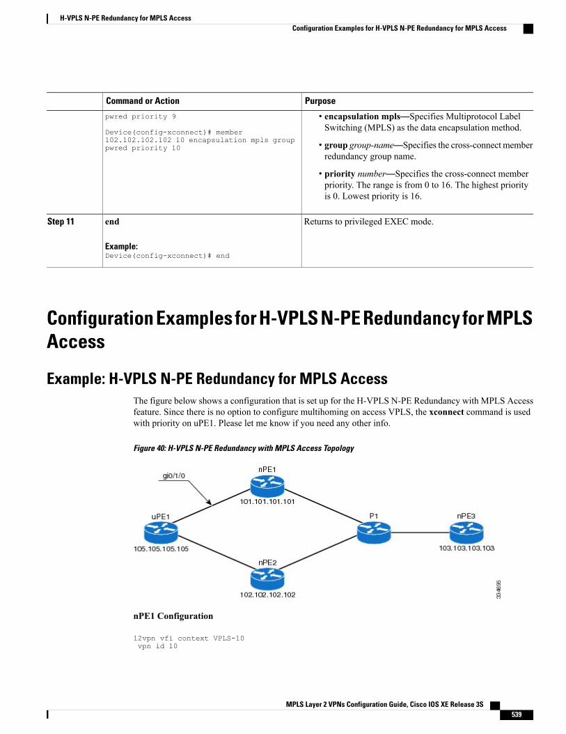
PurposeCommand or Action
• encapsulation mpls—Specifies Multiprotocol LabelSwitching (MPLS) as the data encapsulation method.
pwred priority 9
Device(config-xconnect)# member102.102.102.102 10 encapsulation mpls grouppwred priority 10 • group group-name—Specifies the cross-connect member
redundancy group name.
• priority number—Specifies the cross-connect memberpriority. The range is from 0 to 16. The highest priorityis 0. Lowest priority is 16.
Returns to privileged EXEC mode.end
Example:Device(config-xconnect)# end
Step 11
Configuration Examples for H-VPLS N-PE Redundancy for MPLSAccess
Example: H-VPLS N-PE Redundancy for MPLS AccessThe figure below shows a configuration that is set up for the H-VPLS N-PE Redundancy with MPLS Accessfeature. Since there is no option to configure multihoming on access VPLS, the xconnect command is usedwith priority on uPE1. Please let me know if you need any other info.
Figure 40: H-VPLS N-PE Redundancy with MPLS Access Topology
nPE1 Configuration
l2vpn vfi context VPLS-10vpn id 10
MPLS Layer 2 VPNs Configuration Guide, Cisco IOS XE Release 3S 539
H-VPLS N-PE Redundancy for MPLS AccessConfiguration Examples for H-VPLS N-PE Redundancy for MPLS Access
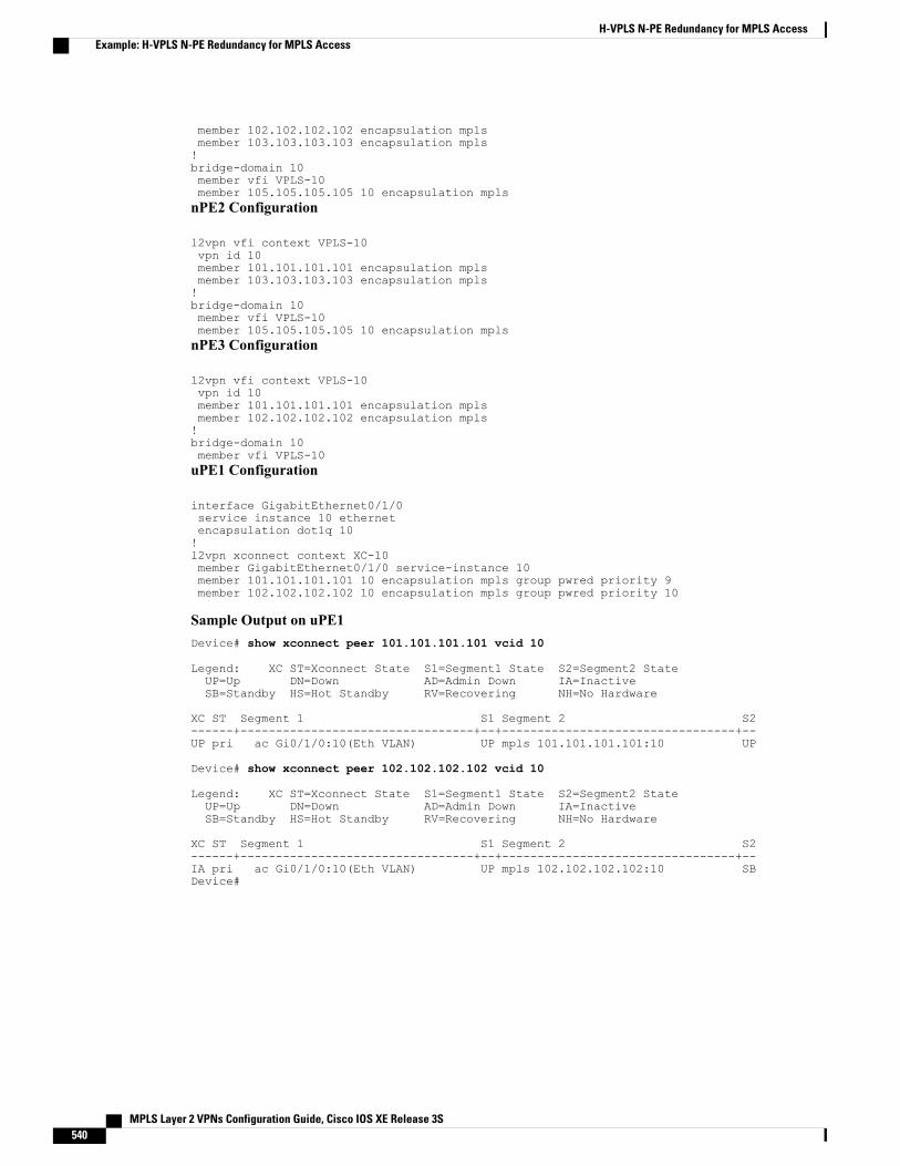
member 102.102.102.102 encapsulation mplsmember 103.103.103.103 encapsulation mpls!bridge-domain 10member vfi VPLS-10member 105.105.105.105 10 encapsulation mplsnPE2 Configuration
l2vpn vfi context VPLS-10vpn id 10member 101.101.101.101 encapsulation mplsmember 103.103.103.103 encapsulation mpls!bridge-domain 10member vfi VPLS-10member 105.105.105.105 10 encapsulation mplsnPE3 Configuration
l2vpn vfi context VPLS-10vpn id 10member 101.101.101.101 encapsulation mplsmember 102.102.102.102 encapsulation mpls!bridge-domain 10member vfi VPLS-10uPE1 Configuration
interface GigabitEthernet0/1/0service instance 10 ethernetencapsulation dot1q 10!l2vpn xconnect context XC-10member GigabitEthernet0/1/0 service-instance 10member 101.101.101.101 10 encapsulation mpls group pwred priority 9member 102.102.102.102 10 encapsulation mpls group pwred priority 10
Sample Output on uPE1Device# show xconnect peer 101.101.101.101 vcid 10
Legend: XC ST=Xconnect State S1=Segment1 State S2=Segment2 StateUP=Up DN=Down AD=Admin Down IA=InactiveSB=Standby HS=Hot Standby RV=Recovering NH=No Hardware
XC ST Segment 1 S1 Segment 2 S2------+---------------------------------+--+---------------------------------+--UP pri ac Gi0/1/0:10(Eth VLAN) UP mpls 101.101.101.101:10 UP
Device# show xconnect peer 102.102.102.102 vcid 10
Legend: XC ST=Xconnect State S1=Segment1 State S2=Segment2 StateUP=Up DN=Down AD=Admin Down IA=InactiveSB=Standby HS=Hot Standby RV=Recovering NH=No Hardware
XC ST Segment 1 S1 Segment 2 S2------+---------------------------------+--+---------------------------------+--IA pri ac Gi0/1/0:10(Eth VLAN) UP mpls 102.102.102.102:10 SBDevice#
MPLS Layer 2 VPNs Configuration Guide, Cisco IOS XE Release 3S540
H-VPLS N-PE Redundancy for MPLS AccessExample: H-VPLS N-PE Redundancy for MPLS Access
Additional References for L2VPN VPLS Inter-AS Option BRelated Documents
Document TitleRelated Topic
Cisco IOS Master Command List, All ReleasesCisco IOS commands
Cisco IOSMultiprotocol Label Switching CommandReference
MPLS commands
Cisco IOS IP Routing: BGP Command ReferenceIP Routing (BGP) commands
VPLS Autodiscovery BGP BasedConcepts and tasks related to configuring the VPLSAutodiscovery: BGP Based feature.
BGP Support for the L2VPN Address FamilyBGP support for the L2VPN address family
“VPLS Overview” section in the ConfiguringMultiprotocol Label Switching on the Optical ServicesModules document
VPLS
L2VPN Multisegment PseudowiresL2VPN multisegment pseudowires, MPLS OAMsupport for L2VPNmultisegment pseudowires,MPLSOAM support for L2VPN inter-AS option B
Standards
TitleStandard
—No new or modified standards are supported, andsupport for existing standards has not been modified.
MIBs
MIBs LinkMIB
To locate and downloadMIBs for selected platforms,Cisco software releases, and feature sets, use CiscoMIB Locator found at the following URL:
http://www.cisco.com/go/mibs
No new or modifiedMIBs are supported, and supportfor existing standards has not been modified.
MPLS Layer 2 VPNs Configuration Guide, Cisco IOS XE Release 3S 541
H-VPLS N-PE Redundancy for MPLS AccessAdditional References for L2VPN VPLS Inter-AS Option B
RFCs
TitleRFC
BGP Extended Communities AttributeRFC 4360
BGP/MPLS IP Virtual Private Networks (VPNs)RFC 4364
Technical Assistance
LinkDescription
http://www.cisco.com/cisco/web/support/index.htmlThe Cisco Support and Documentation websiteprovides online resources to download documentation,software, and tools. Use these resources to install andconfigure the software and to troubleshoot and resolvetechnical issues with Cisco products and technologies.Access to most tools on the Cisco Support andDocumentation website requires a Cisco.com user IDand password.
Feature Information for H-VPLS N-PE Redundancy for MPLSAccess
The following table provides release information about the feature or features described in this module. Thistable lists only the software release that introduced support for a given feature in a given software releasetrain. Unless noted otherwise, subsequent releases of that software release train also support that feature.
Use Cisco Feature Navigator to find information about platform support and Cisco software image support.To access Cisco Feature Navigator, go to www.cisco.com/go/cfn. An account on Cisco.com is not required.
MPLS Layer 2 VPNs Configuration Guide, Cisco IOS XE Release 3S542
H-VPLS N-PE Redundancy for MPLS AccessFeature Information for H-VPLS N-PE Redundancy for MPLS Access
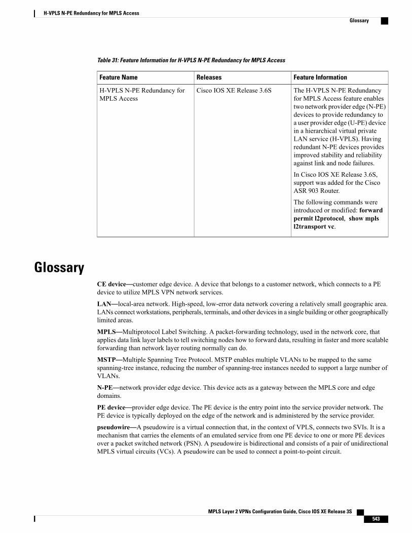
Table 31: Feature Information for H-VPLS N-PE Redundancy for MPLS Access
Feature InformationReleasesFeature Name
The H-VPLS N-PE Redundancyfor MPLS Access feature enablestwo network provider edge (N-PE)devices to provide redundancy toa user provider edge (U-PE) devicein a hierarchical virtual privateLAN service (H-VPLS). Havingredundant N-PE devices providesimproved stability and reliabilityagainst link and node failures.
In Cisco IOS XE Release 3.6S,support was added for the CiscoASR 903 Router.
The following commands wereintroduced or modified: forwardpermit l2protocol, show mplsl2transport vc.
Cisco IOS XE Release 3.6SH-VPLS N-PE Redundancy forMPLS Access
GlossaryCE device—customer edge device. A device that belongs to a customer network, which connects to a PEdevice to utilize MPLS VPN network services.
LAN—local-area network. High-speed, low-error data network covering a relatively small geographic area.LANs connect workstations, peripherals, terminals, and other devices in a single building or other geographicallylimited areas.
MPLS—Multiprotocol Label Switching. A packet-forwarding technology, used in the network core, thatapplies data link layer labels to tell switching nodes how to forward data, resulting in faster and more scalableforwarding than network layer routing normally can do.
MSTP—Multiple Spanning Tree Protocol. MSTP enables multiple VLANs to be mapped to the samespanning-tree instance, reducing the number of spanning-tree instances needed to support a large number ofVLANs.
N-PE—network provider edge device. This device acts as a gateway between the MPLS core and edgedomains.
PE device—provider edge device. The PE device is the entry point into the service provider network. ThePE device is typically deployed on the edge of the network and is administered by the service provider.
pseudowire—A pseudowire is a virtual connection that, in the context of VPLS, connects two SVIs. It is amechanism that carries the elements of an emulated service from one PE device to one or more PE devicesover a packet switched network (PSN). A pseudowire is bidirectional and consists of a pair of unidirectionalMPLS virtual circuits (VCs). A pseudowire can be used to connect a point-to-point circuit.
MPLS Layer 2 VPNs Configuration Guide, Cisco IOS XE Release 3S 543
H-VPLS N-PE Redundancy for MPLS AccessGlossary
QinQ—An IEEE 802.1QVLAN tunnel. Amechanism for constructingmultipoint Layer 2 VPN using Ethernetswitches.
redundancy—The duplication of devices, services, or connections so that, in the event of a failure, they canperform the work of those that failed.
router—A network layer device that uses one or more metrics to determine the optimal path along whichnetwork traffic should be forwarded. Routers forward packets from one network to another based on networklayer information.
spanning tree—Loop-free subset of a network topology.
U-PE—user provider edge device. This device connects CE devices to the service.
VFI—virtual forwarding instance. AVFI is a collection of data structures used by the data plane, software-basedor hardware-based, to forward packets to one or more VCs.
VLAN—Virtual LAN. Group of devices on one or more LANs that are configured (using managementsoftware) so that they can communicate as if they were attached to the same wire, when in fact they are locatedon a number of different LAN segments.
VPLS—Virtual Private LAN Service. VPLS describes an architecture that delivers Layer 2 service thatemulates an Ethernet LAN across a wide-area network (WAN) and inherits the scaling characteristics of aLAN.
VPLS redundancy—Also called N-PE redundancy. Allows U-PEs to be dual-honed (to their N-PEs) in aloop-free topology with MPLS or QinQ as the access or aggregation domain.
VPN—Virtual Private Network. Allows IP traffic to travel securely over public TCP/IP networks and theInternet by encapsulating and encrypting all IP packets. VPN uses a tunnel to encrypt all information at theIP level.
MPLS Layer 2 VPNs Configuration Guide, Cisco IOS XE Release 3S544
H-VPLS N-PE Redundancy for MPLS AccessGlossary
C H A P T E R 18VPLS MAC Address Withdrawal
The VPLS MAC Address Withdrawal feature provides faster convergence by removing (or unlearning)MAC addresses that have been dynamically learned. A Label Distribution Protocol (LDP)-based MACaddress withdrawal message is used for this purpose. A MAC list Type Length Value (TLV) is part of theMAC address withdrawal message. No configuration is needed.
• Finding Feature Information, page 545
• Information About VPLS MAC Address Withdrawal, page 545
• Additional References for Any Transport over MPLS, page 547
• Feature Information for VPLS MAC Address Withdrawal, page 548
Finding Feature InformationYour software release may not support all the features documented in this module. For the latest caveats andfeature information, see Bug Search Tool and the release notes for your platform and software release. Tofind information about the features documented in this module, and to see a list of the releases in which eachfeature is supported, see the feature information table at the end of this module.
Use Cisco Feature Navigator to find information about platform support and Cisco software image support.To access Cisco Feature Navigator, go to www.cisco.com/go/cfn. An account on Cisco.com is not required.
Information About VPLS MAC Address Withdrawal
VPLS MAC Address WithdrawalThe VPLSMACAddressWithdrawal feature provides faster convergence by removing (or unlearning) MACaddresses that have been dynamically learned. A Label Distribution Protocol (LDP)-based MAC addresswithdrawal message is used for this purpose. A MAC list Type Length Value (TLV) is part of the MACaddress withdrawal message.
The debugmpls ldpmessages and debugmpls ldp session io commands support monitoring ofMAC addresswithdrawal messages being exchanged between LDP peers. Any Transport overMultiprotocol Label Switching
MPLS Layer 2 VPNs Configuration Guide, Cisco IOS XE Release 3S 545
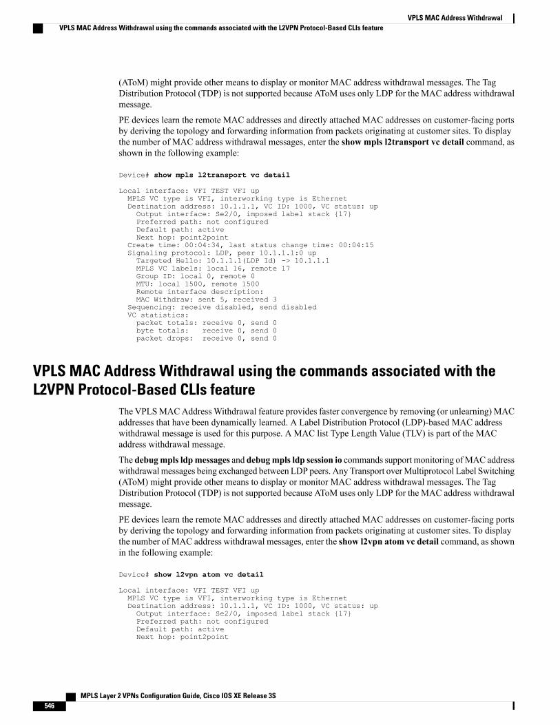
(AToM) might provide other means to display or monitor MAC address withdrawal messages. The TagDistribution Protocol (TDP) is not supported because AToM uses only LDP for the MAC address withdrawalmessage.
PE devices learn the remote MAC addresses and directly attached MAC addresses on customer-facing portsby deriving the topology and forwarding information from packets originating at customer sites. To displaythe number of MAC address withdrawal messages, enter the show mpls l2transport vc detail command, asshown in the following example:
Device# show mpls l2transport vc detail
Local interface: VFI TEST VFI upMPLS VC type is VFI, interworking type is EthernetDestination address: 10.1.1.1, VC ID: 1000, VC status: upOutput interface: Se2/0, imposed label stack {17}Preferred path: not configuredDefault path: activeNext hop: point2point
Create time: 00:04:34, last status change time: 00:04:15Signaling protocol: LDP, peer 10.1.1.1:0 upTargeted Hello: 10.1.1.1(LDP Id) -> 10.1.1.1MPLS VC labels: local 16, remote 17Group ID: local 0, remote 0MTU: local 1500, remote 1500Remote interface description:MAC Withdraw: sent 5, received 3
Sequencing: receive disabled, send disabledVC statistics:packet totals: receive 0, send 0byte totals: receive 0, send 0packet drops: receive 0, send 0
VPLS MAC Address Withdrawal using the commands associated with theL2VPN Protocol-Based CLIs feature
The VPLSMACAddressWithdrawal feature provides faster convergence by removing (or unlearning) MACaddresses that have been dynamically learned. A Label Distribution Protocol (LDP)-based MAC addresswithdrawal message is used for this purpose. A MAC list Type Length Value (TLV) is part of the MACaddress withdrawal message.
The debugmpls ldpmessages and debugmpls ldp session io commands support monitoring ofMAC addresswithdrawal messages being exchanged between LDP peers. Any Transport overMultiprotocol Label Switching(AToM) might provide other means to display or monitor MAC address withdrawal messages. The TagDistribution Protocol (TDP) is not supported because AToM uses only LDP for the MAC address withdrawalmessage.
PE devices learn the remote MAC addresses and directly attached MAC addresses on customer-facing portsby deriving the topology and forwarding information from packets originating at customer sites. To displaythe number of MAC address withdrawal messages, enter the show l2vpn atom vc detail command, as shownin the following example:
Device# show l2vpn atom vc detail
Local interface: VFI TEST VFI upMPLS VC type is VFI, interworking type is EthernetDestination address: 10.1.1.1, VC ID: 1000, VC status: upOutput interface: Se2/0, imposed label stack {17}Preferred path: not configuredDefault path: activeNext hop: point2point
MPLS Layer 2 VPNs Configuration Guide, Cisco IOS XE Release 3S546
VPLS MAC Address WithdrawalVPLS MAC Address Withdrawal using the commands associated with the L2VPN Protocol-Based CLIs feature
Create time: 00:04:34, last status change time: 00:04:15Signaling protocol: LDP, peer 10.1.1.1:0 upTargeted Hello: 10.1.1.1(LDP Id) -> 10.1.1.1MPLS VC labels: local 16, remote 17Group ID: local 0, remote 0MTU: local 1500, remote 1500Remote interface description:MAC Withdraw: sent 5, received 3
Sequencing: receive disabled, send disabledVC statistics:packet totals: receive 0, send 0byte totals: receive 0, send 0packet drops: receive 0, send 0
How MAC Address Withdrawal Works with H-VPLS N-PE Redundancy withMPLS Access
If the pseudowire between the user provider edge (U-PE) device and network provider edge (N-PE) devicefails, the L2VPN Pseudowire Redundancy feature on the U-PE device activates the standby pseudowire. Inaddition, the U-PE device sends a Label Distribution Protocol (LDP) MAC address withdrawal request to thenew N-PE device, which forwards the message to all pseudowires in the virtual private LAN service (VPLS)core and flushes its MAC address table.
If a switched virtual interface (SVI) on the N-PE device fails, the L2VPN Pseudowire Redundancy featureactivates the standby pseudowire and the U-PE device sends a MAC withdrawal message to the newly activeN-PE device.
How MAC Address Withdrawal Works with H-VPLS N-PE Redundancy withQinQ Access
If a failure occurs in the customer-switched network, a spanning-tree Topology Change Notification (TCN)is issued to the network provider edge (N-PE) device, which issues a Label Distribution Protocol (LDP)-basedMAC address withdrawal message to the peer N-PE devices and flushes its MAC address table.
Additional References for Any Transport over MPLSRelated Documents
Document TitleRelated Topic
Cisco IOS Master Command List, All ReleasesCisco IOS commands
Cisco IOSMultiprotocol Label Switching CommandReference
MPLS commands
MPLS Layer 2 VPNs Configuration Guide, Cisco IOS XE Release 3S 547
VPLS MAC Address WithdrawalHow MAC Address Withdrawal Works with H-VPLS N-PE Redundancy with MPLS Access
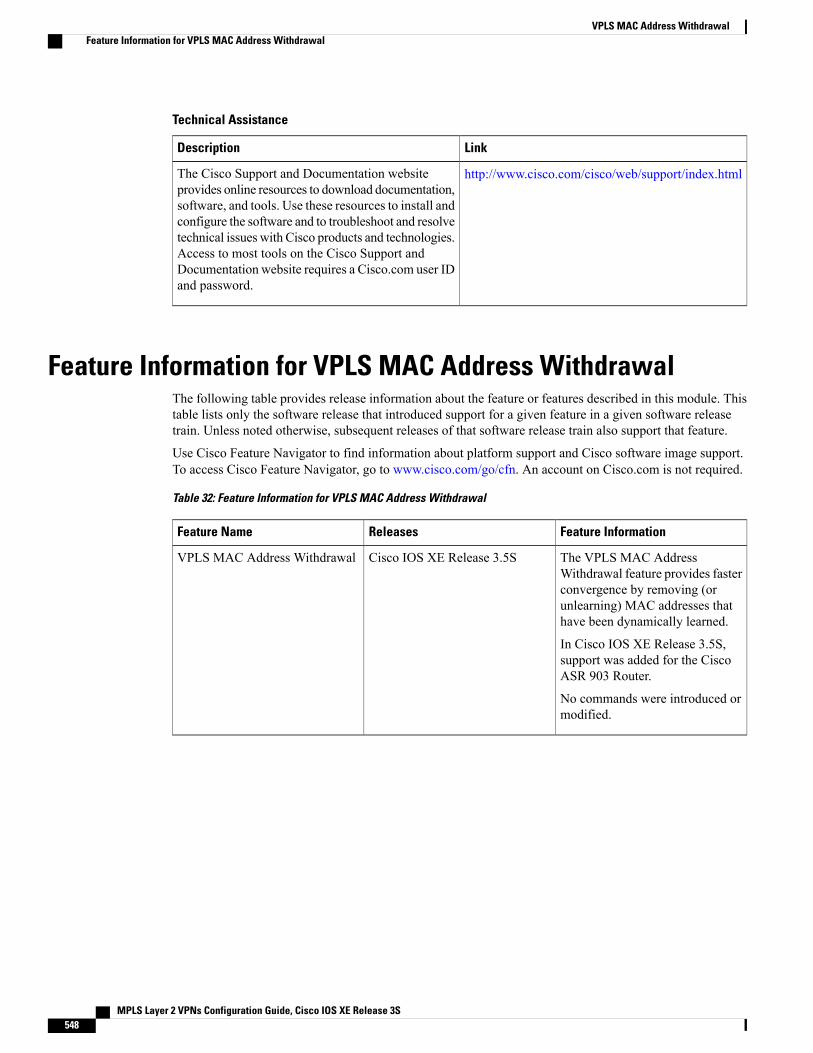
Technical Assistance
LinkDescription
http://www.cisco.com/cisco/web/support/index.htmlThe Cisco Support and Documentation websiteprovides online resources to download documentation,software, and tools. Use these resources to install andconfigure the software and to troubleshoot and resolvetechnical issues with Cisco products and technologies.Access to most tools on the Cisco Support andDocumentation website requires a Cisco.com user IDand password.
Feature Information for VPLS MAC Address WithdrawalThe following table provides release information about the feature or features described in this module. Thistable lists only the software release that introduced support for a given feature in a given software releasetrain. Unless noted otherwise, subsequent releases of that software release train also support that feature.
Use Cisco Feature Navigator to find information about platform support and Cisco software image support.To access Cisco Feature Navigator, go to www.cisco.com/go/cfn. An account on Cisco.com is not required.
Table 32: Feature Information for VPLS MAC Address Withdrawal
Feature InformationReleasesFeature Name
The VPLS MAC AddressWithdrawal feature provides fasterconvergence by removing (orunlearning) MAC addresses thathave been dynamically learned.
In Cisco IOS XE Release 3.5S,support was added for the CiscoASR 903 Router.
No commands were introduced ormodified.
Cisco IOS XE Release 3.5SVPLS MAC Address Withdrawal
MPLS Layer 2 VPNs Configuration Guide, Cisco IOS XE Release 3S548
VPLS MAC Address WithdrawalFeature Information for VPLS MAC Address Withdrawal
C H A P T E R 19Configuring Virtual Private LAN Services
Virtual Private LAN Services (VPLS) enables enterprises to link together their Ethernet-based LANs frommultiple sites via the infrastructure provided by their service provider.
This module explains VPLS and how to configure it.
• Finding Feature Information, page 549
• Prerequisites for Virtual Private LAN Services, page 549
• Restrictions for Virtual Private LAN Services, page 550
• Information About Virtual Private LAN Services, page 550
• How to Configure Virtual Private LAN Services, page 554
• Configuration Examples for Virtual Private LAN Services, page 586
• Feature Information for Configuring Virtual Private LAN Services, page 595
Finding Feature InformationYour software release may not support all the features documented in this module. For the latest caveats andfeature information, see Bug Search Tool and the release notes for your platform and software release. Tofind information about the features documented in this module, and to see a list of the releases in which eachfeature is supported, see the feature information table at the end of this module.
Use Cisco Feature Navigator to find information about platform support and Cisco software image support.To access Cisco Feature Navigator, go to www.cisco.com/go/cfn. An account on Cisco.com is not required.
Prerequisites for Virtual Private LAN ServicesBefore your configure Virtual Private LAN Services (VPLS), ensure that the network is configured as follows:
• Configure IP routing in the core so that provider edge (PE) devices can reach each other via IP.
• Configure Multiprotocol Label Switching (MPLS) in the core so that a label switched path (LSP) existsbetween PE devices.
MPLS Layer 2 VPNs Configuration Guide, Cisco IOS XE Release 3S 549
• Configure a loopback interface for originating and terminating Layer 2 traffic. Ensure that PE devicescan access the loopback interface of the other device. Note that the loopback interface is not requiredin all cases. For example, tunnel selection does not need a loopback interface when VPLS is directlymapped to a traffic engineering (TE) tunnel.
• Identify peer PE devices and attach Layer 2 circuits to VPLS at each PE device.
Restrictions for Virtual Private LAN ServicesThe following general restrictions apply to all transport types under Virtual Private LAN Services (VPLS):
• Split horizon is the default configuration to avoid broadcast packet looping and to isolate Layer 2 traffic.Split horizon prevents packets received from an emulated virtual circuit (VC) from being forwardedinto another emulated VC. This technique is important for creating loop-free paths in a full-meshednetwork.
• Supported maximum values:
• Total number of virtual forwarding instances (VFIs): 4096 (4 K)
• Maximum combined number of edge and the core peer provider edge (PE) devices per VFI: VPLS250 and hierarchical VPLS (H-VPLS) 500
• Total number of VC: 12,288 (12 K)
• Software-based data plane is not supported.
• Auto-discovery mechanism is not supported.
• Load sharing and failover on redundant customer-edge-provider-edge (CE-PE) links are not supported.
• The addition or removal of MAC addresses with Label Distribution Protocol (LDP) is not supported.
• VFI is supported only with the interface vlan command.
Information About Virtual Private LAN Services
VPLS OverviewVirtual Private LAN Services (VPLS) enables enterprises to link together their Ethernet-based LANs frommultiple sites via the infrastructure provided by their service provider. From the enterprise perspective, theservice provider’s public network looks like one giant Ethernet LAN. For the service provider, VPLS providesan opportunity to deploy another revenue-generating service on top of the existing network without majorcapital expenditures. Operators can extend the operational life of equipment in their network.
VPLS uses the provider core to join multiple attachment circuits together to simulate a virtual bridge thatconnects the multiple attachment circuits together. From a customer point of view, there is no topology for
MPLS Layer 2 VPNs Configuration Guide, Cisco IOS XE Release 3S550
Configuring Virtual Private LAN ServicesRestrictions for Virtual Private LAN Services
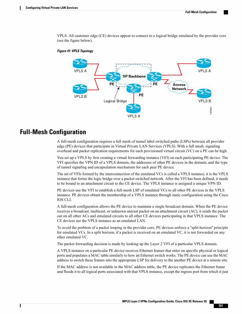
VPLS. All customer edge (CE) devices appear to connect to a logical bridge emulated by the provider core(see the figure below).
Figure 41: VPLS Topology
Full-Mesh ConfigurationA full-mesh configuration requires a full mesh of tunnel label switched paths (LSPs) between all provideredge (PE) devices that participate in Virtual Private LAN Services (VPLS). With a full mesh, signalingoverhead and packet replication requirements for each provisioned virtual circuit (VC) on a PE can be high.
You set up a VPLS by first creating a virtual forwarding instance (VFI) on each participating PE device. TheVFI specifies the VPN ID of a VPLS domain, the addresses of other PE devices in the domain, and the typeof tunnel signaling and encapsulation mechanism for each peer PE device.
The set of VFIs formed by the interconnection of the emulated VCs is called a VPLS instance; it is the VPLSinstance that forms the logic bridge over a packet switched network. After the VFI has been defined, it needsto be bound to an attachment circuit to the CE device. The VPLS instance is assigned a unique VPN ID.
PE devices use the VFI to establish a full-mesh LSP of emulated VCs to all other PE devices in the VPLSinstance. PE devices obtain the membership of a VPLS instance through static configuration using the CiscoIOS CLI.
A full-mesh configuration allows the PE device to maintain a single broadcast domain. When the PE devicereceives a broadcast, multicast, or unknown unicast packet on an attachment circuit (AC), it sends the packetout on all other ACs and emulated circuits to all other CE devices participating in that VPLS instance. TheCE devices see the VPLS instance as an emulated LAN.
To avoid the problem of a packet looping in the provider core, PE devices enforce a “split-horizon” principlefor emulated VCs. In a split horizon, if a packet is received on an emulated VC, it is not forwarded on anyother emulated VC.
The packet forwarding decision is made by looking up the Layer 2 VFI of a particular VPLS domain.
A VPLS instance on a particular PE device receives Ethernet frames that enter on specific physical or logicalports and populates a MAC table similarly to how an Ethernet switch works. The PE device can use the MACaddress to switch these frames into the appropriate LSP for delivery to the another PE device at a remote site.
If the MAC address is not available in the MAC address table, the PE device replicates the Ethernet frameand floods it to all logical ports associated with that VPLS instance, except the ingress port from which it just
MPLS Layer 2 VPNs Configuration Guide, Cisco IOS XE Release 3S 551
Configuring Virtual Private LAN ServicesFull-Mesh Configuration
entered. The PE device updates the MAC table as it receives packets on specific ports and removes addressesnot used for specific periods.
Static VPLS ConfigurationVirtual Private LAN Services (VPLS) over Multiprotocol Label Switching-Transport Profile (MPLS-TP)tunnels allows you to deploy a multipoint-to-multipoint layer 2 operating environment over an MPLS-TPnetwork for services such as Ethernet connectivity and multicast video. To configure static VPLS, you mustspecify a static range of MPLS labels using thempls label range command with the static keyword.
H-VPLSHierarchical VPLS (H-VPLS) reduces signaling and replication overhead by using full-mesh and hub-and-spokeconfigurations. Hub-and-spoke configurations operate with split horizon to allow packets to be switchedbetween pseudowires (PWs), effectively reducing the number of PWs between provider edge (PE) devices.
Split horizon is the default configuration to avoid broadcast packet looping.Note
Supported Features
Multipoint-to-Multipoint SupportIn a multipoint-to-multipoint network, two or more devices are associated over the core network. No singledevice is designated as the Root node; all devices are considered as Root nodes. All frames can be exchangeddirectly between the nodes.
Non-Transparent OperationA virtual Ethernet connection (VEC) can be transparent or non-transparent with respect to Ethernet protocoldata units (PDUs). The VEC non-transparency allows users to have a Frame Relay-type service between Layer3 devices.
Circuit MultiplexingCircuit multiplexing allows a node to participate in multiple services over a single Ethernet connection. Byparticipating in multiple services, the Ethernet connection is attached to multiple logical networks. Someexamples of possible service offerings are VPN services between sites, Internet services, and third-partyconnectivity for intercompany communications.
MAC-Address Learning, Forwarding, and AgingProvider edge (PE) devices must learn remote MAC addresses and directly attached MAC addresses on portsthat face the external network.MAC address learning accomplishes this by deriving the topology and forwarding
MPLS Layer 2 VPNs Configuration Guide, Cisco IOS XE Release 3S552
Configuring Virtual Private LAN ServicesStatic VPLS Configuration
information from packets originating at customer sites. A timer is associated with stored MAC addresses.After the timer expires, the entry is removed from the table.
Jumbo Frame SupportJumbo frame support provides support for frame sizes between 1548 and 9216 bytes. You use the CLI toestablish the jumbo frame size for any value specified in the above range. The default value is 1500 bytes inany Layer 2/VLAN interface. You can configure jumbo frame support on a per-interface basis.
Q-in-Q Support and Q-in-Q to EoMPLS SupportWith 802.1Q tunneling (Q-in-Q), the customer edge (CE) device issues VLAN-tagged packets and VPLSforwards these packets to a far-end CE device. Q-in-Q refers to the fact that one or more 802.1Q tags may belocated in a packet within the interior of the network. As packets are received from a CE device, an additionalVLAN tag is added to incoming Ethernet packets to segregate traffic from different CE devices. Untaggedpackets originating from a CE device use a single tag within the interior of the VLAN switched network,whereas previously tagged packets originating from the CE device use two or more tags.
VPLS Services
Transparent LAN Service
Transparent LAN Service (TLS) is an extension to the point-to-point port-based Ethernet over MultiprotocolLabel Switching (EoMPLS), which provides bridging protocol transparency (for example, bridge protocoldata units [BPDUs]) and VLAN values. Bridges see this service as an Ethernet segment. With TLS, the PEdevice forwards all Ethernet packets received from the customer-facing interface (including tagged anduntagged packets, and BPDUs) as follows:
• To a local Ethernet interface or an emulated virtual circuit (VC) if the destination MAC address is foundin the Layer 2 forwarding table.
• To all other local Ethernet interfaces and emulated VCs belonging to the same VPLS domain if thedestination MAC address is a multicast or broadcast address or if the destination MAC address is notfound in the Layer 2 forwarding table.
You must enable Layer 2 protocol tunneling to run the Cisco Discovery Protocol (CDP), the VLANTrunking Protocol (VTP), and the Spanning-Tree Protocol (STP).
Note
Ethernet Virtual Connection Service
Ethernet Virtual Connection Service (EVCS) is an extension to the point-to-point VLAN-based Ethernet overMPLS (EoMPLS) that allows devices to reach multiple intranet and extranet locations from a single physicalport. With EVCS, the provider edge (PE) device forwards all Ethernet packets with a particular VLAN tagreceived from the customer-facing interface (excluding bridge protocol data units [BPDUs]) as follows:
• To a local Ethernet interface or to an emulated virtual circuit (VC) if the destination MAC address isfound in the Layer 2 forwarding table.
MPLS Layer 2 VPNs Configuration Guide, Cisco IOS XE Release 3S 553
Configuring Virtual Private LAN ServicesSupported Features
• To all other local Ethernet interfaces and emulated VCs belonging to the same Virtual Private LANServices (VPLS) domain if the destination MAC address is a multicast or a broadcast address or if thedestination MAC address is not found in the Layer 2 forwarding table.
Because it has only local significance, the demultiplexing VLAN tag that identifies a VPLS domain isremoved before the packet is forwarded to the outgoing Ethernet interfaces or emulated VCs.
Note
VPLS Integrated Routing and BridgingVirtual Private LAN Services (VPLS) integrated routing and bridging routes Layer 3 traffic and switchesLayer 2 frames for pseudowire connections between provider edge (PE) devices using a VPLS multipoint PEdevice. The ability to route frames to and from these interfaces supports the termination of a pseudowire intoa Layer 3 network (VPN or global) on the same switch or to tunnel Layer 3 frames over a Layer 2 tunnel(VPLS).
To configure routing support for a pseudowire, configure an IP address and other Layer 3 features for theLayer 3 domain in interface configuration mode.
VPLS integrated routing and bridging does not support multicast routing. VPLS integrated routing andbridging is also known as routed pseudowire and routed VPLS.
Note
The following example shows how to assign IP address 10.10.10.1 to a bridge domain interface (BDI).
interface bdi 100ip address 10.10.10.1 255.255.255.0
How to Configure Virtual Private LAN ServicesProvisioning a Virtual Private LAN Services (VPLS) link involves provisioning the associated attachmentcircuit and a virtual forwarding instance (VFI) on a provider edge (PE) device.
In Cisco IOSXERelease 3.7S, the L2VPN Protocol-Based CLIs feature was introduced. This feature providesa set of processes and an improved infrastructure for developing and delivering Cisco IOS software on variousCisco platforms. This feature introduces new commands and modifies or replaces existing commands toachieve a consistent functionality across Cisco platforms and provide cross-Operating System (OS) support.
This section consists of tasks that use the commands existing prior to Cisco IOS XE Release 3.7S and acorresponding task that uses the commands introduced or modified by the L2VPN Protocol-Based CLIsfeature.
Configuring PE Layer 2 Interfaces on CE DevicesYou can configure the Ethernet flow point (EFP) as a Layer 2 virtual interface. You can also select tagged oruntagged traffic from a customer edge (CE) device.
MPLS Layer 2 VPNs Configuration Guide, Cisco IOS XE Release 3S554
Configuring Virtual Private LAN ServicesVPLS Integrated Routing and Bridging
Configuring 802.1Q Access Ports for Tagged Traffic from a CE Device
When Ethernet Virtual Connection Service (EVCS) is configured, a provider edge (PE) device forwardsall Ethernet packets with a particular VLAN tag to a local Ethernet interface or emulated virtual circuit(VC) if the destination MAC address is found in the Layer 2 forwarding table.
Note
SUMMARY STEPS
1. enable2. configure terminal3. interface type number4. no ip address [ip-address mask] [secondary]5. negotiation auto6. service instance si-id ethernet7. encapsulation dot1q vlan-id8. bridge-domain bd-id9. end
DETAILED STEPS
PurposeCommand or Action
Enables privileged EXEC mode.enable
Example:
Device> enable
Step 1
• Enter your password if prompted.
Enters global configuration mode.configure terminal
Example:
Device# configure terminal
Step 2
Specifies an interface and enters interface configurationmode.interface type number
Example:
Device(config)# interface gigabitethernet0/0/1
Step 3
Disables IP processing.no ip address [ip-address mask] [secondary]
Example:
Device(config-if)# no ip address
Step 4
MPLS Layer 2 VPNs Configuration Guide, Cisco IOS XE Release 3S 555
Configuring Virtual Private LAN ServicesConfiguring PE Layer 2 Interfaces on CE Devices
PurposeCommand or Action
Enables the autonegotiation protocol to configure the speed,duplex, and automatic flow control of the Gigabit Ethernetinterface.
negotiation auto
Example:
Device(config-if)# negotiation auto
Step 5
Specifies the service instance ID and enters service instanceconfiguration mode.
service instance si-id ethernet
Example:
Device(config-if)# service instance 10ethernet
Step 6
Defines the matching criteria to map 802.1Q frames ingresson an interface to the appropriate service instance.
encapsulation dot1q vlan-id
Example:
Device(config-if-srv)# encapsulation dot1q200
Step 7
Ensure that the interface on the adjoining customer edge (CE)device is on the same VLAN as this PE device.
Binds a service instance to a bridge domain instance.bridge-domain bd-id
Example:
Device(config-if-srv)# bridge-domain 100
Step 8
Exits service instance configuration mode and returns toprivileged EXEC mode.
end
Example:
Device(config-if-srv)# end
Step 9
Configuring 802.1Q Access Ports for Tagged Traffic from a CE Device: Alternate Configuration
When Ethernet Virtual Connection Service (EVCS) is configured, the PE device forwards all Ethernetpackets with a particular VLAN tag to a local Ethernet interface or an emulated virtual circuit (VC) if thedestination MAC address is found in the Layer 2 forwarding table.
Note
MPLS Layer 2 VPNs Configuration Guide, Cisco IOS XE Release 3S556
Configuring Virtual Private LAN ServicesConfiguring PE Layer 2 Interfaces on CE Devices
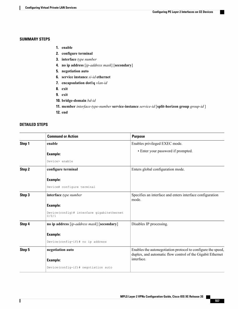
SUMMARY STEPS
1. enable2. configure terminal3. interface type number4. no ip address [ip-address mask] [secondary]5. negotiation auto6. service instance si-id ethernet7. encapsulation dot1q vlan-id8. exit9. exit10. bridge-domain bd-id11. member interface-type-number service-instance service-id [split-horizon group group-id ]12. end
DETAILED STEPS
PurposeCommand or Action
Enables privileged EXEC mode.enable
Example:
Device> enable
Step 1
• Enter your password if prompted.
Enters global configuration mode.configure terminal
Example:
Device# configure terminal
Step 2
Specifies an interface and enters interface configurationmode.
interface type number
Example:
Device(config)# interface gigabitethernet0/0/1
Step 3
Disables IP processing.no ip address [ip-address mask] [secondary]
Example:
Device(config-if)# no ip address
Step 4
Enables the autonegotiation protocol to configure the speed,duplex, and automatic flow control of the Gigabit Ethernetinterface.
negotiation auto
Example:
Device(config-if)# negotiation auto
Step 5
MPLS Layer 2 VPNs Configuration Guide, Cisco IOS XE Release 3S 557
Configuring Virtual Private LAN ServicesConfiguring PE Layer 2 Interfaces on CE Devices
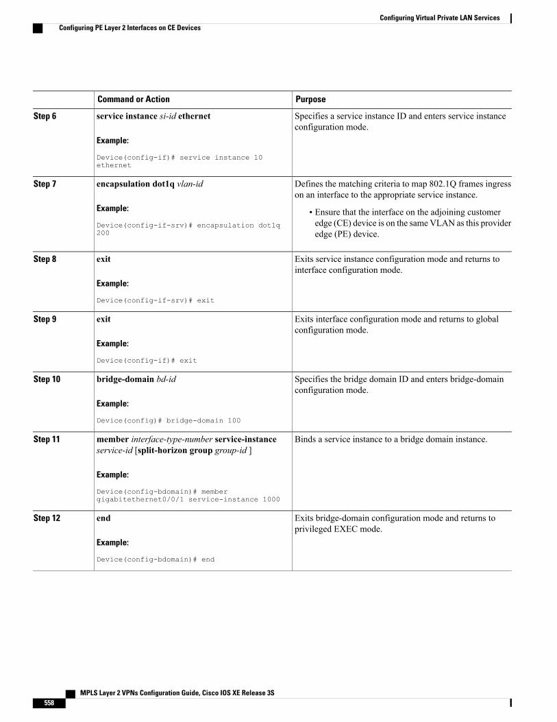
PurposeCommand or Action
Specifies a service instance ID and enters service instanceconfiguration mode.
service instance si-id ethernet
Example:
Device(config-if)# service instance 10ethernet
Step 6
Defines the matching criteria to map 802.1Q frames ingresson an interface to the appropriate service instance.
encapsulation dot1q vlan-id
Example:
Device(config-if-srv)# encapsulation dot1q200
Step 7
• Ensure that the interface on the adjoining customeredge (CE) device is on the sameVLAN as this provideredge (PE) device.
Exits service instance configuration mode and returns tointerface configuration mode.
exit
Example:
Device(config-if-srv)# exit
Step 8
Exits interface configuration mode and returns to globalconfiguration mode.
exit
Example:
Device(config-if)# exit
Step 9
Specifies the bridge domain ID and enters bridge-domainconfiguration mode.
bridge-domain bd-id
Example:
Device(config)# bridge-domain 100
Step 10
Binds a service instance to a bridge domain instance.member interface-type-number service-instanceservice-id [split-horizon group group-id ]
Step 11
Example:
Device(config-bdomain)# membergigabitethernet0/0/1 service-instance 1000
Exits bridge-domain configuration mode and returns toprivileged EXEC mode.
end
Example:
Device(config-bdomain)# end
Step 12
MPLS Layer 2 VPNs Configuration Guide, Cisco IOS XE Release 3S558
Configuring Virtual Private LAN ServicesConfiguring PE Layer 2 Interfaces on CE Devices
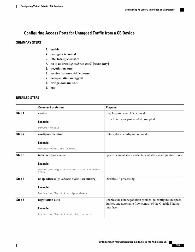
Configuring Access Ports for Untagged Traffic from a CE Device
SUMMARY STEPS
1. enable2. configure terminal3. interface type number4. no ip address [ip-address mask] [secondary]5. negotiation auto6. service instance si-id ethernet7. encapsulation untagged8. bridge-domain bd-id9. end
DETAILED STEPS
PurposeCommand or Action
Enables privileged EXEC mode.enable
Example:
Device> enable
Step 1
• Enter your password if prompted.
Enters global configuration mode.configure terminal
Example:
Device# configure terminal
Step 2
Specifies an interface and enters interface configuration mode.interface type number
Example:
Device(config)# interface gigabitethernet0/0/0
Step 3
Disables IP processing.no ip address [ip-address mask] [secondary]
Example:
Device(config-if)# no ip address
Step 4
Enables the autonegotiation protocol to configure the speed,duplex, and automatic flow control of the Gigabit Ethernetinterface.
negotiation auto
Example:
Device(config-if)# negotiation auto
Step 5
MPLS Layer 2 VPNs Configuration Guide, Cisco IOS XE Release 3S 559
Configuring Virtual Private LAN ServicesConfiguring PE Layer 2 Interfaces on CE Devices
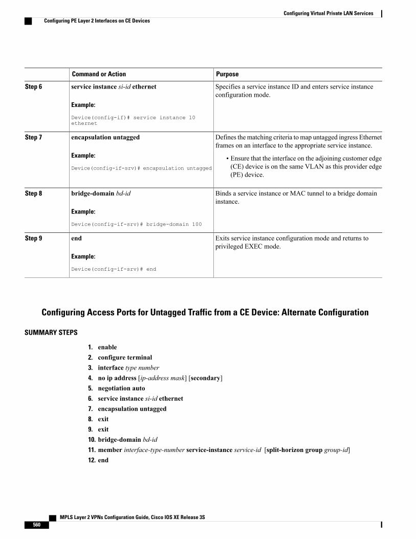
PurposeCommand or Action
Specifies a service instance ID and enters service instanceconfiguration mode.
service instance si-id ethernet
Example:
Device(config-if)# service instance 10ethernet
Step 6
Defines the matching criteria to map untagged ingress Ethernetframes on an interface to the appropriate service instance.
encapsulation untagged
Example:
Device(config-if-srv)# encapsulation untagged
Step 7
• Ensure that the interface on the adjoining customer edge(CE) device is on the same VLAN as this provider edge(PE) device.
Binds a service instance or MAC tunnel to a bridge domaininstance.
bridge-domain bd-id
Example:
Device(config-if-srv)# bridge-domain 100
Step 8
Exits service instance configuration mode and returns toprivileged EXEC mode.
end
Example:
Device(config-if-srv)# end
Step 9
Configuring Access Ports for Untagged Traffic from a CE Device: Alternate Configuration
SUMMARY STEPS
1. enable2. configure terminal3. interface type number4. no ip address [ip-address mask] [secondary]5. negotiation auto6. service instance si-id ethernet7. encapsulation untagged8. exit9. exit10. bridge-domain bd-id11. member interface-type-number service-instance service-id [split-horizon group group-id]12. end
MPLS Layer 2 VPNs Configuration Guide, Cisco IOS XE Release 3S560
Configuring Virtual Private LAN ServicesConfiguring PE Layer 2 Interfaces on CE Devices
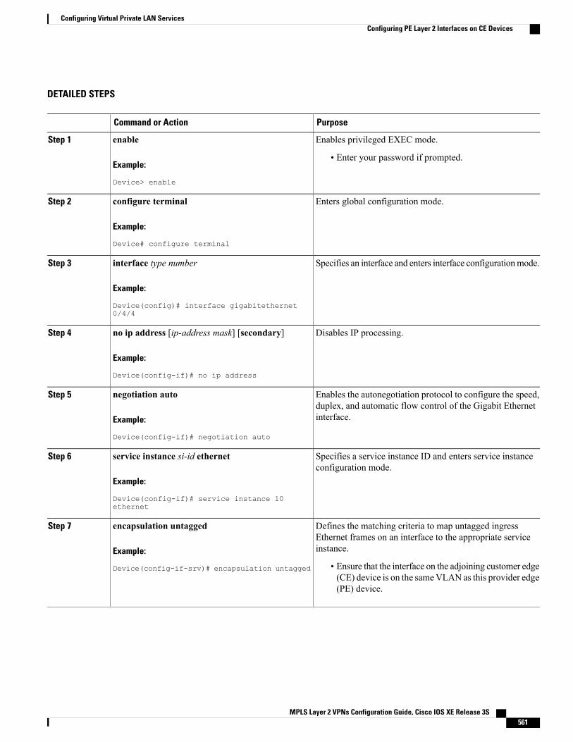
DETAILED STEPS
PurposeCommand or Action
Enables privileged EXEC mode.enable
Example:
Device> enable
Step 1
• Enter your password if prompted.
Enters global configuration mode.configure terminal
Example:
Device# configure terminal
Step 2
Specifies an interface and enters interface configurationmode.interface type number
Example:
Device(config)# interface gigabitethernet0/4/4
Step 3
Disables IP processing.no ip address [ip-address mask] [secondary]
Example:
Device(config-if)# no ip address
Step 4
Enables the autonegotiation protocol to configure the speed,duplex, and automatic flow control of the Gigabit Ethernetinterface.
negotiation auto
Example:
Device(config-if)# negotiation auto
Step 5
Specifies a service instance ID and enters service instanceconfiguration mode.
service instance si-id ethernet
Example:
Device(config-if)# service instance 10ethernet
Step 6
Defines the matching criteria to map untagged ingressEthernet frames on an interface to the appropriate serviceinstance.
encapsulation untagged
Example:
Device(config-if-srv)# encapsulation untagged
Step 7
• Ensure that the interface on the adjoining customer edge(CE) device is on the sameVLAN as this provider edge(PE) device.
MPLS Layer 2 VPNs Configuration Guide, Cisco IOS XE Release 3S 561
Configuring Virtual Private LAN ServicesConfiguring PE Layer 2 Interfaces on CE Devices
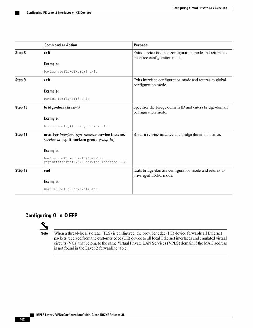
PurposeCommand or Action
Exits service instance configuration mode and returns tointerface configuration mode.
exit
Example:
Device(config-if-srv)# exit
Step 8
Exits interface configuration mode and returns to globalconfiguration mode.
exit
Example:
Device(config-if)# exit
Step 9
Specifies the bridge domain ID and enters bridge-domainconfiguration mode.
bridge-domain bd-id
Example:
Device(config)# bridge-domain 100
Step 10
Binds a service instance to a bridge domain instance.member interface-type-number service-instanceservice-id [split-horizon group group-id]
Step 11
Example:
Device(config-bdomain)# membergigabitethernet0/4/4 service-instance 1000
Exits bridge-domain configuration mode and returns toprivileged EXEC mode.
end
Example:
Device(config-bdomain)# end
Step 12
Configuring Q-in-Q EFP
When a thread-local storage (TLS) is configured, the provider edge (PE) device forwards all Ethernetpackets received from the customer edge (CE) device to all local Ethernet interfaces and emulated virtualcircuits (VCs) that belong to the same Virtual Private LAN Services (VPLS) domain if the MAC addressis not found in the Layer 2 forwarding table.
Note
MPLS Layer 2 VPNs Configuration Guide, Cisco IOS XE Release 3S562
Configuring Virtual Private LAN ServicesConfiguring PE Layer 2 Interfaces on CE Devices
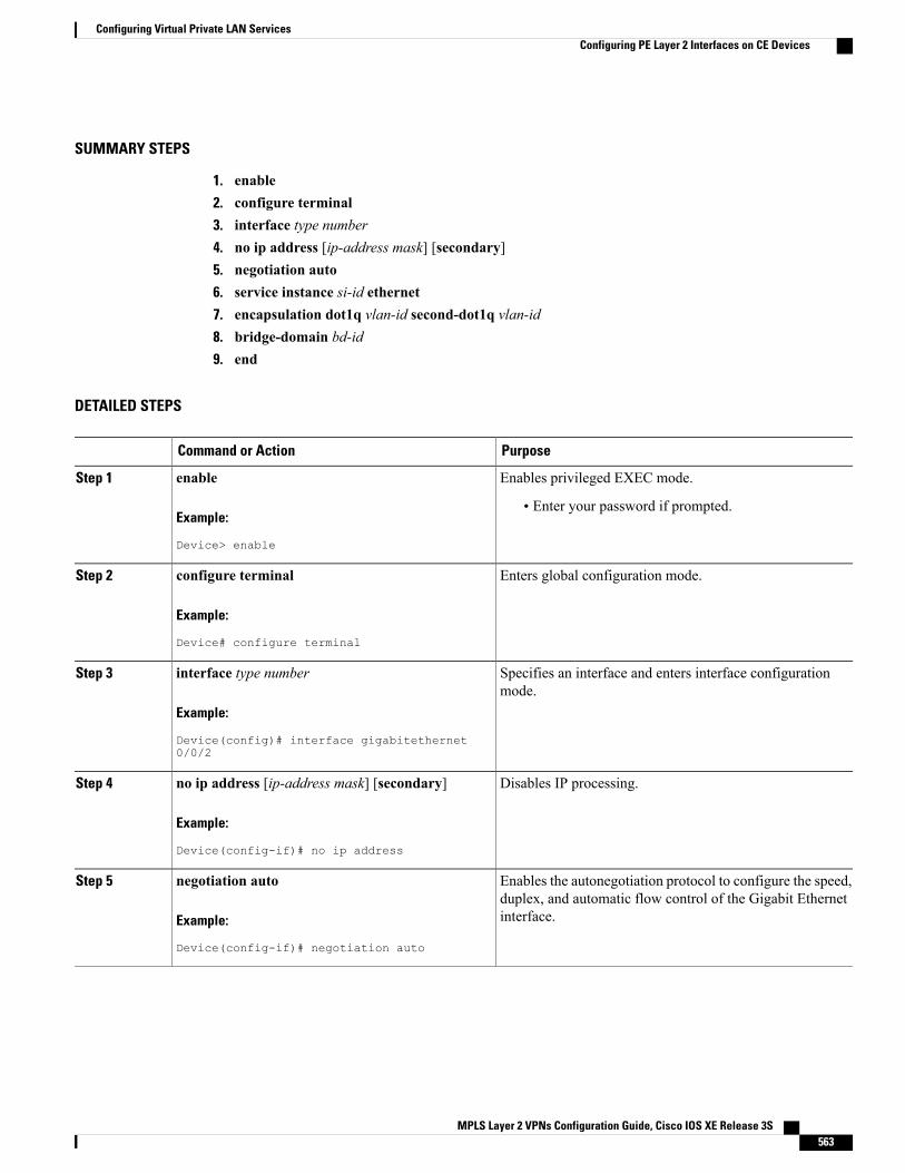
SUMMARY STEPS
1. enable2. configure terminal3. interface type number4. no ip address [ip-address mask] [secondary]5. negotiation auto6. service instance si-id ethernet7. encapsulation dot1q vlan-id second-dot1q vlan-id8. bridge-domain bd-id9. end
DETAILED STEPS
PurposeCommand or Action
Enables privileged EXEC mode.enable
Example:
Device> enable
Step 1
• Enter your password if prompted.
Enters global configuration mode.configure terminal
Example:
Device# configure terminal
Step 2
Specifies an interface and enters interface configurationmode.
interface type number
Example:
Device(config)# interface gigabitethernet0/0/2
Step 3
Disables IP processing.no ip address [ip-address mask] [secondary]
Example:
Device(config-if)# no ip address
Step 4
Enables the autonegotiation protocol to configure the speed,duplex, and automatic flow control of the Gigabit Ethernetinterface.
negotiation auto
Example:
Device(config-if)# negotiation auto
Step 5
MPLS Layer 2 VPNs Configuration Guide, Cisco IOS XE Release 3S 563
Configuring Virtual Private LAN ServicesConfiguring PE Layer 2 Interfaces on CE Devices
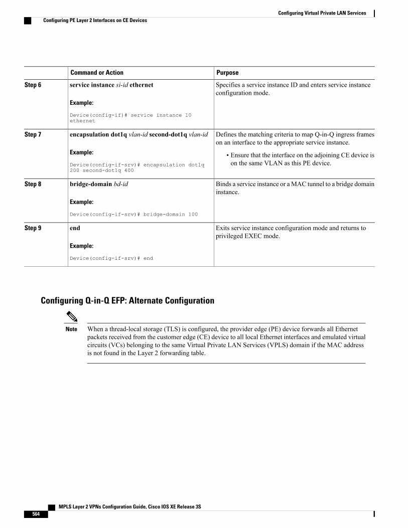
PurposeCommand or Action
Specifies a service instance ID and enters service instanceconfiguration mode.
service instance si-id ethernet
Example:
Device(config-if)# service instance 10ethernet
Step 6
Defines the matching criteria to map Q-in-Q ingress frameson an interface to the appropriate service instance.
encapsulation dot1q vlan-id second-dot1q vlan-id
Example:
Device(config-if-srv)# encapsulation dot1q200 second-dot1q 400
Step 7
• Ensure that the interface on the adjoining CE device ison the same VLAN as this PE device.
Binds a service instance or aMAC tunnel to a bridge domaininstance.
bridge-domain bd-id
Example:
Device(config-if-srv)# bridge-domain 100
Step 8
Exits service instance configuration mode and returns toprivileged EXEC mode.
end
Example:
Device(config-if-srv)# end
Step 9
Configuring Q-in-Q EFP: Alternate Configuration
When a thread-local storage (TLS) is configured, the provider edge (PE) device forwards all Ethernetpackets received from the customer edge (CE) device to all local Ethernet interfaces and emulated virtualcircuits (VCs) belonging to the same Virtual Private LAN Services (VPLS) domain if the MAC addressis not found in the Layer 2 forwarding table.
Note
MPLS Layer 2 VPNs Configuration Guide, Cisco IOS XE Release 3S564
Configuring Virtual Private LAN ServicesConfiguring PE Layer 2 Interfaces on CE Devices
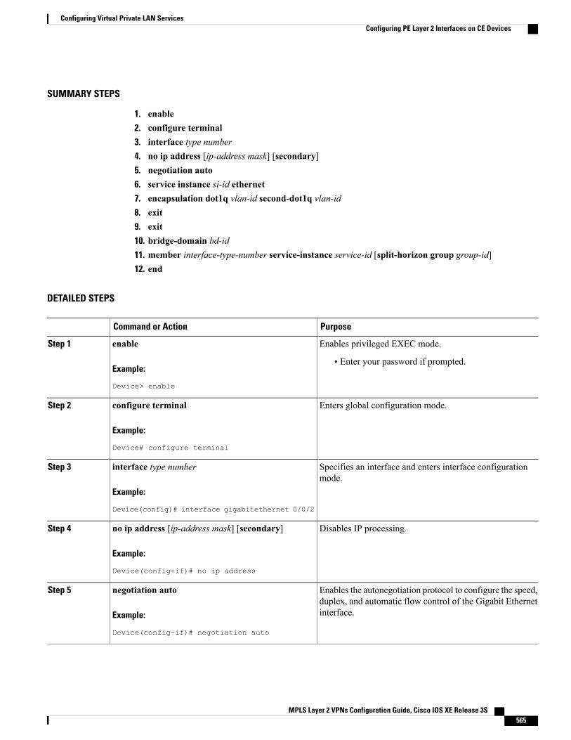
SUMMARY STEPS
1. enable2. configure terminal3. interface type number4. no ip address [ip-address mask] [secondary]5. negotiation auto6. service instance si-id ethernet7. encapsulation dot1q vlan-id second-dot1q vlan-id8. exit9. exit10. bridge-domain bd-id11. member interface-type-number service-instance service-id [split-horizon group group-id]12. end
DETAILED STEPS
PurposeCommand or Action
Enables privileged EXEC mode.enable
Example:
Device> enable
Step 1
• Enter your password if prompted.
Enters global configuration mode.configure terminal
Example:
Device# configure terminal
Step 2
Specifies an interface and enters interface configurationmode.
interface type number
Example:
Device(config)# interface gigabitethernet 0/0/2
Step 3
Disables IP processing.no ip address [ip-address mask] [secondary]
Example:
Device(config-if)# no ip address
Step 4
Enables the autonegotiation protocol to configure the speed,duplex, and automatic flow control of the Gigabit Ethernetinterface.
negotiation auto
Example:
Device(config-if)# negotiation auto
Step 5
MPLS Layer 2 VPNs Configuration Guide, Cisco IOS XE Release 3S 565
Configuring Virtual Private LAN ServicesConfiguring PE Layer 2 Interfaces on CE Devices
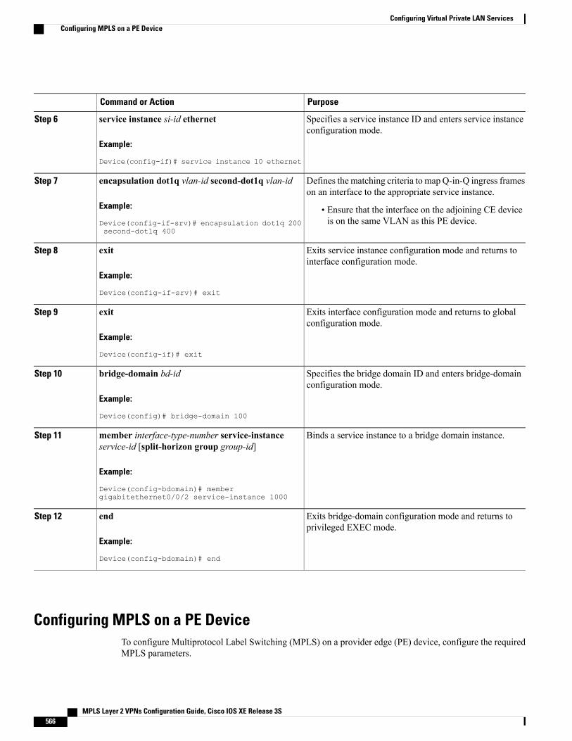
PurposeCommand or Action
Specifies a service instance ID and enters service instanceconfiguration mode.
service instance si-id ethernet
Example:
Device(config-if)# service instance 10 ethernet
Step 6
Defines the matching criteria to map Q-in-Q ingress frameson an interface to the appropriate service instance.
encapsulation dot1q vlan-id second-dot1q vlan-id
Example:
Device(config-if-srv)# encapsulation dot1q 200second-dot1q 400
Step 7
• Ensure that the interface on the adjoining CE deviceis on the same VLAN as this PE device.
Exits service instance configuration mode and returns tointerface configuration mode.
exit
Example:
Device(config-if-srv)# exit
Step 8
Exits interface configuration mode and returns to globalconfiguration mode.
exit
Example:
Device(config-if)# exit
Step 9
Specifies the bridge domain ID and enters bridge-domainconfiguration mode.
bridge-domain bd-id
Example:
Device(config)# bridge-domain 100
Step 10
Binds a service instance to a bridge domain instance.member interface-type-number service-instanceservice-id [split-horizon group group-id]
Step 11
Example:
Device(config-bdomain)# membergigabitethernet0/0/2 service-instance 1000
Exits bridge-domain configuration mode and returns toprivileged EXEC mode.
end
Example:
Device(config-bdomain)# end
Step 12
Configuring MPLS on a PE DeviceTo configure Multiprotocol Label Switching (MPLS) on a provider edge (PE) device, configure the requiredMPLS parameters.
MPLS Layer 2 VPNs Configuration Guide, Cisco IOS XE Release 3S566
Configuring Virtual Private LAN ServicesConfiguring MPLS on a PE Device
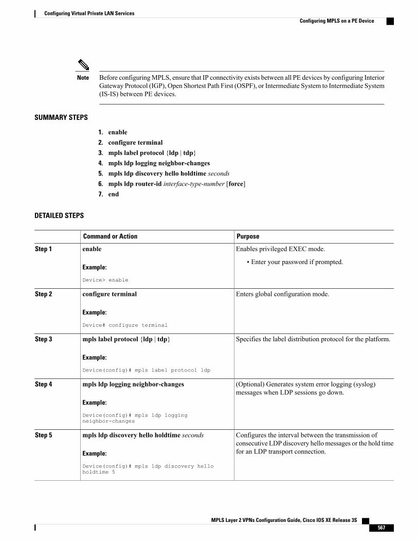
Before configuringMPLS, ensure that IP connectivity exists between all PE devices by configuring InteriorGateway Protocol (IGP), Open Shortest Path First (OSPF), or Intermediate System to Intermediate System(IS-IS) between PE devices.
Note
SUMMARY STEPS
1. enable2. configure terminal3. mpls label protocol {ldp | tdp}4. mpls ldp logging neighbor-changes5. mpls ldp discovery hello holdtime seconds6. mpls ldp router-id interface-type-number [force]7. end
DETAILED STEPS
PurposeCommand or Action
Enables privileged EXEC mode.enableStep 1
Example:
Device> enable
• Enter your password if prompted.
Enters global configuration mode.configure terminal
Example:
Device# configure terminal
Step 2
Specifies the label distribution protocol for the platform.mpls label protocol {ldp | tdp}
Example:
Device(config)# mpls label protocol ldp
Step 3
(Optional) Generates system error logging (syslog)messages when LDP sessions go down.
mpls ldp logging neighbor-changes
Example:
Device(config)# mpls ldp loggingneighbor-changes
Step 4
Configures the interval between the transmission ofconsecutive LDP discovery hello messages or the hold timefor an LDP transport connection.
mpls ldp discovery hello holdtime seconds
Example:
Device(config)# mpls ldp discovery helloholdtime 5
Step 5
MPLS Layer 2 VPNs Configuration Guide, Cisco IOS XE Release 3S 567
Configuring Virtual Private LAN ServicesConfiguring MPLS on a PE Device
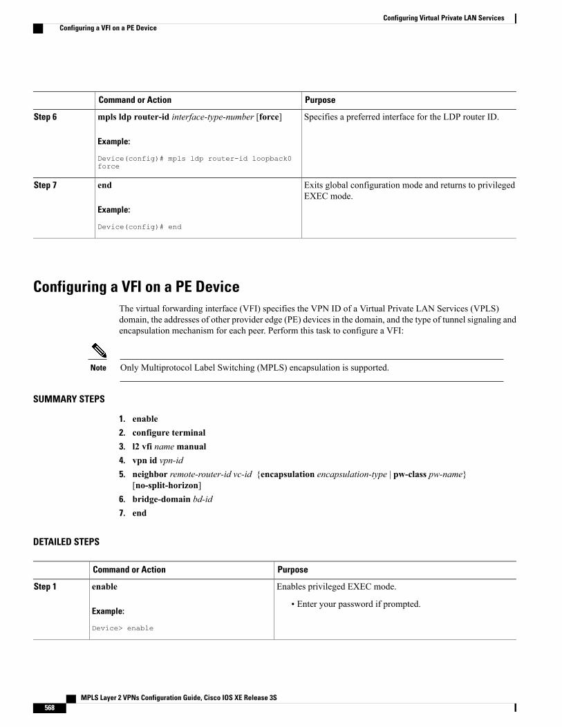
PurposeCommand or Action
Specifies a preferred interface for the LDP router ID.mpls ldp router-id interface-type-number [force]
Example:
Device(config)# mpls ldp router-id loopback0force
Step 6
Exits global configuration mode and returns to privilegedEXEC mode.
end
Example:
Device(config)# end
Step 7
Configuring a VFI on a PE DeviceThe virtual forwarding interface (VFI) specifies the VPN ID of a Virtual Private LAN Services (VPLS)domain, the addresses of other provider edge (PE) devices in the domain, and the type of tunnel signaling andencapsulation mechanism for each peer. Perform this task to configure a VFI:
Only Multiprotocol Label Switching (MPLS) encapsulation is supported.Note
SUMMARY STEPS
1. enable2. configure terminal3. l2 vfi namemanual4. vpn id vpn-id5. neighbor remote-router-id vc-id {encapsulation encapsulation-type | pw-class pw-name}
[no-split-horizon]6. bridge-domain bd-id7. end
DETAILED STEPS
PurposeCommand or Action
Enables privileged EXEC mode.enable
Example:
Device> enable
Step 1
• Enter your password if prompted.
MPLS Layer 2 VPNs Configuration Guide, Cisco IOS XE Release 3S568
Configuring Virtual Private LAN ServicesConfiguring a VFI on a PE Device
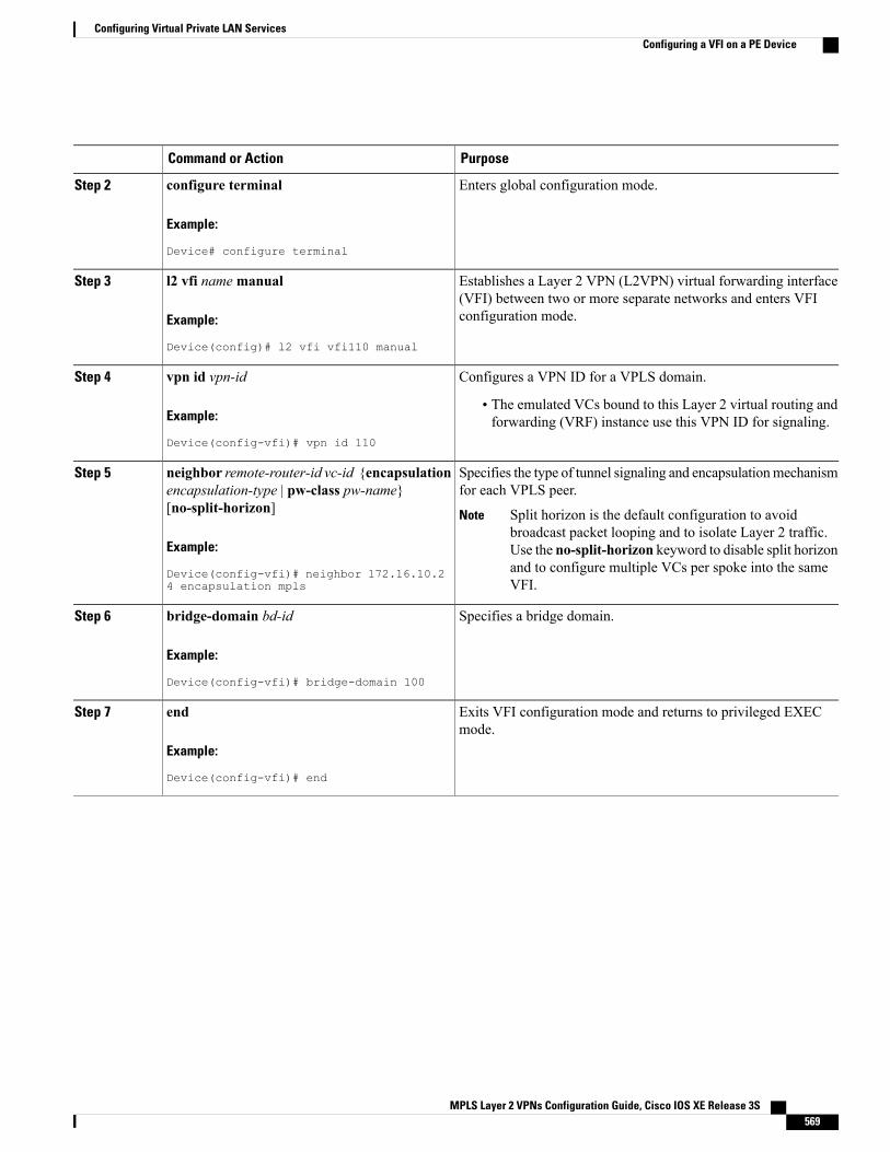
PurposeCommand or Action
Enters global configuration mode.configure terminal
Example:
Device# configure terminal
Step 2
Establishes a Layer 2 VPN (L2VPN) virtual forwarding interface(VFI) between two or more separate networks and enters VFIconfiguration mode.
l2 vfi namemanual
Example:
Device(config)# l2 vfi vfi110 manual
Step 3
Configures a VPN ID for a VPLS domain.vpn id vpn-id
Example:
Device(config-vfi)# vpn id 110
Step 4
• The emulated VCs bound to this Layer 2 virtual routing andforwarding (VRF) instance use this VPN ID for signaling.
Specifies the type of tunnel signaling and encapsulationmechanismfor each VPLS peer.
neighbor remote-router-id vc-id {encapsulationencapsulation-type | pw-class pw-name}[no-split-horizon]
Step 5
Split horizon is the default configuration to avoidbroadcast packet looping and to isolate Layer 2 traffic.Use the no-split-horizon keyword to disable split horizonand to configure multiple VCs per spoke into the sameVFI.
Note
Example:
Device(config-vfi)# neighbor 172.16.10.24 encapsulation mpls
Specifies a bridge domain.bridge-domain bd-id
Example:
Device(config-vfi)# bridge-domain 100
Step 6
Exits VFI configuration mode and returns to privileged EXECmode.
end
Example:
Device(config-vfi)# end
Step 7
MPLS Layer 2 VPNs Configuration Guide, Cisco IOS XE Release 3S 569
Configuring Virtual Private LAN ServicesConfiguring a VFI on a PE Device
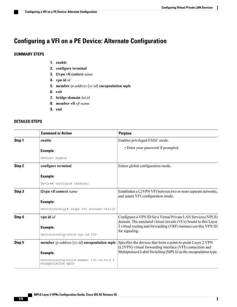
Configuring a VFI on a PE Device: Alternate Configuration
SUMMARY STEPS
1. enable2. configure terminal3. l2vpn vfi context name4. vpn id id5. member ip-address [vc-id] encapsulation mpls6. exit7. bridge-domain bd-id8. member vfi vfi-name9. end
DETAILED STEPS
PurposeCommand or Action
Enables privileged EXEC mode.enable
Example:
Device> enable
Step 1
• Enter your password if prompted.
Enters global configuration mode.configure terminal
Example:
Device# configure terminal
Step 2
Establishes a L2VPNVFI between two ormore separate networks,and enters VFI configuration mode.
l2vpn vfi context name
Example:
Device(config)# l2vpn vfi context vfi110
Step 3
Configures a VPN ID for a Virtual Private LAN Services (VPLS)domain. The emulated virtual circuits (VCs) bound to this Layer
vpn id id
Example:
Device(config-vfi)# vpn id 110
Step 4
2 virtual routing and forwarding (VRF) instance use this VPN IDfor signaling.
Specifies the devices that form a point-to-point Layer 2 VPN(L2VPN) virtual forwarding interface (VFI) connection andMultiprotocol Label Switching (MPLS) as the encapsulation type.
member ip-address [vc-id] encapsulation mpls
Example:
Device(config-vfi)# member 172.16.10.2 4encapsulation mpls
Step 5
MPLS Layer 2 VPNs Configuration Guide, Cisco IOS XE Release 3S570
Configuring Virtual Private LAN ServicesConfiguring a VFI on a PE Device: Alternate Configuration
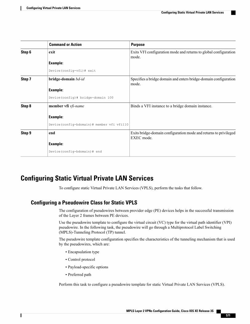
PurposeCommand or Action
Exits VFI configuration mode and returns to global configurationmode.
exit
Example:
Device(config-vfi)# exit
Step 6
Specifies a bridge domain and enters bridge-domain configurationmode.
bridge-domain bd-id
Example:
Device(config)# bridge-domain 100
Step 7
Binds a VFI instance to a bridge domain instance.member vfi vfi-name
Example:
Device(config-bdomain)# member vfi vfi110
Step 8
Exits bridge-domain configurationmode and returns to privilegedEXEC mode.
end
Example:
Device(config-bdomain)# end
Step 9
Configuring Static Virtual Private LAN ServicesTo configure static Virtual Private LAN Services (VPLS), perform the tasks that follow.
Configuring a Pseudowire Class for Static VPLSThe configuration of pseudowires between provider edge (PE) devices helps in the successful transmissionof the Layer 2 frames between PE devices.
Use the pseudowire template to configure the virtual circuit (VC) type for the virtual path identifier (VPI)pseudowire. In the following task, the pseudowire will go through a Multiprotocol Label Switching(MPLS)-Tunneling Protocol (TP) tunnel.
The pseudowire template configuration specifies the characteristics of the tunneling mechanism that is usedby the pseudowires, which are:
• Encapsulation type
• Control protocol
• Payload-specific options
• Preferred path
Perform this task to configure a pseudowire template for static Virtual Private LAN Services (VPLS).
MPLS Layer 2 VPNs Configuration Guide, Cisco IOS XE Release 3S 571
Configuring Virtual Private LAN ServicesConfiguring Static Virtual Private LAN Services
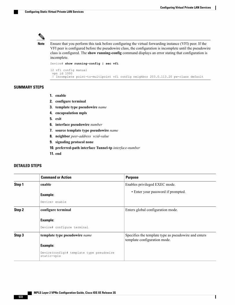
Ensure that you perform this task before configuring the virtual forwarding instance (VFI) peer. If theVFI peer is configured before the pseudowire class, the configuration is incomplete until the pseudowireclass is configured. The show running-config command displays an error stating that configuration isincomplete.Device# show running-config | sec vfi
l2 vfi config manualvpn id 1000! Incomplete point-to-multipoint vfi config neighbor 203.0.113.20 pw-class default
Note
SUMMARY STEPS
1. enable2. configure terminal3. template type pseudowire name4. encapsulation mpls5. exit6. interface pseudowire number7. source template type pseudowire name8. neighbor peer-address vcid-value9. signaling protocol none10. preferred-path interface Tunnel-tp interface-number11. end
DETAILED STEPS
PurposeCommand or Action
Enables privileged EXEC mode.enableStep 1
Example:
Device> enable
• Enter your password if prompted.
Enters global configuration mode.configure terminal
Example:
Device# configure terminal
Step 2
Specifies the template type as pseudowire and enterstemplate configuration mode.
template type pseudowire name
Example:
Device(config)# template type pseudowirestatic-vpls
Step 3
MPLS Layer 2 VPNs Configuration Guide, Cisco IOS XE Release 3S572
Configuring Virtual Private LAN ServicesConfiguring Static Virtual Private LAN Services
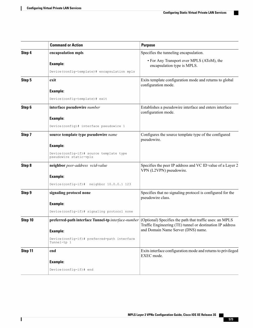
PurposeCommand or Action
Specifies the tunneling encapsulation.encapsulation mpls
Example:
Device(config-template)# encapsulation mpls
Step 4
• For Any Transport over MPLS (AToM), theencapsulation type is MPLS.
Exits template configuration mode and returns to globalconfiguration mode.
exit
Example:
Device(config-template)# exit
Step 5
Establishes a pseudowire interface and enters interfaceconfiguration mode.
interface pseudowire number
Example:
Device(config)# interface pseudowire 1
Step 6
Configures the source template type of the configuredpseudowire.
source template type pseudowire name
Example:
Device(config-if)# source template typepseudowire static-vpls
Step 7
Specifies the peer IP address and VC ID value of a Layer 2VPN (L2VPN) pseudowire.
neighbor peer-address vcid-value
Example:
Device(config-if)# neighbor 10.0.0.1 123
Step 8
Specifies that no signaling protocol is configured for thepseudowire class.
signaling protocol none
Example:
Device(config-if)# signaling protocol none
Step 9
(Optional) Specifies the path that traffic uses: an MPLSTraffic Engineering (TE) tunnel or destination IP addressand Domain Name Server (DNS) name.
preferred-path interface Tunnel-tp interface-number
Example:
Device(config-if)# preferred-path interfaceTunnel-tp 1
Step 10
Exits interface configurationmode and returns to privilegedEXEC mode.
end
Example:
Device(config-if)# end
Step 11
MPLS Layer 2 VPNs Configuration Guide, Cisco IOS XE Release 3S 573
Configuring Virtual Private LAN ServicesConfiguring Static Virtual Private LAN Services
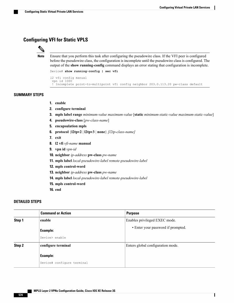
Configuring VFI for Static VPLS
Ensure that you perform this task after configuring the pseudowire class. If the VFI peer is configuredbefore the pseudowire class, the configuration is incomplete until the pseudowire class is configured. Theoutput of the show running-config command displays an error stating that configuration is incomplete.Device# show running-config | sec vfi
l2 vfi config manualvpn id 1000! Incomplete point-to-multipoint vfi config neighbor 203.0.113.20 pw-class default
Note
SUMMARY STEPS
1. enable2. configure terminal3. mpls label range minimum-value maximum-value [static minimum-static-value maximum-static-value]4. pseudowire-class [pw-class-name]5. encapsulation mpls6. protocol {l2tpv2 | l2tpv3 | none} [l2tp-class-name]7. exit8. l2 vfi vfi-namemanual9. vpn id vpn-id10. neighbor ip-address pw-class pw-name11. mpls label local-pseudowire-label remote-pseudowire-label12. mpls control-word13. neighbor ip-address pw-class pw-name14. mpls label local-pseudowire-label remote-pseudowire-label15. mpls control-word16. end
DETAILED STEPS
PurposeCommand or Action
Enables privileged EXEC mode.enableStep 1
Example:
Device> enable
• Enter your password if prompted.
Enters global configuration mode.configure terminal
Example:
Device# configure terminal
Step 2
MPLS Layer 2 VPNs Configuration Guide, Cisco IOS XE Release 3S574
Configuring Virtual Private LAN ServicesConfiguring Static Virtual Private LAN Services
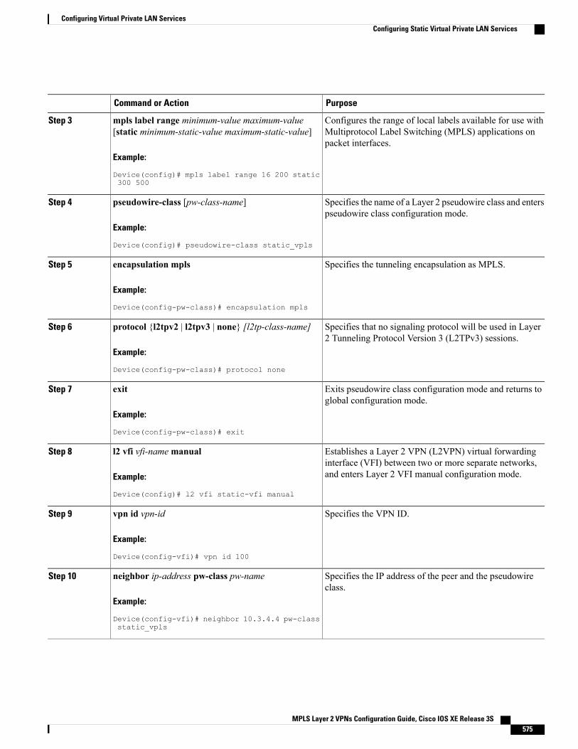
PurposeCommand or Action
Configures the range of local labels available for use withMultiprotocol Label Switching (MPLS) applications onpacket interfaces.
mpls label range minimum-value maximum-value[static minimum-static-value maximum-static-value]
Example:
Device(config)# mpls label range 16 200 static300 500
Step 3
Specifies the name of a Layer 2 pseudowire class and enterspseudowire class configuration mode.
pseudowire-class [pw-class-name]
Example:
Device(config)# pseudowire-class static_vpls
Step 4
Specifies the tunneling encapsulation as MPLS.encapsulation mpls
Example:
Device(config-pw-class)# encapsulation mpls
Step 5
Specifies that no signaling protocol will be used in Layer2 Tunneling Protocol Version 3 (L2TPv3) sessions.
protocol {l2tpv2 | l2tpv3 | none} [l2tp-class-name]
Example:
Device(config-pw-class)# protocol none
Step 6
Exits pseudowire class configuration mode and returns toglobal configuration mode.
exit
Example:
Device(config-pw-class)# exit
Step 7
Establishes a Layer 2 VPN (L2VPN) virtual forwardinginterface (VFI) between two or more separate networks,and enters Layer 2 VFI manual configuration mode.
l2 vfi vfi-namemanual
Example:
Device(config)# l2 vfi static-vfi manual
Step 8
Specifies the VPN ID.vpn id vpn-id
Example:
Device(config-vfi)# vpn id 100
Step 9
Specifies the IP address of the peer and the pseudowireclass.
neighbor ip-address pw-class pw-name
Example:
Device(config-vfi)# neighbor 10.3.4.4 pw-classstatic_vpls
Step 10
MPLS Layer 2 VPNs Configuration Guide, Cisco IOS XE Release 3S 575
Configuring Virtual Private LAN ServicesConfiguring Static Virtual Private LAN Services
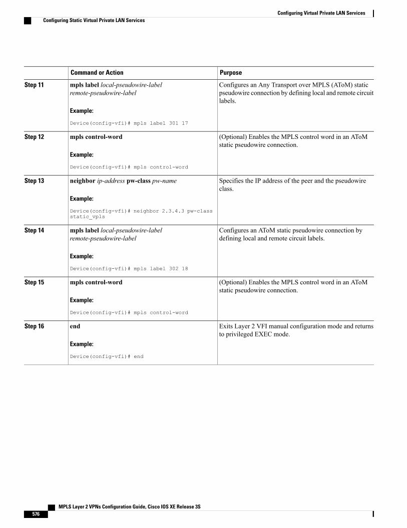
PurposeCommand or Action
Configures an Any Transport over MPLS (AToM) staticpseudowire connection by defining local and remote circuitlabels.
mpls label local-pseudowire-labelremote-pseudowire-label
Example:
Device(config-vfi)# mpls label 301 17
Step 11
(Optional) Enables the MPLS control word in an AToMstatic pseudowire connection.
mpls control-word
Example:
Device(config-vfi)# mpls control-word
Step 12
Specifies the IP address of the peer and the pseudowireclass.
neighbor ip-address pw-class pw-name
Example:
Device(config-vfi)# neighbor 2.3.4.3 pw-classstatic_vpls
Step 13
Configures an AToM static pseudowire connection bydefining local and remote circuit labels.
mpls label local-pseudowire-labelremote-pseudowire-label
Example:
Device(config-vfi)# mpls label 302 18
Step 14
(Optional) Enables the MPLS control word in an AToMstatic pseudowire connection.
mpls control-word
Example:
Device(config-vfi)# mpls control-word
Step 15
Exits Layer 2 VFI manual configuration mode and returnsto privileged EXEC mode.
end
Example:
Device(config-vfi)# end
Step 16
MPLS Layer 2 VPNs Configuration Guide, Cisco IOS XE Release 3S576
Configuring Virtual Private LAN ServicesConfiguring Static Virtual Private LAN Services
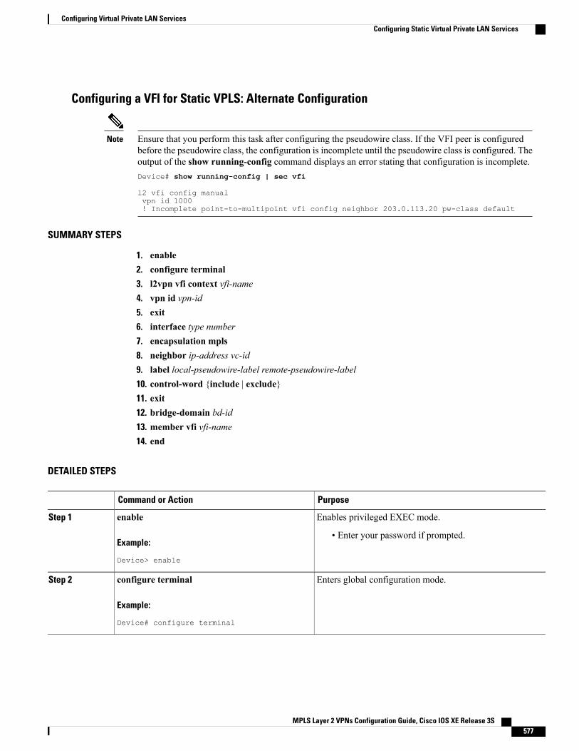
Configuring a VFI for Static VPLS: Alternate Configuration
Ensure that you perform this task after configuring the pseudowire class. If the VFI peer is configuredbefore the pseudowire class, the configuration is incomplete until the pseudowire class is configured. Theoutput of the show running-config command displays an error stating that configuration is incomplete.Device# show running-config | sec vfi
l2 vfi config manualvpn id 1000! Incomplete point-to-multipoint vfi config neighbor 203.0.113.20 pw-class default
Note
SUMMARY STEPS
1. enable2. configure terminal3. l2vpn vfi context vfi-name4. vpn id vpn-id5. exit6. interface type number7. encapsulation mpls8. neighbor ip-address vc-id9. label local-pseudowire-label remote-pseudowire-label10. control-word {include | exclude}11. exit12. bridge-domain bd-id13. member vfi vfi-name14. end
DETAILED STEPS
PurposeCommand or Action
Enables privileged EXEC mode.enableStep 1
Example:
Device> enable
• Enter your password if prompted.
Enters global configuration mode.configure terminal
Example:
Device# configure terminal
Step 2
MPLS Layer 2 VPNs Configuration Guide, Cisco IOS XE Release 3S 577
Configuring Virtual Private LAN ServicesConfiguring Static Virtual Private LAN Services
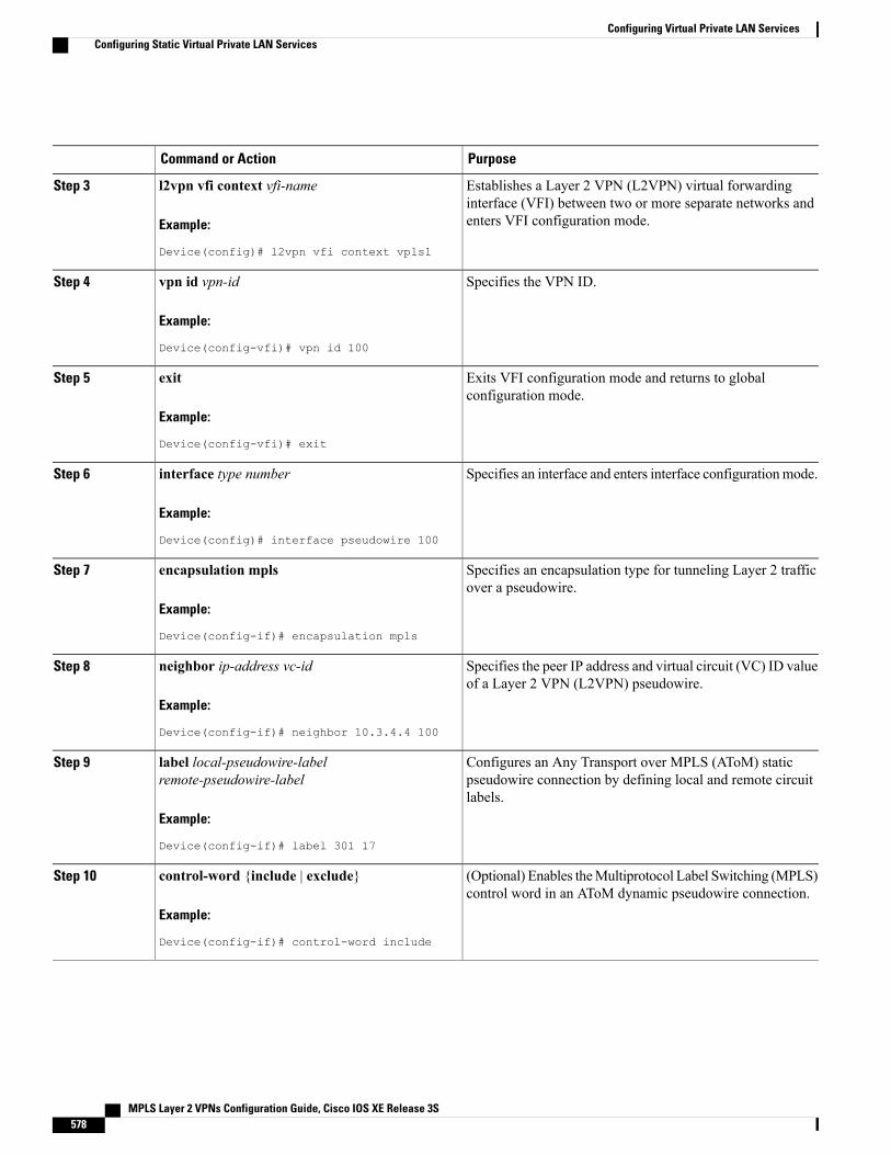
PurposeCommand or Action
Establishes a Layer 2 VPN (L2VPN) virtual forwardinginterface (VFI) between two or more separate networks andenters VFI configuration mode.
l2vpn vfi context vfi-name
Example:
Device(config)# l2vpn vfi context vpls1
Step 3
Specifies the VPN ID.vpn id vpn-id
Example:
Device(config-vfi)# vpn id 100
Step 4
Exits VFI configuration mode and returns to globalconfiguration mode.
exit
Example:
Device(config-vfi)# exit
Step 5
Specifies an interface and enters interface configurationmode.interface type number
Example:
Device(config)# interface pseudowire 100
Step 6
Specifies an encapsulation type for tunneling Layer 2 trafficover a pseudowire.
encapsulation mpls
Example:
Device(config-if)# encapsulation mpls
Step 7
Specifies the peer IP address and virtual circuit (VC) ID valueof a Layer 2 VPN (L2VPN) pseudowire.
neighbor ip-address vc-id
Example:
Device(config-if)# neighbor 10.3.4.4 100
Step 8
Configures an Any Transport over MPLS (AToM) staticpseudowire connection by defining local and remote circuitlabels.
label local-pseudowire-labelremote-pseudowire-label
Example:
Device(config-if)# label 301 17
Step 9
(Optional) Enables theMultiprotocol Label Switching (MPLS)control word in an AToM dynamic pseudowire connection.
control-word {include | exclude}
Example:
Device(config-if)# control-word include
Step 10
MPLS Layer 2 VPNs Configuration Guide, Cisco IOS XE Release 3S578
Configuring Virtual Private LAN ServicesConfiguring Static Virtual Private LAN Services
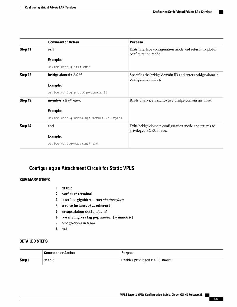
PurposeCommand or Action
Exits interface configuration mode and returns to globalconfiguration mode.
exit
Example:
Device(config-if)# exit
Step 11
Specifies the bridge domain ID and enters bridge-domainconfiguration mode.
bridge-domain bd-id
Example:
Device(config)# bridge-domain 24
Step 12
Binds a service instance to a bridge domain instance.member vfi vfi-name
Example:
Device(config-bdomain)# member vfi vpls1
Step 13
Exits bridge-domain configuration mode and returns toprivileged EXEC mode.
end
Example:
Device(config-bdomain)# end
Step 14
Configuring an Attachment Circuit for Static VPLS
SUMMARY STEPS
1. enable2. configure terminal3. interface gigabitethernet slot/interface4. service instance si-id ethernet5. encapsulation dot1q vlan-id6. rewrite ingress tag pop number [symmetric]7. bridge-domain bd-id8. end
DETAILED STEPS
PurposeCommand or Action
Enables privileged EXEC mode.enableStep 1
MPLS Layer 2 VPNs Configuration Guide, Cisco IOS XE Release 3S 579
Configuring Virtual Private LAN ServicesConfiguring Static Virtual Private LAN Services
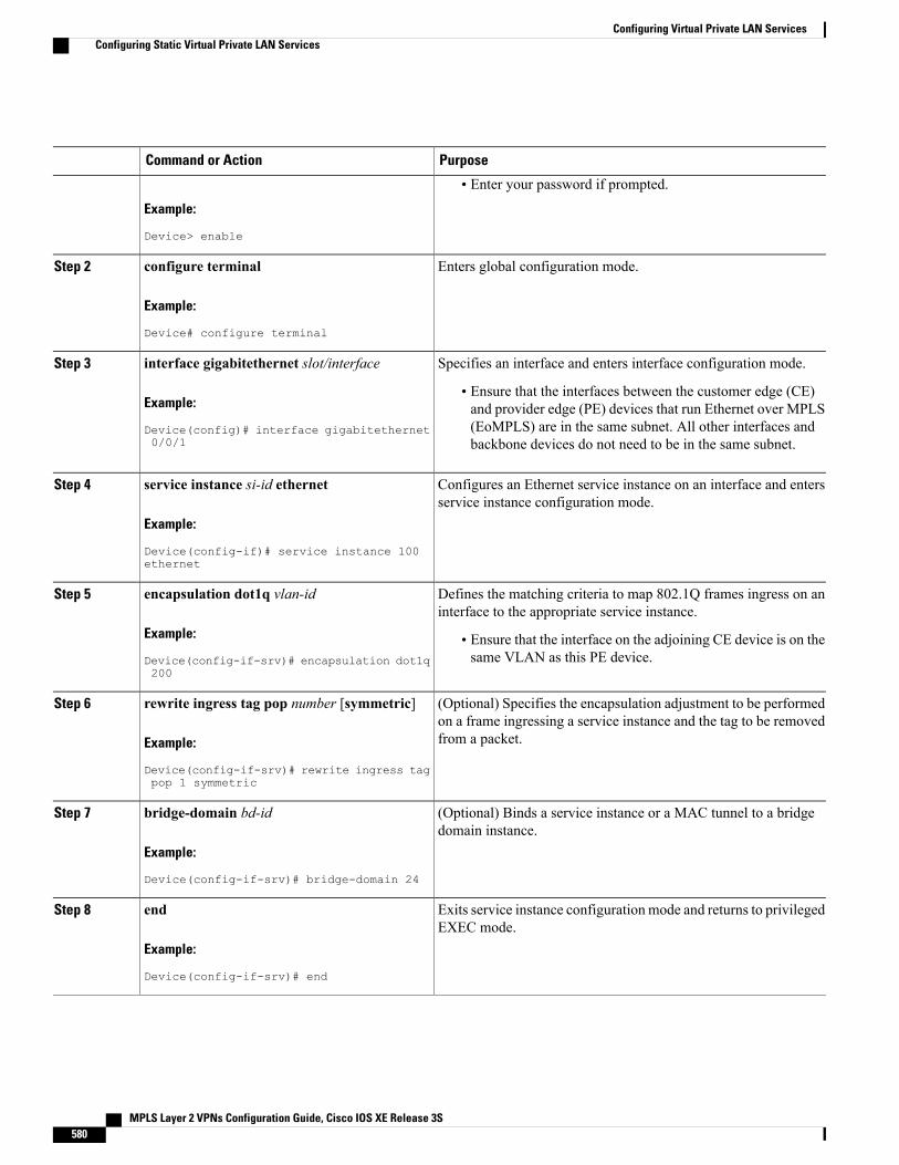
PurposeCommand or Action
Example:
Device> enable
• Enter your password if prompted.
Enters global configuration mode.configure terminal
Example:
Device# configure terminal
Step 2
Specifies an interface and enters interface configuration mode.interface gigabitethernet slot/interface
Example:
Device(config)# interface gigabitethernet0/0/1
Step 3
• Ensure that the interfaces between the customer edge (CE)and provider edge (PE) devices that run Ethernet over MPLS(EoMPLS) are in the same subnet. All other interfaces andbackbone devices do not need to be in the same subnet.
Configures an Ethernet service instance on an interface and entersservice instance configuration mode.
service instance si-id ethernet
Example:
Device(config-if)# service instance 100ethernet
Step 4
Defines the matching criteria to map 802.1Q frames ingress on aninterface to the appropriate service instance.
encapsulation dot1q vlan-id
Example:
Device(config-if-srv)# encapsulation dot1q200
Step 5
• Ensure that the interface on the adjoining CE device is on thesame VLAN as this PE device.
(Optional) Specifies the encapsulation adjustment to be performedon a frame ingressing a service instance and the tag to be removedfrom a packet.
rewrite ingress tag pop number [symmetric]
Example:
Device(config-if-srv)# rewrite ingress tagpop 1 symmetric
Step 6
(Optional) Binds a service instance or a MAC tunnel to a bridgedomain instance.
bridge-domain bd-id
Example:
Device(config-if-srv)# bridge-domain 24
Step 7
Exits service instance configuration mode and returns to privilegedEXEC mode.
end
Example:
Device(config-if-srv)# end
Step 8
MPLS Layer 2 VPNs Configuration Guide, Cisco IOS XE Release 3S580
Configuring Virtual Private LAN ServicesConfiguring Static Virtual Private LAN Services
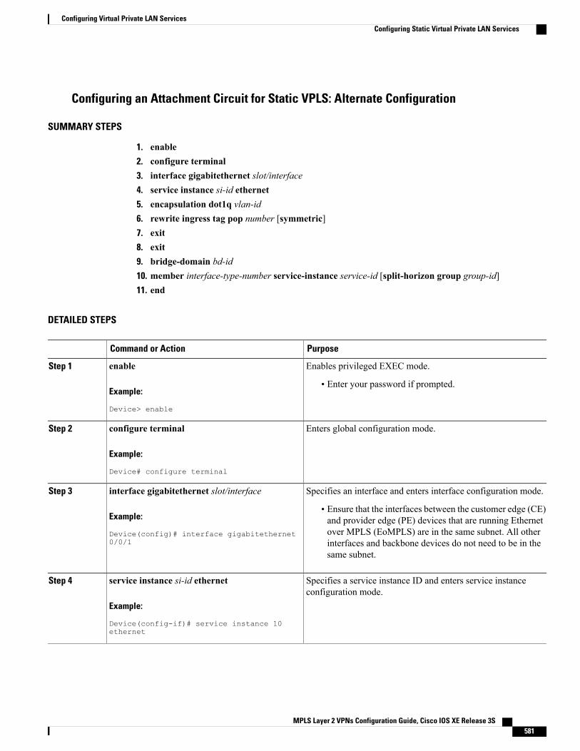
Configuring an Attachment Circuit for Static VPLS: Alternate Configuration
SUMMARY STEPS
1. enable2. configure terminal3. interface gigabitethernet slot/interface4. service instance si-id ethernet5. encapsulation dot1q vlan-id6. rewrite ingress tag pop number [symmetric]7. exit8. exit9. bridge-domain bd-id10. member interface-type-number service-instance service-id [split-horizon group group-id]11. end
DETAILED STEPS
PurposeCommand or Action
Enables privileged EXEC mode.enableStep 1
Example:
Device> enable
• Enter your password if prompted.
Enters global configuration mode.configure terminal
Example:
Device# configure terminal
Step 2
Specifies an interface and enters interface configuration mode.interface gigabitethernet slot/interface
Example:
Device(config)# interface gigabitethernet0/0/1
Step 3
• Ensure that the interfaces between the customer edge (CE)and provider edge (PE) devices that are running Ethernetover MPLS (EoMPLS) are in the same subnet. All otherinterfaces and backbone devices do not need to be in thesame subnet.
Specifies a service instance ID and enters service instanceconfiguration mode.
service instance si-id ethernet
Example:
Device(config-if)# service instance 10ethernet
Step 4
MPLS Layer 2 VPNs Configuration Guide, Cisco IOS XE Release 3S 581
Configuring Virtual Private LAN ServicesConfiguring Static Virtual Private LAN Services
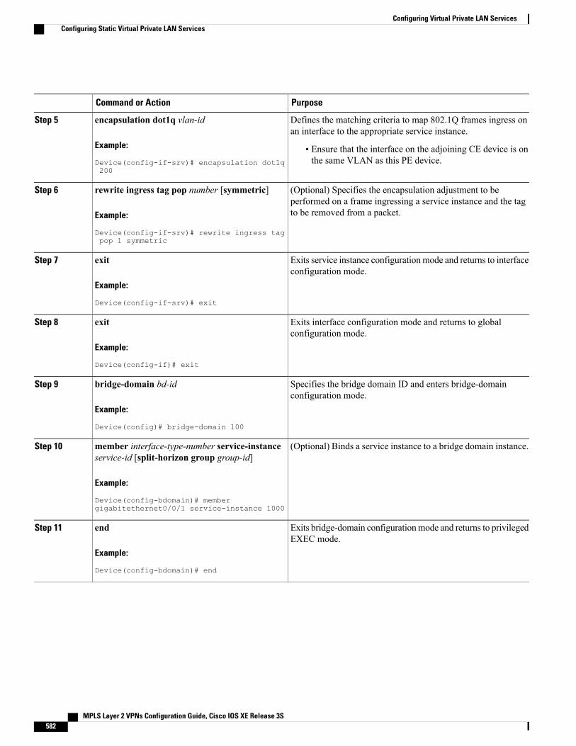
PurposeCommand or Action
Defines the matching criteria to map 802.1Q frames ingress onan interface to the appropriate service instance.
encapsulation dot1q vlan-id
Example:
Device(config-if-srv)# encapsulation dot1q200
Step 5
• Ensure that the interface on the adjoining CE device is onthe same VLAN as this PE device.
(Optional) Specifies the encapsulation adjustment to beperformed on a frame ingressing a service instance and the tagto be removed from a packet.
rewrite ingress tag pop number [symmetric]
Example:
Device(config-if-srv)# rewrite ingress tagpop 1 symmetric
Step 6
Exits service instance configurationmode and returns to interfaceconfiguration mode.
exit
Example:
Device(config-if-srv)# exit
Step 7
Exits interface configuration mode and returns to globalconfiguration mode.
exit
Example:
Device(config-if)# exit
Step 8
Specifies the bridge domain ID and enters bridge-domainconfiguration mode.
bridge-domain bd-id
Example:
Device(config)# bridge-domain 100
Step 9
(Optional) Binds a service instance to a bridge domain instance.member interface-type-number service-instanceservice-id [split-horizon group group-id]
Step 10
Example:
Device(config-bdomain)# membergigabitethernet0/0/1 service-instance 1000
Exits bridge-domain configurationmode and returns to privilegedEXEC mode.
end
Example:
Device(config-bdomain)# end
Step 11
MPLS Layer 2 VPNs Configuration Guide, Cisco IOS XE Release 3S582
Configuring Virtual Private LAN ServicesConfiguring Static Virtual Private LAN Services
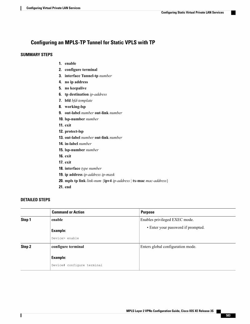
Configuring an MPLS-TP Tunnel for Static VPLS with TP
SUMMARY STEPS
1. enable2. configure terminal3. interface Tunnel-tp number4. no ip address5. no keepalive6. tp destination ip-address7. bfd bfd-template8. working-lsp9. out-label number out-link number10. lsp-number number11. exit12. protect-lsp13. out-label number out-link number14. in-label number15. lsp-number number16. exit17. exit18. interface type number19. ip address ip-address ip-mask20. mpls tp link link-num {ipv4 ip-address | tx-mac mac-address}21. end
DETAILED STEPS
PurposeCommand or Action
Enables privileged EXEC mode.enableStep 1
Example:
Device> enable
• Enter your password if prompted.
Enters global configuration mode.configure terminal
Example:
Device# configure terminal
Step 2
MPLS Layer 2 VPNs Configuration Guide, Cisco IOS XE Release 3S 583
Configuring Virtual Private LAN ServicesConfiguring Static Virtual Private LAN Services
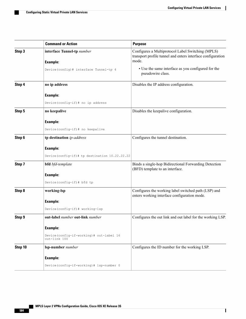
PurposeCommand or Action
Configures a Multiprotocol Label Switching (MPLS)transport profile tunnel and enters interface configurationmode.
interface Tunnel-tp number
Example:
Device(config)# interface Tunnel-tp 4
Step 3
• Use the same interface as you configured for thepseudowire class.
Disables the IP address configuration.no ip address
Example:
Device(config-if)# no ip address
Step 4
Disables the keepalive configuration.no keepalive
Example:
Device(config-if)# no keepalive
Step 5
Configures the tunnel destination.tp destination ip-address
Example:
Device(config-if)# tp destination 10.22.22.22
Step 6
Binds a single-hop Bidirectional Forwarding Detection(BFD) template to an interface.
bfd bfd-template
Example:
Device(config-if)# bfd tp
Step 7
Configures the working label switched path (LSP) andenters working interface configuration mode.
working-lsp
Example:
Device(config-if)# working-lsp
Step 8
Configures the out link and out label for the working LSP.out-label number out-link number
Example:
Device(config-if-working)# out-label 16out-link 100
Step 9
Configures the ID number for the working LSP.lsp-number number
Example:
Device(config-if-working)# lsp-number 0
Step 10
MPLS Layer 2 VPNs Configuration Guide, Cisco IOS XE Release 3S584
Configuring Virtual Private LAN ServicesConfiguring Static Virtual Private LAN Services
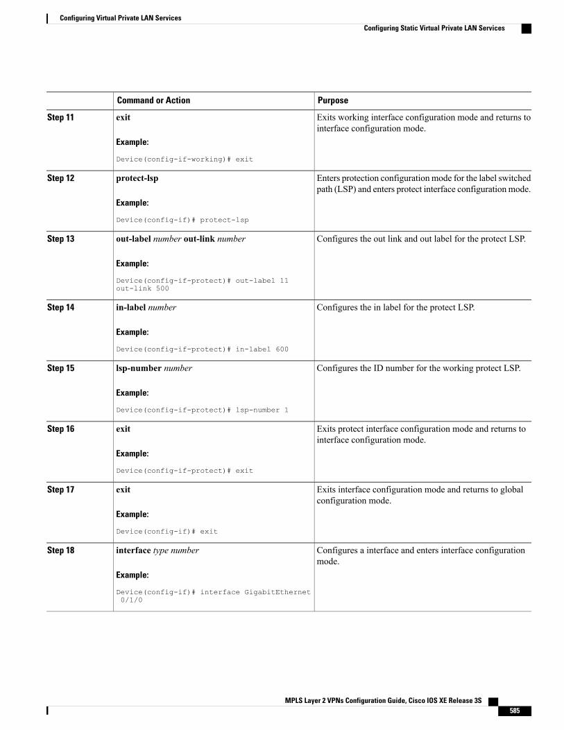
PurposeCommand or Action
Exits working interface configuration mode and returns tointerface configuration mode.
exit
Example:
Device(config-if-working)# exit
Step 11
Enters protection configuration mode for the label switchedpath (LSP) and enters protect interface configuration mode.
protect-lsp
Example:
Device(config-if)# protect-lsp
Step 12
Configures the out link and out label for the protect LSP.out-label number out-link number
Example:
Device(config-if-protect)# out-label 11out-link 500
Step 13
Configures the in label for the protect LSP.in-label number
Example:
Device(config-if-protect)# in-label 600
Step 14
Configures the ID number for the working protect LSP.lsp-number number
Example:
Device(config-if-protect)# lsp-number 1
Step 15
Exits protect interface configuration mode and returns tointerface configuration mode.
exit
Example:
Device(config-if-protect)# exit
Step 16
Exits interface configuration mode and returns to globalconfiguration mode.
exit
Example:
Device(config-if)# exit
Step 17
Configures a interface and enters interface configurationmode.
interface type number
Example:
Device(config-if)# interface GigabitEthernet0/1/0
Step 18
MPLS Layer 2 VPNs Configuration Guide, Cisco IOS XE Release 3S 585
Configuring Virtual Private LAN ServicesConfiguring Static Virtual Private LAN Services
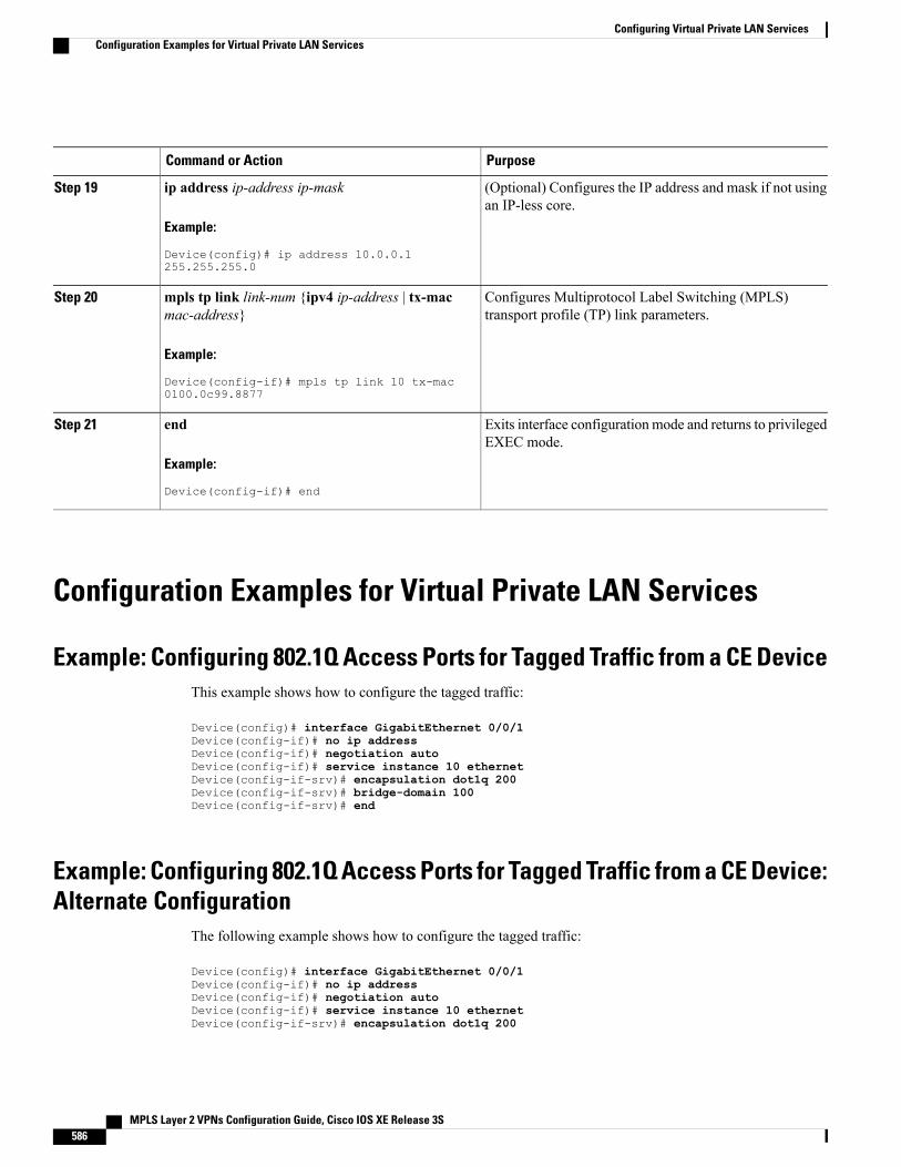
PurposeCommand or Action
(Optional) Configures the IP address and mask if not usingan IP-less core.
ip address ip-address ip-mask
Example:
Device(config)# ip address 10.0.0.1255.255.255.0
Step 19
Configures Multiprotocol Label Switching (MPLS)transport profile (TP) link parameters.
mpls tp link link-num {ipv4 ip-address | tx-macmac-address}
Example:
Device(config-if)# mpls tp link 10 tx-mac0100.0c99.8877
Step 20
Exits interface configurationmode and returns to privilegedEXEC mode.
end
Example:
Device(config-if)# end
Step 21
Configuration Examples for Virtual Private LAN Services
Example: Configuring 802.1Q Access Ports for Tagged Traffic from a CE DeviceThis example shows how to configure the tagged traffic:
Device(config)# interface GigabitEthernet 0/0/1Device(config-if)# no ip addressDevice(config-if)# negotiation autoDevice(config-if)# service instance 10 ethernetDevice(config-if-srv)# encapsulation dot1q 200Device(config-if-srv)# bridge-domain 100Device(config-if-srv)# end
Example: Configuring 802.1Q Access Ports for Tagged Traffic from a CE Device:Alternate Configuration
The following example shows how to configure the tagged traffic:
Device(config)# interface GigabitEthernet 0/0/1Device(config-if)# no ip addressDevice(config-if)# negotiation autoDevice(config-if)# service instance 10 ethernetDevice(config-if-srv)# encapsulation dot1q 200
MPLS Layer 2 VPNs Configuration Guide, Cisco IOS XE Release 3S586
Configuring Virtual Private LAN ServicesConfiguration Examples for Virtual Private LAN Services
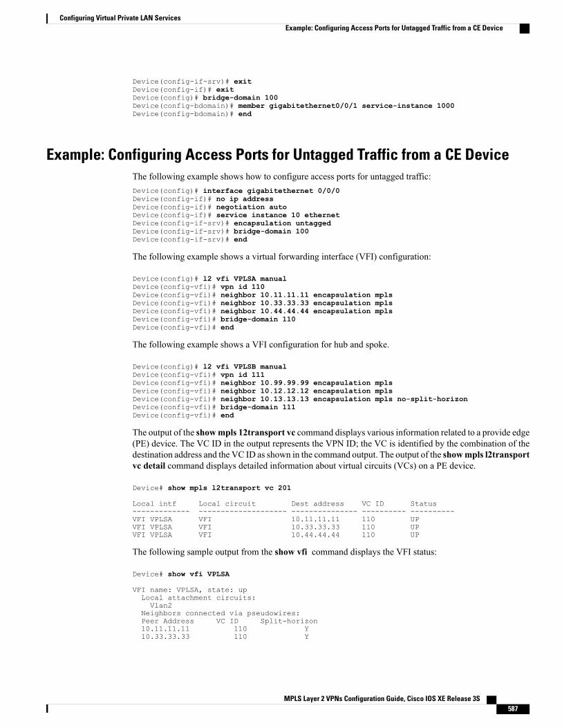
Device(config-if-srv)# exitDevice(config-if)# exitDevice(config)# bridge-domain 100Device(config-bdomain)# member gigabitethernet0/0/1 service-instance 1000Device(config-bdomain)# end
Example: Configuring Access Ports for Untagged Traffic from a CE DeviceThe following example shows how to configure access ports for untagged traffic:Device(config)# interface gigabitethernet 0/0/0Device(config-if)# no ip addressDevice(config-if)# negotiation autoDevice(config-if)# service instance 10 ethernetDevice(config-if-srv)# encapsulation untaggedDevice(config-if-srv)# bridge-domain 100Device(config-if-srv)# end
The following example shows a virtual forwarding interface (VFI) configuration:
Device(config)# l2 vfi VPLSA manualDevice(config-vfi)# vpn id 110Device(config-vfi)# neighbor 10.11.11.11 encapsulation mplsDevice(config-vfi)# neighbor 10.33.33.33 encapsulation mplsDevice(config-vfi)# neighbor 10.44.44.44 encapsulation mplsDevice(config-vfi)# bridge-domain 110Device(config-vfi)# end
The following example shows a VFI configuration for hub and spoke.
Device(config)# l2 vfi VPLSB manualDevice(config-vfi)# vpn id 111Device(config-vfi)# neighbor 10.99.99.99 encapsulation mplsDevice(config-vfi)# neighbor 10.12.12.12 encapsulation mplsDevice(config-vfi)# neighbor 10.13.13.13 encapsulation mpls no-split-horizonDevice(config-vfi)# bridge-domain 111Device(config-vfi)# end
The output of the showmpls 12transport vc command displays various information related to a provide edge(PE) device. The VC ID in the output represents the VPN ID; the VC is identified by the combination of thedestination address and the VC ID as shown in the command output. The output of the showmpls l2transportvc detail command displays detailed information about virtual circuits (VCs) on a PE device.
Device# show mpls l2transport vc 201
Local intf Local circuit Dest address VC ID Status------------- -------------------- --------------- ---------- ----------VFI VPLSA VFI 10.11.11.11 110 UPVFI VPLSA VFI 10.33.33.33 110 UPVFI VPLSA VFI 10.44.44.44 110 UP
The following sample output from the show vfi command displays the VFI status:
Device# show vfi VPLSA
VFI name: VPLSA, state: upLocal attachment circuits:Vlan2
Neighbors connected via pseudowires:Peer Address VC ID Split-horizon10.11.11.11 110 Y10.33.33.33 110 Y
MPLS Layer 2 VPNs Configuration Guide, Cisco IOS XE Release 3S 587
Configuring Virtual Private LAN ServicesExample: Configuring Access Ports for Untagged Traffic from a CE Device
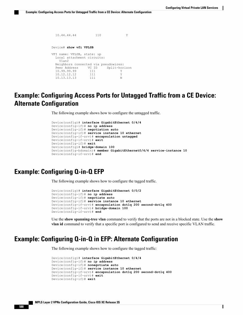
10.44.44.44 110 Y
Device# show vfi VPLSB
VFI name: VPLSB, state: upLocal attachment circuits:Vlan2
Neighbors connected via pseudowires:Peer Address VC ID Split-horizon10.99.99.99 111 Y10.12.12.12 111 Y10.13.13.13 111 N
Example: Configuring Access Ports for Untagged Traffic from a CE Device:Alternate Configuration
The following example shows how to configure the untagged traffic.
Device(config)# interface GigabitEthernet 0/4/4Device(config-if)# no ip addressDevice(config-if)# negotiation autoDevice(config-if)# service instance 10 ethernetDevice(config-if-srv)# encapsulation untaggedDevice(config-if-srv)# exitDevice(config-if)# exitDevice(config)# bridge-domain 100Device(config-bdomain)# member GigabitEthernet0/4/4 service-instance 10Device(config-if-srv)# end
Example: Configuring Q-in-Q EFPThe following example shows how to configure the tagged traffic.
Device(config)# interface GigabitEthernet 0/0/2Device(config-if)# no ip addressDevice(config-if)# negotiate autoDevice(config-if)# service instance 10 ethernetDevice(config-if-srv)# encapsulation dot1q 200 second-dot1q 400Device(config-if-srv)# bridge-domain 100Device(config-if-srv)# end
Use the show spanning-tree vlan command to verify that the ports are not in a blocked state. Use the showvlan id command to verify that a specific port is configured to send and receive specific VLAN traffic.
Example: Configuring Q-in-Q in EFP: Alternate ConfigurationThe following example shows how to configure the tagged traffic:
Device(config)# interface GigabitEthernet 0/4/4Device(config-if)# no ip addressDevice(config-if)# nonegotiate autoDevice(config-if)# service instance 10 ethernetDevice(config-if-srv)# encapsulation dot1q 200 second-dot1q 400Device(config-if-srv)# exitDevice(config-if)# exit
MPLS Layer 2 VPNs Configuration Guide, Cisco IOS XE Release 3S588
Configuring Virtual Private LAN ServicesExample: Configuring Access Ports for Untagged Traffic from a CE Device: Alternate Configuration
Device(config)# bridge-domain 100Device(config-bdomain)# member GigabitEthernet0/4/4 service-instance 1000Device(config-bdomain)# end
Use the show spanning-tree vlan command to verify that the port is not in a blocked state. Use the showvlan id command to verify that a specific port is configured to send and receive a specific VLAN traffic.
Example: Configuring MPLS on a PE DeviceThe following example shows a global Multiprotocol Label Switching (MPLS) configuration:
Device(config)# mpls label protocol ldpDevice(config)# mpls ldp logging neighbor-changesDevice(config)# mpls ldp discovery hello holdtime 5Device(config)# mpls ldp router-id Loopback0 force
The following sample output from the show ip cef command displays the Label Distribution Protocol (LDP)label assigned:
Device# show ip cef 192.168.17.7
192.168.17.7/32, version 272, epoch 0, cached adjacency to POS4/10 packets, 0 bytestag information setlocal tag: 8149fast tag rewrite with PO4/1, point2point, tags imposed: {4017}
via 10.3.1.4, POS4/1, 283 dependenciesnext hop 10.3.1.4, POS4/1valid cached adjacencytag rewrite with PO4/1, point2point, tags imposed: {4017}
Example: VFI on a PE DeviceThe following example shows a virtual forwarding instance (VFI) configuration:
Device(config)# l2 vfi vfi110 manualDevice(config-vfi)# vpn id 110Device(config-vfi)# neighbor 172.16.10.2 4 encapsulation mplsDevice(config-vfi)# neighbor 10.16.33.33 encapsulation mplsDevice(config-vfi)# neighbor 198.51.100.44 encapsulation mplsDevice(config-vfi)# bridge-domain 100Device(config-vfi)# end
The following example shows a VFI configuration for a hub-and-spoke configuration:
Device(config)# l2 vfi VPLSA manualDevice(config-vfi)# vpn id 110Device(config-vfi)# neighbor 10.9.9.9 encapsulation mplsDevice(config-vfi)# neighbor 192.0.2.12 encapsulation mplsDevice(config-vfi)# neighbor 203.0.113.4 encapsulation mpls no-split-horizonDevice(config-vfi)# bridge-domain 100Device(config-vfi)# end
The show mpls 12transport vc command displays information about the provider edge (PE) device. Theshow mpls l2transport vc detail command displays detailed information about the virtual circuits (VCs) ona PE device.
Device# show mpls l2transport vc 201
MPLS Layer 2 VPNs Configuration Guide, Cisco IOS XE Release 3S 589
Configuring Virtual Private LAN ServicesExample: Configuring MPLS on a PE Device
Local intf Local circuit Dest address VC ID Status------------- -------------------- --------------- ---------- ----------VFI test1 VFI 209.165.201.1 201 UPVFI test1 VFI 209.165.201.2 201 UPVFI test1 VFI 209.165.201.3 201 UP
The show vfi vfi-name command displays VFI status. The VC ID in the output represents the VPN ID; theVC is identified by the combination of the destination address and the VC ID as in the example below.
Device# show vfi VPLS-2
VFI name: VPLS-2, state: upLocal attachment circuits:Vlan2
Neighbors connected via pseudowires:Peer Address VC ID Split-horizon10.1.1.1 2 Y10.1.1.2 2 Y10.2.2.3 2 N
Example: VFI on a PE Device: Alternate ConfigurationThe following example shows how to configure a virtual forwarding interface (VFI) on a provider edge (PE)device:
Device(config)# l2vpn vfi context vfi110Device(config-vfi)# vpn id 110Device(config-vfi)# member 172.16.10.2 4 encapsulation mplsDevice(config-vfi)# member 10.33.33.33 encapsulation mplsDevice(config-vfi)# member 10.44.44.44 encapsulation mplsDevice(config-vfi)# exitDevice(config)# bridge-domain 100Device(config-bdomain)# member vfi vfi110Device(config-bdomain)# end
The following example shows how to configure a hub-and-spoke VFI configuration:.
Device(config)# l2vpn vfi context VPLSADevice(config-vfi)# vpn id 110Device(config-vfi)# member 10.9.9.9 encapsulation mplsDevice(config-vfi)# member 172.16.10.2 4 encapsulation mplsDevice(config-vfi)# exitDevice(config)# bridge-domain 100Device(config-bdomain)# member vfi VPLSADevice(config-bdomain)# member GigabitEthernet0/0/0 service-instance 100Device(config-bdomain)# member 10.33.33.33 10 encapsulation mplsDevice(config-bdomain)# end
The show l2vpn atom vc command displays information about the PE device. The command also displaysinformation about Any Transport over MPLS (AToM) virtual circuits (VCs) and static pseudowires that areenabled to route Layer 2 packets on a device.
Device# show l2vpn atom vc
Local intf Local circuit Dest address VC ID Status------------- ----------------------- --------------- ---------- ----------Et0/0.1 Eth VLAN 101 10.0.0.2 101 UPEt0/0.1 Eth VLAN 101 10.0.0.3 201 DOWN
MPLS Layer 2 VPNs Configuration Guide, Cisco IOS XE Release 3S590
Configuring Virtual Private LAN ServicesExample: VFI on a PE Device: Alternate Configuration
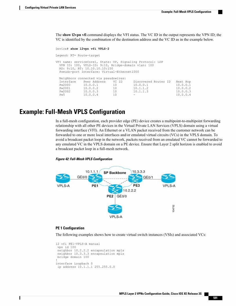
The show l2vpn vfi command displays the VFI status. The VC ID in the output represents the VPN ID; theVC is identified by the combination of the destination address and the VC ID as in the example below.
Device# show l2vpn vfi VPLS-2
Legend: RT= Route-target
VFI name: serviceCore1, State: UP, Signaling Protocol: LDPVPN ID: 100, VPLS-ID: 9:10, Bridge-domain vlan: 100RD: 9:10, RT: 10.10.10.10:150Pseudo-port Interface: Virtual-Ethernet1000
Neighbors connected via pseudowires:Interface Peer Address VC ID Discovered Router ID Next HopPw2000 10.0.0.1 10 10.0.0.1 10.0.0.1Pw2001 10.0.0.2 10 10.1.1.2 10.0.0.2Pw2002 10.0.0.3 10 10.1.1.3 10.0.0.3Pw5 10.0.0.4 10 - 10.0.0.4
Example: Full-Mesh VPLS ConfigurationIn a full-mesh configuration, each provider edge (PE) device creates a multipoint-to-multipoint forwardingrelationship with all other PE devices in the Virtual Private LAN Services (VPLS) domain using a virtualforwarding interface (VFI). An Ethernet or a VLAN packet received from the customer network can beforwarded to one or more local interfaces and/or emulated virtual circuits (VCs) in the VPLS domain. Toavoid a broadcast packet loop in the network, packets received from an emulated VC cannot be forwarded toany emulated VC in the VPLS domain on a PE device. Ensure that Layer 2 split horizon is enabled to avoida broadcast packet loop in a full-mesh network.
Figure 42: Full-Mesh VPLS Configuration
PE 1 Configuration
The following examples shows how to create virtual switch instances (VSIs) and associated VCs:
l2 vfi PE1-VPLS-A manualvpn id 100neighbor 10.2.2.2 encapsulation mplsneighbor 10.3.3.3 encapsulation mplsbridge domain 100!interface Loopback 0ip address 10.1.1.1 255.255.0.0
MPLS Layer 2 VPNs Configuration Guide, Cisco IOS XE Release 3S 591
Configuring Virtual Private LAN ServicesExample: Full-Mesh VPLS Configuration
The following example shows how to configure the customer edge (CE) device interface (there can be multipleLayer 2 interfaces in a VLAN):
interface GigabitEthernet 0/0/0no ip addressnegotiation autoservice instance 10 ethernetencapsulation dot1q 200bridge-domain 100
PE 2 Configuration
The following example shows how to create VSIs and associated VCs.
l2 vfi PE2-VPLS-A manualvpn id 100neighbor 10.1.1.1 encapsulation mplsneighbor 10.3.3.3 encapsulation mplsbridge domain 100!interface Loopback 0ip address 10.2.2.2 255.255.0.0
The following example shows how to configure the CE device interface (there can be multiple Layer 2interfaces in a VLAN):
interface GigabitEthernet 0/0/0no ip addressnegotiation autoservice instance 10 ethernetencapsulation dot1q 200bridge-domain 100
PE 3 Configuration
The following example shows how to create VSIs and associated VCs:
l2 vfi PE3-VPLS-A manualvpn id 112neighbor 10.1.1.1 encapsulation mplsneighbor 10.2.2.2 encapsulation mplsbridge domain 100!interface Loopback 0ip address 10.3.3.3 255.255.0.0
The following example shows how to configure the CE device interface (there can be multiple Layer 2interfaces in a VLAN).
interface GigabitEthernet 0/0/1no ip addressnegotiation autoservice instance 10 ethernetencapsulation dot1q 200bridge-domain 100!The following sample output from the show mpls l2 vc command provides information about the status ofthe VC:
Device# show mpls l2 vc
Local intf Local circuit Dest address VC ID Status
MPLS Layer 2 VPNs Configuration Guide, Cisco IOS XE Release 3S592
Configuring Virtual Private LAN ServicesExample: Full-Mesh VPLS Configuration
------------- -------------------- --------------- ---------- ----------VFI PE1-VPLS-A VFI 10.2.2.2 100 UPVFI PE1-VPLS-A VFI 10.3.3.3 100 UP
The following sample output from the show vfi command provides information about the VFI:
Device# show vfi PE1-VPLS-A
VFI name: VPLSA, state: upLocal attachment circuits:Vlan200
Neighbors connected via pseudowires:10.2.2.2 10.3.3.3
The following sample output from the show mpls 12transport vc command provides information aboutvirtual circuits:
Device# show mpls l2transport vc detail
Local interface: VFI PE1-VPLS-A upDestination address: 10.2.2.2, VC ID: 100, VC status: upTunnel label: imp-null, next hop point2pointOutput interface: Se2/0, imposed label stack {18}
Create time: 3d15h, last status change time: 1d03hSignaling protocol: LDP, peer 10.2.2.2:0 upMPLS VC labels: local 18, remote 18Group ID: local 0, remote 0MTU: local 1500, remote 1500Remote interface description:
Sequencing: receive disabled, send disabledVC statistics:packet totals: receive 0, send 0byte totals: receive 0, send 0packet drops: receive 0, send 0
Example: Full-Mesh Configuration : Alternate ConfigurationIn a full-mesh configuration, each provider edge (PE) router creates a multipoint-to-multipoint forwardingrelationship with all other PE routers in the Virtual Private LAN Services (VPLS) domain using a virtualforwarding interface (VFI). An Ethernet or virtual LAN (VLAN) packet received from the customer networkcan be forwarded to one or more local interfaces and/or emulated virtual circuits (VCs) in the VPLS domain.To avoid broadcasted packets looping in the network, no packet received from an emulated VC can be
MPLS Layer 2 VPNs Configuration Guide, Cisco IOS XE Release 3S 593
Configuring Virtual Private LAN ServicesExample: Full-Mesh Configuration : Alternate Configuration
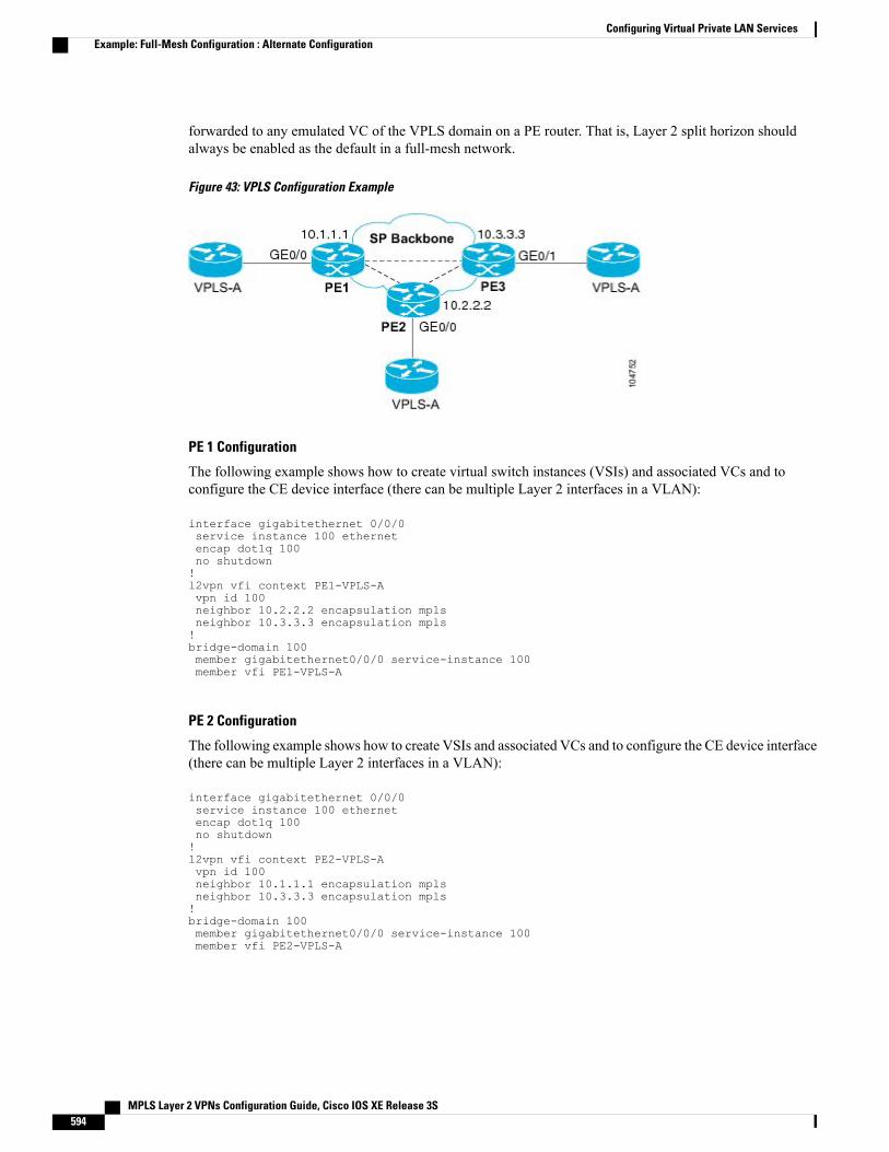
forwarded to any emulated VC of the VPLS domain on a PE router. That is, Layer 2 split horizon shouldalways be enabled as the default in a full-mesh network.
Figure 43: VPLS Configuration Example
PE 1 Configuration
The following example shows how to create virtual switch instances (VSIs) and associated VCs and toconfigure the CE device interface (there can be multiple Layer 2 interfaces in a VLAN):
interface gigabitethernet 0/0/0service instance 100 ethernetencap dot1q 100no shutdown!l2vpn vfi context PE1-VPLS-Avpn id 100neighbor 10.2.2.2 encapsulation mplsneighbor 10.3.3.3 encapsulation mpls!bridge-domain 100member gigabitethernet0/0/0 service-instance 100member vfi PE1-VPLS-A
PE 2 Configuration
The following example shows how to create VSIs and associated VCs and to configure the CE device interface(there can be multiple Layer 2 interfaces in a VLAN):
interface gigabitethernet 0/0/0service instance 100 ethernetencap dot1q 100no shutdown!l2vpn vfi context PE2-VPLS-Avpn id 100neighbor 10.1.1.1 encapsulation mplsneighbor 10.3.3.3 encapsulation mpls!bridge-domain 100member gigabitethernet0/0/0 service-instance 100member vfi PE2-VPLS-A
MPLS Layer 2 VPNs Configuration Guide, Cisco IOS XE Release 3S594
Configuring Virtual Private LAN ServicesExample: Full-Mesh Configuration : Alternate Configuration
PE 3 Configuration
The following example shows how to create of the VSIs and associated VCs and to configure the CE deviceinterface (there can be multiple Layer 2 interfaces in a VLAN):
interface gigabitethernet 0/0/0service instance 100 ethernetencap dot1q 100no shutdown!l2vpn vfi context PE3-VPLS-Avpn id 100neighbor 10.1.1.1 encapsulation mplsneighbor 10.2.2.2 encapsulation mpls!bridge-domain 100member gigabitethernet0/0/0 service-instance 100member vfi PE3-VPLS-A
The following sample output from the show mpls l2 vc command provides information on the status of theVC:
Device# show mpls l2 vc
Local intf Local circuit Dest address VC ID Status------------- -------------- --------------- ---------- ----------VFI PE3-VPLS-A VFI 10.2.2.2 100 UPVFI PE3-VPLS-A VFI 10.3.3.3 100 UP
The following sample output from the show l2vpn vfi command provides information about the VFI:
Device# show l2vpn vfi VPLS-2
Legend: RT= Route-target
VFI name: serviceCore1, State: UP, Signaling Protocol: LDPVPN ID: 100, VPLS-ID: 9:10, Bridge-domain vlan: 100RD: 9:10, RT: 10.10.10.10:150Pseudo-port Interface: Virtual-Ethernet1000
Neighbors connected via pseudowires:Interface Peer Address VC ID Discovered Router ID Next HopPw2000 10.0.0.1 10 10.0.0.1 10.0.0.1Pw2001 10.0.0.2 10 10.1.1.2 10.0.0.2Pw2002 10.0.0.3 10 10.1.1.3 10.0.0.3Pw5 10.0.0.4 10 - 10.0.0.4
The following sample output from the show l2vpn atom vc command provides information on the virtualcircuits:
Device# show l2vpn atom vc
Local intf Local circuit Dest address VC ID Status------------- ----------------------- --------------- ---------- ----------Et0/0.1 Eth VLAN 101 10.0.0.2 101 UPEt0/0.1 Eth VLAN 101 10.0.0.3 201 DOWN
Feature Information for Configuring Virtual Private LAN ServicesThe following table provides release information about the feature or features described in this module. Thistable lists only the software release that introduced support for a given feature in a given software releasetrain. Unless noted otherwise, subsequent releases of that software release train also support that feature.
MPLS Layer 2 VPNs Configuration Guide, Cisco IOS XE Release 3S 595
Configuring Virtual Private LAN ServicesFeature Information for Configuring Virtual Private LAN Services
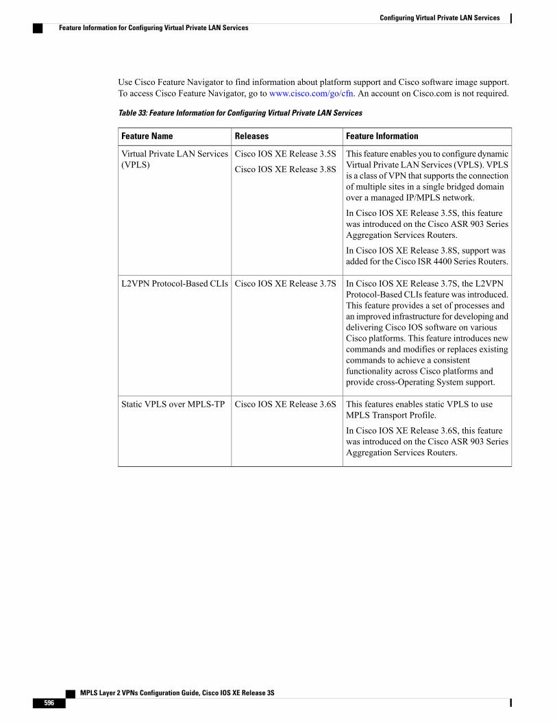
Use Cisco Feature Navigator to find information about platform support and Cisco software image support.To access Cisco Feature Navigator, go to www.cisco.com/go/cfn. An account on Cisco.com is not required.
Table 33: Feature Information for Configuring Virtual Private LAN Services
Feature InformationReleasesFeature Name
This feature enables you to configure dynamicVirtual Private LAN Services (VPLS). VPLSis a class of VPN that supports the connectionof multiple sites in a single bridged domainover a managed IP/MPLS network.
In Cisco IOS XE Release 3.5S, this featurewas introduced on the Cisco ASR 903 SeriesAggregation Services Routers.
In Cisco IOS XE Release 3.8S, support wasadded for the Cisco ISR 4400 Series Routers.
Cisco IOS XE Release 3.5S
Cisco IOS XE Release 3.8S
Virtual Private LAN Services(VPLS)
In Cisco IOS XE Release 3.7S, the L2VPNProtocol-Based CLIs feature was introduced.This feature provides a set of processes andan improved infrastructure for developing anddelivering Cisco IOS software on variousCisco platforms. This feature introduces newcommands and modifies or replaces existingcommands to achieve a consistentfunctionality across Cisco platforms andprovide cross-Operating System support.
Cisco IOS XE Release 3.7SL2VPN Protocol-Based CLIs
This features enables static VPLS to useMPLS Transport Profile.
In Cisco IOS XE Release 3.6S, this featurewas introduced on the Cisco ASR 903 SeriesAggregation Services Routers.
Cisco IOS XE Release 3.6SStatic VPLS over MPLS-TP
MPLS Layer 2 VPNs Configuration Guide, Cisco IOS XE Release 3S596
Configuring Virtual Private LAN ServicesFeature Information for Configuring Virtual Private LAN Services
C H A P T E R 20Routed Pseudo-Wire and Routed VPLS
This feature module explains how to configure Routed Pseudo-Wire and Routed VPLS .
• Finding Feature Information, page 597
• Configuring Routed Pseudo-Wire and Routed VPLS, page 597
• Feature Information for Routed Pseudo-Wire and Routed VPLS, page 598
Finding Feature InformationYour software release may not support all the features documented in this module. For the latest caveats andfeature information, see Bug Search Tool and the release notes for your platform and software release. Tofind information about the features documented in this module, and to see a list of the releases in which eachfeature is supported, see the feature information table at the end of this module.
Use Cisco Feature Navigator to find information about platform support and Cisco software image support.To access Cisco Feature Navigator, go to www.cisco.com/go/cfn. An account on Cisco.com is not required.
Configuring Routed Pseudo-Wire and Routed VPLSRPW and Routed VPLS can route Layer 3 traffic as well as switch Layer 2 frames for pseudowire connectionsbetween provider edge (PE) devices. Both point-to-point PE connections, in the form of Ethernet over MPLS(EoMPLS), and Virtual Private LAN Services (VPLS) multipoint PE connections are supported. The abilityto route frames to and from these interfaces supports termination of a pseudowire into a Layer 3 network(VPN or global) on the same switch, or to tunnel Layer 3 frames over a Layer 2 tunnel (EoMPLS or VPLS).The feature supports faster network convergence in the event of a physical interface or device failure throughthe MPLS Traffic Engineering (MPLS-TE) and Fast Reroute (FRR) features. In particular, the feature enablesMPLS TE-FRR protection for Layer 3 multicast over a VPLS domain.
When the RPW is configured in A-VPLS mode, TE/FRR is not supported because A-VPLS runs over ECMPand the ECMP convergence is comparable to TE/FRR.
To configure routing support for the pseudowire, configure an IP address and other Layer 3 features for theLayer 3 domain (VPN or global) in the virtual LAN (VLAN) interface configuration. The following example
MPLS Layer 2 VPNs Configuration Guide, Cisco IOS XE Release 3S 597
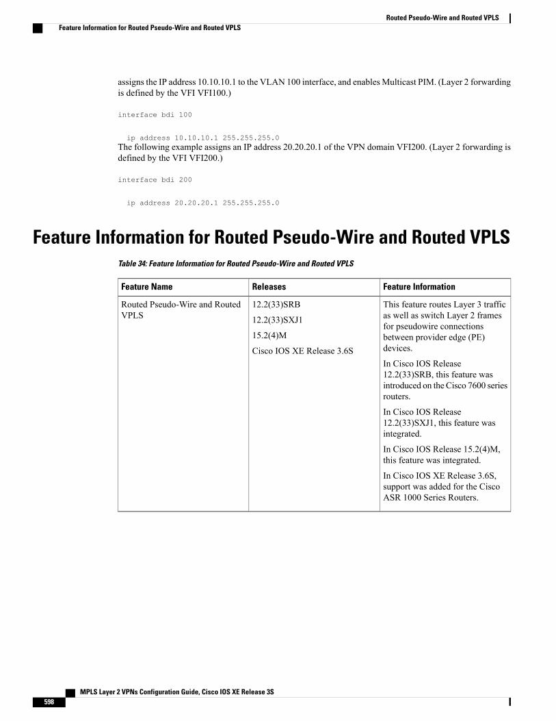
assigns the IP address 10.10.10.1 to the VLAN 100 interface, and enablesMulticast PIM. (Layer 2 forwardingis defined by the VFI VFI100.)
interface bdi 100
ip address 10.10.10.1 255.255.255.0The following example assigns an IP address 20.20.20.1 of the VPN domain VFI200. (Layer 2 forwarding isdefined by the VFI VFI200.)
interface bdi 200
ip address 20.20.20.1 255.255.255.0
Feature Information for Routed Pseudo-Wire and Routed VPLSTable 34: Feature Information for Routed Pseudo-Wire and Routed VPLS
Feature InformationReleasesFeature Name
This feature routes Layer 3 trafficas well as switch Layer 2 framesfor pseudowire connectionsbetween provider edge (PE)devices.
In Cisco IOS Release12.2(33)SRB, this feature wasintroduced on the Cisco 7600 seriesrouters.
In Cisco IOS Release12.2(33)SXJ1, this feature wasintegrated.
In Cisco IOS Release 15.2(4)M,this feature was integrated.
In Cisco IOS XE Release 3.6S,support was added for the CiscoASR 1000 Series Routers.
12.2(33)SRB
12.2(33)SXJ1
15.2(4)M
Cisco IOS XE Release 3.6S
Routed Pseudo-Wire and RoutedVPLS
MPLS Layer 2 VPNs Configuration Guide, Cisco IOS XE Release 3S598
Routed Pseudo-Wire and Routed VPLSFeature Information for Routed Pseudo-Wire and Routed VPLS
C H A P T E R 21VPLS Autodiscovery BGP Based
VPLS Autodiscovery enables Virtual Private LAN Service (VPLS) provider edge (PE) devices to discoverother PE devices that are part of the same VPLS domain. VPLS Autodiscovery also automatically detectswhen PE devices are added to or removed from a VPLS domain. As a result, with VPLS Autodiscoveryenabled, you no longer need to manually configure a VPLS domain and maintain the configuration when aPE device is added or deleted. VPLS Autodiscovery uses the Border Gateway Protocol (BGP) to discoverVPLS members and set up and tear down pseudowires in a VPLS domain.
This module describes how to configure BGP-based VPLS Autodiscovery.
• Finding Feature Information, page 599
• Restrictions for VPLS Autodiscovery BGP Based, page 599
• Information About VPLS Autodiscovery BGP Based, page 600
• How to Configure VPLS Autodiscovery BGP Based, page 604
• Configuration Examples for VPLS Autodiscovery BGP Based, page 620
• Additional References for VPLS Autodiscovery BGP Based, page 627
• Feature Information for VPLS Autodiscovery BGP Based, page 629
Finding Feature InformationYour software release may not support all the features documented in this module. For the latest caveats andfeature information, see Bug Search Tool and the release notes for your platform and software release. Tofind information about the features documented in this module, and to see a list of the releases in which eachfeature is supported, see the feature information table at the end of this module.
Use Cisco Feature Navigator to find information about platform support and Cisco software image support.To access Cisco Feature Navigator, go to www.cisco.com/go/cfn. An account on Cisco.com is not required.
Restrictions for VPLS Autodiscovery BGP Based• Virtual Private LAN Service (VPLS) Autodiscovery supports only IPv4 addresses.
MPLS Layer 2 VPNs Configuration Guide, Cisco IOS XE Release 3S 599
• VPLS Autodiscovery uses Forwarding Equivalence Class (FEC) 129 to convey endpoint information.Manually configured pseudowires use FEC 128.
• VPLS Autodiscovery is not supported with Layer 2 Tunnel Protocol Version 3 (L2TPv3).
• You can configure both autodiscovered and manually configured pseudowires in a single virtualforwarding instance (VFI). However, you cannot configure different pseudowires on the same peer PEdevice.
• After enabling VPLS Autodiscovery, if you manually configure a neighbor by using the neighborcommand and both peers are in autodiscovery mode, each peer will receive discovery data for that VPLS.To prevent peers from receiving data for the VPLS domain, manually configure route target (RT) values.
• If you manually configure multiple pseudowires and target different IP addresses on the same PE devicefor each pseudowire, do not use the same virtual circuit (VC) ID to identify pseudowires that terminateat the same PE device.
• If you manually configure a neighbor on one PE device, you cannot configure the same pseudowire inthe other direction by using autodiscovery on another PE device.
• Tunnel selection is not supported with autodiscovered neighbors.
• Up to 16 RTs are supported per VFI.
• The same RT is not allowed in multiple VFIs on the same PE device.
• The Border Gateway Protocol (BGP) autodiscovery process does not support dynamic, hierarchicalVPLS. User-facing PE (U-PE) devices cannot discover network-facing PE (N-PE) devices, and N-PEdevices cannot discover U-PE devices.
• Pseudowires for autodiscovered neighbors have split horizon enabled. (A split horizon is enabled bydefault on all interfaces. A split horizon blocks route information from being advertised by a device,irrespective of the interface from which the information originates.) Therefore, manually configurepseudowires for hierarchical VPLS. Ensure that U-PE devices do not participate in BGP autodiscoveryfor these pseudowires.
• Do not disable split horizon on autodiscovered neighbors. Split horizon is required with VPLSAutodiscovery.
• The provisioned peer address must be a /32 address bound to the peer’s Label Distribution Protocol(LDP) router ID.
• A peer PE device must be able to access the IP address that is used as the local LDP router ID. Even ifthe IP address is not used in the xconnect command on the peer PE device, the IP address must bereachable.
Information About VPLS Autodiscovery BGP Based
How VPLS WorksVirtual Private LAN Service (VPLS) allows Multiprotocol Label Switching (MPLS) networks to providemultipoint Ethernet LAN services, also known as Transparent LAN Services (TLS). All customer sites in aVPLS appear to be on the same LAN, even though these sites might be in different geographic locations.
MPLS Layer 2 VPNs Configuration Guide, Cisco IOS XE Release 3S600
VPLS Autodiscovery BGP BasedInformation About VPLS Autodiscovery BGP Based
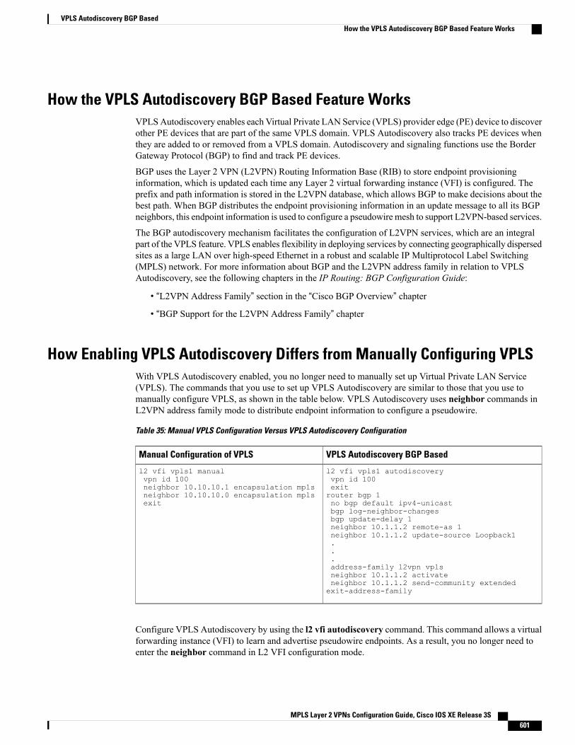
How the VPLS Autodiscovery BGP Based Feature WorksVPLSAutodiscovery enables each Virtual Private LAN Service (VPLS) provider edge (PE) device to discoverother PE devices that are part of the same VPLS domain. VPLS Autodiscovery also tracks PE devices whenthey are added to or removed from a VPLS domain. Autodiscovery and signaling functions use the BorderGateway Protocol (BGP) to find and track PE devices.
BGP uses the Layer 2 VPN (L2VPN) Routing Information Base (RIB) to store endpoint provisioninginformation, which is updated each time any Layer 2 virtual forwarding instance (VFI) is configured. Theprefix and path information is stored in the L2VPN database, which allows BGP to make decisions about thebest path. When BGP distributes the endpoint provisioning information in an update message to all its BGPneighbors, this endpoint information is used to configure a pseudowire mesh to support L2VPN-based services.
The BGP autodiscovery mechanism facilitates the configuration of L2VPN services, which are an integralpart of the VPLS feature. VPLS enables flexibility in deploying services by connecting geographically dispersedsites as a large LAN over high-speed Ethernet in a robust and scalable IP Multiprotocol Label Switching(MPLS) network. For more information about BGP and the L2VPN address family in relation to VPLSAutodiscovery, see the following chapters in the IP Routing: BGP Configuration Guide:
• “L2VPN Address Family” section in the “Cisco BGP Overview” chapter
• “BGP Support for the L2VPN Address Family” chapter
How Enabling VPLS Autodiscovery Differs from Manually Configuring VPLSWith VPLS Autodiscovery enabled, you no longer need to manually set up Virtual Private LAN Service(VPLS). The commands that you use to set up VPLS Autodiscovery are similar to those that you use tomanually configure VPLS, as shown in the table below. VPLS Autodiscovery uses neighbor commands inL2VPN address family mode to distribute endpoint information to configure a pseudowire.
Table 35: Manual VPLS Configuration Versus VPLS Autodiscovery Configuration
VPLS Autodiscovery BGP BasedManual Configuration of VPLS
l2 vfi vpls1 autodiscoveryvpn id 100exitrouter bgp 1no bgp default ipv4-unicastbgp log-neighbor-changesbgp update-delay 1neighbor 10.1.1.2 remote-as 1neighbor 10.1.1.2 update-source Loopback1...address-family l2vpn vplsneighbor 10.1.1.2 activateneighbor 10.1.1.2 send-community extendedexit-address-family
l2 vfi vpls1 manualvpn id 100neighbor 10.10.10.1 encapsulation mplsneighbor 10.10.10.0 encapsulation mplsexit
Configure VPLS Autodiscovery by using the l2 vfi autodiscovery command. This command allows a virtualforwarding instance (VFI) to learn and advertise pseudowire endpoints. As a result, you no longer need toenter the neighbor command in L2 VFI configuration mode.
MPLS Layer 2 VPNs Configuration Guide, Cisco IOS XE Release 3S 601
VPLS Autodiscovery BGP BasedHow the VPLS Autodiscovery BGP Based Feature Works
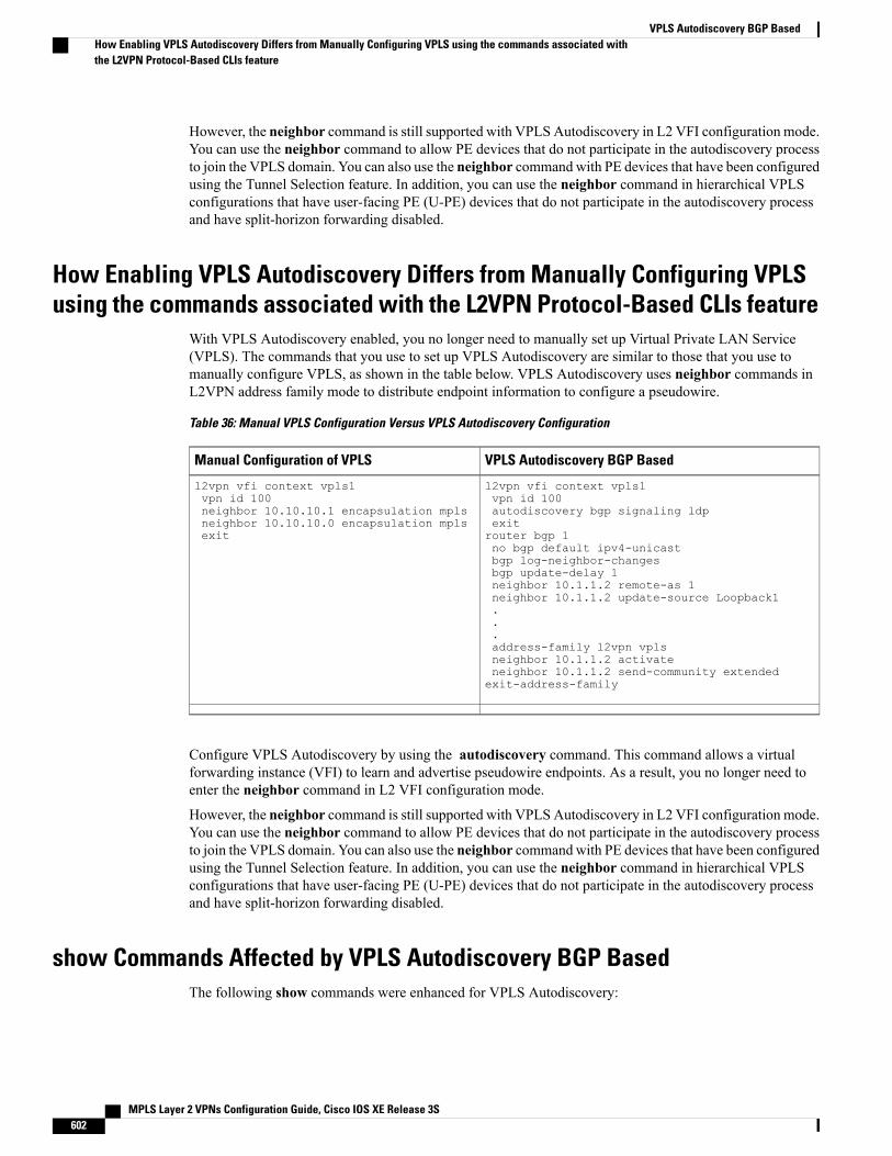
However, the neighbor command is still supported with VPLS Autodiscovery in L2 VFI configuration mode.You can use the neighbor command to allow PE devices that do not participate in the autodiscovery processto join the VPLS domain. You can also use the neighbor command with PE devices that have been configuredusing the Tunnel Selection feature. In addition, you can use the neighbor command in hierarchical VPLSconfigurations that have user-facing PE (U-PE) devices that do not participate in the autodiscovery processand have split-horizon forwarding disabled.
How Enabling VPLS Autodiscovery Differs from Manually Configuring VPLSusing the commands associated with the L2VPN Protocol-Based CLIs feature
With VPLS Autodiscovery enabled, you no longer need to manually set up Virtual Private LAN Service(VPLS). The commands that you use to set up VPLS Autodiscovery are similar to those that you use tomanually configure VPLS, as shown in the table below. VPLS Autodiscovery uses neighbor commands inL2VPN address family mode to distribute endpoint information to configure a pseudowire.
Table 36: Manual VPLS Configuration Versus VPLS Autodiscovery Configuration
VPLS Autodiscovery BGP BasedManual Configuration of VPLS
l2vpn vfi context vpls1vpn id 100autodiscovery bgp signaling ldpexitrouter bgp 1no bgp default ipv4-unicastbgp log-neighbor-changesbgp update-delay 1neighbor 10.1.1.2 remote-as 1neighbor 10.1.1.2 update-source Loopback1...address-family l2vpn vplsneighbor 10.1.1.2 activateneighbor 10.1.1.2 send-community extendedexit-address-family
l2vpn vfi context vpls1vpn id 100neighbor 10.10.10.1 encapsulation mplsneighbor 10.10.10.0 encapsulation mplsexit
Configure VPLS Autodiscovery by using the autodiscovery command. This command allows a virtualforwarding instance (VFI) to learn and advertise pseudowire endpoints. As a result, you no longer need toenter the neighbor command in L2 VFI configuration mode.
However, the neighbor command is still supported with VPLS Autodiscovery in L2 VFI configuration mode.You can use the neighbor command to allow PE devices that do not participate in the autodiscovery processto join the VPLS domain. You can also use the neighbor command with PE devices that have been configuredusing the Tunnel Selection feature. In addition, you can use the neighbor command in hierarchical VPLSconfigurations that have user-facing PE (U-PE) devices that do not participate in the autodiscovery processand have split-horizon forwarding disabled.
show Commands Affected by VPLS Autodiscovery BGP BasedThe following show commands were enhanced for VPLS Autodiscovery:
MPLS Layer 2 VPNs Configuration Guide, Cisco IOS XE Release 3S602
VPLS Autodiscovery BGP BasedHow Enabling VPLS Autodiscovery Differs from Manually Configuring VPLS using the commands associated withthe L2VPN Protocol-Based CLIs feature
• The show mpls l2transport vc detail command was updated to include Forwarding Equivalence Class(FEC) 129 signaling information for autodiscovered Virtual Private LAN Service (VPLS) pseudowires.
• The show vfi commandwas enhanced to display information related to autodiscovered virtual forwardinginstances (VFIs). The new output includes the VPLS ID, the route distinguisher (RD), the route target(RT), and router IDs of discovered peers.
• The show xconnect command was updated with the rib keyword to provide Routing Information Base(RIB) information about pseudowires.
BGP VPLS Autodiscovery Support on a Route ReflectorBy default, routes received from an internal BGP (iBGP) peer are not sent to another iBGP peer unless a fullmesh configuration is formed between all BGP devices within an autonomous system (AS). This results inscalability issues. Using Border Gateway Protocol (BGP) route reflectors leads to much higher levels ofscalability. Configuring a route reflector allows a device to advertise or reflect the iBGP learned routes toother iBGP speakers.
Virtual Private LAN Service (VPLS) Autodiscovery supports BGP route reflectors. A BGP route reflectorcan be used to reflect BGP VPLS prefixes without VPLS being explicitly configured on the route reflector.
A route reflector does not participate in autodiscovery; that is, no pseudowires are set up between the routereflector and the PE devices. A route reflector reflects VPLS prefixes to other PE devices so that these PEdevices do not need to have a full mesh of BGP sessions. The network administrator configures only the BGPVPLS address family on a route reflector. For an example configuration of VPLS Autodiscovery support ona route reflector, see the “Example: BGP VPLS Autodiscovery Support on Route Reflector” section.
N-PE Access to VPLS Using MSTWhen a Virtual Private LAN Service (VPLS) network uses multihoming (network-facing PE [N-PE] VPLSredundancy) to prevent a single point of failure of an N-PE device, a bridging loop is introduced. One of theN-PE devices can be set as a Multiple Spanning Tree (MST) root to break the loop. In most cases, the twoN-PE devices are also separated by a distance that makes direct physical link impossible. You can configurea virtual link (usually through the same VPLS core network) between the two N-PE devices to pass an MSTbridge protocol data unit (BPDU) for path calculation, break the loop, and maintain convergence. The virtuallink is created using a special pseudowire between the active and redundant N-PE devices.
While setting up an MST topology for a VPLS PE device, ensure the following:
• The spanning-tree modemst command is enabled on all PE devices (N-PE and user-facing PE [U-PE])participating in the MST topology.
• A special pseudowire is configured between the two N-PE devices, and these two devices are in the upstate.
• The special pseudowire is a manually created virtual forwarding instance (VFI).
• The configuration (inlcuding the MST instance, the Ethernet virtual circuit [EVC], and the VLAN) onall PE devices is the same.
• One of the N-PE devices, and not one of the U-PE devices, is the root for the MST instance.
• The name and revision for the MST configuration are configured to synchronize with the standby RouteProcessor (RP).
MPLS Layer 2 VPNs Configuration Guide, Cisco IOS XE Release 3S 603
VPLS Autodiscovery BGP BasedBGP VPLS Autodiscovery Support on a Route Reflector
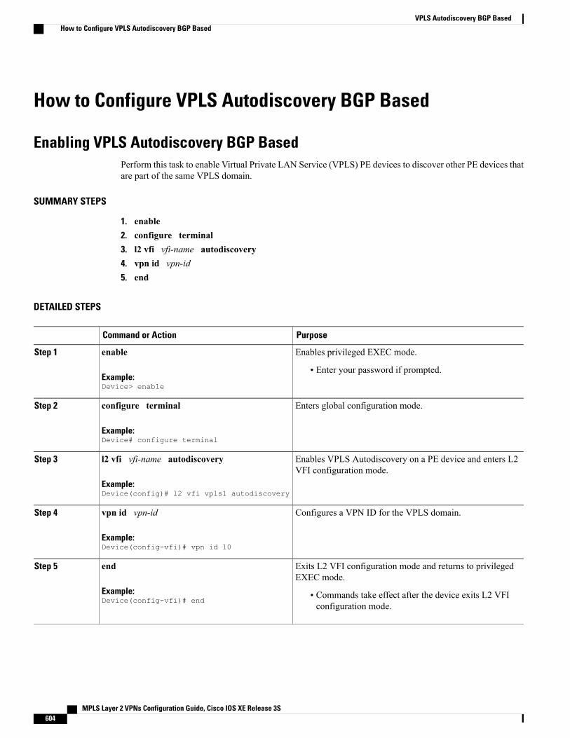
How to Configure VPLS Autodiscovery BGP Based
Enabling VPLS Autodiscovery BGP BasedPerform this task to enable Virtual Private LAN Service (VPLS) PE devices to discover other PE devices thatare part of the same VPLS domain.
SUMMARY STEPS
1. enable2. configure terminal3. l2 vfi vfi-name autodiscovery4. vpn id vpn-id5. end
DETAILED STEPS
PurposeCommand or Action
Enables privileged EXEC mode.enableStep 1
Example:Device> enable
• Enter your password if prompted.
Enters global configuration mode.configure terminal
Example:Device# configure terminal
Step 2
Enables VPLS Autodiscovery on a PE device and enters L2VFI configuration mode.
l2 vfi vfi-name autodiscovery
Example:Device(config)# l2 vfi vpls1 autodiscovery
Step 3
Configures a VPN ID for the VPLS domain.vpn id vpn-id
Example:Device(config-vfi)# vpn id 10
Step 4
Exits L2 VFI configuration mode and returns to privilegedEXEC mode.
end
Example:Device(config-vfi)# end
Step 5
• Commands take effect after the device exits L2 VFIconfiguration mode.
MPLS Layer 2 VPNs Configuration Guide, Cisco IOS XE Release 3S604
VPLS Autodiscovery BGP BasedHow to Configure VPLS Autodiscovery BGP Based
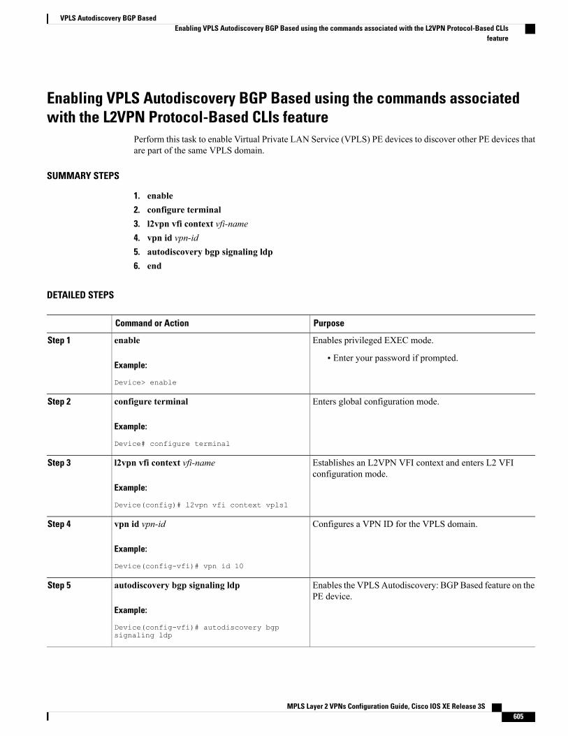
Enabling VPLS Autodiscovery BGP Based using the commands associatedwith the L2VPN Protocol-Based CLIs feature
Perform this task to enable Virtual Private LAN Service (VPLS) PE devices to discover other PE devices thatare part of the same VPLS domain.
SUMMARY STEPS
1. enable2. configure terminal3. l2vpn vfi context vfi-name4. vpn id vpn-id5. autodiscovery bgp signaling ldp6. end
DETAILED STEPS
PurposeCommand or Action
Enables privileged EXEC mode.enableStep 1
Example:
Device> enable
• Enter your password if prompted.
Enters global configuration mode.configure terminal
Example:
Device# configure terminal
Step 2
Establishes an L2VPN VFI context and enters L2 VFIconfiguration mode.
l2vpn vfi context vfi-name
Example:
Device(config)# l2vpn vfi context vpls1
Step 3
Configures a VPN ID for the VPLS domain.vpn id vpn-id
Example:
Device(config-vfi)# vpn id 10
Step 4
Enables the VPLSAutodiscovery: BGP Based feature on thePE device.
autodiscovery bgp signaling ldp
Example:
Device(config-vfi)# autodiscovery bgpsignaling ldp
Step 5
MPLS Layer 2 VPNs Configuration Guide, Cisco IOS XE Release 3S 605
VPLS Autodiscovery BGP BasedEnabling VPLS Autodiscovery BGP Based using the commands associated with the L2VPN Protocol-Based CLIs
feature
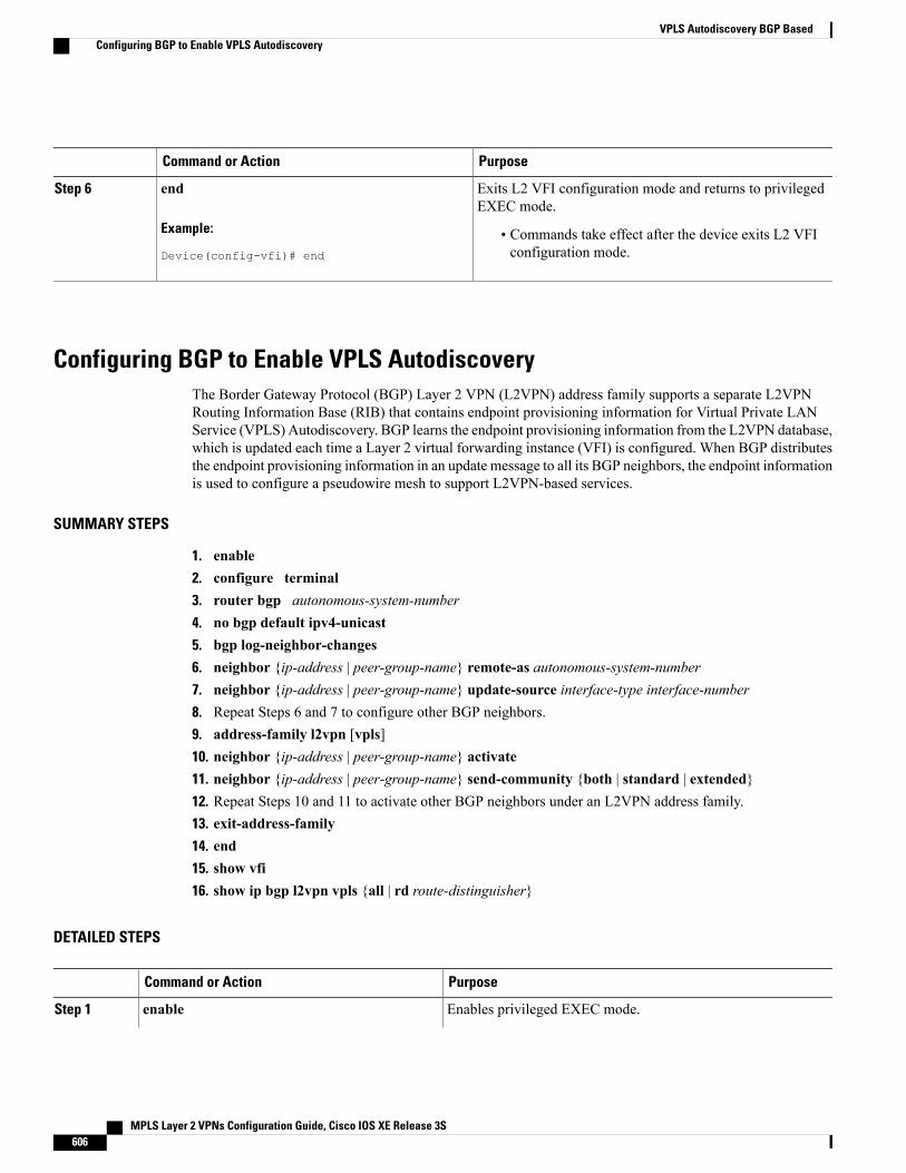
PurposeCommand or Action
Exits L2 VFI configuration mode and returns to privilegedEXEC mode.
end
Example:
Device(config-vfi)# end
Step 6
• Commands take effect after the device exits L2 VFIconfiguration mode.
Configuring BGP to Enable VPLS AutodiscoveryThe Border Gateway Protocol (BGP) Layer 2 VPN (L2VPN) address family supports a separate L2VPNRouting Information Base (RIB) that contains endpoint provisioning information for Virtual Private LANService (VPLS) Autodiscovery. BGP learns the endpoint provisioning information from the L2VPN database,which is updated each time a Layer 2 virtual forwarding instance (VFI) is configured. When BGP distributesthe endpoint provisioning information in an update message to all its BGP neighbors, the endpoint informationis used to configure a pseudowire mesh to support L2VPN-based services.
SUMMARY STEPS
1. enable2. configure terminal3. router bgp autonomous-system-number4. no bgp default ipv4-unicast5. bgp log-neighbor-changes6. neighbor {ip-address | peer-group-name} remote-as autonomous-system-number7. neighbor {ip-address | peer-group-name} update-source interface-type interface-number8. Repeat Steps 6 and 7 to configure other BGP neighbors.9. address-family l2vpn [vpls]10. neighbor {ip-address | peer-group-name} activate11. neighbor {ip-address | peer-group-name} send-community {both | standard | extended}12. Repeat Steps 10 and 11 to activate other BGP neighbors under an L2VPN address family.13. exit-address-family14. end15. show vfi16. show ip bgp l2vpn vpls {all | rd route-distinguisher}
DETAILED STEPS
PurposeCommand or Action
Enables privileged EXEC mode.enableStep 1
MPLS Layer 2 VPNs Configuration Guide, Cisco IOS XE Release 3S606
VPLS Autodiscovery BGP BasedConfiguring BGP to Enable VPLS Autodiscovery
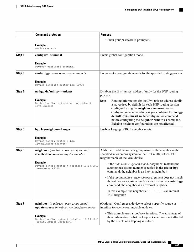
PurposeCommand or Action
Example:Device> enable
• Enter your password if prompted.
Enters global configuration mode.configure terminal
Example:Device# configure terminal
Step 2
Enters router configuration mode for the specified routing process.router bgp autonomous-system-number
Example:Device(config)# router bgp 65000
Step 3
Disables the IPv4 unicast address family for the BGP routingprocess.
no bgp default ipv4-unicast
Example:Device(config-router)# no bgp defaultipv4-unicast
Step 4
Routing information for the IPv4 unicast address familyis advertised by default for each BGP routing sessionconfigured using the neighbor remote-as routerconfiguration command unless you configure the no bgpdefault ipv4-unicast router configuration commandbefore configuring the neighbor remote-as command.Existing neighbor configurations are not affected.
Note
Enables logging of BGP neighbor resets.bgp log-neighbor-changes
Example:Device(config-router)# bgplog-neighbor-changes
Step 5
Adds the IP address or peer group name of the neighbor in thespecified autonomous system to the IPv4 multiprotocol BGPneighbor table of the local device.
neighbor {ip-address | peer-group-name}remote-as autonomous-system-number
Example:Device(config-router)# neighbor 10.10.10.1remote-as 65000
Step 6
• If the autonomous-system-number argument matches theautonomous system number specified in the router bgpcommand, the neighbor is an internal neighbor.
• If the autonomous-system-number argument does not matchthe autonomous system number specified in the router bgpcommand, the neighbor is an external neighbor.
• In this example, the neighbor at 10.10.10.1 is an internalBGP neighbor.
(Optional) Configures a device to select a specific source orinterface to receive routing table updates.
neighbor {ip-address | peer-group-name}update-source interface-type interface-number
Step 7
Example:Device(config-router)# neighbor 10.10.10.1update-source loopback1
• This example uses a loopback interface. The advantage ofthis configuration is that the loopback interface is not affectedby the effects of a flapping interface.
MPLS Layer 2 VPNs Configuration Guide, Cisco IOS XE Release 3S 607
VPLS Autodiscovery BGP BasedConfiguring BGP to Enable VPLS Autodiscovery
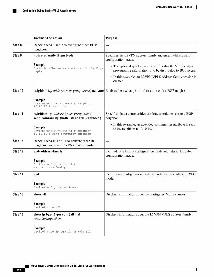
PurposeCommand or Action
—Repeat Steps 6 and 7 to configure other BGPneighbors.
Step 8
Specifies the L2VPN address family and enters address familyconfiguration mode.
address-family l2vpn [vpls]
Example:Device(config-router)# address-family l2vpnvpls
Step 9
• The optional vpls keyword specifies that the VPLS endpointprovisioning information is to be distributed to BGP peers.
• In this example, an L2VPN VPLS address family session iscreated.
Enables the exchange of information with a BGP neighbor.neighbor {ip-address | peer-group-name} activate
Example:Device(config-router-af)# neighbor10.10.10.1 activate
Step 10
Specifies that a communities attribute should be sent to a BGPneighbor.
neighbor {ip-address | peer-group-name}send-community {both | standard | extended}
Step 11
Example:Device(config-router-af)# neighbor10.10.10.1 send-community extended
• In this example, an extended communities attribute is sentto the neighbor at 10.10.10.1.
—Repeat Steps 10 and 11 to activate other BGPneighbors under an L2VPN address family.
Step 12
Exits address family configuration mode and returns to routerconfiguration mode.
exit-address-family
Example:Device(config-router-af)#exit-address-family
Step 13
Exits router configuration mode and returns to privileged EXECmode.
end
Example:Device(config-router)# end
Step 14
Displays information about the configured VFI instances.show vfi
Example:Device# show vfi
Step 15
Displays information about the L2VPN VPLS address family.show ip bgp l2vpn vpls {all | rdroute-distinguisher}
Step 16
Example:Device# show ip bgp l2vpn vpls all
MPLS Layer 2 VPNs Configuration Guide, Cisco IOS XE Release 3S608
VPLS Autodiscovery BGP BasedConfiguring BGP to Enable VPLS Autodiscovery
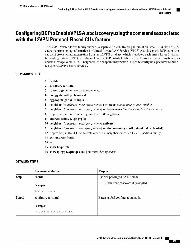
Configuring BGP to Enable VPLS Autodiscovery using the commands associatedwith the L2VPN Protocol-Based CLIs feature
The BGP L2VPN address family supports a separate L2VPN Routing Information Base (RIB) that containsendpoint provisioning information for Virtual Private LAN Service (VPLS) Autodiscovery. BGP learns theendpoint provisioning information from the L2VPN database, which is updated each time a Layer 2 virtualforwarding instance (VFI) is configured. When BGP distributes the endpoint provisioning information in anupdate message to all its BGP neighbors, the endpoint information is used to configure a pseudowire meshto support L2VPN-based services.
SUMMARY STEPS
1. enable2. configure terminal3. router bgp autonomous-system-number4. no bgp default ipv4-unicast5. bgp log-neighbor-changes6. neighbor {ip-address | peer-group-name} remote-as autonomous-system-number7. neighbor {ip-address | peer-group-name} update-source interface-type interface-number8. Repeat Steps 6 and 7 to configure other BGP neighbors.9. address-family l2vpn [vpls]10. neighbor {ip-address | peer-group-name} activate11. neighbor {ip-address | peer-group-name} send-community {both | standard | extended}12. Repeat Steps 10 and 11 to activate other BGP neighbors under an L2VPN address family.13. exit-address-family14. end15. show l2vpn vfi16. show ip bgp l2vpn vpls {all | rd route-distinguisher}
DETAILED STEPS
PurposeCommand or Action
Enables privileged EXEC mode.enableStep 1
Example:
Device> enable
• Enter your password if prompted.
Enters global configuration mode.configure terminal
Example:
Device# configure terminal
Step 2
MPLS Layer 2 VPNs Configuration Guide, Cisco IOS XE Release 3S 609
VPLS Autodiscovery BGP BasedConfiguring BGP to Enable VPLS Autodiscovery using the commands associated with the L2VPN Protocol-Based
CLIs feature
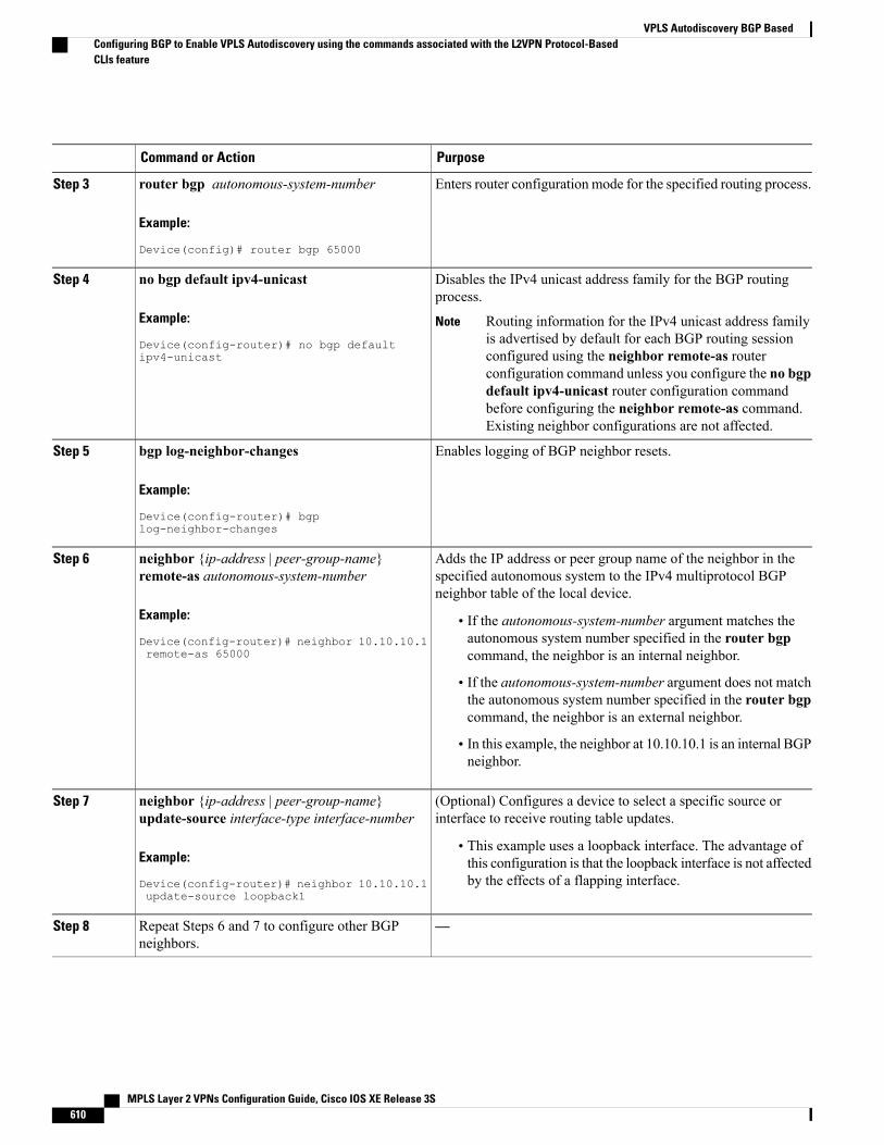
PurposeCommand or Action
Enters router configuration mode for the specified routing process.router bgp autonomous-system-number
Example:
Device(config)# router bgp 65000
Step 3
Disables the IPv4 unicast address family for the BGP routingprocess.
no bgp default ipv4-unicast
Example:
Device(config-router)# no bgp defaultipv4-unicast
Step 4
Routing information for the IPv4 unicast address familyis advertised by default for each BGP routing sessionconfigured using the neighbor remote-as routerconfiguration command unless you configure the no bgpdefault ipv4-unicast router configuration commandbefore configuring the neighbor remote-as command.Existing neighbor configurations are not affected.
Note
Enables logging of BGP neighbor resets.bgp log-neighbor-changes
Example:
Device(config-router)# bgplog-neighbor-changes
Step 5
Adds the IP address or peer group name of the neighbor in thespecified autonomous system to the IPv4 multiprotocol BGPneighbor table of the local device.
neighbor {ip-address | peer-group-name}remote-as autonomous-system-number
Example:
Device(config-router)# neighbor 10.10.10.1remote-as 65000
Step 6
• If the autonomous-system-number argument matches theautonomous system number specified in the router bgpcommand, the neighbor is an internal neighbor.
• If the autonomous-system-number argument does not matchthe autonomous system number specified in the router bgpcommand, the neighbor is an external neighbor.
• In this example, the neighbor at 10.10.10.1 is an internal BGPneighbor.
(Optional) Configures a device to select a specific source orinterface to receive routing table updates.
neighbor {ip-address | peer-group-name}update-source interface-type interface-number
Step 7
Example:
Device(config-router)# neighbor 10.10.10.1update-source loopback1
• This example uses a loopback interface. The advantage ofthis configuration is that the loopback interface is not affectedby the effects of a flapping interface.
—Repeat Steps 6 and 7 to configure other BGPneighbors.
Step 8
MPLS Layer 2 VPNs Configuration Guide, Cisco IOS XE Release 3S610
VPLS Autodiscovery BGP BasedConfiguring BGP to Enable VPLS Autodiscovery using the commands associated with the L2VPN Protocol-BasedCLIs feature
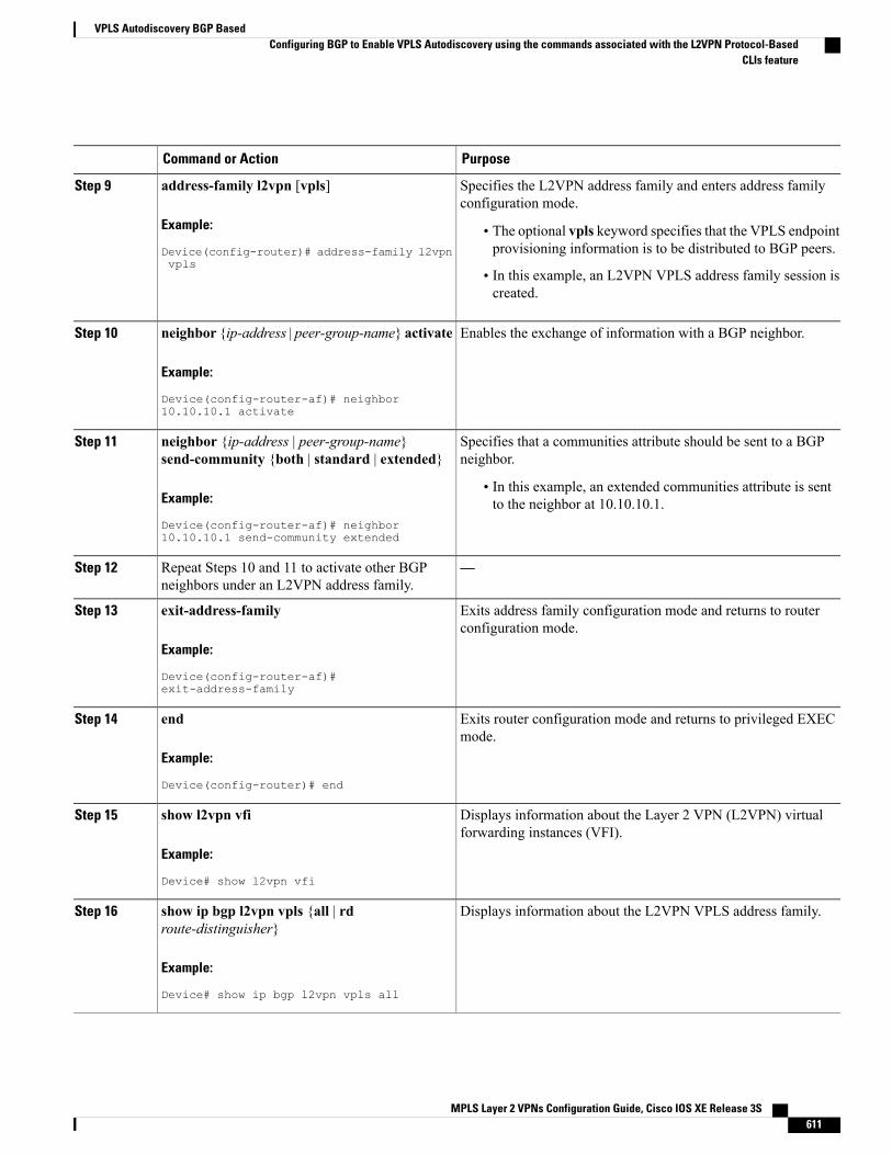
PurposeCommand or Action
Specifies the L2VPN address family and enters address familyconfiguration mode.
address-family l2vpn [vpls]
Example:
Device(config-router)# address-family l2vpnvpls
Step 9
• The optional vpls keyword specifies that the VPLS endpointprovisioning information is to be distributed to BGP peers.
• In this example, an L2VPN VPLS address family session iscreated.
Enables the exchange of information with a BGP neighbor.neighbor {ip-address | peer-group-name} activate
Example:
Device(config-router-af)# neighbor10.10.10.1 activate
Step 10
Specifies that a communities attribute should be sent to a BGPneighbor.
neighbor {ip-address | peer-group-name}send-community {both | standard | extended}
Step 11
Example:
Device(config-router-af)# neighbor10.10.10.1 send-community extended
• In this example, an extended communities attribute is sentto the neighbor at 10.10.10.1.
—Repeat Steps 10 and 11 to activate other BGPneighbors under an L2VPN address family.
Step 12
Exits address family configuration mode and returns to routerconfiguration mode.
exit-address-family
Example:
Device(config-router-af)#exit-address-family
Step 13
Exits router configuration mode and returns to privileged EXECmode.
end
Example:
Device(config-router)# end
Step 14
Displays information about the Layer 2 VPN (L2VPN) virtualforwarding instances (VFI).
show l2vpn vfi
Example:
Device# show l2vpn vfi
Step 15
Displays information about the L2VPN VPLS address family.show ip bgp l2vpn vpls {all | rdroute-distinguisher}
Step 16
Example:
Device# show ip bgp l2vpn vpls all
MPLS Layer 2 VPNs Configuration Guide, Cisco IOS XE Release 3S 611
VPLS Autodiscovery BGP BasedConfiguring BGP to Enable VPLS Autodiscovery using the commands associated with the L2VPN Protocol-Based
CLIs feature
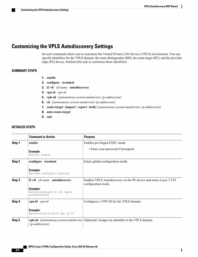
Customizing the VPLS Autodiscovery SettingsSeveral commands allow you to customize the Virtual Private LAN Service (VPLS) environment. You canspecify identifiers for the VPLS domain, the route distinguisher (RD), the route target (RT), and the provideredge (PE) device. Perform this task to customize these identifiers.
SUMMARY STEPS
1. enable2. configure terminal3. l2 vfi vfi-name autodiscovery4. vpn id vpn-id5. vpls-id {autonomous-system-number:nn | ip-address:nn}6. rd {autonomous-system-number:nn | ip-address:nn}7. route-target [import | export | both] {autonomous-system-number:nn | ip-address:nn}8. auto-route-target9. end
DETAILED STEPS
PurposeCommand or Action
Enables privileged EXEC mode.enableStep 1
Example:Device> enable
• Enter your password if prompted.
Enters global configuration mode.configure terminal
Example:Device# configure terminal
Step 2
Enables VPLS Autodiscovery on the PE device and enters Layer 2 VFIconfiguration mode.
l2 vfi vfi-name autodiscovery
Example:Device(config)# l2 vfi vpls1autodiscovery
Step 3
Configures a VPN ID for the VPLS domain.vpn id vpn-id
Example:Device(config-vfi)# vpn id 10
Step 4
(Optional) Assigns an identifier to the VPLS domain.vpls-id {autonomous-system-number:nn| ip-address:nn}
Step 5
MPLS Layer 2 VPNs Configuration Guide, Cisco IOS XE Release 3S612
VPLS Autodiscovery BGP BasedCustomizing the VPLS Autodiscovery Settings
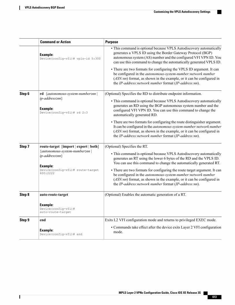
PurposeCommand or Action
• This command is optional because VPLS Autodiscovery automaticallygenerates a VPLS ID using the Border Gateway Protocol (BGP)Example:
Device(config-vfi)# vpls-id 5:300 autonomous system (AS) number and the configured VFI VPN ID. Youcan use this command to change the automatically generated VPLS ID.
• There are two formats for configuring the VPLS ID argument. It canbe configured in the autonomous-system-number:network number(ASN:nn) format, as shown in the example, or it can be configured inthe IP-address:network number format (IP-address:nn).
(Optional) Specifies the RD to distribute endpoint information.rd {autonomous-system-number:nn |ip-address:nn}
Step 6
• This command is optional because VPLS Autodiscovery automaticallygenerates an RD using the BGP autonomous system number and the
Example:Device(config-vfi)# rd 2:3
configured VFI VPN ID. You can use this command to change theautomatically generated RD.
• There are two formats for configuring the route distinguisher argument.It can be configured in the autonomous-system-number:network number(ASN:nn) format, as shown in the example, or it can be configured inthe IP-address:network number format (IP-address:nn).
(Optional) Specifies the RT.route-target [import | export | both]{autonomous-system-number:nn |ip-address:nn}
Step 7
• This command is optional because VPLS Autodiscovery automaticallygenerates an RT using the lower 6 bytes of the RD and the VPLS ID.You can use this command to change the automatically generated RT.
Example:Device(config-vfi)# route-target600:2222
• There are two formats for configuring the route target argument. It canbe configured in the autonomous-system-number:network number(ASN:nn) format, as shown in the example, or it can be configured inthe IP-address:network number format (IP-address:nn).
(Optional) Enables the automatic generation of a RT.auto-route-target
Example:Device(config-vfi)#auto-route-target
Step 8
Exits L2 VFI configuration mode and returns to privileged EXEC mode.endStep 9
Example:Device(config-vfi)# end
• Commands take effect after the device exits Layer 2 VFI configurationmode.
MPLS Layer 2 VPNs Configuration Guide, Cisco IOS XE Release 3S 613
VPLS Autodiscovery BGP BasedCustomizing the VPLS Autodiscovery Settings
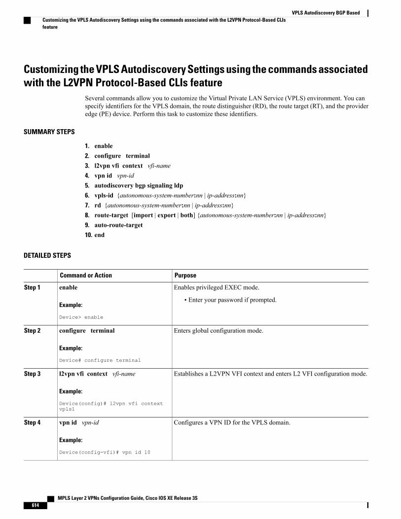
Customizing the VPLS Autodiscovery Settings using the commands associatedwith the L2VPN Protocol-Based CLIs feature
Several commands allow you to customize the Virtual Private LAN Service (VPLS) environment. You canspecify identifiers for the VPLS domain, the route distinguisher (RD), the route target (RT), and the provideredge (PE) device. Perform this task to customize these identifiers.
SUMMARY STEPS
1. enable2. configure terminal3. l2vpn vfi context vfi-name4. vpn id vpn-id5. autodiscovery bgp signaling ldp6. vpls-id {autonomous-system-number:nn | ip-address:nn}7. rd {autonomous-system-number:nn | ip-address:nn}8. route-target [import | export | both] {autonomous-system-number:nn | ip-address:nn}9. auto-route-target10. end
DETAILED STEPS
PurposeCommand or Action
Enables privileged EXEC mode.enableStep 1
Example:
Device> enable
• Enter your password if prompted.
Enters global configuration mode.configure terminal
Example:
Device# configure terminal
Step 2
Establishes a L2VPN VFI context and enters L2 VFI configuration mode.l2vpn vfi context vfi-nameStep 3
Example:
Device(config)# l2vpn vfi contextvpls1
Configures a VPN ID for the VPLS domain.vpn id vpn-id
Example:
Device(config-vfi)# vpn id 10
Step 4
MPLS Layer 2 VPNs Configuration Guide, Cisco IOS XE Release 3S614
VPLS Autodiscovery BGP BasedCustomizing the VPLS Autodiscovery Settings using the commands associated with the L2VPN Protocol-Based CLIsfeature
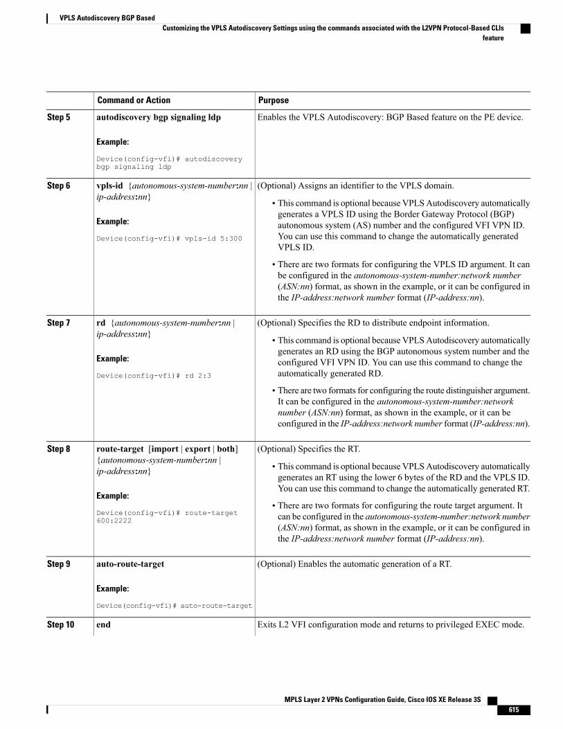
PurposeCommand or Action
Enables the VPLS Autodiscovery: BGP Based feature on the PE device.autodiscovery bgp signaling ldp
Example:
Device(config-vfi)# autodiscoverybgp signaling ldp
Step 5
(Optional) Assigns an identifier to the VPLS domain.vpls-id {autonomous-system-number:nn |ip-address:nn}
Step 6
• This command is optional because VPLSAutodiscovery automaticallygenerates a VPLS ID using the Border Gateway Protocol (BGP)
Example:
Device(config-vfi)# vpls-id 5:300
autonomous system (AS) number and the configured VFI VPN ID.You can use this command to change the automatically generatedVPLS ID.
• There are two formats for configuring the VPLS ID argument. It canbe configured in the autonomous-system-number:network number(ASN:nn) format, as shown in the example, or it can be configured inthe IP-address:network number format (IP-address:nn).
(Optional) Specifies the RD to distribute endpoint information.rd {autonomous-system-number:nn |ip-address:nn}
Step 7
• This command is optional because VPLSAutodiscovery automaticallygenerates an RD using the BGP autonomous system number and the
Example:
Device(config-vfi)# rd 2:3
configured VFI VPN ID. You can use this command to change theautomatically generated RD.
• There are two formats for configuring the route distinguisher argument.It can be configured in the autonomous-system-number:networknumber (ASN:nn) format, as shown in the example, or it can beconfigured in the IP-address:network number format (IP-address:nn).
(Optional) Specifies the RT.route-target [import | export | both]{autonomous-system-number:nn |ip-address:nn}
Step 8
• This command is optional because VPLSAutodiscovery automaticallygenerates an RT using the lower 6 bytes of the RD and the VPLS ID.You can use this command to change the automatically generated RT.
Example:
Device(config-vfi)# route-target600:2222
• There are two formats for configuring the route target argument. Itcan be configured in the autonomous-system-number:network number(ASN:nn) format, as shown in the example, or it can be configured inthe IP-address:network number format (IP-address:nn).
(Optional) Enables the automatic generation of a RT.auto-route-target
Example:
Device(config-vfi)# auto-route-target
Step 9
Exits L2 VFI configuration mode and returns to privileged EXEC mode.endStep 10
MPLS Layer 2 VPNs Configuration Guide, Cisco IOS XE Release 3S 615
VPLS Autodiscovery BGP BasedCustomizing the VPLS Autodiscovery Settings using the commands associated with the L2VPN Protocol-Based CLIs
feature
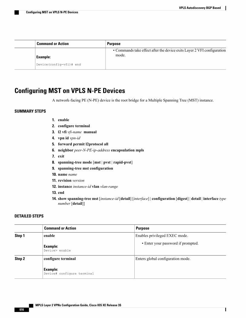
PurposeCommand or Action
Example:
Device(config-vfi)# end
• Commands take effect after the device exits Layer 2 VFI configurationmode.
Configuring MST on VPLS N-PE DevicesA network-facing PE (N-PE) device is the root bridge for a Multiple Spanning Tree (MST) instance.
SUMMARY STEPS
1. enable2. configure terminal3. l2 vfi vfi-name manual4. vpn id vpn-id5. forward permit l2protocol all6. neighbor peer-N-PE-ip-address encapsulation mpls7. exit8. spanning-tree mode [mst | pvst | rapid-pvst]9. spanning-tree mst configuration10. name name11. revision version12. instance instance-id vlan vlan-range13. end14. show spanning-tree mst [instance-id [detail] [interface] | configuration [digest] | detail | interface type
number [detail]]
DETAILED STEPS
PurposeCommand or Action
Enables privileged EXEC mode.enableStep 1
Example:Device> enable
• Enter your password if prompted.
Enters global configuration mode.configure terminal
Example:Device# configure terminal
Step 2
MPLS Layer 2 VPNs Configuration Guide, Cisco IOS XE Release 3S616
VPLS Autodiscovery BGP BasedConfiguring MST on VPLS N-PE Devices
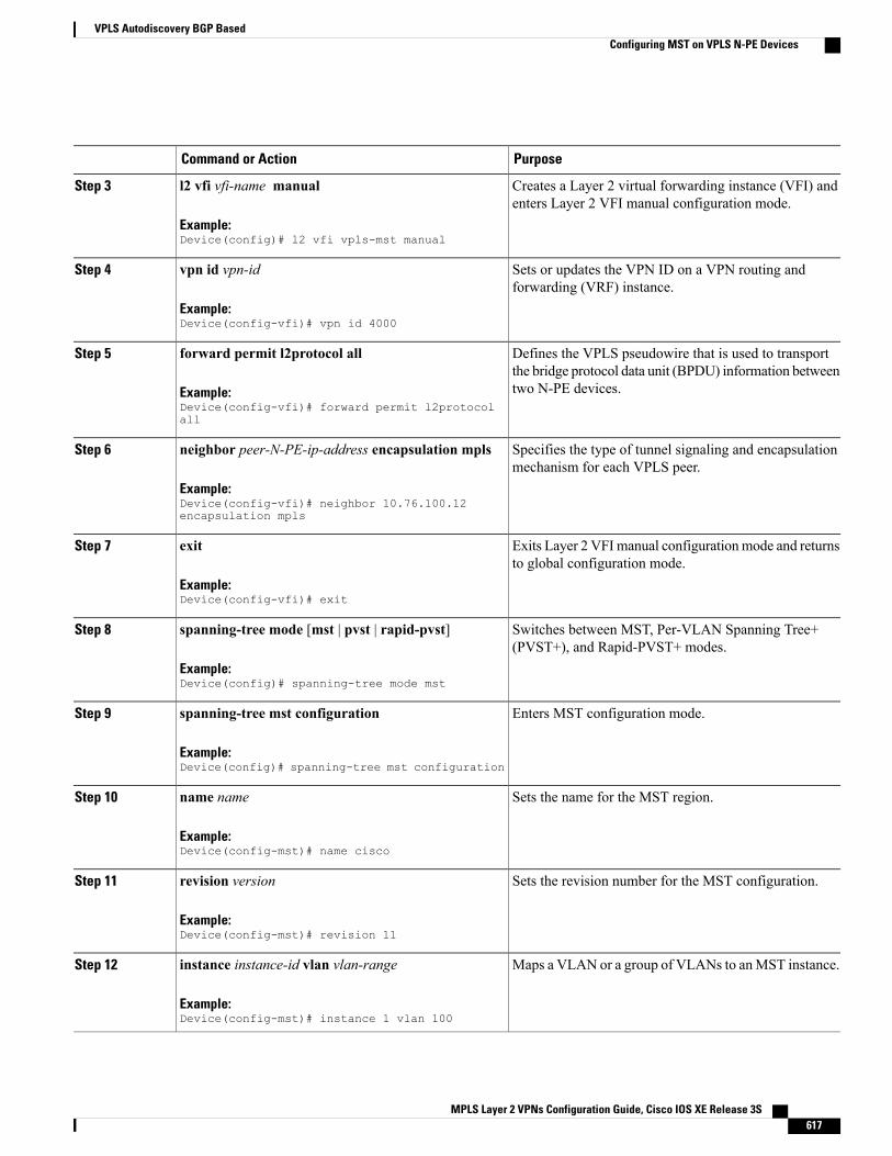
PurposeCommand or Action
Creates a Layer 2 virtual forwarding instance (VFI) andenters Layer 2 VFI manual configuration mode.
l2 vfi vfi-name manual
Example:Device(config)# l2 vfi vpls-mst manual
Step 3
Sets or updates the VPN ID on a VPN routing andforwarding (VRF) instance.
vpn id vpn-id
Example:Device(config-vfi)# vpn id 4000
Step 4
Defines the VPLS pseudowire that is used to transportthe bridge protocol data unit (BPDU) information betweentwo N-PE devices.
forward permit l2protocol all
Example:Device(config-vfi)# forward permit l2protocolall
Step 5
Specifies the type of tunnel signaling and encapsulationmechanism for each VPLS peer.
neighbor peer-N-PE-ip-address encapsulation mpls
Example:Device(config-vfi)# neighbor 10.76.100.12encapsulation mpls
Step 6
Exits Layer 2 VFImanual configurationmode and returnsto global configuration mode.
exit
Example:Device(config-vfi)# exit
Step 7
Switches between MST, Per-VLAN Spanning Tree+(PVST+), and Rapid-PVST+ modes.
spanning-tree mode [mst | pvst | rapid-pvst]
Example:Device(config)# spanning-tree mode mst
Step 8
Enters MST configuration mode.spanning-tree mst configuration
Example:Device(config)# spanning-tree mst configuration
Step 9
Sets the name for the MST region.name name
Example:Device(config-mst)# name cisco
Step 10
Sets the revision number for the MST configuration.revision version
Example:Device(config-mst)# revision 11
Step 11
Maps a VLAN or a group of VLANs to anMST instance.instance instance-id vlan vlan-range
Example:Device(config-mst)# instance 1 vlan 100
Step 12
MPLS Layer 2 VPNs Configuration Guide, Cisco IOS XE Release 3S 617
VPLS Autodiscovery BGP BasedConfiguring MST on VPLS N-PE Devices
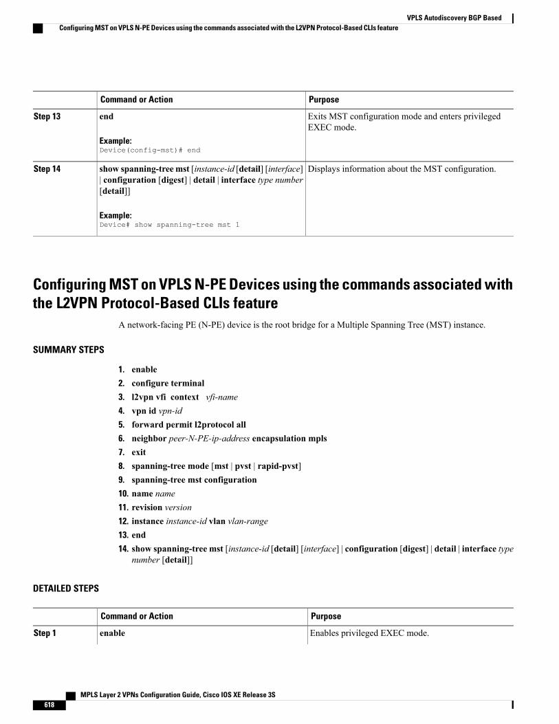
PurposeCommand or Action
Exits MST configuration mode and enters privilegedEXEC mode.
end
Example:Device(config-mst)# end
Step 13
Displays information about the MST configuration.show spanning-treemst [instance-id [detail] [interface]| configuration [digest] | detail | interface type number[detail]]
Step 14
Example:Device# show spanning-tree mst 1
Configuring MST on VPLS N-PE Devices using the commands associated withthe L2VPN Protocol-Based CLIs feature
A network-facing PE (N-PE) device is the root bridge for a Multiple Spanning Tree (MST) instance.
SUMMARY STEPS
1. enable2. configure terminal3. l2vpn vfi context vfi-name4. vpn id vpn-id5. forward permit l2protocol all6. neighbor peer-N-PE-ip-address encapsulation mpls7. exit8. spanning-tree mode [mst | pvst | rapid-pvst]9. spanning-tree mst configuration10. name name11. revision version12. instance instance-id vlan vlan-range13. end14. show spanning-tree mst [instance-id [detail] [interface] | configuration [digest] | detail | interface type
number [detail]]
DETAILED STEPS
PurposeCommand or Action
Enables privileged EXEC mode.enableStep 1
MPLS Layer 2 VPNs Configuration Guide, Cisco IOS XE Release 3S618
VPLS Autodiscovery BGP BasedConfiguring MST on VPLS N-PE Devices using the commands associated with the L2VPN Protocol-Based CLIs feature
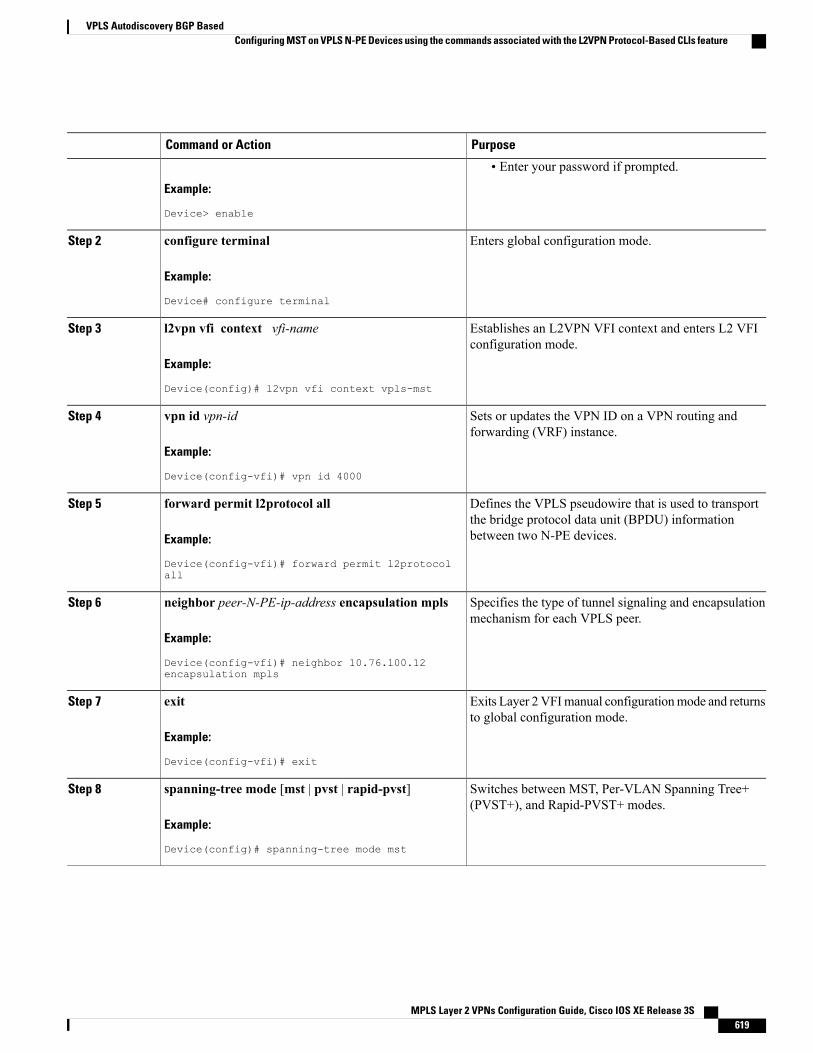
PurposeCommand or Action
Example:
Device> enable
• Enter your password if prompted.
Enters global configuration mode.configure terminal
Example:
Device# configure terminal
Step 2
Establishes an L2VPN VFI context and enters L2 VFIconfiguration mode.
l2vpn vfi context vfi-name
Example:
Device(config)# l2vpn vfi context vpls-mst
Step 3
Sets or updates the VPN ID on a VPN routing andforwarding (VRF) instance.
vpn id vpn-id
Example:
Device(config-vfi)# vpn id 4000
Step 4
Defines the VPLS pseudowire that is used to transportthe bridge protocol data unit (BPDU) informationbetween two N-PE devices.
forward permit l2protocol all
Example:
Device(config-vfi)# forward permit l2protocolall
Step 5
Specifies the type of tunnel signaling and encapsulationmechanism for each VPLS peer.
neighbor peer-N-PE-ip-address encapsulation mpls
Example:
Device(config-vfi)# neighbor 10.76.100.12encapsulation mpls
Step 6
Exits Layer 2 VFImanual configurationmode and returnsto global configuration mode.
exit
Example:
Device(config-vfi)# exit
Step 7
Switches between MST, Per-VLAN Spanning Tree+(PVST+), and Rapid-PVST+ modes.
spanning-tree mode [mst | pvst | rapid-pvst]
Example:
Device(config)# spanning-tree mode mst
Step 8
MPLS Layer 2 VPNs Configuration Guide, Cisco IOS XE Release 3S 619
VPLS Autodiscovery BGP BasedConfiguring MST on VPLS N-PE Devices using the commands associated with the L2VPN Protocol-Based CLIs feature
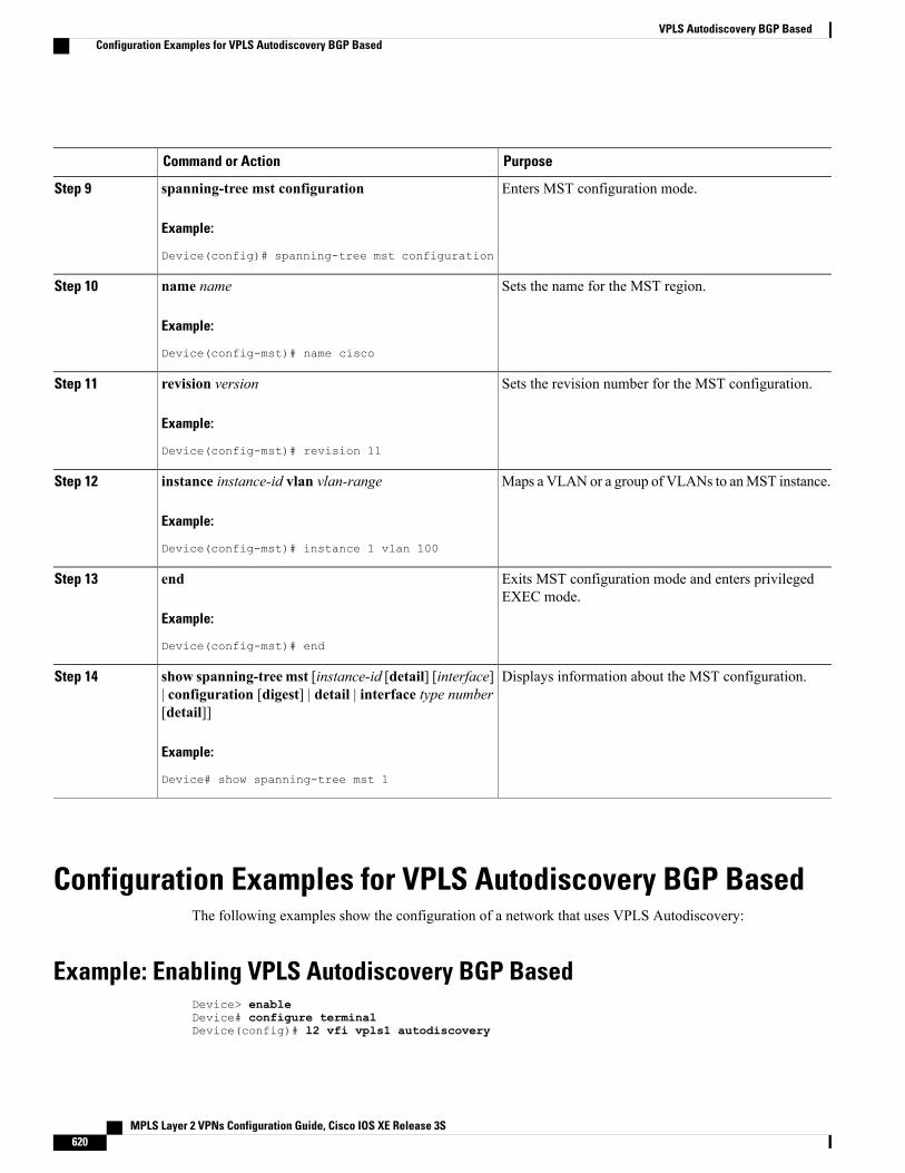
PurposeCommand or Action
Enters MST configuration mode.spanning-tree mst configuration
Example:
Device(config)# spanning-tree mst configuration
Step 9
Sets the name for the MST region.name name
Example:
Device(config-mst)# name cisco
Step 10
Sets the revision number for the MST configuration.revision version
Example:
Device(config-mst)# revision 11
Step 11
Maps a VLAN or a group of VLANs to anMST instance.instance instance-id vlan vlan-range
Example:
Device(config-mst)# instance 1 vlan 100
Step 12
Exits MST configuration mode and enters privilegedEXEC mode.
end
Example:
Device(config-mst)# end
Step 13
Displays information about the MST configuration.show spanning-tree mst [instance-id [detail] [interface]| configuration [digest] | detail | interface type number[detail]]
Step 14
Example:
Device# show spanning-tree mst 1
Configuration Examples for VPLS Autodiscovery BGP BasedThe following examples show the configuration of a network that uses VPLS Autodiscovery:
Example: Enabling VPLS Autodiscovery BGP BasedDevice> enableDevice# configure terminalDevice(config)# l2 vfi vpls1 autodiscovery
MPLS Layer 2 VPNs Configuration Guide, Cisco IOS XE Release 3S620
VPLS Autodiscovery BGP BasedConfiguration Examples for VPLS Autodiscovery BGP Based
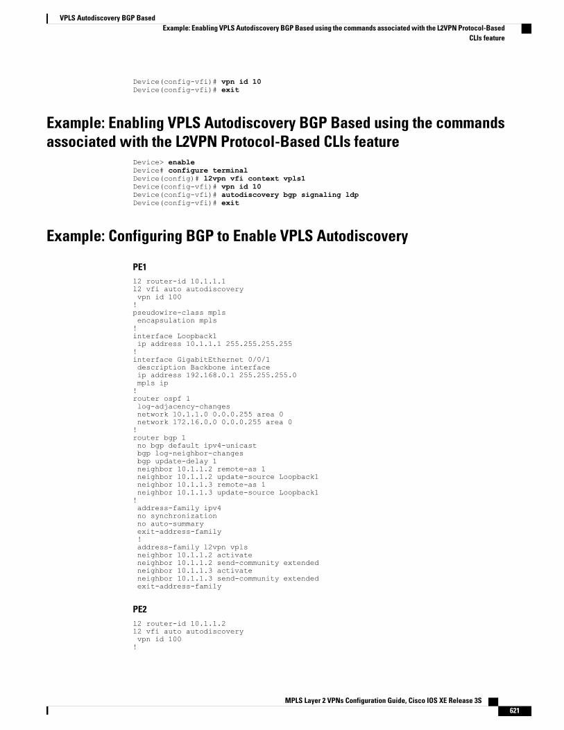
Device(config-vfi)# vpn id 10Device(config-vfi)# exit
Example: Enabling VPLS Autodiscovery BGP Based using the commandsassociated with the L2VPN Protocol-Based CLIs feature
Device> enableDevice# configure terminalDevice(config)# l2vpn vfi context vpls1Device(config-vfi)# vpn id 10Device(config-vfi)# autodiscovery bgp signaling ldpDevice(config-vfi)# exit
Example: Configuring BGP to Enable VPLS Autodiscovery
PE1l2 router-id 10.1.1.1l2 vfi auto autodiscoveryvpn id 100!pseudowire-class mplsencapsulation mpls!interface Loopback1ip address 10.1.1.1 255.255.255.255!interface GigabitEthernet 0/0/1description Backbone interfaceip address 192.168.0.1 255.255.255.0mpls ip!router ospf 1log-adjacency-changesnetwork 10.1.1.0 0.0.0.255 area 0network 172.16.0.0 0.0.0.255 area 0!router bgp 1no bgp default ipv4-unicastbgp log-neighbor-changesbgp update-delay 1neighbor 10.1.1.2 remote-as 1neighbor 10.1.1.2 update-source Loopback1neighbor 10.1.1.3 remote-as 1neighbor 10.1.1.3 update-source Loopback1!address-family ipv4no synchronizationno auto-summaryexit-address-family!address-family l2vpn vplsneighbor 10.1.1.2 activateneighbor 10.1.1.2 send-community extendedneighbor 10.1.1.3 activateneighbor 10.1.1.3 send-community extendedexit-address-family
PE2l2 router-id 10.1.1.2l2 vfi auto autodiscoveryvpn id 100!
MPLS Layer 2 VPNs Configuration Guide, Cisco IOS XE Release 3S 621
VPLS Autodiscovery BGP BasedExample: Enabling VPLS Autodiscovery BGP Based using the commands associated with the L2VPN Protocol-Based
CLIs feature
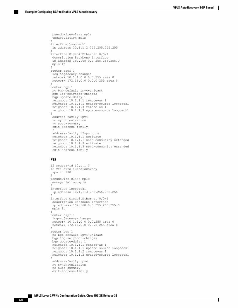
pseudowire-class mplsencapsulation mpls!interface Loopback1ip address 10.1.1.2 255.255.255.255!interface GigabitEthernet 0/0/1description Backbone interfaceip address 192.168.0.2 255.255.255.0mpls ip!router ospf 1log-adjacency-changesnetwork 10.1.1.0 0.0.0.255 area 0network 172.16.0.0 0.0.0.255 area 0!router bgp 1no bgp default ipv4-unicastbgp log-neighbor-changesbgp update-delay 1neighbor 10.1.1.1 remote-as 1neighbor 10.1.1.1 update-source Loopback1neighbor 10.1.1.3 remote-as 1neighbor 10.1.1.3 update-source Loopback1!address-family ipv4no synchronizationno auto-summaryexit-address-family!address-family l2vpn vplsneighbor 10.1.1.1 activateneighbor 10.1.1.1 send-community extendedneighbor 10.1.1.3 activateneighbor 10.1.1.3 send-community extendedexit-address-family
PE3l2 router-id 10.1.1.3l2 vfi auto autodiscoveryvpn id 100!pseudowire-class mplsencapsulation mpls!interface Loopback1ip address 10.1.1.3 255.255.255.255!interface GigabitEthernet 0/0/1description Backbone interfaceip address 192.168.0.3 255.255.255.0mpls ip!router ospf 1log-adjacency-changesnetwork 10.1.1.0 0.0.0.255 area 0network 172.16.0.0 0.0.0.255 area 0!router bgp 1no bgp default ipv4-unicastbgp log-neighbor-changesbgp update-delay 1neighbor 10.1.1.1 remote-as 1neighbor 10.1.1.1 update-source Loopback1neighbor 10.1.1.2 remote-as 1neighbor 10.1.1.2 update-source Loopback1!address-family ipv4no synchronizationno auto-summaryexit-address-family
MPLS Layer 2 VPNs Configuration Guide, Cisco IOS XE Release 3S622
VPLS Autodiscovery BGP BasedExample: Configuring BGP to Enable VPLS Autodiscovery
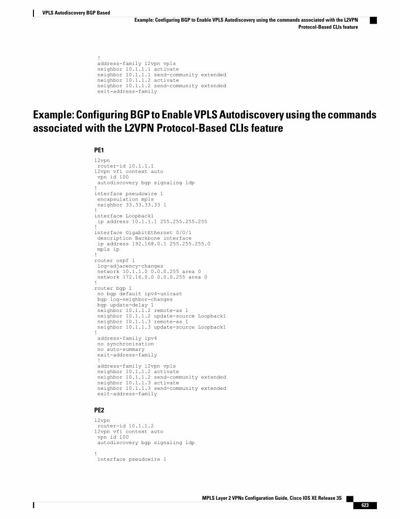
!address-family l2vpn vplsneighbor 10.1.1.1 activateneighbor 10.1.1.1 send-community extendedneighbor 10.1.1.2 activateneighbor 10.1.1.2 send-community extendedexit-address-family
Example: Configuring BGP to Enable VPLS Autodiscovery using the commandsassociated with the L2VPN Protocol-Based CLIs feature
PE1l2vpnrouter-id 10.1.1.1l2vpn vfi context autovpn id 100autodiscovery bgp signaling ldp!interface pseudowire 1encapsulation mplsneighbor 33.33.33.33 1!interface Loopback1ip address 10.1.1.1 255.255.255.255!interface GigabitEthernet 0/0/1description Backbone interfaceip address 192.168.0.1 255.255.255.0mpls ip!router ospf 1log-adjacency-changesnetwork 10.1.1.0 0.0.0.255 area 0network 172.16.0.0 0.0.0.255 area 0!router bgp 1no bgp default ipv4-unicastbgp log-neighbor-changesbgp update-delay 1neighbor 10.1.1.2 remote-as 1neighbor 10.1.1.2 update-source Loopback1neighbor 10.1.1.3 remote-as 1neighbor 10.1.1.3 update-source Loopback1!address-family ipv4no synchronizationno auto-summaryexit-address-family!address-family l2vpn vplsneighbor 10.1.1.2 activateneighbor 10.1.1.2 send-community extendedneighbor 10.1.1.3 activateneighbor 10.1.1.3 send-community extendedexit-address-family
PE2l2vpnrouter-id 10.1.1.2l2vpn vfi context autovpn id 100autodiscovery bgp signaling ldp
!interface pseudowire 1
MPLS Layer 2 VPNs Configuration Guide, Cisco IOS XE Release 3S 623
VPLS Autodiscovery BGP BasedExample: Configuring BGP to Enable VPLS Autodiscovery using the commands associated with the L2VPN
Protocol-Based CLIs feature
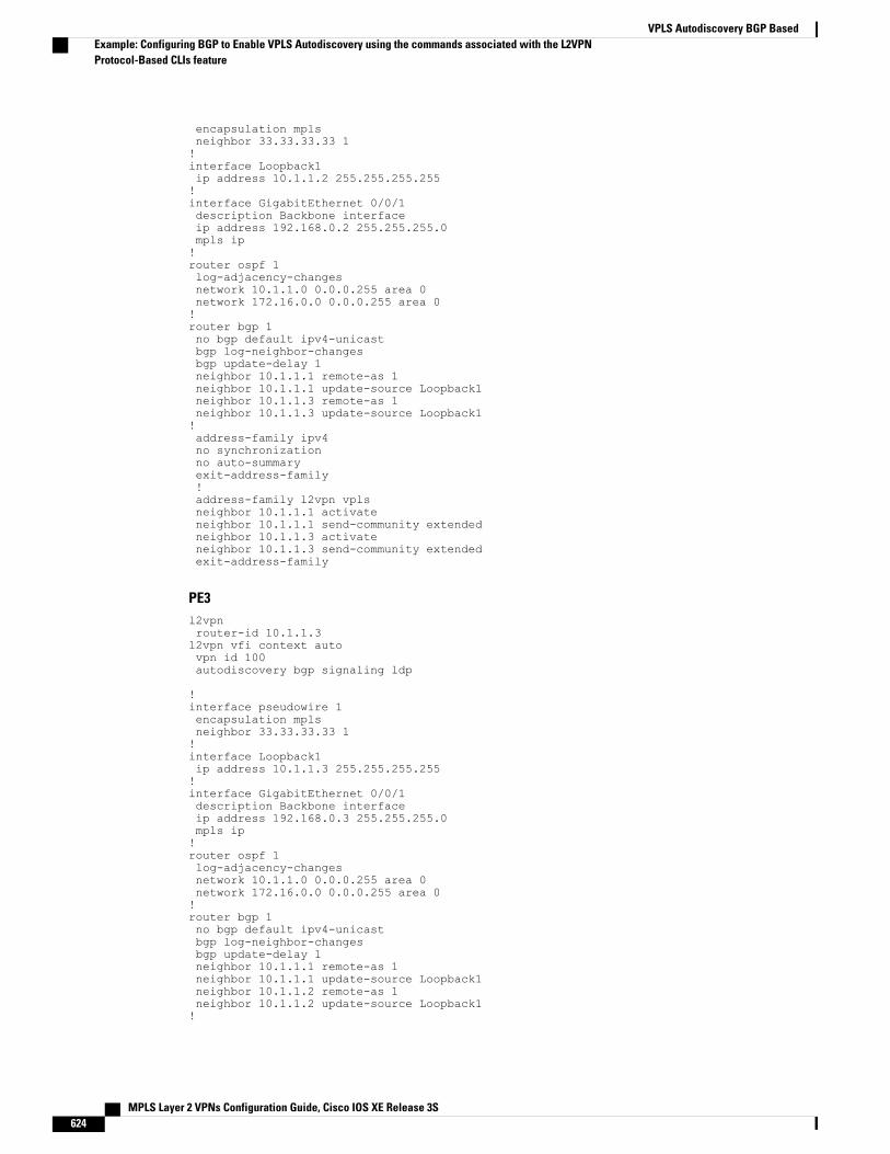
encapsulation mplsneighbor 33.33.33.33 1!interface Loopback1ip address 10.1.1.2 255.255.255.255!interface GigabitEthernet 0/0/1description Backbone interfaceip address 192.168.0.2 255.255.255.0mpls ip!router ospf 1log-adjacency-changesnetwork 10.1.1.0 0.0.0.255 area 0network 172.16.0.0 0.0.0.255 area 0!router bgp 1no bgp default ipv4-unicastbgp log-neighbor-changesbgp update-delay 1neighbor 10.1.1.1 remote-as 1neighbor 10.1.1.1 update-source Loopback1neighbor 10.1.1.3 remote-as 1neighbor 10.1.1.3 update-source Loopback1!address-family ipv4no synchronizationno auto-summaryexit-address-family!address-family l2vpn vplsneighbor 10.1.1.1 activateneighbor 10.1.1.1 send-community extendedneighbor 10.1.1.3 activateneighbor 10.1.1.3 send-community extendedexit-address-family
PE3l2vpnrouter-id 10.1.1.3l2vpn vfi context autovpn id 100autodiscovery bgp signaling ldp
!interface pseudowire 1encapsulation mplsneighbor 33.33.33.33 1!interface Loopback1ip address 10.1.1.3 255.255.255.255!interface GigabitEthernet 0/0/1description Backbone interfaceip address 192.168.0.3 255.255.255.0mpls ip!router ospf 1log-adjacency-changesnetwork 10.1.1.0 0.0.0.255 area 0network 172.16.0.0 0.0.0.255 area 0!router bgp 1no bgp default ipv4-unicastbgp log-neighbor-changesbgp update-delay 1neighbor 10.1.1.1 remote-as 1neighbor 10.1.1.1 update-source Loopback1neighbor 10.1.1.2 remote-as 1neighbor 10.1.1.2 update-source Loopback1!
MPLS Layer 2 VPNs Configuration Guide, Cisco IOS XE Release 3S624
VPLS Autodiscovery BGP BasedExample: Configuring BGP to Enable VPLS Autodiscovery using the commands associated with the L2VPNProtocol-Based CLIs feature
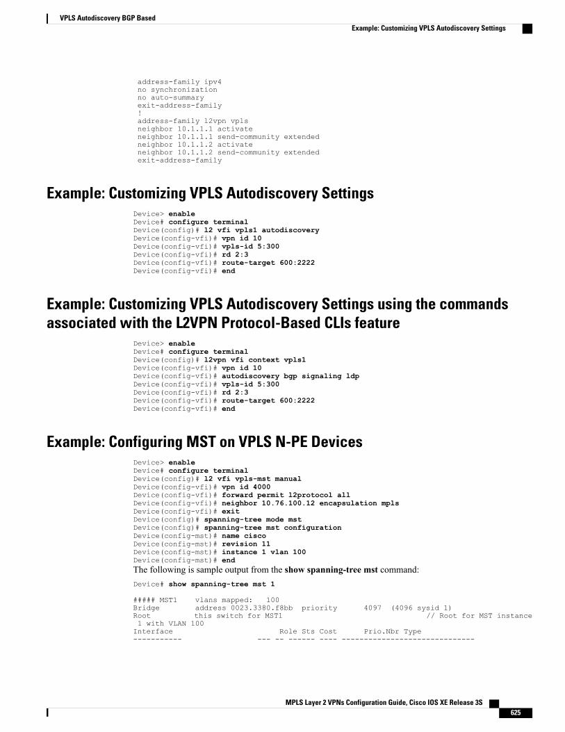
address-family ipv4no synchronizationno auto-summaryexit-address-family!address-family l2vpn vplsneighbor 10.1.1.1 activateneighbor 10.1.1.1 send-community extendedneighbor 10.1.1.2 activateneighbor 10.1.1.2 send-community extendedexit-address-family
Example: Customizing VPLS Autodiscovery SettingsDevice> enableDevice# configure terminalDevice(config)# l2 vfi vpls1 autodiscoveryDevice(config-vfi)# vpn id 10Device(config-vfi)# vpls-id 5:300Device(config-vfi)# rd 2:3Device(config-vfi)# route-target 600:2222Device(config-vfi)# end
Example: Customizing VPLS Autodiscovery Settings using the commandsassociated with the L2VPN Protocol-Based CLIs feature
Device> enableDevice# configure terminalDevice(config)# l2vpn vfi context vpls1Device(config-vfi)# vpn id 10Device(config-vfi)# autodiscovery bgp signaling ldpDevice(config-vfi)# vpls-id 5:300Device(config-vfi)# rd 2:3Device(config-vfi)# route-target 600:2222Device(config-vfi)# end
Example: Configuring MST on VPLS N-PE DevicesDevice> enableDevice# configure terminalDevice(config)# l2 vfi vpls-mst manualDevice(config-vfi)# vpn id 4000Device(config-vfi)# forward permit l2protocol allDevice(config-vfi)# neighbor 10.76.100.12 encapsulation mplsDevice(config-vfi)# exitDevice(config)# spanning-tree mode mstDevice(config)# spanning-tree mst configurationDevice(config-mst)# name ciscoDevice(config-mst)# revision 11Device(config-mst)# instance 1 vlan 100Device(config-mst)# endThe following is sample output from the show spanning-tree mst command:Device# show spanning-tree mst 1
##### MST1 vlans mapped: 100Bridge address 0023.3380.f8bb priority 4097 (4096 sysid 1)Root this switch for MST1 // Root for MST instance1 with VLAN 100Interface Role Sts Cost Prio.Nbr Type----------- --- -- ------ ---- ------------------------------
MPLS Layer 2 VPNs Configuration Guide, Cisco IOS XE Release 3S 625
VPLS Autodiscovery BGP BasedExample: Customizing VPLS Autodiscovery Settings
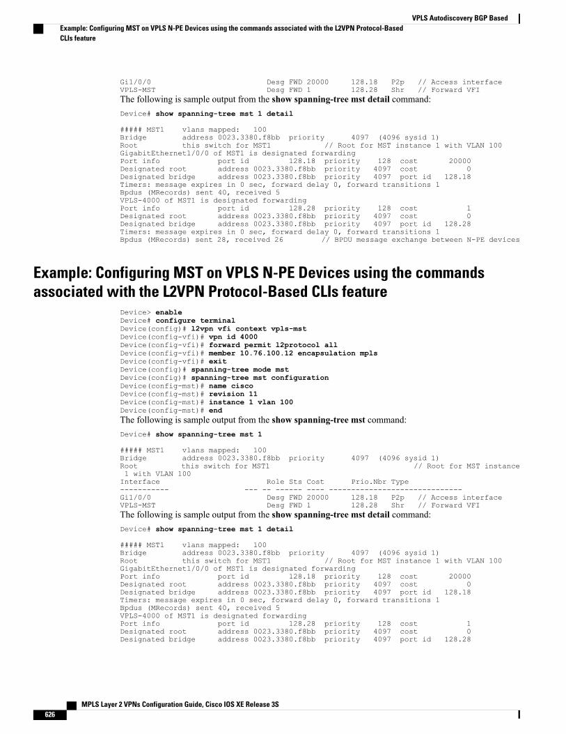
Gi1/0/0 Desg FWD 20000 128.18 P2p // Access interfaceVPLS-MST Desg FWD 1 128.28 Shr // Forward VFIThe following is sample output from the show spanning-tree mst detail command:Device# show spanning-tree mst 1 detail
##### MST1 vlans mapped: 100Bridge address 0023.3380.f8bb priority 4097 (4096 sysid 1)Root this switch for MST1 // Root for MST instance 1 with VLAN 100GigabitEthernet1/0/0 of MST1 is designated forwardingPort info port id 128.18 priority 128 cost 20000Designated root address 0023.3380.f8bb priority 4097 cost 0Designated bridge address 0023.3380.f8bb priority 4097 port id 128.18Timers: message expires in 0 sec, forward delay 0, forward transitions 1Bpdus (MRecords) sent 40, received 5VPLS-4000 of MST1 is designated forwardingPort info port id 128.28 priority 128 cost 1Designated root address 0023.3380.f8bb priority 4097 cost 0Designated bridge address 0023.3380.f8bb priority 4097 port id 128.28Timers: message expires in 0 sec, forward delay 0, forward transitions 1Bpdus (MRecords) sent 28, received 26 // BPDU message exchange between N-PE devices
Example: Configuring MST on VPLS N-PE Devices using the commandsassociated with the L2VPN Protocol-Based CLIs feature
Device> enableDevice# configure terminalDevice(config)# l2vpn vfi context vpls-mstDevice(config-vfi)# vpn id 4000Device(config-vfi)# forward permit l2protocol allDevice(config-vfi)# member 10.76.100.12 encapsulation mplsDevice(config-vfi)# exitDevice(config)# spanning-tree mode mstDevice(config)# spanning-tree mst configurationDevice(config-mst)# name ciscoDevice(config-mst)# revision 11Device(config-mst)# instance 1 vlan 100Device(config-mst)# endThe following is sample output from the show spanning-tree mst command:Device# show spanning-tree mst 1
##### MST1 vlans mapped: 100Bridge address 0023.3380.f8bb priority 4097 (4096 sysid 1)Root this switch for MST1 // Root for MST instance1 with VLAN 100Interface Role Sts Cost Prio.Nbr Type----------- --- -- ------ ---- ------------------------------Gi1/0/0 Desg FWD 20000 128.18 P2p // Access interfaceVPLS-MST Desg FWD 1 128.28 Shr // Forward VFIThe following is sample output from the show spanning-tree mst detail command:Device# show spanning-tree mst 1 detail
##### MST1 vlans mapped: 100Bridge address 0023.3380.f8bb priority 4097 (4096 sysid 1)Root this switch for MST1 // Root for MST instance 1 with VLAN 100GigabitEthernet1/0/0 of MST1 is designated forwardingPort info port id 128.18 priority 128 cost 20000Designated root address 0023.3380.f8bb priority 4097 cost 0Designated bridge address 0023.3380.f8bb priority 4097 port id 128.18Timers: message expires in 0 sec, forward delay 0, forward transitions 1Bpdus (MRecords) sent 40, received 5VPLS-4000 of MST1 is designated forwardingPort info port id 128.28 priority 128 cost 1Designated root address 0023.3380.f8bb priority 4097 cost 0Designated bridge address 0023.3380.f8bb priority 4097 port id 128.28
MPLS Layer 2 VPNs Configuration Guide, Cisco IOS XE Release 3S626
VPLS Autodiscovery BGP BasedExample: Configuring MST on VPLS N-PE Devices using the commands associated with the L2VPN Protocol-BasedCLIs feature
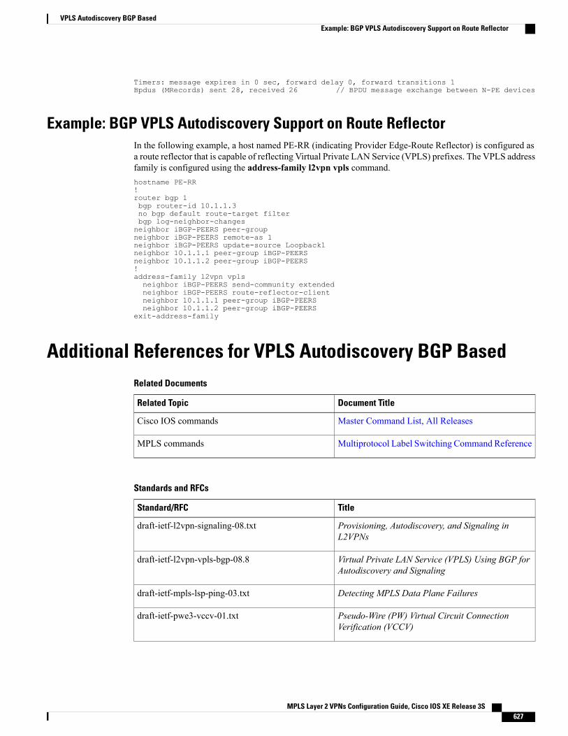
Timers: message expires in 0 sec, forward delay 0, forward transitions 1Bpdus (MRecords) sent 28, received 26 // BPDU message exchange between N-PE devices
Example: BGP VPLS Autodiscovery Support on Route ReflectorIn the following example, a host named PE-RR (indicating Provider Edge-Route Reflector) is configured asa route reflector that is capable of reflecting Virtual Private LAN Service (VPLS) prefixes. The VPLS addressfamily is configured using the address-family l2vpn vpls command.hostname PE-RR!router bgp 1bgp router-id 10.1.1.3no bgp default route-target filterbgp log-neighbor-changesneighbor iBGP-PEERS peer-groupneighbor iBGP-PEERS remote-as 1neighbor iBGP-PEERS update-source Loopback1neighbor 10.1.1.1 peer-group iBGP-PEERSneighbor 10.1.1.2 peer-group iBGP-PEERS!address-family l2vpn vplsneighbor iBGP-PEERS send-community extendedneighbor iBGP-PEERS route-reflector-clientneighbor 10.1.1.1 peer-group iBGP-PEERSneighbor 10.1.1.2 peer-group iBGP-PEERS
exit-address-family
Additional References for VPLS Autodiscovery BGP BasedRelated Documents
Document TitleRelated Topic
Master Command List, All ReleasesCisco IOS commands
Multiprotocol Label Switching Command ReferenceMPLS commands
Standards and RFCs
TitleStandard/RFC
Provisioning, Autodiscovery, and Signaling inL2VPNs
draft-ietf-l2vpn-signaling-08.txt
Virtual Private LAN Service (VPLS) Using BGP forAutodiscovery and Signaling
draft-ietf-l2vpn-vpls-bgp-08.8
Detecting MPLS Data Plane Failuresdraft-ietf-mpls-lsp-ping-03.txt
Pseudo-Wire (PW) Virtual Circuit ConnectionVerification (VCCV)
draft-ietf-pwe3-vccv-01.txt
MPLS Layer 2 VPNs Configuration Guide, Cisco IOS XE Release 3S 627
VPLS Autodiscovery BGP BasedExample: BGP VPLS Autodiscovery Support on Route Reflector
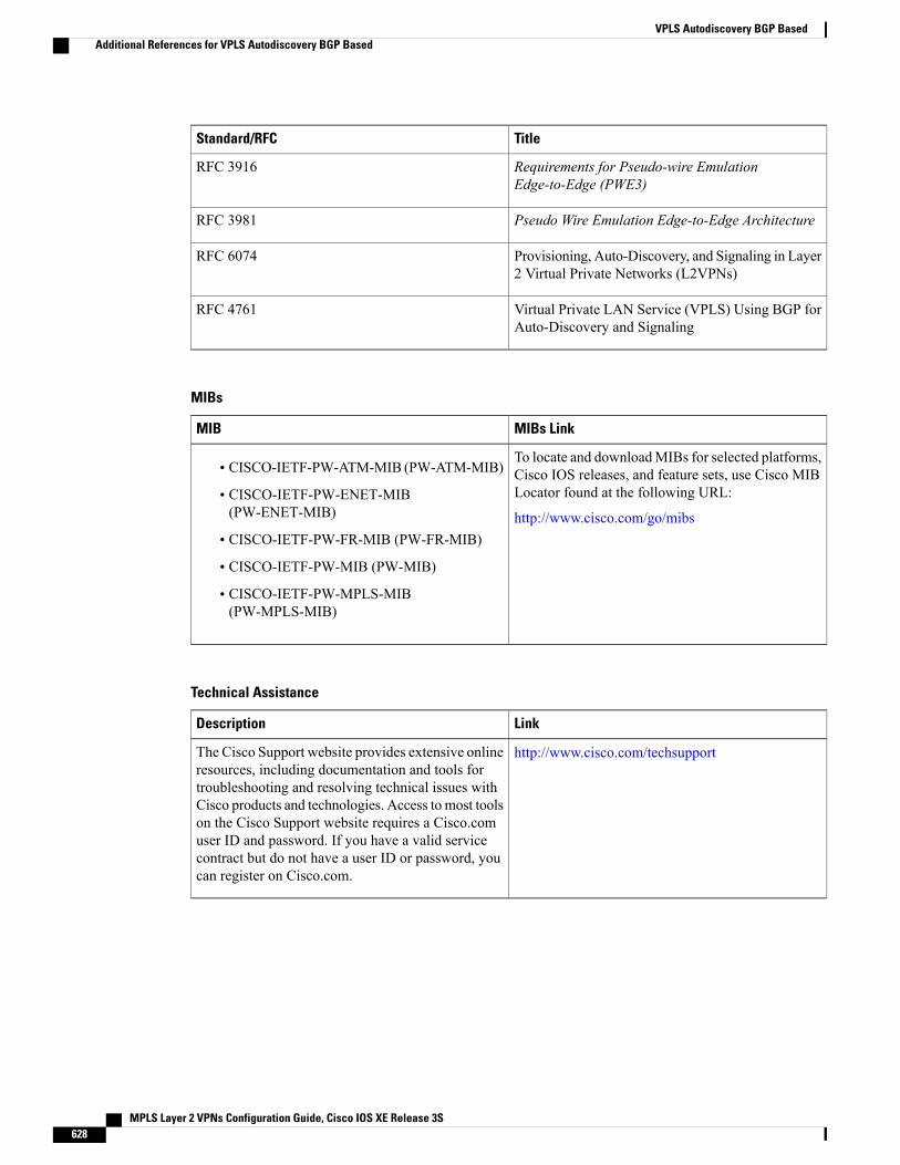
TitleStandard/RFC
Requirements for Pseudo-wire EmulationEdge-to-Edge (PWE3)
RFC 3916
Pseudo Wire Emulation Edge-to-Edge ArchitectureRFC 3981
Provisioning, Auto-Discovery, and Signaling in Layer2 Virtual Private Networks (L2VPNs)
RFC 6074
Virtual Private LAN Service (VPLS) Using BGP forAuto-Discovery and Signaling
RFC 4761
MIBs
MIBs LinkMIB
To locate and downloadMIBs for selected platforms,Cisco IOS releases, and feature sets, use Cisco MIBLocator found at the following URL:
http://www.cisco.com/go/mibs
• CISCO-IETF-PW-ATM-MIB (PW-ATM-MIB)
• CISCO-IETF-PW-ENET-MIB(PW-ENET-MIB)
• CISCO-IETF-PW-FR-MIB (PW-FR-MIB)
• CISCO-IETF-PW-MIB (PW-MIB)
• CISCO-IETF-PW-MPLS-MIB(PW-MPLS-MIB)
Technical Assistance
LinkDescription
http://www.cisco.com/techsupportThe Cisco Support website provides extensive onlineresources, including documentation and tools fortroubleshooting and resolving technical issues withCisco products and technologies. Access to most toolson the Cisco Support website requires a Cisco.comuser ID and password. If you have a valid servicecontract but do not have a user ID or password, youcan register on Cisco.com.
MPLS Layer 2 VPNs Configuration Guide, Cisco IOS XE Release 3S628
VPLS Autodiscovery BGP BasedAdditional References for VPLS Autodiscovery BGP Based
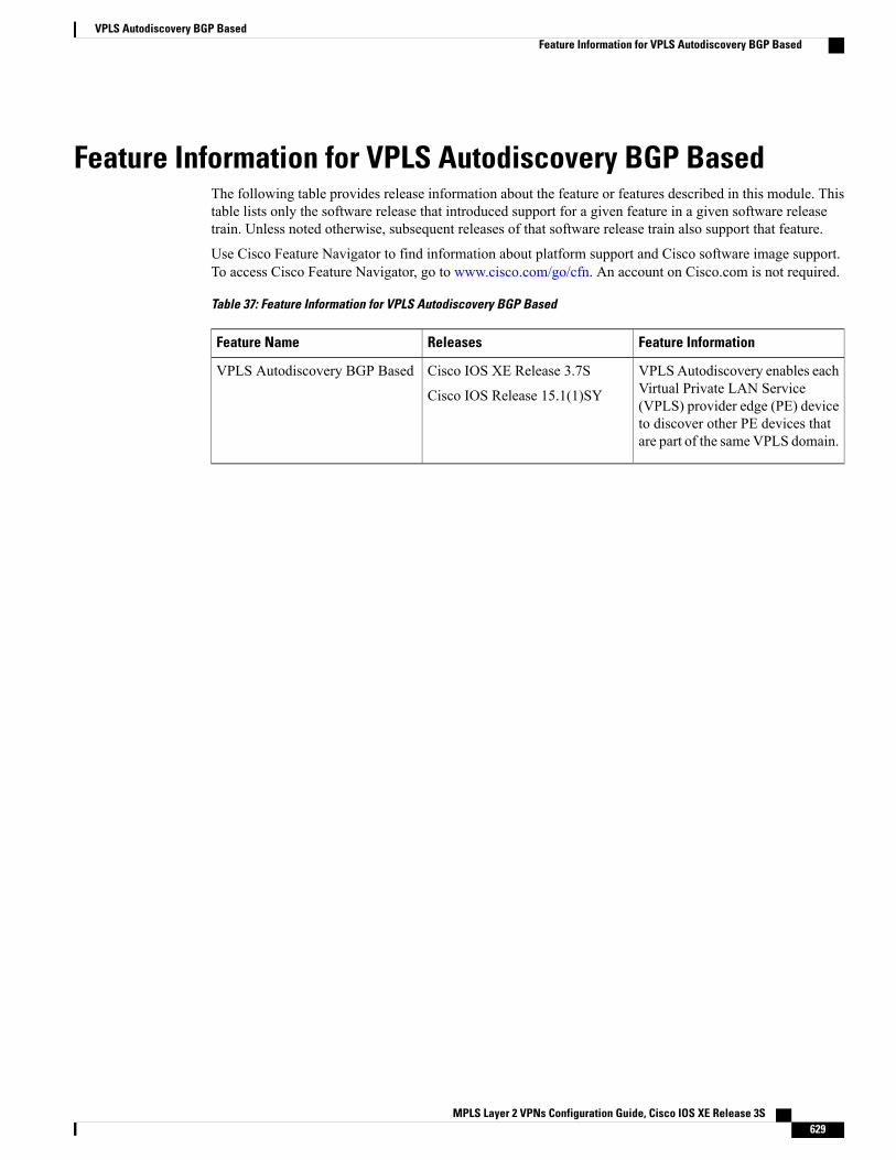
Feature Information for VPLS Autodiscovery BGP BasedThe following table provides release information about the feature or features described in this module. Thistable lists only the software release that introduced support for a given feature in a given software releasetrain. Unless noted otherwise, subsequent releases of that software release train also support that feature.
Use Cisco Feature Navigator to find information about platform support and Cisco software image support.To access Cisco Feature Navigator, go to www.cisco.com/go/cfn. An account on Cisco.com is not required.
Table 37: Feature Information for VPLS Autodiscovery BGP Based
Feature InformationReleasesFeature Name
VPLSAutodiscovery enables eachVirtual Private LAN Service(VPLS) provider edge (PE) deviceto discover other PE devices thatare part of the sameVPLS domain.
Cisco IOS XE Release 3.7S
Cisco IOS Release 15.1(1)SY
VPLS Autodiscovery BGP Based
MPLS Layer 2 VPNs Configuration Guide, Cisco IOS XE Release 3S 629
VPLS Autodiscovery BGP BasedFeature Information for VPLS Autodiscovery BGP Based

MPLS Layer 2 VPNs Configuration Guide, Cisco IOS XE Release 3S630
VPLS Autodiscovery BGP BasedFeature Information for VPLS Autodiscovery BGP Based
C H A P T E R 22N:1 PVC Mapping to PWE with Nonunique VPIs
The N:1 PVC Mapping to PseudoWire Emulation (PWE) with Nonunique virtual path identifiers (VPIs)feature maps one or more ATM permanent virtual circuits (PVCs) to a single pseudowire (PW). There aretwo modes of AAL0 encapsulation, N:1 and 1:1 mapping. In N:1 mapping, multiple unrelated virtual pathidentifier/virtual channel identifier (VPI/VCI) are carried over a singleMultiprotocol Label Switching (MPLS)PW. This is an efficient mapping method because less resources are used from the MPLS network. In 1:1mapping, a single VPI/VCI is carried over a single MPLS PW. Benefits of this feature include the following:
• Aggregate quality of service (QoS) can be applied to related PVCs.
• Bandwidth is conserved with the reduction in the number of pseudowires that are used.
• Finding Feature Information, page 631
• Restrictions for N:1 PVC Mapping to PWE with Nonunique VPIs, page 632
• Information About N:1 PVC Mapping to PWE with Nonunique VPIs, page 632
• How to Configure N:1 PVC Mapping to PWE with Nonunique VPIs, page 633
• Configuration Examples for N:1 PVC Mapping to PWE with Nonunique VPIs, page 638
• Additional References, page 639
• Feature Information for N:1 PVC Mapping to PWE with Nonunique VPIs, page 640
Finding Feature InformationYour software release may not support all the features documented in this module. For the latest caveats andfeature information, see Bug Search Tool and the release notes for your platform and software release. Tofind information about the features documented in this module, and to see a list of the releases in which eachfeature is supported, see the feature information table at the end of this module.
Use Cisco Feature Navigator to find information about platform support and Cisco software image support.To access Cisco Feature Navigator, go to www.cisco.com/go/cfn. An account on Cisco.com is not required.
MPLS Layer 2 VPNs Configuration Guide, Cisco IOS XE Release 3S 631
Restrictions for N:1 PVC Mapping to PWE with Nonunique VPIs• N:1 permanent virtual circuits (PVC)mapping configuration is supported only onmultipoint subinterfaces;it is not supported on main interfaces or point-to-point subinterfaces.
• N:1 PVC mapping mode is not supported on Access Circuit Redundancy subinterfaces.
• Preconfigured PVCs cannot exist on the multipoint subinterface on which you want to configure N:1PVC mapping.
• An attachment circuit that has been bound to a pseudowire cannot be removed unless all Layer 2 virtualcircuits (VCs) have been removed.
• Layer 3 PVCs cannot be configured on N:1 subinterfaces.
• Cell packing values configured under a VC class attached to the PVC, main interface, or subinterfacewill not be inherited by N:1 PVCs.
• Operation, Administration, and Maintenance (OAM) functionality is not supported on N:1 Layer 2PVCs. OAM cells coming from the customer edge (CE) network will be treated as normal data trafficand will traverse through the pseudowire.
• Only ATM adaptation layer type 0 (AAL0) encapsulation is supported for N:1 PVCs.
• The service policy configuration can be configured only at the subinterface level for N:1 PVCs.
Information About N:1 PVC Mapping to PWE with NonuniqueVPIs
N:1 PVC Mapping to PWE with Nonunique VPIs Feature DescriptionTo transport ATM cells overMultiprotocol Label Switching (MPLS), a VC is established between the provideredge (PE) routers on both ends of theMPLS backbone.With the N:1 permanent virtual circuit (PVC)Mappingto PseudoWire Emulation (PWE) with Nonunique VPIs feature, multiple PVCs irrespective of their VirtualPath Identifiers (VPIs), are transported over a single pseudowire configured on a subinterface. (“N:1” refersto the number of PVCs transported over one pseudowire). ATM cells are packed together in a single frameand sent over the single pseudowire. The ATM cell header information is packed together with the cell payloadon a per-cell basis in the packets so that packets received at the egress end are unpacked and the ATM cellsare mapped to the respective PVCs.
In N:1 PVC mapping mode, the device can pack cells only from a single PVC in an MPLS packet to transmitover a pseudowire; cells from multiple PVCs cannot be packed in a single MPLS packet and mapped to asingle pseudowire for transmission. However, if a device receives an MPLS packet that is packed with cellsfrom multiple PVCs, then those cells will be unpacked and sent to the respective PVCs.
MPLS Layer 2 VPNs Configuration Guide, Cisco IOS XE Release 3S632
N:1 PVC Mapping to PWE with Nonunique VPIsRestrictions for N:1 PVC Mapping to PWE with Nonunique VPIs
How to Configure N:1 PVC Mapping to PWE with NonuniqueVPIs
Configuring N:1 PVC Mapping to PWE with Nonunique VPIs
SUMMARY STEPS
1. enable2. configure terminal3. interface atm slot/subslot/port4. atm mcpt-timers timer1 timer2 timer35. exit6. configure terminal7. interface atm slot/subslot/port.subslotmultipoint8. no ip address9. atm enable-ilmi-trap10. cell-packing maxcells mcpt-timer timer-number11. xconnect peer-ipaddress vc-id encapsulation mpls12. pvc vpi/vci l2transport13. Repeat Step 12 for the number of PVCs that you want to configure.14. end
DETAILED STEPS
PurposeCommand or Action
Enables privileged EXEC mode.enableStep 1
Example:Device> enable
• Enter your password if prompted.
Enters global configuration mode.configure terminal
Example:Device# configure terminal
Step 2
Enables the ATM interface and enters interface configurationmode.
interface atm slot/subslot/port
Example:Device(config)# interface atm 9/1/1
Step 3
MPLS Layer 2 VPNs Configuration Guide, Cisco IOS XE Release 3S 633
N:1 PVC Mapping to PWE with Nonunique VPIsHow to Configure N:1 PVC Mapping to PWE with Nonunique VPIs
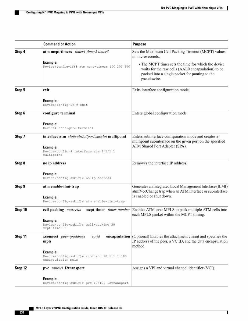
PurposeCommand or Action
Sets the Maximum Cell Packing Timeout (MCPT) valuesin microseconds.
atm mcpt-timers timer1 timer2 timer3
Example:Device(config-if)# atm mcpt-timers 100 200 300
Step 4
• The MCPT timer sets the time for which the devicewaits for the raw cells (AAL0 encapsulation) to bepacked into a single packet for punting to thepseudowire.
Exits interface configuration mode.exit
Example:Device(config-if)# exit
Step 5
Enters global configuration mode.configure terminal
Example:Device# configure terminal
Step 6
Enters subinterface configuration mode and creates amultipoint subinterface on the given port on the specifiedATM Shared Port Adapter (SPA).
interface atm slot/subslot/port.subslotmultipoint
Example:Device(config)# interface atm 9/1/1.1multipoint
Step 7
Removes the interface IP address.no ip address
Example:Device(config-subif)# no ip address
Step 8
Generates an Integrated LocalManagement Interface (ILMI)atmfVccChange trap when an ATM interface or subinterfaceis enabled or shut down.
atm enable-ilmi-trap
Example:Device(config-subif)# atm enable-ilmi-trap
Step 9
Enables ATM over MPLS to pack multiple ATM cells intoeach MPLS packet within the MCPT timing.
cell-packing maxcells mcpt-timer timer-number
Example:Device(config-subif)# cell-packing 20mcpt-timer 2
Step 10
(Optional) Enables the attachment circuit and specifies theIP address of the peer, a VC ID, and the data encapsulationmethod.
xconnect peer-ipaddress vc-id encapsulationmpls
Example:Device(config-subif)# xconnect 10.1.1.1 100encapsulation mpls
Step 11
Assigns a VPI and virtual channel identifier (VCI).pvc vpi/vci l2transport
Example:Device(config-subif)# pvc 10/100 l2transport
Step 12
MPLS Layer 2 VPNs Configuration Guide, Cisco IOS XE Release 3S634
N:1 PVC Mapping to PWE with Nonunique VPIsConfiguring N:1 PVC Mapping to PWE with Nonunique VPIs
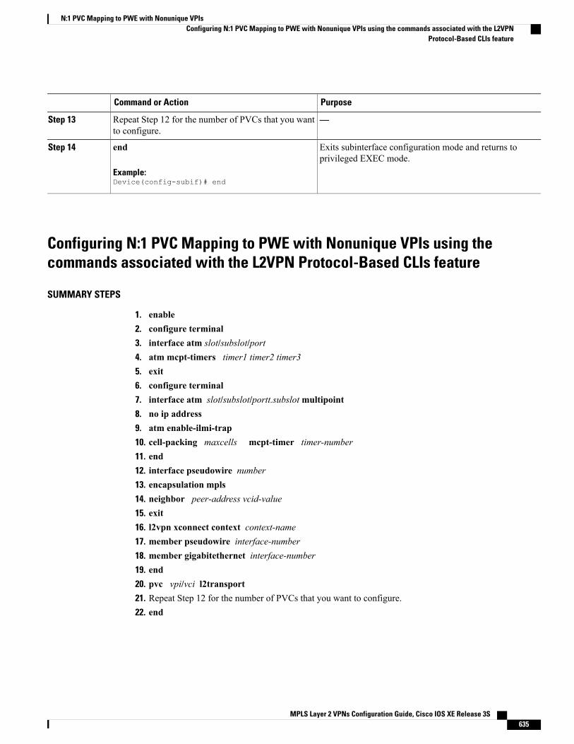
PurposeCommand or Action
—Repeat Step 12 for the number of PVCs that you wantto configure.
Step 13
Exits subinterface configuration mode and returns toprivileged EXEC mode.
end
Example:Device(config-subif)# end
Step 14
Configuring N:1 PVC Mapping to PWE with Nonunique VPIs using thecommands associated with the L2VPN Protocol-Based CLIs feature
SUMMARY STEPS
1. enable2. configure terminal3. interface atm slot/subslot/port4. atm mcpt-timers timer1 timer2 timer35. exit6. configure terminal7. interface atm slot/subslot/portt.subslotmultipoint8. no ip address9. atm enable-ilmi-trap10. cell-packing maxcells mcpt-timer timer-number11. end12. interface pseudowire number13. encapsulation mpls14. neighbor peer-address vcid-value15. exit16. l2vpn xconnect context context-name17. member pseudowire interface-number18. member gigabitethernet interface-number19. end20. pvc vpi/vci l2transport21. Repeat Step 12 for the number of PVCs that you want to configure.22. end
MPLS Layer 2 VPNs Configuration Guide, Cisco IOS XE Release 3S 635
N:1 PVC Mapping to PWE with Nonunique VPIsConfiguring N:1 PVC Mapping to PWE with Nonunique VPIs using the commands associated with the L2VPN
Protocol-Based CLIs feature

DETAILED STEPS
PurposeCommand or Action
Enables privileged EXEC mode.enableStep 1
Example:Device> enable
• Enter your password if prompted.
Enters global configuration mode.configure terminal
Example:Device# configure terminal
Step 2
Enables the ATM interface and enters interfaceconfiguration mode.
interface atm slot/subslot/port
Example:Device(config)# interface atm 9/1/1
Step 3
Sets the Maximum Cell Packing Timeout (MCPT) valuesin microseconds.
atm mcpt-timers timer1 timer2 timer3
Example:Device(config-if)# atm mcpt-timers 100 200 300
Step 4
• The MCPT timer sets the time for which the devicewaits for the raw cells (AAL0 encapsulation) to bepacked into a single packet for punting to thepseudowire.
Exits interface configuration mode.exit
Example:Device(config-if)# exit
Step 5
Enters global configuration mode.configure terminal
Example:Device# configure terminal
Step 6
Enters subinterface configuration mode and creates amultipoint subinterface on the given port on the specifiedATM Shared Port Adapter (SPA).
interface atm slot/subslot/portt.subslotmultipoint
Example:Device(config)# interface atm 9/1/1.1multipoint
Step 7
Removes the interface IP address.no ip address
Example:Device(config-subif)# no ip address
Step 8
Generates an Integrated Local Management Interface(ILMI) atmfVccChange trap when an ATM interface orsubinterface is enabled or shut down.
atm enable-ilmi-trap
Example:Device(config-subif)# atm enable-ilmi-trap
Step 9
MPLS Layer 2 VPNs Configuration Guide, Cisco IOS XE Release 3S636
N:1 PVC Mapping to PWE with Nonunique VPIsConfiguring N:1 PVC Mapping to PWE with Nonunique VPIs using the commands associated with the L2VPNProtocol-Based CLIs feature
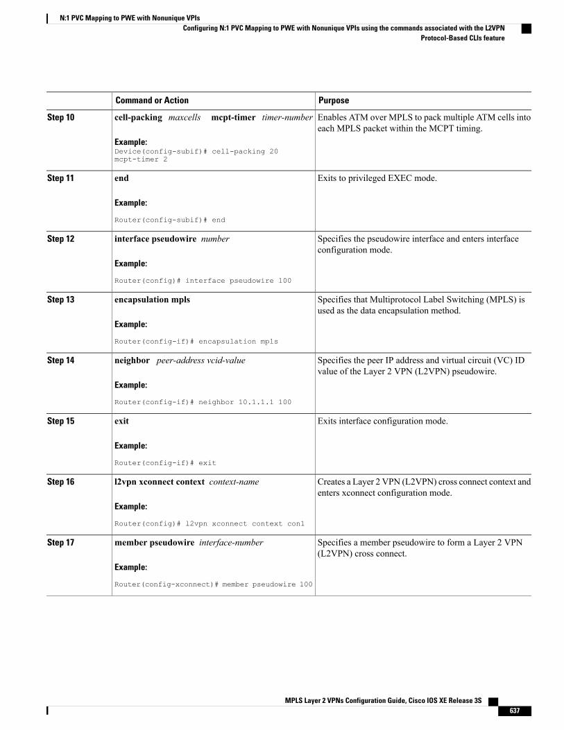
PurposeCommand or Action
Enables ATM over MPLS to pack multiple ATM cells intoeach MPLS packet within the MCPT timing.
cell-packing maxcells mcpt-timer timer-number
Example:Device(config-subif)# cell-packing 20mcpt-timer 2
Step 10
Exits to privileged EXEC mode.end
Example:
Router(config-subif)# end
Step 11
Specifies the pseudowire interface and enters interfaceconfiguration mode.
interface pseudowire number
Example:
Router(config)# interface pseudowire 100
Step 12
Specifies that Multiprotocol Label Switching (MPLS) isused as the data encapsulation method.
encapsulation mpls
Example:
Router(config-if)# encapsulation mpls
Step 13
Specifies the peer IP address and virtual circuit (VC) IDvalue of the Layer 2 VPN (L2VPN) pseudowire.
neighbor peer-address vcid-value
Example:
Router(config-if)# neighbor 10.1.1.1 100
Step 14
Exits interface configuration mode.exit
Example:
Router(config-if)# exit
Step 15
Creates a Layer 2 VPN (L2VPN) cross connect context andenters xconnect configuration mode.
l2vpn xconnect context context-name
Example:
Router(config)# l2vpn xconnect context con1
Step 16
Specifies a member pseudowire to form a Layer 2 VPN(L2VPN) cross connect.
member pseudowire interface-number
Example:
Router(config-xconnect)# member pseudowire 100
Step 17
MPLS Layer 2 VPNs Configuration Guide, Cisco IOS XE Release 3S 637
N:1 PVC Mapping to PWE with Nonunique VPIsConfiguring N:1 PVC Mapping to PWE with Nonunique VPIs using the commands associated with the L2VPN
Protocol-Based CLIs feature
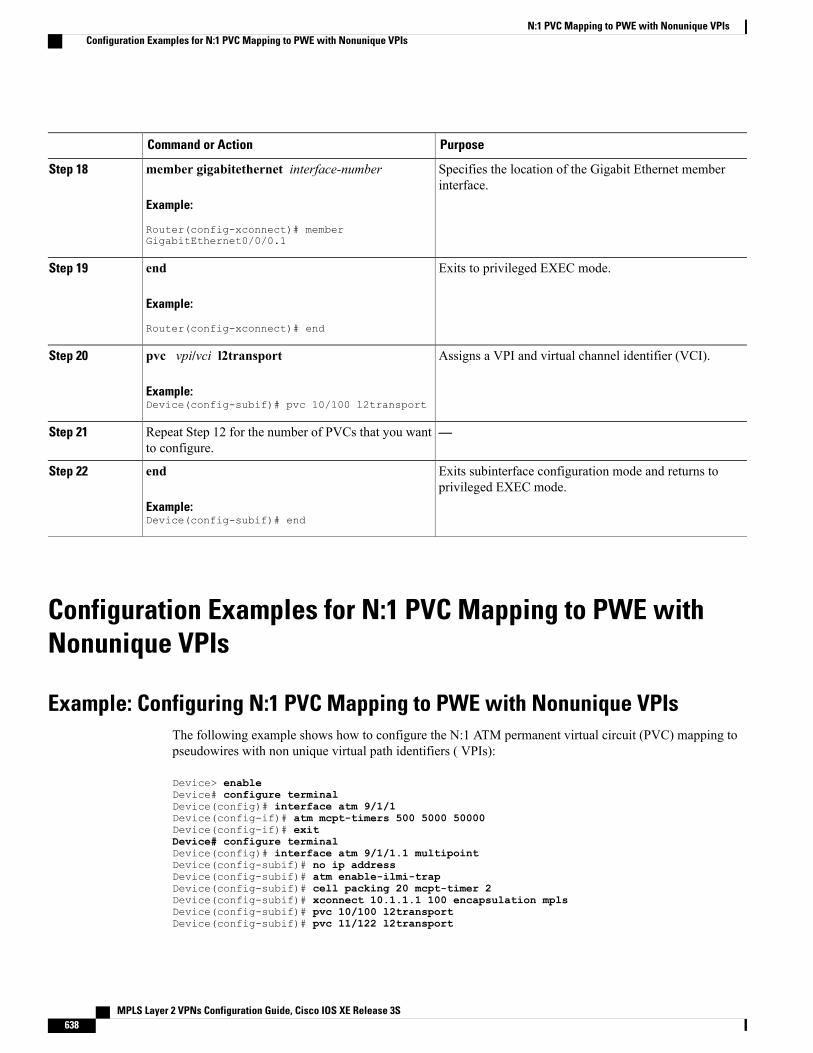
PurposeCommand or Action
Specifies the location of the Gigabit Ethernet memberinterface.
member gigabitethernet interface-number
Example:
Router(config-xconnect)# memberGigabitEthernet0/0/0.1
Step 18
Exits to privileged EXEC mode.end
Example:
Router(config-xconnect)# end
Step 19
Assigns a VPI and virtual channel identifier (VCI).pvc vpi/vci l2transport
Example:Device(config-subif)# pvc 10/100 l2transport
Step 20
—Repeat Step 12 for the number of PVCs that you wantto configure.
Step 21
Exits subinterface configuration mode and returns toprivileged EXEC mode.
end
Example:Device(config-subif)# end
Step 22
Configuration Examples for N:1 PVC Mapping to PWE withNonunique VPIs
Example: Configuring N:1 PVC Mapping to PWE with Nonunique VPIsThe following example shows how to configure the N:1 ATM permanent virtual circuit (PVC) mapping topseudowires with non unique virtual path identifiers ( VPIs):
Device> enableDevice# configure terminalDevice(config)# interface atm 9/1/1Device(config-if)# atm mcpt-timers 500 5000 50000Device(config-if)# exitDevice# configure terminalDevice(config)# interface atm 9/1/1.1 multipointDevice(config-subif)# no ip addressDevice(config-subif)# atm enable-ilmi-trapDevice(config-subif)# cell packing 20 mcpt-timer 2Device(config-subif)# xconnect 10.1.1.1 100 encapsulation mplsDevice(config-subif)# pvc 10/100 l2transportDevice(config-subif)# pvc 11/122 l2transport
MPLS Layer 2 VPNs Configuration Guide, Cisco IOS XE Release 3S638
N:1 PVC Mapping to PWE with Nonunique VPIsConfiguration Examples for N:1 PVC Mapping to PWE with Nonunique VPIs
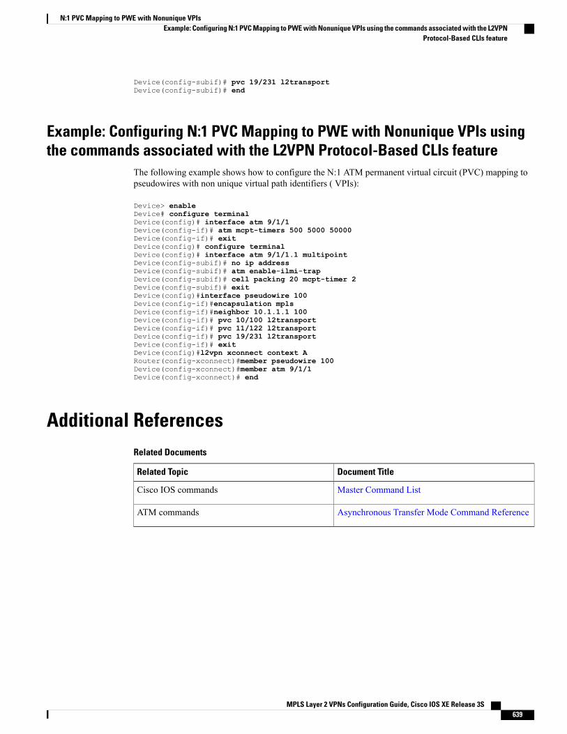
Device(config-subif)# pvc 19/231 l2transportDevice(config-subif)# end
Example: Configuring N:1 PVC Mapping to PWE with Nonunique VPIs usingthe commands associated with the L2VPN Protocol-Based CLIs feature
The following example shows how to configure the N:1 ATM permanent virtual circuit (PVC) mapping topseudowires with non unique virtual path identifiers ( VPIs):
Device> enableDevice# configure terminalDevice(config)# interface atm 9/1/1Device(config-if)# atm mcpt-timers 500 5000 50000Device(config-if)# exitDevice(config)# configure terminalDevice(config)# interface atm 9/1/1.1 multipointDevice(config-subif)# no ip addressDevice(config-subif)# atm enable-ilmi-trapDevice(config-subif)# cell packing 20 mcpt-timer 2Device(config-subif)# exitDevice(config)#interface pseudowire 100Device(config-if)#encapsulation mplsDevice(config-if)#neighbor 10.1.1.1 100Device(config-if)# pvc 10/100 l2transportDevice(config-if)# pvc 11/122 l2transportDevice(config-if)# pvc 19/231 l2transportDevice(config-if)# exitDevice(config)#l2vpn xconnect context ARouter(config-xconnect)#member pseudowire 100Device(config-xconnect)#member atm 9/1/1Device(config-xconnect)# end
Additional ReferencesRelated Documents
Document TitleRelated Topic
Master Command ListCisco IOS commands
Asynchronous Transfer Mode Command ReferenceATM commands
MPLS Layer 2 VPNs Configuration Guide, Cisco IOS XE Release 3S 639
N:1 PVC Mapping to PWE with Nonunique VPIsExample: Configuring N:1 PVC Mapping to PWE with Nonunique VPIs using the commands associated with the L2VPN
Protocol-Based CLIs feature
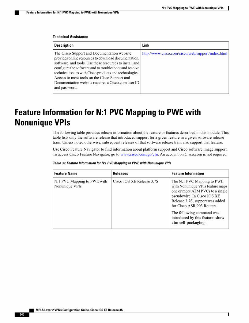
Technical Assistance
LinkDescription
http://www.cisco.com/cisco/web/support/index.htmlThe Cisco Support and Documentation websiteprovides online resources to download documentation,software, and tools. Use these resources to install andconfigure the software and to troubleshoot and resolvetechnical issues with Cisco products and technologies.Access to most tools on the Cisco Support andDocumentation website requires a Cisco.com user IDand password.
Feature Information for N:1 PVC Mapping to PWE withNonunique VPIs
The following table provides release information about the feature or features described in this module. Thistable lists only the software release that introduced support for a given feature in a given software releasetrain. Unless noted otherwise, subsequent releases of that software release train also support that feature.
Use Cisco Feature Navigator to find information about platform support and Cisco software image support.To access Cisco Feature Navigator, go to www.cisco.com/go/cfn. An account on Cisco.com is not required.
Table 38: Feature Information for N:1 PVC Mapping to PWE with Nonunique VPIs
Feature InformationReleasesFeature Name
The N:1 PVC Mapping to PWEwith Nonunique VPIs featuremapsone or more ATMPVCs to a singlepseudowire. In Cisco IOS XERelease 3.7S, support was addedfor Cisco ASR 903 Routers.
The following command wasintroduced by this feature: showatm cell-packaging .
Cisco IOS XE Release 3.7SN:1 PVC Mapping to PWE withNonunique VPIs
MPLS Layer 2 VPNs Configuration Guide, Cisco IOS XE Release 3S640
N:1 PVC Mapping to PWE with Nonunique VPIsFeature Information for N:1 PVC Mapping to PWE with Nonunique VPIs

C H A P T E R 23QoS Policies for VFI Pseudowires
• Finding Feature Information, page 641
• Restrictions for QoS Policies for VFI Pseudowires, page 641
• Information About QoS Policies for VFI Pseudowires, page 642
• How to Configure QoS Policies for VFI Pseudowires, page 642
• Configuration Examples for QoS Policies for VFI Pseudowires, page 666
• Additional References for QoS Policies for VFI Pseudowires, page 669
• Feature Information For QoS Policies for VFI Pseudowires, page 670
Finding Feature InformationYour software release may not support all the features documented in this module. For the latest caveats andfeature information, see Bug Search Tool and the release notes for your platform and software release. Tofind information about the features documented in this module, and to see a list of the releases in which eachfeature is supported, see the feature information table at the end of this module.
Use Cisco Feature Navigator to find information about platform support and Cisco software image support.To access Cisco Feature Navigator, go to www.cisco.com/go/cfn. An account on Cisco.com is not required.
Restrictions for QoS Policies for VFI Pseudowires• A maximum of 32K pseudowires.
• A maximum of 4K unique policy maps.
• A maximum of 128 neighbors per VFI context.
MPLS Layer 2 VPNs Configuration Guide, Cisco IOS XE Release 3S 641
Information About QoS Policies for VFI Pseudowires
QoS Policies for VFI PseudowiresQoS policies are specified on individual pseudowire interfaces and are applied only to the correspondingpseudowires. It is possible to specify different QoS policies on different pseudowire members of the samevirtual forwarding interface (VFI) or on the subset of the pseudowires. There may be one or more pseudowiresconfigured per VFI. Both manually configured and auto discovered pseudowire configurations are supported.
QoS policies are specified using a pseudowire template. The template can be applied on multiple pseudowiresof the same, or different, VFIs. All those pseudowires get the same QoS policy applied as specified in thetemplate. For auto-discovered pseudowires, QoS policies can only be specified using a pseudowire template.
The QoS Policies for VFI Pseudowires feature supports both ingress and egress policies and traffic classificationcan be done based on different match criteria.
How to Configure QoS Policies for VFI Pseudowires
Configuring QoS Policies for PseudowiresPerform this task to configure QoS policies for pseudowires.
MPLS Layer 2 VPNs Configuration Guide, Cisco IOS XE Release 3S642
QoS Policies for VFI PseudowiresInformation About QoS Policies for VFI Pseudowires

Before You Begin
MPLS Layer 2 VPNs Configuration Guide, Cisco IOS XE Release 3S 643
QoS Policies for VFI PseudowiresConfiguring QoS Policies for Pseudowires

SUMMARY STEPS
1. enable2. configure terminal3. policy-map policy-map-name4. class class-map-name5. priority bandwidth-kbps6. exit7. class class-map-name8. bandwidth percent percentage9. exit10. class class-map-name11. police cir bps12. exit13. class class-map-name14. shape average bps15. queue-limit queue-limit size packets16. random-detect17. exit18. exit19. policy-map policy-map-name20. class class-map-name21. shape average bps22. service-policy policy-map23. exit24. exit25. policy-map policy-map-name26. class class-map-name27. shape average bps28. exit29. exit30. policy-map policy-map-name31. class class-map-name32. shape average bps33. exit34. exit35. exit policy-map policy-map-name36. class class-map-name37. shape average bps38. exit39. exit
MPLS Layer 2 VPNs Configuration Guide, Cisco IOS XE Release 3S644
QoS Policies for VFI PseudowiresConfiguring QoS Policies for Pseudowires
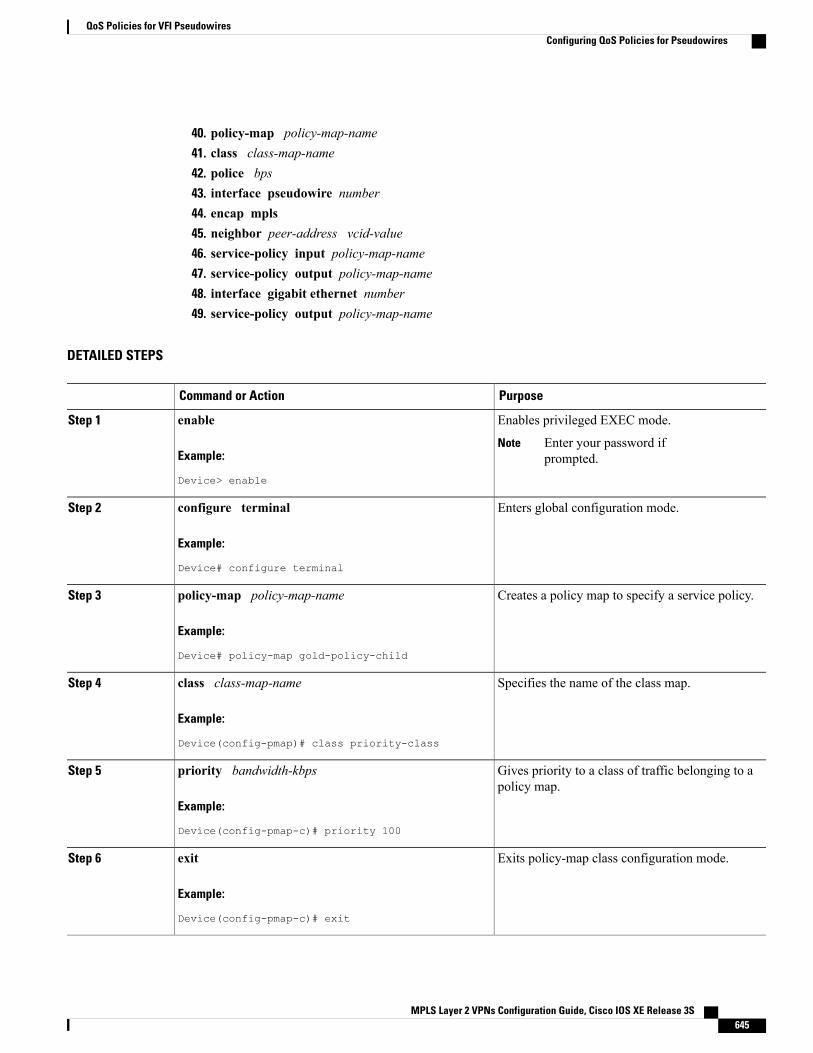
40. policy-map policy-map-name41. class class-map-name42. police bps43. interface pseudowire number44. encap mpls45. neighbor peer-address vcid-value46. service-policy input policy-map-name47. service-policy output policy-map-name48. interface gigabit ethernet number49. service-policy output policy-map-name
DETAILED STEPS
PurposeCommand or Action
Enables privileged EXEC mode.enableStep 1
Example:
Device> enable
Enter your password ifprompted.
Note
Enters global configuration mode.configure terminal
Example:
Device# configure terminal
Step 2
Creates a policy map to specify a service policy.policy-map policy-map-name
Example:
Device# policy-map gold-policy-child
Step 3
Specifies the name of the class map.class class-map-name
Example:
Device(config-pmap)# class priority-class
Step 4
Gives priority to a class of traffic belonging to apolicy map.
priority bandwidth-kbps
Example:
Device(config-pmap-c)# priority 100
Step 5
Exits policy-map class configuration mode.exit
Example:
Device(config-pmap-c)# exit
Step 6
MPLS Layer 2 VPNs Configuration Guide, Cisco IOS XE Release 3S 645
QoS Policies for VFI PseudowiresConfiguring QoS Policies for Pseudowires

PurposeCommand or Action
Specifies the name of the class map.class class-map-name
Example:
Device(config-pmap-c)# class guarantee-class
Step 7
Specifies or modifies the bandwidth allocated fora class belonging to a policy map.
bandwidth percent percentage
Example:
Device(config-pmap-c)# bandwidth percent 50
Step 8
Exits policy-map class configuration mode.exit
Example:
Device(config-pmap-c)# exit
Step 9
Specifies the name of the class map.class class-map-name
Example:
Device(config-pmap-c)# class limited-class
Step 10
Creates a per-interface policer and configures thepolicy-map class to use it.
police cir bps
Example:
Device(config-pmap-c)# police cir 8000
Step 11
Exits policy-map class configuration mode.exit
Example:
Device(config-pmap-c)# exit
Step 12
Specifies the name of the class map.class class-map-name
Example:
Device(config-pmap)# class class-default
Step 13
Shapes traffic to the indicated bit rate.shape average bps
Example:
Device(config-pmap-c)# shape average 8000
Step 14
MPLS Layer 2 VPNs Configuration Guide, Cisco IOS XE Release 3S646
QoS Policies for VFI PseudowiresConfiguring QoS Policies for Pseudowires
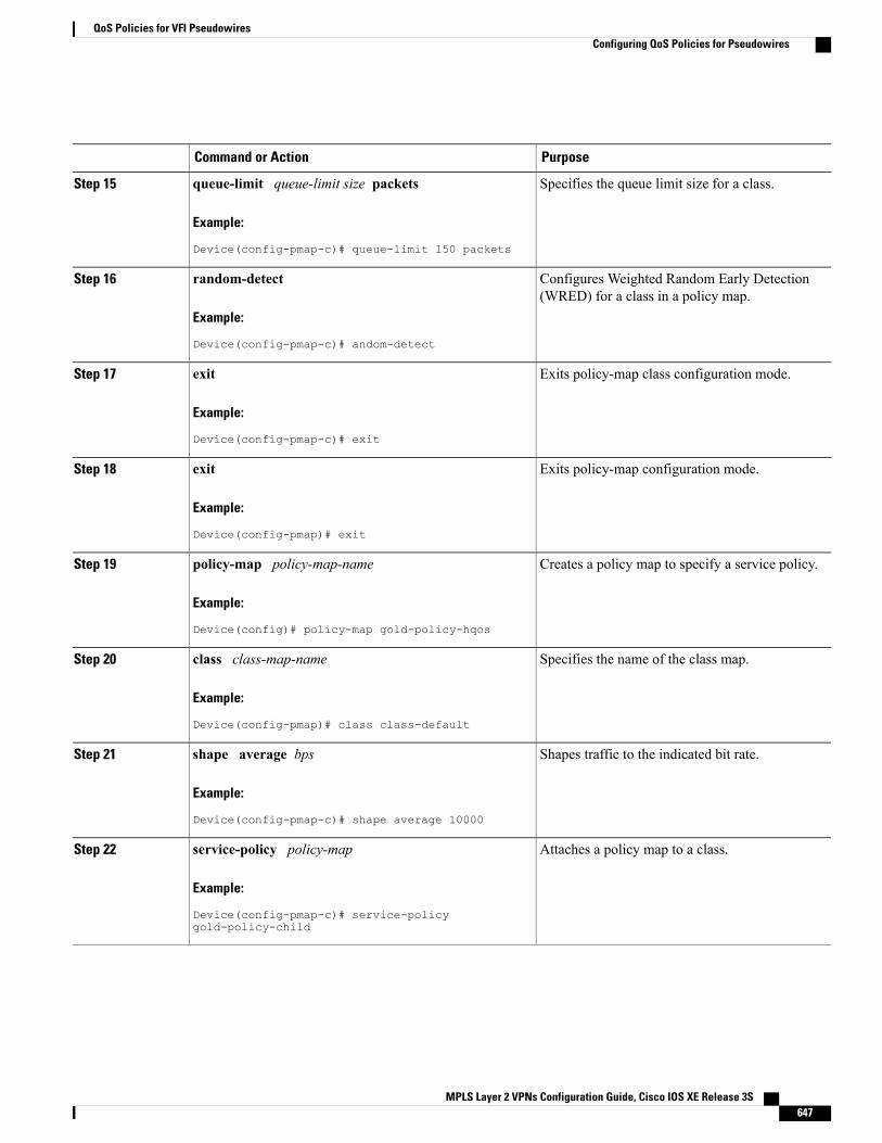
PurposeCommand or Action
Specifies the queue limit size for a class.queue-limit queue-limit size packets
Example:
Device(config-pmap-c)# queue-limit 150 packets
Step 15
Configures Weighted Random Early Detection(WRED) for a class in a policy map.
random-detect
Example:
Device(config-pmap-c)# andom-detect
Step 16
Exits policy-map class configuration mode.exit
Example:
Device(config-pmap-c)# exit
Step 17
Exits policy-map configuration mode.exit
Example:
Device(config-pmap)# exit
Step 18
Creates a policy map to specify a service policy.policy-map policy-map-name
Example:
Device(config)# policy-map gold-policy-hqos
Step 19
Specifies the name of the class map.class class-map-name
Example:
Device(config-pmap)# class class-default
Step 20
Shapes traffic to the indicated bit rate.shape average bps
Example:
Device(config-pmap-c)# shape average 10000
Step 21
Attaches a policy map to a class.service-policy policy-map
Example:
Device(config-pmap-c)# service-policygold-policy-child
Step 22
MPLS Layer 2 VPNs Configuration Guide, Cisco IOS XE Release 3S 647
QoS Policies for VFI PseudowiresConfiguring QoS Policies for Pseudowires
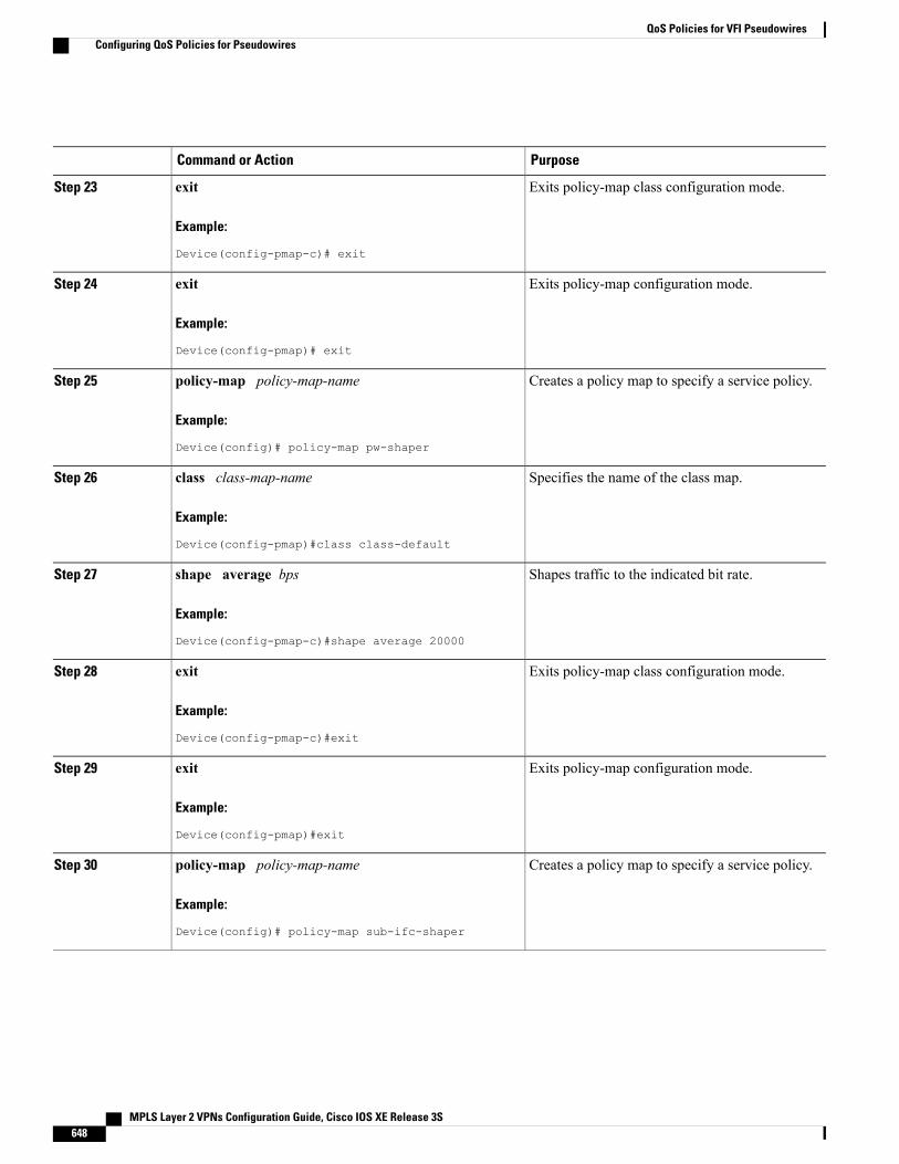
PurposeCommand or Action
Exits policy-map class configuration mode.exit
Example:
Device(config-pmap-c)# exit
Step 23
Exits policy-map configuration mode.exit
Example:
Device(config-pmap)# exit
Step 24
Creates a policy map to specify a service policy.policy-map policy-map-name
Example:
Device(config)# policy-map pw-shaper
Step 25
Specifies the name of the class map.class class-map-name
Example:
Device(config-pmap)#class class-default
Step 26
Shapes traffic to the indicated bit rate.shape average bps
Example:
Device(config-pmap-c)#shape average 20000
Step 27
Exits policy-map class configuration mode.exit
Example:
Device(config-pmap-c)#exit
Step 28
Exits policy-map configuration mode.exit
Example:
Device(config-pmap)#exit
Step 29
Creates a policy map to specify a service policy.policy-map policy-map-name
Example:
Device(config)# policy-map sub-ifc-shaper
Step 30
MPLS Layer 2 VPNs Configuration Guide, Cisco IOS XE Release 3S648
QoS Policies for VFI PseudowiresConfiguring QoS Policies for Pseudowires
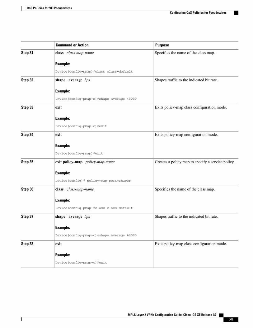
PurposeCommand or Action
Specifies the name of the class map.class class-map-name
Example:
Device(config-pmap)#class class-default
Step 31
Shapes traffic to the indicated bit rate.shape average bps
Example:
Device(config-pmap-c)#shape average 40000
Step 32
Exits policy-map class configuration mode.exit
Example:
Device(config-pmap-c)#exit
Step 33
Exits policy-map configuration mode.exit
Example:
Device(config-pmap)#exit
Step 34
Creates a policy map to specify a service policy.exit policy-map policy-map-name
Example:
Device(config)# policy-map port-shaper
Step 35
Specifies the name of the class map.class class-map-name
Example:
Device(config-pmap)#class class-default
Step 36
Shapes traffic to the indicated bit rate.shape average bps
Example:
Device(config-pmap-c)#shape average 60000
Step 37
Exits policy-map class configuration mode.exit
Example:
Device(config-pmap-c)#exit
Step 38
MPLS Layer 2 VPNs Configuration Guide, Cisco IOS XE Release 3S 649
QoS Policies for VFI PseudowiresConfiguring QoS Policies for Pseudowires
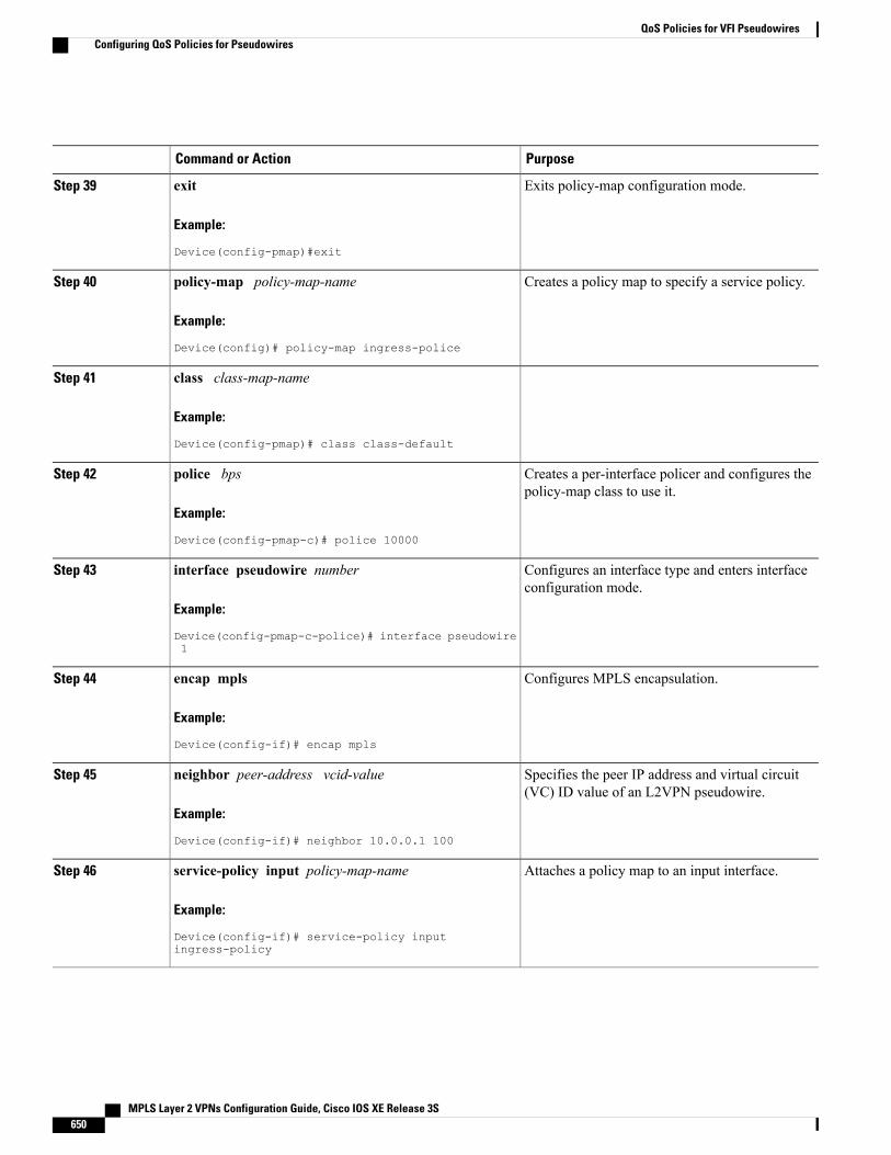
PurposeCommand or Action
Exits policy-map configuration mode.exit
Example:
Device(config-pmap)#exit
Step 39
Creates a policy map to specify a service policy.policy-map policy-map-name
Example:
Device(config)# policy-map ingress-police
Step 40
class class-map-nameStep 41
Example:
Device(config-pmap)# class class-default
Creates a per-interface policer and configures thepolicy-map class to use it.
police bps
Example:
Device(config-pmap-c)# police 10000
Step 42
Configures an interface type and enters interfaceconfiguration mode.
interface pseudowire number
Example:
Device(config-pmap-c-police)# interface pseudowire1
Step 43
Configures MPLS encapsulation.encap mpls
Example:
Device(config-if)# encap mpls
Step 44
Specifies the peer IP address and virtual circuit(VC) ID value of an L2VPN pseudowire.
neighbor peer-address vcid-value
Example:
Device(config-if)# neighbor 10.0.0.1 100
Step 45
Attaches a policy map to an input interface.service-policy input policy-map-name
Example:
Device(config-if)# service-policy inputingress-policy
Step 46
MPLS Layer 2 VPNs Configuration Guide, Cisco IOS XE Release 3S650
QoS Policies for VFI PseudowiresConfiguring QoS Policies for Pseudowires
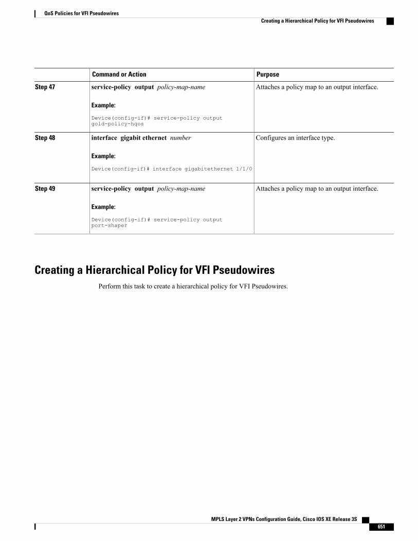
PurposeCommand or Action
Attaches a policy map to an output interface.service-policy output policy-map-name
Example:
Device(config-if)# service-policy outputgold-policy-hqos
Step 47
Configures an interface type.interface gigabit ethernet number
Example:
Device(config-if)# interface gigabitethernet 1/1/0
Step 48
Attaches a policy map to an output interface.service-policy output policy-map-name
Example:
Device(config-if)# service-policy outputport-shaper
Step 49
Creating a Hierarchical Policy for VFI PseudowiresPerform this task to create a hierarchical policy for VFI Pseudowires.
MPLS Layer 2 VPNs Configuration Guide, Cisco IOS XE Release 3S 651
QoS Policies for VFI PseudowiresCreating a Hierarchical Policy for VFI Pseudowires
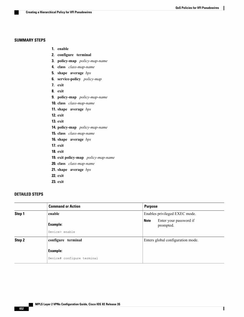
SUMMARY STEPS
1. enable2. configure terminal3. policy-map policy-map-name4. class class-map-name5. shape average bps6. service-policy policy-map7. exit8. exit9. policy-map policy-map-name10. class class-map-name11. shape average bps12. exit13. exit14. policy-map policy-map-name15. class class-map-name16. shape average bps17. exit18. exit19. exit policy-map policy-map-name20. class class-map-name21. shape average bps22. exit23. exit
DETAILED STEPS
PurposeCommand or Action
Enables privileged EXEC mode.enableStep 1
Example:
Device> enable
Enter your password ifprompted.
Note
Enters global configuration mode.configure terminal
Example:
Device# configure terminal
Step 2
MPLS Layer 2 VPNs Configuration Guide, Cisco IOS XE Release 3S652
QoS Policies for VFI PseudowiresCreating a Hierarchical Policy for VFI Pseudowires
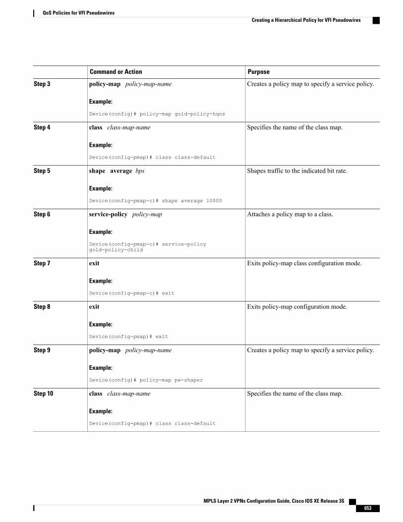
PurposeCommand or Action
Creates a policy map to specify a service policy.policy-map policy-map-name
Example:
Device(config)# policy-map gold-policy-hqos
Step 3
Specifies the name of the class map.class class-map-name
Example:
Device(config-pmap)# class class-default
Step 4
Shapes traffic to the indicated bit rate.shape average bps
Example:
Device(config-pmap-c)# shape average 10000
Step 5
Attaches a policy map to a class.service-policy policy-map
Example:
Device(config-pmap-c)# service-policygold-policy-child
Step 6
Exits policy-map class configuration mode.exit
Example:
Device(config-pmap-c)# exit
Step 7
Exits policy-map configuration mode.exit
Example:
Device(config-pmap)# exit
Step 8
Creates a policy map to specify a service policy.policy-map policy-map-name
Example:
Device(config)# policy-map pw-shaper
Step 9
Specifies the name of the class map.class class-map-name
Example:
Device(config-pmap)# class class-default
Step 10
MPLS Layer 2 VPNs Configuration Guide, Cisco IOS XE Release 3S 653
QoS Policies for VFI PseudowiresCreating a Hierarchical Policy for VFI Pseudowires
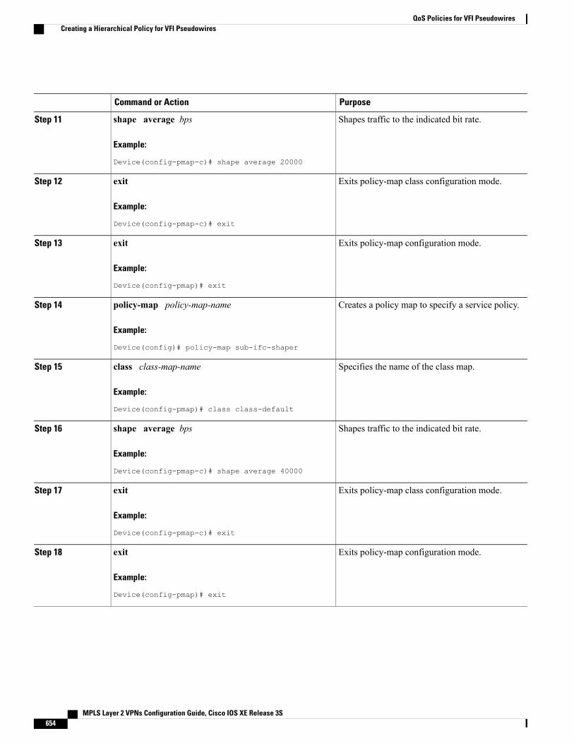
PurposeCommand or Action
Shapes traffic to the indicated bit rate.shape average bps
Example:
Device(config-pmap-c)# shape average 20000
Step 11
Exits policy-map class configuration mode.exit
Example:
Device(config-pmap-c)# exit
Step 12
Exits policy-map configuration mode.exit
Example:
Device(config-pmap)# exit
Step 13
Creates a policy map to specify a service policy.policy-map policy-map-name
Example:
Device(config)# policy-map sub-ifc-shaper
Step 14
Specifies the name of the class map.class class-map-name
Example:
Device(config-pmap)# class class-default
Step 15
Shapes traffic to the indicated bit rate.shape average bps
Example:
Device(config-pmap-c)# shape average 40000
Step 16
Exits policy-map class configuration mode.exit
Example:
Device(config-pmap-c)# exit
Step 17
Exits policy-map configuration mode.exit
Example:
Device(config-pmap)# exit
Step 18
MPLS Layer 2 VPNs Configuration Guide, Cisco IOS XE Release 3S654
QoS Policies for VFI PseudowiresCreating a Hierarchical Policy for VFI Pseudowires
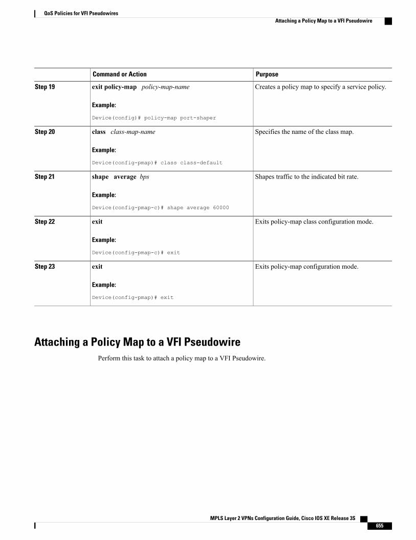
PurposeCommand or Action
Creates a policy map to specify a service policy.exit policy-map policy-map-name
Example:
Device(config)# policy-map port-shaper
Step 19
Specifies the name of the class map.class class-map-name
Example:
Device(config-pmap)# class class-default
Step 20
Shapes traffic to the indicated bit rate.shape average bps
Example:
Device(config-pmap-c)# shape average 60000
Step 21
Exits policy-map class configuration mode.exit
Example:
Device(config-pmap-c)# exit
Step 22
Exits policy-map configuration mode.exit
Example:
Device(config-pmap)# exit
Step 23
Attaching a Policy Map to a VFI PseudowirePerform this task to attach a policy map to a VFI Pseudowire.
MPLS Layer 2 VPNs Configuration Guide, Cisco IOS XE Release 3S 655
QoS Policies for VFI PseudowiresAttaching a Policy Map to a VFI Pseudowire
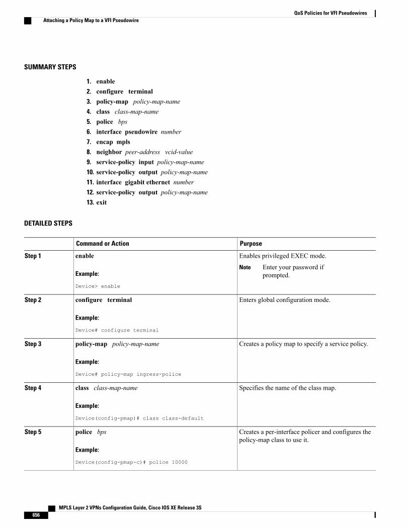
SUMMARY STEPS
1. enable2. configure terminal3. policy-map policy-map-name4. class class-map-name5. police bps6. interface pseudowire number7. encap mpls8. neighbor peer-address vcid-value9. service-policy input policy-map-name10. service-policy output policy-map-name11. interface gigabit ethernet number12. service-policy output policy-map-name13. exit
DETAILED STEPS
PurposeCommand or Action
Enables privileged EXEC mode.enableStep 1
Example:
Device> enable
Enter your password ifprompted.
Note
Enters global configuration mode.configure terminal
Example:
Device# configure terminal
Step 2
Creates a policy map to specify a service policy.policy-map policy-map-name
Example:
Device# policy-map ingress-police
Step 3
Specifies the name of the class map.class class-map-name
Example:
Device(config-pmap)# class class-default
Step 4
Creates a per-interface policer and configures thepolicy-map class to use it.
police bps
Example:
Device(config-pmap-c)# police 10000
Step 5
MPLS Layer 2 VPNs Configuration Guide, Cisco IOS XE Release 3S656
QoS Policies for VFI PseudowiresAttaching a Policy Map to a VFI Pseudowire
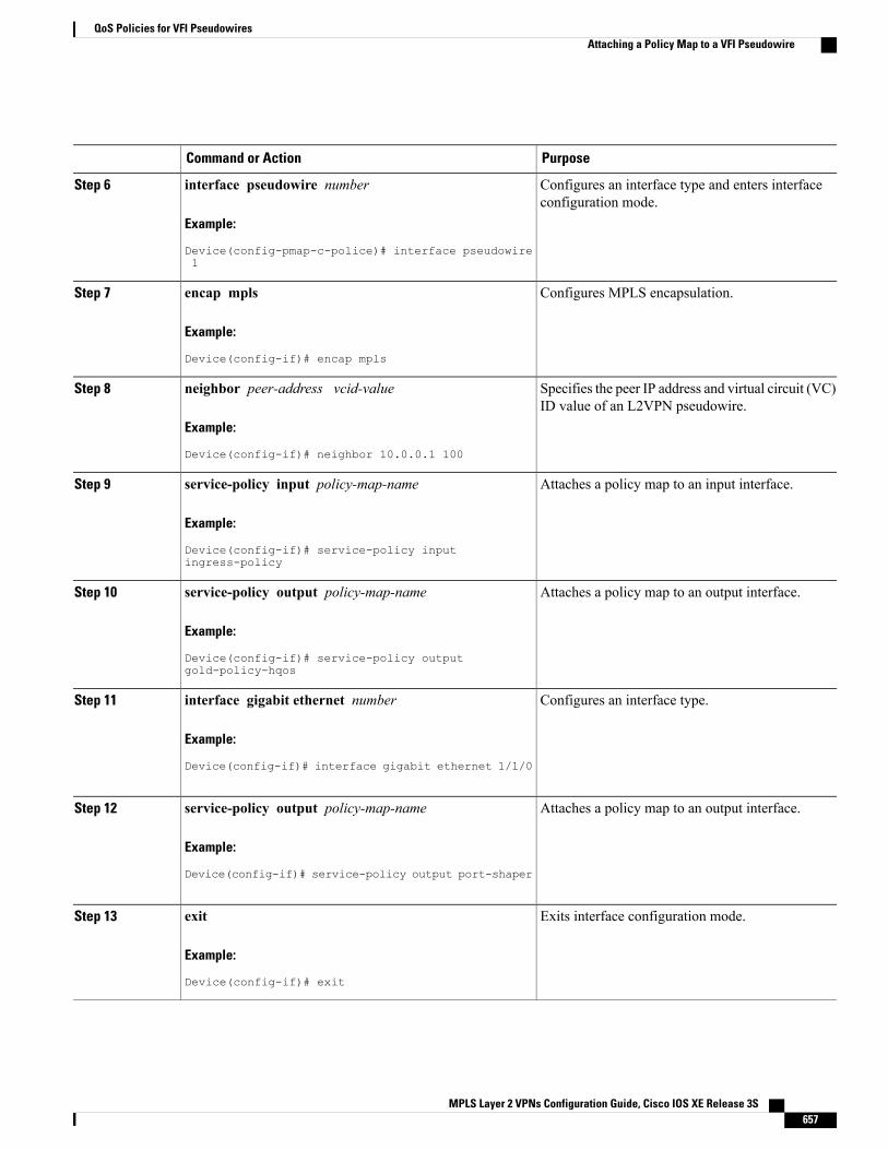
PurposeCommand or Action
Configures an interface type and enters interfaceconfiguration mode.
interface pseudowire number
Example:
Device(config-pmap-c-police)# interface pseudowire1
Step 6
Configures MPLS encapsulation.encap mpls
Example:
Device(config-if)# encap mpls
Step 7
Specifies the peer IP address and virtual circuit (VC)ID value of an L2VPN pseudowire.
neighbor peer-address vcid-value
Example:
Device(config-if)# neighbor 10.0.0.1 100
Step 8
Attaches a policy map to an input interface.service-policy input policy-map-name
Example:
Device(config-if)# service-policy inputingress-policy
Step 9
Attaches a policy map to an output interface.service-policy output policy-map-name
Example:
Device(config-if)# service-policy outputgold-policy-hqos
Step 10
Configures an interface type.interface gigabit ethernet number
Example:
Device(config-if)# interface gigabit ethernet 1/1/0
Step 11
Attaches a policy map to an output interface.service-policy output policy-map-name
Example:
Device(config-if)# service-policy output port-shaper
Step 12
Exits interface configuration mode.exit
Example:
Device(config-if)# exit
Step 13
MPLS Layer 2 VPNs Configuration Guide, Cisco IOS XE Release 3S 657
QoS Policies for VFI PseudowiresAttaching a Policy Map to a VFI Pseudowire
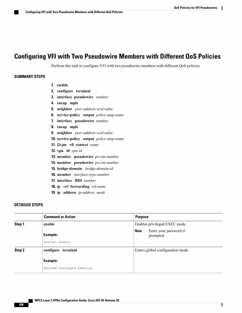
Configuring VFI with Two Pseudowire Members with Different QoS PoliciesPerform this task to configure VFI with two pseudowire members with different QoS policies.
SUMMARY STEPS
1. enable2. configure terminal3. interface pseudowire number4. encap mpls5. neighbor peer-address vcid value6. service-policy output policy-map-name7. interface pseudowire number8. encap mpls9. neighbor peer-address vcid value10. service-policy output policy-map-name11. l2vpn vfi context name12. vpn id vpn-id13. member pseudowire pw-int-number14. member pseudowire pw-int-number15. bridge-domain bridge-domain-id16. member interface-type-number17. interface BDI number18. ip vrf forwarding vrf-name19. ip address ip-address mask
DETAILED STEPS
PurposeCommand or Action
Enables privileged EXEC mode.enableStep 1
Example:
Device> enable
Enter your password ifprompted.
Note
Enters global configuration mode.configure terminal
Example:
Device# configure terminal
Step 2
MPLS Layer 2 VPNs Configuration Guide, Cisco IOS XE Release 3S658
QoS Policies for VFI PseudowiresConfiguring VFI with Two Pseudowire Members with Different QoS Policies
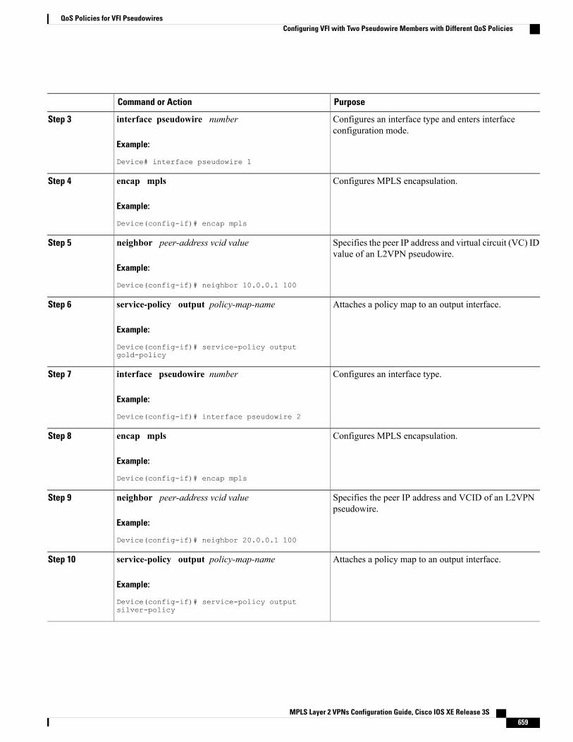
PurposeCommand or Action
Configures an interface type and enters interfaceconfiguration mode.
interface pseudowire number
Example:
Device# interface pseudowire 1
Step 3
Configures MPLS encapsulation.encap mpls
Example:
Device(config-if)# encap mpls
Step 4
Specifies the peer IP address and virtual circuit (VC) IDvalue of an L2VPN pseudowire.
neighbor peer-address vcid value
Example:
Device(config-if)# neighbor 10.0.0.1 100
Step 5
Attaches a policy map to an output interface.service-policy output policy-map-name
Example:
Device(config-if)# service-policy outputgold-policy
Step 6
Configures an interface type.interface pseudowire number
Example:
Device(config-if)# interface pseudowire 2
Step 7
Configures MPLS encapsulation.encap mpls
Example:
Device(config-if)# encap mpls
Step 8
Specifies the peer IP address and VCID of an L2VPNpseudowire.
neighbor peer-address vcid value
Example:
Device(config-if)# neighbor 20.0.0.1 100
Step 9
Attaches a policy map to an output interface.service-policy output policy-map-name
Example:
Device(config-if)# service-policy outputsilver-policy
Step 10
MPLS Layer 2 VPNs Configuration Guide, Cisco IOS XE Release 3S 659
QoS Policies for VFI PseudowiresConfiguring VFI with Two Pseudowire Members with Different QoS Policies
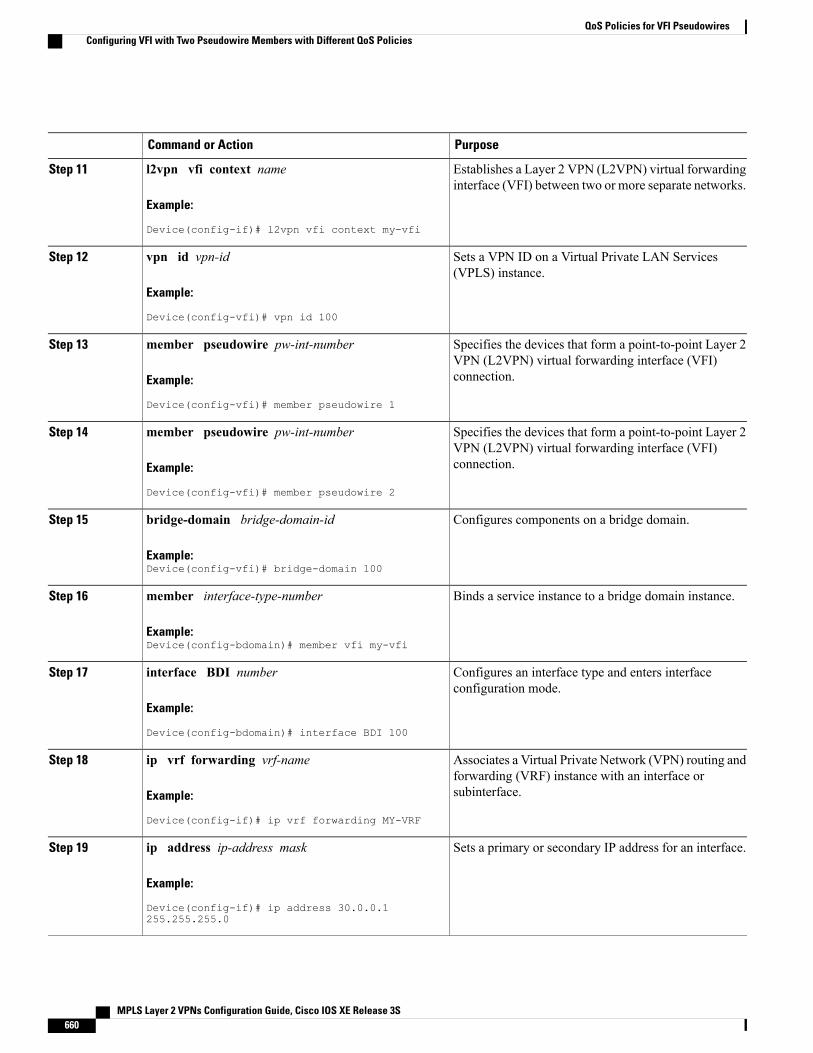
PurposeCommand or Action
Establishes a Layer 2 VPN (L2VPN) virtual forwardinginterface (VFI) between two or more separate networks.
l2vpn vfi context name
Example:
Device(config-if)# l2vpn vfi context my-vfi
Step 11
Sets a VPN ID on a Virtual Private LAN Services(VPLS) instance.
vpn id vpn-id
Example:
Device(config-vfi)# vpn id 100
Step 12
Specifies the devices that form a point-to-point Layer 2VPN (L2VPN) virtual forwarding interface (VFI)connection.
member pseudowire pw-int-number
Example:
Device(config-vfi)# member pseudowire 1
Step 13
Specifies the devices that form a point-to-point Layer 2VPN (L2VPN) virtual forwarding interface (VFI)connection.
member pseudowire pw-int-number
Example:
Device(config-vfi)# member pseudowire 2
Step 14
Configures components on a bridge domain.bridge-domain bridge-domain-id
Example:Device(config-vfi)# bridge-domain 100
Step 15
Binds a service instance to a bridge domain instance.member interface-type-number
Example:Device(config-bdomain)# member vfi my-vfi
Step 16
Configures an interface type and enters interfaceconfiguration mode.
interface BDI number
Example:
Device(config-bdomain)# interface BDI 100
Step 17
Associates a Virtual Private Network (VPN) routing andforwarding (VRF) instance with an interface orsubinterface.
ip vrf forwarding vrf-name
Example:
Device(config-if)# ip vrf forwarding MY-VRF
Step 18
Sets a primary or secondary IP address for an interface.ip address ip-address mask
Example:
Device(config-if)# ip address 30.0.0.1255.255.255.0
Step 19
MPLS Layer 2 VPNs Configuration Guide, Cisco IOS XE Release 3S660
QoS Policies for VFI PseudowiresConfiguring VFI with Two Pseudowire Members with Different QoS Policies
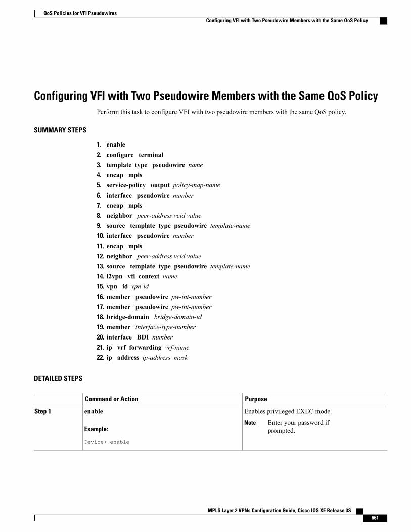
Configuring VFI with Two Pseudowire Members with the Same QoS PolicyPerform this task to configure VFI with two pseudowire members with the same QoS policy.
SUMMARY STEPS
1. enable2. configure terminal3. template type pseudowire name4. encap mpls5. service-policy output policy-map-name6. interface pseudowire number7. encap mpls8. neighbor peer-address vcid value9. source template type pseudowire template-name10. interface pseudowire number11. encap mpls12. neighbor peer-address vcid value13. source template type pseudowire template-name14. l2vpn vfi context name15. vpn id vpn-id16. member pseudowire pw-int-number17. member pseudowire pw-int-number18. bridge-domain bridge-domain-id19. member interface-type-number20. interface BDI number21. ip vrf forwarding vrf-name22. ip address ip-address mask
DETAILED STEPS
PurposeCommand or Action
Enables privileged EXEC mode.enableStep 1
Example:
Device> enable
Enter your password ifprompted.
Note
MPLS Layer 2 VPNs Configuration Guide, Cisco IOS XE Release 3S 661
QoS Policies for VFI PseudowiresConfiguring VFI with Two Pseudowire Members with the Same QoS Policy
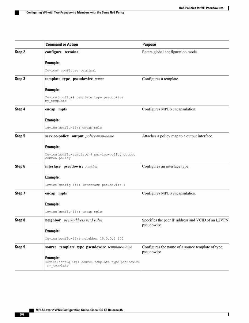
PurposeCommand or Action
Enters global configuration mode.configure terminal
Example:
Device# configure terminal
Step 2
Configures a template.template type pseudowire name
Example:
Device(config)# template type pseudowiremy_template
Step 3
Configures MPLS encapsulation.encap mpls
Example:
Device(config-if)# encap mpls
Step 4
Attaches a policy map to a output interface.service-policy output policy-map-name
Example:
Device(config-template)# service-policy outputcommon-policy
Step 5
Configures an interface type.interface pseudowire number
Example:
Device(config-if)# interface pseudowire 1
Step 6
Configures MPLS encapsulation.encap mpls
Example:
Device(config-if)# encap mpls
Step 7
Specifies the peer IP address and VCID of an L2VPNpseudowire.
neighbor peer-address vcid value
Example:
Device(config-if)# neighbor 10.0.0.1 100
Step 8
Configures the name of a source template of typepseudowire.
source template type pseudowire template-name
Example:Device(config-if)# source template type pseudowiremy_template
Step 9
MPLS Layer 2 VPNs Configuration Guide, Cisco IOS XE Release 3S662
QoS Policies for VFI PseudowiresConfiguring VFI with Two Pseudowire Members with the Same QoS Policy
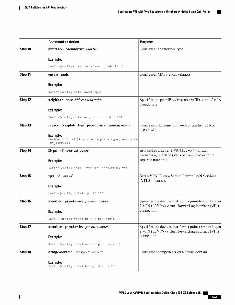
PurposeCommand or Action
Configures an interface type.interface pseudowire number
Example:
Device(config-if)# interface pseudowire 2
Step 10
Configures MPLS encapsulation.encap mpls
Example:
Device(config-if)# encap mpls
Step 11
Specifies the peer IP address and VCID of an L2VPNpseudowire.
neighbor peer-address vcid value
Example:
Device(config-if)# neighbor 20.0.0.1 100
Step 12
Configures the name of a source template of typepseudowire.
source template type pseudowire template-name
Example:Device(config-if)# source template type pseudowiremy_template
Step 13
Establishes a Layer 2 VPN (L2VPN) virtualforwarding interface (VFI) between two or moreseparate networks.
l2vpn vfi context name
Example:
Device(config-if)# l2vpn vfi context my-vfi
Step 14
Sets a VPN ID on a Virtual Private LAN Services(VPLS) instance.
vpn id vpn-id
Example:
Device(config-vfi)# vpn id 100
Step 15
Specifies the devices that form a point-to-point Layer2 VPN (L2VPN) virtual forwarding interface (VFI)connection.
member pseudowire pw-int-number
Example:
Device(config-vfi)# member pseudowire 1
Step 16
Specifies the devices that form a point-to-point Layer2 VPN (L2VPN) virtual forwarding interface (VFI)connection.
member pseudowire pw-int-number
Example:
Device(config-vfi)# member pseudowire 2
Step 17
Configures components on a bridge domain.bridge-domain bridge-domain-id
Example:Device(config-vfi)# bridge-domain 100
Step 18
MPLS Layer 2 VPNs Configuration Guide, Cisco IOS XE Release 3S 663
QoS Policies for VFI PseudowiresConfiguring VFI with Two Pseudowire Members with the Same QoS Policy
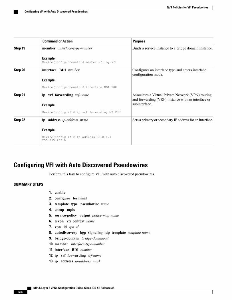
PurposeCommand or Action
Binds a service instance to a bridge domain instance.member interface-type-number
Example:Device(config-bdomain)# member vfi my-vfi
Step 19
Configures an interface type and enters interfaceconfiguration mode.
interface BDI number
Example:
Device(config-bdomain)# interface BDI 100
Step 20
Associates a Virtual Private Network (VPN) routingand forwarding (VRF) instance with an interface orsubinterface.
ip vrf forwarding vrf-name
Example:
Device(config-if)# ip vrf forwarding MY-VRF
Step 21
Sets a primary or secondary IP address for an interface.ip address ip-address mask
Example:
Device(config-if)# ip address 30.0.0.1255.255.255.0
Step 22
Configuring VFI with Auto Discovered PseudowiresPerform this task to configure VFI with auto discovered pseudowires.
SUMMARY STEPS
1. enable2. configure terminal3. template type pseudowire name4. encap mpls5. service-policy output policy-map-name6. l2vpn vfi context name7. vpn id vpn-id8. autodiscovery bgp signaling ldp template template-name9. bridge-domain bridge-domain-id10. member interface-type-number11. interface BDI number12. ip vrf forwarding vrf-name13. ip address ip-address mask
MPLS Layer 2 VPNs Configuration Guide, Cisco IOS XE Release 3S664
QoS Policies for VFI PseudowiresConfiguring VFI with Auto Discovered Pseudowires
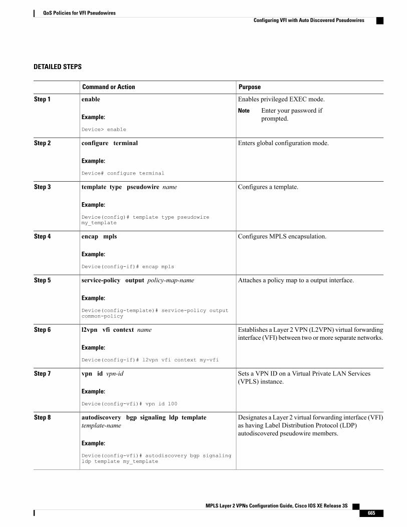
DETAILED STEPS
PurposeCommand or Action
Enables privileged EXEC mode.enableStep 1
Example:
Device> enable
Enter your password ifprompted.
Note
Enters global configuration mode.configure terminal
Example:
Device# configure terminal
Step 2
Configures a template.template type pseudowire name
Example:
Device(config)# template type pseudowiremy_template
Step 3
Configures MPLS encapsulation.encap mpls
Example:
Device(config-if)# encap mpls
Step 4
Attaches a policy map to a output interface.service-policy output policy-map-name
Example:
Device(config-template)# service-policy outputcommon-policy
Step 5
Establishes a Layer 2 VPN (L2VPN) virtual forwardinginterface (VFI) between two or more separate networks.
l2vpn vfi context name
Example:
Device(config-if)# l2vpn vfi context my-vfi
Step 6
Sets a VPN ID on a Virtual Private LAN Services(VPLS) instance.
vpn id vpn-id
Example:
Device(config-vfi)# vpn id 100
Step 7
Designates a Layer 2 virtual forwarding interface (VFI)as having Label Distribution Protocol (LDP)autodiscovered pseudowire members.
autodiscovery bgp signaling ldp templatetemplate-name
Example:
Device(config-vfi)# autodiscovery bgp signalingldp template my_template
Step 8
MPLS Layer 2 VPNs Configuration Guide, Cisco IOS XE Release 3S 665
QoS Policies for VFI PseudowiresConfiguring VFI with Auto Discovered Pseudowires
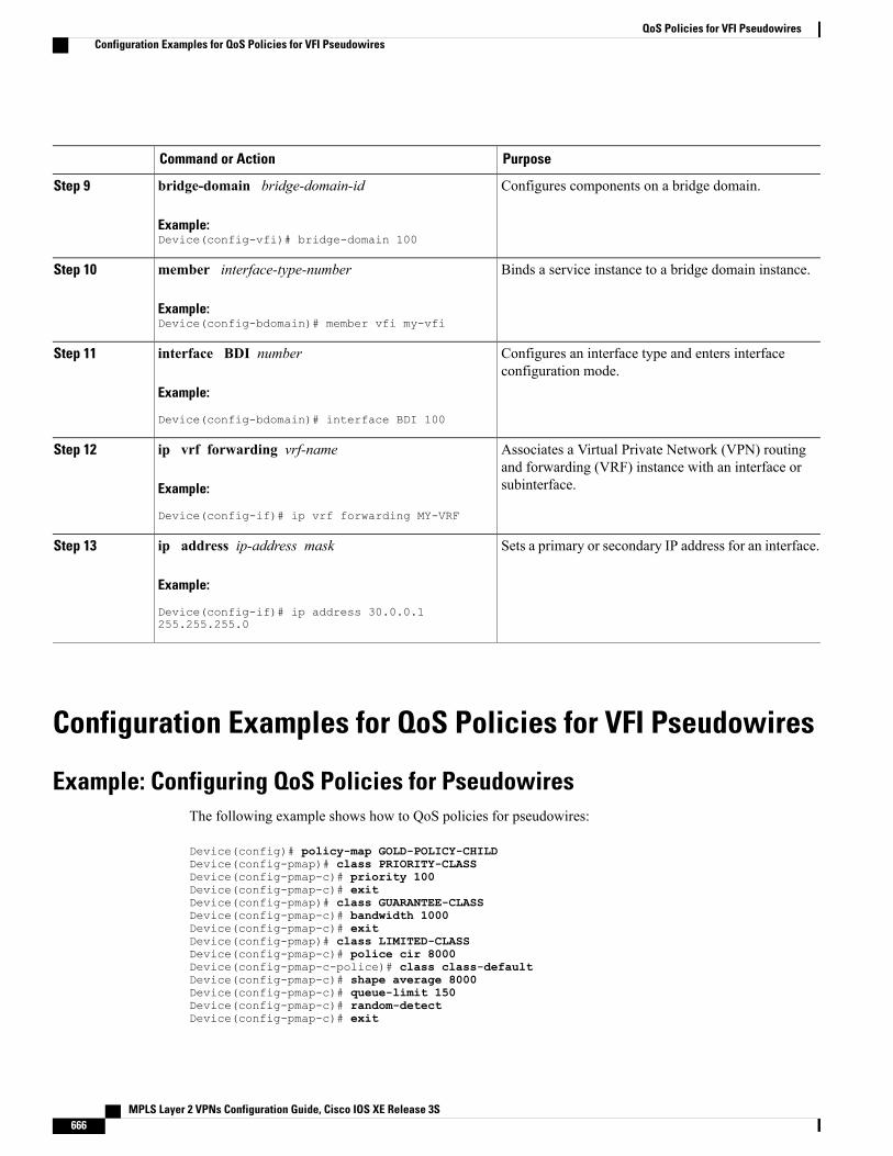
PurposeCommand or Action
Configures components on a bridge domain.bridge-domain bridge-domain-id
Example:Device(config-vfi)# bridge-domain 100
Step 9
Binds a service instance to a bridge domain instance.member interface-type-number
Example:Device(config-bdomain)# member vfi my-vfi
Step 10
Configures an interface type and enters interfaceconfiguration mode.
interface BDI number
Example:
Device(config-bdomain)# interface BDI 100
Step 11
Associates a Virtual Private Network (VPN) routingand forwarding (VRF) instance with an interface orsubinterface.
ip vrf forwarding vrf-name
Example:
Device(config-if)# ip vrf forwarding MY-VRF
Step 12
Sets a primary or secondary IP address for an interface.ip address ip-address mask
Example:
Device(config-if)# ip address 30.0.0.1255.255.255.0
Step 13
Configuration Examples for QoS Policies for VFI Pseudowires
Example: Configuring QoS Policies for PseudowiresThe following example shows how to QoS policies for pseudowires:
Device(config)# policy-map GOLD-POLICY-CHILDDevice(config-pmap)# class PRIORITY-CLASSDevice(config-pmap-c)# priority 100Device(config-pmap-c)# exitDevice(config-pmap)# class GUARANTEE-CLASSDevice(config-pmap-c)# bandwidth 1000Device(config-pmap-c)# exitDevice(config-pmap)# class LIMITED-CLASSDevice(config-pmap-c)# police cir 8000Device(config-pmap-c-police)# class class-defaultDevice(config-pmap-c)# shape average 8000Device(config-pmap-c)# queue-limit 150Device(config-pmap-c)# random-detectDevice(config-pmap-c)# exit
MPLS Layer 2 VPNs Configuration Guide, Cisco IOS XE Release 3S666
QoS Policies for VFI PseudowiresConfiguration Examples for QoS Policies for VFI Pseudowires
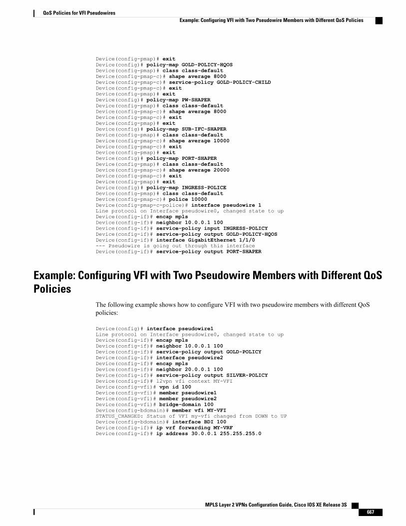
Device(config-pmap)# exitDevice(config)# policy-map GOLD-POLICY-HQOSDevice(config-pmap)# class class-defaultDevice(config-pmap-c)# shape average 8000Device(config-pmap-c)# service-policy GOLD-POLICY-CHILDDevice(config-pmap-c)# exitDevice(config-pmap)# exitDevice(config)# policy-map PW-SHAPERDevice(config-pmap)# class class-defaultDevice(config-pmap-c)# shape average 8000Device(config-pmap-c)# exitDevice(config-pmap)# exitDevice(config)# policy-map SUB-IFC-SHAPERDevice(config-pmap)# class class-defaultDevice(config-pmap-c)# shape average 10000Device(config-pmap-c)# exitDevice(config-pmap)# exitDevice(config)# policy-map PORT-SHAPERDevice(config-pmap)# class class-defaultDevice(config-pmap-c)# shape average 20000Device(config-pmap-c)# exitDevice(config-pmap)# exitDevice(config)# policy-map INGRESS-POLICEDevice(config-pmap)# class class-defaultDevice(config-pmap-c)# police 10000Device(config-pmap-c-police)# interface pseudowire 1Line protocol on Interface pseudowire0, changed state to upDevice(config-if)# encap mplsDevice(config-if)# neighbor 10.0.0.1 100Device(config-if)# service-policy input INGRESS-POLICYDevice(config-if)# service-policy output GOLD-POLICY-HQOSDevice(config-if)# interface GigabitEthernet 1/1/0--- Pseudowire is going out through this interfaceDevice(config-if)# service-policy output PORT-SHAPER
Example: Configuring VFI with Two Pseudowire Members with Different QoSPolicies
The following example shows how to configure VFI with two pseudowire members with different QoSpolicies:
Device(config)# interface pseudowire1Line protocol on Interface pseudowire0, changed state to upDevice(config-if)# encap mplsDevice(config-if)# neighbor 10.0.0.1 100Device(config-if)# service-policy output GOLD-POLICYDevice(config-if)# interface pseudowire2Device(config-if)# encap mplsDevice(config-if)# neighbor 20.0.0.1 100Device(config-if)# service-policy output SILVER-POLICYDevice(config-if)# l2vpn vfi context MY-VFIDevice(config-vfi)# vpn id 100Device(config-vfi)# member pseudowire1Device(config-vfi)# member pseudowire2Device(config-vfi)# bridge-domain 100Device(config-bdomain)# member vfi MY-VFISTATUS_CHANGED: Status of VFI my-vfi changed from DOWN to UPDevice(config-bdomain)# interface BDI 100Device(config-if)# ip vrf forwarding MY-VRFDevice(config-if)# ip address 30.0.0.1 255.255.255.0
MPLS Layer 2 VPNs Configuration Guide, Cisco IOS XE Release 3S 667
QoS Policies for VFI PseudowiresExample: Configuring VFI with Two Pseudowire Members with Different QoS Policies
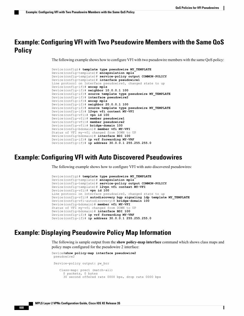
Example: Configuring VFI with Two Pseudowire Members with the Same QoSPolicy
The following example shows how to configure VFI with two pseudowire members with the same QoS policy:
Device(config)# template type pseudowire MY_TEMPLATEDevice(config-template)# encapsulation mplsDevice(config-template)# service-policy output COMMON-POLICYDevice(config-template)# interface pseudowire1Line protocol on Interface pseudowire0, changed state to upDevice(config-if)# encap mplsDevice(config-if)# neighbor 10.0.0.1 100Device(config-if)# source template type pseudowire MY_TEMPLATEDevice(config-if)# interface pseudowire2Device(config-if)# encap mplsDevice(config-if)# neighbor 20.0.0.1 100Device(config-if)# source template type pseudowire MY_TEMPLATEDevice(config-if)# l2vpn vfi context MY-VFIDevice(config-vfi)# vpn id 100Device(config-vfi)# member pseudowire1Device(config-vfi)# member pseudowire2Device(config-vfi)# bridge-domain 100Device(config-bdomain)# member vfi MY-VFIStatus of VFI my-vfi changed from DOWN to UPDevice(config-bdomain)# interface BDI 100Device(config-if)# ip vrf forwarding MY-VRFDevice(config-if)# ip address 30.0.0.1 255.255.255.0
Example: Configuring VFI with Auto Discovered PseudowiresThe following example shows how to configure VFI with auto discovered pseudowires:
Device(config)# template type pseudowire MY_TEMPLATEDevice(config-template)# encapsulation mplsDevice(config-template)# service-policy output COMMON-POLICYDevice(config-template)# l2vpn vfi context MY-VFIDevice(config-vfi)# vpn id 100Line protocol on Interface pseudowire0, changed state to upDevice(config-vfi)# autodiscovery bgp signaling ldp template MY_TEMPLATEDevice(config-vfi-autodiscovery)# bridge-domain 100Device(config-bdomain)# member vfi MY-VFIStatus of VFI my-vfi changed from DOWN to UPDevice(config-bdomain)# interface BDI 100Device(config-if)# ip vrf forwarding MY-VRFDevice(config-if)# ip address 30.0.0.1 255.255.255.0
Example: Displaying Pseudowire Policy Map InformationThe following is sample output from the show policy-map interface command which shows class maps andpolicy maps configured for the pseudowire 2 interface:Device#show policy-map interface pseudowire2pseudowire2
Service-policy output: pw_brr
Class-map: prec1 (match-all)0 packets, 0 bytes30 second offered rate 0000 bps, drop rate 0000 bps
MPLS Layer 2 VPNs Configuration Guide, Cisco IOS XE Release 3S668
QoS Policies for VFI PseudowiresExample: Configuring VFI with Two Pseudowire Members with the Same QoS Policy
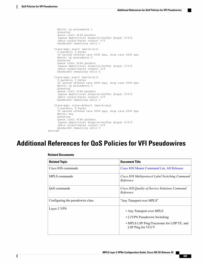
Match: ip precedence 1Queueingqueue limit 4166 packets(queue depth/total drops/no-buffer drops) 0/0/0(pkts output/bytes output) 0/0bandwidth remaining ratio 1
Class-map: prec2 (match-all)0 packets, 0 bytes30 second offered rate 0000 bps, drop rate 0000 bpsMatch: ip precedence 2Queueingqueue limit 4166 packets(queue depth/total drops/no-buffer drops) 0/0/0(pkts output/bytes output) 0/0bandwidth remaining ratio 2
Class-map: prec3 (match-all)0 packets, 0 bytes30 second offered rate 0000 bps, drop rate 0000 bpsMatch: ip precedence 3Queueingqueue limit 4166 packets(queue depth/total drops/no-buffer drops) 0/0/0(pkts output/bytes output) 0/0bandwidth remaining ratio 3
Class-map: class-default (match-any)0 packets, 0 bytes30 second offered rate 0000 bps, drop rate 0000 bpsMatch: anyQueueingqueue limit 4166 packets(queue depth/total drops/no-buffer drops) 0/0/0(pkts output/bytes output) 0/0bandwidth remaining ratio 4
Device#
Additional References for QoS Policies for VFI PseudowiresRelated Documents
Document TitleRelated Topic
Cisco IOS Master Command List, All ReleasesCisco IOS commands
Cisco IOS Multiprotocol Label Switching CommandReference
MPLS commands
Cisco IOS Quality of Service Solutions CommandReference
QoS commands
“Any Transport over MPLS”Configuring the pseudowire class
• Any Transport over MPLS
• L2VPN Pseudowire Switching
• MPLS LSP Ping/Traceroute for LDP/TE, andLSP Ping for VCCV
Layer 2 VPN
MPLS Layer 2 VPNs Configuration Guide, Cisco IOS XE Release 3S 669
QoS Policies for VFI PseudowiresAdditional References for QoS Policies for VFI Pseudowires
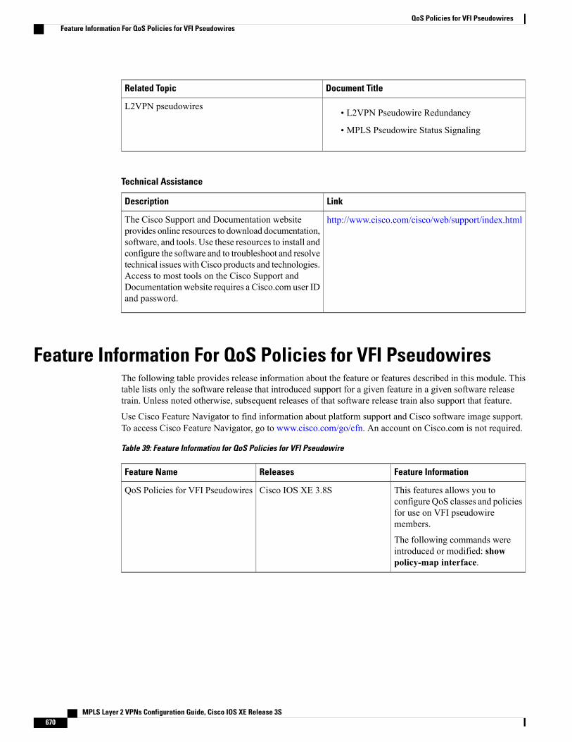
Document TitleRelated Topic
• L2VPN Pseudowire Redundancy
• MPLS Pseudowire Status Signaling
L2VPN pseudowires
Technical Assistance
LinkDescription
http://www.cisco.com/cisco/web/support/index.htmlThe Cisco Support and Documentation websiteprovides online resources to download documentation,software, and tools. Use these resources to install andconfigure the software and to troubleshoot and resolvetechnical issues with Cisco products and technologies.Access to most tools on the Cisco Support andDocumentation website requires a Cisco.com user IDand password.
Feature Information For QoS Policies for VFI PseudowiresThe following table provides release information about the feature or features described in this module. Thistable lists only the software release that introduced support for a given feature in a given software releasetrain. Unless noted otherwise, subsequent releases of that software release train also support that feature.
Use Cisco Feature Navigator to find information about platform support and Cisco software image support.To access Cisco Feature Navigator, go to www.cisco.com/go/cfn. An account on Cisco.com is not required.
Table 39: Feature Information for QoS Policies for VFI Pseudowire
Feature InformationReleasesFeature Name
This features allows you toconfigure QoS classes and policiesfor use on VFI pseudowiremembers.
The following commands wereintroduced or modified: showpolicy-map interface.
Cisco IOS XE 3.8SQoS Policies for VFI Pseudowires
MPLS Layer 2 VPNs Configuration Guide, Cisco IOS XE Release 3S670
QoS Policies for VFI PseudowiresFeature Information For QoS Policies for VFI Pseudowires
C H A P T E R 24VPLS BGP Signaling L2VPN Inter-AS Option A
The Virtual Private LAN Switching (VPLS) Border Gateway Protocol (BGP) Signaling Layer 2 VirtualPrivate Network (L2VPN) feature simplifies the auto-discovery and signaling of all known PE devices in aVPLS instance by using BGP.
• Finding Feature Information, page 671
• Prerequisites for VPLS BGP Signaling L2VPN Inter-AS Option A, page 671
• Information About VPLS BGP Signaling L2VPN Inter-AS Option A, page 672
• How to Configure VPLS BGP Signaling L2VPN Inter-AS Option A, page 673
• VPLS BGP Signaling L2VPN Inter-AS Option A: Example, page 678
• Additional References for VPLS Autodiscovery BGP Based, page 679
• Feature Information for VPLS BGP Signaling L2VPN Inter-AS Option A, page 681
Finding Feature InformationYour software release may not support all the features documented in this module. For the latest caveats andfeature information, see Bug Search Tool and the release notes for your platform and software release. Tofind information about the features documented in this module, and to see a list of the releases in which eachfeature is supported, see the feature information table at the end of this module.
Use Cisco Feature Navigator to find information about platform support and Cisco software image support.To access Cisco Feature Navigator, go to www.cisco.com/go/cfn. An account on Cisco.com is not required.
Prerequisites for VPLS BGP Signaling L2VPN Inter-AS OptionA
• The Control word must turned off for VPLS BGP signaling by using the no control-word commandunder a pseudowire class. For example:Router> enableRouter# configure terminal
MPLS Layer 2 VPNs Configuration Guide, Cisco IOS XE Release 3S 671
Router(config)# pseudowire-class my_pw_classRouter(config-pw-class)# no control-word
• The Route Distinguisher (RD) must match for all the virtual forwarding instances (VFIs) in a VPLSdomain.
Information About VPLS BGP Signaling L2VPN Inter-AS OptionA
BGP Auto-discovery and Signaling for VPLSThe Virtual Private LAN Switching (VPLS) control plane is used for auto-discovery and signaling.Auto-discovery involves locating all provider edge (PE) devices that participate in a particular VPLS instance.Signaling is accomplished by configuring pseudowires for a VPLS instance. Prior to the introduction of theVPLS BGP Signaling L2VPN Inter-AS Option B feature, Label Distribution Protocol (LDP) was used forsignaling and Border Gateway Protocol (BGP) was used for auto-discovery, as specified in RFC 6074. Withthe introduction of the VPLS BGP Signaling L2VPN Inter-AS Option B feature, the VPLS BGP SignalingL2VPN feature supports RFC 4761 by simplifying the auto-discovery and signaling of all known PE devicesin a VPLS instance by using BGP for both functions. Auto-discovery is defined per VPLS instance.
Internal BGP (IBGP) peers exchange update messages of the L2VPN Address Family Identifier (AFI) andthe Subsequent Address Family Identifier (SAFI) numbers with L2VPN information to perform bothauto-discovery and signaling, which includes the Network Layer Reachability Information (NLRI).
Both BGP standards (RFC 6074 and RFC 4761) for the auto-discovery protocol for VPLS use the same BGPAFI (25) and SAFI (65) but they have different Network Layer Reachability Information (NLRI) encoding,which makes them incompatible with each other. CLI configuration is needed to distinguish the two encodingtypes as they are mutually exclusive per neighbor. The difference between the two BGP standards is:
• RFC 6074 provides guidelines for specifying length encoding as bits.
• RFC 4761 provides guidelines for specifying length encoding as bytes.
To detect which NLRI encoding standard is supported, the length encoding needs to be determined.
BGP L2VPN Signaling with NLRINetwork Layer Reachability Information (NLRI) enables Border Gateway Protocol (BGP) to carry supernettinginformation, as well as perform aggregation. Each NLRI consists of block labels that follow the structure LB,LB+1, .... , LB+VBS-1. The NLRI is exchanged between BGP devices for BGP auto-discovery with BGPsignaling. The following fields are configured or auto-generated for each Virtual Private LAN Switching(VPLS) instance:
• Length (2 Octets)
• Route distinguisher (RD) is usually an auto-generated 8-byte VPN ID that can also be configured. Thisvalue must be unique for a VPLS bridge-domain (or instance).
• VPLS Endpoint ID (VEID) (2 Octets). Each PE device is configured with a VEID value.
MPLS Layer 2 VPNs Configuration Guide, Cisco IOS XE Release 3S672
VPLS BGP Signaling L2VPN Inter-AS Option AInformation About VPLS BGP Signaling L2VPN Inter-AS Option A
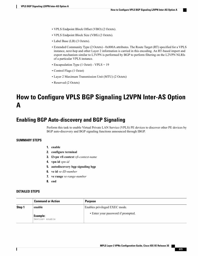
• VPLS Endpoint Block Offset (VBO) (2 Octets).
• VPLS Endpoint Block Size (VBS) (2 Octets).
• Label Base (LB) (3 Octets).
• Extended Community Type (2 Octets) - 0x800A attributes. The Route Target (RT) specified for a VPLSinstance, next-hop and other Layer 2 information is carried in this encoding. An RT-based import andexport mechanism similar to L3VPN is performed by BGP to perform filtering on the L2VPN NLRIsof a particular VPLS instance.
• Encapsulation Type (1 Octet) - VPLS = 19
• Control Flags (1 Octet)
• Layer 2 Maximum Transmission Unit (MTU) (2 Octets)
• Reserved (2 Octets)
How to Configure VPLS BGP Signaling L2VPN Inter-AS OptionA
Enabling BGP Auto-discovery and BGP SignalingPerform this task to enable Virtual Private LAN Service (VPLS) PE devices to discover other PE devices byBGP auto-discovery and BGP signaling functions announced through IBGP.
SUMMARY STEPS
1. enable2. configure terminal3. l2vpn vfi context vfi-context-name4. vpn id vpn-id5. autodiscovery bgp signaling bgp6. ve id ve-ID-number7. ve range ve-range-number8. end
DETAILED STEPS
PurposeCommand or Action
Enables privileged EXEC mode.enableStep 1
Example:Device> enable
• Enter your password if prompted.
MPLS Layer 2 VPNs Configuration Guide, Cisco IOS XE Release 3S 673
VPLS BGP Signaling L2VPN Inter-AS Option AHow to Configure VPLS BGP Signaling L2VPN Inter-AS Option A
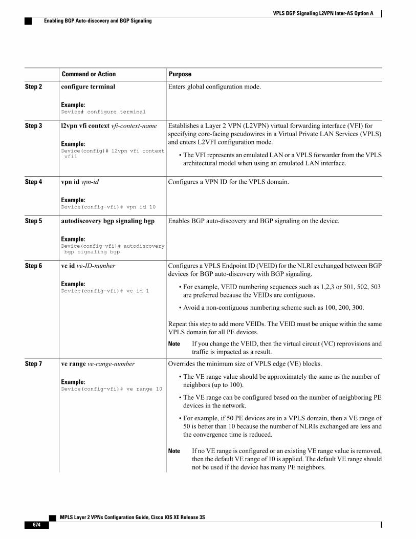
PurposeCommand or Action
Enters global configuration mode.configure terminal
Example:Device# configure terminal
Step 2
Establishes a Layer 2 VPN (L2VPN) virtual forwarding interface (VFI) forspecifying core-facing pseudowires in a Virtual Private LAN Services (VPLS)and enters L2VFI configuration mode.
l2vpn vfi context vfi-context-name
Example:Device(config)# l2vpn vfi contextvfi1
Step 3
• The VFI represents an emulated LAN or a VPLS forwarder from the VPLSarchitectural model when using an emulated LAN interface.
Configures a VPN ID for the VPLS domain.vpn id vpn-id
Example:Device(config-vfi)# vpn id 10
Step 4
Enables BGP auto-discovery and BGP signaling on the device.autodiscovery bgp signaling bgp
Example:Device(config-vfi)# autodiscoverybgp signaling bgp
Step 5
Configures a VPLS Endpoint ID (VEID) for the NLRI exchanged between BGPdevices for BGP auto-discovery with BGP signaling.
ve id ve-ID-number
Example:Device(config-vfi)# ve id 1
Step 6
• For example, VEID numbering sequences such as 1,2,3 or 501, 502, 503are preferred because the VEIDs are contiguous.
• Avoid a non-contiguous numbering scheme such as 100, 200, 300.
Repeat this step to add more VEIDs. The VEIDmust be unique within the sameVPLS domain for all PE devices.
If you change the VEID, then the virtual circuit (VC) reprovisions andtraffic is impacted as a result.
Note
Overrides the minimum size of VPLS edge (VE) blocks.ve range ve-range-numberStep 7
Example:Device(config-vfi)# ve range 10
• The VE range value should be approximately the same as the number ofneighbors (up to 100).
• The VE range can be configured based on the number of neighboring PEdevices in the network.
• For example, if 50 PE devices are in a VPLS domain, then a VE range of50 is better than 10 because the number of NLRIs exchanged are less andthe convergence time is reduced.
If no VE range is configured or an existing VE range value is removed,then the default VE range of 10 is applied. The default VE range shouldnot be used if the device has many PE neighbors.
Note
MPLS Layer 2 VPNs Configuration Guide, Cisco IOS XE Release 3S674
VPLS BGP Signaling L2VPN Inter-AS Option AEnabling BGP Auto-discovery and BGP Signaling

PurposeCommand or Action
If you change the VE range, then the VC reprovisions and traffic isimpacted as a result.
Note
Exits L2 VFI configuration mode and returns to privileged EXEC mode.Commands take effect after the device exits L2VFI configurationmode.
Noteend
Example:Device(config-vfi)# end
Step 8
Configuring BGP Signaling for VPLS Autodiscovery
SUMMARY STEPS
1. enable2. configure terminal3. router bgp autonomous-system-number4. bgp graceful-restart5. neighbor {ip-address | peer-group-name} remote-as autonomous-system-number6. address-family l2vpn vpls7. neighbor {ip-address | peer-group-name} activate8. neighbor {ip-address | peer-group-name} send-community extended9. neighbor {ip-address | peer-group-name} suppress-signaling-protocol ldp10. exit-address-family11. Repeat steps 1 to 10 to configure and activate other BGP neighbors in an L2VPN address family.12. end13. show l2vpn vfi14. show ip bgp l2vpn vpls {all [summary] | rd route-distinguisher}
DETAILED STEPS
PurposeCommand or Action
Enables privileged EXEC mode.enableStep 1
Example:Device> enable
• Enter your password if prompted.
Enters global configuration mode.configure terminal
Example:Device# configure terminal
Step 2
MPLS Layer 2 VPNs Configuration Guide, Cisco IOS XE Release 3S 675
VPLS BGP Signaling L2VPN Inter-AS Option AConfiguring BGP Signaling for VPLS Autodiscovery
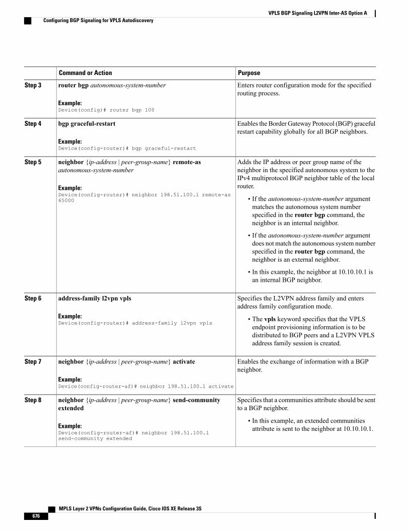
PurposeCommand or Action
Enters router configuration mode for the specifiedrouting process.
router bgp autonomous-system-number
Example:Device(config)# router bgp 100
Step 3
Enables the Border Gateway Protocol (BGP) gracefulrestart capability globally for all BGP neighbors.
bgp graceful-restart
Example:Device(config-router)# bgp graceful-restart
Step 4
Adds the IP address or peer group name of theneighbor in the specified autonomous system to the
neighbor {ip-address | peer-group-name} remote-asautonomous-system-number
Step 5
IPv4 multiprotocol BGP neighbor table of the localrouter.Example:
Device(config-router)# neighbor 198.51.100.1 remote-as65000 • If the autonomous-system-number argument
matches the autonomous system numberspecified in the router bgp command, theneighbor is an internal neighbor.
• If the autonomous-system-number argumentdoes not match the autonomous system numberspecified in the router bgp command, theneighbor is an external neighbor.
• In this example, the neighbor at 10.10.10.1 isan internal BGP neighbor.
Specifies the L2VPN address family and entersaddress family configuration mode.
address-family l2vpn vpls
Example:Device(config-router)# address-family l2vpn vpls
Step 6
• The vpls keyword specifies that the VPLSendpoint provisioning information is to bedistributed to BGP peers and a L2VPN VPLSaddress family session is created.
Enables the exchange of information with a BGPneighbor.
neighbor {ip-address | peer-group-name} activate
Example:Device(config-router-af)# neighbor 198.51.100.1 activate
Step 7
Specifies that a communities attribute should be sentto a BGP neighbor.
neighbor {ip-address | peer-group-name} send-communityextended
Step 8
Example:Device(config-router-af)# neighbor 198.51.100.1send-community extended
• In this example, an extended communitiesattribute is sent to the neighbor at 10.10.10.1.
MPLS Layer 2 VPNs Configuration Guide, Cisco IOS XE Release 3S676
VPLS BGP Signaling L2VPN Inter-AS Option AConfiguring BGP Signaling for VPLS Autodiscovery
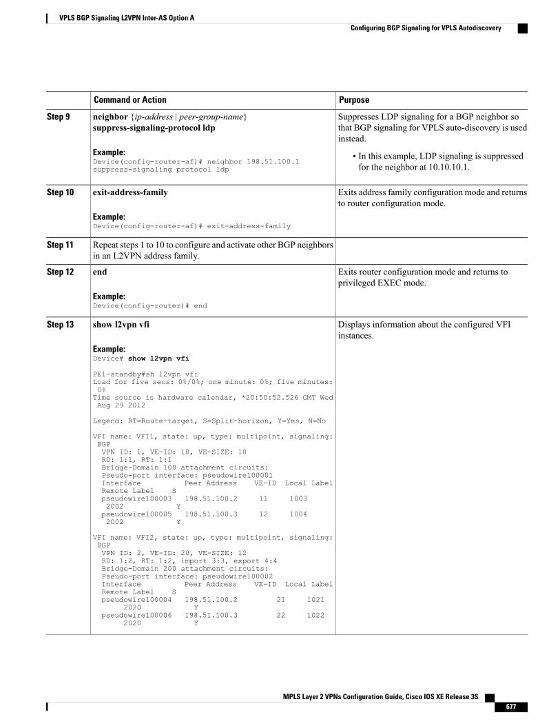
PurposeCommand or Action
Suppresses LDP signaling for a BGP neighbor sothat BGP signaling for VPLS auto-discovery is usedinstead.
neighbor {ip-address | peer-group-name}suppress-signaling-protocol ldp
Example:Device(config-router-af)# neighbor 198.51.100.1suppress-signaling protocol ldp
Step 9
• In this example, LDP signaling is suppressedfor the neighbor at 10.10.10.1.
Exits address family configuration mode and returnsto router configuration mode.
exit-address-family
Example:Device(config-router-af)# exit-address-family
Step 10
Repeat steps 1 to 10 to configure and activate other BGP neighborsin an L2VPN address family.
Step 11
Exits router configuration mode and returns toprivileged EXEC mode.
end
Example:Device(config-router)# end
Step 12
Displays information about the configured VFIinstances.
show l2vpn vfi
Example:Device# show l2vpn vfi
Step 13
PE1-standby#sh l2vpn vfiLoad for five secs: 0%/0%; one minute: 0%; five minutes:0%Time source is hardware calendar, *20:50:52.526 GMT WedAug 29 2012
Legend: RT=Route-target, S=Split-horizon, Y=Yes, N=No
VFI name: VFI1, state: up, type: multipoint, signaling:BGPVPN ID: 1, VE-ID: 10, VE-SIZE: 10RD: 1:1, RT: 1:1Bridge-Domain 100 attachment circuits:Pseudo-port interface: pseudowire100001Interface Peer Address VE-ID Local LabelRemote Label Spseudowire100003 198.51.100.2 11 10032002 Y
pseudowire100005 198.51.100.3 12 10042002 Y
VFI name: VFI2, state: up, type: multipoint, signaling:BGPVPN ID: 2, VE-ID: 20, VE-SIZE: 12RD: 1:2, RT: 1:2, import 3:3, export 4:4Bridge-Domain 200 attachment circuits:Pseudo-port interface: pseudowire100002Interface Peer Address VE-ID Local LabelRemote Label Spseudowire100004 198.51.100.2 21 1021
2020 Ypseudowire100006 198.51.100.3 22 1022
2020 Y
MPLS Layer 2 VPNs Configuration Guide, Cisco IOS XE Release 3S 677
VPLS BGP Signaling L2VPN Inter-AS Option AConfiguring BGP Signaling for VPLS Autodiscovery
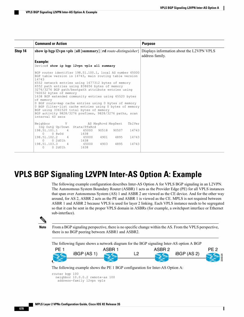
PurposeCommand or Action
Displays information about the L2VPN VPLSaddress family.
show ip bgp l2vpn vpls {all [summary] | rd route-distinguisher}
Example:Device# show ip bgp l2vpn vpls all summary
Step 14
BGP router identifier 198.51.100.1, local AS number 65000BGP table version is 14743, main routing table version147436552 network entries using 1677312 bytes of memory6552 path entries using 838656 bytes of memory3276/3276 BGP path/bestpath attribute entries using760032 bytes of memory1638 BGP extended community entries using 65520 bytesof memory0 BGP route-map cache entries using 0 bytes of memory0 BGP filter-list cache entries using 0 bytes of memoryBGP using 3341520 total bytes of memoryBGP activity 9828/3276 prefixes, 9828/3276 paths, scaninterval 60 secs
Neighbor V AS MsgRcvd MsgSent TblVerInQ OutQ Up/Down State/PfxRcd
198.51.101.1 4 65000 90518 90507 147430 0 8w0d 1638
198.51.102.2 4 65000 4901 4895 147430 0 2d01h 1638
198.51.103.3 4 65000 4903 4895 147430 0 2d01h 1638
VPLS BGP Signaling L2VPN Inter-AS Option A: ExampleThe following example configuration describes Inter-AS Option A for VPLS BGP signaling in an L2VPN.The Autonomous System Boundary Router (ASBR) 1 acts as the Provider Edge (PE) for all VPLS instancesthat span over Autonomous System (AS) 1 and ASBR 2 are viewed as the CE device. And for the other wayaround, for AS 2, ASBR 2 acts as the PE and ASBR 1 is viewed as the CE. MPLS is not required betweenASBR 1 and ASBR 2 because VPLS is used for layer 2 linking. Each VPLS instance needs to be segregatedso that it can be sent in the proper VPLS domain in ASBRs (for example, a switchport interface or Ethernetsub-interface).
From a BGP signaling perspective, there is no specific change within the AS. From the VPLS perspective,there is no BGP peering between ASBR1 and ASBR2.
Note
The following figure shows a network diagram for the BGP signaling Inter-AS option A BGP
configuration:
The following example shows the PE 1 BGP configuration for Inter-AS Option A:router bgp 100neighbor 10.0.0.2 remote-as 100address-family l2vpn vpls
MPLS Layer 2 VPNs Configuration Guide, Cisco IOS XE Release 3S678
VPLS BGP Signaling L2VPN Inter-AS Option AVPLS BGP Signaling L2VPN Inter-AS Option A: Example
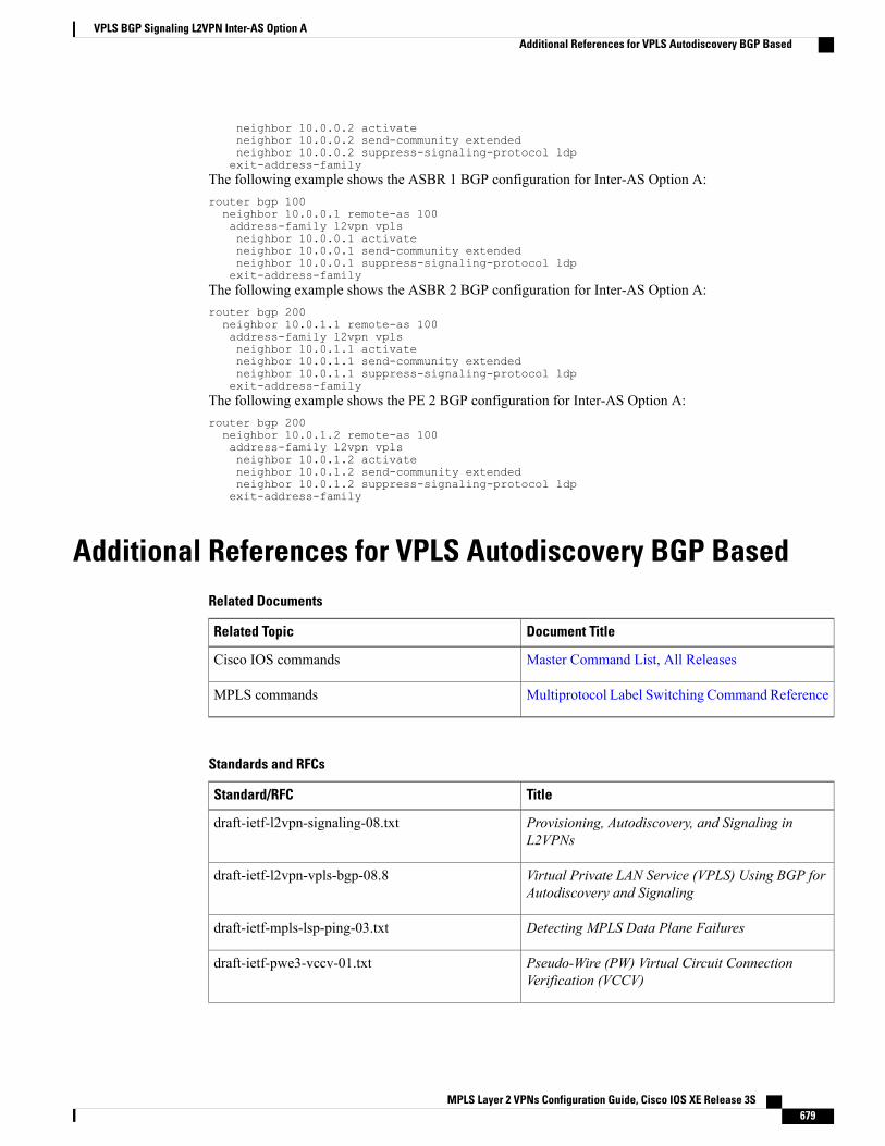
neighbor 10.0.0.2 activateneighbor 10.0.0.2 send-community extendedneighbor 10.0.0.2 suppress-signaling-protocol ldpexit-address-family
The following example shows the ASBR 1 BGP configuration for Inter-AS Option A:router bgp 100neighbor 10.0.0.1 remote-as 100address-family l2vpn vplsneighbor 10.0.0.1 activateneighbor 10.0.0.1 send-community extendedneighbor 10.0.0.1 suppress-signaling-protocol ldpexit-address-family
The following example shows the ASBR 2 BGP configuration for Inter-AS Option A:router bgp 200neighbor 10.0.1.1 remote-as 100address-family l2vpn vplsneighbor 10.0.1.1 activateneighbor 10.0.1.1 send-community extendedneighbor 10.0.1.1 suppress-signaling-protocol ldpexit-address-family
The following example shows the PE 2 BGP configuration for Inter-AS Option A:router bgp 200neighbor 10.0.1.2 remote-as 100address-family l2vpn vplsneighbor 10.0.1.2 activateneighbor 10.0.1.2 send-community extendedneighbor 10.0.1.2 suppress-signaling-protocol ldpexit-address-family
Additional References for VPLS Autodiscovery BGP BasedRelated Documents
Document TitleRelated Topic
Master Command List, All ReleasesCisco IOS commands
Multiprotocol Label Switching Command ReferenceMPLS commands
Standards and RFCs
TitleStandard/RFC
Provisioning, Autodiscovery, and Signaling inL2VPNs
draft-ietf-l2vpn-signaling-08.txt
Virtual Private LAN Service (VPLS) Using BGP forAutodiscovery and Signaling
draft-ietf-l2vpn-vpls-bgp-08.8
Detecting MPLS Data Plane Failuresdraft-ietf-mpls-lsp-ping-03.txt
Pseudo-Wire (PW) Virtual Circuit ConnectionVerification (VCCV)
draft-ietf-pwe3-vccv-01.txt
MPLS Layer 2 VPNs Configuration Guide, Cisco IOS XE Release 3S 679
VPLS BGP Signaling L2VPN Inter-AS Option AAdditional References for VPLS Autodiscovery BGP Based
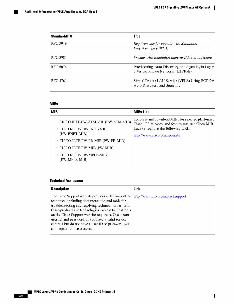
TitleStandard/RFC
Requirements for Pseudo-wire EmulationEdge-to-Edge (PWE3)
RFC 3916
Pseudo Wire Emulation Edge-to-Edge ArchitectureRFC 3981
Provisioning, Auto-Discovery, and Signaling in Layer2 Virtual Private Networks (L2VPNs)
RFC 6074
Virtual Private LAN Service (VPLS) Using BGP forAuto-Discovery and Signaling
RFC 4761
MIBs
MIBs LinkMIB
To locate and downloadMIBs for selected platforms,Cisco IOS releases, and feature sets, use Cisco MIBLocator found at the following URL:
http://www.cisco.com/go/mibs
• CISCO-IETF-PW-ATM-MIB (PW-ATM-MIB)
• CISCO-IETF-PW-ENET-MIB(PW-ENET-MIB)
• CISCO-IETF-PW-FR-MIB (PW-FR-MIB)
• CISCO-IETF-PW-MIB (PW-MIB)
• CISCO-IETF-PW-MPLS-MIB(PW-MPLS-MIB)
Technical Assistance
LinkDescription
http://www.cisco.com/techsupportThe Cisco Support website provides extensive onlineresources, including documentation and tools fortroubleshooting and resolving technical issues withCisco products and technologies. Access to most toolson the Cisco Support website requires a Cisco.comuser ID and password. If you have a valid servicecontract but do not have a user ID or password, youcan register on Cisco.com.
MPLS Layer 2 VPNs Configuration Guide, Cisco IOS XE Release 3S680
VPLS BGP Signaling L2VPN Inter-AS Option AAdditional References for VPLS Autodiscovery BGP Based
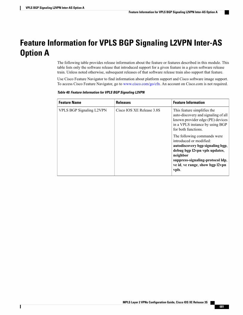
Feature Information for VPLS BGP Signaling L2VPN Inter-ASOption A
The following table provides release information about the feature or features described in this module. Thistable lists only the software release that introduced support for a given feature in a given software releasetrain. Unless noted otherwise, subsequent releases of that software release train also support that feature.
Use Cisco Feature Navigator to find information about platform support and Cisco software image support.To access Cisco Feature Navigator, go to www.cisco.com/go/cfn. An account on Cisco.com is not required.
Table 40: Feature Information for VPLS BGP Signaling L2VPN
Feature InformationReleasesFeature Name
This feature simplifies theauto-discovery and signaling of allknown provider edge (PE) devicesin a VPLS instance by using BGPfor both functions.
The following commands wereintroduced or modified:autodiscovery bgp signaling bgp,debug bgp l2vpn vpls updates,neighborsuppress-signaling-protocol ldp,ve id, ve range, show bgp l2vpnvpls.
Cisco IOS XE Release 3.8SVPLS BGP Signaling L2VPN
MPLS Layer 2 VPNs Configuration Guide, Cisco IOS XE Release 3S 681
VPLS BGP Signaling L2VPN Inter-AS Option AFeature Information for VPLS BGP Signaling L2VPN Inter-AS Option A

MPLS Layer 2 VPNs Configuration Guide, Cisco IOS XE Release 3S682
VPLS BGP Signaling L2VPN Inter-AS Option AFeature Information for VPLS BGP Signaling L2VPN Inter-AS Option A
C H A P T E R 25VPLS BGP Signaling L2VPN Inter-AS Option B
The VPLS BGP Signaling L2VPN Inter-AS Option B feature simplifies the auto-discovery and signalingof all known provider edge (PE) devices in a Virtual Private LAN Switching (VPLS) instance by usingBorder Gateway Protocol (BGP). This document describes how to configure the VPLS BGP SignalingL2VPN Inter-AS Option B feature.
• Finding Feature Information, page 683
• Prerequisites for VPLS BGP Signaling L2VPN Inter-AS Option B, page 683
• Information About VPLS BGP Signaling L2VPN Inter-AS Option B, page 684
• How to Configure VPLS BGP Signaling L2VPN Inter-AS Option B, page 685
• Configuration Examples for L2VPN VPLS Inter-AS Option B, page 690
• Additional References for VPLS BGP Signaling L2VPN Inter-AS Option B, page 694
• Feature Information for VPLS BGP Signaling L2VPN Inter-AS Option B, page 696
Finding Feature InformationYour software release may not support all the features documented in this module. For the latest caveats andfeature information, see Bug Search Tool and the release notes for your platform and software release. Tofind information about the features documented in this module, and to see a list of the releases in which eachfeature is supported, see the feature information table at the end of this module.
Use Cisco Feature Navigator to find information about platform support and Cisco software image support.To access Cisco Feature Navigator, go to www.cisco.com/go/cfn. An account on Cisco.com is not required.
Prerequisites for VPLS BGP Signaling L2VPN Inter-AS OptionB
• Disable control word for Virtual Private LAN Switching (VPLS) Border Gateway Protocol (BGP)signaling by using the no control-word command under a pseudowire class. For example:Device> enableDevice# configure terminal
MPLS Layer 2 VPNs Configuration Guide, Cisco IOS XE Release 3S 683
Device(config)# pseudowire-class my-pw-classDevice(config-pw-class)# no control-word
• The route distinguisher (RD) must match for all the virtual forwarding instances (VFIs) in a VPLSdomain.
• Ensure that the L2VPNVPLS Inter-ASOption B feature is configured on Autonomous SystemBoundaryRouters (ASBRs) and PE devices.
Information About VPLS BGP Signaling L2VPN Inter-AS OptionB
BGP Auto-discovery and Signaling for VPLSThe Virtual Private LAN Switching (VPLS) control plane is used for auto-discovery and signaling.Auto-discovery involves locating all provider edge (PE) devices that participate in a particular VPLS instance.Signaling is accomplished by configuring pseudowires for a VPLS instance. Prior to the introduction of theVPLS BGP Signaling L2VPN Inter-AS Option B feature, Label Distribution Protocol (LDP) was used forsignaling and Border Gateway Protocol (BGP) was used for auto-discovery, as specified in RFC 6074. Withthe introduction of the VPLS BGP Signaling L2VPN Inter-AS Option B feature, the VPLS BGP SignalingL2VPN feature supports RFC 4761 by simplifying the auto-discovery and signaling of all known PE devicesin a VPLS instance by using BGP for both functions. Auto-discovery is defined per VPLS instance.
Internal BGP (IBGP) peers exchange update messages of the L2VPN Address Family Identifier (AFI) andthe Subsequent Address Family Identifier (SAFI) numbers with L2VPN information to perform bothauto-discovery and signaling, which includes the Network Layer Reachability Information (NLRI).
Both BGP standards (RFC 6074 and RFC 4761) for the auto-discovery protocol for VPLS use the same BGPAFI (25) and SAFI (65) but they have different Network Layer Reachability Information (NLRI) encoding,which makes them incompatible with each other. CLI configuration is needed to distinguish the two encodingtypes as they are mutually exclusive per neighbor. The difference between the two BGP standards is:
• RFC 6074 provides guidelines for specifying length encoding as bits.
• RFC 4761 provides guidelines for specifying length encoding as bytes.
To detect which NLRI encoding standard is supported, the length encoding needs to be determined.
BGP L2VPN Signaling with NLRINetwork Layer Reachability Information (NLRI) enables Border Gateway Protocol (BGP) to carry supernettinginformation, as well as perform aggregation. Each NLRI consists of block labels that follow the structure LB,LB+1, .... , LB+VBS-1. The NLRI is exchanged between BGP devices for BGP auto-discovery with BGPsignaling. The following fields are configured or auto-generated for each Virtual Private LAN Switching(VPLS) instance:
• Length (2 Octets)
• Route distinguisher (RD) is usually an auto-generated 8-byte VPN ID that can also be configured. Thisvalue must be unique for a VPLS bridge-domain (or instance).
MPLS Layer 2 VPNs Configuration Guide, Cisco IOS XE Release 3S684
VPLS BGP Signaling L2VPN Inter-AS Option BInformation About VPLS BGP Signaling L2VPN Inter-AS Option B
• VPLS Endpoint ID (VEID) (2 Octets). Each PE device is configured with a VEID value.
• VPLS Endpoint Block Offset (VBO) (2 Octets).
• VPLS Endpoint Block Size (VBS) (2 Octets).
• Label Base (LB) (3 Octets).
• Extended Community Type (2 Octets) - 0x800A attributes. The Route Target (RT) specified for a VPLSinstance, next-hop and other Layer 2 information is carried in this encoding. An RT-based import andexport mechanism similar to L3VPN is performed by BGP to perform filtering on the L2VPN NLRIsof a particular VPLS instance.
• Encapsulation Type (1 Octet) - VPLS = 19
• Control Flags (1 Octet)
• Layer 2 Maximum Transmission Unit (MTU) (2 Octets)
• Reserved (2 Octets)
How to Configure VPLS BGP Signaling L2VPN Inter-AS OptionB
Enabling BGP Auto-discovery and BGP SignalingPerform this task to enable Virtual Private LAN Service (VPLS) PE devices to discover other PE devices byBGP auto-discovery and BGP signaling functions announced through IBGP.
SUMMARY STEPS
1. enable2. configure terminal3. l2vpn vfi context vfi-context-name4. vpn id vpn-id5. autodiscovery bgp signaling bgp6. ve id ve-ID-number7. ve range ve-range-number8. end
DETAILED STEPS
PurposeCommand or Action
Enables privileged EXEC mode.enableStep 1
Example:Device> enable
• Enter your password if prompted.
MPLS Layer 2 VPNs Configuration Guide, Cisco IOS XE Release 3S 685
VPLS BGP Signaling L2VPN Inter-AS Option BHow to Configure VPLS BGP Signaling L2VPN Inter-AS Option B
PurposeCommand or Action
Enters global configuration mode.configure terminal
Example:Device# configure terminal
Step 2
Establishes a Layer 2 VPN (L2VPN) virtual forwarding interface (VFI) forspecifying core-facing pseudowires in a Virtual Private LAN Services (VPLS)and enters L2VFI configuration mode.
l2vpn vfi context vfi-context-name
Example:Device(config)# l2vpn vfi contextvfi1
Step 3
• The VFI represents an emulated LAN or a VPLS forwarder from the VPLSarchitectural model when using an emulated LAN interface.
Configures a VPN ID for the VPLS domain.vpn id vpn-id
Example:Device(config-vfi)# vpn id 10
Step 4
Enables BGP auto-discovery and BGP signaling on the device.autodiscovery bgp signaling bgp
Example:Device(config-vfi)# autodiscoverybgp signaling bgp
Step 5
Configures a VPLS Endpoint ID (VEID) for the NLRI exchanged between BGPdevices for BGP auto-discovery with BGP signaling.
ve id ve-ID-number
Example:Device(config-vfi)# ve id 1
Step 6
• For example, VEID numbering sequences such as 1,2,3 or 501, 502, 503are preferred because the VEIDs are contiguous.
• Avoid a non-contiguous numbering scheme such as 100, 200, 300.
Repeat this step to add more VEIDs. The VEIDmust be unique within the sameVPLS domain for all PE devices.
If you change the VEID, then the virtual circuit (VC) reprovisions andtraffic is impacted as a result.
Note
Overrides the minimum size of VPLS edge (VE) blocks.ve range ve-range-numberStep 7
Example:Device(config-vfi)# ve range 10
• The VE range value should be approximately the same as the number ofneighbors (up to 100).
• The VE range can be configured based on the number of neighboring PEdevices in the network.
• For example, if 50 PE devices are in a VPLS domain, then a VE range of50 is better than 10 because the number of NLRIs exchanged are less andthe convergence time is reduced.
If no VE range is configured or an existing VE range value is removed,then the default VE range of 10 is applied. The default VE range shouldnot be used if the device has many PE neighbors.
Note
MPLS Layer 2 VPNs Configuration Guide, Cisco IOS XE Release 3S686
VPLS BGP Signaling L2VPN Inter-AS Option BEnabling BGP Auto-discovery and BGP Signaling
PurposeCommand or Action
If you change the VE range, then the VC reprovisions and traffic isimpacted as a result.
Note
Exits L2 VFI configuration mode and returns to privileged EXEC mode.Commands take effect after the device exits L2VFI configurationmode.
Noteend
Example:Device(config-vfi)# end
Step 8
Configuring BGP Signaling for VPLS Autodiscovery
SUMMARY STEPS
1. enable2. configure terminal3. router bgp autonomous-system-number4. bgp graceful-restart5. neighbor {ip-address | peer-group-name} remote-as autonomous-system-number6. address-family l2vpn vpls7. neighbor {ip-address | peer-group-name} activate8. neighbor {ip-address | peer-group-name} send-community extended9. neighbor {ip-address | peer-group-name} suppress-signaling-protocol ldp10. exit-address-family11. Repeat steps 1 to 10 to configure and activate other BGP neighbors in an L2VPN address family.12. end13. show l2vpn vfi14. show ip bgp l2vpn vpls {all [summary] | rd route-distinguisher}
DETAILED STEPS
PurposeCommand or Action
Enables privileged EXEC mode.enableStep 1
Example:Device> enable
• Enter your password if prompted.
Enters global configuration mode.configure terminal
Example:Device# configure terminal
Step 2
MPLS Layer 2 VPNs Configuration Guide, Cisco IOS XE Release 3S 687
VPLS BGP Signaling L2VPN Inter-AS Option BConfiguring BGP Signaling for VPLS Autodiscovery

PurposeCommand or Action
Enters router configuration mode for the specifiedrouting process.
router bgp autonomous-system-number
Example:Device(config)# router bgp 100
Step 3
Enables the Border Gateway Protocol (BGP) gracefulrestart capability globally for all BGP neighbors.
bgp graceful-restart
Example:Device(config-router)# bgp graceful-restart
Step 4
Adds the IP address or peer group name of theneighbor in the specified autonomous system to the
neighbor {ip-address | peer-group-name} remote-asautonomous-system-number
Step 5
IPv4 multiprotocol BGP neighbor table of the localrouter.Example:
Device(config-router)# neighbor 198.51.100.1 remote-as65000 • If the autonomous-system-number argument
matches the autonomous system numberspecified in the router bgp command, theneighbor is an internal neighbor.
• If the autonomous-system-number argumentdoes not match the autonomous system numberspecified in the router bgp command, theneighbor is an external neighbor.
• In this example, the neighbor at 10.10.10.1 isan internal BGP neighbor.
Specifies the L2VPN address family and entersaddress family configuration mode.
address-family l2vpn vpls
Example:Device(config-router)# address-family l2vpn vpls
Step 6
• The vpls keyword specifies that the VPLSendpoint provisioning information is to bedistributed to BGP peers and a L2VPN VPLSaddress family session is created.
Enables the exchange of information with a BGPneighbor.
neighbor {ip-address | peer-group-name} activate
Example:Device(config-router-af)# neighbor 198.51.100.1 activate
Step 7
Specifies that a communities attribute should be sentto a BGP neighbor.
neighbor {ip-address | peer-group-name} send-communityextended
Step 8
Example:Device(config-router-af)# neighbor 198.51.100.1send-community extended
• In this example, an extended communitiesattribute is sent to the neighbor at 10.10.10.1.
MPLS Layer 2 VPNs Configuration Guide, Cisco IOS XE Release 3S688
VPLS BGP Signaling L2VPN Inter-AS Option BConfiguring BGP Signaling for VPLS Autodiscovery

PurposeCommand or Action
Suppresses LDP signaling for a BGP neighbor sothat BGP signaling for VPLS auto-discovery is usedinstead.
neighbor {ip-address | peer-group-name}suppress-signaling-protocol ldp
Example:Device(config-router-af)# neighbor 198.51.100.1suppress-signaling protocol ldp
Step 9
• In this example, LDP signaling is suppressedfor the neighbor at 10.10.10.1.
Exits address family configuration mode and returnsto router configuration mode.
exit-address-family
Example:Device(config-router-af)# exit-address-family
Step 10
Repeat steps 1 to 10 to configure and activate other BGP neighborsin an L2VPN address family.
Step 11
Exits router configuration mode and returns toprivileged EXEC mode.
end
Example:Device(config-router)# end
Step 12
Displays information about the configured VFIinstances.
show l2vpn vfi
Example:Device# show l2vpn vfi
Step 13
PE1-standby#sh l2vpn vfiLoad for five secs: 0%/0%; one minute: 0%; five minutes:0%Time source is hardware calendar, *20:50:52.526 GMT WedAug 29 2012
Legend: RT=Route-target, S=Split-horizon, Y=Yes, N=No
VFI name: VFI1, state: up, type: multipoint, signaling:BGPVPN ID: 1, VE-ID: 10, VE-SIZE: 10RD: 1:1, RT: 1:1Bridge-Domain 100 attachment circuits:Pseudo-port interface: pseudowire100001Interface Peer Address VE-ID Local LabelRemote Label Spseudowire100003 198.51.100.2 11 10032002 Y
pseudowire100005 198.51.100.3 12 10042002 Y
VFI name: VFI2, state: up, type: multipoint, signaling:BGPVPN ID: 2, VE-ID: 20, VE-SIZE: 12RD: 1:2, RT: 1:2, import 3:3, export 4:4Bridge-Domain 200 attachment circuits:Pseudo-port interface: pseudowire100002Interface Peer Address VE-ID Local LabelRemote Label Spseudowire100004 198.51.100.2 21 1021
2020 Ypseudowire100006 198.51.100.3 22 1022
2020 Y
MPLS Layer 2 VPNs Configuration Guide, Cisco IOS XE Release 3S 689
VPLS BGP Signaling L2VPN Inter-AS Option BConfiguring BGP Signaling for VPLS Autodiscovery
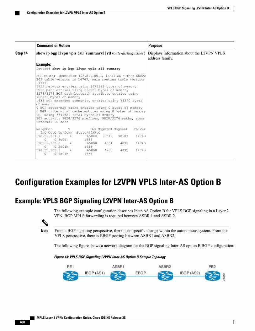
PurposeCommand or Action
Displays information about the L2VPN VPLSaddress family.
show ip bgp l2vpn vpls {all [summary] | rd route-distinguisher}
Example:Device# show ip bgp l2vpn vpls all summary
Step 14
BGP router identifier 198.51.100.1, local AS number 65000BGP table version is 14743, main routing table version147436552 network entries using 1677312 bytes of memory6552 path entries using 838656 bytes of memory3276/3276 BGP path/bestpath attribute entries using760032 bytes of memory1638 BGP extended community entries using 65520 bytesof memory0 BGP route-map cache entries using 0 bytes of memory0 BGP filter-list cache entries using 0 bytes of memoryBGP using 3341520 total bytes of memoryBGP activity 9828/3276 prefixes, 9828/3276 paths, scaninterval 60 secs
Neighbor V AS MsgRcvd MsgSent TblVerInQ OutQ Up/Down State/PfxRcd
198.51.101.1 4 65000 90518 90507 147430 0 8w0d 1638
198.51.102.2 4 65000 4901 4895 147430 0 2d01h 1638
198.51.103.3 4 65000 4903 4895 147430 0 2d01h 1638
Configuration Examples for L2VPN VPLS Inter-AS Option B
Example: VPLS BGP Signaling L2VPN Inter-AS Option BThe following example configuration describes Inter-AS Option B for VPLS BGP signaling in a Layer 2VPN. BGP MPLS forwarding is required between ASBR 1 and ASBR 2.
From a BGP signaling perspective, there is no specific change within the autonomous system. From theVPLS perspective, there is EBGP peering between ASBR1 and ASBR2.
Note
The following figure shows a network diagram for the BGP signaling Inter-AS option B BGP configuration:
Figure 44: VPLS BGP Signaling L2VPN Inter-AS Option B Sample Topology
MPLS Layer 2 VPNs Configuration Guide, Cisco IOS XE Release 3S690
VPLS BGP Signaling L2VPN Inter-AS Option BConfiguration Examples for L2VPN VPLS Inter-AS Option B
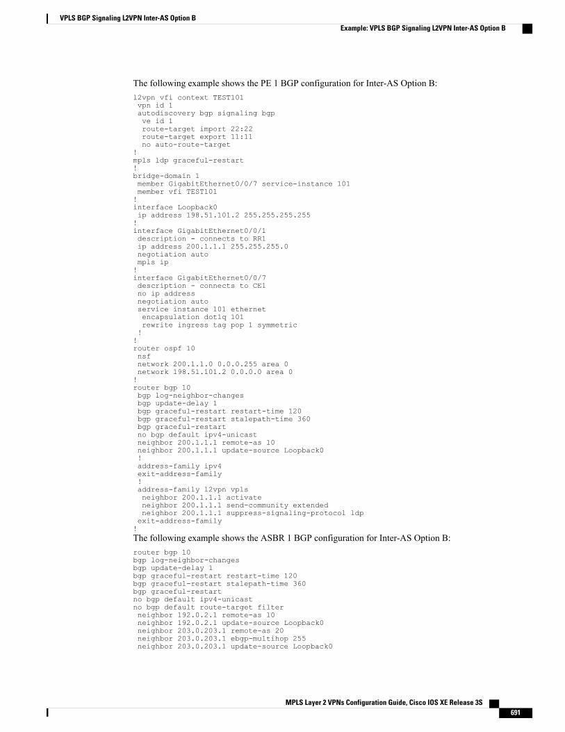
The following example shows the PE 1 BGP configuration for Inter-AS Option B:l2vpn vfi context TEST101vpn id 1autodiscovery bgp signaling bgpve id 1route-target import 22:22route-target export 11:11no auto-route-target
!mpls ldp graceful-restart!bridge-domain 1member GigabitEthernet0/0/7 service-instance 101member vfi TEST101!interface Loopback0ip address 198.51.101.2 255.255.255.255!interface GigabitEthernet0/0/1description - connects to RR1ip address 200.1.1.1 255.255.255.0negotiation autompls ip!interface GigabitEthernet0/0/7description - connects to CE1no ip addressnegotiation autoservice instance 101 ethernetencapsulation dot1q 101rewrite ingress tag pop 1 symmetric!!router ospf 10nsfnetwork 200.1.1.0 0.0.0.255 area 0network 198.51.101.2 0.0.0.0 area 0!router bgp 10bgp log-neighbor-changesbgp update-delay 1bgp graceful-restart restart-time 120bgp graceful-restart stalepath-time 360bgp graceful-restartno bgp default ipv4-unicastneighbor 200.1.1.1 remote-as 10neighbor 200.1.1.1 update-source Loopback0!address-family ipv4exit-address-family!address-family l2vpn vplsneighbor 200.1.1.1 activateneighbor 200.1.1.1 send-community extendedneighbor 200.1.1.1 suppress-signaling-protocol ldpexit-address-family!The following example shows the ASBR 1 BGP configuration for Inter-AS Option B:router bgp 10bgp log-neighbor-changesbgp update-delay 1bgp graceful-restart restart-time 120bgp graceful-restart stalepath-time 360bgp graceful-restartno bgp default ipv4-unicastno bgp default route-target filterneighbor 192.0.2.1 remote-as 10neighbor 192.0.2.1 update-source Loopback0neighbor 203.0.203.1 remote-as 20neighbor 203.0.203.1 ebgp-multihop 255neighbor 203.0.203.1 update-source Loopback0
MPLS Layer 2 VPNs Configuration Guide, Cisco IOS XE Release 3S 691
VPLS BGP Signaling L2VPN Inter-AS Option BExample: VPLS BGP Signaling L2VPN Inter-AS Option B
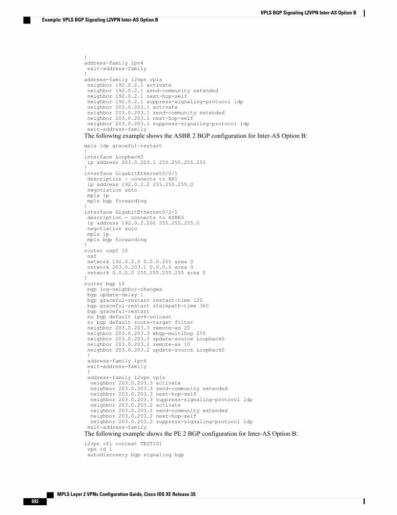
!address-family ipv4exit-address-family!address-family l2vpn vplsneighbor 192.0.2.1 activateneighbor 192.0.2.1 send-community extendedneighbor 192.0.2.1 next-hop-selfneighbor 192.0.2.1 suppress-signaling-protocol ldpneighbor 203.0.203.1 activateneighbor 203.0.203.1 send-community extendedneighbor 203.0.203.1 next-hop-selfneighbor 203.0.203.1 suppress-signaling-protocol ldpexit-address-familyThe following example shows the ASBR 2 BGP configuration for Inter-AS Option B:mpls ldp graceful-restart!interface Loopback0ip address 203.0.203.1 255.255.255.255!interface GigabitEthernet0/0/1description - connects to RR1ip address 192.0.2.2 255.255.255.0negotiation autompls ipmpls bgp forwarding!interface GigabitEthernet0/2/1description - connects to ASBR3ip address 192.0.2.200 255.255.255.0negotiation autompls ipmpls bgp forwarding!router ospf 10nsfnetwork 192.0.2.0 0.0.0.255 area 0network 203.0.203.1 0.0.0.0 area 0network 0.0.0.0 255.255.255.255 area 0!router bgp 10bgp log-neighbor-changesbgp update-delay 1bgp graceful-restart restart-time 120bgp graceful-restart stalepath-time 360bgp graceful-restartno bgp default ipv4-unicastno bgp default route-target filterneighbor 203.0.203.3 remote-as 20neighbor 203.0.203.3 ebgp-multihop 255neighbor 203.0.203.3 update-source Loopback0neighbor 203.0.203.2 remote-as 10neighbor 203.0.203.2 update-source Loopback0!address-family ipv4exit-address-family!address-family l2vpn vplsneighbor 203.0.203.3 activateneighbor 203.0.203.3 send-community extendedneighbor 203.0.203.3 next-hop-selfneighbor 203.0.203.3 suppress-signaling-protocol ldpneighbor 203.0.203.2 activateneighbor 203.0.203.2 send-community extendedneighbor 203.0.203.2 next-hop-selfneighbor 203.0.203.2 suppress-signaling-protocol ldpexit-address-familyThe following example shows the PE 2 BGP configuration for Inter-AS Option B:l2vpn vfi context TEST101vpn id 1autodiscovery bgp signaling bgp
MPLS Layer 2 VPNs Configuration Guide, Cisco IOS XE Release 3S692
VPLS BGP Signaling L2VPN Inter-AS Option BExample: VPLS BGP Signaling L2VPN Inter-AS Option B
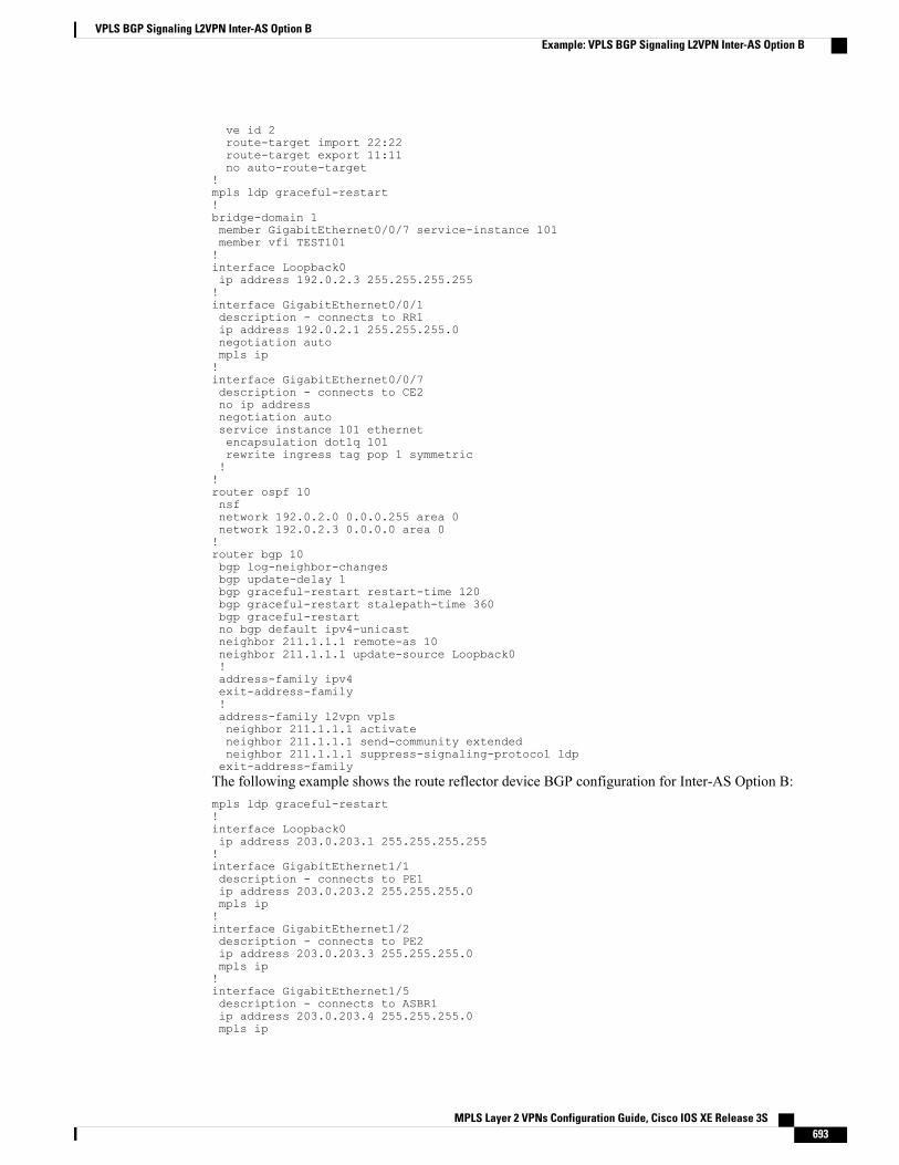
ve id 2route-target import 22:22route-target export 11:11no auto-route-target
!mpls ldp graceful-restart!bridge-domain 1member GigabitEthernet0/0/7 service-instance 101member vfi TEST101!interface Loopback0ip address 192.0.2.3 255.255.255.255!interface GigabitEthernet0/0/1description - connects to RR1ip address 192.0.2.1 255.255.255.0negotiation autompls ip!interface GigabitEthernet0/0/7description - connects to CE2no ip addressnegotiation autoservice instance 101 ethernetencapsulation dot1q 101rewrite ingress tag pop 1 symmetric!!router ospf 10nsfnetwork 192.0.2.0 0.0.0.255 area 0network 192.0.2.3 0.0.0.0 area 0!router bgp 10bgp log-neighbor-changesbgp update-delay 1bgp graceful-restart restart-time 120bgp graceful-restart stalepath-time 360bgp graceful-restartno bgp default ipv4-unicastneighbor 211.1.1.1 remote-as 10neighbor 211.1.1.1 update-source Loopback0!address-family ipv4exit-address-family!address-family l2vpn vplsneighbor 211.1.1.1 activateneighbor 211.1.1.1 send-community extendedneighbor 211.1.1.1 suppress-signaling-protocol ldpexit-address-familyThe following example shows the route reflector device BGP configuration for Inter-AS Option B:mpls ldp graceful-restart!interface Loopback0ip address 203.0.203.1 255.255.255.255!interface GigabitEthernet1/1description - connects to PE1ip address 203.0.203.2 255.255.255.0mpls ip!interface GigabitEthernet1/2description - connects to PE2ip address 203.0.203.3 255.255.255.0mpls ip!interface GigabitEthernet1/5description - connects to ASBR1ip address 203.0.203.4 255.255.255.0mpls ip
MPLS Layer 2 VPNs Configuration Guide, Cisco IOS XE Release 3S 693
VPLS BGP Signaling L2VPN Inter-AS Option BExample: VPLS BGP Signaling L2VPN Inter-AS Option B
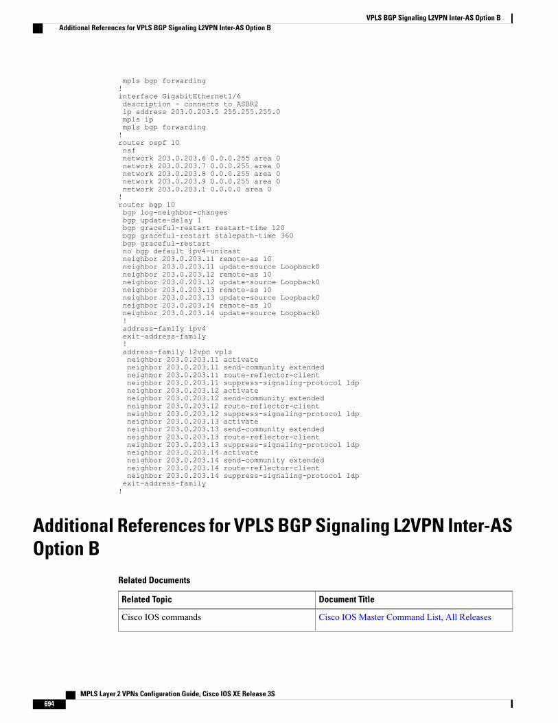
mpls bgp forwarding!interface GigabitEthernet1/6description - connects to ASBR2ip address 203.0.203.5 255.255.255.0mpls ipmpls bgp forwarding!router ospf 10nsfnetwork 203.0.203.6 0.0.0.255 area 0network 203.0.203.7 0.0.0.255 area 0network 203.0.203.8 0.0.0.255 area 0network 203.0.203.9 0.0.0.255 area 0network 203.0.203.1 0.0.0.0 area 0!router bgp 10bgp log-neighbor-changesbgp update-delay 1bgp graceful-restart restart-time 120bgp graceful-restart stalepath-time 360bgp graceful-restartno bgp default ipv4-unicastneighbor 203.0.203.11 remote-as 10neighbor 203.0.203.11 update-source Loopback0neighbor 203.0.203.12 remote-as 10neighbor 203.0.203.12 update-source Loopback0neighbor 203.0.203.13 remote-as 10neighbor 203.0.203.13 update-source Loopback0neighbor 203.0.203.14 remote-as 10neighbor 203.0.203.14 update-source Loopback0!address-family ipv4exit-address-family!address-family l2vpn vplsneighbor 203.0.203.11 activateneighbor 203.0.203.11 send-community extendedneighbor 203.0.203.11 route-reflector-clientneighbor 203.0.203.11 suppress-signaling-protocol ldpneighbor 203.0.203.12 activateneighbor 203.0.203.12 send-community extendedneighbor 203.0.203.12 route-reflector-clientneighbor 203.0.203.12 suppress-signaling-protocol ldpneighbor 203.0.203.13 activateneighbor 203.0.203.13 send-community extendedneighbor 203.0.203.13 route-reflector-clientneighbor 203.0.203.13 suppress-signaling-protocol ldpneighbor 203.0.203.14 activateneighbor 203.0.203.14 send-community extendedneighbor 203.0.203.14 route-reflector-clientneighbor 203.0.203.14 suppress-signaling-protocol ldpexit-address-family!
Additional References for VPLS BGP Signaling L2VPN Inter-ASOption B
Related Documents
Document TitleRelated Topic
Cisco IOS Master Command List, All ReleasesCisco IOS commands
MPLS Layer 2 VPNs Configuration Guide, Cisco IOS XE Release 3S694
VPLS BGP Signaling L2VPN Inter-AS Option BAdditional References for VPLS BGP Signaling L2VPN Inter-AS Option B
Document TitleRelated Topic
Multiprotocol Label Switching Command ReferenceMPLS commands
L2VPN VPLS Inter-AS Option BL2VPN VPLS Inter-AS Option B
VPLS Autodiscovery BGP BasedVPLS Autodiscovery: BGP Based
VPLS BGP Signaling L2VPN Inter-AS Option AVPLS BGP Signaling L2VPN Inter-AS Option A
Standards and RFCs
TitleStandard and RFC
Automatic Generation of Site IDs for Virtual PrivateLAN Service
draft-kothari-l2vpn-auto-site-id-01.txt
BGP based Multi-homing in Virtual Private LANService
draft-ietf-l2vpn-vpls-multihoming-03.txt
Provisioning, Auto-Discovery, and Signaling in Layer2 Virtual Private Networks (L2VPNs)
RFC 6074
Virtual Private LAN Service (VPLS) Using BGP forAuto-Discovery and Signaling
RFC 4761
MIBs
MIBs LinkMIB
To locate and downloadMIBs for selected platforms,Cisco IOS releases, and feature sets, use Cisco MIBLocator found at the following URL:
http://www.cisco.com/go/mibs
• CISCO-IETF-PW-ATM-MIB (PW-ATM-MIB)
• CISCO-IETF-PW-ENET-MIB(PW-ENET-MIB)
• CISCO-IETF-PW-FR-MIB (PW-FR-MIB)
• CISCO-IETF-PW-MIB (PW-MIB)
• CISCO-IETF-PW-MPLS-MIB(PW-MPLS-MIB)
MPLS Layer 2 VPNs Configuration Guide, Cisco IOS XE Release 3S 695
VPLS BGP Signaling L2VPN Inter-AS Option BAdditional References for VPLS BGP Signaling L2VPN Inter-AS Option B
Technical Assistance
LinkDescription
http://www.cisco.com/cisco/web/support/index.htmlThe Cisco Support and Documentation websiteprovides online resources to download documentation,software, and tools. Use these resources to install andconfigure the software and to troubleshoot and resolvetechnical issues with Cisco products and technologies.Access to most tools on the Cisco Support andDocumentation website requires a Cisco.com user IDand password.
Feature Information for VPLS BGP Signaling L2VPN Inter-ASOption B
The following table provides release information about the feature or features described in this module. Thistable lists only the software release that introduced support for a given feature in a given software releasetrain. Unless noted otherwise, subsequent releases of that software release train also support that feature.
Use Cisco Feature Navigator to find information about platform support and Cisco software image support.To access Cisco Feature Navigator, go to www.cisco.com/go/cfn. An account on Cisco.com is not required.
Table 41: Feature Information for VPLS BGP Signaling L2VPN Inter-AS Option B
Feature InformationReleasesFeature Name
This feature simplifies theauto-discovery and signaling of allknown provider edge (PE) devicesin a VPLS instance by using BGPfor both functions.
The following command wasmodified: show mpls forwarding
Cisco IOS XE Release 3.12SVPLS BGP Signaling L2VPNInter-AS Option B
MPLS Layer 2 VPNs Configuration Guide, Cisco IOS XE Release 3S696
VPLS BGP Signaling L2VPN Inter-AS Option BFeature Information for VPLS BGP Signaling L2VPN Inter-AS Option B
C H A P T E R 26Frame Relay over L2TPv3
The Frame Relay over L2TPv3 (FRoL2TPv3) feature enables Frame Relay switching over Layer 2 TunnelProtocol Version 3 (L2TPv3). The feature works with like interfaces and disparate interfaces (L2VPNinterworking).
• Finding Feature Information, page 697
• Prerequisites for Configuring Frame Relay over L2TPv3 , page 697
• Restrictions for Configuring Frame Relay over L2TPv3 , page 698
• Information About Configuring Frame Relay over L2TPv3 , page 698
• How to Configure Frame Relay over L2TPv3, page 699
• Configuration Examples for Frame Relay over L2TPv3, page 712
• Additional References for Frame Relay over L2TPv3, page 713
• Feature Information for Frame Relay over L2TPv3 , page 714
Finding Feature InformationYour software release may not support all the features documented in this module. For the latest caveats andfeature information, see Bug Search Tool and the release notes for your platform and software release. Tofind information about the features documented in this module, and to see a list of the releases in which eachfeature is supported, see the feature information table at the end of this module.
Use Cisco Feature Navigator to find information about platform support and Cisco software image support.To access Cisco Feature Navigator, go to www.cisco.com/go/cfn. An account on Cisco.com is not required.
Prerequisites for Configuring Frame Relay over L2TPv3Before configuring Frame Relay over L2TPv3, you should understand how to configure Layer 2 VPNs andFrame Relay. See the Additional References for pointers to the feature modules that explain how to configureand use Layer 2 VPNs and Frame Relay.
MPLS Layer 2 VPNs Configuration Guide, Cisco IOS XE Release 3S 697
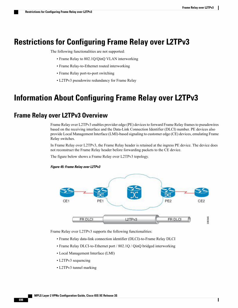
Restrictions for Configuring Frame Relay over L2TPv3The following functionalities are not supported:
• Frame Relay to 802.1Q/QinQ VLAN interworking
• Frame Relay-to-Ethernet routed interworking
• Frame Relay port-to-port switching
• L2TPv3 pseudowire redundancy for Frame Relay
Information About Configuring Frame Relay over L2TPv3
Frame Relay over L2TPv3 OverviewFrame Relay over L2TPv3 enables provider edge (PE) devices to forward Frame Relay frames to pseudowiresbased on the receiving interface and the Data-Link Connection Identifier (DLCI) number. PE devices alsoprovide LocalManagement Interface (LMI)-based signaling to customer edge (CE) devices, emulating FrameRelay switches.
In Frame Relay over L2TPv3, the Frame Relay header is retained at the ingress PE device. The device doesnot reconstruct the Frame Relay header before forwarding packets to the CE device.
The figure below shows a Frame Relay over L2TPv3 topology.
Figure 45: Frame Relay over L2TPv3
Frame Relay over L2TPv3 supports the following functionalities:
• Frame Relay data-link connection identifier (DLCI)-to-Frame Relay DLCI
• Frame Relay DLCI-to-Ethernet port / 802.1Q / QinQ bridged interworking
• Local Management Interface (LMI)
• L2TPv3 sequencing
• L2TPv3 tunnel marking
MPLS Layer 2 VPNs Configuration Guide, Cisco IOS XE Release 3S698
Frame Relay over L2TPv3Restrictions for Configuring Frame Relay over L2TPv3
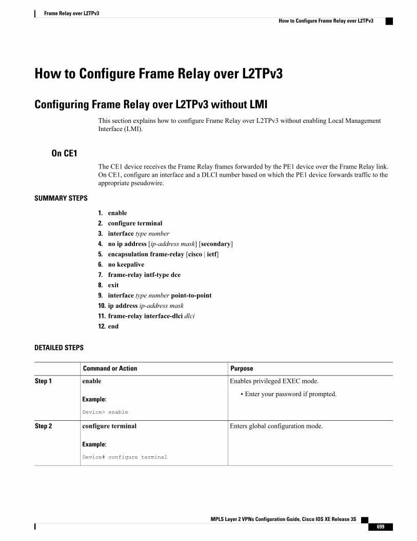
How to Configure Frame Relay over L2TPv3
Configuring Frame Relay over L2TPv3 without LMIThis section explains how to configure Frame Relay over L2TPv3 without enabling Local ManagementInterface (LMI).
On CE1The CE1 device receives the Frame Relay frames forwarded by the PE1 device over the Frame Relay link.On CE1, configure an interface and a DLCI number based on which the PE1 device forwards traffic to theappropriate pseudowire.
SUMMARY STEPS
1. enable2. configure terminal3. interface type number4. no ip address [ip-address mask] [secondary]5. encapsulation frame-relay [cisco | ietf]6. no keepalive7. frame-relay intf-type dce8. exit9. interface type number point-to-point10. ip address ip-address mask11. frame-relay interface-dlci dlci12. end
DETAILED STEPS
PurposeCommand or Action
Enables privileged EXEC mode.enableStep 1
Example:
Device> enable
• Enter your password if prompted.
Enters global configuration mode.configure terminal
Example:
Device# configure terminal
Step 2
MPLS Layer 2 VPNs Configuration Guide, Cisco IOS XE Release 3S 699
Frame Relay over L2TPv3How to Configure Frame Relay over L2TPv3
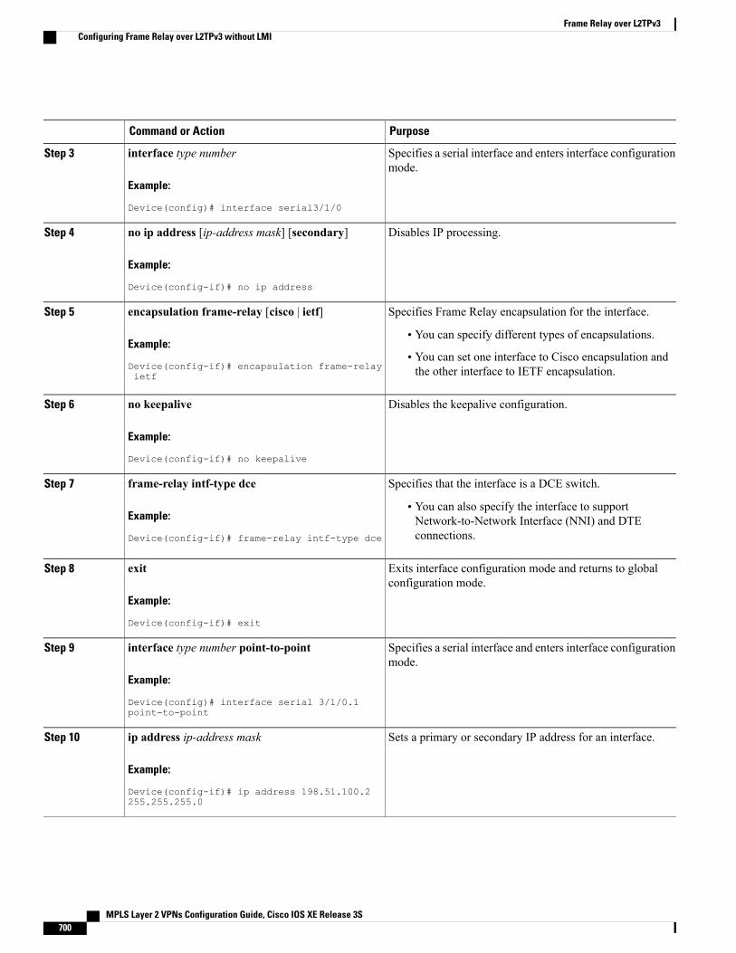
PurposeCommand or Action
Specifies a serial interface and enters interface configurationmode.
interface type number
Example:
Device(config)# interface serial3/1/0
Step 3
Disables IP processing.no ip address [ip-address mask] [secondary]
Example:
Device(config-if)# no ip address
Step 4
Specifies Frame Relay encapsulation for the interface.encapsulation frame-relay [cisco | ietf]Step 5
Example:
Device(config-if)# encapsulation frame-relayietf
• You can specify different types of encapsulations.
• You can set one interface to Cisco encapsulation andthe other interface to IETF encapsulation.
Disables the keepalive configuration.no keepalive
Example:
Device(config-if)# no keepalive
Step 6
Specifies that the interface is a DCE switch.frame-relay intf-type dceStep 7
Example:
Device(config-if)# frame-relay intf-type dce
• You can also specify the interface to supportNetwork-to-Network Interface (NNI) and DTEconnections.
Exits interface configuration mode and returns to globalconfiguration mode.
exit
Example:
Device(config-if)# exit
Step 8
Specifies a serial interface and enters interface configurationmode.
interface type number point-to-point
Example:
Device(config)# interface serial 3/1/0.1point-to-point
Step 9
Sets a primary or secondary IP address for an interface.ip address ip-address mask
Example:
Device(config-if)# ip address 198.51.100.2255.255.255.0
Step 10
MPLS Layer 2 VPNs Configuration Guide, Cisco IOS XE Release 3S700
Frame Relay over L2TPv3Configuring Frame Relay over L2TPv3 without LMI
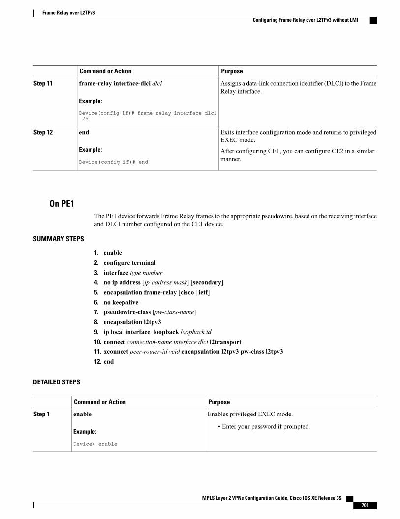
PurposeCommand or Action
Assigns a data-link connection identifier (DLCI) to the FrameRelay interface.
frame-relay interface-dlci dlci
Example:
Device(config-if)# frame-relay interface-dlci25
Step 11
Exits interface configuration mode and returns to privilegedEXEC mode.
end
Example:
Device(config-if)# end
Step 12
After configuring CE1, you can configure CE2 in a similarmanner.
On PE1The PE1 device forwards Frame Relay frames to the appropriate pseudowire, based on the receiving interfaceand DLCI number configured on the CE1 device.
SUMMARY STEPS
1. enable2. configure terminal3. interface type number4. no ip address [ip-address mask] [secondary]5. encapsulation frame-relay [cisco | ietf]6. no keepalive7. pseudowire-class [pw-class-name]8. encapsulation l2tpv39. ip local interface loopback loopback id10. connect connection-name interface dlci l2transport11. xconnect peer-router-id vcid encapsulation l2tpv3 pw-class l2tpv312. end
DETAILED STEPS
PurposeCommand or Action
Enables privileged EXEC mode.enableStep 1
Example:
Device> enable
• Enter your password if prompted.
MPLS Layer 2 VPNs Configuration Guide, Cisco IOS XE Release 3S 701
Frame Relay over L2TPv3Configuring Frame Relay over L2TPv3 without LMI
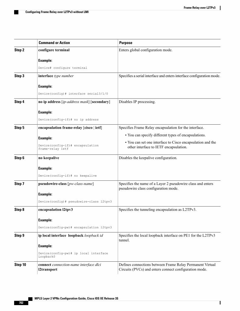
PurposeCommand or Action
Enters global configuration mode.configure terminal
Example:
Device# configure terminal
Step 2
Specifies a serial interface and enters interface configurationmode.interface type number
Example:
Device(config)# interface serial3/1/0
Step 3
Disables IP processing.no ip address [ip-address mask] [secondary]
Example:
Device(config-if)# no ip address
Step 4
Specifies Frame Relay encapsulation for the interface.encapsulation frame-relay [cisco | ietf]Step 5
Example:
Device(config-if)# encapsulationframe-relay ietf
• You can specify different types of encapsulations.
• You can set one interface to Cisco encapsulation and theother interface to IETF encapsulation.
Disables the keepalive configuration.no keepalive
Example:
Device(config-if)# no keepalive
Step 6
Specifies the name of a Layer 2 pseudowire class and enterspseudowire class configuration mode.
pseudowire-class [pw-class-name]
Example:
Device(config)# pseudowire-class l2tpv3
Step 7
Specifies the tunneling encapsulation as L2TPv3.encapsulation l2tpv3
Example:
Device(config-pw)# encapsulation l2tpv3
Step 8
Specifies the local loopback interface on PE1 for the L2TPv3tunnel.
ip local interface loopback loopback id
Example:
Device(config-pw)# ip local interfaceLoopback0
Step 9
Defines connections between Frame Relay Permanent VirtualCircuits (PVCs) and enters connect configuration mode.
connect connection-name interface dlcil2transport
Step 10
MPLS Layer 2 VPNs Configuration Guide, Cisco IOS XE Release 3S702
Frame Relay over L2TPv3Configuring Frame Relay over L2TPv3 without LMI
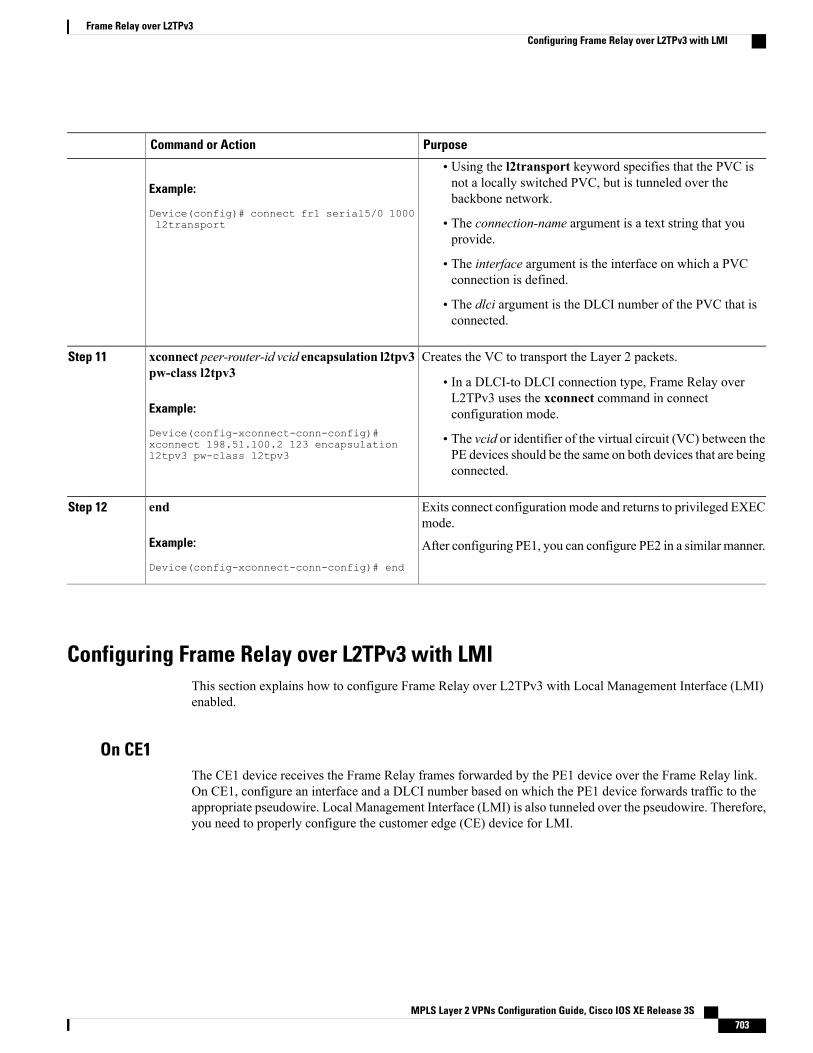
PurposeCommand or Action
Example:
Device(config)# connect fr1 serial5/0 1000l2transport
• Using the l2transport keyword specifies that the PVC isnot a locally switched PVC, but is tunneled over thebackbone network.
• The connection-name argument is a text string that youprovide.
• The interface argument is the interface on which a PVCconnection is defined.
• The dlci argument is the DLCI number of the PVC that isconnected.
Creates the VC to transport the Layer 2 packets.xconnect peer-router-id vcid encapsulation l2tpv3pw-class l2tpv3
Step 11
• In a DLCI-to DLCI connection type, Frame Relay overL2TPv3 uses the xconnect command in connectconfiguration mode.Example:
Device(config-xconnect-conn-config)# • The vcid or identifier of the virtual circuit (VC) between thePE devices should be the same on both devices that are beingconnected.
xconnect 198.51.100.2 123 encapsulationl2tpv3 pw-class l2tpv3
Exits connect configuration mode and returns to privileged EXECmode.
end
Example:
Device(config-xconnect-conn-config)# end
Step 12
After configuring PE1, you can configure PE2 in a similar manner.
Configuring Frame Relay over L2TPv3 with LMIThis section explains how to configure Frame Relay over L2TPv3 with Local Management Interface (LMI)enabled.
On CE1The CE1 device receives the Frame Relay frames forwarded by the PE1 device over the Frame Relay link.On CE1, configure an interface and a DLCI number based on which the PE1 device forwards traffic to theappropriate pseudowire. Local Management Interface (LMI) is also tunneled over the pseudowire. Therefore,you need to properly configure the customer edge (CE) device for LMI.
MPLS Layer 2 VPNs Configuration Guide, Cisco IOS XE Release 3S 703
Frame Relay over L2TPv3Configuring Frame Relay over L2TPv3 with LMI
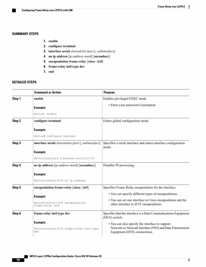
SUMMARY STEPS
1. enable2. configure terminal3. interface serial slot/subslot /port [. subinterface]4. no ip address [ip-address mask] [secondary]5. encapsulation frame-relay [cisco | ietf]6. frame-relay intf-type dce7. end
DETAILED STEPS
PurposeCommand or Action
Enables privileged EXEC mode.enableStep 1
Example:
Device> enable
• Enter your password if prompted.
Enters global configuration mode.configure terminal
Example:
Device# configure terminal
Step 2
Specifies a serial interface and enters interface configurationmode.
interface serial slot/subslot /port [. subinterface]
Example:
Device(config)# interface serial3/1/0
Step 3
Disables IP processing.no ip address [ip-address mask] [secondary]
Example:
Device(config-if)# no ip address
Step 4
Specifies Frame Relay encapsulation for the interface.encapsulation frame-relay [cisco | ietf]Step 5
Example:
Device(config-if)# encapsulationframe-relay ietf
• You can specify different types of encapsulations.
• You can set one interface to Cisco encapsulation and theother interface to IETF encapsulation.
Specifies that the interface is a Data Communications Equipment(DCE) switch.
frame-relay intf-type dce
Example:
Device(config-if)# frame-relay intf-typedce
Step 6
• You can also specify the interface to supportNetwork-to-Network Interface (NNI) andData TransmissionEquipment (DTE) connections.
MPLS Layer 2 VPNs Configuration Guide, Cisco IOS XE Release 3S704
Frame Relay over L2TPv3Configuring Frame Relay over L2TPv3 with LMI
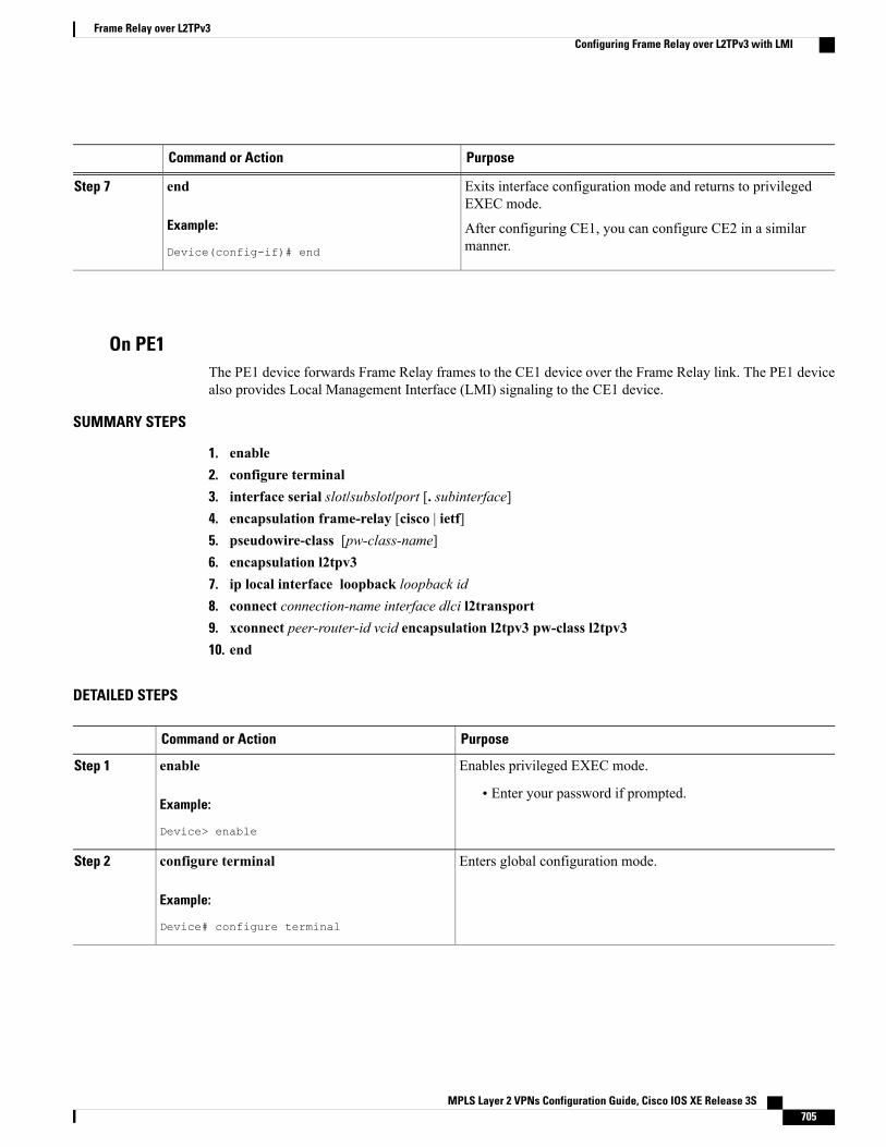
PurposeCommand or Action
Exits interface configuration mode and returns to privilegedEXEC mode.
end
Example:
Device(config-if)# end
Step 7
After configuring CE1, you can configure CE2 in a similarmanner.
On PE1The PE1 device forwards Frame Relay frames to the CE1 device over the Frame Relay link. The PE1 devicealso provides Local Management Interface (LMI) signaling to the CE1 device.
SUMMARY STEPS
1. enable2. configure terminal3. interface serial slot/subslot/port [. subinterface]4. encapsulation frame-relay [cisco | ietf]5. pseudowire-class [pw-class-name]6. encapsulation l2tpv37. ip local interface loopback loopback id8. connect connection-name interface dlci l2transport9. xconnect peer-router-id vcid encapsulation l2tpv3 pw-class l2tpv310. end
DETAILED STEPS
PurposeCommand or Action
Enables privileged EXEC mode.enableStep 1
Example:
Device> enable
• Enter your password if prompted.
Enters global configuration mode.configure terminal
Example:
Device# configure terminal
Step 2
MPLS Layer 2 VPNs Configuration Guide, Cisco IOS XE Release 3S 705
Frame Relay over L2TPv3Configuring Frame Relay over L2TPv3 with LMI
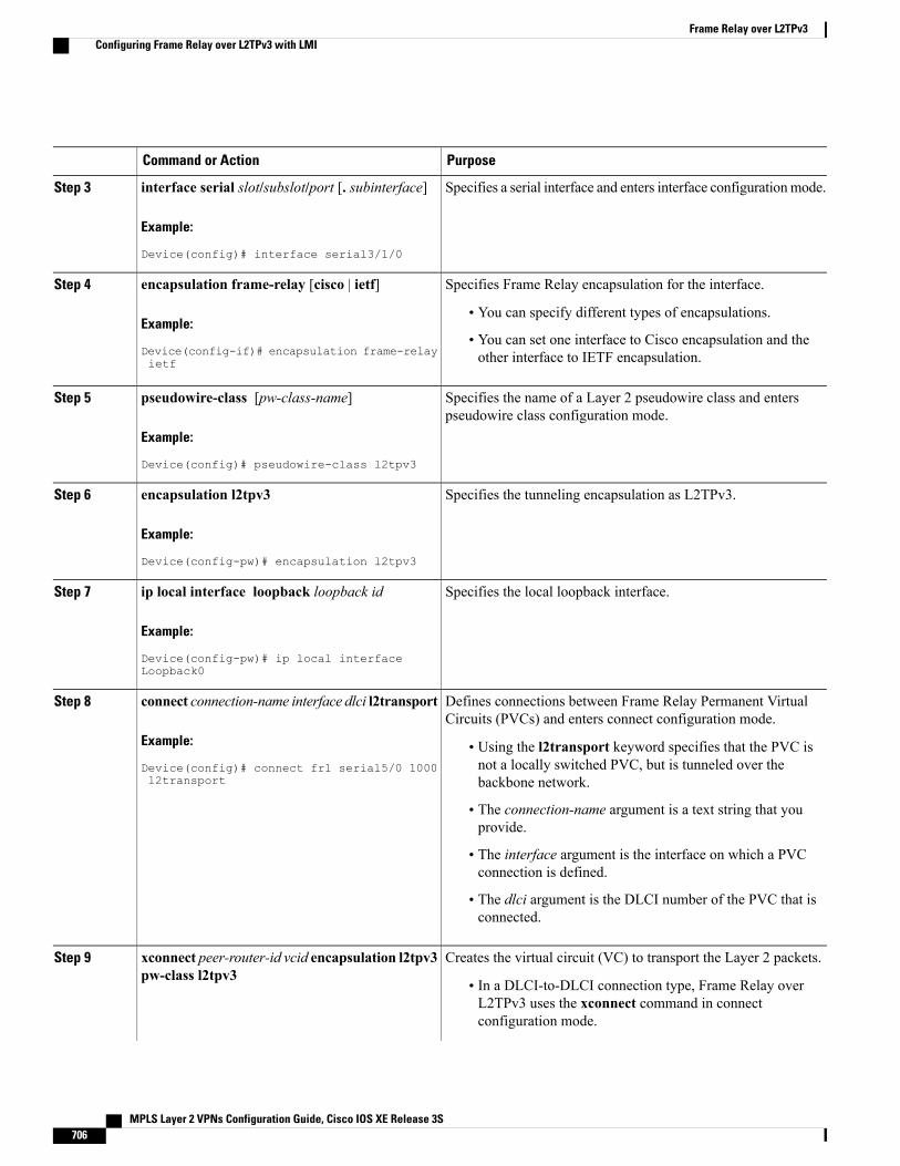
PurposeCommand or Action
Specifies a serial interface and enters interface configurationmode.interface serial slot/subslot/port [. subinterface]
Example:
Device(config)# interface serial3/1/0
Step 3
Specifies Frame Relay encapsulation for the interface.encapsulation frame-relay [cisco | ietf]Step 4
Example:
Device(config-if)# encapsulation frame-relayietf
• You can specify different types of encapsulations.
• You can set one interface to Cisco encapsulation and theother interface to IETF encapsulation.
Specifies the name of a Layer 2 pseudowire class and enterspseudowire class configuration mode.
pseudowire-class [pw-class-name]
Example:
Device(config)# pseudowire-class l2tpv3
Step 5
Specifies the tunneling encapsulation as L2TPv3.encapsulation l2tpv3
Example:
Device(config-pw)# encapsulation l2tpv3
Step 6
Specifies the local loopback interface.ip local interface loopback loopback id
Example:
Device(config-pw)# ip local interfaceLoopback0
Step 7
Defines connections between Frame Relay Permanent VirtualCircuits (PVCs) and enters connect configuration mode.
connect connection-name interface dlci l2transport
Example:
Device(config)# connect fr1 serial5/0 1000l2transport
Step 8
• Using the l2transport keyword specifies that the PVC isnot a locally switched PVC, but is tunneled over thebackbone network.
• The connection-name argument is a text string that youprovide.
• The interface argument is the interface on which a PVCconnection is defined.
• The dlci argument is the DLCI number of the PVC that isconnected.
Creates the virtual circuit (VC) to transport the Layer 2 packets.xconnect peer-router-id vcid encapsulation l2tpv3pw-class l2tpv3
Step 9
• In a DLCI-to-DLCI connection type, Frame Relay overL2TPv3 uses the xconnect command in connectconfiguration mode.
MPLS Layer 2 VPNs Configuration Guide, Cisco IOS XE Release 3S706
Frame Relay over L2TPv3Configuring Frame Relay over L2TPv3 with LMI
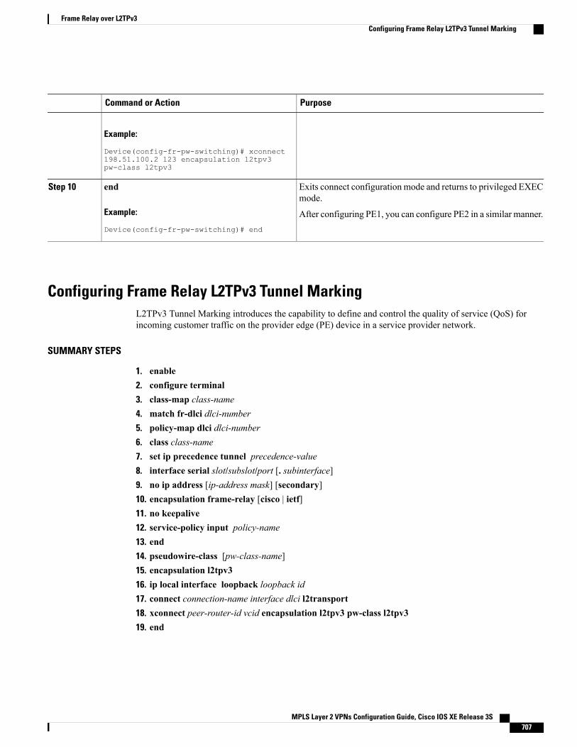
PurposeCommand or Action
Example:
Device(config-fr-pw-switching)# xconnect198.51.100.2 123 encapsulation l2tpv3pw-class l2tpv3
Exits connect configuration mode and returns to privileged EXECmode.
end
Example:
Device(config-fr-pw-switching)# end
Step 10
After configuring PE1, you can configure PE2 in a similar manner.
Configuring Frame Relay L2TPv3 Tunnel MarkingL2TPv3 Tunnel Marking introduces the capability to define and control the quality of service (QoS) forincoming customer traffic on the provider edge (PE) device in a service provider network.
SUMMARY STEPS
1. enable2. configure terminal3. class-map class-name4. match fr-dlci dlci-number5. policy-map dlci dlci-number6. class class-name7. set ip precedence tunnel precedence-value8. interface serial slot/subslot/port [. subinterface]9. no ip address [ip-address mask] [secondary]10. encapsulation frame-relay [cisco | ietf]11. no keepalive12. service-policy input policy-name13. end14. pseudowire-class [pw-class-name]15. encapsulation l2tpv316. ip local interface loopback loopback id17. connect connection-name interface dlci l2transport18. xconnect peer-router-id vcid encapsulation l2tpv3 pw-class l2tpv319. end
MPLS Layer 2 VPNs Configuration Guide, Cisco IOS XE Release 3S 707
Frame Relay over L2TPv3Configuring Frame Relay L2TPv3 Tunnel Marking
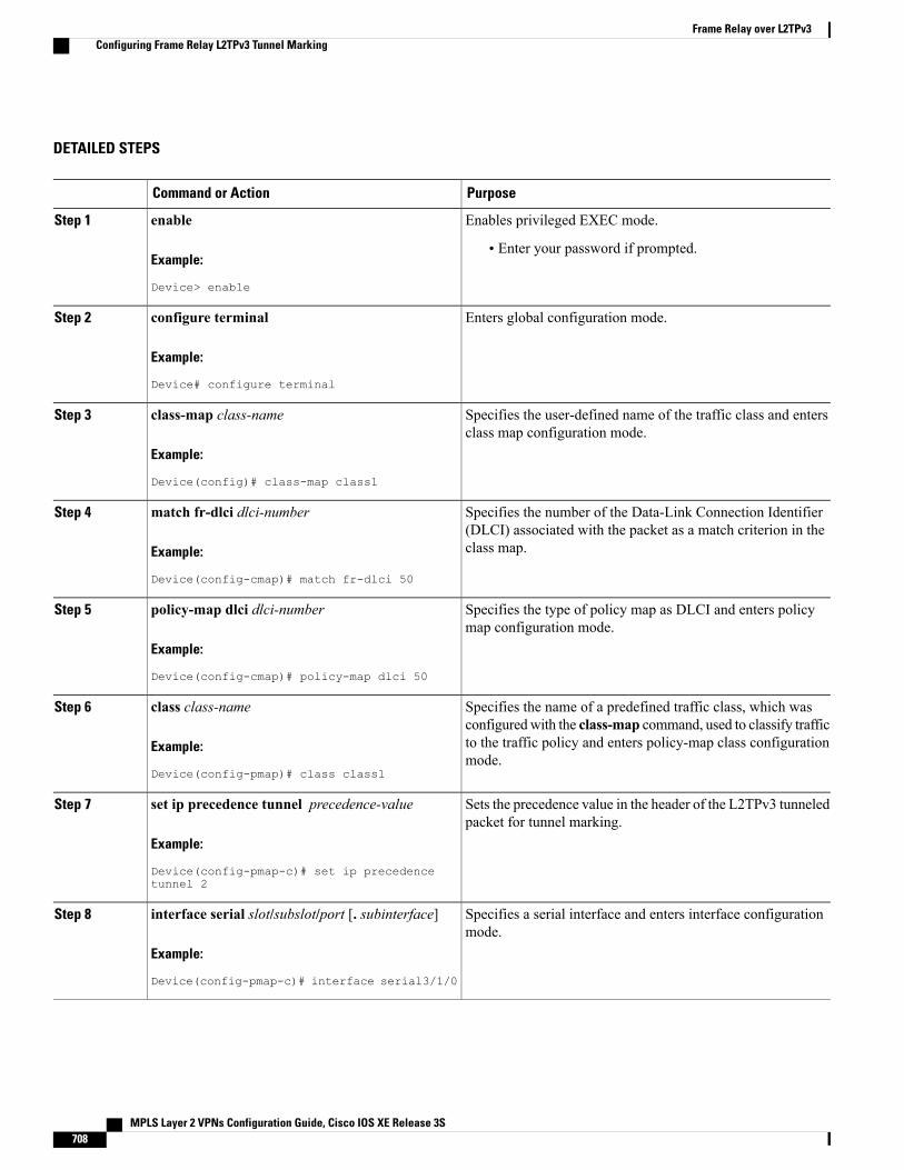
DETAILED STEPS
PurposeCommand or Action
Enables privileged EXEC mode.enableStep 1
Example:
Device> enable
• Enter your password if prompted.
Enters global configuration mode.configure terminal
Example:
Device# configure terminal
Step 2
Specifies the user-defined name of the traffic class and entersclass map configuration mode.
class-map class-name
Example:
Device(config)# class-map class1
Step 3
Specifies the number of the Data-Link Connection Identifier(DLCI) associated with the packet as a match criterion in theclass map.
match fr-dlci dlci-number
Example:
Device(config-cmap)# match fr-dlci 50
Step 4
Specifies the type of policy map as DLCI and enters policymap configuration mode.
policy-map dlci dlci-number
Example:
Device(config-cmap)# policy-map dlci 50
Step 5
Specifies the name of a predefined traffic class, which wasconfiguredwith the class-map command, used to classify traffic
class class-name
Example:
Device(config-pmap)# class class1
Step 6
to the traffic policy and enters policy-map class configurationmode.
Sets the precedence value in the header of the L2TPv3 tunneledpacket for tunnel marking.
set ip precedence tunnel precedence-value
Example:
Device(config-pmap-c)# set ip precedencetunnel 2
Step 7
Specifies a serial interface and enters interface configurationmode.
interface serial slot/subslot/port [. subinterface]
Example:
Device(config-pmap-c)# interface serial3/1/0
Step 8
MPLS Layer 2 VPNs Configuration Guide, Cisco IOS XE Release 3S708
Frame Relay over L2TPv3Configuring Frame Relay L2TPv3 Tunnel Marking
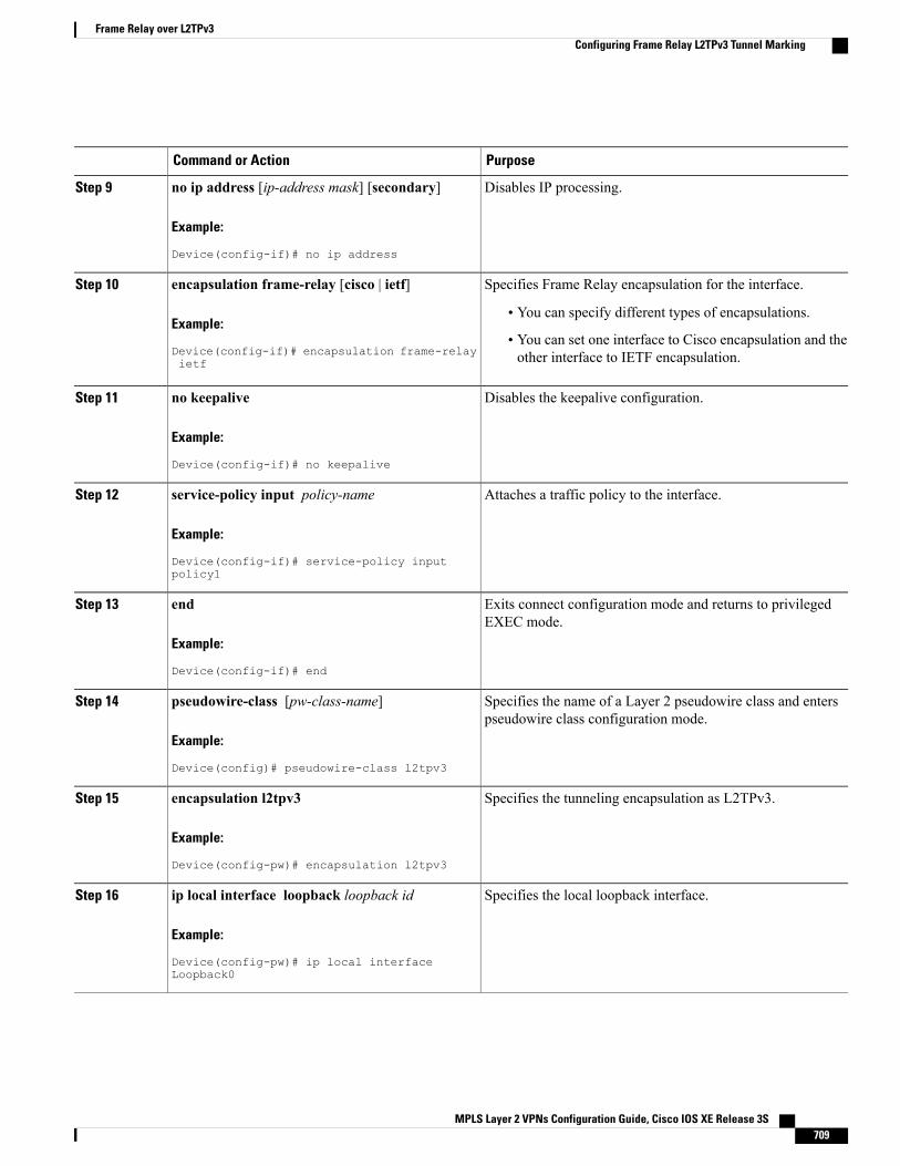
PurposeCommand or Action
Disables IP processing.no ip address [ip-address mask] [secondary]
Example:
Device(config-if)# no ip address
Step 9
Specifies Frame Relay encapsulation for the interface.encapsulation frame-relay [cisco | ietf]Step 10
Example:
Device(config-if)# encapsulation frame-relayietf
• You can specify different types of encapsulations.
• You can set one interface to Cisco encapsulation and theother interface to IETF encapsulation.
Disables the keepalive configuration.no keepalive
Example:
Device(config-if)# no keepalive
Step 11
Attaches a traffic policy to the interface.service-policy input policy-name
Example:
Device(config-if)# service-policy inputpolicy1
Step 12
Exits connect configuration mode and returns to privilegedEXEC mode.
end
Example:
Device(config-if)# end
Step 13
Specifies the name of a Layer 2 pseudowire class and enterspseudowire class configuration mode.
pseudowire-class [pw-class-name]
Example:
Device(config)# pseudowire-class l2tpv3
Step 14
Specifies the tunneling encapsulation as L2TPv3.encapsulation l2tpv3
Example:
Device(config-pw)# encapsulation l2tpv3
Step 15
Specifies the local loopback interface.ip local interface loopback loopback id
Example:
Device(config-pw)# ip local interfaceLoopback0
Step 16
MPLS Layer 2 VPNs Configuration Guide, Cisco IOS XE Release 3S 709
Frame Relay over L2TPv3Configuring Frame Relay L2TPv3 Tunnel Marking
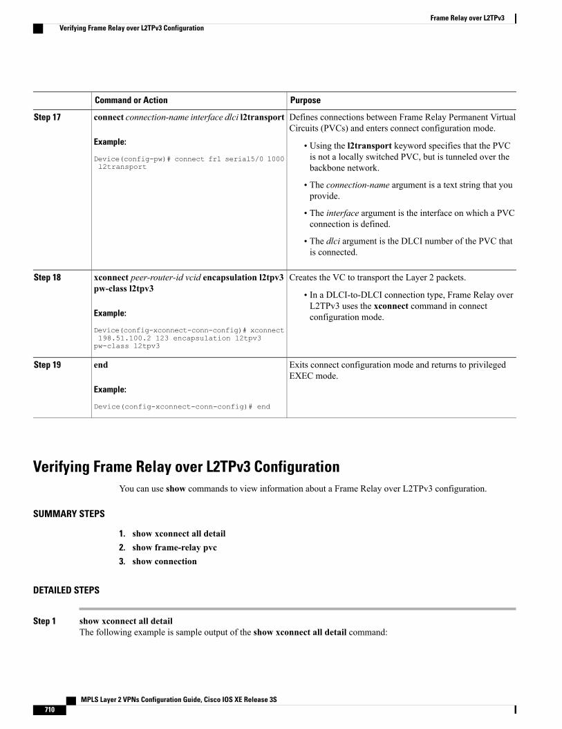
PurposeCommand or Action
Defines connections between Frame Relay Permanent VirtualCircuits (PVCs) and enters connect configuration mode.
connect connection-name interface dlci l2transport
Example:
Device(config-pw)# connect fr1 serial5/0 1000l2transport
Step 17
• Using the l2transport keyword specifies that the PVCis not a locally switched PVC, but is tunneled over thebackbone network.
• The connection-name argument is a text string that youprovide.
• The interface argument is the interface on which a PVCconnection is defined.
• The dlci argument is the DLCI number of the PVC thatis connected.
Creates the VC to transport the Layer 2 packets.xconnect peer-router-id vcid encapsulation l2tpv3pw-class l2tpv3
Step 18
• In a DLCI-to-DLCI connection type, Frame Relay overL2TPv3 uses the xconnect command in connectconfiguration mode.Example:
Device(config-xconnect-conn-config)# xconnect198.51.100.2 123 encapsulation l2tpv3pw-class l2tpv3
Exits connect configuration mode and returns to privilegedEXEC mode.
end
Example:
Device(config-xconnect-conn-config)# end
Step 19
Verifying Frame Relay over L2TPv3 ConfigurationYou can use show commands to view information about a Frame Relay over L2TPv3 configuration.
SUMMARY STEPS
1. show xconnect all detail2. show frame-relay pvc3. show connection
DETAILED STEPS
Step 1 show xconnect all detailThe following example is sample output of the show xconnect all detail command:
MPLS Layer 2 VPNs Configuration Guide, Cisco IOS XE Release 3S710
Frame Relay over L2TPv3Verifying Frame Relay over L2TPv3 Configuration
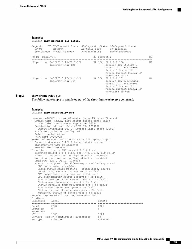
Example:Device# show xconnect all detail
Legend: XC ST=Xconnect State S1=Segment1 State S2=Segment2 StateUP=Up DN=Down AD=Admin Down IA=InactiveSB=Standby HS=Hot Standby RV=Recovering NH=No Hardware
XC ST Segment 1 S1 Segment 2 S2------+---------------------------------+--+---------------------------------+--UP pri ac Se0/2/0:0:16(FR DLCI) UP l2tp 22.2.2.2:100 UP
Interworking: L2L Session ID: 306532470Tunnel ID: 1381396806Protocol State: UPRemote Circuit State: UPpw-class: fr_fr
UP pri ac Se0/2/0:0:17(FR DLCI) UP l2tp 22.2.2.2:101 UPInterworking: Eth Session ID: 1373339282
Tunnel ID: 1381396806Protocol State: UPRemote Circuit State: UPpw-class: fr_eth
Step 2 show frame-relay pvcThe following example is sample output of the show frame-relay pvc command:
Example:Device# show frame-relay pvc
pseudowire100001 is up, VC status is up PW type: EthernetCreate time: 5d20h, last status change time: 5d20hLast label FSM state change time: 5d20h
Destination address: 2.1.1.2 VC ID: 1234000Output interface: Et0/0, imposed label stack {2001}
Preferred path: not configuredDefault path: activeNext hop: 20.0.0.2
Member of xconnect service Et1/0.1-1001, group rightAssociated member Et1/0.1 is up, status is upInterworking type is EthernetService id: 0x6d000002
Signaling protocol: LDP, peer 2.1.1.2:0 upTargeted Hello: 1.1.1.1(LDP Id) -> 2.1.1.2, LDP is UPGraceful restart: not configured and not enabledNon stop routing: not configured and not enabledPWid FEC (128), VC ID: 1234000Status TLV support (local/remote) : enabled/supportedLDP route watch : enabledLabel/status state machine : established, LruRruLocal dataplane status received : No faultBFD dataplane status received : Not sentBFD peer monitor status received : No faultStatus received from access circuit : No faultStatus sent to access circuit : No faultStatus received from pseudowire i/f : No faultStatus sent to network peer : No faultStatus received from network peer : No faultAdjacency status of remote peer : No fault
Sequencing: receive disabled, send disabledBindingsParameter Local Remote------------ ------------------------------ ------------------------------Label 2007 2001Group ID 0 6InterfaceMTU 1500 1500Control word on (configured: autosense) onPW type Ethernet Ethernet
MPLS Layer 2 VPNs Configuration Guide, Cisco IOS XE Release 3S 711
Frame Relay over L2TPv3Verifying Frame Relay over L2TPv3 Configuration
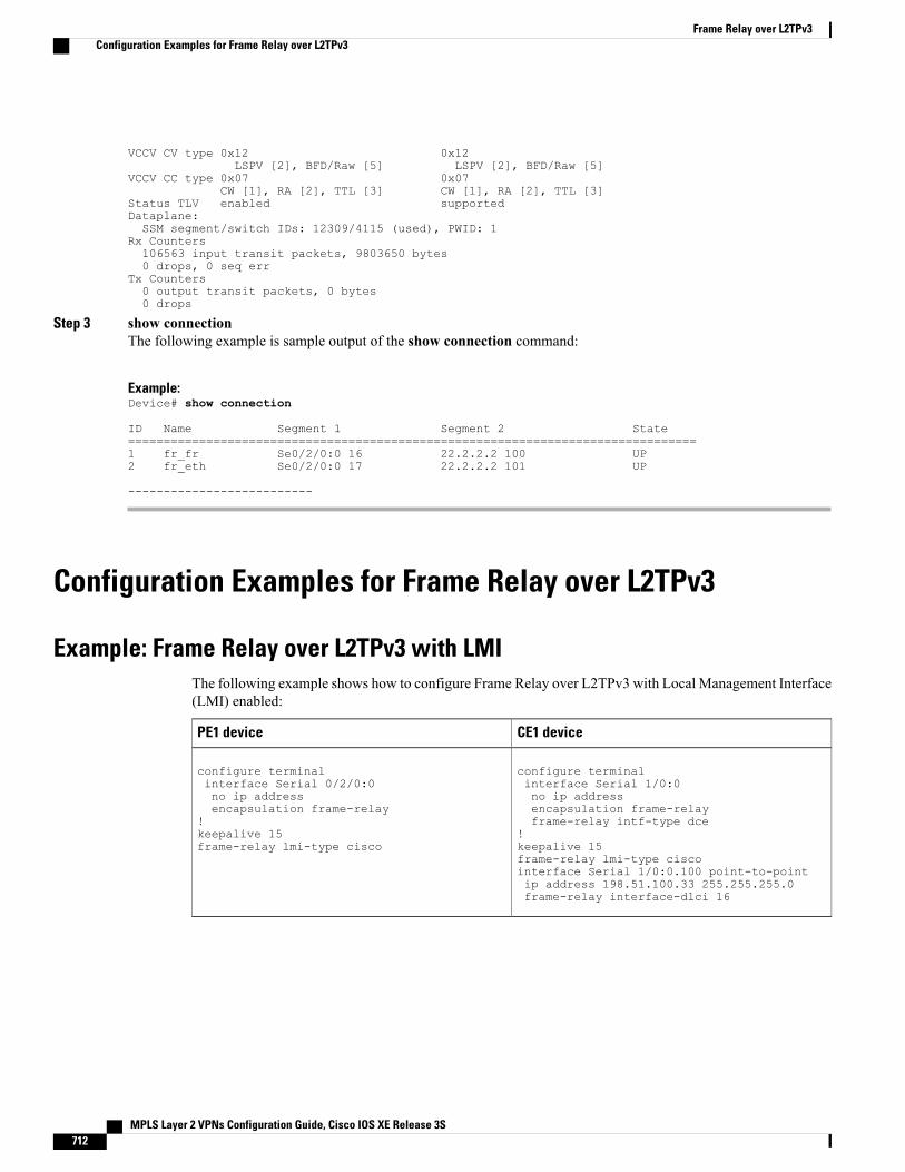
VCCV CV type 0x12 0x12LSPV [2], BFD/Raw [5] LSPV [2], BFD/Raw [5]
VCCV CC type 0x07 0x07CW [1], RA [2], TTL [3] CW [1], RA [2], TTL [3]
Status TLV enabled supportedDataplane:SSM segment/switch IDs: 12309/4115 (used), PWID: 1
Rx Counters106563 input transit packets, 9803650 bytes0 drops, 0 seq err
Tx Counters0 output transit packets, 0 bytes0 drops
Step 3 show connectionThe following example is sample output of the show connection command:
Example:Device# show connection
ID Name Segment 1 Segment 2 State================================================================================1 fr_fr Se0/2/0:0 16 22.2.2.2 100 UP2 fr_eth Se0/2/0:0 17 22.2.2.2 101 UP
--------------------------
Configuration Examples for Frame Relay over L2TPv3
Example: Frame Relay over L2TPv3 with LMIThe following example shows how to configure Frame Relay over L2TPv3 with Local Management Interface(LMI) enabled:
CE1 devicePE1 device
configure terminalinterface Serial 1/0:0no ip addressencapsulation frame-relayframe-relay intf-type dce
!keepalive 15frame-relay lmi-type ciscointerface Serial 1/0:0.100 point-to-pointip address 198.51.100.33 255.255.255.0frame-relay interface-dlci 16
configure terminalinterface Serial 0/2/0:0no ip addressencapsulation frame-relay
!keepalive 15frame-relay lmi-type cisco
MPLS Layer 2 VPNs Configuration Guide, Cisco IOS XE Release 3S712
Frame Relay over L2TPv3Configuration Examples for Frame Relay over L2TPv3
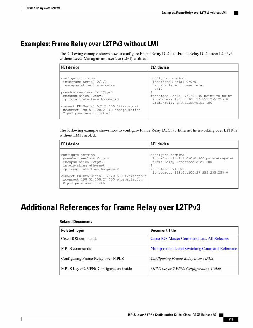
Examples: Frame Relay over L2TPv3 without LMIThe following example shows how to configure Frame Relay DLCI-to-Frame Relay DLCI over L2TPv3without Local Management Interface (LMI) enabled:
CE1 devicePE1 device
configure terminalinterface Serial 0/0/0encapsulation frame-relayexit
!interface Serial 0/0/0.100 point-to-pointip address 198.51.100.22 255.255.255.0frame-relay interface-dlci 100
configure terminalinterface Serial 0/1/0encapsulation frame-relay
!pseudowire-class fr_l2tpv3encapsulation l2tpv3ip local interface Loopback0!connect FR Serial 0/1/0 100 l2transportxconnect 198.51.100.2 100 encapsulationl2tpv3 pw-class fr_l2tpv3
The following example shows how to configure Frame Relay DLCI-to-Ethernet Interworking over L2TPv3without LMI enabled:
CE1 devicePE1 device
configure terminalinterface Serial 0/0/0.500 point-to-pointframe-relay interface-dlci 500!interface BVI 200ip address 198.51.100.29 255.255.255.0
configure terminalpseudowire-class fr_ethencapsulation l2tpv3interworking ethernetip local interface Loopback0!connect FR-Eth Serial 0/1/0 500 l2transportxconnect 198.51.100.27 500 encapsulationl2tpv3 pw-class fr_eth
Additional References for Frame Relay over L2TPv3Related Documents
Document TitleRelated Topic
Cisco IOS Master Command List, All ReleasesCisco IOS commands
Multiprotocol Label Switching Command ReferenceMPLS commands
Configuring Frame Relay over MPLSConfiguring Frame Relay over MPLS
MPLS Layer 2 VPNs Configuration GuideMPLS Layer 2 VPNs Configuration Guide
MPLS Layer 2 VPNs Configuration Guide, Cisco IOS XE Release 3S 713
Frame Relay over L2TPv3Examples: Frame Relay over L2TPv3 without LMI
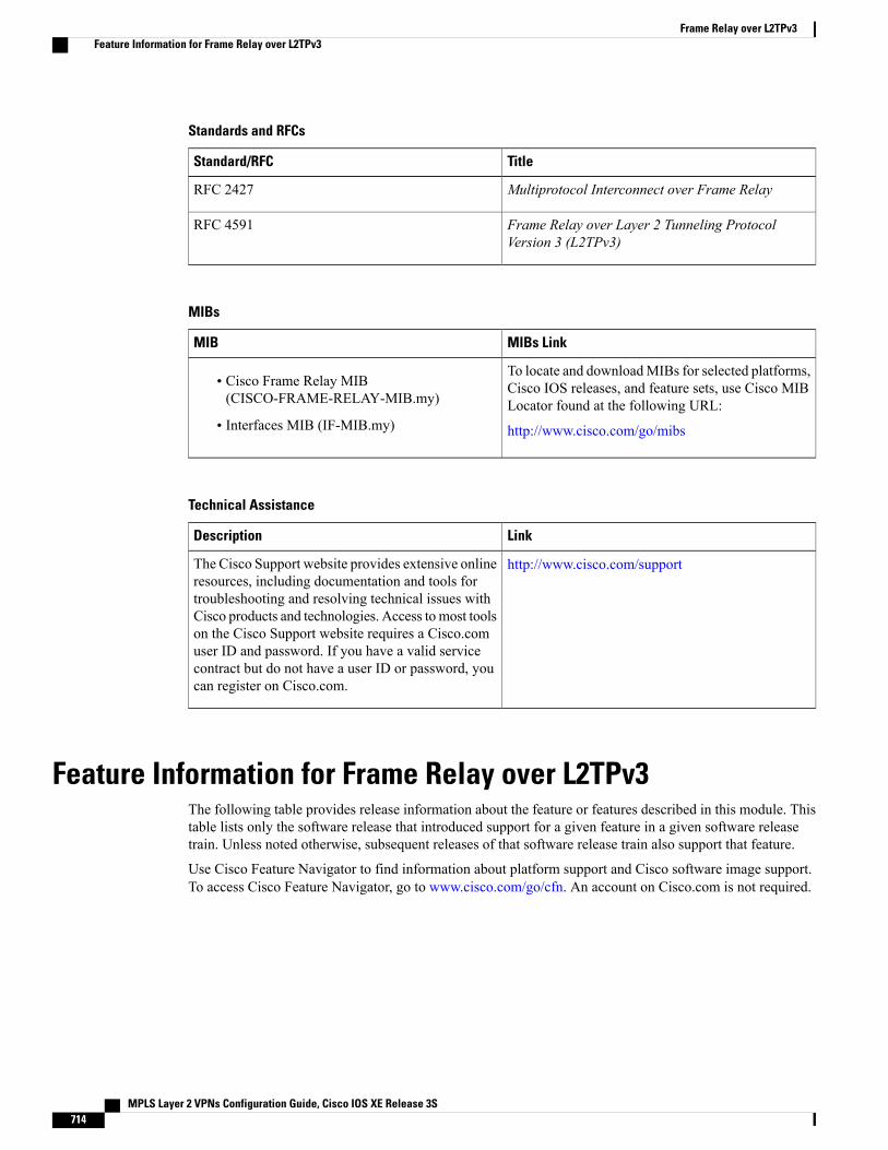
Standards and RFCs
TitleStandard/RFC
Multiprotocol Interconnect over Frame RelayRFC 2427
Frame Relay over Layer 2 Tunneling ProtocolVersion 3 (L2TPv3)
RFC 4591
MIBs
MIBs LinkMIB
To locate and downloadMIBs for selected platforms,Cisco IOS releases, and feature sets, use Cisco MIBLocator found at the following URL:
http://www.cisco.com/go/mibs
• Cisco Frame Relay MIB(CISCO-FRAME-RELAY-MIB.my)
• Interfaces MIB (IF-MIB.my)
Technical Assistance
LinkDescription
http://www.cisco.com/supportThe Cisco Support website provides extensive onlineresources, including documentation and tools fortroubleshooting and resolving technical issues withCisco products and technologies. Access to most toolson the Cisco Support website requires a Cisco.comuser ID and password. If you have a valid servicecontract but do not have a user ID or password, youcan register on Cisco.com.
Feature Information for Frame Relay over L2TPv3The following table provides release information about the feature or features described in this module. Thistable lists only the software release that introduced support for a given feature in a given software releasetrain. Unless noted otherwise, subsequent releases of that software release train also support that feature.
Use Cisco Feature Navigator to find information about platform support and Cisco software image support.To access Cisco Feature Navigator, go to www.cisco.com/go/cfn. An account on Cisco.com is not required.
MPLS Layer 2 VPNs Configuration Guide, Cisco IOS XE Release 3S714
Frame Relay over L2TPv3Feature Information for Frame Relay over L2TPv3

Table 42: Feature Information for Frame Relay over L2TPv3
Feature InformationReleasesFeature Name
This feature enables Frame Relayswitching over Layer 2 TunnelProtocol Version 3 (L2TPv3). Thefeature works with like interfacesand disparate interfaces (L2VPNinterworking).
Cisco IOS XE Release 3.12SFrame Relay over L2TPv3
MPLS Layer 2 VPNs Configuration Guide, Cisco IOS XE Release 3S 715
Frame Relay over L2TPv3Feature Information for Frame Relay over L2TPv3

MPLS Layer 2 VPNs Configuration Guide, Cisco IOS XE Release 3S716
Frame Relay over L2TPv3Feature Information for Frame Relay over L2TPv3
C H A P T E R 27Loop-Free Alternate Fast Reroute with L2VPN
The Loop-Free Alternate (LFA) Fast Reroute (FRR) with Layer 2 Virtual Private Network (L2VPN) featureminimizes packet loss due to link or node failure.
• Finding Feature Information, page 717
• Restrictions for Loop-Free Alternate Fast Reroute with L2VPN, page 717
• Information About Loop-Free Alternate Fast Reroute with L2VPN, page 718
• How to Configure Loop-Free Alternate Fast Reroute with L2VPN, page 718
• Configuration Examples for Loop-Free Alternate Fast Reroute with L2VPN, page 719
• Additional References, page 725
• Feature Information for Loop-Free Alternate Fast Reroute with L2VPN, page 725
Finding Feature InformationYour software release may not support all the features documented in this module. For the latest caveats andfeature information, see Bug Search Tool and the release notes for your platform and software release. Tofind information about the features documented in this module, and to see a list of the releases in which eachfeature is supported, see the feature information table at the end of this module.
Use Cisco Feature Navigator to find information about platform support and Cisco software image support.To access Cisco Feature Navigator, go to www.cisco.com/go/cfn. An account on Cisco.com is not required.
Restrictions for Loop-Free Alternate Fast Reroute with L2VPN• Load balancing is not supported
• Time-division multiplexing (TDM) pseudowire is not supported
• Virtual Private LAN Services (VPLS) is not supported
• The Virtual Private Wire Services (VPWS) scale number might change
MPLS Layer 2 VPNs Configuration Guide, Cisco IOS XE Release 3S 717
Information About Loop-Free Alternate Fast Reroute with L2VPN
L2VPN Over Loop-Free Alternate Fast RerouteThe Loop-Free Alternate (LFA) Fast Reroute (FRR) feature offers an alternative to the MPLS TrafficEngineering Fast Reroute feature to minimize packet loss due to link or node failure. It introduces LFA FRRsupport for L2VPNs and Virtual Private Wire Services (VPWS), providing the following benefits:
• Same level of protection from traffic loss
• Simplified configuration
• Link and node protection
• Link and path protection
• LFA (loop-free alternate) paths
• Support for both IP and Label Distribution Protocol (LDP) core
LFA FRR enables a backup route to avoid traffic loss if a network fails. The backup routes (repair paths) areprecomputed and installed in the router as the backup for the primary paths. After the router detects a link oradjacent node failure, it switches to the backup path to avoid traffic loss.
How to Configure Loop-Free Alternate Fast Reroute with L2VPNTo enable loop-free alternate fast reroute support for L2VPNs and VPWS, you must configure LFA FRR forthe routing protocol. No additional configuration tasks are necessary. See one of the following documents,depending on the routing protocol:
• IS-IS Remote Loop-Free Alternate Fast Reroute in the IP Routing: ISIS Configuration Guide
• OSPFv2 Loop-Free Alternate Fast Reroute in the IP Routing: OSPF Configuration Guide
• OSPF IPv4 Remote Loop-Free Alternate IP Fast Reroute in the IP Routing: OSPF Configuration Guide
Verifying Loop-Free Alternate Fast Reroute with L2VPNUse one or more of the following commands to verify the LFA FRR configuration:
SUMMARY STEPS
1. show ip cef network-prefix internal2. show mpls infrastructure lfd pseudowire internal3. show platform hardware pp active feature cef database ipv4 network-prefix
MPLS Layer 2 VPNs Configuration Guide, Cisco IOS XE Release 3S718
Loop-Free Alternate Fast Reroute with L2VPNInformation About Loop-Free Alternate Fast Reroute with L2VPN
DETAILED STEPS
Step 1 show ip cef network-prefix internal
Example:show ip cef 16.16.16.16 internalDisplays entries in the Cisco Express Forwarding (CEF) Forwarding Information Base (FIB).
Step 2 show mpls infrastructure lfd pseudowire internal
Example:show mpls infrastructure lfd pseudowire internalDisplays information about the Label Forwarding Database (LFD) and pseudowires.
Step 3 show platform hardware pp active feature cef database ipv4 network-prefix
Example:show platform hardware pp active feature cef database ipv4 16.16.16.16/32Displays information about the CEF database.
Configuration Examples for Loop-Free Alternate Fast Reroutewith L2VPN
Example: Verifying LFA FRR with L2VPN
show ip cef internal
The following example shows the configuration of LFA FRR for OSPF:router ospf 1router-id 17.17.17.17fast-reroute per-prefix enable prefix-priority lownetwork 3.3.3.0 0.0.0.255 area 1network 6.6.6.0 0.0.0.255 area 1network 7.7.7.0 0.0.0.255 area 1network 17.17.17.17 0.0.0.0 area 1
show ip cef internal
The following is sample output from the show ip cef internal command:Device# show ip cef 16.16.16.16 internal16.16.16.16/32, epoch 2, RIB[I], refcount 7, per-destination sharingsources: RIB, RR, LTEfeature space:IPRM: 0x00028000Broker: linked, distributed at 1st priorityLFD: 16.16.16.16/32 1 local labellocal label info: global/17
contains path extension listdisposition chain 0x3A3C1DF0
MPLS Layer 2 VPNs Configuration Guide, Cisco IOS XE Release 3S 719
Loop-Free Alternate Fast Reroute with L2VPNConfiguration Examples for Loop-Free Alternate Fast Reroute with L2VPN
label switch chain 0x3A3C1DF0subblocks:1 RR source [no flags]non-eos chain [16|44]
ifnums:GigabitEthernet0/0/2(9): 7.7.7.2GigabitEthernet0/0/7(14): 7.7.17.9path 35D61070, path list 3A388FA8, share 1/1, type attached nexthop, for IPv4, flags
has-repairMPLS short path extensions: MOI flags = 0x20 label 16
nexthop 7.7.7.2 GigabitEthernet0/0/2 label [16|44], adjacency IP adj out ofGigabitEthernet0/0/2, addr 7.7.7.2 35E88520
repair: attached-nexthop 7.7.17.9 GigabitEthernet0/0/7 (35D610E0)path 35D610E0, path list 3A388FA8, share 1/1, type attached nexthop, for IPv4, flags
repair, repair-onlynexthop 7.7.17.9 GigabitEthernet0/0/7, repair, adjacency IP adj out of GigabitEthernet0/0/7,addr 7.7.17.9 3A48A4E0output chain: label [16|44]FRR Primary (0x35D10F60)<primary: TAG adj out of GigabitEthernet0/0/2, addr 7.7.7.2 35E88380><repair: TAG adj out of GigabitEthernet0/0/7, addr 7.7.17.9 3A48A340>
Rudy17#show mpls infrastructure lfd pseudowire internalPW ID: 1VC ID: 4, Nexthop address: 16.16.16.16SSM Class: SSS HWSegment Count: 1VCCV Types Supported: cw ra ttlImposition details:Label stack {22 16}, Output interface: Gi0/0/2Preferred path: not configuredControl Word: enabled, Sequencing: disabledFIB Non IP entry: 0x35D6CEECOutput chain: AToM Imp (locks 4) label 22 label [16|44]FRR Primary (0x35D10F60)<primary: TAG adj out of GigabitEthernet0/0/2, addr 7.7.7.2 35E88380>
Disposition details:Local label: 16Control Word: enabled, Sequencing: disabledSSS Switch: 3976200193Output chain: mpls_eos( connid router-alert AToM Disp (locks 5)/ drop)
show mpls infrastructure lfd pseudowire internal
The following is sample output from the show mpls infrastructure lfd pseudowire internal command:Device# show mpls infrastructure lfd pseudowire internalPW ID: 1VC ID: 4, Nexthop address: 16.16.16.16SSM Class: SSS HWSegment Count: 1VCCV Types Supported: cw ra ttlImposition details:Label stack {22 16}, Output interface: Gi0/0/2Preferred path: not configuredControl Word: enabled, Sequencing: disabledFIB Non IP entry: 0x35D6CEECOutput chain: AToM Imp (locks 4) label 22 label [16|44]FRR Primary (0x35D10F60)<primary: TAG adj out of GigabitEthernet0/0/2, addr 7.7.7.2 35E88380>
Disposition details:Local label: 16Control Word: enabled, Sequencing: disabledSSS Switch: 3976200193Output chain: mpls_eos( connid router-alert AToM Disp (locks 5)/ drop)
show platform hardware pp active feature cef database
The following is sample output from the show platform hardware pp active feature cef database command:Device# show platform hardware pp active feature cef database ipv4 16.16.16.16/32=== CEF Prefix ===16.16.16.16/32 -- next hop: UEA Label OCE (PI:0x104abee0, PD:0x10e6b9c8)
Route Flags: (0)
MPLS Layer 2 VPNs Configuration Guide, Cisco IOS XE Release 3S720
Loop-Free Alternate Fast Reroute with L2VPNExample: Verifying LFA FRR with L2VPN
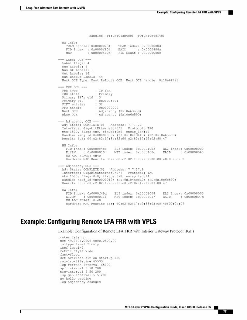
Handles (PI:0x104ab6e0) (PD:0x10e68140)
HW Info:TCAM handle: 0x0000023f TCAM index: 0x0000000dFID index : 0x0000f804 EAID : 0x0000808aMET : 0x0000400c FID Count : 0x00000000
=== Label OCE ===Label flags: 4Num Labels: 1Num Bk Labels: 1Out Labels: 16Out Backup Labels: 44Next OCE Type: Fast ReRoute OCE; Next OCE handle: 0x10e6f428
=== FRR OCE ===FRR type : IP FRRFRR state : PrimaryPrimary IF's gid : 3Primary FID : 0x0000f801FIFC entries : 32PPO handle : 0x00000000Next OCE : Adjacency (0x10e63b38)Bkup OCE : Adjacency (0x10e6e590)
=== Adjacency OCE ===Adj State: COMPLETE(0) Address: 7.7.7.2Interface: GigabitEthernet0/0/2 Protocol: TAGmtu:1500, flags:0x0, fixups:0x0, encap_len:14Handles (adj_id:0x00000039) (PI:0x1041d410) (PD:0x10e63b38)Rewrite Str: d0:c2:82:17:8a:82:d0:c2:82:17:f2:02:88:47
HW Info:FID index: 0x0000f486 EL3 index: 0x00001003 EL2 index: 0x00000000El2RW : 0x00000107 MET index: 0x0000400c EAID : 0x00008060HW ADJ FLAGS: 0x40Hardware MAC Rewrite Str: d0:c2:82:17:8a:82:08:00:40:00:0d:02
=== Adjacency OCE ===Adj State: COMPLETE(0) Address: 7.7.17.9Interface: GigabitEthernet0/0/7 Protocol: TAGmtu:1500, flags:0x0, fixups:0x0, encap_len:14Handles (adj_id:0x00000012) (PI:0x104acbd0) (PD:0x10e6e590)Rewrite Str: d0:c2:82:17:c9:83:d0:c2:82:17:f2:07:88:47
HW Info:FID index: 0x0000f49d EL3 index: 0x00001008 EL2 index: 0x00000000El2RW : 0x00000111 MET index: 0x00004017 EAID : 0x0000807dHW ADJ FLAGS: 0x40Hardware MAC Rewrite Str: d0:c2:82:17:c9:83:08:00:40:00:0d:07
Example: Configuring Remote LFA FRR with VPLSExample: Configuration of Remote LFA FRR with Interior Gateway Protocol (IGP)router isis hpnet 49.0101.0000.0000.0802.00is-type level-2-onlyispf level-2metric-style widefast-floodset-overload-bit on-startup 180max-lsp-lifetime 65535lsp-refresh-interval 65000spf-interval 5 50 200prc-interval 5 50 200lsp-gen-interval 5 5 200no hello paddinglog-adjacency-changes
MPLS Layer 2 VPNs Configuration Guide, Cisco IOS XE Release 3S 721
Loop-Free Alternate Fast Reroute with L2VPNExample: Configuring Remote LFA FRR with VPLS
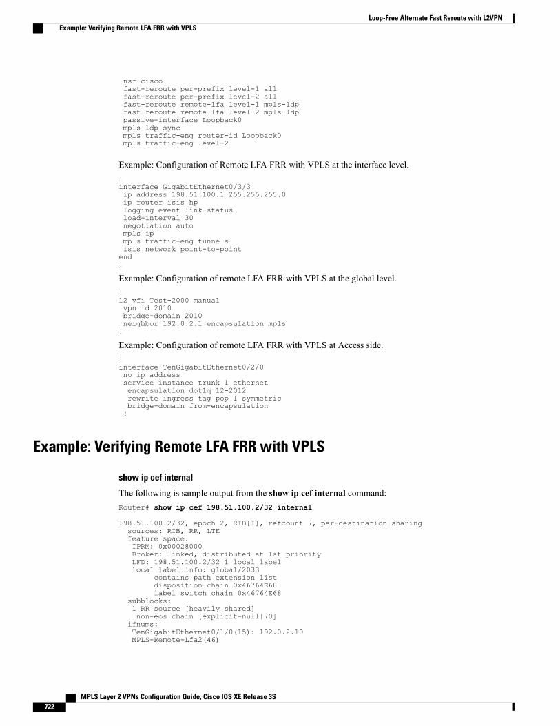
nsf ciscofast-reroute per-prefix level-1 allfast-reroute per-prefix level-2 allfast-reroute remote-lfa level-1 mpls-ldpfast-reroute remote-lfa level-2 mpls-ldppassive-interface Loopback0mpls ldp syncmpls traffic-eng router-id Loopback0mpls traffic-eng level-2
Example: Configuration of Remote LFA FRR with VPLS at the interface level.!interface GigabitEthernet0/3/3ip address 198.51.100.1 255.255.255.0ip router isis hplogging event link-statusload-interval 30negotiation autompls ipmpls traffic-eng tunnelsisis network point-to-pointend!
Example: Configuration of remote LFA FRR with VPLS at the global level.!l2 vfi Test-2000 manualvpn id 2010bridge-domain 2010neighbor 192.0.2.1 encapsulation mpls!
Example: Configuration of remote LFA FRR with VPLS at Access side.!interface TenGigabitEthernet0/2/0no ip addressservice instance trunk 1 ethernetencapsulation dot1q 12-2012rewrite ingress tag pop 1 symmetricbridge-domain from-encapsulation!
Example: Verifying Remote LFA FRR with VPLS
show ip cef internal
The following is sample output from the show ip cef internal command:Router# show ip cef 198.51.100.2/32 internal
198.51.100.2/32, epoch 2, RIB[I], refcount 7, per-destination sharingsources: RIB, RR, LTEfeature space:IPRM: 0x00028000Broker: linked, distributed at 1st priorityLFD: 198.51.100.2/32 1 local labellocal label info: global/2033
contains path extension listdisposition chain 0x46764E68label switch chain 0x46764E68
subblocks:1 RR source [heavily shared]non-eos chain [explicit-null|70]
ifnums:TenGigabitEthernet0/1/0(15): 192.0.2.10MPLS-Remote-Lfa2(46)
MPLS Layer 2 VPNs Configuration Guide, Cisco IOS XE Release 3S722
Loop-Free Alternate Fast Reroute with L2VPNExample: Verifying Remote LFA FRR with VPLS
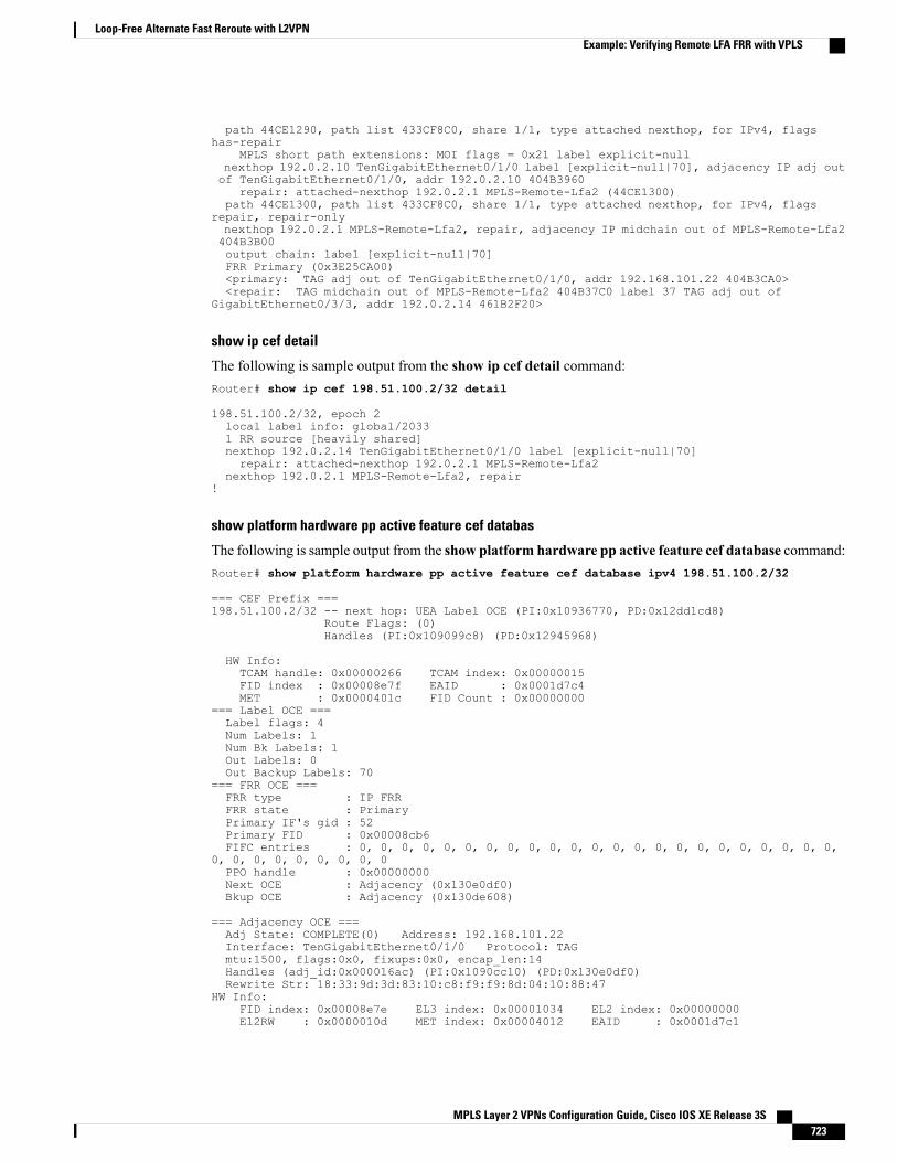
path 44CE1290, path list 433CF8C0, share 1/1, type attached nexthop, for IPv4, flagshas-repair
MPLS short path extensions: MOI flags = 0x21 label explicit-nullnexthop 192.0.2.10 TenGigabitEthernet0/1/0 label [explicit-null|70], adjacency IP adj outof TenGigabitEthernet0/1/0, addr 192.0.2.10 404B3960
repair: attached-nexthop 192.0.2.1 MPLS-Remote-Lfa2 (44CE1300)path 44CE1300, path list 433CF8C0, share 1/1, type attached nexthop, for IPv4, flags
repair, repair-onlynexthop 192.0.2.1 MPLS-Remote-Lfa2, repair, adjacency IP midchain out of MPLS-Remote-Lfa2404B3B00output chain: label [explicit-null|70]FRR Primary (0x3E25CA00)<primary: TAG adj out of TenGigabitEthernet0/1/0, addr 192.168.101.22 404B3CA0><repair: TAG midchain out of MPLS-Remote-Lfa2 404B37C0 label 37 TAG adj out of
GigabitEthernet0/3/3, addr 192.0.2.14 461B2F20>
show ip cef detail
The following is sample output from the show ip cef detail command:Router# show ip cef 198.51.100.2/32 detail
198.51.100.2/32, epoch 2local label info: global/20331 RR source [heavily shared]nexthop 192.0.2.14 TenGigabitEthernet0/1/0 label [explicit-null|70]repair: attached-nexthop 192.0.2.1 MPLS-Remote-Lfa2
nexthop 192.0.2.1 MPLS-Remote-Lfa2, repair!
show platform hardware pp active feature cef databas
The following is sample output from the show platform hardware pp active feature cef database command:Router# show platform hardware pp active feature cef database ipv4 198.51.100.2/32
=== CEF Prefix ===198.51.100.2/32 -- next hop: UEA Label OCE (PI:0x10936770, PD:0x12dd1cd8)
Route Flags: (0)Handles (PI:0x109099c8) (PD:0x12945968)
HW Info:TCAM handle: 0x00000266 TCAM index: 0x00000015FID index : 0x00008e7f EAID : 0x0001d7c4MET : 0x0000401c FID Count : 0x00000000
=== Label OCE ===Label flags: 4Num Labels: 1Num Bk Labels: 1Out Labels: 0Out Backup Labels: 70
=== FRR OCE ===FRR type : IP FRRFRR state : PrimaryPrimary IF's gid : 52Primary FID : 0x00008cb6FIFC entries : 0, 0, 0, 0, 0, 0, 0, 0, 0, 0, 0, 0, 0, 0, 0, 0, 0, 0, 0, 0, 0, 0, 0,
0, 0, 0, 0, 0, 0, 0, 0, 0PPO handle : 0x00000000Next OCE : Adjacency (0x130e0df0)Bkup OCE : Adjacency (0x130de608)
=== Adjacency OCE ===Adj State: COMPLETE(0) Address: 192.168.101.22Interface: TenGigabitEthernet0/1/0 Protocol: TAGmtu:1500, flags:0x0, fixups:0x0, encap_len:14Handles (adj_id:0x000016ac) (PI:0x1090cc10) (PD:0x130e0df0)Rewrite Str: 18:33:9d:3d:83:10:c8:f9:f9:8d:04:10:88:47
HW Info:FID index: 0x00008e7e EL3 index: 0x00001034 EL2 index: 0x00000000El2RW : 0x0000010d MET index: 0x00004012 EAID : 0x0001d7c1
MPLS Layer 2 VPNs Configuration Guide, Cisco IOS XE Release 3S 723
Loop-Free Alternate Fast Reroute with L2VPNExample: Verifying Remote LFA FRR with VPLS
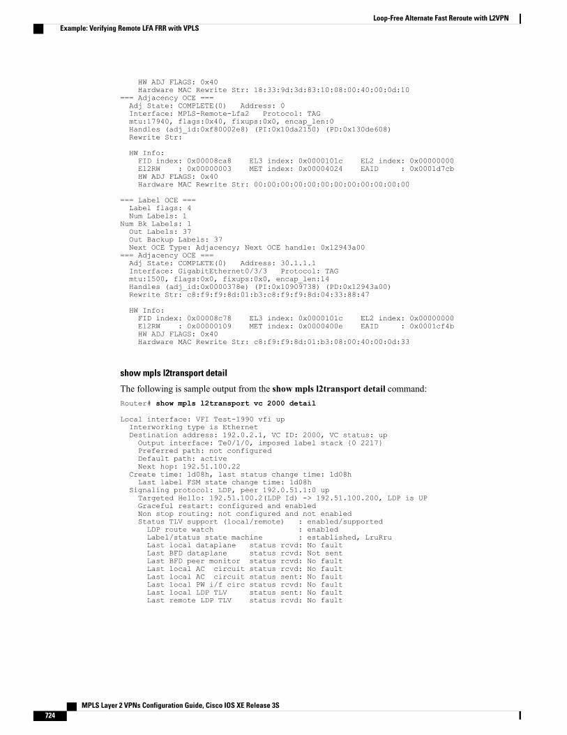
HW ADJ FLAGS: 0x40Hardware MAC Rewrite Str: 18:33:9d:3d:83:10:08:00:40:00:0d:10
=== Adjacency OCE ===Adj State: COMPLETE(0) Address: 0Interface: MPLS-Remote-Lfa2 Protocol: TAGmtu:17940, flags:0x40, fixups:0x0, encap_len:0Handles (adj_id:0xf80002e8) (PI:0x10da2150) (PD:0x130de608)Rewrite Str:
HW Info:FID index: 0x00008ca8 EL3 index: 0x0000101c EL2 index: 0x00000000El2RW : 0x00000003 MET index: 0x00004024 EAID : 0x0001d7cbHW ADJ FLAGS: 0x40Hardware MAC Rewrite Str: 00:00:00:00:00:00:00:00:00:00:00:00
=== Label OCE ===Label flags: 4Num Labels: 1
Num Bk Labels: 1Out Labels: 37Out Backup Labels: 37Next OCE Type: Adjacency; Next OCE handle: 0x12943a00
=== Adjacency OCE ===Adj State: COMPLETE(0) Address: 30.1.1.1Interface: GigabitEthernet0/3/3 Protocol: TAGmtu:1500, flags:0x0, fixups:0x0, encap_len:14Handles (adj_id:0x0000378e) (PI:0x10909738) (PD:0x12943a00)Rewrite Str: c8:f9:f9:8d:01:b3:c8:f9:f9:8d:04:33:88:47
HW Info:FID index: 0x00008c78 EL3 index: 0x0000101c EL2 index: 0x00000000El2RW : 0x00000109 MET index: 0x0000400e EAID : 0x0001cf4bHW ADJ FLAGS: 0x40Hardware MAC Rewrite Str: c8:f9:f9:8d:01:b3:08:00:40:00:0d:33
show mpls l2transport detail
The following is sample output from the show mpls l2transport detail command:Router# show mpls l2transport vc 2000 detail
Local interface: VFI Test-1990 vfi upInterworking type is EthernetDestination address: 192.0.2.1, VC ID: 2000, VC status: upOutput interface: Te0/1/0, imposed label stack {0 2217}Preferred path: not configuredDefault path: activeNext hop: 192.51.100.22
Create time: 1d08h, last status change time: 1d08hLast label FSM state change time: 1d08h
Signaling protocol: LDP, peer 192.0.51.1:0 upTargeted Hello: 192.51.100.2(LDP Id) -> 192.51.100.200, LDP is UPGraceful restart: configured and enabledNon stop routing: not configured and not enabledStatus TLV support (local/remote) : enabled/supportedLDP route watch : enabledLabel/status state machine : established, LruRruLast local dataplane status rcvd: No faultLast BFD dataplane status rcvd: Not sentLast BFD peer monitor status rcvd: No faultLast local AC circuit status rcvd: No faultLast local AC circuit status sent: No faultLast local PW i/f circ status rcvd: No faultLast local LDP TLV status sent: No faultLast remote LDP TLV status rcvd: No fault
MPLS Layer 2 VPNs Configuration Guide, Cisco IOS XE Release 3S724
Loop-Free Alternate Fast Reroute with L2VPNExample: Verifying Remote LFA FRR with VPLS
Additional ReferencesRelated Documents
Document TitleRelated Topic
Cisco IOS Master Command List, All ReleasesCisco IOS commands
Multiprotocol Label Switching Command ReferenceMPLS commands
Technical Assistance
LinkDescription
http://www.cisco.com/cisco/web/support/index.htmlThe Cisco Support and Documentation websiteprovides online resources to download documentation,software, and tools. Use these resources to install andconfigure the software and to troubleshoot and resolvetechnical issues with Cisco products and technologies.Access to most tools on the Cisco Support andDocumentation website requires a Cisco.com user IDand password.
Feature Information for Loop-Free Alternate Fast Reroute withL2VPN
The following table provides release information about the feature or features described in this module. Thistable lists only the software release that introduced support for a given feature in a given software releasetrain. Unless noted otherwise, subsequent releases of that software release train also support that feature.
Use Cisco Feature Navigator to find information about platform support and Cisco software image support.To access Cisco Feature Navigator, go to www.cisco.com/go/cfn. An account on Cisco.com is not required.
MPLS Layer 2 VPNs Configuration Guide, Cisco IOS XE Release 3S 725
Loop-Free Alternate Fast Reroute with L2VPNAdditional References
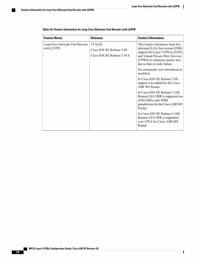
Table 43: Feature Information for Loop-Free Alternate Fast Reroute with L2VPN
Feature InformationReleasesFeature Name
This feature introduces loop-freealternate (LFA) fast reroute (FRR)support for Layer 2 VPN (L2VPN)and Virtual Private Wire Services(VPWS) to minimize packet lossdue to link or node failure.
No commands were introduced ormodified.
In Cisco IOS XE Release 3.9S,support was added for the CiscoASR 903 Router.
In Cisco IOS XE Release 3.10S,Remote LFA FRR is supported onATM (IMA) and TDMpseudowires for the CiscoASR 903Router.
In Cisco IOS XE Release 3.10S,Remote LFA FRR is supportedover VPLS for Cisco ASR 903Router.
15.3(2)S
Cisco IOS XE Release 3.9S
Cisco IOS XE Release 3.10 S
Loop-Free Alternate Fast Reroutewith L2VPN
MPLS Layer 2 VPNs Configuration Guide, Cisco IOS XE Release 3S726
Loop-Free Alternate Fast Reroute with L2VPNFeature Information for Loop-Free Alternate Fast Reroute with L2VPN
Related Documents