MICRO PROCESSOR AND MICRO CONTROLLER Lab manual

Welcome message from author
This document is posted to help you gain knowledge. Please leave a comment to let me know what you think about it! Share it to your friends and learn new things together.
Transcript

MICRO PROCESSOR AND
MICRO CONTROLLER
Lab manual

INTRODUCTION TO MASM
Programming of a microprocessor usually takes several iterations before the right sequence of machine code instruction is written. The process, how machine code is facilitated casing a special program called an “assembler”. The assembler allows the user to write alphanumeric instructions (or) mnemonics called assembly language instructions. An assembler takes the written assembly code and converts it into machine code. Often it will come with a linker that links the assembled file and produces an executable from it.Window executables have the extension. Here are some of the popular ones
MASM:- Microsoft’s macro assembler(MASM) is an integrated software package written by Microsoft co-operation for professional software developers. It consists of an editor, an assembler, a linker and a debugger the programmer’s work bench combines these four path into a user friendly programming environment with built in online help.
FAMILIARITY WITH MASM:-
Available since the beginning of the IBM compatible PCS
Works in MS-DOS and windows environments.
It’s free: Microsoft no longer sells MASM as a standalone product.
Bundled with the Microsoft visual studio product
Numerous tutorials, books and samples floating around, many are free or low cost
TASM:- Another popular assembler made by Borland but it is still a commercial product.
ASSEMBLING THE PROGRAM:-
The assembler is used to convert the assembly language instructions to machine code. It is used immediately after writing the assembly language program. The assembler starts by checking the syntax or validity of the structure of each instruction in the source file. If any errors are found the assembler displays a report on these errors along with brief explanation of their nature. However, if the program does not contain any errors. The assembler produces an object file that the same name as original file but with the “.obj” extension.
LINKING THE PROGRAM:-
The linker is used to convert the object file to an executable file the executable file is the final set of machine code instructions that can directly be executed by microprocessor. It is difficult and different than the object file on the sense that it is self
contained and locatable. An object file may represent on segment of long program. This program cannot operate by itself and must be integrated with other object file representing the rest of the program in order to produce the final self contained exactable file.
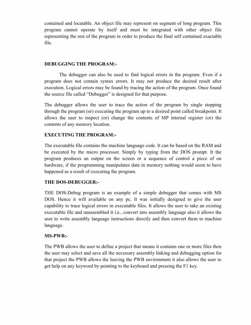
DEBUGGING THE PROGRAM:-
The debugger can also be used to find logical errors in the program. Even if a program does not contain syntax errors. It may not produce the desired result after execution. Logical errors may be found by tracing the action of the program. Once found the source file called “Debugger” is designed for that purpose.
The debugger allows the user to trace the action of the program by single stepping through the program (or) executing the program up to a desired point called breakpoint. It allows the user to inspect (or) change the contents of MP internal register (or) the contents of any memory location.
EXECUTING THE PROGRAM:-
The executable file contains the machine language code. It can be based on the RAM and be executed by the micro processor. Simply by typing from the DOS prompt. It the program produces an output on the screen or a sequence of control a piece of on hardware, if the programming manipulates data in memory nothing would seem to have happened as a result of executing the program.
THE DOS-DEBUGGER:-
THE DOS-Debug program is an example of a simple debugger that comes with MS DOS. Hence it will available on any pc. It was initially designed to give the user capability to trace logical errors in executable files. It allows the user to take an existing executable file and unassembled it i.e., convert into assembly language also it allows the user to write assembly language instructions directly and then convert them to machine language.
MS-PWB:-
The PWB allows the user to define a project that means it contains one or more files then the user may select and save all the necessary assembly linking and debugging option for that project the PWB allows the leaving the PWB environment it also allows the user to get help on any keyword by pointing to the keyboard and pressing the F1 key.

COMMAND SYNTAXAssemble A[address]compare C[range address]dump D[large]enter E address[list]fill F range listgo G[address][address]hex H value 1 value 2input I portload L[address][drive][first sector][number]move M range addressname N[path name][argument list]output O port byteprocess P[address][number]quit Qregister R[register]search S range listtrace T[address][value]Un assemble U[range]write W[address][drive][first sector][number]

INTRODUCTION OF MICROPROCESSOR
INTRODUCTION:
Microprocessor is regarded as one of the most important devices in our everyday machines called computers. Microprocessor is an electronic circuit that functions as the CPU of a computer, providing computational control. Microprocessor are also used in other advanced electronic systems, such as computer printers, automobiles and jet airlines
The first Microprocessor was the Intel 4004, produced in 1971. Originally developed for a calculator and revolutionary for its time, it contained 2300 transistors on a 4-bit microprocessor that could perform only 60,000 operations per second. The first 8-bit microprocessor was the Intel 8008, developed in 1972 to run computer terminals.
INTEL MICROPROCESSOR:
8086(1979):
Created as a cheaper version of Intel’s 8086, the 8088 was a 16-bit processor with an 8-bit external bus
80286(1982):
With 16MB of addressable memory and 1GB of a virtual memory, this 16-bit chip is referred to as the first “modern” microprocessor. It contained 130,000 transistors and packed serious compute power 12MHz
80386(1985):
The price/performance curve continued its steep climb with the 386 and later the 486- 32 bit processors that brought real computing to the masses. The 386, featured 275,000 transistors, the 486 had more than a million
Pentium (1993):
Adding systems-level characteristics to enormous raw compute power, the Pentium supports demanding I/O, graphics and communications intensive applications with more than 3 million transistors
Pentium Pro (1995):
he nearest Pentium has dynamic instruction execution and the chip package is more than 5.5 million transistors
Pentium II (1997):

The 7.5 million transistors Pentium II processor incorporates Intel MMX-TM technology, which is designed specially to process video, audio and graphics data efficiently
Pentium III (1999):
The Pentium III processor features 70 new instructions. It designed to significantly enhance Internet experience, allowing users to do such things as browse through realistic online museums and stores and download high-quality video. The processor incorporates 9.5 million transistors, and was introduced using 0.25 micron technology.
Pentium-IV (2000):
The Pentium-4 is fabricated in Intel’s 0.18 micron CMOS process. Its die size is 217 , power consumption is 50W. The Pentium-4 is available in 1.4GHz & 1.5Hz bins
Buses and operation:
8086 has all internal registers are as well as internal and external data buses, were 16 bits wide, finally estimating the “16 bit micro processor” identity of the 8086. A 20 bit external address bus gave a 1MB physical address space (220=1,048,576). This address space was addressed by means of internal ‘segmentation ‘. The data was multiplexed with the address bus in order to fit a standard 40-pin dual in line package. 16 bit I/O address meant 64KB of separate I/O space (216=65,536). The maximum linear address space was limited to 64KB.Simply because internal registers were only 16 bits wide, programming over 64KB, boundaries involved adjusting segment register.
Some of the control pins which carry essential signals for all external operations had more than one function depending upon whether the device operated in ‘min’ or ‘max’ mode. The former was intended for small single processor systems while latter was for medium and large systems, using more than one processor.
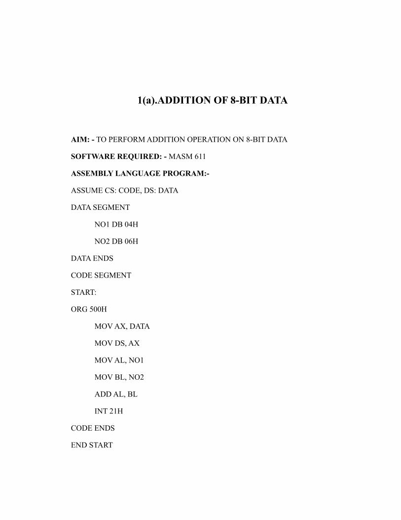
1(a).ADDITION OF 8-BIT DATA
AIM: - TO PERFORM ADDITION OPERATION ON 8-BIT DATA
SOFTWARE REQUIRED: - MASM 611
ASSEMBLY LANGUAGE PROGRAM:-
ASSUME CS: CODE, DS: DATA
DATA SEGMENT
NO1 DB 04H
NO2 DB 06H
DATA ENDS
CODE SEGMENT
START:
ORG 500H
MOV AX, DATA
MOV DS, AX
MOV AL, NO1
MOV BL, NO2
ADD AL, BL
INT 21H
CODE ENDS
END START

RESULT: ADDITION OPERATION IS PERFORMED ON 8-BIT DATA USING MASM SOFTWARE.
1(b).SUBTRACTION OF 8-BIT DATA
AIM: - TO PERFORM SUBTRACTION OPERATION ON 8-BIT DATA
SOFTWARE REQUIRED:- MASM 611
ASSEMBLY LANGUAGE PROGRAM:-
ASSUME CS: CODE, DS: DATA
DATA SEGMAENT
NO1 DB 04H
NO2 DB 06H
DATA ENDS
CODE SEGMENT
START:
ORG 500H
MOV AX, DATA
MOV DS, AX
MOV AL, NO1
MOV BL, NO2
SUB AL, BL
INT 21H
CODE ENDS
END START

RESULT: SUBTRACTION OPERATION IS PERFORMED ON 8-BIT DATA USING MASM SOFTWARE.
1(c).MULTIPLICATION OF 8-BIT DATA
AIM: - TO PERFORM MULTIPLICATION OPERATION ON 8-BIT DATA
SOFTWARE REQUIRED:- MASM 611
ASSEMBLY LANGUAGE PROGRAM:-
ASSUME CS: CODE, DS: DATA
DATA SEGMAENT
NO1 DB 04H
NO2 DB 06H
DATA ENDS
CODE SEGMENT
START:
ORG 500H
MOV AX, DATA
MOV DS, AX
MOV AL, NO1
MOV BL, NO2
MUL AL, BL
INT 21H
CODE ENDS
END START

RESULT: MULTIPLICATION OPERATION IS PERFORMED ON 8-BIT DATA USING MASM SOFTWARE
1(d).DIVISION OF 8-BIT DATA
AIM: - TO PERFORM DIVISION OPERATION ON 8-BIT DATA
SOFTWARE REQUIRED:- MASM 611
ASSEMBLY LANGUAGE PROGRAM:-
ASSUME CS: CODE, DS: DATA
DATA SEGMAENT
NO1 DB 04H
NO2 DB 06H
DATA ENDS
CODE SEGMENT
START:
ORG 500H
MOV AX, DATA
MOV DS, AX
MOV AL, NO1
MOV BL, NO2
DIV AL, BL
INT 21H
CODE ENDS
END START

RESULT: DIVISION OPERATION IS PERFORMED ON 8-BIT DATA USING MASM SOFTWARE.
2(a).ADDITION OF 16-BIT DATA
AIM: - TO PERFORM AN ASSEMBLY LANGUAGE ON 16-BIT NUMBER
(a) ADDITION OF TWO NUMBERS
SOFTWARE REQUIRED: - MASM 611
ASSEMBLY LANGUAGE PROGRAM:-
ASSUME CS: CODE, DS: DATA
DATA SEGMAENT
NO1 DW 1003H
NO2 DW 1002H
DATA ENDS
CODE SEGMENT
START:
ORG 500H
MOV AX, DATA
MOV DS, AX
MOV AX, NO1
MOV BX, NO2
ADD AX, BX
INT 21H
CODE ENDS
END START

RESULT: ADDITION OPERATION IS PERFORMED ON 16-BIT DATA USING MASM SOFTWARE.
2(b).SUBTRACTION OF 16-BIT DATA
AIM: - TO PERFORM AN ASSEMBLY LANGUAGE ON 16-BIT NUMBER
(B) SUBTRACTION OF TWO NUMBERS
SOFTWARE REQUIRED: - MASM 611
ASSEMBLY LANGUAGE PROGRAM:-
ASSUME CS: CODE, DS: DATA
DATA SEGMENT
NO1 DW 1004H
NO2 DW 1002H
DATA ENDS
CODE SEGMENT
START:
ORG 500H
MOV AX, DATA
MOV DS, AX
MOV AX, NO1
MOV BX, NO2
SUB AX, BX
INT 21H
CODE ENDS
END START

RESULT: SUBTRACTION OPERATION IS PERFORMED ON 16-BIT DATA USING MASM SOFTWARE.
2(c).MULTIPLICATION OF 16-BIT DATA
AIM: - TO PERFORM AN ASSEMBLY LANGUAGE ON 16-BIT NUMBER
(B) MULTIPLICATION OF TWO NUMBERS
SOFTWARE REQUIRED: - MASM 611
ASSEMBLY LANGUAGE PROGRAM:-
ASSUME CS: CODE, DS: DATA
DATA SEGMAENT
NO1 DW 1004H
NO2 DW 1002H
DATA ENDS
CODE SEGMENT
START:
ORG 500H
MOV AX, DATA
MOV DS, AX
MOV AX, NO1
MOV BX, NO2
MUL AX, BX
INT 21H
CODE ENDS
END START
RESULT: MULTIPLICATION OPERATION IS PERFORMED ON 16-BIT DATA USING MASM SOFTWARE.
2(d).DIVISION OF 16-BIT DATA
AIM: - TO PERFORM AN ASSEMBLY LANGUAGE ON 16-BIT NUMBER
(B)DIVISION OF TWO NUMBERS
SOFTWARE REQUIRED: - MASM 611
ASSEMBLY LANGUAGE PROGRAM:-
ASSUME CS: CODE, DS: DATA
DATA SEGMAENT
NO1 DW 1004H
NO2 DW 1002H
DATA ENDS
CODE SEGMENT
START:
ORG 500H
MOV AX, DATA
MOV DS, AX
MOV AX, NO1
MOV BX, NO2
DIV AX, BX
INT 21H

CODE ENDS
END START
RESULT: DIVISION OPERATION IS PERFORMED ON 16-BIT DATA USING MASM SOFTWARE.
3(a).ASCENDING ORDER
AIM: WRITE A PROGRAM TO ARRANGE GIVEN NUMBERS IN ASCENDING ORDER.
SOFTWARE REQUIRED: MASM 611
ASSEMBLY LANGUAGE PROGRAM:
ASSUME CS: CODE, DS: DATA
DATA SEGMENT
AD DW 5000H
COUNT DB 05H
DATA ENDS
CODE SEGMENT
START:
ORG 600H
MOV AX, DATA
MOV DS, AX
LOOP1: MOV BX, AD
MOV CL, COUNT
MOV DL, 00H
LOOP2: MOV AL, [BX]
CMP AL, [BX+1]
JL LOOP3

XCHG AL, [BX+1]
MOV [BX], AL
MOV DL, 01H
LOOP3: INC BX
DEC CL
JNZ LOOP2
CMP DL, 01H
JE LOOP1
INT 21H
CODE ENDS
END START
RESULT: ASCENDING OPERATION IS PERFORMED USING MASM SOFTWARE.

3(b).DESCENDING ORDER
AIM: WRITE A PROGRAM TO ARRANGE GIVEN NUMBERS IN DESCENDING ORDER.
SOFTWARE REQUIRED: MASM 611
ASSEMBLY LANGUAGE PROGRAM:
ASSUME CS: CODE, DS: DATA
DATA SEGMENT
AD DW 5000H
COUNT DB 05H
DATA ENDS
CODE SEGMENT
START:
ORG 600H
MOV AX, DATA
MOV DS, AX
LOOP1: MOV BX, AD
MOV CL, COUNT
MOV DL, 00H
LOOP2: MOV AL, [BX]
CMP AL, [BX+1]
JG LOOP3
XCHG AL,[BX+1]

MOV [BX], AL
MOV DL, 01H
LOOP3: INC BX
DEC CL
JNZ LOOP2
CMP DL, 01H
JE LOOP1
INT 21H
CODE ENDS
END START
RESULT: DESCENDING OPERATION IS PERFORMED USING MASM SOFTWARE.

4. REVERSE OF STRING
AIM: WRITE AN ASSEMBLY LANGUAGE PROGRAM TO PRINT A GIVEN STRING IN REVERSE ORDER.
SOFTWARE REQUIRED: MASM 611
ASSEMBLY LANGUAGE PROGRAM:
ASSUME CS: CODE, DS: DATA
DATA SEGMENT
STRING DB “VENKAT”
LEN EQU $-STRING
DATA ENDS
CODE SEGMENT
START:
ORG 290H
MOV AX, DATA
MOV DS, AX
LEA SI, STRING
MOV CX, LEN
ADD SI, CX
BACK: DEC SI
MOV DL, [SI]
MOV AH, 02H
INT 21H
LOOP BACK
INT 03H
CODE ENDS
END START

RESULT: STRING REVERSE OPERATION IS PERFORMED USING MASM SOFTWARE.
5. FACTORIAL OF NUMBERS
AIM: WRITE AN ASSEMBLY LANGUAGE PROGRAM TO FIND THE FACTORIAL OF GIVEN NUMBER
SOFTWARE REQUIRED: MASM 611
ASSEMBLY LANGUAGE PROGRAM:
ASSUME CS: CODE, DS: DATA
DATA SEGMENT
NO1 DW 06H
DATA ENDS
CODE SEGMENT
START:
ORG 500H
MOV AX, DATA
MOV DS, AX
MOV AX, NO1
MOV CX, AX
DEC CX
XYZ: MUL CX
DEC CX
JNZ XYZ
INT 21H
CODE ENDS
END START
RESULT: FACTORIAL OPERATION IS PERFORMED USING MASM

SOFTWARE.
6(a). LARGEST NUMBER IN GIVEN SERIES
AIM: WRITE AN ASSEMBLY LANGUAGE PROGRAM TO FIND THE LARGEST NUMBER FROM SERIES OF NUMBER.
SOFTWARE REQUIRED: MASM 611
ASSEMBLY LANGUAGE PROGRAM:
ASSUME CS: CODE, DS: DATA
DATA SEGMENT
NO1 DB 06H
AD1 DW 5000H
DATA ENDS
CODE SEGMENT
START:
ORG 600H
MOV AX, DATA
MOV DS, AX
MOV BX, AD1
MOV CL, NO1
MOV AL, [BX]
DEC CL
INC BX
XYZ: CMP AL, [BX]
JNB NXT
MOV AL, [BX]
NXT: INC BX
DEC CL
JNZ XYZ
INT 21H
CODE ENDS
END START

RESULT: FINDING OF LARGEST NUMBER OPERATION IS PERFORMED USING MASM SOFTWARE.
6(b). SMALLEST NUMBER IN GIVEN SERIES
AIM: WRITE AN ASSEMBLY LANGUAGE PROGRAM TO FIND THE SMALLEST NUMBER FROM SERIES OF NUMBER.
SOFTWARE REQUIRED: MASM 611
ASSEMBLY LANGUAGE PROGRAM:
ASSUME CS: CODE, DS: DATA
DATA SEGMENT
NO1 DB 06H
AD1 DW 5000H
DATA ENDS
CODE SEGMENT
START:
ORG 600H
MOV AX, DATA
MOV DS, AX
MOV BX, AD1
MOV CL, NO1
MOV AL, [BX]
DEC CL
INC BX
XYZ: CMP AL,[BX]
JB NXT
MOV AL, [BX]
NXT: INC BX
DEC CL
JNZ XYZ
INT 21H
CODE ENDS
END START
RESULT: FINDING OF SMALLEST NUMBER OPERATION IS PERFORMED USING MASM SOFTWARE.
7(a) SQUARE OF NUMBER
AIM: WRITE AN ASSEMBLY LANGUAGE PROGRAM TO FIND THE SQUARE OF THE GIVEN NUMBER.
SOFTWARE REQUIRED: MASM 611
ASSEMBLY LANGUAGE PROGRAM:
ASSUME CS: CODE, DS: DATA
DATA SEGMENT
NO1 DB 06H
AD1 DW 5000H
DATA ENDS
CODE SEGMENT
START:
ORG 600H
MOV AX, DATA
MOV DS, AX
XOV AX, AX
MOV SI, AD1
MOV CL, NO1
ABC: MOV AL, [SI]
MOV BL, AL
MUL BL
MOV [SI], AL,
INC SI
DEC CL
JNZ ABC
INT 21H

CODE ENDS
END START
RESULT: SQUARING OPERATION IS PERFORMED USING MASM SOFTWARE.
7(b) .CUBE OF NUMBER
AIM: WRITE AN ASSEMBLY LANGUAGE PROGRAM TO FIND THE CUBE OF THE GIVEN NUMBER.
SOFTWARE REQUIRED: MASM 611
ASSEMBLY LANGUAGE PROGRAM:
ASSUME CS: CODE, DS: DATA
DATA SEGMENT
NO1 DB 06H
AD1 DW 5000H
DATA ENDS
CODE SEGMENT
START:
ORG 600H
MOV AX, DATA
MOV DS, AX
XOR AX, AX
MOV SI, AD1
MOV CL, NO1
ABC: MOV AL, [SI]
MOV BL, AL
MUL BL
MUL BL
MOV [SI], AL,
INC SI
DEC CL
JNZ ABC
INT 21H
CODE ENDS
END START
RESULT: CUBE OPERATION IS PERFORMED USING MASM SOFTWARE.
7(c).AVERAGE OF NUMBER
AIM: WRITE AN ASSEMBLY LANGUAGE PROGRAM TO FIND THE CUBE OF THE GIVEN NUMBER.
SOFTWARE REQUIRED: MASM 611
ASSEMBLY LANGUAGE PROGRAM:
ASSUME CS: CODE, DS: DATA
DATA SEGMENT
NO1 DW 7000H
DATA ENDS
CODE SEGMENT
START:
ORG 600H
MOV AX, DATA
MOV DS, AX
XOR CX, CX
MOV AX,[BX]
MOV CL, 06H
DEC CX
ABC: INC SI
ADD AX,[BX]
DEC CX
JNZ ABC
DIV BX
INT 21H
CODE ENDS

END START
RESULT: AVERAGE OF NUMBERS OPERATION IS PERFORMED USING MASM SOFTWARE.
INTERFACING OF TRAFFIC LIGHT CONTROL
AIM: - write a program to interface a traffic light control with 8086.
APPARATUS REQUIRED:-
1. 8086 microprocessor kit.
2. Traffic light interfacing cord.
3. Rs-232.
4. Power supply.
5. 26-pin bus.
6. Talk software.
7. Connecting wires.
THEORY:-
Traffic light controller interface module is designed to simulate the function of four way Traffic light controller. Combinations of red, amber and green LED’s are provided to indicate halt, wait and go signals for vehicles. Combinations of red, amber and green LED’s are provided for pedestrian crossing. 36 LED’s are arranged in the from of an intersection. A typical junction is represented on the PCB with comprehensive legend printing.
At the left corner of each road, a group of five LED’s (red, amber and 3 green) are arranged in the from of a T- section to control the traffic of that road. Each road is named north (N), south(S), east (E) and west (w). To minimize the hardware pedestrian’s indicator LED’s both red and green are connected to same port lines (pc4 to pc7) with red inverted. Red LED’s L10 to L28 are connected to port lines PC2 & PC3 while L1 & L19are connected to lines PC0 & PC1 after inversion. All other LED’s (amber and green) are connected to port A & B.
OPERATION:-
The basic operation of the interface is explained with the help of the enclosed program. The user can write program to simulate the traffic in any desired fashion. The enclosed program assumes no entry of vehicles from roar north to west, from road east to south. At the beginning of the program all red LED’s are switched ON & other LED’s are switched OFF. Amber LED is switched on before switching over to precede state from halt state.

Power supply connection:-
Power connection pin number description
1 +5v- blue wire
2 GND –black wire
3 Not used
4 Not used
CIRCUIT DIAGRAMs:
PRROGRAM:
; Program to test TRAFFIC LIGHT SIMULATOR interface using
OUTPUT 2500AD
CWR: EQU FFC6H
PORTA: EQU FFC0H
PORTB: EQU FFC2H

PORTC: EQU FFC4H
DSEG SEGMENT
DSEG ENDS
CODE SEGMENT
ASSUME CS: CODE, DS: DSEG
ORG 0000:4000H
STR:
MOV AL, 80H
MOV DX, CWR
OUT DX, AL
MOV AL, F3H
MOV DX, PORTC
OUT DX, AL
MOV AL, FFH
MOV DX, PORTA
OUT DX, AL
MOV DX, PORTB
OUT DX, AL
MOV CL, 03H
CALL DELAY
TOP:
MOV AL, EEH
MOV DX, PORTA
OUT DX, AL
MOV AL, EEH
MOV DX, PORTB
OUT DX, AL
MOV CL, 02H
CALL DELAY

MOV AL, FCH
MOV DX, PORTC
OUT DX, AL
MOV AL, 7DH
MOV DX, PORTA
OUT DX, AL
MOV AL, 57H
MOV DX, PORTB
OUT DX, AL
MOV CL, 15H
CALL DELAY
MOV AL, E7H
MOV DX, PORTB
OUT DX, AL
MOV AL, FDH
MOV DX, PORTA
OUT DX, AL
MOV AL, EDH
MOV DX, PORTA
OUT DX, AL
MOV CL, 02H
CALL DELAY
MOV AL, F7H
MOV DX, PORTB
OUT DX, AL
MOV AL, F0H
MOV DX, PORTC
OUT DX, AL
MOV AL, F1H

MOV DX, PORTA
OUT DX, AL
MOV CL, 15H
CALL DELAY
MOV AL, FBH
MOV DX, PORTA
OUT DX, AL
MOV DX, PORTB
OUT DX, AL
MOV AL, 50H
MOV DX, PORTC
OUT DX, AL
MOV CL, 15H
CALL DELAY
MOV AL, FEH
MOV DX, PORTA
OUT DX, AL
MOV DX, PORTB
OUT DX, AL
MOV CL, 03
CALL DELAY
MOV AL, FFH
MOV DX, PORTA
OUT DX, AL
MOV AL, AFH
MOV DX, PORTC
OUT DX, AL
MOV AL, EEH
MOV DX, PORTA

OUT DX, AL
MOV DX, PORTB
OUT DX, AL
MOV CL, 02
CALL DELAY
MOV AL, BFH
MOV DX, PORTA
OUT DX, AL
MOV DX, PORTB
OUT DX, AL
MOV CL, 15H
CALL DELAY
JMP TOP
DELAY:
MOV BX, 10H
D1:
MOV CX, 0FFFFH
D2:
LOOP D2
DEC BX
JNZ D1
RET
CODE ENDS
END
PROCEDURE:-
1. Connect power supply 5V & GND to both microprocessor trainer kit and traffic light controller interfacing kit.2. Make the connections in talk window.3. Connect data bus between microprocessor trainer kit and traffic light controller interfacing kit.4. Dump the program in to processor kit using RS-232 cable.

5. Execute the program by typing code segment starting address.6. Observe the LED’s on traffic light controller PCB.
RESULT: - Thus the interfacing of traffic light controller with 8086 is done using Talk software

STEPPER MOTOR
AIM:- Write a program to interface a stepper motor with 8086.
APPARATUS REQUIRED:-
1. 8086 microprocessor kit
2. Stepper motor
3. Rs-232
4. Power supply
5. 26-pin bus
6. Talk software
7. Connecting wires.
THEORY:-
Stepper motor is a device used to obtain an accurate position control of rotating shafts. A stepper motor employs rotation of its shaft in terms of steps, rather than continuous rotation as in cause of AC or DC motor. To rotate the shaft of the stepper motor, a sequence of pulses is needed to be applied to the windings of the stepper motor, in proper sequence. The no. of pulses required for complete rotation of the shaft of the stepper motor are equal to the no. of internal teeth on its rotor. The stator teeth and the rotor teeth lock with each other to fix a position of the shaft. With a pulse applied to the winding input, the rotor rotates by one teeth position or an angle x. the angle ‘X’ may be calculated as.
X=3600/no. of rotor teeth
After the rotation of the shaft through angle x, the rotor locks itself with the next tooth in the sequence on the internal surface of the stator. The typical schematic of a typical stepper motor with 4 windings is as shown below.
OPERATION:-
The stepper motors have been designed to work with digital circuits. Binary level pulses of 0-5v are required at its winding inputs to obtain the rotation of the shafts. The sequence of the pulses can be decided, depending upon the required motion of the shaft. By suitable sequence of the pulses of the motor can be used in 3 modes of operation.
1. one phase ON (medium torque)2. two phase ON (high torque)3. half stepping (low torque)
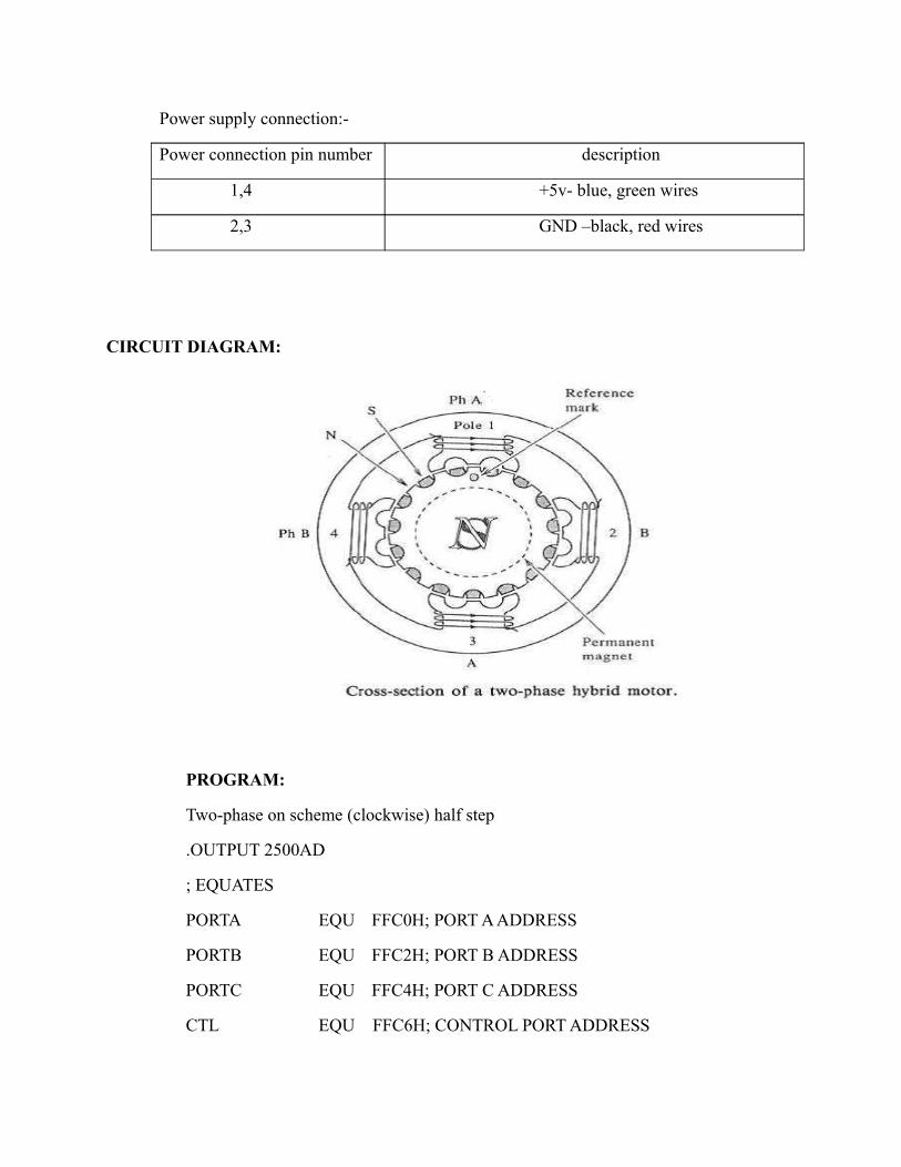
Power supply connection:-
Power connection pin number description
1,4 +5v- blue, green wires
2,3 GND –black, red wires
CIRCUIT DIAGRAM:
PROGRAM:
Two-phase on scheme (clockwise) half step
.OUTPUT 2500AD
; EQUATES
PORTA EQU FFC0H; PORT A ADDRESS
PORTB EQU FFC2H; PORT B ADDRESS
PORTC EQU FFC4H; PORT C ADDRESS
CTL EQU FFC6H; CONTROL PORT ADDRESS

CSEG SEGMENT
ASSUME CS: CSEG
ORG 0000:4000H
MOV AL, 80H
MOV DX, CTL
OUT DX, AL
MOV DX, PORTC
MOV AL, 0DH
OUT DX, AL
CALL DELAY
MOV AL, 0DH
MOV DX, PORTC
OUT DX, AL
CALL DELAY
MOV AL, 0EH
MOV DX, PORTC
OUT DX, AL
CALL DELAY
MOV AL, 06H
MOV DX, PORTC
OUT DX, AL
CALL DELAY
MOV AL, 07H
MOV DX, PORTC
OUT DX, AL
CALL DELAY
MOV AL, 03H
MOV DX, PORTC
OUT DX, AL

CALL DELAY
MOV AL, 0BH
MOV DX, PORTC
OUT DX, AL
CALL DELAY
MOV AL, 09H
OUT DX, AL
CALL DELAY
HERE: JMP HERE
DELAY:
MOV DI, 02H
L00:
MOV CX, 0FFFFH
L1: LOOP L1
DEC DI
JNZ L00
RET
CSEG ENDS
.END
PROCEDURE:-
1. Connect power supply 5v & GND to both microprocessor trainer kit and stepper motor
Interfacing kit.
2. Make the connections in talk window.
3. Connect data bus between microprocessor trainer kit and stepper motor interfacing
Kit.
4. Dump the program in to processor kit using RS-232 cable.
5. Execute the program by typing code segment starting address.
6. Observe the rotation of stepper motor.

RESULT:- Thus the interfacing of stepper motor with 8086 is done using Talk software
KEY BOARD / DISPLAY INTERFACE
AIM: - write a program to interface stepper motor with 8086.
APPARATUS REQUIRED:-
1. 8086 microprocessor kit.
2. Key board / display interfacing card..
3. Rs-232.
4. Power supply.
5. 26-pin bus.
6. Talk software.
7. Connecting wires.
THEORY:-
The 8279 is designed specially to connect to any 8- bit microprocessor bus directivity and thus allows the cpu to do some other work other than scanning the key board and refreshing the display .
Getting meaningful data from a keyboard, it required the following 3 major tasks:
1. Detect a key press.2. De- bounces the key press.3. Encode the key press.
DESCRIPTION:-
KEY BOARD:-
The key board consists of 20 keys arranged in a fashion similar to a calculator key board. It consists of numerals 0 to 9, the special characters +, -, *, %,--., etc and two blank keys. The keys have been organized as 4 rows of 5 keys each in a sense matrix of 3 rows & 8 columns. The 8 columns are connected to bits 0 to 7 of port A of 8255 while the rows are connected to bits 0 to 2 of port C.
DISPLAY:-
A non multiplexed approach to display interfacing is provided by a set of shift registers & their corresponding seven segment displays. All shift registers are serially connected. This approach provides a software intensive solution with minimum hardware & providing the capability of displaying any segment combination.

The Intel 8279 is responsible for de- bouncing of the keys, coding of the keypad matrix and refreshing of the display elements in a microprocessor based development system. Its main features are:
1. Simultaneous keyboard and display operation.
1. Three input modes such as scanned keyboard mode , scanned sensor mode & strobe entry input mode .2. Two input modes such as 8 or 16 bit character multiplexed displays and right entry or left entry display formats.3. Programmable scan timing.4. Two key lock out or N- key roll over with contact de- bounce.5. Auto increment facility for easy programming.
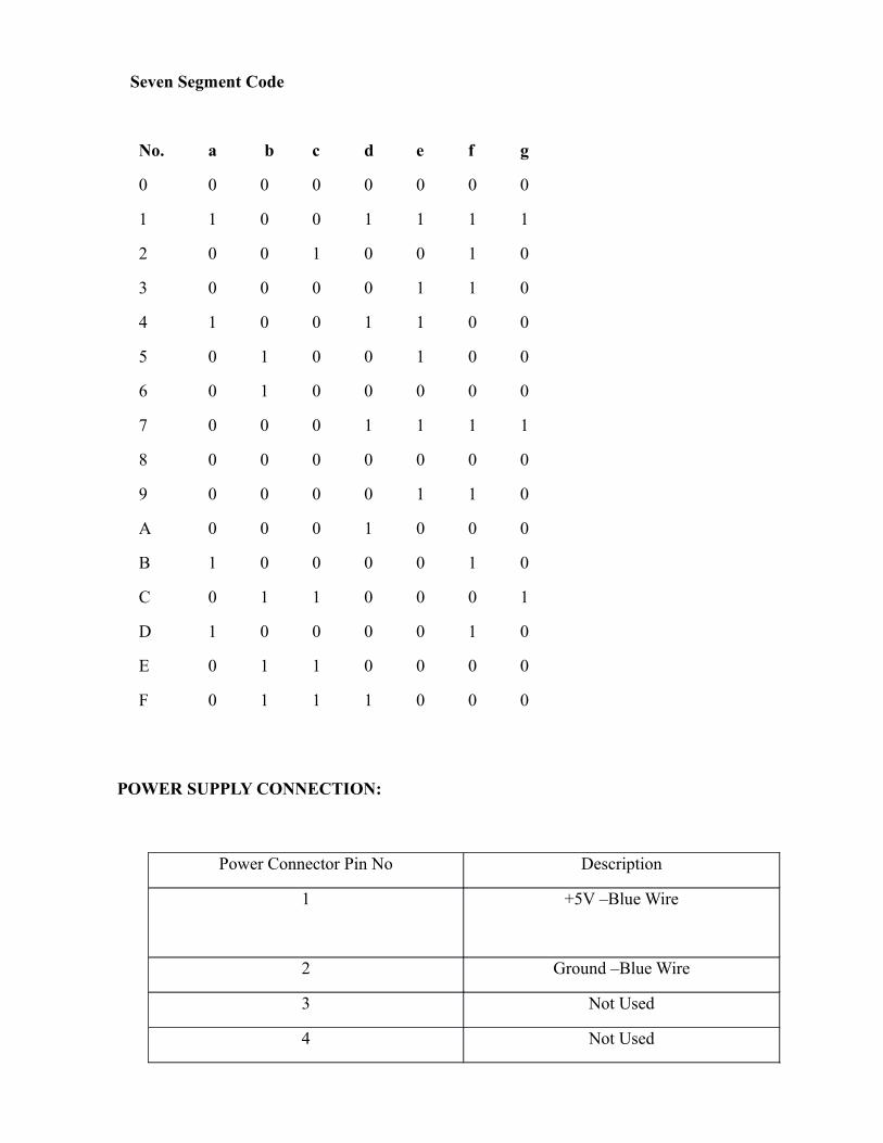
Seven Segment Code
No. a b c d e f g
0 0 0 0 0 0 0 0
1 1 0 0 1 1 1 1
2 0 0 1 0 0 1 0
3 0 0 0 0 1 1 0
4 1 0 0 1 1 0 0
5 0 1 0 0 1 0 0
6 0 1 0 0 0 0 0
7 0 0 0 1 1 1 1
8 0 0 0 0 0 0 0
9 0 0 0 0 1 1 0
A 0 0 0 1 0 0 0
B 1 0 0 0 0 1 0
C 0 1 1 0 0 0 1
D 1 0 0 0 0 1 0
E 0 1 1 0 0 0 0
F 0 1 1 1 0 0 0
POWER SUPPLY CONNECTION:
Power Connector Pin No Description
1 +5V –Blue Wire
2 Ground –Blue Wire
3 Not Used
4 Not Used

CIRCUIT DIAGRAM:

PROCEDURE:-
1. Connect power supply to microprocessor trainer kit and Key board / display
Interfacing kit.
2. Make the connections in talk window.
3. Connect data bus between microprocessor trainer kit and Key board / display Interfacing
Kit.
4. Dump the program in to processor kit using RS-232 cable.
5. Execute the program by typing code segment starting address.
6. Observe the output by pressing keys on interfacing card.
RESULT: - Thus the interfacing of Key board/ Display with 8086 is done using Talk software

LCD DISPLAY
AIM: - write a program to interface LCD display with 8086.
APPARATUS REQUIRED:-
1. 8086 microprocessor kit.
2. LCD interfacing kit.
3. Rs-232.
4. Power supply.
5. 26-pin bus.
6. Talk software.
7. Connecting wires.
THEORY:-
LCD‘s are used in a wide range of application including computer monitor, television instrument panels . LCD’s are more energy efficient and offer refer disposals their CRL’s . its low electrical power consumption enables it to be used in battery powered electronic equipment. It is an electronically modulated optical device made up of any no. of segments filled with liquid crystals and arranged in front of light source (back light) or monochrome . the most flexible ones use an array of small pixels.
About DD RAM (display data RAM):-
The DD RAM stores display data represented in 8-bit (hexadecimal) character codes. Its capacity is 80*8 bits or 80 characters. Depending on 8-bit character codes that is written into DD RAM, LCD will select the character pattern either from CG RAM or FROM CG ROM.
Connector jps pin number description
1 +5v- blue
2 GND –black
3 +12v- red
4 -12v- green
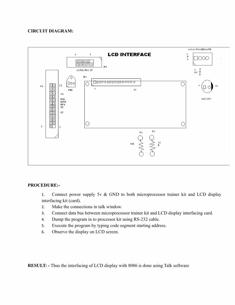
CIRCUIT DIAGRAM:
PROCEDURE:-
1. Connect power supply 5v & GND to both microprocessor trainer kit and LCD display interfacing kit (card).2. Make the connections in talk window.3. Connect data bus between microprocessor trainer kit and LCD display interfacing card.4. Dump the program in to processor kit using RS-232 cable.5. Execute the program by typing code segment starting address.6. Observe the display on LCD screen.
RESULT: - Thus the interfacing of LCD display with 8086 is done using Talk software


INTERFACING OF PPI
AIM: - write a program to interface programmable peripheral interface (8255) with 8086.
APPARATUS REQUIRED:-
1. 8086 microprocessor kit.
2. 8255 interfacing card.
3. Rs-232.
4. Power supply.
5. 26-pin bus.
6. Talk software.
7. Connecting wires.
THEORY: -
This inter face allows the user to study the operation of 8255 in 3modes. The Intel 8255 is a general purpose programmable I/O device designed for use with Intel microprocessor & microcontroller. It has 24 i/o ports, which may be individually programmed in 2 groups i.e., group A consisting of port A(8 pins)& port- C upper(4 pins ) & group- B consisting of port B (8 pins) 7 port C lower (4 pins) & used in 3 modes of operation.
Mode 0 is called as simple output input mode.
In this mode (MODE O), each group of i/o pins may be programmed in sets of 4 to be i/p or o/p. that is, port A, port C (upper), port B & port C (lower) may be configured as i/p ports or o/p ports.
In mode 1, each group is programmed to have 8 lines of i/p or o/p of the remaining 4 pins of port C (lower) , 3 are used for handshaking & interrupt control signals for strobe o/p operation .
The third mode of operation is a bidirectional bus mode which has 8 lines for a bi- directional bus 7 & 5 control lines, borrowing one from the other group, for handshaking.
This inter face is designed in such a way that port- A can be used as both i/p & o/p . port –B can be used in o/p mode & port-c can be used as o/p in mode 0 & as control / status in modes 1& 2 .
OPERATION:

MODE 0 (BASIC I/O MODE)
This functional configuration provides simple input and output operations for each of three ports. No “handshaking” is required; data is simply written to or from a specified port. In MODE 0 PORT-A is the complement of PORT-B.
MODE 1 STROBED INPUT
Control signals used in input operation are STB (Strobe input), IBF (Input buffer full F/F) & INTR (Interrupt request) and are connected to PORT C bits PC4, PC5 & PC3 respectively.
CIRCUIT DIAGRAM:

PROCEDURE:-
1. Connect power supply 5v & GND to both microprocessor trainer kit and programmable peripheral interfacing kit (card).2. Make the connections in talk window.3. Connect data bus between microprocessor trainer kit and programmable peripheral interface kit .4. Dump the program in to processor kit using RS-232 cable.5. Execute the program by typing code segment starting address.6. Observe the display on interfacing card. .
RESULT: - Thus the interfacing of Programmable Peripheral Interface (8255) with 8086 is done using Talk software
Related Documents