User's Manual AudioCodes CPE & Access Gateway Products MP-20x Telephone Adapter Version 4.5.1

Welcome message from author
This document is posted to help you gain knowledge. Please leave a comment to let me know what you think about it! Share it to your friends and learn new things together.
Transcript
User's Manual
AudioCodes CPE & Access Gateway Products
MP-20x Telephone Adapter
Version 4.5.1

Version 4.5.1 3 MP-20x Telephone Adapter
User's Manual Contents
Table of Contents
1 Introduction ....................................................................................................... 11
2 Cabling the MP-20x Telephone Adapter .......................................................... 13
3 Setting up a Network Connection .................................................................... 15
3.1 Defining Your PC's Network Connection .............................................................. 15 3.1.1 Configuring your PC Running Windows 10 .............................................................16 3.1.2 Configuring your PC Running Linux ........................................................................18
3.2 Configuring the MP-20x's Network Connection ..................................................... 18 3.2.1 Logging in to MP-20x Web Interface .......................................................................18 3.2.2 Configuring 'Quick Setup' Screen Parameters ........................................................19
3.2.2.1 Configuring Your Internet Connection ......................................................19 3.2.3 Configuring 3G/LTE USB Modem ...........................................................................24
4 Device Quick Setup ........................................................................................... 27
4.1 Preparing Initial Configuration .............................................................................. 27
4.2 Configuring SIP Signaling Protocol ....................................................................... 28
5 Getting Started with the Web Interface ........................................................... 31
5.1 Logging into the Web Interface ............................................................................. 31
5.2 Menu Bar Description ........................................................................................... 32
5.3 Managing Tables .................................................................................................. 35
5.4 Configuring Users ................................................................................................. 36 5.4.1 Web User Permissions ............................................................................................39
5.4.1.1 Print Commands .......................................................................................39
5.5 Set Commands ..................................................................................................... 48
5.6 Associated Elements ............................................................................................ 49 5.6.1 Configuring Scheduler Rules ...................................................................................49 5.6.2 Configuring Network Objects ...................................................................................51 5.6.3 Configuring Protocols ..............................................................................................53
5.7 Logging out the Web Interface .............................................................................. 54
6 Viewing a Graphical Display of the Device's Network ................................... 55
7 Configuring Computers for Connecting to Device's Network ....................... 57
7.1 Wired Computers ................................................................................................. 57 7.1.1 Configuring Computers Running on Windows 7 .....................................................57 7.1.2 Configuring Computers Running on Linux...............................................................58
8 Setting up your Device ..................................................................................... 59
8.1 Setting up an Internet Connection using the Web Interface .................................. 59 8.1.1 WAN Ethernet ..........................................................................................................60
8.1.1.1 Manual IP Address Ethernet Connection .................................................60 8.1.1.2 Automatic IP Address Ethernet Connection .............................................61 8.1.1.3 PPPoE ......................................................................................................61 8.1.1.4 PPTP ........................................................................................................62
8.2 Using the Automatic Dialer for Internet Connection .............................................. 63 8.2.1 Recommended Configuration ..................................................................................63 8.2.2 Setting up and Starting the Automatic Dialer...........................................................64 8.2.3 Quitting Automatic Dialer for Manual Configuration ................................................64
User's Manual 4 Document #: LTRT-50621
MP-20x Telephone Adapter
9 Configuring VoIP Parameters .......................................................................... 65
9.1 Configuring the SIP Signaling Protocol ................................................................. 66 9.1.1 Configuring Proxy Redundancy ...............................................................................71 9.1.2 Support for DNS Failover Mechanism .....................................................................73
9.2 Support for Common Name/SubjectAltName Verification for SIP ......................... 74
9.3 Support for Advanced Alerting with Ring Splash ................................................... 74
9.4 Configuring Dialing Parameters ............................................................................ 74 9.4.1 Syntax for Digit Maps and Dial Plans ......................................................................79
9.5 Configuring Media Streaming ............................................................................... 81 9.5.1 SRTP .......................................................................................................................83
9.5.1.1 Support for Dynamic SRTP Policy ...........................................................83 9.5.1.2 Changing Default Cipher Suites for SIP Over TLS ..................................84 9.5.1.3 Support for RFC 3329 & MediaSec Extensions .......................................84 9.5.1.4 Configuring Codecs ..................................................................................84
9.5.2 Supported Codecs ...................................................................................................84 9.5.2.1 Packetization Time ...................................................................................84
9.6 Configuring Voice and Fax ................................................................................... 85
9.7 Configuring Supplementary Services .................................................................... 90 9.7.1 Network-based Conferencing (RFC 4240) ..............................................................93
9.8 Voice Menu Guidance .......................................................................................... 94 9.8.1 Configuring Voice Menu ..........................................................................................94
9.8.1.1 Voice Menu Configuration Parameters ....................................................94
9.9 Configuring Micro PBX Line Settings .................................................................... 96
9.10 Configuring Line Extensions ................................................................................. 99
9.11 Configuring Speed Dialing .................................................................................. 101
9.12 Enabling Polarity Reversal .................................................................................. 103
10 Making VoIP Calls with your Analog Telephones ........................................ 105
10.1 Making a Call ...................................................................................................... 105
10.2 Answering a Waiting Call .................................................................................... 105
10.3 Putting a Call on Hold ......................................................................................... 106
10.4 Transferring a Call .............................................................................................. 106
10.5 Forwarding Calls to another Phone .................................................................... 107
10.6 Establishing a 3-Way Conference Call................................................................ 108
11 Quality of Service ............................................................................................ 109
11.1 QoS Wizard ........................................................................................................ 110
11.2 Configuring Traffic Shaping ................................................................................ 111 11.2.1 Configuring Traffic Shaping ...................................................................................112 11.2.2 Configuring Shaping Classes ................................................................................114
11.2.2.1 Class Rules ............................................................................................115
11.3 Configuring Traffic Priority .................................................................................. 117
11.4 Configuring DSCP Mapping ................................................................................ 121
11.5 Configuring 802.1p Mapping ............................................................................... 123
11.6 Configuring Class Statistics ................................................................................ 124
11.7 Configuring Basic VoIP QoS Example ................................................................ 125
12 Network Connections ..................................................................................... 127
12.1 Configuring a WAN Connection .......................................................................... 127 12.1.1 WAN Ethernet Connections ...................................................................................129
Version 4.5.1 5 MP-20x Telephone Adapter
User's Manual Contents
12.1.1.1 External DSL Modem using PPPoE .......................................................129 12.1.1.2 External Cable Modem/Fiber Transceiver without Authentication .........131 12.1.1.3 DHCP .....................................................................................................133 12.1.1.4 Manual IP Address .................................................................................134
12.2 LAN Connection ................................................................................................. 137 12.2.1 LAN Ethernet .........................................................................................................137
12.2.1.1 General Tab ...........................................................................................138 12.2.1.2 Settings Tab ...........................................................................................138 12.2.1.3 Routing Tab ............................................................................................139 12.2.1.4 Advanced Tab ........................................................................................139
12.3 WAN Connection ................................................................................................ 141 12.3.1 General Tab ...........................................................................................................141 12.3.2 Settings Tab ...........................................................................................................142
12.3.2.1 Internet Protocol Settings .......................................................................143 12.3.3 Routing Tab ...........................................................................................................146 12.3.4 PPP Tab ................................................................................................................148 12.3.5 PPTP Tab ..............................................................................................................150 12.3.6 Advanced Tab ........................................................................................................151
12.4 VLAN Settings .................................................................................................... 152 12.4.1 Settings Tab ...........................................................................................................155
12.4.1.1 IP Address Distribution ...........................................................................156 12.4.2 Routing Tab ...........................................................................................................158 12.4.3 Advanced Tab ........................................................................................................159
12.5 LAN-WAN Bridge Settings .................................................................................. 160 12.5.1 Editing LAN-WAN Bridging ....................................................................................162
13 IPv6 ................................................................................................................... 165
13.1 IPv6 Features ..................................................................................................... 165
13.2 Configuring IPv6 ................................................................................................. 166 13.2.1 Configuring IPv6 using CLI ....................................................................................166 13.2.2 Configuring IPv6 using Web ..................................................................................166
13.3 Configuring Connections on IPv6 ....................................................................... 167 13.3.1 Configuring SLACC ...............................................................................................167
13.3.1.1 Configuring Stateless IP Address using CLI ..........................................167 13.3.1.2 Configuring Stateless IP Address using Web ........................................167
13.3.2 Obtaining IPv6 DNS Server by DHCPv6 with 'O' Flag ..........................................168 13.3.3 Obtaining IPv6 NTP Server by DHCPv6 with 'O' Flag ...........................................169
13.4 Supported IPv6 Features .................................................................................... 172 13.4.1 ICMPv6 ..................................................................................................................172
13.4.1.1 Ping ICMPv6 using CLI ..........................................................................172 13.4.1.2 Ping Using Web Interface.......................................................................172
13.4.2 NTP Server IPv6 ....................................................................................................172 13.4.3 Management over IPv6..........................................................................................172 13.4.4 Allow Incoming WAN ICMP Echo Request over IPv6 ...........................................173 13.4.5 Provisioning over IPv6 (Configuration / Firmware) ................................................173 13.4.6 SIP Debug Log over IPv6 ......................................................................................173 13.4.7 VoIP .......................................................................................................................173
13.4.7.1 Configuring SIP Proxy for IPv6 ..............................................................173 13.4.7.2 Configuring SIP Outbound Proxy with IPv6 Address .............................174 13.4.7.3 Configuring Redundant Proxy as IPv6 ...................................................175 13.4.7.4 Configuring SIP Security ........................................................................176
User's Manual 6 Document #: LTRT-50621
MP-20x Telephone Adapter
14 IEEE 802.1X ...................................................................................................... 177
15 Add-on Servers and Disk Management ......................................................... 179
15.1 External File Server ............................................................................................ 179 15.1.1 Automatic File Sharing ...........................................................................................180
15.2 Print Server ........................................................................................................ 182 15.2.1 Connecting and Setting up a Printer on Windows .................................................183 15.2.2 Print Protocols .......................................................................................................184
15.2.2.1 Internet Printing Protocol ........................................................................185 15.2.2.2 Microsoft Shared Printing (Samba) ........................................................193 15.2.2.3 Line Printer Daemon (LPD) ....................................................................196
15.2.3 Storing and Using Printer Drivers ..........................................................................204
16 Remote Device Management .......................................................................... 205
16.1 Overview ............................................................................................................ 205 16.1.1 Remote Configuration ............................................................................................205 16.1.2 Remote Management ............................................................................................207
16.1.2.1 Firmware Upgrade ..................................................................................207 16.1.2.2 Status and Performance Monitoring .......................................................208 16.1.2.3 Alarms, Notifications and Logging ..........................................................209
16.2 Enabling Remote Management .......................................................................... 210 16.2.1 Enabling Local or Remote Management using the SSH Protocol .........................213
16.3 Securing Remote Management with Certificates ................................................ 214
16.4 Remote Configuration and Management Interfaces ............................................ 218 16.4.1 Embedded Web Server .........................................................................................218 16.4.2 TR-069 and TR-104 CPE WAN Management Protocol ........................................219
16.4.2.1 Configuring the Device via TR-069 and TR-104 ....................................220 16.4.2.2 Monitoring the Device Status via TR-069 and TR-104 ..........................228 16.4.2.3 Security Concerns and Measures ..........................................................232
16.4.3 SNMP.....................................................................................................................232 16.4.3.1 Enabling SNMP in the Web Interface .....................................................233 16.4.3.2 Configuring the Device via SNMP ..........................................................234 16.4.3.3 Status Monitoring of System and Network Interfaces via SNMP ...........234 16.4.3.4 Security Concerns and Measures ..........................................................235
16.4.4 Syslog ....................................................................................................................236 16.4.5 Automatic File Download .......................................................................................236
16.4.5.1 Firmware File Download .........................................................................236 16.4.5.2 Configuration File Download ..................................................................236 16.4.5.3 Security Concerns and Measures ..........................................................237
16.4.6 Telnet CLI ..............................................................................................................237 16.4.7 Redirect Server ......................................................................................................237 16.4.8 BroadSoft BroadWorks DMS Provisioning ............................................................239 16.4.9 Provisioning using DHCP Options 66/67 and TFTP ..............................................239
16.4.9.1 Default Behavior .....................................................................................239 16.4.9.2 Disabling DHCP Options 66 and 67 .......................................................240
16.4.10 Setting Provisioning Time of Day (TOD) ...............................................................240 16.4.10.1 Random TOD .........................................................................................240 16.4.10.2 Fixed TOD ..............................................................................................241 16.4.10.3 No TOD Configured – Default Behavior .................................................241 16.4.10.4 Changing Default Cipher Suits for Provisioning .....................................241
17 Security ............................................................................................................ 243
17.1 General Security Level Settings.......................................................................... 244
17.2 Configuring Access Control ................................................................................ 246
17.3 Configuring Port Forwarding ............................................................................... 248
17.4 Configuring a DMZ Host ..................................................................................... 251
Version 4.5.1 7 MP-20x Telephone Adapter
User's Manual Contents
17.5 Configuring Port Triggering ................................................................................. 252
17.6 Configuring Website Restrictions ........................................................................ 255
17.7 Configuring NAT ................................................................................................. 258
17.8 Viewing Current Connections ............................................................................. 261
17.9 Configuring Advanced Filtering ........................................................................... 262
17.10 Viewing the Security Log .................................................................................... 266
18 Advanced Networking Features ..................................................................... 269
18.1 IP Address Distribution ....................................................................................... 269 18.1.1 Configuring the DHCP Server ...............................................................................271 18.1.2 Configuring DHCP Relay .......................................................................................272 18.1.3 Viewing DHCP Clients ...........................................................................................273 18.1.4 Configuring Static DHCP Clients ...........................................................................274
18.2 Configuring a DNS Server .................................................................................. 275
18.3 Configuring Dynamic DNS .................................................................................. 277
18.4 Configuring Routing Rules .................................................................................. 280 18.4.1 Managing Routing Table Rules .............................................................................281 18.4.2 Configuring Routing Protocols ...............................................................................282
18.5 Enabling PPPoE Relay ....................................................................................... 283
18.6 Selecting Regional Settings for Analog Lines ..................................................... 284
18.7 Installation Wizard .............................................................................................. 285
19 Home Media ..................................................................................................... 287
19.1 Universal Plug and Play ..................................................................................... 287 19.1.1 Enabling Universal Plug and Play on the Device ..................................................287 19.1.2 Adding UPnP-enabled PC to Home Network ........................................................288 19.1.3 Monitoring Connection Between the Device and Internet .....................................289 19.1.4 Making Local Services available to PCs on Internet .............................................290
20 Configuring the Device for PacketSmart ....................................................... 293
20.1 Configuring PacketSmart through the Web Interface .......................................... 293
20.2 Configuring PacketSmart through the CLI .......................................................... 296
20.3 Upgrading PacketSmart on the Fly ..................................................................... 297
20.4 Accessing the PacketSmart Web Portal ............................................................. 298
21 Media Sharing .................................................................................................. 301
21.1 Share Music, Pictures and Video on My Local Network ...................................... 301
21.2 Automatically Share Media in All Folders ............................................................ 302
22 Maintenance .................................................................................................... 305
22.1 Enabling the Feature Key ................................................................................... 305
22.2 Viewing the Device Software Version ................................................................. 307
22.3 Configuring Date and Time ................................................................................. 308
22.4 Configuration File ............................................................................................... 311 22.4.1 Uploading Configuration File from PC on the Network ..........................................313 22.4.2 Uploading Configuration File from a Remote Server .............................................315 22.4.3 Remote Configuration Provisioning Based on MD5 Checksum Comparison .......318 22.4.4 Encrypting the Configuration File using CLI ..........................................................319 22.4.5 Automatic Upload using SIP NOTIFY Message ....................................................320
22.5 Firmware Upgrade .............................................................................................. 321 22.5.1 Upgrading the Device from a Computer on the Network .......................................322
User's Manual 8 Document #: LTRT-50621
MP-20x Telephone Adapter
22.5.2 Upgrading the Device from the Internet .................................................................325
22.6 Configuring System Settings .............................................................................. 327
22.7 Rebooting the Device ......................................................................................... 330
22.8 Restoring Factory Settings ................................................................................. 331
23 Diagnostics and Performance Monitoring .................................................... 333
23.1 Running Diagnostics ........................................................................................... 333 23.1.1 Running the Ping Test ...........................................................................................334 23.1.2 Running the ARP Test ...........................................................................................334 23.1.3 Running a Traceroute ............................................................................................335
23.2 Running Debug .................................................................................................. 336 23.2.1 Running Packet Recording ....................................................................................337 23.2.2 Running SIP Debug Log ........................................................................................338 23.2.3 Running TCPDump ................................................................................................339
23.2.3.1 Updating Wireshark ................................................................................339 23.2.3.2 Running TCPDump with Destination Port 7555 .....................................339 23.2.3.3 Defining a Different Destination Port (other than Port 7555) .................340
23.2.4 Running Generic Commands ................................................................................341 23.2.5 Commands Output and Report ..............................................................................342
23.3 System Monitoring .............................................................................................. 345 23.3.1 Viewing Network Connections Status ....................................................................345 23.3.2 Viewing the System Log ........................................................................................346 23.3.3 Viewing CPU Statistics ..........................................................................................347 23.3.4 Viewing VoIP Traffic Statistics ...............................................................................348 23.3.5 Viewing Internet Connection Utilization .................................................................349 23.3.6 Using Debugging Tools .........................................................................................350
23.4 Call Detail Records ............................................................................................. 351 23.4.1 CDR Field Descriptions .........................................................................................351 23.4.2 Release Reasons in CDR ......................................................................................353 23.4.3 Configuring CDR Reporting ...................................................................................353 23.4.4 CDR Log Local Storage .........................................................................................354
A Technical Specifications ................................................................................ 355
A.1 Device Gateway Specifications .......................................................................... 355
User's Manual Notices
Version 4.5.1 9 MP-20x Telephone Adapter
Notice
Information contained in this document is believed to be accurate and reliable at the time of printing. However, due to ongoing product improvements and revisions, AudioCodes cannot guarantee accuracy of printed material after the Date Published nor can it accept responsibility for errors or omissions. Updates to this document can be downloaded from https://www.audiocodes.com/library/technical-documents.
This document is subject to change without notice.
Date Published: October-24-2021
WEEE EU Directive
Pursuant to the WEEE EU Directive, electronic and electrical waste must not be disposed of with unsorted waste. Please contact your local recycling authority for disposal of this product.
Customer Support
Customer technical support and services are provided by AudioCodes or by an authorized AudioCodes Service Partner. For more information on how to buy technical support for AudioCodes products and for contact information, please visit our website at https://www.audiocodes.com/services-support/maintenance-and-support.
Stay in the Loop with AudioCodes
Abbreviations and Terminology
Each abbreviation, unless widely used, is spelled out in full when first used.
General Notes, Warnings, and Safety Information
Note: OPEN SOURCE SOFTWARE. Portions of the software may be open source software and may be governed by and distributed under open source licenses, such as the terms of the GNU General Public License (GPL), the terms of the Lesser General Public License (LGPL), BSD and LDAP. If any open source software is provided in object code, and its accompanying license requires that it be provided in source code as well, the Buyer may receive such source code by contacting AudioCodes.
User's Manual 10 Document #: LTRT-50621
MP-20x Telephone Adapter
Document Revision Record
LTRT Description
50610 Initial document release.
50611 Provisioning using DHCP Options 66 & 67 and TFTP Server sections were added.
50612 MP-204B features were added.
50613 The Remote Configuration and Management Interfaces section was updated.
50614 The PacketSmart Configuration section was updated.
50615 Introduction section was updated. Network Parameters section was removed. Support for CN/SANS and SRTP sections were added. T.38 Version and 3-Way Conference Mode parameters were added. The Max Rate parameter was updated. Screenshots were updated.
50616 New note in Introduction; Replaced Windows XP instructions with Windows 10 instructions, Restoring factory settings, Support for DNS Failover Mechanism; Support for Advanced Alerting with Ring Splash; Support for Dynamic SRTP Policy; Network-based Conferencing (RFC 4240); Configuring Date and Time; Automatic Upload using SIP NOTIFY Message; Restoring Factory Settings; Using Debugging Tools
Deleted L2TP connection; External Cable Modem/Fiber Transceiver with L2TP; using the Internet Dialer for Automatic Connections.
50617 Added Call Detail Records.
50618 Added Changing Default Cipher Suites for SIP over TLS; Setting Provisioning Time of Day (and sub-sections)
50619 Added IPv6 section.
50620 Added IEEE 802.1X section.
50621 Added the following sub-sections: SIP Debug Log over IPv6; Configuring SIP Security.
Deleted Configuring Spped Dial for IPv6.
Documentation Feedback
AudioCodes continually strives to produce high quality documentation. If you have any comments (suggestions or errors) regarding this document, please fill out the Documentation Feedback form on our Web site at http://online.audiocodes.com/documentation-feedback.
User's Manual 1. Introduction
Version 4.5.1 11 MP-20x Telephone Adapter
1 Introduction AudioCodes MP-20x series of analog Telephone Adapters are cost-effective, feature-rich gateways, allowing the connection of ordinary POTS analog telephones or fax machines to a Voice-over-Broadband (VoBB) service provider.
The MP-20x series is designed for the rapidly growing residential and Small Office/Home Office (SOHO) voice-over-IP (VoIP) market. The MP-20x series typically connects to an existing Broadband Internet device (Cable and ADSL modem, - depending on model), and establishes a communications path with the service provider network through its IP uplink connection. Supporting a rich set of subscriber calling features such as caller ID, call forwarding, and call waiting, the MP-20x series maintains a uniform user experience when migrating to VoIP services. In addition, the MP-20x series serves as a router with capabilities such as DHCP, NAT, Firewall, PPPoE and PPTP, supporting connectivity of home PC networks.
The MP-20x VoIP Gateway is an all-in-one unit featuring (depending on model) a VoIP adapter, FXS lines, Ethernet LAN interfaces (with an internal Layer-2 switch), and Ethernet WAN interface.
Utilizing AudioCodes' VoIPerfect™ core architecture, and gaining from its accumulated experience in providing IP telephony solutions, the MP-20x series combines superior voice quality and cutting-edge features for end users, such as T.38 Fax Relay and G.168-2004 compliant Echo Cancellation. Low bit rate vocoders (voice coders) can be used simultaneously on all the telephony ports to save valuable bandwidth.
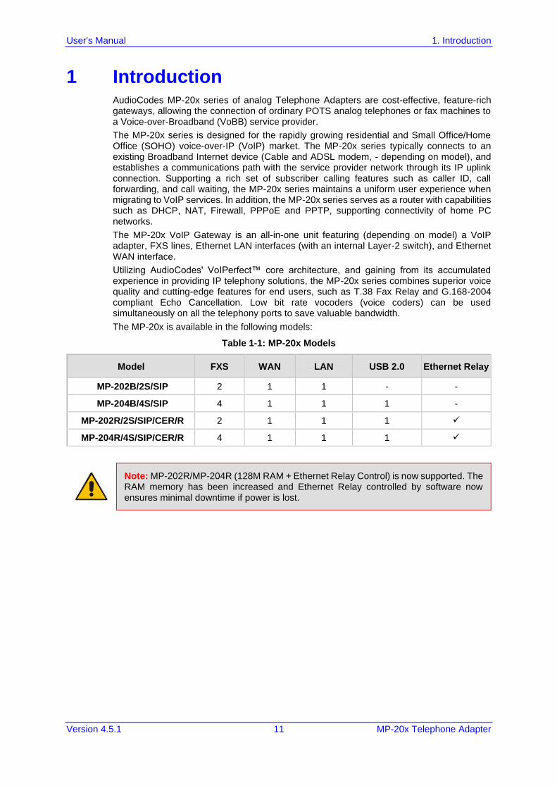
The MP-20x is available in the following models:
Table 1-1: MP-20x Models
Model FXS WAN LAN USB 2.0 Ethernet Relay
MP-202B/2S/SIP 2 1 1 - -
MP-204B/4S/SIP 4 1 1 1 -
MP-202R/2S/SIP/CER/R 2 1 1 1 ✓
MP-204R/4S/SIP/CER/R 4 1 1 1 ✓
Note: MP-202R/MP-204R (128M RAM + Ethernet Relay Control) is now supported. The RAM memory has been increased and Ethernet Relay controlled by software now ensures minimal downtime if power is lost.
User's Manual 12 Document #: LTRT-50621
MP-20x Telephone Adapter
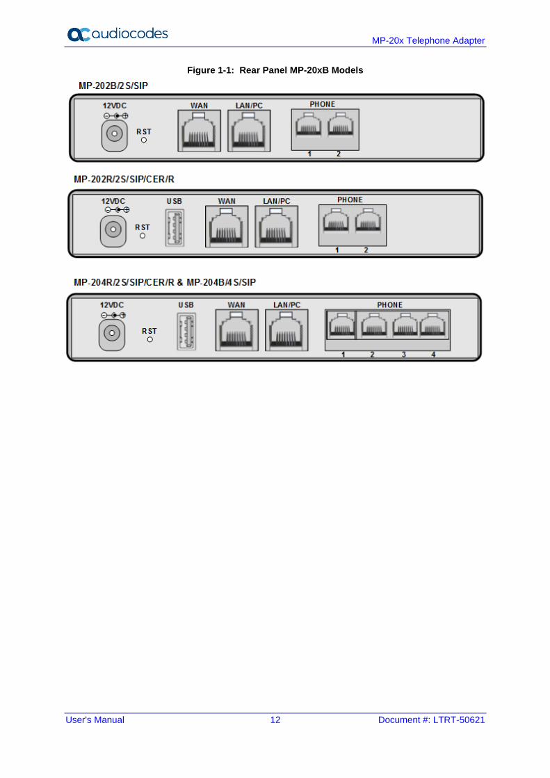
Figure 1-1: Rear Panel MP-20xB Models
User's Manual 2. Cabling the MP-20x Telephone Adapter
Version 4.5.1 13 MP-20x Telephone Adapter
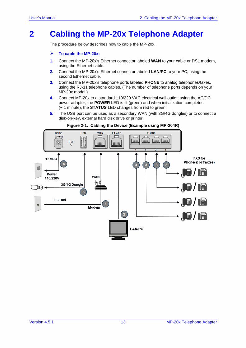
2 Cabling the MP-20x Telephone Adapter The procedure below describes how to cable the MP-20x.
➢ To cable the MP-20x:
1. Connect the MP-20x’s Ethernet connector labeled WAN to your cable or DSL modem, using the Ethernet cable.
2. Connect the MP-20x’s Ethernet connector labeled LAN/PC to your PC, using the second Ethernet cable.
3. Connect the MP-20x’s telephone ports labeled PHONE to analog telephones/faxes, using the RJ-11 telephone cables. (The number of telephone ports depends on your MP-20x model.)
4. Connect MP-20x to a standard 110/220 VAC electrical wall outlet, using the AC/DC power adapter; the POWER LED is lit (green) and when initialization completes (~ 1 minute), the STATUS LED changes from red to green.
5. The USB port can be used as a secondary WAN (with 3G/4G dongles) or to connect a disk-on-key, external hard disk drive or printer.
Figure 2-1: Cabling the Device (Example using MP-204R)
User's Manual 14 Document #: LTRT-50621
MP-20x Telephone Adapter
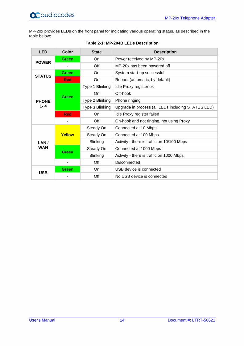
MP-20x provides LEDs on the front panel for indicating various operating status, as described in the table below:
Table 2-1: MP-204B LEDs Description
LED Color State Description
POWER Green On Power received by MP-20x
- Off MP-20x has been powered off
STATUS Green On System start-up successful
Red On Reboot (automatic, by default)
PHONE 1- 4
Green
Type 1 Blinking Idle Proxy register ok
On Off-hook
Type 2 Blinking Phone ringing
Type 3 Blinking Upgrade in process (all LEDs including STATUS LED)
Red On Idle Proxy register failed
- Off On-hook and not ringing, not using Proxy
LAN / WAN
Yellow
Steady On Connected at 10 Mbps
Steady On Connected at 100 Mbps
Blinking Activity - there is traffic on 10/100 Mbps
Green Steady On Connected at 1000 Mbps
Blinking Activity - there is traffic on 1000 Mbps
- Off Disconnected
USB Green On USB device is connected
- Off No USB device is connected
User's Manual 3. Setting up a Network Connection
Version 4.5.1 15 MP-20x Telephone Adapter
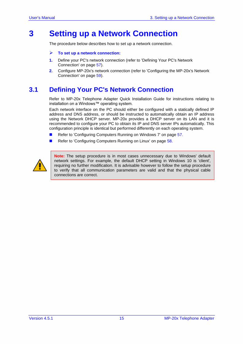
3 Setting up a Network Connection The procedure below describes how to set up a network connection.
➢ To set up a network connection:
1. Define your PC's network connection (refer to 'Defining Your PC's Network Connection' on page 57).
2. Configure MP-20x's network connection (refer to 'Configuring the MP-20x's Network Connection' on page 59).
3.1 Defining Your PC's Network Connection
Refer to MP-20x Telephone Adapter Quick Installation Guide for instructions relating to installation on a Windows™ operating system.
Each network interface on the PC should either be configured with a statically defined IP address and DNS address, or should be instructed to automatically obtain an IP address using the Network DHCP server. MP-20x provides a DHCP server on its LAN and it is recommended to configure your PC to obtain its IP and DNS server IPs automatically. This configuration principle is identical but performed differently on each operating system.
◼ Refer to 'Configuring Computers Running on Windows 7' on page 57.
◼ Refer to 'Configuring Computers Running on Linux' on page 58.
Note: The setup procedure is in most cases unnecessary due to Windows' default network settings. For example, the default DHCP setting in Windows 10 is 'client', requiring no further modification. It is advisable however to follow the setup procedure to verify that all communication parameters are valid and that the physical cable connections are correct.
User's Manual 16 Document #: LTRT-50621
MP-20x Telephone Adapter
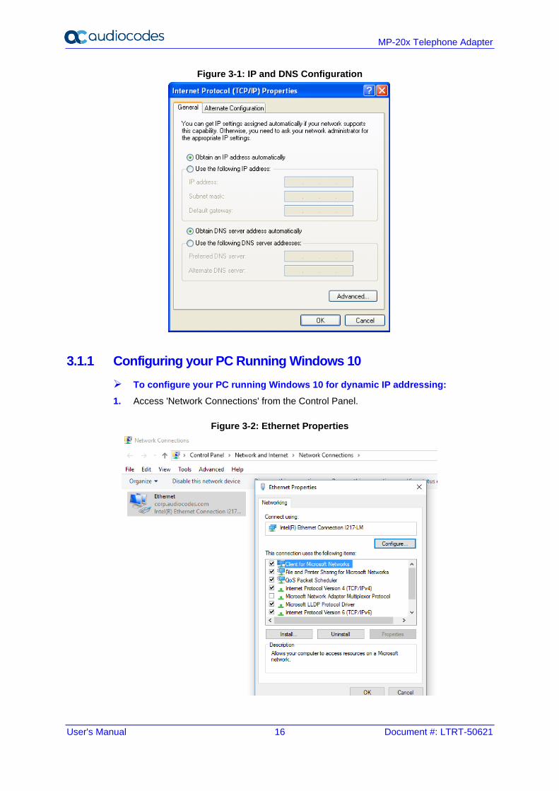
Figure 3-1: IP and DNS Configuration
3.1.1 Configuring your PC Running Windows 10
➢ To configure your PC running Windows 10 for dynamic IP addressing:
1. Access 'Network Connections' from the Control Panel.
Figure 3-2: Ethernet Properties
User's Manual 3. Setting up a Network Connection
Version 4.5.1 17 MP-20x Telephone Adapter
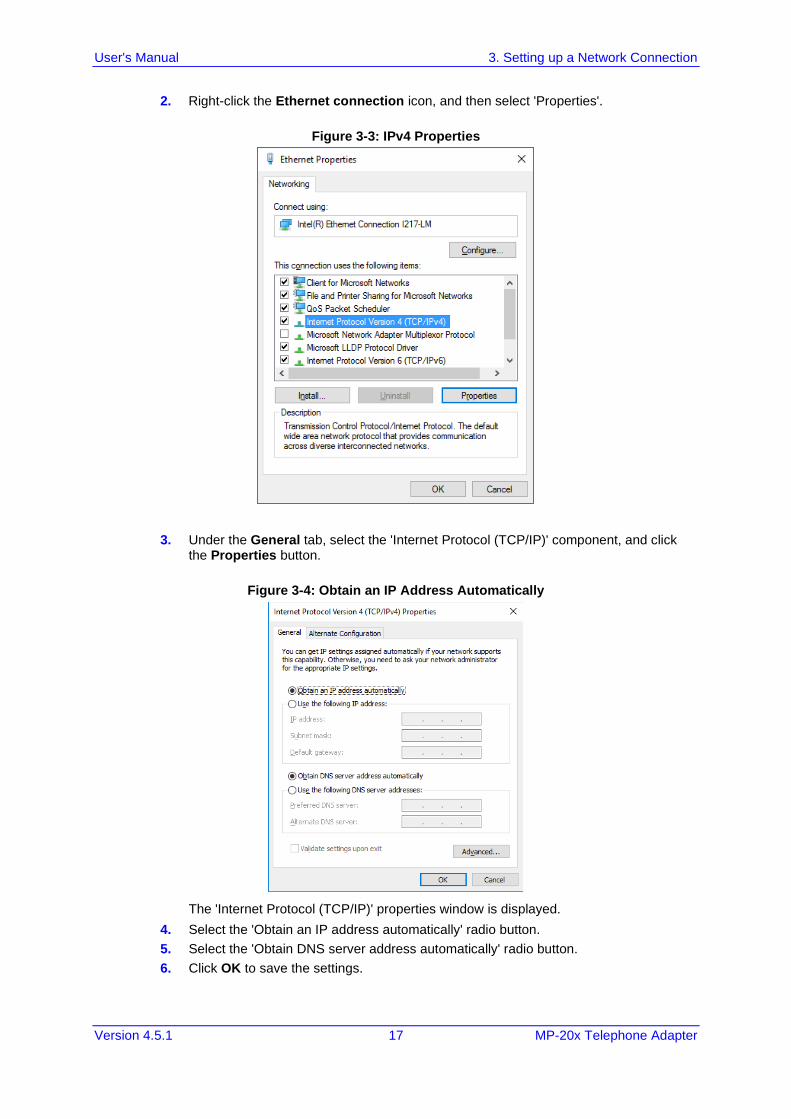
2. Right-click the Ethernet connection icon, and then select 'Properties'.
Figure 3-3: IPv4 Properties
3. Under the General tab, select the 'Internet Protocol (TCP/IP)' component, and click the Properties button.
Figure 3-4: Obtain an IP Address Automatically
The 'Internet Protocol (TCP/IP)' properties window is displayed.
4. Select the 'Obtain an IP address automatically' radio button.
5. Select the 'Obtain DNS server address automatically' radio button.
6. Click OK to save the settings.
User's Manual 18 Document #: LTRT-50621
MP-20x Telephone Adapter
3.1.2 Configuring your PC Running Linux
➢ To configure your PC running Linux for dynamic IP addressing:
1. Log in into the system as a super-user, by entering `su' at the prompt.
2. Type 'ifconfig' to display the network devices and allocated IP's.
3. Type 'pump -i <dev>', where <dev> is the network device name.
4. Type 'ifconfig' again to view the new allocated IP address.
5. Make sure no firewall is active on device <dev>.
3.2 Configuring the MP-20x's Network Connection
The Web-based management interface of MP-20x allows you to control the device's system parameters. The interface is accessed through a Web browser. For detailed information on MP-20x's Web-management interface, refer to 'Using the MP-20x's Web Interface' on page 64.
3.2.1 Logging in to MP-20x Web Interface
The procedure below describes how to login to MP-20x’s embedded Web interface.
➢ To log in:
1. Launch a Web browser on your PC.
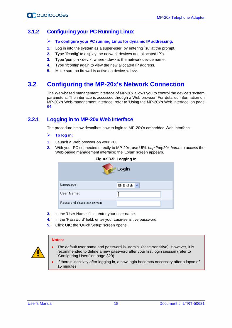
2. With your PC connected directly to MP-20x, use URL http://mp20x.home to access the Web-based management interface; the ‘Login’ screen appears.
Figure 3-5: Logging In
3. In the 'User Name' field, enter your user name.
4. In the 'Password' field, enter your case-sensitive password.
5. Click OK; the 'Quick Setup' screen opens.
Notes:
• The default user name and password is "admin" (case-sensitive). However, it is recommended to define a new password after your first login session (refer to 'Configuring Users' on page 329).
• If there’s inactivity after logging in, a new login becomes necessary after a lapse of 15 minutes.
User's Manual 3. Setting up a Network Connection
Version 4.5.1 19 MP-20x Telephone Adapter
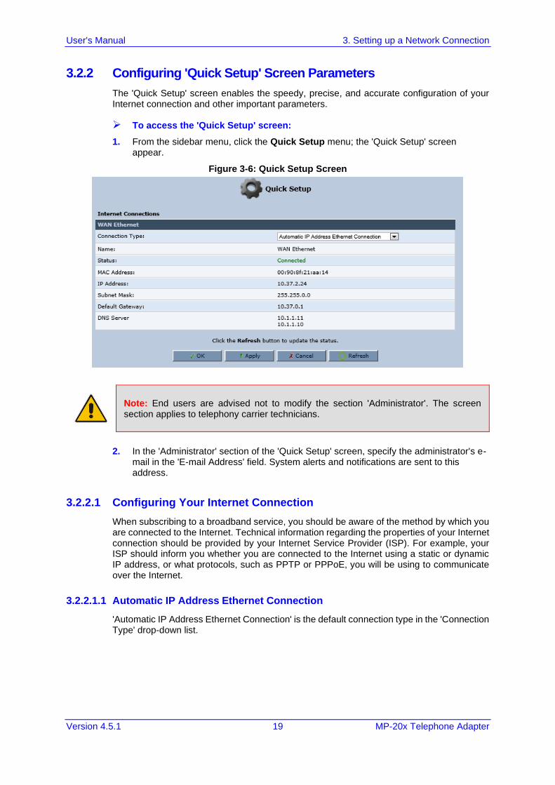
3.2.2 Configuring 'Quick Setup' Screen Parameters
The 'Quick Setup' screen enables the speedy, precise, and accurate configuration of your Internet connection and other important parameters.
➢ To access the 'Quick Setup' screen:
1. From the sidebar menu, click the Quick Setup menu; the 'Quick Setup' screen appear.
Figure 3-6: Quick Setup Screen
Note: End users are advised not to modify the section 'Administrator'. The screen section applies to telephony carrier technicians.
2. In the 'Administrator' section of the 'Quick Setup' screen, specify the administrator's e-mail in the 'E-mail Address' field. System alerts and notifications are sent to this address.
3.2.2.1 Configuring Your Internet Connection
When subscribing to a broadband service, you should be aware of the method by which you are connected to the Internet. Technical information regarding the properties of your Internet connection should be provided by your Internet Service Provider (ISP). For example, your ISP should inform you whether you are connected to the Internet using a static or dynamic IP address, or what protocols, such as PPTP or PPPoE, you will be using to communicate over the Internet.
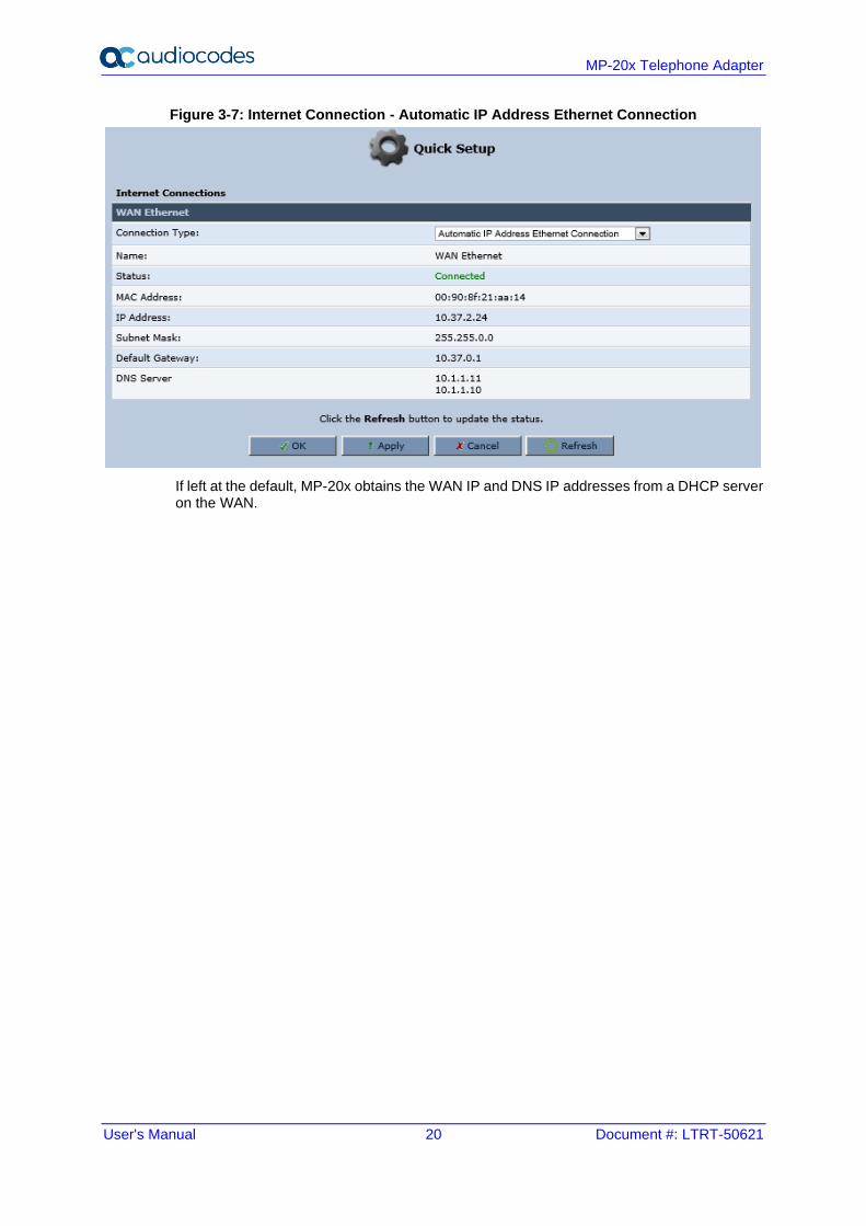
3.2.2.1.1 Automatic IP Address Ethernet Connection
'Automatic IP Address Ethernet Connection' is the default connection type in the 'Connection Type' drop-down list.
User's Manual 20 Document #: LTRT-50621
MP-20x Telephone Adapter
Figure 3-7: Internet Connection - Automatic IP Address Ethernet Connection
If left at the default, MP-20x obtains the WAN IP and DNS IP addresses from a DHCP server on the WAN.
User's Manual 3. Setting up a Network Connection
Version 4.5.1 21 MP-20x Telephone Adapter
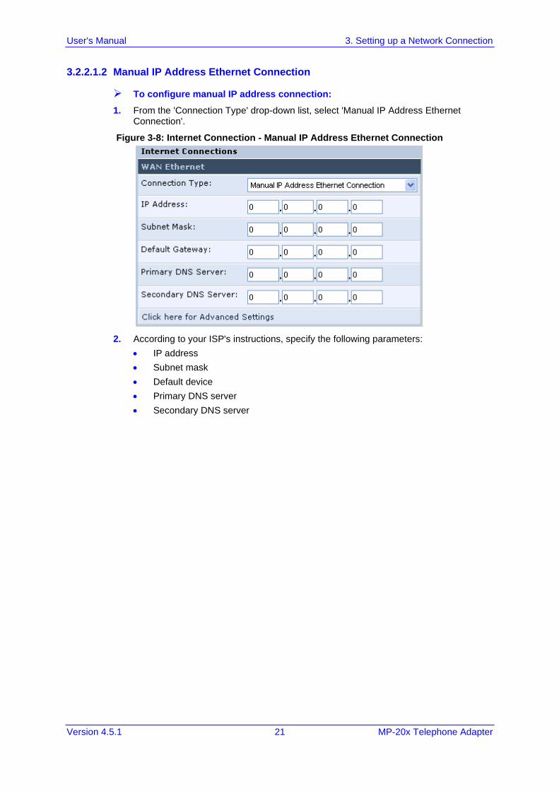
3.2.2.1.2 Manual IP Address Ethernet Connection
➢ To configure manual IP address connection:
1. From the 'Connection Type' drop-down list, select 'Manual IP Address Ethernet Connection'.
Figure 3-8: Internet Connection - Manual IP Address Ethernet Connection
2. According to your ISP's instructions, specify the following parameters:
• IP address
• Subnet mask
• Default device
• Primary DNS server
• Secondary DNS server
User's Manual 22 Document #: LTRT-50621
MP-20x Telephone Adapter
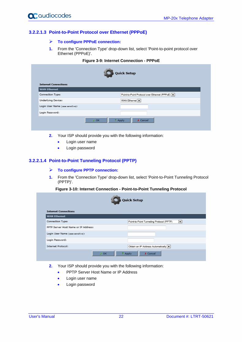
3.2.2.1.3 Point-to-Point Protocol over Ethernet (PPPoE)
➢ To configure PPPoE connection:
1. From the 'Connection Type' drop-down list, select 'Point-to-point protocol over Ethernet (PPPoE)'.
Figure 3-9: Internet Connection - PPPoE
2. Your ISP should provide you with the following information:
• Login user name
• Login password
3.2.2.1.4 Point-to-Point Tunneling Protocol (PPTP)
➢ To configure PPTP connection:
1. From the 'Connection Type' drop-down list, select 'Point-to-Point Tunneling Protocol (PPTP)'.
Figure 3-10: Internet Connection - Point-to-Point Tunneling Protocol
2. Your ISP should provide you with the following information:
• PPTP Server Host Name or IP Address
• Login user name
• Login password
User's Manual 3. Setting up a Network Connection
Version 4.5.1 23 MP-20x Telephone Adapter
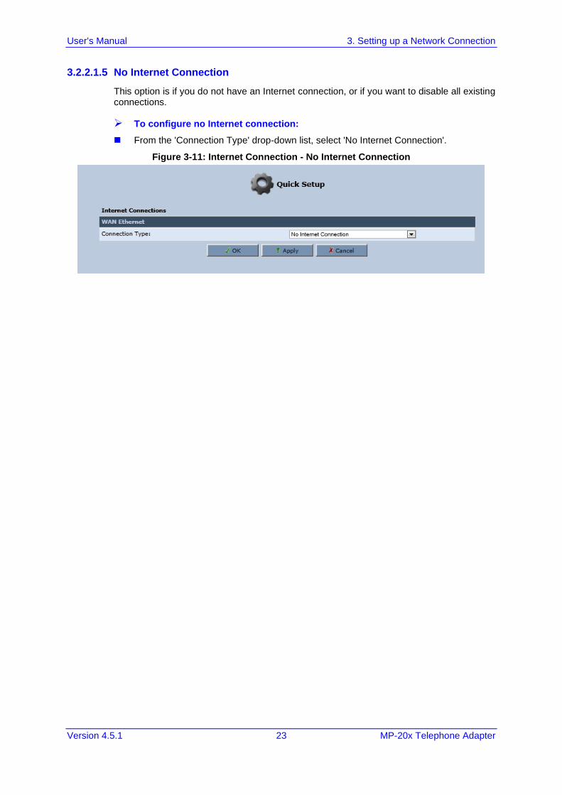
3.2.2.1.5 No Internet Connection
This option is if you do not have an Internet connection, or if you want to disable all existing connections.
➢ To configure no Internet connection:
◼ From the 'Connection Type' drop-down list, select 'No Internet Connection'.
Figure 3-11: Internet Connection - No Internet Connection
User's Manual 24 Document #: LTRT-50621
MP-20x Telephone Adapter
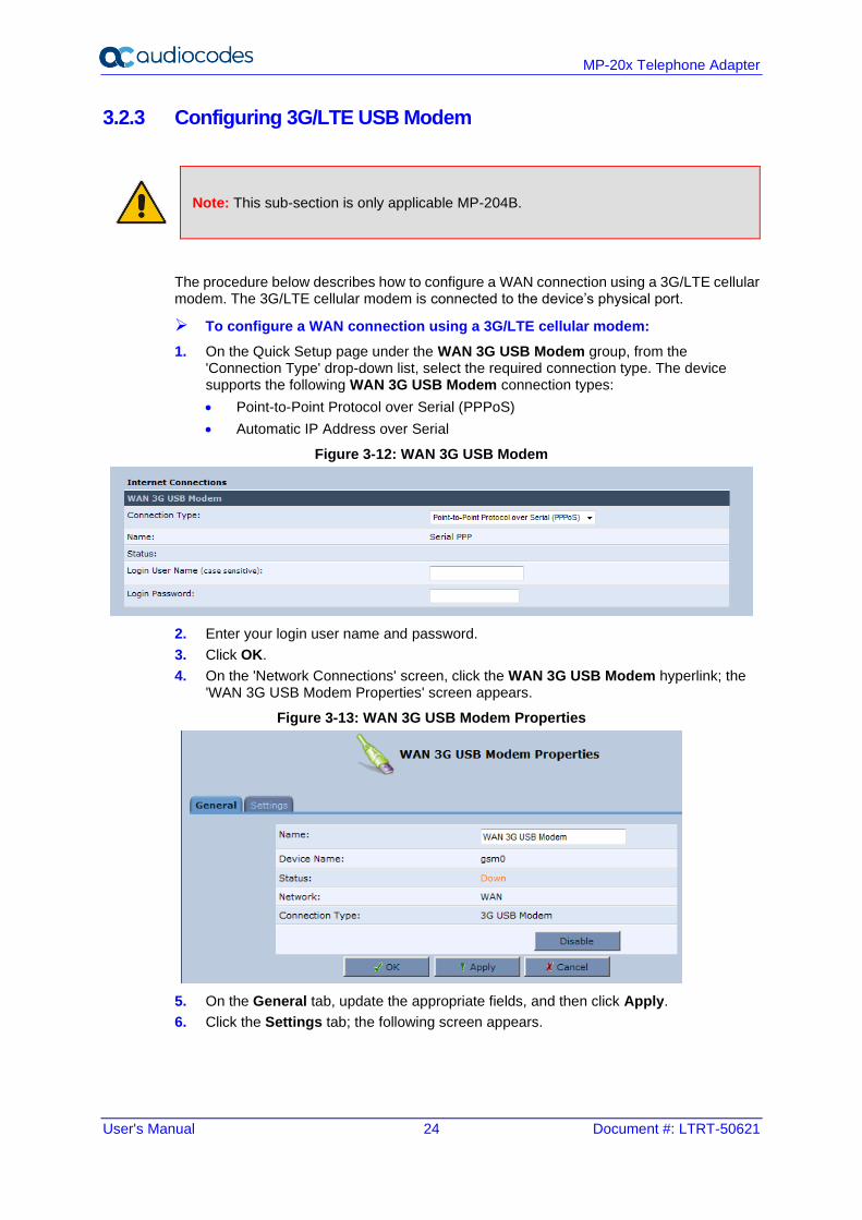
3.2.3 Configuring 3G/LTE USB Modem
Note: This sub-section is only applicable MP-204B.
The procedure below describes how to configure a WAN connection using a 3G/LTE cellular modem. The 3G/LTE cellular modem is connected to the device’s physical port.
➢ To configure a WAN connection using a 3G/LTE cellular modem:
1. On the Quick Setup page under the WAN 3G USB Modem group, from the 'Connection Type' drop-down list, select the required connection type. The device supports the following WAN 3G USB Modem connection types:
• Point-to-Point Protocol over Serial (PPPoS)
• Automatic IP Address over Serial
Figure 3-12: WAN 3G USB Modem
2. Enter your login user name and password.
3. Click OK.
4. On the 'Network Connections' screen, click the WAN 3G USB Modem hyperlink; the 'WAN 3G USB Modem Properties' screen appears.
Figure 3-13: WAN 3G USB Modem Properties
5. On the General tab, update the appropriate fields, and then click Apply.
6. Click the Settings tab; the following screen appears.
User's Manual 3. Setting up a Network Connection
Version 4.5.1 25 MP-20x Telephone Adapter
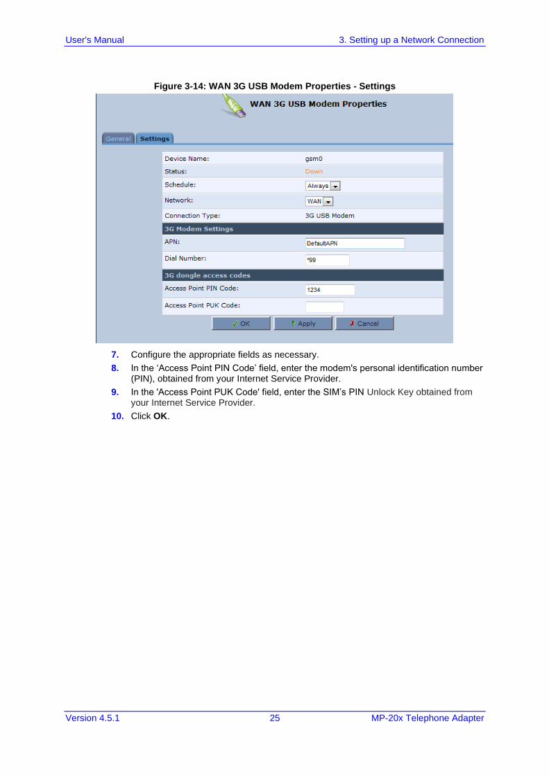
Figure 3-14: WAN 3G USB Modem Properties - Settings
7. Configure the appropriate fields as necessary.
8. In the ‘Access Point PIN Code’ field, enter the modem's personal identification number (PIN), obtained from your Internet Service Provider.
9. In the 'Access Point PUK Code' field, enter the SIM’s PIN Unlock Key obtained from your Internet Service Provider.
10. Click OK.

User's Manual 26 Document #: LTRT-50621
MP-20x Telephone Adapter
This page is intentionally left blank.
User's Manual 4. Device Quick Setup
Version 4.5.1 27 MP-20x Telephone Adapter
4 Device Quick Setup The procedure below describes how to quickly configure your device for connecting it to the Internet (WAN).
4.1 Preparing Initial Configuration
The procedure below describes how to prepare the initial configuration.
➢ To initially prepare for configuration:
1. Connect the cables as shown in Section 2 on page 13.
2. Power on the device.
3. From your browser, enter the device's default IP address (192.168.2.1).
4. From the ‘Language’ drop-down list, select the desired language for the Web graphical user interface (GUI) display.
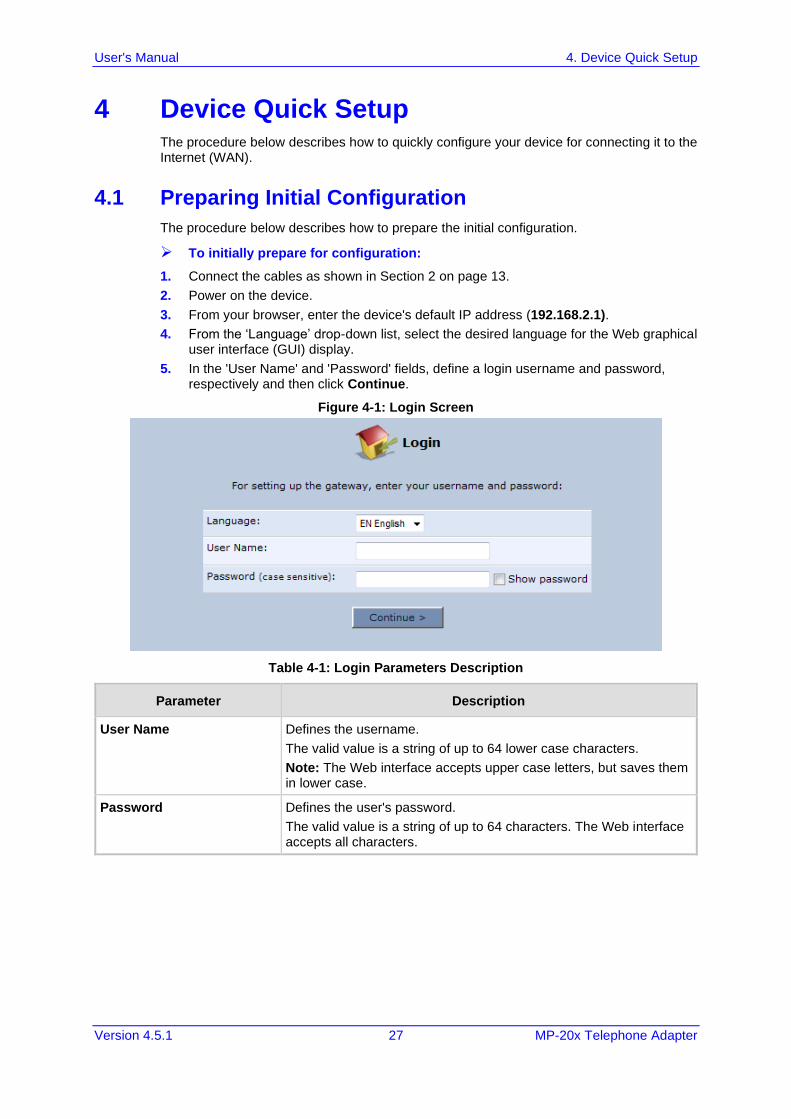
5. In the 'User Name' and 'Password' fields, define a login username and password, respectively and then click Continue.
Figure 4-1: Login Screen
Table 4-1: Login Parameters Description
Parameter Description
User Name Defines the username.
The valid value is a string of up to 64 lower case characters.
Note: The Web interface accepts upper case letters, but saves them in lower case.
Password Defines the user's password.
The valid value is a string of up to 64 characters. The Web interface accepts all characters.
User's Manual 28 Document #: LTRT-50621
MP-20x Telephone Adapter
4.2 Configuring SIP Signaling Protocol
The procedure below describes how to configure the SIP Signaling Protocol.
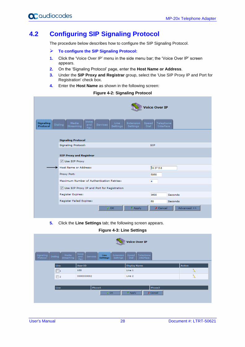
➢ To configure the SIP Signaling Protocol:
1. Click the ‘Voice Over IP’ menu in the side menu bar; the ‘Voice Over IP’ screen appears.
2. On the ‘Signaling Protocol’ page, enter the Host Name or Address.
3. Under the SIP Proxy and Registrar group, select the 'Use SIP Proxy IP and Port for Registration' check box.
4. Enter the Host Name as shown in the following screen:
Figure 4-2: Signaling Protocol
5. Click the Line Settings tab; the following screen appears.
Figure 4-3: Line Settings
User's Manual 4. Device Quick Setup
Version 4.5.1 29 MP-20x Telephone Adapter
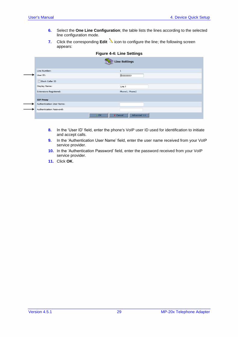
6. Select the One Line Configuration; the table lists the lines according to the selected line configuration mode.
7. Click the corresponding Edit icon to configure the line; the following screen appears:
Figure 4-4: Line Settings
8. In the ‘User ID’ field, enter the phone's VoIP user ID used for identification to initiate and accept calls.
9. In the ‘Authentication User Name’ field, enter the user name received from your VoIP service provider.
10. In the ‘Authentication Password’ field, enter the password received from your VoIP service provider.
11. Click OK.

User's Manual 30 Document #: LTRT-50621
MP-20x Telephone Adapter
This page is intentionally left blank.
User's Manual 5. Getting Started with the Web Interface
Version 4.5.1 31 MP-20x Telephone Adapter
5 Getting Started with the Web Interface The device's embedded Web server (Web interface) provides a user-friendly Web-based management tool that allows you to configure and monitor the device. The procedures below describe how to access, navigate in, and configure parameters with the Web interface.
5.1 Logging into the Web Interface
The procedure below describes how to log in to the device's Web interface.
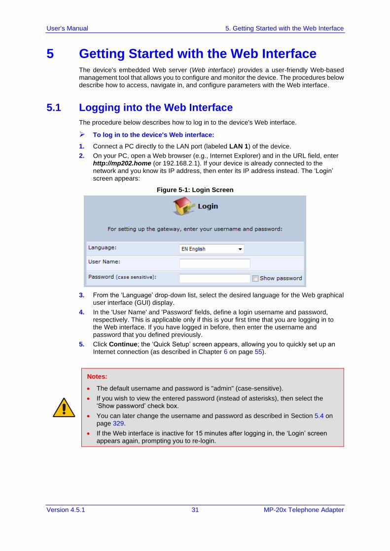
➢ To log in to the device's Web interface:
1. Connect a PC directly to the LAN port (labeled LAN 1) of the device.
2. On your PC, open a Web browser (e.g., Internet Explorer) and in the URL field, enter http://mp202.home (or 192.168.2.1). If your device is already connected to the network and you know its IP address, then enter its IP address instead. The ‘Login’ screen appears:
Figure 5-1: Login Screen
3. From the ‘Language’ drop-down list, select the desired language for the Web graphical user interface (GUI) display.
4. In the 'User Name' and 'Password' fields, define a login username and password, respectively. This is applicable only if this is your first time that you are logging in to the Web interface. If you have logged in before, then enter the username and password that you defined previously.
5. Click Continue; the ‘Quick Setup’ screen appears, allowing you to quickly set up an Internet connection (as described in Chapter 6 on page 55).
Notes:
• The default username and password is "admin" (case-sensitive).
• If you wish to view the entered password (instead of asterisks), then select the ‘Show password’ check box.
• You can later change the username and password as described in Section 5.4 on page 329.
• If the Web interface is inactive for 15 minutes after logging in, the ‘Login’ screen appears again, prompting you to re-login.
User's Manual 32 Document #: LTRT-50621
MP-20x Telephone Adapter
5.2 Menu Bar Description
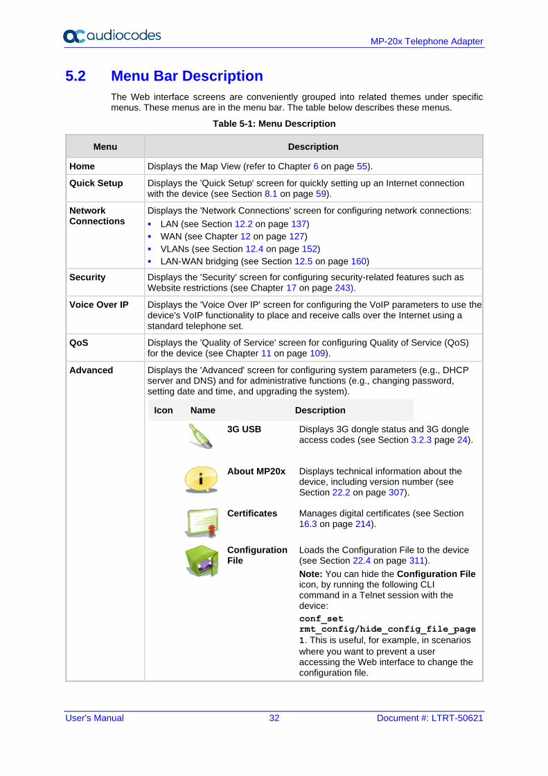
The Web interface screens are conveniently grouped into related themes under specific menus. These menus are in the menu bar. The table below describes these menus.
Table 5-1: Menu Description
Menu Description
Home Displays the Map View (refer to Chapter 6 on page 55).
Quick Setup Displays the 'Quick Setup' screen for quickly setting up an Internet connection with the device (see Section 8.1 on page 59).
Network Connections
Displays the 'Network Connections' screen for configuring network connections:
▪ LAN (see Section 12.2 on page 137)
▪ WAN (see Chapter 12 on page 127)
▪ VLANs (see Section 12.4 on page 152)
▪ LAN-WAN bridging (see Section 12.5 on page 160)
Security Displays the 'Security' screen for configuring security-related features such as Website restrictions (see Chapter 17 on page 243).
Voice Over IP Displays the 'Voice Over IP' screen for configuring the VoIP parameters to use the device's VoIP functionality to place and receive calls over the Internet using a standard telephone set.
QoS Displays the 'Quality of Service' screen for configuring Quality of Service (QoS) for the device (see Chapter 11 on page 109).
Advanced Displays the 'Advanced' screen for configuring system parameters (e.g., DHCP server and DNS) and for administrative functions (e.g., changing password, setting date and time, and upgrading the system).
Icon Name Description
3G USB
Displays 3G dongle status and 3G dongle access codes (see Section 3.2.3 page 24).
About MP20x Displays technical information about the device, including version number (see Section 22.2 on page 307).
Certificates Manages digital certificates (see Section 16.3 on page 214).
Configuration File
Loads the Configuration File to the device (see Section 22.4 on page 311).
Note: You can hide the Configuration File icon, by running the following CLI command in a Telnet session with the device:
conf_set
rmt_config/hide_config_file_page
1. This is useful, for example, in scenarios
where you want to prevent a user accessing the Web interface to change the configuration file.
User's Manual 5. Getting Started with the Web Interface
Version 4.5.1 33 MP-20x Telephone Adapter
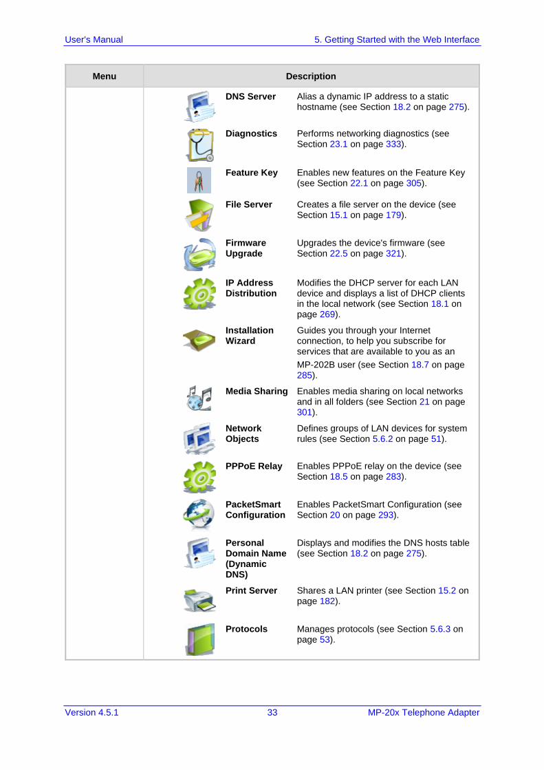
Menu Description
DNS Server Alias a dynamic IP address to a static hostname (see Section 18.2 on page 275).
Diagnostics Performs networking diagnostics (see Section 23.1 on page 333).
Feature Key Enables new features on the Feature Key (see Section 22.1 on page 305).
File Server Creates a file server on the device (see Section 15.1 on page 179).
Firmware Upgrade
Upgrades the device's firmware (see Section 22.5 on page 321).
IP Address Distribution
Modifies the DHCP server for each LAN device and displays a list of DHCP clients in the local network (see Section 18.1 on page 269).
Installation Wizard
Guides you through your Internet connection, to help you subscribe for services that are available to you as an
MP-202B user (see Section 18.7 on page 285).
Media Sharing Enables media sharing on local networks and in all folders (see Section 21 on page 301).
Network Objects
Defines groups of LAN devices for system rules (see Section 5.6.2 on page 51).
PPPoE Relay Enables PPPoE relay on the device (see Section 18.5 on page 283).
PacketSmart Configuration
Enables PacketSmart Configuration (see Section 20 on page 293).
Personal Domain Name (Dynamic DNS)
Displays and modifies the DNS hosts table (see Section 18.2 on page 275).
Print Server Shares a LAN printer (see Section 15.2 on page 182).
Protocols Manages protocols (see Section 5.6.3 on page 53).
User's Manual 34 Document #: LTRT-50621
MP-20x Telephone Adapter
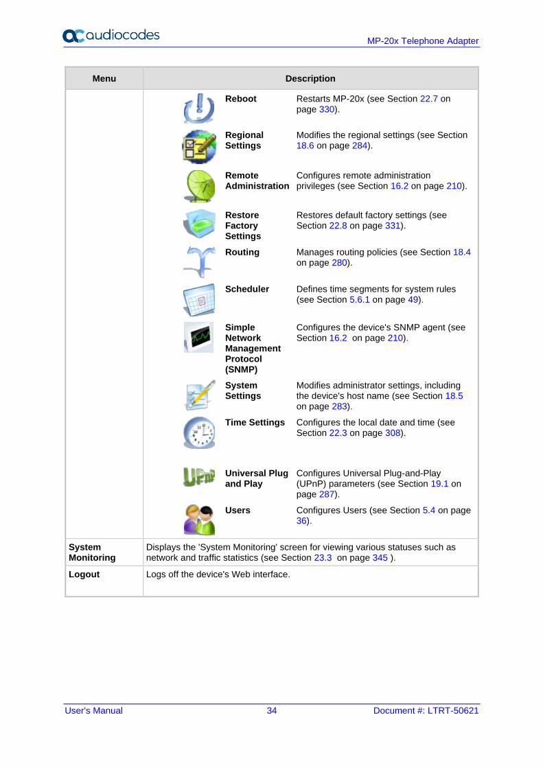
Menu Description
Reboot Restarts MP-20x (see Section 22.7 on page 330).
Regional Settings
Modifies the regional settings (see Section 18.6 on page 284).
Remote Administration
Configures remote administration privileges (see Section 16.2 on page 210).
Restore Factory Settings
Restores default factory settings (see Section 22.8 on page 331).
Routing Manages routing policies (see Section 18.4 on page 280).
Scheduler Defines time segments for system rules (see Section 5.6.1 on page 49).
Simple Network Management Protocol (SNMP)
Configures the device's SNMP agent (see Section 16.2 on page 210).
System Settings
Modifies administrator settings, including the device's host name (see Section 18.5 on page 283).
Time Settings Configures the local date and time (see Section 22.3 on page 308).
Universal Plug and Play
Configures Universal Plug-and-Play (UPnP) parameters (see Section 19.1 on page 287).
Users Configures Users (see Section 5.4 on page 36).
System Monitoring
Displays the 'System Monitoring' screen for viewing various statuses such as network and traffic statistics (see Section 23.3 on page 345 ).
Logout Logs off the device's Web interface.
User's Manual 5. Getting Started with the Web Interface
Version 4.5.1 35 MP-20x Telephone Adapter
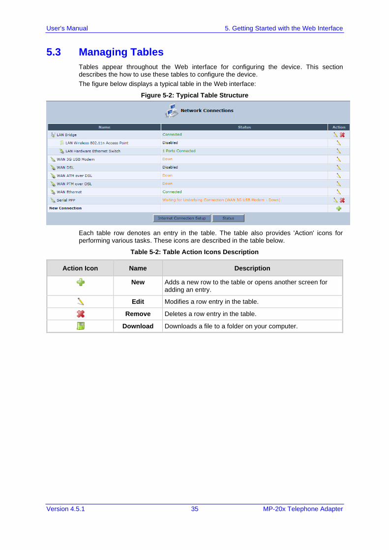
5.3 Managing Tables
Tables appear throughout the Web interface for configuring the device. This section describes the how to use these tables to configure the device.
The figure below displays a typical table in the Web interface:
Figure 5-2: Typical Table Structure
Each table row denotes an entry in the table. The table also provides 'Action' icons for performing various tasks. These icons are described in the table below.
Table 5-2: Table Action Icons Description
Action Icon Name Description
New Adds a new row to the table or opens another screen for adding an entry.
Edit Modifies a row entry in the table.
Remove Deletes a row entry in the table.
Download Downloads a file to a folder on your computer.
User's Manual 36 Document #: LTRT-50621
MP-20x Telephone Adapter
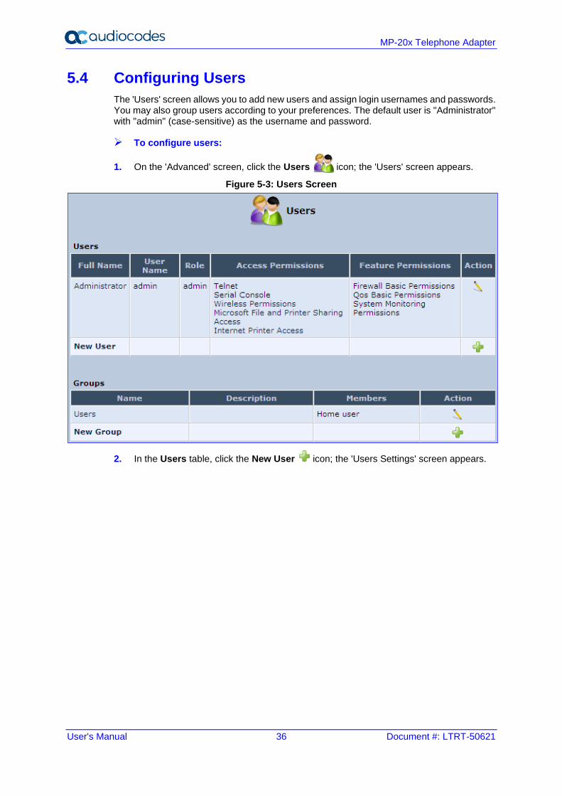
5.4 Configuring Users
The 'Users' screen allows you to add new users and assign login usernames and passwords. You may also group users according to your preferences. The default user is "Administrator" with "admin" (case-sensitive) as the username and password.
➢ To configure users:
1. On the 'Advanced' screen, click the Users icon; the 'Users' screen appears.
Figure 5-3: Users Screen
2. In the Users table, click the New User icon; the 'Users Settings' screen appears.
User's Manual 5. Getting Started with the Web Interface
Version 4.5.1 37 MP-20x Telephone Adapter
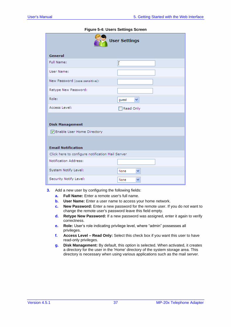
Figure 5-4: Users Settings Screen
3. Add a new user by configuring the following fields:
a. Full Name: Enter a remote user's full name.
b. User Name: Enter a user name to access your home network.
c. New Password: Enter a new password for the remote user. If you do not want to change the remote user's password leave this field empty.
d. Retype New Password: If a new password was assigned, enter it again to verify correctness.
e. Role: User’s role indicating privilege level, where “admin” possesses all privileges.
f. Access Level – Read Only: Select this check box if you want this user to have read-only privileges.
g. Disk Management: By default, this option is selected. When activated, it creates a directory for the user in the 'Home' directory of the system storage area. This directory is necessary when using various applications such as the mail server.
User's Manual 38 Document #: LTRT-50621
MP-20x Telephone Adapter
h. Email Notification: You can use email notification to receive indications of system events for a predefined severity classification. The available types of events are 'System' or 'Security' events. The available severity of events is 'Error', 'Warning' and 'Information. If the 'Information' level is selected, the user receives notification of the 'Information', 'Warning' and 'Error' events. If the 'Warning' level is selected, the user receives notification of the 'Warning' and 'Error' events etc.
Click here to configure notification mail server: This opens the ‘System Settings’ screen (see Section 18.5 on page 283) where you can define an outgoing mail server.
Notification Address: user’s email address.
System Notify Level: By default, the 'None' option is selected, which means that the device does not send notifications to a remote host. To activate the feature, select one of the following notification types:
✓ Error
✓ Warning
✓ Information
Security Notify Level: The remote security notification level can be one of the following:
✓ None
✓ Error
✓ Warning
✓ Information
4. Click OK.
The following is an example of the relevant Telnet parameters:
rg_conf/admin/user/0/enabled=1
rg_conf/admin/user/0/username=admin
rg_conf/admin/user/0/full_name=Administrator
rg_conf/admin/user/0/email=NULL
rg_conf/admin/user/0/notify_level/0=none
rg_conf/admin/user/0/notify_level/1=none
rg_conf/admin/user/0/directory=1
rg_conf/admin/user/0/role=admin
rg_conf/admin/user/1/enabled=1
rg_conf/admin/user/1/username=home
rg_conf/admin/user/1/password=&be;c&5c;&b5;
rg_conf/admin/user/1/full_name=Home user
rg_conf/admin/user/1/email=NULL
rg_conf/admin/user/1/notify_level/0=none
rg_conf/admin/user/1/notify_level/1=none
rg_conf/admin/user/1/directory=1
rg_conf/admin/user/1/role=home
User's Manual 5. Getting Started with the Web Interface
Version 4.5.1 39 MP-20x Telephone Adapter
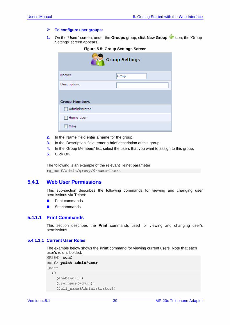
➢ To configure user groups:
1. On the 'Users' screen, under the Groups group, click New Group icon; the 'Group Settings' screen appears.
Figure 5-5: Group Settings Screen
2. In the 'Name' field enter a name for the group.
3. In the 'Description' field, enter a brief description of this group.
4. In the 'Group Members' list, select the users that you want to assign to this group.
5. Click OK.
The following is an example of the relevant Telnet parameter:
rg_conf/admin/group/0/name=Users
5.4.1 Web User Permissions
This sub-section describes the following commands for viewing and changing user permissions via Telnet:
◼ Print commands
◼ Set commands
5.4.1.1 Print Commands
This section describes the Print commands used for viewing and changing user’s permissions.
5.4.1.1.1 Current User Roles
The example below shows the Print command for viewing current users. Note that each user’s role is bolded.
MP264> conf
conf> print admin/user
(user
(0
(enabled(1))
(username(admin))
(full_name(Administrator))
User's Manual 40 Document #: LTRT-50621
MP-20x Telephone Adapter
(email())
(notify_level
(0(none))
(1(none))
)
(directory(1))
(role(admin))
(password(&b7;X&5c;&b9;&a2;))
)
(1
(enabled(1))
(username(home))
(password(&be;c&5c;&b5;))
(full_name(Home user))
(email())
(notify_level
(0(none))
(1(none))
)
(directory(1))
(role(home))
)
)
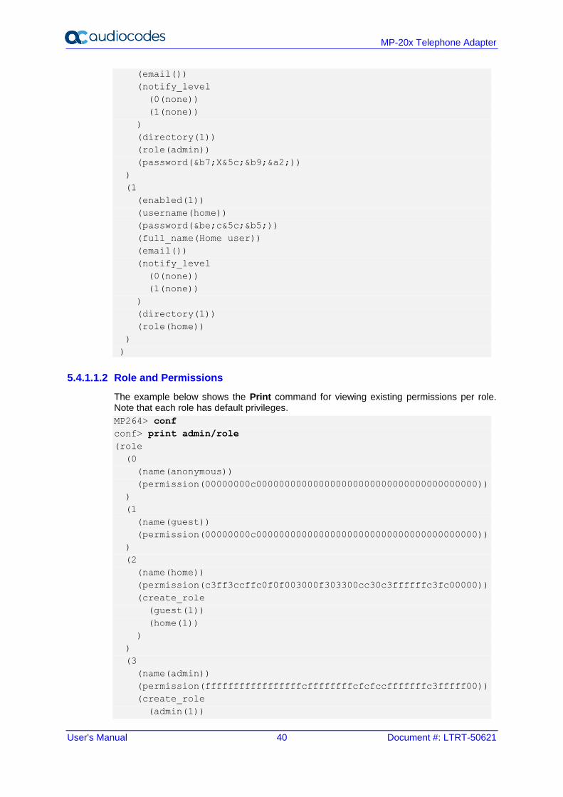
5.4.1.1.2 Role and Permissions
The example below shows the Print command for viewing existing permissions per role. Note that each role has default privileges.
MP264> conf
conf> print admin/role
(role
(0
(name(anonymous))
(permission(00000000c000000000000000000000000000000000000000))
)
(1
(name(guest))
(permission(00000000c000000000000000000000000000000000000000))
)
(2
(name(home))
(permission(c3ff3ccffc0f0f003000f303300cc30c3ffffffc3fc00000))
(create_role
(guest(1))
(home(1))
)
)
(3
(name(admin))
(permission(fffffffffffffffffcffffffffcfcfccfffffffc3fffff00))
(create_role
(admin(1))
User's Manual 5. Getting Started with the Web Interface
Version 4.5.1 41 MP-20x Telephone Adapter
(basic(1))
(advanced(1))
)
)
(4
(name(super))
(permission(ffffffffffffffffffffffffffffffffffffffffffffff00))
(create_role
(guest(1))
(home(1))
(admin(1))
(super(1))
(basic(1))
(advanced(1))
)
)
(5
(name(basic))
(permission(c0000003c000000000000000000000000000000000000000))
)
(6
(name(advanced))
(permission(c0000003c0000000000c0000000000000000000000000000))
)
)
Returned 0
conf>
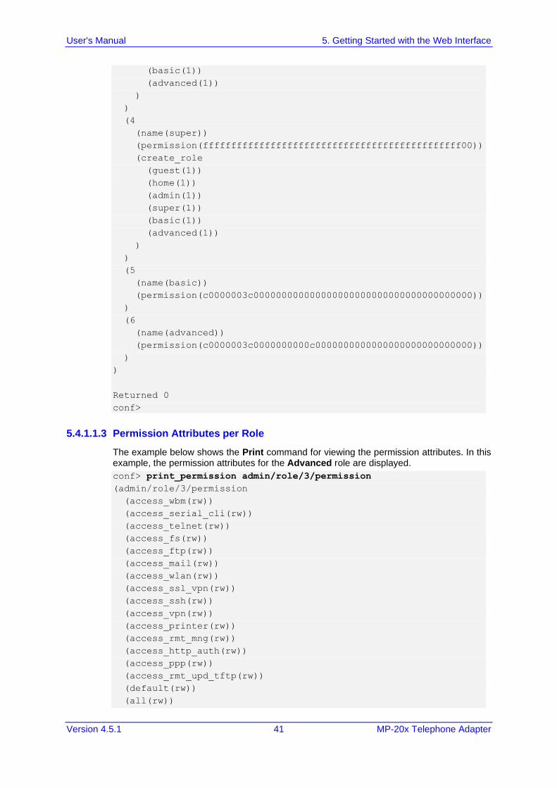
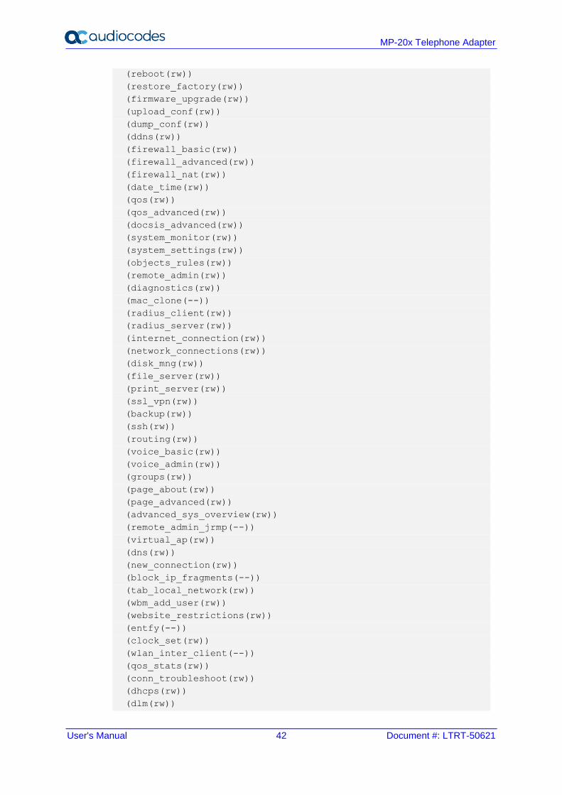
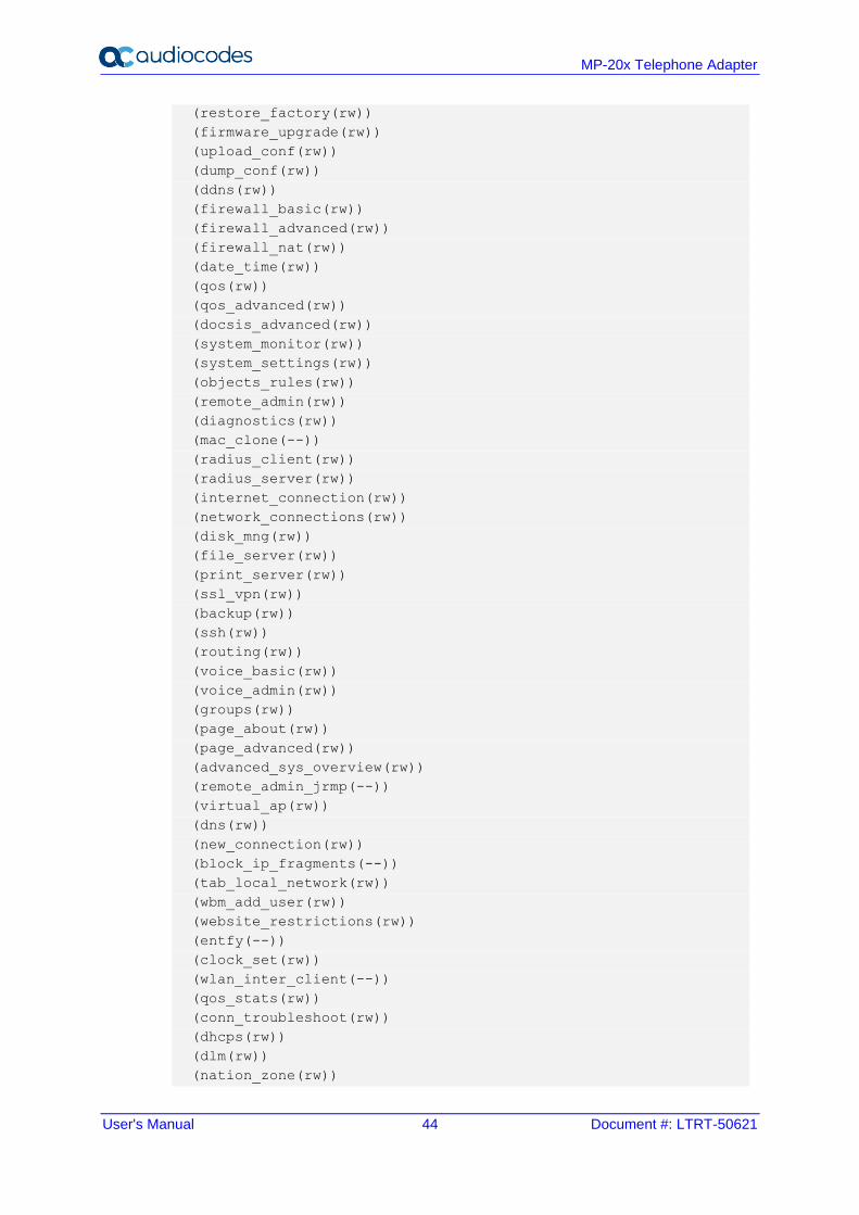
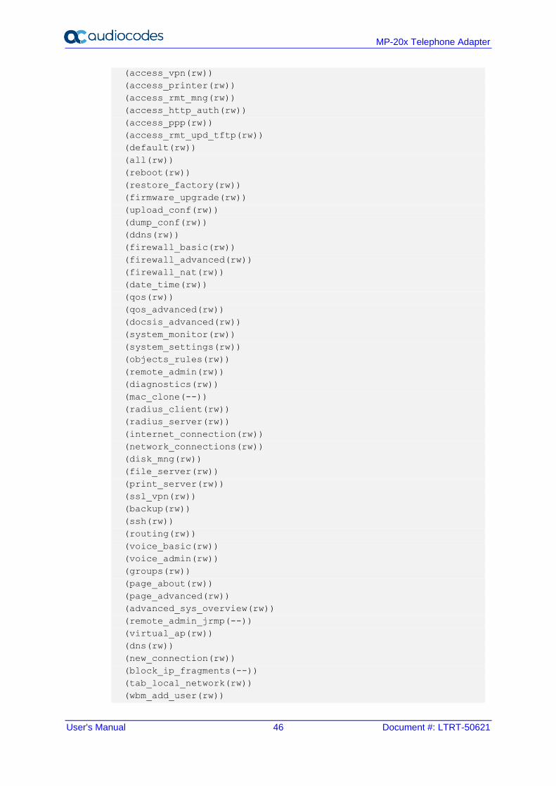
5.4.1.1.3 Permission Attributes per Role
The example below shows the Print command for viewing the permission attributes. In this example, the permission attributes for the Advanced role are displayed.
conf> print_permission admin/role/3/permission
(admin/role/3/permission
(access_wbm(rw))
(access_serial_cli(rw))
(access_telnet(rw))
(access_fs(rw))
(access_ftp(rw))
(access_mail(rw))
(access_wlan(rw))
(access_ssl_vpn(rw))
(access_ssh(rw))
(access_vpn(rw))
(access_printer(rw))
(access_rmt_mng(rw))
(access_http_auth(rw))
(access_ppp(rw))
(access_rmt_upd_tftp(rw))
(default(rw))
(all(rw))
User's Manual 42 Document #: LTRT-50621
MP-20x Telephone Adapter
(reboot(rw))
(restore_factory(rw))
(firmware_upgrade(rw))
(upload_conf(rw))
(dump_conf(rw))
(ddns(rw))
(firewall_basic(rw))
(firewall_advanced(rw))
(firewall_nat(rw))
(date_time(rw))
(qos(rw))
(qos_advanced(rw))
(docsis_advanced(rw))
(system_monitor(rw))
(system_settings(rw))
(objects_rules(rw))
(remote_admin(rw))
(diagnostics(rw))
(mac_clone(--))
(radius_client(rw))
(radius_server(rw))
(internet_connection(rw))
(network_connections(rw))
(disk_mng(rw))
(file_server(rw))
(print_server(rw))
(ssl_vpn(rw))
(backup(rw))
(ssh(rw))
(routing(rw))
(voice_basic(rw))
(voice_admin(rw))
(groups(rw))
(page_about(rw))
(page_advanced(rw))
(advanced_sys_overview(rw))
(remote_admin_jrmp(--))
(virtual_ap(rw))
(dns(rw))
(new_connection(rw))
(block_ip_fragments(--))
(tab_local_network(rw))
(wbm_add_user(rw))
(website_restrictions(rw))
(entfy(--))
(clock_set(rw))
(wlan_inter_client(--))
(qos_stats(rw))
(conn_troubleshoot(rw))
(dhcps(rw))
(dlm(rw))
User's Manual 5. Getting Started with the Web Interface
Version 4.5.1 43 MP-20x Telephone Adapter
(nation_zone(rw))
(dhcp(rw))
(port_forwarding(rw))
(users(rw))
(upnp(rw))
(certificates(rw))
(page_map(rw))
(page_quick_setup_advanced(rw))
(dmz_host(rw))
(wireless_basic(rw))
(wireless_admin(rw))
(wireless_advanced(--))
(change_password(--))
(network_connections_common(rw))
(port_forwarding_advanced(rw))
(primus_advanced(rw))
(packetsmart(rw))
(ipsec(rw))
(installation_wizard(rw))
(media_sharing(rw))
(pptp_server(rw))
(parental_control(rw))
(watchdog(rw))
)
Returned 0
conf>
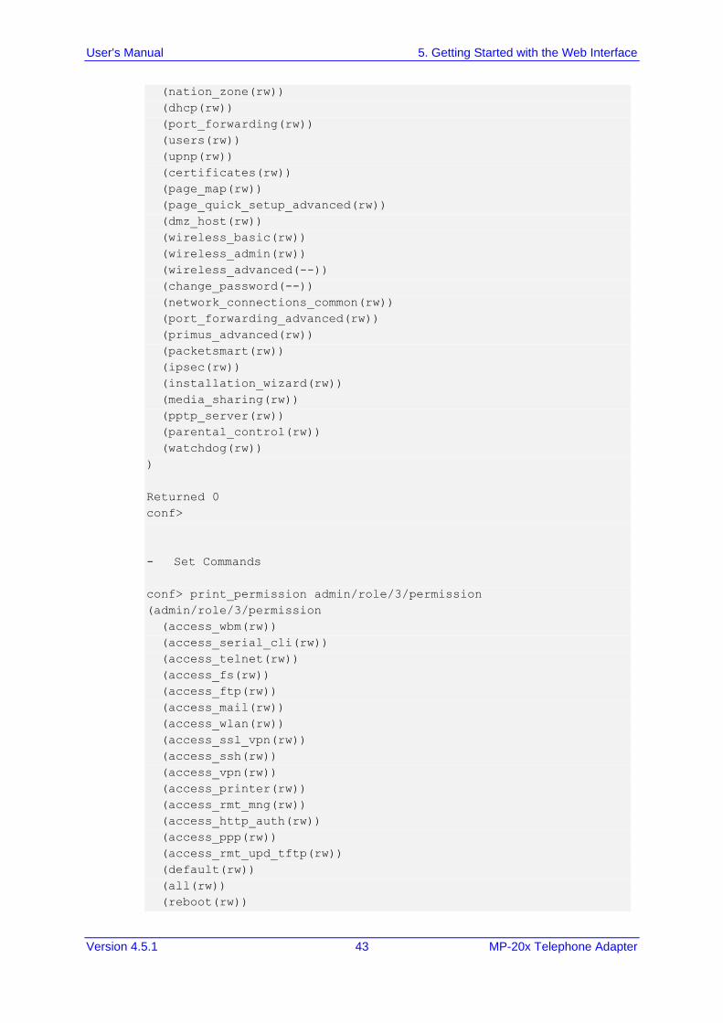
- Set Commands
conf> print_permission admin/role/3/permission
(admin/role/3/permission
(access_wbm(rw))
(access_serial_cli(rw))
(access_telnet(rw))
(access_fs(rw))
(access_ftp(rw))
(access_mail(rw))
(access_wlan(rw))
(access_ssl_vpn(rw))
(access_ssh(rw))
(access_vpn(rw))
(access_printer(rw))
(access_rmt_mng(rw))
(access_http_auth(rw))
(access_ppp(rw))
(access_rmt_upd_tftp(rw))
(default(rw))
(all(rw))
(reboot(rw))
User's Manual 44 Document #: LTRT-50621
MP-20x Telephone Adapter
(restore_factory(rw))
(firmware_upgrade(rw))
(upload_conf(rw))
(dump_conf(rw))
(ddns(rw))
(firewall_basic(rw))
(firewall_advanced(rw))
(firewall_nat(rw))
(date_time(rw))
(qos(rw))
(qos_advanced(rw))
(docsis_advanced(rw))
(system_monitor(rw))
(system_settings(rw))
(objects_rules(rw))
(remote_admin(rw))
(diagnostics(rw))
(mac_clone(--))
(radius_client(rw))
(radius_server(rw))
(internet_connection(rw))
(network_connections(rw))
(disk_mng(rw))
(file_server(rw))
(print_server(rw))
(ssl_vpn(rw))
(backup(rw))
(ssh(rw))
(routing(rw))
(voice_basic(rw))
(voice_admin(rw))
(groups(rw))
(page_about(rw))
(page_advanced(rw))
(advanced_sys_overview(rw))
(remote_admin_jrmp(--))
(virtual_ap(rw))
(dns(rw))
(new_connection(rw))
(block_ip_fragments(--))
(tab_local_network(rw))
(wbm_add_user(rw))
(website_restrictions(rw))
(entfy(--))
(clock_set(rw))
(wlan_inter_client(--))
(qos_stats(rw))
(conn_troubleshoot(rw))
(dhcps(rw))
(dlm(rw))
(nation_zone(rw))
User's Manual 5. Getting Started with the Web Interface
Version 4.5.1 45 MP-20x Telephone Adapter
(dhcp(rw))
(port_forwarding(rw))
(users(rw))
(upnp(rw))
(certificates(rw))
(page_map(rw))
(page_quick_setup_advanced(rw))
(dmz_host(rw))
(wireless_basic(rw))
(wireless_admin(rw))
(wireless_advanced(--))
(change_password(--))
(network_connections_common(rw))
(port_forwarding_advanced(rw))
(primus_advanced(rw))
(packetsmart(rw))
(ipsec(rw))
(installation_wizard(rw))
(media_sharing(rw))
(pptp_server(rw))
(parental_control(rw))
(watchdog(rw))
)
Returned 0
conf>
conf>
conf>
conf>
conf>
conf>
conf>
conf>
conf>
conf> set_permission admin/role/3/permission page_map --
Returned 0
conf> reconf 1
Returned 0
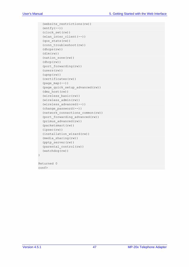
conf> print_permission admin/role/3/permission
(admin/role/3/permission
(access_wbm(rw))
(access_serial_cli(rw))
(access_telnet(rw))
(access_fs(rw))
(access_ftp(rw))
(access_mail(rw))
(access_wlan(rw))
(access_ssl_vpn(rw))
(access_ssh(rw))
User's Manual 46 Document #: LTRT-50621
MP-20x Telephone Adapter
(access_vpn(rw))
(access_printer(rw))
(access_rmt_mng(rw))
(access_http_auth(rw))
(access_ppp(rw))
(access_rmt_upd_tftp(rw))
(default(rw))
(all(rw))
(reboot(rw))
(restore_factory(rw))
(firmware_upgrade(rw))
(upload_conf(rw))
(dump_conf(rw))
(ddns(rw))
(firewall_basic(rw))
(firewall_advanced(rw))
(firewall_nat(rw))
(date_time(rw))
(qos(rw))
(qos_advanced(rw))
(docsis_advanced(rw))
(system_monitor(rw))
(system_settings(rw))
(objects_rules(rw))
(remote_admin(rw))
(diagnostics(rw))
(mac_clone(--))
(radius_client(rw))
(radius_server(rw))
(internet_connection(rw))
(network_connections(rw))
(disk_mng(rw))
(file_server(rw))
(print_server(rw))
(ssl_vpn(rw))
(backup(rw))
(ssh(rw))
(routing(rw))
(voice_basic(rw))
(voice_admin(rw))
(groups(rw))
(page_about(rw))
(page_advanced(rw))
(advanced_sys_overview(rw))
(remote_admin_jrmp(--))
(virtual_ap(rw))
(dns(rw))
(new_connection(rw))
(block_ip_fragments(--))
(tab_local_network(rw))
(wbm_add_user(rw))
User's Manual 5. Getting Started with the Web Interface
Version 4.5.1 47 MP-20x Telephone Adapter
(website_restrictions(rw))
(entfy(--))
(clock_set(rw))
(wlan_inter_client(--))
(qos_stats(rw))
(conn_troubleshoot(rw))
(dhcps(rw))
(dlm(rw))
(nation_zone(rw))
(dhcp(rw))
(port_forwarding(rw))
(users(rw))
(upnp(rw))
(certificates(rw))
(page_map(--))
(page_quick_setup_advanced(rw))
(dmz_host(rw))
(wireless_basic(rw))
(wireless_admin(rw))
(wireless_advanced(--))
(change_password(--))
(network_connections_common(rw))
(port_forwarding_advanced(rw))
(primus_advanced(rw))
(packetsmart(rw))
(ipsec(rw))
(installation_wizard(rw))
(media_sharing(rw))
(pptp_server(rw))
(parental_control(rw))
(watchdog(rw))
)
Returned 0
conf>
User's Manual 48 Document #: LTRT-50621
MP-20x Telephone Adapter
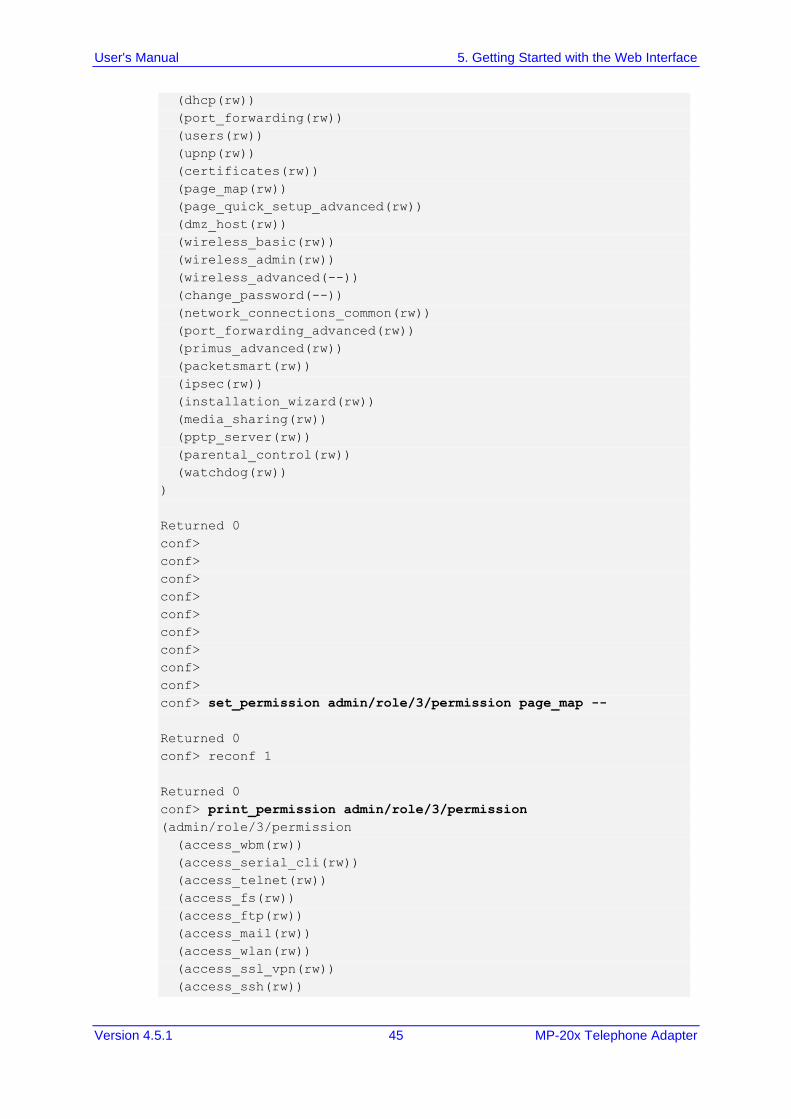
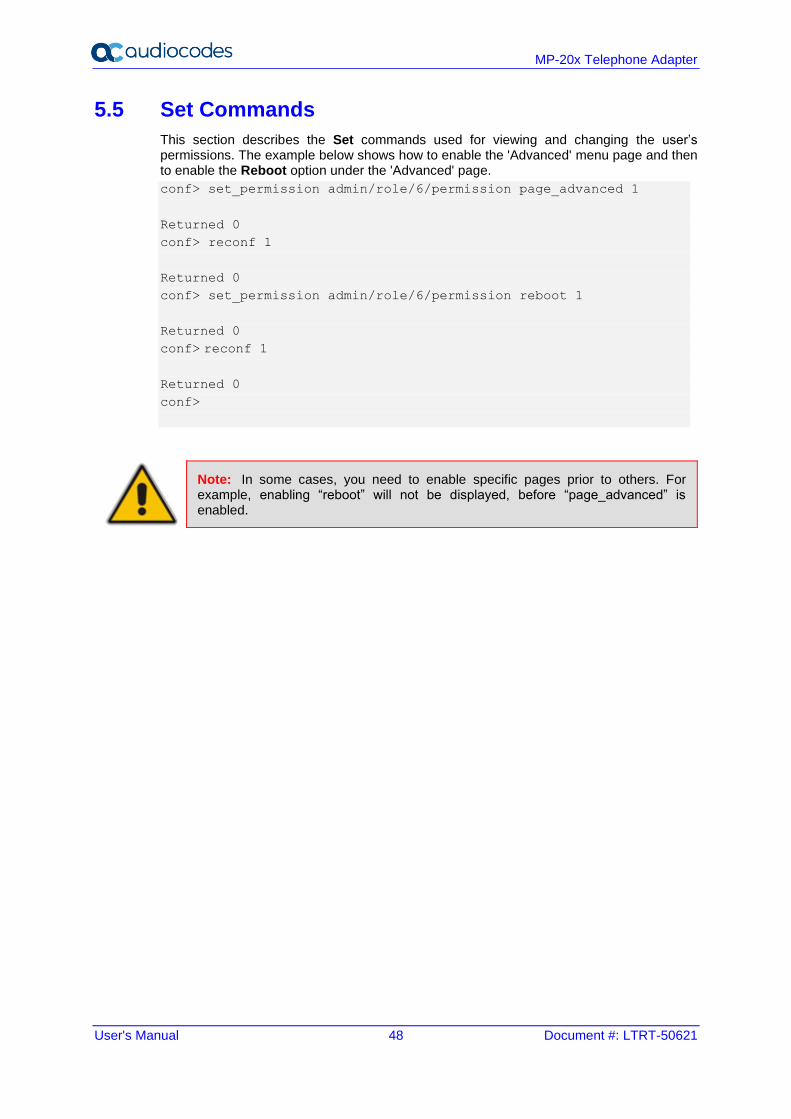
5.5 Set Commands
This section describes the Set commands used for viewing and changing the user’s permissions. The example below shows how to enable the 'Advanced' menu page and then to enable the Reboot option under the 'Advanced' page.
conf> set_permission admin/role/6/permission page_advanced 1
Returned 0
conf> reconf 1
Returned 0
conf> set_permission admin/role/6/permission reboot 1
Returned 0
conf> reconf 1
Returned 0
conf>
Note: In some cases, you need to enable specific pages prior to others. For example, enabling “reboot” will not be displayed, before “page_advanced” is enabled.
User's Manual 5. Getting Started with the Web Interface
Version 4.5.1 49 MP-20x Telephone Adapter
5.6 Associated Elements
You can define certain elements and then use them later when configuring various features throughout the Web interface. This is very convenient in that it eliminates the need to re-configure the same element, especially if used in multiple configuration areas. These elements include the following:
◼ Scheduler Rules – see Section 5.6.1 on page 49
◼ Network Objects – see Section 5.6.2 on page 51
◼ Protocols – see Section 5.6.3 on page 53
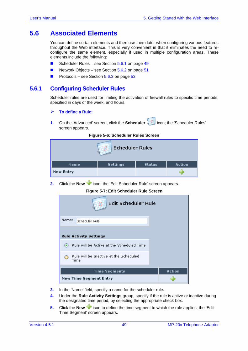
5.6.1 Configuring Scheduler Rules
Scheduler rules are used for limiting the activation of firewall rules to specific time periods, specified in days of the week, and hours.
➢ To define a Rule:
1. On the 'Advanced' screen, click the Scheduler icon; the 'Scheduler Rules'
screen appears.
Figure 5-6: Scheduler Rules Screen
2. Click the New icon; the 'Edit Scheduler Rule' screen appears.
Figure 5-7: Edit Scheduler Rule Screen
3. In the 'Name' field, specify a name for the scheduler rule.
4. Under the Rule Activity Settings group, specify if the rule is active or inactive during the designated time period, by selecting the appropriate check box.
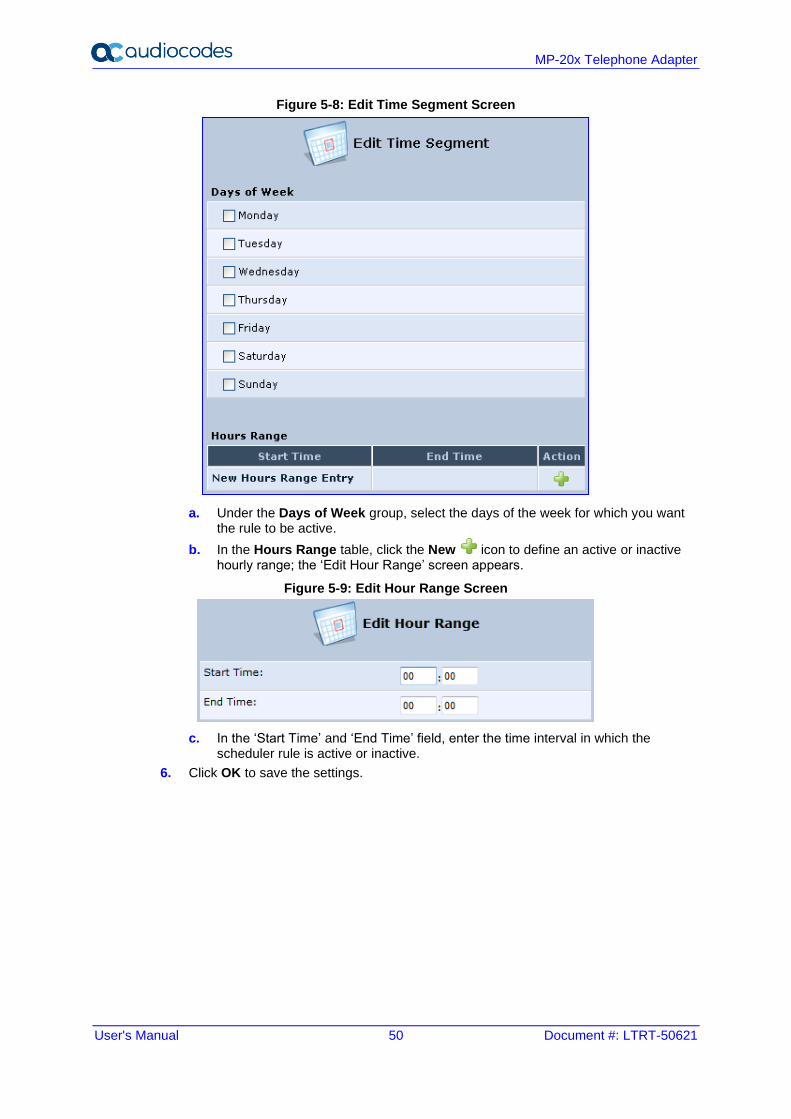
5. Click the New icon to define the time segment to which the rule applies; the 'Edit Time Segment' screen appears.
User's Manual 50 Document #: LTRT-50621
MP-20x Telephone Adapter
Figure 5-8: Edit Time Segment Screen
a. Under the Days of Week group, select the days of the week for which you want the rule to be active.
b. In the Hours Range table, click the New icon to define an active or inactive hourly range; the ‘Edit Hour Range’ screen appears.
Figure 5-9: Edit Hour Range Screen
c. In the ‘Start Time’ and ‘End Time’ field, enter the time interval in which the scheduler rule is active or inactive.
6. Click OK to save the settings.
User's Manual 5. Getting Started with the Web Interface
Version 4.5.1 51 MP-20x Telephone Adapter
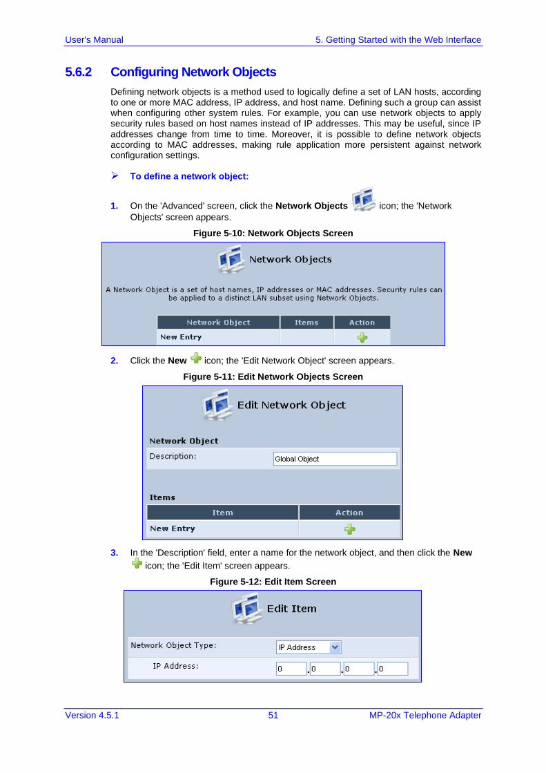
5.6.2 Configuring Network Objects
Defining network objects is a method used to logically define a set of LAN hosts, according to one or more MAC address, IP address, and host name. Defining such a group can assist when configuring other system rules. For example, you can use network objects to apply security rules based on host names instead of IP addresses. This may be useful, since IP addresses change from time to time. Moreover, it is possible to define network objects according to MAC addresses, making rule application more persistent against network configuration settings.
➢ To define a network object:
1. On the 'Advanced' screen, click the Network Objects icon; the 'Network
Objects' screen appears.
Figure 5-10: Network Objects Screen
2. Click the New icon; the 'Edit Network Object' screen appears.
Figure 5-11: Edit Network Objects Screen
3. In the 'Description' field, enter a name for the network object, and then click the New
icon; the 'Edit Item' screen appears.
Figure 5-12: Edit Item Screen
User's Manual 52 Document #: LTRT-50621
MP-20x Telephone Adapter
4. From the 'Network Object Type' drop-down lists, select a source address type:
• IP Address
• IP Subnet
• IP Range
• MAC Address
• Host Name
• DHCP Option (supporting options 60, 61, and 77)
• All Private IP Addresses
When selecting a method from the drop-down list, the screen refreshes, presenting the respective fields by which to enter the relevant information.
5. Click OK to save the settings.
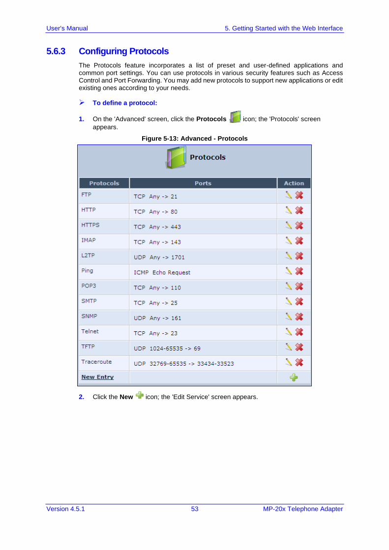
User's Manual 5. Getting Started with the Web Interface
Version 4.5.1 53 MP-20x Telephone Adapter
5.6.3 Configuring Protocols
The Protocols feature incorporates a list of preset and user-defined applications and common port settings. You can use protocols in various security features such as Access Control and Port Forwarding. You may add new protocols to support new applications or edit existing ones according to your needs.
➢ To define a protocol:
1. On the 'Advanced' screen, click the Protocols icon; the 'Protocols' screen
appears.
Figure 5-13: Advanced - Protocols
2. Click the New icon; the 'Edit Service' screen appears.
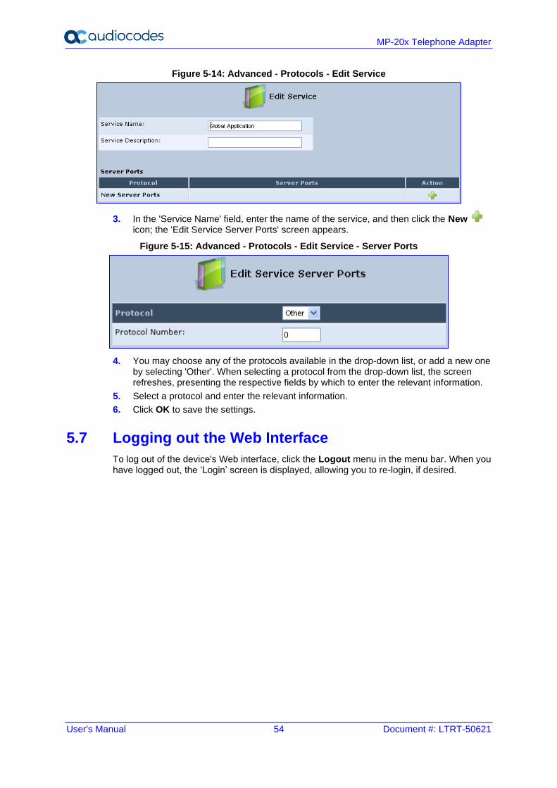
User's Manual 54 Document #: LTRT-50621
MP-20x Telephone Adapter
Figure 5-14: Advanced - Protocols - Edit Service
3. In the 'Service Name' field, enter the name of the service, and then click the New icon; the 'Edit Service Server Ports' screen appears.
Figure 5-15: Advanced - Protocols - Edit Service - Server Ports
4. You may choose any of the protocols available in the drop-down list, or add a new one by selecting 'Other'. When selecting a protocol from the drop-down list, the screen refreshes, presenting the respective fields by which to enter the relevant information.
5. Select a protocol and enter the relevant information.
6. Click OK to save the settings.
5.7 Logging out the Web Interface
To log out of the device's Web interface, click the Logout menu in the menu bar. When you have logged out, the ‘Login’ screen is displayed, allowing you to re-login, if desired.
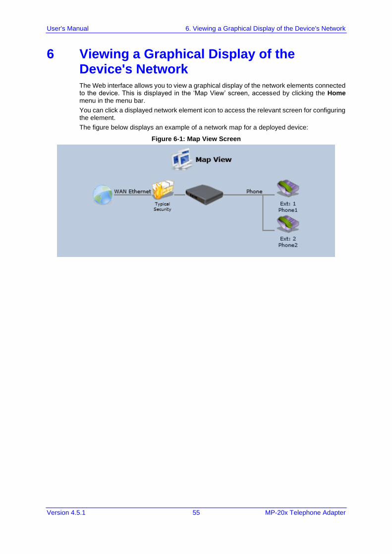
User's Manual 6. Viewing a Graphical Display of the Device's Network
Version 4.5.1 55 MP-20x Telephone Adapter
6 Viewing a Graphical Display of the Device's Network The Web interface allows you to view a graphical display of the network elements connected to the device. This is displayed in the ‘Map View’ screen, accessed by clicking the Home menu in the menu bar.
You can click a displayed network element icon to access the relevant screen for configuring the element.
The figure below displays an example of a network map for a deployed device:
Figure 6-1: Map View Screen
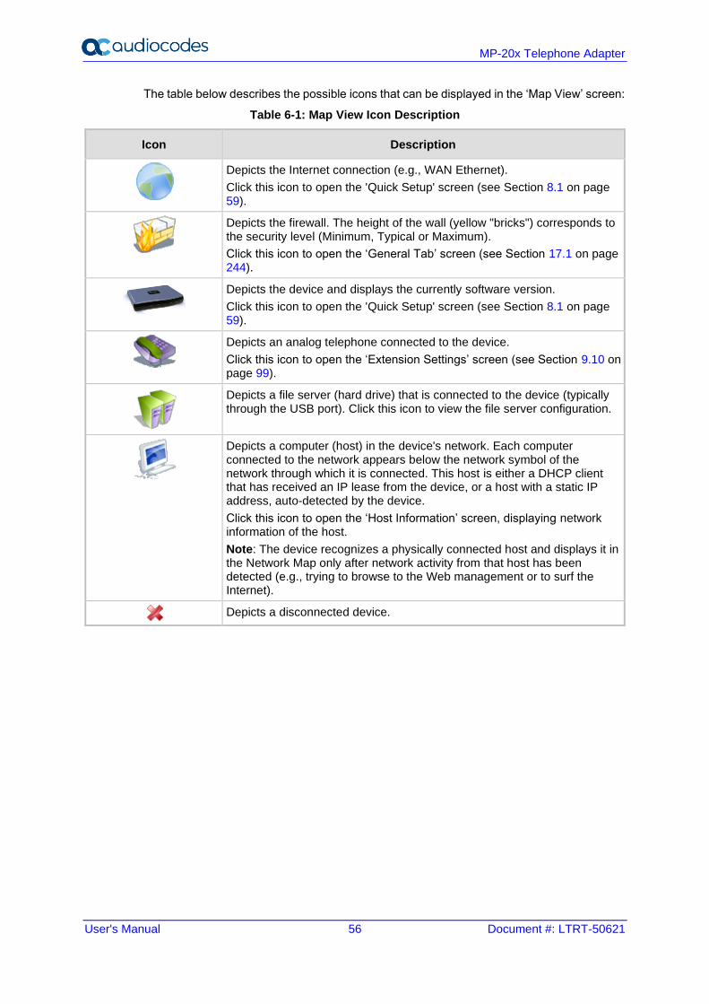
User's Manual 56 Document #: LTRT-50621
MP-20x Telephone Adapter
The table below describes the possible icons that can be displayed in the ‘Map View’ screen:
Table 6-1: Map View Icon Description
Icon Description
Depicts the Internet connection (e.g., WAN Ethernet).
Click this icon to open the 'Quick Setup' screen (see Section 8.1 on page 59).
Depicts the firewall. The height of the wall (yellow "bricks") corresponds to the security level (Minimum, Typical or Maximum).
Click this icon to open the ‘General Tab’ screen (see Section 17.1 on page 244).
Depicts the device and displays the currently software version.
Click this icon to open the 'Quick Setup' screen (see Section 8.1 on page 59).
Depicts an analog telephone connected to the device.
Click this icon to open the ‘Extension Settings’ screen (see Section 9.10 on page 99).
Depicts a file server (hard drive) that is connected to the device (typically through the USB port). Click this icon to view the file server configuration.
Depicts a computer (host) in the device's network. Each computer connected to the network appears below the network symbol of the network through which it is connected. This host is either a DHCP client that has received an IP lease from the device, or a host with a static IP address, auto-detected by the device.
Click this icon to open the ‘Host Information’ screen, displaying network information of the host.
Note: The device recognizes a physically connected host and displays it in the Network Map only after network activity from that host has been detected (e.g., trying to browse to the Web management or to surf the Internet).
Depicts a disconnected device.
User's Manual 7. Configuring Computers for Connecting to Device's Network
Version 4.5.1 57 MP-20x Telephone Adapter
7 Configuring Computers for Connecting to Device's Network The procedure below describes how to configure computers to connect to the device's network,
7.1 Wired Computers
This section describes how to configure computers that connect to the device's network through a LAN cable (i.e., wired).
You can configure the network interface of the computer using one of the following methods:
◼ Statically define an IP address and DNS address
◼ Automatically obtain an IP address using the device embedded DHCP server
This section describes how to configure the computers network for the following operating systems (OS):
◼ Windows 7 – see Section 7.1.1 on page 57
◼ Linux – see Section 7.1.2 on page 58
Note: It is recommended to set the computers to automatically obtain their IP addresses (from a DHCP server).
7.1.1 Configuring Computers Running on Windows 7
The procedure below describes how to configure a computer running on Windows 7 OS to automatically obtain its IP address (from a DHCP server, for example, MP-20x).
Note: For computers running Windows, the setup procedure is generally unnecessary as Windows' default network settings are to obtain an IP address automatically. However, it is recommended to follow the setup procedure to verify that all communication parameters are valid and that the physical cable connections are correct.
➢ To configure a computer running Windows 7 for dynamic IP addressing:
1. Click on your Start menu and select Control Panel.
2. Click Network and Internet.
3. Click Network and Sharing Center.
4. Click Change adapter settings, located on the left-side menu.
5. Right-click on the Local Area Connection icon and select Properties; the 'Internet Protocol (TCP/IP) Properties’ dialog box is displayed.
6. Double-click on the appropriate Internet Protocol version.
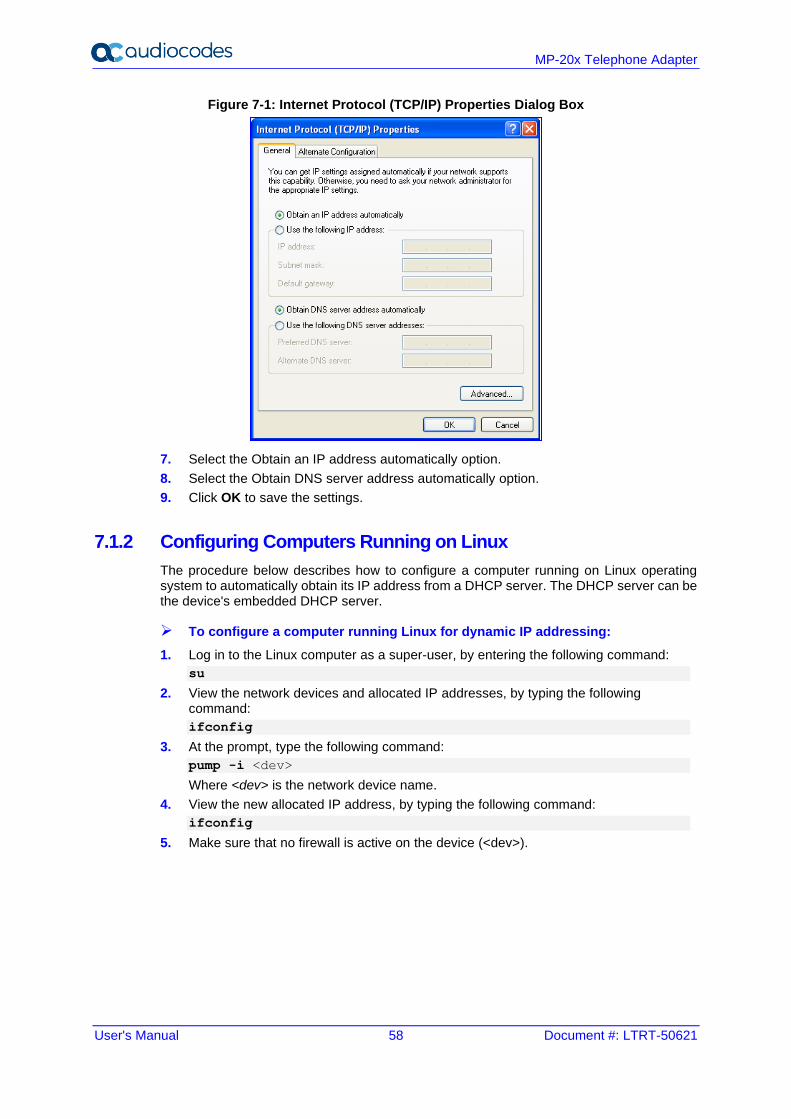
User's Manual 58 Document #: LTRT-50621
MP-20x Telephone Adapter
Figure 7-1: Internet Protocol (TCP/IP) Properties Dialog Box
7. Select the Obtain an IP address automatically option.
8. Select the Obtain DNS server address automatically option.
9. Click OK to save the settings.
7.1.2 Configuring Computers Running on Linux
The procedure below describes how to configure a computer running on Linux operating system to automatically obtain its IP address from a DHCP server. The DHCP server can be the device's embedded DHCP server.
➢ To configure a computer running Linux for dynamic IP addressing:
1. Log in to the Linux computer as a super-user, by entering the following command:
su
2. View the network devices and allocated IP addresses, by typing the following command:
ifconfig
3. At the prompt, type the following command:
pump -i <dev>
Where <dev> is the network device name.
4. View the new allocated IP address, by typing the following command:
ifconfig
5. Make sure that no firewall is active on the device (<dev>).
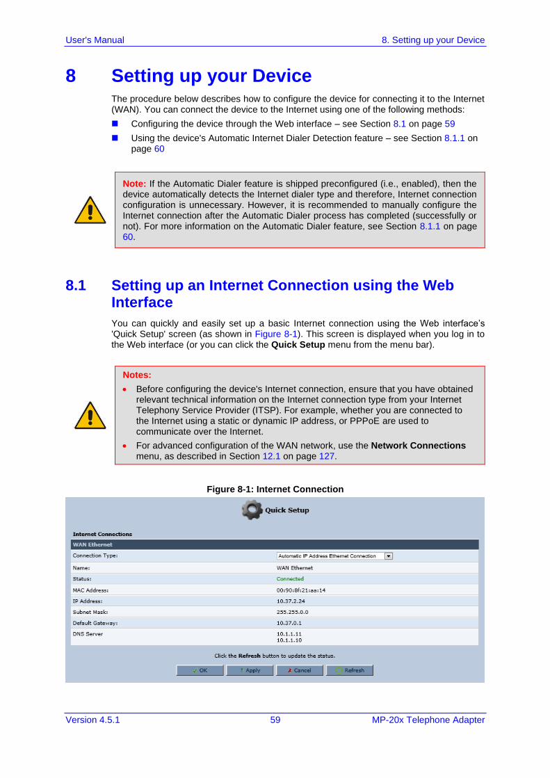
User's Manual 8. Setting up your Device
Version 4.5.1 59 MP-20x Telephone Adapter
8 Setting up your Device The procedure below describes how to configure the device for connecting it to the Internet (WAN). You can connect the device to the Internet using one of the following methods:
◼ Configuring the device through the Web interface – see Section 8.1 on page 59
◼ Using the device's Automatic Internet Dialer Detection feature – see Section 8.1.1 on page 60
Note: If the Automatic Dialer feature is shipped preconfigured (i.e., enabled), then the device automatically detects the Internet dialer type and therefore, Internet connection configuration is unnecessary. However, it is recommended to manually configure the Internet connection after the Automatic Dialer process has completed (successfully or not). For more information on the Automatic Dialer feature, see Section 8.1.1 on page 60.
8.1 Setting up an Internet Connection using the Web Interface
You can quickly and easily set up a basic Internet connection using the Web interface’s 'Quick Setup' screen (as shown in Figure 8-1). This screen is displayed when you log in to the Web interface (or you can click the Quick Setup menu from the menu bar).
Notes:
• Before configuring the device's Internet connection, ensure that you have obtained relevant technical information on the Internet connection type from your Internet Telephony Service Provider (ITSP). For example, whether you are connected to the Internet using a static or dynamic IP address, or PPPoE are used to communicate over the Internet.
• For advanced configuration of the WAN network, use the Network Connections menu, as described in Section 12.1 on page 127.
Figure 8-1: Internet Connection
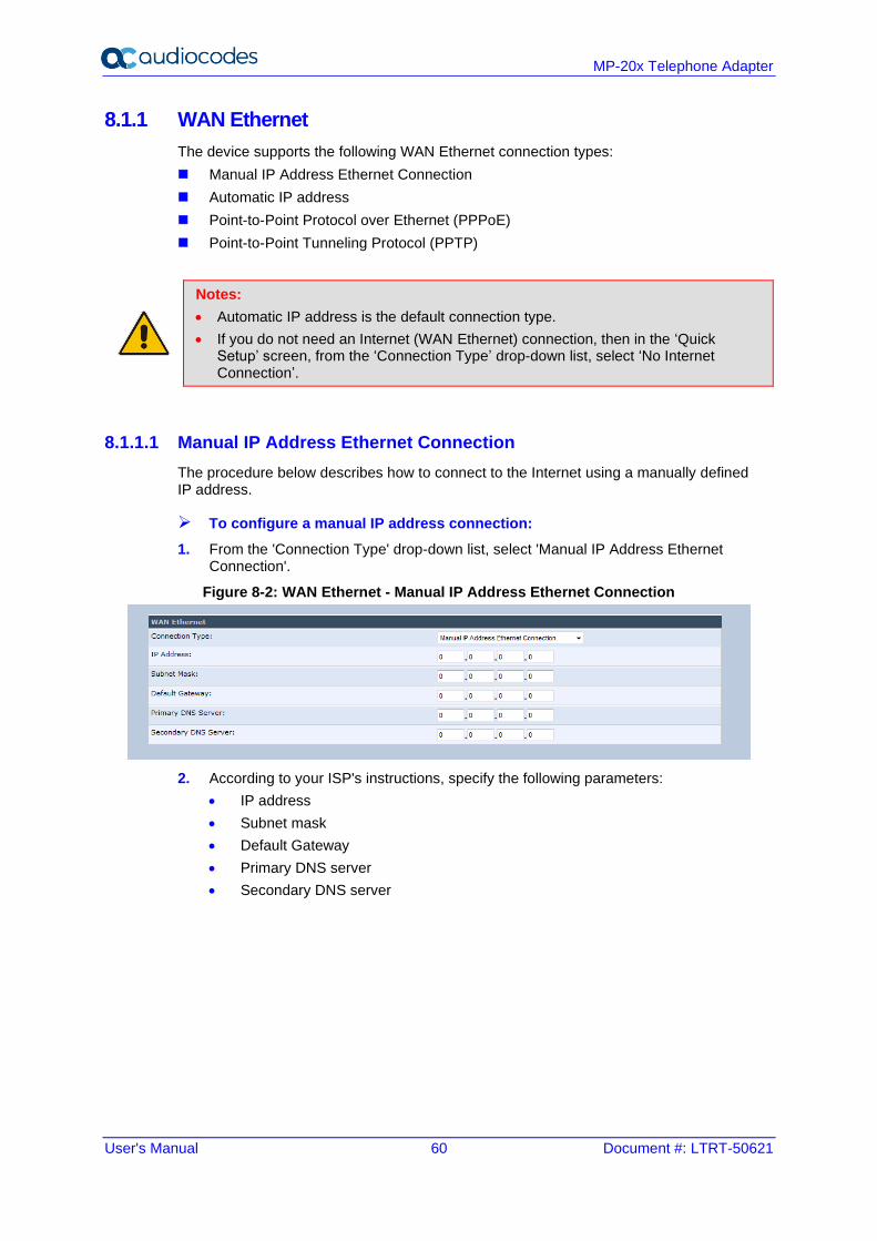
User's Manual 60 Document #: LTRT-50621
MP-20x Telephone Adapter
8.1.1 WAN Ethernet
The device supports the following WAN Ethernet connection types:
◼ Manual IP Address Ethernet Connection
◼ Automatic IP address
◼ Point-to-Point Protocol over Ethernet (PPPoE)
◼ Point-to-Point Tunneling Protocol (PPTP)
Notes:
• Automatic IP address is the default connection type.
• If you do not need an Internet (WAN Ethernet) connection, then in the ‘Quick Setup’ screen, from the ‘Connection Type’ drop-down list, select ‘No Internet Connection’.
8.1.1.1 Manual IP Address Ethernet Connection
The procedure below describes how to connect to the Internet using a manually defined IP address.
➢ To configure a manual IP address connection:
1. From the 'Connection Type' drop-down list, select 'Manual IP Address Ethernet Connection'.
Figure 8-2: WAN Ethernet - Manual IP Address Ethernet Connection
2. According to your ISP's instructions, specify the following parameters:
• IP address
• Subnet mask
• Default Gateway
• Primary DNS server
• Secondary DNS server
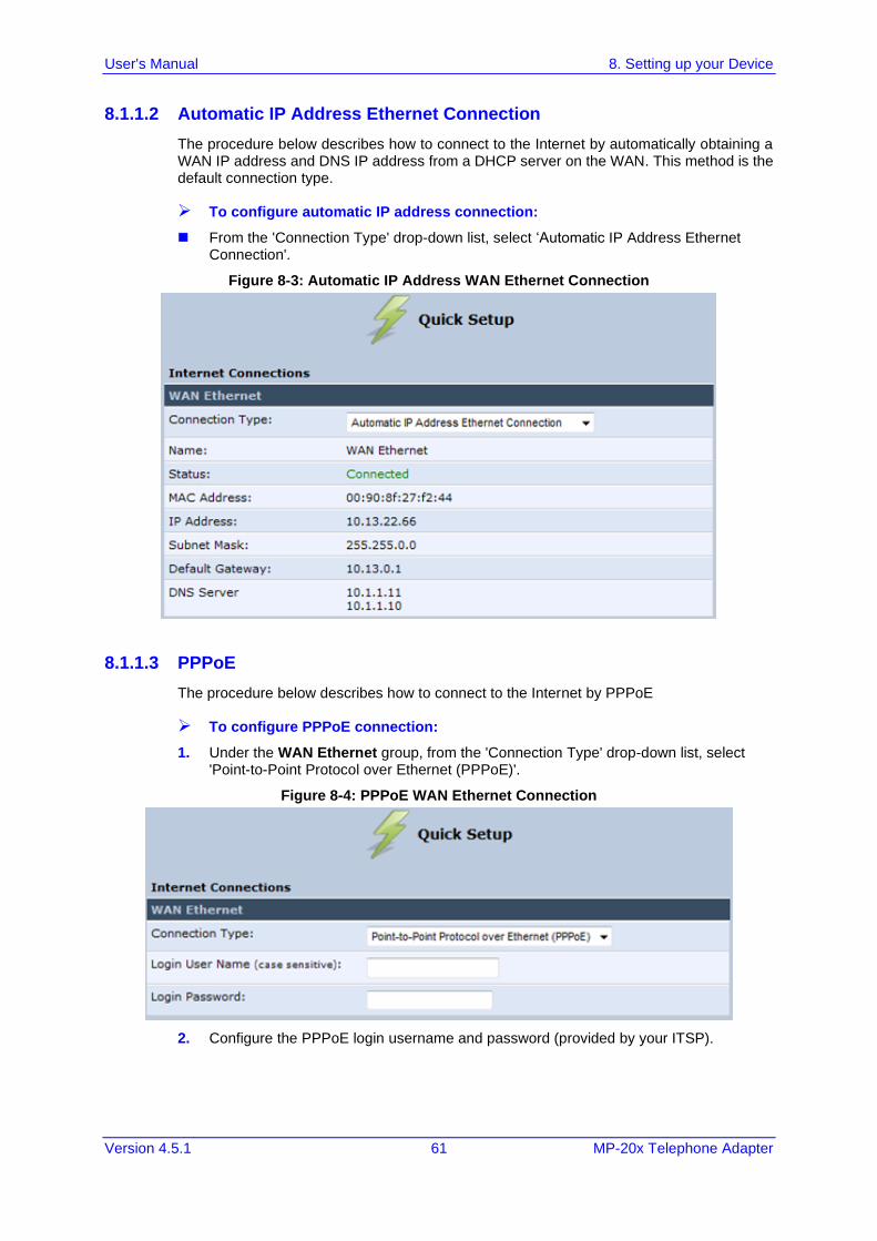
User's Manual 8. Setting up your Device
Version 4.5.1 61 MP-20x Telephone Adapter
8.1.1.2 Automatic IP Address Ethernet Connection
The procedure below describes how to connect to the Internet by automatically obtaining a WAN IP address and DNS IP address from a DHCP server on the WAN. This method is the default connection type.
➢ To configure automatic IP address connection:
◼ From the 'Connection Type' drop-down list, select ‘Automatic IP Address Ethernet Connection'.
Figure 8-3: Automatic IP Address WAN Ethernet Connection
8.1.1.3 PPPoE
The procedure below describes how to connect to the Internet by PPPoE
➢ To configure PPPoE connection:
1. Under the WAN Ethernet group, from the 'Connection Type' drop-down list, select 'Point-to-Point Protocol over Ethernet (PPPoE)'.
Figure 8-4: PPPoE WAN Ethernet Connection
2. Configure the PPPoE login username and password (provided by your ITSP).
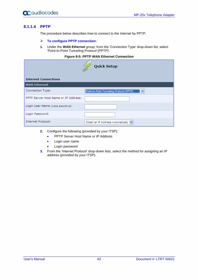
User's Manual 62 Document #: LTRT-50621
MP-20x Telephone Adapter
8.1.1.4 PPTP
The procedure below describes how to connect to the Internet by PPTP.
➢ To configure PPTP connection:
1. Under the WAN Ethernet group, from the 'Connection Type' drop-down list, select 'Point-to-Point Tunneling Protocol (PPTP)'.
Figure 8-5: PPTP WAN Ethernet Connection
2. Configure the following (provided by your ITSP):
• PPTP Server Host Name or IP Address
• Login user name
• Login password
3. From the ‘Internet Protocol’ drop-down lists, select the method for assigning an IP address (provided by your ITSP).
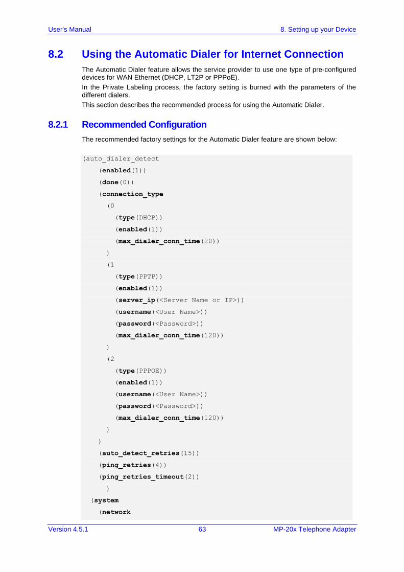
User's Manual 8. Setting up your Device
Version 4.5.1 63 MP-20x Telephone Adapter
8.2 Using the Automatic Dialer for Internet Connection
The Automatic Dialer feature allows the service provider to use one type of pre-configured devices for WAN Ethernet (DHCP, LT2P or PPPoE).
In the Private Labeling process, the factory setting is burned with the parameters of the different dialers.
This section describes the recommended process for using the Automatic Dialer.
8.2.1 Recommended Configuration
The recommended factory settings for the Automatic Dialer feature are shown below:
(auto_dialer_detect
(enabled(1))
(done(0))
(connection_type
(0
(type(DHCP))
(enabled(1))
(max_dialer_conn_time(20))
)
(1
(type(PPTP))
(enabled(1))
(server_ip(<Server Name or IP>))
(username(<User Name>))
(password(<Password>))
(max_dialer_conn_time(120))
)
(2
(type(PPPOE))
(enabled(1))
(username(<User Name>))
(password(<Password>))
(max_dialer_conn_time(120))
)
)
(auto_detect_retries(15))
(ping_retries(4))
(ping_retries_timeout(2))
)
(system
(network
User's Manual 64 Document #: LTRT-50621
MP-20x Telephone Adapter
(internet_url(<Address or Domain Name for Ping Test>))
)
)
8.2.2 Setting up and Starting the Automatic Dialer
The procedure below describes how to setup and start the Automatic Dialer feature.
➢ To setup and start Automatic Dialer:
1. Power off the device.
2. Connect the Ethernet cables.
3. Power on the device; the Automatic Dialer begins its operation and you can view the progress status by checking the device's LEDs.
Note: The connection is WAN Ethernet:
• For DHCP, the connection is fast.
• For PPPoE, the connection can take up to ~4 minutes.
8.2.3 Quitting Automatic Dialer for Manual Configuration
If, for any reason, you need to manually configure the Internet connection, you first need to stop the Automatic Dialer feature and then manually configure the connection, as described below,
➢ To quit Automatic Dialer and manually configure the Internet connection:
1. Power off the device.
2. Disconnect the Ethernet cable.
3. Power on the device.
4. Wait for the Automatic Dialer process to end (i.e., the Broadband LED stops blinking).
5. Log in to the device's Web interface.
6. Manually configure the Internet connection using the 'Quick Setup' screen (see Section 8.1 on page 59). This ensures that the Automatic Dialer feature does not re-activate itself after the device resets.
Once the device successfully connects to the Internet, it downloads its configuration file from the user-defined server on which the file is located.
Note: The configuration file must include the following parameter to indicate that Automatic Dialer is no longer needed: auto_dialer_detect/done = 1.
User's Manual 9. Configuring VoIP Parameters
Version 4.5.1 65 MP-20x Telephone Adapter
9 Configuring VoIP Parameters The VoIP parameters are mainly configured in the 'Voice over IP' screen. This screen is accessed by clicking the Voice over IP menu in the side menu bar. The ‘Voice over IP' screen provides tabs for configuring the following:
◼ Signaling protocol (i.e., Session Initiation Protocol / SIP) – see Section 9.1 on page 65
◼ Dialing – see Section 9.3 on page 72
◼ Media streaming – see Section 9.5 on page 81
◼ Voice and fax – see Section 9.6 on page 85
◼ Supplementary services – see Section 9.7 on page 90
◼ Line settings – see Section 9.8 on page 93
◼ Line extensions – see Section 9.10 on page 99
◼ Speed dials – see Section 9.11 on page 101
◼ Telephone interfaces – see Section 9.12 on page 103
Notes:
• By default, the ‘Voice over IP’ screens initially display only basic parameters. To view all the parameters, click the Advanced button in the required screen.
• Once you have configured the VoIP parameters, you can start using your analog telephones, as described in Chapter 10 on page 105.
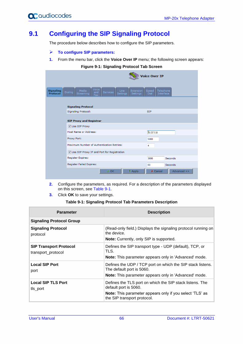
User's Manual 66 Document #: LTRT-50621
MP-20x Telephone Adapter
9.1 Configuring the SIP Signaling Protocol
The procedure below describes how to configure the SIP parameters.
➢ To configure SIP parameters:
1. From the menu bar, click the Voice Over IP menu; the following screen appears:
Figure 9-1: Signaling Protocol Tab Screen
2. Configure the parameters, as required. For a description of the parameters displayed on this screen, see Table 9-1.
3. Click OK to save your settings.
Table 9-1: Signaling Protocol Tab Parameters Description
Parameter Description
Signaling Protocol Group
Signaling Protocol
protocol
(Read-only field.) Displays the signaling protocol running on the device.
Note: Currently, only SIP is supported.
SIP Transport Protocol
transport_protocol
Defines the SIP transport type - UDP (default), TCP, or TLS.
Note: This parameter appears only in 'Advanced' mode.
Local SIP Port
port
Defines the UDP / TCP port on which the SIP stack listens. The default port is 5060.
Note: This parameter appears only in 'Advanced' mode.
Local SIP TLS Port
tls_port
Defines the TLS port on which the SIP stack listens. The default port is 5060.
Note: This parameter appears only if you select ‘TLS’ as the SIP transport protocol.
User's Manual 9. Configuring VoIP Parameters
Version 4.5.1 67 MP-20x Telephone Adapter
Parameter Description
Gateway Name - User Domain
proxy_gateway
Defines the device's domain name which is sent in the SIP From header of outgoing INVITE messages.
Note: This parameter appears only in 'Advanced' mode.
user_agent
Defines the user agent parameter that is used in SIP packet headers.
configured_user_agent
Replaces the default user_agent with the following format:
AudioCodes MP202B; <MAC>
Enable PRACK
prack/enabled
When enabled, the device replies with a PRACK message upon receipt of a reliable provisional response. The device does not initiate reliable provisional responses.
Note: This parameter appears only in 'Advanced' mode.
Include ptime in SDP
sdp_include_ptime
When enabled, the device adds the ptime field to the SDP message body.
Note: This parameter appears only in 'Advanced' mode.
advanced_dns
This parameter is automatically configured to:
▪ [DNS SRV] - If the SIP Proxy/Outbound Proxy port is configured to "65535"
▪ [NAPTR] – If the SIP Protocol is set to "UNDEFINED"
Note: The default value is "Disabled".
Enable rport
rport/enabled
When enabled, the device adds the rport parameter to the relevant SIP message fields.
Note: This parameter appears only in 'Advanced' mode.
Connect media on 180
connectMediaOn180
When enabled, media is connected upon receipt of SIP 180, 183, or 200 messages. When this parameter is disabled, media is connected upon receipt of 183 and 200 messages only.
Note: This parameter appears only in 'Advanced' mode.
Enable Keep Alive
ka_options/enabled
When enabled, a keep-alive notification is sent every user-defined interval to the SIP registrar server.
Note: This parameter appears only in 'Advanced' mode.
Keep-Alive Type
ka_options/ka_type
The type of keep-alive mechanism sent to the SIP registrar:
• Using SIP OPTIONS: sends SIP OPTIONS messages
• Using an Empty UDP packet: sends empty UDP packets
Note: This parameter is available only if the ‘Enable Keep Alive’ check box is selected.
Keep-Alive Period
ka_options/timeout
Defines the periodic interval for keep-alive messages.
Note: This parameter is available only if the ‘Enable Keep Alive’ check box is selected.
SIP Proxy and Registrar
Use SIP Proxy
use_proxy
When checked, outgoing calls are routed to the configured SIP proxy. If the 'Use SIP Proxy IP and Port for Registration' check box is also selected, the configured SIP proxy is also used as the registrar, allowing incoming calls.
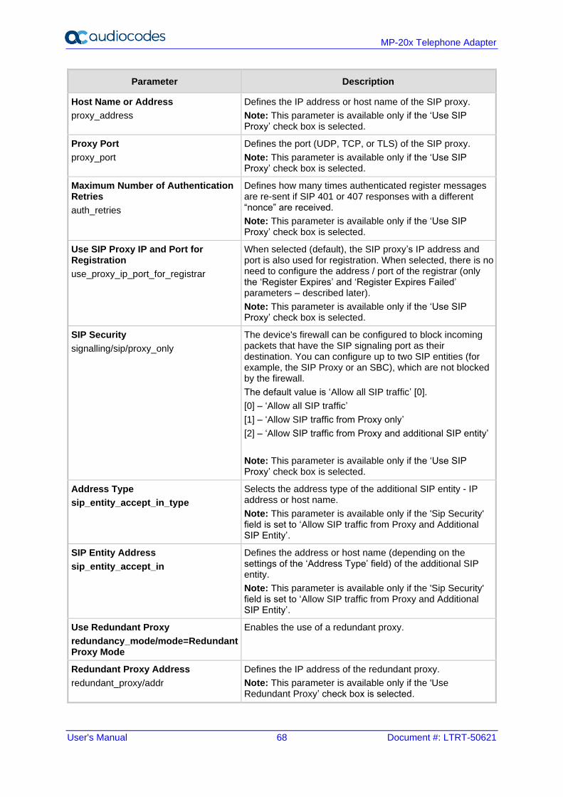
User's Manual 68 Document #: LTRT-50621
MP-20x Telephone Adapter
Parameter Description
Host Name or Address
proxy_address
Defines the IP address or host name of the SIP proxy.
Note: This parameter is available only if the ‘Use SIP Proxy’ check box is selected.
Proxy Port
proxy_port
Defines the port (UDP, TCP, or TLS) of the SIP proxy.
Note: This parameter is available only if the ‘Use SIP Proxy’ check box is selected.
Maximum Number of Authentication Retries
auth_retries
Defines how many times authenticated register messages are re-sent if SIP 401 or 407 responses with a different “nonce” are received.
Note: This parameter is available only if the ‘Use SIP Proxy’ check box is selected.
Use SIP Proxy IP and Port for Registration
use_proxy_ip_port_for_registrar
When selected (default), the SIP proxy’s IP address and port is also used for registration. When selected, there is no need to configure the address / port of the registrar (only the ‘Register Expires’ and ‘Register Expires Failed’ parameters – described later).
Note: This parameter is available only if the ‘Use SIP Proxy’ check box is selected.
SIP Security
signalling/sip/proxy_only
The device's firewall can be configured to block incoming packets that have the SIP signaling port as their destination. You can configure up to two SIP entities (for example, the SIP Proxy or an SBC), which are not blocked by the firewall.
The default value is ‘Allow all SIP traffic’ [0].
[0] – ‘Allow all SIP traffic’
[1] – ‘Allow SIP traffic from Proxy only’
[2] – ‘Allow SIP traffic from Proxy and additional SIP entity’
Note: This parameter is available only if the ‘Use SIP Proxy’ check box is selected.
Address Type
sip_entity_accept_in_type
Selects the address type of the additional SIP entity - IP address or host name.
Note: This parameter is available only if the 'Sip Security' field is set to ‘Allow SIP traffic from Proxy and Additional SIP Entity’.
SIP Entity Address
sip_entity_accept_in
Defines the address or host name (depending on the settings of the ‘Address Type’ field) of the additional SIP entity.
Note: This parameter is available only if the 'Sip Security' field is set to ‘Allow SIP traffic from Proxy and Additional SIP Entity’.
Use Redundant Proxy
redundancy_mode/mode=Redundant Proxy Mode
Enables the use of a redundant proxy.
Redundant Proxy Address
redundant_proxy/addr
Defines the IP address of the redundant proxy.
Note: This parameter is available only if the 'Use Redundant Proxy’ check box is selected.
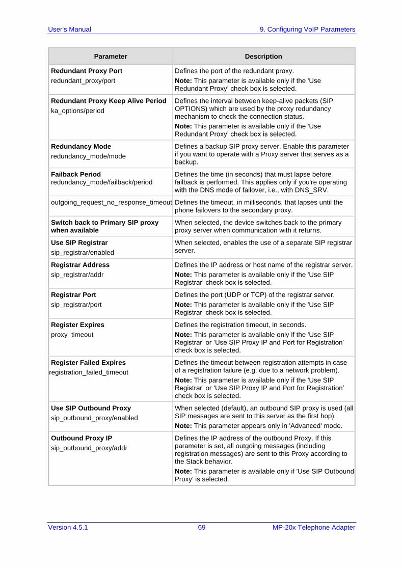
User's Manual 9. Configuring VoIP Parameters
Version 4.5.1 69 MP-20x Telephone Adapter
Parameter Description
Redundant Proxy Port
redundant_proxy/port
Defines the port of the redundant proxy.
Note: This parameter is available only if the 'Use Redundant Proxy’ check box is selected.
Redundant Proxy Keep Alive Period
ka_options/period
Defines the interval between keep-alive packets (SIP OPTIONS) which are used by the proxy redundancy mechanism to check the connection status.
Note: This parameter is available only if the 'Use Redundant Proxy’ check box is selected.
Redundancy Mode
redundancy_mode/mode
Defines a backup SIP proxy server. Enable this parameter if you want to operate with a Proxy server that serves as a backup.
Failback Period redundancy_mode/failback/period
Defines the time (in seconds) that must lapse before failback is performed. This applies only if you're operating with the DNS mode of failover, i.e., with DNS_SRV.
outgoing_request_no_response_timeout Defines the timeout, in milliseconds, that lapses until the phone failovers to the secondary proxy.
Switch back to Primary SIP proxy when available
When selected, the device switches back to the primary proxy server when communication with it returns.
Use SIP Registrar
sip_registrar/enabled
When selected, enables the use of a separate SIP registrar server.
Registrar Address
sip_registrar/addr
Defines the IP address or host name of the registrar server.
Note: This parameter is available only if the 'Use SIP Registrar’ check box is selected.
Registrar Port
sip_registrar/port
Defines the port (UDP or TCP) of the registrar server.
Note: This parameter is available only if the 'Use SIP Registrar’ check box is selected.
Register Expires
proxy_timeout
Defines the registration timeout, in seconds.
Note: This parameter is available only if the 'Use SIP Registrar’ or ‘Use SIP Proxy IP and Port for Registration’ check box is selected.
Register Failed Expires
registration_failed_timeout
Defines the timeout between registration attempts in case of a registration failure (e.g. due to a network problem).
Note: This parameter is available only if the 'Use SIP Registrar’ or ‘Use SIP Proxy IP and Port for Registration’ check box is selected.
Use SIP Outbound Proxy
sip_outbound_proxy/enabled
When selected (default), an outbound SIP proxy is used (all SIP messages are sent to this server as the first hop).
Note: This parameter appears only in 'Advanced' mode.
Outbound Proxy IP
sip_outbound_proxy/addr
Defines the IP address of the outbound Proxy. If this parameter is set, all outgoing messages (including registration messages) are sent to this Proxy according to the Stack behavior.
Note: This parameter is available only if 'Use SIP Outbound Proxy' is selected.
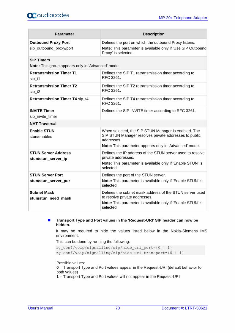
User's Manual 70 Document #: LTRT-50621
MP-20x Telephone Adapter
Parameter Description
Outbound Proxy Port
sip_outbound_proxy/port
Defines the port on which the outbound Proxy listens.
Note: This parameter is available only if 'Use SIP Outbound Proxy' is selected.
SIP Timers
Note: This group appears only in 'Advanced' mode.
Retransmission Timer T1
sip_t1
Defines the SIP T1 retransmission timer according to RFC 3261.
Retransmission Timer T2
sip_t2
Defines the SIP T2 retransmission timer according to RFC 3261.
Retransmission Timer T4 sip_t4 Defines the SIP T4 retransmission timer according to RFC 3261.
INVITE Timer
sip_invite_timer
Defines the SIP INVITE timer according to RFC 3261.
NAT Traversal
Enable STUN
stun/enabled
When selected, the SIP STUN Manager is enabled. The SIP STUN Manager resolves private addresses to public addresses.
Note: This parameter appears only in 'Advanced' mode.
STUN Server Address
stun/stun_server_ip
Defines the IP address of the STUN server used to resolve private addresses.
Note: This parameter is available only if 'Enable STUN' is selected.
STUN Server Port
stun/stun_server_por
Defines the port of the STUN server.
Note: This parameter is available only if 'Enable STUN' is selected.
Subnet Mask
stun/stun_need_mask
Defines the subnet mask address of the STUN server used to resolve private addresses.
Note: This parameter is available only if 'Enable STUN' is selected.
◼ Transport Type and Port values in the ‘Request-URI’ SIP header can now be hidden.
It may be required to hide the values listed below in the Nokia-Siemens IMS environment.
This can be done by running the following:
rg_conf/voip/signalling/sip/hide_uri_port={0 | 1}
rg_conf/voip/signalling/sip/hide_uri_transport={0 | 1}
Possible values: 0 = Transport Type and Port values appear in the Request-URI (default behavior for both values) 1 = Transport Type and Port values will not appear in the Request-URI
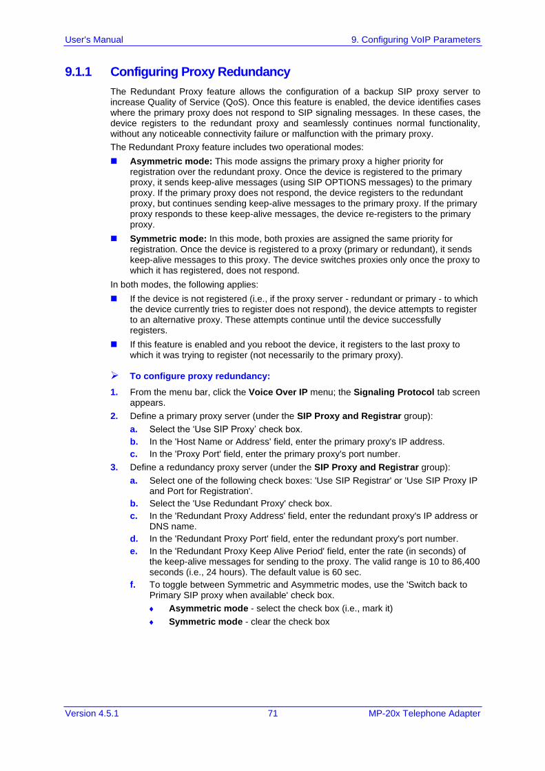
User's Manual 9. Configuring VoIP Parameters
Version 4.5.1 71 MP-20x Telephone Adapter
9.1.1 Configuring Proxy Redundancy
The Redundant Proxy feature allows the configuration of a backup SIP proxy server to increase Quality of Service (QoS). Once this feature is enabled, the device identifies cases where the primary proxy does not respond to SIP signaling messages. In these cases, the device registers to the redundant proxy and seamlessly continues normal functionality, without any noticeable connectivity failure or malfunction with the primary proxy.
The Redundant Proxy feature includes two operational modes:
◼ Asymmetric mode: This mode assigns the primary proxy a higher priority for registration over the redundant proxy. Once the device is registered to the primary proxy, it sends keep-alive messages (using SIP OPTIONS messages) to the primary proxy. If the primary proxy does not respond, the device registers to the redundant proxy, but continues sending keep-alive messages to the primary proxy. If the primary proxy responds to these keep-alive messages, the device re-registers to the primary proxy.
◼ Symmetric mode: In this mode, both proxies are assigned the same priority for registration. Once the device is registered to a proxy (primary or redundant), it sends keep-alive messages to this proxy. The device switches proxies only once the proxy to which it has registered, does not respond.
In both modes, the following applies:
◼ If the device is not registered (i.e., if the proxy server - redundant or primary - to which the device currently tries to register does not respond), the device attempts to register to an alternative proxy. These attempts continue until the device successfully registers.
◼ If this feature is enabled and you reboot the device, it registers to the last proxy to which it was trying to register (not necessarily to the primary proxy).
➢ To configure proxy redundancy:
1. From the menu bar, click the Voice Over IP menu; the Signaling Protocol tab screen appears.
2. Define a primary proxy server (under the SIP Proxy and Registrar group):
a. Select the ‘Use SIP Proxy’ check box.
b. In the 'Host Name or Address' field, enter the primary proxy's IP address.
c. In the 'Proxy Port' field, enter the primary proxy's port number.
3. Define a redundancy proxy server (under the SIP Proxy and Registrar group):
a. Select one of the following check boxes: 'Use SIP Registrar' or 'Use SIP Proxy IP and Port for Registration'.
b. Select the 'Use Redundant Proxy' check box.
c. In the 'Redundant Proxy Address' field, enter the redundant proxy's IP address or DNS name.
d. In the 'Redundant Proxy Port' field, enter the redundant proxy's port number.
e. In the 'Redundant Proxy Keep Alive Period' field, enter the rate (in seconds) of the keep-alive messages for sending to the proxy. The valid range is 10 to 86,400 seconds (i.e., 24 hours). The default value is 60 sec.
f. To toggle between Symmetric and Asymmetric modes, use the 'Switch back to Primary SIP proxy when available' check box.
Asymmetric mode - select the check box (i.e., mark it)
Symmetric mode - clear the check box
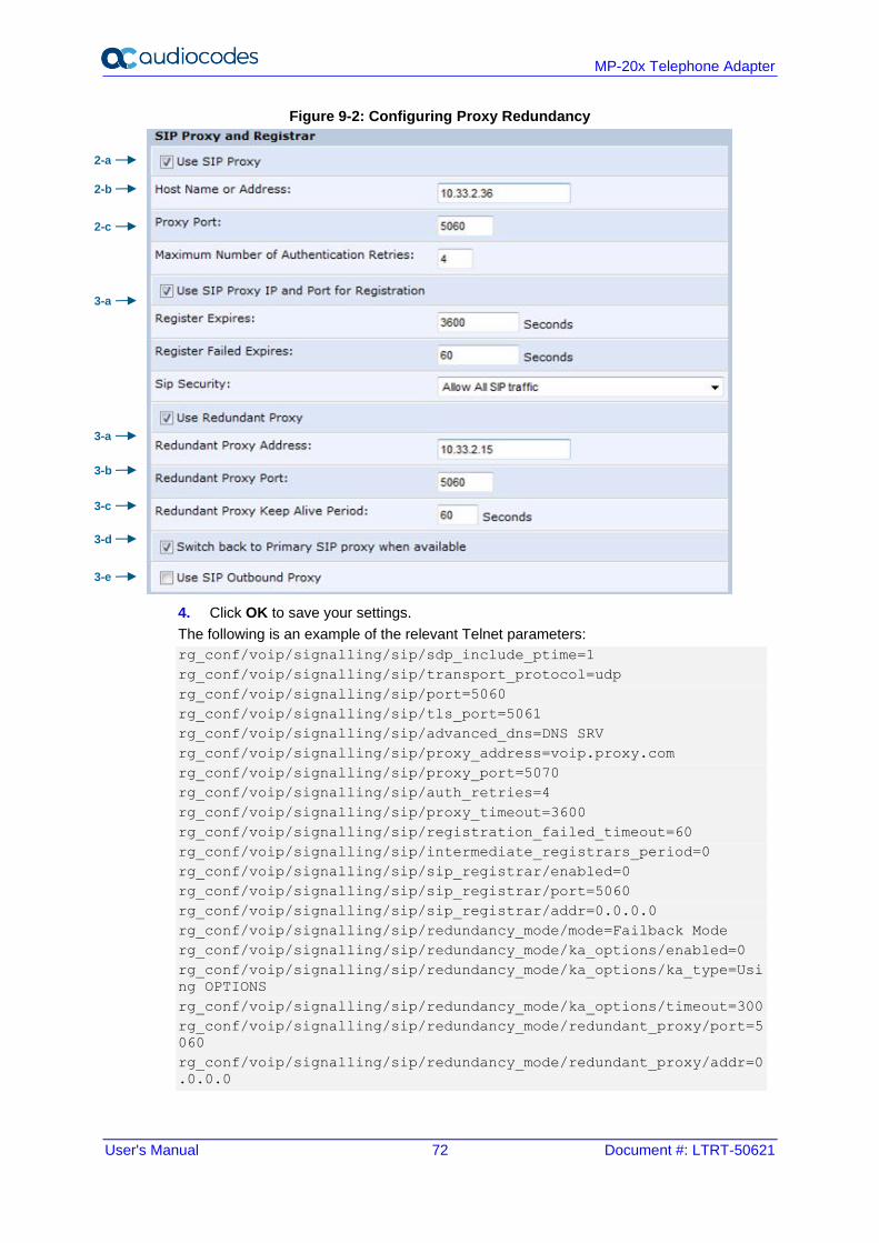
User's Manual 72 Document #: LTRT-50621
MP-20x Telephone Adapter
Figure 9-2: Configuring Proxy Redundancy
4. Click OK to save your settings.
The following is an example of the relevant Telnet parameters:
rg_conf/voip/signalling/sip/sdp_include_ptime=1
rg_conf/voip/signalling/sip/transport_protocol=udp
rg_conf/voip/signalling/sip/port=5060
rg_conf/voip/signalling/sip/tls_port=5061
rg_conf/voip/signalling/sip/advanced_dns=DNS SRV
rg_conf/voip/signalling/sip/proxy_address=voip.proxy.com
rg_conf/voip/signalling/sip/proxy_port=5070
rg_conf/voip/signalling/sip/auth_retries=4
rg_conf/voip/signalling/sip/proxy_timeout=3600
rg_conf/voip/signalling/sip/registration_failed_timeout=60
rg_conf/voip/signalling/sip/intermediate_registrars_period=0
rg_conf/voip/signalling/sip/sip_registrar/enabled=0
rg_conf/voip/signalling/sip/sip_registrar/port=5060
rg_conf/voip/signalling/sip/sip_registrar/addr=0.0.0.0
rg_conf/voip/signalling/sip/redundancy_mode/mode=Failback Mode
rg_conf/voip/signalling/sip/redundancy_mode/ka_options/enabled=0
rg_conf/voip/signalling/sip/redundancy_mode/ka_options/ka_type=Usi
ng OPTIONS
rg_conf/voip/signalling/sip/redundancy_mode/ka_options/timeout=300
rg_conf/voip/signalling/sip/redundancy_mode/redundant_proxy/port=5
060
rg_conf/voip/signalling/sip/redundancy_mode/redundant_proxy/addr=0
.0.0.0
2-a
3-a
2-b
2-c
3-a
3-b
3-c
3-d
3-e
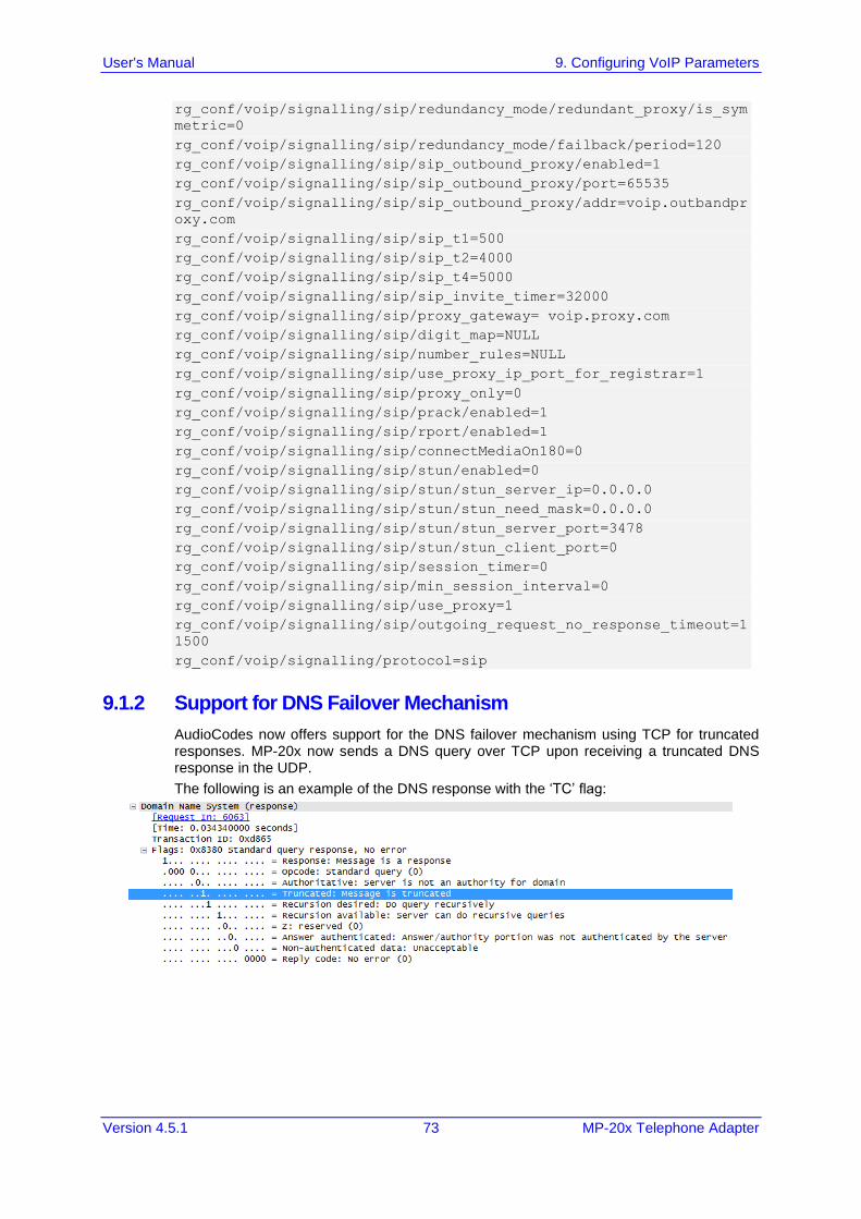
User's Manual 9. Configuring VoIP Parameters
Version 4.5.1 73 MP-20x Telephone Adapter
rg_conf/voip/signalling/sip/redundancy_mode/redundant_proxy/is_sym
metric=0
rg_conf/voip/signalling/sip/redundancy_mode/failback/period=120
rg_conf/voip/signalling/sip/sip_outbound_proxy/enabled=1
rg_conf/voip/signalling/sip/sip_outbound_proxy/port=65535
rg_conf/voip/signalling/sip/sip_outbound_proxy/addr=voip.outbandpr
oxy.com
rg_conf/voip/signalling/sip/sip_t1=500
rg_conf/voip/signalling/sip/sip_t2=4000
rg_conf/voip/signalling/sip/sip_t4=5000
rg_conf/voip/signalling/sip/sip_invite_timer=32000
rg_conf/voip/signalling/sip/proxy_gateway= voip.proxy.com
rg_conf/voip/signalling/sip/digit_map=NULL
rg_conf/voip/signalling/sip/number_rules=NULL
rg_conf/voip/signalling/sip/use_proxy_ip_port_for_registrar=1
rg_conf/voip/signalling/sip/proxy_only=0
rg_conf/voip/signalling/sip/prack/enabled=1
rg_conf/voip/signalling/sip/rport/enabled=1
rg_conf/voip/signalling/sip/connectMediaOn180=0
rg_conf/voip/signalling/sip/stun/enabled=0
rg_conf/voip/signalling/sip/stun/stun_server_ip=0.0.0.0
rg_conf/voip/signalling/sip/stun/stun_need_mask=0.0.0.0
rg_conf/voip/signalling/sip/stun/stun_server_port=3478
rg_conf/voip/signalling/sip/stun/stun_client_port=0
rg_conf/voip/signalling/sip/session_timer=0
rg_conf/voip/signalling/sip/min_session_interval=0
rg_conf/voip/signalling/sip/use_proxy=1
rg_conf/voip/signalling/sip/outgoing_request_no_response_timeout=1
1500
rg_conf/voip/signalling/protocol=sip
9.1.2 Support for DNS Failover Mechanism
AudioCodes now offers support for the DNS failover mechanism using TCP for truncated responses. MP-20x now sends a DNS query over TCP upon receiving a truncated DNS response in the UDP.
The following is an example of the DNS response with the ‘TC’ flag:
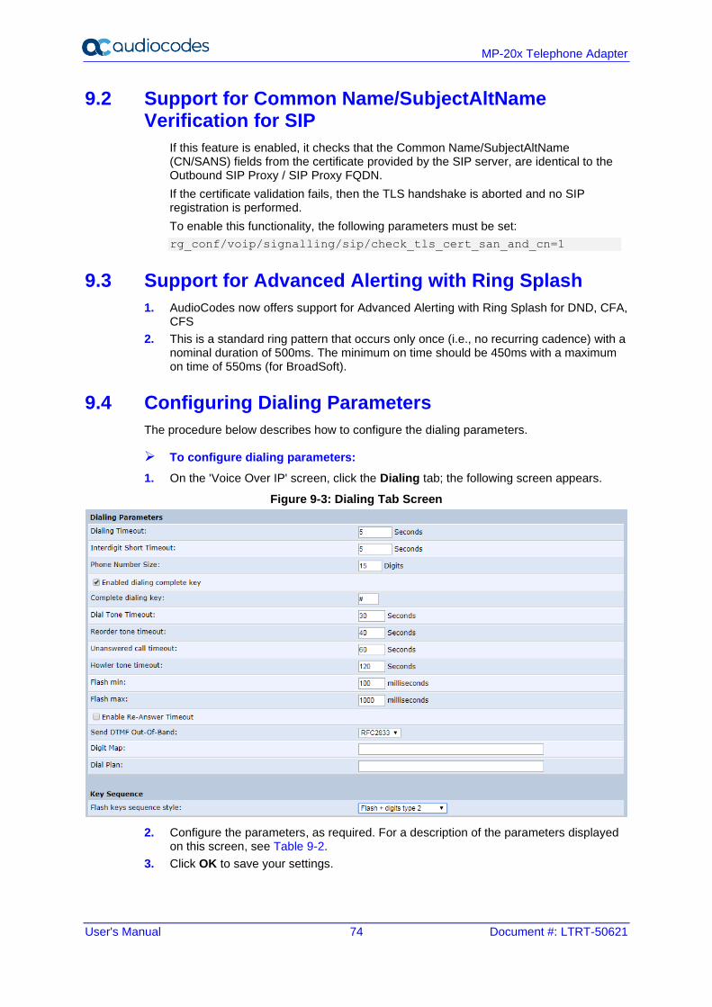
User's Manual 74 Document #: LTRT-50621
MP-20x Telephone Adapter
9.2 Support for Common Name/SubjectAltName Verification for SIP
If this feature is enabled, it checks that the Common Name/SubjectAltName (CN/SANS) fields from the certificate provided by the SIP server, are identical to the Outbound SIP Proxy / SIP Proxy FQDN.
If the certificate validation fails, then the TLS handshake is aborted and no SIP registration is performed.
To enable this functionality, the following parameters must be set:
rg_conf/voip/signalling/sip/check_tls_cert_san_and_cn=1
9.3 Support for Advanced Alerting with Ring Splash
1. AudioCodes now offers support for Advanced Alerting with Ring Splash for DND, CFA, CFS
2. This is a standard ring pattern that occurs only once (i.e., no recurring cadence) with a nominal duration of 500ms. The minimum on time should be 450ms with a maximum on time of 550ms (for BroadSoft).
9.4 Configuring Dialing Parameters
The procedure below describes how to configure the dialing parameters.
➢ To configure dialing parameters:
1. On the 'Voice Over IP' screen, click the Dialing tab; the following screen appears.
Figure 9-3: Dialing Tab Screen
2. Configure the parameters, as required. For a description of the parameters displayed on this screen, see Table 9-2.
3. Click OK to save your settings.
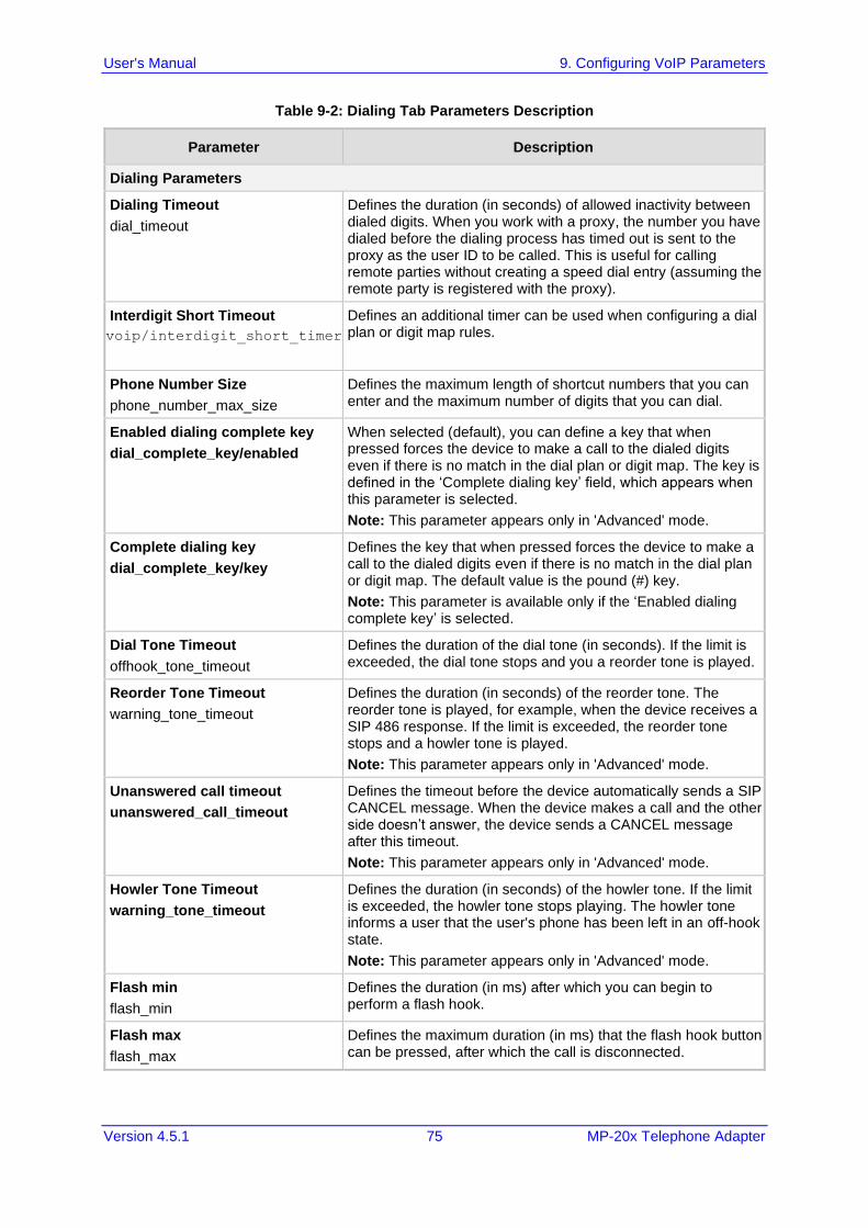
User's Manual 9. Configuring VoIP Parameters
Version 4.5.1 75 MP-20x Telephone Adapter
Table 9-2: Dialing Tab Parameters Description
Parameter Description
Dialing Parameters
Dialing Timeout
dial_timeout
Defines the duration (in seconds) of allowed inactivity between dialed digits. When you work with a proxy, the number you have dialed before the dialing process has timed out is sent to the proxy as the user ID to be called. This is useful for calling remote parties without creating a speed dial entry (assuming the remote party is registered with the proxy).
Interdigit Short Timeout
voip/interdigit_short_timer
Defines an additional timer can be used when configuring a dial plan or digit map rules.
Phone Number Size
phone_number_max_size
Defines the maximum length of shortcut numbers that you can enter and the maximum number of digits that you can dial.
Enabled dialing complete key
dial_complete_key/enabled
When selected (default), you can define a key that when pressed forces the device to make a call to the dialed digits even if there is no match in the dial plan or digit map. The key is defined in the ‘Complete dialing key’ field, which appears when this parameter is selected.
Note: This parameter appears only in 'Advanced' mode.
Complete dialing key
dial_complete_key/key
Defines the key that when pressed forces the device to make a call to the dialed digits even if there is no match in the dial plan or digit map. The default value is the pound (#) key.
Note: This parameter is available only if the ‘Enabled dialing complete key’ is selected.
Dial Tone Timeout
offhook_tone_timeout
Defines the duration of the dial tone (in seconds). If the limit is exceeded, the dial tone stops and you a reorder tone is played.
Reorder Tone Timeout
warning_tone_timeout
Defines the duration (in seconds) of the reorder tone. The reorder tone is played, for example, when the device receives a SIP 486 response. If the limit is exceeded, the reorder tone stops and a howler tone is played.
Note: This parameter appears only in 'Advanced' mode.
Unanswered call timeout
unanswered_call_timeout
Defines the timeout before the device automatically sends a SIP CANCEL message. When the device makes a call and the other side doesn’t answer, the device sends a CANCEL message after this timeout.
Note: This parameter appears only in 'Advanced' mode.
Howler Tone Timeout
warning_tone_timeout
Defines the duration (in seconds) of the howler tone. If the limit is exceeded, the howler tone stops playing. The howler tone informs a user that the user's phone has been left in an off-hook state.
Note: This parameter appears only in 'Advanced' mode.
Flash min
flash_min
Defines the duration (in ms) after which you can begin to perform a flash hook.
Flash max
flash_max
Defines the maximum duration (in ms) that the flash hook button can be pressed, after which the call is disconnected.
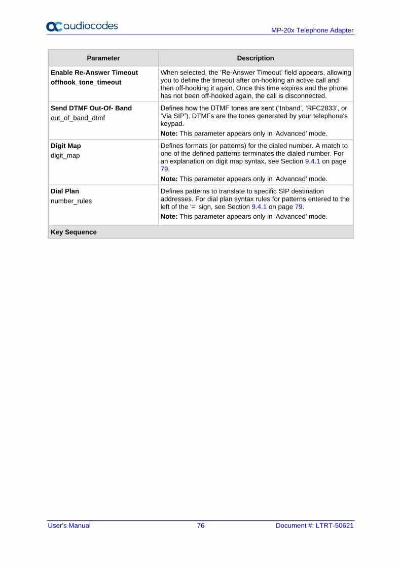
User's Manual 76 Document #: LTRT-50621
MP-20x Telephone Adapter
Parameter Description
Enable Re-Answer Timeout
offhook_tone_timeout
When selected, the ‘Re-Answer Timeout’ field appears, allowing you to define the timeout after on-hooking an active call and then off-hooking it again. Once this time expires and the phone has not been off-hooked again, the call is disconnected.
Send DTMF Out-Of- Band
out_of_band_dtmf
Defines how the DTMF tones are sent (‘Inband’, ‘RFC2833’, or ‘Via SIP’). DTMFs are the tones generated by your telephone's keypad.
Note: This parameter appears only in 'Advanced' mode.
Digit Map
digit_map
Defines formats (or patterns) for the dialed number. A match to one of the defined patterns terminates the dialed number. For an explanation on digit map syntax, see Section 9.4.1 on page 79.
Note: This parameter appears only in 'Advanced' mode.
Dial Plan
number_rules
Defines patterns to translate to specific SIP destination addresses. For dial plan syntax rules for patterns entered to the left of the '=' sign, see Section 9.4.1 on page 79.
Note: This parameter appears only in 'Advanced' mode.
Key Sequence
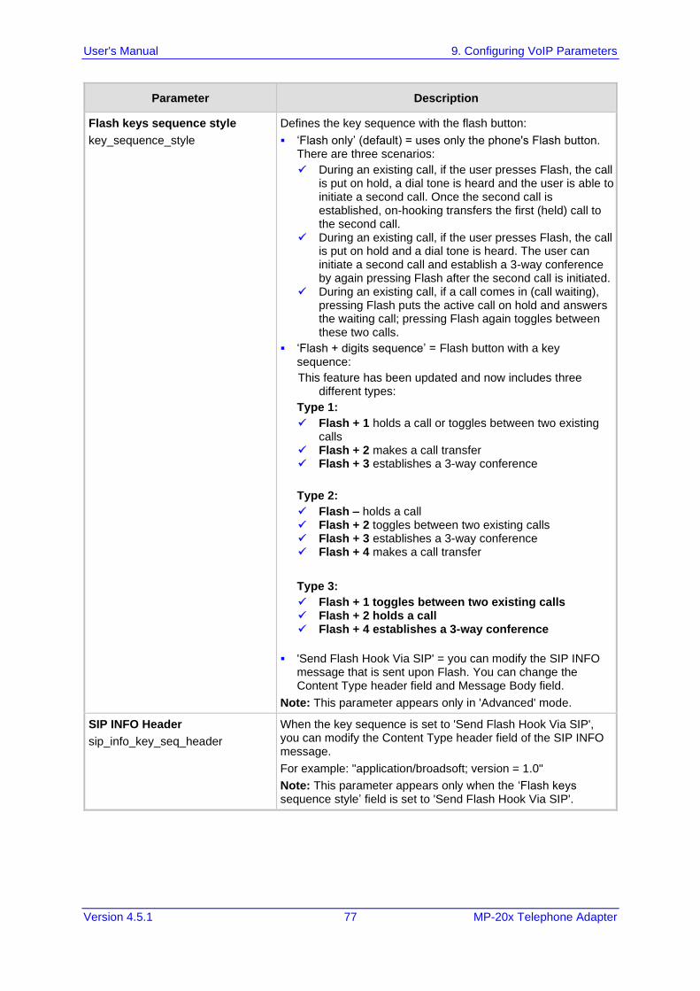
User's Manual 9. Configuring VoIP Parameters
Version 4.5.1 77 MP-20x Telephone Adapter
Parameter Description
Flash keys sequence style
key_sequence_style
Defines the key sequence with the flash button:
▪ ‘Flash only’ (default) = uses only the phone's Flash button. There are three scenarios:
✓ During an existing call, if the user presses Flash, the call is put on hold, a dial tone is heard and the user is able to initiate a second call. Once the second call is established, on-hooking transfers the first (held) call to the second call.
✓ During an existing call, if the user presses Flash, the call is put on hold and a dial tone is heard. The user can initiate a second call and establish a 3-way conference by again pressing Flash after the second call is initiated.
✓ During an existing call, if a call comes in (call waiting), pressing Flash puts the active call on hold and answers the waiting call; pressing Flash again toggles between these two calls.
▪ ‘Flash + digits sequence’ = Flash button with a key sequence:
This feature has been updated and now includes three different types:
Type 1:
✓ Flash + 1 holds a call or toggles between two existing calls
✓ Flash + 2 makes a call transfer ✓ Flash + 3 establishes a 3-way conference
Type 2:
✓ Flash – holds a call ✓ Flash + 2 toggles between two existing calls ✓ Flash + 3 establishes a 3-way conference ✓ Flash + 4 makes a call transfer
Type 3:
✓ Flash + 1 toggles between two existing calls ✓ Flash + 2 holds a call ✓ Flash + 4 establishes a 3-way conference
▪ 'Send Flash Hook Via SIP' = you can modify the SIP INFO message that is sent upon Flash. You can change the Content Type header field and Message Body field.
Note: This parameter appears only in 'Advanced' mode.
SIP INFO Header
sip_info_key_seq_header
When the key sequence is set to 'Send Flash Hook Via SIP', you can modify the Content Type header field of the SIP INFO message.
For example: "application/broadsoft; version = 1.0"
Note: This parameter appears only when the ‘Flash keys sequence style’ field is set to 'Send Flash Hook Via SIP'.
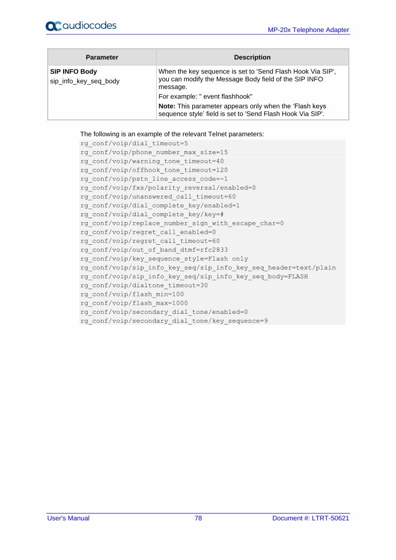
User's Manual 78 Document #: LTRT-50621
MP-20x Telephone Adapter
Parameter Description
SIP INFO Body
sip_info_key_seq_body
When the key sequence is set to 'Send Flash Hook Via SIP', you can modify the Message Body field of the SIP INFO message.
For example: " event flashhook"
Note: This parameter appears only when the ‘Flash keys sequence style’ field is set to 'Send Flash Hook Via SIP'.
The following is an example of the relevant Telnet parameters:
rg_conf/voip/dial_timeout=5
rg_conf/voip/phone_number_max_size=15
rg_conf/voip/warning_tone_timeout=40
rg_conf/voip/offhook_tone_timeout=120
rg_conf/voip/pstn_line_access_code=-1
rg_conf/voip/fxs/polarity_reversal/enabled=0
rg_conf/voip/unanswered_call_timeout=60
rg_conf/voip/dial_complete_key/enabled=1
rg_conf/voip/dial_complete_key/key=#
rg_conf/voip/replace_number_sign_with_escape_char=0
rg_conf/voip/regret_call_enabled=0
rg_conf/voip/regret_call_timeout=60
rg_conf/voip/out_of_band_dtmf=rfc2833
rg_conf/voip/key_sequence_style=Flash only
rg_conf/voip/sip_info_key_seq/sip_info_key_seq_header=text/plain
rg_conf/voip/sip_info_key_seq/sip_info_key_seq_body=FLASH
rg_conf/voip/dialtone_timeout=30
rg_conf/voip/flash_min=100
rg_conf/voip/flash_max=1000
rg_conf/voip/secondary_dial_tone/enabled=0
rg_conf/voip/secondary_dial_tone/key_sequence=9
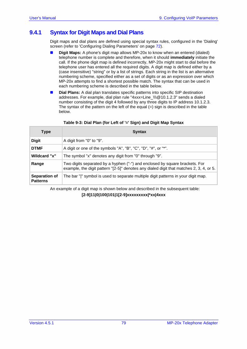
User's Manual 9. Configuring VoIP Parameters
Version 4.5.1 79 MP-20x Telephone Adapter
9.4.1 Syntax for Digit Maps and Dial Plans
Digit maps and dial plans are defined using special syntax rules, configured in the 'Dialing' screen (refer to 'Configuring Dialing Parameters' on page 72).
◼ Digit Maps: A phone's digit map allows MP-20x to know when an entered (dialed) telephone number is complete and therefore, when it should immediately initiate the call. If the phone digit map is defined incorrectly, MP-20x might start to dial before the telephone user has entered all the required digits. A digit map is defined either by a (case insensitive) "string" or by a list of strings. Each string in the list is an alternative numbering scheme, specified either as a set of digits or as an expression over which MP-20x attempts to find a shortest possible match. The syntax that can be used in each numbering scheme is described in the table below.
◼ Dial Plans: A dial plan translates specific patterns into specific SIP destination addresses. For example, dial plan rule "4xxx=Line_\\\@10.1.2.3" sends a dialed number consisting of the digit 4 followed by any three digits to IP address 10.1.2.3. The syntax of the pattern on the left of the equal (=) sign is described in the table below.
Table 9-3: Dial Plan (for Left of '=' Sign) and Digit Map Syntax
Type Syntax
Digit A digit from "0" to "9".
DTMF A digit or one of the symbols "A", "B", "C", "D", "#", or "*".
Wildcard "x" The symbol "x" denotes any digit from "0" through "9".
Range Two digits separated by a hyphen ("-") and enclosed by square brackets. For example, the digit pattern "[2-5]" denotes any dialed digit that matches 2, 3, 4, or 5.
Separation of Patterns
The bar "|" symbol is used to separate multiple digit patterns in your digit map.
An example of a digit map is shown below and described in the subsequent table:
[2-9]11|0|100|101|1[2-9]xxxxxxxxx|*xx|4xxx
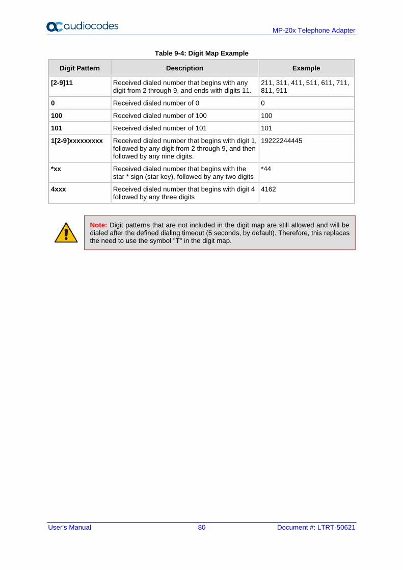
User's Manual 80 Document #: LTRT-50621
MP-20x Telephone Adapter
Table 9-4: Digit Map Example
Digit Pattern Description Example
[2-9]11 Received dialed number that begins with any digit from 2 through 9, and ends with digits 11.
211, 311, 411, 511, 611, 711, 811, 911
0 Received dialed number of 0 0
100 Received dialed number of 100 100
101 Received dialed number of 101 101
1[2-9]xxxxxxxxx Received dialed number that begins with digit 1, followed by any digit from 2 through 9, and then followed by any nine digits.
19222244445
*xx Received dialed number that begins with the star * sign (star key), followed by any two digits
*44
4xxx Received dialed number that begins with digit 4 followed by any three digits
4162
Note: Digit patterns that are not included in the digit map are still allowed and will be dialed after the defined dialing timeout (5 seconds, by default). Therefore, this replaces the need to use the symbol "T" in the digit map.
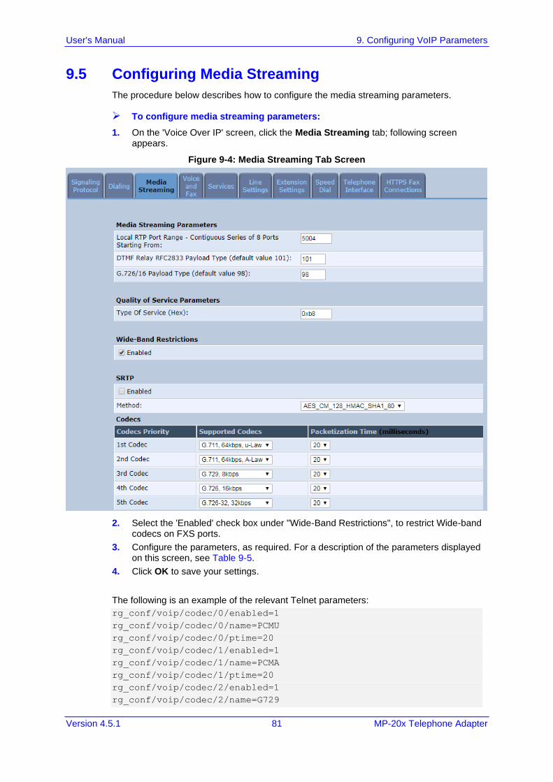
User's Manual 9. Configuring VoIP Parameters
Version 4.5.1 81 MP-20x Telephone Adapter
9.5 Configuring Media Streaming
The procedure below describes how to configure the media streaming parameters.
➢ To configure media streaming parameters:
1. On the 'Voice Over IP' screen, click the Media Streaming tab; following screen appears.
Figure 9-4: Media Streaming Tab Screen
2. Select the 'Enabled' check box under "Wide-Band Restrictions", to restrict Wide-band codecs on FXS ports.
3. Configure the parameters, as required. For a description of the parameters displayed on this screen, see Table 9-5.
4. Click OK to save your settings.
The following is an example of the relevant Telnet parameters:
rg_conf/voip/codec/0/enabled=1
rg_conf/voip/codec/0/name=PCMU
rg_conf/voip/codec/0/ptime=20
rg_conf/voip/codec/1/enabled=1
rg_conf/voip/codec/1/name=PCMA
rg_conf/voip/codec/1/ptime=20
rg_conf/voip/codec/2/enabled=1
rg_conf/voip/codec/2/name=G729
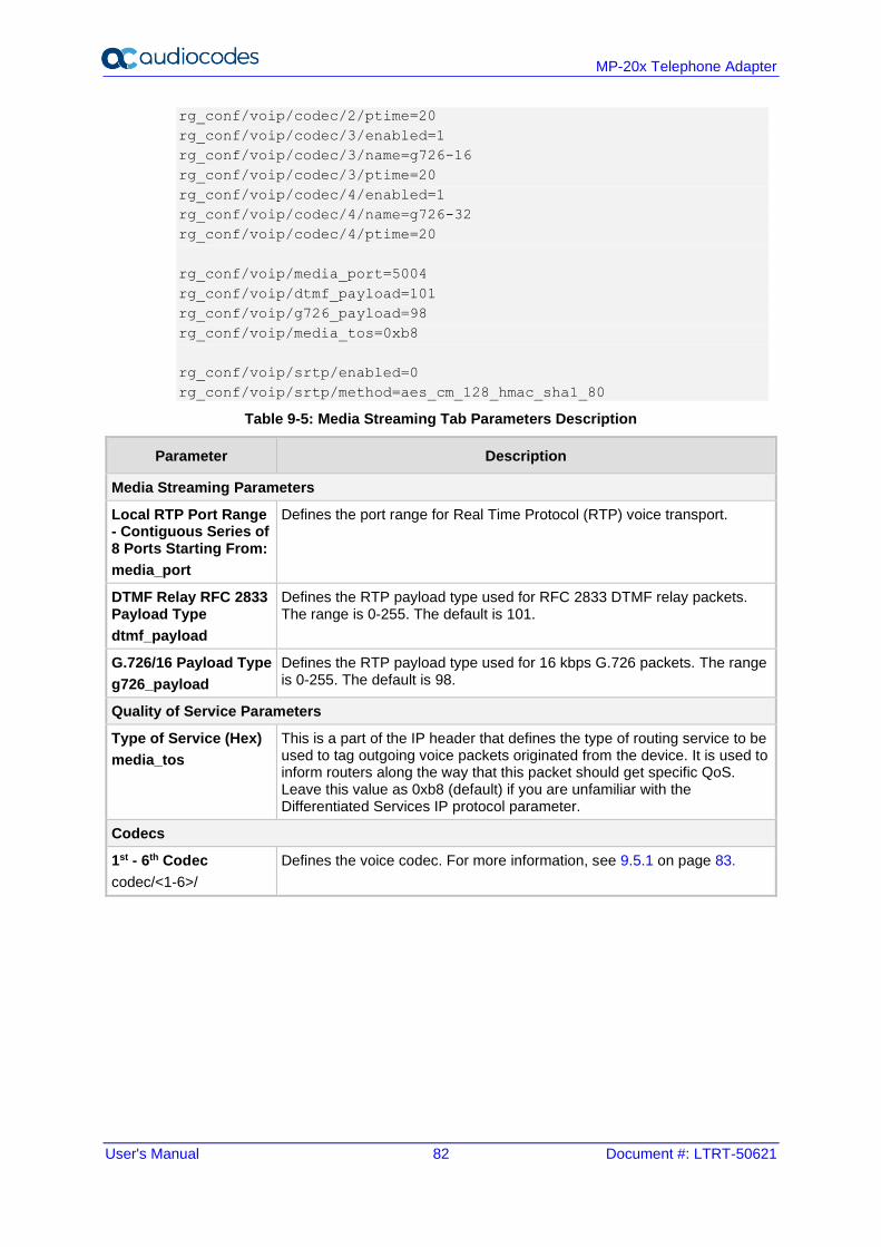
User's Manual 82 Document #: LTRT-50621
MP-20x Telephone Adapter
rg_conf/voip/codec/2/ptime=20
rg_conf/voip/codec/3/enabled=1
rg_conf/voip/codec/3/name=g726-16
rg_conf/voip/codec/3/ptime=20
rg_conf/voip/codec/4/enabled=1
rg_conf/voip/codec/4/name=g726-32
rg_conf/voip/codec/4/ptime=20
rg_conf/voip/media_port=5004
rg_conf/voip/dtmf_payload=101
rg_conf/voip/g726_payload=98
rg_conf/voip/media_tos=0xb8
rg_conf/voip/srtp/enabled=0
rg_conf/voip/srtp/method=aes_cm_128_hmac_sha1_80
Table 9-5: Media Streaming Tab Parameters Description
Parameter Description
Media Streaming Parameters
Local RTP Port Range - Contiguous Series of 8 Ports Starting From:
media_port
Defines the port range for Real Time Protocol (RTP) voice transport.
DTMF Relay RFC 2833 Payload Type
dtmf_payload
Defines the RTP payload type used for RFC 2833 DTMF relay packets. The range is 0-255. The default is 101.
G.726/16 Payload Type
g726_payload
Defines the RTP payload type used for 16 kbps G.726 packets. The range is 0-255. The default is 98.
Quality of Service Parameters
Type of Service (Hex)
media_tos
This is a part of the IP header that defines the type of routing service to be used to tag outgoing voice packets originated from the device. It is used to inform routers along the way that this packet should get specific QoS. Leave this value as 0xb8 (default) if you are unfamiliar with the Differentiated Services IP protocol parameter.
Codecs
1st - 6th Codec
codec/<1-6>/
Defines the voice codec. For more information, see 9.5.1 on page 83.
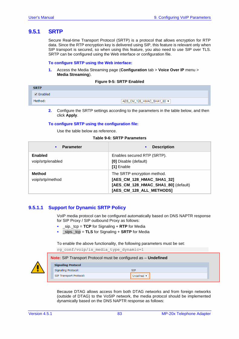
User's Manual 9. Configuring VoIP Parameters
Version 4.5.1 83 MP-20x Telephone Adapter
9.5.1 SRTP
Secure Real-time Transport Protocol (SRTP) is a protocol that allows encryption for RTP data. Since the RTP encryption key is delivered using SIP, this feature is relevant only when SIP transport is secured, so when using this feature, you also need to use SIP over TLS. SRTP can be configured using the Web interface or configuration file.
To configure SRTP using the Web interface:
1. Access the Media Streaming page (Configuration tab > Voice Over IP menu > Media Streaming).
Figure 9-5: SRTP Enabled
2. Configure the SRTP settings according to the parameters in the table below, and then click Apply.
To configure SRTP using the configuration file:
Use the table below as reference.
Table 9-6: SRTP Parameters
▪ Parameter ▪ Description
Enabled
voip/srtp/enabled
Enables secured RTP (SRTP).
[0] Disable (default)
[1] Enable
Method
voip/srtp/method
The SRTP encryption method.
[AES_CM_128_HMAC_SHA1_32]
[AES_CM_128_HMAC_SHA1_80] (default)
[AES_CM_128_ALL_METHODS]
9.5.1.1 Support for Dynamic SRTP Policy
VoIP media protocol can be configured automatically based on DNS NAPTR response for SIP Proxy / SIP outbound Proxy as follows:
▪ _sip._tcp = TCP for Signaling + RTP for Media
▪ _sips._tcp = TLS for Signaling + SRTP for Media
To enable the above functionality, the following parameters must be set:
rg_conf/voip/is_media_type_dynamic=1
Note: SIP Transport Protocol must be configured as – Undefined
Because DTAG allows access from both DTAG networks and from foreign networks (outside of DTAG) to the VoSIP network, the media protocol should be implemented dynamically based on the DNS NAPTR response as follows:
User's Manual 84 Document #: LTRT-50621
MP-20x Telephone Adapter
▪ DTAG access = TCP
▪ Foreign access = TLS
To enable the above functionality the following parameters must be set:
rg_conf/voip/is_media_type_dynamic=1
9.5.1.2 Changing Default Cipher Suites for SIP Over TLS
It is possible to change the default cipher suites to be used (or removed) for SIP over TLS. For example:
rg_conf/voip/cipher_list=
“EDH+CAMELLIA:EDH+aRSA:EECDH+aRSA+AESGCM:EECDH+aRSA+SHA384:EECDH+a
RSA+SHA256:EECDH:+CAMELLIA256:+AES256:+CAMELLIA128:+AES128:!SSLv3:
!aNULL:!eNULL:!LOW:!3DES:!MD5:!EXP:!PSK:!DSS:!RC4:!SEED:!ECDSA:CAM
ELLIA256-SHA:AES256-SHA:CAMELLIA128-SHA:AES128-SHA”
9.5.1.3 Support for RFC 3329 & MediaSec Extensions
Support an additional indication for secured media, used in combination with TLS/SRTP. This may be required in IMS-based core networks.
The following is an example of the relevant Telnet parameters:
rg_conf/voip/media_security/enabled=1
rg_conf/conf set voip/media_security/mechanism/0/name=sdes-srtp
9.5.1.4 Configuring Codecs
Codecs define the method of relaying voice data. Different codecs have different characteristics, such as data compression and voice quality. For example, G.723 is a codec that uses compression, so it is good for use where bandwidth is limited but its voice quality is not as good compared to other codecs such as the G.711.
9.5.2 Supported Codecs
To make a call, at least one codec must be enabled. Moreover, all codecs may be enabled for best performance. When you start a call to a remote party, your available codecs are compared against the remote party's to determine the codec used. The priority by which the codecs are compared is according to their order of appearance in the table (descending order). To change the priorities, rearrange the codecs in the required order.
If there is no codec that both parties have made available, the call attempt fails. Note that if more than one codec is common to both parties, you cannot force which of the common codecs that were found are used by the remote party's client. If you do wish to force the use of a specific codec, leave only that codec checked.
9.5.2.1 Packetization Time
The Packetization Time is the length of the digital voice segment that each packet holds. The default is 20 millisecond packets. Selecting 10 millisecond packets reduces the delay but increases the bandwidth consumption.
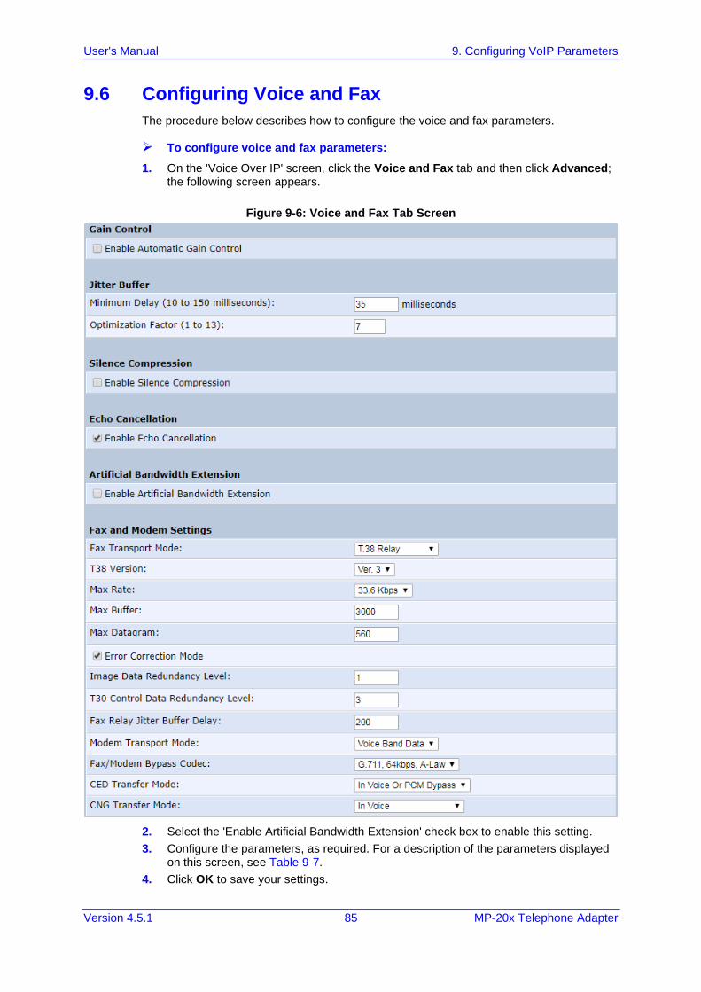
User's Manual 9. Configuring VoIP Parameters
Version 4.5.1 85 MP-20x Telephone Adapter
9.6 Configuring Voice and Fax
The procedure below describes how to configure the voice and fax parameters.
➢ To configure voice and fax parameters:
1. On the 'Voice Over IP' screen, click the Voice and Fax tab and then click Advanced; the following screen appears.
Figure 9-6: Voice and Fax Tab Screen
2. Select the 'Enable Artificial Bandwidth Extension' check box to enable this setting.
3. Configure the parameters, as required. For a description of the parameters displayed on this screen, see Table 9-7.
4. Click OK to save your settings.
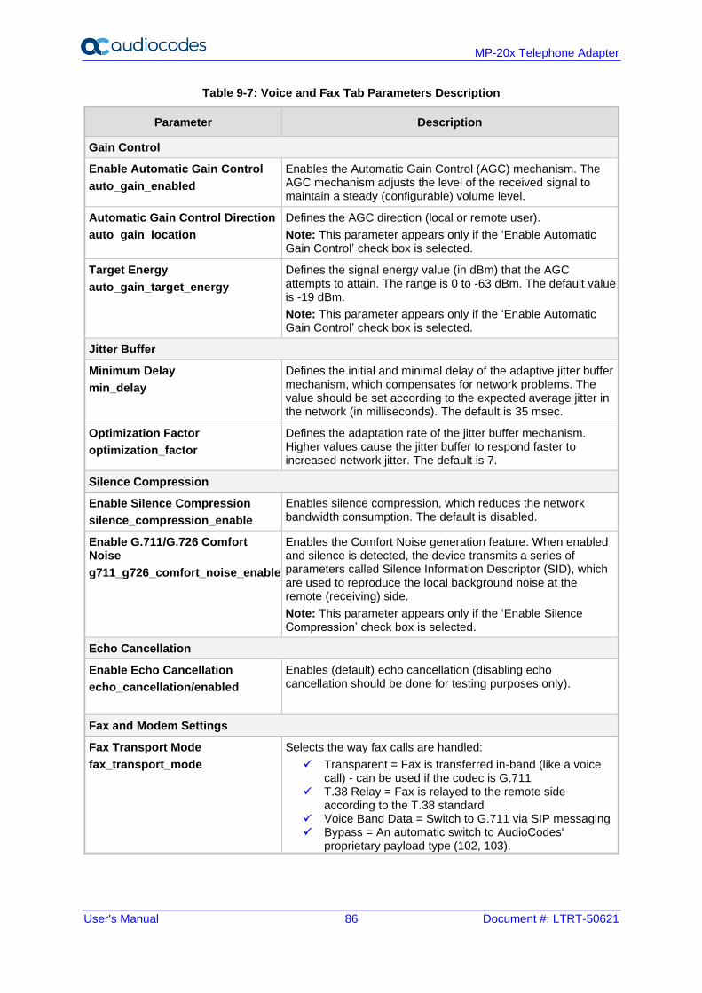
User's Manual 86 Document #: LTRT-50621
MP-20x Telephone Adapter
Table 9-7: Voice and Fax Tab Parameters Description
Parameter Description
Gain Control
Enable Automatic Gain Control
auto_gain_enabled
Enables the Automatic Gain Control (AGC) mechanism. The AGC mechanism adjusts the level of the received signal to maintain a steady (configurable) volume level.
Automatic Gain Control Direction
auto_gain_location
Defines the AGC direction (local or remote user).
Note: This parameter appears only if the ‘Enable Automatic Gain Control’ check box is selected.
Target Energy
auto_gain_target_energy
Defines the signal energy value (in dBm) that the AGC attempts to attain. The range is 0 to -63 dBm. The default value is -19 dBm.
Note: This parameter appears only if the ‘Enable Automatic Gain Control’ check box is selected.
Jitter Buffer
Minimum Delay
min_delay
Defines the initial and minimal delay of the adaptive jitter buffer mechanism, which compensates for network problems. The value should be set according to the expected average jitter in the network (in milliseconds). The default is 35 msec.
Optimization Factor
optimization_factor
Defines the adaptation rate of the jitter buffer mechanism. Higher values cause the jitter buffer to respond faster to increased network jitter. The default is 7.
Silence Compression
Enable Silence Compression
silence_compression_enable
Enables silence compression, which reduces the network bandwidth consumption. The default is disabled.
Enable G.711/G.726 Comfort Noise
g711_g726_comfort_noise_enable
Enables the Comfort Noise generation feature. When enabled and silence is detected, the device transmits a series of parameters called Silence Information Descriptor (SID), which are used to reproduce the local background noise at the remote (receiving) side.
Note: This parameter appears only if the ‘Enable Silence Compression’ check box is selected.
Echo Cancellation
Enable Echo Cancellation
echo_cancellation/enabled
Enables (default) echo cancellation (disabling echo cancellation should be done for testing purposes only).
Fax and Modem Settings
Fax Transport Mode
fax_transport_mode
Selects the way fax calls are handled:
✓ Transparent = Fax is transferred in-band (like a voice call) - can be used if the codec is G.711
✓ T.38 Relay = Fax is relayed to the remote side according to the T.38 standard
✓ Voice Band Data = Switch to G.711 via SIP messaging ✓ Bypass = An automatic switch to AudioCodes'
proprietary payload type (102, 103).
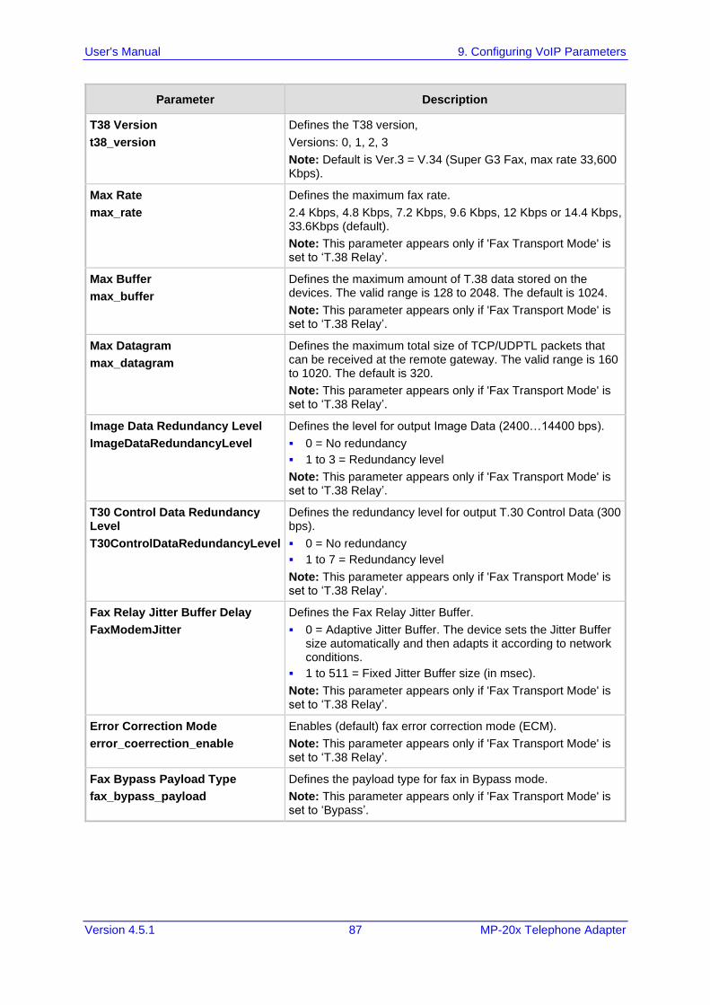
User's Manual 9. Configuring VoIP Parameters
Version 4.5.1 87 MP-20x Telephone Adapter
Parameter Description
T38 Version
t38_version
Defines the T38 version,
Versions: 0, 1, 2, 3
Note: Default is Ver.3 = V.34 (Super G3 Fax, max rate 33,600 Kbps).
Max Rate
max_rate
Defines the maximum fax rate.
2.4 Kbps, 4.8 Kbps, 7.2 Kbps, 9.6 Kbps, 12 Kbps or 14.4 Kbps, 33.6Kbps (default).
Note: This parameter appears only if 'Fax Transport Mode' is set to ‘T.38 Relay’.
Max Buffer
max_buffer
Defines the maximum amount of T.38 data stored on the devices. The valid range is 128 to 2048. The default is 1024.
Note: This parameter appears only if 'Fax Transport Mode' is set to ‘T.38 Relay’.
Max Datagram
max_datagram
Defines the maximum total size of TCP/UDPTL packets that can be received at the remote gateway. The valid range is 160 to 1020. The default is 320.
Note: This parameter appears only if 'Fax Transport Mode' is set to ‘T.38 Relay’.
Image Data Redundancy Level
ImageDataRedundancyLevel
Defines the level for output Image Data (2400…14400 bps).
▪ 0 = No redundancy
▪ 1 to 3 = Redundancy level
Note: This parameter appears only if 'Fax Transport Mode' is set to ‘T.38 Relay’.
T30 Control Data Redundancy Level
T30ControlDataRedundancyLevel
Defines the redundancy level for output T.30 Control Data (300 bps).
▪ 0 = No redundancy
▪ 1 to 7 = Redundancy level
Note: This parameter appears only if 'Fax Transport Mode' is set to ‘T.38 Relay’.
Fax Relay Jitter Buffer Delay
FaxModemJitter
Defines the Fax Relay Jitter Buffer.
▪ 0 = Adaptive Jitter Buffer. The device sets the Jitter Buffer size automatically and then adapts it according to network conditions.
▪ 1 to 511 = Fixed Jitter Buffer size (in msec).
Note: This parameter appears only if 'Fax Transport Mode' is set to ‘T.38 Relay’.
Error Correction Mode
error_coerrection_enable
Enables (default) fax error correction mode (ECM).
Note: This parameter appears only if 'Fax Transport Mode' is set to ‘T.38 Relay’.
Fax Bypass Payload Type
fax_bypass_payload
Defines the payload type for fax in Bypass mode.
Note: This parameter appears only if 'Fax Transport Mode' is set to ‘Bypass’.
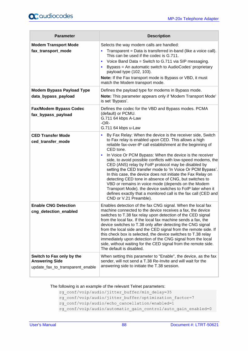
User's Manual 88 Document #: LTRT-50621
MP-20x Telephone Adapter
Parameter Description
Modem Transport Mode
fax_transport_mode
Selects the way modem calls are handled:
▪ Transparent = Data is transferred in-band (like a voice call). This can be used if the codec is G.711.
▪ Voice Band Data = Switch to G.711 via SIP messaging.
▪ Bypass = An automatic switch to AudioCodes' proprietary payload type (102, 103).
Note: If the Fax transport mode is Bypass or VBD, it must match the Modem transport mode.
Modem Bypass Payload Type
data_bypass_payload
Defines the payload type for modems in Bypass mode.
Note: This parameter appears only if 'Modem Transport Mode' is set ‘Bypass’.
Fax/Modem Bypass Codec
fax_bypass_payload
Defines the codec for the VBD and Bypass modes. PCMA (default) or PCMU. G.711 64 kbps A-Law -OR- G.711 64 kbps u-Law
CED Transfer Mode
ced_transfer_mode
▪ By Fax Relay: When the device is the receiver side, Switch to Fax relay is enabled upon CED. This allows a high reliable fax-over-IP call establishment at the beginning of CED tone.
▪ In Voice Or PCM Bypass: When the device is the receiver side, to avoid possible conflicts with low-speed modems, the CED (ANS) relay by FoIP protocol may be disabled by setting the CED transfer mode to ‘In Voice Or PCM Bypass’. In this case, the device does not initiate the Fax Relay on detecting CED tone in absence of CNG, but switches to VBD or remains in voice mode (depends on the Modem Transport Mode). the device switches to FoIP later when it defines exactly that a monitored call is the fax call (CED and CND or V.21 Preamble).
Enable CNG Detection
cng_detection_enabled
Enables detection of the fax CNG signal. When the local fax machine connected to the device receives a fax, the device switches to T.38 fax relay upon detection of the CED signal from the local fax. If the local fax machine sends a fax, the device switches to T.38 only after detecting the CNG signal from the local side and the CED signal from the remote side. If this check box is selected, the device switches to T.38 relay immediately upon detection of the CNG signal from the local side, without waiting for the CED signal from the remote side. The default is disabled.
Switch to Fax only by the Answering Side
update_fax_to_transparent_enable
When setting this parameter to "Enable", the device, as the fax sender, will not send a T.38 Re-Invite and will wait for the answering side to initiate the T.38 session.
The following is an example of the relevant Telnet parameters:
rg_conf/voip/audio/jitter_buffer/min_delay=35
rg_conf/voip/audio/jitter_buffer/optimization_factor=7
rg_conf/voip/audio/echo_cancellation/enabled=1
rg_conf/voip/audio/automatic_gain_control/auto_gain_enabled=0
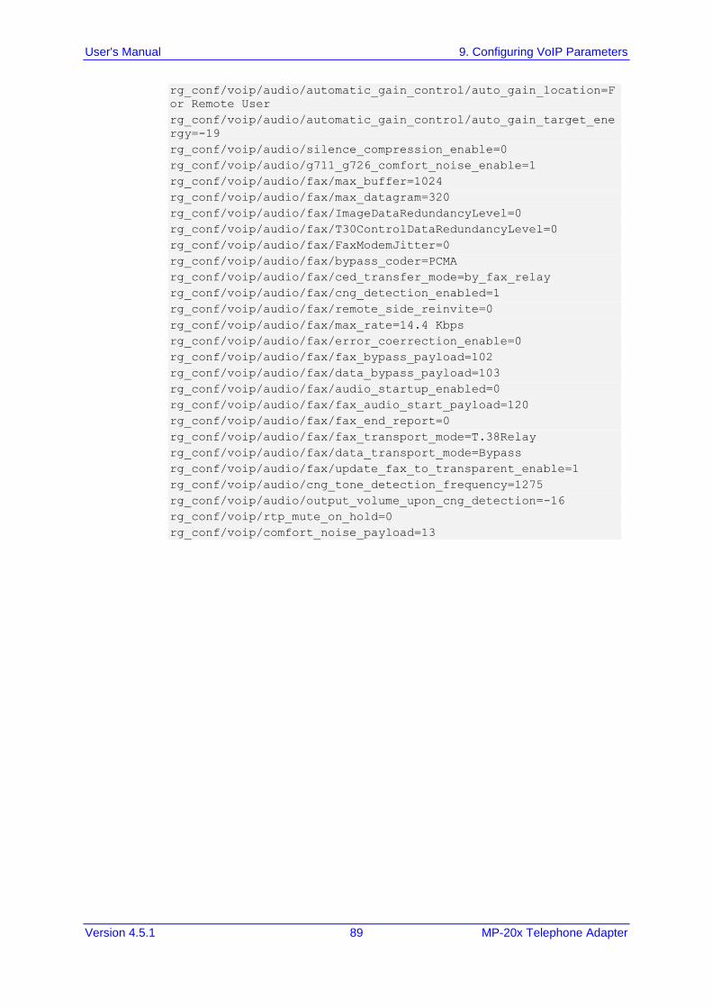
User's Manual 9. Configuring VoIP Parameters
Version 4.5.1 89 MP-20x Telephone Adapter
rg_conf/voip/audio/automatic_gain_control/auto_gain_location=F
or Remote User
rg_conf/voip/audio/automatic_gain_control/auto_gain_target_ene
rgy=-19
rg_conf/voip/audio/silence_compression_enable=0
rg_conf/voip/audio/g711_g726_comfort_noise_enable=1
rg_conf/voip/audio/fax/max_buffer=1024
rg_conf/voip/audio/fax/max_datagram=320
rg_conf/voip/audio/fax/ImageDataRedundancyLevel=0
rg_conf/voip/audio/fax/T30ControlDataRedundancyLevel=0
rg_conf/voip/audio/fax/FaxModemJitter=0
rg_conf/voip/audio/fax/bypass_coder=PCMA
rg_conf/voip/audio/fax/ced_transfer_mode=by_fax_relay
rg_conf/voip/audio/fax/cng_detection_enabled=1
rg_conf/voip/audio/fax/remote_side_reinvite=0
rg_conf/voip/audio/fax/max_rate=14.4 Kbps
rg_conf/voip/audio/fax/error_coerrection_enable=0
rg_conf/voip/audio/fax/fax_bypass_payload=102
rg_conf/voip/audio/fax/data_bypass_payload=103
rg_conf/voip/audio/fax/audio_startup_enabled=0
rg_conf/voip/audio/fax/fax_audio_start_payload=120
rg_conf/voip/audio/fax/fax_end_report=0
rg_conf/voip/audio/fax/fax_transport_mode=T.38Relay
rg_conf/voip/audio/fax/data_transport_mode=Bypass
rg_conf/voip/audio/fax/update_fax_to_transparent_enable=1
rg_conf/voip/audio/cng_tone_detection_frequency=1275
rg_conf/voip/audio/output_volume_upon_cng_detection=-16
rg_conf/voip/rtp_mute_on_hold=0
rg_conf/voip/comfort_noise_payload=13
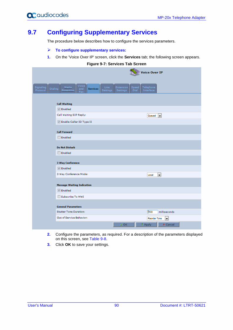
User's Manual 90 Document #: LTRT-50621
MP-20x Telephone Adapter
9.7 Configuring Supplementary Services
The procedure below describes how to configure the services parameters.
➢ To configure supplementary services:
1. On the 'Voice Over IP' screen, click the Services tab; the following screen appears.
Figure 9-7: Services Tab Screen
2. Configure the parameters, as required. For a description of the parameters displayed on this screen, see Table 9-8.
3. Click OK to save your settings.
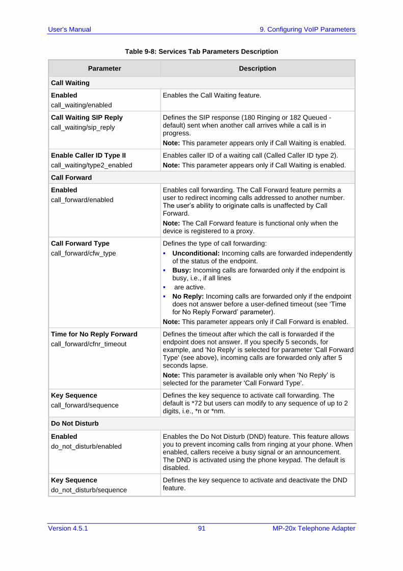
User's Manual 9. Configuring VoIP Parameters
Version 4.5.1 91 MP-20x Telephone Adapter
Table 9-8: Services Tab Parameters Description
Parameter Description
Call Waiting
Enabled
call_waiting/enabled
Enables the Call Waiting feature.
Call Waiting SIP Reply
call_waiting/sip_reply
Defines the SIP response (180 Ringing or 182 Queued - default) sent when another call arrives while a call is in progress.
Note: This parameter appears only if Call Waiting is enabled.
Enable Caller ID Type II
call_waiting/type2_enabled
Enables caller ID of a waiting call (Called Caller ID type 2).
Note: This parameter appears only if Call Waiting is enabled.
Call Forward
Enabled
call_forward/enabled
Enables call forwarding. The Call Forward feature permits a user to redirect incoming calls addressed to another number. The user’s ability to originate calls is unaffected by Call Forward.
Note: The Call Forward feature is functional only when the device is registered to a proxy.
Call Forward Type
call_forward/cfw_type
Defines the type of call forwarding:
▪ Unconditional: Incoming calls are forwarded independently of the status of the endpoint.
▪ Busy: Incoming calls are forwarded only if the endpoint is busy, i.e., if all lines
▪ are active.
▪ No Reply: Incoming calls are forwarded only if the endpoint does not answer before a user-defined timeout (see ‘Time for No Reply Forward’ parameter).
Note: This parameter appears only if Call Forward is enabled.
Time for No Reply Forward
call_forward/cfnr_timeout
Defines the timeout after which the call is forwarded if the endpoint does not answer. If you specify 5 seconds, for example, and 'No Reply' is selected for parameter 'Call Forward Type' (see above), incoming calls are forwarded only after 5 seconds lapse.
Note: This parameter is available only when ‘No Reply’ is selected for the parameter 'Call Forward Type'.
Key Sequence
call_forward/sequence
Defines the key sequence to activate call forwarding. The default is *72 but users can modify to any sequence of up to 2 digits, i.e., *n or *nm.
Do Not Disturb
Enabled
do_not_disturb/enabled
Enables the Do Not Disturb (DND) feature. This feature allows you to prevent incoming calls from ringing at your phone. When enabled, callers receive a busy signal or an announcement. The DND is activated using the phone keypad. The default is disabled.
Key Sequence
do_not_disturb/sequence
Defines the key sequence to activate and deactivate the DND feature.
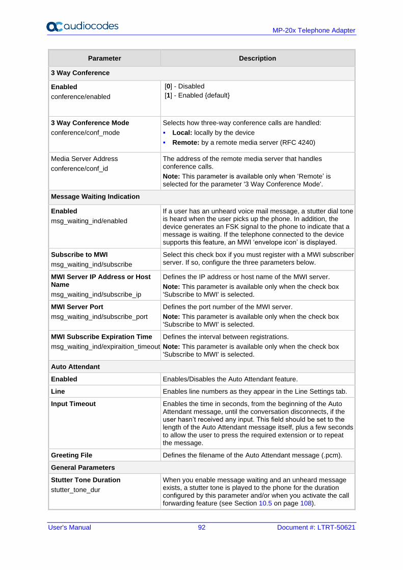
User's Manual 92 Document #: LTRT-50621
MP-20x Telephone Adapter
Parameter Description
3 Way Conference
Enabled
conference/enabled
[0] - Disabled
[1] - Enabled {default}
3 Way Conference Mode
conference/conf_mode
Selects how three-way conference calls are handled:
▪ Local: locally by the device
▪ Remote: by a remote media server (RFC 4240)
Media Server Address
conference/conf_id
The address of the remote media server that handles conference calls.
Note: This parameter is available only when ‘Remote’ is selected for the parameter '3 Way Conference Mode'.
Message Waiting Indication
Enabled
msg_waiting_ind/enabled
If a user has an unheard voice mail message, a stutter dial tone is heard when the user picks up the phone. In addition, the device generates an FSK signal to the phone to indicate that a message is waiting. If the telephone connected to the device supports this feature, an MWI ‘envelope icon’ is displayed.
Subscribe to MWI
msg_waiting_ind/subscribe
Select this check box if you must register with a MWI subscriber server. If so, configure the three parameters below.
MWI Server IP Address or Host Name
msg_waiting_ind/subscribe_ip
Defines the IP address or host name of the MWI server.
Note: This parameter is available only when the check box 'Subscribe to MWI' is selected.
MWI Server Port
msg_waiting_ind/subscribe_port
Defines the port number of the MWI server.
Note: This parameter is available only when the check box 'Subscribe to MWI' is selected.
MWI Subscribe Expiration Time
msg_waiting_ind/expiraition_timeout
Defines the interval between registrations.
Note: This parameter is available only when the check box 'Subscribe to MWI' is selected.
Auto Attendant
Enabled Enables/Disables the Auto Attendant feature.
Line Enables line numbers as they appear in the Line Settings tab.
Input Timeout Enables the time in seconds, from the beginning of the Auto Attendant message, until the conversation disconnects, if the user hasn’t received any input. This field should be set to the length of the Auto Attendant message itself, plus a few seconds to allow the user to press the required extension or to repeat the message.
Greeting File Defines the filename of the Auto Attendant message (.pcm).
General Parameters
Stutter Tone Duration
stutter_tone_dur
When you enable message waiting and an unheard message exists, a stutter tone is played to the phone for the duration configured by this parameter and/or when you activate the call forwarding feature (see Section 10.5 on page 108).
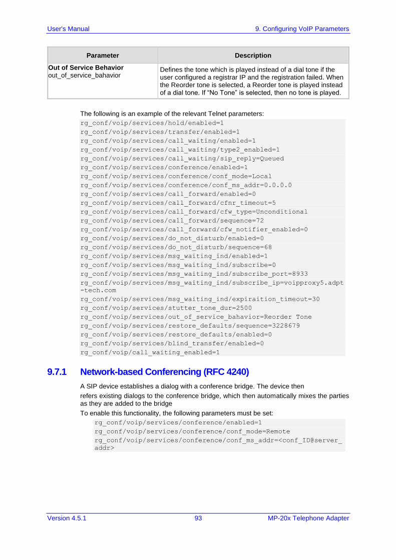
User's Manual 9. Configuring VoIP Parameters
Version 4.5.1 93 MP-20x Telephone Adapter
Parameter Description
Out of Service Behavior out_of_service_bahavior
Defines the tone which is played instead of a dial tone if the user configured a registrar IP and the registration failed. When the Reorder tone is selected, a Reorder tone is played instead of a dial tone. If “No Tone” is selected, then no tone is played.
The following is an example of the relevant Telnet parameters:
rg_conf/voip/services/hold/enabled=1
rg_conf/voip/services/transfer/enabled=1
rg_conf/voip/services/call_waiting/enabled=1
rg_conf/voip/services/call_waiting/type2_enabled=1
rg_conf/voip/services/call_waiting/sip_reply=Queued
rg_conf/voip/services/conference/enabled=1
rg_conf/voip/services/conference/conf_mode=Local
rg_conf/voip/services/conference/conf_ms_addr=0.0.0.0
rg_conf/voip/services/call_forward/enabled=0
rg_conf/voip/services/call_forward/cfnr_timeout=5
rg_conf/voip/services/call_forward/cfw_type=Unconditional
rg_conf/voip/services/call_forward/sequence=72
rg_conf/voip/services/call_forward/cfw_notifier_enabled=0
rg_conf/voip/services/do_not_disturb/enabled=0
rg_conf/voip/services/do_not_disturb/sequence=68
rg_conf/voip/services/msg_waiting_ind/enabled=1
rg_conf/voip/services/msg_waiting_ind/subscribe=0
rg_conf/voip/services/msg_waiting_ind/subscribe_port=8933
rg_conf/voip/services/msg_waiting_ind/subscribe_ip=voipproxy5.adpt
-tech.com
rg_conf/voip/services/msg_waiting_ind/expiraition_timeout=30
rg_conf/voip/services/stutter_tone_dur=2500
rg_conf/voip/services/out_of_service_bahavior=Reorder Tone
rg_conf/voip/services/restore_defaults/sequence=3228679
rg_conf/voip/services/restore_defaults/enabled=0
rg_conf/voip/services/blind_transfer/enabled=0
rg_conf/voip/call_waiting_enabled=1
9.7.1 Network-based Conferencing (RFC 4240)
A SIP device establishes a dialog with a conference bridge. The device then
refers existing dialogs to the conference bridge, which then automatically mixes the parties as they are added to the bridge
To enable this functionality, the following parameters must be set:
rg_conf/voip/services/conference/enabled=1
rg_conf/voip/services/conference/conf_mode=Remote
rg_conf/voip/services/conference/conf_ms_addr=<conf_ID@server_
addr>
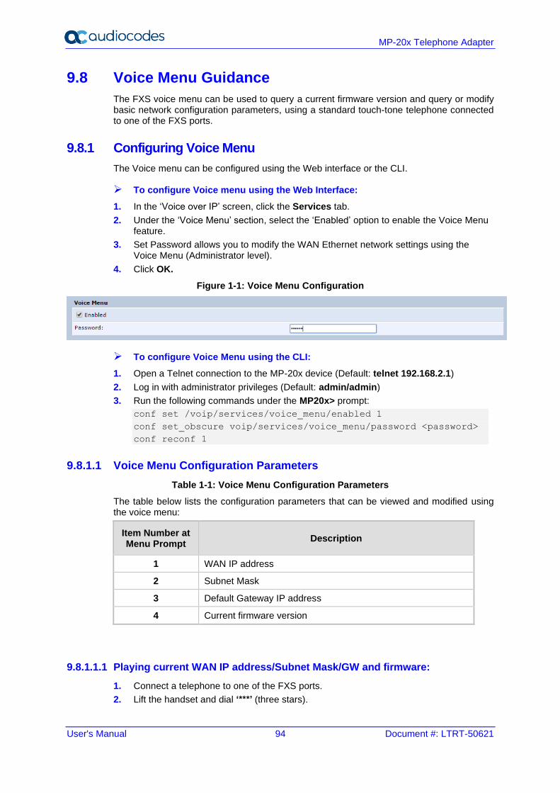
User's Manual 94 Document #: LTRT-50621
MP-20x Telephone Adapter
9.8 Voice Menu Guidance
The FXS voice menu can be used to query a current firmware version and query or modify basic network configuration parameters, using a standard touch-tone telephone connected to one of the FXS ports.
9.8.1 Configuring Voice Menu
The Voice menu can be configured using the Web interface or the CLI.
➢ To configure Voice menu using the Web Interface:
1. In the ‘Voice over IP’ screen, click the Services tab.
2. Under the ‘Voice Menu’ section, select the ‘Enabled’ option to enable the Voice Menu feature.
3. Set Password allows you to modify the WAN Ethernet network settings using the Voice Menu (Administrator level).
4. Click OK.
Figure 1-1: Voice Menu Configuration
➢ To configure Voice Menu using the CLI:
1. Open a Telnet connection to the MP-20x device (Default: telnet 192.168.2.1)
2. Log in with administrator privileges (Default: admin/admin)
3. Run the following commands under the MP20x> prompt:
conf set /voip/services/voice_menu/enabled 1
conf set_obscure voip/services/voice_menu/password <password>
conf reconf 1
9.8.1.1 Voice Menu Configuration Parameters
Table 1-1: Voice Menu Configuration Parameters
The table below lists the configuration parameters that can be viewed and modified using the voice menu:
Item Number at Menu Prompt
Description
1 WAN IP address
2 Subnet Mask
3 Default Gateway IP address
4 Current firmware version
9.8.1.1.1 Playing current WAN IP address/Subnet Mask/GW and firmware:
1. Connect a telephone to one of the FXS ports.
2. Lift the handset and dial ‘***’ (three stars).
User's Manual 9. Configuring VoIP Parameters
Version 4.5.1 95 MP-20x Telephone Adapter
3. Wait for the 'Configuration Menu' voice prompt to be played.
➢ To play the IP address:
a. Press 1 followed by the pound key (#); the current IP address of the device is played.
b. Press the # key to return to the main menu.
➢ To play the Subnet Mask:
a. Press 2 followed by the # key; the current subnet mask of the device is played.
b. Press the # key to return to the main menu.
➢ To play the Default Gateway:
a. Press 3 followed by the # key; the current default gateway of the device is played.
b. Press the # key to return to the main menu.
➢ To play the firmware version:
a. Press 4 followed by the # key; the current firmware version of the device is played.
b. Press the # key to return to the main menu.
9.8.1.1.2 Modifying WAN Ethernet IP settings
1. Connect a telephone to one of the FXS ports.
2. Lift the handset and dial ‘***<password>#’ (three stars followed by admin password, and pound key, #).
3. Wait for the 'Configuration Menu' voice prompt to be played.
➢ To change the IP address:
a. Press 1 followed by the pound key (#); the current IP address of the device is played.
b. Press the pound key (#) to modify;
c. Dial the new IP address, using the star (*) key instead of periods (.), e.g., 192*168*0*4, and then press # to finish.
d. Review the new IP address, and then press 1 to save.
➢ To change the Subnet Mask:
a. Press 2 followed by the # key; the current subnet mask of the device is played.
b. Press the pound key (#) to modify;
c. Dial the new subnet mask (e.g., 255*255*0*0), and then press # to finish.
d. Review the new subnet mask, and then press 1 to save.
➢ To change the Default Gateway:
a. Press 3 followed by the # key; the current default gateway of the device is played.
b. Press the pound key (#) to modify;
c. Dial the new default gateway (e.g., 192*168*1*1), and then press # to finish.
d. Review the new default gateway, and then press 1 to save.
e. Hang up (on-hook) the handset.
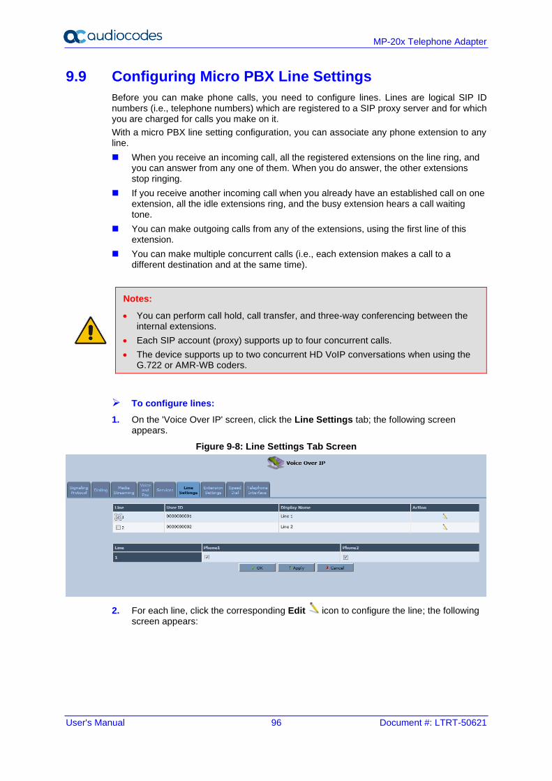
User's Manual 96 Document #: LTRT-50621
MP-20x Telephone Adapter
9.9 Configuring Micro PBX Line Settings
Before you can make phone calls, you need to configure lines. Lines are logical SIP ID numbers (i.e., telephone numbers) which are registered to a SIP proxy server and for which you are charged for calls you make on it.
With a micro PBX line setting configuration, you can associate any phone extension to any line.
◼ When you receive an incoming call, all the registered extensions on the line ring, and you can answer from any one of them. When you do answer, the other extensions stop ringing.
◼ If you receive another incoming call when you already have an established call on one extension, all the idle extensions ring, and the busy extension hears a call waiting tone.
◼ You can make outgoing calls from any of the extensions, using the first line of this extension.
◼ You can make multiple concurrent calls (i.e., each extension makes a call to a different destination and at the same time).
Notes:
• You can perform call hold, call transfer, and three-way conferencing between the internal extensions.
• Each SIP account (proxy) supports up to four concurrent calls.
• The device supports up to two concurrent HD VoIP conversations when using the G.722 or AMR-WB coders.
➢ To configure lines:
1. On the 'Voice Over IP' screen, click the Line Settings tab; the following screen appears.
Figure 9-8: Line Settings Tab Screen
2. For each line, click the corresponding Edit icon to configure the line; the following screen appears:
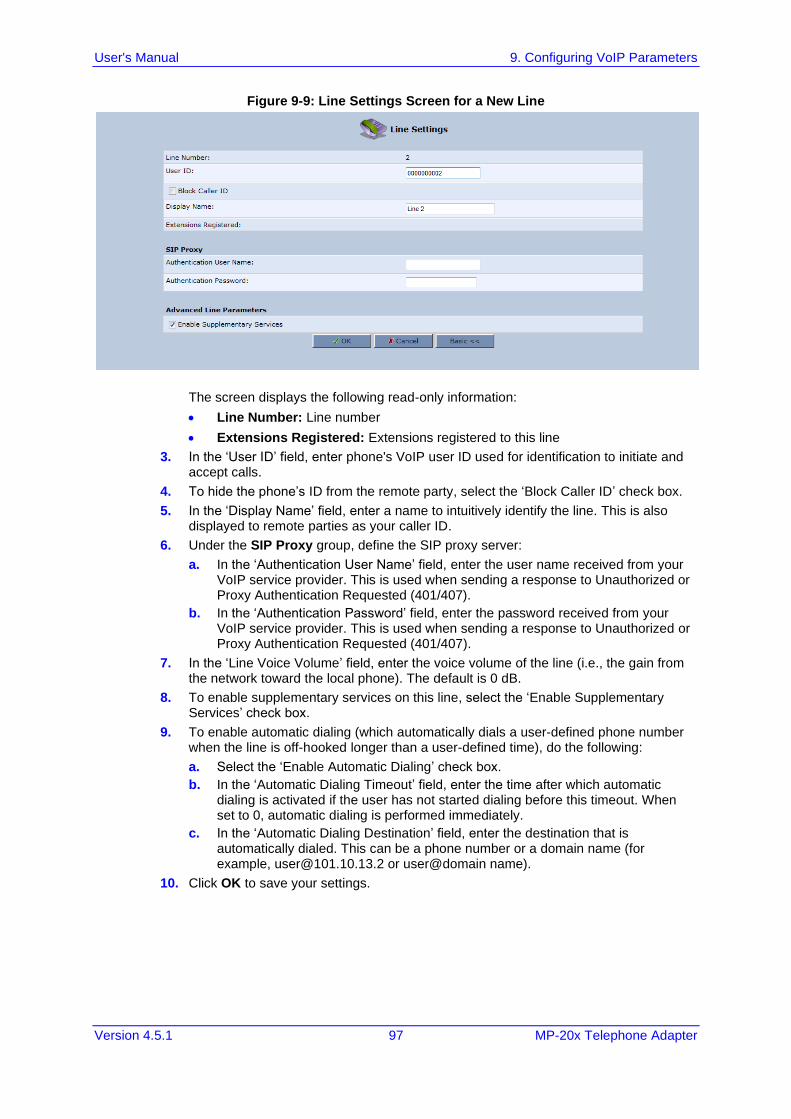
User's Manual 9. Configuring VoIP Parameters
Version 4.5.1 97 MP-20x Telephone Adapter
Figure 9-9: Line Settings Screen for a New Line
The screen displays the following read-only information:
• Line Number: Line number
• Extensions Registered: Extensions registered to this line
3. In the ‘User ID’ field, enter phone's VoIP user ID used for identification to initiate and accept calls.
4. To hide the phone’s ID from the remote party, select the ‘Block Caller ID’ check box.
5. In the ‘Display Name’ field, enter a name to intuitively identify the line. This is also displayed to remote parties as your caller ID.
6. Under the SIP Proxy group, define the SIP proxy server:
a. In the ‘Authentication User Name’ field, enter the user name received from your VoIP service provider. This is used when sending a response to Unauthorized or Proxy Authentication Requested (401/407).
b. In the ‘Authentication Password’ field, enter the password received from your VoIP service provider. This is used when sending a response to Unauthorized or Proxy Authentication Requested (401/407).
7. In the ‘Line Voice Volume’ field, enter the voice volume of the line (i.e., the gain from the network toward the local phone). The default is 0 dB.
8. To enable supplementary services on this line, select the ‘Enable Supplementary Services’ check box.
9. To enable automatic dialing (which automatically dials a user-defined phone number when the line is off-hooked longer than a user-defined time), do the following:
a. Select the ‘Enable Automatic Dialing’ check box.
b. In the ‘Automatic Dialing Timeout’ field, enter the time after which automatic dialing is activated if the user has not started dialing before this timeout. When set to 0, automatic dialing is performed immediately.
c. In the ‘Automatic Dialing Destination’ field, enter the destination that is automatically dialed. This can be a phone number or a domain name (for example, [email protected] or user@domain name).
10. Click OK to save your settings.
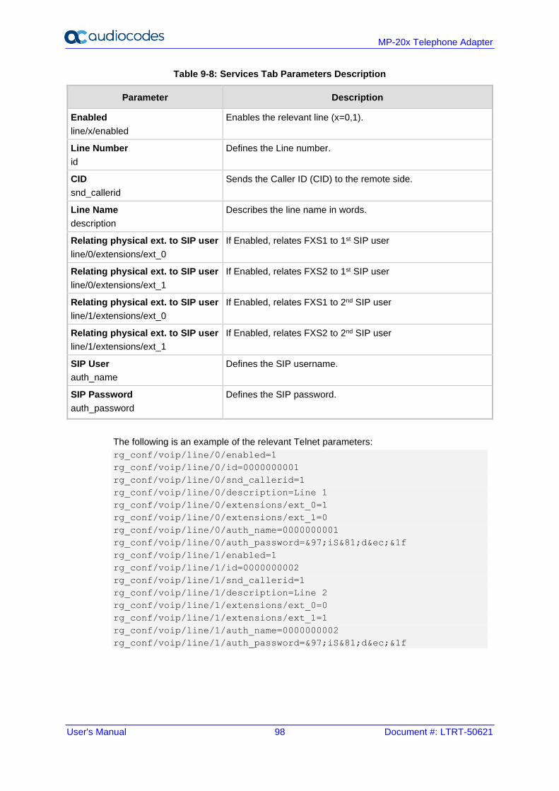
User's Manual 98 Document #: LTRT-50621
MP-20x Telephone Adapter
Table 9-8: Services Tab Parameters Description
Parameter Description
Enabled
line/x/enabled
Enables the relevant line (x=0,1).
Line Number
id
Defines the Line number.
CID
snd_callerid
Sends the Caller ID (CID) to the remote side.
Line Name
description
Describes the line name in words.
Relating physical ext. to SIP user
line/0/extensions/ext_0
If Enabled, relates FXS1 to 1st SIP user
Relating physical ext. to SIP user
line/0/extensions/ext_1
If Enabled, relates FXS2 to 1st SIP user
Relating physical ext. to SIP user
line/1/extensions/ext_0
If Enabled, relates FXS1 to 2nd SIP user
Relating physical ext. to SIP user
line/1/extensions/ext_1
If Enabled, relates FXS2 to 2nd SIP user
SIP User
auth_name
Defines the SIP username.
SIP Password
auth_password
Defines the SIP password.
The following is an example of the relevant Telnet parameters:
rg_conf/voip/line/0/enabled=1
rg_conf/voip/line/0/id=0000000001
rg_conf/voip/line/0/snd_callerid=1
rg_conf/voip/line/0/description=Line 1
rg_conf/voip/line/0/extensions/ext_0=1
rg_conf/voip/line/0/extensions/ext_1=0
rg_conf/voip/line/0/auth_name=0000000001
rg_conf/voip/line/0/auth_password=&97;iS&81;d&ec;&1f
rg_conf/voip/line/1/enabled=1
rg_conf/voip/line/1/id=0000000002
rg_conf/voip/line/1/snd_callerid=1
rg_conf/voip/line/1/description=Line 2
rg_conf/voip/line/1/extensions/ext_0=0
rg_conf/voip/line/1/extensions/ext_1=1
rg_conf/voip/line/1/auth_name=0000000002
rg_conf/voip/line/1/auth_password=&97;iS&81;d&ec;&1f
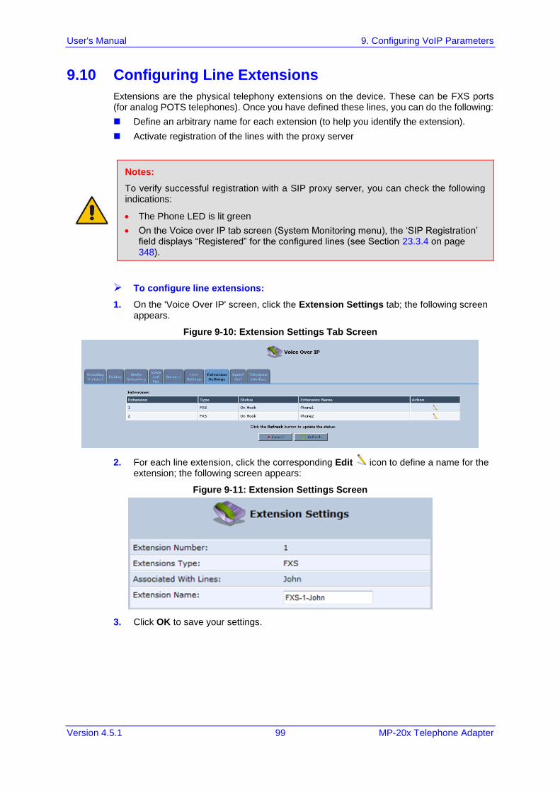
User's Manual 9. Configuring VoIP Parameters
Version 4.5.1 99 MP-20x Telephone Adapter
9.10 Configuring Line Extensions
Extensions are the physical telephony extensions on the device. These can be FXS ports (for analog POTS telephones). Once you have defined these lines, you can do the following:
◼ Define an arbitrary name for each extension (to help you identify the extension).
◼ Activate registration of the lines with the proxy server
Notes:
To verify successful registration with a SIP proxy server, you can check the following indications:
• The Phone LED is lit green
• On the Voice over IP tab screen (System Monitoring menu), the ‘SIP Registration’ field displays “Registered” for the configured lines (see Section 23.3.4 on page 348).
➢ To configure line extensions:
1. On the 'Voice Over IP' screen, click the Extension Settings tab; the following screen appears.
Figure 9-10: Extension Settings Tab Screen
2. For each line extension, click the corresponding Edit icon to define a name for the extension; the following screen appears:
Figure 9-11: Extension Settings Screen
3. Click OK to save your settings.
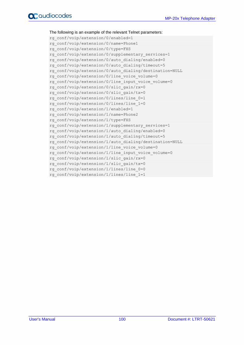
User's Manual 100 Document #: LTRT-50621
MP-20x Telephone Adapter
The following is an example of the relevant Telnet parameters:
rg_conf/voip/extension/0/enabled=1
rg_conf/voip/extension/0/name=Phone1
rg_conf/voip/extension/0/type=FXS
rg_conf/voip/extension/0/supplementary_services=1
rg_conf/voip/extension/0/auto_dialing/enabled=0
rg_conf/voip/extension/0/auto_dialing/timeout=5
rg_conf/voip/extension/0/auto_dialing/destination=NULL
rg_conf/voip/extension/0/line_voice_volume=0
rg_conf/voip/extension/0/line_input_voice_volume=0
rg_conf/voip/extension/0/slic_gain/rx=0
rg_conf/voip/extension/0/slic_gain/tx=0
rg_conf/voip/extension/0/lines/line_0=1
rg_conf/voip/extension/0/lines/line_1=0
rg_conf/voip/extension/1/enabled=1
rg_conf/voip/extension/1/name=Phone2
rg_conf/voip/extension/1/type=FXS
rg_conf/voip/extension/1/supplementary_services=1
rg_conf/voip/extension/1/auto_dialing/enabled=0
rg_conf/voip/extension/1/auto_dialing/timeout=5
rg_conf/voip/extension/1/auto_dialing/destination=NULL
rg_conf/voip/extension/1/line_voice_volume=0
rg_conf/voip/extension/1/line_input_voice_volume=0
rg_conf/voip/extension/1/slic_gain/rx=0
rg_conf/voip/extension/1/slic_gain/tx=0
rg_conf/voip/extension/1/lines/line_0=0
rg_conf/voip/extension/1/lines/line_1=1
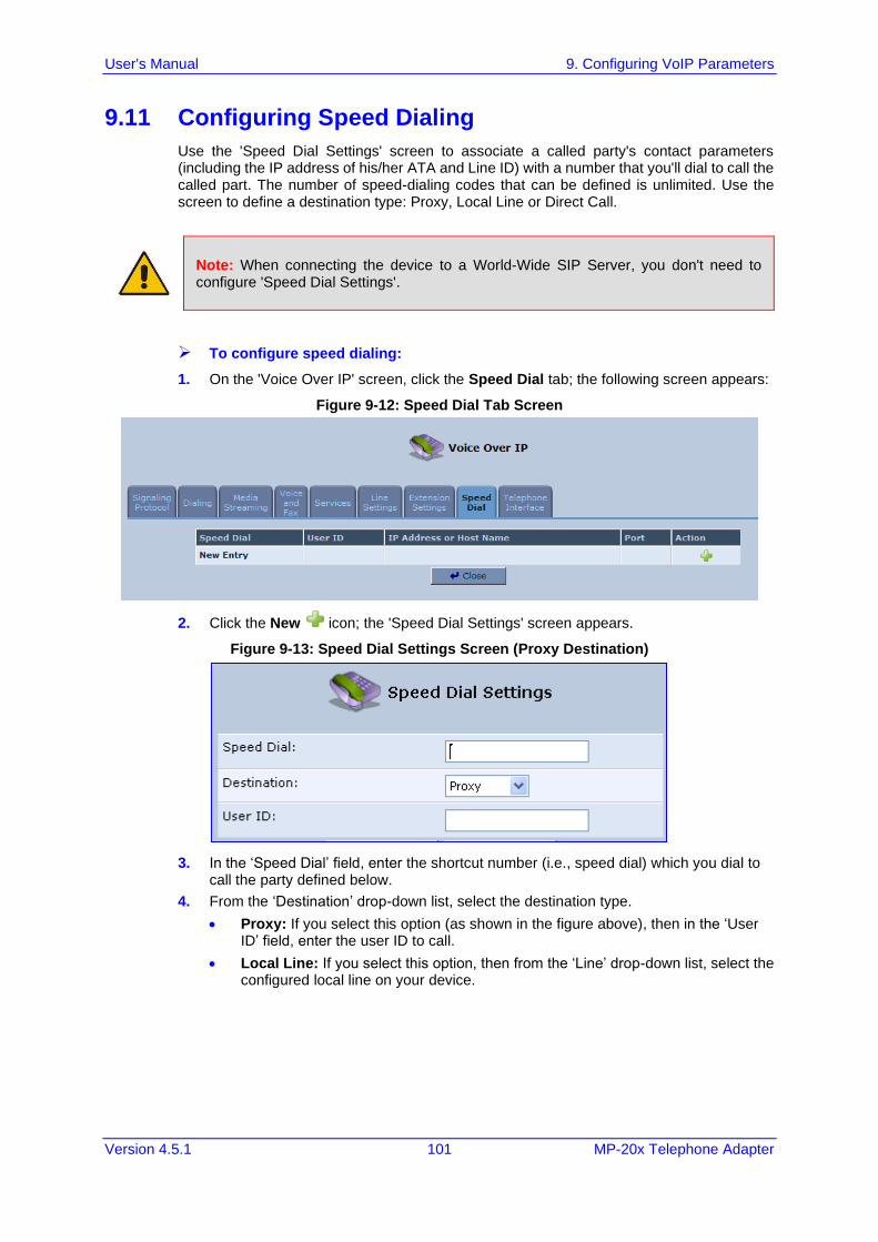
User's Manual 9. Configuring VoIP Parameters
Version 4.5.1 101 MP-20x Telephone Adapter
9.11 Configuring Speed Dialing
Use the 'Speed Dial Settings' screen to associate a called party's contact parameters (including the IP address of his/her ATA and Line ID) with a number that you'll dial to call the called part. The number of speed-dialing codes that can be defined is unlimited. Use the screen to define a destination type: Proxy, Local Line or Direct Call.
Note: When connecting the device to a World-Wide SIP Server, you don't need to configure 'Speed Dial Settings'.
➢ To configure speed dialing:
1. On the 'Voice Over IP' screen, click the Speed Dial tab; the following screen appears:
Figure 9-12: Speed Dial Tab Screen
2. Click the New icon; the 'Speed Dial Settings' screen appears.
Figure 9-13: Speed Dial Settings Screen (Proxy Destination)
3. In the ‘Speed Dial’ field, enter the shortcut number (i.e., speed dial) which you dial to call the party defined below.
4. From the ‘Destination’ drop-down list, select the destination type.
• Proxy: If you select this option (as shown in the figure above), then in the ‘User ID’ field, enter the user ID to call.
• Local Line: If you select this option, then from the ‘Line’ drop-down list, select the configured local line on your device.
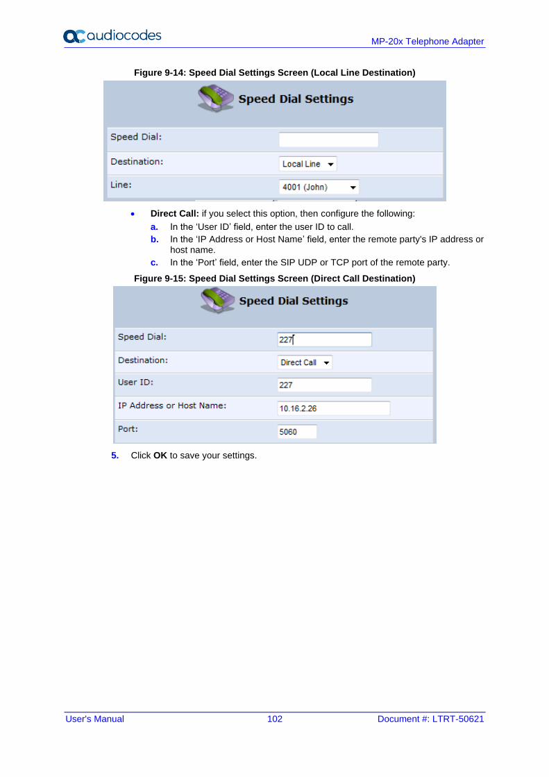
User's Manual 102 Document #: LTRT-50621
MP-20x Telephone Adapter
Figure 9-14: Speed Dial Settings Screen (Local Line Destination)
• Direct Call: if you select this option, then configure the following:
a. In the ‘User ID’ field, enter the user ID to call.
b. In the ‘IP Address or Host Name’ field, enter the remote party's IP address or host name.
c. In the ‘Port’ field, enter the SIP UDP or TCP port of the remote party.
Figure 9-15: Speed Dial Settings Screen (Direct Call Destination)
5. Click OK to save your settings.
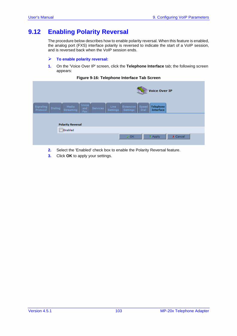
User's Manual 9. Configuring VoIP Parameters
Version 4.5.1 103 MP-20x Telephone Adapter
9.12 Enabling Polarity Reversal
The procedure below describes how to enable polarity reversal. When this feature is enabled, the analog port (FXS) interface polarity is reversed to indicate the start of a VoIP session, and is reversed back when the VoIP session ends.
➢ To enable polarity reversal:
1. On the 'Voice Over IP' screen, click the Telephone Interface tab; the following screen appears:
Figure 9-16: Telephone Interface Tab Screen
2. Select the 'Enabled' check box to enable the Polarity Reversal feature.
3. Click OK to apply your settings.

User's Manual 104 Document #: LTRT-50621
MP-20x Telephone Adapter
This page is intentionally left blank.
User's Manual 10. Making VoIP Calls with your Analog Telephones
Version 4.5.1 105 MP-20x Telephone Adapter
10 Making VoIP Calls with your Analog Telephones Analog telephone users that are connected to the device can place calls, put calls on hold, transfer calls, and establish three-way conferences. The procedures below describe how to perform these operations.
10.1 Making a Call
The procedure below describes how to make a call.
➢ To make a call:
1. Pick up the phone.
2. Make sure that you can hear a dial tone .
3. Dial the remote party's number or the user-defined speed dial number (if configured in Section 9.11 on page 101).
Note: When calling another internal extension, dial “**0” for FXS1, “**1” for FXS2, “**2”.
10.2 Answering a Waiting Call
The procedure below describes how to answer a waiting call. This depends on how you configured the flash-hook functionality, using the ‘Flash keys sequence style’ parameter in Section 9.3 on page 74. To enable call waiting, see Section 9.7 on page 90.
➢ To answer a waiting call when 'Flash only' is set:
1. When you hear a call waiting tone (during a call), press the flash key button on your phone; the active call is put on hold and switches to the waiting call.
2. To return to the original call, press the flash button again. You can toggle from one party to another by pressing the flash button.
➢ To answer a waiting call when 'Flash + digits sequence' is set:
3. When you hear the call waiting tone (during a call), press the flash key button on your phone and then press the '1' key; the original call is put on hold and switches to the waiting call.
4. To return to the original call, press flash + 1 again. You can toggle from one party to another by pressing flash + 1.
User's Manual 106 Document #: LTRT-50621
MP-20x Telephone Adapter
10.3 Putting a Call on Hold
The procedure below describes how to put a call on hold. This depends on how you configured the flash-hook functionality, using the ‘Flash keys sequence style’ parameter in Section 9.3 on page 74.
➢ To put the remote party on hold when 'Flash only' is set:
◼ During a call, press the flash key button on your phone; a dial tone is heard. At this point you can initiate a second call by dialing another party's number.
Note: If you press the flash key button again before the second party answers, the call is established with the original call. If, however, the second party answers and you press the flash key button, a 3-way conference is established.
➢ To put the remote party on hold when 'Flash + digits sequence' is set:
1. Press the flash key button key and then press the '1' key on your phone; the phone plays a dial tone. At this point you can initiate a second call by dialing another party's number.
2. To cancel the hold state and resume the previous phone call, press the flash key button and then press '1'.
10.4 Transferring a Call
The procedure below describes how to transfer an established call to another destination. This depends on how you configured the flash-hook functionality, using the ‘Flash keys sequence style’ parameter in Section 9.3 on page 74.
➢ To transfer a call when 'Flash only' is set:
1. During a call with party B, press the flash key button on your phone; party B is placed on hold and a dial tone is heard.
2. Dial party C's number.
3. You can wait for C to answer or not.
4. On-hook your phone; party B is now transferred to party C.
➢ To transfer a call when 'Flash + digits sequence' is set:
1. During a call with party B, press the flash key button and then press the '1' key on the phone; party B is placed on hold and a dial tone is heard.
2. Dial party C's number.
3. You can wait for C to answer or not.
4. Press the flash key button key and then press '2'; party B is transferred to party C (and a warning tone is heard).
User's Manual 10. Making VoIP Calls with your Analog Telephones
Version 4.5.1 107 MP-20x Telephone Adapter
10.5 Forwarding Calls to another Phone
The procedure below describes how to automatically forward incoming (received) calls to another phone. Before you can forward calls, you need to enable and configure call forwarding as described in Section 9.7 on page 90.
Note: The Call Forward feature is functional only when the device is registered to a proxy.
➢ To forward calls to another phone:
1. Pick up the phone and make sure that you can hear a dial tone.
2. Dial the call forward key sequence (according to your configuration), for example, *32; a dial tone is heard.
3. Dial the number of the phone to where you want calls forwarded; a stutter tone is heard.
4. Replace the receiver; all incoming calls are forwarded. Every time you pick up the phone receiver, a stutter tone is played (for the length of time, as you configured for the 'Stutter Tone Duration' parameter).
➢ To deactivate call forwarding:
1. Pick up the phone; a stutter tone is heard.
2. Dial the call forward key sequence.
3. Replace the receiver.
4. To make sure that call forwarding has been de-activated, pick up the phone again; a regular dial tone should be heard (not the stutter tone).
User's Manual 108 Document #: LTRT-50621
MP-20x Telephone Adapter
10.6 Establishing a 3-Way Conference Call
The procedure below describes how to establish a 3-way conference call. The method for doing this depends on how you configured the flash-hook functionality, using the ‘Flash keys sequence style’ parameter in Section 9.3 on page 74. In addition, to configure 3-way conferencing, see Section 9.7 on page 90.
➢ To establish a 3-way conference call when 'Flash only' is set:
1. During a call with party B, press the flash key button on your phone; Party B is placed on hold and a dial tone is heard.
2. Dial party C's number and wait until the call is established.
3. Press the flash key button again to add parties B and C to a 3-way conference call.
4. To end the 3-way conference call, on-hook your phone (or alternatively, press the flash key button again).
➢ To establish a 3-way conference call when 'Flash + digits sequence' is set:
1. During a call with party B, press the flash key button on your phone and then press the '1' key; Party B is placed on hold and a dial tone is heard.
2. Dial party C's number and wait until the call is established.
3. Press the flash key button and then press the '3' key to add B and C to a 3-way conference call.
4. To end the 3-way conference call, on-hook your phone (or alternatively, press the flash key button and then press the '3' key).
User's Manual 11. Quality of Service
Version 4.5.1 109 MP-20x Telephone Adapter
11 Quality of Service Network-based applications and traffic are growing at a high rate, producing an ever-increasing demand for bandwidth and network capacity. For obvious reasons, bandwidth and capacity cannot be expanded infinitely, requiring that bandwidth-demanding services be delivered over existing infrastructure, without incurring additional, expansive investments.
The next logical means of ensuring optimal use of existing resources are Quality of Service (QoS) mechanisms for congestion management and avoidance. QoS refers to the capability of a network device to provide better service to selected network traffic. This is achieved by shaping the traffic and processing higher priority traffic before lower priority traffic.
As QoS is dependent on the "weakest link in the chain", failure of but a single component along the data path to assure priority packet transmission can easily cause a VoIP call or a Video on Demand (VoD) broadcast to fail miserably. QoS must therefore obviously be addressed end-to-end.
The following are the potential bottleneck areas that need be taken into consideration when implementing an end-to-end QoS-enabled service.
◼ The Local Area Network: LANs have finite bandwidth, and are typically limited to 100 Mbps. When given the chance, some applications consume all available network bandwidth. In business networks, a large number of network-attached devices can lead to congestion.
◼ The Broadband Router: All network traffic passes through and is processed by the broadband router. It is therefore a natural focal point for QoS implementation. Lack of sufficient buffer space, memory or processing power, and poor integration among system components can result in highly undesirable real-time service performance. The only way to assure high QoS is the use of proper and tightly-integrated router operating system software and applications, which can effectively handle multiple real-time services simultaneously.
◼ The Broadband Connection: Typically, the most significant bottleneck of the network, this is where the high-speed LAN meets limited broadband bandwidth. Special QoS mechanisms must be built into routers to ensure that this sudden drop in connectivity speed is taken into account when prioritizing and transmitting real-time service-related data packets.
◼ The Internet: Internet routers typically have a limited amount of memory and bandwidth available to them, so that congestions may easily occur when links are over-utilized, and routers attempt to queue packets and schedule them for retransmission. One must also consider the fact that while Internet backbone routers take some prioritization into account when making routing decisions, all data packets are treated equally under congested conditions.
Note: For recommended QoS configuration see Section 11.7 on page 125.
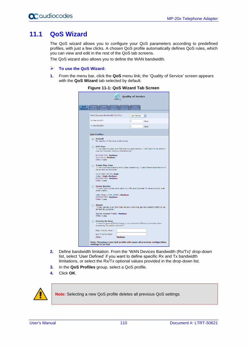
User's Manual 110 Document #: LTRT-50621
MP-20x Telephone Adapter
11.1 QoS Wizard
The QoS wizard allows you to configure your QoS parameters according to predefined profiles, with just a few clicks. A chosen QoS profile automatically defines QoS rules, which you can view and edit in the rest of the QoS tab screens.
The QoS wizard also allows you to define the WAN bandwidth.
➢ To use the QoS Wizard:
1. From the menu bar, click the QoS menu link; the ‘Quality of Service’ screen appears with the QoS Wizard tab selected by default.
Figure 11-1: QoS Wizard Tab Screen
2. Define bandwidth limitation. From the 'WAN Devices Bandwidth (Rx/Tx)' drop-down list, select ‘User Defined’ if you want to define specific Rx and Tx bandwidth limitations, or select the Rx/Tx optional values provided in the drop-down list.
3. In the QoS Profiles group, select a QoS profile.
4. Click OK.
Note: Selecting a new QoS profile deletes all previous QoS settings
User's Manual 11. Quality of Service
Version 4.5.1 111 MP-20x Telephone Adapter
11.2 Configuring Traffic Shaping
Traffic Shaping is the solution for managing and avoiding congestion where a high speed LAN meets limited broadband bandwidth. A user may have, for example, a 100 Mbps Ethernet LAN with a 100 Mbps WAN interface router. The router may communicate with the ISP using a modem with a bandwidth of 2 Mbps. This typical setup makes the modem, having no QoS module, the bottleneck. The router sends traffic as fast as it is received, while its well-designed QoS algorithms are left unused. Traffic shaping limits the bandwidth of the router, artificially forcing the router to be the bottleneck.
A traffic shaper is essentially a regulated queue that accepts uneven and/or bursty flows of packets and transmits them in a steady, predictable stream so that the network is not overwhelmed with traffic.
While Traffic Priority allows basic prioritization of packets, Traffic Shaping provides more sophisticated definitions such as:
◼ Bandwidth limit for each device
◼ Bandwidth limit for classes of rules
◼ Prioritization policy
◼ TCP serialization on a device
You can also define QoS traffic shaping rules for a default device. These rules are used on a device that has no definitions of its own. This enables the definition of QoS rules on Default WAN, for example, and their maintenance even if the PPP or bridge device over the WAN is removed.
The device also supports dynamic traffic shaping during a call. Traffic shaping is critical in residential VoIP gateways because of the bottleneck created in Cable modem/fiber transceiver, mainly in the upload direction. Dynamic traffic shaping ensures a minimum bandwidth for VoIP calls. Without dynamic traffic shaping, traffic shaping limits the bandwidth at all times, even if the user is not making a VoIP call and therefore, the service provider needs to configure the QoS traffic shaping transmit (Tx) bandwidth according to the user's specific upload bandwidth. Configuring a lower value results in a lower upload bandwidth (not only during VoIP calls).
Dynamic traffic shaping enables the service provider to configure two upload traffic shaping bandwidth parameters:
◼ "Tx Bandwidth" - for all traffic
◼ "Tx Bandwidth during Call" - for VoIP calls
The device normally uses the "Tx Bandwidth" value. When the user makes a VoIP call (i.e. any phone/s connected to the device is ringing or off-hook), the device switches to use the "Tx Bandwidth during Call" value.
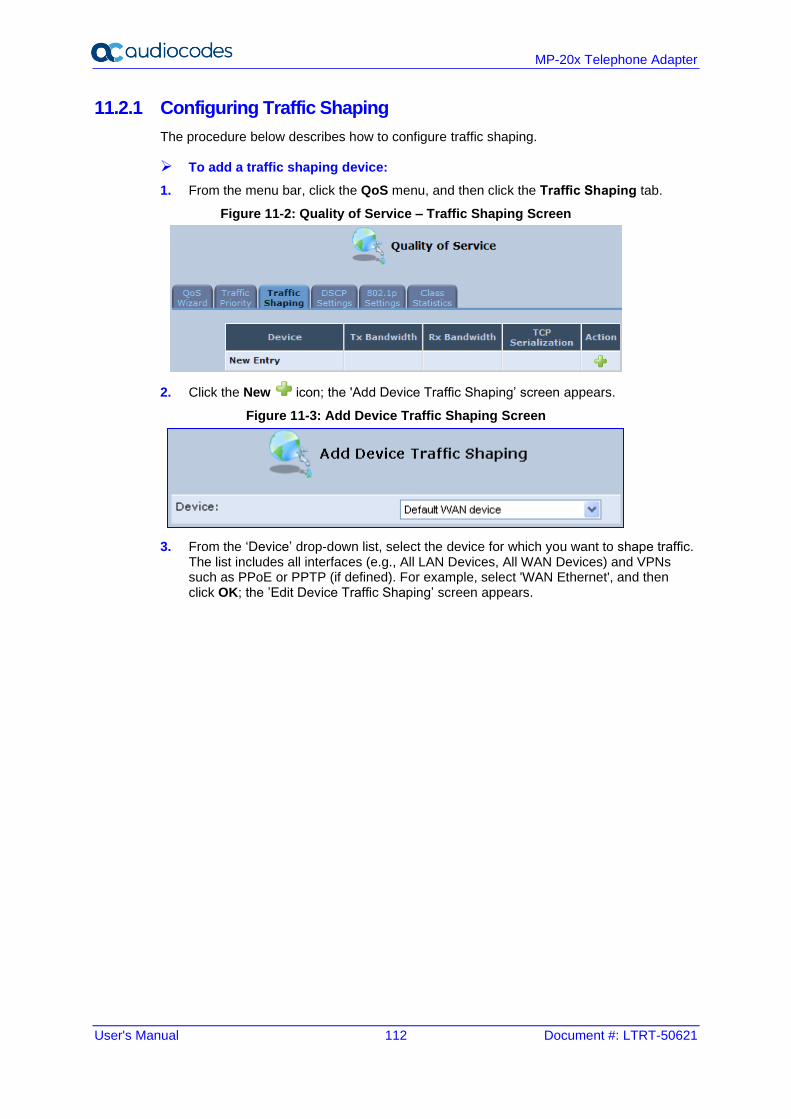
User's Manual 112 Document #: LTRT-50621
MP-20x Telephone Adapter
11.2.1 Configuring Traffic Shaping
The procedure below describes how to configure traffic shaping.
➢ To add a traffic shaping device:
1. From the menu bar, click the QoS menu, and then click the Traffic Shaping tab.
Figure 11-2: Quality of Service – Traffic Shaping Screen
2. Click the New icon; the 'Add Device Traffic Shaping’ screen appears.
Figure 11-3: Add Device Traffic Shaping Screen
3. From the ‘Device’ drop-down list, select the device for which you want to shape traffic. The list includes all interfaces (e.g., All LAN Devices, All WAN Devices) and VPNs such as PPoE or PPTP (if defined). For example, select 'WAN Ethernet', and then click OK; the ’Edit Device Traffic Shaping’ screen appears.
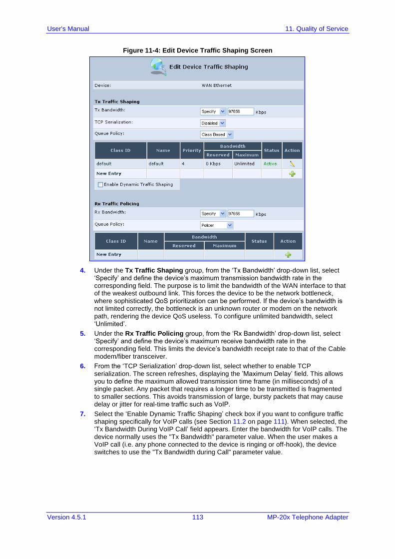
User's Manual 11. Quality of Service
Version 4.5.1 113 MP-20x Telephone Adapter
Figure 11-4: Edit Device Traffic Shaping Screen
4. Under the Tx Traffic Shaping group, from the ‘Tx Bandwidth’ drop-down list, select ‘Specify’ and define the device’s maximum transmission bandwidth rate in the corresponding field. The purpose is to limit the bandwidth of the WAN interface to that of the weakest outbound link. This forces the device to be the network bottleneck, where sophisticated QoS prioritization can be performed. If the device’s bandwidth is not limited correctly, the bottleneck is an unknown router or modem on the network path, rendering the device QoS useless. To configure unlimited bandwidth, select ‘Unlimited’.
5. Under the Rx Traffic Policing group, from the ‘Rx Bandwidth’ drop-down list, select ‘Specify’ and define the device’s maximum receive bandwidth rate in the corresponding field. This limits the device’s bandwidth receipt rate to that of the Cable modem/fiber transceiver.
6. From the ‘TCP Serialization’ drop-down list, select whether to enable TCP serialization. The screen refreshes, displaying the ’Maximum Delay’ field. This allows you to define the maximum allowed transmission time frame (in milliseconds) of a single packet. Any packet that requires a longer time to be transmitted is fragmented to smaller sections. This avoids transmission of large, bursty packets that may cause delay or jitter for real-time traffic such as VoIP.
7. Select the ‘Enable Dynamic Traffic Shaping’ check box if you want to configure traffic shaping specifically for VoIP calls (see Section 11.2 on page 111). When selected, the ‘Tx Bandwidth During VoIP Call’ field appears. Enter the bandwidth for VoIP calls. The device normally uses the "Tx Bandwidth" parameter value. When the user makes a VoIP call (i.e. any phone connected to the device is ringing or off-hook), the device switches to use the "Tx Bandwidth during Call" parameter value.
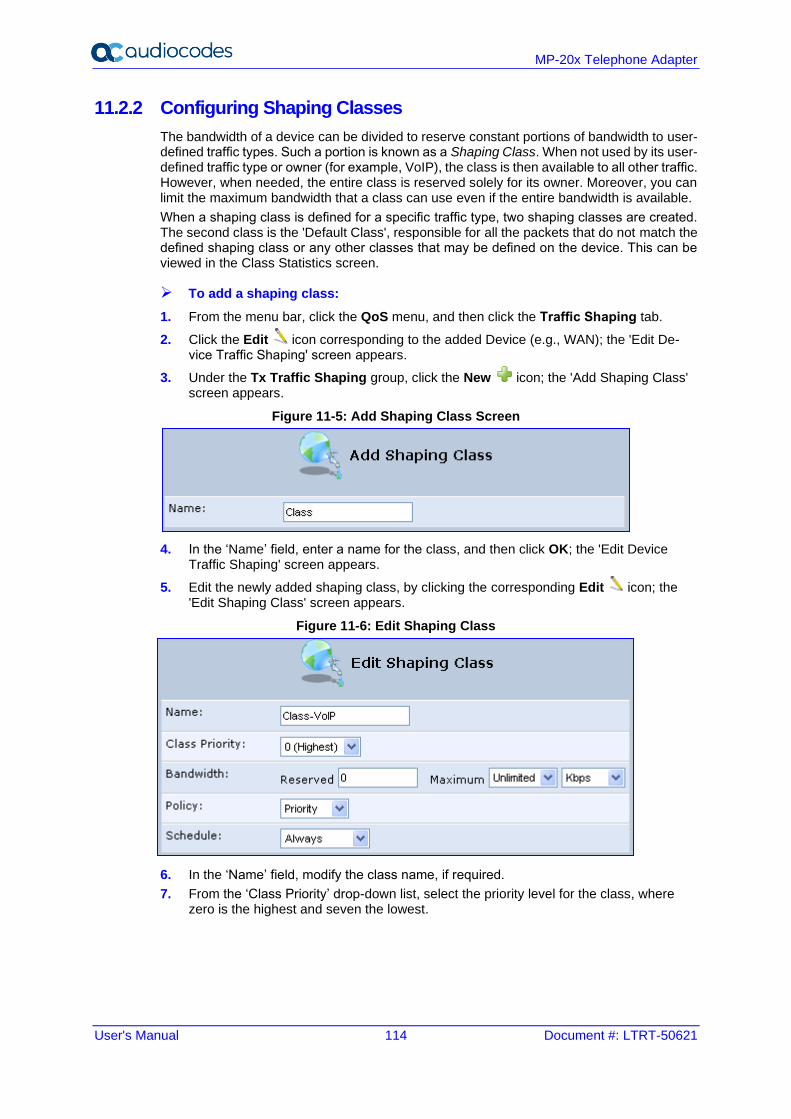
User's Manual 114 Document #: LTRT-50621
MP-20x Telephone Adapter
11.2.2 Configuring Shaping Classes
The bandwidth of a device can be divided to reserve constant portions of bandwidth to user-defined traffic types. Such a portion is known as a Shaping Class. When not used by its user-defined traffic type or owner (for example, VoIP), the class is then available to all other traffic. However, when needed, the entire class is reserved solely for its owner. Moreover, you can limit the maximum bandwidth that a class can use even if the entire bandwidth is available.
When a shaping class is defined for a specific traffic type, two shaping classes are created. The second class is the 'Default Class', responsible for all the packets that do not match the defined shaping class or any other classes that may be defined on the device. This can be viewed in the Class Statistics screen.
➢ To add a shaping class:
1. From the menu bar, click the QoS menu, and then click the Traffic Shaping tab.
2. Click the Edit icon corresponding to the added Device (e.g., WAN); the 'Edit De-vice Traffic Shaping' screen appears.
3. Under the Tx Traffic Shaping group, click the New icon; the 'Add Shaping Class' screen appears.
Figure 11-5: Add Shaping Class Screen
4. In the ‘Name’ field, enter a name for the class, and then click OK; the 'Edit Device Traffic Shaping' screen appears.
5. Edit the newly added shaping class, by clicking the corresponding Edit icon; the 'Edit Shaping Class' screen appears.
Figure 11-6: Edit Shaping Class
6. In the ‘Name’ field, modify the class name, if required.
7. From the ‘Class Priority’ drop-down list, select the priority level for the class, where zero is the highest and seven the lowest.
User's Manual 11. Quality of Service
Version 4.5.1 115 MP-20x Telephone Adapter
8. In the ‘Bandwidth’ field, define the bandwidth for the class:
• Reserved: reserved (i.e., guaranteed) bandwidth (Committed Information Rate / CIR) in kbps.
• Maximum: specify the maximum bandwidth
9. From the ‘Policy’ drop-down list, select the policy for routing packets within the class:
• Priority: Priority queuing uses multiple queues so that traffic is distributed among queues based on priority. This priority is defined according to packet priority, which can be defined explicitly by a DSCP value or an 802.1p value.
• FIFO: First In First Out. This priority queue ignores any previously-marked packet priority.
• Fairness: The fairness algorithm ensures no starvation by granting all packets a certain level of priority.
• RED: Random Early Detection. Utilizes statistical methods to drop packets in a ‘probabilistic’ way before queues overflow. Dropping packets in this way slows a source down enough to keep the queue steady and reduces the number of packets that would be lost when a queue overflows and a host is transmitting at a high rate.
10. From the ‘Schedule’ drop-down list, select the scheduler rule (defined in Section 5.6.1 on page 49) that defines the time segments during which the class can be active. By default, the class is always active.
11. Click OK to save your settings.
11.2.2.1 Class Rules
Class rules define which packets belong to the class. Without class rules, the shaping class has no effect. Each class can have outbound and inbound rules for outgoing and incoming traffic respectively. For example, you can define that all outgoing packets from computer A in your LAN belong to your VoIP class. These packets are limited to the class settings (bandwidth, schedule, etc.). In addition, you can define the traffic protocol and priority for each rule (this is not mandatory as in Traffic Priority rules).
11.2.2.1.1 Inbound and Outbound Data
The device can control outgoing data easily. It can queue packets, delay them, give precedence to other packets, or drop them. This helps in resolving upload (Tx) traffic bottlenecks and in most cases is sufficient. However, in the case of download (Rx) traffic bottlenecks, the ability to control the flow is much more limited. The device cannot queue packets, since in most cases the LAN is much faster than the WAN and when the device receives a packet from the WAN, it passes it immediately to the LAN.
QoS for ingress data has the following limitations, which do not exist for outgoing data:
◼ QoS can only be applied to TCP streams (UDP streams cannot be delayed)
◼ No borrowing mechanism
◼ When reserving Rx bandwidth, it is strictly taken from the bandwidth of all other classes

User's Manual 116 Document #: LTRT-50621
MP-20x Telephone Adapter
In addition, the device cannot control the behavior of its WAN (usually the ISP), which may not have proper QoS handling. Let’s look at a scenario of downloading a large file and surfing the Internet at the same time. Downloading the file is distinguished by small requests, followed by very large responses. This may result in blocking HTML traffic at the ISP. A solution for such a scenario is limiting the bandwidth of low-priority TCP connections (such as file download).
To add outbound and inbound class rules, see 11.3 on page 117.
Note: The hierarchy of the class rules is determined by the order of their addition to the class. For example, if your first rule is match packets with any source address, any destination address, and any protocol to this class; then all packets traversing the device are associated with the specific class. Any rules defined later do not have any effect.
User's Manual 11. Quality of Service
Version 4.5.1 117 MP-20x Telephone Adapter
11.3 Configuring Traffic Priority
Traffic Priority allows you to manage and avoid traffic congestion by defining inbound and outbound priority rules for each device on your gateway. These rules determine the priority assigned to packets traveling through the device. QoS parameters (DSCP marking and packet priority) are set per packet, on an application basis.
You can set QoS parameters using flexible rules, according to the following parameters:
◼ Source/destination IP address, MAC address or host name
◼ Device
◼ Source/destination ports
◼ Limit the rule to specific days and hours
The device supports two priority marking methods for packet prioritization:
◼ DSCP
◼ 802.1p Priority
The matching of packets by rules is connection-based, known as Stateful Packet Inspection (SPI), using the same connection-tracking mechanism used by the firewall. Once a packet matches a rule, all subsequent packets with the same attributes receive the same QoS parameters, both inbound and outbound.
A packet can match more than one rule, and therefore:
◼ The first class rule has precedence over all other class rules (scanning is stopped once the first rule is reached).
◼ The first traffic-priority (classless) rule has precedence over all other traffic-priority rules.
◼ There is no prevention of a traffic-priority rule conflicting with a class rule. In this case, the priority and DSCP setting of the class rule (if given) takes precedence.
Connection-based QoS also allows inheriting QoS parameters by some of the applications that open subsequent connections. For instance, you can define QoS rules on SIP and the rules then apply to both control and data ports (even if the data ports are unknown). This feature applies to all applications that have ALG at firewall:
◼ Any
◼ User Defined (FTP, HTTP, HTTPS, TFTP, IMAP, PING, POP3, SMTP, Telnet, Traceroute or any other protocol)
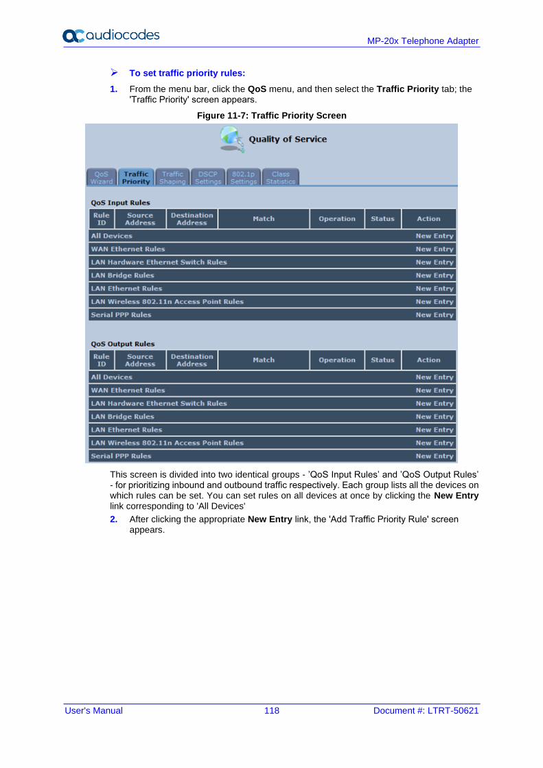
User's Manual 118 Document #: LTRT-50621
MP-20x Telephone Adapter
➢ To set traffic priority rules:
1. From the menu bar, click the QoS menu, and then select the Traffic Priority tab; the 'Traffic Priority' screen appears.
Figure 11-7: Traffic Priority Screen
This screen is divided into two identical groups - ’QoS Input Rules’ and ’QoS Output Rules’ - for prioritizing inbound and outbound traffic respectively. Each group lists all the devices on which rules can be set. You can set rules on all devices at once by clicking the New Entry link corresponding to 'All Devices'
2. After clicking the appropriate New Entry link, the 'Add Traffic Priority Rule' screen appears.
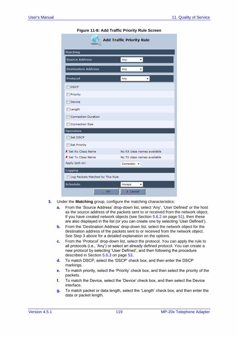
User's Manual 11. Quality of Service
Version 4.5.1 119 MP-20x Telephone Adapter
Figure 11-8: Add Traffic Priority Rule Screen
3. Under the Matching group, configure the matching characteristics:
a. From the ‘Source Address’ drop-down list, select 'Any', 'User Defined' or the host as the source address of the packets sent to or received from the network object. If you have created network objects (see Section 5.6.2 on page 51), then these are also displayed in the list (or you can create one by selecting ‘User Defined’).
b. From the ‘Destination Address’ drop-down list, select the network object for the destination address of the packets sent to or received from the network object. See Step 3 above for a detailed explanation on the options.
c. From the ‘Protocol’ drop-down list, select the protocol. You can apply the rule to all protocols (i.e., ‘Any’) or select an already defined protocol. You can create a new protocol by selecting ‘User Defined’, and then following the procedure described in Section 5.6.3 on page 53.
d. To match DSCP, select the ‘DSCP’ check box, and then enter the DSCP markings.
e. To match priority, select the ‘Priority’ check box, and then select the priority of the packets.
f. To match the Device, select the ‘Device’ check box, and then select the Device interface.
g. To match packet or data length, select the ‘Length’ check box, and then enter the data or packet length.
User's Manual 120 Document #: LTRT-50621
MP-20x Telephone Adapter
h. To match connection duration, select the ‘Connection Duration’ check box, and then enter the duration of the connection (greater or less than).
i. To match connection size, select the ‘Connection Size’ check box, and then enter the connection size.
4. Under the Operation group, configure the QoS operation:
a. Select the ‘Set DSCP’ check box to mark a DSCP value on packets matching this rule and then enter the hexadecimal value of the DSCP.
b. Select the ‘Set Priority’ check box to add a priority to the rule and then select the priority level (where 0 is the lowest and 7 the highest). This sets the priority of a packet on the connection matching the rule, while routing the packet.
c. Select the ‘Tx Class Name’ check box, and then select the class name that you defined.
d. From the ‘Apply QoS on’ drop-down list, select whether you want to apply the QoS rule on the connection or on the packet.
5. Select the ‘Log Packets Matched by This Rule’ check box to log the first packet from a connection that matches by this rule.
6. From the ‘Schedule’ drop-down list, select the time segments during which the rule may be active. By default, the rule is always active (i.e., ‘Always’). If you have defined Scheduler rules (see Section 5.6.1 on page 49), then these are also displayed as options. To define a new one Scheduler rule, select ‘User Defined’.
7. Click OK to save the settings.
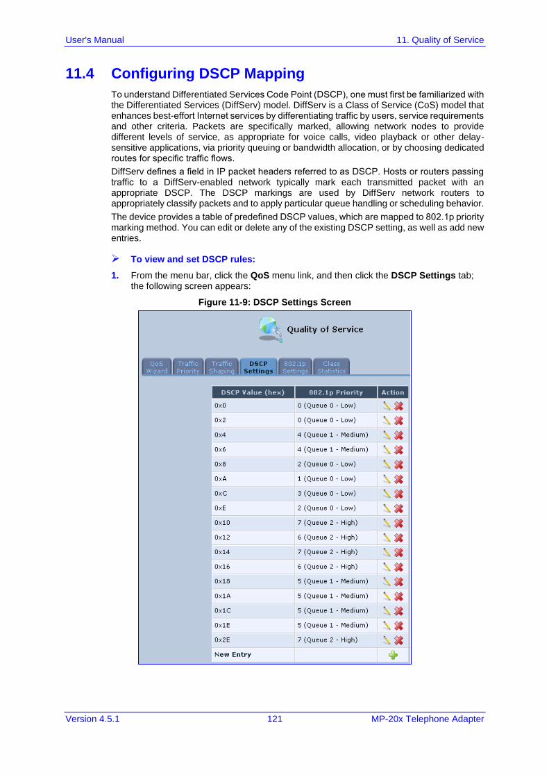
User's Manual 11. Quality of Service
Version 4.5.1 121 MP-20x Telephone Adapter
11.4 Configuring DSCP Mapping
To understand Differentiated Services Code Point (DSCP), one must first be familiarized with the Differentiated Services (DiffServ) model. DiffServ is a Class of Service (CoS) model that enhances best-effort Internet services by differentiating traffic by users, service requirements and other criteria. Packets are specifically marked, allowing network nodes to provide different levels of service, as appropriate for voice calls, video playback or other delay-sensitive applications, via priority queuing or bandwidth allocation, or by choosing dedicated routes for specific traffic flows.
DiffServ defines a field in IP packet headers referred to as DSCP. Hosts or routers passing traffic to a DiffServ-enabled network typically mark each transmitted packet with an appropriate DSCP. The DSCP markings are used by DiffServ network routers to appropriately classify packets and to apply particular queue handling or scheduling behavior.
The device provides a table of predefined DSCP values, which are mapped to 802.1p priority marking method. You can edit or delete any of the existing DSCP setting, as well as add new entries.
➢ To view and set DSCP rules:
1. From the menu bar, click the QoS menu link, and then click the DSCP Settings tab; the following screen appears:
Figure 11-9: DSCP Settings Screen
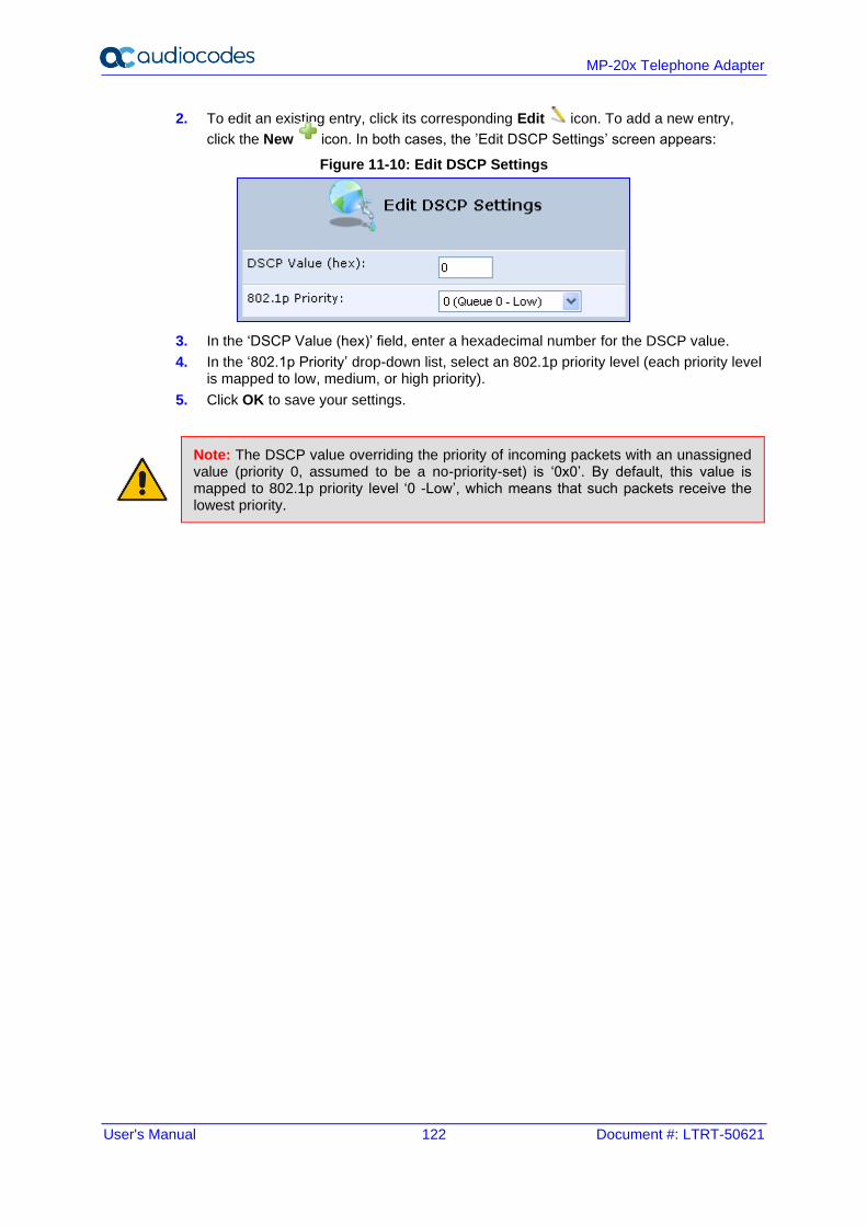
User's Manual 122 Document #: LTRT-50621
MP-20x Telephone Adapter
2. To edit an existing entry, click its corresponding Edit icon. To add a new entry,
click the New icon. In both cases, the ’Edit DSCP Settings’ screen appears:
Figure 11-10: Edit DSCP Settings
3. In the ‘DSCP Value (hex)’ field, enter a hexadecimal number for the DSCP value.
4. In the ‘802.1p Priority’ drop-down list, select an 802.1p priority level (each priority level is mapped to low, medium, or high priority).
5. Click OK to save your settings.
Note: The DSCP value overriding the priority of incoming packets with an unassigned value (priority 0, assumed to be a no-priority-set) is ‘0x0’. By default, this value is mapped to 802.1p priority level ‘0 -Low’, which means that such packets receive the lowest priority.
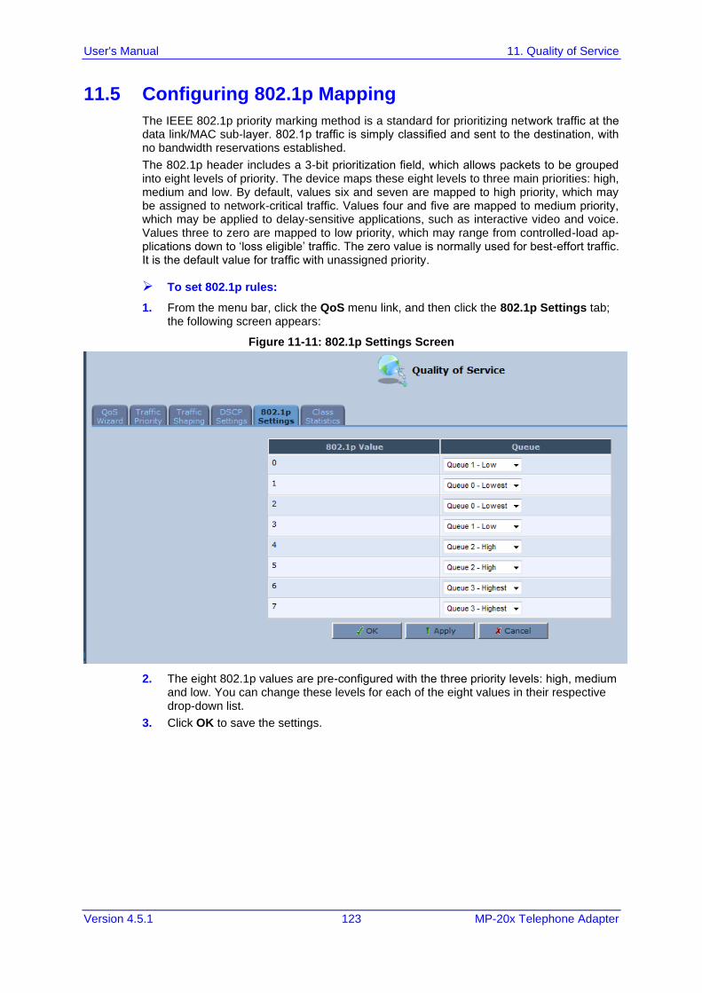
User's Manual 11. Quality of Service
Version 4.5.1 123 MP-20x Telephone Adapter
11.5 Configuring 802.1p Mapping
The IEEE 802.1p priority marking method is a standard for prioritizing network traffic at the data link/MAC sub-layer. 802.1p traffic is simply classified and sent to the destination, with no bandwidth reservations established.
The 802.1p header includes a 3-bit prioritization field, which allows packets to be grouped into eight levels of priority. The device maps these eight levels to three main priorities: high, medium and low. By default, values six and seven are mapped to high priority, which may be assigned to network-critical traffic. Values four and five are mapped to medium priority, which may be applied to delay-sensitive applications, such as interactive video and voice. Values three to zero are mapped to low priority, which may range from controlled-load ap-plications down to ‘loss eligible’ traffic. The zero value is normally used for best-effort traffic. It is the default value for traffic with unassigned priority.
➢ To set 802.1p rules:
1. From the menu bar, click the QoS menu link, and then click the 802.1p Settings tab; the following screen appears:
Figure 11-11: 802.1p Settings Screen
2. The eight 802.1p values are pre-configured with the three priority levels: high, medium and low. You can change these levels for each of the eight values in their respective drop-down list.
3. Click OK to save the settings.
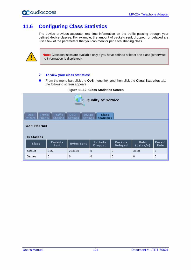
User's Manual 124 Document #: LTRT-50621
MP-20x Telephone Adapter
11.6 Configuring Class Statistics
The device provides accurate, real-time information on the traffic passing through your defined device classes. For example, the amount of packets sent, dropped, or delayed are just a few of the parameters that you can monitor per each shaping class.
Note: Class statistics are available only if you have defined at least one class (otherwise no information is displayed).
➢ To view your class statistics:
◼ From the menu bar, click the QoS menu link, and then click the Class Statistics tab; the following screen appears:
Figure 11-12: Class Statistics Screen
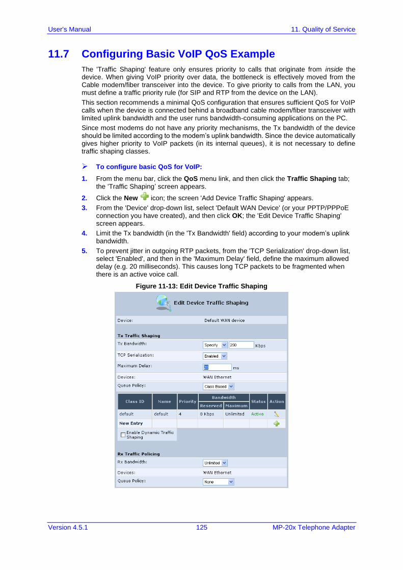
User's Manual 11. Quality of Service
Version 4.5.1 125 MP-20x Telephone Adapter
11.7 Configuring Basic VoIP QoS Example
The 'Traffic Shaping' feature only ensures priority to calls that originate from inside the device. When giving VoIP priority over data, the bottleneck is effectively moved from the Cable modem/fiber transceiver into the device. To give priority to calls from the LAN, you must define a traffic priority rule (for SIP and RTP from the device on the LAN).
This section recommends a minimal QoS configuration that ensures sufficient QoS for VoIP calls when the device is connected behind a broadband cable modem/fiber transceiver with limited uplink bandwidth and the user runs bandwidth-consuming applications on the PC.
Since most modems do not have any priority mechanisms, the Tx bandwidth of the device should be limited according to the modem’s uplink bandwidth. Since the device automatically gives higher priority to VoIP packets (in its internal queues), it is not necessary to define traffic shaping classes.
➢ To configure basic QoS for VoIP:
1. From the menu bar, click the QoS menu link, and then click the Traffic Shaping tab; the ‘Traffic Shaping’ screen appears.
2. Click the New icon; the screen 'Add Device Traffic Shaping' appears.
3. From the 'Device' drop-down list, select 'Default WAN Device' (or your PPTP/PPPoE connection you have created), and then click OK; the 'Edit Device Traffic Shaping' screen appears.
4. Limit the Tx bandwidth (in the 'Tx Bandwidth' field) according to your modem’s uplink bandwidth.
5. To prevent jitter in outgoing RTP packets, from the 'TCP Serialization' drop-down list, select 'Enabled', and then in the 'Maximum Delay' field, define the maximum allowed delay (e.g. 20 milliseconds). This causes long TCP packets to be fragmented when there is an active voice call.
Figure 11-13: Edit Device Traffic Shaping
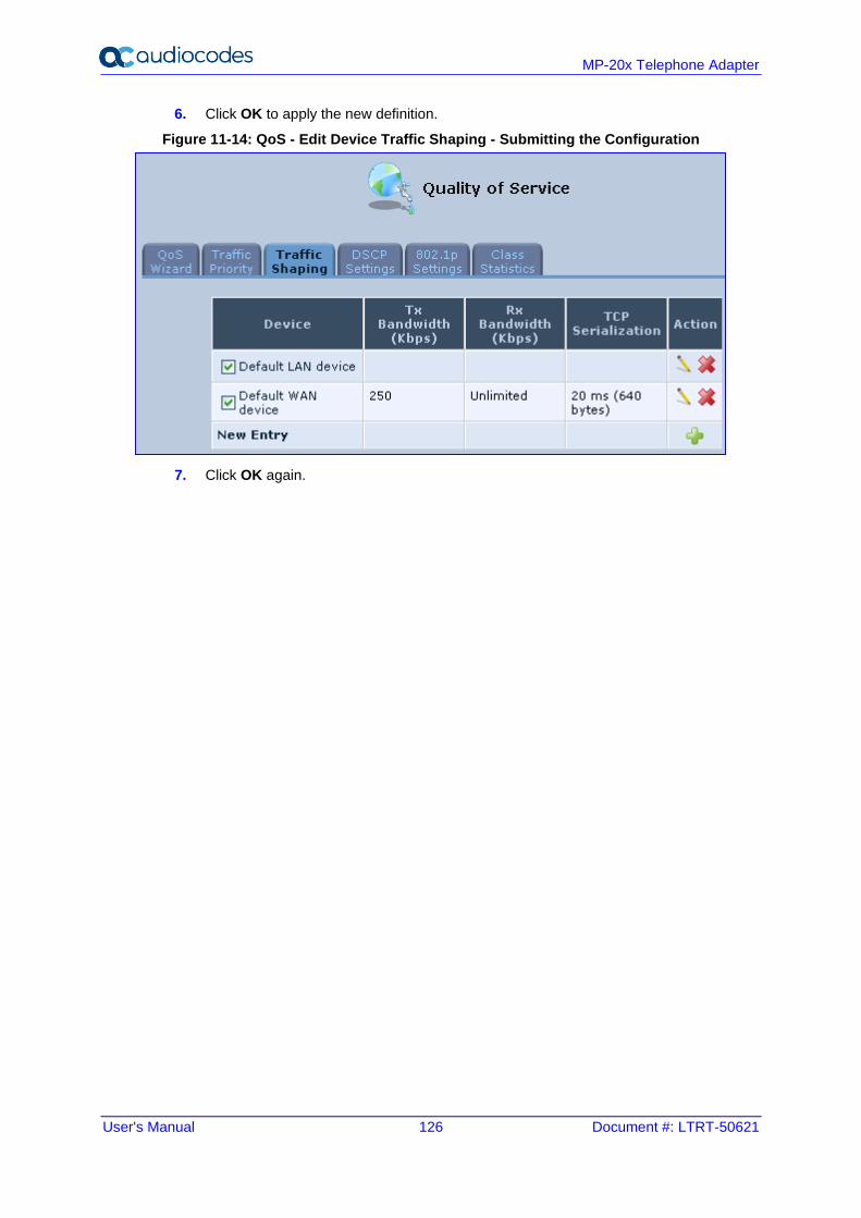
User's Manual 126 Document #: LTRT-50621
MP-20x Telephone Adapter
6. Click OK to apply the new definition.
Figure 11-14: QoS - Edit Device Traffic Shaping - Submitting the Configuration
7. Click OK again.
User's Manual 12. Network Connections
Version 4.5.1 127 MP-20x Telephone Adapter
12 Network Connections The procedures below describe how to configure the following network connections:
◼ WAN – see Section 12.1 on page 127
◼ LAN – see Section 12.2 on page 137
◼ VLANs – see Section 12.4 on page 152
◼ LAN-WAN Bridging – see Section 12.5 on page 160
12.1 Configuring a WAN Connection
This section describes how to configure your WAN Ethernet connection.
The WAN connection is configured in the ‘Network Connections’ screen, which provides a connection wizard that guides you through the network configuration stages.
Notes:
• To quickly configure a basic WAN connection, use the ‘Quick Setup’ screen, as described in Section 8.1 on page 59.
• Before configuring the device Internet connection, ensure that you have obtained relevant technical information on the Internet connection type from your Internet Telephony Service Provider (ITSP). For example, whether you are connected to the Internet using a static or dynamic IP address, or what protocols such as PPTP or PPPoE are used to communicate over the Internet.
• If the Automatic Dialer feature is shipped preconfigured (i.e., enabled), then the device automatically detects the Internet dialer type and therefore, Internet connection configuration is unnecessary. However, it is recommended to manually configure the Internet connection after the Automatic Dialer process has completed (successfully or not). For more information on the Automatic Dialer feature, see Section 8.1.1 on page 60
.
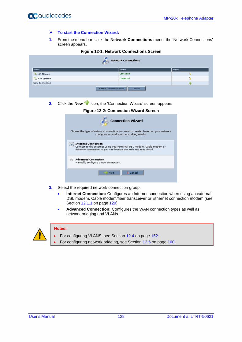
User's Manual 128 Document #: LTRT-50621
MP-20x Telephone Adapter
➢ To start the Connection Wizard:
1. From the menu bar, click the Network Connections menu; the 'Network Connections' screen appears.
Figure 12-1: Network Connections Screen
2. Click the New icon; the ‘Connection Wizard’ screen appears:
Figure 12-2: Connection Wizard Screen
3. Select the required network connection group:
• Internet Connection: Configures an Internet connection when using an external DSL modem, Cable modem/fiber transceiver or Ethernet connection modem (see Section 12.1.1 on page 129)
• Advanced Connection: Configures the WAN connection types as well as network bridging and VLANs.
Notes:
• For configuring VLANS, see Section 12.4 on page 152.
• For configuring network bridging, see Section 12.5 on page 160.
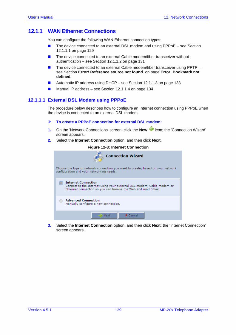
User's Manual 12. Network Connections
Version 4.5.1 129 MP-20x Telephone Adapter
12.1.1 WAN Ethernet Connections
You can configure the following WAN Ethernet connection types:
◼ The device connected to an external DSL modem and using PPPoE – see Section 12.1.1.1 on page 129
◼ The device connected to an external Cable modem/fiber transceiver without authentication – see Section 12.1.1.2 on page 131
◼ The device connected to an external Cable modem/fiber transceiver using PPTP – see Section Error! Reference source not found. on page Error! Bookmark not defined.
◼ Automatic IP address using DHCP – see Section 12.1.1.3 on page 133
◼ Manual IP address – see Section 12.1.1.4 on page 134
12.1.1.1 External DSL Modem using PPPoE
The procedure below describes how to configure an Internet connection using PPPoE when the device is connected to an external DSL modem.
➢ To create a PPPoE connection for external DSL modem:
1. On the 'Network Connections' screen, click the New icon; the 'Connection Wizard' screen appears.
2. Select the Internet Connection option, and then click Next.
Figure 12-3: Internet Connection
3. Select the Internet Connection option, and then click Next; the ‘Internet Connection’ screen appears.
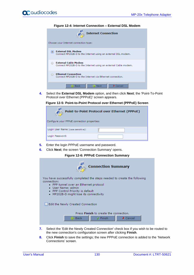
User's Manual 130 Document #: LTRT-50621
MP-20x Telephone Adapter
Figure 12-4: Internet Connection – External DSL Modem
4. Select the External DSL Modem option, and then click Next; the 'Point-To-Point Protocol over Ethernet (PPPoE)' screen appears.
Figure 12-5: Point-to-Point Protocol over Ethernet (PPPoE) Screen
5. Enter the login PPPoE username and password.
6. Click Next; the screen 'Connection Summary' opens.
Figure 12-6: PPPoE Connection Summary
7. Select the 'Edit the Newly Created Connection' check box if you wish to be routed to the new connection's configuration screen after clicking Finish.
8. Click Finish to save the settings; the new PPPoE connection is added to the ‘Network Connections’ screen.
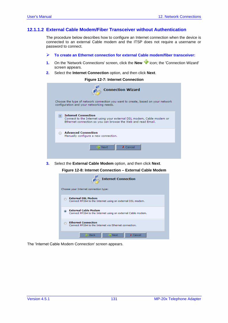
User's Manual 12. Network Connections
Version 4.5.1 131 MP-20x Telephone Adapter
12.1.1.2 External Cable Modem/Fiber Transceiver without Authentication
The procedure below describes how to configure an Internet connection when the device is connected to an external Cable modem and the ITSP does not require a username or password to connect.
➢ To create an Ethernet connection for external Cable modem/fiber transceiver:
1. On the 'Network Connections' screen, click the New icon; the 'Connection Wizard' screen appears.
2. Select the Internet Connection option, and then click Next.
Figure 12-7: Internet Connection
3. Select the External Cable Modem option, and then click Next.
Figure 12-8: Internet Connection – External Cable Modem
The ‘Internet Cable Modem Connection' screen appears.
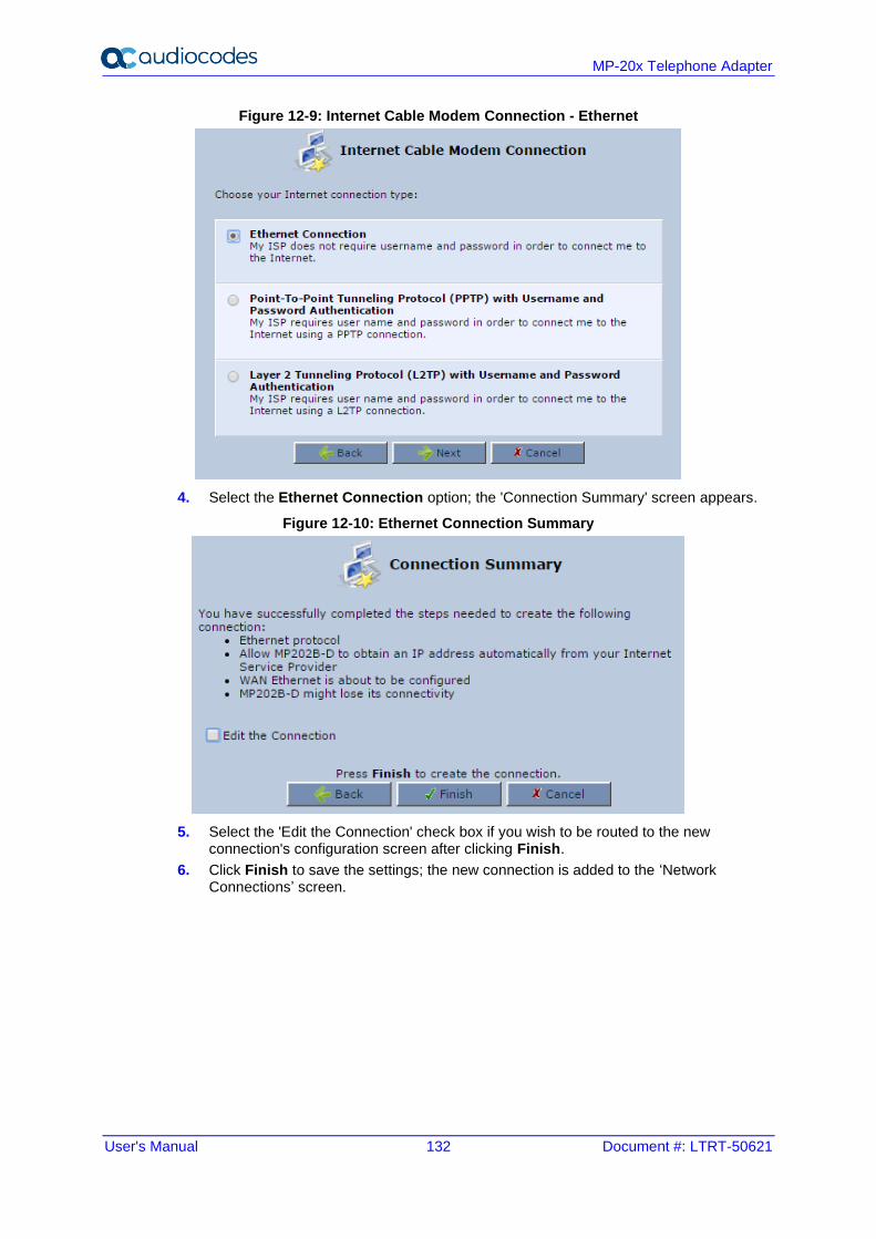
User's Manual 132 Document #: LTRT-50621
MP-20x Telephone Adapter
Figure 12-9: Internet Cable Modem Connection - Ethernet
4. Select the Ethernet Connection option; the 'Connection Summary' screen appears.
Figure 12-10: Ethernet Connection Summary
5. Select the 'Edit the Connection' check box if you wish to be routed to the new connection's configuration screen after clicking Finish.
6. Click Finish to save the settings; the new connection is added to the ‘Network Connections’ screen.
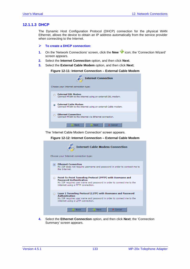
User's Manual 12. Network Connections
Version 4.5.1 133 MP-20x Telephone Adapter
12.1.1.3 DHCP
The Dynamic Host Configuration Protocol (DHCP) connection for the physical WAN Ethernet, allows the device to obtain an IP address automatically from the service provider when connecting to the Internet.
➢ To create a DHCP connection:
1. On the 'Network Connections' screen, click the New icon; the 'Connection Wizard' screen appears.
2. Select the Internet Connection option, and then click Next.
3. Select the External Cable Modem option, and then click Next;
Figure 12-11: Internet Connection – External Cable Modem
The ‘Internet Cable Modem Connection' screen appears.
Figure 12-12: Internet Connection – External Cable Modem
4. Select the Ethernet Connection option, and then click Next; the 'Connection Summary' screen appears.
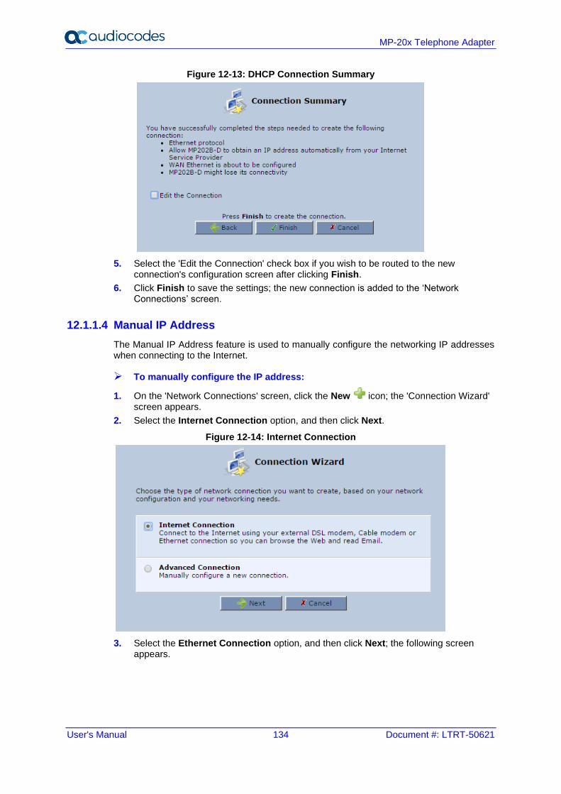
User's Manual 134 Document #: LTRT-50621
MP-20x Telephone Adapter
Figure 12-13: DHCP Connection Summary
5. Select the 'Edit the Connection' check box if you wish to be routed to the new connection's configuration screen after clicking Finish.
6. Click Finish to save the settings; the new connection is added to the ‘Network Connections’ screen.
12.1.1.4 Manual IP Address
The Manual IP Address feature is used to manually configure the networking IP addresses when connecting to the Internet.
➢ To manually configure the IP address:
1. On the 'Network Connections' screen, click the New icon; the 'Connection Wizard' screen appears.
2. Select the Internet Connection option, and then click Next.
Figure 12-14: Internet Connection
3. Select the Ethernet Connection option, and then click Next; the following screen appears.
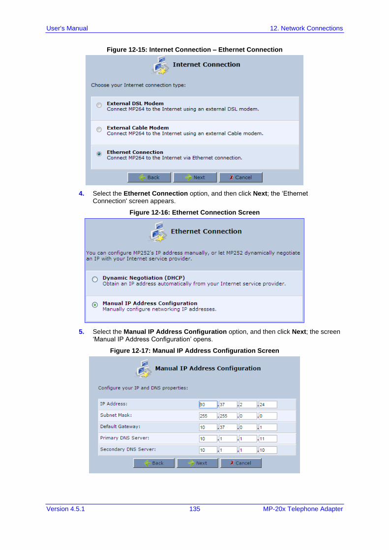
User's Manual 12. Network Connections
Version 4.5.1 135 MP-20x Telephone Adapter
Figure 12-15: Internet Connection – Ethernet Connection
4. Select the Ethernet Connection option, and then click Next; the ‘Ethernet Connection' screen appears.
Figure 12-16: Ethernet Connection Screen
5. Select the Manual IP Address Configuration option, and then click Next; the screen ‘Manual IP Address Configuration’ opens.
Figure 12-17: Manual IP Address Configuration Screen
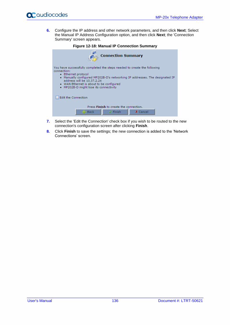
User's Manual 136 Document #: LTRT-50621
MP-20x Telephone Adapter
6. Configure the IP address and other network parameters, and then click Next; Select the Manual IP Address Configuration option, and then click Next; the 'Connection Summary' screen appears.
Figure 12-18: Manual IP Connection Summary
7. Select the 'Edit the Connection' check box if you wish to be routed to the new connection's configuration screen after clicking Finish.
8. Click Finish to save the settings; the new connection is added to the ‘Network Connections’ screen.
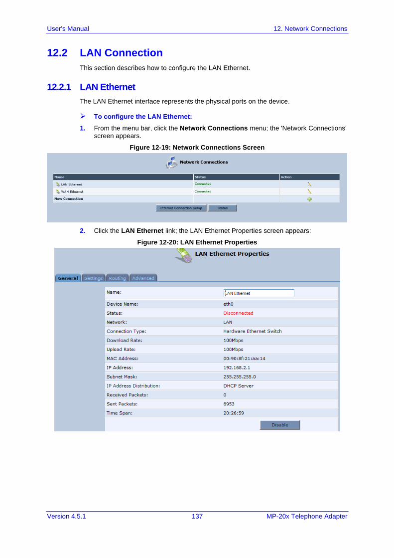
User's Manual 12. Network Connections
Version 4.5.1 137 MP-20x Telephone Adapter
12.2 LAN Connection
This section describes how to configure the LAN Ethernet.
12.2.1 LAN Ethernet
The LAN Ethernet interface represents the physical ports on the device.
➢ To configure the LAN Ethernet:
1. From the menu bar, click the Network Connections menu; the 'Network Connections' screen appears.
Figure 12-19: Network Connections Screen
2. Click the LAN Ethernet link; the LAN Ethernet Properties screen appears:
Figure 12-20: LAN Ethernet Properties
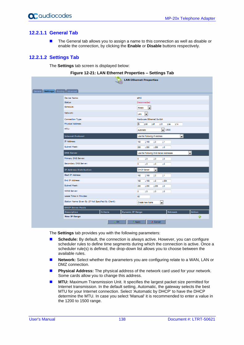
User's Manual 138 Document #: LTRT-50621
MP-20x Telephone Adapter
12.2.1.1 General Tab
◼ The General tab allows you to assign a name to this connection as well as disable or enable the connection, by clicking the Enable or Disable buttons respectively.
12.2.1.2 Settings Tab
The Settings tab screen is displayed below:
Figure 12-21: LAN Ethernet Properties – Settings Tab
The Settings tab provides you with the following parameters:
◼ Schedule: By default, the connection is always active. However, you can configure scheduler rules to define time segments during which the connection is active. Once a scheduler rule(s) is defined, the drop-down list allows you to choose between the available rules.
◼ Network: Select whether the parameters you are configuring relate to a WAN, LAN or DMZ connection.
◼ Physical Address: The physical address of the network card used for your network. Some cards allow you to change this address.
◼ MTU: Maximum Transmission Unit. It specifies the largest packet size permitted for Internet transmission. In the default setting, Automatic, the gateway selects the best MTU for your Internet connection. Select 'Automatic by DHCP' to have the DHCP determine the MTU. In case you select 'Manual' it is recommended to enter a value in the 1200 to 1500 range.
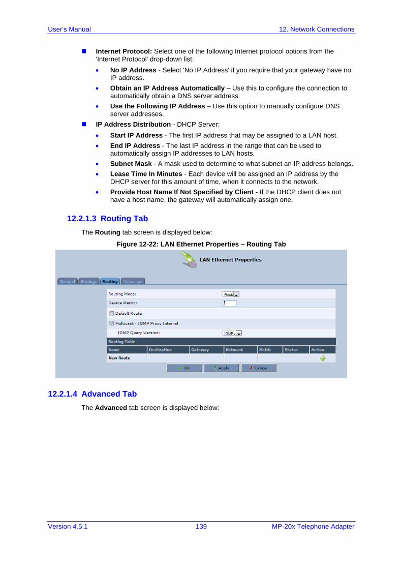
User's Manual 12. Network Connections
Version 4.5.1 139 MP-20x Telephone Adapter
◼ Internet Protocol: Select one of the following Internet protocol options from the 'Internet Protocol' drop-down list:
• No IP Address - Select 'No IP Address' if you require that your gateway have no IP address.
• Obtain an IP Address Automatically – Use this to configure the connection to automatically obtain a DNS server address.
• Use the Following IP Address – Use this option to manually configure DNS server addresses.
◼ IP Address Distribution - DHCP Server:
• Start IP Address - The first IP address that may be assigned to a LAN host.
• End IP Address - The last IP address in the range that can be used to automatically assign IP addresses to LAN hosts.
• Subnet Mask - A mask used to determine to what subnet an IP address belongs.
• Lease Time In Minutes - Each device will be assigned an IP address by the DHCP server for this amount of time, when it connects to the network.
• Provide Host Name If Not Specified by Client - If the DHCP client does not have a host name, the gateway will automatically assign one.
12.2.1.3 Routing Tab
The Routing tab screen is displayed below:
Figure 12-22: LAN Ethernet Properties – Routing Tab
12.2.1.4 Advanced Tab
The Advanced tab screen is displayed below:
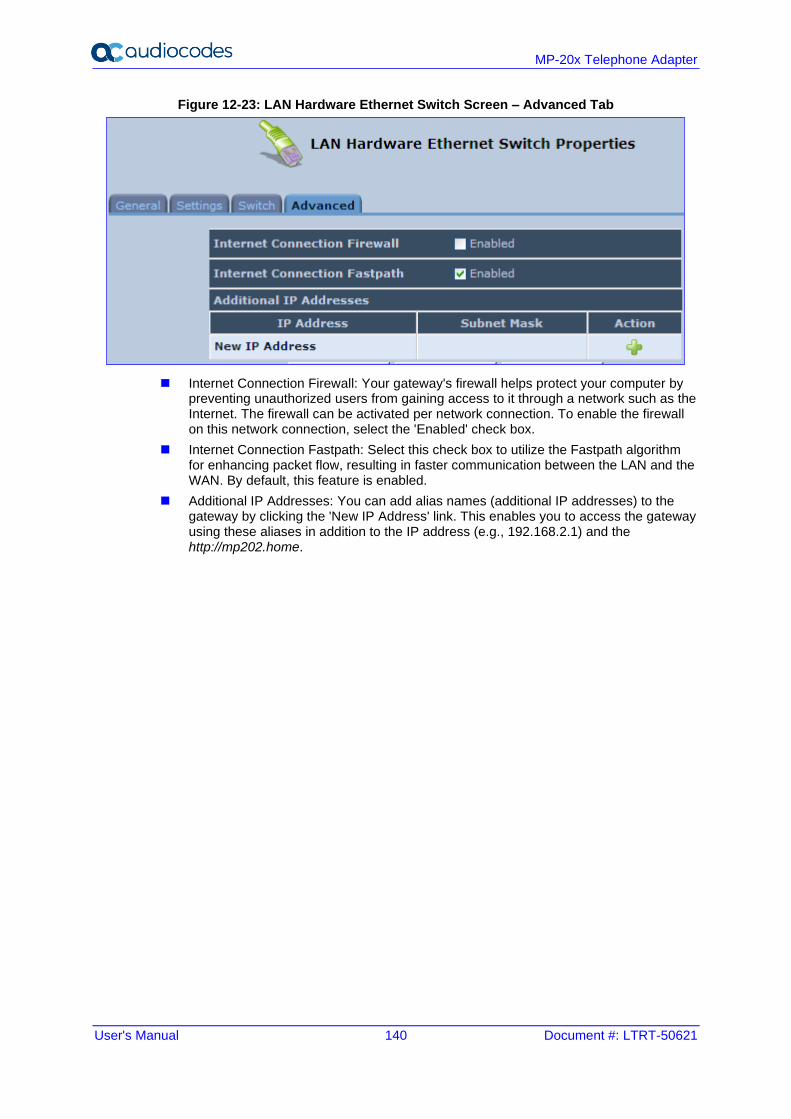
User's Manual 140 Document #: LTRT-50621
MP-20x Telephone Adapter
Figure 12-23: LAN Hardware Ethernet Switch Screen – Advanced Tab
◼ Internet Connection Firewall: Your gateway's firewall helps protect your computer by preventing unauthorized users from gaining access to it through a network such as the Internet. The firewall can be activated per network connection. To enable the firewall on this network connection, select the 'Enabled' check box.
◼ Internet Connection Fastpath: Select this check box to utilize the Fastpath algorithm for enhancing packet flow, resulting in faster communication between the LAN and the WAN. By default, this feature is enabled.
◼ Additional IP Addresses: You can add alias names (additional IP addresses) to the gateway by clicking the 'New IP Address' link. This enables you to access the gateway using these aliases in addition to the IP address (e.g., 192.168.2.1) and the http://mp202.home.
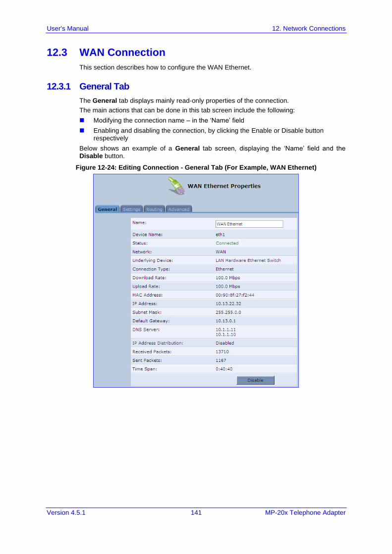
User's Manual 12. Network Connections
Version 4.5.1 141 MP-20x Telephone Adapter
12.3 WAN Connection
This section describes how to configure the WAN Ethernet.
12.3.1 General Tab
The General tab displays mainly read-only properties of the connection.
The main actions that can be done in this tab screen include the following:
◼ Modifying the connection name – in the ‘Name’ field
◼ Enabling and disabling the connection, by clicking the Enable or Disable button respectively
Below shows an example of a General tab screen, displaying the ‘Name’ field and the Disable button.
Figure 12-24: Editing Connection - General Tab (For Example, WAN Ethernet)
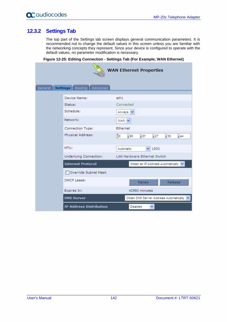
User's Manual 142 Document #: LTRT-50621
MP-20x Telephone Adapter
12.3.2 Settings Tab
The top part of the Settings tab screen displays general communication parameters. It is recommended not to change the default values in this screen unless you are familiar with the networking concepts they represent. Since your device is configured to operate with the default values, no parameter modification is necessary.
Figure 12-25: Editing Connection - Settings Tab (For Example, WAN Ethernet)
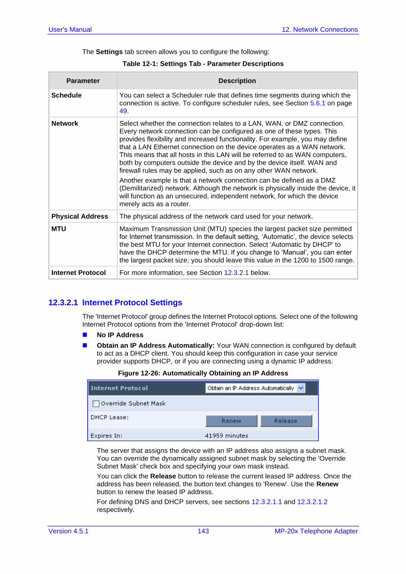
User's Manual 12. Network Connections
Version 4.5.1 143 MP-20x Telephone Adapter
The Settings tab screen allows you to configure the following:
Table 12-1: Settings Tab - Parameter Descriptions
Parameter Description
Schedule You can select a Scheduler rule that defines time segments during which the connection is active. To configure scheduler rules, see Section 5.6.1 on page 49.
Network Select whether the connection relates to a LAN, WAN, or DMZ connection. Every network connection can be configured as one of these types. This provides flexibility and increased functionality. For example, you may define that a LAN Ethernet connection on the device operates as a WAN network. This means that all hosts in this LAN will be referred to as WAN computers, both by computers outside the device and by the device itself. WAN and firewall rules may be applied, such as on any other WAN network.
Another example is that a network connection can be defined as a DMZ (Demilitarized) network. Although the network is physically inside the device, it will function as an unsecured, independent network, for which the device merely acts as a router.
Physical Address The physical address of the network card used for your network.
MTU Maximum Transmission Unit (MTU) species the largest packet size permitted for Internet transmission. In the default setting, ‘Automatic’, the device selects the best MTU for your Internet connection. Select 'Automatic by DHCP' to have the DHCP determine the MTU. If you change to ‘Manual’, you can enter the largest packet size; you should leave this value in the 1200 to 1500 range.
Internet Protocol For more information, see Section 12.3.2.1 below.
12.3.2.1 Internet Protocol Settings
The 'Internet Protocol' group defines the Internet Protocol options. Select one of the following Internet Protocol options from the 'Internet Protocol' drop-down list:
◼ No IP Address
◼ Obtain an IP Address Automatically: Your WAN connection is configured by default to act as a DHCP client. You should keep this configuration in case your service provider supports DHCP, or if you are connecting using a dynamic IP address.
Figure 12-26: Automatically Obtaining an IP Address
The server that assigns the device with an IP address also assigns a subnet mask. You can override the dynamically assigned subnet mask by selecting the 'Override Subnet Mask' check box and specifying your own mask instead.
You can click the Release button to release the current leased IP address. Once the address has been released, the button text changes to 'Renew'. Use the Renew button to renew the leased IP address.
For defining DNS and DHCP servers, see sections 12.3.2.1.1 and 12.3.2.1.2 respectively.
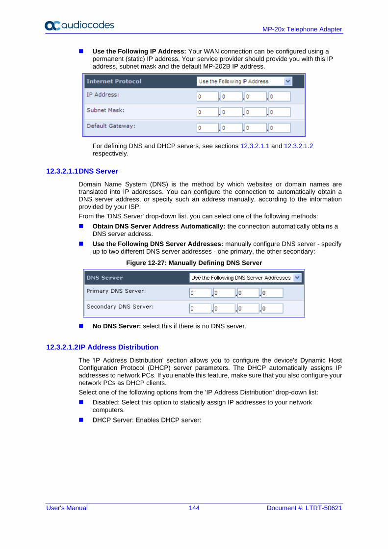
User's Manual 144 Document #: LTRT-50621
MP-20x Telephone Adapter
◼ Use the Following IP Address: Your WAN connection can be configured using a permanent (static) IP address. Your service provider should provide you with this IP address, subnet mask and the default MP-202B IP address.
For defining DNS and DHCP servers, see sections 12.3.2.1.1 and 12.3.2.1.2 respectively.
12.3.2.1.1 DNS Server
Domain Name System (DNS) is the method by which websites or domain names are translated into IP addresses. You can configure the connection to automatically obtain a DNS server address, or specify such an address manually, according to the information provided by your ISP.
From the 'DNS Server' drop-down list, you can select one of the following methods:
◼ Obtain DNS Server Address Automatically: the connection automatically obtains a DNS server address.
◼ Use the Following DNS Server Addresses: manually configure DNS server - specify up to two different DNS server addresses - one primary, the other secondary:
Figure 12-27: Manually Defining DNS Server
◼ No DNS Server: select this if there is no DNS server.
12.3.2.1.2 IP Address Distribution
The 'IP Address Distribution' section allows you to configure the device's Dynamic Host Configuration Protocol (DHCP) server parameters. The DHCP automatically assigns IP addresses to network PCs. If you enable this feature, make sure that you also configure your network PCs as DHCP clients.
Select one of the following options from the 'IP Address Distribution' drop-down list:
◼ Disabled: Select this option to statically assign IP addresses to your network computers.
◼ DHCP Server: Enables DHCP server:
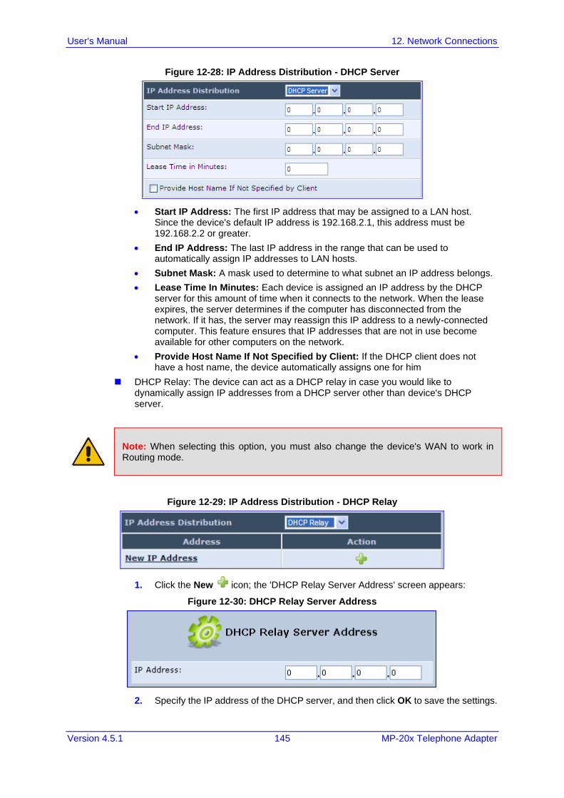
User's Manual 12. Network Connections
Version 4.5.1 145 MP-20x Telephone Adapter
Figure 12-28: IP Address Distribution - DHCP Server
• Start IP Address: The first IP address that may be assigned to a LAN host. Since the device's default IP address is 192.168.2.1, this address must be 192.168.2.2 or greater.
• End IP Address: The last IP address in the range that can be used to automatically assign IP addresses to LAN hosts.
• Subnet Mask: A mask used to determine to what subnet an IP address belongs.
• Lease Time In Minutes: Each device is assigned an IP address by the DHCP server for this amount of time when it connects to the network. When the lease expires, the server determines if the computer has disconnected from the network. If it has, the server may reassign this IP address to a newly-connected computer. This feature ensures that IP addresses that are not in use become available for other computers on the network.
• Provide Host Name If Not Specified by Client: If the DHCP client does not have a host name, the device automatically assigns one for him
◼ DHCP Relay: The device can act as a DHCP relay in case you would like to dynamically assign IP addresses from a DHCP server other than device's DHCP server.
Note: When selecting this option, you must also change the device's WAN to work in Routing mode.
Figure 12-29: IP Address Distribution - DHCP Relay
1. Click the New icon; the 'DHCP Relay Server Address' screen appears:
Figure 12-30: DHCP Relay Server Address
2. Specify the IP address of the DHCP server, and then click OK to save the settings.
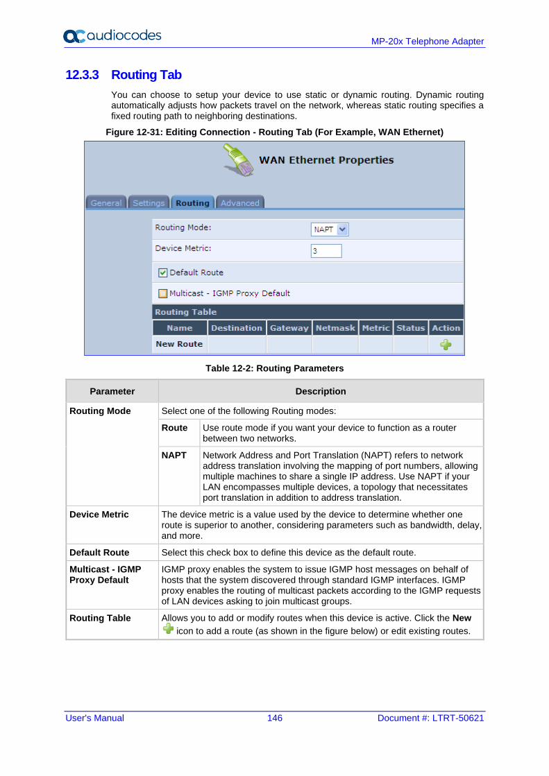
User's Manual 146 Document #: LTRT-50621
MP-20x Telephone Adapter
12.3.3 Routing Tab
You can choose to setup your device to use static or dynamic routing. Dynamic routing automatically adjusts how packets travel on the network, whereas static routing specifies a fixed routing path to neighboring destinations.
Figure 12-31: Editing Connection - Routing Tab (For Example, WAN Ethernet)
Table 12-2: Routing Parameters
Parameter Description
Routing Mode Select one of the following Routing modes:
Route Use route mode if you want your device to function as a router between two networks.
NAPT Network Address and Port Translation (NAPT) refers to network address translation involving the mapping of port numbers, allowing multiple machines to share a single IP address. Use NAPT if your LAN encompasses multiple devices, a topology that necessitates port translation in addition to address translation.
Device Metric The device metric is a value used by the device to determine whether one route is superior to another, considering parameters such as bandwidth, delay, and more.
Default Route Select this check box to define this device as the default route.
Multicast - IGMP Proxy Default
IGMP proxy enables the system to issue IGMP host messages on behalf of hosts that the system discovered through standard IGMP interfaces. IGMP proxy enables the routing of multicast packets according to the IGMP requests of LAN devices asking to join multicast groups.
Routing Table Allows you to add or modify routes when this device is active. Click the New
icon to add a route (as shown in the figure below) or edit existing routes.
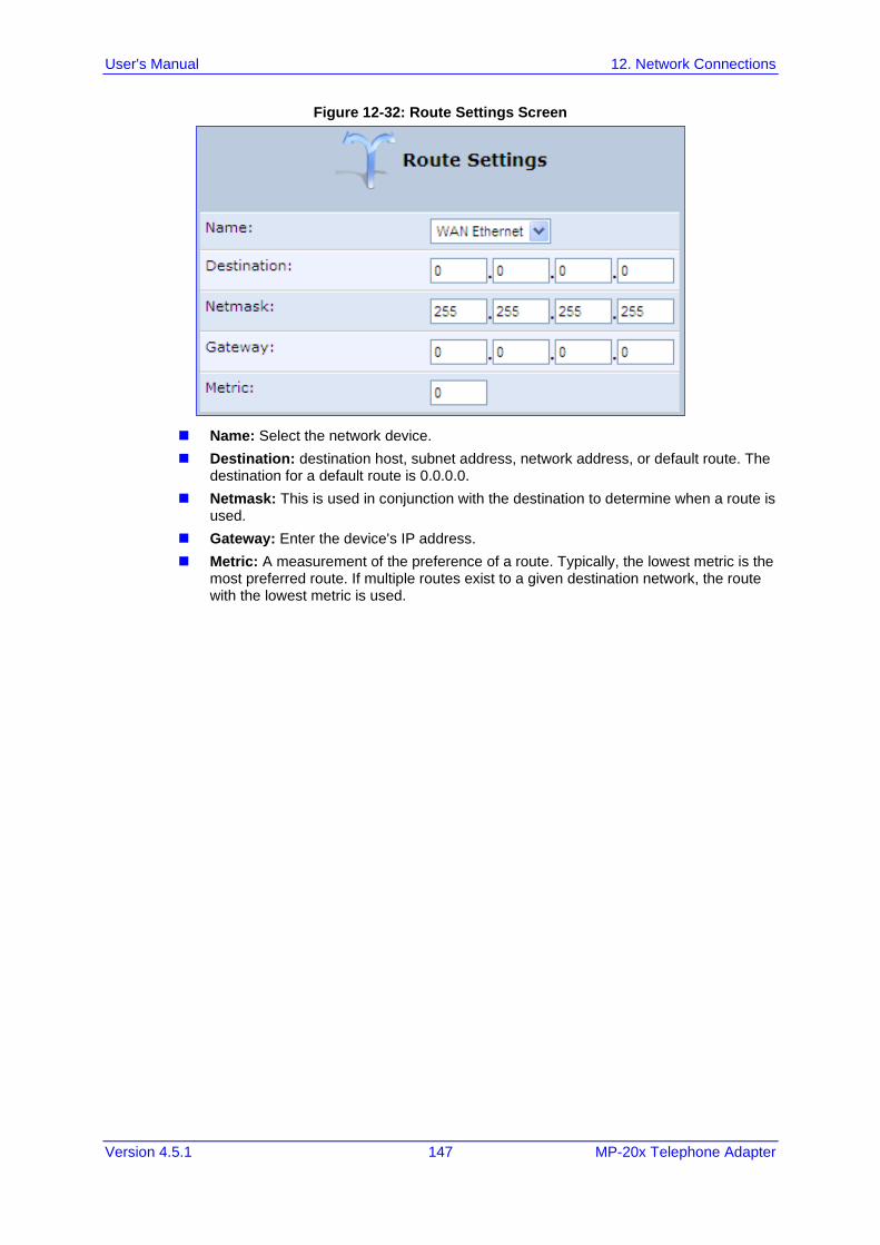
User's Manual 12. Network Connections
Version 4.5.1 147 MP-20x Telephone Adapter
Figure 12-32: Route Settings Screen
◼ Name: Select the network device.
◼ Destination: destination host, subnet address, network address, or default route. The destination for a default route is 0.0.0.0.
◼ Netmask: This is used in conjunction with the destination to determine when a route is used.
◼ Gateway: Enter the device's IP address.
◼ Metric: A measurement of the preference of a route. Typically, the lowest metric is the most preferred route. If multiple routes exist to a given destination network, the route with the lowest metric is used.
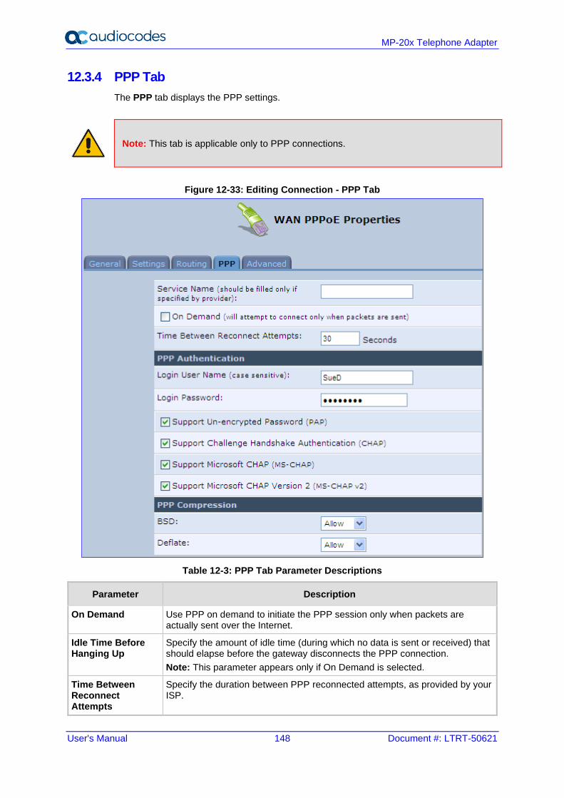
User's Manual 148 Document #: LTRT-50621
MP-20x Telephone Adapter
12.3.4 PPP Tab
The PPP tab displays the PPP settings.
Note: This tab is applicable only to PPP connections.
Figure 12-33: Editing Connection - PPP Tab
Table 12-3: PPP Tab Parameter Descriptions
Parameter Description
On Demand Use PPP on demand to initiate the PPP session only when packets are actually sent over the Internet.
Idle Time Before Hanging Up
Specify the amount of idle time (during which no data is sent or received) that should elapse before the gateway disconnects the PPP connection.
Note: This parameter appears only if On Demand is selected.
Time Between Reconnect Attempts
Specify the duration between PPP reconnected attempts, as provided by your ISP.
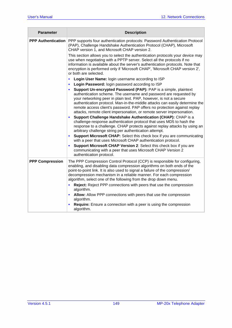
User's Manual 12. Network Connections
Version 4.5.1 149 MP-20x Telephone Adapter
Parameter Description
PPP Authentication PPP supports four authentication protocols: Password Authentication Protocol (PAP), Challenge Handshake Authentication Protocol (CHAP), Microsoft CHAP version 1, and Microsoft CHAP version 2.
This section allows you to select the authentication protocols your device may use when negotiating with a PPTP server. Select all the protocols if no information is available about the server's authentication protocols. Note that encryption is performed only if 'Microsoft CHAP', 'Microsoft CHAP version 2', or both are selected.
▪ Login User Name: login username according to ISP
▪ Login Password: login password according to ISP
▪ Support Un-encrypted Password (PAP): PAP is a simple, plaintext authentication scheme. The username and password are requested by your networking peer in plain text. PAP, however, is not a secure authentication protocol. Man-in-the-middle attacks can easily determine the remote access client's password. PAP offers no protection against replay attacks, remote client impersonation, or remote server impersonation.
▪ Support Challenge Handshake Authentication (CHAP): CHAP is a challenge-response authentication protocol that uses MD5 to hash the response to a challenge. CHAP protects against replay attacks by using an arbitrary challenge string per authentication attempt.
▪ Support Microsoft CHAP: Select this check box if you are communicating with a peer that uses Microsoft CHAP authentication protocol.
▪ Support Microsoft CHAP Version 2: Select this check box if you are communicating with a peer that uses Microsoft CHAP Version 2 authentication protocol.
PPP Compression The PPP Compression Control Protocol (CCP) is responsible for configuring, enabling, and disabling data compression algorithms on both ends of the point-to-point link. It is also used to signal a failure of the compression/ decompression mechanism in a reliable manner. For each compression algorithm, select one of the following from the drop down menu.
▪ Reject: Reject PPP connections with peers that use the compression algorithm.
▪ Allow: Allow PPP connections with peers that use the compression algorithm.
▪ Require: Ensure a connection with a peer is using the compression algorithm.
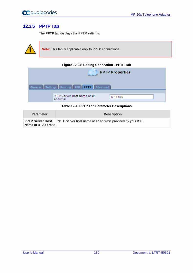
User's Manual 150 Document #: LTRT-50621
MP-20x Telephone Adapter
12.3.5 PPTP Tab
The PPTP tab displays the PPTP settings.
Note: This tab is applicable only to PPTP connections.
Figure 12-34: Editing Connection - PPTP Tab
Table 12-4: PPTP Tab Parameter Descriptions
Parameter Description
PPTP Server Host Name or IP Address
PPTP server host name or IP address provided by your ISP.
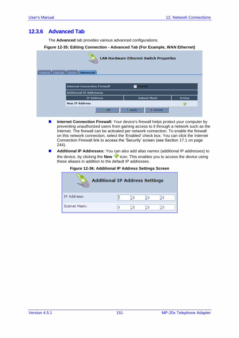
User's Manual 12. Network Connections
Version 4.5.1 151 MP-20x Telephone Adapter
12.3.6 Advanced Tab
The Advanced tab provides various advanced configurations.
Figure 12-35: Editing Connection - Advanced Tab (For Example, WAN Ethernet)
◼ Internet Connection Firewall: Your device's firewall helps protect your computer by preventing unauthorized users from gaining access to it through a network such as the Internet. The firewall can be activated per network connection. To enable the firewall on this network connection, select the 'Enabled' check box. You can click the Internet Connection Firewall link to access the ‘Security’ screen (see Section 17.1 on page 244).
◼ Additional IP Addresses: You can also add alias names (additional IP addresses) to
the device, by clicking the New icon. This enables you to access the device using these aliases in addition to the default IP addresses.
Figure 12-36: Additional IP Address Settings Screen
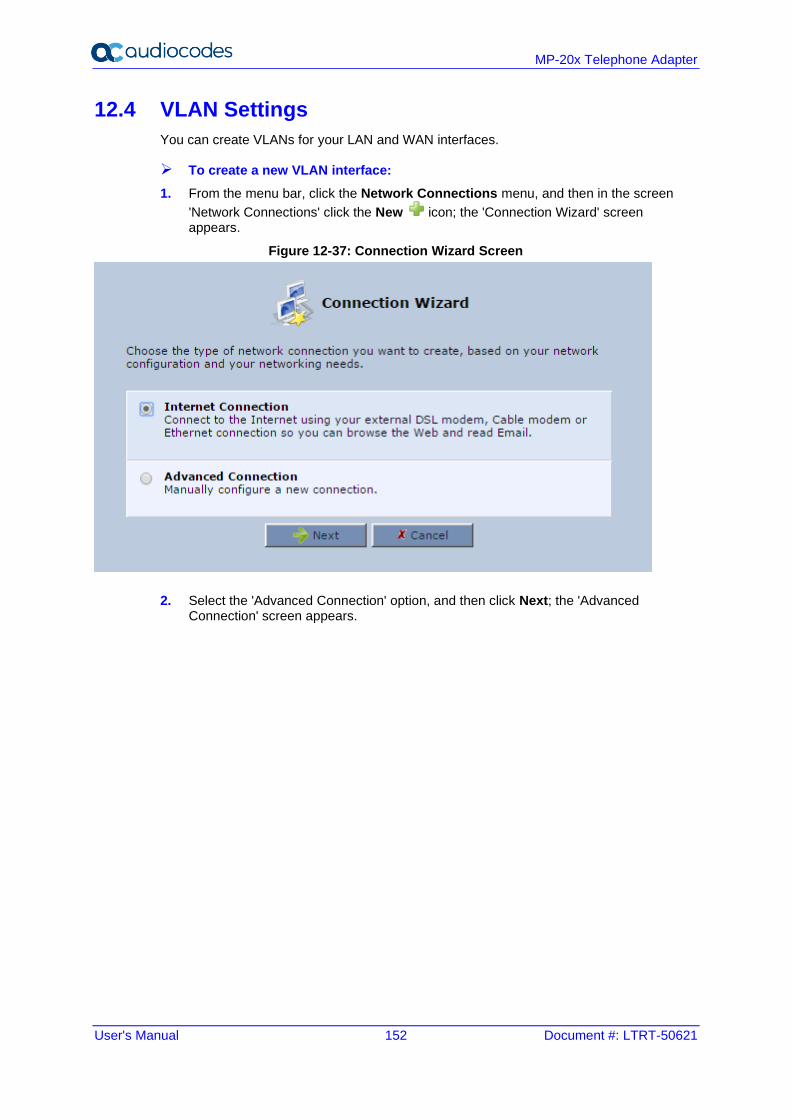
User's Manual 152 Document #: LTRT-50621
MP-20x Telephone Adapter
12.4 VLAN Settings
You can create VLANs for your LAN and WAN interfaces.
➢ To create a new VLAN interface:
1. From the menu bar, click the Network Connections menu, and then in the screen
'Network Connections' click the New icon; the 'Connection Wizard' screen appears.
Figure 12-37: Connection Wizard Screen
2. Select the 'Advanced Connection' option, and then click Next; the 'Advanced Connection' screen appears.
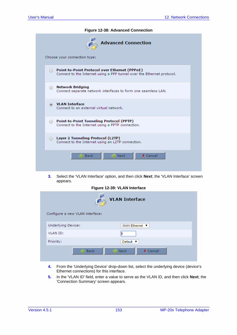
User's Manual 12. Network Connections
Version 4.5.1 153 MP-20x Telephone Adapter
Figure 12-38: Advanced Connection
3. Select the 'VLAN Interface' option, and then click Next; the 'VLAN Interface' screen appears.
Figure 12-39: VLAN Interface
4. From the 'Underlying Device' drop-down list, select the underlying device (device's Ethernet connections) for this interface.
5. In the 'VLAN ID' field, enter a value to serve as the VLAN ID, and then click Next; the 'Connection Summary' screen appears.
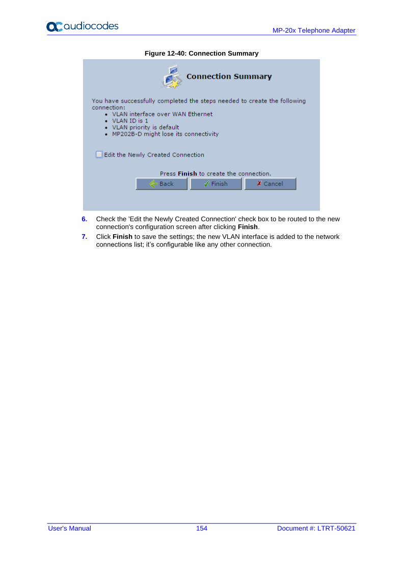
User's Manual 154 Document #: LTRT-50621
MP-20x Telephone Adapter
Figure 12-40: Connection Summary
6. Check the 'Edit the Newly Created Connection' check box to be routed to the new connection's configuration screen after clicking Finish.
7. Click Finish to save the settings; the new VLAN interface is added to the network connections list; it’s configurable like any other connection.
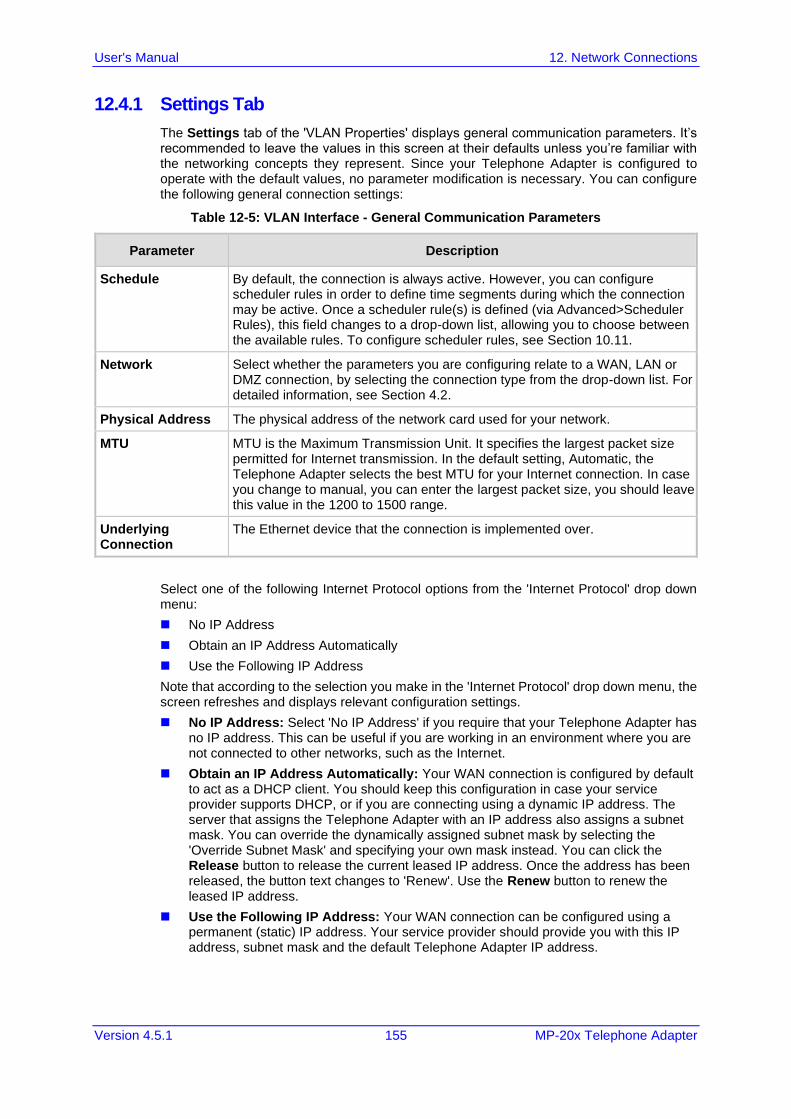
User's Manual 12. Network Connections
Version 4.5.1 155 MP-20x Telephone Adapter
12.4.1 Settings Tab
The Settings tab of the 'VLAN Properties' displays general communication parameters. It’s recommended to leave the values in this screen at their defaults unless you’re familiar with the networking concepts they represent. Since your Telephone Adapter is configured to operate with the default values, no parameter modification is necessary. You can configure the following general connection settings:
Table 12-5: VLAN Interface - General Communication Parameters
Parameter Description
Schedule By default, the connection is always active. However, you can configure scheduler rules in order to define time segments during which the connection may be active. Once a scheduler rule(s) is defined (via Advanced>Scheduler Rules), this field changes to a drop-down list, allowing you to choose between the available rules. To configure scheduler rules, see Section 10.11.
Network Select whether the parameters you are configuring relate to a WAN, LAN or DMZ connection, by selecting the connection type from the drop-down list. For detailed information, see Section 4.2.
Physical Address The physical address of the network card used for your network.
MTU MTU is the Maximum Transmission Unit. It specifies the largest packet size permitted for Internet transmission. In the default setting, Automatic, the Telephone Adapter selects the best MTU for your Internet connection. In case you change to manual, you can enter the largest packet size, you should leave this value in the 1200 to 1500 range.
Underlying Connection
The Ethernet device that the connection is implemented over.
Select one of the following Internet Protocol options from the 'Internet Protocol' drop down menu:
◼ No IP Address
◼ Obtain an IP Address Automatically
◼ Use the Following IP Address
Note that according to the selection you make in the 'Internet Protocol' drop down menu, the screen refreshes and displays relevant configuration settings.
◼ No IP Address: Select 'No IP Address' if you require that your Telephone Adapter has no IP address. This can be useful if you are working in an environment where you are not connected to other networks, such as the Internet.
◼ Obtain an IP Address Automatically: Your WAN connection is configured by default to act as a DHCP client. You should keep this configuration in case your service provider supports DHCP, or if you are connecting using a dynamic IP address. The server that assigns the Telephone Adapter with an IP address also assigns a subnet mask. You can override the dynamically assigned subnet mask by selecting the 'Override Subnet Mask' and specifying your own mask instead. You can click the Release button to release the current leased IP address. Once the address has been released, the button text changes to 'Renew'. Use the Renew button to renew the leased IP address.
◼ Use the Following IP Address: Your WAN connection can be configured using a permanent (static) IP address. Your service provider should provide you with this IP address, subnet mask and the default Telephone Adapter IP address.
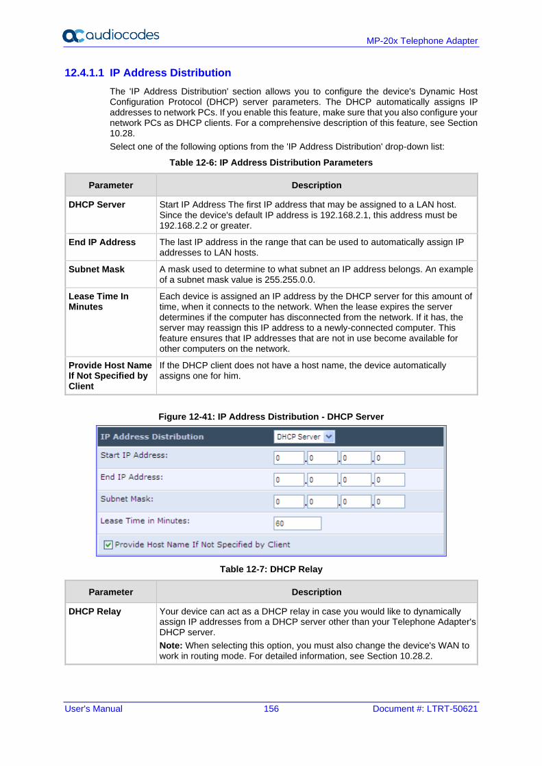
User's Manual 156 Document #: LTRT-50621
MP-20x Telephone Adapter
12.4.1.1 IP Address Distribution
The 'IP Address Distribution' section allows you to configure the device's Dynamic Host Configuration Protocol (DHCP) server parameters. The DHCP automatically assigns IP addresses to network PCs. If you enable this feature, make sure that you also configure your network PCs as DHCP clients. For a comprehensive description of this feature, see Section 10.28.
Select one of the following options from the 'IP Address Distribution' drop-down list:
Table 12-6: IP Address Distribution Parameters
Parameter Description
DHCP Server Start IP Address The first IP address that may be assigned to a LAN host. Since the device's default IP address is 192.168.2.1, this address must be 192.168.2.2 or greater.
End IP Address The last IP address in the range that can be used to automatically assign IP addresses to LAN hosts.
Subnet Mask A mask used to determine to what subnet an IP address belongs. An example of a subnet mask value is 255.255.0.0.
Lease Time In Minutes
Each device is assigned an IP address by the DHCP server for this amount of time, when it connects to the network. When the lease expires the server determines if the computer has disconnected from the network. If it has, the server may reassign this IP address to a newly-connected computer. This feature ensures that IP addresses that are not in use become available for other computers on the network.
Provide Host Name If Not Specified by Client
If the DHCP client does not have a host name, the device automatically assigns one for him.
Figure 12-41: IP Address Distribution - DHCP Server
Table 12-7: DHCP Relay
Parameter Description
DHCP Relay Your device can act as a DHCP relay in case you would like to dynamically assign IP addresses from a DHCP server other than your Telephone Adapter's DHCP server.
Note: When selecting this option, you must also change the device's WAN to work in routing mode. For detailed information, see Section 10.28.2.
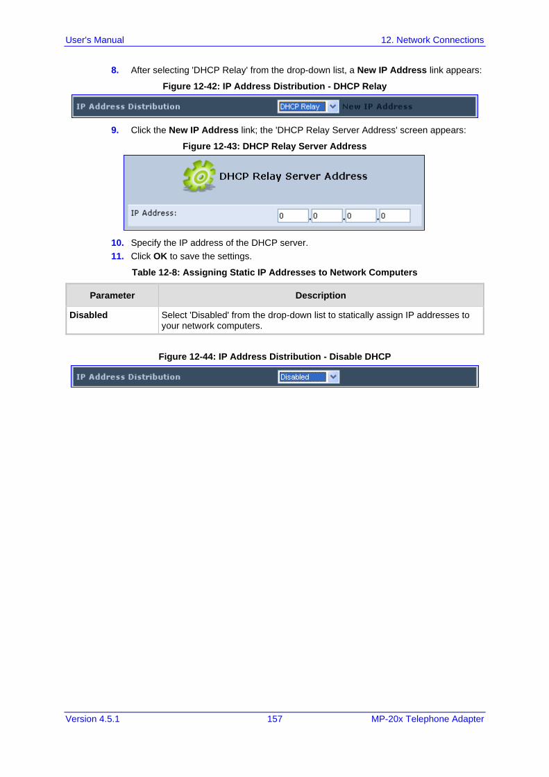
User's Manual 12. Network Connections
Version 4.5.1 157 MP-20x Telephone Adapter
8. After selecting 'DHCP Relay' from the drop-down list, a New IP Address link appears:
Figure 12-42: IP Address Distribution - DHCP Relay
9. Click the New IP Address link; the 'DHCP Relay Server Address' screen appears:
Figure 12-43: DHCP Relay Server Address
10. Specify the IP address of the DHCP server.
11. Click OK to save the settings.
Table 12-8: Assigning Static IP Addresses to Network Computers
Parameter Description
Disabled Select 'Disabled' from the drop-down list to statically assign IP addresses to your network computers.
Figure 12-44: IP Address Distribution - Disable DHCP
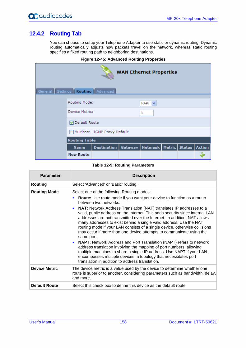
User's Manual 158 Document #: LTRT-50621
MP-20x Telephone Adapter
12.4.2 Routing Tab
You can choose to setup your Telephone Adapter to use static or dynamic routing. Dynamic routing automatically adjusts how packets travel on the network, whereas static routing specifies a fixed routing path to neighboring destinations.
Figure 12-45: Advanced Routing Properties
Table 12-9: Routing Parameters
Parameter Description
Routing Select 'Advanced' or 'Basic' routing.
Routing Mode Select one of the following Routing modes:
▪ Route: Use route mode if you want your device to function as a router between two networks.
▪ NAT: Network Address Translation (NAT) translates IP addresses to a valid, public address on the Internet. This adds security since internal LAN addresses are not transmitted over the Internet. In addition, NAT allows many addresses to exist behind a single valid address. Use the NAT routing mode if your LAN consists of a single device, otherwise collisions may occur if more than one device attempts to communicate using the same port.
▪ NAPT: Network Address and Port Translation (NAPT) refers to network address translation involving the mapping of port numbers, allowing multiple machines to share a single IP address. Use NAPT if your LAN encompasses multiple devices, a topology that necessitates port translation in addition to address translation.
Device Metric The device metric is a value used by the device to determine whether one route is superior to another, considering parameters such as bandwidth, delay, and more.
Default Route Select this check box to define this device as the default route.
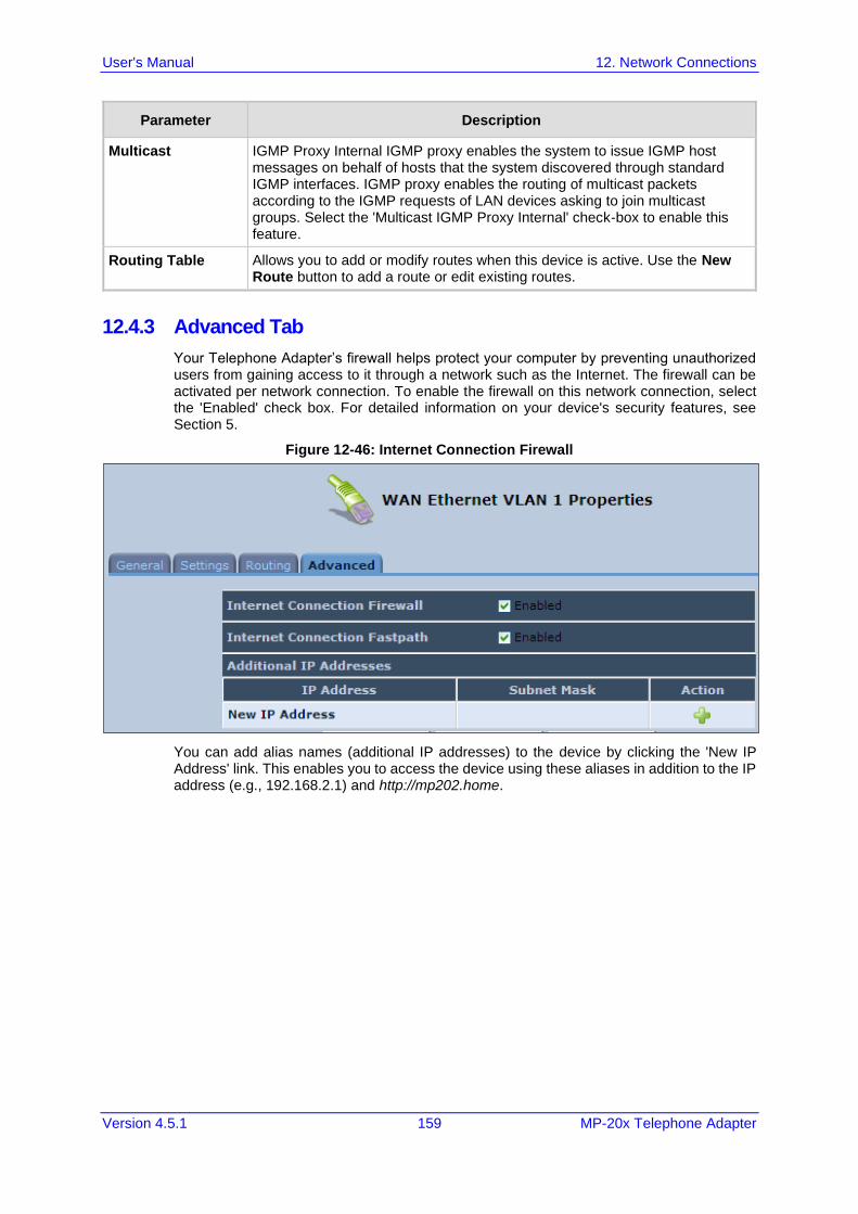
User's Manual 12. Network Connections
Version 4.5.1 159 MP-20x Telephone Adapter
Parameter Description
Multicast IGMP Proxy Internal IGMP proxy enables the system to issue IGMP host messages on behalf of hosts that the system discovered through standard IGMP interfaces. IGMP proxy enables the routing of multicast packets according to the IGMP requests of LAN devices asking to join multicast groups. Select the 'Multicast IGMP Proxy Internal' check-box to enable this feature.
Routing Table Allows you to add or modify routes when this device is active. Use the New Route button to add a route or edit existing routes.
12.4.3 Advanced Tab
Your Telephone Adapter’s firewall helps protect your computer by preventing unauthorized users from gaining access to it through a network such as the Internet. The firewall can be activated per network connection. To enable the firewall on this network connection, select the 'Enabled' check box. For detailed information on your device's security features, see Section 5.
Figure 12-46: Internet Connection Firewall
You can add alias names (additional IP addresses) to the device by clicking the 'New IP Address' link. This enables you to access the device using these aliases in addition to the IP address (e.g., 192.168.2.1) and http://mp202.home.
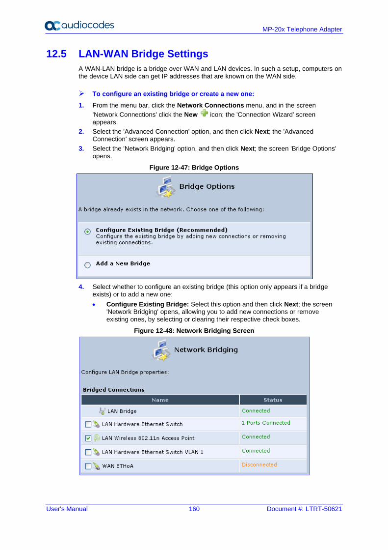
User's Manual 160 Document #: LTRT-50621
MP-20x Telephone Adapter
12.5 LAN-WAN Bridge Settings
A WAN-LAN bridge is a bridge over WAN and LAN devices. In such a setup, computers on the device LAN side can get IP addresses that are known on the WAN side.
➢ To configure an existing bridge or create a new one:
1. From the menu bar, click the Network Connections menu, and in the screen
'Network Connections' click the New icon; the 'Connection Wizard' screen appears.
2. Select the 'Advanced Connection' option, and then click Next; the 'Advanced Connection' screen appears.
3. Select the 'Network Bridging' option, and then click Next; the screen 'Bridge Options' opens.
Figure 12-47: Bridge Options
4. Select whether to configure an existing bridge (this option only appears if a bridge exists) or to add a new one:
• Configure Existing Bridge: Select this option and then click Next; the screen 'Network Bridging' opens, allowing you to add new connections or remove existing ones, by selecting or clearing their respective check boxes.
Figure 12-48: Network Bridging Screen
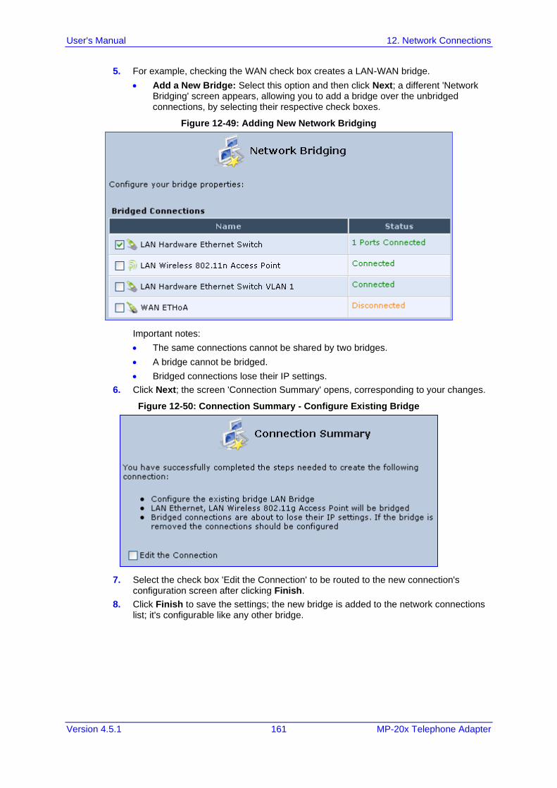
User's Manual 12. Network Connections
Version 4.5.1 161 MP-20x Telephone Adapter
5. For example, checking the WAN check box creates a LAN-WAN bridge.
• Add a New Bridge: Select this option and then click Next; a different 'Network Bridging' screen appears, allowing you to add a bridge over the unbridged connections, by selecting their respective check boxes.
Figure 12-49: Adding New Network Bridging
Important notes:
• The same connections cannot be shared by two bridges.
• A bridge cannot be bridged.
• Bridged connections lose their IP settings.
6. Click Next; the screen 'Connection Summary' opens, corresponding to your changes.
Figure 12-50: Connection Summary - Configure Existing Bridge
7. Select the check box 'Edit the Connection' to be routed to the new connection's configuration screen after clicking Finish.
8. Click Finish to save the settings; the new bridge is added to the network connections list; it's configurable like any other bridge.
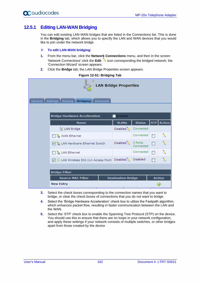
User's Manual 162 Document #: LTRT-50621
MP-20x Telephone Adapter
12.5.1 Editing LAN-WAN Bridging
You can edit existing LAN-WAN bridges that are listed in the Connections list. This is done in the Bridging tab, which allows you to specify the LAN and WAN devices that you would like to join under the network bridge.
➢ To edit LAN-WAN bridging:
1. From the menu bar, click the Network Connections menu, and then in the screen
'Network Connections' click the Edit icon corresponding the bridged network; the 'Connection Wizard' screen appears.
2. Click the Bridge tab; the LAN Bridge Properties screen appears.
Figure 12-51: Bridging Tab
3. Select the check boxes corresponding to the connection names that you want to bridge, or clear the check boxes of connections that you do not want to bridge.
4. Select the ‘Bridge Hardware Acceleration’ check box to utilize the Fastpath algorithm, which enhances packet flow, resulting in faster communication between the LAN and the WAN.
5. Select the 'STP' check box to enable the Spanning Tree Protocol (STP) on the device. You should use this to ensure that there are no loops in your network configuration, and apply these settings if your network consists of multiple switches, or other bridges apart from those created by the device
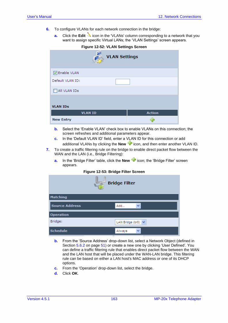
User's Manual 12. Network Connections
Version 4.5.1 163 MP-20x Telephone Adapter
6. To configure VLANs for each network connection in the bridge:
a. Click the Edit icon in the 'VLANs' column corresponding to a network that you want to assign specific Virtual LANs; the ‘VLAN Settings’ screen appears.
Figure 12-52: VLAN Settings Screen
b. Select the ‘Enable VLAN’ check box to enable VLANs on this connection; the screen refreshes and additional parameters appear.
c. In the ‘Default VLAN ID’ field, enter a VLAN ID for this connection or add
additional VLANs by clicking the New icon, and then enter another VLAN ID.
7. To create a traffic filtering rule on the bridge to enable direct packet flow between the WAN and the LAN (i.e., Bridge Filtering):
a. In the ‘Bridge Filter’ table, click the New icon; the ‘Bridge Filter’ screen appears.
Figure 12-53: Bridge Filter Screen
b. From the ‘Source Address’ drop-down list, select a Network Object (defined in Section 5.6.2 on page 51) or create a new one by clicking ‘User Defined’. You can define a traffic filtering rule that enables direct packet flow between the WAN and the LAN host that will be placed under the WAN-LAN bridge. This filtering rule can be based on either a LAN host's MAC address or one of its DHCP options.
c. From the 'Operation' drop-down list, select the bridge.
d. Click OK.

User's Manual 164 Document #: LTRT-50621
MP-20x Telephone Adapter
This page is intentionally left blank.
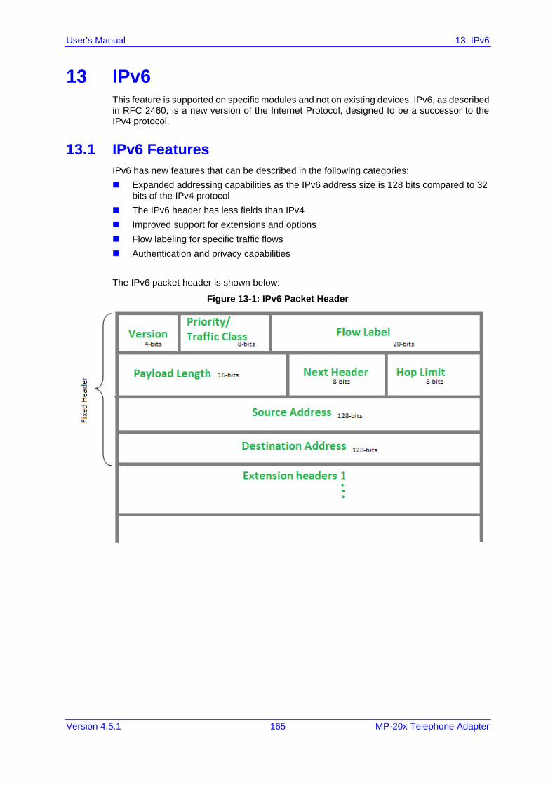
User's Manual 13. IPv6
Version 4.5.1 165 MP-20x Telephone Adapter
13 IPv6 This feature is supported on specific modules and not on existing devices. IPv6, as described in RFC 2460, is a new version of the Internet Protocol, designed to be a successor to the IPv4 protocol.
13.1 IPv6 Features
IPv6 has new features that can be described in the following categories:
◼ Expanded addressing capabilities as the IPv6 address size is 128 bits compared to 32 bits of the IPv4 protocol
◼ The IPv6 header has less fields than IPv4
◼ Improved support for extensions and options
◼ Flow labeling for specific traffic flows
◼ Authentication and privacy capabilities
The IPv6 packet header is shown below:
Figure 13-1: IPv6 Packet Header
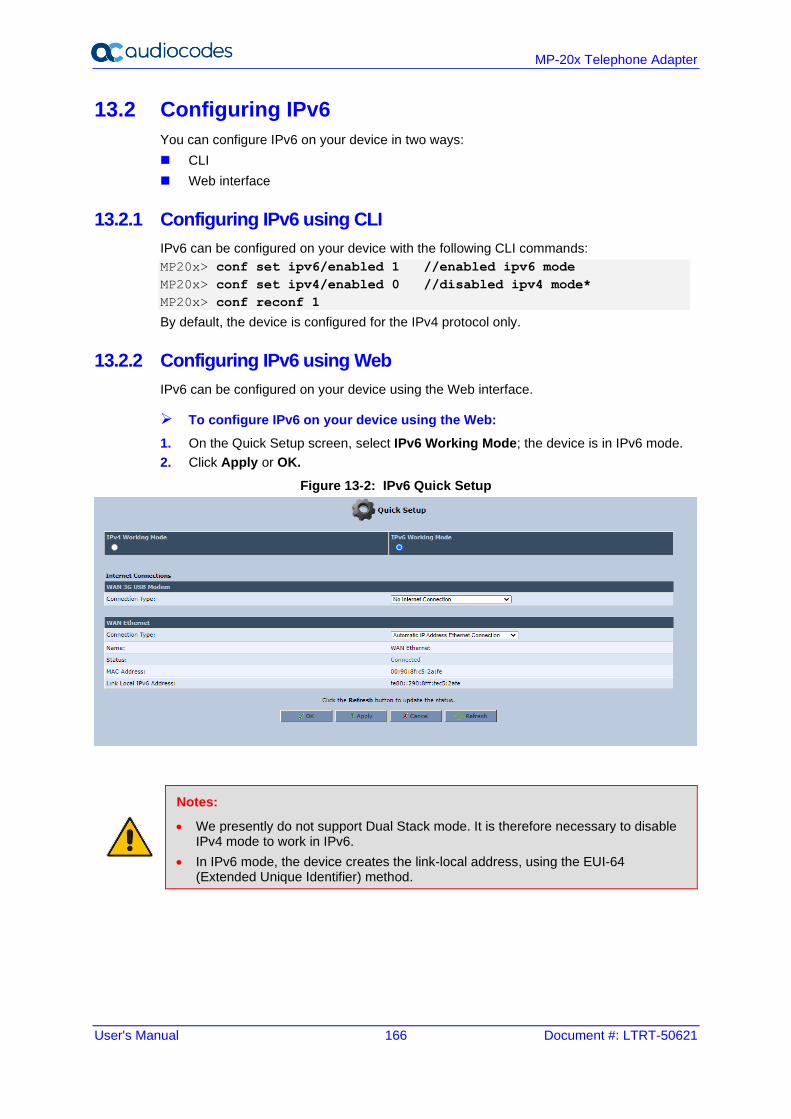
User's Manual 166 Document #: LTRT-50621
MP-20x Telephone Adapter
13.2 Configuring IPv6
You can configure IPv6 on your device in two ways:
◼ CLI
◼ Web interface
13.2.1 Configuring IPv6 using CLI
IPv6 can be configured on your device with the following CLI commands:
MP20x> conf set ipv6/enabled 1 //enabled ipv6 mode
MP20x> conf set ipv4/enabled 0 //disabled ipv4 mode*
MP20x> conf reconf 1
By default, the device is configured for the IPv4 protocol only.
13.2.2 Configuring IPv6 using Web
IPv6 can be configured on your device using the Web interface.
➢ To configure IPv6 on your device using the Web:
1. On the Quick Setup screen, select IPv6 Working Mode; the device is in IPv6 mode.
2. Click Apply or OK.
Figure 13-2: IPv6 Quick Setup
Notes:
• We presently do not support Dual Stack mode. It is therefore necessary to disable IPv4 mode to work in IPv6.
• In IPv6 mode, the device creates the link-local address, using the EUI-64 (Extended Unique Identifier) method.

User's Manual 13. IPv6
Version 4.5.1 167 MP-20x Telephone Adapter
13.3 Configuring Connections on IPv6
13.3.1 Configuring SLACC
The procedure below describes how to connect to the Internet by automatically obtaining a WAN IPv6 address from Stateless Address Autoconfiguration (SLAAC). SLAAC is one of the most convenient methods to assign an IP address automatically and is the defult connection when the device is enabled. For more information, refer to RFC 4862.
You can configure SLACC (Stateless DHCP Connection) on your device in two ways:
◼ CLI
◼ Web interface
13.3.1.1 Configuring Stateless IP Address using CLI
The stateless IP address can be configured on your device with the following CLI commands:
MP20x> conf set dev/eth1/ipv6/accept_ra 1
MP20x> conf set dev/eth1/ipv6/dhcp/enabled 1
MP20x> conf reconf 1
13.3.1.2 Configuring Stateless IP Address using Web
The stateless IP address can be configured on your device with the Web interface.
➢ To configure the stateless IP address using the Web interface:
1. From the menu bar, click Network Connections; the WAN Ethernet Properties screen appears.
2. Click WAN Ethernet.
3. Click the IPv6 tab.
Figure 13-3: WAN Ethernet Properties
4. Enable Accept Router Advertisements.
5. Enable Dynamic Negotiation (DHCP/SLAAC).
6. Click OK or Apply to confirm your settings.
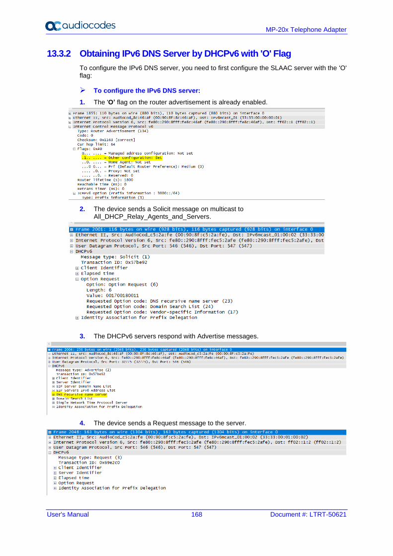
User's Manual 168 Document #: LTRT-50621
MP-20x Telephone Adapter
13.3.2 Obtaining IPv6 DNS Server by DHCPv6 with 'O' Flag
To configure the IPv6 DNS server, you need to first configure the SLAAC server with the 'O' flag:
➢ To configure the IPv6 DNS server:
1. The 'O’ flag on the router advertisement is already enabled.
2. The device sends a Solicit message on multicast to All_DHCP_Relay_Agents_and_Servers.
3. The DHCPv6 servers respond with Advertise messages.
4. The device sends a Request message to the server.
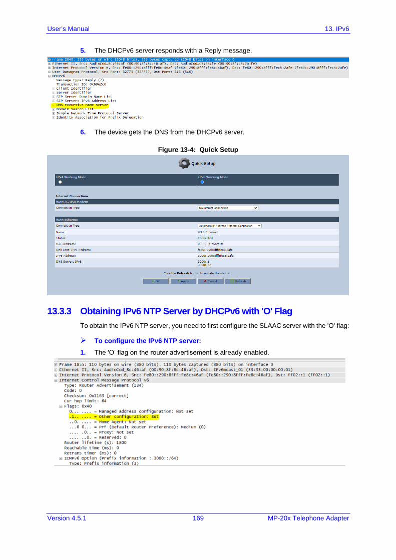
User's Manual 13. IPv6
Version 4.5.1 169 MP-20x Telephone Adapter
5. The DHCPv6 server responds with a Reply message.
6. The device gets the DNS from the DHCPv6 server.
Figure 13-4: Quick Setup
13.3.3 Obtaining IPv6 NTP Server by DHCPv6 with 'O' Flag
To obtain the IPv6 NTP server, you need to first configure the SLAAC server with the 'O' flag:
➢ To configure the IPv6 NTP server:
1. The 'O’ flag on the router advertisement is already enabled.
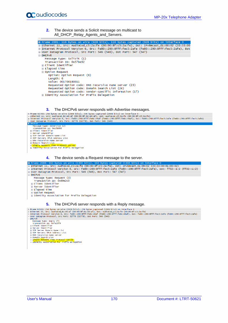
User's Manual 170 Document #: LTRT-50621
MP-20x Telephone Adapter
2. The device sends a Solicit message on multicast to All_DHCP_Relay_Agents_and_Servers.
3. The DHCPv6 server responds with Advertise messages.
4. The device sends a Request message to the server.
5. The DHCPv6 server responds with a Reply message.
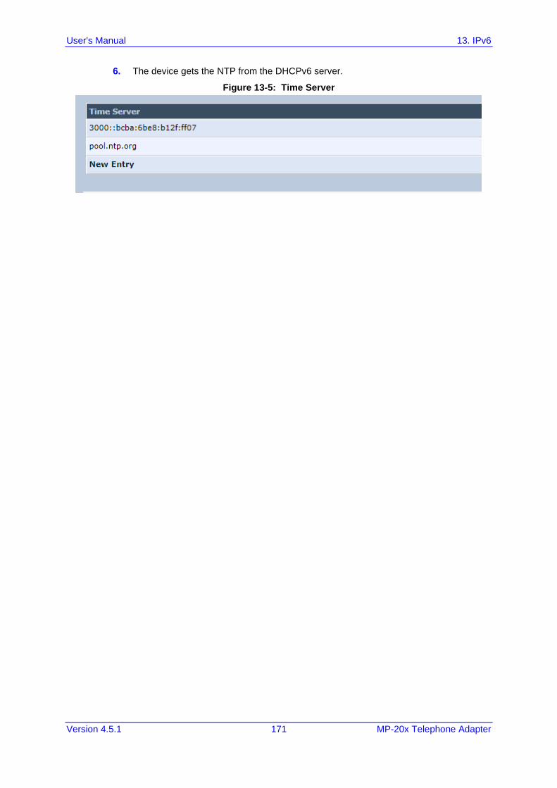
User's Manual 13. IPv6
Version 4.5.1 171 MP-20x Telephone Adapter
6. The device gets the NTP from the DHCPv6 server.
Figure 13-5: Time Server
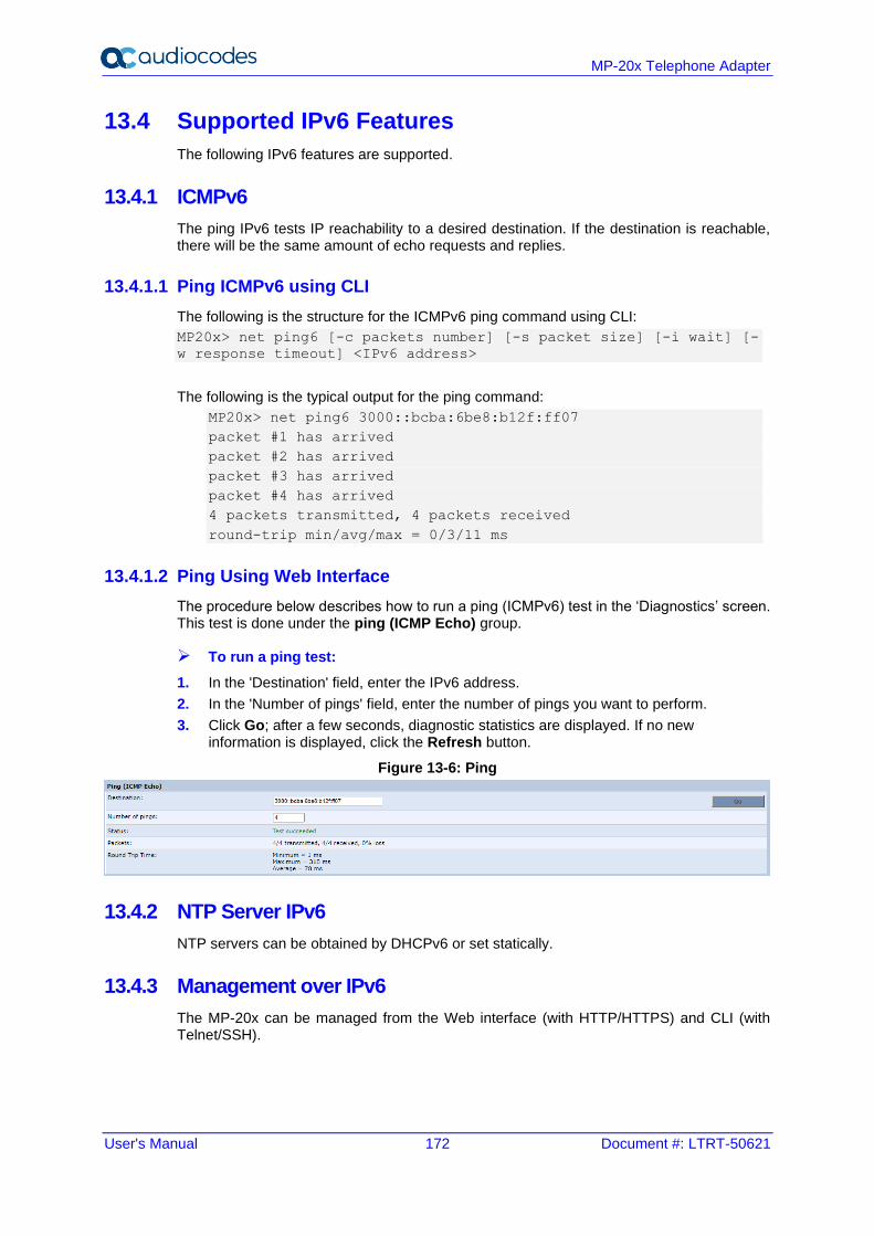
User's Manual 172 Document #: LTRT-50621
MP-20x Telephone Adapter
13.4 Supported IPv6 Features
The following IPv6 features are supported.
13.4.1 ICMPv6
The ping IPv6 tests IP reachability to a desired destination. If the destination is reachable, there will be the same amount of echo requests and replies.
13.4.1.1 Ping ICMPv6 using CLI
The following is the structure for the ICMPv6 ping command using CLI:
MP20x> net ping6 [-c packets number] [-s packet size] [-i wait] [-
w response timeout] <IPv6 address>
The following is the typical output for the ping command:
MP20x> net ping6 3000::bcba:6be8:b12f:ff07
packet #1 has arrived
packet #2 has arrived
packet #3 has arrived
packet #4 has arrived
4 packets transmitted, 4 packets received
round-trip min/avg/max = 0/3/11 ms
13.4.1.2 Ping Using Web Interface
The procedure below describes how to run a ping (ICMPv6) test in the ‘Diagnostics’ screen. This test is done under the ping (ICMP Echo) group.
➢ To run a ping test:
1. In the 'Destination' field, enter the IPv6 address.
2. In the 'Number of pings' field, enter the number of pings you want to perform.
3. Click Go; after a few seconds, diagnostic statistics are displayed. If no new information is displayed, click the Refresh button.
Figure 13-6: Ping
13.4.2 NTP Server IPv6
NTP servers can be obtained by DHCPv6 or set statically.
13.4.3 Management over IPv6
The MP-20x can be managed from the Web interface (with HTTP/HTTPS) and CLI (with Telnet/SSH).
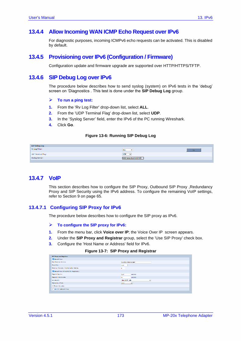
User's Manual 13. IPv6
Version 4.5.1 173 MP-20x Telephone Adapter
13.4.4 Allow Incoming WAN ICMP Echo Request over IPv6
For diagnostic purposes, incoming ICMPv6 echo requests can be activated. This is disabled by default.
13.4.5 Provisioning over IPv6 (Configuration / Firmware)
Configuration update and firmware upgrade are supported over HTTP/HTTPS/TFTP.
13.4.6 SIP Debug Log over IPv6
The procedure below describes how to send syslog (system) on IPv6 tests in the ‘debug’ screen on ‘Diagnostics . This test is done under the SIP Debug Log group.
➢ To run a ping test:
1. From the 'Rv Log Filter' drop-down list, select ALL.
2. From the 'UDP Terminal Flag' drop-down list, select UDP.
3. In the ‘Syslog Server’ field, enter the IPv6 of the PC running Wireshark.
4. Click Go.
Figure 13-6: Running SIP Debug Log
13.4.7 VoIP
This section describes how to configure the SIP Proxy, Outbound SIP Proxy ,Redundancy Proxy and SIP Security using the IPv6 address. To configure the remaining VoIP settings, refer to Section 9 on page 65.
13.4.7.1 Configuring SIP Proxy for IPv6
The procedure below describes how to configure the SIP proxy as IPv6.
➢ To configure the SIP proxy for IPv6:
1. From the menu bar, click Voice over IP; the Voice Over IP screen appears.
2. Under the SIP Proxy and Registrar group, select the 'Use SIP Proxy' check box.
3. Configure the 'Host Name or Address' field for IPv6.
Figure 13-7: SIP Proxy and Registrar
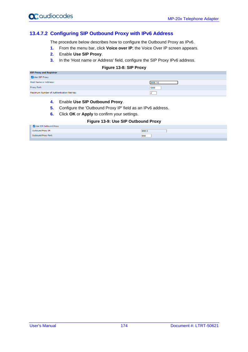
User's Manual 174 Document #: LTRT-50621
MP-20x Telephone Adapter
13.4.7.2 Configuring SIP Outbound Proxy with IPv6 Address
The procedure below describes how to configure the Outbound Proxy as IPv6.
1. From the menu bar, click Voice over IP; the Voice Over IP screen appears.
2. Enable Use SIP Proxy.
3. In the 'Host name or Address' field, configure the SIP Proxy IPv6 address.
Figure 13-8: SIP Proxy
4. Enable Use SIP Outbound Proxy.
5. Configure the 'Outbound Proxy IP' field as an IPv6 address.
6. Click OK or Apply to confirm your settings.
Figure 13-9: Use SIP Outbound Proxy
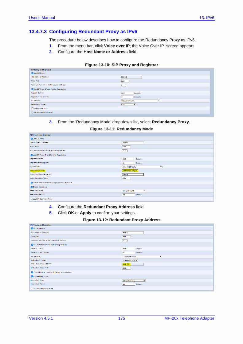
User's Manual 13. IPv6
Version 4.5.1 175 MP-20x Telephone Adapter
13.4.7.3 Configuring Redundant Proxy as IPv6
The procedure below describes how to configure the Redundancy Proxy as IPv6.
1. From the menu bar, click Voice over IP; the Voice Over IP screen appears.
2. Configure the Host Name or Address field.
Figure 13-10: SIP Proxy and Registrar
3. From the 'Redundancy Mode' drop-down list, select Redundancy Proxy.
Figure 13-11: Redundancy Mode
4. Configure the Redundant Proxy Address field.
5. Click OK or Apply to confirm your settings.
Figure 13-12: Redundant Proxy Address
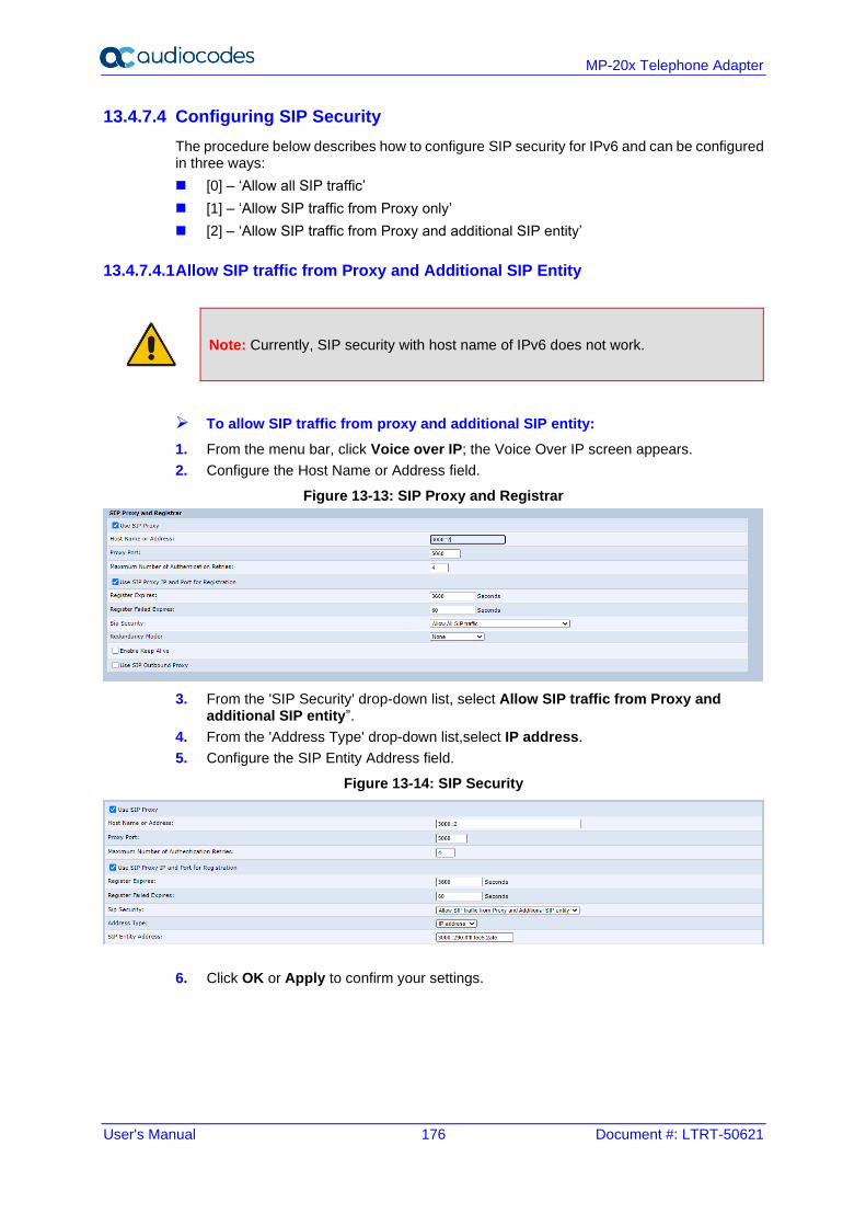
User's Manual 176 Document #: LTRT-50621
MP-20x Telephone Adapter
13.4.7.4 Configuring SIP Security
The procedure below describes how to configure SIP security for IPv6 and can be configured in three ways:
◼ [0] – ‘Allow all SIP traffic’
◼ [1] – ‘Allow SIP traffic from Proxy only’
◼ [2] – ‘Allow SIP traffic from Proxy and additional SIP entity’
13.4.7.4.1 Allow SIP traffic from Proxy and Additional SIP Entity
Note: Currently, SIP security with host name of IPv6 does not work.
➢ To allow SIP traffic from proxy and additional SIP entity:
1. From the menu bar, click Voice over IP; the Voice Over IP screen appears.
2. Configure the Host Name or Address field.
Figure 13-13: SIP Proxy and Registrar
3. From the 'SIP Security' drop-down list, select Allow SIP traffic from Proxy and additional SIP entity”.
4. From the 'Address Type' drop-down list,select IP address.
5. Configure the SIP Entity Address field.
Figure 13-14: SIP Security
6. Click OK or Apply to confirm your settings.
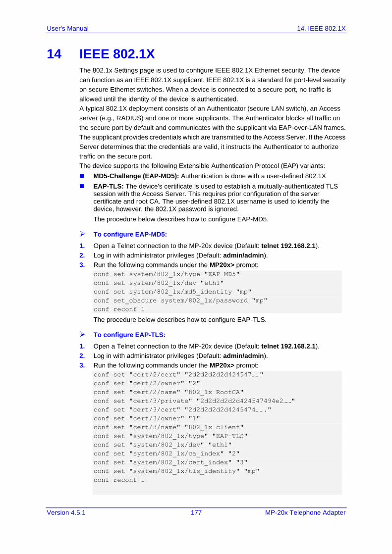
User's Manual 14. IEEE 802.1X
Version 4.5.1 177 MP-20x Telephone Adapter
14 IEEE 802.1X The 802.1x Settings page is used to configure IEEE 802.1X Ethernet security. The device
can function as an IEEE 802.1X supplicant. IEEE 802.1X is a standard for port-level security
on secure Ethernet switches. When a device is connected to a secure port, no traffic is
allowed until the identity of the device is authenticated.
A typical 802.1X deployment consists of an Authenticator (secure LAN switch), an Access
server (e.g., RADIUS) and one or more supplicants. The Authenticator blocks all traffic on
the secure port by default and communicates with the supplicant via EAP-over-LAN frames.
The supplicant provides credentials which are transmitted to the Access Server. If the Access
Server determines that the credentials are valid, it instructs the Authenticator to authorize
traffic on the secure port.
The device supports the following Extensible Authentication Protocol (EAP) variants:
◼ MD5-Challenge (EAP-MD5): Authentication is done with a user-defined 802.1X
◼ EAP-TLS: The device's certificate is used to establish a mutually-authenticated TLS session with the Access Server. This requires prior configuration of the server certificate and root CA. The user-defined 802.1X username is used to identify the device, however, the 802.1X password is ignored.
The procedure below describes how to configure EAP-MD5.
➢ To configure EAP-MD5:
1. Open a Telnet connection to the MP-20x device (Default: telnet 192.168.2.1).
2. Log in with administrator privileges (Default: admin/admin).
3. Run the following commands under the MP20x> prompt:
conf set system/802_1x/type "EAP-MD5"
conf set system/802_1x/dev "eth1"
conf set system/802_1x/md5_identity "mp"
conf set_obscure system/802_1x/password "mp"
conf reconf 1
The procedure below describes how to configure EAP-TLS.
➢ To configure EAP-TLS:
1. Open a Telnet connection to the MP-20x device (Default: telnet 192.168.2.1).
2. Log in with administrator privileges (Default: admin/admin).
3. Run the following commands under the MP20x> prompt:
conf set "cert/2/cert" "2d2d2d2d2d424547……"
conf set "cert/2/owner" "2"
conf set "cert/2/name" "802_1x RootCA"
conf set "cert/3/private" "2d2d2d2d2d424547494e2……"
conf set "cert/3/cert" "2d2d2d2d2d4245474……."
conf set "cert/3/owner" "1"
conf set "cert/3/name" "802_1x client"
conf set "system/802_1x/type" "EAP-TLS"
conf set "system/802_1x/dev" "eth1"
conf set "system/802_1x/ca_index" "2"
conf set "system/802_1x/cert_index" "3"
conf set "system/802_1x/tls_identity" "mp"
conf reconf 1
User's Manual 178 Document #: LTRT-50621
MP-20x Telephone Adapter
The procedure below describes how to disable 802.1X mode.
➢ To disable 802.1X mode:
1. Open a Telnet connection to the MP-20x device (Default: telnet 192.168.2.1).
2. Log in with administrator privileges (Default: admin/admin).
3. Run the following commands under the MP20x> prompt:
conf set "system/802_1x/type" "Disable"
conf reconf 1
Notes:
• Configuring 802.1X is only via CLI.
• When system/802_1x/dev cannot be configured, use the main default WAN.
• Disabled mode takes effect only after reboot.
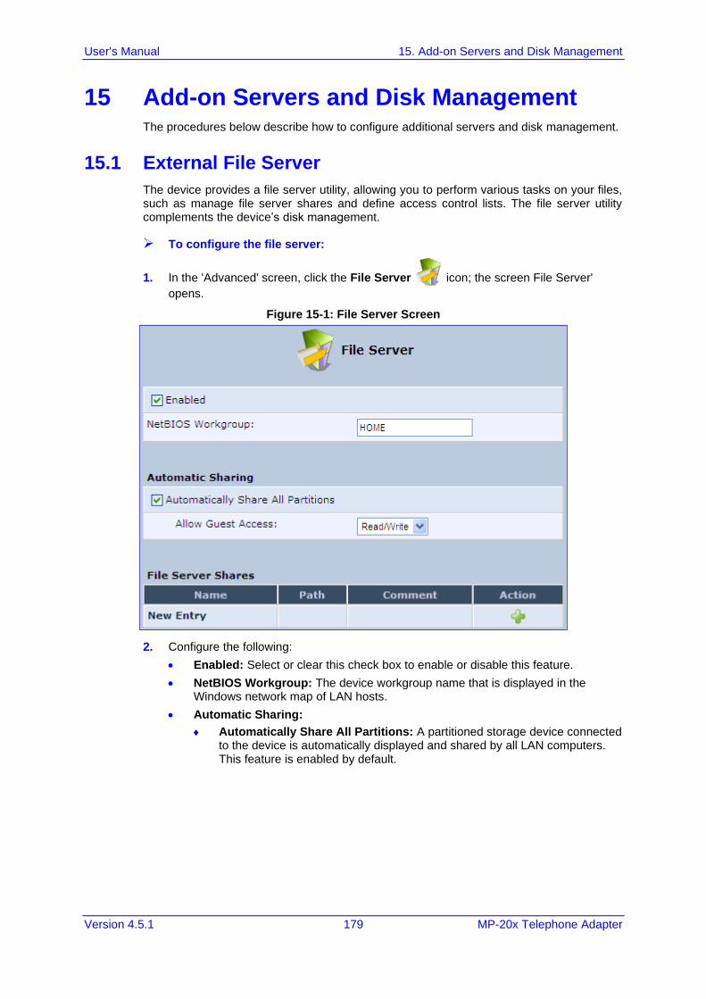
User's Manual 15. Add-on Servers and Disk Management
Version 4.5.1 179 MP-20x Telephone Adapter
15 Add-on Servers and Disk Management The procedures below describe how to configure additional servers and disk management.
15.1 External File Server
The device provides a file server utility, allowing you to perform various tasks on your files, such as manage file server shares and define access control lists. The file server utility complements the device’s disk management.
➢ To configure the file server:
1. In the 'Advanced' screen, click the File Server icon; the screen File Server'
opens.
Figure 15-1: File Server Screen
2. Configure the following:
• Enabled: Select or clear this check box to enable or disable this feature.
• NetBIOS Workgroup: The device workgroup name that is displayed in the Windows network map of LAN hosts.
• Automatic Sharing:
Automatically Share All Partitions: A partitioned storage device connected to the device is automatically displayed and shared by all LAN computers. This feature is enabled by default.
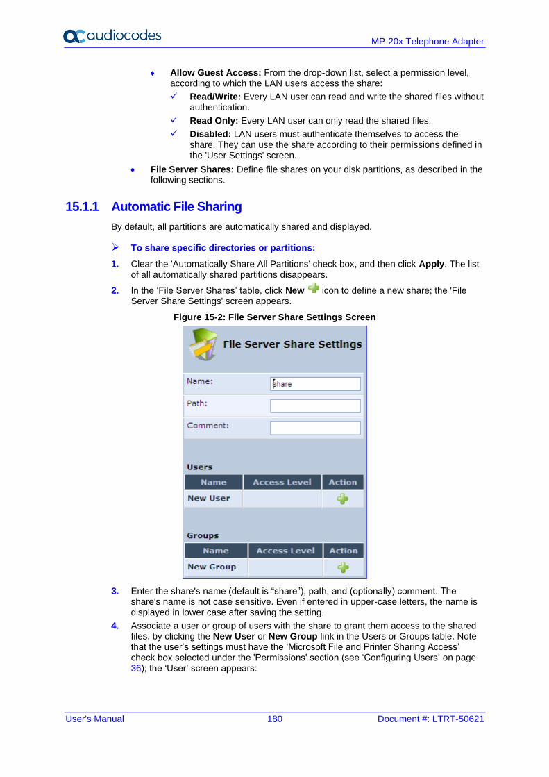
User's Manual 180 Document #: LTRT-50621
MP-20x Telephone Adapter
Allow Guest Access: From the drop-down list, select a permission level, according to which the LAN users access the share:
✓ Read/Write: Every LAN user can read and write the shared files without authentication.
✓ Read Only: Every LAN user can only read the shared files.
✓ Disabled: LAN users must authenticate themselves to access the share. They can use the share according to their permissions defined in the 'User Settings' screen.
• File Server Shares: Define file shares on your disk partitions, as described in the following sections.
15.1.1 Automatic File Sharing
By default, all partitions are automatically shared and displayed.
➢ To share specific directories or partitions:
1. Clear the 'Automatically Share All Partitions' check box, and then click Apply. The list of all automatically shared partitions disappears.
2. In the ‘File Server Shares’ table, click New icon to define a new share; the 'File Server Share Settings' screen appears.
Figure 15-2: File Server Share Settings Screen
3. Enter the share's name (default is “share”), path, and (optionally) comment. The share's name is not case sensitive. Even if entered in upper-case letters, the name is displayed in lower case after saving the setting.
4. Associate a user or group of users with the share to grant them access to the shared files, by clicking the New User or New Group link in the Users or Groups table. Note that the user’s settings must have the ‘Microsoft File and Printer Sharing Access’ check box selected under the 'Permissions' section (see ‘Configuring Users’ on page 36); the ‘User’ screen appears:
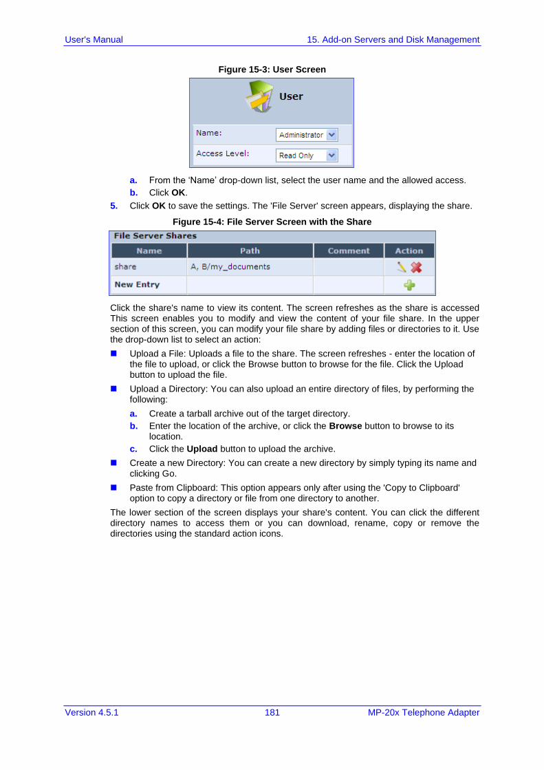
User's Manual 15. Add-on Servers and Disk Management
Version 4.5.1 181 MP-20x Telephone Adapter
Figure 15-3: User Screen
a. From the ‘Name’ drop-down list, select the user name and the allowed access.
b. Click OK.
5. Click OK to save the settings. The 'File Server' screen appears, displaying the share.
Figure 15-4: File Server Screen with the Share
Click the share's name to view its content. The screen refreshes as the share is accessed This screen enables you to modify and view the content of your file share. In the upper section of this screen, you can modify your file share by adding files or directories to it. Use the drop-down list to select an action:
◼ Upload a File: Uploads a file to the share. The screen refreshes - enter the location of the file to upload, or click the Browse button to browse for the file. Click the Upload button to upload the file.
◼ Upload a Directory: You can also upload an entire directory of files, by performing the following:
a. Create a tarball archive out of the target directory.
b. Enter the location of the archive, or click the Browse button to browse to its location.
c. Click the Upload button to upload the archive.
◼ Create a new Directory: You can create a new directory by simply typing its name and clicking Go.
◼ Paste from Clipboard: This option appears only after using the 'Copy to Clipboard' option to copy a directory or file from one directory to another.
The lower section of the screen displays your share's content. You can click the different directory names to access them or you can download, rename, copy or remove the directories using the standard action icons.
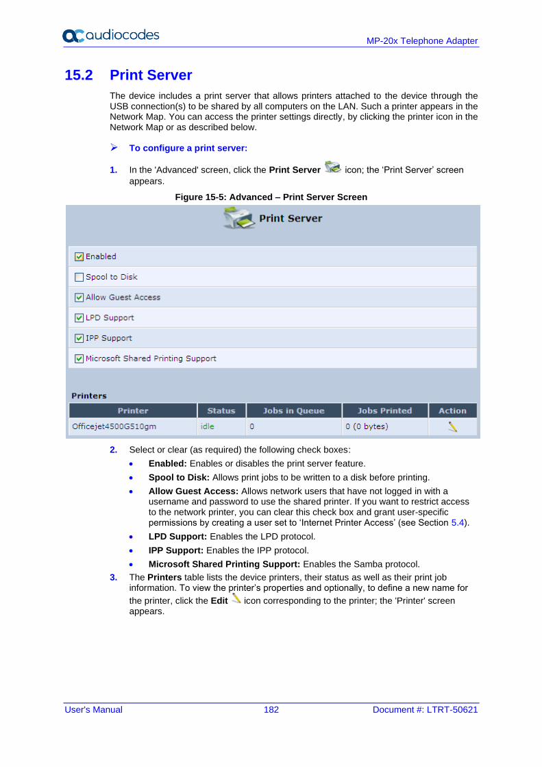
User's Manual 182 Document #: LTRT-50621
MP-20x Telephone Adapter
15.2 Print Server
The device includes a print server that allows printers attached to the device through the USB connection(s) to be shared by all computers on the LAN. Such a printer appears in the Network Map. You can access the printer settings directly, by clicking the printer icon in the Network Map or as described below.
➢ To configure a print server:
1. In the 'Advanced' screen, click the Print Server icon; the ‘Print Server’ screen
appears.
Figure 15-5: Advanced – Print Server Screen
2. Select or clear (as required) the following check boxes:
• Enabled: Enables or disables the print server feature.
• Spool to Disk: Allows print jobs to be written to a disk before printing.
• Allow Guest Access: Allows network users that have not logged in with a username and password to use the shared printer. If you want to restrict access to the network printer, you can clear this check box and grant user-specific permissions by creating a user set to ‘Internet Printer Access’ (see Section 5.4).
• LPD Support: Enables the LPD protocol.
• IPP Support: Enables the IPP protocol.
• Microsoft Shared Printing Support: Enables the Samba protocol.
3. The Printers table lists the device printers, their status as well as their print job information. To view the printer’s properties and optionally, to define a new name for
the printer, click the Edit icon corresponding to the printer; the 'Printer' screen appears.
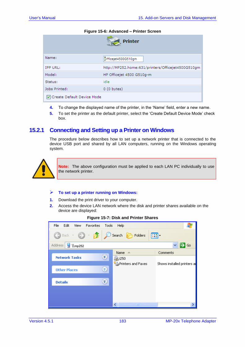
User's Manual 15. Add-on Servers and Disk Management
Version 4.5.1 183 MP-20x Telephone Adapter
Figure 15-6: Advanced – Printer Screen
4. To change the displayed name of the printer, in the ‘Name’ field, enter a new name.
5. To set the printer as the default printer, select the ‘Create Default Device Mode’ check box.
15.2.1 Connecting and Setting up a Printer on Windows
The procedure below describes how to set up a network printer that is connected to the device USB port and shared by all LAN computers, running on the Windows operating system.
Note: The above configuration must be applied to each LAN PC individually to use the network printer.
➢ To set up a printer running on Windows:
1. Download the print driver to your computer.
2. Access the device LAN network where the disk and printer shares available on the device are displayed:
Figure 15-7: Disk and Printer Shares
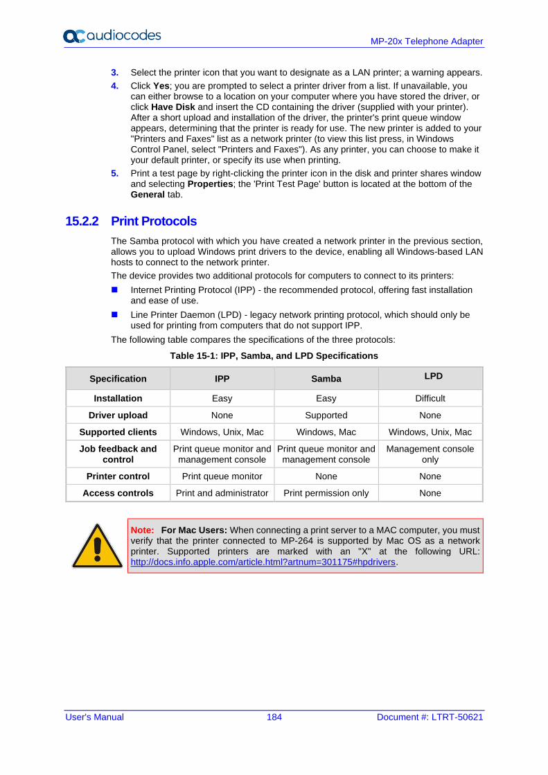
User's Manual 184 Document #: LTRT-50621
MP-20x Telephone Adapter
3. Select the printer icon that you want to designate as a LAN printer; a warning appears.
4. Click Yes; you are prompted to select a printer driver from a list. If unavailable, you can either browse to a location on your computer where you have stored the driver, or click Have Disk and insert the CD containing the driver (supplied with your printer). After a short upload and installation of the driver, the printer's print queue window appears, determining that the printer is ready for use. The new printer is added to your "Printers and Faxes" list as a network printer (to view this list press, in Windows Control Panel, select "Printers and Faxes"). As any printer, you can choose to make it your default printer, or specify its use when printing.
5. Print a test page by right-clicking the printer icon in the disk and printer shares window and selecting Properties; the 'Print Test Page' button is located at the bottom of the General tab.
15.2.2 Print Protocols
The Samba protocol with which you have created a network printer in the previous section, allows you to upload Windows print drivers to the device, enabling all Windows-based LAN hosts to connect to the network printer.
The device provides two additional protocols for computers to connect to its printers:
◼ Internet Printing Protocol (IPP) - the recommended protocol, offering fast installation and ease of use.
◼ Line Printer Daemon (LPD) - legacy network printing protocol, which should only be used for printing from computers that do not support IPP.
The following table compares the specifications of the three protocols:
Table 15-1: IPP, Samba, and LPD Specifications
Specification IPP Samba LPD
Installation Easy Easy Difficult
Driver upload None Supported None
Supported clients Windows, Unix, Mac Windows, Mac Windows, Unix, Mac
Job feedback and control
Print queue monitor and management console
Print queue monitor and management console
Management console only
Printer control Print queue monitor None None
Access controls Print and administrator Print permission only None
Note: For Mac Users: When connecting a print server to a MAC computer, you must verify that the printer connected to MP-264 is supported by Mac OS as a network printer. Supported printers are marked with an "X" at the following URL: http://docs.info.apple.com/article.html?artnum=301175#hpdrivers.
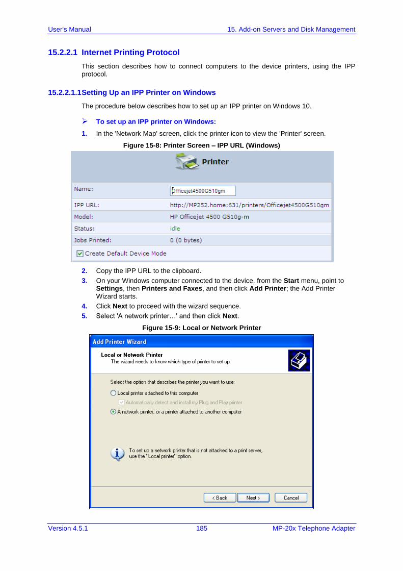
User's Manual 15. Add-on Servers and Disk Management
Version 4.5.1 185 MP-20x Telephone Adapter
15.2.2.1 Internet Printing Protocol
This section describes how to connect computers to the device printers, using the IPP protocol.
15.2.2.1.1 Setting Up an IPP Printer on Windows
The procedure below describes how to set up an IPP printer on Windows 10.
➢ To set up an IPP printer on Windows:
1. In the 'Network Map' screen, click the printer icon to view the 'Printer' screen.
Figure 15-8: Printer Screen – IPP URL (Windows)
2. Copy the IPP URL to the clipboard.
3. On your Windows computer connected to the device, from the Start menu, point to Settings, then Printers and Faxes, and then click Add Printer; the Add Printer Wizard starts.
4. Click Next to proceed with the wizard sequence.
5. Select 'A network printer…' and then click Next.
Figure 15-9: Local or Network Printer
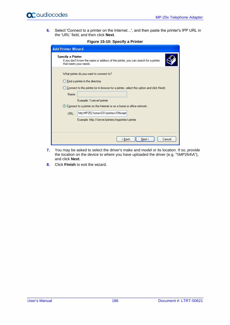
User's Manual 186 Document #: LTRT-50621
MP-20x Telephone Adapter
6. Select 'Connect to a printer on the Internet…', and then paste the printer's IPP URL in the 'URL' field, and then click Next.
Figure 15-10: Specify a Printer
7. You may be asked to select the driver's make and model or its location. If so, provide the location on the device to where you have uploaded the driver (e.g. “\\MP264\A”), and click Next.
8. Click Finish to exit the wizard.
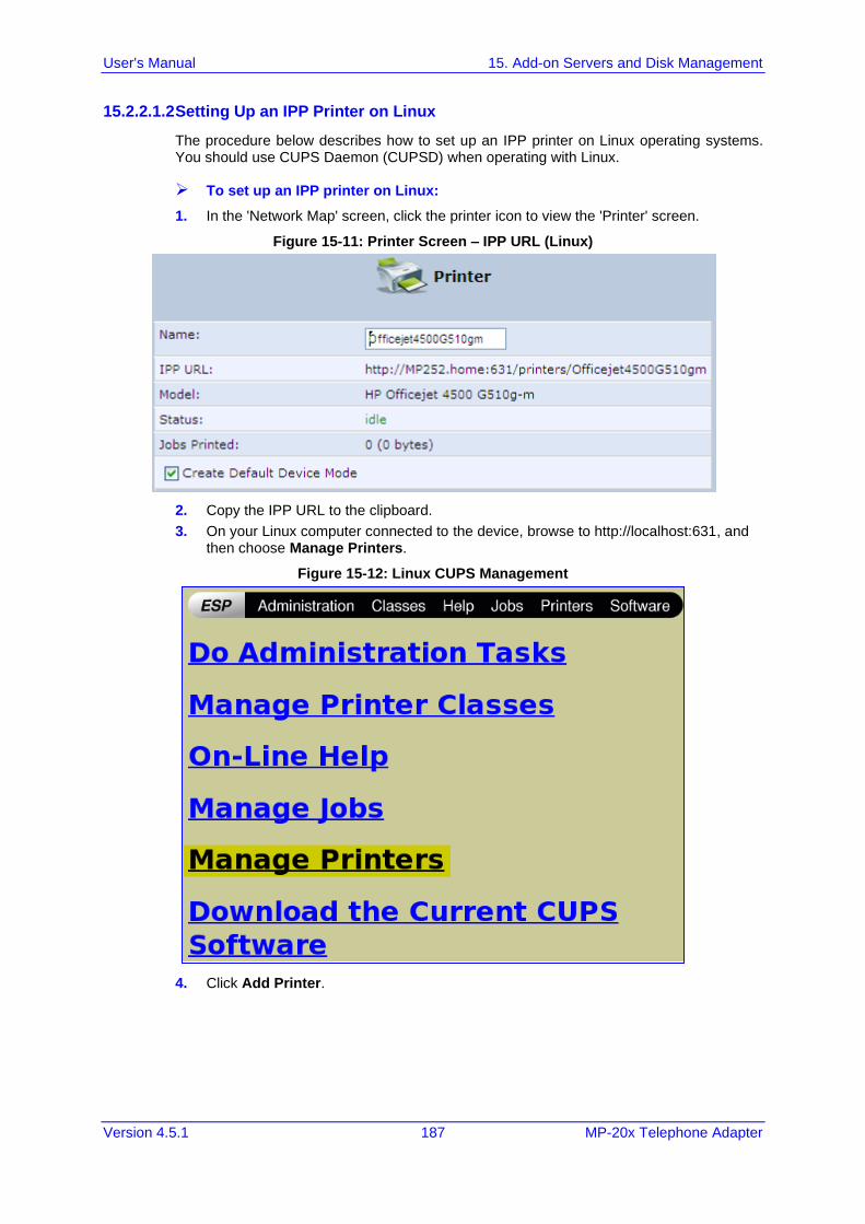
User's Manual 15. Add-on Servers and Disk Management
Version 4.5.1 187 MP-20x Telephone Adapter
15.2.2.1.2 Setting Up an IPP Printer on Linux
The procedure below describes how to set up an IPP printer on Linux operating systems. You should use CUPS Daemon (CUPSD) when operating with Linux.
➢ To set up an IPP printer on Linux:
1. In the 'Network Map' screen, click the printer icon to view the 'Printer' screen.
Figure 15-11: Printer Screen – IPP URL (Linux)
2. Copy the IPP URL to the clipboard.
3. On your Linux computer connected to the device, browse to http://localhost:631, and then choose Manage Printers.
Figure 15-12: Linux CUPS Management
4. Click Add Printer.
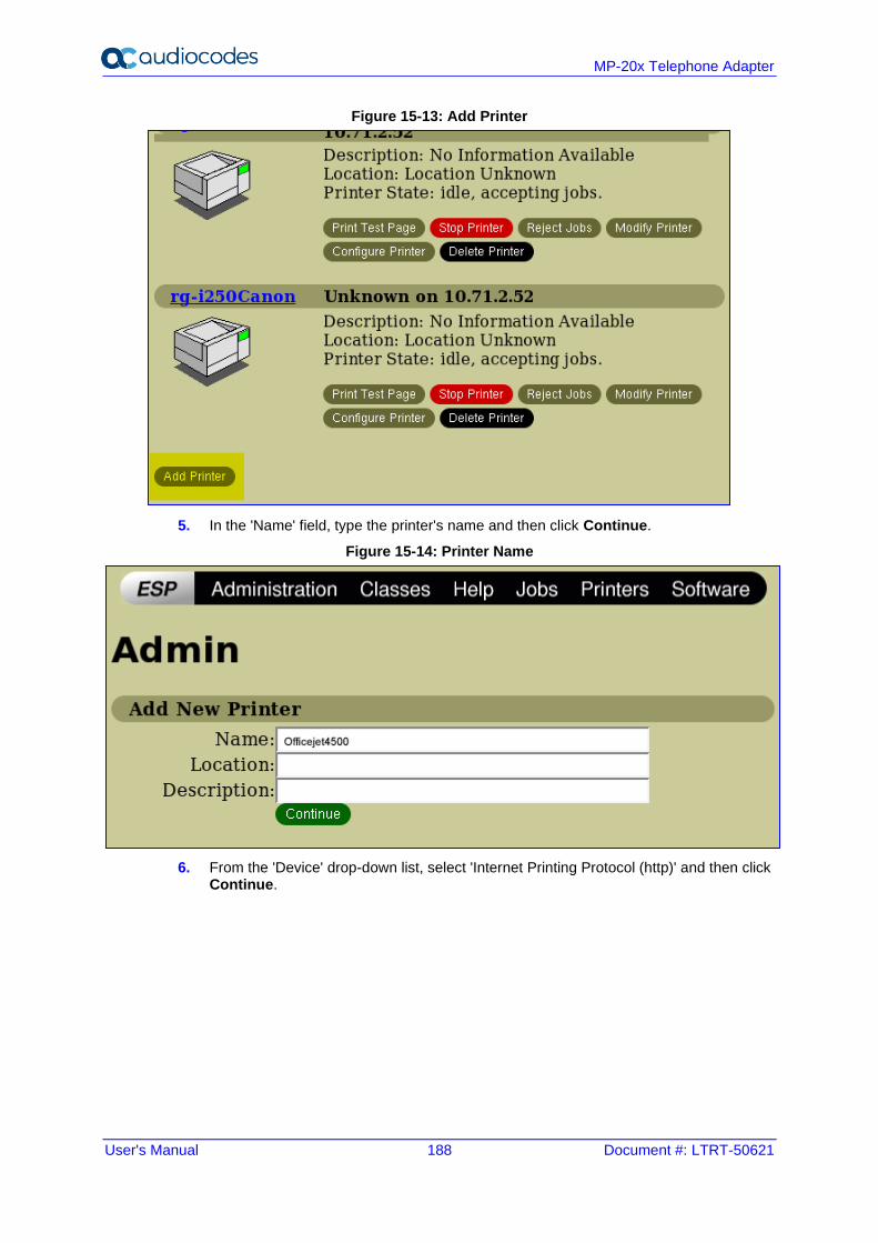
User's Manual 188 Document #: LTRT-50621
MP-20x Telephone Adapter
Figure 15-13: Add Printer
5. In the 'Name' field, type the printer's name and then click Continue.
Figure 15-14: Printer Name
6. From the 'Device' drop-down list, select 'Internet Printing Protocol (http)' and then click Continue.
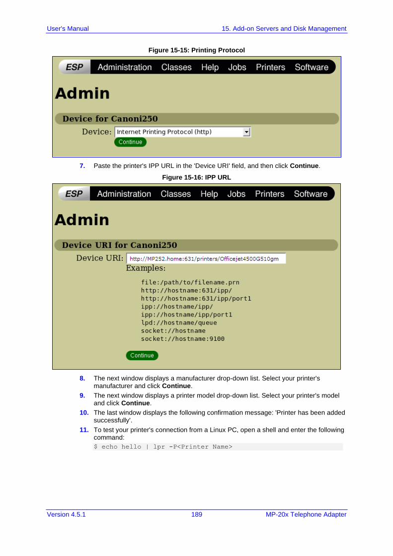
User's Manual 15. Add-on Servers and Disk Management
Version 4.5.1 189 MP-20x Telephone Adapter
Figure 15-15: Printing Protocol
7. Paste the printer's IPP URL in the 'Device URI' field, and then click Continue.
Figure 15-16: IPP URL
8. The next window displays a manufacturer drop-down list. Select your printer's manufacturer and click Continue.
9. The next window displays a printer model drop-down list. Select your printer's model and click Continue.
10. The last window displays the following confirmation message: 'Printer has been added successfully'.
11. To test your printer's connection from a Linux PC, open a shell and enter the following command:
$ echo hello | lpr -P<Printer Name>
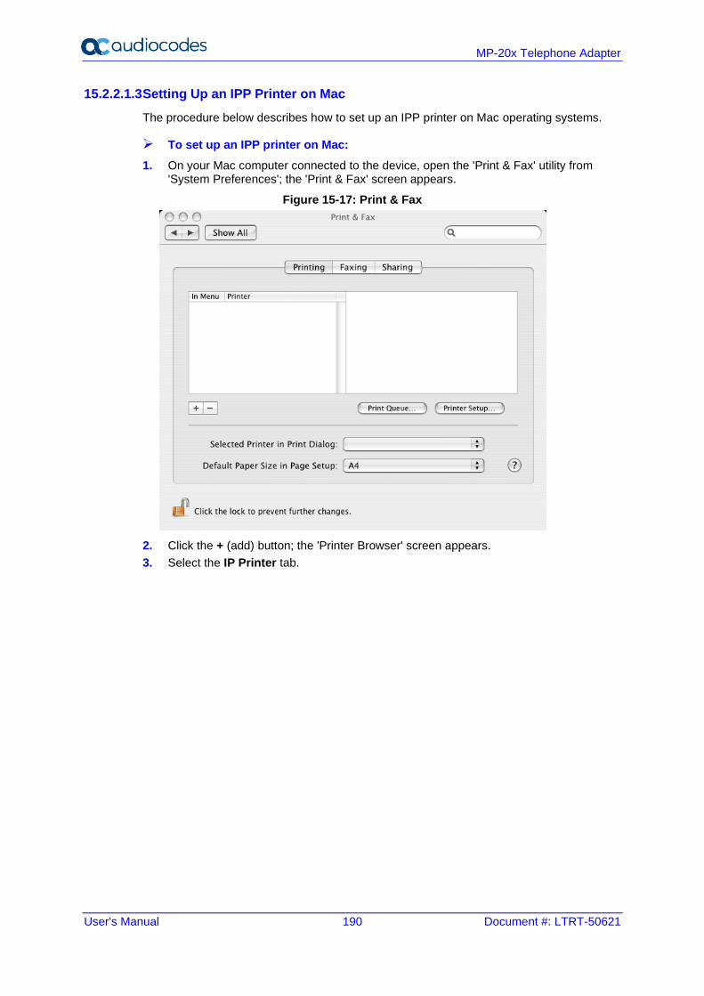
User's Manual 190 Document #: LTRT-50621
MP-20x Telephone Adapter
15.2.2.1.3 Setting Up an IPP Printer on Mac
The procedure below describes how to set up an IPP printer on Mac operating systems.
➢ To set up an IPP printer on Mac:
1. On your Mac computer connected to the device, open the 'Print & Fax' utility from 'System Preferences'; the 'Print & Fax' screen appears.
Figure 15-17: Print & Fax
2. Click the + (add) button; the 'Printer Browser' screen appears.
3. Select the IP Printer tab.
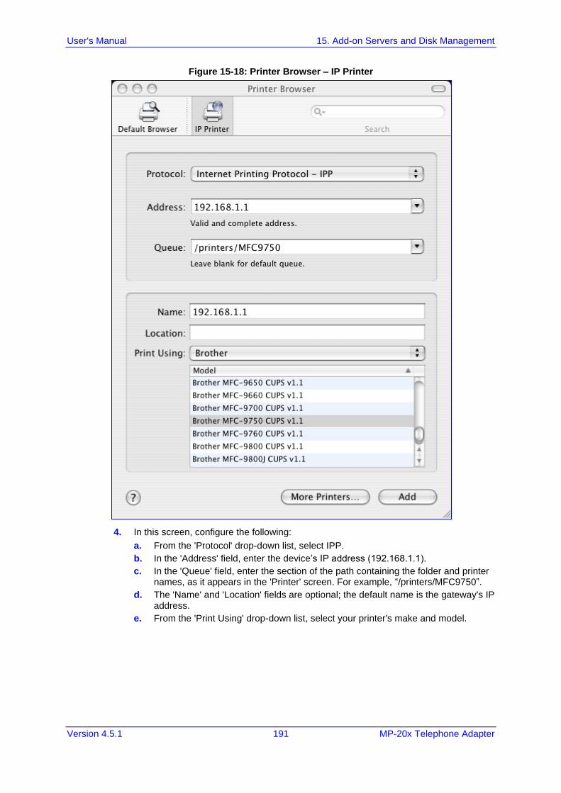
User's Manual 15. Add-on Servers and Disk Management
Version 4.5.1 191 MP-20x Telephone Adapter
Figure 15-18: Printer Browser – IP Printer
4. In this screen, configure the following:
a. From the 'Protocol' drop-down list, select IPP.
b. In the 'Address' field, enter the device’s IP address (192.168.1.1).
c. In the 'Queue' field, enter the section of the path containing the folder and printer names, as it appears in the 'Printer' screen. For example, “/printers/MFC9750”.
d. The 'Name' and 'Location' fields are optional; the default name is the gateway's IP address.
e. From the 'Print Using' drop-down list, select your printer's make and model.
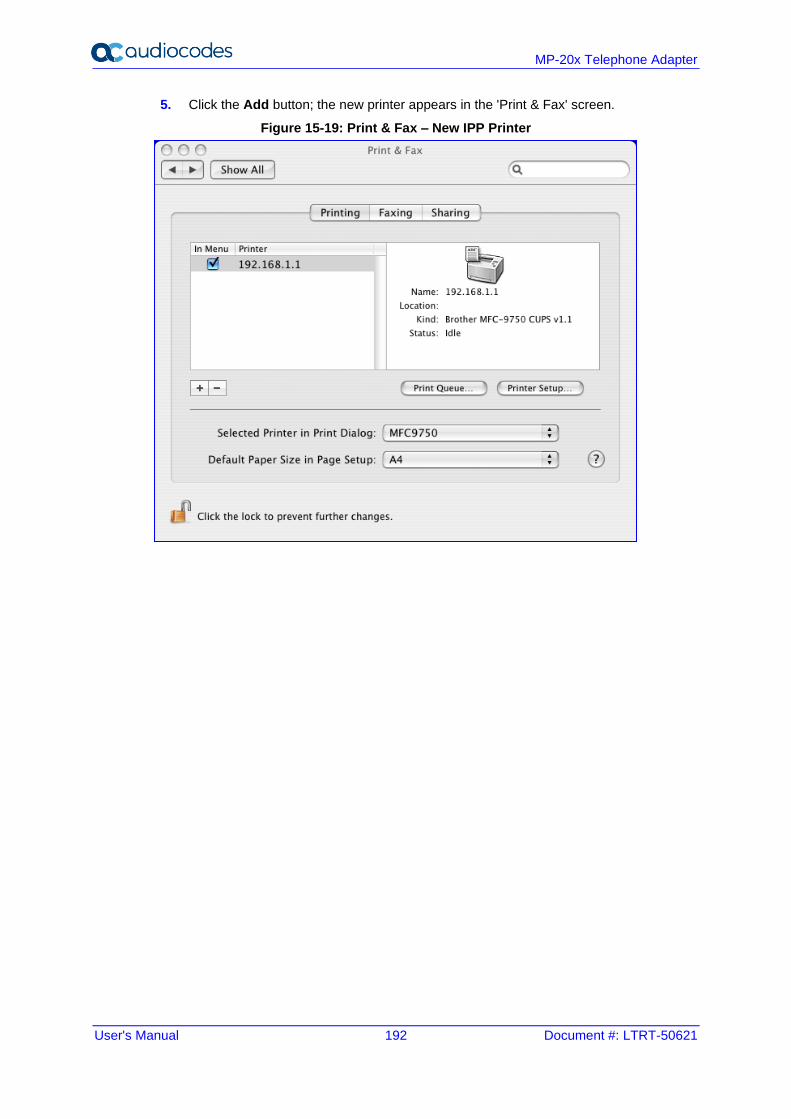
User's Manual 192 Document #: LTRT-50621
MP-20x Telephone Adapter
5. Click the Add button; the new printer appears in the 'Print & Fax' screen.
Figure 15-19: Print & Fax – New IPP Printer
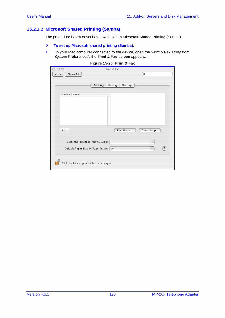
User's Manual 15. Add-on Servers and Disk Management
Version 4.5.1 193 MP-20x Telephone Adapter
15.2.2.2 Microsoft Shared Printing (Samba)
The procedure below describes how to set up Microsoft Shared Printing (Samba).
➢ To set up Microsoft shared printing (Samba):
1. On your Mac computer connected to the device, open the 'Print & Fax' utility from 'System Preferences'; the 'Print & Fax' screen appears.
Figure 15-20: Print & Fax
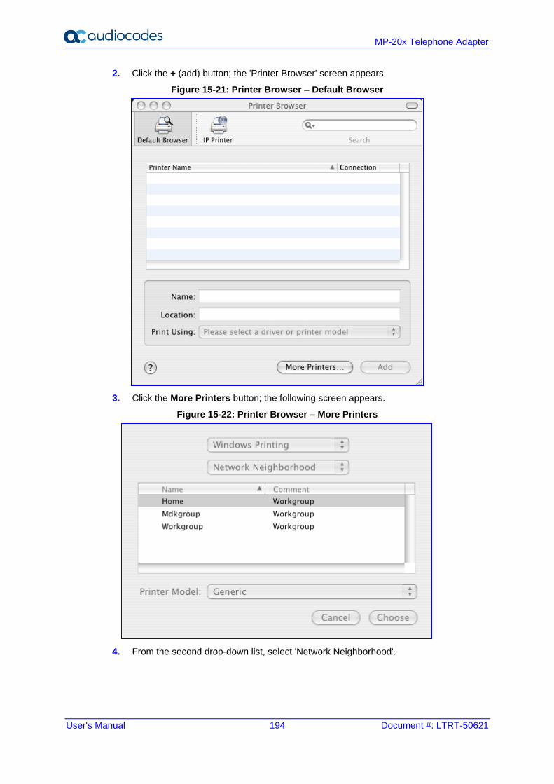
User's Manual 194 Document #: LTRT-50621
MP-20x Telephone Adapter
2. Click the + (add) button; the 'Printer Browser' screen appears.
Figure 15-21: Printer Browser – Default Browser
3. Click the More Printers button; the following screen appears.
Figure 15-22: Printer Browser – More Printers
4. From the second drop-down list, select 'Network Neighborhood'.
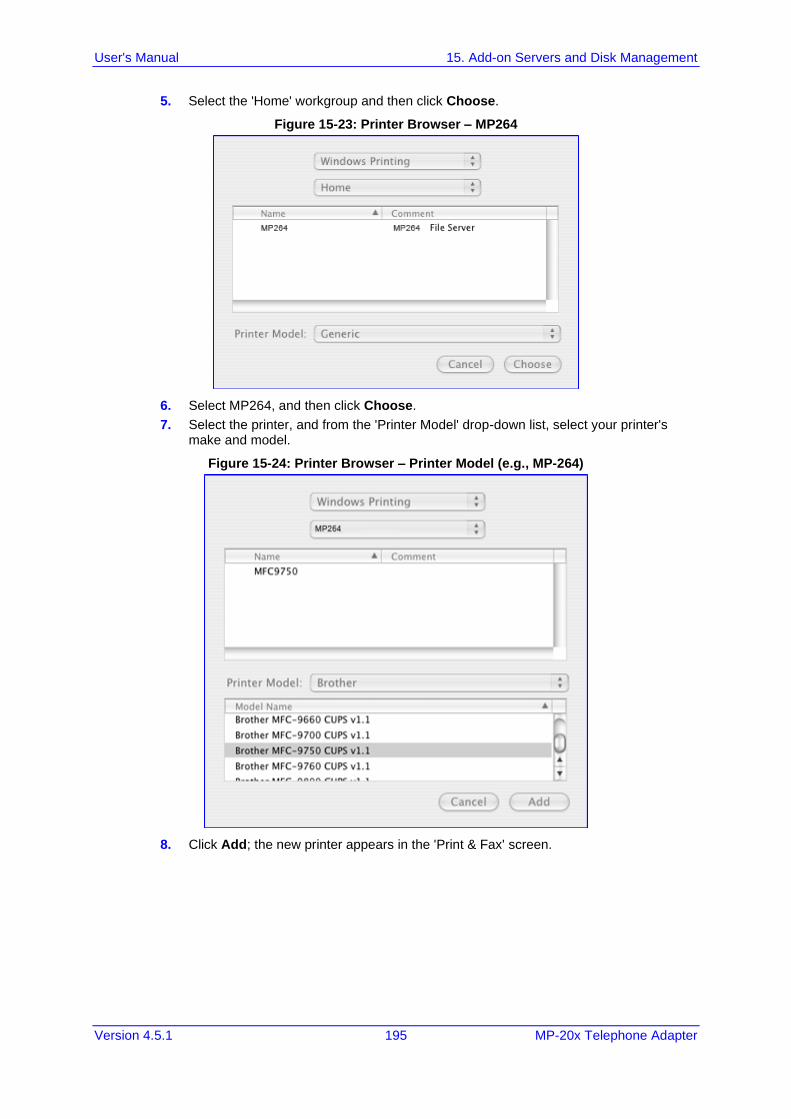
User's Manual 15. Add-on Servers and Disk Management
Version 4.5.1 195 MP-20x Telephone Adapter
5. Select the 'Home' workgroup and then click Choose.
Figure 15-23: Printer Browser – MP264
6. Select MP264, and then click Choose.
7. Select the printer, and from the 'Printer Model' drop-down list, select your printer's make and model.
Figure 15-24: Printer Browser – Printer Model (e.g., MP-264)
8. Click Add; the new printer appears in the 'Print & Fax' screen.
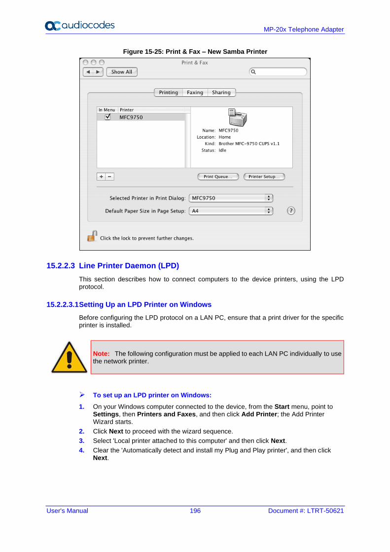
User's Manual 196 Document #: LTRT-50621
MP-20x Telephone Adapter
Figure 15-25: Print & Fax – New Samba Printer
15.2.2.3 Line Printer Daemon (LPD)
This section describes how to connect computers to the device printers, using the LPD protocol.
15.2.2.3.1 Setting Up an LPD Printer on Windows
Before configuring the LPD protocol on a LAN PC, ensure that a print driver for the specific printer is installed.
Note: The following configuration must be applied to each LAN PC individually to use the network printer.
➢ To set up an LPD printer on Windows:
1. On your Windows computer connected to the device, from the Start menu, point to Settings, then Printers and Faxes, and then click Add Printer; the Add Printer Wizard starts.
2. Click Next to proceed with the wizard sequence.
3. Select 'Local printer attached to this computer' and then click Next.
4. Clear the 'Automatically detect and install my Plug and Play printer', and then click Next.
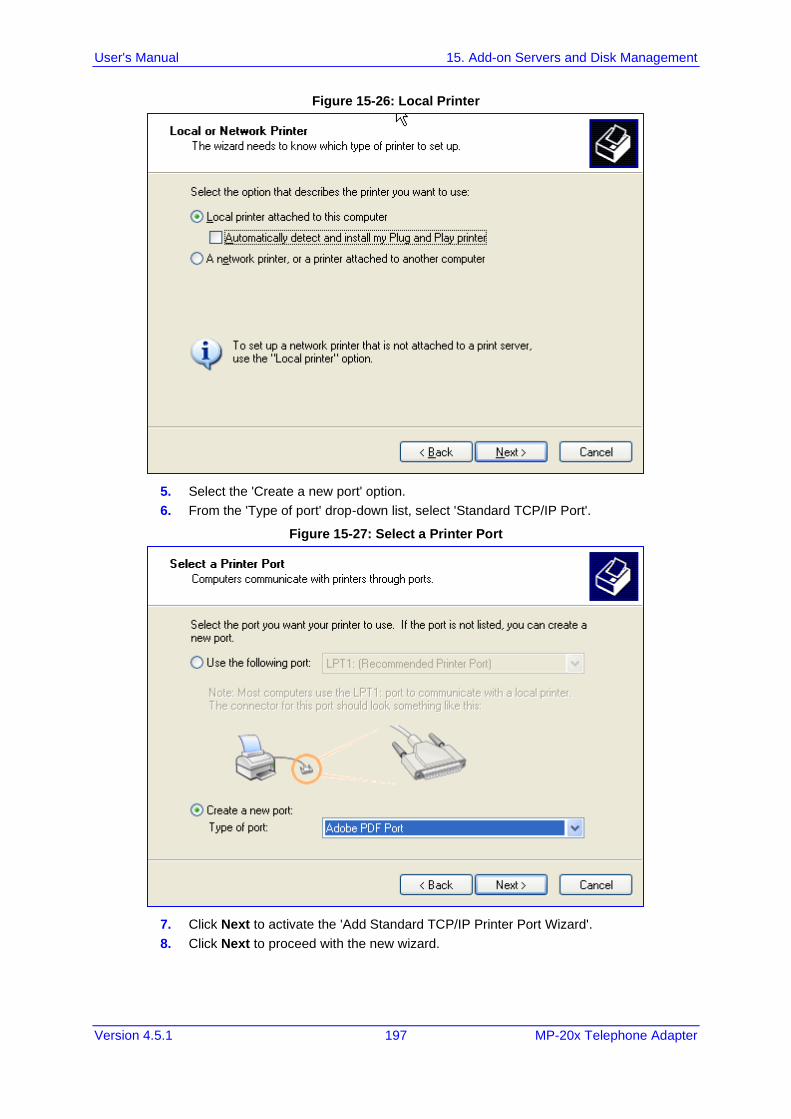
User's Manual 15. Add-on Servers and Disk Management
Version 4.5.1 197 MP-20x Telephone Adapter
Figure 15-26: Local Printer
5. Select the 'Create a new port' option.
6. From the 'Type of port' drop-down list, select 'Standard TCP/IP Port'.
Figure 15-27: Select a Printer Port
7. Click Next to activate the 'Add Standard TCP/IP Printer Port Wizard'.
8. Click Next to proceed with the new wizard.
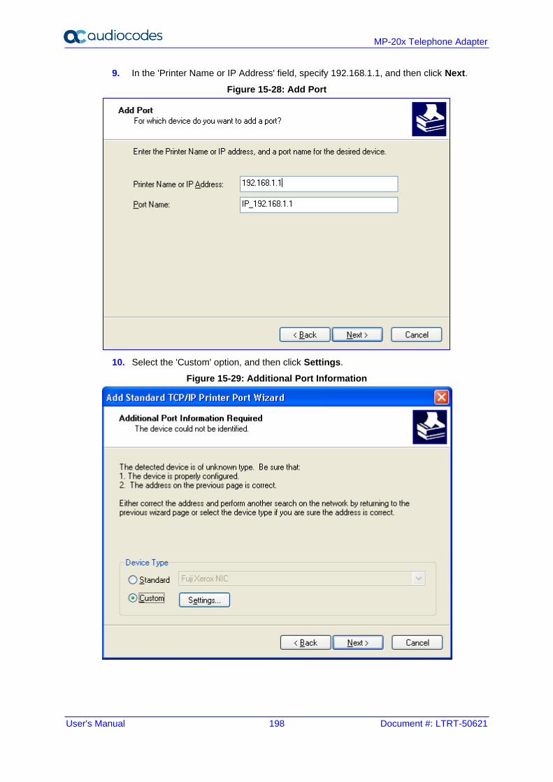
User's Manual 198 Document #: LTRT-50621
MP-20x Telephone Adapter
9. In the 'Printer Name or IP Address' field, specify 192.168.1.1, and then click Next.
Figure 15-28: Add Port
10. Select the 'Custom' option, and then click Settings.
Figure 15-29: Additional Port Information
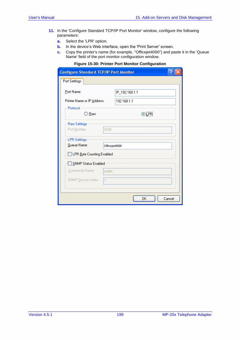
User's Manual 15. Add-on Servers and Disk Management
Version 4.5.1 199 MP-20x Telephone Adapter
11. In the 'Configure Standard TCP/IP Port Monitor' window, configure the following parameters:
a. Select the 'LPR' option.
b. In the device’s Web interface, open the 'Print Server' screen.
c. Copy the printer's name (for example, "Officejet4000") and paste it in the 'Queue Name' field of the port monitor configuration window.
Figure 15-30: Printer Port Monitor Configuration
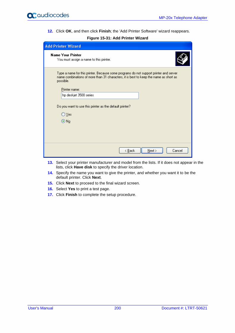
User's Manual 200 Document #: LTRT-50621
MP-20x Telephone Adapter
12. Click OK, and then click Finish; the 'Add Printer Software' wizard reappears.
Figure 15-31: Add Printer Wizard
13. Select your printer manufacturer and model from the lists. If it does not appear in the lists, click Have disk to specify the driver location.
14. Specify the name you want to give the printer, and whether you want it to be the default printer. Click Next.
15. Click Next to proceed to the final wizard screen.
16. Select Yes to print a test page.
17. Click Finish to complete the setup procedure.
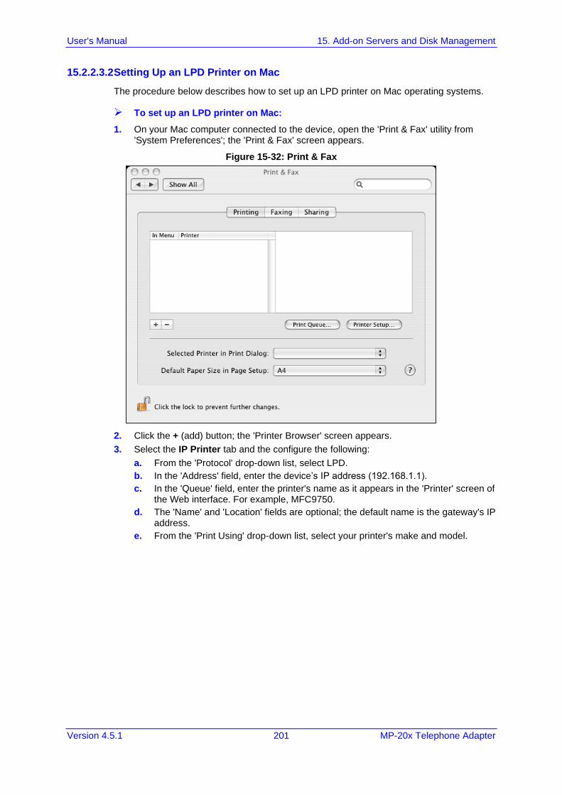
User's Manual 15. Add-on Servers and Disk Management
Version 4.5.1 201 MP-20x Telephone Adapter
15.2.2.3.2 Setting Up an LPD Printer on Mac
The procedure below describes how to set up an LPD printer on Mac operating systems.
➢ To set up an LPD printer on Mac:
1. On your Mac computer connected to the device, open the 'Print & Fax' utility from 'System Preferences'; the 'Print & Fax' screen appears.
Figure 15-32: Print & Fax
2. Click the + (add) button; the 'Printer Browser' screen appears.
3. Select the IP Printer tab and the configure the following:
a. From the 'Protocol' drop-down list, select LPD.
b. In the 'Address' field, enter the device’s IP address (192.168.1.1).
c. In the 'Queue' field, enter the printer's name as it appears in the 'Printer' screen of the Web interface. For example, MFC9750.
d. The 'Name' and 'Location' fields are optional; the default name is the gateway's IP address.
e. From the 'Print Using' drop-down list, select your printer's make and model.
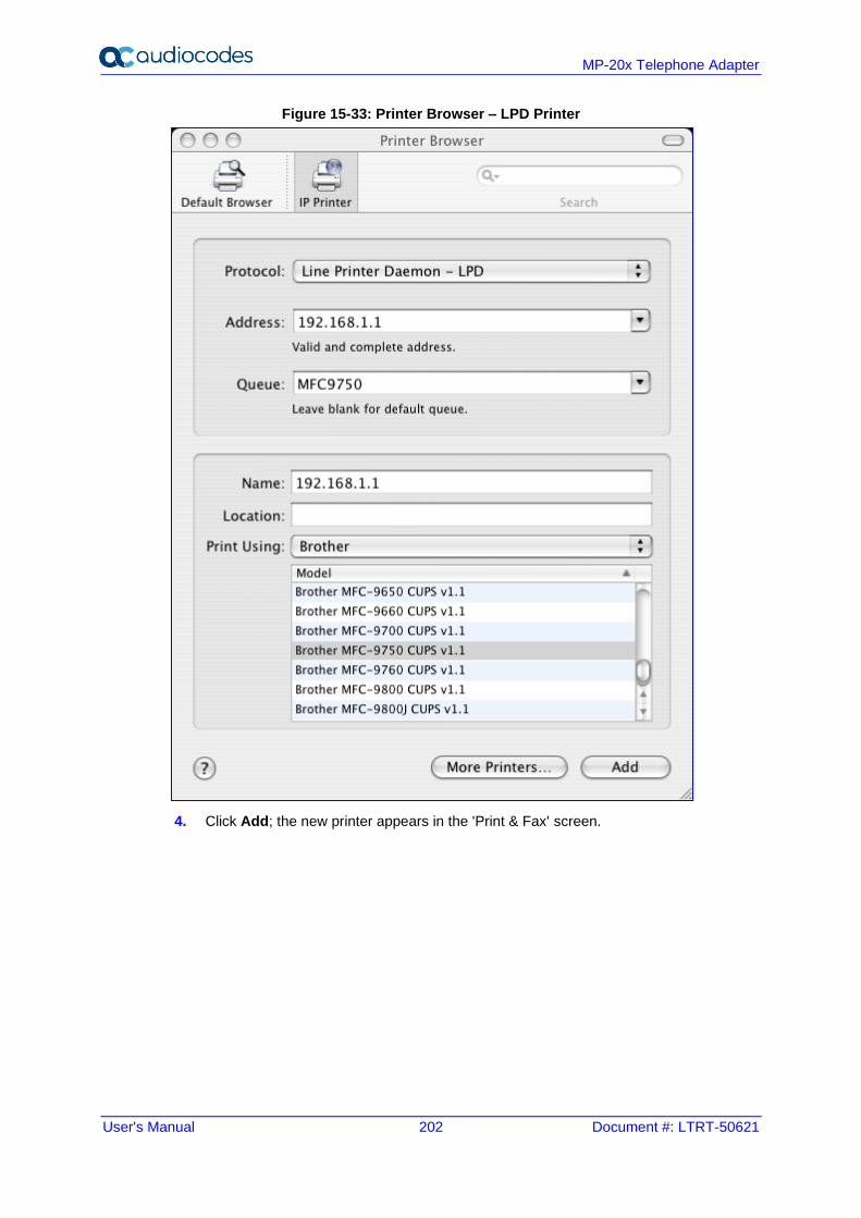
User's Manual 202 Document #: LTRT-50621
MP-20x Telephone Adapter
Figure 15-33: Printer Browser – LPD Printer
4. Click Add; the new printer appears in the 'Print & Fax' screen.
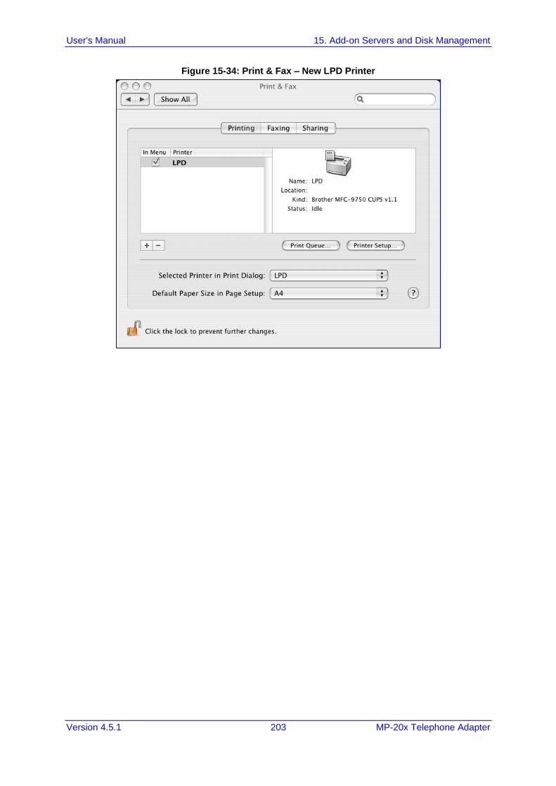
User's Manual 15. Add-on Servers and Disk Management
Version 4.5.1 203 MP-20x Telephone Adapter
Figure 15-34: Print & Fax – New LPD Printer
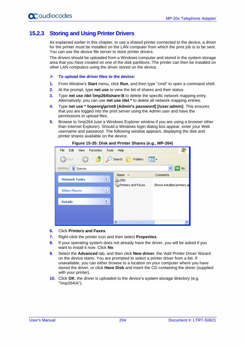
User's Manual 204 Document #: LTRT-50621
MP-20x Telephone Adapter
15.2.3 Storing and Using Printer Drivers
As explained earlier in this chapter, to use a shared printer connected to the device, a driver for the printer must be installed on the LAN computer from which the print job is to be sent. You can use the device file server to store printer drivers.
The drivers should be uploaded from a Windows computer and stored in the system storage area that you have created on one of the disk partitions. The printer can then be installed on other LAN computers using the driver stored on the device.
➢ To upload the driver files to the device:
1. From Window's Start menu, click Run, and then type "cmd" to open a command shell.
2. At the prompt, type net use to view the list of shares and their status.
3. Type net use /del \\mp264\share-B to delete the specific network mapping entry. Alternatively, you can use net use /del * to delete all network mapping entries.
4. Type net use * \\openrg\print$ [Admin's password] [/user:admin]. This ensures that you are logged into the print server using the Admin user and have the permissions to upload files.
5. Browse to \\mp264 (use a Windows Explorer window if you are using a browser other than Internet Explorer). Should a Windows login dialog box appear, enter your Web username and password. The following window appears, displaying the disk and printer shares available on the device.
Figure 15-35: Disk and Printer Shares (e.g., MP-264)
6. Click Printers and Faxes.
7. Right-click the printer icon and then select Properties.
8. If your operating system does not already have the driver, you will be asked if you want to install it now. Click No.
9. Select the Advanced tab, and then click New driver; the 'Add Printer Driver Wizard on the device starts. You are prompted to select a printer driver from a list. If unavailable, you can either browse to a location on your computer where you have stored the driver, or click Have Disk and insert the CD containing the driver (supplied with your printer).
10. Click OK; the driver is uploaded to the device’s system storage directory (e.g. “\\mp264\A”).
User's Manual 16. Remote Device Management
Version 4.5.1 205 MP-20x Telephone Adapter
16 Remote Device Management This chapter provides an overview of the device's remote configuration and management support. In addition, this chapter describes how to enable and secure remote management, as well configure the device through SNMP and TR-069.
16.1 Overview
The device is designed to be mass-deployed. One of the keys to guarantee end-user satisfaction and true toll-quality service in mass field deployment is comprehensive remote configuration and management capabilities:
◼ Automatic and remote configuration updates
◼ Automatic and remote firmware updates
◼ Remote diagnosis of problems reported by the user
◼ Remote collection of statistical information regarding the quality of the service
◼ Remote notifications of problems in the service
16.1.1 Remote Configuration
By default, the device is provided with factory default settings, which are common to all gateway devices (except for the MAC address). The factory settings allow the user to connect to the device's Web interface through the LAN.
By default, the WAN interface is configured for DHCP (i.e., automatically obtains its IP address from a DHCP server). The default configuration should not include any VoIP service provider settings (such as a SIP proxy).
In some cases, AudioCodes can ship devices that are pre-configured with some customer-specific parameters. This set of parameters is usually defined as the new "factory settings" for the specific customer.
The device's factory default settings and the current configuration running on the device are stored on the device's non-volatile flash memory. The current configuration can be remotely updated using several configuration interfaces:
◼ HTTP-based Web server
◼ SNMP
◼ TR-069
◼ Configuration file upload/download
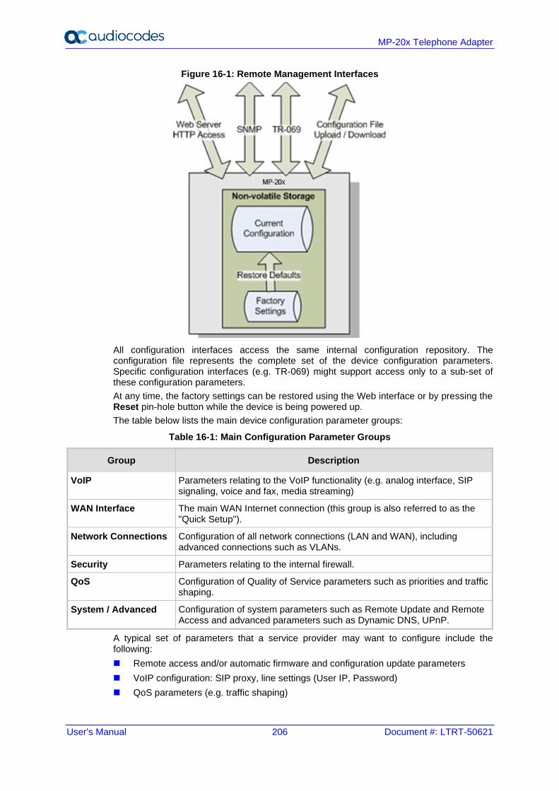
User's Manual 206 Document #: LTRT-50621
MP-20x Telephone Adapter
Figure 16-1: Remote Management Interfaces
All configuration interfaces access the same internal configuration repository. The configuration file represents the complete set of the device configuration parameters. Specific configuration interfaces (e.g. TR-069) might support access only to a sub-set of these configuration parameters.
At any time, the factory settings can be restored using the Web interface or by pressing the Reset pin-hole button while the device is being powered up.
The table below lists the main device configuration parameter groups:
Table 16-1: Main Configuration Parameter Groups
Group Description
VoIP Parameters relating to the VoIP functionality (e.g. analog interface, SIP signaling, voice and fax, media streaming)
WAN Interface The main WAN Internet connection (this group is also referred to as the "Quick Setup").
Network Connections Configuration of all network connections (LAN and WAN), including advanced connections such as VLANs.
Security Parameters relating to the internal firewall.
QoS Configuration of Quality of Service parameters such as priorities and traffic shaping.
System / Advanced Configuration of system parameters such as Remote Update and Remote Access and advanced parameters such as Dynamic DNS, UPnP.
A typical set of parameters that a service provider may want to configure include the following:
◼ Remote access and/or automatic firmware and configuration update parameters
◼ VoIP configuration: SIP proxy, line settings (User IP, Password)
◼ QoS parameters (e.g. traffic shaping)
User's Manual 16. Remote Device Management
Version 4.5.1 207 MP-20x Telephone Adapter
16.1.2 Remote Management
Remote management includes the following:
◼ Firmware upgrade
◼ Status and performance monitoring
◼ Alarms, notifications, and logs
16.1.2.1 Firmware Upgrade
Service providers require the ability to update the device's firmware in the field (e.g. in case of maintenance releases or releases that support new required features). The process is required to be automatic, allowing mass update, which is robust and fail-safe.
The device's firmware is stored on the non-volatile flash memory. The device's flash memory can store a recovery firmware that ensures a fail-safe operation (even if the user unplugs the power during the firmware burning process).
The device's firmware can be upgraded using one of the following mechanisms:
◼ The new firmware can be "pushed" (uploaded) to the device, using the device's Web interface
◼ The new firmware can be "pulled" (downloaded) by the device from a remote HTTP, FTP, or TFTP server
The device has two areas in flash memory for storing the firmware image. One area is active, while the other is "burned" during the upgrade process.
If the upgrade process was successful, the new image is set as "active", while the other area will be used for the next upgrade. If upgrade is not successful, the one that is still active remains valid.
The remote firmware download process can be triggered by one of the following:
◼ The device checks for a new firmware upon device restart
◼ The device periodically checks for a new firmware
◼ Manual trigger using CLI, TR-069, SNMP or Web
Note: Unless forced, the device downloads and upgrades to the new firmware only if its version number is higher than the firmware version currently running on the device. The version number is not taken from the image file name, but from the header of the image file.
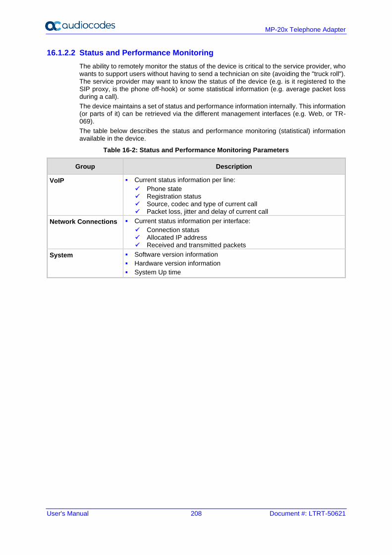
User's Manual 208 Document #: LTRT-50621
MP-20x Telephone Adapter
16.1.2.2 Status and Performance Monitoring
The ability to remotely monitor the status of the device is critical to the service provider, who wants to support users without having to send a technician on site (avoiding the "truck roll"). The service provider may want to know the status of the device (e.g. is it registered to the SIP proxy, is the phone off-hook) or some statistical information (e.g. average packet loss during a call).
The device maintains a set of status and performance information internally. This information (or parts of it) can be retrieved via the different management interfaces (e.g. Web, or TR-069).
The table below describes the status and performance monitoring (statistical) information available in the device.
Table 16-2: Status and Performance Monitoring Parameters
Group Description
VoIP ▪ Current status information per line:
✓ Phone state ✓ Registration status ✓ Source, codec and type of current call ✓ Packet loss, jitter and delay of current call
Network Connections ▪ Current status information per interface:
✓ Connection status ✓ Allocated IP address ✓ Received and transmitted packets
System ▪ Software version information
▪ Hardware version information
▪ System Up time
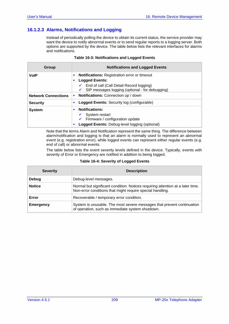
User's Manual 16. Remote Device Management
Version 4.5.1 209 MP-20x Telephone Adapter
16.1.2.3 Alarms, Notifications and Logging
Instead of periodically polling the device to obtain its current status, the service provider may want the device to notify abnormal events or to send regular reports to a logging server. Both options are supported by the device. The table below lists the relevant interfaces for alarms and notifications.
Table 16-3: Notifications and Logged Events
Group Notifications and Logged Events
VoIP ▪ Notifications: Registration error or timeout
▪ Logged Events:
✓ End of call (Call Detail Record logging) ✓ SIP messages logging (optional - for debugging)
Network Connections ▪ Notifications: Connection up / down
Security ▪ Logged Events: Security log (configurable)
System ▪ Notifications:
✓ System restart ✓ Firmware / configuration update
▪ Logged Events: Debug-level logging (optional)
Note that the terms Alarm and Notification represent the same thing. The difference between alarm/notification and logging is that an alarm is normally used to represent an abnormal event (e.g. registration error), while logged events can represent either regular events (e.g. end of call) or abnormal events.
The table below lists the event severity levels defined in the device. Typically, events with severity of Error or Emergency are notified in addition to being logged.
Table 16-4: Severity of Logged Events
Severity Description
Debug Debug-level messages.
Notice Normal but significant condition. Notices requiring attention at a later time. Non-error conditions that might require special handling.
Error Recoverable / temporary error condition.
Emergency System is unusable. The most severe messages that prevent continuation of operation, such as immediate system shutdown.
User's Manual 210 Document #: LTRT-50621
MP-20x Telephone Adapter
16.2 Enabling Remote Management
You can access and manage the device not only from within the home network, but also from the Internet. This allows you to view or change settings while travelling. It also enables you to allow your ISP to change settings or help you troubleshoot functionality or communication issues from a remote location.
Remote access to the device is blocked by default to ensure the security of your home network. However, remote access is supported by the following services, and you may use the 'Remote Access Configuration' screen to selectively enable these services if they are needed.
Notes:
• Telnet and Web-Management can be used to modify the settings of the firewall or to disable it. You can also change local IP addresses and other settings, making it difficult or impossible to access the device from the home network. Therefore, remote access to Telnet or HTTP services should be blocked and should only be permitted when necessary.
• Encrypted remote administration is done using a secure SSL connection that requires an SSL certificate. When accessing the device for the first time using encrypted remote administration, you are prompted by your browser with a warning regarding certificate authentication. This is because the device's SSL certificate is self-generated. When encountering this message under these circumstances, ignore it and continue. It should be noted that even though this message appears, the self-generated certificate is safe, and provides you with a secure SSL connection. You can also assign a user-defined certificate to the device.

User's Manual 16. Remote Device Management
Version 4.5.1 211 MP-20x Telephone Adapter
➢ To enable remote access to the device services:
1. On the 'Advanced' screen, click the Remote Administration icon; the 'Remote
Administration' screen appears.
Figure 16-2: Remote Administration Screen
2. Select the services that you would like to make available to computers on the Internet.
• Allow Incoming WAN Access to Web-Management: Allows access (from a Web browser) to the Web management interface and to all system settings and parameters. Both secure (HTTPS) and non-secure (HTTP) access is available.
• Allow Incoming WAN Access to the Telnet Server: Allows access to the command-line session and to all system settings and parameters (using a text-based terminal).
• SNMP: Allows Simple Network Management Protocol (SNMP) requests to remotely configure and monitor the device.
• Diagnostic Tools: Allows remote access for ping and trace route (over UDP) troubleshooting.
• TR-069: TR-069 is a WAN management protocol for communication between Customer Premise Equipment (CPE) and an Auto-Configuration Server (ACS). It defines a mechanism that encompasses secure auto-configuration of a CPE, and also incorporates other CPE management functions into a common framework.
3. Click OK to save your changes.
4. Select the services that you would like to make available to computers on the Internet.
• Allow Incoming WAN Access to Web-Management: Allows access (from a Web browser) to the Web management interface and to all system settings and parameters. Both secure (HTTPS) and non-secure (HTTP) access is available.
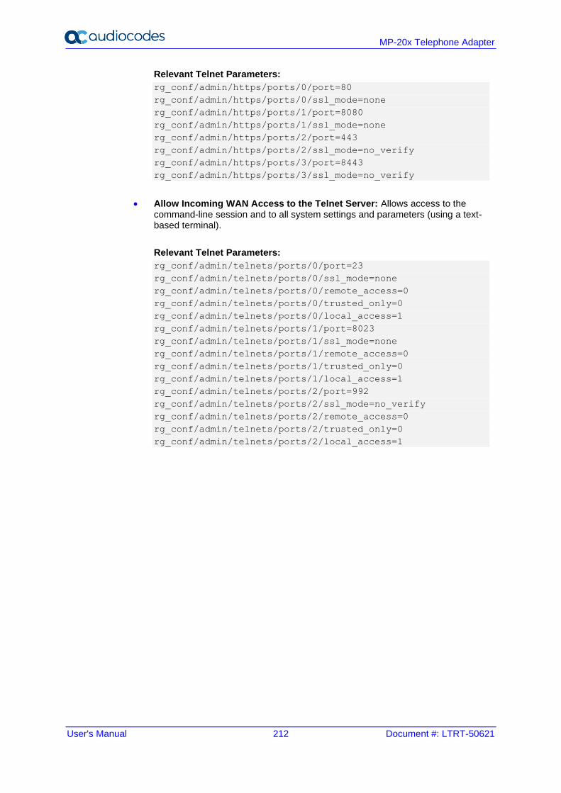
User's Manual 212 Document #: LTRT-50621
MP-20x Telephone Adapter
Relevant Telnet Parameters:
rg_conf/admin/https/ports/0/port=80
rg_conf/admin/https/ports/0/ssl_mode=none
rg_conf/admin/https/ports/1/port=8080
rg_conf/admin/https/ports/1/ssl_mode=none
rg_conf/admin/https/ports/2/port=443
rg_conf/admin/https/ports/2/ssl_mode=no_verify
rg_conf/admin/https/ports/3/port=8443
rg_conf/admin/https/ports/3/ssl_mode=no_verify
• Allow Incoming WAN Access to the Telnet Server: Allows access to the command-line session and to all system settings and parameters (using a text-based terminal).
Relevant Telnet Parameters:
rg_conf/admin/telnets/ports/0/port=23
rg_conf/admin/telnets/ports/0/ssl_mode=none
rg_conf/admin/telnets/ports/0/remote_access=0
rg_conf/admin/telnets/ports/0/trusted_only=0
rg_conf/admin/telnets/ports/0/local_access=1
rg_conf/admin/telnets/ports/1/port=8023
rg_conf/admin/telnets/ports/1/ssl_mode=none
rg_conf/admin/telnets/ports/1/remote_access=0
rg_conf/admin/telnets/ports/1/trusted_only=0
rg_conf/admin/telnets/ports/1/local_access=1
rg_conf/admin/telnets/ports/2/port=992
rg_conf/admin/telnets/ports/2/ssl_mode=no_verify
rg_conf/admin/telnets/ports/2/remote_access=0
rg_conf/admin/telnets/ports/2/trusted_only=0
rg_conf/admin/telnets/ports/2/local_access=1
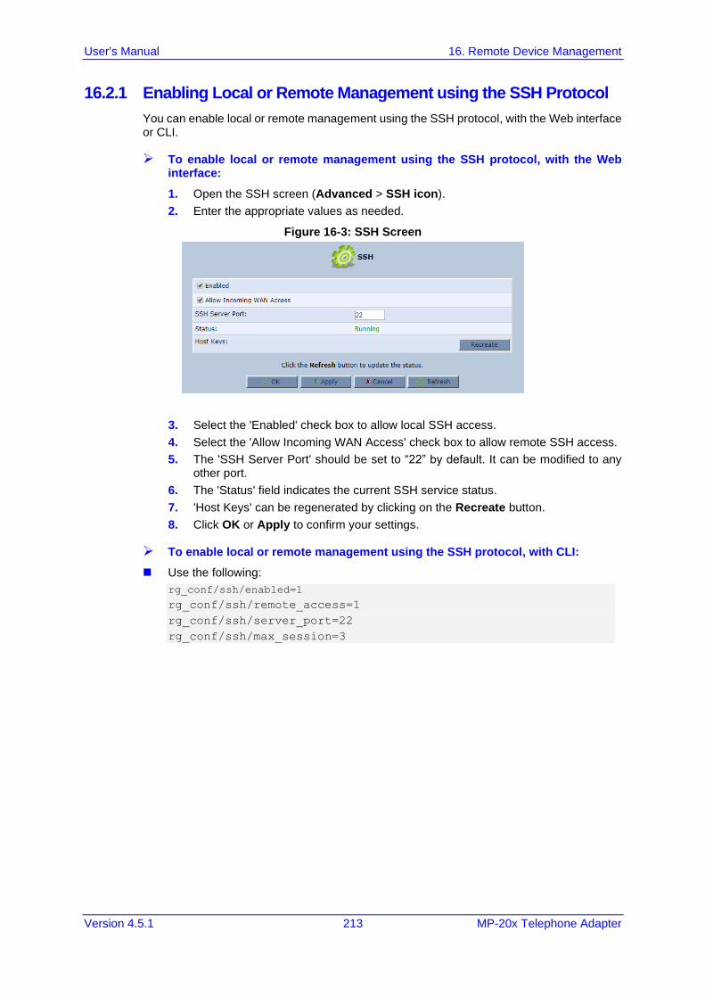
User's Manual 16. Remote Device Management
Version 4.5.1 213 MP-20x Telephone Adapter
16.2.1 Enabling Local or Remote Management using the SSH Protocol
You can enable local or remote management using the SSH protocol, with the Web interface or CLI.
➢ To enable local or remote management using the SSH protocol, with the Web interface:
1. Open the SSH screen (Advanced > SSH icon).
2. Enter the appropriate values as needed.
Figure 16-3: SSH Screen
3. Select the 'Enabled' check box to allow local SSH access.
4. Select the 'Allow Incoming WAN Access' check box to allow remote SSH access.
5. The 'SSH Server Port' should be set to “22” by default. It can be modified to any other port.
6. The 'Status' field indicates the current SSH service status.
7. 'Host Keys' can be regenerated by clicking on the Recreate button.
8. Click OK or Apply to confirm your settings.
➢ To enable local or remote management using the SSH protocol, with CLI:
◼ Use the following:
rg_conf/ssh/enabled=1
rg_conf/ssh/remote_access=1
rg_conf/ssh/server_port=22
rg_conf/ssh/max_session=3
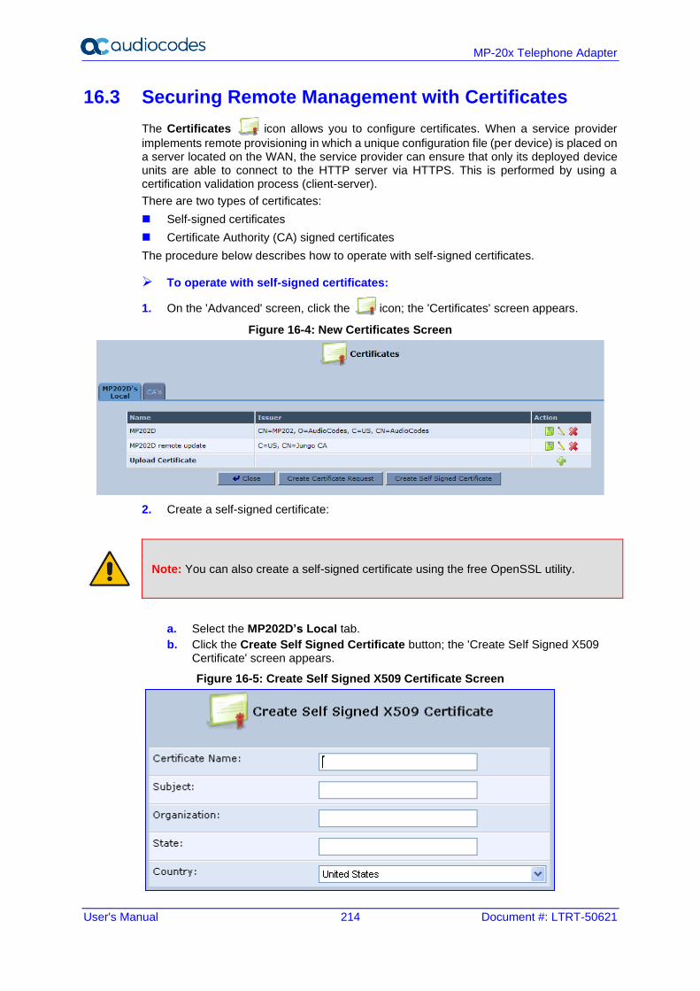
User's Manual 214 Document #: LTRT-50621
MP-20x Telephone Adapter
16.3 Securing Remote Management with Certificates
The Certificates icon allows you to configure certificates. When a service provider
implements remote provisioning in which a unique configuration file (per device) is placed on a server located on the WAN, the service provider can ensure that only its deployed device units are able to connect to the HTTP server via HTTPS. This is performed by using a certification validation process (client-server).
There are two types of certificates:
◼ Self-signed certificates
◼ Certificate Authority (CA) signed certificates
The procedure below describes how to operate with self-signed certificates.
➢ To operate with self-signed certificates:
1. On the 'Advanced' screen, click the icon; the 'Certificates' screen appears.
Figure 16-4: New Certificates Screen
2. Create a self-signed certificate:
Note: You can also create a self-signed certificate using the free OpenSSL utility.
a. Select the MP202D’s Local tab.
b. Click the Create Self Signed Certificate button; the 'Create Self Signed X509 Certificate' screen appears.
Figure 16-5: Create Self Signed X509 Certificate Screen
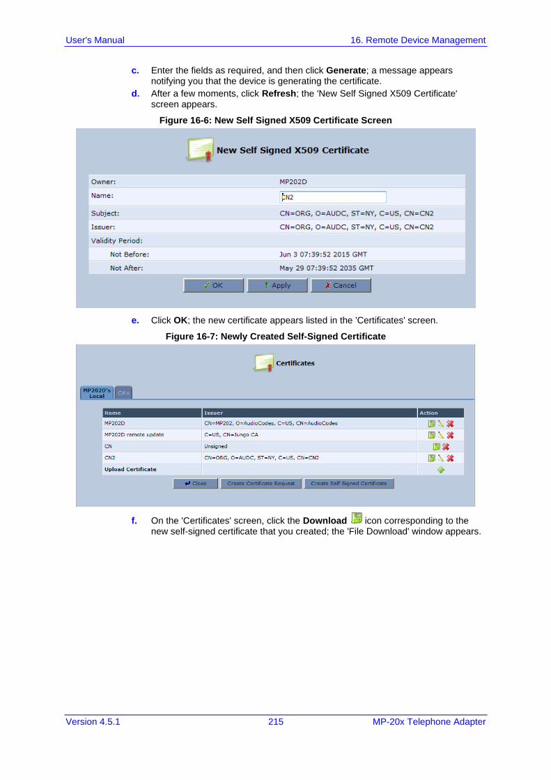
User's Manual 16. Remote Device Management
Version 4.5.1 215 MP-20x Telephone Adapter
c. Enter the fields as required, and then click Generate; a message appears notifying you that the device is generating the certificate.
d. After a few moments, click Refresh; the 'New Self Signed X509 Certificate' screen appears.
Figure 16-6: New Self Signed X509 Certificate Screen
e. Click OK; the new certificate appears listed in the 'Certificates' screen.
Figure 16-7: Newly Created Self-Signed Certificate
f. On the 'Certificates' screen, click the Download icon corresponding to the new self-signed certificate that you created; the 'File Download' window appears.
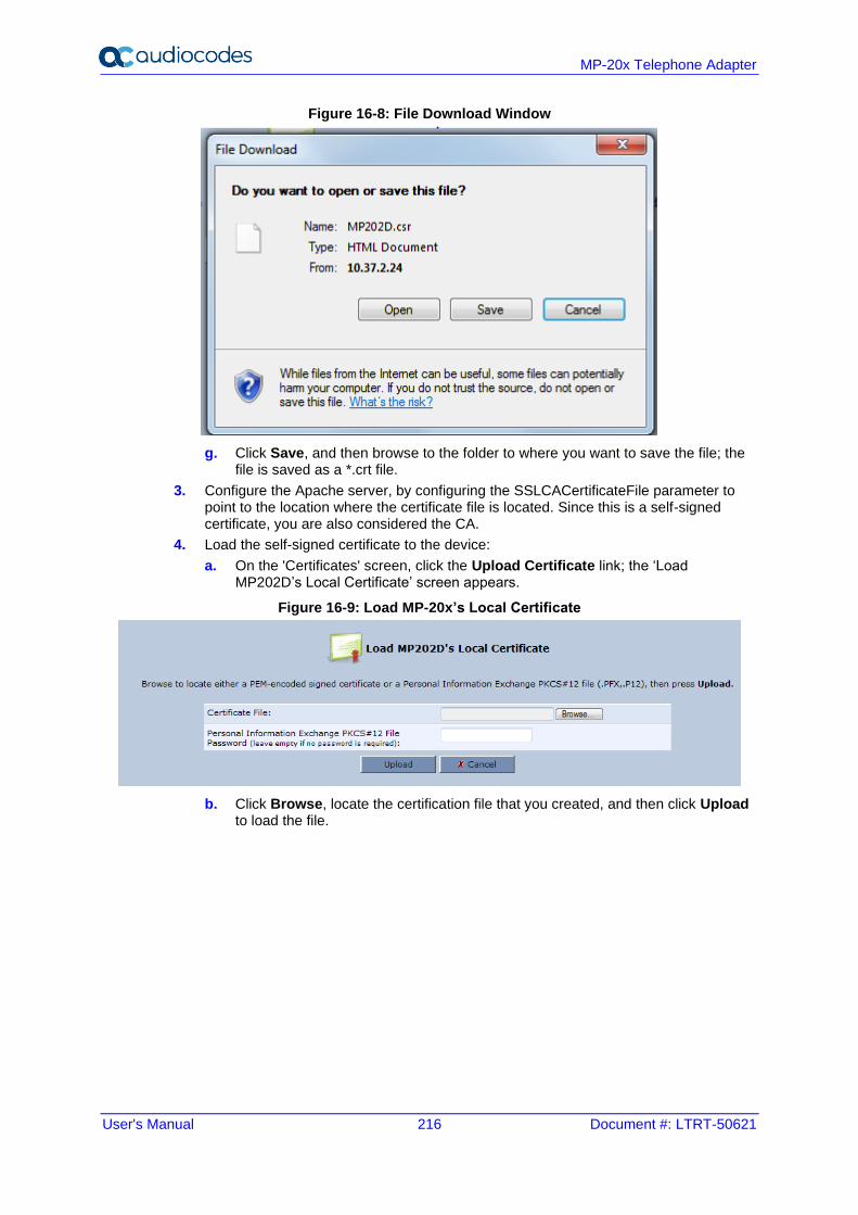
User's Manual 216 Document #: LTRT-50621
MP-20x Telephone Adapter
Figure 16-8: File Download Window
g. Click Save, and then browse to the folder to where you want to save the file; the file is saved as a *.crt file.
3. Configure the Apache server, by configuring the SSLCACertificateFile parameter to point to the location where the certificate file is located. Since this is a self-signed certificate, you are also considered the CA.
4. Load the self-signed certificate to the device:
a. On the 'Certificates' screen, click the Upload Certificate link; the ‘Load MP202D’s Local Certificate’ screen appears.
Figure 16-9: Load MP-20x’s Local Certificate
b. Click Browse, locate the certification file that you created, and then click Upload to load the file.
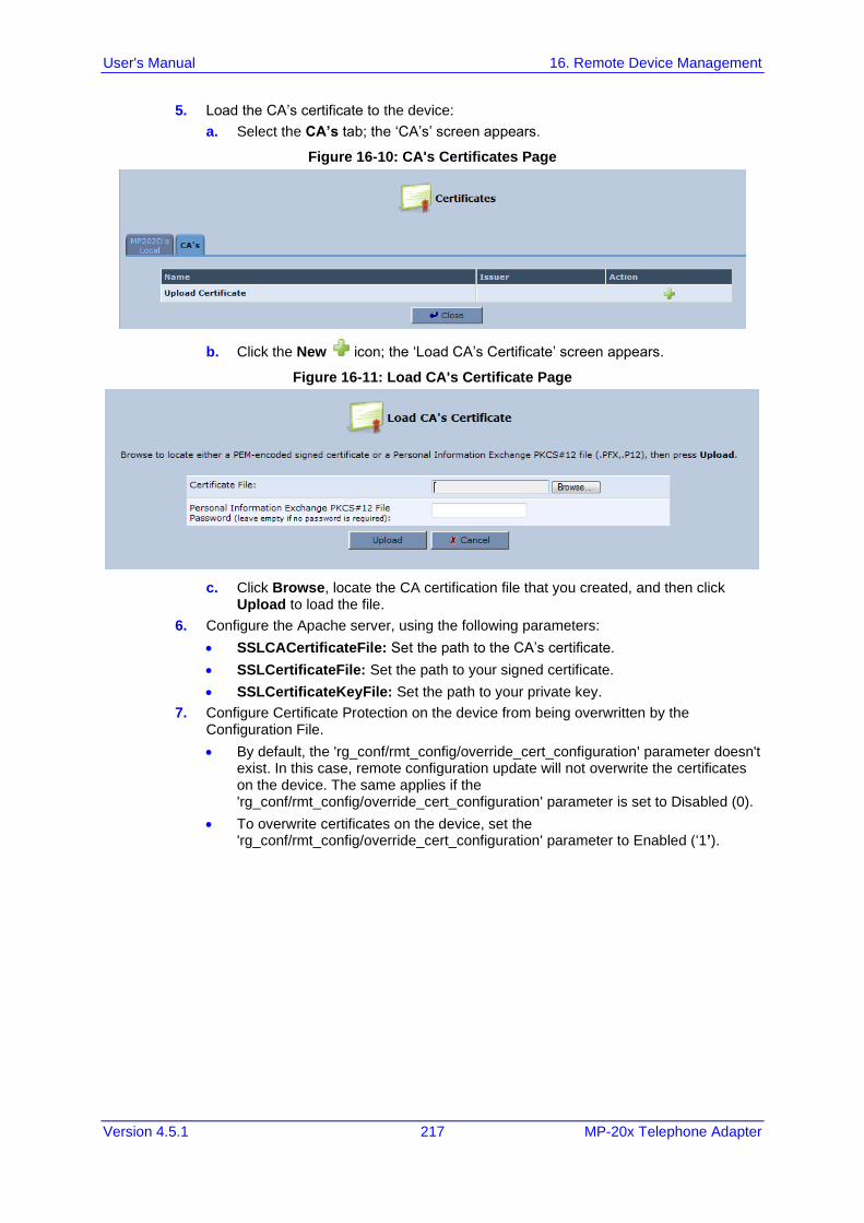
User's Manual 16. Remote Device Management
Version 4.5.1 217 MP-20x Telephone Adapter
5. Load the CA’s certificate to the device:
a. Select the CA’s tab; the ‘CA’s’ screen appears.
Figure 16-10: CA's Certificates Page
b. Click the New icon; the ‘Load CA’s Certificate’ screen appears.
Figure 16-11: Load CA's Certificate Page
c. Click Browse, locate the CA certification file that you created, and then click Upload to load the file.
6. Configure the Apache server, using the following parameters:
• SSLCACertificateFile: Set the path to the CA’s certificate.
• SSLCertificateFile: Set the path to your signed certificate.
• SSLCertificateKeyFile: Set the path to your private key.
7. Configure Certificate Protection on the device from being overwritten by the Configuration File.
• By default, the 'rg_conf/rmt_config/override_cert_configuration' parameter doesn't exist. In this case, remote configuration update will not overwrite the certificates on the device. The same applies if the 'rg_conf/rmt_config/override_cert_configuration' parameter is set to Disabled (0).
• To overwrite certificates on the device, set the 'rg_conf/rmt_config/override_cert_configuration' parameter to Enabled (‘1’).
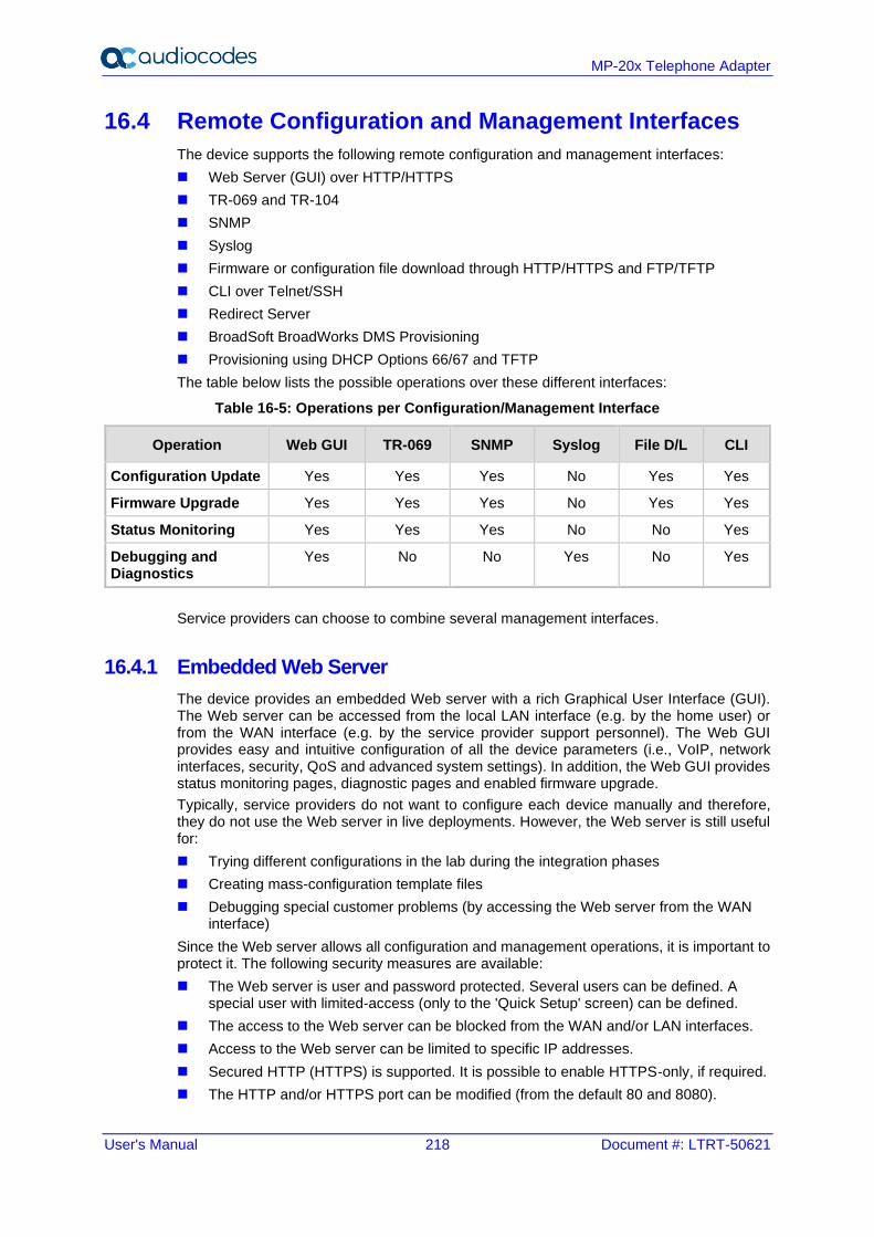
User's Manual 218 Document #: LTRT-50621
MP-20x Telephone Adapter
16.4 Remote Configuration and Management Interfaces
The device supports the following remote configuration and management interfaces:
◼ Web Server (GUI) over HTTP/HTTPS
◼ TR-069 and TR-104
◼ SNMP
◼ Syslog
◼ Firmware or configuration file download through HTTP/HTTPS and FTP/TFTP
◼ CLI over Telnet/SSH
◼ Redirect Server
◼ BroadSoft BroadWorks DMS Provisioning
◼ Provisioning using DHCP Options 66/67 and TFTP
The table below lists the possible operations over these different interfaces:
Table 16-5: Operations per Configuration/Management Interface
Operation Web GUI TR-069 SNMP Syslog File D/L CLI
Configuration Update Yes Yes Yes No Yes Yes
Firmware Upgrade Yes Yes Yes No Yes Yes
Status Monitoring Yes Yes Yes No No Yes
Debugging and Diagnostics
Yes No No Yes No Yes
Service providers can choose to combine several management interfaces.
16.4.1 Embedded Web Server
The device provides an embedded Web server with a rich Graphical User Interface (GUI). The Web server can be accessed from the local LAN interface (e.g. by the home user) or from the WAN interface (e.g. by the service provider support personnel). The Web GUI provides easy and intuitive configuration of all the device parameters (i.e., VoIP, network interfaces, security, QoS and advanced system settings). In addition, the Web GUI provides status monitoring pages, diagnostic pages and enabled firmware upgrade.
Typically, service providers do not want to configure each device manually and therefore, they do not use the Web server in live deployments. However, the Web server is still useful for:
◼ Trying different configurations in the lab during the integration phases
◼ Creating mass-configuration template files
◼ Debugging special customer problems (by accessing the Web server from the WAN interface)
Since the Web server allows all configuration and management operations, it is important to protect it. The following security measures are available:
◼ The Web server is user and password protected. Several users can be defined. A special user with limited-access (only to the 'Quick Setup' screen) can be defined.
◼ The access to the Web server can be blocked from the WAN and/or LAN interfaces.
◼ Access to the Web server can be limited to specific IP addresses.
◼ Secured HTTP (HTTPS) is supported. It is possible to enable HTTPS-only, if required.
◼ The HTTP and/or HTTPS port can be modified (from the default 80 and 8080).
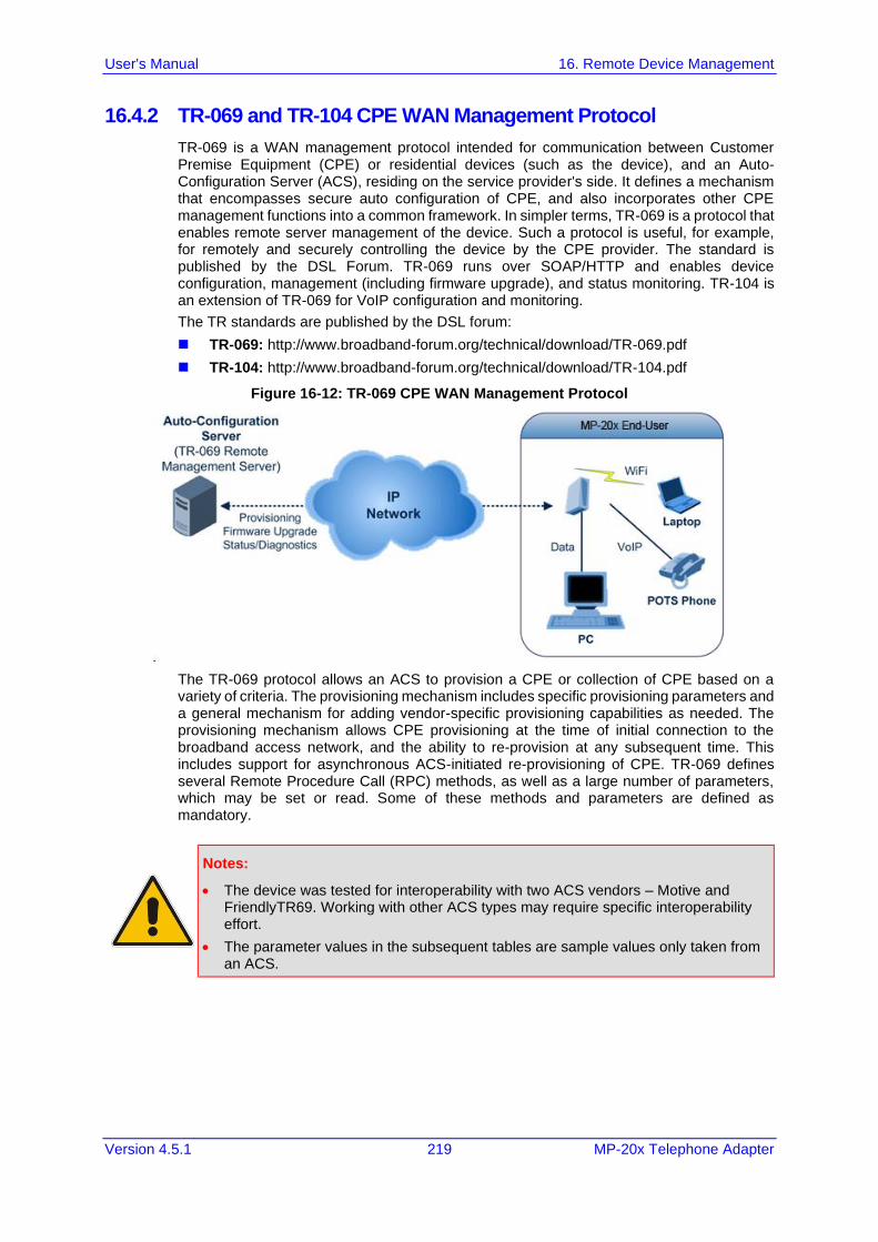
User's Manual 16. Remote Device Management
Version 4.5.1 219 MP-20x Telephone Adapter
16.4.2 TR-069 and TR-104 CPE WAN Management Protocol
TR-069 is a WAN management protocol intended for communication between Customer Premise Equipment (CPE) or residential devices (such as the device), and an Auto-Configuration Server (ACS), residing on the service provider's side. It defines a mechanism that encompasses secure auto configuration of CPE, and also incorporates other CPE management functions into a common framework. In simpler terms, TR-069 is a protocol that enables remote server management of the device. Such a protocol is useful, for example, for remotely and securely controlling the device by the CPE provider. The standard is published by the DSL Forum. TR-069 runs over SOAP/HTTP and enables device configuration, management (including firmware upgrade), and status monitoring. TR-104 is an extension of TR-069 for VoIP configuration and monitoring.
The TR standards are published by the DSL forum:
◼ TR-069: http://www.broadband-forum.org/technical/download/TR-069.pdf
◼ TR-104: http://www.broadband-forum.org/technical/download/TR-104.pdf
Figure 16-12: TR-069 CPE WAN Management Protocol
The TR-069 protocol allows an ACS to provision a CPE or collection of CPE based on a variety of criteria. The provisioning mechanism includes specific provisioning parameters and a general mechanism for adding vendor-specific provisioning capabilities as needed. The provisioning mechanism allows CPE provisioning at the time of initial connection to the broadband access network, and the ability to re-provision at any subsequent time. This includes support for asynchronous ACS-initiated re-provisioning of CPE. TR-069 defines several Remote Procedure Call (RPC) methods, as well as a large number of parameters, which may be set or read. Some of these methods and parameters are defined as mandatory.
Notes:
• The device was tested for interoperability with two ACS vendors – Motive and FriendlyTR69. Working with other ACS types may require specific interoperability effort.
• The parameter values in the subsequent tables are sample values only taken from an ACS.
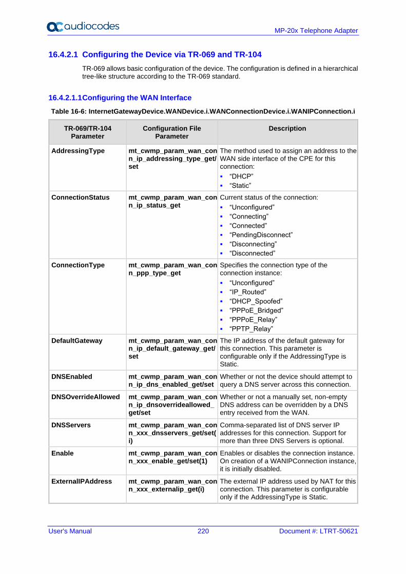
User's Manual 220 Document #: LTRT-50621
MP-20x Telephone Adapter
16.4.2.1 Configuring the Device via TR-069 and TR-104
TR-069 allows basic configuration of the device. The configuration is defined in a hierarchical tree-like structure according to the TR-069 standard.
16.4.2.1.1 Configuring the WAN Interface
Table 16-6: InternetGatewayDevice.WANDevice.i.WANConnectionDevice.i.WANIPConnection.i
TR-069/TR-104 Parameter
Configuration File Parameter
Description
AddressingType mt_cwmp_param_wan_conn_ip_addressing_type_get/set
The method used to assign an address to the WAN side interface of the CPE for this connection:
▪ “DHCP”
▪ “Static”
ConnectionStatus mt_cwmp_param_wan_conn_ip_status_get
Current status of the connection:
▪ “Unconfigured”
▪ “Connecting”
▪ “Connected”
▪ “PendingDisconnect”
▪ “Disconnecting”
▪ “Disconnected”
ConnectionType mt_cwmp_param_wan_conn_ppp_type_get
Specifies the connection type of the connection instance:
▪ “Unconfigured”
▪ “IP_Routed”
▪ “DHCP_Spoofed”
▪ “PPPoE_Bridged”
▪ “PPPoE_Relay”
▪ “PPTP_Relay”
DefaultGateway mt_cwmp_param_wan_conn_ip_default_gateway_get/set
The IP address of the default gateway for this connection. This parameter is configurable only if the AddressingType is Static.
DNSEnabled mt_cwmp_param_wan_conn_ip_dns_enabled_get/set
Whether or not the device should attempt to query a DNS server across this connection.
DNSOverrideAllowed mt_cwmp_param_wan_conn_ip_dnsoverrideallowed_get/set
Whether or not a manually set, non-empty DNS address can be overridden by a DNS entry received from the WAN.
DNSServers mt_cwmp_param_wan_conn_xxx_dnsservers_get/set(i)
Comma-separated list of DNS server IP addresses for this connection. Support for more than three DNS Servers is optional.
Enable mt_cwmp_param_wan_conn_xxx_enable_get/set(1)
Enables or disables the connection instance. On creation of a WANIPConnection instance, it is initially disabled.
ExternalIPAddress mt_cwmp_param_wan_conn_xxx_externalip_get(i)
The external IP address used by NAT for this connection. This parameter is configurable only if the AddressingType is Static.
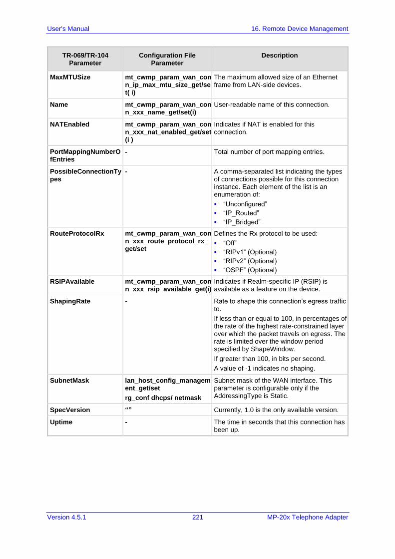
User's Manual 16. Remote Device Management
Version 4.5.1 221 MP-20x Telephone Adapter
TR-069/TR-104 Parameter
Configuration File Parameter
Description
MaxMTUSize mt_cwmp_param_wan_conn_ip_max_mtu_size_get/set( i)
The maximum allowed size of an Ethernet frame from LAN-side devices.
Name mt_cwmp_param_wan_conn_xxx_name_get/set(i)
User-readable name of this connection.
NATEnabled mt_cwmp_param_wan_conn_xxx_nat_enabled_get/set(i )
Indicates if NAT is enabled for this connection.
PortMappingNumberOfEntries
- Total number of port mapping entries.
PossibleConnectionTypes
- A comma-separated list indicating the types of connections possible for this connection instance. Each element of the list is an enumeration of:
▪ “Unconfigured”
▪ “IP_Routed”
▪ “IP_Bridged”
RouteProtocolRx mt_cwmp_param_wan_conn_xxx_route_protocol_rx_get/set
Defines the Rx protocol to be used:
▪ “Off”
▪ “RIPv1” (Optional)
▪ “RIPv2” (Optional)
▪ “OSPF” (Optional)
RSIPAvailable mt_cwmp_param_wan_conn_xxx_rsip_available_get(i)
Indicates if Realm-specific IP (RSIP) is available as a feature on the device.
ShapingRate - Rate to shape this connection’s egress traffic to.
If less than or equal to 100, in percentages of the rate of the highest rate-constrained layer over which the packet travels on egress. The rate is limited over the window period specified by ShapeWindow.
If greater than 100, in bits per second.
A value of -1 indicates no shaping.
SubnetMask lan_host_config_management_get/set
rg_conf dhcps/ netmask
Subnet mask of the WAN interface. This parameter is configurable only if the AddressingType is Static.
SpecVersion “” Currently, 1.0 is the only available version.
Uptime - The time in seconds that this connection has been up.
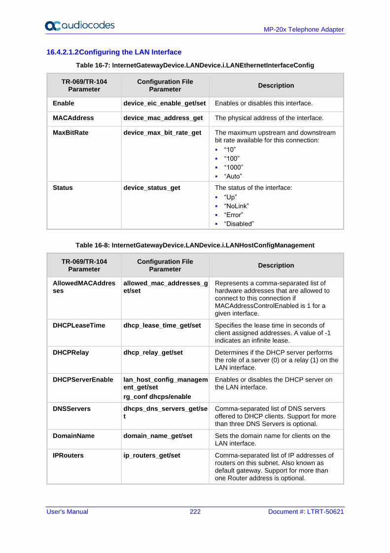
User's Manual 222 Document #: LTRT-50621
MP-20x Telephone Adapter
16.4.2.1.2 Configuring the LAN Interface
Table 16-7: InternetGatewayDevice.LANDevice.i.LANEthernetInterfaceConfig
TR-069/TR-104 Parameter
Configuration File Parameter
Description
Enable device_eic_enable_get/set Enables or disables this interface.
MACAddress device_mac_address_get The physical address of the interface.
MaxBitRate device_max_bit_rate_get The maximum upstream and downstream bit rate available for this connection:
▪ “10”
▪ “100”
▪ “1000”
▪ “Auto”
Status device_status_get The status of the interface:
▪ “Up”
▪ “NoLink”
▪ “Error”
▪ “Disabled”
Table 16-8: InternetGatewayDevice.LANDevice.i.LANHostConfigManagement
TR-069/TR-104 Parameter
Configuration File Parameter
Description
AllowedMACAddresses
allowed_mac_addresses_get/set
Represents a comma-separated list of hardware addresses that are allowed to connect to this connection if MACAddressControlEnabled is 1 for a given interface.
DHCPLeaseTime dhcp_lease_time_get/set Specifies the lease time in seconds of client assigned addresses. A value of -1 indicates an infinite lease.
DHCPRelay dhcp_relay_get/set Determines if the DHCP server performs the role of a server (0) or a relay (1) on the LAN interface.
DHCPServerEnable lan_host_config_management_get/set
rg_conf dhcps/enable
Enables or disables the DHCP server on the LAN interface.
DNSServers dhcps_dns_servers_get/set
Comma-separated list of DNS servers offered to DHCP clients. Support for more than three DNS Servers is optional.
DomainName domain_name_get/set Sets the domain name for clients on the LAN interface.
IPRouters ip_routers_get/set Comma-separated list of IP addresses of routers on this subnet. Also known as default gateway. Support for more than one Router address is optional.
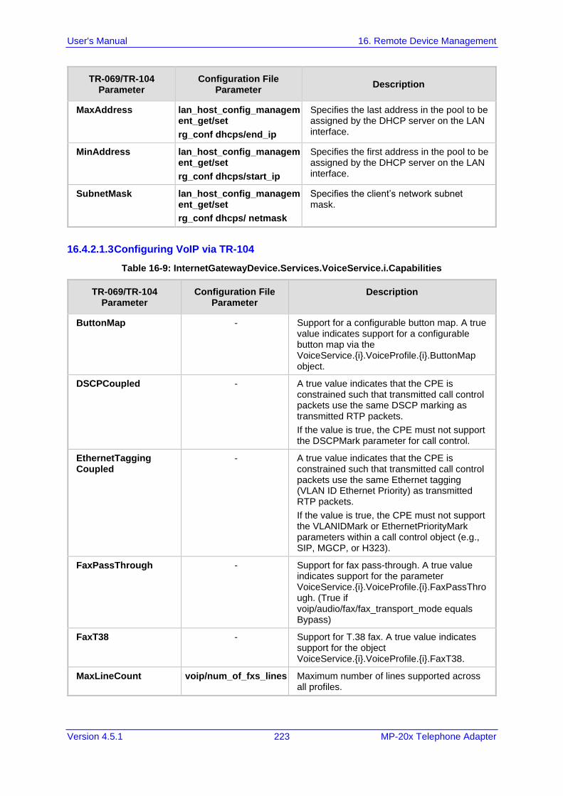
User's Manual 16. Remote Device Management
Version 4.5.1 223 MP-20x Telephone Adapter
TR-069/TR-104 Parameter
Configuration File Parameter
Description
MaxAddress lan_host_config_management_get/set
rg_conf dhcps/end_ip
Specifies the last address in the pool to be assigned by the DHCP server on the LAN interface.
MinAddress lan_host_config_management_get/set
rg_conf dhcps/start_ip
Specifies the first address in the pool to be assigned by the DHCP server on the LAN interface.
SubnetMask lan_host_config_management_get/set
rg_conf dhcps/ netmask
Specifies the client’s network subnet mask.
16.4.2.1.3 Configuring VoIP via TR-104
Table 16-9: InternetGatewayDevice.Services.VoiceService.i.Capabilities
TR-069/TR-104 Parameter
Configuration File Parameter
Description
ButtonMap - Support for a configurable button map. A true value indicates support for a configurable button map via the VoiceService.{i}.VoiceProfile.{i}.ButtonMap object.
DSCPCoupled - A true value indicates that the CPE is constrained such that transmitted call control packets use the same DSCP marking as transmitted RTP packets.
If the value is true, the CPE must not support the DSCPMark parameter for call control.
EthernetTagging Coupled
- A true value indicates that the CPE is constrained such that transmitted call control packets use the same Ethernet tagging (VLAN ID Ethernet Priority) as transmitted RTP packets.
If the value is true, the CPE must not support the VLANIDMark or EthernetPriorityMark parameters within a call control object (e.g., SIP, MGCP, or H323).
FaxPassThrough - Support for fax pass-through. A true value indicates support for the parameter VoiceService.{i}.VoiceProfile.{i}.FaxPassThrough. (True if voip/audio/fax/fax_transport_mode equals Bypass)
FaxT38 - Support for T.38 fax. A true value indicates support for the object VoiceService.{i}.VoiceProfile.{i}.FaxT38.
MaxLineCount voip/num_of_fxs_lines Maximum number of lines supported across all profiles.
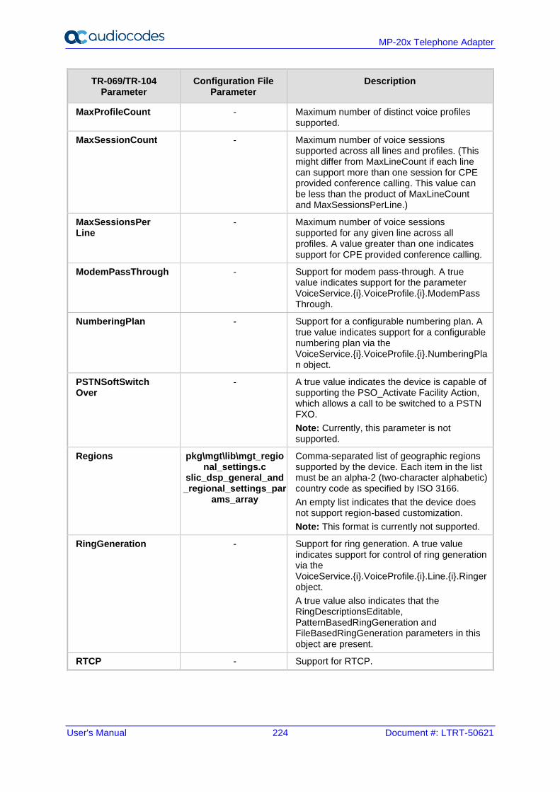
User's Manual 224 Document #: LTRT-50621
MP-20x Telephone Adapter
TR-069/TR-104 Parameter
Configuration File Parameter
Description
MaxProfileCount - Maximum number of distinct voice profiles supported.
MaxSessionCount - Maximum number of voice sessions supported across all lines and profiles. (This might differ from MaxLineCount if each line can support more than one session for CPE provided conference calling. This value can be less than the product of MaxLineCount and MaxSessionsPerLine.)
MaxSessionsPer Line
- Maximum number of voice sessions supported for any given line across all profiles. A value greater than one indicates support for CPE provided conference calling.
ModemPassThrough - Support for modem pass-through. A true value indicates support for the parameter VoiceService.{i}.VoiceProfile.{i}.ModemPass Through.
NumberingPlan - Support for a configurable numbering plan. A true value indicates support for a configurable numbering plan via the VoiceService.{i}.VoiceProfile.{i}.NumberingPlan object.
PSTNSoftSwitch Over
- A true value indicates the device is capable of supporting the PSO_Activate Facility Action, which allows a call to be switched to a PSTN FXO.
Note: Currently, this parameter is not supported.
Regions pkg\mgt\lib\mgt_regional_settings.c
slic_dsp_general_and_regional_settings_par
ams_array
Comma-separated list of geographic regions supported by the device. Each item in the list must be an alpha-2 (two-character alphabetic) country code as specified by ISO 3166.
An empty list indicates that the device does not support region-based customization.
Note: This format is currently not supported.
RingGeneration - Support for ring generation. A true value indicates support for control of ring generation via the VoiceService.{i}.VoiceProfile.{i}.Line.{i}.Ringer object.
A true value also indicates that the RingDescriptionsEditable, PatternBasedRingGeneration and FileBasedRingGeneration parameters in this object are present.
RTCP - Support for RTCP.
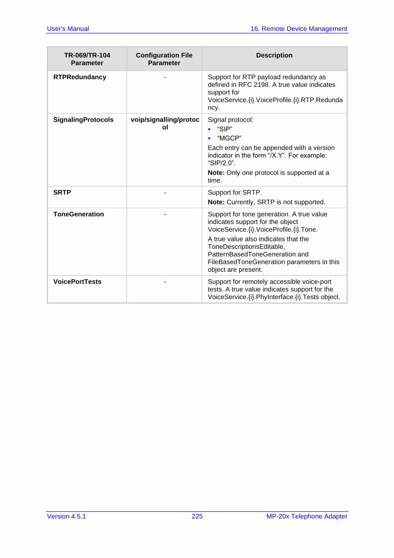
User's Manual 16. Remote Device Management
Version 4.5.1 225 MP-20x Telephone Adapter
TR-069/TR-104 Parameter
Configuration File Parameter
Description
RTPRedundancy - Support for RTP payload redundancy as defined in RFC 2198. A true value indicates support for VoiceService.{i}.VoiceProfile.{i}.RTP.Redundancy.
SignalingProtocols voip/signalling/protocol
Signal protocol:
▪ “SIP”
▪ “MGCP”
Each entry can be appended with a version indicator in the form “/X.Y”. For example: “SIP/2.0”.
Note: Only one protocol is supported at a time.
SRTP - Support for SRTP.
Note: Currently, SRTP is not supported.
ToneGeneration - Support for tone generation. A true value indicates support for the object VoiceService.{i}.VoiceProfile.{i}.Tone.
A true value also indicates that the ToneDescriptionsEditable, PatternBasedToneGeneration and FileBasedToneGeneration parameters in this object are present.
VoicePortTests - Support for remotely accessible voice-port tests. A true value indicates support for the VoiceService.{i}.PhyInterface.{i}.Tests object.
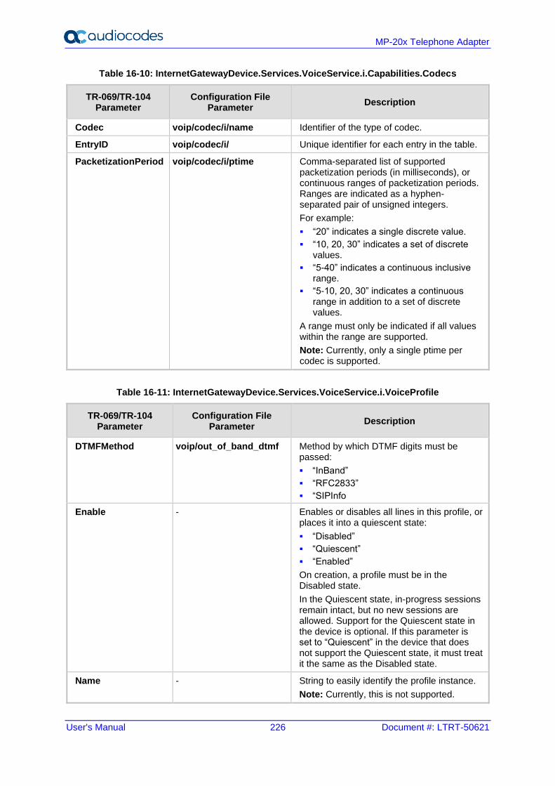
User's Manual 226 Document #: LTRT-50621
MP-20x Telephone Adapter
Table 16-10: InternetGatewayDevice.Services.VoiceService.i.Capabilities.Codecs
TR-069/TR-104 Parameter
Configuration File Parameter
Description
Codec voip/codec/i/name Identifier of the type of codec.
EntryID voip/codec/i/ Unique identifier for each entry in the table.
PacketizationPeriod voip/codec/i/ptime Comma-separated list of supported packetization periods (in milliseconds), or continuous ranges of packetization periods. Ranges are indicated as a hyphen-separated pair of unsigned integers.
For example:
▪ “20” indicates a single discrete value.
▪ “10, 20, 30” indicates a set of discrete values.
▪ “5-40” indicates a continuous inclusive range.
▪ “5-10, 20, 30” indicates a continuous range in addition to a set of discrete values.
A range must only be indicated if all values within the range are supported.
Note: Currently, only a single ptime per codec is supported.
Table 16-11: InternetGatewayDevice.Services.VoiceService.i.VoiceProfile
TR-069/TR-104 Parameter
Configuration File Parameter
Description
DTMFMethod voip/out_of_band_dtmf Method by which DTMF digits must be passed:
▪ “InBand”
▪ “RFC2833”
▪ “SIPInfo
Enable - Enables or disables all lines in this profile, or places it into a quiescent state:
▪ “Disabled”
▪ “Quiescent”
▪ “Enabled”
On creation, a profile must be in the Disabled state.
In the Quiescent state, in-progress sessions remain intact, but no new sessions are allowed. Support for the Quiescent state in the device is optional. If this parameter is set to “Quiescent” in the device that does not support the Quiescent state, it must treat it the same as the Disabled state.
Name - String to easily identify the profile instance.
Note: Currently, this is not supported.
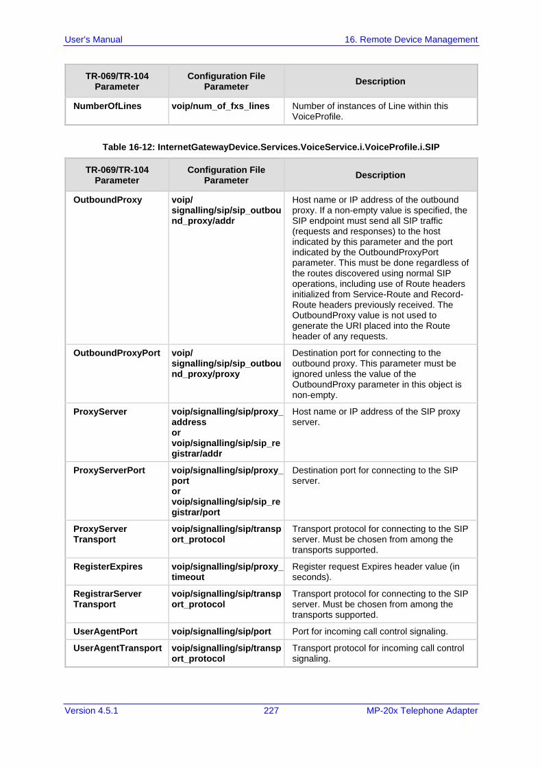
User's Manual 16. Remote Device Management
Version 4.5.1 227 MP-20x Telephone Adapter
TR-069/TR-104 Parameter
Configuration File Parameter
Description
NumberOfLines voip/num_of_fxs_lines Number of instances of Line within this VoiceProfile.
Table 16-12: InternetGatewayDevice.Services.VoiceService.i.VoiceProfile.i.SIP
TR-069/TR-104 Parameter
Configuration File Parameter
Description
OutboundProxy voip/ signalling/sip/sip_outbound_proxy/addr
Host name or IP address of the outbound proxy. If a non-empty value is specified, the SIP endpoint must send all SIP traffic (requests and responses) to the host indicated by this parameter and the port indicated by the OutboundProxyPort parameter. This must be done regardless of the routes discovered using normal SIP operations, including use of Route headers initialized from Service-Route and Record-Route headers previously received. The OutboundProxy value is not used to generate the URI placed into the Route header of any requests.
OutboundProxyPort voip/ signalling/sip/sip_outbound_proxy/proxy
Destination port for connecting to the outbound proxy. This parameter must be ignored unless the value of the OutboundProxy parameter in this object is non-empty.
ProxyServer voip/signalling/sip/proxy_address or voip/signalling/sip/sip_registrar/addr
Host name or IP address of the SIP proxy server.
ProxyServerPort voip/signalling/sip/proxy_port or voip/signalling/sip/sip_registrar/port
Destination port for connecting to the SIP server.
ProxyServer Transport
voip/signalling/sip/transport_protocol
Transport protocol for connecting to the SIP server. Must be chosen from among the transports supported.
RegisterExpires voip/signalling/sip/proxy_timeout
Register request Expires header value (in seconds).
RegistrarServer Transport
voip/signalling/sip/transport_protocol
Transport protocol for connecting to the SIP server. Must be chosen from among the transports supported.
UserAgentPort voip/signalling/sip/port Port for incoming call control signaling.
UserAgentTransport voip/signalling/sip/transport_protocol
Transport protocol for incoming call control signaling.
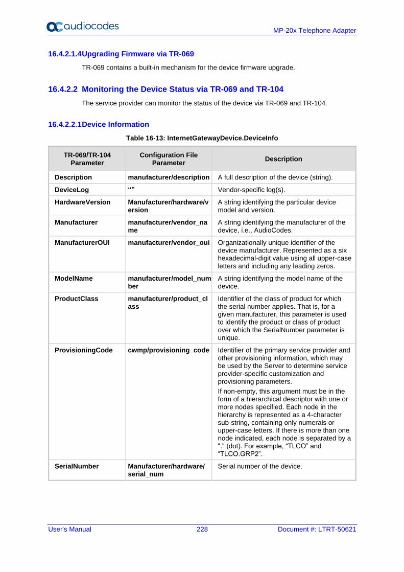
User's Manual 228 Document #: LTRT-50621
MP-20x Telephone Adapter
16.4.2.1.4 Upgrading Firmware via TR-069
TR-069 contains a built-in mechanism for the device firmware upgrade.
16.4.2.2 Monitoring the Device Status via TR-069 and TR-104
The service provider can monitor the status of the device via TR-069 and TR-104.
16.4.2.2.1 Device Information
Table 16-13: InternetGatewayDevice.DeviceInfo
TR-069/TR-104 Parameter
Configuration File Parameter
Description
Description manufacturer/description A full description of the device (string).
DeviceLog “” Vendor-specific log(s).
HardwareVersion Manufacturer/hardware/version
A string identifying the particular device model and version.
Manufacturer manufacturer/vendor_name
A string identifying the manufacturer of the device, i.e., AudioCodes.
ManufacturerOUI manufacturer/vendor_oui Organizationally unique identifier of the device manufacturer. Represented as a six hexadecimal-digit value using all upper-case letters and including any leading zeros.
ModelName manufacturer/model_number
A string identifying the model name of the device.
ProductClass manufacturer/product_class
Identifier of the class of product for which the serial number applies. That is, for a given manufacturer, this parameter is used to identify the product or class of product over which the SerialNumber parameter is unique.
ProvisioningCode cwmp/provisioning_code Identifier of the primary service provider and other provisioning information, which may be used by the Server to determine service provider-specific customization and provisioning parameters.
If non-empty, this argument must be in the form of a hierarchical descriptor with one or more nodes specified. Each node in the hierarchy is represented as a 4-character sub-string, containing only numerals or upper-case letters. If there is more than one node indicated, each node is separated by a "." (dot). For example, “TLCO” and “TLCO.GRP2”.
SerialNumber Manufacturer/hardware/ serial_num
Serial number of the device.
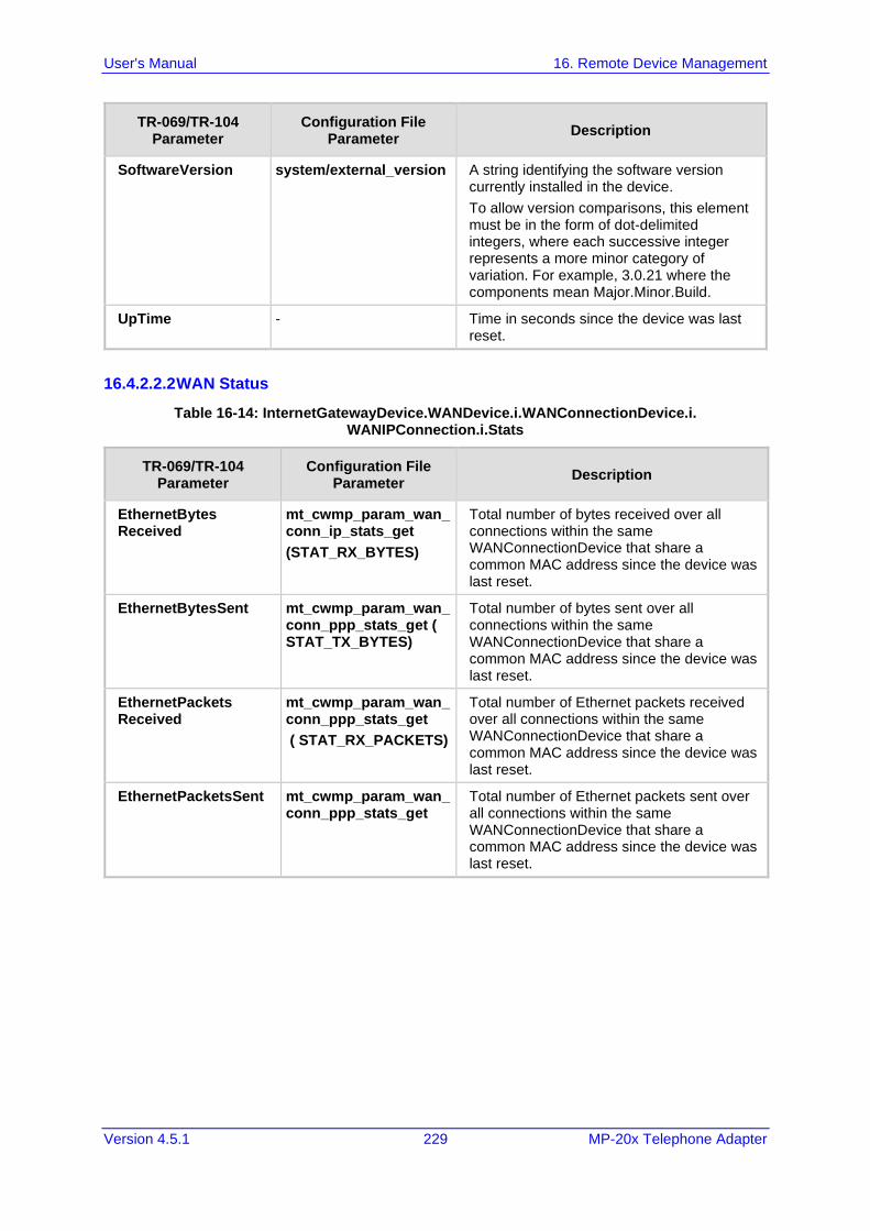
User's Manual 16. Remote Device Management
Version 4.5.1 229 MP-20x Telephone Adapter
TR-069/TR-104 Parameter
Configuration File Parameter
Description
SoftwareVersion system/external_version A string identifying the software version currently installed in the device.
To allow version comparisons, this element must be in the form of dot-delimited integers, where each successive integer represents a more minor category of variation. For example, 3.0.21 where the components mean Major.Minor.Build.
UpTime - Time in seconds since the device was last reset.
16.4.2.2.2 WAN Status
Table 16-14: InternetGatewayDevice.WANDevice.i.WANConnectionDevice.i. WANIPConnection.i.Stats
TR-069/TR-104 Parameter
Configuration File Parameter
Description
EthernetBytes Received
mt_cwmp_param_wan_conn_ip_stats_get
(STAT_RX_BYTES)
Total number of bytes received over all connections within the same WANConnectionDevice that share a common MAC address since the device was last reset.
EthernetBytesSent mt_cwmp_param_wan_conn_ppp_stats_get ( STAT_TX_BYTES)
Total number of bytes sent over all connections within the same WANConnectionDevice that share a common MAC address since the device was last reset.
EthernetPackets Received
mt_cwmp_param_wan_conn_ppp_stats_get
( STAT_RX_PACKETS)
Total number of Ethernet packets received over all connections within the same WANConnectionDevice that share a common MAC address since the device was last reset.
EthernetPacketsSent mt_cwmp_param_wan_conn_ppp_stats_get
Total number of Ethernet packets sent over all connections within the same WANConnectionDevice that share a common MAC address since the device was last reset.
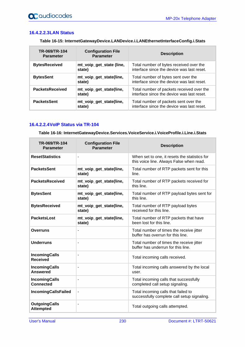
User's Manual 230 Document #: LTRT-50621
MP-20x Telephone Adapter
16.4.2.2.3 LAN Status
Table 16-15: InternetGatewayDevice.LANDevice.i.LANEthernetInterfaceConfig.i.Stats
TR-069/TR-104 Parameter
Configuration File Parameter
Description
BytesReceived mt_voip_get_state (line, state)
Total number of bytes received over the interface since the device was last reset.
BytesSent mt_voip_get_state(line, state)
Total number of bytes sent over the interface since the device was last reset.
PacketsReceived mt_voip_get_state(line, state)
Total number of packets received over the interface since the device was last reset.
PacketsSent mt_voip_get_state(line, state)
Total number of packets sent over the interface since the device was last reset.
16.4.2.2.4 VoIP Status via TR-104
Table 16-16: InternetGatewayDevice.Services.VoiceService.i.VoiceProfile.i.Line.i.Stats
TR-069/TR-104 Parameter
Configuration File Parameter
Description
ResetStatistics - When set to one, it resets the statistics for this voice line. Always False when read.
PacketsSent mt_voip_get_state(line, state)
Total number of RTP packets sent for this line.
PacketsReceived mt_voip_get_state(line, state)
Total number of RTP packets received for this line.
BytesSent mt_voip_get_state(line, state)
Total number of RTP payload bytes sent for this line.
BytesReceived mt_voip_get_state(line, state)
Total number of RTP payload bytes received for this line.
PacketsLost mt_voip_get_state(line, state)
Total number of RTP packets that have been lost for this line.
Overruns - Total number of times the receive jitter buffer has overrun for this line.
Underruns - Total number of times the receive jitter buffer has underrun for this line.
IncomingCalls Received
- Total incoming calls received.
IncomingCalls Answered
- Total incoming calls answered by the local user.
IncomingCalls Connected
- Total incoming calls that successfully completed call setup signaling.
IncomingCallsFailed - Total incoming calls that failed to successfully complete call setup signaling.
OutgoingCalls Attempted
- Total outgoing calls attempted.
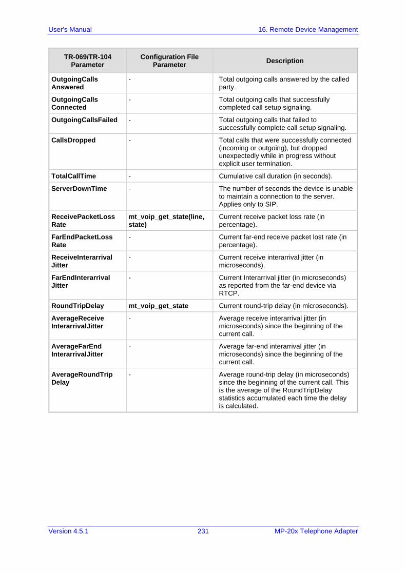
User's Manual 16. Remote Device Management
Version 4.5.1 231 MP-20x Telephone Adapter
TR-069/TR-104 Parameter
Configuration File Parameter
Description
OutgoingCalls Answered
- Total outgoing calls answered by the called party.
OutgoingCalls Connected
- Total outgoing calls that successfully completed call setup signaling.
OutgoingCallsFailed - Total outgoing calls that failed to successfully complete call setup signaling.
CallsDropped - Total calls that were successfully connected (incoming or outgoing), but dropped unexpectedly while in progress without explicit user termination.
TotalCallTime - Cumulative call duration (in seconds).
ServerDownTime - The number of seconds the device is unable to maintain a connection to the server. Applies only to SIP.
ReceivePacketLoss Rate
mt_voip_get_state(line, state)
Current receive packet loss rate (in percentage).
FarEndPacketLoss Rate
- Current far-end receive packet lost rate (in percentage).
ReceiveInterarrival Jitter
- Current receive interarrival jitter (in microseconds).
FarEndInterarrival Jitter
- Current Interarrival jitter (in microseconds) as reported from the far-end device via RTCP.
RoundTripDelay mt_voip_get_state Current round-trip delay (in microseconds).
AverageReceive InterarrivalJitter
- Average receive interarrival jitter (in microseconds) since the beginning of the current call.
AverageFarEnd InterarrivalJitter
- Average far-end interarrival jitter (in microseconds) since the beginning of the current call.
AverageRoundTrip Delay
- Average round-trip delay (in microseconds) since the beginning of the current call. This is the average of the RoundTripDelay statistics accumulated each time the delay is calculated.
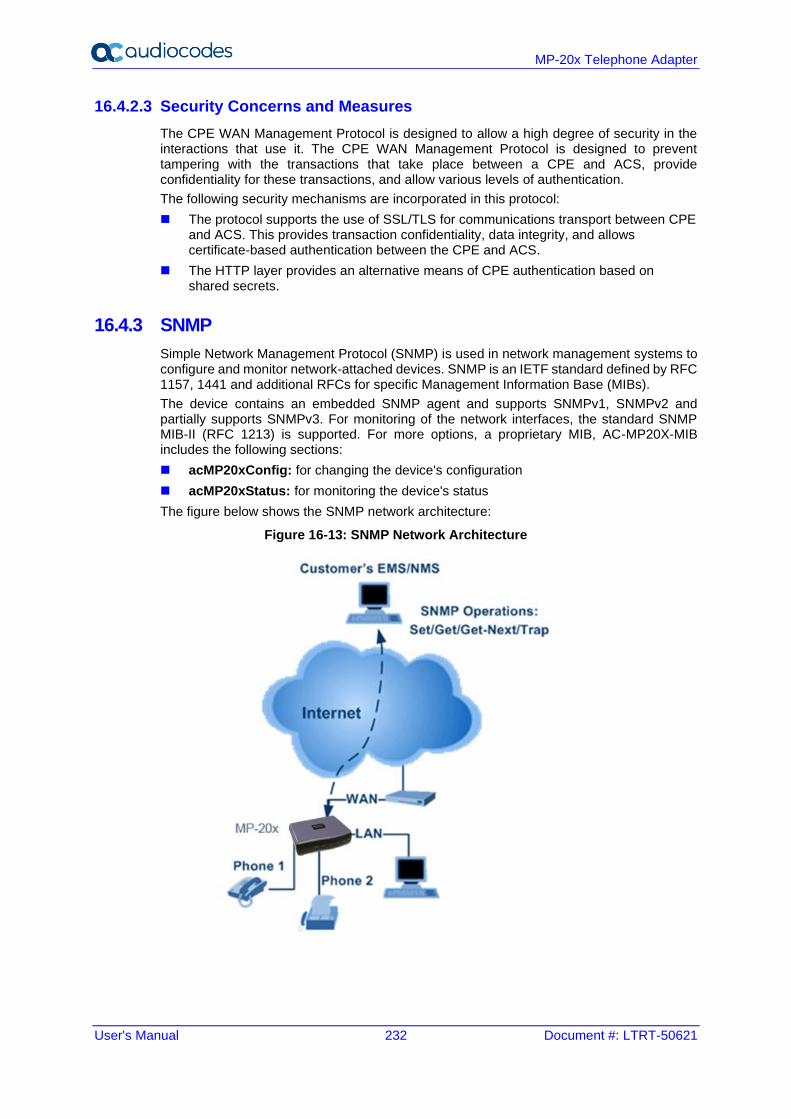
User's Manual 232 Document #: LTRT-50621
MP-20x Telephone Adapter
16.4.2.3 Security Concerns and Measures
The CPE WAN Management Protocol is designed to allow a high degree of security in the interactions that use it. The CPE WAN Management Protocol is designed to prevent tampering with the transactions that take place between a CPE and ACS, provide confidentiality for these transactions, and allow various levels of authentication.
The following security mechanisms are incorporated in this protocol:
◼ The protocol supports the use of SSL/TLS for communications transport between CPE and ACS. This provides transaction confidentiality, data integrity, and allows certificate-based authentication between the CPE and ACS.
◼ The HTTP layer provides an alternative means of CPE authentication based on shared secrets.
16.4.3 SNMP
Simple Network Management Protocol (SNMP) is used in network management systems to configure and monitor network-attached devices. SNMP is an IETF standard defined by RFC 1157, 1441 and additional RFCs for specific Management Information Base (MIBs).
The device contains an embedded SNMP agent and supports SNMPv1, SNMPv2 and partially supports SNMPv3. For monitoring of the network interfaces, the standard SNMP MIB-II (RFC 1213) is supported. For more options, a proprietary MIB, AC-MP20X-MIB includes the following sections:
◼ acMP20xConfig: for changing the device's configuration
◼ acMP20xStatus: for monitoring the device's status
The figure below shows the SNMP network architecture:
Figure 16-13: SNMP Network Architecture
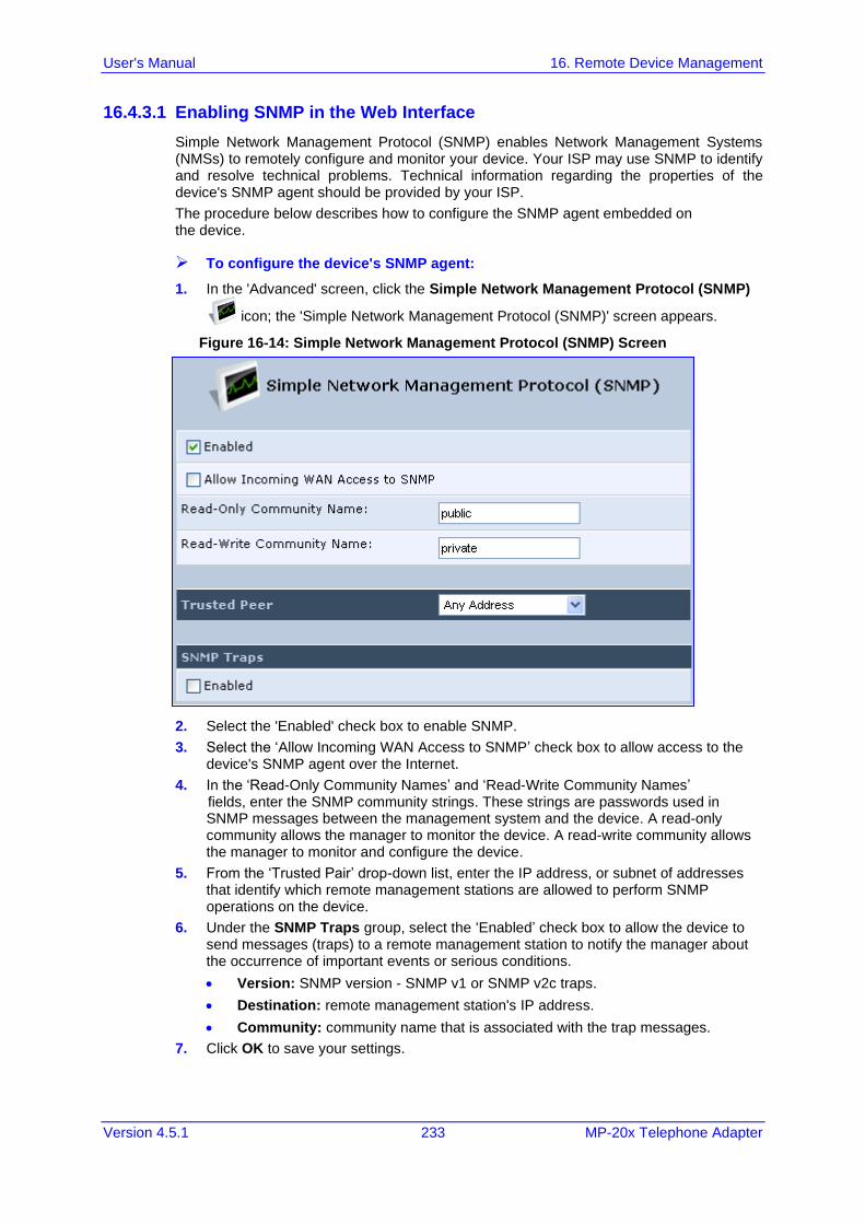
User's Manual 16. Remote Device Management
Version 4.5.1 233 MP-20x Telephone Adapter
16.4.3.1 Enabling SNMP in the Web Interface
Simple Network Management Protocol (SNMP) enables Network Management Systems (NMSs) to remotely configure and monitor your device. Your ISP may use SNMP to identify and resolve technical problems. Technical information regarding the properties of the device's SNMP agent should be provided by your ISP.
The procedure below describes how to configure the SNMP agent embedded on the device.
➢ To configure the device's SNMP agent:
1. In the 'Advanced' screen, click the Simple Network Management Protocol (SNMP)
icon; the 'Simple Network Management Protocol (SNMP)' screen appears.
Figure 16-14: Simple Network Management Protocol (SNMP) Screen
2. Select the 'Enabled' check box to enable SNMP.
3. Select the ‘Allow Incoming WAN Access to SNMP’ check box to allow access to the device's SNMP agent over the Internet.
4. In the ‘Read-Only Community Names’ and ‘Read-Write Community Names’ fields, enter the SNMP community strings. These strings are passwords used in SNMP messages between the management system and the device. A read-only community allows the manager to monitor the device. A read-write community allows the manager to monitor and configure the device.
5. From the ‘Trusted Pair’ drop-down list, enter the IP address, or subnet of addresses that identify which remote management stations are allowed to perform SNMP operations on the device.
6. Under the SNMP Traps group, select the ‘Enabled’ check box to allow the device to send messages (traps) to a remote management station to notify the manager about the occurrence of important events or serious conditions.
• Version: SNMP version - SNMP v1 or SNMP v2c traps.
• Destination: remote management station's IP address.
• Community: community name that is associated with the trap messages.
7. Click OK to save your settings.
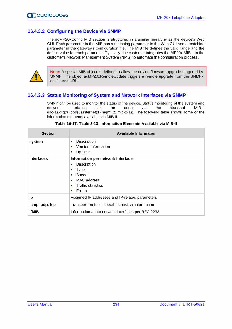
User's Manual 234 Document #: LTRT-50621
MP-20x Telephone Adapter
16.4.3.2 Configuring the Device via SNMP
The acMP20xConfig MIB section is structured in a similar hierarchy as the device's Web GUI. Each parameter in the MIB has a matching parameter in the Web GUI and a matching parameter in the gateway’s configuration file. The MIB file defines the valid range and the default value for each parameter. Typically, the customer integrates the MP20x MIB into the customer's Network Management System (NMS) to automate the configuration process.
Note: A special MIB object is defined to allow the device firmware upgrade triggered by SNMP. The object acMP20xRemoteUpdate triggers a remote upgrade from the SNMP-configured URL.
16.4.3.3 Status Monitoring of System and Network Interfaces via SNMP
SMNP can be used to monitor the status of the device. Status monitoring of the system and network interfaces can be done via the standard MIB-II (iso(1).org(3).dod(6).internet(1).mgmt(2).mib-2(1)). The following table shows some of the information elements available via MIB-II:
Table 16-17: Table 3-13: Information Elements Available via MIB-II
Section Available Information
system ▪ Description
▪ Version Information
▪ Up-time
interfaces Information per network interface:
▪ Description
▪ Type
▪ Speed
▪ MAC address
▪ Traffic statistics
▪ Errors
ip Assigned IP addresses and IP-related parameters
icmp, udp, tcp Transport-protocol specific statistical information
ifMIB Information about network interfaces per RFC 2233
User's Manual 16. Remote Device Management
Version 4.5.1 235 MP-20x Telephone Adapter
16.4.3.4 Security Concerns and Measures
Since SNMP allows write-access to configuration parameters, it is important to protect this interface. The following security measures are available:
◼ A community string (password) can be defined for read-only access and for read/write access.
◼ It is possible to limit access to SNMP to a trusted peer (single IP address or a range of addresses).
◼ SNMPv3 provides an significant security improvement over SNMPv1/2. Version 2.8.0 will support SNMPv3 and will allow the service provider to configure SNMPv3 security parameters.
User's Manual 236 Document #: LTRT-50621
MP-20x Telephone Adapter
16.4.4 Syslog
Syslog is a standard protocol for reporting and logging of messages over IP network and is defined by RFC 3164. The device enables the service provider to configure a Syslog server and a severity level above which errors are sent to the server. Typically, only error-level messages should be sent to the Syslog server (in order not to flood it with irrelevant debug-level information). For debugging, it is possible to temporarily allow logging for debug-level messages (e.g. for SIP messages).
Many free Syslog servers exist, including Kiwi Syslog Daemon (http://www.kiwisyslog.com).
Note: Since Syslog is used only to output messages from the device, it does not contain any security concerns.
16.4.5 Automatic File Download
A practical, straight-forward and easy to implement method for mass configuration and firmware update is automatic file download from a remote file server (via HTTP, FTP, or TFTP). This method is used by many service providers.
16.4.5.1 Firmware File Download
The device's firmware files contain information about the target product type and the firmware version information.
16.4.5.2 Configuration File Download
The device supports two configuration file formats, a *.conf file and an *.ini file. Both files define the same parameters, but in a different format; the *.conf file has a hierarchical tree-like structure and the *.ini file is "flat" (defining the full path for each parameter).
As with the firmware file, the configuration file can be “pushed” to the device via the Web server or “pulled” by the device from a remote server. This section refers only to the second option.
When the device downloads a file from a remote server, it performs the following actions:
◼ Decrypts the file, if it is encrypted.
◼ Checks that the file version is later than the current configuration file version (if it is not later, the new configuration is not used).
◼ Checks the software version with which the configuration file was created (if the file was created with a later software version, it is not used).
User's Manual 16. Remote Device Management
Version 4.5.1 237 MP-20x Telephone Adapter
◼ Merges the configuration file with the current configuration:
• Parameters that appear in the new file are modified or added
• Parameters that do not appear in the new file remain in their existing value
Notes:
• It is recommended that the configuration file (that is downloaded from the network), contains only the small subset of parameters that the service provider needs to update remotely.
• To create the configuration file, it is recommended to use the device that is restored to factory settings, modify the required parameters using the Web GUI, and then upload the configuration file from the device with the option to get only the modified configuration fields enabled.
16.4.5.3 Security Concerns and Measures
The main security hazard in automatic file download is that a hacker can force the device to download a file from the hacker's server instead of the service provider’s legitimate server. Another concern is exposing information such as the SIP proxy IP address and user and password information in the configuration file (if the hacker is sniffing the network).
The following security measures are available to prevent this:
◼ The configuration file can be encrypted using 3DES with pre-configured key. This prevents the user from learning the format of the file and obtaining information from it.
◼ HTTPS can be used to further encrypt the transport.
◼ HTTPS certificates can be used to allow the device to authenticate the server and also to prevent the user from acquiring the file from the server.
16.4.6 Telnet CLI
The device features a Command Line Interface (CLI) over Telnet. The CLI enables the service provider to manage the device (e.g. reboot, force a firmware upgrade), to obtain information about the status of the device (e.g. VoIP calls, network interfaces, version information), to change the configuration and to perform different debugging tasks (e.g. enable debug logging, enable packet recording).
Typically, the CLI interface is only used for debugging and diagnostics, since it does not allow mass configuration and monitoring.
Since the CLI allows all configuration and management operations, it is important to protect it. The following security measures are available:
◼ The CLI is user and password protected (same as the Web).
◼ Telnet access can be blocked from the WAN and/or LAN interfaces.
◼ It is possible to limit Telnet access to specific IP addresses.
16.4.7 Redirect Server
You can use the AudioCodes Redirect server to direct you to the appropriate Provisioning server URL to download the relevant configuration and firmware files.
Once the MP-20x is powered up and network connectivity is established, it automatically request for provisioning information. In case it does not obtain these files according to the regular provisioning hunt order methods, it sends a request to the AudioCodes Redirect server. The server responds to the MP-20x with an HTTP Redirect response containing the URL of the Provisioning server where the configuration file is located.
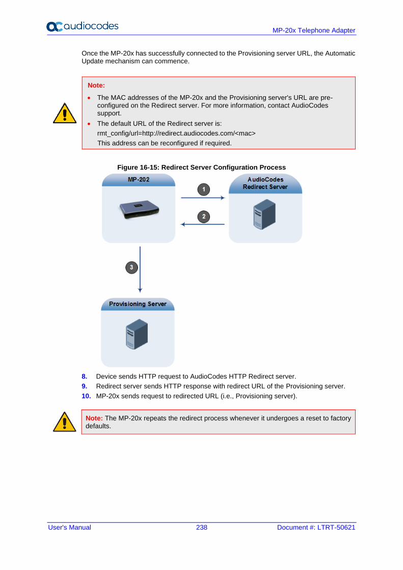
User's Manual 238 Document #: LTRT-50621
MP-20x Telephone Adapter
Once the MP-20x has successfully connected to the Provisioning server URL, the Automatic Update mechanism can commence.
Note:
• The MAC addresses of the MP-20x and the Provisioning server's URL are pre-configured on the Redirect server. For more information, contact AudioCodes support.
• The default URL of the Redirect server is:
rmt_config/url=http://redirect.audiocodes.com/<mac>
This address can be reconfigured if required.
Figure 16-15: Redirect Server Configuration Process
8. Device sends HTTP request to AudioCodes HTTP Redirect server.
9. Redirect server sends HTTP response with redirect URL of the Provisioning server.
10. MP-20x sends request to redirected URL (i.e., Provisioning server).
Note: The MP-20x repeats the redirect process whenever it undergoes a reset to factory defaults.
User's Manual 16. Remote Device Management
Version 4.5.1 239 MP-20x Telephone Adapter
16.4.8 BroadSoft BroadWorks DMS Provisioning
1. You can now force the SIP and media to be encrypted using BroadSoft DMS (i.e., configuration file).
This is in addition to the current mechanism which is based on DNS NAPTR.
It gives additional control to the customer to force VoIP encryption by setting a specific custom tag from the BroadSoft Web portal. This tag -%ENABLE_SIP_ENCRYPTION% - will reflect the relevant configuration parameter in MP-20x.
rg_conf/voip/signalling/enable_sip_rtp_encryption = {0,1} (0
by default)
Note: If enable_sip_rtp_encryption=1 and the NAPTR record response does not contain any TLS option, the device stops the DNS query process and won’t continue to the SIP Register phase.
For more information, refer to the BroadSoft Partner Configuration Guide (PartnerConfigGuide_AudioCodes_MP-2xx.pdf).
16.4.9 Provisioning using DHCP Options 66/67 and TFTP
DHCP Options 66 and 67 together with the TFTP server allow mass provisioning of MP-20x devices. The following table describes these DHCP Options.
Table 16-18: DHCP Options 66/67 Descriptions
DHCP Option Number
DHCP Option Name
Description
66 TFTP Server
Name Defines the FQDN or IP address of the TFTP server that the device should use.
67 Filename Defines the filename to be downloaded from the TFTP server specified in Option 66.
16.4.9.1 Default Behavior
During the DHCP process (DHCP Discover), the device declares the list of supported DHCP Options, including Options 66 and 67. If one or both of these Options are defined on the DHCP server, the DHCP server replies with defined values (i.e., IP address of the TFTP server and the file to download).
16.4.9.1.1 Option 66 Only
If the DHCP server replies to Option 66 only (i.e., sends the address of the TFTP server), the device sends a request to the TFTP server for the default firmware and configuration filenames:
◼ Firmware filename: MP202.rms
◼ Configuration filename: MP202_<MAC>.ini
If the firmware file exists, the device downloads the file, upgrades and reboots itself.
If the firmware file does not exist, the device downloads the configuration file, applies the settings and then reboots. The default firmware and configuration filenames can be changed through CLI, using the following:
rg_conf/system/dhcpc/option_67_default_name=MP202_<MAC>.ini;MP202.
rms
User's Manual 240 Document #: LTRT-50621
MP-20x Telephone Adapter
16.4.9.1.2 Options 66 and 67
If the DHCP server replies to both Options 66 and 67, the device sends a request to the TFTP server for a filename as specified in Option 67 (instead of the default filename).
16.4.9.2 Disabling DHCP Options 66 and 67
At every reboot, the device requests DHCP Options 66 and 67. If the DHCP server responds to the request, the device accesses the TFTP server and downloads the configuration. This process repeats itself until the device stops requesting these Options or the DHCP stops responding to these Options. To avoid this DHCP looping process upon each reboot, it is possible to disable the use of DHCP Options 66 and 67 on the WAN interface once the device downloads the file.
Add the relevant parameter (see below) on the device's WAN interface to the configuration file located in TFTP directory. The file is downloaded only once and after that, the device no longer declares Options 66 and 67.
The following needs to be added to the configuration to disable DHCP Options 66 and 67:
rg_conf/dev/eth1/dhcpc/options_66_67_disabled=1
To return to the default behavior, either remove this parameter or set the parameter to "0":
rg_conf/dev/eth1/dhcpc/options_66_67_disabled=0
16.4.10 Setting Provisioning Time of Day (TOD)
It is possible to configure the device to perform provisioning at random or fixed times using the configuration below.
Note: The device has to be rebooted for the configuration to take effect.
Table 16-19: Provisioning TOD Configuration
TOD Configuration Type of TOD Format (default)
rg_conf/rmt_config/random_tod/start Random TOD HH:MM (not configured)
rg_conf/rmt_config/random_tod/end Random TOD HH:MM (not configured)
rg_conf/rmt_config/random_tod/check_tod Random TOD HH:MM (not configured)
rg_conf/rmt_config/tod Fixed TOD HH:MM (not configured )
rg_conf/rmt_config/check_interval No TOD Seconds (86400)
16.4.10.1 Random TOD
You can configure a time range for when the provisioning can take place.
User's Manual 16. Remote Device Management
Version 4.5.1 241 MP-20x Telephone Adapter
The range is configured between rg_conf/rmt_config/random_tod/start and rg_conf/rmt_config/random_tod/end.
The device calculates a new time each day in that range, for the provisioning.
The calculation time occurs every day at rg_conf/rmt_config/random_tod/check_tod (default is midnight), and is saved at rg_conf/rmt_config/random_tod/calc_tod for reference.
Example:
For the following configuration, at 10:00 AM every day, the device calculates a provisioning time between 22:00 and 02:00 the following day. There are 14,400 calculation possibilities (4 hours x 60 minutes x 60 seconds).
rg_conf/rmt_config/random_tod/start 22:00
rg_conf/rmt_config/random_tod/end 02:00
rg_conf/rmt_config/random_tod/check_tod 10:00
16.4.10.2 Fixed TOD
If Random TOD is not configured (i.e., no rg_conf/rmt_config/random_tod configuration is found), the device will perform provisioning every day at the time configured at rg_conf/rmt_config/tod.
16.4.10.3 No TOD Configured – Default Behavior
If no Random TOD or Fixed TOD is configured, the device tries to perform provisioning at fixed intervals since the start-up time of the device, configured with rg_conf/rmt_config/check_interval (configured in seconds – default is 24 hours).
16.4.10.4 Changing Default Cipher Suits for Provisioning
It is possible to change the default cipher suites to be used (or removed) for Provisioning. For example:
rg_conf/admin/cipher_list=
“EDH+CAMELLIA:EDH+aRSA:EECDH+aRSA+AESGCM:EECDH+aRSA+SHA384:EECDH+a
RSA+SHA256:EECDH:+CAMELLIA256:+AES256:+CAMELLIA128:+AES128:!SSLv3:
!aNULL:!eNULL:!LOW:!3DES:!MD5:!EXP:!PSK:!DSS:!RC4:!SEED:!ECDSA:CAM
ELLIA256-SHA:AES256-SHA:CAMELLIA128-SHA:AES128-SHA”

User's Manual 242 Document #: LTRT-50621
MP-20x Telephone Adapter
This page is intentionally left blank.
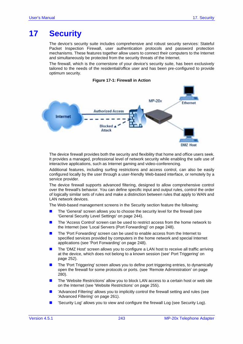
User's Manual 17. Security
Version 4.5.1 243 MP-20x Telephone Adapter
17 Security The device's security suite includes comprehensive and robust security services: Stateful Packet Inspection Firewall, user authentication protocols and password protection mechanisms. These features together allow users to connect their computers to the Internet and simultaneously be protected from the security threats of the Internet.
The firewall, which is the cornerstone of your device's security suite, has been exclusively tailored to the needs of the residential/office user and has been pre-configured to provide optimum security.
Figure 17-1: Firewall in Action
The device firewall provides both the security and flexibility that home and office users seek. It provides a managed, professional level of network security while enabling the safe use of interactive applications, such as Internet gaming and video-conferencing.
Additional features, including surfing restrictions and access control, can also be easily configured locally by the user through a user-friendly Web-based interface, or remotely by a service provider.
The device firewall supports advanced filtering, designed to allow comprehensive control over the firewall's behavior. You can define specific input and output rules, control the order of logically similar sets of rules and make a distinction between rules that apply to WAN and LAN network devices.
The Web-based management screens in the Security section feature the following:
◼ The 'General' screen allows you to choose the security level for the firewall (see 'General Security Level Settings' on page 244).
◼ The 'Access Control' screen can be used to restrict access from the home network to the Internet (see 'Local Servers (Port Forwarding)' on page 248).
◼ The 'Port Forwarding' screen can be used to enable access from the Internet to specified services provided by computers in the home network and special Internet applications (see 'Port Forwarding' on page 248).
◼ The 'DMZ Host' screen allows you to configure a LAN host to receive all traffic arriving at the device, which does not belong to a known session (see' Port Triggering' on page 252).
◼ The 'Port Triggering' screen allows you to define port triggering entries, to dynamically open the firewall for some protocols or ports. (see 'Remote Administration' on page 280).
◼ The 'Website Restrictions' allow you to block LAN access to a certain host or web site on the Internet (see 'Website Restrictions' on page 255).
◼ 'Advanced Filtering' allows you to implicitly control the firewall setting and rules (see 'Advanced Filtering' on page 261).
◼ 'Security Log' allows you to view and configure the firewall Log (see Security Log).
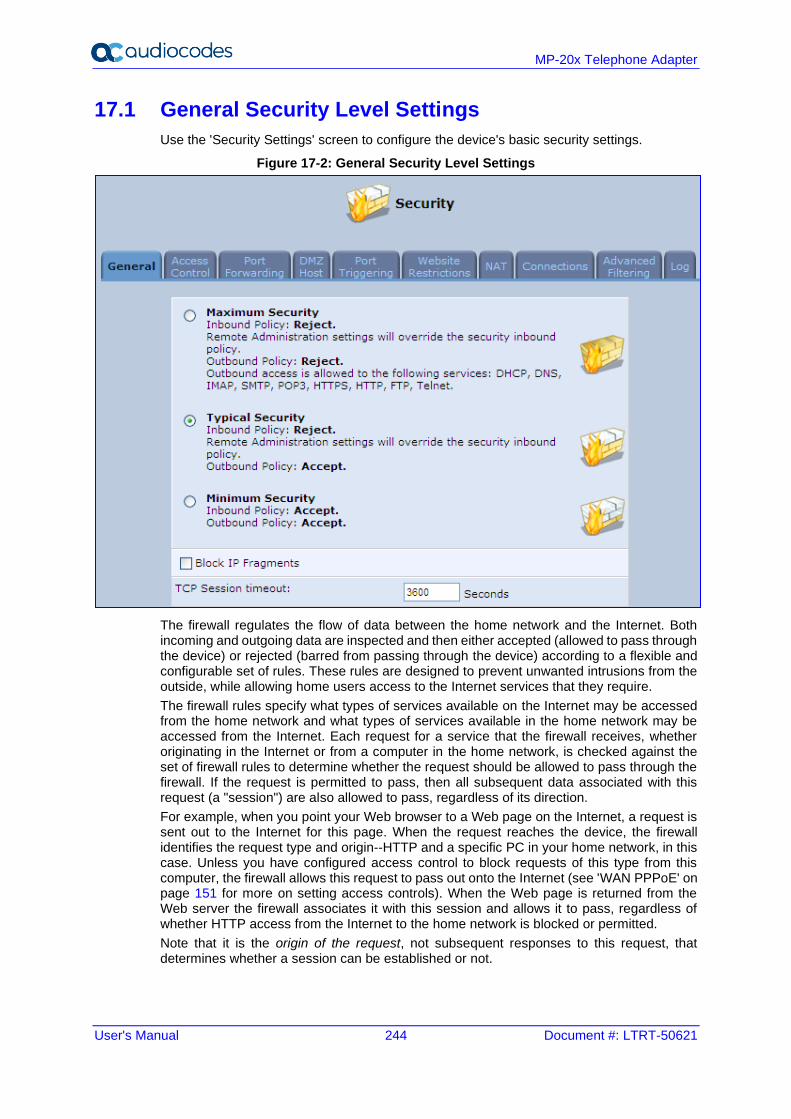
User's Manual 244 Document #: LTRT-50621
MP-20x Telephone Adapter
17.1 General Security Level Settings
Use the 'Security Settings' screen to configure the device's basic security settings.
Figure 17-2: General Security Level Settings
The firewall regulates the flow of data between the home network and the Internet. Both incoming and outgoing data are inspected and then either accepted (allowed to pass through the device) or rejected (barred from passing through the device) according to a flexible and configurable set of rules. These rules are designed to prevent unwanted intrusions from the outside, while allowing home users access to the Internet services that they require.
The firewall rules specify what types of services available on the Internet may be accessed from the home network and what types of services available in the home network may be accessed from the Internet. Each request for a service that the firewall receives, whether originating in the Internet or from a computer in the home network, is checked against the set of firewall rules to determine whether the request should be allowed to pass through the firewall. If the request is permitted to pass, then all subsequent data associated with this request (a "session") are also allowed to pass, regardless of its direction.
For example, when you point your Web browser to a Web page on the Internet, a request is sent out to the Internet for this page. When the request reaches the device, the firewall identifies the request type and origin--HTTP and a specific PC in your home network, in this case. Unless you have configured access control to block requests of this type from this computer, the firewall allows this request to pass out onto the Internet (see 'WAN PPPoE' on page 151 for more on setting access controls). When the Web page is returned from the Web server the firewall associates it with this session and allows it to pass, regardless of whether HTTP access from the Internet to the home network is blocked or permitted.
Note that it is the origin of the request, not subsequent responses to this request, that determines whether a session can be established or not.
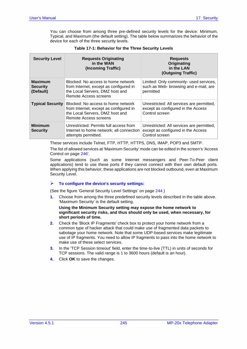
User's Manual 17. Security
Version 4.5.1 245 MP-20x Telephone Adapter
You can choose from among three pre-defined security levels for the device: Minimum, Typical, and Maximum (the default setting). The table below summarizes the behavior of the device for each of the three security levels.
Table 17-1: Behavior for the Three Security Levels
Security Level Requests Originating in the WAN
(Incoming Traffic)
Requests Originating in the LAN
(Outgoing Traffic)
Maximum Security (Default)
Blocked: No access to home network from Internet, except as configured in the Local Servers, DMZ host and Remote Access screens
Limited: Only commonly- used services, such as Web- browsing and e-mail, are permitted
Typical Security Blocked: No access to home network from Internet, except as configured in the Local Servers, DMZ host and Remote Access screens
Unrestricted: All services are permitted, except as configured in the Access Control screen
Minimum Security
Unrestricted: Permits full access from Internet to home network; all connection attempts permitted.
Unrestricted: All services are permitted, except as configured in the Access Control screen
These services include Telnet, FTP, HTTP, HTTPS, DNS, IMAP, POP3 and SMTP.
The list of allowed services at 'Maximum Security' mode can be edited in the screen's 'Access Control on page 246'.
Some applications (such as some Internet messengers and Peer-To-Peer client applications) tend to use these ports if they cannot connect with their own default ports. When applying this behavior, these applications are not blocked outbound, even at Maximum Security Level.
➢ To configure the device's security settings:
(See the figure 'General Security Level Settings' on page 244.)
1. Choose from among the three predefined security levels described in the table above. 'Maximum Security' is the default setting.
Using the Minimum Security setting may expose the home network to significant security risks, and thus should only be used, when necessary, for short periods of time.
2. Check the 'Block IP Fragments' check box to protect your home network from a common type of hacker attack that could make use of fragmented data packets to sabotage your home network. Note that some UDP-based services make legitimate use of IP fragments. You need to allow IP fragments to pass into the home network to make use of these select services.
3. In the 'TCP Session timeout' field, enter the time-to-live (TTL) in units of seconds for TCP sessions. The valid range is 1 to 3600 hours (default is an hour).
4. Click OK to save the changes.
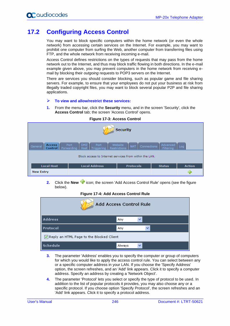
User's Manual 246 Document #: LTRT-50621
MP-20x Telephone Adapter
17.2 Configuring Access Control
You may want to block specific computers within the home network (or even the whole network) from accessing certain services on the Internet. For example, you may want to prohibit one computer from surfing the Web, another computer from transferring files using FTP, and the whole network from receiving incoming e-mail.
Access Control defines restrictions on the types of requests that may pass from the home network out to the Internet, and thus may block traffic flowing in both directions. In the e-mail example given above, you may prevent computers in the home network from receiving e-mail by blocking their outgoing requests to POP3 servers on the Internet.
There are services you should consider blocking, such as popular game and file sharing servers. For example, to ensure that your employees do not put your business at risk from illegally traded copyright files, you may want to block several popular P2P and file sharing applications.
➢ To view and allow/restrict these services:
1. From the menu bar, click the Security menu, and in the screen 'Security', click the Access Control tab; the screen 'Access Control' opens.
Figure 17-3: Access Control
2. Click the New icon; the screen 'Add Access Control Rule' opens (see the figure below).
Figure 17-4: Add Access Control Rule
3. The parameter 'Address' enables you to specify the computer or group of computers for which you would like to apply the access control rule. You can select between any or a specific computer address in your LAN. If you choose the 'Specify Address' option, the screen refreshes, and an 'Add' link appears. Click it to specify a computer address. Specify an address by creating a 'Network Object'.
4. The parameter 'Protocol' lets you select or specify the type of protocol to be used. In addition to the list of popular protocols it provides, you may also choose any or a specific protocol. If you choose option 'Specify Protocol', the screen refreshes and an 'Add' link appears. Click it to specify a protocol address.
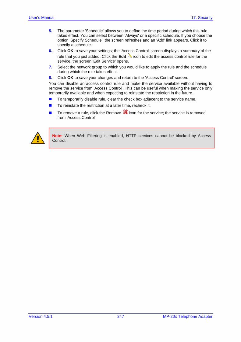
User's Manual 17. Security
Version 4.5.1 247 MP-20x Telephone Adapter
5. The parameter 'Schedule' allows you to define the time period during which this rule takes effect. You can select between 'Always' or a specific schedule. If you choose the option 'Specify Schedule', the screen refreshes and an 'Add' link appears. Click it to specify a schedule.
6. Click OK to save your settings; the 'Access Control' screen displays a summary of the
rule that you just added. Click the Edit icon to edit the access control rule for the service; the screen 'Edit Service' opens.
7. Select the network group to which you would like to apply the rule and the schedule during which the rule takes effect.
8. Click OK to save your changes and return to the 'Access Control' screen.
You can disable an access control rule and make the service available without having to remove the service from 'Access Control'. This can be useful when making the service only temporarily available and when expecting to reinstate the restriction in the future.
◼ To temporarily disable rule, clear the check box adjacent to the service name.
◼ To reinstate the restriction at a later time, recheck it.
◼ To remove a rule, click the Remove icon for the service; the service is removed from 'Access Control'.
Note: When Web Filtering is enabled, HTTP services cannot be blocked by Access Control.
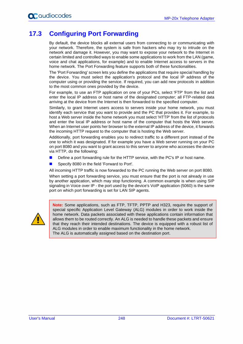
User's Manual 248 Document #: LTRT-50621
MP-20x Telephone Adapter
17.3 Configuring Port Forwarding
By default, the device blocks all external users from connecting to or communicating with your network. Therefore, the system is safe from hackers who may try to intrude on the network and damage it. However, you may want to expose your network to the Internet in certain limited and controlled ways to enable some applications to work from the LAN (game, voice and chat applications, for example) and to enable Internet access to servers in the home network. The Port Forwarding feature supports both of these functionalities.
The 'Port Forwarding' screen lets you define the applications that require special handling by the device. You must select the application's protocol and the local IP address of the computer using or providing the service. If required, you can add new protocols in addition to the most common ones provided by the device.
For example, to use an FTP application on one of your PCs, select 'FTP' from the list and enter the local IP address or host name of the designated computer; all FTP-related data arriving at the device from the Internet is then forwarded to the specified computer.
Similarly, to grant Internet users access to servers inside your home network, you must identify each service that you want to provide and the PC that provides it. For example, to host a Web server inside the home network you must select 'HTTP' from the list of protocols and enter the local IP address or host name of the computer that hosts the Web server. When an Internet user points her browser to the external IP address of the device, it forwards the incoming HTTP request to the computer that is hosting the Web server.
Additionally, port forwarding enables you to redirect traffic to a different port instead of the one to which it was designated. If for example you have a Web server running on your PC on port 8080 and you want to grant access to this server to anyone who accesses the device via HTTP, do the following:
◼ Define a port forwarding rule for the HTTP service, with the PC's IP or host name.
◼ Specify 8080 in the field 'Forward to Port'.
All incoming HTTP traffic is now forwarded to the PC running the Web server on port 8080.
When setting a port forwarding service, you must ensure that the port is not already in use by another application, which may stop functioning. A common example is when using SIP signaling in Voice over IP - the port used by the device's VoIP application (5060) is the same port on which port forwarding is set for LAN SIP agents.
Note: Some applications, such as FTP, TFTP, PPTP and H323, require the support of special specific Application Level Gateway (ALG) modules in order to work inside the home network. Data packets associated with these applications contain information that allows them to be routed correctly. An ALG is needed to handle these packets and ensure that they reach their intended destinations. The device is equipped with a robust list of ALG modules in order to enable maximum functionality in the home network. The ALG is automatically assigned based on the destination port.
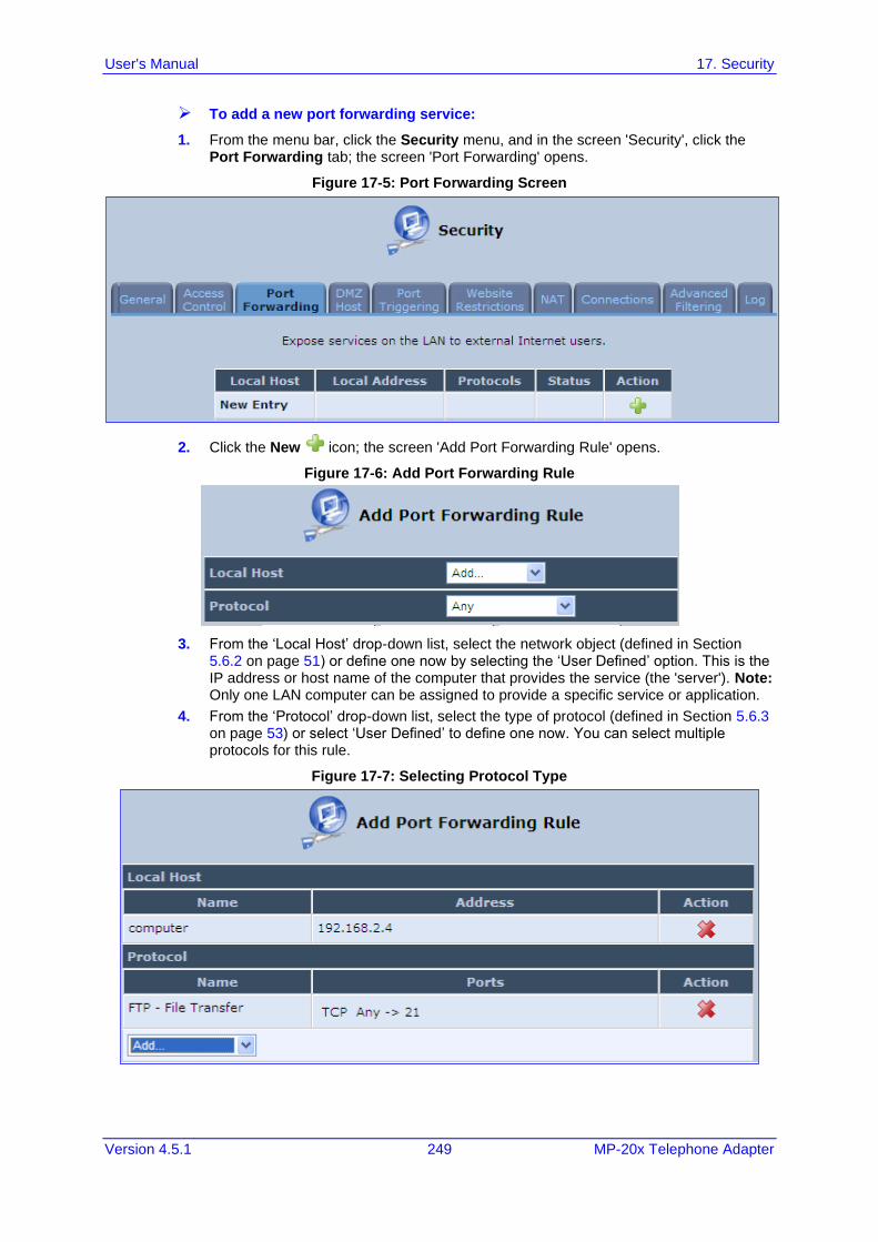
User's Manual 17. Security
Version 4.5.1 249 MP-20x Telephone Adapter
➢ To add a new port forwarding service:
1. From the menu bar, click the Security menu, and in the screen 'Security', click the Port Forwarding tab; the screen 'Port Forwarding' opens.
Figure 17-5: Port Forwarding Screen
2. Click the New icon; the screen 'Add Port Forwarding Rule' opens.
Figure 17-6: Add Port Forwarding Rule
3. From the ‘Local Host’ drop-down list, select the network object (defined in Section 5.6.2 on page 51) or define one now by selecting the ‘User Defined’ option. This is the IP address or host name of the computer that provides the service (the 'server'). Note: Only one LAN computer can be assigned to provide a specific service or application.
4. From the ‘Protocol’ drop-down list, select the type of protocol (defined in Section 5.6.3 on page 53) or select ‘User Defined’ to define one now. You can select multiple protocols for this rule.
Figure 17-7: Selecting Protocol Type
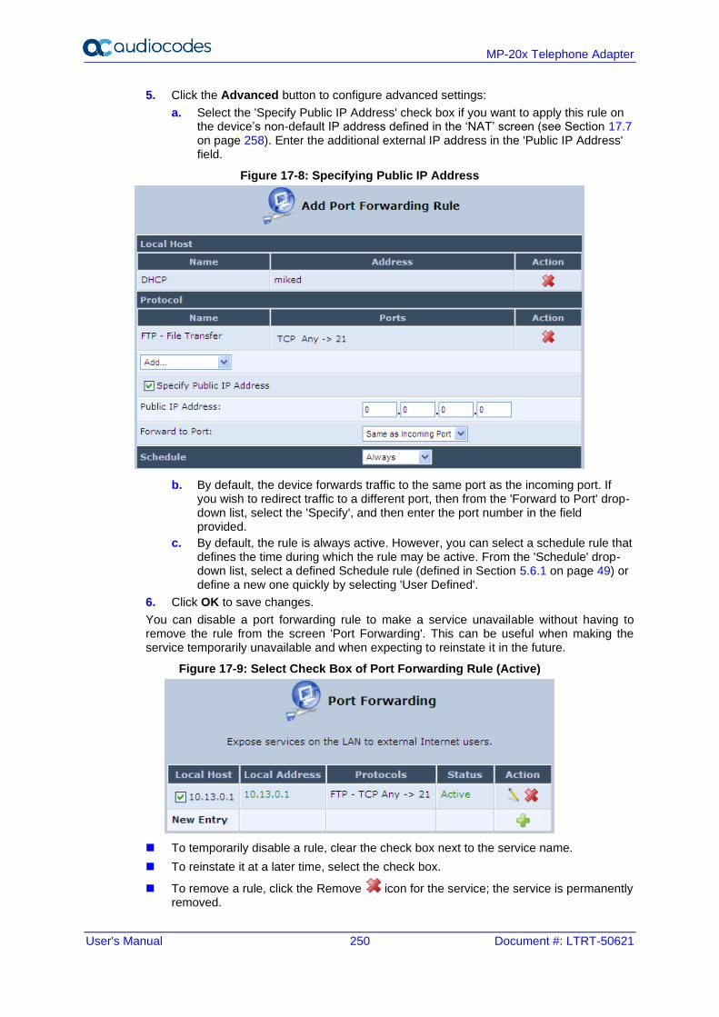
User's Manual 250 Document #: LTRT-50621
MP-20x Telephone Adapter
5. Click the Advanced button to configure advanced settings:
a. Select the 'Specify Public IP Address' check box if you want to apply this rule on the device’s non-default IP address defined in the ‘NAT’ screen (see Section 17.7 on page 258). Enter the additional external IP address in the 'Public IP Address' field.
Figure 17-8: Specifying Public IP Address
b. By default, the device forwards traffic to the same port as the incoming port. If you wish to redirect traffic to a different port, then from the 'Forward to Port' drop-down list, select the 'Specify', and then enter the port number in the field provided.
c. By default, the rule is always active. However, you can select a schedule rule that defines the time during which the rule may be active. From the 'Schedule' drop-down list, select a defined Schedule rule (defined in Section 5.6.1 on page 49) or define a new one quickly by selecting 'User Defined'.
6. Click OK to save changes.
You can disable a port forwarding rule to make a service unavailable without having to remove the rule from the screen 'Port Forwarding'. This can be useful when making the service temporarily unavailable and when expecting to reinstate it in the future.
Figure 17-9: Select Check Box of Port Forwarding Rule (Active)
◼ To temporarily disable a rule, clear the check box next to the service name.
◼ To reinstate it at a later time, select the check box.
◼ To remove a rule, click the Remove icon for the service; the service is permanently removed.
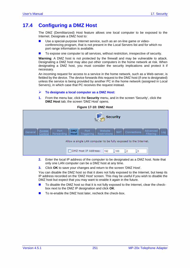
User's Manual 17. Security
Version 4.5.1 251 MP-20x Telephone Adapter
17.4 Configuring a DMZ Host
The DMZ (Demilitarized) Host feature allows one local computer to be exposed to the Internet. Designate a DMZ host to:
◼ Use a special-purpose Internet service, such as an on-line game or video-conferencing program, that is not present in the Local Servers list and for which no port range information is available.
◼ To expose one computer to all services, without restriction, irrespective of security.
Warning: A DMZ host is not protected by the firewall and may be vulnerable to attack. Designating a DMZ host may also put other computers in the home network at risk. When designating a DMZ host, you must consider the security implications and protect it if necessary.
An incoming request for access to a service in the home network, such as a Web-server, is fielded by the device. The device forwards this request to the DMZ host (if one is designated) unless the service is being provided by another PC in the home network (assigned in Local Servers), in which case that PC receives the request instead.
➢ To designate a local computer as a DMZ Host:
1. From the menu bar, click the Security menu, and in the screen 'Security', click the DMZ Host tab; the screen 'DMZ Host' opens.
Figure 17-10: DMZ Host
2. Enter the local IP address of the computer to be designated as a DMZ host. Note that only one LAN computer can be a DMZ host at any time.
3. Click OK to save your changes and return to the screen 'DMZ Host'.
You can disable the DMZ host so that it does not fully exposed to the Internet, but keep its IP address recorded on the 'DMZ Host' screen. This may be useful if you wish to disable the DMZ host but expect that you may want to enable it again in the future.
◼ To disable the DMZ host so that it is not fully exposed to the Internet, clear the check-box next to the DMZ IP designation and click OK.
◼ To re-enable the DMZ host later, recheck the check-box.
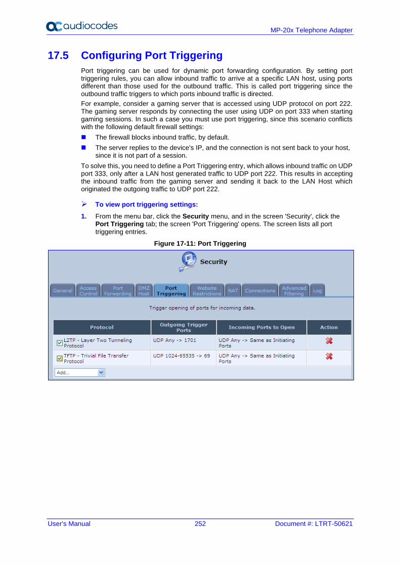
User's Manual 252 Document #: LTRT-50621
MP-20x Telephone Adapter
17.5 Configuring Port Triggering
Port triggering can be used for dynamic port forwarding configuration. By setting port triggering rules, you can allow inbound traffic to arrive at a specific LAN host, using ports different than those used for the outbound traffic. This is called port triggering since the outbound traffic triggers to which ports inbound traffic is directed.
For example, consider a gaming server that is accessed using UDP protocol on port 222. The gaming server responds by connecting the user using UDP on port 333 when starting gaming sessions. In such a case you must use port triggering, since this scenario conflicts with the following default firewall settings:
◼ The firewall blocks inbound traffic, by default.
◼ The server replies to the device's IP, and the connection is not sent back to your host, since it is not part of a session.
To solve this, you need to define a Port Triggering entry, which allows inbound traffic on UDP port 333, only after a LAN host generated traffic to UDP port 222. This results in accepting the inbound traffic from the gaming server and sending it back to the LAN Host which originated the outgoing traffic to UDP port 222.
➢ To view port triggering settings:
1. From the menu bar, click the Security menu, and in the screen 'Security', click the Port Triggering tab; the screen 'Port Triggering' opens. The screen lists all port triggering entries.
Figure 17-11: Port Triggering
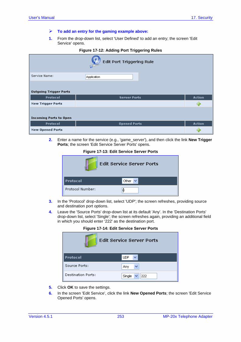
User's Manual 17. Security
Version 4.5.1 253 MP-20x Telephone Adapter
➢ To add an entry for the gaming example above:
1. From the drop-down list, select 'User Defined' to add an entry; the screen 'Edit Service' opens.
Figure 17-12: Adding Port Triggering Rules
2. Enter a name for the service (e.g., 'game_server'), and then click the link New Trigger Ports; the screen 'Edit Service Server Ports' opens.
Figure 17-13: Edit Service Server Ports
3. In the 'Protocol' drop-down list, select 'UDP'; the screen refreshes, providing source and destination port options.
4. Leave the 'Source Ports' drop-down list at its default 'Any'. In the 'Destination Ports' drop-down list, select 'Single'; the screen refreshes again, providing an additional field in which you should enter '222' as the destination port.
Figure 17-14: Edit Service Server Ports
5. Click OK to save the settings.
6. In the screen 'Edit Service', click the link New Opened Ports; the screen 'Edit Service Opened Ports' opens.
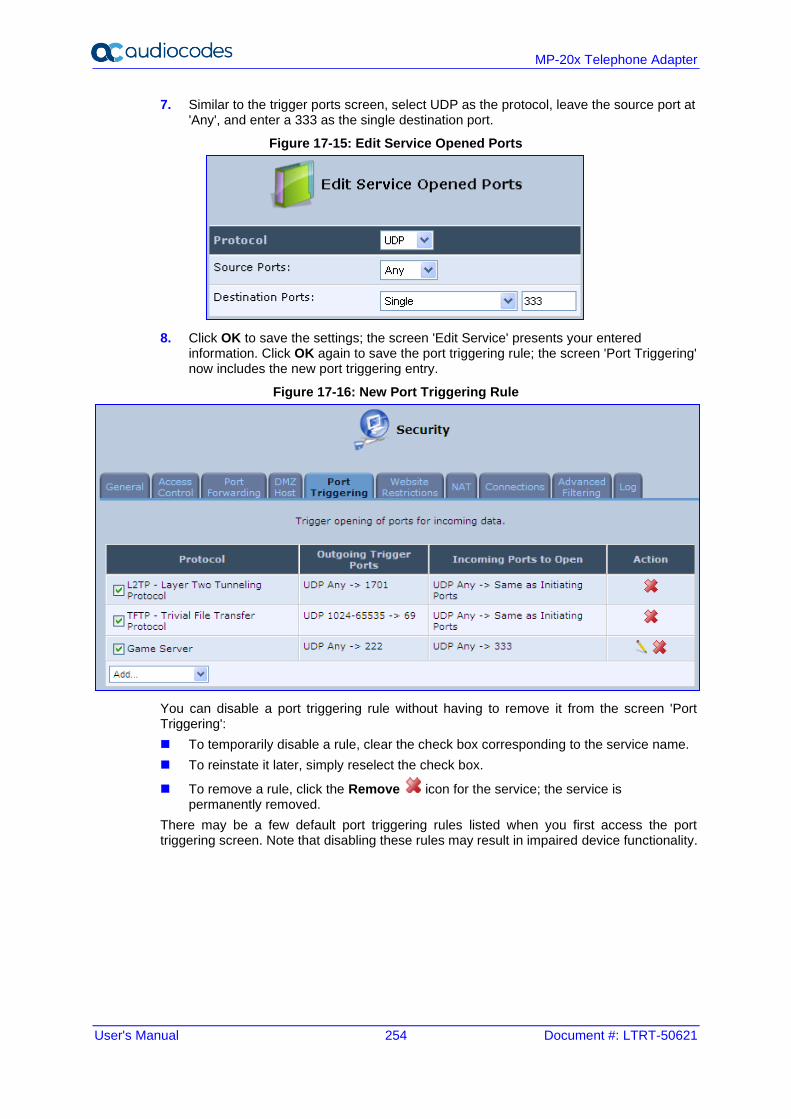
User's Manual 254 Document #: LTRT-50621
MP-20x Telephone Adapter
7. Similar to the trigger ports screen, select UDP as the protocol, leave the source port at 'Any', and enter a 333 as the single destination port.
Figure 17-15: Edit Service Opened Ports
8. Click OK to save the settings; the screen 'Edit Service' presents your entered information. Click OK again to save the port triggering rule; the screen 'Port Triggering' now includes the new port triggering entry.
Figure 17-16: New Port Triggering Rule
You can disable a port triggering rule without having to remove it from the screen 'Port Triggering':
◼ To temporarily disable a rule, clear the check box corresponding to the service name.
◼ To reinstate it later, simply reselect the check box.
◼ To remove a rule, click the Remove icon for the service; the service is permanently removed.
There may be a few default port triggering rules listed when you first access the port triggering screen. Note that disabling these rules may result in impaired device functionality.
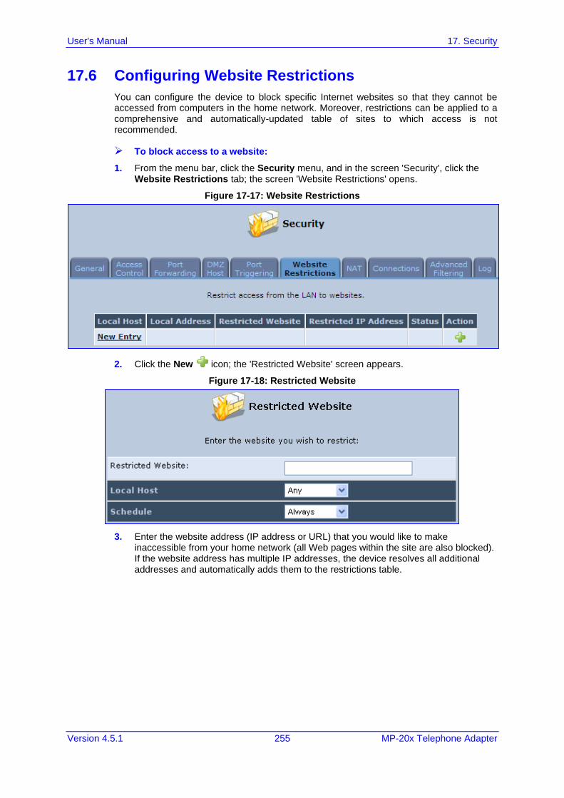
User's Manual 17. Security
Version 4.5.1 255 MP-20x Telephone Adapter
17.6 Configuring Website Restrictions
You can configure the device to block specific Internet websites so that they cannot be accessed from computers in the home network. Moreover, restrictions can be applied to a comprehensive and automatically-updated table of sites to which access is not recommended.
➢ To block access to a website:
1. From the menu bar, click the Security menu, and in the screen 'Security', click the Website Restrictions tab; the screen 'Website Restrictions' opens.
Figure 17-17: Website Restrictions
2. Click the New icon; the 'Restricted Website' screen appears.
Figure 17-18: Restricted Website
3. Enter the website address (IP address or URL) that you would like to make inaccessible from your home network (all Web pages within the site are also blocked). If the website address has multiple IP addresses, the device resolves all additional addresses and automatically adds them to the restrictions table.
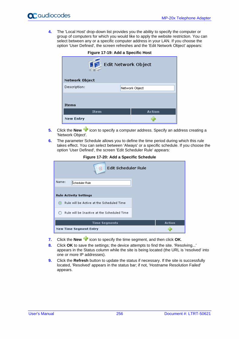
User's Manual 256 Document #: LTRT-50621
MP-20x Telephone Adapter
4. The 'Local Host' drop-down list provides you the ability to specify the computer or group of computers for which you would like to apply the website restriction. You can select between any or a specific computer address in your LAN. If you choose the option 'User Defined', the screen refreshes and the 'Edit Network Object' appears:
Figure 17-19: Add a Specific Host
5. Click the New icon to specify a computer address. Specify an address creating a 'Network Object'.
6. The parameter Schedule allows you to define the time period during which this rule takes effect. You can select between 'Always' or a specific schedule. If you choose the option 'User Defined', the screen 'Edit Scheduler Rule' appears:
Figure 17-20: Add a Specific Schedule
7. Click the New icon to specify the time segment, and then click OK.
8. Click OK to save the settings; the device attempts to find the site. 'Resolving...' appears in the Status column while the site is being located (the URL is 'resolved' into one or more IP addresses).
9. Click the Refresh button to update the status if necessary. If the site is successfully located, 'Resolved' appears in the status bar; if not, 'Hostname Resolution Failed' appears.
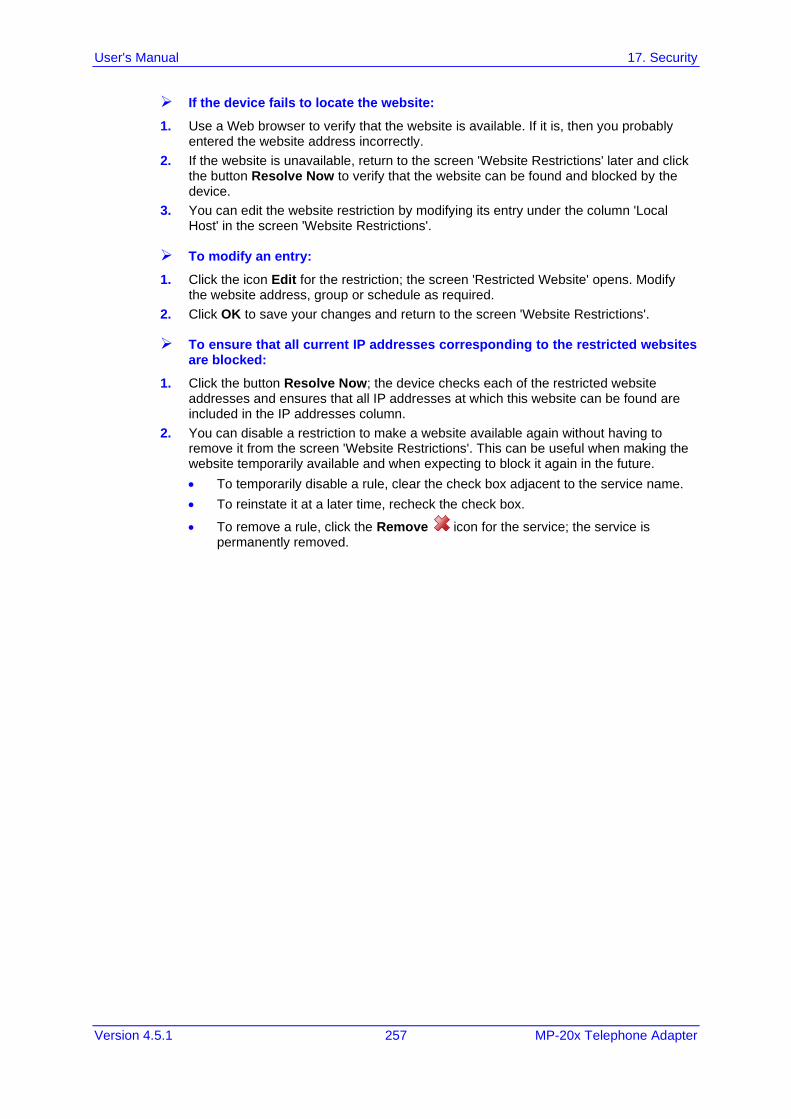
User's Manual 17. Security
Version 4.5.1 257 MP-20x Telephone Adapter
➢ If the device fails to locate the website:
1. Use a Web browser to verify that the website is available. If it is, then you probably entered the website address incorrectly.
2. If the website is unavailable, return to the screen 'Website Restrictions' later and click the button Resolve Now to verify that the website can be found and blocked by the device.
3. You can edit the website restriction by modifying its entry under the column 'Local Host' in the screen 'Website Restrictions'.
➢ To modify an entry:
1. Click the icon Edit for the restriction; the screen 'Restricted Website' opens. Modify the website address, group or schedule as required.
2. Click OK to save your changes and return to the screen 'Website Restrictions'.
➢ To ensure that all current IP addresses corresponding to the restricted websites are blocked:
1. Click the button Resolve Now; the device checks each of the restricted website addresses and ensures that all IP addresses at which this website can be found are included in the IP addresses column.
2. You can disable a restriction to make a website available again without having to remove it from the screen 'Website Restrictions'. This can be useful when making the website temporarily available and when expecting to block it again in the future.
• To temporarily disable a rule, clear the check box adjacent to the service name.
• To reinstate it at a later time, recheck the check box.
• To remove a rule, click the Remove icon for the service; the service is permanently removed.
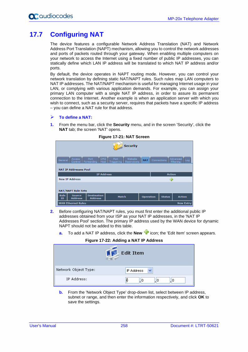
User's Manual 258 Document #: LTRT-50621
MP-20x Telephone Adapter
17.7 Configuring NAT
The device features a configurable Network Address Translation (NAT) and Network Address Port Translation (NAPT) mechanism, allowing you to control the network addresses and ports of packets routed through your gateway. When enabling multiple computers on your network to access the Internet using a fixed number of public IP addresses, you can statically define which LAN IP address will be translated to which NAT IP address and/or ports.
By default, the device operates in NAPT routing mode. However, you can control your network translation by defining static NAT/NAPT rules. Such rules map LAN computers to NAT IP addresses. The NAT/NAPT mechanism is useful for managing Internet usage in your LAN, or complying with various application demands. For example, you can assign your primary LAN computer with a single NAT IP address, in order to assure its permanent connection to the Internet. Another example is when an application server with which you wish to connect, such as a security server, requires that packets have a specific IP address – you can define a NAT rule for that address.
➢ To define a NAT:
1. From the menu bar, click the Security menu, and in the screen 'Security', click the NAT tab; the screen 'NAT' opens.
Figure 17-21: NAT Screen
2. Before configuring NAT/NAPT rules, you must first enter the additional public IP addresses obtained from your ISP as your NAT IP addresses, in the 'NAT IP Addresses Pool' section. The primary IP address used by the WAN device for dynamic NAPT should not be added to this table.
a. To add a NAT IP address, click the New icon; the 'Edit Item' screen appears.
Figure 17-22: Adding a NAT IP Address
b. From the 'Network Object Type' drop-down list, select between IP address, subnet or range, and then enter the information respectively, and click OK to save the settings.
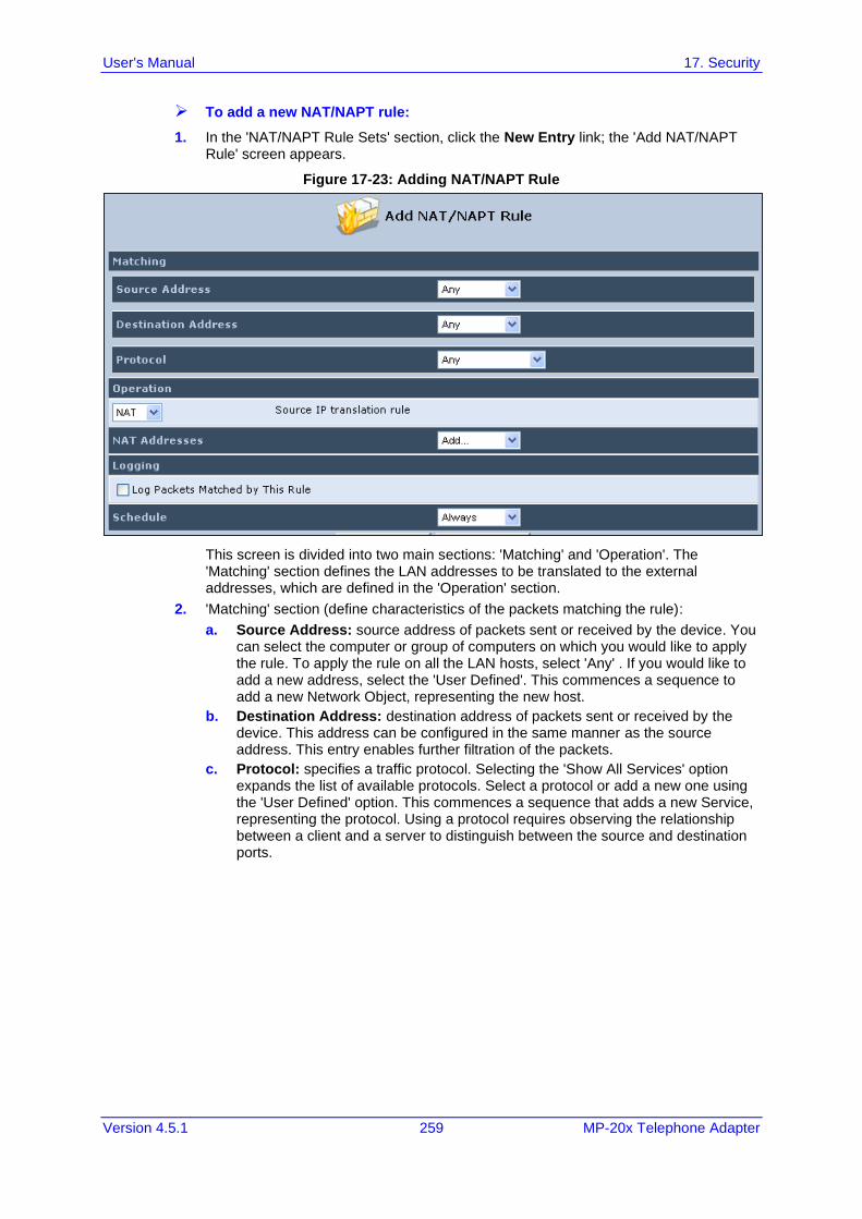
User's Manual 17. Security
Version 4.5.1 259 MP-20x Telephone Adapter
➢ To add a new NAT/NAPT rule:
1. In the 'NAT/NAPT Rule Sets' section, click the New Entry link; the 'Add NAT/NAPT Rule' screen appears.
Figure 17-23: Adding NAT/NAPT Rule
This screen is divided into two main sections: 'Matching' and 'Operation'. The 'Matching' section defines the LAN addresses to be translated to the external addresses, which are defined in the 'Operation' section.
2. 'Matching' section (define characteristics of the packets matching the rule):
a. Source Address: source address of packets sent or received by the device. You can select the computer or group of computers on which you would like to apply the rule. To apply the rule on all the LAN hosts, select 'Any' . If you would like to add a new address, select the 'User Defined'. This commences a sequence to add a new Network Object, representing the new host.
b. Destination Address: destination address of packets sent or received by the device. This address can be configured in the same manner as the source address. This entry enables further filtration of the packets.
c. Protocol: specifies a traffic protocol. Selecting the 'Show All Services' option expands the list of available protocols. Select a protocol or add a new one using the 'User Defined' option. This commences a sequence that adds a new Service, representing the protocol. Using a protocol requires observing the relationship between a client and a server to distinguish between the source and destination ports.
User's Manual 260 Document #: LTRT-50621
MP-20x Telephone Adapter
3. Operation section (define the operation to apply on the IP addresses, matching the criteria defined above): NAT or NAPT.
• NAT Addresses: NAT address into which the original IP address is translated. The drop-down list displays all of your available NAT addresses/ranges from which you can select an entry. If you would like to add a single address or a sub-range from the given pool/range, select the 'User Defined' option. This commences a sequence that adds a new Network Object, representing the new host.
• NAPT Address: NAPT address into which the original IP address is translated. The drop-down list displays all of your available NAPT addresses/ranges from which you can select an entry. If you would like to add a single address or a sub-range from the given pool/range, select the 'User Defined' option. This commences a sequence that adds a new Network Object, representing the new host. . Note, that in this case the network object may only be an IP address, as NAPT is port-specific.
• NAPT Ports: specify the port(s) of the IP address into which the original IP address is translated. Enter a single port or select 'Range' (the screen refreshes, enabling you to enter a range of ports).
4. Select the 'Log Packets Matched by This Rule' check box to log the first packet from a connection that was matched by this rule.
5. By default, the 'Schedule' rule is always active. However, you can configure scheduler rules to define time segments during which the rule may be active.
6. Click OK to save the settings.
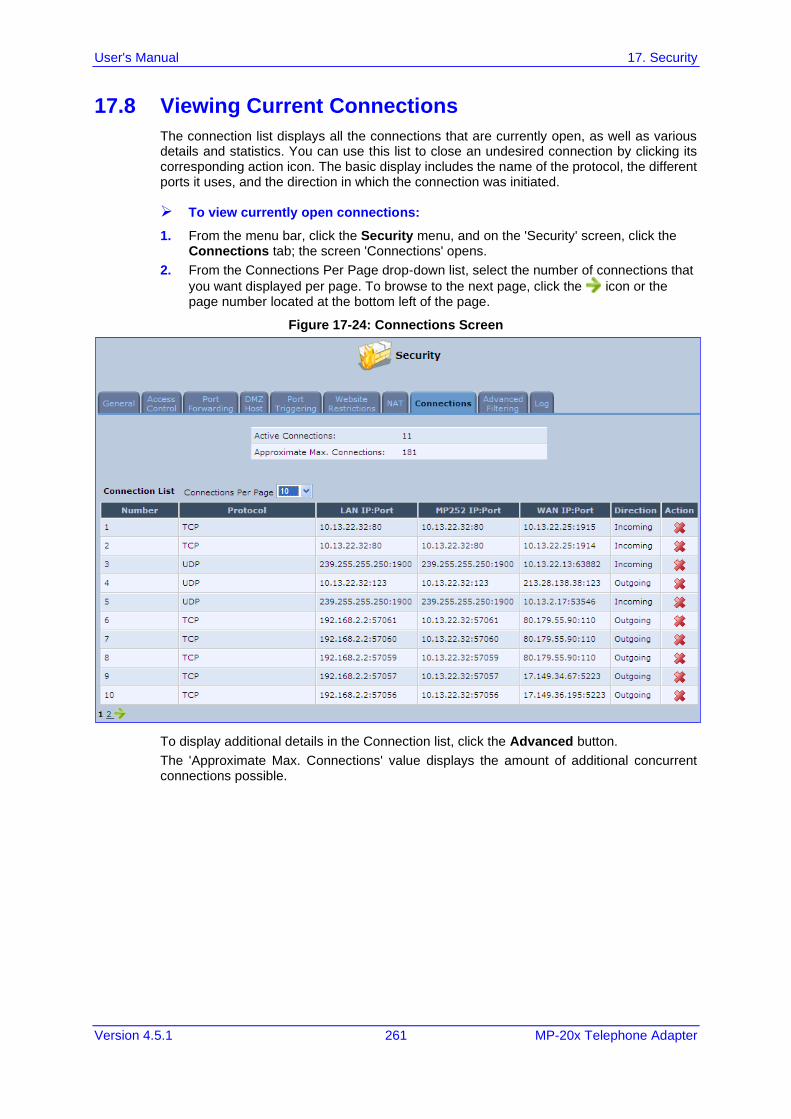
User's Manual 17. Security
Version 4.5.1 261 MP-20x Telephone Adapter
17.8 Viewing Current Connections
The connection list displays all the connections that are currently open, as well as various details and statistics. You can use this list to close an undesired connection by clicking its corresponding action icon. The basic display includes the name of the protocol, the different ports it uses, and the direction in which the connection was initiated.
➢ To view currently open connections:
1. From the menu bar, click the Security menu, and on the 'Security' screen, click the Connections tab; the screen 'Connections' opens.
2. From the Connections Per Page drop-down list, select the number of connections that
you want displayed per page. To browse to the next page, click the icon or the page number located at the bottom left of the page.
Figure 17-24: Connections Screen
To display additional details in the Connection list, click the Advanced button.
The 'Approximate Max. Connections' value displays the amount of additional concurrent connections possible.
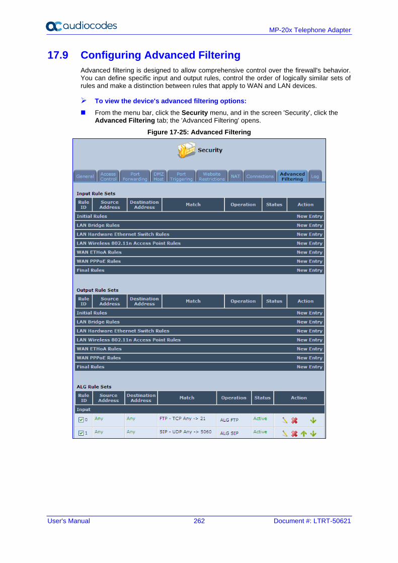
User's Manual 262 Document #: LTRT-50621
MP-20x Telephone Adapter
17.9 Configuring Advanced Filtering
Advanced filtering is designed to allow comprehensive control over the firewall's behavior. You can define specific input and output rules, control the order of logically similar sets of rules and make a distinction between rules that apply to WAN and LAN devices.
➢ To view the device's advanced filtering options:
◼ From the menu bar, click the Security menu, and in the screen 'Security', click the Advanced Filtering tab; the 'Advanced Filtering' opens.
Figure 17-25: Advanced Filtering
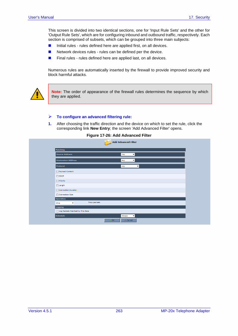
User's Manual 17. Security
Version 4.5.1 263 MP-20x Telephone Adapter
This screen is divided into two identical sections, one for 'Input Rule Sets' and the other for 'Output Rule Sets', which are for configuring inbound and outbound traffic, respectively. Each section is comprised of subsets, which can be grouped into three main subjects:
◼ Initial rules - rules defined here are applied first, on all devices.
◼ Network devices rules - rules can be defined per the device.
◼ Final rules - rules defined here are applied last, on all devices.
Numerous rules are automatically inserted by the firewall to provide improved security and block harmful attacks.
Note: The order of appearance of the firewall rules determines the sequence by which they are applied.
➢ To configure an advanced filtering rule:
1. After choosing the traffic direction and the device on which to set the rule, click the corresponding link New Entry; the screen 'Add Advanced Filter' opens.
Figure 17-26: Add Advanced Filter
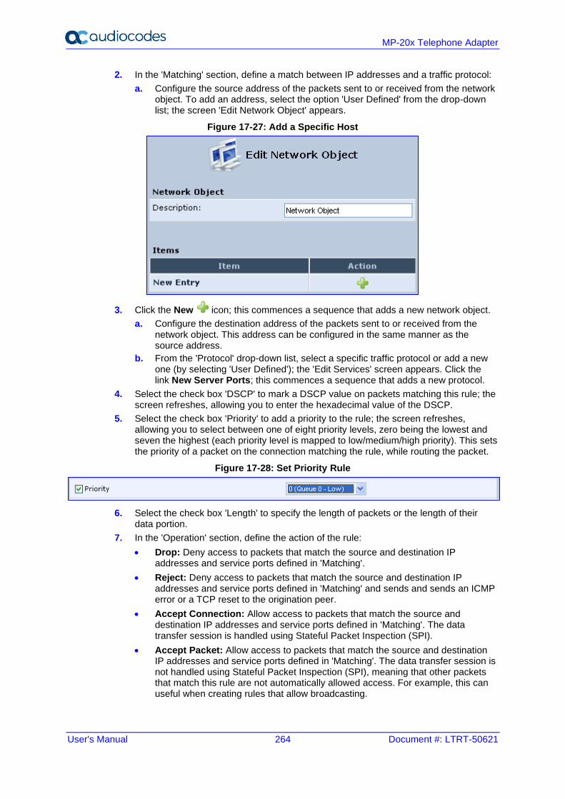
User's Manual 264 Document #: LTRT-50621
MP-20x Telephone Adapter
2. In the 'Matching' section, define a match between IP addresses and a traffic protocol:
a. Configure the source address of the packets sent to or received from the network object. To add an address, select the option 'User Defined' from the drop-down list; the screen 'Edit Network Object' appears.
Figure 17-27: Add a Specific Host
3. Click the New icon; this commences a sequence that adds a new network object.
a. Configure the destination address of the packets sent to or received from the network object. This address can be configured in the same manner as the source address.
b. From the 'Protocol' drop-down list, select a specific traffic protocol or add a new one (by selecting 'User Defined'); the 'Edit Services' screen appears. Click the link New Server Ports; this commences a sequence that adds a new protocol.
4. Select the check box 'DSCP' to mark a DSCP value on packets matching this rule; the screen refreshes, allowing you to enter the hexadecimal value of the DSCP.
5. Select the check box 'Priority' to add a priority to the rule; the screen refreshes, allowing you to select between one of eight priority levels, zero being the lowest and seven the highest (each priority level is mapped to low/medium/high priority). This sets the priority of a packet on the connection matching the rule, while routing the packet.
Figure 17-28: Set Priority Rule
6. Select the check box 'Length' to specify the length of packets or the length of their data portion.
7. In the 'Operation' section, define the action of the rule:
• Drop: Deny access to packets that match the source and destination IP addresses and service ports defined in 'Matching'.
• Reject: Deny access to packets that match the source and destination IP addresses and service ports defined in 'Matching' and sends and sends an ICMP error or a TCP reset to the origination peer.
• Accept Connection: Allow access to packets that match the source and destination IP addresses and service ports defined in 'Matching'. The data transfer session is handled using Stateful Packet Inspection (SPI).
• Accept Packet: Allow access to packets that match the source and destination IP addresses and service ports defined in 'Matching'. The data transfer session is not handled using Stateful Packet Inspection (SPI), meaning that other packets that match this rule are not automatically allowed access. For example, this can useful when creating rules that allow broadcasting.

User's Manual 17. Security
Version 4.5.1 265 MP-20x Telephone Adapter
8. Under the section 'Logging', select the parameter 'Log Packets Matched By This Rule' to log the first packet from a connection that was matched by this rule.
9. By default, the 'Schedule' rule is always active. However, you can configure scheduler rules to define time segments during which the rule may be active.
10. Click OK to save the settings.
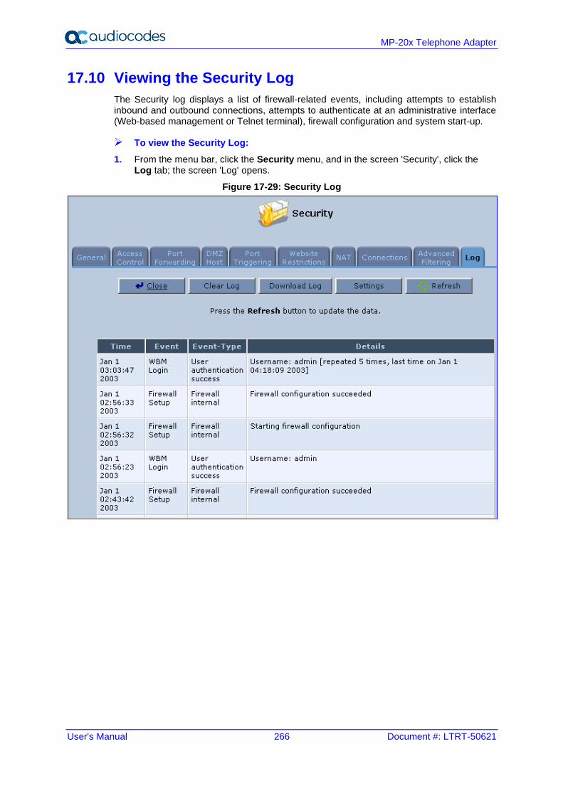
User's Manual 266 Document #: LTRT-50621
MP-20x Telephone Adapter
17.10 Viewing the Security Log
The Security log displays a list of firewall-related events, including attempts to establish inbound and outbound connections, attempts to authenticate at an administrative interface (Web-based management or Telnet terminal), firewall configuration and system start-up.
➢ To view the Security Log:
1. From the menu bar, click the Security menu, and in the screen 'Security', click the Log tab; the screen 'Log' opens.
Figure 17-29: Security Log
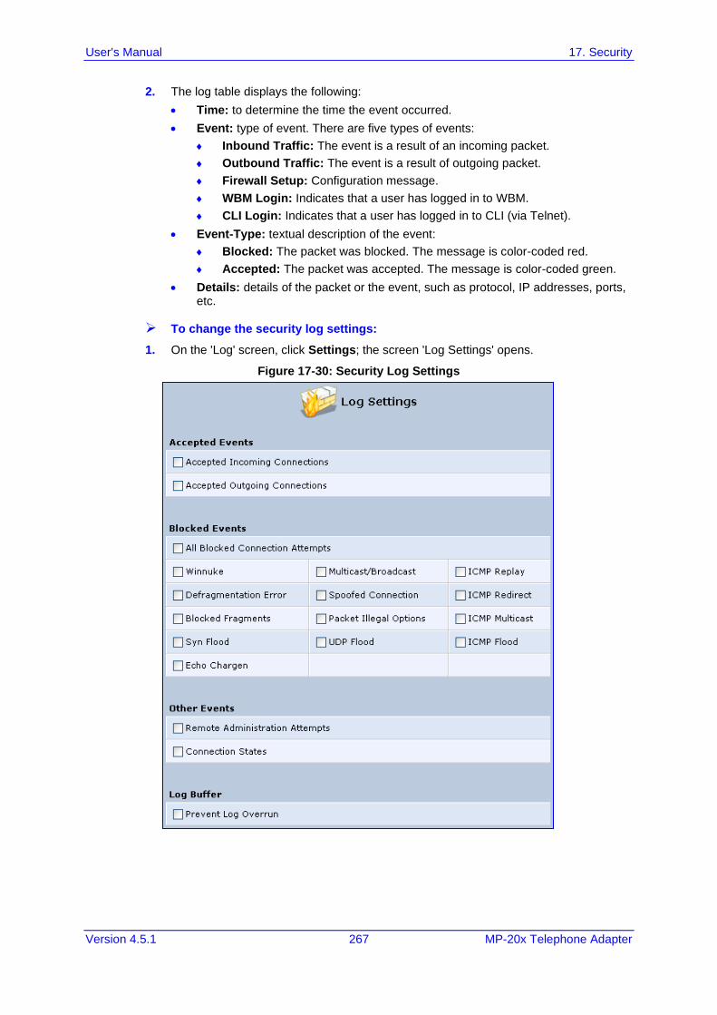
User's Manual 17. Security
Version 4.5.1 267 MP-20x Telephone Adapter
2. The log table displays the following:
• Time: to determine the time the event occurred.
• Event: type of event. There are five types of events:
Inbound Traffic: The event is a result of an incoming packet.
Outbound Traffic: The event is a result of outgoing packet.
Firewall Setup: Configuration message.
WBM Login: Indicates that a user has logged in to WBM.
CLI Login: Indicates that a user has logged in to CLI (via Telnet).
• Event-Type: textual description of the event:
Blocked: The packet was blocked. The message is color-coded red.
Accepted: The packet was accepted. The message is color-coded green.
• Details: details of the packet or the event, such as protocol, IP addresses, ports, etc.
➢ To change the security log settings:
1. On the 'Log' screen, click Settings; the screen 'Log Settings' opens.
Figure 17-30: Security Log Settings
User's Manual 268 Document #: LTRT-50621
MP-20x Telephone Adapter
2. Select the types of activities for which you would like to have a log message generated.
• Accepted Events:
Accepted Incoming Connections: Write a log message for each successful attempt to establish an inbound connection to the home network.
Accepted Outgoing Connections: Write a log message for each successful attempt to establish an outgoing connection to the public network.
• Blocked Events:
All Blocked Connection Attempts: Write a log message for each blocked attempt to establish an inbound connection to the home network or vice versa. You can enable logging of blocked packets of specific types by disabling this option, and enabling some of the more specific options below it.
Specific Events: Specify the blocked events that should be monitored. Use this to monitor specific event such as Syn Flood. A log message is generated if either the corresponding check-box is checked, or the check-box 'All Blocked Connection Attempts' is checked.
• Other Events:
Remote Administration Attempts: Write a log message for each remote-administration connection attempt, whether successful or not.
Connection States: Provide extra information about every change in a connection opened by the firewall. Use this option to track connection handling by the firewall and Application Level Gateways (ALGs).
• Log Buffer:
Prevent Log Overrun: Select this check box in order to stop logging firewall activities when the memory allocated for the log fills up.
3. Click OK to save the settings.
User's Manual 18. Advanced Networking Features
Version 4.5.1 269 MP-20x Telephone Adapter
18 Advanced Networking Features This chapter describes various advanced networking features such as DHCP.
18.1 IP Address Distribution
The device's Dynamic Host Configuration Protocol (DHCP) server makes it possible to easily add computers that are configured as DHCP clients to the home network. It provides a mechanism for allocating IP addresses and delivering network configuration parameters to such hosts. The device's default DHCP server is the LAN bridge.
A client (host) sends out a broadcast message on the LAN requesting an IP address for itself. The DHCP server then checks its list of available addresses and leases a local IP address to the host for a specific period of time and simultaneously designates this IP address as `taken'. At this point, the host is configured with an IP address for the duration of the lease.
The host can choose to renew an expiring lease or let it expire. If it chooses to renew a lease then it also receives current information about network services, as it did with the original lease, allowing it to update its network configurations to reject any changes that may have occurred since it first connected to the network. If the host wishes to terminate a lease before its expiration it can send a release message to the DHCP server, which then makes the IP address available for use by others.
The device embedded DHCP server provides the following features:
◼ Displays a list of all DHCP host devices connected to the device
◼ Defines the range of IP addresses that can be allocated to the LAN
◼ Defines the length of time for which dynamic IP addresses are allocated
◼ Provides the above configurations for each LAN device and can be configured and enabled / disabled separately for each LAN device
◼ Can assign a static lease to a LAN PC so that it receives the same IP address each time it connects to the network even if this IP address is within the range of addresses that the DHCP server may assign to other computers
◼ Provides the DNS server with the host name and IP address of each PC that is connected to the LAN
In addition, the device can act as a DHCP relay, escalating DHCP responsibilities to a WAN DHCP server. In this case, the device acts merely as a router, while its LAN hosts receives their IP addresses from an external DHCP server on the WAN.
With the device's optional Zero Configuration Technology feature, the IP Auto Detection method detects statically-defined IP addresses in addition to the device's DHCP clients. It learns all the IP addresses on the LAN and integrates the collected information with the database of the DHCP server. This allows the DHCP server to issue valid leases, thus avoiding conflicting IP addresses used by other computers in the network.
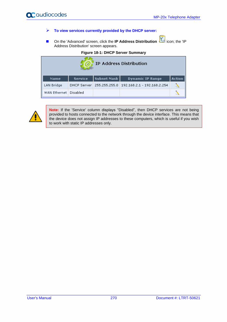
User's Manual 270 Document #: LTRT-50621
MP-20x Telephone Adapter
➢ To view services currently provided by the DHCP server:
◼ On the 'Advanced' screen, click the IP Address Distribution icon; the 'IP Address Distribution' screen appears.
Figure 18-1: DHCP Server Summary
Note: If the 'Service' column displays “Disabled”, then DHCP services are not being provided to hosts connected to the network through the device interface. This means that the device does not assign IP addresses to these computers, which is useful if you wish to work with static IP addresses only.
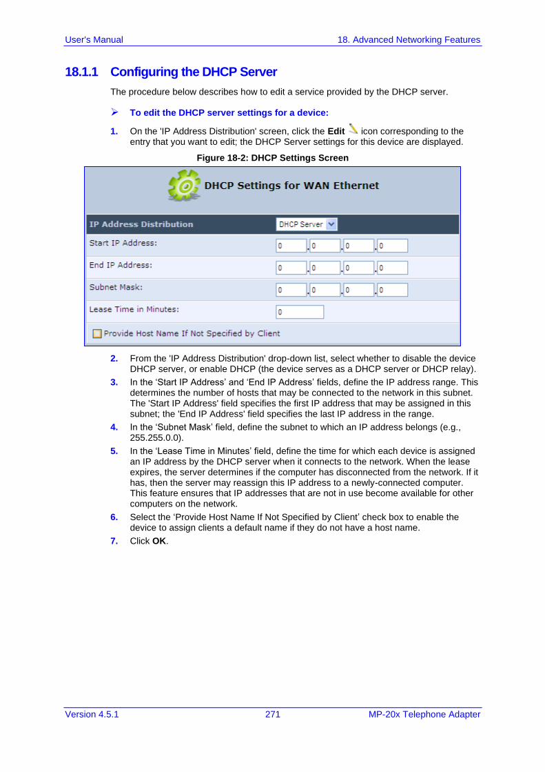
User's Manual 18. Advanced Networking Features
Version 4.5.1 271 MP-20x Telephone Adapter
18.1.1 Configuring the DHCP Server
The procedure below describes how to edit a service provided by the DHCP server.
➢ To edit the DHCP server settings for a device:
1. On the 'IP Address Distribution' screen, click the Edit icon corresponding to the entry that you want to edit; the DHCP Server settings for this device are displayed.
Figure 18-2: DHCP Settings Screen
2. From the 'IP Address Distribution' drop-down list, select whether to disable the device DHCP server, or enable DHCP (the device serves as a DHCP server or DHCP relay).
3. In the ‘Start IP Address’ and ‘End IP Address’ fields, define the IP address range. This determines the number of hosts that may be connected to the network in this subnet. The 'Start IP Address' field specifies the first IP address that may be assigned in this subnet; the 'End IP Address' field specifies the last IP address in the range.
4. In the ‘Subnet Mask’ field, define the subnet to which an IP address belongs (e.g., 255.255.0.0).
5. In the ‘Lease Time in Minutes’ field, define the time for which each device is assigned an IP address by the DHCP server when it connects to the network. When the lease expires, the server determines if the computer has disconnected from the network. If it has, then the server may reassign this IP address to a newly-connected computer. This feature ensures that IP addresses that are not in use become available for other computers on the network.
6. Select the ‘Provide Host Name If Not Specified by Client’ check box to enable the device to assign clients a default name if they do not have a host name.
7. Click OK.
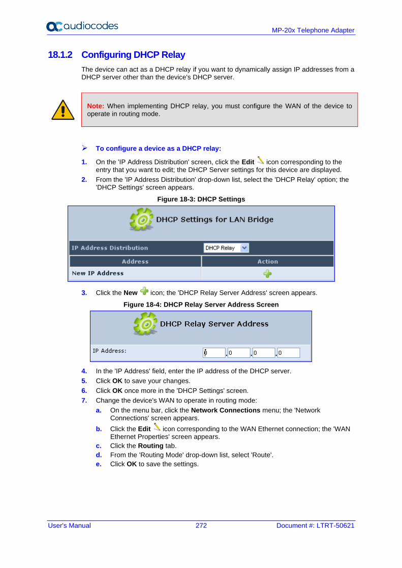
User's Manual 272 Document #: LTRT-50621
MP-20x Telephone Adapter
18.1.2 Configuring DHCP Relay
The device can act as a DHCP relay if you want to dynamically assign IP addresses from a DHCP server other than the device's DHCP server.
Note: When implementing DHCP relay, you must configure the WAN of the device to operate in routing mode.
➢ To configure a device as a DHCP relay:
1. On the 'IP Address Distribution' screen, click the Edit icon corresponding to the entry that you want to edit; the DHCP Server settings for this device are displayed.
2. From the 'IP Address Distribution' drop-down list, select the 'DHCP Relay' option; the 'DHCP Settings' screen appears.
Figure 18-3: DHCP Settings
3. Click the New icon; the 'DHCP Relay Server Address' screen appears.
Figure 18-4: DHCP Relay Server Address Screen
4. In the 'IP Address' field, enter the IP address of the DHCP server.
5. Click OK to save your changes.
6. Click OK once more in the 'DHCP Settings' screen.
7. Change the device's WAN to operate in routing mode:
a. On the menu bar, click the Network Connections menu; the 'Network Connections' screen appears.
b. Click the Edit icon corresponding to the WAN Ethernet connection; the 'WAN Ethernet Properties' screen appears.
c. Click the Routing tab.
d. From the 'Routing Mode' drop-down list, select 'Route'.
e. Click OK to save the settings.
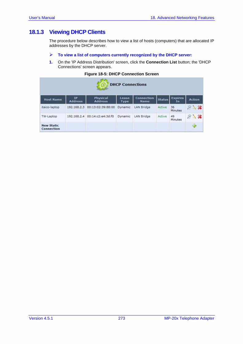
User's Manual 18. Advanced Networking Features
Version 4.5.1 273 MP-20x Telephone Adapter
18.1.3 Viewing DHCP Clients
The procedure below describes how to view a list of hosts (computers) that are allocated IP addresses by the DHCP server.
➢ To view a list of computers currently recognized by the DHCP server:
1. On the 'IP Address Distribution' screen, click the Connection List button; the 'DHCP Connections' screen appears.
Figure 18-5: DHCP Connection Screen
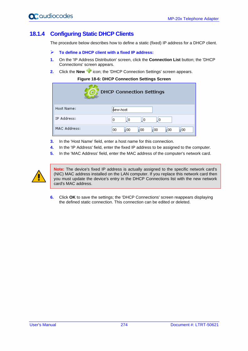
User's Manual 274 Document #: LTRT-50621
MP-20x Telephone Adapter
18.1.4 Configuring Static DHCP Clients
The procedure below describes how to define a static (fixed) IP address for a DHCP client.
➢ To define a DHCP client with a fixed IP address:
1. On the 'IP Address Distribution' screen, click the Connection List button; the 'DHCP Connections' screen appears.
2. Click the New icon; the 'DHCP Connection Settings' screen appears.
Figure 18-6: DHCP Connection Settings Screen
3. In the 'Host Name' field, enter a host name for this connection.
4. In the 'IP Address' field, enter the fixed IP address to be assigned to the computer.
5. In the 'MAC Address' field, enter the MAC address of the computer's network card.
Note: The device's fixed IP address is actually assigned to the specific network card's (NIC) MAC address installed on the LAN computer. If you replace this network card then you must update the device's entry in the DHCP Connections list with the new network card's MAC address.
6. Click OK to save the settings; the 'DHCP Connections' screen reappears displaying the defined static connection. This connection can be edited or deleted.
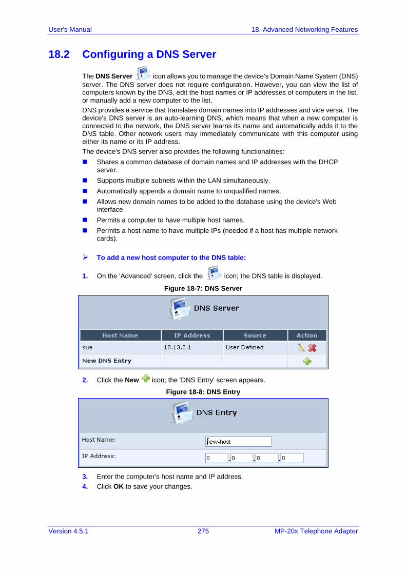
User's Manual 18. Advanced Networking Features
Version 4.5.1 275 MP-20x Telephone Adapter
18.2 Configuring a DNS Server
The DNS Server icon allows you to manage the device's Domain Name System (DNS)
server. The DNS server does not require configuration. However, you can view the list of computers known by the DNS, edit the host names or IP addresses of computers in the list, or manually add a new computer to the list.
DNS provides a service that translates domain names into IP addresses and vice versa. The device's DNS server is an auto-learning DNS, which means that when a new computer is connected to the network, the DNS server learns its name and automatically adds it to the DNS table. Other network users may immediately communicate with this computer using either its name or its IP address.
The device's DNS server also provides the following functionalities:
◼ Shares a common database of domain names and IP addresses with the DHCP server.
◼ Supports multiple subnets within the LAN simultaneously.
◼ Automatically appends a domain name to unqualified names.
◼ Allows new domain names to be added to the database using the device's Web interface.
◼ Permits a computer to have multiple host names.
◼ Permits a host name to have multiple IPs (needed if a host has multiple network cards).
➢ To add a new host computer to the DNS table:
1. On the 'Advanced' screen, click the icon; the DNS table is displayed.
Figure 18-7: DNS Server
2. Click the New icon; the 'DNS Entry' screen appears.
Figure 18-8: DNS Entry
3. Enter the computer's host name and IP address.
4. Click OK to save your changes.
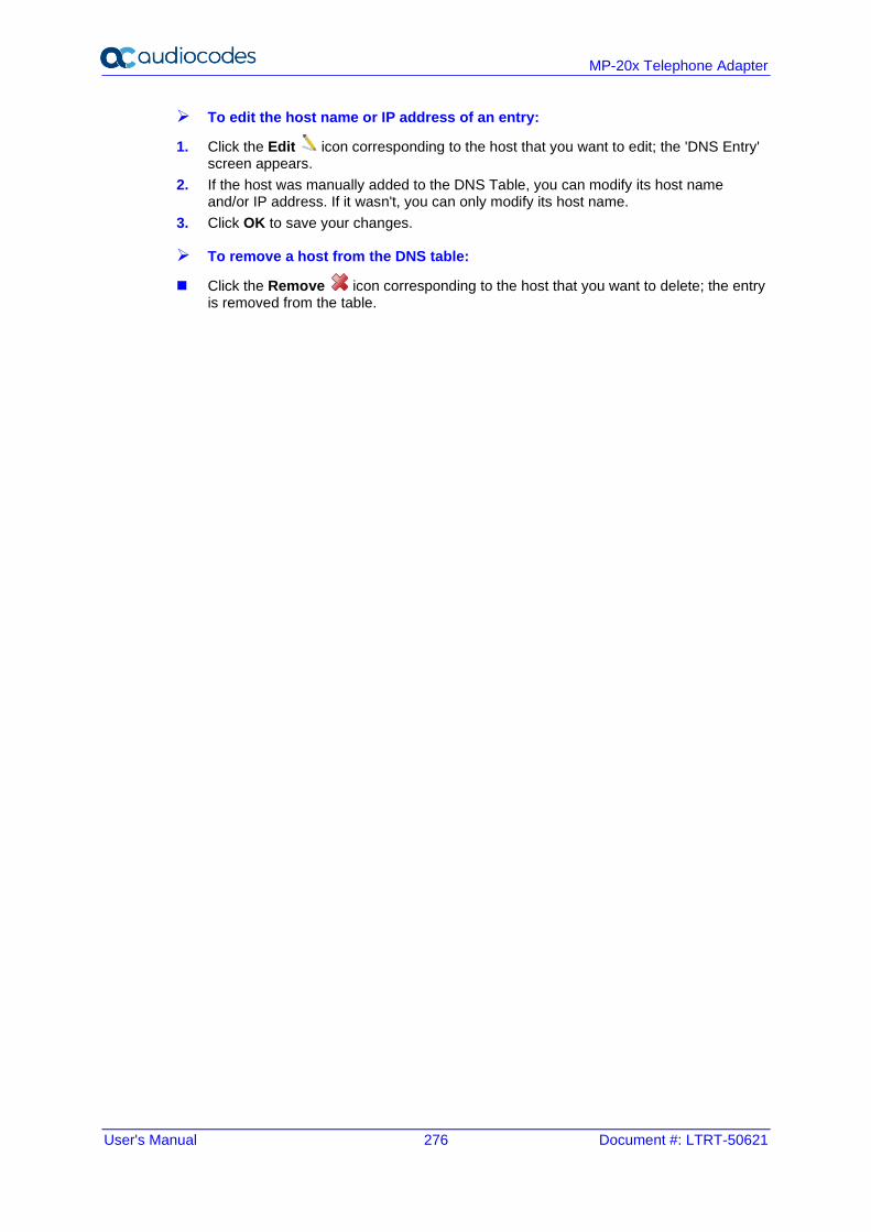
User's Manual 276 Document #: LTRT-50621
MP-20x Telephone Adapter
➢ To edit the host name or IP address of an entry:
1. Click the Edit icon corresponding to the host that you want to edit; the 'DNS Entry' screen appears.
2. If the host was manually added to the DNS Table, you can modify its host name and/or IP address. If it wasn't, you can only modify its host name.
3. Click OK to save your changes.
➢ To remove a host from the DNS table:
◼ Click the Remove icon corresponding to the host that you want to delete; the entry is removed from the table.
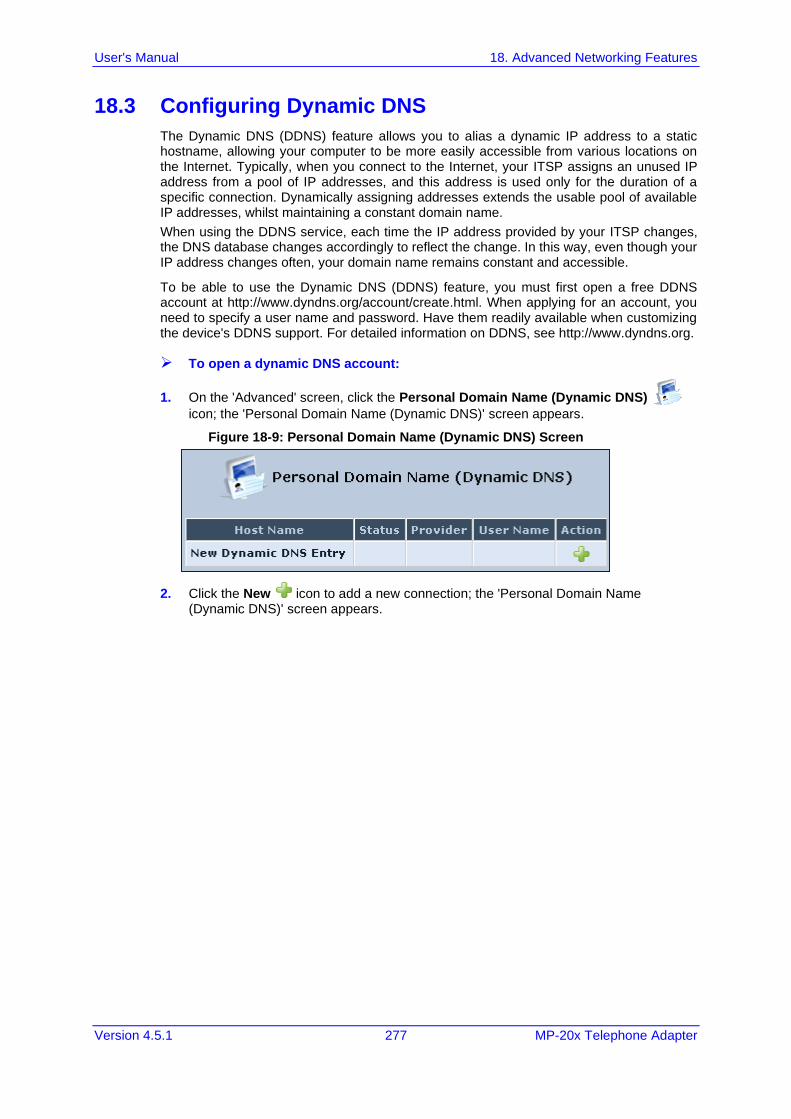
User's Manual 18. Advanced Networking Features
Version 4.5.1 277 MP-20x Telephone Adapter
18.3 Configuring Dynamic DNS
The Dynamic DNS (DDNS) feature allows you to alias a dynamic IP address to a static hostname, allowing your computer to be more easily accessible from various locations on the Internet. Typically, when you connect to the Internet, your ITSP assigns an unused IP address from a pool of IP addresses, and this address is used only for the duration of a specific connection. Dynamically assigning addresses extends the usable pool of available IP addresses, whilst maintaining a constant domain name.
When using the DDNS service, each time the IP address provided by your ITSP changes, the DNS database changes accordingly to reflect the change. In this way, even though your IP address changes often, your domain name remains constant and accessible.
To be able to use the Dynamic DNS (DDNS) feature, you must first open a free DDNS account at http://www.dyndns.org/account/create.html. When applying for an account, you need to specify a user name and password. Have them readily available when customizing the device's DDNS support. For detailed information on DDNS, see http://www.dyndns.org.
➢ To open a dynamic DNS account:
1. On the 'Advanced' screen, click the Personal Domain Name (Dynamic DNS)
icon; the 'Personal Domain Name (Dynamic DNS)' screen appears.
Figure 18-9: Personal Domain Name (Dynamic DNS) Screen
2. Click the New icon to add a new connection; the 'Personal Domain Name (Dynamic DNS)' screen appears.
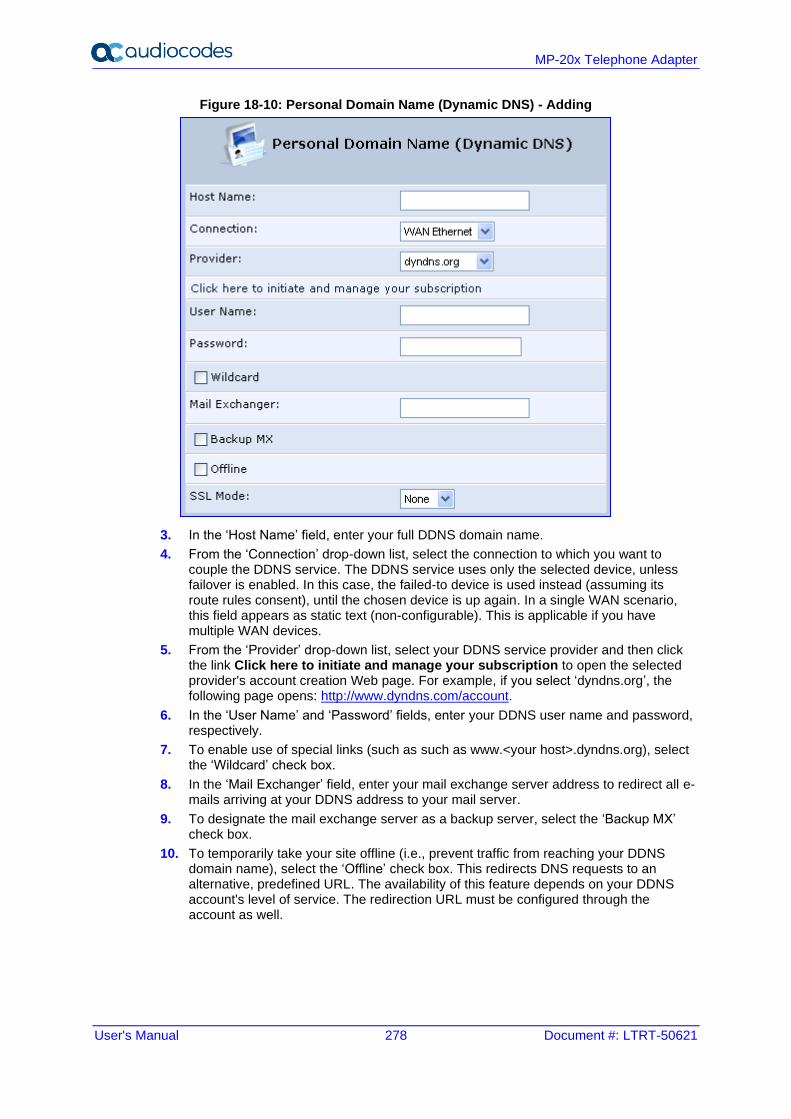
User's Manual 278 Document #: LTRT-50621
MP-20x Telephone Adapter
Figure 18-10: Personal Domain Name (Dynamic DNS) - Adding
3. In the ‘Host Name’ field, enter your full DDNS domain name.
4. From the ‘Connection’ drop-down list, select the connection to which you want to couple the DDNS service. The DDNS service uses only the selected device, unless failover is enabled. In this case, the failed-to device is used instead (assuming its route rules consent), until the chosen device is up again. In a single WAN scenario, this field appears as static text (non-configurable). This is applicable if you have multiple WAN devices.
5. From the ‘Provider’ drop-down list, select your DDNS service provider and then click the link Click here to initiate and manage your subscription to open the selected provider's account creation Web page. For example, if you select ‘dyndns.org’, the following page opens: http://www.dyndns.com/account.
6. In the ‘User Name’ and ‘Password’ fields, enter your DDNS user name and password, respectively.
7. To enable use of special links (such as such as www.<your host>.dyndns.org), select the ‘Wildcard’ check box.
8. In the ‘Mail Exchanger’ field, enter your mail exchange server address to redirect all e-mails arriving at your DDNS address to your mail server.
9. To designate the mail exchange server as a backup server, select the ‘Backup MX’ check box.
10. To temporarily take your site offline (i.e., prevent traffic from reaching your DDNS domain name), select the ‘Offline’ check box. This redirects DNS requests to an alternative, predefined URL. The availability of this feature depends on your DDNS account's level of service. The redirection URL must be configured through the account as well.
User's Manual 18. Advanced Networking Features
Version 4.5.1 279 MP-20x Telephone Adapter
11. From the ‘SSL Mode’ drop-down list, select the certificate validation method used by the device to validate the DDNS server's certificate upon secured connection to DDNS using HTTPS:
• None: The server's certificate is not validated.
• Chain: Validates the entire certificate chain. When selecting this option, the screen refreshes, displaying the 'Validate Time' drop-down list for selecting whether or not to validate the certificate's expiration time ('Ignore' or 'Check' respectively). If the certificate has expired, the connection terminates immediately.
• Direct: Ensures that the server's certificate is directly signed by the root certificate. This option also provides the 'Validate Time' drop-down list for validation of the certificate's expiration time, as described above.
12. Click OK.
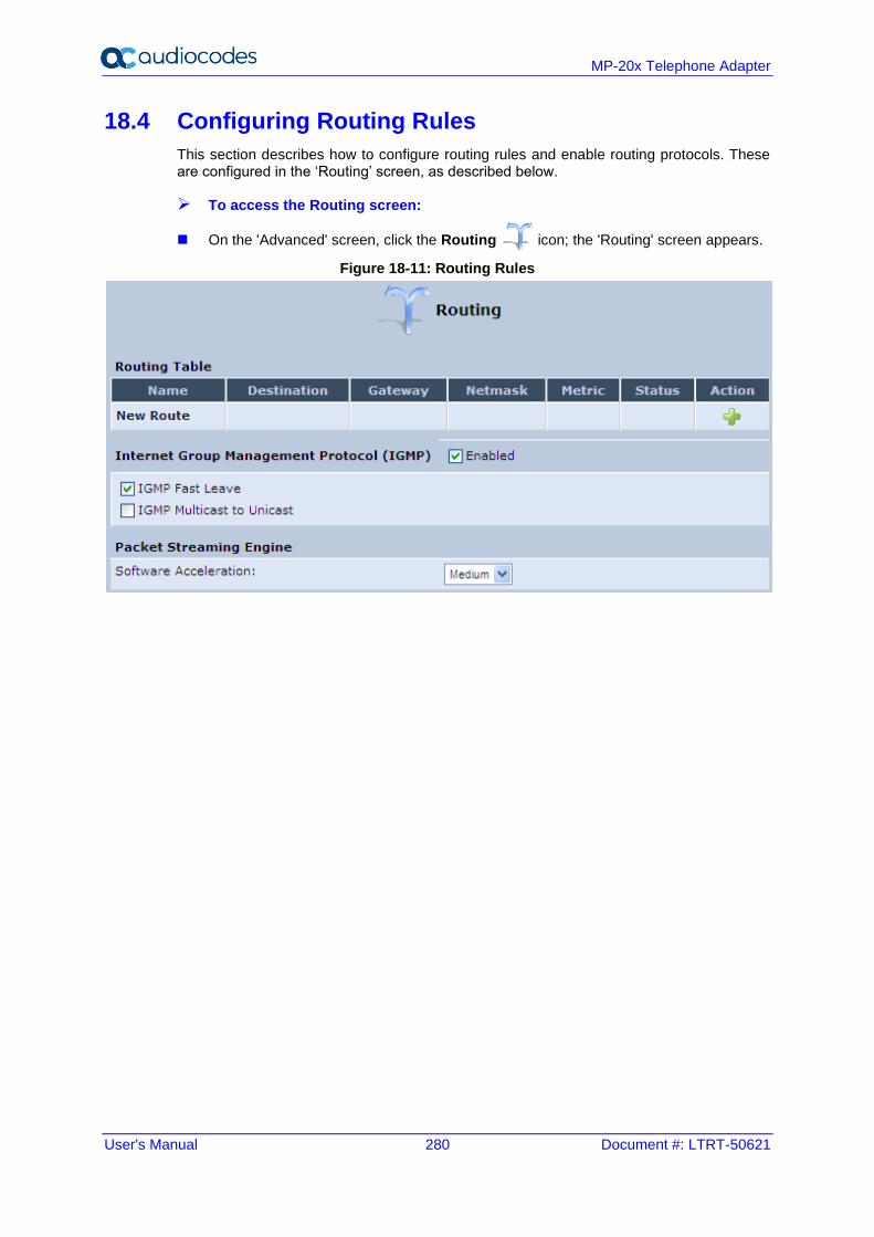
User's Manual 280 Document #: LTRT-50621
MP-20x Telephone Adapter
18.4 Configuring Routing Rules
This section describes how to configure routing rules and enable routing protocols. These are configured in the ‘Routing’ screen, as described below.
➢ To access the Routing screen:
◼ On the 'Advanced' screen, click the Routing icon; the 'Routing' screen appears.
Figure 18-11: Routing Rules
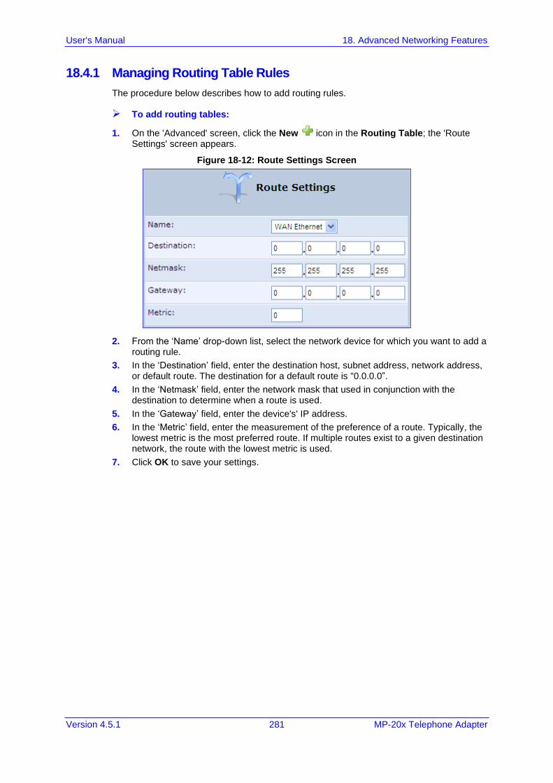
User's Manual 18. Advanced Networking Features
Version 4.5.1 281 MP-20x Telephone Adapter
18.4.1 Managing Routing Table Rules
The procedure below describes how to add routing rules.
➢ To add routing tables:
1. On the 'Advanced' screen, click the New icon in the Routing Table; the 'Route Settings' screen appears.
Figure 18-12: Route Settings Screen
2. From the ‘Name’ drop-down list, select the network device for which you want to add a routing rule.
3. In the ‘Destination’ field, enter the destination host, subnet address, network address, or default route. The destination for a default route is “0.0.0.0”.
4. In the ‘Netmask’ field, enter the network mask that used in conjunction with the destination to determine when a route is used.
5. In the ‘Gateway’ field, enter the device's' IP address.
6. In the ‘Metric’ field, enter the measurement of the preference of a route. Typically, the lowest metric is the most preferred route. If multiple routes exist to a given destination network, the route with the lowest metric is used.
7. Click OK to save your settings.
User's Manual 282 Document #: LTRT-50621
MP-20x Telephone Adapter
18.4.2 Configuring Routing Protocols
The device supports IGMP multicasting, which allows hosts connected to a network to be updated whenever an important change occurs in the network. A multicast is simply a message that is sent simultaneously to a pre-defined group of recipients. When you join a multicast group you receive all messages addressed to the group, similar to an e-mail message sent to a mailing list.
When an application running on a computer in the home network sends out a request to join a multicast group, the device intercepts and processes the request. If the device is set to 'Minimum Security', no further action is required. However, if the device is set to 'Typical Security' or 'Maximum Security', you must add the group's IP address to the device's 'Multicast Groups' screen. This allows incoming messages addressed to the group to pass through the device's firewall and on to the correct LAN computer.
➢ To configure routing protocols:
1. On the 'Advanced' screen, under the Internet Group Management Protocol (IGMP) group, do the following:
a. Select the 'Enabled' check box to enable IGMP multicasting.
b. Select the ‘IGMP Fast Leave' check box if you want the device to stop forwarding traffic to a host that is the only subscriber, immediately upon request (without query delay).
c. Select the 'IGMP Multicast to Unicast' check box to enable the device to convert the incoming multicast data stream into unicast format to route it to the specific LAN host that requested the data. In this way, the device prevents flooding the rest of the LAN hosts with irrelevant multicast traffic.
2. Under the Packet Streaming Engine group, from the ‘Software Acceleration’ drop-down list, select the packet flow speed:
• None: Packet Streaming Engine (PSE) is disabled
• Medium: PSE is active (recommended)
• High: PSE traffic is prioritized over other traffic
3. Click OK.
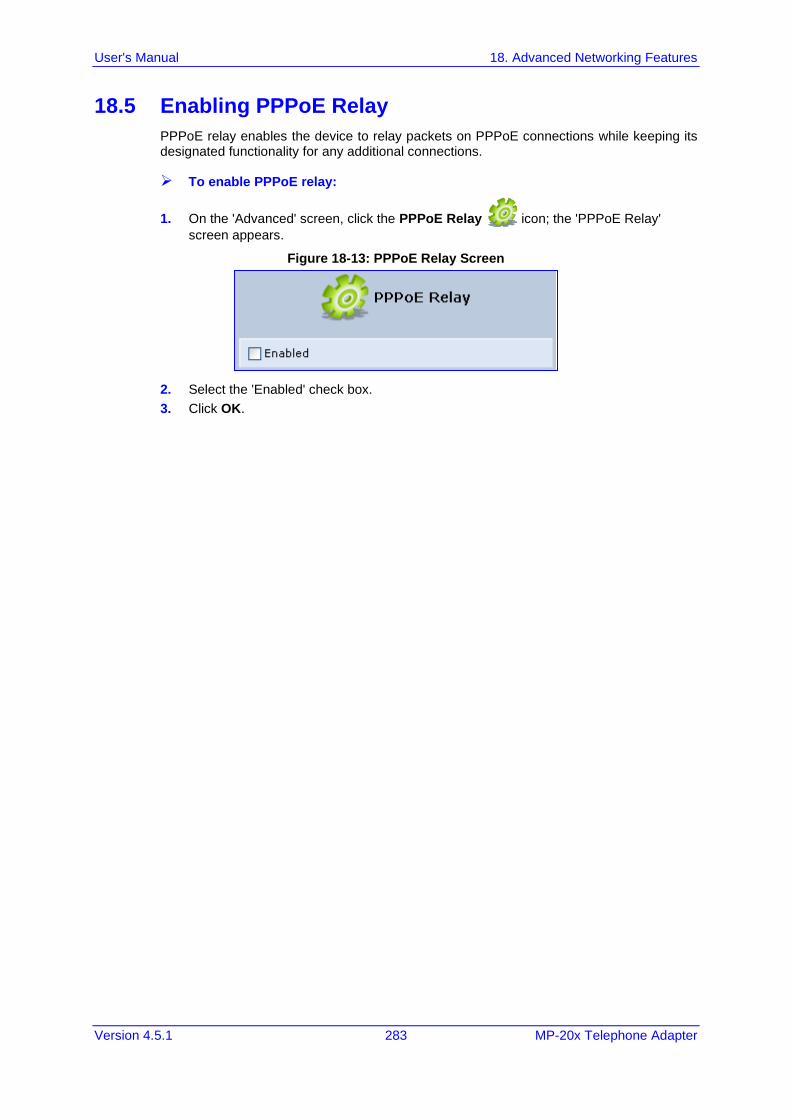
User's Manual 18. Advanced Networking Features
Version 4.5.1 283 MP-20x Telephone Adapter
18.5 Enabling PPPoE Relay
PPPoE relay enables the device to relay packets on PPPoE connections while keeping its designated functionality for any additional connections.
➢ To enable PPPoE relay:
1. On the 'Advanced' screen, click the PPPoE Relay icon; the 'PPPoE Relay'
screen appears.
Figure 18-13: PPPoE Relay Screen
2. Select the 'Enabled' check box.
3. Click OK.
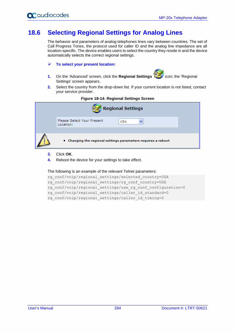
User's Manual 284 Document #: LTRT-50621
MP-20x Telephone Adapter
18.6 Selecting Regional Settings for Analog Lines
The behavior and parameters of analog telephones lines vary between countries. The set of Call Progress Tones, the protocol used for caller ID and the analog line impedance are all location-specific. The device enables users to select the country they reside in and the device automatically selects the correct regional settings.
➢ To select your present location:
1. On the 'Advanced' screen, click the Regional Settings icon; the 'Regional
Settings' screen appears.
2. Select the country from the drop-down list. If your current location is not listed, contact your service provider.
Figure 18-14: Regional Settings Screen
3. Click OK.
4. Reboot the device for your settings to take effect.
The following is an example of the relevant Telnet parameters:
rg_conf/voip/regional_settings/selected_country=USA
rg_conf/voip/regional_settings/rg_conf_country=USA
rg_conf/voip/regional_settings/use_rg_conf_configuration=0
rg_conf/voip/regional_settings/caller_id_standard=0
rg_conf/voip/regional_settings/caller_id_timing=0
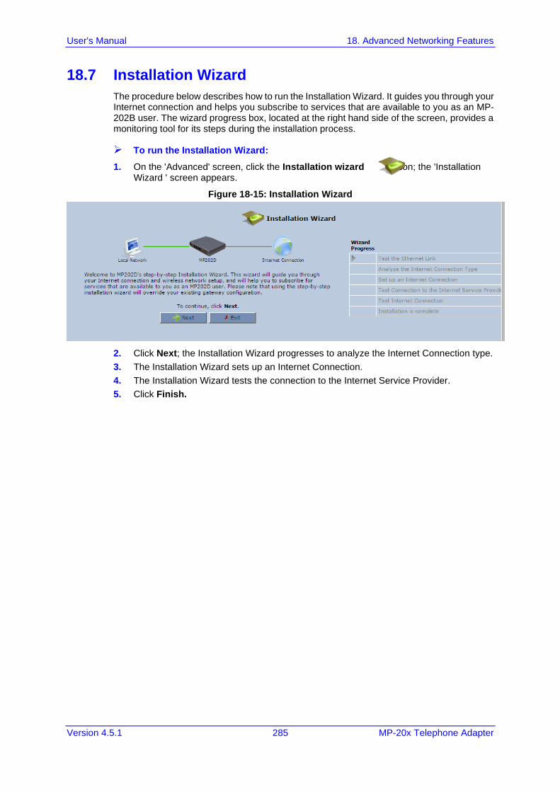
User's Manual 18. Advanced Networking Features
Version 4.5.1 285 MP-20x Telephone Adapter
18.7 Installation Wizard
The procedure below describes how to run the Installation Wizard. It guides you through your Internet connection and helps you subscribe to services that are available to you as an MP-202B user. The wizard progress box, located at the right hand side of the screen, provides a monitoring tool for its steps during the installation process.
➢ To run the Installation Wizard:
1. On the 'Advanced' screen, click the Installation wizard icon; the 'Installation Wizard ' screen appears.
Figure 18-15: Installation Wizard
2. Click Next; the Installation Wizard progresses to analyze the Internet Connection type.
3. The Installation Wizard sets up an Internet Connection.
4. The Installation Wizard tests the connection to the Internet Service Provider.
5. Click Finish.

User's Manual 286 Document #: LTRT-50621
MP-20x Telephone Adapter
This page is intentionally left blank.
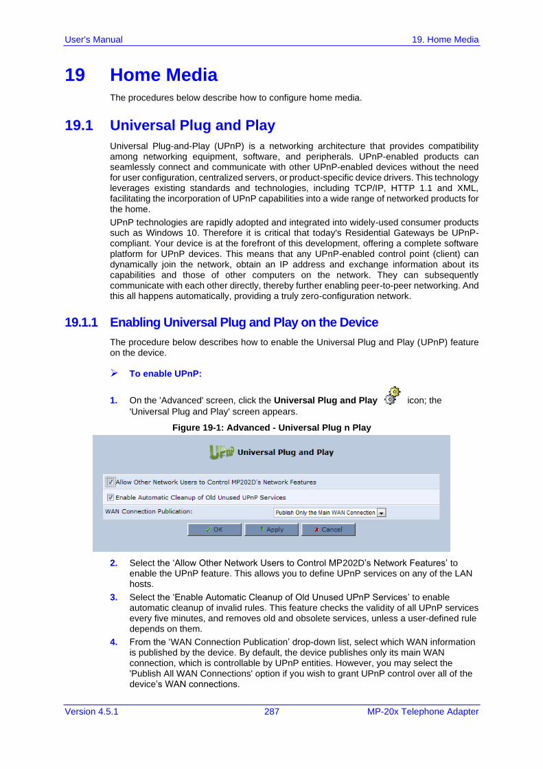
User's Manual 19. Home Media
Version 4.5.1 287 MP-20x Telephone Adapter
19 Home Media The procedures below describe how to configure home media.
19.1 Universal Plug and Play
Universal Plug-and-Play (UPnP) is a networking architecture that provides compatibility among networking equipment, software, and peripherals. UPnP-enabled products can seamlessly connect and communicate with other UPnP-enabled devices without the need for user configuration, centralized servers, or product-specific device drivers. This technology leverages existing standards and technologies, including TCP/IP, HTTP 1.1 and XML, facilitating the incorporation of UPnP capabilities into a wide range of networked products for the home.
UPnP technologies are rapidly adopted and integrated into widely-used consumer products such as Windows 10. Therefore it is critical that today's Residential Gateways be UPnP-compliant. Your device is at the forefront of this development, offering a complete software platform for UPnP devices. This means that any UPnP-enabled control point (client) can dynamically join the network, obtain an IP address and exchange information about its capabilities and those of other computers on the network. They can subsequently communicate with each other directly, thereby further enabling peer-to-peer networking. And this all happens automatically, providing a truly zero-configuration network.
19.1.1 Enabling Universal Plug and Play on the Device
The procedure below describes how to enable the Universal Plug and Play (UPnP) feature on the device.
➢ To enable UPnP:
1. On the 'Advanced' screen, click the Universal Plug and Play icon; the
'Universal Plug and Play' screen appears.
Figure 19-1: Advanced - Universal Plug n Play
2. Select the ‘Allow Other Network Users to Control MP202D’s Network Features’ to enable the UPnP feature. This allows you to define UPnP services on any of the LAN hosts.
3. Select the ‘Enable Automatic Cleanup of Old Unused UPnP Services’ to enable automatic cleanup of invalid rules. This feature checks the validity of all UPnP services every five minutes, and removes old and obsolete services, unless a user-defined rule depends on them.
4. From the ‘WAN Connection Publication’ drop-down list, select which WAN information is published by the device. By default, the device publishes only its main WAN connection, which is controllable by UPnP entities. However, you may select the 'Publish All WAN Connections' option if you wish to grant UPnP control over all of the device’s WAN connections.
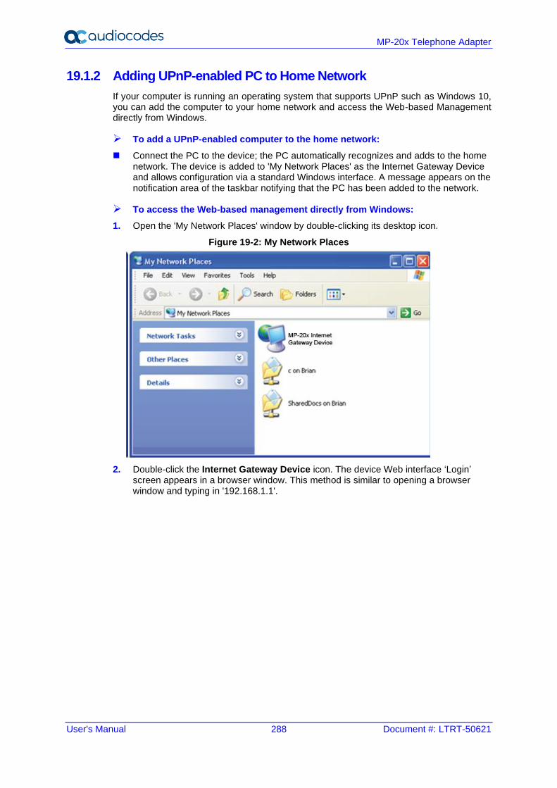
User's Manual 288 Document #: LTRT-50621
MP-20x Telephone Adapter
19.1.2 Adding UPnP-enabled PC to Home Network
If your computer is running an operating system that supports UPnP such as Windows 10, you can add the computer to your home network and access the Web-based Management directly from Windows.
➢ To add a UPnP-enabled computer to the home network:
◼ Connect the PC to the device; the PC automatically recognizes and adds to the home network. The device is added to 'My Network Places' as the Internet Gateway Device and allows configuration via a standard Windows interface. A message appears on the notification area of the taskbar notifying that the PC has been added to the network.
➢ To access the Web-based management directly from Windows:
1. Open the 'My Network Places' window by double-clicking its desktop icon.
Figure 19-2: My Network Places
2. Double-click the Internet Gateway Device icon. The device Web interface ‘Login’ screen appears in a browser window. This method is similar to opening a browser window and typing in '192.168.1.1'.
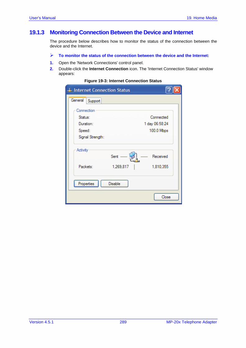
User's Manual 19. Home Media
Version 4.5.1 289 MP-20x Telephone Adapter
19.1.3 Monitoring Connection Between the Device and Internet
The procedure below describes how to monitor the status of the connection between the device and the Internet.
➢ To monitor the status of the connection between the device and the Internet:
1. Open the 'Network Connections' control panel.
2. Double-click the Internet Connection icon. The 'Internet Connection Status' window appears:
Figure 19-3: Internet Connection Status
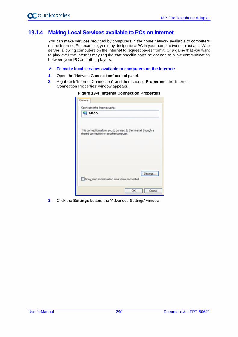
User's Manual 290 Document #: LTRT-50621
MP-20x Telephone Adapter
19.1.4 Making Local Services available to PCs on Internet
You can make services provided by computers in the home network available to computers on the Internet. For example, you may designate a PC in your home network to act as a Web server, allowing computers on the Internet to request pages from it. Or a game that you want to play over the Internet may require that specific ports be opened to allow communication between your PC and other players.
➢ To make local services available to computers on the Internet:
1. Open the 'Network Connections' control panel.
2. Right-click 'Internet Connection', and then choose Properties; the 'Internet Connection Properties' window appears.
Figure 19-4: Internet Connection Properties
3. Click the Settings button; the 'Advanced Settings' window.
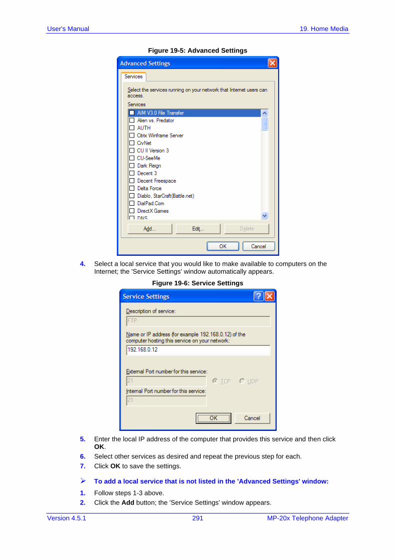
User's Manual 19. Home Media
Version 4.5.1 291 MP-20x Telephone Adapter
Figure 19-5: Advanced Settings
4. Select a local service that you would like to make available to computers on the Internet; the 'Service Settings' window automatically appears.
Figure 19-6: Service Settings
5. Enter the local IP address of the computer that provides this service and then click OK.
6. Select other services as desired and repeat the previous step for each.
7. Click OK to save the settings.
➢ To add a local service that is not listed in the 'Advanced Settings' window:
1. Follow steps 1-3 above.
2. Click the Add button; the 'Service Settings' window appears.
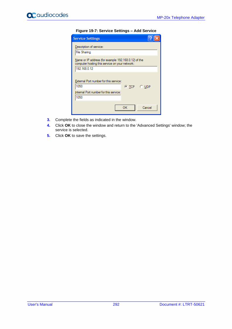
User's Manual 292 Document #: LTRT-50621
MP-20x Telephone Adapter
Figure 19-7: Service Settings – Add Service
3. Complete the fields as indicated in the window.
4. Click OK to close the window and return to the 'Advanced Settings' window; the service is selected.
5. Click OK to save the settings.
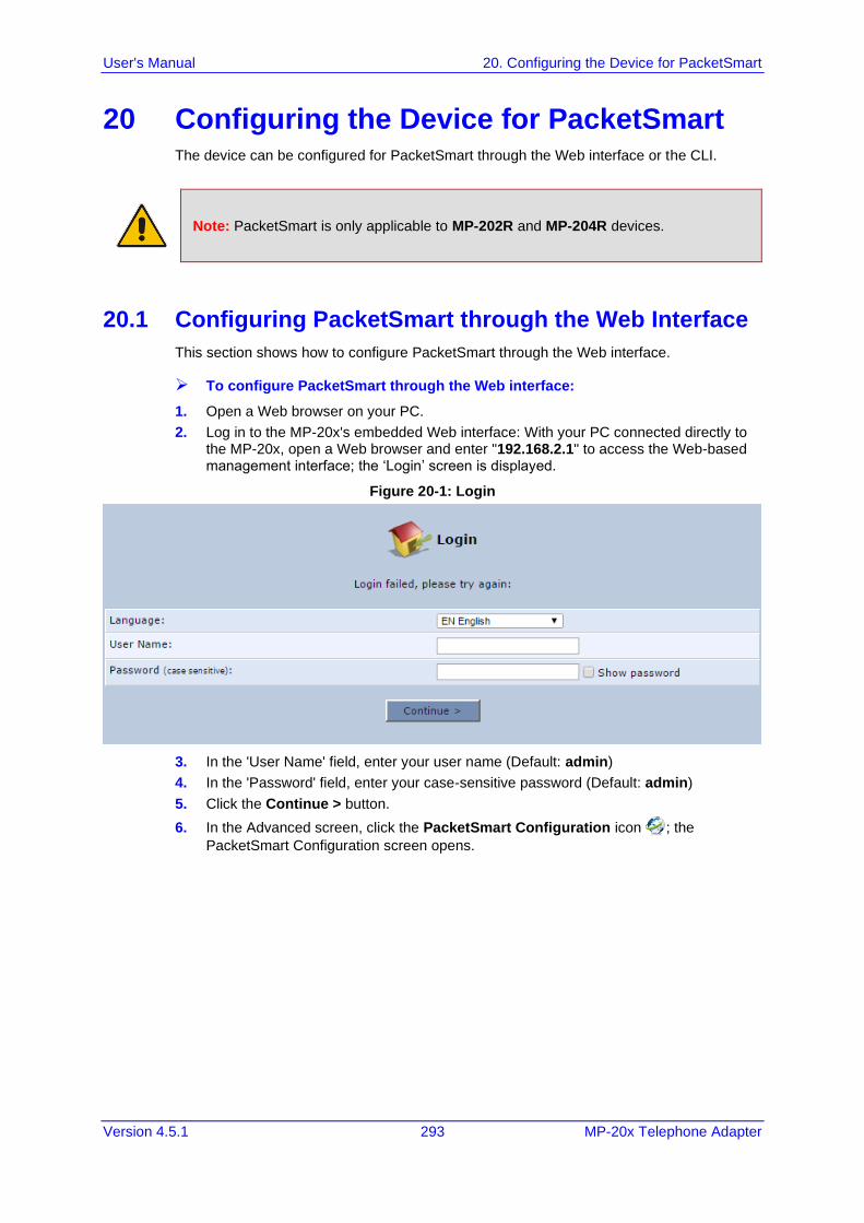
User's Manual 20. Configuring the Device for PacketSmart
Version 4.5.1 293 MP-20x Telephone Adapter
20 Configuring the Device for PacketSmart The device can be configured for PacketSmart through the Web interface or the CLI.
Note: PacketSmart is only applicable to MP-202R and MP-204R devices.
20.1 Configuring PacketSmart through the Web Interface
This section shows how to configure PacketSmart through the Web interface.
➢ To configure PacketSmart through the Web interface:
1. Open a Web browser on your PC.
2. Log in to the MP-20x's embedded Web interface: With your PC connected directly to the MP-20x, open a Web browser and enter "192.168.2.1" to access the Web-based management interface; the ‘Login’ screen is displayed.
Figure 20-1: Login
3. In the 'User Name' field, enter your user name (Default: admin)
4. In the 'Password' field, enter your case-sensitive password (Default: admin)
5. Click the Continue > button.
6. In the Advanced screen, click the PacketSmart Configuration icon ; the
PacketSmart Configuration screen opens.
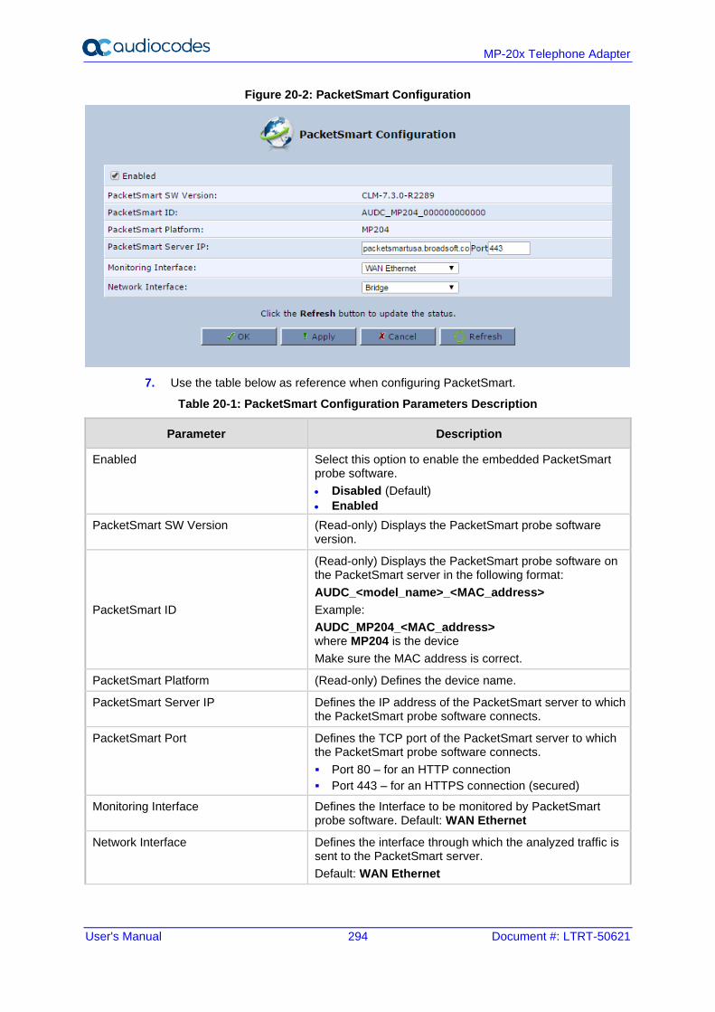
User's Manual 294 Document #: LTRT-50621
MP-20x Telephone Adapter
Figure 20-2: PacketSmart Configuration
7. Use the table below as reference when configuring PacketSmart.
Table 20-1: PacketSmart Configuration Parameters Description
Parameter Description
Enabled Select this option to enable the embedded PacketSmart probe software.
• Disabled (Default)
• Enabled
PacketSmart SW Version (Read-only) Displays the PacketSmart probe software version.
PacketSmart ID
(Read-only) Displays the PacketSmart probe software on the PacketSmart server in the following format:
AUDC_<model_name>_<MAC_address>
Example:
AUDC_MP204_<MAC_address> where MP204 is the device
Make sure the MAC address is correct.
PacketSmart Platform (Read-only) Defines the device name.
PacketSmart Server IP Defines the IP address of the PacketSmart server to which the PacketSmart probe software connects.
PacketSmart Port Defines the TCP port of the PacketSmart server to which the PacketSmart probe software connects.
▪ Port 80 – for an HTTP connection
▪ Port 443 – for an HTTPS connection (secured)
Monitoring Interface Defines the Interface to be monitored by PacketSmart probe software. Default: WAN Ethernet
Network Interface Defines the interface through which the analyzed traffic is sent to the PacketSmart server.
Default: WAN Ethernet
User's Manual 20. Configuring the Device for PacketSmart
Version 4.5.1 295 MP-20x Telephone Adapter
Parameter Description
Configuration Server URL Defines the address of the new PacketSmart firmware file.
Note: This parameter does not appear in the Web interface. It can only be modified through the CLI. See Section 20.3 on page 297 for more information.
Upgrade Needed This parameter is used to immediately upgrade PacketSmart. Possible values:
▪ 1 - Immediately upgrade
▪ 0 – Do not upgrade
Note: After PacketSmart has been upgraded, this parameter is automatically set to "0". *
8. Click OK.
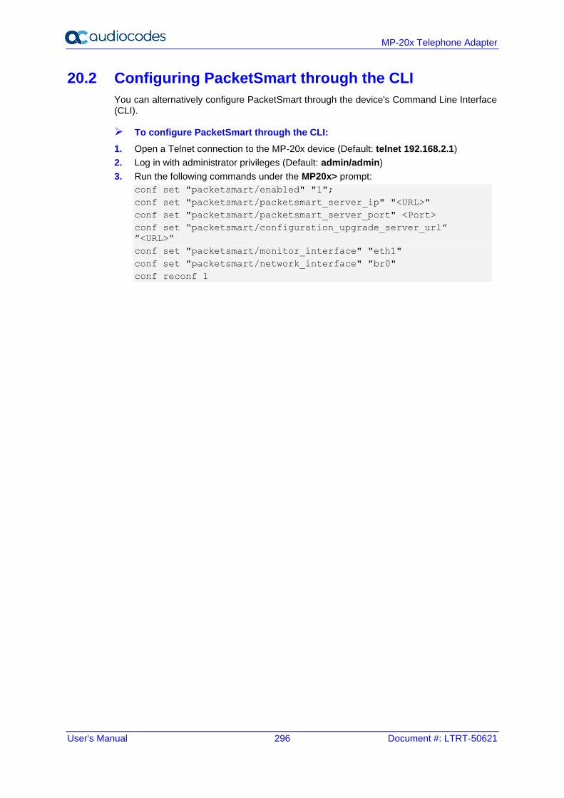
User's Manual 296 Document #: LTRT-50621
MP-20x Telephone Adapter
20.2 Configuring PacketSmart through the CLI
You can alternatively configure PacketSmart through the device's Command Line Interface (CLI).
➢ To configure PacketSmart through the CLI:
1. Open a Telnet connection to the MP-20x device (Default: telnet 192.168.2.1)
2. Log in with administrator privileges (Default: admin/admin)
3. Run the following commands under the MP20x> prompt:
conf set "packetsmart/enabled" "1";
conf set "packetsmart/packetsmart_server_ip" "<URL>"
conf set "packetsmart/packetsmart_server_port" <Port>
conf set “packetsmart/configuration_upgrade_server_url”
”<URL>”
conf set "packetsmart/monitor_interface" "eth1"
conf set "packetsmart/network_interface" "br0"
conf reconf 1
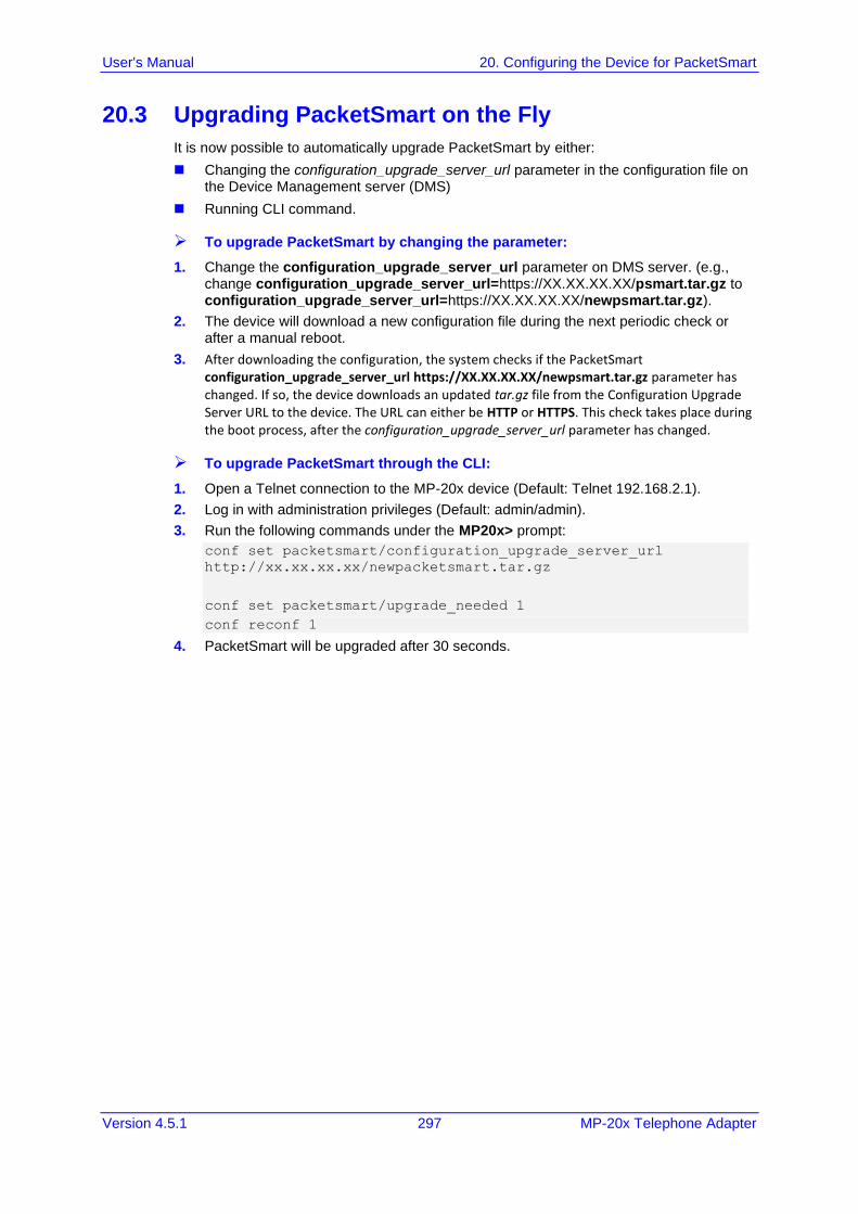
User's Manual 20. Configuring the Device for PacketSmart
Version 4.5.1 297 MP-20x Telephone Adapter
20.3 Upgrading PacketSmart on the Fly
It is now possible to automatically upgrade PacketSmart by either:
◼ Changing the configuration_upgrade_server_url parameter in the configuration file on the Device Management server (DMS)
◼ Running CLI command.
➢ To upgrade PacketSmart by changing the parameter:
1. Change the configuration_upgrade_server_url parameter on DMS server. (e.g., change configuration_upgrade_server_url=https://XX.XX.XX.XX/psmart.tar.gz to configuration_upgrade_server_url=https://XX.XX.XX.XX/newpsmart.tar.gz).
2. The device will download a new configuration file during the next periodic check or after a manual reboot.
3. After downloading the configuration, the system checks if the PacketSmart configuration_upgrade_server_url https://XX.XX.XX.XX/newpsmart.tar.gz parameter has changed. If so, the device downloads an updated tar.gz file from the Configuration Upgrade Server URL to the device. The URL can either be HTTP or HTTPS. This check takes place during the boot process, after the configuration_upgrade_server_url parameter has changed.
➢ To upgrade PacketSmart through the CLI:
1. Open a Telnet connection to the MP-20x device (Default: Telnet 192.168.2.1).
2. Log in with administration privileges (Default: admin/admin).
3. Run the following commands under the MP20x> prompt:
conf set packetsmart/configuration_upgrade_server_url
http://xx.xx.xx.xx/newpacketsmart.tar.gz
conf set packetsmart/upgrade_needed 1
conf reconf 1
4. PacketSmart will be upgraded after 30 seconds.
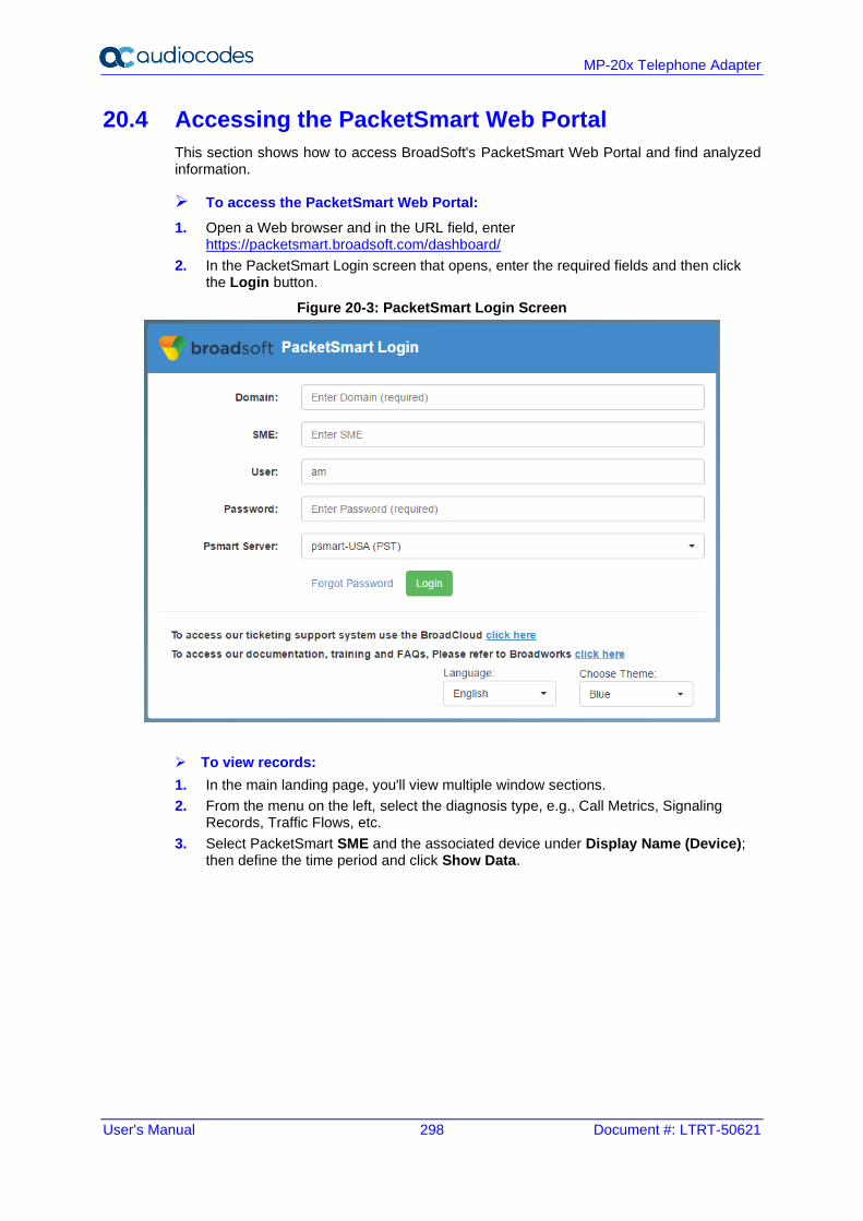
User's Manual 298 Document #: LTRT-50621
MP-20x Telephone Adapter
20.4 Accessing the PacketSmart Web Portal
This section shows how to access BroadSoft's PacketSmart Web Portal and find analyzed information.
➢ To access the PacketSmart Web Portal:
1. Open a Web browser and in the URL field, enter https://packetsmart.broadsoft.com/dashboard/
2. In the PacketSmart Login screen that opens, enter the required fields and then click the Login button.
Figure 20-3: PacketSmart Login Screen
➢ To view records:
1. In the main landing page, you'll view multiple window sections.
2. From the menu on the left, select the diagnosis type, e.g., Call Metrics, Signaling Records, Traffic Flows, etc.
3. Select PacketSmart SME and the associated device under Display Name (Device); then define the time period and click Show Data.
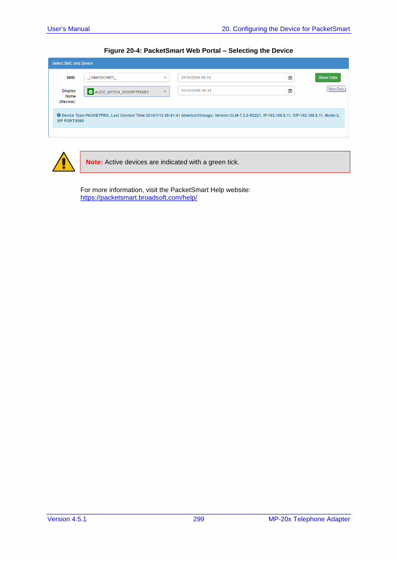
User's Manual 20. Configuring the Device for PacketSmart
Version 4.5.1 299 MP-20x Telephone Adapter
Figure 20-4: PacketSmart Web Portal – Selecting the Device
Note: Active devices are indicated with a green tick.
For more information, visit the PacketSmart Help website: https://packetsmart.broadsoft.com/help/

User's Manual 300 Document #: LTRT-50621
MP-20x Telephone Adapter
This page is intentionally left blank.
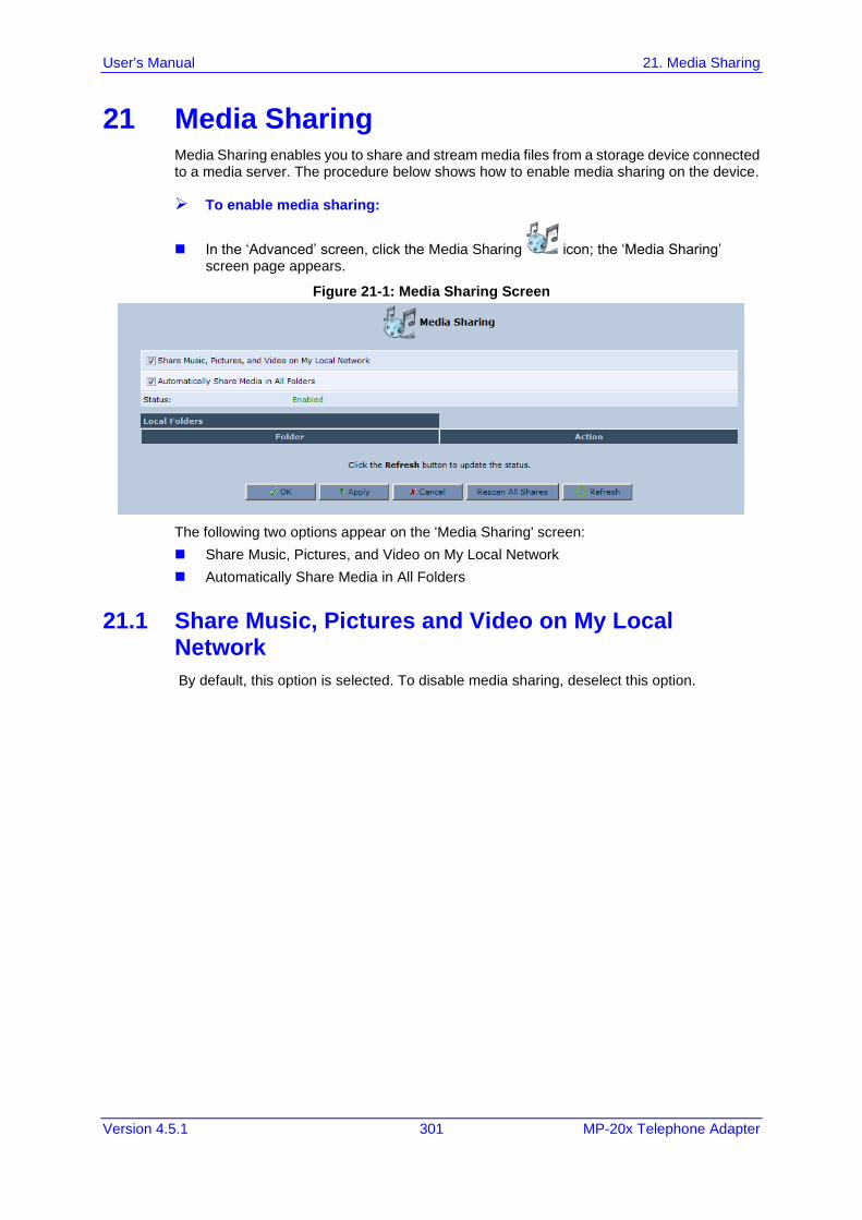
User's Manual 21. Media Sharing
Version 4.5.1 301 MP-20x Telephone Adapter
21 Media Sharing Media Sharing enables you to share and stream media files from a storage device connected to a media server. The procedure below shows how to enable media sharing on the device.
➢ To enable media sharing:
◼ In the ‘Advanced’ screen, click the Media Sharing icon; the ‘Media Sharing’ screen page appears.
Figure 21-1: Media Sharing Screen
The following two options appear on the 'Media Sharing' screen:
◼ Share Music, Pictures, and Video on My Local Network
◼ Automatically Share Media in All Folders
21.1 Share Music, Pictures and Video on My Local Network
By default, this option is selected. To disable media sharing, deselect this option.
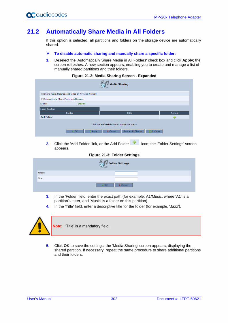
User's Manual 302 Document #: LTRT-50621
MP-20x Telephone Adapter
21.2 Automatically Share Media in All Folders
If this option is selected, all partitions and folders on the storage device are automatically shared.
➢ To disable automatic sharing and manually share a specific folder:
1. Deselect the 'Automatically Share Media in All Folders' check box and click Apply; the screen refreshes. A new section appears, enabling you to create and manage a list of manually shared partitions and their folders.
Figure 21-2: Media Sharing Screen - Expanded
2. Click the 'Add Folder' link, or the Add Folder icon; the 'Folder Settings' screen appears.
Figure 21-3: Folder Settings
3. In the 'Folder' field, enter the exact path (for example, A1/Music, where 'A1' is a partition's letter, and 'Music' is a folder on this partition).
4. In the 'Title' field, enter a descriptive title for the folder (for example, 'Jazz').
Note: ‘Title’ is a mandatory field.
5. Click OK to save the settings; the 'Media Sharing' screen appears, displaying the shared partition. If necessary, repeat the same procedure to share additional partitions and their folders.
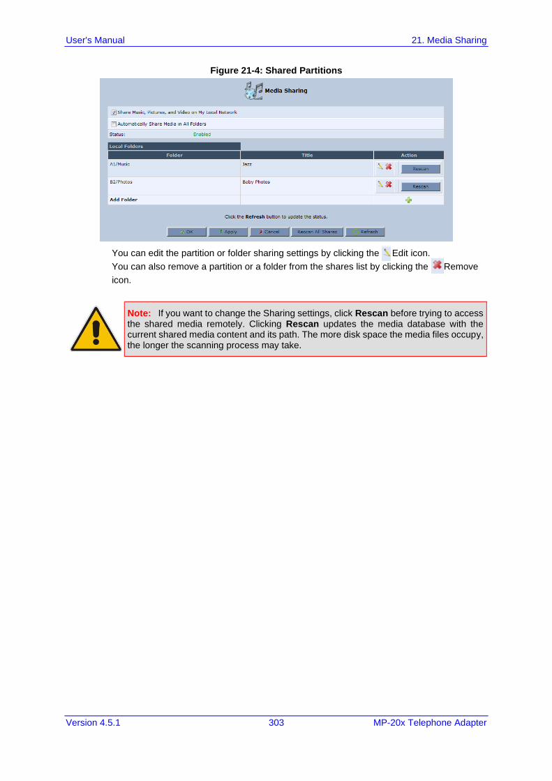
User's Manual 21. Media Sharing
Version 4.5.1 303 MP-20x Telephone Adapter
Figure 21-4: Shared Partitions
You can edit the partition or folder sharing settings by clicking the Edit icon.
You can also remove a partition or a folder from the shares list by clicking the Remove
icon.
Note: If you want to change the Sharing settings, click Rescan before trying to access the shared media remotely. Clicking Rescan updates the media database with the current shared media content and its path. The more disk space the media files occupy, the longer the scanning process may take.

User's Manual 304 Document #: LTRT-50621
MP-20x Telephone Adapter
This page is intentionally left blank.
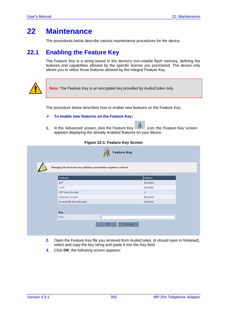
User's Manual 22. Maintenance
Version 4.5.1 305 MP-20x Telephone Adapter
22 Maintenance The procedures below describe various maintenance procedures for the device.
22.1 Enabling the Feature Key
The Feature Key is a string stored in the device's non-volatile flash memory, defining the features and capabilities allowed by the specific license you purchased. The device only allows you to utilize those features allowed by the integral Feature Key.
Note: The Feature Key is an encrypted key provided by AudioCodes only.
The procedure below describes how to enable new features on the Feature Key.
➢ To enable new features on the Feature Key:
1. In the 'Advanced' screen, click the Feature Key icon; the 'Feature Key' screen appears displaying the already enabled features on your device.
Figure 22-1: Feature Key Screen
2. Open the Feature Key file you received from AudioCodes, (it should open in Notepad), select and copy the key string and paste it into the Key field.
3. Click OK; the following screen appears:
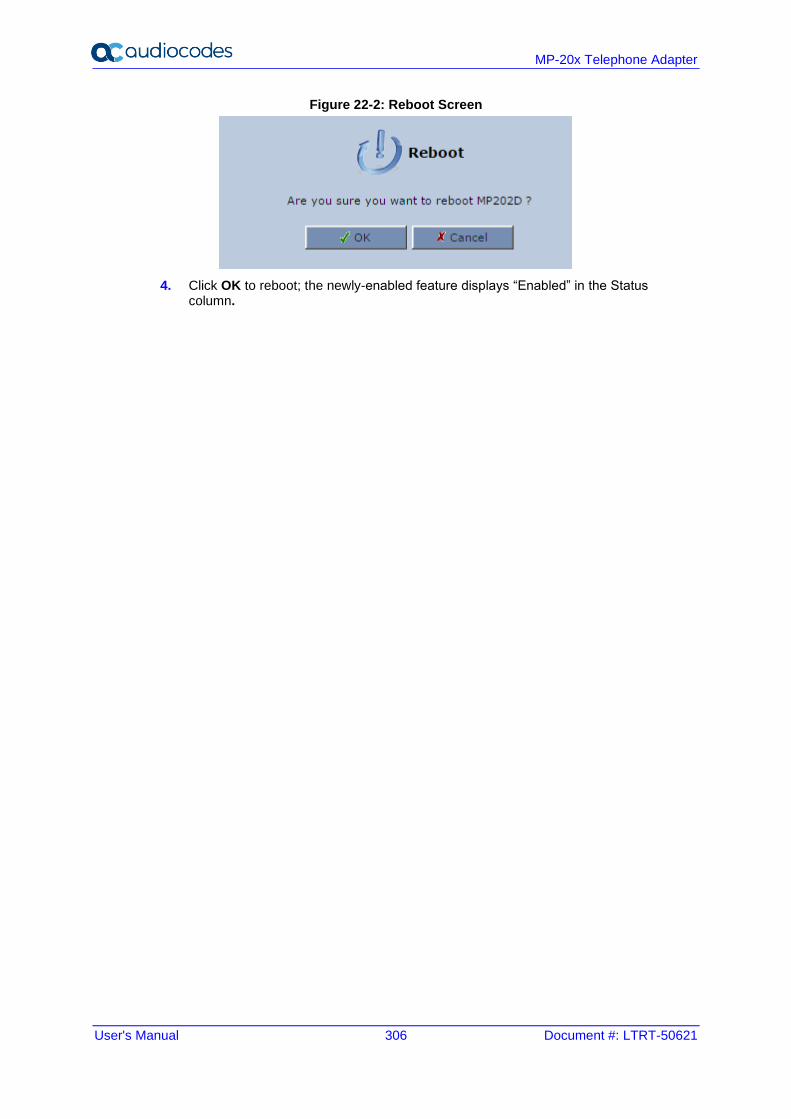
User's Manual 306 Document #: LTRT-50621
MP-20x Telephone Adapter
Figure 22-2: Reboot Screen
4. Click OK to reboot; the newly-enabled feature displays “Enabled” in the Status column.
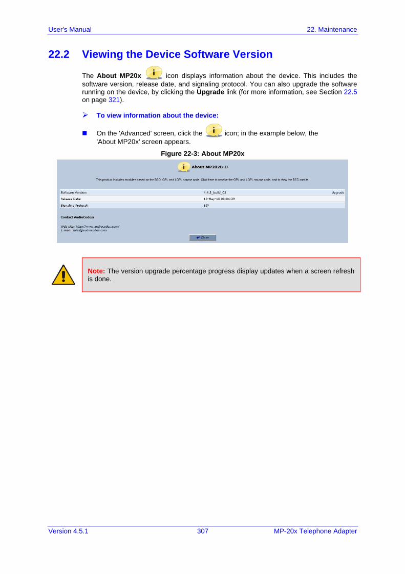
User's Manual 22. Maintenance
Version 4.5.1 307 MP-20x Telephone Adapter
22.2 Viewing the Device Software Version
The About MP20x icon displays information about the device. This includes the
software version, release date, and signaling protocol. You can also upgrade the software running on the device, by clicking the Upgrade link (for more information, see Section 22.5 on page 321).
➢ To view information about the device:
◼ On the 'Advanced' screen, click the icon; in the example below, the
'About MP20x' screen appears.
Figure 22-3: About MP20x
Note: The version upgrade percentage progress display updates when a screen refresh is done.
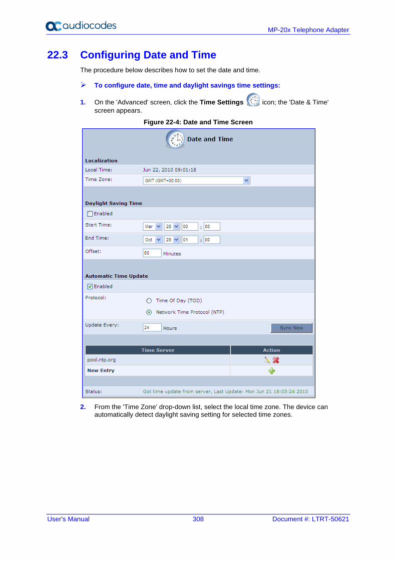
User's Manual 308 Document #: LTRT-50621
MP-20x Telephone Adapter
22.3 Configuring Date and Time
The procedure below describes how to set the date and time.
➢ To configure date, time and daylight savings time settings:
1. On the 'Advanced' screen, click the Time Settings icon; the 'Date & Time'
screen appears.
Figure 22-4: Date and Time Screen
2. From the 'Time Zone' drop-down list, select the local time zone. The device can automatically detect daylight saving setting for selected time zones.
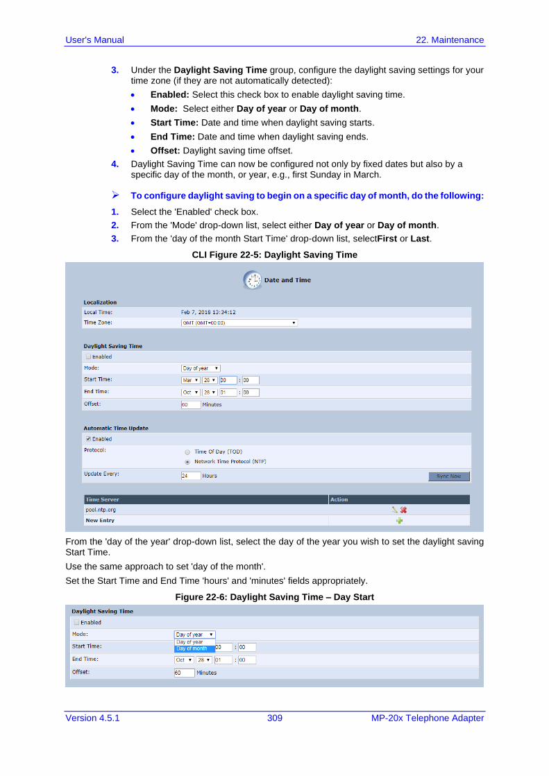
User's Manual 22. Maintenance
Version 4.5.1 309 MP-20x Telephone Adapter
3. Under the Daylight Saving Time group, configure the daylight saving settings for your time zone (if they are not automatically detected):
• Enabled: Select this check box to enable daylight saving time.
• Mode: Select either Day of year or Day of month.
• Start Time: Date and time when daylight saving starts.
• End Time: Date and time when daylight saving ends.
• Offset: Daylight saving time offset.
4. Daylight Saving Time can now be configured not only by fixed dates but also by a specific day of the month, or year, e.g., first Sunday in March.
➢ To configure daylight saving to begin on a specific day of month, do the following:
1. Select the 'Enabled' check box.
2. From the 'Mode' drop-down list, select either Day of year or Day of month.
3. From the 'day of the month Start Time' drop-down list, selectFirst or Last.
CLI Figure 22-5: Daylight Saving Time
From the 'day of the year' drop-down list, select the day of the year you wish to set the daylight saving Start Time.
Use the same approach to set 'day of the month'.
Set the Start Time and End Time 'hours' and 'minutes' fields appropriately.
Figure 22-6: Daylight Saving Time – Day Start
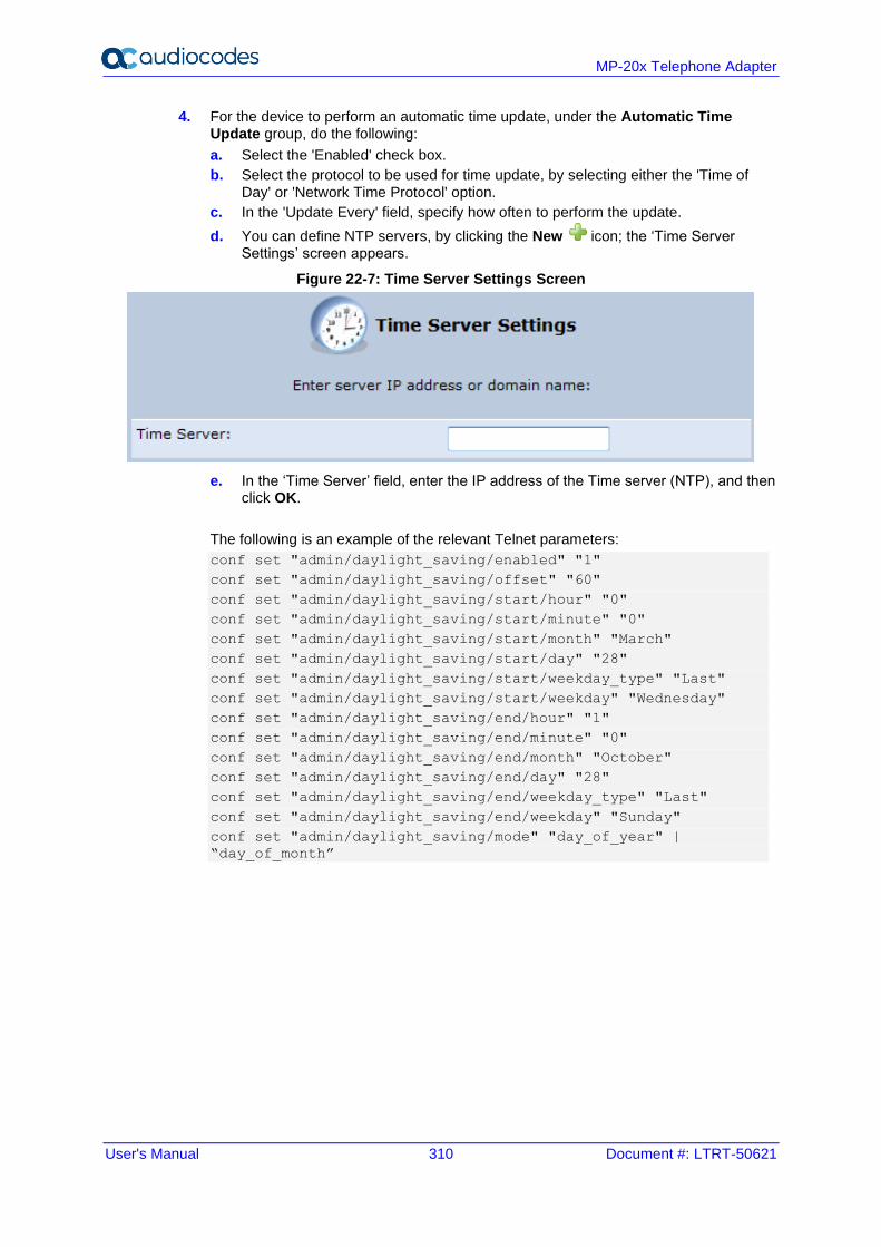
User's Manual 310 Document #: LTRT-50621
MP-20x Telephone Adapter
4. For the device to perform an automatic time update, under the Automatic Time Update group, do the following:
a. Select the 'Enabled' check box.
b. Select the protocol to be used for time update, by selecting either the 'Time of Day' or 'Network Time Protocol' option.
c. In the 'Update Every' field, specify how often to perform the update.
d. You can define NTP servers, by clicking the New icon; the ‘Time Server Settings’ screen appears.
Figure 22-7: Time Server Settings Screen
e. In the ‘Time Server’ field, enter the IP address of the Time server (NTP), and then click OK.
The following is an example of the relevant Telnet parameters:
conf set "admin/daylight_saving/enabled" "1"
conf set "admin/daylight_saving/offset" "60"
conf set "admin/daylight_saving/start/hour" "0"
conf set "admin/daylight_saving/start/minute" "0"
conf set "admin/daylight_saving/start/month" "March"
conf set "admin/daylight_saving/start/day" "28"
conf set "admin/daylight_saving/start/weekday_type" "Last"
conf set "admin/daylight_saving/start/weekday" "Wednesday"
conf set "admin/daylight_saving/end/hour" "1"
conf set "admin/daylight_saving/end/minute" "0"
conf set "admin/daylight_saving/end/month" "October"
conf set "admin/daylight_saving/end/day" "28"
conf set "admin/daylight_saving/end/weekday_type" "Last"
conf set "admin/daylight_saving/end/weekday" "Sunday"
conf set "admin/daylight_saving/mode" "day_of_year" |
“day_of_month”
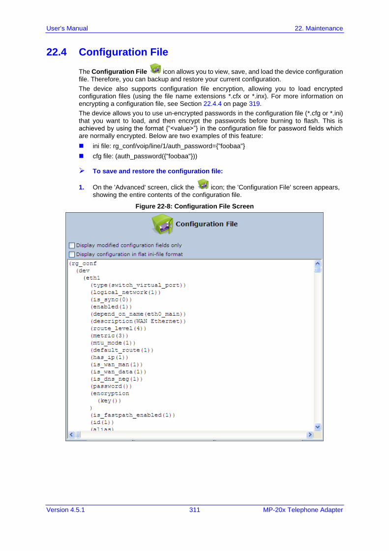
User's Manual 22. Maintenance
Version 4.5.1 311 MP-20x Telephone Adapter
22.4 Configuration File
The Configuration File icon allows you to view, save, and load the device configuration file. Therefore, you can backup and restore your current configuration.
The device also supports configuration file encryption, allowing you to load encrypted configuration files (using the file name extensions *.cfx or *.inx). For more information on encrypting a configuration file, see Section 22.4.4 on page 319.
The device allows you to use un-encrypted passwords in the configuration file (*.cfg or *.ini) that you want to load, and then encrypt the passwords before burning to flash. This is achieved by using the format {“<value>”} in the configuration file for password fields which are normally encrypted. Below are two examples of this feature:
◼ ini file: rg_conf/voip/line/1/auth_password={"foobaa"}
◼ cfg file: (auth_password({"foobaa"}))
➢ To save and restore the configuration file:
1. On the 'Advanced' screen, click the icon; the 'Configuration File' screen appears, showing the entire contents of the configuration file.
Figure 22-8: Configuration File Screen
User's Manual 312 Document #: LTRT-50621
MP-20x Telephone Adapter
2. You can customize the displayed configuration file, by selecting the following check boxes:
• Display modified configuration fields only: Displays only the configuration parameters that have values other than default values.
• Display configuration in flat ini-file format: Displays the configuration file in flat INI-file format.
3. To back up your current configuration to a file on your PC, click Download Configuration File. The saved configuration file can be used as a backup for the specific the device's configuration for creating a configuration file for remote configuration update, and for debugging and diagnostics. When creating a configuration backup, disable the two display check boxes (i.e. save a full configuration file in the hierarchic conf format). This file can be loaded back to the same device, using the procedure described in Section 22.4.1 on page 313.
Note: The file is generated according to the selected display option (in Step 2).
4. To restore your configuration from a file saved on your PC, click Upload Configuration File.
Note: Do not load this file to a different device as it includes the MAC address, which is unique to the device from where it was saved.
When creating a file for remote configuration update, it is recommended to only select the 'Display modified configuration fields only'. This ensures that the file includes only parameters that were modified from their default value. You can choose the conf format or the flat ini-file format. In both cases, it is recommended to review the file and ensure that only the parameters that the user has intended to modify appear. This file can be placed on an FTP or HTTP server for mass configuration update, as described in Remote Configuration Download.
Note: When rebooting, the device restores the settings from its configuration file. However, if reboot attempts fail three times consecutively, the device resets the configuration file by restoring factory defaults before attempting to reboot.
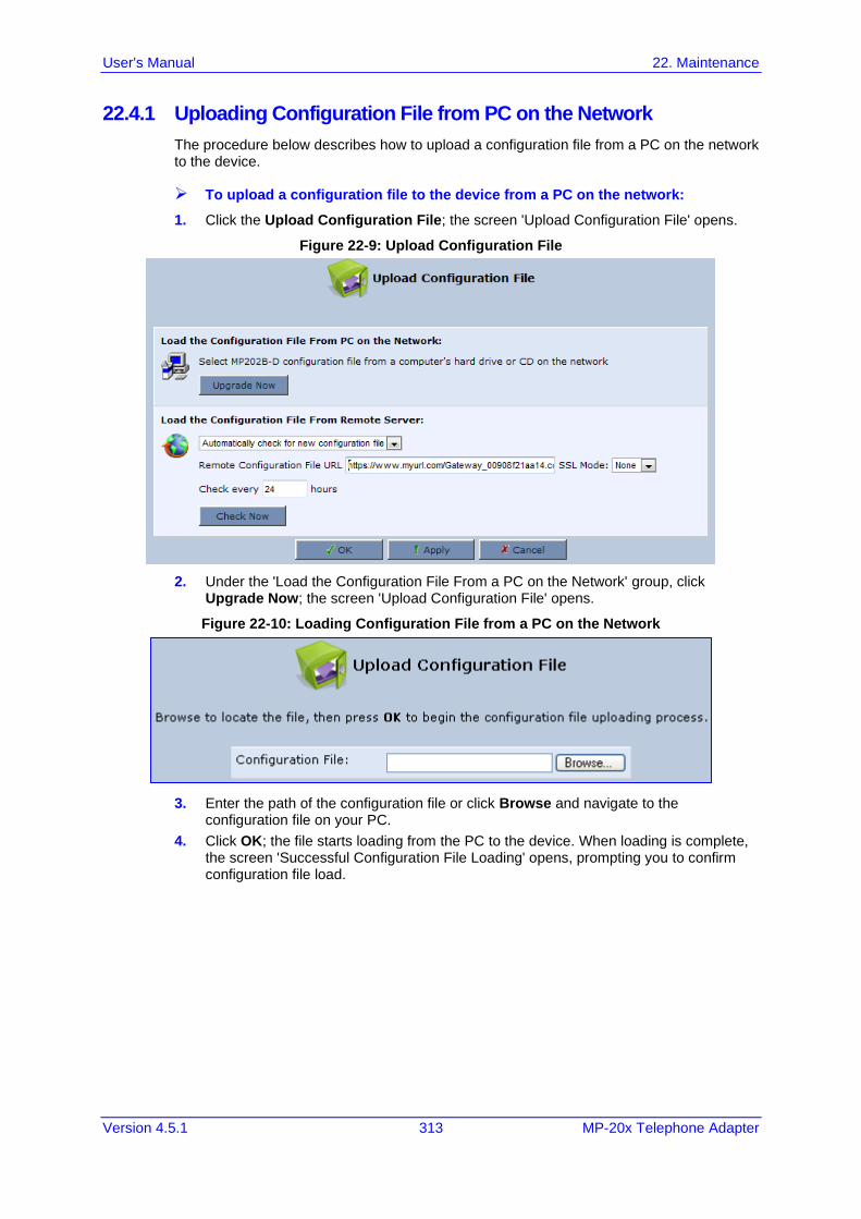
User's Manual 22. Maintenance
Version 4.5.1 313 MP-20x Telephone Adapter
22.4.1 Uploading Configuration File from PC on the Network
The procedure below describes how to upload a configuration file from a PC on the network to the device.
➢ To upload a configuration file to the device from a PC on the network:
1. Click the Upload Configuration File; the screen 'Upload Configuration File' opens.
Figure 22-9: Upload Configuration File
2. Under the 'Load the Configuration File From a PC on the Network' group, click Upgrade Now; the screen 'Upload Configuration File' opens.
Figure 22-10: Loading Configuration File from a PC on the Network
3. Enter the path of the configuration file or click Browse and navigate to the configuration file on your PC.
4. Click OK; the file starts loading from the PC to the device. When loading is complete, the screen 'Successful Configuration File Loading' opens, prompting you to confirm configuration file load.
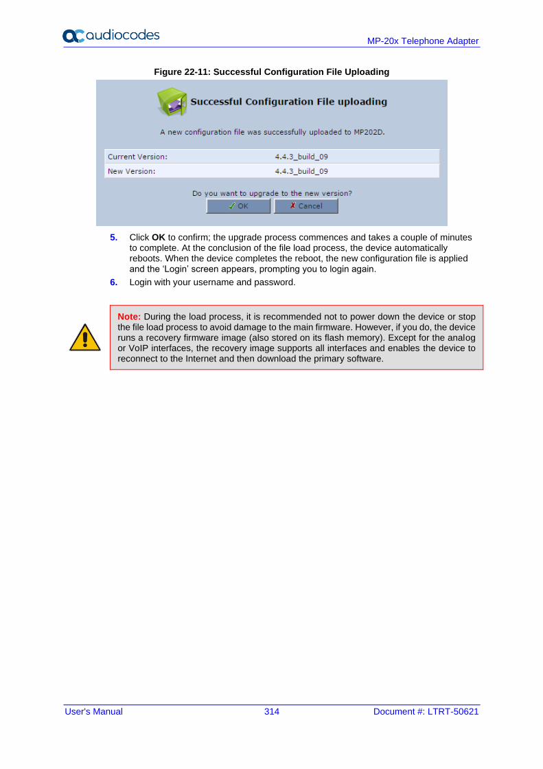
User's Manual 314 Document #: LTRT-50621
MP-20x Telephone Adapter
Figure 22-11: Successful Configuration File Uploading
5. Click OK to confirm; the upgrade process commences and takes a couple of minutes to complete. At the conclusion of the file load process, the device automatically reboots. When the device completes the reboot, the new configuration file is applied and the ‘Login’ screen appears, prompting you to login again.
6. Login with your username and password.
Note: During the load process, it is recommended not to power down the device or stop the file load process to avoid damage to the main firmware. However, if you do, the device runs a recovery firmware image (also stored on its flash memory). Except for the analog or VoIP interfaces, the recovery image supports all interfaces and enables the device to reconnect to the Internet and then download the primary software.
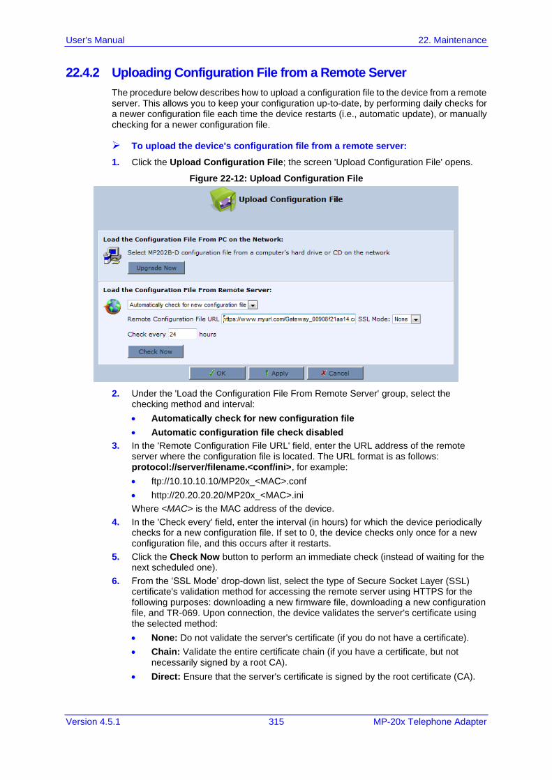
User's Manual 22. Maintenance
Version 4.5.1 315 MP-20x Telephone Adapter
22.4.2 Uploading Configuration File from a Remote Server
The procedure below describes how to upload a configuration file to the device from a remote server. This allows you to keep your configuration up-to-date, by performing daily checks for a newer configuration file each time the device restarts (i.e., automatic update), or manually checking for a newer configuration file.
➢ To upload the device's configuration file from a remote server:
1. Click the Upload Configuration File; the screen 'Upload Configuration File' opens.
Figure 22-12: Upload Configuration File
2. Under the 'Load the Configuration File From Remote Server' group, select the checking method and interval:
• Automatically check for new configuration file
• Automatic configuration file check disabled
3. In the 'Remote Configuration File URL' field, enter the URL address of the remote server where the configuration file is located. The URL format is as follows: protocol://server/filename.<conf/ini>, for example:
• ftp://10.10.10.10/MP20x_<MAC>.conf
• http://20.20.20.20/MP20x_<MAC>.ini
Where <MAC> is the MAC address of the device.
4. In the 'Check every' field, enter the interval (in hours) for which the device periodically checks for a new configuration file. If set to 0, the device checks only once for a new configuration file, and this occurs after it restarts.
5. Click the Check Now button to perform an immediate check (instead of waiting for the next scheduled one).
6. From the ‘SSL Mode’ drop-down list, select the type of Secure Socket Layer (SSL) certificate's validation method for accessing the remote server using HTTPS for the following purposes: downloading a new firmware file, downloading a new configuration file, and TR-069. Upon connection, the device validates the server's certificate using the selected method:
• None: Do not validate the server's certificate (if you do not have a certificate).
• Chain: Validate the entire certificate chain (if you have a certificate, but not necessarily signed by a root CA).
• Direct: Ensure that the server's certificate is signed by the root certificate (CA).
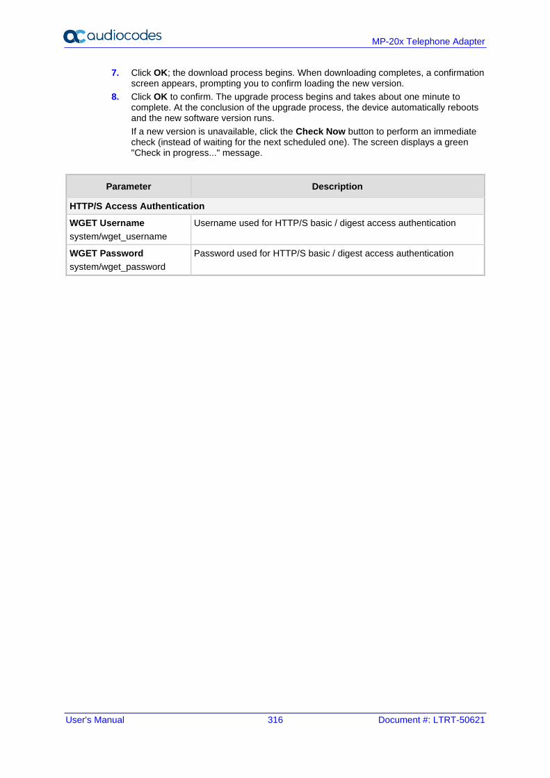
User's Manual 316 Document #: LTRT-50621
MP-20x Telephone Adapter
7. Click OK; the download process begins. When downloading completes, a confirmation screen appears, prompting you to confirm loading the new version.
8. Click OK to confirm. The upgrade process begins and takes about one minute to complete. At the conclusion of the upgrade process, the device automatically reboots and the new software version runs.
If a new version is unavailable, click the Check Now button to perform an immediate check (instead of waiting for the next scheduled one). The screen displays a green "Check in progress..." message.
Parameter Description
HTTP/S Access Authentication
WGET Username
system/wget_username
Username used for HTTP/S basic / digest access authentication
WGET Password
system/wget_password
Password used for HTTP/S basic / digest access authentication
User's Manual 22. Maintenance
Version 4.5.1 317 MP-20x Telephone Adapter
Notes:
• For additional security, the device can be configured to use HTTPS client-server certification when connecting to a remote server (see Section 16.3 on page 214).
• The configuration file can have one of the following two formats: a hierarchical conf file (indicated by file extension *.conf) or a flat ini file (indicated by file extension .ini).
• The parameter ‘/rmt_config/version’ defines the version of the configuration file. The device uses the new configuration file only if the version that is defined in this file is later than the current version. By default, the ‘version’ is set to 0. This means that each time Service Providers’ operations personnel require the device to download a new configuration file, they need to increment the ‘version’ parameter in the new file (in the .conf file, the ‘version’ parameter is under the section ‘rmt_config’). To simplify the procedure, it is possible to use the current date in YYYYMMDD format as the version field.
• The remote configuration file must include only a subset of the complete MP20x.conf file. A recommended procedure is to start with the device restored to its factory settings, modify using the embedded Web server the parameters that should appear in the remote configuration file, and then upload (save) the configuration file. You must save only the modified parameters, as described in 'Remote Administration' on page 280.
• The string <MAC> enables the ISP to pre-configure all its deployed the devices with the same URL and file details (under rmt_config/url) and still have each device download its unique configuration file. Once the URL is configured with the string <MAC>, the device that is trying to update its configuration file automatically replaces <MAC> with its own unique MAC address. For example, if there’s a device with a WAN MAC address 00:01:02:03:04:05, the ISP can configure the url to http://myserver.com/my_conf_file_<MAC>.conf - and place a file called ‘my_conf_file_00_01_02_03_04_05.conf’ on the server.
• Downloading a configuration file from a remote server can also be performed from the CLI: 1) Using Telnet, access the device, and then enter the user name and password. 2) Enter the command rmt_config, for example: rmt_config –u http://myserver.com/my_conf_file.conf 3) Enter rmt_config without any arguments for more help information.
User's Manual 318 Document #: LTRT-50621
MP-20x Telephone Adapter
22.4.3 Remote Configuration Provisioning Based on MD5 Checksum Comparison
By default, a new method for remote configuration provisioning based on MD5 checksum comparison has been added with the following steps: 1. The device downloads the configuration file and calculates its MD5-checksum.
2. The device compares the calculated value to the previous MD5-checksum (‘rmt_config/checksum’).
3. If the value is different, the device applies the downloaded configuration and saves the new MD5-checksum value.
4. If the value is the same, the downloaded file will be discarded.
5. To revert back to the methods used in previous versions, (e.g., “use_if_modified_since” or “version” counter), the following parameter needs to be added to the configuration: rg_conf/rmt_config/default_prov_disabled=1.
User's Manual 22. Maintenance
Version 4.5.1 319 MP-20x Telephone Adapter
22.4.4 Encrypting the Configuration File using CLI
Encrypted files include the file name extension *.cfx (instead of *.cfg) or *.inx (instead of *.ini). After the device loads the encrypted file from the HTTP server, it automatically identifies the encrypted file by its file name extensions *.cfx or *.inx, and subsequently decrypts the file before saving it to flash memory.
The following procedure describes how to encrypt configuration files.
➢ To encrypt a configuration file:
◼ Run the following CLI shell command (on Linux or Windows PC with OpenSSL installed):
openssl des3 -in <original file> -out <encrypted file> -k
<password> -S <salt value>
Where,
• <original file> is the original clear-text configuration file (*.cfg or *.ini file).
• <encrypted file> is the output file (an encrypted *.cfx or *.inx file).
• <password> is the password that is used to encrypt the file.
• <salt value> is the 8 bytes of a special key value that is combined with the password. The format is 16 hexadecimal digits [0-9,A-F].
An example of this command is shown below:
openssl des3 -in c:\temp\try_enc_conf.cfg -out
c:\temp\try_enc_conf.cfx -k My_P@$$w0rd! -S 0123456789ABCDEF
Notes:
• You can choose any <salt value> – the device does not have to know about it.
• A password can be pre-configured in the device, using the following CLI command: conf set_obscure/rmt_config/password <password>
For example: tftp://1.2.3.4/file
• You can also define the password in a configuration file that you download from the server.
• If you don’t define a password in the configuration file, a default password is used. Different default passwords are defined per customer, according to the config-file url hostname.
User's Manual 320 Document #: LTRT-50621
MP-20x Telephone Adapter
22.4.5 Automatic Upload using SIP NOTIFY Message
You can enable automatic configuration update for the device from a remote server, using the SIP NOTIFY message. The contents of the configuration file can initiate (“push”) the remote server to update the device to a desired configuration version.
➢ To “push” a configuration file when a change of parameter is needed:
1. Create a new configuration file with the required change.
2. Place the file on the HTTP server.
3. Send the SIP NOTIFY message to the device; the device integrates the contents of the new file and reboots.
➢ To “push” a configuration file and initiate an upgrade or downgrade:
1. Create a new configuration file that includes two important entries:
a. In rg_conf/rmt_upd/chech_sync_version, configure the details of the version to which you want the device to upgrade or downgrade, for example:
(rmt_upd
(check_sync_version(4.4.8_build_86))
)
b. You may need to update the URL address from where the device is downloading the firmware (the path is configured in rmt_upd/url).
Note: In the case of a downgrade, the service provider MUST provide a configuration file based on a template that matches the version to which the device is downgrading.
2. Place the file on the HTTP server.
3. Send the SIP NOTIFY message to the device; the device integrates the contents of the new file and reboots. After rebooting, the device compares the currently running version with the version which is configured in rmt_upd/chech_sync_version and then determines whether to connect to the rmt_upd/url for downloading the new *.rmt file. Once the file is downloaded, its headers are parsed, and only if it represents the same version which was configured in the value of rmt_upd/chech_sync_version, does the upgrade/downgrade process begin.
In addition to the standard Event: check-sync format, AudioCodes now supports o:check-sync, in the compact format. The MP-20x’s behavior is similar for both formats.
User's Manual 22. Maintenance
Version 4.5.1 321 MP-20x Telephone Adapter
22.5 Firmware Upgrade
The device provides a built-in mechanism for upgrading its software image. There are two methods for upgrading the software image:
◼ Upgrading from a Computer on the Network: This method uses a software image file that is pre-downloaded on a PC's disk drive or located on an accompanying CD. (See Section 22.5.1 on page 322.)
◼ Upgrading from the Internet: This method also referred to as 'Remote Update', upgrades your firmware by remotely downloading an updated software image file. (See Section 22.5.2 on page 324.)
The device provides a flash memory of 16 MB, which is capable of storing two firmware images. In addition to the primary firmware, the device also stores a recovery firmware, which is used only if the primary image is missing or damaged (e.g. if the user unplugs the power during firmware upgrade). Except for the analog or VoIP interfaces, the recovery image supports all interfaces and enables the device to reconnect to the Internet and download the primary firmware.
Note: During the upgrade process, do NOT power off the device.
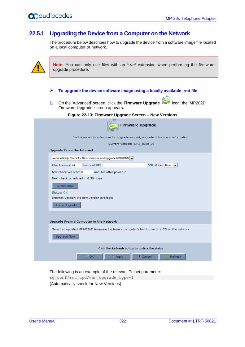
User's Manual 322 Document #: LTRT-50621
MP-20x Telephone Adapter
22.5.1 Upgrading the Device from a Computer on the Network
The procedure below describes how to upgrade the device from a software image file located on a local computer or network.
Note: You can only use files with an *.rmt extension when performing the firmware upgrade procedure.
➢ To upgrade the device software image using a locally available .rmt file:
1. On the 'Advanced' screen, click the Firmware Upgrade icon; the ‘MP202D Firmware Upgrade' screen appears.
Figure 22-13: Firmware Upgrade Screen – New Versions
The following is an example of the relevant Telnet parameter:
rg_conf/rmt_upd/wan_upgrade_type=1
(Automatically check for New Versions)
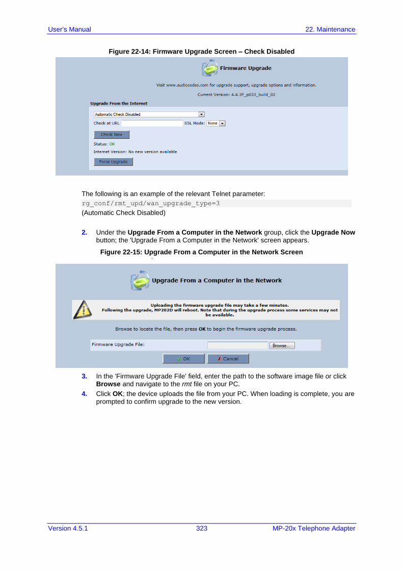
User's Manual 22. Maintenance
Version 4.5.1 323 MP-20x Telephone Adapter
Figure 22-14: Firmware Upgrade Screen – Check Disabled
The following is an example of the relevant Telnet parameter:
rg_conf/rmt_upd/wan_upgrade_type=3
(Automatic Check Disabled)
2. Under the Upgrade From a Computer in the Network group, click the Upgrade Now button; the 'Upgrade From a Computer in the Network' screen appears.
Figure 22-15: Upgrade From a Computer in the Network Screen
3. In the 'Firmware Upgrade File' field, enter the path to the software image file or click Browse and navigate to the rmt file on your PC.
4. Click OK; the device uploads the file from your PC. When loading is complete, you are prompted to confirm upgrade to the new version.
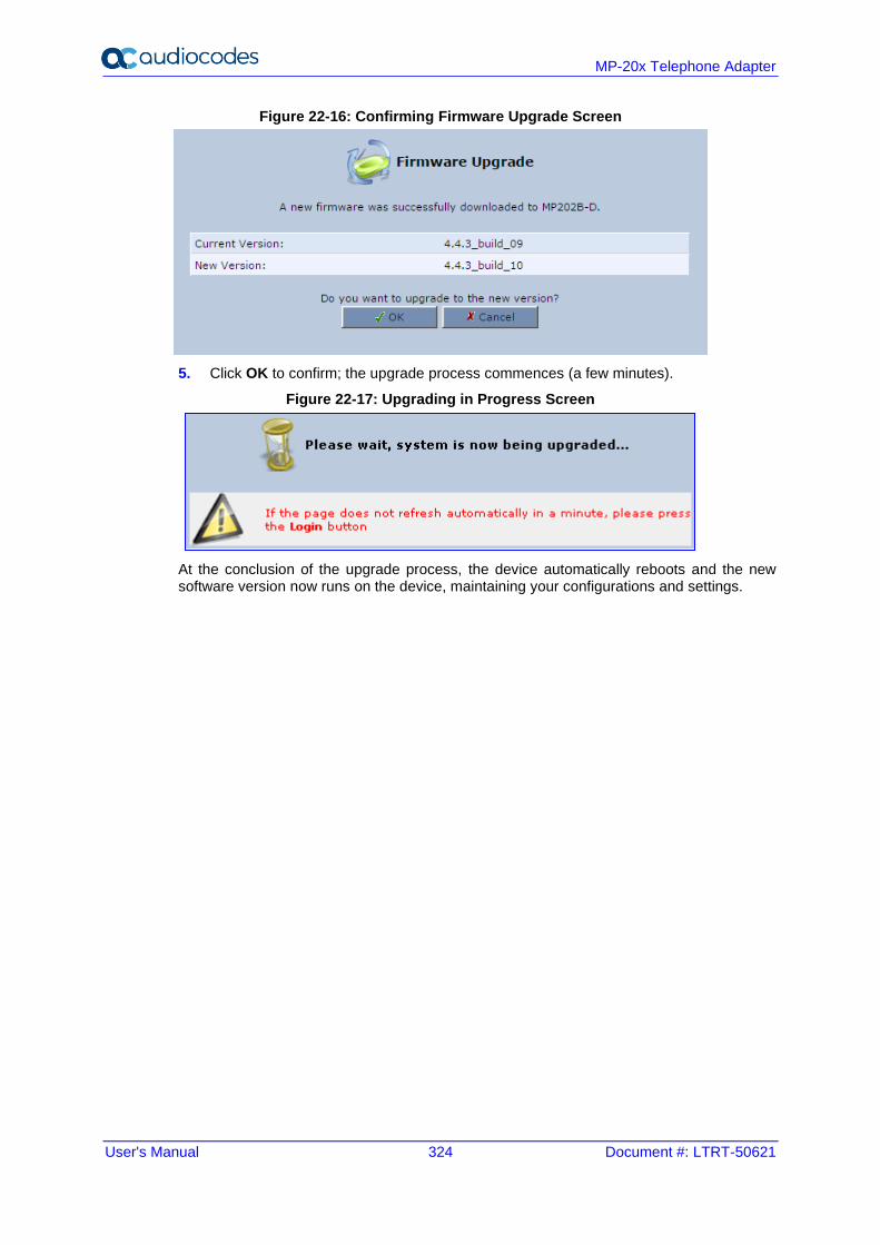
User's Manual 324 Document #: LTRT-50621
MP-20x Telephone Adapter
Figure 22-16: Confirming Firmware Upgrade Screen
5. Click OK to confirm; the upgrade process commences (a few minutes).
Figure 22-17: Upgrading in Progress Screen
At the conclusion of the upgrade process, the device automatically reboots and the new software version now runs on the device, maintaining your configurations and settings.
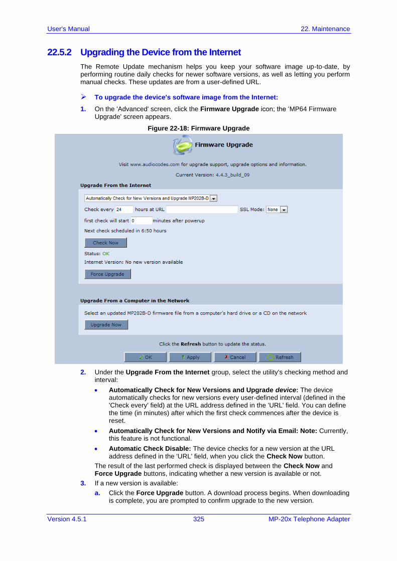
User's Manual 22. Maintenance
Version 4.5.1 325 MP-20x Telephone Adapter
22.5.2 Upgrading the Device from the Internet
The Remote Update mechanism helps you keep your software image up-to-date, by performing routine daily checks for newer software versions, as well as letting you perform manual checks. These updates are from a user-defined URL.
➢ To upgrade the device's software image from the Internet:
1. On the 'Advanced' screen, click the Firmware Upgrade icon; the ‘MP64 Firmware Upgrade' screen appears.
Figure 22-18: Firmware Upgrade
2. Under the Upgrade From the Internet group, select the utility's checking method and interval:
• Automatically Check for New Versions and Upgrade device: The device automatically checks for new versions every user-defined interval (defined in the 'Check every' field) at the URL address defined in the 'URL' field. You can define the time (in minutes) after which the first check commences after the device is reset.
• Automatically Check for New Versions and Notify via Email: Note: Currently, this feature is not functional.
• Automatic Check Disable: The device checks for a new version at the URL address defined in the 'URL' field, when you click the Check Now button.
The result of the last performed check is displayed between the Check Now and Force Upgrade buttons, indicating whether a new version is available or not.
3. If a new version is available:
a. Click the Force Upgrade button. A download process begins. When downloading is complete, you are prompted to confirm upgrade to the new version.
User's Manual 326 Document #: LTRT-50621
MP-20x Telephone Adapter
b. Click OK to confirm. The upgrade process begins and takes about one minute to complete. At the conclusion of the upgrade process, the device automatically reboots with the new software version.
4. If a new version is unavailable:
a. Click the Check Now button to perform an immediate check (instead of waiting for the next scheduled one). The screen displays the "Check in progress" message.
b. Click the Refresh button until the check is complete and the result is displayed.
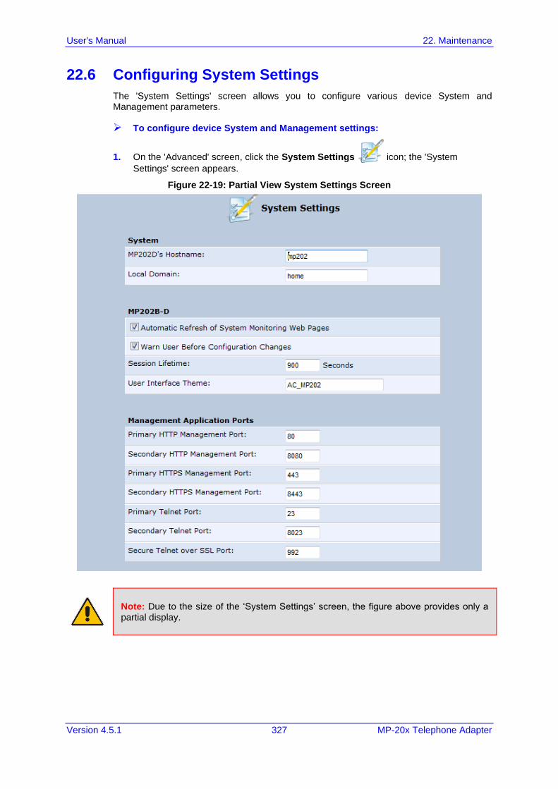
User's Manual 22. Maintenance
Version 4.5.1 327 MP-20x Telephone Adapter
22.6 Configuring System Settings
The 'System Settings' screen allows you to configure various device System and Management parameters.
➢ To configure device System and Management settings:
1. On the 'Advanced' screen, click the System Settings icon; the 'System
Settings' screen appears.
Figure 22-19: Partial View System Settings Screen
Note: Due to the size of the ‘System Settings’ screen, the figure above provides only a partial display.
User's Manual 328 Document #: LTRT-50621
MP-20x Telephone Adapter
2. Under the System Settings group, configure the following:
• In the ‘MP202Ds Hostname' field, enter the device's host name. The host name is the device's URL address.
• In the 'Local Domain' field, enter your network's local domain.
3. Under the MP202b-D group, do the following:
• Automatic Refresh of System Monitoring Web Pages: select this check box to enable automatic refreshing of system monitoring Web interface pages.
• Warn User Before Network Configuration Changes: select this check box to activate user warnings before network configuration changes take effect.
• Session Lifetime: duration of idle time (in seconds) in which the Web session remains active. When this duration times out, you must re-login.
• User Interface Theme: Defines a different GUI theme that affects the GUI design and available parameters. For more information, contact your AudioCodes distributor.
• Language: select a language for the Web interface GUI.
4. Under the Management Application Ports group, define the following ports:
• Primary/secondary HTTP management ports
• Primary/secondary management HTTPS ports
• Primary/secondary Telnet ports
• Secure Telnet over SSL ports
5. Under the Management Application SSL Authentication Options group, configure whether the following is required:
• Primary/Secondary HTTPS Management Client Authentication
• Secure Telnet over SSL Client Authentication
6. Under the System Logging group, do the following:
• System Log Buffer Size: size of the system log buffer in kilobytes.
• Remote System Notify Level: The device sends notifications to a remote host (None, Error, Warning, Information)
• Persistent System Log: saves the system log to the device flash memory. This prevents the system log from being erased when the device reboots.
7. Under the Security Logging group, do the following:
• Security Log Buffer Size: size of the security log buffer in Kilobytes
• Remote Security Notify Level: None, Error, Warning, Information
• Persistent Security Log: saves the security log to the flash. This prevents the security log from being erased when the device reboots.
Note: Do not leave the persistent logging feature enabled permanently, as continuous writing of the log files to the flash memory reduces the device's performance.
User's Manual 22. Maintenance
Version 4.5.1 329 MP-20x Telephone Adapter
8. Under the Outgoing Mail Server group, do the following:
• Server: hostname of your outgoing (SMTP) server.
• From Email Address: Each email requires a 'from' address and some outgoing servers refuse to forward mail without a valid 'from' address for anti-spam reasons.
• Port: port used by your outgoing mail server.
• Server Requires Authentication: If your outgoing mail server requires authentication, select this check box and enter your user name and password in the subsequent 'User Name' and 'Password' fields respectively.
To define email notifications per User to receive indications of system and security events, see Section 5.4 on page 36.
9. The Swap group configures the Swap feature that enables you to free a portion of the RAM by creating a swap file on the storage device connected to the device. This is especially useful for platforms with a small RAM. To activate this feature:
a. Verify that a storage device is connected to the device.
b. Select the 'Enabled' check box.
c. In the 'Swap Size' field, enter a swap file size in megabytes.
d. Click Apply; a swap file is created on the storage device and the read-only ‘Status’ field changes to “Ready”.
10. Under the Host Information group, select the ‘Enable Auto Detection of Host Services’ check box to enable the device to auto-detect its LAN hosts' properties, available services, traffic statistics, and connections.
11. Under the Installation Wizard group, select the ‘Use Installation Wizard Pre-configured Values’ check box to have the wizard skip the steps for which parameters had been preconfigured and saved in the factory settings file (rg_factory).
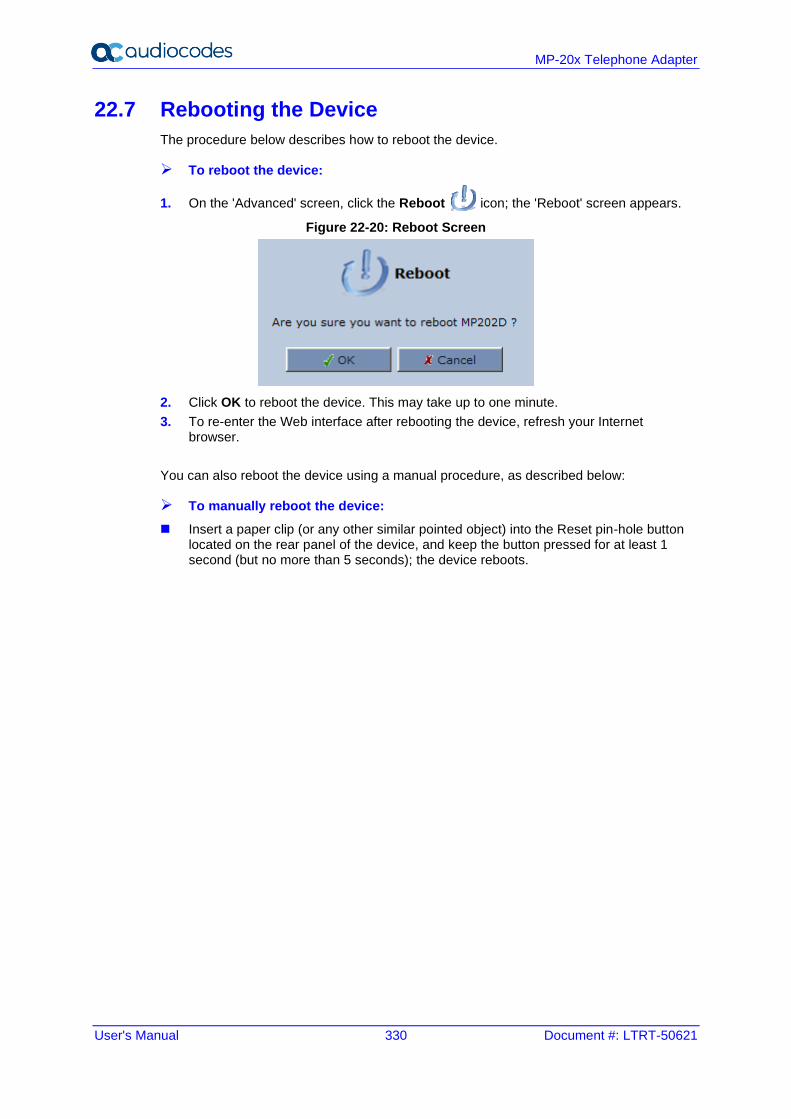
User's Manual 330 Document #: LTRT-50621
MP-20x Telephone Adapter
22.7 Rebooting the Device
The procedure below describes how to reboot the device.
➢ To reboot the device:
1. On the 'Advanced' screen, click the Reboot icon; the 'Reboot' screen appears.
Figure 22-20: Reboot Screen
2. Click OK to reboot the device. This may take up to one minute.
3. To re-enter the Web interface after rebooting the device, refresh your Internet browser.
You can also reboot the device using a manual procedure, as described below:
➢ To manually reboot the device:
◼ Insert a paper clip (or any other similar pointed object) into the Reset pin-hole button located on the rear panel of the device, and keep the button pressed for at least 1 second (but no more than 5 seconds); the device reboots.
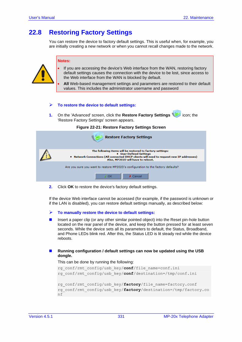
User's Manual 22. Maintenance
Version 4.5.1 331 MP-20x Telephone Adapter
22.8 Restoring Factory Settings
You can restore the device to factory default settings. This is useful when, for example, you are initially creating a new network or when you cannot recall changes made to the network.
Notes:
• If you are accessing the device's Web interface from the WAN, restoring factory default settings causes the connection with the device to be lost, since access to the Web interface from the WAN is blocked by default.
• All Web-based management settings and parameters are restored to their default values. This includes the administrator username and password
➢ To restore the device to default settings:
1. On the 'Advanced' screen, click the Restore Factory Settings icon; the
'Restore Factory Settings' screen appears.
Figure 22-21: Restore Factory Settings Screen
2. Click OK to restore the device's factory default settings.
If the device Web interface cannot be accessed (for example, if the password is unknown or if the LAN is disabled), you can restore default settings manually, as described below:
➢ To manually restore the device to default settings:
◼ Insert a paper clip (or any other similar pointed object) into the Reset pin-hole button located on the rear panel of the device, and keep the button pressed for at least seven seconds. While the device sets all its parameters to default, the Status, Broadband, and Phone LEDs blink red. After this, the Status LED is lit steady red while the device reboots.
◼ Running configuration / default settings can now be updated using the USB dongle.
This can be done by running the following:
rg_conf/rmt_config/usb_key/conf/file_name=conf.ini
rg_conf/rmt_config/usb_key/conf/destination=/tmp/conf.ini
rg_conf/rmt_config/usb_key/factory/file_name=factory.conf
rg_conf/rmt_config/usb_key/factory/destination=/tmp/factory.co
nf

User's Manual 332 Document #: LTRT-50621
MP-20x Telephone Adapter
This page is intentionally left blank.
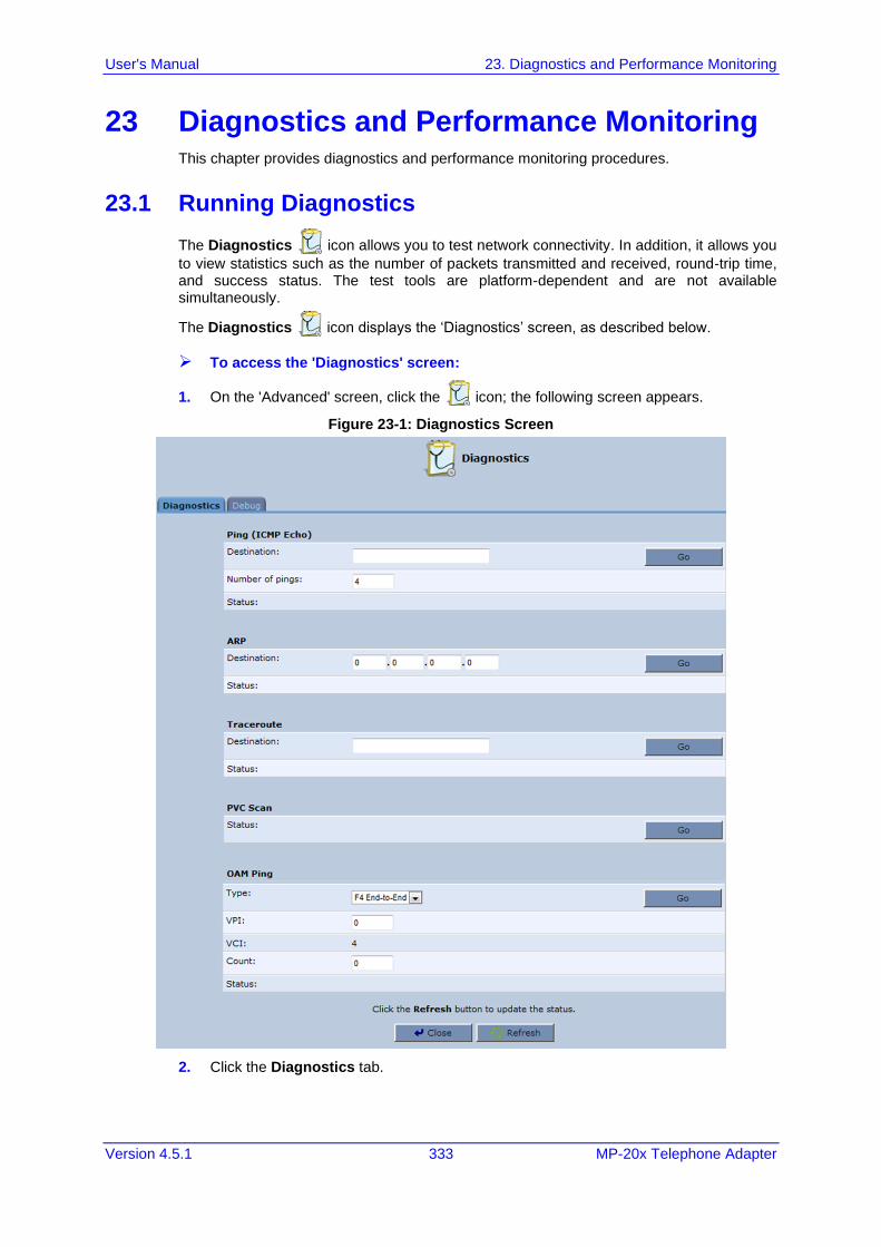
User's Manual 23. Diagnostics and Performance Monitoring
Version 4.5.1 333 MP-20x Telephone Adapter
23 Diagnostics and Performance Monitoring This chapter provides diagnostics and performance monitoring procedures.
23.1 Running Diagnostics
The Diagnostics icon allows you to test network connectivity. In addition, it allows you
to view statistics such as the number of packets transmitted and received, round-trip time, and success status. The test tools are platform-dependent and are not available simultaneously.
The Diagnostics icon displays the ‘Diagnostics’ screen, as described below.
➢ To access the 'Diagnostics' screen:
1. On the 'Advanced' screen, click the icon; the following screen appears.
Figure 23-1: Diagnostics Screen
2. Click the Diagnostics tab.
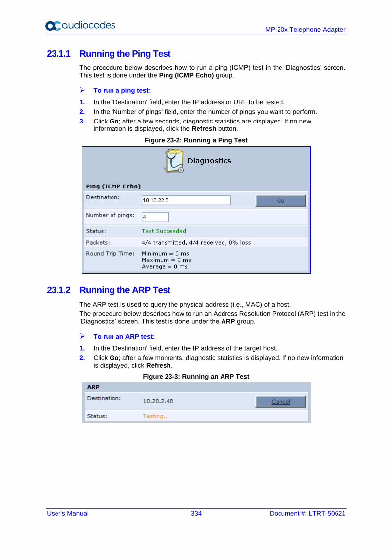
User's Manual 334 Document #: LTRT-50621
MP-20x Telephone Adapter
23.1.1 Running the Ping Test
The procedure below describes how to run a ping (ICMP) test in the ‘Diagnostics’ screen. This test is done under the Ping (ICMP Echo) group.
➢ To run a ping test:
1. In the 'Destination' field, enter the IP address or URL to be tested.
2. In the 'Number of pings' field, enter the number of pings you want to perform.
3. Click Go; after a few seconds, diagnostic statistics are displayed. If no new information is displayed, click the Refresh button.
Figure 23-2: Running a Ping Test
23.1.2 Running the ARP Test
The ARP test is used to query the physical address (i.e., MAC) of a host.
The procedure below describes how to run an Address Resolution Protocol (ARP) test in the ‘Diagnostics’ screen. This test is done under the ARP group.
➢ To run an ARP test:
1. In the 'Destination' field, enter the IP address of the target host.
2. Click Go; after a few moments, diagnostic statistics is displayed. If no new information is displayed, click Refresh.
Figure 23-3: Running an ARP Test
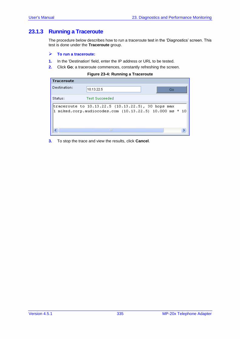
User's Manual 23. Diagnostics and Performance Monitoring
Version 4.5.1 335 MP-20x Telephone Adapter
23.1.3 Running a Traceroute
The procedure below describes how to run a traceroute test in the ‘Diagnostics’ screen. This test is done under the Traceroute group.
➢ To run a traceroute:
1. In the 'Destination' field, enter the IP address or URL to be tested.
2. Click Go; a traceroute commences, constantly refreshing the screen.
Figure 23-4: Running a Traceroute
3. To stop the trace and view the results, click Cancel.
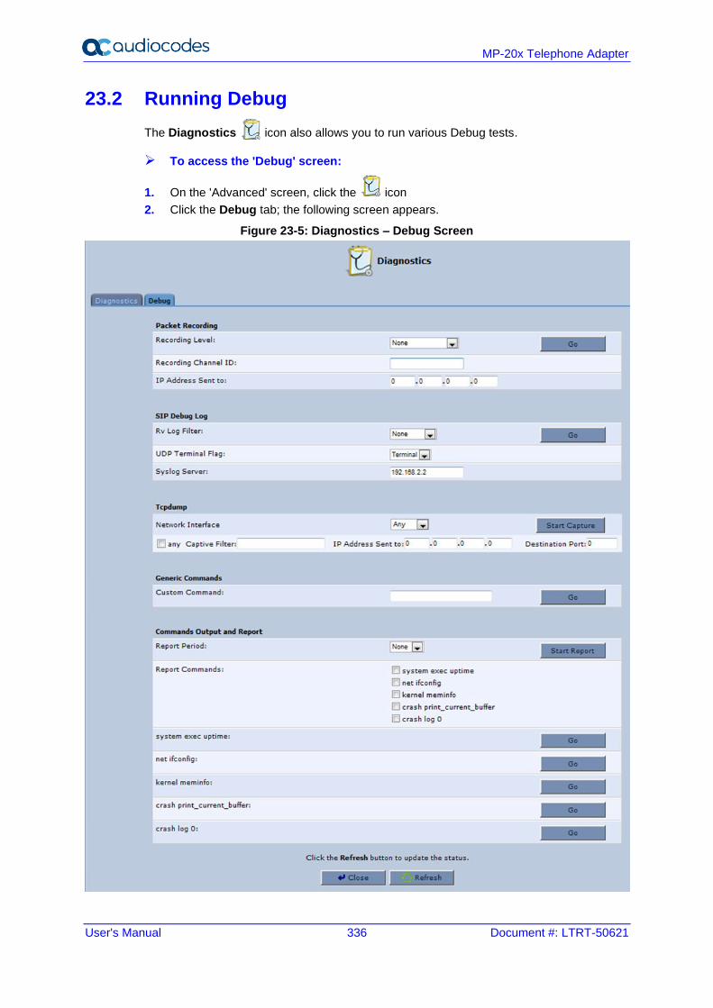
User's Manual 336 Document #: LTRT-50621
MP-20x Telephone Adapter
23.2 Running Debug
The Diagnostics icon also allows you to run various Debug tests.
➢ To access the 'Debug' screen:
1. On the 'Advanced' screen, click the icon
2. Click the Debug tab; the following screen appears.
Figure 23-5: Diagnostics – Debug Screen
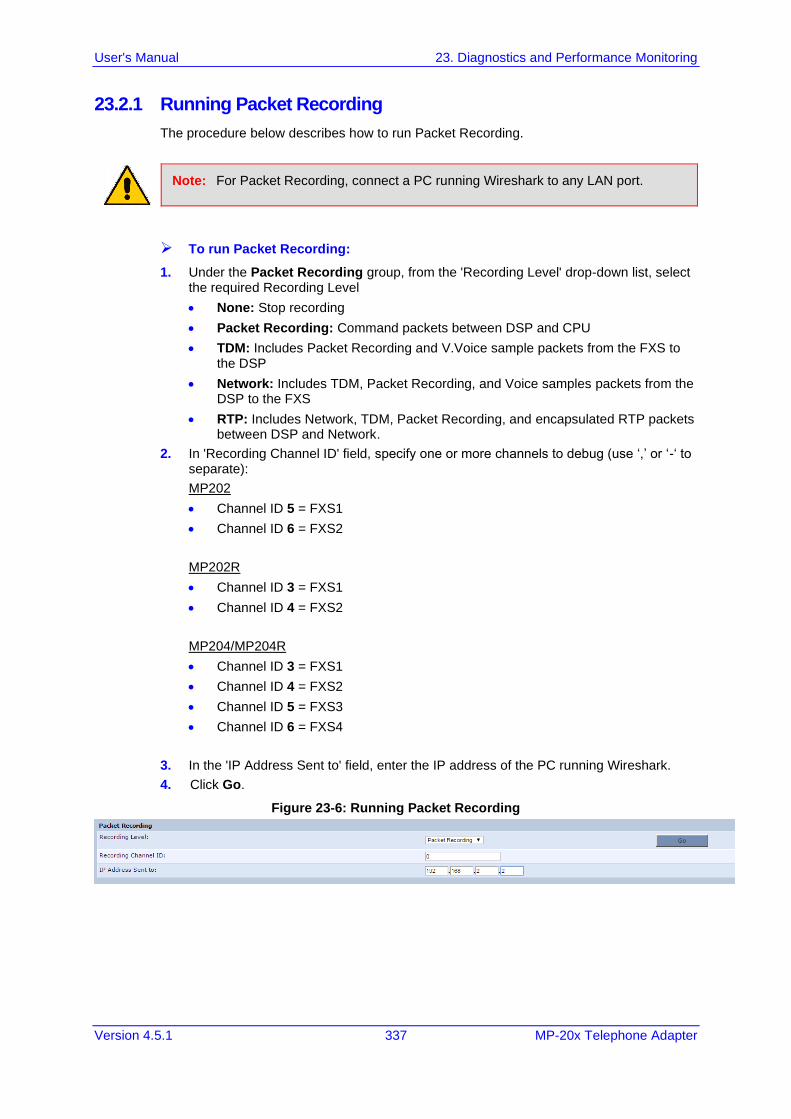
User's Manual 23. Diagnostics and Performance Monitoring
Version 4.5.1 337 MP-20x Telephone Adapter
23.2.1 Running Packet Recording
The procedure below describes how to run Packet Recording.
Note: For Packet Recording, connect a PC running Wireshark to any LAN port.
➢ To run Packet Recording:
1. Under the Packet Recording group, from the 'Recording Level' drop-down list, select the required Recording Level
• None: Stop recording
• Packet Recording: Command packets between DSP and CPU
• TDM: Includes Packet Recording and V.Voice sample packets from the FXS to the DSP
• Network: Includes TDM, Packet Recording, and Voice samples packets from the DSP to the FXS
• RTP: Includes Network, TDM, Packet Recording, and encapsulated RTP packets between DSP and Network.
2. In 'Recording Channel ID' field, specify one or more channels to debug (use ‘,’ or ‘-‘ to separate):
MP202
• Channel ID 5 = FXS1
• Channel ID 6 = FXS2
MP202R
• Channel ID 3 = FXS1
• Channel ID 4 = FXS2
MP204/MP204R
• Channel ID 3 = FXS1
• Channel ID 4 = FXS2
• Channel ID 5 = FXS3
• Channel ID 6 = FXS4
3. In the 'IP Address Sent to' field, enter the IP address of the PC running Wireshark.
4. Click Go.
Figure 23-6: Running Packet Recording
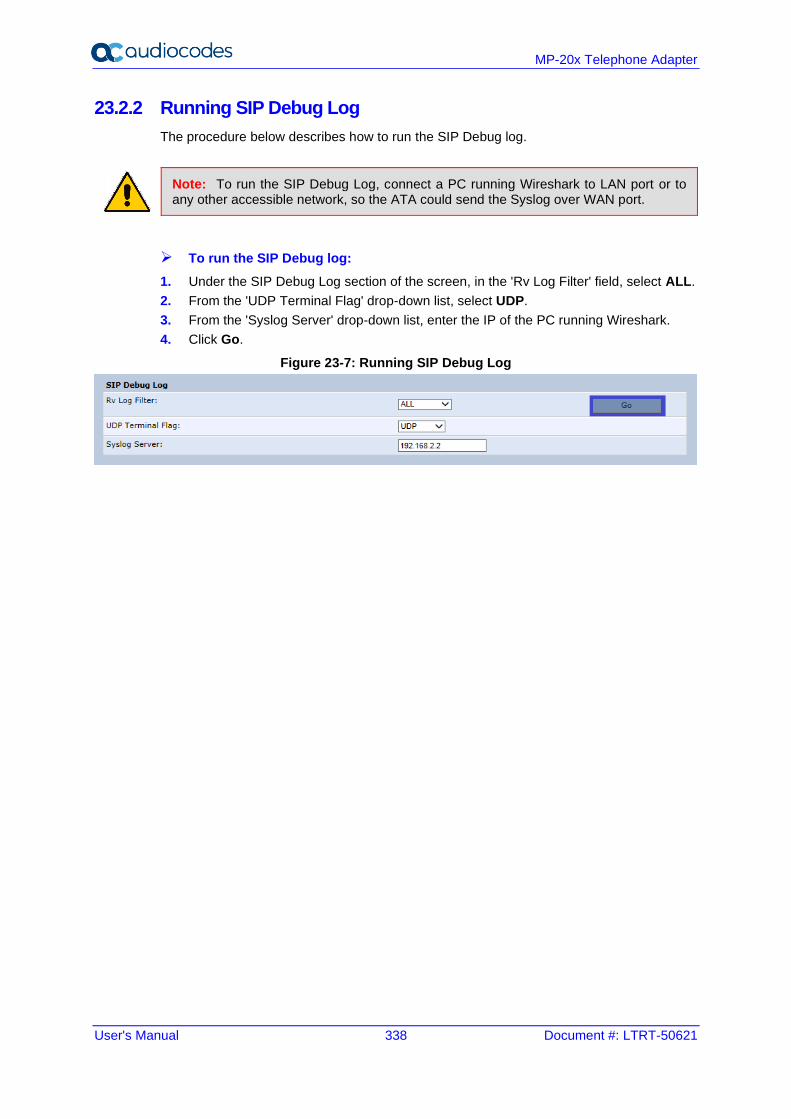
User's Manual 338 Document #: LTRT-50621
MP-20x Telephone Adapter
23.2.2 Running SIP Debug Log
The procedure below describes how to run the SIP Debug log.
Note: To run the SIP Debug Log, connect a PC running Wireshark to LAN port or to any other accessible network, so the ATA could send the Syslog over WAN port.
➢ To run the SIP Debug log:
1. Under the SIP Debug Log section of the screen, in the 'Rv Log Filter' field, select ALL.
2. From the 'UDP Terminal Flag' drop-down list, select UDP.
3. From the 'Syslog Server' drop-down list, enter the IP of the PC running Wireshark.
4. Click Go.
Figure 23-7: Running SIP Debug Log
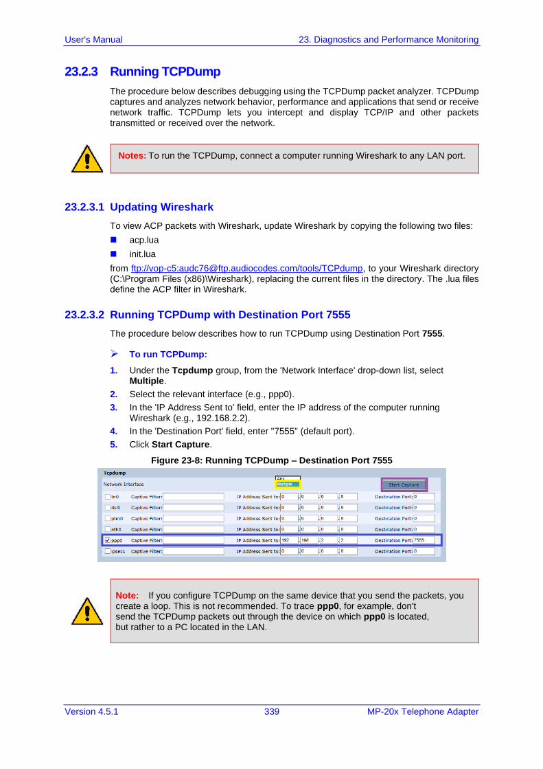
User's Manual 23. Diagnostics and Performance Monitoring
Version 4.5.1 339 MP-20x Telephone Adapter
23.2.3 Running TCPDump
The procedure below describes debugging using the TCPDump packet analyzer. TCPDump captures and analyzes network behavior, performance and applications that send or receive network traffic. TCPDump lets you intercept and display TCP/IP and other packets transmitted or received over the network.
Notes: To run the TCPDump, connect a computer running Wireshark to any LAN port.
23.2.3.1 Updating Wireshark
To view ACP packets with Wireshark, update Wireshark by copying the following two files:
◼ acp.lua
◼ init.lua
from ftp://vop-c5:[email protected]/tools/TCPdump, to your Wireshark directory (C:\Program Files (x86)\Wireshark), replacing the current files in the directory. The .lua files define the ACP filter in Wireshark.
23.2.3.2 Running TCPDump with Destination Port 7555
The procedure below describes how to run TCPDump using Destination Port 7555.
➢ To run TCPDump:
1. Under the Tcpdump group, from the 'Network Interface' drop-down list, select Multiple.
2. Select the relevant interface (e.g., ppp0).
3. In the 'IP Address Sent to' field, enter the IP address of the computer running Wireshark (e.g., 192.168.2.2).
4. In the 'Destination Port' field, enter "7555" (default port).
5. Click Start Capture.
Figure 23-8: Running TCPDump – Destination Port 7555
Note: If you configure TCPDump on the same device that you send the packets, you create a loop. This is not recommended. To trace ppp0, for example, don't send the TCPDump packets out through the device on which ppp0 is located, but rather to a PC located in the LAN.
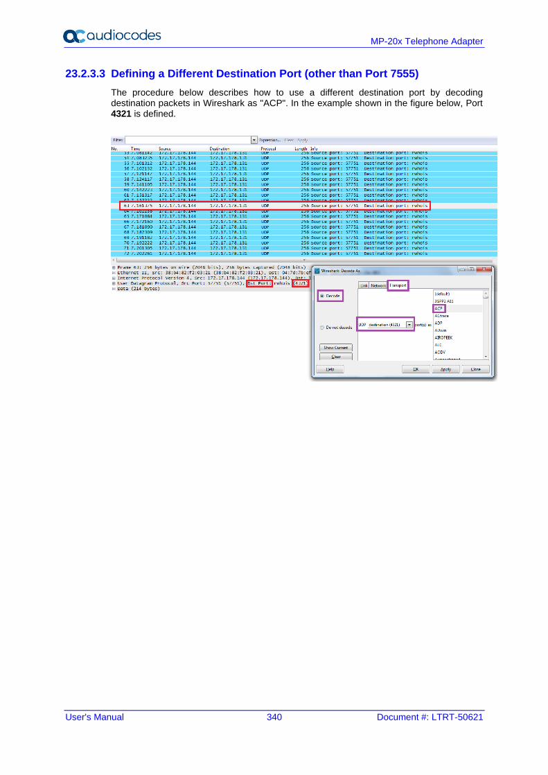
User's Manual 340 Document #: LTRT-50621
MP-20x Telephone Adapter
23.2.3.3 Defining a Different Destination Port (other than Port 7555)
The procedure below describes how to use a different destination port by decoding destination packets in Wireshark as "ACP". In the example shown in the figure below, Port 4321 is defined.
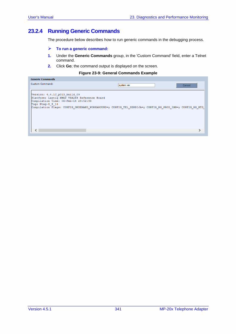
User's Manual 23. Diagnostics and Performance Monitoring
Version 4.5.1 341 MP-20x Telephone Adapter
23.2.4 Running Generic Commands
The procedure below describes how to run generic commands in the debugging process.
➢ To run a generic command:
1. Under the Generic Commands group, in the 'Custom Command' field, enter a Telnet command.
2. Click Go; the command output is displayed on the screen.
Figure 23-9: General Commands Example
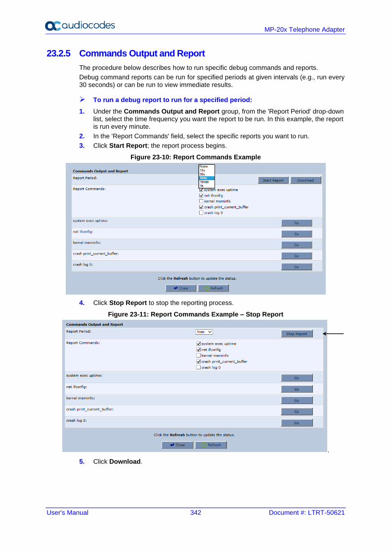
User's Manual 342 Document #: LTRT-50621
MP-20x Telephone Adapter
23.2.5 Commands Output and Report
The procedure below describes how to run specific debug commands and reports.
Debug command reports can be run for specified periods at given intervals (e.g., run every 30 seconds) or can be run to view immediate results.
➢ To run a debug report to run for a specified period:
1. Under the Commands Output and Report group, from the 'Report Period' drop-down list, select the time frequency you want the report to be run. In this example, the report is run every minute.
2. In the 'Report Commands' field, select the specific reports you want to run.
3. Click Start Report; the report process begins.
Figure 23-10: Report Commands Example
4. Click Stop Report to stop the reporting process.
Figure 23-11: Report Commands Example – Stop Report
.
5. Click Download.
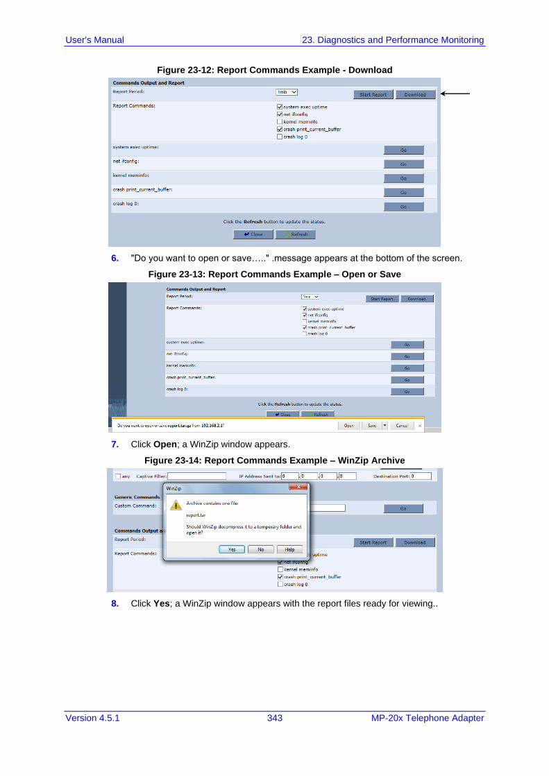
User's Manual 23. Diagnostics and Performance Monitoring
Version 4.5.1 343 MP-20x Telephone Adapter
Figure 23-12: Report Commands Example - Download
6. "Do you want to open or save….." .message appears at the bottom of the screen.
Figure 23-13: Report Commands Example – Open or Save
7. Click Open; a WinZip window appears.
Figure 23-14: Report Commands Example – WinZip Archive
8. Click Yes; a WinZip window appears with the report files ready for viewing..
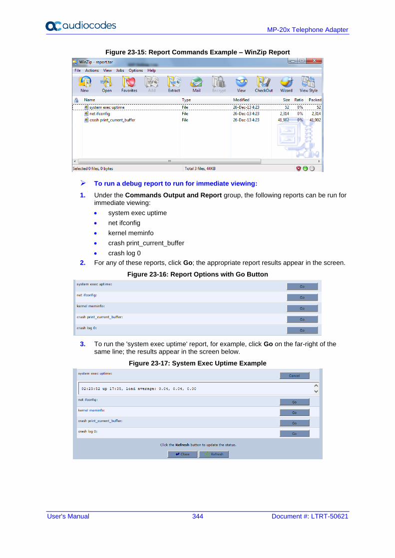
User's Manual 344 Document #: LTRT-50621
MP-20x Telephone Adapter
Figure 23-15: Report Commands Example – WinZip Report
➢ To run a debug report to run for immediate viewing:
1. Under the Commands Output and Report group, the following reports can be run for immediate viewing:
• system exec uptime
• net ifconfig
• kernel meminfo
• crash print_current_buffer
• crash log 0
2. For any of these reports, click Go; the appropriate report results appear in the screen.
Figure 23-16: Report Options with Go Button
3. To run the 'system exec uptime' report, for example, click Go on the far-right of the same line; the results appear in the screen below.
Figure 23-17: System Exec Uptime Example
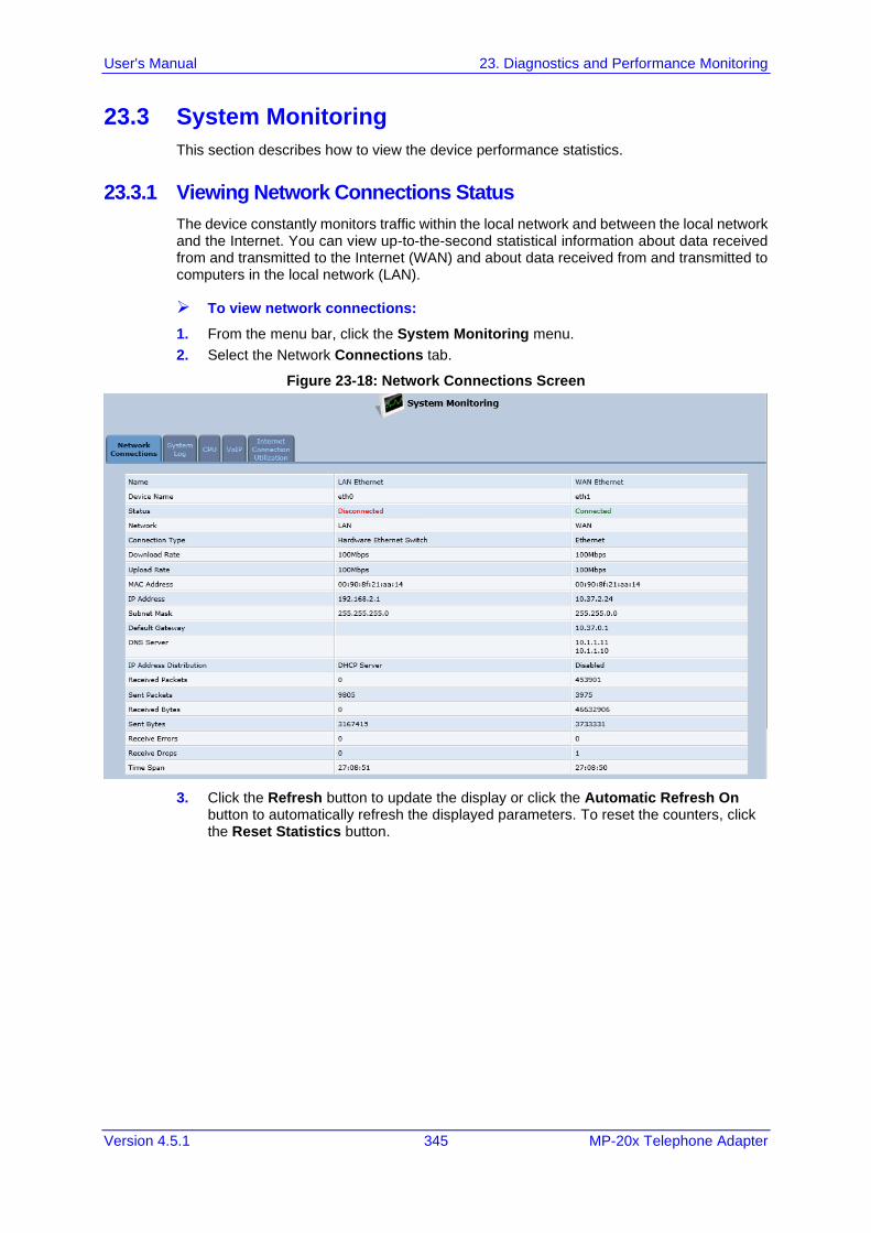
User's Manual 23. Diagnostics and Performance Monitoring
Version 4.5.1 345 MP-20x Telephone Adapter
23.3 System Monitoring
This section describes how to view the device performance statistics.
23.3.1 Viewing Network Connections Status
The device constantly monitors traffic within the local network and between the local network and the Internet. You can view up-to-the-second statistical information about data received from and transmitted to the Internet (WAN) and about data received from and transmitted to computers in the local network (LAN).
➢ To view network connections:
1. From the menu bar, click the System Monitoring menu.
2. Select the Network Connections tab.
Figure 23-18: Network Connections Screen
3. Click the Refresh button to update the display or click the Automatic Refresh On button to automatically refresh the displayed parameters. To reset the counters, click the Reset Statistics button.
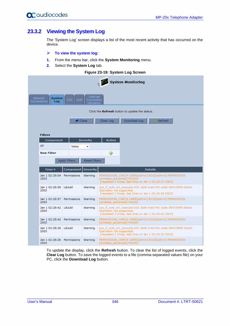
User's Manual 346 Document #: LTRT-50621
MP-20x Telephone Adapter
23.3.2 Viewing the System Log
The ‘System Log’ screen displays a list of the most recent activity that has occurred on the device.
➢ To view the system log:
1. From the menu bar, click the System Monitoring menu.
2. Select the System Log tab.
Figure 23-19: System Log Screen
To update the display, click the Refresh button. To clear the list of logged events, click the Clear Log button. To save the logged events to a file (comma-separated values file) on your PC, click the Download Log button.
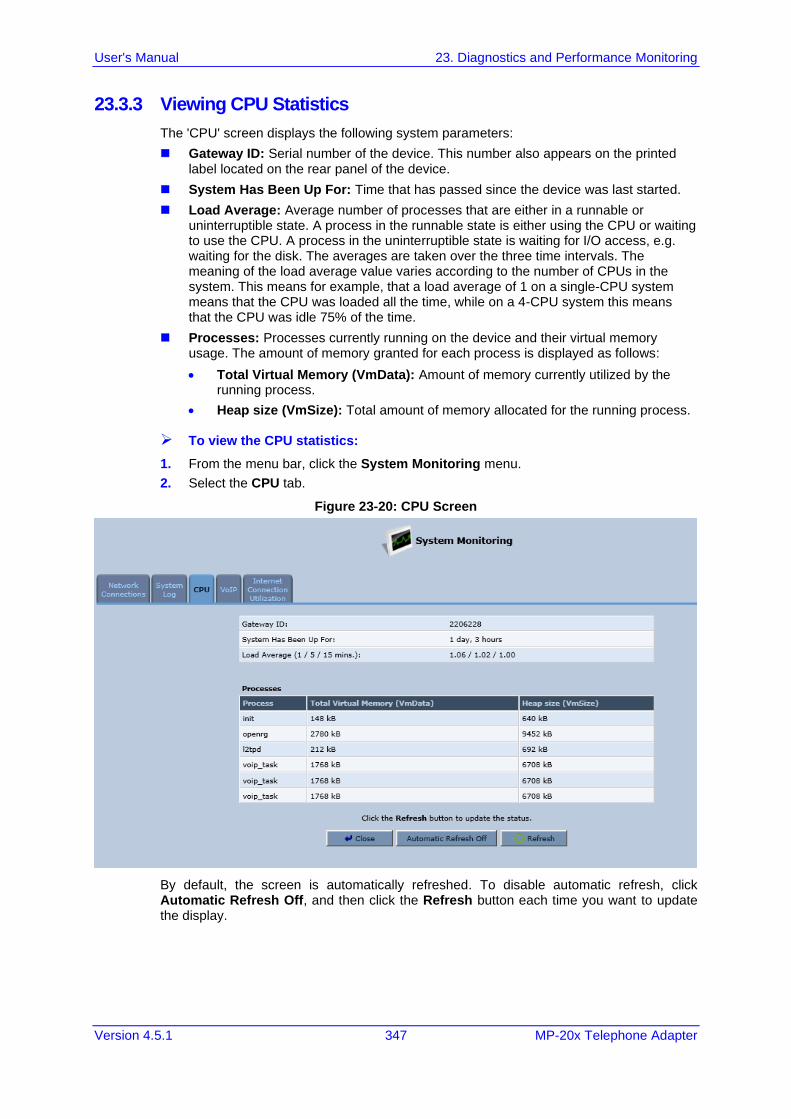
User's Manual 23. Diagnostics and Performance Monitoring
Version 4.5.1 347 MP-20x Telephone Adapter
23.3.3 Viewing CPU Statistics
The 'CPU' screen displays the following system parameters:
◼ Gateway ID: Serial number of the device. This number also appears on the printed label located on the rear panel of the device.
◼ System Has Been Up For: Time that has passed since the device was last started.
◼ Load Average: Average number of processes that are either in a runnable or uninterruptible state. A process in the runnable state is either using the CPU or waiting to use the CPU. A process in the uninterruptible state is waiting for I/O access, e.g. waiting for the disk. The averages are taken over the three time intervals. The meaning of the load average value varies according to the number of CPUs in the system. This means for example, that a load average of 1 on a single-CPU system means that the CPU was loaded all the time, while on a 4-CPU system this means that the CPU was idle 75% of the time.
◼ Processes: Processes currently running on the device and their virtual memory usage. The amount of memory granted for each process is displayed as follows:
• Total Virtual Memory (VmData): Amount of memory currently utilized by the running process.
• Heap size (VmSize): Total amount of memory allocated for the running process.
➢ To view the CPU statistics:
1. From the menu bar, click the System Monitoring menu.
2. Select the CPU tab.
Figure 23-20: CPU Screen
By default, the screen is automatically refreshed. To disable automatic refresh, click Automatic Refresh Off, and then click the Refresh button each time you want to update the display.
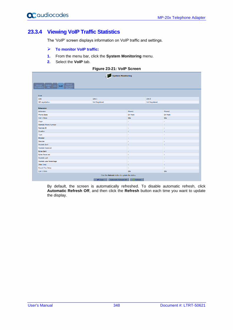
User's Manual 348 Document #: LTRT-50621
MP-20x Telephone Adapter
23.3.4 Viewing VoIP Traffic Statistics
The ‘VoIP’ screen displays information on VoIP traffic and settings.
➢ To monitor VoIP traffic:
1. From the menu bar, click the System Monitoring menu.
2. Select the VoIP tab.
Figure 23-21: VoIP Screen
By default, the screen is automatically refreshed. To disable automatic refresh, click Automatic Refresh Off, and then click the Refresh button each time you want to update the display.
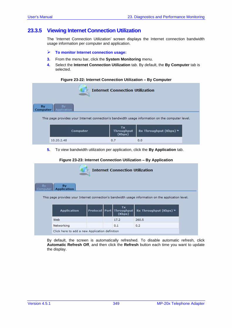
User's Manual 23. Diagnostics and Performance Monitoring
Version 4.5.1 349 MP-20x Telephone Adapter
23.3.5 Viewing Internet Connection Utilization
The ‘Internet Connection Utilization’ screen displays the Internet connection bandwidth usage information per computer and application.
➢ To monitor Internet connection usage:
3. From the menu bar, click the System Monitoring menu.
4. Select the Internet Connection Utilization tab. By default, the By Computer tab is selected.
Figure 23-22: Internet Connection Utilization – By Computer
5. To view bandwidth utilization per application, click the By Application tab.
Figure 23-23: Internet Connection Utilization – By Application
By default, the screen is automatically refreshed. To disable automatic refresh, click Automatic Refresh Off, and then click the Refresh button each time you want to update the display.
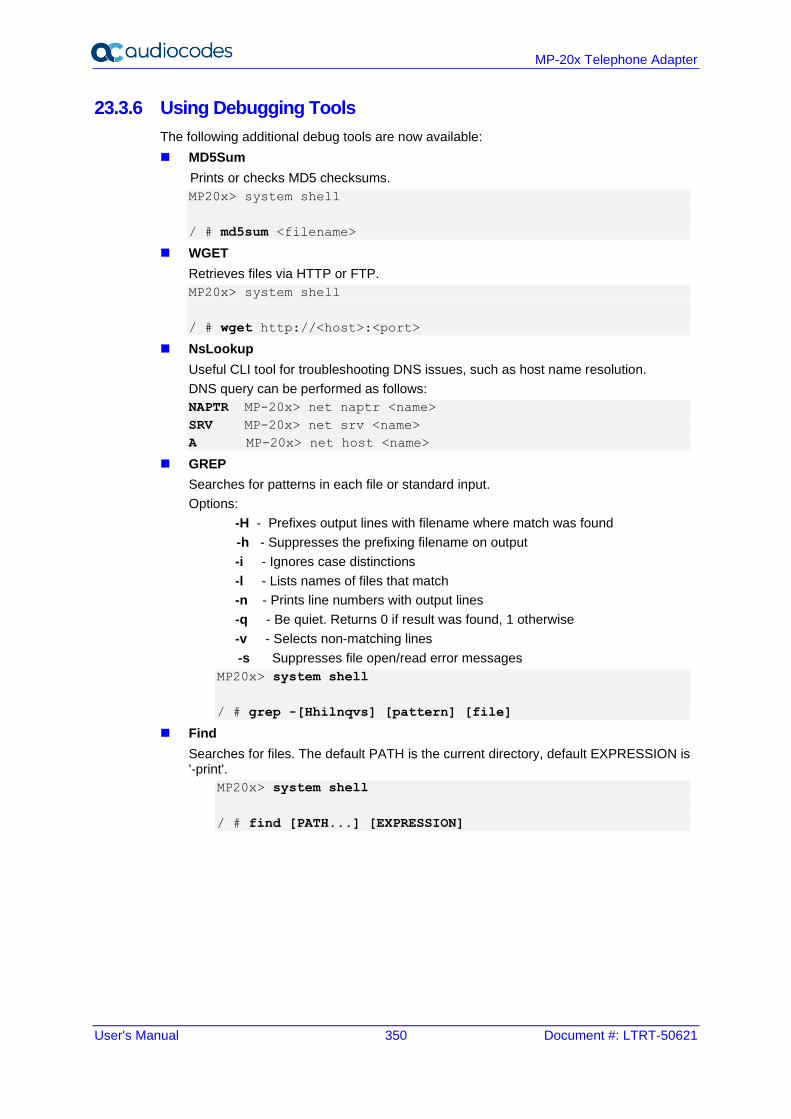
User's Manual 350 Document #: LTRT-50621
MP-20x Telephone Adapter
23.3.6 Using Debugging Tools
The following additional debug tools are now available:
◼ MD5Sum
Prints or checks MD5 checksums.
MP20x> system shell
/ # md5sum <filename>
◼ WGET
Retrieves files via HTTP or FTP.
MP20x> system shell
/ # wget http://<host>:<port>
◼ NsLookup
Useful CLI tool for troubleshooting DNS issues, such as host name resolution.
DNS query can be performed as follows:
NAPTR MP-20x> net naptr <name>
SRV MP-20x> net srv <name>
A MP-20x> net host <name>
◼ GREP
Searches for patterns in each file or standard input.
Options:
-H - Prefixes output lines with filename where match was found
-h - Suppresses the prefixing filename on output
-i - Ignores case distinctions
-l - Lists names of files that match
-n - Prints line numbers with output lines
-q - Be quiet. Returns 0 if result was found, 1 otherwise
-v - Selects non-matching lines
-s Suppresses file open/read error messages
MP20x> system shell
/ # grep -[Hhilnqvs] [pattern] [file]
◼ Find
Searches for files. The default PATH is the current directory, default EXPRESSION is '-print'.
MP20x> system shell
/ # find [PATH...] [EXPRESSION]
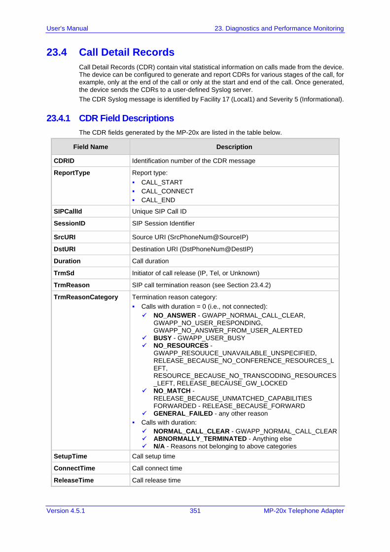
User's Manual 23. Diagnostics and Performance Monitoring
Version 4.5.1 351 MP-20x Telephone Adapter
23.4 Call Detail Records
Call Detail Records (CDR) contain vital statistical information on calls made from the device. The device can be configured to generate and report CDRs for various stages of the call, for example, only at the end of the call or only at the start and end of the call. Once generated, the device sends the CDRs to a user-defined Syslog server.
The CDR Syslog message is identified by Facility 17 (Local1) and Severity 5 (Informational).
23.4.1 CDR Field Descriptions
The CDR fields generated by the MP-20x are listed in the table below.
Field Name Description
CDRID Identification number of the CDR message
ReportType Report type:
▪ CALL_START
▪ CALL_CONNECT
▪ CALL_END
SIPCallId Unique SIP Call ID
SessionID SIP Session Identifier
SrcURI Source URI (SrcPhoneNum@SourceIP)
DstURI Destination URI (DstPhoneNum@DestIP)
Duration Call duration
TrmSd Initiator of call release (IP, Tel, or Unknown)
TrmReason SIP call termination reason (see Section 23.4.2)
TrmReasonCategory Termination reason category:
▪ Calls with duration = 0 (i.e., not connected):
✓ NO_ANSWER - GWAPP_NORMAL_CALL_CLEAR, GWAPP_NO_USER_RESPONDING, GWAPP_NO_ANSWER_FROM_USER_ALERTED
✓ BUSY - GWAPP_USER_BUSY ✓ NO_RESOURCES -
GWAPP_RESOUUCE_UNAVAILABLE_UNSPECIFIED, RELEASE_BECAUSE_NO_CONFERENCE_RESOURCES_LEFT, RESOURCE_BECAUSE_NO_TRANSCODING_RESOURCES_LEFT, RELEASE_BECAUSE_GW_LOCKED
✓ NO_MATCH - RELEASE_BECAUSE_UNMATCHED_CAPABILITIES FORWARDED - RELEASE_BECAUSE_FORWARD
✓ GENERAL_FAILED - any other reason
▪ Calls with duration:
✓ NORMAL_CALL_CLEAR - GWAPP_NORMAL_CALL_CLEAR ✓ ABNORMALLY_TERMINATED - Anything else ✓ N/A - Reasons not belonging to above categories
SetupTime Call setup time
ConnectTime Call connect time
ReleaseTime Call release time
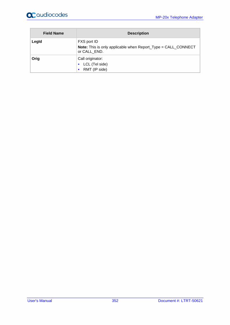
User's Manual 352 Document #: LTRT-50621
MP-20x Telephone Adapter
Field Name Description
LegId FXS port ID
Note: This is only applicable when Report_Type = CALL_CONNECT or CALL_END.
Orig Call originator:
▪ LCL (Tel side)
▪ RMT (IP side)
User's Manual 23. Diagnostics and Performance Monitoring
Version 4.5.1 353 MP-20x Telephone Adapter
23.4.2 Release Reasons in CDR
The following is a list of possible reasons for call termination on the MP-20x, displayed in the TrmReason field:
◼ "RELEASE_BECAUSE_LOCAL_REJECT"
◼ "RELEASE_BECAUSE_REQUEST_FAILURE"
◼ "RELEASE_BECAUSE_SERVER_FAILURE"
◼ "RELEASE_BECAUSE_GLOBAL_FAILURE"
◼ "RELEASE_BECAUSE_LOCAL_DISCONNECTING"
◼ "RELEASE_BECAUSE_DISCONNECTED"
◼ "RELEASE_BECAUSE_REMOTE_DISCONNECTED"
◼ "RELEASE_BECAUSE_LOCAL_FAILURE"
◼ "RELEASE_BECAUSE_LOCAL_TIME_OUT"
◼ "RELEASE_BECAUSE_CALL_TERMINATED"
◼ "RELEASE_BECAUSE_AUTH_NEEDED"
◼ "RELEASE_BECAUSE_UNSUPPORTED_AUTH_PARAMS"
◼ "RELEASE_BECAUSE_LOCAL_CANCELLING"
◼ "RELEASE_BECAUSE_REMOTE_CANCELED"
◼ "RELEASE_BECAUSE_REMOTE_DISCONNECT_REQUESTED"
◼ "RELEASE_BECAUSE_DISCONNECT_LOCAL_REJECT"
◼ "RELEASE_BECAUSE_DISCONNECT_REMOTE_REJECT"
◼ "RELEASE_BECAUSE_DISCONNECT_LOCAL_ACCEPT"
◼ "RELEASE_BECAUSE_NETWORK_ERROR"
◼ "RELEASE_BECAUSE_503_RECEIVED"
◼ "RELEASE_BECAUSE_GIVE_UP_DNS"
◼ "RELEASE_BECAUSE_CONTINUE_DNS"
◼ "RELEASE_BECAUSE_OUT_OF_RESOURCES"
23.4.3 Configuring CDR Reporting
The procedure below describes how to configure CDR reporting.
➢ To configure CDR reporting:
1. Open a browser, and then connect to the MP-20x Web interface.
2. In the Web interface, click the Advanced menu.
3. On the Diagnostics page, click Debug tab.
4. From the ‘CDR Report Level’ drop-down list, under the CDR Log group, select the required level.
Note: If the 'CDR Report Level' value is "None", the feature has been disabled.
5. In the ‘CDR Server Address’ field, enter the IP address of the Syslog server.
6. In the ‘CDR Server Port’ field, enter the port number of the Syslog server.
7. Click Go.
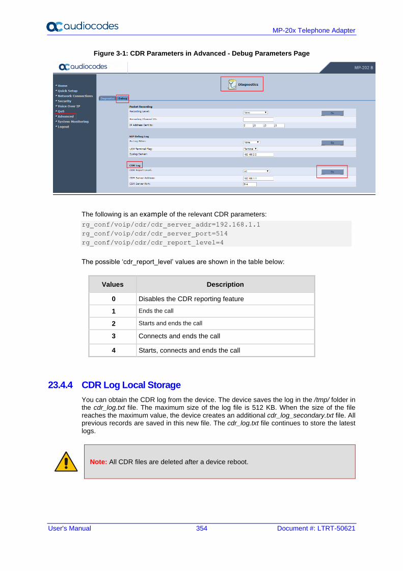
User's Manual 354 Document #: LTRT-50621
MP-20x Telephone Adapter
Figure 3-1: CDR Parameters in Advanced - Debug Parameters Page
The following is an example of the relevant CDR parameters:
rg_conf/voip/cdr/cdr_server_addr=192.168.1.1
rg_conf/voip/cdr/cdr_server_port=514
rg_conf/voip/cdr/cdr_report_level=4
The possible ‘cdr_report_level’ values are shown in the table below:
Values Description
0 Disables the CDR reporting feature
1 Ends the call
2 Starts and ends the call
3 Connects and ends the call
4 Starts, connects and ends the call
23.4.4 CDR Log Local Storage
You can obtain the CDR log from the device. The device saves the log in the /tmp/ folder in the cdr_log.txt file. The maximum size of the log file is 512 KB. When the size of the file reaches the maximum value, the device creates an additional cdr_log_secondary.txt file. All previous records are saved in this new file. The cdr_log.txt file continues to store the latest logs.
Note: All CDR files are deleted after a device reboot.
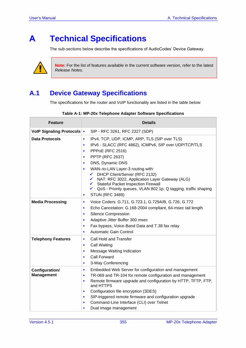
Version 4.5.1 355 MP-20x Telephone Adapter
User's Manual A. Technical Specifications
A Technical Specifications The sub-sections below describe the specifications of AudioCodes’ Device Gateway.
Note: For the list of features available in the current software version, refer to the latest Release Notes.
A.1 Device Gateway Specifications
The specifications for the router and VoIP functionality are listed in the table below:
Table A-1: MP-20x Telephone Adapter Software Specifications
Feature Details
VoIP Signaling Protocols ▪ SIP - RFC 3261, RFC 2327 (SDP)
Data Protocols ▪ IPv4, TCP, UDP, ICMP, ARP, TLS (SIP over TLS)
▪ IPv6 - SLACC (RFC 4862), ICMPv6, SIP over UDP/TCP/TLS
▪ PPPoE (RFC 2516)
▪ PPTP (RFC 2637)
▪ DNS, Dynamic DNS
▪ WAN–to-LAN Layer-3 routing with:
✓ DHCP Client/Server (RFC 2132) ✓ NAT: RFC 3022, Application Layer Gateway (ALG) ✓ Stateful Packet Inspection Firewall ✓ QoS - Priority queues, VLAN 802.1p, Q tagging, traffic shaping
▪ STUN (RFC 3489)
Media Processing ▪ Voice Coders: G.711, G.723.1, G.729A/B, G.726, G.772
▪ Echo Cancelation: G.168-2004 compliant, 64-msec tail length
▪ Silence Compression
▪ Adaptive Jitter Buffer 300 msec
▪ Fax bypass, Voice-Band Data and T.38 fax relay
▪ Automatic Gain Control
Telephony Features ▪ Call Hold and Transfer
▪ Call Waiting
▪ Message Waiting Indication
▪ Call Forward
▪ 3-Way Conferencing
Configuration/ Management
▪ Embedded Web Server for configuration and management
▪ TR-069 and TR-104 for remote configuration and management
▪ Remote firmware upgrade and configuration by HTTP, TFTP, FTP, and HTTPS
▪ Configuration file encryption (3DES)
▪ SIP-triggered remote firmware and configuration upgrade
▪ Command-Line Interface (CLI) over Telnet
▪ Dual image management

User's Manual 356 Document #: LTRT-50621
MP-20x Telephone Adapter
Feature Details
▪ SNMP
▪ Local Support and Troubleshooting with Web interception and voice notification
▪ BroadSoft BroadCloud certification
▪ BroadCloud PacketSmart integration (applicable only to MP-204B)
▪ Optional 3G/4G dongle (applicable only to MP-204B)
▪ Link Layer Discovery Protocol (LLDP) support
▪ Faxback integration (Fax over HTTPS) – Optional
▪ File server
▪ Printer server
▪ DLNA Media server
▪ FXS Voice menu
Packetization ▪ RTP/RTCP Packetization (RFC 3550, RFC 3551)
▪ DTMF Relay (RFC 2833)
Security ▪ HTTPS for Web-based configuration
▪ Password protected Web pages (MD5)
Telephony Signaling ▪ In-band:
✓ DTMF: Detection and Generation, TIA464B ✓ Caller ID: Telcordia, ETSI, NTT - Type I, Telcordia Type II ✓ Call Progress Tones
▪ Out-of-band:
✓ FXS Loop-start Signaling ✓ On/Off Hook, Flash Hook
Hardware
Power ▪ MP-202B – Power Supply 12VDC/1A
▪ MP-204B/MP-204R/MP202R – Power Supply 12VDC/2A
Interfaces ▪ WAN 10/100Base-T (RJ-45)
▪ LAN 10/100Base-T (RJ-45)
▪ RJ-11 FXS ports for telephones (POTS)
▪ Network Interface WAN/LAN 10/100 Base-T(RJ-45)
▪ Ethernet ports are 10/100/1000Base-T (applicable to MP-204B)
▪ USB 2.0 (applicable to MP-204B)
LED Indications ▪ FXS Phone lines (1 to 4, depending on MP-20x model) - Registered, In Use, Alert
▪ LAN activity on Ethernet Port
▪ WAN
▪ USB
▪ Status
▪ Power on
3G Backup (Optional) ▪ Support for 3G USB dongles for primary WAN backup including:
✓ Alcatel 4G LTE (1bbb:f000->1bbb:0195) ✓ Alcatel AL720 ✓ Huawei E1550 ✓ Huawei E156 ✓ Huawei E156G ✓ Huawei E160 ✓ Huawei E169 ✓ Huawei E1750 ✓ Huawei E1756
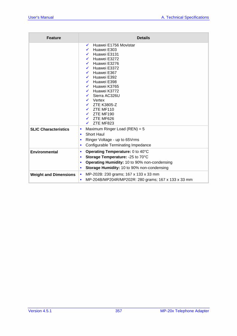
Version 4.5.1 357 MP-20x Telephone Adapter
User's Manual A. Technical Specifications
Feature Details
✓ Huawei E1756 Movistar ✓ Huawei E303 ✓ Huawei E3131 ✓ Huawei E3272 ✓ Huawei E3276 ✓ Huawei E3372 ✓ Huawei E367 ✓ Huawei E392 ✓ Huawei E398 ✓ Huawei K3765 ✓ Huawei K3772 ✓ Sierra AC326U ✓ Vertex ✓ ZTE K3805-Z ✓ ZTE MF110 ✓ ZTE MF190 ✓ ZTE MF626 ✓ ZTE MF823
SLIC Characteristics ▪ Maximum Ringer Load (REN) = 5
▪ Short Haul
▪ Ringer Voltage - up to 65Vrms
▪ Configurable Terminating Impedance
Environmental ▪ Operating Temperature: 0 to 40°C
▪ Storage Temperature: -25 to 70°C
▪ Operating Humidity: 10 to 90% non-condensing
▪ Storage Humidity: 10 to 90% non-condensing
Weight and Dimensions ▪ MP-202B: 230 grams; 167 x 133 x 33 mm
▪ MP-204B/MP204R/MP202R: 280 grams; 167 x 133 x 33 mm
International Headquarters
1 Hayarden Street,
Airport City
Lod 7019900, Israel
Tel: +972-3-976-4000
Fax: +972-3-976-4040
AudioCodes Inc.
200 Cottontail Lane
Suite A101E
Somerset NJ 08873
Tel: +1-732-469-0880
Fax: +1-732-469-2298
Contact us: https://www.audiocodes.com/corporate/offices-worldwide
Website: https://www.audiocodes.com/
©2021 AudioCodes Ltd. All rights reserved. AudioCodes, AC, HD VoIP, HD VoIP Sounds Better, IPmedia, Mediant,
MediaPack, What’s Inside Matters, OSN, SmartTAP, User Management Pack, VMAS, VoIPerfect, VoIPerfectHD, Your
Gateway To VoIP, 3GX, VocaNom, AudioCodes One Voice, AudioCodes Meeting Insights, AudioCodes Room
Experience and CloudBond are trademarks or registered trademarks of AudioCodes Limited. All other products or
trademarks are property of their respective owners. Product specifications are subject to change without notice.
Document #: LTRT-50621
Related Documents