Moxa TN-5916 Industrial Secure Router User’s Manual Version 2.0, April 2021 www.moxa.com/product © 2021 Moxa Inc. All rights reserved.

Welcome message from author
This document is posted to help you gain knowledge. Please leave a comment to let me know what you think about it! Share it to your friends and learn new things together.
Transcript
Moxa TN-5916 Industrial Secure Router User’s Manual
Version 2.0, April 2021
www.moxa.com/product
© 2021 Moxa Inc. All rights reserved.
Moxa TN-5916 Industrial Secure Router User’s Manual
The software described in this manual is furnished under a license agreement and may be used only in accordance with the terms of that agreement.
Copyright Notice
© 2021 Moxa Inc. All rights reserved.
Trademarks
The MOXA logo is a registered trademark of Moxa Inc. All other trademarks or registered marks in this manual belong to their respective manufacturers.
Disclaimer
Information in this document is subject to change without notice and does not represent a commitment on the part of Moxa.
Moxa provides this document as is, without warranty of any kind, either expressed or implied, including, but not limited to, its particular purpose. Moxa reserves the right to make improvements and/or changes to this manual, or to the products and/or the programs described in this manual, at any time.
Information provided in this manual is intended to be accurate and reliable. However, Moxa assumes no responsibility for its use, or for any infringements on the rights of third parties that may result from its use.
This product might include unintentional technical or typographical errors. Changes are periodically made to the information herein to correct such errors, and these changes are incorporated into new editions of the publication.
Technical Support Contact Information
www.moxa.com/support
Moxa Americas Toll-free: 1-888-669-2872 Tel: +1-714-528-6777 Fax: +1-714-528-6778
Moxa China (Shanghai office) Toll-free: 800-820-5036 Tel: +86-21-5258-9955 Fax: +86-21-5258-5505
Moxa Europe Tel: +49-89-3 70 03 99-0 Fax: +49-89-3 70 03 99-99
Moxa Asia-Pacific Tel: +886-2-8919-1230 Fax: +886-2-8919-1231
Moxa India Tel: +91-80-4172-9088 Fax: +91-80-4132-1045
Table of Contents
1. Introduction ...................................................................................................................................... 1-1 Overview ........................................................................................................................................... 1-2 Package Checklist ............................................................................................................................... 1-2 Features ............................................................................................................................................ 1-2
Industrial Networking Capability .................................................................................................... 1-2 Designed for Industrial Applications ............................................................................................... 1-2 Useful Utility and Remote Configuration ......................................................................................... 1-2
2. Getting Started ................................................................................................................................. 2-1 RS-232 Console Configuration (115200, None, 8, 1, VT100) .................................................................... 2-2 Using Telnet to Access the ToughNet Secure Router’s Console .................................................................. 2-4 Using a Web Browser to Configure the ToughNet Secure Router ............................................................... 2-4
3. TN-5916 Series Features and Functions ............................................................................................ 3-1 System .............................................................................................................................................. 3-2
System Information ..................................................................................................................... 3-2 User Account .............................................................................................................................. 3-3 Account Password Policy .............................................................................................................. 3-4 Date and Time ............................................................................................................................ 3-5 Warning Notification .................................................................................................................... 3-8 System File Update—by Remote TFTP .......................................................................................... 3-12 System File Update—by Local Import/Export ................................................................................ 3-13 Back Up Media .......................................................................................................................... 3-13 Restart..................................................................................................................................... 3-14 Reset to Factory Default ............................................................................................................. 3-14
Port ................................................................................................................................................ 3-14 Port Settings ............................................................................................................................. 3-14 Port Status ............................................................................................................................... 3-16 Link Aggregation ....................................................................................................................... 3-16 The Port Trunking Concept ......................................................................................................... 3-16 Port Mirror ................................................................................................................................ 3-18
Using Virtual LAN .............................................................................................................................. 3-18 The VLAN Concept ..................................................................................................................... 3-18 Configuring Virtual LAN .............................................................................................................. 3-19
Multicast .......................................................................................................................................... 3-21 The Concept of Multicast Filtering ................................................................................................ 3-21 IGMP Snooping ......................................................................................................................... 3-23 IGMP Snooping Settings ............................................................................................................. 3-23 IGMP Table ............................................................................................................................... 3-24 Stream Table ............................................................................................................................ 3-25 Static Multicast MAC .................................................................................................................. 3-25
QoS ................................................................................................................................................ 3-26 QoS Classification ...................................................................................................................... 3-26 CoS Mapping ............................................................................................................................ 3-27 ToS/DSCP Mapping .................................................................................................................... 3-28
MAC Address Table ........................................................................................................................... 3-28 Interface ......................................................................................................................................... 3-29
WAN ........................................................................................................................................ 3-29 LAN ......................................................................................................................................... 3-30
DHCP .............................................................................................................................................. 3-31 DHCP Server Mode .................................................................................................................... 3-31 DHCP ....................................................................................................................................... 3-31 DHCP Leases ............................................................................................................................ 3-33 IP-MAC Binding ......................................................................................................................... 3-33 IP-Port Binding ......................................................................................................................... 3-35
SNMP .............................................................................................................................................. 3-36 DNS Server ...................................................................................................................................... 3-38
DNS Global Setting .................................................................................................................... 3-39 DNS Zone Setting ...................................................................................................................... 3-43 DNS Zone Forwarding Setting ..................................................................................................... 3-44 DNS ACL Setting ....................................................................................................................... 3-45 DNS Security Setting ................................................................................................................. 3-45 DNS Root Hints ......................................................................................................................... 3-47
Monitor ........................................................................................................................................... 3-47 Statistics .................................................................................................................................. 3-47 Bandwidth Utilization ................................................................................................................. 3-47 Packet Counter ......................................................................................................................... 3-49 Event Log ................................................................................................................................. 3-50
4. Routing ............................................................................................................................................. 4-1
Unicast Routing .................................................................................................................................. 4-2 Static Routing ............................................................................................................................. 4-2 Routing Information Protocol (RIP) ................................................................................................ 4-3 Open Shortest Path First (OSPF) ................................................................................................... 4-4 Routing Table ............................................................................................................................. 4-9
Multicast Routing ................................................................................................................................ 4-9 Global Setting ............................................................................................................................. 4-9 Static Multicast ......................................................................................................................... 4-10 Distance Vector Multicast Routing Protocol (DVMRP) ...................................................................... 4-11 Protocol Independent Multicast Sparse Mode (PIM-SM) .................................................................. 4-12 Multicast Forwarding Table ......................................................................................................... 4-15
5. Network Redundancy ........................................................................................................................ 5-1 Layer 2 Redundant Protocols ................................................................................................................ 5-2
Configuring RSTP ........................................................................................................................ 5-2 Configuring Turbo Ring V2 ............................................................................................................ 5-4
Layer 3 Redundant Protocols ................................................................................................................ 5-5 VRRP Settings ............................................................................................................................. 5-5
6. Network Address Translation ............................................................................................................ 6-1 Network Address Translation (NAT) ....................................................................................................... 6-2
NAT Concept ............................................................................................................................... 6-2 1-to-1 NAT ................................................................................................................................. 6-2 N-to-1 NAT ................................................................................................................................. 6-3 Port Forward ............................................................................................................................... 6-4
7. Firewall ............................................................................................................................................. 7-1 Policy Concept .................................................................................................................................... 7-2 Policy Overview .................................................................................................................................. 7-2 Policy Setup ....................................................................................................................................... 7-3 Quick Automation Profile ..................................................................................................................... 7-5 Layer 2 Policy Setup ........................................................................................................................... 7-7 Denial of Service (DoS) Defense ........................................................................................................... 7-8
8. Virtual Private Network (VPN) .......................................................................................................... 8-1 Overview ........................................................................................................................................... 8-2 IPsec Configuration ............................................................................................................................. 8-2
Global Settings ........................................................................................................................... 8-2 IPsec Settings ............................................................................................................................. 8-3 IPsec Use Case Demonstration ...................................................................................................... 8-7 IPsec Status ............................................................................................................................. 8-10
L2TP Server (Layer 2 Tunnel Protocol) ................................................................................................. 8-11 L2TP Configuration .................................................................................................................... 8-11
9. Certificate Management .................................................................................................................... 9-1 Local Certificate .................................................................................................................................. 9-2
Local Certificate .......................................................................................................................... 9-2 Trusted CA Certificates ........................................................................................................................ 9-2 Certificate Signing Request .................................................................................................................. 9-3 CA Server .......................................................................................................................................... 9-4
10. Security ........................................................................................................................................... 10-1 User Interface Management ............................................................................................................... 10-2 Authentication Certificate ................................................................................................................... 10-3 Trusted Access ................................................................................................................................. 10-3 Port Access Control ........................................................................................................................... 10-4
IEEE 802.1X Setting .................................................................................................................. 10-6 IEEE 802.1X Information ............................................................................................................ 10-7 RADIUS Server Setting .............................................................................................................. 10-7 Local User Database .................................................................................................................. 10-8
11. Diagnosis ........................................................................................................................................ 11-1 Ping ................................................................................................................................................ 11-2 LLDP ............................................................................................................................................... 11-2
A. MIB Groups ....................................................................................................................................... A-1

1 1. Introduction
Welcome to the Moxa TN-5916 ToughNet Secure Router Series. The ToughNet Secure Router is designed for connecting Ethernet-enabled devices with network IP security.
The following topics are covered in this chapter:
Overview
Package Checklist
Features
Industrial Networking Capability
Designed for Industrial Applications
Useful Utility and Remote Configuration
TN-5916 Introduction
1-2
Overview As the world’s network and information technology becomes more mature, the trend is to use Ethernet as the major communications interface in many industrial communications and automation applications. In fact, a entirely new industry has sprung up to provide Ethernet products that comply with the requirements of demanding industrial applications.
The ToughNet TN-5916, designed for rolling stock backbone networks, is a high performance M12 router. It supports NAT, Firewall and routing functionality to facilitate the deployment of applications across networks. The TN-5916 router uses M12 and other circular connectors to ensure tight, robust connections and guarantee reliable resilience against environmental disturbances, such as vibration and shock. In addition, wide temperature models are available that operate reliably in hazardous, -40 to 75°C environments.
Package Checklist The ToughNet Secure Routers are shipped with the following items. If any of these items are missing or damaged, please contact your customer service representative for assistance.
• 1 Moxa ToughNet Secure Router • RJ45 to DB9 console port cable • Protective caps for unused ports • Quick installation guide (printed) • CD-ROM with user’s manual and Windows utility • Warranty card
Features
Industrial Networking Capability • Unicast and Multicast routing • Network Redundancy (Layer 2 and Layer 3) • Network address translation (N-to-1, 1-to-1, and port forwarding) • Firewall and Denial of Service (DoS) Defense
Designed for Industrial Applications • Bypass relay ensures non-stop data communication in the event the router stops working due to a power
failure • EN 50155/50121-3-2 compliant. See specs for details about compliance with specific parts of these
standards • -40 to 75°C operating temperature (T models) • Dual 24 to 110 VDC power inputs • IP54, rugged high-strength metal case • DIN rail or panel mounting ability
Useful Utility and Remote Configuration • Configurable using a Web browser and Telnet/Serial console • Send ping commands to identify network segment integrity This chapter explains how to access the ToughNet Secure Router for the first time. There are three ways to access the router: (1) serial console, (2) Telnet console, and (3) web browser. The serial console connection method, which requires using a short serial cable to connect the ToughNet Secure Router to a PC’s COM
TN-5916 Introduction
1-3
port, can be used if you do not know the ToughNet Secure Router’s IP address. The Telnet console and web browser connection methods can be used to access the ToughNet Secure Router over an Ethernet LAN, or over the Internet. A web browser can be used to perform all monitoring and administration functions, but the serial console and Telnet console only provide basic functions.
The following topics are covered in this chapter:
RS-232 Console Configuration (115200, None, 8, 1, VT100)
Using Telnet to Access the ToughNet Secure Router’s Console
Using a Web Browser to Configure the ToughNet Secure Router
2 2. Getting Started
The following topics are covered in this chapter:
RS-232 Console Configuration (115200, None, 8, 1, VT100)
Using Telnet to Access the ToughNet Secure Router’s Console
Using a Web Browser to Configure the ToughNet Secure Router
TN-5916 Getting Started
2-2
RS-232 Console Configuration (115200, None, 8, 1, VT100) NOTE Connection Caution!
We strongly suggest that you do NOT use more than one connection method at the same time. Following this advice will allow you to maintain better control over the configuration of your ToughNet Secure Router
NOTE We recommend using Moxa PComm Terminal Emulator, which can be downloaded free of charge from Moxa’s website.
Before running PComm Terminal Emulator, use an RJ45 to DB9-F (or RJ45 to DB25-F) cable to connect the ToughNet Secure Router’s RS-232 console port to your PC’s COM port (generally COM1 or COM2, depending on how your system is set up).
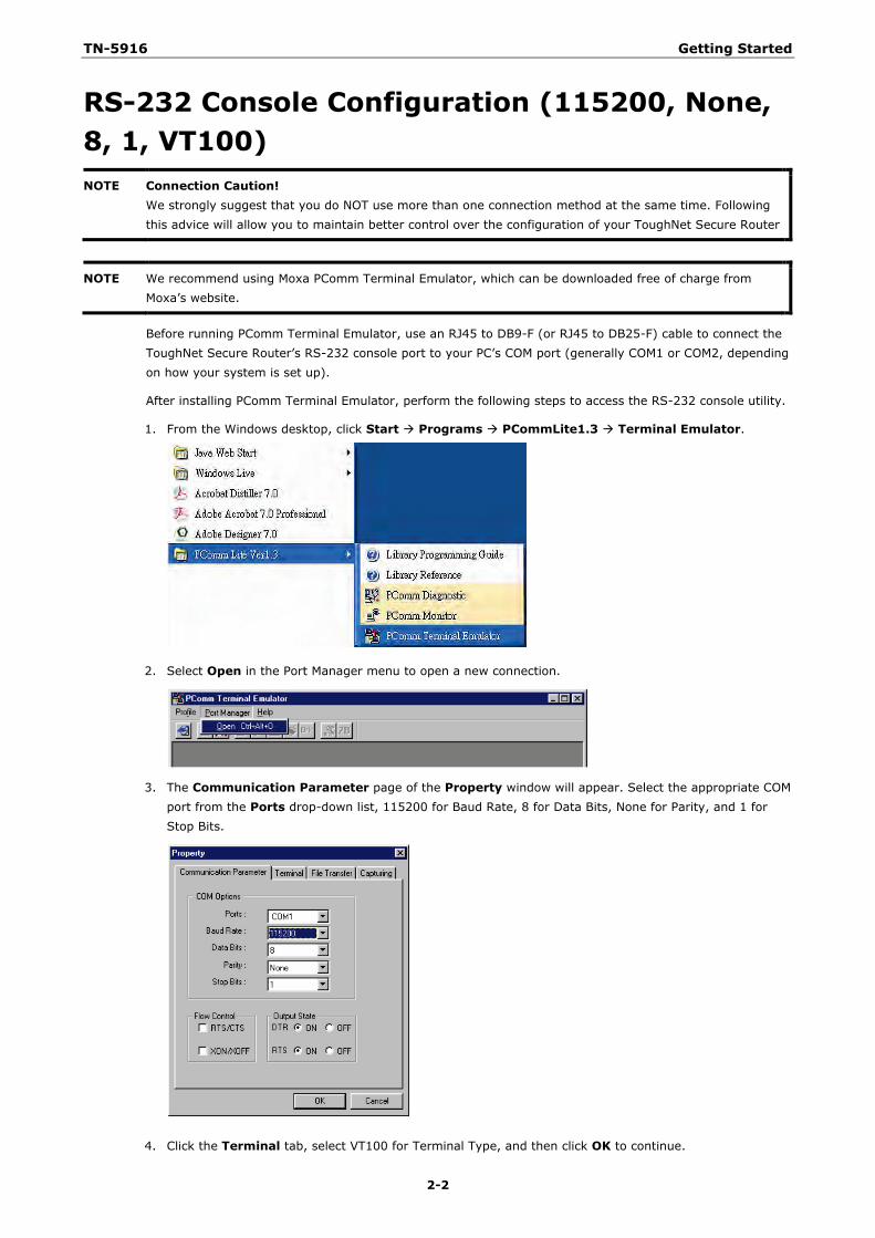
After installing PComm Terminal Emulator, perform the following steps to access the RS-232 console utility.
1. From the Windows desktop, click Start Programs PCommLite1.3 Terminal Emulator.
2. Select Open in the Port Manager menu to open a new connection.
3. The Communication Parameter page of the Property window will appear. Select the appropriate COM port from the Ports drop-down list, 115200 for Baud Rate, 8 for Data Bits, None for Parity, and 1 for Stop Bits.
4. Click the Terminal tab, select VT100 for Terminal Type, and then click OK to continue.
TN-5916 Getting Started
2-3
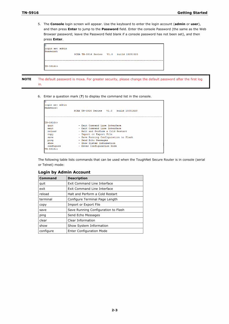
5. The Console login screen will appear. Use the keyboard to enter the login account (admin or user), and then press Enter to jump to the Password field. Enter the console Password (the same as the Web Browser password; leave the Password field blank if a console password has not been set), and then press Enter.
NOTE The default password is moxa. For greater security, please change the default password after the first log in.
6. Enter a question mark (?) to display the command list in the console.
The following table lists commands that can be used when the ToughNet Secure Router is in console (serial or Telnet) mode:
Login by Admin Account Command Description quit Exit Command Line Interface
exit Exit Command Line Interface
reload Halt and Perform a Cold Restart
terminal Configure Terminal Page Length
copy Import or Export File
save Save Running Configuration to Flash
ping Send Echo Messages
clear Clear Information
show Show System Information
configure Enter Configuration Mode
TN-5916 Getting Started
2-4
Using Telnet to Access the ToughNet Secure Router’s Console
You may use Telnet to access the ToughNet Secure Router’s console utility over a network. To access the TN’s functions over the network (by either Telnet or a web browser) from a PC host that is connected to the same LAN as the ToughNet Secure Router, you need to make sure that the PC host and the ToughNet Secure Router are on the same logical subnet. To do this, check your PC host’s IP address and subnet mask. By default, the LAN IP address is 192.168.127.254 and the Industrial subnet mask is 255.255.255.0 (for a Class C subnet). If you do not change these values, and your PC host’s subnet mask is 255.255.0.0, then its IP address must have the form 192.168.xxx.xxx. On the other hand, if your PC host’s subnet mask is 255.255.255.0, then its IP address must have the form, 192.168.127.xxx.
NOTE To use the ToughNet Secure Router’s management and monitoring functions from a PC host connected to the same LAN as the ToughNet Secure Router, you must make sure that the PC host and the ToughNet Secure Router are connected to the same logical subnet.
NOTE Before accessing the console utility via Telnet, first connect the ToughNet Secure Router’s RJ45 Ethernet LAN ports to your Ethernet LAN, or directly to your PC’s Ethernet card (NIC). You can use either a straight-through or cross-over Ethernet cable.
NOTE The ToughNet Secure Router’s default LAN IP address is 192.168.127.254.
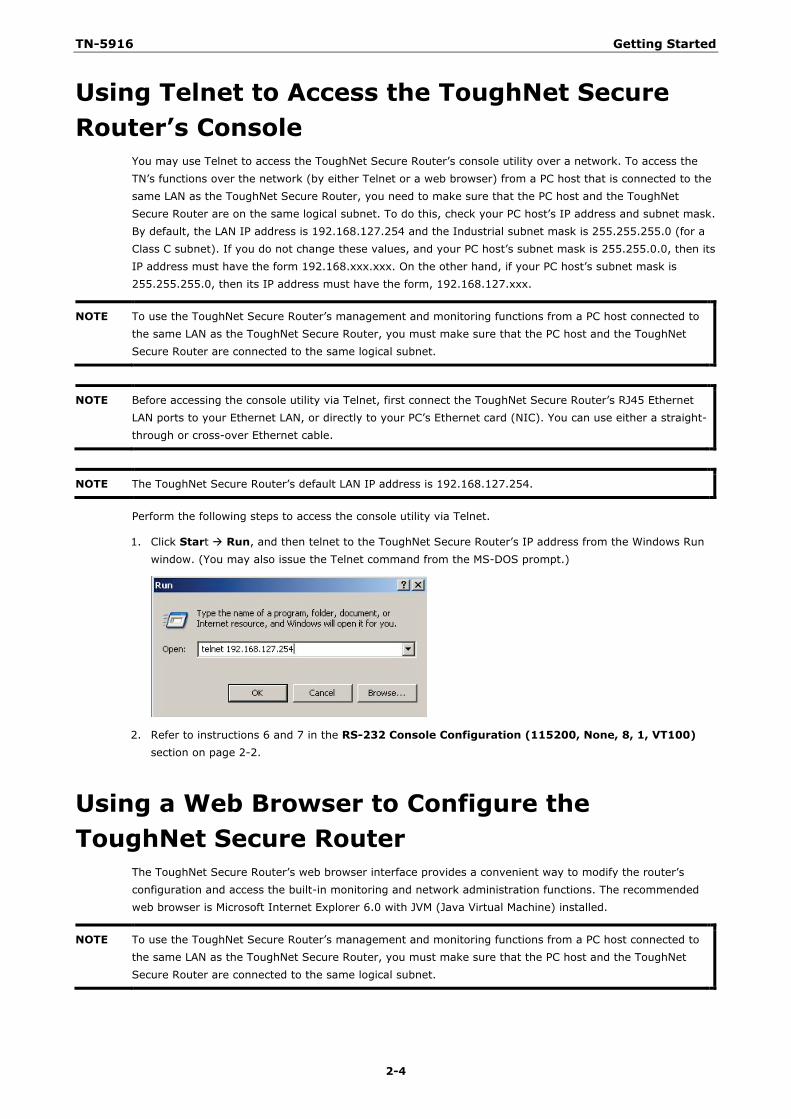
Perform the following steps to access the console utility via Telnet.
1. Click Start Run, and then telnet to the ToughNet Secure Router’s IP address from the Windows Run window. (You may also issue the Telnet command from the MS-DOS prompt.)
2. Refer to instructions 6 and 7 in the RS-232 Console Configuration (115200, None, 8, 1, VT100) section on page 2-2.
Using a Web Browser to Configure the ToughNet Secure Router
The ToughNet Secure Router’s web browser interface provides a convenient way to modify the router’s configuration and access the built-in monitoring and network administration functions. The recommended web browser is Microsoft Internet Explorer 6.0 with JVM (Java Virtual Machine) installed.
NOTE To use the ToughNet Secure Router’s management and monitoring functions from a PC host connected to the same LAN as the ToughNet Secure Router, you must make sure that the PC host and the ToughNet Secure Router are connected to the same logical subnet.
TN-5916 Getting Started
2-5
NOTE Before accessing the ToughNet Secure Router’s web browser, first connect the ToughNet Secure Router’s M12 Ethernet LAN ports to your Ethernet LAN, or directly to your PC’s Ethernet card (NIC). You can use either a straight-through or cross-over Ethernet cable.
NOTE The ToughNet Secure Router’s default LAN IP address is 192.168.127.254.
Perform the following steps to access the ToughNet Secure Router’s web browser interface.
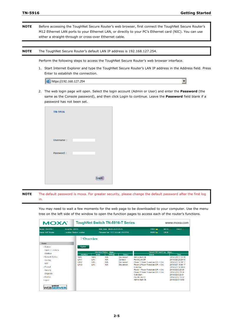
1. Start Internet Explorer and type the ToughNet Secure Router’s LAN IP address in the Address field. Press Enter to establish the connection.
2. The web login page will open. Select the login account (Admin or User) and enter the Password (the same as the Console password), and then click Login to continue. Leave the Password field blank if a password has not been set.
NOTE The default password is moxa. For greater security, please change the default password after the first log in.
You may need to wait a few moments for the web page to be downloaded to your computer. Use the menu tree on the left side of the window to open the function pages to access each of the router’s functions.
3 3. TN-5916 Series Features and Functions
The web browser is the most user-friendly way to configure the ToughNet Secure Router, since you can both monitor the ToughNet Secure Router and use administration functions from the web browser. An RS-232 or Telnet console connection only provides basic functions. In this chapter, we use the web browser to introduce the ToughNet Secure Router’s configuration and monitoring functions.
The following topics are covered in this chapter:
System
System Information
User Account
Account Password Policy
Date and Time
Warning Notification
System File Update—by Remote TFTP
System File Update—by Local Import/Export
Back Up Media
Restart
Reset to Factory Default
Port
Port Settings
Port Status
Link Aggregation
The Port Trunking Concept
Port Mirror
Using Virtual LAN
The VLAN Concept
Configuring Virtual LAN
Multicast
The Concept of Multicast Filtering
IGMP Snooping
IGMP Snooping Settings
IGMP Table
Stream Table
Static Multicast MAC
QoS
ToS/DSCP Mapping
MAC Address Table
Interface
WAN
LAN
DHCP
DHCP Server Mode
DHCP
DHCP Leases
IP-MAC Binding
IP-Port Binding
SNMP
DNS Server
DNS Global Setting
DNS Zone Setting
DNS Zone Forwarding Setting
DNS ACL Setting
DNS Security Setting
DNS Root Hints
Monitor
Statistics
Bandwidth Utilization
Packet Counter
Event Log
TN-5916 TN-5916 Series Features and Functions
3-2
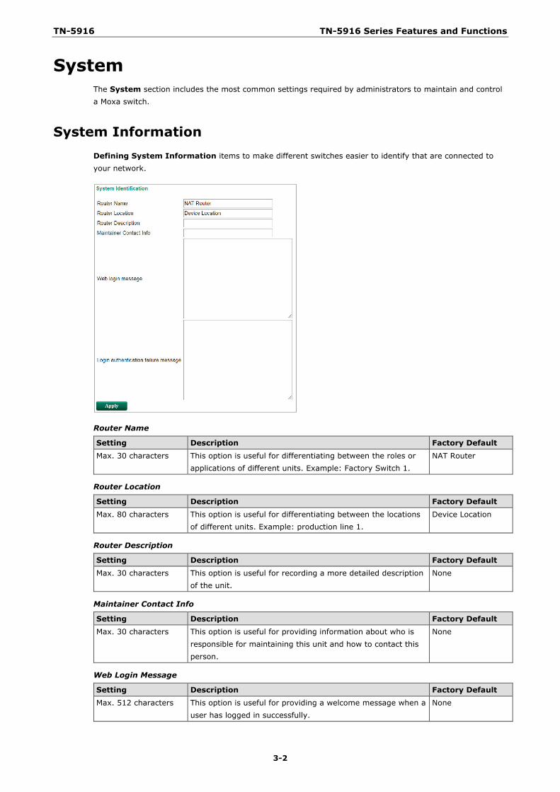
System The System section includes the most common settings required by administrators to maintain and control a Moxa switch.
System Information Defining System Information items to make different switches easier to identify that are connected to your network.
Router Name
Setting Description Factory Default Max. 30 characters This option is useful for differentiating between the roles or
applications of different units. Example: Factory Switch 1. NAT Router
Router Location
Setting Description Factory Default Max. 80 characters This option is useful for differentiating between the locations
of different units. Example: production line 1. Device Location
Router Description
Setting Description Factory Default
Max. 30 characters This option is useful for recording a more detailed description of the unit.
None
Maintainer Contact Info
Setting Description Factory Default Max. 30 characters This option is useful for providing information about who is
responsible for maintaining this unit and how to contact this person.
None
Web Login Message
Setting Description Factory Default Max. 512 characters This option is useful for providing a welcome message when a
user has logged in successfully. None
TN-5916 TN-5916 Series Features and Functions
3-3
Login Authentication Failure Message
Setting Description Factory Default Max. 512 characters This option is useful for providing a message when a user has
failed to log in. None
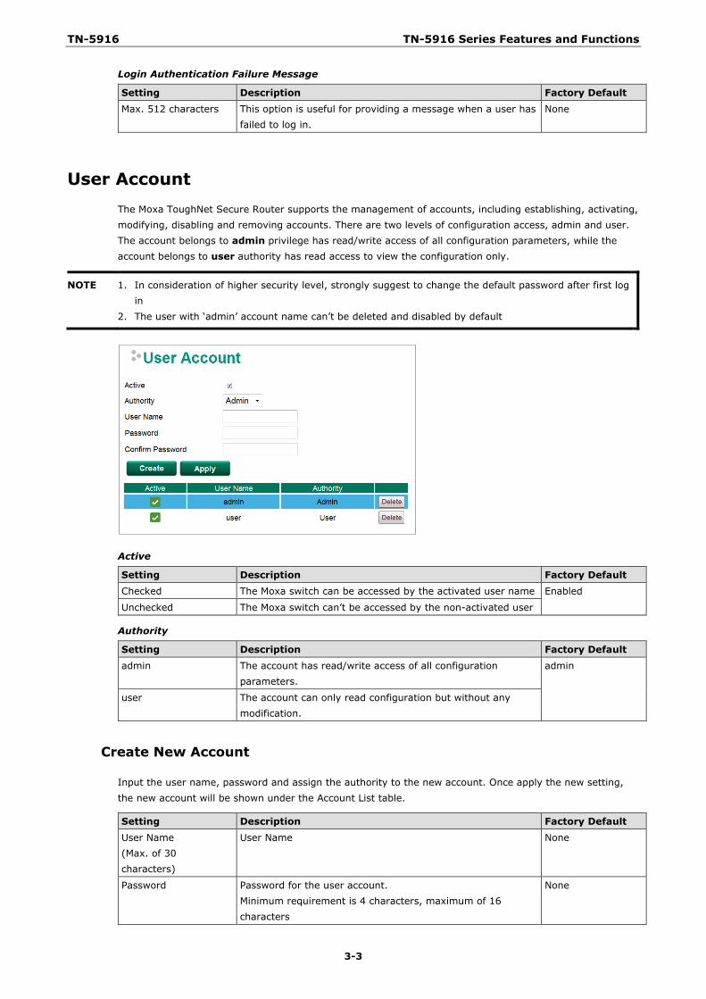
User Account The Moxa ToughNet Secure Router supports the management of accounts, including establishing, activating, modifying, disabling and removing accounts. There are two levels of configuration access, admin and user. The account belongs to admin privilege has read/write access of all configuration parameters, while the account belongs to user authority has read access to view the configuration only.
NOTE 1. In consideration of higher security level, strongly suggest to change the default password after first log in
2. The user with ‘admin’ account name can’t be deleted and disabled by default
Active
Setting Description Factory Default Checked The Moxa switch can be accessed by the activated user name Enabled
Unchecked The Moxa switch can’t be accessed by the non-activated user
Authority
Setting Description Factory Default admin The account has read/write access of all configuration
parameters. admin
user The account can only read configuration but without any modification.
Create New Account
Input the user name, password and assign the authority to the new account. Once apply the new setting, the new account will be shown under the Account List table.
Setting Description Factory Default User Name (Max. of 30 characters)
User Name None
Password Password for the user account. Minimum requirement is 4 characters, maximum of 16 characters
None
TN-5916 TN-5916 Series Features and Functions
3-4
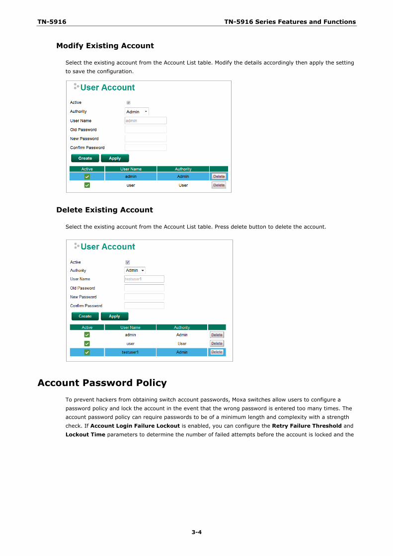
Modify Existing Account
Select the existing account from the Account List table. Modify the details accordingly then apply the setting to save the configuration.
Delete Existing Account
Select the existing account from the Account List table. Press delete button to delete the account.
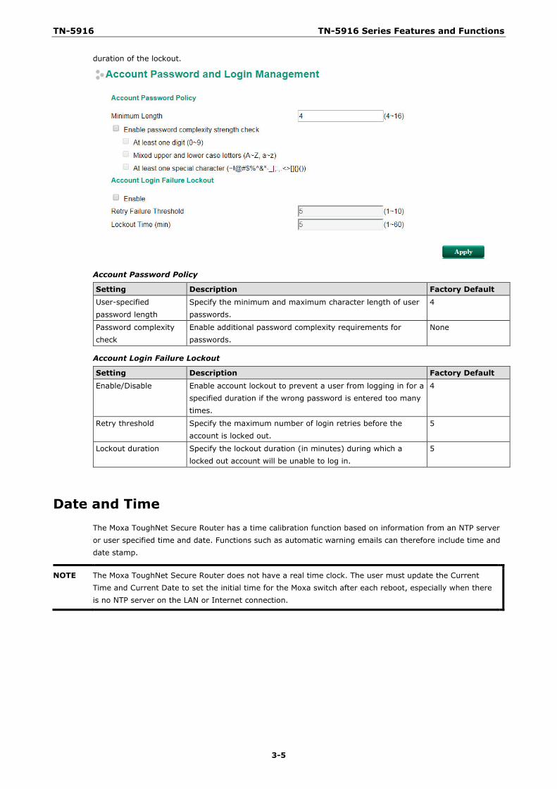
Account Password Policy To prevent hackers from obtaining switch account passwords, Moxa switches allow users to configure a password policy and lock the account in the event that the wrong password is entered too many times. The account password policy can require passwords to be of a minimum length and complexity with a strength check. If Account Login Failure Lockout is enabled, you can configure the Retry Failure Threshold and Lockout Time parameters to determine the number of failed attempts before the account is locked and the
TN-5916 TN-5916 Series Features and Functions
3-5
duration of the lockout.
Account Password Policy
Setting Description Factory Default User-specified password length
Specify the minimum and maximum character length of user passwords.
4
Password complexity check
Enable additional password complexity requirements for passwords.
None
Account Login Failure Lockout
Setting Description Factory Default
Enable/Disable Enable account lockout to prevent a user from logging in for a specified duration if the wrong password is entered too many times.
4
Retry threshold Specify the maximum number of login retries before the account is locked out.
5
Lockout duration Specify the lockout duration (in minutes) during which a locked out account will be unable to log in.
5
Date and Time The Moxa ToughNet Secure Router has a time calibration function based on information from an NTP server or user specified time and date. Functions such as automatic warning emails can therefore include time and date stamp.
NOTE The Moxa ToughNet Secure Router does not have a real time clock. The user must update the Current Time and Current Date to set the initial time for the Moxa switch after each reboot, especially when there is no NTP server on the LAN or Internet connection.
TN-5916 TN-5916 Series Features and Functions
3-6
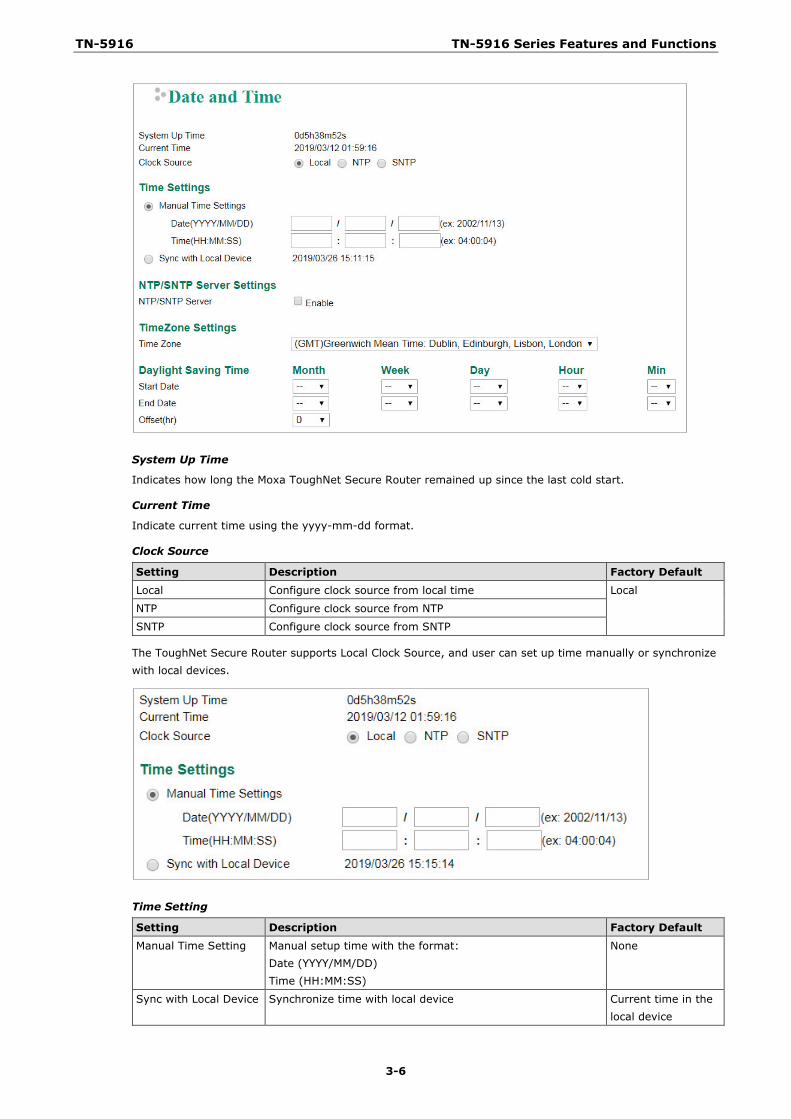
System Up Time
Indicates how long the Moxa ToughNet Secure Router remained up since the last cold start.
Current Time
Indicate current time using the yyyy-mm-dd format.
Clock Source
Setting Description Factory Default
Local Configure clock source from local time Local
NTP Configure clock source from NTP
SNTP Configure clock source from SNTP
The ToughNet Secure Router supports Local Clock Source, and user can set up time manually or synchronize with local devices.
Time Setting
Setting Description Factory Default
Manual Time Setting Manual setup time with the format: Date (YYYY/MM/DD) Time (HH:MM:SS)
None
Sync with Local Device Synchronize time with local device Current time in the local device
TN-5916 TN-5916 Series Features and Functions
3-7
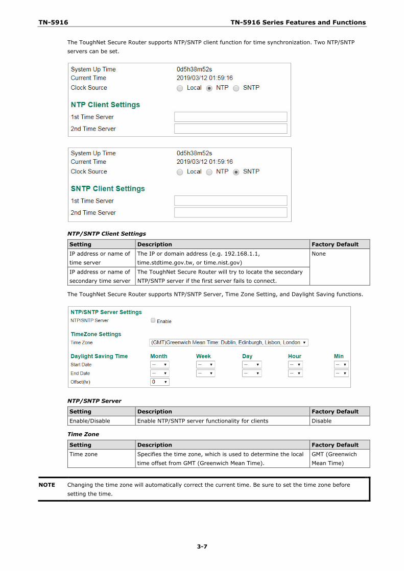
The ToughNet Secure Router supports NTP/SNTP client function for time synchronization. Two NTP/SNTP servers can be set.
NTP/SNTP Client Settings
Setting Description Factory Default IP address or name of time server
The IP or domain address (e.g. 192.168.1.1, time.stdtime.gov.tw, or time.nist.gov)
None
IP address or name of secondary time server
The ToughNet Secure Router will try to locate the secondary NTP/SNTP server if the first server fails to connect.
The ToughNet Secure Router supports NTP/SNTP Server, Time Zone Setting, and Daylight Saving functions.
NTP/SNTP Server
Setting Description Factory Default
Enable/Disable Enable NTP/SNTP server functionality for clients Disable
Time Zone
Setting Description Factory Default Time zone Specifies the time zone, which is used to determine the local
time offset from GMT (Greenwich Mean Time). GMT (Greenwich Mean Time)
NOTE Changing the time zone will automatically correct the current time. Be sure to set the time zone before setting the time.
TN-5916 TN-5916 Series Features and Functions
3-8
The Daylight Saving Time settings are used to automatically set the ToughNet Secure Router’s time according to national standards.
Start Date
Setting Description Factory Default User-specified date Specifies the date that Daylight Saving Time begins. None
End Date
Setting Description Factory Default User-specified date Specifies the date that Daylight Saving Time ends. None
Offset
Setting Description Factory Default
User-specified hour Specifies the number of hours that the time should be set forward during Daylight Saving Time.
None
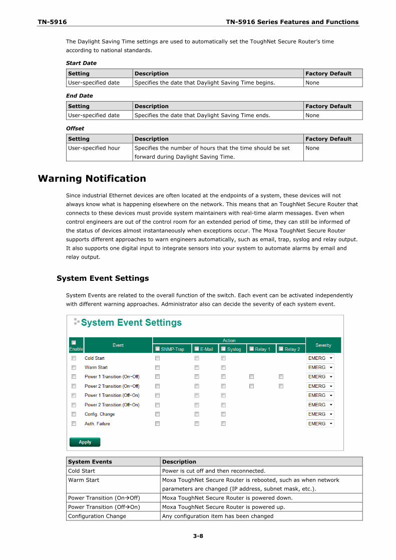
Warning Notification Since industrial Ethernet devices are often located at the endpoints of a system, these devices will not always know what is happening elsewhere on the network. This means that an ToughNet Secure Router that connects to these devices must provide system maintainers with real-time alarm messages. Even when control engineers are out of the control room for an extended period of time, they can still be informed of the status of devices almost instantaneously when exceptions occur. The Moxa ToughNet Secure Router supports different approaches to warn engineers automatically, such as email, trap, syslog and relay output. It also supports one digital input to integrate sensors into your system to automate alarms by email and relay output.
System Event Settings
System Events are related to the overall function of the switch. Each event can be activated independently with different warning approaches. Administrator also can decide the severity of each system event.
System Events Description
Cold Start Power is cut off and then reconnected.
Warm Start Moxa ToughNet Secure Router is rebooted, such as when network parameters are changed (IP address, subnet mask, etc.).
Power Transition (OnOff) Moxa ToughNet Secure Router is powered down.
Power Transition (OffOn) Moxa ToughNet Secure Router is powered up.
Configuration Change Any configuration item has been changed
TN-5916 TN-5916 Series Features and Functions
3-9
Authentication Failure An incorrect password was entered.
There are four response actions available on the EDS E series when events are triggered.
Action Description Trap The ToughNet Secure Router will send notification to the trap server when event is
triggered
E-Mail The ToughNet Secure Router will send notification to the email server defined in the Email Setting
Syslog The ToughNet Secure Router will record a syslog to syslog server defined in Syslog Server Setting
Relay The ToughNet Secure Router supports digital inputs to integrate sensors. When event is triggered, the device will automate alarms by relay output
Severity
Severity Description
Emergency System is unusable
Alert Action must be taken immediately
Critical Critical conditions
Error Error conditions
Warning Warning conditions
Notice Normal but significant condition
Information Informational messages
Debug Debug-level messages
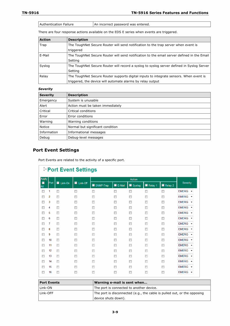
Port Event Settings
Port Events are related to the activity of a specific port.
Port Events Warning e-mail is sent when… Link-ON The port is connected to another device.
Link-OFF The port is disconnected (e.g., the cable is pulled out, or the opposing device shuts down).
TN-5916 TN-5916 Series Features and Functions
3-10
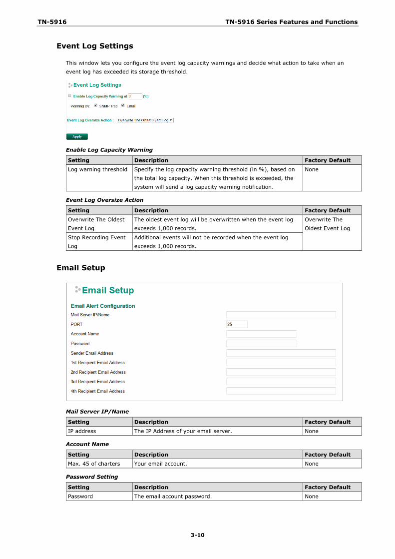
Event Log Settings
This window lets you configure the event log capacity warnings and decide what action to take when an event log has exceeded its storage threshold.
Enable Log Capacity Warning
Setting Description Factory Default Log warning threshold Specify the log capacity warning threshold (in %), based on
the total log capacity. When this threshold is exceeded, the system will send a log capacity warning notification.
None
Event Log Oversize Action
Setting Description Factory Default Overwrite The Oldest Event Log
The oldest event log will be overwritten when the event log exceeds 1,000 records.
Overwrite The Oldest Event Log
Stop Recording Event Log
Additional events will not be recorded when the event log exceeds 1,000 records.
Email Setup
Mail Server IP/Name
Setting Description Factory Default IP address The IP Address of your email server. None
Account Name
Setting Description Factory Default Max. 45 of charters Your email account. None
Password Setting
Setting Description Factory Default
Password The email account password. None
TN-5916 TN-5916 Series Features and Functions
3-11
Email Address
Setting Description Factory Default Max. of 30 characters You can set up to 4 email addresses to receive alarm emails
from the Moxa switch. None
Send Test Email
After you complete the email settings, you should first click Apply to activate those settings, and then press the Test button to verify that the settings are correct.
NOTE Auto warning e-mail messages will be sent through an authentication protected SMTP server that supports the CRAM-MD5, LOGIN, and PAIN methods of SASL (Simple Authentication and Security Layer) authentication mechanism.
We strongly recommend not entering your Account Name and Account Password if auto warning e-mail messages can be delivered without using an authentication mechanism.
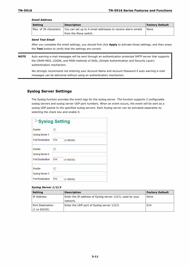
Syslog Server Settings
The Syslog function provides the event logs for the syslog server. The function supports 3 configurable syslog servers and syslog server UDP port numbers. When an event occurs, the event will be sent as a syslog UDP packet to the specified syslog servers. Each Syslog server can be activated separately by selecting the check box and enable it.
Syslog Server 1/2/3
Setting Description Factory Default
IP Address Enter the IP address of Syslog server 1/2/3, used by your network.
None
Port Destination (1 to 65535)
Enter the UDP port of Syslog server 1/2/3. 514
TN-5916 TN-5916 Series Features and Functions
3-12
NOTE The following events will be recorded into the Moxa ToughNet Secure Router’s Event Log table, and will then be sent to the specified Syslog Server: • Cold start • Warm start • Configuration change activated • Power 1/2 transition (Off (On), Power 1/2 transition (On (Off)) • Authentication fail • Port link off/on
Relay Warning Status
When relay warning triggered by either system or port events, administrator can decide to shut down the hardware warning buzzer by clicking Apply button. The event still be recorded in the event list.
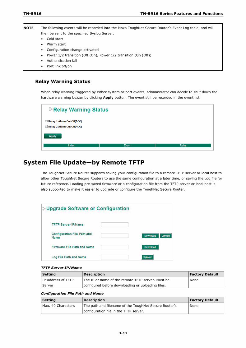
System File Update—by Remote TFTP The ToughNet Secure Router supports saving your configuration file to a remote TFTP server or local host to allow other ToughNet Secure Routers to use the same configuration at a later time, or saving the Log file for future reference. Loading pre-saved firmware or a configuration file from the TFTP server or local host is also supported to make it easier to upgrade or configure the ToughNet Secure Router.
TFTP Server IP/Name
Setting Description Factory Default IP Address of TFTP Server
The IP or name of the remote TFTP server. Must be configured before downloading or uploading files.
None
Configuration File Path and Name
Setting Description Factory Default Max. 40 Characters The path and filename of the ToughNet Secure Router’s
configuration file in the TFTP server. None
TN-5916 TN-5916 Series Features and Functions
3-13
Firmware File Path and Name
Setting Description Factory Default Max. 40 Characters The path and filename of the ToughNet Secure Router’s
firmware file None
Log File Path and Name
Setting Description Factory Default Max. 40 Characters The path and filename of the ToughNet Secure Router’s log
file None
After setting up the desired path and filename, click Activate to save the setting. Next, click Download to download the file from the remote TFTP server, or click Upload to upload a file to the remote TFTP server.
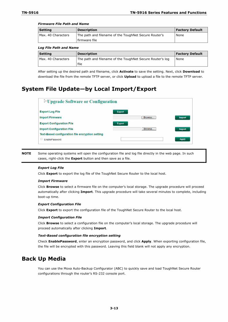
System File Update—by Local Import/Export
NOTE Some operating systems will open the configuration file and log file directly in the web page. In such cases, right-click the Export button and then save as a file.
Export Log File
Click Export to export the log file of the ToughNet Secure Router to the local host.
Import Firmware
Click Browse to select a firmware file on the computer’s local storage. The upgrade procedure will proceed automatically after clicking Import. This upgrade procedure will take several minutes to complete, including boot-up time.
Export Configuration File
Click Export to export the configuration file of the ToughNet Secure Router to the local host.
Import Configuration File
Click Browse to select a configuration file on the computer’s local storage. The upgrade procedure will proceed automatically after clicking Import.
Text-Based configuration file encryption setting
Check EnablePassword, enter an encryption password, and click Apply. When exporting configuration file, the file will be encrypted with this password. Leaving this field blank will not apply any encryption.
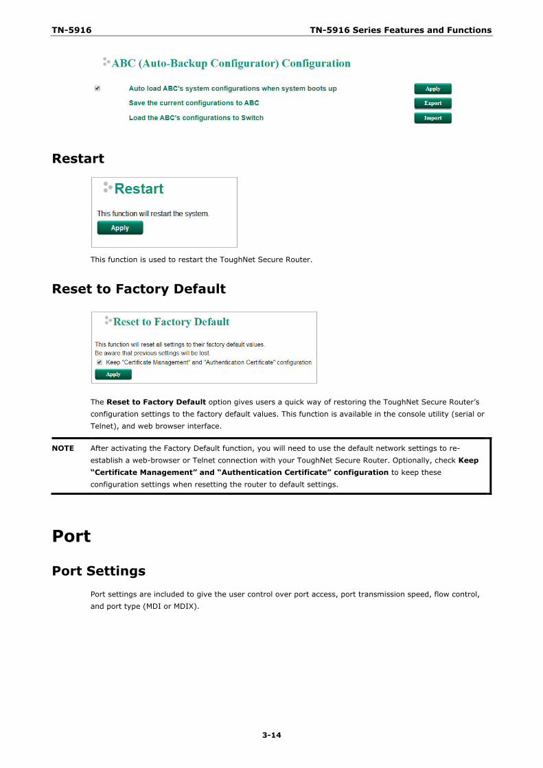
Back Up Media You can use the Moxa Auto-Backup Configurator (ABC) to quickly save and load ToughNet Secure Router configurations through the router’s RS-232 console port.
TN-5916 TN-5916 Series Features and Functions
3-14
Restart
This function is used to restart the ToughNet Secure Router.
Reset to Factory Default
The Reset to Factory Default option gives users a quick way of restoring the ToughNet Secure Router’s configuration settings to the factory default values. This function is available in the console utility (serial or Telnet), and web browser interface.
NOTE After activating the Factory Default function, you will need to use the default network settings to re-establish a web-browser or Telnet connection with your ToughNet Secure Router. Optionally, check Keep “Certificate Management” and “Authentication Certificate” configuration to keep these configuration settings when resetting the router to default settings.
Port
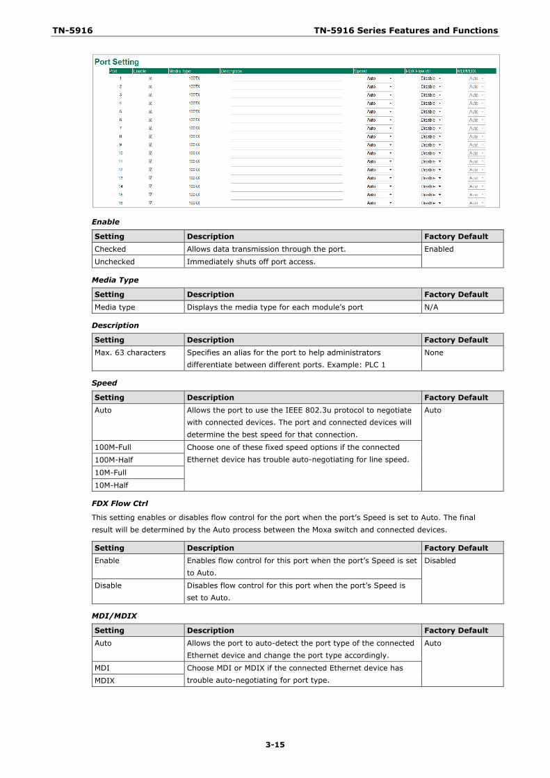
Port Settings Port settings are included to give the user control over port access, port transmission speed, flow control, and port type (MDI or MDIX).
TN-5916 TN-5916 Series Features and Functions
3-15
Enable
Setting Description Factory Default Checked Allows data transmission through the port. Enabled
Unchecked Immediately shuts off port access.
Media Type
Setting Description Factory Default
Media type Displays the media type for each module’s port N/A
Description
Setting Description Factory Default Max. 63 characters Specifies an alias for the port to help administrators
differentiate between different ports. Example: PLC 1 None
Speed
Setting Description Factory Default Auto Allows the port to use the IEEE 802.3u protocol to negotiate
with connected devices. The port and connected devices will determine the best speed for that connection.
Auto
100M-Full Choose one of these fixed speed options if the connected Ethernet device has trouble auto-negotiating for line speed. 100M-Half
10M-Full
10M-Half
FDX Flow Ctrl
This setting enables or disables flow control for the port when the port’s Speed is set to Auto. The final result will be determined by the Auto process between the Moxa switch and connected devices.
Setting Description Factory Default Enable Enables flow control for this port when the port’s Speed is set
to Auto. Disabled
Disable Disables flow control for this port when the port’s Speed is set to Auto.
MDI/MDIX
Setting Description Factory Default
Auto Allows the port to auto-detect the port type of the connected Ethernet device and change the port type accordingly.
Auto
MDI Choose MDI or MDIX if the connected Ethernet device has trouble auto-negotiating for port type. MDIX
TN-5916 TN-5916 Series Features and Functions
3-16
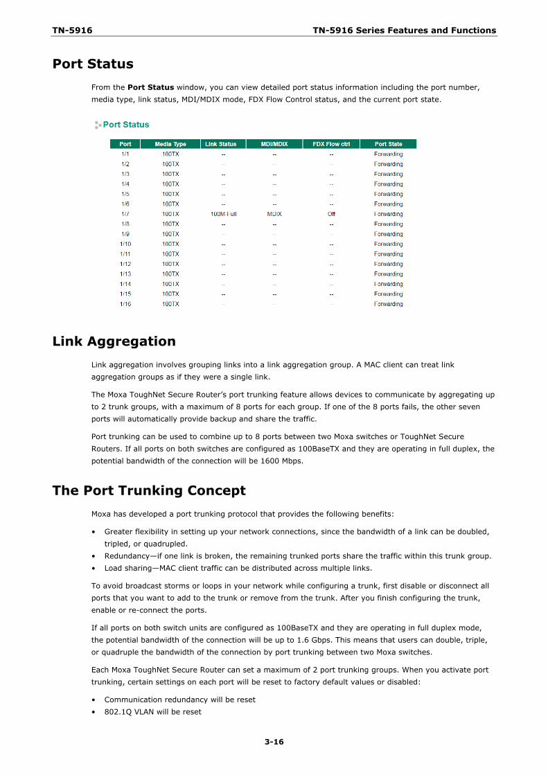
Port Status From the Port Status window, you can view detailed port status information including the port number, media type, link status, MDI/MDIX mode, FDX Flow Control status, and the current port state.
Link Aggregation Link aggregation involves grouping links into a link aggregation group. A MAC client can treat link aggregation groups as if they were a single link.
The Moxa ToughNet Secure Router’s port trunking feature allows devices to communicate by aggregating up to 2 trunk groups, with a maximum of 8 ports for each group. If one of the 8 ports fails, the other seven ports will automatically provide backup and share the traffic.
Port trunking can be used to combine up to 8 ports between two Moxa switches or ToughNet Secure Routers. If all ports on both switches are configured as 100BaseTX and they are operating in full duplex, the potential bandwidth of the connection will be 1600 Mbps.
The Port Trunking Concept Moxa has developed a port trunking protocol that provides the following benefits:
• Greater flexibility in setting up your network connections, since the bandwidth of a link can be doubled, tripled, or quadrupled.
• Redundancy—if one link is broken, the remaining trunked ports share the traffic within this trunk group. • Load sharing—MAC client traffic can be distributed across multiple links.
To avoid broadcast storms or loops in your network while configuring a trunk, first disable or disconnect all ports that you want to add to the trunk or remove from the trunk. After you finish configuring the trunk, enable or re-connect the ports.
If all ports on both switch units are configured as 100BaseTX and they are operating in full duplex mode, the potential bandwidth of the connection will be up to 1.6 Gbps. This means that users can double, triple, or quadruple the bandwidth of the connection by port trunking between two Moxa switches.
Each Moxa ToughNet Secure Router can set a maximum of 2 port trunking groups. When you activate port trunking, certain settings on each port will be reset to factory default values or disabled:
• Communication redundancy will be reset • 802.1Q VLAN will be reset
TN-5916 TN-5916 Series Features and Functions
3-17
• Multicast Filtering will be reset • Port Lock will be reset and disabled. • Set Device IP will be reset • Mirror will be reset
After port trunking has been activated, you can configure these items again for each trunking port.
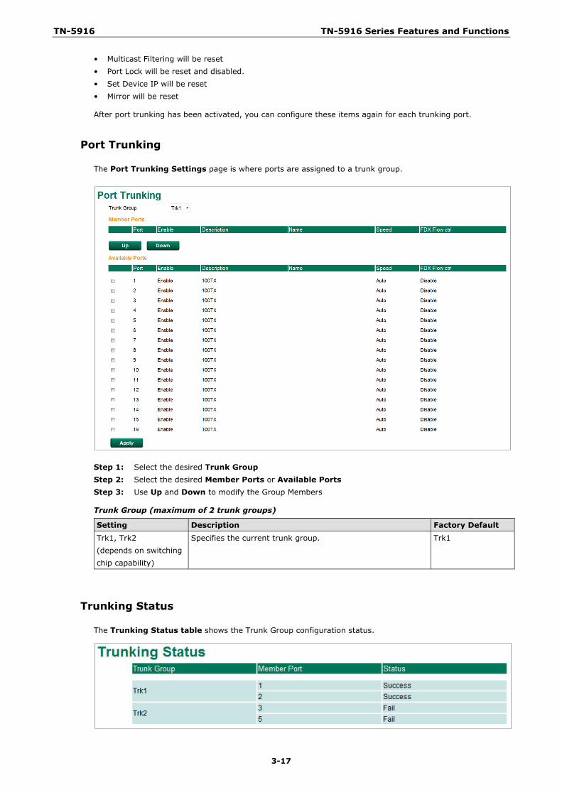
Port Trunking
The Port Trunking Settings page is where ports are assigned to a trunk group.
Step 1: Select the desired Trunk Group Step 2: Select the desired Member Ports or Available Ports Step 3: Use Up and Down to modify the Group Members
Trunk Group (maximum of 2 trunk groups)
Setting Description Factory Default Trk1, Trk2 (depends on switching chip capability)
Specifies the current trunk group. Trk1
Trunking Status
The Trunking Status table shows the Trunk Group configuration status.
TN-5916 TN-5916 Series Features and Functions
3-18
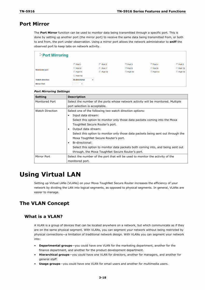
Port Mirror The Port Mirror function can be used to monitor data being transmitted through a specific port. This is done by setting up another port (the mirror port) to receive the same data being transmitted from, or both to and from, the port under observation. Using a mirror port allows the network administrator to sniff the observed port to keep tabs on network activity.
Port Mirroring Settings
Setting Description Monitored Port Select the number of the ports whose network activity will be monitored. Multiple
port selection is acceptable.
Watch Direction Select one of the following two watch direction options: • Input data stream:
Select this option to monitor only those data packets coming into the Moxa ToughNet Secure Router’s port.
• Output data stream: Select this option to monitor only those data packets being sent out through the Moxa ToughNet Secure Router’s port.
• Bi-directional: Select this option to monitor data packets both coming into, and being sent out through, the Moxa ToughNet Secure Router’s port.
Mirror Port Select the number of the port that will be used to monitor the activity of the monitored port.
Using Virtual LAN Setting up Virtual LANs (VLANs) on your Moxa ToughNet Secure Router increases the efficiency of your network by dividing the LAN into logical segments, as opposed to physical segments. In general, VLANs are easier to manage.
The VLAN Concept
What is a VLAN?
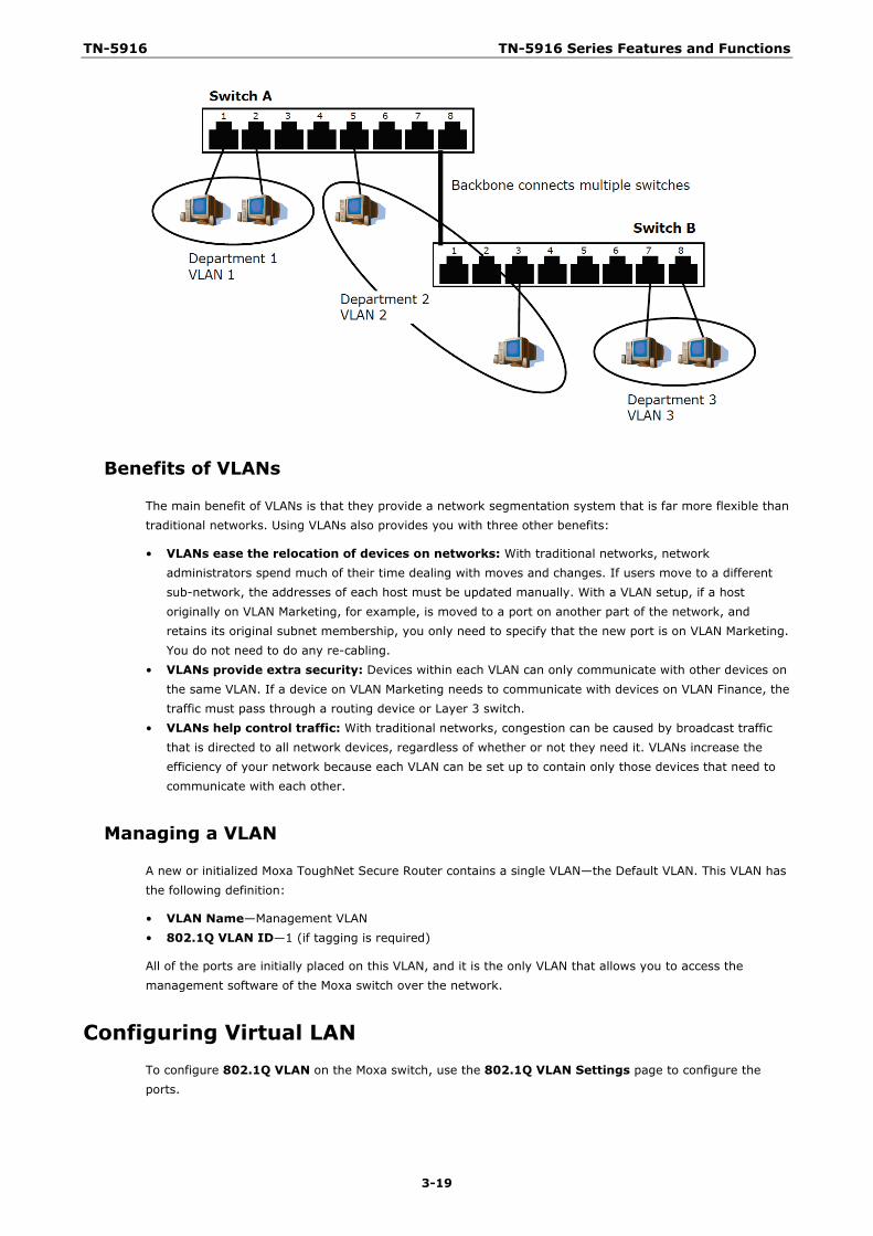
A VLAN is a group of devices that can be located anywhere on a network, but which communicate as if they are on the same physical segment. With VLANs, you can segment your network without being restricted by physical connections—a limitation of traditional network design. With VLANs you can segment your network into:
• Departmental groups—you could have one VLAN for the marketing department, another for the finance department, and another for the product development department.
• Hierarchical groups—you could have one VLAN for directors, another for managers, and another for general staff.
• Usage groups—you could have one VLAN for email users and another for multimedia users.
TN-5916 TN-5916 Series Features and Functions
3-19
Benefits of VLANs
The main benefit of VLANs is that they provide a network segmentation system that is far more flexible than traditional networks. Using VLANs also provides you with three other benefits:
• VLANs ease the relocation of devices on networks: With traditional networks, network administrators spend much of their time dealing with moves and changes. If users move to a different sub-network, the addresses of each host must be updated manually. With a VLAN setup, if a host originally on VLAN Marketing, for example, is moved to a port on another part of the network, and retains its original subnet membership, you only need to specify that the new port is on VLAN Marketing. You do not need to do any re-cabling.
• VLANs provide extra security: Devices within each VLAN can only communicate with other devices on the same VLAN. If a device on VLAN Marketing needs to communicate with devices on VLAN Finance, the traffic must pass through a routing device or Layer 3 switch.
• VLANs help control traffic: With traditional networks, congestion can be caused by broadcast traffic that is directed to all network devices, regardless of whether or not they need it. VLANs increase the efficiency of your network because each VLAN can be set up to contain only those devices that need to communicate with each other.
Managing a VLAN
A new or initialized Moxa ToughNet Secure Router contains a single VLAN—the Default VLAN. This VLAN has the following definition:
• VLAN Name—Management VLAN • 802.1Q VLAN ID—1 (if tagging is required)
All of the ports are initially placed on this VLAN, and it is the only VLAN that allows you to access the management software of the Moxa switch over the network.
Configuring Virtual LAN To configure 802.1Q VLAN on the Moxa switch, use the 802.1Q VLAN Settings page to configure the ports.
TN-5916 TN-5916 Series Features and Functions
3-20
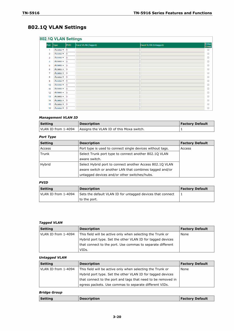
802.1Q VLAN Settings
Management VLAN ID
Setting Description Factory Default VLAN ID from 1-4094 Assigns the VLAN ID of this Moxa switch. 1
Port Type
Setting Description Factory Default Access Port type is used to connect single devices without tags. Access
Trunk Select Trunk port type to connect another 802.1Q VLAN aware switch.
Hybrid Select Hybrid port to connect another Access 802.1Q VLAN aware switch or another LAN that combines tagged and/or untagged devices and/or other switches/hubs.
PVID
Setting Description Factory Default VLAN ID from 1-4094 Sets the default VLAN ID for untagged devices that connect
to the port. 1
Tagged VLAN
Setting Description Factory Default
VLAN ID from 1-4094 This field will be active only when selecting the Trunk or Hybrid port type. Set the other VLAN ID for tagged devices that connect to the port. Use commas to separate different VIDs.
None
Untagged VLAN
Setting Description Factory Default VLAN ID from 1-4094 This field will be active only when selecting the Trunk or
Hybrid port type. Set the other VLAN ID for tagged devices that connect to the port and tags that need to be removed in egress packets. Use commas to separate different VIDs.
None
Bridge Group
Setting Description Factory Default
TN-5916 TN-5916 Series Features and Functions
3-21
Enable/Disable Enables the Bridge Group that is related to the Bridge Interface.
Disable
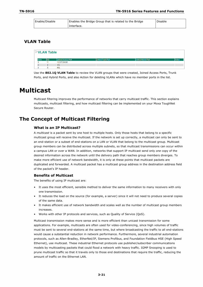
VLAN Table
Use the 802.1Q VLAN Table to review the VLAN groups that were created, Joined Access Ports, Trunk Ports, and Hybrid Ports, and also Action for deleting VLANs which have no member ports in the list.
Multicast Multicast filtering improves the performance of networks that carry multicast traffic. This section explains multicasts, multicast filtering, and how multicast filtering can be implemented on your Moxa ToughNet Secure Router.
The Concept of Multicast Filtering
What is an IP Multicast? A multicast is a packet sent by one host to multiple hosts. Only those hosts that belong to a specific multicast group will receive the multicast. If the network is set up correctly, a multicast can only be sent to an end-station or a subset of end-stations on a LAN or VLAN that belong to the multicast group. Multicast group members can be distributed across multiple subnets, so that multicast transmissions can occur within a campus LAN or over a WAN. In addition, networks that support IP multicast send only one copy of the desired information across the network until the delivery path that reaches group members diverges. To make more efficient use of network bandwidth, it is only at these points that multicast packets are duplicated and forwarded. A multicast packet has a multicast group address in the destination address field of the packet’s IP header.
Benefits of Multicast The benefits of using IP multicast are:
• It uses the most efficient, sensible method to deliver the same information to many receivers with only one transmission.
• It reduces the load on the source (for example, a server) since it will not need to produce several copies of the same data.
• It makes efficient use of network bandwidth and scales well as the number of multicast group members increases.
• Works with other IP protocols and services, such as Quality of Service (QoS).
Multicast transmission makes more sense and is more efficient than unicast transmission for some applications. For example, multicasts are often used for video-conferencing, since high volumes of traffic must be sent to several end-stations at the same time, but where broadcasting the traffic to all end-stations would cause a substantial reduction in network performance. Furthermore, several industrial automation protocols, such as Allen-Bradley, EtherNet/IP, Siemens Profibus, and Foundation Fieldbus HSE (High Speed Ethernet), use multicast. These industrial Ethernet protocols use publisher/subscriber communications models by multicasting packets that could flood a network with heavy traffic. IGMP Snooping is used to prune multicast traffic so that it travels only to those end destinations that require the traffic, reducing the amount of traffic on the Ethernet LAN.
TN-5916 TN-5916 Series Features and Functions
3-22
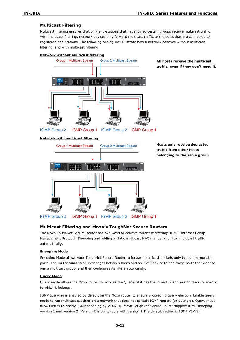
Multicast Filtering Multicast filtering ensures that only end-stations that have joined certain groups receive multicast traffic. With multicast filtering, network devices only forward multicast traffic to the ports that are connected to registered end-stations. The following two figures illustrate how a network behaves without multicast filtering, and with multicast filtering.
Network without multicast filtering
All hosts receive the multicast traffic, even if they don’t need it.
Network with multicast filtering
Hosts only receive dedicated traffic from other hosts belonging to the same group.
Multicast Filtering and Moxa’s ToughNet Secure Routers The Moxa ToughNet Secure Router has two ways to achieve multicast filtering: IGMP (Internet Group Management Protocol) Snooping and adding a static multicast MAC manually to filter multicast traffic automatically.
Snooping Mode
Snooping Mode allows your ToughNet Secure Router to forward multicast packets only to the appropriate ports. The router snoops on exchanges between hosts and an IGMP device to find those ports that want to join a multicast group, and then configures its filters accordingly.
Query Mode
Query mode allows the Moxa router to work as the Querier if it has the lowest IP address on the subnetwork to which it belongs.
IGMP querying is enabled by default on the Moxa router to ensure proceeding query election. Enable query mode to run multicast sessions on a network that does not contain IGMP routers (or queriers). Query mode allows users to enable IGMP snooping by VLAN ID. Moxa ToughNet Secure Router support IGMP snooping version 1 and version 2. Version 2 is compatible with version 1.The default setting is IGMP V1/V2. "
TN-5916 TN-5916 Series Features and Functions
3-23
IGMP Multicast Filtering IGMP is used by IP-supporting network devices to register hosts with multicast groups. It can be used on all LANs and VLANs that contain a multicast capable IP router, and on other network devices that support multicast filtering. Moxa switches support IGMP version 1 and 2. IGMP version 1 and 2 work as follows::
• The IP router (or querier) periodically sends query packets to all end-stations on the LANs or VLANs that are connected to it. For networks with more than one IP router, the router with the lowest IP address is the querier. A switch with IP address lower than the IP address of any other IGMP queriers connected to the LAN or VLAN can become the IGMP querier.
• When an IP host receives a query packet, it sends a report packet back that identifies the multicast group that the end-station would like to join.
• When the report packet arrives at a port on a switch with IGMP Snooping enabled, the switch knows that the port should forward traffic for the multicast group, and then proceeds to forward the packet to the router.
• When the router receives the report packet, it registers that the LAN or VLAN requires traffic for the multicast groups.
• When the router forwards traffic for the multicast group to the LAN or VLAN, the switches only forward the traffic to ports that received a report packet.
IGMP version comparison
IGMP Version Main Features Reference V1 a. Periodic query RFC-1112
V2 Compatible with V1 and adds: a. Group-specific query b. Leave group messages c. Resends specific queries to verify leave message was the last one in the group d. Querier election
RFC-2236
Static Multicast MAC Some devices may only support multicast packets, but not support either IGMP Snooping. The Moxa ToughNet Secure Router supports adding multicast groups manually to enable multicast filtering.
Enabling Multicast Filtering Use the USB console or web interface to enable or disable IGMP Snooping and IGMP querying. If IGMP Snooping is not enabled, then IP multicast traffic is always forwarded, flooding the network.
IGMP Snooping IGMP Snooping provides the ability to prune multicast traffic so that it travels only to those end destinations that require that traffic, thereby reducing the amount of traffic on the Ethernet LAN.
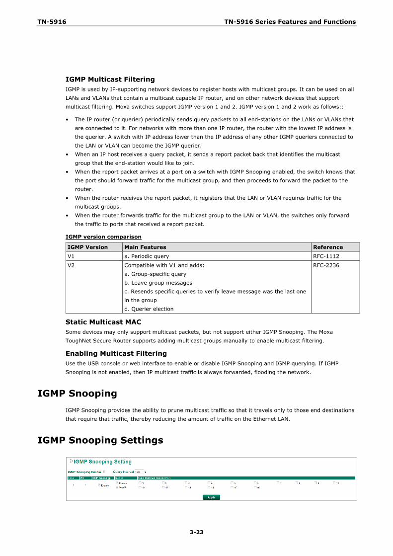
IGMP Snooping Settings
TN-5916 TN-5916 Series Features and Functions
3-24
Enable IGMP Snooping (Global)
Setting Description Factory Default Enable/Disable Checkmark the Enable IGMP Snooping checkbox near the top
of the window to enable the IGMP Snooping function globally. Disabled
Query Interval (sec)
Setting Description Factory Default Numerical value, input by the user
Sets the query interval of the Querier function globally. Valid settings are from 20 to 600 seconds.
125 seconds
Enable IGMP Snooping
Setting Description Factory Default
Enable/Disable Enables or disables the IGMP Snooping function on that particular VLAN.
Enabled if IGMP Snooping is enabled globally
Querier
Setting Description Factory Default Enable/Disable Enables or disables the Moxa ToughNet Secure Router’s
querier function. Disabled
V1/V2 Checkbox V1/V2: Enables the Moxa ToughNet Secure Router to send IGMP snooping version 1 and 2 queries
V1/V2
Static Multicast Querier Port
Setting Description Factory Default
Select/Deselect Select the ports that will connect to the multicast routers. These ports will receive all multicast packets from the source. This option is only active when IGMP Snooping is enabled.
Disabled
NOTE If a router or layer 3 switch is connected to the network, it will act as the Querier, and consequently this Querier option will be disabled on all Moxa layer 2 switches.
If all switches on the network are Moxa layer 2 switches, then only one layer 2 switch will act as Querier.
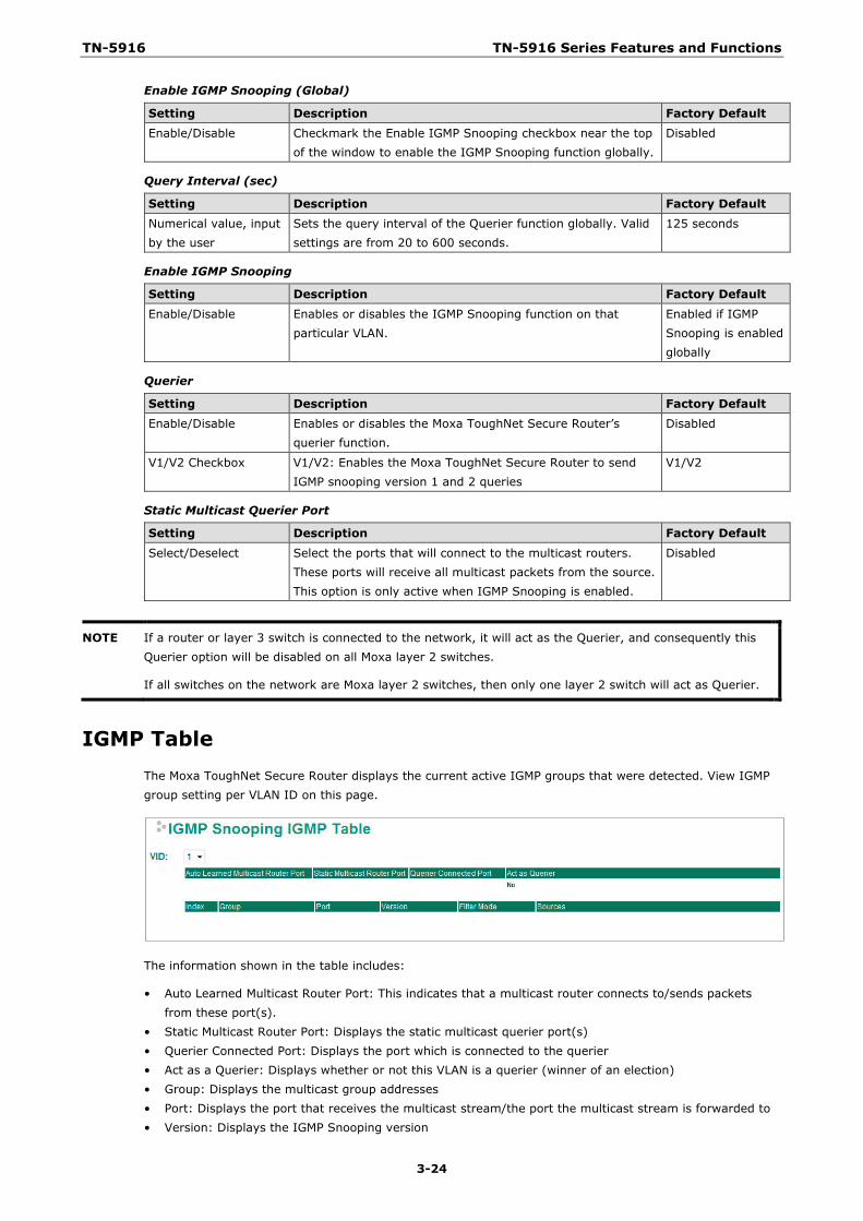
IGMP Table The Moxa ToughNet Secure Router displays the current active IGMP groups that were detected. View IGMP group setting per VLAN ID on this page.
The information shown in the table includes:
• Auto Learned Multicast Router Port: This indicates that a multicast router connects to/sends packets from these port(s).
• Static Multicast Router Port: Displays the static multicast querier port(s) • Querier Connected Port: Displays the port which is connected to the querier • Act as a Querier: Displays whether or not this VLAN is a querier (winner of an election) • Group: Displays the multicast group addresses • Port: Displays the port that receives the multicast stream/the port the multicast stream is forwarded to • Version: Displays the IGMP Snooping version
TN-5916 TN-5916 Series Features and Functions
3-25
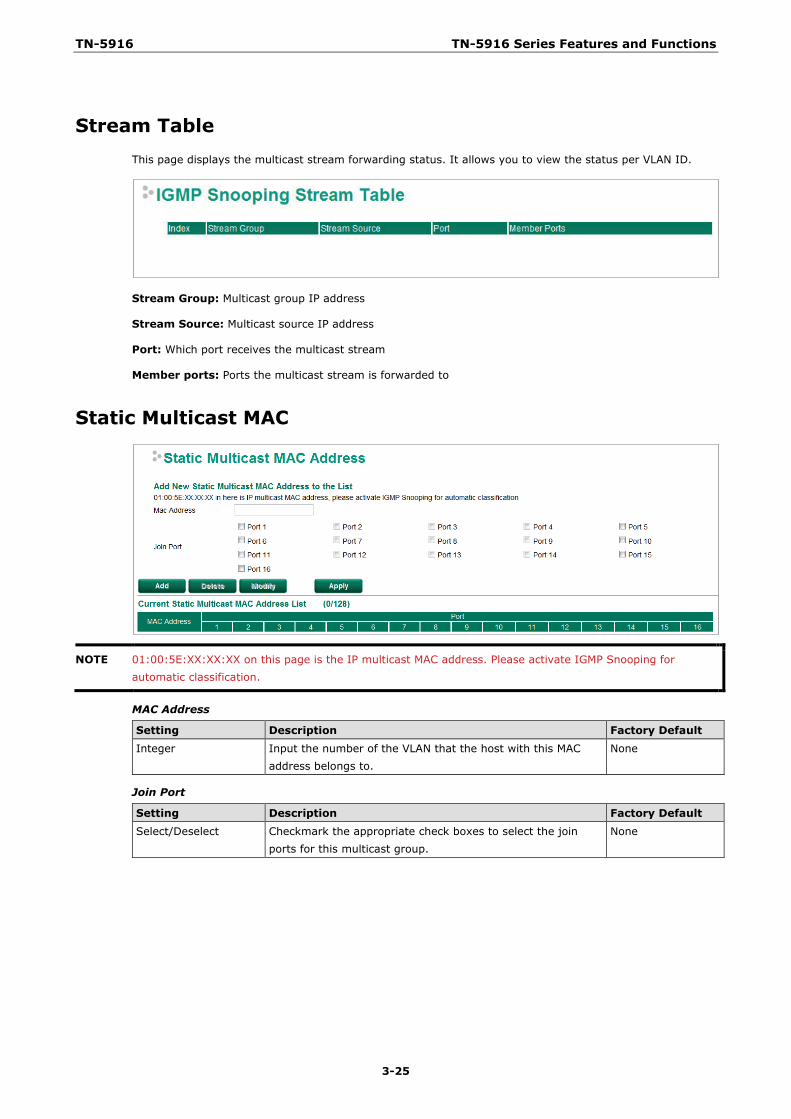
Stream Table This page displays the multicast stream forwarding status. It allows you to view the status per VLAN ID.
Stream Group: Multicast group IP address
Stream Source: Multicast source IP address
Port: Which port receives the multicast stream
Member ports: Ports the multicast stream is forwarded to
Static Multicast MAC
NOTE 01:00:5E:XX:XX:XX on this page is the IP multicast MAC address. Please activate IGMP Snooping for automatic classification.
MAC Address
Setting Description Factory Default Integer Input the number of the VLAN that the host with this MAC
address belongs to. None
Join Port
Setting Description Factory Default Select/Deselect Checkmark the appropriate check boxes to select the join
ports for this multicast group. None
TN-5916 TN-5916 Series Features and Functions
3-26
QoS
QoS Classification
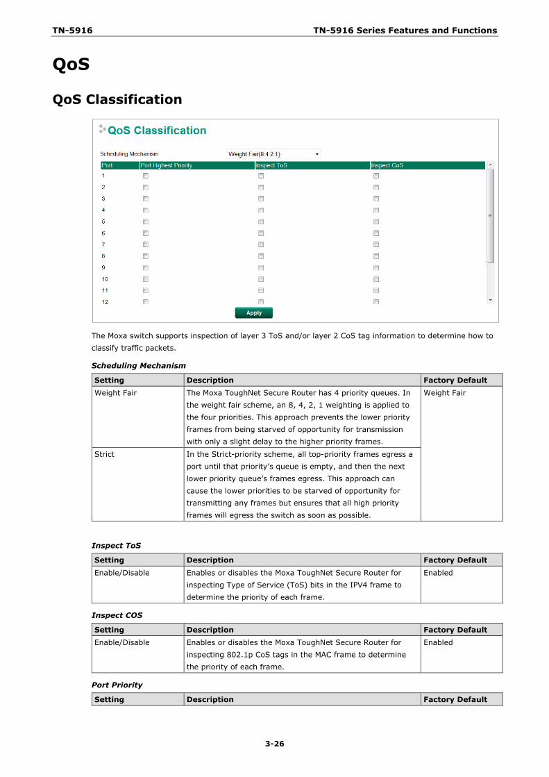
The Moxa switch supports inspection of layer 3 ToS and/or layer 2 CoS tag information to determine how to classify traffic packets.
Scheduling Mechanism
Setting Description Factory Default Weight Fair The Moxa ToughNet Secure Router has 4 priority queues. In
the weight fair scheme, an 8, 4, 2, 1 weighting is applied to the four priorities. This approach prevents the lower priority frames from being starved of opportunity for transmission with only a slight delay to the higher priority frames.
Weight Fair
Strict In the Strict-priority scheme, all top-priority frames egress a port until that priority’s queue is empty, and then the next lower priority queue’s frames egress. This approach can cause the lower priorities to be starved of opportunity for transmitting any frames but ensures that all high priority frames will egress the switch as soon as possible.
Inspect ToS
Setting Description Factory Default
Enable/Disable Enables or disables the Moxa ToughNet Secure Router for inspecting Type of Service (ToS) bits in the IPV4 frame to determine the priority of each frame.
Enabled
Inspect COS
Setting Description Factory Default Enable/Disable Enables or disables the Moxa ToughNet Secure Router for
inspecting 802.1p CoS tags in the MAC frame to determine the priority of each frame.
Enabled
Port Priority
Setting Description Factory Default
TN-5916 TN-5916 Series Features and Functions
3-27
Port priority The port priority has 4 priority queues. Low, normal, medium, high priority queue option is applied to each port.
3(Normal)
NOTE The priority of an ingress frame is determined in the following order:
1. Inspect CoS 2. Inspect ToS 3. Port Priority
NOTE The designer can enable these classifications individually or in combination. For instance, if a “hot” higher priority port is required for a network design, Inspect TOS and Inspect CoS can be disabled. This setting leaves only port default priority active, which results in all ingress frames being assigned the same priority on that port.
CoS Mapping
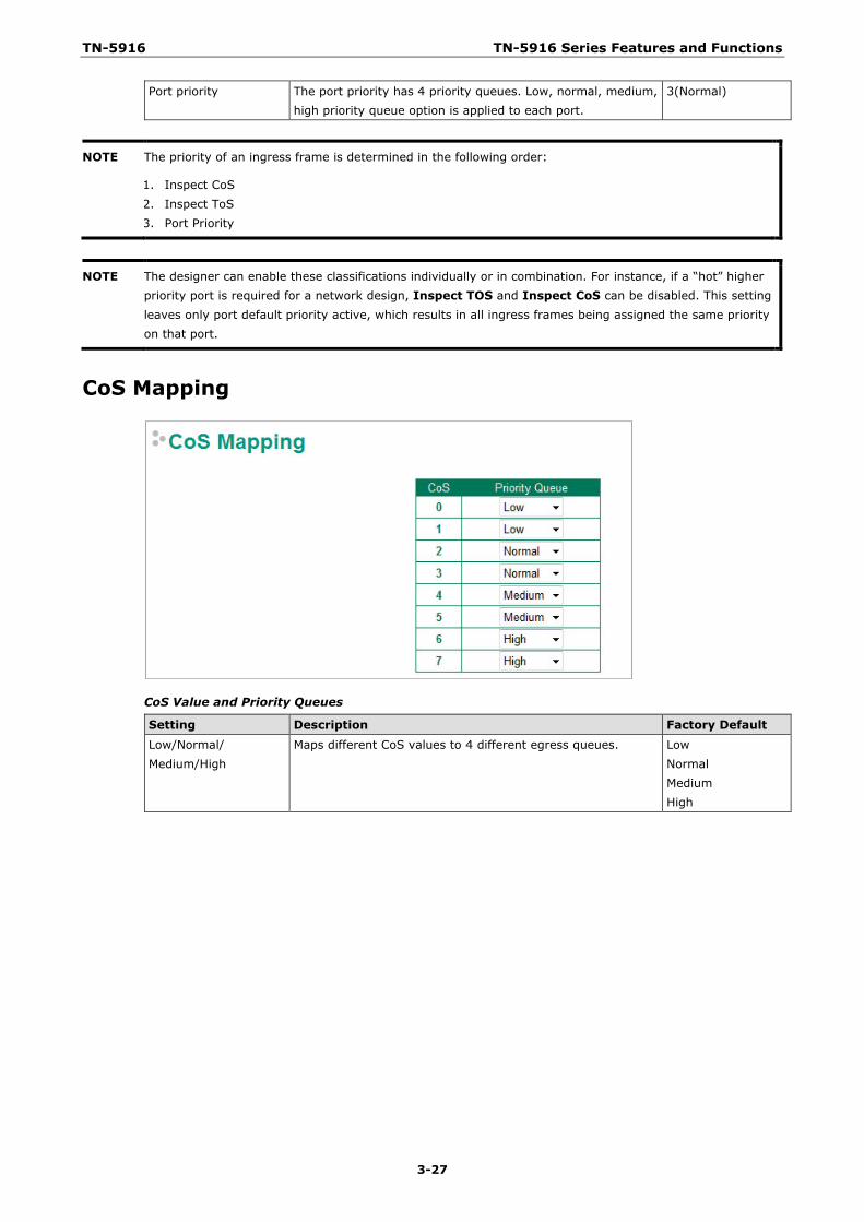
CoS Value and Priority Queues
Setting Description Factory Default
Low/Normal/ Medium/High
Maps different CoS values to 4 different egress queues. Low Normal Medium High
TN-5916 TN-5916 Series Features and Functions
3-28
ToS/DSCP Mapping
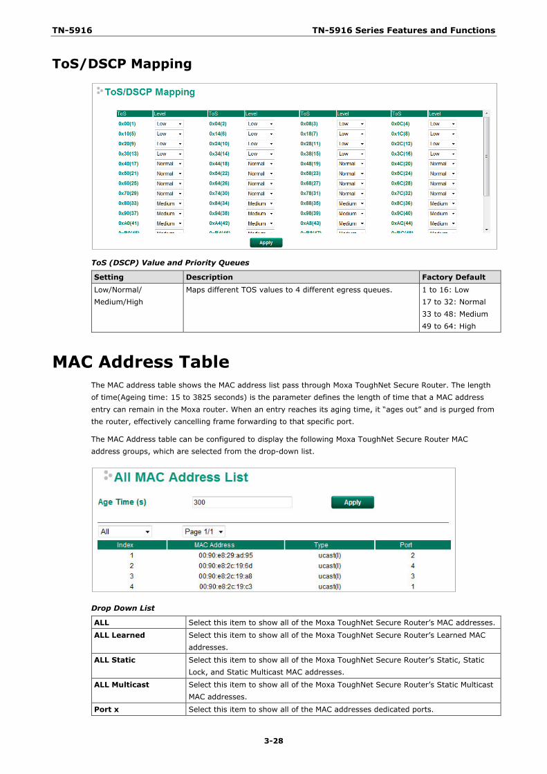
ToS (DSCP) Value and Priority Queues
Setting Description Factory Default Low/Normal/ Medium/High
Maps different TOS values to 4 different egress queues. 1 to 16: Low 17 to 32: Normal 33 to 48: Medium 49 to 64: High
MAC Address Table The MAC address table shows the MAC address list pass through Moxa ToughNet Secure Router. The length of time(Ageing time: 15 to 3825 seconds) is the parameter defines the length of time that a MAC address entry can remain in the Moxa router. When an entry reaches its aging time, it “ages out” and is purged from the router, effectively cancelling frame forwarding to that specific port.
The MAC Address table can be configured to display the following Moxa ToughNet Secure Router MAC address groups, which are selected from the drop-down list.
Drop Down List
ALL Select this item to show all of the Moxa ToughNet Secure Router’s MAC addresses.
ALL Learned Select this item to show all of the Moxa ToughNet Secure Router’s Learned MAC addresses.
ALL Static Select this item to show all of the Moxa ToughNet Secure Router’s Static, Static Lock, and Static Multicast MAC addresses.
ALL Multicast Select this item to show all of the Moxa ToughNet Secure Router’s Static Multicast MAC addresses.
Port x Select this item to show all of the MAC addresses dedicated ports.
TN-5916 TN-5916 Series Features and Functions
3-29
The table displays the following information:
MAC Address This field shows the MAC address.
Type This field shows the type of this MAC address.
Port This field shows the port that this MAC address belongs to.
Interface
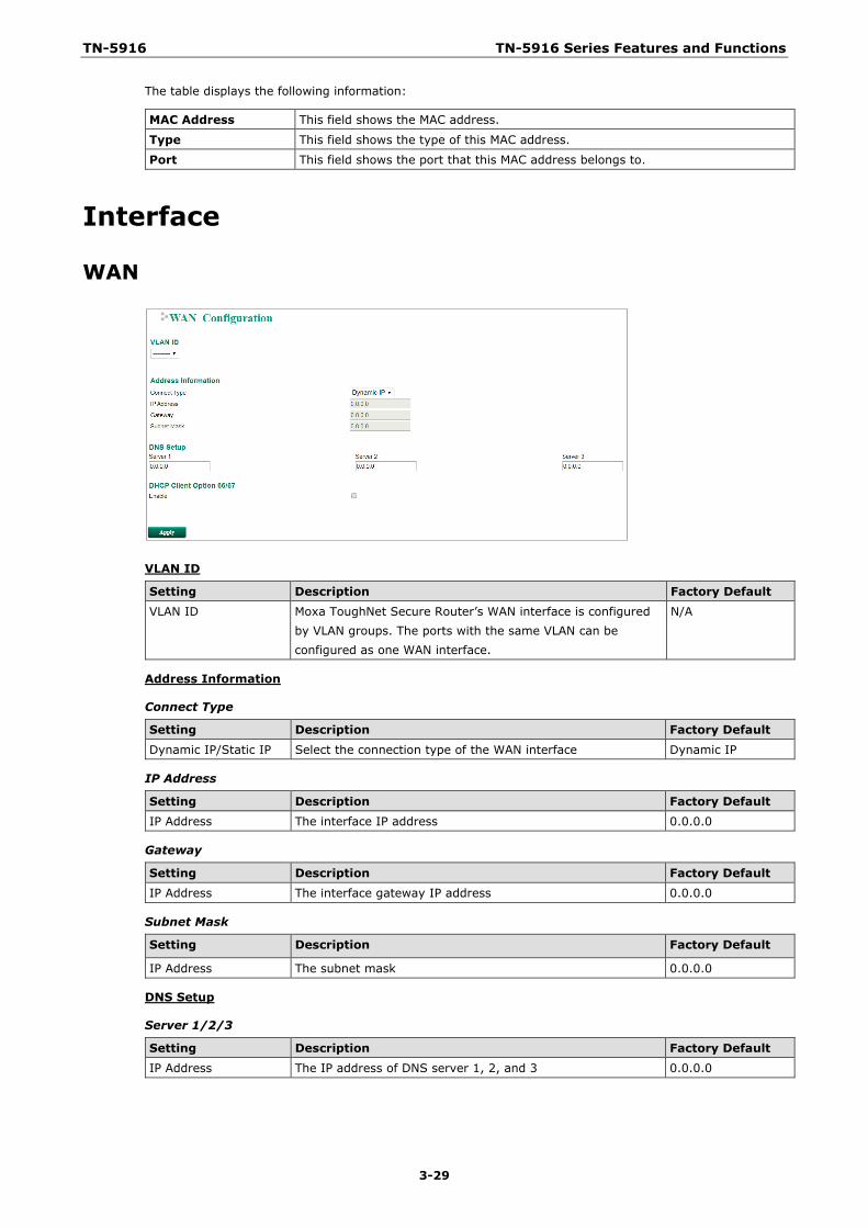
WAN
VLAN ID
Setting Description Factory Default VLAN ID Moxa ToughNet Secure Router’s WAN interface is configured
by VLAN groups. The ports with the same VLAN can be configured as one WAN interface.
N/A
Address Information
Connect Type
Setting Description Factory Default
Dynamic IP/Static IP Select the connection type of the WAN interface Dynamic IP
IP Address
Setting Description Factory Default IP Address The interface IP address 0.0.0.0
Gateway
Setting Description Factory Default IP Address The interface gateway IP address 0.0.0.0
Subnet Mask
Setting Description Factory Default
IP Address The subnet mask 0.0.0.0
DNS Setup
Server 1/2/3
Setting Description Factory Default IP Address The IP address of DNS server 1, 2, and 3 0.0.0.0
TN-5916 TN-5916 Series Features and Functions
3-30
DHCP Client Option 66/67
Enable
Setting Description Factory Default Enable/Disable Enable or disable DHCP Client Option 66/67 Disabled
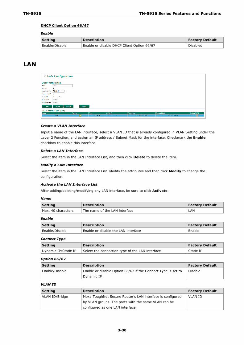
LAN
Create a VLAN Interface
Input a name of the LAN interface, select a VLAN ID that is already configured in VLAN Setting under the Layer 2 Function, and assign an IP address / Subnet Mask for the interface. Checkmark the Enable checkbox to enable this interface.
Delete a LAN Interface
Select the item in the LAN Interface List, and then click Delete to delete the item.
Modify a LAN Interface
Select the item in the LAN Interface List. Modify the attributes and then click Modify to change the configuration.
Activate the LAN Interface List
After adding/deleting/modifying any LAN interface, be sure to click Activate.
Name
Setting Description Factory Default
Max. 40 characters The name of the LAN interface LAN
Enable
Setting Description Factory Default Enable/Disable Enable or disable the LAN interface Enable
Connect Type
Setting Description Factory Default Dynamic IP/Static IP Select the connection type of the LAN interface Static IP
Option 66/67
Setting Description Factory Default
Enable/Disable Enable or disable Option 66/67 if the Connect Type is set to Dynamic IP
Disable
VLAN ID
Setting Description Factory Default VLAN ID/Bridge Moxa ToughNet Secure Router’s LAN interface is configured
by VLAN groups. The ports with the same VLAN can be configured as one LAN interface.
VLAN ID
TN-5916 TN-5916 Series Features and Functions
3-31
IP Address
Setting Description Factory Default IP Address The IP address 192.168.127.254
Subnet Mask
Setting Description Factory Default IP Address The subnet mask 255.255.255.0
Bridge Group Interface When ports are set in the VLAN, the packets transmitted within these ports will be forwarded by the switching chip without being filtered by the firewall. However, in some scenarios, it is required to filter specific packets transmitted within the VLAN. By assigning ports as Bridge port, the packets transmitted between these ports will be checked by the firewall.
In addition, when ports are set in different VLANs, the packets transmitted within these VLANs will be routed by the switching chip locally, without being inspected by the firewall. However in some scenarios, it is required to filter specific packets transmitted within VLANs. By assigning a VLAN to join the Bridge Zone, the packets transmitted between these two zones will be checked by the firewall.
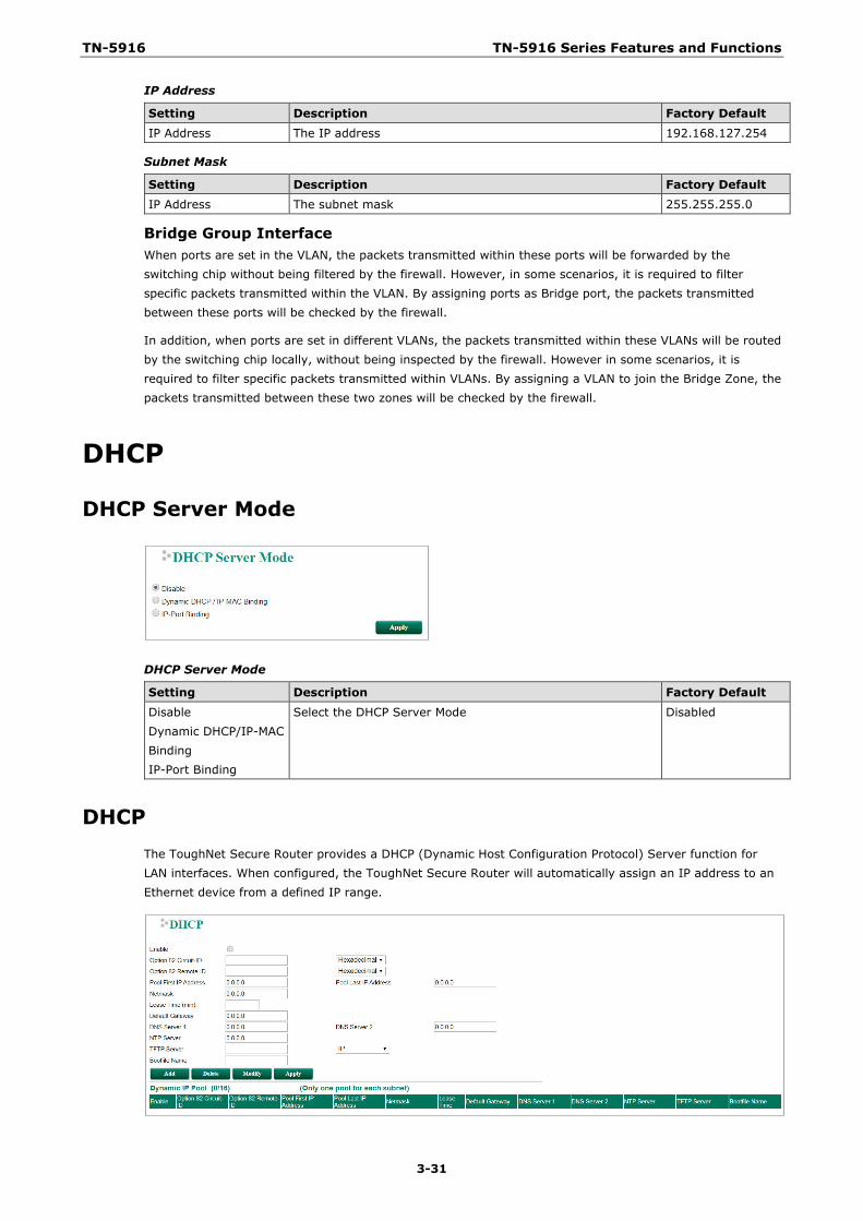
DHCP
DHCP Server Mode
DHCP Server Mode
Setting Description Factory Default Disable Dynamic DHCP/IP-MAC Binding IP-Port Binding
Select the DHCP Server Mode Disabled
DHCP The ToughNet Secure Router provides a DHCP (Dynamic Host Configuration Protocol) Server function for LAN interfaces. When configured, the ToughNet Secure Router will automatically assign an IP address to an Ethernet device from a defined IP range.
TN-5916 TN-5916 Series Features and Functions
3-32
DHCP Server Enable/Disable
Setting Description Factory Default Enable/Disable Enable or disable the DHCP server function Disable
Option 82 Circuit-ID
Setting Description Factory Default Max. 20 characters The name of the Circuit-ID None
Hexadecimal/String Select the type of the Circuit-ID Hexadecimal
Option 82 Remote-ID
Setting Description Factory Default Max. 20 characters The name of the Remote-ID None
Hexadecimal/String Select the type of the Remote-ID Hexadecimal
Pool First IP Address
Setting Description Factory Default
IP Address The first IP address of the offered IP address range for DHCP clients
0.0.0.0
Pool Last IP Address
Setting Description Factory Default IP Address The last IP address of the offered IP address range for DHCP
clients 0.0.0.0
Netmask
Setting Description Factory Default Netmask The netmask for DHCP clients 0.0.0.0
Lease Time
Setting Description Factory Default
≥ 5 min. The lease time of the DHCP server None
Default Gateway
Setting Description Factory Default IP Address The default gateway for DHCP clients 0.0.0.0
DNS Server
Setting Description Factory Default IP Address The DNS server for DHCP clients 0.0.0.0
NTP Server
Setting Description Factory Default
IP Address The NTP server for DHCP clients 0.0.0.0
TFTP Server
Setting Description Factory Default IP Address The TFTP server for DHCP clients None
IP/Domain Name Select the type of TFTP server IP
Boot File Name
Setting Description Factory Default
Max. 20 characters The name of boot file None
Clickable Buttons
Add
Use the Add button to input a new DHCP list.
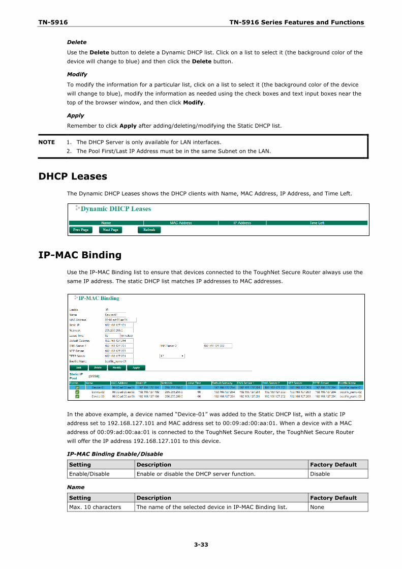
TN-5916 TN-5916 Series Features and Functions
3-33
Delete
Use the Delete button to delete a Dynamic DHCP list. Click on a list to select it (the background color of the device will change to blue) and then click the Delete button.
Modify
To modify the information for a particular list, click on a list to select it (the background color of the device will change to blue), modify the information as needed using the check boxes and text input boxes near the top of the browser window, and then click Modify.
Apply
Remember to click Apply after adding/deleting/modifying the Static DHCP list.
NOTE 1. The DHCP Server is only available for LAN interfaces. 2. The Pool First/Last IP Address must be in the same Subnet on the LAN.
DHCP Leases The Dynamic DHCP Leases shows the DHCP clients with Name, MAC Address, IP Address, and Time Left.
IP-MAC Binding Use the IP-MAC Binding list to ensure that devices connected to the ToughNet Secure Router always use the same IP address. The static DHCP list matches IP addresses to MAC addresses.
In the above example, a device named “Device-01” was added to the Static DHCP list, with a static IP address set to 192.168.127.101 and MAC address set to 00:09:ad:00:aa:01. When a device with a MAC address of 00:09:ad:00:aa:01 is connected to the ToughNet Secure Router, the ToughNet Secure Router will offer the IP address 192.168.127.101 to this device.
IP-MAC Binding Enable/Disable
Setting Description Factory Default Enable/Disable Enable or disable the DHCP server function. Disable
Name
Setting Description Factory Default Max. 10 characters The name of the selected device in IP-MAC Binding list. None
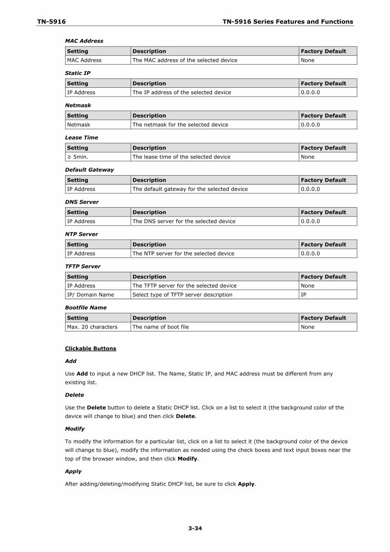
TN-5916 TN-5916 Series Features and Functions
3-34
MAC Address
Setting Description Factory Default MAC Address The MAC address of the selected device None
Static IP
Setting Description Factory Default IP Address The IP address of the selected device 0.0.0.0
Netmask
Setting Description Factory Default
Netmask The netmask for the selected device 0.0.0.0
Lease Time
Setting Description Factory Default ≥ 5min. The lease time of the selected device None
Default Gateway
Setting Description Factory Default IP Address The default gateway for the selected device 0.0.0.0
DNS Server
Setting Description Factory Default
IP Address The DNS server for the selected device 0.0.0.0
NTP Server
Setting Description Factory Default IP Address The NTP server for the selected device 0.0.0.0
TFTP Server
Setting Description Factory Default IP Address The TFTP server for the selected device None
IP/ Domain Name Select type of TFTP server description IP
Bootfile Name
Setting Description Factory Default Max. 20 characters The name of boot file None
Clickable Buttons
Add
Use Add to input a new DHCP list. The Name, Static IP, and MAC address must be different from any existing list.
Delete
Use the Delete button to delete a Static DHCP list. Click on a list to select it (the background color of the device will change to blue) and then click Delete.
Modify
To modify the information for a particular list, click on a list to select it (the background color of the device will change to blue), modify the information as needed using the check boxes and text input boxes near the top of the browser window, and then click Modify.
Apply
After adding/deleting/modifying Static DHCP list, be sure to click Apply.
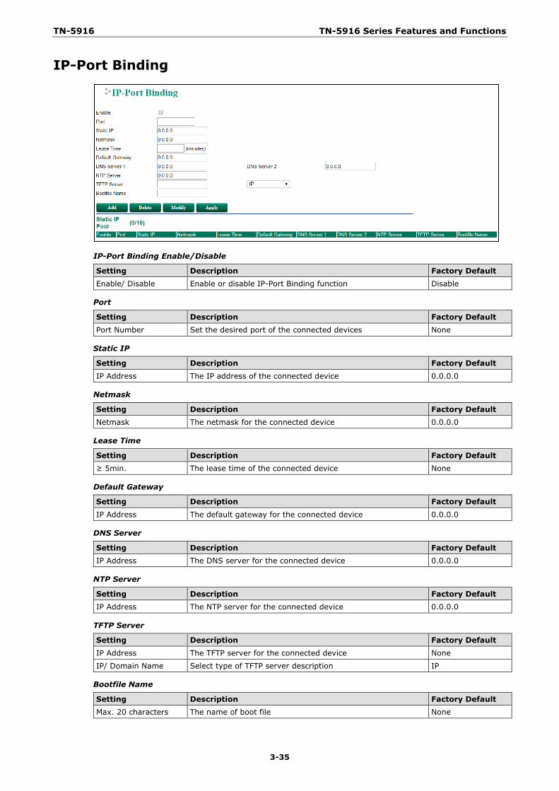
TN-5916 TN-5916 Series Features and Functions
3-35
IP-Port Binding
IP-Port Binding Enable/Disable
Setting Description Factory Default Enable/ Disable Enable or disable IP-Port Binding function Disable
Port
Setting Description Factory Default Port Number Set the desired port of the connected devices None
Static IP
Setting Description Factory Default
IP Address The IP address of the connected device 0.0.0.0
Netmask
Setting Description Factory Default Netmask The netmask for the connected device 0.0.0.0
Lease Time
Setting Description Factory Default ≥ 5min. The lease time of the connected device None
Default Gateway
Setting Description Factory Default
IP Address The default gateway for the connected device 0.0.0.0
DNS Server
Setting Description Factory Default IP Address The DNS server for the connected device 0.0.0.0
NTP Server
Setting Description Factory Default IP Address The NTP server for the connected device 0.0.0.0
TFTP Server
Setting Description Factory Default
IP Address The TFTP server for the connected device None
IP/ Domain Name Select type of TFTP server description IP
Bootfile Name
Setting Description Factory Default Max. 20 characters The name of boot file None
TN-5916 TN-5916 Series Features and Functions
3-36
Clickable Buttons
Add
Use the Add button to input a new IP-Port Binding list.
Delete
Use the Delete button to delete a IP-Port Binding list. Click on a list to select it (the background color of the device will change to blue) and then click the Delete button.
Modify
To modify the information for a particular list, click on a list to select it (the background color of the device will change to blue), modify the information as needed using the check boxes and text input boxes near the top of the browser window, and then click Modify.
Apply
After adding/deleting/modifying IP-Port Binding list, be sure to click Apply.
SNMP The ToughNet Secure Router supports SNMP V1/V2c/V3. SNMP V1 and SNMP V2c use a community string match for authentication, which means that SNMP servers access all objects with read-only permissions using the community string public (default value). SNMP V3, which requires that the user selects an authentication level of MD5 or SHA, is the most secure protocol. You can also enable data encryption to enhance data security. SNMP security modes and security levels supported by the ToughNet Secure Router are shown in the following table. Select the security mode and level that will be used to communicate between the SNMP agent and manager.
Protocol Version
UI Setting Authentication Type
Data Encryption Method
SNMP V1, V2c V1, V2c Read Community
Community string No Uses a community string match for authentication
SNMP V3 MD5 or SHA Authentication based on MD5 or SHA
No Provides authentication based on HMAC-MD5, or HMAC-SHA algorithms. 8-character passwords are the minimum requirement for authentication.
MD5 or SHA Authentication based on MD5 or SHA
Data encryption key
Provides authentication based onHMAC-MD5 or HMAC-SHA algorithms, and data encryption key. 8-character passwords and a data encryption key are the minimum requirements for authentication and encryption.
These parameters are configured on the SNMP page. A more detailed explanation of each parameter is given below.
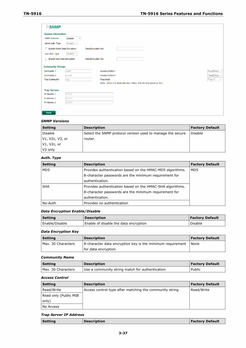
TN-5916 TN-5916 Series Features and Functions
3-37
SNMP Versions
Setting Description Factory Default Disable V1, V2c, V3, or V1, V2c, or V3 only
Select the SNMP protocol version used to manage the secure router.
Disable
Auth. Type
Setting Description Factory Default MD5 Provides authentication based on the HMAC-MD5 algorithms.
8-character passwords are the minimum requirement for authentication.
MD5
SHA Provides authentication based on the HMAC-SHA algorithms. 8-character passwords are the minimum requirement for authentication.
No-Auth Provides no authentication
Data Encryption Enable/Disable
Setting Description Factory Default Enable/Disable Enable of disable the data encryption Disable
Data Encryption Key
Setting Description Factory Default
Max. 30 Characters 8-character data encryption key is the minimum requirement for data encryption
None
Community Name
Setting Description Factory Default Max. 30 Characters Use a community string match for authentication Public
Access Control
Setting Description Factory Default Read/Write Access control type after matching the community string Read/Write
Read only (Public MIB only)
No Access
Trap Server IP Address
Setting Description Factory Default
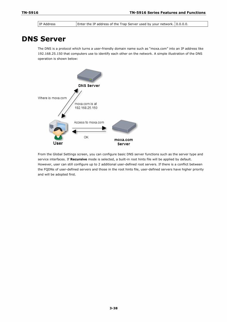
TN-5916 TN-5916 Series Features and Functions
3-38
IP Address Enter the IP address of the Trap Server used by your network. 0.0.0.0.
DNS Server The DNS is a protocol which turns a user-friendly domain name such as “moxa.com” into an IP address like 192.168.25.150 that computers use to identify each other on the network. A simple illustration of the DNS operation is shown below:
From the Global Settings screen, you can configure basic DNS server functions such as the server type and service interfaces. If Recursive mode is selected, a built-in root hints file will be applied by default. However, user can still configure up to 2 additional user-defined root servers. If there is a conflict between the FQDNs of user-defined servers and those in the root hints file, user-defined servers have higher priority and will be adopted first.
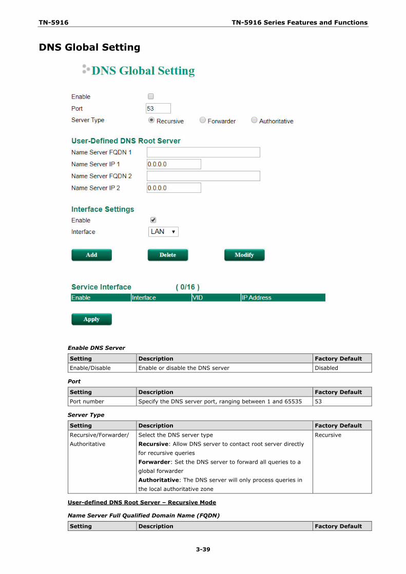
TN-5916 TN-5916 Series Features and Functions
3-39
DNS Global Setting
Enable DNS Server
Setting Description Factory Default Enable/Disable Enable or disable the DNS server Disabled
Port
Setting Description Factory Default Port number Specify the DNS server port, ranging between 1 and 65535 53
Server Type
Setting Description Factory Default
Recursive/Forwarder/ Authoritative
Select the DNS server type Recursive: Allow DNS server to contact root server directly for recursive queries Forwarder: Set the DNS server to forward all queries to a global forwarder Authoritative: The DNS server will only process queries in the local authoritative zone
Recursive
User-defined DNS Root Server – Recursive Mode
Name Server Full Qualified Domain Name (FQDN)
Setting Description Factory Default
TN-5916 TN-5916 Series Features and Functions
3-40
DNS Domain Name Define the DNS server FQDN None
Name Server IP
Setting Description Factory Default
Name Server IP Specify the IP address of the DNS server FQDN 0.0.0.0
Interface Settings
Enable Interface
Setting Description Factory Default Enable/Disable Enable or disable the DNS server interface Enabled
Interface
Setting Description Factory Default LAN Interface Select the DNS service interface LAN
Clickable Buttons
Add
Click the Add button to add a new interface.
Delete
Click on a list to select it, the background color of the interface will change to blue, then click the Delete button.
Modify
Click on an interface to select it, the background color of the interface will change to blue, then click Modify to change the information of the selected interface.
Apply
Click Apply after adding, deleting, or modifying an interface to apply the changes.

TN-5916 TN-5916 Series Features and Functions
3-41
User-defined DNS Root Server – Forwarder Mode
Name Server IP
Setting Description Factory Default Name Server IP Specify the IP address of the DNS server 0.0.0.0
Interface Settings
Enable Interface
Setting Description Factory Default Enable/Disable Enable or disable the DNS server interface Enabled
Interface
Setting Description Factory Default
LAN Interface Select the DNS service interface LAN
Clickable Buttons
Add
Click the Add button to add a new interface.
Delete
Click on a list to select it, the background color of the interface will change to blue, then click the Delete button.
Modify
Click on an interface to select it, the background color of the interface will change to blue, then click Modify to change the information of the selected interface.
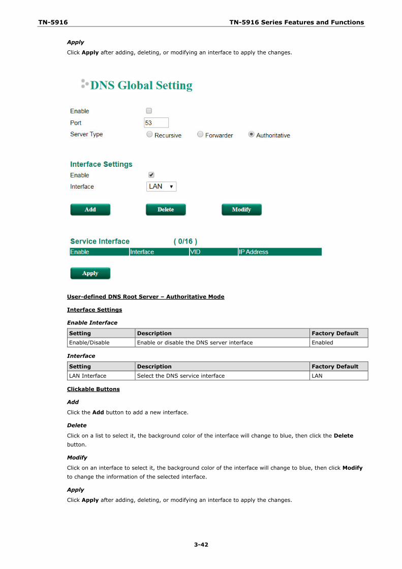
TN-5916 TN-5916 Series Features and Functions
3-42
Apply
Click Apply after adding, deleting, or modifying an interface to apply the changes.
User-defined DNS Root Server – Authoritative Mode
Interface Settings
Enable Interface
Setting Description Factory Default Enable/Disable Enable or disable the DNS server interface Enabled
Interface
Setting Description Factory Default
LAN Interface Select the DNS service interface LAN
Clickable Buttons
Add
Click the Add button to add a new interface.
Delete
Click on a list to select it, the background color of the interface will change to blue, then click the Delete button.
Modify
Click on an interface to select it, the background color of the interface will change to blue, then click Modify to change the information of the selected interface.
Apply
Click Apply after adding, deleting, or modifying an interface to apply the changes.
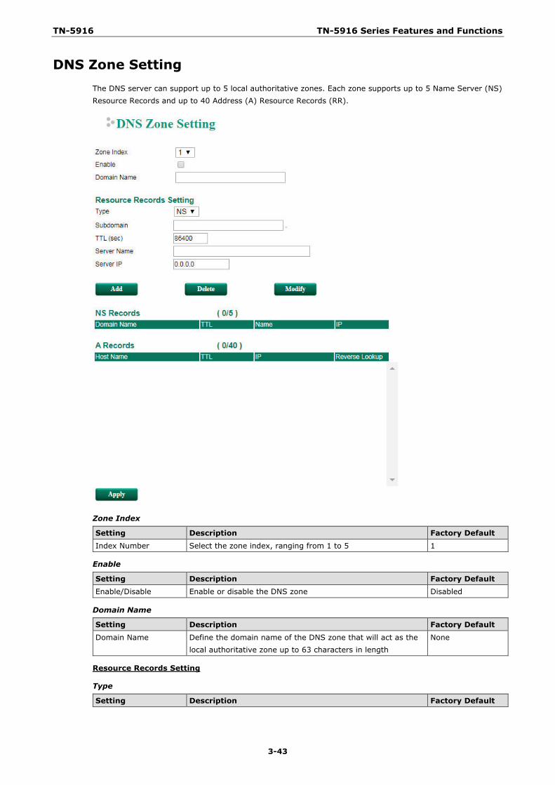
TN-5916 TN-5916 Series Features and Functions
3-43
DNS Zone Setting The DNS server can support up to 5 local authoritative zones. Each zone supports up to 5 Name Server (NS) Resource Records and up to 40 Address (A) Resource Records (RR).
Zone Index
Setting Description Factory Default Index Number Select the zone index, ranging from 1 to 5 1
Enable
Setting Description Factory Default Enable/Disable Enable or disable the DNS zone Disabled
Domain Name
Setting Description Factory Default
Domain Name Define the domain name of the DNS zone that will act as the local authoritative zone up to 63 characters in length
None
Resource Records Setting
Type
Setting Description Factory Default
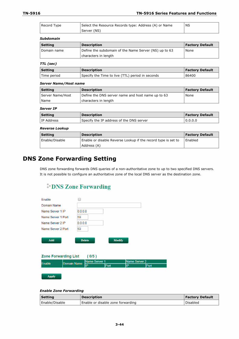
TN-5916 TN-5916 Series Features and Functions
3-44
Record Type Select the Resource Records type: Address (A) or Name Server (NS)
NS
Subdomain
Setting Description Factory Default
Domain name Define the subdomain of the Name Server (NS) up to 63 characters in length
None
TTL (sec)
Setting Description Factory Default Time period Specify the Time to live (TTL) period in seconds 86400
Server Name/Host name
Setting Description Factory Default Server Name/Host Name
Define the DNS server name and host name up to 63 characters in length
None
Server IP
Setting Description Factory Default
IP Address Specify the IP address of the DNS server 0.0.0.0
Reverse Lookup
Setting Description Factory Default Enable/Disable Enable or disable Reverse Lookup if the record type is set to
Address (A) Enabled
DNS Zone Forwarding Setting DNS zone forwarding forwards DNS queries of a non-authoritative zone to up to two specified DNS servers. It is not possible to configure an authoritative zone of the local DNS server as the destination zone.
Enable Zone Forwarding
Setting Description Factory Default Enable/Disable Enable or disable zone forwarding Disabled
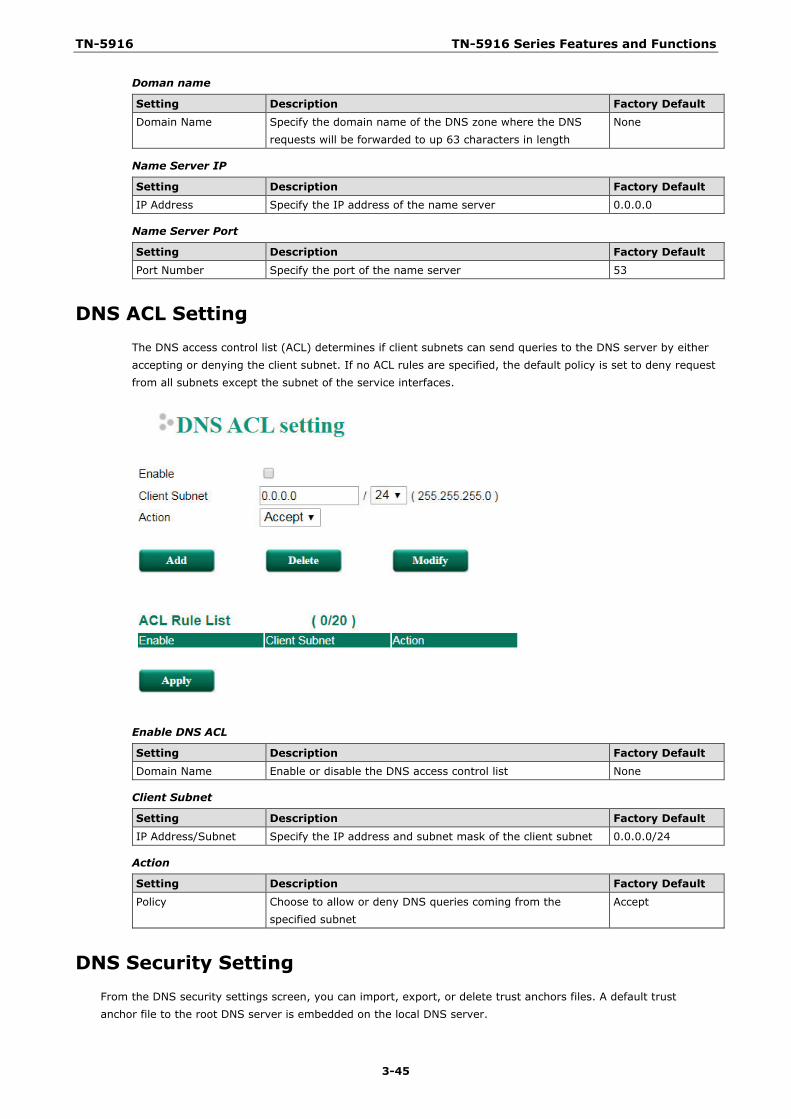
TN-5916 TN-5916 Series Features and Functions
3-45
Doman name
Setting Description Factory Default Domain Name Specify the domain name of the DNS zone where the DNS
requests will be forwarded to up 63 characters in length None
Name Server IP
Setting Description Factory Default IP Address Specify the IP address of the name server 0.0.0.0
Name Server Port
Setting Description Factory Default
Port Number Specify the port of the name server 53
DNS ACL Setting The DNS access control list (ACL) determines if client subnets can send queries to the DNS server by either accepting or denying the client subnet. If no ACL rules are specified, the default policy is set to deny request from all subnets except the subnet of the service interfaces.
Enable DNS ACL
Setting Description Factory Default Domain Name Enable or disable the DNS access control list None
Client Subnet
Setting Description Factory Default IP Address/Subnet Specify the IP address and subnet mask of the client subnet 0.0.0.0/24
Action
Setting Description Factory Default
Policy Choose to allow or deny DNS queries coming from the specified subnet
Accept
DNS Security Setting From the DNS security settings screen, you can import, export, or delete trust anchors files. A default trust anchor file to the root DNS server is embedded on the local DNS server.
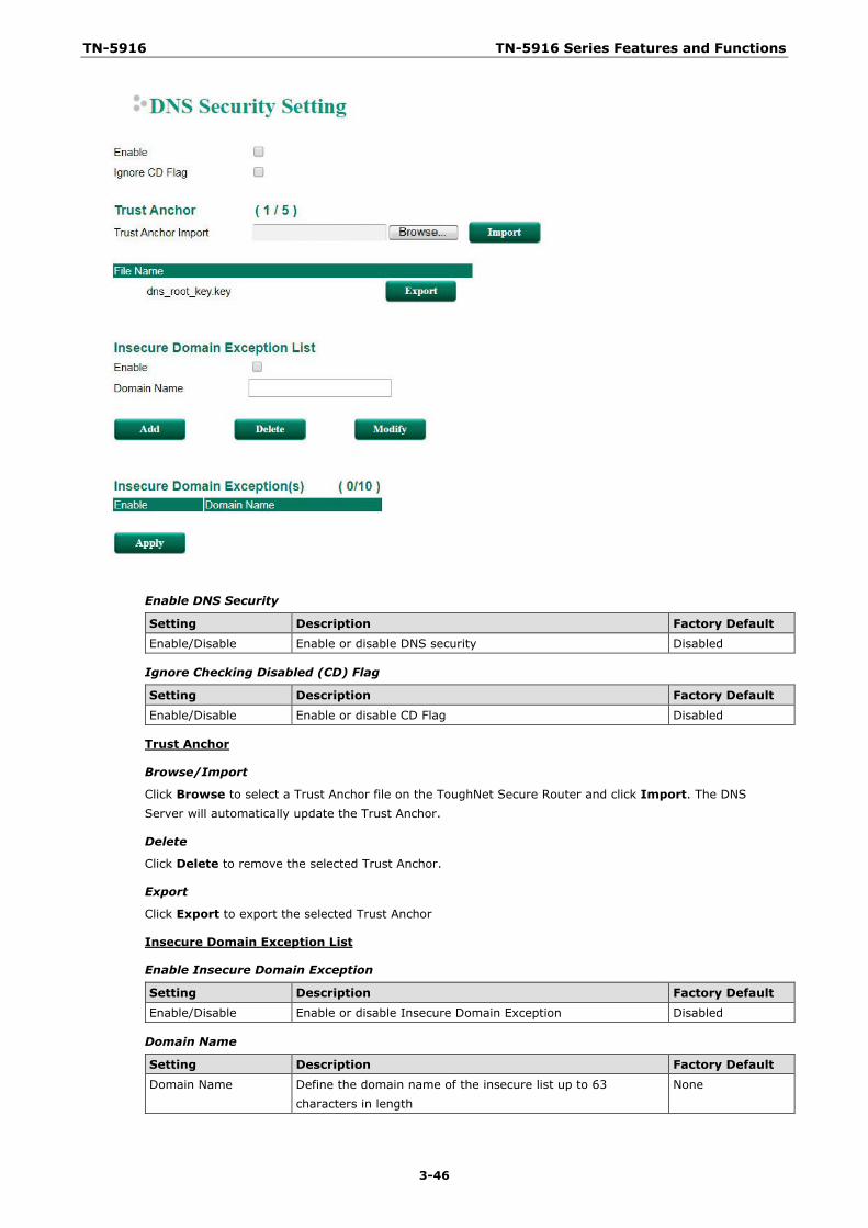
TN-5916 TN-5916 Series Features and Functions
3-46
Enable DNS Security
Setting Description Factory Default Enable/Disable Enable or disable DNS security Disabled
Ignore Checking Disabled (CD) Flag
Setting Description Factory Default Enable/Disable Enable or disable CD Flag Disabled
Trust Anchor
Browse/Import
Click Browse to select a Trust Anchor file on the ToughNet Secure Router and click Import. The DNS Server will automatically update the Trust Anchor.
Delete
Click Delete to remove the selected Trust Anchor.
Export
Click Export to export the selected Trust Anchor
Insecure Domain Exception List
Enable Insecure Domain Exception
Setting Description Factory Default
Enable/Disable Enable or disable Insecure Domain Exception Disabled
Domain Name
Setting Description Factory Default Domain Name Define the domain name of the insecure list up to 63
characters in length None
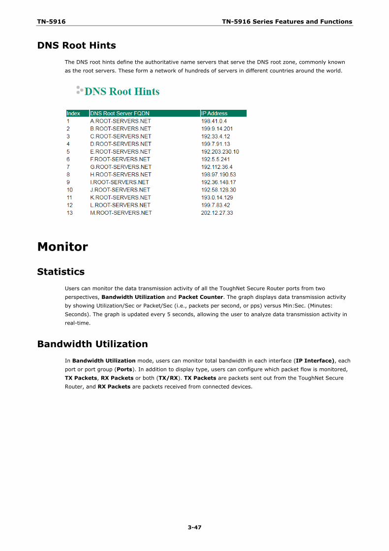
TN-5916 TN-5916 Series Features and Functions
3-47
DNS Root Hints The DNS root hints define the authoritative name servers that serve the DNS root zone, commonly known as the root servers. These form a network of hundreds of servers in different countries around the world.
Monitor
Statistics Users can monitor the data transmission activity of all the ToughNet Secure Router ports from two perspectives, Bandwidth Utilization and Packet Counter. The graph displays data transmission activity by showing Utilization/Sec or Packet/Sec (i.e., packets per second, or pps) versus Min:Sec. (Minutes: Seconds). The graph is updated every 5 seconds, allowing the user to analyze data transmission activity in real-time.
Bandwidth Utilization In Bandwidth Utilization mode, users can monitor total bandwidth in each interface (IP Interface), each port or port group (Ports). In addition to display type, users can configure which packet flow is monitored, TX Packets, RX Packets or both (TX/RX). TX Packets are packets sent out from the ToughNet Secure Router, and RX Packets are packets received from connected devices.
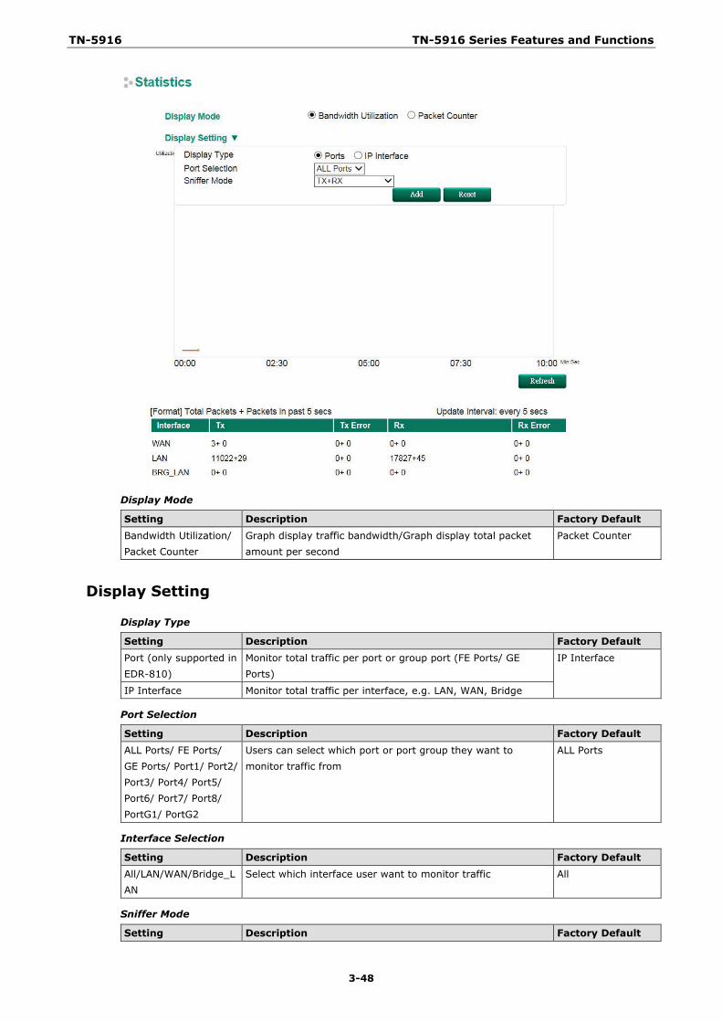
TN-5916 TN-5916 Series Features and Functions
3-48
Display Mode
Setting Description Factory Default Bandwidth Utilization/ Packet Counter
Graph display traffic bandwidth/Graph display total packet amount per second
Packet Counter
Display Setting
Display Type
Setting Description Factory Default Port (only supported in EDR-810)
Monitor total traffic per port or group port (FE Ports/ GE Ports)
IP Interface
IP Interface Monitor total traffic per interface, e.g. LAN, WAN, Bridge
Port Selection
Setting Description Factory Default ALL Ports/ FE Ports/ GE Ports/ Port1/ Port2/ Port3/ Port4/ Port5/ Port6/ Port7/ Port8/ PortG1/ PortG2
Users can select which port or port group they want to monitor traffic from
ALL Ports
Interface Selection
Setting Description Factory Default All/LAN/WAN/Bridge_LAN
Select which interface user want to monitor traffic All
Sniffer Mode
Setting Description Factory Default
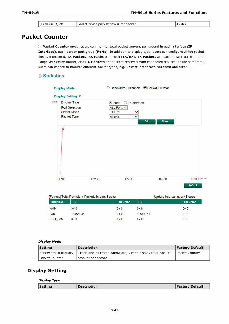
TN-5916 TN-5916 Series Features and Functions
3-49
(TX/RX)/TX/RX Select which packet flow is monitored TX/RX
Packet Counter In Packet Counter mode, users can monitor total packet amount per second in each interface (IP Interface), each port or port group (Ports). In addition to display type, users can configure which packet flow is monitored, TX Packets, RX Packets or both (TX/RX). TX Packets are packets sent out from the ToughNet Secure Router, and RX Packets are packets received from connected devices. At the same time, users can choose to monitor different packet types, e.g. unicast, broadcast, multicast and error.
Display Mode
Setting Description Factory Default
Bandwidth Utilization/ Packet Counter
Graph display traffic bandwidth/ Graph display total packet amount per second
Packet Counter
Display Setting
Display Type
Setting Description Factory Default
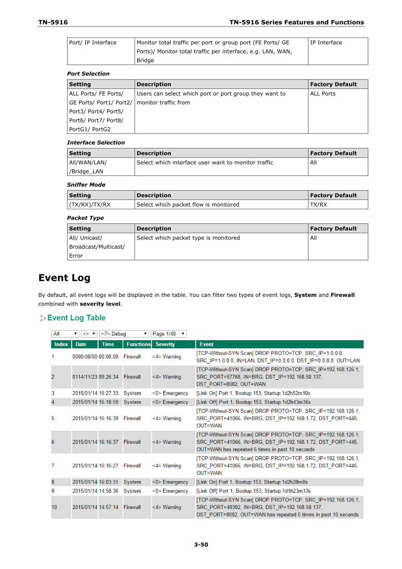
TN-5916 TN-5916 Series Features and Functions
3-50
Port/ IP Interface Monitor total traffic per port or group port (FE Ports/ GE Ports)/ Monitor total traffic per interface, e.g. LAN, WAN, Bridge
IP Interface
Port Selection
Setting Description Factory Default
ALL Ports/ FE Ports/ GE Ports/ Port1/ Port2/ Port3/ Port4/ Port5/ Port6/ Port7/ Port8/ PortG1/ PortG2
Users can select which port or port group they want to monitor traffic from
ALL Ports
Interface Selection
Setting Description Factory Default All/WAN/LAN/ /Bridge_LAN
Select which interface user want to monitor traffic All
Sniffer Mode
Setting Description Factory Default (TX/RX)/TX/RX Select which packet flow is monitored TX/RX
Packet Type
Setting Description Factory Default
All/ Unicast/ Broadcast/Multicast/ Error
Select which packet type is monitored All
Event Log By default, all event logs will be displayed in the table. You can filter two types of event logs, System and Firewall combined with severity level.
4 4. Routing
The following topics are covered in this chapter:
Unicast Routing
Static Routing
RIP (Routing Information Protocol)
Open Shortest Path First (OSPF)
Routing Table
Multicast Routing
Global Setting
Static Multicast
Distance Vector Multicast Routing Protocol (DVMRP)
Protocol Independent Multicast Sparse Mode (PIM-SM)
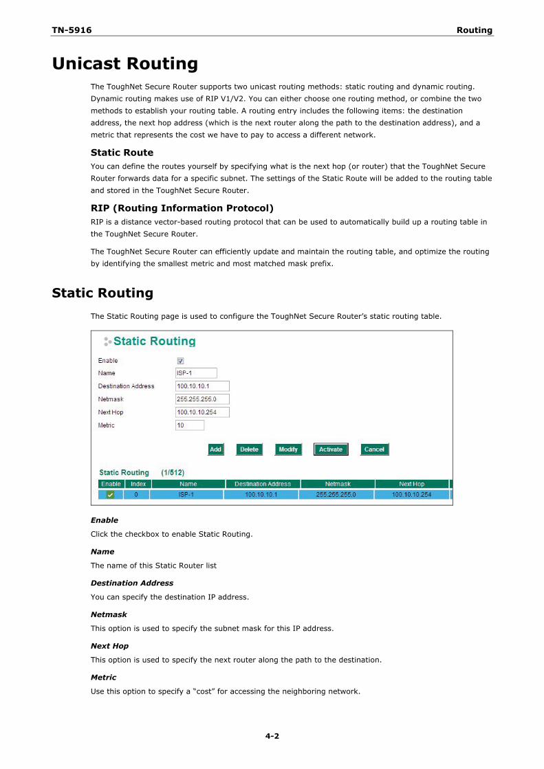
TN-5916 Routing
4-2
Unicast Routing The ToughNet Secure Router supports two unicast routing methods: static routing and dynamic routing. Dynamic routing makes use of RIP V1/V2. You can either choose one routing method, or combine the two methods to establish your routing table. A routing entry includes the following items: the destination address, the next hop address (which is the next router along the path to the destination address), and a metric that represents the cost we have to pay to access a different network.
Static Route You can define the routes yourself by specifying what is the next hop (or router) that the ToughNet Secure Router forwards data for a specific subnet. The settings of the Static Route will be added to the routing table and stored in the ToughNet Secure Router.
RIP (Routing Information Protocol) RIP is a distance vector-based routing protocol that can be used to automatically build up a routing table in the ToughNet Secure Router.
The ToughNet Secure Router can efficiently update and maintain the routing table, and optimize the routing by identifying the smallest metric and most matched mask prefix.
Static Routing The Static Routing page is used to configure the ToughNet Secure Router’s static routing table.
Enable
Click the checkbox to enable Static Routing.
Name
The name of this Static Router list
Destination Address
You can specify the destination IP address.
Netmask
This option is used to specify the subnet mask for this IP address.
Next Hop
This option is used to specify the next router along the path to the destination.
Metric
Use this option to specify a “cost” for accessing the neighboring network.
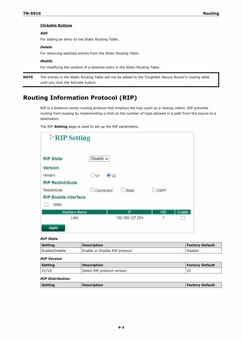
TN-5916 Routing
4-3
Clickable Buttons
Add
For adding an entry to the Static Routing Table.
Delete
For removing selected entries from the Static Routing Table.
Modify
For modifying the content of a selected entry in the Static Routing Table.
NOTE The entries in the Static Routing Table will not be added to the ToughNet Secure Router’s routing table until you click the Activate button.
Routing Information Protocol (RIP) RIP is a distance-vector routing protocol that employs the hop count as a routing metric. RIP prevents routing from looping by implementing a limit on the number of hops allowed in a path from the source to a destination.
The RIP Setting page is used to set up the RIP parameters.
RIP State
Setting Description Factory Default Enable/Disable Enable or Disable RIP protocol Disable
RIP Version
Setting Description Factory Default V1/V2 Select RIP protocol version. V2
RIP Distribution
Setting Description Factory Default
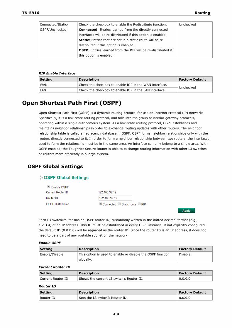
TN-5916 Routing
4-4
Connected/Static/ OSPF/Unchecked
Check the checkbox to enable the Redistribute function. Connected: Entries learned from the directly connected interfaces will be re-distributed if this option is enabled. Static: Entries that are set in a static route will be re-distributed if this option is enabled. OSFP: Entries learned from the RIP will be re-distributed if this option is enabled.
Unchecked
RIP Enable Interface
Setting Description Factory Default
WAN Check the checkbox to enable RIP in the WAN interface. Unchecked
LAN Check the checkbox to enable RIP in the LAN interface.
Open Shortest Path First (OSPF) Open Shortest Path First (OSPF) is a dynamic routing protocol for use on Internet Protocol (IP) networks. Specifically, it is a link-state routing protocol, and falls into the group of interior gateway protocols, operating within a single autonomous system. As a link-state routing protocol, OSPF establishes and maintains neighbor relationships in order to exchange routing updates with other routers. The neighbor relationship table is called an adjacency database in OSPF. OSPF forms neighbor relationships only with the routers directly connected to it. In order to form a neighbor relationship between two routers, the interfaces used to form the relationship must be in the same area. An interface can only belong to a single area. With OSPF enabled, the ToughNet Secure Router is able to exchange routing information with other L3 switches or routers more efficiently in a large system.
OSPF Global Settings
Each L3 switch/router has an OSPF router ID, customarily written in the dotted decimal format (e.g., 1.2.3.4) of an IP address. This ID must be established in every OSPF instance. If not explicitly configured, the default ID (0.0.0.0) will be regarded as the router ID. Since the router ID is an IP address, it does not need to be a part of any routable subnet on the network.
Enable OSPF
Setting Description Factory Default Enable/Disable This option is used to enable or disable the OSPF function
globally. Disable
Current Router ID
Setting Description Factory Default
Current Router ID Shows the current L3 switch’s Router ID. 0.0.0.0
Router ID
Setting Description Factory Default Router ID Sets the L3 switch’s Router ID. 0.0.0.0
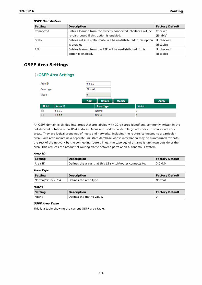
TN-5916 Routing
4-5
OSPF Distribution
Setting Description Factory Default Connected Entries learned from the directly connected interfaces will be
re-distributed if this option is enabled. Checked (Enable)
Static Entries set in a static route will be re-distributed if this option is enabled.
Unchecked (disable)
RIP Entries learned from the RIP will be re-distributed if this option is enabled.
Unchecked (disable)
OSPF Area Settings
An OSPF domain is divided into areas that are labeled with 32-bit area identifiers, commonly written in the dot-decimal notation of an IPv4 address. Areas are used to divide a large network into smaller network areas. They are logical groupings of hosts and networks, including the routers connected to a particular area. Each area maintains a separate link state database whose information may be summarized towards the rest of the network by the connecting router. Thus, the topology of an area is unknown outside of the area. This reduces the amount of routing traffic between parts of an autonomous system.
Area ID
Setting Description Factory Default Area ID Defines the areas that this L3 switch/router connects to. 0.0.0.0
Area Type
Setting Description Factory Default Normal/Stub/NSSA Defines the area type. Normal
Metric
Setting Description Factory Default
Metric Defines the metric value. 0
OSPF Area Table
This is a table showing the current OSPF area table.
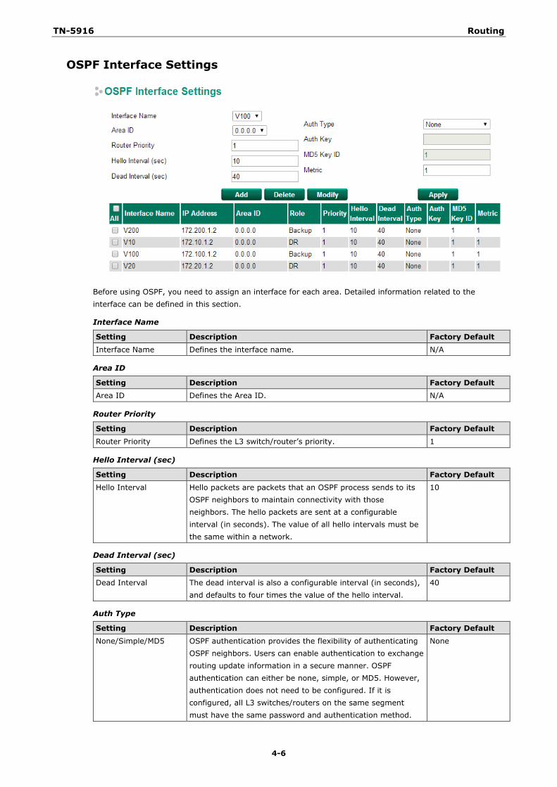
TN-5916 Routing
4-6
OSPF Interface Settings
Before using OSPF, you need to assign an interface for each area. Detailed information related to the interface can be defined in this section.
Interface Name
Setting Description Factory Default Interface Name Defines the interface name. N/A
Area ID
Setting Description Factory Default Area ID Defines the Area ID. N/A
Router Priority
Setting Description Factory Default
Router Priority Defines the L3 switch/router’s priority. 1
Hello Interval (sec)
Setting Description Factory Default Hello Interval Hello packets are packets that an OSPF process sends to its
OSPF neighbors to maintain connectivity with those neighbors. The hello packets are sent at a configurable interval (in seconds). The value of all hello intervals must be the same within a network.
10
Dead Interval (sec)
Setting Description Factory Default Dead Interval The dead interval is also a configurable interval (in seconds),
and defaults to four times the value of the hello interval. 40
Auth Type
Setting Description Factory Default
None/Simple/MD5 OSPF authentication provides the flexibility of authenticating OSPF neighbors. Users can enable authentication to exchange routing update information in a secure manner. OSPF authentication can either be none, simple, or MD5. However, authentication does not need to be configured. If it is configured, all L3 switches/routers on the same segment must have the same password and authentication method.
None
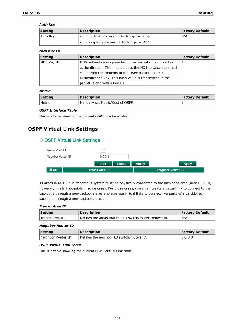
TN-5916 Routing
4-7
Auth Key
Setting Description Factory Default Auth Key • pure-text password if Auth Type = Simple
• encrypted password if Auth Type = MD5
N/A
MD5 Key ID
Setting Description Factory Default MD5 Key ID MD5 authentication provides higher security than plain text
authentication. This method uses the MD5 to calculate a hash value from the contents of the OSPF packet and the authentication key. This hash value is transmitted in the packet, along with a key ID.
1
Metric
Setting Description Factory Default Metric Manually set Metric/Cost of OSPF. 1
OSPF Interface Table
This is a table showing the current OSPF interface table.
OSPF Virtual Link Settings
All areas in an OSPF autonomous system must be physically connected to the backbone area (Area 0.0.0.0). However, this is impossible in some cases. For those cases, users can create a virtual link to connect to the backbone through a non-backbone area and also use virtual links to connect two parts of a partitioned backbone through a non-backbone area.
Transit Area ID
Setting Description Factory Default Transit Area ID Defines the areas that this L3 switch/router connect to. N/A
Neighbor Router ID
Setting Description Factory Default Neighbor Router ID Defines the neighbor L3 switch/route’s ID. 0.0.0.0
OSPF Virtual Link Table
This is a table showing the current OSPF Virtual Link table.
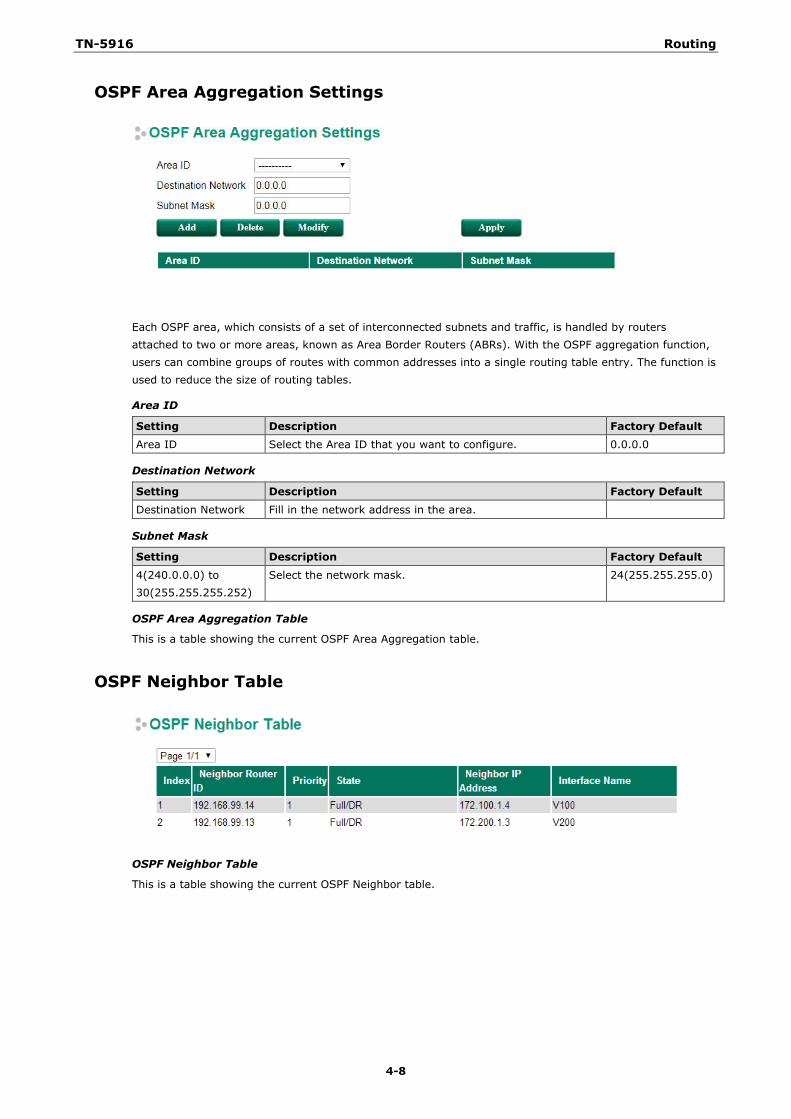
TN-5916 Routing
4-8
OSPF Area Aggregation Settings
Each OSPF area, which consists of a set of interconnected subnets and traffic, is handled by routers attached to two or more areas, known as Area Border Routers (ABRs). With the OSPF aggregation function, users can combine groups of routes with common addresses into a single routing table entry. The function is used to reduce the size of routing tables.
Area ID
Setting Description Factory Default Area ID Select the Area ID that you want to configure. 0.0.0.0
Destination Network
Setting Description Factory Default Destination Network Fill in the network address in the area.
Subnet Mask
Setting Description Factory Default
4(240.0.0.0) to 30(255.255.255.252)
Select the network mask. 24(255.255.255.0)
OSPF Area Aggregation Table
This is a table showing the current OSPF Area Aggregation table.
OSPF Neighbor Table
OSPF Neighbor Table
This is a table showing the current OSPF Neighbor table.
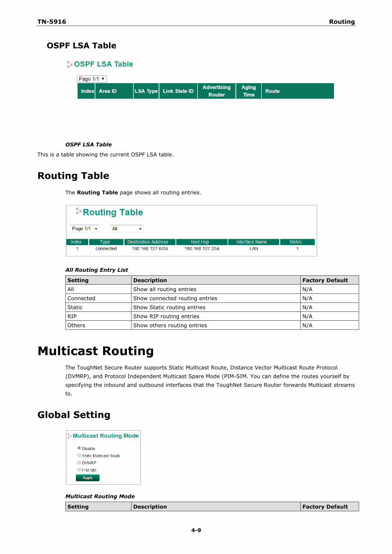
TN-5916 Routing
4-9
OSPF LSA Table
OSPF LSA Table
This is a table showing the current OSPF LSA table.
Routing Table The Routing Table page shows all routing entries.
All Routing Entry List
Setting Description Factory Default All Show all routing entries N/A
Connected Show connected routing entries N/A
Static Show Static routing entries N/A
RIP Show RIP routing entries N/A
Others Show others routing entries N/A
Multicast Routing The ToughNet Secure Router supports Static Multicast Route, Distance Vector Multicast Route Protocol (DVMRP), and Protocol Independent Multicast Spare Mode (PIM-SIM. You can define the routes yourself by specifying the inbound and outbound interfaces that the ToughNet Secure Router forwards Multicast streams to.
Global Setting
Multicast Routing Mode
Setting Description Factory Default
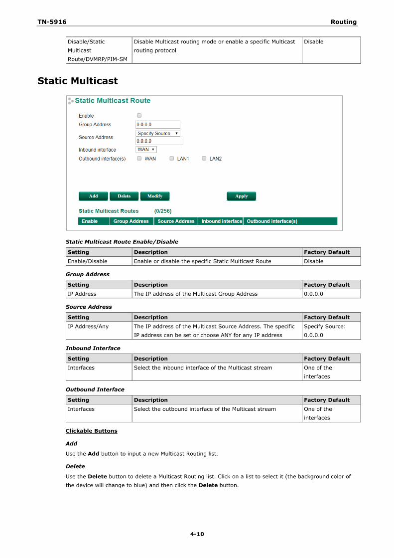
TN-5916 Routing
4-10
Disable/Static Multicast Route/DVMRP/PIM-SM
Disable Multicast routing mode or enable a specific Multicast routing protocol
Disable
Static Multicast
Static Multicast Route Enable/Disable
Setting Description Factory Default
Enable/Disable Enable or disable the specific Static Multicast Route Disable
Group Address
Setting Description Factory Default IP Address The IP address of the Multicast Group Address 0.0.0.0
Source Address
Setting Description Factory Default IP Address/Any The IP address of the Multicast Source Address. The specific
IP address can be set or choose ANY for any IP address Specify Source: 0.0.0.0
Inbound Interface
Setting Description Factory Default
Interfaces Select the inbound interface of the Multicast stream One of the interfaces
Outbound Interface
Setting Description Factory Default Interfaces Select the outbound interface of the Multicast stream One of the
interfaces
Clickable Buttons
Add
Use the Add button to input a new Multicast Routing list.
Delete
Use the Delete button to delete a Multicast Routing list. Click on a list to select it (the background color of the device will change to blue) and then click the Delete button.
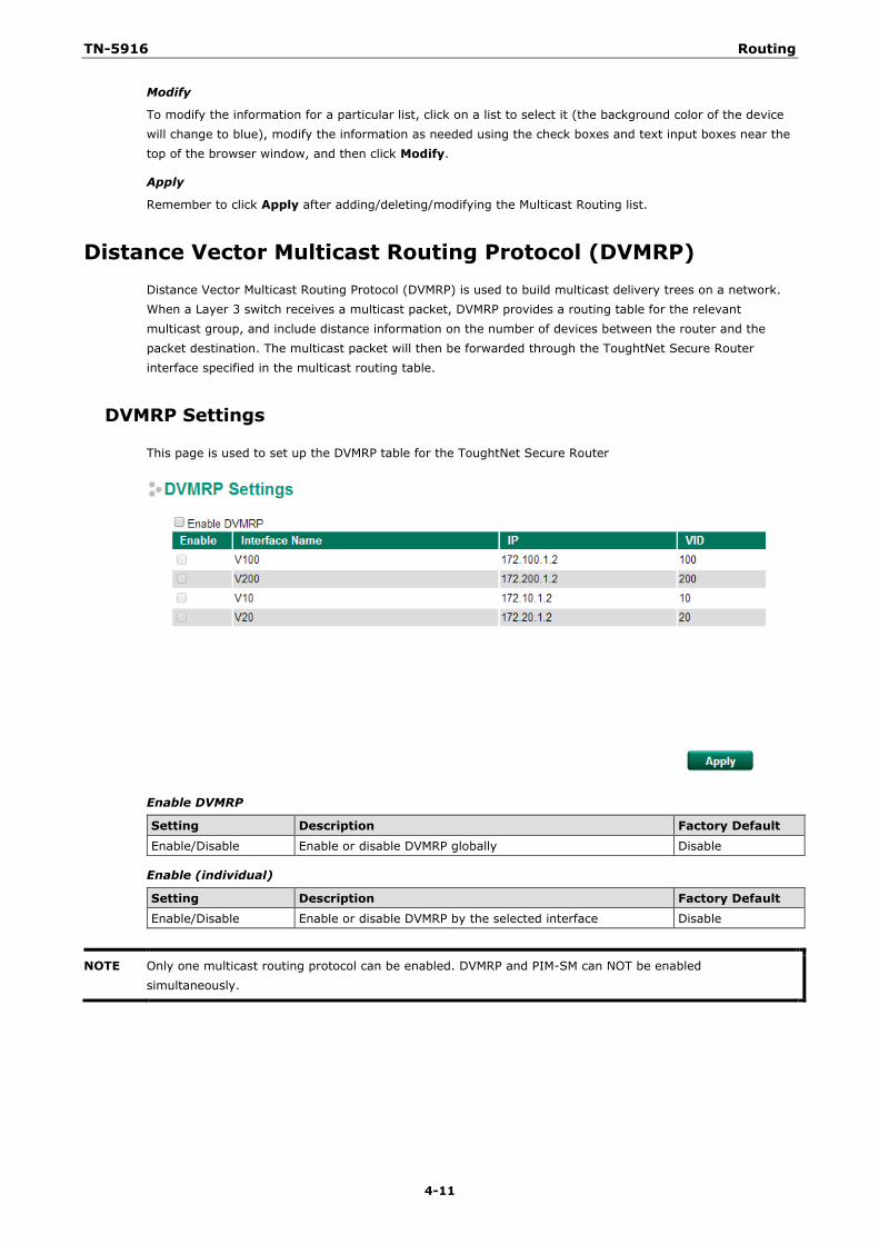
TN-5916 Routing
4-11
Modify
To modify the information for a particular list, click on a list to select it (the background color of the device will change to blue), modify the information as needed using the check boxes and text input boxes near the top of the browser window, and then click Modify.
Apply
Remember to click Apply after adding/deleting/modifying the Multicast Routing list.
Distance Vector Multicast Routing Protocol (DVMRP) Distance Vector Multicast Routing Protocol (DVMRP) is used to build multicast delivery trees on a network. When a Layer 3 switch receives a multicast packet, DVMRP provides a routing table for the relevant multicast group, and include distance information on the number of devices between the router and the packet destination. The multicast packet will then be forwarded through the ToughtNet Secure Router interface specified in the multicast routing table.
DVMRP Settings
This page is used to set up the DVMRP table for the ToughtNet Secure Router
Enable DVMRP
Setting Description Factory Default
Enable/Disable Enable or disable DVMRP globally Disable
Enable (individual)
Setting Description Factory Default Enable/Disable Enable or disable DVMRP by the selected interface Disable
NOTE Only one multicast routing protocol can be enabled. DVMRP and PIM-SM can NOT be enabled simultaneously.
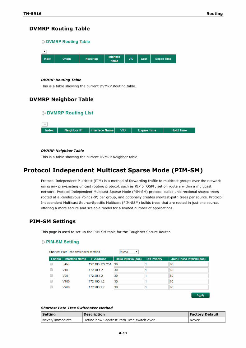
TN-5916 Routing
4-12
DVMRP Routing Table
DVMRP Routing Table
This is a table showing the current DVMRP Routing table.
DVMRP Neighbor Table
DVMRP Neighbor Table
This is a table showing the current DVMRP Neighbor table.
Protocol Independent Multicast Sparse Mode (PIM-SM) Protocol Independent Multicast (PIM) is a method of forwarding traffic to multicast groups over the network using any pre-existing unicast routing protocol, such as RIP or OSPF, set on routers within a multicast network. Protocol Independent Multicast Sparse Mode (PIM-SM) protocol builds unidirectional shared trees rooted at a Rendezvous Point (RP) per group, and optionally creates shortest-path trees per source. Protocol Independent Multicast Source-Specific Multicast (PIM-SSM) builds trees that are rooted in just one source, offering a more secure and scalable model for a limited number of applications.
PIM-SM Settings
This page is used to set up the PIM-SM table for the ToughNet Secure Router.
Shortest Path Tree Switchover Method
Setting Description Factory Default
Never/Immediate Define how Shortest Path Tree switch over Never
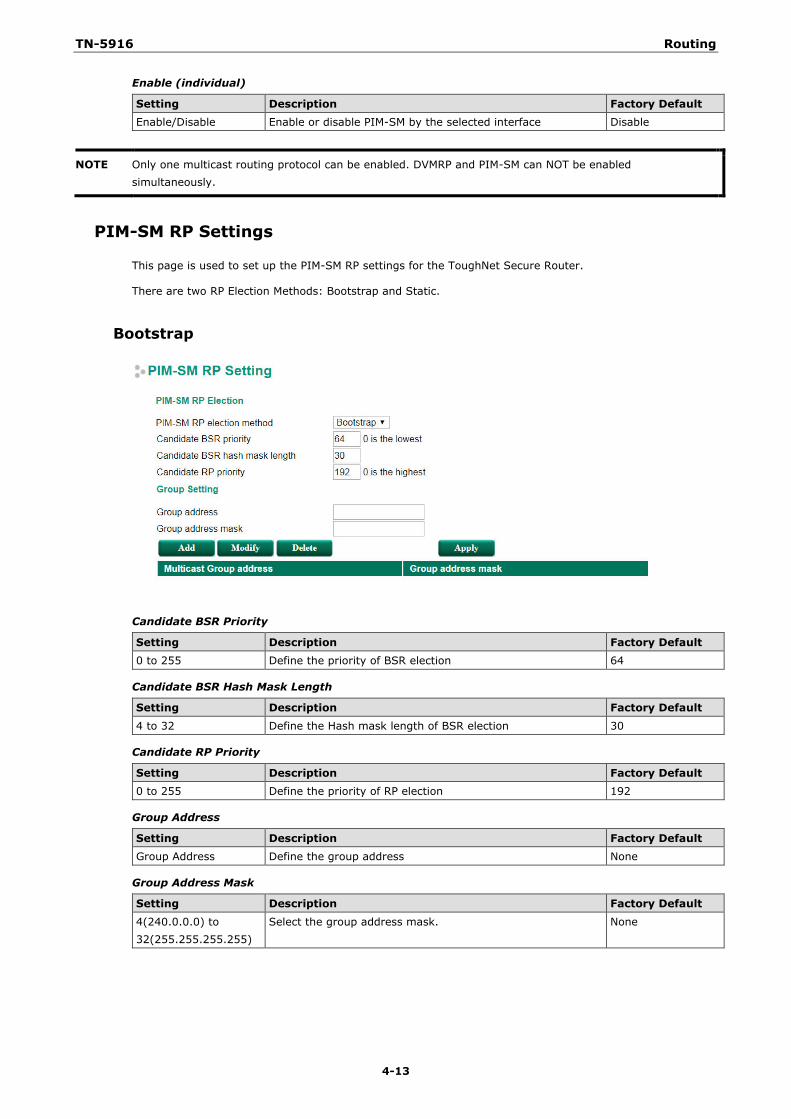
TN-5916 Routing
4-13
Enable (individual)
Setting Description Factory Default Enable/Disable Enable or disable PIM-SM by the selected interface Disable
NOTE Only one multicast routing protocol can be enabled. DVMRP and PIM-SM can NOT be enabled simultaneously.
PIM-SM RP Settings
This page is used to set up the PIM-SM RP settings for the ToughNet Secure Router.
There are two RP Election Methods: Bootstrap and Static.
Bootstrap
Candidate BSR Priority
Setting Description Factory Default 0 to 255 Define the priority of BSR election 64
Candidate BSR Hash Mask Length
Setting Description Factory Default
4 to 32 Define the Hash mask length of BSR election 30
Candidate RP Priority
Setting Description Factory Default 0 to 255 Define the priority of RP election 192
Group Address
Setting Description Factory Default Group Address Define the group address None
Group Address Mask
Setting Description Factory Default
4(240.0.0.0) to 32(255.255.255.255)
Select the group address mask. None
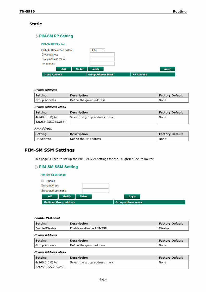
TN-5916 Routing
4-14
Static
Group Address
Setting Description Factory Default Group Address Define the group address None
Group Address Mask
Setting Description Factory Default 4(240.0.0.0) to 32(255.255.255.255)
Select the group address mask. None
RP Address
Setting Description Factory Default
RP Address Define the RP address None
PIM-SM SSM Settings
This page is used to set up the PIM-SM SSM settings for the ToughNet Secure Router.
Enable PIM-SSM
Setting Description Factory Default Enable/Disable Enable or disable PIM-SSM Disable
Group Address
Setting Description Factory Default Group Address Define the group address None
Group Address Mask
Setting Description Factory Default
4(240.0.0.0) to 32(255.255.255.255)
Select the group address mask. None
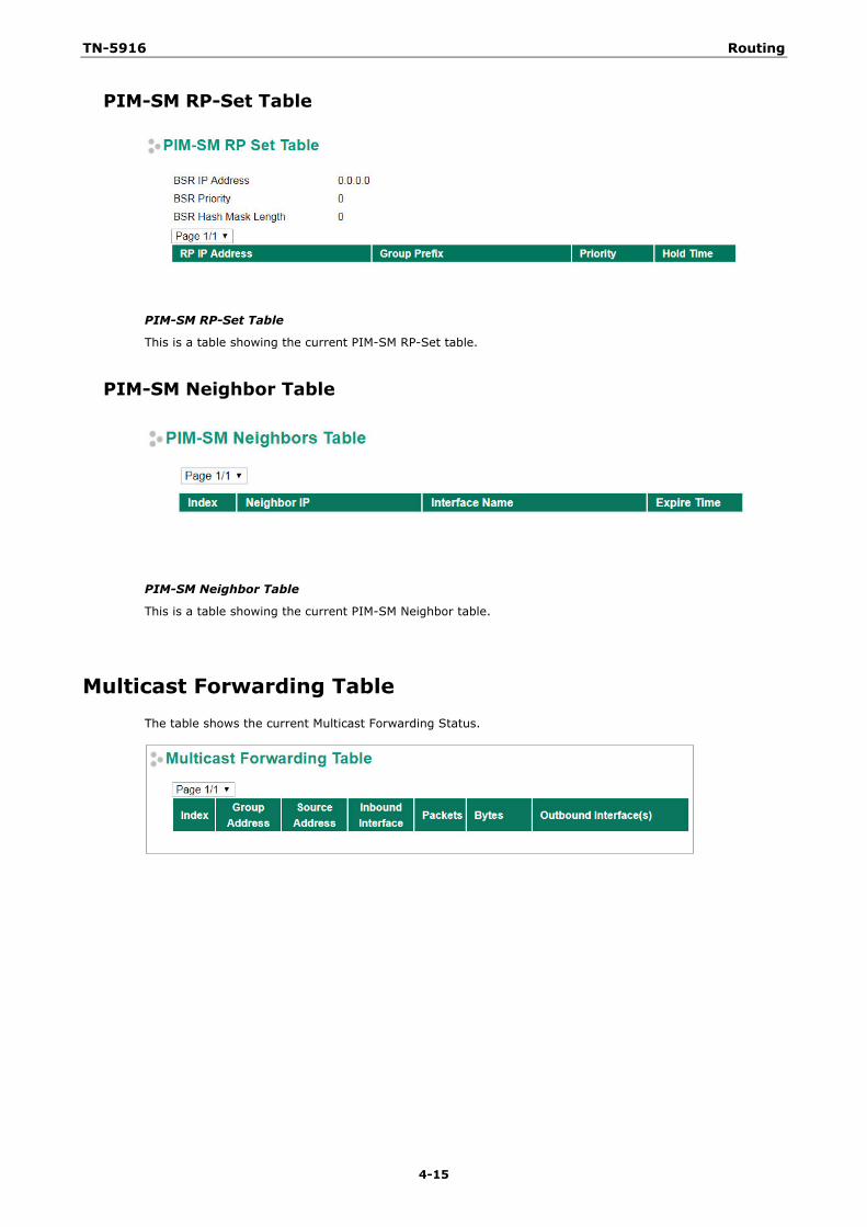
TN-5916 Routing
4-15
PIM-SM RP-Set Table
PIM-SM RP-Set Table
This is a table showing the current PIM-SM RP-Set table.
PIM-SM Neighbor Table
PIM-SM Neighbor Table
This is a table showing the current PIM-SM Neighbor table.
Multicast Forwarding Table The table shows the current Multicast Forwarding Status.
5 5. Network Redundancy
The following topics are covered in this chapter:
Layer 2 Redundant Protocols
Configuring RSTP
Configuring Turbo Ring V2
Layer 3 Redundant Protocols
VRRP Settings
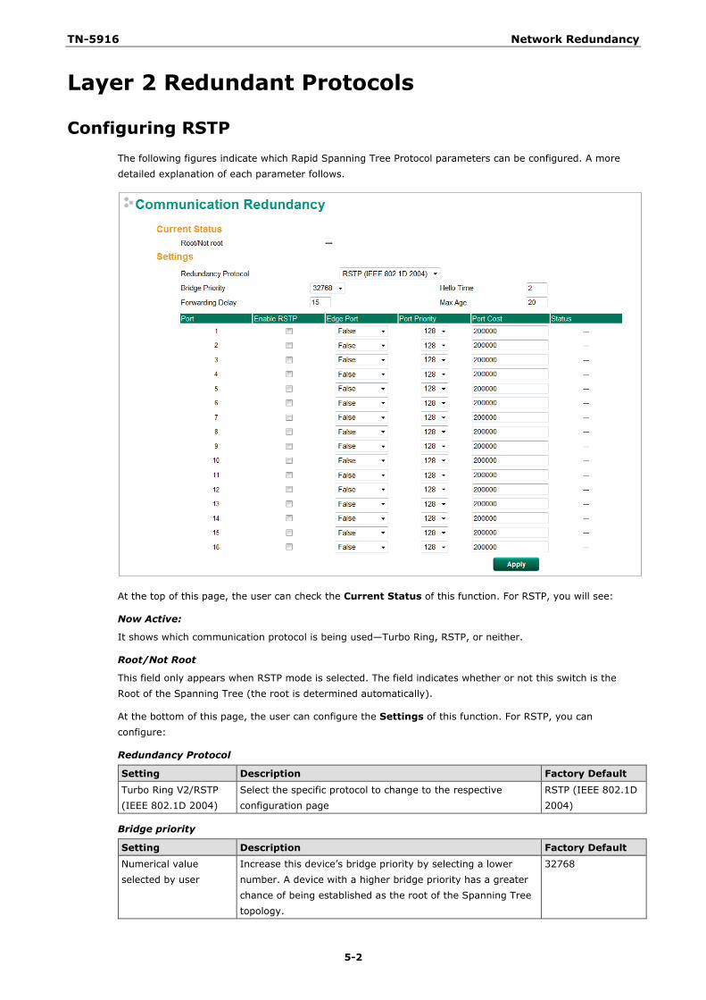
TN-5916 Network Redundancy
5-2
Layer 2 Redundant Protocols
Configuring RSTP The following figures indicate which Rapid Spanning Tree Protocol parameters can be configured. A more detailed explanation of each parameter follows.
At the top of this page, the user can check the Current Status of this function. For RSTP, you will see:
Now Active:
It shows which communication protocol is being used—Turbo Ring, RSTP, or neither.
Root/Not Root
This field only appears when RSTP mode is selected. The field indicates whether or not this switch is the Root of the Spanning Tree (the root is determined automatically).
At the bottom of this page, the user can configure the Settings of this function. For RSTP, you can configure:
Redundancy Protocol
Setting Description Factory Default
Turbo Ring V2/RSTP (IEEE 802.1D 2004)
Select the specific protocol to change to the respective configuration page
RSTP (IEEE 802.1D 2004)
Bridge priority
Setting Description Factory Default Numerical value selected by user
Increase this device’s bridge priority by selecting a lower number. A device with a higher bridge priority has a greater chance of being established as the root of the Spanning Tree topology.
32768
TN-5916 Network Redundancy
5-3
Forwarding Delay (sec.)
Setting Description Factory Default Numerical value input by user
The amount of time this device waits before checking to see if it should change to a different state.
15
Hello time (sec.)
Setting Description Factory Default Numerical value input by user
The root of the Spanning Tree topology periodically sends out a “hello” message to other devices on the network to check if the topology is healthy. The “hello time” is the amount of time the root waits between sending hello messages.
2
Max. Age (sec.)
Setting Description Factory Default
Numerical value input by user
If this device is not the root, and it has not received a hello message from the root in an amount of time equal to “Max. Age,” then this device will reconfigure itself as a root. Once two or more devices on the network are recognized as a root, the devices will renegotiate to set up a new Spanning Tree topology.
20
Enable RSTP per Port
Setting Description Factory Default Enable/Disable Select to enable the port as a node on the Rapid Spanning
Tree Protocol. Disabled
NOTE We suggest not enabling the Rapid Spanning Tree Protocol once the port is connected to a device (PLC, RTU, etc.) as opposed to network equipment. The reason is that it will cause unnecessary negotiation.
Setting Description Factory Default Force Edge The port is fixed as an edge port and will always be in the
forwarding state False
False The port is set as the normal RSTP port
Port Priority
Setting Description Factory Default
Numerical value selected by user
Increase this port’s priority as a node on the Spanning Tree topology by entering a lower number.
128
Port Cost
Setting Description Factory Default Numerical value input by user
Input a higher cost to indicate that this port is less suitable as a node for the Spanning Tree topology.
200000
Port Status
Indicates the current Spanning Tree status of this port. Forwarding for normal transmission, or Blocking to block transmission.
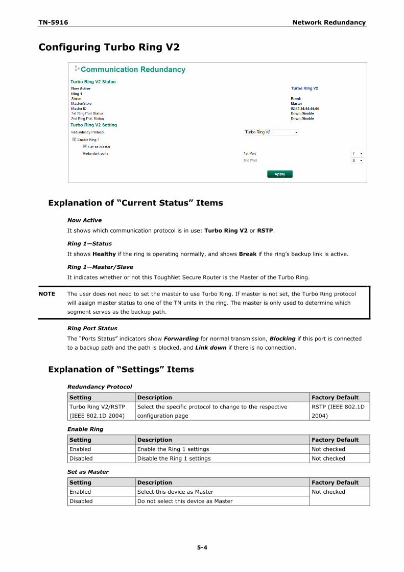
TN-5916 Network Redundancy
5-4
Configuring Turbo Ring V2
Explanation of “Current Status” Items
Now Active
It shows which communication protocol is in use: Turbo Ring V2 or RSTP.
Ring 1—Status
It shows Healthy if the ring is operating normally, and shows Break if the ring’s backup link is active.
Ring 1—Master/Slave
It indicates whether or not this ToughNet Secure Router is the Master of the Turbo Ring.
NOTE The user does not need to set the master to use Turbo Ring. If master is not set, the Turbo Ring protocol will assign master status to one of the TN units in the ring. The master is only used to determine which segment serves as the backup path.
Ring Port Status
The “Ports Status” indicators show Forwarding for normal transmission, Blocking if this port is connected to a backup path and the path is blocked, and Link down if there is no connection.
Explanation of “Settings” Items
Redundancy Protocol
Setting Description Factory Default Turbo Ring V2/RSTP (IEEE 802.1D 2004)
Select the specific protocol to change to the respective configuration page
RSTP (IEEE 802.1D 2004)
Enable Ring
Setting Description Factory Default
Enabled Enable the Ring 1 settings Not checked
Disabled Disable the Ring 1 settings Not checked
Set as Master
Setting Description Factory Default Enabled Select this device as Master Not checked
Disabled Do not select this device as Master
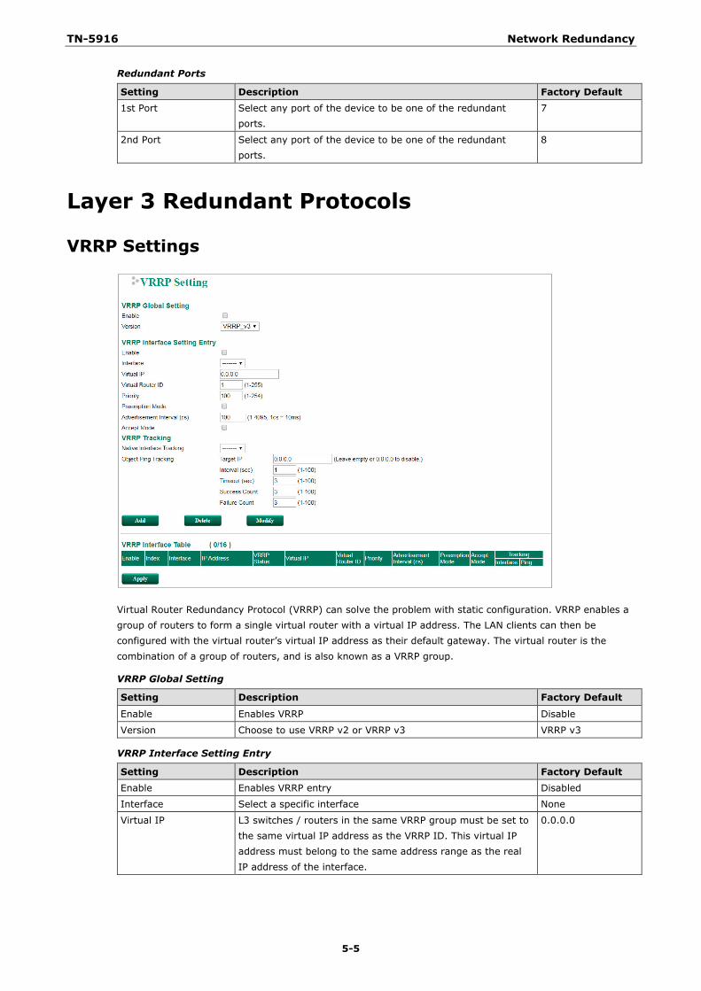
TN-5916 Network Redundancy
5-5
Redundant Ports
Setting Description Factory Default 1st Port Select any port of the device to be one of the redundant
ports. 7
2nd Port Select any port of the device to be one of the redundant ports.
8
Layer 3 Redundant Protocols
VRRP Settings
Virtual Router Redundancy Protocol (VRRP) can solve the problem with static configuration. VRRP enables a group of routers to form a single virtual router with a virtual IP address. The LAN clients can then be configured with the virtual router’s virtual IP address as their default gateway. The virtual router is the combination of a group of routers, and is also known as a VRRP group.
VRRP Global Setting
Setting Description Factory Default
Enable Enables VRRP Disable
Version Choose to use VRRP v2 or VRRP v3 VRRP v3
VRRP Interface Setting Entry
Setting Description Factory Default Enable Enables VRRP entry Disabled
Interface Select a specific interface None
Virtual IP L3 switches / routers in the same VRRP group must be set to the same virtual IP address as the VRRP ID. This virtual IP address must belong to the same address range as the real IP address of the interface.
0.0.0.0
TN-5916 Network Redundancy
5-6
Setting Description Factory Default
Virtual Router ID Virtual Router ID is used to assign a VRRP group. The L3 switches / routers, which operate as master / backup, should have the same ID. Moxa L3 switches / routers support one virtual router ID for each interface. IDs can range from 1 to 255.
0
Priority Determines priority in a VRRP group. The priority value range is 1 to 255 and the 255 is the highest priority. If several L3 switches / routers have the same priority, the router with higher IP address has the higher priority. The usable range is “1 to 255”.
100
Preemption Mode Determines whether a backup L3 switch / router will take the authority of master or not.
Enabled
Advertisement Interval (cs)
Specify the VRRP Advertisement Interval time, ranging from 1 to 4095 cs. 1 cs equals 10 ms.
100
Accept Mode Enable or disable Accept Mode. Disabled
VRRP Tracking
VRRP interface tracking is used to track a specific interface of the router that can change the status of the virtual router for a VRRP Group. For example, the WAN interface can be tracked and if the link is down, the other backup router will become the new master of the VRRP group.
Setting Description Factory Default
Native Interface Tracking
Select the interface to track None
Object Ping Tracking-Target IP
Specify the target IP address to be tracked 0.0.0.0
Object Ping Tracking-Interval (sec)
Specify the tracking interval in seconds 1
Object Ping Tracking-Timeout (sec)
Specify the timeout period in seconds 3
Object Ping Tracking-Success Count
Specify the success count 3
Object Ping Tracking-Fail Count
Specify the failure count 3
6 6. Network Address Translation
The following topics are covered in this chapter:
Network Address Translation (NAT)
NAT Concept
1-to-1 NAT
N-to-1 NAT
Port Forward
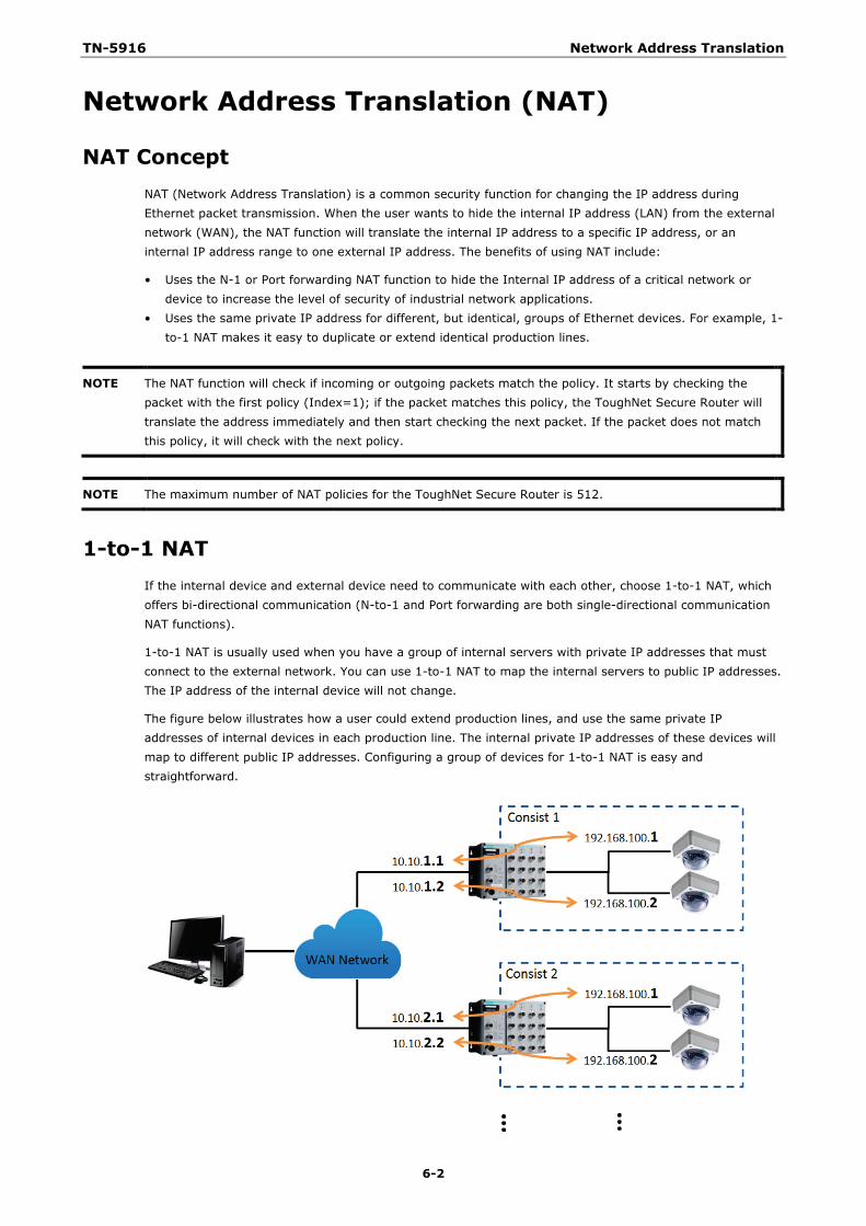
TN-5916 Network Address Translation
6-2
Network Address Translation (NAT)
NAT Concept NAT (Network Address Translation) is a common security function for changing the IP address during Ethernet packet transmission. When the user wants to hide the internal IP address (LAN) from the external network (WAN), the NAT function will translate the internal IP address to a specific IP address, or an internal IP address range to one external IP address. The benefits of using NAT include:
• Uses the N-1 or Port forwarding NAT function to hide the Internal IP address of a critical network or device to increase the level of security of industrial network applications.
• Uses the same private IP address for different, but identical, groups of Ethernet devices. For example, 1-to-1 NAT makes it easy to duplicate or extend identical production lines.
NOTE The NAT function will check if incoming or outgoing packets match the policy. It starts by checking the packet with the first policy (Index=1); if the packet matches this policy, the ToughNet Secure Router will translate the address immediately and then start checking the next packet. If the packet does not match this policy, it will check with the next policy.
NOTE The maximum number of NAT policies for the ToughNet Secure Router is 512.
1-to-1 NAT If the internal device and external device need to communicate with each other, choose 1-to-1 NAT, which offers bi-directional communication (N-to-1 and Port forwarding are both single-directional communication NAT functions).
1-to-1 NAT is usually used when you have a group of internal servers with private IP addresses that must connect to the external network. You can use 1-to-1 NAT to map the internal servers to public IP addresses. The IP address of the internal device will not change.
The figure below illustrates how a user could extend production lines, and use the same private IP addresses of internal devices in each production line. The internal private IP addresses of these devices will map to different public IP addresses. Configuring a group of devices for 1-to-1 NAT is easy and straightforward.
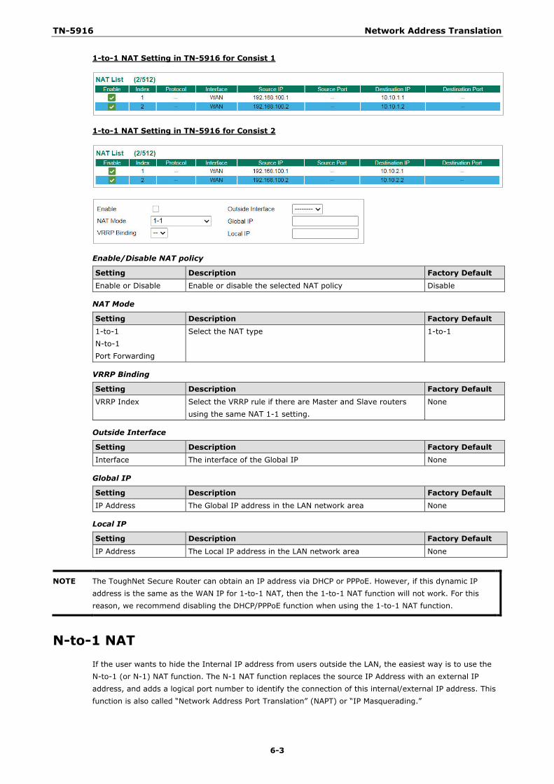
TN-5916 Network Address Translation
6-3
1-to-1 NAT Setting in TN-5916 for Consist 1
1-to-1 NAT Setting in TN-5916 for Consist 2
Enable/Disable NAT policy
Setting Description Factory Default Enable or Disable Enable or disable the selected NAT policy Disable
NAT Mode
Setting Description Factory Default 1-to-1 N-to-1 Port Forwarding
Select the NAT type 1-to-1
VRRP Binding
Setting Description Factory Default
VRRP Index Select the VRRP rule if there are Master and Slave routers using the same NAT 1-1 setting.
None
Outside Interface
Setting Description Factory Default Interface The interface of the Global IP None
Global IP
Setting Description Factory Default IP Address The Global IP address in the LAN network area None
Local IP
Setting Description Factory Default
IP Address The Local IP address in the LAN network area None
NOTE The ToughNet Secure Router can obtain an IP address via DHCP or PPPoE. However, if this dynamic IP address is the same as the WAN IP for 1-to-1 NAT, then the 1-to-1 NAT function will not work. For this reason, we recommend disabling the DHCP/PPPoE function when using the 1-to-1 NAT function.
N-to-1 NAT If the user wants to hide the Internal IP address from users outside the LAN, the easiest way is to use the N-to-1 (or N-1) NAT function. The N-1 NAT function replaces the source IP Address with an external IP address, and adds a logical port number to identify the connection of this internal/external IP address. This function is also called “Network Address Port Translation” (NAPT) or “IP Masquerading.”
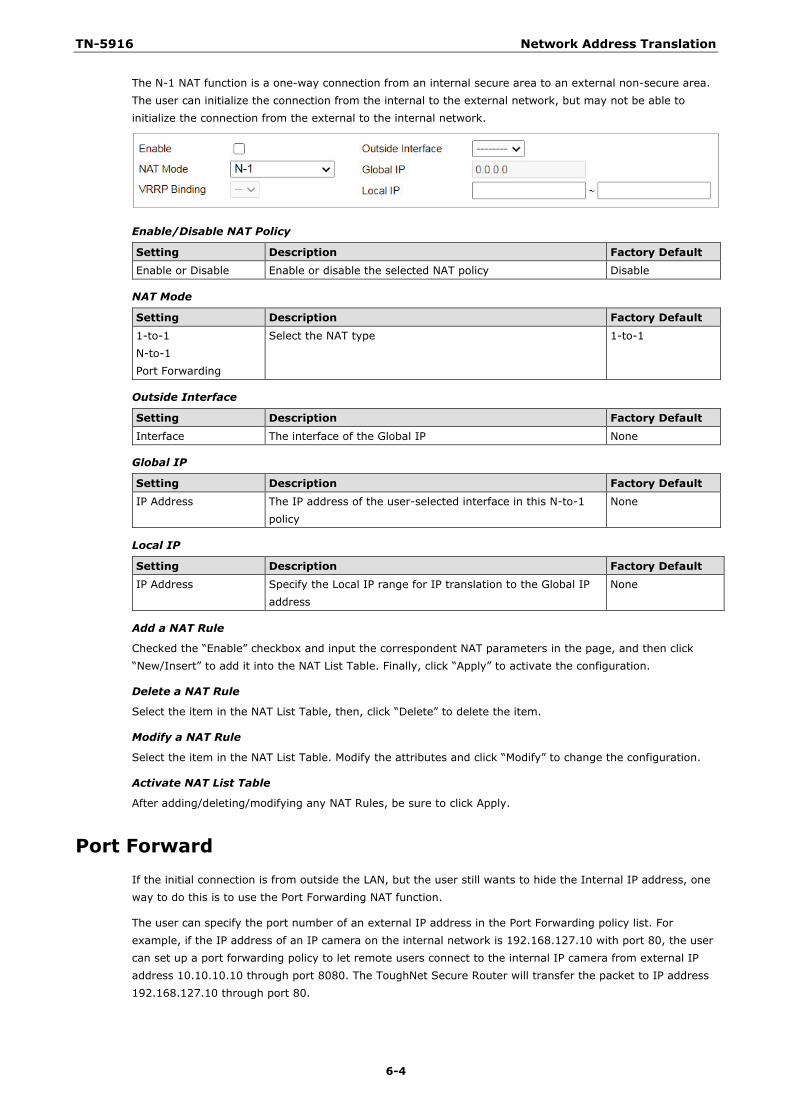
TN-5916 Network Address Translation
6-4
The N-1 NAT function is a one-way connection from an internal secure area to an external non-secure area. The user can initialize the connection from the internal to the external network, but may not be able to initialize the connection from the external to the internal network.
Enable/Disable NAT Policy
Setting Description Factory Default Enable or Disable Enable or disable the selected NAT policy Disable
NAT Mode
Setting Description Factory Default 1-to-1 N-to-1 Port Forwarding
Select the NAT type 1-to-1
Outside Interface
Setting Description Factory Default
Interface The interface of the Global IP None
Global IP
Setting Description Factory Default IP Address The IP address of the user-selected interface in this N-to-1
policy None
Local IP
Setting Description Factory Default IP Address Specify the Local IP range for IP translation to the Global IP
address None
Add a NAT Rule
Checked the “Enable” checkbox and input the correspondent NAT parameters in the page, and then click “New/Insert” to add it into the NAT List Table. Finally, click “Apply” to activate the configuration.
Delete a NAT Rule
Select the item in the NAT List Table, then, click “Delete” to delete the item.
Modify a NAT Rule
Select the item in the NAT List Table. Modify the attributes and click “Modify” to change the configuration.
Activate NAT List Table
After adding/deleting/modifying any NAT Rules, be sure to click Apply.
Port Forward If the initial connection is from outside the LAN, but the user still wants to hide the Internal IP address, one way to do this is to use the Port Forwarding NAT function.
The user can specify the port number of an external IP address in the Port Forwarding policy list. For example, if the IP address of an IP camera on the internal network is 192.168.127.10 with port 80, the user can set up a port forwarding policy to let remote users connect to the internal IP camera from external IP address 10.10.10.10 through port 8080. The ToughNet Secure Router will transfer the packet to IP address 192.168.127.10 through port 80.
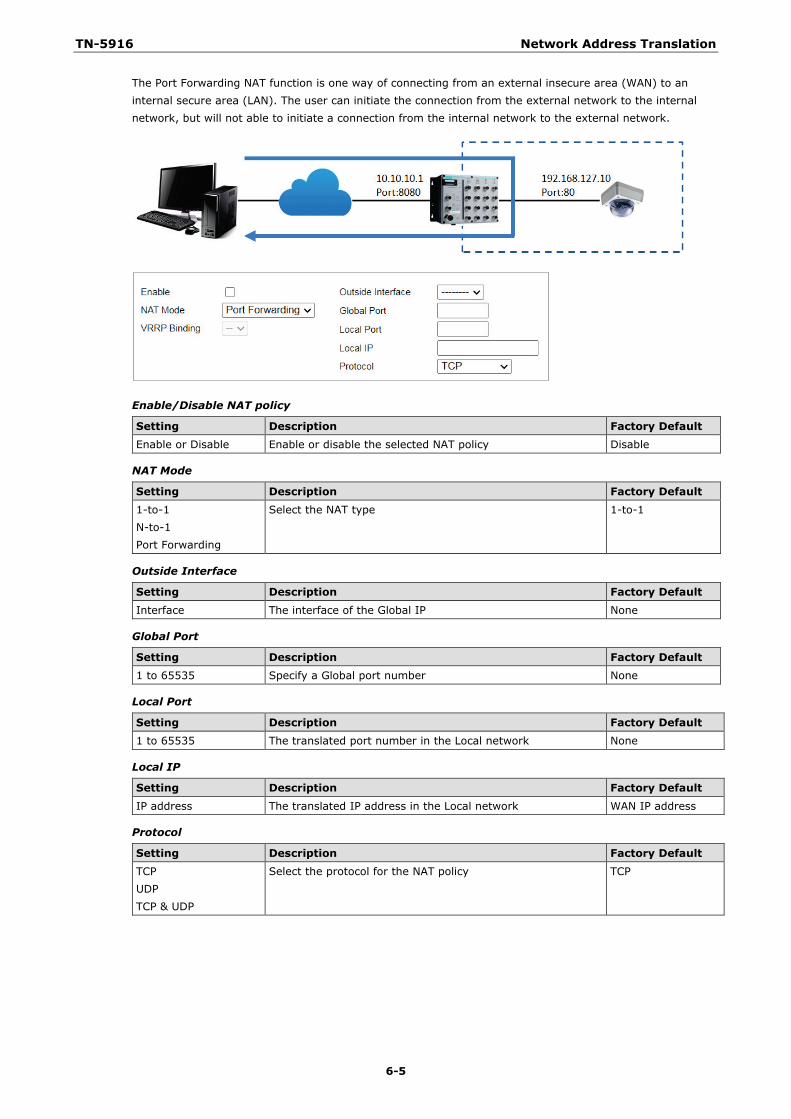
TN-5916 Network Address Translation
6-5
The Port Forwarding NAT function is one way of connecting from an external insecure area (WAN) to an internal secure area (LAN). The user can initiate the connection from the external network to the internal network, but will not able to initiate a connection from the internal network to the external network.
Enable/Disable NAT policy
Setting Description Factory Default Enable or Disable Enable or disable the selected NAT policy Disable
NAT Mode
Setting Description Factory Default 1-to-1 N-to-1 Port Forwarding
Select the NAT type 1-to-1
Outside Interface
Setting Description Factory Default
Interface The interface of the Global IP None
Global Port
Setting Description Factory Default 1 to 65535 Specify a Global port number None
Local Port
Setting Description Factory Default 1 to 65535 The translated port number in the Local network None
Local IP
Setting Description Factory Default
IP address The translated IP address in the Local network WAN IP address
Protocol
Setting Description Factory Default TCP UDP TCP & UDP
Select the protocol for the NAT policy TCP
7 7. Firewall
The following topics are covered in this chapter:
Policy Concept
Policy Overview
Policy Setup
Quick Automation Profile
Layer 2 Policy Setup
Denial of Service (DoS) Defense
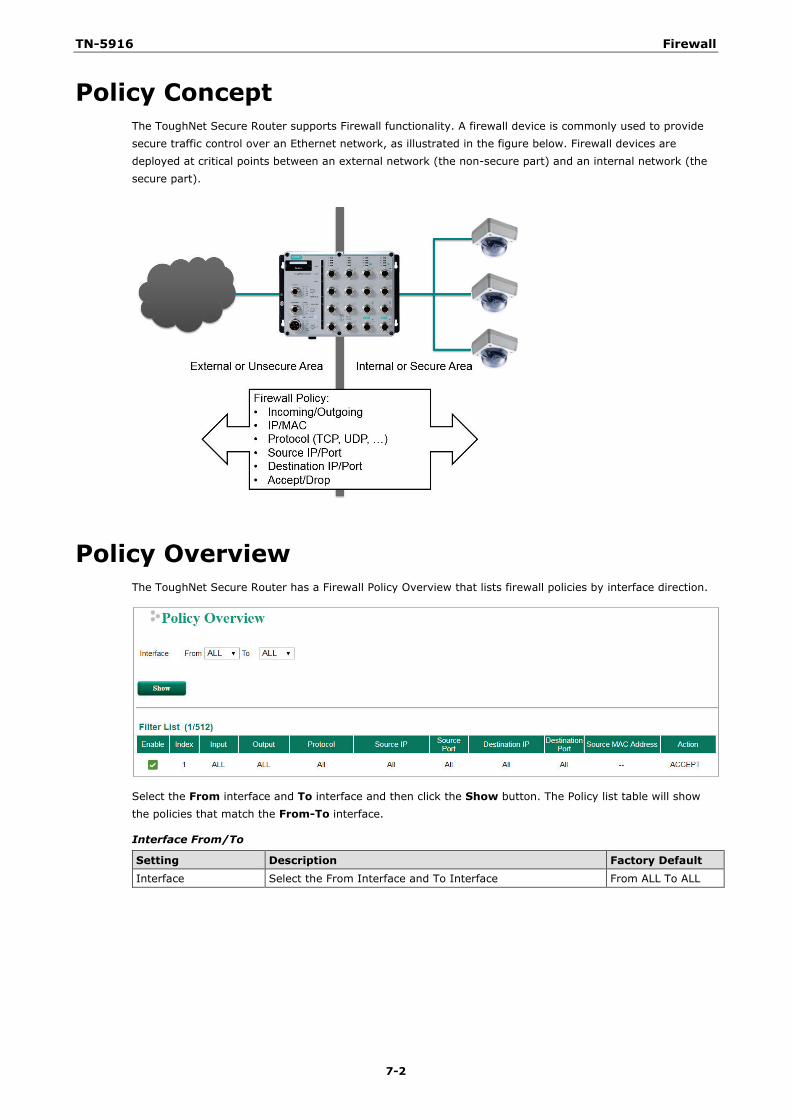
TN-5916 Firewall
7-2
Policy Concept The ToughNet Secure Router supports Firewall functionality. A firewall device is commonly used to provide secure traffic control over an Ethernet network, as illustrated in the figure below. Firewall devices are deployed at critical points between an external network (the non-secure part) and an internal network (the secure part).
Policy Overview The ToughNet Secure Router has a Firewall Policy Overview that lists firewall policies by interface direction.
Select the From interface and To interface and then click the Show button. The Policy list table will show the policies that match the From-To interface.
Interface From/To
Setting Description Factory Default Interface Select the From Interface and To Interface From ALL To ALL
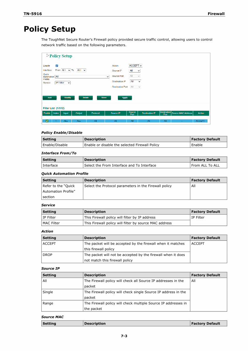
TN-5916 Firewall
7-3
Policy Setup The ToughNet Secure Router’s Firewall policy provided secure traffic control, allowing users to control network traffic based on the following parameters.
Policy Enable/Disable
Setting Description Factory Default Enable/Disable Enable or disable the selected Firewall Policy Enable
Interface From/To
Setting Description Factory Default Interface Select the From Interface and To Interface From ALL To ALL
Quick Automation Profile
Setting Description Factory Default
Refer to the “Quick Automation Profile” section
Select the Protocol parameters in the Firewall policy All
Service
Setting Description Factory Default IP Filter This Firewall policy will filter by IP address IP Filter
MAC Filter This Firewall policy will filter by source MAC address
Action
Setting Description Factory Default
ACCEPT The packet will be accepted by the firewall when it matches this firewall policy
ACCEPT
DROP The packet will not be accepted by the firewall when it does not match this firewall policy
Source IP
Setting Description Factory Default All The Firewall policy will check all Source IP addresses in the
packet All
Single The Firewall policy will check single Source IP address in the packet
Range The Firewall policy will check multiple Source IP addresses in the packet
Source MAC
Setting Description Factory Default
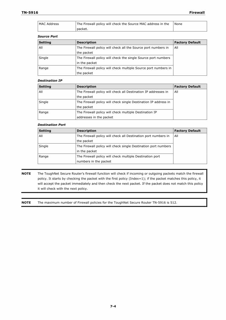
TN-5916 Firewall
7-4
MAC Address The Firewall policy will check the Source MAC address in the packet.
None
Source Port
Setting Description Factory Default
All The Firewall policy will check all the Source port numbers in the packet
All
Single The Firewall policy will check the single Source port numbers in the packet
Range The Firewall policy will check multiple Source port numbers in the packet
Destination IP
Setting Description Factory Default
All The Firewall policy will check all Destination IP addresses in the packet
All
Single The Firewall policy will check single Destination IP address in the packet
Range The Firewall policy will check multiple Destination IP addresses in the packet
Destination Port
Setting Description Factory Default
All The Firewall policy will check all Destination port numbers in the packet
All
Single The Firewall policy will check single Destination port numbers in the packet
Range The Firewall policy will check multiple Destination port numbers in the packet
NOTE The ToughNet Secure Router’s firewall function will check if incoming or outgoing packets match the firewall policy. It starts by checking the packet with the first policy (Index=1); if the packet matches this policy, it will accept the packet immediately and then check the next packet. If the packet does not match this policy it will check with the next policy.
NOTE The maximum number of Firewall policies for the ToughNet Secure Router TN-5916 is 512.
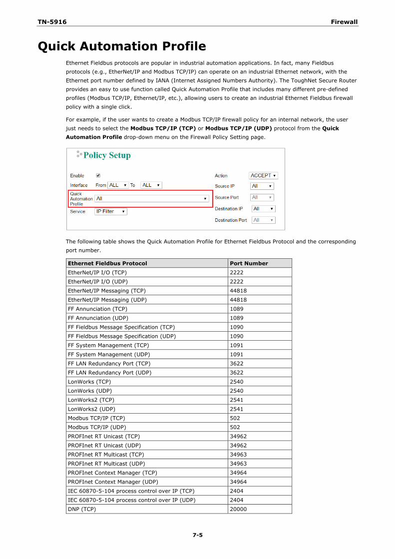
TN-5916 Firewall
7-5
Quick Automation Profile Ethernet Fieldbus protocols are popular in industrial automation applications. In fact, many Fieldbus protocols (e.g., EtherNet/IP and Modbus TCP/IP) can operate on an industrial Ethernet network, with the Ethernet port number defined by IANA (Internet Assigned Numbers Authority). The ToughNet Secure Router provides an easy to use function called Quick Automation Profile that includes many different pre-defined profiles (Modbus TCP/IP, Ethernet/IP, etc.), allowing users to create an industrial Ethernet Fieldbus firewall policy with a single click.
For example, if the user wants to create a Modbus TCP/IP firewall policy for an internal network, the user just needs to select the Modbus TCP/IP (TCP) or Modbus TCP/IP (UDP) protocol from the Quick Automation Profile drop-down menu on the Firewall Policy Setting page.
The following table shows the Quick Automation Profile for Ethernet Fieldbus Protocol and the corresponding port number.
Ethernet Fieldbus Protocol Port Number
EtherNet/IP I/O (TCP) 2222
EtherNet/IP I/O (UDP) 2222
EtherNet/IP Messaging (TCP) 44818
EtherNet/IP Messaging (UDP) 44818
FF Annunciation (TCP) 1089
FF Annunciation (UDP) 1089
FF Fieldbus Message Specification (TCP) 1090
FF Fieldbus Message Specification (UDP) 1090
FF System Management (TCP) 1091
FF System Management (UDP) 1091
FF LAN Redundancy Port (TCP) 3622
FF LAN Redundancy Port (UDP) 3622
LonWorks (TCP) 2540
LonWorks (UDP) 2540
LonWorks2 (TCP) 2541
LonWorks2 (UDP) 2541
Modbus TCP/IP (TCP) 502
Modbus TCP/IP (UDP) 502
PROFInet RT Unicast (TCP) 34962
PROFInet RT Unicast (UDP) 34962
PROFInet RT Multicast (TCP) 34963
PROFInet RT Multicast (UDP) 34963
PROFInet Context Manager (TCP) 34964
PROFInet Context Manager (UDP) 34964
IEC 60870-5-104 process control over IP (TCP) 2404
IEC 60870-5-104 process control over IP (UDP) 2404
DNP (TCP) 20000
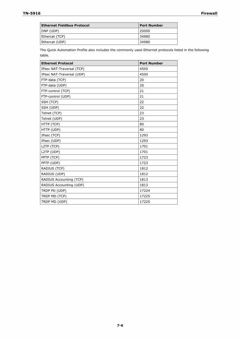
TN-5916 Firewall
7-6
Ethernet Fieldbus Protocol Port Number
DNP (UDP) 20000
Ethercat (TCP) 34980
Ethercat (UDP) 34980
The Quick Automation Profile also includes the commonly used Ethernet protocols listed in the following table.
Ethernet Protocol Port Number IPsec NAT-Traversal (TCP) 4500
IPsec NAT-Traversal (UDP) 4500
FTP-data (TCP) 20
FTP-data (UDP) 20
FTP-control (TCP) 21
FTP-control (UDP) 21
SSH (TCP) 22
SSH (UDP) 22
Telnet (TCP) 23
Telnet (UDP) 23
HTTP (TCP) 80
HTTP (UDP) 80
IPsec (TCP) 1293
IPsec (UDP) 1293
L2TP (TCP) 1701
L2TP (UDP) 1701
PPTP (TCP) 1723
PPTP (UDP) 1723
RADIUS (TCP) 1812
RADIUS (UDP) 1812
RADIUS Accounting (TCP) 1813
RADIUS Accounting (UDP) 1813
TRDP PD (UDP) 17224
TRDP MD (TCP) 17225
TRDP MD (UDP) 17225
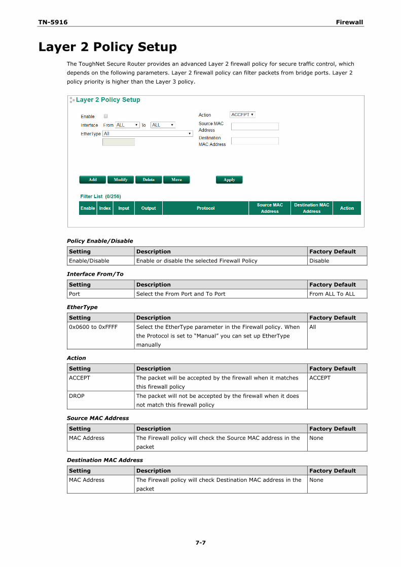
TN-5916 Firewall
7-7
Layer 2 Policy Setup The ToughNet Secure Router provides an advanced Layer 2 firewall policy for secure traffic control, which depends on the following parameters. Layer 2 firewall policy can filter packets from bridge ports. Layer 2 policy priority is higher than the Layer 3 policy.
Policy Enable/Disable
Setting Description Factory Default Enable/Disable Enable or disable the selected Firewall Policy Disable
Interface From/To
Setting Description Factory Default Port Select the From Port and To Port From ALL To ALL
EtherType
Setting Description Factory Default
0x0600 to 0xFFFF Select the EtherType parameter in the Firewall policy. When the Protocol is set to “Manual” you can set up EtherType manually
All
Action
Setting Description Factory Default ACCEPT The packet will be accepted by the firewall when it matches
this firewall policy ACCEPT
DROP The packet will not be accepted by the firewall when it does not match this firewall policy
Source MAC Address
Setting Description Factory Default
MAC Address The Firewall policy will check the Source MAC address in the packet
None
Destination MAC Address
Setting Description Factory Default MAC Address The Firewall policy will check Destination MAC address in the
packet None
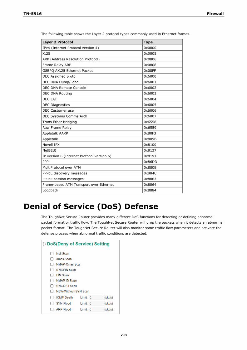
TN-5916 Firewall
7-8
The following table shows the Layer 2 protocol types commonly used in Ethernet frames.
Layer 2 Protocol Type
IPv4 (Internet Protocol version 4) 0x0800
X.25 0x0805
ARP (Address Resolution Protocol) 0x0806
Frame Relay ARP 0x0808
G8BPQ AX.25 Ethernet Packet 0x08FF
DEC Assigned proto 0x6000
DEC DNA Dump/Load 0x6001
DEC DNA Remote Console 0x6002
DEC DNA Routing 0x6003
DEC LAT 0x6004
DEC Diagnostics 0x6005
DEC Customer use 0x6006
DEC Systems Comms Arch 0x6007
Trans Ether Bridging 0x6558
Raw Frame Relay 0x6559
Appletalk AARP 0x80F3
Appletalk 0x809B
Novell IPX 0x8100
NetBEUI 0x8137
IP version 6 (Internet Protocol version 6) 0x8191
PPP 0x86DD
MultiProtocol over ATM 0x880B
PPPoE discovery messages 0x884C
PPPoE session messages 0x8863
Frame-based ATM Transport over Ethernet 0x8864
Loopback 0x8884
Denial of Service (DoS) Defense The ToughNet Secure Router provides many different DoS functions for detecting or defining abnormal packet format or traffic flow. The ToughNet Secure Router will drop the packets when it detects an abnormal packet format. The ToughNet Secure Router will also monitor some traffic flow parameters and activate the defense process when abnormal traffic conditions are detected.
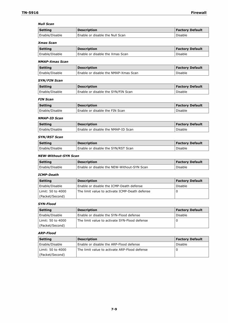
TN-5916 Firewall
7-9
Null Scan
Setting Description Factory Default Enable/Disable Enable or disable the Null Scan Disable
Xmas Scan
Setting Description Factory Default Enable/Disable Enable or disable the Xmas Scan Disable
NMAP-Xmas Scan
Setting Description Factory Default
Enable/Disable Enable or disable the NMAP-Xmas Scan Disable
SYN/FIN Scan
Setting Description Factory Default Enable/Disable Enable or disable the SYN/FIN Scan Disable
FIN Scan
Setting Description Factory Default Enable/Disable Enable or disable the FIN Scan Disable
NMAP-ID Scan
Setting Description Factory Default
Enable/Disable Enable or disable the NMAP-ID Scan Disable
SYN/RST Scan
Setting Description Factory Default Enable/Disable Enable or disable the SYN/RST Scan Disable
NEW-Without-SYN Scan
Setting Description Factory Default Enable/Disable Enable or disable the NEW-Without-SYN Scan Disable
ICMP-Death
Setting Description Factory Default
Enable/Disable Enable or disable the ICMP-Death defense Disable
Limit: 50 to 4000 (Packet/Second)
The limit value to activate ICMP-Death defense 0
SYN-Flood
Setting Description Factory Default Enable/Disable Enable or disable the SYN-Flood defense Disable
Limit: 50 to 4000 (Packet/Second)
The limit value to activate SYN-Flood defense 0
ARP-Flood
Setting Description Factory Default Enable/Disable Enable or disable the ARP-Flood defense Disable
Limit: 50 to 4000 (Packet/Second)
The limit value to activate ARP-Flood defense 0
8 8. Virtual Private Network (VPN)
The following topics are covered in this chapter:
Overview
IPsec Configuration
Global Settings
IPsec Settings
L2TP Server (Layer 2 Tunnel Protocol)
L2TP Configuration
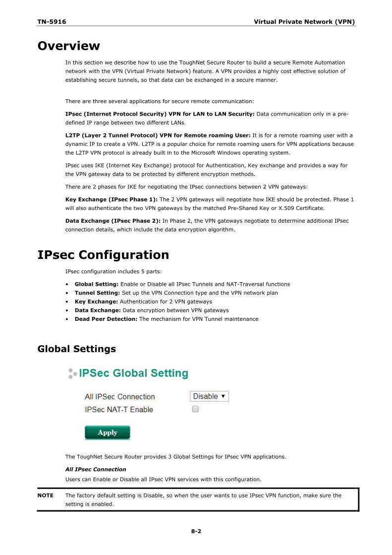
TN-5916 Virtual Private Network (VPN)
8-2
Overview In this section we describe how to use the ToughNet Secure Router to build a secure Remote Automation network with the VPN (Virtual Private Network) feature. A VPN provides a highly cost effective solution of establishing secure tunnels, so that data can be exchanged in a secure manner.
There are three several applications for secure remote communication:
IPsec (Internet Protocol Security) VPN for LAN to LAN Security: Data communication only in a pre-defined IP range between two different LANs.
L2TP (Layer 2 Tunnel Protocol) VPN for Remote roaming User: It is for a remote roaming user with a dynamic IP to create a VPN. L2TP is a popular choice for remote roaming users for VPN applications because the L2TP VPN protocol is already built in to the Microsoft Windows operating system.
IPsec uses IKE (Internet Key Exchange) protocol for Authentication, Key exchange and provides a way for the VPN gateway data to be protected by different encryption methods.
There are 2 phases for IKE for negotiating the IPsec connections between 2 VPN gateways:
Key Exchange (IPsec Phase 1): The 2 VPN gateways will negotiate how IKE should be protected. Phase 1 will also authenticate the two VPN gateways by the matched Pre-Shared Key or X.509 Certificate.
Data Exchange (IPsec Phase 2): In Phase 2, the VPN gateways negotiate to determine additional IPsec connection details, which include the data encryption algorithm.
IPsec Configuration IPsec configuration includes 5 parts:
• Global Setting: Enable or Disable all IPsec Tunnels and NAT-Traversal functions • Tunnel Setting: Set up the VPN Connection type and the VPN network plan • Key Exchange: Authentication for 2 VPN gateways • Data Exchange: Data encryption between VPN gateways • Dead Peer Detection: The mechanism for VPN Tunnel maintenance
Global Settings
The ToughNet Secure Router provides 3 Global Settings for IPsec VPN applications.
All IPsec Connection
Users can Enable or Disable all IPsec VPN services with this configuration.
NOTE The factory default setting is Disable, so when the user wants to use IPsec VPN function, make sure the setting is enabled.
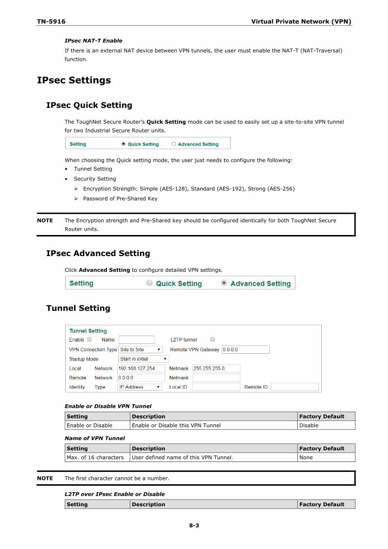
TN-5916 Virtual Private Network (VPN)
8-3
IPsec NAT-T Enable
If there is an external NAT device between VPN tunnels, the user must enable the NAT-T (NAT-Traversal) function.
IPsec Settings
IPsec Quick Setting
The ToughNet Secure Router’s Quick Setting mode can be used to easily set up a site-to-site VPN tunnel for two Industrial Secure Router units.
When choosing the Quick setting mode, the user just needs to configure the following: • Tunnel Setting
• Security Setting
Encryption Strength: Simple (AES-128), Standard (AES-192), Strong (AES-256)
Password of Pre-Shared Key
NOTE The Encryption strength and Pre-Shared key should be configured identically for both ToughNet Secure Router units.
IPsec Advanced Setting
Click Advanced Setting to configure detailed VPN settings.
Tunnel Setting
Enable or Disable VPN Tunnel
Setting Description Factory Default
Enable or Disable Enable or Disable this VPN Tunnel Disable
Name of VPN Tunnel
Setting Description Factory Default Max. of 16 characters User defined name of this VPN Tunnel. None
NOTE The first character cannot be a number.
L2TP over IPsec Enable or Disable
Setting Description Factory Default
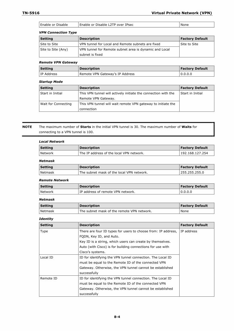
TN-5916 Virtual Private Network (VPN)
8-4
Enable or Disable Enable or Disable L2TP over IPsec None
VPN Connection Type
Setting Description Factory Default
Site to Site VPN tunnel for Local and Remote subnets are fixed Site to Site
Site to Site (Any) VPN tunnel for Remote subnet area is dynamic and Local subnet is fixed
Remote VPN Gateway
Setting Description Factory Default IP Address Remote VPN Gateway’s IP Address 0.0.0.0
Startup Mode
Setting Description Factory Default
Start in Initial This VPN tunnel will actively initiate the connection with the Remote VPN Gateway.
Start in Initial
Wait for Connecting This VPN tunnel will wait remote VPN gateway to initiate the connection
NOTE The maximum number of Starts in the initial VPN tunnel is 30. The maximum number of Waits for connecting to a VPN tunnel is 100.
Local Network
Setting Description Factory Default Network The IP address of the local VPN network. 192.168.127.254
Netmask
Setting Description Factory Default
Netmask The subnet mask of the local VPN network. 255.255.255.0
Remote Network
Setting Description Factory Default Network IP address of remote VPN network. 0.0.0.0
Netmask
Setting Description Factory Default Netmask The subnet mask of the remote VPN network. None
Identity
Setting Description Factory Default
Type There are four ID types for users to choose from: IP address, FQDN, Key ID, and Auto. Key ID is a string, which users can create by themselves. Auto (with Cisco) is for building connections for use with Cisco’s systems.
IP address
Local ID ID for identifying the VPN tunnel connection. The Local ID must be equal to the Remote ID of the connected VPN Gateway. Otherwise, the VPN tunnel cannot be established successfully
Remote ID ID for identifying the VPN tunnel connection. The Local ID must be equal to the Remote ID of the connected VPN Gateway. Otherwise, the VPN tunnel cannot be established successfully
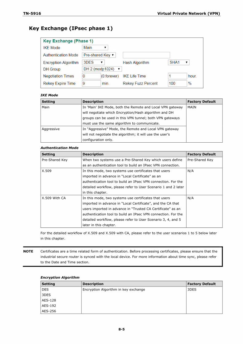
TN-5916 Virtual Private Network (VPN)
8-5
Key Exchange (IPsec phase 1)
IKE Mode
Setting Description Factory Default Main In ‘Main’ IKE Mode, both the Remote and Local VPN gateway
will negotiate which Encryption/Hash algorithm and DH groups can be used in this VPN tunnel; both VPN gateways must use the same algorithm to communicate.
MAIN
Aggressive In “Aggressive” Mode, the Remote and Local VPN gateway will not negotiate the algorithm; it will use the user’s configuration only.
Authentication Mode
Setting Description Factory Default
Pre-Shared Key When two systems use a Pre-Shared Key which users define as an authentication tool to build an IPsec VPN connection.
Pre-Shared Key
X.509 In this mode, two systems use certificates that users imported in advance in “Local Certificate” as an authentication tool to build an IPsec VPN connection. For the detailed workflow, please refer to User Scenario 1 and 2 later in this chapter.
N/A
X.509 With CA In this mode, two systems use certificates that users imported in advance in “Local Certificate”, and the CA that users imported in advance in “Trusted CA Certificate” as an authentication tool to build an IPsec VPN connection. For the detailed workflow, please refer to User Scenario 3, 4, and 5 later in this chapter.
N/A
For the detailed workflow of X.509 and X.509 with CA, please refer to the user scenarios 1 to 5 below later in this chapter.
NOTE Certificates are a time related form of authentication. Before processing certificates, please ensure that the industrial secure router is synced with the local device. For more information about time sync, please refer to the Date and Time section.
Encryption Algorithm
Setting Description Factory Default
DES 3DES AES-128 AES-192 AES-256
Encryption Algorithm in key exchange 3DES
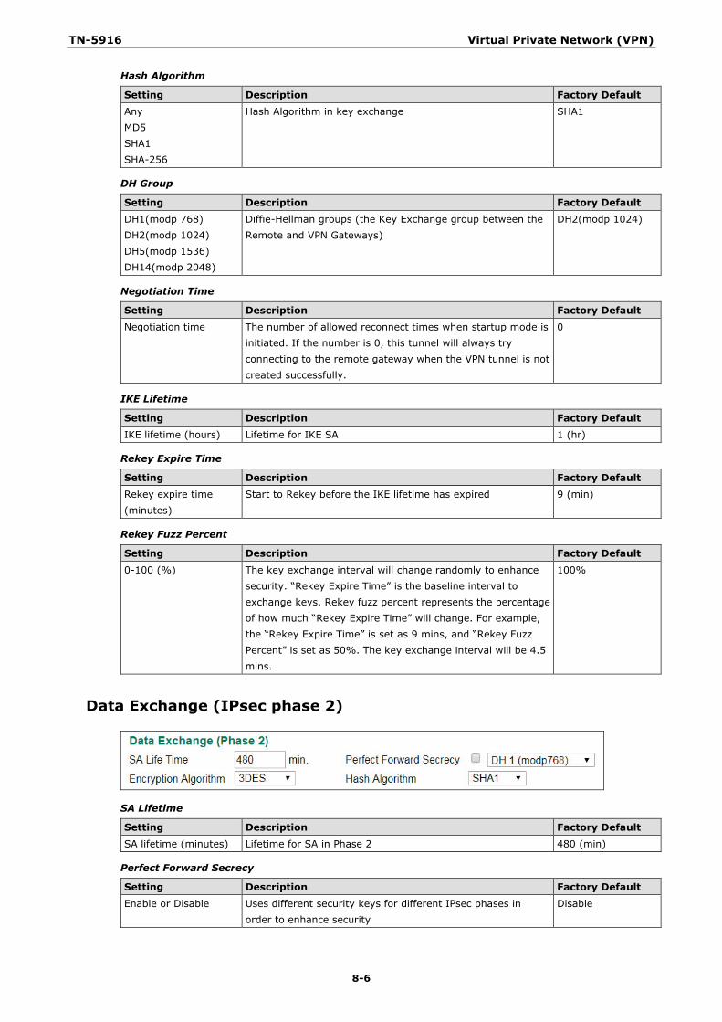
TN-5916 Virtual Private Network (VPN)
8-6
Hash Algorithm
Setting Description Factory Default Any MD5 SHA1 SHA-256
Hash Algorithm in key exchange SHA1
DH Group
Setting Description Factory Default DH1(modp 768) DH2(modp 1024) DH5(modp 1536) DH14(modp 2048)
Diffie-Hellman groups (the Key Exchange group between the Remote and VPN Gateways)
DH2(modp 1024)
Negotiation Time
Setting Description Factory Default
Negotiation time The number of allowed reconnect times when startup mode is initiated. If the number is 0, this tunnel will always try connecting to the remote gateway when the VPN tunnel is not created successfully.
0
IKE Lifetime
Setting Description Factory Default IKE lifetime (hours) Lifetime for IKE SA 1 (hr)
Rekey Expire Time
Setting Description Factory Default Rekey expire time (minutes)
Start to Rekey before the IKE lifetime has expired 9 (min)
Rekey Fuzz Percent
Setting Description Factory Default
0-100 (%) The key exchange interval will change randomly to enhance security. “Rekey Expire Time” is the baseline interval to exchange keys. Rekey fuzz percent represents the percentage of how much “Rekey Expire Time” will change. For example, the “Rekey Expire Time” is set as 9 mins, and “Rekey Fuzz Percent” is set as 50%. The key exchange interval will be 4.5 mins.
100%
Data Exchange (IPsec phase 2)
SA Lifetime
Setting Description Factory Default SA lifetime (minutes) Lifetime for SA in Phase 2 480 (min)
Perfect Forward Secrecy
Setting Description Factory Default Enable or Disable Uses different security keys for different IPsec phases in
order to enhance security Disable
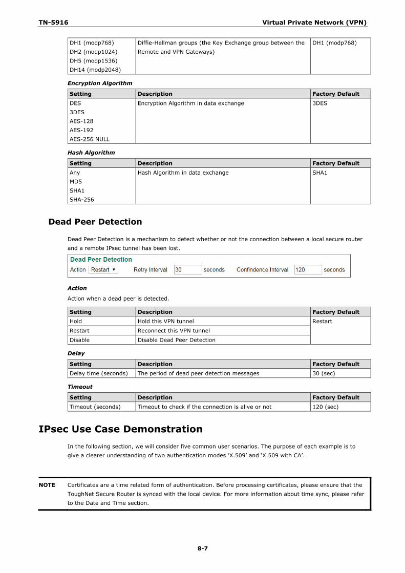
TN-5916 Virtual Private Network (VPN)
8-7
DH1 (modp768) DH2 (modp1024) DH5 (modp1536) DH14 (modp2048)
Diffie-Hellman groups (the Key Exchange group between the Remote and VPN Gateways)
DH1 (modp768)
Encryption Algorithm
Setting Description Factory Default
DES 3DES AES-128 AES-192 AES-256 NULL
Encryption Algorithm in data exchange 3DES
Hash Algorithm
Setting Description Factory Default Any MD5 SHA1 SHA-256
Hash Algorithm in data exchange SHA1
Dead Peer Detection
Dead Peer Detection is a mechanism to detect whether or not the connection between a local secure router and a remote IPsec tunnel has been lost.
Action
Action when a dead peer is detected.
Setting Description Factory Default Hold Hold this VPN tunnel Restart
Restart Reconnect this VPN tunnel
Disable Disable Dead Peer Detection
Delay
Setting Description Factory Default Delay time (seconds) The period of dead peer detection messages 30 (sec)
Timeout
Setting Description Factory Default
Timeout (seconds) Timeout to check if the connection is alive or not 120 (sec)
IPsec Use Case Demonstration In the following section, we will consider five common user scenarios. The purpose of each example is to give a clearer understanding of two authentication modes ‘X.509’ and ‘X.509 with CA’.
NOTE Certificates are a time related form of authentication. Before processing certificates, please ensure that the ToughNet Secure Router is synced with the local device. For more information about time sync, please refer to the Date and Time section.
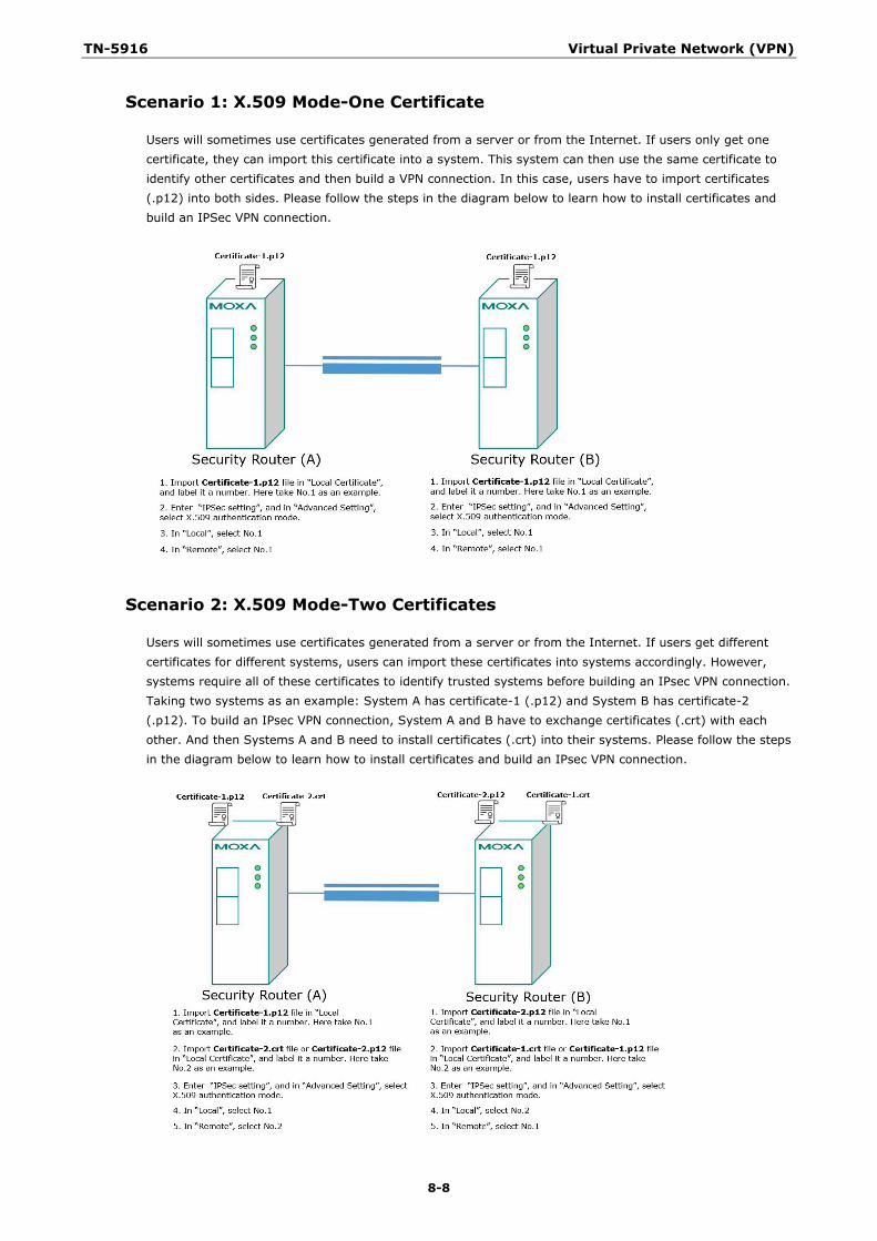
TN-5916 Virtual Private Network (VPN)
8-8
Scenario 1: X.509 Mode-One Certificate
Users will sometimes use certificates generated from a server or from the Internet. If users only get one certificate, they can import this certificate into a system. This system can then use the same certificate to identify other certificates and then build a VPN connection. In this case, users have to import certificates (.p12) into both sides. Please follow the steps in the diagram below to learn how to install certificates and build an IPSec VPN connection.
Scenario 2: X.509 Mode-Two Certificates
Users will sometimes use certificates generated from a server or from the Internet. If users get different certificates for different systems, users can import these certificates into systems accordingly. However, systems require all of these certificates to identify trusted systems before building an IPsec VPN connection. Taking two systems as an example: System A has certificate-1 (.p12) and System B has certificate-2 (.p12). To build an IPsec VPN connection, System A and B have to exchange certificates (.crt) with each other. And then Systems A and B need to install certificates (.crt) into their systems. Please follow the steps in the diagram below to learn how to install certificates and build an IPsec VPN connection.
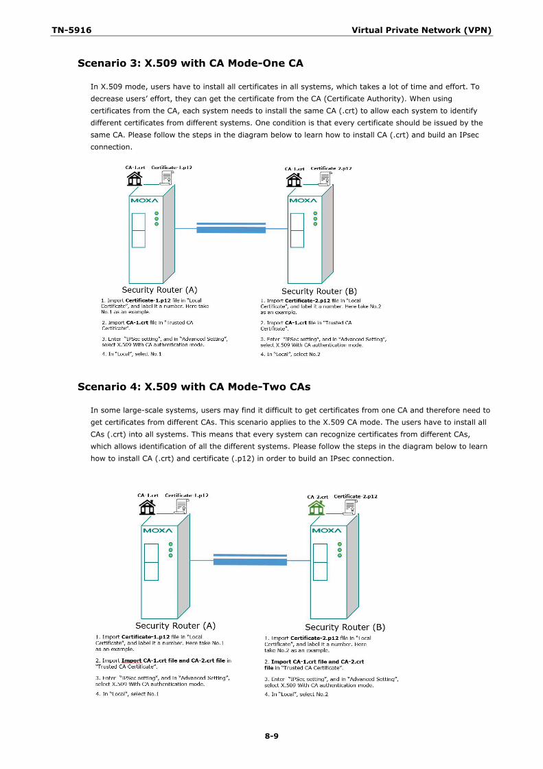
TN-5916 Virtual Private Network (VPN)
8-9
Scenario 3: X.509 with CA Mode-One CA
In X.509 mode, users have to install all certificates in all systems, which takes a lot of time and effort. To decrease users’ effort, they can get the certificate from the CA (Certificate Authority). When using certificates from the CA, each system needs to install the same CA (.crt) to allow each system to identify different certificates from different systems. One condition is that every certificate should be issued by the same CA. Please follow the steps in the diagram below to learn how to install CA (.crt) and build an IPsec connection.
Scenario 4: X.509 with CA Mode-Two CAs
In some large-scale systems, users may find it difficult to get certificates from one CA and therefore need to get certificates from different CAs. This scenario applies to the X.509 CA mode. The users have to install all CAs (.crt) into all systems. This means that every system can recognize certificates from different CAs, which allows identification of all the different systems. Please follow the steps in the diagram below to learn how to install CA (.crt) and certificate (.p12) in order to build an IPsec connection.
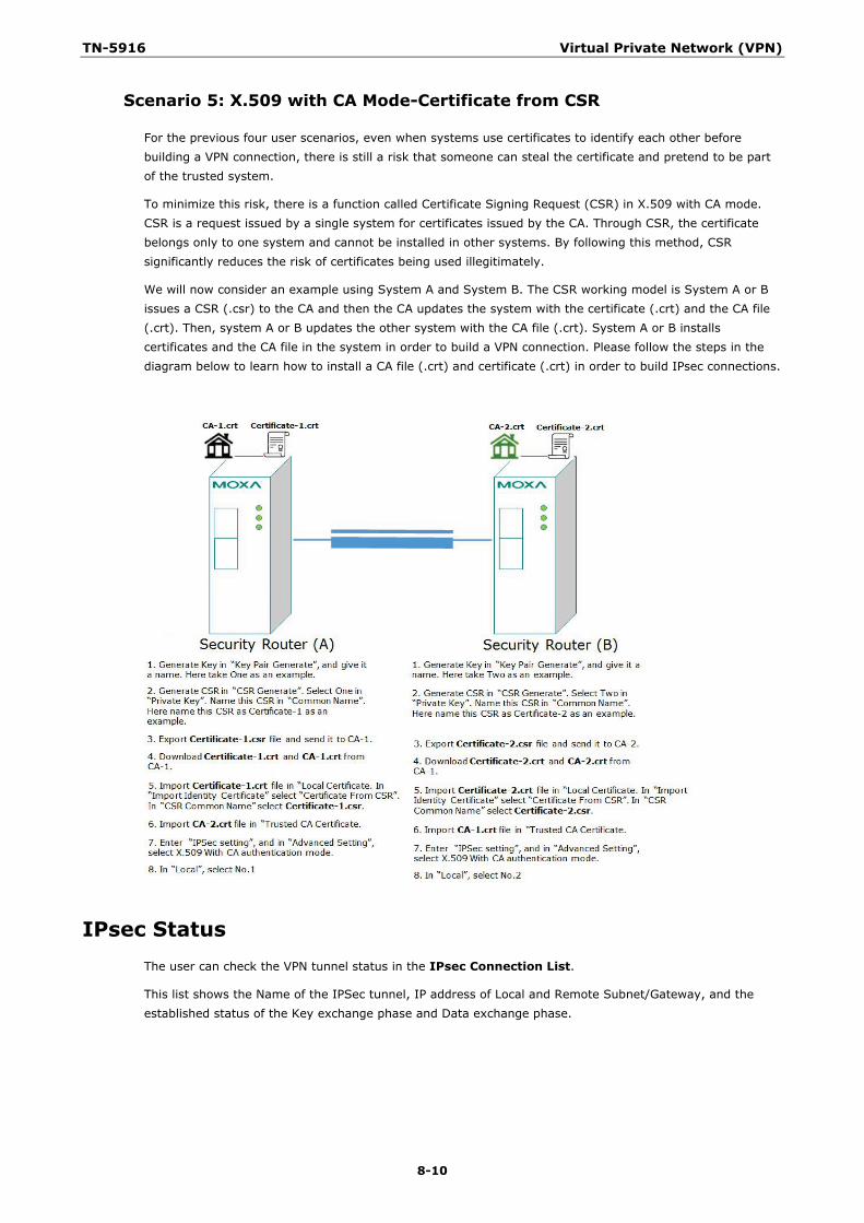
TN-5916 Virtual Private Network (VPN)
8-10
Scenario 5: X.509 with CA Mode-Certificate from CSR
For the previous four user scenarios, even when systems use certificates to identify each other before building a VPN connection, there is still a risk that someone can steal the certificate and pretend to be part of the trusted system.
To minimize this risk, there is a function called Certificate Signing Request (CSR) in X.509 with CA mode. CSR is a request issued by a single system for certificates issued by the CA. Through CSR, the certificate belongs only to one system and cannot be installed in other systems. By following this method, CSR significantly reduces the risk of certificates being used illegitimately.
We will now consider an example using System A and System B. The CSR working model is System A or B issues a CSR (.csr) to the CA and then the CA updates the system with the certificate (.crt) and the CA file (.crt). Then, system A or B updates the other system with the CA file (.crt). System A or B installs certificates and the CA file in the system in order to build a VPN connection. Please follow the steps in the diagram below to learn how to install a CA file (.crt) and certificate (.crt) in order to build IPsec connections.
IPsec Status The user can check the VPN tunnel status in the IPsec Connection List.
This list shows the Name of the IPSec tunnel, IP address of Local and Remote Subnet/Gateway, and the established status of the Key exchange phase and Data exchange phase.
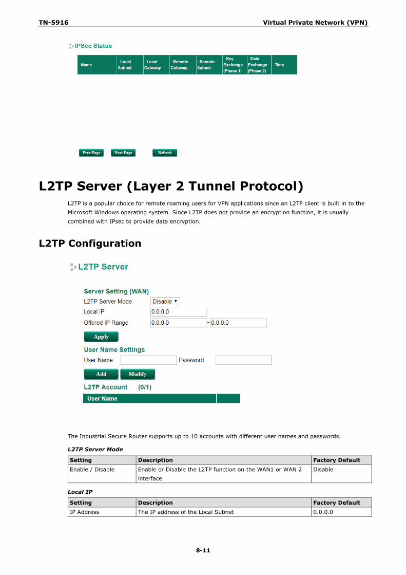
TN-5916 Virtual Private Network (VPN)
8-11
L2TP Server (Layer 2 Tunnel Protocol) L2TP is a popular choice for remote roaming users for VPN applications since an L2TP client is built in to the Microsoft Windows operating system. Since L2TP does not provide an encryption function, it is usually combined with IPsec to provide data encryption.
L2TP Configuration
The Industrial Secure Router supports up to 10 accounts with different user names and passwords.
L2TP Server Mode
Setting Description Factory Default Enable / Disable Enable or Disable the L2TP function on the WAN1 or WAN 2
interface Disable
Local IP
Setting Description Factory Default IP Address The IP address of the Local Subnet 0.0.0.0

TN-5916 Virtual Private Network (VPN)
8-12
Offered IP Range
Setting Description Factory Default IP Address Offered IP range is for the L2TP clients 0.0.0.0
Login User Name
Setting Description Factory Default Max. 32 characters. User Name for L2TP connection None
Login Password
Setting Description Factory Default
Max. 32 characters. Password for L2TP connection None
9 9. Certificate Management
For the purposes of this document, certificate management refers to the X.509 SSL certificate. X.509 is a digital certificate method commonly used for IPsec and HTTPS authentication. The ToughNet Secure Router can act as a Root CA (Certificate Authority) and issue a trusted Root Certificate. Alternatively, users can import certificates from other CAs into the ToughNet Secure Router.
Certificates are a time related authentication mechanism. Before processing certificate management, please make ensure the ToughNet secure router is synced with the local device. For more details regarding time sync, please refer to section Date and Time.
The following topics are covered in this chapter:
Local Certificate
Local Certificate
Trusted CA Certificates
Certificate Signing Request
CA Server
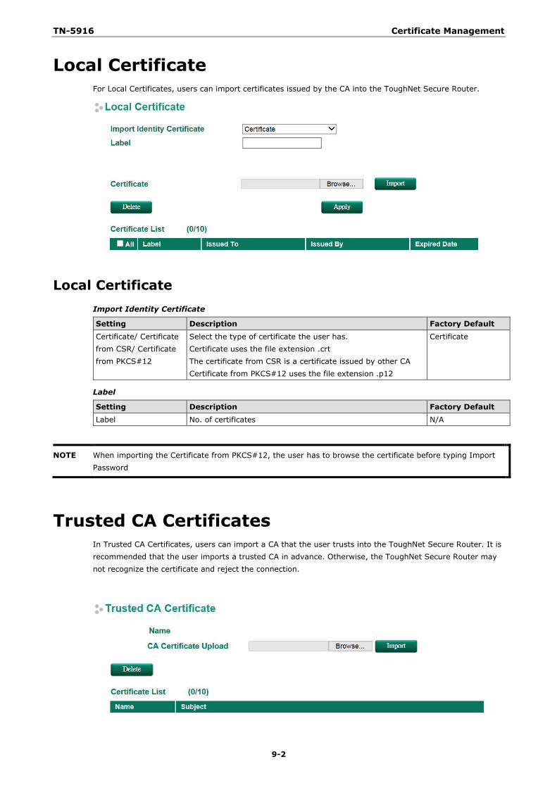
TN-5916 Certificate Management
9-2
Local Certificate For Local Certificates, users can import certificates issued by the CA into the ToughNet Secure Router.
Local Certificate Import Identity Certificate
Setting Description Factory Default Certificate/ Certificate from CSR/ Certificate from PKCS#12
Select the type of certificate the user has. Certificate uses the file extension .crt The certificate from CSR is a certificate issued by other CA Certificate from PKCS#12 uses the file extension .p12
Certificate
Label
Setting Description Factory Default Label No. of certificates N/A
NOTE When importing the Certificate from PKCS#12, the user has to browse the certificate before typing Import Password
Trusted CA Certificates In Trusted CA Certificates, users can import a CA that the user trusts into the ToughNet Secure Router. It is recommended that the user imports a trusted CA in advance. Otherwise, the ToughNet Secure Router may not recognize the certificate and reject the connection.
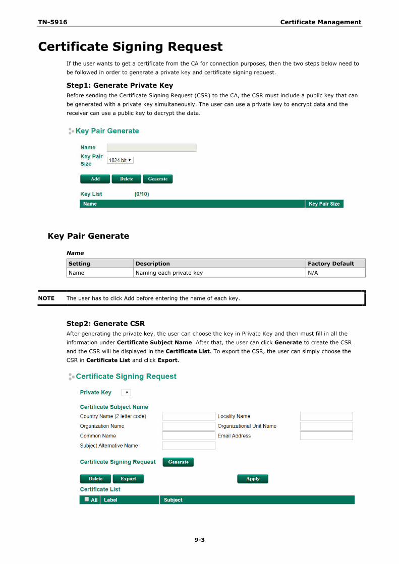
TN-5916 Certificate Management
9-3
Certificate Signing Request If the user wants to get a certificate from the CA for connection purposes, then the two steps below need to be followed in order to generate a private key and certificate signing request.
Step1: Generate Private Key Before sending the Certificate Signing Request (CSR) to the CA, the CSR must include a public key that can be generated with a private key simultaneously. The user can use a private key to encrypt data and the receiver can use a public key to decrypt the data.
Key Pair Generate
Name
Setting Description Factory Default Name Naming each private key N/A
NOTE The user has to click Add before entering the name of each key.
Step2: Generate CSR After generating the private key, the user can choose the key in Private Key and then must fill in all the information under Certificate Subject Name. After that, the user can click Generate to create the CSR and the CSR will be displayed in the Certificate List. To export the CSR, the user can simply choose the CSR in Certificate List and click Export.
TN-5916 Certificate Management
9-4
Certificate Signing Request
Private Key
Setting Description Factory Default Private Key Choose the key generated in Key Pair Generate N/A
CA Server Aside from getting the certificate from other CAs, the ToughNet Secure Router can act as a RootCA to issue a certificate for each connection. After the RootCA has been set up, the ToughNet Secure Router can send requests to ask for a certificate from the RootCA.
Certificate Request
If a system only has their own certificate on hand, and do not have other systems’ certificates, how can the system recognize other systems? The answer to this problem is Trust CA. As mentioned in the section Trust CA certificate, users can import a CA (.cer) that they trust into the ToughNet Secure Router. When the user does this, the system will accept the certificate that was issued by a trusted CA.
If users want to use a certificate issued by the ToughNet Secure Router functioning as a RootCA, the receiver must import this RootCA settings (.cer) as a trusted CA and recognize then it will recognize the RootCA certificate during connection. Otherwise, this connection will be rejected by the receiver. Users can create RootCA via Certificate Request and export the RootCA settings by clicking RootCA Export.
The user has to fill in all the RootCA information in the Certificate Request in order to create the RootCA.
Certificate Setting
After creating the RootCA successfully, users can issue a request for a certificate from the RootCA in the Certificate Setting. After filling in the information, users can generate two kinds of certificate: PKCS#12 (.p12) and certificate (.crt). A PKCS#12 request includes a private key but a certificate does not. To export a PKCS#12 certificate, please click PKCS#12 Export. To export a certificate request, please click Certification Export.
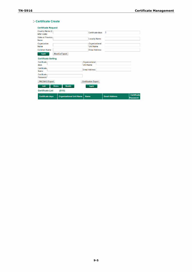
TN-5916 Certificate Management
9-5
10 10. Security
Type page 1 content here.
The following topics are covered in this chapter:
User Interface Management
Authentication Certificate
Trusted Access
Port Access Control
IEEE 802.1X Setting
IEEE 802.1X Information
RADIUS Server Setting
Local User Database
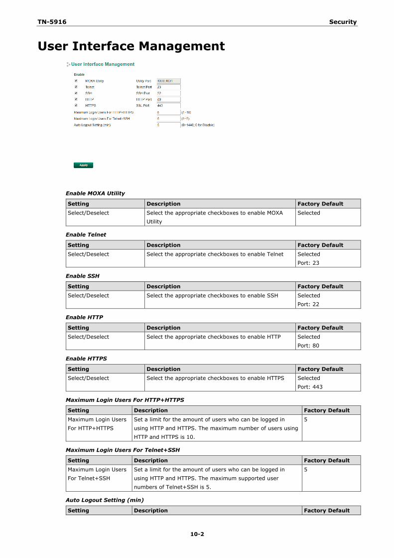
TN-5916 Security
10-2
User Interface Management
Enable MOXA Utility
Setting Description Factory Default Select/Deselect Select the appropriate checkboxes to enable MOXA
Utility Selected
Enable Telnet
Setting Description Factory Default Select/Deselect Select the appropriate checkboxes to enable Telnet Selected
Port: 23
Enable SSH
Setting Description Factory Default
Select/Deselect Select the appropriate checkboxes to enable SSH Selected Port: 22
Enable HTTP
Setting Description Factory Default Select/Deselect Select the appropriate checkboxes to enable HTTP Selected
Port: 80
Enable HTTPS
Setting Description Factory Default Select/Deselect Select the appropriate checkboxes to enable HTTPS Selected
Port: 443
Maximum Login Users For HTTP+HTTPS
Setting Description Factory Default
Maximum Login Users For HTTP+HTTPS
Set a limit for the amount of users who can be logged in using HTTP and HTTPS. The maximum number of users using HTTP and HTTPS is 10.
5
Maximum Login Users For Telnet+SSH
Setting Description Factory Default Maximum Login Users For Telnet+SSH
Set a limit for the amount of users who can be logged in using HTTP and HTTPS. The maximum supported user numbers of Telnet+SSH is 5.
5
Auto Logout Setting (min)
Setting Description Factory Default
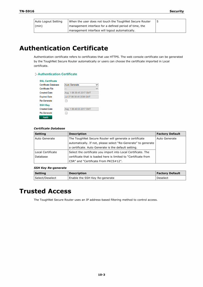
TN-5916 Security
10-3
Auto Logout Setting (min)
When the user does not touch the ToughNet Secure Router management interface for a defined period of time, the management interface will logout automatically.
5
Authentication Certificate Authentication certificate refers to certificates that use HTTPS. The web console certificate can be generated by the ToughNet Secure Router automatically or users can choose the certificate imported in Local certificate.
Certificate Database
Setting Description Factory Default
Auto Generate The ToughNet Secure Router will generate a certificate automatically. If not, please select “Re-Generate” to generate a certificate. Auto Generate is the default setting.
Auto Generate
Local Certificate Database
Select the certificate you import into Local Certificate. The certificate that is loaded here is limited to “Certificate from CSR” and “Certificate From PKCS#12”.
SSH Key Re-generate
Setting Description Factory Default Select/Deselect Enable the SSH Key Re-generate Deselect
Trusted Access The ToughNet Secure Router uses an IP address-based filtering method to control access.
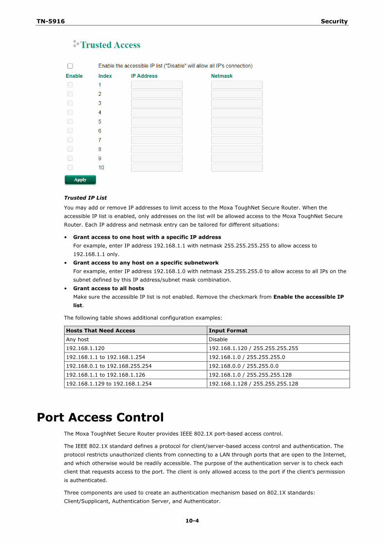
TN-5916 Security
10-4
Trusted IP List
You may add or remove IP addresses to limit access to the Moxa ToughNet Secure Router. When the accessible IP list is enabled, only addresses on the list will be allowed access to the Moxa ToughNet Secure Router. Each IP address and netmask entry can be tailored for different situations:
• Grant access to one host with a specific IP address For example, enter IP address 192.168.1.1 with netmask 255.255.255.255 to allow access to 192.168.1.1 only.
• Grant access to any host on a specific subnetwork For example, enter IP address 192.168.1.0 with netmask 255.255.255.0 to allow access to all IPs on the subnet defined by this IP address/subnet mask combination.
• Grant access to all hosts Make sure the accessible IP list is not enabled. Remove the checkmark from Enable the accessible IP list.
The following table shows additional configuration examples:
Hosts That Need Access Input Format Any host Disable
192.168.1.120 192.168.1.120 / 255.255.255.255
192.168.1.1 to 192.168.1.254 192.168.1.0 / 255.255.255.0
192.168.0.1 to 192.168.255.254 192.168.0.0 / 255.255.0.0
192.168.1.1 to 192.168.1.126 192.168.1.0 / 255.255.255.128
192.168.1.129 to 192.168.1.254 192.168.1.128 / 255.255.255.128
Port Access Control The Moxa ToughNet Secure Router provides IEEE 802.1X port-based access control.
The IEEE 802.1X standard defines a protocol for client/server-based access control and authentication. The protocol restricts unauthorized clients from connecting to a LAN through ports that are open to the Internet, and which otherwise would be readily accessible. The purpose of the authentication server is to check each client that requests access to the port. The client is only allowed access to the port if the client’s permission is authenticated.
Three components are used to create an authentication mechanism based on 802.1X standards: Client/Supplicant, Authentication Server, and Authenticator.
TN-5916 Security
10-5
Client/Supplicant: The end station that requests access to the LAN and switch services and responds to the requests from the switch.
Authentication Server: The server that performs the actual authentication of the supplicant.
Authenticator: Edge switch or wireless access point that acts as a proxy between the supplicant and the authentication server, requesting identity information from the supplicant, verifying the information with the authentication server, and relaying a response to the supplicant.
The Moxa ToughNet Secure Router acts as an authenticator in the 802.1X environment. A supplicant and an authenticator exchange EAPOL (Extensible Authentication Protocol over LAN) frames with each other. We can either use an external RADIUS server as the authentication server, or implement the authentication server in the Moxa ToughNet Secure Router by using a Local User Database as the authentication look-up table. When we use an external RADIUS server as the authentication server, the authenticator and the authentication server exchange EAP frames between each other.
Authentication can be initiated either by the supplicant or the authenticator. When the supplicant initiates the authentication process, it sends an EAPOL-Start frame to the authenticator. When the authenticator initiates the authentication process or when it receives an EAPOL-Start frame, it sends an EAP-Request/Identity frame to ask for the username of the supplicant.
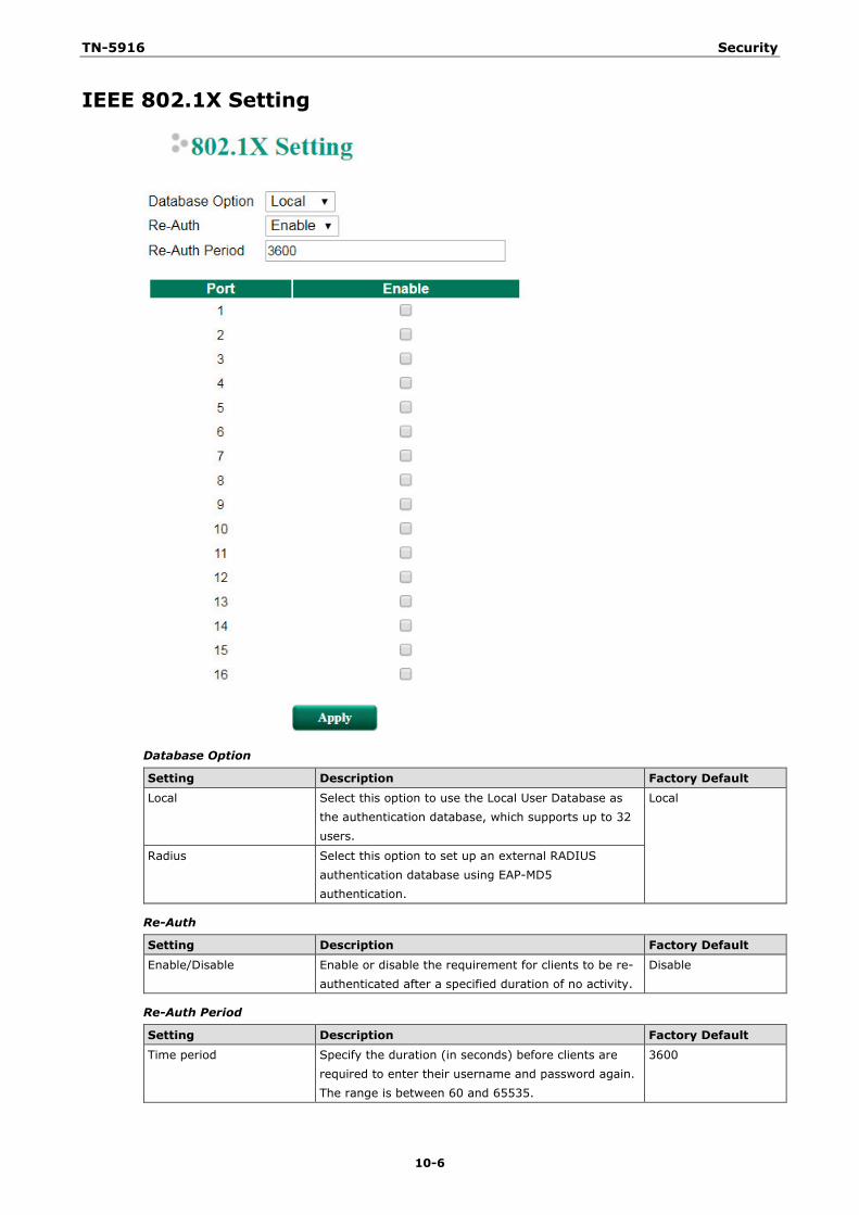
TN-5916 Security
10-6
IEEE 802.1X Setting
Database Option
Setting Description Factory Default Local Select this option to use the Local User Database as
the authentication database, which supports up to 32 users.
Local
Radius Select this option to set up an external RADIUS authentication database using EAP-MD5 authentication.
Re-Auth
Setting Description Factory Default
Enable/Disable Enable or disable the requirement for clients to be re-authenticated after a specified duration of no activity.
Disable
Re-Auth Period
Setting Description Factory Default Time period Specify the duration (in seconds) before clients are
required to enter their username and password again. The range is between 60 and 65535.
3600
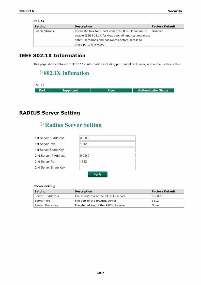
TN-5916 Security
10-7
802.1X
Setting Description Factory Default Enable/Disable Check the box for a port under the 802.1X column to
enable IEEE 802.1X for that port. All end stations must enter usernames and passwords before access to these ports is allowed.
Disabled
IEEE 802.1X Information This page shows detailed IEEE 802.1X information including port, supplicant, user, and authenticator status.
RADIUS Server Setting
Server Setting
Setting Description Factory Default Server IP Address The IP address of the RADIUS server. 0.0.0.0
Server Port The port of the RADIUS server 1812
Server Share key The shared key of the RADIUS server None
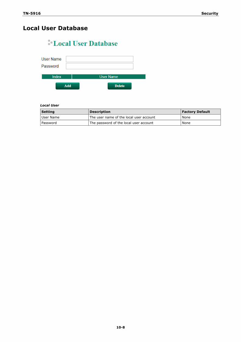
TN-5916 Security
10-8
Local User Database
Local User
Setting Description Factory Default User Name The user name of the local user account None
Password The password of the local user account None
11 11. Diagnosis
The ToughNet Secure Router provides Ping tools and LLDP for administrators to diagnose network systems.
The following topics are covered in this chapter:
Ping
LLDP
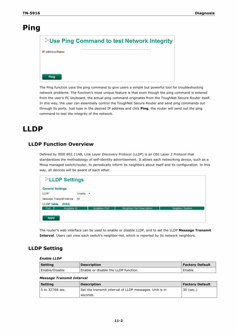
TN-5916 Diagnosis
11-2
Ping
The Ping function uses the ping command to give users a simple but powerful tool for troubleshooting network problems. The function’s most unique feature is that even though the ping command is entered from the user’s PC keyboard, the actual ping command originates from the ToughNet Secure Router itself. In this way, the user can essentially control the ToughNet Secure Router and send ping commands out through its ports. Just type in the desired IP address and click Ping, the router will send out the ping command to test the integrity of the network.
LLDP
LLDP Function Overview
Defined by IEEE 802.11AB, Link Layer Discovery Protocol (LLDP) is an OSI Layer 2 Protocol that standardizes the methodology of self-identity advertisement. It allows each networking device, such as a Moxa managed switch/router, to periodically inform its neighbors about itself and its configuration. In this way, all devices will be aware of each other.
The router’s web interface can be used to enable or disable LLDP, and to set the LLDP Message Transmit Interval. Users can view each switch’s neighbor-list, which is reported by its network neighbors.
LLDP Setting
Enable LLDP
Setting Description Factory Default Enable/Disable Enable or disable the LLDP function. Enable
Message Transmit Interval
Setting Description Factory Default 5 to 32768 sec. Set the transmit interval of LLDP messages. Unit is in
seconds. 30 (sec.)
TN-5916 Diagnosis
11-3
LLDP Table
Port: The port number that connects to the neighbor device. Neighbor ID: A unique entity that identifies a neighbor device; this is typically the MAC address. Neighbor Port: The port number of the neighbor device. Neighbor Port Description: A textual description of the neighbor device’s interface. Neighbor System: Hostname of the neighbor device.
A A. MIB Groups
The ToughNet Secure Router comes with built-in SNMP (Simple Network Management Protocol) agent software that supports cold start trap, line up/down trap, and RFC 1213 MIB-II. The standard MIB groups that the ToughNet Secure Router series support are:
MIB II.1 – System Group
sysORTable
MIB II.2 – Interfaces Group
ifTable
MIB II.4 – IP Group
ipAddrTable ipNetToMediaTable IpGroup IpBasicStatsGroup IpStatsGroup
MIB II.5 – ICMP Group
IcmpGroup IcmpInputStatus IcmpOutputStats
MIB II.6 – TCP Group
tcpConnTable TcpGroup TcpStats
MIB II.7 – UDP Group
udpTable UdpStats
MIB II.11 – SNMP Group
SnmpBasicGroup SnmpInputStats SnmpOutputStats
Public Traps
1. Cold Start 2. Link Up 3. Link Down 4. Authentication Failure
Private Traps:
1. Configuration Changed 2. Power On 3. Power Off
The ToughNet Secure Router also provides a MIB file, located in the file “Moxa-TN5916-MIB.my” on the ToughNet Secure Router Series utility CD-ROM for SNMP trap message interpretation.
Related Documents