*27788490_0522* Drive Technology \ Drive Automation \ System Integration \ Services Operating Instructions Inverter MOVITRAC ® advanced Edition 05/2022 27788490/EN

Welcome message from author
This document is posted to help you gain knowledge. Please leave a comment to let me know what you think about it! Share it to your friends and learn new things together.
Transcript

*27788490_0522*Drive Technology \ Drive Automation \ System Integration \ Services
Operating Instructions
InverterMOVITRAC® advanced
Edition 05/2022 27788490/EN

SEW-EURODRIVE—Driving the world

Table of contents
Operating Instructions – MOVITRAC® advanced 3
Table of contents1 General information.................................................................................................................. 6
1.1 About this documentation ............................................................................................... 61.2 Structure of the safety notes ........................................................................................... 61.3 Decimal separator in numerical values ........................................................................... 71.4 Rights to claim under limited warranty ............................................................................ 71.5 Content of the documentation......................................................................................... 71.6 Other applicable documentation ..................................................................................... 81.7 Product names and trademarks...................................................................................... 81.8 Copyright notice .............................................................................................................. 81.9 Graphic presentation of the devices ............................................................................... 8
2 Safety notes .............................................................................................................................. 92.1 Preliminary information ................................................................................................... 92.2 Duties of the user............................................................................................................ 92.3 Target group ................................................................................................................. 102.4 Network security and access protection ....................................................................... 102.5 Designated use ............................................................................................................. 112.6 Functional safety technology ........................................................................................ 122.7 Transport....................................................................................................................... 122.8 Installation/assembly..................................................................................................... 132.9 Electrical installation ..................................................................................................... 142.10 Protective separation .................................................................................................... 142.11 Startup/operation .......................................................................................................... 15
3 Device structure ..................................................................................................................... 163.1 Nameplates................................................................................................................... 163.2 Type code ................................................................................................................... 183.3 Device structure of the inverter ..................................................................................... 19
4 Installation............................................................................................................................... 264.1 Permitted tightening torques ......................................................................................... 264.2 Permissible cross-sections of the terminals.................................................................. 274.3 Special aspects when transporting the devices ............................................................ 304.4 Mechanical installation.................................................................................................. 314.5 Covers........................................................................................................................... 334.6 Control cabinet installation............................................................................................ 374.7 Electrical installation ..................................................................................................... 394.8 Braking resistors ........................................................................................................... 574.9 NF.. line filter................................................................................................................. 714.10 EMC-compliant installation ........................................................................................... 724.11 Terminal assignment of basic unit ................................................................................ 774.12 Wiring diagrams ............................................................................................................ 834.13 UL-compliant installation............................................................................................... 98
5 Startup ................................................................................................................................... 1025.1 General ....................................................................................................................... 1025.2 Startup requirements .................................................................................................. 103
2778
8490
/EN
– 0
5/20
22
Table of contents
Operating Instructions – MOVITRAC® advanced4
5.3 Operation without startup............................................................................................ 1045.4 Startup with MOVISUITE® engineering software ....................................................... 1055.5 EtherCAT® ID ............................................................................................................. 1095.6 Startup with the CBG01A keypad ............................................................................... 1115.7 Startup with the CBG11A keypad ............................................................................... 1145.8 Startup with the CBG21A keypad ............................................................................... 1165.9 Firmware update ......................................................................................................... 1185.10 Startup of motors with the MOVILINK® DDI interface ................................................ 1185.11 Control of control signal sources................................................................................. 1195.12 Application-related startup .......................................................................................... 121
6 Operation............................................................................................................................... 1276.1 General information .................................................................................................... 1276.2 CMM11A memory module .......................................................................................... 1286.3 LED display................................................................................................................. 1306.4 7-segment display....................................................................................................... 1416.5 Operating displays ...................................................................................................... 1426.6 Fault description.......................................................................................................... 1456.7 Fault responses .......................................................................................................... 212
7 Service................................................................................................................................... 2157.1 Electronics Service by SEW‑EURODRIVE................................................................. 2157.2 Extended storage........................................................................................................ 2157.3 Device replacement .................................................................................................... 2167.4 Shutdown.................................................................................................................... 2177.5 Waste disposal............................................................................................................ 218
8 Technical data....................................................................................................................... 2198.1 Markings ..................................................................................................................... 2198.2 General technical data ................................................................................................ 2248.3 Technical data of basic unit ........................................................................................ 2268.4 Technical data of accessories..................................................................................... 2358.5 Electronics data – signal terminals ............................................................................. 2378.6 Dimension sheets ....................................................................................................... 2418.7 Diagnostic module CDM11A....................................................................................... 2488.8 USM21A interface adapter.......................................................................................... 2498.9 CMM11A memory module .......................................................................................... 2508.10 Keypads ...................................................................................................................... 2518.11 Technical data of braking resistors, filters, and chokes .............................................. 252
9 Functional safety .................................................................................................................. 2779.1 General information .................................................................................................... 2779.2 Integrated safety technology....................................................................................... 2779.3 Safety-related conditions ............................................................................................ 2889.4 Connection variants .................................................................................................... 2959.5 Electrical installation ................................................................................................... 2989.6 Startup ........................................................................................................................ 3149.7 Operation .................................................................................................................... 357 27
7884
90/E
N –
05/
2022

Table of contents
Operating Instructions – MOVITRAC® advanced 5
9.8 Data exchange with higher-level controller ................................................................. 3589.9 Response times .......................................................................................................... 3769.10 Service ........................................................................................................................ 3819.11 Technical data............................................................................................................. 392
10 Appendix ............................................................................................................................... 39510.1 Abbreviation key ......................................................................................................... 395
Index ...................................................................................................................................... 397
11 Address list ........................................................................................................................... 402
2778
8490
/EN
– 0
5/20
22

1 General informationAbout this documentation
Operating Instructions – MOVITRAC® advanced6
1 General information1.1 About this documentation
The documentation at hand is the original.This documentation is an integral part of the product. The documentation is intendedfor all employees who perform work on the product.Make sure this documentation is accessible and legible. Ensure that persons respon-sible for the systems and their operation as well as persons who work on the productindependently have read through the documentation carefully and understood it. If youare unclear about any of the information in this documentation or if you require furtherinformation, contact SEW‑EURODRIVE.
1.2 Structure of the safety notes1.2.1 Meaning of signal words
The following table shows the grading and meaning of the signal words for safetynotes.
Signal word Meaning Consequences if disregarded
DANGER Imminent hazard Severe or fatal injuries
WARNING Possible dangerous situation Severe or fatal injuries
CAUTION Possible dangerous situation Minor injuries
NOTICE Possible damage to property Damage to the product or its envi-ronment
INFORMATION Useful information or tip: Simplifieshandling of the product.
1.2.2 Structure of section-related safety notesSection-related safety notes do not apply to a specific action but to several actionspertaining to one subject. The hazard symbols used either indicate a general hazardor a specific hazard.This is the formal structure of a safety note for a specific section:
SIGNAL WORDType and source of hazard.Possible consequence(s) if disregarded.• Measure(s) to prevent the hazard.
2778
8490
/EN
– 0
5/20
22

1General informationDecimal separator in numerical values
Operating Instructions – MOVITRAC® advanced 7
Meaning of the hazard symbolsThe hazard symbols in the safety notes have the following meaning:
Hazard symbol MeaningGeneral hazard
Warning of dangerous electrical voltage
Warning of hot surfaces
Warning about suspended load
Warning of automatic restart
1.2.3 Structure of embedded safety notesEmbedded safety notes are directly integrated into the instructions just before the de-scription of the dangerous action.This is the formal structure of an embedded safety note:
SIGNAL WORD! Type and source of hazard. Possible consequence(s) if disre-garded. Measure(s) to prevent the hazard.
1.3 Decimal separator in numerical values
In this document, a period is used to indicate the decimal separator.Example: 30.5 kg
1.4 Rights to claim under limited warrantyRead the information in this documentation. This is essential for fault-free operationand fulfillment of any rights to claim under limited warranty. Read the documentationbefore you start working with the product.
1.5 Content of the documentationThis documentation contains additional safety-related information and conditions foroperation in safety-related applications.27
7884
90/E
N –
05/
2022
1 General informationOther applicable documentation
Operating Instructions – MOVITRAC® advanced8
1.6 Other applicable documentationObserve the corresponding documentation for all additional components.
1.7 Product names and trademarks
The brands and product names in this documentation are trademarks or registeredtrademarks of their respective titleholders.
1.7.1 Trademark of Beckhoff Automation GmbHEtherCAT® is a registered trademark and patented technology, licensed by BeckhoffAutomation GmbH, Germany.
1.7.2 Trademark of Beckhoff Automation GmbHSafety over EtherCAT® is a registered trademark and patented technology, licensedby Beckhoff Automation GmbH, Germany.
25798632331
1.7.3 Trademarks of ODVA, Inc.EtherNet/IP™, CIP™, CIP Safety™, ODVA® and ODVA CONFORMANT® are re-gistered trademarks of ODVA, Inc.
1.8 Copyright notice
© 2022 SEW‑EURODRIVE. All rights reserved. Unauthorized reproduction, modifica-tion, distribution or any other use of the whole or any part of this documentation isstrictly prohibited.
1.9 Graphic presentation of the devicesIn the present documentation, the inverters are shown with a plugged-in keypad onlywhen that is necessary for explaining a presentation, a function, or an instruction.
2778
8490
/EN
– 0
5/20
22

2Safety notesPreliminary information
Operating Instructions – MOVITRAC® advanced 9
2 Safety notes2.1 Preliminary information
The following general safety notes serve the purpose of preventing injury to personsand damage to property. They primarily apply to the use of products described in thisdocumentation. If you use additional components, also observe the relevant warningand safety notes.
2.2 Duties of the userAs the user, you must ensure that the basic safety notes are observed and compliedwith. Make sure that persons responsible for the machinery and its operation as wellas persons who work on the device independently have read through the documenta-tion carefully and understood it.As the user, you must ensure that all of the work listed in the following is carried outonly by qualified specialists:• Setup and installation• Installation and connection• Startup• Maintenance and repairs• Shutdown• DisassemblyEnsure that the persons who work on the product pay attention to the following regula-tions, conditions, documentation, and information:• National and regional safety and accident prevention regulations• Warning and safety signs on the product• All other relevant project planning documents, installation and startup instructions,
and wiring diagrams• Do not assemble, install or operate damaged products• All system-specific specifications and conditionsEnsure that systems in which the product is installed are equipped with additionalmonitoring and protection devices. Observe the applicable safety regulations and leg-islation governing technical work equipment and accident prevention regulations.
2778
8490
/EN
– 0
5/20
22

2 Safety notesTarget group
Operating Instructions – MOVITRAC® advanced10
2.3 Target group
Specialist for me-chanical work
Any mechanical work may be performed only by adequately qualified specialists. Spe-cialists in the context of this documentation are persons who are familiar with thedesign, mechanical installation, troubleshooting, and maintenance of the product whopossess the following qualifications:• Qualifications in the field of mechanics in accordance with the national regulations• Familiarity with this documentation
Specialist for elec-trotechnical work
Any electrotechnical work may be performed only by electrically skilled persons with asuitable education. Electrically skilled persons in the context of this documentation arepersons who are familiar with electrical installation, startup, troubleshooting, and main-tenance of the product who possess the following qualifications:• Qualifications in the field of electrical engineering in accordance with the national
regulations• Familiarity with this documentation
Additional qualifi-cations
In addition to that, these persons must be familiar with the valid safety regulations andlaws, as well as with the requirements of the standards, directives, and laws specifiedin this documentation.The persons must have the express authorization of the company to operate, pro-gram, parameterize, label, and ground devices, systems, and circuits in accordancewith the standards of safety technology.
Instructed persons All work in the areas of transport, storage, installation, operation and waste disposalmay only be carried out by persons who are trained and instructed appropriately.These instructions must enable the persons to carry out the required activities andwork steps safely and in accordance with regulations.
2.4 Network security and access protectionA bus system makes it possible to adapt electronic drive technology components tothe particulars of the machinery within wide limits. There is a risk that a change of pa-rameters that cannot be detected externally may result in unexpected but not uncon-trolled system behavior and may have a negative impact on operational safety, systemavailability, or data security.Ensure that unauthorized access is prevented, especially with respect to Ethernet-based networked systems and engineering interfaces.Use IT‑specific safety standards to increase access protection to the ports. For a portoverview, refer to the respective technical data of the device in use.
2778
8490
/EN
– 0
5/20
22

2Safety notesDesignated use
Operating Instructions – MOVITRAC® advanced 11
2.5 Designated use
The product is intended for control cabinet installation in electrical systems or ma-chines.In case of installation in electrical systems or machines, startup of the product is pro-hibited until it is determined that the machine meets the requirements stipulated in thelocal laws and directives. For Europe, Machinery Directive 2006/42/EC as well as theEMC Directive 2014/30/EU apply. Observe EN 60204-1 (Safety of machinery - elec-trical equipment of machines). The product meets the requirements stipulated in theLow Voltage Directive 2014/35/EU.The standards given in the declaration of conformity apply to the product.The systems can be mobile or stationary.Do not connect any other loads to the product. Never connect capacitive loads to theproduct.The product can be used to operate the following motors in industrial and commercialsystems:• AC asynchronous motors with squirrel-cage rotor• Permanent-field AC synchronous motorsTechnical data and information on the connection conditions are provided on thenameplate and in chapter "Technical data" in the documentation. Always comply withthe data and conditions.Unintended or improper use of the product may result in severe injury to persons anddamage to property.
2.5.1 Hoist applicationsTo avoid danger of fatal injury due to falling hoists, observe the following points whenusing the product in lifting applications:• Use mechanical protection devices.
Application in ELSM® control modeWhen the inverter is operated in ELSM® control mode, using it in lifting applications isnot permitted. In this control mode only applications of horizontal materials handlingare permitted.
2.5.2 Restrictions under the European WEEE Directive 2012/19/EUOptions and accessories from SEW-EURODRIVE may only be used in combinationwith products from SEW-EURODRIVE.
2778
8490
/EN
– 0
5/20
22

2 Safety notesFunctional safety technology
Operating Instructions – MOVITRAC® advanced12
2.6 Functional safety technologyThe product must not perform any safety functions without a higher-level safety sys-tem unless explicitly allowed by the documentation.
2.7 Transport
Inspect the shipment for damage as soon as you receive the delivery. Inform the ship-ping company immediately about any damage. If the product is damaged, it must notbe assembled, installed or started up.Observe the following notes when transporting the device:• Ensure that the product is not subject to mechanical impact.If necessary, use suitable, sufficiently dimensioned handling equipment.Observe the information on climatic conditions in chapter "Technical data" of the docu-mentation.
2778
8490
/EN
– 0
5/20
22

2Safety notesInstallation/assembly
Operating Instructions – MOVITRAC® advanced 13
2.8 Installation/assemblyEnsure that the product is installed and cooled according to the regulations in this doc-umentation.Protect the product from strong mechanical strain. Ensure that components are notdeformed and insulation spaces are not changed, particularly during transportationand handling. Electrical components must not be mechanically damaged or destroyed.Observe the notes in the chapter "Mechanical installation".
2.8.1 Restrictions of useThe following applications are prohibited unless the device is explicitly designed forsuch use:• Use in potentially explosive atmospheres• Use in areas exposed to harmful oils, acids, gases, vapors, dust, and radiation• Operation in applications with impermissibly high mechanical vibration and shock
loads in excess of the regulations stipulated in EN 61800-5-1• Use at an elevation of more than 3800 m above sea levelThe product can be used at altitudes above 1000 m above sea level up to 3800 mabove sea level under the following conditions:• Taking the reduced continuous rated current into consideration, see the chapter
"Technical data" of the documentation.• Above 2000 m above sea level, the air and creeping distances are only sufficient
for overvoltage class II according to EN 60664. If the installation requires over-voltage category III according to EN 60664 you have to reduce the overvoltageson the system side from category III to II using additional external overvoltage pro-tection.
• If a protective electrical separation is required, then implement this outside theproduct at altitudes of more than 2000 m above sea level (protective separation inaccordance with EN 61800‑5‑1 and EN 60204‑1).
2778
8490
/EN
– 0
5/20
22

2 Safety notesElectrical installation
Operating Instructions – MOVITRAC® advanced14
2.9 Electrical installation
Ensure that all of the required covers are correctly attached after carrying out the elec-trical installation.Make sure that preventive measures and protection devices comply with the applica-ble regulations (e.g. EN 60204-1 or EN 61800-5-1).
2.9.1 Required preventive measureMake sure that the product is correctly attached to the ground connection.
2.9.2 Stationary applicationNecessary preventive measure for the product:
Type of energy transfer Preventive measureDirect power supply • Ground connection
2.9.3 Regenerative operationThe drive is operated as a generator due to the kinetic energy of the system/machine.Before opening the connection box, secure the output shaft against rotation.
2.10 Protective separationThe product meets all requirements for protective separation of power and electronicsconnections in accordance with EN 61800-5-1. The connected signal circuits mustmeet requirements according to SELV (Safety Extra Low Voltage) or PELV (ProtectiveExtra Low Voltage) to ensure protective separation. The installation must meet the re-quirements for protective separation.In order to avoid exceeding the permitted contact voltages in SELV or PELV power cir-cuits in the event of a fault, continuous equipotential bonding is required in the vicinityof these power circuits. If this is not possible, other preventive measures must betaken. These preventive measures are described in EN 61800-5-1.
2778
8490
/EN
– 0
5/20
22
2Safety notesStartup/operation
Operating Instructions – MOVITRAC® advanced 15
2.11 Startup/operation
Observe the safety notes in chapters "Startup" and "Operation" in this documentation.Make sure the connection boxes are closed and screwed before connecting the sup-ply voltage.Depending on the degree of protection, products may have live, uninsulated, andsometimes moving or rotating parts as well as hot surfaces during operation.When the device is switched on, dangerous voltages are present at all power connec-tions as well as at any connected cables and terminals. This also applies even whenthe product is inhibited and the motor is at standstill.Risk of burns due to arcing: Do not disconnect power connections during operation.Do not connect power connections during operation.If you disconnect the product from the voltage supply, do not touch any live compo-nents or power connections because capacitors might still be charged. Observe thefollowing minimum switch-off time:10 minutes.Observe the corresponding information signs on the product.The fact that the operation LED and other display elements are no longer illuminateddoes not indicate that the product has been disconnected from the supply system andno longer carries any voltage.Mechanical blocking or internal protective functions of the product can cause a motorstandstill. Eliminating the cause of the problem or performing a reset may result in thedrive restarting automatically. If, for safety reasons, this is not permitted for the drive-controlled machine, first disconnect the product from the supply system and then starttroubleshooting.Risk of burns: The surface temperature of the product can exceed 60 °C during opera-tion. Do not touch the product during operation. Let the product cool down beforetouching it.
2.11.1 Energy storage unitProducts with a connected energy storage unit are not necessarily de-energized whenthey have been disconnected from the supply system. Usually, the energy storage unitstores sufficient energy to continue operation of the connected motors for a limitedperiod of time. It is not sufficient to observe a minimum switch-off time.Perform a shutdown as described in the documentation in the chapter "Service" >"Shutdown".
2778
8490
/EN
– 0
5/20
22

3 Device structureNameplates
Operating Instructions – MOVITRAC® advanced16
3 Device structure3.1 Nameplates
The nameplates are presented as an example.
3.1.1 System nameplate
MCX91A-0010 – 0160-5E3.., MCX91A-0017 – 0093-2E3-.., MCX91A-0017 – 0110-2E1-..
[3] [4]
[1]
[2]
9007232359125003
[1] Device status[2] Master password MOVISAFE® CSB/CLS safety option[3] Serial number[4] Year of manufacture as part of the serial number. Example: 20 → year of manu-
facture 2020
2778
8490
/EN
– 0
5/20
22

3Device structureNameplates
Operating Instructions – MOVITRAC® advanced 17
MCX91A-0240 – 1770-503-.., MCX91A-0213 – 1080-2E3-..
[1][3] [4]
[1]
[2]
9007232359129867
[1] Device status[2] Master password MOVISAFE® CSB/CLS safety option[3] Serial number[4] Year of manufacture as part of the serial number. Example: 19 → year of manu-
facture 2019
3.1.2 Performance data nameplate
[1] [2]
9007232359127435
[1] Device status[2] Firmware status
3.1.3 Product label
Product label with QR code. The QR code can be scanned. You will be re-directed to the digital services of SEW‑EURODRIVE. There, you have ac-cess to product-specific data, documents, and further services.
2778
8490
/EN
– 0
5/20
22
3 Device structureType code
Operating Instructions – MOVITRAC® advanced18
3.2 Type code Type code
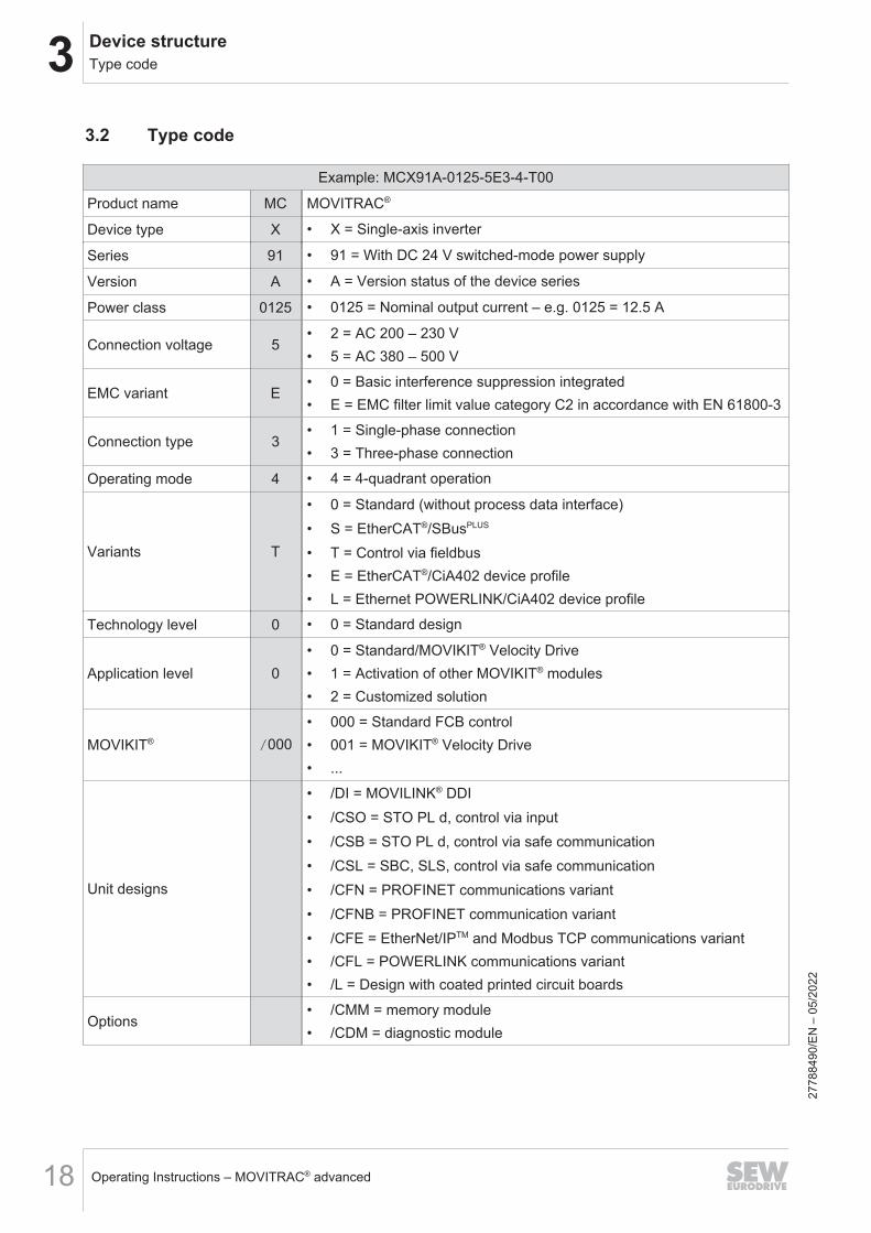
Example: MCX91A-0125-5E3-4-T00
Product name MC MOVITRAC®
Device type X • X = Single-axis inverter
Series 91 • 91 = With DC 24 V switched-mode power supply
Version A • A = Version status of the device series
Power class 0125 • 0125 = Nominal output current – e.g. 0125 = 12.5 A
Connection voltage 5• 2 = AC 200 – 230 V• 5 = AC 380 – 500 V
EMC variant E• 0 = Basic interference suppression integrated• E = EMC filter limit value category C2 in accordance with EN 61800-3
Connection type 3• 1 = Single-phase connection• 3 = Three-phase connection
Operating mode 4 • 4 = 4-quadrant operation
Variants T
• 0 = Standard (without process data interface)• S = EtherCAT®/SBusPLUS
• T = Control via fieldbus• E = EtherCAT®/CiA402 device profile• L = Ethernet POWERLINK/CiA402 device profile
Technology level 0 • 0 = Standard design
Application level 0• 0 = Standard/MOVIKIT® Velocity Drive• 1 = Activation of other MOVIKIT® modules• 2 = Customized solution
MOVIKIT® /000• 000 = Standard FCB control• 001 = MOVIKIT® Velocity Drive• ...
Unit designs
• /DI = MOVILINK® DDI• /CSO = STO PL d, control via input• /CSB = STO PL d, control via safe communication• /CSL = SBC, SLS, control via safe communication• /CFN = PROFINET communications variant• /CFNB = PROFINET communication variant• /CFE = EtherNet/IPTM and Modbus TCP communications variant• /CFL = POWERLINK communications variant• /L = Design with coated printed circuit boards
Options• /CMM = memory module• /CDM = diagnostic module
2778
8490
/EN
– 0
5/20
22

3Device structureDevice structure of the inverter
Operating Instructions – MOVITRAC® advanced 19
3.3 Device structure of the inverterThe elements shown in the device structures vary depending on the device variant.
3.3.1 MCX91A-0010 – 0055-5E3-4-.., MCX91A-0017 – 0055-2E3-4-.., MCX91A-0017 – 0042-2E1-4-..(size 0S)
X33
S1
S2
X20 X22X23
mA V
S4
IN X30/X40 OUT X30/X41
XM X60
A B C
[3]
[1]
[2]
[12][15]
[13]
[17]
[18]
[4]
[5]
[6]
[8][9]
[10]
[21]
[20]
[23]
[11]
[14]
[16]
[19]
[22]
[7]
18014431160792203
A: View from top B: View from front C: View from bottom[1] X1: Line connection [4] 2 × housing PE connection [20] X10: Brake control and mo-
tor temperature monitoring[2] X5: 24 V supply voltage [5] X33: Slot for CDM (access to
service interface)[21] X2: Motor and braking resis-
tor connection[3] X6: Connection for Safe
Torque Off (STO)[6] S1/S2: EtherCAT® ID switch [22] X18: Encoder connection
[7] QR code product label [23] X16: MOVILINK® DDI con-nection
[8] Status LEDs[9] Memory module
[10] X20: Digital inputs/outputs[11] X22: Isolated relay contact[12] X30/X40 IN: Fieldbus[13] X60: Safe inputs/outputs[14] X23: Analog inputs/outputs[15] S4: Changeover analog input
mA/V[16] X30/X41 OUT: Fieldbus[17] PE connection at housing[18] Shield plate[19] PE connection at housing
2778
8490
/EN
– 0
5/20
22
3 Device structureDevice structure of the inverter
Operating Instructions – MOVITRAC® advanced20
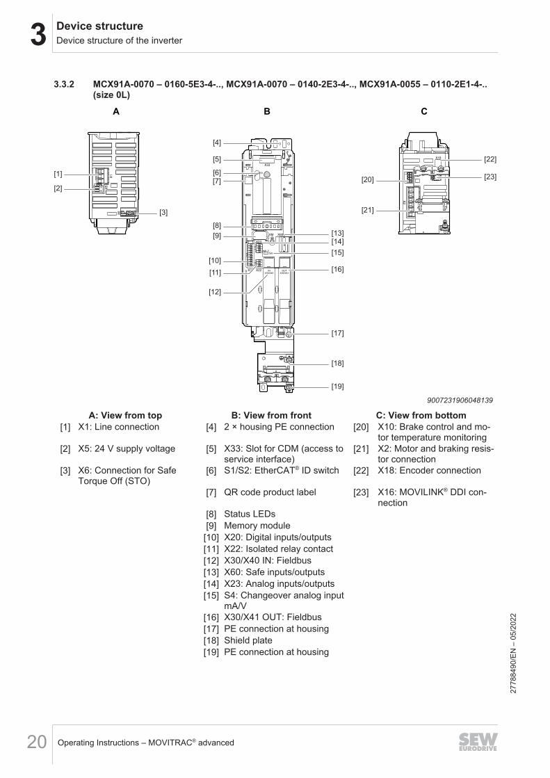
3.3.2 MCX91A-0070 – 0160-5E3-4-.., MCX91A-0070 – 0140-2E3-4-.., MCX91A-0055 – 0110-2E1-4-..(size 0L)
A B C
[3]
[1]
[2]
[16]
[15]
[13]
[17]
[18]
[5]
[6]
[8]
[9]
[10]
[11]
[21]
[23][20]
[4]
[12]
[14]
[19]
[22]
[7]
9007231906048139
A: View from top B: View from front C: View from bottom[1] X1: Line connection [4] 2 × housing PE connection [20] X10: Brake control and mo-
tor temperature monitoring[2] X5: 24 V supply voltage [5] X33: Slot for CDM (access to
service interface)[21] X2: Motor and braking resis-
tor connection[3] X6: Connection for Safe
Torque Off (STO)[6] S1/S2: EtherCAT® ID switch [22] X18: Encoder connection
[7] QR code product label [23] X16: MOVILINK® DDI con-nection
[8] Status LEDs[9] Memory module
[10] X20: Digital inputs/outputs[11] X22: Isolated relay contact[12] X30/X40 IN: Fieldbus[13] X60: Safe inputs/outputs[14] X23: Analog inputs/outputs[15] S4: Changeover analog input
mA/V[16] X30/X41 OUT: Fieldbus[17] PE connection at housing[18] Shield plate[19] PE connection at housing
2778
8490
/EN
– 0
5/20
22
3Device structureDevice structure of the inverter
Operating Instructions – MOVITRAC® advanced 21
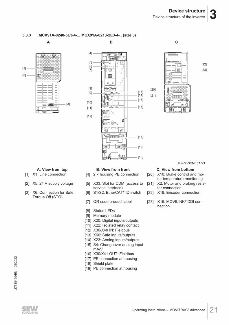
3.3.3 MCX91A-0240-5E3-4-.., MCX91A-0213-2E3-4-.. (size 3)
A B C
[3]
[1]
[2]
[16]
[15]
[13]
[17]
[18]
[5]
[6]
[8]
[9]
[10]
[11]
[21]
[23]
[20]
[4]
[12]
[14]
[19]
[22]
[7]
9007233010101771
A: View from top B: View from front C: View from bottom[1] X1: Line connection [4] 2 × housing PE connection [20] X10: Brake control and mo-
tor temperature monitoring[2] X5: 24 V supply voltage [5] X33: Slot for CDM (access to
service interface)[21] X2: Motor and braking resis-
tor connection[3] X6: Connection for Safe
Torque Off (STO)[6] S1/S2: EtherCAT® ID switch [22] X18: Encoder connection
[7] QR code product label [23] X16: MOVILINK® DDI con-nection
[8] Status LEDs[9] Memory module
[10] X20: Digital inputs/outputs[11] X22: Isolated relay contact[12] X30/X40 IN: Fieldbus[13] X60: Safe inputs/outputs[14] X23: Analog inputs/outputs[15] S4: Changeover analog input
mA/V[16] X30/X41 OUT: Fieldbus[17] PE connection at housing[18] Shield plate[19] PE connection at housing
2778
8490
/EN
– 0
5/20
22
3 Device structureDevice structure of the inverter
Operating Instructions – MOVITRAC® advanced22
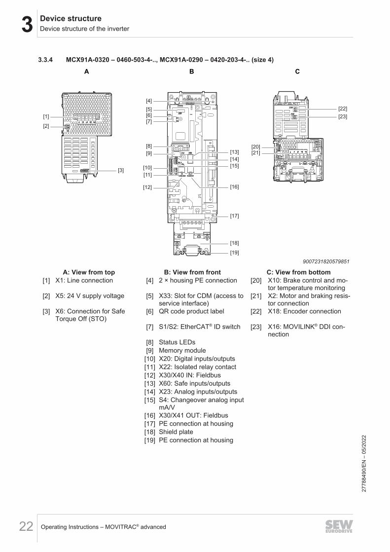
3.3.4 MCX91A-0320 – 0460-503-4-.., MCX91A-0290 – 0420-203-4-.. (size 4)
A B C
[3]
[1]
[2]
[16]
[13]
[17]
[18]
[5]
[7]
[8]
[9]
[10]
[11]
[20]
[4]
[12]
[15]
[14]
[19]
[22]
[23]
[21]
[6]
9007231820579851
A: View from top B: View from front C: View from bottom[1] X1: Line connection [4] 2 × housing PE connection [20] X10: Brake control and mo-
tor temperature monitoring[2] X5: 24 V supply voltage [5] X33: Slot for CDM (access to
service interface)[21] X2: Motor and braking resis-
tor connection[3] X6: Connection for Safe
Torque Off (STO)[6] QR code product label [22] X18: Encoder connection
[7] S1/S2: EtherCAT® ID switch [23] X16: MOVILINK® DDI con-nection
[8] Status LEDs[9] Memory module
[10] X20: Digital inputs/outputs[11] X22: Isolated relay contact[12] X30/X40 IN: Fieldbus[13] X60: Safe inputs/outputs[14] X23: Analog inputs/outputs[15] S4: Changeover analog input
mA/V[16] X30/X41 OUT: Fieldbus[17] PE connection at housing[18] Shield plate[19] PE connection at housing
2778
8490
/EN
– 0
5/20
22

3Device structureDevice structure of the inverter
Operating Instructions – MOVITRAC® advanced 23
3.3.5 MCX91A-0620 – 0910-503-4-.., MCX91A-0570 – 0840-203-4-.. (size 5)
A B C
[1]
[2]
[4]
[3]
[5]
[7]
[8]
[9]
[12]
[13]
[10][11]
[15][16]
[17][14]
[18][19]
[6]
9007234586327947
A: View from top B: View from front C: View from bottom[1] X1: Line connection [3] PE connection at housing [18] X10: Brake control and mo-
tor temperature monitoring[2] X5: 24 V supply voltage [4] X6: Connection for Safe
Torque Off (STO)[19] X2: Motor and braking resis-
tor connection[5] X33: Slot for CDM (access to
service interface)[6] QR code product label[7] S1/S2: EtherCAT® ID switch[8] Status LEDs[9] Memory module
[10] X23: Analog inputs/outputs[11] X20: Digital inputs/outputs[12] X30/X40 IN: Fieldbus[13] X30/X41 OUT: Fieldbus[14] Shield plate[15] S4: Changeover analog input
mA/V[16] X22: Isolated relay contact[17] PE connection at housing
2778
8490
/EN
– 0
5/20
22
3 Device structureDevice structure of the inverter
Operating Instructions – MOVITRAC® advanced24
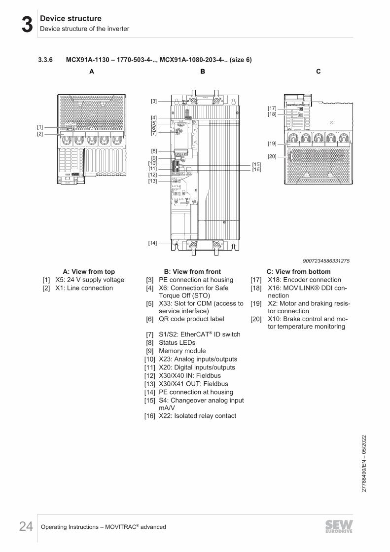
3.3.6 MCX91A-1130 – 1770-503-4-.., MCX91A-1080-203-4-.. (size 6)A B CB
[1]
[2]
[4]
[3]
[5]
[7]
[8]
[9]
[12]
[13]
[14]
[10][11]
[15][16]
[17][18]
[19]
[20]
[6]
9007234586331275
A: View from top B: View from front C: View from bottom[1] X5: 24 V supply voltage [3] PE connection at housing [17] X18: Encoder connection[2] X1: Line connection [4] X6: Connection for Safe
Torque Off (STO)[18] X16: MOVILINK® DDI con-
nection[5] X33: Slot for CDM (access to
service interface)[19] X2: Motor and braking resis-
tor connection[6] QR code product label [20] X10: Brake control and mo-
tor temperature monitoring[7] S1/S2: EtherCAT® ID switch[8] Status LEDs[9] Memory module
[10] X23: Analog inputs/outputs[11] X20: Digital inputs/outputs[12] X30/X40 IN: Fieldbus[13] X30/X41 OUT: Fieldbus[14] PE connection at housing[15] S4: Changeover analog input
mA/V[16] X22: Isolated relay contact
2778
8490
/EN
– 0
5/20
22

3Device structureDevice structure of the inverter
Operating Instructions – MOVITRAC® advanced 25
3.3.7 MCX91A-2200 – 3000-503-4-.. (size 7)
A B CB
(x10)
(x1)EC ID
S2
S1
X33
X60
S4mA V
X20 X22 INX30/X40
OUTX30/X41
23456 1
Stewart Stewart
X18
X16
[1]
[2]
[4]
[3]
[5]
[8][9]
[10]
[13]
[14]
[11]
[12]
[15]
[16]
[17]
[18]
[19]
[20]
[7]
[14]
[6]
36226240395
A: View from top B: View from front C: View from bottom[1] X5: 24 V supply voltage [3] PE connection at housing [17] X18: Encoder connection[2] X1: Line connection [4] X6: Connection for Safe
Torque Off (STO)[18] X16: MOVILINK® DDI con-
nection[5] X33: Slot for CDM (access to
service interface)[19] X2: Motor and braking resis-
tor connection[6] QR code product label [20] X10: Brake control and mo-
tor temperature monitoring[7] S1/S2: EtherCAT® ID switch[8] Status LEDs[9] Memory module
[10] X23: Analog inputs/outputs[11] X20: Digital inputs/outputs[12] X30/X40 IN: Fieldbus[13] X30/X41 OUT: Fieldbus[14] PE connection at housing[15] S4: Changeover analog input
mA/V[16] X22: Isolated relay contact
2778
8490
/EN
– 0
5/20
22

4 InstallationPermitted tightening torques
Operating Instructions – MOVITRAC® advanced26
4 Installation4.1 Permitted tightening torques
MCX91A-....-5_3-.. 0010 –0055
0070 –0160
0240 0320 –0460
0620 –0910
1130 –1770
2200 –3000
3800 –4700
MCX91A-....-2_3-.. 0017 –0055
0070 –0140
0213 0290 –0420
0570 –0840
1080 – –
MCX91A-....-2_1-.. 0017 –0042
0055 –0110
– – – – – –
Screw connection Tightening torques in NmLine connection X1 0.5 – 0.6 1.7 – 1.8 8.5 – 9.5 10 – 15 14 – 20 14 – 20Motor and braking resistorconnection X2 0.5 – 0.6 1.7 – 1.8 8.5 – 9.5 10 – 15 14 – 20 14 – 20
Terminal screw for TN/IT sys-tems EMC 1.2 – 1.7 1 – 1.2
PE connections 1.2 – 1.5 3 – 4 6 – 10 10 – 15 14 – 20 14 – 20Other M4 screw connectionsat the shield plate and frontoption
1.4 – 1.6
NOTICEFailure to adhere to prescribed tightening torques.Possible inverter damage.• Always adhere to the stipulated tightening torques. Otherwise, excessive heat
can develop, causing damage to the inverter.• An excessive tightening torque can cause damage.
2778
8490
/EN
– 0
5/20
22
4InstallationPermissible cross-sections of the terminals
Operating Instructions – MOVITRAC® advanced 27
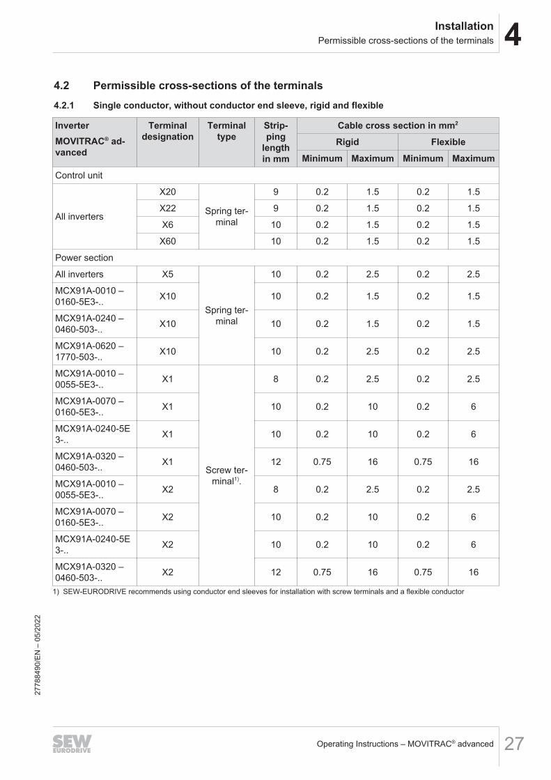
4.2 Permissible cross-sections of the terminals4.2.1 Single conductor, without conductor end sleeve, rigid and flexible
InverterMOVITRAC® ad-vanced
Terminaldesignation
Terminaltype
Strip-ping
lengthin mm
Cable cross section in mm2
Rigid FlexibleMinimum Maximum Minimum Maximum
Control unit
All inverters
X20
Spring ter-minal
9 0.2 1.5 0.2 1.5
X22 9 0.2 1.5 0.2 1.5
X6 10 0.2 1.5 0.2 1.5
X60 10 0.2 1.5 0.2 1.5
Power section
All inverters X5
Spring ter-minal
10 0.2 2.5 0.2 2.5
MCX91A-0010 –0160-5E3-.. X10 10 0.2 1.5 0.2 1.5
MCX91A-0240 –0460-503-.. X10 10 0.2 1.5 0.2 1.5
MCX91A-0620 –1770-503-.. X10 10 0.2 2.5 0.2 2.5
MCX91A-0010 –0055-5E3-.. X1
Screw ter-minal1).
8 0.2 2.5 0.2 2.5
MCX91A-0070 –0160-5E3-.. X1 10 0.2 10 0.2 6
MCX91A-0240-5E3-.. X1 10 0.2 10 0.2 6
MCX91A-0320 –0460-503-.. X1 12 0.75 16 0.75 16
MCX91A-0010 –0055-5E3-.. X2 8 0.2 2.5 0.2 2.5
MCX91A-0070 –0160-5E3-.. X2 10 0.2 10 0.2 6
MCX91A-0240-5E3-.. X2 10 0.2 10 0.2 6
MCX91A-0320 –0460-503-.. X2 12 0.75 16 0.75 16
1) SEW-EURODRIVE recommends using conductor end sleeves for installation with screw terminals and a flexible conductor
2778
8490
/EN
– 0
5/20
22

4 InstallationPermissible cross-sections of the terminals
Operating Instructions – MOVITRAC® advanced28
4.2.2 Single conductor, without conductor end sleeve, with or without plastic collar
InverterMOVITRAC® ad-vanced
Terminaldesignation
Terminaltype
Strip-ping
lengthin mm
Cable cross section in mm2
Plastic collarWith Without
Minimum Maximum Minimum MaximumControl unit
All inverters
X20
Spring ter-minal
9 0.25 1.5 0.25 0.75
X22 9 0.25 1.5 0.25 0.75
X6 10 0.14 0.75 0.25 1.5
X60 10 0.14 0.75 0.25 1.5
Power section
All inverters X5
Spring ter-minal
10 0.25 2.5 0.25 2.5
MCX91A-0010 –0160-5E3-.. X10 14 0.14 0.75 0.25 1.5
MCX91A-0240 –0460-503-.. X10 10 0.14 0.75 0.25 1.5
MCX91A-0620 –1770-503-.. X10
Screw ter-minal
10 0.25 2.5 0.25 2.5
MCX91A-0010 –0055-5E3-.. X1 8 0.25 2.5 0.25 2.5
MCX91A-0070 –0160-5E3-.. X1 10 0.25 4 0.25 6
MCX91A-0240-5E3-.. X1 10 0.25 4 0.25 6
MCX91A-0320 –0460-503-.. X1 12 0.5 10 0.5 16
MCX91A-0010 –0055-5E3-.. X2 8 0.25 2.5 0.25 2.5
MCX91A-0070 –0160-5E3-.. X2 10 0.25 4 0.25 6
MCX91A-0240-5E3-.. X2 10 0.25 4 0.25 6
MCX91A-0320 –0460-503-.. X2 12 0.5 10 0.5 16
2778
8490
/EN
– 0
5/20
22
4InstallationPermissible cross-sections of the terminals
Operating Instructions – MOVITRAC® advanced 29
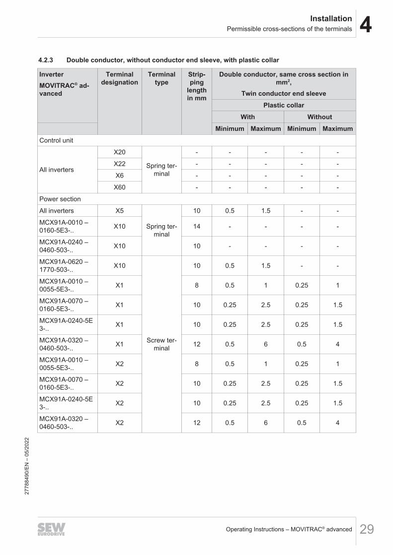
4.2.3 Double conductor, without conductor end sleeve, with plastic collar
InverterMOVITRAC® ad-vanced
Terminaldesignation
Terminaltype
Strip-ping
lengthin mm
Double conductor, same cross section inmm2,
Twin conductor end sleevePlastic collar
With WithoutMinimum Maximum Minimum Maximum
Control unit
All inverters
X20
Spring ter-minal
- - - - -
X22 - - - - -
X6 - - - - -
X60 - - - - -
Power section
All inverters X5
Spring ter-minal
10 0.5 1.5 - -
MCX91A-0010 –0160-5E3-.. X10 14 - - - -
MCX91A-0240 –0460-503-.. X10 10 - - - -
MCX91A-0620 –1770-503-.. X10
Screw ter-minal
10 0.5 1.5 - -
MCX91A-0010 –0055-5E3-.. X1 8 0.5 1 0.25 1
MCX91A-0070 –0160-5E3-.. X1 10 0.25 2.5 0.25 1.5
MCX91A-0240-5E3-.. X1 10 0.25 2.5 0.25 1.5
MCX91A-0320 –0460-503-.. X1 12 0.5 6 0.5 4
MCX91A-0010 –0055-5E3-.. X2 8 0.5 1 0.25 1
MCX91A-0070 –0160-5E3-.. X2 10 0.25 2.5 0.25 1.5
MCX91A-0240-5E3-.. X2 10 0.25 2.5 0.25 1.5
MCX91A-0320 –0460-503-.. X2 12 0.5 6 0.5 4
2778
8490
/EN
– 0
5/20
22
4 InstallationSpecial aspects when transporting the devices
Operating Instructions – MOVITRAC® advanced30
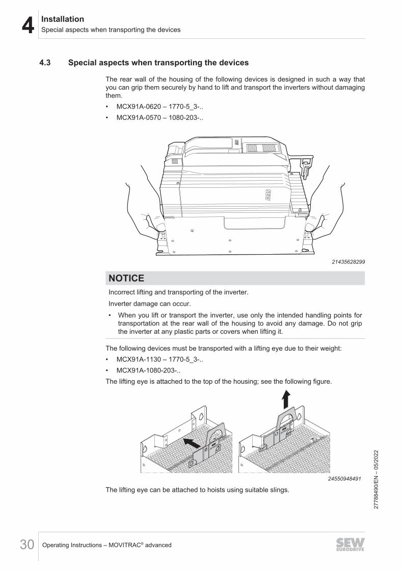
4.3 Special aspects when transporting the devices
The rear wall of the housing of the following devices is designed in such a way thatyou can grip them securely by hand to lift and transport the inverters without damagingthem.• MCX91A-0620 – 1770-5_3-..• MCX91A-0570 – 1080-203-..
21435628299
NOTICEIncorrect lifting and transporting of the inverter.Inverter damage can occur.• When you lift or transport the inverter, use only the intended handling points for
transportation at the rear wall of the housing to avoid any damage. Do not gripthe inverter at any plastic parts or covers when lifting it.
The following devices must be transported with a lifting eye due to their weight:• MCX91A-1130 – 1770-5_3-..• MCX91A-1080-203-..The lifting eye is attached to the top of the housing; see the following figure.
24550948491
The lifting eye can be attached to hoists using suitable slings.
2778
8490
/EN
– 0
5/20
22
4InstallationMechanical installation
Operating Instructions – MOVITRAC® advanced 31
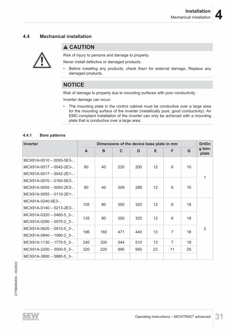
4.4 Mechanical installation
CAUTIONRisk of injury to persons and damage to property.Never install defective or damaged products.• Before installing any products, check them for external damage. Replace any
damaged products.
NOTICERisk of damage to property due to mounting surfaces with poor conductivity.Inverter damage can occur.• The mounting plate in the control cabinet must be conductive over a large area
for the mounting surface of the inverter (metallically pure, good conductivity). AnEMC‑compliant installation of the inverter can only be achieved with a mountingplate that is conductive over a large area.
4.4.1 Bore patterns
Inverter Dimensions of the device base plate in mm Drilling tem-plateA B C D E F G
MCX91A-0010 – 0055-5E3-..MCX91A-0017 – 0042-2E3-..MCX91A-0017 – 0042-2E1-..
80 40 220 200 12 6 10
1MCX91A-0070 – 0160-5E3-..MCX91A-0055 – 0093-2E3-..MCX91A-0055 – 0110-2E1-..
80 40 309 288 12 6 10
MCX91A-0240-5E3-..MCX91A-0140 – 0213-2E3-..
105 80 350 325 12 6 18
2
MCX91A-0320 – 0460-5_3-..MCX91A-0290 – 0570-2_3-..
135 80 350 325 12 6 18
MCX91A-0620 – 0910-5_3-..MCX91A-0840 – 1080-2_3-..
196 160 471 440 13 7 18
MCX91A-1130 – 1770-5_3-.. 240 200 544 510 13 7 18
MCX91A-2200 – 3000-5_3-.. 320 220 990 950 23 11 25
MCX91A-3800 – 5880-5_3-..
2778
8490
/EN
– 0
5/20
22

4 InstallationMechanical installation
Operating Instructions – MOVITRAC® advanced32
D
A
B
F
G
C
D
A
B
F
E
G
C
F
30904224779
Hole pattern 1 Hole pattern 2
4.4.2 Minimum clearance and mounting positionWhen installing the inverters in the control cabinet, observe the following:• To ensure unobstructed cooling, leave a minimum clearance of 100 mm above
and below the inverter housings. Ensure that the air circulation in this clearance isnot impaired by cables or other installation equipment.
• Make sure that the inverters are not within the area of the warm exhaust air ofother devices.
• Install the inverters only vertically. Do not install them horizontally, tilted or upsidedown.
• Clearance at the side is not necessary. The units can be arranged directly next toone another.
INFORMATIONSpecial bending spaces are required according to EN 61800‑5‑1 for cables with across section of 10 mm2 and larger. This means the clearance must be increased ifrequired.
2778
8490
/EN
– 0
5/20
22
4InstallationCovers
Operating Instructions – MOVITRAC® advanced 33
4.5 Covers4.5.1 Safety covers
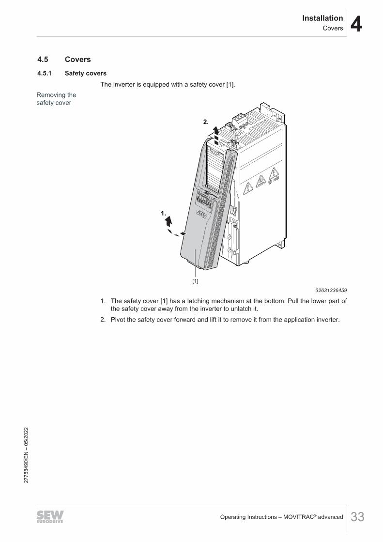
The inverter is equipped with a safety cover [1].Removing thesafety cover
1.
2.
[1]
32631336459
1. The safety cover [1] has a latching mechanism at the bottom. Pull the lower part ofthe safety cover away from the inverter to unlatch it.
2. Pivot the safety cover forward and lift it to remove it from the application inverter.
2778
8490
/EN
– 0
5/20
22

4 InstallationCovers
Operating Instructions – MOVITRAC® advanced34
Installing thesafety cover
1.
[1]
2.
32631338891
3. Place the safety cover [1] into the upper recess and move it towards the inverteruntil it clicks into place.
4. Always install the safety cover [1] after having worked on the application inverter.
2778
8490
/EN
– 0
5/20
22

4InstallationCovers
Operating Instructions – MOVITRAC® advanced 35
4.5.2 Touch guardsWith the following devices, the touch guards must be removed for the line connectionand the connection of the motor and the braking resistor:• MCX91A-0620 – 1770-503-..• MCX91A-0570 – 1080-203-..
Line connection
F-E
RR
F-R
UN
L/A
OU
T
L/A
IN
ER
R
RU
N
DR
IVE
1/L1
2/L2
3/L3
7/-UZ
8/+UZ
[1]
[2]
32650052491
1. Remove the 2 screws [1] on the upper touch guard [2].2. Remove the touch guard [2].
2778
8490
/EN
– 0
5/20
22

4 InstallationCovers
Operating Instructions – MOVITRAC® advanced36
Connection motor/braking resistor
F-E
RR
F-R
UN
L/A
OU
T
L/A
IN
ER
R
RU
N
DR
IVE
1/L1
2/L2
3/L3
7/-UZ
8/+UZ
F-E
RR
F-R
UN
L/A
OU
T
L/A
IN
ER
R
RU
N
DR
IVE
1/L1
2/L2
3/L3
7/-UZ
8/+UZ
F-E
RR
F-R
UN
L/A
OU
T
L/A
IN
ER
R
RU
N
DR
IVE
1/L1
2/L2
3/L3
7/-UZ
8/+UZ
[2]
[3][1]
32650050059
3. Push the plastic clips of the touch guard [1] to the inside and remove the touchguard [1] by moving it to the front.
4. Remove the 2 screws [2] and remove the touch guard [3] by moving it to the front.
2778
8490
/EN
– 0
5/20
22

4InstallationControl cabinet installation
Operating Instructions – MOVITRAC® advanced 37
4.6 Control cabinet installation4.6.1 Inverter and bottom shield plate
The retaining screws [1] and [2] are screwed into the prepared tapped holes in themounting plate in the control cabinet but not tightened.1. Place the inverter with the slotted holes in the device base plate onto the retaining
screws [1] from the top.
[2]
[1]
[3]
[1]
[1]
32659176459
2. Push the inverter backwards to insert the retaining screws [2] into the upper holesin the device base plate.
3. Lower the inverter.4. Install the shield plate [3] as shown above. This work step applies to the inverters
MCX9_A-0010 – 0460-5_3-.. and MCX9_A-0017 – 0420-2_3-..5. Tighten the retaining screws [1] and [2].
2778
8490
/EN
– 0
5/20
22
4 InstallationControl cabinet installation
Operating Instructions – MOVITRAC® advanced38
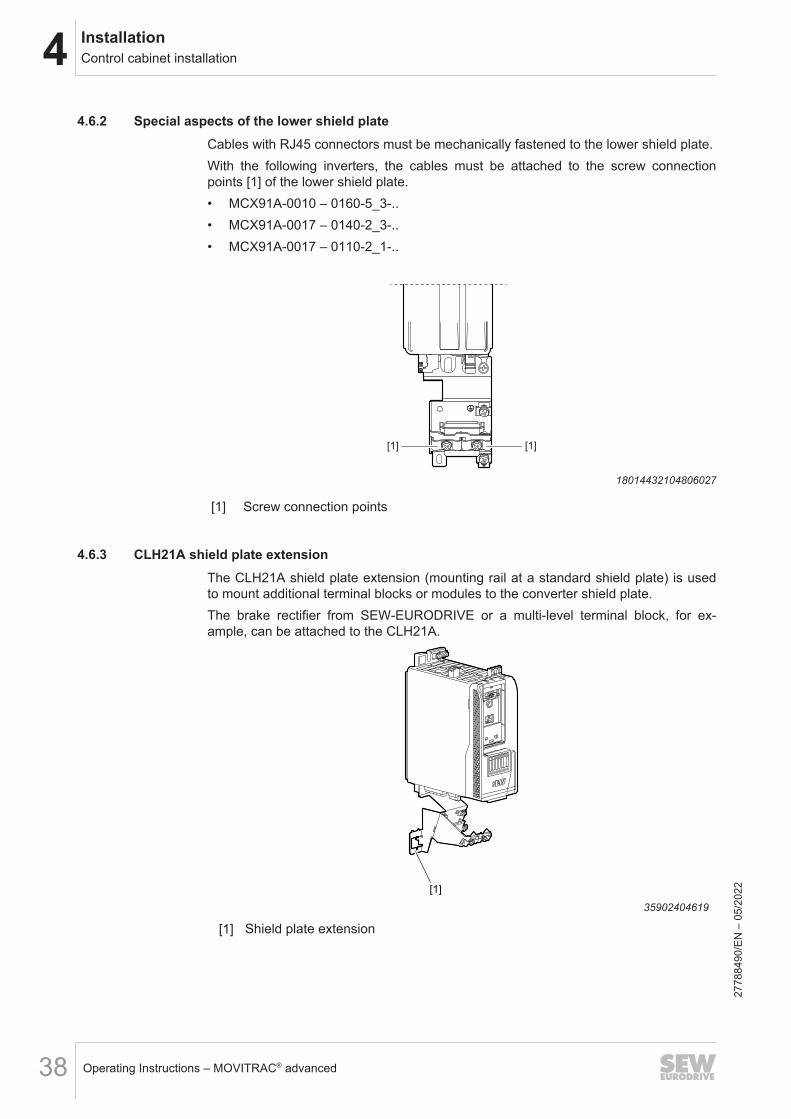
4.6.2 Special aspects of the lower shield plateCables with RJ45 connectors must be mechanically fastened to the lower shield plate.With the following inverters, the cables must be attached to the screw connectionpoints [1] of the lower shield plate.• MCX91A-0010 – 0160-5_3-..• MCX91A-0017 – 0140-2_3-..• MCX91A-0017 – 0110-2_1-..
[1] [1]
18014432104806027
[1] Screw connection points
4.6.3 CLH21A shield plate extensionThe CLH21A shield plate extension (mounting rail at a standard shield plate) is usedto mount additional terminal blocks or modules to the converter shield plate.The brake rectifier from SEW-EURODRIVE or a multi-level terminal block, for ex-ample, can be attached to the CLH21A.
[1]
35902404619
[1] Shield plate extension
2778
8490
/EN
– 0
5/20
22

4InstallationElectrical installation
Operating Instructions – MOVITRAC® advanced 39
4.7 Electrical installation
DANGERDangerous voltage levels may still be present inside the device and at the terminalstrips up to 10 minutes after the inverter has been disconnected from the power sup-ply.Severe or fatal injuries from electric shock can occur.To prevent electric shocks:• Disconnect the inverter from the power supply and wait 10 minutes before re-
moving the safety covers.
DANGERA leakage current > 3.5 mA can occur when operating the inverter.Severe or fatal injuries from electric shock can occur.To avoid dangerous shock currents in accordance with EN 61800-5-1, strictly ob-serve the following:• Supply system cable < 10 mm2:
– Route a second PE conductor with the cable cross-section of the supply sys-tem cable in parallel to the protective earth via separate terminals or use acopper PE conductor with a cable cross-section of 10 mm2.
• Supply system cable 10 mm2 – 16 mm2:– Route a copper PE conductor with the cable cross-section of the supply sys-
tem cable.• Supply system cable 16 mm2 – 35 mm2:
– Route a copper protective earth conductor with a cable cross-section of16 mm2.
• Supply system cable > 35 mm2:– Route a copper protective earth conductor with half the cross-section of the
supply system cable.• If a residual current device is used for protection against direct and indirect con-
tact in isolated cases, it must be universal current-sensitive (RCD type B).
INFORMATIONInstallation with protective separation.The inverter meets all requirements for protective separation of power and electron-ics connections in accordance with EN 61800-5-1. The connected signal circuits mustmeet requirements according to SELV (Safety Extra Low Voltage) or PELV (Protect-ive Extra Low Voltage) to ensure protective separation. The installation must meetthe requirements for protective separation.
4.7.1 General information• Provide for suitable measures to prevent the motor from starting up unintentionally.
Take additional safety measures depending on the application to prevent possibleinjuries to people and damage to machinery.
• Only use closed cable lugs or conductor end sleeves for connection to the screwsin order to prevent litz strands from escaping.
2778
8490
/EN
– 0
5/20
22

4 InstallationElectrical installation
Operating Instructions – MOVITRAC® advanced40
4.7.2 Permitted voltage systems
Information on voltage systems Information on permissibilityTN and TT systems – voltage systems with di-rectly grounded star point. Use is possible without restrictions.
IT systems – voltage systems with non-grounded star point.
Use is only permitted adhering tospecific measures. The measuresare described in chapter "Use in ITsystems".
Voltage systems with grounded outer con-ductor.
Use only for nominal line voltages upto max. 240 V.
4.7.3 Use in IT systemsTo ensure IT system capability, the terminal screw shown in the following figures mustbe removed from the inverter.
Inverters Position of the terminal screwMCX91A-0010 – 0160-5_3-..
MCX91A-0017 – 0140-2_3-..
MCX91A-0017 – 0110-2_1-..
See chapter "Deactivating the EMC capacit-ors" (→ 2 41).
MCX91A-0240 – 0460-5_3-..MCX91A-1130 – 1770-503-..
MCX91A-0213 – 0420-2_3-..MCX91A-1080-203-..
2778
8490
/EN
– 0
5/20
22
4InstallationElectrical installation
Operating Instructions – MOVITRAC® advanced 41
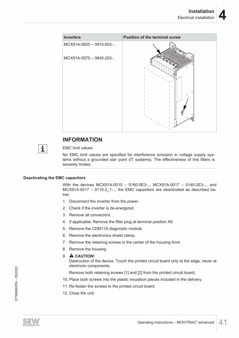
Inverters Position of the terminal screwMCX91A-0620 – 0910-503-..
MCX91A-0570 – 0840-203-..
INFORMATIONEMC limit valuesNo EMC limit values are specified for interference emission in voltage supply sys-tems without a grounded star point (IT systems). The effectiveness of line filters isseverely limited.
Deactivating the EMC capacitorsWith the devices MCX91A-0010 – 0160-5E3-.., MCX91A-0017 – 0140-2E3-.., andMCX91A-0017 – 0110-2_1-.., the EMC capacitors are deactivated as described be-low.1. Disconnect the inverter from the power.2. Check if the inverter is de-energized.3. Remove all connectors.4. If applicable: Remove the filler plug at terminal position X6.5. Remove the CDM11A diagnostic module.6. Remove the electronics shield clamp.7. Remove the retaining screws in the center of the housing front.8. Remove the housing.
9. CAUTION! Destruction of the device. Touch the printed circuit board only at the edge, never atelectronic components.Remove both retaining screws [1] and [2] from the printed circuit board.
10. Place both screws into the plastic insulation pieces included in the delivery.11. Re-fasten the screws to the printed circuit board.12. Close the unit.
2778
8490
/EN
– 0
5/20
22

4 InstallationElectrical installation
Operating Instructions – MOVITRAC® advanced42
13. Identify the device by marking the respective point on the nameplate.
[1] [2]
33764824203
2778
8490
/EN
– 0
5/20
22

4InstallationElectrical installation
Operating Instructions – MOVITRAC® advanced 43
4.7.4 Line fuses, fuse types
Type class RequirementFusesin utilization categories gL,gG
Fusing voltage ≥ nominal line voltage
Miniature circuit breaker withcharacteristics B, C, D
Nominal miniature circuit breaker voltage ≥ nominalline voltage
Nominal currents of the miniature circuit breaker mustbe 10% higher than the nominal line current of the in-verter
4.7.5 Line connection• The line contactor must always be located upstream of the line filter.• Use only line contactors of utilization category AC-3 (EN 60947-4-1) or higher.• Do not use the line contactor for jog mode, but only for switching the inverter on
and off. The FCB 20 "Jog" must be used for jog mode.• Observe the required dimensioning of the cable cross-section for UL-compliant in-
stalling.For the terminal assignment for line connection of the various sizes, refer to chapter"Terminal assignment".Observe a minimum switch-off time of 10 s for the inverter. Do not switch the power onmore than once per minute.
NOTICENon-compliance with the minimum switch-on/switch-off timesInverter damage can occur.Adhere to the specified times and intervals.• Observe the minimum switch-off time of 10 s before switching the power back on.
• With 3-phase devices, do not switch on the supply system more frequent thanonce every 60 seconds.
• With 1-phase devices, do not switch on the supply system more frequent thanonce every 120 seconds.
2778
8490
/EN
– 0
5/20
22

4 InstallationElectrical installation
Operating Instructions – MOVITRAC® advanced44
Special aspects for the line connectionNote that the IP20 degree of protection is achieved with the following devices only ifthe terminal studs are protected with special plastic covers against contact.• MCX91A-0620 – 1770-5_3-..• MCX91A-0570 – 1080-2_3-..These covers must be ordered separately; see the chapter "Installation accesso-ries" (→ 2 235).1. Remove any plastic covers that are inserted in the terminal strip.
X1
9007232230579979
2. Connect the cables.
X1
9007232230585867
2778
8490
/EN
– 0
5/20
22

4InstallationElectrical installation
Operating Instructions – MOVITRAC® advanced 45
3. The plastic covers must be removed in different ways depending on the usedcross section.
21439477771
4. Attach the plastic covers at the individual connections.
X1
9007232230588299
2778
8490
/EN
– 0
5/20
22

4 InstallationElectrical installation
Operating Instructions – MOVITRAC® advanced46
4.7.6 Motor connectionFor the terminal assignment for motor connection of the various devices, refer tochapter "Terminal assignment".
NOTICEConnecting capacitive loads to the inverter.Damage to the inverter.• Only connect ohmic/inductive loads (motors).• Never connect capacitive loads.
Special aspects for the motor connectionNote that the IP20 degree of protection is achieved with the following devices only ifthe terminal studs are protected with special plastic covers against contact.• from MCX91A-0620 – 1770-5_3-..• from MCX91A-0570 – 1080-2_3-..These covers must be ordered separately, see the chapter "Installation accesso-ries" (→ 2 235).1. Remove any plastic covers that are inserted in the terminal strip.
X2
+R
21439470475
2778
8490
/EN
– 0
5/20
22

4InstallationElectrical installation
Operating Instructions – MOVITRAC® advanced 47
2. Connect the cables.
X2
+R
9007220694213899
3. The plastic covers must be removed in different ways depending on the usedcross section.
21439477771
4. Attach the plastic covers at the individual connections.
X2
+R
18014419948957323
2778
8490
/EN
– 0
5/20
22

4 InstallationElectrical installation
Operating Instructions – MOVITRAC® advanced48
4.7.7 Line contactorThe following table provides an overview of when a line contactor is required and whatkind of preventive measures must be taken for the used braking resistor, see alsochapter "Protection of the braking resistor against thermal overload" in the ProductManual.
Inverter type Braking resistor type Protective element/preven-tive measure
Line con-tactor re-quired?
MCX91A-0010 – 0240-5E3-..
MCX91A-0017 – 0213-2E3-..
MCX91A-0017 – 0110-2E1-..
No BR – no
BW... flat design – no
BW... as PTC – no
BW... External bimetallic relay yes
BW...-T External bimetallic relay yes
from MCX91A-0320-503-..
from MCX91A-0290-203-..
No BR – no
BW... flat design – no
BW... as PTC – no
BW... External bimetallic relay no
BW...-TTemperature contact evalu-
ation no
External bimetallic relay no
When connecting a braking resistor, an external DC 24 V voltage supply must beprovided for the inverter with the following inverter types without line contactor:• from MCX91A-0320-503-..• from MCX91A-0290-203-..
2778
8490
/EN
– 0
5/20
22
4InstallationElectrical installation
Operating Instructions – MOVITRAC® advanced 49
4.7.8 24 V supply voltageThe MCX91A-... inverters have an internal 24 V voltage supply that can also be sup-ported externally.For inverters of sizes 3 – 8, the 24 V switched-mode power supply has a power of80 W.For inverters of sizes 0S and 0L, the internal 24 V switched-mode power supply has apower of 15 W. Observe the following:• Devices without safety option do not require an external backup voltage. In this
case, a total of 300 mA is available at the outputs. The maximum load of theMOVILINK® DDI connection is 150 mA. The actual current consumption of theMOVILINK® DDI connection must be subtracted from the 300 mA.
• Devices with safety option (CSB, CSL) must have an external backup voltage. Thisbackup voltage must not be interrupted; otherwise, the safety options are not sup-plied.
• The following applies to both cases:If the device is supported by an external supply, the entire supply is provided bythe external power supply unit. In this case, the MOVILINK® DDI connection canbe loaded with a maximum of 500 mA. For all other device outputs, the limitation ofthe technical data applies.
If a 24 V backup voltage is necessary, it must be switched on before the line voltageand switched off after the line voltage.The maximally permitted length of the 24 V supply cable is 30 m.
2778
8490
/EN
– 0
5/20
22
4 InstallationElectrical installation
Operating Instructions – MOVITRAC® advanced50
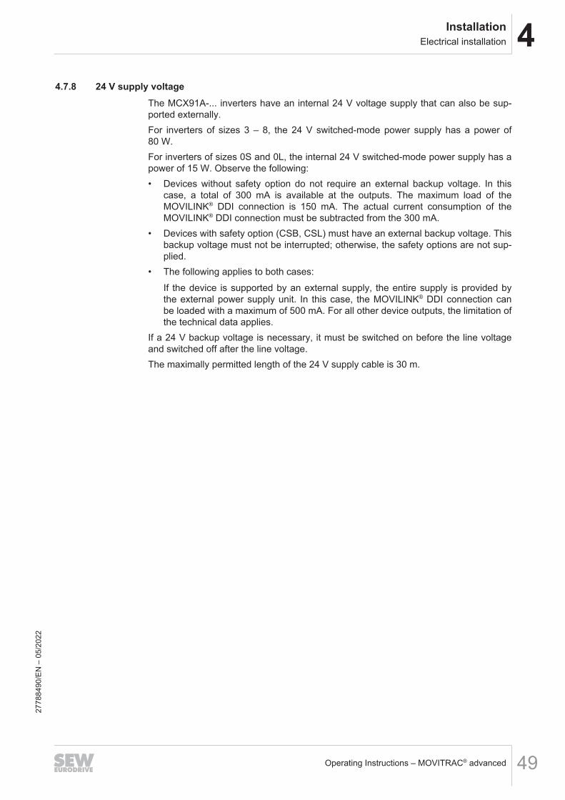
4.7.9 Brake chopper output
NOTICEConnecting capacitive loads to the output of the brake chopper.Connecting inductive loads to the output of the brake chopper.Damage to the inverter.• Only connect ohmic loads (braking resistors) to the output of the brake chopper.• Never connect capacitive or inductive loads to the output of the brake chopper.
The braking resistor is connected to the +R and -R terminals of the inverter.The maximum permitted cable length between braking resistor and inverter is 100 m.
Special aspects when connecting the braking resistorNote that the IP20 degree of protection is achieved with the following devices only ifthe terminal studs are protected with special plastic covers against contact.• from MCX91A-0620 – 1770-5_3-..• from MCX91A-0570 – 1080-2_3-..These covers must be ordered separately; see the chapter "Installation accesso-ries" (→ 2 235).1. Remove any plastic covers that are inserted in the terminal strip.
X2
+R
33565719307
2778
8490
/EN
– 0
5/20
22
4InstallationElectrical installation
Operating Instructions – MOVITRAC® advanced 51
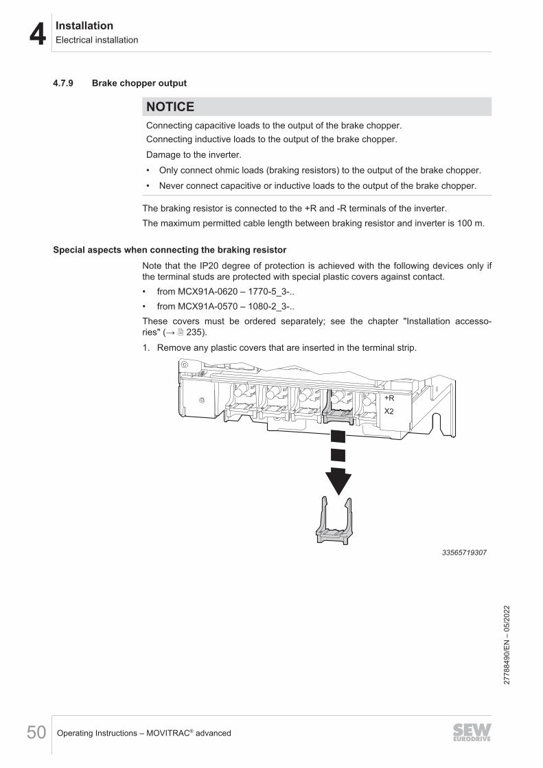
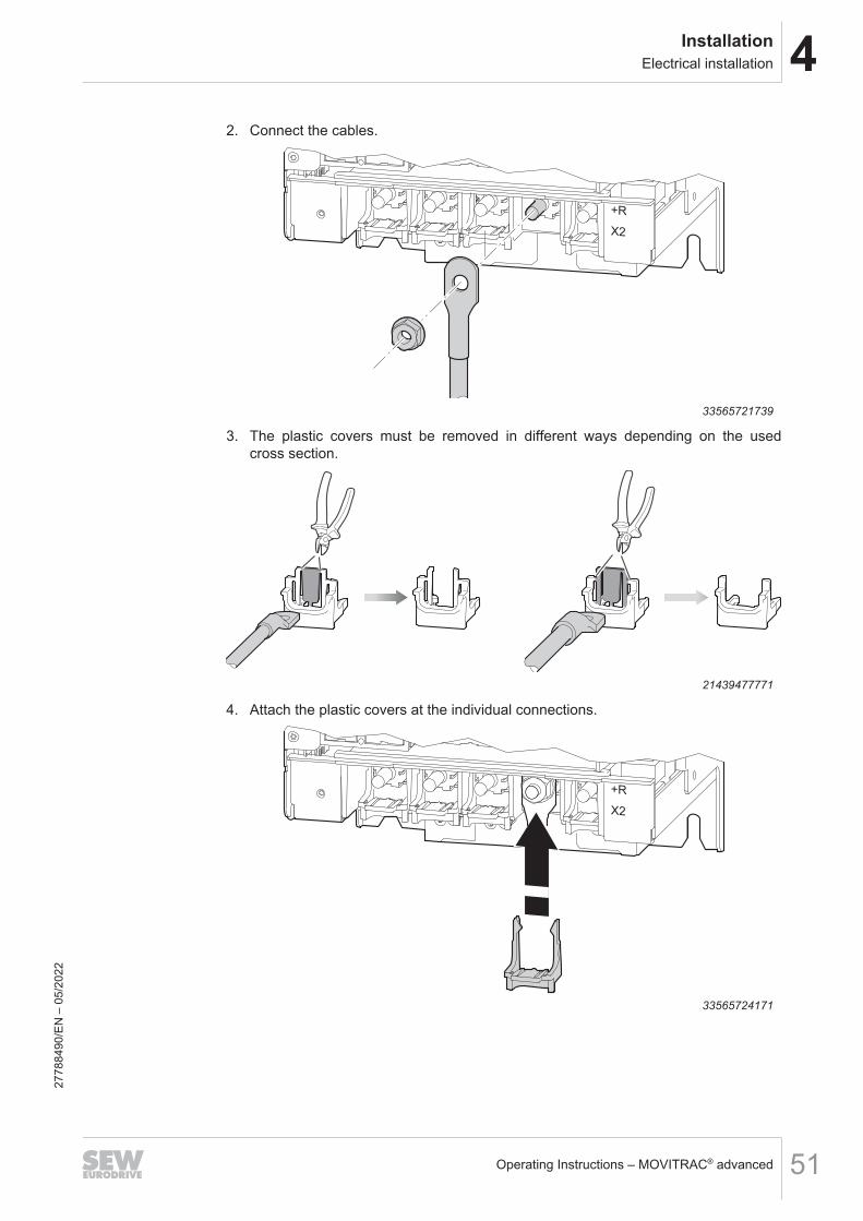
2. Connect the cables.
X2
+R
33565721739
3. The plastic covers must be removed in different ways depending on the usedcross section.
21439477771
4. Attach the plastic covers at the individual connections.
X2
+R
33565724171
2778
8490
/EN
– 0
5/20
22
4 InstallationElectrical installation
Operating Instructions – MOVITRAC® advanced52
4.7.10 Temperature evaluation of the motorThe temperature can be evaluated in 3 ways:• via terminal X10• Via MOVILINK® DDI• Via thermal protection model for motors from SEW-EURODRIVE
WARNINGDangerous contact voltages at the terminals of the inverter when connecting thewrong temperature sensors.Severe or fatal injuries from electric shock.• Connect only temperature sensors with protective separation from the motor
winding to the temperature evaluation. Otherwise, the requirements for protectiveseparation are not met. Dangerous contact voltages may occur at the terminalsof the inverter via the signal electronics in the event of a fault.
• It is preferable to use TH bimetallic temperature switches for group drives on oneinverter.
• The series connection of the TH contacts (normally closed) is not subject to anyrestriction if joint monitoring is provided.
• If TF temperature sensors are available in motors that are intended for a groupdrive, the temperature sensors of a maximum of 3 motors may be connected inparallel.
4.7.11 Brake output
INFORMATION• If the brake connection and the motor connection are combined in one power
cable, the brake cable must be shielded separately. The shielding of the powercable and the brake cable must be connected to the motor and inverter over alarge area.
• SEW‑EURODRIVE recommends to also use a shielded brake cable for separatebrake cable routing.
• Note the different project planning criteria to determine the length of brake cableand motor cable.
2778
8490
/EN
– 0
5/20
22

4InstallationElectrical installation
Operating Instructions – MOVITRAC® advanced 53
4.7.12 Inputs/outputs
NOTICEDamage to the digital inputs and digital outputs.The digital inputs and digital outputs are not electrically isolated. Incorrectly appliedvoltages can damage the digital inputs and digital outputs.• Do not apply a voltage > DC 30 V to the digital inputs and digital outputs.• The digital inputs and outputs are dimensioned according to IEC 61131‑2.
If you route the cables outside the control cabinet, you have to shield them irrespec-tive of the length.When connecting the shielding, ensure equipotential bonding.
2778
8490
/EN
– 0
5/20
22
4 InstallationElectrical installation
Operating Instructions – MOVITRAC® advanced54
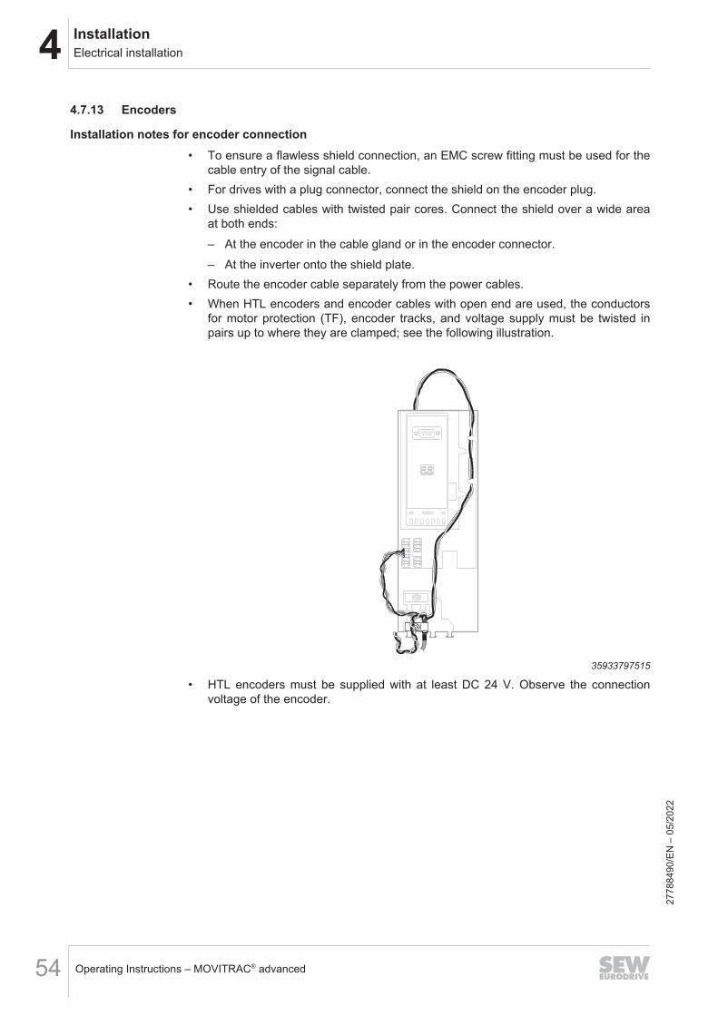
4.7.13 Encoders
Installation notes for encoder connection• To ensure a flawless shield connection, an EMC screw fitting must be used for the
cable entry of the signal cable.• For drives with a plug connector, connect the shield on the encoder plug.• Use shielded cables with twisted pair cores. Connect the shield over a wide area
at both ends:– At the encoder in the cable gland or in the encoder connector.– At the inverter onto the shield plate.
• Route the encoder cable separately from the power cables.• When HTL encoders and encoder cables with open end are used, the conductors
for motor protection (TF), encoder tracks, and voltage supply must be twisted inpairs up to where they are clamped; see the following illustration.
35933797515
• HTL encoders must be supplied with at least DC 24 V. Observe the connectionvoltage of the encoder.
2778
8490
/EN
– 0
5/20
22

4InstallationElectrical installation
Operating Instructions – MOVITRAC® advanced 55
Prefabricated cablesSEW‑EURODRIVE offers pre-fabricated cables for connecting encoders.SEW‑EURODRIVE recommends to use these prefabricated cables.
Encoder cablesSEW-EURODRIVE recommends using shielded encoder cables.
Encoder designation Signal type Maximum permitted cablelength
A...Z, E..Z MOVILINK® DDI 200 m
EI7C-FS HTL (Functional Safety) 100 m
EI.C, EK.C, EG.C, ES.C, EV.C HTL 50 m
2778
8490
/EN
– 0
5/20
22

4 InstallationElectrical installation
Operating Instructions – MOVITRAC® advanced56
Encoder connection
Encoder Inverterconnection
Conductorcolor1) accordingto IEC 60757
Information
MOVILINK® DDI X16 - Coaxial cable
EI7C-FS X18 - Mini IO
Encoder with M12 connector
EI7C, EI8C X20:4 BN A-track at DI04
X20:5 YE B-track at DI05
X20:6 GN C track on DI062)
X10:TF1 RD TF+
X10:GND BU TF-
External3) GY +Ub
External2) PK GND
Encoder with M23 connector or encoder connection cover
EI8C, EH1C,EK8C, EH7C,EV8C, ES1C,ES7C, ES2C,EG7C, EV1C,EV7C, EV2C
X20:4 RD A-track at DI04
X20:5 YE B-track at DI05
X20:6 BN C-track at DI06 (optional)
X10:TF1 GYPK TF+
X10:GND RDBU TF-
External2) GY +Ub
External2) PK GND
Encoder with direct connection
HTL encoder:4) notbySEW‑EURODRIVE
X20:4 - A-track at DI04
X20:5 - B-track at DI05
X20:6 - C-track at DI06 (optional)
X10:TF1 - TF+
X10:GND - TF-
External2) - +Ub
External2) - GND1) For encoder cables by SEW-EURODRIVE2) The C track can only be used with EI8C. With the EI7C, this wire remains unused.3) Encoder supply via external 24 V voltage supply4) maximally 56 kHz
2778
8490
/EN
– 0
5/20
22
4InstallationBraking resistors
Operating Instructions – MOVITRAC® advanced 57
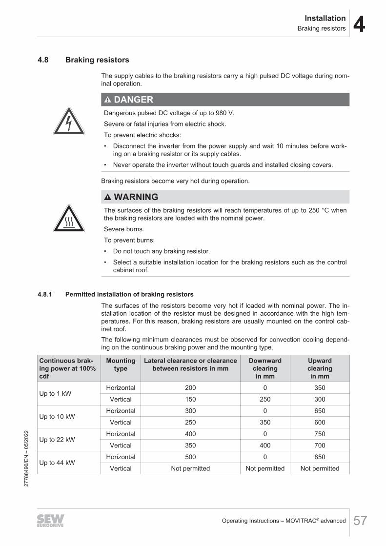
4.8 Braking resistors
The supply cables to the braking resistors carry a high pulsed DC voltage during nom-inal operation.
DANGERDangerous pulsed DC voltage of up to 980 V.Severe or fatal injuries from electric shock.To prevent electric shocks:• Disconnect the inverter from the power supply and wait 10 minutes before work-
ing on a braking resistor or its supply cables.• Never operate the inverter without touch guards and installed closing covers.
Braking resistors become very hot during operation.
WARNINGThe surfaces of the braking resistors will reach temperatures of up to 250 °C whenthe braking resistors are loaded with the nominal power.Severe burns.To prevent burns:• Do not touch any braking resistor.• Select a suitable installation location for the braking resistors such as the control
cabinet roof.
4.8.1 Permitted installation of braking resistorsThe surfaces of the resistors become very hot if loaded with nominal power. The in-stallation location of the resistor must be designed in accordance with the high tem-peratures. For this reason, braking resistors are usually mounted on the control cab-inet roof.The following minimum clearances must be observed for convection cooling depend-ing on the continuous braking power and the mounting type.
Continuous brak-ing power at 100%cdf
Mountingtype
Lateral clearance or clearancebetween resistors in mm
Downwardclearingin mm
Upwardclearingin mm
Up to 1 kWHorizontal 200 0 350
Vertical 150 250 300
Up to 10 kWHorizontal 300 0 650
Vertical 250 350 600
Up to 22 kWHorizontal 400 0 750
Vertical 350 400 700
Up to 44 kWHorizontal 500 0 850
Vertical Not permitted Not permitted Not permitted
2778
8490
/EN
– 0
5/20
22

4 InstallationBraking resistors
Operating Instructions – MOVITRAC® advanced58
NOTICEOverheating of the braking resistor.Non-permissible installation might lead to heat build-up in the braking resistor due toreduced convection. A tripping temperature contact or an overheated braking resis-tor can lead to a system standstill.
Observe the following permitted mounting positions when installing the resistors:• Grid resistor, frame resistor
1
2
3
5
27021616276683147
Braking resistors BW003-420-T and BW1.0-170 may only be used in position 1.
2778
8490
/EN
– 0
5/20
22

4InstallationBraking resistors
Operating Instructions – MOVITRAC® advanced 59
• Wire resistor
1
2
3
4
5
18512455307
• Flat-type resistor
1
2
3
4
5
18512457739
2778
8490
/EN
– 0
5/20
22

4 InstallationBraking resistors
Operating Instructions – MOVITRAC® advanced60
4.8.2 Protection of braking resistor against thermal overload
INFORMATIONPTC braking resistorA PTC braking resistor goes to high resistance in the event of overload.
INFORMATIONFlat-type resistorFlat-type resistors have internal thermal protection (fuse cannot be replaced) that in-terrupts the current circuit in the event of overload. The project planning guidelinesand the documented assignments of the drive inverter and braking resistor must beadhered to.
Parallel connection of braking resistorsIt is permitted to connect several identical braking resistors in parallel. The followingapplies:• The power connections of the braking resistors must be connected to +R and -R in
parallel.• Each braking resistor requires a separate protection against thermal overload.• The signal contacts (NC contacts) of the protection devices must be connected in
series.
2778
8490
/EN
– 0
5/20
22
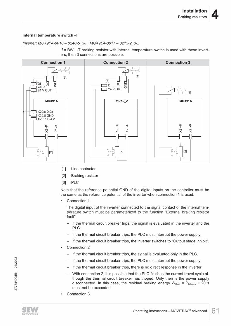
4InstallationBraking resistors
Operating Instructions – MOVITRAC® advanced 61
Internal temperature switch -T
Inverter: MCX91A-0010 – 0240-5_3-.., MCX91A-0017 – 0213-2_3-..
If a BW...-T braking resistor with internal temperature switch is used with these invert-ers, then 3 connections are possible.
Connection 1 Connection 2 Connection 3
[3]
MCX91A
X20:x DI0x
X20:8 GND
DI
24 V OUT
[1]
X2 -
R
X2 +
RD
O
GN
D
[2]
X20:7 +24 V
GND
MDX9_A
[2]
X2 -R
X2 +
R
DI
24 V OUT
DO
GN
D
[1]
[3]
MCX91A
[2]
X2 -R
X2 +
R
[1]
[1] Line contactor
[2] Braking resistor
[3] PLC
Note that the reference potential GND of the digital inputs on the controller must bethe same as the reference potential of the inverter when connection 1 is used.• Connection 1
The digital input of the inverter connected to the signal contact of the internal tem-perature switch must be parameterized to the function "External braking resistorfault".– If the thermal circuit breaker trips, the signal is evaluated in the inverter and the
PLC.– If the thermal circuit breaker trips, the PLC must interrupt the power supply.– If the thermal circuit breaker trips, the inverter switches to "Output stage inhibit".
• Connection 2– If the thermal circuit breaker trips, the signal is evaluated only in the PLC.– If the thermal circuit breaker trips, the PLC must interrupt the power supply.– If the thermal circuit breaker trips, there is no direct response in the inverter.– With connection 2, it is possible that the PLC finishes the current travel cycle al-
though the thermal circuit breaker has tripped. Only then is the power supplydisconnected. In this case, the residual braking energy WRest = PBRnom × 20 smust not be exceeded.
• Connection 3
2778
8490
/EN
– 0
5/20
22

4 InstallationBraking resistors
Operating Instructions – MOVITRAC® advanced62
– If the thermal circuit breaker trips, the signal directly affects the line contactor.– This does not require a response by the PLC.– If the thermal circuit breaker trips, there is no direct response in the inverter.
2778
8490
/EN
– 0
5/20
22
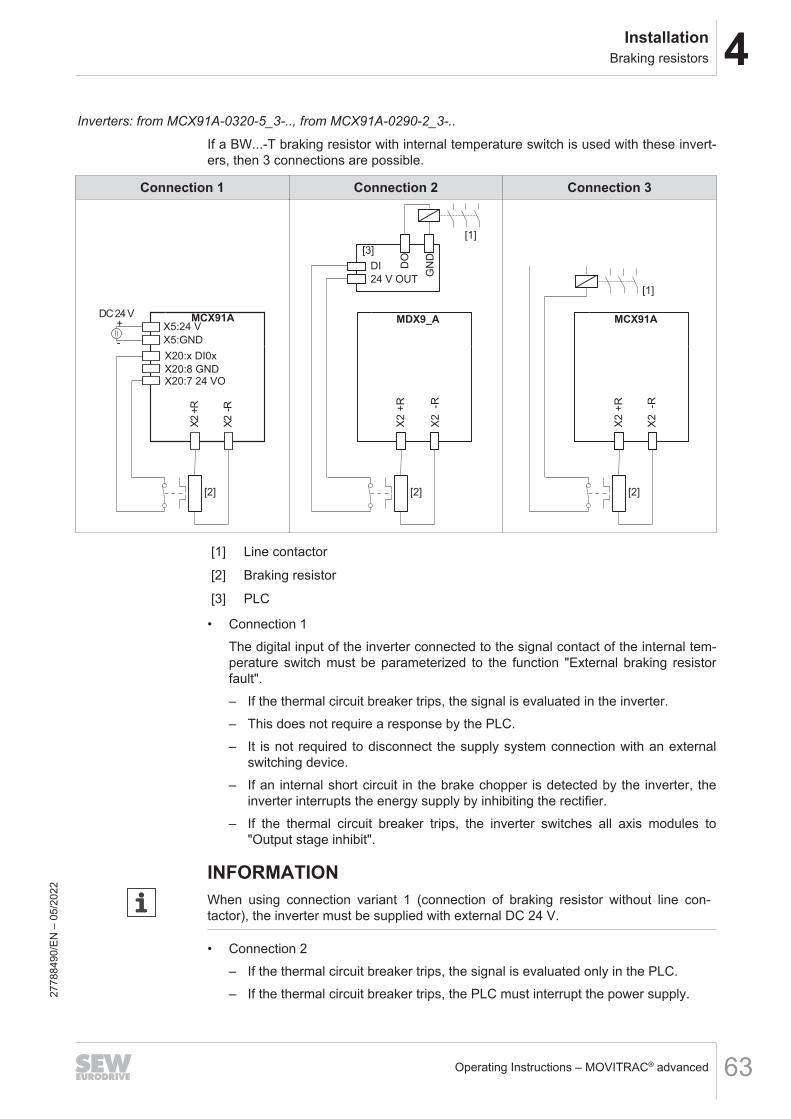
4InstallationBraking resistors
Operating Instructions – MOVITRAC® advanced 63
Inverters: from MCX91A-0320-5_3-.., from MCX91A-0290-2_3-..
If a BW...-T braking resistor with internal temperature switch is used with these invert-ers, then 3 connections are possible.
Connection 1 Connection 2 Connection 3
MCX91A
X20:x DI0x
X20:8 GND
[2]
X2 -
R
X2 +
R
X20:7 24 VO
X5:GND
X5:24 V+
-
DC 24 VMDX9_A
[2]
X2 -R
X2 +
R
DI
24 V OUT
DO
GN
D
[1]
[3]
MCX91A
[2]
X2 -R
X2 +
R
[1]
[1] Line contactor
[2] Braking resistor
[3] PLC
• Connection 1The digital input of the inverter connected to the signal contact of the internal tem-perature switch must be parameterized to the function "External braking resistorfault".– If the thermal circuit breaker trips, the signal is evaluated in the inverter.– This does not require a response by the PLC.– It is not required to disconnect the supply system connection with an external
switching device.– If an internal short circuit in the brake chopper is detected by the inverter, the
inverter interrupts the energy supply by inhibiting the rectifier.– If the thermal circuit breaker trips, the inverter switches all axis modules to
"Output stage inhibit".
INFORMATIONWhen using connection variant 1 (connection of braking resistor without line con-tactor), the inverter must be supplied with external DC 24 V.
• Connection 2– If the thermal circuit breaker trips, the signal is evaluated only in the PLC.– If the thermal circuit breaker trips, the PLC must interrupt the power supply.27
7884
90/E
N –
05/
2022

4 InstallationBraking resistors
Operating Instructions – MOVITRAC® advanced64
– If the thermal circuit breaker trips, there is no direct response in the inverter.– With connection 2, it is possible that the PLC finishes the current travel cycle al-
though the thermal circuit breaker has tripped. Only then is the power supplydisconnected. In this case, the residual braking energy WRest = PBRnom × 20 smust not be exceeded.
• Connection 3– If the thermal circuit breaker trips, the signal directly affects the line contactor.– This does not require a response by the PLC.– If the thermal circuit breaker trips, there is no direct response in the inverter.
2778
8490
/EN
– 0
5/20
22
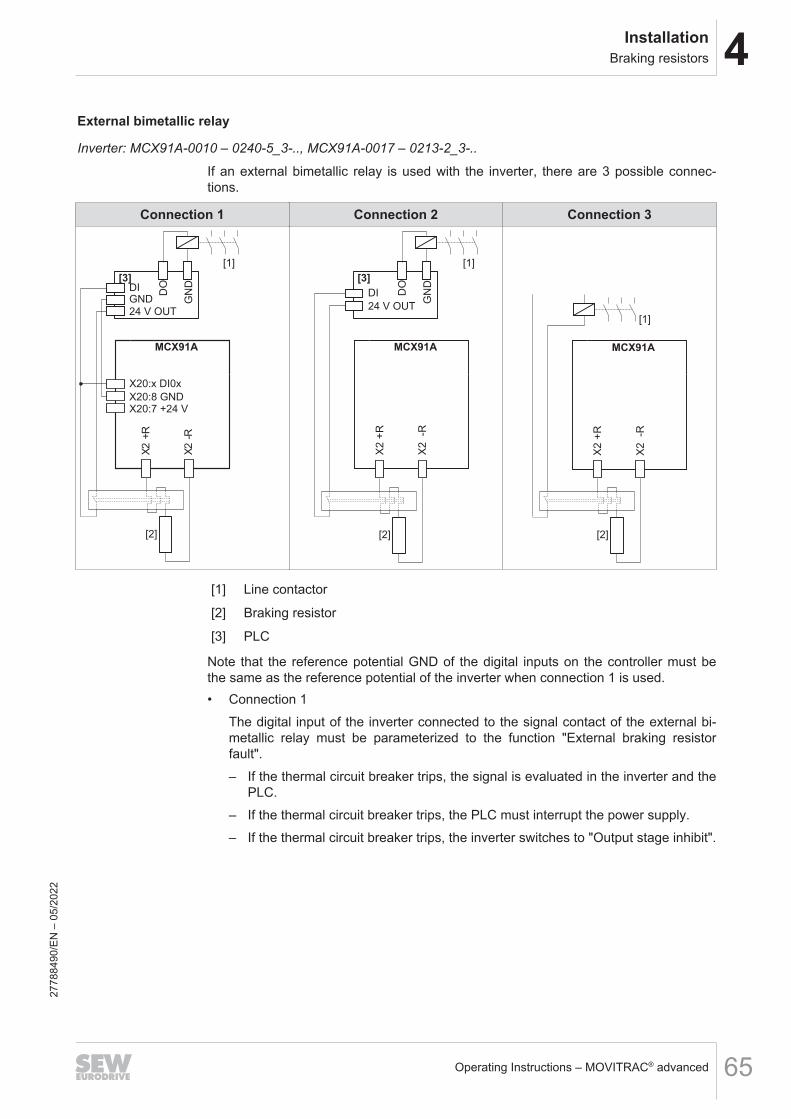
4InstallationBraking resistors
Operating Instructions – MOVITRAC® advanced 65
External bimetallic relay
Inverter: MCX91A-0010 – 0240-5_3-.., MCX91A-0017 – 0213-2_3-..
If an external bimetallic relay is used with the inverter, there are 3 possible connec-tions.
Connection 1 Connection 2 Connection 3
MCX91A
X20:x DI0x
X20:8 GND
[2]
X2 -
R
X2 +
R
[3]DI
24 V OUT
DO
GN
D
[1]
GND
X20:7 +24 V
MCX91A
X2 -R
X2 +
R
[2]
[3]
DI
24 V OUT
DO
GN
D
[1]
MCX91A
X2 -R
X2 +
R
[2]
[1]
[1] Line contactor
[2] Braking resistor
[3] PLC
Note that the reference potential GND of the digital inputs on the controller must bethe same as the reference potential of the inverter when connection 1 is used.• Connection 1
The digital input of the inverter connected to the signal contact of the external bi-metallic relay must be parameterized to the function "External braking resistorfault".– If the thermal circuit breaker trips, the signal is evaluated in the inverter and the
PLC.– If the thermal circuit breaker trips, the PLC must interrupt the power supply.– If the thermal circuit breaker trips, the inverter switches to "Output stage inhibit".
2778
8490
/EN
– 0
5/20
22

4 InstallationBraking resistors
Operating Instructions – MOVITRAC® advanced66
• Connection 2– If the thermal circuit breaker trips, the signal is evaluated only in the PLC.– If the thermal circuit breaker trips, the PLC must interrupt the power supply.– If the thermal circuit breaker trips, there is no direct response in the inverter.– With connection 2, it is possible that the PLC finishes the current travel cycle al-
though the thermal circuit breaker has tripped. Only then is the power supplydisconnected. In this case, the residual braking energy WRest = PBRnom × 20 smust not be exceeded.
• Connection 3– If the thermal circuit breaker trips, the signal directly affects the line contactor.– This does not require a response by the PLC.– If the thermal circuit breaker trips, there is no direct response in the inverter.
2778
8490
/EN
– 0
5/20
22
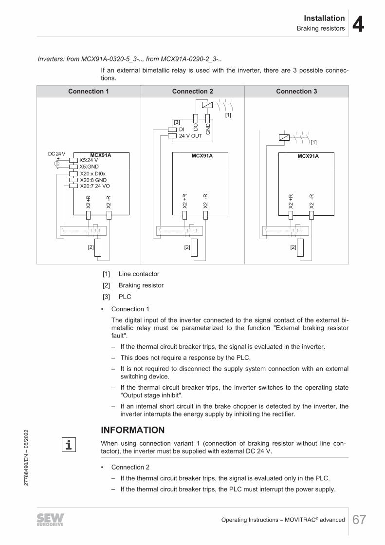
4InstallationBraking resistors
Operating Instructions – MOVITRAC® advanced 67
Inverters: from MCX91A-0320-5_3-.., from MCX91A-0290-2_3-..
If an external bimetallic relay is used with the inverter, there are 3 possible connec-tions.
Connection 1 Connection 2 Connection 3
MCX91A
X20:x DI0x
X20:8 GND
X2 -
R
X2 +
R
[2]
X20:7 24 VO
X5:GND
X5:24 V+
-
DC 24 VMCX91A
X2 -R
X2 +
R
[2]
[3]
DI
24 V OUT
DO
GN
D
[1]
MCX91A
X2 -R
X2 +
R
[2]
[1]
[1] Line contactor
[2] Braking resistor
[3] PLC
• Connection 1The digital input of the inverter connected to the signal contact of the external bi-metallic relay must be parameterized to the function "External braking resistorfault".– If the thermal circuit breaker trips, the signal is evaluated in the inverter.– This does not require a response by the PLC.– It is not required to disconnect the supply system connection with an external
switching device.– If the thermal circuit breaker trips, the inverter switches to the operating state
"Output stage inhibit".– If an internal short circuit in the brake chopper is detected by the inverter, the
inverter interrupts the energy supply by inhibiting the rectifier.
INFORMATIONWhen using connection variant 1 (connection of braking resistor without line con-tactor), the inverter must be supplied with external DC 24 V.
• Connection 2– If the thermal circuit breaker trips, the signal is evaluated only in the PLC.– If the thermal circuit breaker trips, the PLC must interrupt the power supply.
2778
8490
/EN
– 0
5/20
22

4 InstallationBraking resistors
Operating Instructions – MOVITRAC® advanced68
– If the thermal circuit breaker trips, there is no direct response in the inverter.– With connection 2, it is possible that the PLC finishes the current travel cycle al-
though the thermal circuit breaker has tripped. Only then is the power supplydisconnected. In this case, the residual braking energy WRest = PBRnom × 20 smust not be exceeded.
• Connection 3– If the thermal circuit breaker trips, the signal directly affects the line contactor.– This does not require a response by the PLC.– If the thermal circuit breaker trips, there is no direct response in the inverter.
2778
8490
/EN
– 0
5/20
22

4InstallationBraking resistors
Operating Instructions – MOVITRAC® advanced 69
4.8.3 Installation of the braking resistors BW120-001 and BW100-002/MThe braking resistors BW120-001 and BW100-002/M can be used for theMCX91A-0020 - 0055-5E3-4-.. and MCX91A-0017 - 0055-2E3-4-.. inverters. Mountingis only carried out in an upright position next to an inverter.The minimum lateral distance from adjacent components and walls can be reduced to10 mm, contrary to the generally permissible mounting of braking resistors.The minimum distance from components/ceilings above can be reduced to 100 mm,contrary to the generally permissible mounting of braking resistors.
20363403787
2778
8490
/EN
– 0
5/20
22

4 InstallationBraking resistors
Operating Instructions – MOVITRAC® advanced70
4.8.4 Mounting the CLH31A and CLH41A braking resistors with support plateThe CLH31A and CLH41A braking resistors with support plate are supplied as a com-bination of a support plate and an integrated braking resistor. There is a choice ofbraking resistors with different ratings for each support plate, see chapter "Technicaldata of braking resistors with submounting plate" (→ 2 262).During mounting, make sure no connection wires are pinched.Use the fastening bolts (3 pieces) included in the scope of delivery to mount the in-verter and the support plate in the control cabinet. Refer to the dimension sheets forthe bore positions of the fastening bolt.
[1]
[2]
[2]
35843912715
[1] Braking resistor with support plate[2] Fastening bolt
2778
8490
/EN
– 0
5/20
22

4InstallationNF.. line filter
Operating Instructions – MOVITRAC® advanced 71
4.9 NF.. line filter
• Install the line filter close to the power supply module/inverter but outside the min-imum clearance for cooling. The line filter must not be heated by the exhaust air ofthe power supply module/inverter.
• Do not wire any other consumers between the line filter and the power supplymodule/inverter.
• The connection cable between line filter and power supply module/inverter doesnot have to be shielded.
• Limit the length of the cable between the line filter and the power supply module/inverter to the required length.
• Do not switch between the line filter and power supply module/inverter.
2778
8490
/EN
– 0
5/20
22
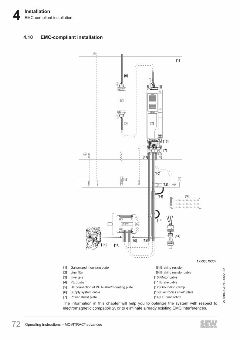
4 InstallationEMC-compliant installation
Operating Instructions – MOVITRAC® advanced72
4.10 EMC-compliant installation
[6]
[6]
[3]
[1]
[2]
[7]
[11]
[11]
[9]
[5]
[12]
[14]
[14]
[14]
[14]
[12][10]
[8]
[4]
[13]
[10]
19508519307
[1] Galvanized mounting plate [8] Braking resistor[2] Line filter [9] Braking resistor cable[3] Inverters [10] Motor cable[4] PE busbar [11] Brake cable[5] HF connection of PE busbar/mounting plate [12] Grounding clamp[6] Supply system cable [13] Electronics shield plate[7] Power shield plate [14] HF connection
The information in this chapter will help you to optimize the system with respect toelectromagnetic compatibility, or to eliminate already existing EMC interferences.
2778
8490
/EN
– 0
5/20
22
4InstallationEMC-compliant installation
Operating Instructions – MOVITRAC® advanced 73
The notes in this chapter are not legal regulations, but rather recommendations for im-proving the electromagnetic compatibility of your plant.For further notes on EMC-compliant installation, refer to the publication Drive Engi-neering – Practical Implementation edition "EMC in Drive Engineering – Basic Theor-etical Principles – EMC-Compliant Installation in Practice".Compliance with limit class C2 has been tested in a CE-typical drive system.SEW‑EURODRIVE can provide detailed information on request.
4.10.1 Control cabinetUse control cabinets with electrically conductive (galvanized) mounting plates. If sev-eral mounting plates are used, connect them in such a way that they are conductiveover a large area.Mount the line filter and inverter on a shared mounting plate if possible. Make surethey are connected over a large area and with good conductivity.
4.10.2 HF equipotential bonding in the systemMake sure that there is a suitable equipotential bonding between the system, the con-trol cabinet, the machine structure, the cable ducts, and the drives.Connect the individual sections together in an HF-capable manner.From an electrical safety perspective, the PE busbar is the star point. However, thePE connection does not replace either the HF grounding or the shielding.In terms of EMC, it is advantageous if the mounting plate is used as a star point withrespect to HF equipotential bonding.Perform the following measures for a suitable HF equipotential bonding:• Connect the PE busbar to the mounting plate in an HF-compatible manner.• Connect the sheet metal cable ducts to the control cabinet in an HF-compatible
manner.• Connect the cable ducts to the mounting plate in the control cabinet using a high
frequency litz wire.• Connect the parts of the sheet metal cable ducts together in an HF-compatible
manner.• Connect the sheet metal cable ducts to the gearmotor in an HF-compatible man-
ner.
4.10.3 Cable installationRoute the power cables, such as the motor cable and the brake cable, separately fromthe supply system cable and the control cables.Route all cables as closely to the reference potential as possible, e.g. the mountingplate.Keep all cables as short as possible. Avoid spare loops.
2778
8490
/EN
– 0
5/20
22

4 InstallationEMC-compliant installation
Operating Instructions – MOVITRAC® advanced74
4.10.4 Supply system cable connectionThe supply system cable can be connected to the line choke and/or line filter usingtwisted unshielded single conductors or using unshielded cables.If necessary, shielded cables may improve EMC.
4.10.5 Line filter connectionLimit the length of the connection lead between the line filter and the inverter to theabsolute minimum needed.You must never route filtered and unfiltered cables together. For this reason, route in-coming and outgoing line filter cables separately.
4.10.6 Braking resistor connectionFor connecting braking resistors, use two closely twisted cores or a shielded powercable. In the case of shielded cables, connect the braided shields over the entire cir-cumference. Use the designated shield plates at the basic device to connect theshield.
19508521739
2778
8490
/EN
– 0
5/20
22

4InstallationEMC-compliant installation
Operating Instructions – MOVITRAC® advanced 75
4.10.7 Motor and brake connectionUse shielded motor cables only. Connect the braided shield of the motor cable at bothends over its entire circumference to the power shield plate at the inverter.Provide shielded cables for the brake supply. The shield of the brake cable can beconnected to the power shield plate at the inverter.If the motor cable and brake cable are combined in a shared cable, the cable musthave an inner shield separating the brake cables from the motor cores. The cablesalso possess an overall shield.
19508524171
SEW-EURODRIVE recommends using prefabricated cables.In the event of exceptionally high EMC requirements, an additional connection pointfor the shield is recommended. To limit the emitted interference the motor shield canadditionally be grounded to the control cabinet outlet using commercial installation ma-terials (grounding clamps or EMC screw fittings).
4.10.8 Control cable connectionEnsure that the digital inputs are connected with unshielded individual cores. Shieldedcables increase the EMC. Use the designated shield plates to connect the shield.For routing outside of the control cabinet, you must use shielded cables.
19508526603
4.10.9 Encoder connectionSEW‑EURODRIVE recommends the use of prefabricated encoder cables.The shield of prefabricated cables from SEW‑EURODRIVE is connected via the con-nector.
2778
8490
/EN
– 0
5/20
22

4 InstallationEMC-compliant installation
Operating Instructions – MOVITRAC® advanced76
4.10.10 Shielding connectionEnsure that there is an HF-compatible shield connection, e.g. by using groundingclamps or EMC cable glands, so that the braided shield has a large connection sur-face.
2778
8490
/EN
– 0
5/20
22

4InstallationTerminal assignment of basic unit
Operating Instructions – MOVITRAC® advanced 77
4.11 Terminal assignment of basic unit
INFORMATIONReference potentials inside the device.The device-internal reference potential is designated as GND in the following table.All reference potentials GND are internally connected to PE.
INFORMATIONThe assignment "Reserved" means that no cable may be connected to this connec-tion.
INFORMATIONThe technical data for the power and control electronics connections is provided inchapter "Technical data".
4.11.1 MCX91A-0010 – 0055-5E3-.. and MCX91A-0017 – 0055-2E3-.. (size 0S)
Representa-tion
Terminal Connection Brief description
X1:L1 L1
Line connectionX1:L2 L2
X1:L3 L3
PE PE connection
X2:U U
Motor connectionX2:V V
X2:W W
X2:-R -RBraking resistor connection
X2:+R +R
PE PE connection
2778
8490
/EN
– 0
5/20
22

4 InstallationTerminal assignment of basic unit
Operating Instructions – MOVITRAC® advanced78
4.11.2 MCX91A-0070 – 0160-5E3-.. and MCX91A-0070 – 0140-2E3-.. (size 0L)
Representa-tion
Terminal Connection Brief description
X1:L1 L1
Line connectionX1:L2 L2
X1:L3 L3
PE PE connection
-UZ
UV
W+R-R
X2:U U
Motor connectionX2:V V
X2:W W
X2:-R -RBraking resistor connection
X2:+R +R
X2:-UZ -UZ DC link connection -UZ (+UZ connection at +R)
PE PE connection
4.11.3 MCX91A-0240-5E3-.. and MCX91A-0213-2E3-.. (size 3)
Representa-tion
Terminal Connection Brief description
X1:L1 L1
Line connectionX1:L2 L2
X1:L3 L3
X1:-UZ -UZDC link connection
X1:+UZ +UZ
PE PE connection
X2:U U
Motor connectionX2:V V
X2:W W
X2:+R +RBraking resistor connection
X2:-R -R
PE PE connection
2778
8490
/EN
– 0
5/20
22

4InstallationTerminal assignment of basic unit
Operating Instructions – MOVITRAC® advanced 79
4.11.4 MCX91A-0320 – 0460-503-.. and MCX91A-0290 – 0420-203-.. (size 4)
Representa-tion
Terminal Connection Brief description
X1:L1 L1
Line connectionX1:L2 L2
X1:L3 L3
X1:-UZ -UZDC link connection
X1:+UZ +UZ
PE PE connection
X2:U U
Motor connectionX2:V V
X2:W W
X2:+R +RBraking resistor connection
X2:-R -R
PE PE connection
4.11.5 MCX91A-0620 – 1770-503-.. and MCX91A-0570 – 1080-203-.. (size 5, size 6)
Representa-tion
Terminal Connection Brief description
L1 L2 L3 -UZ +UZ
X1:L1 L1
Line connectionX1:L2 L2
X1:L3 L3
X1:-UZ -UZDC link connection
X1:+UZ +UZ
PE PE connection
U V W -R +R
X2:U U
Motor connectionX2:V V
X2:W W
X2:+R +RBraking resistor connection
X2:-R -R
PE PE connection
4.11.6 MCX91A-0017 – 0042-2E1-.. (size 0S)
Representa-tion
Terminal Connection Brief description
L1
N X1:N NLine connection
X1:L1 L1
PE PE connection2778
8490
/EN
– 0
5/20
22

4 InstallationTerminal assignment of basic unit
Operating Instructions – MOVITRAC® advanced80
Representa-tion
Terminal Connection Brief description
X2:U U
Motor connectionX2:V V
X2:W W
X2:-R -RBraking resistor connection
X2:+R +R
PE PE connection
4.11.7 MCX91A-0055 – 0110-2E1-.. (size 0L)
Representa-tion
Terminal Connection Brief description
L1
N X1:N NLine connection
X1:L1 L1
PE PE connection
-UZ
UV
W+R-R
X2:U U
Motor connectionX2:V V
X2:W W
X2:-R -RBraking resistor connection
X2:+R +R
PE PE connection
4.11.8 Inverter in CSO design
Representa-tion
Terminal Connection Brief description
1
2
3
4
5
6
X6:1 F_STO_P F_STO_P: DC +24 V input
X6:2 F_STO_M F_STO_M: DC 0 V input
X6:3 F_STO_P F_STO_P: DC +24 V input
X6:4 F_STO_M F_STO_M: DC 0 V input
X6:5 VO24_STO F_STO_P: DC 24 V supply
X6:6 GND Reference potential
4.11.9 All inverters
Representa-tion
Terminal Connection Brief description
X5:24 V 24V_in DC 24 V supply voltage
X5:GND GND Reference potential
2778
8490
/EN
– 0
5/20
22
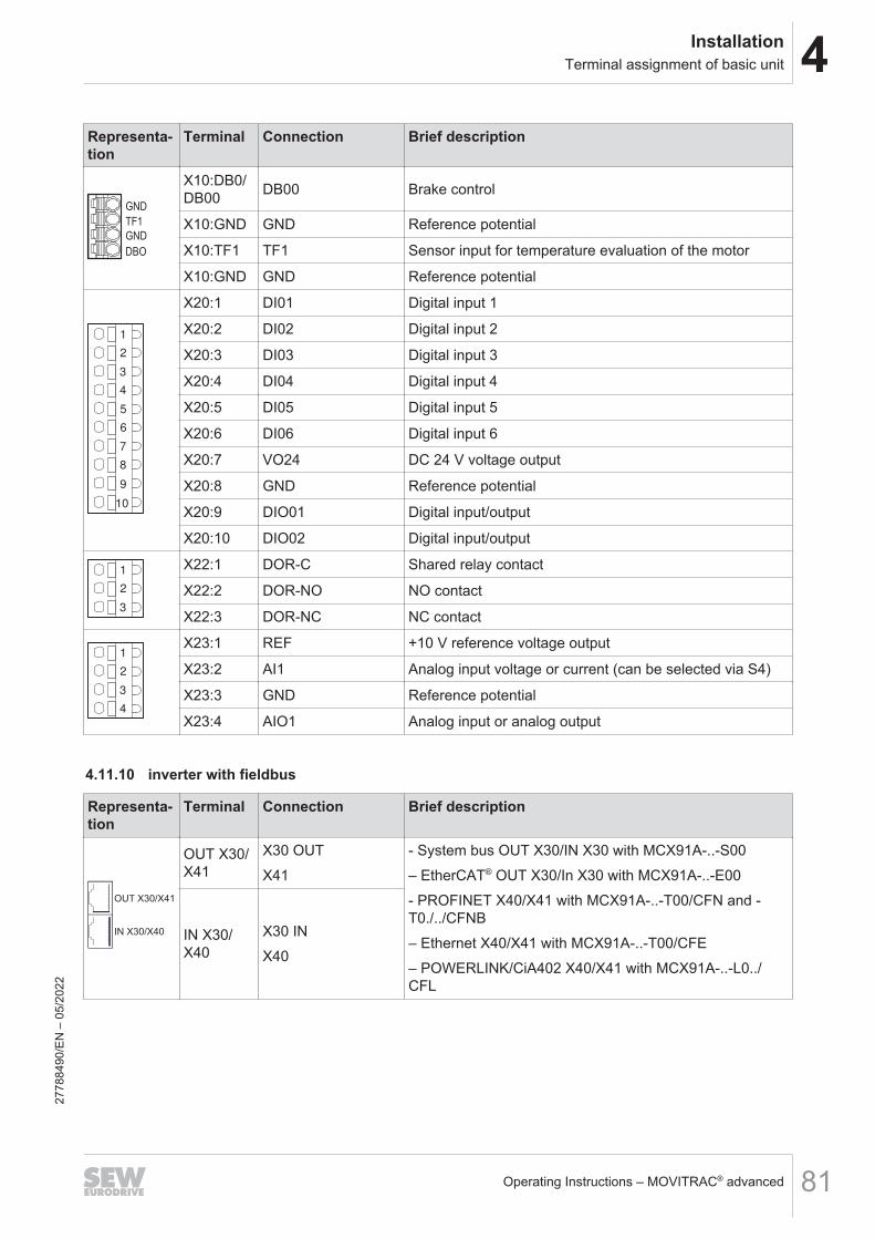
4InstallationTerminal assignment of basic unit
Operating Instructions – MOVITRAC® advanced 81
Representa-tion
Terminal Connection Brief description
DBO
GND
TF1
GND
X10:DB0/DB00 DB00 Brake control
X10:GND GND Reference potential
X10:TF1 TF1 Sensor input for temperature evaluation of the motor
X10:GND GND Reference potential
1
2
3
4
5
6
7
8
9
10
X20:1 DI01 Digital input 1
X20:2 DI02 Digital input 2
X20:3 DI03 Digital input 3
X20:4 DI04 Digital input 4
X20:5 DI05 Digital input 5
X20:6 DI06 Digital input 6
X20:7 VO24 DC 24 V voltage output
X20:8 GND Reference potential
X20:9 DIO01 Digital input/output
X20:10 DIO02 Digital input/output
1
2
3
X22:1 DOR-C Shared relay contact
X22:2 DOR-NO NO contact
X22:3 DOR-NC NC contact
1
2
3
4
X23:1 REF +10 V reference voltage output
X23:2 AI1 Analog input voltage or current (can be selected via S4)
X23:3 GND Reference potential
X23:4 AIO1 Analog input or analog output
4.11.10 inverter with fieldbus
Representa-tion
Terminal Connection Brief description
OUT X30/X41
IN X30/X40
OUT X30/X41
X30 OUTX41
- System bus OUT X30/IN X30 with MCX91A-..-S00– EtherCAT® OUT X30/In X30 with MCX91A-..-E00- PROFINET X40/X41 with MCX91A-..-T00/CFN and -T0./../CFNB– Ethernet X40/X41 with MCX91A-..-T00/CFE– POWERLINK/CiA402 X40/X41 with MCX91A-..-L0../CFL
IN X30/X40
X30 INX40
2778
8490
/EN
– 0
5/20
22

4 InstallationTerminal assignment of basic unit
Operating Instructions – MOVITRAC® advanced82
4.11.11 Inverter with CSB/CSL
Representa-tion
Terminal Connection Brief description
212108
64
X60:1 F-DI00 Safe digital input F-DI00
X60:2 F-DI01 Safe digital input F-DI01
X60:3 GND Reference potential for safe digital inputs/outputs
X60:4 GND Reference potential for safe digital inputs/outputs
X60:5 F-DI02 Safe digital input F-DI02
X60:6 F-DI03 Safe digital input F-DI03
X60:7 GND Reference potential for safe digital inputs/outputs
X60:8 GND Reference potential for safe digital inputs/outputs
X60:9 F-SS0 DC 24 V sensor voltage supply for safe digital inputs F-DI00 and F-DI02
X60:10 F-SS1 DC 24 V sensor voltage supply for safe digital inputs F-DI01 and F-DI03
X60:11 F-DO00_M Safe digital output F-DO00_M (not with CSB)
X60:12 F-DO00_P Safe digital output F-DO00_P (not with CSB)
4.11.12 Inverter with MOVILINK® DDI
Representa-tion
Terminal Connection Assignment
X16 Coaxial connection MOVILINK® DDI
4.11.13 Inverter with CSL
Representa-tion
Terminal Connection Assignment
X18 Mini IO Encoder connection for EI7C-FS27
7884
90/E
N –
05/
2022

4InstallationWiring diagrams
Operating Instructions – MOVITRAC® advanced 83
4.12 Wiring diagrams
4.12.1 General information on the wiring diagrams• For technical data of the power electronics and the control electronics, refer to
chapter "Technical data" (→ 2 219).• For the terminal assignment and connections, refer to chapter "Terminal assign-
ment".
2778
8490
/EN
– 0
5/20
22

4 InstallationWiring diagrams
Operating Instructions – MOVITRAC® advanced84
4.12.2 Power connection
Wiring of the power connections with line contactor, line choke, line filter, and output choke -MCX91A-0010 – 0055-5_3-.., MCX91A-0017 – 0042-2_3-...
L1 L2 L3
L1´ L2´ L3´
L1
L2
L3PE
X1L1 L2 L3
PE
X2
PE
[3]
[2]
PE
PE
[1]
[4]
U V W -R+R
PE
MCX91A..
U1 V1 W1
U2 V2 W2
[5]
[6]
L1 L2 L3
L1´ L2´ L3´
M
9007230381084043[1] Line contactor [4] Braking resistor (optional)[2] Line choke (optional) [5] Output choke[3] Line filter (optional) [6] Motor
2778
8490
/EN
– 0
5/20
22
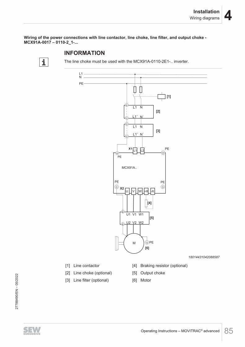
4InstallationWiring diagrams
Operating Instructions – MOVITRAC® advanced 85
Wiring of the power connections with line contactor, line choke, line filter, and output choke -MCX91A-0017 – 0110-2_1-...
INFORMATIONThe line choke must be used with the MCX91A-0110-2E1-.. inverter.
L1
L1´
PE
X1L1 L2
PE
X2
PE
[3]
[2]
PE
PE
[1]
[4]
U V W -R+R
PE
MCX91A..
U1 V1 W1
U2 V2 W2
[5]
[6]
N
L1
L1´
L1
N
N´
N
N´
M
18014431042088587
[1] Line contactor [4] Braking resistor (optional)
[2] Line choke (optional) [5] Output choke
[3] Line filter (optional) [6] Motor
2778
8490
/EN
– 0
5/20
22

4 InstallationWiring diagrams
Operating Instructions – MOVITRAC® advanced86
Wiring of the power connections with line contactor, line choke, line filter, and output choke -MCX91A-0070 – 0240-5_3-.., MCX91A-0055– 0213-2_3-...
L1 L2 L3
L1´ L2´ L3´
L1
L2
L3PE
X1L1 L2 L3
PE
X2
PE
[3]
[2]
PE
PE
[1]
-Uz
[4]
U V W -R+R
PE
MCX91A..
U1 V1 W1
U2 V2 W2
[5]
[6]
L1 L2 L3
L1´ L2´ L3´
M
9007230159093003
[1] Line contactor [4] Braking resistor (optional)
[2] Line choke (optional) [5] Output choke
[3] Line filter (optional) [6] Motor
2778
8490
/EN
– 0
5/20
22

4InstallationWiring diagrams
Operating Instructions – MOVITRAC® advanced 87
Wiring of the power connections with line contactor, line choke, line filter, and output choke – fromMCX91A-0320-5_3-..., from MCX91A-0290-2_3...
L1 L2 L3
L1´ L2´ L3´
L1
L2
L3PE
X1L1 L2 L3
PE
X2
PE
[3]
[2]
PE
PE
[1]
-Uz z+U
[4]
U V W -R+R
PE
MCX91A..
U1 V1 W1
U2 V2 W2
[5]
[6]
L1 L2 L3
L1´ L2´ L3´
M
9007229658855435
[1] Line contactor [4] Braking resistor (optional)
[2] Line choke (optional) [5] Output choke
[3] Line filter (optional) [6] Motor
2778
8490
/EN
– 0
5/20
22

4 InstallationWiring diagrams
Operating Instructions – MOVITRAC® advanced88
Wiring of the power connections with line choke, line filter, output choke, without line contactorRefer to the table in chapter "Line contactor" (→ 2 48) to find out which inverters canbe operated without a line contactor.
NOTICEOperation without line contactorIf the required measures are not taken, operation of an inverter with connected brak-ing resistor without line contactor may result in severe damage to property.Refer to the chapter "Line contactor" (→ 2 48) for the necessary measures.
L1 L2 L3
L1´ L2´ L3´
L1
L2
L3PE
[1]
X1L1 L2 L3
PE
X2
PE
U V W
PE
PE
-Uz z
+R
+U
[2]
[3]
-R
MCX91A..
PE
U1 V1 W1
U2 V2 W2
[4]
[5]
L1 L2 L3
L1´ L2´ L3´
M
9007229658857867[1] Line choke (optional) [4] Output choke[2] Line filter (optional) [5] Motor[3] Braking resistor (optional)
2778
8490
/EN
– 0
5/20
22

4InstallationWiring diagrams
Operating Instructions – MOVITRAC® advanced 89
INFORMATIONIn the event of a line connection without line contactor, the temperature evaluation ofthe braking resistor must be ensured via a digital input on the inverter. The connecteddigital input must be parameterized for monitoring the braking resistor temperatureevaluation.
2778
8490
/EN
– 0
5/20
22

4 InstallationWiring diagrams
Operating Instructions – MOVITRAC® advanced90
4.12.3 Brake controlKey:
AC
DC Cut-off in the DC and AC circuits(rapid brake application)
DC Cut-off in the DC circuit
BS
TS
BrakeBS = Accelerator coilTS = Coil section
+
-
DC brake with one brake coil
1a
2a
5a
4a
3a Auxiliary terminal strip in terminal box
Control cabinet limit
WH White
RD Red
BU Blue
INFORMATIONThe selection of the brake control and the shown connection diagrams only representone of the many possibilities. Observe the catalogs and operating instructions of themotors for more information and installation notes.
2778
8490
/EN
– 0
5/20
22

4InstallationWiring diagrams
Operating Instructions – MOVITRAC® advanced 91
BMK. brake control
BU
+- AC
WH
RD1a
2a
5a
4a
3aM
TS
BS
1
2
13
14
15
4
3
BMK3.0
BMK1.5
BMKB1.5
DB00GNDAC
DC
33921560203
BMV brake control – 2 coils
BU
+-DC 24 V
WH
RD1a
2a
5a
4a
3aM
TS
BS
1
2
13
14
15
4
3
BMV
DB00GND
DC
+-
14373482507
2778
8490
/EN
– 0
5/20
22

4 InstallationWiring diagrams
Operating Instructions – MOVITRAC® advanced92
BMV brake control – 1 coil
BU
+-DC 24 V
RD
1a
2a
5a
4a
3aM
1
2
13
14
15
4
3
BMV
DB00GND
DC
+-
14373494923
BMS, BME brake control
BU
AC
WH
RD1a
2a
5a
4a
3aM
TS
BS
BMS
BME1
2
13
14
15
4
3
AC
DC
DB00
GND
14324554891
2778
8490
/EN
– 0
5/20
22

4InstallationWiring diagrams
Operating Instructions – MOVITRAC® advanced 93
BMP brake control
BU
AC
WH
RD1a
2a
5a
4a
3aM
TS
BS
1
2
13
14
15
4
3
BMP
DB00
GND
AC
DC
14324544523
BG, BGE brake control
AC
BG
BGE
RD
WH
5
4
1
3
2
BU
M
TS
BS
AC
DC
DB00
GND
14324565259
2778
8490
/EN
– 0
5/20
22

4 InstallationWiring diagrams
Operating Instructions – MOVITRAC® advanced94
BSG brake control
M4
1
3
2
TS
BS
BU
BSG
RD
WH
DC 24 V
+ -
5
DB00
GND
AC
DC
14324597131
Brake control SBM with 1 control cable
PEUZ
+ -SBC
+ -STATUS
+
SBM 1
+U -Uz
2
4
SBC_M
OUT_M
OUT_P
6
7
GND
STATUS
13
14
15
RD
WH
BU
STATUS
X4
1
3
5
X20
SBC_P
DB00
X14
8 N.C.
4a
3a
5a
RD
BU
M
[2]
4a
3a
5a
BS
TS
WH
RD
BU
M
[1]
9007232120094731
[1] Connection of the brake with 3-wire technology (standard)
[2] Connection of the brake with 2-wire technology (optional). In this case, thereis no connection from terminal X14:14 of the brake module to terminal 3a ofthe auxiliary terminal strip.
2778
8490
/EN
– 0
5/20
22

4InstallationWiring diagrams
Operating Instructions – MOVITRAC® advanced 95
Brake control SBM with 2 control cables
PEUZ
+ -SBC
+ -DB00
+ -STATUS
+
SBM 1
+U -Uz
2
4
SBC_M
OUT_M
OUT_P
6
7
GND
STATUS
13
14
15
RD
WH
BU
STATUS
X4
1
3
5
X20
SBC_P
DB00
X14
8 N.C.
4a
3a
5a
RD
BU
M
[2]
4a
3a
5a
BS
TS
WH
RD
BU
M
[1]
9007232118783115
[1] Connection of the brake with 3-wire technology (standard)
[2] Connection of the brake with 2-wire technology (optional). In this case, thereis no connection from terminal X14:14 of the brake module to terminal 3a ofthe auxiliary terminal strip.
2778
8490
/EN
– 0
5/20
22

4 InstallationWiring diagrams
Operating Instructions – MOVITRAC® advanced96
4.12.4 Electronics connectionFor the assignment of the signal terminals and connections, refer to chapter "Terminalassignment of basic unit" (→ 2 77).
Wiring of the control electronics – frontThe assignment of the digital inputs/outputs is different depending on the device vari-ant.
2
X20
1
3
4
5
6
8
7
DI01
DI02
DI03
DI04
DI05
2
X22
1
3
DOR-C
DOR-NO
9
GND
DOR-NC
2
X23
1
3
AI1
GND
RE1
DI06
DIO02
DIO01
10
VO24
4AIO1
mA V
S4
2
X60
1
3
4
5
6
8
7
F-DI00
F-DI01
DI02
DI03
9
GND
F-SS1
F-SS0
10
F-DO00_M 11
12
GND
GND
GND
F-DO00_P
Digital input 1Digital input 2Digital input 3Digital input 4Digital input 5Digital input 6DC 24 V voltage outputReference potentialDigital input/outputDigital input/output
NC contact
Shared relay contactNO contact
+10 V reference voltage outputAnalog input voltage or currentReference potentialAnalog input/output
Safe digital input F-DI00Safe digital input F-DI01Reference potential for safe digital inputs/outputsReference potential for safe digital inputs/outputsSafe digital input F-DI02Safe digital input F-DI03Reference potential for safe digital inputs/outputsReference potential for safe digital inputs/outputsDC 24 V voltage supply of the sensor for F-DI00DC 24 V voltage supply of the sensor for F-DI01Safe digital output F-DO00_M (not with CSB)Safe digital output F-DO00_P (not with CSB)
9007230010138507
X20 Digital inputs/outputsX22 Isolated relay contactX23 Analog inputs/analog outputsS4 Changeover switch between voltage input and current input at X23:2 (AI)
2778
8490
/EN
– 0
5/20
22

4InstallationWiring diagrams
Operating Instructions – MOVITRAC® advanced 97
Wiring of the control electronics – top and bottom
2
1
5
6 GND
X6
VO24_STO
X5
VI24GND
DB0/DB00
GND
TF1
GND
X10
DC 24 V+
-
X16
F_STO_P
F_STO_M
34
F_STO_P
F_STO_M
X18
Brake controlReference potentialMotor temperature evaluationReference potential
36028827928345867
X5 24 V supply voltageX6 Connection for Safe Torque Off (STO)
If safety option CSB and CSL are installed, X6 has no function.X10 Connection of brake control and motor temperature monitoringX16 Digital motor integration connectionX18 Connection of EI7C-FS encoder
2778
8490
/EN
– 0
5/20
22

4 InstallationUL-compliant installation
Operating Instructions – MOVITRAC® advanced98
4.13 UL-compliant installation
INFORMATIONDue to UL requirements, the following chapter is always printed in English indepen-dent of the language of the documentation.
INFORMATIONUL and cUL approval for the following devices is in preparation:• Devices of sizes 7 and 8• 1 x 230 V devices
4.13.1 (Field Wiring) Power Terminals• Use 75 °C copper wire only.• Tightening torque and wire size for field wiring terminals:
MCX91A-…-5_3-.. 0010 – 0055 0070 – 0160 0240 0320 – 0460 0620 – 0910 1130 – 1770 2200 – 3000 3800 – 5880MCX91A-…-2_3-.. 0017 – 0055 0070 – 0140 0213 0290 – 0420 0570 – 0840 1080 – –MCX91A-…-2_1-.. 0017 – 0042 0055 – 0110 – – – – – –Unit Size 0S 0L 3 4 5 6 7 8Screw connection Tightening torques in in.lbsLine connection X1 4.4 – 5.3 15.0 – 15.9 75.2 – 84.1 88.5 – 132.8 123.9 – 177.0 123.9 – 177.0Motor and brakingresistor connection
X2 4.4 – 5.3 15.0 – 15.9 75.2 – 84.1 88.5 – 132.8 123.9 – 177.0 123.9 – 177.0
PE connections 10.6 – 13.3 26.6 – 35.4 53.1 – 88.5 88.5 – 132.8 123.9 – 177.0 123.9 – 177.0Other M4 screwconnections 12.4 – 14.2
4.13.2 Short Circuit Current RatingSuitable for use on a circuit capable of delivering not more than 65,000 rms symmet-rical amperes when protected by fuses, inverse time circuit breakers or Type E Combi-nation Motor Controllers as described in the tables below:• MOVITRAC® MCX91B 0010 – 5880 (400 V units only)
– The max. voltage is limited to 500 V.• MOVITRAC® MCX91B 0017 – 0140 (230 V units only)
– The max. voltage is limited to 240 V.
2778
8490
/EN
– 0
5/20
22
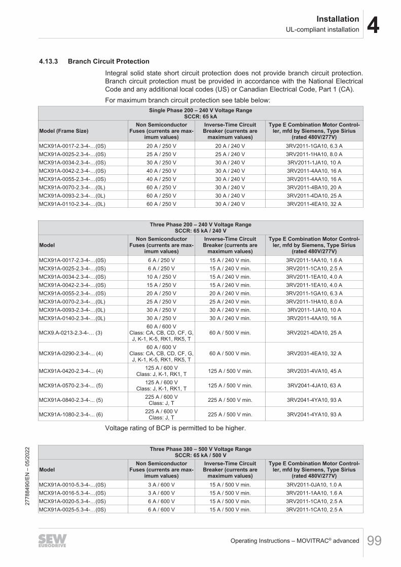
4InstallationUL-compliant installation
Operating Instructions – MOVITRAC® advanced 99
4.13.3 Branch Circuit ProtectionIntegral solid state short circuit protection does not provide branch circuit protection.Branch circuit protection must be provided in accordance with the National ElectricalCode and any additional local codes (US) or Canadian Electrical Code, Part 1 (CA).For maximum branch circuit protection see table below:
Single Phase 200 – 240 V Voltage RangeSCCR: 65 kA
Model (Frame Size)Non Semiconductor
Fuses (currents are max-imum values)
Inverse-Time CircuitBreaker (currents are
maximum values)
Type E Combination Motor Control-ler, mfd by Siemens, Type Sirius
(rated 480V/277V)MCX91A-0017-2.3-4-…(0S) 20 A / 250 V 20 A / 240 V 3RV2011-1GA10, 6.3 AMCX91A-0025-2.3-4-…(0S) 25 A / 250 V 25 A / 240 V 3RV2011-1HA10, 8.0 AMCX91A-0034-2.3-4-…(0S) 30 A / 250 V 30 A / 240 V 3RV2011-1JA10, 10 AMCX91A-0042-2.3-4-…(0S) 40 A / 250 V 30 A / 240 V 3RV2011-4AA10, 16 AMCX91A-0055-2.3-4-…(0S) 40 A / 250 V 30 A / 240 V 3RV2011-4AA10, 16 AMCX91A-0070-2.3-4-…(0L) 60 A / 250 V 30 A / 240 V 3RV2011-4BA10, 20 AMCX91A-0093-2.3-4-…(0L) 60 A / 250 V 30 A / 240 V 3RV2011-4DA10, 25 AMCX91A-0110-2.3-4-…(0L) 60 A / 250 V 30 A / 240 V 3RV2011-4EA10, 32 A
Three Phase 200 – 240 V Voltage RangeSCCR: 65 kA / 240 V
ModelNon Semiconductor
Fuses (currents are max-imum values)
Inverse-Time CircuitBreaker (currents are
maximum values)
Type E Combination Motor Control-ler, mfd by Siemens, Type Sirius
(rated 480V/277V)MCX91A-0017-2.3-4-…(0S) 6 A / 250 V 15 A / 240 V min. 3RV2011-1AA10, 1.6 AMCX91A-0025-2.3-4-…(0S) 6 A / 250 V 15 A / 240 V min. 3RV2011-1CA10, 2.5 AMCX91A-0034-2.3-4-…(0S) 10 A / 250 V 15 A / 240 V min. 3RV2011-1EA10, 4.0 AMCX91A-0042-2.3-4-…(0S) 15 A / 250 V 15 A / 240 V min. 3RV2011-1EA10, 4.0 AMCX91A-0055-2.3-4-…(0S) 20 A / 250 V 20 A / 240 V min. 3RV2011-1GA10, 6.3 AMCX91A-0070-2.3-4-…(0L) 25 A / 250 V 25 A / 240 V min. 3RV2011-1HA10, 8.0 AMCX91A-0093-2.3-4-…(0L) 30 A / 250 V 30 A / 240 V min. 3RV2011-1JA10, 10 AMCX91A-0140-2.3-4-…(0L) 30 A / 250 V 30 A / 240 V min. 3RV2011-4AA10, 16 A
MCX9.A-0213-2.3-4-… (3)60 A / 600 V
Class: CA, CB, CD, CF, G,J, K-1, K-5, RK1, RK5, T
60 A / 500 V min. 3RV2021-4DA10, 25 A
MCX91A-0290-2.3-4-... (4)60 A / 600 V
Class: CA, CB, CD, CF, G,J, K-1, K-5, RK1, RK5, T
60 A / 500 V min. 3RV2031-4EA10, 32 A
MCX91A-0420-2.3-4-... (4) 125 A / 600 VClass: J, K-1, RK1, T 125 A / 500 V min. 3RV2031-4VA10, 45 A
MCX91A-0570-2.3-4-... (5) 125 A / 600 VClass: J, K-1, RK1, T 125 A / 500 V min. 3RV2041-4JA10, 63 A
MCX91A-0840-2.3-4-... (5) 225 A / 600 VClass: J, T 225 A / 500 V min. 3RV2041-4YA10, 93 A
MCX91A-1080-2.3-4-... (6) 225 A / 600 VClass: J, T 225 A / 500 V min. 3RV2041-4YA10, 93 A
Voltage rating of BCP is permitted to be higher.
Three Phase 380 – 500 V Voltage RangeSCCR: 65 kA / 500 V
ModelNon Semiconductor
Fuses (currents are max-imum values)
Inverse-Time CircuitBreaker (currents are
maximum values)
Type E Combination Motor Control-ler, mfd by Siemens, Type Sirius
(rated 480V/277V)MCX91A-0010-5.3-4-…(0S) 3 A / 600 V 15 A / 500 V min. 3RV2011-0JA10, 1.0 AMCX91A-0016-5.3-4-…(0S) 3 A / 600 V 15 A / 500 V min. 3RV2011-1AA10, 1.6 AMCX91A-0020-5.3-4-…(0S) 6 A / 600 V 15 A / 500 V min. 3RV2011-1CA10, 2.5 AMCX91A-0025-5.3-4-…(0S) 6 A / 600 V 15 A / 500 V min. 3RV2011-1CA10, 2.5 A
2778
8490
/EN
– 0
5/20
22
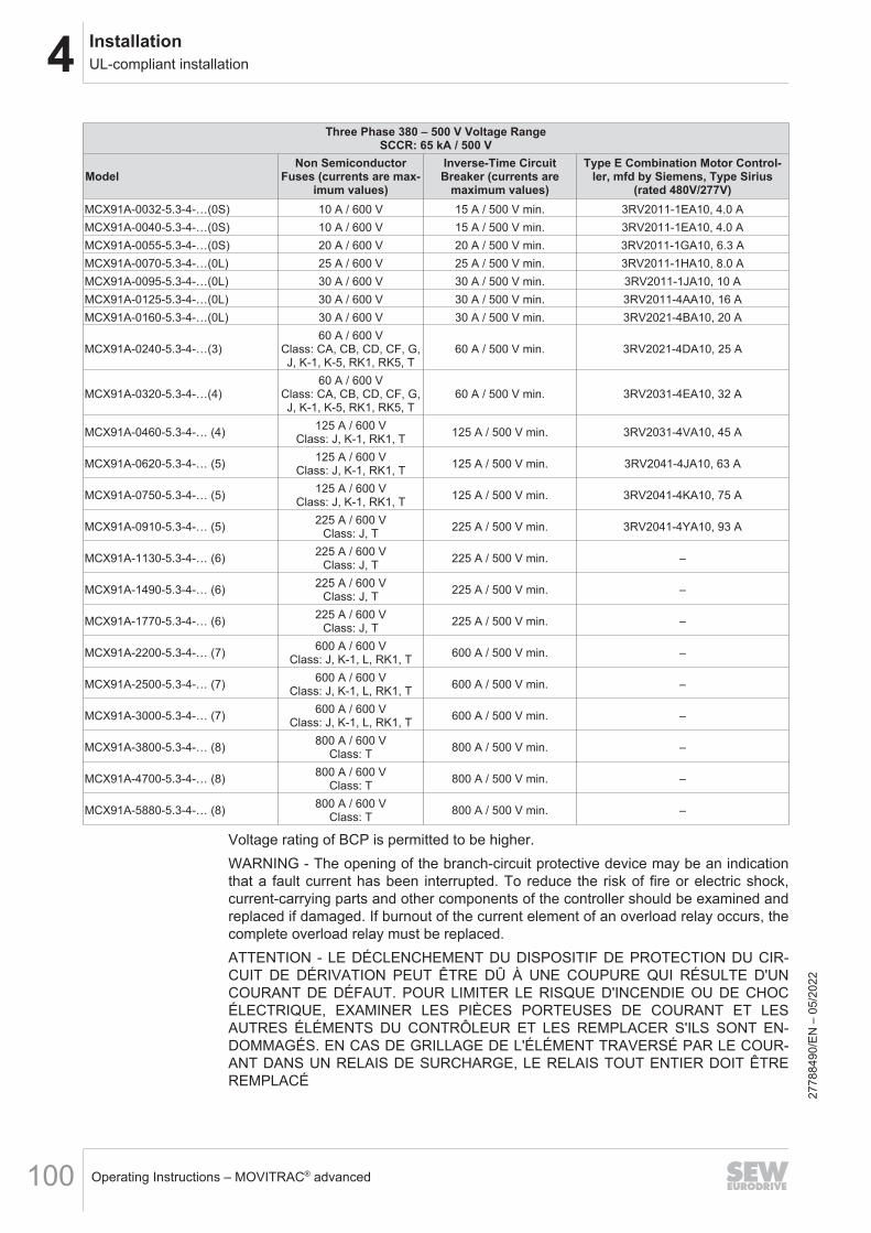
4 InstallationUL-compliant installation
Operating Instructions – MOVITRAC® advanced100
Three Phase 380 – 500 V Voltage RangeSCCR: 65 kA / 500 V
ModelNon Semiconductor
Fuses (currents are max-imum values)
Inverse-Time CircuitBreaker (currents are
maximum values)
Type E Combination Motor Control-ler, mfd by Siemens, Type Sirius
(rated 480V/277V)MCX91A-0032-5.3-4-…(0S) 10 A / 600 V 15 A / 500 V min. 3RV2011-1EA10, 4.0 AMCX91A-0040-5.3-4-…(0S) 10 A / 600 V 15 A / 500 V min. 3RV2011-1EA10, 4.0 AMCX91A-0055-5.3-4-…(0S) 20 A / 600 V 20 A / 500 V min. 3RV2011-1GA10, 6.3 AMCX91A-0070-5.3-4-…(0L) 25 A / 600 V 25 A / 500 V min. 3RV2011-1HA10, 8.0 AMCX91A-0095-5.3-4-…(0L) 30 A / 600 V 30 A / 500 V min. 3RV2011-1JA10, 10 AMCX91A-0125-5.3-4-…(0L) 30 A / 600 V 30 A / 500 V min. 3RV2011-4AA10, 16 AMCX91A-0160-5.3-4-…(0L) 30 A / 600 V 30 A / 500 V min. 3RV2021-4BA10, 20 A
MCX91A-0240-5.3-4-…(3)60 A / 600 V
Class: CA, CB, CD, CF, G,J, K-1, K-5, RK1, RK5, T
60 A / 500 V min. 3RV2021-4DA10, 25 A
MCX91A-0320-5.3-4-…(4)60 A / 600 V
Class: CA, CB, CD, CF, G,J, K-1, K-5, RK1, RK5, T
60 A / 500 V min. 3RV2031-4EA10, 32 A
MCX91A-0460-5.3-4-… (4) 125 A / 600 VClass: J, K-1, RK1, T 125 A / 500 V min. 3RV2031-4VA10, 45 A
MCX91A-0620-5.3-4-… (5) 125 A / 600 VClass: J, K-1, RK1, T 125 A / 500 V min. 3RV2041-4JA10, 63 A
MCX91A-0750-5.3-4-… (5) 125 A / 600 VClass: J, K-1, RK1, T 125 A / 500 V min. 3RV2041-4KA10, 75 A
MCX91A-0910-5.3-4-… (5) 225 A / 600 VClass: J, T 225 A / 500 V min. 3RV2041-4YA10, 93 A
MCX91A-1130-5.3-4-… (6) 225 A / 600 VClass: J, T 225 A / 500 V min. –
MCX91A-1490-5.3-4-… (6) 225 A / 600 VClass: J, T 225 A / 500 V min. –
MCX91A-1770-5.3-4-… (6) 225 A / 600 VClass: J, T 225 A / 500 V min. –
MCX91A-2200-5.3-4-… (7) 600 A / 600 VClass: J, K-1, L, RK1, T 600 A / 500 V min. –
MCX91A-2500-5.3-4-… (7) 600 A / 600 VClass: J, K-1, L, RK1, T 600 A / 500 V min. –
MCX91A-3000-5.3-4-… (7) 600 A / 600 VClass: J, K-1, L, RK1, T 600 A / 500 V min. –
MCX91A-3800-5.3-4-… (8) 800 A / 600 VClass: T 800 A / 500 V min. –
MCX91A-4700-5.3-4-… (8) 800 A / 600 VClass: T 800 A / 500 V min. –
MCX91A-5880-5.3-4-… (8) 800 A / 600 VClass: T 800 A / 500 V min. –
Voltage rating of BCP is permitted to be higher.WARNING - The opening of the branch-circuit protective device may be an indicationthat a fault current has been interrupted. To reduce the risk of fire or electric shock,current-carrying parts and other components of the controller should be examined andreplaced if damaged. If burnout of the current element of an overload relay occurs, thecomplete overload relay must be replaced.ATTENTION - LE DÉCLENCHEMENT DU DISPOSITIF DE PROTECTION DU CIR-CUIT DE DÉRIVATION PEUT ÊTRE DÛ À UNE COUPURE QUI RÉSULTE D'UNCOURANT DE DÉFAUT. POUR LIMITER LE RISQUE D'INCENDIE OU DE CHOCÉLECTRIQUE, EXAMINER LES PIÈCES PORTEUSES DE COURANT ET LESAUTRES ÉLÉMENTS DU CONTRÔLEUR ET LES REMPLACER S'ILS SONT EN-DOMMAGÉS. EN CAS DE GRILLAGE DE L'ÉLÉMENT TRAVERSÉ PAR LE COUR-ANT DANS UN RELAIS DE SURCHARGE, LE RELAIS TOUT ENTIER DOIT ÊTREREMPLACÉ
2778
8490
/EN
– 0
5/20
22

4InstallationUL-compliant installation
Operating Instructions – MOVITRAC® advanced 101
4.13.4 Motor Overload ProtectionMOVITRAC® advanced is provided with load and speed-sensitive overload protectionand thermal memory retention upon shutdown or power loss.The trip current is adjusted to 150 % of the rated motor current.
4.13.5 Surrounding Air Temperature RatingFor surrounding air temperature rating refer to chapter “General technical data”.
4.13.6 DeratingFor derating refer to chapter “Selecting an inverter” of the Product Manual.
4.13.7 Other Ratings
Type rating Open Type
Pollution Degree 2
Overvoltage Category III
Max. Altitude 2000 m
4.13.8 Wiring DiagramsFor wiring diagrams, refer to chapter “Wiring Diagrams”.
2778
8490
/EN
– 0
5/20
22

5 StartupGeneral
Operating Instructions – MOVITRAC® advanced102
5 Startup5.1 General5.1.1 Lifting applications
WARNINGDanger of fatal injury if the hoist falls.Severe or fatal injuries.• The inverter is not designed for use as a safety device in lifting applications. Use
monitoring systems or mechanical protection devices to ensure safety.
5.1.2 Connecting power
NOTICEUndercutting the minimum switch-off time of the line contactor.Irreparable damage to the inverter or unforeseeable malfunctions.Adhere to the specified times and intervals.• After disconnection from the supply system, observe a minimum switch-off time
of 10 s.• Do not switch on/off the power supply system more than once per minute, for
single-phase inverters MCX91A-..-2E1-4-... only every 2 minutes!
5.1.3 Connecting the cables
NOTICECables may only be connected and plugged in a de-energized state.Irreparable damage to the inverter or unforeseeable malfunctions.• De-energize the inverter.
5.1.4 Risk of crushing
DANGERRisk of crushing if the motor starts up unintentionally.Serious or fatal injuries can occur.• Binary device: Prevent unintentional starting of the motor, e.g. by setting STO or
by setting the 24 V operation.• Bus device: Disconnect the motor.• Additional safety precautions must be taken, depending on the application, to
avoid injury to personnel and damage to machinery.
2778
8490
/EN
– 0
5/20
22

5StartupStartup requirements
Operating Instructions – MOVITRAC® advanced 103
5.2 Startup requirements
The following requirements apply to startup:• You have installed the inverter correctly, both mechanically and electrically.• You have configured the inverter and connected drives correctly.• Safety measures prevent accidental startup of the drive.• Safety precautions prevent danger to persons or machines.
You can perform the startup in different ways:• If you use a power-adjusted motor, you can dispense with startup (operation
without startup), depending on the requirements.• You can perform startup using a keypad or the MOVISUITE® engineering software.
• Required hardware for startup with MOVISUITE® engineering software:– USM21A interface adapter (28231449), CDM11A diagnostic module
(28265092) and serial interface cable RJ10 → d-sub-9 (18123864)or
– CBG11A/CBG21A keypad and USB cable A → Mini B (25643517)
Part number Scope of delivery
28231449• USM21A interface adapter• Serial interface cable with 2 × RJ10 connectors• USB cable (A-B)
18123864 • Serial interface cable RJ10 → D-sub -9
25643517 • USB cable (A-B)
2778
8490
/EN
– 0
5/20
22

5 StartupOperation without startup
Operating Instructions – MOVITRAC® advanced104
5.3 Operation without startupMotor The inverter is set to operate a motor in delivery state according to the specification
"Motor power ASM PMot" (corresponds to the specification P(ASM) on the nameplate ofthe inverter).
Signal terminals If an inverter is delivered without a MOVIKIT® software module, the following pre-as-signed terminal functions are available:
Digital inputsDI01 FCB 05 – fixed setpoints positive direction of rotation
DI02 FCB 05 – fixed setpoints negative direction of rotation
DI03 Fixed speed setpoint bit 0
DI04 Fixed speed setpoint bit 1
DI05 Fault reset
DI06 No function
Digital outputsDB00 Brake output
DOR No function
Configurable digital inputs/digital outputsDIO01 No function (set as input)
DIO02 No function (set as input)
2778
8490
/EN
– 0
5/20
22
5StartupStartup with MOVISUITE® engineering software
Operating Instructions – MOVITRAC® advanced 105
5.4 Startup with MOVISUITE® engineering softwareStartupwithMOVISUITE®engineeringsoftware
The inverters are started up using the MOVISUITE® engineering software from SEW-EURODRIVE.
15643252491
The motor is started up in drive train 1 or drive train 2.When using a motor from SEW‑EURODRIVE, select the motor type from the catalog.When using a third-party motor, enter the corresponding nominal motor data.SEW‑EURODRIVE recommends performing a motor parameter measurement usingthe FCB 25 for third-party motors.The engineering software can be operated intuitively and is not described further inthis document.
2778
8490
/EN
– 0
5/20
22
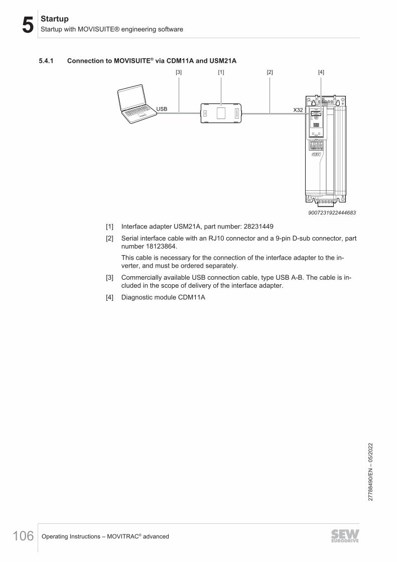
5 StartupStartup with MOVISUITE® engineering software
Operating Instructions – MOVITRAC® advanced106
5.4.1 Connection to MOVISUITE® via CDM11A and USM21A
6 5 4 3 2 1
DR
IVE
RU
N
ER
R
L/A
IN
L/A
OU
T
F-R
UN
F-E
RR
USB X32CA
N/R
S485
US
B
[1] [2][3] [4]
9007231922444683
[1] Interface adapter USM21A, part number: 28231449
[2] Serial interface cable with an RJ10 connector and a 9-pin D-sub connector, partnumber 18123864.This cable is necessary for the connection of the interface adapter to the in-verter, and must be ordered separately.
[3] Commercially available USB connection cable, type USB A-B. The cable is in-cluded in the scope of delivery of the interface adapter.
[4] Diagnostic module CDM11A
2778
8490
/EN
– 0
5/20
22

5StartupStartup with MOVISUITE® engineering software
Operating Instructions – MOVITRAC® advanced 107
5.4.2 Connection to MOVISUITE® via fieldbus interfaceThe following description refers to the PROFINET, Ethernet/IPTM, POWERLINK field-bus interfaces.The CDM11A diagnostic module is required to connect the keypad.
6 5 4 3 2 1
DR
IVE
RU
N
ER
R
L/A
IN
L/A
OU
T
F-R
UN
F-E
RR
[1]
35273973643
[1] Conventional Ethernet cable
• Activate "Ethernet" at Communication/Network type.The inverter can only be scanned if you assign an IP address to the inverter. The as-signment is made using an external addressing tool.
2778
8490
/EN
– 0
5/20
22
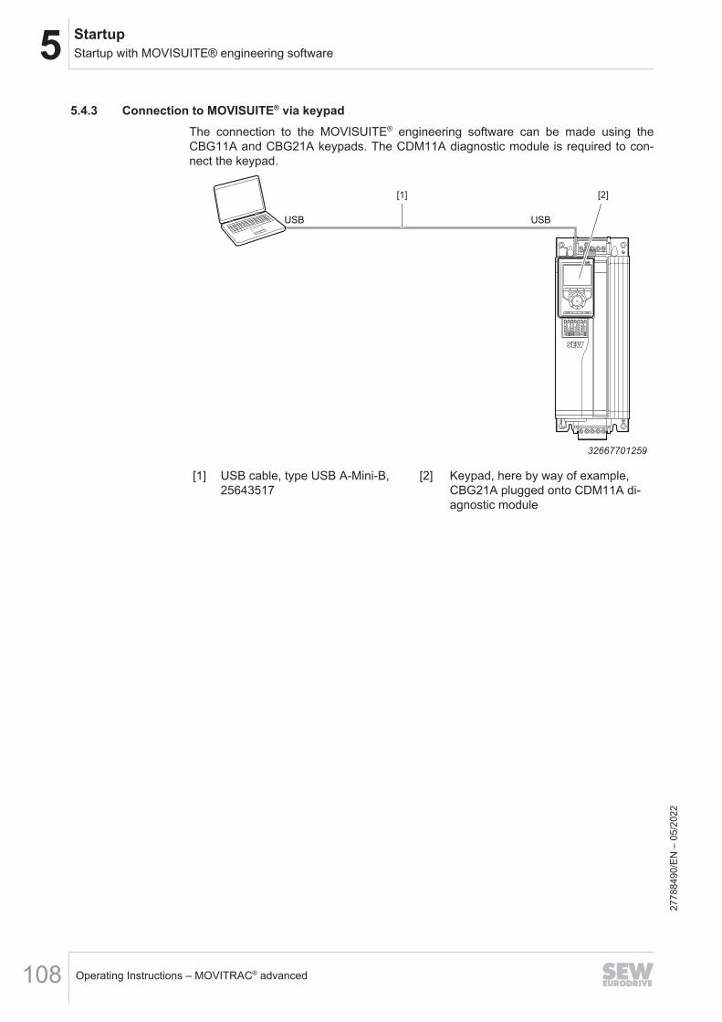
5 StartupStartup with MOVISUITE® engineering software
Operating Instructions – MOVITRAC® advanced108
5.4.3 Connection to MOVISUITE® via keypadThe connection to the MOVISUITE® engineering software can be made using theCBG11A and CBG21A keypads. The CDM11A diagnostic module is required to con-nect the keypad.
6 5 4 3 2 1
DR
IVE
RU
N
ER
R
L/A
IN
L/A
OU
T
F-R
UN
F-E
RR
USB USB
[1] [2]
32667701259
[1] USB cable, type USB A-Mini-B,25643517
[2] Keypad, here by way of example,CBG21A plugged onto CDM11A di-agnostic module
2778
8490
/EN
– 0
5/20
22
5StartupEtherCAT® ID
Operating Instructions – MOVITRAC® advanced 109
5.5 EtherCAT® IDEtherCAT®ID
It is not strictly necessary to set one of the EtherCAT® IDs. The slaves are automatica-lly addressed by the master as standard. The EtherCAT® ID must only be set on theinverter if the use of EtherCAT® IDs has been preset in the hardware configuration ofthe master.An EtherCAT® ID can be permanently assigned to the inverter in the EtherCAT® vari-ant ..E00 using the hexadecimal switches S1 and S2. With these switches, you canset a decimal EtherCAT® ID between 1 and 255 in hexadecimal notation.The ID serves as a unique device identification of the respective EtherCAT® slave forthe EtherCAT® master. The EtherCAT® ID is not an EtherCAT® address. TheEtherCAT® ID is always assigned by the EtherCAT® master.In the delivery state of the inverter, the ID is set to 0 by default (S1 = 0 and S2 = 0).
2778
8490
/EN
– 0
5/20
22

5 StartupEtherCAT® ID
Operating Instructions – MOVITRAC® advanced110
5.5.1 Setting the EtherCAT® IDAn EtherCAT® ID can be permanently assigned to the inverter in the EtherCAT® vari-ant ..E00 using the hexadecimal switches S1 and S2. With these switches, you canset a decimal EtherCAT® ID between 1 and 255 in hexadecimal notation.The ID serves as a unique device identification of the respective EtherCAT® slave forthe EtherCAT® master. The EtherCAT® ID is not an EtherCAT® address.The EtherCAT® ID is always assigned by the EtherCAT® master. In the delivery stateof the inverter, the ID is set to 0 by default (S1 = 0 and S2 = 0).It is not strictly necessary to set one of the EtherCAT® IDs. The slaves are automatica-lly addressed by the master as standard.The EtherCAT® ID must only be set on the inverter if the use of EtherCAT® IDs hasbeen preset in the hardware configuration of the master.
Required ID, decimal ID, hexadecimal Setting S1(x10)
Setting S2(x1)
3 03 0 3
18 12 1 2
25 19 1 9
100 64 6 4
110 6E 6 E
255 FF F F
S1 EtherCAT® ID (x10)123
0FEDC
54
6789
AB
6
S2 EtherCAT® ID (x1)1
2
3
0FE
D
C
5
4
6789
A
B
E
The EtherCAT® ID "110" is set as an example in the illustration above.27
7884
90/E
N –
05/
2022

5StartupStartup with the CBG01A keypad
Operating Instructions – MOVITRAC® advanced 111
5.6 Startup with the CBG01A keypadWith the CBG01A keypad, only asynchronous motors with or without brake (firmware-dependent), without motor sensor and without encoder can be started up.The startup of other motors can only be carried out with the CBG21A keypad or withthe MOVISUITE® engineering software.
5.6.1 CBG01A keypad
[1]
[2]
[3]
[4]
[5]
[7] [6]
a
b
32733276939
[1] 5-digit 7-segment display
[2] Escape key
a = Navigate in the menu
[3] Right/left arrow keys
[4] Confirm entry
[5] Up/down arrow keys
b = Manual mode operating range
[6] RUN key
[7] STOP key
To open the main menu, press the <Esc> key. Press the <right/left> arrow keys to se-lect functions in the main menu. Confirm your selection with the <OK> key.When entering numbers, you must confirm the proposed or entered number with the<OK> key.To return to the previous step in the menu, press the escape key.
2778
8490
/EN
– 0
5/20
22

5 StartupStartup with the CBG01A keypad
Operating Instructions – MOVITRAC® advanced112
Symbols usedThe available functions are shown with pictograms in the keypad display.
Inverter status, FCB number, fault number
Actual speed in min-1
Actual current in A
DC link voltage in V
Fixed setpoints – acceleration 1, 2 in (min × s)-1
Fixed setpoints – deceleration 1, 2 in (min × s)-1
Maximum speed in min-1
Fixed setpoints – speed in min-1
Parameter
Startup
Data management
Manual mode
2778
8490
/EN
– 0
5/20
22

5StartupStartup with the CBG01A keypad
Operating Instructions – MOVITRAC® advanced 113
5.6.2 Startup procedure for motor startup
Value flashes. Possible values: 1 or 2
Value flashes. Adjustable values from ... to ...
Value flashes. Adjustable values from ... to ...
Value flashes. Adjustable values from ... to ...
Value flashes. Adjustable values from ... to ...
Value flashes. Adjustable values from ... to ...
Value flashes. Adjustable values from ... to ...
Value flashes. Can Be Selected: VFC / U/f
Value flashes.
PLUS
Lines flash alternately
Value flashes. Can Be Selected: YES / no
9007235377752331
2778
8490
/EN
– 0
5/20
22

5 StartupStartup with the CBG11A keypad
Operating Instructions – MOVITRAC® advanced114
5.7 Startup with the CBG11A keypad
You can perform the startup intuitively with a CBG11A keypad using the symbols andfunctions shown in the display.Only asynchronous motors without encoder can be started up with the CBG11Akeypad. The startup of other motors can only be performed with the CBG21A keypador with the MOVISUITE® engineering software.
5.7.1 CBG11A keypadThe user interface of this keypad is in English.
[2]
[3]OK
STOP RUN
Esc
[4]
[5]
[7] [6]
[1]
a
b
9007225173448203
[1] Display
[2] Esc key
a = Navigate in the menu
[3] Right/left arrow keys
[4] Confirm entry
[5] Up/down arrow keys
b = Manual mode operating range
[6] RUN key
[7] STOP key
To open the main menu, press the <Esc> key. Press the <right/left> arrow keys to se-lect functions in the main menu. Confirm your selection with the <OK> key.When entering numbers, you must confirm the proposed or entered number with the<OK> key. The digit of the number that is currently editable is then shown underlined.You can use the <up/down> arrow keys to change the value of the digit. Use the<right/left> arrow keys to switch the digit to be edited within the number.
2778
8490
/EN
– 0
5/20
22

5StartupStartup with the CBG11A keypad
Operating Instructions – MOVITRAC® advanced 115
Symbols usedThe available functions are shown with pictograms in the keypad display.
Diagnostics
Data management
Startup
Manual mode
Parameter tree
Keypad settings
2778
8490
/EN
– 0
5/20
22
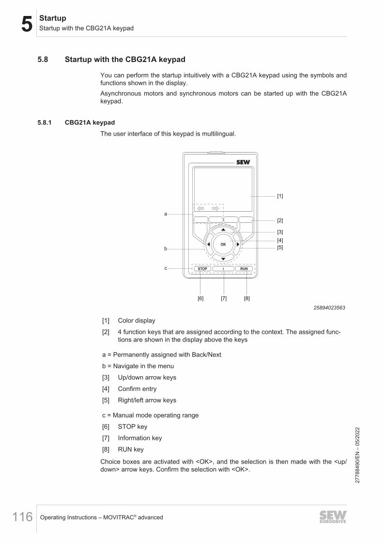
5 StartupStartup with the CBG21A keypad
Operating Instructions – MOVITRAC® advanced116
5.8 Startup with the CBG21A keypad
You can perform the startup intuitively with a CBG21A keypad using the symbols andfunctions shown in the display.Asynchronous motors and synchronous motors can be started up with the CBG21Akeypad.
5.8.1 CBG21A keypadThe user interface of this keypad is multilingual.
[2]
[5]
[3]
[6] [7] [8]
[4]
[1]
a
b
c
25894023563
[1] Color display
[2] 4 function keys that are assigned according to the context. The assigned func-tions are shown in the display above the keys
a = Permanently assigned with Back/Next
b = Navigate in the menu
[3] Up/down arrow keys
[4] Confirm entry
[5] Right/left arrow keys
c = Manual mode operating range
[6] STOP key
[7] Information key
[8] RUN key
Choice boxes are activated with <OK>, and the selection is then made with the <up/down> arrow keys. Confirm the selection with <OK>.
2778
8490
/EN
– 0
5/20
22

5StartupStartup with the CBG21A keypad
Operating Instructions – MOVITRAC® advanced 117
When entering numbers, you must confirm the proposed or entered number with the<OK> key. The digit of the number that is currently editable is then shown with acolored background. You can use the <up/down> arrow keys to change the value ofthe digit. Use the <right/left> arrow keys to switch the digit to be edited within the num-ber.
Symbols used
Startup
Manual mode
Drive train optimization
Application
Diagnostics
Parameters
Data management
Keypad settings
Start menu
MOVISAFE® CS..
Gateway
Back
Next
2778
8490
/EN
– 0
5/20
22

5 StartupFirmware update
Operating Instructions – MOVITRAC® advanced118
5.9 Firmware update• Connect the inverter to the MOVISUITE® engineering software.• Open MOVISUITE® and select the corresponding device.• Right-click to open the context menu. You can open the firmware loader via the
"Tools" menu item.• Now select the corresponding target version of the firmware and transfer it to the
selected component by pressing the "Accept selected firmware" button.• Do not disconnect the communication link during a firmware update, and ensure
that the voltage supply is not interrupted.
5.10 Startup of motors with the MOVILINK® DDI interfaceStartup ofmotors withtheMOVILINK®DDIinterface
If an inverter has the MOVILINK® DDI interface and is connected to a motor that alsohas this interface, the motor is started up automatically via its electronic nameplate.The process is started by switching on the inverter. This function is only supported ifthe inverter is in the delivery state.The status of the inverter is "AC" (Auto Configuration) during the data transfer from theelectronic nameplate. You can obtain more information from the SEW‑EURODRIVEhotline.
2778
8490
/EN
– 0
5/20
22

5StartupControl of control signal sources
Operating Instructions – MOVITRAC® advanced 119
5.11 Control of control signal sourcesThe following description requires the use of the MOVISUITE® engineering software.Depending on the version of the inverter, it is controlled via the digital inputs/analog in-puts or via fieldbus.In principle, the user is free to configure the respective interface individually or to usethe SEW standard interface.Various MOVIKIT® software modules are available for this purpose.This offers the following benefits:• Application-specific functionalities• Standard interface from SEW-EURODRIVE• Automated parameterization of the interface• MOVIKIT®-specific diagnostics and manual operation
5.11.1 Control via terminalsAnalog setpoints and fixed setpoints can be used for control via the terminals. If noMOVIKIT® is loaded ex-works, the source is set to "No source" under "Setpoints/basicsetting" and the inverter can be controlled via terminals.The following applies:• Digital inputs
– DI00: Output stage enable (DI00 is not led out to terminal X20 and thereforecannot be used)
– DI01: Fixed setpoint – positive direction of rotation– DI02: Fixed setpoint – negative direction of rotation– DI03: Fixed speed setpoint bit 0– DI04: Fixed speed setpoint bit 1– DI05: Fault reset– DI06: No function
• Configurable digital inputs/digital outputs– DIO01: No function– DIO02: No function
• Digital outputs– DB00: Brake output– DOR: No function
• Analog input AI1If no "Fixed speed setpoint" bit is selected, the AI1 is taken over as speed setpointsource. The set numerator/denominator scaling in user units applies.Speed setpoint (user units) = AI1 value × 15/100
• Configurable analog input/analog output AIO1– AIO1: No function
2778
8490
/EN
– 0
5/20
22

5 StartupControl of control signal sources
Operating Instructions – MOVITRAC® advanced120
5.11.2 Control via fieldbusFor control via fieldbus, the source must be set to "Standard fieldbus system" under"Setpoints/basic setting".• Process output data (controller → device)
Setpoint and profile value interconnections can be individually linked to the corre-sponding process output data.In addition, the control words used must be documented and the link to the pro-cess output data must be established.
• Process input data (device → controller)The data sources for the process input data can be linked under "Actual values/PIdata".In addition, the status words used must be documented and the link to the processinput data must be established.
5.11.3 Control via MOVIKIT® software moduleThe MOVIKIT® software modules have firmly defined interfaces.When using the MOVISUITE® engineering software, MOVIKIT® modules can be se-lected and added via the software catalog.For further information on using and operating the MOVIKIT® modules, refer to thecorresponding documentation.
2778
8490
/EN
– 0
5/20
22

5StartupApplication-related startup
Operating Instructions – MOVITRAC® advanced 121
5.12 Application-related startupThe following lists applications with specific settings for startup.Startup is performed using the MOVISUITE® engineering software.
5.12.1 Pumps and fans• The control mode to be used depends on the motor type.• Switch the slip compensation off.• Activate the flying start function.• In the V/f control mode, the direct current brake is effective.
5.12.2 HoistThe following parameters must be taken into account and set for a hoist:• Preload hoist (index 8404.9): This parameter determines the behavior of the integ-
rator when re-entering control. Example: When the output stage is inhibited (e.g.with FCB 02, FCB 01, FCB 13, FCB 14), the I component (which corresponds tothe preload in the case of the hoist) is deleted. The following selections are avail-able to prevent this:– ‘Off’ (=default): The integrator always starts with the value "0". Adjustment is
made to an existing load torque. The speed controller can usually compensatefor sagging of the hoist without additional settings.
– "Save": The value is maintained as present at the time of opening the speedcontrol loop. If the load torque has not changed, no adjustment is necessarywhen closing the speed control loop.
– "Initialization value": If the load torque is known, this can be specified on thespeed controller as an initial value via the parameter 'Torque bias' in the range-1000% to 1000% of the nominal motor torque. This can be done during startupor optimization of the drive with the MOVISUITE® engineering software or youcan use a local setpoint or a channel of the process data buffer. If the directionof rotation is positive in the stroke direction, enter a positive value and viceversa.
• Activate speed monitoring (index 8550.1). You must set the monitoring time (index8550.2) for the specific application.
• For hoists without encoder, activate the stop by setpoint function (index 8570.1)and set it.
2778
8490
/EN
– 0
5/20
22
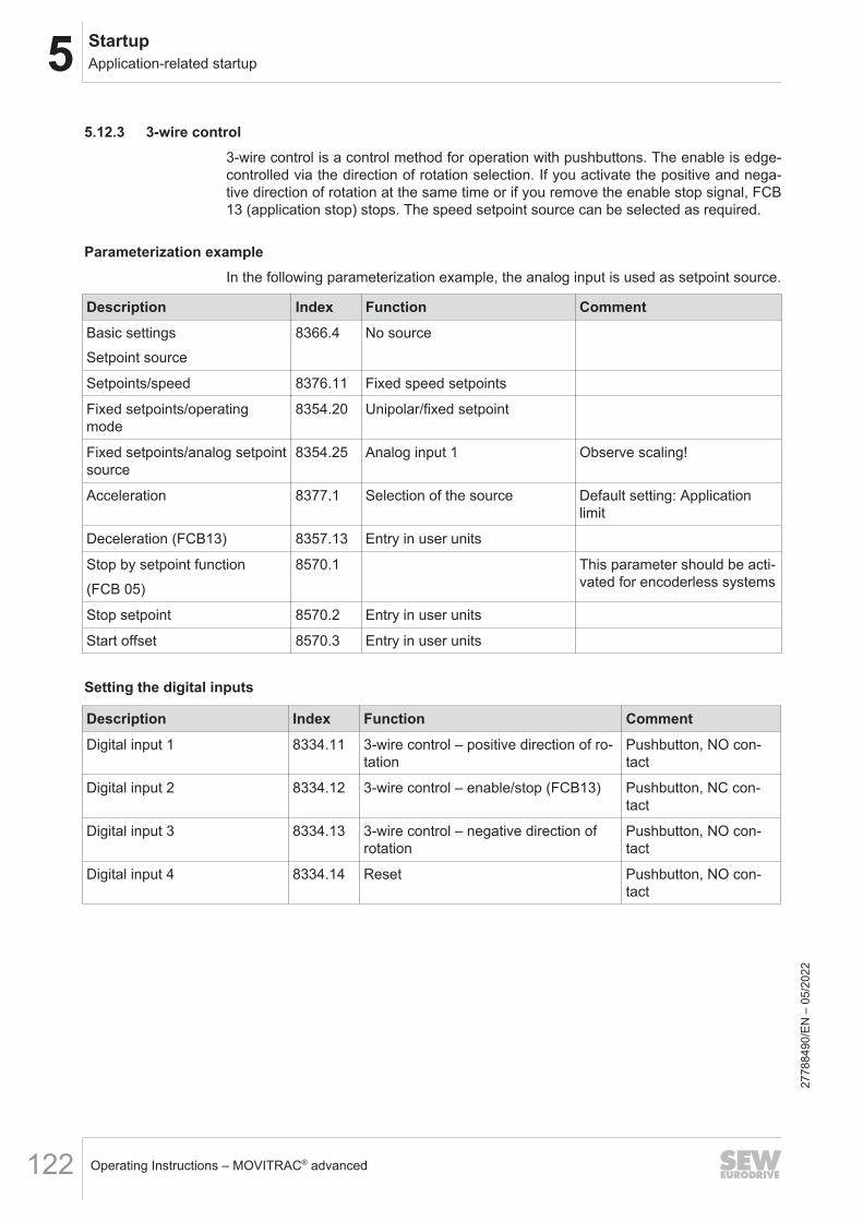
5 StartupApplication-related startup
Operating Instructions – MOVITRAC® advanced122
5.12.3 3-wire control3-wire control is a control method for operation with pushbuttons. The enable is edge-controlled via the direction of rotation selection. If you activate the positive and nega-tive direction of rotation at the same time or if you remove the enable stop signal, FCB13 (application stop) stops. The speed setpoint source can be selected as required.
Parameterization exampleIn the following parameterization example, the analog input is used as setpoint source.
Description Index Function CommentBasic settingsSetpoint source
8366.4 No source
Setpoints/speed 8376.11 Fixed speed setpoints
Fixed setpoints/operatingmode
8354.20 Unipolar/fixed setpoint
Fixed setpoints/analog setpointsource
8354.25 Analog input 1 Observe scaling!
Acceleration 8377.1 Selection of the source Default setting: Applicationlimit
Deceleration (FCB13) 8357.13 Entry in user units
Stop by setpoint function(FCB 05)
8570.1 This parameter should be acti-vated for encoderless systems
Stop setpoint 8570.2 Entry in user units
Start offset 8570.3 Entry in user units
Setting the digital inputs
Description Index Function CommentDigital input 1 8334.11 3-wire control – positive direction of ro-
tationPushbutton, NO con-tact
Digital input 2 8334.12 3-wire control – enable/stop (FCB13) Pushbutton, NC con-tact
Digital input 3 8334.13 3-wire control – negative direction ofrotation
Pushbutton, NO con-tact
Digital input 4 8334.14 Reset Pushbutton, NO con-tact
2778
8490
/EN
– 0
5/20
22

5StartupApplication-related startup
Operating Instructions – MOVITRAC® advanced 123
Cycle diagram
n
-n
n0
X20.7
X20.1
X20.2
X20.3
X23.1
X23.2
X23.3
+24 V
DI01
DI02
DI03
+10 V
AI 1
0 V
DI01
DI02
DI03
AI 1
1
0
1
0
1
0
10 V
5 V
0 V
n0
[1] [2]
[1] [2]
[1]
36070034187
[1] Acceleration according to the source[2] Application limit deceleration (FCB 13)DI01 3-wire control – positive direction of rotationDI02 3-wire control – enable/stopDI03 3-wire control – negative direction of rotationAI 1 Setpoint input AI1n Motor speedn0 Start/stop speed
2778
8490
/EN
– 0
5/20
22

5 StartupApplication-related startup
Operating Instructions – MOVITRAC® advanced124
5.12.4 Motor potentiometer functionThe motor potentiometer function lets the inverter respond to signal levels.If the digital inputs "motor potentiometer up/down" are activated, the speed changeswith the profile value "max. acceleration" (index 8377.21) or "max. deceleration" (index8377.31).The last motor potentiometer setpoint is retained even when the supply system isswitched off if the "save setpoint" function is activated via index 8369.2.If the digital inputs "motor potentiometer up/down" are activated simultaneously, thereare two options:• Save setpoint (index 8369.2): OFF:
– The inverter stops along the "max. deceleration" (index 8377.31)• Save setpoint (index 8369.2): ON:
– The current speed is maintained.If none of the two inputs are activated, the current speed and direction of rotation aremaintained.
Parameterization example
Description Index Function CommentBasic settingsSetpoint source
8366.4 No source
Setpoints/speed 8376.11 Fixed setpoints – velocity
Fixed setpoints/operatingmode
8354.20 Motor potentiometer/fixed set-point
Fixed setpoints/analog setpointsource
8354.25 No source
Setpoints/max. Acceleration 8377.21 Selection of the source Default setting: Applicationlimit
Setpoints/max. Deceleration 8377.31 Selection of the source Default setting: Applicationlimit
Minimum speed* In preparation (planned forFW10)
Save setpoint 8369.2 Off Behavior after "mains off"
Setting the digital inputs
Description Index Function CommentDigital input 1 8334.11 FCB05 – Fixed setpoints, positive di-
rection of rotationSwitch, NO contact
Digital input 2 8334.12 FCB05 – Fixed setpoints, negative di-rection of rotation
Switch, NO contact
Digital input 3 8334.13 Motor potentiometer up Pushbutton, NO con-tact
Digital input 4 8334.14 Motor potentiometer down Pushbutton, NO con-tact 27
7884
90/E
N –
05/
2022

5StartupApplication-related startup
Operating Instructions – MOVITRAC® advanced 125
Description Index Function CommentDigital input 5 8334.14 Reset Pushbutton, NO con-
tact
Cycle diagram
t1 t2 t3 t4 t5 t6 t7 t8 t9 t10 t11
Application limit positive
Minimum speed
FCB 05: Fixed setpoints, positive direction of rotation
FCB 05: Fixed setpoints negative direction of rotation
Motor potentiometer up
Motor potentiometer down
36070906379
t1 Output stage enable via "FCB05 – fixed setpoints for positive direction of rotation".t1 - t2 Motor runs up to the set minimum speed.t2 - t3 Motor keeps minimum speed1).t3 "Motor potentiometer up" is activated.t3 - t4 As long as the signal "Motor potentiometer up" is present, the motor speed is increased along ac-
celeration ramp (index 8377.21).t4 - t5 If no signal is present any longer at "Motor potentiometer", the actual speed is maintained.t5 "Motor potentiometer up" is activated again.t5 - t6 As long as the signal "Motor potentiometer up" is present, the motor speed is increased further
along the acceleration ramp until it reaches the application limit (8357.10/11).t6 - t7 The maximum speed is maintained, even if the signal at "Motor potentiometer up" is no longer
present.t7 “Motor potentiometer down” is activated.t7 - t8 As long as the signal at "Motor potentiometer down" is present, the motor speed is decreased
along deceleration ramp (index 8377.31).t8 - t9 If no signal is present any longer at "Motor potentiometer down", the actual speed is maintained.t9 - t10 As long as the signal at "Motor potentiometer down" is present, the motor speed is decreased
along deceleration ramp (index 8377.31) until the minimum speed.t10 - t11 The minimum speed is maintained.t11 Revoking of the output stage inhibit via "FCB 05 – fixed setpoints positive direction of rotation".
1) in preparation
2778
8490
/EN
– 0
5/20
22
5 StartupApplication-related startup
Operating Instructions – MOVITRAC® advanced126
5.12.5 Positioning and speed control with HTL encoders• Start up the drive train with HTL encoders.• Insert the MOVIKIT® "Positioning Drive" software module.• Assign inputs DI04 (track A), DI05 (track B) and optional DI06 (track C).
Restrictions for the EI7C encoder:Only simple positioning tasks can be implemented in combination with the MOVIKIT®
"Positioning Drive" software module and the EI7C encoder. The achievable accuracyis 1/4 motor revolutions.Due to the low encoder resolution, observe the following:• Speed control is not possible.• Position control at speed 0 is not possible, so you must inhibit the output stage
when the "in position" signal is displayed. If a brake is installed, you must parame-terize it so that it is applied.
• SEW‑EURODRIVE recommends to set the lag range accordingly and to set thecontrol to soft.
2778
8490
/EN
– 0
5/20
22

6OperationGeneral information
Operating Instructions – MOVITRAC® advanced 127
6 Operation6.1 General information
DANGERDangerous voltages present at cables and motor terminals.Severe or fatal injuries from electric shock• Dangerous voltages are present at the output terminals and the cables and motor
terminals connected to them when the device is switched on. This also applieseven when the device is inhibited and the motor is at standstill.
• The fact that the operation LED is no longer illuminated does not indicate that theinverter has been disconnected from the power supply and no longer carries anyvoltage.
• Before you touch the power terminals, check that the inverter has been discon-nected from the power supply.
• Observe the general safety notes in the "Safety notes" chapter and the notes inthe "Electrical installation" chapter.
DANGERRisk of crushing if the motor starts up unintentionally.Serious or fatal injuries• Binary device: Prevent unintentional starting of the motor, e.g. by setting STO or
by setting the 24 V operation.• Bus device: Disconnect the motor.• Additional safety precautions must be taken, depending on the application, to
avoid injury to personnel and damage to machinery.
NOTICESwitching the motor output at the inverter with enabled output stage.Inverter damage• The motor output of the inverter may be switched or disconnected only when the
output stage is inhibited.
2778
8490
/EN
– 0
5/20
22
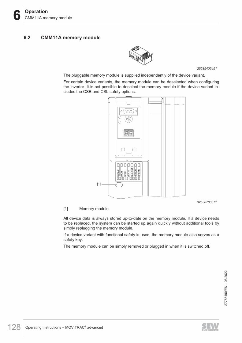
6 OperationCMM11A memory module
Operating Instructions – MOVITRAC® advanced128
6.2 CMM11A memory module
25585405451
The pluggable memory module is supplied independently of the device variant.For certain device variants, the memory module can be deselected when configuringthe inverter. It is not possible to deselect the memory module if the device variant in-cludes the CSB and CSL safety options.
DR
IVE
RU
N
ER
R
L/A
IN
L/A
OU
T
F-R
UN
F-E
RR
[1]
32536703371
[1] Memory module
All device data is always stored up-to-date on the memory module. If a device needsto be replaced, the system can be started up again quickly without additional tools bysimply replugging the memory module.If a device variant with functional safety is used, the memory module also serves as asafety key.The memory module can be simply removed or plugged in when it is switched off.
2778
8490
/EN
– 0
5/20
22
6OperationCMM11A memory module
Operating Instructions – MOVITRAC® advanced 129
6.2.1 Instructions on the use of the memory module when exchanging a deviceThe prerequisite for the error-free exchange of an inverter is that the same optionsmust be installed in the new device as in the original one.If this is not the case, the error message "25.70 NV memory initialization" is displayed.You can acknowledge the fault by opening the "Fault reset with parameter accept-ance" menu item in the context menu, and you must ensure that the information thatwas provided via the previous options (e.g. encoder signals via encoder option) reachthe inverter through different means or are deselected.Alternatively, the device can also be reset to the delivery state. A new startup is thenrequired.If a memory module is removed during operation, the following error message is dis-played: "33.13 System initialization: Memory module removed".This fault status can be acknowledged with a fault reset.
2778
8490
/EN
– 0
5/20
22
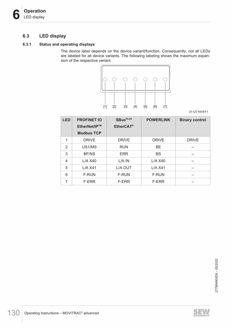
6 OperationLED display
Operating Instructions – MOVITRAC® advanced130
6.3 LED display6.3.1 Status and operating displays
The device label depends on the device variant/function. Consequently, not all LEDsare labeled for all device variants. The following labeling shows the maximum expan-sion of the respective variant.
[1] [2] [4] [5] [7][3] [6]
31127161611
LED PROFINET IOEtherNet/IPTM
Modbus TCP
SBusPLUS
EtherCAT®
POWERLINK Binary control
1 DRIVE DRIVE DRIVE DRIVE
2 US1/MS RUN BE –
3 BF/NS ERR BS –
4 L/A X40 L/A IN L/A X40 –
5 L/A X41 L/A OUT L/A X41 –
6 F-RUN F-RUN F-RUN –
7 F-ERR F-ERR F-ERR –
2778
8490
/EN
– 0
5/20
22
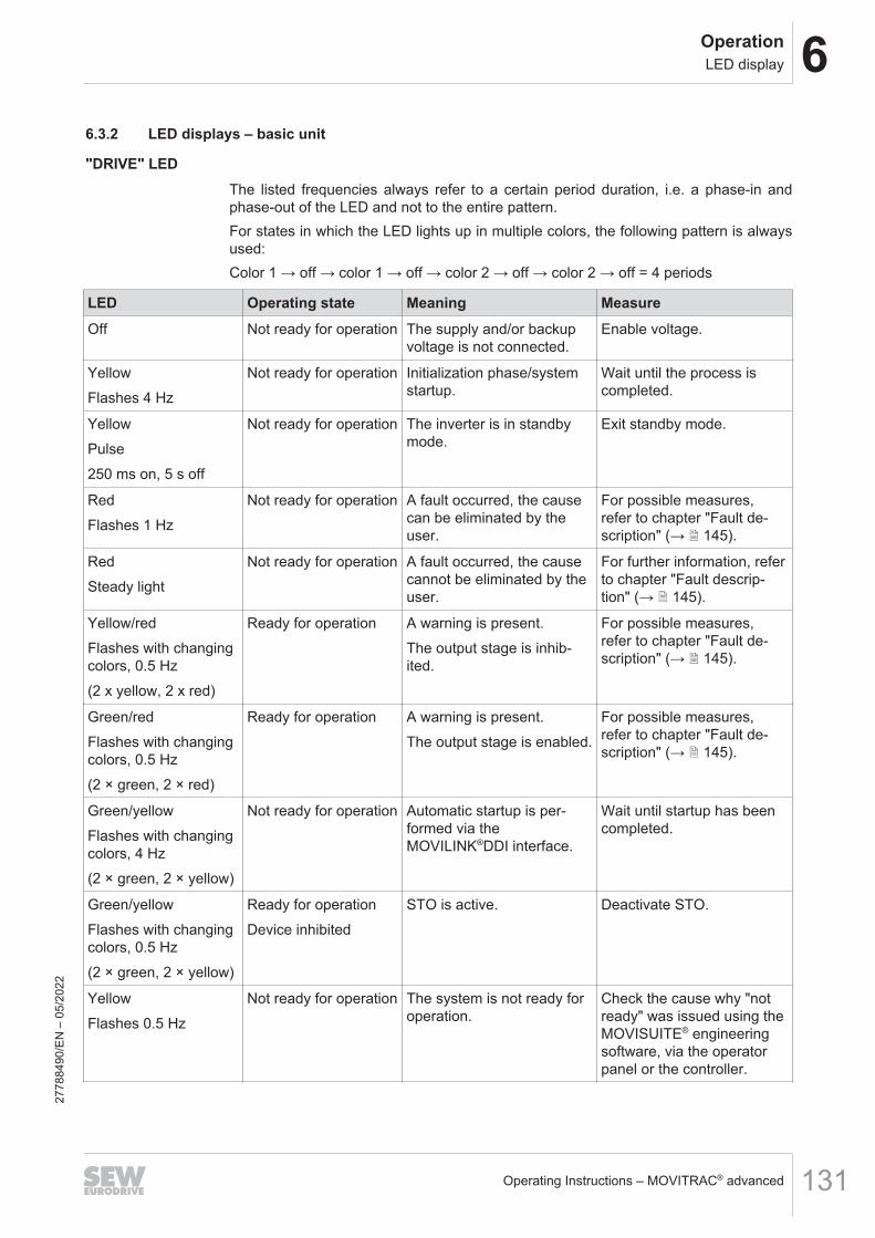
6OperationLED display
Operating Instructions – MOVITRAC® advanced 131
6.3.2 LED displays – basic unit
"DRIVE" LEDThe listed frequencies always refer to a certain period duration, i.e. a phase-in andphase-out of the LED and not to the entire pattern.For states in which the LED lights up in multiple colors, the following pattern is alwaysused:Color 1 → off → color 1 → off → color 2 → off → color 2 → off = 4 periods
LED Operating state Meaning MeasureOff Not ready for operation The supply and/or backup
voltage is not connected.Enable voltage.
YellowFlashes 4 Hz
Not ready for operation Initialization phase/systemstartup.
Wait until the process iscompleted.
YellowPulse250 ms on, 5 s off
Not ready for operation The inverter is in standbymode.
Exit standby mode.
RedFlashes 1 Hz
Not ready for operation A fault occurred, the causecan be eliminated by theuser.
For possible measures,refer to chapter "Fault de-scription" (→ 2 145).
RedSteady light
Not ready for operation A fault occurred, the causecannot be eliminated by theuser.
For further information, referto chapter "Fault descrip-tion" (→ 2 145).
Yellow/redFlashes with changingcolors, 0.5 Hz(2 x yellow, 2 x red)
Ready for operation A warning is present.The output stage is inhib-ited.
For possible measures,refer to chapter "Fault de-scription" (→ 2 145).
Green/redFlashes with changingcolors, 0.5 Hz(2 × green, 2 × red)
Ready for operation A warning is present.The output stage is enabled.
For possible measures,refer to chapter "Fault de-scription" (→ 2 145).
Green/yellowFlashes with changingcolors, 4 Hz(2 × green, 2 × yellow)
Not ready for operation Automatic startup is per-formed via theMOVILINK®DDI interface.
Wait until startup has beencompleted.
Green/yellowFlashes with changingcolors, 0.5 Hz(2 × green, 2 × yellow)
Ready for operationDevice inhibited
STO is active. Deactivate STO.
YellowFlashes 0.5 Hz
Not ready for operation The system is not ready foroperation.
Check the cause why "notready" was issued using theMOVISUITE® engineeringsoftware, via the operatorpanel or the controller.
2778
8490
/EN
– 0
5/20
22

6 OperationLED display
Operating Instructions – MOVITRAC® advanced132
LED Operating state Meaning MeasureYellowFlashes 1 Hz
Ready for operation.Manual mode/localmode/prioritized termi-nal control status
The device is ready foroperation, waiting for en-able.
–
GreenFlashes 1 Hz
Unit enabled.Manual mode/localmode/prioritized termi-nal control status
The output stage is enabled. –
YellowFlashes 2 Hz
Ready for operation The brake is releasedwithout drive enable.
–
YellowSteady light
Ready for operationDevice inhibited
The device is ready foroperation; the output stageis inhibited.
–
GreenFlashes 4 Hz
Unit enabled.Current limit active.
The drive is at the currentlimit.
Reduce the load.
GreenSteady light
Device enabled The output stage is enabled. –
"RUN" LED
LED MeaningOff "INIT" state
The interface is in the "INIT" state.
GreenFlashing
"PRE_OPERATIONAL" stateMailbox communication is possible.Process data communication is not possible.
GreenFlashing once
"SAFE_OPERATIONAL" stateMailbox and process data communication is possible.Safety-related output signals are not output.
GreenIlluminated
"OPERATIONAL Mode" stateMailbox and process data communication is possible.
2778
8490
/EN
– 0
5/20
22

6OperationLED display
Operating Instructions – MOVITRAC® advanced 133
"ERR" LED
LED MeaningOff No error
The interface is in operating state.
RedFlickering
Boot errorA BOOT error has occurred."INIT" state has not been reached.However the "Change" parameter is set to "0x01:change/error".
RedFlashing
Invalid configurationA general configuration error has occurred.
RedFlashing once
Unprompted state changeThe slave application has changed the state automatically.The "Change" parameter is set to "0x01:change/error".
RedFlashing twice
Application watchdog timeoutA watchdog timeout error has occurred in the application.
RedIlluminated
PDI1) Watchdog TimeoutA PDI watchdog timeout error has occurred.
1) PDI = Process Data Interface
"LNK/ACT" LED
LED MeaningOff No link available.
No physical connection to a neighboring device was detected.
GreenIlluminated
Link available, no bus activity.A physical connection to a neighboring device was detected.No data is being exchanged via the Ethernet port.
GreenFlickering
Link available, bus activity.A physical connection to a neighboring device was detected.Data is being exchanged via the Ethernet port.
2778
8490
/EN
– 0
5/20
22

6 OperationLED display
Operating Instructions – MOVITRAC® advanced134
6.3.3 Fieldbus variants PROFINET CFN and PROFINET CFNB
"BF" LEDThis LED indicates the status of the PROFINET interface. The state includes commu-nication link, bus error and process data configuration.
Status Possible cause MeasureOff Fault-free operating state.
The PROFINET device is exchangingdata with the PROFINET controller(Data Exchange state).
–
RedPermanently lit
Connection to the PROFINET control-ler has failed.Bus communication has been inter-rupted.
Check the PROFINET connection ofthe PROFINET device.Check all the cables in the PROFINETnetwork.
The PROFINET controller is not inoperation.
Check the PROFINET controller.
The PROFINET device does not de-tect a PROFINET baud rate.
Check the configuration of thePROFINET controller.
YellowPermanently lit
There is a connection to thePROFINET controller, but the configu-ration of the PROFINET network isfaulty.The following faults may have oc-curred:• A hardware module was selected
that does not support thePROFINET interface.
• The standard process data and thesafe process data have been as-signed mixed to the PROFINETdevice.
Check the configuration of thePROFINET controller.
2778
8490
/EN
– 0
5/20
22
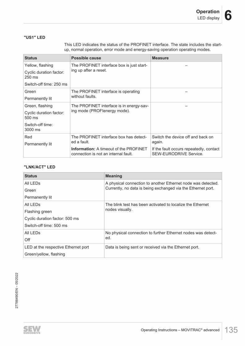
6OperationLED display
Operating Instructions – MOVITRAC® advanced 135
"US1" LEDThis LED indicates the status of the PROFINET interface. The state includes the start-up, normal operation, error mode and energy-saving operation operating modes.
Status Possible cause MeasureYellow, flashingCyclic duration factor:250 msSwitch-off time: 250 ms
The PROFINET interface box is just start-ing up after a reset.
–
GreenPermanently lit
The PROFINET interface is operatingwithout faults.
–
Green, flashingCyclic duration factor:500 msSwitch-off time:3000 ms
The PROFINET interface is in energy-sav-ing mode (PROFIenergy mode).
–
RedPermanently lit
The PROFINET interface box has detect-ed a fault.Information: A timeout of the PROFINETconnection is not an internal fault.
Switch the device off and back onagain.If the fault occurs repeatedly, contactSEW‑EURODRIVE Service.
"LNK/ACT" LED
Status MeaningAll LEDsGreenPermanently lit
A physical connection to another Ethernet node was detected.Currently, no data is being exchanged via the Ethernet port.
All LEDsFlashing greenCyclic duration factor: 500 msSwitch-off time: 500 ms
The blink test has been activated to localize the Ethernetnodes visually.
All LEDsOff
No physical connection to further Ethernet nodes was detect-ed.
LED at the respective Ethernet portGreen/yellow, flashing
Data is being sent or received via the Ethernet port.
2778
8490
/EN
– 0
5/20
22
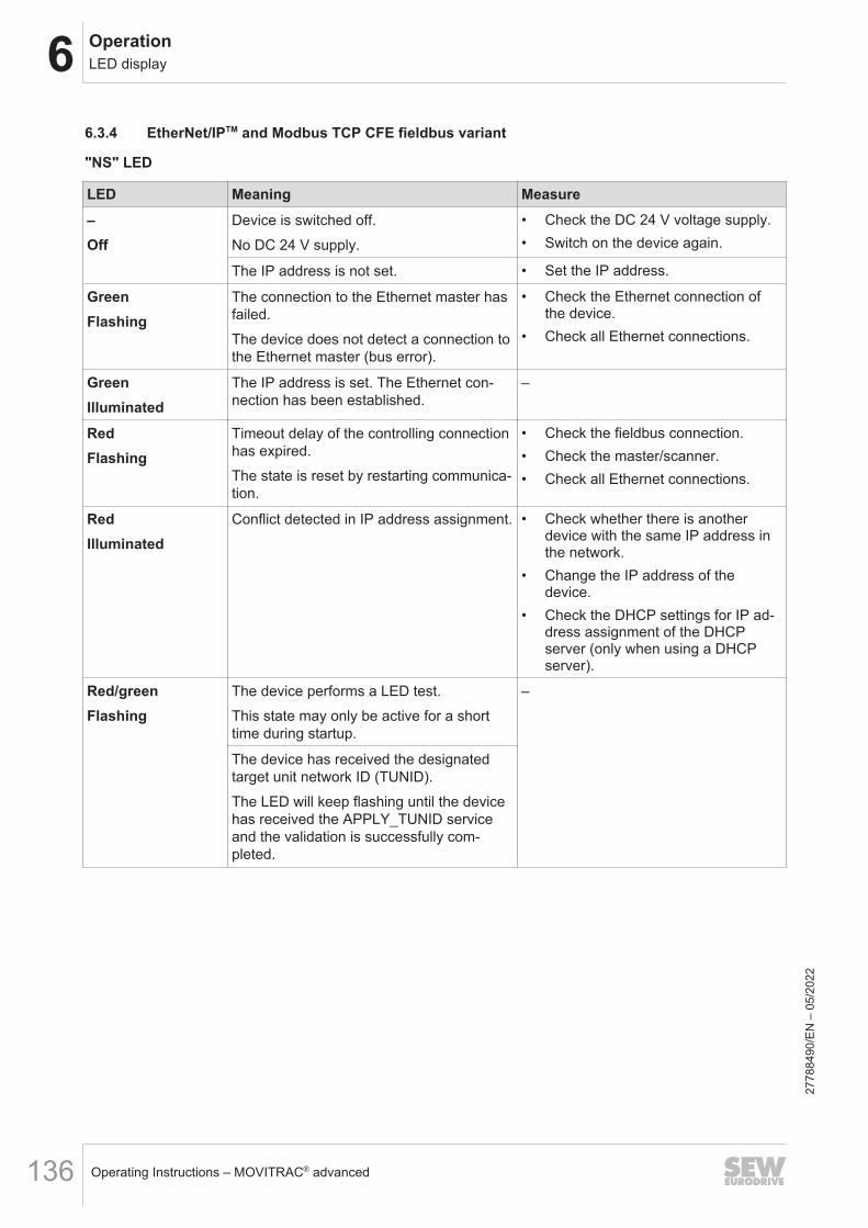
6 OperationLED display
Operating Instructions – MOVITRAC® advanced136
6.3.4 EtherNet/IPTM and Modbus TCP CFE fieldbus variant
"NS" LED
LED Meaning Measure–Off
Device is switched off.No DC 24 V supply.
• Check the DC 24 V voltage supply.• Switch on the device again.
The IP address is not set. • Set the IP address.
GreenFlashing
The connection to the Ethernet master hasfailed.The device does not detect a connection tothe Ethernet master (bus error).
• Check the Ethernet connection ofthe device.
• Check all Ethernet connections.
GreenIlluminated
The IP address is set. The Ethernet con-nection has been established.
–
RedFlashing
Timeout delay of the controlling connectionhas expired.The state is reset by restarting communica-tion.
• Check the fieldbus connection.• Check the master/scanner.• Check all Ethernet connections.
RedIlluminated
Conflict detected in IP address assignment. • Check whether there is anotherdevice with the same IP address inthe network.
• Change the IP address of thedevice.
• Check the DHCP settings for IP ad-dress assignment of the DHCPserver (only when using a DHCPserver).
Red/greenFlashing
The device performs a LED test.This state may only be active for a shorttime during startup.
–
The device has received the designatedtarget unit network ID (TUNID).The LED will keep flashing until the devicehas received the APPLY_TUNID serviceand the validation is successfully com-pleted.
2778
8490
/EN
– 0
5/20
22
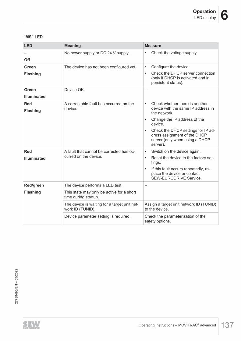
6OperationLED display
Operating Instructions – MOVITRAC® advanced 137
"MS" LED
LED Meaning Measure–Off
No power supply or DC 24 V supply. • Check the voltage supply.
GreenFlashing
The device has not been configured yet. • Configure the device.• Check the DHCP server connection
(only if DHCP is activated and inpersistent status).
GreenIlluminated
Device OK. –
RedFlashing
A correctable fault has occurred on thedevice.
• Check whether there is anotherdevice with the same IP address inthe network.
• Change the IP address of thedevice.
• Check the DHCP settings for IP ad-dress assignment of the DHCPserver (only when using a DHCPserver).
RedIlluminated
A fault that cannot be corrected has oc-curred on the device.
• Switch on the device again.• Reset the device to the factory set-
tings.• If this fault occurs repeatedly, re-
place the device or contactSEW‑EURODRIVE Service.
Red/greenFlashing
The device performs a LED test.This state may only be active for a shorttime during startup.
–
The device is waiting for a target unit net-work ID (TUNID).
Assign a target unit network ID (TUNID)to the device.
Device parameter setting is required. Check the parameterization of thesafety options.
2778
8490
/EN
– 0
5/20
22

6 OperationLED display
Operating Instructions – MOVITRAC® advanced138
"LNK/ACT" LED
Status MeaningAll LEDsGreenPermanently lit
A physical connection to another Ethernet node was detected.Currently, no data is being exchanged via the Ethernet port.
All LEDsFlashing greenCyclic duration factor: 500 msSwitch-off time: 500 ms
The blink test has been activated to localize the Ethernetnodes visually.
All LEDsOff
No physical connection to further Ethernet nodes was detect-ed.
LED at the respective Ethernet portGreen/yellow, flashing
Data is being sent or received via the Ethernet port.
2778
8490
/EN
– 0
5/20
22
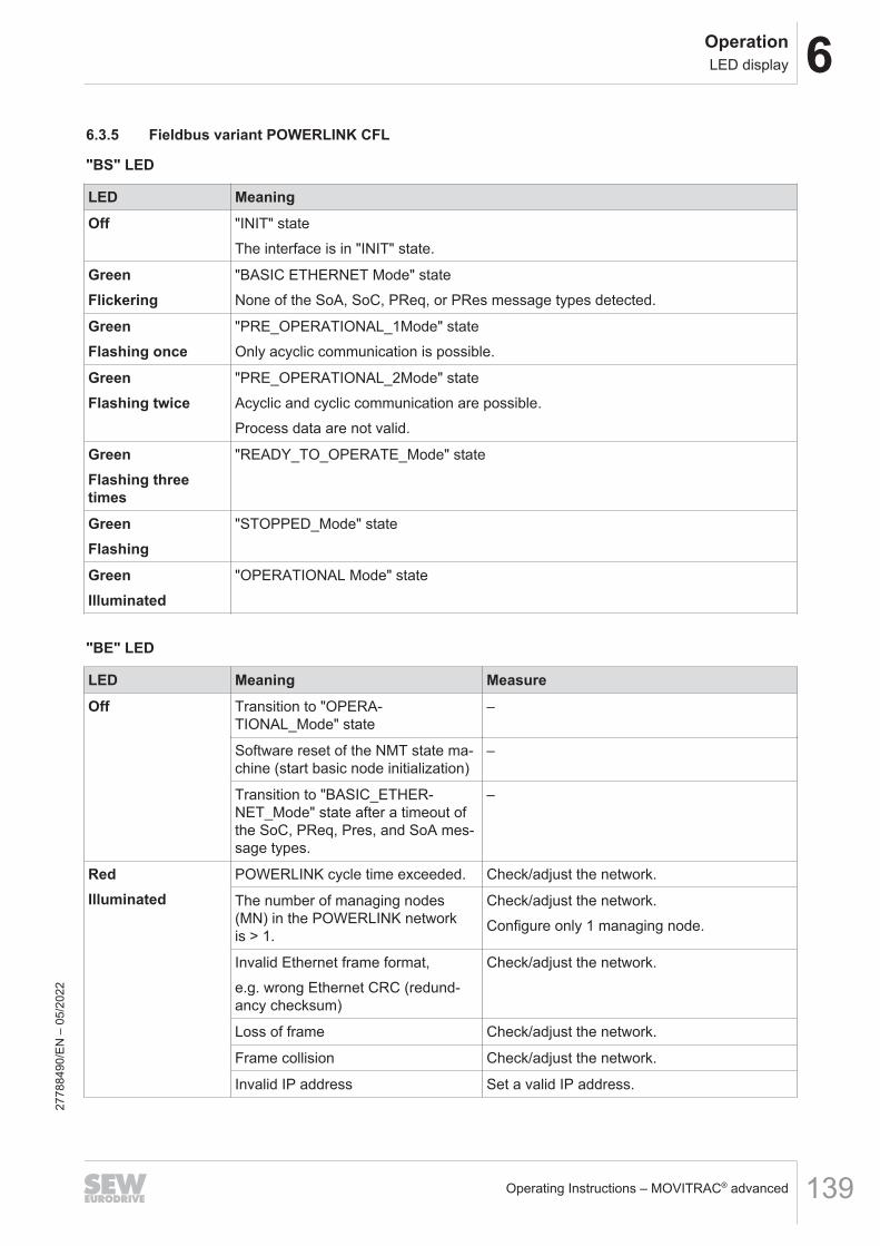
6OperationLED display
Operating Instructions – MOVITRAC® advanced 139
6.3.5 Fieldbus variant POWERLINK CFL
"BS" LED
LED MeaningOff "INIT" state
The interface is in "INIT" state.
GreenFlickering
"BASIC ETHERNET Mode" stateNone of the SoA, SoC, PReq, or PRes message types detected.
GreenFlashing once
"PRE_OPERATIONAL_1Mode" stateOnly acyclic communication is possible.
GreenFlashing twice
"PRE_OPERATIONAL_2Mode" stateAcyclic and cyclic communication are possible.Process data are not valid.
GreenFlashing threetimes
"READY_TO_OPERATE_Mode" state
GreenFlashing
"STOPPED_Mode" state
GreenIlluminated
"OPERATIONAL Mode" state
"BE" LED
LED Meaning MeasureOff Transition to "OPERA-
TIONAL_Mode" state–
Software reset of the NMT state ma-chine (start basic node initialization)
–
Transition to "BASIC_ETHER-NET_Mode" state after a timeout ofthe SoC, PReq, Pres, and SoA mes-sage types.
–
RedIlluminated
POWERLINK cycle time exceeded. Check/adjust the network.
The number of managing nodes(MN) in the POWERLINK networkis > 1.
Check/adjust the network.Configure only 1 managing node.
Invalid Ethernet frame format,e.g. wrong Ethernet CRC (redund-ancy checksum)
Check/adjust the network.
Loss of frame Check/adjust the network.
Frame collision Check/adjust the network.
Invalid IP address Set a valid IP address.
2778
8490
/EN
– 0
5/20
22
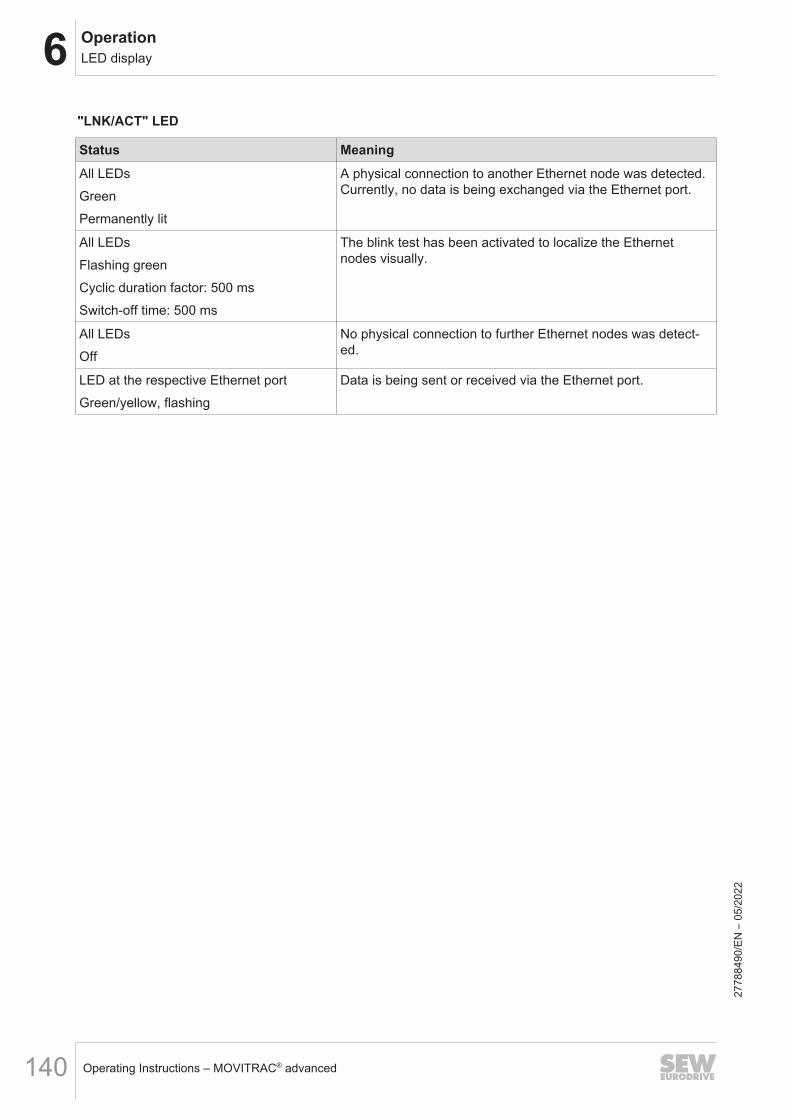
6 OperationLED display
Operating Instructions – MOVITRAC® advanced140
"LNK/ACT" LED
Status MeaningAll LEDsGreenPermanently lit
A physical connection to another Ethernet node was detected.Currently, no data is being exchanged via the Ethernet port.
All LEDsFlashing greenCyclic duration factor: 500 msSwitch-off time: 500 ms
The blink test has been activated to localize the Ethernetnodes visually.
All LEDsOff
No physical connection to further Ethernet nodes was detect-ed.
LED at the respective Ethernet portGreen/yellow, flashing
Data is being sent or received via the Ethernet port.
2778
8490
/EN
– 0
5/20
22

6Operation7-segment display
Operating Instructions – MOVITRAC® advanced 141
6.4 7-segment displayThe 7-segment display is only available when the CDM diagnostic module is used.
6.4.1 Operating displays
• The two 7‑segment displays indicate the operating state of the inverter.
6.4.2 Error displayThe inverter detects any faults that occur and displays them as fault code. Each faultis clearly defined by its fault code and corresponding attributes, as shown below:• Fault response• Final state after executing the fault response• Type of reset response.The fault codes are displayed as flashing numeric values in the inverter.The fault code is displayed in the following display sequence:
500 ms 124 ms 1000 ms 124 ms
1000 ms 124 ms
12082058123
In the example, a 2-digit fault code with subfault is shown; in this example, fault 07.01.
2778
8490
/EN
– 0
5/20
22

6 OperationOperating displays
Operating Instructions – MOVITRAC® advanced142
6.5 Operating displays6.5.1 7-segment display – CDM11A diagnostic module
Display Description State Comment/actionDisplays during boot processb0 Device passes through
several states when load-ing the firmware (boot) inorder to become ready foroperation.
• Status: Not ready• Output stage is inhibited.• Communication is not
yet possible.
• Waiting for boot process to finish.• Device stays in this condition:
Device is defective.b1
b3
br
Display Description State Comment/actionDisplays of different device statuses
• Energy-saving mode Energy-saving mode active
00 DC link voltage missing. • Status: Not ready• Output stage is inhibited.• Communication is pos-
sible.
Check supply system.
C0Flashing
Module bus is not ready. Check the module bus connection.
C1Flashing
Startup state Startup state is active.
C2Flashing
STO active • Status: Not ready• Output stage is inhibited.• Communication is pos-
sible.
The function Safe Torque Off is ac-tive.
C3Flashing
Synchronization with bus isincorrect. Process dataprocessing not available.
• Check the bus connection.• Check synchronization setting at
device and controller.• Check process data settings at
device and controller.
C4Flashing
Encoder evaluation is notready.
• Encoders are being initialized.• Device stays in this condition:
– No encoder selected.– "Source actual speed" or "Ac-tual position" parameter shows anencoder that does not exist.
C5Flashing
Motor management is notready.
C6Flashing
Internal device supply in-complete.
C7Flashing
Power section not ready.
C8Flashing
External device not ready.
2778
8490
/EN
– 0
5/20
22

6OperationOperating displays
Operating Instructions – MOVITRAC® advanced 143
Display Description State Comment/actionC9Flashing
Data flexibilization layer notready.
CdFlashing
Parameter download run-ning.
CA MOVILINK® DDI not ready MOVILINK® DDI interface not ready
Display Description State Comment/actionDisplays during initialization processes (parameters will be reset to default values)
d0Flashing
Basic initialization • Status: Not ready• Output stage is inhibited.• Communication is pos-
sible.
Waiting for initialization to finish.
d1Flashing
Initialization at deliverystate
Display Description State Comment/actionDisplays in normal operation01 Output stage inhibit • Output stage is inhibited. The drive is not actuated by the out-
put stage. The brake is applied;without the brake, the motor coasts toa halt. The FCB 01 can be selectedfrom various sources.
AC Auto Configuration Data is transferred to the in-verter via the MOVILINK®
DDI interface.
Motor is started up via theMOVILINK® DDI interface.
2778
8490
/EN
– 0
5/20
22
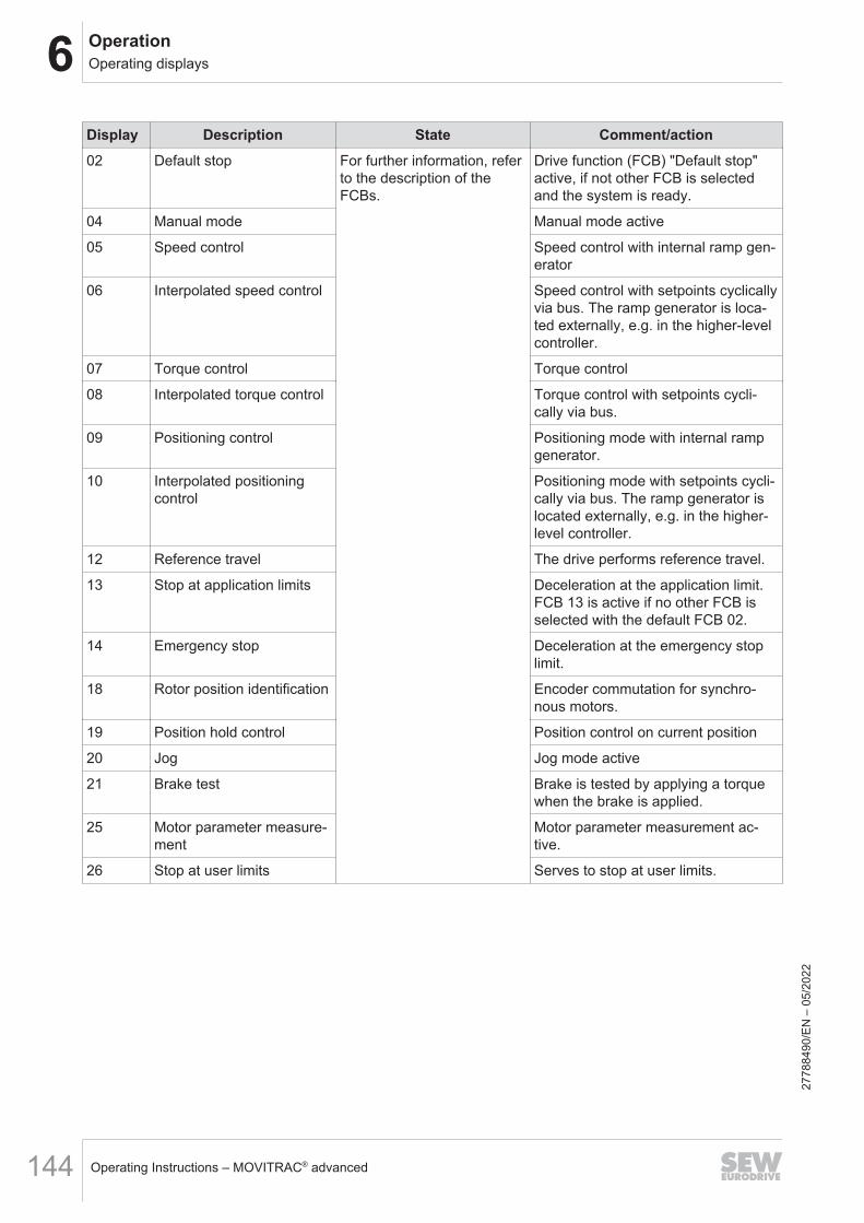
6 OperationOperating displays
Operating Instructions – MOVITRAC® advanced144
Display Description State Comment/action02 Default stop For further information, refer
to the description of theFCBs.
Drive function (FCB) "Default stop"active, if not other FCB is selectedand the system is ready.
04 Manual mode Manual mode active
05 Speed control Speed control with internal ramp gen-erator
06 Interpolated speed control Speed control with setpoints cyclicallyvia bus. The ramp generator is loca-ted externally, e.g. in the higher-levelcontroller.
07 Torque control Torque control
08 Interpolated torque control Torque control with setpoints cycli-cally via bus.
09 Positioning control Positioning mode with internal rampgenerator.
10 Interpolated positioningcontrol
Positioning mode with setpoints cycli-cally via bus. The ramp generator islocated externally, e.g. in the higher-level controller.
12 Reference travel The drive performs reference travel.
13 Stop at application limits Deceleration at the application limit.FCB 13 is active if no other FCB isselected with the default FCB 02.
14 Emergency stop Deceleration at the emergency stoplimit.
18 Rotor position identification Encoder commutation for synchro-nous motors.
19 Position hold control Position control on current position
20 Jog Jog mode active
21 Brake test Brake is tested by applying a torquewhen the brake is applied.
25 Motor parameter measure-ment
Motor parameter measurement ac-tive.
26 Stop at user limits Serves to stop at user limits.
2778
8490
/EN
– 0
5/20
22

6OperationFault description
Operating Instructions – MOVITRAC® advanced 145
6.6 Fault description6.6.1 Fault 1 Output stage monitoring
Subfault: 1.1Description: Short circuit in motor output terminals
Response: Output stage inhibit
Cause Measure
Overcurrent in output stage or faulty output stagecontrol detected, and output stage inhibited byhardware.
Possible causes for overcurrent are short circuitat the output, excessive motor current, or a defec-tive power output stage.
Subfault: 1.2Description: Overcurrent in output stage
Response: Output stage inhibit
Cause Measure
Motor current too high. Connect a smaller motor.
Current supply Check the current supply.
Current transformer Check the current transformer.
Ramp limit deactivated and set ramp time tooshort.
Increase the ramp time.
Phase module defective. Check the phase module.
DC 24 V supply voltage unstable. Check the DC 24 V supply voltage.
Interruption or short circuit on signal lines ofphase modules.
Check the signal lines.
6.6.2 Fault 3 Ground fault
Subfault: 3.1Description: Ground fault
Response: Output stage inhibit
Cause Measure
Ground fault in the motor lead. Eliminate ground fault in motor lead.
Ground fault in the inverter. Eliminate ground fault in inverter.
Ground fault in the motor. Eliminate ground fault in motor.
Ground fault in line components. Eliminate ground fault in line components.
2778
8490
/EN
– 0
5/20
22

6 OperationFault description
Operating Instructions – MOVITRAC® advanced146
6.6.3 Fault 4 Brake chopper
Subfault: 4.1Description: Brake chopper overcurrent
Response: Output stage inhibit
Cause Measure
Excessive regenerative power. Extend the deceleration ramps.
Short circuit detected in braking resistor circuit. Check the supply cable to the braking resistor.
The braking resistor impedance is too low. Check the technical data of the braking resistor.
Subfault: 4.2Description: Brake chopper defective
Response: Output stage inhibit
Cause Measure
Output stage of brake chopper defective. Replace the defective brake chopper.
6.6.4 Fault 6 Line fault
Subfault: 6.1Description: Line phase failure
Response: Line phase failure
Cause Measure
Missing line phase detected. Check the supply system cable.
DC link voltage periodically too low. Check the configuration of the supply system.
Inadequate line voltage quality. Check the supply (fuses, contactor).
6.6.5 Fault 7 DC link
Subfault: 7.1Description: DC link overvoltage
Response: Output stage inhibit
Cause Measure
Maximum permitted DC link voltage limit ex-ceeded and output stage inhibited by hardware.
– Extend the deceleration ramps.– Check the supply cable to the braking resistor.– Check the technical data of the braking resistor.
Subfault: 7.2Description: DC link discharge failed
Response: Warning
Cause Measure
DC link voltage level not dropped below dis-charge threshold within discharge time.
Contact SEW‑EURODRIVE Service.
2778
8490
/EN
– 0
5/20
22

6OperationFault description
Operating Instructions – MOVITRAC® advanced 147
6.6.6 Fault 8 Speed monitoring
Subfault: 8.1Description: Speed monitoring – motor mode
Response: Output stage inhibit
Cause Measure
Speed controller operates at setting limit (me-chanical overload or phase failure in supply sys-tem or motor).
Increase the delay time set for speed monitoring,or reduce the load.
Encoder not connected correctly. Check the encoder connection and direction ofrotation. If necessary, increase the current limitingor reduce the acceleration values.
Encoder has incorrect direction of rotation. – Check encoder connection and direction of ro-tation. If necessary, increase current limiting orreduce acceleration values.– Check motor lead and motor, check linephases.
Subfault: 8.2Description: Speed monitoring – generator mode
Response: Output stage inhibit
Cause Measure
Speed controller operates at setting limit (me-chanical overload or phase failure in supply sys-tem or motor).
Increase the delay time set for speed monitoring,or reduce the regenerative load.
Encoder not connected correctly. Check the encoder connection and direction ofrotation. If necessary, increase the current limitingor reduce the deceleration values.
Encoder has incorrect direction of rotation. – Check the encoder connection and direction ofrotation. If necessary, increase the current limitingor reduce the deceleration values.– Check motor lead and motor. Check the linephases.
Subfault: 8.3Description: Maximum speed at motor shaft
Response: Output stage inhibit
Cause Measure
Actual speed exceeded "Maximum speed at mo-tor shaft" limit value (index 8360.9 / 8361.9). Thislimit value is set at startup matching the motorand gear unit.
Reduce the maximum speed.
2778
8490
/EN
– 0
5/20
22

6 OperationFault description
Operating Instructions – MOVITRAC® advanced148
6.6.7 Fault 9 Control mode
Subfault: 9.1Description: Magnetization of motor not possible
Response: Output stage inhibit
Cause Measure
The user-defined current limit or output stagemonitoring have reduced the possible maximumcurrent to such a degree that the required mag-netizing current cannot be set.
– Reduce the output stage utilization, e.g. by re-ducing the PWM frequency or reducing the load.– Increase the user-defined current limit.
Subfault: 9.2Description: Requested operating mode not possible with active control mode
Response: Output stage inhibit
Cause Measure
The current FCB activated an operating mode.The active control mode does not support this op-erating mode, for example "positioning control" or"torque control" with V/f control mode.
– Use a control mode that supports the requiredoperating mode. Connect an encoder if neces-sary.– Select an operating mode that is supported bythe current control mode.
Subfault: 9.3Description: Absolute rotor position not available
Response: Output stage inhibit
Cause Measure
The current control mode requires an absolute ro-tor position. The encoder selected for "Source ofactual speed" does not provide an absolute rotorposition.
Use an absolute encoder, or identify the rotor po-sition using FCB 18.
Subfault: 9.4Description: Correct current supply of motor not possible
Response: Output stage inhibit
Cause Measure
Failed to set required current during premagneti-zation.
– Check the cabling.– Deactivate the "current monitoring during pre-magnetization" function.– Deactivate the "current monitoring during initialposition determination" function.
Subfault: 9.5Description: Maximum output frequency exceeded
Response: Output stage inhibit
Cause Measure
Maximum output frequency exceeded. Reduce the maximum speed.
2778
8490
/EN
– 0
5/20
22
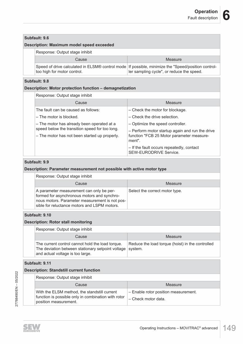
6OperationFault description
Operating Instructions – MOVITRAC® advanced 149
Subfault: 9.6Description: Maximum model speed exceeded
Response: Output stage inhibit
Cause Measure
Speed of drive calculated in ELSM® control modetoo high for motor control.
If possible, minimize the "Speed/position control-ler sampling cycle", or reduce the speed.
Subfault: 9.8Description: Motor protection function – demagnetization
Response: Output stage inhibit
Cause Measure
The fault can be caused as follows:– The motor is blocked.– The motor has already been operated at aspeed below the transition speed for too long.– The motor has not been started up properly.
– Check the motor for blockage.– Check the drive selection.– Optimize the speed controller.– Perform motor startup again and run the drivefunction "FCB 25 Motor parameter measure-ment".– If the fault occurs repeatedly, contactSEW‑EURODRIVE Service.
Subfault: 9.9Description: Parameter measurement not possible with active motor type
Response: Output stage inhibit
Cause Measure
A parameter measurement can only be per-formed for asynchronous motors and synchro-nous motors. Parameter measurement is not pos-sible for reluctance motors and LSPM motors.
Select the correct motor type.
Subfault: 9.10Description: Rotor stall monitoring
Response: Output stage inhibit
Cause Measure
The current control cannot hold the load torque.The deviation between stationary setpoint voltageand actual voltage is too large.
Reduce the load torque (hoist) in the controlledsystem.
Subfault: 9.11Description: Standstill current function
Response: Output stage inhibit
Cause Measure
With the ELSM method, the standstill currentfunction is possible only in combination with rotorposition measurement.
– Enable rotor position measurement.– Check motor data.
2778
8490
/EN
– 0
5/20
22

6 OperationFault description
Operating Instructions – MOVITRAC® advanced150
6.6.8 Fault 10 Data flexibility
Subfault: 10.1Description: Initialization
Response: Application stop + output stage inhibit
Cause Measure
Init task error. The init task has issued a return code ! = 0.Check the program.
Subfault: 10.2Description: Illegal program command
Response: Application stop + output stage inhibit
Cause Measure
The version of the MOVIKIT® software module inuse is not compatible with the current firmwareversion of the device.
– Use the latest firmware version of the device.– Adjust the firmware version of the device ac-cording to the version overview in the installationnotes.– Adjust the version of the MOVIKIT® softwaremodule according to the version overview in theinstallation notes.– In the shortcut menu of the device, execute the"Adjust version and device" menu command.
Unknown program command (illegal opcode) de-tected in Data Flexibility program.
Contact SEW‑EURODRIVE Service.
Subfault: 10.3Description: Memory access
Response: Application stop + output stage inhibit
Cause Measure
Memory area violated while accessing array. For example, an array access results in writingbeyond the permitted memory range. Check theprogram.
Subfault: 10.4Description: Stack
Response: Application stop + output stage inhibit
Cause Measure
Overflow of Data Flexibility stack detected. Check the program.
Subfault: 10.5Description: Division by 0
Response: Application stop + output stage inhibit
Cause Measure
Division by 0. Check the program.
2778
8490
/EN
– 0
5/20
22
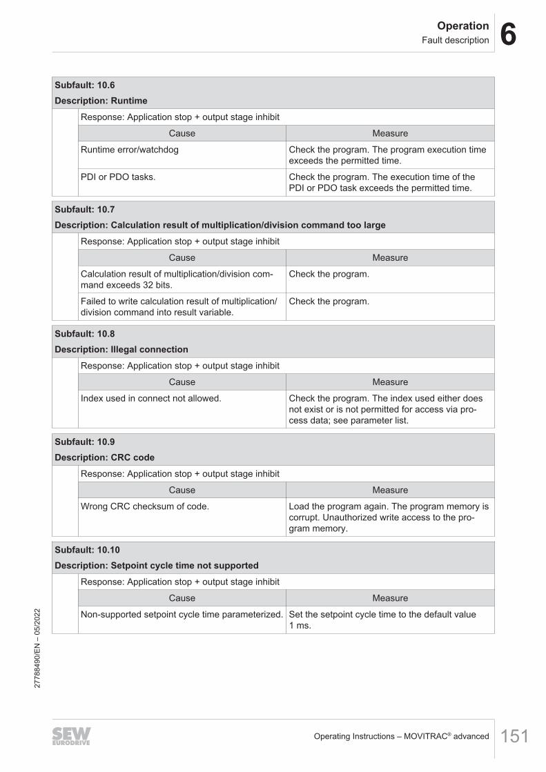
6OperationFault description
Operating Instructions – MOVITRAC® advanced 151
Subfault: 10.6Description: Runtime
Response: Application stop + output stage inhibit
Cause Measure
Runtime error/watchdog Check the program. The program execution timeexceeds the permitted time.
PDI or PDO tasks. Check the program. The execution time of thePDI or PDO task exceeds the permitted time.
Subfault: 10.7Description: Calculation result of multiplication/division command too large
Response: Application stop + output stage inhibit
Cause Measure
Calculation result of multiplication/division com-mand exceeds 32 bits.
Check the program.
Failed to write calculation result of multiplication/division command into result variable.
Check the program.
Subfault: 10.8Description: Illegal connection
Response: Application stop + output stage inhibit
Cause Measure
Index used in connect not allowed. Check the program. The index used either doesnot exist or is not permitted for access via pro-cess data; see parameter list.
Subfault: 10.9Description: CRC code
Response: Application stop + output stage inhibit
Cause Measure
Wrong CRC checksum of code. Load the program again. The program memory iscorrupt. Unauthorized write access to the pro-gram memory.
Subfault: 10.10Description: Setpoint cycle time not supported
Response: Application stop + output stage inhibit
Cause Measure
Non-supported setpoint cycle time parameterized. Set the setpoint cycle time to the default value1 ms.
2778
8490
/EN
– 0
5/20
22

6 OperationFault description
Operating Instructions – MOVITRAC® advanced152
Subfault: 10.11Description: No application program loaded
Response: Output stage inhibit
Cause Measure
No Data Flexibility application program loaded. Load the program or disable Data Flexibility.
Subfault: 10.12Description: Runtime warning
Response: Warning
Cause Measure
The program requires more runtime than con-figured.
Check the program.
Subfault: 10.99Description: Unknown fault
Response: Application stop + output stage inhibit
Cause Measure
Unknown Data Flexibility error. Contact SEW‑EURODRIVE Service.
6.6.9 Fault 11 Temperature monitoring
Subfault: 11.1Description: Heat sink overtemperature
Response: Output stage inhibit
Cause Measure
Maximum permitted heat sink temperature ex-ceeded. The capacity utilization is possibly toohigh.
– Reduce the load.– Reduce the rms value of the current.– Reduce the PWM frequency.– Ensure sufficient cooling.– Reduce the ambient temperature.
Subfault: 11.2Description: Heat sink utilization – prewarning
Response: Heat sink utilization – prewarning
Cause Measure
High thermal load on heat sink of device, and pre-warning threshold reached.
– Reduce the load.– Reduce the rms value of the output current.– Reduce the PWM frequency.– Ensure sufficient cooling.– Reduce the ambient temperature.
2778
8490
/EN
– 0
5/20
22

6OperationFault description
Operating Instructions – MOVITRAC® advanced 153
Subfault: 11.3Description: Device utilization
Response: Output stage inhibit
Cause Measure
The temperature has reached or exceeded theswitch-off threshold. The mean output current istoo high.
– Reduce the load.– Check motor/inverter combination.
PWM frequency too high. Reduce the PWM frequency.
Ambient temperature too high. Ensure sufficient cooling.
Unfavorable air convection. Check air convection.
Fan defective. Check the fan and replace if necessary.
Subfault: 11.5Description: Electromechanical capacity utilization
Response: Output stage inhibit
Cause Measure
Electromechanical components of device over-loaded by excessive continuous current.
Reduce the load. If necessary, reduce the rmsvalue of the current.
Subfault: 11.6Description: Electromechanical capacity utilization – prewarning
Response: Electromechanical capacity utilization – prewarning
Cause Measure
High load on electromechanical components ofdevice due to high continuous current. Prewarn-ing threshold reached.
– Reduce the load.– Reduce the PWM frequency.– Reduce the rms value of the current.– Reduce the ambient temperature.
Subfault: 11.7Description: Wire break at temperature sensor of heat sink
Response: Output stage inhibit
Cause Measure
Wire break at temperature sensor of heat sink. Contact SEW‑EURODRIVE Service.
Subfault: 11.8Description: Short circuit at temperature sensor of heat sink
Response: Output stage inhibit
Cause Measure
Short circuit at temperature sensor of heat sink. Contact SEW‑EURODRIVE Service.
2778
8490
/EN
– 0
5/20
22

6 OperationFault description
Operating Instructions – MOVITRAC® advanced154
Subfault: 11.9Description: Signal electronics overtemperature
Response: Output stage inhibit
Cause Measure
Maximum permitted signal electronics tempera-ture exceeded.
– Reduce the load.– Reduce the ambient temperature.
Subfault: 11.10Description: Wire break at temperature sensor of signal electronics
Response: Output stage inhibit
Cause Measure
Wire break at temperature sensor of signal elec-tronics
Contact SEW‑EURODRIVE Service.
Subfault: 11.11Description: Short circuit at temperature sensor of signal electronics
Response: Output stage inhibit
Cause Measure
Short circuit at temperature sensor of signal elec-tronics.
Contact SEW‑EURODRIVE Service.
6.6.10 Fault 12 Brake
Subfault: 12.1Description: Brake output fault
Response: Application stop + output stage inhibit
Cause Measure
No brake connected. Check the connection of the brake.
Brake cable disconnected in switched-on state. Check the connection of the brake.
The brake was overloaded by an overcurrent > 2A.
Check the sequential profile of brake control.
The brake was overloaded by frequent connec-tion (> 0.5 Hz).
Check the sequential profile of brake control.
Monitoring works only with parameter setting"Brake installed" and "Brake applied".
Make sure that the connected brake is permitted.
2778
8490
/EN
– 0
5/20
22

6OperationFault description
Operating Instructions – MOVITRAC® advanced 155
Subfault: 12.2Description: DC 24 V brake voltage
Response: Application stop + output stage inhibit
Cause Measure
DC 24 V supply voltage not within permitted toler-ance of ±10%.
Check the DC 24 V supply voltage.
Monitoring is only active with parameter settings“Brake installed” and “Brake applied”.
Check the parameter setting.
Subfault: 12.20Description: Digital motor integration fault – critical
Response: Output stage inhibit with self-reset
Cause Measure
The intelligent brake rectifier of digital motor inte-gration has detected a critical component fault.
For the exact cause of the fault and for informa-tion on how to correct it, refer to the fault detectedby the subcomponent.
Subfault: 12.21Description: Digital motor integration fault
Response: Emergency stop + output stage inhibit with self-reset
Cause Measure
The intelligent brake rectifier of digital motor inte-gration has detected a component fault.
For the exact cause of the fault and for informa-tion on how to correct it, refer to the fault detectedby the subcomponent.
Subfault: 12.22Description: Digital motor integration warning
Response: Warning with self-reset
Cause Measure
The intelligent brake rectifier of digital motor inte-gration signaled a warning.
For the exact cause of the fault and for informa-tion on how to correct the warning, refer to thefault signaled by the subcomponent.
Subfault: 12.23Description: Digital motor integration timeout
Response: Output stage inhibit
Cause Measure
Communication with intelligent brake rectifier dis-rupted.
Check the connection.
2778
8490
/EN
– 0
5/20
22
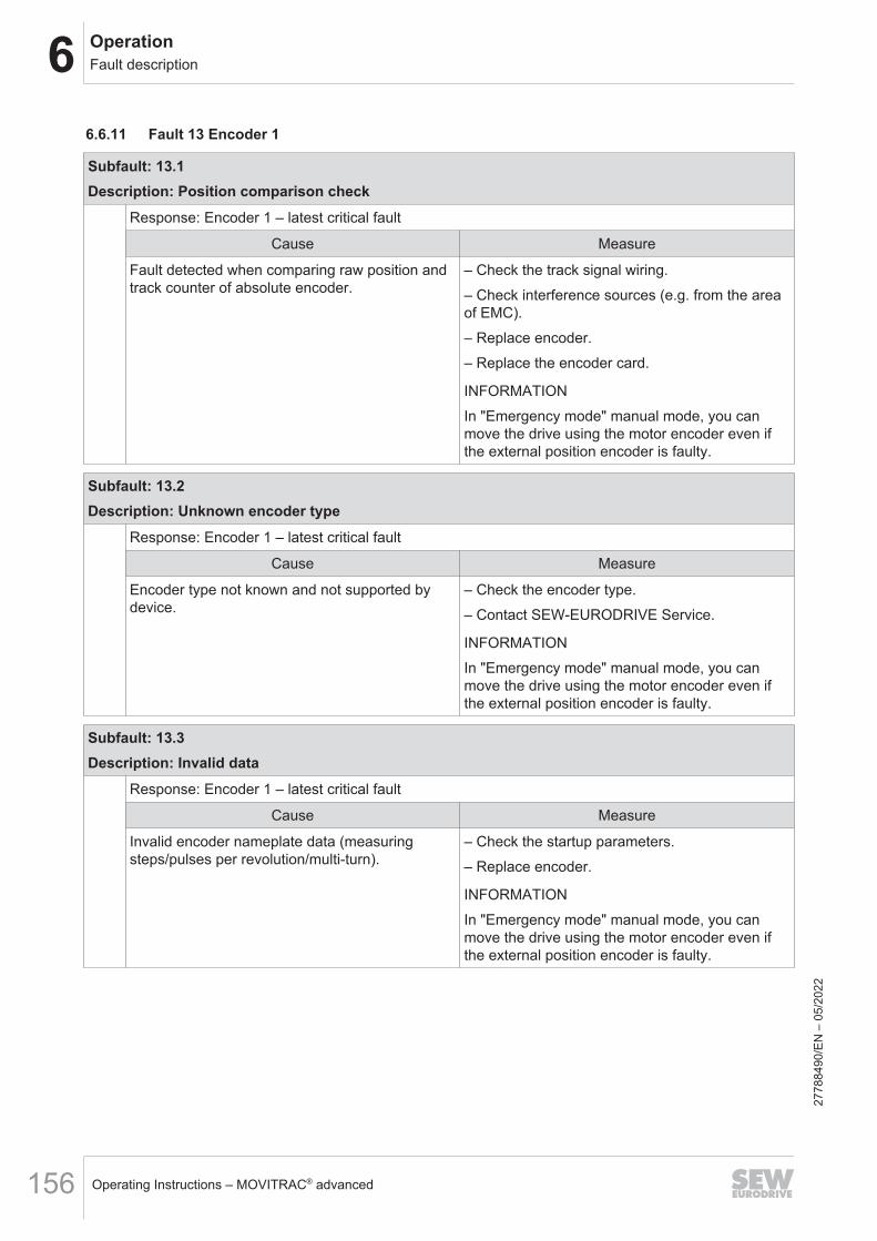
6 OperationFault description
Operating Instructions – MOVITRAC® advanced156
6.6.11 Fault 13 Encoder 1
Subfault: 13.1Description: Position comparison check
Response: Encoder 1 – latest critical fault
Cause Measure
Fault detected when comparing raw position andtrack counter of absolute encoder.
– Check the track signal wiring.– Check interference sources (e.g. from the areaof EMC).– Replace encoder.– Replace the encoder card.
INFORMATIONIn "Emergency mode" manual mode, you canmove the drive using the motor encoder even ifthe external position encoder is faulty.
Subfault: 13.2Description: Unknown encoder type
Response: Encoder 1 – latest critical fault
Cause Measure
Encoder type not known and not supported bydevice.
– Check the encoder type.– Contact SEW-EURODRIVE Service.
INFORMATIONIn "Emergency mode" manual mode, you canmove the drive using the motor encoder even ifthe external position encoder is faulty.
Subfault: 13.3Description: Invalid data
Response: Encoder 1 – latest critical fault
Cause Measure
Invalid encoder nameplate data (measuringsteps/pulses per revolution/multi-turn).
– Check the startup parameters.– Replace encoder.
INFORMATIONIn "Emergency mode" manual mode, you canmove the drive using the motor encoder even ifthe external position encoder is faulty.
2778
8490
/EN
– 0
5/20
22

6OperationFault description
Operating Instructions – MOVITRAC® advanced 157
Subfault: 13.4Description: Track measurement error
Response: Encoder 1 – latest critical fault
Cause Measure
Error during track measurement. – Switch the device off and on again.– Check the wiring.– Check interference sources (e.g. from the areaof EMC).– Check the encoder. Replace if necessary.
INFORMATIONIn "Emergency mode" manual mode, you canmove the drive using the motor encoder even ifthe external position encoder is faulty.
Subfault: 13.5Description: Internal warning
Response: Encoder – warning
Cause Measure
Encoder signaled warning. – Check the wiring.– Check interference sources (light beam inter-rupted, reflector, signal cables, etc.).– Clean the sensor.
Subfault: 13.6Description: Signal level too low
Response: Encoder 1 – latest critical fault
Cause Measure
The value established from the level of the twotrack signals A and B is below the permitted limit.
– Check the wiring.– Check interference sources (e.g. from the areaof EMC).– Check the encoder.
INFORMATIONIn "Emergency mode" manual mode, you canmove the drive using the motor encoder even ifthe external position encoder is faulty.
2778
8490
/EN
– 0
5/20
22
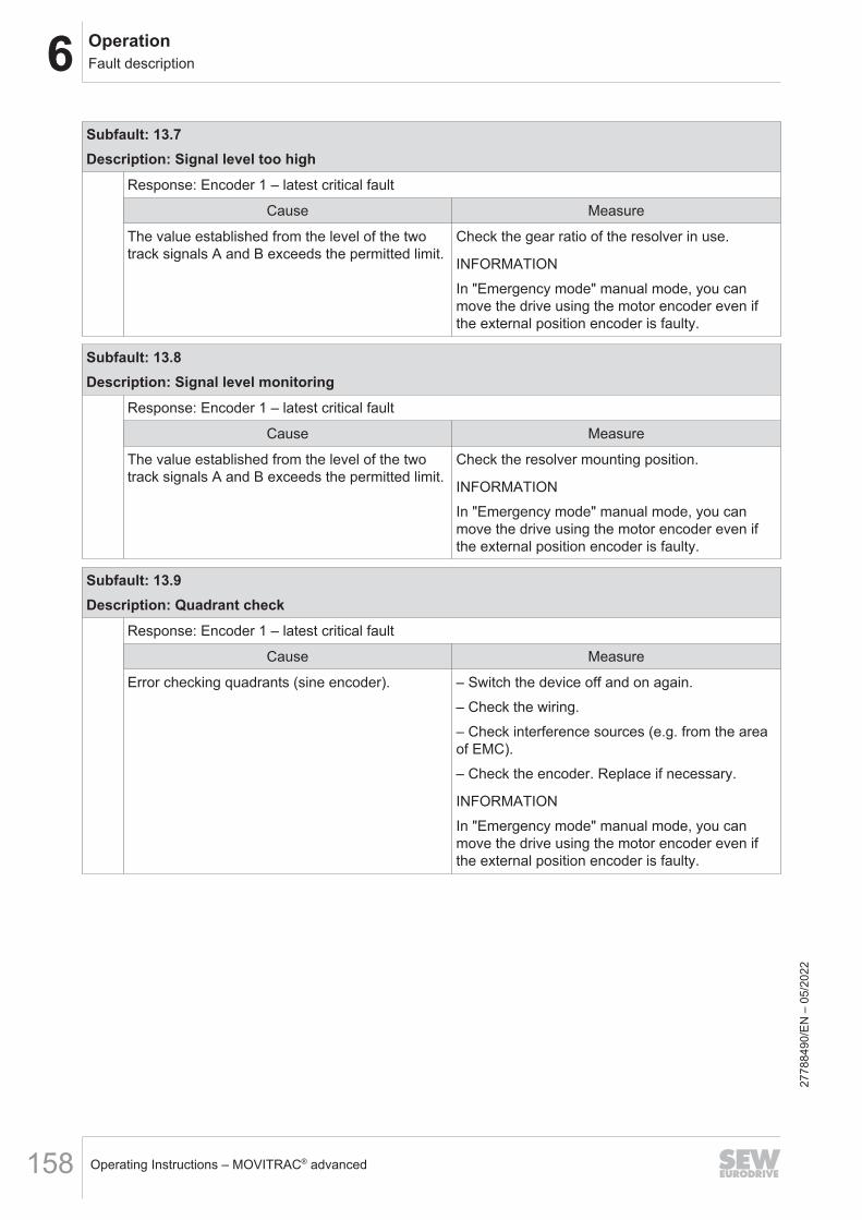
6 OperationFault description
Operating Instructions – MOVITRAC® advanced158
Subfault: 13.7Description: Signal level too high
Response: Encoder 1 – latest critical fault
Cause Measure
The value established from the level of the twotrack signals A and B exceeds the permitted limit.
Check the gear ratio of the resolver in use.
INFORMATIONIn "Emergency mode" manual mode, you canmove the drive using the motor encoder even ifthe external position encoder is faulty.
Subfault: 13.8Description: Signal level monitoring
Response: Encoder 1 – latest critical fault
Cause Measure
The value established from the level of the twotrack signals A and B exceeds the permitted limit.
Check the resolver mounting position.
INFORMATIONIn "Emergency mode" manual mode, you canmove the drive using the motor encoder even ifthe external position encoder is faulty.
Subfault: 13.9Description: Quadrant check
Response: Encoder 1 – latest critical fault
Cause Measure
Error checking quadrants (sine encoder). – Switch the device off and on again.– Check the wiring.– Check interference sources (e.g. from the areaof EMC).– Check the encoder. Replace if necessary.
INFORMATIONIn "Emergency mode" manual mode, you canmove the drive using the motor encoder even ifthe external position encoder is faulty.
2778
8490
/EN
– 0
5/20
22

6OperationFault description
Operating Instructions – MOVITRAC® advanced 159
Subfault: 13.10Description: Position tolerance range exceeded
Response: Encoder 1 – latest critical fault
Cause Measure
Position outside tolerance range. – Check the startup parameters.– Check the wiring.– Check interference sources (light beam inter-rupted, reflector, signal cables, etc.).– Replace encoder.
INFORMATIONIn "Emergency mode" manual mode, you canmove the drive using the motor encoder even ifthe external position encoder is faulty.
Subfault: 13.11Description: Encoder data timeout
Response: Encoder 1 – latest critical fault
Cause Measure
Encoder process data triggered timeout state. – Check interference sources (e.g. from the areaof EMC).– Check the startup parameters.
INFORMATIONIn "Emergency mode" manual mode, you canmove the drive using the motor encoder even ifthe external position encoder is faulty.
Subfault: 13.12Description: Emergency
Response: Encoder 1 – latest critical fault
Cause Measure
Encoder signaled emergency. – Check interference sources (e.g. from the areaof EMC).– Check the startup parameters.
INFORMATIONIn "Emergency mode" manual mode, you canmove the drive using the motor encoder even ifthe external position encoder is faulty.
2778
8490
/EN
– 0
5/20
22
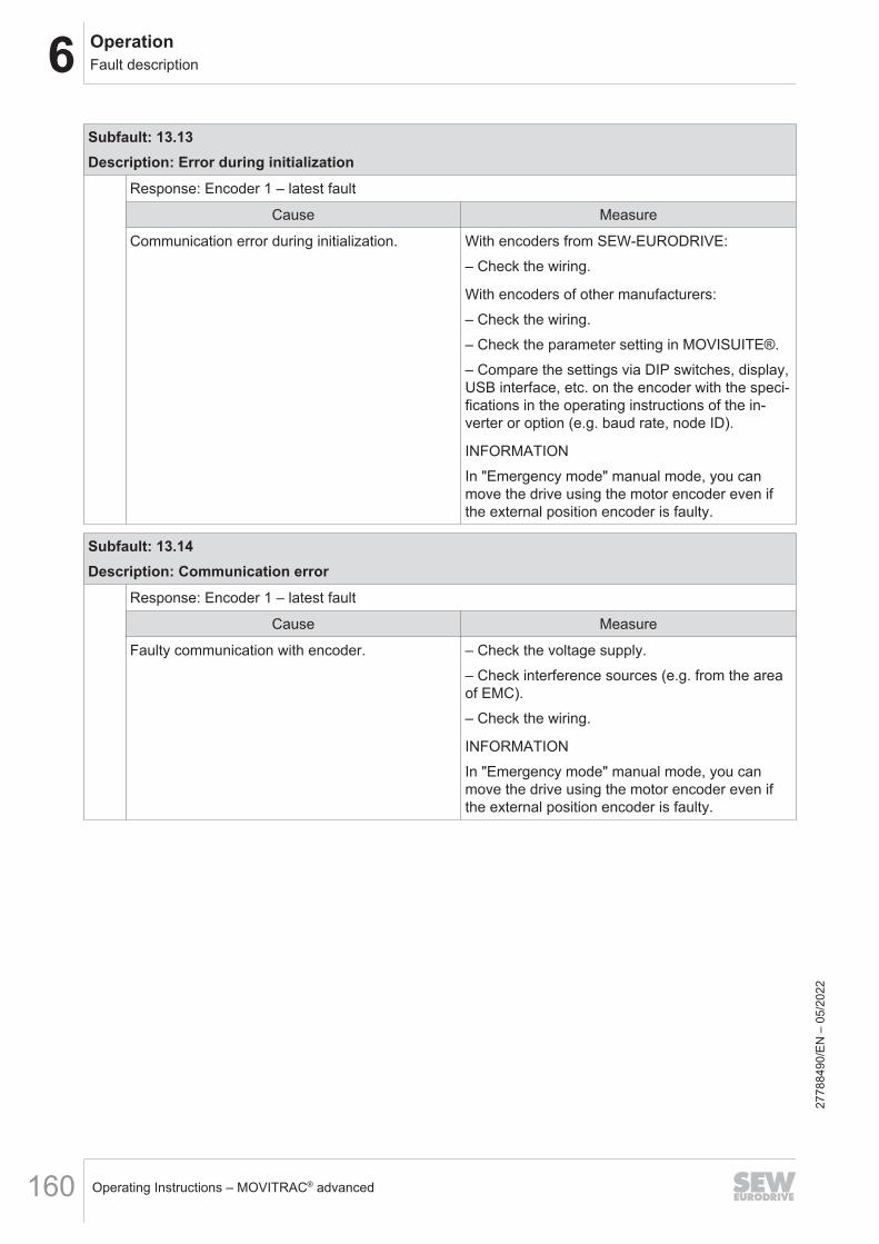
6 OperationFault description
Operating Instructions – MOVITRAC® advanced160
Subfault: 13.13Description: Error during initialization
Response: Encoder 1 – latest fault
Cause Measure
Communication error during initialization. With encoders from SEW‑EURODRIVE:– Check the wiring.
With encoders of other manufacturers:– Check the wiring.– Check the parameter setting in MOVISUITE®.– Compare the settings via DIP switches, display,USB interface, etc. on the encoder with the speci-fications in the operating instructions of the in-verter or option (e.g. baud rate, node ID).
INFORMATIONIn "Emergency mode" manual mode, you canmove the drive using the motor encoder even ifthe external position encoder is faulty.
Subfault: 13.14Description: Communication error
Response: Encoder 1 – latest fault
Cause Measure
Faulty communication with encoder. – Check the voltage supply.– Check interference sources (e.g. from the areaof EMC).– Check the wiring.
INFORMATIONIn "Emergency mode" manual mode, you canmove the drive using the motor encoder even ifthe external position encoder is faulty.
2778
8490
/EN
– 0
5/20
22

6OperationFault description
Operating Instructions – MOVITRAC® advanced 161
Subfault: 13.15Description: System error
Response: Encoder 1 – latest critical fault
Cause Measure
System error while evaluating encoder. – Ensure that the multi-turn encoder is within theconfigured path range.– Check the limits.– Check for correct settings of encoder numer-ator/denominator factors.– Check interference sources (e.g. from the areaof EMC).– Check the startup parameters.– Switch the device off and on again.– If the fault occurs repeatedly, contactSEW‑EURODRIVE Service.
INFORMATIONIn "Emergency mode" manual mode, you canmove the drive using the motor encoder even ifthe external position encoder is faulty.
Subfault: 13.16Description: Permanent high level in signal cable – critical
Response: Encoder 1 – latest critical fault
Cause Measure
Permanent high level of data signal detected. – Check the wiring.– Check the encoder.
INFORMATIONIn "Emergency mode" manual mode, you canmove the drive using the motor encoder even ifthe external position encoder is faulty.
Subfault: 13.17Description: Permanent high level in signal cable
Response: Encoder 1 – latest fault
Cause Measure
Permanent high level of data signal detected. – Check the wiring.– Check the encoder.
INFORMATIONIn "Emergency mode" manual mode, you canmove the drive using the motor encoder even ifthe external position encoder is faulty.
2778
8490
/EN
– 0
5/20
22

6 OperationFault description
Operating Instructions – MOVITRAC® advanced162
Subfault: 13.18Description: Permanent low level in signal cable – critical
Response: Encoder 1 – latest critical fault
Cause Measure
Permanent low level of data signal detected. – Check the wiring.– Check the encoder.
INFORMATIONIn "Emergency mode" manual mode, you canmove the drive using the motor encoder even ifthe external position encoder is faulty.
Subfault: 13.19Description: Permanent low level in signal cable
Response: Encoder 1 – latest fault
Cause Measure
Permanent low level of data signal detected. – Check the wiring.– Check the encoder.
INFORMATIONIn "Emergency mode" manual mode, you canmove the drive using the motor encoder even ifthe external position encoder is faulty.
Subfault: 13.20Description: SSI encoder – critical fault
Response: Encoder 1 – latest critical fault
Cause Measure
SSI encoder signaled a critical fault. – Check the startup parameters.– Check the settings at the SSI encoder.– Check the wiring.– Check interference sources (light beam inter-rupted, reflector, signal cables, etc.).– Replace encoder.
INFORMATIONIn "Emergency mode" manual mode, you canmove the drive even with a fault in an external po-sition encoder.
2778
8490
/EN
– 0
5/20
22

6OperationFault description
Operating Instructions – MOVITRAC® advanced 163
Subfault: 13.21Description: SSI encoder – fault
Response: Encoder 1 – latest fault
Cause Measure
SSI encoder signaled a fault. – Check the startup parameters.– Check the settings at the SSI encoder.– Check the wiring.– Check interference sources (light beam inter-rupted, reflector, signal cables, etc.).– Replace encoder.
INFORMATIONIn "Emergency mode" manual mode, you canmove the drive even with a fault in an external po-sition encoder.
Subfault: 13.22Description: Internal fault – critical
Response: Encoder 1 – latest critical fault
Cause Measure
Encoder signaled internal fault. – Check the wiring.– Check interference sources (light beam inter-rupted, reflector, signal cables, etc.).– Replace encoder.
INFORMATIONIn "Emergency mode" manual mode, you canmove the drive using the motor encoder even ifthe external position encoder is faulty.
Subfault: 13.23Description: Internal fault
Response: Encoder 1 – latest fault
Cause Measure
Encoder signaled internal fault. – Check the wiring.– Check interference sources (light beam inter-rupted, reflector, signal cables, etc.).– Replace encoder.
INFORMATIONIn "Emergency mode" manual mode, you canmove the drive using the motor encoder even ifthe external position encoder is faulty.
2778
8490
/EN
– 0
5/20
22

6 OperationFault description
Operating Instructions – MOVITRAC® advanced164
Subfault: 13.24Description: Travel range exceeded
Response: Encoder 1 – latest fault
Cause Measure
Current position mode does not allow for largertravel range.
Check the travel range.
INFORMATIONIn "Emergency mode" manual mode, you canmove the drive using the motor encoder even ifthe external position encoder is faulty.
Subfault: 13.25Description: Error during encoder startup
Response: Output stage inhibit
Cause Measure
Fatal error during encoder startup. Switch the device off and on again.
INFORMATIONIn "Emergency mode" manual mode, you canmove the drive using the motor encoder even ifthe external position encoder is faulty.
Subfault: 13.26Description: Digital motor integration fault – critical
Response: Encoder 1 – latest critical fault
Cause Measure
Encoder of digital motor integration detected acomponent fault.
– Check interference sources.– Replace encoder.
Subfault: 13.27Description: Digital motor integration fault
Response: Encoder 1 – latest fault
Cause Measure
Encoder of digital motor integration detected acomponent fault.
– Check interference sources.– Replace encoder.
Subfault: 13.28Description: Digital motor integration warning
Response: Encoder – warning
Cause Measure
Encoder of digital motor integration signaled awarning.
Check interference sources.
2778
8490
/EN
– 0
5/20
22

6OperationFault description
Operating Instructions – MOVITRAC® advanced 165
Subfault: 13.29Description: Absolute position invalid
Response: Encoder 1 – latest fault
Cause Measure
Diagnostics error detected while evaluating abso-lute encoder position. Referencing is canceled.
– Reference the drive again.– If the fault occurs repeatedly, contactSEW‑EURODRIVE Service.
INFORMATIONIn "Emergency mode" manual mode, you canmove the drive using the motor encoder even ifthe external position encoder is faulty.
6.6.12 Fault 16 Startup
Subfault: 16.1Description: Motor not started up
Response: Output stage inhibit
Cause Measure
Motor not started up or not started up completely. Perform complete motor startup.
Subfault: 16.2Description: Cannot calculate controller parameters
Response: Output stage inhibit
Cause Measure
Delay of encoder in use too long to calculate re-quired filter coefficients.
Use an encoder with a shorter delay, or contactSEW‑EURODRIVE Service.
Subfault: 16.3Description: Thermal motor model not possible
Response: Output stage inhibit
Cause Measure
Invalid parameters for thermal motor model or fordrive enable although starting up thermal modelnot yet completed.
Check the parameters of the thermal motormodel, and perform startup.
Subfault: 16.5Description: Current limit smaller than magnetizing current of the motor
Response: Output stage inhibit
Cause Measure
Current limit smaller than magnetizing current ofthe motor calculated by active control mode.
Increase the current limit. Required magnetizingcurrent: See diagnostics parameters of controlmode.
2778
8490
/EN
– 0
5/20
22

6 OperationFault description
Operating Instructions – MOVITRAC® advanced166
Subfault: 16.6Description: Control mode not possible
Response: Output stage inhibit
Cause Measure
When starting up a synchronous third-party mo-tor, some control modes and drive functions areonly permitted after a parameter measurement.
Perform a motor parameter measurement usingthe drive function FCB 25.
Wrong control mode selected for the motor. Choose a control mode that matches the selectedmotor.
Subfault: 16.7Description: PWM frequency not possible
Response: Output stage inhibit
Cause Measure
The motor cannot be operated with the inverter.The motor requires a higher PWM frequency thanthe inverter can provide.
Use an inverter with a suitable PWM frequencyrange.
Specified PWM frequency not allowed for thispower output stage.
Choose another PWM frequency. The possiblePWM frequencies can be found in the device con-figuration data.
Subfault: 16.8Description: Temperature sensor motor 1
Response: Output stage inhibit
Cause Measure
Faulty startup of temperature sensor of motor 1. Perform startup again.
Subfault: 16.9Description: Temperature sensor motor 2
Response: Output stage inhibit
Cause Measure
Faulty startup of temperature sensor of motor 2. Perform startup again.
Subfault: 16.10Description: Actual position source not assigned
Response: Application stop + output stage inhibit
Cause Measure
Active control mode requires an encoder for posi-tion mode.
– Assign actual position source in encoder as-signment of the active drive train (Index 8565.3 or8566.3).– If no encoder is installed, activate the FCBsonly using "torque control" or "speed control" op-erating modes.
2778
8490
/EN
– 0
5/20
22

6OperationFault description
Operating Instructions – MOVITRAC® advanced 167
Subfault: 16.11Description: Motor data calculation error
Response: Output stage inhibit
Cause Measure
Motor startup not possible because of inconsis-tent motor data or wrong device configurationdata.
Check the motor data for plausibility, or contactSEW‑EURODRIVE Service.
Subfault: 16.12Description: Motor data write sequence
Response: Output stage inhibit
Cause Measure
Subindex 1 not written to zero before writing elec-trical startup parameters (index 8357, 8360,8394, 8420 or 8358, 8361, 8395, 8421).
Reset the error. Set parameters 8360/1 or 8361/1to "0" before writing additional parameters.
Subfault: 16.13Description: Several motor protection models are active
Response: Output stage inhibit
Cause Measure
More than one model active at the same time inthermal motor monitoring, e.g. for asynchronousmotor and synchronous motor.
If the startup parameters were changed manually,switch off motor monitoring.In all other cases, contact SEW‑EURODRIVEService.
Subfault: 16.20Description: Nominal speed too high or nominal frequency too low
Response: Output stage inhibit
Cause Measure
During startup using nameplate data: Nominalspeed too high or nominal frequency too low. Theresulting number of pole pairs is 0.
Enter plausible motor data (nominal speed andnominal frequency).
Subfault: 16.21Description: Nominal slip negative
Response: Output stage inhibit
Cause Measure
During startup using nameplate data, the calcu-lated nominal slip is negative: Nominal frequencytoo low, or nominal speed too high, or number ofpole pairs too high.
Enter plausible motor data (nominal frequency,nominal speed, number of pole pairs).
2778
8490
/EN
– 0
5/20
22
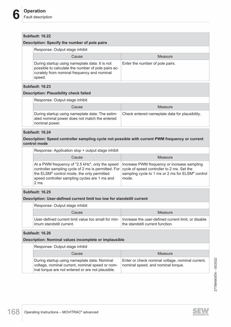
6 OperationFault description
Operating Instructions – MOVITRAC® advanced168
Subfault: 16.22Description: Specify the number of pole pairs
Response: Output stage inhibit
Cause Measure
During startup using nameplate data: It is notpossible to calculate the number of pole pairs ac-curately from nominal frequency and nominalspeed.
Enter the number of pole pairs.
Subfault: 16.23Description: Plausibility check failed
Response: Output stage inhibit
Cause Measure
During startup using nameplate data: The estim-ated nominal power does not match the enterednominal power.
Check entered nameplate data for plausibility.
Subfault: 16.24Description: Speed controller sampling cycle not possible with current PWM frequency or currentcontrol mode
Response: Application stop + output stage inhibit
Cause Measure
At a PWM frequency of "2.5 kHz", only the speedcontroller sampling cycle of 2 ms is permitted. Forthe ELSM® control mode, the only permittedspeed controller sampling cycles are 1 ms and2 ms.
Increase PWM frequency or increase samplingcycle of speed controller to 2 ms. Set thesampling cycle to 1 ms or 2 ms for ELSM® controlmode.
Subfault: 16.25Description: User-defined current limit too low for standstill current
Response: Output stage inhibit
Cause Measure
User-defined current limit value too small for min-imum standstill current.
Increase the user-defined current limit, or disablethe standstill current function.
Subfault: 16.26Description: Nominal values incomplete or implausible
Response: Output stage inhibit
Cause Measure
During startup using nameplate data: Nominalvoltage, nominal current, nominal speed or nom-inal torque are not entered or are not plausible.
Enter or check nominal voltage, nominal current,nominal speed, and nominal torque.
2778
8490
/EN
– 0
5/20
22

6OperationFault description
Operating Instructions – MOVITRAC® advanced 169
Subfault: 16.27Description: Maximum current or maximum torque not plausible
Response: Output stage inhibit
Cause Measure
During startup using nameplate data: Maximumcurrent or maximum torque not entered, or maxi-mum current and maximum torque not plausible.
Check the maximum current and maximumtorque.
Subfault: 16.30Description: Faulty EtherCAT® EEPROM configuration status
Response: Warning
Cause Measure
Faulty EtherCAT®/SBusPLUS EEPROM configu-ration status.EEPROM not loaded; binary file not loaded.
Contact SEW‑EURODRIVE Service.
Faulty EEPROM loading procedure. Contact SEW‑EURODRIVE Service.
Faulty EEPROM checksum. Contact SEW‑EURODRIVE Service.
Subfault: 16.40Description: Data of selected motor not valid
Response: Output stage inhibit
Cause Measure
Startup data set on replaceable memory modulenot valid for this motor.
Replace the memory module.
Subfault: 16.41Description: Data of selected motor does not exist
Response: Output stage inhibit
Cause Measure
No startup data set found on the replaceablememory module for the selected motor.
Check the selection and, if necessary, start upanother motor or replace the memory module.
Subfault: 16.60Description: Parameter setting for 3-wire control not valid
Response: Warning
Cause Measure
No 3-wire control stop terminal configured. Set stop terminal parameters.
2778
8490
/EN
– 0
5/20
22

6 OperationFault description
Operating Instructions – MOVITRAC® advanced170
6.6.13 Fault 17 Internal processor fault
Subfault: 17.7Description: Exception error
Response: Output stage inhibit
Cause Measure
Exception trap in CPU. Contact SEW‑EURODRIVE Service.
Subfault: 17.8Description: NV data not loaded
Response: Output stage inhibitSystem state: Fault acknowledgment with CPU reset
Cause Measure
CPU was restarted several times by reset withoutfirmware being fully initialized. The non-volatiledata is not loaded, the default values remain ac-tive.
– Acknowledge the fault.– Check the voltage supply.– If the fault occurs repeatedly, contactSEW‑EURODRIVE Service.
6.6.14 Fault 18 Software error
Subfault: 18.1Description: Motor management
Response: Output stage inhibitSystem state: Fault acknowledgment with CPU reset
Cause Measure
Error at motor management interface. – Switch the device off and on again.– If the fault occurs repeatedly, contactSEW‑EURODRIVE Service.
Subfault: 18.3Description: Task system – warning
Response: Warning
Cause Measure
A fault was detected during the processing of theinternal task system. This may be a timeout forcyclical tasks, for example.
– Acknowledge the warning.– If the warning occurs repeatedly, contact SEW-EURODRIVE Service.
2778
8490
/EN
– 0
5/20
22

6OperationFault description
Operating Instructions – MOVITRAC® advanced 171
Subfault: 18.4Description: Task system – error
Response: Output stage inhibitSystem state: Fault acknowledgment with CPU reset
Cause Measure
A fault was detected during the processing of theinternal task system. This may be a timeout forcyclical tasks, for example.
– Switch the device off and on again.– If the fault occurs repeatedly, contactSEW‑EURODRIVE Service.
Subfault: 18.7Description: Fatal error
Response: Output stage inhibitSystem state: Fault acknowledgment with CPU reset
Cause Measure
Fatal software error. – Switch the device off and on again.– If the fault occurs repeatedly, replace the deviceand send it together with the fault number toSEW‑EURODRIVE. For further support, contactSEW‑EURODRIVE Service.
Subfault: 18.8Description: Invalid fault code
Response: Output stage inhibit
Cause Measure
Invalid fault code requested. – Switch the device off and on again.– If the fault occurs repeatedly, contactSEW‑EURODRIVE Service.
Subfault: 18.9Description: Internal software error
Response: Output stage inhibitSystem state: Fault acknowledgment with CPU reset
Cause Measure
The software reports an unexpected event. – Switch the device off and on again.– If the fault occurs repeatedly, replace the deviceand send it together with the fault number toSEW‑EURODRIVE. For further support, contactSEW‑EURODRIVE Service.
2778
8490
/EN
– 0
5/20
22

6 OperationFault description
Operating Instructions – MOVITRAC® advanced172
Subfault: 18.10Description: Watchdog
Response: Output stage inhibit
Cause Measure
Software no longer operates within intended cycletime.
– Switch the device off and on again.– If the fault occurs repeatedly, contactSEW‑EURODRIVE Service.
Subfault: 18.12Description: Configuration data
Response: Output stage inhibitSystem state: Fault acknowledgment with CPU reset
Cause Measure
Configuration data not plausible or cannot be in-terpreted by active firmware version.
Update the firmware or load valid configurationdata.
Subfault: 18.13Description: Calibration data
Response: Output stage inhibitSystem state: Fault acknowledgment with CPU reset
Cause Measure
Calibration data not plausible. Load valid calibration data.
6.6.15 Fault 19 Process data
Subfault: 19.1Description: Torque profile value violation
Response: Application stop + output stage inhibit
Cause Measure
The set torque profile values are not plausible. Adjust the torque profile values.
Subfault: 19.2Description: Position setpoint violation
Response: Application stop + output stage inhibit
Cause Measure
Position setpoint outside software limit switches. Check position setpoint.
Position setpoint outside modulo range. Check position setpoint.
Position in user unit generates number overflowin the system unit.
Check the position in user unit.
2778
8490
/EN
– 0
5/20
22

6OperationFault description
Operating Instructions – MOVITRAC® advanced 173
Subfault: 19.3Description: Speed profile value violation
Response: Application stop + output stage inhibit
Cause Measure
The set speed profile values are not plausible.The speed profile values must be in the range ofvalues >= 0.
Adjust the speed profile values.
Subfault: 19.4Description: Acceleration profile value violation
Response: Emergency stop + output stage inhibit
Cause Measure
The set acceleration profile values are not plaus-ible. The acceleration profile values must be inthe range of values >= 0.
Adjust the acceleration profile values.
Subfault: 19.5Description: Drive function does not exist
Response: Application stop + output stage inhibit
Cause Measure
Non-existent drive function (FCB) selected viaprocess data.
Enter the correct FCB number.
Subfault: 19.6Description: Mass moment of inertia setpoint violation
Response: Emergency stop + output stage inhibit
Cause Measure
The set mass moment of inertia setpoints are notplausible. The mass moment of inertia setpointsmust be in the range of values >= 0.
Adjust the setpoints for the mass moment of iner-tia.
Subfault: 19.7Description: Referencing missing
Response: Application stop + output stage inhibit
Cause Measure
Activated function permitted only with referencedencoder.
Reference the encoder first, then activate thefunction.
Subfault: 19.8Description: Drive train changeover not allowed
Response: Application stop + output stage inhibit
Cause Measure
Drive train changeover requested while outputstage is enabled.
Inhibit the output stage before changing to an-other drive train.
2778
8490
/EN
– 0
5/20
22

6 OperationFault description
Operating Instructions – MOVITRAC® advanced174
Subfault: 19.9Description: Jerk setpoint violation
Response: Application stop + output stage inhibit
Cause Measure
The set jerk values are not plausible. Adjust jerk setpoints.
6.6.16 Fault 20 Device monitoring
Subfault: 20.1Description: Supply voltage fault
Response: Output stage inhibitSystem state: Fault acknowledgment with CPU reset
Cause Measure
24 V power supply unit overloaded. Check the project planning for the power de-mand.
The internal electronics supply voltage or exter-nally connected DC 24 V standby supply voltageis outside the permitted voltage range.
Check the voltage level of the external DC 24 Vstandby supply voltage and check for correct con-nection. If required, correct.– Acknowledge the fault.– If the fault occurs repeatedly, replace thedevice. For further support, contactSEW‑EURODRIVE Service.
Subfault: 20.2Description: Supply voltage overload
Response: Output stage inhibit
Cause Measure
For MOVIDRIVE® system, the current load of thecurrent paths of the DC 24 V standby supplyvoltage inside the device is too high. The devicesignal output of the device was de-energized be-cause of the fault message.
Identify the consumer that is overloading the in-ternal supply voltage:1. Remove all external consumers:– At the digital outputs of the basic device.– At options that may be present.– At all encoder connections.– At other consumers at the DC 24 V outputvoltage terminals.2. Acknowledge the error.3. Reconnect the consumers with the device, oneafter the other, until the fault message appearsonce again.4. To eliminate the fault, connect a consumer witha lower current consumption or eliminate theshort circuit.
2778
8490
/EN
– 0
5/20
22
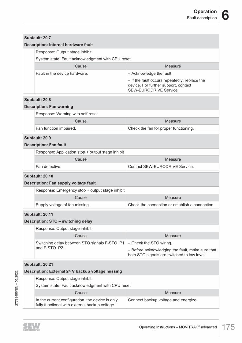
6OperationFault description
Operating Instructions – MOVITRAC® advanced 175
Subfault: 20.7Description: Internal hardware fault
Response: Output stage inhibitSystem state: Fault acknowledgment with CPU reset
Cause Measure
Fault in the device hardware. – Acknowledge the fault.– If the fault occurs repeatedly, replace thedevice. For further support, contactSEW‑EURODRIVE Service.
Subfault: 20.8Description: Fan warning
Response: Warning with self-reset
Cause Measure
Fan function impaired. Check the fan for proper functioning.
Subfault: 20.9Description: Fan fault
Response: Application stop + output stage inhibit
Cause Measure
Fan defective. Contact SEW‑EURODRIVE Service.
Subfault: 20.10Description: Fan supply voltage fault
Response: Emergency stop + output stage inhibit
Cause Measure
Supply voltage of fan missing. Check the connection or establish a connection.
Subfault: 20.11Description: STO – switching delay
Response: Output stage inhibit
Cause Measure
Switching delay between STO signals F-STO_P1and F-STO_P2.
– Check the STO wiring.– Before acknowledging the fault, make sure thatboth STO signals are switched to low level.
Subfault: 20.21Description: External 24 V backup voltage missing
Response: Output stage inhibitSystem state: Fault acknowledgment with CPU reset
Cause Measure
In the current configuration, the device is onlyfully functional with external backup voltage.
Connect backup voltage and energize.
2778
8490
/EN
– 0
5/20
22

6 OperationFault description
Operating Instructions – MOVITRAC® advanced176
Subfault: 20.23Description: Power section temperature detection
Response: Output stage inhibit
Cause Measure
Fault in the device hardware. Power section doesnot provide temperature data.
– Acknowledge the fault.– If the fault occurs repeatedly, replace thedevice. For further support, contactSEW‑EURODRIVE Service.
6.6.17 Fault 21 Digital motor integration 1
Subfault: 21.1Description: Communication error
Response: Output stage inhibit
Cause Measure
Communication error detected on the interface ofdigital motor integration.
Check the cabling.
Subfault: 21.2Description: Component required
Response: Digital motor integration
Cause Measure
Device started up with a drive with digital motorintegration but no drive with digital motor integra-tion is connected.
Connect a suitable drive with digital motor inte-gration for startup, or perform a new startup.
Subfault: 21.3Description: Incompatible driving motor
Response: Output stage inhibit
Cause Measure
Connected drive not compatible with started-updrive.
Connect a drive that matches startup, or performa new startup.
Subfault: 21.4Description: Invalid label
Response: Output stage inhibit
Cause Measure
The connected drive contains invalid data. Replace the drive.
2778
8490
/EN
– 0
5/20
22

6OperationFault description
Operating Instructions – MOVITRAC® advanced 177
Subfault: 21.5Description: Incompatible component
Response: Output stage inhibit
Cause Measure
The connected component of digital motor inte-gration cannot be used with this inverter firmware.
Update inverter or component.
Subfault: 21.6Description: Overload/short circuit on the interface
Response: Output stage inhibit
Cause Measure
Short circuit in the cabling of components of digi-tal motor integration.
Check the cabling of the digital motor integrationcomponent.
Voltage of digital motor integration component toolow.
Check the voltage supply of the component.
Subfault: 21.7Description: Continuous supply current of component too high
Response: Output stage inhibit
Cause Measure
Continuous supply current of component too high.The inverter cannot operate the components.
Use a component with lower supply current.
Subfault: 21.8Description: Parameter error
Response: Output stage inhibit
Cause Measure
Error processing data from digital motor integra-tion component.
Repeat the process in configuration state.
The connected drive contains invalid data. Replace the drive.
Subfault: 21.9Description: Illegal hot plug
Response: Emergency stop + output stage inhibit
Cause Measure
A component of digital motor integration was con-nected while the drive was enabled.
– Set the device to configuration state or switch itoff.– Connect the component.
A component of digital motor integration was con-nected while the device was in standby modewithout switching off the encoder supply.
– Switch off encoder supply in standby mode.– Connect the component.
2778
8490
/EN
– 0
5/20
22
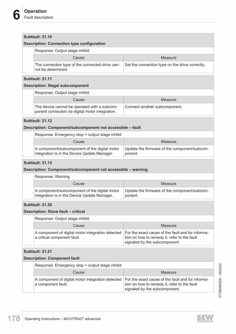
6 OperationFault description
Operating Instructions – MOVITRAC® advanced178
Subfault: 21.10Description: Connection type configuration
Response: Output stage inhibit
Cause Measure
The connection type of the connected drive can-not be determined.
Set the connection type on the drive correctly.
Subfault: 21.11Description: Illegal subcomponent
Response: Output stage inhibit
Cause Measure
The device cannot be operated with a subcom-ponent connected via digital motor integration.
Connect another subcomponent.
Subfault: 21.12Description: Component/subcomponent not accessible – fault
Response: Emergency stop + output stage inhibit
Cause Measure
A component/subcomponent of the digital motorintegration is in the Device Update Manager.
Update the firmware of the component/subcom-ponent.
Subfault: 21.13Description: Component/subcomponent not accessible – warning
Response: Warning
Cause Measure
A component/subcomponent of the digital motorintegration is in the Device Update Manager.
Update the firmware of the component/subcom-ponent.
Subfault: 21.20Description: Slave fault – critical
Response: Output stage inhibit
Cause Measure
A component of digital motor integration detecteda critical component fault.
For the exact cause of the fault and for informa-tion on how to remedy it, refer to the faultsignaled by the subcomponent.
Subfault: 21.21Description: Component fault
Response: Emergency stop + output stage inhibit
Cause Measure
A component of digital motor integration detecteda component fault.
For the exact cause of the fault and for informa-tion on how to remedy it, refer to the faultsignaled by the subcomponent.
2778
8490
/EN
– 0
5/20
22

6OperationFault description
Operating Instructions – MOVITRAC® advanced 179
Subfault: 21.22Description: Component warning
Response: Warning
Cause Measure
A component of digital motor integration signaleda warning.
For the exact cause of the fault and for informa-tion on how to correct the warning, refer to thefault signaled by the subcomponent.
Subfault: 21.23Description: FDDI – critical fault
Response: Output stage inhibit
Cause Measure
FDDI – critical fault TBD
Subfault: 21.24Description: FDDI – fault
Response: Application stop + output stage inhibit
Cause Measure
FDDI fault –
Subfault: 21.25Description: FDDI – warning
Response: Warning
Cause Measure
FDDI warning –
6.6.18 Fault 23 Power section
Subfault: 23.1Description: Warning
Response: Warning with self-reset
Cause Measure
Power section fault with fault response of the type"Warning".
See also "Power section subcomponent" faultstatus.
Subfault: 23.2Description: Fault
Response: Emergency stop + output stage inhibit
Cause Measure
Power section fault with fault response of the type"Standard".
See also "Power section subcomponent" faultstatus.
2778
8490
/EN
– 0
5/20
22
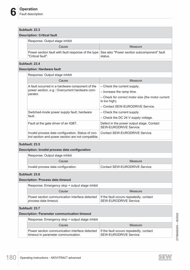
6 OperationFault description
Operating Instructions – MOVITRAC® advanced180
Subfault: 23.3Description: Critical fault
Response: Output stage inhibit
Cause Measure
Power section fault with fault response of the type"Critical fault".
See also "Power section subcomponent" faultstatus.
Subfault: 23.4Description: Hardware fault
Response: Output stage inhibit
Cause Measure
A fault occurred in a hardware component of thepower section, e.g.: Overcurrent hardware com-parator.
– Check the current supply.– Increase the ramp time.– Check for correct motor size (the motor currentis too high).– Contact SEW-EURODRIVE Service.
Switched-mode power supply fault, hardwarefault.
– Check the current supply.– Check the DC 24 V supply voltage.
Fault at the gate driver of an IGBT. Defect in the power output stage. ContactSEW‑EURODRIVE Service.
Invalid process data configuration. Status of con-trol section and power section are not compatible.
Contact SEW‑EURODRIVE Service.
Subfault: 23.5Description: Invalid process data configuration
Response: Output stage inhibit
Cause Measure
Invalid process data configuration. Contact SEW‑EURODRIVE Service.
Subfault: 23.6Description: Process data timeout
Response: Emergency stop + output stage inhibit
Cause Measure
Power section communication interface detectedprocess data timeout.
If the fault occurs repeatedly, contactSEW‑EURODRIVE Service.
Subfault: 23.7Description: Parameter communication timeout
Response: Emergency stop + output stage inhibit
Cause Measure
Power section communication interface detectedtimeout in parameter communication.
If the fault occurs repeatedly, contactSEW‑EURODRIVE Service.
2778
8490
/EN
– 0
5/20
22
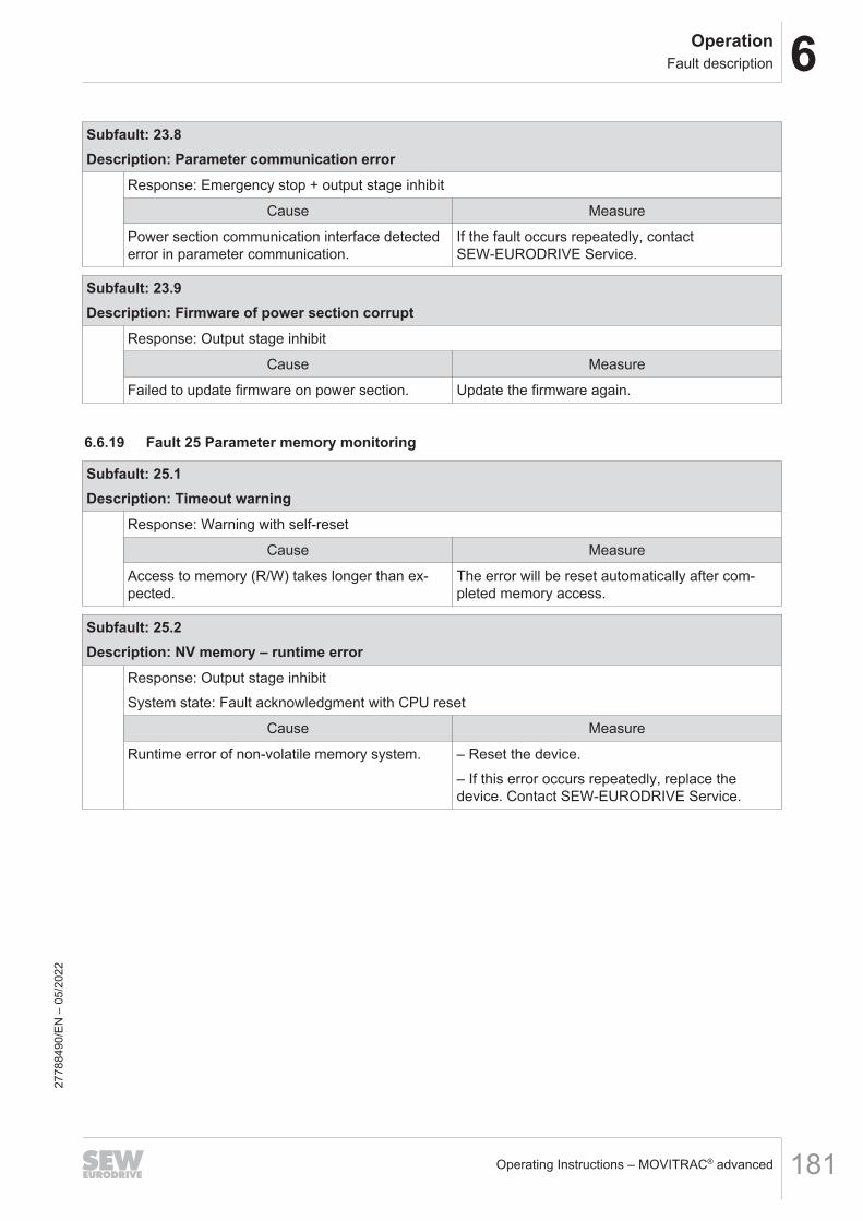
6OperationFault description
Operating Instructions – MOVITRAC® advanced 181
Subfault: 23.8Description: Parameter communication error
Response: Emergency stop + output stage inhibit
Cause Measure
Power section communication interface detectederror in parameter communication.
If the fault occurs repeatedly, contactSEW‑EURODRIVE Service.
Subfault: 23.9Description: Firmware of power section corrupt
Response: Output stage inhibit
Cause Measure
Failed to update firmware on power section. Update the firmware again.
6.6.19 Fault 25 Parameter memory monitoring
Subfault: 25.1Description: Timeout warning
Response: Warning with self-reset
Cause Measure
Access to memory (R/W) takes longer than ex-pected.
The error will be reset automatically after com-pleted memory access.
Subfault: 25.2Description: NV memory – runtime error
Response: Output stage inhibitSystem state: Fault acknowledgment with CPU reset
Cause Measure
Runtime error of non-volatile memory system. – Reset the device.– If this error occurs repeatedly, replace thedevice. Contact SEW‑EURODRIVE Service.
2778
8490
/EN
– 0
5/20
22

6 OperationFault description
Operating Instructions – MOVITRAC® advanced182
Subfault: 25.6Description: Incompatible device configuration
Response: Output stage inhibit
Cause Measure
The data set in the device was copied from an-other device, which differs from the current devicein the device family, power, or voltage.
– Check whether the configuration is correct andrepeat the startup, if necessary.– Acknowledge the fault by manual reset with pa-rameter set acceptance. Setting under [Diagnos-tics] > [Status] > [Fault status] parameter "Manualfault reset".
Replaceable memory module used by anotherdevice. Power, device family, or voltage differsfrom the current device.
– Check whether the configuration is correct andrepeat the startup, if necessary.– Acknowledge the fault by manual reset with pa-rameter set acceptance. Setting under [Diagnos-tics] > [Status] > [Fault status] parameter "Manualfault reset".
The power section was replaced and differs in itspower rating or voltage from the original powersection.
– Check whether the configuration is correct andrepeat the startup, if necessary.– Acknowledge the fault by manual reset with pa-rameter set acceptance. Setting under [Diagnos-tics] > [Status] > [Fault status] parameter "Manualfault reset".
Subfault: 25.7Description: NV memory initialization – error
Response: Output stage inhibit
Cause Measure
Error initializing non-volatile memory system. – Reset the device.– If this error occurs repeatedly, replace thedevice. Contact SEW‑EURODRIVE Service.
Subfault: 25.10Description: Power section configuration data – version conflict
Response: Output stage inhibit
Cause Measure
Wrong version of configuration data of power sec-tion.
Contact SEW‑EURODRIVE Service.
Subfault: 25.12Description: Power section configuration data – CRC error
Response: Output stage inhibit
Cause Measure
Faulty configuration data of power section. Contact SEW‑EURODRIVE Service.
2778
8490
/EN
– 0
5/20
22

6OperationFault description
Operating Instructions – MOVITRAC® advanced 183
Subfault: 25.13Description: Control electronics configuration data – CRC error
Response: Output stage inhibit
Cause Measure
Faulty configuration data of control electronics. Contact SEW‑EURODRIVE Service.
Subfault: 25.14Description: Calibration data of power section – version conflict
Response: Output stage inhibit
Cause Measure
Wrong version of calibration data of power sec-tion.
Contact SEW‑EURODRIVE Service.
Subfault: 25.15Description: Calibration data of control electronics – version conflict
Response: Output stage inhibit
Cause Measure
Wrong version of calibration data of control elec-tronics.
Contact SEW‑EURODRIVE Service.
Subfault: 25.16Description: Power section calibration data – CRC error
Response: Output stage inhibit
Cause Measure
Faulty calibration data of power section. Contact SEW‑EURODRIVE Service.
Subfault: 25.17Description: Control electronics calibration data – CRC error
Response: Output stage inhibit
Cause Measure
Faulty calibration data of control electronics. Contact SEW‑EURODRIVE Service.
Subfault: 25.18Description: Power section QA data – CRC error
Response: Warning
Cause Measure
Faulty quality assurance data of power section. Contact SEW‑EURODRIVE Service.
2778
8490
/EN
– 0
5/20
22

6 OperationFault description
Operating Instructions – MOVITRAC® advanced184
Subfault: 25.19Description: Control electronics QA data – CRC error
Response: Warning
Cause Measure
Faulty quality assurance data of control electron-ics.
Contact SEW‑EURODRIVE Service.
Subfault: 25.20Description: Initialization error – basic device memory
Response: Output stage inhibit
Cause Measure
Initialization error of the basic device memory. Contact SEW‑EURODRIVE Service.
Subfault: 25.21Description: Runtime error – basic device memory
Response: Emergency stop + output stage inhibit
Cause Measure
Runtime error in memory of basic device. Contact SEW‑EURODRIVE Service.
Subfault: 25.30Description: Initialization error – replaceable memory module
Response: Output stage inhibit
Cause Measure
The formatting of the replaceable memorymodule does not match.
Restore delivery state.
NOTICEAll the data on the replaceable memory modulewill be reset to default.
Initialization error of replaceable memory moduleafter delivery state.
Contact SEW‑EURODRIVE Service.
Subfault: 25.31Description: Runtime error – replaceable memory module
Response: Emergency stop + output stage inhibit
Cause Measure
Runtime error of replaceable memory module. Contact SEW‑EURODRIVE Service.
Subfault: 25.32Description: Replaceable memory module not compatible
Response: Output stage inhibitSystem state: Fault acknowledgment with CPU reset
Cause Measure
The inserted replaceable memory module cannotbe used.
Replace the memory module.
2778
8490
/EN
– 0
5/20
22

6OperationFault description
Operating Instructions – MOVITRAC® advanced 185
Subfault: 25.33Description: Replaceable memory module with different device category
Response: Output stage inhibit
Cause Measure
The replaceable memory module is formatted andcontains data from a device of a different devicecategory. The data is not compatible and cannotbe used.
– Replace the memory module.– Restore delivery state. Bear in mind that alldata on the replaceable memory module will bereset to the default values.
Subfault: 25.50Description: Runtime error – replaceable safety memory module
Response: Output stage inhibitSystem state: Fault acknowledgment with CPU reset
Cause Measure
Runtime error of the replaceable safety memorymodule.
Contact SEW‑EURODRIVE Service.
Subfault: 25.51Description: Initialization error – replaceable safety memory module
Response: Warning
Cause Measure
Initialization error of the replaceable safetymemory module.
Contact SEW‑EURODRIVE Service.
Subfault: 25.61Description: Failure – restore point
Response: Emergency stop + output stage inhibit
Cause Measure
Failed to create restore point. Delete restore point.
Subfault: 25.70Description: Incompatible card configuration
Response: Emergency stop + output stage inhibit
Cause Measure
The current configuration of the cards does notmatch the state of the stored startup.For example, a card was removed that was stillpresent during startup.
– Restore the original configuration of the cards.– Acknowledge the fault by manual reset with pa-rameter set acceptance. Setting under [Diagnos-tics] > [Status] > [Fault status] parameter "Manualfault reset".
2778
8490
/EN
– 0
5/20
22

6 OperationFault description
Operating Instructions – MOVITRAC® advanced186
6.6.20 Fault 26 External fault
Subfault: 26.1Description: Terminal
Response: External fault
Cause Measure
Fault message about external fault source. Programmable via 8622.5 (default: applicationstop (with output stage inhibit)).
Subfault: 26.3Description: Power section emergency shutdown
Response: Output stage inhibit
Cause Measure
Power section requested external emergencyshutdown because it detected critical fault.
Contact SEW‑EURODRIVE Service.
Subfault: 26.4Description: External braking resistor fault
Response: Response to external braking resistor fault
Cause Measure
External braking resistor's temperature switchconnected to terminal tripped.
– Check the resistor mounting position.– Clean the resistor.– Check the configuration of the resistor.– Install a larger resistor.– Check the trip switch settings.– Optimize the travel cycle so that less regenera-tive operation energy arises.– Check the settings of the storage unit dischargefunction in the MOVIKIT® software module.
6.6.21 Fault 28 FCB drive functions
Subfault: 28.1Description: FCB 11/12 – Timeout while searching zero pulse
Response: Emergency stop + output stage inhibit
Cause Measure
Failed to find zero pulse of encoder's C trackwithin specified search time during referencetravel.
Check the encoder wiring.
2778
8490
/EN
– 0
5/20
22
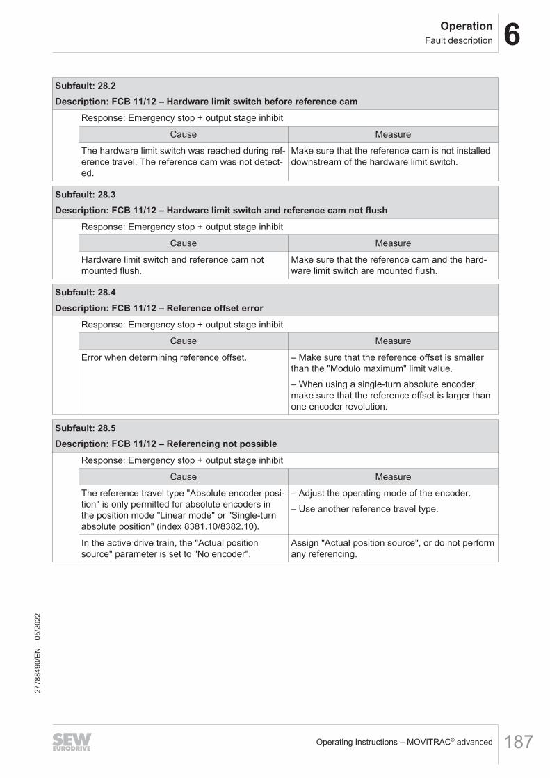
6OperationFault description
Operating Instructions – MOVITRAC® advanced 187
Subfault: 28.2Description: FCB 11/12 – Hardware limit switch before reference cam
Response: Emergency stop + output stage inhibit
Cause Measure
The hardware limit switch was reached during ref-erence travel. The reference cam was not detect-ed.
Make sure that the reference cam is not installeddownstream of the hardware limit switch.
Subfault: 28.3Description: FCB 11/12 – Hardware limit switch and reference cam not flush
Response: Emergency stop + output stage inhibit
Cause Measure
Hardware limit switch and reference cam notmounted flush.
Make sure that the reference cam and the hard-ware limit switch are mounted flush.
Subfault: 28.4Description: FCB 11/12 – Reference offset error
Response: Emergency stop + output stage inhibit
Cause Measure
Error when determining reference offset. – Make sure that the reference offset is smallerthan the "Modulo maximum" limit value.– When using a single-turn absolute encoder,make sure that the reference offset is larger thanone encoder revolution.
Subfault: 28.5Description: FCB 11/12 – Referencing not possible
Response: Emergency stop + output stage inhibit
Cause Measure
The reference travel type "Absolute encoder posi-tion" is only permitted for absolute encoders inthe position mode "Linear mode" or "Single-turnabsolute position" (index 8381.10/8382.10).
– Adjust the operating mode of the encoder.– Use another reference travel type.
In the active drive train, the "Actual positionsource" parameter is set to "No encoder".
Assign "Actual position source", or do not performany referencing.
2778
8490
/EN
– 0
5/20
22

6 OperationFault description
Operating Instructions – MOVITRAC® advanced188
Subfault: 28.6Description: FCB 11/12 – Limit switch/reference cam not flush/overlapping with fixed stop
Response: Emergency stop + output stage inhibit
Cause Measure
Hardware limit switch or reference cam that hasnot been selected was approached during refer-ence travel to fixed stop.
Check whether the parameters set for referencetravel are correct.
During reference travel to fixed stop with selectedhardware limit switch or reference cam, the fixedstop was reached without approaching the hard-ware limit switch or reference cam.
Check whether the parameters set for referencetravel are correct.
Subfault: 28.7Description: FCB 21 – Total torque greater than maximum torque at motor shaft
Response: Output stage inhibit
Cause Measure
The required total torque is greater than the per-mitted maximum torque at the motor shaft. Thetotal torque is calculated from the torque specifi-cation and the load torque.
– Reduce the torque input.– Change the direction of rotation.– Increase the power of the drive.
Subfault: 28.8Description: FCB 21 – Total torque not reached
Response: Output stage inhibit
Cause Measure
The required total torque (at least 90%) was notreached. The total torque is calculated from thetorque specification and the determined/specifiedload torque.
– Reduce the torque input.– Check the limit values of the inverter.– Check motor connection.
Subfault: 28.9Description: FCB 18 – Rotor position identification not possible
Response: Output stage inhibit
Cause Measure
Rotor position identification started with incre-mental encoder but aborted prematurely.
– Restart the rotor position identification.– Check whether the encoder is connected cor-rectly.– Check whether the encoder is defective.
Result of rotor position identification cannot bestored in encoder.
Select "Inverter" as storage location.
Combination of "Automatic" operating mode and"Encoder" storage location not permitted.
Set the operating mode to "Manual" or the stor-age location to "Inverter".
2778
8490
/EN
– 0
5/20
22

6OperationFault description
Operating Instructions – MOVITRAC® advanced 189
Subfault: 28.10Description: FCB 25 – Asymmetrical motor phases
Response: Output stage inhibit
Cause Measure
Significantly different values determined in thethree phases while measuring stator resistances.
– Check whether the motor is connected cor-rectly.– Check all contact points on the motor and in-verter.– Check the motor and motor cable for damage.
Subfault: 28.11Description: FCB 25 – At least one phase with high resistance
Response: Output stage inhibit
Cause Measure
At least one motor phase could not be measuredduring motor parameter measurement.
– Check whether the motor is connected cor-rectly.– Check all contact points on the motor and in-verter.– Check the motor and motor cable for damage.
Subfault: 28.12Description: FCB 25 – Timeout during stator resistance measurement
Response: Output stage inhibit
Cause Measure
Motor parameter measurement activated whilemotor is turning.
– Stop motor.– Start motor parameter measurement when themotor is at standstill.
Subfault: 28.13Description: FCB 25 – Characteristic curve identification not possible
Response: Output stage inhibit
Cause Measure
Motor parameter measurement does not allow forunique identification of the characteristic curve.
Contact SEW‑EURODRIVE Service.
Subfault: 28.14Description: Modulo min. and max. swapped
Response: Emergency stop + output stage inhibit
Cause Measure
In the active data set, the value for "Modulo min-imum" is greater than the value for "Modulo maxi-mum"; see Monitoring functions\Limit values 1 orMonitoring functions\Limit values 2.
Swap the values for modulo minimum and mod-ulo maximum.
2778
8490
/EN
– 0
5/20
22

6 OperationFault description
Operating Instructions – MOVITRAC® advanced190
Subfault: 28.15Description: FCB 25 – Timeout
Response: Output stage inhibit
Cause Measure
Measuring rotor resistance, LSigma, or stator in-ductance not completed.
Contact SEW‑EURODRIVE Service.
Subfault: 28.17Description: FCB only possible for drive train 1
Response: Output stage inhibit
Cause Measure
The activated FCB can only be operated if drivetrain 1 is set as the active drive train.
Select drive train 1 as the active drive train.
Subfault: 28.18Description: FCB 21 – Brake missing
Response: Application stop + output stage inhibit
Cause Measure
No brake has been parameterized in the inverter.However, a brake is required to perform the braketest.
– Parameterize the brake in drive train 1.– Start FCB 21 again.
Subfault: 28.19Description: FCB 21 – Encoder missing
Response: Application stop + output stage inhibit
Cause Measure
No encoder has been parameterized in the in-verter. However, an encoder is required to detecta movement of the drive.
– Parameterize the encoder in drive train 1.– Use an encoder for speed control or positioncontrol.– Start FCB 21 again.
Subfault: 28.20Description: FCB 21 – Load torque not within tolerance range
Response: Application stop + output stage inhibit
Cause Measure
The measured load torque is outside of the per-mitted range. The permitted range is defined bythe parameters “Load torque” and “Permitted loadtorque tolerance” as follows:Load torque ± permitted tolerance load torque
Match the settings in FCB 21 with the require-ments of the system:– Check the load torque of the system.– Check the setting of the load torque.– Check the setting of the permitted tolerance.– Check the load torque.– Check the system.
2778
8490
/EN
– 0
5/20
22
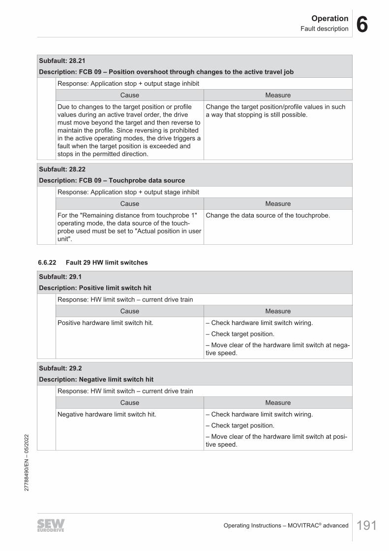
6OperationFault description
Operating Instructions – MOVITRAC® advanced 191
Subfault: 28.21Description: FCB 09 – Position overshoot through changes to the active travel job
Response: Application stop + output stage inhibit
Cause Measure
Due to changes to the target position or profilevalues during an active travel order, the drivemust move beyond the target and then reverse tomaintain the profile. Since reversing is prohibitedin the active operating modes, the drive triggers afault when the target position is exceeded andstops in the permitted direction.
Change the target position/profile values in sucha way that stopping is still possible.
Subfault: 28.22Description: FCB 09 – Touchprobe data source
Response: Application stop + output stage inhibit
Cause Measure
For the "Remaining distance from touchprobe 1"operating mode, the data source of the touch-probe used must be set to "Actual position in userunit".
Change the data source of the touchprobe.
6.6.22 Fault 29 HW limit switches
Subfault: 29.1Description: Positive limit switch hit
Response: HW limit switch – current drive train
Cause Measure
Positive hardware limit switch hit. – Check hardware limit switch wiring.– Check target position.– Move clear of the hardware limit switch at nega-tive speed.
Subfault: 29.2Description: Negative limit switch hit
Response: HW limit switch – current drive train
Cause Measure
Negative hardware limit switch hit. – Check hardware limit switch wiring.– Check target position.– Move clear of the hardware limit switch at posi-tive speed.
2778
8490
/EN
– 0
5/20
22

6 OperationFault description
Operating Instructions – MOVITRAC® advanced192
Subfault: 29.3Description: Limit switch missing
Response: Emergency stop + output stage inhibit
Cause Measure
Both positive and negative hardware limitswitches approached at the same time.
– Check hardware limit switch wiring.– Check the parameter setting of digital inputs.– Check the parameter setting of process outputdata.
Subfault: 29.4Description: Limit switches swapped
Response: Emergency stop + output stage inhibit
Cause Measure
Positive hardware limit switch hit at negativespeed, or negative hardware limit switch hit atpositive speed.
Check whether hardware limit switch connectionsare swapped.
6.6.23 Fault 30 Software limit switches
Subfault: 30.1Description: Positive limit switch hit
Response: SW limit switches – current drive train
Cause Measure
Positive software limit switch hit. – Check position of the software limit switch.– Check target position.– Move clear of software limit switch at negativespeed.
Subfault: 30.2Description: Negative limit switch hit
Response: SW limit switches – current drive train
Cause Measure
Negative software limit switch hit. – Check position of the software limit switch.– Check target position.– Move clear of the software limit switch at posi-tive speed.
Subfault: 30.3Description: Limit switches swapped
Response: Emergency stop + output stage inhibit
Cause Measure
Position of negative software limit switch greaterthan position of positive software limit switch.
Check the positions of the software limit switches.
2778
8490
/EN
– 0
5/20
22
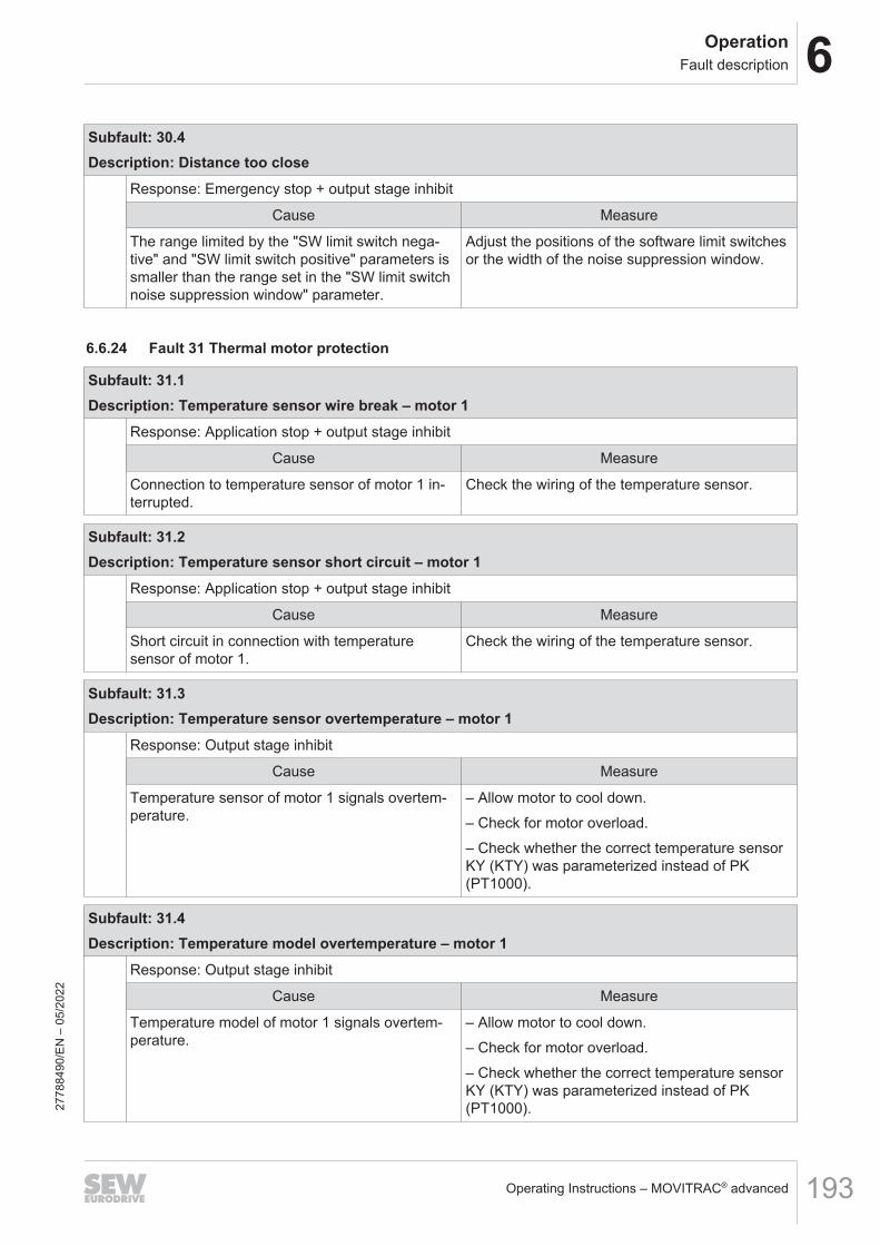
6OperationFault description
Operating Instructions – MOVITRAC® advanced 193
Subfault: 30.4Description: Distance too close
Response: Emergency stop + output stage inhibit
Cause Measure
The range limited by the "SW limit switch nega-tive" and "SW limit switch positive" parameters issmaller than the range set in the "SW limit switchnoise suppression window" parameter.
Adjust the positions of the software limit switchesor the width of the noise suppression window.
6.6.24 Fault 31 Thermal motor protection
Subfault: 31.1Description: Temperature sensor wire break – motor 1
Response: Application stop + output stage inhibit
Cause Measure
Connection to temperature sensor of motor 1 in-terrupted.
Check the wiring of the temperature sensor.
Subfault: 31.2Description: Temperature sensor short circuit – motor 1
Response: Application stop + output stage inhibit
Cause Measure
Short circuit in connection with temperaturesensor of motor 1.
Check the wiring of the temperature sensor.
Subfault: 31.3Description: Temperature sensor overtemperature – motor 1
Response: Output stage inhibit
Cause Measure
Temperature sensor of motor 1 signals overtem-perature.
– Allow motor to cool down.– Check for motor overload.– Check whether the correct temperature sensorKY (KTY) was parameterized instead of PK(PT1000).
Subfault: 31.4Description: Temperature model overtemperature – motor 1
Response: Output stage inhibit
Cause Measure
Temperature model of motor 1 signals overtem-perature.
– Allow motor to cool down.– Check for motor overload.– Check whether the correct temperature sensorKY (KTY) was parameterized instead of PK(PT1000).27
7884
90/E
N –
05/
2022
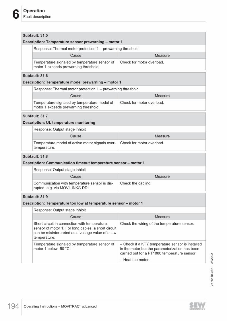
6 OperationFault description
Operating Instructions – MOVITRAC® advanced194
Subfault: 31.5Description: Temperature sensor prewarning – motor 1
Response: Thermal motor protection 1 – prewarning threshold
Cause Measure
Temperature signaled by temperature sensor ofmotor 1 exceeds prewarning threshold.
Check for motor overload.
Subfault: 31.6Description: Temperature model prewarning – motor 1
Response: Thermal motor protection 1 – prewarning threshold
Cause Measure
Temperature signaled by temperature model ofmotor 1 exceeds prewarning threshold.
Check for motor overload.
Subfault: 31.7Description: UL temperature monitoring
Response: Output stage inhibit
Cause Measure
Temperature model of active motor signals over-temperature.
Check for motor overload.
Subfault: 31.8Description: Communication timeout temperature sensor – motor 1
Response: Output stage inhibit
Cause Measure
Communication with temperature sensor is dis-rupted, e.g. via MOVILINK® DDI.
Check the cabling.
Subfault: 31.9Description: Temperature too low at temperature sensor – motor 1
Response: Output stage inhibit
Cause Measure
Short circuit in connection with temperaturesensor of motor 1. For long cables, a short circuitcan be misinterpreted as a voltage value of a lowtemperature.
Check the wiring of the temperature sensor.
Temperature signaled by temperature sensor ofmotor 1 below -50 °C.
– Check if a KTY temperature sensor is installedin the motor but the parameterization has beencarried out for a PT1000 temperature sensor.– Heat the motor.
2778
8490
/EN
– 0
5/20
22

6OperationFault description
Operating Instructions – MOVITRAC® advanced 195
Subfault: 31.11Description: Temperature sensor wire break – motor 2
Response: Application stop + output stage inhibit
Cause Measure
Connection to temperature sensor of motor 2 in-terrupted.
Check the wiring of the temperature sensor.
Subfault: 31.12Description: Temperature sensor short circuit – motor 2
Response: Application stop + output stage inhibit
Cause Measure
Short circuit in connection with temperaturesensor of motor 2.
Check the wiring of the temperature sensor.
Subfault: 31.13Description: Temperature sensor overtemperature – motor 2
Response: Output stage inhibit
Cause Measure
Temperature sensor of motor 2 signals overtem-perature.
– Allow motor to cool down.– Check for motor overload.– Check whether the correct temperature sensorKY (KTY) was parameterized instead of PK(PT1000).
Subfault: 31.14Description: Temperature model overtemperature – motor 2
Response: Output stage inhibit
Cause Measure
Temperature model of motor 2 signals overtem-perature.
– Allow motor to cool down.– Check for motor overload.– Check whether the correct temperature sensorKY (KTY) was parameterized instead of PK(PT1000).
Subfault: 31.15Description: Temperature sensor prewarning – motor 2
Response: Thermal motor protection 2 – prewarning threshold
Cause Measure
Temperature signaled by temperature sensor ofmotor 2 exceeds prewarning threshold.
Check for motor overload.
2778
8490
/EN
– 0
5/20
22

6 OperationFault description
Operating Instructions – MOVITRAC® advanced196
Subfault: 31.16Description: Temperature model prewarning – motor 2
Response: Thermal motor protection 2 – prewarning threshold
Cause Measure
Temperature signaled by temperature model ofmotor 2 exceeds prewarning threshold.
Check for motor overload.
Subfault: 31.18Description: Communication timeout temperature sensor – motor 2
Response: Output stage inhibit
Cause Measure
Communication with temperature sensor is dis-rupted, e.g. via MOVILINK® DDI.
Check the cabling.
Subfault: 31.19Description: Temperature too low at temperature sensor – motor 2
Response: Output stage inhibit
Cause Measure
Short circuit in connection with temperaturesensor of motor 2. For long cables, a short circuitcan be misinterpreted as a voltage value of a lowtemperature.
Check the wiring of the temperature sensor.
Temperature signaled by temperature sensor ofmotor 2 below -50 °C.
– Check if a KTY temperature sensor is installedin the motor but the parameterization has beencarried out for a PT1000 temperature sensor.– Heat the motor.
Subfault: 31.50Description: Fault at temperature sensor 1
Response: Output stage inhibit
Cause Measure
Fault detected at temperature sensor 1 of the mo-tor.
Observe main fault code and take measures ac-cording to the main fault.
Subfault: 31.51Description: Fault at temperature sensor 2
Response: Output stage inhibit
Cause Measure
Fault detected at temperature sensor 2 of the mo-tor.
Observe main fault code and take measures ac-cording to the main fault.
2778
8490
/EN
– 0
5/20
22

6OperationFault description
Operating Instructions – MOVITRAC® advanced 197
Subfault: 31.52Description: Fault at temperature sensor 3
Response: Output stage inhibit
Cause Measure
Fault detected at temperature sensor 3 of the mo-tor.
Observe main fault code and take measures ac-cording to the main fault.
6.6.25 Fault 32 Communication
Subfault: 32.2Description: EtherCAT®/SBusPLUS process data timeout
Response: Fieldbus – timeout response
Cause Measure
Timeout in process data transfer duringEtherCAT®/SBusPLUS communication.
– Check the wiring of the system bus and modulebus.– Check that the EtherCAT®/SBusPLUS configura-tion is set correctly in the MOVI-C®
CONTROLLER.– Check the EtherCAT®/SBusPLUS timeout con-figuration in the device.
Subfault: 32.3Description: Faulty synchronization signal
Response: External synchronization
Cause Measure
Faulty synchronization signal period. Check that the EtherCAT®/SBusPLUS configurationis set correctly in the MOVI-C® CONTROLLER.
Subfault: 32.4Description: No synchronization signal
Response: External synchronization
Cause Measure
No synchronization signal present. Check that the EtherCAT®/SBusPLUS configurationis set correctly in the MOVI-C® CONTROLLER.
Subfault: 32.5Description: Synchronization timeout
Response: External synchronization
Cause Measure
Timeout while synchronizing to synchronizationsignal.
Check that the EtherCAT®/SBusPLUS configurationis set correctly in the MOVI-C® CONTROLLER.
2778
8490
/EN
– 0
5/20
22

6 OperationFault description
Operating Instructions – MOVITRAC® advanced198
Subfault: 32.6Description: Copy parameter set
Response: Output stage inhibit
Cause Measure
Error while downloading parameter set to device. – Check the wiring of the system bus and modulebus.– Restart download.
Subfault: 32.7Description: Application heartbeat timeout
Response: Application heartbeat – timeout response
Cause Measure
Communication between application program(e.g. MOVIKIT® of the Drive or IEC Programmodule group) and device interrupted.
– Check status of the application program.– Restart application program.
Subfault: 32.8Description: Timeout user timeout
Response: User timeout – timeout response
Cause Measure
The timeout time of the user timeout functionelapsed
Write the parameter for triggering the usertimeout function cyclically before the timeout timeelapses.
Subfault: 32.12Description: Manual mode timeout
Response: Manual mode – timeout response
Cause Measure
Communication connection to device interruptedin manual mode.
– Check whether too many programs are open onthe engineering PC.– Increase the timeout time in manual mode.
New Scope project created. – Reset the fault.– Restart manual mode.
Scope measurement loaded from device. – Reset the fault.– Restart manual mode.
2778
8490
/EN
– 0
5/20
22
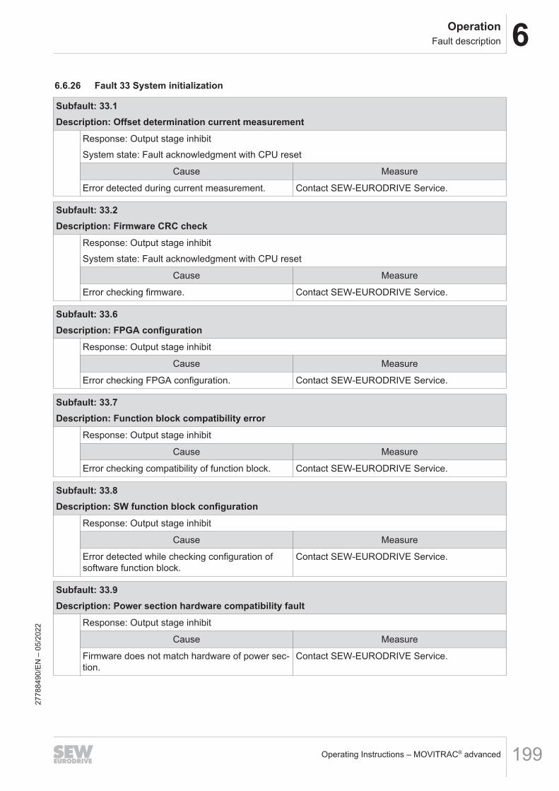
6OperationFault description
Operating Instructions – MOVITRAC® advanced 199
6.6.26 Fault 33 System initialization
Subfault: 33.1Description: Offset determination current measurement
Response: Output stage inhibitSystem state: Fault acknowledgment with CPU reset
Cause Measure
Error detected during current measurement. Contact SEW‑EURODRIVE Service.
Subfault: 33.2Description: Firmware CRC check
Response: Output stage inhibitSystem state: Fault acknowledgment with CPU reset
Cause Measure
Error checking firmware. Contact SEW‑EURODRIVE Service.
Subfault: 33.6Description: FPGA configuration
Response: Output stage inhibit
Cause Measure
Error checking FPGA configuration. Contact SEW‑EURODRIVE Service.
Subfault: 33.7Description: Function block compatibility error
Response: Output stage inhibit
Cause Measure
Error checking compatibility of function block. Contact SEW‑EURODRIVE Service.
Subfault: 33.8Description: SW function block configuration
Response: Output stage inhibit
Cause Measure
Error detected while checking configuration ofsoftware function block.
Contact SEW‑EURODRIVE Service.
Subfault: 33.9Description: Power section hardware compatibility fault
Response: Output stage inhibit
Cause Measure
Firmware does not match hardware of power sec-tion.
Contact SEW‑EURODRIVE Service.
2778
8490
/EN
– 0
5/20
22
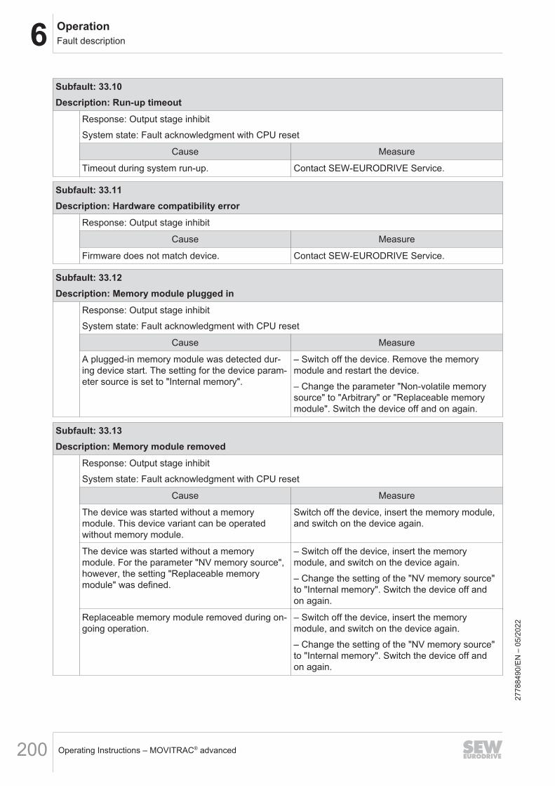
6 OperationFault description
Operating Instructions – MOVITRAC® advanced200
Subfault: 33.10Description: Run-up timeout
Response: Output stage inhibitSystem state: Fault acknowledgment with CPU reset
Cause Measure
Timeout during system run-up. Contact SEW‑EURODRIVE Service.
Subfault: 33.11Description: Hardware compatibility error
Response: Output stage inhibit
Cause Measure
Firmware does not match device. Contact SEW‑EURODRIVE Service.
Subfault: 33.12Description: Memory module plugged in
Response: Output stage inhibitSystem state: Fault acknowledgment with CPU reset
Cause Measure
A plugged-in memory module was detected dur-ing device start. The setting for the device param-eter source is set to "Internal memory".
– Switch off the device. Remove the memorymodule and restart the device.– Change the parameter "Non-volatile memorysource" to "Arbitrary" or "Replaceable memorymodule". Switch the device off and on again.
Subfault: 33.13Description: Memory module removed
Response: Output stage inhibitSystem state: Fault acknowledgment with CPU reset
Cause Measure
The device was started without a memorymodule. This device variant can be operatedwithout memory module.
Switch off the device, insert the memory module,and switch on the device again.
The device was started without a memorymodule. For the parameter "NV memory source",however, the setting "Replaceable memorymodule" was defined.
– Switch off the device, insert the memorymodule, and switch on the device again.– Change the setting of the "NV memory source"to "Internal memory". Switch the device off andon again.
Replaceable memory module removed during on-going operation.
– Switch off the device, insert the memorymodule, and switch on the device again.– Change the setting of the "NV memory source"to "Internal memory". Switch the device off andon again.
2778
8490
/EN
– 0
5/20
22
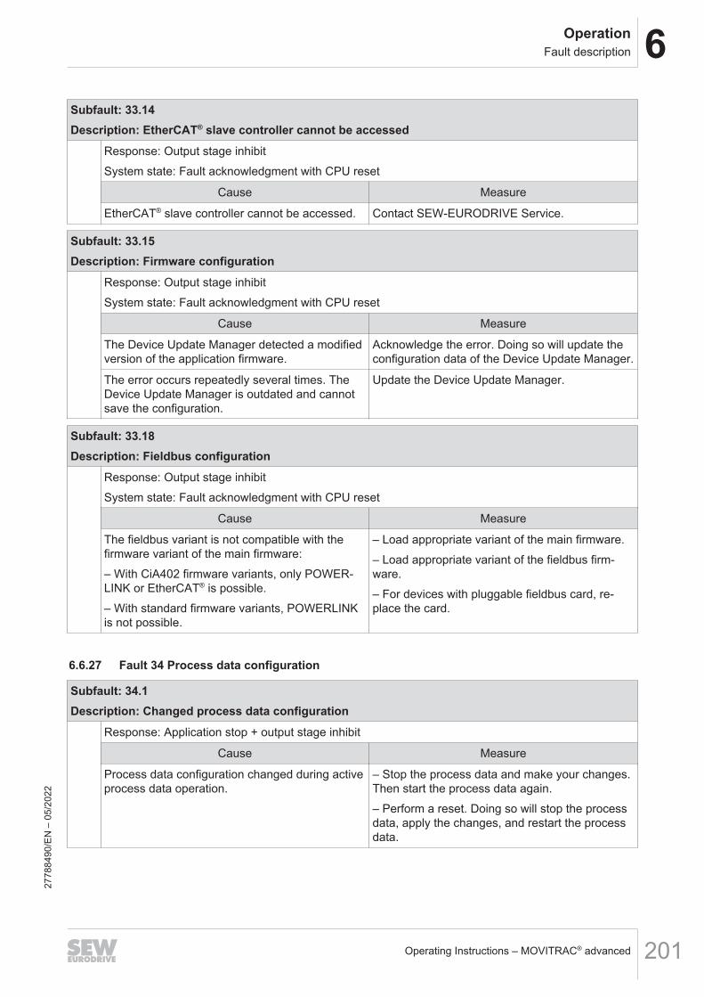
6OperationFault description
Operating Instructions – MOVITRAC® advanced 201
Subfault: 33.14Description: EtherCAT® slave controller cannot be accessed
Response: Output stage inhibitSystem state: Fault acknowledgment with CPU reset
Cause Measure
EtherCAT® slave controller cannot be accessed. Contact SEW‑EURODRIVE Service.
Subfault: 33.15Description: Firmware configuration
Response: Output stage inhibitSystem state: Fault acknowledgment with CPU reset
Cause Measure
The Device Update Manager detected a modifiedversion of the application firmware.
Acknowledge the error. Doing so will update theconfiguration data of the Device Update Manager.
The error occurs repeatedly several times. TheDevice Update Manager is outdated and cannotsave the configuration.
Update the Device Update Manager.
Subfault: 33.18Description: Fieldbus configuration
Response: Output stage inhibitSystem state: Fault acknowledgment with CPU reset
Cause Measure
The fieldbus variant is not compatible with thefirmware variant of the main firmware:– With CiA402 firmware variants, only POWER-LINK or EtherCAT® is possible.– With standard firmware variants, POWERLINKis not possible.
– Load appropriate variant of the main firmware.– Load appropriate variant of the fieldbus firm-ware.– For devices with pluggable fieldbus card, re-place the card.
6.6.27 Fault 34 Process data configuration
Subfault: 34.1Description: Changed process data configuration
Response: Application stop + output stage inhibit
Cause Measure
Process data configuration changed during activeprocess data operation.
– Stop the process data and make your changes.Then start the process data again.– Perform a reset. Doing so will stop the processdata, apply the changes, and restart the processdata.
2778
8490
/EN
– 0
5/20
22

6 OperationFault description
Operating Instructions – MOVITRAC® advanced202
6.6.28 Fault 35 Function activation
Subfault: 35.1Description: Activation level – invalid activation key
Response: Emergency stop + output stage inhibit
Cause Measure
The activation key was entered incorrectly. Enter the activation key again.
The activation key was not created for thisdevice.
Check the activation key.
When using a double axis, the activation key forthe wrong instance was entered in the device.
Enter the activation key for the allocated instance.
Activation key entered for technology level in pa-rameter "Application level – activation key".
Enter the activation key in the correct parameter.
Subfault: 35.2Description: Application level too low
Response: Emergency stop + output stage inhibit
Cause Measure
The activated software module requires a higherapplication level.
Activation key was entered for required applica-tion level. You can read the required level fromthe parameter "Application level – Requiredlevel".
Subfault: 35.3Description: Technology level too low
Response: Emergency stop + output stage inhibit
Cause Measure
An activated technology function requires ahigher technology level.
Enter an activation key for the required technolo-gy level. You can find the required level in the pa-rameter 8438.13 "Technology level – Requiredlevel".
Subfault: 35.4Description: Technology level – invalid activation key
Response: Emergency stop + output stage inhibit
Cause Measure
The activation key was entered incorrectly. Enter the activation key again.
The activation key was not created for thisdevice.
Check the activation key.
When using a double axis, the activation key forthe wrong instance was entered in the device.
Enter the activation key for the allocated instance.
Activation key entered for application level in pa-rameter "Technology level – activation key".
Enter the activation key in the correct parameter.
2778
8490
/EN
– 0
5/20
22
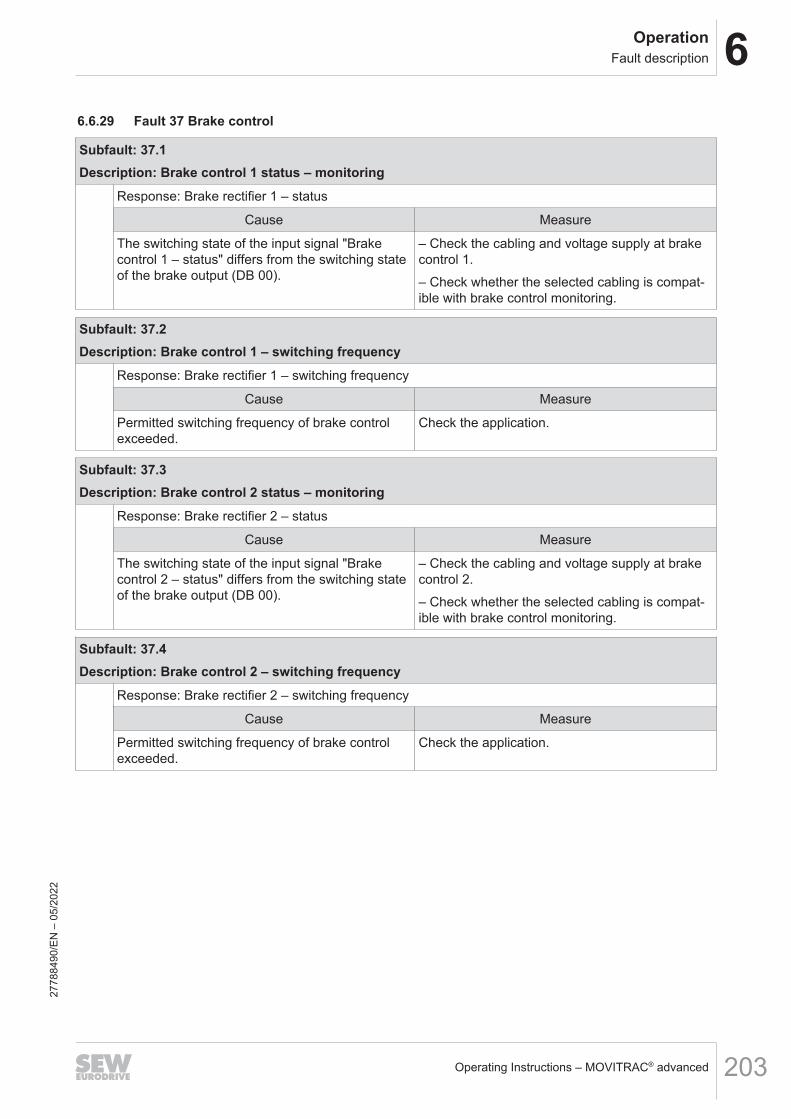
6OperationFault description
Operating Instructions – MOVITRAC® advanced 203
6.6.29 Fault 37 Brake control
Subfault: 37.1Description: Brake control 1 status – monitoring
Response: Brake rectifier 1 – status
Cause Measure
The switching state of the input signal "Brakecontrol 1 – status" differs from the switching stateof the brake output (DB 00).
– Check the cabling and voltage supply at brakecontrol 1.– Check whether the selected cabling is compat-ible with brake control monitoring.
Subfault: 37.2Description: Brake control 1 – switching frequency
Response: Brake rectifier 1 – switching frequency
Cause Measure
Permitted switching frequency of brake controlexceeded.
Check the application.
Subfault: 37.3Description: Brake control 2 status – monitoring
Response: Brake rectifier 2 – status
Cause Measure
The switching state of the input signal "Brakecontrol 2 – status" differs from the switching stateof the brake output (DB 00).
– Check the cabling and voltage supply at brakecontrol 2.– Check whether the selected cabling is compat-ible with brake control monitoring.
Subfault: 37.4Description: Brake control 2 – switching frequency
Response: Brake rectifier 2 – switching frequency
Cause Measure
Permitted switching frequency of brake controlexceeded.
Check the application.
2778
8490
/EN
– 0
5/20
22

6 OperationFault description
Operating Instructions – MOVITRAC® advanced204
6.6.30 Fault 42 Lag error
Subfault: 42.1Description: Positioning lag error
Response: Positioning lag error
Cause Measure
Encoder not connected correctly. Check the connection of the encoder.
Position encoder inverted or not installed cor-rectly at the track.
Check the installation and connection of the posi-tion encoder.
Wiring faulty. – Check the wiring of encoder and motor.– Check the line phases.
Acceleration too high. – Check the profile values.– Increase the torque limit and/or current limit.– Check the project planning.
P component of position controller too small. Set P component of the position controller to alarger value.
Speed controller parameterized incorrectly. Check controller parameters.
Lag error window too small. Increase the lag error window.
Mechanical components cannot move freely orare blocked.
– Check whether the mechanical componentscan move freely.– Check the mechanical components for block-age.
Subfault: 42.2Description: Jog mode lag error
Response: Output stage inhibit
Cause Measure
Encoder not connected correctly. Check the connection of the encoder.
Position encoder inverted or not installed cor-rectly at the track.
Check the installation and connection of the posi-tion encoder.
Wiring faulty. – Check the wiring of encoder and motor.– Check the line phases.
Acceleration too high. – Check the profile values.– Increase the torque limit and/or current limit.– Check the project planning.
P component of position controller too small. Set P component of the position controller to alarger value.
Speed controller parameterized incorrectly. Check controller parameters.
Lag error window too small. Increase the lag error window.
Mechanical components cannot move freely orare blocked.
– Check whether the mechanical componentscan move freely.– Check the mechanical components for block-age.
2778
8490
/EN
– 0
5/20
22
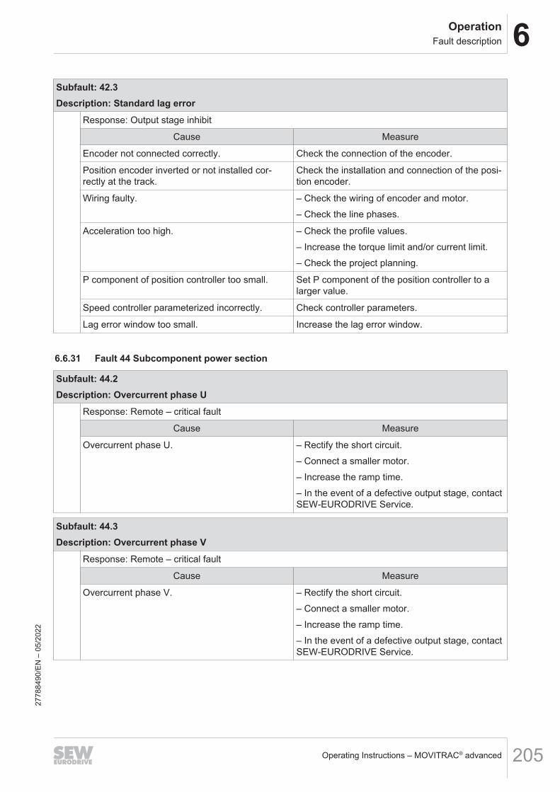
6OperationFault description
Operating Instructions – MOVITRAC® advanced 205
Subfault: 42.3Description: Standard lag error
Response: Output stage inhibit
Cause Measure
Encoder not connected correctly. Check the connection of the encoder.
Position encoder inverted or not installed cor-rectly at the track.
Check the installation and connection of the posi-tion encoder.
Wiring faulty. – Check the wiring of encoder and motor.– Check the line phases.
Acceleration too high. – Check the profile values.– Increase the torque limit and/or current limit.– Check the project planning.
P component of position controller too small. Set P component of the position controller to alarger value.
Speed controller parameterized incorrectly. Check controller parameters.
Lag error window too small. Increase the lag error window.
6.6.31 Fault 44 Subcomponent power section
Subfault: 44.2Description: Overcurrent phase U
Response: Remote – critical fault
Cause Measure
Overcurrent phase U. – Rectify the short circuit.– Connect a smaller motor.– Increase the ramp time.– In the event of a defective output stage, contactSEW‑EURODRIVE Service.
Subfault: 44.3Description: Overcurrent phase V
Response: Remote – critical fault
Cause Measure
Overcurrent phase V. – Rectify the short circuit.– Connect a smaller motor.– Increase the ramp time.– In the event of a defective output stage, contactSEW‑EURODRIVE Service.
2778
8490
/EN
– 0
5/20
22

6 OperationFault description
Operating Instructions – MOVITRAC® advanced206
Subfault: 44.4Description: Overcurrent phase W
Response: Remote – critical fault
Cause Measure
Overcurrent phase W. – Rectify the short circuit.– Connect a smaller motor.– Increase the ramp time.– In the event of a defective output stage, contactSEW‑EURODRIVE Service.
6.6.32 Fault 45 Fieldbus card
Subfault: 45.1Description: No response from fieldbus interface
Response: Emergency stop + output stage inhibit
Cause Measure
The fieldbus interface does not start properly andis therefore not functional.
– Switch the power off and on again/perform a re-set.– If the fault occurs repeatedly, replace the field-bus interface or device and send it together withthe fault number to SEW‑EURODRIVE. For fur-ther support, contact SEW‑EURODRIVE Service.
Subfault: 45.2Description: Fieldbus interface – fault
Response: Fieldbus – timeout response
Cause Measure
Device detected fault on device-internal connec-tion to fieldbus interface.
– Switch the device off and on again.– If the fault occurs repeatedly, replace the field-bus interface or device and send it together withthe fault number to SEW‑EURODRIVE. For fur-ther support, contact SEW‑EURODRIVE Service.
Subfault: 45.3Description: Process output data timeout
Response: Fieldbus – timeout response
Cause Measure
Fieldbus interface detected timeout of processoutput data.
– Check the communication connection betweenthe fieldbus master and the fieldbus interface forinterruption.– Check the configuration of the fieldbus master.– Adjust the fieldbus timeout monitoring.
2778
8490
/EN
– 0
5/20
22
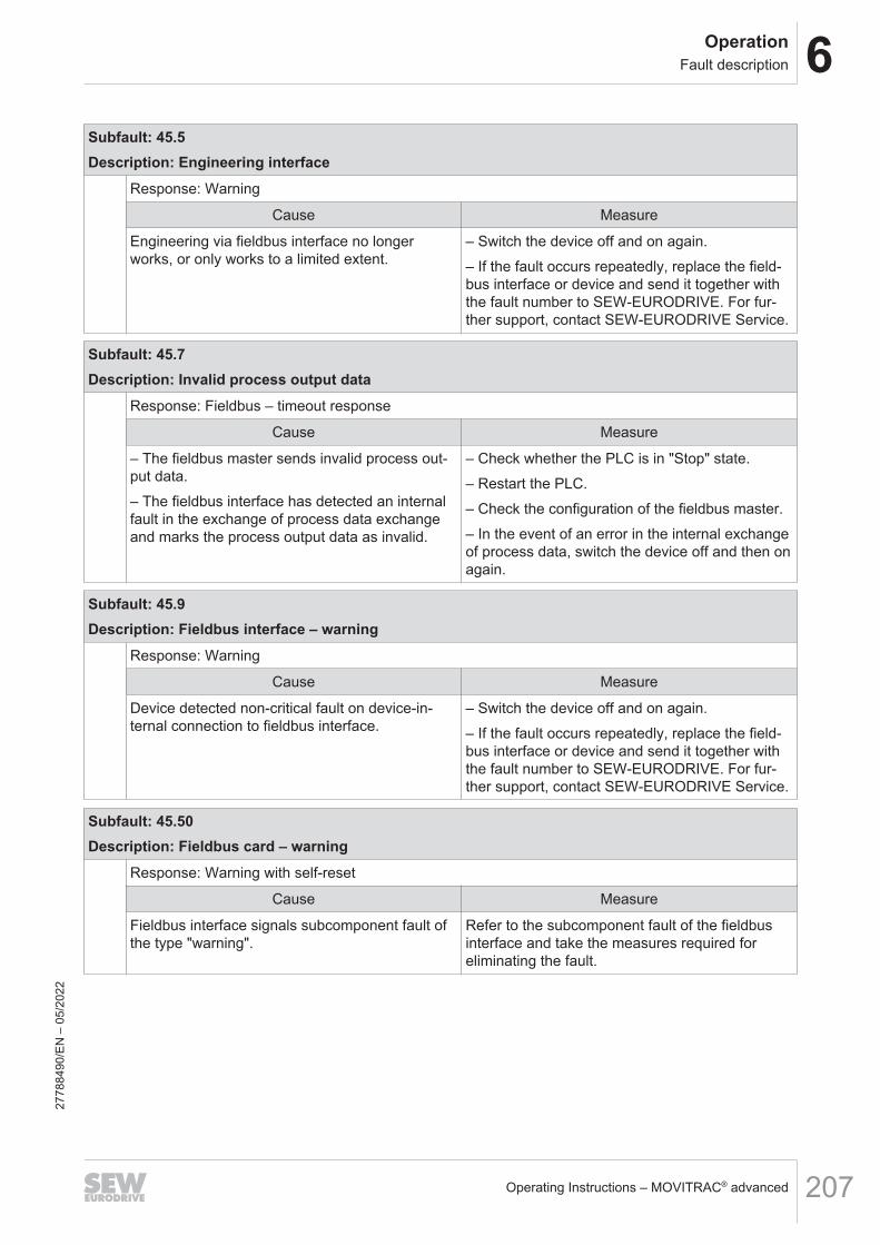
6OperationFault description
Operating Instructions – MOVITRAC® advanced 207
Subfault: 45.5Description: Engineering interface
Response: Warning
Cause Measure
Engineering via fieldbus interface no longerworks, or only works to a limited extent.
– Switch the device off and on again.– If the fault occurs repeatedly, replace the field-bus interface or device and send it together withthe fault number to SEW‑EURODRIVE. For fur-ther support, contact SEW‑EURODRIVE Service.
Subfault: 45.7Description: Invalid process output data
Response: Fieldbus – timeout response
Cause Measure
– The fieldbus master sends invalid process out-put data.– The fieldbus interface has detected an internalfault in the exchange of process data exchangeand marks the process output data as invalid.
– Check whether the PLC is in "Stop" state.– Restart the PLC.– Check the configuration of the fieldbus master.– In the event of an error in the internal exchangeof process data, switch the device off and then onagain.
Subfault: 45.9Description: Fieldbus interface – warning
Response: Warning
Cause Measure
Device detected non-critical fault on device-in-ternal connection to fieldbus interface.
– Switch the device off and on again.– If the fault occurs repeatedly, replace the field-bus interface or device and send it together withthe fault number to SEW‑EURODRIVE. For fur-ther support, contact SEW‑EURODRIVE Service.
Subfault: 45.50Description: Fieldbus card – warning
Response: Warning with self-reset
Cause Measure
Fieldbus interface signals subcomponent fault ofthe type "warning".
Refer to the subcomponent fault of the fieldbusinterface and take the measures required foreliminating the fault.
2778
8490
/EN
– 0
5/20
22

6 OperationFault description
Operating Instructions – MOVITRAC® advanced208
Subfault: 45.51Description: Fieldbus card – fault
Response: Fieldbus – timeout response
Cause Measure
Fieldbus interface signals subcomponent fault ofthe type "standard".
Refer to the subcomponent fault of the fieldbusinterface and take the measures required foreliminating the fault.
Subfault: 45.52Description: Fieldbus card – critical fault
Response: Fieldbus – timeout response
Cause Measure
Fieldbus interface signals subcomponent fault ofthe type "Critical fault".
Refer to the subcomponent fault of the fieldbusinterface and take the measures required foreliminating the fault.
6.6.33 Fault 46 Safety card
Subfault: 46.1Description: No response
Response: Output stage inhibit
Cause Measure
Failed to synchronize with subcomponent. – Check device assignment of basic device andoption.– Check card slot and installation and correct ifnecessary.– Restart the device.– Contact SEW-EURODRIVE Service.
Subfault: 46.2Description: Invalid variant
Response: Output stage inhibit
Cause Measure
Plugged safety card design does not match in-verter type.
– Remove the safety card.– Use the correct safety card design.
For double axes, only designs without encoder in-terface can be used.
– Remove the option.– Use the design without encoder interface.
For double axes, no encoder option must beplugged in.
Remove the option.
2778
8490
/EN
– 0
5/20
22

6OperationFault description
Operating Instructions – MOVITRAC® advanced 209
Subfault: 46.3Description: Internal communication timeout
Response: Output stage inhibit
Cause Measure
Communication interrupted between inverter andsafety card.
Check card slot and installation and correct ifnecessary. Contact SEW‑EURODRIVE Service ifthe error is still present.
Safety card signals subcomponent fault of thetype "warning".
Check card slot and installation and correct ifnecessary. Contact SEW‑EURODRIVE Service ifthe error is still present.
Subfault: 46.50Description: Warning
Response: Warning with self-reset
Cause Measure
Safety card signals subcomponent fault of thetype "warning".
Observe the subcomponent fault of the safetycard and take measures according to the sub-component fault.
Subfault: 46.51Description: Fault
Response: Emergency stop + output stage inhibit with self-reset
Cause Measure
Safety card signals subcomponent fault of thetype "standard fault".
Observe the subcomponent fault of the safetycard and take measures according to the sub-component fault.
Subfault: 46.52Description: System error
Response: Output stage inhibit with self-reset
Cause Measure
Safety card signals subcomponent fault of thetype "system fault" or "critical fault".
Observe the subcomponent fault of the safetycard and take measures according to the sub-component fault.
6.6.34 Fault 51 Analog processing
Subfault: 51.1Description: Analog current input 4 mA limit
Response: Warning with self-reset
Cause Measure
Input current below 4 mA. Check the input current.
2778
8490
/EN
– 0
5/20
22

6 OperationFault description
Operating Instructions – MOVITRAC® advanced210
Subfault: 51.2Description: Voltage/current changeover
Response: Output stage inhibit
Cause Measure
The hardware configuration for switching betweenvoltage input and current input does not matchthe parameterization of the analog input.
Change the hardware configuration or the param-eter setting.
6.6.35 Fault 52 Category 2 explosion protection function
Subfault: 52.1Description: Startup error
Response: Output stage inhibit
Cause Measure
No valid startup available. Perform startup.
Subfault: 52.2Description: Impermissible system function
Response: Output stage inhibit
Cause Measure
Impermissible system function activated. Disable impermissible functions when Ex protec-tion function is active, such as "Activate standstillcurrent" = "On" in the active control mode.
Subfault: 52.3Description: Inverter too large
Response: Output stage inhibit
Cause Measure
Ratio of inverter current to nominal motor currenttoo large.
Check the assignment of motor and inverter, andcheck the dimensioning of the system.
Subfault: 52.4Description: Parameterization of current limit characteristic
Response: Output stage inhibit
Cause Measure
Error while setting parameters for current limitcharacteristic.
– Parameterize the current limit characteristic.– Perform startup again.
2778
8490
/EN
– 0
5/20
22

6OperationFault description
Operating Instructions – MOVITRAC® advanced 211
Subfault: 52.5Description: Time duration exceeded f < 5 Hz
Response: Emergency stop + output stage inhibit
Cause Measure
Duration of 60 s for f < 5 Hz exceeded. Check the dimensioning of the system: If speedcontrol = FCB05, increase the speed. If speed =0, inhibit output stage / with stop FCBs, activatethe brake function if a brake is installed.
2778
8490
/EN
– 0
5/20
22

6 OperationFault responses
Operating Instructions – MOVITRAC® advanced212
6.7 Fault responses
6.7.1 Default fault responseFault response DescriptionNo response The inverter ignores the event.
Warning with self-reset The inverter sends a warning message with self-reset. The fault is automatically reset afterthe cause of fault is eliminated.
Warning The inverter issues a warning message.Application stop (with output stage in-hibit)
The inverter stops with the deceleration set for the application limit.Parameter set 1 Index 8375.0-13Parameter set 2 Index 8375.8-13For n=0: Brake "applied" and output stage "off".
Application stop (with output stage in-hibit) with self-resetEmergency stop (with output stage in-hibit) The inverter stops with the set emergency stop deceleration.
Parameter set 1 Index 8375.0-20Parameter set 2 Index 8375.8-20Emergency stop (with output stage in-
hibit) with self-resetInhibit output stage with self-reset
The output stage is deactivated and the brake is applied.Inhibit output stage
Self-reset means: Eliminating the cause of the fault acknowledges the fault. The in-verter automatically resumes the operation performed before the fault. The drive re-starts automatically.
6.7.2 Parameterizable faultsParameterizable faults Description Index no. Possible fault responseManual mode – timeout re-sponse
This parameter is used to set the response toa bus timeout during manual mode.
8504.3 • Application stop (with output stage in-hibit)
• Emergency stop (with output stage in-hibit)
• Inhibit output stageHeat sink overtemperature –prewarning
Here, you can set the device response whenthe prewarning threshold for heat sink utiliza-tion is exceeded (index 8336.1).
8622.2 • No response• Warning
Positioning lag fault This parameter is used to set the device re-sponse to a lag error (lag error window ex-ceeded, index 8509.4).
8622.3 • No response• Warning• Application stop (with output stage in-
hibit)• Emergency stop (with output stage in-
hibit)• Inhibit output stage
Line phase failure This parameter is used to set the device re-sponse to a line phase failure (values belowthreshold defined by the user, index 8351.5).
8622.4 • No response• Warning• Application stop (with output stage in-
hibit)• Emergency stop (with output stage in-
hibit)• Inhibit output stage
External fault This parameter is used to set the device re-sponse to an external fault (e.g. triggered byterminal or control word).
8622.5 • No response• Warning• Application stop (with output stage in-
hibit)• Emergency stop (with output stage in-
hibit)• Inhibit output stage
2778
8490
/EN
– 0
5/20
22

6OperationFault responses
Operating Instructions – MOVITRAC® advanced 213
Parameterizable faults Description Index no. Possible fault responseFieldbus – timeout This parameter is used to set the device re-
sponse to an EtherCAT®/SBusPLUS timeout(timeout time, index 8455.3).
8622.6 • Warning• Application stop (with output stage in-
hibit)• Emergency stop (with output stage in-
hibit)• Inhibit output stage• Warning with self reset• Application stop (with output stage in-
hibit) with self reset• Emergency stop (with output stage in-
hibit) with self reset• Inhibit output stage with self reset
External synchronization This parameter is used to set the device re-sponse to loss of external synchronization.
8622.7 • No response• Warning• Application stop (with output stage in-
hibit)• Emergency stop (with output stage in-
hibit)• Inhibit output stage• Warning with self reset• Application stop (with output stage in-
hibit) with self reset• Emergency stop (with output stage in-
hibit) with self reset• Inhibit output stage with self reset
Motor temperature prewarning –current parameter set
Motor temperature active parameter set – pre-warning.
8622.8 • No response• Warning• Application stop (with output stage in-
hibit)• Emergency stop (with output stage in-
hibit)• Inhibit output stage
Electromechanical utilization –prewarning
This parameter is used to set the device re-sponse to an exceeded prewarning thresholdfor electromechanical utilization (index8336.2).
8622.10 • No response• Warning• Application stop (with output stage in-
hibit)• Emergency stop (with output stage in-
hibit)• Inhibit output stage
HW limit switches – current pa-rameter set
8622.11 • No response• Emergency stop (with output stage in-
hibit)• Emergency stop (with output stage in-
hibit) with self resetSW limit switches – current pa-rameter set
8622.12 • No response• Emergency stop (with output stage in-
hibit)• Emergency stop (with output stage in-
hibit) with self resetEncoder – warning This parameter is used to set the device re-
sponse to an encoder warning.8622.13 • Warning
• Application stop (with output stage in-hibit)
• Emergency stop (with output stage in-hibit)
• Inhibit output stageEncoder – fault This parameter is used to set the device re-
sponse to an encoder fault.8622.14 • Application stop (with output stage in-
hibit)• Emergency stop (with output stage in-
hibit)• Inhibit output stage
Additional encoder This parameter is used to set the device re-sponse to a fault of an encoder that is notused for control (speed or positioning control).
8622.15 • Warning• Application stop (with output stage in-
hibit)• Emergency stop (with output stage in-
hibit)• Inhibit output stage
Encoder 1 – latest fault 8622.16 • No responseEncoder 2 – latest fault 8622.17 • No response27
7884
90/E
N –
05/
2022

6 OperationFault responses
Operating Instructions – MOVITRAC® advanced214
Parameterizable faults Description Index no. Possible fault responseEncoder 1 – latest critical fault 8622.18 • No response
• Inhibit output stageEncoder 2 – latest critical fault 8622.19 • No response
• Inhibit output stageResponse to external braking re-sistor fault
External braking resistor fault 8622.20 • No response• Warning• Application stop (with output stage in-
hibit)• Emergency stop (with output stage in-
hibit)• Inhibit output stage
Application heartbeat timeout This parameter is used to set the device re-sponse to a timeout of the application heart-beat.
8622.21 • Warning• Application stop (with output stage in-
hibit)• Emergency stop (with output stage in-
hibit)• Inhibit output stage
2778
8490
/EN
– 0
5/20
22

7ServiceElectronics Service by SEW‑EURODRIVE
Operating Instructions – MOVITRAC® advanced 215
7 Service7.1 Electronics Service by SEW‑EURODRIVE
If you are unable to rectify a fault, contact SEW‑EURODRIVE Service. For addresses,refer to www.sew‑eurodrive.com.When contacting SEW‑EURODRIVE Service, always specify the following informationso that our service personnel can assist you more effectively:• Information on the device type on the nameplate (e.g. type designation, serial
number, part number, product key, purchase order number)• Brief description of the application• Fault message on the status display• Nature of the fault• Accompanying circumstances• Any unusual events preceding the problem
7.2 Extended storage
If the devices are stored in a temperature range of 5 °C to 40 °C, no measures are re-quired.The following table lists the devices, time intervals, and measures that are required ifthe devices are stored outside the above-mentioned temperature range.For all inverters other than the ones listed, no measures are required.
Devices Time interval Measure
All inverters Every 2 yearsLine connections: Connect the device to the line
voltage for 5 minutes.
Connect the device to 24 V for 5 minutes
2778
8490
/EN
– 0
5/20
22

7 ServiceDevice replacement
Operating Instructions – MOVITRAC® advanced216
7.2.1 Procedure when maintenance has been neglectedIf you have not performed maintenance regularly, SEW-EURODRIVE recommendsthat you increase the line voltage slowly up to the maximum voltage. This can bedone, for example, by using a variable transformer for which the output voltage hasbeen set according to the following overview. After you have completed the regenera-tion process, the device can be used immediately or stored again.The following graduations are recommended:AC 400/500 V devices:• Stage 1: 0 V to AC 350 V within a few seconds• Stage 2: AC 350 V for 15 minutes• Stage 3: AC 420 V for 15 minutes• Stage 4: AC 500 V for 1 hourAC 230 V devices• Stages 1, 2: 170 V• Stage 3: 200 V• Stage 4: 240 V
7.3 Device replacementIf a device needs to be replaced, the following procedures apply.
7.3.1 Exclusive use of the CMM.. memory moduleIf the inverter is equipped with a CMM.. memory module, the parameter and configura-tion settings are stored on the memory module. By plugging the memory module intoanother inverter, this data is available so that the inverter is immediately ready foroperation for the specific application.
Instructions on the use of the memory module when exchanging a deviceThe prerequisite for the error-free exchange of an inverter is that the same optionsmust be installed in the new device as in the original one.If this is not the case, the error message "25.70 NV memory initialization" is displayed.You can acknowledge the error by opening the "Error reset with parameter accept-ance" menu item in the context menu, and you must ensure that the information thatwas provided via the previous options (e.g. encoder signals via encoder option) reachthe application inverter through different means or are deselected.Alternatively, the device can also be reset to the delivery state. A new startup is thenrequired.If a memory module is removed during operation, the following error message is dis-played: "33.13 System initialization: Memory module removed".This fault status can be acknowledged with a fault reset.SEW-EURODRIVE recommends operating the inverter only with an inserted memorymodule.
2778
8490
/EN
– 0
5/20
22

7ServiceShutdown
Operating Instructions – MOVITRAC® advanced 217
7.3.2 Using a CBG.. keypadWhen using a keypad, the parameter and configuration settings can be stored on thekeypad. By plugging the keypad into another inverter and activating data transmission,data is transferred to the inverter. After the transmission is complete, the inverter is im-mediately ready for operation for the specific application.
7.3.3 Using a MOVI-C® CONTROLLER with or without CMM.. memory moduleIf the data management (axis data set recovery) of the MOVI-C® CONTROLLER isused, the parameter and configuration settings of the controller are always transferredto the inverter.The data is on the memory card of the MOVI-C® CONTROLLER. If the data manage-ment of the MOVI-C® CONTROLLER is not active, the memory source can be set inindex 8431.20 (memory source) as follows:• 0 - Any
The parameter and configuration settings are written both to the internal devicememory of the inverter and to the CMM.. memory module. Thus, the data is syn-chronized on both storage media.
• 1 - Internal memoryThe inverter reads or writes the parameter and configuration settings to the in-ternal device memory of the inverter.
• 2 - Replaceable memory moduleThe inverter reads or writes the parameter and configuration settings to the CMM...memory module.
7.3.4 Device replacement without error messagesDevice replacement without error messages is only possible when using an identicalreplacement device. Deviating device configurations lead to error E25.06 and can beacknowledged with parameter acceptance (index 8365.5) via reset. The device canthen be used without further startup.
7.4 Shutdown
To shut down the inverter, de-energize the inverter using appropriate measures.
WARNINGElectric shock due to incompletely discharged capacitors.Severe or fatal injuries.• Observe a minimum switch-off time of 10 minutes after disconnecting the power
supply.
2778
8490
/EN
– 0
5/20
22
7 ServiceWaste disposal
Operating Instructions – MOVITRAC® advanced218
7.5 Waste disposalDispose of the product and all parts separately in accordance with their material struc-ture and the national regulations. Put the product through a recycling process or con-tact a specialist waste disposal company. If possible, divide the product into the follow-ing categories:• Iron, steel or cast iron• Stainless steel• Magnets• Aluminum• Copper• Electronic parts• PlasticsThe following materials are hazardous to health and the environment. These materialsmust be collected and disposed of separately.• Oil and grease
Collect used oil and grease separately according to type. Ensure that the used oilis not mixed with solvent. Dispose of used oil and grease correctly.
• Screens• Capacitors• Rechargeable batteries• Batteries
Waste disposal according to WEEE Directive 2012/19/EUThis product and its accessories may fall within the scope of the country-specific appli-cation of the WEEE Directive. Dispose of the product and its accessories according tothe national regulations of your country.For further information, contact the responsible SEW‑EURODRIVE branch or an au-thorized partner of SEW‑EURODRIVE.
2778
8490
/EN
– 0
5/20
22

8Technical dataMarkings
Operating Instructions – MOVITRAC® advanced 219
8 Technical data8.1 Markings8.1.1 Basic device
The inverter complies with the following directives and guidelines:
Mark DefinitionThe CE mark states compliance with the following European directives:• Low Voltage Directive 2014/35/EU1)
• EMC Directive 2014/30/EU• Machinery Directive 2006/42/EC• Directive 2011/65/EU for limiting the use of certain hazardous sub-
stances in electric and electronic equipment• Ecodesign Directive 2009/125/EC
The waste disposal of this product is performed in compliance with theWEEE Directive 2012/19/EU.
The EAC mark declares compliance with the requirements of the technicalregulations of the Customs Union of Russia, Kazakhstan, and Belarus.
The RCM mark declares compliance with the technical regulations of theAustralian Communications and Media Authority (ACMA).
The China RoHS mark states compliance with Directive SJ/T 11364-2014for limiting the use of hazardous substances in electric and electronicequipment and their packaging.
The UL and cUL marks state UL approval.cUL is equivalent to CSA approval.
The NM mark states compliance with the following Moroccan guidelines:• Low Voltage Directive N° 2573-14 (July 16, 2015)• EMC Directive N° 2574-14 (July 16, 2015)
The KC mark declares compliance with §3 of Article 58-2 for the KoreanRadio Wave Act.
2778
8490
/EN
– 0
5/20
22

8 Technical dataMarkings
Operating Instructions – MOVITRAC® advanced220
Mark DefinitionThe UKCA mark states the compliance with the following British guidelines:• Low Voltage Directive S.I. 2016/11012)
• EMC S. I. 2016/1091• Machinery Safety S. I. 2008/1597• Directive S. I. 2012/3032 for limiting the use of certain hazardous sub-
stances in electrical and electronic equipment• Ecodesign Regulation S. I. 2019/539
1) For products with functional safety, the requirements from the Low Voltage Directive are fulfilled by the Machinery Directive.2) For products with functional safety, the requirements from the Low Voltage Directive are fulfilled by the Machinery Safety S.I.
2008/1597.
2778
8490
/EN
– 0
5/20
22

8Technical dataMarkings
Operating Instructions – MOVITRAC® advanced 221
8.1.2 Accessories
BW.. braking resistors
Mark DefinitionThe CE mark states compliance with the following European directives:• Low Voltage Directive 2014/35/EU• Directive 2011/65/EU for limiting the use of certain hazardous sub-
stances in electric and electronic equipment
The waste disposal of this product is performed in compliance with theWEEE Directive 2012/19/EU.
The China RoHS mark declares compliance with the Directive SJ/T 11364-2014 regarding the restriction of use of certain hazardous sub-stances in electrical and electronic equipment and its packaging.
The UKCA mark states compliance with the following British guidelines:• Low Voltage Directive S. I. 2016/1101• Directive S. I. 2012/3032 for limiting the use of certain hazardous sub-
stances in electric and electronic equipment
The cUR mark states the UL approval for this component.
2778
8490
/EN
– 0
5/20
22

8 Technical dataMarkings
Operating Instructions – MOVITRAC® advanced222
NF.. line filter
Mark DefinitionThe waste disposal of this product is performed in compliance with theWEEE Directive 2012/19/EU.
The China RoHS mark declares compliance with the Directive SJ/T 11364-2014 regarding the restriction of use of certain hazardous sub-stances in electrical and electronic equipment and its packaging.
The cUR mark states the UL approval for this component.
ND.. line chokes
Mark DefinitionThe CE mark states compliance with the following European directives:• Low Voltage Directive 2014/35/EU• Directive 2011/65/EU for limiting the use of certain hazardous sub-
stances in electric and electronic equipment
The waste disposal of this product is performed in compliance with theWEEE Directive 2012/19/EU.
The China RoHS mark declares compliance with the directive SJ/T 11364-2014 regarding the restriction of use of certain hazardous sub-stances in electrical and electronic equipment and its packaging.
The UKCA mark states compliance with the following British guidelines:• Low Voltage Directive S. I. 2016/1101• Directive S. I. 2012/3032 for limiting the use of certain hazardous sub-
stances in electric and electronic equipment
The cUR mark states the UL approval for this component.27
7884
90/E
N –
05/
2022

8Technical dataMarkings
Operating Instructions – MOVITRAC® advanced 223
HF.. output filters
Mark DefinitionThe CE mark states compliance with the following European directives:• Low Voltage Directive 2014/35/EU• Directive 2011/65/EU for limiting the use of certain hazardous sub-
stances in electric and electronic equipment
The waste disposal of this product is performed in compliance with theWEEE Directive 2012/19/EU.
The China RoHS mark declares compliance with the directive SJ/T 11364-2014 regarding the restriction of use of certain hazardous sub-stances in electrical and electronic equipment and its packaging.
The UKCA mark states compliance with the following British guidelines:• Low Voltage Directive S. I. 2016/1101• Directive S. I. 2012/3032 for limiting the use of certain hazardous sub-
stances in electric and electronic equipment
The cUR mark states the UL approval for this component.
HD.. output chokes
Mark DefinitionThe CE mark states compliance with the following European directives:• Low Voltage Directive 2014/35/EU• Directive 2011/65/EU for limiting the use of certain hazardous sub-
stances in electric and electronic equipment
The waste disposal of this product is performed in compliance with theWEEE Directive 2012/19/EU.
The China RoHS mark declares compliance with the directive SJ/T 11364-2014 regarding the restriction of use of certain hazardous sub-stances in electrical and electronic equipment and its packaging.
The UKCA mark states compliance with the following British guidelines:• Low Voltage Directive S. I. 2016/1101• Directive S. I. 2012/3032 for limiting the use of certain hazardous sub-
stances in electric and electronic equipment
The cUR mark states the UL approval for this component.
2778
8490
/EN
– 0
5/20
22

8 Technical dataGeneral technical data
Operating Instructions – MOVITRAC® advanced224
8.2 General technical dataThe following table lists the technical data for all inverters independent of• Type• Design• Size• Power rating
General specifications
Interference immunity Meets EN 61800-3; 2. Environment
Interference emission
Limit value class C2 according to EN 61800‑3. The interference suppression level can beimproved with relevant measures.A line filter for limit class C2 is required for the inverters listed below:• MCX91A-0320-.. – MCX91A-5880-503-..• MCX91A-0290-.. – MCX91A-1080-203-..Refer to chapter "EMC-compliant installation according to EN 61800-3" in the productmanual for further information.
Ambient temperature ϑamb
0 °C to +40 °C without derating40 °C to +55 °C with deratingFor further information, refer to chapter "Selection of an inverter > Derating".
Type of cooling • Convection
– MCX91A-0010 - 0025-5E3-..
– MCX91A-0017 - 0025-2E3-..
– MCX91A-0017 - 0025-2E1-..• Built-in, temperature-controlled fan
– From MCX91A-0032-5E3-..
– From MCX91A-0034-2E3-..
– From MCX91A-0034-2E1-..
Short-circuit current The uninfluenced short-circuit current according to EN 61800-5-1 (ICC) is 5000 A.Degree of protection according to EN 60529MCX91A-0010-.. – 0460-5.3-..MCX91A-0017-.. – 0420-2.3-..MCX91A-0017-.. – 0110-2E1-..
IP20, only with power connectors plugged in for grid and motor
from MCX91A-0620-503-..from MCX91A-0570-203-..
IP10, optionally IP20, with the appropriate covers
Pollution class, overvoltage category, installation altitudePollution class 2 in accordance with IEC 60664-1Overvoltage category III in accordance with IEC 60664-1
Installation altitude
Up to h ≤ 1000 m without restrictions.The following restrictions apply to altitudes > 1000 m:• From 1000 m to max. 3800 m: IN reduction by 1% per 100 m• From 2000 m to max. 3800 m: To maintain protective separation and the air gaps and
creeping distances in accordance with EN 61800‑5‑1, you have to connect an over-voltage protection device in order to reduce the overvoltages from category III to catego-ry II.
Ambient conditions
Climatic conditions
• Long-term storage (weatherproof):EN 60721-3-1 class 1K2 temperature -25 °C to +70 °C (in contrast to the standard)Non-condensing, no moisture condensation
• Transport (weatherproof):EN 60721-3-2 class 2K3 temperature -25 °C to +70 °CNon-condensing; no moisture condensation
• Operation (fixed installation, weatherproof):EN 60721-3-3 class 3K3 temperature 0 °C to +40 °C (deviating from norm)Non-condensing; no moisture condensation
2778
8490
/EN
– 0
5/20
22

8Technical dataGeneral technical data
Operating Instructions – MOVITRAC® advanced 225
Ambient conditions
Chemically active substances
• Extended storage (weatherproof):EN 60721-3-1 class 2C2, no corrosive gases, no salt mist (deviating from norm)
• Transport (weatherproof):EN 60721-3-2 class 2C2, no corrosive gases, no salt mist, no sea water (deviating fromnorm)
• Operation (fixed installation, weatherproof):EN 60721-3-3 class 3C2, no corrosive gases, no salt mist
Mechanically active substances
• Extended storage (weatherproof):EN 60721-3-1 class 1S1, no conductive dust
• Transport (weatherproof):EN 60721‑3‑2 class 2S1
• Operation (fixed installation, weatherproof):EN 60721-3-3 class 3S1, no conductive dust
2778
8490
/EN
– 0
5/20
22

8 Technical dataTechnical data of basic unit
Operating Instructions – MOVITRAC® advanced226
8.3 Technical data of basic unit8.3.1 Performance data 3 x AC 380 – 500 V
Size 0SUnit MCX91A-...-5E3-4-..
Type 0010 0016 0020 0025 0032 0040 0055Size 0SNominal output current IN fPWM = 4 kHz A 1 1.6 2 2.5 3.2 4 5.5InputNominal line voltage (according to EN 50160)AC Vline
3 × 380 – 500 V
Nominal line current AC Iline A 0.9 1.4 1.8 2.3 2.9 3.6 5Line frequency fline Hz 50 – 60 ± 5%Controlled rectifier No
X1 connection contactsPlug connector– 1 conductor: 0.25 – 2.5 mm2
– 2 conductors: 0.5 – 1 mm2 (twin CES)1)
OutputOutput voltage Vout V 0 – Vline
Motor power ASM PMot kW 0.25 0.37 0.55 0.75 1.1 1.5 2.2Nominal output current IN fPWM = 4 kHz A 1 1.6 2 2.5 3.2 4 5.5Overload capacity 150%: 30 s at fPWM = 4 kHzContinuous output current at f = 0 Hz 75% × IN with fPWM = 4 kHzApparent output power SN kVA 0.7 1.1 1.4 1.7 2.2 2.8 3.8Nominal DC link voltage VNDCL V DC 560 at Vline = 400 VFrequency fPWM kHz 4, 8, 16 (adjustable)
Max. output frequency fmax Hz599
Recommendation: VFCPLUS maximum 250 Hz, do not exceed all other controlmodes fPWM/10.
X2 connection contactsPlug connector– 1 conductor: 0.25 – 2.5 mm2
– 2 conductors: 0.25 – 1.5 mm2 (twin CES)1)
GeneralPower consumption 24 V W Maximum 8.5 (depending on the device variant)Power section nominal power loss2) W 7 11 15 19 27 34 50Permitted number of times power may beswitched on/off min-1 1
Minimum switch-off time for power off s 10Power section interference suppression EMC filter limit value category C2 to EN 61800-3PE connection contacts M4Mass kg 1.7Brake chopper and braking resistorMinimum braking resistance value RBWmin Ω 90Brake chopper continuous power kW 0.7 1.1 1.4 1.7 2.2 2.8 3.8Brake chopper peak power 150% × brake chopper continuous power × 0.9
X2 connection contactsPlug connector– 1 conductor: 0.25 – 2.5 mm2
– 2 conductors: 0.25 – 1.5 mm2 (twin CES)1)
DimensionsWidth mm 80Height of the basic device mm 220Height of basic unit with shield plates mm 303Depth mm 1601) CES: Conductor end sleeve2) To calculate the thermal power loss, add the values of "24 V power consumption" and "Nominal power loss of the power section".
2778
8490
/EN
– 0
5/20
22

8Technical dataTechnical data of basic unit
Operating Instructions – MOVITRAC® advanced 227
Size 0L, 3Unit MCX91A-...-5E3-4-..
Type 0070 0095 0125 0160 0240Size 0L 3Nominal output current IN fPWM = 4 kHz A 7 9.5 12.5 16 24InputNominal line voltage AC Uline (according toEN 50160) 3 × 380 – 500 V
Nominal line current AC Iline A 6.3 8.6 11.3 14.4 21.6Line frequency fline Hz 50 – 60 ± 5%Controlled rectifier No
X1 connection contactsPlug connector– 1 conductor: 0.25 – 4 mm2
– 2 conductors: 0.25 – 2.5 mm2 (twin CES)1)
OutputOutput voltage Vout V 0 – Vline
Motor power ASM PMot kW 3 4 5.5 7.5 11Nominal output current IN fPWM = 4 kHz A 7 9.5 12.5 16 24Overload capacity 150%: 30 s at fPWM = 4 kHzContinuous output current at f = 0 Hz 75% × IN with fPWM = 4 kHzApparent output power SN kVA 4.8 6.6 8.7 11.1 16.8Nominal DC link voltage VNDCL V DC 560 at Vline = 400 VFrequency fPWM kHz 4, 8, 16 (adjustable)
Max. output frequency fmax Hz599
Recommendation: VFCPLUS maximum 250 Hz, do not exceed all other controlmodes fPWM/10.
X2 connection contactsPlug connector– 1 conductor: 0.25 – 4 mm2
– 2 conductors: 0.25 – 2.5 mm2 (twin CES)1)
GeneralPower consumption 24 V W Maximum 8.5 (depending on the device variant) 20Power section nominal power loss2) W 63 83 120 147 236Permitted number of times power may beswitched on/off min-1 1
Minimum switch-off time for power off s 10Power section interference suppression C2PE connection contacts M4Mass kg 2.7 2.8 5.3Brake chopper and braking resistorMinimum braking resistance value RBWmin Ω 42 24Brake chopper continuous power kW 4.8 6.6 8.7 11.1 16.8Brake chopper peak power 150% × brake chopper continuous power × 0.9
X2 connection contactsPlug connector– 1 conductor: 0.25 – 4 mm2
– 2 conductors: 0.25 – 2.5 mm2 (twin CES)1)
DimensionsWidth mm 80 105Height of the basic device mm 309 350Height of basic unit with shield plates mm 392 440Depth mm 170 2451) CES: Conductor end sleeve2) To calculate the thermal power loss, add the values of "24 V power consumption" and "Nominal power loss of the power section".
2778
8490
/EN
– 0
5/20
22

8 Technical dataTechnical data of basic unit
Operating Instructions – MOVITRAC® advanced228
size 4, 5, 6Unit MCX91A-...-503-4-..
Type 0320 0460 0620 0750 0910 1130 1490 1770Size 4 5 6Nominal output current IN fPWM = 4 kHz A 32 46 62 75 91 113 149 177InputNominal line voltage (according toEN 50160) AC Vline
3 × 380 – 500 V
Nominal line current AC Iline A 28.8 41.4 55.8 67.5 81.9 102 134 159Line frequency fline Hz 50 – 60 ± 5%Controlled rectifier Yes
X1 connection contacts
Plug connector– 1 conductor: 0.5 – 16 mm2
– 2 conductors:0.25 – 6 mm2 (twinCES)1)
M8 M10
OutputOutput voltage Vout V 0 – Vline
Motor power ASM PMot kW 15 22 30 37 45 55 75 90Nominal output current IN fPWM = 4 kHz A 32 46 62 75 91 113 149 177Overload capacity 150%: 30 s at fPWM = 4 kHzContinuous output current at f = 0 Hz 75% × IN with fPWM = 4 kHzApparent output power SN kVA 22.6 32.7 44.4 53.8 65.4 78.5 104 124Nominal DC link voltage VNDCL V DC 560 at Vline = 400 VFrequency fPWM kHz 4, 8, 16 (adjustable)
Max. output frequency fmax Hz599
Recommendation: VFCPLUS maximum 250 Hz,do not exceed all other control modes fPWM/10.
X2 connection contacts
Plug connector– 1 conductor: 0.5 – 16 mm2
– 2 conductors:0.25 – 6 mm2 (twinCES)1)
M8 M10
GeneralPower consumption 24 V W 30 15 20Power section nominal power loss2) W 282 438 600 760 974 1160 1332 1693Permitted number of times power maybe switched on/off min-1 1
Minimum switch-off time for power off s 10Power section interference suppres-sion
Basic interference suppression integrated
PE connection contacts M6 M8 M10Mass kg 6.2 11.7 23.7Brake chopper and braking resistorMinimum braking resistance valueRBWmin
Ω 13 9 5.4 4.2 2.7
Brake chopper continuous power kW 22.6 32.7 44.4 53.8 65.4 78.5 104 124Brake chopper peak power 150% × brake chopper continuous power × 0.9
X2 connection contacts
Plug connector– 1 conductor: 0.5 – 16 mm2
– 2 conductors:0.25 – 6 mm2 (twinCES)1)
M8 M10
DimensionsWidth mm 135 196 240Height of the basic device mm 350 471 544Height with shield plates mm 440 471 544
2778
8490
/EN
– 0
5/20
22
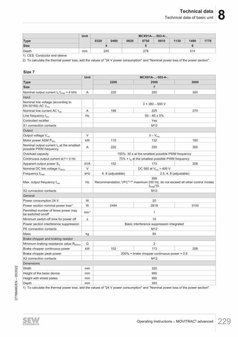
8Technical dataTechnical data of basic unit
Operating Instructions – MOVITRAC® advanced 229
Unit MCX91A-...-503-4-..Type 0320 0460 0620 0750 0910 1130 1490 1770Size 4 5 6Depth mm 245 278 3141) CES: Conductor end sleeve2) To calculate the thermal power loss, add the values of "24 V power consumption" and "Nominal power loss of the power section".
Size 7Unit MCX91A-...-503-4-..
Type 2200 2500 3000Size 7Nominal output current IN fPWM = 4 kHz A 220 250 300InputNominal line voltage (according toEN 50160) AC Vline
3 × 380 – 500 V
Nominal line current AC Iline A 198 225 270Line frequency fline Hz 50 – 60 ± 5%Controlled rectifier YesX1 connection contacts M12OutputOutput voltage Vout V 0 – Vline
Motor power ASM PMot kW 110 132 160Nominal output current IN at the smallestpossible PWM frequency A 220 250 300
Overload capacity 150%: 30 s at the smallest possible PWM frequencyContinuous output current at f = 0 Hz 75% × IN at the smallest possible PWM frequencyApparent output power SN kVA 152 173 208Nominal DC link voltage VNDCL V DC 560 at Vline = 400 VFrequency fPWM kHz 4, 8 (adjustable) 2.5, 4, 8 (adjustable)
Max. output frequency fmax Hz599
Recommendation: VFCPLUS maximum 250 Hz, do not exceed all other control modesfPWM/10.
X2 connection contacts M12GeneralPower consumption 24 V W 20Power section nominal power loss1) W 2484 2818 3100Permitted number of times power maybe switched on/off min-1 1
Minimum switch-off time for power off s 10Power section interference suppression Basic interference suppression integratedPE connection contacts M12Mass kg 84Brake chopper and braking resistorMinimum braking resistance value RBWmin Ω 2Brake chopper continuous power kW 152 173 208Brake chopper peak power 200% × brake chopper continuous power × 0.9X2 connection contacts M12DimensionsWidth mm 320Height of the basic device mm 990Height with shield plates mm 990Depth mm 3931) To calculate the thermal power loss, add the values of "24 V power consumption" and "Nominal power loss of the power section".
2778
8490
/EN
– 0
5/20
22

8 Technical dataTechnical data of basic unit
Operating Instructions – MOVITRAC® advanced230
8.3.2 Performance data 3 x AC 200 – 240 V
Size 0SUnit MCX91A-...-2E3-4-..
Type 0017 0025 0034 0042 0055Size 0SNominal output current IN fPWM = 4 kHz A 1.7 2.5 3.4 4.2 5.5InputNominal line voltage (according to EN 50160)AC Vline
3 × 200 – 240 V
Nominal line current AC Iline A 1.5 2.3 3.1 3.8 5Line frequency fline Hz 50 – 60 ± 5%Controlled rectifier No
X1 connection contactsPlug connector– 1 conductor: 0.25 – 2.5 mm2
– 2 conductors: 0.25 – 1.5 mm2 (twin CES)1)
OutputOutput voltage Vout V 0 – Vline
Motor power ASM PMot kW 0.25 0.37 0.55 0.75 1.1Nominal output current IN fPWM = 4 kHz A 1.7 2.5 3.4 4.2 5.5Overload capacity 150%: 30 s at fPWM = 4 kHzContinuous output current at f = 0 Hz 75% × IN with fPWM = 4 kHzApparent output power SN kVA 0.68 1 1.35 1.67 2.2Nominal DC link voltage VNDCL V DC 325 at Vline = 230 VFrequency fPWM kHz 4, 8, 16 (adjustable)
Max. output frequency fmax Hz599
Recommendation: VFCPLUS maximum 250 Hz, do not exceed all other con-trol modes fPWM/10.
X2 connection contactsPlug connector– 1 conductor: 0.25 – 2.5 mm2
– 2 conductors: 0.25 – 1.5 mm2 (twin CES)1)
GeneralPower consumption 24 V W Maximum 8.5 (depending on the device variant)Power section nominal power loss2) W 10 16 25 32 44Permitted number of times power may be switchedon/off min-1 1
Minimum switch-off time for power off s 10Power section interference suppression C2PE connection contacts M4Mass kg 1.7Brake chopper and braking resistorMinimum braking resistance value RBWmin Ω 60Brake chopper continuous power kW 0.68 1 1.35 1.67 2.2Brake chopper peak power 150% × brake chopper continuous power × 0.9
X2 connection contactsPlug connector– 1 conductor: 0.25 – 2.5 mm2
– 2 conductors: 0.25 – 1.5 mm2 (twin CES)1)
DimensionsWidth mm 80Height of the basic device mm 220Height of basic unit with shield plates mm 303Depth mm 1601) CES: Conductor end sleeve2) To calculate the thermal power loss, add the values of "24 V power consumption" and "Nominal power loss of the power section".
2778
8490
/EN
– 0
5/20
22

8Technical dataTechnical data of basic unit
Operating Instructions – MOVITRAC® advanced 231
Size 0L, 3Unit MCX91A-...-2E3-4-..
Type 0070 0093 0140 0213Size 0L 3Nominal output current IN fPWM = 4 kHz A 7 9.3 14 21.3InputNominal line voltage (according to EN 50160)AC Vline
3 × 200 – 240 V
Nominal line current AC Iline A 6.3 8.4 12.6 19.2Line frequency fline Hz 50 – 60 ± 5%Controlled rectifier No
X1 connection contactsPlug connector– 1 conductor: 0.25 – 4 mm2
– 2 conductors: 0.25 – 2.5 mm2 (twin CES)1)
OutputOutput voltage Vout V 0 – Vline
Motor power ASM PMot kW 1.5 2.2 3.7 5.5Nominal output current IN fPWM = 4 kHz A 7 9.3 14 21.3Overload capacity 150%: 30 s at fPWM = 4 kHzContinuous output current at f = 0 Hz 75% × IN with fPWM = 4 kHzApparent output power SN kVA 2.8 3.7 5.6 8.5Nominal DC link voltage VNDCL V DC 325 at Vline = 230 VFrequency fPWM kHz 4, 8, 16 (adjustable)
Max. output frequency fmax Hz599
Recommendation: VFCPLUS maximum 250 Hz, do not exceed all other con-trol modes fPWM/10.
X2 connection contactsPlug connector– 1 conductor: 0.25 – 4 mm2
– 2 conductors: 0.25 – 2.5 mm2 (twin CES)1)
GeneralPower consumption 24 V W Maximum 8.5 (depending on the device variant) 20Power section nominal power loss2) W 51 71 107 174Permitted number of times power may be switchedon/off min-1 1
Minimum switch-off time for power off s 10Power section interference suppression C2PE connection contacts M4Mass kg 2.7 5.3Brake chopper and braking resistorMinimum braking resistance value RBWmin Ω 24 13Brake chopper continuous power kW 2.8 3.7 5.6 8.5Brake chopper peak power 150% × brake chopper continuous power × 0.9
X2 connection contactsPlug connector– 1 conductor: 0.25 – 4 mm2
– 2 conductors: 0.25 – 2.5 mm2 (twin CES)1)
DimensionsWidth mm 80 105Height of the basic device mm 309 350Height of basic unit with shield plates mm 392 440Depth mm 170 2451) CES: Conductor end sleeve2) To calculate the thermal power loss, add the values of "24 V power consumption" and "Nominal power loss of the power section".
2778
8490
/EN
– 0
5/20
22
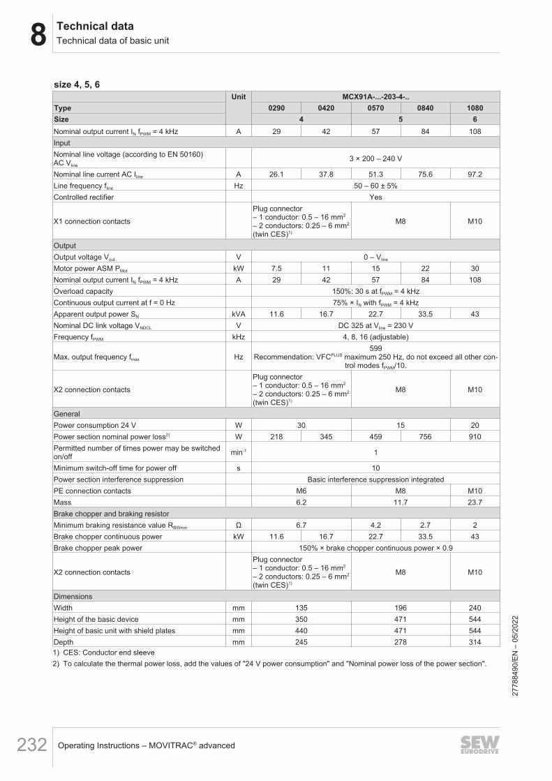
8 Technical dataTechnical data of basic unit
Operating Instructions – MOVITRAC® advanced232
size 4, 5, 6Unit MCX91A-...-203-4-..
Type 0290 0420 0570 0840 1080Size 4 5 6Nominal output current IN fPWM = 4 kHz A 29 42 57 84 108InputNominal line voltage (according to EN 50160)AC Vline
3 × 200 – 240 V
Nominal line current AC Iline A 26.1 37.8 51.3 75.6 97.2Line frequency fline Hz 50 – 60 ± 5%Controlled rectifier Yes
X1 connection contacts
Plug connector– 1 conductor: 0.5 – 16 mm2
– 2 conductors: 0.25 – 6 mm2
(twin CES)1)
M8 M10
OutputOutput voltage Vout V 0 – Vline
Motor power ASM PMot kW 7.5 11 15 22 30Nominal output current IN fPWM = 4 kHz A 29 42 57 84 108Overload capacity 150%: 30 s at fPWM = 4 kHzContinuous output current at f = 0 Hz 75% × IN with fPWM = 4 kHzApparent output power SN kVA 11.6 16.7 22.7 33.5 43Nominal DC link voltage VNDCL V DC 325 at Vline = 230 VFrequency fPWM kHz 4, 8, 16 (adjustable)
Max. output frequency fmax Hz599
Recommendation: VFCPLUS maximum 250 Hz, do not exceed all other con-trol modes fPWM/10.
X2 connection contacts
Plug connector– 1 conductor: 0.5 – 16 mm2
– 2 conductors: 0.25 – 6 mm2
(twin CES)1)
M8 M10
GeneralPower consumption 24 V W 30 15 20Power section nominal power loss2) W 218 345 459 756 910Permitted number of times power may be switchedon/off min-1 1
Minimum switch-off time for power off s 10Power section interference suppression Basic interference suppression integratedPE connection contacts M6 M8 M10Mass 6.2 11.7 23.7Brake chopper and braking resistorMinimum braking resistance value RBWmin Ω 6.7 4.2 2.7 2Brake chopper continuous power kW 11.6 16.7 22.7 33.5 43Brake chopper peak power 150% × brake chopper continuous power × 0.9
X2 connection contacts
Plug connector– 1 conductor: 0.5 – 16 mm2
– 2 conductors: 0.25 – 6 mm2
(twin CES)1)
M8 M10
DimensionsWidth mm 135 196 240Height of the basic device mm 350 471 544Height of basic unit with shield plates mm 440 471 544Depth mm 245 278 3141) CES: Conductor end sleeve2) To calculate the thermal power loss, add the values of "24 V power consumption" and "Nominal power loss of the power section".
2778
8490
/EN
– 0
5/20
22

8Technical dataTechnical data of basic unit
Operating Instructions – MOVITRAC® advanced 233
8.3.3 Performance data 1 x AC 200 – 240 V
Size 0SUnit MCX91A-...-2E1-4-..
Type 0017 0025 0034 0042Size 0SNominal output current IN fPWM = 4 kHz A 1.7 2.5 3.4 4.2InputNominal line voltage (according to EN 50160)AC Vline
1 × 200 – 240 V
Nominal line current AC Iline A 5.1 7 8.8 10.9Line frequency fline Hz 50 – 60 ± 5%Controlled rectifier Yes (precharge circuit)
X1 connection contactsPlug connector– 1 conductor: 0.25 – 2.5 mm2
– 2 conductors: 0.25 – 1.5 mm2 (twin CES)1)
OutputOutput voltage Vout V 0 – Vline
Motor power ASM PMot kW 0.25 0.37 0.55 0.75Nominal output current IN fPWM = 4 kHz A 1.7 2.5 3.4 4.2Overload capacity 150%: 30 s at fPWM = 4 kHzContinuous output current at f = 0 Hz 75% × IN with fPWM = 4 kHzApparent output power SN kVA 0.68 1 1.35 1.67Nominal DC link voltage VNDCL V DC 325 at Vline = 230 VFrequency fPWM kHz 4, 8, 16 (adjustable)
Max. output frequency fmax Hz599
Recommendation: VFCPLUS maximum 250 Hz, do not exceed all other con-trol modes fPWM/10.
X2 connection contactsPlug connector– 1 conductor: 0.25 – 2.5 mm2
– 2 conductors: 0.25 – 1.5 mm2 (twin CES)1)
GeneralPower consumption 24 V W Max. 8.5Power section nominal power loss2) W 15 24 36 48Permitted number of times power may be switchedon/off
min-1 0.5
Minimum switch-off time for power off s 10Power section interference suppression C2PE connection contacts M4Mass kg 1.7Brake chopper and braking resistorMinimum braking resistance value RBWmin Ω 60Brake chopper continuous power kW 0.68 1 1.35 1.67Brake chopper peak power 150% × brake chopper continuous power × 0.9
X2 connection contactsPlug connector– 1 conductor: 0.25 – 2.5 mm2
– 2 conductors: 0.25 – 1.5 mm2 (twin CES)1)
DimensionsWidth mm 80Height of the basic device mm 220Height of basic unit with shield plates mm 303Depth mm 1601) CES: Conductor end sleeve2) To calculate the thermal power loss, add the values of "24 V power consumption" and "Nominal power loss of the power section".
2778
8490
/EN
– 0
5/20
22

8 Technical dataTechnical data of basic unit
Operating Instructions – MOVITRAC® advanced234
Size 0LUnit MCX91A-...-2E1-4-..
Type 0055 0070 0093 01101)
Size 0LNominal output current IN fPWM = 4 kHz A 5.5 7 9.3 11InputNominal line voltage (according to EN 50160)AC Vline
1 × 200 – 240 V
Nominal line current AC Iline A 14.8 16A 21.4 24.9Line frequency fline Hz 50 – 60 ± 5%Controlled rectifier Yes (precharge circuit)
X1 connection contactsPlug connector– 1 conductor: 0.25 – 4 mm2
– 2 conductors: 0.25 – 2.5 mm2 (twin CES)2)
OutputOutput voltage Vout V 0 – Vline
Motor power ASM PMot kW 1.1 1.5 2.2 3Nominal output current IN fPWM = 4 kHz A 5.5 7 9.3 11Overload capacity 150%: 30 s at fPWM = 4 kHzContinuous output current at f = 0 Hz 75% × IN with fPWM = 4 kHzApparent output power SN kVA 2.2 2.8 3.7 4.4Nominal DC link voltage VNDCL V DC 325 at Vline = 230 VFrequency fPWM kHz 4, 8, 16 (adjustable)
Max. output frequency fmax Hz599
Recommendation: VFCPLUS maximum 250 Hz, do not exceed all other con-trol modes fPWM/10.
X2 connection contactsPlug connector– 1 conductor: 0.25 – 4 mm2
– 2 conductors: 0.25 – 2.5 mm2 (twin CES)2)
GeneralPower consumption 24 V W Max. 8.5Power section nominal power loss3) W 57 76 110 147Permitted number of times power may be switchedon/off
min-1 0.5
Minimum switch-off time for power off s 10Power section interference suppression C2PE connection contacts M4MassBrake chopper and braking resistorMinimum braking resistance value RBWmin Ω 60 24 13Brake chopper continuous power kW 2.2 2.8 3.7 4.4Brake chopper peak power 150% × brake chopper continuous power × 0.9
X2 connection contactsPlug connector– 1 conductor: 0.25 – 4 mm2
– 2 conductors: 0.25 – 2.5 mm2 (twin CES)2)
DimensionsWidth mm 80Height of the basic device mm 309Height of basic unit with shield plates mm 392Depth mm 1701) Using a line choke is mandatory with MCX91A-0110-2E1-4-..2) CES: Conductor end sleeve3) To calculate the thermal power loss, add the values of "24 V power consumption" and "Nominal power loss of the power section".
2778
8490
/EN
– 0
5/20
22
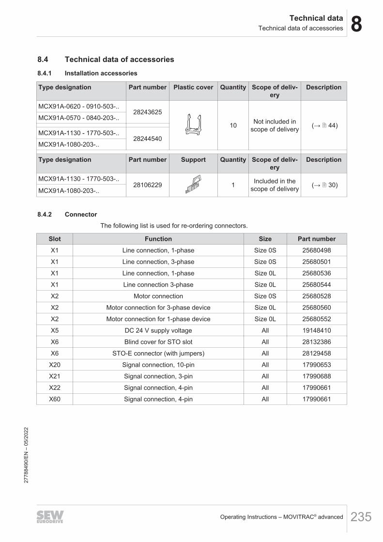
8Technical dataTechnical data of accessories
Operating Instructions – MOVITRAC® advanced 235
8.4 Technical data of accessories8.4.1 Installation accessories
Type designation Part number Plastic cover Quantity Scope of deliv-ery
Description
MCX91A-0620 - 0910-503-..28243625
10 Not included inscope of delivery (→ 2 44)
MCX91A-0570 - 0840-203-..
MCX91A-1130 - 1770-503-..28244540
MCX91A-1080-203-..
Type designation Part number Support Quantity Scope of deliv-ery
Description
MCX91A-1130 - 1770-503-..28106229 1 Included in the
scope of delivery (→ 2 30)MCX91A-1080-203-..
8.4.2 ConnectorThe following list is used for re-ordering connectors.
Slot Function Size Part numberX1 Line connection, 1-phase Size 0S 25680498
X1 Line connection, 3-phase Size 0S 25680501
X1 Line connection, 1-phase Size 0L 25680536
X1 Line connection 3-phase Size 0L 25680544
X2 Motor connection Size 0S 25680528
X2 Motor connection for 3-phase device Size 0L 25680560
X2 Motor connection for 1-phase device Size 0L 25680552
X5 DC 24 V supply voltage All 19148410
X6 Blind cover for STO slot All 28132386
X6 STO-E connector (with jumpers) All 28129458
X20 Signal connection, 10-pin All 17990653
X21 Signal connection, 3-pin All 17990688
X22 Signal connection, 4-pin All 17990661
X60 Signal connection, 4-pin All 17990661
2778
8490
/EN
– 0
5/20
22
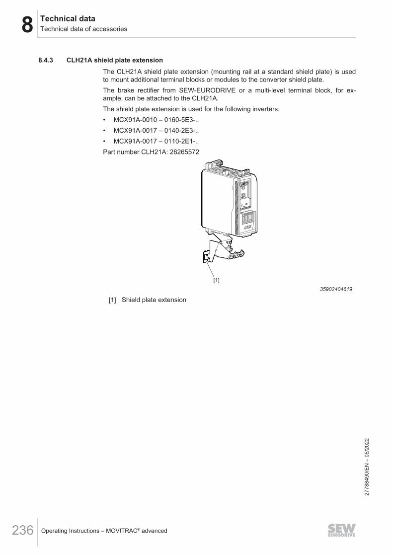
8 Technical dataTechnical data of accessories
Operating Instructions – MOVITRAC® advanced236
8.4.3 CLH21A shield plate extensionThe CLH21A shield plate extension (mounting rail at a standard shield plate) is usedto mount additional terminal blocks or modules to the converter shield plate.The brake rectifier from SEW-EURODRIVE or a multi-level terminal block, for ex-ample, can be attached to the CLH21A.The shield plate extension is used for the following inverters:• MCX91A-0010 – 0160-5E3-..• MCX91A-0017 – 0140-2E3-..• MCX91A-0017 – 0110-2E1-..Part number CLH21A: 28265572
[1]
35902404619
[1] Shield plate extension
2778
8490
/EN
– 0
5/20
22
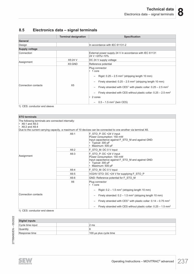
8Technical dataElectronics data – signal terminals
Operating Instructions – MOVITRAC® advanced 237
8.5 Electronics data – signal terminalsTerminal designation Specification
GeneralDesign In accordance with IEC 61131-2Supply voltageConnection External power supply 24 V in accordance with IEC 61131
24 V +20%/-10%
AssignmentX5:24 V DC 24 V supply voltageX5:GND Reference potential
Connection contacts X5
Plug connector• 1 core
– Rigid: 0.25 – 2.5 mm2 (stripping length 10 mm)
– Finely stranded: 0.25 – 2.5 mm2 (stripping length 10 mm)
– Finely stranded with CES1) with plastic collar: 0.25 – 2.5 mm2
– Finely stranded with CES without plastic collar: 0.25 – 2.5 mm2
• 2 cores
– 0.5 – 1.5 mm2 (twin CES)1) CES: conductor end sleeve
STO terminalsThe following terminals are connected internally:• X6:1 and X6:3• X6:2 and X6:4Due to the current carrying capacity, a maximum of 10 devices can be connected to one another via terminal X6.
Assignment
X6:1 F_STO_P: DC +24 V inputPower consumption: 150 mWInput capacitance against F_STO_M and against GND:• Typical: 300 pF• Maximum: 500 pF
X6:2 F_STO_M: DC 0 V inputX6:3 F_STO_P: DC +24 V input
Power consumption: 150 mWInput capacitance against F_STO_M and against GND:• Typical: 300 pF• Maximum: 500 pF
X6:4 F_STO_M: DC 0 V inputX6:5 VO24V STO: DC +24 V for supplying F_STO_PX6:6 GND: Reference potential for F_STO_M
Connection contacts
X6 Plug connector• 1 core
– Rigid: 0.2 – 1.5 mm2 (stripping length 10 mm)
– Finely stranded: 0.2 – 1.5 mm2 (stripping length 10 mm)
– Finely stranded with CES1) with plastic collar: 0.14 – 0.75 mm2
– Finely stranded with CES without plastic collar: 0.25 – 1.5 mm2
1) CES: conductor end sleeve
Digital inputsCycle time input 2 msQuantity 6Response time 100 μs plus cycle time
2778
8490
/EN
– 0
5/20
22
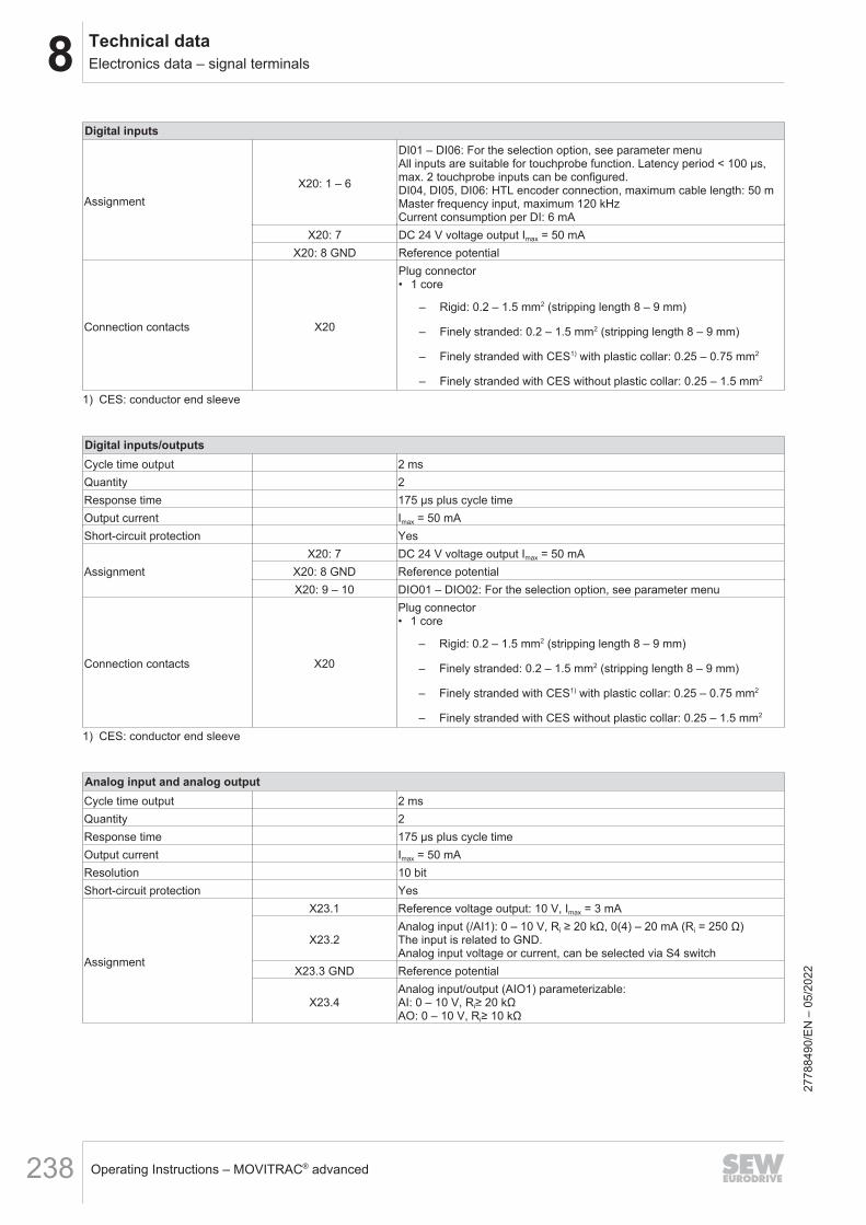
8 Technical dataElectronics data – signal terminals
Operating Instructions – MOVITRAC® advanced238
Digital inputs
AssignmentX20: 1 – 6
DI01 – DI06: For the selection option, see parameter menuAll inputs are suitable for touchprobe function. Latency period < 100 μs,max. 2 touchprobe inputs can be configured.DI04, DI05, DI06: HTL encoder connection, maximum cable length: 50 mMaster frequency input, maximum 120 kHzCurrent consumption per DI: 6 mA
X20: 7 DC 24 V voltage output Imax = 50 mAX20: 8 GND Reference potential
Connection contacts X20
Plug connector• 1 core
– Rigid: 0.2 – 1.5 mm2 (stripping length 8 – 9 mm)
– Finely stranded: 0.2 – 1.5 mm2 (stripping length 8 – 9 mm)
– Finely stranded with CES1) with plastic collar: 0.25 – 0.75 mm2
– Finely stranded with CES without plastic collar: 0.25 – 1.5 mm2
1) CES: conductor end sleeve
Digital inputs/outputsCycle time output 2 msQuantity 2Response time 175 μs plus cycle timeOutput current Imax = 50 mAShort-circuit protection Yes
AssignmentX20: 7 DC 24 V voltage output Imax = 50 mA
X20: 8 GND Reference potentialX20: 9 – 10 DIO01 – DIO02: For the selection option, see parameter menu
Connection contacts X20
Plug connector• 1 core
– Rigid: 0.2 – 1.5 mm2 (stripping length 8 – 9 mm)
– Finely stranded: 0.2 – 1.5 mm2 (stripping length 8 – 9 mm)
– Finely stranded with CES1) with plastic collar: 0.25 – 0.75 mm2
– Finely stranded with CES without plastic collar: 0.25 – 1.5 mm2
1) CES: conductor end sleeve
Analog input and analog outputCycle time output 2 msQuantity 2Response time 175 μs plus cycle timeOutput current Imax = 50 mAResolution 10 bitShort-circuit protection Yes
Assignment
X23.1 Reference voltage output: 10 V, Imax = 3 mA
X23.2Analog input (/AI1): 0 – 10 V, Ri ≥ 20 kΩ, 0(4) – 20 mA (Ri = 250 Ω)The input is related to GND.Analog input voltage or current, can be selected via S4 switch
X23.3 GND Reference potential
X23.4Analog input/output (AIO1) parameterizable:AI: 0 – 10 V, Ri≥ 20 kΩAO: 0 – 10 V, Ri≥ 10 kΩ
2778
8490
/EN
– 0
5/20
22

8Technical dataElectronics data – signal terminals
Operating Instructions – MOVITRAC® advanced 239
Analog input and analog output
Connection contacts X23
Plug connector• 1 core
– Rigid: 0.2 – 1.5 mm2 (stripping length 8 – 9 mm)
– Finely stranded: 0.2 – 1.5 mm2 (stripping length 8 – 9 mm)
– Finely stranded with CES1) with plastic collar: 0.25 – 0.75 mm2
– Finely stranded with CES without plastic collar: 0.25 – 1.5 mm2
1) CES: conductor end sleeve
Safe digital inputs/digital outputsNumber of F-DI 4Number of F-DO 1Response time See chapter "Response times" (→ 2 376)
Assignment
X60:1 – 2, 5 – 6 Failsafe digital inputs F-DI00, F-DI01, F-DI02, F-DI03Current consumption per F-DI ≤ 15 mAInput capacitance < 500 pF
X60:3 – 4, 7 – 8 Reference potential for safe digital inputsX60:9 F-SS0 DC 24 V sensor voltage supply for safe digital inputs F-DI00 and F-
DI02Rated current = 150 mA, maximum inrush current 300 mA
X60:10 F-SS1 DC 24 V sensor voltage supply for safe digital inputs F-DI01 and F-DI03Rated current = 150 mA, maximum inrush current 300 mA
X60:11X60:12
F-DO00_M (not with CSB)F-DO00_P (not with CSB)Characteristics:• DC 24 V output in accordance with EN 61131-2• Short circuit and overload protection• Rated current 150 mA
Connection contacts X60
Plug connector• 1 core
– Finely stranded: 0.2 – 1.5 mm2 (stripping length 10 mm)
– Finely stranded with CES1) with plastic collar: 0.14 – 0.75 mm2
– Finely stranded with CES without plastic collar: 0.25 – 1.5 mm2
1) CES: conductor end sleeve
Relay outputQuantity 1Current-carrying capacity of re-lay contacts
DC 30 V, Imax = 0.8 ADo not connect any inductive loads to the relay contact.
AssignmentX22.1 DOR-C: Shared relay contactX22.2 DOR-NO: NO contactX22.3 DOR-NC: NC contact
Connection contacts X22
Plug connector• 1 core
– Rigid: 0.2 – 1.5 mm2 (stripping length 8 – 9 mm)
– Finely stranded: 0.2 – 1.5 mm2 (stripping length 8 – 9 mm)
– Finely stranded with CES1) with plastic collar: 0.25 – 0.75 mm2
– Finely stranded with CES without plastic collar: 0.25 – 1.5 mm2
1) CES: conductor end sleeve
2778
8490
/EN
– 0
5/20
22

8 Technical dataElectronics data – signal terminals
Operating Instructions – MOVITRAC® advanced240
Brake control/temperature input
Assignment
X10:DB00/X10:DB0DB00/DB0:- Brake control– Control braking contactor DC 24 V, max. 150 mA
X10:GND Reference potentialX10: TF1 Sensor input for temperature sensorX10:GND Reference potential
Connection contacts
Plug connector:
MCX91A-0010 – 0460-5_3-..MCX91A-0070 – 0290-2_3-..:MCX91A-0017 – 0110-2E1-..• 1 core
– Rigid: 0.2 – 1.5 mm2 (stripping length 10 mm)
– Finely stranded: 0.2 – 1.5 mm2 (stripping length 10 mm)
– Finely stranded with CES1) with plastic collar: 0.14 – 0.75 mm2
– Finely stranded with CES without plastic collar: 0.25 – 1.5 mm2
From MCX91A-0620-5_3-.. andfrom MCX91A-0420-2_3..:• 1 core
– Rigid: 0.25 – 2.5 mm2 (stripping length 10 mm)
– Finely stranded: 0.25 – 2.5 mm2 (stripping length 10 mm)
– Finely stranded with CES1) with plastic collar: 0.25 – 2.5 mm2
– Finely stranded with CES without plastic collar: 0.25 – 2.5 mm2
• 2 cores
– 0.5 – 1.5 mm2 (twin CES)1) CES: conductor end sleeve
Digital motor integration connectionQuantity 1 (optional)Connection contacts X16 Coaxial connection for encoder with MOVILINK® DDI interfaceMaximum line length 200 m
Connection for FS encoder (functional safety)Quantity 1 (optional)Connection contacts X18 Mini IO connector for EI7C-FS encoderMaximum line length 100 m
Fieldbus connectionQuantity 2
Connection contactsIN X30/X40
RJ45 socketOUT X30/X41
2778
8490
/EN
– 0
5/20
22

8Technical dataDimension sheets
Operating Instructions – MOVITRAC® advanced 241
8.6 Dimension sheets8.6.1 MCX91A-0010 – 0055-5E3-4-.., MCX91A-0017 – 0055-2E3-4-.., MCX91A-0017 – 0042-2E1-4-..
(size 0S), CLH21A, CLH31A
9007234502107915
2778
8490
/EN
– 0
5/20
22

8 Technical dataDimension sheets
Operating Instructions – MOVITRAC® advanced242
8.6.2 MCX91A-0070 – 0160-5E3-4-.., MCX91A-0070 – 0140-2E3-4-.., MCX91A-0055 – 0110-2E1-4-..(size 0L), CLH21A, CLH41A
9007234502110347
2778
8490
/EN
– 0
5/20
22

8Technical dataDimension sheets
Operating Instructions – MOVITRAC® advanced 243
8.6.3 MCX91A-0240-5E3-4-.., MCX91A-0213-2E3-4-.. (size 3)
9007234502112779
2778
8490
/EN
– 0
5/20
22

8 Technical dataDimension sheets
Operating Instructions – MOVITRAC® advanced244
8.6.4 MCX91A-0320 – 0460-503-4-.., MCX91A-0290 – 0420-203-4-.. (size 4)
9007234502294411
2778
8490
/EN
– 0
5/20
22

8Technical dataDimension sheets
Operating Instructions – MOVITRAC® advanced 245
8.6.5 MCX91A-0620 – 0910-503-4-.., MCX91A-0570 – 0840-203-4-.. (size 5)
9007234502296843
2778
8490
/EN
– 0
5/20
22

8 Technical dataDimension sheets
Operating Instructions – MOVITRAC® advanced246
8.6.6 MCX91A-1130 – 1770-503-4-.., MCX91A-1080-203-4-.. (size 6)
9007234502299275
2778
8490
/EN
– 0
5/20
22

8Technical dataDimension sheets
Operating Instructions – MOVITRAC® advanced 247
8.6.7 MCX91A-2200 – 3000-503-4-.. (size 7)
35989549707
2778
8490
/EN
– 0
5/20
22

8 Technical dataDiagnostic module CDM11A
Operating Instructions – MOVITRAC® advanced248
8.7 Diagnostic module CDM11A
32676917771
Power consumption 0.25 W
Dimensions
H: 100 mm
B: 46 mm
D: 20 mm
Screen type 2-digit 7-segment display
Engineering interface D-sub, 9-pin
Part number 28265092
2778
8490
/EN
– 0
5/20
22

8Technical dataUSM21A interface adapter
Operating Instructions – MOVITRAC® advanced 249
8.8 USM21A interface adapter
USM21A Technical dataPart number 28231449
Ambient temperature 0 °C to 40 °C
Storage temperature -25 °C to 70 °C
Degree of protection IP20
Dimensions
Width 42 mm
Height 89 mm
Depth 25 mm
An order using part number 28231449 includes the following parts:• USM21A interface adapter• USB connection cable for the USM21A – PC connection• Serial interface cable with 2 RJ10 connectors
INFORMATIONTo connect the inverter to the USM21A, you need an additional serial interface cablewith an RJ10 connector and a 9‑pin D‑sub connector, part number 18123864.This cable must be ordered separately.
26663013387
The CDM diagnostic module is required to connect the MOVITRAC® advanced in-verter to the USM21A interface adapter.The USM21A interface adapter can be used to perform a firmware update of the in-verter.
2778
8490
/EN
– 0
5/20
22

8 Technical dataCMM11A memory module
Operating Instructions – MOVITRAC® advanced250
8.9 CMM11A memory module
25585405451
The pluggable memory module is supplied independently of the device variant.For certain device variants, the memory module can be deselected when configuringthe inverter. It is not possible to deselect the memory module if the device variant in-cludes the CSB and CSL safety options.
CMM11A Part numberPart number 28230760
2778
8490
/EN
– 0
5/20
22
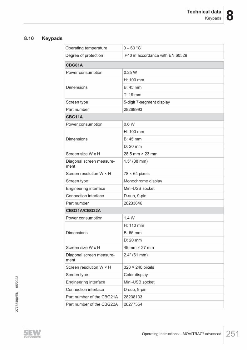
8Technical dataKeypads
Operating Instructions – MOVITRAC® advanced 251
8.10 Keypads
Operating temperature 0 – 60 °C
Degree of protection IP40 in accordance with EN 60529
CBG01APower consumption 0.25 W
Dimensions
H: 100 mm
B: 45 mm
T: 19 mm
Screen type 5-digit 7-segment display
Part number 28269993
CBG11APower consumption 0.6 W
Dimensions
H: 100 mm
B: 45 mm
D: 20 mm
Screen size W x H 28.5 mm × 23 mm
Diagonal screen measure-ment
1.5" (38 mm)
Screen resolution W × H 78 × 64 pixels
Screen type Monochrome display
Engineering interface Mini-USB socket
Connection interface D-sub, 9-pin
Part number 28233646
CBG21A/CBG22APower consumption 1.4 W
Dimensions
H: 110 mm
B: 65 mm
D: 20 mm
Screen size W x H 49 mm × 37 mm
Diagonal screen measure-ment
2.4" (61 mm)
Screen resolution W × H 320 × 240 pixels
Screen type Color display
Engineering interface Mini-USB socket
Connection interface D-sub, 9-pin
Part number of the CBG21A 28238133
Part number of the CBG22A 28277554
2778
8490
/EN
– 0
5/20
22

8 Technical dataTechnical data of braking resistors, filters, and chokes
Operating Instructions – MOVITRAC® advanced252
8.11 Technical data of braking resistors, filters, and chokes8.11.1 Braking resistors type BW.../BW...-T
GeneralThe BW.../BW...-T braking resistors are adapted to the technical characteristics of theinverter.Braking resistors with different continuous and peak braking powers are available.The braking resistors can be protected against overload and overtemperature by thecustomer when a thermal overload relay is used. The tripping current is set to thevalue IF; for this, see the following tables "Technical data and assignment to an in-verter".A PTC resistor protects itself (reversible) against regenerative overload by changingabruptly to high resistance and no longer consuming any more energy. The inverterthen switches off and signals an "overvoltage" fault.A flat-type resistor has internal thermal protection (fuse cannot be replaced) that inter-rupts the current circuit in the event of overload. The configuration guidelines and thedocumented assignments of the drive inverter and braking resistor must be adheredto.
INFORMATIONUse of protection devices.Use only the protection devices listed in the following section:• Internal temperature switch T• External bimetallic relay
→ See also the chapter "Protection of the braking resistor against thermal overload".
UL and cURus approvalThe listed braking resistors have a cURus approval independent of the inverter.
Parallel connection of braking resistorsIdentical braking resistors must be connected in parallel for some inverter/resistorcombinations.In this case, protect each braking resistor against overload and overtemperature usinga thermal overload relay.The temperature switches must be connected in series for braking resistors of theBW...-T series.
2778
8490
/EN
– 0
5/20
22

8Technical dataTechnical data of braking resistors, filters, and chokes
Operating Instructions – MOVITRAC® advanced 253
Technical data
Technical data
Braking resistor Unit BW120-001
BW100-002/M
BW100-001
BW100-002
BW100-006-T
BW168-T
BW268-T
Part number 18176011
25664514
08281718
08281653
18204198
18201334
18204171
Current-carrying capacityat 100% cdf kW 0.03 0.15 0.1 0.2 0.6 0.8 1.2
Resistance value RBW Ω 117 100 100 ± 10% 68 ± 10%
Tripping current Itrip A - 1.2 0.8 1 2.4 3.4 4.2
DesignPTC
brakingresistor
Flatpackresistor Flat-type resistor Wire resistor
Power connections Single conductors Ceramic terminal 2.5 mm2
Wire length mm 170 300 510 -
Cable cross section mm2 0.5 1.5 -
Tightening torque Nm - 0.5
PE connection - M4
PE tightening torque Nm - 1.8
Degree of protection inaccordance withEN 60529
IP20 IP40 IP54 IP20
Ambient temperature ϑamb
-20 °C to +40 °C(Reduction 4% PN/10 K to +60 °C)
Mass kg 0.95 1.4 0.3 0.6 3 3.6 4.9
2778
8490
/EN
– 0
5/20
22

8 Technical dataTechnical data of braking resistors, filters, and chokes
Operating Instructions – MOVITRAC® advanced254
Technical data
Braking resistor Unit BW047-010-T BW147-T BW247-TPart number 17983207 18201342 18200842
Current-carrying capacityat 100% cdf kW 1 1.2 2
Resistance value RBW Ω 47 ± 10%
Tripping current Itrip A 4.6 5.1 6.5
Design Wire resistor
Power connections Ceramic terminal 2.5 mm2
Tightening torque Nm 0.5
PE connection M4
PE tightening torque Nm 1.8
Degree of protection IP20
Ambient temperature ϑamb -20 °C to +40 °C
Mass kg 4 4.9 6.7
2778
8490
/EN
– 0
5/20
22
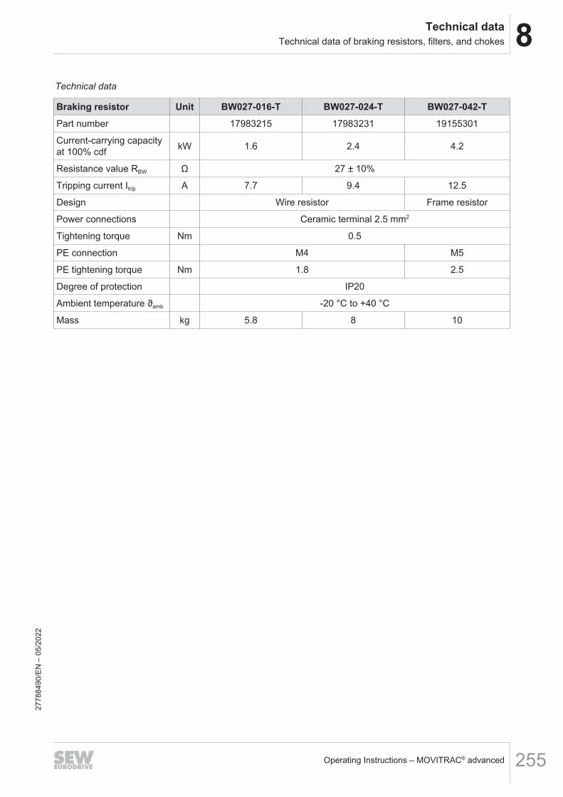
8Technical dataTechnical data of braking resistors, filters, and chokes
Operating Instructions – MOVITRAC® advanced 255
Technical data
Braking resistor Unit BW027-016-T BW027-024-T BW027-042-TPart number 17983215 17983231 19155301
Current-carrying capacityat 100% cdf kW 1.6 2.4 4.2
Resistance value RBW Ω 27 ± 10%
Tripping current Itrip A 7.7 9.4 12.5
Design Wire resistor Frame resistor
Power connections Ceramic terminal 2.5 mm2
Tightening torque Nm 0.5
PE connection M4 M5
PE tightening torque Nm 1.8 2.5
Degree of protection IP20
Ambient temperature ϑamb -20 °C to +40 °C
Mass kg 5.8 8 10
2778
8490
/EN
– 0
5/20
22

8 Technical dataTechnical data of braking resistors, filters, and chokes
Operating Instructions – MOVITRAC® advanced256
Technical data
Braking resistor Unit BW015-016 BW015-042-T BW015-075-T BW915-TPart number 17983258 19155328 19155271 18204139
Current-carrying capacityat 100% cdf kW 1.6 4.2 7.5 16
Resistance value RBW Ω 15 ± 10%
Tripping current Itrip A 10.3 16.7 22.4 32.7
Design Wire resistor Frame resistor Grid resistor mounting position 1
Power connections Ceramic terminal2.5 mm2
Ceramic terminal4 mm2 M8 stud
Tightening torque Nm 0.5 0.9 6
PE connection M4 M5 M6 stud
PE tightening torque Nm 1.8 2.5 3
Degree of protection IP20
Ambient temperature ϑamb -20 °C to +40 °C
Mass kg 5.8 10 12 32
2778
8490
/EN
– 0
5/20
22

8Technical dataTechnical data of braking resistors, filters, and chokes
Operating Instructions – MOVITRAC® advanced 257
Technical data
Braking resistor Unit BW010-024 BW010-050-T BW010-108-TPart number 17983266 17983274 19155298
Current-carrying capacityat 100% cdf kW 2.4 5 10.8
Resistance value RBW Ω 10 ± 10%
Tripping current Itrip A 15.5 22.4 32.9
Design Wire resistor Grid resistor mounting position 1
Power connections Ceramic terminal2.5 mm2 M8 stud
Tightening torque Nm 0.5 6
PE connection M4 stud M6 stud
PE tightening torque Nm 1.8 3
Degree of protection IP20
Ambient temperature ϑamb -20 °C to +40 °C
Mass kg 8 11 17.5
2778
8490
/EN
– 0
5/20
22
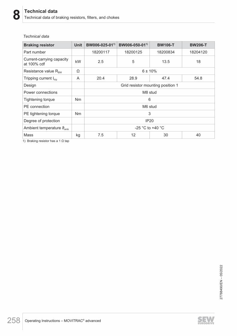
8 Technical dataTechnical data of braking resistors, filters, and chokes
Operating Instructions – MOVITRAC® advanced258
Technical data
Braking resistor Unit BW006-025-011) BW006-050-011) BW106-T BW206-TPart number 18200117 18200125 18200834 18204120
Current-carrying capacityat 100% cdf kW 2.5 5 13.5 18
Resistance value RBW Ω 6 ± 10%
Tripping current Itrip A 20.4 28.9 47.4 54.8
Design Grid resistor mounting position 1
Power connections M8 stud
Tightening torque Nm 6
PE connection M6 stud
PE tightening torque Nm 3
Degree of protection IP20
Ambient temperature ϑamb -25 °C to +40 °C
Mass kg 7.5 12 30 401) Braking resistor has a 1 Ω tap
2778
8490
/EN
– 0
5/20
22
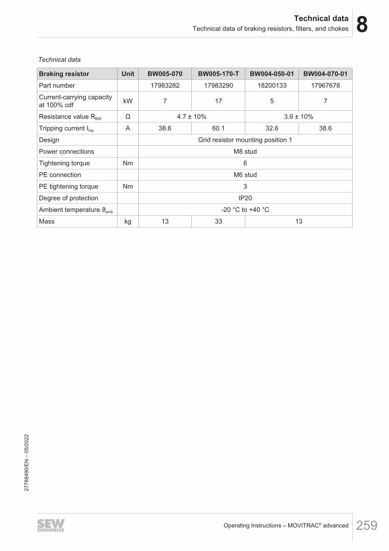
8Technical dataTechnical data of braking resistors, filters, and chokes
Operating Instructions – MOVITRAC® advanced 259
Technical data
Braking resistor Unit BW005-070 BW005-170-T BW004-050-01 BW004-070-01Part number 17983282 17983290 18200133 17967678
Current-carrying capacityat 100% cdf kW 7 17 5 7
Resistance value RBW Ω 4.7 ± 10% 3.6 ± 10%
Tripping current Itrip A 38.6 60.1 32.6 38.6
Design Grid resistor mounting position 1
Power connections M8 stud
Tightening torque Nm 6
PE connection M6 stud
PE tightening torque Nm 3
Degree of protection IP20
Ambient temperature ϑamb -20 °C to +40 °C
Mass kg 13 33 13
2778
8490
/EN
– 0
5/20
22
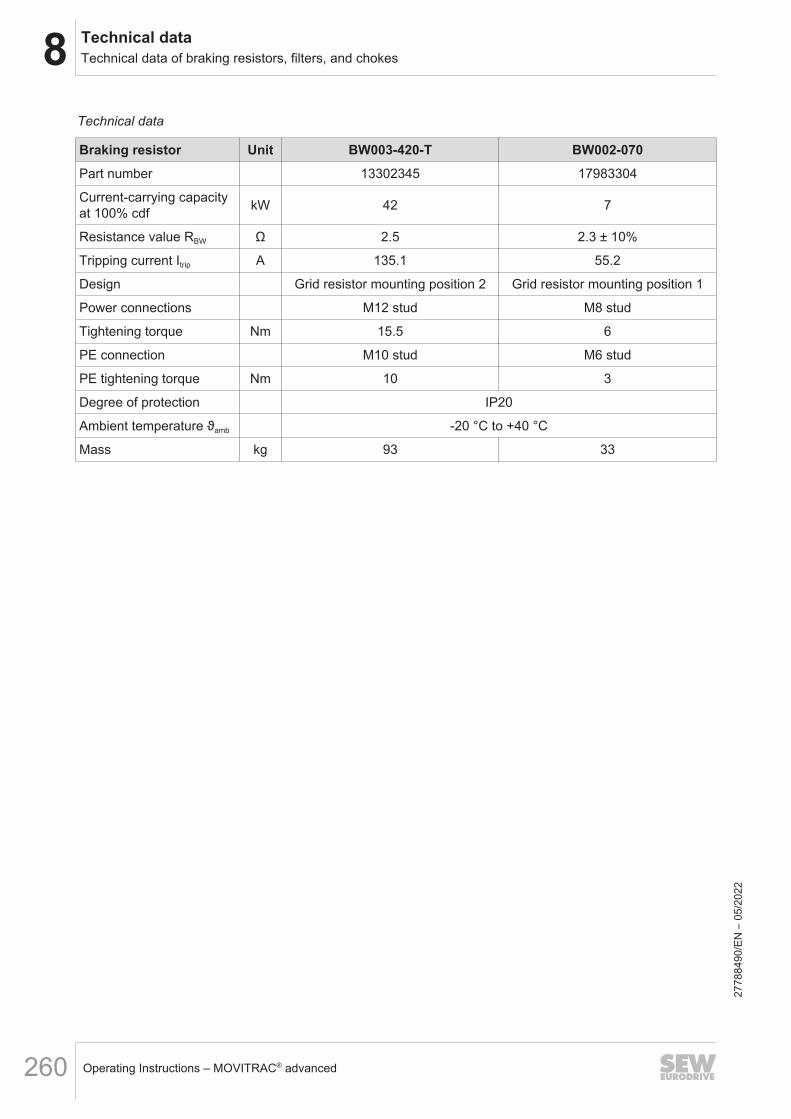
8 Technical dataTechnical data of braking resistors, filters, and chokes
Operating Instructions – MOVITRAC® advanced260
Technical data
Braking resistor Unit BW003-420-T BW002-070Part number 13302345 17983304
Current-carrying capacityat 100% cdf kW 42 7
Resistance value RBW Ω 2.5 2.3 ± 10%
Tripping current Itrip A 135.1 55.2
Design Grid resistor mounting position 2 Grid resistor mounting position 1
Power connections M12 stud M8 stud
Tightening torque Nm 15.5 6
PE connection M10 stud M6 stud
PE tightening torque Nm 10 3
Degree of protection IP20
Ambient temperature ϑamb -20 °C to +40 °C
Mass kg 93 33
2778
8490
/EN
– 0
5/20
22

8Technical dataTechnical data of braking resistors, filters, and chokes
Operating Instructions – MOVITRAC® advanced 261
Technical data
Braking resistor Unit BW1.0-170Part number 17985455
Current-carrying capacityat 100% cdf kW 17
Resistance value RBW Ω 1 ± 10%
Tripping current Itrip A 130.4
Design Grid resistor mounting position 2
Power connections M12 stud
Tightening torque Nm 15.5
PE connection M10 stud
PE tightening torque Nm 10
Degree of protection IP20
Ambient temperature ϑamb -25 °C to +40 °C
Mass kg 45
2778
8490
/EN
– 0
5/20
22

8 Technical dataTechnical data of braking resistors, filters, and chokes
Operating Instructions – MOVITRAC® advanced262
Technical data of braking resistors with submounting plate
Braking resistor Unit CLH31A/BW4
CLH31A/BW2
CLH31A/BW072-001
CLH31A/BW100-001
CLH41A/BW027-001
CLH41A/BW047-001
Part number 28284712 28284720 28284739 28284755 28284747 28284763
Current-carrying ca-pacity at 100% cdf kW 0.025 0.025 0.1 0.1 0.1 0.1
Resistance valueRBW
Ω 88 175 72 100 ±10% 27 47
Tripping current Itrip A – – 0.9 0.8 1.5 1.1
Design PTC Flat-type resistor
Power connections Single conductor
Wire length mm 170 170 510 510 510 510
Cable cross section mm2 0.75 0.75 1.5 1.5 1.5 1.5
Tightening torque Nm – – – – – –
PE connection – – – – – –
PE tightening torque Nm – – – – – –
Degree of protectionin accordance withEN 60529
IP20 IP20 IP65 IP65 IP65 IP65
Ambient tempera-ture ϑamb
– – -20 °C to +40 °C(Reduction 4% PN/10 K to +60 °C)
Mass kg 0.08 0.08 0.3 0.3 0.3 0.3
The CLH31A and CLH41A braking resistors with submounting plate are supplied as acombination of submounting plate and integrated braking resistor. There is a choice ofbraking resistors with different ratings for each submounting plate.Braking resistors mounted to the submounting plate may not achieve the load capacityspecified in the table at 100% cdf. The specifications for the nominal power of the in-verter can be observed in submounted operation at 4 kHz, 40 °C and 400 V.
Technical data BW..-T signal contact
Specifications for BW..-T DesignSignal contact connection cross section 1 × 2.5 mm2
Tightening torque of the signal contact 1 Nm
Switching capacity signal contactDC 2 A / DC 24 V (DC11)AC 2 A / AC 230 V (AC11)
Switch contact (NC contact) According to EN 60730
2778
8490
/EN
– 0
5/20
22

8Technical dataTechnical data of braking resistors, filters, and chokes
Operating Instructions – MOVITRAC® advanced 263
Dimension sheets and dimensions
Wire resistor
A
d x a
M../PG..
M../PG..
C
B
b
[1]
18874863883Braking resistor Main dimensions in mm Mounting dimensions in mm Cable gland
A B C a b d xBW100-006-T 549 92 125 430 80 6.5 8 M25 + M12BW047-010-T 749 92 125 630 80 6.5 8 M25 + M12BW147-T 549 185 125 430 150 6.5 8 PG16 + M12BW247-T 749 185 125 630 150 6.5 8 PG16 + M12BW027-016-T 649 185 125 530 150 6.5 8 M25 + M12BW027-024-T 649 275 125 530 240 6.5 8 M25 + M12BW015-016 649 185 125 530 150 6.5 8 M25BW010-024 649 275 125 530 240 6.5 8 M25
Grid resistor mounting position 1
C
B
b
d
A
a
18874868747Braking resistor Main dimensions in mm Fastening dimensions in mm Cable gland
A B C a b d xBW015-075-T 415 500 270 395 380 9 – –BW106-T 795 490 270 770 380 10.5 – –BW206-T 995 490 270 970 380 10.5 – –BW915-T 795 490 270 770 380 10.5 – –BW010-050-T 395 490 260 370 380 10.5 – –BW010-108-T 525 500 270 505 380 9 – –BW004-050-01 395 490 260 370 380 10.5 – –BW005-070 395 490 260 370 380 10.5 – –BW002-070 395 490 260 370 380 10.5 – –BW005-170-T 490 795 270 380 770 10.5 – –BW006-025-01 295 490 260 270 380 10.5 – –BW006-050-01 395 490 260 370 380 10.5 – –
2778
8490
/EN
– 0
5/20
22

8 Technical dataTechnical data of braking resistors, filters, and chokes
Operating Instructions – MOVITRAC® advanced264
Grid resistor mounting position 2
A
C
a
B
d
b
18874876043Braking resistor Main dimensions in mm Mounting dimensions in mm Cable gland
A B C a b d xBW003-420-T 995 490 710 970 380 10.5 — —BW1.0-170 490 795 490 380 770 10.5 — —
Frame resistor
A
C
x a
M../PG..
M../PG..
B
d b
18874873611Braking resistor Main dimensions in mm Mounting dimensions in mm Cable gland
A B C a b d xBW027-042-T 570 390 180 380 370 6.5 55 M25 + M12BW015-042-T 570 390 180 380 370 6.5 55 M25 + M12
2778
8490
/EN
– 0
5/20
22

8Technical dataTechnical data of braking resistors, filters, and chokes
Operating Instructions – MOVITRAC® advanced 265
Flat-type resistor
A
a
B b
M4
C
12
18874878475Braking resistor Main dimensions in mm Mounting dimensions in mm Connection length
in mmA B C a b d xBW100-001 110 80 15 98 60 – – 300BW100-002 216 80 15 204 60 – – 300
2778
8490
/EN
– 0
5/20
22

8 Technical dataTechnical data of braking resistors, filters, and chokes
Operating Instructions – MOVITRAC® advanced266
BW120-001 resistor
6
50
6
.6
21
.5
92
27.5 325380
3667
24
19506873227
Length of connections: 130 mm
BW100-002/M resistor
325
366
380
7
27.5
Ø 1
2
6
Ø 6
.5
92 50
21.5
6
60
3441610586727
7884
90/E
N –
05/
2022

8Technical dataTechnical data of braking resistors, filters, and chokes
Operating Instructions – MOVITRAC® advanced 267
8.11.2 NF.. line filterLine filters are used to suppress interference emission on the line side of inverters.
INFORMATIONDo not switch between the NF.. line filter and inverter.
UL and cURus approvalThe listed line filters have a cURus approval independent of the inverter.
Technical dataLine filter Unit NF0055-503 NF0120-503 NF0220-503 NF0420-513 NF0910-523 NF1800-523 NF2700-503Part number 17984319 17984270 17984300 17983789 17987504 17987865 18000576Nominal line voltage (accord-ing to EN 50160) AC Vline
V 3 × 230 – 500 V
Line frequency fline Hz 50 – 60 ± 5%Nominal current IN A 5.5 12 22 42 91 180 270Nominal power loss W 4 6 30 30 51.5 89 103Ambient temperature ϑamb 0 °C to 45 °C (reduction: 3% IN up to maximum 60 °C)Connection contactsL1/L2/L3 – L1'/L2'/L3' Cage clamp terminals Screw terminal M12 stud
Cross sectionL1/L2/L3 – L1'/L2'/L3' mm2 Max. 6 2.5 – 16 10 – 50 16 – 120 –
Tightening torqueL1/L2/L3 – L1'/L2'/L3' Nm - 2 – 4 3.5 – 6 12 – 20 14 – 20
PE connection contacts M4 screw M5 screw M6 stud M8 stud M10 stud M12 studPE tightening torque Nm 1.5 3 6 12 23 30Degree of protection IP20 according to EN 60529 IP00Mass kg 1 1 1.4 3 5 9 15.8
AssignmentLine filter NF0055-503 NF0120-503 NF0220-503 NF0420-513 NF0910-523 NF1800-523 NF2700-503MCX91A-...-5_3-.. 0010 – 0055 0070 – 0125 0160 – 0240 0320 – 0460 0620 – 0910 1130 – 1770 2200 – 3000MCX91A-...-2_3-.. 0017 – 0055 0070 – 0093 0140 – 0213 0290 – 0420 0570 – 0840 1080 –
2778
8490
/EN
– 0
5/20
22
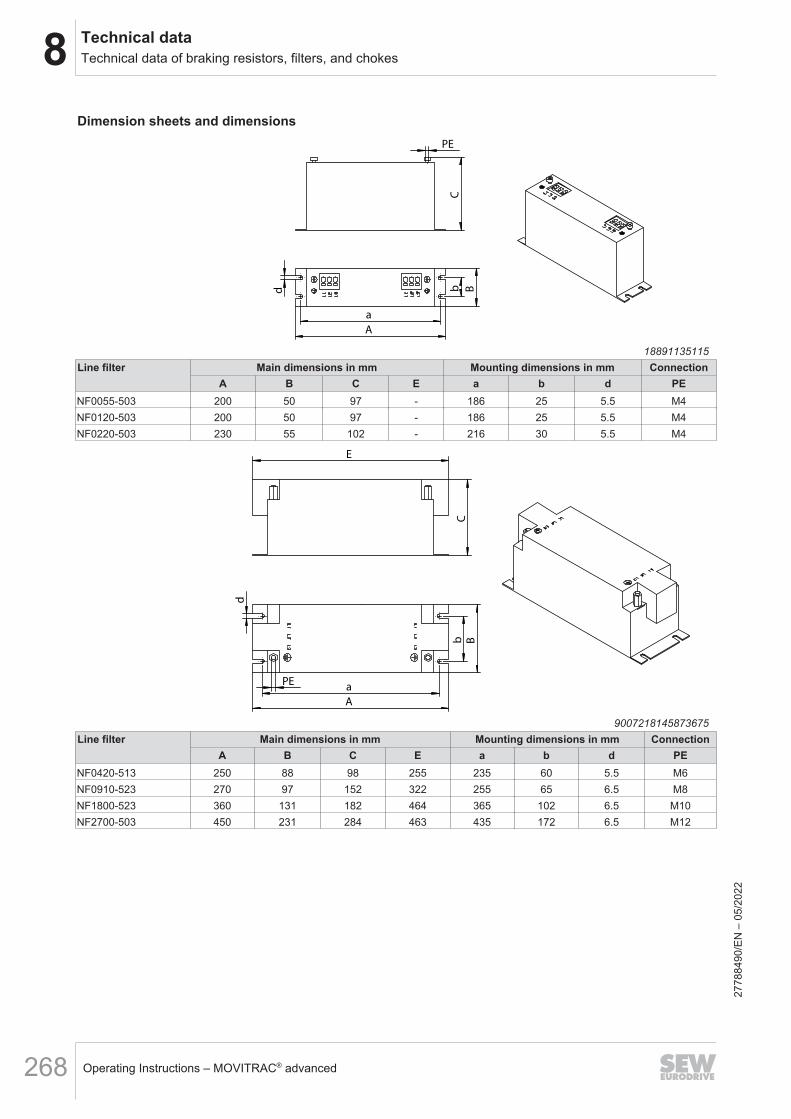
8 Technical dataTechnical data of braking resistors, filters, and chokes
Operating Instructions – MOVITRAC® advanced268
Dimension sheets and dimensions
C
PE
A
a
B
b
d
18891135115Line filter Main dimensions in mm Mounting dimensions in mm Connection
A B C E a b d PENF0055-503 200 50 97 - 186 25 5.5 M4NF0120-503 200 50 97 - 186 25 5.5 M4NF0220-503 230 55 102 - 216 30 5.5 M4
C
E
B
a
b
d
PE
A
9007218145873675Line filter Main dimensions in mm Mounting dimensions in mm Connection
A B C E a b d PENF0420-513 250 88 98 255 235 60 5.5 M6NF0910-523 270 97 152 322 255 65 6.5 M8NF1800-523 360 131 182 464 365 102 6.5 M10NF2700-503 450 231 284 463 435 172 6.5 M12
2778
8490
/EN
– 0
5/20
22
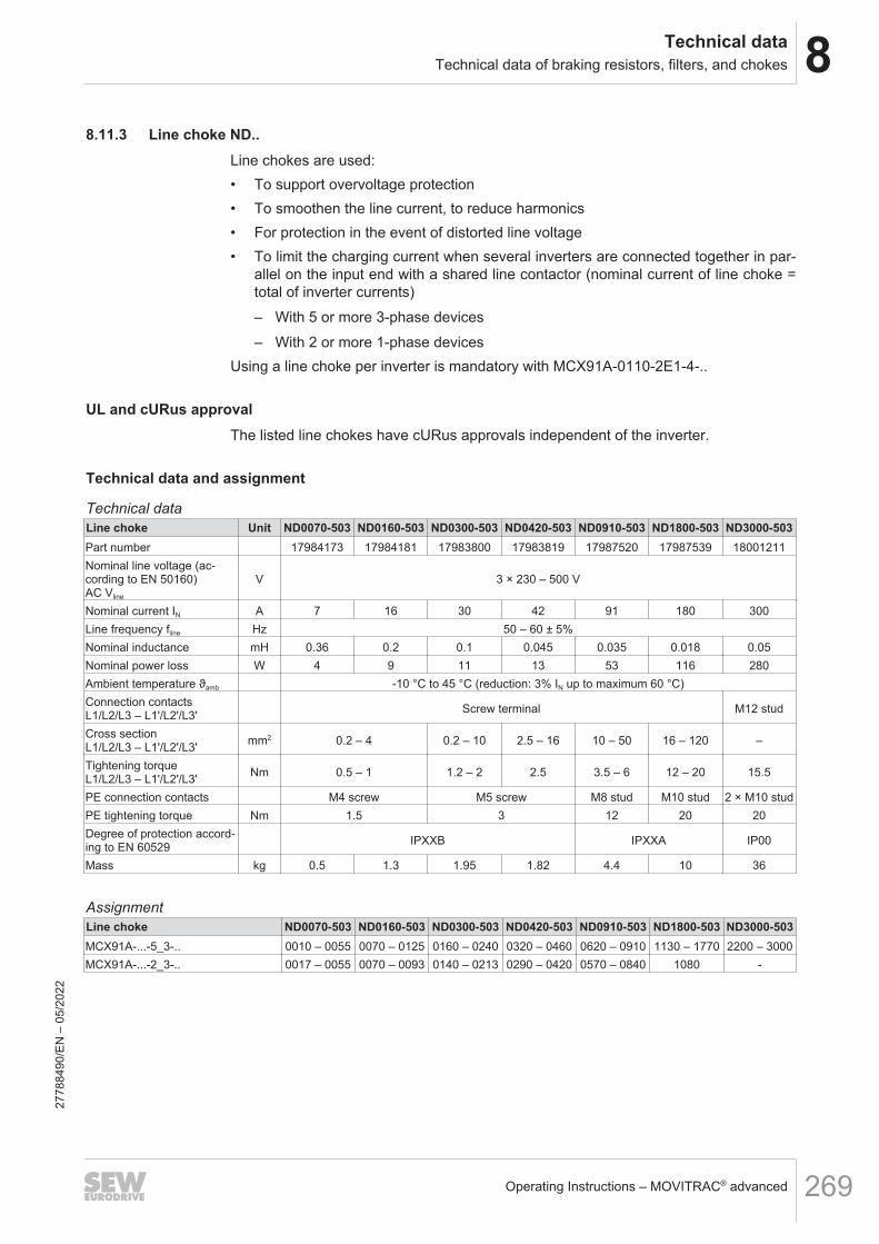
8Technical dataTechnical data of braking resistors, filters, and chokes
Operating Instructions – MOVITRAC® advanced 269
8.11.3 Line choke ND..Line chokes are used:• To support overvoltage protection• To smoothen the line current, to reduce harmonics• For protection in the event of distorted line voltage• To limit the charging current when several inverters are connected together in par-
allel on the input end with a shared line contactor (nominal current of line choke =total of inverter currents)– With 5 or more 3-phase devices– With 2 or more 1-phase devices
Using a line choke per inverter is mandatory with MCX91A-0110-2E1-4-..
UL and cURus approvalThe listed line chokes have cURus approvals independent of the inverter.
Technical data and assignment
Technical dataLine choke Unit ND0070-503 ND0160-503 ND0300-503 ND0420-503 ND0910-503 ND1800-503 ND3000-503Part number 17984173 17984181 17983800 17983819 17987520 17987539 18001211Nominal line voltage (ac-cording to EN 50160)AC Vline
V 3 × 230 – 500 V
Nominal current IN A 7 16 30 42 91 180 300Line frequency fline Hz 50 – 60 ± 5%Nominal inductance mH 0.36 0.2 0.1 0.045 0.035 0.018 0.05Nominal power loss W 4 9 11 13 53 116 280Ambient temperature ϑamb -10 °C to 45 °C (reduction: 3% IN up to maximum 60 °C)Connection contactsL1/L2/L3 – L1'/L2'/L3' Screw terminal M12 stud
Cross sectionL1/L2/L3 – L1'/L2'/L3' mm2 0.2 – 4 0.2 – 10 2.5 – 16 10 – 50 16 – 120 –
Tightening torqueL1/L2/L3 – L1'/L2'/L3' Nm 0.5 – 1 1.2 – 2 2.5 3.5 – 6 12 – 20 15.5
PE connection contacts M4 screw M5 screw M8 stud M10 stud 2 × M10 studPE tightening torque Nm 1.5 3 12 20 20Degree of protection accord-ing to EN 60529 IPXXB IPXXA IP00
Mass kg 0.5 1.3 1.95 1.82 4.4 10 36
AssignmentLine choke ND0070-503 ND0160-503 ND0300-503 ND0420-503 ND0910-503 ND1800-503 ND3000-503MCX91A-...-5_3-.. 0010 – 0055 0070 – 0125 0160 – 0240 0320 – 0460 0620 – 0910 1130 – 1770 2200 – 3000MCX91A-...-2_3-.. 0017 – 0055 0070 – 0093 0140 – 0213 0290 – 0420 0570 – 0840 1080 -
2778
8490
/EN
– 0
5/20
22
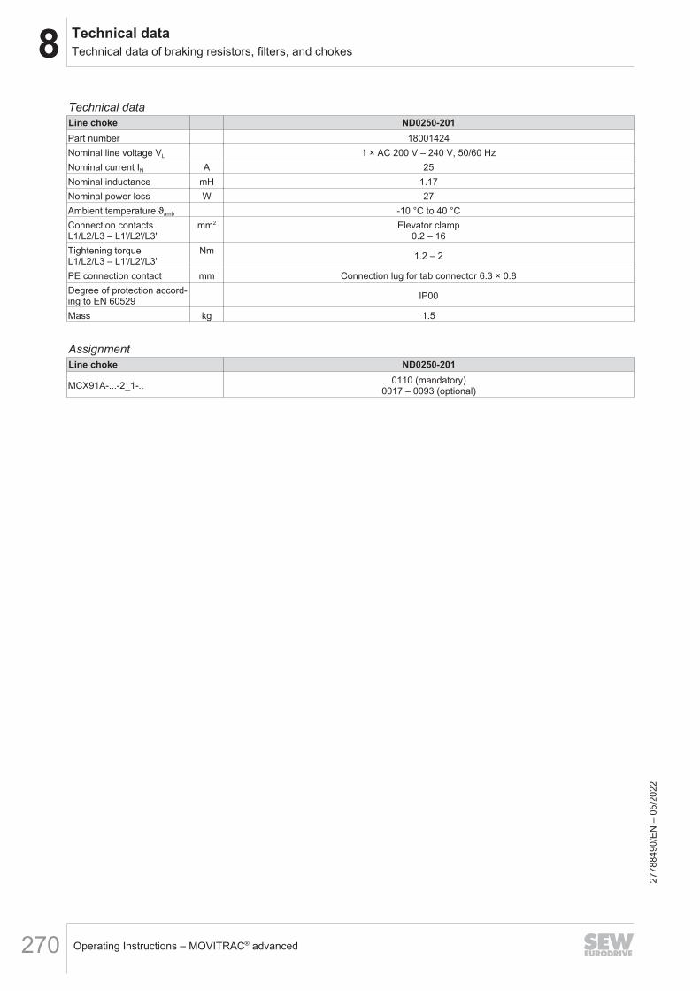
8 Technical dataTechnical data of braking resistors, filters, and chokes
Operating Instructions – MOVITRAC® advanced270
Technical dataLine choke ND0250-201Part number 18001424Nominal line voltage VL 1 × AC 200 V – 240 V, 50/60 HzNominal current IN A 25Nominal inductance mH 1.17Nominal power loss W 27Ambient temperature ϑamb -10 °C to 40 °CConnection contactsL1/L2/L3 – L1'/L2'/L3'
mm2 Elevator clamp0.2 – 16
Tightening torqueL1/L2/L3 – L1'/L2'/L3'
Nm 1.2 – 2
PE connection contact mm Connection lug for tab connector 6.3 × 0.8Degree of protection accord-ing to EN 60529 IP00
Mass kg 1.5
AssignmentLine choke ND0250-201
MCX91A-...-2_1-.. 0110 (mandatory)0017 – 0093 (optional)
2778
8490
/EN
– 0
5/20
22
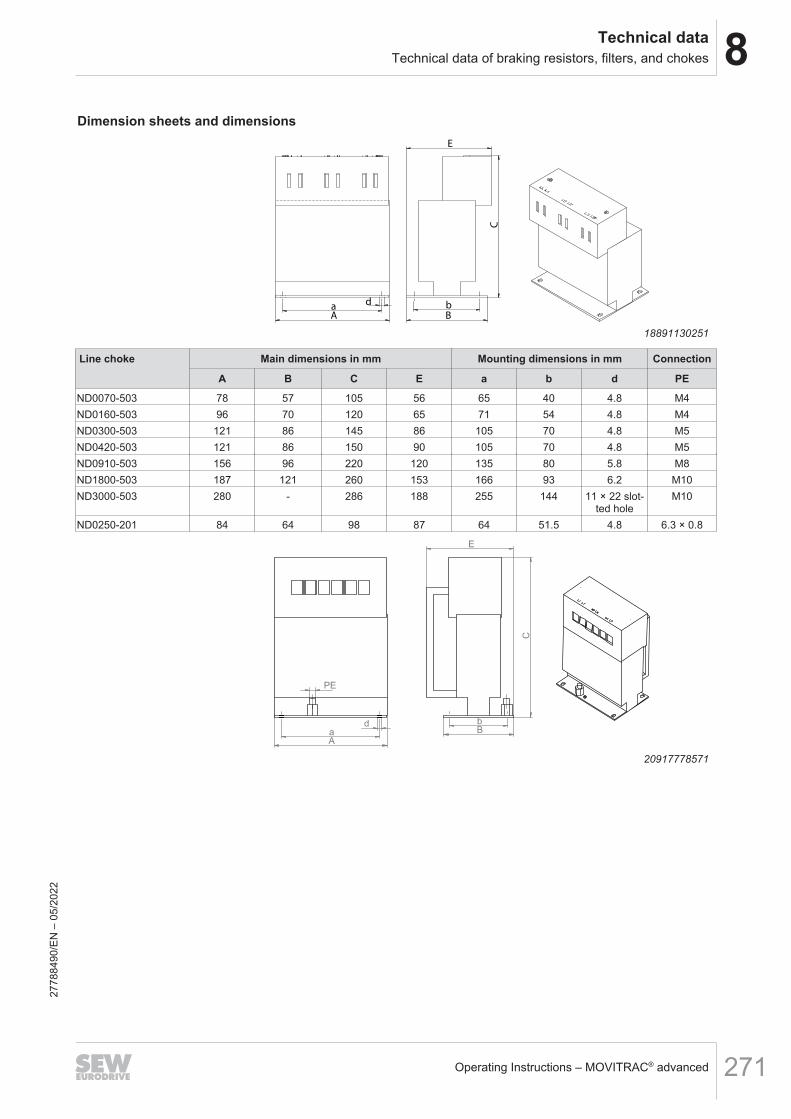
8Technical dataTechnical data of braking resistors, filters, and chokes
Operating Instructions – MOVITRAC® advanced 271
Dimension sheets and dimensions
A a
d
B
C
E
b
18891130251
Line choke Main dimensions in mm Mounting dimensions in mm Connection
A B C E a b d PE
ND0070-503 78 57 105 56 65 40 4.8 M4ND0160-503 96 70 120 65 71 54 4.8 M4ND0300-503 121 86 145 86 105 70 4.8 M5ND0420-503 121 86 150 90 105 70 4.8 M5ND0910-503 156 96 220 120 135 80 5.8 M8ND1800-503 187 121 260 153 166 93 6.2 M10ND3000-503 280 - 286 188 255 144 11 × 22 slot-
ted holeM10
ND0250-201 84 64 98 87 64 51.5 4.8 6.3 × 0.8
d
A a
PE
b B
C
E
20917778571
2778
8490
/EN
– 0
5/20
22

8 Technical dataTechnical data of braking resistors, filters, and chokes
Operating Instructions – MOVITRAC® advanced272
A
a
d
E
C
b
B
36108348299
2778
8490
/EN
– 0
5/20
22

8Technical dataTechnical data of braking resistors, filters, and chokes
Operating Instructions – MOVITRAC® advanced 273
8.11.4 HF.. output filter
Description of the output filterHF.. type output filters are sine filters used to smooth the output voltages of inverters.• Discharge currents in the motor cables are suppressed.• Motor winding insulations of third-party motors that are not suitable for inverters
are protected.• For long motor cables (> 100 m), overvoltage peaks are prevented.
UL and cURus approvalThe listed output filters have a cURus approval independent of the inverter.
Technical dataOutput filter HF0055-503 HF0125-503 HF0240-503 HF0460-503 HF0650-503 HF1150-503Part number 17985110 17985129 17985137 17985145 17991277 17991269Nominal voltage UN 3 × AC 230 V – 500 V, 50/60 HzNominal current IN A 5.5 12.5 24 46 65 115Nominal power loss W 80 120 200 400 500 900Ambient temperature ϑamb 0 °C to 45 °C (reduction: 3% IN/K up to maximum 60 °C)Connection contactsU1/V1/W1/UDC – U2/V2/W2
mm2
Screw terminal 0.2 – 10 Screw terminal 2.5 – 16 Screw terminal16 – 50
Screw terminal16 – 95
Tightening torqueU1/V1/W1/UDC – U2/V2/W2
Nm1.2 – 2 2 – 4 3 – 6 12 – 20
PE connection contacts M6 stud M8 stud M10 studPE tightening torque Nm 6 12 23Degree of protection inaccordance withEN 60529
IPXXB IPXXA
Mass kg 8 18 25 40 48 68
AssignmentOutput filter HF0055-503 HF0125-503 HF0240-503 HF0460-503 HF0650-503 HF1150-503
MCX91A-...-5_3-.. 0010 – 0055 0070 – 0125 0160 – 0240 0320 – 0460
0620 0750 – 09101130 (Parallel
connection of 2filters)
1490 – 1770(Parallel con-
nection of 2 fil-ters)
MCX91A-...-2_3-.. 0017 – 0055 0070 – 0093 0140 – 0213 0290 – 04200840 (Parallel
connection of 2filters)
05701080 (Parallel
connection of 2filters)
MCX91A-...-2E1-.. 0017 – 0055 0070 – 0110 – – – –
2778
8490
/EN
– 0
5/20
22

8 Technical dataTechnical data of braking resistors, filters, and chokes
Operating Instructions – MOVITRAC® advanced274
Dimension sheets and dimensions
C
E
A
a
b
B
PE
d
x
9007218523812619Output filter Main dimensions in mm Mounting dimensions in mm Connection
A B C E a b d x PEHF0055-503 310 105 160 – 290 75 6.5 7 M6HF0125-503 390 120 215 – 370 90 6.5 7 M6HF0240-503 450 135 270 – 430 100 6.5 7 M6HF0460-503 450 160 310 – 430 120 6.5 7 M6HF0650-503 635 210 285 637 610 174 8.5 10 M8HF1150-503 725 260 273 755 700 224 8.5 10 M10
2778
8490
/EN
– 0
5/20
22

8Technical dataTechnical data of braking resistors, filters, and chokes
Operating Instructions – MOVITRAC® advanced 275
8.11.5 HD.. output chokes
Description of output chokesHD.. type output chokes suppress interference emitted from unshielded motor cables.
UL and cURus approvalThe listed output chokes have a cURus approval independent of the inverter.
Technical dataOutput choke HD0125-503 HD0240-503 HD0460-503 HD1000-503 HD2000-503 HD6000-503Part number 17985153 17985188 17985161 17991307 17991250 17963362Nominal voltage UN 3 × AC 230 V – 500 V, 50/60 HzNominal current IN A 12.5 24 46 100 200 600Nominal power loss W 2.9 6 14 37 83 162Ambient temperature ϑamb 0 °C to 45 °C (reduction: 3% IN/K up to maximum 60 °C)Connection contactsU1/V1/W1/UDC – U2/V2/W2
mm2Screw terminal
0.2 – 10 Screw terminal 2.5 – 16 Screw terminal16 – 50
Screw terminal16 – 150
Copper rail 30 ×8, bore
Ø12 mmTightening torqueU1/V1/W1/UDC – U2/V2/W2
Nm1.2 – 2 2 – 4 6 – 8 12 – 20 –
PE connection contact M6 stud M8 stud M10 stud M12 × 50PE tightening torque Nm 6 12 23 30Degree of protection inaccordance withEN 60529
IPXXB IPXXA IP00
Mass kg 0.85 1.46 2.35 3 6.5 16
AssignmentOutput choke HD0125-503 HD0240-503 HD0460-503 HD1000-503 HD2000-503 HD6000-503MCX91A-...-5_3-.. 0010 – 0125 0160 – 0240 0320 – 0460 0620 – 0910 1130 – 1770 2200 – 3000MCX91A-...-2_3-.. 0017 – 0093 0140 – 0213 0290 – 0420 0570 – 0840 1080 –MCX91A-...-2E1-.. 0017 – 0110 – – – – –
2778
8490
/EN
– 0
5/20
22

8 Technical dataTechnical data of braking resistors, filters, and chokes
Operating Instructions – MOVITRAC® advanced276
Dimension sheets and dimensions
C
E
B
a
b
d
PE
A
9007218145873675Output choke Main dimensions in mm Mounting dimensions in mm Connection
A B C E a b d PEHD0125-503 153 62.5 72.5 151 138 40 5.5 M6HD0240-503 173 92.5 82.5 178 158 65 5.5 M6HD0460-503 185 122.5 112.5 189 170 90 5.5 M6HD1000-503 255 116 143.5 265 240 82 6.5 M8HD2000-503 300 178 175 330 286 120 6.5 M10
C
E
PE
e
A
B
a
b
d
35975896715Output choke Main dimensions in mm Mounting dimensions in mm Connection
A B C E a b d PEHD6000-503 300 260 116 395 240 240 13 M12
2778
8490
/EN
– 0
5/20
22

9Functional safetyGeneral information
Operating Instructions – MOVITRAC® advanced 277
9 Functional safety9.1 General information9.1.1 Underlying standards
The safety assessment of the device is based on the following standards and safetyclasses:
Underlying standardsSafety class/underlying standard
• Performance Level (PL) in accordance withEN ISO 13849‑1
• Safety Integrity Level (SIL) according to EN 61800‑5‑2,EN 61508 and EN 62061
Note the versions of the relevant standards on the declaration of conformity or on theTÜV certificate.
9.2 Integrated safety technology3 safety options can be configured for the MOVITRAC® advanced inverter.1. MOVISAFE® CSO safety option
The STO safety subfunction is available via terminals with the MOVISAFE® CSOsafety option.
2. MOVISAFE® CSB safety optionThe STO and SS1-t safety subfunctions are available via safe communication withthe MOVISAFE® CSB safety option.
3. MOVISAFE® CSL safety optionThe SBC, STO and SS1-t safety subfunctions are available via safe communica-tion with the MOVISAFE® CSL safety option. For example, the SLS and SDI safetysubfunctions are available via EI7C FS for motion monitoring.
The described safety technology of the device has been developed and tested in ac-cordance with the following safety requirements:• MOVISAFE® CSB/CSL safety option:
– SIL 2 according to EN 61800-5-2, EN 61508– PL d according to EN ISO 13849-1
This was certified by TÜV Rheinland. A copy of the TÜV certificate can be requestedfrom SEW‑EURODRIVE.
9.2.1 Safe stateFor safety-related operation of the device, Safe Torque Off is defined as safe state(see STO safety subfunction). The safety concept is based on this definition.
2778
8490
/EN
– 0
5/20
22

9 Functional safetyIntegrated safety technology
Operating Instructions – MOVITRAC® advanced278
9.2.2 Safety concept STOThe device is supposed to be able to perform the safety subfunction "Safe Torque Off"in accordance with IEC 61800‑5‑2:• The device is characterized by the optional connection of an external safety con-
troller/safety relay. This external safety controller/safety relay disconnects thesafety-related STO input via a 2-channel 24 V switching signal (sourcing/sinking)when a connected command device (e.g. emergency stop button with latchingfunction) is activated. This activates the STO function of the device. With the CSB/CSL safety options, the STO function is performed using the safety option.
• An internal structure with diagnostics prevents the generation of pulse trains at thepower output stage (IGBT).
• If the internal diagnostics detects a fault, the PWM signals are permanentlyswitched off.
• Instead of a galvanic isolation of the drive from the supply system by means ofcontactors or switches, the disconnection of the STO input described here safelyprevents the activation of the power semiconductors in the output stage. Therotary-field generation for the respective motor is deactivated even though the linevoltage is still present.
• If the internal diagnostics of the STO circuit detects a fault, the PWM signals arelocked, i.e. the STO is activated. This locking requires a reset by switching theDC 24 V supply voltage of the device or the DC 24 V switching signal at the STOinput F_STO_P off and on.
9.2.3 Schematic representation of the safety concept STO
With CSO safety optionUz+
Uz-
[2]
[4]
[5]
[6]
[1]
[3]
33200049803
[1] STO function[2] Drive controller[3] Switching element[4] Safety switching equipment[5] External safety device (optional)[6] Motor 27
7884
90/E
N –
05/
2022

9Functional safetyIntegrated safety technology
Operating Instructions – MOVITRAC® advanced 279
With CSB/CSL safety options
Uz+
Uz-
[2]
[4]
[5]
[1]
[3]
33207807755
[1] STO function[2] Drive controller[3] Safety option[4] Diagnostics and inhibiting unit[5] Motor
9.2.4 CSB/CSL safety concept
GeneralThe CSB and CSL safety options are safe modules with safe digital inputs and outputsand, depending on the parameterization, with safe communication.The CSB or CSL safety options are completely integrated into the MOVITRAC® ad-vanced inverter. This means that the safety option internally activates the STO safetysubfunction of the inverter. Instead of galvanic isolation of the drive from the supplysystem by means of contactors or switches, the disconnection via STO within thedevice safely prevents the control of the power semiconductors in the output stage.The rotary-field generation for the respective motor is deactivated even though the linevoltage is still present.The safety concept is based on a safe state existing for all safe process values. A safestate of the safety option is defined as follows:• The internal safe digital output F-DO_STO is disabled. This activates the STO
safety subfunction.• All other existing safe digital outputs are disabled.• If safe communication is parameterized, either substitute values are sent for the
data (i.e. all data is "0"), or the communication is interrupted.
Notes on the stop categories according to EN 60204-1• The STO safety subfunction corresponds to stop category 0.• The SS1-r and SS1-t safety subfunctions correspond to stop category 1.
2778
8490
/EN
– 0
5/20
22
9 Functional safetyIntegrated safety technology
Operating Instructions – MOVITRAC® advanced280
Pluggable safety keyThe safety key must already be plugged when activating the safety option and mustnot be removed while the safety option is active. The safety key is part of the datamemory of the basic device.The parameterization data of the MOVISAFE® CSB/CSL safety options is divided intoapplication data and the key data set. The key data set ensures data integrity.The application data are stored in the device. The application data are enabled withthe aid of the key data set on the pluggable safety key. The safety option becomes op-erational only if the key data set on the pluggable safety key matches the parameteri-zation.The pluggable safety key is also used to establish a location reference in the system.Since the application-related data set is enabled only with the matching key data seton the pluggable safety key, the location reference can be established in this way. It isthe user’s responsibility to save the location reference of the pluggable safety key inthe system. The data for safe communication is also stored on the pluggable safetykey because this data has the same location reference. This ensures that the applica-tion-related data and the communication data are available again immediately in theevent of a device replacement.The safety key contains the following data:• Checksum of the application data set• Checksum of the accepted data set• Bus checksum (ParCRCBus)• Parameters of the F protocol
Identification and authenticationIn the "Assist CS.." parameterization tool, unique identification of the device and anauthentication of the user is necessary for the steps "Parameterize", "Create report"and "Confirm validation". To identify the device, enter the ID of the pluggable safetykey in the login dialog of the parameterization tool. The safety key ID is printed on thesafety key. Instead, the safety key ID can be read by the "Assist CS.." parameteriza-tion tool. To do this, the user must perform an identity verification using the LED dis-play of the device. This mechanism with the safety key ID ensures that the Assist CS..parameterization tool is connected to the correct device. The user is authenticated byentering a password.
INFORMATIONIt is essential to ensure unique identification of the device to be parameterized.
Report and safety checkWhen downloading the parameters to the device, both the application data set and thechecksum of the application data of the safety key set are created. The safety optiongoes into operation if all tests are fault-free. From this moment on, all parameterizedfunctions are active.
2778
8490
/EN
– 0
5/20
22

9Functional safetyIntegrated safety technology
Operating Instructions – MOVITRAC® advanced 281
WARNINGDepending on the parameter setting the safety option does not control the STOsafety subfunction. This can cause the drive to start unexpectedly.Severe or fatal injuries.• Make sure that the drive does not restart automatically after parameterization of
the safety option (e.g. set start inhibit, remove travel commands).
The acceptance report can be created once the parameters are downloaded. Duringthis process, the new ParCRC value of the "application data" set is made known to theF‑protocol master. The new ParCRC value must be transferred to the F‑protocol mas-ter. The acceptance report must be used to perform the acceptance of the "applicationdata" set in combination with the safety option within the system.After acceptance, the performed acceptance can be published via the safety option.The publication of the acceptance does not replace the acceptance itself to be carriedout. For the publication of the acceptance, the "checksum of the acceptance report" ofthe safety option is made known.The publication of the acceptance is not implemented in a safety-related manner andis not necessary for the safety-related operation of the safety option. The publicationof the acceptance is a supporting function for the user of the safety option.
Variants• The safety options CSB and CSL are integrated safe electronics modules that can
be operated with or without safe communication. The PROFIsafe, Safety overEtherCAT®, and CIP Safety™ profiles are available for safe communication. Thesafety options CSB and CSL are equipped with safe inputs and outputs (F-DI, F-DO) and are available in the following designs.CSB safety option:– 4 safe inputsCSL safety option:– 4 safe inputs– 1 safe 2-channel output
• The CSB/CSL safety options can release or safely deactivate the output stage ofthe inverter. The switching state of the safe internal digital output F-DO_STO, andconsequently the STO safety subfunction, must be stable on "1" or stable on "0"once within 60 seconds for at least 2 seconds (2.5 seconds with extended diag-nostics).
• The safety concept of the CSB/CSL safety options is based on the fact that a safestate exists for all safe process variables. For the CSB/CSL safety options, thisvalue is "0" for all F-DI inputs and F-DO outputs.
• The CSB/CSL safety options were designed according to EN 61508 for SIL 2 andEN ISO 13849‑1 for performance level d.
• In combination with the EI7C FS built-in encoder, the CSL safety option can safelymonitor movement functions.
2778
8490
/EN
– 0
5/20
22
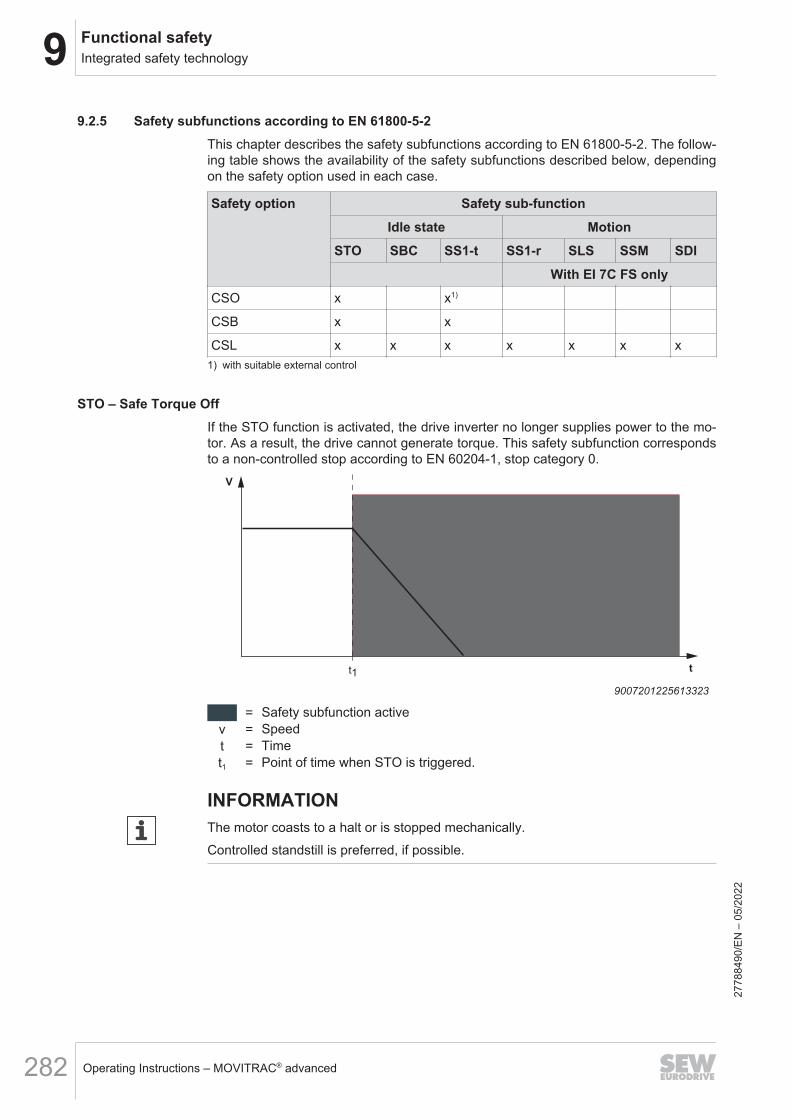
9 Functional safetyIntegrated safety technology
Operating Instructions – MOVITRAC® advanced282
9.2.5 Safety subfunctions according to EN 61800-5-2This chapter describes the safety subfunctions according to EN 61800‑5‑2. The follow-ing table shows the availability of the safety subfunctions described below, dependingon the safety option used in each case.
Safety option Safety sub-functionIdle state Motion
STO SBC SS1-t SS1-r SLS SSM SDIWith EI 7C FS only
CSO x x1)
CSB x x
CSL x x x x x x x1) with suitable external control
STO – Safe Torque OffIf the STO function is activated, the drive inverter no longer supplies power to the mo-tor. As a result, the drive cannot generate torque. This safety subfunction correspondsto a non-controlled stop according to EN 60204‑1, stop category 0.
t
V
t1
9007201225613323
= Safety subfunction activev = Speedt = Timet1 = Point of time when STO is triggered.
INFORMATIONThe motor coasts to a halt or is stopped mechanically.Controlled standstill is preferred, if possible.
2778
8490
/EN
– 0
5/20
22

9Functional safetyIntegrated safety technology
Operating Instructions – MOVITRAC® advanced 283
SBC – Safe Brake ControlThe SBC function provides a safe output signal for controlling an external brake.
t1t
V
27021600043191563
= Safety subfunction activatedv = Speedt = Timet1 = Point in time when SBC is triggered.
SS1-t – Safe Stop 1 with time controlWhen the SS1-t function is active, the drive inverter brings the motor to a standstill electrically. The STO safety subfunction will be triggered after a specified, safety-re-lated time.This safety subfunction corresponds to a controlled stop of the drive according toEN 60204‑1, stop category 1.
t2t1
t
V
∆t
9007201225618443
= Safety subfunction monitored= STO safety subfunction active
v = Speedt = Timet1 = Point of time when SS1-t is activated and motor deceleration is triggered.t2 = Point of time when STO is triggered.Δt = Safety-related period of time
2778
8490
/EN
– 0
5/20
22

9 Functional safetyIntegrated safety technology
Operating Instructions – MOVITRAC® advanced284
INFORMATION• The SS1-t function does not monitor the stopping of the drive.• The safety-related period of time Δt allows the drive to come to a stop. In the
event of a fault, the drive does not come to a stop and becomes de-energized atthe time t2 (STO).
SS1-r – Safe Stop 1 with monitoring of the deceleration rampWhen the SS1-r function is active, the drive inverter brings the motor to a standstill electrically. The deceleration is monitored. The STO safety subfunction is triggeredwhen the monitored deceleration is exceeded or when an idle state is reached.This safety subfunction corresponds to a controlled stop of the drive according toEN 60204‑1, stop category 1.
t
V
t1 t2
18014400480357003
= Safety subfunction monitored= Safety subfunction triggers
v = Speedt = Timet1 = Point in time when SS1-r is activated and motor deceleration is triggered.t2 = Point of time when STO is triggered.
2778
8490
/EN
– 0
5/20
22

9Functional safetyIntegrated safety technology
Operating Instructions – MOVITRAC® advanced 285
SLS – Safely Limited SpeedThe SLS function prevents the drive from exceeding a specified speed. If the permit-ted speed is exceeded, the safety subfunction will be triggered and an error responsewill be initiated at the same time.
t
V
t1 t2
9007201225702923
= Safety subfunction monitored= Safety subfunction triggers
v = Speedt = Timet1 = Point in time at which SLS is activated.t2 = Point in time at which SLS is deactivated.
SSM – Safe Speed MonitoringThe SSM function monitors whether the drive exceeds a specified speed. An exceed-ing of the allowed speed is signaled.
t
V
t1 t2
9007201225702923
= Safety subfunction monitored= Safety subfunction triggers
v = Speedt = Timet1 = Point in time at which SSM is activated.t2 = Point in time at which SSM is deactivated.
2778
8490
/EN
– 0
5/20
22
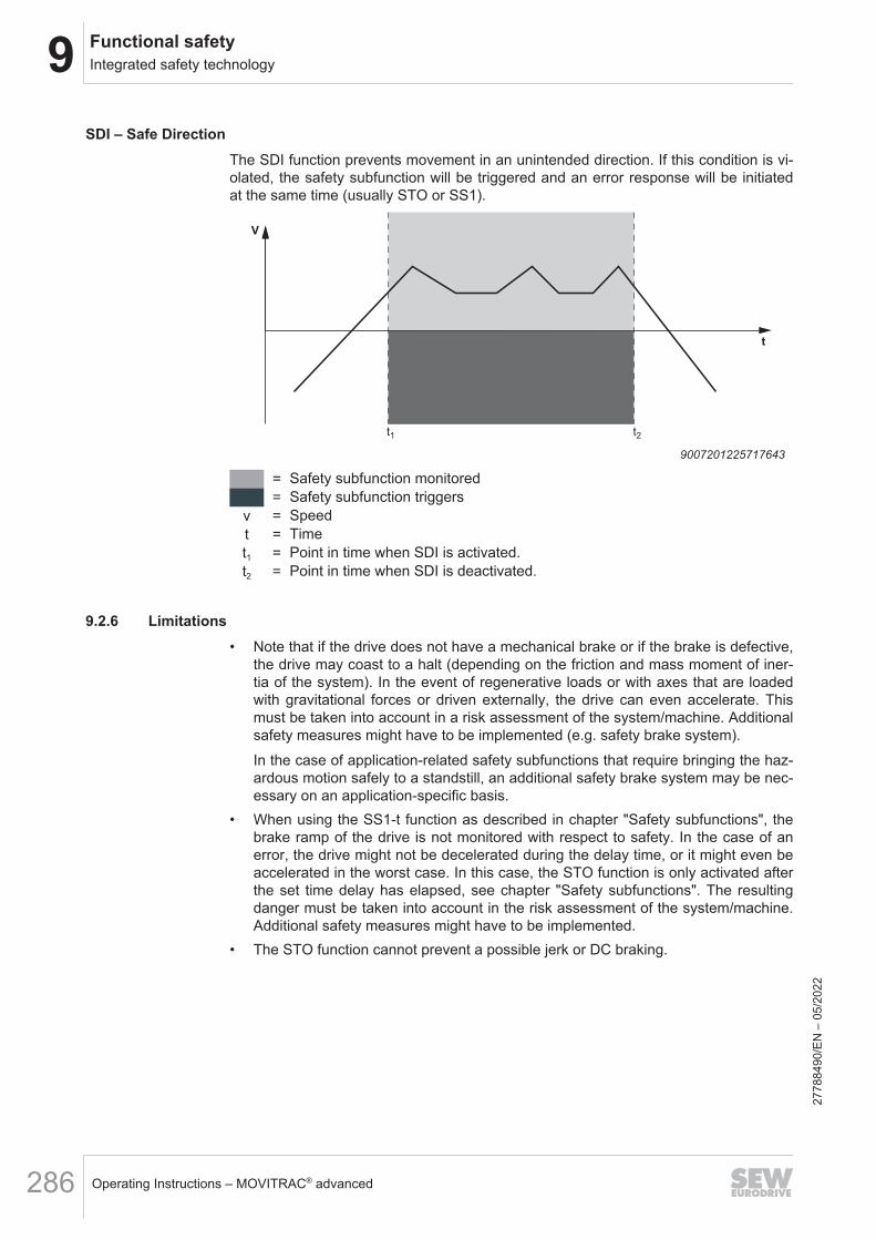
9 Functional safetyIntegrated safety technology
Operating Instructions – MOVITRAC® advanced286
SDI – Safe DirectionThe SDI function prevents movement in an unintended direction. If this condition is vi-olated, the safety subfunction will be triggered and an error response will be initiatedat the same time (usually STO or SS1).
t
V
t1 t2
9007201225717643
= Safety subfunction monitored= Safety subfunction triggers
v = Speedt = Timet1 = Point in time when SDI is activated.t2 = Point in time when SDI is deactivated.
9.2.6 Limitations• Note that if the drive does not have a mechanical brake or if the brake is defective,
the drive may coast to a halt (depending on the friction and mass moment of iner-tia of the system). In the event of regenerative loads or with axes that are loadedwith gravitational forces or driven externally, the drive can even accelerate. Thismust be taken into account in a risk assessment of the system/machine. Additionalsafety measures might have to be implemented (e.g. safety brake system).In the case of application-related safety subfunctions that require bringing the haz-ardous motion safely to a standstill, an additional safety brake system may be nec-essary on an application-specific basis.
• When using the SS1-t function as described in chapter "Safety subfunctions", thebrake ramp of the drive is not monitored with respect to safety. In the case of anerror, the drive might not be decelerated during the delay time, or it might even beaccelerated in the worst case. In this case, the STO function is only activated afterthe set time delay has elapsed, see chapter "Safety subfunctions". The resultingdanger must be taken into account in the risk assessment of the system/machine.Additional safety measures might have to be implemented.
• The STO function cannot prevent a possible jerk or DC braking.
2778
8490
/EN
– 0
5/20
22

9Functional safetyIntegrated safety technology
Operating Instructions – MOVITRAC® advanced 287
WARNINGThe safety concept is only suitable for performing mechanical work on driven sys-tem/machine components.When the STO signal is disconnected, the voltage is still present at the DC link ofthe device.• Before working on the electric part of the drive system, disconnect it from the
supply voltage using an appropriate external disconnecting device and secure itagainst unintentional reconnection.
INFORMATIONIn the event of a safety-related disconnection of the DC 24 V supply voltage at theSTO connection, the brake controller is switched off. The brake control in the deviceis not safety-related.
9.2.7 Safety concept of Assist CS..
Safety parametersThe CSB and CSL safety options have adjustable parameters for parameterizing thesafety subfunctions.The safety parameters determine the behavior of the corresponding safety subfunc-tions and are therefore safety-related. All safety parameters are combined in the pa-rameter set.The following actions are performed when downloading the parameters in the As-sist CS.. tool:• Parameterization of the safety option.• Generation of the "application data" checksum of the key data set on the safety
key.• A modified parameter setting clears the "validation" status.As a result, the safety key is connected with the respective parameterization by down-loading the parameters.
Test concept and test procedureThe parameters of the CSB and CSL safety options are set using an engineering PCwith the "Assist CS.." parameterization tool. As the PC and the "Assist CS.." parame-terization tool are not safety-related and therefore possibly not fault-free, the safetyconcept prescribes the following measures:• Identify safety options.• When establishing a connection to the safety option, the safety key ID must be
entered in a dialog.• Guided parameter setting procedure with the parameterization tool "Assist CS.."
with integrated safety features such as plausibility check of entries during datatransmission to the device.
• Completion of parameterization with an acceptance report to validate the safetysubfunctions.
2778
8490
/EN
– 0
5/20
22

9 Functional safetySafety-related conditions
Operating Instructions – MOVITRAC® advanced288
9.3 Safety-related conditionsThe requirement for safe operation is that the safety subfunctions of the device areproperly integrated into an application-specific, higher-level safety subfunction. A sys-tem/machine-specific risk assessment must be carried out without fail by the system/machine manufacturer and taken into account for the use of the drive system with thedevice.The system/machine manufacturer and the user are responsible for the compliance ofthe system/machine with the applicable safety regulations.The following requirements are mandatory when installing and operating the device insafety-related applications:• Use of the approved devices• Installation requirements• Requirements for external safety controllers and safety relays• Startup requirements• Operational requirements
9.3.1 Approved devicesThe following device variants of MOVITRAC® are permitted for safety-related applica-tions:
Device SizeMOVITRAC® advanced All sizes with CSO, CSB, CSL safety option
9.3.2 Installation requirements• The components must be protected against conductive dirt, e.g. by installing them
in a control cabinet with degree of protection IP54 in accordance with EN 60529.Assuming that the presence of conductive dirt can be excluded at the installationsite, a control cabinet with a correspondingly lower degree of protection is alsopermitted if in accordance with the applicable standards, e.g. EN 60204‑1. Thesame applies to temporary condensation, e.g. due to rapid changes of the ambienttemperature.
• The wiring technology used must comply with the standard EN 60204-1.• The safe control cables must be routed according to EMC guidelines and as fol-
lows:– Inside an electrical installation space: Single conductors can be routed.– Outside a closed installation space: Shielded cables must be routed perma-
nently (fixed) and protected against external damage, or equivalent measuresmust be taken.
– Adhere to the regulations in force for the application.– If the safe outputs and inputs are wired in a 2-channel configuration, the corre-
sponding cables must be routed closely together.– The cables must have the same length. A difference in length ≤ 3% of the two
cables is permitted.– The following maximum cable lengths must be observed:
STO: 30 mF-DI: 30 m
2778
8490
/EN
– 0
5/20
22
9Functional safetySafety-related conditions
Operating Instructions – MOVITRAC® advanced 289
F-DOx: 30 mF-SSx: 30 m
– You must use suitable measures to ensure that the safe control cables arerouted separately from the power lines of the drive. This does not apply tocables approved by SEW‑EURODRIVE specifically for this application case.
• The STO function does not detect short circuits or interference voltage in the sup-ply line, so you must ensure the following:– No parasitic voltages can occur in the STO control cables– The external safety controller can detect a crossfault from an external potential
to the STO control cables• Observe without fail the values specified for safety components when designing
the safety circuits.• The STO signal (F_STO_P and F_STO_M) must not be used for feedback.• For safety controller/safety relays, you must only use grounded voltage sources
with protective electrical separation (PELV) in accordance with EN 61131-2 andEN 60204-1.
• When planning the installation, observe the technical data of the device.• Do not use the port X6:4 (VO24_STO) of the device for safety-related applications.
The voltage is only permitted to supply the port for the safe disconnection X6 whena jumper plug is plugged.
• For safety-related applications with the CSO device variant, the jumper plug at theSTO input X6 must be removed. With the CSB and CSL device variants, the STOfunction is performed exclusively via the safety option. The STO input X6 has nofunction and must not be used for safety-relevant applications.
• When connecting an EI7C FS built-in encoder to the MOVITRAC® advanced, theencoder cable must not carry a TF signal.
2778
8490
/EN
– 0
5/20
22

9 Functional safetySafety-related conditions
Operating Instructions – MOVITRAC® advanced290
9.3.3 Requirements for the external safety controllerA safety relay can be used as an alternative to a safety controller. The following re-quirements apply accordingly.• The safety controller and all other safety-related subsystems must be approved for
at least the safety class that is required in the overall system for the respective ap-plication-related drive safety function.The following table shows an example of the required safety class of the safetycontroller:
Application Safety controller requirementsPerformance level d according to
EN ISO 13849-1, SIL 2 according toEN 62061
Performance level d according toEN ISO 13849‑1
SIL 2 according to EN 61508
• The wiring of the safety controller must be suitable for the required safety class(see manufacturer documentation). The STO input of the device can be switchedwith 2 channels (sourcing/sinking) or with 1 channel (sourcing).
• The values specified for the safety controller must be strictly adhered to whendesigning the circuit.
• No electro-sensitive protective equipment (such as a light grid or scanner) in ac-cordance with EN 61496‑1 or emergency stop buttons may be connected directlyto the STO input. The connection must be made via a safety controller or a safetyrelay.
• To ensure protection against an unintended startup in accordance withEN ISO 14118, the safe control system must be designed and connected in such away that resetting the command device alone does not lead to a restart. Thismeans that a restart may be carried out only after a manual reset of the safety cir-cuit.
• If no fault exclusion is used for the STO wiring in accordance with EN ISO 13849-2or EN 61800-5-2, the external safety device must detect the following faults in theSTO wiring within 20 s depending on the connection type:– 2-channel, sourcing/sinking output:
Short circuit of 24 V at F_STO_P (Stuck-at 1)Short circuit of 0 V at F_STO_M (Stuck-at 0)
– 1-channel, sourcing output:With 1-channel connection, a fault exclusion is necessary for the wiringbetween the safety relay and the STO input.
2-channel, sourcing/sinking output:• Test pulses can be present when the device is switched on or off:
– The test pulses in the sourcing and sinking channel must not exceed 1 ms.– The next test pulse in the sourcing or sinking channel must only occur after a
2 ms time period at the earliest.– A maximum packet of 3 switch-on test pulses may be generated in sequence at
an interval of 2 ms. Wait for at least 500 ms after any packet before you gener-ate another switch-on test pulse or another switch-on test pulse packet.
– The test pulses must be monitored in the safety device. If a fault is detected,the safety device must initiate a suitable fault response.
2778
8490
/EN
– 0
5/20
22

9Functional safetySafety-related conditions
Operating Instructions – MOVITRAC® advanced 291
1-channel, sourcing output:• In switched-off state, no switch-on test pulses must occur in the sourcing cable.• In switched-on state:
– The switch-off test pulse in the sourcing channel must not exceed 1 ms.– The next switch-off test pulse may only occur after a time period of 2 ms at the
earliest.– A maximum packet of 3 switch-on test pulses may be generated in sequence at
an interval of 2 ms. Wait for at least 500 ms after any packet before you gener-ate another switch-on test pulse or another switch-on test pulse packet.
– The test pulses must be monitored in the safety device. If a fault is detected,the safety device must initiate a suitable fault response.
9.3.4 Sensor and actuator requirements• The project planner and the user of the system or machine are responsible for the
number and utilization of external sensors and actuators for connection with thesafe inputs and outputs of the MOVISAFE® CSB/CSL safety options.
• To meet the required safety level (PL/SIL), you must use suitable and appropri-ately qualified sensors and actuators and observe the permitted wiring diagrams(see chapter "Wiring diagrams") and information in the chapters "Safe digital inputs(F-DI.)" and "Safe digital output (F-DO00)". The permissible encoders are de-scribed in the chapter "Encoder requirements".
9.3.5 Encoder requirementsThe EI7C FS built-in encoder is permitted for use with the CSL safety option. For moreinformation on the EI7C FS built-in encoder, refer to the corresponding documenta-tion.
Quantization error
Position
The actual position value is formed directly from the encoder increments. On the basisof one encoder revolution, this results in the following quantization fault for the actualposition value, which is included in all position functions:• EI7C FS: 7.5 °
Speed
The speed calculation for the EI7C FS built-in encoder determines the average speedover the last 4 recorded encoder increments. The response time of the encoder evalu-ation is thus dependent on the actual speed. The error in the calculated speed valueequals a maximum of 1% of the actual speed:Error_v_EI7C FS = Actual speed x 1%Setting the Filter time speed HTL (8708.4) parameter makes it possible to filter the cal-culated speed via a sliding average value filter with the parameterized length.
2778
8490
/EN
– 0
5/20
22
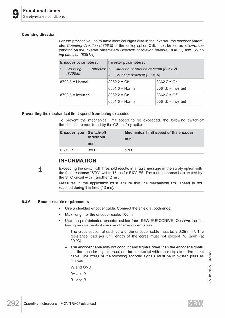
9 Functional safetySafety-related conditions
Operating Instructions – MOVITRAC® advanced292
Counting directionFor the process values to have identical signs also in the inverter, the encoder param-eter Counting direction (8708.6) of the safety option CSL must be set as follows, de-pending on the inverter parameters Direction of rotation reversal (8362.2) and Count-ing direction (8381.6):
Encoder parameters: Inverter parameters:• Counting direction
(8708.6)• Direction of rotation reversal (8362.2)• Counting direction (8381.6)
8708.6 = Normal 8362.2 = Off8381.6 = Normal
8362.2 = On8381.6 = Inverted
8708.6 = Inverted 8362.2 = On8381.6 = Normal
8362.2 = Off8381.6 = Inverted
Preventing the mechanical limit speed from being exceededTo prevent the mechanical limit speed to be exceeded, the following switch-offthresholds are monitored by the CSL safety option.
Encoder type Switch-offthresholdmin-1
Mechanical limit speed of the encodermin-1
EI7C FS 3800 5700
INFORMATIONExceeding the switch-off threshold results in a fault message in the safety option withthe fault response "STO" within 13 ms for EI7C FS. The fault response is executed bythe STO circuit within another 2 ms.Measures in the application must ensure that the mechanical limit speed is notreached during this time (13 ms).
9.3.6 Encoder cable requirements• Use a shielded encoder cable. Connect the shield at both ends.• Max. length of the encoder cable: 100 m• Use the prefabricated encoder cables from SEW-EURODRIVE. Observe the fol-
lowing requirements if you use other encoder cables:– The cross section of each core of the encoder cable must be ≥ 0.25 mm2. The
resistance load per unit length of the cores must not exceed 78 Ω/km (at20 °C).
– The encoder cable may not conduct any signals other than the encoder signals,i.e. the encoder signals must not be conducted with other signals in the samecable. The cores of the following encoder signals must be in twisted pairs asfollows:VB and GNDA+ and A-B+ and B-
2778
8490
/EN
– 0
5/20
22

9Functional safetySafety-related conditions
Operating Instructions – MOVITRAC® advanced 293
– The encoder cable may have the following maximum capacitances per unitlength:Capacitance per unit length core/core: CA’ = 70 pF/mCapacitance per unit length core/shield: CS’ = 120 pF/m
– In the signal path from the encoder to the inverter, the encoder signals must notbranch off to other devices.
9.3.7 Startup requirements• To validate the implemented safety subfunctions, they must be documented and
checked after successful startup (functional test).• Observe the restrictions for safety subfunctions in chapter "Limitations". Non-
safety-related parts and components that affect the result of the functional test(e.g. motor brake) must be deactivated, if necessary.
• For use of the device in safety-related applications, it is essential that you performand document startup checks for the disconnecting device and the correct elec-trical connection.
• For the CSB and CSL safety options, the startup check and logging is supportedby the "Assist CS..." parameterization tool with an acceptance report.
INFORMATION• In order to avoid a hazard in the intended application when a fault occurs, the user
must check whether the fault response time of each safety subfunction is shorterthan the maximum permitted fault response time of the application. The maximumpermitted fault response time must not be exceeded.
• The user must ensure implementation of the requirements of the required safetyintegrity level (SIL) in accordance with EN 61508 or performance level (PL) pursu-ant to EN ISO 13849-1.
9.3.8 Requirements for stopping in an emergency according to EN 60204-1 (emergency stop)The CSB and CSL safety options, in combination with an emergency stop commanddevice and the external control, are suitable for implementing an emergency stop ac-cording to EN 60204-1.
WARNINGIn the case of a pending travel command, the drive restarts after acknowledgment ofthe safety option.Severe or fatal injuries.• Cancel the travel command before acknowledging the safety option.
9.3.9 AcceptanceThe system manufacturer has to perform an overall evaluation for determining thesafety of a machine or a system. The effectiveness of each risk minimization must bechecked. It must also be checked if the required safety integrity (SIL and/or PL) isreached for each implemented safety subfunction.To validate the safety integrity level, you can use the "SISTEMA" calculation tool fromthe Institut für Arbeitsschutz (Institute for Occupational Safety and Health of the Ger-man Social Accident Insurance).
2778
8490
/EN
– 0
5/20
22
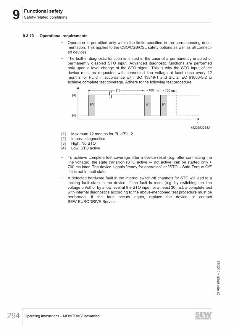
9 Functional safetySafety-related conditions
Operating Instructions – MOVITRAC® advanced294
9.3.10 Operational requirements• Operation is permitted only within the limits specified in the corresponding docu-
mentation. This applies to the CSO/CSB/CSL safety options as well as all connect-ed devices.
• The built-in diagnostic function is limited in the case of a permanently enabled orpermanently disabled STO input. Advanced diagnostic functions are performedonly upon a level change of the STO signal. This is why the STO input of thedevice must be requested with connected line voltage at least once every 12months for PL d in accordance with ISO 13849‑1 and SIL 2 IEC 61800-5-2 toachieve complete test coverage. Adhere to the following test procedure.
[1] > 700 ms > 700 ms
[3]
t
[2] [2] [2]
[4]
15205932683
[1] Maximum 12 months for PL d/SIL 2[2] Internal diagnostics[3] High: No STO[4] Low: STO active
• To achieve complete test coverage after a device reset (e.g. after connecting theline voltage), the state transition (STO active → not active) can be started only >700 ms later. The device signals "ready for operation" or "STO – Safe Torque Off"if it is not in fault state.
• A detected hardware fault in the internal switch-off channels for STO will lead to alocking fault state in the device. If the fault is reset (e.g. by switching the linevoltage on/off or by a low level at the STO input for at least 30 ms), a complete testwith internal diagnostics according to the above-mentioned test procedure must beperformed. If the fault occurs again, replace the device or contactSEW‑EURODRIVE Service.
2778
8490
/EN
– 0
5/20
22

9Functional safetyConnection variants
Operating Instructions – MOVITRAC® advanced 295
9.4 Connection variants
9.4.1 General informationGenerally, all the connection designs listed in this documentation are permitted forsafety-relevant applications, insofar as the safety conditions arising from this docu-mentation are satisfied. This means that you must ensure without fail that the DC 24 Vsafety inputs are activated by a safety controller or an external safety relay, so that anindependent restart is not possible.All the safety conditions stipulated in the chapters "Integrated safety technology","Safety conditions", and "Connection variants" must be satisfied on a primary basis forthe basic selection, installation, and application of the safety components, such assafety relay, emergency stop switch, and the approved connection variants.The wiring diagrams are block diagrams whose only purpose is to show the safetysubfunction(s) with the relevant components. For reasons of clarity, circuit-relatedmeasures that usually always have to be implemented are not shown in the diagram.These measures are e.g.:• Ensuring the availability of touch guards.• Handling overvoltages and undervoltages.• Avoiding installation errors.• Detecting ground faults or short circuits in externally installed lines.• Guaranteeing the required interference immunity against electromagnetic interfer-
ence.
9.4.2 Requirements
Using safety relaysThe requirements of the manufacturers of safety relays (such as protecting the outputcontacts against welding) or of other safety components must be strictly observed.The basic requirements for cable routing apply as described in this documentation.For connecting the device to the safety relays, observe the installation requirements inaccordance with chapters "Installation requirements" and "Requirements for the exter-nal safety controller".All instructions by the manufacturer of the safety relay used in the particular applica-tion must be observed.
INFORMATIONIf F_STO_P is connected to DC 24 V, and F_STO_M is connected to GND, STO isdeactivated.
STO signal for group disconnectionFor group drives, the STO signal may be provided for several devices by a singlesafety relay. The following requirements must be met:• The total cable length is limited to max. 30 m. Any other instructions published by
the manufacturer on the use of the safety device (for the respective application)must also be observed.
• The maximum output current and the maximally permitted contact load of thesafety device must be observed (see chapter "Technical data" > "Electronic data –Safety subfunctions").27
7884
90/E
N –
05/
2022
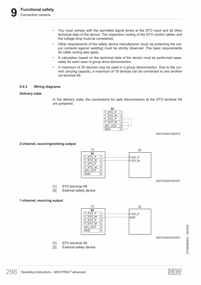
9 Functional safetyConnection variants
Operating Instructions – MOVITRAC® advanced296
• You must comply with the permitted signal levels at the STO input and all othertechnical data of the device. The respective routing of the STO control cables andthe voltage drop must be considered.
• Other requirements of the safety device manufacturer (such as protecting the out-put contacts against welding) must be strictly observed. The basic requirementsfor cable routing also apply.
• A calculation based on the technical data of the device must be performed sepa-rately for each case of group drive disconnection.
• A maximum of 20 devices may be used in a group disconnection. Due to the cur-rent carrying capacity, a maximum of 10 devices can be connected to one anothervia terminal X6.
9.4.3 Wiring diagrams
Delivery stateIn the delivery state, the connections for safe disconnection at the STO terminal X6are jumpered.
2
X6
1F_STO_P
F_STO_M
3
4
5
F_STO_P
6
F_STO_M
24V_OUT
GND
9007232451506315
2-channel, sourcing/sinking output[1] [2]
2
X6
1F_STO_P
F_STO_M
3
4
5
F_STO_P
6
F_STO_M
F-DO_P
F-DO_M
24V_OUT
GND
9007232451544331
[1] STO terminal X6[2] External safety device
1-channel, sourcing output[1] [2]
2
X6
1F_STO_P
F_STO_M
3
4
5
F_STO_P
6
F_STO_M
F-DO_P
GND
24V_OUT
GND
9007232451610251
[1] STO terminal X6[2] External safety device
2778
8490
/EN
– 0
5/20
22
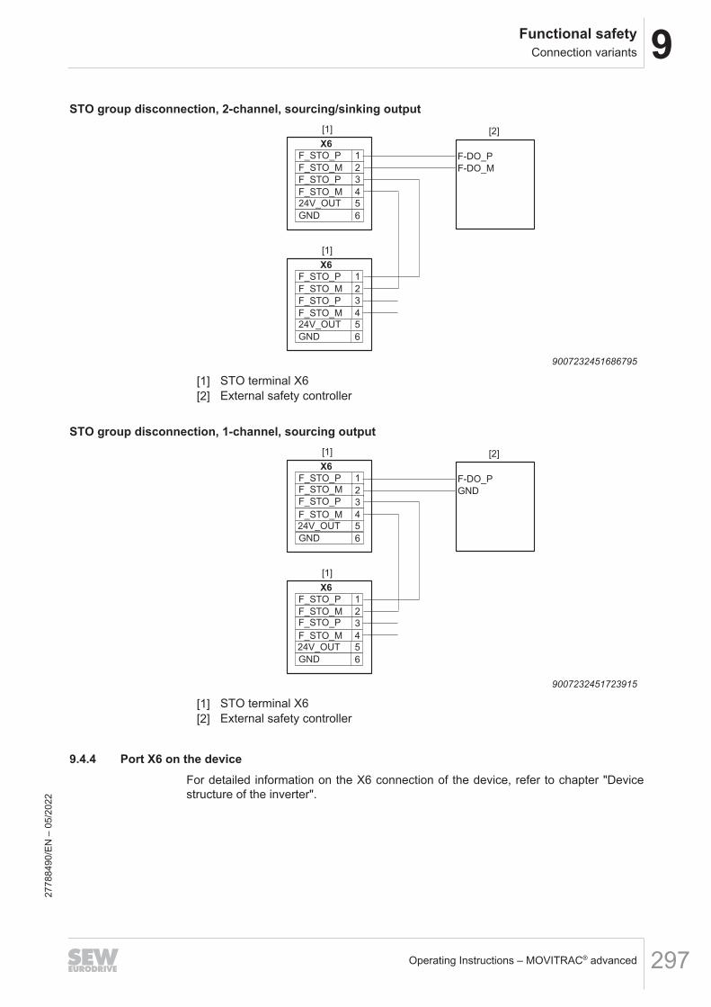
9Functional safetyConnection variants
Operating Instructions – MOVITRAC® advanced 297
STO group disconnection, 2-channel, sourcing/sinking output[1] [2]
2
X6
1F_STO_P
F_STO_M
3
4
5
F_STO_P
6
F_STO_M
F-DO_P
F-DO_M
[1]
2
X6
1F_STO_P
F_STO_M
3
4
5
F_STO_P
6
F_STO_M
24V_OUT
GND
24V_OUT
GND
9007232451686795
[1] STO terminal X6[2] External safety controller
STO group disconnection, 1-channel, sourcing output[1] [2]
2
X6
1F_STO_P
F_STO_M
3
4
5
F_STO_P
6
F_STO_M
F-DO_P
GND
[1]
2
X6
1F_STO_P
F_STO_M
3
4
5
F_STO_P
6
F_STO_M
24V_OUT
GND
24V_OUT
GND
9007232451723915
[1] STO terminal X6[2] External safety controller
9.4.4 Port X6 on the deviceFor detailed information on the X6 connection of the device, refer to chapter "Devicestructure of the inverter".
2778
8490
/EN
– 0
5/20
22
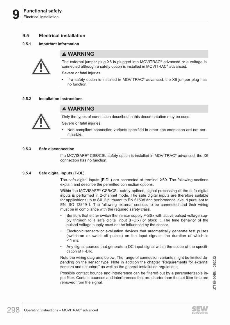
9 Functional safetyElectrical installation
Operating Instructions – MOVITRAC® advanced298
9.5 Electrical installation9.5.1 Important information
WARNINGThe external jumper plug X6 is plugged into MOVITRAC® advanced or a voltage isconnected although a safety option is installed in MOVITRAC® advanced.Severe or fatal injuries.• If a safety option is installed in MOVITRAC® advanced, the X6 jumper plug has
no function.
9.5.2 Installation instructions
WARNINGOnly the types of connection described in this documentation may be used.Severe or fatal injuries.• Non-compliant connection variants specified in other documentation are not per-
missible.
9.5.3 Safe disconnectionIf a MOVISAFE® CSB/CSL safety option is installed in MOVITRAC® advanced, the X6connection has no function.
9.5.4 Safe digital inputs (F-DI.)The safe digital inputs (F-DI.) are connected at terminal X60. The following sectionsexplain and describe the permitted connection options.Within the MOVISAFE® CSB/CSL safety options, signal processing of the safe digitalinputs is performed in 2-channel mode. The safe digital inputs are therefore suitablefor applications up to SIL 2 pursuant to EN 61508 and performance level d pursuant toEN ISO 13849-1. The following external sensors to be connected and their wiringmust be in compliance with the required safety class.• Sensors that either switch the sensor supply F-SSx with active pulsed voltage sup-
ply through to a safe digital input (F-DIx) or block it. The time behavior of thepulsed voltage supply must not be influenced by the sensor.
• Electronic sensors or evaluation devices that automatically generate test pulses(switch-on or switch-off pulses) on the input signals, the duration of which is< 1 ms.
• Any signal sources that generate a DC input signal within the scope of the specifi-cation of F-DIx.
Note the wiring diagrams below. The range of connection variants might be limited de-pending on the sensor type. Note in addition the chapter "Requirements for externalsensors and actuators" as well as the general installation regulations.Possible contact bounce and interference can be filtered out by a parameterizable in-put filter. Contact bounces and interferences that are shorter than the set filter time areremoved from the signal.
2778
8490
/EN
– 0
5/20
22

9Functional safetyElectrical installation
Operating Instructions – MOVITRAC® advanced 299
Unassigned inputs need not be wired. An open input is always evaluated as a "0" sig-nal. The safe state of the safe digital inputs is the output of "logical 0" on the associ-ated process values.The MOVISAFE® CSB/CSL safety options evaluate the digital inputs as follows.Connection type 1-channel (NC contact):
Logic level input terminal F‑DI. Process value F‑DI.0 0
1 1
Connection type 2-channel equivalent (NC contact/NC contact):
Logic level input terminalF‑DI.
Logic level input terminalF‑DI. + 1
Process valueF‑DI.
0 0 0
0 1 0
1 0 0
1 1 1
Connection type 2-channel non-equivalent (NC contact/NO contact):
Logic level input terminalF‑DI.
Logic level input terminalF‑DI. + 1
Process valueF‑DI.
0 0 0
0 1 0
1 0 1
1 1 0
With paired evaluation, 2 safe digital inputs F-DI. are combined into one input pair,which has an effect on a common process value.The assignment is made according to the following table.
Input terminal Input pair Assigned process valueF-DI0
F-DI0/1 F-DI0F-DI1
F-DI2F-DI2/3 F-DI2
F-DI3
Discrepancy monitoringThe safety option carries out discrepancy time monitoring for input pairs in the 2-chan-nel equivalent and 2-channel non-equivalent connection types. The discrepancy timemonitoring verifies whether the two input signals are delivering error-free levels thatmatch the switching state of the sensor. A deviation is tolerated for the parameterizeddiscrepancy time. An input error occurs if the deviation from the expected signal stateexceeds the discrepancy time. The discrepancy time can be adjusted for each inputpair via a parameter.
2778
8490
/EN
– 0
5/20
22

9 Functional safetyElectrical installation
Operating Instructions – MOVITRAC® advanced300
The safety option carries out a switch test function for input pairs in the 2-channelequivalent and 2-channel non-equivalent connection types in order to verify the con-nected switch for correct switching behavior following a detected discrepancy error.The switch test function can be activated and deactivated for each input pair via a pa-rameter. The switch test function assumes that the switch contacts are moved into theopened/activated state after the occurrence of the discrepancy error so that the two in-put signals assume the required state for the switch test:• Connection type; 2-channel equivalent
– F-DI. = logical "0"– F-DI. + 1 = logical "0"
• Connection type; 2-channel non-equivalent– F-DI. = logical "0"– F-DI. + 1 = logical "1"
Only in this case can the discrepancy error be acknowledged; acknowledgment is oth-erwise impossible and the input remains in the discrepancy error.
LatchingA latching function is available for the safe digital inputs. This function can be activa-ted via a parameter using the "Assist CS.." parameterization tool. Latching prevents asafety subfunction activated via the safe digital inputs from being deactivated withoutuser intervention via the change in input signals from the "0" state to the "1" state. Theinterlocking sets the process value of the safe digital input to logical "0" until an ac-knowledgment has occurred.Unlatching can occur as follows:• Via a safe digital input that is parameterized as "Acknowledge latching safe digital
input".• Via a safe digital input that is parameterized as "Acknowledge latching safe digital
input and fault".• Via the "Acknowledge F-DI" bit in the safe process output data.The inputs with active parameterization remain at logical "0" after each activation ofthe safety option until an acknowledgment has been carried out.Unlatching is performed by a 0 → 1 edge. If a permanent high signal is present on theF-DI to which the unlocking function has been assigned, this is indicated by a warningafter 20 seconds. The safe digital inputs with active parameterization remain at logical"0" after each activation of the safety option until an acknowledgment has been carriedout.If one of the following functions is assigned to the safe digital input, the latching func-tion of an F-DI must not be activated:• Acknowledge faults• Acknowledge latched F-DI• Muting• Test mode
2778
8490
/EN
– 0
5/20
22
9Functional safetyElectrical installation
Operating Instructions – MOVITRAC® advanced 301
Signal monitoringThe signal monitoring detects when the input signal is in an undefined state (unstablestate) for too long. The maximum duration for which an unstable state is permitted iscalculated from the set filter time multiplied by the parameter value of the parameterSignal monitoring (Index 8704, Subindex 8). The function can also be deactivated withthe value "0" via the Signal monitoring parameter. The safety option responds with aninput error if the signal monitoring is active and the maximum duration has been ex-ceeded.
Pulsed voltage supply and crossfault monitoringFor information about parameter setting and operating principles, refer to chapter"Startup".If crossfault monitoring is used for a safe digital input F-DI, the following assignmentbetween the sensor supply F-SS and the safe digital input F-DI must be adhered to:• F-DI00, F-DI02 via the respective sensor to F-SS0.• F-DI01, F-DI03 via the respective sensor to F-SS1.Crossfault monitoring can be selected separately for each input.If crossfault monitoring is not active (e.g. for sensors with OSSD output), the sensorscan be supplied either from F-SS0 / F-SS1 or from another +24 V supply that has thesame ground reference.
WARNINGDanger due to incorrect setting of the parameter F-DI. Connection type when con-necting 2-channel sensors. There is no redundancy or discrepancy check with the"1-channel" setting.Severe or fatal injuries.• When connecting 2-channel sensors, the parameter F-DI. connection type must
be set to "2-channel (non-equivalent/equivalent)".
Only the connection variants shown below are permitted for safe applications! Alsonote the assignment of the connection variants of the safe digital inputs to the catego-ry structures pursuant to EN ISO 13849-1.
Contact-equipped sensors (1-channel)A 1-channel sensor is connected via the sensor supply F-SS0 or F-SS1. The sensorcycle available there makes it possible for crossfaults in the wiring to be detected.Note the detailed assignment of F-DI. to the sensor supply F-SS0 or F-SS1 in thechapter "Terminal assignment".Settings in the parameterization tool "Assist CS..":• Choose the 1-channel connection type.• Depending on the requirement with respect to safety technology, activate or deac-
tivate the "crossfault monitoring" and pulsed voltage supply of the sensor supply.
2778
8490
/EN
– 0
5/20
22

9 Functional safetyElectrical installation
Operating Instructions – MOVITRAC® advanced302
The following figure shows the MOVISAFE® CSB/CSL safety option with 1-channelsensors with contacts.
9
10
3, 4, 7, 8
F-SS0
F-DI00
F-DI01
F-DI02
F-DI03
F-SS1
GND
1
5
2
6
X60
X60
MOVISAFE® CSB/CSL
33512478859
Operation with activated crossfault monitoringThe following faults are detected:• Crossfault between every digital input line F-DI. and a 24 V supply voltage.• Crossfault between a digital input line F-DIx and another digital input line F-DIy,
which is assigned to another sensor supply, if at least the associated switch con-tact of the other digital input F-DIy is closed.
• Crossfault between a digital input line F-DI. and a sensor supply line not assignedto the input F-DI.
• Crossfault between a sensor supply line F-SS and a 24 V supply voltage if the digi-tal input F-DI is assigned to the sensor supply and the switch contact belonging toF-DI is closed.
• Crossfault between the sensor supply lines F-SS themselves if the switch contactbelonging to the digital input F-DI is closed.
WARNINGThe MOVISAFE® CSB/CSL safety option cannot detect a short circuit between anF-SS. sensor supply and an associated safe input F-DI.Severe or fatal injuries.• Make sure that no short circuit between the sensor supply F-SS. and an associ-
ated safe input F-DI. is possible.
WARNINGIf crossfault monitoring is deactivated, the MOVISAFE® CSB/CSL safety option can-not detect crossfaults in the wiring. This configuration is not permitted for safe appli-cations without further measures.Severe or fatal injuries.• A 1-channel sensor with crossfault monitoring can achieve a category 2 structure
pursuant to EN ISO 13849-1.
Sensors with contact (2-channel)A 2-channel contact-equipped sensor is connected via the sensor supply F-SS0 andF-SS1. Note the detailed assignment of the safe digital inputs (F-DI.) to the sensorsupply F-SS0 and F-SS1 in chapter "Terminal assignment".
2778
8490
/EN
– 0
5/20
22
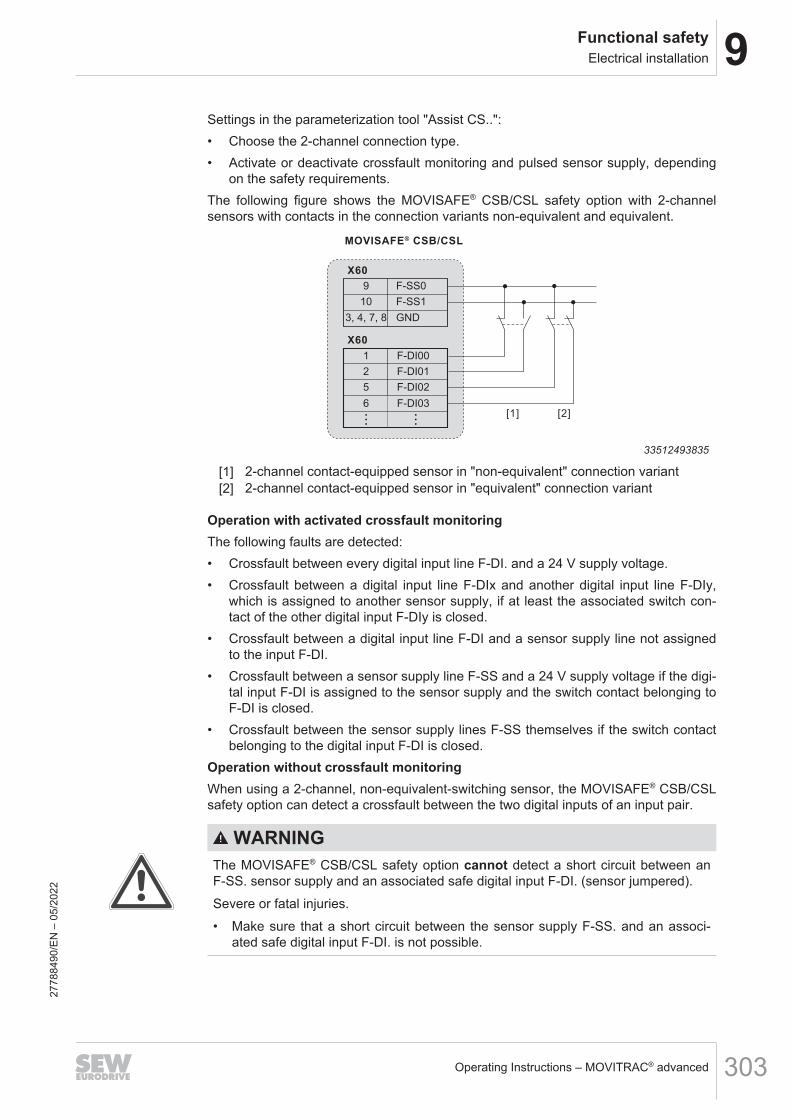
9Functional safetyElectrical installation
Operating Instructions – MOVITRAC® advanced 303
Settings in the parameterization tool "Assist CS..":• Choose the 2-channel connection type.• Activate or deactivate crossfault monitoring and pulsed sensor supply, depending
on the safety requirements.The following figure shows the MOVISAFE® CSB/CSL safety option with 2-channelsensors with contacts in the connection variants non-equivalent and equivalent.
9
10
3, 4, 7, 8
F-SS0
F-DI00
F-DI01
F-DI02
F-DI03
F-SS1
GND
1
5
2
6
X60
X60
MOVISAFE® CSB/CSL
[1] [2]
33512493835
[1] 2-channel contact-equipped sensor in "non-equivalent" connection variant[2] 2-channel contact-equipped sensor in "equivalent" connection variant
Operation with activated crossfault monitoringThe following faults are detected:• Crossfault between every digital input line F-DI. and a 24 V supply voltage.• Crossfault between a digital input line F-DIx and another digital input line F-DIy,
which is assigned to another sensor supply, if at least the associated switch con-tact of the other digital input F-DIy is closed.
• Crossfault between a digital input line F-DI and a sensor supply line not assignedto the input F-DI.
• Crossfault between a sensor supply line F-SS and a 24 V supply voltage if the digi-tal input F-DI is assigned to the sensor supply and the switch contact belonging toF-DI is closed.
• Crossfault between the sensor supply lines F-SS themselves if the switch contactbelonging to the digital input F-DI is closed.
Operation without crossfault monitoringWhen using a 2-channel, non-equivalent-switching sensor, the MOVISAFE® CSB/CSLsafety option can detect a crossfault between the two digital inputs of an input pair.
WARNINGThe MOVISAFE® CSB/CSL safety option cannot detect a short circuit between anF-SS. sensor supply and an associated safe digital input F-DI. (sensor jumpered).Severe or fatal injuries.• Make sure that a short circuit between the sensor supply F-SS. and an associ-
ated safe digital input F-DI. is not possible.
2778
8490
/EN
– 0
5/20
22

9 Functional safetyElectrical installation
Operating Instructions – MOVITRAC® advanced304
WARNINGIf crossfault monitoring is deactivated and a 2-channel, equivalent-switching sensoris used, the MOVISAFE® CSB/CSL safety option cannot detect crossfaults in thewiring.Severe or fatal injuries.• Make sure that crossfaults are not possible at the safe digital inputs F-DI.
INFORMATIONNote that in the non-equivalent connection variant, the NC contact is connected tothe sensor supply F-SS0.
Active sensors (2-channel)When connecting a 2-channel sensor with additional voltage supply, the voltage issupplied via an external DC 24 V power supply. The voltage supplies for the sensoroutputs are connected to the sensor supply F-SS0 and F-SS1. The safe outputs of thesensor are connected with 2 channels to the respective safe digital inputs (F-DI.) atterminal X60. Note the detailed assignment of the safe digital inputs (F-DI.) to thesensor supply F-SS0 and F-SS1 in chapter "Terminal assignment".Settings in the parameterization tool "Assist CS..":• Choose the 2-channel connection type (equivalent/non-equivalent).• Activate or deactivate the pulsed sensor supply, depending on the safety require-
ments.• Parameterize the permitted discrepancy time between the two input signals of the
sensor you are using.
2778
8490
/EN
– 0
5/20
22

9Functional safetyElectrical installation
Operating Instructions – MOVITRAC® advanced 305
The following figure shows the MOVISAFE® CSB/CSL safety option with an activesensor (2-channel).
DC 24 V
0 V
[6]
9
10
3, 4, 7, 8
F-SS0
F-DI00
F-DI01
F-DI02
F-DI03
F-SS1
GND
1
5
2
6
X60
X60
MOVISAFE® CSB/CSL
Pulse1 [2]
Pulse2 [3]
Out1 [4]
Out2 [5]
+24V
0V
[1]
33516311179
[1] Active 2-channel sensor[2] Supply of output 1 (Out1)[3] Supply of output 2 (Out2)[4] Safe digital output 1[5] Safe digital output 2[6] External DC 24 V voltage supply
Operation with activated crossfault monitoringThe following faults are detected:• Crossfault between every digital input line F-DI. and a 24 V supply voltage.• Crossfault between a digital input line F-DIx and another digital input line F-DIy,
which is assigned to another sensor supply, if at least the associated switch con-tact of the other digital input F-DIy is closed.
• Crossfault between a digital input line F-DI. and a sensor supply line not assignedto the input F-DI.
• Crossfault between a sensor supply line F-SS and a 24 V supply voltage if the digi-tal input F-DI is assigned to the sensor supply and the switch contact belonging toF-DI is closed.
• Crossfault between the sensor supply lines F-SS themselves if the switch contactbelonging to the digital input F-DI is closed.
WARNINGThe MOVISAFE® CSB/CSL safety option cannot detect a short circuit between anF-SS. sensor supply and an associated safe digital input F-DI. (sensor jumpered).Severe or fatal injuries.• Make sure that a short circuit between the sensor supply F-SS. and an associ-
ated safe digital input F-DI. is not possible.2778
8490
/EN
– 0
5/20
22
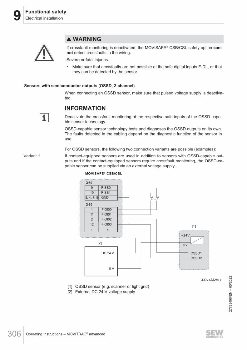
9 Functional safetyElectrical installation
Operating Instructions – MOVITRAC® advanced306
WARNINGIf crossfault monitoring is deactivated, the MOVISAFE® CSB/CSL safety option can-not detect crossfaults in the wiring.Severe or fatal injuries.• Make sure that crossfaults are not possible at the safe digital inputs F-DI., or that
they can be detected by the sensor.
Sensors with semiconductor outputs (OSSD, 2-channel)When connecting an OSSD sensor, make sure that pulsed voltage supply is deactiva-ted.
INFORMATIONDeactivate the crossfault monitoring at the respective safe inputs of the OSSD-capa-ble sensor technology.OSSD-capable sensor technology tests and diagnoses the OSSD outputs on its own.The faults detected in the cabling depend on the diagnostic function of the sensor inuse.
For OSSD sensors, the following two connection variants are possible (examples):Variant 1 If contact-equipped sensors are used in addition to sensors with OSSD-capable out-
puts and if the contact-equipped sensors require crossfault monitoring, the OSSD-ca-pable sensor can be supplied via an external voltage supply.
DC 24 V
0 V
[2]
9
10
3, 4, 7, 8
F-SS0
F-DI00
F-DI01
F-DI02
F-DI03
F-SS1
GND
1
2
11
12
X60
X60
MOVISAFE® CSB/CSL
OSSD1
OSSD2
+24V
0V
[1]
33314332811
[1] OSSD sensor (e.g. scanner or light grid)[2] External DC 24 V voltage supply
2778
8490
/EN
– 0
5/20
22

9Functional safetyElectrical installation
Operating Instructions – MOVITRAC® advanced 307
Variant 2 If only OSSD sensors are used, the voltage can also be supplied via terminals F-SS0and F-SS1. In this case, deactivate the pulsed sensor voltage supply (F-SS0 and F-SS1) in the "Assist CS.." parameterization tool.
[1]
9
10
3, 4, 7, 8
F-SS0
F-DI00
F-DI01
F-DI02
F-DI03
F-SS1
GND
0
5
2
6
X60
X60
MOVISAFE® CS..A
OSSD1
OSSD2
+24V
0V
33314842635
[1] OSSD sensor (e.g. scanner or light grid)
INFORMATIONThe performance level that can be achieved is mainly determined by the OSSDsensors used.Use the external voltage supply for sensors that have a higher current consumptionthan the F-SS. sensor supply lines can provide.
2778
8490
/EN
– 0
5/20
22
9 Functional safetyElectrical installation
Operating Instructions – MOVITRAC® advanced308
9.5.5 Safe digital output (F-DO00)
General informationSignal processing of the safe digital output within the MOVISAFE® CSL safety optionis performed in 2 channels. The safe digital output can therefore achieve SIL 2 pursu-ant to EN 61508 and performance level d pursuant to EN ISO 13849-1. The externalactuators to be connected and their wiring must comply with the respective requiredsafety class.The actuators can be connected to the safe digital output F-DO00 via 2 channels,sourcing/sinking output, or via 1 channel, sourcing output.The following functions can be assigned to the safe digital outputs:• None
Control of the safe digital output F‑DO via the safe process data. If no safe pro-cess data has been activated, the safe digital output is open.
• STOF‑DO behaves like F‑DO_STO. Control via safe process data is not possible.
• SBCA brake is connected to the safe digital output. Control via safe process data isonly possible indirectly via the STO safety subfunction. The basic device controlsthe brake when the STO safety subfunction is inactive. The SBC function can onlybe activated if a brake has been parameterized in the inverter in drive train 1.
Set the respective configuration during startup using the parameterization tool "AssistCS..".1-channel, sinking digital outputs are not permitted.It is not necessary to use shielded cables for all safe digital outputs.Note the dependency of the achieved performance level (PL) and SIL on the selectedconnection variant of the safe digital outputs. A maximum switching frequency of10 Hz is permitted for the safe digital output F‑DO00. The switching state of the safedigital output F-DO00 must be stable for at least 2 seconds at least once within60 seconds. If a fault is detected by diagnostics, the "output error" error response oc-curs, which disables all outputs. The consequence of this is that the respective digitaloutput is switched to the safe state "open".Diagnostics can be activated optionally for the safe digital output F‑DO00. Diagnosticssafely detects a wire break in the interrupted output current circuit.If a wire break is detected, the "Output error" error response occurs, which blocks alloutputs.In standalone operation, the outputs of the safety option can be safely disabled. Thismeans that the safe outputs are switched at the same time as the internal STO outputor with a time delay, depending on the parameterization. The outputs can also be setsafely via a safe fieldbus, e.g. to unlock a door lock when the machine is in the idlestate.One safe F-DO digital output can be used to control up to 10 STO inputs to units ofthe MOVI-C® modular system or one STO input and one safe SBM brake module.
2778
8490
/EN
– 0
5/20
22
9Functional safetyElectrical installation
Operating Instructions – MOVITRAC® advanced 309
Capacitive loads• A capacitive load of no more than 10 nF is allowed to be connected to the output
without any additional measures. Capacitive loads often occur in electronic assem-blies as buffer capacitors.If the capacitive load has a diode in series to its input, the maximum load capacitypermitted is 12 µF. This diode is often installed as polarity protection diode in elec-tronic assemblies.
• If the capacitive load is not known or is higher than 10 nF, the inrush current mustbe limited to the permitted values of the output pursuant to EN 61131-2.
INFORMATIONDue to the thermal load of the output components, the maximum switching frequencyof the digital outputs in the presence of capacitive loads must be limited to the valuespecified in chapter "Technical data" > "Safe digital outputs".
Inductive loadsInductive loads are, for example, relays, contactors, and valves.• Inductive loads always must be connected between sourcing and sinking outputs.• The energy stored in the load inductance, which depends on the inductance value
and the current, may not exceed the values specified in chapter "Technical data".
NOTICEOperation of inductive loads without freewheeling diode can damage theMOVISAFE® CSL safety option.Damage to the MOVISAFE® CSL safety option• Inductive loads must always be connected via a freewheeling diode. The safe
digital output of the MOVISAFE® CSL safety option does not have a freewheelingdiode.
• Varistors and other overvoltage protection elements are not permitted.
Ohmic loadsLight bulbs are examples of ohmic loads.• Lamps can be connected for display purposes. Note that an increased cold current
flows when incandescent lamps or halogen lamps are switched on. The cold cur-rent must not exceed the permitted output current pursuant to EN 61131-2.
Information about line diagnostics and test pulsesFor monitoring of the cabling, the output circuit uses test pulses and thus detectsfaults in the external wiring. This means the output voltage is interrupted briefly(pulsed). The maximum duration of the interruption can be set in the F-DO parameterMaximum test duration. The required duration of test pulses is determined by the ca-pacitances in the connected load, which affect the line diagnostics.For safe disconnection of MOVISAFE® CSL with maximally 10 MOVITRAC® advancedunits, a test pulse duration of 1 ms is to be used.Total capacitance must not exceed 1 µF with the maximum test pulse duration(5000 µs).
2778
8490
/EN
– 0
5/20
22

9 Functional safetyElectrical installation
Operating Instructions – MOVITRAC® advanced310
For the 24 V switching output F-DO00, line diagnostics is always active regardless ofthe parameter setting.
WARNINGWhen line diagnostics is deactivated, the MOVISAFE® CSL safety option cannot de-tect a short circuit between a sourcing output (F‑DO00_P) and the +24 V supplyvoltage, or between a sinking output (F‑DO00_M) and the reference potential.Severe or fatal injuries.Install the wiring in such a way that no short circuit is possible:• Between a sourcing output (F-DO00_P) and the +24 V supply voltage.• Or between a sinking output (F-DO00_M) and the reference potential.
The safe digital output F‑DO00 is equipped with an optional wire break monitoring.The wire break monitoring checks whether the connected actuator is consuming aminimum current. If the actuator current is below the minimum value, the MOVISAFE®
CSL safety option detects this as an open circuit.Activate wire break monitoring only if you are sure that the current consumption of theactuator is always above the minimum current (see chapter "Technical data" > "Safedigital outputs").
Internal safe digital output F‑DO_STOThe CSB/CSL safety options have one internal safe digital output F‑DO_STO forswitching the device-internal STO function of the inverter.A maximum switching frequency of 10 Hz is permitted for the internal safe digital out-put F-DO_STO. The switching state of the internal safe digital output F‑DO_STO mustbe stable for at least 2 seconds at least once within 60 seconds.The internal safe digital output F‑DO_STO is always operated in the connection type"2‑channel sourcing" and must only be used for the STO function of the inverter. If thediagnostics implemented for the internal safe digital output F‑DO_STO detects a fault,the error response "output error" occurs, which disables all outputs.
Actuator (2-channel, sourcing/sinking output)
F-DO00_P
F-DO00_M
12
11
X60
MOVISAFE® CSL
[1]
33518124427
[1] Actuator
Connect the actuator between F‑DO00_P and F‑DO00_M. The actuator can still beswitched off in case of a crossfault in one of the connection lines, because theMOVISAFE® CSL safety option disconnects the sourcing and the sinking output termi-nal.The input of the actuator must be isolated and without any connection to a referencepotential. Inside the MOVISAFE® CSL safety option there is a switching elementbetween F‑DO00_M and the reference potential. With a non-isolated actuator, thisswitching element would be bridged. The redundancy of the sourcing and sinking out-put would no longer apply.
2778
8490
/EN
– 0
5/20
22

9Functional safetyElectrical installation
Operating Instructions – MOVITRAC® advanced 311
The sourcing/sinking output connection variant is suitable for applications up to SIL 3according to EN 61508 and Performance Level e according to EN ISO 13849-1.Fault detection using line diagnosticsThe MOVISAFE® CSL safety option detects the following faults in the external wiringwhen the output is disabled or enabled:• Short circuit between sourcing output and a supply voltage that lies within the
range of 15 to 30 V and has the same ground reference as the MOVISAFE® CSL.• Short circuit between the sinking output and the reference potential or a voltage
< 6 V.The MOVISAFE® CSL safety option can also detect the following faults when the out-put is enabled:• Short circuit between different sourcing outputs• Short circuit between different sinking outputs• Short circuit between sourcing output and sinking output• Short circuit between sourcing output and GND• Overload at every output• Open circuit (with F-DO., if activated)
INFORMATIONIn case of a short circuit, a high short-circuit current can occur for a short time. De-pending on the DC 24 V supply voltage used, this can cause a voltage drop that af-fects the operation of MOVITRAC® advanced and/or individual assemblies.If the voltage supply is not stable enough, it may result in a reset and a restart of theMOVISAFE® CSL safety option.• Make sure the voltage supply does not break down in the event of short circuits at
the output.
Actuator (1-channel, sourcing output)
F-DO00_P
F-DO00_M
GND
GND
12
11
07
08
X60
MOVISAFE® CSL
[1]
33518128779
[1] Actuator
Connect the actuator between F‑DO00_P and the GND reference potential.The actuator input need not be isolated.The sourcing output connection variant is suitable for applications up to SIL 2 pursuantto EN 61508 and performance level d pursuant to EN ISO 138491.The MOVISAFE® CSL safety option detects the following faults in the external wiringwhen the output is disabled or enabled:• Short circuit between sourcing output and a supply voltage that lies within the
range of 15 to 30 V and has the same ground potential as the assembly.2778
8490
/EN
– 0
5/20
22
9 Functional safetyElectrical installation
Operating Instructions – MOVITRAC® advanced312
The MOVISAFE® CSL safety option can also detect the following faults when the out-put is enabled:• Short circuit between different sourcing outputs• Short circuit between the P output and the reference potential 0 V• Overload at every output• Wire break F-DO., if activated)
WARNINGIn case of a short circuit between the sourcing output and a 24 V supply voltage, theMOVISAFE® CSL safety option can no longer switch off the actuator and otherwiseenter a safe state.The line diagnostics function can detect the fault. However, the MOVISAFE® CSLsafety option cannot enter a safe state as there is no redundant switch-off channel inthis connection variant.Severe or fatal injuries.• Route the cables in such a way that no short circuit can occur between the
sourcing output and a +24 V supply voltage.• Make sure that an additional redundant switch-off channel exists for the actuator
(e.g. by using a second sourcing output).
INFORMATIONSEW-EURODRIVE recommends the sourcing/sinking output connection, if possible.For safe outputs, refer also to details in the chapter "Technical data".
INFORMATIONIn case of a short circuit, a high short-circuit current can occur for a short time. De-pending on the 24 V supply voltage used, this can cause a voltage drop that affectsthe operation of MOVITRAC® advanced and/or individual assemblies.If the voltage supply is not stable enough, it may result in a reset and a restart of theMOVISAFE® CSL safety option.• Make sure the DC 24 V voltage supply does not break down in the event of short
circuits at the output.27
7884
90/E
N –
05/
2022

9Functional safetyElectrical installation
Operating Instructions – MOVITRAC® advanced 313
9.5.6 Built-in encoder EI7C FS
PropertiesThe EI7C FS built-in encoder is a safe incremental encoder with 24 signal periods perrevolution.You may only use the EI7C FS built-in encoder in conjunction with the MOVISAFE®
CSL safety option.MOVISAFE® CSL can detect a minimum speed of 60 min-1 in connection with anEI7C FS built-in encoder.MOVISAFE® CSL evaluates the signal of the EI7C FS built-in encoder.MOVISAFE® CSL and the EI7C FS built-in encoder monitor the encoder signal. TheMOVISAFE® CSL safety option detects interruptions and crossfaults in the encoderline. If a fault occurs, MOVISAFE® CSL activates the STO safety subfunction inMOVITRAC® advanced, and the torque is switched off safely.
InstallationConnect the EI7C FS built-in encoder to the X18 encoder interface ofMOVITRAC® advanced via the encoder cable (part number 18118804) (see chapter"Encoder cable for EI7C FS").
WARNINGIncorrect wiring can disable the encoder function and monitoring features for the en-coder.Severe or fatal injuries.• You may connect the EI7C FS built-in encoder only with the MOVISAFE® CSL
safety option.• You may only connect the encoder signals to the designated encoder interface of
MOVITRAC® advanced. It is not permitted to connect other devices or assem-blies.
INFORMATIONWhen connecting an EI7C FS built-in encoder to the MOVITRAC® advanced, the en-coder cable must not carry a TF signal.
2778
8490
/EN
– 0
5/20
22

9 Functional safetyStartup
Operating Instructions – MOVITRAC® advanced314
9.6 Startup9.6.1 Important information
WARNINGUnexpected and unwanted movement of the drive may occur during parameteriza-tion of the safety option.Severe or fatal injuries.• Before parameterization, make sure the system is in idle state.
INFORMATIONNo safety subfunction is enabled in the delivery state of the safety option. The safetyoption permanently activates STO.
9.6.2 General startup instructions
INFORMATION• The startup procedure for the standard functions of MOVITRAC® advanced is de-
scribed in the "MOVITRAC® advanced inverter" operating instructions.• If a brake is connected to the MOVITRAC® advanced, the FCB 01 Output stage
inhibit function block must be selected in the MOVISUITE® parameter tree under[Functions] > [Drive functions]. In FCB 01 Output stage inhibit, the Apply brake inevent of STO parameter must be set to "On".
• The following chapters describe the additional startup procedure for theMOVISAFE® CSB/CSL safety option and the safety subfunctions.
• Note the prerequisites for installation and operation of MOVISUITE®.• The MOVISAFE® CSB and CSL safety options are supported by MOVISUITE®
version 2.20 and higher.• The CIP Safety™ safety protocol and the EDM diagnostics function are supported
by the safety options as of firmware version 4.01, the basic unit firmware as ofversion 9.0 and MOVISUITE® as of version 2.30.
• Make sure that the PROFIsafe Slave Editor and the Assist CS.. parameterizationtool are not used simultaneously in the system. The parameterization tool usedmust be open only once.
• When starting up several similar devices with identical parameterization, thedevices can be parameterized using the "Import/Export" function. Note that youmust accept every single device to accomplish this.
• If the SBC safety subfunction is active, the brake is controlled via the selected F-DO00. The safe digital output F‑DO00 additionally performs the function of thebrake control DB00. The DB00 connection on the basic device does not have tobe used additionally. The SBM safe brake module (in size 3 or larger ofMOVITRAC®advanced) can be used as a safe actuator for controlling the brake.
2778
8490
/EN
– 0
5/20
22

9Functional safetyStartup
Operating Instructions – MOVITRAC® advanced 315
9.6.3 Startup options
RequirementsFor a successful startup, you need the "Assist CS.." parameterization tool. You cancall up the "Assist CS.." parameterization tool directly in MOVISUITE® (download fromwww.sew-eurodrive.com).
Parameterization procedureThis chapter describes how to set the parameters of the safety functions step-by-step.1. Start MOVISUITE®.2. Scan the network.
Scan the network that contains your engineering interface to the MOVITRAC®
device (USB, Ethernet, etc.).3. Start the "Assist CS.." parameterization tool.
Start the "Assist CS.." parameterization tool from the MOVISUITE® interface.A window opens with a prompt to enter the ID of the safety key and the password.
4. Enter the safety key ID number of the device and establish a connection.Enter the safety key ID of the safety option to be parameterized and the corre-sponding password, and confirm the entry with [OK].The safety key ID is printed on the safety key. During the first connection, you canset a password by entering it twice.The querying of the safety key ID ensures that the "Assist CS.." parameterizationtool connects to the correct device.As an alternative, you can read the safety key ID via the "Assist CS.." parameteri-zation tool. Proceed as follows:• Click on the [Read safety key ID] button.• Check if the addressed device signals a read safety key ID operation via the "F-
RUN" LED (see chapter "F-RUN LED"). This process may not take longer thana minute. After one minute, the device LED does not flash anymore and con-firmation of the flash code is no longer accepted. In this case, restart the flashcode query.
• The read safety key ID is applied in the "Safety key ID" field.5. Upload the current parameterization of the device.
Once the safety key ID is entered, the current parameterization of the CSB/CSLsafety options is compared to the current parameterization in the "Assist CS.." pa-rameterization tool. If both data sets are identical, the “Assist CS..” parameteriza-tion tool starts. In case of deviation, a dialog opens in which the user can choosewhether the data set of the safety option or the data set of the "Assist CS.." isused.
2778
8490
/EN
– 0
5/20
22

9 Functional safetyStartup
Operating Instructions – MOVITRAC® advanced316
6. ParameterizationSet the parameterization according to your safety-related requirements of your ap-plication.To parameterize the MOVISAFE® CSB/CSL safety options, call up the individualareas in the parameter tree and enter the required input values. The higher-levelparameters, such as IO fault effects, fieldbus connection, encoder activation, andlimit speeds of the motor are set in the "General parameters" area. The parameter-ization of the sensors and actuators are set in the "F-DI" and "F-DO" areas. Theparameters of the safety subfunctions are then set and assigned to the parameter-ized inputs/outputs in the "Function assignment" area.The "Assist CS.." parameterization tool creates a parameter set from all of the pa-rameters.
7. Transferring the parameter set to the deviceClicking the [Download] button transfers the parameter set to the MOVISAFE®
CSB/CSL safety options.After the download, the transferred parameter set is checked for consistency andplausibility. Possible inconsistencies or plausibility errors are displayed and canthen be corrected.
When the parameter set has been transferred to the MOVISAFE® CSB/CSL safety op-tions without any problems, you can start up the standard functions and, if required,connect it to the higher-level safety controller (F‑PLC).
Variant 1: Independent operation (without connection to safe communication)The MOVISAFE® CSB/CSL safety options can be parameterized and operated withoutsafe communication connection (independent operation).Take into account the following constraints for this operating mode:• The parameters of the MOVISAFE® CSB/CSL safety options are set using the "As-
sist CS.." parameterization tool.• The safety-relevant acceptance of the system is supported by an acceptance pro-
tocol generated in the "Assist CS.." parameterization tool.For startup, perform the following steps:1. Parameterization of drive safety functions in the "Assist CS.." parameterization
tool.2. Startup of the standard functions.
For detailed information, refer to chapter "Startup" in the "MOVITRAC® advanced“operating instructions.
3. The acceptance is supported by the "Assist CS.." parameterization tool.
Variant 2: With connection to safe communicationThe MOVISAFE® CSB/CSL safety options can be parameterized and operated (field-bus connection) with connection to safe communication (e.g. PROFIsafe, Safety overEtherCAT®, CIP Safety™).Take into account the following constraints for this operating mode:• The parameters of the MOVISAFE® CSB/CSL safety options are set using the "As-
sist CS.." parameterization tool.• The validation of the system is supported by an acceptance protocol generated in
the "Assist CS.." parameterization tool. 2778
8490
/EN
– 0
5/20
22

9Functional safetyStartup
Operating Instructions – MOVITRAC® advanced 317
For startup, perform the following steps:1. Parameterization of safety subfunctions in the "Assist CS.." parameterization tool.2. Startup of the fieldbus and the higher-level F-PLC.3. Startup of the standard functions.
For detailed information, refer to chapter "Startup" in the "MOVITRAC® advanced“operating instructions.
4. The acceptance is supported by the "Assist CS.." parameterization tool. When theacceptance protocol is created, the ParCRCBus parameter is updated and mustbe adjusted in the safety controller.
9.6.4 Adjusting the maximum test duration for load with unknown capacitanceIn order to determine the "Maximum test duration" parameter (Index 8705.2) for a loadwith unknown capacitance at the safe digital output F-DO00, proceed as follows:1. Select the safe digital output F-DO00. Connect the load according to the selected
connection type and set the "Connection type".2. Set the "Maximum test duration" parameter (Index 8705.2) to the maximum value
of 5000 μs.3. Interconnect the selected output for at least 10 seconds.4. Form the maximum value from the following values for the selected output:
• Value of the "Maximum duration test pulse A" display parameter (Index8703.37)
• Value of display parameter "Maximum duration test pulse B" (Index 8703.8)5. Block the selected output for at least 10 seconds.6. Form the maximum value from the following values for the selected output:
• Formed maximum value from step 4• Value of the "Maximum duration test pulse A" display parameter (Index
8703.37)• Value of display parameter "Maximum duration test pulse B" (Index 8702.8)
7. In order to specify the "Maximum test duration" value (Index 8705.2), add a re-serve of 500 μs to the maximum value determined in step 6.
9.6.5 Starting up encoder systems
Encoder evaluation of the CSL safety optionThe CSL safety option supports the EI7C FS safe encoder. The encoder used is con-sidered a safe encoder. The following conditions are met:• The encoder meets the prescribed safety requirements according to
EN ISO 13849‑1 and EN 62061.• The encoder is approved for the use of speed/position-dependent safety subfunc-
tions.The safe encoder EI7C FS is connected to the standard inverter at X18.In assist CS.., select the used encoder in the "Encoder" dialog via the "Encoder type"drop-down menu. All required encoder settings are applied. The parameter is markedwith an "i" if the selection of the encoder differs from the set motor encoder in the drivetrain.27
7884
90/E
N –
05/
2022
9 Functional safetyStartup
Operating Instructions – MOVITRAC® advanced318
9.6.6 Parameterizing safety subfunctions
RequirementsTo use the safety subfunctions, certain process values must be available.• For the SS1-r, SLS and SSM safety subfunctions, the process values "Speed" and
"Acceleration" must be generated.• The process value "position" is used for the SDI safety subfunction.• All limit speeds of the safety subfunctions must be between the minimum speed
and the maximum speed.With the CSL safety option , the required process values are generated when the en-coder is selected.Proceed in this order:1. Configure the drive train in the inverter with all the encoders involved and the user
units.2. Open the "Assist CS.." parameterization tool and log in. The user units configured
in the drive train are transferred to the "assist CS.." parameterization tool.3. Apply the encoder parameters to the safe configuration.4. The safety subfunctions can be activated via parameterization, safe digital inputs
F‑DI or safe process data. Activation via safe digital inputs F‑DI and safe processdata is performed with logic "0".
STO safety subfunction with MOVISAFE® CSB/CSLWhen the safety subfunction STO is activated, the internal safe digital output F-DO_STO and the safe digital output F-DO00, that are assigned to the STO function,are switched off. In the basic device, the function block FCB01 Output stage inhibit ac-tivated and the status STO is set.If the SBC enable parameter is parameterized to "Yes", the safe digital output F-DO00is switched off immediately when the STO function is activated if the SBC function isassigned to it. Once the time defined in the parameter Brake application time elapsed,the internal safe digital output F-DO_STO and all safe digital outputs F‑DO assignedto the STO function are disabled with a delay.If the STO function is activated due to a limit value violation of a safety subfunction,the internal safe digital output F-DO_STO and the safe digital output F-DO00 assignedto the STO/SBC function are switched off immediately.If a limit value violation of a safety subfunction, a system error, or an output error oc-curs during the brake application delay, the brake application time is immediatelystopped and the internal safe digital output F-DO_STO and all safe digital outputsF‑DO assigned to the STO function are disabled. The safe digital outputs F-DO as-signed to the SBC function are already switched off.If the STO function is deactivated, the internal safe digital output F-DO_STO and allsafe digital outputs F-DO assigned to the STO/SBC function are disabled immediately.
2778
8490
/EN
– 0
5/20
22

9Functional safetyStartup
Operating Instructions – MOVITRAC® advanced 319
Activation
Number of instances: 1The STO/SBC safety subfunction can be activated by the following sources:• F-DI (function assignment)• Safe process output data (STO 1)• SSx 1/2 final state• Fault response• Limit value violation
Status
The status of the STO/SBC safety subfunction is displayed in the following areas:• MOVISAFE® CSB/CSL diagnostics, STO status• Safe process input data (STO 1)
SS1-r safety subfunction with MOVISAFE® CSLThe SS1-r safety subfunction monitors the amount of motor deceleration within speci-fied limits. The STO safety subfunction is activated if the motor speed drops below aspecified limit value. When the limit speed is exceeded, the STO safety subfunction isactivated without brake application delay.If the SS1‑r safety subfunction is activated, first the parameterized Monitoring delay(8706.9) applies. During the monitoring delay, the parameterized Maximum speed(8707.1) is monitored. Then the monitoring of the parameterized speed ramp starts.If the Ramp monitoring parameter is set to "linear", monitoring of the linear speedramp starts at the currently detected actual speed when the SS1‑r safety subfunctionis activated. The end speed of the speed ramp is the parameterized maximum speed.If the Ramp monitoring parameter is set to "jerk-limited", monitoring of the jerk-limitedspeed ramp starts at the currently detected actual speed and the parameterized offsetspeed when the SS1‑r safety subfunction is activated. The end speed of the speedvalue is either the parameterized minimum speed or, if larger, the parameterized offsetspeed.If the limit speed of the speed ramp reaches the end speed, the final state of the STOfunction is activated.If the Inverter control parameter is set to "active", activating the safety subfunction re-sults in the activation of the FCB13 Application stop drive function in the inverter.If the Inverter control parameter is set to "Not active", the inverter is not controlled.If the Inverter control parameter is set to "Active with limiting", the stop ramp of the in-verter is limited to the following values:• Minimum value of the SSx deceleration• Maximum value of the parameterized jerk time
Activation
Number of instances: 2 (SSx1, SSx2)The safety subfunction can be activated by the following sources:• F-DI (function assignment)• Safe process output data (SSx1, SSx2)27
7884
90/E
N –
05/
2022

9 Functional safetyStartup
Operating Instructions – MOVITRAC® advanced320
Status
The status of the safety subfunction is displayed in the following areas:• MOVISAFE® CSB/CSL diagnostics, speed function status• Safe process input data (SSx1, SSx2)
Limit value violation
Due to the value limit violation, the STO safety subfunction is activated without brakeapplication delay.The value limit violation must be acknowledged. By deactivating the SSx function, thelimit value violation is not acknowledged. The SSx function cannot be reactivated withan existing limit value violation. The fault can only be acknowledged if the SSx func-tion is deactivated. After fault acknowledgment, the final state of the SSx function isactive immediately.
Encoder faultIf an encoder fault occurs, the STO safety subfunction is activated immediately withoutbrake application delay. The status of the SSx function becomes inactive. The en-coder fault must be acknowledged. The encoder fault cannot be acknowledged by de-activating the SSx function.
SS1-t safety subfunction with MOVISAFE® CSB/CSLThe SS1-t safety subfunction monitors the parameterized time delay and triggers theSTO safety subfunction once the time delay has elapsed.If the parameter Inverter control is set to "active", activating the SS1-t safety subfunc-tion results in the activation of the FCB13 Application stop drive function in the in-verter.If the Inverter control parameter is set to "Not active", the inverter is not controlled.
Activation
Number of instances: 2 (SSx1, SSx2)The safety subfunction can be activated by the following sources:• F-DI (function assignment)• Safe process output data (SSx1, SSx2)
Status
The status of the safety subfunction is displayed in the following areas:• MOVISAFE® CSB/CSL diagnostics, speed function status• Safe process input data (SSx1, SSx2)
Limit value violation
Due to the value limit violation, the STO safety subfunction is activated without brakeapplication delay.The value limit violation must be acknowledged. By deactivating the SSx function, thelimit value violation is not acknowledged. The SSx function cannot be reactivated withan existing limit value violation. The fault can only be acknowledged if the SSx func-tion is deactivated. After fault acknowledgment, the final state of the SSx function isactive immediately.
2778
8490
/EN
– 0
5/20
22

9Functional safetyStartup
Operating Instructions – MOVITRAC® advanced 321
Encoder faultIf an encoder fault occurs, the STO safety subfunction is activated immediately withoutbrake application delay. The status of the SSx function becomes inactive. The en-coder fault must be acknowledged. The encoder fault cannot be acknowledged by de-activating the SSx function.
SLS safety subfunction with MOVISAFE® CSLThe SLS safety subfunction monitors the actual speed for exceeding the parameter-ized limit speed. When the limit speed is exceeded, the parameterized fault responseis triggered.The speed filter allows for exceeding the limit speed "briefly" without triggering thefault response (see parameter Speed filter, index 8706.25).Monitoring of the SLS limit speed or start of the transition ramp can be delayed usingthe Monitoring delay t2 parameter. The actual speed is monitored for exceeding theparameterized maximum speed during the monitoring delay.The Ramp start at actual speed parameter defines whether the monitoring ramp be-gins at the maximum speed or the actual speed.If the Ramp start at actual speed parameter (8706.18) is set to "Yes" and the Rampmonitoring parameter is parameterized to "linear", the monitoring of the linear speedramp begins at the currently detected actual speed after the SLS safety subfunction isactivated. The end speed of the speed ramp is the parameterized limit speed.If the Ramp start at actual speed (8706.18) parameter is set to "Yes" and the Rampmonitoring parameter is set to "jerk-limited", monitoring of the jerk-limited speed rampstarts at the sum of the currently detected actual speed plus the parameterized offsetspeed after the SLS safety subfunction is activated. The end speed of the speed rampis the parameterized limit speed.If the Ramp start at actual speed (8706.18) parameter is parameterized to "No", thetransition ramp begins at the lowest, previously monitored limit speed.If no other SLS safety function is activated, the parameterized maximum speed isused as the lowest, previously monitored limit speed.The lowest, previously monitored limit speed is the lowest, parameterized limit speedof all activated SLS instances that meet all the following conditions:• The transition ramp is finished.• Both effective directions are monitored, or the monitored effective direction is
identical to the current speed.• The limit speed or the speed filter have not been exceeded.If the lowest monitored limit speed is lower than the parameterized limit speed of thelast activated SLS, no transition ramp is calculated; rather, the limit speed is immedi-ately monitored.Use the Effective direction parameter to define the direction of rotation in which theSLS function is effective:• Only in positive rotation• Only in negative direction of rotation• In both directions of rotation• The maximum speed must not be exceeded during movement against the effective
direction.
2778
8490
/EN
– 0
5/20
22

9 Functional safetyStartup
Operating Instructions – MOVITRAC® advanced322
If the Inverter control parameter is set to "Not active", the inverter is not controlled. Ifthe Inverter control parameter is set to "Active with limiting", the following inverter val-ues are reduced to these values:• Minimum value of the deceleration• Maximum value of the parameterized jerk time• Speed:
Maximum limit speed – SLS distance to the limit speedThis limit does not affect interpolated FCBs (e.g., FCB10).
Activation
Number of instances: 4The SLS safety subfunction can be activated by the following sources:• F-DI (function assignment)• Safe process output data (SLS 1, SLS 2, SLS 3, SLS 4)• Permanently activated
Status
If the SLS function is activated and the transition ramp is completed, the status of theSLS function is active. If the limit speed is exceeded, the status is deactivated.The status is displayed in the following areas:• MOVISAFE® CSB/CSL diagnostics, speed function status• Safe process input data (SLS1, SLS2, SLS3, SLS4)
Fault response
One of the following parameterized error responses can be activated:• STO• SSx 1• SSx 2
The fault response "SSx1" or "SSx2" can only be selected if the correspondingSSx instance is enabled.
SSM safety subfunction with MOVISAFE® CSLThe SSM function provides a safe output signal on the safe process data to indicatewhether the motor speed is below a specified limit value.A speed window can be activated for each instance of the SSM function. The speedwindow integrates the speeds exceeding the speed limit along the track. If the track islonger than the parameterized track, feedback is provided by the corresponding statusmessage.Use the Effective direction parameter to determine in which direction the SSM functionshould be effective (positive, negative, or both directions) for each SSM function.
Activation
Number of instances: 4The SSM function is permanently active.
2778
8490
/EN
– 0
5/20
22
9Functional safetyStartup
Operating Instructions – MOVITRAC® advanced 323
Status
If the limit values are exceeded, the status of the SSM safety subfunction switches to"0". If, taking into account the speed hysteresis, the actual speed is below the limitvalue, the status of the SSM safety subfunction changes back to "1". A parameterizedspeed filter delays the status change. An acknowledgment at standstill or below thelimit speed resets the speed filter and the status immediately changes to "1".The status is displayed in the following areas:• Diagnostics MOVISAFE® CSL, speed function status• Safe process input data (SSM1, SSM2, SSM3, SSM4)
Fault response
None.
Safety function SDI with MOVISAFE® CSLThe SDI function monitors the movement in blocked direction of rotation. The STOsafety subfunction is activated when the configured tolerance is violated.The function can be activated by means of a safe digital input F‑DI via fast processdata (SDI 1, SDI 2), or the function can be activated permanently if configured accord-ingly.At the moment when the SDI safety subfunction is activated, the limit position is calcu-lated based on the actual position detected by the encoder system and the parame-ters Tolerance and Permitted direction of movement. The limit position is corrected formovements in the permitted direction of movement, which means the limit position isrecalculated cyclically from the current actual position. This means the maximum dis-tance to the actual position is the configured tolerance. The maximum speed must notbe exceeded during movement. In case of movement in the inhibited direction ofmovement or if a limit position is exceeded, a fault response is issued. The limit posi-tion is calculated again when a fault is acknowledged after violation of a limit value, orafter an encoder fault. The position on which the recalculation is based is the actualposition detected at the time when the fault is acknowledged. The SDI function doesnot monitor the speed.
Activation
Number of instances: 2The SDI safety subfunction can be activated by the following sources:• F-DI (function assignment)• Safe process output data (SDI1, SDI2)• Permanently activated
Status
If the SDI safety subfunction is activated and no movement is detected in the mon-itored direction of rotation, the status of the SDI function is active. The status of theSDI function is deactivated if movement in the monitored direction of rotation over theparameterized tolerance is detected.The status of the SDI safety subfunction is displayed in the following areas:• MOVISAFE® CSL diagnostics, position function status• Safe process input data (SDI1, SDI2)27
7884
90/E
N –
05/
2022

9 Functional safetyStartup
Operating Instructions – MOVITRAC® advanced324
Fault response
When the limit position is exceeded, the STO safety subfunction is activated withoutbrake application delay as fault response.
Encoder fault muting
WARNINGThe active "Encoder fault muting" function deactivates the encoder-dependentsafety subfunctions (except STO). This can cause the system to start up immedi-ately.Severe or fatal injuries.• Before activating the "Encoder fault muting" function, the user must take organiz-
ational measures for the protection of personnel and machinery.
The "Encoder fault muting" function can be activated by a safe digital input F-DI, bythe safe process output data (F-PO) or by starting emergency mode with the keypad.The activated "Encoder fault muting" function is signaled on the LED F-ERR by rapidyellow flashing. The "Encoder fault muting" function has the following effects:• Opening of the internal safe digital output F-DO_STO is suppressed due to the en-
coder fault response.• Fault responses of all safety subfunctions are suppressed.• The safe process data bit F-PI_Muting_Enc-Err is set.• The safe process data bit F-PI-ErrorState remains set.• The error code continues to be displayed.• Activation of the STO safety subfunction is still possible without restriction. All
other safety subfunctions become ineffective.The "Encoder fault muting" function is automatically terminated in the following cases:• Another fault is detected.• A fault is acknowledged.• 1 to 60 minutes after activation via F-DI or F-PA. The time is set via the Maximum
muting time parameter.• 5 minutes after activation via emergency modeIf the "Encoder fault muting" function has been automatically deactivated, all sourcesmust first cancel activation before another activation.
Muting safe process output data (muting F-PO)
WARNINGAn active "Muting F-PO" function deactivates encoder-dependent safety subfunc-tions (except STO). This can cause the system to start up immediately.Severe or fatal injuries.• Before activating the "Muting F-PO" function, the user must take organizational
measures for the protection of personnel and machinery.
2778
8490
/EN
– 0
5/20
22

9Functional safetyStartup
Operating Instructions – MOVITRAC® advanced 325
The "Muting safe process output data" function is activated by a 0 → 1 edge on a safedigital input F-DI or by starting the emergency mode using the keypad. The activated"Muting F-PO" function is signaled on the LED F-ERR by rapid yellow flashing. The"Muting F-PO" function has the following effects:• Opening the internal safe digital output F-DO_STO is suppressed due to the sub-
stitute values of the F-PO data.• Fault responses of all safety subfunctions are suppressed.• The Encoder fault muting bit is set in the safe process input data.• Activating the STO safety subfunction is still possible without any restrictions using
a safe digital input F-DI.The "Muting F-PO" function is automatically terminated in the following cases:• Another fault is detected.• A fault is acknowledged.• 1 to 60 minutes after activation via F-DI or F-PA. The time is set via the Maximum
muting time parameter.• 5 minutes after activation via emergency mode• Connection to the keypad is interrupted if the "Muting F-PO" function was activated
using the keypad.After automatic deactivation of the "Muting F-PO" function, all sources must revoketheir activation prior to a new activation of the function.
Test modeThe limit value violation of the safety subfunction SS1 can be tested when test modeis active.The test mode suppresses the base device control (FCB selection).Test mode is activated by a rising edge (0 → 1) at a safe digital input or via the safeprocess output data (F-PA).The status of the test mode is signaled by the safe process data (process data bit:Test mode active), in the "Assist CS.." parameterization tool and via the LED display.Test mode is automatically exited in the following cases:• During parameterization of the safety option.• By opening the internal safe digital output F-DO_STO (e.g. fault response, limit
value violation, activation of STO safety subfunction).• 5 minutes after activation.
EDM safety subfunction with MOVISAFE® CSLThe EDM (external device monitoring) safety subfunction diagnostics the connectionof the external safe digital output F-DO00. The EDM function uses one or more safeF-DI digital inputs to monitor the external switching elements connected to a safe digi-tal output. For this purpose, the auxiliary contacts of the external switching elementare connected to the safe digital inputs F-DI of the CSL safety option.The EDM function continuously compares the logical output signal of the safe digitaloutput F-DO with the logical input signals of the assigned safe digital inputs F-DI.If the expected logical signals are not detected after the monitoring time has elapsed,the set fault response is triggered and the affected safe digital output F-DO is switchedoff. If the F-DO has the switching state "closed" and voltage is present, the startingtime T_1 (8705.32) is used as the monitoring time. If the F-DO has the switching state"open" and no voltage is present at the F-DO, the drop time T_2 (8705.33) is used as
2778
8490
/EN
– 0
5/20
22

9 Functional safetyStartup
Operating Instructions – MOVITRAC® advanced326
the monitoring time. The monitoring times of the start time T_1 (8705.32) and the droptime T_2 (8705.33) must be greater than the input filter time. In addition, the discrep-ancy time in the monitoring time must be taken into account for a 2-channel safe digi-tal input. The monitoring times for the start time T_1 (8705.32) and the drop time T_2(8705.33) should be set to the same value. If different values are required for the ap-plication, the signal may only be changed again after the longer time has elapsed.The monitoring time starts again each time the logical F-DO signal is changed. If thesignal of the auxiliary contact bounces, the bounce must be filtered out via the input fil-ter time (8704.2) of the F-DI. With constant control of the F-DO and after the monitor-ing time has elapsed, a level change of the input signal must lead to the execution ofthe error response.An EDM instance can be enabled for the safe digital output F-DO:• EDM 1 at F-DO 001 or 2 F-DI can be assigned to the EDM instance. The F-DI must not be parameter-ized in a locked manner. The auxiliary contacts of the external switching element canbe designed as NO contact or typically as NC contact. It is the user's responsibility toensure safety-related suitability.The following tables show all fault-free combinations of the input and output signals.• 1 auxiliary contact of type NO contact
F-DO F-DI0 0
1 1
• 1 auxiliary contact of type NC contact
F-DO F-DI0 1
1 0
• 2 auxiliary contacts of type NO contact
F-DO F-DI0 F-DI10 0 0
1 1 1
• 2 auxiliary contacts of type NC contact
F-DO F-DI0 F-DI10 1 1
1 0 0
Activation
Number of instances: 1The EDM instance is permanently activated with the enable.
Status
The status of the EDM safety subfunction is "1" if the function is enabled and the faultresponse is not executed. The status of all EDM instances is transferred to the safeprocess output data. The EDM status bit has the value "1" if the status of all enabledEDM functions is "1".
2778
8490
/EN
– 0
5/20
22

9Functional safetyStartup
Operating Instructions – MOVITRAC® advanced 327
The status of the EDM safety subfunction is "0" if the EDM instance is not enabled ora fault response is performed.
Fault response
If the expected logical signals are not detected after the monitoring time has elapsed,the set fault response occurs:• STO• SSx1• SSx2• Only F-PI
The fault response "F-PE" can only be executed if a safe protocol has been select-ed.
In addition to the set fault response, the EDM output is switched off.The fault response is also performed when a fault is detected at one of the inputs as-signed to the EDM function.The fault response is executed until an acknowledgment is present.
9.6.7 Startup of the safety option at the safety protocol
Requirements for safe communicationRequirements regarding IT security regarding safety protocols must be checked in ac-cordance with EN 61508-1, chapter "Hazard and risk analysis".
INFORMATIONBefore making changes to the set safety protocol at the CSB/CSL safety option, youhave to disconnect the F-master physically.
PROFIsafe safety protocol
INFORMATIONTo control failsafe functions and for evaluation of the responses from the CSB/CSLsafety option via PROFIsafe, the assignment of the individual bits within the safetyprotocol must be taken into account.
Requirements
• The CSB and CSL safety options support PROFIsafe versions 2.4 and 2.6.• The higher-level F‑PLC must support the iPar CRC mechanism.• For a successful startup, you need the "Assist CS.." parameterization tool.• Additional requirements when using MOVISAFE® CSB/CSL with PROFIsafe field-
bus connection via PROFINET:– TIA portal with STEP7 Safety option (for Siemens controllers)– Device description file of MOVITRAC® advanced or the
MOVI‑C® CONTROLLER in use.Download at www.sew-eurodrive.com. Always use the latest device descriptionfile.27
7884
90/E
N –
05/
2022
9 Functional safetyStartup
Operating Instructions – MOVITRAC® advanced328
– To ensure that the safety option can be configured correctly in the device con-figuration, it must be ensured that the current version of the device descriptionfile is installed. The safety option must be configured in the device configurationusing drag & drop from the hardware catalog into the slot of the SEW drive sys-tem that is enabled for this purpose. To establish fault-free PROFIsafe commu-nication with the safety option, the following settings must be checked:
– F source address (F_Source_Add)– F target address (F_Dest_Add)– F monitoring time (F_WD_Time)– F iParameter CRC (F_iPar_CRC)
INFORMATIONThe PROFIsafe addresses must be unique in the existing network structure. Depend-ing on the network structure, the safety option can be configured via the Address typeparameter to ensure the required uniqueness.
Safety option settings
Besides parameterization of the safety subfunctions, the corresponding safety protocoland the target address must be set during startup.
Setting the safety protocol
The CSB/CSL safety options support multiple safety protocols. Select "PROFIsafe"under [F-communication] > [Configuration] in the "Assist CS.." parameterization tool.
Setting the destination address
The target address must be identical with the address set for the station in thePROFIsafe host. Enter the correct destination address under [F-communication] >[Configuration] > [PROFIsafe]. The destination addresses used must be unique in thefieldbus network.
2778
8490
/EN
– 0
5/20
22

9Functional safetyStartup
Operating Instructions – MOVITRAC® advanced 329
PROFIsafe host settings
The settings that must be made at the PROFIsafe host are shown in an example foran S71500F in the TIA portal. Transfer the F_iPar_CRC of the report to thePROFIsafe host after successful startup of the CSB/CSL safety option.
9007227555231883
To enable the safety option in the higher-level controller to issue a diagnostic alarm,the diagnostic alarm must be enabled for the module in the device configuration.
Safety over EtherCAT® safety protocol
Requirements
• For communication via Safety over EtherCAT® (FSoE), the CSB/CSL safety op-tions must be connected to a safety controller with FSoE master functionality.
• Firmware version 4.01 or higher is required for the CSB/CSL safety options.• The basic unit firmware 9.0 or higher is required.• MOVISUITE® engineering software version 2.30 or later (download from www.sew-
eurodrive.com).• Additional requirements when using MOVISAFE®CSB/CSL with fieldbus connec-
tion Safety over EtherCAT®:– ESI device description file (EtherCAT® XML file for MOVI-C®, MOVITRAC® ad-
vanced, MOVITRAC® advanced with CiA402). Download at www.sew-eurodrive.com. Always use the latest device description file.
Safety option settings
Besides parameterization of the safety subfunctions, the corresponding safety protocoland the F‑addresses must be set during startup.
2778
8490
/EN
– 0
5/20
22
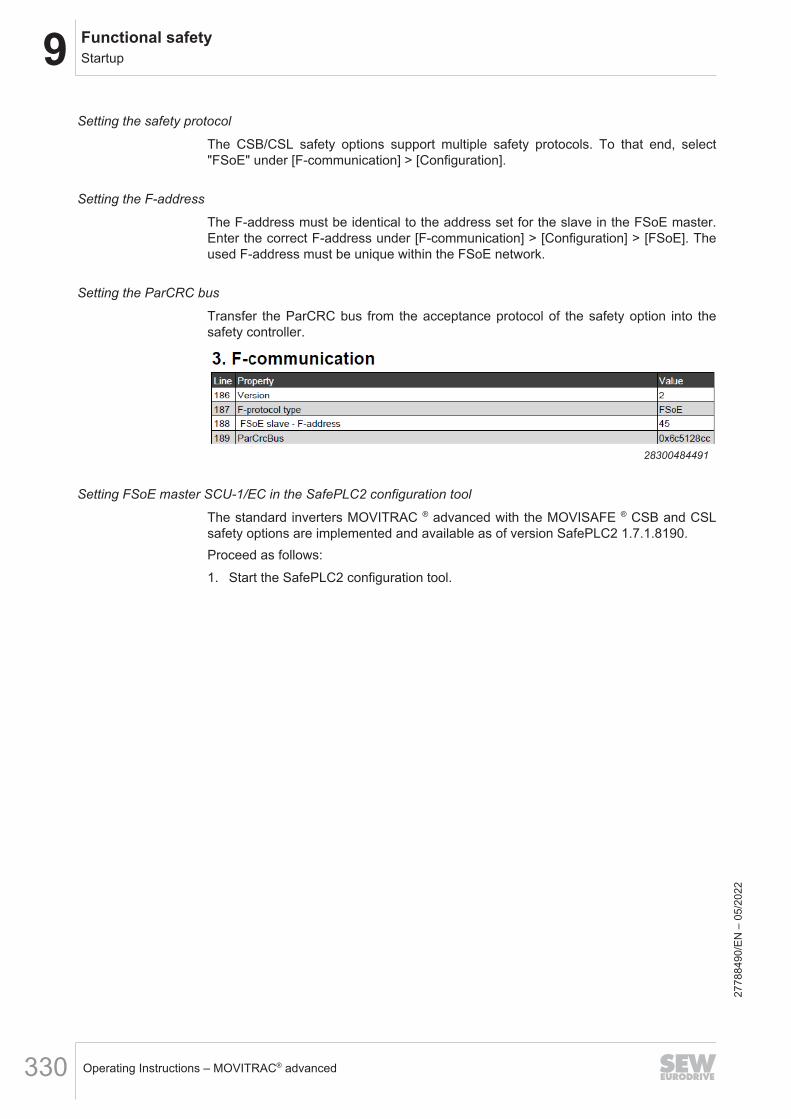
9 Functional safetyStartup
Operating Instructions – MOVITRAC® advanced330
Setting the safety protocol
The CSB/CSL safety options support multiple safety protocols. To that end, select"FSoE" under [F-communication] > [Configuration].
Setting the F-address
The F-address must be identical to the address set for the slave in the FSoE master.Enter the correct F-address under [F-communication] > [Configuration] > [FSoE]. Theused F-address must be unique within the FSoE network.
Setting the ParCRC bus
Transfer the ParCRC bus from the acceptance protocol of the safety option into thesafety controller.
28300484491
Setting FSoE master SCU-1/EC in the SafePLC2 configuration tool
The standard inverters MOVITRAC ® advanced with the MOVISAFE ® CSB and CSLsafety options are implemented and available as of version SafePLC2 1.7.1.8190.Proceed as follows:1. Start the SafePLC2 configuration tool.
2778
8490
/EN
– 0
5/20
22

9Functional safetyStartup
Operating Instructions – MOVITRAC® advanced 331
2. Integrate a corresponding FSoE master into the project.
33765177227
2778
8490
/EN
– 0
5/20
22
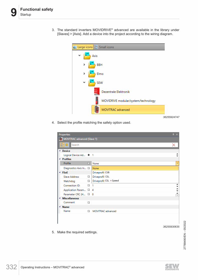
9 Functional safetyStartup
Operating Instructions – MOVITRAC® advanced332
3. The standard inverters MOVIDRIVE® advanced are available in the library under[Slaves] > [Axis]. Add a device into the project according to the wiring diagram.
36255924747
4. Select the profile matching the safety option used.
36255930635
5. Make the required settings.
2778
8490
/EN
– 0
5/20
22

9Functional safetyStartup
Operating Instructions – MOVITRAC® advanced 333
36256000523
• "Slave address" choice boxHere you select the FSoE address specified in the "Assist CS.." parameteriza-tion tool in MOVISUITE®.
• "Watchdog" choice boxTransmission is monitored via timers (watchdog) that are checked in eachFSoE station in the network. In this way, an interruption in the transmission canbe reliably detected. Default: 200 ms. Recommended: 250 ms.
• "Connection ID" choice boxSet this value to "1".
• "RT Ethernet Bus" drop-down listThe clock-synchronous EtherCAT® is connected to the SCU at "ECAT in" and"ECAT out". Choose "ECAT".
• "Application Parameter Length" choice boxSet this value to "4".
• "Parameter CRC" choice boxFor this value, refer to MOVISUITE® once you have successfully parameterizedthe safety option using the "Assist CS.." parameterization tool.
6. Call up the function diagram.
2778
8490
/EN
– 0
5/20
22
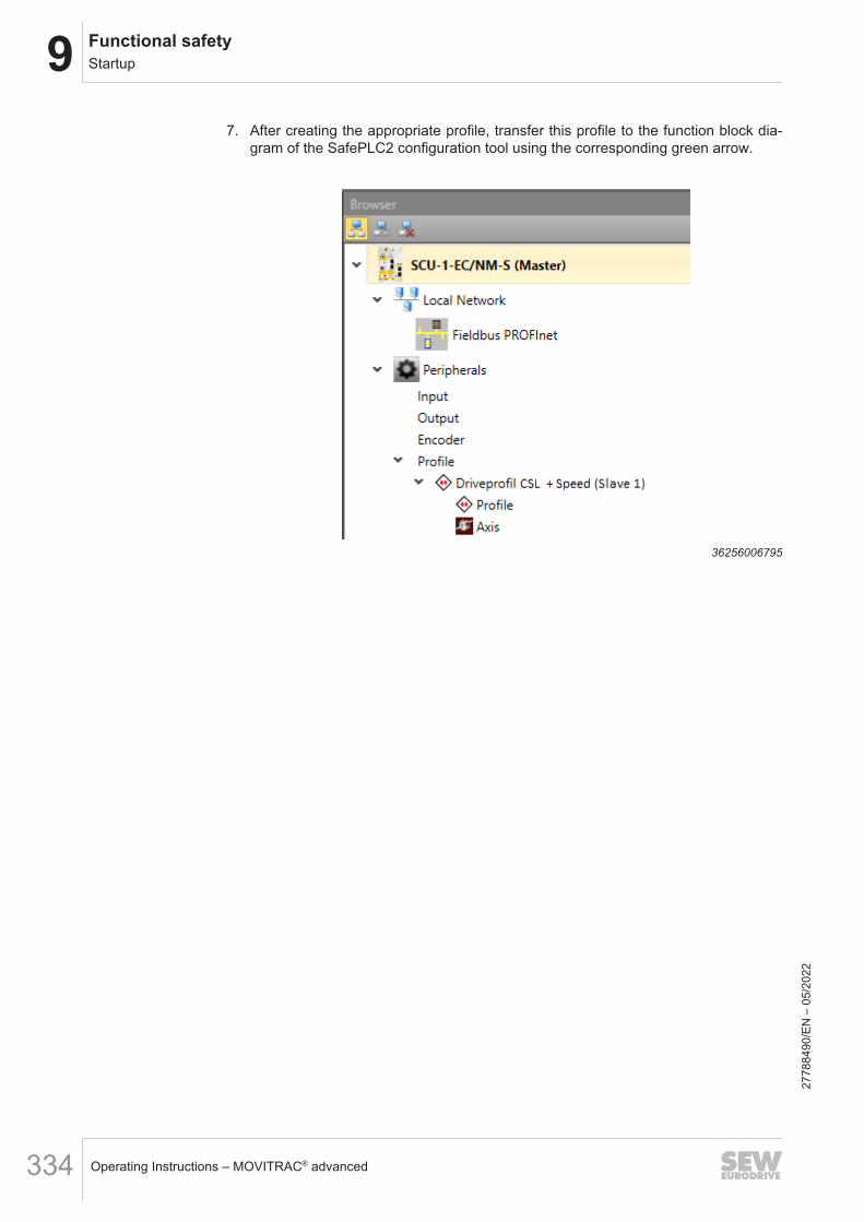
9 Functional safetyStartup
Operating Instructions – MOVITRAC® advanced334
7. After creating the appropriate profile, transfer this profile to the function block dia-gram of the SafePLC2 configuration tool using the corresponding green arrow.
36256006795
2778
8490
/EN
– 0
5/20
22

9Functional safetyStartup
Operating Instructions – MOVITRAC® advanced 335
8. In the function block diagram of the SafePLC2 configuration tool, you now haveaccess to all available safety subfunctions of the safety option.
36256103435
9. Load the configuration into the FSoE master module SCU.
Requirements in the IEC Editor
To being able to use FSoE communication between the FSoE master module SCUand the safety options in the inverter, it is necessary to activate this in the project set-tings in the IEC Editor.Proceed as follows:1. Create or open a corresponding IEC project or MOVISUITE® project.2. In the IEC Editor, click the [Project] > [Project Settings] menu item.
2778
8490
/EN
– 0
5/20
22

9 Functional safetyStartup
Operating Instructions – MOVITRAC® advanced336
33037484171
3. Under "Project Settings", select the "FSoE Router" entry. In the "FSoE Router"window, activate the "FSoE Routing Enabled" check box and confirm your settingwith [OK].
33037456139
Startup in the IEC Editor
Requirements • FSoE routing is activated.• The safety program with the safety options used has been loaded onto the safety
controller.• The safety controller is physically integrated in the EtherCAT® string.• The safety controller is scanned in the EtherCAT® string by software and the corre-
sponding defined profiles are visible in the IEC Editor.27
7884
90/E
N –
05/
2022
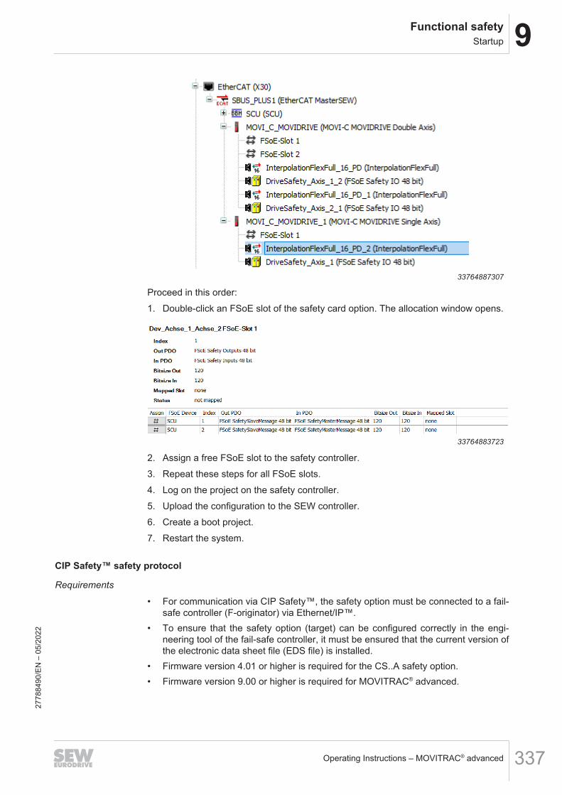
9Functional safetyStartup
Operating Instructions – MOVITRAC® advanced 337
33764887307
Proceed in this order:1. Double-click an FSoE slot of the safety card option. The allocation window opens.
33764883723
2. Assign a free FSoE slot to the safety controller.3. Repeat these steps for all FSoE slots.4. Log on the project on the safety controller.5. Upload the configuration to the SEW controller.6. Create a boot project.7. Restart the system.
CIP Safety™ safety protocol
Requirements
• For communication via CIP Safety™, the safety option must be connected to a fail-safe controller (F-originator) via Ethernet/IP™.
• To ensure that the safety option (target) can be configured correctly in the engi-neering tool of the fail-safe controller, it must be ensured that the current version ofthe electronic data sheet file (EDS file) is installed.
• Firmware version 4.01 or higher is required for the CS..A safety option.• Firmware version 9.00 or higher is required for MOVITRAC® advanced.
2778
8490
/EN
– 0
5/20
22
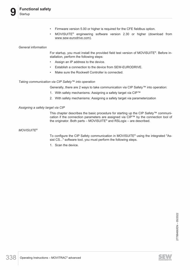
9 Functional safetyStartup
Operating Instructions – MOVITRAC® advanced338
• Firmware version 5.00 or higher is required for the CFE fieldbus option.• MOVISUITE® engineering software version 2.30 or higher (download from
www.sew-eurodrive.com).
General information
For startup, you must install the provided field test version of MOVISUITE®. Before in-stallation, perform the following steps:• Assign an IP address to the device.• Establish a connection to the device from SEW-EURODRIVE.• Make sure the Rockwell Controller is connected.
Taking communication via CIP Safety™ into operation
Generally, there are 2 ways to take communication via CIP Safety™ into operation:1. With safety mechanisms: Assigning a safety target via CIP™2. With safety mechanisms: Assigning a safety target via parameterization
Assigning a safety target via CIP
This chapter describes the basic procedure for starting up the CIP Safety™ communi-cation if the connection parameters are assigned via CIP™ by the connection tool ofthe originator. Both parts – MOVISUITE® and RSLogix – are described.
MOVISUITE®
To configure the CIP Safety communication in MOVISUITE® using the integrated "As-sist CS..." software tool, you must perform the following steps.1. Scan the device.
2778
8490
/EN
– 0
5/20
22

9Functional safetyStartup
Operating Instructions – MOVITRAC® advanced 339
2. Right-click on the upper half of the device. In the "Tools" context menu, select thesoftware tool "Assist CS..".
34912293259
3. Log in to the device. To do so, read out the ID of the safety key.
34912344587
4. Make sure you are connected with the correct device. To do this, check the LEDflashing pattern of the corresponding device.
5. Enter the password and log in. When logging in for the first time, you must enterthe password twice.
2778
8490
/EN
– 0
5/20
22

9 Functional safetyStartup
Operating Instructions – MOVITRAC® advanced340
6. To enable CIP safety communication, go to "F-communication".
34912504843
7. Select the entry "CIP Safety" under "Protocol type". Then set the mode for addressassignment to "Via CIP".
34912509067
8. After completing the complete configuration, download the parameters to thesafety option. Perform a transfer when the configuration is complete.
RSLogix Studio 5000
Configuration options
The following example configurations are possible:• CSB safety option in the "Technology" profile variant
– SafetyInput: 4 SINT
2778
8490
/EN
– 0
5/20
22

9Functional safetyStartup
Operating Instructions – MOVITRAC® advanced 341
– SafetyOutput: 3 SINT– Exclusive Owner Input: 5 INT– Exclusive Owner Output: 5 INTIn case more inputs/outputs are required for the Exclusive Owner Connection, upto 16 INT can be used.
• CSL safety option in the "Technology" profile variant– SafetyInput: 6 SINT– SafetyOutput: 5 SINT– Exclusive Owner Input: 5 INT– Exclusive Owner Output: 5 INTIn case more inputs/outputs are required for the Exclusive Owner Connection, upto 16 INT can be used.
• CSL safety option in the "System" profile variant– SafetyInput: 12 SINT– SafetyOutput: 5 SINT– Exclusive Owner Input: 5 INT– Exclusive Owner Output: 5 INTIn case more inputs/outputs are required for the Exclusive Owner Connection, upto 16 INT can be used.
configuration example
Perform the following steps to configure a safety device from SEW-EURODRIVE inRSLogix Studio 5000.ü Make sure you are using at least version 30 of the software.ü If necessary, configure and adjust the size of the safety inputs/outputs according
to the safety option used and the communication profile (see chapter "Configura-tion options").
1. Start up the device as an Ethernet/IP™ station.
2778
8490
/EN
– 0
5/20
22

9 Functional safetyStartup
Operating Instructions – MOVITRAC® advanced342
2. Check and configure the module definition by clicking "Change".
34916445707
3. Go to the option "Safety" and enter the required information.
9007234171190155
2778
8490
/EN
– 0
5/20
22

9Functional safetyStartup
Operating Instructions – MOVITRAC® advanced 343
4. You must enter the following data under "Configuration Signature":
9007234171974283
• ID: Enter the value of the check value SCCRC parameter from MOVISUITE® here.• Date: Select a specified date (reference: 01.03.2022 – dd.mm.yyyy).• Time: Use the arrow keys to select a specified time stamp (reference: 13:00 UTC).• Date: 01.03.2022, time: Depending on the respective time zone
The system time of the computer on which the engineering tool of the originator isrunning is relevant.
The following UTC time stamps apply to CIP Safety:
UTC Date Time-12 01.03.2022 00:00:00
-11 01.03.2022 01:00:00
-10 01.03.2022 02:00:00
-9 01.03.2022 03:00:00
-8 01.03.2022 04:00:00
-7 01.03.2022 05:00:00
-6 01.03.2022 06:00:00
-5 01.03.2022 07:00:00
-4 01.03.2022 08:00:00
-3 01.03.2022 09:00:00
-2 01.03.2022 10:00:00
-1 01.03.2022 11:00:00
0 01.03.2022 12:00:00
+1 01.03.2022 13:00:00
+2 01.03.2022 14:00:00
+3 01.03.2022 15:00:00
+4 01.03.2022 16:00:00
+5 01.03.2022 17:00:00
+6 01.03.2022 18:00:00
+7 01.03.2022 19:00:00
+8 01.03.2022 20:00:00
+9 01.03.2022 21:00:00
+10 01.03.2022 22:00:002778
8490
/EN
– 0
5/20
22

9 Functional safetyStartup
Operating Instructions – MOVITRAC® advanced344
UTC Date Time+11 02.03.2022 23:00:00
+12 02.03.2022 00:00:00
+12:45 02.03.2022 00:45:00
+13:00 02.03.2022 01:00:00
+13:45 02.03.2022 01:45:00
+14 02.03.2022 02:00:00
5. Make sure that you are in online mode of the RSLogix Studio 5000 engineeringtool. Use the [Set] button to load the safety network number into the safety optionand check the connection.
34928190475
2778
8490
/EN
– 0
5/20
22

9Functional safetyStartup
Operating Instructions – MOVITRAC® advanced 345
6. Check the connection.
9007234182967435
Assigning a safety target via parameterization
This chapter describes the basic procedure for starting up the CIP Safety communica-tion when the safety target of CIP Safety is assigned by the master software via CIP.Both, MOVISUITE® and RSLogix are described.
MOVISUITE®
To configure the CIP Safety communication in MOVISUITE® using the integrated "As-sist CS..." software tool, you must perform the following steps.1. Scan the device.
2778
8490
/EN
– 0
5/20
22

9 Functional safetyStartup
Operating Instructions – MOVITRAC® advanced346
2. Right-click on the upper half of the device. In the "Tools" context menu, select thesoftware tool "Assist CS..".
34912293259
3. Log in to the device. To do so, read out the ID of the safety key.
34912344587
4. Make sure you are connected with the correct device. To do this, check the LEDflashing pattern of the corresponding device.
5. Enter the password and log in. When logging in for the first time, you must enterthe password twice.
2778
8490
/EN
– 0
5/20
22

9Functional safetyStartup
Operating Instructions – MOVITRAC® advanced 347
6. To enable CIP safety communication, go to "F-communication".
34912504843
7. Select the entry "CIP Safety" under "Protocol type".
34928232587
2778
8490
/EN
– 0
5/20
22

9 Functional safetyStartup
Operating Instructions – MOVITRAC® advanced348
8. Then set the mode for address assignment ("Via parameterization").
34928235915
9. Enter the "Safety Network Number" that was generated in the RSLogix engineer-ing tool.
34928239627
10. After completing the complete configuration, download the parameters to thesafety option. Perform a transfer when the configuration is complete.
Programming in RSLogix Studio 5000
This chapter explains how to exchange data within the RSLogix Studio 5000 program-ming environment
2778
8490
/EN
– 0
5/20
22
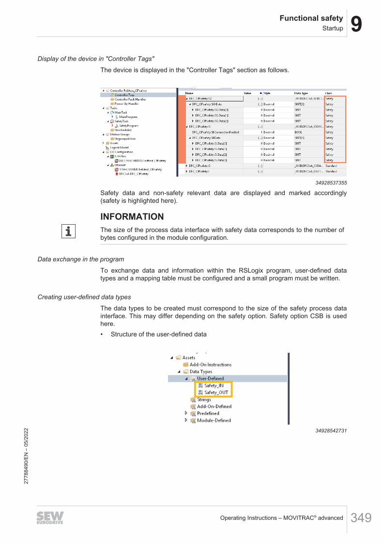
9Functional safetyStartup
Operating Instructions – MOVITRAC® advanced 349
Display of the device in "Controller Tags"
The device is displayed in the "Controller Tags" section as follows.
34928537355
Safety data and non-safety relevant data are displayed and marked accordingly(safety is highlighted here).
INFORMATIONThe size of the process data interface with safety data corresponds to the number ofbytes configured in the module configuration.
Data exchange in the program
To exchange data and information within the RSLogix program, user-defined datatypes and a mapping table must be configured and a small program must be written.
Creating user-defined data types
The data types to be created must correspond to the size of the safety process datainterface. This may differ depending on the safety option. Safety option CSB is usedhere.• Structure of the user-defined data
34928542731
2778
8490
/EN
– 0
5/20
22

9 Functional safetyStartup
Operating Instructions – MOVITRAC® advanced350
• Safety_IN (here: 4 bytes)
34928546059
• Safety_OUT (here: 3 bytes)
34928600587
The sizes of the IN and OUT structures must correspond to the real size of the inter-face.
INFORMATIONThis is only a very brief example. It is also possible to split the interface into the indi-vidual bits of the interface.
Creating instances of user-defined data types
You must create instances to use the data types in the program. These must bemarked as "Safety" or "Standard" depending on the use of the variables.The variables/instances must be created in the "Controller Tags".
• Safety variables can only be changed in the safety program.• Only default variables can be used in the non-safe program.
2778
8490
/EN
– 0
5/20
22

9Functional safetyStartup
Operating Instructions – MOVITRAC® advanced 351
Data exchange between safety program and non-safe program
A mapping table must be created to exchange data between both program parts.
34928609291
Here, the previously defined default and safety variables must be mapped to the cor-responding variable.
34929175819
Creating a safety program
The following routine is the minimum realizable program that must be written to trans-fer information from the safety interface to the program or to send information from theprogram to the safety interface.
349291801712778
8490
/EN
– 0
5/20
22

9 Functional safetyStartup
Operating Instructions – MOVITRAC® advanced352
9.6.8 Operating statesThe MOVISAFE® CSB/CSL safety options distinguish between the following operatingstates:• Operation• Parameterization• Safe state after critical error
"Operation" operating stateIn the "Operation" operating state, the selected safety subfunctions are executed inaccordance with the parameterization (see chapter "Safety subfunctions"). The safetysubfunctions are selected either via the safe digital inputs or the F‑process data. Theexternal, safe digital outputs can be controlled directly via the F‑process data if nofunction has been assigned to the safe digital outputs in the function assignment.
Operating state "Parameterization"In the "Parameterization" operating state, the MOVISAFE® CSB/CSL safety optionsare in the safe state and can be parameterized. If an error occurs during the parame-terization, e.g., a violation of a plausibility rule, MOVISAFE® CSB/CSL remains in the“Parameterization” state.
Operating state "Safe state" after critical faultNo F-process data communication occurs in the "Safe state" operating state. All safedigital inputs and outputs are disconnected. The "Safe state" operating state can beresolved only by deactivation and reactivation.
9.6.9 Safety-relevant acceptance
DANGERProper functioning of the safety subfunctions is not guaranteed without a safety-re-lated acceptance.Severe or fatal injuries.• Verify every single safety subfunction.• An individual acceptance report may be created only when the system is in idle
state.
To ensure that safety subfunctions have been parameterized properly, you must per-form validation and documentation of the parameters once startup and parameteriza-tion have been completed. This is supported by the Assist CS.. tool integrated inMOVISUITE® in the form of an acceptance protocol. The acceptance report can onlybe created with valid parameterization. If the parameterization is invalid, the creationof the acceptance report is rejected.The safety concept relies on the following basic assumptions. Parameters stored inthe flash memory of the safety option cannot change automatically. Online tests andcorresponding signatures ensure this by implementing basic measures on the as-sembly. However, the configuration cannot be evaluated by the assembly. This affectsthe parameterization of the safe inputs and outputs and the limit values of the safetysubfunctions. Verification is performed by means of the acceptance report.For safety subfunctions that are not used, it is sufficient to verify whether the release isparameterized to "No".
2778
8490
/EN
– 0
5/20
22

9Functional safetyStartup
Operating Instructions – MOVITRAC® advanced 353
ProcedureAfter a successful startup, you must confirm that the data of the acceptance reportmatches the parameters on the safety option. You must identify and protocol the val-ues parameterized for the user units, sensors and monitoring functions individually byperforming a function test. All limit values of the safety option must be verified by ex-ceeding each limit value and then triggering the defined state (safe state = STO +brake de-energized). You must take this into account in the machine or system controlsystem.
Performing a simple acceptance
ü The unit used is an SI unit (e.g. m, mm)1. Generate the acceptance report. Enter the value of the ParCRCBus parameter in
the engineering tool of the F-host.2. Check the limit values in the report for input or transmission errors.3. Check the correct calculation of position values. This is also required if only speed
and acceleration functions are used.4. Check the correct calculation of speed and acceleration values.5. Check the wiring of inputs and outputs.6. Select all parameterized safety functions once via the digital inputs and/or via the
safety bus. Use the status of the CS..A to check whether the corresponding safetyfunction is selected. In addition, check the LED and the 7‑segment display on theinverter for the STO function, as well as the application of the brake.
INFORMATIONA fault injection test is not required for MOVISAFE® CS..A. This means that it is notnecessary to explicitly test whether, for example, an SLS function triggers when theparameterized limit value is exceeded.
Procedure for acceptance of the position values
It is always necessary to check the position values as they are the basis for the speedand acceleration values. Proceed as follows to accept the correct encoder resolutionand conversion into user units:1. Set a start point for a movement, e.g. a reference point.2. Mark the start point.3. In MOVISUITE®, read the positions of the encoders in the
[Diagnostics] > [MOVISAFE® CS..A] > [Encoders] dialog and log them.4. Travel a defined distance (e.g. 5 m).5. Mark the target point.6. Measure the traveled distance using a suitable measuring instrument (e.g. mag-
netic tape).7. In MOVISUITE® in Dialog [Diagnostics] > [MOVISAFE® CS..] > [Encoder], read the
position values of the utilized encoders again and log them.8. Calculate the traveled distance from the difference of read-out values and com-
pare the result with the measured distance.9. If both values are identical, the following is accepted:
• Position values in user units2778
8490
/EN
– 0
5/20
22
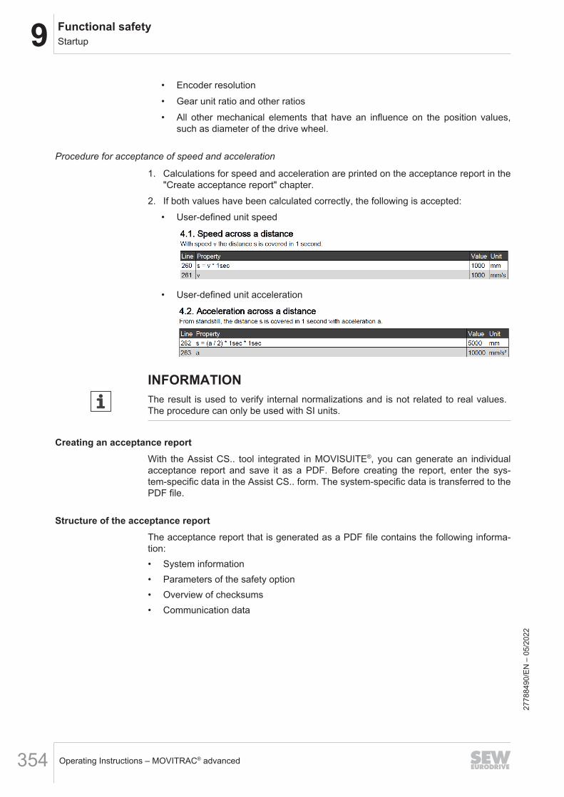
9 Functional safetyStartup
Operating Instructions – MOVITRAC® advanced354
• Encoder resolution• Gear unit ratio and other ratios• All other mechanical elements that have an influence on the position values,
such as diameter of the drive wheel.
Procedure for acceptance of speed and acceleration
1. Calculations for speed and acceleration are printed on the acceptance report in the"Create acceptance report" chapter.
2. If both values have been calculated correctly, the following is accepted:• User-defined unit speed
• User-defined unit acceleration
INFORMATIONThe result is used to verify internal normalizations and is not related to real values.The procedure can only be used with SI units.
Creating an acceptance reportWith the Assist CS.. tool integrated in MOVISUITE®, you can generate an individualacceptance report and save it as a PDF. Before creating the report, enter the sys-tem‑specific data in the Assist CS.. form. The system‑specific data is transferred to thePDF file.
Structure of the acceptance reportThe acceptance report that is generated as a PDF file contains the following informa-tion:• System information• Parameters of the safety option• Overview of checksums• Communication data
2778
8490
/EN
– 0
5/20
22
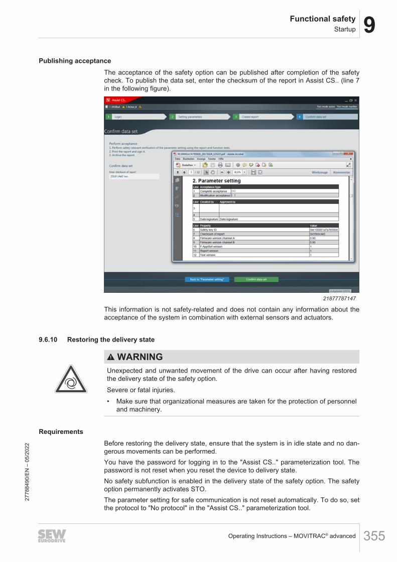
9Functional safetyStartup
Operating Instructions – MOVITRAC® advanced 355
Publishing acceptanceThe acceptance of the safety option can be published after completion of the safetycheck. To publish the data set, enter the checksum of the report in Assist CS.. (line 7in the following figure).
21877787147
This information is not safety-related and does not contain any information about theacceptance of the system in combination with external sensors and actuators.
9.6.10 Restoring the delivery state
WARNINGUnexpected and unwanted movement of the drive can occur after having restoredthe delivery state of the safety option.Severe or fatal injuries.• Make sure that organizational measures are taken for the protection of personnel
and machinery.
RequirementsBefore restoring the delivery state, ensure that the system is in idle state and no dan-gerous movements can be performed.You have the password for logging in to the "Assist CS.." parameterization tool. Thepassword is not reset when you reset the device to delivery state.No safety subfunction is enabled in the delivery state of the safety option. The safetyoption permanently activates STO.The parameter setting for safe communication is not reset automatically. To do so, setthe protocol to "No protocol" in the "Assist CS.." parameterization tool.
2778
8490
/EN
– 0
5/20
22

9 Functional safetyStartup
Operating Instructions – MOVITRAC® advanced356
Procedure
1. In MOVISUITE®, select "MOVISAFE® CS.. diagnostics" in the "Diagnostics" menu.Select the menu item "General". Click the [Restore delivery state] button.
2. Open the "Assist CS.." parameterization tool and log in.3. Transfer the data to the device. In the context menu of the axis, select the menu
item "Device → PC" to update the data in MOVISUITE®. After this, the data set isvalid and behaves like after delivery. "Accepted" is not set.
INFORMATIONThe parameters of the F-communication are not reset.
9.6.11 Reset the passwordProceed as follows:1. You can find the option-specific master password on the small system nameplate
behind the front flap of the device.2. Open the "Assist CS.." parameterization tool. To open the main menu, click the red
"Assist CS.." tile in the left upper corner.3. Select the menu item "Change password". In the "Old password" edit box, enter
the master password.4. In the edit boxes "New password" and "Enter new password again", enter the new
password. Confirm your entries.You can now parameterize the safety option in Assist CS...
9.6.12 Changing the password
1. Open the "Assist CS.." parameterization tool. To open the main menu, click the red"Assist CS.." tile in the left upper corner.
2. Select the menu item "Change password". In the "Old password" edit box, enterthe old password.
3. In the edit boxes "New password" and "Enter new password again", enter the newpassword and confirm your entries.
2778
8490
/EN
– 0
5/20
22
9Functional safetyOperation
Operating Instructions – MOVITRAC® advanced 357
9.7 Operation9.7.1 Hazard caused by coasting of the drive
WARNINGHazard caused by coasting of the drive. Without mechanical brake or if the brake isfaulty, a danger exists of the drive coasting to a halt.Severe or fatal injuries.• If the coasting of the drive causes any application-specific dangers, you must
provide for additional preventive measures (e.g. guard with guard lockingdevice). The additional preventive measures must cover the danger zone until nofurther danger to personnel exists. As an alternative, you must equip the drivewith a safety brake.
• The additional protective covers must be designed and integrated so that theymeet the requirements determined in the risk assessment for the machine.
• After activating the stop command, access to the machine must remain blockeduntil the drive has reached standstill depending on the hazard involved. As an al-ternative, you must determine the access or intervention time and then calculateand observe the resulting safety clearance.
2778
8490
/EN
– 0
5/20
22

9 Functional safetyData exchange with higher-level controller
Operating Instructions – MOVITRAC® advanced358
9.8 Data exchange with higher-level controller9.8.1 Introduction
MOVITRAC® advanced with integrated CSB/CSL safety option support parallel opera-tion of standard and safe communication via a bus system or network. Safe communi-cation is possible via PROFIsafe, Safety over EtherCAT®, and CIP Safety™.The safe PROFIsafe communication can be carried out via PROFINET. To that end,the basic device with integrated safety option via PROFINET must be connected to afail-safe controller (F-PLC).Safe communication is possible via EtherCAT® with Safety over EtherCAT®. To thatend, the basic device in the variant DSI with integrated safety option must be connect-ed to a fail-safe controller (F‑PLC) via EtherCAT®/SBusPLUS.Safe CIP Safety™ communication is possible via EtherNet/IP™. To that end, the basicdevice with integrated safety option directly via EtherNet/IP™ must be connected to afail-safe controller (F-PLC).To control safety subfunctions and to evaluate the responses from the safety optionvia PROFIsafe, Safety over EtherCAT® or CIP Safety™ take into account the assign-ment of the individual bits in the F‑process input/output data.In the "System" profile variant, an additional 16 bit and a 32 bit process value aretransferred. The safe speed can be transferred via the process values.
9.8.2 PROFIsafe safety protocol
Number of safety options on the MOVI-C® CONTROLLERThe safe PROFIsafe communication is routed via the MOVI‑C® CONTROLLERs to thedevices of the MOVITRAC® advanced series with integrated CSB/CSL safety options.MOVI-C® CONTROLLERs support a different number of devices.
MOVI-C®
CONTROLLERNumber ofsafety options
Note
UHX25-NFHX25-N
8
UHX45-NFHX45-N
8
UHX65-R 24 Maximum of 24 safety options or maximum of432 bytes of safe process data (sum of all safeprocess data of the safety options)
UHX85-R 8 • Firmware V2.0 release 201703xxxx(March 2017) and older.
• Object in the hardware catalog of the TIAportal:UHX84-R/UHX85-R V2.0
2778
8490
/EN
– 0
5/20
22

9Functional safetyData exchange with higher-level controller
Operating Instructions – MOVITRAC® advanced 359
MOVI-C®
CONTROLLERNumber ofsafety options
Note
UHX85-R 24 Maximum of 24 safety options or maximum of432 bytes of safe process data (sum of all safeprocess data of the safety options).• Firmware V2.x or V3.0 release 201707xxxx
(July 2017) and later.• Object in the hardware catalog of the TIA
portal:UHX84-R/UHX85-R V3.0 and later
The following number of bytes is to be taken into account when routing:• CSB: 14 bytes• CSL in the "Technology" profile variant: 18 bytes• CSL in the "System" profile variant: 22 bytes
F-periphery access of the safety option in the TIA Portal
PROFIsafe version 2.4
For safe communication, the CSB safety option requires a total of 8 bytes for inputdata and 7 bytes for output data for the PROFIsafe telegram part and occupies themin the process image. Of these, 4 bytes of input data and 3 bytes of output data arethe actual safe I/O data (F-reference data). The module with the designation F-I/Omodule (4/3 bytes) is required for data exchange via PROFIsafe with the CSB safetyoption.For safe communication with "Technology" profile variant, the CSL safety optionsneeds a total of 10 bytes for input data and 9 bytes for output data for the PROFIsafetelegram part and occupies them in the process image. Of these, 6 bytes of input dataand 5 bytes of output data are the actual safe I/O data (F-reference data). The modulewith the designation F-I/O module (6/5 bytes) is required for data exchange viaPROFIsafe with the CSL safety option.For safe communication with "System" profile variant, the CSL safety option needs atotal of 16 bytes for input data and 9 bytes for output data for the PROFIsafe telegrampart and occupies them in the process image. Of these, 12 bytes of input data and5 bytes of output data are the actual safe I/O data (F-reference data). The module withthe designation F-I/O module (12/5 bytes) is required for data exchange viaPROFIsafe with the CSL safety option.The remaining 4 bytes are required for the telegram backup according to thePROFIsafe specification.
PROFIsafe version 2.6
For safe communication, the CSB safety option requires a total of 9 bytes for inputdata and 8 bytes for output data for the PROFIsafe telegram part and occupies themin the process image. Of these, 4 bytes of input data and 3 bytes of output data arethe actual safe I/O data (F-reference data). The module with the designation F-I/O‑module (4/3 bytes) 2.6 is required for data exchange via PROFIsafe with the CSBsafety option.
2778
8490
/EN
– 0
5/20
22

9 Functional safetyData exchange with higher-level controller
Operating Instructions – MOVITRAC® advanced360
For safe communication with "Technology" profile variant, the CSL safety optionsneeds a total of 11 bytes for input data and 10 bytes for output data for the PROFIsafetelegram part and occupies them in the process image. Of these, 6 bytes of input dataand 5 bytes of output data are the actual safe I/O data (F-reference data). The modulewith the designation F-I/O module (6/5 bytes) 2.6 is required for data exchange viaPROFIsafe with the CSL safety option.For safe communication with "System" profile variant, the CSL safety option needs atotal of 17 bytes for input data and 10 bytes for output data for the PROFIsafe tele-gram part and occupies them in the process image. Of these, 12 bytes of input dataand 5 bytes of output data are the actual safe I/O data (F-reference data). The modulewith the designation F-I/O module (12/5 bytes) 2.6 is required for data exchange viaPROFIsafe with the CSL safety option.The remaining 5 bytes are required for the telegram backup according to thePROFIsafe specification.
PROFIsafe address type 1
Uniqueness of the PROFIsafe address is only ensured by the destination address.• The destination address must be unique in the fieldbus network and the control
network. This means the destination address ranges of all F-PLCs must not over-lap.
• Destination and source address are included in the CRC value of the safety pro-gram of the F‑PLC.
PROFIsafe address type 2
Uniqueness of the PROFIsafe address can be ensured by combining the source anddestination addresses.• The destination address must be unique in the control network and must differ
from all destination addresses of PROFIsafe address type 1 in the same network.• The source address used for the F‑periphery of an F‑PLC must be unique in the
network.• Destination and source address are included in the CRC value of the safety pro-
gram of the F‑PLC.
F-periphery data component of the safety option
While compiling the configuration tool (HW Config), the system automatically gener-ates an F-periphery data component (DB) for each safety option. The F periphery DBoffers the user an interface in which he or she can evaluate or control variables in thesafety program.The symbolic name consists of the invariable prefix "F", the start address of the F-peri-phery, and the name entered in the object properties during configuration for the F-periphery (e.g.: F00008_198).
2778
8490
/EN
– 0
5/20
22
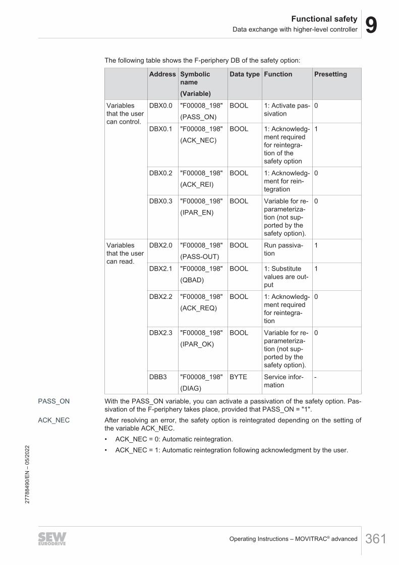
9Functional safetyData exchange with higher-level controller
Operating Instructions – MOVITRAC® advanced 361
The following table shows the F‑periphery DB of the safety option:
Address Symbolicname(Variable)
Data type Function Presetting
Variablesthat the usercan control.
DBX0.0 "F00008_198"(PASS_ON)
BOOL 1: Activate pas-sivation
0
DBX0.1 "F00008_198"(ACK_NEC)
BOOL 1: Acknowledg-ment requiredfor reintegra-tion of thesafety option
1
DBX0.2 "F00008_198"(ACK_REI)
BOOL 1: Acknowledg-ment for rein-tegration
0
DBX0.3 "F00008_198"(IPAR_EN)
BOOL Variable for re-parameteriza-tion (not sup-ported by thesafety option).
0
Variablesthat the usercan read.
DBX2.0 "F00008_198"(PASS-OUT)
BOOL Run passiva-tion
1
DBX2.1 "F00008_198"(QBAD)
BOOL 1: Substitutevalues are out-put
1
DBX2.2 "F00008_198"(ACK_REQ)
BOOL 1: Acknowledg-ment requiredfor reintegra-tion
0
DBX2.3 "F00008_198"(IPAR_OK)
BOOL Variable for re-parameteriza-tion (not sup-ported by thesafety option).
0
DBB3 "F00008_198"(DIAG)
BYTE Service infor-mation
-
PASS_ON With the PASS_ON variable, you can activate a passivation of the safety option. Pas-sivation of the F-periphery takes place, provided that PASS_ON = "1".
ACK_NEC After resolving an error, the safety option is reintegrated depending on the setting ofthe variable ACK_NEC.• ACK_NEC = 0: Automatic reintegration.• ACK_NEC = 1: Automatic reintegration following acknowledgment by the user.
2778
8490
/EN
– 0
5/20
22

9 Functional safetyData exchange with higher-level controller
Operating Instructions – MOVITRAC® advanced362
WARNINGImpermissible parameterization of the variable ACK_NEC = 0.Severe or fatal injuries.• The parameterization of the variable ACK_NEC = 0 is permitted only if automatic
reintegration is safe for the respective process.• Check if automatic reintegration is permitted for the respective process.
ACK_REI In order to reintegrate the safety option after the fault has been corrected, user ac-knowledgment with positive edge at the variable ACK_REI is required. Acknowledg-ment is only possible if variable ACK_REQ = 1.
ACK_REQ The F control system sets ACK_REQ = 1 after all faults in the data exchange with thesafety option have been corrected. After successful acknowledgment, the F controlsystem sets ACK_REQ to "0".
PASS_OUT The variable PASS_OUT indicates whether there is a passivation of the safety option.Substitute values are output.
QBAD Fault in the data exchange with the safety option. Indicates passivation. Substitute val-ues are output.
DIAG For service information purposes, the variable DIAG supplies non-failsafe informationabout faults that have occurred in the F control system. For further information, refer tothe relevant F control system manual.
Acknowledgment of PROFIsafe data exchangeThe PROFIsafe communication must be fault-free for safe data exchange of the safetyoption via PROFIsafe. As soon as there is an acknowledgment request of the safetyoption via the ACK_REQ bit in the F-periphery data component, the user must triggeran acknowledgment by a rising edge via the ACK_REI bit.As soon as the safe data exchange of the safety option using PROFIsafe is fault-free,faults in the safety option can be acknowledged by a 0 → 1 edge with the "Acknowl-edgment" bit in the F-process data profile.
9.8.3 Safety over EtherCAT® safety protocol• For data exchange via Safety over EtherCAT® (FSoE) between the CSB/CSL
safety options and a higher-level controller, the safety option in the "Technology"profile variant has the following process data assignment:– 6 bytes input data– 1 byte header data– 3 × 2 bytes of user data and 2 bytes of CRC, each in pairs– 2 byte connection ID– 6 bytes output data– 1 byte header data– 3 × 2 bytes of user data and 2 bytes of CRC, each in pairs– 2 byte connection ID
• For data exchange via Safety over EtherCAT® between the CSL safety option anda higher-level controller, the safety option in the "System" profile variant has thefollowing process data assignment:– 12 bytes input data
2778
8490
/EN
– 0
5/20
22

9Functional safetyData exchange with higher-level controller
Operating Instructions – MOVITRAC® advanced 363
– 1 byte header data– 6 × 2 bytes of user data and 2 bytes of CRC, each in pairs– 2 byte connection ID– 12 bytes output data– 1 byte header data– 6 × 2 bytes of user data and 2 bytes of CRC, each in pairs– 2 byte connection ID
Profile data must be evaluated and made available in the "Little Endian" representa-tion for Safety over EtherCAT®.
Integrating the safe communicationEach safety option must be created by the user in the safety program. For establishingthe operation of the safety function, defined variables are available that can be nameddifferently depending on the FSoE master.
Example The following example illustrates these variables on the basis of group ports fromBeckhoff.
Variable FunctionGroup ports for controlling RUN/STOP Starts/stops the execution of the
FSoE program.
Err Ack Error reset/acknowledgment of safecommunication.
Module fault TBA
Group ports for monitoring FB Err Error during execution of a functionblock.
Com Err Communication error.
Out Err Output error.
Other Err Other error.
Com Startup Safe communication is established.
FB Inactive TBA
FB Run Execution of function blocks is run-ning.
In Run Safety program is running.
The procedure for starting the safety function and for reintegrating a safety device de-pends on the FSoE master and is not shown here.Safety over EtherCAT® has validity information for its safe process data. This is trans-ferred from master to slave for the process output data when the safety protocol is es-tablished and from slave to master for the process input data. If the master signals themessage "invalid", all process output data on the slave side is reset. The slave alwayssignals the message "valid" with the current process input data.
2778
8490
/EN
– 0
5/20
22

9 Functional safetyData exchange with higher-level controller
Operating Instructions – MOVITRAC® advanced364
Requirements for the FSoE parameterization
Requirement for the FSoE address
The Safety over EtherCAT® user must ensure that the F-address is between 1 and65535 and that it is unique in a communication domain. A communication domain is alogical network within which the safety-related messages are transported. The mes-sages are not permitted to be transported beyond this network. The F-addresses areset in the master and slave.
Requirements for the connection ID
The Safety over EtherCAT® user must ensure that the connection ID is unique in acommunications domain. A communication domain is a logical network within whichthe safety-related messages are transported. The messages are not permitted to betransported beyond this network. The connection ID is set in the master.
FSoE watchdog time
The FSoE connection monitoring time must be set in the master. The range of valuesis from 24 ms to 60000 ms.
9.8.4 CIP Safety™ safety protocolTo communicate via CIP Safety™, the safety option (target) must be connected to afail-safe controller (F-Originator) via EtherNet/IP™.
CIP Safety™ data exchange with MOVISAFE® CSBTo exchange data between the safety option and a fail-safe controller via CIPSafety™, the CSB safety option have the module name "Safety output" and "Safety in-put" with the following process data assignment:• "Technology" profile variant
– 16 bytes input dataThe first 4 bytes contain the useful data from the FS protocol profile, and the re-maining bytes are needed for the safety IO connection.
– 14 byte output dataThe first 3 bytes contain the useful data from the FS protocol profile, and the re-maining bytes are needed for the safety IO connection
CIP Safety™ data exchange with MOVISAFE® CSLTo exchange data between the safety option and a higher-level controller via CIPSafety™, the CSL safety option have the module name "Safety output" and "Safety in-put" with the following process data assignment:• "Technology" profile variant
– 20 bytes input dataThe first 6 bytes contain the useful data from the FS protocol profile, and the re-maining bytes are needed for the safety IO connection.
– 18 bytes input dataThe first 5 bytes contain the useful data from the FS protocol profile, and the re-maining bytes are needed for the safety IO connection.
• "System" profile variant– 32 bytes input data
2778
8490
/EN
– 0
5/20
22

9Functional safetyData exchange with higher-level controller
Operating Instructions – MOVITRAC® advanced 365
The first 12 bytes contain the useful data from the FS protocol profile, and theremaining bytes are needed for the safety IO connection.
– 18 bytes input dataThe first 5 bytes contain the useful data from the FS protocol profile, and the re-maining bytes are needed for the safety IO connection.
Profile data must be evaluated and provided in CIP Safety™ in the "Little Endian" dis-play.
Startup in the CIP Safety™ safety protocolThe safety option supports 2 types of startup in a CIP Safety™ network. It is selectedvia the Address assignment mode parameter with both parameter settings "Via CIPSafety™ originator" and "Via parameterization". In the delivery state, the Address as-signment mode parameter is set to "Via CIP Safety™ originator". As a result, the start-up can be executed via the engineering tool of the fail-safe controller.After startup, the user must ensure that the fail-safe controller and the safety optionare properly configured. The user must conduct their own user tests to verify that theconfiguration data has been properly downloaded. All address parameters are con-figured by a fail-safe controller or its engineering tool using CIP mechanisms.
Activating the CIP Safety™ safety protocol
In the delivery state, no safety protocol is activated in the safety option. This is the pre-requisite that the CIP Safety™ safety protocol is activated in the safety option via theEtherNet/IP™ interface. The changeover is carried out in the parameter object withthe class code 0x0F of the EtherNet/IP™ interface and the instance 4. To do so, theuser must write the value "1" to the attribute 1 in the data object via the CIP™ serviceSet_Attribute_Single. In the safety option, the changeover to CIP Safety™ is carriedout internally and is saved to non-volatile memory. Via the CIP™ service Get_Attrib-ute_Single, you can read on the EtherNet/IP™ interface whether the CIP Safety™function is activated or deactivated.All address parameters are controlled by a fail-safe controller or its engineering toolvia CIP™ mechanisms. The management rights of the CIP Safety™ target can onlybe reset via a safety reset type 2.
Addressing CIP Safety™CIP Safety™ requires that an EtherNet/IP™ device must possess a unique networknode number (Target Unique Network Identifier, TUNID). The TUNID consists of theIP address of the inverter and the Safety Network Number (SNN) together and is gen-erated in the engineering tool of the fail-safe controller. The safety option retains itsTUNID after the assignment. The TUNID is written to the safety key in non-volatilememory.
Safety Network Number (SNN)
The Safety Network Number (SNN) uniquely identifies a network in all the networks inthe safety system. The SNN is responsible for assigning a unique number to eachsafety network or safety subnetwork in a system. The SNN constitutes part of theunique network node ID (unique network identifier, UNID).The Safety Network Number (SNN) of the safety option must match the Safety Net-work Number of the assigned, fail-safe controller.The safety option maintains its SNN after assignment. The SNN must first be reset be-fore it can be reused with another value.27
7884
90/E
N –
05/
2022
9 Functional safetyData exchange with higher-level controller
Operating Instructions – MOVITRAC® advanced366
SNN formats
The SNN is a hexadecimal number consisting of six bytes, and it can be configured in2 formats:• Time-based
If the time-based format is selected, the SNN contains localized date and time in-formation.
• ManualIf the manual format is selected, the SNN contains a network type and must havea decimal value from 1 to 9999.
The following requirement must be fulfilled for this purpose:• The inverter is already integrated into the Ethernet/IP™ network in the engineering
tool of the originator.
Target Unit Network Identifier (TUNID)
CIP Safety™ requires that an EtherNet/IP™ device have a unique network node num-ber (target unique network identifier, TUNID). The TUNID is composed of the inverter'sIP address and the safety network number (SNN).The safety option maintains its TUNID after assignment. The TUNID is stored in non-volatile memory on the safety key.
Assignment via MOVISUITE® Assist CS..
To assign the TUNID, the SNN must be read from the engineering tool of the fail-safecontroller and added to MOVISUITE® Assist CS.. Furthermore, the target network ID(the device's IP address) must match the IP address of the EtherNet/IP™ interfaceconnection and the configuration on the engineering tool of the fail-safe controller. Tothat end, the IP address of the EtherNet/IP™ interface connection must be read inMOVISUITE® and added to MOVISUITE® Assist CS..The following requirements must all be fulfilled for this purpose:• In Assist CS.., the CIP Safety™ protocol type must be selected in the F-communi-
cation menu, and the Address assignment mode parameter must be set to "Viaparameterization".
• The inverter is already integrated in the EtherNet/IP™ network in the engineeringtool of the fail-safe controller.
• The IP address and the SNN of the inverter are configured in the engineering toolof the fail-safe controller.
• The inverter is configured with the IP address.
Assigning the TUNID on the engineering tool of the fail-safe controller
The TUNID must be assigned to the "Safety Supervisor" CIP Safety™ object via spe-cific CIP services using service codes 0x56 (Propose_TUNID) and 0x57 (Ap-ply_TUNID).The following requirements must all be fulfilled for this purpose:• The inverter is already integrated in the EtherNet/IP™ network in the engineering
tool of the fail-safe controller.• The IP address and the SNN of the inverter are configured in the engineering tool
of the fail-safe controller.• The inverter is configured with the IP address. 27
7884
90/E
N –
05/
2022

9Functional safetyData exchange with higher-level controller
Operating Instructions – MOVITRAC® advanced 367
• The TUNID contains the delivery value (default value; all bytes 0xFF)• The CIP Safety™ object reports the "Waiting for TUNID" state in online mode.The TUNID must first be reset before it can be reused with another value. This cantake place via the CIP Safety™ service "Safety Reset".
Safety Configuration Identifier (SCID)
The Safety Configuration Identifier (SCID) is a combination of the Safety ConfigurationCRC (SCCRC) and the Safety Configuration Time Stamp (SCTS). The SCID is usedto uniquely identify a configuration for the safety option and the fail-safe controller.The Safety Configuration CRC (SCCRC) is the checksum (CRC) of the application-specific configuration data of the safety option.Safety Configuration Time Stamp (SCTS) is the timestamp of the application-specificconfiguration of the safety option. The SCTS is transferred in CIP date-and-timeformat as a hex value.The safety option has a statically defined SCTS with the value 0x02932E004792. Thisis equivalent to the timestamp 03/01/2022/12:00 p.m. In the MOVISUITE® engineeringtool, the SCTS is calculated according to the locally configured local time of the com-puter system and shown via a display parameter.The SCID displayed in the MOVISUITE® engineering tool must be accepted for theconnection process if the user's intention is for the application-specific configurationdata to be verified by the safety option when establishing a connection (SafetyOpenType 2a). To that end, the user must read the SCCRC and SCTS values from theMOVISUITE® engineering tool and add them to the engineering tool of the fail-safecontroller (recommended use).If the user initiates establishing a connection with an SCID equal to zero, then theSCID is not reviewed in the safety option. In this case, the user themselves is respon-sible for ensuring that the fail-safe controller and the safety option have the right con-figuration (SafetyOpen Type 2b). The mechanism is supported but it is not recom-mended for productive use.The safety option cannot be configured via a fail-safe controller in the connection pro-cess (SafetyOpen Type 1 is not supported).
CIP Safety™ service "Safety Reset"The safety option can be reset by the "Safety reset" CIP Safety™ service on theSafety Supervisor object. During the process, the safety reset type 0 and 2 are sup-ported.• Safety reset type 0
– The Ethernet™ interface connection is restarted– The safety option is restarted
• Safety reset type 2– The EtherNet/IP™ interface connection is restarted– The safety option is restarted– The safety option can reset the CIP Safety™ parameters TUNID, CFUNID, and
OCPUNID to the default values. To that end, the existing "Bit Map" attribute inthe service (Bit 2: TUNID, Bit 4: CFUNID, Bit 5: OCPUNID) is additionally eval-uated.
The AlarmEnable and WarningEnable parameters are always reset to their defaultvalue.27
7884
90/E
N –
05/
2022

9 Functional safetyData exchange with higher-level controller
Operating Instructions – MOVITRAC® advanced368
The following prerequisites have to be fulfilled:• In Assist CS.., the CIP Safety™ protocol type must be selected in the "F-communi-
cation" menu, and the Address assignment mode parameter must be set to "ViaCIP Safety™ originator".
• A valid parameterization must be present.• The CIP communication connection must be blocked (inhibit).
9.8.5 F process data profile
CSL profile variant "Technology"
Process output data
Byte Bit Name Value Description0 0 STO1 0 Activate STO.
1 Deactivate STO.
1 Reserve
2 Reserve
3 Reserve
4 Muting 0 Deactivate encoder fault muting.
1 Activate encoder fault muting.
5 Test modeactive
0 Deactivate test mode.
1 Activate test mode.
6 Unlatch F-DI
0 No acknowledgment.
1 Acknowledgment of latched F-DI (0 → 1 edge).
7 Fault ac-knowledg-ment
0 No acknowledgment.
1 Fault acknowledgment (0 → 1 edge).
1 0 F-DO00 0 Disable F-DO00 output (open).
1 Enable F-DO00 output (close).
1 Reserve
2 Reserve
3 Reserve
4 Reserve
5 Reserve
6 Reserve
7 Reserve
2778
8490
/EN
– 0
5/20
22

9Functional safetyData exchange with higher-level controller
Operating Instructions – MOVITRAC® advanced 369
Byte Bit Name Value Description2 0 Reserve
1 EDM 0 No fault detected.
1 Fault on at least one of the outputs assigned to theEDM function.
2 SSX1 0 Activate SSx1.
1 Deactivate SSx1.
3 SSX2 0 Activate SSx2.
1 Deactivate SSx2.
4 SDI1 0 Activate SDI1.
1 Deactivate SDI1.
5 SDI2 0 Activate SDI2.
1 Deactivate SDI2.
6 Reserve
7 Reserve
3 0 SLS1 0 Activate SLS1.
1 Deactivate SLS1.
1 SLS2 0 Activate SLS2.
1 Deactivate SLS2.
2 SLS3 0 Activate SLS3.
1 Deactivate SLS3.
3 SLS4 0 Activate SLS4.
1 Deactivate SLS4.
4 Reserve
5 Reserve
6 Reserve
7 Reserve
4 0 Reserve
1 Reserve
2 Reserve
3 Reserve
4 Reserve
5 Reserve
6 Reserve
7 Reserve
2778
8490
/EN
– 0
5/20
22

9 Functional safetyData exchange with higher-level controller
Operating Instructions – MOVITRAC® advanced370
Process input data
Byte Bit Name Value Description0 0 STO 0 STO is not active. Safe disconnection is not ac-
tive.
1 STO signals "STO active" status. All outputsparameterized to STO are disabled.
1 Drive safetyfunction diag-nostics (ASF)
0 No drive safety function has determined the ex-ceeding of a limit value.
1 At least one selected drive safety function hasdetermined the exceeding of a limit value orcannot execute limit value monitoring as a con-sequential error.
2 Reserve
3 Input data valid 0 At least one of the F-DI process values sends asubstitute value.
1 All process values of the F-DI contain actualvalues.
4 Muting 0 The encoder fault muting function is not active,or a fault has occurred.
1 The encoder fault muting function is active.
5 Test mode ac-tive
0 Test mode for safety subfunctions is not active.
1 Test mode for safety subfunctions is active.
6 Warning 0 The safety option is in fault-free operation.
1 At least one warning in the safety option is ac-tive.
7 Fault status 0 The safety option is in fault-free operation.
1 At least one fault in the safety option.
1 0 F-DI00 0 F‑DI00 process value: "low" or fault.
1 F‑DI00 process value: "high".
1 F-DI01 0 F‑DI01 process value: "low" or fault.
1 F‑DI01 process value: "high".
2 F-DI02 0 F‑DI02 process value: "low" or fault.
1 F‑DI02 process value: "high".
3 F-DI03 0 F‑DI03 process value: "low" or fault.
1 F‑DI03 process value: "high".
4 Reserve
5 Reserve
6 Reserve
7 Reserve
2778
8490
/EN
– 0
5/20
22

9Functional safetyData exchange with higher-level controller
Operating Instructions – MOVITRAC® advanced 371
Byte Bit Name Value Description2 0 Reserve
1 Reserve
2 SSx1 0 SSx1 not active or limit value violation/fault.
1 SSx1 is active.
3 SSx2 0 SSx2 not active or limit value violation/fault.
1 SSx2 is active.
4 SDI1 0 SDI1 not active or limit value violation/fault.
1 SDI1 is active.
5 SDI2 0 SDI2 not active or limit value violation/fault.
1 SDI2 is active.
6 Reserve
7 Reserve
3 0 SLS1 0 SLS1 not active or limit value violation/fault.
1 SLS1 is active.
1 SLS2 0 SLS2 not active or limit value violation/fault.
1 SLS2 is active.
2 SLS3 0 SLS3 not active or limit value violation/fault.
1 SLS3 is active.
3 SLS4 0 SLS4 not active or limit value violation/fault.
1 SLS4 is active.
4 Reserve
5 Reserve
6 Reserve
7 Reserve
4 0 Reserve
1 Reserve
2 SSM1 0 SSM1 not active or limit value violation/fault.
1 SSM1 is active.
3 SSM2 0 SSM2 not active or limit value violation/fault.
1 SSM2 is active.
4 SSM3 0 SSM3 not active or limit value violation/fault.
1 SSM3 is active.
5 SSM4 0 SSM4 not active or limit value violation/fault.
1 SSM4 is active.
6 Reserve
7 Reserve
2778
8490
/EN
– 0
5/20
22
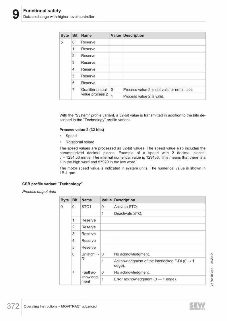
9 Functional safetyData exchange with higher-level controller
Operating Instructions – MOVITRAC® advanced372
Byte Bit Name Value Description5 0 Reserve
1 Reserve
2 Reserve
3 Reserve
4 Reserve
5 Reserve
6 Reserve
7 Qualifier actualvalue process 2
0 Process value 2 is not valid or not in use.
1 Process value 2 is valid.
With the "System" profile variant, a 32-bit value is transmitted in addition to the bits de-scribed in the "Technology" profile variant.
Process value 2 (32 bits)• Speed• Rotational speedThe speed values are processed as 32-bit values. The speed value also includes theparameterized decimal places. Example of a speed with 2 decimal places:v = 1234.56 mm/s. The internal numerical value is 123456. This means that there is a1 in the high word and 57920 in the low word.The motor speed value is indicated in system units. The numerical value is shown in1E-4 rpm.
CSB profile variant "Technology"
Process output data
Byte Bit Name Value Description0 0 STO1 0 Activate STO.
1 Deactivate STO.
1 Reserve
2 Reserve
3 Reserve
4 Reserve
5 Reserve
6 Unlatch F-DI
0 No acknowledgment.
1 Acknowledgment of the interlocked F-DI (0 → 1edge).
7 Fault ac-knowledg-ment
0 No acknowledgment.
1 Error acknowledgment (0 → 1 edge).
2778
8490
/EN
– 0
5/20
22
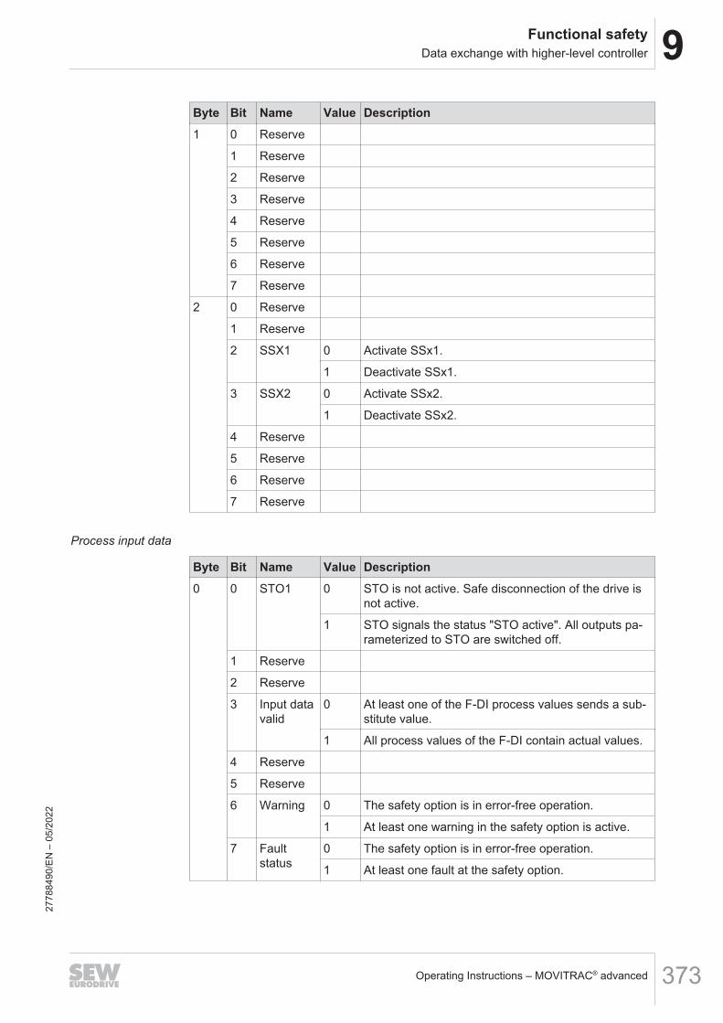
9Functional safetyData exchange with higher-level controller
Operating Instructions – MOVITRAC® advanced 373
Byte Bit Name Value Description1 0 Reserve
1 Reserve
2 Reserve
3 Reserve
4 Reserve
5 Reserve
6 Reserve
7 Reserve
2 0 Reserve
1 Reserve
2 SSX1 0 Activate SSx1.
1 Deactivate SSx1.
3 SSX2 0 Activate SSx2.
1 Deactivate SSx2.
4 Reserve
5 Reserve
6 Reserve
7 Reserve
Process input data
Byte Bit Name Value Description0 0 STO1 0 STO is not active. Safe disconnection of the drive is
not active.
1 STO signals the status "STO active". All outputs pa-rameterized to STO are switched off.
1 Reserve
2 Reserve
3 Input datavalid
0 At least one of the F-DI process values sends a sub-stitute value.
1 All process values of the F-DI contain actual values.
4 Reserve
5 Reserve
6 Warning 0 The safety option is in error-free operation.
1 At least one warning in the safety option is active.
7 Faultstatus
0 The safety option is in error-free operation.
1 At least one fault at the safety option.
2778
8490
/EN
– 0
5/20
22

9 Functional safetyData exchange with higher-level controller
Operating Instructions – MOVITRAC® advanced374
Byte Bit Name Value Description1 0 F-DI00 0 F‑DI00 process value: "low" or fault.
1 F‑DI00 process value: "high".
1 F-DI01 0 F‑DI01 process value: "low" or fault.
1 F‑DI01 process value: "high".
2 F-DI02 0 F‑DI02 process value: "low" or fault.
1 F‑DI02 process value: "high".
3 F-DI03 0 F‑DI03 process value: "low" or fault.
1 F‑DI03 process value: "high".
4 Reserve
5 Reserve
6 Reserve
7 Reserve
2 0 Reserve
1 Reserve
2 SSX1 0 SSx1 is not active or limit violation/fault.
1 SSx1 is active.
3 SSX2 0 SSx2 is not active or limit violation/fault.
1 SSx2 is active.
4 Reserve
5 Reserve
6 Reserve
7 Reserve
3 0 Reserve
1 Reserve
2 Reserve
3 Reserve
4 Reserve
5 Reserve
6 Reserve
7 Reserve
9.8.6 Process input data (F-PI) substitute valuesFor all process data (F-PE) outgoing from the safety option, the value "0" is written asthe substitute value. One exception is Fault state. For Error state, the value "1" is writ-ten as the substitute value in the case of an error-free protocol. In the case of a faultyF-protocol, the value "0" is written for Error State.
2778
8490
/EN
– 0
5/20
22

9Functional safetyData exchange with higher-level controller
Operating Instructions – MOVITRAC® advanced 375
9.8.7 Edge evaluation of F‑DI process dataObserve the following points for edge evaluation of F DI process data in the higher-level controller for safety-relevant functions:• Only the 0 → 1 edge may be used. The 1 → 0 edge must not be used as it can oc-
cur at any time during the transition to the safe state, e.g. in the event of a detect-ed fault or a line interruption.
• The higher-level controller may only evaluate the edge if the process data bitchanges from 0 to 1 and the "Qualifier process data" is set to "OK" (logical 1) forboth the value "0" of the process data bit and the value "1" of the process data bit.If it is set to "Fault" (logical 0), the edge must be ignored.
• It is ensured that all edges evaluated in the higher-level controller were actuallypresent at the F‑DI input terminal.
• What cannot be ensured is that all edges occurring at the F‑DI input terminal aredetected by the higher-level controller. This must be particularly observed in theevent of a defect in the safety option or the wiring.
9.8.8 Response when canceling secure communicationIf the "Safe communication fault response" is not activated during a failure of the safeprocess data communication, all process data bits will be overwritten and processedwith the substitute value "0". This means that all enabled safety subfunctions (includ-ing the STO safety subfunction) will be activated. This can lead to a jerky stop of thesystem.With activated "Safe communication fault response", the "SS1" fault response can beset and the corresponding SSx1 or SSx2 instance can be selected.Before first establishment of the safe process data communication, all process databits are set to the substitute value "0". After the safe process data communication isestablished and fails again, the process data bit of the configured SSX instance is setto "0". The other process data bits of the STO, SDI and SLS function retain the lastvalue. All other process data bits will be set to "0". After the SSX ramp has reachedthe final state of STO, all the process data bits are set to "0".With the "Safe communication error response" activated, the response time until acti-vation of the STO safety subfunction is extended by the time of the parameterizedSSX instance when communication is cut off.
INFORMATIONIf the F-DO function selection is set to "none", the outputs are disabled (logically "0").If the F-DO function selection is set to "STO" or "SBC", the opening of the outputs isdelayed by the activated function after the SSX ramp.
2778
8490
/EN
– 0
5/20
22
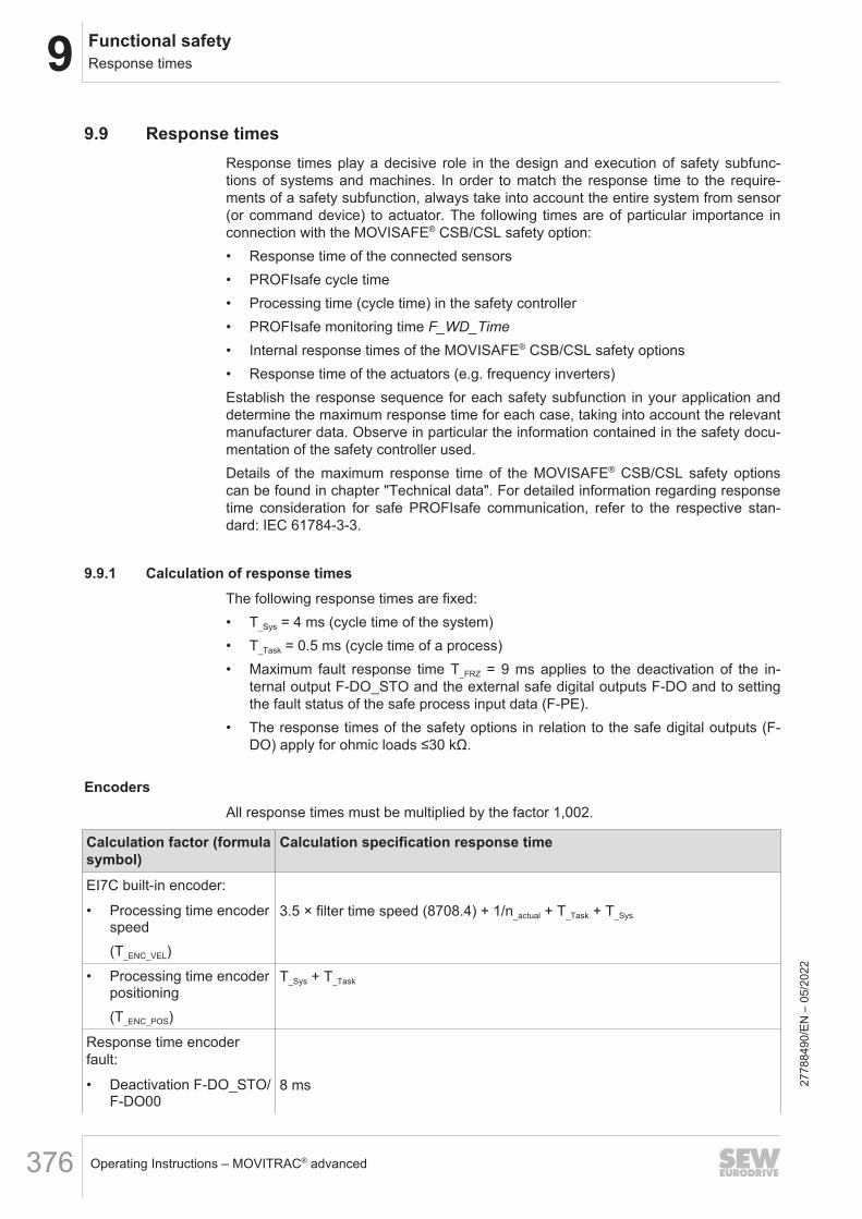
9 Functional safetyResponse times
Operating Instructions – MOVITRAC® advanced376
9.9 Response timesResponse times play a decisive role in the design and execution of safety subfunc-tions of systems and machines. In order to match the response time to the require-ments of a safety subfunction, always take into account the entire system from sensor(or command device) to actuator. The following times are of particular importance inconnection with the MOVISAFE® CSB/CSL safety option:• Response time of the connected sensors• PROFIsafe cycle time• Processing time (cycle time) in the safety controller• PROFIsafe monitoring time F_WD_Time• Internal response times of the MOVISAFE® CSB/CSL safety options• Response time of the actuators (e.g. frequency inverters)Establish the response sequence for each safety subfunction in your application anddetermine the maximum response time for each case, taking into account the relevantmanufacturer data. Observe in particular the information contained in the safety docu-mentation of the safety controller used.Details of the maximum response time of the MOVISAFE® CSB/CSL safety optionscan be found in chapter "Technical data". For detailed information regarding responsetime consideration for safe PROFIsafe communication, refer to the respective stan-dard: IEC 61784-3-3.
9.9.1 Calculation of response timesThe following response times are fixed:• T_Sys = 4 ms (cycle time of the system)• T_Task = 0.5 ms (cycle time of a process)• Maximum fault response time T_FRZ = 9 ms applies to the deactivation of the in-
ternal output F-DO_STO and the external safe digital outputs F-DO and to settingthe fault status of the safe process input data (F-PE).
• The response times of the safety options in relation to the safe digital outputs (F-DO) apply for ohmic loads ≤30 kΩ.
EncodersAll response times must be multiplied by the factor 1,002.
Calculation factor (formulasymbol)
Calculation specification response time
EI7C built-in encoder:
• Processing time encoderspeed(T_ENC_VEL)
3.5 × filter time speed (8708.4) + 1/n_actual + T_Task + T_Sys
• Processing time encoderpositioning(T_ENC_POS)
T_Sys + T_Task
Response time encoderfault:
• Deactivation F-DO_STO/F-DO00
8 ms 2778
8490
/EN
– 0
5/20
22

9Functional safetyResponse times
Operating Instructions – MOVITRAC® advanced 377
Calculation factor (formulasymbol)
Calculation specification response time
• Setting fault status F-PI 12 ms
Safe digital input F-DIAll response times must be multiplied by the factor 1.002.
Calculation factor (formula symbol) Calculation specification response timeInput processing time with selection F-DI(T_InputProcessing_F-DI)
Input filter time (8704.2) + 2 ms + T_Sys + 350 µs
Input processing with deselection F-DI:(T_InputProcessing_F-DI_Deselection)
• 1-channel Input filter time (8704.2) + 51 ms + T_Sys + 350 µs
• 2-channel Input filter time (8704.2) + 2 ms + T_Sys + 350 µs
Response time of line diagnostics 30 ms (the response times of the safety subfunctions are nottaken into account)
Safe communicationThe response times for the safe communication always relate to the safe protocol andnot to the external interface of the safety option. All response times must be multipliedby the factor 1,002.
Calculation factor (formula symbol) Calculation specification response timeInput processing time via safe process out-put data(T_InputProcessing_F-PO)
2 × T_Task + T_Sys
Response time selection (F-DIx after F-PE) T_InputProcessing_F-DIx + TSys
Response time (F-PO after F-DOx) T_InputProcessing_F-PO + TSys
Response time (safe velocity (SV) afterF‑PI)
T_ENC_VEL_COMBINED + TSys
Selection of a safety subfunction via safe digital inputAll response times must be multiplied by the factor 1,002.
Calculation factor Calculation specification response timeSTO T_InputProcessing_F-DI + T_Sys + 1 ms
SS1-r T_InputProcessing_F-DI + T_Sys + SSx‑r monitoring delay t2 (8706.9) + brake application time1)
(8706.15) + actual_speed/SSx‑r deceleration a (8706.10) + SSx‑r jerk time2) t3
(8706.11) + 1 ms
SS1-t T_InputProcessing_F-DI + T_Sys + SSx‑t delay t1 (8706.8) + brake application time1) (8706.15)+ 1 ms
2778
8490
/EN
– 0
5/20
22
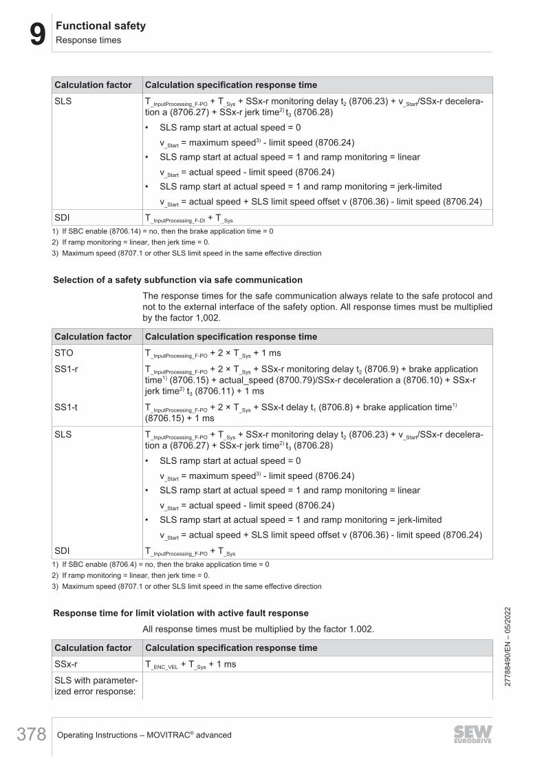
9 Functional safetyResponse times
Operating Instructions – MOVITRAC® advanced378
Calculation factor Calculation specification response timeSLS T_InputProcessing_F-PO + T_Sys + SSx‑r monitoring delay t2 (8706.23) + v_Start/SSx‑r decelera-
tion a (8706.27) + SSx‑r jerk time2) t3 (8706.28)• SLS ramp start at actual speed = 0
v_Start = maximum speed3) - limit speed (8706.24)• SLS ramp start at actual speed = 1 and ramp monitoring = linear
v_Start = actual speed - limit speed (8706.24)• SLS ramp start at actual speed = 1 and ramp monitoring = jerk-limited
v_Start = actual speed + SLS limit speed offset v (8706.36) - limit speed (8706.24)
SDI T_InputProcessing_F-DI + T_Sys
1) If SBC enable (8706.14) = no, then the brake application time = 02) If ramp monitoring = linear, then jerk time = 0.3) Maximum speed (8707.1 or other SLS limit speed in the same effective direction
Selection of a safety subfunction via safe communicationThe response times for the safe communication always relate to the safe protocol andnot to the external interface of the safety option. All response times must be multipliedby the factor 1,002.
Calculation factor Calculation specification response timeSTO T_InputProcessing_F-PO + 2 × T_Sys + 1 ms
SS1-r T_InputProcessing_F-PO + 2 × T_Sys + SSx‑r monitoring delay t2 (8706.9) + brake applicationtime1) (8706.15) + actual_speed (8700.79)/SSx‑r deceleration a (8706.10) + SSx‑rjerk time2) t3 (8706.11) + 1 ms
SS1-t T_InputProcessing_F-PO + 2 × T_Sys + SSx‑t delay t1 (8706.8) + brake application time1)
(8706.15) + 1 ms
SLS T_InputProcessing_F-PO + T_Sys + SSx‑r monitoring delay t2 (8706.23) + v_Start/SSx‑r decelera-tion a (8706.27) + SSx‑r jerk time2) t3 (8706.28)• SLS ramp start at actual speed = 0
v_Start = maximum speed3) - limit speed (8706.24)• SLS ramp start at actual speed = 1 and ramp monitoring = linear
v_Start = actual speed - limit speed (8706.24)• SLS ramp start at actual speed = 1 and ramp monitoring = jerk-limited
v_Start = actual speed + SLS limit speed offset v (8706.36) - limit speed (8706.24)
SDI T_InputProcessing_F-PO + T_Sys
1) If SBC enable (8706.4) = no, then the brake application time = 02) If ramp monitoring = linear, then jerk time = 0.3) Maximum speed (8707.1 or other SLS limit speed in the same effective direction
Response time for limit violation with active fault responseAll response times must be multiplied by the factor 1.002.
Calculation factor Calculation specification response timeSSx-r T_ENC_VEL + T_Sys + 1 ms
SLS with parameter-ized error response:
2778
8490
/EN
– 0
5/20
22
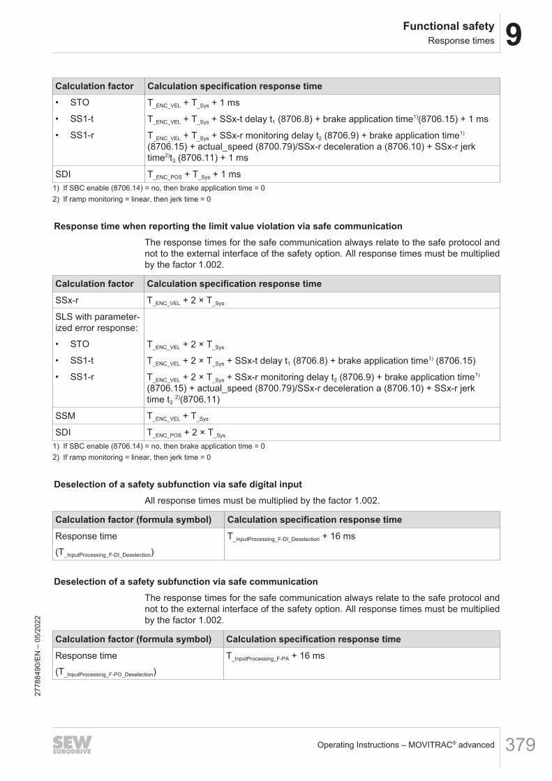
9Functional safetyResponse times
Operating Instructions – MOVITRAC® advanced 379
Calculation factor Calculation specification response time• STO T_ENC_VEL + T_Sys + 1 ms
• SS1-t T_ENC_VEL + T_Sys + SSx‑t delay t1 (8706.8) + brake application time1)(8706.15) + 1 ms
• SS1-r T_ENC_VEL + T_Sys + SSx‑r monitoring delay t2 (8706.9) + brake application time1)
(8706.15) + actual_speed (8700.79)/SSx‑r deceleration a (8706.10) + SSx‑r jerktime2)t3 (8706.11) + 1 ms
SDI T_ENC_POS + T_Sys + 1 ms1) If SBC enable (8706.14) = no, then brake application time = 02) If ramp monitoring = linear, then jerk time = 0
Response time when reporting the limit value violation via safe communicationThe response times for the safe communication always relate to the safe protocol andnot to the external interface of the safety option. All response times must be multipliedby the factor 1.002.
Calculation factor Calculation specification response timeSSx-r T_ENC_VEL + 2 × T_Sys
SLS with parameter-ized error response:
• STO T_ENC_VEL + 2 × T_Sys
• SS1-t T_ENC_VEL + 2 × T_Sys + SSx‑t delay t1 (8706.8) + brake application time1) (8706.15)
• SS1-r T_ENC_VEL + 2 × T_Sys + SSx‑r monitoring delay t2 (8706.9) + brake application time1)
(8706.15) + actual_speed (8700.79)/SSx‑r deceleration a (8706.10) + SSx‑r jerktime t3 2)(8706.11)
SSM T_ENC_VEL + T_Sys
SDI T_ENC_POS + 2 × T_Sys
1) If SBC enable (8706.14) = no, then brake application time = 02) If ramp monitoring = linear, then jerk time = 0
Deselection of a safety subfunction via safe digital inputAll response times must be multiplied by the factor 1.002.
Calculation factor (formula symbol) Calculation specification response timeResponse time(T_InputProcessing_F-DI_Deselection)
T_InputProcessing_F-DI_Deselection + 16 ms
Deselection of a safety subfunction via safe communicationThe response times for the safe communication always relate to the safe protocol andnot to the external interface of the safety option. All response times must be multipliedby the factor 1.002.
Calculation factor (formula symbol) Calculation specification response timeResponse time(T_InputProcessing_F-PO_Deselection)
T_InputProcessing_F-PA + 16 ms
2778
8490
/EN
– 0
5/20
22
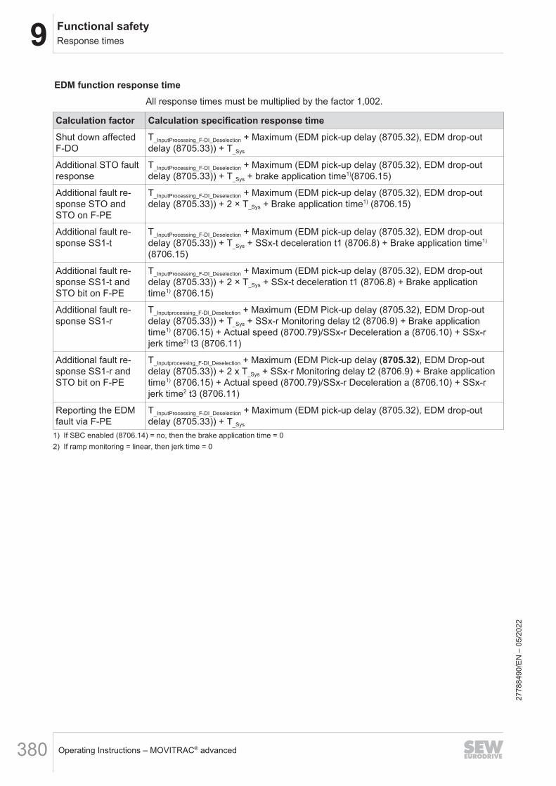
9 Functional safetyResponse times
Operating Instructions – MOVITRAC® advanced380
EDM function response timeAll response times must be multiplied by the factor 1,002.
Calculation factor Calculation specification response timeShut down affectedF-DO
T_InputProcessing_F-DI_Deselection + Maximum (EDM pick-up delay (8705.32), EDM drop-outdelay (8705.33)) + T_Sys
Additional STO faultresponse
T_InputProcessing_F-DI_Deselection + Maximum (EDM pick-up delay (8705.32), EDM drop-outdelay (8705.33)) + T_Sys + brake application time1)(8706.15)
Additional fault re-sponse STO andSTO on F-PE
T_InputProcessing_F-DI_Deselection + Maximum (EDM pick-up delay (8705.32), EDM drop-outdelay (8705.33)) + 2 × T_Sys + Brake application time1) (8706.15)
Additional fault re-sponse SS1-t
T_InputProcessing_F-DI_Deselection + Maximum (EDM pick-up delay (8705.32), EDM drop-outdelay (8705.33)) + T_Sys + SSx-t deceleration t1 (8706.8) + Brake application time1)
(8706.15)
Additional fault re-sponse SS1-t andSTO bit on F-PE
T_InputProcessing_F-DI_Deselection + Maximum (EDM pick-up delay (8705.32), EDM drop-outdelay (8705.33)) + 2 × T_Sys + SSx-t deceleration t1 (8706.8) + Brake applicationtime1) (8706.15)
Additional fault re-sponse SS1-r
T_Inputprocessing_F-DI_Deselection + Maximum (EDM Pick-up delay (8705.32), EDM Drop-outdelay (8705.33)) + T_Sys + SSx-r Monitoring delay t2 (8706.9) + Brake applicationtime1) (8706.15) + Actual speed (8700.79)/SSx-r Deceleration a (8706.10) + SSx-rjerk time2) t3 (8706.11)
Additional fault re-sponse SS1-r andSTO bit on F-PE
T_Inputprocessing_F-DI_Deselection + Maximum (EDM Pick-up delay (8705.32), EDM Drop-outdelay (8705.33)) + 2 x T_Sys + SSx-r Monitoring delay t2 (8706.9) + Brake applicationtime1) (8706.15) + Actual speed (8700.79)/SSx-r Deceleration a (8706.10) + SSx-rjerk time2 t3 (8706.11)
Reporting the EDMfault via F-PE
T_InputProcessing_F-DI_Deselection + Maximum (EDM pick-up delay (8705.32), EDM drop-outdelay (8705.33)) + T_Sys
1) If SBC enabled (8706.14) = no, then the brake application time = 02) If ramp monitoring = linear, then jerk time = 0
2778
8490
/EN
– 0
5/20
22

9Functional safetyService
Operating Instructions – MOVITRAC® advanced 381
9.10 Service9.10.1 Modification/changes to the device
• Hardware changesAny changes to the CSB/CSL safety option can be performed only bySEW‑EURODRIVE.
• Firmware modificationsOnly SEW‑EURODRIVE is authorized to make changes to the firmware.
• RepairOnly SEW‑EURODRIVE is authorized to repair the CSB/CSL safety option.
• Warranty
INFORMATIONThe safety certification and any right to claim under limited warranty ofSEW‑EURODRIVE become void if the user modifies the device internally (e.g. ex-change of components, welding parts).
9.10.2 Status LEDs
WARNINGDanger due to incorrect interpretation of the LEDs "F-RUN" and "F-ERR"Severe or fatal injuries.• The LEDs are not safety-related and must not be used as a safety device.
INFORMATION• "Slow" flashing frequency means that the LED is flashing at 0.5 Hz.• "Fast" flashing frequency means that the LED is flashing at 2Hz.• The "flashing sequence" state means that both LEDs of the assembly alternately
flash in yellow or green. The LED color is alternately assigned to the LEDs, e.g.the F-RUN LED flashes green, the F-ERR LED flashes yellow, and vice versa.
"F-RUN" LEDThe following table shows the states of the "F-RUN" LED.
LED status MeaningFlashing sequence Device identification for safety key ID query.
Red, slowly flashing Device identification for parameterization.
Red, rapidly flashing Firmware update, do not switch the device off.
Red Critical fault (cannot be acknowledged).
Yellow STO safety subfunction is active.
Yellow, flashing slowly Device in the operating state with one or more of the follow-ing constraints:• The safety card controls inverters• Test mode
2778
8490
/EN
– 0
5/20
22
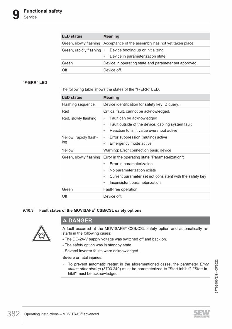
9 Functional safetyService
Operating Instructions – MOVITRAC® advanced382
LED status MeaningGreen, slowly flashing Acceptance of the assembly has not yet taken place.
Green, rapidly flashing • Device booting up or initializing• Device in parameterization state
Green Device in operating state and parameter set approved.
Off Device off.
"F-ERR" LEDThe following table shows the states of the "F-ERR" LED.
LED status MeaningFlashing sequence Device identification for safety key ID query.
Red Critical fault, cannot be acknowledged.
Red, slowly flashing • Fault can be acknowledged• Fault outside of the device, cabling system fault• Reaction to limit value overshoot active
Yellow, rapidly flash-ing
• Error suppression (muting) active• Emergency mode active
Yellow Warning: Error connection basic device
Green, slowly flashing Error in the operating state "Parameterization":• Error in parameterization• No parameterization exists• Current parameter set not consistent with the safety key• Inconsistent parameterization
Green Fault-free operation.
Off Device off.
9.10.3 Fault states of the MOVISAFE® CSB/CSL safety options
DANGERA fault occurred at the MOVISAFE® CSB/CSL safety option and automatically re-starts in the following cases:- The DC-24-V supply voltage was switched off and back on.- The safety option was in standby state.- Several inverter faults were acknowledged.Severe or fatal injuries.• To prevent automatic restart in the aforementioned cases, the parameter Error
status after startup (8703.240) must be parameterized to "Start inhibit". "Start in-hibit" must be acknowledged.
2778
8490
/EN
– 0
5/20
22
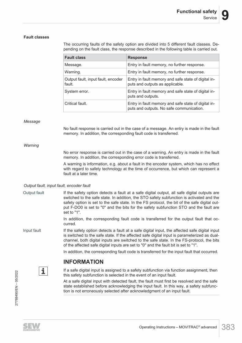
9Functional safetyService
Operating Instructions – MOVITRAC® advanced 383
Fault classesThe occurring faults of the safety option are divided into 5 different fault classes. De-pending on the fault class, the response described in the following table is carried out.
Fault class ResponseMessage. Entry in fault memory, no further response.
Warning. Entry in fault memory, no further response.
Output fault, input fault, encoderfault.
Entry in fault memory and safe state of digital in-puts and outputs as applicable.
System error. Entry in fault memory and safe state of digital in-puts and outputs.
Critical fault. Entry in fault memory and safe state of digital in-puts and outputs. No safe communication.
Message
No fault response is carried out in the case of a message. An entry is made in the faultmemory. In addition, the corresponding fault code is transferred.
Warning
No error response is carried out in the case of a warning. An entry is made in the faultmemory. In addition, the corresponding error code is transferred.A warning is information, e.g. about a fault in the encoder system, which has no effectwith regard to safety technology at the time of occurrence, but which can represent afault at a later time.
Output fault, input fault, encoder fault
Output fault If the safety option detects a fault at a safe digital output, all safe digital outputs areswitched to the safe state. In addition, the STO safety subfunction is activated and thesafety option is set to the safe state. In the FS protocol, the bit of the safe digital out-put F-DO0 is set to "0" and the bits for the safety subfunction STO and the fault areset to "1".In addition, the corresponding fault code is transferred for the output fault that oc-curred.
Input fault If the safety option detects a fault at a safe digital input, the affected safe digital inputis switched to the safe state. If the affected safe digital input is parameterized as dual-channel, both digital inputs are switched to the safe state. In the FS-protocol, the bitsof the affected safe digital inputs are set to "0" and the fault bit is set to "1".In addition, the corresponding fault code is transferred for the input fault that occurred.
INFORMATIONIf a safe digital input is assigned to a safety subfunction via function assignment, thenthis safety subfunction is selected in the event of an input fault.At a safe digital input with detected fault, the fault must first be resolved and the safestate established before acknowledging the input fault. In this way, a safety subfunc-tion is not erroneously selected after acknowledgment of an input fault.
2778
8490
/EN
– 0
5/20
22

9 Functional safetyService
Operating Instructions – MOVITRAC® advanced384
Encoder fault If the safety option detects a fault in the encoder system, this results in a warning if nosafety subfunction is activated. The safety option continues to remain operational. If atleast one safety subfunction is active, this leads to an encoder fault. The safety sub-functions change to the corresponding fault state. The corresponding fault code for theencoder fault that occurred is transferred.In the case of faults in the encoder system that are assigned to the fault class "En-coder fault" or "System error", the corresponding fault response is initiated as soon asthe fault or error is detected.Acknowledging the encoder fault with activated safety subfunction leads to a restart ofthe safety subfunction.
INFORMATIONAcknowledgment of a limit value violation leads to a different behavior of the activa-ted safety subfunction than the acknowledgment of an encoder fault.
The response to an encoder fault can be suppressed with the "Encoder fault muting"function. The "Encoder fault muting" function can be activated at a safe digital input orvia the safe process data. Refer to the "Encoder fault muting" chapter for more infor-mation.
System error In the case of a system fault, all safe digital inputs and all safe digital outputs areswitched to the safe state. In addition, the STO safety subfunction is executed withoutdelay and the safe digital outputs F-DO00 is disabled. The safety option is set to thesafe state.In the FS protocol, the bit of the safe digital output F-DO00 and the bits of the safe dig-ital inputs F-DI00, F-DI01, F-DI02 and F-DI03 are set to "0". The bits for the safetysubfunction STO and the fault are set to "1".In addition, the corresponding fault code is transferred for the system error that oc-curred.
INFORMATIONIf the safe digital output is assigned to a safety subfunction via the function assign-ment, this safety subfunction is selected in the case of a system error.
Critical fault In the case of a critical fault, the safety option is set to the safe state. All safe digital in-puts and all safe digital outputs are switched to the safe state. In addition, the STOsafety subfunction is executed without delay. The sensor supply for the safe digital in-puts is also switched to de-energized state. Active safe communication is suspended.In addition, the corresponding fault code is transferred for the critical fault that oc-curred.
Fault messages If there is a fault in the safety option, the inverter indicates that the safety option is re-porting a fault.Measures for fault resolution and more information on causes can be found using thefault status of the safety option.
2778
8490
/EN
– 0
5/20
22

9Functional safetyService
Operating Instructions – MOVITRAC® advanced 385
Starting behavior of the safety option
DANGERAfter a fault, the safety option automatically restarts if the supply voltage is turnedon, if the standby mode is completed, or if certain inverter faults are acknowledged.Severe or fatal injuries.• The Fault status after startup parameter must be parameterized to "start inhibit".
This way, the automatic restart of the safety option is prevented in the casesmentioned above.
In the "Basic settings" of the "Assist CS.." parameterization tool, the starting behaviorof the safety option can be defined with the Fault status after startup parameter. Thefollowing parameter settings are possible.• "Start inhibit" parameter setting
The safety option always starts with start inhibit after the supply voltage isswitched on. This parameterization is available for independent operation.
• "No start inhibit" parameter settingThe safety option starts immediately. Observe that faults must be acknowledgedby switching the supply voltage off and on again or by quitting standby mode. Thismeans that a fault pending prior to switching off the supply voltage or duringstandby mode is acknowledged and the safety option starts up. This parameteriza-tion is designated for fieldbus operation where the higher-level controller, if neces-sary, takes over interlocking in case of a fault.
The STO safety subfunction is active as long as start inhibit is active. Outputs as-signed to the STO or SBC function are activated depending on the safety subfunction.If outputs are configured to "F-PO data", they will still be controlled by the higher-levelcontroller. The outputs are not set to safe stateStart inhibit is deactivated if one of the following conditions is met:• Fault acknowledgment completed• Muting is activated
9.10.4 Fault diagnosticsThe "Latest initial fault" fault status shows the fault that occurred first in the safety op-tion with the corresponding fault code, subfault code and fault description. For internalpurposes, additional fault codes are displayed.The current first fault is the fault that occurs after a restart or since the last acknowl-edgment as the first fault with the highest priority.
Fault messagesIf there is a fault in the safety option, this fault is indicated by the inverter as follows.
Subfault: 46.50Description: Warning
Response: Warning with self-reset
Cause Measure
– The safety option signals a subcomponent faultof the type "warning".
See fault status "Subcomponent safety option"
2778
8490
/EN
– 0
5/20
22

9 Functional safetyService
Operating Instructions – MOVITRAC® advanced386
Subfault: 46.51Description: Fault
Response: Emergency stop and output stage inhibit with self-reset
Cause Measure
– The safety option signals a subcomponent faultof the type "standard fault".
See fault status "Subcomponent safety option"
Subfault: 46.52Description: Critical fault
Response: Output stage inhibit with self-reset
Cause Measure
– The safety option signals a subcomponent faultof the type "critical fault".
See fault status "Subcomponent safety option"
Diagnostics with MOVISUITE® Assist CS..The current fault of the safety option is displayed with the corresponding fault descrip-tion in the "Diagnostics" segment in the menu command [MOVISAFE® CS..] > [Faultstatus].
9007221132519563
Diagnostics with PROFIsafe connectionThe safety option with PROFIsafe connection triggers a diagnostic alarm on the F-PLC in the data exchange between the F-PLC (fieldbus master) and the safety option(fieldbus slave) in case of a fault. Simultaneously, the associated fault code is trans-ferred via the communication connection.
2778
8490
/EN
– 0
5/20
22

9Functional safetyService
Operating Instructions – MOVITRAC® advanced 387
The F-PLC responds to the dispatched diagnostic alarm if the Diagnostic alarm as-sembly parameter is enabled for the safety option in the F-PLC per configuration. De-pending on the fieldbus used (PROFINET), the fault code of the safety option can beevaluated in the F-PLC. A diagnostic alarm does not trigger a fault response in the F-PLC (default setting of the safety option in the F-PLC).The safety option has PROFIsafe and assembly-specific fault codes. All fault codes ofthe safety option are listed in a fault table.
INFORMATIONYou can find the structure and the evaluation of a diagnostic data set in the F-PLC inthe respective manual of the fieldbus master. In addition, ensure that the currentdevice description file of the SEW‑EURODRIVE drive system is always installed inthe engineering tool of the F-PLC during configuration.
Fault memoryThe current initial fault and all other subsequent faults are residually saved in the faultmemory with associated timestamp.
9007221132546955
Additional messages for the errors are entered in the fault memory in the columns"Primary error" and "Sub-error". These are messages that do not directly trigger a faultresponse of the CSB/CSL safety option. Essentially, these are the message "PowerOn" (primary error 66 and sub-error 100) and the message "Acknowledgment mes-sage" (primary error 66 and sub-error 101).In the "Pos" column, the position of the fault is displayed. In the "Info" column, an iconindicates the category of the fault. In the "Error message" column, the fault number,the main fault text and the subfault text is displayed. The actual value of the operatinghours counter of the safety option is displayed in the "Time" column. The "Internalfault" column is used for internal purposes. The fault memory is organized as a ringmemory. The most recently occurring error is shown in line 0 of the list. If there aremore than 50 entries, the oldest fault is overwritten.
9.10.5 AcknowledgmentA fault or a limit value violation can be acknowledged via a safe digital input F‑DI orvia the "fault acknowledgment" bit of the safe process data.
2778
8490
/EN
– 0
5/20
22

9 Functional safetyService
Operating Instructions – MOVITRAC® advanced388
To acknowledge a fault or a limit value violation via a safe digital input, an input mustbe set to "Acknowledge faults" or "Unlatch latched F-DI and acknowledge faults".Acknowledgment is performed by a 0 → 1 edge. In the following cases, a warning willbe indicated after 20 s:• a permanent high signal is present on the safe digital input to which the acknowl-
edgment has been assigned.• One of the fault acknowledgment bits in the process data is permanently "1".To acknowledge faults via PROFIsafe, Safety over EtherCAT® or CIP Safety™, theexchange of safe data of the safety option must be fault-free. Faults can the be ac-knowledged by a rising edge via the "Fault acknowledgment" bit in the F‑process out-put data.A critical fault can only be acknowledged by switching the supply voltage off and on.
DANGERDepending on the wiring, MOVISAFE® CSB/CSL can deactivate the STO safety sub-function after fault acknowledgment. This can cause an immediate restart of the sys-tem.Severe or fatal injuries.• Make sure that no persons enter the hazardous area of the system while ac-
knowledging a fault.• Make sure that the STO safety subfunction is active via F-DI or safe communica-
tion during fault acknowledgment.
Existing limit violations of the safety subfunctions are deleted by parameterizing, creat-ing the acceptance report, and publishing the acceptance. Start inhibit is set to preventthe system from switching to operation afterwards.
Acknowledging a system errorIf safe digital inputs with active interlocking are used for acknowledging a systemerror, adhere to the following sequence:1. If possible, eliminate the cause of the error.2. Make sure of the following:
• No person is in the hazardous area of the system.• The STO safety subfunction is activated via F-DI or via safe communication
and the SDI safety subfunction is deselected.3. Acknowledge system error.4. If necessary, select the deselected SDI safety subfunction again.
Acknowledging an input faultAn input fault can occur if one of the following functions is assigned to a 2‑channelsafe digital input F‑DI in the function assignment.• Unlatch F-DI• Unlatch F-DI and acknowledge fault• Muting• Activate test mode
2778
8490
/EN
– 0
5/20
22
9Functional safetyService
Operating Instructions – MOVITRAC® advanced 389
Before acknowledging an input fault, ensure the following:• No person is in the hazardous area of the system.• No DC 24 V signal is present at the corresponding inputs.
Acknowledging a limit value violation of a safety subfunctionOnce a limit value violation of a safety subfunction has been identified, the status ofthis function becomes inactive. Furthermore, an error in the "Warning" class is set.A limit value violation must always be acknowledged.A limit value violation cannot be acknowledged by deactivating the safety subfunction.With the exception of this, the parameterization of the fault response is at "F-PE only".With the SSM safety subfunction, the fault is acknowledged by deactivating the safetysubfunction.Acknowledgment always affects all the safety subfunctions. The safety subfunctioncan continue to be activated during acknowledgment.Parameterized speed filters of the safety subfunctions that have triggered a limit valueviolation are reset.Please note the following behavior of the safety subfunctions during an acknowledg-ment:• SDI:
The limit positions are recalculated.• SLS:
The delay time and the transition ramp are not recalculated; the limit speed is im-mediately monitored.
• SS1:The deceleration time and the transition ramp are not recalculated; the final statebecomes immediately active (STO activation).
9.10.6 "Emergency mode" functionThe "emergency mode" function can only be triggered using the keypad. The "emer-gency mode" function automatically triggers the "Encoder fault muting" function (seechapter "Encoder fault muting") and the "Muting safe process output data (F-PO)"function (see chapter "Muting safe process output").
Safety notes
DANGERDue to the "Emergency mode" function, immediate restart of the system is possible.Severe or fatal injuries.• Before activating the "Emergency mode" function, the user must undertake or-
ganizational measures for the protection of personnel and machinery.
2778
8490
/EN
– 0
5/20
22

9 Functional safetyService
Operating Instructions – MOVITRAC® advanced390
DANGERThe keypad is connected to the wrong device. This can cause immediate restart ofthe system.Severe or fatal injuries.• Before activating the "Emergency mode" function, the user must undertake or-
ganizational measures for the protection of personnel and machinery.• The keypad must mechanically be connected to the correct device.• Make sure that you can see the display of the keypad and the system at any time
during emergency mode. The connection between the keypad and the devicemust be designed in such a way that it can be disconnected at any time withouttools.
Requirements• The "Emergency mode" function (index 8707.2) must be enabled.• To start the "Emergency mode" function, an encoder fault or communication error
must be pending in the F-protocol.
Starting the emergency modeDo the following:• Select "emergency mode" using the keypad.• With the "F-ERR" LED (see chapter "F-ERR LED"), check if the correct device sig-
nals emergency mode. If the wrong device is flashing, activation of the emergencymode must be canceled immediately.
• If the correct device is selected, the emergency mode ID is displayed. Confirm sig-naling of the correct device. For this, enter the displayed emergency mode ID inreverse order and click OK.
Ending emergency mode• You can end emergency mode in a safety-related manner by interrupting the con-
nection between keypad and device.• You cannot end emergency mode in a safety-related manner by selecting "End
emergency mode" on the keypad.• Emergency mode is automatically terminated after 5 minutes.
9.10.7 Device replacement
WARNINGAn incorrect parameterization of the safety option is enabled if the CMM memorymodule with integrated safety key is inserted incorrectly.Severe or fatal injuries.• Make sure that the safety key matching the application is plugged into the correct
system position.
2778
8490
/EN
– 0
5/20
22

9Functional safetyService
Operating Instructions – MOVITRAC® advanced 391
INFORMATIONA MOVITRAC® advanced with faulty CSB/CSL safety option must be taken out ofoperation within 100 hours.
Device replacement with MOVI-C® without PCThe MOVI-C® system offers the option to save the application-related data set for theinverter and the data set for the safety option on the memory module in the inverter oron the MOVI-C® CONTROLLER. This step must be performed in advance by the userwith the MOVI-C® CONTROLLER.The following steps must be performed for the actual device replacement:1. Switch off the device to be replaced.2. Remove the pluggable CMM memory module with integrated safety key from the
device.3. Replace the device (including MOVISAFE® CSB/CSL safety option).4. Reinsert the CMM memory module with integrated safety key that was removed in
step 2.5. Carry out a functional test. The checking of all parameters is omitted.The controller/inverter detects the device replacement automatically and loads the ap-plicative data set to the MOVISAFE® CSB/CSL safety option. The localized key dataset on the pluggable safety key ensures that the correct application data set has beenloaded. The MOVISAFE® CSB/CSL safety option is subsequently in the same statethat it was in before the device replacement. This means that the MOVISAFE® CSB/CSL safety option will be in the "Accepted" state again afterwards if it was in the "Ac-cepted" state before the device replacement. In order to ensure correct connection ofthe sensors and actuators, a function test of the safety option is required in the case ofautomatic device replacement function.
Device replacement with MOVISUITE®
For device replacement with MOVISUITE® , proceed as follows:1. Back up the device data set of the device to be replaced using the menu item
[Device] > [PC].2. Switch off the device to be replaced.3. Remove the pluggable CMM memory module with integrated safety key from the
device.4. Replace the device (including MOVISAFE® CSB/CSL safety option).5. Reinsert the CMM memory module that was removed in step 3.6. Switch only the DC 24 V control voltage back on.7. Load the device data set saved in step 1 back onto the new device using the menu
item [PC] > [Device].8. Switch the main power supply (AC 230 V) back on and perform a functional test of
the system.
2778
8490
/EN
– 0
5/20
22
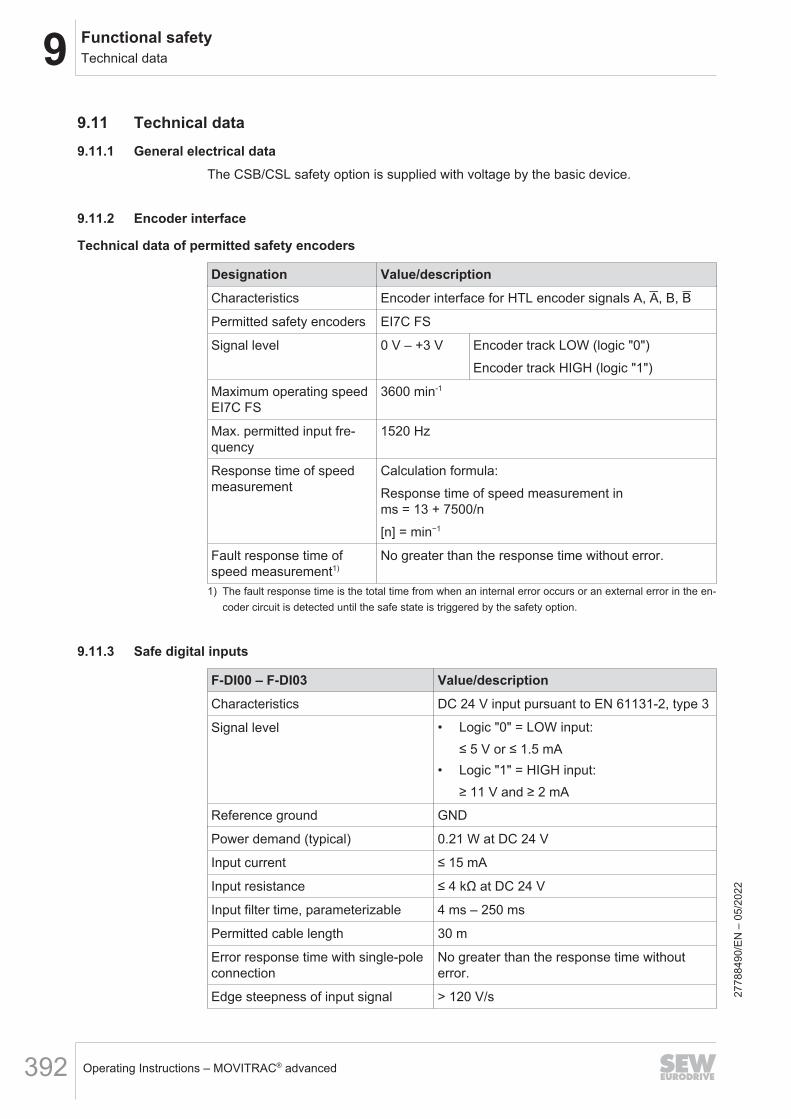
9 Functional safetyTechnical data
Operating Instructions – MOVITRAC® advanced392
9.11 Technical data9.11.1 General electrical data
The CSB/CSL safety option is supplied with voltage by the basic device.
9.11.2 Encoder interface
Technical data of permitted safety encoders
Designation Value/descriptionCharacteristics Encoder interface for HTL encoder signals A, A, B, B
Permitted safety encoders EI7C FS
Signal level 0 V – +3 V Encoder track LOW (logic "0")Encoder track HIGH (logic "1")
Maximum operating speedEI7C FS
3600 min-1
Max. permitted input fre-quency
1520 Hz
Response time of speedmeasurement
Calculation formula:Response time of speed measurement inms = 13 + 7500/n[n] = min−1
Fault response time ofspeed measurement1)
No greater than the response time without error.
1) The fault response time is the total time from when an internal error occurs or an external error in the en-coder circuit is detected until the safe state is triggered by the safety option.
9.11.3 Safe digital inputs
F-DI00 – F-DI03 Value/descriptionCharacteristics DC 24 V input pursuant to EN 61131-2, type 3
Signal level • Logic "0" = LOW input:≤ 5 V or ≤ 1.5 mA
• Logic "1" = HIGH input:≥ 11 V and ≥ 2 mA
Reference ground GND
Power demand (typical) 0.21 W at DC 24 V
Input current ≤ 15 mA
Input resistance ≤ 4 kΩ at DC 24 V
Input filter time, parameterizable 4 ms – 250 ms
Permitted cable length 30 m
Error response time with single-poleconnection
No greater than the response time withouterror.
Edge steepness of input signal > 120 V/s 2778
8490
/EN
– 0
5/20
22

9Functional safetyTechnical data
Operating Instructions – MOVITRAC® advanced 393
F-DI00 – F-DI03 Value/descriptionInput capacitance < 500 pF
9.11.4 Sensor supply
F-SS0, F-SS1 Value/descriptionCharacteristics • DC 24 V output pursuant to EN 61131-2
• Short circuit and overload protection• No galvanic isolation
Rated current 150 mA
Inrush current (≤ 10 ms) 300 mA
Short-circuit protection 1.2 A
Internal voltage drop < DC 1.3 V
Pulsed voltage supply (if activated) • 2 ms open (LOW)• Period duration, pulsed voltage supply:
8 ms
Permitted cable length 30 m (per sensor)
Leakage current (F-SSx blocked) < 0.1 mA
9.11.5 Safe digital outputs
F-DO00_P/M Value/descriptionProperties • DC 24 V output in accordance with
EN 61131-2• Short circuit and overload protection
Rated current 150 mA
Inrush current (≤ 10 ms) 300 mA
Leakage current (F-DOx blocked) < 0.1 mA
Maximum switching frequency 10 Hz during operation
Overload protection 210 mA
Minimum current for wire breakmonitoring
15 mA
Permitted cable length 30 m
Load capacitance (max. test pulseduration)
≤ 300 nF
Load capacitance (1 ms test pulseduration)
≤ 50 nF
Capacitance to GND/PE (sourcingoutput only)
≤ 10 nF
Load capacitance with diode de-coupling
≤ 12 µF
Load inductance ≤ 100 µH2778
8490
/EN
– 0
5/20
22

9 Functional safetyTechnical data
Operating Instructions – MOVITRAC® advanced394
F-DO00_P/M Value/descriptionLoad inductance with freewheelingdiode
≤ 40 H
Minimum load resistance > 130 Ω
9.11.6 MOVISAFE® CSO characteristic safety values
Characteristic values pursuant toEN 62061/IEC 61800‑5‑2 EN ISO 13849-1
Tested safety class/underlying stan-dards
SIL 2 PL d
Probability of a dangerous failureper hour (PFH value)
30 × 10-9 1/h
Service life 20 years, after which the component must bereplaced with a new one.
Proof test interval > 20 years -
Safe state Safe Torque Off (STO)
Safety subfunction STO, SS11) in accordance with IEC 61800‑5‑21) With suitable external control
9.11.7 MOVISAFE® CSB/CSL characteristic safety values
Characteristic values pursuant toEN 62061/IEC 61800-5-2 EN ISO 13849-1
Tested safety class/underlyingstandards
SIL 2 PL d
Probability of dangerous failure perhour (PFHD value)
7 × 10⁻⁹ 1/h
Mission time/service life 20 years, after which the component must be re-placed with a new one.
Proof test interval 20 years -
Safe state Value "0" for all safe F-DO process values (out-put disabled).
Safety subfunction • STO, SS1, SLS, SSM, SDI, SBC• Safe digital inputs/outputs• Safe communication
2778
8490
/EN
– 0
5/20
22

10AppendixAbbreviation key
Operating Instructions – MOVITRAC® advanced 395
10 Appendix10.1 Abbreviation key
The following table lists the abbreviations that are used in this documentation togetherwith their unit and meaning:
Abbreviation Information onthe nameplate
Unit Meaning
ASM Asynchronous motor
BG.. Inverter size
C C μF Capacitance
fmax f Hz Maximum output frequency
fline f Hz Line frequency
fPWM kHz Frequency of the pulse width modulation
h m Installation altitude
HF High frequency
Itrip A Tripping current (braking resistor)
Imax Imax A Max. DC link current (specification on the nameplate)
Imax A Maximum output current (encoder cards)
Ipeak A Output peak current (encoder cards)
IA max A Max. output current
IAppl A Total current of the application
IN A Nominal output current/nominal current (filter, choke)
Iline I A Nominal line current
INDCL I A Nominal DC link current
LN mH Inductance
LSPM Line Start Permanent Magnet
asl m Above sea level, reference for altitudes above sea level
Peff kW Effective power (braking resistor)
Pmax kW Maximum power (braking resistor)
PMot P(ASM) kW Motor power of the asynchronous motor
PN kW Nominal motor power (rated power)
PV W Power loss
PWM Pulse width modulation
RBW Ω Value of the braking resistance
RBWmin Ω Minimum value of the braking resistance
SN S kVA Apparent output power
SM Synchronous motor
Vout U V Motor output voltage
VBR V Brake supply voltage
2778
8490
/EN
– 0
5/20
22

10 AppendixAbbreviation key
Operating Instructions – MOVITRAC® advanced396
Abbreviation Information onthe nameplate
Unit Meaning
VN V Nominal line voltage (filter, choke)
Vline U V Connection voltage
VNDCL U V Nominal DC link voltage
VDCL V DC link voltage
Vout V DC 24 V to supply STO_P1 and STO_P2
VS V Supply voltage of encoders
VS12VG V DC 12 V supply voltage of encoders
VS24VG V DC 24 V supply voltage of encoders
VI24 V Voltage supply for electronics and brake
ϑU T °C Ambient temperature
(+ES) ... with output stage inhibit
2778
8490
/EN
– 0
5/20
22

Index
IndexNumerical
24 V supply voltage ............................................. 49
A
Abbreviation key................................................ 395Acknowledgment of the safety option
Acknowledgment of PROFIsafe data exchange..................................................................... 362
Ambient conditions ............................................ 224Ambient temperature......................................... 224Assist CS..
Safety concept.............................................. 287
B
Brake control ....................................................... 90Brake output ........................................................ 52Braking resistors.......................................... 57, 252
External bimetallic relay ................................. 65Internal temperature switch ............................ 61Parallel connection of braking resistors.......... 60Permitted installation ...................................... 57Protection of braking resistor against thermaloverload.......................................................... 60
Built-in encoder EI7C FS installation................. 313Built-in encoder EI7C FS properties.................. 313
C
Calculation of response timesDeselection of a safety subfunction via safecommunication ............................................. 379Deselection of a safety subfunction via safe digi-tal input......................................................... 379EDM function response time ........................ 380Encoder ........................................................ 376Fixed response times ................................... 376Response time for limit violation with active faultresponse....................................................... 378Response time when reporting the limit value vi-olation via safe communication .................... 379Safe communication..................................... 377Safe digital input F-DI................................... 377Selection of a safety subfunction via safe digitalinput.............................................................. 377
Checking the disconnection device ................... 293CIP Safety™.......................................................... 8CIP™..................................................................... 8
CLH21ACLH21A shield plate extension ............ 241, 242
CLH31ASupport plate CLH31A ................................. 241
CLH41ASupport plate CLH41A ................................. 242
Connecting braking resistors in parallel .............. 60Connecting cables, operating switches. ............ 102Connecting power ............................................. 102Connection variants........................................... 295Copyright notice .................................................... 8Covers
Safety covers.................................................. 33Touch guards ................................................. 35
CSB profile variant "Technology"Process input data........................................ 373Process output data ..................................... 372
CSB/CSL safety conceptVariants ........................................................ 281
CSL profile variant "Technology Standard"Process input data........................................ 370
CSL profile variant "Technology"Process output data ..................................... 368
D
Data exchange with higher-level controllerAcknowledgment of the safety option........... 362CIP Safety™ safety protocol ........................ 364F-periphery access of the safety option in theTIA Portal ..................................................... 359Introduction................................................... 358Safety over EtherCAT® safety protocol ........ 362
Decimal separator ................................................. 7Degree of protection.......................................... 224Derating............................................................... 13Designated use ................................................... 11Device replacement
With MOVI-C® without PC ............................ 391With MOVISUITE® ........................................ 391
Device structureType code....................................................... 18
Digital inputs/outputs ........................................... 53Dimension drawings
Line filter....................................................... 2682778
8490
/EN
– 0
5/22
Operating Instructions – MOVITRAC® advanced 397
Index
Disconnection of a single deviceRequirements ............................................... 295
Drilling patterns ................................................... 31
E
Electrical installation............................................ 1424 V supply voltage ........................................ 49Brake chopper output ..................................... 50Brake output ................................................... 52Digital inputs/outputs ...................................... 53EI7C FS built-in encoder .............................. 313Encoder connection........................................ 54Fuse types, line fuses..................................... 43General information........................................ 39Installation instructions ................................. 298Installation notes encoder connection ............ 54Line connection .............................................. 43Line contactor................................................. 48Line fuses, fuse types..................................... 43Motor connection............................................ 46Permitted voltage supply systems.................. 40Safe digital inputs (F-DI.).............................. 298Safe disconnection ....................................... 298Safety notes ................................................... 14Temperature evaluation of the motor ............. 52Terminal assignment ...................................... 77
Electronics connection ........................................ 96Electronics Service............................................ 215Embedded safety notes......................................... 7EMC-compliant installation.................................. 72Encoder cable requirements ............................. 292Encoder connection
Installation notes ............................................ 54Prefabricated cables....................................... 55
Encoder fault muting ......................................... 324Encoder requirements
Quantization error......................................... 291Error display of the 7-segment display .............. 141EtherCAT®
Beckhoff trademark .......................................... 8EtherNet/IP™ ........................................................ 8Extended storage .............................................. 215External bimetallic relay ...................................... 65External safety controller ................................... 290
F
F process data profile ........................................ 368CSB profile variant "Technology" ................. 372CSL profile variant "System" ........................ 372CSL profile variant "Technology".................. 368
Fault classesCritical fault................................................... 384Encoder fault ................................................ 384Fault messages ............................................ 384Input fault...................................................... 383Message....................................................... 383Output fault................................................... 383System error................................................. 384Warning ........................................................ 383
Fault diagnosticsFault memory ............................................... 387Fault messages ............................................ 385With MOVISUITE® Assist CS.. ..................... 386With PROFIsafe connection ......................... 386
Fault responses................................................. 212Default fault response .................................. 212Parameterizable faults.................................. 212
Fault states of the CSB/CSL safety optionsFault classes ................................................ 383Important information ................................... 382
F-periphery access of the safety option in the TIAPortalF-periphery data component of the safety option..................................................................... 360
FS standards ..................................................... 277FS validity .......................................................... 277Functional safety
Approved devices......................................... 288Functional safety technology
Safety note ..................................................... 12Fuse types, line fuses.......................................... 43
H
Hazard symbolsMeaning............................................................ 7
I
StartupRestore delivery state................................... 355
InstallationEMC-compliant installation............................. 72
2778
8490
/EN
– 0
5/22
Operating Instructions – MOVITRAC® advanced398

Index
Line filter......................................................... 71Permitted installation of braking resistors....... 57Permitted tightening torques .......................... 26Requirements ............................................... 288Safety notes ................................................... 13UL-compliant .................................................. 98
Installation accessories ..................................... 235Installation altitude............................................. 224Installation instructions
Derating.......................................................... 13Installation altitude.......................................... 13
Installation notesDerating.......................................................... 13Installation altitude > 1000 m ......................... 13
Interference immunity, interference emission.... 224Internal safe digital output (F-DO_STO)
F-DO_STO output ........................................ 310Internal temperature switch ................................. 61
L
Lifting applications....................................... 11, 102Line choke for power supply module................. 269Line connection ................................................... 43Line contactor ...................................................... 48Line filter NF..
Description ................................................... 267Dimension sheets......................................... 268Dimensions................................................... 268Technical data .............................................. 267
Line fuses, fuse types.......................................... 43
M
Memory module................................................. 128Minimum clearance and mounting position ......... 32Modification/changes to the device ................... 381Motor connection................................................. 46MOVISAFE® CSO characteristic safety values . 394Muting safe process output data (F-PO) ........... 325
N
ND.. line chokeTechnical data .............................................. 269
NotesDesignation in the documentation .................... 6Meaning of the hazard symbols ....................... 7
O
ODVA CONFORMANT® ........................................ 8ODVA®................................................................... 8Operating displays and faults
Table of displays .......................................... 142Operating states of the 7-segment display........ 141Operating states of the CSB/CSL safety options
..................................................................... 352"Operation" operating state .......................... 352Operating state "Parameterization" .............. 352Operating state "Safe state" after critical fault..................................................................... 352
OperationError display of the 7-segment display ......... 141Fault responses............................................ 212Memory module............................................ 128Operating states of the 7-segment display... 141Safety notes ................................................... 15Table of displays .......................................... 142
Operation, requirements.................................... 294
P
Parameterizing safety subfunctionsEncoder fault muting .................................... 324Muting safe process output data (F-PO) ...... 325Procedure..................................................... 315Requirements ............................................... 315Test mode .................................................... 325
Part numberConnector..................................................... 235
Permitted tightening torques ............................... 26Permitted voltage supply systems....................... 40Process input data
Substitute values .......................................... 374Product names ...................................................... 8Protection of braking resistor against thermal over-
load................................................................. 60Protective separation........................................... 14
Q
Quantization errorPosition......................................................... 291Speed ........................................................... 291
R
Repair ................................................................ 2152778
8490
/EN
– 0
5/22
Operating Instructions – MOVITRAC® advanced 399
Index
RequirementsExternal safety controller.............................. 290Installation .................................................... 288Operation...................................................... 294Startup.......................................................... 293
Requirements for startup................................... 103Response times
Calculation of response times ...................... 376General information...................................... 376
Restore delivery state........................................ 355Restriction of use................................................. 13Rights to claim under limited warranty .................. 7
S
Safe digital inputs (F-DI.)Active sensors (2-channel)........................... 304Contact-equipped sensors (1-channel) ........ 301Discrepancy monitoring................................ 299Interlocking ................................................... 300Possible connections.................................... 298Pulsed voltage supply and crossfault monitoring..................................................................... 301Sensors with contact (2-channel) ................. 302Sensors with semiconductor outputs (OSSD, 2-channel)........................................................ 306Signal monitoring.......................................... 301
Safe digital output (F-DO00)Actuator (1-channel, sourcing output) .......... 311Capacitive loads ........................................... 309General......................................................... 308Inductive loads ............................................. 309Information about line diagnostics and testpulses ........................................................... 309Ohmic loads ................................................. 309
Safe state .......................................................... 277Safety concept................................................... 278
Assist CS...................................................... 287Identification and authentication................... 280Limitations .................................................... 286Report and safety check............................... 280
Safety concept of Assist CS..Safety parameters ........................................ 287Test concept and test procedure.................. 287
Safety controller, external.................................. 290Requirements ............................................... 290
Safety functions................................................... 12
Safety notesBus systems ................................................... 10Designation in the documentation .................... 6Installation ...................................................... 13Installation altitude > 1000 m ......................... 13Meaning of the hazard symbols ....................... 7Preliminary information..................................... 9Regenerative operation .................................. 14Setup .............................................................. 13Structure of embedded..................................... 7Structure of section-related .............................. 6Transportation ................................................ 12
Safety over EtherCAT®
Beckhoff trademark .......................................... 8Safety relays, requirements............................... 295Safety requirements
Sensor and actuator requirements ............... 291Safety subfunctions
SBC – Safe Brake Control............................ 283SDI – Safe Direction..................................... 286SLS – Safely Limited Speed......................... 285SS1-r – Safe Stop 1 ..................................... 284SS1-t – Safe Stop 1...................................... 283SSM – Safe Speed Monitoring ..................... 285STO – Safe Torque Off ................................ 282
Safety subfunctions verification......................... 293Safety technology
Safe state ..................................................... 277Safety-related conditions................................... 288
Requirements for stopping in an emergency ac-cording to EN 60204-1 (emergency stop) .... 293
Safety-relevant acceptanceCreating an acceptance report ..................... 354Procedure..................................................... 353Publishing acceptance ................................. 355Structure of the acceptance report ............... 354
SBC – Safe Brake Control................................. 283SDI – Safe Direction.......................................... 286Section-related safety notes.................................. 6Separation, protective ......................................... 14Service
Extended storage ......................................... 215Fault diagnostics .......................................... 385Fault states of the CSB/CSL safety options . 382Important information for device replacement..................................................................... 390
2778
8490
/EN
– 0
5/22
Operating Instructions – MOVITRAC® advanced400
Index
Modification/changes to the device .............. 381Shutdown ..................................................... 217Status LEDs ................................................. 381
Setting the EtherCAT® ID .................................. 110Shutdown .......................................................... 217Signal terminals – electronics data.................... 237Signal words in safety notes.................................. 6SLS – Safely Limited Speed.............................. 285SS1-r – Safe Stop 1 .......................................... 284SS1-t – Safe Stop 1........................................... 283SSM – Safe Speed Monitoring .......................... 285Startup
Adjusting the maximum test duration for loadwith unknown capacitance ........................... 317Connecting cables, operating switches ........ 102Connecting power ........................................ 102General information...................................... 314Lifting applications........................................ 102Operating states of the CSB/CSL safety options..................................................................... 352Parameterizing safety subfunctions ............. 315Safety notes ................................................... 15Safety option at F-protocol ........................... 327Safety-relevant acceptance.......................... 352Setting the EtherCAT® ID ............................. 110
Startup of fieldbus and higher-level F-PLCSetting the target address ............................ 328
Startup optionsVariant 1: Independent operation (without con-nection to safe communication).................... 316Variant 2: With connection to safe communica-tion................................................................ 316
Startup requirements......................................... 103Startup with the CBG11A keypad...................... 114Startup with the CBG21A keypad...................... 116Startup, requirements........................................ 293
Status LEDs"F-ERR" LED................................................ 382"F-RUN" LED................................................ 381
STO – Safe Torque Off ..................................... 282
T
Target group........................................................ 10Technical data
General electrical data ................................. 392Line choke for power supply module............ 269Line filter NF.. ............................................... 267MOVISAFE® CSB/CSL characteristic safety val-ues................................................................ 394ND.. line choke ............................................. 269Safe digital inputs ......................................... 392Safe digital outputs....................................... 393Sensor supply............................................... 393
Temperature evaluation of the motor .................. 52Terminal assignment
Basic unit........................................................ 77Tightening torques............................................... 26Trademarks ........................................................... 8Transport of the inverter ...................................... 30Transportation ..................................................... 12Type code............................................................ 18
U
UL-compliant installation ..................................... 98
V
Validation........................................................... 293
W
Waste disposal .................................................. 218Wiring diagrams .................................................. 83
Brake control .................................................. 90General information........................................ 83Power connection........................................... 84
2778
8490
/EN
– 0
5/22
Operating Instructions – MOVITRAC® advanced 401

11 Address list
Operating Instructions – MOVITRAC® advanced402
11 Address listArgentinaAssemblySales
Buenos Aires SEW EURODRIVE ARGENTINA S.A.Ruta Panamericana Km 37.5, Lote 35(B1619IEA) Centro Industrial GarínProv. de Buenos Aires
Tel. +54 3327 4572-84Fax +54 3327 4572-21http://[email protected]
AustraliaAssemblySalesService
Melbourne SEW-EURODRIVE PTY. LTD.27 Beverage DriveTullamarine, Victoria 3043
Tel. +61 3 9933-1000Fax +61 3 9933-1003http://[email protected]
Sydney SEW-EURODRIVE PTY. LTD.9, Sleigh Place, Wetherill ParkNew South Wales, 2164
Tel. +61 2 9725-9900Fax +61 2 [email protected]
AustriaAssemblySalesService
Vienna SEW-EURODRIVE Ges.m.b.H.Richard-Strauss-Straße 241230 Wien
Tel. +43 1 617 55 00-0Fax +43 1 617 55 00-30http://[email protected]
BangladeshSales Bangladesh SEW-EURODRIVE INDIA PRIVATE LIMITED
345 DIT RoadEast RampuraDhaka-1219, Bangladesh
Tel. +88 01729 [email protected]
BelarusSales Minsk Foreign unitary production enterprise SEW-
EURODRIVENovodvorskij village council 145223016, Minsk region
Tel. +375 17 319 47 56 / +375 17 378 47 58Fax +375 17 378 47 54http://[email protected]
BelgiumAssemblySalesService
Brussels SEW-EURODRIVE n.v./s.a.Researchpark Haasrode 1060Evenementenlaan 73001 Leuven
Tel. +32 16 386-311Fax +32 16 386-336http://[email protected]
Service CompetenceCenter
IndustrialGears
SEW-EURODRIVE n.v./s.a.Rue du Parc Industriel, 316900 Marche-en-Famenne
Tel. +32 84 219-878Fax +32 84 219-879http://[email protected]
BrazilProductionSalesService
São Paulo SEW-EURODRIVE Brasil Ltda.Estrada Municipal José Rubim, 205 – RodoviaSantos Dumont Km 49Indaiatuba – 13347-510 – SP
Tel. +55 19 [email protected]
AssemblySalesService
Rio Claro SEW-EURODRIVE Brasil Ltda.Rodovia Washington Luiz, Km 172Condomínio Industrial ConparkCaixa Postal: 32713501-600 – Rio Claro / SP
Tel. +55 19 3522-3100Fax +55 19 [email protected]
Joinville SEW-EURODRIVE Brasil Ltda. Jvl / IndRua Dona Francisca, 12.346 – Pirabeiraba89239-270 – Joinville / SC
Tel. +55 47 3027-6886Fax +55 47 [email protected]
BulgariaSales Sofia BEVER-DRIVE GmbH
Bogdanovetz Str.11606 Sofia
Tel. +359 2 9151160Fax +359 2 [email protected]
2778
8490
/EN
– 0
5/20
22

11Address list
Operating Instructions – MOVITRAC® advanced 403
CameroonSales Douala SEW-EURODRIVE SARLU
Ancienne Route BonabériP.O. BoxB.P 8674Douala-Cameroun
Tel. +237 233 39 12 35Fax +237 233 39 02 10www.sew-eurodrive.ci/[email protected]
CanadaAssemblySalesService
Toronto SEW-EURODRIVE CO. OF CANADA LTD.210 Walker DriveBramalea, ON L6T 3W1
Tel. +1 905 791-1553Fax +1 905 791-2999http://[email protected]
Vancouver SEW-EURODRIVE CO. OF CANADA LTD.Tilbury Industrial Park7188 Honeyman StreetDelta, BC V4G 1G1
Tel. +1 604 946-5535Fax +1 604 [email protected]
Montreal SEW-EURODRIVE CO. OF CANADA LTD.2001 Ch. de I'AviationDorvalQuebec H9P 2X6
Tel. +1 514 367-1124Fax +1 514 [email protected]
ChileAssemblySalesService
Santiago deChile
SEW-EURODRIVE CHILE LTDALas Encinas 1295Parque Industrial Valle GrandeLAMPASantiago de ChileP.O. BoxCasilla 23 Correo Quilicura - Santiago - Chile
Tel. +56 2 2757 7000Fax +56 2 2757 7001http://[email protected]
ChinaProductionAssemblySalesService
Tianjin SEW-EURODRIVE (Tianjin) Co., Ltd.No. 78, 13th Avenue, TEDATianjin 300457
Tel. +86 22 25322612Fax +86 22 25323273http://[email protected]
AssemblySalesService
Suzhou SEW-EURODRIVE (Suzhou) Co., Ltd.333, Suhong Middle RoadSuzhou Industrial ParkJiangsu Province, 215021
Tel. +86 512 62581781Fax +86 512 [email protected]
Guangzhou SEW-EURODRIVE (Guangzhou) Co., Ltd.No. 9, JunDa RoadEast Section of GETDDGuangzhou 510530
Tel. +86 20 82267890Fax +86 20 [email protected]
Shenyang SEW-EURODRIVE (Shenyang) Co., Ltd.10A-2, 6th RoadShenyang Economic Technological Develop-ment AreaShenyang, 110141
Tel. +86 24 25382538Fax +86 24 [email protected]
Taiyuan SEW-EURODRIVE (Taiyuan) Co,. Ltd.No.3, HuaZhang Street,TaiYuan Economic & Technical DevelopmentZoneShanXi, 030032
Tel. +86-351-7117520Fax [email protected]
Wuhan SEW-EURODRIVE (Wuhan) Co., Ltd.10A-2, 6th RoadNo. 59, the 4th Quanli Road, WEDA430056 Wuhan
Tel. +86 27 84478388Fax +86 27 [email protected]
Xi'An SEW-EURODRIVE (Xi'An) Co., Ltd.No. 12 Jinye 2nd RoadXi'An High-Technology Industrial DevelopmentZoneXi'An 710065
Tel. +86 29 68686262Fax +86 29 [email protected]
SalesService
Hong Kong SEW-EURODRIVE LTD.Unit No. 801-806, 8th FloorHong Leong Industrial ComplexNo. 4, Wang Kwong RoadKowloon, Hong Kong
Tel. +852 36902200Fax +852 [email protected]
2778
8490
/EN
– 0
5/20
22

11 Address list
Operating Instructions – MOVITRAC® advanced404
ColombiaAssemblySalesService
Bogota SEW-EURODRIVE COLOMBIA LTDA.Calle 17 No. 132-18Interior 2 Bodega 6, Manzana BSantafé de Bogotá
Tel. +57 1 54750-50Fax +57 1 54750-44http://[email protected]
CroatiaSalesService
Zagreb KOMPEKS d. o. o.Zeleni dol 1010 000 Zagreb
Tel. +385 1 4613-158Fax +385 1 [email protected]
Czech RepublicAssemblySalesService
Hostivice SEW-EURODRIVE CZ s.r.o.Floriánova 2459253 01 Hostivice
Tel. +420 255 709 601Fax +420 235 350 613http://[email protected]
DenmarkAssemblySalesService
Copenhagen SEW-EURODRIVEA/SGeminivej 28-302670 Greve
Tel. +45 43 95 8500Fax +45 43 9585-09http://[email protected]
Service Vejle SEW-EURODRIVE A/SBødkervej 27100 Vejle
Tel. +45 43 9585 00http://[email protected]
EgyptRepresentation: United Arab Emirates
EstoniaSales Tallin ALAS-KUUL AS
Loomäe tee 1, Lehmja küla75306 Rae vald Harjumaa
Tel. +372 6593230Fax +372 6593231http://[email protected]
FinlandAssemblySalesService
Hollola SEW-EURODRIVE OYVesimäentie 415860 Hollola
Tel. +358 201 589-300Fax +358 3 780-6211http://[email protected]
Service Hollola SEW-EURODRIVE OYKeskikankaantie 2115860 Hollola
Tel. +358 201 589-300Fax +358 3 780-6211http://[email protected]
Tornio SEW-EURODRIVE OyLossirannankatu 595420 Tornio
Tel. +358 201 589 300Fax +358 3 780 6211http://[email protected]
ProductionAssembly
Karkkila SEW Industrial Gears OySantasalonkatu 6, PL 803620 Karkkila, 03601 Karkkila
Tel. +358 201 589-300Fax +358 201 589-310http://[email protected]
FranceProductionSales
Hagenau SEW USOCOME48-54 route de SoufflenheimB. P. 2018567506 Haguenau Cedex
Tel. +33 3 88 73 67 00http://[email protected]
Production Forbach SEW USOCOMEZone industrielleTechnopôle Forbach SudB. P. 3026957604 Forbach Cedex
Tel. +33 3 87 29 38 00
Brumath SEW USOCOME1 Rue de Bruxelles67670 Mommenheim Cedex
Tel. +33 3 88 37 48 00
2778
8490
/EN
– 0
5/20
22

11Address list
Operating Instructions – MOVITRAC® advanced 405
FranceAssemblySalesService
Bordeaux SEW USOCOMEParc d'activités de Magellan62 avenue de Magellan – B. P. 18233607 Pessac Cedex
Tel. +33 5 57 26 39 [email protected]
Hagenau SEW USOCOME48-54 route de SoufflenheimB. P. 2018567506 Haguenau Cedex
Tel. +33 3 88 73 67 [email protected]
Lyon SEW USOCOME75 rue Antoine Condorcet38090 Vaulx-Milieu
Tel. +33 4 74 99 60 [email protected]
Nantes SEW USOCOMEParc d’activités de la forêt4 rue des Fontenelles44140 Le Bignon
Tel. +33 2 40 78 42 [email protected]
Paris SEW USOCOMEZone industrielle2 rue Denis Papin77390 Verneuil I'Étang
Tel. +33 1 64 42 40 [email protected]
GabonRepresentation: Cameroon
GermanyHeadquartersProductionSales
Bruchsal SEW-EURODRIVE GmbH & Co KGErnst-Blickle-Straße 4276646 Bruchsal
Tel. +49 7251 75-0Fax +49 7251 75-1970http://[email protected]
Production / IndustrialGears
Bruchsal SEW-EURODRIVE GmbH & Co KGChristian-Pähr-Str. 1076646 Bruchsal
Tel. +49 7251 75-0Fax +49 7251 75-2970
Production / PrecisionGear Units
Bruchsal SEW-EURODRIVE GmbH & Co KGErnst-Blickle-Straße 4276646 Bruchsal
Tel. +49 7251 75-0Fax +49 7251 [email protected]
Production Graben SEW-EURODRIVE GmbH & Co KGErnst-Blickle-Straße 176676 Graben-Neudorf
Tel. +49 7251 75-0Fax +49 7251-2970
Service CompetenceCenter
Mechanics /Mechatronics
SEW-EURODRIVE GmbH & Co KGErnst-Blickle-Straße 176676 Graben-Neudorf
Tel. +49 7251 75-1710Fax +49 7251 [email protected]
Electronics SEW-EURODRIVE GmbH & Co KGChristian-Pähr-Straße 1276646 Bruchsal
Tel. +49 7251 75-1780Fax +49 7251 [email protected]
MAXOLU-TION® FactoryAutomation
SEW-EURODRIVE GmbH & Co KGEisenbahnstraße 1176646 Bruchsal
Tel. +49 7251 75-0Fax +49 7251 [email protected]
Drive TechnologyCenter
North SEW-EURODRIVE GmbH & Co KGAlte Ricklinger Straße 4330823 Garbsen (Hannover)
Tel. +49 5137 8798-30Fax +49 5137 [email protected]
East SEW-EURODRIVE GmbH & Co KGDänkritzer Weg 108393 Meerane (Zwickau)
Tel. +49 3764 7606-0Fax +49 3764 [email protected]
South SEW-EURODRIVE GmbH & Co KGDomagkstraße 585551 Kirchheim (München)
Tel. +49 89 909551-21Fax +49 89 [email protected]
West SEW-EURODRIVE GmbH & Co KGSiemensstraße 140764 Langenfeld (Düsseldorf)
Tel. +49 2173 8507-10Fax +49 2173 [email protected]
Drive Center Berlin SEW-EURODRIVE GmbH & Co KGAlexander-Meißner-Straße 4412526 Berlin
Tel. +49 306331131-30Fax +49 [email protected]
Bremen SEW-EURODRIVE GmbH & Co KGAllerkai 428309 Bremen
Tel. +49 421 33918-10Fax +49 421 [email protected]
2778
8490
/EN
– 0
5/20
22

11 Address list
Operating Instructions – MOVITRAC® advanced406
GermanyHamburg SEW-EURODRIVE GmbH & Co KG
Hasselbinnen 1122869 Schenefeld
Tel. +49 40298109-60Fax +49 [email protected]
Saarland SEW-EURODRIVE GmbH & Co KGGottlieb-Daimler-Straße 466773 Schwalbach Saar – Hülzweiler
Tel. +49 6831 48946 10Fax +49 6831 48946 [email protected]
Ulm SEW-EURODRIVE GmbH & Co KGDieselstraße 1889160 Dornstadt
Tel. +49 7348 9885-0Fax +49 7348 [email protected]
Würzburg SEW-EURODRIVE GmbH & Co KGNürnbergerstraße 11897076 Würzburg-Lengfeld
Tel. +49 931 27886-60Fax +49 931 [email protected]
Drive Service Hotline / 24 Hour Service 0 800 SEWHELP0 800 7394357
Great BritainAssemblySalesService
Normanton SEW-EURODRIVE Ltd.DeVilliers WayTrident ParkNormantonWest YorkshireWF6 1GX
Tel. +44 1924 893-855Fax +44 1924 893-702http://[email protected]
GreeceSales Athens Christ. Boznos & Son S.A.
12, K. Mavromichali StreetP.O. Box 8013618545 Piraeus
Tel. +30 2 1042 251-34Fax +30 2 1042 251-59http://[email protected]
HungarySalesService
Budapest SEW-EURODRIVE Kft.Csillaghegyí út 13.1037 Budapest
Tel. +36 1 437 06-58Fax +36 1 437 06-50http://[email protected]
IcelandSales Reykjavik Varma & Vélaverk ehf.
Knarrarvogi 4104 Reykjavík
Tel. +354 585 1070Fax +354 585)1071https://vov.is/[email protected]
IndiaRegistered OfficeAssemblySalesService
Vadodara SEW-EURODRIVE India Private Limited302, NOTUS IT PARK,Sarabhai Campus,Beside Notus Pride, Genda Circle,Vadodara 390023Gujarat
Tel. +91 265 3045200Fax +91 265 3045300http://[email protected]
AssemblySalesService
Chennai SEW-EURODRIVE India Private LimitedPlot No. K3/1, Sipcot Industrial Park Phase IIMambakkam VillageSriperumbudur - 602105Kancheepuram Dist, Tamil Nadu
Tel. +91 44 37188888Fax +91 44 [email protected]
Pune SEW-EURODRIVE India Private LimitedPlant: Plot No. D236/1,Chakan Industrial Area Phase- II,Warale, Tal- Khed,Pune-410501, Maharashtra
Tel. +91 21 35 628700Fax +91 21 35 [email protected]
SalesService
Gurgaon SEW-EURODRIVE India Private LimitedDrive Center GurugramPlot no 395, Phase-IV, UdyogViharGurugram , 122016 Haryana
Tel. +91 99588 [email protected]
2778
8490
/EN
– 0
5/20
22
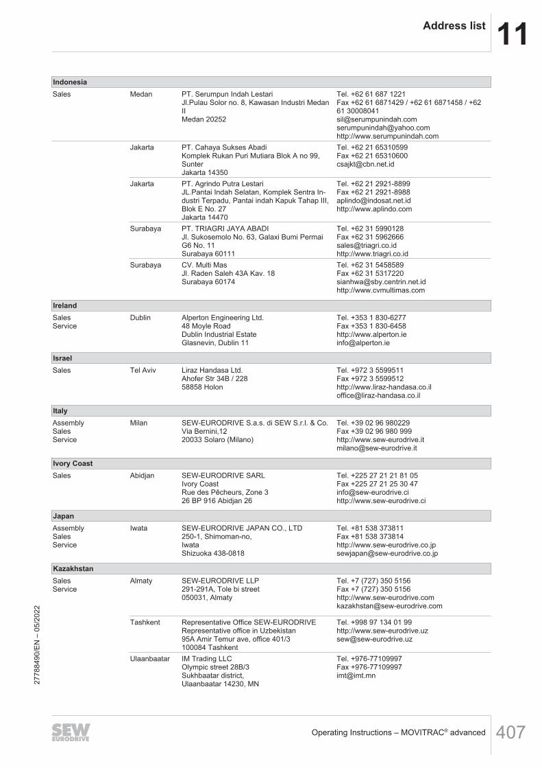
11Address list
Operating Instructions – MOVITRAC® advanced 407
IndonesiaSales Medan PT. Serumpun Indah Lestari
Jl.Pulau Solor no. 8, Kawasan Industri MedanIIMedan 20252
Tel. +62 61 687 1221Fax +62 61 6871429 / +62 61 6871458 / +6261 [email protected]@yahoo.comhttp://www.serumpunindah.com
Jakarta PT. Cahaya Sukses AbadiKomplek Rukan Puri Mutiara Blok A no 99,SunterJakarta 14350
Tel. +62 21 65310599Fax +62 21 [email protected]
Jakarta PT. Agrindo Putra LestariJL.Pantai Indah Selatan, Komplek Sentra In-dustri Terpadu, Pantai indah Kapuk Tahap III,Blok E No. 27Jakarta 14470
Tel. +62 21 2921-8899Fax +62 21 [email protected]://www.aplindo.com
Surabaya PT. TRIAGRI JAYA ABADIJl. Sukosemolo No. 63, Galaxi Bumi PermaiG6 No. 11Surabaya 60111
Tel. +62 31 5990128Fax +62 31 [email protected]://www.triagri.co.id
Surabaya CV. Multi MasJl. Raden Saleh 43A Kav. 18Surabaya 60174
Tel. +62 31 5458589Fax +62 31 [email protected]://www.cvmultimas.com
IrelandSalesService
Dublin Alperton Engineering Ltd.48 Moyle RoadDublin Industrial EstateGlasnevin, Dublin 11
Tel. +353 1 830-6277Fax +353 1 830-6458http://[email protected]
IsraelSales Tel Aviv Liraz Handasa Ltd.
Ahofer Str 34B / 22858858 Holon
Tel. +972 3 5599511Fax +972 3 5599512http://[email protected]
ItalyAssemblySalesService
Milan SEW-EURODRIVE S.a.s. di SEW S.r.l. & Co.Via Bernini,1220033 Solaro (Milano)
Tel. +39 02 96 980229Fax +39 02 96 980 999http://[email protected]
Ivory CoastSales Abidjan SEW-EURODRIVE SARL
Ivory CoastRue des Pêcheurs, Zone 326 BP 916 Abidjan 26
Tel. +225 27 21 21 81 05Fax +225 27 21 25 30 [email protected]://www.sew-eurodrive.ci
JapanAssemblySalesService
Iwata SEW-EURODRIVE JAPAN CO., LTD250-1, Shimoman-no,IwataShizuoka 438-0818
Tel. +81 538 373811Fax +81 538 373814http://[email protected]
KazakhstanSalesService
Almaty SEW-EURODRIVE LLP291-291A, Tole bi street050031, Almaty
Tel. +7 (727) 350 5156Fax +7 (727) 350 5156http://[email protected]
Tashkent Representative Office SEW-EURODRIVERepresentative office in Uzbekistan95A Amir Temur ave, office 401/3100084 Tashkent
Tel. +998 97 134 01 99http://[email protected]
Ulaanbaatar IM Trading LLCOlympic street 28B/3Sukhbaatar district,Ulaanbaatar 14230, MN
Tel. +976-77109997Fax [email protected]
2778
8490
/EN
– 0
5/20
22
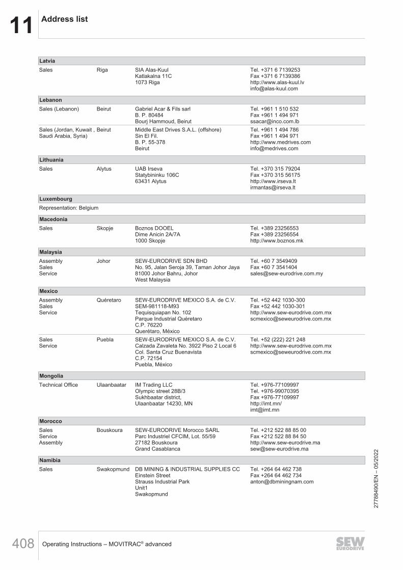
11 Address list
Operating Instructions – MOVITRAC® advanced408
LatviaSales Riga SIA Alas-Kuul
Katlakalna 11C1073 Riga
Tel. +371 6 7139253Fax +371 6 7139386http://[email protected]
LebanonSales (Lebanon) Beirut Gabriel Acar & Fils sarl
B. P. 80484Bourj Hammoud, Beirut
Tel. +961 1 510 532Fax +961 1 494 [email protected]
Sales (Jordan, Kuwait ,Saudi Arabia, Syria)
Beirut Middle East Drives S.A.L. (offshore)Sin El Fil.B. P. 55-378Beirut
Tel. +961 1 494 786Fax +961 1 494 971http://[email protected]
LithuaniaSales Alytus UAB Irseva
Statybininku 106C63431 Alytus
Tel. +370 315 79204Fax +370 315 56175http://[email protected]
LuxembourgRepresentation: Belgium
MacedoniaSales Skopje Boznos DOOEL
Dime Anicin 2A/7A1000 Skopje
Tel. +389 23256553Fax +389 23256554http://www.boznos.mk
MalaysiaAssemblySalesService
Johor SEW-EURODRIVE SDN BHDNo. 95, Jalan Seroja 39, Taman Johor Jaya81000 Johor Bahru, JohorWest Malaysia
Tel. +60 7 3549409Fax +60 7 [email protected]
MexicoAssemblySalesService
Quéretaro SEW-EURODRIVE MEXICO S.A. de C.V.SEM-981118-M93Tequisquiapan No. 102Parque Industrial QuéretaroC.P. 76220Querétaro, México
Tel. +52 442 1030-300Fax +52 442 1030-301http://[email protected]
SalesService
Puebla SEW-EURODRIVE MEXICO S.A. de C.V.Calzada Zavaleta No. 3922 Piso 2 Local 6Col. Santa Cruz BuenavistaC.P. 72154Puebla, México
Tel. +52 (222) 221 248http://[email protected]
MongoliaTechnical Office Ulaanbaatar IM Trading LLC
Olympic street 28B/3Sukhbaatar district,Ulaanbaatar 14230, MN
Tel. +976-77109997Tel. +976-99070395Fax +976-77109997http://imt.mn/[email protected]
MoroccoSalesServiceAssembly
Bouskoura SEW-EURODRIVE Morocco SARLParc Industriel CFCIM, Lot. 55/5927182 BouskouraGrand Casablanca
Tel. +212 522 88 85 00Fax +212 522 88 84 50http://[email protected]
NamibiaSales Swakopmund DB MINING & INDUSTRIAL SUPPLIES CC
Einstein StreetStrauss Industrial ParkUnit1Swakopmund
Tel. +264 64 462 738Fax +264 64 462 [email protected]
2778
8490
/EN
– 0
5/20
22

11Address list
Operating Instructions – MOVITRAC® advanced 409
NetherlandsAssemblySalesService
Rotterdam SEW-EURODRIVE B.V.Industrieweg 1753044 AS RotterdamPostbus 100853004 AB Rotterdam
Tel. +31 10 4463-700Fax +31 10 4155-552Service: 0800-SEWHELPhttp://[email protected]
New ZealandAssemblySalesService
Auckland SEW-EURODRIVE NEW ZEALAND LTD.P.O. Box 58-42882 Greenmount driveEast Tamaki Auckland
Tel. +64 9 2745627Fax +64 9 2740165http://[email protected]
Christchurch SEW-EURODRIVE NEW ZEALAND LTD.30 Lodestar Avenue, WigramChristchurch
Tel. +64 3 384-6251Fax +64 3 [email protected]
NigeriaSales Lagos Greenpeg Nig. Ltd
64C Toyin Street Opebi-AllenIkeja Lagos-Nigeria
Tel. +234-701-821-9200-1http://[email protected]
NorwayAssemblySalesService
Moss SEW-EURODRIVE A/SSolgaard skog 711599 Moss
Tel. +47 69 24 10 20Fax +47 69 24 10 40http://[email protected]
PakistanSales Karachi Industrial Power Drives
Al-Fatah Chamber A/3, 1st Floor Central Com-mercial Area,Sultan Ahmed Shah Road, Block 7/8,Karachi
Tel. +92 21 452 9369Fax +92-21-454 [email protected]
ParaguaySales Fernando de la
MoraSEW-EURODRIVE PARAGUAY S.R.LNu Guazu No. 642 casi Campo EsperanzaSantisima TrinidadAsuncion
Tel. +595 991 519695Fax +595 21 [email protected]
PeruAssemblySalesService
Lima SEW EURODRIVE DEL PERU S.A.C.Los Calderos, 120-124Urbanizacion Industrial Vulcano, ATE, Lima
Tel. +51 1 3495280Fax +51 1 3493002http://[email protected]
PhilippinesSales Makati P.T. Cerna Corporation
4137 Ponte St., Brgy. Sta. CruzMakati City 1205
Tel. +63 2 519 6214Fax +63 2 890 [email protected]://www.ptcerna.com
PolandAssemblySalesService
Łódź SEW-EURODRIVE Polska Sp.z.o.o.ul. Techniczna 592-518 Łódź
Tel. +48 42 293 00 00Fax +48 42 293 00 49http://[email protected]
Service Tel. +48 42 293 0030Fax +48 42 293 0043
24 Hour ServiceTel. +48 602 739 739 (+48 602 SEW SEW)[email protected]
PortugalAssemblySalesService
Coimbra SEW-EURODRIVE, LDA.Av. da Fonte Nova, n.º 863050-379 Mealhada
Tel. +351 231 20 9670Fax +351 231 20 3685http://[email protected]
2778
8490
/EN
– 0
5/20
22

11 Address list
Operating Instructions – MOVITRAC® advanced410
RomaniaSalesService
Bucharest Sialco Trading SRLstr. Brazilia nr. 36011783 Bucuresti
Tel. +40 21 230-1328Fax +40 21 230-7170http://[email protected]
RussiaAssemblySalesService
St. Petersburg ЗАО «СЕВ-ЕВРОДРАЙФ»188660, Russia, Leningrad Region, Vse-volozhsky District, Korabselki, AleksandraNevskogo str.building 4, block 1P.O. Box 36195220 St. Petersburg
Tel. +7 812 3332522 / +7 812 5357142Fax +7 812 3332523http://[email protected]
SenegalSales Dakar SENEMECA
Mécanique GénéraleKm 8, Route de RufisqueB.P. 3251, Dakar
Tel. +221 338 494 770Fax +221 338 494 771http://[email protected]
SerbiaSales Belgrade DIPAR d.o.o.
Ustanicka 128aPC Košum, IV floor11000 Beograd
Tel. +381 11 347 3244 / +381 11 288 0393Fax +381 11 347 [email protected]
SingaporeAssemblySalesService
Singapore SEW-EURODRIVE PTE. LTD.No 9, Tuas Drive 2Jurong Industrial EstateSingapore 638644
Tel. +65 68621701Fax +65 68612827http://[email protected]
SlovakiaSales Bernolákovo SEW-Eurodrive SK s.r.o.
Priemyselná ulica 6267/7900 27 Bernolákovo
Tel.+421 2 48 212 800http://[email protected]
SloveniaSalesService
Celje Pakman - Pogonska Tehnika d.o.o.UI. XIV. divizije 143000 Celje
Tel. +386 3 490 83-20Fax +386 3 490 [email protected]
South AfricaAssemblySalesService
Johannesburg SEW-EURODRIVE (PROPRIETARY) LIMITED32 O’Connor PlaceEurodrive HouseAerotonJohannesburg 2190P.O.Box 90004Bertsham 2013
Tel. +27 11 248-7000Fax +27 11 248-7289http://[email protected]
Cape Town SEW-EURODRIVE (PROPRIETARY) LIMITEDRainbow ParkCnr. Racecourse & Omuramba RoadMontague GardensCape TownP.O.Box 36556Chempet 7442
Tel. +27 21 552-9820Fax +27 21 552-9830Telex 576 [email protected]
Durban SEW-EURODRIVE (PROPRIETARY) LIMITED48 Prospecton RoadIsipingoDurbanP.O. Box 10433, Ashwood 3605
Tel. +27 31 902 3815Fax +27 31 902 [email protected]
Nelspruit SEW-EURODRIVE (PROPRIETARY) LIMITED7 Christie CrescentVintoniaP.O.Box 1942Nelspruit 1200
Tel. +27 13 752-8007Fax +27 13 [email protected]
2778
8490
/EN
– 0
5/20
22
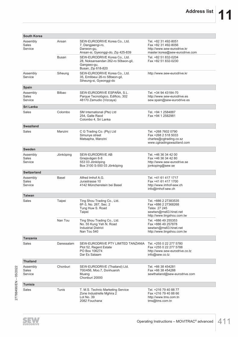
11Address list
Operating Instructions – MOVITRAC® advanced 411
South KoreaAssemblySalesService
Ansan SEW-EURODRIVE Korea Co., Ltd.7, Dangjaengi-ro,Danwon-gu,Ansan-si, Gyeonggi-do, Zip 425-839
Tel. +82 31 492-8051Fax +82 31 492-8056http://[email protected]
Busan SEW-EURODRIVE Korea Co., Ltd.28, Noksansandan 262-ro 50beon-gil,Gangseo-gu,Busan, Zip 618-820
Tel. +82 51 832-0204Fax +82 51 832-0230
AssemblyService
Siheung SEW-EURODRIVE Korea Co., Ltd.35, Emtibeui 26-ro 58beon-gil,Siheung-si, Gyeonggi-do
http://www.sew-eurodrive.kr
SpainAssemblySalesService
Bilbao SEW-EURODRIVE ESPAÑA, S.L.Parque Tecnológico, Edificio, 30248170 Zamudio (Vizcaya)
Tel. +34 94 43184-70http://[email protected]
Sri LankaSales Colombo SM International (Pte) Ltd
254, Galle RaodColombo 4, Sri Lanka
Tel. +94 1 2584887Fax +94 1 2582981
SwazilandSales Manzini C G Trading Co. (Pty) Ltd
Simunye streetMatsapha, Manzini
Tel. +268 7602 0790Fax +268 2 518 [email protected]
SwedenAssemblySalesService
Jönköping SEW-EURODRIVE ABGnejsvägen 6-8553 03 JönköpingBox 3100 S-550 03 Jönköping
Tel. +46 36 34 42 00Fax +46 36 34 42 80http://[email protected]
SwitzerlandAssemblySalesService
Basel Alfred lmhof A.G.Jurastrasse 104142 Münchenstein bei Basel
Tel. +41 61 417 1717Fax +41 61 417 1700http://[email protected]
TaiwanSales Taipei Ting Shou Trading Co., Ltd.
6F-3, No. 267, Sec. 2Tung Huw S. RoadTaipei
Tel. +886 2 27383535Fax +886 2 27368268Telex 27 [email protected]://www.tingshou.com.tw
Nan Tou Ting Shou Trading Co., Ltd.No. 55 Kung Yeh N. RoadIndustrial DistrictNan Tou 540
Tel. +886 49 255353Fax +886 49 [email protected]://www.tingshou.com.tw
TanzaniaSales Daressalam SEW-EURODRIVE PTY LIMITED TANZANIA
Plot 52, Regent EstatePO Box 106274Dar Es Salaam
Tel. +255 0 22 277 5780Fax +255 0 22 277 5788http://[email protected]
ThailandAssemblySalesService
Chonburi SEW-EURODRIVE (Thailand) Ltd.700/456, Moo.7, DonhuarohMuangChonburi 20000
Tel. +66 38 454281Fax +66 38 [email protected]
TunisiaSales Tunis T. M.S. Technic Marketing Service
Zone Industrielle Mghira 2Lot No. 392082 Fouchana
Tel. +216 79 40 88 77Fax +216 79 40 88 66http://[email protected]
7884
90/E
N –
05/
2022
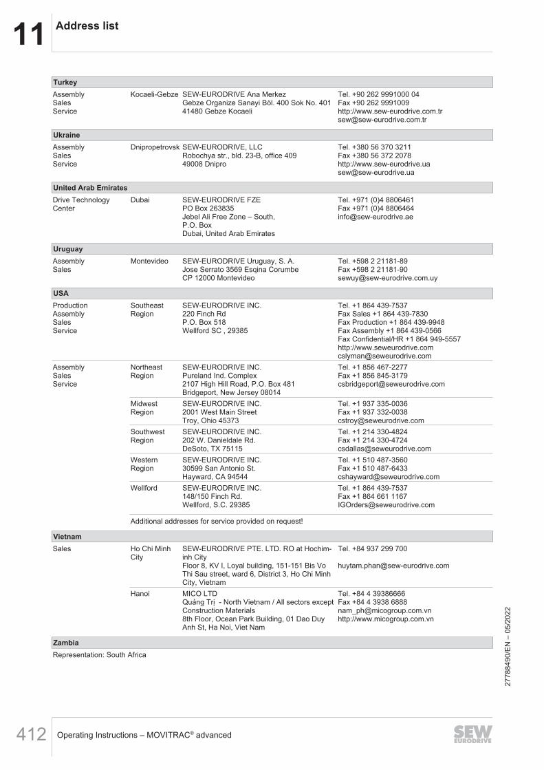
11 Address list
Operating Instructions – MOVITRAC® advanced412
TurkeyAssemblySalesService
Kocaeli-Gebze SEW-EURODRIVE Ana MerkezGebze Organize Sanayi Böl. 400 Sok No. 40141480 Gebze Kocaeli
Tel. +90 262 9991000 04Fax +90 262 9991009http://[email protected]
UkraineAssemblySalesService
Dnipropetrovsk SEW-EURODRIVE, LLCRobochya str., bld. 23-B, office 40949008 Dnipro
Tel. +380 56 370 3211Fax +380 56 372 2078http://[email protected]
United Arab EmiratesDrive TechnologyCenter
Dubai SEW-EURODRIVE FZEPO Box 263835Jebel Ali Free Zone – South,P.O. BoxDubai, United Arab Emirates
Tel. +971 (0)4 8806461Fax +971 (0)4 [email protected]
UruguayAssemblySales
Montevideo SEW-EURODRIVE Uruguay, S. A.Jose Serrato 3569 Esqina CorumbeCP 12000 Montevideo
Tel. +598 2 21181-89Fax +598 2 [email protected]
USAProductionAssemblySalesService
SoutheastRegion
SEW-EURODRIVE INC.220 Finch RdP.O. Box 518Wellford SC , 29385
Tel. +1 864 439-7537Fax Sales +1 864 439-7830Fax Production +1 864 439-9948Fax Assembly +1 864 439-0566Fax Confidential/HR +1 864 949-5557http://[email protected]
AssemblySalesService
NortheastRegion
SEW-EURODRIVE INC.Pureland Ind. Complex2107 High Hill Road, P.O. Box 481Bridgeport, New Jersey 08014
Tel. +1 856 467-2277Fax +1 856 [email protected]
MidwestRegion
SEW-EURODRIVE INC.2001 West Main StreetTroy, Ohio 45373
Tel. +1 937 335-0036Fax +1 937 [email protected]
SouthwestRegion
SEW-EURODRIVE INC.202 W. Danieldale Rd.DeSoto, TX 75115
Tel. +1 214 330-4824Fax +1 214 [email protected]
WesternRegion
SEW-EURODRIVE INC.30599 San Antonio St.Hayward, CA 94544
Tel. +1 510 487-3560Fax +1 510 [email protected]
Wellford SEW-EURODRIVE INC.148/150 Finch Rd.Wellford, S.C. 29385
Tel. +1 864 439-7537Fax +1 864 661 [email protected]
Additional addresses for service provided on request!
VietnamSales Ho Chi Minh
CitySEW-EURODRIVE PTE. LTD. RO at Hochim-inh CityFloor 8, KV I, Loyal building, 151-151 Bis VoThi Sau street, ward 6, District 3, Ho Chi MinhCity, Vietnam
Tel. +84 937 299 700
Hanoi MICO LTDQuảng Trị - North Vietnam / All sectors except Construction Materials8th Floor, Ocean Park Building, 01 Dao DuyAnh St, Ha Noi, Viet Nam
Tel. +84 4 39386666Fax +84 4 3938 [email protected]://www.micogroup.com.vn
ZambiaRepresentation: South Africa
2778
8490
/EN
– 0
5/20
22


SEW-EURODRIVE—Driving the world
SEW-EURODRIVE GmbH & Co KGErnst-Blickle-Str. 4276646 BRUCHSALGERMANYTel. +49 7251 75-0Fax +49 7251 [email protected]
Related Documents