MOTOTRBO System Planner System Release 2.9.5 MOTOTRBO ™ IP Site Connect and Capacity Plus *68007024085* 68007024085-NL AUGUST 2018 © 2018 Motorola Solutions, Inc. All rights reserved

Welcome message from author
This document is posted to help you gain knowledge. Please leave a comment to let me know what you think about it! Share it to your friends and learn new things together.
Transcript
MOTOTRBO SystemPlanner
System Release 2.9.5MOTOTRBO™ IP Site Connect and Capacity Plus
*68007024085*68007024085-NL
AUGUST 2018
© 2018 Motorola Solutions, Inc. All rights reserved
CopyrightsThe Motorola Solutions products described in this document may include copyrighted MotorolaSolutions computer programs. Laws in the United States and other countries preserve for MotorolaSolutions certain exclusive rights for copyrighted computer programs. Accordingly, any copyrightedMotorola Solutions computer programs contained in the Motorola Solutions products described in thisdocument may not be copied or reproduced in any manner without the express written permission ofMotorola Solutions.© 2018 Motorola Solutions, Inc. All Rights Reserved
No part of this document may be reproduced, transmitted, stored in a retrieval system, or translatedinto any language or computer language, in any form or by any means, without the prior writtenpermission of Motorola Solutions, Inc.
Furthermore, the purchase of Motorola Solutions products shall not be deemed to grant either directlyor by implication, estoppel or otherwise, any license under the copyrights, patents or patentapplications of Motorola Solutions, except for the normal non-exclusive, royalty-free license to use thatarises by operation of law in the sale of a product.
DisclaimerPlease note that certain features, facilities, and capabilities described in this document may not beapplicable to or licensed for use on a specific system, or may be dependent upon the characteristics ofa specific subscriber unit or configuration of certain parameters. Please refer to your MotorolaSolutions contact for further information.
TrademarksMOTOROLA, MOTO, MOTOROLA SOLUTIONS, and the Stylized M Logo are trademarks orregistered trademarks of Motorola Trademark Holdings, LLC and are used under license. All othertrademarks are the property of their respective owners.
European Union (EU) Waste of Electrical and Electronic Equipment (WEEE)directive
The European Union's WEEE directive requires that products sold into EU countries must havethe crossed out trash bin label on the product (or the package in some cases).
As defined by the WEEE directive, this cross-out trash bin label means that customers and end-usersin EU countries should not dispose of electronic and electrical equipment or accessories in householdwaste.
Customers or end-users in EU countries should contact their local equipment supplier representative orservice centre for information about the waste collection system in their country.
68007024085-NLCopyrights
2
Contact UsMotorola Solutions Support CenterThe Solutions Support Center (SSC) is the primary contact for technical support included in yourorganization's service agreement with Motorola Solutions.
Service agreement customers should be sure to call the SSC in all situations listed under CustomerResponsibilities in their agreement, such as:
• Before reloading software.
• To confirm troubleshooting results and analysis before taking action.
Your organization received support phone numbers and other contact information appropriate for yourgeographic region and service agreement. Use that contact information for the most efficient response.However, if needed, you can also find general support contact information on the Motorola Solutionswebsite, by following these steps:
• Enter motorolasolutions.com in your browser.
• Ensure that your organization's country or region is displayed on the page. Clicking or tapping thename of the region provides a way to change it.
• Select "Support" on the motorolasolutions.com page.
CommentsSend questions and comments regarding user documentation to [email protected].
Provide the following information when reporting a documentation error:
• The document title and part number.
• The page number or title of the section with the error.
• A description of the error.
68007024085-NLContact Us
3

Document HistoryVersion Description Date
68007024085-NK 2.9 system release of the MOTOTRBO IP Site Con-nect, Capacity Plus System Planner manual.
• New in this release:
- MOTOTRBO Link Mode on page 53
- MOTOTRBO Link on page 358
- MOTOTRBO Link Standalone Topology onpage 360
- MOTOTRBO Link Hybrid Topology on page360
- Estimate Loading (for MOTOTRBO Link) onpage 373
- MOTOTRBO Link Mode on page 541
- When Ignore Rx Clear Voice/Packet Data andFixed Privacy Key Decryption Options are notEnabled on page 173
• Minor edits to the following topics:
- Data Gateway Privacy Settings on page 178
- Keys and Key Management on page 177
- Key Mismatch on page 176
- Fixed Privacy Key Decryption Option on page174
- Ignore Rx Clear Voice or Packet Data Optionon page 174
- User Control Over Privacy on page 173
- AES Configuration in MOTOTRBO on page171
- Strength of the Protection Mechanism on page172
- Types of Privacy on page 171
- Extended Range Direct Mode on page 310
- Configuration in Radio on page 311
- Configuration in Repeater on page 311
April 2018
68007024085-NL 2.9.5 system release of the MOTOTRBO IP Site Con-nect, Capacity Plus System Planner manual. This up-date includes the follwing changes:
• Added Indoor Location on page 123 and its sub-sections.
August 2018
68007024085-NLDocument History
4

Version Description Date
• Updated MOTOTRBO Link Mode on page 53 andits subsections.
68007024085-NLDocument History
5
ContentsCopyrights................................................................................................................... 2Contact Us................................................................................................................... 3Document History....................................................................................................... 4List of Figures............................................................................................................22List of Tables............................................................................................................. 29About MOTOTRBO IP Site Connect, Capacity Plus System Planner...................31
What is Covered in this Manual................................................................................................... 31
Helpful Background Information.................................................................................................. 31
Related Information..................................................................................................................... 31
Chapter 1: Introduction.............................................................................................331.1 Welcome to MOTOTRBO...................................................................................................... 33
1.2 Software Version................................................................................................................... 33
Chapter 2: System Feature Overview......................................................................352.1 MOTOTRBO Digital Radio Technology................................................................................. 35
2.1.1 Digital Radio Technology Overview......................................................................... 35
2.1.1.1 Analog to Digital Conversion......................................................................35
2.1.1.2 Vocoder and Forward Error Correction...................................................... 36
2.1.1.3 Framing...................................................................................................... 36
2.1.1.4 Time Division Multiple Access Transmission............................................. 36
2.1.1.5 Standards Compliance...............................................................................37
2.1.2 Spectrum Efficiency Through 2-Slot TDMA............................................................. 37
2.1.2.1 Frequencies, Channels, and Requirements for Spectrum Efficiency.........37
2.1.2.2 Delivering Increased Capacity in Existing 12.5 kHz Channels...................37
2.1.2.3 2-Slot TDMA Reducing Infrastructure Equipment...................................... 38
2.1.2.4 2-Slot TDMA Enables System Flexibility....................................................39
2.1.2.5 2-Slot TDMA System Planning Considerations..........................................40
2.1.3 Digital Audio Quality and Coverage Performance................................................... 41
2.1.3.1 Digital Audio Coverage.............................................................................. 41
2.1.3.2 Predicting Digital Audio Coverage............................................................. 42
2.1.3.3 User Expectations for Digital Audio Performance...................................... 43
2.1.3.4 Audio Balancing......................................................................................... 44
2.2 Basic System Topologies for Digital and Analog Operations................................................ 45
2.2.1 Repeater and Direct Mode Configurations...............................................................46
2.2.1.1 Analog Repeater Mode.............................................................................. 47
2.2.1.2 Digital Repeater Mode............................................................................... 47
68007024085-NLContents
6
2.2.1.3 Dynamic Mixed Mode.................................................................................47
2.2.1.4 IP Site Connect Mode................................................................................ 48
2.2.1.5 Capacity Plus Single Site Mode................................................................. 49
2.2.1.6 Capacity Plus Multi Site Mode................................................................... 51
2.2.1.7 MOTOTRBO Link Mode.............................................................................53
2.2.2 MOTOTRBO Supports Analog and Digital Operation..............................................66
2.2.3 MOTOTRBO Channel Access................................................................................. 67
2.2.3.1 Impolite Operation......................................................................................68
2.2.3.2 Polite to All Operation................................................................................ 69
2.2.3.3 Polite to Own Digital System Operation..................................................... 69
2.2.3.4 Polite to Other Analog System Operation.................................................. 69
2.2.3.5 Polite, Impolite or Voice Interrupt In A Call................................................ 69
2.2.3.6 Repeater Wake-up Provisioning................................................................ 70
2.3 Digital Voice Features............................................................................................................70
2.3.1 Group Calls.............................................................................................................. 71
2.3.2 Private Calls.............................................................................................................71
2.3.3 All Call......................................................................................................................72
2.3.4 DTMF Hot Keypad................................................................................................... 73
2.4 Transmit Interrupt.................................................................................................................. 73
2.4.1 Transmit Interrupt Capable System Upgrade.......................................................... 76
2.5 Digital Signaling Features......................................................................................................76
2.5.1 PTT ID and Aliasing................................................................................................. 77
2.5.2 Radio Enable/Disable.............................................................................................. 77
2.5.2.1 Over-the-Air Signaling Enable/Disable.......................................................77
2.5.3 Remote Monitor....................................................................................................... 78
2.5.4 Radio Check............................................................................................................ 79
2.5.5 Call Alert.................................................................................................................. 79
2.5.6 Remote Voice Dekey............................................................................................... 80
2.6 Digital Emergency..................................................................................................................80
2.6.1 Emergency Alarm Only............................................................................................ 83
2.6.2 Emergency Alarm and Call...................................................................................... 84
2.6.3 Emergency Alarm with Voice to Follow....................................................................84
2.6.4 Emergency Voice Interrupt for Emergency Alarm....................................................85
2.6.5 Emergency Voice Interrupt for Emergency Voice.................................................... 86
2.6.6 Emergency Search Tone......................................................................................... 86
2.7 Restricted Access to System................................................................................................. 87
2.7.1 Restricted Access to System Key Authentication.................................................... 88
2.7.2 Radio ID Range Check............................................................................................ 89
2.8 Digital Voting..........................................................................................................................89
68007024085-NLContents
7
2.9 CSBK Data............................................................................................................................ 90
2.9.1 Supported Data Service...........................................................................................90
2.9.2 Impacted Features................................................................................................... 90
2.9.3 Improved Third-Party Interfaces.............................................................................. 91
2.9.4 Affected System Components................................................................................. 91
2.10 Digital Audio.........................................................................................................................91
2.11 Confirmed Group Data.........................................................................................................92
2.12 MOTOTRBO Integrated Data.............................................................................................. 93
2.12.1 MOTOTRBO Integrated Data Overview................................................................ 93
2.12.2 Text Messaging Services.......................................................................................94
2.12.2.1 Built-In Text Messaging Service...............................................................95
2.12.2.2 MOTOTRBO Text Messaging Application............................................... 96
2.12.2.3 Predictive Text Entry................................................................................ 98
2.12.2.4 ETSI DMR Standard Text Messaging...................................................... 99
2.12.2.5 ETSI DMR Tier 2 UDP/IP Header Compression....................................100
2.12.3 Location Services.................................................................................................100
2.12.3.1 Performance Specifications................................................................... 101
2.12.3.2 Services Provided to a Radio User........................................................ 102
2.12.3.3 Services Provided to a Location Application.......................................... 102
2.12.3.4 Services Provided by the MOTOTRBO Location Services Application..103
2.12.3.5 GPS Revert Channel..............................................................................104
2.12.3.6 Enhanced GPS Revert Channel............................................................ 105
2.12.3.7 Data Revert Channel..............................................................................116
2.12.3.8 Global Navigation Satellite System........................................................ 117
2.12.3.9 GPIO Triggered Event Driven and Distance Driven Location Update....117
2.12.4 Telemetry Services.............................................................................................. 117
2.12.4.1 Physical Connection Information............................................................118
2.12.4.2 Telemetry Examples.............................................................................. 119
2.12.5 Data Precedence and Data Over Voice Interrupt................................................ 119
2.12.6 Enhanced Job Tickets..........................................................................................120
2.12.6.1 Job Tickets Registration.........................................................................120
2.12.6.2 Common Job Tickets Data Communication...........................................120
2.12.6.3 Common Job Tickets Inbox Folders.......................................................121
2.12.6.4 Subscriber Created Job Tickets............................................................. 122
2.12.6.5 Delete All Job Tickets.............................................................................122
2.12.6.6 MNIS Network........................................................................................ 122
2.13 Indoor Location.................................................................................................................. 123
2.13.1 iBeacon................................................................................................................ 123
2.13.2 Indoor Location Operation................................................................................... 123
68007024085-NLContents
8
2.13.3 iBeacon Configuration and Operation Parameters.............................................. 124
2.13.4 iBeacon Deployment Considerations...................................................................124
2.13.4.1 iBeacon UUID and Radio Operation Considerations............................. 125
2.13.4.2 iBeacon BLE Advertisement Time Interval and Radio Scan ModeOperation Considerations............................................................................... 125
2.13.4.3 Radio CPS Configurable Scan Interval On/Off Time OperationConsiderations................................................................................................ 127
2.13.4.4 iBeacon Advertisement Tx Power and iBeacon RF Site SurveyConsiderations................................................................................................ 129
2.13.4.5 Other iBeacon Deployment Considerations........................................... 131
2.13.4.6 Indoor Location Deployment Requirement Checklist............................. 131
2.13.5 iBeacon OTA Parameters.................................................................................... 132
2.13.6 Radio Indoor Location Configuration and Operation Parameters................................................................................................................ 133
2.13.7 Radio Indoor/Outdoor Location Application Services.......................................... 133
2.13.8 Third-Party Location Application Services........................................................... 134
2.13.9 Radio GPS Revert Channel Location Services....................................................134
2.13.10 Radio Enhanced GPS Revert Channel Location Services................................ 135
2.13.11 Connect Plus Fast GPS Location Services........................................................139
2.14 Scan...................................................................................................................................141
2.14.1 Priority Sampling..................................................................................................142
2.14.2 Channel Marking..................................................................................................143
2.14.3 Scan Considerations............................................................................................144
2.14.3.1 Scanning and Preamble.........................................................................145
2.14.3.2 Channel Scan and Last Landed Channel.............................................. 146
2.14.3.3 Scan Members with Similar Receive Parameters.................................. 147
2.14.3.4 Voice Transmission Reception Improvement While Scanning...............149
2.14.3.5 Disable Scan Hangtime for Voice Calls................................................. 149
2.14.3.6 Unconfirmed Group Data Scanning....................................................... 150
2.14.4 Transmit Interrupt and Scan................................................................................ 150
2.15 Site Roaming..................................................................................................................... 151
2.15.1 Passive Site Searching........................................................................................ 152
2.15.2 Active Site Searching...........................................................................................154
2.15.3 Roaming Considerations......................................................................................156
2.15.3.1 Configuring the Roaming RSSI Threshold............................................. 156
2.15.3.2 Roam List Configuration.........................................................................163
2.15.3.3 Scan or Roam........................................................................................ 166
2.15.3.4 Beacon Duration and Beacon Interval Settings..................................... 166
2.15.3.5 Emergency Revert, GPS/Data Revert, and Roaming Interactions.........168
2.15.3.6 Performance while Roaming.................................................................. 169
68007024085-NLContents
9

2.15.3.7 ARS Registration on Roaming............................................................... 170
2.16 Voice and Data Privacy..................................................................................................... 170
2.16.1 Types of Privacy.................................................................................................. 171
2.16.1.1 AES Configuration in MOTOTRBO........................................................ 171
2.16.2 Strength of the Protection Mechanism.................................................................172
2.16.3 Effects of Privacy Protection on Performance..................................................... 172
2.16.4 User Control Over Privacy................................................................................... 173
2.16.4.1 When Ignore Rx Clear Voice/Packet Data and Fixed Privacy KeyDecryption Options are not Enabled............................................................... 173
2.16.4.2 Ignore Rx Clear Voice or Packet Data Option........................................174
2.16.4.3 Fixed Privacy Key Decryption Option.....................................................174
2.16.5 Privacy Indications to User.................................................................................. 176
2.16.6 Key Mismatch...................................................................................................... 176
2.16.7 Keys and Key Management.................................................................................177
2.16.8 Multiple Keys in a Basic Privacy System............................................................. 178
2.16.9 Data Gateway Privacy Settings........................................................................... 178
2.16.10 Protecting One Group’s Message from Another Group..................................... 179
2.16.11 Updating the Privacy Type.................................................................................179
2.17 Real-Time Clock Synchronization......................................................................................180
2.18 Repeater Diagnostics and Control.....................................................................................180
2.18.1 Connecting Remotely Through the Network........................................................ 184
2.18.2 Connecting Locally Through the USB..................................................................185
2.18.3 Connecting Locally Through GPIO Lines.............................................................185
2.18.3.1 RDAC Local Settings Rear Accessory Port CPS Programmable Pins.. 186
2.18.4 Redundant Repeater Setup................................................................................. 187
2.18.5 Dual Control Considerations................................................................................ 189
2.18.6 Digital Voting Control and Monitor....................................................................... 189
2.18.7 General Considerations When Utilizing the RDAC Application to Set Up theNetwork Connection...................................................................................................190
2.19 Repeater Diagnostics System Enhancement.................................................................... 191
2.20 IP Repeater Programming ................................................................................................ 192
2.20.1 System Configuration for IRP Support.................................................................192
2.21 Over-the-Air Battery Management.....................................................................................193
2.21.1 Over-the-Air Battery Management Process......................................................... 194
2.21.2 Automatic Over The Air Battery Data Collection Configuration........................... 194
2.21.3 System Level Optimizations.................................................................................195
2.21.3.1 Battery Data Refresh Timer................................................................... 195
2.21.3.2 Radio Hold Off Timer............................................................................. 195
2.21.3.3 Manual Battery Data Read Performance............................................... 196
2.21.3.4 Radio Battery Utilization While Charging............................................... 196
68007024085-NLContents
10
2.21.4 Advanced System Deployments.......................................................................... 196
2.21.4.1 MOTOTRBO Network Interface Service (MNIS) Deployments..............196
2.21.4.2 Control Station Configurations............................................................... 199
2.21.4.3 Battery Management Application Deployment....................................... 203
2.21.4.4 Coexistence with Other Data Applications............................................. 205
2.21.5 Battery Fleet Management Computer Specifications...........................................206
2.21.5.1 Operating System Requirement.............................................................206
2.21.5.2 Hardware Minimum Requirement.......................................................... 206
2.21.5.3 Server Hardware Minimum Requirement...............................................206
2.21.5.4 Client or Proxy Hardware Minimum Requirement..................................206
2.22 Over-the-Air Radio Programming (OTAP)......................................................................... 207
2.22.1 Basic Deployments of OTAP Software................................................................ 208
2.22.1.1 Local Single Channel Configuration.......................................................208
2.22.1.2 Local Single Channel Configuration with Presence............................... 209
2.22.1.3 Remote Client Configuration.................................................................. 211
2.22.1.4 Remote Client Configuration with Multiple RM Servers......................... 211
2.22.1.5 Remote Device Programmer Configuration........................................... 213
2.22.1.6 Multi-Channel Configuration...................................................................215
2.22.2 Process Flow for Over-the-Air Programming....................................................... 216
2.22.2.1 Essential Communication Parameters Initial Programming................... 216
2.22.2.2 Populating the RM Server with Current Radio Configurations............... 218
2.22.2.3 Modifying the Radio Configurations within the RM Server.....................219
2.22.2.4 Delivering the Modified Radio Configurations to the Radios..................220
2.22.2.5 Switching Over the Delivered Radio Configurations.............................. 221
2.23 Voice Operated Transmission........................................................................................... 222
2.23.1 Voice Operated Transmission Operation.............................................................222
2.23.2 Voice Operated Transmission Usage.................................................................. 222
2.23.2.1 Suspending Voice Operated Transmission............................................222
2.23.2.2 Talk Permit Tone ...................................................................................222
2.23.2.3 Emergency Calls.................................................................................... 223
2.23.2.4 Transmit Interrupt...................................................................................223
2.24 Lone Worker...................................................................................................................... 223
2.25 Bluetooth Support.............................................................................................................. 223
2.25.1 Bluetooth Pairing and Connection....................................................................... 224
2.25.1.1 Bluetooth Device Pairing with Display Radio......................................... 224
2.25.1.2 Bluetooth Device Pairing with Non-Display Radio................................. 224
2.25.2 Bluetooth Headset, PTT and Radio Operation.................................................... 224
2.25.2.1 Radio Operation with COTS Headset.................................................... 224
2.25.2.2 Motorola Solutions Headset or PTT Radio Operation............................225
68007024085-NLContents
11

2.25.2.3 Motorola Solutions PTT Only Device Radio Operation.......................... 225
2.25.3 Bluetooth Bar Code Scanner Operation.............................................................. 225
2.25.4 Bluetooth Personal Area Networking Operation.................................................. 225
2.25.5 Recommended Bluetooth Devices.......................................................................226
2.25.6 Avoiding Accidental Connection.......................................................................... 226
2.26 One Touch Home Revert Button....................................................................................... 227
2.27 Password and Lock Feature.............................................................................................. 227
2.28 Digital Telephone Patch ....................................................................................................228
2.28.1 Phone Call Initiation............................................................................................. 229
2.28.1.1 Call Initiation by a Radio User................................................................229
2.28.1.2 Call Initiation by a Phone User...............................................................229
2.28.2 Access Priority During a Phone Call.................................................................... 231
2.28.3 Ending a Phone Call............................................................................................ 232
2.28.4 Digital Telephone Patch System Configuration................................................... 233
2.28.4.1 Phone Patch in Single Site and IP Site Connect Local Area Channels 233
2.28.4.2 Phone Patch in IP Site Connect Wide Area Channels...........................234
2.28.4.3 Phone Patch in Capacity Plus Single Site..............................................236
2.28.5 Wireline Telephony.............................................................................................. 236
2.29 Voice Announcement Feature........................................................................................... 237
2.30 Wi-Fi® Support...................................................................................................................238
2.30.1 Wi-Fi Network Name............................................................................................239
2.30.2 Wi-Fi Security Support......................................................................................... 239
2.30.3 Wi-Fi Default Profile............................................................................................. 240
2.30.4 Wi-Fi Channel Usage...........................................................................................240
2.30.5 Wi-Fi Network Settings........................................................................................ 240
2.30.6 Wi-Fi Network Protocols...................................................................................... 240
2.30.7 Wi-Fi Features..................................................................................................... 241
2.30.7.1 Radio Management in Wi-Fi...................................................................241
2.31 Certificate Management.....................................................................................................241
2.31.1 Certificate Management Feature Overview......................................................... 241
2.31.2 Certificate Enrollment...........................................................................................242
2.31.3 Certificate Renewal and Rollover.........................................................................242
2.31.4 Design Considerations.........................................................................................243
2.32 Radio Transmit Inhibit........................................................................................................243
2.33 Radio Response Inhibit......................................................................................................243
2.34 Analog Features................................................................................................................ 244
2.34.1 Analog Voice Features.........................................................................................244
2.34.2 MDC Analog Signaling Features..........................................................................245
2.34.3 Quik-Call II Signaling Features............................................................................ 245
68007024085-NLContents
12
2.34.4 Analog Scan Features......................................................................................... 246
2.34.5 Analog Repeater Interface................................................................................... 246
2.34.5.1 Analog Repeater Interface Settings....................................................... 247
2.34.5.2 Configuration Summary Table............................................................... 253
2.34.5.3 Configuration Considerations.................................................................254
2.34.6 Auto-Range Transponder System ...................................................................... 263
2.34.7 TX Inhibit Quick Key Override..............................................................................264
2.34.8 Alert Tone Fixed Volume..................................................................................... 264
2.34.9 Alert Tone Auto Reset..........................................................................................265
2.34.10 Emergency Permanent Sticky Revert................................................................ 265
Chapter 3: System Components And Topologies................................................2663.1 System Components........................................................................................................... 266
3.1.1 Fixed End Components......................................................................................... 266
3.1.1.1 Repeater.................................................................................................. 266
3.1.1.2 MTR3000 Base Station/Repeater............................................................ 269
3.1.1.3 MTR3000 Satellite Receiver.................................................................... 273
3.1.1.4 SLR 5000 Series Repeater...................................................................... 274
3.1.1.5 SLR 8000 Series Repeater...................................................................... 277
3.1.1.6 Satellite Receiver and Voting Repeater................................................... 281
3.1.1.7 Radio Control Station............................................................................... 281
3.1.1.8 MOTOTRBO Network Interface Service (MNIS)......................................282
3.1.1.9 MC1000, MC2000, MC2500 Console...................................................... 283
3.1.2 Mobile Components............................................................................................... 284
3.1.2.1 MOTOTRBO Portable.............................................................................. 285
3.1.2.2 MOTOTRBO Mobile.................................................................................290
3.1.2.3 MOTOTRBO Device Discovery and Mobility Service (DDMS)................ 294
3.2 System Topologies.............................................................................................................. 295
3.2.1 Direct Mode/Dual Capacity Direct Mode (DCDM)..................................................295
3.2.1.1 Digital MOTOTRBO Radios in DCDM......................................................296
3.2.1.2 Interoperability between Analog MOTOTRBO Radios and AnalogRadios in Direct Mode.....................................................................................305
3.2.1.3 Interoperability Between Digital MOTOTRBO Radios, Mixed ModeMOTOTRBO Radios, and Analog Radios in Direct Mode...............................306
3.2.1.4 Direct Mode Spectrum Efficiency............................................................. 307
3.2.2 Dual Capacity Direct Mode.................................................................................... 307
3.2.2.1 Timeslot Synchronization......................................................................... 308
3.2.2.2 Channel Timing Leader (CTL) Preference............................................... 308
3.2.2.3 Color Code............................................................................................... 308
3.2.2.4 Channel Access Rule...............................................................................309
3.2.2.5 Scan......................................................................................................... 309
68007024085-NLContents
13
3.2.2.6 Interoperability and Backward Compatibility............................................ 309
3.2.2.7 Revert Features....................................................................................... 309
3.2.3 Extended Range Direct Mode................................................................................310
3.2.3.1 Interactions Between Extended Range Direct Mode and Mode Radios.. 311
3.2.3.2 Extended Range Direct Mode Feature Licensing.................................... 311
3.2.3.3 Repeater Emission Designator................................................................ 311
3.2.3.4 Configuration in Repeater........................................................................ 311
3.2.3.5 Configuration in Radio..............................................................................311
3.2.3.6 Repeater TX/RX Isolation........................................................................ 312
3.2.4 Repeater Mode...................................................................................................... 312
3.2.4.1 Digital MOTOTRBO Radios in Repeater Mode........................................313
3.2.4.2 Analog MOTOTRBO Radios in Repeater Mode...................................... 327
3.2.5 IP Site Connect Mode............................................................................................ 329
3.2.5.1 Topologies of IP Site Connect System.....................................................330
3.2.5.2 Network Topologies for IP Site Connect.................................................. 333
3.2.5.3 Summary of Features in IP Site Connect Mode.......................................339
3.2.6 Capacity Plus Single Site Mode.............................................................................339
3.2.6.1 Topologies of Capacity Plus Single Site System..................................... 340
3.2.7 Capacity Plus Multi Site Mode (CPMS)................................................................. 348
3.2.7.1 Topologies of Capacity Plus Multi Site System........................................349
3.2.7.2 Summary of Features in Capacity Plus Single Site and Capacity PlusMulti Site Modes..............................................................................................353
3.2.8 Digital Voting..........................................................................................................354
3.2.8.1 Digital Voting in Digital Conventional Single Site/Local Channels........... 355
3.2.8.2 Digital Voting in IP Site Connect (Wide Area Channels)..........................355
3.2.8.3 Digital Voting in Capacity Plus Single Site............................................... 357
3.2.8.4 Digital Voting in Capacity Plus Multi Site................................................. 358
3.2.9 MOTOTRBO Link...................................................................................................358
3.2.9.1 MOTOTRBO Link Standalone Topology..................................................360
3.2.9.2 MOTOTRBO Link Hybrid Topology..........................................................360
Chapter 4: System Design Considerations.......................................................... 3624.1 Overview..............................................................................................................................362
4.2 Analog-to-Digital Migration Plans........................................................................................ 362
4.2.1 Pre-Deployment System Integration...................................................................... 362
4.2.2 Preparing and Migratiing Analog to Digital.............................................................363
4.2.3 New/Full System Replacement..............................................................................364
4.3 New Frequency Licensing (Region Specific)....................................................................... 364
4.4 Converting Existing 12.5/25 kHz Licenses.......................................................................... 365
4.5 Repeater Continuous Wave Identification (CWID).............................................................. 365
68007024085-NLContents
14
4.6 Repeater Narrow IF Filter.................................................................................................... 365
4.7 Digital Repeater Loading..................................................................................................... 366
4.7.1 Assumptions and Precautions for Digital Repeater Loading..................................366
4.7.2 Voice and Data Traffic Profile................................................................................ 366
4.7.3 Estimate Loading (for Single Repeater and IP Site Connect)................................367
4.7.4 Estimate Loading (for Capacity Plus Single Site).................................................. 369
4.7.5 Estimate Loading (for Capacity Plus Multi Site).....................................................372
4.7.6 Estimate Loading (for MOTOTRBO Link).............................................................. 373
4.7.7 Load Optimization (for Single Repeater and IP Site Connect)...............................375
4.7.7.1 Distribution of High Usage Users............................................................. 375
4.7.7.2 Minimize Location Periodic Update Rate................................................. 376
4.7.7.3 Data Application Retry Attempts and Intervals.........................................377
4.7.7.4 Optimize Data Application Outbound Message Rate...............................378
4.7.7.5 GPS Revert and Loading......................................................................... 378
4.7.7.6 Enhanced GPS Revert – Loading and Reliability.....................................382
4.7.8 Load Optimization (for Capacity Plus Single Site and Capacity Plus Multi Site)... 386
4.7.8.1 Preference for Using a Frequency........................................................... 387
4.7.8.2 Improving Channel Capacity by Adjusting Hang Times........................... 387
4.7.8.3 Call Priority...............................................................................................387
4.7.8.4 Call Initiation.............................................................................................388
4.8 Multiple Digital Repeaters in Standalone Mode...................................................................388
4.8.1 Overlapping Coverage Area.................................................................................. 388
4.8.2 Color Codes in a Digital System............................................................................ 389
4.8.3 Additional Considerations for Color Codes............................................................ 390
4.9 Multiple Digital Repeaters in IP Site Connect Mode............................................................ 391
4.9.1 System Capacity in IP Site Connect Mode............................................................ 391
4.9.2 Frequencies and Color Code Considerations........................................................ 392
4.9.3 Considerations for the Back-End Network in IP Site Connect Mode............................................................................................................392
4.9.3.1 Automatic Reconfiguration....................................................................... 394
4.9.3.2 Back-End Network Design in IP Site Connect Mode............................... 395
4.9.4 Flow of Voice/Data/Control Messages...................................................................402
4.9.5 Security Considerations......................................................................................... 403
4.9.6 General Considerations When Setting Up the Network Connection for an IPSite Connect System................................................................................................. 403
4.9.7 Considerations for Shared Use of a Channel........................................................ 404
4.9.8 Migration from Single Site Systems....................................................................... 406
4.9.9 Migration from an Older IP Site Connect System.................................................. 406
4.10 Multiple Digital Repeaters in Capacity Plus Single Site.....................................................407
4.10.1 System Capacity in Capacity Plus Single Site..................................................... 407
68007024085-NLContents
15
4.10.2 Frequencies and Color Code Considerations...................................................... 407
4.10.3 Considerations for the Back-End Network in Capacity Plus Single Site.............. 408
4.10.4 Behaviors in Presence of Failures....................................................................... 409
4.10.5 Adaptive Rest Channel Rotation (ARCR)............................................................ 409
4.10.6 Limiting Interference to Other Systems................................................................410
4.10.7 Plan for Talkaround Mode....................................................................................411
4.10.8 Ways to Improve Battery Life...............................................................................411
4.10.9 MOTOTRBO Telemetry Connection Details........................................................ 411
4.10.10 Considerations for Configuring Combined Firmware Versions.......................... 411
4.10.11 Upgrading from Capacity Plus Single Site......................................................... 412
4.11 Multiple Digital Repeaters in Capacity Plus Multi Site....................................................... 412
4.11.1 System Capacity in Capacity Plus Multi Site....................................................... 412
4.11.2 Considerations for Frequencies, Color Code, and Interference...........................413
4.11.3 Considerations for the Back-End Network in Capacity Plus Multi Site................ 414
4.11.3.1 Back-End Network Characteristics in Capacity Plus Multi Site.............. 415
4.11.3.2 Back-End Network Bandwidth Considerations.......................................416
4.11.4 Behaviors in Presence of Failures....................................................................... 416
4.11.4.1 Failure of the Master.............................................................................. 416
4.11.4.2 Failure of a Site...................................................................................... 417
4.11.4.3 Failure of a Repeater............................................................................. 417
4.11.4.4 Failure of the LAN Switch.......................................................................417
4.11.4.5 Failure of the Back-End Network or Router........................................... 418
4.11.4.6 Failure of a Revert Repeater..................................................................418
4.11.5 Automatic Reconfiguration...................................................................................418
4.11.6 Security Considerations....................................................................................... 418
4.11.7 Migration.............................................................................................................. 419
4.11.7.1 Migrating from IP Site Connect.............................................................. 419
4.11.7.2 Migrating from Capacity Plus Single Site............................................... 419
4.11.8 Upgrade from Capacity Plus Multi Site................................................................ 420
4.12 Digital Voting......................................................................................................................420
4.12.1 Repeater to Receiver Configuration.....................................................................421
4.12.2 Enable/Disable Digital Voting...............................................................................421
4.12.3 Digital Voting Status.............................................................................................421
4.12.4 Digital Voting Controls/Configurations................................................................. 422
4.13 Digital Telephone Patch (DTP).......................................................................................... 423
4.13.1 Enable/Disable Phone Gateway Repeater for Phone Calls.................................424
4.13.1.1 Conventional Single Site........................................................................ 425
4.13.2 Enable/Disable a Radio from Initiating/Receiving Phone Calls............................425
4.13.3 Enable/Disable Pre-Configured Target ID........................................................... 426
68007024085-NLContents
16
4.13.4 Phone Channel Configuration..............................................................................426
4.13.4.1 One APP Box per Repeater Through 4-wire Interface...........................426
4.13.4.2 Single Site.............................................................................................. 426
4.13.4.3 IP Site Connect...................................................................................... 426
4.13.4.4 Capacity Plus Single Site....................................................................... 427
4.13.4.5 Capacity Plus Multi Site......................................................................... 427
4.13.5 APP Box Configuration........................................................................................ 427
4.13.6 Phone System Configuration............................................................................... 428
4.13.6.1 Radio Configuration in a Phone System................................................ 428
4.13.6.2 Repeater Configuration in a Phone System...........................................430
4.13.7 Access/De-access Code Configuration............................................................... 430
4.13.7.1 Repeater Configuration.......................................................................... 430
4.13.7.2 Radio Configuration............................................................................... 431
4.13.8 Dual Tone Multi Frequency (DTMF) Configuration.............................................. 431
4.13.9 Ringing Modes..................................................................................................... 432
4.13.10 Enable/Disable Manual Dial...............................................................................432
4.13.11 Connecting APP Boxes to the Repeater in Capacity Plus Single Site andCapacity Plus Multi Site............................................................................................. 432
4.13.12 PBX Routing Configuration in Capacity Plus Single Site................................... 432
4.14 Transmit Interrupt System Design Considerations............................................................ 433
4.14.1 Interruptible Radios..............................................................................................433
4.14.2 Voice Interrupt......................................................................................................433
4.14.3 Emergency Voice Interrupt.................................................................................. 434
4.14.4 Data Over Voice Interrupt.................................................................................... 435
4.14.5 Remote Voice Dekey........................................................................................... 436
4.15 Restricted Access to System (RAS) Design Considerations............................................. 436
4.15.1 RAS Key Authentication.......................................................................................436
4.15.2 Radio ID Range Check........................................................................................ 438
4.16 Data Sub-System Design Considerations......................................................................... 438
4.16.1 Computer and IP Network Configurations........................................................... 439
4.16.1.1 Radio to Mobile Client Network Connectivity......................................... 439
4.16.1.2 Radio to Air Interface Network Connectivity...........................................440
4.16.1.3 Application Server Control Station Network Connectivity...................... 442
4.16.1.4 Control Station Considerations.............................................................. 444
4.16.1.5 Multi-Channel Device Driver (MCDD) and Required Static Routes....... 446
4.16.1.6 Application Server and Dispatcher Network Connectivity...................... 446
4.16.1.7 MOTOTRBO Subject Line Usage.......................................................... 446
4.16.1.8 MOTOTRBO Example System IP Plan..................................................448
4.16.1.9 Application Server Network Connection Considerations........................448
4.16.1.10 Reduction in Data Messages (When Radios Power On)..................... 449
68007024085-NLContents
17
4.16.1.11 Optimizing for Data Reliability.............................................................. 450
4.16.1.12 Optimizing for Data Throughput........................................................... 451
4.16.1.13 Data Revert Channels for Capacity Plus Single Site and CapacityPlus Multi Site................................................................................................. 453
4.16.2 Data Application Licensing Considerations..........................................................455
4.16.3 Mobile Terminal and Application Server Power Management Considerations.... 456
4.16.4 MOTOTRBO Telemetry Connection Details........................................................ 456
4.16.5 MOTOTRBO Network Interface Service (MNIS) and Device Discovery andMobility Service (DDMS)............................................................................................456
4.16.5.1 MNIS and DDMS Operation Overview...................................................457
4.16.5.2 System Topology with MNIS.................................................................. 460
4.16.5.3 Data Applications and MNIS Deployments............................................ 465
4.16.5.4 Mobility Management and Individual Data Transmission.......................467
4.16.5.5 Group Messages....................................................................................468
4.16.5.6 Data Privacy...........................................................................................469
4.16.5.7 Considerations for Advanced MNIS Configurations...............................470
4.16.5.8 DDMS Usage by MNIS.......................................................................... 471
4.16.5.9 Control Station Migration to MNIS..........................................................471
4.16.5.10 Considerations for the IP Network....................................................... 472
4.16.5.11 MNIS Data Gateway Computer Specifications.................................... 475
4.17 CSBK Data System Design Considerations...................................................................... 475
4.18 GPIO Triggered Event Driven and Distance Driven Location Update System DesignConsiderations......................................................................................................................476
4.19 Customer Fleetmap Development..................................................................................... 477
4.19.1 Identify a Functional Fleetmap Design Team ..................................................... 478
4.19.2 Identify Radio Users.............................................................................................478
4.19.3 Radio Users Organized into Groups.................................................................... 479
4.19.3.1 Configuring Groups................................................................................ 480
4.19.4 IDs and Aliases Assignments.............................................................................. 481
4.19.4.1 Radio ID Identification............................................................................ 481
4.19.4.2 Radio Alias Assignments....................................................................... 482
4.19.4.3 Group ID Identifications..........................................................................483
4.19.4.4 Group Alias Assignments.......................................................................483
4.19.5 Determine Which Channel Operates in Repeater Mode or Direct Mode/DualCapacity Direct Mode.................................................................................................483
4.19.6 Supervisor Radios Feature.................................................................................. 484
4.19.7 Configuring the Private Calls Feature.................................................................. 484
4.19.8 Configuring the All Call Feature........................................................................... 485
4.19.9 Radio Disable Feature......................................................................................... 485
4.19.10 Remote Monitor Feature.................................................................................... 485
68007024085-NLContents
18

4.19.11 Radio Check Feature......................................................................................... 486
4.19.12 Call Alert Feature............................................................................................... 486
4.19.13 RX Only Feature................................................................................................ 486
4.19.14 Remote Voice Dekey Feature............................................................................486
4.19.15 Emergency Handling Configuration................................................................... 487
4.19.15.1 Emergency Handling User Roles......................................................... 487
4.19.15.2 Emergency Handling Strategies...........................................................488
4.19.15.3 Acknowledging Supervisors in Emergency.......................................... 489
4.19.15.4 Extended Emergency Call Hang Time................................................. 489
4.19.15.5 Emergency Revert and GPS/Data Revert Considerations...................490
4.19.16 Channel Access Configuration...........................................................................495
4.19.17 Zones and Channel Knob Programming............................................................495
4.20 Base Station Identifications (BSI) Setting Considerations................................................. 496
4.21 GPS Revert Considerations (For Single Repeater and IP Site Connect only).................. 497
4.22 Enhanced GPS Revert Considerations............................................................................. 498
4.22.1 Single Site Mode..................................................................................................499
4.22.2 Capacity Plus Single Site and Capacity Plus Multi Site Modes........................... 499
4.22.3 IP Site Connect Mode.......................................................................................... 500
4.22.3.1 Other Considerations............................................................................. 500
4.23 Enhanced Channel Access Consideration........................................................................ 500
4.23.1 Enhanced Channel Access Advantages..............................................................501
4.23.2 Enhanced Channel Access Limitations................................................................501
4.24 Failure Preparedness – Direct Mode Fallback (Talkaround)............................................. 502
4.25 Failure Preparedness – Uninterrupted Power Supplies (Battery Backup).........................502
4.26 Dynamic Mixed Mode System Design Considerations...................................................... 503
4.26.1 Configuring Considerations for a Dynamic Mixed Mode System ........................503
4.26.2 Distribution Considerations in a Dynamic Mixed Mode System...........................506
4.27 Advanced Over-the-Air Radio Programming Configurations............................................. 506
4.27.1 Control Station Configuration...............................................................................506
4.27.2 MOTOTRBO Network Interface Service (MNIS) Configuration........................... 507
4.27.3 Conventional Configurations................................................................................507
4.27.3.1 RF Isolated Single Site Repeaters......................................................... 509
4.27.3.2 Local Channel Support on IP Site Connect............................................511
4.27.3.3 Dynamic Mixed Mode (DMM).................................................................513
4.27.4 Capacity Plus Trunking Configurations................................................................513
4.27.4.1 One Trunked Control Station without Presence.....................................514
4.27.4.2 One Trunked Control Station with Presence..........................................514
4.27.4.3 One Trunked Control Station and Conventional Control Stations withPresence......................................................................................................... 515
68007024085-NLContents
19
4.27.4.4 One Trunked Control Station and Data Revert Control Stations withPresence......................................................................................................... 515
4.27.4.5 MNIS without Presence (DDMS)............................................................517
4.27.4.6 MNIS with Presence and No Data Revert..............................................517
4.27.4.7 MNIS with Presence (DDMS) and Data Revert..................................... 518
4.27.5 Capacity Plus Trunking Multi Site Configurations................................................ 519
4.27.6 Coexistence with Third-Party Data Applications.................................................. 521
4.27.6.1 RM and Third-Party Data Application with Control Stations...................521
4.27.6.2 RM with MNIS and Third-Party Data Application with Control Stations. 522
4.27.6.3 RM and Third-Party Data Application with MNIS................................... 522
4.27.6.4 Passive Presence and ARS Monitor ID Configuration........................... 523
4.28 Over-the-Air Authentication Key Management.................................................................. 525
4.29 Over-the-Air Privacy Key Management............................................................................. 526
4.29.1 Updating the Privacy Keys in the System............................................................ 526
4.30 Performance of Over-the-Air Programming....................................................................... 527
4.30.1 Time to Complete Over-the-Air Operations......................................................... 527
4.30.1.1 Size of the Configuration Update........................................................... 527
4.30.1.2 Number of Radios being Processed...................................................... 528
4.30.1.3 System Loading and RF Environment................................................... 529
4.30.2 Performance Impact on Other Services...............................................................531
4.30.2.1 Voice Access Time during an Over-the-Air Operation........................... 531
4.30.2.2 Voice Downtime During a Switchover.................................................... 532
4.30.2.3 Data Downtime During a Switchover..................................................... 533
4.31 Radio Management Computer Specifications................................................................... 533
4.32 Configurable Timers.......................................................................................................... 535
4.33 MOTOTRBO Link Mode.................................................................................................... 541
4.33.1 System Capacity in MOTOTRBO Link Mode.......................................................541
4.33.2 Frequency Considerations in MOTOTRBO Link Mode........................................541
4.33.3 Delay in MOTOTRBO Link Mode.........................................................................542
4.33.4 Repeater Role in a Dedicated Link Backhaul System Configuration................... 542
4.33.5 GPIO Pin Configurations......................................................................................544
4.33.6 Repeater Diagnostics and Control (RDAC) Feature Considerations................... 545
4.33.7 Restricted Access to System (RAS) Feature Considerations.............................. 545
4.33.8 Network Application Interface (NAI) Wireline Interface Feature Considerations. 545
4.33.9 Failure of the Terminating Site.............................................................................546
4.33.10 Failure of the Interim or Origin Site.................................................................... 546
4.33.11 Failure of a LAN Switch..................................................................................... 546
4.33.12 Failure of a MOTOTRBO Link Repeater............................................................546
Chapter 5: Sales and Service Support Tools....................................................... 548
68007024085-NLContents
20
5.1 Purpose of This Section Testing..........................................................................................548
5.2 Applications Overview......................................................................................................... 548
5.3 Service Equipment...............................................................................................................548
5.3.1 Recommended Test Equipment............................................................................ 548
5.4 Documentation ....................................................................................................................549
5.4.1 MOTOTRBO Documentation................................................................................. 549
5.4.2 URL........................................................................................................................551
Appendix A: Control Station Installation.............................................................. 552A.1 Data Bearer Service............................................................................................................ 552
A.1.1 Unconfirmed Data..................................................................................................552
A.1.2 Confirmed Data..................................................................................................... 553
A.2 Interference......................................................................................................................... 553
A.2.1 Intermodulation......................................................................................................553
A.2.2 Desense (Blocking)............................................................................................... 553
A.3 Control Station Installation Considerations......................................................................... 554
A.3.1 Unconfirmed Data Considerations.........................................................................554
A.3.2 Confirmed Data Considerations............................................................................ 556
A.3.3 Antenna Separation...............................................................................................557
68007024085-NLContents
21

List of FiguresFigure 1: MOTOTRBO System...............................................................................................................33
Figure 2: MOTOTRBO Digital Radio Technology...................................................................................35
Figure 3: Comparison between Today’s Analog and MOTOTRBO........................................................38
Figure 4: Analog 2-Channel System.......................................................................................................39
Figure 5: MOTOTRBO 2-Channel System............................................................................................. 39
Figure 6: MOTOTRBO 2-Slot TDMA...................................................................................................... 40
Figure 7: Comparison of Audio Quality versus Signal Strength for Analog and Digital.......................... 42
Figure 8: Differences in Analog Coverage..............................................................................................43
Figure 9: Transmit Audio Sensitivity....................................................................................................... 45
Figure 10: MOTOTRBO Link System: Example 1.................................................................................. 55
Figure 11: MOTOTRBO Link System: Example 2.................................................................................. 62
Figure 12: MOTOTRBO Link System: Example 3.................................................................................. 66
Figure 13: Digital Emergency Flowchart.................................................................................................83
Figure 14: Text Messaging Services...................................................................................................... 95
Figure 15: Location Services................................................................................................................ 101
Figure 16: Subscriber Scheduling in a Window Map with 30 Seconds Data Frame............................ 108
Figure 17: Subscriber Scheduling in a Window Map with 7.5-Second Data Frame............................. 109
Figure 18: Indoor Location Operation...................................................................................................124
Figure 19: Beacon Interval of 151ms and Radio Normal Scan Mode Detection Alignment................. 127
Figure 20: Beacon Interval of 181ms and Radio WiFi Coexistence Mode Detection Alignment.......... 127
Figure 21: Beacon RF Site Survey....................................................................................................... 130
Figure 22: GPS Revert Channel Location Windows Data Structure for a Window Size of Six............ 136
Figure 23: Number of Analog Scan List Members................................................................................145
Figure 24: Misdirected Response While Scanning...............................................................................147
Figure 25: Misdirected Response While Scanning...............................................................................148
Figure 26: Example of Neighboring Sites............................................................................................. 151
Figure 27: Roaming Triggered by Roaming RSSI Threshold Value.....................................................157
Figure 28: Dense Overlapping Coverage (Urban)................................................................................159
Figure 29: Isolated No Overlapping Coverage (Rural)......................................................................... 160
Figure 30: Corridor Coverage...............................................................................................................161
Figure 31: Multi-Floor Coverage...........................................................................................................162
Figure 32: Two Wide-Area Systems (Each with Two Wide-Area Channels)........................................164
Figure 33: Local Connection Using GPIO Lines...................................................................................185
Figure 34: Redundant Repeater Setup.................................................................................................188
Figure 35: Battery Fleet Management Application (BMA) set up......................................................... 194
Figure 36: BMA Deployment in Single Site with MNIS......................................................................... 197
68007024085-NLList of Figures
22
Figure 37: BMA Deployment in IP Site Connect with MNIS................................................................. 198
Figure 38: BMA Deployment in Capacity Plus Single Site with MNIS.................................................. 198
Figure 39: BMA Deployment in Capacity Plus Multi Site with MNIS.................................................... 199
Figure 40: BMA Deployment in Single Channel Direct Mode with Control Stations.............................200
Figure 41: BMA Deployment in Multi-Channel Direct Mode with Control Stations............................... 200
Figure 42: BMA Deployment in Single Site with Control Stations........................................................ 201
Figure 43: BMA Deployment in IP Site Connect with Control Stations.................................................201
Figure 44: BMA Deployment in Capacity Plus with a Control Station.................................................. 202
Figure 45: BMA Deployment in Capacity Plus Multi Site with a Control Station...................................202
Figure 46: Simplified BMA Deployment Diagram................................................................................. 203
Figure 47: BMA Deployment with Client, Server and Proxy on the Same PC......................................203
Figure 48: BMA Deployment with Client Remote from Server and Proxy............................................ 204
Figure 49: BMA Deployment with Client Remote from Multiple Server and Proxies............................ 204
Figure 50: BMA Deployment with Multiple Proxies Remote from Server............................................. 205
Figure 51: Single Channel Non-Remote RM Configuration Through Control Station.......................... 209
Figure 52: Single Channel Non-Remote RM Application Configuration Through MNIS.......................209
Figure 53: Single Channel Non-Remote RM Application with Presence and Control Station.............. 210
Figure 54: Single Channel Non-Remote RM Application with Presence and MNIS.............................210
Figure 55: Single Channel Non-Remote RM Application with Presence .............................................210
Figure 56: Remote RM Client from RM Server with Control Station.................................................... 211
Figure 57: Remote RM Client from RM Server with MNIS................................................................... 211
Figure 58: Remote RM Client with Multiple RM Servers with Control Station...................................... 212
Figure 59: Remote RM Client with Multiple RM Servers with MNIS.....................................................213
Figure 60: RM Server with Remote Device Programmers and Control Stations..................................214
Figure 61: RM Server with Remote Device Programmers and MNIS.................................................. 215
Figure 62: Multi-Channel Non-Remote RM Application Configuration with Control Stations............... 215
Figure 63: Multi-Channel Non-Remote RM Application Configuration with MNIS................................216
Figure 64: Phone Patch Topology in Single Site Configuration............................................................233
Figure 65: Phone Patch Topology in IP Site Connect Local Area Channel Configuration................... 234
Figure 66: One APP Box Supporting Two Wide Area Channels in IP Site Connect............................ 235
Figure 67: Two APP Boxes Supporting Two Wide Area Channels in IP Site Connect........................ 235
Figure 68: APP Boxes Supporting Wide Area Channels and Local Area Channels in IP SiteConnect........................................................................................................................................... 235
Figure 69: Phone Patch Topology in a Capacity Plus Single Site Configuration..................................236
Figure 70: Wireline Telephony with Third-party Telephony Application............................................... 237
Figure 71: Certificate Enrollment.......................................................................................................... 242
Figure 72: Certificate Renewal and Rollover........................................................................................ 242
Figure 73: DR 3000 Cable Schematic for Zetron Controllers............................................................... 255
Figure 74: Hardware Connections between SLR 5000/SLR 8000 and M827/M807 Controller............258
Figure 75: CPS Configuration for M827/M807 Controller (1 of 2)........................................................ 259
68007024085-NLList of Figures
23

Figure 76: CPS Configuration for M827/M807 Controller (2 of 2)........................................................ 260
Figure 77: Hardware Connections between SLR 5000/SLR 8000 and TSCC03 Channel Controller.. 261
Figure 78: CPS Configuration for TSCC03 Channel Controller (1 of 2)............................................... 262
Figure 79: CPS Configuration for TSCC03 Channel Controller (2 of 2)............................................... 263
Figure 80: Satellite Receiver Connections Within a Voting System..................................................... 274
Figure 81: SLR 5000 Series Repeater................................................................................................. 275
Figure 82: SLR 8000 Series Repeater................................................................................................. 278
Figure 83: MOTOTRBO Network Interface Service (MNIS)................................................................. 282
Figure 84: MOTOTRBO Portable (Display Model)............................................................................... 286
Figure 85: MOTOTRBO Portable (Non-Display Model)....................................................................... 287
Figure 86: MOTOTRBO Mobile Control Head (Full Display Model)..................................................... 291
Figure 87: MOTOTRBO Mobile Control Head (Numeric Display Model)............................................. 291
Figure 88: MOTOTRBO Radios (in digital mode) In Direct Mode/Dual Capacity Direct Mode.............296
Figure 89: MOTOTRBO Radios (in digital mode) Text Messaging In Direct Mode/Dual CapacityDirect Mode..................................................................................................................................... 297
Figure 90: MOTOTRBO Radios (in digital mode) Text Messaging In Multiple Direct Mode/DualCapacity Direct Mode...................................................................................................................... 298
Figure 91: Send Telemetry Command from MOTOTRBO Radio to Another MOTOTRBO Radio toToggle an Output Pin.......................................................................................................................298
Figure 92: Send Telemetry Message from MOTOTRBO Radio to Another MOTOTRBO Radiowhen Input Pin State Changes........................................................................................................299
Figure 93: Send Telemetry Command to Toggle an Output Pin from MOTOTRBO Radio toAnother MOTOTRBO Radio when Input Pin State Changes.......................................................... 299
Figure 94: MOTOTRBO Radios In Digital Direct Mode/Dual Capacity Direct Mode with LocationServer and Local Location Client.....................................................................................................300
Figure 95: MOTOTRBO Radios In Digital Direct Mode with Text Message Server, Location Serverand Local Dispatchers.....................................................................................................................301
Figure 96: MOTOTRBO Radios In Digital Direct Mode/Dual Capacity Direct Mode Server BasedConfiguration with Remote Dispatchers.......................................................................................... 302
Figure 97: MOTOTRBO Radios in Two Channel Digital Direct Mode Server-Based Configurationwith Remote Dispatchers.................................................................................................................303
Figure 98: MOTOTRBO Radios in Two Channel Direct Mode GPS Revert Configuration.................. 304
Figure 99: Legacy Analog Radios and MOTOTRBO Radios (in analog mode) in Direct Mode........... 306
Figure 100: Legacy Analog and MOTOTRBO Analog and Digital Radios in Direct Mode................... 307
Figure 101: Direct Mode Channels.......................................................................................................307
Figure 102: Dual Capacity Direct Mode Channels............................................................................... 307
Figure 103: Time Division Duplex Repeater.........................................................................................310
Figure 104: MOTOTRBO Digital Radios on MOTOTRBO Two-Slot Digital Repeater..........................314
Figure 105: MOTOTRBO Radios in Digital Two-Slot Digital Repeater Mode with Built-In TextMessaging....................................................................................................................................... 315
Figure 106: MOTOTRBO Radios in Digital Two-Slot Digital Repeater Mode with Text Messaging.....316
68007024085-NLList of Figures
24
Figure 107: MOTOTRBO Radios in Digital Two-Slot Digital Repeater Mode with TelemetryFunctions.........................................................................................................................................317
Figure 108: MOTOTRBO Radios in Digital Two-Slot Digital Repeater Mode with a Server-BasedConfiguration Using Control Stations.............................................................................................. 319
Figure 109: MOTOTRBO Radios in Digital Two-Slot Digital Repeater Mode with a Server-BasedConfiguration Using Control Stations and Remote Dispatchers......................................................320
Figure 110: MOTOTRBO Radios in Digital Two-Slot, Digital Repeater Mode with Text MessageServer, Location Server Using Control Stations with Local and Remote Dispatchers.................... 321
Figure 111: MOTOTRBO Radios in Two-Slot Digital Repeater Mode with GPS Revert Configuration322
Figure 112: Single Site Conventional System with an Enhanced GPS Revert Channel...................... 324
Figure 113: IP Site Connect System with an Enhanced GPS Revert Channel.................................... 325
Figure 114: A Capacity Plus Single Site System with an Enhanced GPS Revert Channel..................326
Figure 115: MOTOTRBO Analog and Legacy Analog Radios on Legacy Analog Repeater................327
Figure 116: MOTOTRBO Analog and Legacy Analog Radios on MOTOTRBO Analog Repeater.......328
Figure 117: MOTOTRBO Digital Radios on a Two-Slot MOTOTRBO Digital Repeater with AnalogLegacy Repeater Support................................................................................................................329
Figure 118: Wide Area System with Centralized Data Application Server........................................... 331
Figure 119: Wide and Local Area System with Distributed Data Application Servers..........................332
Figure 120: Multiple Wide Area Systems with Centralized Data Application Server............................ 333
Figure 121: IP Site Connect devices connected through Local Area Network..................................... 335
Figure 122: IP Site Connect Devices connected through Wide Area Network.....................................337
Figure 123: IP Site Connect Devices connected through Local Area and Wide Area Network............338
Figure 124: Capacity Plus Single Site Devices with Local RDAC and no Data Application Server..... 341
Figure 125: 2-Channel Capacity Plus Single Site System without Data Application Server................ 342
Figure 126: Capacity Plus Single Site Devices with Remote RDAC and no Data Application Server. 343
Figure 127: Capacity Plus Single Site Devices with Data over Trunked Channels.............................. 344
Figure 128: Two-Channel Capacity Plus Single Site Devices with Data over Trunked Channels........345
Figure 129: Capacity Plus Single Site Devices with Data over Revert Channels.................................346
Figure 130: Capacity Plus Single Site Devices with a Dispatch Station (Console).............................. 347
Figure 131: Capacity Plus Multi Site System with Data over Trunked Channels................................. 350
Figure 132: Capacity Plus Multi Site System with Data over Local Revert Channels.......................... 352
Figure 133: Capacity Plus Multi Site System with Data over Wide Area Revert Channels.................. 353
Figure 134: Digital Voting Topology for Conventional Single Site or IP Site Connect Local Channel..355
Figure 135: Digital Voting Topology for a Two-Site IP Site Connect System....................................... 356
Figure 136: Digital Voting Topology for a Capacity Plus Single Site System....................................... 357
Figure 137: Digital Voting Topology for a 2-Site Capacity Plus Multi Site System............................... 358
Figure 138: Dedicated Standalone MOTOTRBO Link System.............................................................360
Figure 139: Dedicated Hybrid MOTOTRBO Link System.................................................................... 361
Figure 140: Number of Users per Slot versus User Experience...........................................................368
Figure 141: Number of Users Versus Number of Channels for Voice-Only Profile.............................. 370
Figure 142: Number of Users Versus Number of Channels for Mixed Profiles.................................... 371
68007024085-NLList of Figures
25
Figure 143: Number of Location Updates versus Number of Data Revert Channels...........................372
Figure 144: Number of Users per Slot Versus User Experience (One Chain, Three Sites)................. 374
Figure 145: Number of Users per Slot Versus User Experience (Two Chains, Five Sites Each).........374
Figure 146: Number of Users Versus Location Update Period............................................................ 377
Figure 147: Channel Loading with GPS Revert Channels................................................................... 379
Figure 148: Minimum Location Update Period versus Number of Subscribers....................................381
Figure 149: 1-Minute Update Rate with a 10-second Call per Minute at 75% Loading........................383
Figure 150: 4-Minute Update Rate with a 10-second Call per Minute at 75% Loading........................384
Figure 151: 1-Minute Update Rate with a 20-second Call per Minute at 75% Loading........................385
Figure 152: 1- Minute Update Rate with a 20-second Call per Minute at 45% Loading.......................385
Figure 153: One Minute Update Rate with Different Window Sizes, Loading and Call Duration......... 386
Figure 154: Multiple Repeaters............................................................................................................ 388
Figure 155: Multiple Repeaters with Overlap....................................................................................... 389
Figure 156: Multiple Repeaters with Overlap and Common Frequencies............................................ 389
Figure 157: Multiple Digital Repeaters with Unique Color Codes.........................................................390
Figure 158: Color Code with Site Congestion...................................................................................... 391
Figure 159: Example of Two IP Site Connect Systems with Overlapping Coverage Areas................. 392
Figure 160: Required Bandwidth for Two Simple IP Site Connect System Configurations..................397
Figure 161: Example System for Calculating Bandwidth Requirements without Secure VPN............. 399
Figure 162: Required Bandwidth Calculations While Utilizing a Secure Virtual Private Network.........401
Figure 163: An Example of Interference at Receive Frequency...........................................................405
Figure 164: An Example of Interference at Transmit Frequency..........................................................406
Figure 165: Connectivity between the Mobile Client and the MOTOTRBO Radio............................... 440
Figure 166: Air Interface Network Connectivity.................................................................................... 442
Figure 167: Application Server Control Station Network Connectivity..................................................444
Figure 168: Example MOTOTRBO System IP Plan............................................................................. 448
Figure 169: An example showing IPv4 addresses in a Capacity Plus Single Site Configuration withData Revert..................................................................................................................................... 455
Figure 170: MNIS and DDMS Interface Overview................................................................................458
Figure 171: Location Application with MNIS and DDMS in a Single Site Digital System..................... 460
Figure 172: Multiple Conventional Systems with MNIS........................................................................461
Figure 173: Capacity Plus Single Site System with MNIS Deployed in the Same LAN as theRepeaters........................................................................................................................................462
Figure 174: Capacity Plus Single Site System with MNIS Deployed Remotely................................... 462
Figure 175: Capacity Plus Multi Site System with MNIS...................................................................... 463
Figure 176: Capacity Plus Multi Site System with Two MNIS.............................................................. 464
Figure 177: Capacity Plus Single Site System with MNIS and Control Stations.................................. 465
Figure 178: Application and MNIS Deployed on Separate Computers................................................ 466
Figure 179: System with Control Stations Used by a Voice Console and Data Applications............... 471
68007024085-NLList of Figures
26
Figure 180: System with a Control Stations Used by a Voice Console and MNIS Used by DataApplications..................................................................................................................................... 472
Figure 181: Radio Users Organized into Groups................................................................................. 480
Figure 182: Emergency Alarm and GPS Revert Interaction Diagram.................................................. 491
Figure 183: Emergency Alarm and Call and GPS Interaction Diagram................................................492
Figure 184: Emergency Alarm with Voice to Follow and GPS Revert Interaction Diagram................. 494
Figure 185: Multi-Channel RM Application with Control Stations in Direct Mode.................................507
Figure 186: Multi-Channel RM Application with Control Stations in Single Site Repeater Mode......... 508
Figure 187: Multi-Channel RM Application with Control Stations in IP Site Connect Mode................. 508
Figure 188: Multi-Channel RM Application with MNIS in Single Site or IP Site Connect Mode........... 509
Figure 189: RM Application with Control Stations Covering RF Isolated Single Site Repeaters..........510
Figure 190: RM Application with Control Stations Covering RF Isolated Single Site RepeatersUsing Remote Device Programmers............................................................................................... 510
Figure 191: RM Application with MNIS Covering RF Isolated Single Site Repeaters.......................... 511
Figure 192: RM Application with Control Stations in IP Site Connect Mode Covering LocalChannels with Remote Device Programmers..................................................................................512
Figure 193: RM Application with MNIS in IP Site Connect Mode Covering Local Channels................512
Figure 194: RM Application in Dynamic Mixed Mode...........................................................................513
Figure 195: RM Application in a Capacity Plus System with No DDMS and One Trunked ControlStation............................................................................................................................................. 514
Figure 196: RM Application in a Capacity Plus System with a DDMS and One Trunked ControlStation............................................................................................................................................. 515
Figure 197: RM Application in a Capacity Plus System with a DDMS and One Trunked andNumerous Conventional Control Stations....................................................................................... 515
Figure 198: RM Application in a Capacity Plus System with a DDMS, Data Revert Channels, andControl Stations...............................................................................................................................516
Figure 199: RM Application in a Capacity Plus System with a MNIS................................................... 517
Figure 200: RM Application in a Capacity Plus System with a MNIS and a DDMS............................. 518
Figure 201: RM Application in a Capacity Plus System with a MNIS and a DDMS, and DataRevert Channels..............................................................................................................................519
Figure 202: RM Application with Control Stations in a Capacity Plus Multi Site System withPresence (DDMS) and Wide Area Data Revert Channels.............................................................. 519
Figure 203: RM Application with Control Stations in a Capacity Plus Multi Site System withPresence (DDMS) and Local Area Data Revert Channels..............................................................520
Figure 204: RM Application with MNIS in a Capacity Plus Multi Site System with Presence andWide or Local Area Data Revert Channels......................................................................................521
Figure 205: RM Application with Control Stations and Passive Presence Configuration with Third-Party Data Application.....................................................................................................................524
Figure 206: RM Application with Control Stations and Passive Presence Configuration with Third-Party Data Application on a Capacity Plus Single Site Data Revert Configuration......................... 524
Figure 207: RM Application with MNIS and Passive Presence Configuration with Third-Party DataApplication on a Capacity Plus Single Site Data Revert Configuration........................................... 525
Figure 208: Time to Deliver a Number of Address Book Entries to One Radio....................................528
68007024085-NLList of Figures
27
Figure 209: Time to Deliver a Typical Change to a Number of Radios................................................ 529
Figure 210: Time to Deliver a Typical Change to a Number of Radios in Single Site Mode................ 530
Figure 211: Time to Deliver a Typical Change to a Number of Radios in Capacity Plus Mode........... 531
Figure 212: Voice Downtime when Switching Over a Number of Radios.............................................532
Figure 213: Example of a Dedicated MOTOTRBO Link System with Four Backhaul Sites................. 542
Figure 214: GPIO Pin Configurations................................................................................................... 544
Figure 215: RDAC Backhaul Status..................................................................................................... 545
Figure 216: Installation of Control Stations for Unconfirmed Data....................................................... 555
Figure 217: Installation of Control Stations for Confirmed Data........................................................... 556
Figure 218: Horizontal Separation Isolation......................................................................................... 557
Figure 219: Vertical Separation Isolation..............................................................................................558
68007024085-NLList of Figures
28
List of TablesTable 1: Frequency Pairs....................................................................................................................... 55
Table 2: Frequency Pairs....................................................................................................................... 62
Table 3: Transmit Interrupt Features...................................................................................................... 74
Table 4: RAS Configuration....................................................................................................................88
Table 5: Software Confirmed and Unconfirmed Mode........................................................................... 93
Table 6: Input Methods Supported in Full Keypad................................................................................. 99
Table 7: Performance Specification Accuracy......................................................................................101
Table 8: GPS Signal Icon..................................................................................................................... 102
Table 9: Service Methods.....................................................................................................................103
Table 10: Interaction Between Parameters to Dictate Radio Performance.......................................... 105
Table 11: Windowed Data Structure for a Window Size of Six.............................................................107
Table 12: Number of Windows in a 30-Second Data Frame................................................................ 107
Table 13: Window Size versus Number of Windows............................................................................108
Table 14: Calculation for the Window Size with Enhanced Privacy Enabled....................................... 110
Table 15: Wait Time Before De-Allocation of Windows .......................................................................111
Table 16: The System Throughput....................................................................................................... 112
Table 17: Total Number of Radios Sending ARS based on ARS Initial Delay Value........................... 114
Table 18: Number of Radios Sending ARS Based on ARS Initial Delay Value....................................115
Table 19: Number of Radios Sending ARS Based on ARS Initial Delay Value....................................116
Table 20: Use of Precedence Designator.............................................................................................119
Table 21: Scan Interval On Time..........................................................................................................128
Table 22: Same Beacon Set Between Cycle Buffering Scheme.......................................................... 128
Table 23: Different Beacon Set Between Cycle Buffering Scheme......................................................129
Table 24: Radio GPS Revert Channel Location Services Configuration Parameters.......................... 135
Table 25: GPS Revert Channel Location Number of Windows in a 3-Second Data Frame.................136
Table 26: Outdoor Location GPS Revert Channel Data Size...............................................................137
Table 27: Indoor Location GPS Revert Channel Element Data Size for One Beacon......................... 137
Table 28: GPS Revert Channel Wait Time Before De-allocation......................................................... 138
Table 29: GPS Revert Channel System Throughput............................................................................139
Table 30: Report Channel Time Slot.................................................................................................... 141
Table 31: Number of Priority Members.................................................................................................146
Table 32: Voice Pretime Duration Recommendation .......................................................................... 149
Table 33: Neighboring Sites List...........................................................................................................151
Table 34: Basic Site Configurations..................................................................................................... 157
Table 35: Basic Site Configuration Setting........................................................................................... 162
Table 36: Two Site Configuration in CPS............................................................................................. 164
68007024085-NLList of Tables
29
Table 37: Roam List Configuration....................................................................................................... 165
Table 38: Recommended Beacon Duration and Beacon Interval........................................................ 167
Table 39: Roaming Interaction Summary............................................................................................. 169
Table 40: Reception of Unprotected Calls While Privacy Configuration...............................................174
Table 41: Reception of Protected Calls While Privacy Configuration...................................................175
Table 42: CPS Programmable Pins......................................................................................................186
Table 43: COTS Bluetooth Devices Recommended by Motorola Solutions.........................................226
Table 44: Summarized Performance Parameters................................................................................ 232
Table 45: Standard and Premium Voice Announcement Feature........................................................ 238
Table 46: MOTOTRBO Analog Voice Features................................................................................... 244
Table 47: MOTOTRBO MDC Analog Signaling Features.................................................................... 245
Table 48: Quik-Call II Signaling Features.............................................................................................245
Table 49: Analog Scan Features.......................................................................................................... 246
Table 50: CPS Repeater Wide Settings............................................................................................... 247
Table 51: Rear Accessory Port CPS Programmable Pins....................................................................249
Table 52: Rear Accessory Port Fixed Audio Pins for DR 3000............................................................ 250
Table 53: Rear Panel Port Fixed Audio Pins for MTR 3000................................................................. 251
Table 54: Rear Panel DB25 Port Fixed Audio Pins for SLR 5000 and SLR 8000................................251
Table 55: Zetron Model 42 Trunking Controller Jumper Settings.........................................................255
Table 56: Zetron Model 42 Trunking Controller Jumper Settings.........................................................256
Table 57: Zetron Model 38 Tone Panel Switch Settings...................................................................... 256
Table 58: Programmable Options for ARTS.........................................................................................264
Table 59: Digital MOTOTRBO Radios in Direct Mode/Dual Capacity Direct Mode..............................305
Table 60: Horizontal and Vertical Antenna Required Isolation............................................................. 312
Table 61: Digital MOTOTRBO Radios in Repeater Mode.................................................................... 327
Table 62: Digital MOTOTRBO Radios in IP Site Connect Mode..........................................................339
Table 63: Digital MOTOTRBO Radios in Capacity Plus Single Site and Capacity Plus Multi SiteModes..............................................................................................................................................353
Table 64: Maximum Number of Satellite Receivers Supported per Voting Repeater per Site in aMulti-Site System.............................................................................................................................356
Table 65: Digital MOTOTRBO Radios in MOTOTRBO Link Mode...................................................... 359
Table 66: Detailed Bandwidth Calculation for Repeater 1 in IP Site Connect Mode............................ 399
Table 67: Detailed Bandwidth Calculation for Repeater 2 in IP Site Connect Mode............................ 400
Table 68: CPS Option per Channel...................................................................................................... 488
Table 69: Emergency Revert and GPS/Data Revert Considerations................................................... 490
Table 70: Dynamic Mixed Mode System CPS Configuration Recommendations................................ 504
Table 71: Radio Management Computer Specifications...................................................................... 533
Table 72: Configurable Timers............................................................................................................. 535
Table 73: Standalone Dedicated-Link Backhaul Configuration............................................................ 543
Table 74: Hybrid Dedicated-Link Backhaul Configuration.................................................................... 543
68007024085-NLList of Tables
30
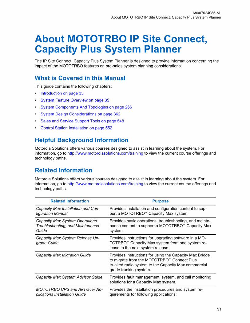
About MOTOTRBO IP Site Connect,Capacity Plus System PlannerThe IP Site Connect, Capacity Plus System Planner is designed to provide information concerning theimpact of the MOTOTRBO features on pre-sales system planning considerations.
What is Covered in this ManualThis guide contains the following chapters:
• Introduction on page 33
• System Feature Overview on page 35
• System Components And Topologies on page 266
• System Design Considerations on page 362
• Sales and Service Support Tools on page 548
• Control Station Installation on page 552
Helpful Background InformationMotorola Solutions offers various courses designed to assist in learning about the system. Forinformation, go to http://www.motorolasolutions.com/training to view the current course offerings andtechnology paths.
Related InformationMotorola Solutions offers various courses designed to assist in learning about the system. Forinformation, go to http://www.motorolasolutions.com/training to view the current course offerings andtechnology paths.
Related Information Purpose
Capacity Max Installation and Con-figuration Manual
Provides installation and configuration content to sup-port a MOTOTRBO™ Capacity Max system.
Capacity Max System Operations,Troubleshooting, and MaintenanceGuide
Provides basic operations, troubleshooting, and mainte-nance content to support a MOTOTRBO™ Capacity Maxsystem.
Capacity Max System Release Up-grade Guide
Provides instructions for upgrading software in a MO-TOTRBO™ Capacity Max system from one system re-lease to the next system release.
Capacity Max Migration Guide Provides instructions for using the Capacity Max Bridgeto migrate from the MOTOTRBO™ Connect Plustrunked radio system to the Capacity Max commercialgrade trunking system.
Capacity Max System Advisor Guide Provides fault management, system, and call monitoringsolutions for a Capacity Max system.
MOTOTRBO CPS and AirTracer Ap-plications Installation Guide
Provides the installation procedures and system re-quirements for following applications:
68007024085-NLAbout MOTOTRBO IP Site Connect, Capacity Plus System Planner
31

Related Information Purpose
• MOTOTRBO™ Customer Programming Software
• Radio Management Server and Radio ManagementDevice Programmer
• MOTOTRBO™ AirTracer
• MOTOTRBO™ RDAC
• MOTOTRBO™ Tuner
Repeater Diagnostics and Control(RDAC) User Guide and Online Help
Explains the features of the MOTOTRBO™ RDAC,which is a standalone Windows application for systemtechnicians who need to run diagnostics on the radio(repeater or base radio) that has the RDAC capability.
MOTOTRBO CPS Radio Manage-ment User Guide and Online Help
Provides information about the Customer ProgrammingSoftware structure and features which allows techni-cians to manage all radio components, in addition withRadio Management which provides a centralized man-agement of programming radios in-the-field.
MOTOTRBO Radio ManagementUser Guide and Online Help
Provides information about the Radio Management(RM) which allows the user to manage an entire fleet ofradios that are connected to the Radio ManagementConfiguration Client (RMC).
MOTOTRBO System Design Tools Estimates the infrastructure and loading constraints ona MOTOTRBO™ system. The System Design Tools is adown-loadable program from Motorola Online.
WAVE 5000 Solution System Plan-ner for release 5.13
Provides guidance on when it is appropriate for aWAVE 5000™ deployment with a MOTOTRBO™ system.
Wave 7000 System Planner for re-lease 17.3
Provides system operators' supporting the WAVE7000™ server to collect and generate reports on statisti-cal data on the MOTOTRBO™ system performance.
SmartPTT PLUS Provides an explanation of the components of 3rd partysupported solution for Control Rooms compatible withMOTOTRBO™ systems.
IMPRES Over Air Battery Manage-ment
Provides information about the functionality of the appli-cation managing batteries for radio fleets.
Radio Management DeploymentGuide
Provides recommendations for deploying an RM systemwithin a customer's network. It provides hardware rec-ommendations for the various RM components basedon customer requirements and the number of radios inthe fleet. This guide is included with the RM InstallationSuite DVD media.
Standards and Guidelines for Com-munication Sites Feature Guide
Provides standards and guidelines that should be fol-lowed when setting up a communications site. Alsoknown as the R56 manual.
Radio Management System Planner Provides information about Radio Management systemcomponents, installation, and troubleshooting of possi-ble issues.
68007024085-NLAbout MOTOTRBO IP Site Connect, Capacity Plus System Planner
32
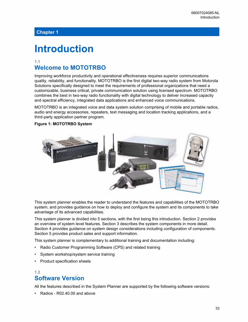
Chapter 1
Introduction1.1Welcome to MOTOTRBOImproving workforce productivity and operational effectiveness requires superior communicationsquality, reliability, and functionality. MOTOTRBO is the first digital two-way radio system from MotorolaSolutions specifically designed to meet the requirements of professional organizations that need acustomizable, business critical, private communication solution using licensed spectrum. MOTOTRBOcombines the best in two-way radio functionality with digital technology to deliver increased capacityand spectral efficiency, integrated data applications and enhanced voice communications.
MOTOTRBO is an integrated voice and data system solution comprising of mobile and portable radios,audio and energy accessories, repeaters, text messaging and location tracking applications, and athird-party application partner program.
Figure 1: MOTOTRBO System
This system planner enables the reader to understand the features and capabilities of the MOTOTRBOsystem, and provides guidance on how to deploy and configure the system and its components to takeadvantage of its advanced capabilities.
This system planner is divided into 5 sections, with the first being this introduction. Section 2 providesan overview of system level features. Section 3 describes the system components in more detail.Section 4 provides guidance on system design considerations including configuration of components.Section 5 provides product sales and support information.
This system planner is complementary to additional training and documentation including:
• Radio Customer Programming Software (CPS) and related training
• System workshop/system service training
• Product specification sheets
1.2Software VersionAll the features described in the System Planner are supported by the following software versions:
• Radios - R02.40.00 and above
68007024085-NLIntroduction
33

• Repeaters - R02.40.00 and above
68007024085-NLChapter 1: Introduction
34
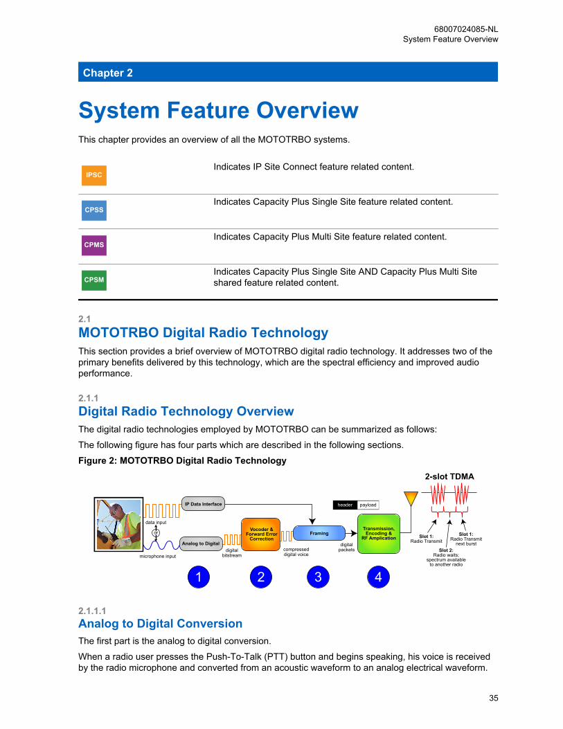
Chapter 2
System Feature OverviewThis chapter provides an overview of all the MOTOTRBO systems.
IPSCIndicates IP Site Connect feature related content.
CPSSIndicates Capacity Plus Single Site feature related content.
CPMSIndicates Capacity Plus Multi Site feature related content.
CPSMIndicates Capacity Plus Single Site AND Capacity Plus Multi Siteshared feature related content.
2.1MOTOTRBO Digital Radio TechnologyThis section provides a brief overview of MOTOTRBO digital radio technology. It addresses two of theprimary benefits delivered by this technology, which are the spectral efficiency and improved audioperformance.
2.1.1Digital Radio Technology OverviewThe digital radio technologies employed by MOTOTRBO can be summarized as follows:
The following figure has four parts which are described in the following sections.
Figure 2: MOTOTRBO Digital Radio Technology
data input
or
microphone inputdigital
bitstreamcompresseddigital voice
digitalpackets
2-slot TDMA
Slot 1:Radio Transmit
Transmission,Encoding &
RF AmplicationFraming
header payload
Vocoder &Forward Error
Correction
IP Data Interface
Analog to DigitalSlot 2:
Radio waits;spectrum available
to another radio
Slot 1:Radio Transmit
next burst
1 2 3 4
2.1.1.1Analog to Digital ConversionThe first part is the analog to digital conversion.
When a radio user presses the Push-To-Talk (PTT) button and begins speaking, his voice is receivedby the radio microphone and converted from an acoustic waveform to an analog electrical waveform.
68007024085-NLSystem Feature Overview
35
This voice waveform is then sampled by an analog to digital converter. In typical radio applications, a16-bit sample is taken every 8 kHz, this produces a 128,000bps (bits per second) digital bitstream,which contains far too much information to send over a 12.5 kHz or 20/25 kHz radio channel. Thereforesome form of compression is required.
2.1.1.2Vocoder and Forward Error CorrectionThe second part is the Vocoding and Forward Error Correction (FEC) application.
Vocoding (Voice encoding) compresses speech by breaking it into its most important parts andencoding them with a small number of bits, while greatly reducing background noise. Vocodingcompresses the voice bitstream to fit the narrow (for MOTOTRBO) 6.25 kHz equivalent radio channel.The MOTOTRBO vocoder is AMBE+2TM which was developed by Digital Voice System, Inc. (DVSI), aleader in the vocoding industry. This particular vocoder works by dividing speech into short segments,typically 20 to 30 milliseconds in length. Each segment of speech is analyzed, and the importantparameters such as pitch, level, and frequency response are extracted. These parameters are thenencoded using a small number of digital bits. The AMBE+2TM vocoder is the first to demonstrate verylow bit rates while producing toll-quality speech such as traditionally associated with wireline telephonesystems.
Together with the vocoding process, FEC is also applied. FEC is a mathematical checksum techniquethat enables the receiver to both validate the integrity of a received message and determine which, ifany, bits have been corrupted. FEC enables the receiver to correct bit errors that may have occurreddue to radio frequency (RF) channel impairment. This effectively rejects noise that can distort ananalog signal and by comparison enables more consistent audio performance throughout the coveragearea. At this stage, the vocoder has already compressed the 128,000bps input signal to 3,600bps.
2.1.1.3FramingThe third part is where the framing process happens.
In framing, the vocoded speech is formatted for transmission. This includes organizing the voice andany embedded signaling information (such as color code, group ID, PTT ID, call type, and others) intopackets. These packets form a header and payload type of structure. The header contains the callcontrol and ID information, and the payload contains the vocoded speech. This same structure canalso relay Internet Protocol (IP) data packets. The IP packets are simply an alternative form of payloadto the MOTOTRBO radio. The header information is repeated periodically throughout the transmission,thereby improving the reliability of the signaling information as well as enabling a receiving radio to joina call that may already be in progress. This condition is referred as “late entry”.
2.1.1.4Time Division Multiple Access TransmissionFinally, the signal is encoded for a Frequency Modulation (FM) transmission. The bits contained in thedigital packets are encoded as symbols representing the amplitude and phase of the modulated carrierfrequency, amplified, and then transmitted.
Time Division Multiple Access (TDMA) organizes a channel into 2-time slots. A given radio’stransmitter is active only for short bursts, which provides longer battery life. By transmitting only ontheir alternating time slots, two calls can share the same channel at the same time without interferingwith one another, thereby doubling spectrum efficiency. Using TDMA, a radio transmits only during itstime slot (it transmits a burst of information, waits, then transmits the next burst of information).
68007024085-NLChapter 2: System Feature Overview
36
2.1.1.5Standards ComplianceThe digital protocols employed in MOTOTRBO (from vocoding and forward error correction to framing,transmission encoding, and transmission through 2-slot TDMA) are fully specified by the ETSI11
DMR22 Tier 233 Standard, which is an internationally recognized standard with agreements among itssupporting members. Although formal interoperability testing and verification processes for thisstandard have yet to fully mature, Motorola Solutions anticipates that MOTOTRBO radio systems areinteroperable with other solutions that comply to the ETSI DMR Tier 2 standard.
2.1.2Spectrum Efficiency Through 2-Slot TDMAThis section describes the spectrum efficiency through 2-slot TDMA.
2.1.2.1Frequencies, Channels, and Requirements for Spectrum EfficiencyA radio communications channel is defined by its carrier frequency, and its bandwidth. The spectrum ofavailable carrier frequencies is divided into major bands (such as 800/900 MHz, VHF, and UHF), andthe majority of licensed channels in use today have widths of either 20/25 kHz or 12.5 kHz. As theairwaves have become increasingly crowded, new standards and technologies that allow more radiousers to share the available spectrum in any given area are needed. The demand for greater spectralefficiency is being driven, in part, by regulatory agencies. In the U.S., for example, the FederalCommunications Commission (FCC) requires manufacturers to offer only devices that operate within12.5 kHz VHF and UHF channels by 2011. By the year 2013, all VHF and UHF users are required tooperate in 12.5 kHz channels.
The next logical step is to further improve the effective capacity of 12.5 kHz channels. While there is nocurrent mandate requiring a move to 6.25 kHz, such discussions are on-going at the FCC and otheragencies. It’s only a matter of time before the ability to carry two voice paths in a single 12.5 kHzchannel, also known as 6.25 kHz equivalent efficiency, becomes a requirement in 800/900 MHz, VHF,and UHF bands. Presently, FCC rules are in place to mandate manufacturers to build radios capable ofthe 6.25 kHz efficiency for 800/900 MHz, VHF, and UHF bands, but the enforcement of these rules areput on hold. In the meantime, MOTOTRBO offers a way to divide a 12.5 kHz channel into twoindependent time slots, thus achieving 6.25 kHz-equivalent efficiency today.
2.1.2.2Delivering Increased Capacity in Existing 12.5 kHz ChannelsMOTOTRBO uses a 2-slot TDMA architecture. This architecture divides the channel into twoalternating time slots, thereby creating two logical channels on one physical 12.5 kHz channel.
Each voice call utilizes only one of these logical channels, and each user accesses a time slot as if it isan independent channel. A transmitting radio transmits information only during its selected slot, and isidle during the alternate slot. The receiving radio observes the transmissions in either time slot, andrelies on the signaling information included in each time slot to determine which call it was meant toreceive.
By comparison, analog radios operate on the concept of Frequency Division Multiple Access (FDMA).In FDMA, each transmitting radio transmits continuously on a designated channel, and the receivingradio receives the relevant transmission by tuning to the desired carrier frequency.
1 European Telecommunications Standards Institute2 Digital Mobile Radio3 Tier 2 indicates full power conventional operation in licensed channels for professional and
commercial users.
68007024085-NLChapter 2: System Feature Overview
37
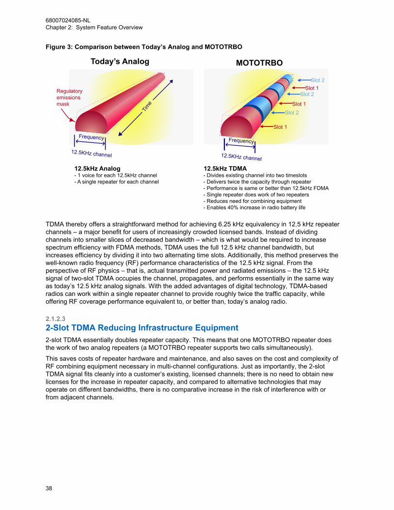
Figure 3: Comparison between Today’s Analog and MOTOTRBO
Time
12.5kHz Analog - 1 voice for each 12.5kHz channel - A single repeater for each channel
12.5kHz TDMA - Divides existing channel into two timeslots - Delivers twice the capacity through repeater - Performance is same or better than 12.5kHz FDMA - Single repeater does work of two repeaters - Reduces need for combining equipment - Enables 40% increase in radio battery life
Regulatoryemissionsmask
Slot 1
Slot 1
Slot 1
Slot 2
Slot 2
Slot 2
Frequency
12.5KHz channel
Frequency
12.5KHz channel
Today’s Analog MOTOTRBO
TDMA thereby offers a straightforward method for achieving 6.25 kHz equivalency in 12.5 kHz repeaterchannels – a major benefit for users of increasingly crowded licensed bands. Instead of dividingchannels into smaller slices of decreased bandwidth – which is what would be required to increasespectrum efficiency with FDMA methods, TDMA uses the full 12.5 kHz channel bandwidth, butincreases efficiency by dividing it into two alternating time slots. Additionally, this method preserves thewell-known radio frequency (RF) performance characteristics of the 12.5 kHz signal. From theperspective of RF physics – that is, actual transmitted power and radiated emissions – the 12.5 kHzsignal of two-slot TDMA occupies the channel, propagates, and performs essentially in the same wayas today’s 12.5 kHz analog signals. With the added advantages of digital technology, TDMA-basedradios can work within a single repeater channel to provide roughly twice the traffic capacity, whileoffering RF coverage performance equivalent to, or better than, today’s analog radio.
2.1.2.32-Slot TDMA Reducing Infrastructure Equipment2-slot TDMA essentially doubles repeater capacity. This means that one MOTOTRBO repeater doesthe work of two analog repeaters (a MOTOTRBO repeater supports two calls simultaneously).
This saves costs of repeater hardware and maintenance, and also saves on the cost and complexity ofRF combining equipment necessary in multi-channel configurations. Just as importantly, the 2-slotTDMA signal fits cleanly into a customer’s existing, licensed channels; there is no need to obtain newlicenses for the increase in repeater capacity, and compared to alternative technologies that mayoperate on different bandwidths, there is no comparative increase in the risk of interference with orfrom adjacent channels.
68007024085-NLChapter 2: System Feature Overview
38
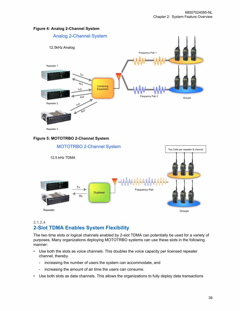
Figure 4: Analog 2-Channel System
Tx1
Rx1
Tx2
Rx2
Tx3
Rx3
Repeater 1
12.5kHz Analog
Repeater 2
Repeater 3
Combining Equipment
Frequency Pair 2Groups
Frequency Pair 1
Analog 2-Channel System
Figure 5: MOTOTRBO 2-Channel System
Repeater
Tx
Rx
12.5 kHz TDMA
MOTOTRBO 2-Channel System
DuplexerFrequency Pair
Two Calls per repeater & channel
Groups
2.1.2.42-Slot TDMA Enables System FlexibilityThe two time slots or logical channels enabled by 2-slot TDMA can potentially be used for a variety ofpurposes. Many organizations deploying MOTOTRBO systems can use these slots in the followingmanner:
• Use both the slots as voice channels. This doubles the voice capacity per licensed repeaterchannel, thereby
- increasing the number of users the system can accommodate, and
- increasing the amount of air time the users can consume.
• Use both slots as data channels. This allows the organizations to fully deploy data transactions
68007024085-NLChapter 2: System Feature Overview
39
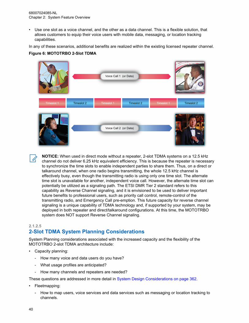
• Use one slot as a voice channel, and the other as a data channel. This is a flexible solution, thatallows customers to equip their voice users with mobile data, messaging, or location trackingcapabilities.
In any of these scenarios, additional benefits are realized within the existing licensed repeater channel.
Figure 6: MOTOTRBO 2-Slot TDMA
Timeslot 1 Timeslot 1 Timeslot 1Timeslot 2 Timeslot 2 Timeslot 2
Voice Call 2 (or Data)
Voice Call 1 (or Data)
NOTICE: When used in direct mode without a repeater, 2-slot TDMA systems on a 12.5 kHzchannel do not deliver 6.25 kHz equivalent efficiency. This is because the repeater is necessaryto synchronize the time slots to enable independent parties to share them. Thus, on a direct ortalkaround channel, when one radio begins transmitting, the whole 12.5 kHz channel iseffectively busy, even though the transmitting radio is using only one time slot. The alternatetime slot is unavailable for another, independent voice call. However, the alternate time slot canpotentially be utilized as a signaling path. The ETSI DMR Tier 2 standard refers to thiscapability as Reverse Channel signaling, and it is envisioned to be used to deliver importantfuture benefits to professional users, such as priority call control, remote-control of thetransmitting radio, and Emergency Call pre-emption. This future capacity for reverse channelsignaling is a unique capability of TDMA technology and, if supported by your system, may bedeployed in both repeater and direct/talkaround configurations. At this time, the MOTOTRBOsystem does NOT support Reverse Channel signaling.
2.1.2.52-Slot TDMA System Planning ConsiderationsSystem Planning considerations associated with the increased capacity and the flexibility of theMOTOTRBO 2-slot TDMA architecture include:
• Capacity planning:
- How many voice and data users do you have?
- What usage profiles are anticipated?
- How many channels and repeaters are needed?
These questions are addressed in more detail in System Design Considerations on page 362.
• Fleetmapping:
- How to map users, voice services and data services such as messaging or location tracking tochannels.
68007024085-NLChapter 2: System Feature Overview
40
Voice and data service capabilities are described in more detail in this module and in SystemComponents And Topologies on page 266. Fleetmapping considerations are addressed in more detailin System Design Considerations on page 362, in the MOTOTRBO Systems Training, and within theMOTOTRBO radio CPS.
• Migration Planning:
- How to migrate existing channels to digital channels?
- What updates to licensing requirements may be needed?
These questions are addressed in more detail in section four System Design Considerations on page362.
2.1.3Digital Audio Quality and Coverage PerformanceThis section describes how digital audio drives coverage performance. It also sets expectations forhow digital audio behaves and sounds from the end-user’s perspective.
2.1.3.1Digital Audio CoverageThe main difference between analog and digital coverage is how the audio quality degrades throughoutthe coverage region. Analog audio degrades linearly throughout the region of coverage, while digitalaudio quality performs more consistently in the same region of coverage. A primary reason for thedifferent degradation characteristics is the use of forward error correction coding used in digitaltransmissions, which can accurately deliver both audio and data content with virtually no loss over a fargreater area.
It is this error protection that allows a MOTOTRBO system to provide consistent audio qualitythroughout its coverage area. A comparable analog system can never offer such consistency. In theMOTOTRBO system, the audio quality remains at a high level, because the error protection minimizesthe noise effect.
The following figure graphically illustrates the relationship of delivered system audio quality, whilecomparing good to poor audio quality with strong to weak signal strength.
• In very strong signal areas the analog signal, because there is no processing, may sound slightlybetter than the digital audio signal.
• Digital signals increase the effective coverage area above the minimally acceptable audio qualitylevel.
• Digital signals improve the quality and consistency of the audio throughout the effective coveragearea.
• Digital signals do not necessarily increase the total distance that an RF signal propagates.
68007024085-NLChapter 2: System Feature Overview
41

Figure 7: Comparison of Audio Quality versus Signal Strength for Analog and Digital
Enhanced Audio Performance
Excellent
Minimal Acceptable Audio Quality
DIGITAL
ANALOG audio quality
Poor
Strong Weak
Area of ImprovedPerformance
SIGNAL STRENGTH
AU
DIO
QU
ALI
TY
2.1.3.2Predicting Digital Audio CoveragePredicting coverage for a radio site can be complicated. There are many factors that affect RFperformance prediction, and generally, the more factors that can be considered, the more accurate theprediction of coverage. Perhaps the most influential factor is the selection of the RF propagation modeland/or RF prediction software tools.
Coverage prediction techniques for analog and digital systems generally follow the same basicprocedures, and require similar sets of input factors. Therefore, if the site’s analog coverage footprint isalready known, it is easier to plan the site’s digital coverage footprint. This approach allows the systemdesigner to use their existing analog site coverage prediction techniques, whether simple or complex,and then translate the results of the analog coverage prediction to predict digital coverage.
Delivered Audio Quality (DAQ) is a method to quantify audio quality. It is a measure of the intelligibilityand quality of voice transported through a communications system, as defined in TIA TSB-88. DAQreports audio quality on a 5-point scale, with a DAQ rating of three is considered as the minimalacceptable level of audio quality for public safety applications. The definition of DAQ 3 is “Speechunderstandable with slight effort and occasional repetition required due to Noise/Distortion.”.
When comparing an analog site and a MOTOTRBO site, the relative regions of coverage offeringcomparable audio quality are illustrated in the following figure.
68007024085-NLChapter 2: System Feature Overview
42

Figure 8: Differences in Analog Coverage
Improving Audio Quality
Analog Digital
analog_digital_audio_quality
For a DAQ 3 audio quality, MOTOTRBO provides a greater usable range than analog, when all otherfactors are considered equal (for example, transmit power level, antenna height, receiver noise figures,IF filter bandwidths, no audio processing – such as Hear Clear, on the analog radios, terrain, antennacombining equipment, and others).
For an advanced, more comprehensive understanding of RF coverage prediction for the MOTOTRBOsite, the reader is encouraged to obtain the TIA Telecommunications Service Bulletin TSB-88 –“Wireless Communications Systems-Performance in Noise and Interference-Limited Situations,Recommended Methods for Technology-Independent Modeling, Simulation, and Verification.”
A copy of TSB-88 can be obtained from http://www.tiaonline.org.
2.1.3.3User Expectations for Digital Audio PerformanceThere are a number of differences between how digital audio behaves compared to analog audio fromthe end user (listener’s) perspective. Motorola Solutions has found that setting proper end userexpectations in this regard is an important aspect of system planning.
What End-Users Experience with Digital Audio• Consistent performance throughout coverage area with no gradual fade at the fringes: While analog
signals slowly degrade as the receiver moves away from the transmitter, digital signals performmore consistently throughout the coverage area. However, digital signals, more abruptly, shift from“good” to “no signal”, when crossing the fringe of the coverage area. This means, users cannot relyon degrading audio quality to warn them that they are approaching the fringe of coverage. On theother hand, just prior to the fringe of the coverage area, digital audio is still crisp and clean, whereasanalog audio has excessive noise and static.
68007024085-NLChapter 2: System Feature Overview
43

• Digital Sounds Different: The vocoding process is designed to deliver optimum audio quality with avery small number of bits. Some listeners find the resulting tonal qualities of digital speechsomewhat different from what they have experienced with analog speech. Because the vocodingprocess is highly specialized for reproducing human speech, other sounds like music and tones arenot reproduced accurately. Additionally, digital audio can introduce end-to-end audio delays. Whenoverwhelming errors or dropouts are encountered, digital radios can generate some unique-sounding audio “artifacts”.
• Background Noise Reduction: The advanced vocoding capabilities in MOTOTRBO also includebackground noise reduction. Regardless of what is happening in the environment of the transmittingradio, only voice is reconstructed at the receiving radio – background noise, like machine noise,wind noise, and traffic noise, is not reconstructed, and thus, not heard. This is a key advantage ofthe MOTOTRBO digital voice solution over typical analog solutions, because noisy environmentslike factories, stores, work sites, and windy locations do NOT significantly degrade communicationintelligibility.
What End-Users Do NOT Experience with Digital Audio• Digital radio is not “CD Quality.” MOTOTRBO is the first radio in the industry to use the AMBE+2TM
low bit rate vocoder to deliver communications grade voice quality. End users should not be misledinto thinking that “communications grade” digital audio quality in radio systems is analogous to thehigh fidelity audio quality of CD’s and DVD’s.
• Digital cannot solve historic problems. System issues with coverage and interference are notnecessarily eliminated by switching to digital. Adjacent or co-channel interference may sounddifferent to a digital user, but digital technology does not solve interference issues. For example,analog interference is not heard as voice to a digital radio and vice versa, but disruption of systemperformance can still occur.
2.1.3.4Audio BalancingTransmitting voice over a digital air interface requires a voice coder, or vocoder for short. The vocoderused by MOTOTRBO is the Digital Voice Systems Inc. (DVSI) AMBE+2TM. This vocoder deliversexcellent voice quality with robustness to both background noise and RF channel bit errors in a 6.25kHz equivalent channel bandwidth. In order to produce optimal voice quality, the input level into thevocoder must fall within a specific amplitude range.
The diverse nature of users with respect to mouth-to-microphone distance as well as voice level anddirectivity can make this a bit problematic. In an effort to produce optimal voice quality over thesediverse input conditions, MOTOTRBO digital always employs Automatic Gain Control (AGC) in theaudio transmit path. The primary function of the transmit AGC is to produce the best voice qualitypossible under real life conditions. Since voice is still the main application of a two-way radio, this is aprimary goal.
A secondary result of the AGC is to produce flat received speech loudness level over a range of inputlevels at the microphone. The usage of IMPRES Accessories extends this input range so optimal voicequality occurs over an even greater input range. The following figure illustrates this extended range flatresponse in the curve titled MOTOTRBO with IMPRES RSM (Digital). This same response curve canalso be produced in analog mode by using an IMPRES Accessory and enabling Analog Mic AGC in theCPS General Settings. The following figure illustrates this type of response in the curve titledMOTOTRBO with IMPRES RSM (AGC on, Analog). An advantage of this type of response is that softtalkers and users that turn away from the microphone while speaking still come through loud and clear.
68007024085-NLChapter 2: System Feature Overview
44
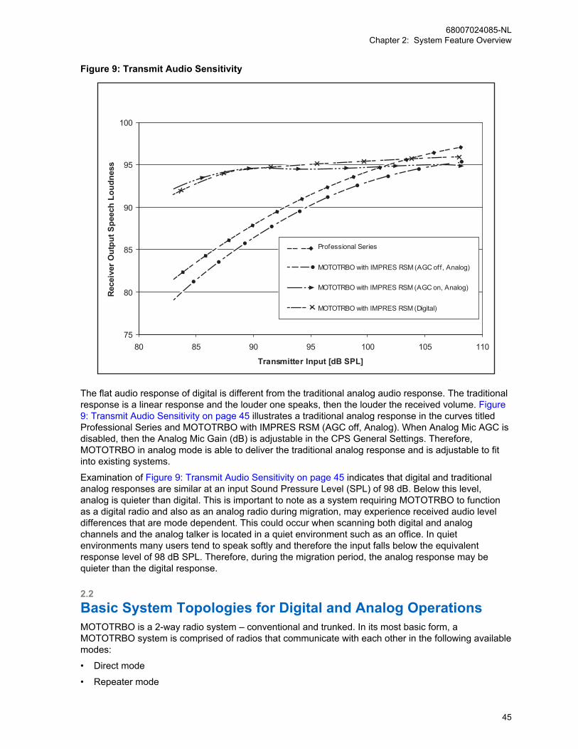
Figure 9: Transmit Audio Sensitivity
75
80
85
90
95
100
80 85 90 95 100 105 110
Transmitter Input [dB SPL]
Rece
iver
Out
put S
peec
h Lo
udne
ss
Professional Series
MOTOTRBO with IMPRES RSM (AGC off, Analog)
MOTOTRBO with IMPRES RSM (AGC on, Analog)
MOTOTRBO with IMPRES RSM (Digital)
The flat audio response of digital is different from the traditional analog audio response. The traditionalresponse is a linear response and the louder one speaks, then the louder the received volume. Figure9: Transmit Audio Sensitivity on page 45 illustrates a traditional analog response in the curves titledProfessional Series and MOTOTRBO with IMPRES RSM (AGC off, Analog). When Analog Mic AGC isdisabled, then the Analog Mic Gain (dB) is adjustable in the CPS General Settings. Therefore,MOTOTRBO in analog mode is able to deliver the traditional analog response and is adjustable to fitinto existing systems.
Examination of Figure 9: Transmit Audio Sensitivity on page 45 indicates that digital and traditionalanalog responses are similar at an input Sound Pressure Level (SPL) of 98 dB. Below this level,analog is quieter than digital. This is important to note as a system requiring MOTOTRBO to functionas a digital radio and also as an analog radio during migration, may experience received audio leveldifferences that are mode dependent. This could occur when scanning both digital and analogchannels and the analog talker is located in a quiet environment such as an office. In quietenvironments many users tend to speak softly and therefore the input falls below the equivalentresponse level of 98 dB SPL. Therefore, during the migration period, the analog response may bequieter than the digital response.
2.2Basic System Topologies for Digital and Analog OperationsMOTOTRBO is a 2-way radio system – conventional and trunked. In its most basic form, aMOTOTRBO system is comprised of radios that communicate with each other in the following availablemodes:
• Direct mode
• Repeater mode
68007024085-NLChapter 2: System Feature Overview
45

• Through a repeater in conventional single site mode
IPSC
IP Site Connect
MOTOTRBO system is configured through aset of repeaters in IP Site Connect mode.
CPSS
Capacity Plus Single Site
MOTOTRBO system is configured by trunking aset of repeaters in Capacity Plus Single Sitemode.
CPMS
Capacity Plus Multi Site
MOTOTRBO system is configured by trunking aset of repeaters connected across multiple sitesin Capacity Plus Multi Site mode.
The MOTOTRBO system can be configured to operate in analog mode, digital mode, or in both modes.
2.2.1Repeater and Direct Mode ConfigurationsIn direct mode, receive and transmit functions are both carried out on the same physical channel(transmit and receive frequencies are the same).
1 When operating in Analog Direct Mode, MOTOTRBO supports one voice path (transmit andreceive) on one physical channel, and can be configured to operate in 12.5/20/25 kHz channelbandwidth systems.
The option board interface meets the timing constraint of the MPT1327 standard, which is asignaling standard for trunked private land mobile radio system. The following features do not workwith MPT1327:
• VOX
• Scan (normal and priority)
• Battery saver
2 When operating in Digital Direct Mode, MOTOTRBO uses one physical channel configured for a12.5 kHz channel bandwidth. On that one direct 12.5 kHz physical channel bandwidth, aMOTOTRBO digital system can support only one voice (or data) path at a time. Without a repeaterin place to coordinate the time slot sequence among radios, only one radio can transmit at a time inorder to guarantee transmissions do not overlap.
In repeater-based radio communications systems, a voice path requires a pair of channels: one fortransmission, the other for reception.
68007024085-NLChapter 2: System Feature Overview
46
2.2.1.1Analog Repeater ModeWhen operating in Analog Repeater Mode, MOTOTRBO operates similar to existing analog repeatersby supporting one voice path (transmit and receive) on one pair of physical channels, and can beconfigured to operate in 12.5/20/25 kHz channel bandwidth systems.
2.2.1.2Digital Repeater ModeWhen operating in Digital Repeater Mode, MOTOTRBO uses a pair of physical channels configured for12.5 kHz channel bandwidth. Through the use of Time Division Multiple Access (TDMA) technologyand the synchronization provided by the repeater, MOTOTRBO splits each 12.5 kHz channel (onetransmit and one receive) into two independent time slots or logical channels within the 12.5 kHzphysical channel bandwidth. This allows the user to assign voice or data traffic to either of the timeslots independently. To the end user, this means they now have two voice or data channels that can bemanaged independently, instead of one. These two logical channels (two time slots) can transmit andreceive independently of each other. The two logical channels in a 12.5 kHz channel makes thechannel equivalent to a 6.25 kHz wide channel.
2.2.1.3Dynamic Mixed ModeWhen operating in Dynamic Mixed Mode (DMM), MOTOTRBO uses a pair of physical channelsconfigured for 12.5 kHz channel bandwidth for digital operation and 12.5/20/25 kHz for analogoperation.
The repeater dynamically switches between analog and digital modes based on the call it receivesfrom radios. If an analog radio transmits, the repeater switches to analog mode to repeat the analogcall. However, the repeater only repeats analog calls that are qualified by PL (DPL/TPL). If a digitalradio transmits, then the repeater switches to digital mode to repeat the digital call if the call uses theright color code. While the repeater repeats one analog call at a time, it can repeat two digital calls at atime, one on each logical channel.
When a repeater repeats a new digital call that starts on one of the logical channels, the repeater doesnot qualify any analog call including an Emergency Call until the digital call (both the transmission andcall hang time) is over and the corresponding channel hang time has expired. Upon the expiry ofchannel hang time, only then does the repeater start qualifying both analog and digital callssimultaneously. Similarly, if an analog call is being repeated, the repeater does not qualify any digitalcall including digital data and Emergency Calls on any of the two logical channels until the analog callis over and the corresponding hang time has expired.
Analog console device(s) are supported only when the repeater has not qualified an OTA digital call. Ifan analog console device tries to key up the repeater when a digital call has been received over-the-air, the analog call will be denied access. The repeater notifies the console via a channel busy tonegenerated over the speaker and Rx audio pins on the 4-wire repeater interface. Analog consoles donot have priority over digital calls (voice or data) in DMM mode.
Dynamic Mixed Mode is a repeater only configuration and the main functions of this feature are:
• The system requires one pair of physical channels (one Tx frequency and one Rx frequency) forboth analog and digital calls, one MOTOTRBO repeater, and one set of RF equipment (antenna,combiners, couplers, LNA, and others) to enable analog and digital radio users to communicate.
• This configuration allows the user to have a mix of legacy analog radios and the digital MOTOTRBOradios in a MOTOTRBO system.
• The repeater supports two independent time slots or logical channels within the 12.5 kHz physicalchannel bandwidth while repeating digital calls. However, the repeater supports one voice path(transmit and receive) on a 12.5/20/25 kHz channel while repeating analog calls.
68007024085-NLChapter 2: System Feature Overview
47

Dynamic Mixed Mode does not support the following configurations/features:
IPSC
IP Site Connect
This means that in Dynamic Mixed Mode, therepeater can only repeat the digital calls over-the-air and cannot send the voice/data packetsover the IP network. The status of the repeaterand the control of the repeater cannot be per-formed from a remote PC application likeRDAC-IP.
CPSS
Capacity Plus Single Site
This means that in Dynamic Mixed Mode, trunk-ing the logical channels of multiple MOTOTR-BO repeaters as per Capacity Plus Single Siteis not supported.
• FCC Type-I and Type-II monitoringSince FCC Type-I and Type-II monitoring are not supported in single site analog operation in any ofthe earlier MOTOTRBO releases, it is also not supported in Dynamic Mixed Mode single siteoperation.
• Transmit Interrupt FeatureThe Voice Interrupt, Emergency Voice Interrupt, Remote Voice Dekey, and Data Over VoiceInterrupt features are presently not supported in Dynamic Mixed Mode systems.
• RDAC Over IP FeatureRDAC over local USB and connections via GPIO are supported. RDAC over the network is NOTsupported.
• Repeater KnockdownIn Dynamic Mixed Mode systems, this feature is not supported during an ongoing digitaltransmission.
• PTT on a 4-wire InterfaceIn Dynamic Mixed Mode systems, this feature is not supported during a digital repeat operation.
2.2.1.4IP Site Connect Mode
IPSC
When operating in IP Site Connect Mode, MOTOTRBO combines the logical channels of multipleMOTOTRBO systems (operating in digital repeater mode at dispersed locations) into one logicalchannel covering all locations.
In this mode, repeaters across dispersed locations exchange voice and data packets over an IPv4-based back-end network. There are three main functions of this mode, as follows:
• To increase the RF coverage area of a MOTOTRBO system.
• To provide voice and data communication between two or more MOTOTRBO single site systemslocated at geographically separate locations.
• To provide voice and data communication between two or more MOTOTRBO single site systemsoperating in different frequency bands (for example, 800/900 MHz, VHF, and UHF).
The backend network of an IP Site Connect system is designed to work seamlessly with internetconnectivity provided by an Internet Service Provider (ISP). The system only requires that one of the
68007024085-NLChapter 2: System Feature Overview
48
repeaters have a static IPv4 or DNS address, while the others may be dynamic. Also, the systemavoids the need for reconfiguration of a customer’s network such as reprogramming of firewalls.
When a new call starts at one of the logical channel of a repeater, the repeater sends the call to all therepeaters and all these repeaters repeat the call on their corresponding logical channel. This allows aradio in the coverage area of any repeater to participate in the call. Thus, the coverage area of an IPSite Connect system is the sum of the coverage areas of all the repeaters. However, note that an IPSite Connect configuration does not increase the capacity (number of calls per hour) of the system.The capacity of one Wide Area Channel of an IP Site Connect system is approximately the same asthat of a single repeater working in digital repeater mode.
In an IP Site Connect configuration, MOTOTRBO radios support all the features that they alreadysupport in digital repeater mode. This also includes Transmit Interrupt features that are supported onlogical channels configured over wide area networks. Additionally, the radios are capable ofautomatically roaming from one site to another.
The IP Site Connect configuration of MOTOTRBO does not require any new hardware besidesbackend network devices such as routers. If a customer has multiple MOTOTRBO systems working indigital repeater mode at dispersed sites and wants to convert them into an IP Site Connect systemthen the repeaters and the radios should be updated with new software and the repeaters need to beconnected to an IPv4-based backend network. It is possible to configure a repeater such that:
• Both logical channels work in IP Site Connect mode (over wide area).
• Both logical channels work in digital repeater mode (single site over local area).
• One of its logical channels works in IP Site Connect mode (over wide area) and the other logicalchannel works in digital repeater mode (single site over local area).
MOTOTRBO has three security features in the IP Site Connect configuration.
• Provides the confidentiality of voice and data payloads by extending the privacy feature, whetherBasic or Enhanced, or Advanced Encryption Standard (AES), to cover the communication over thebackend network.
• Ensures that all the messages between repeaters are authentic.
• Supports Secure VPN (Virtual Private Network) based communication between the repeaters forcustomers needing higher level of security (protection against replay attack).
The IP Site Connect configuration of MOTOTRBO provides a mechanism and a tool to remotelymanage repeaters. The tool (called RDAC) receives alarms from all the repeaters, helps in diagnosis ofrepeaters, and provides some controls over the repeaters.
2.2.1.5Capacity Plus Single Site Mode
CPSS
When operating in Capacity Plus Single Site Mode, MOTOTRBO trunks the logical channels of multipleMOTOTRBO repeaters (operating in digital repeater mode) at the same location.
This allows the radios to share the logical channels, resulting in less waiting time to access the systemand increased channel capacity for a given quality of service. Another advantage is that the probabilityof all channels being busy at the same instant is low. Therefore the probability of a call being blocked islower than when only one channel can be accessed.
Capacity Plus Single Site is a single site trunking configuration of the MOTOTRBO system. In aCapacity Plus Single Site configuration, all the “idle” radios (radios neither receiving nor transmitting)are on an idle channel called the Rest Channel. Therefore, a new call always starts on the RestChannel. At the start of a call, the Rest Channel repeater selects one of the idle channels as the new
68007024085-NLChapter 2: System Feature Overview
49

Rest Channel, informs the radios on the current Rest Channel about the new Rest Channel, convertsthe current Rest Channel to a traffic channel, and starts repeating the bursts sent by the radio. Theradios that are not participating in the call (that is, destination of the call is not of their interest) move tothe new Rest Channel.
If the current Rest Channel is the last idle channel (that is, all the other available channels are in use),the current Rest Channel remains as the Rest Channel. The call starts on the channel and non-participating radios stay on the channel. In this condition, non-participating radios indicate that thechannel is busy through its yellow LED. If all channels are busy and a radio user initiates a call, thenthe radio generates a distinct tone to indicate that the system is busy. As soon as a channel becomesfree in the Capacity Plus Single Site system, the non-participating radios are informed, and move to thefree channel.
At the end of the call (that is, after the call hang time), the repeater also broadcasts the status of allother available channels. This triggers any radio on the channel to move to the current Rest Channel orto a channel where a Group Call of interest is active.
The Capacity Plus Single Site system has no central controller to manage the Rest Channel. The RestChannel is managed collectively by all the trunked repeaters. A trunked repeater periodically informsthe status of its channels to other trunked repeaters whenever the status of its channels change. Whena new Rest Channel is selected, the selecting repeater informs all the other repeaters. The new RestChannel is selected based on the following conditions:
• At the start of a call, the repeater of the current Rest Channel selects the new Rest Channel.
• On detection of interference or before starting CWID (BSI) transmission, the repeater of the currentRest Channel selects the new Rest Channel.
• On detection of no Rest Channel (in the event of a failure of the current Rest Channel repeater orthe backend network), the repeater with the lowest ID selects the new Rest Channel.
• When a call ends on a system, if a call is in progress on the current Rest Channel, then the repeaterof the current Rest Channel selects the new Rest Channel.
The Capacity Plus Single Site system does not require an exclusive control channel. The Rest Channelchanges on every call; in case of an interference or if the repeater becomes unavailable due to failure.This results in the following advantages:
• Non-exclusive channels make it easier to satisfy regulator frequency coordination (where exclusiveuse of channels is not possible).
• Capacity Plus Single Site does not use “request and grant” mechanism to allocate channels anddoes not require any central controller to trunk the channels.
• The dynamic Rest Channel mechanism makes Capacity Plus Single Site very suitable for anenvironment where channels are shared by multiple radio systems.
• The dynamic Rest Channel mechanism also improves the reliability of the Capacity Plus Single Sitesystem. In the event of a repeater failure, the other available repeaters automatically reconfigurethemselves and continue to work as the Capacity Plus Single Site system.
The Capacity Plus Single Site system configuration of MOTOTRBO does not require any newhardware apart from backend network devices such as routers. If a customer has multipleMOTOTRBO systems working in digital repeater mode at the same site and wants to convert to aCapacity Plus Single Site system, then the repeaters and radios should be updated with the newsoftware, and the repeaters need to be connected to an IPv4-based backend network. If one logicalchannel of a repeater is configured to the Capacity Plus Single Site mode, then the other logicalchannel will also be in the same mode.
In a Capacity Plus Single Site configuration, MOTOTRBO systems support all previous digital repeatermode features, with the exception of the following:
• Scan: Capacity Plus Single Site supports Group Scan, so a properly programmed radio listens formultiple talkgroups within a single Capacity Plus Single Site system, but does not support scanning
68007024085-NLChapter 2: System Feature Overview
50
channels of another system. Adding multiple talkgroups to the Receive list of a radio allows the userto hear the conversations of those talkgroups, and reply within the call hang time, regardless of thephysical channel on which that call takes place.
• Emergency Revert Channel: Capacity Plus Single Site does not support a revert channel foremergency because probability of all Trunked Channels becoming busy is low. However, revertingto an emergency group is supported. This promotes a centralized handling of an emergencysituation.
• IP Site Connect configuration: Capacity Plus Single Site is a single site system and therefore doesnot support features related to IP Site Connect configuration such as wide-area coverage andautomatic roaming. However, a radio can be programmed with multiple channels in multiple zones,one of which could be a Capacity Plus Single Site system, another an IP Site Connect System, andothers could be MOTOTRBO conventional channels or Analog conventional channels.
• Impolite calls: Capacity Plus Single Site supports impolite Emergency Call and impolitetransmissions (group members can transmit over an ongoing call). A new call always starts on anidle channel and therefore, a radio does not start a non-Emergency Call impolitely.
• Talkaround mode: A radio can have a talkaround personality but in Capacity Plus Single Site mode,there is no talkaround option.
• Monitoring of channels status: Monitoring is important in a conventional system, where a radio stayson a channel. In Capacity Plus Single Site, a radio moves from one Rest Channel to another. Mostof the Rest Channels are in an idle state and therefore, monitoring is not necessarily needed.
• Fragmentation of a Data Packet: Capacity Plus Single Site does not fragment a data packet beforetransmitting over-the-air. Thus, the size of an IP datagram (including IP and UDP headers) shouldbe less than the maximum size of the Packet Data Unit. The value of the Packet Data Unit is a CPSprogrammable parameter with a maximum size of 1500 bytes.
• Option Board: If the Option Board feature is enabled for Capacity Plus Single Site, then the featureis automatically enabled for all trunked and revert channels of a Capacity Plus Single Site system.On a Capacity Plus Single Site personality, the Option Board is not aware of the transmit or receivechannel. Additionally, an Option Board does not use or create Virtual Personalities in a CapacityPlus Single Site system. Hence, an Option Board will not be able to customize the current workingpersonality.
• Transmit Interrupt: The Voice Interrupt, Emergency Voice Interrupt, Remote Voice Dekey, and DataOver Voice Interrupt features are supported on Capacity Plus Single Site systems.
Capacity Plus Single Site does not provide the following features:
• Coverage of multiple sites.
• Call queuing, priority, and preemption.
• Priority Monitor: Capacity Plus Single Site provides higher priority only to an All Call.
• Radio access control.
Greater detail on system services available in direct-mode and repeater-based system topologies
is described in System Components And Topologies on page 266.
2.2.1.6Capacity Plus Multi Site Mode
CPMS
When operating in Capacity Plus Multi Site Mode, MOTOTRBO trunks the logical channels (that is, theTDMA slots) of multiple MOTOTRBO repeaters (operating in digital repeater mode) at multiple
68007024085-NLChapter 2: System Feature Overview
51
locations and combines the logical channels into one logical channel. This allows radios to share thelogical channels, as well as increase the RF coverage area of a MOTOTRBO system.
When operating in Capacity Plus Multi Site Mode, MOTOTRBO trunks the logical channels (that is, theTDMA slots) of multiple MOTOTRBO repeaters (operating in digital repeater mode) at multiplelocations and combines the logical channels into one logical channel. This allows radios to share thelogical channels, as well as increase the RF coverage area of a MOTOTRBO system.
Capacity Plus Multi Site (CPMS) is a trunked multisite multi-channel configuration of MOTOTRBO,which combines both the Capacity Plus Single Site and IP Site Connect configurations. This combinedconfiguration requires only software updates for radios and repeaters, but does not require any newhardware.
NOTICE: Only repeaters with 32 MB of internal memory (for example, XPR 8380/XPR 8400 orMTR3000) can support the CPMS configuration.
Capacity Plus Multi Site uses the IP Site Connect type of backend network for communication betweensites. The IP Site Connect supports a wide variety of backend networks from a dedicated network to aninternet provided by the ISP. Capacity Plus Multi Site supports all backend networks supported by IPSite Connect, but more bandwidth is required from an ISP. The backend is designed to workseamlessly with internet connectivity. The system requires only one of the repeaters to have a staticIPv4 or DNS address. Additionally, the system avoids the need for reconfiguration of a customer’snetwork, such as reprogramming of firewalls.
Similar to Capacity Plus Single Site, CPMS repeaters at a site are connected over a LAN. A CapacityPlus Single Site repeater uses multiple individual messages to communicate with the rest of therepeaters on site. However, an CPMS repeater sends a broadcast message to IP Limited BroadcastAddress (255.255.255.255). The broadcast messages may produce somea dverse effects on the otherdevices present on the LAN. Therefore, an CPMS configuration requires only the CPMS repeaters tobe present on the LAN.
The call start-up of CPMS is a combination of IP Site Connect and Capacity Plus Single Siteconfigurations with the following enhancements:
• In an IP Site Connect system, a customer can configure a logical channel as either a local channelor a wide area channel. A call over a local channel is repeated only over the local site, whereas acall over a wide area channel is repeated over all the sites where at least a channel is idle. Insteadof local and wide area channels of IP Site Connect, CPMS supports both local and wide areatalkgroups. A repeater handles a local talkgroup call in the same method as in a Capacity PlusSingle Site configuration. However, a wide area talkgroup call is repeated over all the associatedsites where at least one logical channel is idle.
• In an IP Site Connect system, a call starts at all sites. This is often called “All sites Light-Up". Anadvantage of this is the simplicity in implementation because repeaters are not required to know thelist of radios present at its site. A disadvantage is that a multi-site configuration does not increasethe capacity of a system. Only the coverage of the coverage of the system increases. CPMS makesthe following enhancements:
- CPMS allows defining a talkgroup as a wide area talkgroup. A wide area talkgroup call "lights-up" only the sites which are statically associated with the talkgroup. The call is rejected when aradio tries to initiate a wide area Group Call from a site not associated with the talkgroup.
- The talkgroups not defined as wide-area are local talkgroups. A local call "lights-up" only onesite where the initiating radio is located.
- The CPMS Private Call initially “lights-up” all the sites but after approximately 400 milliseconds,the call continues only at the sites (at most two) where the source radio or destination radio arepresent.
• In CPMS, a wide area non-Emergency talkgroup call starts only if all the associated sites have idlechannels. This is defined as “All Start.” Additionally, CPMS allows a customer to reserve a number
68007024085-NLChapter 2: System Feature Overview
52
of logical channels for wide area talkgroup calls only. This improves the success of “All Start” for thewide area talkgroup calls.
• Just like a Capacity Plus Single Site system, an CPMS system has no controller. Repeaters of asite trunk the logical channels available at the site. The trunking process in CPMS is similar to thatof Capacity Plus Single Site. Repeaters of a site do not participate in trunking the RF resources ofanother site. Each site trunks their channels.
2.2.1.7MOTOTRBO Link ModeMOTOTRBO Link Mode is a configuration that enables over-the-air (OTA) backhaul through repeaters.This functionality is useful in areas where no site link connectivity exists.
When operating in MOTOTRBO Link Mode, MOTOTRBO supports chaining together a series ofrepeaters using a DMR channel as the backhaul link mechanism. In this mode, repeaters acrossdispersed locations exchange voice and data packets over a DMR-based OTA protocol with twotimeslots.
The sites are linked or chained together using DMR channels that are dedicated for the sole purpose oflinking the sites. Each site must contain at least one repeater that performs either the role of a Link orStandard Repeater. The Backhaul Link Repeater is a repeater dedicated to linking two sites togetherby forwarding the call data between the adjacent sites in the chain. A Standard Repeater can beconceptualized as a tap that is dropped into the network at some sites for subscriber radios to receiveand/or transmit new calls into the network.
Within a backhaul site, the Drop and Link repeaters have connectivity to each other through anEthernet connection to a local-area network. The repeaters synchronize their timeslot timing by usingGeneral Purpose Input/Output (GPIO) pins on the accessory connector allocated for slotsynchronization. Within a backhaul chain, connectivity between sites is available through the DMRchannels in the Link repeaters. All backhaul sites and repeaters within the backhaul chain are timeslottiming aligned.
Every backhaul site in the system is treated as an isolated IP Site Connect system. This means thefollowing:
• Every backhaul site must have one Master repeater.
• Every backhaul site must reside in its own IP subnet.
• When the backhaul link is down, each backhaul site continues to work as an isolated IP SiteConnect system.
MOTOTRBO supports Dedicated-Link Backhaul system mode with the following configurations:
Standalone Dedicated-Link BackhaulThe system consists of one MOTOTRBO Link chain, which includes no more than nineMOTOTRBO Link sites.
Hybrid Dedicated-Link BackhaulThe system consists of one IPSC Backhaul network and one or more standalone MOTOTRBO Linkchains. The Proxy repeater is responsible to bridge the calls between IPSC Backhaul network andthe backhaul chain.
NOTICE: Only SLR Series Repeaters (for example, SLR 1000/SLR 5000/SLR 8000) andsecond generation subscribers can support the MOTOTRBO Link configuration.
When a subscriber radio initiates a call (group or private), the Standard repeater receives the call andforwards it to an adjacent backhaul site by a link repeater/channel, and repeated by the Standardrepeaters at all adjacent sites along the backhaul chain. The subscriber radio talk permit tone is onlyplayed when a call has been set up across the whole backhaul chain of repeaters. During the voice callset up, the Standard repeater transmits a Control Signaling Block (CSBK) to the subscriber thatconfirms that it has won the right to transmit on the channel. During the data call set up, the subscriber
68007024085-NLChapter 2: System Feature Overview
53
confirms that it has won the right to transmit on the channel but retries when it fails to win the channeluntil the maximum number of retries is exceeded.
Since the MOTOTRBO Link configuration uses daisy-chaining, each new site that is added to the chainincreases the transmission delay required for a call to be transmitted from the origin of the chain to aterminating site in the chain. To enable a good user experience with minimal delay, a MOTOTRBOLink chain of repeaters is limited to chaining together up to nine sites with eight OTA links. And,MOTOTRBO Link systems are not expected to be heavily loaded systems with many users per site.
In a MOTOTRBO Link configuration, MOTOTRBO systems support all previous IP Site Connectrepeater mode features, except for the following:
Auto RoamingMOTOTRBO supports the ability to automatically roam between sites of one MOTOTRBO Linkchain. Auto roaming between MOTOTRBO Link chains or/and IP Site Connect backhaul sites is notsupported.
Enhanced Channel AccessMOTOTRBO only supports Backhaul Channel Access (BCA) with a TRART mechanism as channelaccess rule during call setup phase. This should be based on to the TRT mechanism for ECA withthe “R1” phase replaced with the “R1-A” phase that is more similar to what is used for LCP.
Remote Diagnostic and Alarm Control (RDAC)MOTOTRBO supports only remotely monitor presence and alarm status from backhaul chainrepeaters (No remote control command is supported).
Remote Repeater Programming (RRP)MOTOTRBO supports RRP feature on IP Site Control backhaul repeaters (include the Proxyrepeater) same as legacy IPSC systems. The Drop and Link repeaters do not support RRP.
A MOTOTRBO Link system does not support the following features:
• Transmit Interrupt
• Digital Telephone Patch
• Digital Voting
• Confirmed Group Data
• GPS Revert, Data Revert
• Enhanced/Scheduled GPS
• Repeater Call Monitoring (RCM)
• CSBK Data
2.2.1.7.1Hardware and Software RequirementsMOTOTRBO Link Mode software and hardware requirements are listed in this section.
• SLR 5000/8000/1000 series repeaters with R2.9 firmware or newer.
• Custom DB25-DB25 sync cable, see Figure 214: GPIO Pin Configurations on page 544.
• DP/DM4000 or DP3441/3661/e series radios with R2.9 firmware or newer.
• DP1400/2400/2600 as well as SL4000/1600/2600 portables with the latest firmware.
• Peripheral hardware for the repeaters such as duplexers, ethernet switches, and cabling.
• CPS 16.0 or later, alternatively Radio Management R2.9 or newer.
Not supported:
• DR3000 and MTR3000 irrespective of memory size.
• First generation DP36xx; DP34xx; DM36xx and DM34xx.
68007024085-NLChapter 2: System Feature Overview
54
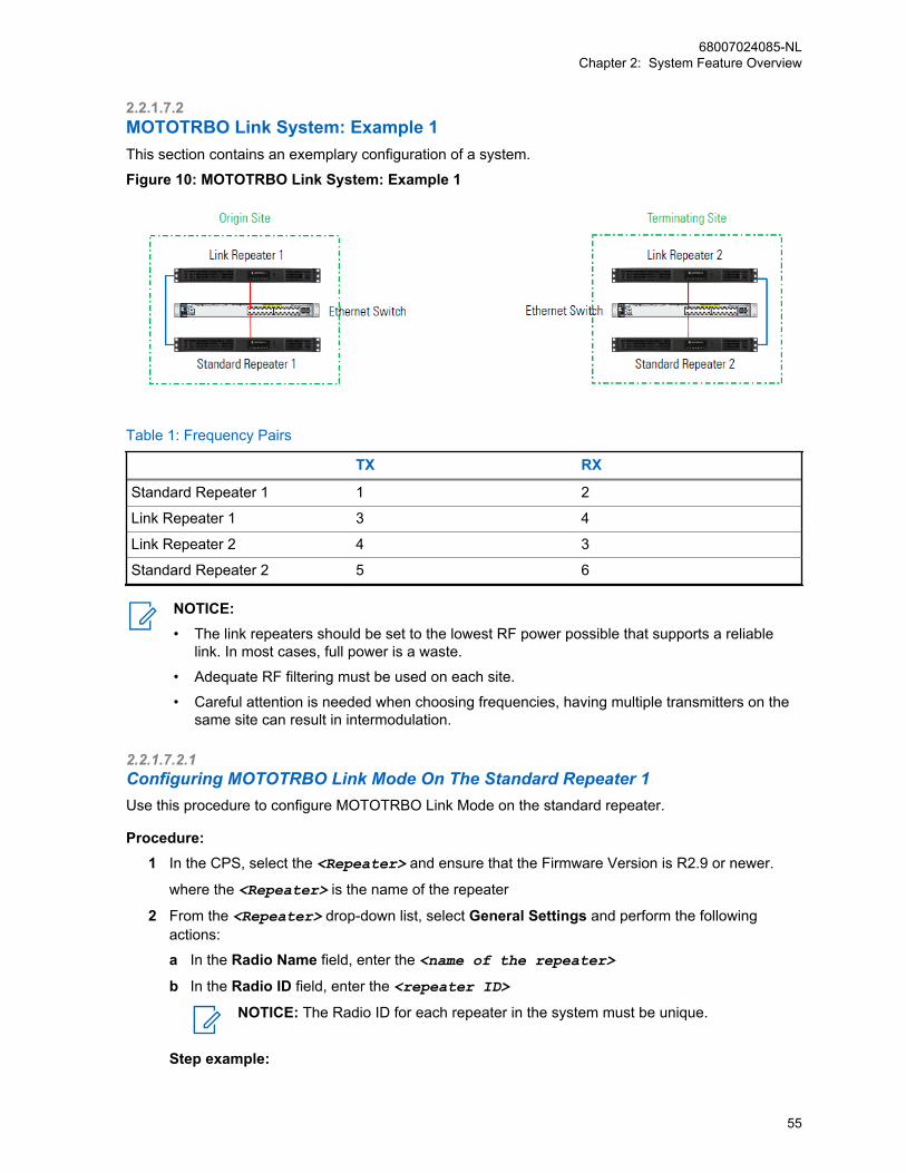
2.2.1.7.2MOTOTRBO Link System: Example 1This section contains an exemplary configuration of a system.
Figure 10: MOTOTRBO Link System: Example 1
Table 1: Frequency Pairs
TX RX
Standard Repeater 1 1 2
Link Repeater 1 3 4
Link Repeater 2 4 3
Standard Repeater 2 5 6
NOTICE:• The link repeaters should be set to the lowest RF power possible that supports a reliable
link. In most cases, full power is a waste.
• Adequate RF filtering must be used on each site.
• Careful attention is needed when choosing frequencies, having multiple transmitters on thesame site can result in intermodulation.
2.2.1.7.2.1Configuring MOTOTRBO Link Mode On The Standard Repeater 1Use this procedure to configure MOTOTRBO Link Mode on the standard repeater.
Procedure:1 In the CPS, select the <Repeater> and ensure that the Firmware Version is R2.9 or newer.
where the <Repeater> is the name of the repeater
2 From the <Repeater> drop-down list, select General Settings and perform the followingactions:
a In the Radio Name field, enter the <name of the repeater>
b In the Radio ID field, enter the <repeater ID>
NOTICE: The Radio ID for each repeater in the system must be unique.
Step example:
68007024085-NLChapter 2: System Feature Overview
55
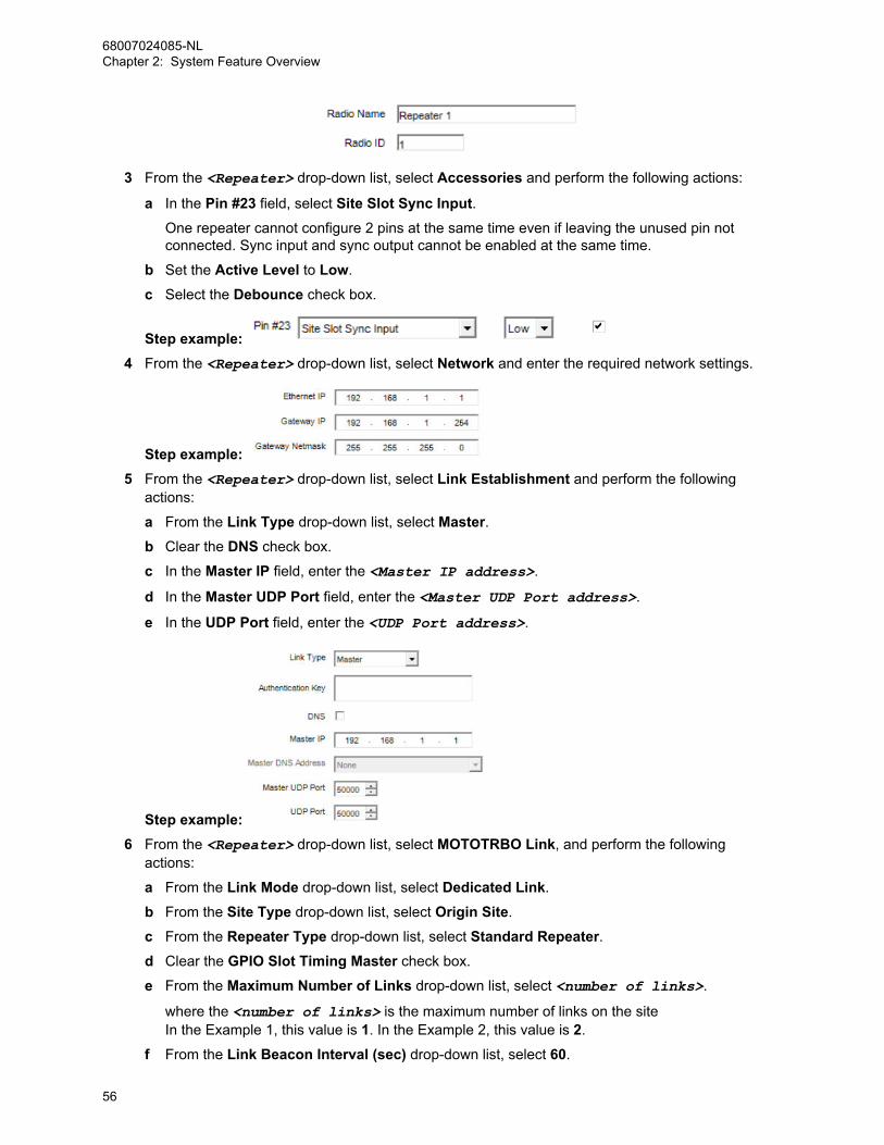
3 From the <Repeater> drop-down list, select Accessories and perform the following actions:
a In the Pin #23 field, select Site Slot Sync Input.One repeater cannot configure 2 pins at the same time even if leaving the unused pin notconnected. Sync input and sync output cannot be enabled at the same time.
b Set the Active Level to Low.
c Select the Debounce check box.
Step example: 4 From the <Repeater> drop-down list, select Network and enter the required network settings.
Step example: 5 From the <Repeater> drop-down list, select Link Establishment and perform the following
actions:
a From the Link Type drop-down list, select Master.b Clear the DNS check box.
c In the Master IP field, enter the <Master IP address>.
d In the Master UDP Port field, enter the <Master UDP Port address>.
e In the UDP Port field, enter the <UDP Port address>.
Step example: 6 From the <Repeater> drop-down list, select MOTOTRBO Link, and perform the following
actions:
a From the Link Mode drop-down list, select Dedicated Link.
b From the Site Type drop-down list, select Origin Site.
c From the Repeater Type drop-down list, select Standard Repeater.d Clear the GPIO Slot Timing Master check box.
e From the Maximum Number of Links drop-down list, select <number of links>.
where the <number of links> is the maximum number of links on the siteIn the Example 1, this value is 1. In the Example 2, this value is 2.
f From the Link Beacon Interval (sec) drop-down list, select 60.
68007024085-NLChapter 2: System Feature Overview
56

g Select the IP Site Connect MOTOTRBO Link Site check box.
Step example: 7 From the <Repeater> drop-down list, select Channels → Zone1 → Channel1.
8 From the IP Site Connect drop-down list, select Slot 1 & Slot 2.
NOTICE: This parameter differs depending on the site structure. In this example, theparameter is Slot 1 & Slot 2.
2.2.1.7.2.2Configuring MOTOTRBO Link Mode On The Link Repeater 1Use this procedure to configure MOTOTRBO Link Mode on the link repeater.
Procedure:1 In the CPS, from the <Repeater> drop-down list, select General Settings, and in the Radio ID
field, enter the repeater ID.
where the <Repeater> is the name of the repeater
NOTICE: The Radio ID for each repeater in the system must be unique.
Step example: 2 From the <Repeater> drop-down list, select Accessories and perform the following actions:
a In the Pin #8 field, select Site Slot Sync Output.One repeater cannot configure 2 pins at the same time even if leaving the unused pin notconnected. Sync input and sync output cannot be enabled at the same time.
b Set the Active Level to Low.
c Select the Debounce check box.
3 From the <Repeater> drop-down list, select Network and enter the required network settings.
Step example: 4 From the <Repeater> drop-down list, select Link Establishment and perform the following
actions:
a From the Link Type drop-down list, select Peer.b Clear the DNS check box.
c In the Master IP field, enter the <Master IP address>.
68007024085-NLChapter 2: System Feature Overview
57

d In the Master UDP Port field, enter the <Master UDP Port address>.
e In the UDP Port field, enter the <UDP Port address>.
Step example: 5 From the <Repeater> drop-down list, select MOTOTRBO Link, and perform the following
actions:
a From the Link Mode drop-down list, select Dedicated Link.
b From the Site Type drop-down list, select Origin Site.
c From the Repeater Type drop-down list, select Link Repeater.d Select the GPIO Slot Timing Master check box.
e From the Maximum Number of Links drop-down list, select <number of links>.
where the <number of links> is the maximum number of links on the siteIn the Example 1, this value is 1. In the Example 2, this value is 2.
f From the Link Beacon Interval (sec) drop-down list, select 60.
g Clear the IP Site Connect MOTOTRBO Link Site check box.
Step example: 6 From the <Repeater> drop-down list, go to Channels → Zone1 → Channel1
7 From the IP Site Connect drop-down list, select None.
2.2.1.7.2.3Configuring MOTOTRBO Link Mode On The Standard Repeater 2Use this procedure to configure MOTOTRBO Link Mode on the standard repeater.
Procedure:1 In the CPS, from the <Repeater> drop-down list, select General Settings, and in the Radio ID
field, enter the <repeater ID>.
where the <Repeater> is the name of the repeater
NOTICE: The Radio ID for each repeater in the system must be unique.
Step example:
68007024085-NLChapter 2: System Feature Overview
58
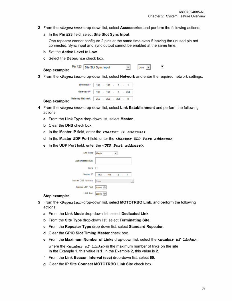
2 From the <Repeater> drop-down list, select Accessories and perform the following actions:
a In the Pin #23 field, select Site Slot Sync Input.One repeater cannot configure 2 pins at the same time even if leaving the unused pin notconnected. Sync input and sync output cannot be enabled at the same time.
b Set the Active Level to Low.
c Select the Debounce check box.
Step example: 3 From the <Repeater> drop-down list, select Network and enter the required network settings.
Step example: 4 From the <Repeater> drop-down list, select Link Establishment and perform the following
actions:
a From the Link Type drop-down list, select Master.b Clear the DNS check box.
c In the Master IP field, enter the <Master IP address>.
d In the Master UDP Port field, enter the <Master UDP Port address>.
e In the UDP Port field, enter the <UDP Port address>.
Step example: 5 From the <Repeater> drop-down list, select MOTOTRBO Link, and perform the following
actions:
a From the Link Mode drop-down list, select Dedicated Link.
b From the Site Type drop-down list, select Terminating Site.
c From the Repeater Type drop-down list, select Standard Repeater.d Clear the GPIO Slot Timing Master check box.
e From the Maximum Number of Links drop-down list, select the <number of links>.
where the <number of links> is the maximum number of links on the siteIn the Example 1, this value is 1. In the Example 2, this value is 2.
f From the Link Beacon Interval (sec) drop-down list, select 60.
g Clear the IP Site Connect MOTOTRBO Link Site check box.
68007024085-NLChapter 2: System Feature Overview
59
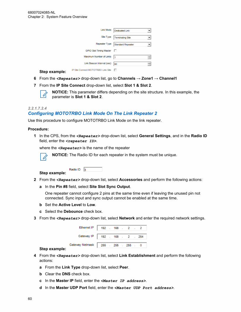
Step example: 6 From the <Repeater> drop-down list, go to Channels → Zone1 → Channel1
7 From the IP Site Connect drop-down list, select Slot 1 & Slot 2.
NOTICE: This parameter differs depending on the site structure. In this example, theparameter is Slot 1 & Slot 2.
2.2.1.7.2.4Configuring MOTOTRBO Link Mode On The Link Repeater 2Use this procedure to configure MOTOTRBO Link Mode on the link repeater.
Procedure:1 In the CPS, from the <Repeater> drop-down list, select General Settings, and in the Radio ID
field, enter the <repeater ID>.
where the <Repeater> is the name of the repeater
NOTICE: The Radio ID for each repeater in the system must be unique.
Step example: 2 From the <Repeater> drop-down list, select Accessories and perform the following actions:
a In the Pin #8 field, select Site Slot Sync Output.One repeater cannot configure 2 pins at the same time even if leaving the unused pin notconnected. Sync input and sync output cannot be enabled at the same time.
b Set the Active Level to Low.
c Select the Debounce check box.
3 From the <Repeater> drop-down list, select Network and enter the required network settings.
Step example: 4 From the <Repeater> drop-down list, select Link Establishment and perform the following
actions:
a From the Link Type drop-down list, select Peer.b Clear the DNS check box.
c In the Master IP field, enter the <Master IP address>.
d In the Master UDP Port field, enter the <Master UDP Port address>.
68007024085-NLChapter 2: System Feature Overview
60

e In the UDP Port field, enter the <UDP Port address>.
Step example: 5 From the <Repeater> drop-down list, select MOTOTRBO Link, and perform the following
actions:
a From the Link Mode drop-down list, select Dedicated Link.
b From the Site Type drop-down list, select Terminating Site.
c From the Repeater Type drop-down list, select Link Repeater.d Select the GPIO Slot Timing Master check box.
e From the Maximum Number of Links drop-down list, select <number of links>.
where the <number of links> is the maximum number of links on the siteIn the Example 1, this value is 1. In the Example 2, this value is 2.
f From the Link Beacon Interval (sec) drop-down list, select 60.
g Clear the IP Site Connect MOTOTRBO Link Site check box.
Step example: 6 From the <Repeater> drop-down list, go to Channels → Zone1 → Channel1
7 From the IP Site Connect drop-down list, select None.
2.2.1.7.2.5Configuring RadiosUse this procedure to configure the radios in the MOTOTRBO Link System.
Procedure:1 In the CPS, select the <Radio name> and ensure that the Firmware Version is R2.9 or newer.
• where <Radio name> is the name of the radio
2 Select <Radio name> → Channels → Zone1 → IPSC Group 101.
3 Ensure that the MOTOTRBO Link check box is selected in all channels in the Zone and ChannelPool.
68007024085-NLChapter 2: System Feature Overview
61
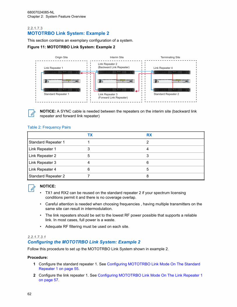
2.2.1.7.3MOTOTRBO Link System: Example 2This section contains an exemplary configuration of a system.
Figure 11: MOTOTRBO Link System: Example 2
Link Repeater 1
Standard Repeater 1 Standard Repeater 2
Link Repeater 2(Backward Link Repeater)
Link Repeater 3 (Forward Link Repeater)
Link Repeater 4
Origin Site Interim Site Terminating Site
NOTICE: A SYNC cable is needed between the repeaters on the interim site (backward linkrepeater and forward link repeater)
Table 2: Frequency Pairs
TX RX
Standard Repeater 1 1 2
Link Repeater 1 3 4
Link Repeater 2 5 3
Link Repeater 3 4 6
Link Repeater 4 6 5
Standard Repeater 2 7 8
NOTICE:• TX1 and RX2 can be reused on the standard repeater 2 if your spectrum licensing
conditions permit it and there is no coverage overlap.
• Careful attention is needed when choosing frequencies , having multiple transmitters on thesame site can result in intermodulation.
• The link repeaters should be set to the lowest RF power possible that supports a reliablelink. In most cases, full power is a waste.
• Adequate RF filtering must be used on each site.
2.2.1.7.3.1Configuring the MOTOTRBO Link System: Example 2Follow this procedure to set up the MOTOTRBO Link System shown in example 2.
Procedure:1 Configure the standard repeater 1. See Configuring MOTOTRBO Link Mode On The Standard
Repeater 1 on page 55.
2 Configure the link repeater 1. See Configuring MOTOTRBO Link Mode On The Link Repeater 1on page 57.
68007024085-NLChapter 2: System Feature Overview
62

3 Configure the link repeater 2. See Configuring MOTOTRBO Link Mode On The Link Repeater 2on page 63.
4 Configure the link repeater 3. See Configuring MOTOTRBO Link Mode On The Link Repeater 3on page 64.
5 Configure the link repeater 4. See Configuring MOTOTRBO Link Mode On The Link Repeater 2on page 60.
6 Configure the standard repeater 2. See Configuring MOTOTRBO Link Mode On The StandardRepeater 2 on page 58.
7 Configure the radios. See Configuring Radios on page 61.
2.2.1.7.3.1.1Configuring MOTOTRBO Link Mode On The Link Repeater 2Use this procedure to configure MOTOTRBO Link Mode on the link repeater.
Procedure:1 In the CPS, select the <Repeater> and ensure that the Firmware Version is R2.9 or newer.
where the <Repeater> is the name of the repeater
2 From the <Repeater> drop-down list, select General Settings and in the Radio ID field, enterthe <repeater ID>.
NOTICE: The Radio ID for each repeater in the system must be unique.
Step example: 3 From the <Repeater> drop-down list, select Accessories and perform the following actions:
a In the Pin #23 field, select Site Slot Sync Input.One repeater cannot configure 2 pins at the same time even if leaving the unused pin notconnected. Sync input and sync output cannot be enabled at the same time.
b Set the Active Level to Low.
c Select the Debounce check box.
Step example: 4 From the <Repeater> drop-down list, select Network and enter the required network settings.
Step example: 5 From the <Repeater> drop-down list, select Link Establishment and perform the following
actions:
a From the Link Type drop-down list, select Master.b Clear the DNS check box.
c In the Master IP field, enter the <Master IP address>.
d In the Master UDP Port field, enter the <Master UDP Port address>.
e In the UDP Port field, enter the <UDP Port address>.
68007024085-NLChapter 2: System Feature Overview
63
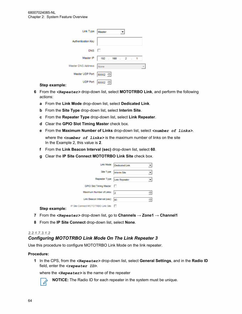
Step example: 6 From the <Repeater> drop-down list, select MOTOTRBO Link, and perform the following
actions:
a From the Link Mode drop-down list, select Dedicated Link.
b From the Site Type drop-down list, select Interim Site.
c From the Repeater Type drop-down list, select Link Repeater.d Clear the GPIO Slot Timing Master check box.
e From the Maximum Number of Links drop-down list, select <number of links>.
where the <number of links> is the maximum number of links on the siteIn the Example 2, this value is 2.
f From the Link Beacon Interval (sec) drop-down list, select 60.
g Clear the IP Site Connect MOTOTRBO Link Site check box.
Step example: 7 From the <Repeater> drop-down list, go to Channels → Zone1 → Channel1
8 From the IP Site Connect drop-down list, select None.
2.2.1.7.3.1.2Configuring MOTOTRBO Link Mode On The Link Repeater 3Use this procedure to configure MOTOTRBO Link Mode on the link repeater.
Procedure:1 In the CPS, from the <Repeater> drop-down list, select General Settings, and in the Radio ID
field, enter the <repeater ID>.
where the <Repeater> is the name of the repeater
NOTICE: The Radio ID for each repeater in the system must be unique.
68007024085-NLChapter 2: System Feature Overview
64
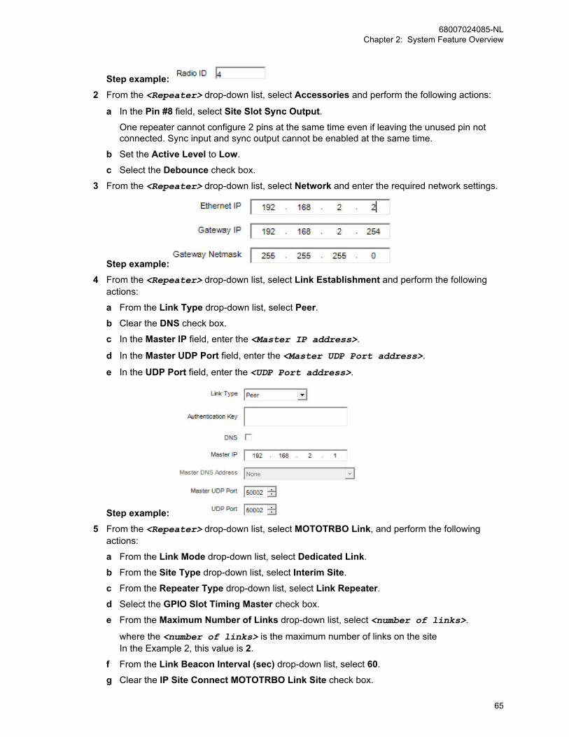
Step example: 2 From the <Repeater> drop-down list, select Accessories and perform the following actions:
a In the Pin #8 field, select Site Slot Sync Output.One repeater cannot configure 2 pins at the same time even if leaving the unused pin notconnected. Sync input and sync output cannot be enabled at the same time.
b Set the Active Level to Low.
c Select the Debounce check box.
3 From the <Repeater> drop-down list, select Network and enter the required network settings.
Step example: 4 From the <Repeater> drop-down list, select Link Establishment and perform the following
actions:
a From the Link Type drop-down list, select Peer.b Clear the DNS check box.
c In the Master IP field, enter the <Master IP address>.
d In the Master UDP Port field, enter the <Master UDP Port address>.
e In the UDP Port field, enter the <UDP Port address>.
Step example: 5 From the <Repeater> drop-down list, select MOTOTRBO Link, and perform the following
actions:
a From the Link Mode drop-down list, select Dedicated Link.
b From the Site Type drop-down list, select Interim Site.
c From the Repeater Type drop-down list, select Link Repeater.d Select the GPIO Slot Timing Master check box.
e From the Maximum Number of Links drop-down list, select <number of links>.
where the <number of links> is the maximum number of links on the siteIn the Example 2, this value is 2.
f From the Link Beacon Interval (sec) drop-down list, select 60.
g Clear the IP Site Connect MOTOTRBO Link Site check box.
68007024085-NLChapter 2: System Feature Overview
65
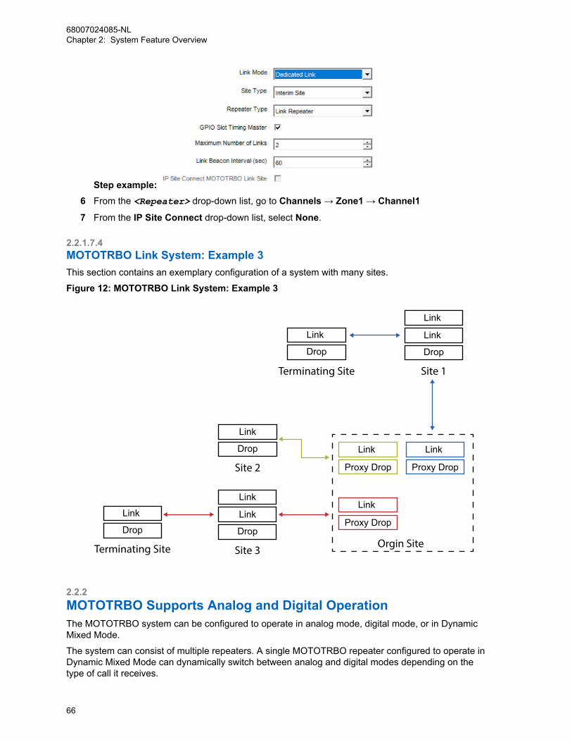
Step example: 6 From the <Repeater> drop-down list, go to Channels → Zone1 → Channel1
7 From the IP Site Connect drop-down list, select None.
2.2.1.7.4MOTOTRBO Link System: Example 3This section contains an exemplary configuration of a system with many sites.
Figure 12: MOTOTRBO Link System: Example 3
Link
Proxy Drop
Link
Proxy Drop
Link
Link
Drop
Link
Proxy Drop
Orgin Site
Site 1
Link
Link
Drop
Site 3
Link
Drop
Site 2
Link
Drop
Terminating Site
Link
Drop
Terminating Site
2.2.2MOTOTRBO Supports Analog and Digital OperationThe MOTOTRBO system can be configured to operate in analog mode, digital mode, or in DynamicMixed Mode.
The system can consist of multiple repeaters. A single MOTOTRBO repeater configured to operate inDynamic Mixed Mode can dynamically switch between analog and digital modes depending on thetype of call it receives.
68007024085-NLChapter 2: System Feature Overview
66
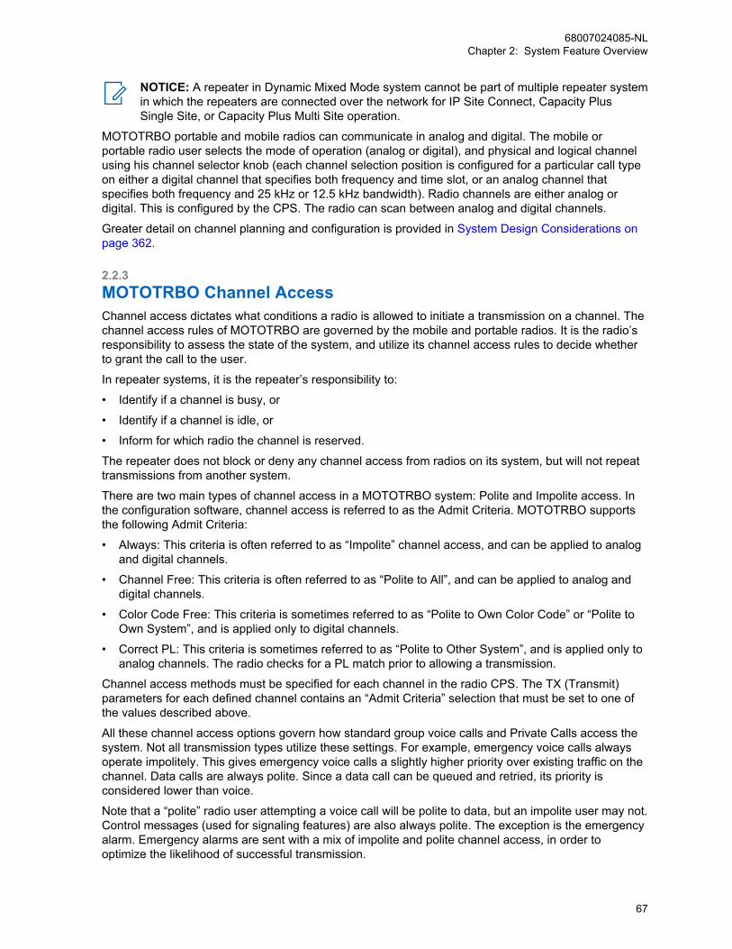
NOTICE: A repeater in Dynamic Mixed Mode system cannot be part of multiple repeater systemin which the repeaters are connected over the network for IP Site Connect, Capacity PlusSingle Site, or Capacity Plus Multi Site operation.
MOTOTRBO portable and mobile radios can communicate in analog and digital. The mobile orportable radio user selects the mode of operation (analog or digital), and physical and logical channelusing his channel selector knob (each channel selection position is configured for a particular call typeon either a digital channel that specifies both frequency and time slot, or an analog channel thatspecifies both frequency and 25 kHz or 12.5 kHz bandwidth). Radio channels are either analog ordigital. This is configured by the CPS. The radio can scan between analog and digital channels.
Greater detail on channel planning and configuration is provided in System Design Considerations onpage 362.
2.2.3MOTOTRBO Channel AccessChannel access dictates what conditions a radio is allowed to initiate a transmission on a channel. Thechannel access rules of MOTOTRBO are governed by the mobile and portable radios. It is the radio’sresponsibility to assess the state of the system, and utilize its channel access rules to decide whetherto grant the call to the user.
In repeater systems, it is the repeater’s responsibility to:
• Identify if a channel is busy, or
• Identify if a channel is idle, or
• Inform for which radio the channel is reserved.
The repeater does not block or deny any channel access from radios on its system, but will not repeattransmissions from another system.
There are two main types of channel access in a MOTOTRBO system: Polite and Impolite access. Inthe configuration software, channel access is referred to as the Admit Criteria. MOTOTRBO supportsthe following Admit Criteria:
• Always: This criteria is often referred to as “Impolite” channel access, and can be applied to analogand digital channels.
• Channel Free: This criteria is often referred to as “Polite to All”, and can be applied to analog anddigital channels.
• Color Code Free: This criteria is sometimes referred to as “Polite to Own Color Code” or “Polite toOwn System”, and is applied only to digital channels.
• Correct PL: This criteria is sometimes referred to as “Polite to Other System”, and is applied only toanalog channels. The radio checks for a PL match prior to allowing a transmission.
Channel access methods must be specified for each channel in the radio CPS. The TX (Transmit)parameters for each defined channel contains an “Admit Criteria” selection that must be set to one ofthe values described above.
All these channel access options govern how standard group voice calls and Private Calls access thesystem. Not all transmission types utilize these settings. For example, emergency voice calls alwaysoperate impolitely. This gives emergency voice calls a slightly higher priority over existing traffic on thechannel. Data calls are always polite. Since a data call can be queued and retried, its priority isconsidered lower than voice.
Note that a “polite” radio user attempting a voice call will be polite to data, but an impolite user may not.Control messages (used for signaling features) are also always polite. The exception is the emergencyalarm. Emergency alarms are sent with a mix of impolite and polite channel access, in order tooptimize the likelihood of successful transmission.
68007024085-NLChapter 2: System Feature Overview
67
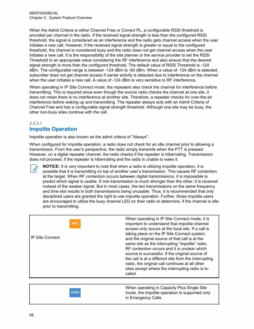
When the Admit Criteria is either Channel Free or Correct PL, a configurable RSSI threshold isprovided per channel in the radio. If the received signal strength is less than the configured RSSIthreshold, the signal is considered as an interference and the radio gets channel access when the userinitiates a new call. However, if the received signal strength is greater or equal to the configuredthreshold, the channel is considered busy and the radio does not get channel access when the userinitiates a new call. It is the responsibility of the site planner or the service provider to set the RSSIThreshold to an appropriate value considering the RF interference and also ensure that the desiredsignal strength is more than the configured threshold. The default value of RSSI Threshold is -124dBm. The configurable range is between -124 dBm to -80 dBm. When a value of -124 dBm is selected,subscriber does not get channel access if carrier activity is detected due to interference on the channelwhen the user initiates a new call. A value of -124 dBm is very sensitive to RF interference.
When operating in IP Site Connect mode, the repeaters also check the channel for interference beforetransmitting. This is required since even though the source radio checks the channel at one site, itdoes not mean there is no interference at another site. Therefore, a repeater checks for over-the-airinterference before waking up and transmitting. The repeater always acts with an Admit Criteria ofChannel Free and has a configurable signal strength threshold. Although one site may be busy, theother non-busy sites continue with the call.
2.2.3.1Impolite OperationImpolite operation is also known as the admit criteria of "Always".
When configured for impolite operation, a radio does not check for an idle channel prior to allowing atransmission. From the user’s perspective, the radio simply transmits when the PTT is pressed.However, on a digital repeater channel, the radio checks if the repeater is hibernating. Transmissiondoes not proceed, if the repeater is hibernating and the radio is unable to wake it.
NOTICE: It is very important to note that when a radio is utilizing impolite operation, it ispossible that it is transmitting on top of another user’s transmission. This causes RF contentionat the target. When RF contention occurs between digital transmissions, it is impossible topredict which signal is usable. If one transmission is much stronger than the other, it is receivedinstead of the weaker signal. But in most cases, the two transmissions on the same frequencyand time slot results in both transmissions being unusable. Thus, it is recommended that onlydisciplined users are granted the right to use impolite operation. Further, those impolite usersare encouraged to utilize the busy channel LED on their radio to determine, if the channel is idleprior to transmitting.
IPSC
IP Site Connect
When operating in IP Site Connect mode, it isimportant to understand that impolite channelaccess only occurs at the local site. If a call istaking place on the IP Site Connect system,and the original source of that call is at thesame site as the interrupting “impolite” radio,RF contention occurs and it is unclear whichsource is successful. If the original source ofthe call is at a different site from the interruptingradio, the original call continues at all othersites except where the interrupting radio is lo-cated.
CPSSWhen operating in Capacity Plus Single Sitemode, the impolite operation is supported onlyin Emergency Calls.
68007024085-NLChapter 2: System Feature Overview
68

Capacity Plus Single Site
CPMS
Capacity Plus Multi Site
When operating in Capacity Plus Multi Sitemode, the impolite operation is supported onlyin Emergency Calls.
2.2.3.2Polite to All OperationPolite to all operation is also known as the admit critearia of "Channel Free".
When configured for Polite to All operation, the radio checks if channels are idle or busy, prior toallowing a transmission. The radio is polite to all analog or digital transmissions, another system’stransmission, or other traffic on your system. This option is often used, when there are neighboringcommunications systems, to prevent radio users from disrupting other transmissions. However, whenthis option is used, any strong signal on the channel blocks other users from transmitting.
2.2.3.3Polite to Own Digital System OperationThis criteria applies only to digital channels, and also known as the admit criteria of "Color Code Free".
When configured for Polite to Own Digital System operation, the radio checks for an idle or busychannel, prior to allowing a transmission. This operation is similar to the Polite to All operation withexception that the radio is not polite to analog systems or other system transmissions. It is only politeto other traffic in its own system. This option is often used when there are no neighboringcommunications systems, or when there is no concern about interfering with radios in neighboringcommunication systems.
2.2.3.4Polite to Other Analog System OperationThis criteria applies only to analog channels, and also known as the admit criteria of "Correct PL".
When configured for Polite to Other Analog System operation, the radio checks for an Idle or busychannel, prior to allowing a transmission. This operation is similar to the Polite to All operation withexception that the radio is not polite to analog systems with the same PL. It is polite to other systemtransmissions. The radio checks for a PL match prior to allowing a transmission.
2.2.3.5Polite, Impolite or Voice Interrupt In A CallThis is also known as "In Call Criteria", and applies only when the radio is participating in an active call.
The radio can optionally allow others that are part of the call to transmit impolitely (Always), toautomatically clear the channel using the Voice Interrupt feature prior to beginning the voicetransmission (Voice Interrupt), or to follow the previously configured channel access (Follow AdmitCriteria). If configured for an In Call Criteria of Always, the user receives a Talk Permit Tone when theypress the PTT while receiving a transmission for them. In other words, a radio has the ability totransmit over another user while listening to their transmission. However, when this happens, the otherparty does not stop transmitting and therefore RF contention can occur which may corrupt bothtransmissions. The In Call Criteria of Voice Interrupt is an alternative to the In Call Criteria of Impolite.
The Voice Interrupt option has advantages including the ability to avoid the previously described RFcontention issue by clearing the channel prior to beginning a transmission, which yields a higher
68007024085-NLChapter 2: System Feature Overview
69
probability of successfully communicating with the intended target radio(s), as compared with the RFcontention encountered with impolite transmissions. However, Voice Interrupt has disadvantagesincluding a longer channel access time when an interruption is necessary, due to the signaling havingto complete the interruption and handoff.
If configured for an In Call Criteria of Voice Interrupt, the radio user receives a Talk Permit Tone whenPTT is pressed while receiving an interruptible voice transmission and the channel is successfullycleared down. In other words, a radio user has the ability to clear the channel of another user’sinterruptible voice transmission before beginning their own voice transmission when both radios areparticipating in the same voice call (for example, both are members of the same group during a GroupCall, or both are participating in the same Private Call). Depending on the radio’s CPS configuration,the radio user whose transmission was interrupted may or may not receive a Talk Prohibit Tone untilthe user releases the PTT. If the channel is not successfully cleared down, the user typically receives aChannel Busy Tone until the PTT is released.
NOTICE: For the Voice Interrupt feature to operate consistently, all radios using the channelshould be provisioned with the ability to be interrupted. However, not all need to be provisionedwith the Voice Interrupt capability.
If some radios are provisioned without the ability to be interrupted (for example, normally desirable fora supervisor’s radio), then those transmissions cannot be interrupted and the radio user receives aChannel Busy tone if the Voice Interrupt feature is attempted while receiving an uninterruptible voicetransmission.
If configured for Follow Admit Criteria and the previously configured channel access (Admit Criteria) isset to either Channel Free or Color Code Free, the user receives a Transmit Denial Tone when theypress the PTT while receiving a transmission for them. Users must wait until the user stops transmittingand call hangtime starts before they are granted a transmission. Utilizing the Channel Free Tone helpstrain users from transmitting too early. Although a setting of Always may be useful for speeding upconversations for well disciplined users, it may cause undisciplined users to “step over” other users.Therefore, it is recommended that most users are provisioned with an In Call Criteria of Follow AdmitCriteria.
2.2.3.6Repeater Wake-up ProvisioningWhen there is no inbound traffic for a specified duration (Subscriber Inactivity Timer), the repeaterstops transmitting and enters an inactive state. In this inactive state, the repeater is not transmitting,but instead it is listening for transmissions. When the user or radio needs to transmit through therepeater, the radio sends a wake-up message to the repeater.
Upon receiving the wake-up message, the repeater activates and begins transmitting idle messages.The radio then synchronizes with the repeater before it begins its transmission.
The repeater wake-up sequence is configurable within the radio. The number of wake-up attempts (“TXWakeup Message Limit“) and the time between the attempts (“TX Sync Wakeup Time Out Timer”) maybe altered if required to operate with other vendor’s systems. It is recommended that these valuesremain at default while operating on MOTOTRBO systems.
2.3Digital Voice FeaturesIt is not recommended to delete a contact from the digital contact list because each contact can be tiedto a cross-functional fleet of systems and devices communicating together. This may cause the radio towork incorrectly.
68007024085-NLChapter 2: System Feature Overview
70

2.3.1Group CallsThe digital group is a way of enabling groups to share a channel without distracting and disrupting oneanother. Because two-way radios are well suited for “one-to-many” types of calls, the Group Call is themost common call in a MOTOTRBO system. Hence, the majority of conversations takes place within agroup.
CPSM
Capacity Plus Single Site and Capacity PlusMulti Site
The Capacity Plus Single Site and CapacityPlus Multi Site systems allow a radio user toleave a Group Call and start another voice oremergency or control call (for example, CallAlert, Radio Check, Radio Inhibit/Uninhibit, andothers) while the radio is busy listening in to aGroup Call. The radio moves to the currentRest Channel and starts a new call on the RestChannel. If a user starts a non-Emergency Callwhen all channels are busy, then the call fails,and the radio stays on the traffic channel.
Individual radios that need to communicate with one another are grouped together, and configured tobe members of a group. A transmitting radio can be heard by all the radios within the same group, andon the same logical channel (frequency and time slot.) Two radios cannot hear each other, if they areon the same logical channel (frequency and time slot) but on different groups. Two radios on differentlogical channels cannot hear each other, even if they are placed in the same group.
In MOTOTRBO systems, capabilities for Group Calls are configured with the portable and mobile radioCPS. The repeater does not require any specific configuration for groups. Radios can be configured toenable the user to select among multiple groups using the radio channel selector knob or buttons, orusing the radio menu contacts list. Which group a radio user hears on a given channel depends on aconfigurable parameter called the RX Group List. A call preceding tone can be provisioned to alert thetarget user of the incoming Group Call. This can be enabled or disabled per Group. An introduction toconfiguring Group Calls and RX Group Lists is provided in System Design Considerations on page 362of this document.
Groups are defined according to the organizational structure of the end user. When planning forgroups, customers should think about:
• which members of the functional workgroups in their organization that need to talk with one another,
• how those workgroups interact with members of other workgroups, and
• how users will collectively share the channel resources.
Greater detail on the fleetmapping process is provided in System Design Considerations on page 362of this document.
2.3.2Private CallsMOTOTRBO provides the capability for a user to place a Private Call directly to another radio, even ifthey are not in the same group. However, for this action to take place both radios need to be on thesame channel and time slot.
This feature allows a radio user to carry a one-to-one conversation that is only heard by the two partiesinvolved. For example, an employee may use a Private Call to privately alert a specific manager abouta security incident, rather than placing a Group Call that would be heard by the whole group. ThoughPrivate Calls utilize the signaling capabilities in MOTOTRBO systems to govern which radios are
68007024085-NLChapter 2: System Feature Overview
71

allowed to participate, the use of a Private Call does not necessarily imply the use of encryption orscrambling.
Private Calls can be configured as confirmed or unconfirmed on a per channel basis. For confirmedPrivate Calls, the calling radio transmits a short control signal message to the target radio. Thissignaling verifies the presence of the target radio before being allowed to start the call. The receivinguser does not need to manually “answer” this signal, but rather the receiving radio automaticallyresponds to the setup request. Once the receiving radio replies to the setup request, the initiating radiosounds a Talk Permit tone and starts the call. The receiving radio sounds a Private Call indication tothe user, prior to relaying the received voice. Once a Private Call is set up, subsequent transmissionsdo not require the call setup messaging. For unconfirmed Private Calls, the calling radio does nottransmit any control signaling before being allowed to start the call. Although there is no confirmationthe radio is present on the system, an audible indication from the target user may act as confirmation.For example, “Joe are you there?”, “Yes, go ahead.”.
It is important to understand the advantages and disadvantages of confirmed and unconfirmedoperation as it relates to performance. In general, confirming radio presence increases the setup time(voice access time) of a Private Call since the user must wait for the control signaling to go through theradio network before acquiring a talk permit tone. Although this may take more time, it does guaranteethat the target radio is present prior to providing the talk permit tone. When operating on an IP SiteConnect system that is connected through the public Internet, this time may be longer than whenoperating on a single site since the control messaging may be traversing through the Internet. If thetarget radio is scanning or roaming, the setup time of a confirmed Private Call may increase due to thefact that the first control message may not successfully reach the scanning or roaming radio. Thesecond attempt, which contains a preamble, has a higher likelihood of reaching the scanning orroaming radio.
Since unconfirmed Private Calls do not transmit any control signaling, the additional setup time is notrequired and therefore the voice access time is shorter. Because setup messaging is not used prior tostarting the call, it is possible that scanning or roaming radios may arrive late to a call. This couldcause the user to miss the first few words of the transmission (no more than what is lost while scanningfor a Group Call). In addition, the user must utilize an audible acknowledgment to validate presencewhen configured with unconfirmed Private Calls since no control messaging is used to confirm radiopresence.
In MOTOTRBO systems, capabilities for Private Calls are configured with the portable and mobileradio CPS. The repeater does not require any specific configurations for Private Calls. Radios can beconfigured to allow the user to select the recipient of a Private Call using the radio menu contacts list.Private Calls can also be mapped to a channel selection or a programmable button. Users can alsomanually dial the destination radio ID with the radio keypad. This means a radio can make a PrivateCall to any other radio that is on the channel, regardless of whether the radio has created a CPSPrivate Call entry for the target radio. A call receive tone, or call preceding tone, can be configured toalert the target user of the incoming Private Call. This can be enabled or disabled per individual radio.Greater detail on the fleetmapping process that governs who is allowed to make Private Calls and towhom, as well as an introduction to the CPS configuration section for Private Calls, is provided in System Design Considerations on page 362.
2.3.3All CallAll Call is a one way voice call between a privileged operator and all users on a logical channel. Thetransmitting radio utilizes a special All Call group that every radio on the same system and logicalchannel (regardless of group) receives.
An All Call is occurring on Channel 1, and Channel 2 is the Rest Channel. The radio initiating anEmergency Call leaves Channel 1, moves to Channel 2, and starts the Emergency Call. The start ofthe Emergency Call is announced on Channel 1. This triggers the radios that want to participate in theEmergency Call to leave Channel 1 and move to Channel 2.
68007024085-NLChapter 2: System Feature Overview
72
As an All Call is considered a one-way transmission, users cannot talk back to an All Call. If the usertransmits after receiving an All Call, they transmit using their currently selected group. An All Callfollows the Admit Criteria of the selected channel. More information on the Admit Criteria is provided in Channel Access Configuration on page 495.
All Calls do not communicate across different time slots or channels within the system. The ability toinitiate an All Call is only programmed into radios that are used in supervisory roles. All other radiosmonitor All Call transmissions by default. This feature is very useful when a supervisor needs tocommunicate with all the users on a logical channel, rather than just a particular group or individual.
In MOTOTRBO systems, capabilities for All Calls are configured with the portable and mobile CPS.The repeater does not require any specific configurations for All Calls. Radios can be configured toenable the user to select an All Call through the radio menu contacts list. All Calls can also be mappedto a channel selection or a programmable button. A call receive tone, or call preceding tone, can beconfigured to alert the target user of the incoming All Call. Greater detail on the fleetmapping processgoverns who is allowed to make All Calls, as well as an introduction to CPS configuration section for AllCalls, is provided in System Design Considerations on page 362 of this document.
2.3.4DTMF Hot KeypadWhen this feature is enabled, the numeric keypad allows live dialing during dispatch operation. Duringa voice call, the user can transmit the following characters using a MOTOTRBO radio with keypad: 0 12 3 4 5 6 7 8 9 * #. These characters are encoded as dual tone multi frequency (DTMF). These DTMFtones enable the user to communicate with a device connected to a control station using the numerickeypad.
This feature is supported in single site conventional, IP Site Connect, Capacity Plus Single Site andCapacity Plus Multi Site system configurations. This feature is also supported by radios in analogmode.
WARNING: A phone patch call needs other call processing requirements in addition to DTMFtones, simply connecting an APP box to the control station does not enable the phone patchcall capability. If phone patch calls need to be supported, please use the configurations definedin the DTP feature. See Digital Telephone Patch (DTP) on page 423.
2.4Transmit InterruptThe Transmit Interrupt feature is a suite of features proprietary to Motorola Solutions. This featuregenerally allows a radio to shut down an ongoing clear Basic Privacy or Enhanced Privacy interruptiblevoice transmission, and potentially initiate a new transmission. Transmit Interrupt is independent of calltype, therefore it applies to Group Calls, Private Calls, Emergency Calls and All Calls. This feature alsoapplies to Private Calls that are initiated through remote monitor command, and Group Calls that areinitiated via emergency remote monitor.
NOTICE: For software version R01.06.00, this feature is supported on digital direct channelsand digital repeater channels.
IPSC
IP Site Connect
For software version R01.06.00, this feature issupported on IP Site Connect local channels.For software version R01.07.00 or later, thisfeature is supported on IP Site Connect widearea channels. For IP Site Connect wide areachannels, a repeater can use this feature tostop a voice transmission where a radio contin-ues to transmit even after failure of arbitration.
68007024085-NLChapter 2: System Feature Overview
73
This also provides feedback to the transmittingradio that the transmission is not repeated over-the-air and allows the radio to participate in acall started by another radio.
CPSM
Capacity Plus Single Site and Capacity PlusMulti Site
For software version R01.07.00 or later, thisfeature is supported on Capacity Plus SingleSite system configurations and Capacity PlusMulti Site system configurations.
To support different use cases, Transmit Interrupt has four unique variations:
Table 3: Transmit Interrupt Features
Feature Description
Voice Interrupt This feature allows a radio that is unmuted toan interruptible voice call, to stop the ongoingvoice transmission and initiate its own voicetransmission to the same call membership.Voice Interrupt is typically used during a pro-longed voice transmission when “late-breaking”or urgent information becomes available, and itis necessary to disseminate the information tothe group as quickly as possible.
Emergency Voice Interrupt This feature allows a radio to stop any ongoinginterruptible voice transmission, and initiate itsown emergency transmission. EmergencyVoice Interrupt gives a radio an improved ac-cess to the radio channel, in an emergencycondition.
Remote Voice Dekey This feature allows a radio to stop an ongoinginterruptible voice transmission. It is typicallyused by a supervisor to remotely dekey a radiothat is inadvertently transmitting (for example,the PTT is inadvertently pressed for an extend-ed period of time) and occupying the radiochannel.
Data Over Voice Interrupt This feature allows a third-party data applicationon an option board or attached PC to controlthe radio in order to stop any ongoing interrupti-ble voice transmission and initiate its own datamessage transmission. The application can al-so specify in the data message, an option todiscard itself, if an ongoing voice transmissionis not interruptible. This feature is useful in sit-uations where data traffic is more importantthan voice traffic. Data Over Voice Interrupt isnot used by any data applications native to theradio (for example, Text Message, Location,
68007024085-NLChapter 2: System Feature Overview
74
Feature Description
and Telemetry do not use Data Over Voice In-terrupt).
While receiving a Direct Mode/Dual Capacity Direct Mode (DCDM) on page 295 transmission, a radiomay use the Transmit Interrupt feature to remotely dekey the transmitting radio and begin its ownDirect Mode or Repeater Mode on page 312 transmission. Similarly, while receiving a Repeater Modetransmission, a radio may use the Transmit Interrupt feature to remotely dekey the transmitting radio,and begin its own Repeater Mode transmission. However, the radio may not use the Transmit Interruptfeature to remotely dekey the transmitting radio’s Repeater Mode transmission and begin its ownDirect Mode transmission. This scenario is not supported because Transmit Interrupt dekeys only theradio’s transmission within a channel (timeslot), but does not dekey the repeater which remains keyedon the Direct Mode carrier frequency, and supports two channels (timeslots). The repeater is notdekeyed because this may interfere undesirably with a call in the other channel (timeslot) supported bythat repeater.
Provisioning of the Transmit Interrupt feature in general, is separated into two basic categories:
• Radios that have the ability for voice transmissions to be interrupted.
• Radios that have the ability to initiate transmit interrupt commands.
NOTICE: The radios may be provisioned with none, one, or both of these capabilities.
There are a few important items to consider before provisioning of the Transmit Interrupt feature:
• The Transmit Interrupt feature is supported in digital direct mode and single site repeater mode
• Because the Transmit Interrupt features are proprietary to Motorola Solutions and use someproprietary signaling (that is, manufacturer-specific extensions that comply to the ETSI DMR Tier 2standards), non-Motorola Solutions radios may not be able to unmute to an interruptible voicetransmission and Motorola Solutions radios may not be able to interrupt a non-Motorola Solutionsradio’s voice transmission. Hence, it is highly recommended to assign radios to separate groupsand/or channels. This classifies radios provisioned with Transmit Interrupt capability from the radiosthat are not provisioned with the capability.
• In Direct Mode, Transmit Interrupt can typically clear an interruptible voice transmission from thechannel in less than two seconds. In Single Site Repeater Mode, Transmit Interrupt can typicallyclear an interruptible voice transmission from the channel in less than three seconds. The TransmitInterrupt feature provides one automatic retry in the event that the first interrupt attempt fails due tocorrupt signaling (for example, RF coverage degradation, signaling collisions with other radios, andothers). The retry essentially doubles the times mentioned. If the radio user still needs to interruptafter the failed retry, the user needs to initiate another service request.
• VOX is not compatible with the Transmit Interrupt feature. Therefore, VOX is prevented fromoperating when any of the Transmit Interrupt features are enabled.
IPSC
IP Site Connect
The Transmit Interrupt feature is supported onboth local and wide area slots of the IP SiteConnect mode
CPSMThe Transmit Interrupt feature is supported onboth local and wide area slots of the CapacityPlus Single Site and Capacity Plus Multi Sitesystem configurations.
68007024085-NLChapter 2: System Feature Overview
75
Capacity Plus Single Site and Capacity PlusMulti Site
In Capacity Plus Single Site and Capacity PlusMulti Site configurations, an All Call can only bestopped by Emergency Voice Interrupt. VoiceInterrupt, Remote Voice Dekey, or Data OverVoice Interrupt features are not supported.
NOTICE: For the Transmit Interrupt feature to operate consistently, all radios using the channelshould be provisioned with the ability to be interrupted. If some radios are provisioned withoutthe ability to be interrupted (for example, normally desirable for a supervisor’s radio), then thoseradios’ transmissions cannot be interrupted.
2.4.1Transmit Interrupt Capable System UpgradeThere are several considerations when upgrading a deployed system that presently do not support theTransmit Interrupt feature, to become Transmit Interrupt capable.
NOTICE: For systems that use a DR 3000 repeater, the repeater software version must beupgraded to R01.06.00, or later.
For systems that do not use privacy exclusively (Voice and Data Privacy on page 170), radiotransmissions with privacy disabled and interruptible voice enabled cannot be received by radios usingsoftware versions prior to R01.06.00.
For systems that use privacy exclusively, there are no major concerns receiving radio transmissionswith both privacy and interruptible voice enabled; provided the older release supports the type ofprivacy being used by the radio provisioned with software version R01.06.00 or later.
To minimize service disruption during the upgrade period, systems that do not use privacy exclusivelymay be upgraded using the following approach:
• Provision new radios with software version R01.06.00 or later. Configure two channels; one channelwith Transmit Interrupt features enabled, and the other channel with all Transmit Interrupt featuresdisabled. During the upgrade, the channel with all Transmit Interrupt features disabled is used.
• Individually upgrade previously deployed radios to software version R01.06.00 or later, andprovision with the two channels described above. The channel with all Transmit Interrupt featuresdisabled is then used during the upgrade.
• For systems that use a repeater, the repeater may be upgraded to be Transmit Interrupt capable atany time. Finally, once all radios have been upgraded to the compatible software version, thechannel with the Transmit Interrupt features enabled is used by all radios on the system.
2.5Digital Signaling FeaturesDigital calls utilize digital vocoding and error correction coding processes, and a digital call occupies asingle logical channel (frequency and TDMA time slot).
Within a given time slot, the digital call is organized into voice information and signaling information.Included in the signaling information is an identifier used to describe the type of call that is transmittedwithin the time slot (for example, Group Call, All Call, or Private Call). Signaling information alsoincludes identification information and/or control information, which is used to notify listeners on a voicecall of system events and status (for example, the ID of the transmitting radio and the group ID).Because this information is repeated periodically during the course of the call, this embedded signalingallows users to join a voice transmission that is already in progress and still participate in the call. Thisis referred to as Late Entry, and is an advantage over analog signaling schemes.
68007024085-NLChapter 2: System Feature Overview
76

2.5.1PTT ID and AliasingThe PTT ID and Aliasing feature allows the target radio to identify the originator of a call.
If programmed with the radio Customer Programming Software (CPS), a user friendly alphanumericname or “alias” can also be displayed. These user friendly aliases are also used when initiating voicecalls and digital signaling features. The alias information in the transmitting radio should correspondwith the alias information in the receiving radio. The transmitting radio ID is sent over-the-air and, ifthere is an alias for that ID in the receiving radio, the receiving radio displays the alias. If no alias isconfigured at the receiving radio for that ID, then only the transmitting radio's ID is shown.
2.5.2Radio Enable/DisableA radio can be enabled or disabled in either of the following ways:
• By another radio, typically in a supervisory role, that sends Inhibit/Uninhibit command using over-the-air signaling. This radio-to-radio enable/disable can be done in the following three methods:
- Device Authentication: Both the target radio (the one to be disabled) and the supervisory radio(the one to disable the target radio), are configured with some keys from the enhanced privacyor AES. Once the target radio receives the inhibit/uninhibit command from the supervisory radio,it sends back a message to challenge the supervisory radio and the supervisory radio responds.If both radios share the same key, the supervisory radio is able to respond correctly then thetarget radio can be enabled/disabled; otherwise, the target radio can’t be enabled/disabled.
- User Authentication: This is similar to the Device Authentication. The only difference is that thesupervisory user must manually key in a passphrase, when challenged by the target radio, whileit is not needed in Device Authentication scenario.
- Without Authentication: Once the target radio receives the inhibit/uninhibit command from thesupervisory radio, it enables/disables itself immediately without challenging the supervisory radioor radio user.
• By a third-party application connected to the system, that sends Inhibit/Uninhibit command usingthe third-party application.
NOTICE: If the target radio is enabled/disabled through either of the methods listed, it canbe disabled/enabled through the same or a different method.
2.5.2.1Over-the-Air Signaling Enable/DisableThe Radio Disable feature can be used to stop any inappropriate use of a radio, or to prevent a stolenradio from functioning. In MOTOTRBO systems, Radio Disable is configured in the portable and mobileradios with the CPS.
To allow a radio to use this function, it must be enabled in the CPS Menu settings. To permit (orprevent) a radio from receiving and responding to this command, go to the Signaling Systemssettings in the CPS.
When disabled, the radio's display blanks and the radio is no longer able to make or receive calls. Theradio can still be turned on and off; this indicates that the radio has not failed, but is disabled. Oncedisabled, a radio can also be enabled through the CPS. All radios are configured to accept Inhibitcommands by default, but this can be disabled through the CPS.
For over-the-air radio enable signaling to be successful, the target radio must be turned on and bewithin coverage of the site it was disabled at. This is important since a disabled radio locks onto thesite or channel on which it was disabled, even after a power cycle. To receive an enable commandover-the-air, the radio also has to be within coverage of the site where the disabling occurred. This may
68007024085-NLChapter 2: System Feature Overview
77

also be accomplished by communicating with the radio on the talkaround frequency of the site in whichit was disabled.
2.5.3Remote MonitorThe Remote Monitor feature allows a remote user to activate a target radio’s microphone andtransmitter for a period of time. A call is silently set up on the target radio, and its PTT is controlledremotely without any indications given to the end user. The duration that the target radio transmits afterreceiving a Remote Monitor command is set in the target radio through the CPS. When receiving theRemote Monitor command, the target radio initiates a Private Call back to the originator of the RemoteMonitor command.
This feature is used to ascertain the situation of a target radio which is powered-on, but isunresponsive. This is beneficial in a number of situations including:
• Theft
• Incapacity of the radio user
• Allowing the initiator of an Emergency Call to communicate hands-free in an emergency situation
In MOTOTRBO systems, Remote Monitor is configured in portable and mobile radio through the CPS.To allow a radio to use this function, it must be enabled in the CPS Menu settings. To permit (orprevent) a radio from receiving and responding to this command, go to the Signaling Systemssettings in the CPS. When a radio is configured to decode the remote monitor command, the durationthat the target radio transmits after receiving a Remote Monitor command is also set in the CPSSignaling Systems settings of the target radio.
The Remote Monitor feature may be activated on a disabled radio. Remote Monitor could also beprogrammed to be activated on radios that are in emergency mode only.
When a radio operates in conventional single site/IPSC system configuration, talkaround mode, ordirect mode/dual capacity direct mode, an optional authentication procedure can be added into theremote monitor/emergency remote monitor operations. After the initiating radio sends out the remotemonitor request to the target radio, instead of keying up and responding immediately, the target radiosends a challenge to the initiating radio to ensure the initiating device/user is legitimate. Only afterreception of a valid response from the initiating radio, the target radio keys up for the remote monitorprocedure. If there is no valid response from the initiating radio, the target radio does not key up, andthe remote monitor session ends.
In order to enable this optional authentication procedure, both the target radio and initiating radio musthave enhanced privacy or symmetric keys enabled. This authentication does not depend on theseprivacy features, but it uses the privacy key from these privacy methods.
There are two types of authentication which are the device authentication and user authentication. Theauthentication type is selected and configured in the target radio through Radio Management (RM)-CPS.
Device AuthenticationDevice authentication is used to authenticate the initiating radio only, so the authentication istransparent to the initiating radio user and the radio user does not need to take any action.
The target radio is configured to use device authentication. No additional configuration is needed forthe initiating radio.
In order for the initiating radio to be a “legitimate” one, in its privacy key set (enhanced privacy orsymmetric keys), it must have the privacy key that the target radio uses to generate the challenge. Thetarget radio always uses the first privacy key in its privacy key set that is associated with its currentpersonality. If the current personality is not associated with any privacy method, the radio uses the first
68007024085-NLChapter 2: System Feature Overview
78
privacy key from its radio wide key set pools by the following order: symmetric keys, then enhancedprivacy key set.
When the initiating radio user initiates a remote monitor, the target radio sends a message to challengethe initiating radio. Upon receiving the challenge, the initiating radio uses the privacy key in its privacykey set to respond to the challenge. After receiving the response to the challenge, the target radioverifies that the response is correct. If the response is correct, the target radio transmits, and if theresponse is incorrect, the target radio does not transmit.
User AuthenticationUser authentication is used to authenticate both the initiating radio and the radio user.
The configuration is the same as the device authentication, except that the target radio must beconfigured for user authentication and provisioned with an additional passphrase.
For the initiating radio and radio user to be “legitimate”, the initiating radio must have the privacy key,as in the device authentication scenario. Also, the initiating radio user must know the passphrase thatis configured in the target radio.
The authentication procedure is similar to that in the device authentication except that: whenchallenged by the target radio, the initiating radio user must enter the passphrase manually from theradio keypad. If the passphrase entered matches the passphrase provisioned in the target radio, theauthentication procedure succeeds, and the remote monitor process continues. Otherwise, the remotemonitor process stops, and the target radio does not key up and respond.
2.5.4Radio CheckThe Radio Check feature checks if a radio is active in a system without notifying the user of the targetradio. Besides the Busy LED, there is no other audible or visual indication on the checked radio. Thereceiving radio automatically and silently responds with an acknowledgment to the initiating radio.
This feature is used to discreetly determine if a target radio is available. For example, if a radio user isnon-responsive, Radio Check could be used to determine if the target radio is switched on andmonitoring the channel. If the target radio responds with an acknowledgment, the initiator could thentake additional action such as using the Remote Monitor command to activate the target radio’s PTT.
In MOTOTRBO systems, Radio Check is configured in portable and mobile radios through CPS. Toallow a radio to use this function, it must be enabled in the CPS Menu settings. All MOTOTRBO radiosreceive and respond to a Radio Check. This feature cannot be turned off in the CPS.
2.5.5Call AlertThe Call Alert feature allows a radio user to essentially page another user. When a radio receives aCall Alert, a persistent audible and visual alert is presented to the user. The initiator of the Call Alert isalso displayed. If a user is away from his radio at the time of the reception, the alert remains until theuser clears the Call Alert screen. If the user presses the PTT while the Call Alert screen is active, theystarts a Private Call to the originator of the Call Alert.
For in-vehicle applications, this is often used in conjunction with the Horn and Lights option. When auser is away from his vehicle, a Call Alert can initiate the vehicle’s horn and lights to sound and flash,which notifies the user to return to the vehicle and call the originator.
In MOTOTRBO systems, Call Alert is configured in portable and mobile radio through CPS. To allow aradio to use this function, it must be enabled in the CPS Menu settings. All MOTOTRBO radios receiveand respond to a Call Alert. This feature cannot be disabled using the CPS).
68007024085-NLChapter 2: System Feature Overview
79
2.5.6Remote Voice DekeyThe Remote Voice Dekey feature allows a radio user to stop any interruptible voice transmission,except for All Calls. This ability to remotely stop an interruptible voice transmission is provisioned intothe radio through the CPS and accessed using a programmable button.
NOTICE: For the Remote Voice Dekey feature to operate consistently, all radios using thechannel should be provisioned with the ability to be interrupted. However, not all must beprovisioned with the Remote Voice Dekey capability.
If some radios are provisioned without the ability to be interrupted (for example, normally desirable fora supervisor’s radio), then those radios’ transmissions cannot be interrupted and the radio userreceives a Remote Voice Dekey Failure Tone if Remote Voice Dekey is attempted while receiving anuninterruptible transmission. The radios that are provisioned without the ability to be interrupted (forexample, a supervisor’s radio) may still be provisioned with the Remote Voice Dekey feature, whichgives those radios the ability to interrupt another radio’s interruptible voice transmission.
For this feature, the initiating radio is not required to be a member of the voice call that is beinginterrupted. Therefore, it is possible to interrupt a voice call, and then initiate a new call to a differentgroup or individual. Once the original voice transmission is terminated via the Remote Voice Dekeyfeature, the interrupting radio user can initiate a new call through any of the available call initiationmethods.
When the programmable button is pressed and an interruptible voice transmission is on the channel,the radio attempts to stop the interruptible voice transmission. If the radio succeeds at interrupting thevoice transmission, the radio user receives a Remote Voice Dekey Success Tone when the channel issuccessfully cleared down. If the radio fails to interrupt the voice transmission, then the radio usertypically receives a Remote Voice Dekey Failure Tone. Depending on the radio’s CPS configuration,the radio user whose transmission was interrupted may or may not receive a Talk Prohibit Tone untilthe PTT is released.
2.6Digital EmergencyMOTOTRBO offers a variety of emergency handling strategies that fits the customer’s organizationalneeds. In its basic form, MOTOTRBO provides the ability for a radio user in distress to send aconfirmed emergency alarm message, and emergency voice to a user on a supervisory radio.
The emergency alarm message contains the individual radio ID of the initiator. Upon reception of anemergency alarm, the supervisor receives audible and visual indications of the emergency and theinitiating radio ID is displayed. Depending on configuration, emergency voice may follow between theinitiator and the supervisor. Once the supervisor handles the emergency situation (solves the problem),he clears the emergency on the supervisor radio. Once the initiator clears his emergency on theinitiator radio, the emergency is considered over.
NOTICE: A radio does not roam while reverted to a channel due to an emergency or whenActive Site Search is disabled. See Site Roaming on page 151 for details on the interactionsbetween emergency and roaming.
Each mobile radio can program the Emergency Alarm to any of the programmable buttons, whereasfor the portable radio the Emergency Alarm can only be programmed to the orange button. TheEmergency Alarm can also be triggered externally through a footswitch for a mobile application or anyother applicable accessory. Pressing the emergency button causes the radio to enter emergencymode, and begin its emergency process.
When a user presses the Emergency button, the radio gives audible and visual indications to show thatit has entered emergency mode. There is a CPS configurable option available, referred to as SilentEmergency, which suppresses all indications of the emergency status on the user’s radio. This featureis valuable in situations where an indication of an emergency state is not desirable. Once the user
68007024085-NLChapter 2: System Feature Overview
80

breaks radio silence by pressing the PTT and speaking, the Silent Emergency ends, and audible andvisual indications return.
When the user’s radio is in the emergency mode, various other features are blocked that may distracthim from his communication with the supervisor. For example, the user is not able to initiate otherfeatures such as Scan, Private Call, or other command and control functions.
Once the emergency is complete (for example, turn off and turn on the radio, or long/short press of theemergency button depending on the radio configuration) these abilities return.
The emergency sequence is generally made up of two major parts:
• the signaling and
• the following voice call.
The emergency alarm is sent first, and depending on configuration is commonly followed up by anEmergency Call.
An emergency alarm is not a data service, but rather a confirmed command and control signaling thatis sent to a group. More than one radio can be configured on the system to monitor that group, and bedesignated to acknowledge emergency alarms for that group. These radios are consideredacknowledging supervisors. There is no user level acknowledgment. The supervisor radioautomatically acknowledges the emergency, and provides an alert to the supervisor radio user. Thereare other radios that are designated to only monitor emergency alarms, but are not permitted toacknowledge them; these users are commonly referred to as non-acknowledging supervisors. Thus,sending the emergency alarm to a group allows for multiple supervisors to receive the emergencyalarm indication. It is important that only one acknowledging supervisor should be configured per groupand slot; otherwise there may be contention between the acknowledgements.
The supervisors retain a list of received emergency alarms so that they can keep track of multipleemergencies. Once cleared, the emergency alarm is removed from the list, and the next one isdisplayed. These emergencies are displayed in a last-in-first-out sequence. The supervisor has theability to hide the emergency alarm list, so he can contact service personnel to attend to the receivedemergency situation. The channel where the emergency alarm was received is displayed to aid thesupervisor when changing channels.
If the user follows up the Emergency Alarm with a voice call while in the emergency mode, histransmission contains an embedded emergency indication. Any radio user can be configured to displaythis embedded emergency indication. Emergency Calls are always processed with an admit criteria ofAlways. This allows the Emergency Call to transmit regardless of the current channel activity. If there isanother radio currently transmitting, contention may occur.
The initiating radio supports a feature that is tied to silent emergency and the Emergency Call. The“Unmute Option” prevents the radio from receiving voice traffic after initiation of a Silent Emergency. Insituations where an indication of an emergency state is not desirable, it is important to be able to muteincoming voice, that may give away the initiators emergency state. Once the user breaks radio silenceby pressing the PTT and speaking, the radio returns to its normal unmute rules.
Silent emergency and the unmute options have no effect on data. It is the responsibility of the end userto make sure data is not sent to a terminal that would divulge any emergency state. Transmission ofdata does not clear Silent Emergency.
The channel and group on which a user transmits his emergency is crucial to properly contacting asupervisor. MOTOTRBO offers the ability for a user to transmit the emergency on a selected channelor to automatically change to a predetermined channel to transmit his emergency.
Transmitting an emergency on a selected channel (referred to as a “tactical” emergency) is often usefulon small systems where there are only a few groups of users. Each group has its own specified userthat handles emergencies.
Automatically changing to a predetermined channel, referred to as “reverting”, is often useful insystems that have a dispatch style emergency strategy. Users in various groups and channels areconfigured to revert to a specific channel and group to process an emergency. This allows one user to
68007024085-NLChapter 2: System Feature Overview
81

monitor an “Emergency” group, and all other users revert to him in case of an emergency. Thisminimizes the possibility of supervisors missing emergencies on one channel, while monitoring otherchannels. After the emergency is cleared, all users revert back to the selected channel they were onbefore the emergency. In MOTOTRBO systems, the Emergency Revert Channel is configured inportable and mobile radio CPS at the Digital Emergency Systems settings.
CPSM
Capacity Plus Single Site and Ca-pacity Plus Multi Site
The Capacity Plus Single Site and Capacity Plus Multi Sitesystems do not support a revert channel for emergency. Thestart of an Emergency Call is announced over all busy chan-nels. This allows a listening radio that is interested in joiningthe Emergency Call, to leave its channel and join the Emer-gency Call. A radio is interested in an Emergency Call if theemergency group is either the Tx-Group, or is in the Rx-Group list of the radio. A radio listening to an EmergencyCall (for example, e1) joins another Emergency Call (for ex-ample, e2), only if the e2’s group has a higher priority thanthe e1’s group. The first priority is the Tx-Group, followed byany Rx-Group in the Rx-Group list of the radio.The Capacity Plus Single Site and Capacity Plus Multi Sitesystems ensure that an Emergency Call should start on achannel where the users monitoring the “Emergency” groupare present. There are some behavior differences in soft-ware versions R01.05.00 – R01.07.00. This is shown in thefollowing flowchart:
NOTICE: In software version R01.05.00, an Emer-gency Call may not be serviced if ALL of the fol-lowing scenarios occur:
• All Trunked Channels are busy.
• A call for the emergency talkgroup is active ona channel.
• A radio powers on or joins the system after along fade and the radio initiates an EmergencyCall. In this instance, there is no radio to serv-ice the Emergency Call on the busy RestChannel.
There are three major methods to process the emergencyalarm and the Emergency Call; all are configurable throughthe CPS. They are Emergency Alarm Only, EmergencyAlarm and Call, and Emergency Alarm with Voice to Follow.
The Capacity Plus Multi Site system handles an EmergencyCall at the source site in the same way as in a R01.07.00Capacity Plus Single Site system. If a Rest Channel is busyat a destination site, and the call is interruptible, then the on-going call is interrupted for the Emergency Call to proceed.However, if the ongoing call is not interruptible, the Emer-gency Call starts impolitely.
NOTICE: The impolite Emergency Call is sent tothe sites associated with the emergency talk-group.
68007024085-NLChapter 2: System Feature Overview
82
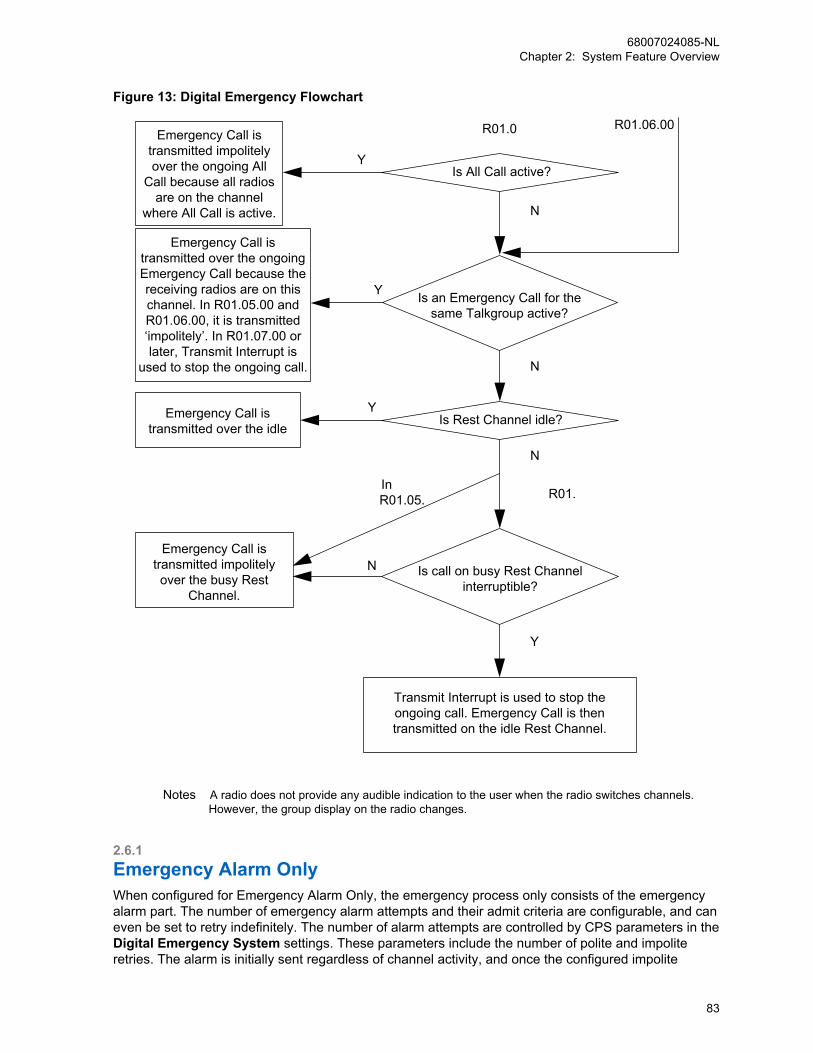
Figure 13: Digital Emergency Flowchart
Is All Call active?
Is Rest Channel idle?
Is an Emergency Call for thesame Talkgroup active?
Is call on busy Rest Channelinterruptible?
Emergency Call is transmitted impolitely over the ongoing All
Call because all radios are on the channel
where All Call is active.
Emergency Call is transmitted over the ongoing Emergency Call because the receiving radios are on this channel. In R01.05.00 and R01.06.00, it is transmitted ‘impolitely’. In R01.07.00 or later, Transmit Interrupt is
used to stop the ongoing call.
Emergency Call istransmitted over the idle
Emergency Call is transmitted impolitely over the busy Rest
Channel.
Transmit Interrupt is used to stop theongoing call. Emergency Call is thentransmitted on the idle Rest Channel.
R01.0 R01.06.00
In R01.05. R01.
Y
N
Y
Y
N
N
Y
N
Notes A radio does not provide any audible indication to the user when the radio switches channels. However, the group display on the radio changes.
2.6.1Emergency Alarm OnlyWhen configured for Emergency Alarm Only, the emergency process only consists of the emergencyalarm part. The number of emergency alarm attempts and their admit criteria are configurable, and caneven be set to retry indefinitely. The number of alarm attempts are controlled by CPS parameters in theDigital Emergency System settings. These parameters include the number of polite and impoliteretries. The alarm is initially sent regardless of channel activity, and once the configured impolite
68007024085-NLChapter 2: System Feature Overview
83
attempts are exhausted, the polite retries are executed when the channel is idle. The EmergencyAlarm Only ends when:
• an acknowledgment is received,
• all retries are exhausted,
• the user manually clears the emergency, or
• the user pushes the PTT.
No voice call is associated with the emergency when operating as Emergency Alarm Only. Pressingthe PTT clears the emergency, and a standard voice call is processed.
2.6.2Emergency Alarm and CallWhen configured for Emergency Alarm and Call, the emergency consists of the emergency alarmprocess followed by the ability to perform an Emergency Call. The number of emergency alarmattempts and their admit criteria are configurable, and can even be set to retry indefinitely. The alarm isinitially sent regardless of channel activity, and once the configured impolite retries are exhausted, thepolite retries are executed when the channel is idle.
Emergency alarm stops when:
• an acknowledgment is received, or
• all retries are exhausted.
The radio still remains in an emergency state. Any follow up PTT initiates an Emergency Call, and thecall includes an embedded emergency indication. If the user presses the PTT before the radio sendsan emergency alarm, the radio stops sending the alarm, and starts the Emergency Call. While in theemergency mode, all subsequent voice transmissions are Emergency Calls. The user remains inemergency mode until he manually clears emergency. The only way to reinitiate the emergency alarmprocess is to reinitiate the emergency.
2.6.3Emergency Alarm with Voice to FollowWhen configured for Emergency Alarm and with Voice to Follow, the emergency consists of sending asingle emergency alarm, and followed by an automatic transmission of an Emergency Call. This isreferred to as hot microphone.
The radio only sends one emergency alarm regardless if there is channel activity, and then withoutwaiting for an acknowledgment the radio immediately activates the microphone and initiates anEmergency Call without the need of the user pressing the PTT. The duration of the hot microphonestate is configurable through the CPS in the Digital Emergency Systems settings. This transmission isconsidered an Emergency Call, and therefore includes the embedded emergency indication. Once thishot microphone duration expires, the radio stops transmitting, but remains in the emergency mode.Any follow up PTT initiates an Emergency Call, and includes the embedded emergency indication. Theuser remains in the emergency mode until he manually clears his emergency. The only way toreinitiate the emergency alarm and the hot microphone is to re-initiate the emergency.
It is important to note that when configured for Emergency Alarm with Voice to Follow, the radiocontinues to transmit voice for the duration of the provisioned hot microphone timer. Since voice haspriority over data, any data is queued while voice is transmitting, including the GPS update that wastriggered by the emergency. The GPS data cannot be delivered until after the radio stops transmittingvoice, and after the repeater hangtime has expired. The GPS data has no additional priority over otherdata queued in the radios, or over any traffic on the channel. Therefore, its delivery may be delayed ifthe radio in emergency has pending data queued or if the channel is busy processing other traffic.
68007024085-NLChapter 2: System Feature Overview
84
It is recommended when utilizing Emergency Alarm with Voice to Follow and GPS, that the hotmicrophone timer be at maximum 30 seconds. There are a few reasons for this. First of all, datamessages do not stay in the queue forever, 30 seconds is short enough so to give the GPS data achance to be transmitted without timing out. Second, if the hot microphone timer is longer than 30seconds, and the GPS update rate is around the same value, then other GPS messages may start tofill up in the queue while the voice transmission is processing. This not only occurs with the radio inemergency, but with all other radios since the channel is busy. Therefore when the voice call ends, allradios attempt to access the channel with their GPS data which increases the likelihood of collisionsand lost messages. Finally, understand that while the user is transmitting due to its hot microphonetimer, there is no way to communicate back to them. Most users can explain their situation in less than30 seconds and require some feedback from the emergency dispatcher much sooner. That is why it isrecommended to keep this value low and if additional monitoring is required, the remote monitorfeature can be utilized. Only use a long hot microphone timer in specialized applications.
Also, since the emergency alarm itself is not acknowledged nor retried, its reliability is less than that ofthe standard Emergency Alarm and Emergency Alarm Only and Call. These considerations should betaken into account when choosing to operate with Emergency Alarm with Voice to Follow.
2.6.4Emergency Voice Interrupt for Emergency AlarmThe Emergency Voice Interrupt feature, when enabled in a radio, is used during the initiation of anemergency condition when an interruptible voice transmission is already taking place on the channel.
When an emergency is initiated with Emergency Voice Interrupt enabled, the radio attempts to interruptan ongoing, interruptible voice transmission on the channel. The radio then uses the establishedprocedures for either Emergency Alarm or Emergency Alarm with Call, depending upon the CPSconfiguration. For the Emergency Voice Interrupt for Emergency Alarm feature, the radio is notrequired to be a member of the voice call being interrupted.
NOTICE: For the Emergency Voice Interrupt for Emergency Alarm feature to operateconsistently, all radios using the channel should be provisioned with the ability to be interrupted.However, not all need to be provisioned with the Emergency Voice Interrupt for EmergencyAlarm capability.
If some radios are provisioned without the ability to be interrupted (for example, normally desirable fora supervisor’s radio), then those radios’ transmissions cannot be interrupted and the radio user insteadtransmits the Emergency Alarm in accordance with the configuration of the polite and impoliteEmergency Alarm fields in the CPS, if Emergency Alarm is attempted while receiving another radio’suninterruptible transmission.
If the interruption of the voice transmission is successful, the radio uses the established procedures foreither Emergency Alarm or Emergency Alarm with Call, depending upon the CPS configuration, oncethe channel has been cleared. Depending on the radio’s CPS configuration, the radio user whosetransmission was interrupted may or may not receive a Talk Prohibit Tone until the PTT is released.
If the interruption of the voice transmission fails, the radio then uses the established procedures foreither Emergency Alarm or Emergency Alarm with Call, depending upon the CPS configuration.However, the probability of success diminishes because the original voice transmission had not beensuccessfully cleared from the channel.
If the voice call on the channel is not transmitting an interruptible voice signal, the radio uses theestablished procedures for either Emergency Alarm or Emergency Alarm with Call, depending uponthe CPS configuration, again with a lower probability of success.
68007024085-NLChapter 2: System Feature Overview
85
2.6.5Emergency Voice Interrupt for Emergency VoiceThe Emergency Voice Interrupt feature, when enabled in a radio, is used during the initiation of anemergency voice transmission, primarily when an interruptible voice transmission takes place on thechannel and the radio does not belong to that voice transmission.
The radio attempts to interrupt the voice transmission, and then uses the established procedures forEmergency Voice Transmissions, when all of the following conditions are met:
• Emergency Voice Interrupt is enabled.
• The radio is in an emergency condition (for example, the designated Emergency button waspressed previously).
• Another radio’s interruptible voice transmission is taking place on the channel.
• The radio in the emergency condition does not belong to the other radio’s voice transmission (thatis, the radio in the emergency condition is not receiving the other radio’s voice transmission).
• The radio user in the emergency condition requests an Emergency Voice Transmission.
The Emergency Voice Interrupt for Emergency Voice feature is not used when the radio belongs to thevoice call is being interrupted. Instead, when the radio belongs to the call on the channel (that is, theradio that is receiving the voice transmission), the “In Call Criteria” is used rather than the EmergencyVoice Interrupt feature. This is because some systems may disallow radios to interrupt any call towhich they belong. In this case, the user must wait until the receiving transmission has finished, beforebeginning their Emergency Voice transmission.
The Emergency Voice Interrupt for Emergency Voice feature is also capable of interrupting an All Callprovided the All Call is transmitting interruptible voice.
NOTICE: For this feature to operate consistently, all radios using the channel should beprovisioned with the ability to be interrupted. However, not all need to be provisioned with theEmergency Voice Interrupt for Emergency Voice capability.
If the radio succeeds at interrupting the voice transmission, the radio uses the established proceduresfor Emergency Voice Transmissions, once the channel has been cleared. Depending on the radio’sCPS configuration, the radio user whose transmission was interrupted may or may not receive a TalkProhibit Tone until the PTT is released. If the radio fails to interrupt the voice transmission or the voicetransmission is not interruptible, the radio also uses the established procedures for Emergency VoiceTransmissions. However, the probability of success diminishes because the original voice transmissionhad not been successfully cleared from the channel.
2.6.6Emergency Search ToneThis Emergency Search Tone is optional for all MOTOTRBO radios (version R02.00.00 onwards)excluding MOTOTRBO Light, and can be enabled or disabled via CPS configuration.
This feature is available in direct mode (12.5e or 6.25e) and Conventional Single Site.
IPSC
IP Site Connect
This feature is available in IP Site Connect
68007024085-NLChapter 2: System Feature Overview
86
CPMS
Capacity Plus Single Site and Capacity PlusMulti Site
This feature is available in Capacity Plus SingleSite and Capacity Plus Multi Site
If enabled, when the radio initiates an emergency, it plays out a loud and attention grabbing tone(Emergency Search Tone), to help people around to locate and identify the emergency initiator. ThisEmergency Search Tone is for the emergency initiating radio only, and not for the emergency receivingradios. This tone starts when the emergency starts and ends when the radio exits the emergency. Thetone is temporarily suspended, when the radio is transmitting or receiving voice/data/CSBK calls.
If enabled, this Emergency Search Tone is played out regardless if the CPS “All Tone Disabled” optionis turned on or not.
NOTICE: The Emergency Search Tone feature is disabled on a transmitting radio whenever theEmergency Call is acknowledged by a Receiving/Acknowledging radio. If the Emergency Call isnot acknowledged, the Emergency Search Tone is emitted by the transmitting radio andcontinues to be emitted as expected.
This tone is mutual exclusive with the Silent Emergency feature. That is, if the Silent Emergency isenabled for the radio, this feature is disabled automatically regardless if this tone is CPS enabled ornot.
Also, it is CPS configurable to specify where to route this Emergency Search Tone/incoming voice,either the radio’s internal speaker or the accessory. When an accessory is not attached, it is alwaysrouted to the radio’s internal speaker automatically.
2.7Restricted Access to SystemRestricted Access to System (RAS) supports all existing ADP interfaces and is supported in allMOTOTRBO system configurations including Conventional Single Site.
IPSC
IP Site Connect
This feature is supported by IP Site Connect
CPSM
Capacity Plus Single Site and Capacity PlusMulti Site
This feature is supported by Capacity Plus Sin-gle Site and Capacity Plus Multi Site
This feature supports all existing ADP interfaces and is supported in all MOTOTRBO systemconfigurations including Conventional Single Site.
The Restricted Access to System (RAS) feature prevents unauthorized subscriber users from using therepeaters in the system to transmit to their targeted user or user groups. Additionally, RAS provideslimited protection to prevent unauthorized subscribers from listening to any voice/data/CSBKtransmission repeated from the RAS enabled repeaters. The unauthorized subscriber device could bea Motorola Solutions subscriber, or a DMR-compatible subscriber from other vendors. However, RAS
68007024085-NLChapter 2: System Feature Overview
87
is not a privacy feature and if voice privacy is a concern, Basic Privacy, or Enhanced Privacy should beused. See Types of Privacy on page 171 for details.
This feature provides two methods to prevent a subscriber from accessing the system: RAS KeyAuthentication and Radio ID Range Check. These two methods are independent of each other andmay be enabled/disabled separately or together. When used together, they provide a robust andflexible way to control the subscribers’ access to the system.
2.7.1Restricted Access to System Key AuthenticationIn this method, both the repeater and subscriber are configured with a secret Restricted Access toSystem (RAS) key through CPS.
When a subscriber transmits, the subscriber uses its configured RAS key to encode the bursts. Whena repeater receives the bursts, the repeater also uses its configured RAS key to decode the bursts. Ifthe RAS keys in the subscriber and repeater are the same, the repeater decodes and repeats thebursts successfully. However, if the subscriber does not have a RAS key or its RAS key does notmatch the one configured in the repeater, the decoding process in the repeater fails, and thetransmission is blocked at the repeater. Therefore, the bursts from the unauthorized subscriber are notrepeated and cannot reach the targeted user or user group.
This method is secure and difficult to break or circumvent, because the RAS ID length ranges from 6 to24 characters. The algorithm is very robust. However, this method requires CPS configurations in thesubscriber’s codeplug, resulting in more time and extra effort, when changes have to be made to afleet of radios.
The RAS key authorization is enabled by default. The following table shows the default settings forRAS configuration in a repeater and a subscriber:
Table 4: RAS Configuration
RAS Configuration Default Setting
In a repeater all RAS configuration is performedin the ‘Security’ section and therefore applies toall channels in the repeater.
Authentication = Enabled
Authentication Key Alias = Default
Authentication Key = 000000
In a subscriber, most RAS configuration is per-formed in the ‘Security’ section.
Key Alias = Default
Key Value = 000000 (By default)
In a subscriber the enablement of RAS is on aper channel basis.
RAS Alias = Default (In a channel)
The following are several scenarios when adding these RAS key authentication enabled repeaters/radios into an existing system:
• If cloning is utilized on the device, there are no new configuration steps when deploying into anexisting system utilizing RAS or an existing system not utilizing RAS.
• If cloning is not utilized and the existing system is RAS disabled, the RAS enabled repeaters/radiosneed to be RAS disabled using the CPS/RM tool, before they can be used in the system.
• If cloning is not utilized and the existing system is RAS enabled with a customer chosen RAS key,the RAS enabled repeaters/radios (with the default RAS key) need to be re-programmed with thecustomer chosen RAS key using the CPS/RM tool.
68007024085-NLChapter 2: System Feature Overview
88
2.7.2Radio ID Range CheckIn this method, up to 64 radio ID ranges can be provisioned in the repeaters. Each of these radio IDranges may be configured as allowed or left as un-configured. If the radio ID is within any of theallowed radio ID ranges when the repeater receives a transmission from a subscriber, the repeaterrepeats it normally. However, if the subscriber’s radio ID is not within any of the allowed radio IDranges, the repeater blocks the transmission. Hence, the transmission from unauthorized subscribersare not repeated and cannot reach the targeted user or user group.
This method only requires configurations in the repeaters. Therefore, it is very easy to make changesquickly. However, an unauthorized user may analyze the radio transmission over-the-air, or use othermeans to guess some allowed radio IDs and create clones of authorized IDs, thus gaining access touse the repeater.
2.8Digital VotingThe digital voting feature is the voting solution for MOTOTRBO digital radio systems. To achieve thebest voting result, the voting selection is executed at the smallest possible level, known as the burstlevel, and is called continuous voting. MOTOTRBO digital voting is available in all systemconfigurations including Digital Conventional Single Site.
IPSC
IP Site Connect
This feature is supported by IP Site Connect
CPSM
Capacity Plus Single Site and Capacity PlusMulti Site
This feature is supported by Capacity Plus Sin-gle Site and Capacity Plus Multi Site
In a two-way radio system, a receive-and-transmit repeater is typically located at an elevated areasuch as the top of a hill or tall building, and has a high powered transmitter so that all the subscribersoperating within the desired service area can receive signals at an acceptable strength. However, themobile and portable subscribers typically have considerably smaller transmitted power because of sizeand cost considerations. The result is that while all the subscribers within the service area of therepeater can receive the transmissions, the repeater may not receive the transmissions from thesubscribers, or may receive the transmissions at signal strengths that are too low to provide reliablecommunications. In other words, the talk-in range of the repeater is typically significantly less than itstalk-out range.
To resolve this imbalance, multiple receive-only repeaters (satellite receivers) can be installed atvarious locations throughout the service area to relay the radio’s transmission to the repeater. Once asatellite receiver receives an acceptable signal transmitted by the radio, the signal can be relayed backto the repeater over the IP network. Then the repeater repeats the relayed signal at a sufficiently highpower level such that all radios in the service area are able to receive it.
However, depending on where the transmitting radio is, the repeater itself (via its internal receiver) andother satellite receivers may also receive the radio’s transmission at an acceptable signal strengthlevel. In this case, the repeater receives multiple copies of the same transmission from differentreceivers, selects one best copy of the received transmission, and ignores the rest. This selection is
68007024085-NLChapter 2: System Feature Overview
89

accomplished by a “voting” process. Typically, the voting process analyzes each received signal anddetermines which one is the best based on the signal-to-noise ratio of the signal or a bit error rate.
By selecting the best signal copy among all the receivers, an additional benefit of voting is reducing theeffects of local interference or fading, thus improving voice and data quality.
NOTICE: Digital voting is available starting from software version R02.30.02 onwards. Anyrepeaters or radios prior to those versions must be upgraded in order to operate properly in avoting enabled system. Radios with firmware: R01.11.02 and above for MOTOTRBO,R02.06.04 and above for MOTOTRBO 2.0 are compatible with digital voting.
2.9CSBK DataThis feature aims to improve the data communication performance and reliability, by using a datatransmission method called “CSBK data”, whereby a single CSBK is used to transmit the ARS, GPSand XCMP device raw data. The OTA transmission time is reduced to one burst. Therefore chances ofchannel collision are reduced, and the system capacity of enhanced GPS is enlarged greatly.
An XCMP device can send multiple single CSBKs to other XCMP devices; the same CSBK can betransmitted repetitively to improve reliability.
NOTICE: The XCMP device here refers to an option board (OB) or a non-IP peripheral device.
2.9.1Supported Data ServiceThe following is a listing of the CSBK data services supported:
• ARS data that originates from the radio or the server.
• GPS data that originates from the radio or the XCMP device targeted to the server.
• Raw data that originates from the XCMP device and targeted to the server.
• Data from XCMP device to XCMP device can be sent as one CSBK or multiple single CSBKs.Multiple single CSBKs are only supported in direct mode.
2.9.2Impacted FeaturesThe following is a listing of the impacted CSBK Data features:
Enhanced GPSCSBK data follows the existing Enhanced GPS rule when the window sizes are 5, 6, 7, 8, 9, 10.Enhanced GPS with window sizes 5, 6, 7, 8, 9, 10 are compatible with CSBK data compression.Window sizes 1 and 2 are introduced to generate high data throughput.
Battery Save and Scan PreambleCSBK data follows the unconfirmed data method for Battery Save and Scan Preamble CSBK.There is no preamble for the CSBK data targeted to the server.
Enhanced Channel AccessCSBK data follows the unconfirmed data method for ECA.
GPS RevertLocation CSBK data follows the unconfirmed GPS data method for GPS revert.
68007024085-NLChapter 2: System Feature Overview
90

2.9.3Improved Third-Party InterfacesThe following is a list of improved third-party interfaces categorized by repeater and radio:
• Repeater
- Repeater Call Monitor – monitors CSBK data
- Wireline Protocol – routes CSBK data to the wireline gateway
• Radio
- XCMP – transmits as CSBK data, and transmits at the Enhanced GPS channel
- ARS – transmits as CSBK data
- LRRP – transmits as CSBK data
2.9.4Affected System ComponentsThe following is a list of system components affected by the CSBK data feature:
• Repeater – only supported by MTR3000 and 32 MB DR 3000 Series
• Radio – only supported by R02.08.10.00 and later
• CPS
• MNIS
• ARS (DDMS), LRRP and Raw Data Applications
2.10Digital AudioThe SLR 8000 repeater provides integrated speaker and connector for an external microphone on itsfront panel. Digital Audio supports speaker and microphone in digital mode, as done in analog mode.Digital audio features include digital audio receive and digital audio transmit.
Digital audio receive plays back the voice from the speaker when an DMR voice call is repeated at theSLR 8000 repeater. The playback of the receive audio from the speaker is only supported in theConventional Single Site, IP Site Connect, Capacity Plus Single Site, Capacity Plus Multi Site, ConnectPlus, and Capacity Max system configurations. CPS provides configurations for the speaker phone toplay back as follows:
• none (digital audio receive at FP is de-activated),
• audio received on slot 0 (one of the two digital channels),
• audio received on slot 1 (another digital channel), or
• mix of audio received on slot 0 and slot 1 (both digital channels).
Digital audio transmit transmits the microphone audio OTA as a DMR voice call. The voice call can bean individual or talkgroup voice call. Digital audio transmit is supported only in a conventional singlesite system.
The DMR voice call is supported by microphone audio and is a clear voice call without basic orenhanced privacy, and it is not Transmit Interruptible. CPS provides configuration to enablemicrophone audio to be transmitted on Slot 1 (one of the two digital channels), or Slot 2 (another digitalchannel). CPS also supports configurations that allow the user to configure the preempt priority of OTAtransmitting, among multiple transmission requests. The requests can be from a local audio (frontpanel microphone), repeat audio (non-emergency voice call), or an emergency repeat audio
68007024085-NLChapter 2: System Feature Overview
91
(emergency voice call). CPS also provides configuration to set a target ID for the microphone audiotransmission. The target ID includes:
• Call type (individual or talkgroup call)
• Target subscriber radio ID
2.11Confirmed Group DataConfirmed Group Data is the most efficient way of sending a message, when the same data is requiredto be sent to ‘n’ radios, and then sending one data message to a talkgroup, where all ‘n’ radios aremember of the talkgroup. The DMR Protocol does not support confirmation of a data packet sent to agroup.
The disadvantage of unconfirmed data packet is that the reliability of transferring the data decreasesrapidly as the size of data messages increases. For example, if the reliability of one unconfirmed databurst (12 bytes) is 98%, then the reliability of 32 bursts (384 bytes), is only 52% = (0.98)32.
NOTICE: A confirmed data is more reliable because it uses SARQ (Selective Automatic RepeatRequest), where the sender tries multiple times to transfer the part of the message, which wasreceived by the target incorrectly.
MOTOTRBO provides a proprietary method to transfer data messages to a group in a confirmed way.The transfer has the following constraints:
• The data messages can be transferred only from a data application (that is only through a MNISData Gateway). The source cannot be a radio and it is not sent through a control station.
• The maximum number of blocks in the message is limited to 40. This limits the size of the messageto 636 bytes, including IP and UDP headers.
• The maximum number of target radios for a message is limited to 200. The target radios must beMOTOTRBO radios.
• The target radios of a message must be members of a talkgroup.
• A radio, which is participating in a Confirmed Group Data suspends the Priority Scan during theConfirmed Group Data.
• The transfer is supported only in the repeater mode (Not in direct mode).
• The transfer is supported only in the single site conventional, IP Site Connect, Capacity Plus, orCapacity Max Systems.
The data application requests to transfer a data message to a set of radios by providing the datapayload, a list of recipient radios, and a talkgroup to a MNIS Data Gateway.
NOTICE: The destination talkgroup must be an Rx member in all the recipient radios.
The MOTOTRBO system forms and transmits a confirmed packet data unit (PDU) in the same way asan individual data packet. After transmitting the PDU, the system polls all the recipient radios one byone for their acknowledgments on the trunked channel. If the response from one or more radios isnegative for the whole PDU or for few blocks, then the system follows the SARQ procedure, which at ahigh level is similar to the SARQ procedure for individual data packets.
After the SARQ procedure is completed, the MNIS Data Gateway returns to the source (dataapplication) and confirms the success or failure of the transfer for each recipient radio.
In good signal condition (that is when all radios receive the PDU correctly on the first attempt), themethod takes (p+r+9) * 0.06 seconds of over the air time; where ‘p’ is the number of blocks in the PDUand ‘r’ is the number of recipient radios.
68007024085-NLChapter 2: System Feature Overview
92
2.12MOTOTRBO Integrated DataThis section describes the MOTOTRBO Integrated Data.
2.12.1MOTOTRBO Integrated Data OverviewWhen performing in digital mode, any MOTOTRBO radio can be used as an integrated voice and dataradio, where the radio can send voice as well as data messages on a given logical channel. This doesnot refer to data services like enabling users to surf the web, send video images, or synchronize theiroffice desktops. This is not the right technology for such bandwidth-hungry applications. However, it isa great technology for productivity-enhancing applications like messaging, location based services,simple database queries, bar code reading, and fill-in-the-form type of applications. Additionally, it isbuilt into the MOTOTRBO system, so there are no monthly fees or dependencies on public carrierservices, and customers control what applications their users can access.
The MOTOTRBO system provides reliable data communications throughout the same areas where thesystem provides readily usable voice communications. However, there is a trade-off between thedesired RF coverage area for data and the data throughput of the system. Extending the range of asystem's operation requires more data message retries to successfully complete confirmedtransactions, thus lowering throughput.
Integrating voice and data on the same channel brings several benefits. These include:
• Use of one RF channel for both voice and data.
• Use of one system infrastructure for both voice and data.
• Use of one subscriber to send and retrieve both voice and data messages over-the-air.
Integrating voice and data on the same channel also brings several considerations. These include thefollowing:
• Traffic loading
• Customer application requirements
• Contention of voice and data.
System Design Considerations on page 362 provides practical guidance on the above considerations.
MOTOTRBO supports data services in a number of ways.
• MOTOTRBO allows radios to send “unit-to-unit” and “unit-to-group” data packets. It supportsconfirmed and unconfirmed delivery of a data packet. The following table shows the confirmed andunconfirmed mode for all the software versions.
Table 5: Software Confirmed and Unconfirmed Mode
Call Type/Release R01.01.00 –R01.03.00
R01.04.00 R01.05.00 –R01.06.00
Unit-to-Unit Confirmed Confirmed CPS selectable for apersonality. Con-firmed (by default)
Exception: In IP Site Connect, location data isalways sent unconfirmed.
Unit-to-Group Unconfirmed
NOTICE: If some of the radios are still running on older software versions like R01.00.00 orR01.01.00, then the radios must select the unit-to-unit data as confirmed mode.
68007024085-NLChapter 2: System Feature Overview
93
• MOTOTRBO also enables infrastructure and/or PC based applications by supporting InternetProtocol (IP) addressing and IP packet data services. Rather than relying upon external modems,MOTOTRBO radios can connect directly to computer equipment with standard USB interfaces. Thissimplifies and lowers the cost of integrating with applications, and at the same time expands theuniverse of potential applications that organizations can deploy. Depending upon availability in yourregion, Motorola Solutions offers two PC based MOTOTRBO applications, as follows:
- MOTOTRBO Location Services
- MOTOTRBO Text Messaging
• MOTOTRBO supports a Third-Party Application Partner Program. This program includes acomplete application developer’s kit that fully describes interfaces for IP data services, commandand control of the radio, and for option boards that can be installed in the radio.
For some infrastructure based data applications,such as MOTOTRBO Location Services andMOTOTRBO Text Messaging, the radio must first complete a registration process before datamessages can be exchanged between the radio and the infrastructure based application. Registrationhas no impact on voice operation, aside from utilizing the same channel. Polite voice calls have to waituntil an in-progress registration completes before it can use the channel, while impolite voice calls cantransmit on top of a registration transmission. A radio does not have to register for voice services. Aradio registers when the radio powers up in a data capable mode, or changes into a data capablemode. A radio registers with a Presence Notifier, which is incorporated within the MOTOTRBOLocation Services and MOTOTRBO Text Messaging applications, but may also be utilized with third-party applications. The Presence Notifier informs the data application servers that the registered radiois “on the system” and available for services.
In MOTOTRBO systems, the codeplug configuration determines whether or not a radio attempts toregister on the selected channel. This is defined through the ARS parameter which is enabled ordisabled through the settings within each channel. It must be set to enabled for those channels that areutilized for data communications with infrastructure based applications, such as MOTOTRBO LocationServices and MOTOTRBO Text Messaging. Besides device registration, if enabled through CPS, theradio also allows the radio user to register using their user id with the support from additional third-party application.
2.12.2Text Messaging ServicesMultiple MOTOTRBO system components interact together to deliver text messaging services. Theseinclude the built-in text messaging capabilities of MOTOTRBO subscriber radios and the MOTOTRBOText Messaging Services application. The MOTOTRBO Text Messaging Services application in turnconsists of several components, including the MOTOTRBO Mobile Text Messaging Client used withfielded radios, the MOTOTRBO Text Messaging Client used with dispatch-oriented positions, and theMOTOTRBO Text Messaging Server . The services provided by each of these components aredescribed in the following subsections.
The following figure shows a sample MOTOTRBO Text Messaging system configuration. See SystemComponents And Topologies on page 266 for more details on setting up your MOTOTRBO system.
68007024085-NLChapter 2: System Feature Overview
94
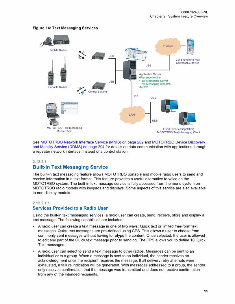
Figure 14: Text Messaging Services
Fixed Clients (Dispatcher)MOTOTRBO Text Messaging Client
Portable Radios
Mobile Radios
MOTOTRBO Text MessagingMobile Client
Internet
Cell phone or e-mailaddressable device
USB
TxRx
Tx
RxUSB
LAN
USB
USB
Application Server•Presence Notifier•Text Messaging Server•Text Messaging Dispatch•MCDD
Control Stations
USB
USB
See MOTOTRBO Network Interface Service (MNIS) on page 282 and MOTOTRBO Device Discoveryand Mobility Service (DDMS) on page 294 for details on data communication with applications througha repeater network interface, instead of a control station.
2.12.2.1Built-In Text Messaging ServiceThe built-in text messaging feature allows MOTOTRBO portable and mobile radio users to send andreceive information in a text format. This feature provides a useful alternative to voice on theMOTOTRBO system. The built-in text message service is fully accessed from the menu system onMOTOTRBO radio models with keypads and displays. Some aspects of this service are also availableto non-display models.
2.12.2.1.1Services Provided to a Radio UserUsing the built-in text messaging services, a radio user can create, send, receive, store and display atext message. The following capabilities are included:
• A radio user can create a text message in one of two ways: Quick text or limited free-form textmessages. Quick text messages are pre-defined using CPS. This allows a user to choose fromcommonly sent messages without having to retype the content. Once selected, the user is allowedto edit any part of the Quick text message prior to sending. The CPS allows you to define 10 QuickText messages.
• A radio user can select to send a text message to other radios. Messages can be sent to anindividual or to a group. When a message is sent to an individual, the sender receives anacknowledgment once the recipient receives the message. If all delivery retry attempts wereexhausted, a failure indication will be generated. With messages addressed to a group, the senderonly receives confirmation that the message was transmitted and does not receive confirmationfrom any of the intended recipients.
68007024085-NLChapter 2: System Feature Overview
95
• When receiving a text message, the user is notified of a new message by an icon, display string,and an audible tone if enabled in the codeplug through the CPS.
• Messages are received only if the radio is currently in digital mode of operation. A radio user shouldenter Scan mode to receive messages if multiple channels are being utilized. System planningconsiderations associated with data and scan are discussed in System Design Considerations onpage 362.
• A user can store up to 30 received or sent text messages at a time. The user is notified once theInbox and Sent folder storage becomes full. Once full, subsequent new messages automaticallycause the oldest messages to be deleted. Messages are not deleted when the radio is turned off.
• A user can store up to 30 draft text messages in the Drafts folder at a time. Once full, subsequentnew drafts automatically cause the oldest draft(s) to be deleted. A user can opt to Send, Edit, orDelete the drafts in the Drafts folder. The user can opt to Save a text message that is being writtenor edited to the Drafts folder. If a high priority event causes the radio to exit the text message editingscreen, the current text message is automatically saved into the Drafts folder. A draft that is sent isdeleted from the Drafts folder and stored to the Sent folder.
• The user can scroll through messages and select any message to read, reply to, forward, save ordelete.
2.12.2.2MOTOTRBO Text Messaging ApplicationDepending upon availability in your region, Motorola Solutions offers MOTOTRBO Text Messaging, aWindows PC-based application. It extends the system’s text messaging services to mobile and centraldispatch PC users. It also provides access to an important additional service: e-mail messaging toradio users. The MOTOTRBO Text Messing application consists of the Text Messaging Server, theDispatch Text Messaging Client, and the Mobile Text Messaging Client.
2.12.2.2.1Services Provided to a Radio UserLeveraging on the built-in text messaging services, a user can create, send, receive, store and displaya text message. The capabilities include the same ones available for Built-In Text Messaging Serviceon page 95.
• E-mail text messaging. A user is capable of sending and receiving text messages to and from anypreconfigured e-mail address. These preconfigured e-mail addresses must be configured in theradio using the CPS and also in the Text Messaging Server. Thus, the user can select e-mailaddresses from the radio contacts menu, and send short messages to any of those addresses.
• E-mail text messaging is only available to users when the radio is configured to interact with theMOTOTRBO Text Messaging Server application.
• Both the radio and the application server must be configured for e-mail. See System DesignConsiderations on page 362 for further details.
2.12.2.2.2Services Provided to a Mobile ClientA Mobile PC user is located in the field and utilizes the MOTOTRBO Mobile Text Messaging Clientapplication to create and view the text messages. In MOTOTRBO systems, portable or mobile radioscan be configured through the CPS to route text messages to an attached mobile PC user.
The services offered by the text message mobile clients are as follows:
Direct RoutingThe mobile client provides the ability to text message other mobile clients or radio users withoutgoing through the text messaging server, provided they are on the same channel as the originating
68007024085-NLChapter 2: System Feature Overview
96

mobile client. This is also applicable if the destination mobile clients or radios are scanning thechannel that the originating mobile client is on.
Indirect RoutingThe mobile client sends all text messages for e-mail and dispatch destinations through theMOTOTRBO Text Messaging Server. The Text Messaging Server can route the text message to adestination radio that is on a different channel.
Extended Messaging LengthThe Mobile client application user interface contains two messaging composition panes; one forsending short messages to radio destinations and the other for long messages to e-mail, dispatchdestinations, and other mobile clients. Text messages of up to 681 characters are supported.
Local Mailbox StorageThe mobile client provides individual access to the local storage of mailboxes.
2.12.2.2.3Services Provided to a DispatcherA PC-based Dispatcher utilizes the MOTOTRBO Text Messaging Client and is connected to the textmessaging application server, either on the same machine or on the same Local Area Network.
The services offered by the MOTOTRBO Text Messaging Client are as follows:
Full Messaging FeaturesThe local clients provide services such as Send/Reply/Forward text messages to radio users,dispatch users and e-mail destinations. The clients also support common mail folders such asInbox, Outbox, Sent Items, Trash, Drafts, and addressing from Address Books.
Group MessagingThe local client is capable of sending messages to a group of users (system groups), in addition toText Groups which serve as customized distribution lists.
Extended Messaging LengthThe local client application user interface contains two messaging composition panes; one forsending short messages to radio destinations and the other for long messages to e-mail anddispatch destinations. Text messages of up to 681 characters are supported.
Support for WorkgroupsWorkgroups allow multiple individuals to send/receive messages as a common dispatcher entitysimultaneously. This provides a central storage of Inbox and Sent Items mailboxes on the server forshared access among users of same workgroup.
Presence StatusThe local client provides the dispatch user with the display of the presence status for all radios ofinterest.
2.12.2.2.4Services Provided by the MOTOTRBO Text Messaging Server ApplicationThe backbone of the MOTOTRBO text message application is the server application. It is located onthe customer’s Local Area Network (LAN). The server application sends, receives, and stores the textmessages that involve the dispatcher clients, mobile clients, and e-mail addresses.
The services offered by the MOTOTRBO text message server application are as follows:
Communication GatewayThe server acts as a gateway between the radios on the system and the dispatcher clients.Configurable parameters within the codeplug include the number of retries desired, and theduration between attempts.
68007024085-NLChapter 2: System Feature Overview
97
E-mail Gateway (SMTP)The server provides the functionality of an e-mail server using Simple Mail Transfer Protocol(SMTP). This enables text messaging users across the MOTOTRBO system to communicate withan e-mail user located anywhere on the internet. The e-mail addresses which a radio user wishesto use must be configured on the server application for proper routing. Alternatively, a radio usercan send a text message to the dispatcher requesting that the message be forwarded to an e-mailaddress.
Presence NotificationThe Presence Service notifies a subscribing text message server application when a radio powerson/off, thus providing the status of radios to Dispatch users. When utilizing the Presence Services,the text message server application does not send any text messages to a user that is known to beabsent from the system. To preserve bandwidth, such message are discarded, and a failurenotification is returned to the original sender. Group messages do not receive a failure notification;group messages are sent as unconfirmed messages.
Central Device ManagementThe server provides a central configuration point for all text messaging client address books.
AuthenticationThe server provides an authentication gateway for dispatch users during login to their clients.
Management of Messaging DataThe server provides a central storage location for shared mailboxes for dispatch users and themanagement of concurrent access for these mailboxes. The archiving and backup of dispatch usermailboxes and the logging of message exchanges on all interfaces are also provided.
2.12.2.3Predictive Text EntryPredictive text entry is now available for text messaging in MOTOTRBO software version R02.10.00.Previous releases supported the multi-tap input method whereby the user repeatedly presses the samekey to cycle through the letters for that key. For example, to type the word “the” using multi-tap method,the radio user presses the buttons “8-tuv”, “4-ghi” twice, and “3-def” twice. However, with predictivetext, each key press results in a prediction, therefore they only have to press “8-tuv”, “4-ghi”, and “3-def”, which generates “the”.
Predictive text may take some time to master for some radio users. Therefore, there is an option toreturn to the multi-tap input method when necessary. Although once mastered, predictive text entry canlower the number of overall keystrokes utilized when typing a text message, making text messagingquicker and easier.
Predictive text also provides additional functions:
Smart PunctuationFor alphabetic languages, the radio includes punctuation intelligently based on the input key. Forexample, after the radio user presses “2-abc”, “2-abc”, “6-mno”, “1 -,.?” and “8-tuv”, the word “can’t”is predicted.
Word PredictionThe radio can learn the common word sequences the radio user uses often. This function predictsthe next word after the user enters the first word of the sequence that is frequently used. This canbe enabled or disabled through the utilities menu.
Sentence CapitalizationThe radio can automatically capitalize the first word of a sentence for alphabetic languages. Thisfunction can be enabled or disabled through the utilities menu.
68007024085-NLChapter 2: System Feature Overview
98
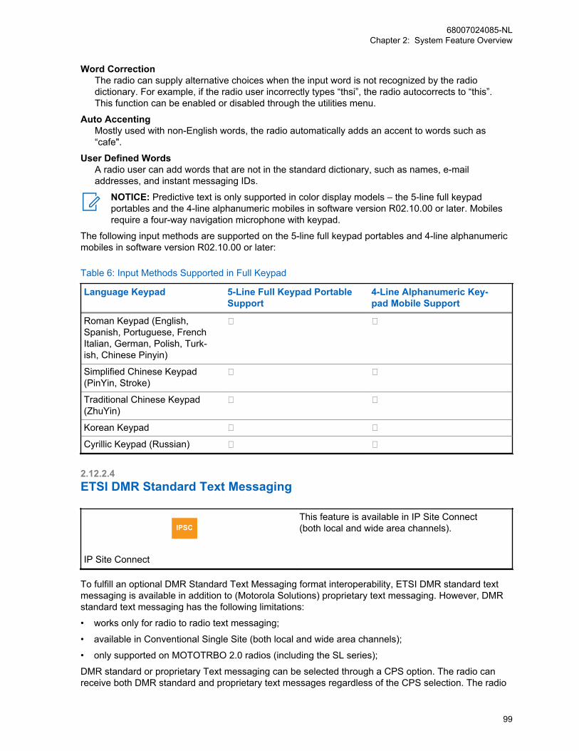
Word CorrectionThe radio can supply alternative choices when the input word is not recognized by the radiodictionary. For example, if the radio user incorrectly types “thsi”, the radio autocorrects to “this”.This function can be enabled or disabled through the utilities menu.
Auto AccentingMostly used with non-English words, the radio automatically adds an accent to words such as“cafe".
User Defined WordsA radio user can add words that are not in the standard dictionary, such as names, e-mailaddresses, and instant messaging IDs.
NOTICE: Predictive text is only supported in color display models – the 5-line full keypadportables and the 4-line alphanumeric mobiles in software version R02.10.00 or later. Mobilesrequire a four-way navigation microphone with keypad.
The following input methods are supported on the 5-line full keypad portables and 4-line alphanumericmobiles in software version R02.10.00 or later:
Table 6: Input Methods Supported in Full Keypad
Language Keypad 5-Line Full Keypad PortableSupport
4-Line Alphanumeric Key-pad Mobile Support
Roman Keypad (English,Spanish, Portuguese, FrenchItalian, German, Polish, Turk-ish, Chinese Pinyin)
Simplified Chinese Keypad(PinYin, Stroke)
Traditional Chinese Keypad(ZhuYin)
Korean Keypad
Cyrillic Keypad (Russian)
2.12.2.4ETSI DMR Standard Text Messaging
IPSC
IP Site Connect
This feature is available in IP Site Connect(both local and wide area channels).
To fulfill an optional DMR Standard Text Messaging format interoperability, ETSI DMR standard textmessaging is available in addition to (Motorola Solutions) proprietary text messaging. However, DMRstandard text messaging has the following limitations:
• works only for radio to radio text messaging;
• available in Conventional Single Site (both local and wide area channels);
• only supported on MOTOTRBO 2.0 radios (including the SL series);
DMR standard or proprietary Text messaging can be selected through a CPS option. The radio canreceive both DMR standard and proprietary text messages regardless of the CPS selection. The radio
68007024085-NLChapter 2: System Feature Overview
99

also replies in-kind, meaning the reply follows the received text message format (DMR standard orMotorola Solutions proprietary). However, while initiating a radio to radio text message, the initiatingradio always follows the CPS configuration (DMR standard or Motorola Solutions proprietary textmessage).
2.12.2.5ETSI DMR Tier 2 UDP/IP Header CompressionThere are three choices for header compression: ETSI DMR Tier 2 UDP/IP Header Compression(DMR), Motorola Solutions legacy Header Compression (MSI), or do not use header compression(none). DMR header compression and MSI header compression are not interoperable. DMR headercompression is supported only in the newer version radios/repeaters (R02.40.00 or later) ofMOTOTRBO 2.0 series, and provides improved retry reliability compared to MSI header compressionand should therefore be used in preference with both DMR Tier 2 text messaging and Motorola textmessaging but only if supported by all radios in the fleet to maintain interoperability.
Header Compression selection is configurable through CPS. The following are the recommendationsfor selecting the appropriate option.
• Select ‘DMR’ Header Compression when using ETSI DMR Tier 2 text messaging (the entire fleetsupports software version R02.40.00 or later).
• Select ‘DMR’ Header Compression if using Motorola text messaging and the entire Radio andRepeater fleet has software version R02.40.00 or later.
• Select ‘DMR’ Header Compression if the entire Radio and Repeater fleet supports “DMR”, that is,their software version is R02.40.00 or later.
• Select ‘MSI’ or ‘none’ Header Compression if not all the radio/repeater fleet support “DMR”. This isfor backward compatibility. Older radios/repeaters (prior to software version R02.40.00) onlysupport MSI header compression or no header compression.
• Select ‘MSI’ or ‘none’ Header Compression if not all the radio/repeater fleet support softwareversion R02.40.00 or later. This is for backward compatibility. Older radios/repeaters (prior tosoftware version R02.40.00) only support MSI header compression or no header compression.
2.12.3Location ServicesThe MOTOTRBO location feature allows a dispatcher to determine the current location of a radio on adisplay map. The dispatcher can obtain the radio’s location alone (latitude/longitude) or the locationcombined with other information about the environment (horizontal speed, direction, and others) thatallows value-added services, such as tracking of resources.
MOTOTRBO systems enable location services through two complementary functions. First, theMOTOTRBO mobile and portable radio portfolio includes models that are equipped with a built-inGlobal Positioning System (GPS) receiver. The acquisition of location data is done by a GPS receiverinside the radio and is dependent on the GPS receiver receiving accurate signals from the earth-orbiting GPS satellites. However, the GPS receiver may not work well indoors or in environmentswhere the sky is largely obscured.
Using the integrated data services capability of the MOTOTRBO system, GPS equipped mobiles andportables are able to transmit their location coordinates, over the radio system, to a receivingapplication that displays the radios’ geographic locations on a high resolution map. This third-partyreceiving application is the second part of the system.
Third-party location service applications are also supported. MOTOTRBO provides a location interfaceto third-party location services applications.
68007024085-NLChapter 2: System Feature Overview
100
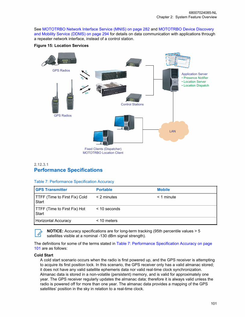
See MOTOTRBO Network Interface Service (MNIS) on page 282 and MOTOTRBO Device Discoveryand Mobility Service (DDMS) on page 294 for details on data communication with applications througha repeater network interface, instead of a control station.
Figure 15: Location Services
Fixed Clients (Dispatcher)MOTOTRBO Location Client
GPS Radios
GPS Radios Tx
Rx
Tx
Rx
LAN
Application Server• Presence Notifier• Location Server• Location Dispatch
Control Stations
2.12.3.1Performance Specifications
Table 7: Performance Specification Accuracy
GPS Transmitter Portable Mobile
TTFF (Time to First Fix) ColdStart
< 2 minutes < 1 minute
TTFF (Time to First Fix) HotStart
< 10 seconds
Horizontal Accuracy < 10 meters
NOTICE: Accuracy specifications are for long-term tracking (95th percentile values > 5satellites visible at a nominal -130 dBm signal strength).
The definitions for some of the terms stated in Table 7: Performance Specification Accuracy on page101 are as follows:
Cold StartA cold start scenario occurs when the radio is first powered up, and the GPS receiver is attemptingto acquire its first position lock. In this scenario, the GPS receiver only has a valid almanac stored;it does not have any valid satellite ephemeris data nor valid real-time clock synchronization.Almanac data is stored in a non-volatile (persistent) memory, and is valid for approximately oneyear. The GPS receiver regularly updates the almanac data; therefore it is always valid unless theradio is powered off for more than one year. The almanac data provides a mapping of the GPSsatellites’ position in the sky in relation to a real-time clock.
68007024085-NLChapter 2: System Feature Overview
101
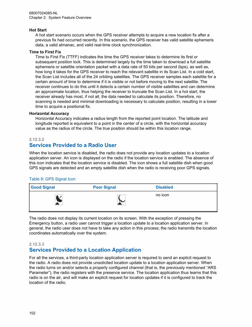
Hot StartA hot start scenario occurs when the GPS receiver attempts to acquire a new location fix after aprevious fix had occurred recently. In this scenario, the GPS receiver has valid satellite ephemerisdata, a valid almanac, and valid real-time clock synchronization.
Time to First FixTime to First Fix (TTFF) indicates the time the GPS receiver takes to determine its first orsubsequent position lock. This is determined largely by the time taken to download a full satelliteephemeris or satellite orientation packet with a data rate of 50 bits per second (bps), as well as,how long it takes for the GPS receiver to reach the relevant satellite in its Scan List. In a cold start,the Scan List includes all of the 24 orbiting satellites. The GPS receiver samples each satellite for acertain amount of time to determine if it is visible or not before moving to the next satellite. Thereceiver continues to do this until it detects a certain number of visible satellites and can determinean approximate location, thus helping the receiver to truncate the Scan List. In a hot start, thereceiver already has most, if not all, the data needed to calculate its position. Therefore, noscanning is needed and minimal downloading is necessary to calculate position, resulting in a lowertime to acquire a positional fix.
Horizontal AccuracyHorizontal Accuracy indicates a radius length from the reported point location. The latitude andlongitude reported is equivalent to a point in the center of a circle, with the horizontal accuracyvalue as the radius of the circle. The true position should be within this location range.
2.12.3.2Services Provided to a Radio UserWhen the location service is disabled, the radio does not provide any location updates to a locationapplication server. An icon is displayed on the radio if the location service is enabled. The absence ofthis icon indicates that the location service is disabled. The icon shows a full satellite dish when goodGPS signals are detected and an empty satellite dish when the radio is receiving poor GPS signals.
Table 8: GPS Signal Icon
Good Signal Poor Signal Disabled
no icon
The radio does not display its current location on its screen. With the exception of pressing theEmergency button, a radio user cannot trigger a location update to a location application server. Ingeneral, the radio user does not have to take any action in this process; the radio transmits the locationcoordinates automatically over the system.
2.12.3.3Services Provided to a Location ApplicationFor all the services, a third-party location application server is required to send an explicit request tothe radio. A radio does not provide unsolicited location update to a location application server. Whenthe radio turns on and/or selects a properly configured channel (that is, the previously mentioned “ARSParameter”), the radio registers with the presence service. The location application thus learns that thisradio is on the air, and will make an explicit request for location updates if it is configured to track thelocation of the radio.
68007024085-NLChapter 2: System Feature Overview
102
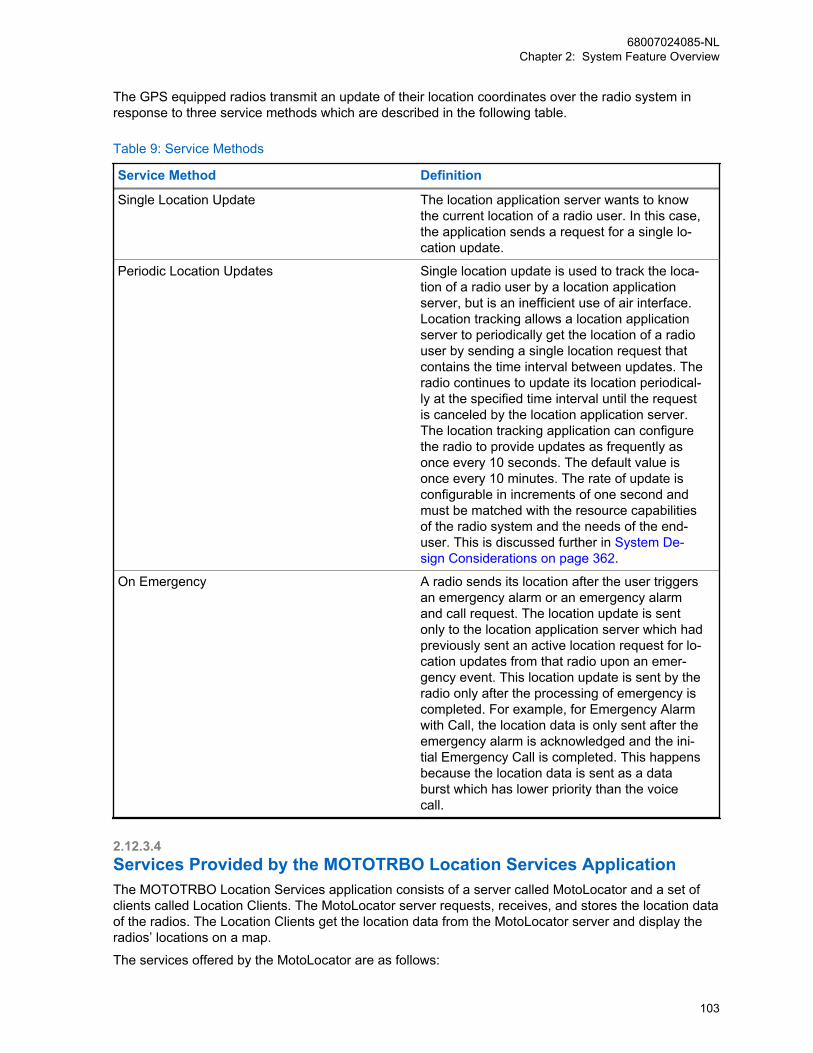
The GPS equipped radios transmit an update of their location coordinates over the radio system inresponse to three service methods which are described in the following table.
Table 9: Service Methods
Service Method Definition
Single Location Update The location application server wants to knowthe current location of a radio user. In this case,the application sends a request for a single lo-cation update.
Periodic Location Updates Single location update is used to track the loca-tion of a radio user by a location applicationserver, but is an inefficient use of air interface.Location tracking allows a location applicationserver to periodically get the location of a radiouser by sending a single location request thatcontains the time interval between updates. Theradio continues to update its location periodical-ly at the specified time interval until the requestis canceled by the location application server.The location tracking application can configurethe radio to provide updates as frequently asonce every 10 seconds. The default value isonce every 10 minutes. The rate of update isconfigurable in increments of one second andmust be matched with the resource capabilitiesof the radio system and the needs of the end-user. This is discussed further in System De-sign Considerations on page 362.
On Emergency A radio sends its location after the user triggersan emergency alarm or an emergency alarmand call request. The location update is sentonly to the location application server which hadpreviously sent an active location request for lo-cation updates from that radio upon an emer-gency event. This location update is sent by theradio only after the processing of emergency iscompleted. For example, for Emergency Alarmwith Call, the location data is only sent after theemergency alarm is acknowledged and the ini-tial Emergency Call is completed. This happensbecause the location data is sent as a databurst which has lower priority than the voicecall.
2.12.3.4Services Provided by the MOTOTRBO Location Services ApplicationThe MOTOTRBO Location Services application consists of a server called MotoLocator and a set ofclients called Location Clients. The MotoLocator server requests, receives, and stores the location dataof the radios. The Location Clients get the location data from the MotoLocator server and display theradios’ locations on a map.
The services offered by the MotoLocator are as follows:
68007024085-NLChapter 2: System Feature Overview
103
• Tracked radio management: MotoLocator provides a way to edit (insert and delete) the list of theradios that it is currently tracking. It also allows modifying the attributes of those radios (for example,a unique identifier and the name of the radio) and the parameters associated with the tracking of aradio (for example, elapsed time or distance after which the location is sent by the radio, andcontent of the location data).
• Storage of Location Data.
• Viewing of Location Data: MotoLocator provides a user interface to view the current or historicallocation data of a radio.
• Radio Group Management: This service allows grouping of a set of radios, so that they can betracked together.
• Resource Management.
• Dispatcher Capability Management: This service allows configuring the radio groups that adispatcher can track.
The services offered by a Location Client are as follows:
• Display location on a map of targeted radio/group/resource including polling and historical data.
• Map Operations: This feature allows zooming, panning, and scrolling of the map on display. It alsoallows adding and editing the point of interests, and selecting the layers of the map for display.
• Map Data Setup: This feature allows changing the setting of a map by allowing selection of thelayers of the map, allowing geocoding, and customization of the search.
• Searching: This feature allows searching the map based on the address or common place (forexample, hospital, or school), or point of interest.
• Routing: This feature allows finding the shortest path between two points on a map.
• Geofencing: This feature allows the defining of multiple boundaries. A notice is provided, and a toneis heard when a resource enters or leaves any defined boundary. The notice indicates the devicethat has crossed the boundary, the boundary name (if the radio has more than one activeboundary), and also if the device has entered or left the boundary.
• Text Messaging: A Location Client integrates with MOTOTRBO Text Messaging Client for sendingand receiving text messages to/from other resources.
2.12.3.5GPS Revert ChannelThe GPS Revert Channel feature allows system operators a configurable option to off load radiotransmitted location updates onto a programmed digital channel that differs from the digital SelectedChannel. This feature effectively removes Location Update traffic from the Selected Channel in order tofree up that channel to accommodate increased voice loads and/or to enhance the user experience byreducing the number of channel busies during voice call requests. This feature also allows a largegroup to communicate on a single voice channel while sending location updates on multiple GPSRevert Channels to accommodate larger Location Update loads. This increases the Location Updatethroughput associated with radios belonging to a single group.
Each channel programmed into the radio has a configurable CPS option to designate the GPStransmission channel on which it transmits Location Update messages. The CPS options for the GPStransmission channel are Selected, All, and None. Choosing Selected means that the GPS updatesare transmitted on the current channel. In the case of All, a single channel must be chosen from the listof all channels. This chosen channel is known as the GPS Revert Channel and this is where GPSupdates are transmitted on. It is understood that there may be instances when the radio is known to beout of range. In order to extend battery life, minimize time away from the Selected Channel, and/or toefficiently use frequency resources in these situations, the radio can also be configured to disable thetransmission of Location Update messages on a per channel basis by using the selection None. A
68007024085-NLChapter 2: System Feature Overview
104

radio is shown as present to the dispatcher when a radio is switched from a GPS enabled channel to aGPS disabled channel until the presence indication duration is exceeded.
To configure the radio to support location updates, there are a few parameters that must be managedcorrectly. How these parameters interact to dictate the radio’s performance is shown in the followingtable. These parameters are the radio wide GPS setting that resides in the General Settings CPSfolder, and the ARS and GPS Revert settings that are present for each channel defined in CPS. In thiscase the channel being defined is titled “Channel1”. Also, in the case where a GPS Revert Channel(GPS1) is selected, this requires that GPS1 has already been defined as a channel in CPS.
Table 10: Interaction Between Parameters to Dictate Radio Performance
General Settings:GPS
Channels: Zone1Channel1ARS
Channels: Zone1Channel1GPS Revert
Result
Not Enabled Not Enabled Not Selectable GPS Chip: DisabledPresence: DisabledLocation: Disabled
Not Enabled Enabled Not Selectable GPS Chip: DisabledPresence: EnabledLocation: Disabled
Enabled Not Enabled Not Selectable GPS Chip: EnabledPresence: DisabledLocation: Disabled
Enabled Enabled None GPS Chip: EnabledPresence: EnabledLocation: Disabled
Enabled Enabled Selected (Channel1) GPS Chip: EnabledPresence: EnabledLocation: TX onChannel1
GPS1 GPS Chip: EnabledPresence: EnabledLocation: TX onGPS1
NOTICE: Not Selectable means the setting cannot be configured as the option is grayed out.
2.12.3.6Enhanced GPS Revert Channel
IPSC
IP Site Connect
This feature is supported in repeater mode onlyand works in IP Site Connect mode of opera-tion. Only GPS data (unconfirmed only) is sup-ported on the Enhanced GPS Revert channel inIP Site Connect mode
68007024085-NLChapter 2: System Feature Overview
105
CPSM
Capacity Plus Single Site and Capacity PlusMulti Site
This feature is supported in repeater mode onlyand works in Capacity Plus Single Site and Ca-pacity Plus Multi Site modes of operation. InCapacity Plus Single Site and Capacity PlusMulti Site modes, ARS Registration Message isalso supported on the Enhanced GPS Revertchannel.
NOTICE: This feature is supported in repeater mode only and works in single-site mode ofoperation. Only GPS data (unconfirmed only) is supported on the Enhanced GPS Revertchannel in conventional mode for single-site mode. There is no support for voice or other non-GPS data on the Enhanced GPS Revert channel. Data from option board interface is also notsupported over an Enhanced GPS Revert channel.
The Enhanced GPS Revert channel is an enhancement of the GPS Revert channel functionality thatsupports higher throughput and increased reliability. Similar to the former feature, a subscriber offloadslocation responses routed to a server, to a revert channel. The primary difference lies in the method asubscriber accesses the channel. In the GPS Revert channel feature, subscribers access a channel ina desynchronized manner and may therefore cause transmission collisions. The probability of collisionincreases with the number of transmissions made over the channel and collisions adversely affect thereliability of transmissions.
This enhanced feature enables subscribers to access a channel in a synchronized manner, whicheliminate collisions and allow them to use the channel efficiently. The synchronization betweensubscribers is achieved by a repeater that divides a logical channel into groups of contiguous burstsdefined as “windows”. This allows subscribers to make reservations for these windows in which GPSdata can be transmitted. This is a slot wide configuration. The windowed data structure consists of aneight minute data superframe. Within the eight minute data superframe, there are 16 data frames, each30-second in duration This data superframe is repeated over and over again. Both the data frame andsuperframe always have the same size for every windowed GPS Revert channel.
Within a 30-second data frame, there are windows that can be reserved by subscribers for GPS datatransmission. The number of windows within a 30-second data frame depends on the size of eachwindow. A window consists of an announcement slot in the beginning followed by bursts of GPS data.The following figure shows the windowed data structure for a window size of six (one announcement +five bursts of GPS data).
68007024085-NLChapter 2: System Feature Overview
106

Table 11: Windowed Data Structure for a Window Size of Six
DataFrame 0 1 2 3 8079 8281
A B A B A B AAnnouncement
CSBK
On Slot Off Slot
DataHeader
ProprietaryHeader
½ RateData
½ RateData
½ RateData
B A B A
0 1 2 13 14 15
30 seconds
8 min
Single Site, encrypted example
DataSuperframe
The window size is dependent on the amount of GPS data to be sent, the privacy mode and headercompression usage. Based on window size, the number of windows in a 30-second data frame isshown in the following table:
Table 12: Number of Windows in a 30-Second Data Frame
Window Size(Includes Announcement Burst)
Number of Windows(in a 30-second data frame)
5 100
6 83
7 71
8 62
9 55
10 50
The CSBK data feature introduces a 7.5-second data frame; within a 2-minute data superframe, thereare 16 data frames. This feature compresses the GPS and ARS data into one single CSBK, withwindow size 1 and is only supported with the MNIS. This is because the repeater’s outbound data isnot transmitted over the air.
A window size 2 is supported by a control station and MNIS. In order to ease system migration whenenabling the CSBK data feature, a window size of 5-10 can be considered as it works best with thefeature.
Based on window size, the number of windows in a 7.5-second data frame is shown in the followingtable.
68007024085-NLChapter 2: System Feature Overview
107

Table 13: Window Size versus Number of Windows
Window Size(Includes Announcement Burst)
Number of Windows(in a 7.5-second data frame)
1 125
2 62
A repeater’s slot that is configured with “Enhanced GPS” maintains allocations of all the windows. Atthe beginning of every window, the repeater sends an announcement containing the current windownumber, data frame and the ID of the subscriber for the next reserved window. The following figureshows the scheduling of different subscribers in a window map for a given data superframe.
Figure 16: Subscriber Scheduling in a Window Map with 30 Seconds Data Frame
30 seconds
window1
window2
window3
window4 .... .... .... window
99 window
100
Data Frame 1 Sub 23 sub 0 sub 48 sub 13 sub 0 sub 0 sub 0 sub 32 sub 0
Data Frame 2 Sub 23 sub 8 sub 55 sub 43 sub 0 sub 0 sub 0 sub 0
Data Frame 3 Sub 23 sub 0 sub 0 sub 0 sub 0 sub 0 sub 0 sub 32 sub 0
Data Frame 4 Sub 23 sub 0 sub 55 sub 0 sub 0 sub 0 sub 0 sub 0
Data Frame 5 Sub 23 sub 0 sub 48 sub 0 sub 0 sub 0 sub 0 sub 32 sub 0
Data Frame 6 Sub 23 sub 8 sub 55 sub 0 sub 0 sub 0 sub 0 sub 0
Data Frame 7 Sub 23 sub 0 sub 0 sub 0 sub 0 sub 0 sub 0 sub 32 sub 0
Data Frame 8 Sub 23 sub 0 sub 55 sub 0 sub 0 sub 0 sub 0 sub 0
Data Frame 9 Sub 23 sub 0 sub 48 sub 13 sub 0 sub 0 sub 0 sub 32 sub 0
Data Frame 10 Sub 23 sub 8 sub 55 sub 0 sub 0 sub 0 sub 0 sub 0
Data Frame 11 Sub 23 sub 0 sub 0 sub 0 sub 0 sub 0 sub 0 sub 32 sub 0
Data Frame 12 Sub 23 sub 0 sub 55 sub 0 sub 0 sub 0 sub 0 sub 0
Data Frame 13 Sub 23 sub 0 sub 48 sub 0 sub 0 sub 0 sub 0 sub 32 sub 0
Data Frame 14 Sub 23 sub 8 sub 55 sub 0 sub 0 sub 0 sub 0 sub 0
Data Frame 15 Sub 23 sub 0 sub 0 sub 0 sub 0 sub 0 sub 0 sub 32 sub 0
Data Frame 16 Sub 23 sub 0 sub 55 sub 0 sub 0 sub 0 sub 0 sub 0
30 sec 1 min 2 min 4 min 8 min Freewindow
This windowed data structure with an 8-minute data superframe and a 30-second data frame allowsthis enhanced feature to support update rates of 0.5, 1, 2, 4 and 8 minutes in addition to one-timeupdates.
The following figure shows the scheduling of different subscribers in a window map for a given datasuperframe when the window size is 1 with a 7.5-second data frame.
68007024085-NLChapter 2: System Feature Overview
108
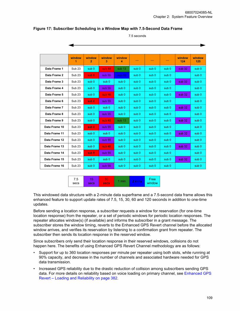
Figure 17: Subscriber Scheduling in a Window Map with 7.5-Second Data Frame
7.5 seconds
window1
window2
window3
window4 .... .... .... window
124 window
125
Data Frame 1 Sub 23 sub 0 sub 48 sub 13 sub 0 sub 0 sub 0 sub 32 sub 0
Data Frame 2 Sub 23 sub 8 sub 55 sub 43 sub 0 sub 0 sub 0 sub 0
Data Frame 3 Sub 23 sub 0 sub 0 sub 0 sub 0 sub 0 sub 0 sub 32 sub 0
Data Frame 4 Sub 23 sub 0 sub 55 sub 0 sub 0 sub 0 sub 0 sub 0
Data Frame 5 Sub 23 sub 0 sub 48 sub 0 sub 0 sub 0 sub 0 sub 32 sub 0
Data Frame 6 Sub 23 sub 8 sub 55 sub 0 sub 0 sub 0 sub 0 sub 0
Data Frame 7 Sub 23 sub 0 sub 0 sub 0 sub 0 sub 0 sub 0 sub 32 sub 0
Data Frame 8 Sub 23 sub 0 sub 55 sub 0 sub 0 sub 0 sub 0 sub 0
Data Frame 9 Sub 23 sub 0 sub 48 sub 13 sub 0 sub 0 sub 0 sub 32 sub 0
Data Frame 10 Sub 23 sub 8 sub 55 sub 0 sub 0 sub 0 sub 0 sub 0
Data Frame 11 Sub 23 sub 0 sub 0 sub 0 sub 0 sub 0 sub 0 sub 32 sub 0
Data Frame 12 Sub 23 sub 0 sub 55 sub 0 sub 0 sub 0 sub 0 sub 0
Data Frame 13 Sub 23 sub 0 sub 48 sub 0 sub 0 sub 0 sub 0 sub 32 sub 0
Data Frame 14 Sub 23 sub 8 sub 55 sub 0 sub 0 sub 0 sub 0 sub 0
Data Frame 15 Sub 23 sub 0 sub 0 sub 0 sub 0 sub 0 sub 0 sub 32 sub 0
Data Frame 16 Sub 23 sub 0 sub 55 sub 0 sub 0 sub 0 sub 0 sub 0
7.5secs
15secs
30secs 1 min 2 mins Free
window
This windowed data structure with a 2-minute data superframe and a 7.5-second data frame allows thisenhanced feature to support update rates of 7.5, 15, 30, 60 and 120 seconds in addition to one-timeupdates.
Before sending a location response, a subscriber requests a window for reservation (for one-timelocation response) from the repeater, or a set of periodic windows for periodic location responses. Therepeater allocates window(s) (if available) and informs the subscriber in a grant message. Thesubscriber stores the window timing, reverts to the Enhanced GPS Revert channel before the allocatedwindow arrives, and verifies its reservation by listening to a confirmation grant from repeater. Thesubscriber then sends its location response in the reserved window.
Since subscribers only send their location response in their reserved windows, collisions do nothappen here. The benefits of using Enhanced GPS Revert Channel methodology are as follows:
• Support for up to 360 location responses per minute per repeater using both slots, while running at90% capacity, and decrease in the number of channels and associated hardware needed for GPSdata transmission.
• Increased GPS reliability due to the drastic reduction of collision among subscribers sending GPSdata. For more details on reliability based on voice loading on primary channel, see Enhanced GPSRevert – Loading and Reliability on page 382.
68007024085-NLChapter 2: System Feature Overview
109

• More control over system throughput, by allowing users to choose the most appropriate windowsize, based on the location response characteristics needed.
• For a window size of 1, support up to 1808 location responses per minute per repeater using bothslots, while running at 90% capacity is possible. According to the memory limitation, 3616 radios fora 2-minute update per repeater using both slots cannot be supported, the maximum number ofradios allowed is only 2200. If there are more than 2200 radios, it is recommended to configure thetwo scheduled slots with two repeaters to share the loading.
• For a window size of 2, support up to 896 location responses per minute per repeater using bothslots, while running at 90% capacity is allowed.
When the CSBK data feature is enabled, the GPS and ARS data are compressed into a single CSBKdata. Window size 1 is only supported by MNIS mode because the window announcement getstransmitted through the repeater’s outbound air interface, while window size 2 is supported by both thecontrol station and MNIS mode. Window size 2 is supported for control station mode, while windowsize 2 and 1 are supported with the MNIS. A window size ranges from 5 to 10. In order to ease systemmigration when enabling the CSBK data feature, a window size of 5 to 10 can be considered as it isquite compatible with the CSBK data feature. The size depends on the following factors:
• The parameters that the application has requested in a location response, such as longitude,latitude, time, altitude, velocity, direction, and so on.
• Whether IP/UDP headers compression is enabled.
The following table shows the calculation for the window size with enhanced privacy enabled.
Table 14: Calculation for the Window Size with Enhanced Privacy Enabled
Requested Element LRRP Response Size (bytes)
Latitude + Longitude 11
Time 6
Request ID ** 3
Speed_hor * 3
Direction_hor 2
Altitude * 3
Radius * 2
* Variable sized fields
** Assume that Request ID value is smaller than 256.
The following calculations assume GPS data is unconfirmed and “Compressed UDP Data Header” isselected in the CPS.
For No Privacy: WindowSize = ((LRRPResponseSize + 1) ÷ 12) + 3
For Enhanced Privacy: WindowSize = ((LRRPResponseSize + 1) ÷ 12) + 4
If a subscriber is out of range or its battery is dead, GPS data is not sent GPS during its reservedwindows, so the repeater also has a mechanism to free up the windows reserved for that subscriber.The repeater waits for a certain period of time before releasing the windows and this time is dependenton the cadence rate of the subscriber’s location request. The table below summarizes the amount oftime the repeater waits before de-allocating windows for a subscriber.
68007024085-NLChapter 2: System Feature Overview
110
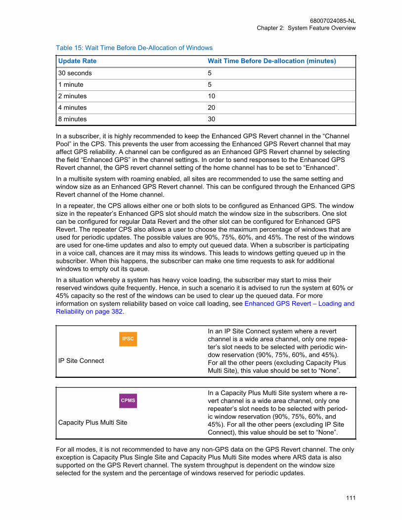
Table 15: Wait Time Before De-Allocation of Windows
Update Rate Wait Time Before De-allocation (minutes)
30 seconds 5
1 minute 5
2 minutes 10
4 minutes 20
8 minutes 30
In a subscriber, it is highly recommended to keep the Enhanced GPS Revert channel in the “ChannelPool” in the CPS. This prevents the user from accessing the Enhanced GPS Revert channel that mayaffect GPS reliability. A channel can be configured as an Enhanced GPS Revert channel by selectingthe field “Enhanced GPS” in the channel settings. In order to send responses to the Enhanced GPSRevert channel, the GPS revert channel setting of the home channel has to be set to “Enhanced”.
In a multisite system with roaming enabled, all sites are recommended to use the same setting andwindow size as an Enhanced GPS Revert channel. This can be configured through the Enhanced GPSRevert channel of the Home channel.
In a repeater, the CPS allows either one or both slots to be configured as Enhanced GPS. The windowsize in the repeater’s Enhanced GPS slot should match the window size in the subscribers. One slotcan be configured for regular Data Revert and the other slot can be configured for Enhanced GPSRevert. The repeater CPS also allows a user to choose the maximum percentage of windows that areused for periodic updates. The possible values are 90%, 75%, 60%, and 45%. The rest of the windowsare used for one-time updates and also to empty out queued data. When a subscriber is participatingin a voice call, chances are it may miss its windows. This leads to windows getting queued up in thesubscriber. When this happens, the subscriber can make one time requests to ask for additionalwindows to empty out its queue.
In a situation whereby a system has heavy voice loading, the subscriber may start to miss theirreserved windows quite frequently. Hence, in such a scenario it is advised to run the system at 60% or45% capacity so the rest of the windows can be used to clear up the queued data. For moreinformation on system reliability based on voice call loading, see Enhanced GPS Revert – Loading andReliability on page 382.
IPSC
IP Site Connect
In an IP Site Connect system where a revertchannel is a wide area channel, only one repea-ter’s slot needs to be selected with periodic win-dow reservation (90%, 75%, 60%, and 45%).For all the other peers (excluding Capacity PlusMulti Site), this value should be set to “None”.
CPMS
Capacity Plus Multi Site
In a Capacity Plus Multi Site system where a re-vert channel is a wide area channel, only onerepeater’s slot needs to be selected with period-ic window reservation (90%, 75%, 60%, and45%). For all the other peers (excluding IP SiteConnect), this value should be set to “None”.
For all modes, it is not recommended to have any non-GPS data on the GPS Revert channel. The onlyexception is Capacity Plus Single Site and Capacity Plus Multi Site modes where ARS data is alsosupported on the GPS Revert channel. The system throughput is dependent on the window sizeselected for the system and the percentage of windows reserved for periodic updates.
68007024085-NLChapter 2: System Feature Overview
111

The following table summarizes system throughput:
Table 16: The System Throughput
Window Size Number of Updates per Minute per Slot
90% 75% 60% 45%
1 904 752 600 456
2 448 376 304 224
5 180 150 120 90
6 150 125 100 75
7 128 107 86 64
8 112 93 75 56
9 100 83 66 50
10 90 75 60 45
NOTICE: These numbers are based on good signal conditions. The actual throughput andreliability may vary with RF conditions and voice call loading. For more details on loading-reliability relationship, see Enhanced GPS Revert – Loading and Reliability on page 382.
The Enhanced GPS feature can be configured in the following manner:
• Conventional Single-Site Mode
- One slot for voice, one slot for Enhanced GPS Revert
- One slot for GPS Revert, one slot for Enhanced GPS Revert
- Both slots for Enhanced GPS Revert
IPSC
IP Site Connect
• One slot for voice, one slot for EnhancedGPS Revert
• Both slots for Enhanced GPS Revert
• Both slots for Enhanced GPS Revert
CPSM
Capacity Plus Single Site and Capacity PlusMulti Site
• One slot of data revert repeater for GPS/ARS, one slot for all other data
• Both slots for Enhanced GPS Revert
If digital voting is enabled in a system with Enhanced GPS, some of the window sizes cannot be usedfor the Enhanced GPS feature:
• Capacity Plus Single Site
- If the system is a single site system, all window sizes 1 to 2 with CSBK data feature enabled, or5 to 10 may be used. Examples of such systems are Conventional Single Site.
IPSC• If the system is a single site IP Site Connect
system, all window sizes 1 to 2 with CSBK
68007024085-NLChapter 2: System Feature Overview
112

IP Site Connect data feature enabled, or 5 to 10 may beused.
• For multisite IPSC or Capacity Plus MultiSite, if the IP delay between sites is up to 60milliseconds, the window size must be 1 or 2with CSBK data feature enabled, or 7, orbigger. If the IP delay is up to 90 millisec-onds, the window size must be 1 or 2 withCSBK data feature enabled, or 8, or bigger.Otherwise, the GPS data may not be trans-mitted nor received properly.
CPSM
Capacity Plus Single Site and Capacity PlusMulti Site
• If the system is a single site Capacity PlusSingle Site or Capacity Plus Multi Site sys-tem, all window sizes 1 to 2 with CSBK datafeature enabled, or 5 to 10 may be used.
CPMS
Capacity Plus Multi Site
• For multi-site Capacity Plus Multi Site, if theIP delay between sites is up to 60 millisec-onds, the window size must be 1 or 2 withCSBK data feature enabled, or 7, or bigger.If the IP delay is up to 90 milliseconds, thewindow size must be 1 or 2 with CSBK datafeature enabled, or 8, or bigger. Otherwise,the GPS data may not be transmitted nor re-ceived properly.
For more information, see Single Site Conventional on page 323, IP Site Connect Mode on page 329,and Capacity Plus Single Site Mode on page 339.
2.12.3.6.1ARS Initialization DelayUpon power on, subscribers normally register with the Presence Notifier by sending ARS messagesimmediately. In a scenario where a user has a system with many subscribers powering on within ashort time, there can be many collisions between ARS registration messages. To reduce collisions, auser can configure the maximum value of an initial random delay for ARS registration through the CPS.This field is called “ARS Initialization Delay” and has a range of 0 minutes to 4 hours with a defaultvalue of 0 minutes.
A value of “0 minutes” defines that the ARS registration message is sent out between 5 seconds and15 seconds and this feature is essentially not delayed (5 seconds to 15 seconds was the existing delayin ARS registration prior to R01.07.00). If a user selects a value of “30 minutes”, then the subscriberrandomly chooses a time between 5 seconds and 30 minutes and sends the ARS when this randomtime elapses. This randomization of time between different subscribers sending the ARS reduce ARScollisions at power on.
When to use:• This feature can be used with Enhanced GPS to avoid collisions among large number of
subscribers sending ARS messages in a short period of time. However, the user must enable“Persistent LRRP Request” in the CPS to ensure that GPS data is still sent even if ARS is delayed.
68007024085-NLChapter 2: System Feature Overview
113
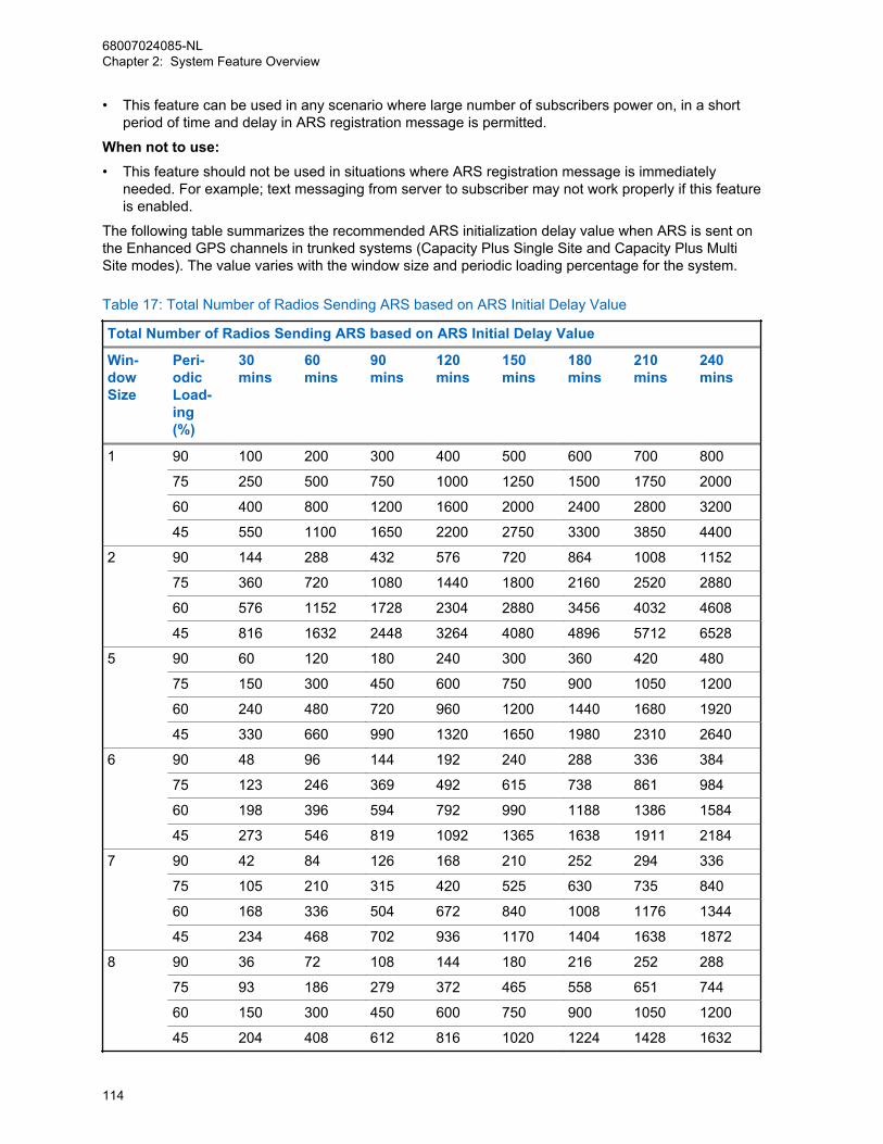
• This feature can be used in any scenario where large number of subscribers power on, in a shortperiod of time and delay in ARS registration message is permitted.
When not to use:• This feature should not be used in situations where ARS registration message is immediately
needed. For example; text messaging from server to subscriber may not work properly if this featureis enabled.
The following table summarizes the recommended ARS initialization delay value when ARS is sent onthe Enhanced GPS channels in trunked systems (Capacity Plus Single Site and Capacity Plus MultiSite modes). The value varies with the window size and periodic loading percentage for the system.
Table 17: Total Number of Radios Sending ARS based on ARS Initial Delay Value
Total Number of Radios Sending ARS based on ARS Initial Delay Value
Win-dowSize
Peri-odicLoad-ing(%)
30mins
60mins
90mins
120mins
150mins
180mins
210mins
240mins
1 90 100 200 300 400 500 600 700 800
75 250 500 750 1000 1250 1500 1750 2000
60 400 800 1200 1600 2000 2400 2800 3200
45 550 1100 1650 2200 2750 3300 3850 4400
2 90 144 288 432 576 720 864 1008 1152
75 360 720 1080 1440 1800 2160 2520 2880
60 576 1152 1728 2304 2880 3456 4032 4608
45 816 1632 2448 3264 4080 4896 5712 6528
5 90 60 120 180 240 300 360 420 480
75 150 300 450 600 750 900 1050 1200
60 240 480 720 960 1200 1440 1680 1920
45 330 660 990 1320 1650 1980 2310 2640
6 90 48 96 144 192 240 288 336 384
75 123 246 369 492 615 738 861 984
60 198 396 594 792 990 1188 1386 1584
45 273 546 819 1092 1365 1638 1911 2184
7 90 42 84 126 168 210 252 294 336
75 105 210 315 420 525 630 735 840
60 168 336 504 672 840 1008 1176 1344
45 234 468 702 936 1170 1404 1638 1872
8 90 36 72 108 144 180 216 252 288
75 93 186 279 372 465 558 651 744
60 150 300 450 600 750 900 1050 1200
45 204 408 612 816 1020 1224 1428 1632
68007024085-NLChapter 2: System Feature Overview
114

Total Number of Radios Sending ARS based on ARS Initial Delay Value
Win-dowSize
Peri-odicLoad-ing(%)
30mins
60mins
90mins
120mins
150mins
180mins
210mins
240mins
9 90 33 66 99 132 165 198 231 264
75 81 162 243 324 405 486 567 648
60 132 264 396 528 660 792 924 1056
45 183 366 549 732 915 1098 1281 1464
10 90 30 60 90 120 150 180 210 240
75 75 150 225 300 375 450 525 600
60 120 240 360 480 600 720 840 960
45 165 330 495 660 825 990 1155 1320
In conventional mode, when ARS is sent on the Home channel, the table below can be used as aguideline to choose the delay values based on voice call loading and the number of subscribers in thesystem.
Table 18: Number of Radios Sending ARS Based on ARS Initial Delay Value
Number of Radios Sending ARS Based on ARS Initial Delay Value
30mins
60mins
90mins
120mins
150mins
180mins
210mins
240mins
NoVoice
300 600 900 1200 1500 1800 2100 2400
LowVoice**
51 102 153 204 255 306 357 408
HighVoice**
24 48 72 96 120 144 168 192
** See Voice and Data Traffic Profile on page 366 for the definitions of “High Voice”, and “Low Voice”.
In conventional mode with CSBK data feature enabled, the table below can be used as a guideline tochoose the delay values. When the ARS initial delay value is zero, the number of radios illustrated inthe following table guarantees successful ARS registration of most radios within five minutes. Based on Figure 140: Number of Users per Slot versus User Experience on page 368, a large number of radioscan cause poor user experience for voice calls – numbers larger than 102 with a Low Voice profile andnumbers larger than 48 with High Voice profile are not recommended.
68007024085-NLChapter 2: System Feature Overview
115
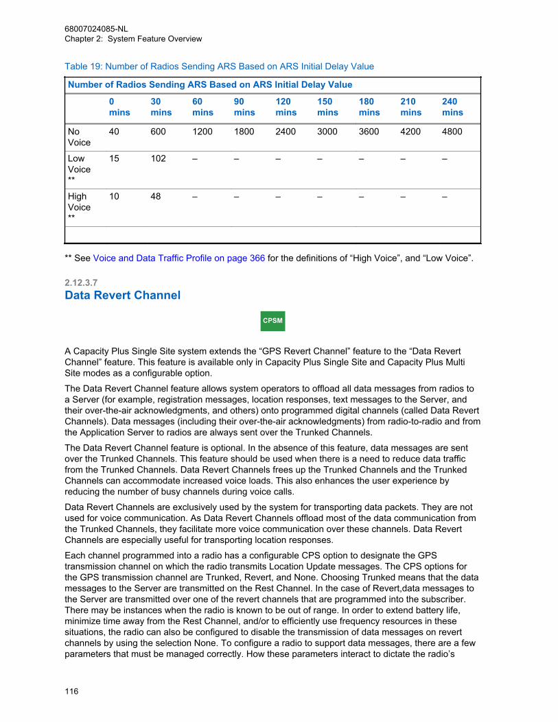
Table 19: Number of Radios Sending ARS Based on ARS Initial Delay Value
Number of Radios Sending ARS Based on ARS Initial Delay Value
0mins
30mins
60mins
90mins
120mins
150mins
180mins
210mins
240mins
NoVoice
40 600 1200 1800 2400 3000 3600 4200 4800
LowVoice**
15 102 – – – – – – –
HighVoice**
10 48 – – – – – – –
** See Voice and Data Traffic Profile on page 366 for the definitions of “High Voice”, and “Low Voice”.
2.12.3.7Data Revert Channel
CPSM
A Capacity Plus Single Site system extends the “GPS Revert Channel” feature to the “Data RevertChannel” feature. This feature is available only in Capacity Plus Single Site and Capacity Plus MultiSite modes as a configurable option.
The Data Revert Channel feature allows system operators to offload all data messages from radios toa Server (for example, registration messages, location responses, text messages to the Server, andtheir over-the-air acknowledgments, and others) onto programmed digital channels (called Data RevertChannels). Data messages (including their over-the-air acknowledgments) from radio-to-radio and fromthe Application Server to radios are always sent over the Trunked Channels.
The Data Revert Channel feature is optional. In the absence of this feature, data messages are sentover the Trunked Channels. This feature should be used when there is a need to reduce data trafficfrom the Trunked Channels. Data Revert Channels frees up the Trunked Channels and the TrunkedChannels can accommodate increased voice loads. This also enhances the user experience byreducing the number of busy channels during voice calls.
Data Revert Channels are exclusively used by the system for transporting data packets. They are notused for voice communication. As Data Revert Channels offload most of the data communication fromthe Trunked Channels, they facilitate more voice communication over these channels. Data RevertChannels are especially useful for transporting location responses.
Each channel programmed into a radio has a configurable CPS option to designate the GPStransmission channel on which the radio transmits Location Update messages. The CPS options forthe GPS transmission channel are Trunked, Revert, and None. Choosing Trunked means that the datamessages to the Server are transmitted on the Rest Channel. In the case of Revert,data messages tothe Server are transmitted over one of the revert channels that are programmed into the subscriber.There may be instances when the radio is known to be out of range. In order to extend battery life,minimize time away from the Rest Channel, and/or to efficiently use frequency resources in thesesituations, the radio can also be configured to disable the transmission of data messages on revertchannels by using the selection None. To configure a radio to support data messages, there are a fewparameters that must be managed correctly. How these parameters interact to dictate the radio’s
68007024085-NLChapter 2: System Feature Overview
116

performance is shown in Table 10: Interaction Between Parameters to Dictate Radio Performance onpage 105.
2.12.3.8Global Navigation Satellite SystemThe Global Navigation Satellite System (GNSS) feature is available for MOTOTRBO 2.0 GNSS modelsonly. This feature adds another independent satellite system (GLONASS or Beidou) to work with GPS.
• GLONASS (Global Navigation Satellite System) is a Russian global satellite system consisting of 24satellites, designed to provide positioning and velocity determination for government and civilianuse.
• Beidou is a satellite navigation system created by the People's Republic of China, named after theChinese constellation.
GLONASS or Beidou alone is slightly less accurate than GPS. However, the GNSS models, combiningGPS and GLONASS/Beidou, improves time to fix (TTF) and accuracy over GPS alone with theincreased number of satellites. The Radio menu shows the numbers of GPS and GLONASS/Beidousatellites separately in the GPS info.
The default GNSS setting could be “GPS+Beidou”, “GPS+GLONASS”, “Beidou Only” or “GLONASSOnly” depending on the countries that the GNSS radio models are sold. The User can change theGNSS setting through the CPS configuration. A GNSS radio can also be configured with “GPS only”mode, for example for power saving consideration.
2.12.3.9GPIO Triggered Event Driven and Distance Driven Location UpdateGPIO Triggered Event Driven Location Update is triggered by the radio’s GPIO status change. Thelocation information, timestamp and the GPIO Pin Status are combined as one location update.Therefore it’s easy for the location application to know when and where a GPIO Pin status change istriggered.
NOTICE: Both features are for MOTOTRBO 2.0 radios only (excluding the SL series)
Distance Driven Location Update is triggered when the distance traveled by a radio from the lastupdate exceeds specific values defined in the location server application. This feature reduces thenumber of location updates over the air when a radio is not moving or moving slowly.
2.12.4Telemetry ServicesThe MOTOTRBO radios incorporate telemetry functionality that is only supported in the digital mode ofoperation. Both the MOTOTRBO portable and mobile radio support General Purpose Input/Output(GPIO) lines on the radio accessory connector.
With this telemetry functionality, the originating radio can send a telemetry command to another radio.Sending the telemetry command can be triggered either by GPIO pins or a programmable button. Ineither case, the telemetry command can be sent out on the “normal traffic” channel (for example, theselected channel for single site conventional systems). Alternatively, in firmware versions R01.08.00and R01.08.10, if the telemetry command is triggered by a programmable button, the telemetrycommand can be sent out on a CPS configured telemetry channel that is selected from the “ChannelPool” or visible zone channels.
68007024085-NLChapter 2: System Feature Overview
117

NOTICE: When sending the telemetry command on the CPS configured telemetry channel (thatis, not the “normal traffic channel”), neither preambles nor retries are used. To avoid missing thetelemetry message, it is recommended for the receiving radio not to scan other channels, whenlistening on the telemetry receiving channel.Regardless of whether the home channel is analog or digital, when the telemetry revertfunctionality is initiated via predefined buttons, the radio leaves any ongoing call and initiatesthe telemetry command transmission on a digital revert channel.
Telemetry commands instruct GPIO pins on the target radio to be set, clear, toggle or pulse. Thetelemetry commands can also be used to query the status of GPIO pins at the target radio.
At the receiving end, the basic built-in telemetry functionality allows the target radio to translate thereceived telemetry command and to trigger GPIO action. The telemetry functionality also enables thetarget radio to display a programmed Text Status Message or act on a telemetry command receivedfrom the originating radio responding to an event at the originating radio's GPIO pins. The TelemetryText Status Message is provisioned in the source telemetry radio and is displayed as a pop-up alert ata target radio through the telemetry application. Since the Telemetry Text Status Message is not sentas a standard text message, it is not saved in the Inbox or indexed. Furthermore, its target can only beanother radio since it must be received and processed by the telemetry application within the radio.
It is possible for the message to be forwarded to an external computer connected to the radio, or theoption board, where a customer supplied application could monitor and take an action. MOTOTRBOprovides a telemetry interface for third-party telemetry applications.
Telemetry over-the-air signaling utilizes the data service similar to the way that text messaging works.It can co-exist with voice and text messaging. If telemetry messages are expected to occur often, forexample 30 radios sending telemetry once every five minutes, this may affect performance of otherservices on the channel. This should be taken into consideration when determining the data loadversus quality of service of a channel.
2.12.4.1Physical Connection InformationThe MOTOTRBO portable offers three GPIO pins, and the MOTOTRBO mobile offers five GPIO pinsfor telemetry. These GPIO pins can be set to high or low, toggled, or pulsed for a configured duration.A pin can be configured to be active high or active low. It is recommended to use an AC-poweredMOTOTRBO mobile for most extended telemetry applications. Motorola Solutions does not currentlyoffer external hardware for telemetry configuration.
The GPIO lines have a 4.7k ohm pull-up resistor tied to a regulated 5 VDC supply within the mobileradio. The regulated supply remains on as long as power is supplied to the mobile, even if the mobile isturned off so the pull-ups are active even when the radio is off.
When configured as input, the voltages of the GPIO lines should be within the range of 0 VDC to 5.5VDC.
• 0 VDC to 0.8 VDC are interpreted as low level
• 2.2 VDC to 5.5 VDC are interpreted as high level
When configured as output, the GPIO are able to source a current of 1mA maximum at the followinglevels:
• 4.7 VDC to 5.5 VDC for a high level
• 0 VDC to 0.8 VDC for a low level
68007024085-NLChapter 2: System Feature Overview
118
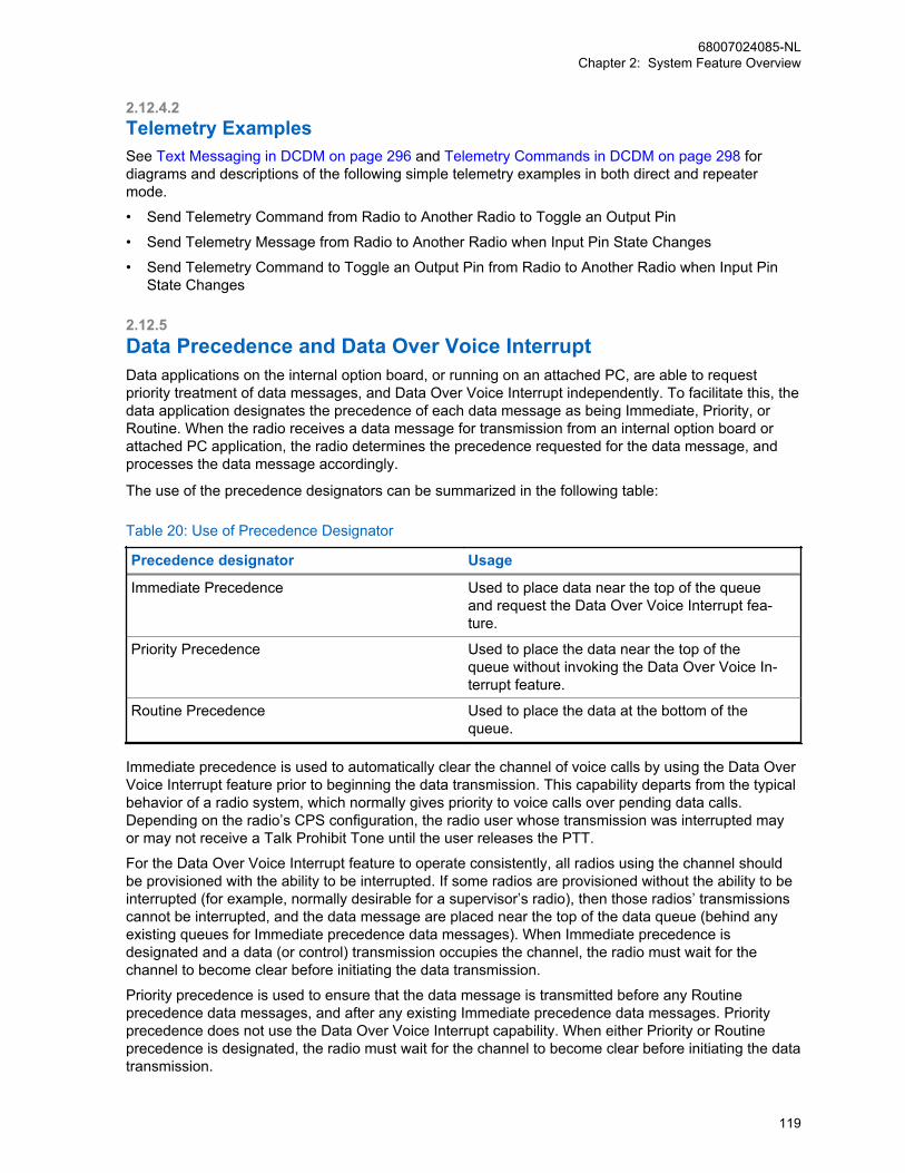
2.12.4.2Telemetry ExamplesSee Text Messaging in DCDM on page 296 and Telemetry Commands in DCDM on page 298 fordiagrams and descriptions of the following simple telemetry examples in both direct and repeatermode.
• Send Telemetry Command from Radio to Another Radio to Toggle an Output Pin
• Send Telemetry Message from Radio to Another Radio when Input Pin State Changes
• Send Telemetry Command to Toggle an Output Pin from Radio to Another Radio when Input PinState Changes
2.12.5Data Precedence and Data Over Voice InterruptData applications on the internal option board, or running on an attached PC, are able to requestpriority treatment of data messages, and Data Over Voice Interrupt independently. To facilitate this, thedata application designates the precedence of each data message as being Immediate, Priority, orRoutine. When the radio receives a data message for transmission from an internal option board orattached PC application, the radio determines the precedence requested for the data message, andprocesses the data message accordingly.
The use of the precedence designators can be summarized in the following table:
Table 20: Use of Precedence Designator
Precedence designator Usage
Immediate Precedence Used to place data near the top of the queueand request the Data Over Voice Interrupt fea-ture.
Priority Precedence Used to place the data near the top of thequeue without invoking the Data Over Voice In-terrupt feature.
Routine Precedence Used to place the data at the bottom of thequeue.
Immediate precedence is used to automatically clear the channel of voice calls by using the Data OverVoice Interrupt feature prior to beginning the data transmission. This capability departs from the typicalbehavior of a radio system, which normally gives priority to voice calls over pending data calls.Depending on the radio’s CPS configuration, the radio user whose transmission was interrupted mayor may not receive a Talk Prohibit Tone until the user releases the PTT.
For the Data Over Voice Interrupt feature to operate consistently, all radios using the channel shouldbe provisioned with the ability to be interrupted. If some radios are provisioned without the ability to beinterrupted (for example, normally desirable for a supervisor’s radio), then those radios’ transmissionscannot be interrupted, and the data message are placed near the top of the data queue (behind anyexisting queues for Immediate precedence data messages). When Immediate precedence isdesignated and a data (or control) transmission occupies the channel, the radio must wait for thechannel to become clear before initiating the data transmission.
Priority precedence is used to ensure that the data message is transmitted before any Routineprecedence data messages, and after any existing Immediate precedence data messages. Priorityprecedence does not use the Data Over Voice Interrupt capability. When either Priority or Routineprecedence is designated, the radio must wait for the channel to become clear before initiating the datatransmission.
68007024085-NLChapter 2: System Feature Overview
119
NOTICE: The Data Precedence and Data Over Voice Interrupt features do not need to beconfigured in the radio or repeater via the CPS because these features are always available.
For more information on the Data Precedence and Data Over Voice Interrupt features, please refer tothe MOTOTRBO Option Board ADK Development Guide on the MOTODEV Application Developerswebsite https://mototrbodev.motorolasolutions.com
2.12.6Enhanced Job TicketsMOTOTRBO Job Tickets also known as “Work Tickets” allow the system dispatcher server applicationto manage the flow of tasks by sending and assigning Job Tickets (tasks) to one or multiple radios. Theradio users work on the assigned tasks and move the tasks to different preconfigured states such as“New” state, “In Progress” state, and others, according to the progress of the tasks. The modified tasksare sent back from the radio to the dispatcher application server.
A number of MOTOTRBO application developer program solutions can create and manage job ticketswhich makes this feature extremely useful in service organizations (for example the hotel staff, taxi,security staff, and others). The enhanced Job Tickets application is not compatible with the legacy TextMessage based Job Tickets application.
2.12.6.1Job Tickets RegistrationThe Subscriber Unit ID (SUID) and User ID registrations are supported through the ARS registrationsystem topology. The PC Job Tickets application supports the Conventional, IP Site Connect andCapacity Plus Multi Site ARS Presence Interface. The PC Job Tickets presence application mayregister to the Presence Interface for receiving the Radio subscriber’s presence (SUID and User ID)and associate them for device and user level Job Tickets management. Job Tickets Registration is alsosupported on the Conventional system.
IPSC
IP Site Connect
The Job Tickets Registration is supported on IPSite Connect mode.
CPMS
Capacity Plus Multi Site
The Job Tickets Registration is supported onCapacity Plus Multi Site mode.
2.12.6.2Common Job Tickets Data CommunicationAn Enhanced Job Tickets Protocol (EJTP) specification is defined for message exchanges betweenthe communicating devices. The JTP can be communicated over a variety of transport mechanisms.The messages exchanged by JTP are XML documents. The design allows for extension to support
68007024085-NLChapter 2: System Feature Overview
120
future Job Ticket requirements. Job Tickets Data Communication is also supported on theConventional system.
IPSC
IP Site Connect
The Job Tickets Data Communication is sup-ported on IP Site Connect mode.
CPMS
Capacity Plus Multi Site
The Job Tickets Data Communication is sup-ported on Capacity Plus Multi Site mode.
In order to address the limited OTA Radio network bandwidth available, the encoding of JTP messagesare based on the Motorola Solutions Binary Extensible Markup Language (MBXML) for OTA LMRRadio network transfer. MBXML was explicitly designed to efficiently encode JTP XML documents.
The Subscriber Unit supports a Radio Management (RM) configurable Job Tickets application serverSUID and UDP port for the Subscriber Unit, for sending Subscriber created Job Tickets to theapplication server. The MNIS application supports routing of the Job Tickets data application to theconnected Job Tickets application. The JT application server IP address is derived from the SubscriberIP address mapping scheme. The Subscriber Unit sends locally created ticket to this IP address. Seethe following examples:
• CAI Network = 10 (RM configurable)
• JT Server SUID = 2 (RM configurable)
• JT Server IP Network = CAI Network + 1 (derived)
• JT Server IP Address = (JT Server IP Network + JT Server SUID) = (11.0.0.2) (derived)
The Subscriber Unit supports a fixed internal receive UDP port (0x0FAD), for receiving Job TicketsProtocol IP datagram. The PC Job Tickets server application can send tickets to an individual or agroup of Subscriber Units through the MNIS interface. When the Subscriber Unit sends the response tothe received Job Ticket, it uses the source IP address and UDP port from the received message as thedestination address and port.
The Subscriber Unit supports a CPS/RM configurable “Forward to PC” function for forwarding theSubscriber Unit received Job Tickets UDP datagram to the Subscriber connected PC network (that isthe CAI+1 network) as a pass-through operation. All Job Tickets targeted to the Subscriber internal JobTickets UDP port and IP address are forwarded to the locally connected PC network.
The Job Tickets application IP datagram are sent through the system Trunk Channel between theSubscriber Unit and the MNIS. The MNIS application supports the routing of the data to/from the PCJob Tickets application. The maximum Job Ticket data payload size is 1000 bytes.
2.12.6.3Common Job Tickets Inbox FoldersThe Subscriber Unit supports storing or sorting two types of Job Tickets Menu inbox messages like“My Tasks” and “Shared Tasks”. The “Shared Tasks” is a public type which could be accessed by anyuser. The “My Tasks” is a private type which can only be accessed by the matching User ID that has
68007024085-NLChapter 2: System Feature Overview
121

logged in to the Subscriber Unit. Job Tickets Data Communication is also supported on a Conventionalsystem.
IPSC
IP Site Connect
The Job Tickets Data Communication is sup-ported on IP Site Connect mode.
CPMS
Capacity Plus Multi Site
The Job Tickets Data Communication is sup-ported on Capacity Plus Multi Site mode.
The Job Tickets dispatcher server application sends the tickets to the specified User ID or as a publicmessage type. If the dispatcher sends the ticket to the specified User ID and the user is not logged in,the Subscriber Unit just stores the message without providing any user feedback. When the matchingUser ID is logged into the Subscriber Unit, the private messages are accessible.
The Status Folder are CPS or RM configurable for the Job Tickets inbox messages. Both “My Tasks”and “Shared Tasks” folders share the same Status Folders configuration. The Job Tickets Inbox storesup to 500 received messages for both “My Tasks” and “Shared Tasks”. When the Job Ticket status ismodified, the Subscriber Unit sends a response message to the server application and move the ticketto the corresponding Status Folder. When the Subscriber Unit’s Job Ticket Inbox is full, the oldestcompleted task will be deleted for storing the new incoming message. The Subscriber Unit sendsonetime broadcast message for the deleted message to the Job Tickets server application.
2.12.6.4Subscriber Created Job TicketsThe Subscriber Unit supports the creation of new Job Ticket, and sends it to the preconfigured JobTickets server application IP Address and UDP port.
The new ticket creation is governed by the CPS or RM preconfigured templates. After the ticket hasbeen sent to the server application successfully, the ticket is stored in the Job Ticket outbound “SentTasks” folder. A success or failure icon is used for message sent status. The user can resend thefailure messages through the Sent Tasks menu. The Job Tickets “Sent Tasks” folder can store up to 30created tickets. When the “Sent Tasks” folder is full, the oldest ticket is deleted to allow a newly createdticket to be stored.
2.12.6.5Delete All Job TicketsThe portable or mobile radio supports a Customer Programmable Software (CPS) or RadioManagement (RM) configurable field, for deleting all Job Tickets at power up. If Delete All Job Ticketsis enabled, the radio deletes both public and private Job Tickets at power up.
2.12.6.6MNIS NetworkThe following are the three types of MNIS Networks:
CAI NetworkThis field must be the same as CAI (Comment Air Interface) Network assignment of the radios. Theradio has multiple CAI IP addresses such as Internal Network Address, External Network Address,
68007024085-NLChapter 2: System Feature Overview
122

and Bluetooth Network Address. The addresses are Class A addresses using the network IDs suchas CAI Network, CAI Network+1, and CAI Network+2. As a default CAI Network setting, the CAI IPaddresses have Class A network IDs of 12, 13 and 14. Typically one would leave the assignment tothe default unless the radio IP addresses resulting from the default setting would conflict with IPaddresses of other devices on the customer’s network. For more information, see MOTOTRBONetwork Interface Service (MNIS) and Device Discovery and Mobility Service (DDMS) on page 456.
CAI Group NetworkThis field must be the same as CAI (Comment Air Interface) Network assignment of the talkgroup,and also must be the same as CAI Group Network assignment of the radios. The talkgroups haveMulticast IP addresses with network ID of CAI Group Network. The consideration are similar as CAINetwork applies for CAI Group Network.
Job Tickets UDP PortThis field represents the Job Tickets Data Application UDP port. Since most of the MOTOTRBOJob Tickets applications use this port as default, typically a user leaves the assignment to thedefault. If there is port conflict, this port could be changed.
NOTICE: See the MNIS System Planner for other MNIS configuration to deploy a system.
2.13Indoor LocationThis section describes the indoor location operation in conjunction with the outdoor (such as GPS)location support. The indoor location feature is supported in LCP, IPSC, Cap Max, Connect Plus, andConventional digital operation modes. The indoor location configurations and operation along withoutdoor location operation are described in this section.
2.13.1iBeaconiBeacon is Apple's implementation of Bluetooth Low Energy (BLE) wireless technology to create adifferent way of providing location-based information and services to iPhones and other iOS devices.
The iBeacon is the dominant beacon devices in the market today. The iBeacon is not the only beacondevice on the market. There are other non-Apple beacons in the market, but MOTOTRBO onlysupports iBeacon in release 2.5. Apple does not develop the beacons. They are manufactured by third-parties such as Estimote, Roximity & Gimbal. Estimote is the preferred iBeacon vendor forMOTOTRBO internal test and development.
2.13.2Indoor Location OperationMOTOTRBO radio software listens for the signal transmitted by the ibeacons and it sends the datafrom the radio to the server application, which requested for the beacons data. The beacons data aremapped to the strategically deployed indoor location, and presented to the user via a mappingapplication.
The indoor location operation leverages the same outdoor (that is, GPS) location request/responsesystem topology and LRRP protocol to support both indoor and outdoor location request/responsemessaging. The indoor location data is encapsulated in the LRRP protocol with or without the outdoor(that is, GPS) location data. Thus, either indoor and/or outdoor data can be requested by the LRRPinitiating application. The radio sends a response message according to the LRRP request. The LRRPinitiator can request for one or more iBeacon data set.
68007024085-NLChapter 2: System Feature Overview
123

Figure 18: Indoor Location Operation
Radio Subscriber
BLEBeaconAdvertizing
Client/ServerApplications Control
Center
Radio RF/ Data Networks
(MNIS, Repeaters, Control Station, XRC, etc.)
3 Party Location Server/ Mapping Applications
rd
LRRP
2.13.3iBeacon Configuration and Operation ParametersWhen selecting an off-the-shelf iBeacon for indoor location deployment, it is recommended that thefollowing iBeacon device protocol attributes and operation parameters should be programmable:
UUIDIs a region identifier that distinguishes your iBeacons from others.
MajorIs used to group a related set of iBeacons for location mapping.
MinorIs used to identify an individual iBeacons for location mapping.
Tx PowerTwo′s complement of measured beacon Tx power. The actual Tx power can be calculated as a two′s complement of the data: (0xC5 = 197 => 256-197 = -59 dBm). Tx power is the strength of thesignal measured at 1 meter from the iBeacon.
BLE Advertisement Time IntervalSpecifies the beacon periodic advertisement broadcast interval.
NOTICE: It is important to understand that there is a beacon battery life; the BLEAdvertisement Time Interval settings. When the beacon device is configured for morefrequent broadcast transmission, it consumes more power.
Omni-Directional Antenna with Configurable Range.Specifies the configurable range for Omni-Directional Antenna.
NOTICE: Not all parameters are used for their indoor location deployment, as it depends on thecustomer’s requirements.
2.13.4iBeacon Deployment ConsiderationsWhen selecting an off-the-shelf iBeacon for indoor location deployment, it is important that the devicevendor provides the software tools for the remote fleet management and analytics.
For example, Estimote provides a fleet management tool (iOS and Android base) for batch beaconupdate. Once the user starts the batch update, new configurable settings are applied to beacons whenthe user is in range. The update continues in the background, therefore the Estimote application doesnot have to be active during the process. When the user leaves the range of beacons, the update stopsand then seamlessly continues in the background once the user is back in range. The applicationremembers the beacons, which are pending update. Estimote provides iOS and Android baseapplication for beacon site survey proposes, and it can even modify the beacon configurableparameters as needed.
68007024085-NLChapter 2: System Feature Overview
124
2.13.4.1iBeacon UUID and Radio Operation ConsiderationsThe iBeacon vendor ships the iBeacon devices with the same vendor UUID in all iBeacon devices.When deploying a system, the site must be surveyed to track for other people’s iBeacon devices toensure your iBeacon UUID is not the same as the other collocated party’s iBeacon devices.
Only the desired UUIDs are programmed into the Radio for iBeacon device detection. The iBeacondevices must be programmed with the same UUID within the same site or region. If the site happens tohave two different iBeacon system deployments with the same UUID, and the radio detects the otherparty’s collocated iBeacons, it impacts the radio iBeacon device detection performance, bufferingscheme, and unnecessary Radio OTA report overhead. When the radio detects the UUID from adifferent iBeacon system deployment, the third-party mapping application filters for their deployedunique iBeacon Major or Minor value for mapping purpose.
2.13.4.2iBeacon BLE Advertisement Time Interval and Radio Scan ModeOperation ConsiderationsThe following are the iBeacon BLE Advertisement Interval Rate and Scan Mode Operation parametersconsiderations:
Scan ModeIs a Radio Management (RM) or Customer Programmable Software (CPS) configurable parameter.This field is used for configuring the Bluetooth advertisement scan bandwidth. When “Normal” isselected, the radio uses 50% of the 100ms Bluetooth scan advertisement bandwidth to performscan within the “Scan Interval On Time”. If “Aggressive” is selected, the radio uses 75% of the100ms Bluetooth scan advertisement bandwidth to perform the scan within the “Scan Interval OnTime”. The “Scan Mode” is only available when the radio is not associated to a Wi-Fi access point.If the radio is associated to a Wi-Fi access point, then the radio automatically uses only 20% of the100ms Bluetooth scan advertisement bandwidth to perform scan within the “Scan Interval OnTime”.
Scan Interval On TimeIs a RM or CPS configurable parameter. It instructs the Radio to turn on BLE scanning for theconfigured time. The “Scan Interval On/Off Time” is a duty cycle. When the Indoor Location isturned on, the radio performs the BLE scan continuously base on this duty cycle until it is turned offby the user.
Scan Interval Off TimeIs a RM or CPS configurable parameter. It instructs the radio to turn off BLE scanning for theconfigured time.
The iBeacon BLE Advertisement Interval Rate is configured in the iBeacon device for a specific timingdeployment need. This beacon advertisement interval rate is configured to meet each deploymenttiming requirements. On the radio CPS, the “Scan Mode” field is used for configuring the Bluetoothscan advertisement bandwidth. When “Normal” is selected, the radio uses 50% of the radio Bluetoothadvertisement scan bandwidth to perform scan within the configured “Scan Interval Time = ON” time. If“Aggressive” is selected, the radio uses 75% of the radio Bluetooth advertisement scan bandwidth toperform the scan within the configured “Scan Interval Time = ON” time. If the radio is connected to aBluetooth headset, the Bluetooth advertisement scan bandwidth is reduced. The “Scan Mode” is onlyavailable when the radio is not associated to a Wi-Fi access point. If the radio is associated to a Wi-Fiaccess point, then the radio automatically uses only 20% of the Bluetooth advertisement scanbandwidth to perform scan. Misalignment of the iBeacon Advertisement Interval which lands on theRadio advertisement scan OFF window may cause the radio unable to detect the beacons. A detailedtiming calculation must be performed to align the radio Bluetooth scanning and beacon advertisementinterval for better beacon detection performance. It is also recommended to use two beacons or more
68007024085-NLChapter 2: System Feature Overview
125

to cover the radio walk-path at one location, to provide better beacon detection performance. Adetailed site survey must be done for every deployed beacon coverage spot.
The following table shows the examples of timing configurations:
Operation Example Timing Configuration
Radio Bluetooth or WiFi Coexistence Operation iBeacon Device BLE Advertisement IntervalRate (programmable in the iBeacon device)
Bluetooth Only The Radio BLE scan advertisement bandwidthis only 50% in every 100ms duty cycle withinthe configured “Scan Interval On Time”. TheiBeacon BLE Advertising Interval Rate valuelast 2 digits should be configured to end with51ms (that is 151ms, 251ms, 551ms, and oth-ers) when possible. This configuration allowsthe radio to better distribute the Scan advertise-ment bandwidth on/off cycle. This is for betteralignment with the iBeacon Advertising Interval,for better detection performance. For example,see Figure 19: Beacon Interval of 151ms andRadio Normal Scan Mode Detection Alignmenton page 127. If the suggested time increment isnot supported, the beacon interval should beconfigured in such a way that it could get bestpossible alignment to land on the radio BLEscan advertisement On window.
Bluetooth and WiFi Coexisted When WiFi connection is active, the radio scanadvertisement bandwidth is 20% in every100ms duty cycle within the configured “ScanInterval On Time”. The iBeacon BLE Advertis-ing Interval Rate value last 2 digits should beconfigured to end with 81ms (that is 181ms,281ms, 381ms, and others) when possible. Thisconfiguration allows the radio to better distributethe Scan advertisement bandwidth on/off cycle.This helps to better align with the iBeacon Ad-vertising Interval for better detection perform-ance. A faster iBeacon BLE AdvertisementTime Interval Rate is desired in this mode forbetter detection performance.
The following figure assumes that there is no interference, good RF condition, and that the radio is ableto detect the beacon in the 50ms scan on window (Hit), and unable to detect the beacon in the 50msscan off window (Miss). It assumes the beacon initial random starting point is at the 70ms time markwith a beacon interval of 151ms. When the beacon advertising is aligned within the Hit window, it is asuccessful detection. When the beacon advertising is aligned within the missed window, it is a faileddetection. In this example, the number of Hit within a scan interval cycle is 3 (at 221ms, 523ms, and825ms). For other beacon interval value, which may not be aligned with the radio scan advertisementon window, it may not able to detect the beacon at all. User must calculate the probability of thebeacon interval and radio scan advertisement window alignment to optimize detection performance.
68007024085-NLChapter 2: System Feature Overview
126

Figure 19: Beacon Interval of 151ms and Radio Normal Scan Mode Detection Alignment
Beacon Interval 151ms
Time
(BLE Scan Window 50ms/50ms On/Off; 1000ms/100ms Scan Interval On/Off Cycle)
50ms On
50ms Off
50ms On
50ms Off
50ms On
50ms Off
50ms On
50ms Off
50ms On
50ms Off
50ms On
50ms Off
50ms On
50ms Off
50ms On
50ms Off
50ms On
50ms Off
50ms On
50ms Off
100ms Scan Interval Off
50ms On
50ms Off
50ms On …….
70ms 221ms 372ms 523ms
100ms 300ms 500ms
674ms 825ms
700ms
976ms 1127ms
The following figure assumes there is no interference, good RF condition and the radio is able to detectthe beacon in the 20ms scan on window (Hit), and unable to detect the beacon in the 80ms scan offmissed window. It assumes the beacon initial random starting point is at the 70ms time mark with abeacon interval of 181ms. When the beacon advertising is aligned within the Hit window, it is asuccessful detection. When the beacon advertising is aligned within the missed window, it is a faileddetection. In this example, the number of Hit within a scan interval cycle is 1 (at 613ms) only. For otherbeacon interval value, which may not be aligned with the radio scan advertisement on window, it maynot able to detect the beacon at all. User must calculate the probability of the beacon interval and radioscan advertisement window alignment to optimize detection performance.
Figure 20: Beacon Interval of 181ms and Radio WiFi Coexistence Mode Detection Alignment
Beacon Interval 181ms
Time
(BLE Scan Window 20ms On/80ms Off; 1000ms/100ms Scan Interval On/Off Cycle)
70ms 251ms 432ms 613ms
100ms 300ms 500ms
794ms 975ms
700ms
1156ms
20ms On
80ms Off
20ms On
80ms Off
20ms On
80ms Off
20ms On
80ms Off
20ms On
80ms Off
20ms On
80ms Off
20ms On
80ms Off
20ms On
80ms Off
20ms On
80ms Off
20ms On
80ms Off
100 Scan Interval Off
20ms On
80ms Off …
2.13.4.3Radio CPS Configurable Scan Interval On/Off Time OperationConsiderationsThe CPS configurable “Scan Interval On/Off Time” is used for turning on/off the Bluetooth scanning foriBeacon devices.
The actual scan active duty cycle is controlled by the predefined BLE Scan Advertisement bandwidth.See iBeacon BLE Advertisement Time Interval and Radio Scan Mode Operation Considerations onpage 125 for more information. The radio buffers the detected iBeacon devices in every BluetoothScan Interval Time On/Off cycle in the volatile memory. The same iBeacon may be detected multiple
68007024085-NLChapter 2: System Feature Overview
127
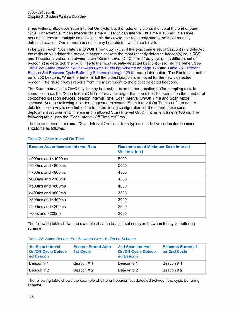
times within a Bluetooth Scan Interval On cycle, but the radio only stores it once at the end of eachcycle. For example, “Scan Interval On Time = 5 sec; Scan Interval Off Time = 100ms”, if a samebeacon is detected multiple times within this duty cycle, the radio only stores the most recentlydetected beacon. One or more beacons may be detected within each cycle.
In between each “Scan Interval On/Off Time” duty cycle, if the exact same set of beacon(s) is detected,the radio only updates the previous beacon set with the most recently detected beacon(s) set’s RSSIand Timestamp value. In between each “Scan Interval On/Off Time” duty cycle, if a different set ofbeacon(s) is detected, the radio inserts the most recently detected beacon(s) set into the buffer. See Table 22: Same Beacon Set Between Cycle Buffering Scheme on page 128 and Table 23: DifferentBeacon Set Between Cycle Buffering Scheme on page 129 for more information. The Radio can bufferup to 200 beacons. When the buffer is full the oldest beacon is removed for the newly detectedbeacon. The radio always reports from the most recent to the oldest detected beacons.
The Scan Interval time On/Off cycle may be treated as an Indoor Location buffer sampling rate. Insome scenarios the “Scan Interval On time” may be longer than the other. It depends on the number ofco-located iBeacon devices, beacon Interval Rate, Scan Interval On/Off Time and Scan Modeselected. See the following table for suggested minimum “Scan Interval On Time” configuration. Adetailed site survey is needed to fine tune the timing configuration for the different use casedeployment requirement. The minimum allowed Scan Interval On/Off increment time is 100ms. Thefollowing table uses the “Scan Interval Off Time =100ms”.
The recommended minimum “Scan Interval On Time” for a typical one to five co-located beaconsshould be as followed:
Table 21: Scan Interval On Time
Beacon Advertisement Interval Rate Recommended Minimum Scan Interval On Time (ms)
>900ms and <1000ms 5000
>800ms and <900ms 5000
>700ms and <800ms 4500
>600ms and <700ms 4500
>500ms and <600ms 4000
>400ms and <500ms 3500
>300ms and <400ms 3000
>200ms and <300ms 2500
>0ms and <200ms 2000
The following table shows the example of same beacon set detected between the cycle bufferingscheme:
Table 22: Same Beacon Set Between Cycle Buffering Scheme
1st Scan IntervalOn/Off Cycle Detect-ed Beacon
Beacon Stored After1st Cycle
2nd Scan IntervalOn/Off Cycle Detect-ed Beacon
Beacons Stored af-ter 2nd Cycle
Beacon # 1 Beacon # 1 Beacon # 1 Beacon # 1
Beacon # 2 Beacon # 2 Beacon # 2 Beacon # 2
The following table shows the example of different beacon set detected between the cycle bufferingscheme:
68007024085-NLChapter 2: System Feature Overview
128
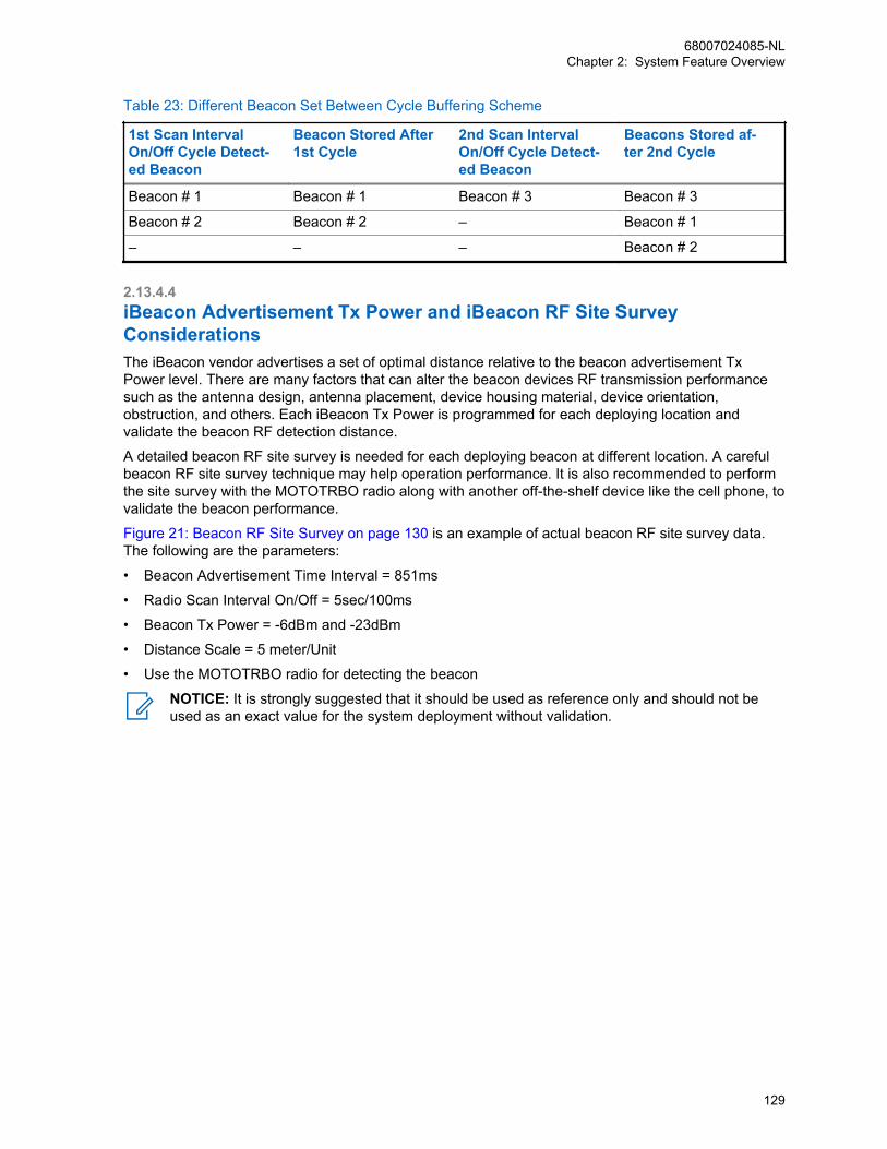
Table 23: Different Beacon Set Between Cycle Buffering Scheme
1st Scan IntervalOn/Off Cycle Detect-ed Beacon
Beacon Stored After1st Cycle
2nd Scan IntervalOn/Off Cycle Detect-ed Beacon
Beacons Stored af-ter 2nd Cycle
Beacon # 1 Beacon # 1 Beacon # 3 Beacon # 3
Beacon # 2 Beacon # 2 – Beacon # 1
– – – Beacon # 2
2.13.4.4iBeacon Advertisement Tx Power and iBeacon RF Site SurveyConsiderationsThe iBeacon vendor advertises a set of optimal distance relative to the beacon advertisement TxPower level. There are many factors that can alter the beacon devices RF transmission performancesuch as the antenna design, antenna placement, device housing material, device orientation,obstruction, and others. Each iBeacon Tx Power is programmed for each deploying location andvalidate the beacon RF detection distance.
A detailed beacon RF site survey is needed for each deploying beacon at different location. A carefulbeacon RF site survey technique may help operation performance. It is also recommended to performthe site survey with the MOTOTRBO radio along with another off-the-shelf device like the cell phone, tovalidate the beacon performance.
Figure 21: Beacon RF Site Survey on page 130 is an example of actual beacon RF site survey data.The following are the parameters:
• Beacon Advertisement Time Interval = 851ms
• Radio Scan Interval On/Off = 5sec/100ms
• Beacon Tx Power = -6dBm and -23dBm
• Distance Scale = 5 meter/Unit
• Use the MOTOTRBO radio for detecting the beacon
NOTICE: It is strongly suggested that it should be used as reference only and should not beused as an exact value for the system deployment without validation.
68007024085-NLChapter 2: System Feature Overview
129

Figure 21: Beacon RF Site Survey
0
5
10
15
20
25
301
2
3
4
5
6
7
8
-23dbm-6dbm
Based on the beacon detection distance/coverage area plot in Figure 21: Beacon RF Site Survey onpage 130, even when the beacon is placed on the ground in an open space, the detection distancevaries from point to point. Quadrant 1–2 has the best distance and coverage area, and quadrant 5–7has the worst coverage. User can conclude that the beacon RF coverage is not a perfect circle. This iswhy a beacon RF site survey is needed when deploying every beacon.
NOTICE: Most of the off-the-shelf iBeacon device vendors would not advise the user on theBluetooth antenna location in the device. As a conclusion on where the beacon antenna isplaced, user can point between Point 1 and 2, because it has the best distance and coveragearea from both plots with different Tx Power.
2.13.4.4.1Conducting the RF Site SurveyThe following are the procedures to conduct the site survey:
Procedure:1 Place the beacon on the ground in an open space without any obstruction at the origin point “0”.
See Figure 21: Beacon RF Site Survey on page 130.
2 Hold the MOTOTRBO radio in the hand for detecting the beacon.
It is also recommended to use a mobile phone that can detect the iBeacon to perform the surveysimultaneously.
68007024085-NLChapter 2: System Feature Overview
130
3 Walk from out-of-range point to in-range point direction, toward to the beacon with the radio indirect line-of-sight with the beacon.
NOTICE: It is very important to avoid walking the opposite way. When the user is inbetween the radio and the beacon, it may block the RF energy and cause unpredictableresult. This beacon RF site survey technique provides a better beacon deployment in differentsituations.
4 Start walking from Point 1 (at the 30 meter mark) toward the beacon at the Scan Interval On/Offcycle time for every 1 meter (1m in 5 seconds) and record the beacon detection distance resulton both Radio.
5 Repeat Step 4 for Point 1 to Point 8.
The beacon distance detection result is plotted in Red for the -6dBm Tx Power, and the -23dBm Tx Power is plotted in Blue.
2.13.4.5Other iBeacon Deployment ConsiderationsOnce the beacon RF coverage is known, it is static for the deployment. However, the environmentaround the beacon may change such as obstruction may move in and block the beacon. To minimizethis uncertain environment which may impact the beacon performance, a strategic beacon placementis important at deployment.
For example, if the iBeacons are being deployed in a shopping mall, it is preferred not to mount thebeacon at human body waist level, because there could be many people around and block the beaconfrom the radio user under Indoor Location tracking.
The human body RF blocking concern should be taken into consideration when deploying the iBeacondevices. If the human body is in between the radio and beacon, it blocks most of the beacon RFenergy which may reach the radio. The radio may not be able to detect the beacon even when it iswithin the beacon RF line-of-sight coverage. This situation happens when the portable radio is wore onthe human body. The solution is to deploy multiple co-located beacons in different points to cover thehuman body factor use case. For example, in a hallway beacon deployment case, the beacons shouldbe placed and interleaved on both side of the hallway with the desired distance coverage.
The other complicated consideration is the radio under Indoor Location tracking may move in atdifferent speed. User must know the use case condition/requirements for configuring the iBeacondevices and radio parameters. The radio may move in/out of the beacon coverage at different time. Ifthe radio stays within the coverage for less than the required beacon detection time, it may not detectthe beacon. For example, with the 851ms Beacon Interval time and radio operates in Bluetooth 50%scan duty cycle, it may take up to 2x851ms to detect the beacon. This assumes there is no Bluetoothinterference. For example, in Figure 21: Beacon RF Site Survey on page 130 and -23dBm Tx Power, ifthe radio user walks from Point 3 toward to Point 7 in one meter per second, the user should spendabout five seconds within the beacon RF coverage range, and the radio should be able to detect thebeacon. If the radio user runs at five meters per second, and stays within beacon coverage rangeabout one second, the radio may not detect the beacon.
2.13.4.6Indoor Location Deployment Requirement ChecklistEach iBeacon configuration, mounting, environment, and others may be different, even for a singleend-to-end Indoor Location deployment, such as a shopping mall. To deploy each iBeacon, a detailedplanning and requirement considerations are mandatory.
The following requirement checklist guides the user to configure the Application Server/Map, Radioand iBeacon.
68007024085-NLChapter 2: System Feature Overview
131
• How many beacons should the application server request from the radio for Indoor Locationtracking, distance triangulation, tracking history, and others? How should the server/mappingapplication filter for its own deployed iBeacon devices?
• Will the radio be connected to other Bluetooth devices and/or WiFi AP while under Indoor Locationtracking enable mode? Is the beacon Advertisement Interval configuration aligned with the radiooperation modes according the recommendation?
• What is the desired radio Customer Programmable Software (CPS) configurable Scan Interval TimeOn/Off rate? Is the value configured according to the recommended rules?
• What is the maximum number of co-located beacons that the radio has to detect within a ScanInterval Time On/Off period (100 co-located beacons should require a longer time to detect than afive co-located beacons case)? If there are large numbers of co-located beacons, the collision rateis higher thus the detection performance could be poor?
• What supports the radio moving speed (walking or running) for passing through the beacon RFcoverage area? What is the desired radio beacon detection time?
• How is the radio be worn or attached (portable radio on human body or mobile radio mounted inwarehouse forklift)?
• What is the required iBeacon Advertisement Interval speed to cover the radio movementconditions?
• Is the iBeacon Advertisement Interval time value configured according to the recommended ruleand value for best detection performance in different Bluetooth/WiFi operation mode?
• What is the required iBeacon RF coverage range/Tx Power setting?
• What is the best iBeacon mounting location for the best RF coverage condition?
• What is the deploying beacon location environment (shopping mall with high human traffics whichmay block beacon RF)?
• How many beacons do you need to cover an area to provide the best coverage without blind spot?
• What is the distance accuracy requirement?
• What is the required beacon battery life?
• Have you performed a site survey for other people’s iBeacon which may have the same UUID?
• Have you performed an iBeacon RF range site survey for every deployed beacon?
2.13.5iBeacon OTA ParametersThe following iBeacon data attributes can be requested through the LRRP application servermessages. These data are encapsulated in the LRRP response message.
UUIDIs a region identifier that distinguishes customers iBeacons from others.
MajorIs used to group a related set of iBeacons for location mapping.
MinorIs used to identify individual iBeacons for location mapping.
Tx PowerTwo's complement of measured Tx power. The actual Tx power can be calculated as a two'scomplement of the data: (0xC5 = 197 => 256-197 = - 59 dBm). Tx power is the strength of thesignal measured at one meter from the iBeacon.
TimestampIs a one second counter parameter to determine the time between beacon detection.
68007024085-NLChapter 2: System Feature Overview
132

RSSIIs the beacon Tx RSSI level received by the radio.
2.13.6Radio Indoor Location Configuration and Operation ParametersThe indoor location feature depends on the Radio Bluetooth LE technology and operation. TheBluetooth feature must be turned on for indoor location to operate. The following radio Indoor LocationCPS configurable parameters should be supported for Indoor Location operation:
• Indoor Location – This field is used to enable or disable the Indoor Location feature. If it’s enabled,the radio starts scanning for the beacon by default. The Menu or Programmable Button can be usedto turn on/off scan.
• Scan Mode – This field is used for configuring the Bluetooth advertisement scan bandwidth. When“Normal” is selected, the radio uses 50% of the 100ms Bluetooth scan advertisement bandwidth toperform scan within the “Scan Interval On Time”. If “Aggressive” is selected, the radio uses 75% ofthe 100ms Bluetooth scan advertisement bandwidth to perform the scan within the “Scan IntervalOn Time”. The “Scan Mode” is only available when the radio is not associated to a Wi-Fi accesspoint. If the radio is associated to a Wi-Fi access point, then the radio automatically uses only 20%of the 100ms Bluetooth scan advertisement bandwidth to perform scan within the “Scan Interval OnTime”.
• Beacon UUID – Up to 20 programmable UUID shall be supported, and the radio listens to theconfigured UUID only. At least one UUID must be programmed in the radio. Otherwise, the featureis considered disabled. A LRRP request message can be used to instruct the radio to listen to anyiBeacon device, but the LRRP request is not remembered after the radio powers off.
• Scan Interval On Time – This instructs the radio to turn on BLE scanning for the configured time.The “Scan Interval On/Off Time” is a duty cycle. When the Indoor Location is turned on, the radioperforms the BLE scan continuously based on this duty cycle until it is turned off by the user.
• Scan Interval Off Time – This instructs the radio to turn off BLE scanning for the configured time.
2.13.7Radio Indoor/Outdoor Location Application ServicesA location application server is required to send an explicit LRRP request to the radio, for all theservices. A radio does not provide unsolicited location update to a location application server. Whenthe radio turns on and/or selects a properly configured channel, the radio registers with the presenceservice (that is, ARS, Connect Plus or Cap Max registration). The location application server learnsthat this radio is on the air, and makes an explicit request for location updates when it is configured totrack the indoor/outdoor location of the radio.
The outdoor (that is, GPS) and indoor location equipped radios transmit an update of their locationcoordinates and/or iBeacon data over the radio system in response to four service methods, as follows:
• Single Location Update – The location application server wants to know the current location of aradio user. In this case, the application sends a request for a single location update.
• Periodic Location Updates – The location tracking allows a location application server to periodicallyget the location of a radio user, by sending a single location request that contains the time intervalbetween updates. The radio continues to update its location periodically at the specified timeinterval until the request is canceled by the location application server. The location trackingapplication server can configure the radio to provide update rate base on the system’s datathroughput resource capabilities. The fastest supported indoor and outdoor (that is, GPS) locationupdate interval is 30 seconds. The radio supports the stored persistent LRRP update base on theapplication server request too.
68007024085-NLChapter 2: System Feature Overview
133
• On Emergency – A radio sends its location after the user triggers an emergency alarm or anemergency alarm and call request. The location update is sent only to the location applicationserver, which had previously sent an active location request for location updates from that radioupon an emergency event. This location update is sent by the radio only after the processing ofemergency is completed. For example, for Emergency Alarm with Call, the location data is only sentafter the Emergency Alarm is acknowledged and the initial Emergency Call is completed. Thishappens because the location data is sent as a data burst which has lower priority than the voicecall.
• On GPIO Trigger (Mobile radio only) – A radio sends its location after the location configured GPIOtriggers a level transition. The location update is sent only to the location application server, whichhad previously sent an active location request for location updates from that radio upon an event.
This beacon data is sent in the LRRP update from the most recent to the least recent, up to therequested number of beacons. Once the beacon data is sent, it is removed from the radio buffer. Theradio keeps the most recent beacon in the buffer as the last known location. If no new beacon isdetected in the subsequent scan cycle, the radio reports the last known beacon data plus up to therequested number of beacons available in the buffer.
2.13.8Third-Party Location Application ServicesThe third-party location services application consists of an application server and location clients. Theapplication server requests, receives, and stores the location data of the radios. The location clientsget the location data from the application server for managing and displaying the radios’ locations on amap. The types of available indoor/outdoor location services (that is, indoor location iBeacon distancetriangulation/approximation and others) are third-party application dependent.
2.13.9Radio GPS Revert Channel Location ServicesThe GPS Revert Channel feature is applicable to Digital Conventional mode only, and it allows systemoperators a configurable option to off load radio transmitted location updates onto a programmeddigital channel that differs from the digital Selected Channel. This feature effectively removes LocationUpdate traffic from the Selected Channel in order to free up that channel to accommodate increasedvoice loads and/or to enhance the user experience by reducing the number of channel busies duringvoice call requests. This feature also allows a large group to communicate on a single voice channelwhile sending location updates on multiple GPS Revert Channels to accommodate larger locationupdate loads. This increases the location update throughput associated with radios belonging to asingle group.
Each channel programmed into the radio has a configurable CPS option to designate the location (thatis, indoor and/or outdoor location) transmission channel on which it transmits location updatemessages. The CPS options for the “GPS Transmission Channel” are “Selected, Channel and None”.Choosing Selected means the location updates are transmitted on the current channel. In the case of“Channel”, a single channel must be chosen from the list of all channels. This chosen channel is knownas the “GPS Revert” channel and this is where location updates are transmitted. There may beinstances when the radio is known to be out of range of any control station accepting location updates.In order to extend battery life, minimize time away from the Selected Channel, and/or to efficiently usefrequency resources in these situations, the radio can also be configured to disable the transmission oflocation update messages on a per channel basis by using the selection “None”. A radio is shown aspresent to the dispatcher when a radio is switched from a location (that is, indoor and/or outdoor)enabled channel to a location disabled channel, until the presence indication duration is exceeded.
To configure the radio to support location updates, a few parameters must be managed correctly. Howthese parameters interact to dictate the radio’s performance is shown in the following table. The “GPS”and “Indoor Location” settings reside in the Radio Wide General Settings CPS folder. The “Indoor
68007024085-NLChapter 2: System Feature Overview
134

Location” service must be purchased for it to be shown on the CPS menu. The CPS configurable“ARS” and “GPS Revert” settings are present for each channel. When revert channel (that is,RevertChan1) should be used, it must be created by CPS. When a “GPS Revert” channel is“Selected”, it uses the currently selected channel for location transmission.
Table 24: Radio GPS Revert Channel Location Services Configuration Parameters
Radio Wide Channel Wide
GPS Indoor Location ARS GPS Revert
Do not care Do not care Disabled Disallowed
Enabled Do not care Enabled Allowed
Do not care Do not care Disabled Disallowed
Do not care Enabled Enabled Allowed
See GPS Revert Channel on page 104 for more details on existing GPS Revert support.
2.13.10Radio Enhanced GPS Revert Channel Location ServicesThe Enhanced GPS Revert channel is an enhancement of the GPS Revert channel functionality thatsupports higher throughput and increased reliability. Similar to the former feature, a subscriber offloadslocation responses routed to a server, to a revert channel. The primary difference lies in the method asubscriber accesses the channel. In the GPS Revert channel feature, subscribers access a channel ina desynchronized manner and may therefore cause transmission collisions. The probability of collisionincreases with the number of transmissions made over the channel and collisions adversely affect thereliability of transmissions.
This enhanced feature enables subscribers to access a channel in a synchronized manner, whicheliminate collisions and allow them to use the channel efficiently. The synchronization betweensubscribers is achieved by a repeater that divides a logical channel into groups of contiguous burstsdefined as “windows”. This allows subscribers to make reservations for these windows in which GPSdata can be transmitted. This is a slot wide configuration. The windowed data structure consists of aneight minute data super frame. Within the 8-minute data super frame, there are 16 data frames, each is30 seconds in duration. This data super frame is repeated over and over again. Both the data frameand super frame always have the same size for every windowed GPS Revert channel.
Within a 30-second data frame, there are windows that can be reserved by subscribers for GPS datatransmission. The number of windows within a 30-second data frame depends on the size of eachwindow. A window consists of an announcement slot in the beginning followed by bursts of location(that is, indoor and/or outdoor GPS) data. The following figure illustrates the windowed data structurefor a window size of six (one announcement + five bursts of location data).
68007024085-NLChapter 2: System Feature Overview
135
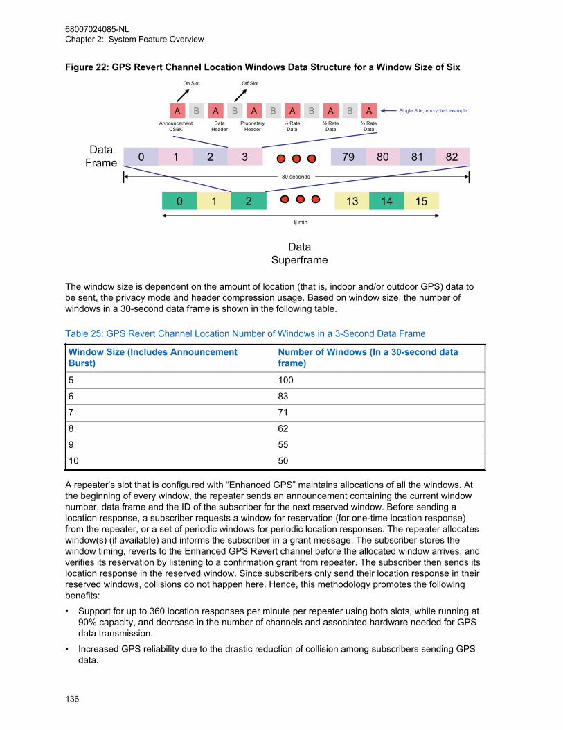
Figure 22: GPS Revert Channel Location Windows Data Structure for a Window Size of Six
DataFrame 0 1 2 3 8079 8281
A B A B A B AAnnouncement
CSBK
On Slot Off Slot
DataHeader
ProprietaryHeader
½ RateData
½ RateData
½ RateData
B A B A
0 1 2 13 14 15
30 seconds
8 min
Single Site, encrypted example
DataSuperframe
The window size is dependent on the amount of location (that is, indoor and/or outdoor GPS) data tobe sent, the privacy mode and header compression usage. Based on window size, the number ofwindows in a 30-second data frame is shown in the following table.
Table 25: GPS Revert Channel Location Number of Windows in a 3-Second Data Frame
Window Size (Includes AnnouncementBurst)
Number of Windows (In a 30-second dataframe)
5 100
6 83
7 71
8 62
9 55
10 50
A repeater’s slot that is configured with “Enhanced GPS” maintains allocations of all the windows. Atthe beginning of every window, the repeater sends an announcement containing the current windownumber, data frame and the ID of the subscriber for the next reserved window. Before sending alocation response, a subscriber requests a window for reservation (for one-time location response)from the repeater, or a set of periodic windows for periodic location responses. The repeater allocateswindow(s) (if available) and informs the subscriber in a grant message. The subscriber stores thewindow timing, reverts to the Enhanced GPS Revert channel before the allocated window arrives, andverifies its reservation by listening to a confirmation grant from repeater. The subscriber then sends itslocation response in the reserved window. Since subscribers only send their location response in theirreserved windows, collisions do not happen here. Hence, this methodology promotes the followingbenefits:
• Support for up to 360 location responses per minute per repeater using both slots, while running at90% capacity, and decrease in the number of channels and associated hardware needed for GPSdata transmission.
• Increased GPS reliability due to the drastic reduction of collision among subscribers sending GPSdata.
68007024085-NLChapter 2: System Feature Overview
136
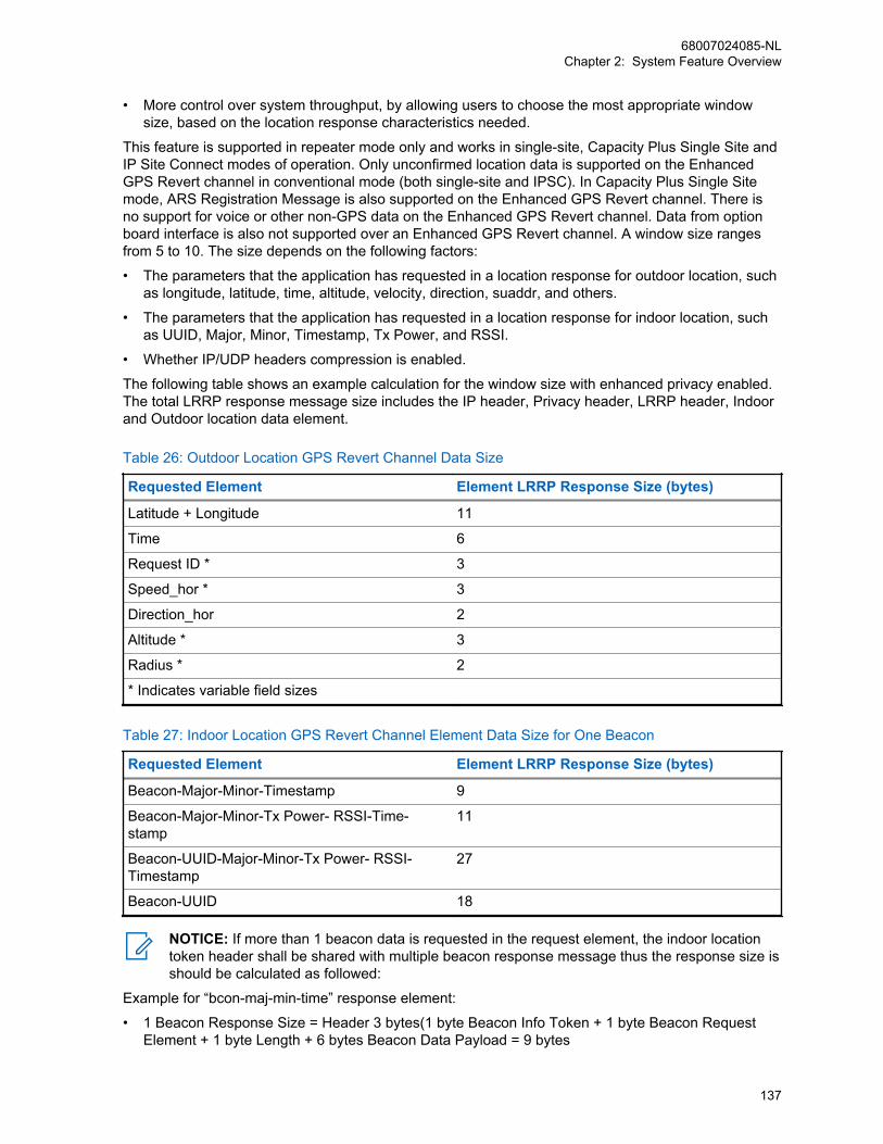
• More control over system throughput, by allowing users to choose the most appropriate windowsize, based on the location response characteristics needed.
This feature is supported in repeater mode only and works in single-site, Capacity Plus Single Site andIP Site Connect modes of operation. Only unconfirmed location data is supported on the EnhancedGPS Revert channel in conventional mode (both single-site and IPSC). In Capacity Plus Single Sitemode, ARS Registration Message is also supported on the Enhanced GPS Revert channel. There isno support for voice or other non-GPS data on the Enhanced GPS Revert channel. Data from optionboard interface is also not supported over an Enhanced GPS Revert channel. A window size rangesfrom 5 to 10. The size depends on the following factors:
• The parameters that the application has requested in a location response for outdoor location, suchas longitude, latitude, time, altitude, velocity, direction, suaddr, and others.
• The parameters that the application has requested in a location response for indoor location, suchas UUID, Major, Minor, Timestamp, Tx Power, and RSSI.
• Whether IP/UDP headers compression is enabled.
The following table shows an example calculation for the window size with enhanced privacy enabled.The total LRRP response message size includes the IP header, Privacy header, LRRP header, Indoorand Outdoor location data element.
Table 26: Outdoor Location GPS Revert Channel Data Size
Requested Element Element LRRP Response Size (bytes)
Latitude + Longitude 11
Time 6
Request ID * 3
Speed_hor * 3
Direction_hor 2
Altitude * 3
Radius * 2
* Indicates variable field sizes
Table 27: Indoor Location GPS Revert Channel Element Data Size for One Beacon
Requested Element Element LRRP Response Size (bytes)
Beacon-Major-Minor-Timestamp 9
Beacon-Major-Minor-Tx Power- RSSI-Time-stamp
11
Beacon-UUID-Major-Minor-Tx Power- RSSI-Timestamp
27
Beacon-UUID 18
NOTICE: If more than 1 beacon data is requested in the request element, the indoor locationtoken header shall be shared with multiple beacon response message thus the response size isshould be calculated as followed:
Example for “bcon-maj-min-time” response element:
• 1 Beacon Response Size = Header 3 bytes(1 byte Beacon Info Token + 1 byte Beacon RequestElement + 1 byte Length + 6 bytes Beacon Data Payload = 9 bytes
68007024085-NLChapter 2: System Feature Overview
137

• 2 Beacon Response Size = Header 3 bytes(1 byte Beacon Info Token + 1 byte Beacon RequestElement + 1 byte Length + 12 bytes Beacon Data Payload = 15 bytes
The following calculations assume GPS data is unconfirmed and “Compressed UDP Data Header” isselected in the CPS. The total LRRP response message size shall include the UDP/IP header, Privacyheader, LRRP header, Indoor and Outdoor location data element.
• For No PrivacyWindowSize= ((LRRPResponseSize+1)÷12)+3
• For Enhanced PrivacyWindowSize= ((LRRPResponseSize+1)÷12)+4
For windows de-allocation, if a subscriber is out of range or its battery is dead, it will not send locationdata during its reserved windows. Thus, the repeater also has a mechanism to free up the windowsreserved for that subscriber. The repeater waits for a certain period of time before releasing thewindows and this time is dependent on the cadence rate of the subscriber’s location request. Thefollowing table summarizes the amount of time the repeater waits before de-allocating windows for asubscriber.
Table 28: GPS Revert Channel Wait Time Before De-allocation
Update Rate Wait Time Before De-allocation (minutes)
30 seconds 5
1 minute 5
2 minutes 10
4 minutes 20
8 minutes 30
In a subscriber, it is highly recommended to keep the Enhanced GPS Revert channel in the “ChannelPool” in the CPS. This prevents the user from accessing the Enhanced GPS Revert channel that mayaffect GPS reliability. A channel can be configured as an Enhanced GPS Revert channel by selectingthe field “Enhanced GPS” in the channel settings. In order to send responses to the Enhanced GPSRevert channel, the GPS revert channel setting of the home channel has to be set to “Enhanced”.
In a multisite system with roaming enabled, all sites are recommended to use the same setting andwindow size as an Enhanced GPS Revert channel. This can be configured through the Enhanced GPSRevert channel of the Home channel.
In a repeater, the CPS allows either one or both slots to be configured as Enhanced GPS. The windowsize in the repeater’s Enhanced GPS slot should match the window size in the subscribers. One slotcan be configured for regular Data Revert and the other slot can be configured for Enhanced GPSRevert. The repeater CPS also allows a user to choose the maximum percentage of windows that willbe used for periodic updates. The possible values are 90%, 75%, 60%, and 45%. The rest of thewindows are used for one-time updates and also to empty out queued data. When a subscriber isparticipating in a voice call, chances are it may miss its windows. This will lead to windows gettingqueued up in the subscriber. When this happens, the subscriber can make one time requests to ask foradditional windows to empty out its queue.
In a situation whereby a system has heavy voice loading, the subscriber may start to miss theirreserved windows quite frequently. Hence, in such a scenario it is advised to run the system at 60% or45% capacity so the rest of the windows can be used to clear up the queued data.
In an IP Site Connect system where a revert channel is a wide area channel, only one repeater’s slotneeds to be selected with periodic window reservation (90%, 75%, 60%, and 45%). For all the otherpeers, this value should be set to “None”.
68007024085-NLChapter 2: System Feature Overview
138

For all modes, it is not recommended to have any non-GPS data on the GPS Revert channel. The onlyexception is Capacity Plus Single Site mode, where ARS data is also supported on the GPS Revertchannel. The system throughput is dependent on the window size selected for the system and thepercentage of windows reserved for periodic updates. The following table summarizes systemthroughput:
Table 29: GPS Revert Channel System Throughput
Window Size Number of Updates per Minute per Slot
90% 75% 60% 45%
5 180 150 120 90
6 150 125 100 75
7 128 107 86 64
8 112 93 75 56
9 100 83 66 50
10 90 75 60 45
NOTICE: These numbers are based on good signal conditions. The actual throughput andreliability may vary with RF conditions and voice call loading.
The Enhanced GPS feature can be configured in the following manner:
• Conventional single-site and IPSC modes:
- One slot for voice, one slot for Enhanced GPS Revert
- One slot for GPS Revert, one slot for Enhanced GPS Revert
- Both slots for Enhanced GPS Revert
• Capacity Plus Single Site mode:
- One slot of data revert repeater for GPS/ARS, one slot for all other data
- Both slots for Enhanced GPS Revert
2.13.11Connect Plus Fast GPS Location ServicesWhen the location application requests a periodic location update, each Subscriber Unit (SU) that hascompatible radio and Option Board (OB) firmware is assigned the following information.
Periodic Update Report Channel (Fast GPS Report Channel)• Decodes expected Frame # and Window # of the SU (OB) in the Control Channel (CC) Control
Signaling Block (CSBK) and informs to which repeater and slot it should trunk.
• Communicates to the OB through Over the Air (OTA) messaging from controller. It is notprogrammed in the OB.
• The Controller determines which specific repeaters and slots to use in Report Channels. TheNetwork Manager (NM) provides two user-configurable settings that determine which channelthe controller uses:
- The maximum number of slots to use in Report Channels. This cannot exceed the number ofreport channel licenses for the XRC site.
- Repeaters and slots that are NOT to be used as Report Channels (exclusion list).
68007024085-NLChapter 2: System Feature Overview
139
• The Controller loads the Report Channels one at a time and as fully as possible beforeassigning radios to a new Report Channel. This allows the slot to be used as a voice trunk untilthe number of reporting SUs has grown to a point that it requires its use as a Report Channel.
• The Controller assigns SUs to a Report Channel before activating the Report Channel.
• When necessary, the Controller can temporarily suspend reporting on a Report Channel. TheSUs are not reassigned to a different channel during the temporary suspension.
• When necessary, the Controller can reassign Report Channels.
• The use of Report Channels is a purchasable feature (on a per-channel basis).
Window NumberThe SU (the OB) scans Control Channel messaging for its assigned Window Number (SUsassigned to even-numbered windows) or the Window preceding its assigned Number (SUsassigned to odd-numbered windows). This causes the SU to trunk immediately (even numbers) orafter a short delay (odd numbers) to its preassigned Report Channel if:
• The Frame Number is an expected Frame in which the SU reports (Based on the Initial Frameand Frame interval information provided to the SU).
• The SU determines (from the same CSBK) if preassigned Report Channel is active (such asaccepting reports).
Initial Frame Number (0-15)The SU begins reporting when it decodes its Initial Frame Number and Window Number.
Report Interval• When SU sees its Windows Number, it reports to subsequent Frame Numbers based on its
Report Interval.
• The Report Interval is assigned according to the SUs Update Interval.
• The Update Intervals shown on the chart are supported initially.
Assignment is made when system first delivers the periodic Location Request to the SU and/or eachtime the SU registers (and re-registers on a site). This info is put into a new Registration ResponseCSBK.
Control Channel downlink sends a CSBK that announces the Frame Number and Window Number.The CSBK is sent for every even-numbered window (beginning with Window zero).
SUs assigned to even-numbered windowsAfter the SU decodes expected frame number and window number in the Control Channelmessage, it moves to its preassigned Report Channel, transmits the Periodic Location Updatethrough the DMRII unconfirmed method, and then returns to CC time slot.
SUs assigned to odd-numbered windowsSUs search for for the even-numbered window that precedes their assigned window. Once SUdetects the even-numbered preceding window, it starts a short delay timer before moving to itspreassigned Report Channel slot. The delay timer is determined by the window size, which is alsocommunicated in the CC CSBK. This allows two SUs to be assigned to the same traffic channel slotby the same message, at slightly different times.
The Report Channel Time Slot table shows the frame and window structure on each Report Channeltime slot.
The frame and window number given on the CC down link applies to all Report Channels. The ReportChannel downlink transmits only idles. The number of frames per cycle is always 16. After 16 frames, it
68007024085-NLChapter 2: System Feature Overview
140

cycles back to Frame 1. In this example, it takes 30 seconds to single a single frame (supports updateintervals of 30 sec to 8 min).
Table 30: Report Channel Time Slot
Window ↓ Frame →
1 2 3 4 5 6 7 8 9 10
11
12
13
14
15
16
1 1 1 1 1 1 1 1 1 1 1 1 1 1 1 1 1
2 2 2 2 2 2 2 2 2 2 2 2 2 2 2 2 2
3 3 3 3 3 3 3 3 3 3 3 3 3 3 3 3 3
4 4 4 4 4 4 4 4 4 4 4 4 4 4 4 4 4
5 5 5 5 5 5 5 5 5 5 5 5 5 5 5 5 5
6 6 6 6 6 6 6 6 6 6 6 6 6 6 6 6 6
... ... ... ... ... ... ... ... ... ... ... ... ... ... ... ... ...
70 70
70
70
70
70
70
70
70
70
70
70
70
70
70
70
70
The number of Windows per frame varies, and depends on:
• Report Size in bursts (set with the Network Manager). In this example, Report Size=5 bursts (300ms).
• Number of slots of padding placed between each report. In this example, Padding=120ms.
• Length of time required to send a single frame (depends on fastest supported update interval). Inthis example: 30 sec.
2.14ScanMOTOTRBO supports scanning of analog voice, digital voice, data, and digital signaling through arepeater or directly from another radio. MOTOTRBO radios scan channels or groups, or both. InCapacity Plus Single Site and Capacity Plus Multi Site modes, it scans the groups only.
When scanning channels, the radio continuously searches a list of channels for activity of interest.When activity of interest is found, the radio stops and switches to that channel. When finished, theradio continues scanning the channels in the list.
The set of channels to be scanned (or scan members) are determined by a configured Scan List. Aradio can have multiple Scan Lists, and each channel in a radio can be associated with a differentScan List. Scan Lists can contain only analog channels, only digital channels, or a mixture of bothanalog and digital channels. Once Scan is started, the radio scans through each Scan member of theassociated Scan List for the selected channel.
The CPS allows a user to create, edit, or delete Scan members in a Scan List, as well as associate aScan List to a channel. The user can start or stop Scan, and also add or remove Scan members of aScan List using the radio’s interface. Changes to the Scan List made via the radio front panel userinterface are permanent, that is, not affected by power cycle (*). Note that Scan and Roam aremutually exclusive on a channel within CPS.
NOTICE: This is different from the other supported feature – Nuisance Channel Delete: Achannel with unwanted activity is called a Nuisance Channel. The user can remove a NuisanceChannel from the Scan List temporarily by using the Nuisance Channel Delete feature.
68007024085-NLChapter 2: System Feature Overview
141
When the radio is scanning, and it detects a digital Scan member in its Scan List, it looks fortransmissions targeted towards the group associated with that channel. The radio also looks fortransmissions targeted towards itself (for example, Private Calls or signaling commands). The radiocan be configured such that replies that occur within a specified duration is transmitted to the samegroup and channel (this reply is called talkback). If the reply occurs outside of this duration, it isconsidered a new transmission.
There are also options for where new voice transmissions (outside of the previously mentionedduration) are transmitted while scanning. Voice can be configured to transmit on the selected channel(the channel from which Scan was started), another predetermined channel, or on the last landedchannel for voice (the last channel that Scan “locked-on-to”). Data and digital signaling are alwaystransmitted on the selected channel. The last landed channel is not updated for data and digitalsignaling.
Priority levels can also be configured for members of a Scan List. There are three levels of prioritywithin a Scan List – Priority-1, Priority-2, and Non-Priority. The Priority-1 and Priority-2 channels arescanned more often than the Non-Priority Scan members. Priority Scan is available with any mix ofanalog, digital, talkaround or repeater channels.
The Scan List can be configured to have one Priority-1 member and one Priority-2 member; theremaining are considered Non-Priority. When scanning, these priorities affect the order of scanning.The following represents the scan order of Scan List: Priority-1, Non-Priority-1, Priority-2, Non-Priority-2, Priority-3, Non-Priority-3, and others However, the radio may reorder Non-Priority scanmembers in order to optimize the efficiency of the scan.
In the CPS, there are two parameters associated with Scan Lists – Set/Clear Priority-1 and Set/ClearPriority-2. These are used to mark a Scan List member as Priority 1 and Priority 2; unmarked listmembers are “non priority”.
While scanning, the radio can accept data (for example, text message, location, telemetry, or terminal(PC) data). However this is only applicable if the data is received on its selected (home) channel.
NOTICE: In MOTOTRBO radios with software versions R01.04.00 or later, variousenhancements were made to the scan engine to improve scanning performance. This hascaused some features, such as scanning for Group Text Messaging and Emergency Alarms, tono longer be backward compatible with older software versions. All equipment must beupgraded for these features to perform correctly.
2.14.1Priority SamplingWhen scanning, if some activity of interest is found, the radio stops and switches to that channel. If theactivity of interest is incoming data addressed to the scanning radio, an individual voice call, or it is ona Priority-1 scan member, scanning completely stops for the duration of the call. But if the activity is avoice Group Call on a Priority-2 or a Non-Priority scan member, the radio continues to periodically scanhigher priority scan members.
For example, if the radio is receiving voice on a Non-Priority scan member, then the Priority-1 andPriority-2 scan members are scanned periodically. In this case, the order of scan is: Priority-1,Priority-2, Priority-1, Priority-2, and others. If the radio is receiving voice on a Priority-2 scan member,then only the Priority-1 scan member is scanned periodically. If a transmission of interest is found onthe higher priority member, the radio switches to that member to monitor the transmission. If it is not ofinterest, it returns to the previously monitored member. Priority Sampling does not occur whentransmitting.
Because the radio is currently receiving voice, leaving the current scan member to scan a higherpriority member causes the radio to temporarily leave the current transmission. This causes an audiohole in received audio that is being played through the radio’s speaker. Thus, the intervals duringwhich the radio samples the higher priority members, essentially, becomes the audio holes that areintroduced into the currently monitored voice. If there are two priority channels configured, this time is
68007024085-NLChapter 2: System Feature Overview
142
how often a sample is taken of either one. Therefore, one particular channel is sampled at a rate ofdouble the priority sampling duration. A balance between how often an audio hole is introduced andhow often a channel is sampled needs to be achieved to ensure that transmissions are not missed andto prevent introducing too many audio holes. This interval is CPS configurable through the “PrioritySample Time” interval parameter. Since the radio only samples at the rate of the Priority Sample Time,it is important to understand that if sampling for data, the Scan Preamble must be set to double thePriority Sample Time.
The user experiences few to no audio holes if they are currently unmuted to a lower priority voice whilethe priority member is in the other timeslot of the same repeater. In this situation, the radio uses theembedded signaling in the repeater to monitor activity in the other timeslot. This should be taken intoconsideration when deciding which identifiers are assigned to which channels and slots.
Not all identifiers are uniquely identified in the embedded signaling because they are compressed intosmaller identifiers. If the system contains two or more identifiers that share the same compressedidentifier, the radio incurs additional audio holes to validate the actual uncompressed identifiermatches.
Duplicate compressed identifiers can be avoided if kept within a 256 ID range where the first ID of therange is an integer multiple of 256. For example if group and individual identifiers are kept between 0and 255, or 256 and 511, or 512 and 767, and others, they will have unique compressed identifiers andno audio hole is experienced while priority sampling the other timeslot.
Setting a busy channel as a priority channel can cause excessive audio holes in non-priority audio asthe radio checks each new transmission on the priority channel to determine if it is call of interest. If thepriority channel has many short transmissions that are not of interest, the radio is forced to incur atleast one audio hole for each. Therefore, it is recommended, that if possible, high priority transmissionsshould be isolated on channels that are not overly utilized by other traffic.
2.14.2Channel MarkingIn addition to configuring the sampling interval for Priority Sampling, MOTOTRBO offers a way tomitigate the duration of the audio hole itself with a feature called Channel Marking. Although relativelyshort, it does take time to determine if a transmission is of interest on a particular scan member. Duringthis time, there is an audio hole in the scanned audio.
The Channel Marking feature introduces logic that assumes that if a transmission was recentlyidentified as not of interest, there is no need to fully review it at every scan interval. Additionally, if thetype of transmission is of the same type as the transmission identified as not of interest before, there isa high likelihood it is the same transmission. Therefore, the radio only needs to identify the type oftransmission taking place, which is beneficial as identifying a transmission type takes much less timethan fully identifying if a transmission is not of interest. This assumption is made for a pre-determinednumber of times, after which, the scan member is fully reviewed again. This method changes theexperienced audio holes from long audio holes every priority scan interval to one long audio holefollowed by numerous short audio holes, and then another long audio hole, and so on.
This feature can greatly increase audio quality while a radio is in priority sampling mode. The drawbackto channel marking is the assumption that the target of a transmission has not changed. The scanningradio does not know if the target has changed until the next full inspection. The system should beconfigured in such a way using CPS parameters to achieve a balance which delivers improved audioquality without sacrificing too much flexibility to consistently locate new transmissions which otherwisewould be of interest. It is recommended that Channel Marking is set as Enabled in most scenarios.
However, if there is an analog signal on a digital priority channel, the radio incurs a medium size audiohole on every sample even if channel marking is enabled. The radio spends this time searching forsynchronization that is not present. It is recommended that the priority traffic be placed on a channelthat has limited analog interference (that is, shared use).
68007024085-NLChapter 2: System Feature Overview
143

2.14.3Scan ConsiderationsThe ability to scan multiple channels is an advantage when a user must be aware of activity onnumerous channels. MOTOTRBO offers the ability to scan a list of analog and digital channels(frequency and slot) within the same Scan List (often referred to as a Channel Scan List). This featureis incredibly useful when planning to migrate from analog to digital, or when a user must monitormultiple repeater frequencies and slots at the same time. When operating in digital, MOTOTRBO alsoprovides the ability to scan multiple groups on a channel (slot). This is often referred to as a GroupScan.
A Group Scan is an optimized way to scan for multiple groups on the same channel (slot). The radiomonitors the channel from either the repeater or directly from another radio to determine which group iscurrently transmitting. If the group transmitting is one specified in the Group Scan List, the radio stopsand listens. The radio is allowed to talkback to the group for the duration of the call hang time. This callhang time overrides the TX Contact Name setting of the channel. Because only one call takes place ona channel (slot) at any given time, the scanning radio will not miss a transmission of interest,regardless of the length of the group list. A Group Scan is configured by creating a group list andadding groups already in the Contacts folder. This group list can then be selected as the RX Group Listof a particular Channel. The Group Scan does not have the advanced features and configurationoptions of a channel scan. For example, once configured via CPS, the Group Scan cannot be turnedon or off and members cannot be added or removed. Furthermore, the configurable scan options(Scan Hang time Timer, Talkback, and others) do not control the Group Scan. The Group Scan shouldbe used in simple systems where no advanced scan options are required. If advanced scan optionsand features are required, a Channel Scan should be configured instead.
A Channel Scan scans a list of different channels within a system – analog or digital. A Channel Scanis different from a Group Scan since the radio must change frequencies and sometimes evenmodulations (analog to digital) in order to scan for activity. Unlike a Group Scan where only one calloccurs at any given time, when scanning different channels (analog or multiple digital slots), there canbe calls taking place on any or all of the channels. Because the radio cannot be everywhere at once,there is a possibility that the radio misses a transmission of interest. Because of this, it isrecommended that the number of channels in a Channel Scan List is kept to a minimum. The larger theScan List, the more likely a user misses, or join late, a transmission of interest during busy times.
CPSM
Capacity Plus Single Site and Capacity PlusMulti Site
In Capacity Plus Single Site and Capacity PlusMulti Site modes, MOTOTRBO radios only sup-port Group Scan.
• All idle radios can perform a Group Scan atthe start of a call. A call always starts on theRest Channel and all idle radios are on theRest Channel.
• At the end of a call, the participating radiosare informed about the ongoing calls, allow-ing them to perform a Group Scan.
• When a radio powers on or when it comesinto coverage, it searches the channels andjoins a call of interest (if any). If all the chan-nels are busy, then a radio may not join anongoing call of interest.
68007024085-NLChapter 2: System Feature Overview
144
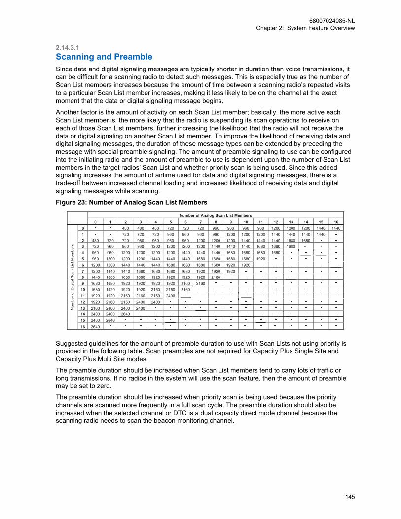
2.14.3.1Scanning and PreambleSince data and digital signaling messages are typically shorter in duration than voice transmissions, itcan be difficult for a scanning radio to detect such messages. This is especially true as the number ofScan List members increases because the amount of time between a scanning radio’s repeated visitsto a particular Scan List member increases, making it less likely to be on the channel at the exactmoment that the data or digital signaling message begins.
Another factor is the amount of activity on each Scan List member; basically, the more active eachScan List member is, the more likely that the radio is suspending its scan operations to receive oneach of those Scan List members, further increasing the likelihood that the radio will not receive thedata or digital signaling on another Scan List member. To improve the likelihood of receiving data anddigital signaling messages, the duration of these message types can be extended by preceding themessage with special preamble signaling. The amount of preamble signaling to use can be configuredinto the initiating radio and the amount of preamble to use is dependent upon the number of Scan Listmembers in the target radios’ Scan List and whether priority scan is being used. Since this addedsignaling increases the amount of airtime used for data and digital signaling messages, there is atrade-off between increased channel loading and increased likelihood of receiving data and digitalsignaling messages while scanning.
Figure 23: Number of Analog Scan List Members
Number of Analog Scan List Members 0 1 2 3 4 5 6 7 8 9 10 11 12 13 14 15 16
0 480 480 480 720 720 720 960 960 960 960 1200 1200 1200 1440 1440 1 720 720 720 960 960 960 960 1200 1200 1200 1440 1440 1440 1440 2 480 720 720 960 960 960 960 1200 1200 1200 1440 1440 1440 1680 1680 3 720 960 960 960 1200 1200 1200 1200 1440 1440 1440 1680 1680 1680 4 960 960 1200 1200 1200 1200 1440 1440 1440 1680 1680 1680 1680 5 960 1200 1200 1200 1440 1440 1440 1680 1680 1680 1680 1920 6 1200 1200 1440 1440 1440 1680 1680 1680 1680 1920 1920 7 1200 1440 1440 1680 1680 1680 1680 1920 1920 1920 8 1440 1680 1680 1680 1920 1920 1920 1920 2160 9 1680 1680 1920 1920 1920 1920 2160 2160 10 1680 1920 1920 1920 2160 2160 2160 11 1920 1920 2160 2160 2160 2400 12 1920 2160 2160 2400 2400 13 2160 2400 2400 2400 14 2400 2400 2640 15 2400 2640 16 2640
- - -
- - - - - - -
- - - - - - - - - - -
- - - - - - - - - - - - - - -
- - - - - - - - - - - - - - - - - - -
- - - - - - - - - - - - - - - - - - - - - - -
- - - - - - - - - - - - - - - - - - - - - - - - - - -
- - - - - - - - - - - - - - - -
--
--
- - - - - - - - - - - - - - -
Num
ber o
f Dig
ital S
can
List
Mem
bers
Suggested guidelines for the amount of preamble duration to use with Scan Lists not using priority isprovided in the following table. Scan preambles are not required for Capacity Plus Single Site andCapacity Plus Multi Site modes.
The preamble duration should be increased when Scan List members tend to carry lots of traffic orlong transmissions. If no radios in the system will use the scan feature, then the amount of preamblemay be set to zero.
The preamble duration should be increased when priority scan is being used because the prioritychannels are scanned more frequently in a full scan cycle. The preamble duration should also beincreased when the selected channel or DTC is a dual capacity direct mode channel because thescanning radio needs to scan the beacon monitoring channel.
68007024085-NLChapter 2: System Feature Overview
145

The following table suggests guidelines for the amount of preamble duration to use, with or without adual capacity direct mode selected channel or DTC in a digital-only Scan Lists using priority.
Table 31: Number of Priority Members
Number of Priority Members
Without DCDM DTC/SelectedChannel
With DCDM DTC/Selected Chan-nel
0 1 2 0 1 2
Numberof DigitalScan ListMem-bers
0 – – – – – –
1 – – – – – –
2 480 480 480 960 960 960
3 720 960 960 1200 1440 1200
4 960 1200 960 1440 1920 1440
5 960 1440 1200 1680 2640 1920
6 1200 1680 1440 1920 3120 2640
7 1200 1920 1680 2400 3840 3120
8 1440 2400 1920 2640 4320 3840
9 1680 2640 2400 2880 4800 4320
10 1680 2880 2640 3120 5520 4800
11 1920 3120 2880 3360 6000 5520
12 1920 3360 3120 3840 6720 6000
13 2160 3840 3360 4080 7200 6720
14 2400 4080 3840 4320 7680 7200
15 2400 4320 4080 4560 8400 7680
16 2640 4560 4320 4800 8640 8400
If data and digital signaling is not carried on any of the non-priority channels and is only carried on oneof the priority channels (which must be the selected channel for data messages), then the amount ofscan preamble to use can be as specified in the first row of the Priority Scan table, above, regardlessof the number of non-priority Scan List members.
2.14.3.2Channel Scan and Last Landed ChannelA Channel Scan can be configured by selecting a group of already configured channels within a radiousing the CPS, and adding them to a Scan List. Each channel is then configured to use this Scan Listof channels. When scan is activated on a channel that contains a Channel Scan List, the MOTOTRBOradio checks for activity on each of the channels on the list.
While scanning a digital channel for activity, all Groups specified in the channel’s RX Group List will bemonitored.However if the radio is configured with a Channel Scan that contains channels that areconfigured with a RX Group List (a Group Scan), then only the Last Landed Channel is remembered bythe radio, not the Last Landed Channel and Group. This means that voice transmissions aretransmitted on the TX Call Member configured for the channel that was the Last Landed Channel, notthe Group in the Receive Group List of channel that was the Last Landed Channel. Note that if atransmission is made within the call hang time of the scanned transmission, it will be targeted towards
68007024085-NLChapter 2: System Feature Overview
146
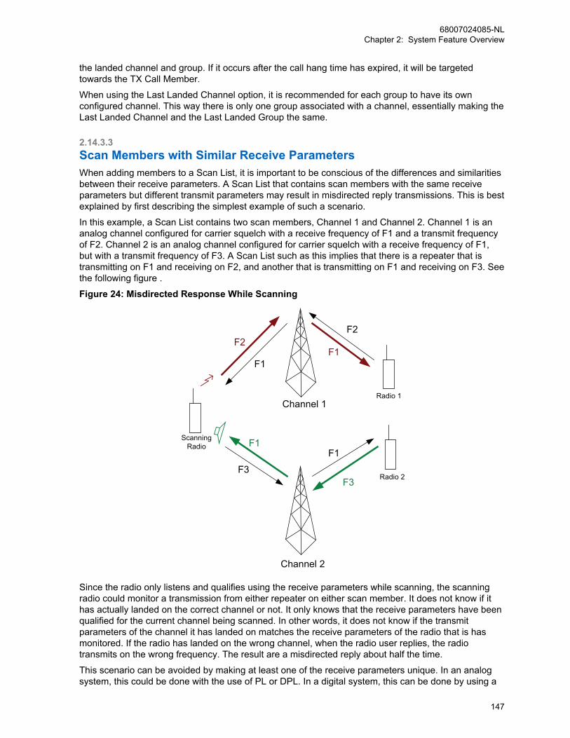
the landed channel and group. If it occurs after the call hang time has expired, it will be targetedtowards the TX Call Member.
When using the Last Landed Channel option, it is recommended for each group to have its ownconfigured channel. This way there is only one group associated with a channel, essentially making theLast Landed Channel and the Last Landed Group the same.
2.14.3.3Scan Members with Similar Receive ParametersWhen adding members to a Scan List, it is important to be conscious of the differences and similaritiesbetween their receive parameters. A Scan List that contains scan members with the same receiveparameters but different transmit parameters may result in misdirected reply transmissions. This is bestexplained by first describing the simplest example of such a scenario.
In this example, a Scan List contains two scan members, Channel 1 and Channel 2. Channel 1 is ananalog channel configured for carrier squelch with a receive frequency of F1 and a transmit frequencyof F2. Channel 2 is an analog channel configured for carrier squelch with a receive frequency of F1,but with a transmit frequency of F3. A Scan List such as this implies that there is a repeater that istransmitting on F1 and receiving on F2, and another that is transmitting on F1 and receiving on F3. Seethe following figure .
Figure 24: Misdirected Response While Scanning
Channel 1
Channel 2
F1
F1
F2
F3F3
F1
F2
F1
Radio 1
Radio 2
ScanningRadio
Since the radio only listens and qualifies using the receive parameters while scanning, the scanningradio could monitor a transmission from either repeater on either scan member. It does not know if ithas actually landed on the correct channel or not. It only knows that the receive parameters have beenqualified for the current channel being scanned. In other words, it does not know if the transmitparameters of the channel it has landed on matches the receive parameters of the radio that is hasmonitored. If the radio has landed on the wrong channel, when the radio user replies, the radiotransmits on the wrong frequency. The result are a misdirected reply about half the time.
This scenario can be avoided by making at least one of the receive parameters unique. In an analogsystem, this could be done with the use of PL or DPL. In a digital system, this can be done by using a
68007024085-NLChapter 2: System Feature Overview
147

unique color code or unique group per channel. This will allow the scanning radio to only “land” on thechannel where all receive parameters match and therefore properly direct the user’s reply.
Similar problems can occur if one scan member has fewer qualifiers than the others. Taking theexample in the following figure, Channel 1 is still an analog channel configured for carrier squelch witha receive frequency of F1 and a transmit frequency of F2. However, Channel 2 is now a digital channelconfigured for Color Code 1 and Group 10 with a receive frequency of F1 and a transmit frequency ofF3. The receive parameters in this example are different, but Channel 1 has few qualifiers. Channel 1is configured to land on any transmission that breaks squelch. This means that any transmission thatoccurs on Channel 2 is heard on Channel 1 as an analog signal. This Scan List not only results inmisdirected replies, but it also results in a digital transmission being played out the speaker as analog.The net result is undesirable sounds presented through the user’s speaker. This type of configurationshould be avoided at all times. This could be avoided by utilizing a PL or DPL on the analog channelinstead of only carrier squelch.
Figure 25: Misdirected Response While Scanning
Channel 1
F1
F2F2
F1
Radio 1
Radio 2
ScanningRadio
F1
Another similar problem occurs when the unique receive parameters between scan members aremissing or cannot be determined. One scenario where this occurs is while scanning two slots of arepeater and a transmission is received directly from a subscriber on the same frequency. A radio inrepeater mode can receive a transmission directly from a radio. However, in direct mode, slotnumbering is not utilized. Therefore, if a radio is scanning two scan members with the same qualifierswith the exception of the unique slot number, when it receives a transmission without a slot number,either scan member monitors it and “land”. When the user replies, the transmission is returned throughthe repeater on whichever slot assigned to the scan member it was monitored on. Depending on theconfiguration of the direct mode radio and its proximity to the repeater, the transmission may or maynot be monitored. This can be managed by having different groups configured for each slot. Thisensures that each slot has unique identifiers besides just the slot number. However, this does not helpif the subscriber in direct mode is out of range of the repeater. This is why it is not good practice totransmit in direct mode in the RF range of the repeater.
Generally, these scenarios can be avoided if Scan Lists are created with scan members that haveunique receive parameters.
68007024085-NLChapter 2: System Feature Overview
148
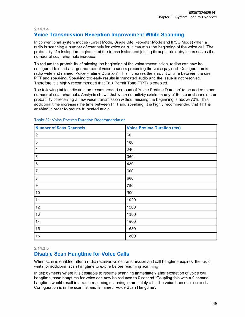
2.14.3.4Voice Transmission Reception Improvement While ScanningIn conventional system modes (Direct Mode, Single Site Repeater Mode and IPSC Mode) when aradio is scanning a number of channels for voice calls, it can miss the beginning of the voice call. Theprobability of missing the beginning of the transmission and joining through late entry increases as thenumber of scan channels increase.
To reduce the probability of missing the beginning of the voice transmission, radios can now beconfigured to send a larger number of voice headers preceding the voice payload. Configuration isradio wide and named ‘Voice Pretime Duration’. This increases the amount of time between the userPTT and speaking. Speaking too early results in truncated audio and the issue is not resolved.Therefore it is highly recommended that Talk Permit Tone (TPT) is enabled.
The following table indicates the recommended amount of ‘Voice Pretime Duration’ to be added to pernumber of scan channels. Analysis shows that when no activity exists on any of the scan channels, theprobability of receiving a new voice transmission without missing the beginning is above 70%. Thisadditional time increases the time between PTT and speaking. It is highly recommended that TPT isenabled in order to reduce truncated audio.
Table 32: Voice Pretime Duration Recommendation
Number of Scan Channels Voice Pretime Duration (ms)
2 60
3 180
4 240
5 360
6 480
7 600
8 660
9 780
10 900
11 1020
12 1200
13 1380
14 1500
15 1680
16 1800
2.14.3.5Disable Scan Hangtime for Voice CallsWhen scan is enabled after a radio receives voice transmission and call hangtime expires, the radiowaits for additional scan hangtime to expire before resuming scanning.
In deployments where it is desirable to resume scanning immediately after expiration of voice callhangtime, scan hangtime for voice can now be reduced to 0 second. Coupling this with a 0 secondhangtime would result in a radio resuming scanning immediately after the voice transmission ends.Configuration is in the scan list and is named ‘Voice Scan Hangtime’.
68007024085-NLChapter 2: System Feature Overview
149
2.14.3.6Unconfirmed Group Data ScanningRadios can be configured to receive unconfirmed group data on channels other than the selectedchannel, when the selected channel is a digital channel.
The use case being accommodated here is broadcast data messages that do not need a response. Itshould be noted that a user sending a response to the group data source radio (individual datamessage) would be transmitted on the responding radio selected channel, which would be theincorrect channel. Since scanning for individual data messages is not supported, it is important if thisscenario is to be supported, that the user selects the correct channel before sending the individual datamessage response.
2.14.4Transmit Interrupt and ScanSome of the Transmit Interrupt features and scan can be used together. However, there are a fewinteractions that need to be taken into consideration, as discussed in the following paragraphs.
Firstly, since scan is not permitted when the radio is in an emergency mode of operation, EmergencyVoice Interrupt and scan do not have any direct interactions to consider because these two featuresare mutually exclusive. However, if a radio is in scan mode when the radio user initiates an emergencycondition, the radio first exits the scan mode of operation, and then enters the emergency mode ofoperation (optionally following emergency revert procedures). At this point, Emergency Voice Interruptcould be invoked, if the feature has been configured in accordance with the Emergency Voice Interruptoperation as described previously.
The second interaction to consider occurs when the radio is provisioned for both the Scan PrioritySampling and a Transmit Interrupt feature. Priority Sampling is temporarily suspended when aTransmit Interrupt request is pending. This is necessary to ensure that the radio user’s transmit requesttakes priority over the radio’s receive activities.
Thirdly, the radio can be configured with the scan feature such that replies occurring within a specifiedduration are transmitted to the same group and channel (this reply is called talkback). A reply thatoccurs outside of this duration is considered a new transmission.
If the radio is provisioned for Transmit Interrupt and talkback, then Transmit Interrupt is applied to thesame group and channel, when the radio user invokes a Transmit Interrupt feature while receiving. Ifthe designated transmit channel is busy and the radio is not a member of the ongoing call, then theVoice Interrupt request is simply denied.
Recall the options for new voice transmissions – outside of the previously mentioned duration – aretransmitted while scanning; include the selected channel (the channel from which scan was started),another predetermined channel, or on the last landed channel for voice. Data and digital signaling arealways transmitted on the selected channel. The last landed channel is not updated for data and digitalsignaling. In the event that the channel selected for a new transmission is busy, a Transmit Interruptfeature may be invoked on that channel if so provisioned on that channel. However, the radio mustadditionally be a member of the call in progress for Voice Interrupt to be invoked.
Finally, a radio’s interruptible voice transmission periodically stops transmitting momentarily, and“listens” to the channel to determine whether it is being requested to stop its transmission. When aradio is scanning channels and testing the channel for presence of a carrier while another transmittingradio is listening to the channel for Transmit Interrupt signaling, the scanning radio may conclude thatthe channel has no activity and moves on to the next channel in the Scan List. However, thisoccurrence should happen only occasionally. It is most likely that the next time the scanning radio visitsthe channel, it does not occur at the moment that the transmitting radio has suspended itstransmission. The net result is that the time taken to detect channel activity for an interruptible voicetransmission may increase slightly, versus uninterruptible voice transmissions. Since the repeater istransmitting continuously even during interruptible voice calls, this is only a concern when scanningchannels that may contain interruptible voice Direct Mode transmissions.
68007024085-NLChapter 2: System Feature Overview
150

2.15Site RoamingThe Master repeater distributes the list to all the repeaters at the site.
The Rest Channel repeater of a site periodically broadcasts the Rest Channels of all neighboring sitesover-the-air. The radio searches through the list of sites and selects the one with the strongest signal,and identifies this site as its current home site. The radio remains on this home site until the signalstrength has dropped below a programmable threshold or when it has lost communications with thehome site, at which time it attempts to find a better home site. If available, this process takes around 60seconds in an IP Site Connect system, and around 10 seconds in a Capacity Plus Multi Site system. Ifa better home site is not found, it remains on the previous home site and continues searching. Notethat roaming occurs while the user is not in a call. Roaming is not supported while the user is in a call.
Automatic roaming involves scanning, which requires a radio to leave the Home channel for a shortduration. This may cause the radio to make a late entry, or to miss a data/control call (withoutpreambles). A stationary radio user may suspend the automatic roaming feature by using the SiteLock/Unlock features. The Site Lock/Unlock feature can be activated through the menu or aprogrammable button. An icon is shown on the radio display to indicate the status of automaticroaming.Automatic roaming uses signal strength (RSSI) to select the Home channel. The signal strength is notalways the best indication of the reception quality, especially when co-channel interference exists. Ifpoor reception is encountered while automatic roaming is on, then the user can request the radio tofind another channel. Automatic roaming, when activated through the menu/programmable button,allows the user to find another channel. The radio then responds to the user on the failure or successof the search. The radio LED indicates when the radio is roaming.
An example of neighboring sites is shown in the following figure. The Neighboring Sites List of a 'site A'should only identify the sites to which a radio can roam from site A.
Figure 26: Example of Neighboring Sites
Site1
Site2
Site3
Site4
Site5
For example, if the coverage areas of the sites are as shown in Figure 26: Example of NeighboringSites on page 151, the Neighboring Sites Lists can be concluded in the following table:
Table 33: Neighboring Sites List
Site ID Neighboring Sites List
1 2
2 1, 3
3 2
4 5
5 4
The radios can be programmed with all the six sites as neighbors to each other. However, this causesinefficiency and potentially slows down the roaming from one geographically adjacent site to another.The radio has two methods in which it accomplishes the act of roaming; a passive method and anactive method.
68007024085-NLChapter 2: System Feature Overview
151

IPSC
IP Site Connect
MOTOTRBO supports the ability to automatical-ly roam between sites of an IP Site Connectsystem.In an IP Site Connect system, a portable or mo-bile is configured with a roam list that contains alist of channels, each of which is one site (onerepeater) of an IP Site Connect system (widearea system).
The process of searching for a better home sitetakes around 60 seconds in a IP Site Connectsystem.
In IP Site Connect mode, the radio display indi-cates which site the radio is currently on, whenthe user enables Site Lock/Unlock via a buttonpress
CPMS
Capacity Plus Multi Site
MOTOTRBO supports the ability to automatical-ly roam between sites of a Capacity Plus MultiSite system.In a Capacity Plus Multi Site system, the Masterrepeater is configured with a list of neighboringsites for each site.
The process of searching for a better home sitetakes around 10 seconds in a Capacity PlusMulti Site system.
In Capacity Plus Multi Site, the radio display in-dicates which site the radio is currently on,when the user presses a button preprogram-med as the “Site Alias”. A wide area talkgroupcall is broadcasted over all the sites associatedwith the talkgroup. When a Group Call is drop-ped at a site due to poor reception, the radioroams and joins the call (as late entry) afterlanding on another site. This only happens if thesite is associated with the talkgroup and the callhas not ended. A Private Call is repeated overat most two sites. Therefore the radio can jointhe call (as late entry), only if the radio roamsbetween those two sites.
2.15.1Passive Site SearchingWhile passively roaming, the radio temporarily leaves the current home channel and inspects othersites to decide if a better site is available.
It is important to note that since the radio is temporarily away from the home channel, it is possible tomiss the beginning of a transmission (late entry). Because of this, it is not advisable or required toperform passive roaming all the time. Therefore, the radio should only passively search for a better sitewhen the current home site is no longer desirable. If the radio is within good coverage of a site, there isno need to search for a better site. In other words, the radio should only passively roam when the radiohas moved far enough away from the site that its signal strength has degraded below an acceptable
68007024085-NLChapter 2: System Feature Overview
152
value or when its signal is no longer present. The signal strength threshold to initiate the Passive SiteSearch (Roaming RSSI Threshold) is configurable through the CPS. See Configuring the RoamingRSSI Threshold on page 156 for suggestions on setting the Roaming RSSI Threshold for various siteconfigurations and scenarios.
Initiating Passive Site Search and selecting sites based on signal strength works well when therepeater is transmitting, but the MOTOTRBO repeater does perform in a shared-use environment andis required to de-key when not in use. If there is no activity on a system, the Passive Site Searchcannot detect any repeaters and therefore is unable to determine at which site the radio should be on.Therefore, the repeater can be configured to transmit a beacon, called a roaming beacon. Roamingbeacons are periodic short transmissions by a repeater when the repeater is neither transmitting norhaving interference from other systems.
During times of no activity, the radio utilizes the signal strength of the beacon to determine when itshould roam and which site it should roam to. If the radio does not receive a beacon in the expectedduration, it assumes it is out of range of the repeater or that the repeater has failed and tries to roam toanother site. See Beacon Duration and Beacon Interval Settings on page 166 for suggestions onsetting the beacon duration and interval for various site configurations and scenarios.
The radio does not perform Passive Site Search while:
• transmitting,
• receiving a call of interest,
• in emergency,
• in good RF coverage,
• in talkaround (direct) mode,
• radio disabled,
• received call alert,
• monitor mode,
• microphone is off hook, or
• while in active menu.
IPSC
IP Site Connect
In IP Site Connect, the Passive Site Searchmethod has the radio searching through a list ofsites and selecting the one with the strongestsignal.The duration of the beacon is a function of thenumber of sites in the IP Site Connect systemand therefore in the roam list. The interval ofthe beacon is a function of the shared use rulesof the channel and how quickly a radio is re-quired to roam when there is no activity.
The duration and interval of the roaming bea-con are programmable, in an IP Site Connectsystem only.
The radio does not perform Passive SiteSearch while on a channel that has scan list inIP Site Connect mode.
68007024085-NLChapter 2: System Feature Overview
153

CPMS
Capacity Plus Multi Site
In Capacity Plus Multi Site, the radio searchesthrough a list of neighboring sites and selectsthe one with the strongest signal. This methodis utilized whenever the site is unlocked. It re-lies on repeater transmissions in order for thesubscriber to determine which site has thestrongest signal strength. Since it is expectedthat the radio encounters other activity whileperforming the Passive Site Search, it qualifiesthe signal using the sites’ programmed colorcode prior to selecting it as the new home. Inaddition, it sorts the sites in the roam list ac-cording to their signal strength in order to opti-mize follow up roams. Sites that have been de-tected in previous roam attempts and are as-sumed to be near by are searched before thosethat have not been detected before. Also, whileroaming, the radio inspects the current homesite in between other sites in order to minimizethe time away. This strategy provides priority tothe last home site and minimizes missing anytransmissions while performing the roam at-tempt.In Capacity Plus Multi Site, the roaming beaconduration and interval are not configurable. Theroaming beacon interval is five times the “lostdetection beacon interval” of Capacity Plus Sin-gle Site. The duration of the roaming beacon, inCapacity Plus Multi Site consists of only oneburst and is appended at the end of every fifthsequence of the Lost Detection Beacons.
NOTICE: The “lost detection bea-cons” are transmitted periodically bythe Rest Channel repeater when therepeater is not transmitting. The de-tection of the beacon by a radio indi-cates that the radio is in the coveragearea of the repeater.
2.15.2Active Site SearchingThe Active Site Search method consists of the radio sending wake-up messages to each repeater in itssorted roam list until it finds an active site. This method is utilized when the user or radio initiates atransmission and the home site repeater cannot be awoken, or when the user initiates a Manual SiteRoam.
In most cases, the Passive Site Search determines and selects the correct site if the radio is in theunlocked state. It may be possible that the radio has roamed into a new site and has yet to receive abeacon.
When the user presses the PTT or a data transmission is requested, the radio tries to wake the Homechannel repeater. This Home channel repeater is chosen from the repeaters at the radio’s currenthome site which was determined by the Passive Site Search.
68007024085-NLChapter 2: System Feature Overview
154
If the repeater does not wake up, the radio repeats this process for all the sites. If a repeater wakes up,the radio synchronizes itself with the repeater, completes the transmission and make the new site thehome site. If the end of the roam list is reached and a site is not found, the user receives a failureindication.
This entire process of discovering and synchronizing with an active repeater increases the voiceaccess time of the transmission (time from PTT to Talk Permit Tone). However, this increase onlyoccurs for one transmission since the next transmission proceeds regularly on the new site.
NOTICE: Wake-up messages are always sent politely. This means that if the radio detects aninterfering signal, the radio does not transmit a wake-up message on that roam list member.Instead, it continues performing an Active Site Search on the next roam list member.
If the user requests a Manual Site Roam, be it through a button press or menu item, the radio activelysearches for the next available site using the process described above. The Manual Site Roam doesnot necessarily find the best site, but rather allows the user to move to the next site that is in range andtransmitting. If no site is found, a negative indication is provided to the user. If in direct mode, asuccessful site search changes the new channel found to repeater mode. An unsuccessful site searchremains in direct mode.
NOTICE: Generally, the radio does not perform any Passive Site Search during an emergency.No automatic roaming is performed when the radio is reverted during an emergency. However,when configured to a non-revert emergency channel and with Active Site Search enabled, theradio will perform Active Site Search automatically whenever the RSSI of the repeater dropsbelow the programmed threshold or if it no longer detects repeater beacons. Note that ManualSite Roam is supported while in an emergency. See Emergency Revert, GPS/Data Revert, andRoaming Interactions on page 168 for more details.
If this is still not acceptable in the area of operation, the radios should have automatic Active SiteSearch disabled, the Manual Site Roam button removed, and the beacon interval should be configuredas short as possible. This ensures that the Passive Site Search finds new sites quickly and the userhas no method to initiate an Active Site Search.
NOTICE: If Active Site Search is disabled, there is no roaming while in an emergency
IPSC
IP Site Connect
In an IP Site Connect system, the beacon inter-val is usually in the range of minutes and it typi-cally takes approximately a minute for a radiouser to move out of range of one site and intothe range of another during Passive SiteSearch. Until a new site is found, the radio con-siders the previous site as the home site.For IP Site Connect, the radio chooses the sin-gle repeater at its home site channel.
It is important to note that Active Site Searchcauses wake-up messages to be transmitted oneach roam list member’s frequencies until a siteis found. This may not be agreeable in someareas where frequency overlap and sharing iscommon. In order to minimize the number ofunwanted transmissions, the radio transmitsone polite wake-up message. If a radio sendsfrequent GPS location updates while out ofrange, the radio limits the Active Site Search toonly occur once every 30 seconds. This scenar-
68007024085-NLChapter 2: System Feature Overview
155
io is applicable in an IP Site Connect systemonly.
CPMS
Capacity Plus Multi Site
In Capacity Plus Multi Site the radio choosesthe current Rest Channel repeater at its homesite. The radio then tries to wake a repeater atthe home site. If the radio has lost the previoussite and is searching for a new site, all trans-missions by the radio fail. Otherwise, the radiotries to wake the Rest Channel repeater.
2.15.3Roaming ConsiderationsThis section describes the roaming considerations.
2.15.3.1Configuring the Roaming RSSI ThresholdThe Roaming RSSI Threshold is a CPS configurable parameter that controls the signal strength, that asubscriber needs to reach before searching for another site.
This RSSI roaming threshold can be CPS configured as either system wide, where every site in thesystem has the same threshold, or on a per site basis, where each site may have its own roamingRSSI threshold, and this roaming RSSI threshold may be different from site to site.
2.15.3.1.1System Wide Roaming RSSI ThresholdIf the Roaming RSSI Threshold is configured as system wide, and the RSSI measurement of thecurrently determined home site is above the specified Roaming RSSI Threshold, then the radioremains on that site and not roam.
Once the RSSI measurement drops below the threshold it begins a Passive Site Search process tofind a site with higher signal strength. This parameter essentially controls the distance away from a sitea subscriber will begin looking for another site. In real life environments RF coverage is seldom aperfect circle, but to simplify this explanation, coverage is abstracted as a circle.
It is important to note that while passively roaming the radio temporarily leaves the current home site todetermine if a stronger site is available. Since the radio is temporarily away from the home channel, itis possible to miss the beginning of a transmission (for example, enter the call late). Because of this, itis not advisable to perform passive roaming all the time.
The setting of the Roaming RSSI Threshold is a balance between when a radio leaves one site andlook for the next versus how often the radio performs roam and therefore increase the chances of lateentry to voice calls. If the Roaming RSSI Threshold is too low, the radio remains on a low signalstrength home site even though there might be a stronger site available. If the Roaming RSSIThreshold is too high, the radio is roaming in full coverage of a repeater and causing late entry whennot required. The following figure shows the impact of the Roaming RSSI Threshold value inrelationship to the good coverage line (dotted) which most system coverage isdesigned to meet. Note that the Roaming RSSI Threshold is a negative number therefore a high valueis -80 dBm and a low value is -120 dBm. The colored area is where the radio would roam.
68007024085-NLChapter 2: System Feature Overview
156
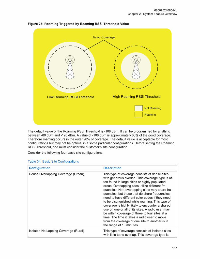
Figure 27: Roaming Triggered by Roaming RSSI Threshold Value
Low Roaming RSSI Threshold High Roaming RSSI Threshold
Not Roaming
Roaming
Good Coverage
The default value of the Roaming RSSI Threshold is -108 dBm. It can be programmed for anythingbetween -80 dBm and -120 dBm. A value of -108 dBm is approximately 80% of the good coverage.Therefore roaming occurs in the outer 20% of coverage. The default value is acceptable for mostconfigurations but may not be optimal in a some particular configurations. Before setting the RoamingRSSI Threshold, one must consider the customer’s site configuration.
Consider the following four basic site configurations:
Table 34: Basic Site Configurations
Configuration Description
Dense Overlapping Coverage (Urban) This type of coverage consists of dense siteswith generous overlap. This coverage type is of-ten found in large cities or highly populatedareas. Overlapping sites utilize different fre-quencies. Non-overlapping sites may share fre-quencies, but those that do share frequenciesneed to have different color codes if they needto be distinguished while roaming. This type ofcoverage is highly likely to encounter a shareduse on one or all of its sites. A radio user maybe within coverage of three to four sites at atime. The time it takes a radio user to movefrom the coverage of one site to another is inthe range of 10 minutes.
Isolated No Lapping Coverage (Rural) This type of coverage consists of isolated siteswith little to no overlap. This coverage type is
68007024085-NLChapter 2: System Feature Overview
157
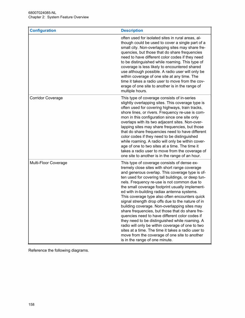
Configuration Description
often used for isolated sites in rural areas, al-though could be used to cover a single part of asmall city. Non-overlapping sites may share fre-quencies, but those that do share frequenciesneed to have different color codes if they needto be distinguished while roaming. This type ofcoverage is less likely to encountered shareduse although possible. A radio user will only bewithin coverage of one site at any time. Thetime it takes a radio user to move from the cov-erage of one site to another is in the range ofmultiple hours.
Corridor Coverage This type of coverage consists of in-seriesslightly overlapping sites. This coverage type isoften used for covering highways, train tracks,shore lines, or rivers. Frequency re-use is com-mon in this configuration since one site onlyoverlaps with its two adjacent sites. Non-over-lapping sites may share frequencies, but thosethat do share frequencies need to have differentcolor codes if they need to be distinguishedwhile roaming. A radio will only be within cover-age of one to two sites at a time. The time ittakes a radio user to move from the coverage ofone site to another is in the range of an hour.
Multi-Floor Coverage This type of coverage consists of dense ex-tremely close sites with short range coverageand generous overlap. This coverage type is of-ten used for covering tall buildings, or deep tun-nels. Frequency re-use is not common due tothe small coverage footprint usually implement-ed with in-building radiax antenna systems.This coverage type also often encounters quicksignal strength drop offs due to the nature of inbuilding coverage. Non-overlapping sites mayshare frequencies, but those that do share fre-quencies need to have different color codes ifthey need to be distinguished while roaming. Aradio will only be within coverage of one to twosites at a time. The time it takes a radio user tomove from the coverage of one site to anotheris in the range of one minute.
Reference the following diagrams.
68007024085-NLChapter 2: System Feature Overview
158
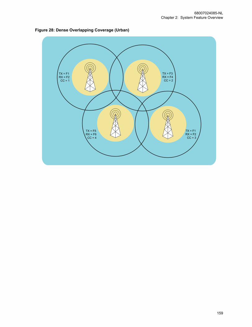
Figure 28: Dense Overlapping Coverage (Urban)
TX = F1RX = F2 CC = 1
TX = F3RX = F4 CC = 2
TX = F5RX = F6 CC = 4
TX = F1RX = F2 CC = 3
68007024085-NLChapter 2: System Feature Overview
159

Figure 29: Isolated No Overlapping Coverage (Rural)
TX = F1RX = F2 CC = 1
TX = F3RX = F4 CC = 2
TX = F1RX = F2 CC = 3
TX = F5RX = F6 CC = 4
68007024085-NLChapter 2: System Feature Overview
160
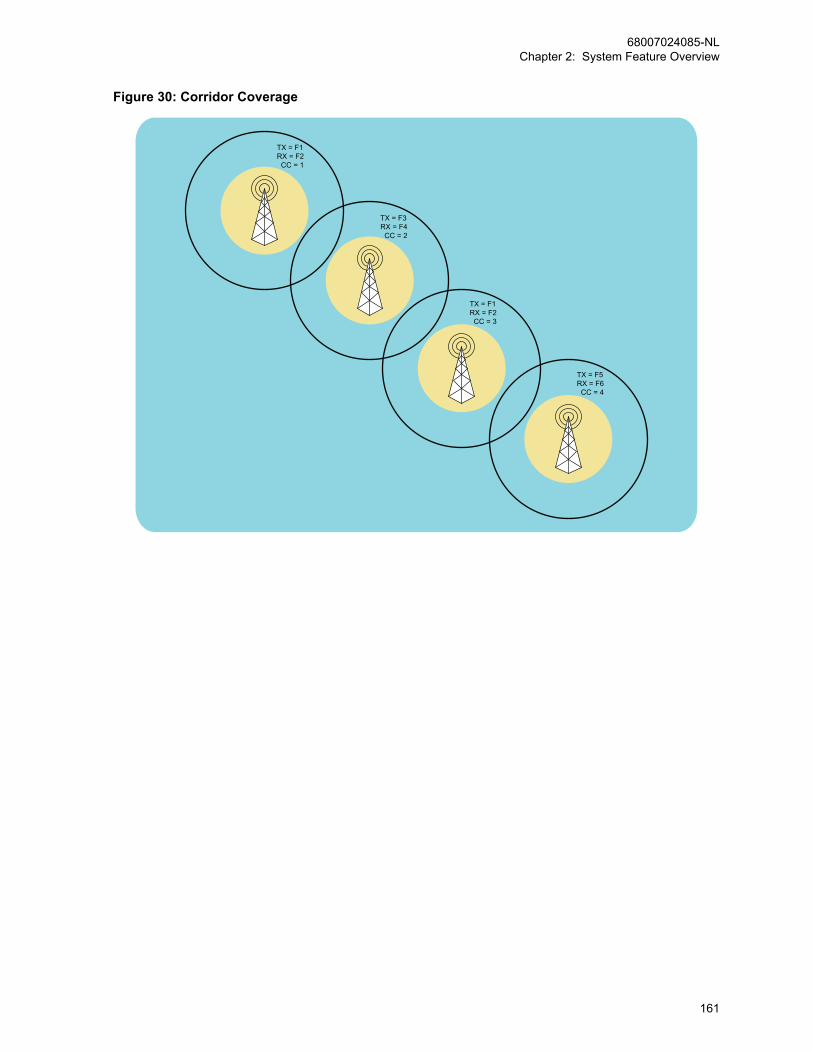
Figure 30: Corridor Coverage
TX = F1RX = F2 CC = 1
TX = F3RX = F4 CC = 2
TX = F5RX = F6 CC = 4
TX = F1RX = F2 CC = 3
68007024085-NLChapter 2: System Feature Overview
161
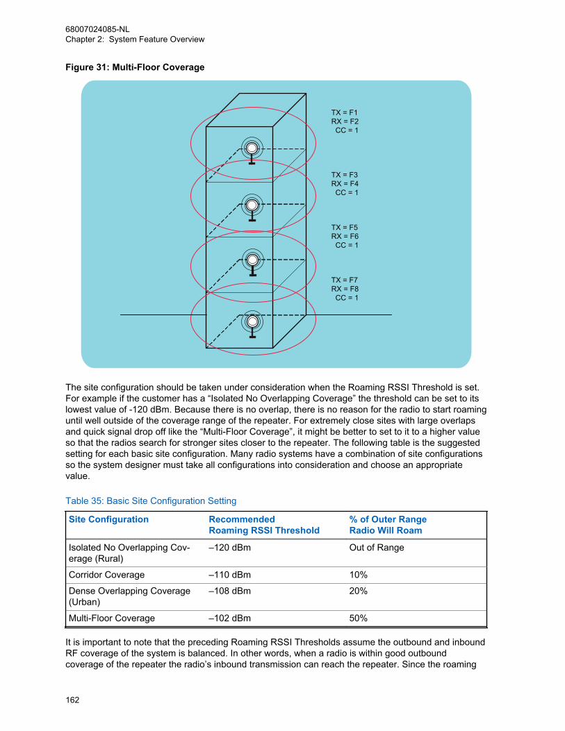
Figure 31: Multi-Floor Coverage
TX = F1 RX = F2 CC = 1
TX = F3 RX = F4 CC = 1
TX = F5 RX = F6 CC = 1
TX = F7 RX = F8 CC = 1
The site configuration should be taken under consideration when the Roaming RSSI Threshold is set.For example if the customer has a “Isolated No Overlapping Coverage” the threshold can be set to itslowest value of -120 dBm. Because there is no overlap, there is no reason for the radio to start roaminguntil well outside of the coverage range of the repeater. For extremely close sites with large overlapsand quick signal drop off like the “Multi-Floor Coverage”, it might be better to set to it to a higher valueso that the radios search for stronger sites closer to the repeater. The following table is the suggestedsetting for each basic site configuration. Many radio systems have a combination of site configurationsso the system designer must take all configurations into consideration and choose an appropriatevalue.
Table 35: Basic Site Configuration Setting
Site Configuration RecommendedRoaming RSSI Threshold
% of Outer RangeRadio Will Roam
Isolated No Overlapping Cov-erage (Rural)
–120 dBm Out of Range
Corridor Coverage –110 dBm 10%
Dense Overlapping Coverage(Urban)
–108 dBm 20%
Multi-Floor Coverage –102 dBm 50%
It is important to note that the preceding Roaming RSSI Thresholds assume the outbound and inboundRF coverage of the system is balanced. In other words, when a radio is within good outboundcoverage of the repeater the radio’s inbound transmission can reach the repeater. Since the roaming
68007024085-NLChapter 2: System Feature Overview
162
algorithm uses the outbound transmission to determine when to roam, having an unbalanced systemcan cause radios not to roam even though they can no longer reach the repeater. This can lead toradio transmissions that do not reach the repeater and are therefore not repeated.
One method to rectify this problem is to lower the output power of the repeater. This decreases theoutbound coverage area, but ensures that if a subscriber can hear the repeater well, it can respondsuccessfully. If lowering the output power is not desirable, the Roaming RSSI Threshold needs to beraised higher (less negative) than the recommended values. This forces the radios to roam to anothersite within very good RF coverage of another. This value may be different for portables and mobilessince they have different output power and therefore different inbound coverage. Portables may need ahigher (less negative) Roaming RSSI Threshold than mobiles.
Also note that there is one Roaming RSSI Threshold per roam list. This means that if one site has aninbound outbound imbalance and another does not, it may be difficult to find the correct Roaming RSSIThreshold to exactly accommodate both sites. In other words if you set the threshold to roam correctlyon the imbalanced site, it may end up roaming too early on a balanced site.
2.15.3.1.2Per Site Roaming RSSI ThresholdWhen the Roaming RSSI Thresholds for all the sites of the system are configured the same, it maycause a radio to roam very often between sites, especially when the radio is moving around highbuildings in a city.
IPSC
IP Site Connect
This per site configuration is available to MO-TOTRBO radios (version R02.00.00 onwards)in IP Site Connect.
CPMS
Capacity Plus Multi Site
This per site configuration is available to MO-TOTRBO radios (version R02.00.00 onwards)in Capacity Plus Multi Site.
This frequent roaming may cause large audio holes or let the radio miss calls. This situation can beimproved if we could lower the Roaming RSSI Threshold of the site that the radio is currently in, butstill at acceptable level. When the current site’s RSSI is above that lowered threshold, the radio will notroam even if the radio detects a higher RSSI from adjacent sites. In this way, the radio could avoidfrequent roaming.
Thus, if audio holes/missing calls from frequent roaming is a problem for the system, we may considerto configure the Roaming RSSI Threshold on a per site basis. That is, each site in the roaming list canbe configured to have its own Roaming RSSI Threshold, and this threshold may be different from siteto site. When the threshold is configured on a per site basis, as long as the current site’s RSSI >= itsconfigured Roaming RSSI Threshold, the radio does not roam. When roaming, the radio uses therelative RSSI value, to decide which site to roam to. The relative RSSI value is, the “current RSSI – itsCPS configured Roaming RSSI Threshold” value.
2.15.3.2Roam List Configuration
IPSC
68007024085-NLChapter 2: System Feature Overview
163

When configuring a Roam List it is important to keep in mind that a system can contain more than oneIP Site Connect system, or also known here as a wide area system.
A wide area system is made up of one or two wide area channels. Each wide area channel is anindividual voice path, in other words, the users on the same wide area channel monitors each other onany site. The following figure shows a system with 2 sites, 2 wide area systems, each with 2 wide areachannels. Wide Area System 1, Channel 1 (WAS1 CH1) represents a wide area channel in wide areasystem 1.
Figure 32: Two Wide-Area Systems (Each with Two Wide-Area Channels)
WAS1 CH2
WAS1 CH1
WAS1 CH2
WAS1 CH1Network
WAS2 CH1
WAS2 CH2WAS2 CH1
WAS2 CH2
Site 2 Site 1
Each wide area channel should have its own roam list. The roam list should contain one logicalchannel from each site that corresponds to the wide area channel. A logical channel is defined as thefrequency pair, color code, timeslot combination. If there are multiple personalities (CPS Channels)that reference the same logical channel, only one should be added to the wide area channel roam list.Only wide area channels should be added to the roam list.
The following table shows an example of the two site configuration in CPS. For clarification, the colorsmatch those of Figure 32: Two Wide-Area Systems (Each with Two Wide-Area Channels) on page164.
Table 36: Two Site Configuration in CPS
Zone/Folder(Alias)
Personali-ty(CPSChannel)#– Alias
Logical Channel Group Roam List# – AliasFrequen-
cy PairColorCode
Time Slot
Zone 1(Site 1)
1 – SITE 1TGA
1 1 1 TGA 1 – WAS1CH1
2 – SITE 1TGB
1 1 2 TGB 2 – WAS1CH2
3 – SITE 1TGC
2 1 1 TGC 3 – WAS2CH1
4 – SITE 1TGD
2 1 2 TGD 4 – WAS2CH2
Zone 2(Site 2)
5 – SITE 2TGA
3 2 1 TGA 1 – WAS1CH1
6 – SITE 2TGB
3 2 2 TGB 2 – WAS1CH2
7 – SITE 2TGC
4 2 1 TGC 3 – WAS2CH1
68007024085-NLChapter 2: System Feature Overview
164
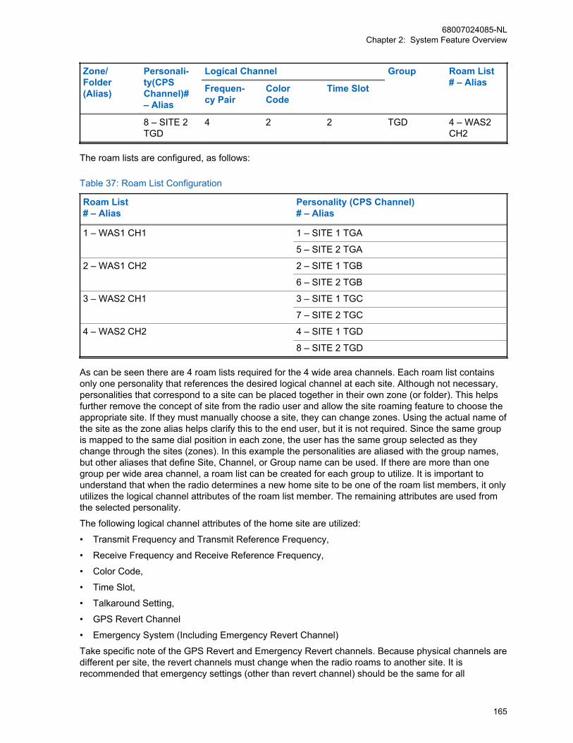
Zone/Folder(Alias)
Personali-ty(CPSChannel)#– Alias
Logical Channel Group Roam List# – AliasFrequen-
cy PairColorCode
Time Slot
8 – SITE 2TGD
4 2 2 TGD 4 – WAS2CH2
The roam lists are configured, as follows:
Table 37: Roam List Configuration
Roam List# – Alias
Personality (CPS Channel)# – Alias
1 – WAS1 CH1 1 – SITE 1 TGA
5 – SITE 2 TGA
2 – WAS1 CH2 2 – SITE 1 TGB
6 – SITE 2 TGB
3 – WAS2 CH1 3 – SITE 1 TGC
7 – SITE 2 TGC
4 – WAS2 CH2 4 – SITE 1 TGD
8 – SITE 2 TGD
As can be seen there are 4 roam lists required for the 4 wide area channels. Each roam list containsonly one personality that references the desired logical channel at each site. Although not necessary,personalities that correspond to a site can be placed together in their own zone (or folder). This helpsfurther remove the concept of site from the radio user and allow the site roaming feature to choose theappropriate site. If they must manually choose a site, they can change zones. Using the actual name ofthe site as the zone alias helps clarify this to the end user, but it is not required. Since the same groupis mapped to the same dial position in each zone, the user has the same group selected as theychange through the sites (zones). In this example the personalities are aliased with the group names,but other aliases that define Site, Channel, or Group name can be used. If there are more than onegroup per wide area channel, a roam list can be created for each group to utilize. It is important tounderstand that when the radio determines a new home site to be one of the roam list members, it onlyutilizes the logical channel attributes of the roam list member. The remaining attributes are used fromthe selected personality.
The following logical channel attributes of the home site are utilized:
• Transmit Frequency and Transmit Reference Frequency,
• Receive Frequency and Receive Reference Frequency,
• Color Code,
• Time Slot,
• Talkaround Setting,
• GPS Revert Channel
• Emergency System (Including Emergency Revert Channel)
Take specific note of the GPS Revert and Emergency Revert channels. Because physical channels aredifferent per site, the revert channels must change when the radio roams to another site. It isrecommended that emergency settings (other than revert channel) should be the same for all
68007024085-NLChapter 2: System Feature Overview
165
personalities within a roam list. Otherwise the radio may perform an emergency differently as it movesfrom one site to another.
The remaining personality attributes (Transmit and Receive Group List, Channel Access, and others)are used from the currently selected channel regardless of which site the radio is currently roamed to.It is good practice to make these parameters identical for personalities within a roam list so that theradio acts the same regardless if it roams to the personality or if the user selects the personality.
2.15.3.3Scan or RoamWhen selecting a roam list for a personality to utilize, one notices that a personality cannot contain aroam list and a Channel Scan List.
MOTOTRBO does not currently support the ability to roam between sites and then scan channels at aparticular site. Therefore while on a particular personality, a user has the ability to roam or scanchannels, not both.
2.15.3.4Beacon Duration and Beacon Interval Settings
IPSC
If there is no activity on a system, the repeaters hibernate and the radio’s Passive Site Search is notable to determine the signal strength and determine which site is the best, as repeaters are nottransmitting.
Due to this, the repeater can be configured to transmit a beacon when not active and there is no otherinterfering signal. During times of no activity, the subscriber utilizes the signal strength of the beacon todetermine when it should roam and which site it should roam to. If the subscriber does not receive abeacon in the expected duration, it assumes it is out of range of the repeater (or the repeater hasfailed) and attempts to roam to another site.
Both the beacon duration and the interval are programmable through CPS. The beacon duration is onlyconfigured in the repeater, but the beacon interval is programmed in both the repeater and the radio.
The duration and interval of the beacon is a function of the over-the-air shared use rules in thecustomer’s region. The beacon duration is dependent on the number of sites in the IP Site Connectsystem and therefore in the roam list. The beacon interval is dependent on how quickly the radio isexpected to roam to and from a site when there is no activity. The minimal duration and interval needto be met while keeping within the shared use guidelines of the region.
The ratio of the beacon duration and beacon interval equate to how often the repeaters transmit whilethere is no inbound radio activity, (the beacon transmit ratio). This ratio is not directly programmed intothe system, but is rather a guideline for setting the Beacon Duration and Interval. If on a shared usefrequency the beacon transmit ratio should be kept low. The target ratio is between 5% and 10%. Inother words, if there is a need to increase the beacon duration, the beacon interval must also increasein order to keep the correct ratio.
If the beacon duration is configured too short it can be difficult for a roaming radio to detect it. This isespecially true as the number of sites increases. As the amount of time between a roaming radio’srepeated roam attempts to a particular site increases, it is less likely to be inspecting the site at theexact moment that the beacon is transmitted. Recall that the home site is sampled in between othersites, which increases the overall cycle time. A user is typically within the coverage of no more than 4sites at any given time, therefore even with a large roam list, most of the sites have no activity and canbe inspected very quickly. If numerous sites have shared-use frequencies (interference) the radio takeslonger to get through its roam list and this increases the time between inspections of one particularsite. Note that because the roam list is sorted by signal strength, the nearer sites are inspected first.
68007024085-NLChapter 2: System Feature Overview
166
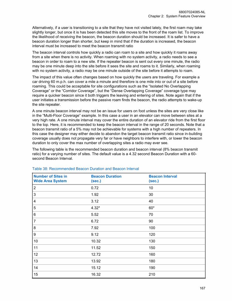
Alternatively, if a user is transitioning to a site that they have not visited lately, the first roam may takeslightly longer, but once it is has been detected this site moves to the front of the roam list. To improvethe likelihood of receiving the beacon, the beacon duration should be increased. It is safer to have abeacon duration longer than shorter, but keep in mind that if the duration is increased, the beaconinterval must be increased to meet the beacon transmit ratio
The beacon interval controls how quickly a radio can roam to a site and how quickly it roams awayfrom a site when there is no activity. When roaming with no system activity, a radio needs to see abeacon in order to roam to a new site. If the repeater beacon is sent out every one minute, the radiomay be one minute deep into the site before it sees the site and roams to it. Similarly, when roamingwith no system activity, a radio may be one minute outside of the site before it attempts to roam.
The impact of this value often changes based on how quickly the users are traveling. For example acar driving 60 m.p.h. can cover a mile a minute and therefore is one mile into or out of a site beforeroaming. This could be acceptable for site configurations such as the “Isolated No OverlappingCoverage” or the “Corridor Coverage”, but the “Dense Overlapping Coverage” coverage type mayrequire a quicker beacon since it both triggers the leaving and entering of sites. Note again that if theuser initiates a transmission before the passive roam finds the beacon, the radio attempts to wake-upthe site repeater.
A one minute beacon interval may not be an issue for users on foot unless the sites are very close likein the “Multi-Floor Coverage” example. In this case a user in an elevator can move between sites at avery high rate. A one minute interval may cover the entire duration of an elevator ride from the first floorto the top. Here, it is recommended to keep the beacon interval in the range of 20 seconds. Note that abeacon transmit ratio of a 5% may not be achievable for systems with a high number of repeaters. Inthis case the designer may either decide to abandon the target beacon transmit ratio since in-buildingcoverage usually does not propagate very far or have neighbors to interfere with, or lower the beaconduration to only cover the max number of overlapping sites a radio may ever see.
The following table is the recommended beacon duration and beacon interval (8% beacon transmitratio) for a varying number of sites. The default value is a 4.32 second Beacon Duration with a 60-second Beacon Interval.
Table 38: Recommended Beacon Duration and Beacon Interval
Number of Sites inWide Area System
Beacon Duration(sec.)
Beacon Interval(sec.)
2 0.72 10
3 1.92 30
4 3.12 40
5 4.32* 60*
6 5.52 70
7 6.72 90
8 7.92 100
9 9.12 120
10 10.32 130
11 11.52 150
12 12.72 160
13 13.92 180
14 15.12 190
15 16.32 210
68007024085-NLChapter 2: System Feature Overview
167
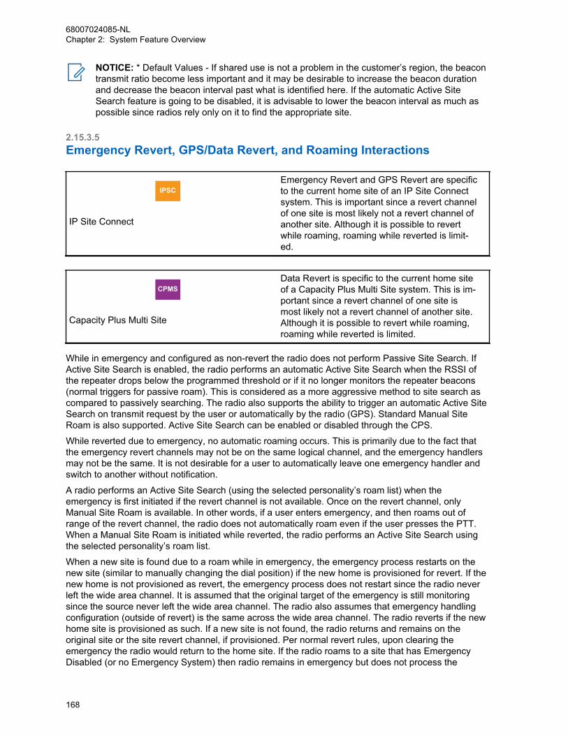
NOTICE: * Default Values - If shared use is not a problem in the customer’s region, the beacontransmit ratio become less important and it may be desirable to increase the beacon durationand decrease the beacon interval past what is identified here. If the automatic Active SiteSearch feature is going to be disabled, it is advisable to lower the beacon interval as much aspossible since radios rely only on it to find the appropriate site.
2.15.3.5Emergency Revert, GPS/Data Revert, and Roaming Interactions
IPSC
IP Site Connect
Emergency Revert and GPS Revert are specificto the current home site of an IP Site Connectsystem. This is important since a revert channelof one site is most likely not a revert channel ofanother site. Although it is possible to revertwhile roaming, roaming while reverted is limit-ed.
CPMS
Capacity Plus Multi Site
Data Revert is specific to the current home siteof a Capacity Plus Multi Site system. This is im-portant since a revert channel of one site ismost likely not a revert channel of another site.Although it is possible to revert while roaming,roaming while reverted is limited.
While in emergency and configured as non-revert the radio does not perform Passive Site Search. IfActive Site Search is enabled, the radio performs an automatic Active Site Search when the RSSI ofthe repeater drops below the programmed threshold or if it no longer monitors the repeater beacons(normal triggers for passive roam). This is considered as a more aggressive method to site search ascompared to passively searching. The radio also supports the ability to trigger an automatic Active SiteSearch on transmit request by the user or automatically by the radio (GPS). Standard Manual SiteRoam is also supported. Active Site Search can be enabled or disabled through the CPS.
While reverted due to emergency, no automatic roaming occurs. This is primarily due to the fact thatthe emergency revert channels may not be on the same logical channel, and the emergency handlersmay not be the same. It is not desirable for a user to automatically leave one emergency handler andswitch to another without notification.
A radio performs an Active Site Search (using the selected personality’s roam list) when theemergency is first initiated if the revert channel is not available. Once on the revert channel, onlyManual Site Roam is available. In other words, if a user enters emergency, and then roams out ofrange of the revert channel, the radio does not automatically roam even if the user presses the PTT.When a Manual Site Roam is initiated while reverted, the radio performs an Active Site Search usingthe selected personality’s roam list.
When a new site is found due to a roam while in emergency, the emergency process restarts on thenew site (similar to manually changing the dial position) if the new home is provisioned for revert. If thenew home is not provisioned as revert, the emergency process does not restart since the radio neverleft the wide area channel. It is assumed that the original target of the emergency is still monitoringsince the source never left the wide area channel. The radio also assumes that emergency handlingconfiguration (outside of revert) is the same across the wide area channel. The radio reverts if the newhome site is provisioned as such. If a new site is not found, the radio returns and remains on theoriginal site or the site revert channel, if provisioned. Per normal revert rules, upon clearing theemergency the radio would return to the home site. If the radio roams to a site that has EmergencyDisabled (or no Emergency System) then radio remains in emergency but does not process the
68007024085-NLChapter 2: System Feature Overview
168
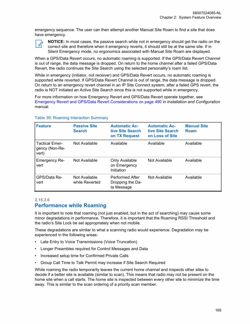
emergency sequence. The user can then attempt another Manual Site Roam to find a site that doeshave emergency.
NOTICE: In most cases, the passive search while not in emergency should get the radio on thecorrect site and therefore when it emergency reverts, it should still be at the same site. If inSilent Emergency mode, no ergonomics associated with Manual Site Roam are displayed.
When a GPS/Data Revert occurs, no automatic roaming is supported. If the GPS/Data Revert Channelis out of range, the data message is dropped. On return to the home channel after a failed GPS/DataRevert, the radio continues the Site Search using the selected personality’s roam list.
While in emergency (initiator, not receiver) and GPS/Data Revert occurs, no automatic roaming issupported while reverted. If GPS/Data Revert Channel is out of range, the data message is dropped.On return to an emergency revert channel in an IP Site Connect system, after a failed GPS revert, theradio is NOT initiated an Active Site Search since this is not supported while in emergency.
For more information on how Emergency Revert and GPS/Data Revert operate together, see Emergency Revert and GPS/Data Revert Considerations on page 490 in Installation and Configurationmanual.
Table 39: Roaming Interaction Summary
Feature Passive SiteSearch
Automatic Ac-tive Site Searchon TX Request
Automatic Ac-tive Site Searchon Loss of Site
Manual SiteRoam
Tactical Emer-gency (Non-Re-vert)
Not Available Available Available Available
Emergency Re-vert
Not Available Only Availableon EmergencyInitiation
Not Available Available
GPS/Data Re-vert
Not Availablewhile Reverted
Performed AfterDropping the Da-ta Message
Not Available Available
2.15.3.6Performance while RoamingIt is important to note that roaming (not just enabled, but in the act of searching) may cause someminor degradations in performance. Therefore, it is important that the Roaming RSSI Threshold andthe radio’s Site Lock be set appropriately when not mobile.
These degradations are similar to what a scanning radio would experience. Degradation may beexperienced in the following areas:
• Late Entry to Voice Transmissions (Voice Truncation)
• Longer Preambles required for Control Messages and Data
• Increased setup time for Confirmed Private Calls
• Group Call Time to Talk Permit may increase if Site Search Required
While roaming the radio temporarily leaves the current home channel and inspects other sites todecide if a better site is available (similar to scan). This means that radio may not be present on thehome site when a call starts. The home site is inspected between every other site to minimize the timeaway. This is similar to the scan ordering of a priority scan member.
68007024085-NLChapter 2: System Feature Overview
169
One issue that arises from this situation is that if a Group Call or unconfirmed Private Call starts whilethe target is inspecting another site, the may be a short delay before joining the call. This equates tovoice truncation for the target radio.
Another issue faced is the need for longer preambles in order for command and control messages, anddata to be received by a radio that is currently roaming. Without an extended preamble, roaming radiosmiss the message.
The need for preambles also affects the setup time for confirmed Private Calls. Confirmed Private Callsutilize command and control messaging to setup the call. In addition, the first setup attempt does notutilize any preambles. This increases the setup time between radios that are not roaming. This meansthat the first setup attempt of a Private Call is not successful if the target radio is roaming. The radiothen attempts a second time with a preamble. This second attempt is likely to be successful and thePrivate Call continues.
If the current home site cannot be awoken, the radio attempts to locate another site using an automaticActive Site Search. As the radio attempts to wake-up other sites, the user must wait. This increase intime is recognized as an increase in the time from PTT to receiving the Talk Permit Tone. This is notexpected to occur often if the beacon interval is set appropriately.
It is expected that the value that the roaming feature adds is worth these performance degradations.The Beacon Interval and the Roaming RSSI Threshold should be set appropriately to minimize theamount of time a radio is searching for a site.
2.15.3.7ARS Registration on RoamingWhen a radio roams in data capable mode with the Presence Service enabled, the radio can beconfigured to automatically send ARS registration messages to the Presence Notifier application. ThisARS registration on roaming capability can be enabled or disabled through CPS configuration, and isapplicable in both Passive Site Search and Active Site Search.
During Passive Site Search roaming, when ARS registration on roaming is disabled, the radio roamswhen the RSSI of the repeater roamed into is greater than the RSSI of the current Home channel by 0dB. However, when ARS registration on roaming is enabled, the radio roams only when the RSSI ofthe repeater roamed into is greater than the RSSI of the current Home channel by 6 dB. As a result,this reduces frequent registrations on roaming.
During Active Site Search roaming, when ARS registration on roaming is enabled, the radioautomatically sends an ARS message to the Presence Notifier application if it roams into a sitesuccessfully.
This ARS registration on roaming capability can be used by user applications to monitor which repeatersite a radio is currently in.
2.16Voice and Data PrivacyOver a digital channel, MOTOTRBO supports a way to keep communication (both voice and data)private. Privacy protects the information, where “protection” means that the MOTOTRBO resistsreading of data payload or listening of voice by anybody other than the intended receivers.
MOTOTRBO does not provide any mechanism to authenticate the radios or radio users and it does notprotect the integrity of the messages.
68007024085-NLChapter 2: System Feature Overview
170
2.16.1Types of PrivacyMOTOTRBO offers the following types of privacy mechanisms – Basic, Enhanced, and AdvancedEncryption Standard (AES). Basic Privacy utilizes Motorola Solutions proprietary mechanisms andalgorithms and therefore is not interoperable with privacy offerings from other vendors.
Both Enhanced Privacy and AES Privacy are licensed in the subscriber. They can be utilized in allMOTOTRBO architectures.
The main differences between Basic Privacy, Enhanced Privacy, and AES Privacy are that EnhancedPrivacy and AES privacy provide a higher level of protection and support multiple keys in a radio,compared with one key in the case of Basic Privacy.
The main differences between Enhanced Privacy and AES Privacy are the algorithm utilized and theirkey size. Enhanced Privacy utilizes ARC4 algorithm with 40 bit keys, and AES Privacy utilizes the AESalgorithm with 256 bit keys. The AES Privacy has a higher level of protection in terms of algorithm thanEnhanced Privacy.
The privacy types are not interoperable. Only one type can operate in each radio at any time. Thisimplies that all digital private channels support either Basic Privacy or Enhanced Privacy, and that allradios on a repeater must use the same mode, even if they are in different groups. In direct mode, allradios that communicate with each other must use the same privacy mechanism.
Enhanced Privacy and AES Privacy are interoperable with privacy offerings from other vendors.
2.16.1.1AES Configuration in MOTOTRBOThe AES/Symmetric Key options are visible in the CPS only if the AES feature is purchased. The radio,repeater, and MNIS of a system require configuration for AES. In CPS, the radio codeplug lists allSymmetric Keys on the Privacy tab, under the AES heading. Privacy types None or Enhanced areindependent from the Symmetric Keys configuration. Basic Privacy does not work with AES. If BasicPrivacy is configured, the radio bypasses AES for the transmission even if Symmetric Keys areconfigured in the radio. The radio allows the privacy type selection of None or Enhanced to beconfigured with or without Symmetric Keys. Only one privacy type is allowed on each radio channel.The radio allows up to 16 different Symmetric Keys to be configured. Each Symmetric Key can be upto 256 bits in length.
To support AES, the repeater codeplug must be configured with Enhanced Privacy type since therepeater does not encrypt or decrypt any AES payload. The Enhanced Privacy option allows therepeater to repeat the AES and Enhanced Privacy encrypted audio and data bursts. For properfunctioning of the repeater in a system with AES encrypted transmissions, the repeater must berunning on firmware version R02.30.00 or later.
A radio can be configured with both Enhanced Privacy keys and Symmetric Keys. The radio canreceive audio and data calls encrypted with AES or Enhanced Privacy keys, from any talkgroup in theRX Talkgroup list that is tied to a personality, as long as the same key and privacy type of thetransmitting radio is selected in the personality.
The RM feature of the CPS can be used to pre-configure and manage the Symmetric Keys. The AESuses the Symmetric Keys as encryption keys.
The MNIS require Symmetric Keys configuration for AES encryption. The MNIS allows up to 255Symmetric Keys.
68007024085-NLChapter 2: System Feature Overview
171
2.16.2Strength of the Protection MechanismThe Basic, Enhanced, and AES privacy types protect confidentiality of the payload. The protectionmechanisms described in this section require a key that is shared only among the intended parties.
The resistance provided by Basic Privacy is minimal for the following reasons:
• The Basic Privacy uses a non-cryptographic algorithm to transform plain voice/data into protectedvoice/data. It is possible for an adversary to obtain the key by storing a few over-the-air voice ordata packets and performing few simple mathematical operations.
• The Basic Privacy uses 16-bit keys. A user selects a key from 255 predefined keys stored in theCPS. The limited number of possible keys makes it easy for an adversary to guess the key in-use.
NOTICE: The intended use of the Basic Privacy is to stop casual eavesdropping only.
The resistance provided by the Enhanced Privacy is significantly better than the resistance provided bythe Basic Privacy for the following reasons:
• The Enhanced Privacy uses a cryptographic algorithm to transform plain voice/data into protectedvoice/data. The algorithm is the well-known Alleged RC4 (ARC4), and is same as RC41. Acryptographic algorithm makes it very difficult for an adversary to obtain the key from over-the-airprotected messages.4
• The Enhanced Privacy uses 40-bit long keys. A radio can store up to 16 keys and the EnhancedPrivacy allows using different keys for different channels. The large number of possible keys(approximately 1 trillion) makes it difficult for an adversary to guess the value of a key. Note that a40-bit long key may not provide the protection needed to transmit valuable data such as credit cardnumbers.
• Using the same key, the Enhanced Privacy protects each superframe of voice or each data packetin a different and unrelated way. This increases the resistance further.
The resistance provided by the AES is significantly better than the resistance provided by EnhancedPrivacy for the following reasons:
• A cryptographic algorithm is used to transform plain voice/data into protected voice/data. The AEShas been adopted by the United States government, and is now used worldwide.
• The AES uses 256-bit long keys. A radio can store up to 16 Symmetric Keys for AES privacy, andthe radio configuration allows using different keys for different channels. The large number ofpossible keys makes it difficult for even sophisticated hackers to guess the key from the OTAinterface.
• Using the same key, the AES protects each super frame of voice or each data packet in a differentand unrelated method, which further increases the resistance.
2.16.3Effects of Privacy Protection on PerformanceBasic Privacy uses only one key, which is known to both the sender and the receiver. This eliminatesthe need to transport cryptographic parameters (for example, Key Identifier) with the voice or datapayload. A voice message, in case of Basic Privacy, neither requires any modification in the payloadnor any additional headers. Therefore, the System Access Time and the audio quality of a Basicprivacy protected voice is same as that of an unprotected voice.
Enhanced Privacy and AES Privacy use multiple keys and a random number to ensure that theencryption data is different for each data message and each superframe of a voice message. This
4 The name “RC4” is trademarked by RSA Security. Although “unofficial” implementations are legal,but the RC4 name cannot be used.
68007024085-NLChapter 2: System Feature Overview
172

requires transporting cryptographic parameters (for example, Key Identifier, Initialization Vector) withthe voice or data payload. A voice message, in the case of Enhanced and AES Privacy, requires anadditional header and replaces some of the least important bits of the voice payload with theInitialization Vector. The additional header increases the System Access Time except when TalkPermit Tone is enabled (in repeater mode) where the additional header replaces one of the normalvoice headers. The replacement of payload bits reduces the voice quality. Note that the reduction invoice quality is barely noticeable.
In the case of Basic Privacy, Enhanced Privacy, and AES Privacy, a data message requires anadditional header to distinguish between an unprotected data message and a protected data message.In the case of Enhanced and AES Privacy, the additional header is also used to transportcryptographic parameter. This reduces the data throughput. For example, a typical protected confirmedlocation response takes 600 milliseconds compared to 540 milliseconds for an unprotected one(approximately 10% loss in throughput).
2.16.4User Control Over PrivacyCustomer Programming Software (CPS) allows a System Installer to select the type of privacy (that is,Basic Privacy or Enhanced Privacy or AES Privacy). CPS also allows the enabling or disabling of theprivacy service of a channel. The option to toggle the privacy capability per channel can additionally begiven to the radio user by providing a menu entry or programmable button. Without the menu entry orprogrammable button, the radio user is essentially “locked” to the channel’s privacy setting. It isimportant to note that a user can set or reset privacy for a channel, and not for the radio. If the user isprovided with the menu entry or programmable button, and the user toggles the privacy setting, onlythe selected channel’s privacy setting is toggled and remains toggled even after the user changeschannels or zones. Toggling the privacy setting on a channel will not affect the privacy setting on otherchannels.
The privacy setting of a channel controls the transmit privacy setting, not the receive privacy setting. Aradio on a privacy-enabled channel always transmits protected, while a radio on a privacy-disabledchannel always transmits unprotected.
However, for the privacy reception, it is little bit different. It depends on whether “Ignore Rx ClearVoice/Packet Data” and “Fixed Privacy Key Decryption” options are enabled. See When Ignore RxClear Voice/Packet Data and Fixed Privacy Key Decryption Options are not Enabled on page 173.
2.16.4.1When Ignore Rx Clear Voice/Packet Data and Fixed Privacy KeyDecryption Options are not EnabledIn general, the radio receives and decodes both unprotected and protected message, regardless of thechannel’s privacy setting. Also, when the radio receives a protected message, regardless of thechannel's privacy setting, the radio always tries to unscramble or decrypt the message.
If a radio is never required to receive protected messages, then it should not be provisioned with keysor should be provisioned with a key that is different from the key(s) used by the rest of the system.Simply setting a channel to be privacy-disabled does not stop the radio from receiving protectedmessages. A radio receives a protected message correctly as long as it has the right key.
Therefore, when one radio user on a privacy-enabled channel transmits, every radio, regardless of itschannel’s privacy-enabled or privacy-disabled status hears the transmission clearly if their provisionedPrivacy Key is identical to that of the transmitting radio. A radio user receiving a protected transmissionsees the green LED blinking rapidly. The receiving radio user should consider changing the privacysetting to match that of the call initiator when replying.
In Basic Privacy, a system utilizes only one key and if all radios are privacy capable, it is recommendedthat all radios are set to privacy enabled and equipped without the option to toggle the privacy settingsby a radio user. Since Basic Privacy does not cause any degradation in audio quality, or decrease in
68007024085-NLChapter 2: System Feature Overview
173
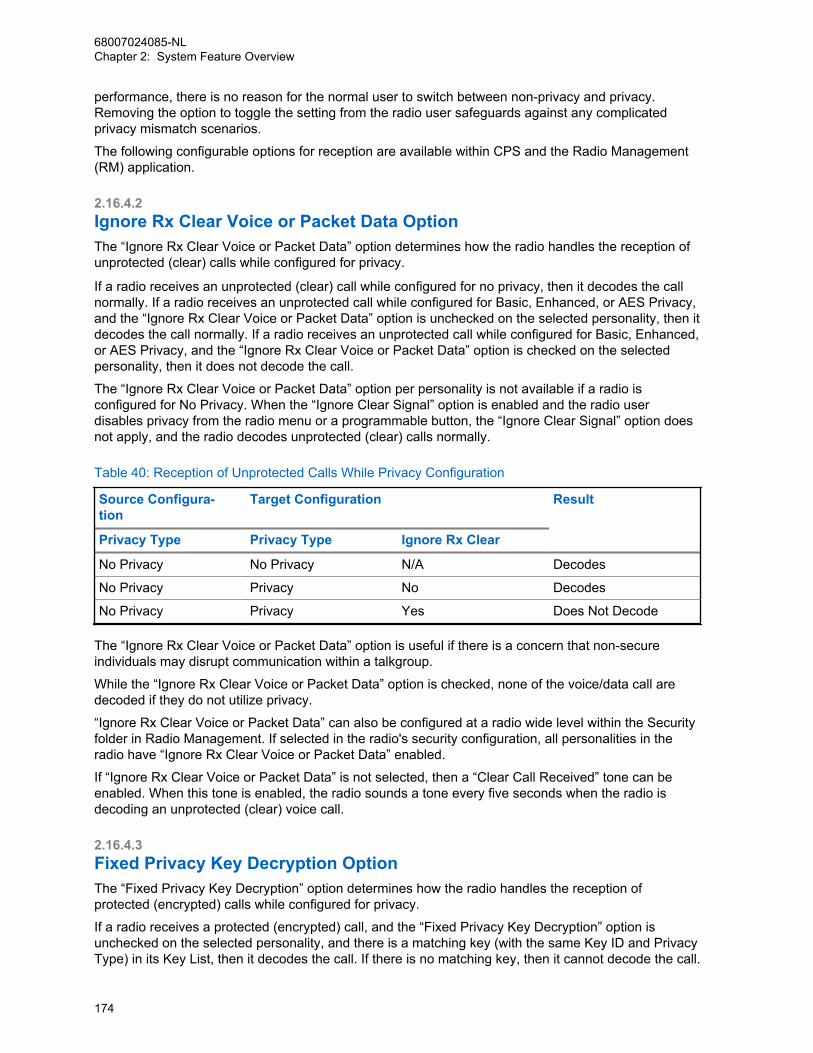
performance, there is no reason for the normal user to switch between non-privacy and privacy.Removing the option to toggle the setting from the radio user safeguards against any complicatedprivacy mismatch scenarios.
The following configurable options for reception are available within CPS and the Radio Management(RM) application.
2.16.4.2Ignore Rx Clear Voice or Packet Data OptionThe “Ignore Rx Clear Voice or Packet Data” option determines how the radio handles the reception ofunprotected (clear) calls while configured for privacy.
If a radio receives an unprotected (clear) call while configured for no privacy, then it decodes the callnormally. If a radio receives an unprotected call while configured for Basic, Enhanced, or AES Privacy,and the “Ignore Rx Clear Voice or Packet Data” option is unchecked on the selected personality, then itdecodes the call normally. If a radio receives an unprotected call while configured for Basic, Enhanced,or AES Privacy, and the “Ignore Rx Clear Voice or Packet Data” option is checked on the selectedpersonality, then it does not decode the call.
The “Ignore Rx Clear Voice or Packet Data” option per personality is not available if a radio isconfigured for No Privacy. When the “Ignore Clear Signal” option is enabled and the radio userdisables privacy from the radio menu or a programmable button, the “Ignore Clear Signal” option doesnot apply, and the radio decodes unprotected (clear) calls normally.
Table 40: Reception of Unprotected Calls While Privacy Configuration
Source Configura-tion
Target Configuration Result
Privacy Type Privacy Type Ignore Rx Clear
No Privacy No Privacy N/A Decodes
No Privacy Privacy No Decodes
No Privacy Privacy Yes Does Not Decode
The “Ignore Rx Clear Voice or Packet Data” option is useful if there is a concern that non-secureindividuals may disrupt communication within a talkgroup.
While the “Ignore Rx Clear Voice or Packet Data” option is checked, none of the voice/data call aredecoded if they do not utilize privacy.
“Ignore Rx Clear Voice or Packet Data” can also be configured at a radio wide level within the Securityfolder in Radio Management. If selected in the radio's security configuration, all personalities in theradio have “Ignore Rx Clear Voice or Packet Data” enabled.
If “Ignore Rx Clear Voice or Packet Data” is not selected, then a “Clear Call Received” tone can beenabled. When this tone is enabled, the radio sounds a tone every five seconds when the radio isdecoding an unprotected (clear) voice call.
2.16.4.3Fixed Privacy Key Decryption OptionThe “Fixed Privacy Key Decryption” option determines how the radio handles the reception ofprotected (encrypted) calls while configured for privacy.
If a radio receives a protected (encrypted) call, and the “Fixed Privacy Key Decryption” option isunchecked on the selected personality, and there is a matching key (with the same Key ID and PrivacyType) in its Key List, then it decodes the call. If there is no matching key, then it cannot decode the call.
68007024085-NLChapter 2: System Feature Overview
174
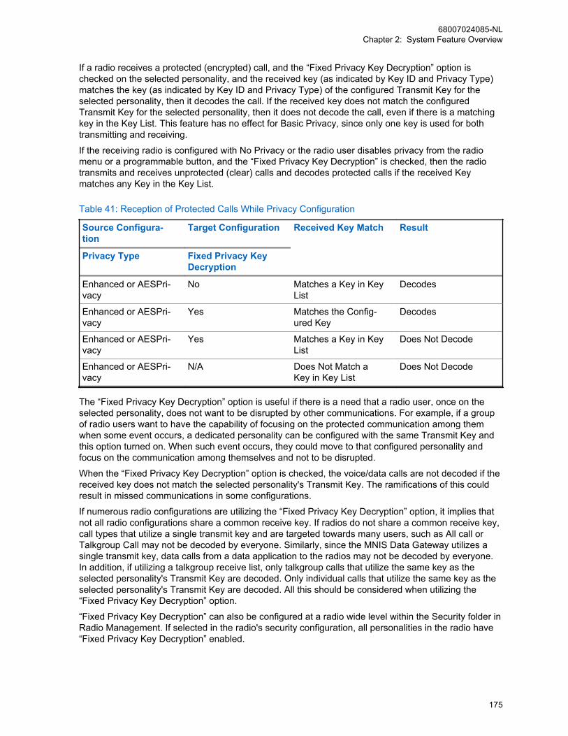
If a radio receives a protected (encrypted) call, and the “Fixed Privacy Key Decryption” option ischecked on the selected personality, and the received key (as indicated by Key ID and Privacy Type)matches the key (as indicated by Key ID and Privacy Type) of the configured Transmit Key for theselected personality, then it decodes the call. If the received key does not match the configuredTransmit Key for the selected personality, then it does not decode the call, even if there is a matchingkey in the Key List. This feature has no effect for Basic Privacy, since only one key is used for bothtransmitting and receiving.
If the receiving radio is configured with No Privacy or the radio user disables privacy from the radiomenu or a programmable button, and the “Fixed Privacy Key Decryption” is checked, then the radiotransmits and receives unprotected (clear) calls and decodes protected calls if the received Keymatches any Key in the Key List.
Table 41: Reception of Protected Calls While Privacy Configuration
Source Configura-tion
Target Configuration Received Key Match Result
Privacy Type Fixed Privacy KeyDecryption
Enhanced or AESPri-vacy
No Matches a Key in KeyList
Decodes
Enhanced or AESPri-vacy
Yes Matches the Config-ured Key
Decodes
Enhanced or AESPri-vacy
Yes Matches a Key in KeyList
Does Not Decode
Enhanced or AESPri-vacy
N/A Does Not Match aKey in Key List
Does Not Decode
The “Fixed Privacy Key Decryption” option is useful if there is a need that a radio user, once on theselected personality, does not want to be disrupted by other communications. For example, if a groupof radio users want to have the capability of focusing on the protected communication among themwhen some event occurs, a dedicated personality can be configured with the same Transmit Key andthis option turned on. When such event occurs, they could move to that configured personality andfocus on the communication among themselves and not to be disrupted.
When the “Fixed Privacy Key Decryption” option is checked, the voice/data calls are not decoded if thereceived key does not match the selected personality's Transmit Key. The ramifications of this couldresult in missed communications in some configurations.
If numerous radio configurations are utilizing the “Fixed Privacy Key Decryption” option, it implies thatnot all radio configurations share a common receive key. If radios do not share a common receive key,call types that utilize a single transmit key and are targeted towards many users, such as All call orTalkgroup Call may not be decoded by everyone. Similarly, since the MNIS Data Gateway utilizes asingle transmit key, data calls from a data application to the radios may not be decoded by everyone.In addition, if utilizing a talkgroup receive list, only talkgroup calls that utilize the same key as theselected personality's Transmit Key are decoded. Only individual calls that utilize the same key as theselected personality's Transmit Key are decoded. All this should be considered when utilizing the“Fixed Privacy Key Decryption” option.
“Fixed Privacy Key Decryption” can also be configured at a radio wide level within the Security folder inRadio Management. If selected in the radio's security configuration, all personalities in the radio have“Fixed Privacy Key Decryption” enabled.
68007024085-NLChapter 2: System Feature Overview
175
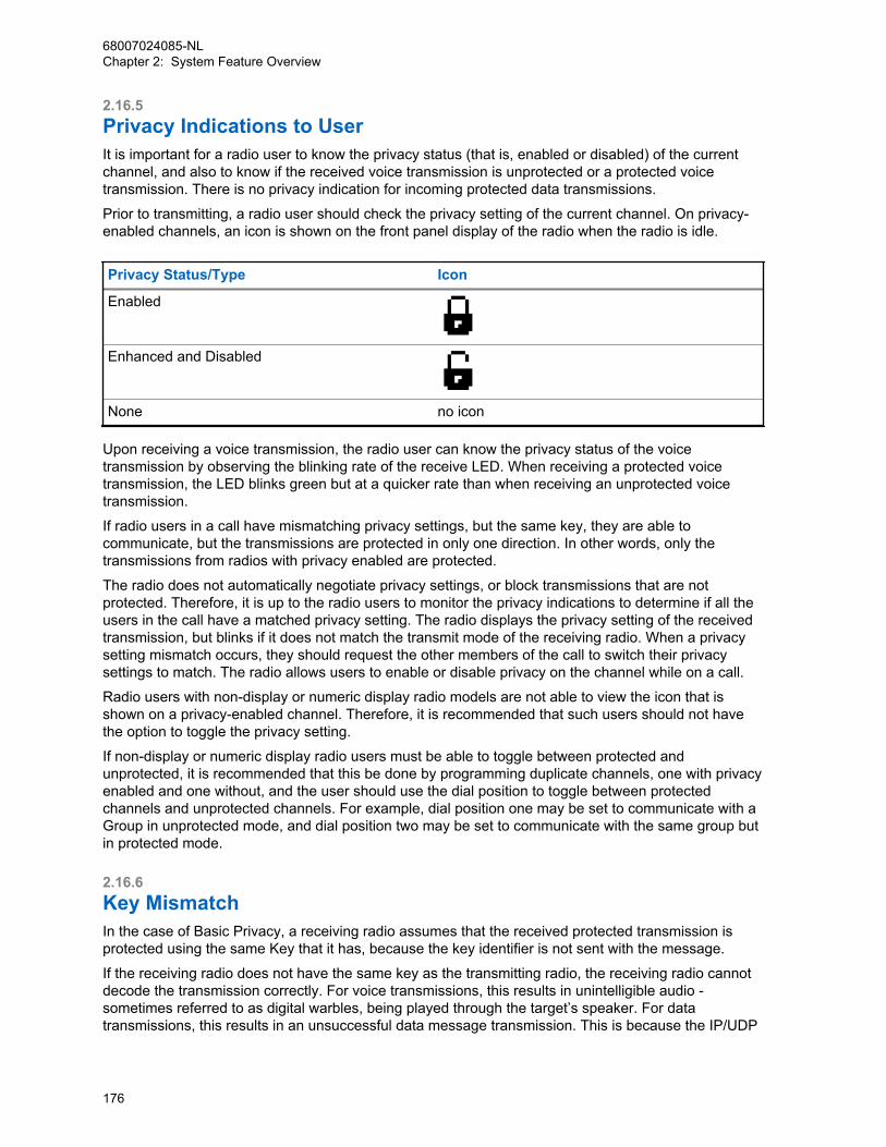
2.16.5Privacy Indications to UserIt is important for a radio user to know the privacy status (that is, enabled or disabled) of the currentchannel, and also to know if the received voice transmission is unprotected or a protected voicetransmission. There is no privacy indication for incoming protected data transmissions.
Prior to transmitting, a radio user should check the privacy setting of the current channel. On privacy-enabled channels, an icon is shown on the front panel display of the radio when the radio is idle.
Privacy Status/Type Icon
Enabled
Enhanced and Disabled
None no icon
Upon receiving a voice transmission, the radio user can know the privacy status of the voicetransmission by observing the blinking rate of the receive LED. When receiving a protected voicetransmission, the LED blinks green but at a quicker rate than when receiving an unprotected voicetransmission.
If radio users in a call have mismatching privacy settings, but the same key, they are able tocommunicate, but the transmissions are protected in only one direction. In other words, only thetransmissions from radios with privacy enabled are protected.
The radio does not automatically negotiate privacy settings, or block transmissions that are notprotected. Therefore, it is up to the radio users to monitor the privacy indications to determine if all theusers in the call have a matched privacy setting. The radio displays the privacy setting of the receivedtransmission, but blinks if it does not match the transmit mode of the receiving radio. When a privacysetting mismatch occurs, they should request the other members of the call to switch their privacysettings to match. The radio allows users to enable or disable privacy on the channel while on a call.
Radio users with non-display or numeric display radio models are not able to view the icon that isshown on a privacy-enabled channel. Therefore, it is recommended that such users should not havethe option to toggle the privacy setting.
If non-display or numeric display radio users must be able to toggle between protected andunprotected, it is recommended that this be done by programming duplicate channels, one with privacyenabled and one without, and the user should use the dial position to toggle between protectedchannels and unprotected channels. For example, dial position one may be set to communicate with aGroup in unprotected mode, and dial position two may be set to communicate with the same group butin protected mode.
2.16.6Key MismatchIn the case of Basic Privacy, a receiving radio assumes that the received protected transmission isprotected using the same Key that it has, because the key identifier is not sent with the message.
If the receiving radio does not have the same key as the transmitting radio, the receiving radio cannotdecode the transmission correctly. For voice transmissions, this results in unintelligible audio -sometimes referred to as digital warbles, being played through the target’s speaker. For datatransmissions, this results in an unsuccessful data message transmission. This is because the IP/UDP
68007024085-NLChapter 2: System Feature Overview
176
headers of a data message when unprotected using a wrong key fail to CRC check. On failure of thechecksum, the data message is not delivered to the application.
In the case of Enhanced and AES Privacy, the key identifier is sent with the message and if thereceiving radio does not have the key then it either remains muted (in case of voice message) ordiscards the data message. If the key value associated with the key identifier is different in the senderand receiver, due to a miss-configuration, then the voice transmissions result in unintelligible audio andthe data transmissions are unsuccessful.
2.16.7Keys and Key ManagementIn the case of Basic Privacy, a radio is capable of holding only one Privacy Key. The same key is usedto protect and unprotect voice and data transmissions over all the channels and for all call types:Group Call, Private Call, All Call, or Emergency Call.
In the case of Enhanced Privacy, a radio is capable of holding up to sixteen Privacy Keys, where keysare associated with channels. In the case of AES, a radio is capable of holding up to sixteenSymmetric Keys, where each key is associated with channels.The relationship between keys andchannels is 1:0...n. (in other words 1 to 0 or 1 to many) “0” means that keys may be provisioned intothe radio but are not associated with any channel. In this case, the keys are used to decode a receivedmessage but are not used by the radio to encode a transmission.
A Privacy Key is provisioned in a radio using a CPS. The keys are not readable, editable, or erasableby the radio user. Once a key has been chosen and programmed into a radio, the key cannot beextracted and viewed by CPS. It can only be retained or overwritten.
In the case of Basic Privacy, a CPS user can select one of the 255 prescribed keys. These keys arereferenced by a key index from 1 to 255. Each key index references a particular 16-bit key that is usedfor protecting over-the-air. There is no option for a “blank”, “null”, or “zero” key. In the case ofEnhanced Privacy, the valid range for the value of a key is 1 to 1,099,511,627,774 (that is,FFFFFFFFFE in hex). The key values 0 and 1,099,511,627,775 (that is, FFFFFFFFFF in hex) arereserved and should not be used. In the case of AES, the valid range for the value of a key is 1 to1.15x 10^77 (FFFF FFFF FFFF FFFF FFFF FFFF FFFF FFFF FFFF FFFF FFFF FFFF FFFF FFFFFFFF FFFF in hex i.e. a 256-bit binary number except for zeros in all the 256 bits).
NOTICE: The following details of this key management section is only applicable when theOTAP feature is not purchased or not available in the system. If OTAP is present, refer to theOTAP sections on updating the privacy type and the keys.
MOTOTRBO does not support remote or over-the-air programming of keys into a radio. For a systemwithout the OTAP feature, the encryption keys can be programmed in a radio using only CPS. Keyscan be programmed in a radio using only CPS. CPS supports loading of the value and identifier of akey into a radio either manually, or from the RM, or from a protected archive file (in case of EnhancedPrivacy only). In case of getting the keys from a protected archive file, the CPS User selects theprotected file and provides the password. The file is unreadable without a password. The CPS iscapable of copying key(s) from one radio's archive into another radio's archive without the userneeding to retype the key for each radio.
A customer may need to change one or more keys (in the case of Enhanced and AES Privacy) with aset of new keys into a set of radios. Some of the reasons for changing keys are:
• Compromise of keys
• Security policy of the customer requires periodic update of keys
• Loss of a radio resulting in a concern that this may lead to compromise of keys or eavesdropping.
The easiest way to implement a key switchover is to gather all radios and re-program them together atthe same time. But it may not always be possible to gather all the radios without seriously affectingday-to-day operations.
68007024085-NLChapter 2: System Feature Overview
177
An alternate method is to create two zones where one zone is set to unprotected while the other is setto “protected”. The key can be changed on the protected zone and the users shall use the unprotectedzone until all radios have been updated. Once all radios have been updated, the dispatcher informs thefielded radios to switch zones. This allows users to communicate in clear until the all radios areprovisioned, and then all the users switch keys at the same time.
A similar zone strategy can be used to perform periodic key set changeovers. For example, when onezone has January’s keys and another duplicate zone has February’s keys. On the first of February, theusers switch to the February zone. Throughout February, the January zone is updated with March’skeys and renamed to “March Keys”. On the first of March, the users switch, and so cycle starts again.This makes sure that only two months of keys are compromised if a radio is stolen or lost.
2.16.8Multiple Keys in a Basic Privacy SystemAlthough a radio can only use one key in a Basic privacy system at a time, a Basic privacy system mayutilize multiple keys to sub-divide a group into a set of groups. Note that this is not a recommendedconfiguration, and some considerations need to taken into account, if the decision is made to utilizemultiple keys in a system.
It is not recommended that Groups be sub-divided into smaller groups with the use of keys. Thisresults in one sub-group of users hearing unintelligible audio (or digital warbles) when the other sub-group communicates. It is recommended that the users should be divided into Groups, and provisionedso that a user can not transmit nor receive on another Group. If users with different keys are allowed tocommunicate with Basic privacy enabled, for example through a protected Private Call, a keymismatch occurs and unintelligible audio is heard. Although these users with different keys are neverable to communicate privately, they are able to communicate when privacy is disabled.
For example, two different Groups are isolated by provisioning different privacy keys. When a user ineach Group needs to communicate to each other through a Private Call, they must do it with privacydisabled. If a radio user needs to communicate with both Groups through an All Call, the radio usermust transmit in clear mode so that both Groups can monitor. If users respond with privacy-enabled,the user who initiated the All Call only monitors the responses protected with a matching key.
If the system is utilizing data applications and must communicate through a control station to theapplication server, all radios on a slot must have the same key or they are not all able to properlycommunicate with the control station. For similar reasons, it is not recommended to have radioswithout privacy capability, like the older software versions, in the same Group as radios with privacycapability. Since older radios are not provisioned with a Privacy Key, the audio is muted. If radios withprivacy capability need to communicate to radios without privacy capability, they must disable privacybefore transmitting.
As a general rule, it is always recommended that groups with different privacy capabilities and settingsbe placed in different Groups and on different slots.
2.16.9Data Gateway Privacy SettingsSee MOTOTRBO Network Interface Service (MNIS) on page 282 and MOTOTRBO Device Discoveryand Mobility Service (DDMS) on page 294 for details on privacy configuration when the MNIS is actingas the data gateway.
The privacy setting of a control station acting as the data gateway to the application server is veryimportant for consistent data communications. This may even drive the privacy configuration of the restof the system.
If a system contains some privacy-capable radios and some privacy-incapable (older softwareversions), radios then the control station must be privacy capable, but configured to transmit in clearmode. This way, outbound messages can be received and processed by the older radios (not privacy
68007024085-NLChapter 2: System Feature Overview
178
capable). Note that the privacy capable radios send their data protected and the control station will beable to decode these messages, as long as it has the proper key.
In case of Basic Privacy, there can only be one key per channel (or slot). Since the control station canonly contain one key, it cannot communicate protected to two different Groups utilizing different keys. Ifa Basic Privacy system utilizes multiple keys, those users must be divided onto two separate channels(or slots), each with their own control station utilizing the proper key. Setting the control station toprivacy disabled does not solve this problem since incoming messages such as GPS or text messagesmay be protected using different keys and only one key can be used at the control station to decode.Therefore, although outbound messages would be functional, inbound messages would not be.
If users have the ability to toggle their privacy settings, it is acceptable to have the control station set toeither privacy enabled or privacy disabled, but only if their provisioned keys match. If the control stationis set to privacy enabled, and the radio is set to privacy disabled, one direction of the datacommunication is protected and the other is unprotected. Since radios set to privacy disabled receiveprotected, and radios set to privacy enabled receive unprotected, the communication path works. Ifimportant data is being transferred to and from the fixed infrastructure, it is recommended that thecontrol station should be set to “protected”. This guarantees that at least half of the data transmissionis private. Also, the system is tolerant if fielded radios are set to privacy disabled.
It is recommended that all radios including control station should have same privacy settings. If theprivacy setting is Enhanced and/or AES Privacy, then the control station should have the transmit keysof all the radios and all the radios should have the transmit key of the control station.
2.16.10Protecting One Group’s Message from Another GroupThere may be a need for one group’s voice and data to be protected against another group over thesame channel (same frequency and same slot). There may be some radio users who are members ofone or more of the groups. In this case, if a group not only wants to protect their communication fromintruders but also from other groups then each group should use separate keys for protection.
The System Installer should make each group that need to be protected as “TX Group” for apersonality. The relationship between a personality and a group is 1:1. The System Installer shouldassociate a key to a personality. The relationship between a key and a personality is 1:1. And thereforethe relationship between a key and a group becomes 1:1. If a radio ‘X’ wants to make a protectedPrivate Call to a radio ‘Y’ and if both the radios are member of a group ‘T’ then the radio ‘X’ goes to apersonality whose “TX Group” is ‘T’. If there is no group where both the radios are member then it isnot possible to send a protected message.
For a protected “All Call”, the transmitting radio should go to a specific personality and the keyassociated with that personality is present in all the radios. For a protected Private Call, thetransmitting radio should go to a specific personality and the key associated with that personality ispresent in the receiving radio.
2.16.11Updating the Privacy TypeIt may not be possible for a System Installer to update all the radios from Basic Privacy to EnhancedPrivacy and/or AES in one session for a system where OTAP is not available. In such cases, theSystem Installer instructs all the radio users to disable the privacy feature and operate in clear mode.When instructed, the radio users disable the privacy feature using the radio front panel. All themessages are transmitted in clear.
The System Installer updates the software of radios and configures the radios for desired privacy(Enhanced Privacy and/or AES). Once all the radios are upgraded, the System Installer updates thesoftware of repeaters and configures them for Enhanced Privacy. The repeaters require EnhancedPrivacy configuration for AES.The control stations acting as the data gateway should also beupgraded.
68007024085-NLChapter 2: System Feature Overview
179
The System Installer instructs all the radio users to enable the desired privacy feature. The radio usersenable the desired privacy feature using the radio front panel. The control stations also enable thedesired privacy. All the messages are transmitted using the desired privacy setting.
2.17Real-Time Clock SynchronizationThe SLR Series Repeaters contain a Real-Time Clock (RTC) which is used by the repeater to keeptrack of the actual time. This RTC can be used to timestamp data such as alarm and diagnostic logs.Any application showing these logs should be able to show the logs with timestamps that contain theyear, month, day, hour, minute, and second. There is a rechargeable battery, which is used to keep theRTC operating when the repeater is turned off or disconnected from power. The RTC can remainoperating with power supplied from the rechargeable battery for approximately 23 days. Once thebattery is fully discharged, it will take approximately 33 hours to recharge once power is restored.
The RTC must be synchronized to a time source at least once every 24 hours to maintain the mostaccurate timestamps. The recommended time source is an Network Time Protocol (NTP) Server thatall of the repeaters in the system can be configured to synchronize to periodically. If an NTP Server isnot specified using CPS, then CPS will sync the repeater’s RTC to the current time of the PC runningCPS. This should allow the RTC to be somewhat accurate, but it will become less accurate each daythat it cannot be synchronized to an NTP Server.
In the event that the network where the repeaters are deployed do not have any local NTP Serversavailable, then a public NTP Server can be used instead. There are public NTP Servers available onthe Internet that be used for this time synchronization. More information about NTP and the addressesfor public NTP Servers can be found at the following website: http://support.ntp.org/bin/view/Servers/WebHome%20and%20http://www.pool.ntp.org.
In a Connect Plus system, the repeaters can be configured to synchronize themselves to the NTPServer address on the XRC. If there are more than 100 repeaters in the system, then a separatededicated NTP Server should be used instead of the NTP Server on the XRC.
RTC Synchronization to NTP servers can be configured through CPS by specifying one of thefollowing: the IP Address of the NTP Server, the DNS Address of the NTP Server, or that the NTPServer Address should be queried from the DHCP Server. The DHCP Server is usually present onnetwork routers, but not all DHCP Servers support assigning the NTP Server Address to devices onthe network.
It should be noted that the RTC based timestamps will only be available on SLR Series Repeaters. Allother repeaters will continue to report diagnostic and alarms logs with timestamps that equate to thenumber seconds since the repeater last powered up.
2.18Repeater Diagnostics and ControlRepeater Diagnostics and Control (RDAC) allows a system administrator the ability to monitor andcontrol repeaters within the system. The following services are provided:
Repeater Diagnostics• Read Enabled/Disabled Status
• Read Analog/Digital Status
• Read Wide or Local Area Status
• Read Transmit Power (High or Low) Status
• Read Available Channels (including Currently Selected)
• Read Inbound RSSI
• Read IPv4 Address and UDP Port (required for connectivity)
68007024085-NLChapter 2: System Feature Overview
180

• Read FRU status, for example the AC Voltage, DC Current, and Modem Board Temperature (onlyon the SLR 5000 and SLR 8000 series).
Repeater Alarm Reporting• Detect and Report Receiver Lock Detect Failure
• Detect and Report Transmitter Lock Detect Failure
• Detect and Report AC Power Failure
• Detect and Report RF PA/System Overheating
• Detect and Report RF Power Out
• Detect and Report High VSWR Detection
• Detect and Report RF PA Fan Failure Alarm (only on the MTR3000, SLR 5000 and SLR 8000series)
• Detect and Report EEPROM Corruption (only on the MTR3000)
• Detect and Report Low and High RF PA Voltage (only on the MTR3000, SLR 5000 and SLR 8000series)
• Detect and Report SCM Reference Incompatibility Alarm, for example, SCM with TCXO in800/900MHz band (only on the MTR3000, SLR 5000 and SLR 8000 series)
• Detect and Report FRU Incompatibility Alarms, for example, PA and exciter are incompatible (onlyon the MTR3000, SLR 5000 and SLR 8000 series)
• Detect and Report Main Fan Failure (only on the SLR 5000 and SLR 8000 , DR 3000 not applicablefor the MTR3000)
• Detect and Report FRU Module ID Failure (only on the SLR 5000 and SLR 8000 series)
• Detect and Report FRU Communication Failure (only on the SLR 5000 and SLR 8000 series)
• Detect and Report Power Supply Status alarm, for example, over voltage and over current (only onthe SLR 5000 and SLR 8000 series)
• Detect and Report Battery Status alarm, for example, low and bad battery (only on the SLR 5000and SLR 8000 series)
Repeater Control• Change Enabled or Disabled Status
• Change Channels
• Change Transmit Power Level (High or Low)
• Reset Repeater
• Knockdown Repeater
The RDAC application can be configured to work over the network through an IP or locally through aUSB.
When working over the IP network, the application communicates with all repeaters within an IP SiteConnect or Capacity Plus Single Site system using the same link establishment process that therepeaters utilize. Therefore, it benefits from the existing link establishment and authentication utilizedbetween repeaters. All services in the list above are available through the RDAC application.
When working locally, the RDAC application connects to a single repeater through a USB. All servicesin the previous list are available through the RDAC application. The repeater control services are notavailable through the USB interface through the RDAC application.
The user also has access to the repeaters external GPIO pins. External equipment (or existing remoteadapters and desk-sets) can be configured to set or read the GPIO pins to allow access to the repeatercontrol services as well as access to indications that a minor or major alarm has occurred. The access
68007024085-NLChapter 2: System Feature Overview
181
to these GPIO pins further allows the radio installer to utilize the alarm pin and enable/disable pin tocreate a redundant switch over configuration. Alarm Reporting and Control is available using the GPIOpins.
NOTICE: Any combination of RDAC connected over the Network, RDAC connected via USB, orconnections via GPIO are supported.
The ability to change the repeater channel can be utilized to toggle channel parameters betweenpredetermined settings. For example, if the repeater contains one channel that is in analog mode andanother channel that is in digital mode, changing the channel between these channels essentiallychanges the mode from analog to digital. The same strategy can be used to toggle the wide area andlocal setting of a timeslot. One personality could be provisioned for two wide area channels, while thenext has one wide and one local channel. Other channel parameters can be changed using the samestrategy.
NOTICE: When a repeater in Capacity Plus Single Site or Capacity Plus Multi Site modechanges to an analog mode via RDAC, the repeater can no longer be accessed via RDAC.
It is important to note that many control operations require the repeater to perform a reset beforeprocessing the control operation. During the reset the repeater is not able to service inboundtransmission from fielded radios. Also note that the repeater takes no consideration to the ongoingtraffic when instructed to perform a control operation. In other words if a call is in progress (Group Call,Private Call, All Call, Emergency Call, data call, and other), the repeaters perform the control operationand drop the call in progress. In addition, the IP connection between the repeater and the RDAC will betemporarily severed while the repeater is rebooting. The connection must be re-established before additional operations can be performed. This should be taken into considerationbefore performing any control functions on an active repeater.
In addition to the repeater reporting alarms to RDAC application and setting the GPIO alarm pinsaccordingly, it is important to note that it also takes action when major alarms are received. Therepeater performs a reset after a major alarm is reported as an attempt to clear the alarm. If the alarmis not clear after reset it resets again. This continues until the alarm is cleared or the repeater is locked.
NOTICE: For XPR 8300/8380/8400 and MTR3000, the repeater enters the Locked state andset the Major Alarm Pin after three major alarms have been reported.For SLR 5000 and SLR 8000 series, for the alarms that do not impact transmitter performance,repeater enters the Locked state and sets the Major Alarm Pin after three major alarms havebeen reported.
For other alarms which impact transmitter performance, repeater will enter the Locked state and setthe Major Alarm Pin after one major alarm has been reported. At this time, all the LEDs on theRepeater front panel are solid. While in the locked state, the repeater does not service any calls over-the-air. The RDAC application displays the locked state and has the ability to retrieve logs.
NOTICE: In order to exit the locked state for XPR 8300/8380/8400 and MTR3000, the repeatermust be read and written to with the CPS to reset the major alarm counter. This is automaticallydone when CPS writes a codeplug to the repeater.For SLR 5000 and SLR 8000 series, the repeater can also be unlocked by power cycle repeateror reset with RDAC application.
NOTICE: Three major alarms mean that there is a hardware problem that should be addressedprior to clearing the locked state.
All MOTOTRBO repeaters support the following alarms:
• Rx Alarm
• Tx Alarm
• Fan Alarm
• Power System Alarm
• Temp Alarm
68007024085-NLChapter 2: System Feature Overview
182
The following alarms are additionally supported by the MTR3000 , SLR 5000 and SLR 8000 seriesrepeaters:
• Tx Power Alarm
• VSWR Alarm
The following alarms are additionally supported by the MTR3000, SLR 5000 and SLR 8000 seriesrepeaters only:
• PA Voltage Alarm
• Tx Gain Alarm
The following alarms are additionally supported by the MTR3000 repeater only:
• Backplane Supply Alarm
The following alarm is additionally supported by the MTR3000 and SLR 8000 series repeaters only:
• External Circulator Temp Alarm
The following alarms are additionally supported by the SLR 5000 and SLR 8000 series repeaters only:
• Frequency Reference Alarm
• PSU HardwareVer Alarm
• Chassis Hardware Ver Alarm
• Front Panel HardwareVer Alarm
• PA HardwareVer Alarm
• Illegal Carrier Alarm
• PSU Program Fail Alarm
The following alarms are additionally supported by the SLR 8000 series repeaters only:
• Wireline Board Module ID Alarm
• Front Panel Communication Fail Alarm
• Front Panel Program Fail Alarm
• Wireline HardwareVer Alarm
• Incompatible DC Supply Alarm
NOTICE: Revision A UHF B1 and VHF repeaters do not support any RDAC alarms. Thesealarms were only supported on Revision B and later, hardware.
Alarms are categorized as shown below:
Major AlarmsMajor alarms indicate hardware failures that prevent the repeater from functioning normally.
Minor AlarmsMinor alarms are warning alarms, which impacts the repeater performance, but still responds toGPIO controls such as channel steering, alarms and diagnostics.
Informational AlarmsInformational alarms are prompting user about repeater status change, repeater performance maybe impacted.
Mixed AlarmsThis alarm type could be major, minor or informational, depending on the availability of a backuprepeater and the type of the system configuration
The list of major, minor, informational and mixed alarms varies for different repeaters and repeatermodels.
68007024085-NLChapter 2: System Feature Overview
183
NOTICE: For SLR 5000 and SLR 8000 series, the alarm type of some alarms can beconfigured in CPS. Refer to the RDAC application and CPS Online Help for further details.
2.18.1Connecting Remotely Through the Network
IPSCIP Site Connect
Connecting RDAC via the network allows ac-cess to all repeaters in an IP Site Connect sys-tem.If a system has more than one wide area sys-tem (more than one Master repeater) then theRDAC application is required to know the staticIPv4 or DNS address, and UDP port for each ofthe Master repeaters.
A single RDAC application supports up to eightIP Site Connect system (eight Master repeat-ers). It will learn the addresses of the other re-peaters through communication with each Mas-ter.
Similar to repeater communication, the RDACapplication should not require any specific fire-wall configuration. It will require the appropriateauthentication be entered that is being utilizedby the repeaters in the IP Site Connect system.
When connecting to multiple IP Site Connectsystem, RDAC must be configured with a dif-ferent UDP port for each Master.
CPSSCapacity Plus Single Site
Connecting RDAC via the network allows ac-cess to all repeaters in an Capacity Plus SingleSite system.If a system has more than one wide area sys-tem (more than one Master repeater) then theRDAC application is required to know the staticIPv4 or DNS address, and UDP port for each ofthe Master repeaters.
A single RDAC application supports up to eightCapacity Plus system (eight Master repeaters).It will learn the addresses of the other repeatersthrough communication with each Master.
Similar to repeater communication, the RDACapplication should not require any specific fire-wall configuration. It will require the appropriateauthentication be entered that is being utilizedby the repeaters in the Capacity Plus system.
When connecting to multiple Capacity Plus sys-tem, RDAC must be configured with a differentUDP port for each Master.
68007024085-NLChapter 2: System Feature Overview
184
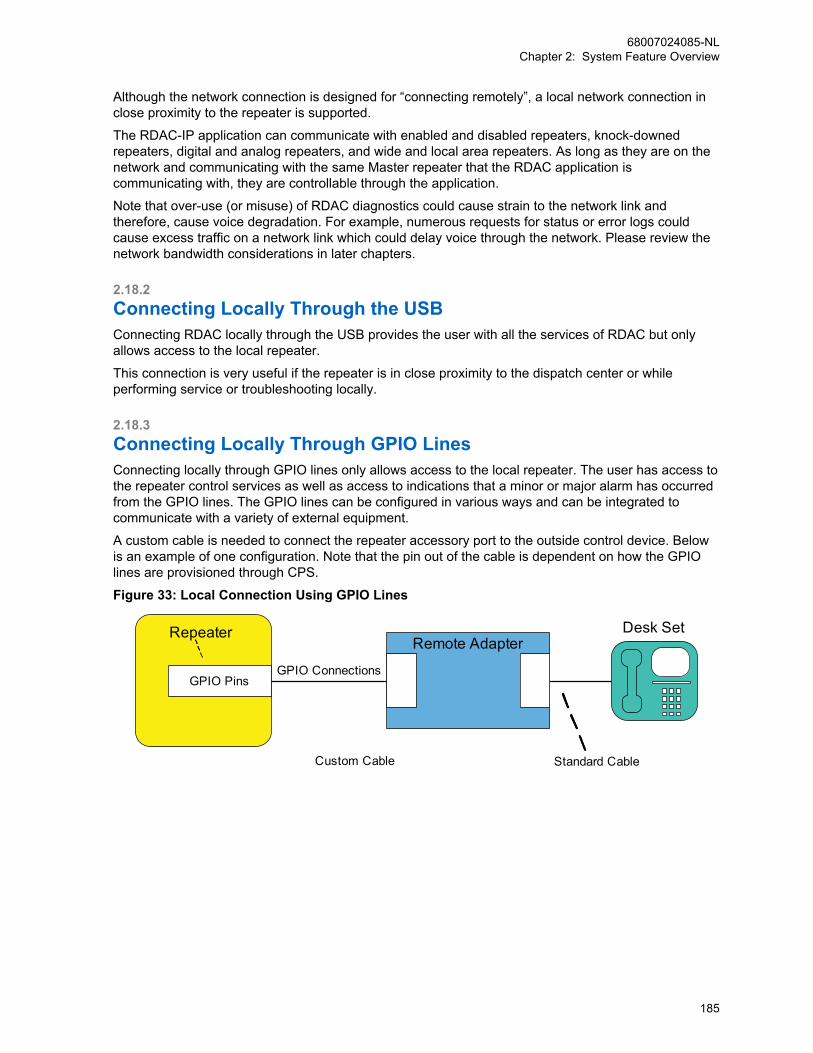
Although the network connection is designed for “connecting remotely”, a local network connection inclose proximity to the repeater is supported.
The RDAC-IP application can communicate with enabled and disabled repeaters, knock-downedrepeaters, digital and analog repeaters, and wide and local area repeaters. As long as they are on thenetwork and communicating with the same Master repeater that the RDAC application iscommunicating with, they are controllable through the application.
Note that over-use (or misuse) of RDAC diagnostics could cause strain to the network link andtherefore, cause voice degradation. For example, numerous requests for status or error logs couldcause excess traffic on a network link which could delay voice through the network. Please review thenetwork bandwidth considerations in later chapters.
2.18.2Connecting Locally Through the USBConnecting RDAC locally through the USB provides the user with all the services of RDAC but onlyallows access to the local repeater.
This connection is very useful if the repeater is in close proximity to the dispatch center or whileperforming service or troubleshooting locally.
2.18.3Connecting Locally Through GPIO LinesConnecting locally through GPIO lines only allows access to the local repeater. The user has access tothe repeater control services as well as access to indications that a minor or major alarm has occurredfrom the GPIO lines. The GPIO lines can be configured in various ways and can be integrated tocommunicate with a variety of external equipment.
A custom cable is needed to connect the repeater accessory port to the outside control device. Belowis an example of one configuration. Note that the pin out of the cable is dependent on how the GPIOlines are provisioned through CPS.
Figure 33: Local Connection Using GPIO Lines
GPIO Connections
Desk Set
Custom Cable Standard Cable
Remote Adapter
GPIO Pins
Repeater
68007024085-NLChapter 2: System Feature Overview
185
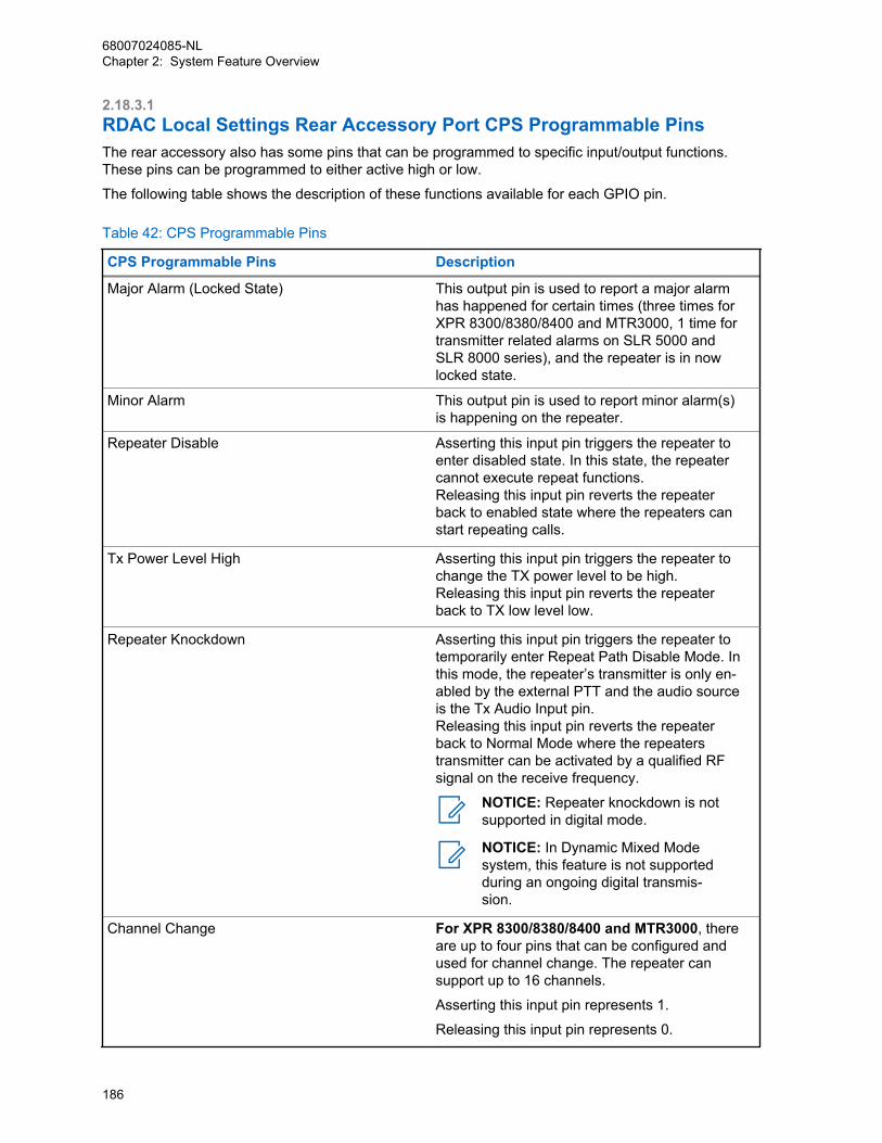
2.18.3.1RDAC Local Settings Rear Accessory Port CPS Programmable PinsThe rear accessory also has some pins that can be programmed to specific input/output functions.These pins can be programmed to either active high or low.
The following table shows the description of these functions available for each GPIO pin.
Table 42: CPS Programmable Pins
CPS Programmable Pins Description
Major Alarm (Locked State) This output pin is used to report a major alarmhas happened for certain times (three times forXPR 8300/8380/8400 and MTR3000, 1 time fortransmitter related alarms on SLR 5000 andSLR 8000 series), and the repeater is in nowlocked state.
Minor Alarm This output pin is used to report minor alarm(s)is happening on the repeater.
Repeater Disable Asserting this input pin triggers the repeater toenter disabled state. In this state, the repeatercannot execute repeat functions.Releasing this input pin reverts the repeaterback to enabled state where the repeaters canstart repeating calls.
Tx Power Level High Asserting this input pin triggers the repeater tochange the TX power level to be high.Releasing this input pin reverts the repeaterback to TX low level low.
Repeater Knockdown Asserting this input pin triggers the repeater totemporarily enter Repeat Path Disable Mode. Inthis mode, the repeater’s transmitter is only en-abled by the external PTT and the audio sourceis the Tx Audio Input pin.Releasing this input pin reverts the repeaterback to Normal Mode where the repeaterstransmitter can be activated by a qualified RFsignal on the receive frequency.
NOTICE: Repeater knockdown is notsupported in digital mode.
NOTICE: In Dynamic Mixed Modesystem, this feature is not supportedduring an ongoing digital transmis-sion.
Channel Change For XPR 8300/8380/8400 and MTR3000, thereare up to four pins that can be configured andused for channel change. The repeater cansupport up to 16 channels.
Asserting this input pin represents 1.
Releasing this input pin represents 0.
68007024085-NLChapter 2: System Feature Overview
186
CPS Programmable Pins Description
0000 represents first channel, 1111 representthe last channel.
For SLR 5000 and SLR 8000 series, there areup to six pins that can be configured and usedfor channel change. The repeater can supportup to 64 channels.
000000 represents first channel, and 111111represent the last channel.
2.18.4Redundant Repeater SetupBy using the alarm feature and control feature together, it is possible to setup redundant repeaters. Sothat when one repeater fails, the standby repeater can take over the repeat function.
Before installation, both repeaters are programmed with the same channel information. The installerconfigures one repeater as primary repeater and the other one as standby repeater. For the primaryrepeater, the installer configures one GPIO pin for major alarm reporting and configures the pin’spolarity. Additionally, it configures through CPS in the primary repeater to indicate the availability of astandby repeater. For the standby repeater, the installer configures one of its GPIO pins as repeaterdisabled control input pin and its polarity opposite of the primary repeater’s alarm pin polarity. Whenthe primary repeater’s alarm pin becomes active it deactivates the disabled pin and the standbyrepeater becomes enabled. The antenna system is connected to the primary repeater and alsoconnected to an antenna switch. The antenna switch is external to the repeater hardware. The installerconnects the primary repeater’s alarm pin (output pin) and standby repeater’s repeater disable pin(input pin) and the antenna switch all together. The installer powers on the primary repeater first andverifies it is working with no major alarm reported. Then the installer powers on the standby repeater.
When a major alarm happens for certain times in the primary repeater and the repeater enters thelocked state, the primary repeater sets the major alarm GPIO pin to active level. The standby repeaterdetects the disable pin is changed to inactive level and it becomes enabled. The antenna switch is alsotriggered which changes the antenna to the now active repeater.
Once the fault in the primary repeater is addressed, the repeater is removed from the locked state andreset, the primary repeater is enabled and again becomes the primary repeater. The standby repeaterthen becomes disabled.
68007024085-NLChapter 2: System Feature Overview
187
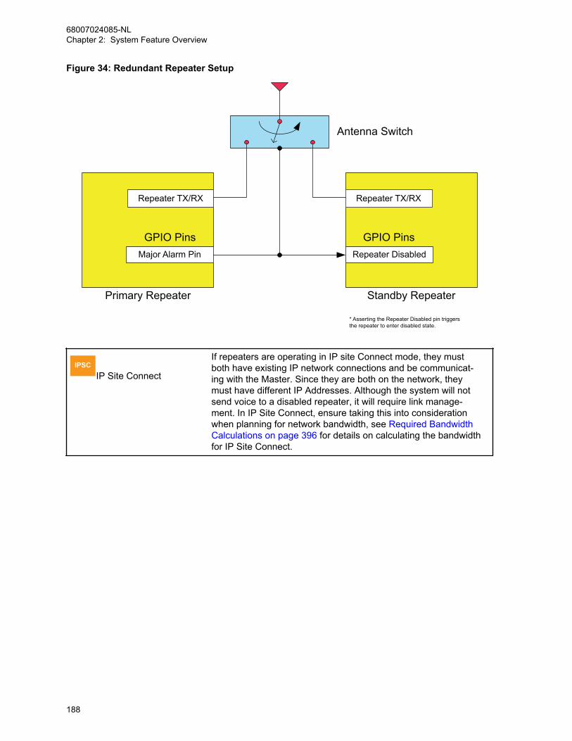
Figure 34: Redundant Repeater Setup
Major Alarm Pin
GPIO Pins
Primary Repeater Standby Repeater
Repeater Disabled
GPIO Pins
Repeater TX/RX Repeater TX/RX
Antenna Switch
* Asserting the Repeater Disabled pin triggers the repeater to enter disabled state.
IPSCIP Site Connect
If repeaters are operating in IP site Connect mode, they mustboth have existing IP network connections and be communicat-ing with the Master. Since they are both on the network, theymust have different IP Addresses. Although the system will notsend voice to a disabled repeater, it will require link manage-ment. In IP Site Connect, ensure taking this into considerationwhen planning for network bandwidth, see Required BandwidthCalculations on page 396 for details on calculating the bandwidthfor IP Site Connect.
68007024085-NLChapter 2: System Feature Overview
188

NOTICE: A redundant repeater connected to the IPSite Connect system counts in the total number of sup-ported peers.It is also important to note that when setting up theMaster repeater of an IP Site Connect system into a re-dundant configuration, the network link must also beswitched with external hardware similar to that of anRF Antenna.
In this case, the IP Address of both the Primary andthe Standby repeaters must be the same since all thePeers communicate with it using this IP address. Asthey have the same IP Address, they cannot be con-nected to the network at the same time. This alsomeans that the standby repeater cannot be contactedvia a network RDAC application while not in the pri-mary repeater role since it is not connected to the net-work.
Because the two devices have the same IP addressbut different MAC addresses, Peers may not be able tocontact the Master repeater until the router and repeat-er ARP tables are updated. Depending on router con-figuration this could take up to 15 to 20 minutes. It isrecommended to consult the Network Administrator fordetails on setting the ARP interval within the custom-er’s network.
CPMSCapacity Plus Multi Site
Similar configuration as IP Site Connect System for RedundantRepeater Setup applies to Capacity Plus Multi Site
2.18.5Dual Control ConsiderationsIt is possible to have RDAC connected locally, over the network, and connected through GPIO linessimultaneously to a single repeater.
In this case, the repeater can be controlled through GPIO as well as through the network. The usershould be aware that it is not recommend using both methods to control the repeater at the same time.Note that after a control command has being executed from RDAC application, the control consoleconnected through GPIO may no longer indicate the state of the repeater correctly since it reads thestate of the hardware pin rather than the internal repeater state. In other words if the externalapplication has pulled a pin low or high, the repeater cannot change the level of that pin after RDAChas made a change.
2.18.6Digital Voting Control and MonitorRDAC can be used to control digital voting such as enabling or disabling the feature, force vote, anddisplay voting status. See Digital Voting on page 420 section for more details.
68007024085-NLChapter 2: System Feature Overview
189

2.18.7General Considerations When Utilizing the RDAC Application to SetUp the Network ConnectionConnecting a single RDAC application to numerous systems that were previously residing on the sameLAN, VPN, or WAN requires minimal configuration change. The RDAC application needs to beconfigured with each master repeater’s IP address and a unique UDP port for each system. This isbecause the IP address of the master repeater that can be reached at wide or local area IP address,does not change.
When connecting a single RDAC application to systems that were previously residing on independentLANs or VPNs, the following configuration options can be considered:
• Combine both networks into one LAN or VPN, which most likely requires changing repeater IPaddresses in one of the networks.
• Connect to each LAN through a WAN. As it is now a wide area configuration, this requires somechanges because all peers (including the RDAC application) are now required to utilize the masterrepeater’s wide area IP address, instead of the local IP address.
• Place the RDAC on the LAN of one of the sites. This requires one system to communicate using thelocal IP addresses, while the others, the wide area IP address.
In all of the options previously mentioned, each system must utilize a unique UDP port configuredthrough the RDAC application.
If a channel is changed to a channel not supported by the system, the channel’s repeater does notreconnect to the system, and the repeater will not be visible in RDAC. Therefore, it is strongly notrecommended to change a channel’s mode to an unsupported mode of the system.
IPSCIP Site Connect
When utilizing the RDAC application to commu-nicate with multiple IP Site Connect systems,each system’s network topology has to be con-sidered independently. This is important be-cause some connections may utilize a LANconfiguration (See Local Area Network (LAN)Configuration on page 334), while others utilizea WAN configuration (See Wide Area NetworkConfiguration on page 335). The main differ-ence being that local area configurations utilizethe master repeater’s local IP address, whilewide area configurations utilize the wide area IPaddress.An IP Site Connect system supports analog,and digital conventional channels.
CPSSCapacity Plus Single Site
When utilizing the RDAC application to commu-nicate with multiple Capacity Plus Single Sitesystems, each system’s network topology hasto be considered independently. This is impor-tant because some connections may utilize aLAN configuration (See Local Area Network(LAN) Configuration on page 334), while othersutilize a WAN configuration (See Wide AreaNetwork Configuration on page 335). The maindifference being that local area configurationsutilize the master repeater’s local IP address,
68007024085-NLChapter 2: System Feature Overview
190
while wide area configurations utilize the widearea IP address.A Capacity Plus Single Site system supportsonly Capacity Plus Single Site channels.
CPMSCapacity Plus Multi Site
A Capacity Plus Multi Sitesystem supports onlyCapacity Plus Multi Site channels.
2.19Repeater Diagnostics System EnhancementRepeater Diagnostics, Alarm and Control (RDAC), described in Repeater Diagnostics and Control onpage 180, is for monitoring of hardware alarms, diagnosis of RSSI, power level, repeater state, andrepeater control of enable/disable, channel change and so on. In contrast, Repeater DiagnosticsSystem (RDS) feature focuses more on software alarm detection which provides more troubleshootingcapability in the field. The RDS feature uses RDAC to control and retrieve the diagnostic informationfrom the repeaters.
The following services are provided:
• Enable and disable RDS
• Repeater software alarm control
• Configure automatic polling interval
• Detect and report software alarms
• Retrieve and clear software alarms
• Log file management
Software alarms detected in RDS are as follows:
OTA LayerFCC interference type I and II; Color code failure; MFID failure and others.
IP LayerLink status between repeaters; Call streaming failure.
Network LayerNetwork cable error; Gateway error; DHCP error and others.
All the services in the list above are available in both analog and digital mode. The connection betweenrepeater and RDAC application can be network either through IP or locally through a USB.
When working over the IP network, the application communicates with all repeaters within the system;when working locally, the RDAC application connects to a single repeater through a USB. All servicesin the list above are available through the RDAC application.
The alarm information of multiple repeaters in the same system will be stored in the same log file byRDAC application. PC time stamp and repeater peer ID are added to each alarms in the log file.Different log folders are used for different system configurations.
NOTICE: RDS feature are applied in MOTOTRBO 32 MB Repeaters.
68007024085-NLChapter 2: System Feature Overview
191

2.20IP Repeater Programming
NOTICE: This feature is supported on repeaters equipped with a 32 MB memory running onfirmware version R01.07.00 or later.
IP Repeater Programming allows a system administrator to provision and to upgrade repeaters withinthe system utilizing the IP network. Additionally, the Master repeater of a system configuration must berunning on the same firmware version as well. The following services are provided:
1 Repeater Configuration
• Read the current repeater configuration
• Write a modified repeater configuration
2 Repeater Upgrade
• Upgrade repeater firmware and/or codeplug version
3 Repeater Feature Enable
• Activate a purchased feature on the repeater
2.20.1System Configuration for IRP SupportConnecting the Customer Programming Software (CPS) to an IP network allows the CPS to access allrepeaters in an IP Site Connect system and a Capacity Plus Single Site system, utilizing their backendnetwork connections. The CPS can also leverage IP-based access to Dynamic Mixed Mode (DMM) orSingle Site repeaters by connecting the repeaters to an IP network and configuring each one to act asa single site Master.
Prior to using IRP, the feature must be configured with the repeater locally connected through a USB tothe CPS application. The CPS can communicate with repeaters of multiple modes; enabled, disabled,knockdown, digital and analog. The primary requirement is that the repeater must be on an IP networkand communicating with a Master repeater or acting as one. However, the CPS can only connect toone Master at a time and can only program a single repeater at a time.
Once the repeater has been properly configured and installed in a networked configuration, the CPSneeds to be directed to the IP address of a Master repeater as defined by the repeater configuration. Ifa system has more than one wide area system (more than one Master repeater), then the CPS isrequired to know the static IPv4 or DNS address, and UDP port for each of the Master repeaters. TheCPS then learns the addresses of other repeaters connected to the Master once the applicationconnects to the Master.
Unlike repeater-to-repeater communication, the CPS application may require firewall configuration.This is to allow the repeater to make a secure connection to the CPS application on the PC. If the PCresides behind a firewall, the firewall must be configured to allow inbound traffic (repeater-to-CPS) on aspecific CPS TCP port that is configurable in the application. Upon initiating an IRP action, the CPScommunicates its opened TCP port number to which the repeater attempts to connect. If multiple CPSapplications (different PCs) are behind a single firewall, each application must use a unique TCP portnumber, and the firewall must be configured to correctly route TCP traffic to the correspondingapplication.
To authorize access to the repeater, codeplug password authentication on a per repeater basis, isoptional and configurable through CPS. The codeplug password can be provisioned in the repeaterprior to using this feature.
NOTICE: Using the CPS to provision or upgrade a repeater temporarily disables the repeateruntil the operation is completed. The duration of the disabled repeater depends on the networkbandwidth and amount of data that is transferred to complete a selected operation.
68007024085-NLChapter 2: System Feature Overview
192
2.21Over-the-Air Battery Management
IPSCIP Site Connect
IP Site Connect supports Over-the-Air BatteryManagement
CPSSCapacity Plus Single Site
Capacity Plus Single Site supports Over-the-AirBattery Management
CPMSCapacity Plus Multi Site
Capacity Plus Multi Site supports Over-the-AirBattery Management
When a battery fails and communication is lost, it impacts every aspect of an organization from servingcustomers to saving lives. But monitoring and maintaining the status of a large fleet of batteries can betime-consuming, inefficient and potentially overwhelming.
That is why the proprietary IMPRES™ Battery Fleet Management technology was created. It saves theguesswork, complexity and costs of managing hundreds even thousands of radio batteries andchargers wherever they’re located, and makes it easier for users to do their work safely andsuccessfully.
IMPRES Battery Fleet Management already supports collection of battery information each time anIMPRES battery is inserted into an IMPRES charger. And now IMPRES Battery Fleet Managementsupports automatic collection of battery information over the air while the radios are in use. Thisremoves the need for wired network connections, Charger Interface Units, and remote clients atcharger locations.
With IMPRES Battery Fleet Management, existing or customizable reports can be utilized to see themost relevant information. Data is stored in a database and can be exported to an Excel file or printed.IMPRES Battery Fleet Management software records and organizes a variety of data so the user can:
• Evaluate whether batteries are meeting their performance criteria
• Determine when batteries are nearing their end-of-life
• Eliminate unexpected downtime and work interruptions
• Avoid the expense of throwing batteries away prematurely
• Identify batteries that are missing, misplaced or inactive
• Identify radios that are not using IMPRES batteries
• Decide exactly when to buy new batteries
• Optimize charger utilization
NOTICE: Over-the-Air battery management focuses on managing the long term health of thebatteries. It is not meant to acquire the current real-time energy levels of all radios within thesystem.
Automatic collection of battery information over the air is supported in the following systemarchitectures:
• Direct Mode (including Dual Capacity)
• Single Site Repeater
• IP Site Connect
68007024085-NLChapter 2: System Feature Overview
193
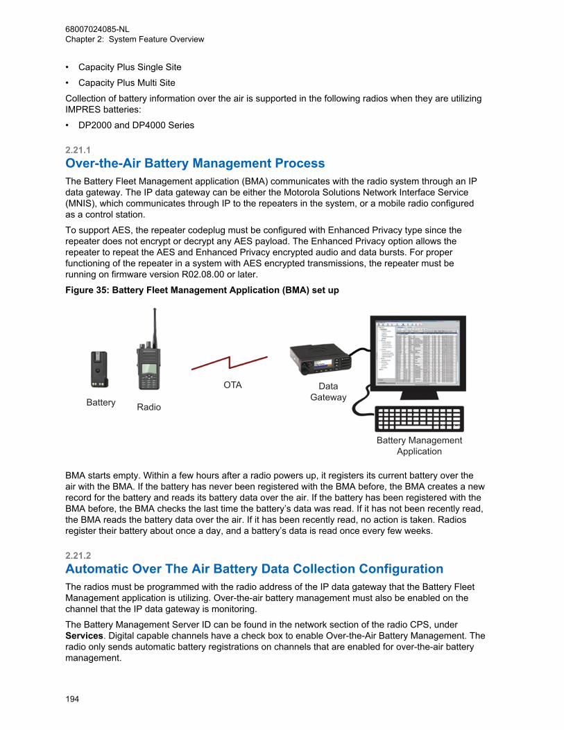
• Capacity Plus Single Site
• Capacity Plus Multi Site
Collection of battery information over the air is supported in the following radios when they are utilizingIMPRES batteries:
• DP2000 and DP4000 Series
2.21.1Over-the-Air Battery Management ProcessThe Battery Fleet Management application (BMA) communicates with the radio system through an IPdata gateway. The IP data gateway can be either the Motorola Solutions Network Interface Service(MNIS), which communicates through IP to the repeaters in the system, or a mobile radio configuredas a control station.
To support AES, the repeater codeplug must be configured with Enhanced Privacy type since therepeater does not encrypt or decrypt any AES payload. The Enhanced Privacy option allows therepeater to repeat the AES and Enhanced Privacy encrypted audio and data bursts. For properfunctioning of the repeater in a system with AES encrypted transmissions, the repeater must berunning on firmware version R02.08.00 or later.
Figure 35: Battery Fleet Management Application (BMA) set up
Battery Radio
OTA DataGateway
Battery ManagementApplication
BMA starts empty. Within a few hours after a radio powers up, it registers its current battery over theair with the BMA. If the battery has never been registered with the BMA before, the BMA creates a newrecord for the battery and reads its battery data over the air. If the battery has been registered with theBMA before, the BMA checks the last time the battery’s data was read. If it has not been recently read,the BMA reads the battery data over the air. If it has been recently read, no action is taken. Radiosregister their battery about once a day, and a battery’s data is read once every few weeks.
2.21.2Automatic Over The Air Battery Data Collection ConfigurationThe radios must be programmed with the radio address of the IP data gateway that the Battery FleetManagement application is utilizing. Over-the-air battery management must also be enabled on thechannel that the IP data gateway is monitoring.
The Battery Management Server ID can be found in the network section of the radio CPS, underServices. Digital capable channels have a check box to enable Over-the-Air Battery Management. Theradio only sends automatic battery registrations on channels that are enabled for over-the-air batterymanagement.
68007024085-NLChapter 2: System Feature Overview
194
Per standard data system configuration, the IP data gateway, either MNIS or a control station, musthave a unique radio ID on the system. The IP data gateway utilized by the BMA must be configured forconfirmed data calls, otherwise the success rate of the over-the-air battery management messaging isnoticeable low.
If there is a UDP port conflict on the PC, the IP data gateway, either MNIS or a control station, and theBattery Management Application can be configured with a different UDP Port. The setting can be foundin the Network section of CPS for the control station, and the Configuration menu of the BatteryManagement Application.
Over the air battery management messaging does not revert, therefore the BMA IP data gatewaysneed not be monitoring revert channels.
Since the over-the-air messaging utilizes the MOTOTRBO IP data service, all prerequisites andlimitations of the standard IP data service apply to battery management.
2.21.3System Level OptimizationsThere are two timers that may require adjustments for optimal performance such as the Battery DataRefresh Timer, and the Radio Hold Off Timer.
The default values should be acceptable for most scenarios.
2.21.3.1Battery Data Refresh TimerThe Battery Data Refresh Timer controls how frequently the battery data is read.
Its default value is 21 days (3 weeks). Battery data changes fairly slowly, therefore it unnecessary toread it over-the-air very often. The more often the battery data is read, the larger the load on thesystem. This is especially true if the system contains a very large number of radios. The Battery DataRefresh Timer can be found in the Preferences of the Battery Fleet Management application.
2.21.3.2Radio Hold Off TimerThe Radio Hold Off Timer controls how long after power up does the radio wait before registering itscurrent battery with the Battery Fleet Management application. Its default value is two hours. The radiowaits for a random time between 30 minutes and the configured Radio Hold Off Timer.
If a system contains a very large number of radios, the Radio Hold Off Timer should be increased tominimize the over-the-air message collisions and congestion during shift changes or other scenarioswhere many radios power cycle within a short period of time. Because battery data is normally onlyread once every three weeks, delaying a battery registration a few hours after power up does notimpact the long term automatic battery data collection process.
The Radio Hold Off Timer can be found in the Preferences of the Battery Fleet Managementapplication. It can also be configured per radio within the Radio Information dialog. The Battery FleetManagement application informs the radio of the new Radio Hold Off Timer the next time it registers.The radio utilizes the new Radio Hold Off Timer starting after the next power cycle, which usuallyoccurs the next day.
After the CPS configuration, the radio registers within minutes after power up prior to its first successfulregistration with the Battery Fleet Management application.
68007024085-NLChapter 2: System Feature Overview
195
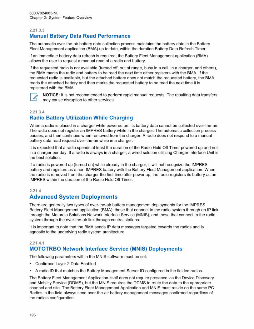
2.21.3.3Manual Battery Data Read PerformanceThe automatic over-the-air battery data collection process maintains the battery data in the BatteryFleet Management application (BMA) up to date, within the duration Battery Data Refresh Timer.
If an immediate battery data refresh is required, the Battery Fleet Management application (BMA)allows the user to request a manual read of a radio and battery.
If the requested radio is not available (turned off, out of range, busy in a call, in a charger, and others),the BMA marks the radio and battery to be read the next time either registers with the BMA. If therequested radio is available, but the attached battery does not match the requested battery, the BMAreads the attached battery and then marks the requested battery to be read the next time it isregistered with the BMA.
NOTICE: It is not recommended to perform rapid manual requests. The resulting data transfersmay cause disruption to other services.
2.21.3.4Radio Battery Utilization While ChargingWhen a radio is placed in a charger while powered on, its battery data cannot be collected over-the-air.The radio does not register an IMPRES battery while in the charger. The automatic collection processpauses, and then continues when removed from the charger. A radio does not respond to a manualbattery data read request over-the-air while in a charger.
It is expected that a radio spends at least the duration of the Radio Hold Off Timer powered up and notin a charger per day. If a radio is always in a charger, a wired solution utilizing Charger Interface Unit isthe best solution.
If a radio is powered up (turned on) while already in the charger, it will not recognize the IMPRESbattery and registers as a non-IMPRES battery with the Battery Fleet Management application. Whenthe radio is removed from the charger the first time after power up, the radio registers its battery as anIMPRES within the duration of the Radio Hold Off Timer.
2.21.4Advanced System DeploymentsThere are generally two types of over-the-air battery management deployments for the IMPRESBattery Fleet Management application (BMA): those that connect to the radio system through an IP linkthrough the Motorola Solutions Network Interface Service (MNIS), and those that connect to the radiosystem through the over-the-air link through control stations.
It is important to note that the BMA sends IP data messages targeted towards the radios and isagnostic to the underlying radio system architecture.
2.21.4.1MOTOTRBO Network Interface Service (MNIS) DeploymentsThe following parameters within the MNIS software must be set:
• Confirmed Layer 2 Data Enabled
• A radio ID that matches the Battery Management Server ID configured in the fielded radios.
The Battery Fleet Management Application itself does not require presence via the Device Discoveryand Mobility Service (DDMS), but the MNIS requires the DDMS to route the data to the appropriatechannel and site. The Battery Fleet Management Application and MNIS must reside on the same PC.Radios in the field always send over-the-air battery management messages confirmed regardless ofthe radio’s configuration.
68007024085-NLChapter 2: System Feature Overview
196
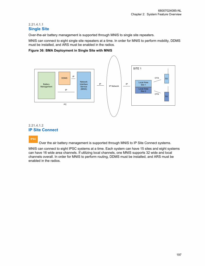
2.21.4.1.1Single SiteOver-the-air battery management is supported through MNIS to single site repeaters.
MNIS can connect to eight single site repeaters at a time. In order for MNIS to perform mobility, DDMSmust be installed, and ARS must be enabled in the radios.
Figure 36: BMA Deployment in Single Site with MNIS
PC
IP
IPDDMS
BatteryManagement
NetworkInterfaceService(MNIS)
IP IP
OTA
OTA
SITE 1
IP Network
Local AreaSlot 1
Local AreaSlot 2
SU
SU
2.21.4.1.2IP Site Connect
IPSC Over the air battery management is supported through MNIS to IP Site Connect systems.
MNIS can connect to eight IPSC systems at a time. Each system can have 15 sites and eight systemscan have 16 wide area channels. If utilizing local channels, one MNIS supports 32 wide and localchannels overall. In order for MNIS to perform routing, DDMS must be installed, and ARS must beenabled in the radios.
68007024085-NLChapter 2: System Feature Overview
197
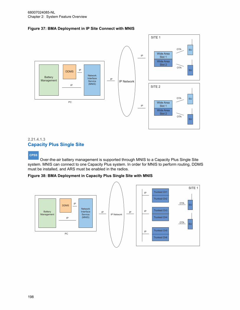
Figure 37: BMA Deployment in IP Site Connect with MNIS
BatteryManagement
DDMSNetworkInterfaceService(MNIS)
IP
IP
IP
IP
IP
PC
Wide AreaSlot 1
Wide AreaSlot 2
IP Network
OTA
OTA
SITE 1
SITE 2
SU
SU
Wide AreaSlot 1
Wide AreaSlot 2
OTA
OTA
SU
SU
2.21.4.1.3Capacity Plus Single Site
CPSS Over-the-air battery management is supported through MNIS to a Capacity Plus Single Site
system. MNIS can connect to one Capacity Plus system. In order for MNIS to perform routing, DDMSmust be installed, and ARS must be enabled in the radios.
Figure 38: BMA Deployment in Capacity Plus Single Site with MNIS
BatteryManagement
PC
IP
DDMSIP
IPIP Network
IP
IP
IP
IP
OTA
OTA
NetworkInterfaceService(MNIS)
SITE 1Trunked Ch1
Trunked Ch2
Trunked Ch3
Trunked Ch4
Trunked Ch5
Trunked Ch6
SU
SU
68007024085-NLChapter 2: System Feature Overview
198
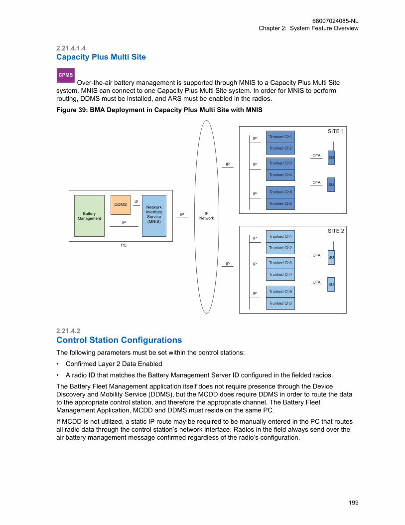
2.21.4.1.4Capacity Plus Multi Site
CPMS Over-the-air battery management is supported through MNIS to a Capacity Plus Multi Site
system. MNIS can connect to one Capacity Plus Multi Site system. In order for MNIS to performrouting, DDMS must be installed, and ARS must be enabled in the radios.
Figure 39: BMA Deployment in Capacity Plus Multi Site with MNIS
IPNetwork
IP
DDMS
IP
IP
PC
NetworkInterfaceService(MNIS)
BatteryManagement
IP
IPIP
IP
IP
OTA
OTA
SITE 1Trunked Ch1
Trunked Ch2
Trunked Ch3
Trunked Ch4
Trunked Ch5
Trunked Ch6
SU
SU
IP
IP
IP
OTA
OTA
SITE 2Trunked Ch1
Trunked Ch2
Trunked Ch3
Trunked Ch4
Trunked Ch5
Trunked Ch6
SU
SU
2.21.4.2Control Station ConfigurationsThe following parameters must be set within the control stations:
• Confirmed Layer 2 Data Enabled
• A radio ID that matches the Battery Management Server ID configured in the fielded radios.
The Battery Fleet Management application itself does not require presence through the DeviceDiscovery and Mobility Service (DDMS), but the MCDD does require DDMS in order to route the datato the appropriate control station, and therefore the appropriate channel. The Battery FleetManagement Application, MCDD and DDMS must reside on the same PC.
If MCDD is not utilized, a static IP route may be required to be manually entered in the PC that routesall radio data through the control station’s network interface. Radios in the field always send over theair battery management message confirmed regardless of the radio’s configuration.
68007024085-NLChapter 2: System Feature Overview
199
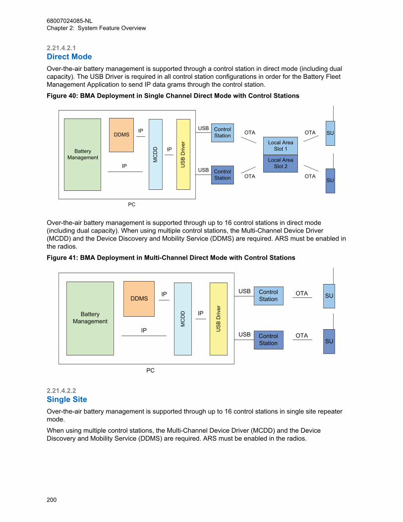
2.21.4.2.1Direct ModeOver-the-air battery management is supported through a control station in direct mode (including dualcapacity). The USB Driver is required in all control station configurations in order for the Battery FleetManagement Application to send IP data grams through the control station.
Figure 40: BMA Deployment in Single Channel Direct Mode with Control Stations
PC
IP
IPDDMS
MC
DD
US
B D
river
BatteryManagement
IP
USB
USBOTA
OTA
Local AreaSlot 1
Local AreaSlot 2
OTA
OTA SU
SU
ControlStation
ControlStation
Over-the-air battery management is supported through up to 16 control stations in direct mode(including dual capacity). When using multiple control stations, the Multi-Channel Device Driver(MCDD) and the Device Discovery and Mobility Service (DDMS) are required. ARS must be enabled inthe radios.
Figure 41: BMA Deployment in Multi-Channel Direct Mode with Control Stations
MC
DD
US
B D
river
DDMS
BatteryManagement
PC
IP
IP
IP
USB
USB OTA SU
SUOTAControl
Station
ControlStation
2.21.4.2.2Single SiteOver-the-air battery management is supported through up to 16 control stations in single site repeatermode.
When using multiple control stations, the Multi-Channel Device Driver (MCDD) and the DeviceDiscovery and Mobility Service (DDMS) are required. ARS must be enabled in the radios.
68007024085-NLChapter 2: System Feature Overview
200

Figure 42: BMA Deployment in Single Site with Control Stations
PC
IP
IPDDMS
MC
DD
US
B D
river
BatteryManagement
IP
USB
USBOTA
OTA
Local AreaSlot 1
Local AreaSlot 2
OTA
OTA SU
SU
ControlStation
ControlStation
2.21.4.2.3IP Site Connect
IPSC Over the air battery management is supported through up to 16 control stations in IP Site
Connect mode.
When using multiple control stations, the Multi-Channel Device Driver (MCDD) and the DeviceDiscovery and Mobility Service (DDMS) are required. ARS must be enabled in the radios. Localchannels may require an additional proxy and control stations in order to communicate over the air tothe local channel.
Figure 43: BMA Deployment in IP Site Connect with Control Stations
BatteryManagement
DDMS
MC
DD
US
B D
river
IP
IP
IP
USB ControlStation
ControlStation
Wide AreaSlot 1
Wide AreaSlot 2 Wide Area
Slot 1
Wide AreaSlot 2
USBIPIPIP
Network
OTA
OTAOTA
OTA
OTA
SITE 1 SITE 2
SU
SU
SU
SU
2.21.4.2.4Capacity Plus Single Site
CPSS Over-the-air battery management is supported through control stations in Capacity Plus Single
Site mode.
Only one trunking control station is required. The Multi-Channel Device Driver (MCDD) and the DeviceDiscovery and Mobility Service (DDMS) are not required in Capacity Plus Single Site. Over-the-airbattery management messages are sent on the trunking channels. They are not sent on data revertchannels.
68007024085-NLChapter 2: System Feature Overview
201
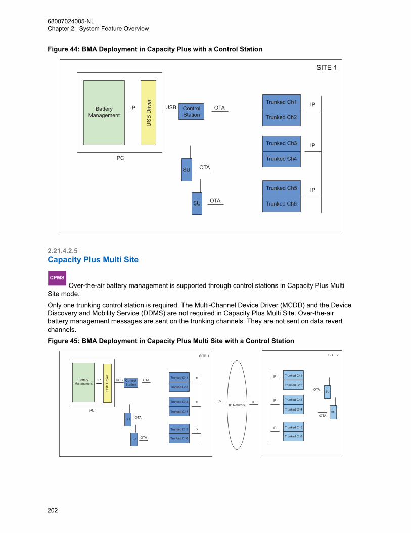
Figure 44: BMA Deployment in Capacity Plus with a Control Station
BatteryManagement
IP IP
IP
IP
USB OTA
SITE 1
OTA
OTA
SU
ControlStation
Trunked Ch1
Trunked Ch2
Trunked Ch3
Trunked Ch4
Trunked Ch5
Trunked Ch6SU
PC
US
B D
river
2.21.4.2.5Capacity Plus Multi Site
CPMS Over-the-air battery management is supported through control stations in Capacity Plus Multi
Site mode.
Only one trunking control station is required. The Multi-Channel Device Driver (MCDD) and the DeviceDiscovery and Mobility Service (DDMS) are not required in Capacity Plus Multi Site. Over-the-airbattery management messages are sent on the trunking channels. They are not sent on data revertchannels.
Figure 45: BMA Deployment in Capacity Plus Multi Site with a Control Station
BatteryManagement
IP NetworkIPIP
IPIP
PC
OTA
OTA
SITE 2
OTA
ControlStation
USB
US
B D
river
OTA
OTA
SITE 1
IP
IP
IP
IP
IP
Trunked Ch1
Trunked Ch2
Trunked Ch3
Trunked Ch4
Trunked Ch5
Trunked Ch6
Trunked Ch1
Trunked Ch2
Trunked Ch3
Trunked Ch4
Trunked Ch5
Trunked Ch6SU
SU
SU
SU
68007024085-NLChapter 2: System Feature Overview
202
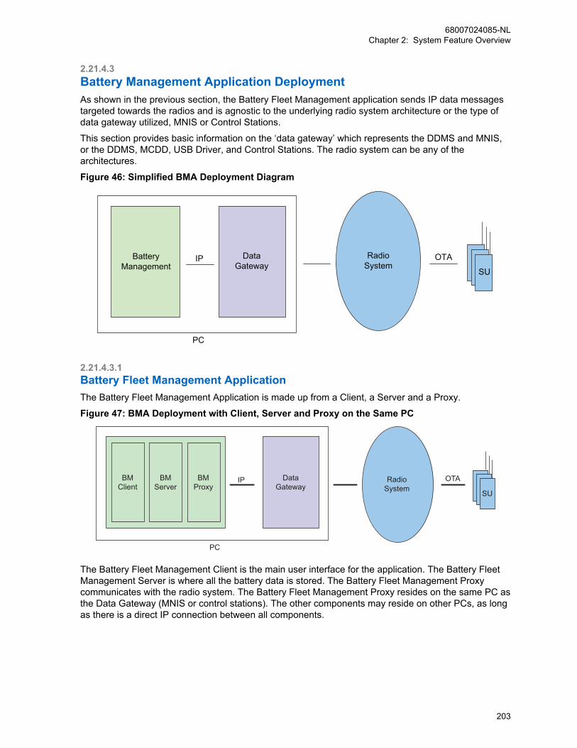
2.21.4.3Battery Management Application DeploymentAs shown in the previous section, the Battery Fleet Management application sends IP data messagestargeted towards the radios and is agnostic to the underlying radio system architecture or the type ofdata gateway utilized, MNIS or Control Stations.
This section provides basic information on the ‘data gateway’ which represents the DDMS and MNIS,or the DDMS, MCDD, USB Driver, and Control Stations. The radio system can be any of thearchitectures.
Figure 46: Simplified BMA Deployment Diagram
BatteryManagement
PC
IPSU
OTARadioSystem
DataGateway
2.21.4.3.1Battery Fleet Management ApplicationThe Battery Fleet Management Application is made up from a Client, a Server and a Proxy.
Figure 47: BMA Deployment with Client, Server and Proxy on the Same PC
BMClient
BMServer
BMProxy
DataGateway
RadioSystem
OTA
SU
IP
PC
The Battery Fleet Management Client is the main user interface for the application. The Battery FleetManagement Server is where all the battery data is stored. The Battery Fleet Management Proxycommunicates with the radio system. The Battery Fleet Management Proxy resides on the same PC asthe Data Gateway (MNIS or control stations). The other components may reside on other PCs, as longas there is a direct IP connection between all components.
68007024085-NLChapter 2: System Feature Overview
203

2.21.4.3.2Remote Battery Management ClientThe Battery Fleet Management Application Client can be remotely located away from the Battery FleetManagement Server and Proxy, and useful when the dealer site is not co-located with the customer’ssite.
Figure 48: BMA Deployment with Client Remote from Server and Proxy
BMClient
BMServer
BMProxy
BMClient
BMServer
BMProxy
DataGateway Radio
SystemOTA
SU
IPIPIP IP Network
PCPC
It is helpful when one battery management user needs to manage multiple systems that cannot beaccessed with one data gateway. For example, if using control stations to monitor systems that are notwithin RF coverage of each other, multiple sets of control stations and proxies must be utilized. Sincean MNIS has limitations on how many systems it can connect to, multiple sets of MNIS and proxiesmust be utilized.
In the case of remote client, each data gateway has its own Battery Fleet Management Proxy andServer. This means that each system’s batteries have their own database and the database is oftenlocated at the customer’s site.
Figure 49: BMA Deployment with Client Remote from Multiple Server and Proxies
BMClient
BMServer
BMProxy
BMClient
BMServer
BMProxy
DataGateway
RadioSystem
RadioSystem
OTASU
OTASU
IPIP
IP
IP IP NetworkPC
BMClient
BMServer
BMProxy
DataGateway
IP
PC
PC
2.21.4.3.3Remote Battery Management ProxyA remote battery management proxy is similar to the remote client use cases explained earlier;however this allows the battery management user to maintain one server for all of their batteries andsystems. Rather than the servers being located at the customer sites, only the proxy is located at thecustomer sites. This is convenient for the battery management user, but requires the connection
68007024085-NLChapter 2: System Feature Overview
204

between the server site and the proxy site to be available all the time since there is communicationbetween those components occurring all the time. In contrast, the client only communicates to theserver when the user is present and reviewing battery data.
The Battery Fleet Management application handles the mobility between the server and the proxies.When a radio registers its battery, the proxy from which it registered is saved in the Battery FleetManagement Server in order to route outbound messages. There is only one MNIS or one MCDD onone PC at a time.
Figure 50: BMA Deployment with Multiple Proxies Remote from Server
BMClient
BMServer
BMProxy
BMClient
BMServer
BMProxy
DataGateway
RadioSystem
RadioSystem
OTASU
OTASU
IPIP
IP
IP IP NetworkPC
BMClient
BMServer
BMProxy
DataGateway
IP
PC
PC
2.21.4.4Coexistence with Other Data ApplicationsThe Battery Fleet Management application is supported in system configurations with the RadioManagement application. Battery Fleet Management and Radio Management may be installed on thesame computer.
The Battery Fleet Management application is supported in system configurations with third-partyapplications, but there may be some special considerations and configurations required.
In general, it is recommended that the Battery Fleet Management application be installed on a differentcomputer than any other third-party application. There may be various conflicts present, messagerouting being the most common, which may cause issues. Interoperability testing with every third-partyapplication in the market is not possible; therefore we only support installations on different computers.If installation on the same computer as a third-party application is a must, it is recommended you pre-test all functionality before deployment.
Third-party applications have a wide array of methods to implement presence notification. In somecases, their implementations conflict with our implementation. As described in earlier sections,although the Battery Fleet Management application itself does not require presence, some systemarchitectures may require it for data routing.
Radios can be configured to send automatic registration service (ARS) messages through the systemto the Device Discovery and Mobility Service (DDMS). These messages are utilized by the system forpresence and mobility. The radios are configured to send these messages to one target. If the radiosare already configured to send these messages to a third-party application’s presence service, stepsmust be taken so that the DDMS can also receive them.
If installing the Battery Fleet Management application on a system with a third-party application thatutilizes a non-ARS based method of implementing presence, then the Device Discovery and Mobility
68007024085-NLChapter 2: System Feature Overview
205
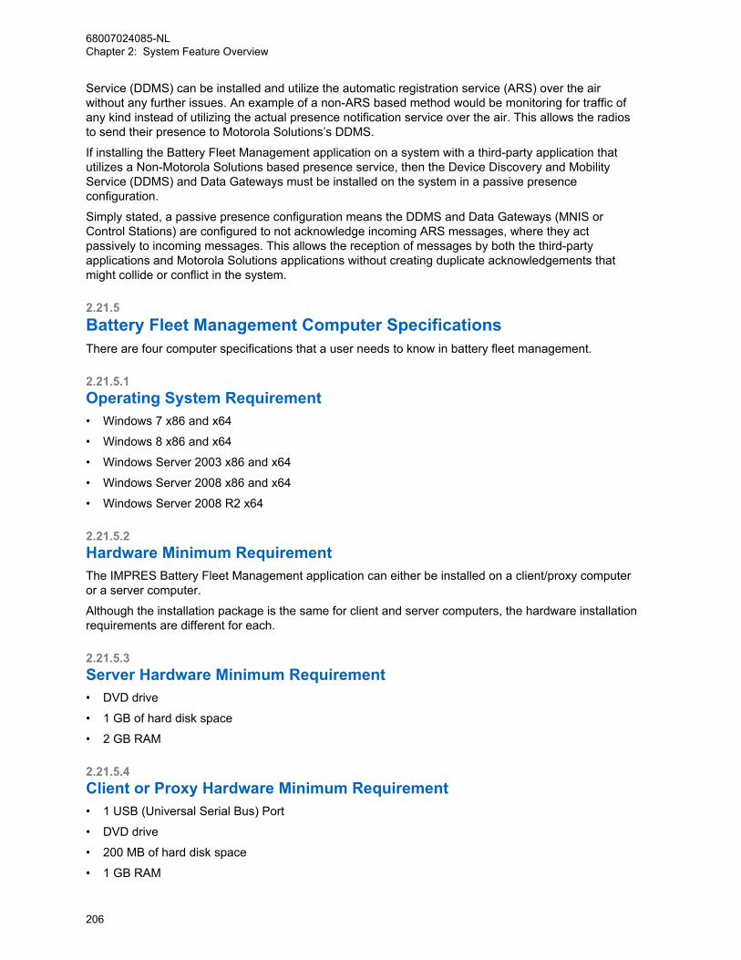
Service (DDMS) can be installed and utilize the automatic registration service (ARS) over the airwithout any further issues. An example of a non-ARS based method would be monitoring for traffic ofany kind instead of utilizing the actual presence notification service over the air. This allows the radiosto send their presence to Motorola Solutions’s DDMS.
If installing the Battery Fleet Management application on a system with a third-party application thatutilizes a Non-Motorola Solutions based presence service, then the Device Discovery and MobilityService (DDMS) and Data Gateways must be installed on the system in a passive presenceconfiguration.
Simply stated, a passive presence configuration means the DDMS and Data Gateways (MNIS orControl Stations) are configured to not acknowledge incoming ARS messages, where they actpassively to incoming messages. This allows the reception of messages by both the third-partyapplications and Motorola Solutions applications without creating duplicate acknowledgements thatmight collide or conflict in the system.
2.21.5Battery Fleet Management Computer SpecificationsThere are four computer specifications that a user needs to know in battery fleet management.
2.21.5.1Operating System Requirement• Windows 7 x86 and x64
• Windows 8 x86 and x64
• Windows Server 2003 x86 and x64
• Windows Server 2008 x86 and x64
• Windows Server 2008 R2 x64
2.21.5.2Hardware Minimum RequirementThe IMPRES Battery Fleet Management application can either be installed on a client/proxy computeror a server computer.
Although the installation package is the same for client and server computers, the hardware installationrequirements are different for each.
2.21.5.3Server Hardware Minimum Requirement• DVD drive
• 1 GB of hard disk space
• 2 GB RAM
2.21.5.4Client or Proxy Hardware Minimum Requirement• 1 USB (Universal Serial Bus) Port
• DVD drive
• 200 MB of hard disk space
• 1 GB RAM
68007024085-NLChapter 2: System Feature Overview
206

2.22Over-the-Air Radio Programming (OTAP)
IPSCIP Site Connect
IP Site Connect supports Over-the-Air RadioProgramming
CPSSCapacity Plus Single Site
Capacity Plus Single Site supports Over-the-AirRadio Programming
CPMSCapacity Plus Multi Site
Capacity Plus Multi Site supports Over-the-AirRadio Programming
When the need to program a radio or a fleet of radios occurs, the process can take place at thecustomer location or the dealer’s shop. However, the process of programming radio parameters,features, contact lists, and others can be troublesome.
Some issues encountered include – difficulty to locate all radios, delays waiting for radios to be broughtin for programming, radios mounted in vehicles, operation and downtime during programming, wastedtime traveling to/from customer location, only a limited number of radios can be programmedsimultaneously. It is often difficult for dealers to extract value for this. Therefore, radio programming isviewed as a hassle, time consuming, and inefficient.
To support this need, the MOTOTRBO Radio Management (RM) now offers the following services withsoftware version R02.10.00 or later:
• Writes and reads radio configurations over-the-air
• Manages up to 5000 radio configurations
• Group and individual archive management
• Application and radio mutual authentication
• Synchronized configuration switchover
• Radio user receives one time option to accept or delay
• Scheduling of over-the-air operations
• Unmanned batch processing of numerous over-the-air operations
• Remote client capability
• Multi-customer and system capable
• Optimized performance using Presence Services
• Compressed and differential configuration transfer
• Designed to allow voice traffic priority while transferring
• Utilizes existing over-the-air encryption
• Session logging
• Historical reporting
The above features are available in all digital architectures including:
• Direct Mode (12.5e and 6.25e)
• Single Site Repeater
68007024085-NLChapter 2: System Feature Overview
207

• IP Site Connect
• Capacity Plus Single Site
• Capacity Plus Multi Site
The services that are supported are not available to the ADP developers.
The following features and services are specifically not supported by OTAP:
• radio software upgrades
• language packet updates
• radio tuning parameter updates
• device recovery
• update or download voice announcement files
• radios prior to software version R02.10.00
• over-the-air repeater programming (only IP Repeater Programming is available)
• programming while in Connect Plus or Passport Mode
• programming while in Analog Mode
2.22.1Basic Deployments of OTAP SoftwareThere are six basic deployments of Radio Management (RM) for OTAP. These are used as thebuilding blocks for more complicated configurations.
The configurations are:
• Local Single Channel Configuration
• Local Single Channel Configuration with Presence
• Remote Client Configuration
• Remote Client Configuration with Multiple RM Servers
• Remote Device Programmer Configuration
• Multi-Channel Configuration
2.22.1.1Local Single Channel ConfigurationThe RM application utilizes the existing MOTOTRBO IP data service to communicate with the fieldradios over-the-air. Connectivity with the system can be achieved over-the-air through control stationsor over the IP network utilizing the MOTOTRBO Network Interface Service (MNIS). No other over-the-air data application is supported on the same PC as the RM.
This control station setup requires a radio to be configured as a control station, connected to the RMPC via a USB cable and utilized as the data gateway into the radio system. The standard radio USBdriver is also required.
68007024085-NLChapter 2: System Feature Overview
208
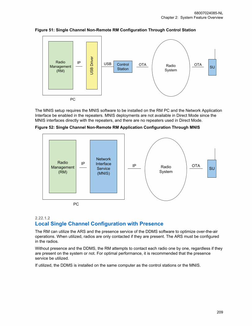
Figure 51: Single Channel Non-Remote RM Configuration Through Control Station
USB OTA
US
B D
river
IP OTARadioSystem
PC
ControlStation SU
RadioManagement
(RM)
The MNIS setup requires the MNIS software to be installed on the RM PC and the Network ApplicationInterface be enabled in the repeaters. MNIS deployments are not available in Direct Mode since theMNIS interfaces directly with the repeaters, and there are no repeaters used in Direct Mode.
Figure 52: Single Channel Non-Remote RM Application Configuration Through MNIS
IPIP OTARadioSystem
PC
SU
Network Interface Service(MNIS)
RadioManagement
(RM)
2.22.1.2Local Single Channel Configuration with PresenceThe RM can utilize the ARS and the presence service of the DDMS software to optimize over-the-airoperations. When utilized, radios are only contacted if they are present. The ARS must be configuredin the radios.
Without presence and the DDMS, the RM attempts to contact each radio one by one, regardless if theyare present on the system or not. For optimal performance, it is recommended that the presenceservice be utilized.
If utilized, the DDMS is installed on the same computer as the control stations or the MNIS.
68007024085-NLChapter 2: System Feature Overview
209

Figure 53: Single Channel Non-Remote RM Application with Presence and Control Station
DDMS
RadioManagement
(RM)
IP
IP USB
Driv
er
IP
OTA OTARadioSystem
PC
USB ControlStation SU
Figure 54: Single Channel Non-Remote RM Application with Presence and MNIS
DDMSIP
IP
IP
OTARadioSystem
PC
SU
Network Interface Service(MNIS)
IPRadio
Management(RM)
The RM consists of three major components:
• RM Client: Main User Interface
• RM Server: Storage of Configurations
• RM Device Programmer: Communication to Radio System
NOTICE: The RM Device Programmer is also known as the “RM Proxy”.
In local deployments, all three components can be installed at the same time on the same computer.This is most useful when the system administrator is within RF coverage of the radio system. Below isa diagram showing the individual components. This is the same when utilizing the MNIS.
Figure 55: Single Channel Non-Remote RM Application with Presence
DDMSIP
IP
USB
Driv
er
IP
RMDeviceProg
RMServer
RMClient
OTA OTARadioSystem
PC
ControlStation
USBSU
NOTICE: The RM Client, RM Server, and RM Device Programmer is shown in
68007024085-NLChapter 2: System Feature Overview
210
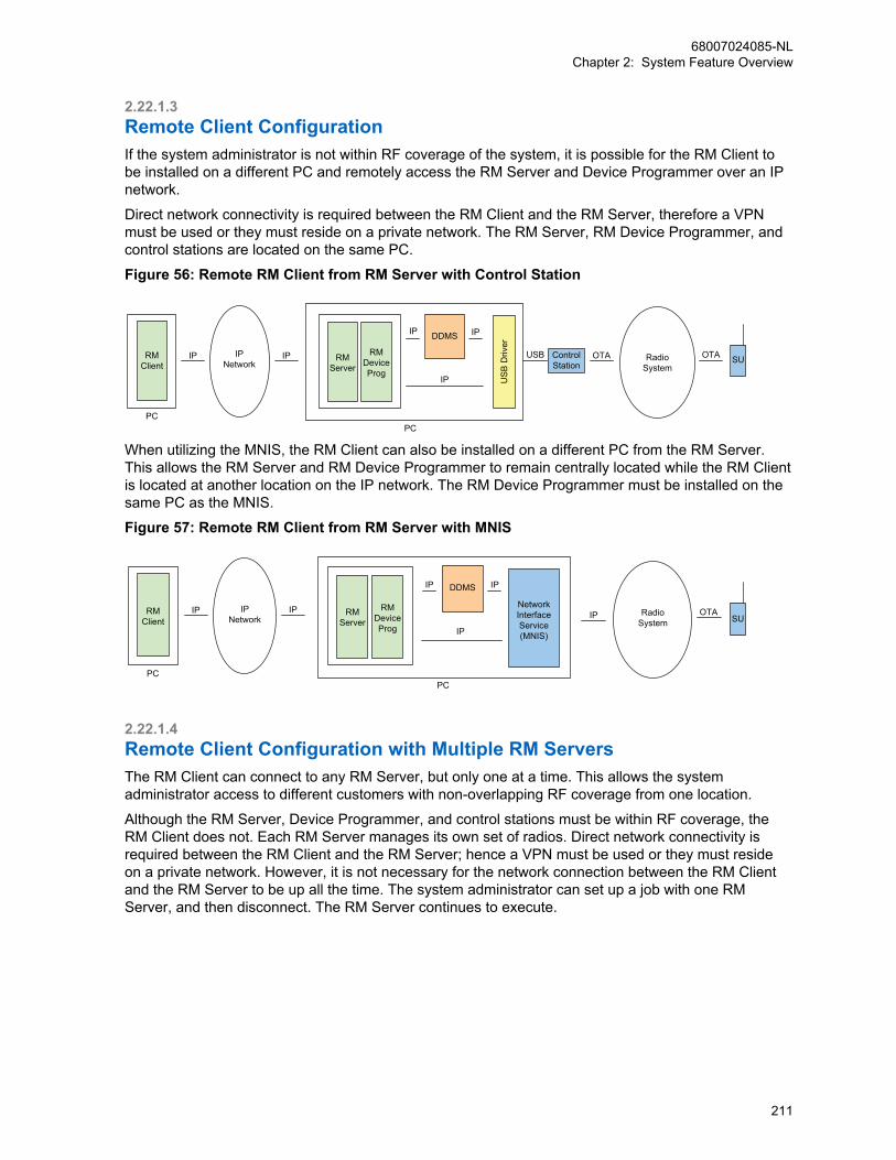
2.22.1.3Remote Client ConfigurationIf the system administrator is not within RF coverage of the system, it is possible for the RM Client tobe installed on a different PC and remotely access the RM Server and Device Programmer over an IPnetwork.
Direct network connectivity is required between the RM Client and the RM Server, therefore a VPNmust be used or they must reside on a private network. The RM Server, RM Device Programmer, andcontrol stations are located on the same PC.
Figure 56: Remote RM Client from RM Server with Control Station
DDMSIP
IP US
B D
river
IP
RMDeviceProg
RMServer
RMClient
IPIP OTA OTARadioSystem
PCPC
ControlStation
USB SUIP
Network
When utilizing the MNIS, the RM Client can also be installed on a different PC from the RM Server.This allows the RM Server and RM Device Programmer to remain centrally located while the RM Clientis located at another location on the IP network. The RM Device Programmer must be installed on thesame PC as the MNIS.
Figure 57: Remote RM Client from RM Server with MNIS
DDMSIP
IP
IP
OTARadioSystem
PC
SUNetwork Interface Service(MNIS)
IPRM
DeviceProg
RMServer
RMClient
IPIP
PC
IPNetwork
2.22.1.4Remote Client Configuration with Multiple RM ServersThe RM Client can connect to any RM Server, but only one at a time. This allows the systemadministrator access to different customers with non-overlapping RF coverage from one location.
Although the RM Server, Device Programmer, and control stations must be within RF coverage, theRM Client does not. Each RM Server manages its own set of radios. Direct network connectivity isrequired between the RM Client and the RM Server; hence a VPN must be used or they must resideon a private network. However, it is not necessary for the network connection between the RM Clientand the RM Server to be up all the time. The system administrator can set up a job with one RMServer, and then disconnect. The RM Server continues to execute.
68007024085-NLChapter 2: System Feature Overview
211

Figure 58: Remote RM Client with Multiple RM Servers with Control Station
DDMSIP
IP USB
Driv
er
IP
RMDeviceProg
RMServer
RMClient
IP
IP USB
Driv
er
IP
RMDeviceProg
RMServer
IP
OTA OTARadioSystem
OTA OTARadioSystem
PC
PC
PC
ControlStation
USB
ControlStation
USB
SU
SU
IPNetwork
IP
IP
DDMS
NOTICE: One MNIS can connect to multiple remote single site systems over an IP network.
IPSCIP Site Connect
One MNIS can connect to multiple remote IPSite Connect systems over an IP network.
CPSMCapacity Plus Single Site and Capacity
Plus Multi Site
One MNIS can connect only to one CapacityPlus Single Site or Capacity Plus Multi Site sys-tem at a time. Therefore, multiple MNISs shouldbe deployed. A remote RM Server, Device Pro-grammer and MNIS can be located at each Ca-pacity Plus system, or at one of the sites of anCapacity Plus Multi Site system. They canshare one central RM Server which can be ac-cessed with a RM Client.
68007024085-NLChapter 2: System Feature Overview
212
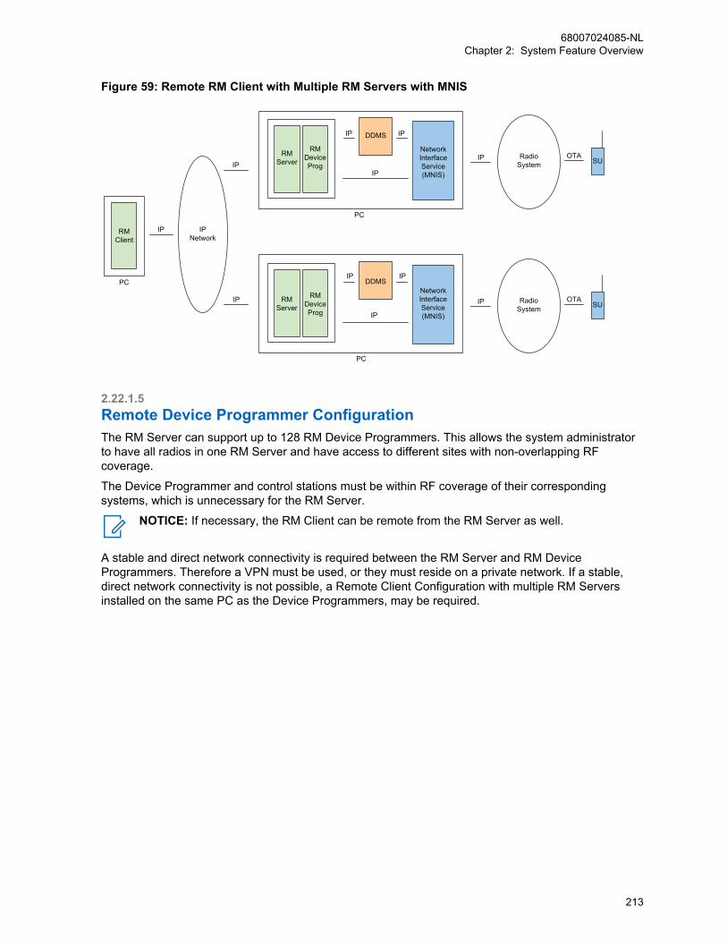
Figure 59: Remote RM Client with Multiple RM Servers with MNIS
RMClient
IP
PC
IPNetwork
IP
IP
DDMSIP
IP
IP
OTARadioSystem
PC
SUNetwork Interface Service(MNIS)
IPRM
DeviceProg
RMServer
DDMSIP
IP
IP
OTARadioSystem
PC
SU
Network Interface Service(MNIS)
IPRM
DeviceProg
RMServer
2.22.1.5Remote Device Programmer ConfigurationThe RM Server can support up to 128 RM Device Programmers. This allows the system administratorto have all radios in one RM Server and have access to different sites with non-overlapping RFcoverage.
The Device Programmer and control stations must be within RF coverage of their correspondingsystems, which is unnecessary for the RM Server.
NOTICE: If necessary, the RM Client can be remote from the RM Server as well.
A stable and direct network connectivity is required between the RM Server and RM DeviceProgrammers. Therefore a VPN must be used, or they must reside on a private network. If a stable,direct network connectivity is not possible, a Remote Client Configuration with multiple RM Serversinstalled on the same PC as the Device Programmers, may be required.
68007024085-NLChapter 2: System Feature Overview
213
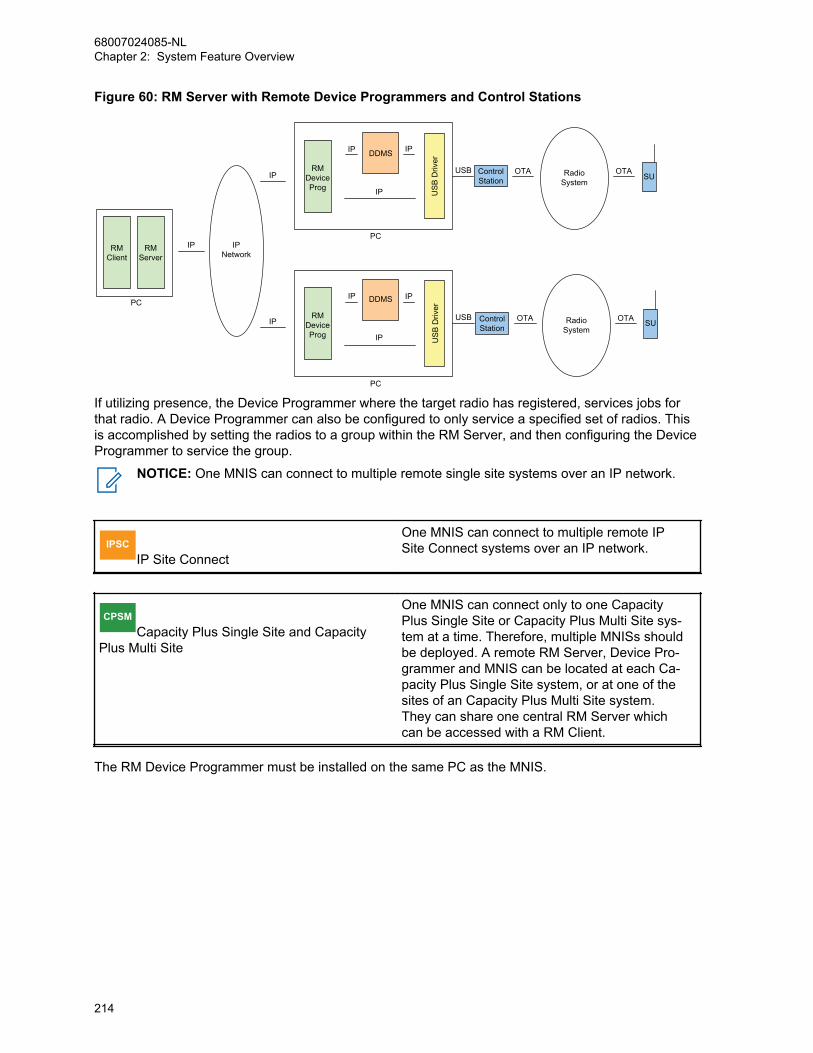
Figure 60: RM Server with Remote Device Programmers and Control Stations
DDMSIP
IP USB
Driv
er
IP
RMDeviceProg
RMServer
RMClient
DDMSIP
IP USB
Driv
er
IP
RMDeviceProg
IP
OTA OTARadioSystem
OTA OTARadioSystem
PC
PC
PC
ControlStation
USB
ControlStation
USB
SU
SU
IPNetwork
IP
IP
If utilizing presence, the Device Programmer where the target radio has registered, services jobs forthat radio. A Device Programmer can also be configured to only service a specified set of radios. Thisis accomplished by setting the radios to a group within the RM Server, and then configuring the DeviceProgrammer to service the group.
NOTICE: One MNIS can connect to multiple remote single site systems over an IP network.
IPSCIP Site Connect
One MNIS can connect to multiple remote IPSite Connect systems over an IP network.
CPSMCapacity Plus Single Site and Capacity
Plus Multi Site
One MNIS can connect only to one CapacityPlus Single Site or Capacity Plus Multi Site sys-tem at a time. Therefore, multiple MNISs shouldbe deployed. A remote RM Server, Device Pro-grammer and MNIS can be located at each Ca-pacity Plus Single Site system, or at one of thesites of an Capacity Plus Multi Site system.They can share one central RM Server whichcan be accessed with a RM Client.
The RM Device Programmer must be installed on the same PC as the MNIS.
68007024085-NLChapter 2: System Feature Overview
214

Figure 61: RM Server with Remote Device Programmers and MNIS
RMClient
IP
PC
IPNetwork
IP
IP
RMServer
RMDeviceProg
DDMSIP
IP
IP
OTARadioSystem
PC
SU
Network Interface Service(MNIS)
IP
RMDeviceProg
DDMSIP
IP
IP
OTARadioSystem
PC
SUNetwork Interface Service(MNIS)
IP
2.22.1.6Multi-Channel ConfigurationMultiple conventional channels are supported per RM Device Programmer in both local and remoteconfigurations.
This requires a control station per channel, up to 16 are allowed. Because radios can move fromchannel to channel, this configuration requires the MCDD and DDMS to be installed on the same PC.The MCDD tracks the location of the radios as they move from channel to channel. As they registerwith the DDMS, the MCDD updates the routing accordingly.
Figure 62: Multi-Channel Non-Remote RM Application Configuration with Control Stations
OTA
OTA
MC
DD
DDMSIP
IP US
B D
river
IP
IPRadioManagement
(RM)Radio
System
OTA
OTA
PC
ControlStation
USB
ControlStation
USB
SU
SU
It is not recommended to utilize multiple control stations without the MCDD and DDMS. Without them,there is no method for RM messages to be properly routed on the appropriate channel. Specific routingcan be added in the PC, but this means radios can only be contacted on a specific channel. Anotheroption is to configure the PC to broadcast on all channels, but this is an extreme waste of bandwidth.
NOTICE: A multiple channel configuration can be deployed with remote RM DeviceProgrammers, remote RM Servers, or a remote RM client. The RM works the same regardlessif the control stations are communicating in direct mode, single site repeater mode, dynamicmixed mode, IP Site Connect mode, Capacity Plus Single Site mode, or Capacity Plus MultiSite mode.
When utilizing MNIS with DDMS, there is no need for MCDD. DDMS handles the mobility in single siteand IPSC systems. DDMS requires ARS to be enabled in the fielded radios. The MNIS can connect toeight conventional systems.
68007024085-NLChapter 2: System Feature Overview
215
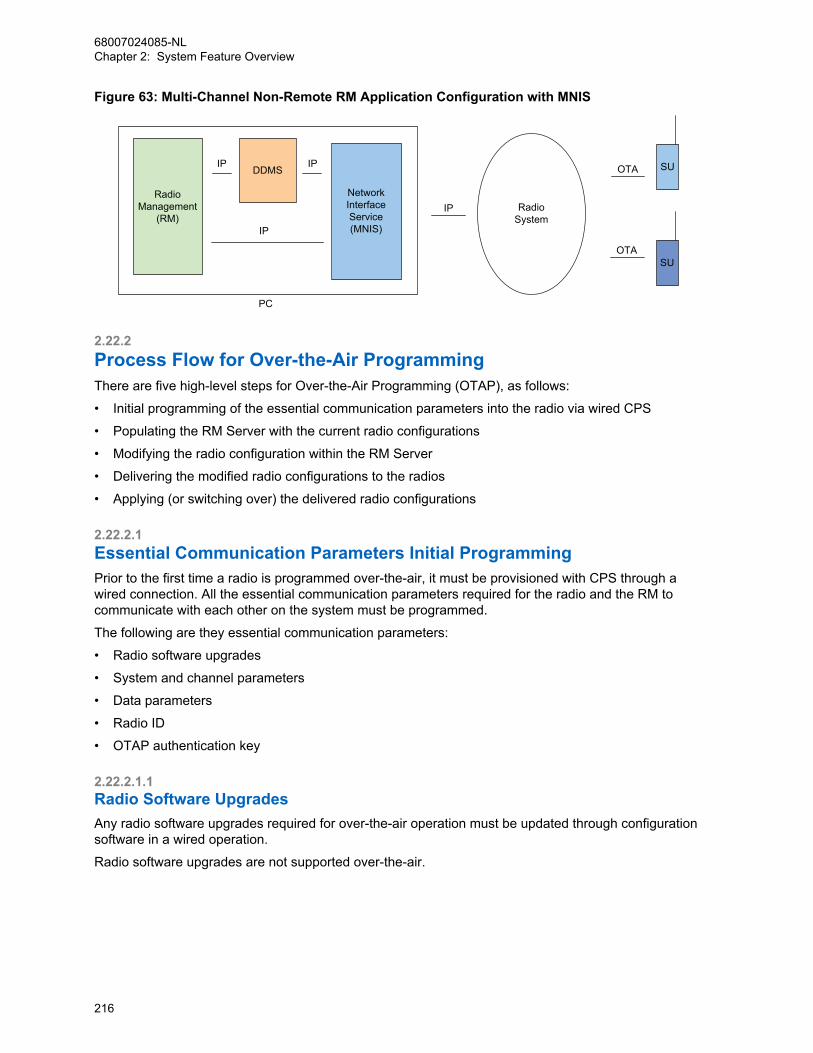
Figure 63: Multi-Channel Non-Remote RM Application Configuration with MNIS
DDMSIP
IP
IP
RadioSystem
PC
Network Interface Service(MNIS)
IP
OTA
OTA
SU
SU
RadioManagement
(RM)
2.22.2Process Flow for Over-the-Air ProgrammingThere are five high-level steps for Over-the-Air Programming (OTAP), as follows:
• Initial programming of the essential communication parameters into the radio via wired CPS
• Populating the RM Server with the current radio configurations
• Modifying the radio configuration within the RM Server
• Delivering the modified radio configurations to the radios
• Applying (or switching over) the delivered radio configurations
2.22.2.1Essential Communication Parameters Initial ProgrammingPrior to the first time a radio is programmed over-the-air, it must be provisioned with CPS through awired connection. All the essential communication parameters required for the radio and the RM tocommunicate with each other on the system must be programmed.
The following are they essential communication parameters:
• Radio software upgrades
• System and channel parameters
• Data parameters
• Radio ID
• OTAP authentication key
2.22.2.1.1Radio Software UpgradesAny radio software upgrades required for over-the-air operation must be updated through configurationsoftware in a wired operation.
Radio software upgrades are not supported over-the-air.
68007024085-NLChapter 2: System Feature Overview
216
2.22.2.1.2System and Channel ParametersAll system and channel parameters required for the radio to communicate with the system must beconfigured prior to the first operation over-the-air.
This includes the standard communication parameters such as frequencies, color codes, channels,talkgroups, voice privacy keys, and so on. If the radio cannot communicate on the system properly, theRM will not be able to contact it.
2.22.2.1.3Data ParametersRM utilizes the MOTOTRBO data service to communicate with the radios.
This means that all communication parameters required for data capability must be provisioned prior tothe first operation over-the-air. This includes the ARS parameters.
2.22.2.1.4Radio IDIn conventional configurations, the data service requires every radio on a logical channel to have aunique radio ID.
If a data application is communicating on multiple channels, and an MCDD and DDMS are present,every radio communicating through the DDMS and MCDD must have a unique radio ID, even if theyare on different logical channels.
If the RM communicates through a DDMS and a MCDD to multiple channels, every radio across thosechannels must have a unique radio ID.
If utilizing a centralized RM Server to communicate with multiple systems using Remote DeviceProgrammers, every radio across those systems must have unique radio IDs. If this is not achievable,then OTAP sessions to systems with duplicate IDs have to be executed sequentially – only one at atime, or a separate RM Server must be utilized for each system. Ultimately, end-user fleets should bereconfigured to unique IDs so that multiple OTAP sessions to multiple customer fleets can beprocessed simultaneously.
NOTICE: The radio ID must be programmed prior to the first over-the-air operation. There arerules about the data service and the uniqueness of the radio’s radio ID that must be followed.
CPSMCapacity Plus Single Site and Capacity
Plus Multi Site
In Capacity Plus Single Site and Capacity PlusMulti Site, every radio must have a unique radioID. If one customer contains multiple CapacityPlus Single Site systems, then every radioacross those systems must have unique radioIDs. If this is not achievable, then one customermust have multiple RM Servers, one for eachCapacity Plus Single Site system. This only lim-its the ability to connect to both systems at thesame time.
68007024085-NLChapter 2: System Feature Overview
217
2.22.2.1.5Over-the-Air Programming Authentication KeyThe only new OTAP parameter required to be programmed in the radio is the OTAP authentication keyand key ID.
It must be present in both the radio and in the RM prior to the first over-the-air operation. The OTAPauthentication key can be changed over-the-air if the current key in the radio matches the previous keyentered in RM.
2.22.2.2Populating the RM Server with Current Radio ConfigurationsAfter the radios have been initially programmed with wired CPS, their configurations must be populatedinto the RM Server.
There are three different ways to populate the RM Server with the current radio configurations:
• Archive importing
• Entering radio identity information
• Radio identity file importing
2.22.2.2.1Archive ImportingRadios can be populated into the RM Server by importing the saved archive as each radio isprogrammed with its initial programming. This requires the CPS to have IP network connectivity to theRM Server during the initial programming.
If IP network connectivity is not available while initially programming the radios, each radio archive canbe saved and imported into the RM Server when connection is available. One archive must be savedand imported for each radio since their specific identity information must be available in order toproperly identify them in the RM Server.
The saved archive to be imported should contain the over-the-air authentication key, Enhanced Privacykeys, and Symmetric Keys that were entered in CPS prior to programming the radio via the wire.These are not available if a radio is only read with wired CPS since these cannot be retrieved from aradio. If not within the imported archive, the keys have to be entered into the RM prior to first over-the-air delivery.
NOTICE: The initial retrieval or delivery over-the-air is not differential after importing an archive.For large codeplugs, it is recommended to perform a scheduled wired retrieval or delivery priorto the first over-the-air operation to minimize transfer time.
2.22.2.2.2Entering Radio Identity InformationRadios can also be entered one at a time into the RM Server.
This requires the system administrator to know all identification information of the radio including theserial number, radio ID, common air interface ID (CAI), OTAP authentication key ID and OTAPauthentication key value.
68007024085-NLChapter 2: System Feature Overview
218
2.22.2.2.3Radio Identity File ImportingIf populating numerous radios at one time, a Radio Identity File may be used.
The Radio Identity File is a Comma Separated Value (CSV) file that contains a list of radios eachcontaining the serial number, radio ID, CAI, OTAP authentication key ID and OTAP authentication keyvalue. An example file can be found in the RM install directory.
2.22.2.2.4Performing a Configuration Retrieval OperationThe RM allows scheduling of multiple radio configurations to be retrieved unattended. The RM startsthe retrieval at the scheduled time and continues until all selected radios are either complete, errored,or canceled.
It is recommended that over-the-air operations are scheduled during times of low traffic in order tominimize the impact on system performance.
NOTICE: After importing a radio into the RM Server, a scheduled over-the-air or wired retrievaloperation is required. For large codeplugs, it is recommended to perform a scheduled wiredretrieval or delivery prior to the first over-the-air operation to minimize transfer time.
The retrieval mechanism over-the-air supports RM data and voice to coexist, although systemperformance may be degraded slightly. The mechanism can also handle radios that enter and leaveRF coverage. The retrieval operation utilizes presence to optimize the delivery.
2.22.2.2.5Recommended RM Server Population MethodThere are numerous methods to initially populate the RM Server. Most dealers can quickly determinewhich method aligns the best with their standard practices. The following steps are considered themost optimal RM Server population method:
Procedure:1 Add a new radio with serial number.
2 Schedule a wired read.
3 Assign the proper radio ID, CAI, radio IP, OTAP authentication key ID and value.
4 Select the appropriate radio template.
5 Upgrade the template firmware if necessary.
6 Schedule a wired delivery.
After a successful wired delivery, the radio should be completely synchronized and ready for use onthe system, and for its next over-the-air programming. These steps should be followed for each radio.
If the RM Client, Server, and Device Programmer are all on the same computer, these steps can all beperformed without disconnecting the radio from the computer. The Device Programmer should beconfigured via a wired connection during these steps. If the selected template has Enhanced Privacyand/or Symmetric Keys enabled, the key values must be populated in order for the delivery to besuccessful.
2.22.2.3Modifying the Radio Configurations within the RM ServerOnce populated in the RM Server, the radio configurations are modified using the classic CPSinterface. A radio entry in the RM Server references a configuration. The referenced configuration,
68007024085-NLChapter 2: System Feature Overview
219

referred to as a template, can be unique to the specified radio, or can be a configuration referenced bynumerous radios. Radio identity information is specific to the radio, while other parameters in thetemplate are shared.
When a radio’s configuration is updated, the status gets updated to “Codeplug Modified”. This meansthat the configuration needs to be delivered to the radio over-the-air.
If the radio user is allowed to make changes via the radio front panel, it is important to understand thatthese updates are not retained after a delivery. The configuration in the RM Server overwrites what isin the radio when delivered. Similar to how wired CPS functions today, the system administrator mustread radios over-the-air first, make individual updates to each, and then deliver the new configurationsin order for the previous changes to be retained. If using a single configuration (a template) fornumerous radios, there is no way to retain any individual changes the radio users may have made. Allradios are updated to match what is in the template, with the exception of the radio identity information.
NOTICE: Programming radios that are managed within the RM Server with an unmanagedwired CPS causes the radio to be out of sync with the RM Server. This causes the next over-the-air operation to take a longer time since the entire configuration must be retrieved ordelivered.
It is important to take special care when changing parameters that may break communication betweenthe radio and the control stations used by the RM Server. For example, accidentally changing thefrequencies of the channel used for OTAP communication results in the RM no longer being able tocommunicate with that radio. The radio must be programmed via the wire in order to recover.
If changing parameters such as radio ID and OTAP authentication key ID and value over-the-air, theprevious known values are used to deliver the new values. If these values become out of sync(possibly due to an unmanaged wired write of a radio), the Reset Identifiers feature should be utilized.Reset Identifiers allows the values used to communicate with the radio (in contrast to the new values)to be set within the RM Server. If these values are unknown, the radio must be programmed via thewire in order to recover.
2.22.2.4Delivering the Modified Radio Configurations to the RadiosOnce the updates have been made to the radio configurations within the RM Server, their status getsupdated to “Codeplug Modified”. This means that the configuration needs to be delivered to the radioover-the-air.
The RM allows scheduling of multiple radio configurations to be delivered over-the-air unattended. TheRM starts the delivery at the scheduled time and continues until all selected radios are either complete,errored, or canceled. It is recommended that over-the-air operations are scheduled during low traffic inorder to minimize the impact on the system performance. The delivery mechanism over-the-air allowsfor voice to coexist with the RM data, although system performance may be degraded slightly. Themechanism can also handle radios that enter and leave RF coverage. It utilizes presence to optimizethe delivery.
The time it takes to deliver a configuration to a set of radios is dependent on the number of radios andthe amount of changes to the configuration currently in the radio.
A pacing option is available to add additional delay to the delivery process. This is useful when deliverytime is not important and it is desirable to minimize impact on the system performance. The pacingoption is set to zero unless manually changed in the RM Device Programmer.
68007024085-NLChapter 2: System Feature Overview
220
2.22.2.5Switching Over the Delivered Radio ConfigurationsA delivery has an option to simply deliver the new configuration without applying it, or to apply itimmediately after delivery. Applying the configuration is known as a “switchover”.
NOTICE: When changing critical communication parameters, it is recommended that the newconfiguration is delivered to all the radios first, and then a separate switchover is delivered tothe same set of radios.
This minimizes the downtime by applying all configurations at the same time. If making minor changesto the configuration, for example address book entries or button configurations, it is acceptable foreach radio to apply the changes immediately as they are delivered.
Although the first radio may end up receiving the address book before the last radio, there would belittle impact on the system operation. In contrast, if updating a critical communication parameter liketransmit or receive frequency, the first radio is out of communication with the last radio until the lastradio receives its programming.
2.22.2.5.1Delay Option and Switchover TimerA configuration switchover has the option for a max delay timer, also known as the switchover timer.The switchover timer is the maximum duration the radio waits after receiving the switchover messagebefore performing the switchover.
NOTICE: Because radio users have the option to accept or delay, it is not recommended tohave a large switchover timer when changing critical communication parameters. Otherwise thefirst radio applies its changes well before the last and results in possible communicationdisruption.
If the switchover timer is set to zero, there is no prompt at the radio, and the switchover occursimmediately upon receiving the switchover message. If the value is greater than zero, the radio userreceives a prompt to accept or delay the switchover.
If accept is selected, the radio immediately resets and applies the changes. If there is no selection or adelay is selected, the radio continues to operate on the old configuration until the switchover timerexpires, at which time the radio resets and applies the changes.
If in an emergency or in a voice call when the switchover timer expires, the radio delays the switchoveruntil the emergency is cleared or the voice call is over. If at any time while the switchover timer isrunning and the radio user cycles power, the configuration is applied on power up.
2.22.2.5.2Presence Registration SuppressionIf switching over many radios independent of the delivery and utilizing a zero value switchover timer,the radios may be reset within a short duration of each other.
This may result in radios sending their presence registration, also known as their automatic registrationservice (ARS) message, within a short duration of each other, which may result in channel blocking.There is an option available in the RM to enable or disable the radio from sending a presenceregistration immediately after a switchover.
If making changes to the radio configuration that does not affect the channel assignments, like addressbook entries or button layout, it is not necessary to re-register with the DDMS. Therefore presenceregistration can be suppressed after a switchover.
If making changes to the radio configuration that affects the channel assignments, like adding,changing or removing channels, it is necessary to re-register with the DDMS. Therefore presenceregistration should not be suppressed after a switchover.
68007024085-NLChapter 2: System Feature Overview
221
If making changes to the presence server address, the presence should not be suppressed.
2.22.2.5.3Access to the Last Modified Date and Time via the Radio MenuThe radio user can access the radio menu to see the date and time the configuration was modified.
This represents the date and time the codeplug package was compiled by the device programmer justprior to delivery.
2.23Voice Operated TransmissionMOTOTRBO provides the ability for hands-free radio transmissions with selected radio accessories.
2.23.1Voice Operated Transmission OperationVoice Operated Transmission (VOX) monitors the accessory microphone for voice activity.
When voice is detected, the radio is keyed-up and the voice is transmitted. When voice is no longerdetected at the accessory microphone, the radio is de-keyed.
2.23.2Voice Operated Transmission UsageThere are several considerations that should be made when Voice Operated Transmission (VOX) isused. First, VOX is designed to key-up and transmit whenever voice is detected. This means that everytime the operator speaks the radio will transmit. If the radio operator is in close proximity to anotherperson, the radio may detect the other person’s voice and begin transmitting. The successful use ofVOX requires the radio operator to be aware of any possible audio sources that may inadvertentlycause the radio to transmit at an undesirable time.
Second, the use position of the VOX accessory is an important factor in using VOX successfully. Theradio operator should position the accessory so that it can pickup the operators voice with a minimalamount of ambient noise.
Additional consideration is needed as outlined in the following sections.
2.23.2.1Suspending Voice Operated TransmissionIn situation when Voice Operated Transmission (VOX) may not be desired, the radio operator cantemporarily suspend VOX by pressing PTT. The radio will immediately suspend VOX and key-up thetransmitter. Traditional (non-VOX) radio behavior will be used for any following transmissions. VOXoperation will be resumed if the channel is changed (and changed back), the radio is power cycled, orthe user re-enables VOX using the menu or a designated programmable button.
To disable VOX on a channel so that VOX behavior does not resume after a power-cycle or channelchange, the menu or the designated programmable button must be used.
2.23.2.2Talk Permit Tone When VOX is used in conjunction with the Talk-Permit-Tone (TPT), some expected behaviors of theradio can be noticed.
When TPTs are disabled, the radio operator may begin speaking and the radio will immediately key-upand transmit the entire phrase uttered by the radio operator. However, when TPTs are enabled the
68007024085-NLChapter 2: System Feature Overview
222
radio operator must use a trigger word to key-up the radio. The trigger word will not, in most cases, betransmitted. After uttering the trigger word, the radio operator should wait until after the TPT is heard tobegin speaking.
2.23.2.3Emergency CallsWhen a radio operator presses the Emergency Alarm button on a VOX-enabled channel, VOX istemporarily suspended so that the radio operator can handle the emergency situation.
VOX operation will automatically resume once the emergency has been cleared. If at any time duringthe emergency the radio operator presses PTT, VOX operation will not automatically resume after theemergency is cleared. Suspending Voice Operated Transmission on page 222 for instructions on howto resume VOX.
2.23.2.4Transmit InterruptBecause of the long delay involved with interrupting a voice transmission that translates to largeamounts of audio truncation in a radio configured for VOX operation, VOX is not compatible with theTransmit Interrupt features (specifically, Voice Interrupt and Emergency Voice Interrupt).
Accordingly, for a radio that is provisioned to transmit interruptible voice, VOX is prevented fromoperating. Radios should not be provisioned with VOX and either Voice Interrupt or Emergency VoiceInterrupt features on the same channel.
2.24Lone WorkerThe Lone Worker feature is available for both the portable and mobile radios, and in analog and digitalmodes.
For a radio user who is operating machinery, carrying out a security patrol or working in a plant alone,the Lone Worker feature provides a way to remotely monitor, if a user has stopped activity.
The Lone Worker feature is a predefined timer reset with user activity. For example, if the activity timeris set for 10 minutes and the user has no interaction with the radio during this time, the inactivity timerexpires and a pre-warning tone sounds immediately after 10 minutes. If the user fails to reset the timerby an interaction with the radio (such as a button press, PTT, volume knob turn, and others), the radioinitiates Emergency. For more information, see section Digital Emergency.
2.25Bluetooth SupportThe MOTOTRBO radio subscriber supports the Bluetooth Headset Profile (HSP), Bluetooth PersonalArea Networking (PAN) profile for Bluetooth IP networking to a PC, and Serial Port Profile (SPP) forcommunication with Commercial Off-the-Shelf (COTS) Bluetooth Headset, Bluetooth Bar CodeScanner, Motorola Solutions Bluetooth Headset with remote PTT, and Motorola Solutions BluetoothPTT Only Device (POD).
The radio subscriber supports up to four simultaneous Bluetooth device connections, one of each type.The types include HSP, SPP, PAN and Fast PTT.
NOTICE: The radio subscriber can connect to a Bluetooth headset, a Bluetooth scanner, aBluetooth PAN PC and a Motorola Solutions Bluetooth POD simultaneously.
68007024085-NLChapter 2: System Feature Overview
223
2.25.1Bluetooth Pairing and ConnectionBluetooth operates within a range of 10 meters line-of-sight. This is an unobstructed path between theradio and the Bluetooth device. It is not recommended to leave the radio behind and expect theheadset to work with a high degree of reliability when they are separated. At the fringe areas ofreception, both voice and tone quality may start to sound “garbled” or “broken”. To correct this problem,simply position the radio and headset closer to each other to re-establish clear audio reception.
For pairing with multiple Bluetooth devices, it is recommended to pair with data devices such as thescanner and/or Motorola Solutions POD, before the headset. If the headset is paired first and activatesthe audio link, the audio link delays and/or interferes with subsequent pairings between the radio andadditional Bluetooth devices. In some scenarios, pairing to additional devices may time out and fail dueto audio link interferences, requiring attempts for reconnection. Hence pairing with data devices prior tothe headset provides a better pairing experience.
In order to allow other Bluetooth devices such as the PC to discover and pair with the radio, place theradio in Bluetooth “Find Me” mode. The radio can enter this mode through the user menu in the displaymodel, or via a programmable button on the non-display model.
2.25.1.1Bluetooth Device Pairing with Display RadioPairing a device with a display radio is a user-initiated action. Basically, turn on the Bluetooth deviceand place it in pairing mode.
Use the “Find Devices” option under the Bluetooth menu to locate available devices. Some devicesmay require additional steps to complete the pairing. Refer to the respective devices’ user manuals.Upon successful pairing, the radio display and tone indicators will alert the user of an establishedconnection.
NOTICE: If the Bluetooth device requires pin authentication, the user will be prompted to enterthe pin code via the keypad, to establish a connection.
2.25.1.2Bluetooth Device Pairing with Non-Display RadioPairing a device with a non-display radio is also a user-initiated action.
Turn on the Bluetooth device and place it in pairing mode. Use the preprogrammed Bluetooth buttonon the radio to connect to the device. The LED blinks yellow and a tone sounds when a connection isbeing established. Upon successful pairing, a positive tone will alert the user of an establishedconnection.
NOTICE: If pin authentication is required for pairing, the pin codes should be preprogrammedinto the non-display radios via CPS.
2.25.2Bluetooth Headset, PTT and Radio Operation
2.25.2.1Radio Operation with COTS HeadsetWhen the radio and COTS headset are paired and connected via user selection through the displayradio user interface, the radio sends ring indications to the headset to indicate the start of an incomingaudio call setup.
The incoming call can be accepted by pressing the multi-function button on the headset; the audio linkis set up between the radio and headset for communication. Once the Bluetooth audio link is
68007024085-NLChapter 2: System Feature Overview
224

connected, the Bluetooth microphone/speaker is used as the active audio path for voicecommunication. When the radio receives an incoming voice transmission, the incoming audio is routedto the Bluetooth headset speaker. When the radio PTT is pressed, the radio initiates an outgoing voicetransmission with the headset microphone audio. The radio treats the headset microphone audiosimilar to the internal radio microphone audio for outgoing call transmissions.
For portable radios, the active Bluetooth audio path can be switched on/off from the radio userinterface via menu, or programmable button. For mobile radios, the active Bluetooth audio path can beswitched on/off via the on/off hook.
The audio path automatically switches from the Bluetooth headset to the radio when the headsetdisconnects either intentionally or accidentally, or when the headset battery is dead. Otherwise, theuser can manually press the multi-function key of the COTS headset to switch to the radio audio path.
2.25.2.2Motorola Solutions Headset or PTT Radio OperationFor Motorola Solutions Bluetooth headsets equipped with a remote PTT, the remote PTT can be usedto initiate outgoing voice transmissions.
The audio path will be set up to the headset audio path after the connection to the headset/PTT isestablished.
2.25.2.3Motorola Solutions PTT Only Device Radio OperationAdditionally, the radio supports the Motorola Solutions Bluetooth PTT Only Device (POD) for initiatingvoice communication.
This device can be connected and used independently with the radio, or could also be used inconjunction with a Bluetooth headset connected to the radio. The remote POD is used to initiateoutgoing voice transmissions. The behavior of pressing the POD has an identical operation to pressingthe radio PTT button – with respect to audio transmission and routing.
This device is not equipped with a local microphone or speaker; the Bluetooth headset or radiomicrophone/speaker will be used for audio communication.
2.25.3Bluetooth Bar Code Scanner OperationAfter the radio and a Bluetooth bar code scanner are paired and connected as a SPP serial device viauser selection through the radio user interface, the scanned data sent from the scanner to the radiocould be routed to the option board, or to a remote radio via the over-the-air interface.
The routing of the data to the option board or to the remote radio is configurable via CPS. Sending thedata from the radio via the over-the-air interface to the remote radio is supported in digital mode only.The security support for over-the-air interface transmission is limited to the radio’s Enhanced Privacyand/or AES support. Routing of data from the radio to the option board is supported in both analog anddigital mode.
2.25.4Bluetooth Personal Area Networking OperationThe radio supports the Bluetooth Personal Area Networking (PAN) as an access point.
The remote Bluetooth PAN device, for example a PC should be connected to the radio as a PAN client.After the radio and the remote Bluetooth PC client are paired and connected with the PAN profile, anIP network connection will be established for IP datagram communication. All data communication
68007024085-NLChapter 2: System Feature Overview
225
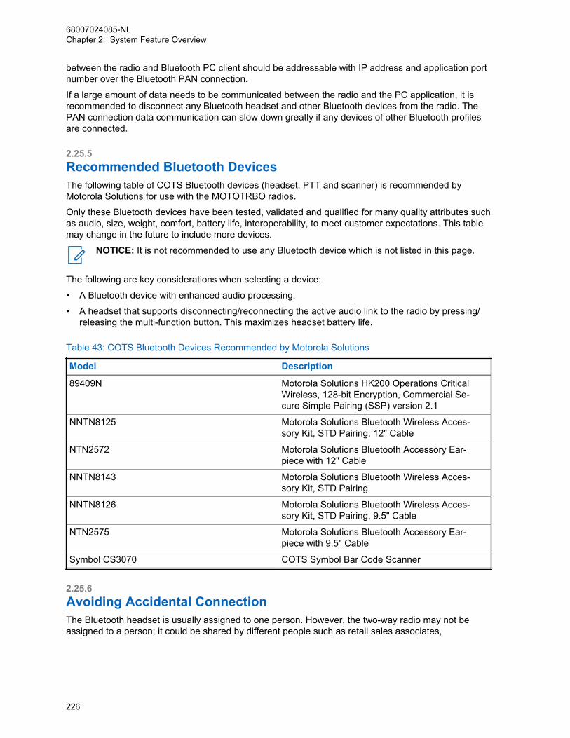
between the radio and Bluetooth PC client should be addressable with IP address and application portnumber over the Bluetooth PAN connection.
If a large amount of data needs to be communicated between the radio and the PC application, it isrecommended to disconnect any Bluetooth headset and other Bluetooth devices from the radio. ThePAN connection data communication can slow down greatly if any devices of other Bluetooth profilesare connected.
2.25.5Recommended Bluetooth DevicesThe following table of COTS Bluetooth devices (headset, PTT and scanner) is recommended byMotorola Solutions for use with the MOTOTRBO radios.
Only these Bluetooth devices have been tested, validated and qualified for many quality attributes suchas audio, size, weight, comfort, battery life, interoperability, to meet customer expectations. This tablemay change in the future to include more devices.
NOTICE: It is not recommended to use any Bluetooth device which is not listed in this page.
The following are key considerations when selecting a device:
• A Bluetooth device with enhanced audio processing.
• A headset that supports disconnecting/reconnecting the active audio link to the radio by pressing/releasing the multi-function button. This maximizes headset battery life.
Table 43: COTS Bluetooth Devices Recommended by Motorola Solutions
Model Description
89409N Motorola Solutions HK200 Operations CriticalWireless, 128-bit Encryption, Commercial Se-cure Simple Pairing (SSP) version 2.1
NNTN8125 Motorola Solutions Bluetooth Wireless Acces-sory Kit, STD Pairing, 12" Cable
NTN2572 Motorola Solutions Bluetooth Accessory Ear-piece with 12" Cable
NNTN8143 Motorola Solutions Bluetooth Wireless Acces-sory Kit, STD Pairing
NNTN8126 Motorola Solutions Bluetooth Wireless Acces-sory Kit, STD Pairing, 9.5" Cable
NTN2575 Motorola Solutions Bluetooth Accessory Ear-piece with 9.5" Cable
Symbol CS3070 COTS Symbol Bar Code Scanner
2.25.6Avoiding Accidental ConnectionThe Bluetooth headset is usually assigned to one person. However, the two-way radio may not beassigned to a person; it could be shared by different people such as retail sales associates,
68007024085-NLChapter 2: System Feature Overview
226
housekeeping, security and others. If a Bluetooth headset was paired with a radio, the headsetautomatically reconnects to the same radio the next time it powers on.
Scenario: If the same radio has been assigned to a different user, the headset can accidentallyreconnect to the wrong radio belonging to a different user. Automatically, the previous user stillreceives a positive pairing indication from the headset.
To avoid accidental connection as described in the above mentioned scenario, follow the instructionsbelow:
• For HK200: Erase all pairing information from the headset by pressing and holding the volumebutton and call button together, followed by turning on the headset. When this procedure isperformed, the headset does not initiate connection to any remote device automatically.
• For Motorola Solutions Headset/PTT and POD: Erase all pairing information from the device bypressing and holding the PTT button followed by turning on the headset. When this procedure isperformed, the headset or POD does not initiate connection to any remote device automatically.
2.26One Touch Home Revert ButtonThis feature is available for mobile radios in both analog and digital modes.
The customer can program a button as the “Home Revert” button via the CPS. This button allows theuser to jump to a pre-assigned “Home” channel. The CPS does not allow a customer to select achannel in the "Channel Pool" to be the Home Revert Channel.
NOTICE: The “Channel Pool” is a zone for keeping all the trunked and Data Revert Channels.
2.27Password and Lock FeatureMOTOTRBO provides a password-based locking mechanism (Radio Authentication) to protect radiosfrom unauthorized users.
This feature can be enabled and the password can be changed both via the CPS or the radio menu.
With this feature enabled, a radio prompts the user to enter a four-digit password on powering up. Afterthree incorrect password attempts, the radio enters a locked state for 15 minutes. No calls (includingEmergency Calls) can be placed or received, when a portable radio is in locked state. Upon correctpassword entry, the radio enters normal operation mode.
The password input method varies according to the radio display models. For example:
• On a non-keypad portable, a user inputs the password via a combination of the Channel Switch andSide Button(s).
• On a non-keypad mobile, a user inputs the password via a combination of the Channel Knob andFront Button 2.
• On a keypad mobile, a user inputs the password either with the Accessory Keypad or via acombination of the Channel Rocker button and the <OK_Button>.
If a Foot Switch is configured to initiate an emergency and the radio is powered up using the FootSwitch, the radio skips the password input procedure. Upon completion of an emergency, the radiothen initiates the password authentication if this feature is enabled.
If a user presses the test mode series button when the radio is locked or in password input state, theradio skips the password authentication and enters test mode.
68007024085-NLChapter 2: System Feature Overview
227
2.28Digital Telephone Patch
IPSC IP Site Connect
IP Site Connect supports Digital TelephonePatch
CPSSCapacity Plus Single Site
Capacity Plus Single Site supports Digital Tele-phone Patch
CPMSCapacity Plus Multi Site
Capacity Plus Multi Site supports Digital Tele-phone Patch
The MOTOTRBO Digital Telephone Patch is a Motorola Solutions proprietary feature introduced insoftware version R01.08.00 supporting two types of phone patch calls:
Individual Phone Patch CallThis allows a half-duplex voice communication between a radio user and a phone user. Thiscommunication can be initiated from either party.
Talkgroup Phone Patch CallThis allows a half-duplex voice communication between a phone user and a group of radio users.This type of communication can be initiated only by the phone user.
This feature is supported in Single Site, IPSC LACs, IPSC WACs, and Capacity Plus Single Siteconfigurations. This feature is supported in display and non-display radios. However, for non-displaymodels, phone numbers, over dial or access/de-access codes need to be configured manually to theprogrammable buttons because the radios do not have a keypad.
The DTP feature utilizes Commercial Off-the-Shelf (COTS) Analog Phone Patch (APP) boxes, and iscompatible with any DTMF-based APP box that supports the 4-wire interface and can communicate inhalf-duplex mode. The Zetron 30 (Worldpatch) and PL 1877A (MRTI2000) are two examples. MostAPP boxes in the market support the following telephony services:
• Access and De-access Codes
- The access code is used to wake up the APP box, and prevent the radio user or phone userfrom making unauthorized phone patch calls.
- The de-access code is used to terminate the phone patch call if an access code is requiredwhen setting up the call.
- Different access code/de-access codes may be configured to have different privileges, so thecodes can be used to block/allow radio from performing a call type.
• Phone Usage Time-Out Timer (TOT) – The APP box ends the call once the timer expires.
• A go-ahead tone is emitted to the phone user when the radio user de-keys. This provides anindication to the phone user to begin talking.
• Direct connection to the PBX or PSTN line
• Type Approvals for Supported Countries
Instead of recreating such services in the radio system, this feature relies on the APP box to providethese services. The APP Box is connected to the MOTOTRBO repeater via the 4-wire interface. Thephone patch feature utilizes APP boxes that are connected to the repeater, hence this feature is onlyavailable in repeater mode, but not direct mode.
68007024085-NLChapter 2: System Feature Overview
228
2.28.1Phone Call InitiationIt can be configured via CPS to allow a radio to initiate or receive phone calls on per digital personalitybasis.
Only phone-enabled radios can initiate and receive a phone call.
2.28.1.1Call Initiation by a Radio UserWhen a radio user initiates a phone call, the channel access is always polite (even if configured asimpolite), regardless of the radio’s programmed admit criteria. This is analogous to sending CSBK ordata signaling, which is sent politely.
When a radio enters a phone call, a phone call text string and icon shows up on the display screen toalert the radio user.
Buffer dial is supported for access/de-access code, phone number, and over dial digits. “Buffer Dial”means that the radio user enters the digits from the radio keypad, then presses the “OK” button to sendout the digits as in-band audio. The phone number can be 22 digits long or shorter. Before calling aphone user, the radio user switches to the channel that is capable of a phone patch call, and uses oneof the following dialing methods:
• Manual Dial – Enter the phone number from the radio keypad manually. This option can be enabledor disabled on the radio via CPS.
• Phone Address Book – Select a phone number from the radio’s Phone Address Book.
• One Touch Button – Push a programmable button of the radio. The one touch button is associatedwith a phone number from the Phone Address Book.
If an access code is required for phone calls, it could be configured in the radio or entered by the radiouser manually. When the access code is not configured in the radio, the radio user is prompted tomanually enter the access code after dialing the phone number. If access code is not required, theradio user can skip this step by not keying anything. After the radio user sends out the phone numberand access code, the phone rings and the user can answer the call.
If there is an Interactive Voice Response (IVR) device at the phone user’s end and over dial isrequired, the radio user can enter the over dial digits via the radio keypad or a programmable button.
NOTICE: The IVR device at a bank may prompt the user to enter the account number to accessaccount information.
2.28.1.2Call Initiation by a Phone UserWhen a phone user initiates the call, the phone user dials the phone number of the APP box, or thePBX box, if a PBX is used. The PBX then connects the call to the APP box.
If access code is required, the phone user enters the access code following the audible prompt fromthe APP box. After the APP box validates the access code, the box connects the call to the repeater.The repeater sounds a tone and prompts the phone user for the target ID. Then, the phone user entersthe target ID to reach the radio user/group.
NOTICE: If a Go-Ahead tone is configured in the APP box, the phone user hears the tone forthe Target ID, followed by the Go-Ahead tone.
68007024085-NLChapter 2: System Feature Overview
229

The length of the target ID is configurable via CPS, and the format varies according to different systemconfigurations.
CPSSCapacity Plus Single Site
The target ID includes the call type, channelslot number, and the radio/talkgroup identifier.
IPSCIP Site Connect
The target ID includes the call type, channelslot number, and the radio/talkgroup identifier.
CPSMCapacity Plus Single Site and Capacity
Plus Multi Site
The target ID only includes the call type and theradio/talkgroup identifier; the channel slot num-ber is not required.
When keying in the target ID, the phone user may try up to three times maximum, after which thesystem terminates the call automatically if no valid target ID is received. After the repeater validates thetarget ID, if the channel is busy, the repeater sounds a busy-waiting tone to the phone user and waitsfor the channel to become idle, before resuming the call setup. While waiting for the channel tobecome idle, the phone user hears the busy-waiting tone, and can choose to wait or end the call. If thechannel does not become idle for a configurable period of time, the repeater ends the call setup. In thisscenario, the phone user stops hearing the busy-waiting tone and hangs up the call. If the channel isidle or becomes idle before the timer expires, the repeater alerts the called radio user/group by ringingtones.
A radio user can join a phone call from a phone user while scanning for activities on the phonechannel.
NOTICE:
CPSMCapacity Plus Single Site and Ca-
pacity Plus Multi Site
Scanning is NOT supported in CapacityPlus Single Site and Capacity Plus MultiSite
For individual phone calls, the target radio user answers by pushing the PTT before the call can be setup completely. For talkgroup phone calls, it is configurable in the repeater via CPS to allow a targetradio user to answer the call by pushing the PTT before the call can be set up completely. Whenanswering is not required, the phone user can talk immediately after the first ring. When answering isrequired, the phone user is not permitted to talk until one of the target radio users answers the call bypushing the PTT. Otherwise, the phone user is not heard by the radio users. When answering isrequired but the call is unanswered during the configured response period, the repeater sends a de-access code to the APP box, and the call ends automatically.
Phone All Call, an exclusive phone talkgroup call, is supported in the DTP feature as well. The phoneuser can follow the same phone talkgroup call setup procedure to set up the phone call by using the AllCall ID or 0s as the Target ID. In a Phone All Call, the phone user can start to talk after the first ring,before any radio user answers the call. During a Phone All Call, not all radio users are able to respondto the phone user. Only radio users with radios configured with All Call announcement capability areable to respond to the landline phone user and heard by all the other radio users. These users are ableto end the Phone All Call by sending the de-access code. Hence, when a phone user makes a PhoneAll Call, it is recommended to provide contact information so that the receiving radio users have meansto contact the phone user if needed. Phone All Call can be enabled/disabled in the repeater via CPS.
68007024085-NLChapter 2: System Feature Overview
230

Pre-Configured Target ID: For any system configuration (Conventional Single Site, IPSC, CapacityPlus Single Site and Capacity Plus Multi Site), a default target ID may be preconfigured in the phonegateway repeater. This is an optional configuration and can be enabled/disabled via CPS. Whenenabled, if the phone user does not enter the first digit of the target ID within 3 seconds (3-second rule)after hearing the target ID prompt tone, the preconfigured target ID will be used for the phone callautomatically and the system will start to ring the target user or user group. If the target ID entered bythe phone user is invalid and a re-try is needed, the same 3-second rule will be applied in each retry.The preconfigured target ID can be an individual radio user, or a user group, or an All Call.
2.28.2Access Priority During a Phone CallDuring a phone patch call, the radio user in the phone call has higher channel access priority than thephone user, allowing the radio user to key up and talk impolitely over a phone user regardless of theradio’s in-call permit criteria configuration.
However, if a phone user needs to talk, the phone user has to wait until the radio user dekeys.Otherwise, the phone user will not be heard by the radio users.
When another radio user is talking in a phone talkgroup call, the radio user follows the radio’s In CallCriteria configuration with the exception of using the Follow Admit Criteria when the In Call Criteria isprovisioned with Transmit Interrupt.
NOTICE: This is because Transmit Interrupt is not supported in the phone call.
When detecting an impolite takeover from a radio that is not partied to the phone call or an emergencyon the phone patch channel during a phone call, the repeater automatically ends the phone call bysending a de-access code to the APP box.
During a phone call, if a radio drops out of the call due to various reasons (for example; out-of-range),the radio can make a late entry back into the call if it is a talkgroup call. If it is an Private Call, the radiocan make a late entry back to the call in Conventional Single Site or IPSC. However, late entry is notsupported in a Capacity Plus Single Site system configuration if a radio fades out of an Private Callcompletely.
There are three switches that happen during a call:
Radio-to-Phone switchThe radio user finishes talking and dekeys, then the phone user starts to talk.
Phone-to-Radio switchThe phone user talks while a radio user keys up and starts to talk.
Radio-to-Radio switchThe radio user finishes talking and dekeys, while another radio user keys up immediately and startstalking. This switch only takes place in talkgroup calls only.
To ensure a smooth switch and avoid voice truncation, the Enhanced Channel Access feature isintroduced to minimize the switching impact and to achieve the best overall user experience in all
68007024085-NLChapter 2: System Feature Overview
231
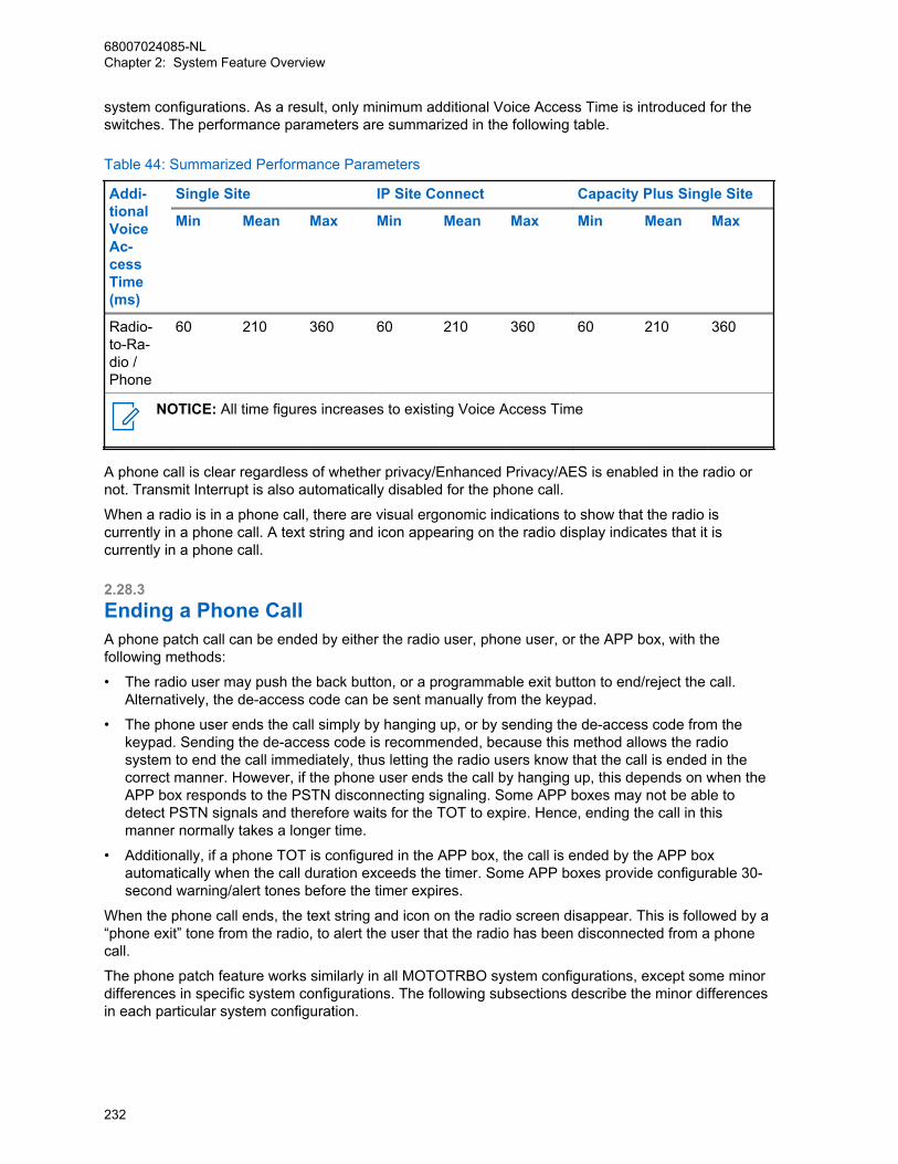
system configurations. As a result, only minimum additional Voice Access Time is introduced for theswitches. The performance parameters are summarized in the following table.
Table 44: Summarized Performance Parameters
Addi-tionalVoiceAc-cessTime(ms)
Single Site IP Site Connect Capacity Plus Single Site
Min Mean Max Min Mean Max Min Mean Max
Radio-to-Ra-dio /Phone
60 210 360 60 210 360 60 210 360
NOTICE: All time figures increases to existing Voice Access Time
A phone call is clear regardless of whether privacy/Enhanced Privacy/AES is enabled in the radio ornot. Transmit Interrupt is also automatically disabled for the phone call.
When a radio is in a phone call, there are visual ergonomic indications to show that the radio iscurrently in a phone call. A text string and icon appearing on the radio display indicates that it iscurrently in a phone call.
2.28.3Ending a Phone CallA phone patch call can be ended by either the radio user, phone user, or the APP box, with thefollowing methods:
• The radio user may push the back button, or a programmable exit button to end/reject the call.Alternatively, the de-access code can be sent manually from the keypad.
• The phone user ends the call simply by hanging up, or by sending the de-access code from thekeypad. Sending the de-access code is recommended, because this method allows the radiosystem to end the call immediately, thus letting the radio users know that the call is ended in thecorrect manner. However, if the phone user ends the call by hanging up, this depends on when theAPP box responds to the PSTN disconnecting signaling. Some APP boxes may not be able todetect PSTN signals and therefore waits for the TOT to expire. Hence, ending the call in thismanner normally takes a longer time.
• Additionally, if a phone TOT is configured in the APP box, the call is ended by the APP boxautomatically when the call duration exceeds the timer. Some APP boxes provide configurable 30-second warning/alert tones before the timer expires.
When the phone call ends, the text string and icon on the radio screen disappear. This is followed by a“phone exit” tone from the radio, to alert the user that the radio has been disconnected from a phonecall.
The phone patch feature works similarly in all MOTOTRBO system configurations, except some minordifferences in specific system configurations. The following subsections describe the minor differencesin each particular system configuration.
68007024085-NLChapter 2: System Feature Overview
232
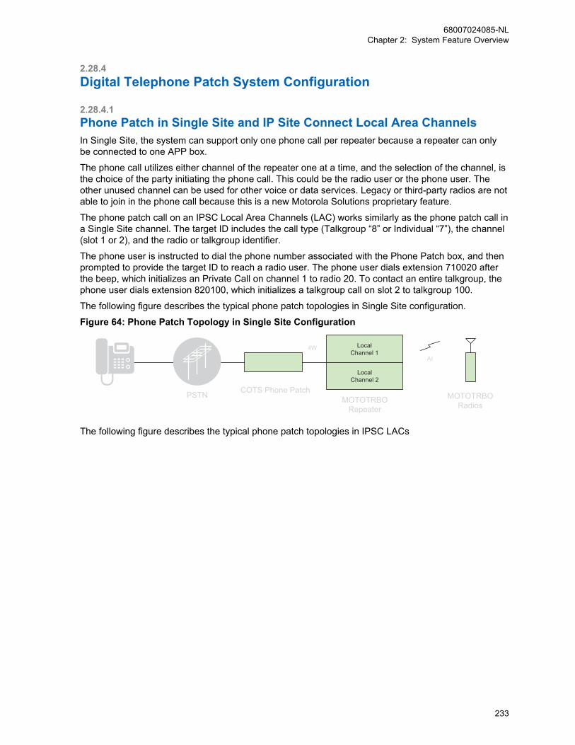
2.28.4Digital Telephone Patch System Configuration
2.28.4.1Phone Patch in Single Site and IP Site Connect Local Area Channels In Single Site, the system can support only one phone call per repeater because a repeater can onlybe connected to one APP box.
The phone call utilizes either channel of the repeater one at a time, and the selection of the channel, isthe choice of the party initiating the phone call. This could be the radio user or the phone user. Theother unused channel can be used for other voice or data services. Legacy or third-party radios are notable to join in the phone call because this is a new Motorola Solutions proprietary feature.
The phone patch call on an IPSC Local Area Channels (LAC) works similarly as the phone patch call ina Single Site channel. The target ID includes the call type (Talkgroup “8” or Individual “7”), the channel(slot 1 or 2), and the radio or talkgroup identifier.
The phone user is instructed to dial the phone number associated with the Phone Patch box, and thenprompted to provide the target ID to reach a radio user. The phone user dials extension 710020 afterthe beep, which initializes an Private Call on channel 1 to radio 20. To contact an entire talkgroup, thephone user dials extension 820100, which initializes a talkgroup call on slot 2 to talkgroup 100.
The following figure describes the typical phone patch topologies in Single Site configuration.
Figure 64: Phone Patch Topology in Single Site Configuration
LocalChannel 1
LocalChannel 2
PSTN
AI
MOTOTRBORepeater
COTS Phone PatchMOTOTRBO
Radios
4W
The following figure describes the typical phone patch topologies in IPSC LACs
68007024085-NLChapter 2: System Feature Overview
233
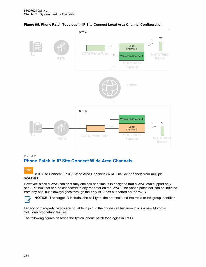
Figure 65: Phone Patch Topology in IP Site Connect Local Area Channel Configuration
LocalChannel 1
Wide Area Channel 1
LocalChannel 2
Wide Area Channel 1
IP
SITE A
SITE B
Internet
IP
IP
PSTN
PSTN
COTS Phone Patch
COTS Phone Patch
4W
4W
MOTOTRBORepeater
MOTOTRBORepeater MOTOTRBO
Radios
MOTOTRBORadios
AI
AI
2.28.4.2Phone Patch in IP Site Connect Wide Area Channels
IPSC In IP Site Connect (IPSC), Wide Area Channels (WAC) include channels from multiple
repeaters.
However, since a WAC can host only one call at a time, it is designed that a WAC can support onlyone APP box that can be connected to any repeater on the WAC. The phone patch call can be initiatedfrom any site, but it always goes through the only APP box supported on the WAC.
NOTICE: The target ID includes the call type, the channel, and the radio or talkgroup identifier.
Legacy or third-party radios are not able to join in the phone call because this is a new MotorolaSolutions proprietary feature.
The following figures describe the typical phone patch topologies in IPSC.
68007024085-NLChapter 2: System Feature Overview
234
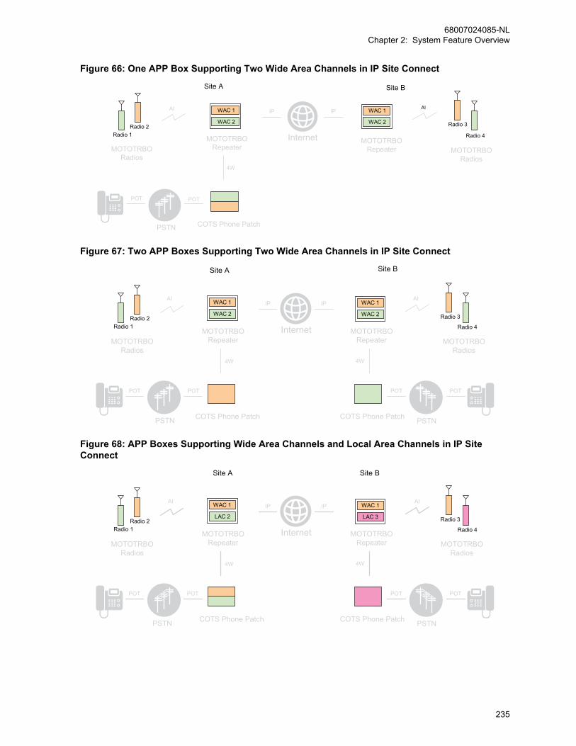
Figure 66: One APP Box Supporting Two Wide Area Channels in IP Site Connect
COTS Phone Patch
4W
POT
PSTN
POT
AI
MOTOTRBORepeater
Internet
IP IP
MOTOTRBORepeater MOTOTRBO
Radios
AI
MOTOTRBORadios
WAC 1
WAC 2
WAC 1
WAC 2 Radio 2
Radio 1
Radio 3
Radio 4
Site A Site B
Figure 67: Two APP Boxes Supporting Two Wide Area Channels in IP Site Connect
COTS Phone Patch
POT POT POT POT
PSTN
AI
MOTOTRBORepeater
Internet
IP IP
MOTOTRBORepeater MOTOTRBO
RadiosMOTOTRBO
Radios
COTS Phone Patch
4W
PSTN
WAC 1
WAC 2
WAC 1
WAC 2 Radio 2
Radio 1
Radio 3
Radio 4
Site A Site B
AI
4W
Figure 68: APP Boxes Supporting Wide Area Channels and Local Area Channels in IP SiteConnect
COTS Phone Patch
POT POT POT POT
PSTN
AI
MOTOTRBORepeater
Internet
IP IP
MOTOTRBORepeater MOTOTRBO
RadiosMOTOTRBO
Radios
COTS Phone Patch
4W
PSTN
WAC 1
LAC 2
WAC 1
LAC 3Radio 2
Radio 1
Radio 3
Radio 4
Site A Site B
AI
4W
68007024085-NLChapter 2: System Feature Overview
235

2.28.4.3Phone Patch in Capacity Plus Single Site
CPSS In Capacity Plus Single Site, because a repeater can only be connected to one APP box, the
system can support one phone call per repeater.
The phone call only uses one channel; the other channel can be used for other voice or data services.Any voice repeater can be used for phone calls, hence the maximum number of APP boxes that canbe supported in a Capacity Plus Single Site system is equal to the number of voice repeaters in thesystem.
The target ID includes the call type, and the radio or talkgroup identifier. The channel ID is not requiredbecause the system automatically selects the channel for the phone call. When the radio user initiatesa phone call, if the rest channel is idle and phone capable for this radio, the phone call starts on therest channel. If the rest channel is not phone capable for the radio, the phone call starts on an idlechannel that is phone capable.
When a phone user calls a radio user/group, the user dials the telephone number of the APP box. Thephone call can start on either idle channel of the repeater that the APP box is connected to. Then thefollowing rule is in order - If a channel is the rest channel, the phone call starts on this channel; ifneither channel is the rest channel, channel 1 has a higher priority than channel 2. Legacy or third-party radios are not able to join in the phone call because this is a new Motorola Solutions proprietaryfeature.
The following figure describes the typical phone patch topology in Capacity Plus Single Site.
Figure 69: Phone Patch Topology in a Capacity Plus Single Site Configuration
COTS Phone Patch
4W
4W
POT
POT
POT POT
IP
IP
IP
IP
MOTOTRBORadiosPBX
PSTN
MOTOTRBORepeaters
COTS Phone Patch LAN
AI
2.28.5Wireline TelephonyA wireline telephony solution is available in all MOTOTRBO system configurations (ConventionalSingle Site, IPSC, Capacity Plus Single Site and Capacity Plus Multi Site) through Network ApplicationInterface (for voice), and also supported by third-party telephony applications. The wireline telephony isillustrated in Figure 70: Wireline Telephony with Third-party Telephony Application on page 237.
68007024085-NLChapter 2: System Feature Overview
236

Figure 70: Wireline Telephony with Third-party Telephony Application
MOTOTRBO RepeaterSystem
IP Network
VoiceApplication
VoiceApplication
Phone Console Console
OperatorOperator
The wireline telephony solution provides the same set of functionalities and similar user experience asthe DTP solution that uses the APP box. The only difference is that the wire line solution does not usethe APP box, instead, it uses a third-party telephony application.
2.29Voice Announcement FeatureMOTOTRBO 2.0 radio products support the voice announcement feature suite to audibly conveyinformation to the radio user.
An example of when this feature is helpful is when the MOTOTRBO radio display or indicators are noteasily accessible (for example, located under protective clothing) or when radio operator cannot bedistracted from their task to look at the display or indicators.
The voice announcement feature is supported in both analog and digital operation. The voiceannouncement feature includes a standard feature set and a premium feature set. The standardfeature set and premium feature set are mutually exclusive (only one may be enabled). The voiceannouncement priority configuration determines whether radio traffic and alert tones may interrupt avoice announcement. The MOTOTRBO radio operator can enable or disable the voice announcementfeature as appropriate for their work environment.
The standard feature set uses pre-recorded voice announcement files that are loaded into theMOTOTRBO radio. A selection of professionally recorded voice announcement files is included withthe MOTOTRBO Customer Programming Software (CPS). In addition, users may record their own
68007024085-NLChapter 2: System Feature Overview
237
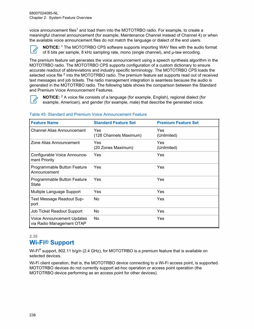
voice announcement files1 and load them into the MOTOTRBO radio. For example, to create ameaningful channel announcement (for example, Maintenance Channel instead of Channel 4) or whenthe available voice announcement files do not match the language or dialect of the end users.
NOTICE: 1 The MOTOTRBO CPS software supports importing WAV files with the audio formatof 8 bits per sample, 8 kHz sampling rate, mono (single channel), and µ-law encoding.
The premium feature set generates the voice announcement using a speech synthesis algorithm in theMOTOTRBO radio. The MOTOTRBO CPS supports configuration of a custom dictionary to ensureaccurate readout of abbreviations and industry specific terminology. The MOTOTRBO CPS loads theselected voice file 2 into the MOTOTRBO radio. The premium feature set supports read out of receivedtext messages and job tickets. The radio management integration is seamless because the audio isgenerated in the MOTOTRBO radio. The following table shows the comparison between the Standardand Premium Voice Announcement Features.
NOTICE: 2 A voice file consists of a language (for example, English), regional dialect (forexample, American), and gender (for example, male) that describe the generated voice.
Table 45: Standard and Premium Voice Announcement Feature
Feature Name Standard Feature Set Premium Feature Set
Channel Alias Announcement Yes(128 Channels Maximum)
Yes(Unlimited)
Zone Alias Announcement Yes(20 Zones Maximum)
Yes(Unlimited)
Configurable Voice Announce-ment Priority
Yes Yes
Programmable Button FeatureAnnouncement
Yes Yes
Programmable Button FeatureState
Yes Yes
Multiple Language Support Yes Yes
Text Message Readout Sup-port
No Yes
Job Ticket Readout Support No Yes
Voice Announcement Updatesvia Radio Management OTAP
No Yes
2.30Wi-Fi® SupportWi-Fi® support, 802.11 b/g/n (2.4 GHz), for MOTOTRBO is a premium feature that is available onselected devices.
Wi-Fi client operation, that is, the MOTOTRBO device connecting to a Wi-Fi access point, is supported.MOTOTRBO devices do not currently support ad-hoc operation or access point operation (theMOTOTRBO device performing as an access point for other devices).
68007024085-NLChapter 2: System Feature Overview
238

2.30.1Wi-Fi Network NameThe Service Set Identifier (SSID) or network name, needs to match the SSID configured in the accesspoint.
The SSID is case sensitive and supports internationalization per the IEEE 802.11-2012 standard.
NOTICE: Hidden networks do not broadcast their SSID over Wi-Fi. Hidden networks aresupported, but not recommended, because it increases the connection time and doesn’tincrease security since the SSID is still available through other means.
2.30.2Wi-Fi Security SupportThe security setting should match the type of authentication and encryption used by your Wi-Fi router.The security setting controls the access to the wireless network and the level of privacy between theMOTOTRBO device and the access point. WPA2 with AES encryption provides the strongest securityoffered by the Wi-Fi product and is recommended.
The following security modes are supported:
• “None” provides no authentication or encryption. This security mode is supported but notrecommended.
• “WEP” is insecure and obsolete. This security mode is supported but not recommended.
• "WPA/WPA2 Personal" is supported with both AES and TKIP encryption.
• “WPA/WPA2 Enterprise” is supported with both AES and TKIP encryption.
- Support EAP TLS
- Support PEAP with Phase 2 authentication as TLS and MSCHAPV2
- Support EAP TTLS with Phase 2 authentication as PAP, CHAP, MSCHAP, and MSCHAPV2
NOTICE: WPS is not supported due to security flaws discovered in the protocol.
NOTICE: If validation of the server certificate is required, the certificate of the subscriber andthe certificate of the authentication server must be issued by the same Certificate Authority(CA).
Wi-Fi Clients
EAPOL
EAP
Access Point
Authentication Server
Networks
RADIUS / Diameter
EAP
68007024085-NLChapter 2: System Feature Overview
239
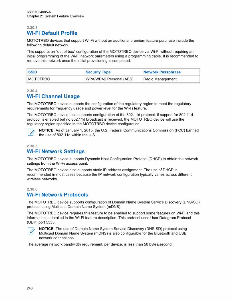
2.30.3Wi-Fi Default ProfileMOTOTRBO devices that support Wi-Fi without an additional premium feature purchase include thefollowing default network.
This supports an “out of box” configuration of the MOTOTRBO device via Wi-Fi without requiring aninitial programming of the Wi-Fi network parameters using a programming cable. It is recommended toremove this network once the initial provisioning is completed.
SSID Security Type Network Passphrase
MOTOTRBO WPA/WPA2 Personal (AES) Radio Management
2.30.4Wi-Fi Channel UsageThe MOTOTRBO device supports the configuration of the regulatory region to meet the regulatoryrequirements for frequency usage and power level for the Wi-Fi feature.
The MOTOTRBO device also supports configuration of the 802.11d protocol. If support for 802.11dprotocol is enabled but no 802.11d broadcast is received, the MOTOTRBO device will use theregulatory region specified in the MOTOTRBO device configuration.
NOTICE: As of January 1, 2015, the U.S. Federal Communications Commission (FCC) bannedthe use of 802.11d within the U.S.
2.30.5Wi-Fi Network SettingsThe MOTOTRBO device supports Dynamic Host Configuration Protocol (DHCP) to obtain the networksettings from the Wi-Fi access point.
The MOTOTRBO device also supports static IP address assignment. The use of DHCP isrecommended in most cases because the IP network configuration typically varies across differentwireless networks.
2.30.6Wi-Fi Network ProtocolsThe MOTOTRBO device supports configuration of Domain Name System Service Discovery (DNS-SD)protocol using Multicast Domain Name System (mDNS).
The MOTOTRBO device requires this feature to be enabled to support some features on Wi-Fi and thisinformation is detailed in the Wi-Fi feature description. This protocol uses User Datagram Protocol(UDP) port 5353.
NOTICE: The use of Domain Name System Service Discovery (DNS-SD) protocol usingMulticast Domain Name System (mDNS) is also configurable for the Bluetooth and USBnetwork connections.
The average network bandwidth requirement, per device, is less than 50 bytes/second.
68007024085-NLChapter 2: System Feature Overview
240

2.30.7Wi-Fi FeaturesThe following features can be supported over the Wi-Fi interface on MOTOTRBO devices.
2.30.7.1Radio Management in Wi-FiThe MOTOTRBO radio management application supports all device configuration operations viathe Wi-Fi interface.
The following are the supported operations:
• Configuration of Device Settings
• Update of Device Firmware
• Activation of Premium Features
• Updates of Device Resources (that is, Language Packs and Voice Packs)
NOTICE: Please refer to the MOTOTRBO radio management application release notes todetermine the release that supports some or all the following functionalities
The MOTOTRBO radio management device programmer component must be present on the samelocal area network (LAN) as the MOTOTRBO device. This is required because the MOTOTRBO radiomanagement device programmer identifies MOTOTRBO devices using the DNS-SD protocol. Thedeployment of a virtual local area network (VLAN) is beyond the scope of this system planner but doesprovide additional deployment options when physically deploying a MOTOTRBO radio managementdevice programmer on the same LAN is not feasible.
2.31Certificate ManagementCertificate management provides a solution for managing certificates in the MOTORBO system.
2.31.1Certificate Management Feature OverviewThe MOTOTRBO device supports Certificate Management through the Simple Certificate EnrollmentProtocol (SCEP).
The following certificate management operations are supported:
• Supports RSA based X.509 V3 certificate.
• Supports downloading Certificate Authority (CA) certificate.
• Supports client certificate enrollment and auto-renewal.
• Uses Challenge Password to authenticate the radio as the valid SCEP client.
• Uses MD5 Fingerprint to validate the CA certificate.
• Supports RSA key size as 1024, 2048 and 4096 bits.
• Supports Signature Hash Algorithm as MD5, SHA-1, SHA-256, SHA-384 and SHA-512.
NOTICE: Certificates are used for Wi-Fi Enterprise.
68007024085-NLChapter 2: System Feature Overview
241
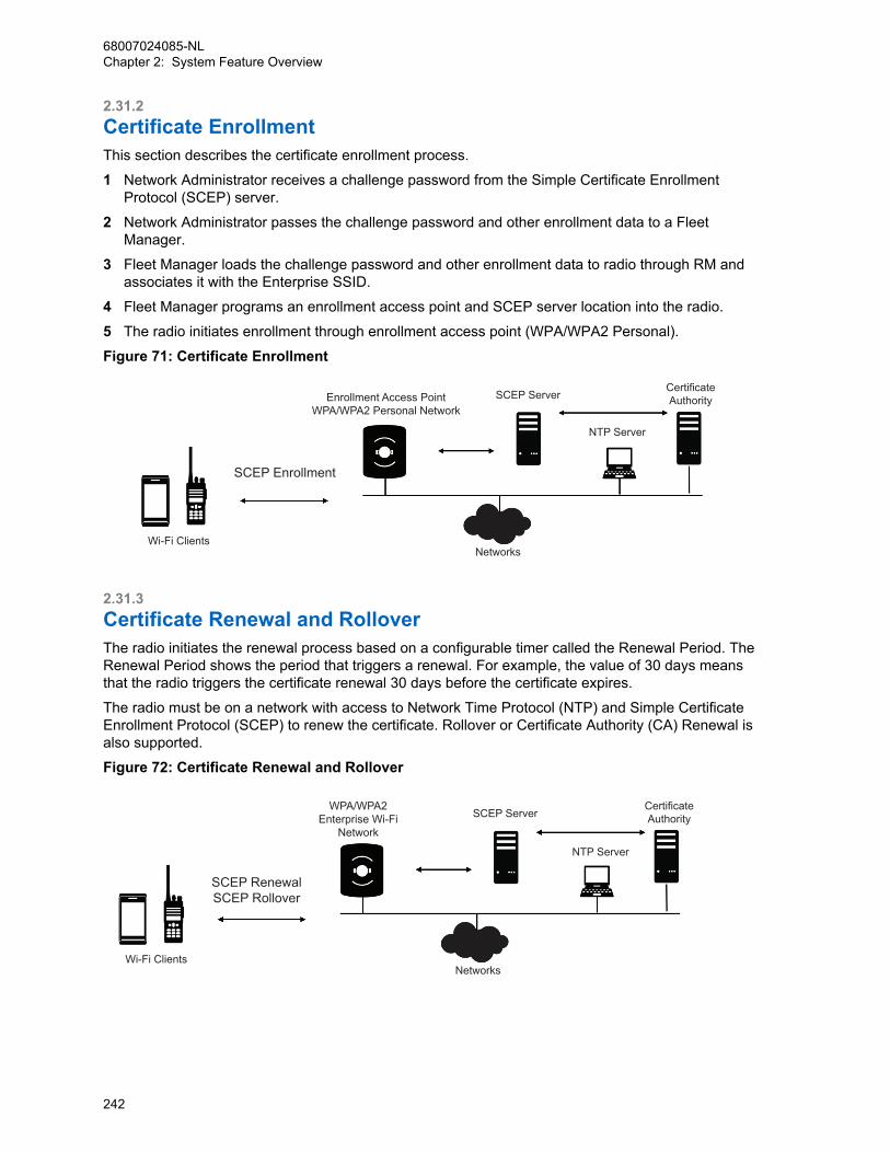
2.31.2Certificate EnrollmentThis section describes the certificate enrollment process.
1 Network Administrator receives a challenge password from the Simple Certificate EnrollmentProtocol (SCEP) server.
2 Network Administrator passes the challenge password and other enrollment data to a FleetManager.
3 Fleet Manager loads the challenge password and other enrollment data to radio through RM andassociates it with the Enterprise SSID.
4 Fleet Manager programs an enrollment access point and SCEP server location into the radio.
5 The radio initiates enrollment through enrollment access point (WPA/WPA2 Personal).
Figure 71: Certificate Enrollment
Wi-Fi Clients
SCEP Enrollment
Enrollment Access PointWPA/WPA2 Personal Network
SCEP ServerCertificateAuthority
NTP Server
Networks
2.31.3Certificate Renewal and RolloverThe radio initiates the renewal process based on a configurable timer called the Renewal Period. TheRenewal Period shows the period that triggers a renewal. For example, the value of 30 days meansthat the radio triggers the certificate renewal 30 days before the certificate expires.
The radio must be on a network with access to Network Time Protocol (NTP) and Simple CertificateEnrollment Protocol (SCEP) to renew the certificate. Rollover or Certificate Authority (CA) Renewal isalso supported.
Figure 72: Certificate Renewal and Rollover
Wi-Fi Clients
SCEP RenewalSCEP Rollover
WPA/WPA2Enterprise Wi-Fi
Network
SCEP ServerCertificateAuthority
NTP Server
Networks
68007024085-NLChapter 2: System Feature Overview
242
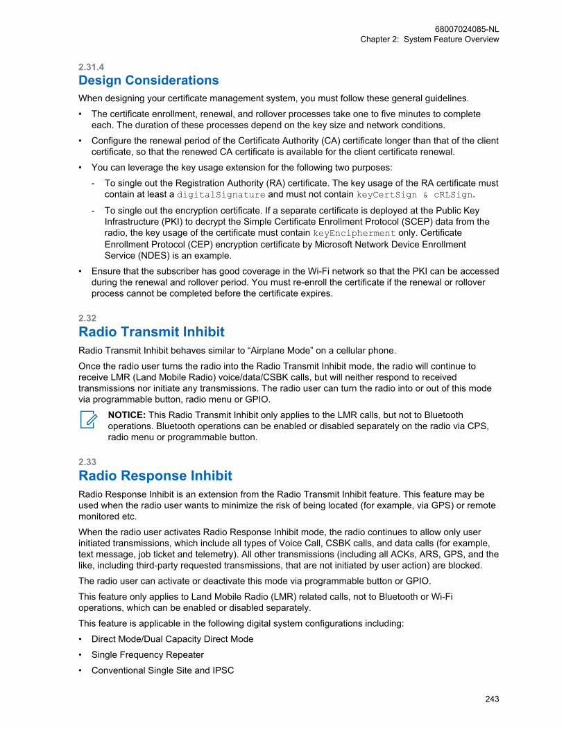
2.31.4Design ConsiderationsWhen designing your certificate management system, you must follow these general guidelines.
• The certificate enrollment, renewal, and rollover processes take one to five minutes to completeeach. The duration of these processes depend on the key size and network conditions.
• Configure the renewal period of the Certificate Authority (CA) certificate longer than that of the clientcertificate, so that the renewed CA certificate is available for the client certificate renewal.
• You can leverage the key usage extension for the following two purposes:
- To single out the Registration Authority (RA) certificate. The key usage of the RA certificate mustcontain at least a digitalSignature and must not contain keyCertSign & cRLSign.
- To single out the encryption certificate. If a separate certificate is deployed at the Public KeyInfrastructure (PKI) to decrypt the Simple Certificate Enrollment Protocol (SCEP) data from theradio, the key usage of the certificate must contain keyEncipherment only. CertificateEnrollment Protocol (CEP) encryption certificate by Microsoft Network Device EnrollmentService (NDES) is an example.
• Ensure that the subscriber has good coverage in the Wi-Fi network so that the PKI can be accessedduring the renewal and rollover period. You must re-enroll the certificate if the renewal or rolloverprocess cannot be completed before the certificate expires.
2.32Radio Transmit InhibitRadio Transmit Inhibit behaves similar to “Airplane Mode” on a cellular phone.
Once the radio user turns the radio into the Radio Transmit Inhibit mode, the radio will continue toreceive LMR (Land Mobile Radio) voice/data/CSBK calls, but will neither respond to receivedtransmissions nor initiate any transmissions. The radio user can turn the radio into or out of this modevia programmable button, radio menu or GPIO.
NOTICE: This Radio Transmit Inhibit only applies to the LMR calls, but not to Bluetoothoperations. Bluetooth operations can be enabled or disabled separately on the radio via CPS,radio menu or programmable button.
2.33Radio Response InhibitRadio Response Inhibit is an extension from the Radio Transmit Inhibit feature. This feature may beused when the radio user wants to minimize the risk of being located (for example, via GPS) or remotemonitored etc.
When the radio user activates Radio Response Inhibit mode, the radio continues to allow only userinitiated transmissions, which include all types of Voice Call, CSBK calls, and data calls (for example,text message, job ticket and telemetry). All other transmissions (including all ACKs, ARS, GPS, and thelike, including third-party requested transmissions, that are not initiated by user action) are blocked.
The radio user can activate or deactivate this mode via programmable button or GPIO.
This feature only applies to Land Mobile Radio (LMR) related calls, not to Bluetooth or Wi-Fioperations, which can be enabled or disabled separately.
This feature is applicable in the following digital system configurations including:
• Direct Mode/Dual Capacity Direct Mode
• Single Frequency Repeater
• Conventional Single Site and IPSC
68007024085-NLChapter 2: System Feature Overview
243

• Capacity Plus
2.34Analog FeaturesFor customers that are migrating from Analog systems to Digital systems, MOTOTRBO supports bothanalog and digital modes of operation.
MOTOTRBO mobile and portable radios support both analog and digital modes (the user can selectwhich mode to use, and change modes dynamically), while MOTOTRBO repeaters are configured tooperate in digital mode or in analog mode. When in Analog mode, MOTOTRBO utilizes traditional FMtechnology, supports both 12.5and 25 kHz channel spacing, and can operate in repeater and directmodes.
2.34.1Analog Voice FeaturesThe following traditional Analog features are supported by the MOTOTRBO system:
Table 46: MOTOTRBO Analog Voice Features
Feature Name Description
Time-Out Timer Sets the amount of time that the radio can con-tinuously transmit before the transmission is au-tomatically terminated.
Squelch Special electronic circuitry added to the receiverof a radio which reduces or squelches, unwant-ed signals before they are heard through thespeaker.
Monitor/Permanent Monitor The user can check channel activity by pressingthe Monitor button. If the channel is clear, theuser hears static. If the channel is in use, theuser hears the conversation. It also serves as away to check the volume level of the radio, aswhile pressing the monitor button, the user canadjust the volume according to the volume ofthe static/conversation heard.
Talkaround This feature allows a user to talk directly to an-other unit for easy local unit-to-unit communica-tions and bypass the repeater.
12.5/20/25 kHz Configurable Bandwidth Channels on the radio can be programmedthrough the CPS to operate at either 12.5 kHzor 20/25 kHz.
PL/DPL Transmitted when the receiving radio is to onlyreceive calls from radios with specific PL/DPLcodes, this creates communications groupswhile operating in Conventional Dispatch mode.PL/DPL allows for more privacy on a frequency.PL/DPL is transmitted as a sub-audible fre-quency or a digital code.
Channel Access Control This feature dictates what conditions a radio isallowed to initiate a transmission on a channel.
68007024085-NLChapter 2: System Feature Overview
244
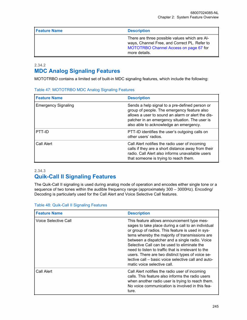
Feature Name Description
There are three possible values which are Al-ways, Channel Free, and Correct PL. Refer to MOTOTRBO Channel Access on page 67 formore details.
2.34.2MDC Analog Signaling FeaturesMOTOTRBO contains a limited set of built-in MDC signaling features, which include the following:
Table 47: MOTOTRBO MDC Analog Signaling Features
Feature Name Description
Emergency Signaling Sends a help signal to a pre-defined person orgroup of people. The emergency feature alsoallows a user to sound an alarm or alert the dis-patcher in an emergency situation. The user isalso able to acknowledge an emergency.
PTT-ID PTT-ID identifies the user’s outgoing calls onother users’ radios.
Call Alert Call Alert notifies the radio user of incomingcalls if they are a short distance away from theirradio. Call Alert also informs unavailable usersthat someone is trying to reach them.
2.34.3Quik-Call II Signaling FeaturesThe Quik-Call II signaling is used during analog mode of operation and encodes either single tone or asequence of two tones within the audible frequency range (approximately 300 – 3000Hz). Encoding/Decoding is particularly used for the Call Alert and Voice Selective Call features.
Table 48: Quik-Call II Signaling Features
Feature Name Description
Voice Selective Call This feature allows announcement type mes-sages to take place during a call to an individualor group of radios. This feature is used in sys-tems whereby the majority of transmissions arebetween a dispatcher and a single radio. VoiceSelective Call can be used to eliminate theneed to listen to traffic that is irrelevant to theusers. There are two distinct types of voice se-lective call – basic voice selective call and auto-matic voice selective call.
Call Alert Call Alert notifies the radio user of incomingcalls. This feature also informs the radio userswhen another radio user is trying to reach them.No voice communication is involved in this fea-ture.
68007024085-NLChapter 2: System Feature Overview
245
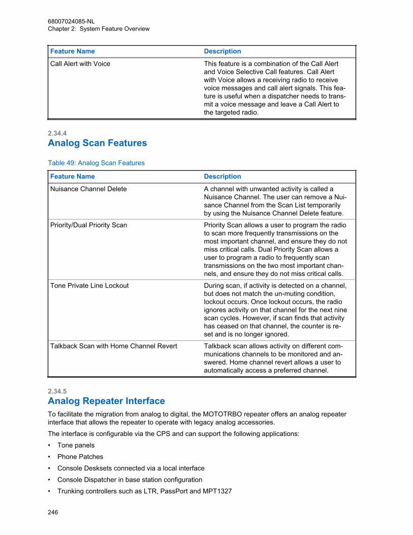
Feature Name Description
Call Alert with Voice This feature is a combination of the Call Alertand Voice Selective Call features. Call Alertwith Voice allows a receiving radio to receivevoice messages and call alert signals. This fea-ture is useful when a dispatcher needs to trans-mit a voice message and leave a Call Alert tothe targeted radio.
2.34.4Analog Scan Features
Table 49: Analog Scan Features
Feature Name Description
Nuisance Channel Delete A channel with unwanted activity is called aNuisance Channel. The user can remove a Nui-sance Channel from the Scan List temporarilyby using the Nuisance Channel Delete feature.
Priority/Dual Priority Scan Priority Scan allows a user to program the radioto scan more frequently transmissions on themost important channel, and ensure they do notmiss critical calls. Dual Priority Scan allows auser to program a radio to frequently scantransmissions on the two most important chan-nels, and ensure they do not miss critical calls.
Tone Private Line Lockout During scan, if activity is detected on a channel,but does not match the un-muting condition,lockout occurs. Once lockout occurs, the radioignores activity on that channel for the next ninescan cycles. However, if scan finds that activityhas ceased on that channel, the counter is re-set and is no longer ignored.
Talkback Scan with Home Channel Revert Talkback scan allows activity on different com-munications channels to be monitored and an-swered. Home channel revert allows a user toautomatically access a preferred channel.
2.34.5Analog Repeater InterfaceTo facilitate the migration from analog to digital, the MOTOTRBO repeater offers an analog repeaterinterface that allows the repeater to operate with legacy analog accessories.
The interface is configurable via the CPS and can support the following applications:
• Tone panels
• Phone Patches
• Console Desksets connected via a local interface
• Console Dispatcher in base station configuration
• Trunking controllers such as LTR, PassPort and MPT1327
68007024085-NLChapter 2: System Feature Overview
246
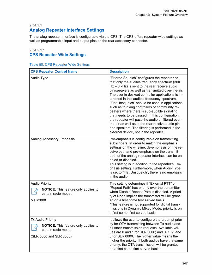
2.34.5.1Analog Repeater Interface SettingsThe analog repeater interface is configurable via the CPS. The CPS offers repeater-wide settings aswell as programmable input and output pins on the rear accessory connector.
2.34.5.1.1CPS Repeater Wide Settings
Table 50: CPS Repeater Wide Settings
CPS Repeater Control Name Description
Audio Type “Filtered Squelch” configures the repeater sothat only the audible frequency spectrum (300Hz – 3 kHz) is sent to the rear receive audiopin/speakers as well as transmitted over-the-air.The user in deskset controller applications is in-terested in this audible frequency spectrum.“Flat Unsquelch” should be used in applicationssuch as trunking controllers or community re-peaters where there is sub-audible signalingthat needs to be passed. In this configuration,the repeater will pass the audio unfiltered over-the-air as well as to the rear receive audio pinand speakers. The filtering is performed in theexternal device, not in the repeater.
Analog Accessory Emphasis Pre-emphasis is configurable on transmittingsubscribers. In order to match the emphasissettings on the wireline, de-emphasis on the re-ceive path and pre-emphasis on the transmitpath of the analog repeater interface can be en-abled or disabled.This setting is in addition to the repeater’s Em-phasis setting. Furthermore, when Audio Typeis set to “Flat Unsquelch”, there is no emphasisin the audio.
Audio Priority
NOTICE: This feature only applies tocertain radio model.
MTR3000
This setting determines if “External PTT” or“Repeat Path” has priority over the transmitterwhen Disable Repeat Path is disabled. A priori-ty of None implies the transmitter will be grant-ed on a first come first served basis.*This feature is not supported for digital trans-missions in Dynamic Mixed Mode; priority is ona first come, first served basis.
Tx Audio Priority
NOTICE: This feature only applies tocertain radio model.
(SLR 5000 and SLR 8000)
It allows the user to configure the preempt prior-ity for OTA transmitting between Tx audio andall other transmission requests. Available val-ues are 0 and 1 for SLR 5000; and 0, 1, 2, and3 for SLR 8000. The higher value means thehigher the priority. If both audios have the samepriority, the OTA transmission will be grantedon a first come first served basis.
68007024085-NLChapter 2: System Feature Overview
247
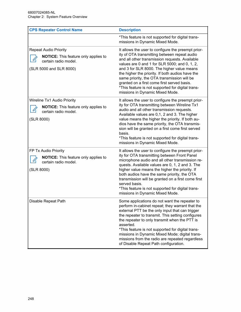
CPS Repeater Control Name Description
*This feature is not supported for digital trans-missions in Dynamic Mixed Mode.
Repeat Audio Priority
NOTICE: This feature only applies tocertain radio model.
(SLR 5000 and SLR 8000)
It allows the user to configure the preempt prior-ity of OTA transmitting between repeat audioand all other transmission requests. Availablevalues are 0 and 1 for SLR 5000; and 0, 1, 2,and 3 for SLR 8000. The higher value meansthe higher the priority. If both audios have thesame priority, the OTA transmission will begranted on a first come first served basis.*This feature is not supported for digital trans-missions in Dynamic Mixed Mode.
Wireline Tx1 Audio Priority
NOTICE: This feature only applies tocertain radio model.
(SLR 8000)
It allows the user to configure the preempt prior-ity for OTA transmitting between Wireline Tx1audio and all other transmission requests.Available values are 0,1, 2 and 3. The highervalue means the higher the priority. If both au-dios have the same priority, the OTA transmis-sion will be granted on a first come first servedbasis.*This feature is not supported for digital trans-missions in Dynamic Mixed Mode.
FP Tx Audio Priority
NOTICE: This feature only applies tocertain radio model.
(SLR 8000)
It allows the user to configure the preempt prior-ity for OTA transmitting between Front Panelmicrophone audio and all other transmission re-quests. Available values are 0, 1, 2 and 3. Thehigher value means the higher the priority. Ifboth audios have the same priority, the OTAtransmission will be granted on a first come firstserved basis.*This feature is not supported for digital trans-missions in Dynamic Mixed Mode.
Disable Repeat Path Some applications do not want the repeater toperform in-cabinet repeat; they warrant that theexternal PTT be the only input that can triggerthe repeater to transmit. This setting configuresthe repeater to only transmit when the PTT isasserted.*This feature is not supported for digital trans-missions in Dynamic Mixed Mode; digital trans-missions from the radio are repeated regardlessof Disable Repeat Path configuration.
68007024085-NLChapter 2: System Feature Overview
248
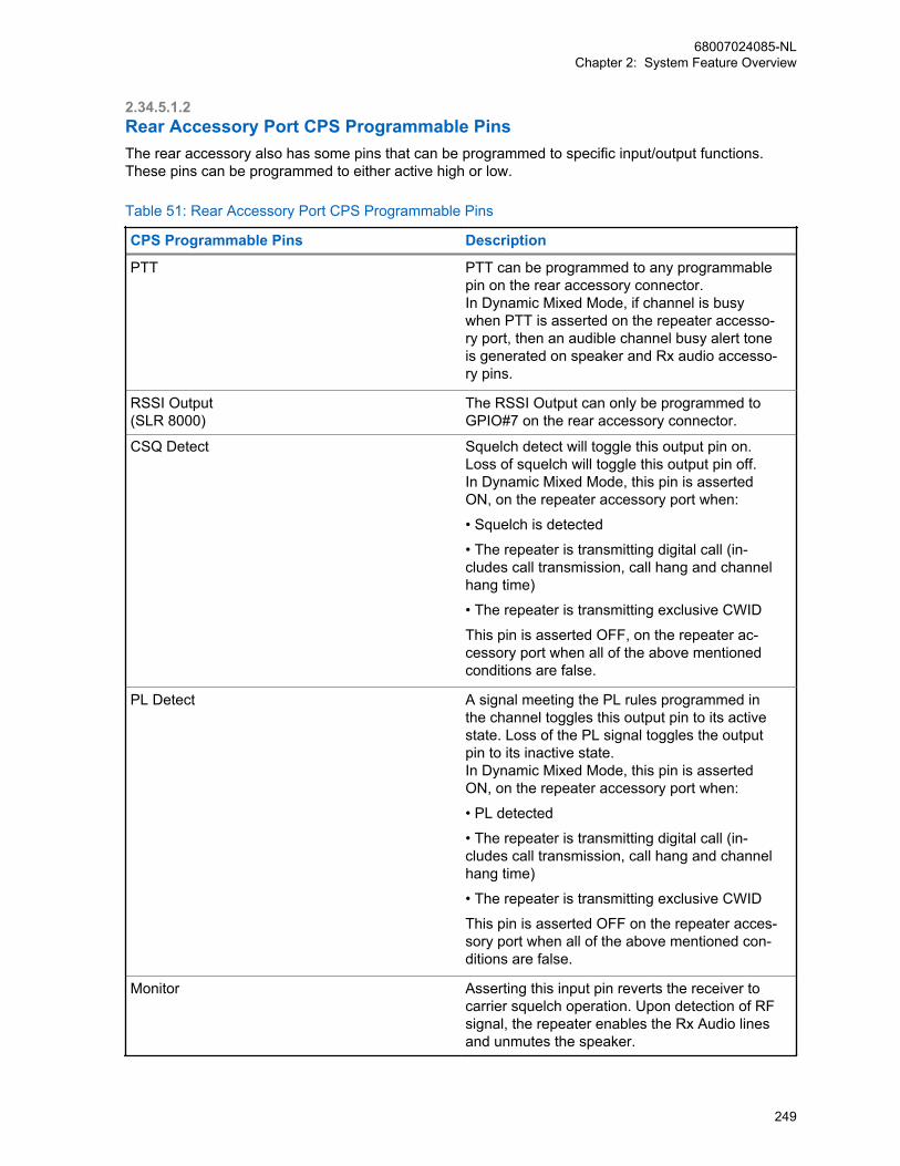
2.34.5.1.2Rear Accessory Port CPS Programmable PinsThe rear accessory also has some pins that can be programmed to specific input/output functions.These pins can be programmed to either active high or low.
Table 51: Rear Accessory Port CPS Programmable Pins
CPS Programmable Pins Description
PTT PTT can be programmed to any programmablepin on the rear accessory connector.In Dynamic Mixed Mode, if channel is busywhen PTT is asserted on the repeater accesso-ry port, then an audible channel busy alert toneis generated on speaker and Rx audio accesso-ry pins.
RSSI Output (SLR 8000)
The RSSI Output can only be programmed toGPIO#7 on the rear accessory connector.
CSQ Detect Squelch detect will toggle this output pin on.Loss of squelch will toggle this output pin off.In Dynamic Mixed Mode, this pin is assertedON, on the repeater accessory port when:
• Squelch is detected
• The repeater is transmitting digital call (in-cludes call transmission, call hang and channelhang time)
• The repeater is transmitting exclusive CWID
This pin is asserted OFF, on the repeater ac-cessory port when all of the above mentionedconditions are false.
PL Detect A signal meeting the PL rules programmed inthe channel toggles this output pin to its activestate. Loss of the PL signal toggles the outputpin to its inactive state.In Dynamic Mixed Mode, this pin is assertedON, on the repeater accessory port when:
• PL detected
• The repeater is transmitting digital call (in-cludes call transmission, call hang and channelhang time)
• The repeater is transmitting exclusive CWID
This pin is asserted OFF on the repeater acces-sory port when all of the above mentioned con-ditions are false.
Monitor Asserting this input pin reverts the receiver tocarrier squelch operation. Upon detection of RFsignal, the repeater enables the Rx Audio linesand unmutes the speaker.
68007024085-NLChapter 2: System Feature Overview
249

CPS Programmable Pins Description
In a Dynamic Mixed Mode repeater, the user isable to listen to the analog channel activity.However, for digital channel activity, the repeat-er will emit audible channel busy alert tone onspeaker and Rx audio accessory pins, but it willnot unmute to the actual digital channel activity.
Repeater Knockdown Asserting this input pin triggers the repeater totemporarily enter Repeat Path Disable Mode. Inthis mode, the repeater’s transmitter will only beenabled by the external PTT and the audiosource will be the Tx Audio Input pin.Releasing this input pin will revert the repeaterback to Normal Mode where the repeaterstransmitter can be activated by a qualified RFsignal on the receive frequency.
In Dynamic Mixed Mode, this feature is not sup-ported during an ongoing digital transmission.
Antenna Relay This output pin is used to drive an antenna re-lay switch for applications where the repeateracts as a dispatch station that will only receiveor transmit at a time. This allows the use of asingle antenna without the need of expensivecombining equipment. The pin toggles activewhen the repeater enters a transmit state, andreverts to inactive when the repeater dropsback to idle/receive.This feature is not supported in Digital and Dy-namic Mixed modes.
2.34.5.1.3Rear Accessory Port Fixed Audio PinsThe following table provides a description of the fixed audio pins on the rear accessory connector forthe DR 3000 which can be used in Digital Telephone Patch or Analog modes only.
Table 52: Rear Accessory Port Fixed Audio Pins for DR 3000
Fixed Pins Description
Speaker+/Speaker- Act as a differential pair and should be connect-ed at opposite ends of an audio speaker orequivalent load. Under rated conditions, theoutput voltage will be 7.75V RMS and the radiosupports impedances down to 4 ohms with dis-tortion typically less than 3%. Under no condi-tions should either of these two outputs be con-nected to ground.
Rx Audio Provides a line level audio output at 330 mVrmsunder rated conditions. The frequency responseof this output has been extended below 300 Hz
68007024085-NLChapter 2: System Feature Overview
250
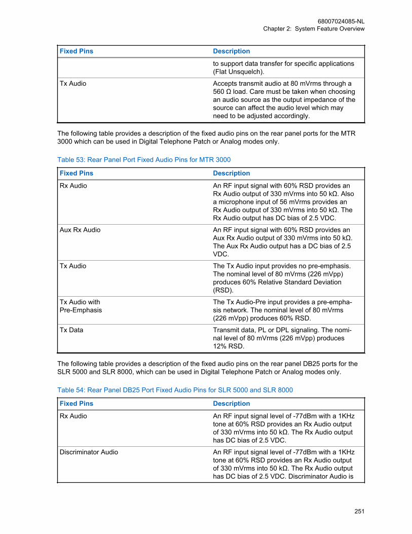
Fixed Pins Description
to support data transfer for specific applications(Flat Unsquelch).
Tx Audio Accepts transmit audio at 80 mVrms through a560 Ω load. Care must be taken when choosingan audio source as the output impedance of thesource can affect the audio level which mayneed to be adjusted accordingly.
The following table provides a description of the fixed audio pins on the rear panel ports for the MTR3000 which can be used in Digital Telephone Patch or Analog modes only.
Table 53: Rear Panel Port Fixed Audio Pins for MTR 3000
Fixed Pins Description
Rx Audio An RF input signal with 60% RSD provides anRx Audio output of 330 mVrms into 50 kΩ. Alsoa microphone input of 56 mVrms provides anRx Audio output of 330 mVrms into 50 kΩ. TheRx Audio output has DC bias of 2.5 VDC.
Aux Rx Audio An RF input signal with 60% RSD provides anAux Rx Audio output of 330 mVrms into 50 kΩ.The Aux Rx Audio output has a DC bias of 2.5VDC.
Tx Audio The Tx Audio input provides no pre-emphasis.The nominal level of 80 mVrms (226 mVpp)produces 60% Relative Standard Deviation(RSD).
Tx Audio with Pre-Emphasis
The Tx Audio-Pre input provides a pre-empha-sis network. The nominal level of 80 mVrms(226 mVpp) produces 60% RSD.
Tx Data Transmit data, PL or DPL signaling. The nomi-nal level of 80 mVrms (226 mVpp) produces12% RSD.
The following table provides a description of the fixed audio pins on the rear panel DB25 ports for theSLR 5000 and SLR 8000, which can be used in Digital Telephone Patch or Analog modes only.
Table 54: Rear Panel DB25 Port Fixed Audio Pins for SLR 5000 and SLR 8000
Fixed Pins Description
Rx Audio An RF input signal level of -77dBm with a 1KHztone at 60% RSD provides an Rx Audio outputof 330 mVrms into 50 kΩ. The Rx Audio outputhas DC bias of 2.5 VDC.
Discriminator Audio An RF input signal level of -77dBm with a 1KHztone at 60% RSD provides an Rx Audio outputof 330 mVrms into 50 kΩ. The Rx Audio outputhas DC bias of 2.5 VDC. Discriminator Audio is
68007024085-NLChapter 2: System Feature Overview
251

Fixed Pins Description
only available when the MPT 1327 box ischecked and it is always flat.
Tx Audio The nominal level of 80 mVrms (226 mVpp)produces 60% RSD with a 1KHz tone.
Tx Data Transmit data, PL or DPL signaling. The nomi-nal level of 80 mVrms (226 mVpp) produces12% RSD.
2.34.5.1.4Front Panel Audio Ports on the MTR3000
Front Panel Audio Ports on the MTR3000The following table provides a description of the front panel ports for the MTR3000.
Front Panel Ports Description
Speaker Output to Powered Voice speaker. Adjustablebetween 0 to 500 mVrms [1.4 Vpp] across 2.4kΩ @ 60% system deviation. Audio signal ap-pears between Pins 3 and 4 on the connector.Must use speaker type HSN1000 (older model)or HSN1006 via adapter cable Part.No.0185180U01.
NOTICE: The Speaker port is onlysupported in analog mode regardlessof the speaker used.
Microphone Local microphone Input. Use microphone typeGMN6147 (older model) or GMMN4063. Modu-lation sensitivity for 60% system deviation istypically 56 mVrms (158 mVpp).
NOTICE: The Mic port is only sup-ported in analog mode regardless ofthe Mic used. For older model of mi-crophone (GMN6147), the 3 controlbuttons for speaker volume control,Rx monitor and Intercom control func-tions are not supported.
2.34.5.1.5Front Panel Audio Ports on the SLR 8000
Front Panel Audio Ports on the SLR 8000The following table provides a description of the front panel ports for the SLR 8000.
Front Panel Ports Description
Speaker The front panel assembly contains an integrat-ed speaker which is controlled via the two front
68007024085-NLChapter 2: System Feature Overview
252
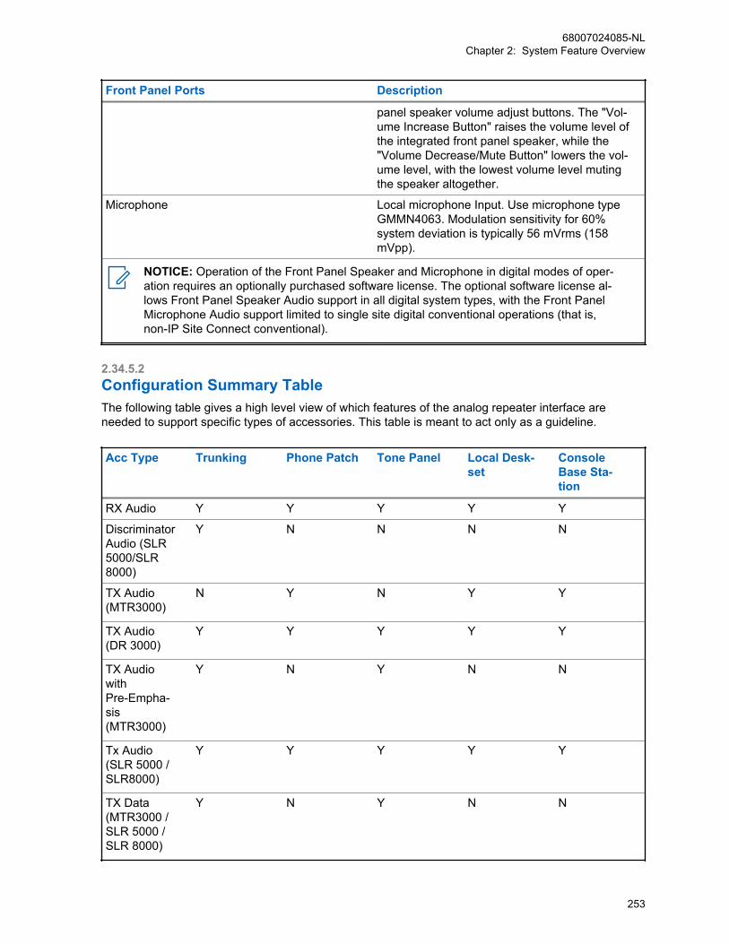
Front Panel Ports Description
panel speaker volume adjust buttons. The "Vol-ume Increase Button" raises the volume level ofthe integrated front panel speaker, while the"Volume Decrease/Mute Button" lowers the vol-ume level, with the lowest volume level mutingthe speaker altogether.
Microphone Local microphone Input. Use microphone typeGMMN4063. Modulation sensitivity for 60%system deviation is typically 56 mVrms (158mVpp).
NOTICE: Operation of the Front Panel Speaker and Microphone in digital modes of oper-ation requires an optionally purchased software license. The optional software license al-lows Front Panel Speaker Audio support in all digital system types, with the Front PanelMicrophone Audio support limited to single site digital conventional operations (that is,non-IP Site Connect conventional).
2.34.5.2Configuration Summary TableThe following table gives a high level view of which features of the analog repeater interface areneeded to support specific types of accessories. This table is meant to act only as a guideline.
Acc Type Trunking Phone Patch Tone Panel Local Desk-set
ConsoleBase Sta-tion
RX Audio Y Y Y Y Y
DiscriminatorAudio (SLR5000/SLR8000)
Y N N N N
TX Audio(MTR3000)
N Y N Y Y
TX Audio(DR 3000)
Y Y Y Y Y
TX Audiowith Pre-Empha-sis(MTR3000)
Y N Y N N
Tx Audio(SLR 5000 /SLR8000)
Y Y Y Y Y
TX Data(MTR3000 /SLR 5000 /SLR 8000)
Y N Y N N
68007024085-NLChapter 2: System Feature Overview
253

Acc Type Trunking Phone Patch Tone Panel Local Desk-set
ConsoleBase Sta-tion
Ext PTT Y Y Y Y Y
Disable Re-peat Path
Y N Y N Y
RepeaterKnockdown
NA Y NA Y NA
Monitor N Y N Y Y
PL Detect N O O O O
CSQ Detect O O O O O
Audio Type FLAT FILTERED FLAT FILTERED FILTERED
Analog Ac-cessory Em-phasis
NA O NA O O
Antenna Re-lay
NA NA NA O O
Y = This feature is necessary for the applicationN = This feature is not necessary for the application
O = This is an optional parameter for the application
NA = Not Applicable
2.34.5.3Configuration Considerations
2.34.5.3.1Analog Trunking Controllers and Community RepeatersMost analog trunking controllers and community repeaters will have two outputs that are to bemodulated by the repeater: voice audio, signaling data.
NOTICE: The MOTOTRBO DR 3000 repeater only accepts one audio input. Thus the twooutputs must first be mixed into a single input and dropped down to the audio level theMOTOTRBO repeater expects on the microphone port.
The microphone port is designed to transmit audio at 80mV RMS (220 mVp-p) through a 560 ohmload. Care must be taken when choosing an audio source as the output impedance of the source canaffect the audio level which may need to be adjusted accordingly.
When mixing the audio and signaling, care must also be taken to determine the expected deviation ofthe signaling. For example, in LTR controllers, the expected deviation of the LTR data is ~800Hz.Please refer to your controller’s user manual which gives guidance on how to tune the data signaloutput to achieve adequate data deviation.
Similar to existing cables, resistors can be placed on the cable to drop the level coming out from thecontroller (on the order of 1-2 Vp-p) to the level expected by the transmit audio pin. Once the resistorvalue is determined, the audio and signaling signals can be mixed into a single wire that can becrimped onto the MOTOTRBO accessory connector (Motorola Solutions Part Number PMLN5072_).
NOTICE: The MTR3000/SLR 5000/SLR8000 repeater has an audio transmit input and a datatransmit input that can be used with the two outputs on the analog trunking controllers andcommunity repeater panels (tone panel).
68007024085-NLChapter 2: System Feature Overview
254
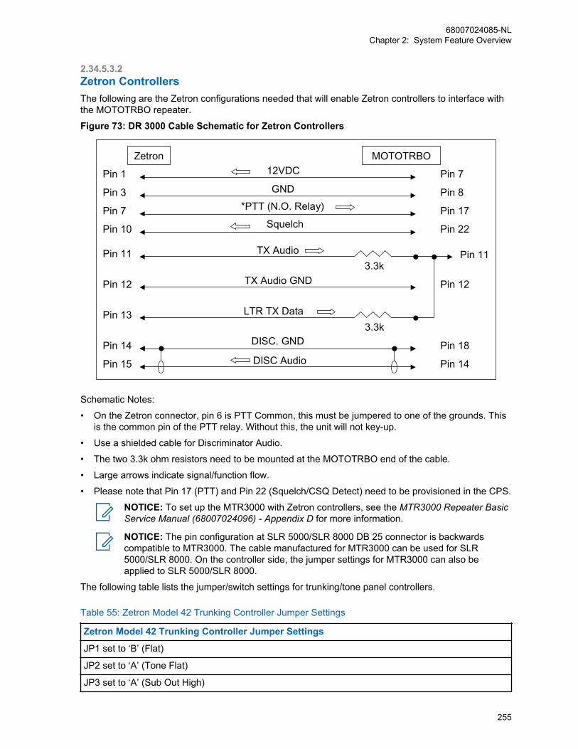
2.34.5.3.2Zetron ControllersThe following are the Zetron configurations needed that will enable Zetron controllers to interface withthe MOTOTRBO repeater.
Figure 73: DR 3000 Cable Schematic for Zetron Controllers
Pin 11
Pin 12
Pin 1
Pin 3
Pin 7
Pin 11
Pin 12
Pin 13
Pin 14
Pin 15
Pin 7
MOTOTRBO
Pin 8
Pin 17
Pin 18
Pin 14
Pin 22Pin 10
12VDC
3.3k
3.3k
GND
*PTT (N.O. Relay)
Squelch
TX Audio
TX Audio GND
LTR TX Data
DISC. GND
DISC Audio
Zetron
Schematic Notes:
• On the Zetron connector, pin 6 is PTT Common, this must be jumpered to one of the grounds. Thisis the common pin of the PTT relay. Without this, the unit will not key-up.
• Use a shielded cable for Discriminator Audio.
• The two 3.3k ohm resistors need to be mounted at the MOTOTRBO end of the cable.
• Large arrows indicate signal/function flow.
• Please note that Pin 17 (PTT) and Pin 22 (Squelch/CSQ Detect) need to be provisioned in the CPS.
NOTICE: To set up the MTR3000 with Zetron controllers, see the MTR3000 Repeater BasicService Manual (68007024096) - Appendix D for more information.
NOTICE: The pin configuration at SLR 5000/SLR 8000 DB 25 connector is backwardscompatible to MTR3000. The cable manufactured for MTR3000 can be used for SLR5000/SLR 8000. On the controller side, the jumper settings for MTR3000 can also beapplied to SLR 5000/SLR 8000.
The following table lists the jumper/switch settings for trunking/tone panel controllers.
Table 55: Zetron Model 42 Trunking Controller Jumper Settings
Zetron Model 42 Trunking Controller Jumper Settings
JP1 set to ‘B’ (Flat)
JP2 set to ‘A’ (Tone Flat)
JP3 set to ‘A’ (Sub Out High)
68007024085-NLChapter 2: System Feature Overview
255
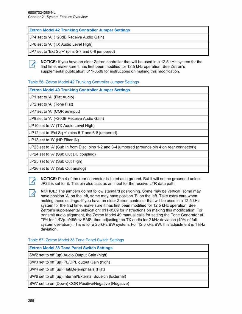
Zetron Model 42 Trunking Controller Jumper Settings
JP4 set to ‘A’ (+20dB Receive Audio Gain)
JP6 set to ‘A’ (TX Audio Level High)
JP7 set to ‘Ext Sq +’ (pins 5-7 and 6-8 jumpered)
NOTICE: If you have an older Zetron controller that will be used in a 12.5 kHz system for thefirst time, make sure it has first been modified for 12.5 kHz operation. See Zetron’ssupplemental publication: 011-0509 for instructions on making this modification.
Table 56: Zetron Model 42 Trunking Controller Jumper Settings
Zetron Model 49 Trunking Controller Jumper Settings
JP1 set to ‘A’ (Flat Audio)
JP2 set to ‘A’ (Tone Flat)
JP7 set to ‘A’ (COR as input)
JP9 set to ‘A’ (+20dB Receive Audio Gain)
JP10 set to ‘A’ (TX Audio Level High)
JP12 set to ‘Ext Sq +’ (pins 5-7 and 6-8 jumpered)
JP13 set to ‘B’ (HP Filter IN)
JP23 set to ‘A’ (Sub In from Disc: pins 1-2 and 3-4 jumpered (grounds pin 4 on rear connector))
JP24 set to ‘A’ (Sub Out DC coupling)
JP25 set to ‘A’ (Sub Out High)
JP26 set to ‘A’ (Sub Out analog)
NOTICE: Pin 4 of the rear connector is listed as a ground. But it will not be grounded unlessJP23 is set for it. This pin also acts as an input for the receive LTR data path.
NOTICE: The jumpers do not follow standard positioning. Some may be vertical, some mayhave position ‘A’ on the left, some may have position ‘B’ on the left. Take extra care whenmaking these settings. If you have an older Zetron controller that will be used in a 12.5 kHzsystem for the first time, make sure it has first been modified for 12.5 kHz operation. SeeZetron’s supplemental publication: 011-0509 for instructions on making this modification. Fortransmit audio alignment, the Zetron Model 49 manual calls for setting the Tone Generator atTP4 for 1.4Vp-p/495mv RMS, then adjusting the TX audio for 2 kHz deviation (40% of fullsystem deviation). This is for a 25 kHz BW system. For 12.5 kHz BW, this adjustment is 1 kHzdeviation.
Table 57: Zetron Model 38 Tone Panel Switch Settings
Zetron Model 38 Tone Panel Switch Settings
SW2 set to off (up) Audio Output Gain (high)
SW3 set to off (up) PL/DPL output Gain (high)
SW4 set to off (up) Flat/De-emphasis (Flat)
SW6 set to off (up) Internal/External Squelch (External)
SW7 set to on (Down) COR Positive/Negative (Negative)
68007024085-NLChapter 2: System Feature Overview
256
NOTICE: Tone Panel Programming Note - It may be necessary to set the generated DPL(DCS) signal to “Invert” from the tone panel to be recognized by the user radios. These DTMFcommands are 3750 for normal and 3751 for inverted signal generation.
Once the above cable and jumper/switch settings have been achieved, you should now be able to referto the specific controller product manual to complete installation.
2.34.5.3.3Trident ControllersTrident MicroSystems manufactures a cable that interfaces Trident Controllers with MOTOTRBOrepeaters and provides jumper settings for Trident Controllers.
NOTICE: The pin configuration at SLR 5000/SLR 8000 DB 25 connector is backwardscompatible to MTR3000. The Trident cable manufactured for MTR3000 can be used for SLR5000/SLR 8000. On the Trident controller side, the jumper settings for MTR3000 can also beapplied to SLR 5000/SLR 8000.
2.34.5.3.4Zetron M827/M807 ControllerIn addition to the Zetron controllers mentioned in the previous section, SLR 5000/SLR 8000 supportsZetron M827/M807 for the MPT 1327 analog trunking application.
Hardware ConnectionThe connections between the SLR Base Station/Repeater and the M827/M807 controller are facilitatedwith cable connected between the SLR 5000/SLR 8000 DB25 connector and that of the M827/M807controller. The connection cable provides the following signals:
• Transmit Data
• Transmit Audio
• Discriminator audio
• Push-to-talk (PTT)
• Carrier Operated Relay (COR)
• Ground
The connection diagram is illustrated in Figure 74: Hardware Connections between SLR 5000/SLR8000 and M827/M807 Controller on page 258.
68007024085-NLChapter 2: System Feature Overview
257
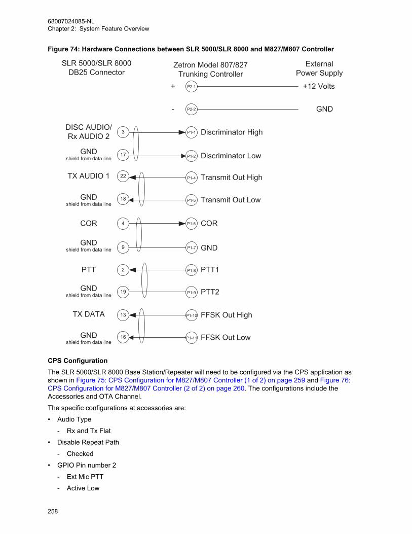
Figure 74: Hardware Connections between SLR 5000/SLR 8000 and M827/M807 Controller
P1-10
P1-1
P1-4
P1-5
Zetron Model 807/827Trunking Controller
FFSK Out High
Discriminator High
Transmit Out High
Transmit Out Low
3
13
22
18
SLR 5000/SLR 8000DB25 Connector
TX DATA
DISC AUDIO/Rx AUDIO 2
TX AUDIO 1
P1-8
P1-6
PTT1
COR
2
4
PTT
COR
P2-1+
P1-7 GND9
P1-11 FFSK Out Low16
P1-2 Discriminator Low17GNDshield from data line
P1-9 PTT2
P2-2-
19
ExternalPower Supply
+12 Volts
GND
GNDshield from data line
GNDshield from data line
GNDshield from data line
GNDshield from data line
CPS ConfigurationThe SLR 5000/SLR 8000 Base Station/Repeater will need to be configured via the CPS application asshown in Figure 75: CPS Configuration for M827/M807 Controller (1 of 2) on page 259 and Figure 76:CPS Configuration for M827/M807 Controller (2 of 2) on page 260. The configurations include theAccessories and OTA Channel.
The specific configurations at accessories are:
• Audio Type
- Rx and Tx Flat
• Disable Repeat Path
- Checked
• GPIO Pin number 2
- Ext Mic PTT
- Active Low
68007024085-NLChapter 2: System Feature Overview
258
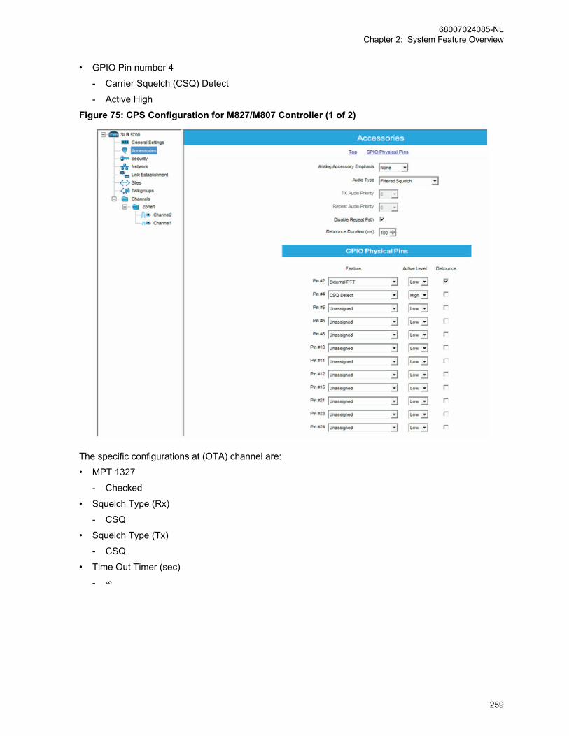
• GPIO Pin number 4
- Carrier Squelch (CSQ) Detect
- Active High
Figure 75: CPS Configuration for M827/M807 Controller (1 of 2)
The specific configurations at (OTA) channel are:
• MPT 1327
- Checked
• Squelch Type (Rx)
- CSQ
• Squelch Type (Tx)
- CSQ
• Time Out Timer (sec)
- ∞
68007024085-NLChapter 2: System Feature Overview
259
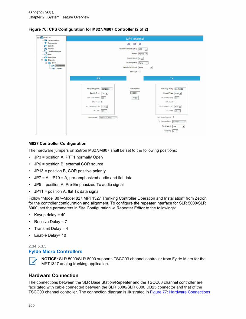
Figure 76: CPS Configuration for M827/M807 Controller (2 of 2)
M827 Controller ConfigurationThe hardware jumpers on Zetron M827/M807 shall be set to the following positions:
• JP3 = position A, PTT1 normally Open
• JP6 = position B, external COR source
• JP13 = position B, COR positive polarity
• JP7 = A; JP10 = A, pre-emphasized audio and flat data
• JP5 = position A, Pre-Emphasized Tx audio signal
• JP11 = position A, flat Tx data signal
Follow “Model 807–Model 827 MPT1327 Trunking Controller Operation and Installation” from Zetronfor the controller configuration and alignment. To configure the repeater interface for SLR 5000/SLR8000, set the parameters in Site Configuration -> Repeater Editor to the followings:
• Keyup delay = 40
• Receive Delay = 7
• Transmit Delay = 4
• Enable Delay= 10
2.34.5.3.5Fylde Micro Controllers
NOTICE: SLR 5000/SLR 8000 supports TSCC03 channel controller from Fylde Micro for theMPT1327 analog trunking application.
Hardware ConnectionThe connections between the SLR Base Station/Repeater and the TSCC03 channel controller arefacilitated with cable connected between the SLR 5000/SLR 8000 DB25 connector and that of theTSCC03 channel controller. The connection diagram is illustrated in Figure 77: Hardware Connections
68007024085-NLChapter 2: System Feature Overview
260
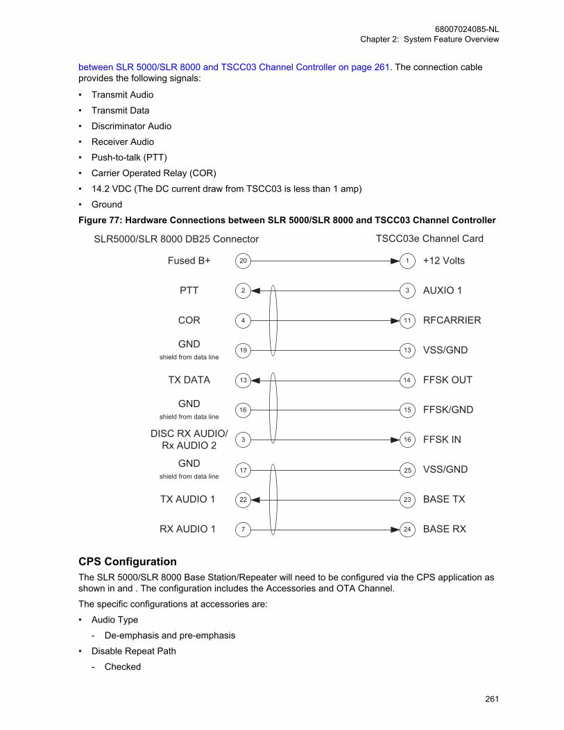
between SLR 5000/SLR 8000 and TSCC03 Channel Controller on page 261. The connection cableprovides the following signals:
• Transmit Audio
• Transmit Data
• Discriminator Audio
• Receiver Audio
• Push-to-talk (PTT)
• Carrier Operated Relay (COR)
• 14.2 VDC (The DC current draw from TSCC03 is less than 1 amp)
• Ground
Figure 77: Hardware Connections between SLR 5000/SLR 8000 and TSCC03 Channel Controller
14
16
23
24
TSCC03e Channel Card
FFSK OUT
FFSK IN
BASE TX
BASE RX
3
13
22
7
SLR5000/SLR 8000 DB25 Connector
TX DATA
DISC RX AUDIO/Rx AUDIO 2
TX AUDIO 1
RX AUDIO 1
3
11
AUXIO 1
RFCARRIER
2
4
PTT
COR
1 +12 Volts20Fused B+
13 VSS/GND19GND
shield from data line
15 FFSK/GND16GND
shield from data line
25 VSS/GND17GND
shield from data line
CPS ConfigurationThe SLR 5000/SLR 8000 Base Station/Repeater will need to be configured via the CPS application asshown in and . The configuration includes the Accessories and OTA Channel.
The specific configurations at accessories are:
• Audio Type
- De-emphasis and pre-emphasis
• Disable Repeat Path
- Checked
68007024085-NLChapter 2: System Feature Overview
261
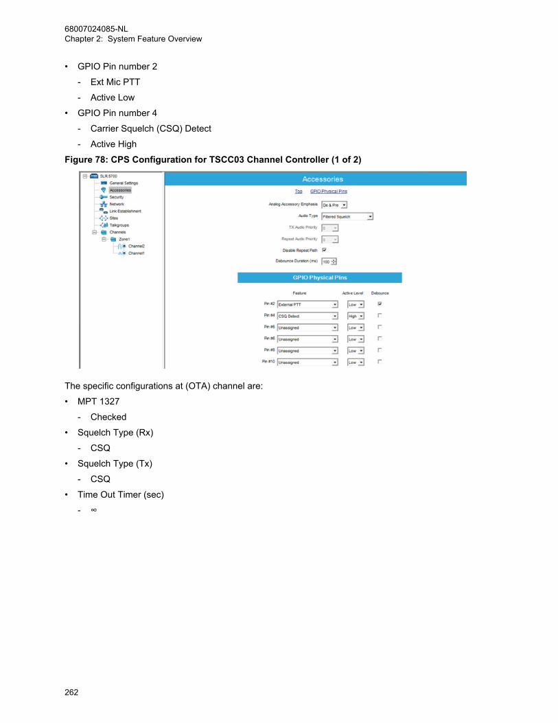
• GPIO Pin number 2
- Ext Mic PTT
- Active Low
• GPIO Pin number 4
- Carrier Squelch (CSQ) Detect
- Active High
Figure 78: CPS Configuration for TSCC03 Channel Controller (1 of 2)
The specific configurations at (OTA) channel are:
• MPT 1327
- Checked
• Squelch Type (Rx)
- CSQ
• Squelch Type (Tx)
- CSQ
• Time Out Timer (sec)
- ∞
68007024085-NLChapter 2: System Feature Overview
262

Figure 79: CPS Configuration for TSCC03 Channel Controller (2 of 2)
TSCC03 Channel Controller ConfigurationFor more information, see the Service and Operation Manual from Fylde for the channel controllerconfiguration and alignment.
NOTICE: To configure the repeater interface for SLR 5000/SLR 8000, the “override settings forMTR2000 base station” box must be checked in the field programmer menu.
2.34.6Auto-Range Transponder System Auto-Range Transponder System (ARTS) is now available in analog mode (direct or repeater) insoftware version R02.10.00. This feature informs radio users when their radio is out of range fromother ARTS-equipped radios.
ARTS uses automatic polling whereby the radio automatically transmits once every 25 or 55 secondsin an attempt to “shake hands” with another ARTS-equipped radio. When a radio receives an incomingARTS signal, a short in range tone sounds and an “In Range” message is shown on the radio. If aradio is out of range for more than two minutes, a short out of range tone sounds and an “Out ofRange” message is shown on the radio. When radios return in range from out of range, a short inrange tone sounds and an “In Range” message appears again on the radio to notify the user.
The Auto-Range Transponder System (ARTS) feature has three operating modes:
• Transmit ModeThe radio only transmits polling signals to connect with other radios. The radio does not receivesignals and therefore does not notify the radio user of its own range status.
• Receive ModeThe radio only receives polling signals to be notified when in range or out of range. The radio doesnot transmit polling signals to connect with other radios.
68007024085-NLChapter 2: System Feature Overview
263
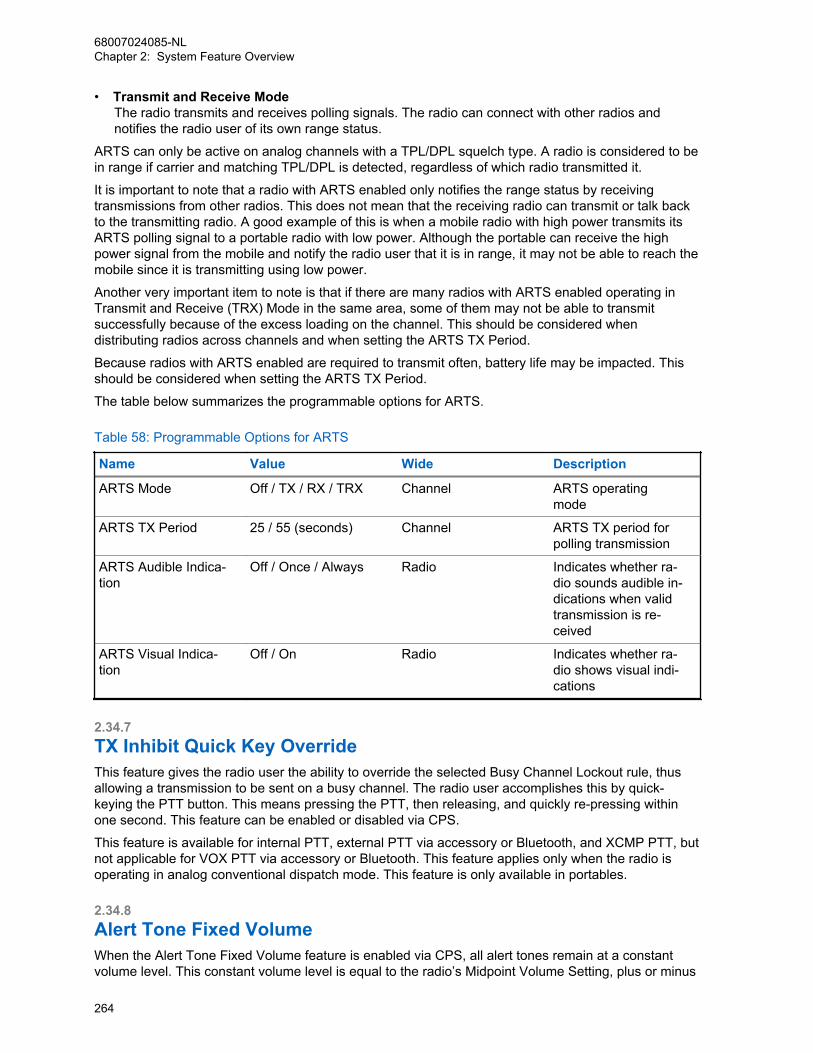
• Transmit and Receive ModeThe radio transmits and receives polling signals. The radio can connect with other radios andnotifies the radio user of its own range status.
ARTS can only be active on analog channels with a TPL/DPL squelch type. A radio is considered to bein range if carrier and matching TPL/DPL is detected, regardless of which radio transmitted it.
It is important to note that a radio with ARTS enabled only notifies the range status by receivingtransmissions from other radios. This does not mean that the receiving radio can transmit or talk backto the transmitting radio. A good example of this is when a mobile radio with high power transmits itsARTS polling signal to a portable radio with low power. Although the portable can receive the highpower signal from the mobile and notify the radio user that it is in range, it may not be able to reach themobile since it is transmitting using low power.
Another very important item to note is that if there are many radios with ARTS enabled operating inTransmit and Receive (TRX) Mode in the same area, some of them may not be able to transmitsuccessfully because of the excess loading on the channel. This should be considered whendistributing radios across channels and when setting the ARTS TX Period.
Because radios with ARTS enabled are required to transmit often, battery life may be impacted. Thisshould be considered when setting the ARTS TX Period.
The table below summarizes the programmable options for ARTS.
Table 58: Programmable Options for ARTS
Name Value Wide Description
ARTS Mode Off / TX / RX / TRX Channel ARTS operatingmode
ARTS TX Period 25 / 55 (seconds) Channel ARTS TX period forpolling transmission
ARTS Audible Indica-tion
Off / Once / Always Radio Indicates whether ra-dio sounds audible in-dications when validtransmission is re-ceived
ARTS Visual Indica-tion
Off / On Radio Indicates whether ra-dio shows visual indi-cations
2.34.7TX Inhibit Quick Key OverrideThis feature gives the radio user the ability to override the selected Busy Channel Lockout rule, thusallowing a transmission to be sent on a busy channel. The radio user accomplishes this by quick-keying the PTT button. This means pressing the PTT, then releasing, and quickly re-pressing withinone second. This feature can be enabled or disabled via CPS.
This feature is available for internal PTT, external PTT via accessory or Bluetooth, and XCMP PTT, butnot applicable for VOX PTT via accessory or Bluetooth. This feature applies only when the radio isoperating in analog conventional dispatch mode. This feature is only available in portables.
2.34.8Alert Tone Fixed VolumeWhen the Alert Tone Fixed Volume feature is enabled via CPS, all alert tones remain at a constantvolume level. This constant volume level is equal to the radio’s Midpoint Volume Setting, plus or minus
68007024085-NLChapter 2: System Feature Overview
264

the Alert Tone Volume Offset setting. The volume level for alert tones then remains constant, evenwhen the radio’s volume knob is adjusted.
This does not affect tone volumes that are automatically adjusted by the radio, for example, whenQuik-Call II Call Alert, Escalate, and Intelligent Audio features are enabled. This feature is onlyavailable in portables, and both analog and digital modes.
2.34.9Alert Tone Auto ResetThe Call Alert tone is normally a repetitive alert tone.
This feature enables the radio to generate only one sequence of the Call Alert tone when the radiodecodes a Digital, MDC, or Quik-Call II Call Alert. The Call Alert tone duration can be configured viaCPS from 0 (∞) second to 1200 seconds by a 5-second increment. If the Infinity (∞) option is selected,the Call Alert tone continuously sounds until the user cancels the Call Alert indication.
This is a radio-wide feature available in analog and digital modes. This feature is only applicable if theDisable All Tones feature is disabled.
2.34.10Emergency Permanent Sticky RevertThis feature enables the radio to remain permanently on the Emergency Revert Personality after theemergency transmission has been sent and acknowledged. The radio must be powered off for it toreturn to the selected channel on the Channel Selector.
Any mode change – analog vote scan, scan and auto scan will not work while the radio is operating onthe Emergency Sticky Revert Channel. The radio can still receive MDC and Quik-Call II Call Alerts orSelective Calls, but cannot initiate them.
This feature can be enabled or disabled via CPS and is only available in portable radios.
.
68007024085-NLChapter 2: System Feature Overview
265

Chapter 3
System Components And TopologiesIPSC
Indicates IP Site Connect feature related content.
CPSSIndicates Capacity Plus Single Site feature related content.
CPMSIndicates Capacity Plus Multi Site feature related content.
CPSMIndicates Capacity Plus Single Site AND Capacity Plus Multi Siteshared feature related content.
3.1System ComponentsMOTOTRBO consists of numerous components and applications that function together in a system.The first step in designing a system that satisfies the customer’s needs is identifying the devices andapplications within the system, and then choosing a basic system configuration of how thesecomponents will be interconnected. This section defines the different components and applicationsavailable, their offered services, and their roles in the system. Some of the standard system topologiesthat MOTOTRBO supports are described.
All data application modules contained in this system planner are depictions of typical third-party dataapplication modules and have been included simply to illustrate certain MOTOTRBO applicationenabling features.
3.1.1Fixed End ComponentsThe system contains devices with fixed locations and other devices that are mobile. This subsectioncovers the devices with fixed locations.
3.1.1.1RepeaterThe MOTOTRBO repeater provides an RF interface to the field subscribers.
The repeater is AC and DC-powered and designed to be discreetly mounted on a standard 19” rackfound in most communication tower locations. It offers front panel indicators of its current statusincluding real time transmit and receive indicators for each time slot. Once configured through theCustomer Programming Software (CPS), the repeater is designed to operate behind the scenes andwithout the need for further user interaction.
The repeater can either be configured as a standalone repeater or as a repeater connected to a back-end network, as in the case of IP Site Connect, Capacity Plus Single Site, and Capacity Plus Multi Sitemodes. As a repeater, it listens on one uplink frequency, and then re-transmits on a downlinkfrequency. Therefore a pair of RF frequencies is required for each repeater in the system.
68007024085-NLChapter 3: System Components And Topologies
266
A major advantage of using a repeater in the system is that it allows a greater communication rangethan would be possible talking from subscriber to subscriber. Multiple repeaters can be installed instrategic locations for the users’ coverage to be consistent throughout their required range ofoperation. However, only in IP Site Connect mode, do the radios seamlessly roam between repeaters.In digital repeater mode, the users must know the coverage range provided by each repeater, andmanually switch channels when necessary.
The repeater is capable of operating in either digital mode, analog mode, or in Dynamic Mixed Mode.This is determined at the initial configuration, and is not updated dynamically. Therefore at any giventime, it either operates as a digital repeater, as an analog repeater, or as a Dynamic Mixed Moderepeater.
When configured for analog operation, the repeater is designed to operate with existing analogsystems, therefore making migration to a MOTOTRBO system smoother.
When configured for digital operation, the repeater offers additional services. The digital repeateroperates in TDMA mode, which essentially divides one channel into two virtual channels using timeslots; therefore the user capacity is doubled. The repeater utilizes embedded signaling to inform thefield radios of the busy/idle status of each channel (time slot), the type of traffic, and even the sourceand destination information.
Another advantage during digital operation is error detection and correction. The further a transmissiontravels, the more predominant the interference becomes, and inevitably more errors are introduced.The receiving MOTOTRBO radio, operating in digital mode, utilizes built-in error detection andcorrection algorithms, native to the protocol, to correct these problems. The MOTOTRBO repeateruses the same algorithms to correct the errors prior to retransmission, thus repairing any errors thatoccur on the uplink; it then transmits the repaired signal on the downlink. This greatly increases thereliability and audio quality in the system, which increases the customer’s coverage area.
In digital mode, the repeater only retransmits digital signals from radios configured with the samesystem identifier. This aids in preventing co-system interference. The repeater does not blocktransmissions of radios within its own system.
As previously described, the repeater utilizes embedded signaling to announce the current status ofeach channel. It is up to the radios in the field to interpret these signals, and grant or deny their user’srequest for transmission. Therefore, when a user or a group of users utilizes a channel (time slot), therepeater announces that the channel is being used and who is using it. Only radios that are part of thatgroup are allowed to transmit. The repeater additionally allows a short duration of reserved time after atransmission. This allows other users in the group to respond to the originator. This reserved hang timegreatly improves the continuity of calls, because new calls cannot start until the previous call ends.Without this feature, users may experience delays in responses (that is, between transmissions ofcalls), due to other calls taking over the channel in-between their transmissions.
After this reserved hang time, the repeater continues to monitor for a short period. If no user transmitson the channel for a duration of time, the repeater stops transmitting. When the next radio transmissionoccurs, the repeater begins repeating again.
In Dynamic Mixed Mode, the repeater dynamically switches between analog and digital calls. When arepeater repeats a new digital call that starts on one of the logical channels, the repeater does notqualify any analog call including an Emergency Call until the digital call (both the transmission and callhang time) is over and the corresponding channel hang time has expired. Upon the expiry of channelhang time, only then does the repeater start qualifying both analog and digital calls simultaneously.Similarly, if an analog call is being repeated, the repeater does not qualify any digital call includingdigital data and Emergency Calls on any of the two logical channels until the analog call is over and thecorresponding hang time has expired.
The repeater 4-wire interface and over-the-air digital calls are polite to each other. If the PTT button orknockdown GPIO pin is asserted on the repeater 4-wire interface while a digital transmission is
68007024085-NLChapter 3: System Components And Topologies
267
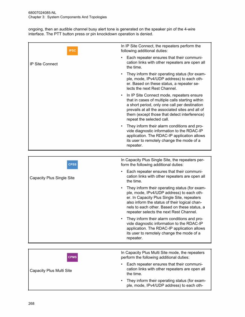
ongoing, then an audible channel busy alert tone is generated on the speaker pin of the 4-wireinterface. The PTT button press or pin knockdown operation is denied.
IPSC
IP Site Connect
In IP Site Connect, the repeaters perform thefollowing additional duties:
• Each repeater ensures that their communi-cation links with other repeaters are open allthe time.
• They inform their operating status (for exam-ple, mode, IPv4/UDP address) to each oth-er. Based on these status, a repeater se-lects the next Rest Channel.
• In IP Site Connect mode, repeaters ensurethat in cases of multiple calls starting withina short period, only one call per destinationprevails at all the associated sites and all ofthem (except those that detect interference)repeat the selected call.
• They inform their alarm conditions and pro-vide diagnostic information to the RDAC-IPapplication. The RDAC-IP application allowsits user to remotely change the mode of arepeater.
CPSS
Capacity Plus Single Site
In Capacity Plus Single Site, the repeaters per-form the following additional duties:
• Each repeater ensures that their communi-cation links with other repeaters are open allthe time.
• They inform their operating status (for exam-ple, mode, IPv4/UDP address) to each oth-er. In Capacity Plus Single Site, repeatersalso inform the status of their logical chan-nels to each other. Based on these status, arepeater selects the next Rest Channel.
• They inform their alarm conditions and pro-vide diagnostic information to the RDAC-IPapplication. The RDAC-IP application allowsits user to remotely change the mode of arepeater.
CPMS
Capacity Plus Multi Site
In Capacity Plus Multi Site mode, the repeatersperform the following additional duties:
• Each repeater ensures that their communi-cation links with other repeaters are open allthe time.
• They inform their operating status (for exam-ple, mode, IPv4/UDP address) to each oth-
68007024085-NLChapter 3: System Components And Topologies
268
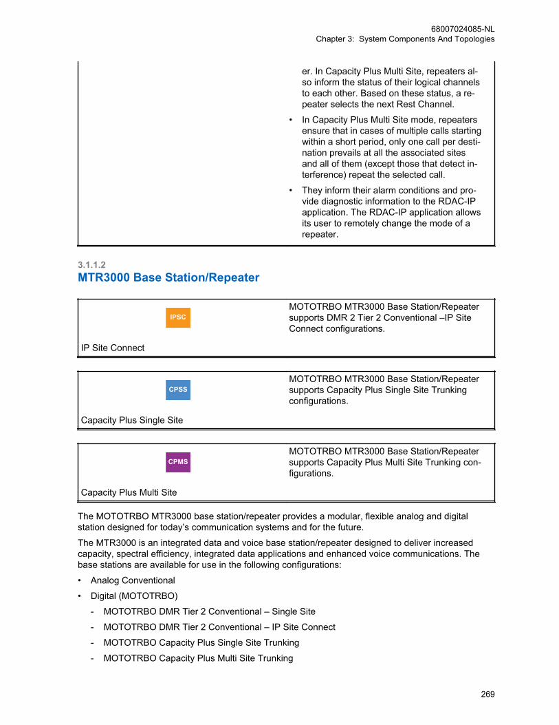
er. In Capacity Plus Multi Site, repeaters al-so inform the status of their logical channelsto each other. Based on these status, a re-peater selects the next Rest Channel.
• In Capacity Plus Multi Site mode, repeatersensure that in cases of multiple calls startingwithin a short period, only one call per desti-nation prevails at all the associated sitesand all of them (except those that detect in-terference) repeat the selected call.
• They inform their alarm conditions and pro-vide diagnostic information to the RDAC-IPapplication. The RDAC-IP application allowsits user to remotely change the mode of arepeater.
3.1.1.2MTR3000 Base Station/Repeater
IPSC
IP Site Connect
MOTOTRBO MTR3000 Base Station/Repeatersupports DMR 2 Tier 2 Conventional –IP SiteConnect configurations.
CPSS
Capacity Plus Single Site
MOTOTRBO MTR3000 Base Station/Repeatersupports Capacity Plus Single Site Trunkingconfigurations.
CPMS
Capacity Plus Multi Site
MOTOTRBO MTR3000 Base Station/Repeatersupports Capacity Plus Multi Site Trunking con-figurations.
The MOTOTRBO MTR3000 base station/repeater provides a modular, flexible analog and digitalstation designed for today’s communication systems and for the future.
The MTR3000 is an integrated data and voice base station/repeater designed to deliver increasedcapacity, spectral efficiency, integrated data applications and enhanced voice communications. Thebase stations are available for use in the following configurations:
• Analog Conventional
• Digital (MOTOTRBO)
- MOTOTRBO DMR Tier 2 Conventional – Single Site
- MOTOTRBO DMR Tier 2 Conventional – IP Site Connect
- MOTOTRBO Capacity Plus Single Site Trunking
- MOTOTRBO Capacity Plus Multi Site Trunking
68007024085-NLChapter 3: System Components And Topologies
269
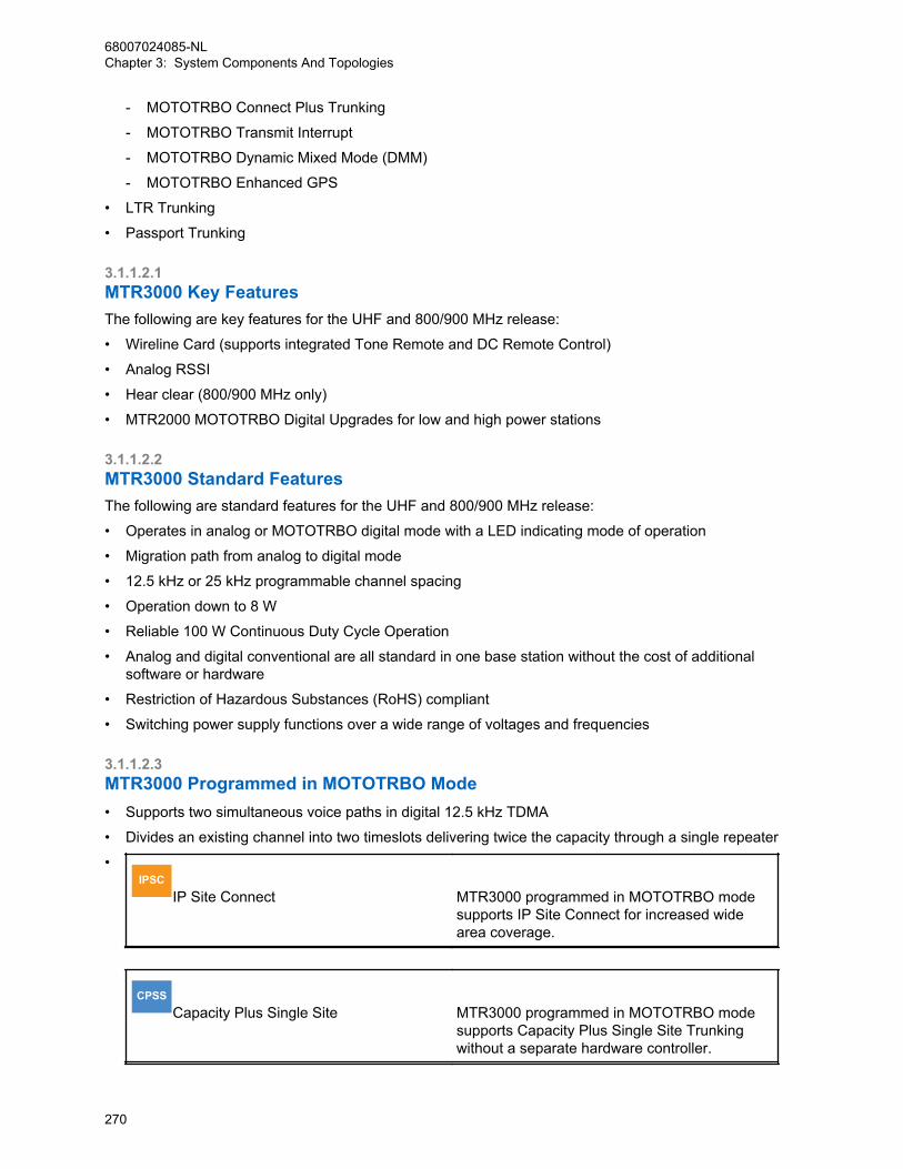
- MOTOTRBO Connect Plus Trunking
- MOTOTRBO Transmit Interrupt
- MOTOTRBO Dynamic Mixed Mode (DMM)
- MOTOTRBO Enhanced GPS
• LTR Trunking
• Passport Trunking
3.1.1.2.1MTR3000 Key FeaturesThe following are key features for the UHF and 800/900 MHz release:
• Wireline Card (supports integrated Tone Remote and DC Remote Control)
• Analog RSSI
• Hear clear (800/900 MHz only)
• MTR2000 MOTOTRBO Digital Upgrades for low and high power stations
3.1.1.2.2MTR3000 Standard FeaturesThe following are standard features for the UHF and 800/900 MHz release:
• Operates in analog or MOTOTRBO digital mode with a LED indicating mode of operation
• Migration path from analog to digital mode
• 12.5 kHz or 25 kHz programmable channel spacing
• Operation down to 8 W
• Reliable 100 W Continuous Duty Cycle Operation
• Analog and digital conventional are all standard in one base station without the cost of additionalsoftware or hardware
• Restriction of Hazardous Substances (RoHS) compliant
• Switching power supply functions over a wide range of voltages and frequencies
3.1.1.2.3MTR3000 Programmed in MOTOTRBO Mode• Supports two simultaneous voice paths in digital 12.5 kHz TDMA
• Divides an existing channel into two timeslots delivering twice the capacity through a single repeater
•IPSC
IP Site Connect MTR3000 programmed in MOTOTRBO modesupports IP Site Connect for increased widearea coverage.
CPSSCapacity Plus Single Site MTR3000 programmed in MOTOTRBO mode
supports Capacity Plus Single Site Trunkingwithout a separate hardware controller.
68007024085-NLChapter 3: System Components And Topologies
270
CPMSCapacity Plus Multi Site MTR3000 programmed in MOTOTRBO mode
supports Capacity Plus Multi Site Trunkingwithout a separate hardware controller.
• Supports MOTOTRBO Dynamic Mixed Mode to facilitate your analog-to-digital migration inconventional repeater applications
• Supports MOTOTRBO Transmit Interrupt for greater subscriber unit control and flexibility
3.1.1.2.4MTR3000 Serviceability• Repeater diagnostic and control software provides remote or local site monitoring
• Easy to replace components with functionally separate Field Replaceable Units (FRU)
• Software-based design simplifies feature upgrades
• Easy access to station ports (no need to remove the front panel) shortening installation andmaintenance time
• For ease of installation, minimal station alignment is needed
• Supported by Motorola Solutions 2-year standard warranty
3.1.1.2.5Total Cost of Ownership• Analog Conventional, Digital Conventional are standard in one base station without the cost of
additional software
• Twice the spectral efficiency; one frequency pair provides two logical voice paths
• Effectively twice the power efficiency as compared to two analog stations when operating in digitalmode
• Integrated Components optimizes expensive site space; one physical station provides the capacityof two in digital mode
3.1.1.2.6Wireline Interface BoardThe MTR3000 Wireline board is used to connect an analog audio source and sink (such as a console)to the MTR3000 Base Station/Repeater. The Wireline board supports Tone and DC.
Remote Control modes that allow for channel selection and PTT signaling from compatible consoles.Local PTT operation is also supported. The Wireline can be configured for either 2-wire or 4-wireoperation as needed.
The table below provides a description of the impedance supported by the Wireline board.
Option Functionality
High Impedance For use with an external impedance matching
600 Ω For Argentina, Canada, Chile, Columbia, Ecua-dor, El Salvador, Guam, Hong Kong, India, In-donesia, Japan, Jordan, Kazakhstan, Kuwait,Macao, Malaysia, Mexico, Oman, Pakistan, Pe-ru, Philippines, Russia, Saudi Arabia, Singa-
68007024085-NLChapter 3: System Components And Topologies
271
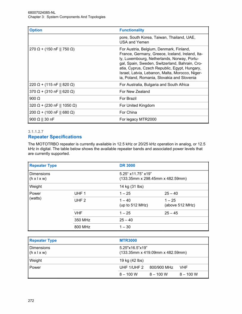
Option Functionality
pore, South Korea, Taiwan, Thailand, UAE,USA and Yemen
270 Ω + (150 nF || 750 Ω) For Austria, Belgium, Denmark, Finland,France, Germany, Greece, Iceland, Ireland, Ita-ly, Luxembourg, Netherlands, Norway, Portu-gal, Spain, Sweden, Switzerland, Bahrain, Cro-atia, Cyprus, Czech Republic, Egypt, Hungary,Israel, Latvia, Lebanon, Malta, Morocco, Niger-ia, Poland, Romania, Slovakia and Slovenia
220 Ω + (115 nF || 820 Ω) For Australia, Bulgaria and South Africa
370 Ω + (310 nF || 620 Ω) For New Zealand
900 Ω For Brazil
320 Ω + (230 nF || 1050 Ω) For United Kingdom
200 Ω + (100 nF || 680 Ω) For China
900 Ω || 30 nF For legacy MTR2000
3.1.1.2.7Repeater SpecificationsThe MOTOTRBO repeater is currently available in 12.5 kHz or 20/25 kHz operation in analog, or 12.5kHz in digital. The table below shows the available repeater bands and associated power levels thatare currently supported.
Repeater Type DR 3000
Dimensions(h x l x w)
5.25“ x11.75” x19”(133.35mm x 298.45mm x 482.59mm)
Weight 14 kg (31 lbs)
Power(watts)
UHF 1 1 – 25 25 – 40
UHF 2 1 – 40(up to 512 MHz)
1 – 25(above 512 MHz)
VHF 1 – 25 25 – 45
350 MHz 25 – 40
800 MHz 1 – 30
Repeater Type MTR3000
Dimensions(h x l x w)
5.25"x16.5”x19”(133.35mm x 419.09mm x 482.59mm)
Weight 19 kg (42 lbs)
Power UHF 1/UHF 2 800/900 MHz VHF
8 – 100 W 8 – 100 W 8 – 100 W
68007024085-NLChapter 3: System Components And Topologies
272

3.1.1.3MTR3000 Satellite ReceiverThe MTR3000 Satellite Receiver, unlike the base station/repeater, – provides a modular, flexibleanalog and digital station designed for today's communication systems and for the future. It is designedto eliminate “dead zones” in a communications system by improving the “talk-in” coverage on aparticular receive frequency when used in a receiver voting system.
Like the Base Station/Repeater, the Satellite Receiver is divided into functional modules that separatethe frequency band specific functions (for example, RF receive) from that of non-frequency specificfunctions (for example, station control, user audio and GPIO interface, power system, and others).
The satellite receiver is divided into functional modules that separate the frequency band specific andcontrol circuits. These modules are self-contained functional blocks with module-specific alarms. Thisdesign facilitates the field replaceable unit (FRU) concept of field repair to maximize system uptime.
The satellite receiver (T7713A) contains the following:
• Receiver Module
• Station Control Module
• Power Supply Module
• Backplane Board
• Wireline Board (standard)
NOTICE: The MTR3000 Satellite Receiver does not contain a transmitter, however, the RDACapplication is supported in local and remote network connections. support any transmittersubsystems or digital communications functionality. However, the RDAC application issupported in local and remote network connections.
3.1.1.3.1Satellite Receiver SystemTypically, the satellite receiver connects to a Spectra-TAC™ or a DigiTAC™ comparator. Figure 80: Satellite Receiver Connections Within a Voting System on page 274 shows a typical votingsystem and the connections of the satellite receivers.
68007024085-NLChapter 3: System Components And Topologies
273

Figure 80: Satellite Receiver Connections Within a Voting System
Control Console Comparator
Dispatch Site
Phone Line
Phone Line
Phone Line
R2
R2
R2
R2
T1
Repeater
Phone Line
Satellite Receiver
Satellite Receiver
Satellite Receiver
3.1.1.4SLR 5000 Series Repeater
NOTICE: This feature is supported only by specific product model.
IPSC
IP Site Connect
MOTOTRBO SLR 5000 Series Repeater sup-ports DMR Tier 2 Conventional – IP Site Con-nect configurations.
CPSS
Capacity Plus Single Site
MOTOTRBO SLR 5000 Series Repeater sup-ports Capacity Plus Single Site Trunking config-urations
68007024085-NLChapter 3: System Components And Topologies
274

CPMS
Capacity Plus Multi Site
MOTOTRBO SLR 5000 Series Repeater sup-ports Capacity Plus Multi SiteTrunking configu-rations.
The SLR 5000 Series is Motorola Solutions Next-Generation integrated voice and data MOTOTRBORepeater designed to meet the needs of professional and commercial radio operators. It offerssignificant improvements in Reliability, Performance and Serviceability in a more Eco-friendly design.The SLR 5000 will reuse much of the MOTOTRBO Suite of tools such as Customer ProgrammingSoftware (CPS) and Remote Diagnostics and Control (RDAC) that today's customers are alreadyfamiliar with, and will support all the features and functionality of today's XPR/XiR/DGR/DR products.
Figure 81: SLR 5000 Series Repeater
The Motorola Solutions SLR 5000 Series Repeater provides a modular, flexible analog and digitalstation designed for today's communication systems and for the future. The station is available for usein the following configurations:
• Analog Conventional
• Digital (MOTOTRBO)
- MOTOTRBO DMR Tier 2 Conventional – Single Site
- MOTOTRBO DMR Tier 2 Conventional – IP Site Connect
- MOTOTRBO Capacity Plus Single Site Trunking
- MOTOTRBO Capacity Plus Multi Site Trunking
- MOTOTRBO Connect Plus Trunking
- MOTOTRBO Capacity Max Trunking
- MOTOTRBO Digital Voting
• LTR Trunking
• Passport Trunking
• MPT1327 Trunking
The SLR 5000 series can either be configured as a stand-alone repeater or as a repeater connected toa back-end network, as in the case of operating in IP Site Connect mode. As a repeater, it listens onone uplink frequency, and then re-transmits on a downlink frequency, thus providing the RF interface tothe field subscribers. When configured for analog station operation, the repeater is designed to operatewith most existing analog systems, which enables a smooth migration to the MOTOTRBO system.
68007024085-NLChapter 3: System Components And Topologies
275
When configured for digital operation, the repeater offers additional services. The digital repeateroperates in TDMA mode, which essentially divides one channel into two virtual channels using timeslots; therefore the user capacity is doubled. The repeater utilizes embedded signaling to inform thefield radios of the busy/idle status of each channel (time slot), the type of traffic, and even the sourceand destination information.
The SLR 5000 series facilitates the field replaceable unit (FRU) concept of field repair to maximizesystem uptime. The FRU concept also aids in allowing the end user/ maintainer to lower their inventorycosts. The base model SLR 5000 series FRUs are as follows:
• Modem FRU
• Power Amplifier FRU
• Power Supply FRU
• Front Panel FRU
For more details on the FRUs, see the Basic Service and Installation Manual.
3.1.1.4.1Operating FeaturesThe following are the standard features of an SLR 5000 series model:
• MOTOTRBO Conventional Operation (2-Slot TDMA, 4FSK Modulation)
• Analog Conventional Operation (FM)
• 1 – 50 W Continuous Duty Cycle Operation over -30 °C to +60 °C
• Meets or exceeds the following standards:
- TIA603D
- ETSI 086
- ETSI 113
- ETSI TS 102 361-1 Part 1: DMR Air Interface Protocol
- ETSI TS 102 361-2 Part 2: DMR Voice and Generic Services and Facilities
- ETSI TS 102 361-3 Part 3: DMR Packet Data Protocol
• AMBE +2™ Digital VOCODER
• Synthesized Frequency Generation
• Female N-type Antenna Connector (Tx)
• Female BNC Antenna Connector (Rx)
• Ethernet Port (Network)
• Front mounted USB Port (Service)
• 12 configurable GPIO ports (Digital)
• 4 configurable GPI ports (Analog, Not Supported in Initial Release)
• 2 configurable GPO ports (Analog, Not Supported in Initial Release)
• Power for third-party controllers (1 Amp)
• 1.5 PPM Frequency Stability (Temperature AND 1-Year Aging) (VHF and UHF)
• External Reference Capability
• Real-Time Clock with rechargeable backup battery
• Switching Power Supply operates from 85 – 264 VAC (47 – 63 Hz)
• Multi-Power Source configurable (AC, DC, or AC with Battery Revert)
68007024085-NLChapter 3: System Components And Topologies
276
• Integrated 3 A battery charger
• Station Diagnostic Tests – Fixed Set of Tests run upon Start-up
• Physical Dimensions: 1.75" H x 19" W x 14.6" D (44 x 483 x 370 mm) 1RU
• Weight: 19 pounds (8.62 kg) excluding cabinet or other peripheral equipment
Network Application Interface:
• IP Site Connect
• Repeater Diagnostics and Control (RDAC)
• Capacity Plus Single Site
• Capacity Plus Multi Site
• Connect Plus
Third-Party Controller Interface:
• Phone Patch
• Multi Coded Squelch Interface (Repeater Panel)
• Tone Remote Adapter
• LTR Trunking
• Passport Trunking
• MPT1327 Trunking
In addition, the following features are also included. These features are shipped in a presetcondition, but may be altered through the use of the CPS.
• 64 Tx/Rx Frequencies – Factory Programmed with 1 Tx, 1 Rx
• 12.5 kHz or 25 kHz Operation – Factory Programmed to 12.5 kHz
• 1 Tx and 1 Rx (PL or DPL) Squelch Code per channel – Factory Programmed to CSQ
• Base Station Identification (BSI) – Factory Programmed as “BLANK” (“BLANK” disables BSI)
• Push-To-Talk (PTT) Priority – Factory Programmed to Repeat Path
3.1.1.5SLR 8000 Series Repeater
NOTICE: This feature is supported only by specific product model.
IPSC
IP Site Connect
MOTOTRBO SLR 8000 Series Repeater sup-ports DMR Tier 2 Conventional – IP Site Con-nect configurations.
CPSS
Capacity Plus Single Site
MOTOTRBO SLR 8000 Series Repeater sup-ports Capacity Plus Single Site Trunking config-urations.
68007024085-NLChapter 3: System Components And Topologies
277
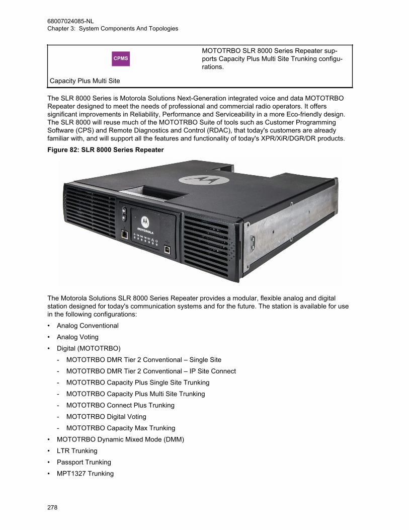
CPMS
Capacity Plus Multi Site
MOTOTRBO SLR 8000 Series Repeater sup-ports Capacity Plus Multi Site Trunking configu-rations.
The SLR 8000 Series is Motorola Solutions Next-Generation integrated voice and data MOTOTRBORepeater designed to meet the needs of professional and commercial radio operators. It offerssignificant improvements in Reliability, Performance and Serviceability in a more Eco-friendly design.The SLR 8000 will reuse much of the MOTOTRBO Suite of tools such as Customer ProgrammingSoftware (CPS) and Remote Diagnostics and Control (RDAC), that today's customers are alreadyfamiliar with, and will support all the features and functionality of today's XPR/XiR/DGR/DR products.
Figure 82: SLR 8000 Series Repeater
The Motorola Solutions SLR 8000 Series Repeater provides a modular, flexible analog and digitalstation designed for today's communication systems and for the future. The station is available for usein the following configurations:
• Analog Conventional
• Analog Voting
• Digital (MOTOTRBO)
- MOTOTRBO DMR Tier 2 Conventional – Single Site
- MOTOTRBO DMR Tier 2 Conventional – IP Site Connect
- MOTOTRBO Capacity Plus Single Site Trunking
- MOTOTRBO Capacity Plus Multi Site Trunking
- MOTOTRBO Connect Plus Trunking
- MOTOTRBO Digital Voting
- MOTOTRBO Capacity Max Trunking
• MOTOTRBO Dynamic Mixed Mode (DMM)
• LTR Trunking
• Passport Trunking
• MPT1327 Trunking
68007024085-NLChapter 3: System Components And Topologies
278
The SLR 8000 series can either be configured as a stand-alone repeater or as a repeater connected toa back-end network, as in the case of operating in IP Site Connect mode. As a repeater, it listens onone uplink frequency, and then re-transmits on a downlink frequency, thus providing the RF interface tothe field subscribers. When configured for analog station operation, the repeater is designed to operatewith most existing analog systems, which enables a smooth migration to the MOTOTRBO system.
When configured for digital operation, the repeater offers additional services. The digital repeateroperates in TDMA mode, which essentially divides one channel into two virtual channels using timeslots; therefore the user capacity is doubled. The repeater utilizes embedded signaling to inform thefield radios of the busy/idle status of each channel (time slot), the type of traffic, and even the sourceand destination information.
The SLR 8000 series facilitates the field replaceable unit (FRU) concept of field repair to maximizesystem uptime. The FRU concept also aids in allowing the end user/ maintainer to lower their inventorycosts. The SLR 8000 series repeater supports an optional Wireline Board FRU. The Wireline boardsupports Tone Remote Control and DC Remote Control, E&M control, and analog voting modes. Thebase model SLR 8000 series FRUs are as follows:
• Modem FRU
• Power Amplifier FRU
• Power Supply FRU
• Front Panel FRU
For more details on the FRUs, see the Basic Service and Installation Manual.
3.1.1.5.1Operating FeaturesThe following are the standard features of an SLR 8000 series model:
• MOTOTRBO Conventional Operation (2-Slot TDMA, 4FSK Modulation)
• Analog Conventional Operation (FM)
• 1 – 100 W Continuous Duty Cycle Operation over -30 °C to +60 °C
• Meets or exceeds the following standards:
- TIA603D
- ETSI 086
- ETSI 113
- ETSI TS 102 361-1 Part 1: DMR Air Interface Protocol
- ETSI TS 102 361-2 Part 2: DMR Voice and Generic Services and Facilities
- ETSI TS 102 361-3 Part 3: DMR Packet Data Protocol
• AMBE +2™ Digital VOCODER
• Synthesized Frequency Generation
• Female N-type Antenna Connector (Tx)
• Female BNC Antenna Connector (Rx)
• Ethernet Port (Network)
• Front mounted USB Port (Service)
• 12 configurable GPIO ports (Digital)
• 4 configurable GPI ports (Analog, Not Supported in Initial Release)
• 2 configurable GPO ports (Analog, Not Supported in Initial Release)
68007024085-NLChapter 3: System Components And Topologies
279

• Power for third-party controllers (1 Amp)
• 1.5 PPM Frequency Stability (Temperature AND 1-Year Aging) (VHF and UHF)
• Wireline Capability
• External Reference Capability
• Real-Time Clock with rechargeable backup battery
• Switching Power Supply operates from 100 – 240 VAC (47 – 63 Hz)
• Dual DC Power Supply Systems 12 V or 24 V
• Multi-Power Source configurable (AC, DC, or AC with Battery Revert)
• Integrated 5 A battery charger
• Station Diagnostic Tests – Fixed Set of Tests run upon Start-up
• Physical Dimensions: 3.5" H x 19" W x 17.3" D (89 x 483 x 438 mm) 1RU
• Weight: 31 pounds (14.06 kg) excluding cabinet or other peripheral equipment
Network Application Interface:
• IP Site Connect
• Repeater Diagnostics and Control (RDAC)
• Capacity Plus Single Site
• Capacity Plus Multi Site
• Connect Plus
Third-Party Controller Interface:
• Phone Patch
• Multi Coded Squelch Interface (Repeater Panel)
• Tone Remote Adapter
• LTR Trunking
• Passport Trunking
• MPT1327 Trunking
Optionally, the SLR 8000 repeater may be configured with the following:
• Internal Pre-selector
• Antenna Relay
• Duplexer
• External Dual Circulator Tray
• Integrated Tone Remote Control (with Wireline option)
• Integrated DC Remote Control (with Wireline option)
• Integrated E&M Remote Control (with Wireline option)
• Analog Voting (with Wireline option)
• Simplex operation (Tx=Rx)
In addition, the following features are also included. These features are shipped in a preset condition,but may be altered through the use of the CPS.
• 64 Tx/Rx Frequencies – Factory Programmed with 1 Tx, 1 Rx
• 12.5 kHz or 25 kHz Operation – Factory Programmed to 12.5 kHz
• 1 Tx and 1 Rx (PL or DPL) Squelch Code per channel – Factory Programmed to CSQ
68007024085-NLChapter 3: System Components And Topologies
280

• Base Station Identification (BSI) – Factory Programmed as “BLANK” (“BLANK” disables BSI)
• Push-To-Talk (PTT) Priority – Factory Programmed to Repeat Path
• Local Digital Audio via front panel microphone and speaker
3.1.1.6Satellite Receiver and Voting RepeaterA satellite receiver is required when digital voting is enabled in the system. The satellite receiver is aRF receiver-only device used to extend the repeaters’ inbound range.
The device functions to receive over-the-air transmission from the radios, forwards the transmissionover an IP link to the voting repeater. The voting repeater then “votes” on all the transmissionsreceived from all its receivers, including its internal receiver and all its satellite receivers, based on thequality of the bursts. The voted result is then repeated over the air, and other sites or applications.
NOTICE: The satellite receivers reuse repeater hardware; the following repeaters may be usedas satellite receivers:
• MOTOTRBO 32 MB Repeaters (MTR3000 and DR 3000 Series)
• SLR 1000/SLR 5000/SLR 8000 Series
• MTR3000 Receiver only boxes
The regular receive-and-transmit repeater with a built-in voting capability is usually called a votingrepeater. Therefore there is no additional voting device in the system. The voting process is a softwaremodule built inside the voting repeater. The following repeaters can be used as voting repeaters:
• MOTOTRBO 32 MB Repeaters (MTR3000 and DR 3000 Series)
• SLR 5000/SLR 8000 Series
3.1.1.7Radio Control StationThe MOTOTRBO Control Station is based on the MOTOTRBO Mobile, except that it is configured tobe the RF link from the data Application Server to the repeater and other radios.
The MOTOTRBO Control Station is integrated with an AC power supply and appropriate housing to beplaced on a desk. Since it is the radio gateway to the server, it is configured to transmit and receive ona single channel. It is programmed with a known radio ID, so that field radios know how to contact theserver. In a MOTOTRBO system, there can be up to 16 control stations connected via four USB ports;each control station communicates through a separate logical channel, that is a TDMA slot.
In most cases, the Control Station is externally controlled by the PC. It requires no user interactiononce programmed. However, if a situation requires the use of a control station to transmit voice, it iscapable of transmitting voice as well.
CPSMCapacity Plus Single Site and Capacity
Plus Multi Site
Capacity Plus Single Site or Capacity Plus MultiSite configurations with Data Revert Channelsrequires a set of control stations to route datafrom radios to the Server and another set ofcontrol stations to route data from the Server toradios. Control stations operating in convention-al mode (called Revert Control Stations) areused for routing data messages from radios to adata Application Server. Alternatively, controlstations operating in Capacity Plus Single Siteor Capacity Plus Multi Site modes (calledTrunked Control Stations) are used for routing
68007024085-NLChapter 3: System Components And Topologies
281
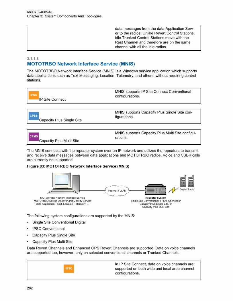
data messages from the data Application Serv-er to the radios. Unlike Revert Control Stations,idle Trunked Control Stations move with theRest Channel and therefore are on the samechannel with all the idle radios.
3.1.1.8MOTOTRBO Network Interface Service (MNIS)The MOTOTRBO Network Interface Service (MNIS) is a Windows service application which supportsdata applications such as Text Messaging, Location, Telemetry, and others, without requiring controlstations.
IPSCIP Site Connect
MNIS supports IP Site Connect Conventionalconfigurations.
CPSSCapacity Plus Single Site
MNIS supports Capacity Plus Single Site con-figurations.
CPMSCapacity Plus Multi Site
MNIS supports Capacity Plus Multi Site configu-rations.
The MNIS connects with the repeater system over an IP network and utilizes the repeaters to transmitand receive data messages between data applications and MOTOTRBO radios. Voice and CSBK callsare currently not supported.
Figure 83: MOTOTRBO Network Interface Service (MNIS)
Internet / WAN
Repeater SystemSingle Site Conventional, IP Site Connect or
Capacity Plus Single Site, orCapacity Plus Multi Site
Digital Radio
MOTOTRBO Network Interface ServiceMOTOTRBO Device Discover and Mobility Service
Data Application - Text, Location, Telemetry, ...
The following system configurations are supported by the MNIS:
• Single Site Conventional Digital
• IPSC Conventional
• Capacity Plus Single Site
• Capacity Plus Multi Site
Data Revert Channels and Enhanced GPS Revert Channels are supported. Data on voice channelsare supported too, however, only on selected conventional channels or Trunked Channels.
IPSCIn IP Site Connect, data on voice channels aresupported on both wide and local area channelconfigurations.
68007024085-NLChapter 3: System Components And Topologies
282
IP Site Connect
The following MOTOTRBO data features are supported by MNIS:
• Layer 2 confirmed and unconfirmed data message delivery
• Individual and Group data messages
• Basic, Enhanced, and AES Privacy
• Data message IP/UDP header compression
• Data Precedence and Data Over Voice Interrupt access priority
The MNIS supports MOTOTRBO data applications, including Text Messaging, Location, Telemetry,Third-Party Raw Data, and OTAP with CPS. The MNIS requires the MOTOTRBO Device Discoveryand Mobility Service application (DDMS), formerly called the MOTOTRBO Presence Notifier, for radioARS.
There are several benefits of selecting MNIS over control stations, particularly when the controlstations are used only by data applications. Some of the benefits include:
• The deployment is simpler compared to using control stations, because control stations and otherassociated hardware such as power supplies, antennae, and others are not required.
• Previously, data revert channels were required to be wide area in order for the data messages to berouted to the site where the control stations are located. Now, MNIS allows a centralized dataapplication to access local Data Revert Channels at all remote sites. The former wide area DataRevert Channel can now be split into multiple local Data Revert Channels, which routes data to thecentralized data application via MNIS, thus allowing higher data throughput from each remote site.
• MNIS connectivity with the system can be monitored via RDAC.
However, there are a few considerations to take note of:
• The MNIS does not support Dynamic Mixed Mode system configuration.
• The repeater’s “Network Application Interface for Data” feature must be enabled to allow the MNISto interface with the repeater.
• The MNIS does not support L2 fragmented data. Ensure that the largest data size [Data Message +IP/UDP Header] transmitted from the radio is less than the Max TX PDU Size configured in theradios.
• The MNIS software is available on the MOTOTRBO MOL website.
3.1.1.9MC1000, MC2000, MC2500 Console
NOTICE: This feature is supported only by specific product model.
The MOTOTRBO mobile in analog mode supports the MC Deskset Series of consoles. The MCDeskset Series provides a complete portfolio of products for a small control room. Each unit providescontrol of the radio(s) via a compact desk unit offering a choice of control methods: Local and Remote.The portfolio ranges from a simple talk and listen unit to a miniature multi-channel console.
The MC1000 can control a single control station, and provides a selection of up to four frequencies.This unit requires no software for programming.
The MC2000 can also control a single control station, but provides a selection of up to 16 frequencies.Programming this unit is through configuration software installed on a PC.
The MC2500 controls up to four control stations, with the ability to patch and multi-select channels. Allchannels are capable of 16 frequency controls. This unit is programmed through configuration softwareinstalled on a PC.
68007024085-NLChapter 3: System Components And Topologies
283
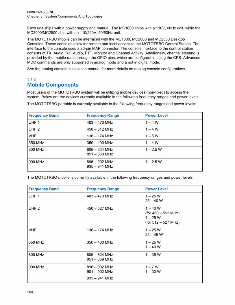
Each unit ships with a power supply and manual. The MC1000 ships with a 110V, 60Hz unit, while theMC2000/MC2500 ship with an 110/220V, 50/60Hz unit.
The MOTOTRBO mobile can be interfaced with the MC1000, MC2000 and MC2500 DesktopConsoles. These consoles allow for remote and local access to the MOTOTRBO Control Station. Theinterface to the console uses a 26-pin MAP connector. The console interface to the control stationconsists of TX_Audio, RX_Audio, PTT, Monitor and Channel Activity. Additionally, channel steering isprovided by the mobile radio through the GPIO pins, which are configurable using the CPS. AdvancedMDC commands are only supported in analog mode and a not in digital mode.
See the analog console installation manual for more details on analog console configurations.
3.1.2Mobile ComponentsMost users of the MOTOTRBO system will be utilizing mobile devices (non-fixed) to access thesystem. Below are the devices currently available in the following frequency ranges and power levels.
The MOTOTRBO portable is currently available in the following frequency ranges and power levels:
Frequency Band Frequency Range Power Level
UHF 1 403 – 470 MHz 1 – 4 W
UHF 2 450 – 512 MHz 1 – 4 W
VHF 136 – 174 MHz 1 – 5 W
350 MHz 350 – 400 MHz 1 – 4 W
800 MHz 806 – 824 MHz851 – 869 MHz
1 – 2.5 W
900 MHz 896 – 902 MHz935 – 941 MHz
1 – 2.5 W
The MOTOTRBO mobile is currently available in the following frequency ranges and power levels:
Frequency Band Frequency Range Power Level
UHF 1 403 – 470 MHz 1 – 25 W25 – 40 W
UHF 2 450 – 527 MHz 1 – 40 W (for 450 – 512 MHz)1 – 25 W (for 512 – 527 MHz)
VHF 136 – 174 MHz 1 – 25 W25 – 45 W
350 MHz 350 – 400 MHz 1 – 25 W1 – 40 W
800 MHz 806 – 824 MHz851 – 869 MHz
1 – 35 W
900 MHz 896 – 902 MHz901 – 902 MHz
935 – 941 MHz
1 – 7 W1 – 30 W
68007024085-NLChapter 3: System Components And Topologies
284
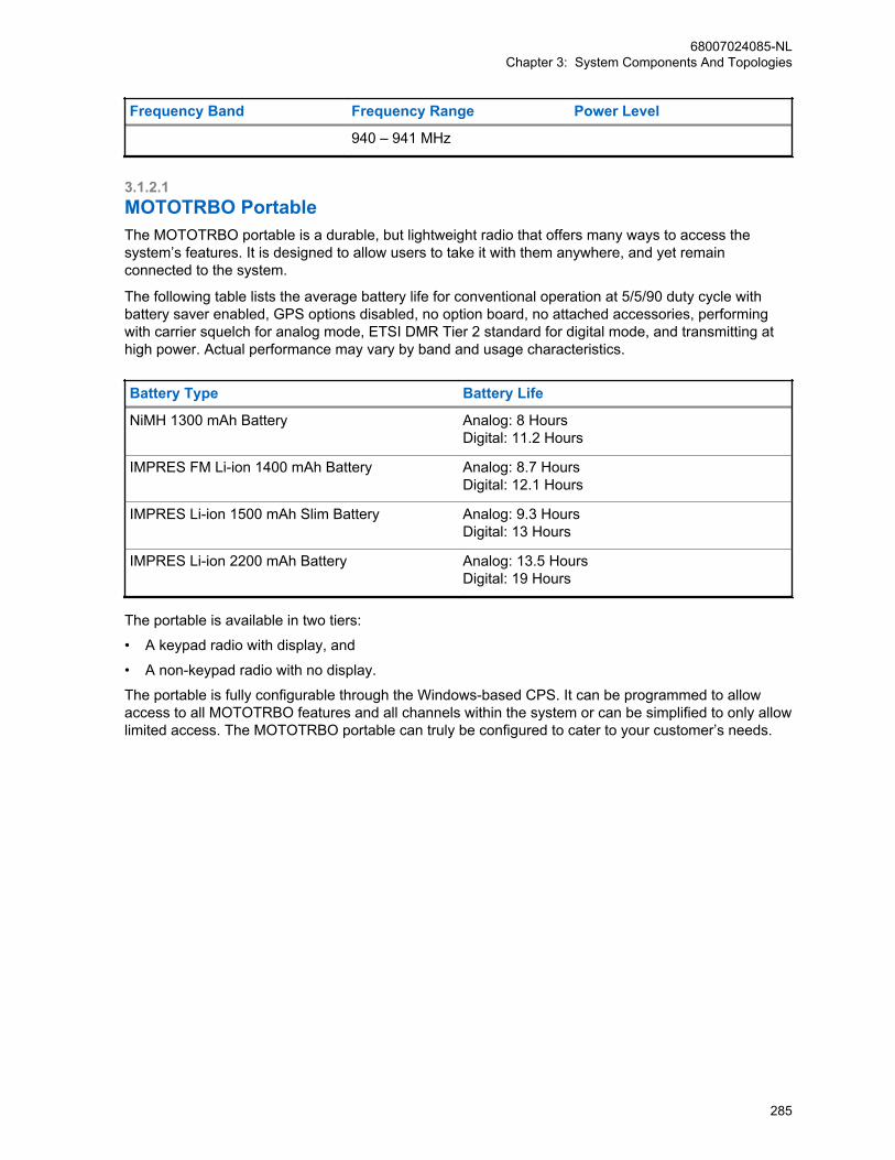
Frequency Band Frequency Range Power Level
940 – 941 MHz
3.1.2.1MOTOTRBO PortableThe MOTOTRBO portable is a durable, but lightweight radio that offers many ways to access thesystem’s features. It is designed to allow users to take it with them anywhere, and yet remainconnected to the system.
The following table lists the average battery life for conventional operation at 5/5/90 duty cycle withbattery saver enabled, GPS options disabled, no option board, no attached accessories, performingwith carrier squelch for analog mode, ETSI DMR Tier 2 standard for digital mode, and transmitting athigh power. Actual performance may vary by band and usage characteristics.
Battery Type Battery Life
NiMH 1300 mAh Battery Analog: 8 HoursDigital: 11.2 Hours
IMPRES FM Li-ion 1400 mAh Battery Analog: 8.7 HoursDigital: 12.1 Hours
IMPRES Li-ion 1500 mAh Slim Battery Analog: 9.3 HoursDigital: 13 Hours
IMPRES Li-ion 2200 mAh Battery Analog: 13.5 HoursDigital: 19 Hours
The portable is available in two tiers:
• A keypad radio with display, and
• A non-keypad radio with no display.
The portable is fully configurable through the Windows-based CPS. It can be programmed to allowaccess to all MOTOTRBO features and all channels within the system or can be simplified to only allowlimited access. The MOTOTRBO portable can truly be configured to cater to your customer’s needs.
68007024085-NLChapter 3: System Components And Topologies
285

3.1.2.1.1User InterfaceFigure 84: MOTOTRBO Portable (Display Model)
1
2
4
5
6
7
8
9
10
11
12
13
14
15
16
17
3
68007024085-NLChapter 3: System Components And Topologies
286

Figure 85: MOTOTRBO Portable (Non-Display Model)
1
2
4
5
6
7
8
9
10
11
12
3
The primary buttons of the MOTOTRBO portable offer the user the ability to initiate most systemfeatures. These buttons and switches should be very familiar to radio users.
3.1.2.1.1.1Push-to-Talk ButtonThe large round Push-To-Talk button, or PTT button, is the primary button used to initiate voicetransmissions. Its location is on the left side of the portable, but is still easy to reach for both right-handed or left-handed users. The button is raised from the side and has a raised pattern, so that it iseasily found even under low light conditions. Pressing the PTT button starts a voice transmission onthe selected channel. This enables the user to simply push and talk.
3.1.2.1.1.2Channel Selector KnobThe MOTOTRBO portable user chooses his communication environment by twisting the 16-positionchannel knob on the top of the portable radio. This Channel Selector Knob is the main way a user usesto access the system. It also has a raised pattern, so it too is easy to find under low light conditions.
68007024085-NLChapter 3: System Components And Topologies
287
Although easy to find, it is designed to require some force to turn it, so as not to be accidentally rotatedthrough normal user activities. Each knob position can be programmed to access a different channelwithin the radio’s programming. This allows the user to quickly switch between analog and digitalchannels and even different groups.
But the user is not limited to 16 channels. Up to 16 channels can be placed into a zone, and thenswitched between multiple zones. This greatly increases the number of available channels to the user.
3.1.2.1.1.3Programmable ButtonsThere are programmable buttons on the MOTOTRBO portable. The display portable has sixprogrammable buttons, while the non-display portable only has four programmable buttons. Eachbutton can be programmed to perform a particular function. The short press and long press can beprogrammed to act differently. The orange button located on the top of the radio is commonly used toinitiate emergency alarms, although it can be configured to function differently.
3.1.2.1.1.4Status IndicatorsThere are a few different ways to provide feedback to the user.
Depending on its color and state, a large tri-colored LED on the top of the radio indicates whether theradio is transmitting or receiving, and whether the selected channel is busy or idle. The LED busyindication represents the presence of RF activity on the selected channel and is not specific to thedigital slot currently being monitored. The MOTOTRBO keypad portable with display also has a two-line LCD that displays a wide variety of information including received signal strength, battery power,emergency status, received text message indicator, monitor on/off, and GPS status. This display alsoallows each channel name to be displayed, so that the user knows the name of the selected channel.The source ID and target group alias are also displayed. User names are kept in an address book. Thisallows the user to assign user-friendly names as aliases to a radio ID. Various alert tones, talk permittones and keypad tones are also available to give additional audio feedback to the user.
3.1.2.1.1.5Menu SystemIn addition to accessing system features through buttons, the MOTOTRBO keypad portable withdisplay offers a menu shown on its two line LCD display. With use of a menu button, left and rightarrow buttons, a back/home button, and an OK button for selection, users can easily navigate throughthe following additional features.
• Contacts
• Scan
• Messages
• Call Logs
• Utilities
For further details on these menus, see the MOTOTRBO portable user manual.
68007024085-NLChapter 3: System Components And Topologies
288
3.1.2.1.1.6Full KeypadThe MOTOTRBO keypad portable with display offers a full numeric keypad for users to manually entertarget addresses for system features. This keypad is also used as an alphanumeric keyboard for textmessaging. The non-display portable does not come with a keypad.
3.1.2.1.2Voice Feature SupportWith use of the MOTOTRBO portable interface, the user has access to all the voice features theMOTOTRBO system has to offer. These features include Group Calls, Private Calls, All Calls, andEmergency Calls.
3.1.2.1.3Command and Control Feature SupportCommand and control system features like Radio Check, Call Alert, Remote Monitor, Radio Enable/Disable are all accessible from the MOTOTRBO portable user interface.
3.1.2.1.4Analog CompatibilityThe radios can be programmed to support many current analog system features. Supported analogfeatures include:
• Analog communications on a 12.5/20/25 kHz channel (as standard),
• Private-Line (PL) and Digital Private-Line (DPL) coded squelch control (as standard),
• MDC signaling.
3.1.2.1.5Integrated GPS Antenna and ReceiverThe MOTOTRBO portable can contain an internal GPS receiver that works with the Location Services /Tracking Data Application. The location application and radio can be configured so that the radiotransmits its location to a centralized application. The GPS antenna is integrated into the main antennaof the portable. In the LCD display on the radio, an icon indicates if the radio is in range of the GPSsatellites.
3.1.2.1.6Text Messaging CompatibilityThe MOTOTRBO portable can receive and transmit text messages.
These can be Quick Text (pre-defined) messages already stored on the portable. In the case of keypadradio with display, freeform messages also can be created using the keypad. Through the menu, theuser can access the Inbox that contains all the messages he has received. The radio allows a user tosend a text message to an individual, a dispatcher or a group of radios. He can also reply to andforward text messages to other radios.
Do note that all the features mentioned apply to the radio’s built-in text messaging as well as to “mobileon a PC” text messaging.
68007024085-NLChapter 3: System Components And Topologies
289

3.1.2.1.7Accessory and Peripherals InterfaceThe MOTOTRBO portable radio supports an improved accessory and peripherals interface. This newinterface is Motorola Solutions platform for future accessory development, and is not compatible witholder accessories. It supports the following capabilities:
Enhanced Audio FunctionalityThis unique technology enables communication between the radio and Motorola Solutionsenhanced accessories to optimize audio performance. It enables more consistent audio levelsbetween accessory types. So headsets, remote speaker mics, or the radio’s built-in mic andspeaker sound more consistent and interoperate more effectively. It also optimizes audio qualityperformance for a given accessory type, by employing digital signal processing (DSP) technology tobest match the radio’s audio signals to the capabilities of the accessory.
USB CapabilityThe MOTOTRBO accessory and peripherals interface incorporates the standard Universal SerialBus (USB) capability, thus enabling IP connectivity through standard USB ports with personalcomputers and other peripherals via a Motorola Solutions-supplied cable. This interface supportsradio programming capabilities with no Radio-Interface-Box (RIB) required. It also enables theinterface to MOTOTRBO data applications such as text messaging and location tracking. Thisinterface also supports third-party applications by enabling interfaces for IP data service, telemetryservices, text messaging and location tracking.
Core peripheralThe MOTOTRBO accessory and peripherals interface also includes core functionality for audioinput and output, PTT, monitor, receive unsquelch, channel steering, and other general purposeinput-output (GPIO) functions. This enables interface with dispatch and telemetry applications andother traditional radio system applications.
RF input/outputThe MOTOTRBO accessory and peripherals interface also includes antenna signal (RF input/out)for use with future accessories such as public safety style microphones and vehicular adapters.
Rugged and SubmersibleThe MOTOTRBO accessory and peripherals interface meets IP57 requirements (submersible to 1meter for 30 minutes), thus enabling development of rugged and submersible accessories.
3.1.2.2MOTOTRBO MobileThe MOTOTRBO Mobile is designed to be located in a vehicle and powered by the vehicle’s battery orby AC power. Its durable construction makes it safe to use in most in-vehicle environments. It also canbe used on desktops that are not truly mobile. Similar to the portable, the mobile offers numerous waysto access the system’s features.
The mobile is available in two tiers:
• A radio with full display, and
• A radio with numeric display.
The mobile is fully configurable through the Windows-based configuration software (CPS). It can beprogrammed to allow access to all MOTOTRBO features and all channels within the system, or can besimplified to only allow limited access. The MOTOTRBO Mobile can truly be configured to cater to yourcustomer’s needs.
68007024085-NLChapter 3: System Components And Topologies
290
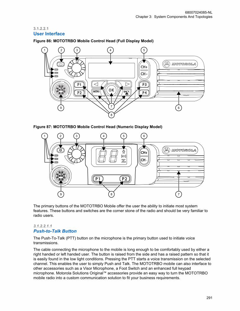
3.1.2.2.1User InterfaceFigure 86: MOTOTRBO Mobile Control Head (Full Display Model)
1 2 3 4 5
69 7
8
Figure 87: MOTOTRBO Mobile Control Head (Numeric Display Model)
1 2 3 4 5 6
79 8
The primary buttons of the MOTOTRBO Mobile offer the user the ability to initiate most systemfeatures. These buttons and switches are the corner stone of the radio and should be very familiar toradio users.
3.1.2.2.1.1Push-to-Talk ButtonThe Push-To-Talk (PTT) button on the microphone is the primary button used to initiate voicetransmissions.
The cable connecting the microphone to the mobile is long enough to be comfortably used by either aright handed or left handed user. The button is raised from the side and has a raised pattern so that itis easily found in the low light conditions. Pressing the PTT starts a voice transmission on the selectedchannel. This enables the user to simply Push and Talk. The MOTOTRBO mobile can also interface toother accessories such as a Visor Microphone, a Foot Switch and an enhanced full keypadmicrophone. Motorola Solutions Original™ accessories provide an easy way to turn the MOTOTRBOmobile radio into a custom communication solution to fit your business requirements.
68007024085-NLChapter 3: System Components And Topologies
291

3.1.2.2.1.2Channel RockerThe MOTOTRBO Mobile user chooses his communication environment by selecting a channel usingthe Channel Rocker on the control head.
The Channel Rocker has a raised pattern that is back-lit so it is easy to find in low light conditions.Although easy to find, it requires some force to push it so as not to change channels throughaccidentally pressing. Each press can be programmed to access a different channel within the radio’sprogramming. This allows the user to quickly switch between analog and digital channels and evendifferent groups. The user can quickly switch to different channels by pushing the up or down sectionsof the rocker. This greatly increases the number of available channels to the user.
3.1.2.2.1.3Programmable ButtonsThere are programmable buttons on the MOTOTRBO mobile. The full display mobile has fourprogrammable buttons while the numeric display mobile has two programmable buttons.
Each button can be programmed to perform a particular function. The short press and long press canbe programmed to act differently. The buttons can be programmed to give quick and easy access tothe MOTOTRBO system features, triggering emergency alarms and operating horns or lights.
3.1.2.2.1.4Status IndicatorsThe MOTOTRBO mobile provides a multi-colored LED on the front of the radio that informs the user ofthe busy or idle status of the selected channel. The LED busy indication represents the presence of RFactivity on the selected channel and is not specific to the digital slot currently being monitored.
The MOTOTRBO Mobile also provides a two line LCD display that shows a wide variety of information,including received signal strength, battery power, emergency status, monitor on/off, and GPS status.This display allows each channel name to be displayed so that the user knows the name of theselected channel. The source ID and target group alias are also displayed for ease of use. User namesare kept in an address book. This allows the user to use familiar names as aliases a radio ID. Variousaudio alert tones, talk permit tones and keypad tones are available to help the user navigate.
3.1.2.2.1.5Menu SystemIn addition to the accessing system features through buttons, the MOTOTRBO Mobile offers a menushown on its two line LCD display. With use of a menu button, left and right arrow buttons, a back/home button, and an OK button for selection, users can easily navigate through the following additionalfeatures. The Menu includes:
• Contacts
• Scan
• Messages
• Call Logs
• Utilities
For further details on these menus, please see the MOTOTRBO mobile user manual.
3.1.2.2.1.6Full KeypadAs an option, the MOTOTRBO Mobile offers an Enhanced Keypad Microphone so that users canmanually enter target addresses for system features. Text messaging from the mobile is available to
68007024085-NLChapter 3: System Components And Topologies
292
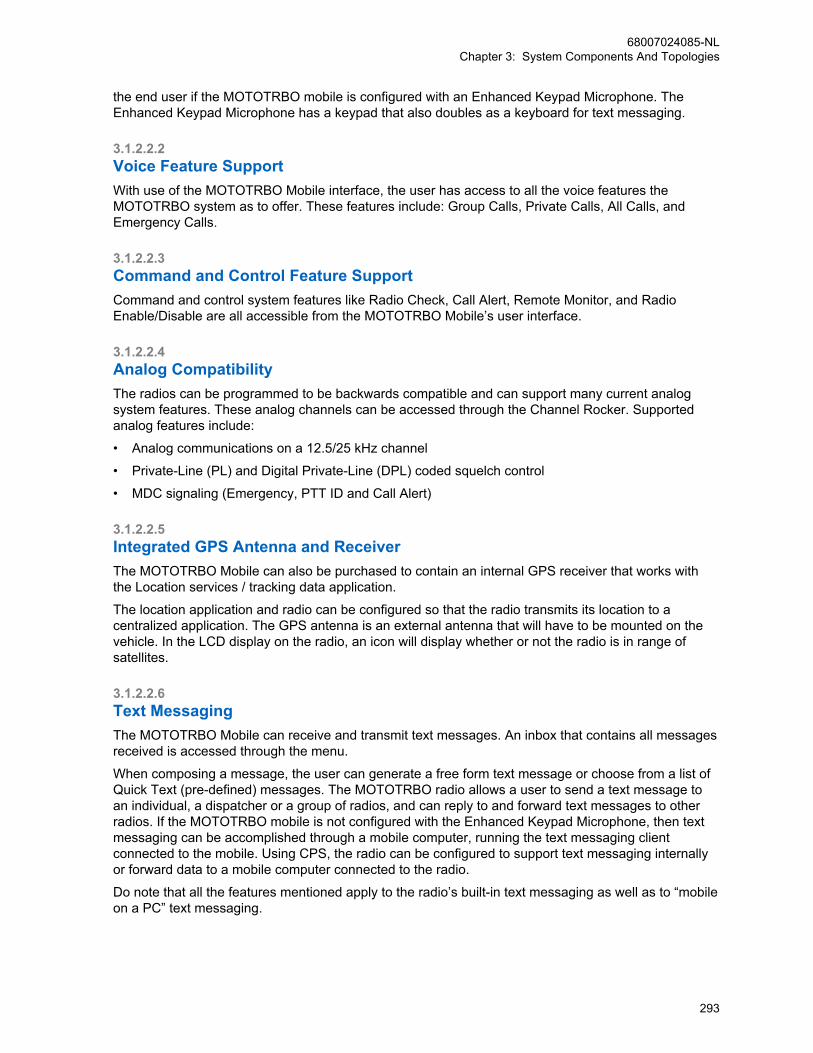
the end user if the MOTOTRBO mobile is configured with an Enhanced Keypad Microphone. TheEnhanced Keypad Microphone has a keypad that also doubles as a keyboard for text messaging.
3.1.2.2.2Voice Feature SupportWith use of the MOTOTRBO Mobile interface, the user has access to all the voice features theMOTOTRBO system as to offer. These features include: Group Calls, Private Calls, All Calls, andEmergency Calls.
3.1.2.2.3Command and Control Feature SupportCommand and control system features like Radio Check, Call Alert, Remote Monitor, and RadioEnable/Disable are all accessible from the MOTOTRBO Mobile’s user interface.
3.1.2.2.4Analog CompatibilityThe radios can be programmed to be backwards compatible and can support many current analogsystem features. These analog channels can be accessed through the Channel Rocker. Supportedanalog features include:
• Analog communications on a 12.5/25 kHz channel
• Private-Line (PL) and Digital Private-Line (DPL) coded squelch control
• MDC signaling (Emergency, PTT ID and Call Alert)
3.1.2.2.5Integrated GPS Antenna and ReceiverThe MOTOTRBO Mobile can also be purchased to contain an internal GPS receiver that works withthe Location services / tracking data application.
The location application and radio can be configured so that the radio transmits its location to acentralized application. The GPS antenna is an external antenna that will have to be mounted on thevehicle. In the LCD display on the radio, an icon will display whether or not the radio is in range ofsatellites.
3.1.2.2.6Text MessagingThe MOTOTRBO Mobile can receive and transmit text messages. An inbox that contains all messagesreceived is accessed through the menu.
When composing a message, the user can generate a free form text message or choose from a list ofQuick Text (pre-defined) messages. The MOTOTRBO radio allows a user to send a text message toan individual, a dispatcher or a group of radios, and can reply to and forward text messages to otherradios. If the MOTOTRBO mobile is not configured with the Enhanced Keypad Microphone, then textmessaging can be accomplished through a mobile computer, running the text messaging clientconnected to the mobile. Using CPS, the radio can be configured to support text messaging internallyor forward data to a mobile computer connected to the radio.
Do note that all the features mentioned apply to the radio’s built-in text messaging as well as to “mobileon a PC” text messaging.
68007024085-NLChapter 3: System Components And Topologies
293

3.1.2.2.7Front Panel Accessory InterfaceThe MOTOTRBO mobile radio supports an improved front panel accessory interface. This newinterface is Motorola Solutions platform for future accessory development and is not backwardscompatible with older accessories. This interface supports the following capabilities:
• Enhanced Audio Functionality – This unique technology enables communication between the radioand Motorola Solutions enhanced accessories to optimize audio performance. It enables moreconsistent audio levels between accessory types, so that users of different microphones soundmore consistent and inter-operate more effectively. It also optimizes audio quality performance for agiven accessory type, employing DSP (digital signal processing) technology to best match theradio’s audio signals to the capabilities of the accessory.
• USB Capability – The MOTOTRBO accessory and peripherals interface incorporates standardUniversal Serial Bus (USB) capability, enabling IP connectivity through standard USB ports withPersonal Computers and other peripherals through a Motorola Solutions-supplied cable. Thisinterface supports radio programming capabilities with no RIB box required, from the front(microphone port) connection. It also enables the interface to MOTOTRBO data applications suchas text messaging and location tracking. This interface also supports third-party applications byenabling interfaces for IP data service, telemetry services, and text messaging and locationtracking.
• Improved Connection – The MOTOTRBO microphone connection employs a rugged “twist and lock”mechanism for greater durability and connection strength.
3.1.2.2.8Rear Accessory and Peripherals InterfaceThe MOTOTRBO mobile radio also supports an improved rear panel accessory and peripheralsinterface. It supports the following capabilities:
• USB Capability – The MOTOTRBO accessory and peripherals interface incorporates standardUniversal Serial Bus (USB) capability, enabling IP connectivity through standard USB ports withPersonal Computers and other peripherals through a Motorola Solutions-supplied cable. Thisinterface supports radio programming capabilities with no RIB box required. It also enables theinterface to MOTOTRBO data applications such as text messaging and location tracking. Thisinterface also supports third-party applications by enabling interfaces for IP data service, telemetryservices, and text messaging and location tracking.
• Core peripherals – The MOTOTRBO accessory and peripherals interface also includes corefunctionality for audio input and output, PTT, monitor, receive unsquelch, channel steering, andother general purpose input-output (GPIO) functions. This enables interface with dispatch andtelemetry applications and other traditional radio system applications.
3.1.2.3MOTOTRBO Device Discovery and Mobility Service (DDMS)The MOTOTRBO Device Discovery and Mobility Service (DDMS) application replaces theMOTOTRBO Presence Notifier in software versions R02.06.10 and later.
The application supports radios presence and radio mobility notification services. It can be deployedwith the controls station or the MNIS. In deployments with a control station, the DDMS only supportsradio presence notifications. In deployments with the MNIS, it supports presence as well as mobilitynotifications.
68007024085-NLChapter 3: System Components And Topologies
294
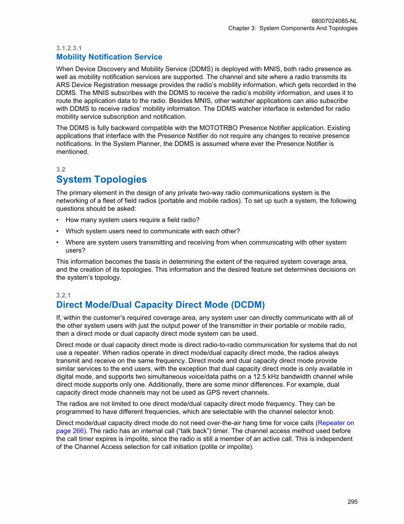
3.1.2.3.1Mobility Notification ServiceWhen Device Discovery and Mobility Service (DDMS) is deployed with MNIS, both radio presence aswell as mobility notification services are supported. The channel and site where a radio transmits itsARS Device Registration message provides the radio’s mobility information, which gets recorded in theDDMS. The MNIS subscribes with the DDMS to receive the radio’s mobility information, and uses it toroute the application data to the radio. Besides MNIS, other watcher applications can also subscribewith DDMS to receive radios’ mobility information. The DDMS watcher interface is extended for radiomobility service subscription and notification.
The DDMS is fully backward compatible with the MOTOTRBO Presence Notifier application. Existingapplications that interface with the Presence Notifier do not require any changes to receive presencenotifications. In the System Planner, the DDMS is assumed where ever the Presence Notifier ismentioned.
3.2System TopologiesThe primary element in the design of any private two-way radio communications system is thenetworking of a fleet of field radios (portable and mobile radios). To set up such a system, the followingquestions should be asked:
• How many system users require a field radio?
• Which system users need to communicate with each other?
• Where are system users transmitting and receiving from when communicating with other systemusers?
This information becomes the basis in determining the extent of the required system coverage area,and the creation of its topologies. This information and the desired feature set determines decisions onthe system’s topology.
3.2.1Direct Mode/Dual Capacity Direct Mode (DCDM)If, within the customer’s required coverage area, any system user can directly communicate with all ofthe other system users with just the output power of the transmitter in their portable or mobile radio,then a direct mode or dual capacity direct mode system can be used.
Direct mode or dual capacity direct mode is direct radio-to-radio communication for systems that do notuse a repeater. When radios operate in direct mode/dual capacity direct mode, the radios alwaystransmit and receive on the same frequency. Direct mode and dual capacity direct mode providesimilar services to the end users, with the exception that dual capacity direct mode is only available indigital mode, and supports two simultaneous voice/data paths on a 12.5 kHz bandwidth channel whiledirect mode supports only one. Additionally, there are some minor differences. For example, dualcapacity direct mode channels may not be used as GPS revert channels.
The radios are not limited to one direct mode/dual capacity direct mode frequency. They can beprogrammed to have different frequencies, which are selectable with the channel selector knob.
Direct mode/dual capacity direct mode do not need over-the-air hang time for voice calls (Repeater onpage 266). The radio has an internal call (“talk back”) timer. The channel access method used beforethe call timer expires is impolite, since the radio is still a member of an active call. This is independentof the Channel Access selection for call initiation (polite or impolite).
68007024085-NLChapter 3: System Components And Topologies
295
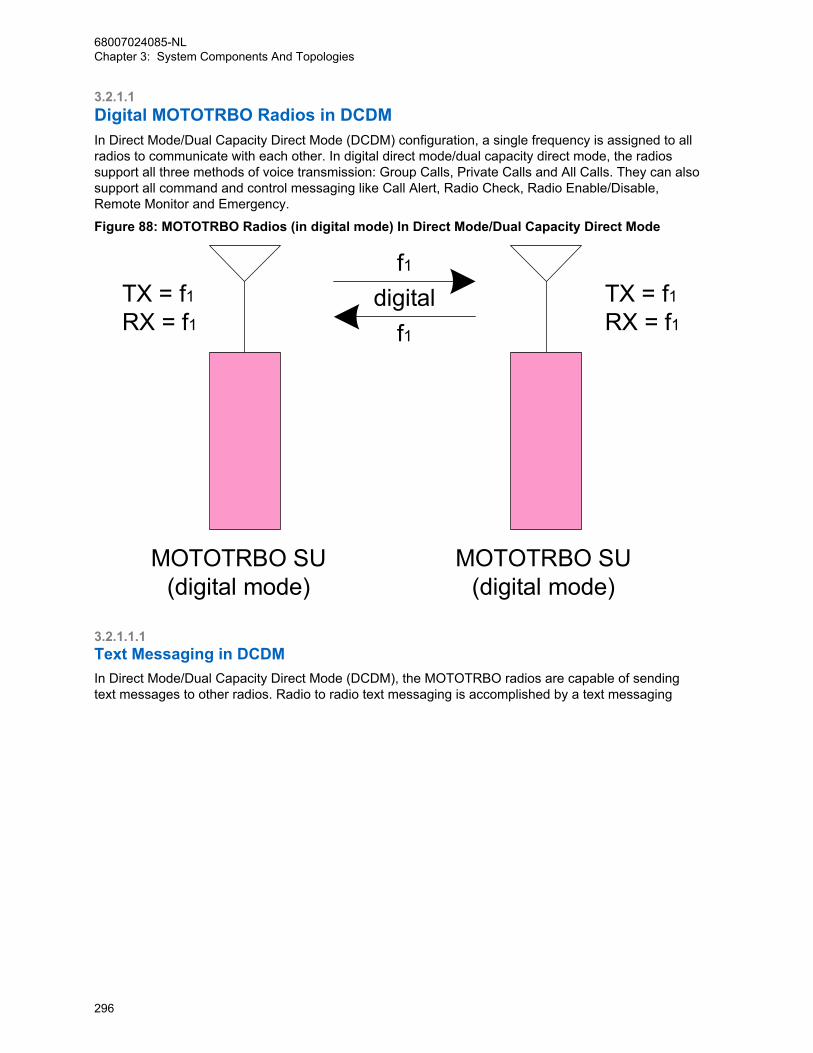
3.2.1.1Digital MOTOTRBO Radios in DCDMIn Direct Mode/Dual Capacity Direct Mode (DCDM) configuration, a single frequency is assigned to allradios to communicate with each other. In digital direct mode/dual capacity direct mode, the radiossupport all three methods of voice transmission: Group Calls, Private Calls and All Calls. They can alsosupport all command and control messaging like Call Alert, Radio Check, Radio Enable/Disable,Remote Monitor and Emergency.
Figure 88: MOTOTRBO Radios (in digital mode) In Direct Mode/Dual Capacity Direct Mode
MOTOTRBO SU(digital mode)
MOTOTRBO SU(digital mode)
f1
f1digital TX = f1
RX = f1TX = f1RX = f1
3.2.1.1.1Text Messaging in DCDMIn Direct Mode/Dual Capacity Direct Mode (DCDM), the MOTOTRBO radios are capable of sendingtext messages to other radios. Radio to radio text messaging is accomplished by a text messaging
68007024085-NLChapter 3: System Components And Topologies
296

application that is built into the radio. From the front keypad, the radio user can select the target radio,and type a text message.
Figure 89: MOTOTRBO Radios (in digital mode) Text Messaging In Direct Mode/Dual CapacityDirect Mode
MOTOTRBO SU(digital mode)
MOTOTRBO SU(digital mode)
f1
f1digital TX = f1
RX = f1TX = f1RX = f1
TM TM
In order for the text message to be sent successfully to the target radio, both radios need to be on thesame frequency. Similar to voice, if multiple direct mode/dual capacity direct mode frequencies arebeing used, the user must choose the channel his target is on before sending his text message. Theradios do not have to be on the same group.
Text messaging and the previously discussed voice services operate on the same frequency. Sincedata operates in a polite manner, the radio avoids transmitting text messages while any voice serviceis active. If operating with only field radios, text messages are limited to radio to radio communications.
Text messages can also be sent from radio to radio using a PC attached to the radio. A software-based text messaging client will be installed on the PC. These configurations are commonly used invehicles or on desktops that do not have LAN connections. Since they can run on AC power or off thein-vehicle battery, mobile radios are usually used for these applications, though a portable can also beused. Note that the radio can be configured to route incoming text messages to itself or to the PC, butnot both.
68007024085-NLChapter 3: System Components And Topologies
297
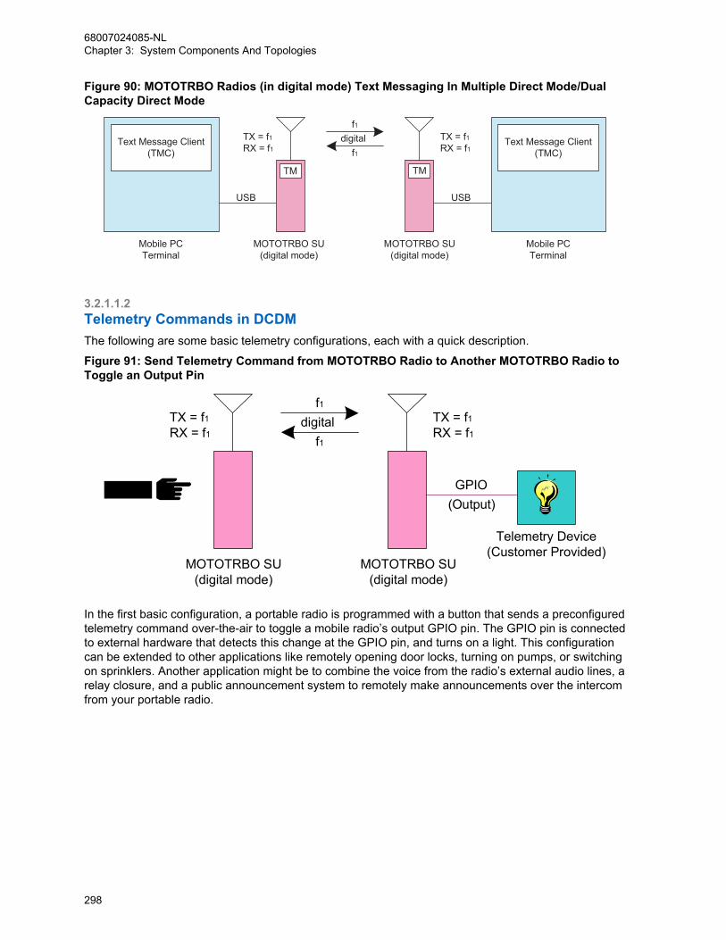
Figure 90: MOTOTRBO Radios (in digital mode) Text Messaging In Multiple Direct Mode/DualCapacity Direct Mode
TX = f1RX = f1
TX = f1RX = f1
MOTOTRBO SU(digital mode)
MOTOTRBO SU(digital mode)
f1
f1digital
Mobile PCTerminal
Mobile PCTerminal
Text Message Client(TMC)
Text Message Client(TMC)
TM TM
USBUSB
3.2.1.1.2Telemetry Commands in DCDMThe following are some basic telemetry configurations, each with a quick description.
Figure 91: Send Telemetry Command from MOTOTRBO Radio to Another MOTOTRBO Radio toToggle an Output Pin
TX = f1RX = f1
TX = f1RX = f1
MOTOTRBO SU(digital mode)
MOTOTRBO SU(digital mode)
f1
f1digital
Telemetry Device(Customer Provided)
(Output)GPIO
In the first basic configuration, a portable radio is programmed with a button that sends a preconfiguredtelemetry command over-the-air to toggle a mobile radio’s output GPIO pin. The GPIO pin is connectedto external hardware that detects this change at the GPIO pin, and turns on a light. This configurationcan be extended to other applications like remotely opening door locks, turning on pumps, or switchingon sprinklers. Another application might be to combine the voice from the radio’s external audio lines, arelay closure, and a public announcement system to remotely make announcements over the intercomfrom your portable radio.
68007024085-NLChapter 3: System Components And Topologies
298
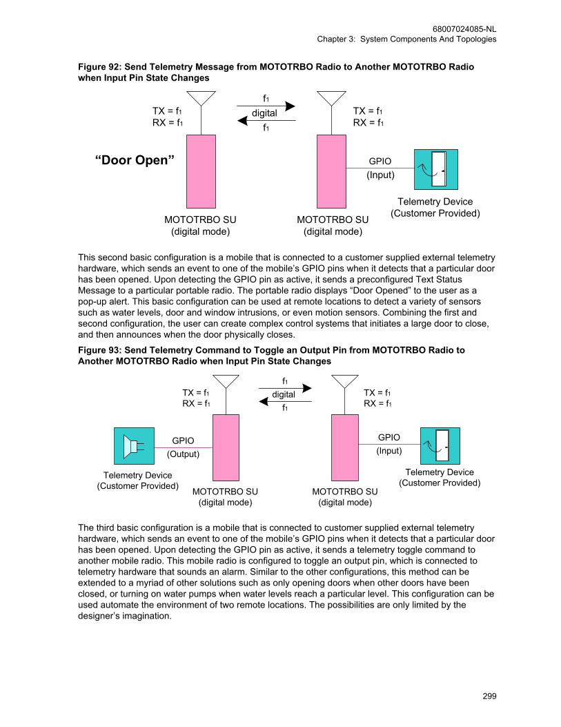
Figure 92: Send Telemetry Message from MOTOTRBO Radio to Another MOTOTRBO Radiowhen Input Pin State Changes
MOTOTRBO SU(digital mode)
MOTOTRBO SU(digital mode)
f1
f1digital TX = f1
RX = f1TX = f1RX = f1
(Input)
Telemetry Device(Customer Provided)
“Door Open” GPIO
This second basic configuration is a mobile that is connected to a customer supplied external telemetryhardware, which sends an event to one of the mobile’s GPIO pins when it detects that a particular doorhas been opened. Upon detecting the GPIO pin as active, it sends a preconfigured Text StatusMessage to a particular portable radio. The portable radio displays “Door Opened” to the user as apop-up alert. This basic configuration can be used at remote locations to detect a variety of sensorssuch as water levels, door and window intrusions, or even motion sensors. Combining the first andsecond configuration, the user can create complex control systems that initiates a large door to close,and then announces when the door physically closes.
Figure 93: Send Telemetry Command to Toggle an Output Pin from MOTOTRBO Radio toAnother MOTOTRBO Radio when Input Pin State Changes
TX = f1RX = f1
TX = f1RX = f1
MOTOTRBO SU(digital mode)
MOTOTRBO SU(digital mode)
f1
f1digital
(Input)
Telemetry Device(Customer Provided)
Telemetry Device(Customer Provided)
GPIO(Output)
GPIO
The third basic configuration is a mobile that is connected to customer supplied external telemetryhardware, which sends an event to one of the mobile’s GPIO pins when it detects that a particular doorhas been opened. Upon detecting the GPIO pin as active, it sends a telemetry toggle command toanother mobile radio. This mobile radio is configured to toggle an output pin, which is connected totelemetry hardware that sounds an alarm. Similar to the other configurations, this method can beextended to a myriad of other solutions such as only opening doors when other doors have beenclosed, or turning on water pumps when water levels reach a particular level. This configuration can beused automate the environment of two remote locations. The possibilities are only limited by thedesigner’s imagination.
68007024085-NLChapter 3: System Components And Topologies
299
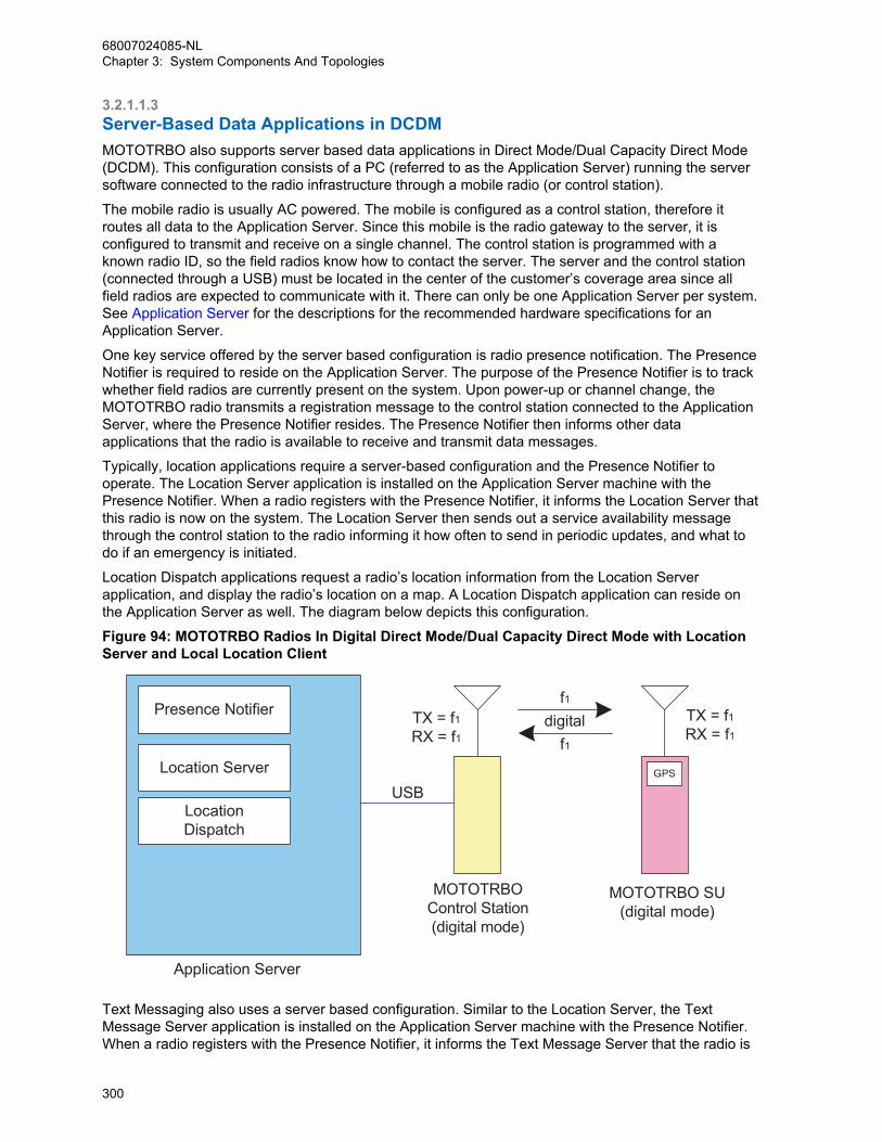
3.2.1.1.3Server-Based Data Applications in DCDMMOTOTRBO also supports server based data applications in Direct Mode/Dual Capacity Direct Mode(DCDM). This configuration consists of a PC (referred to as the Application Server) running the serversoftware connected to the radio infrastructure through a mobile radio (or control station).
The mobile radio is usually AC powered. The mobile is configured as a control station, therefore itroutes all data to the Application Server. Since this mobile is the radio gateway to the server, it isconfigured to transmit and receive on a single channel. The control station is programmed with aknown radio ID, so the field radios know how to contact the server. The server and the control station(connected through a USB) must be located in the center of the customer’s coverage area since allfield radios are expected to communicate with it. There can only be one Application Server per system.See Application Server for the descriptions for the recommended hardware specifications for anApplication Server.
One key service offered by the server based configuration is radio presence notification. The PresenceNotifier is required to reside on the Application Server. The purpose of the Presence Notifier is to trackwhether field radios are currently present on the system. Upon power-up or channel change, theMOTOTRBO radio transmits a registration message to the control station connected to the ApplicationServer, where the Presence Notifier resides. The Presence Notifier then informs other dataapplications that the radio is available to receive and transmit data messages.
Typically, location applications require a server-based configuration and the Presence Notifier tooperate. The Location Server application is installed on the Application Server machine with thePresence Notifier. When a radio registers with the Presence Notifier, it informs the Location Server thatthis radio is now on the system. The Location Server then sends out a service availability messagethrough the control station to the radio informing it how often to send in periodic updates, and what todo if an emergency is initiated.
Location Dispatch applications request a radio’s location information from the Location Serverapplication, and display the radio’s location on a map. A Location Dispatch application can reside onthe Application Server as well. The diagram below depicts this configuration.
Figure 94: MOTOTRBO Radios In Digital Direct Mode/Dual Capacity Direct Mode with LocationServer and Local Location Client
TX = f1RX = f1
TX = f1RX = f1
f1
f1digital
MOTOTRBO Control Station(digital mode)
MOTOTRBO SU(digital mode)
GPS
Presence Notifier
Location Server
LocationDispatch
Application Server
USB
Text Messaging also uses a server based configuration. Similar to the Location Server, the TextMessage Server application is installed on the Application Server machine with the Presence Notifier.When a radio registers with the Presence Notifier, it informs the Text Message Server that the radio is
68007024085-NLChapter 3: System Components And Topologies
300

now on the system. The Text Message Server then sends out a service availability message throughthe control station to the radio informing it how it can communicate with the Text Message Server. TextMessage Dispatch applications communicate with the Text Message Server in order to send andreceive messages to and from the radio network via the connected control station. A Text MessageDispatch application can reside on the Application Server as well.
As previously described, radios can send text messages to each other without communicating throughthe Text Message Server. But in order to send and receive text messages to Text MessageDispatchers, the Text Message Server configuration is required. The diagram below depicts thisconfiguration. This configuration also works with external text message applications connected to thefield radios.
Figure 95: MOTOTRBO Radios In Digital Direct Mode with Text Message Server, LocationServer and Local Dispatchers
TX = f1RX = f1
TX = f1RX = f1
f1
f1digital
MOTOTRBOControl Station(digital mode)
Mobile PCTerminal
Text Message Client(TMC)
MOTOTRBO SU(digital mode)
TM
GPS
Text MessageServer
Presence Notifier
Text MessageDispatch
Location Server
LocationDispatch
Application Server
USB USB
This configuration can be expanded by locating up to four Text Message Dispatchers and four LocationDispatchers throughout the customer’s Enterprise Network. Up to four installations of each applicationcan be located anywhere on the customer’s LAN, as long as they can communicate with theApplication Server. The Dispatcher installation on the Application Server counts as one of theinstances of the dispatch software. The diagram below shows two instances of each application. Oneis on the Application Server and one remote. The applications can reside on the same remotemachine, if desired.
68007024085-NLChapter 3: System Components And Topologies
301

Figure 96: MOTOTRBO Radios In Digital Direct Mode/Dual Capacity Direct Mode Server BasedConfiguration with Remote Dispatchers
f1
f1digital TX = f1
RX = f1TX = f1RX = f1
MOTOTRBOControl Station(digital mode)
TMText Message
Server
Presence Notifier
Text MessageDispatch
Location Server
LocationDispatch
GPS
Application Server
USB
PC Terminal
Text MessageDispatch
PC Terminal
LocationDispatch
CustomerEnterpriseNetwork(CEN)
NETWORK
NETWORK
NETWORK
MOTOTRBO SU(digital mode)
Internet(E-mail)
NETWORK
Another Text Message service that is only available in a server based configuration is the ability toreceive and send text messages to external e-mail addresses. This allows PCs or pagers and cellphones that are text message capable on the system to send e-mail messages. In order for the TextMessage Server to communicate with the outside world, the Application Server must have access tothe Internet. When a radio sends a text message to a Text Message Dispatcher, and it is identified asan external e-mail address in the Text Message Server, the Text Message Server will forward the textmessage to the designated e-mail address.
The Text Message Server forwards incoming e-mails in a similar fashion. The source e-mail addressmust be configured in the Text Message Server for it to forward the text messages to the destinationradio. This blocks unknown e-mail traffic from utilizing the bandwidth of the radio system.
3.2.1.1.4Multi-Channel Server-Based Data Applications in DCDMFor larger systems that have multiple direct mode/dual capacity direct mode frequencies, theApplication Server can be connected to up to 16 control stations. Each control station is configured tocommunicate on the specified channel and acts as the data gateway for that channel.
Presence registration works in the same manner with this configuration as it does with the singlechannel configuration. When a radio powers up or changes channels, it sends in a registration to thePresence Notifier via the control station, which then informs the applications of the radio’s presence.Each control station has the same radio ID, therefore the field radios transmit their messages to thisradio ID regardless of which channel they are on.
Because the field radios are located on different channels, a Multi-Channel Device Driver (MCDD) isrequired to track the location of each radio, so outbound data from the Application Server can berouted to the appropriate channel. The MCDD is a small piece of software installed on the ApplicationServer. Each control station is handled like a different network interface to the Application Server.When the MCDD sees a registration, it updates the PC’s routing table so that any data traffic for thatradio is routed out the correct network interface, and therefore through the correct control station andover the correct channel. (Note: MCDD release R1.0 version 1.00.17 also updates the routing table onreceipt of any data traffic, making it incompatible with GPS Revert). This allows data applications to
68007024085-NLChapter 3: System Components And Topologies
302

simply transmit a data message to the radio, and the MCDD takes care of the routing to the correctchannel.
Any channel, that supports data and needs to communicate to the Application Server, needs adedicated control station.
Figure 97: MOTOTRBO Radios in Two Channel Digital Direct Mode Server-Based Configurationwith Remote Dispatchers
TX = f1RX = f1
TX = f1RX = f1
TX = f2RX = f2
TX = f2RX = f2
f1
f1digital
digitalf2
f2
TM
GPS
Text MessageServer
Text MessageDispatch
Presence Notifier
Mul
ti-C
hann
el D
evic
e D
river
(MC
DD
)
Location Server
LocationDispatch
Application Server USB
USB
GPS
PC Terminal
Text MessageDispatch
PC Terminal
LocationDispatch
CustomerEnterpriseNetwork(CEN)
NETWORK
NETWORK
NETWORK
MOTOTRBOControl Station
(digital mode)
MOTOTRBOControl Station
(digital mode)
MOTOTRBO SU(digital mode)
MOTOTRBO SU(digital mode)
Internet(E-mail)
NETWORK
3.2.1.1.5GPS Revert in DCDMWith the addition of the GPS Revert feature, it is now possible to transmit Location Update messageson channels other than the Selected Channel (See GPS Revert Channel on page 104 for configurationinformation). The diagram in Figure 98: MOTOTRBO Radios in Two Channel Direct Mode GPS RevertConfiguration on page 304 illustrates this concept in its simplest form while operating in direct mode/dual capacity direct mode. The dual capacity direct mode operation is similar to direct mode in GPSrevert scenarios, with the exception that a dual capacity direct mode channel can not be used as aGPS revert channel. As a result of that, a radio can revert from a dual capacity direct mode channel,but can not revert to a dual capacity direct mode channel to send the GPS update. In this example,Channel f1 is the Selected Channel and Channel f2 is the GPS Revert Channel. Communications suchas presence, location requests (Application Server to radio), text and voice occur on the SelectedChannel, while all location responses (radio to Application Server) including location updates occur onthe GPS Revert Channel. Therefore, a minimum of two control stations are required to support GPSRevert.
68007024085-NLChapter 3: System Components And Topologies
303

Figure 98: MOTOTRBO Radios in Two Channel Direct Mode GPS Revert Configuration
MOTOTRBOControl Station(digital mode)
MOTOTRBOControl Station(digital mode)
Location Response
Loca
tion R
espo
nse
Location RequestVoice/Text
Location Request
Presence
Presence
USBApplication Server
MCDD
USB
Presence Notifier
Location Server
MOTOTRBO SU(digital mode)
MOTOTRBO SU(digital mode)
f2GPS
TM
GPS
TM
SELETEDTX=f1RX=f1
GPS REVERTTX=f2RX=f2
SELETEDTX=f1RX=f1
GPS REVERTTX=f2RX=f2
TX=f2RX=f2
TX=f1RX=f1 f1
f1
f1
f1 f1f1
f1
f1
Under a typical scenario, the radio is powered on, and then registers on the Selected Channel with thePresence Notifier and the Location Server. The radio receives a Periodic Location Request and anEmergency Location Request from the Location Server on the Selected Channel. This PeriodicLocation Request instructs the radio to send location updates at a specific rate, while the EmergencyLocation Request instructs the radio to send a single Emergency Location Update when an emergencyis initiated.
The radio spends the most time on the Selected Channel. The radio only switches to the GPS RevertChannel when a Location Update needs to be transmitted. Since voice transmissions have priority overdata transmissions, when the radio is involved in a call on the Selected Channel, the Location Updateis queued until after the call is completed. In order to minimize the amount of time spent away from theSelected Channel while on the GPS Revert Channel, the radio will not attempt to qualify traffic on theGPS Revert Channel. Therefore, all voice, data, and control messages transmitted to a radio shouldnever be transmitted on the GPS Revert Channel, as they will not reach their destination.
The example in Figure 98: MOTOTRBO Radios in Two Channel Direct Mode GPS RevertConfiguration on page 304 illustrates only one GPS Revert Channel. However, depending on the GPSdata load, more than one GPS Revert Channel may be needed. For example, a single large group thatgenerates significant Location Update traffic must be sub-divided across several GPS RevertChannels. Each GPS Revert Channel requires a control station, which must be connected to theApplication Server PC. The maximum number of control stations that can be connected to the PC isfour.
68007024085-NLChapter 3: System Components And Topologies
304
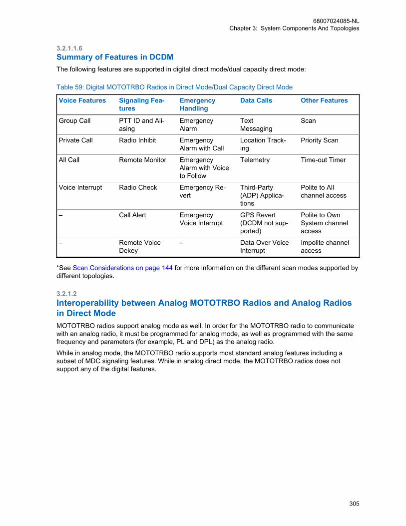
3.2.1.1.6Summary of Features in DCDMThe following features are supported in digital direct mode/dual capacity direct mode:
Table 59: Digital MOTOTRBO Radios in Direct Mode/Dual Capacity Direct Mode
Voice Features Signaling Fea-tures
EmergencyHandling
Data Calls Other Features
Group Call PTT ID and Ali-asing
EmergencyAlarm
Text Messaging
Scan
Private Call Radio Inhibit EmergencyAlarm with Call
Location Track-ing
Priority Scan
All Call Remote Monitor EmergencyAlarm with Voiceto Follow
Telemetry Time-out Timer
Voice Interrupt Radio Check Emergency Re-vert
Third-Party(ADP) Applica-tions
Polite to Allchannel access
– Call Alert EmergencyVoice Interrupt
GPS Revert(DCDM not sup-ported)
Polite to OwnSystem channelaccess
– Remote VoiceDekey
– Data Over VoiceInterrupt
Impolite channelaccess
*See Scan Considerations on page 144 for more information on the different scan modes supported bydifferent topologies.
3.2.1.2Interoperability between Analog MOTOTRBO Radios and Analog Radiosin Direct ModeMOTOTRBO radios support analog mode as well. In order for the MOTOTRBO radio to communicatewith an analog radio, it must be programmed for analog mode, as well as programmed with the samefrequency and parameters (for example, PL and DPL) as the analog radio.
While in analog mode, the MOTOTRBO radio supports most standard analog features including asubset of MDC signaling features. While in analog direct mode, the MOTOTRBO radios does notsupport any of the digital features.
68007024085-NLChapter 3: System Components And Topologies
305
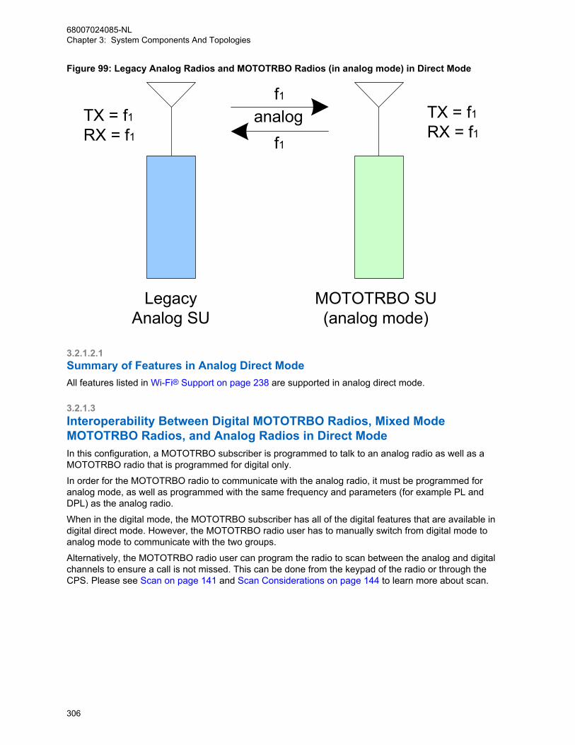
Figure 99: Legacy Analog Radios and MOTOTRBO Radios (in analog mode) in Direct Mode
TX = f1RX = f1
TX = f1RX = f1
f1
f1analog
LegacyAnalog SU
MOTOTRBO SU(analog mode)
3.2.1.2.1Summary of Features in Analog Direct ModeAll features listed in Wi-Fi® Support on page 238 are supported in analog direct mode.
3.2.1.3Interoperability Between Digital MOTOTRBO Radios, Mixed ModeMOTOTRBO Radios, and Analog Radios in Direct ModeIn this configuration, a MOTOTRBO subscriber is programmed to talk to an analog radio as well as aMOTOTRBO radio that is programmed for digital only.
In order for the MOTOTRBO radio to communicate with the analog radio, it must be programmed foranalog mode, as well as programmed with the same frequency and parameters (for example PL andDPL) as the analog radio.
When in the digital mode, the MOTOTRBO subscriber has all of the digital features that are available indigital direct mode. However, the MOTOTRBO radio user has to manually switch from digital mode toanalog mode to communicate with the two groups.
Alternatively, the MOTOTRBO radio user can program the radio to scan between the analog and digitalchannels to ensure a call is not missed. This can be done from the keypad of the radio or through theCPS. Please see Scan on page 141 and Scan Considerations on page 144 to learn more about scan.
68007024085-NLChapter 3: System Components And Topologies
306
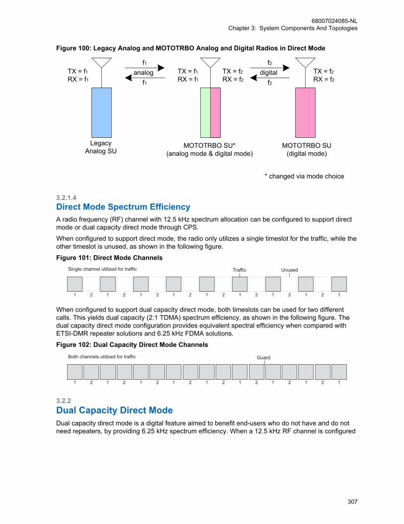
Figure 100: Legacy Analog and MOTOTRBO Analog and Digital Radios in Direct Mode
LegacyAnalog SU
TX = f1RX = f1
TX = f1RX = f1
TX = f2RX = f2
TX = f2RX = f2
f1
f1
MOTOTRBO SU*(analog mode & digital mode)
analog
MOTOTRBO SU(digital mode)
f2
f2digital
* changed via mode choice
3.2.1.4Direct Mode Spectrum EfficiencyA radio frequency (RF) channel with 12.5 kHz spectrum allocation can be configured to support directmode or dual capacity direct mode through CPS.
When configured to support direct mode, the radio only utilizes a single timeslot for the traffic, while theother timeslot is unused, as shown in the following figure.
Figure 101: Direct Mode Channels
1
Single channel utilized for traffic Traffic Unused
2 1 2 1 2 1 2 1 2 1 2 1 2 1 12
When configured to support dual capacity direct mode, both timeslots can be used for two differentcalls. This yields dual capacity (2:1 TDMA) spectrum efficiency, as shown in the following figure. Thedual capacity direct mode configuration provides equivalent spectral efficiency when compared withETSI-DMR repeater solutions and 6.25 kHz FDMA solutions.
Figure 102: Dual Capacity Direct Mode Channels
1
Both channels utilized for traffic Guard
2 1 2 1 2 1 2 1 2 1 2 1 2 1 12
3.2.2Dual Capacity Direct ModeDual capacity direct mode is a digital feature aimed to benefit end-users who do not have and do notneed repeaters, by providing 6.25 kHz spectrum efficiency. When a 12.5 kHz RF channel is configured
68007024085-NLChapter 3: System Components And Topologies
307

for dual capacity direct mode, both timeslots are available for independent and simultaneous radio callconversations.
3.2.2.1Timeslot SynchronizationSince there is no repeater designating a slotting structure and dual capacity direct mode uses bothtimeslots for the traffic, timeslot synchronization needs to be applied to differentiate timeslot 1 fromtimeslot 2.
In the absence of a repeater, the radios in dual capacity direct mode automatically and cooperativelyselect a Channel Timing Leader (CTL) and synchronize to the leader’s channel timing. This CTLelection process is transparent to the end user. For a 12.5 kHz RF channel, only one CTL is elected,that is, the same radio that provides the channel timing for both timeslots irrespective of radio timeslotprovisioning and color code provisioning. The selected CTL periodically announces the channeltimeslot structure via beacons, and the other radios synchronize with the leader directly or indirectly(via other radios) by following the synchronization information in these beacons. The dual capacitydirect mode beacon transmits for 600 milliseconds every 4.5 minutes. This only uses 0.22% of thechannel capacity and should have little impact to other services.
3.2.2.2Channel Timing Leader (CTL) PreferenceWhen operating in dual capacity direct mode, a radio’s preference to be a CTL can be CPS configuredon a per channel basis as follows:
Preferred CTLThe radios that are always turned on, always selected to dual capacity direct mode channel, neverscans or have large transmit coverage are “good” candidates to be the preferred CTL. Wheneverpossible, a mobile may act as the preferred CTL since synchronization beaconing may drain morebattery capacity.
Normal PreferenceThe default configuration that allows a radio to act as the CTL, but should yield leadership to higherpreference candidates.
Least PreferredThis option is not CPS selectable, but is automatically selected when a scan list is attached to theselected dual capacity direct mode channel.
IneligibleThis option may be selected in radios that are “bad” candidates to be a CTL. For example, radiosthat change channels often, or roam often, and so on, but at least one radio must not be “Ineligible”.
To avoid frequent CTL re-election, it is recommended to assign the same CTL preference to all dualcapacity personalities that use the same frequency when configuring a specific radio.
3.2.2.3Color CodeSimilar to direct mode operation, in dual capacity direct mode, color code 0-14 are specified on a pertimeslot (channel) basis through CPS provisioning. Color code 15 is reserved for future usage and not
68007024085-NLChapter 3: System Components And Topologies
308
available for dual capacity direct mode channels. Different color codes can be used in the two timeslotsof an RF channel.
3.2.2.4Channel Access RuleDual capacity direct mode channel access rules are specified on a timeslot (channel) basis throughCPS provisioning. The channel access in dual capacity direct mode follows the same rules as definedin MOTOTRBO Channel Access on page 67.
3.2.2.5ScanTo enable migration and interoperability, a dual capacity direct mode channel can have a scan list thatincludes a non-dual capacity direct mode channel, and a non-dual capacity direct mode channel canhave a scan list that includes a dual capacity direct mode channel.
Therefore, a scan list may include a mixture of dual capacity direct mode and direct mode channels aswell as analog and repeater channels. If talkback is enabled and the radio lands on a dual capacitydirect mode channel, the radio can talk back in dual capacity direct mode in the proper timeslot.
There may be up to 16 channels in a scan list, among which the radio uses the DTC to track thechannel timeslot structure. The choices for the DTC are: selected channel, last active, or otherdesignated channel. In order for the selected DTC to be easily tracked, it is recommended to use the“selected channel” as the DTC and enable “Talkback”, especially when the selected channel is a dualcapacity direct mode channel.
3.2.2.6Interoperability and Backward CompatibilityA radio may be configured in CPS to operate in repeater mode, direct mode, dual capacity directmode, or talkaround mode on different personalities. Direct mode is not as efficient as dual capacitydirect mode in spectrum usage. However, it is still supported so that the radio is interoperable withother ETSI-DMR compatible radio and is backward compatible with software versions R02.00.00 orearlier, which can only support direct mode.
A radio operating in dual capacity direct mode is not interoperable with a radio operating in repeatermode, direct mode, or talkaround mode. The radio treats the other radio’s transmission as interference.
3.2.2.7Revert FeaturesA radio does not monitor the GPS revert channel hence it does not track the channel timeslot structureon the GPS revert channel. Therefore, dual capacity direct mode channels can not be used as GPSrevert channels.
A radio that is selected to a dual capacity direct mode channel may revert to emergency revertchannels, or GPS revert channels, or enhanced GPS revert channels.
68007024085-NLChapter 3: System Components And Topologies
309

3.2.3Extended Range Direct ModeThe Extended Range Direct Mode feature utilizes a time division duplex repeater that receives a directmode transmission and repeats it 90 ms later, as show in the following figure:
Figure 103: Time Division Duplex Repeater
BS TX
MS TX
Outbound
Inbound Inbound Inbound Inbound Inbound Inbound Inbound
Time
Outbound Outbound Outbound Outbound Outbound OutboundRepeat
1TX3
Repeat2
TX4
Repeat3
TX5
Repeat4
TX6
Repeat5
TX7
Repeat6
TX8
Repeat7
TX9
This mode's primary purpose is to extend direct mode range while utilizing a single frequency. (Note,this does not extend the range of Dual Capacity Direct Mode.) A radio initiates a transmission as itdoes in direct mode and can receive transmissions directly from a radio or from the repeater. At thebeginning of reception, the radio selects the best signal. Therefore direct mode operation is stillsupported in the absence of the repeater without having to change channels. When receiving directlyfrom a radio, the receiving radio displays the talkaround icon. When receiving from the repeater, thereceiving radio does not display the talkaround icon. Additionally, Enhanced Channel Access (ECA) issupported in this mode to minimize the impacts of transmission collisions.
Extended Range Direct Mode is a single site conventional mode solution that supports the followingfeatures.
• Voice Calls (Group, Individual and All)
• IP Data (Unconfirmed Group, Unconfirmed Individual and Confirmed Individual)
• Control (Radio Check, Radio Inhibit and Uninhibit, Remote Monitor and Call Alert)
• Privacy (Basic, Enhanced and AES)
• Restricted Access to System (RAS)
• Voice Transmitter Interrupt
• NAI wireline interface for voice and control for 3rd Party Voice and Control Applications
• MNIS Wireline Data gateway for MSI and 3rd Party Data Applications
• Remote Repeater Programming
• RDAC
• Analog CWID and FCC Level 1 Monitoring
The solution does not support the following features:
• Repeater Broadcast Hangtime Signaling (same as direct mode)
• Data Revert Channel
• Digital Phone Patch
• Enhanced Channel Access (same as direct mode)
• Digital Voting
• Digital/Analog Mixed Mode
• RAS Migration Mode
68007024085-NLChapter 3: System Components And Topologies
310

3.2.3.1Interactions Between Extended Range Direct Mode and Mode RadiosIf both Direct Mode radios and Extended Range Direct Mode radios are programmed with the samefrequency, color code, and talkgroup, they are able to communicate with each other in direct mode.However, in the presence of the Extended Range Direct Mode repeater, there is an imbalance in rangethat is dependent upon the receiving radio.
The repeater re-transmits either the Direct Mode radio's transmission or the Extended Range DirectMode radio's transmission. However, only the Extended Range Direct Mode radio is able to receive therepeater's transmission. Because a Direct Mode radio does not receive the repeater's transmission,there is an imbalance in coverage. Therefore, it is recommended that Direct Mode and ExtendedRange Direct Mode radios are not used to communicate with each other in the presence of theExtended Range Direct Mode repeater.
3.2.3.2Extended Range Direct Mode Feature LicensingA software license is required in the repeater for this feature to be operational. However, license is notrequired in the radio.
3.2.3.3Repeater Emission DesignatorWhen operating in Extended Range Direct Mode, the repeater should use emission designators7K60FXD for data and 7K60FXE for voice. These are required to indicate the TDMA (pulsed) nature ofthe repeater’s transmission.
3.2.3.4Configuration in RepeaterThis feature is activated in the repeater by ENABLING the Direct Mode Range Extension field within aDigital Channel. Enter the same frequency for TX and RX frequency. Enable Enhanced ChannelAccess (ECA) if this is desired system operation.This feature allows the inbound (radio transmission)and outbound (repeater) transmissions to use different color codes. It is not necessary to use differentcolor codes. However this is recommended when operating on the same frequency as direct moderadios not supporting this feature.
In the case of an SLR1000 repeater, a high speed RF switch, which is installed internal to the repeater,is available (PMLN7263). If this kit is used, Tx/Rx switch must be configured for GPIO6. The activelevel is defaulted to the correct state and cannot be changed.
3.2.3.5Configuration in RadioThis feature is activated in the radio by enabling the Direct Mode Range Extension field within a DigitalChannel.
Once enabled, one TX/RX frequency is required to be entered. This feature allows the inbound (radiotransmission) and outbound (repeater) transmissions to use different color codes. It is not necessary touse different color codes. However this is recommended when operating on the same frequency asdirect mode radios not supporting this feature.
68007024085-NLChapter 3: System Components And Topologies
311
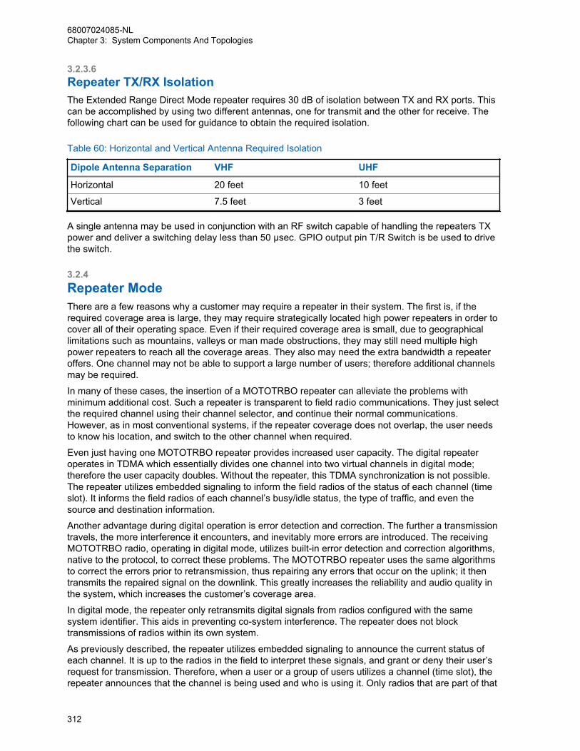
3.2.3.6Repeater TX/RX IsolationThe Extended Range Direct Mode repeater requires 30 dB of isolation between TX and RX ports. Thiscan be accomplished by using two different antennas, one for transmit and the other for receive. Thefollowing chart can be used for guidance to obtain the required isolation.
Table 60: Horizontal and Vertical Antenna Required Isolation
Dipole Antenna Separation VHF UHF
Horizontal 20 feet 10 feet
Vertical 7.5 feet 3 feet
A single antenna may be used in conjunction with an RF switch capable of handling the repeaters TXpower and deliver a switching delay less than 50 μsec. GPIO output pin T/R Switch is be used to drivethe switch.
3.2.4Repeater ModeThere are a few reasons why a customer may require a repeater in their system. The first is, if therequired coverage area is large, they may require strategically located high power repeaters in order tocover all of their operating space. Even if their required coverage area is small, due to geographicallimitations such as mountains, valleys or man made obstructions, they may still need multiple highpower repeaters to reach all the coverage areas. They also may need the extra bandwidth a repeateroffers. One channel may not be able to support a large number of users; therefore additional channelsmay be required.
In many of these cases, the insertion of a MOTOTRBO repeater can alleviate the problems withminimum additional cost. Such a repeater is transparent to field radio communications. They just selectthe required channel using their channel selector, and continue their normal communications.However, as in most conventional systems, if the repeater coverage does not overlap, the user needsto know his location, and switch to the other channel when required.
Even just having one MOTOTRBO repeater provides increased user capacity. The digital repeateroperates in TDMA which essentially divides one channel into two virtual channels in digital mode;therefore the user capacity doubles. Without the repeater, this TDMA synchronization is not possible.The repeater utilizes embedded signaling to inform the field radios of the status of each channel (timeslot). It informs the field radios of each channel’s busy/idle status, the type of traffic, and even thesource and destination information.
Another advantage during digital operation is error detection and correction. The further a transmissiontravels, the more interference it encounters, and inevitably more errors are introduced. The receivingMOTOTRBO radio, operating in digital mode, utilizes built-in error detection and correction algorithms,native to the protocol, to correct these problems. The MOTOTRBO repeater uses the same algorithmsto correct the errors prior to retransmission, thus repairing any errors that occur on the uplink; it thentransmits the repaired signal on the downlink. This greatly increases the reliability and audio quality inthe system, which increases the customer’s coverage area.
In digital mode, the repeater only retransmits digital signals from radios configured with the samesystem identifier. This aids in preventing co-system interference. The repeater does not blocktransmissions of radios within its own system.
As previously described, the repeater utilizes embedded signaling to announce the current status ofeach channel. It is up to the radios in the field to interpret these signals, and grant or deny their user’srequest for transmission. Therefore, when a user or a group of users utilizes a channel (time slot), therepeater announces that the channel is being used and who is using it. Only radios that are part of that
68007024085-NLChapter 3: System Components And Topologies
312

group are allowed to transmit. The repeater additionally allows a short duration of reserved time after atransmission. This allows other users in the group to respond to the originator. This reserved hang timegreatly increases the continuity of calls, because new calls cannot start until the previous call ends.Without this feature, users may experience delays in responses (that is, between transmissions ofcalls), due to other calls taking over the channel in-between their transmissions.
After this reserved hang time, the repeater stays active for a short period of time, and offers anopportunity for any user on the system to transmit or start a new call. If no user transmits for a durationof time, the repeater stops transmitting. When the next radio transmission occurs, the repeater startsrepeating again.
Most of the basic MOTOTRBO voice and data services work the same in repeater mode as they do indirect mode/dual capacity direct mode. The customer will only notice the increased performance andcoverage.
3.2.4.1Digital MOTOTRBO Radios in Repeater ModeIn digital mode, a repeater uses one frequency pair (1-transmit, 1-receive) to support the two logicalchannels. As mentioned earlier, this is done by using TDMA technology to divide the physical channelinto two time slots. In order to access the repeater, the radio user selects the physical and logicalchannel using the channel selector. Hence, when operating in repeater mode, the field radios cannotdynamically choose a time slot. Each of the channel selector positions is programmed for a particulardigital frequency and time slot.
The end user sees, in effect, each time slot as a different conventional channel. Radio groups can befurther segmented within the time slot by assigning different group IDs to each group. Groups ondifferent time slots cannot communicate with each other.
Synchronization is the key to a MOTOTRBO repeater system. It is the role of the repeater to keep thissynchronization. When accessed, the repeater begins transmitting idle messages as well as identifyingthe time slot structure. The radios synchronize to the transmissions from the repeater. When a radiotransmits on its time slot, the radio pulses its transmissions in 30ms increments. This allows forsimultaneous conversation to occur on the other time slot. While the first radio is pulsed on, the otherradio is pulsed off. The repeater receives these two pulsed transmissions, combines them andtransmits them in the correct order in one continuous transmission.
68007024085-NLChapter 3: System Components And Topologies
313
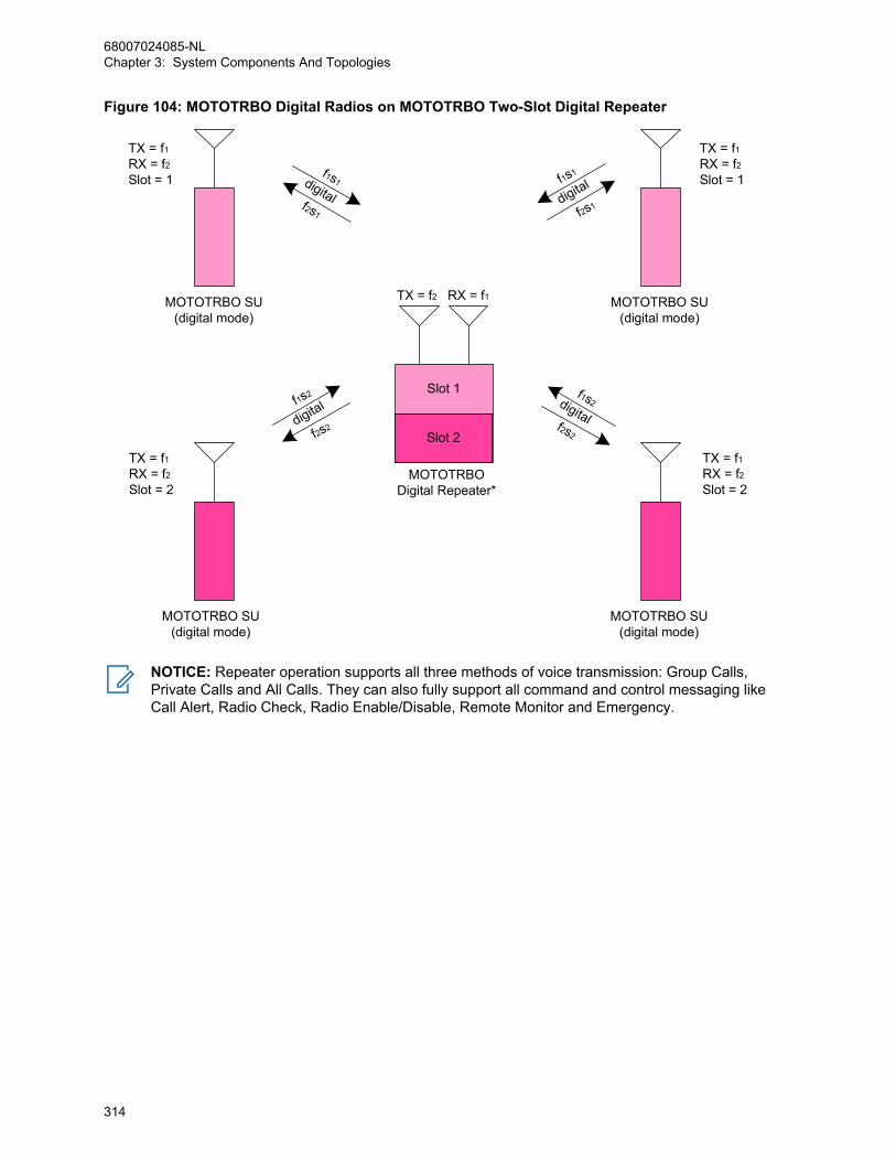
Figure 104: MOTOTRBO Digital Radios on MOTOTRBO Two-Slot Digital Repeater
MOTOTRBODigital Repeater*
RX = f1TX = f2MOTOTRBO SU(digital mode)
MOTOTRBO SU(digital mode)
Slot 1
Slot 2
TX = f1RX = f2Slot = 1
TX = f1RX = f2Slot = 1
TX = f1RX = f2Slot = 2
TX = f1RX = f2Slot = 2
f2s2
f1s2
digital
f2s1
f1s1
digitalf2s1
f1s1digital
f2s2
f1s2digital
MOTOTRBO SU(digital mode)
MOTOTRBO SU(digital mode)
NOTICE: Repeater operation supports all three methods of voice transmission: Group Calls,Private Calls and All Calls. They can also fully support all command and control messaging likeCall Alert, Radio Check, Radio Enable/Disable, Remote Monitor and Emergency.
68007024085-NLChapter 3: System Components And Topologies
314

3.2.4.1.1Text Messaging in Repeater ModeIn repeater mode, the MOTOTRBO radios are capable of sending text messages to other radios. Radioto radio text messaging is accomplished by a text messaging application that is built into the radio.From the front keypad, the radio user can select the target radio, and type a text message.
Figure 105: MOTOTRBO Radios in Digital Two-Slot Digital Repeater Mode with Built-In TextMessaging
f1s1
f1s2
f2s2
f1s1
f1s2
f2s2
f2s1f2s1
MOTOTRBODigital Repeater
RX = f1TX = f2
digital
MOTOTRBO SU(digital mode)
MOTOTRBO SU(digital mode)
Slot 1
Slot 2
TX = f1RX = f2Slot = 1
TX = f1RX = f2Slot = 1
TX = f1RX = f2Slot = 2
TX = f1RX = f2Slot = 2
digital
digital
MOTOTRBO SU(digital mode)
MOTOTRBO SU(digital mode)
digital
TM
TM
TM
TM
In order for the text message to be sent successfully to the target radio, both radios need to be on thesame channel and time slot. Similar to voice, if multiple direct mode/dual capacity direct modefrequencies are being used, the user must choose the channel his target is on before sending his textmessage. The radios do not have to be on the same group.
Text messaging and the previously discussed voice services operate on the same channel and timeslot. Since data operates in a polite manner, the radio avoids transmitting text messages while anyvoice service is active. If operating with only field radios, text messages are limited to radio to radiocommunications.
Text messages can also be sent from radio to radio using a PC attached to the radio. A software-based text messaging client will be installed on the PC. These configurations are commonly used in
68007024085-NLChapter 3: System Components And Topologies
315
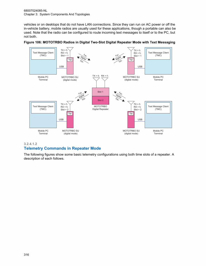
vehicles or on desktops that do not have LAN connections. Since they can run on AC power or off thein-vehicle battery, mobile radios are usually used for these applications, though a portable can also beused. Note that the radio can be configured to route incoming text messages to itself or to the PC, butnot both.
Figure 106: MOTOTRBO Radios in Digital Two-Slot Digital Repeater Mode with Text Messaging
f1s1
f2s1
f2s2
f2s1
f1s1
f1s2 f1s2
f2s2
MOTOTRBODigital Repeater
RX = f1TX = f2
digital
MOTOTRBO SU(digital mode)
MOTOTRBO SU(digital mode)
Slot 1
Slot 2
digital
digital
MOTOTRBO SU(digital mode)
TX = f1RX = f2Slot = 2
TX = f1RX = f2Slot = 2
TX = f1RX = f2Slot = 1
TX = f1RX = f2Slot = 1
MOTOTRBO SU(digital mode)
digital
TM
TM
TM
TM
Mobile PCTerminal
Text Message Client(TMC)
Mobile PCTerminal
Text Message Client(TMC)
Mobile PCTerminal
Text Message Client(TMC)
Mobile PCTerminal
Text Message Client(TMC)
USB
USB
USB
USB
3.2.4.1.2Telemetry Commands in Repeater ModeThe following figures show some basic telemetry configurations using both time slots of a repeater. Adescription of each follows.
68007024085-NLChapter 3: System Components And Topologies
316
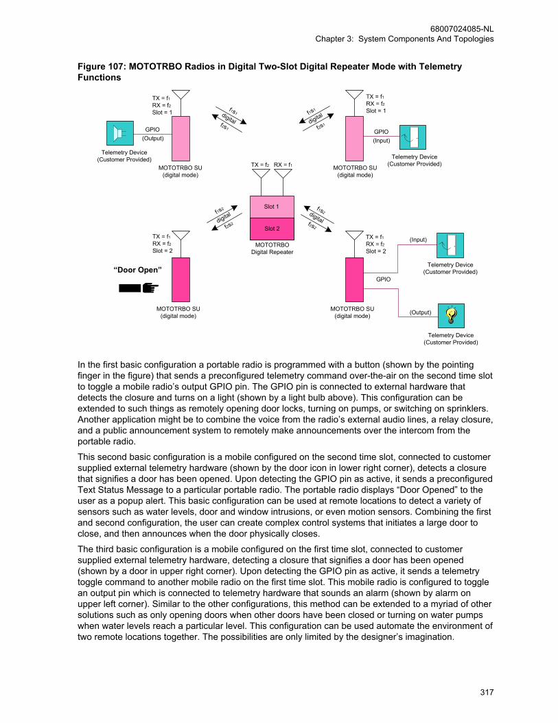
Figure 107: MOTOTRBO Radios in Digital Two-Slot Digital Repeater Mode with TelemetryFunctions
f2s1
f1s1
MOTOTRBODigital Repeater
RX = f1TX = f2
digital
f2s2
f1s2digitalf2s2
f1s2
digital
f2s1
f1s1
digital
MOTOTRBO SU(digital mode)
MOTOTRBO SU(digital mode)
Slot 1
Slot 2
TX = f1RX = f2Slot = 1
TX = f1RX = f2Slot = 2
TX = f1RX = f2Slot = 1
TX = f1RX = f2Slot = 2
MOTOTRBO SU(digital mode)
MOTOTRBO SU(digital mode)
(Input)
Telemetry Device(Customer Provided)
Telemetry Device(Customer Provided)
GPIO
(Input)
Telemetry Device(Customer Provided)“Door Open”
Telemetry Device(Customer Provided)
(Output)
GPIO(Output)
GPIO
In the first basic configuration a portable radio is programmed with a button (shown by the pointingfinger in the figure) that sends a preconfigured telemetry command over-the-air on the second time slotto toggle a mobile radio’s output GPIO pin. The GPIO pin is connected to external hardware thatdetects the closure and turns on a light (shown by a light bulb above). This configuration can beextended to such things as remotely opening door locks, turning on pumps, or switching on sprinklers.Another application might be to combine the voice from the radio’s external audio lines, a relay closure,and a public announcement system to remotely make announcements over the intercom from theportable radio.
This second basic configuration is a mobile configured on the second time slot, connected to customersupplied external telemetry hardware (shown by the door icon in lower right corner), detects a closurethat signifies a door has been opened. Upon detecting the GPIO pin as active, it sends a preconfiguredText Status Message to a particular portable radio. The portable radio displays “Door Opened” to theuser as a popup alert. This basic configuration can be used at remote locations to detect a variety ofsensors such as water levels, door and window intrusions, or even motion sensors. Combining the firstand second configuration, the user can create complex control systems that initiates a large door toclose, and then announces when the door physically closes.
The third basic configuration is a mobile configured on the first time slot, connected to customersupplied external telemetry hardware, detecting a closure that signifies a door has been opened(shown by a door in upper right corner). Upon detecting the GPIO pin as active, it sends a telemetrytoggle command to another mobile radio on the first time slot. This mobile radio is configured to togglean output pin which is connected to telemetry hardware that sounds an alarm (shown by alarm onupper left corner). Similar to the other configurations, this method can be extended to a myriad of othersolutions such as only opening doors when other doors have been closed or turning on water pumpswhen water levels reach a particular level. This configuration can be used automate the environment oftwo remote locations together. The possibilities are only limited by the designer’s imagination.
68007024085-NLChapter 3: System Components And Topologies
317
3.2.4.1.3Server Based Data Applications in Repeater Mode
NOTICE: MOTOTRBO also supports server based data applications in repeater mode. Thisconfiguration consists of a PC (referred to as the Application Server) running the serversoftware connected to the radio infrastructure through a mobile radio or through the MNISapplication. For details on data communication with applications through the repeater networkinterface instead of a control station, see MOTOTRBO Network Interface Service (MNIS) onpage 282 and MOTOTRBO Device Discovery and Mobility Service (DDMS) on page 294.
The mobile radio is usually AC powered. The mobile is configured as a control station, therefore itroutes all data to the Application Server. Since this mobile is the radio gateway to the server, it shouldbe configured to transmit and receive on a single channel (frequency and time slot). The control stationis programmed with a known radio ID so the field radios know how to contact the server. The serverand the control station (connected through a USB) must be located in an area that is in good coverageof the repeater it is communicating with. If there are multiple repeaters covering a large geographicalarea, the Application Server’s control stations must be located in good coverage of each repeater. Thisis important since it is common for the overlap between repeaters to be small and often only in lowsignal strength areas. There can only be one Application Server per system.
One key service offered by the server based configuration is radio presence notification. The PresenceNotifier is required to reside on the Application Server. The purpose of the Presence Notifier is to trackwhether field radios are currently present on the system. Upon power-up or channel change, theMOTOTRBO radio transmits a registration message to the control station connected to the ApplicationServer, where the Presence Notifier resides. The Presence Notifier then informs other dataapplications that the radio is available to receive and transmit data messages.
Each frequency and time slot that needs to communicate with the Application Server needs to have itsown control stations. The Application Server can be connected to up to 16 control stations. Eachcontrol station is configured to communicate on the specified frequency and time slot and acts as thedata gateway for that channel. Therefore a MOTOTRBO system can support server based data on upto two repeaters, each with two time slots.
When a radio powers up or changes channels, it sends a registration to the Presence Notifier throughthe control station on its frequency and time slot, which in turn informs the applications of the radio’spresence. Each control station has the same radio ID, therefore the field radios transmit theirmessages to the same radio ID regardless of which frequency and time slot they are on. Because thefield radios are located on different time slots, there needs to be a method to track the location of eachradio so that outbound data from the Application Server can be routed to the appropriate time slot. Thisis the purpose of the Multi-Channel Device Driver (or MCDD). The MCDD is a small piece of softwareinstalled on the Application Server. Its purpose is to keep track of which interface each radio iscurrently located on. Each control station is handled like a different network interface to the ApplicationServer. When the MCDD sees a registration from a radio, it updates the PC’s routing table so that anydata traffic targeted towards that radio is routed out the correct network interface, therefore out thecorrect control station and over-the-air frequency and time slot. (Note: MCDD release R1.0 version1.00.17 also updated the routing table on receipt of any data traffic, making it incompatible with GPSRevert). This allows data applications to simply transmit a data message to the radio and the MCDDtakes care of the routing to the correct frequency and time slot.
Any channel that supports data and needs to communicate to the Application Server needs adedicated control station. Below is a diagram of this configuration.
68007024085-NLChapter 3: System Components And Topologies
318
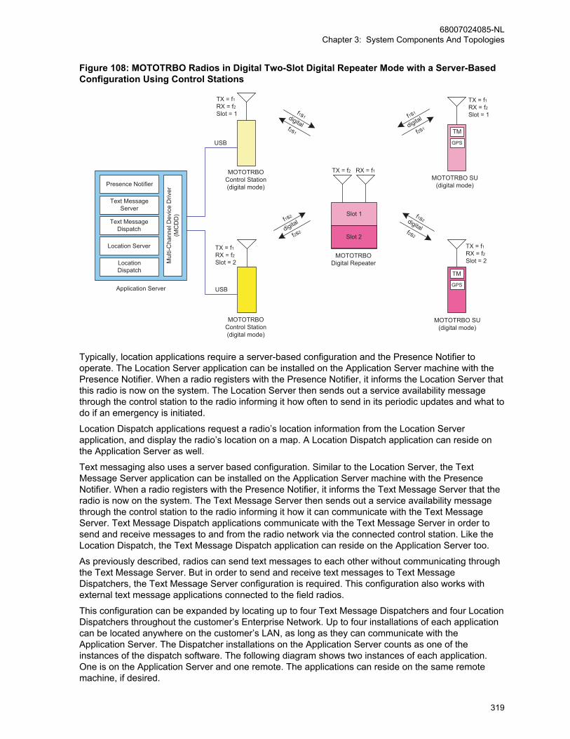
Figure 108: MOTOTRBO Radios in Digital Two-Slot Digital Repeater Mode with a Server-BasedConfiguration Using Control Stations
f1s1
f2s1
RX = f1TX = f2
digital
f1s2
f2s2
digital
Slot 1
Slot 2
f1s2
f2s2digital
f1s1
f2s1digital
TX = f1RX = f2Slot = 2
TX = f1RX = f2Slot = 2
TX = f1RX = f2Slot = 1
TX = f1RX = f2Slot = 1
TM
TM
GPS
GPS
Text MessageServer
Presence Notifier
Mul
ti-C
hann
el D
evic
e D
river
(MC
DD
)
Text MessageDispatch
Location Server
LocationDispatch
Application Server
USB
USB
MOTOTRBOControl Station(digital mode)
MOTOTRBOControl Station(digital mode)
MOTOTRBO SU(digital mode)
MOTOTRBO SU(digital mode)
MOTOTRBODigital Repeater
Typically, location applications require a server-based configuration and the Presence Notifier tooperate. The Location Server application can be installed on the Application Server machine with thePresence Notifier. When a radio registers with the Presence Notifier, it informs the Location Server thatthis radio is now on the system. The Location Server then sends out a service availability messagethrough the control station to the radio informing it how often to send in its periodic updates and what todo if an emergency is initiated.
Location Dispatch applications request a radio’s location information from the Location Serverapplication, and display the radio’s location on a map. A Location Dispatch application can reside onthe Application Server as well.
Text messaging also uses a server based configuration. Similar to the Location Server, the TextMessage Server application can be installed on the Application Server machine with the PresenceNotifier. When a radio registers with the Presence Notifier, it informs the Text Message Server that theradio is now on the system. The Text Message Server then sends out a service availability messagethrough the control station to the radio informing it how it can communicate with the Text MessageServer. Text Message Dispatch applications communicate with the Text Message Server in order tosend and receive messages to and from the radio network via the connected control station. Like theLocation Dispatch, the Text Message Dispatch application can reside on the Application Server too.
As previously described, radios can send text messages to each other without communicating throughthe Text Message Server. But in order to send and receive text messages to Text MessageDispatchers, the Text Message Server configuration is required. This configuration also works withexternal text message applications connected to the field radios.
This configuration can be expanded by locating up to four Text Message Dispatchers and four LocationDispatchers throughout the customer’s Enterprise Network. Up to four installations of each applicationcan be located anywhere on the customer’s LAN, as long as they can communicate with theApplication Server. The Dispatcher installations on the Application Server counts as one of theinstances of the dispatch software. The following diagram shows two instances of each application.One is on the Application Server and one remote. The applications can reside on the same remotemachine, if desired.
68007024085-NLChapter 3: System Components And Topologies
319
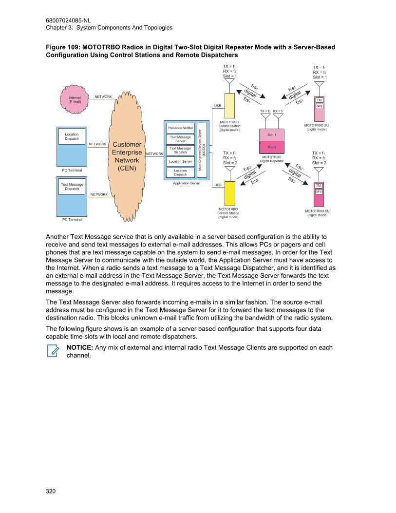
Figure 109: MOTOTRBO Radios in Digital Two-Slot Digital Repeater Mode with a Server-BasedConfiguration Using Control Stations and Remote Dispatchers
RX = f1TX = f2
Slot 1
Slot 2
f1s2
f2s2digital
f1s1
f2s1digital
TX = f1RX = f2Slot = 2
TX = f1RX = f2Slot = 2
TX = f1RX = f2Slot = 1
TX = f1RX = f2Slot = 1
f1s2
f2s2
digital
f1s1
f2s1
digitalTM
GPS
TM
GPS
Text MessageServer
Presence Notifier
Mul
ti-C
hann
el D
evic
e D
river
(MC
DD
)
Text MessageDispatch
Location Server
LocationDispatch
Application Server
USB
USB
PC Terminal
PC Terminal
LocationDispatch
Text MessageDispatch
CustomerEnterpriseNetwork(CEN)
MOTOTRBO SU(digital mode)
MOTOTRBO SU(digital mode)
MOTOTRBOControl Station(digital mode)
MOTOTRBOControl Station(digital mode)
MOTOTRBODigital Repeater
Internet(E-mail)
NETWORK
NETWORK
NETWORK
NETWORK
Another Text Message service that is only available in a server based configuration is the ability toreceive and send text messages to external e-mail addresses. This allows PCs or pagers and cellphones that are text message capable on the system to send e-mail messages. In order for the TextMessage Server to communicate with the outside world, the Application Server must have access tothe Internet. When a radio sends a text message to a Text Message Dispatcher, and it is identified asan external e-mail address in the Text Message Server, the Text Message Server forwards the textmessage to the designated e-mail address. It requires access to the Internet in order to send themessage.
The Text Message Server also forwards incoming e-mails in a similar fashion. The source e-mailaddress must be configured in the Text Message Server for it to forward the text messages to thedestination radio. This blocks unknown e-mail traffic from utilizing the bandwidth of the radio system.
The following figure shows is an example of a server based configuration that supports four datacapable time slots with local and remote dispatchers.
NOTICE: Any mix of external and internal radio Text Message Clients are supported on eachchannel.
68007024085-NLChapter 3: System Components And Topologies
320

Figure 110: MOTOTRBO Radios in Digital Two-Slot, Digital Repeater Mode with Text MessageServer, Location Server Using Control Stations with Local and Remote Dispatchers
Mobile PCTerminal
Mobile PCTerminal
TM
GPS
PC Terminal
PC Terminal
PC Terminal
PC Terminal
Application Server
Internet(E-mail)
CustomerEnterpriseNetwork(CEN)
RX = f3TX = f4
RX = f1TX = f2
Slot 1
Slot 2
Slot 1
Slot 2
TX = f3RX = f4Slot = 1
TX = f3RX = f4Slot = 1
TX = f1RX = f2Slot = 2
TX = f1RX = f2Slot = 2
TX = f1RX = f2Slot = 1
TX = f1RX = f2Slot = 1
TX = f3RX = f4Slot = 2
TX = f3RX = f4Slot = 2
f3s2
f4s2digital
f3s1
f4s1digital
f1s2
f2s2digital
f1s1
f2s1digital
f3s1
f4s1
digital
f1s2
f2s2
digital
f1s1
f2s1
digital
f3s2
f4s2
digital
Text Message Client(TMC)
Text Message Client(TMC)
TM
GPS
GPS
Text MessageServer
Presence Notifier
Mul
ti-C
hann
el D
evic
e D
river
(MC
DD
)
Text MessageDispatch
Location Server
LocationDispatch USB
USB USB
USB
USB USB
NETWORK
NETWORK
LocationDispatch
Text MessageDispatch
LocationDispatch
LocationDispatch
Text MessageDispatch
Text MessageDispatch
NETWORK
NETWORK
NETWORK
NETWORK
GPS
MOTOTRBOControl Station(digital mode)
MOTOTRBOControl Station(digital mode)
MOTOTRBOControl Station(digital mode)
MOTOTRBOControl Station(digital mode)
MOTOTRBO SU(digital mode)
MOTOTRBO SU(digital mode)
MOTOTRBO SU(digital mode)
MOTOTRBO SU(digital mode)
MOTOTRBODigital Repeater
MOTOTRBODigital Repeater
3.2.4.1.4GPS Revert in Repeater ModeWith the addition of the GPS Revert feature, it is now possible to transmit Location Update messageson channels other than the Selected Channel. See GPS Revert Channel on page 104 for configurationinformation. Figure 111: MOTOTRBO Radios in Two-Slot Digital Repeater Mode with GPS RevertConfiguration on page 322 illustrates this concept in its simplest form while operating in repeater mode.In this example, channels f1s1 and f2s1 compose the Selected Channel frequency pair and channelsf1s2 and f2s2 compose the GPS Revert Channel frequency pair. Communications such a presence,location requests (Application Server to radio), text, and voice occur on the Selected Channel, while alllocation responses (radio to Application Server) including location updates occur on the GPS RevertChannel. Therefore, a minimum of two control stations are required to support GPS Revert.
68007024085-NLChapter 3: System Components And Topologies
321
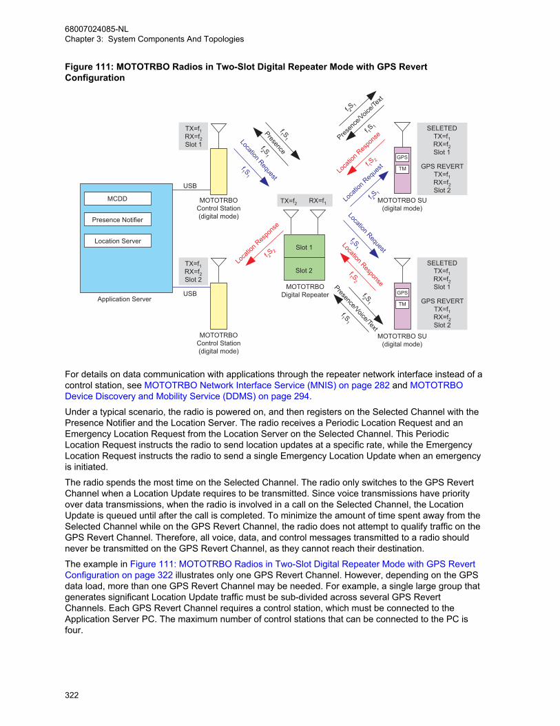
Figure 111: MOTOTRBO Radios in Two-Slot Digital Repeater Mode with GPS RevertConfiguration
MOTOTRBOControl Station(digital mode)
MOTOTRBOControl Station(digital mode)
MOTOTRBODigital Repeater
MCDD
Presence Notifier
Location Server
USB
USB
Application Server
MOTOTRBO SU(digital mode)
MOTOTRBO SU(digital mode)
GPS
TM
GPS
TM
SELETEDTX=f1RX=f2Slot 1
GPS REVERTTX=f1RX=f2Slot 2
SELETEDTX=f1RX=f2Slot 1
GPS REVERTTX=f1RX=f2Slot 2
TX=f1RX=f2Slot 1
TX=f1RX=f2Slot 2
Location RequestPresence
f1 S1
f2 S1
Presen
ce/Voic
e/Tex
t
f 2S 1
f 1S 1
f 1S 2
f 2S 2
f1 S2
Presence/Voice/Text
f2 S1
f2 S1
f1 S1
f 2S 1
f1 S1
Loca
tion R
espo
nse
Location Response
Loca
tion R
espo
nse
Loca
tion R
eque
st
Location Request
TX=f2 RX=f1
Slot 1
Slot 2
For details on data communication with applications through the repeater network interface instead of acontrol station, see MOTOTRBO Network Interface Service (MNIS) on page 282 and MOTOTRBODevice Discovery and Mobility Service (DDMS) on page 294.
Under a typical scenario, the radio is powered on, and then registers on the Selected Channel with thePresence Notifier and the Location Server. The radio receives a Periodic Location Request and anEmergency Location Request from the Location Server on the Selected Channel. This PeriodicLocation Request instructs the radio to send location updates at a specific rate, while the EmergencyLocation Request instructs the radio to send a single Emergency Location Update when an emergencyis initiated.
The radio spends the most time on the Selected Channel. The radio only switches to the GPS RevertChannel when a Location Update requires to be transmitted. Since voice transmissions have priorityover data transmissions, when the radio is involved in a call on the Selected Channel, the LocationUpdate is queued until after the call is completed. To minimize the amount of time spent away from theSelected Channel while on the GPS Revert Channel, the radio does not attempt to qualify traffic on theGPS Revert Channel. Therefore, all voice, data, and control messages transmitted to a radio shouldnever be transmitted on the GPS Revert Channel, as they cannot reach their destination.
The example in Figure 111: MOTOTRBO Radios in Two-Slot Digital Repeater Mode with GPS RevertConfiguration on page 322 illustrates only one GPS Revert Channel. However, depending on the GPSdata load, more than one GPS Revert Channel may be needed. For example, a single large group thatgenerates significant Location Update traffic must be sub-divided across several GPS RevertChannels. Each GPS Revert Channel requires a control station, which must be connected to theApplication Server PC. The maximum number of control stations that can be connected to the PC isfour.
68007024085-NLChapter 3: System Components And Topologies
322

3.2.4.1.5Enhanced GPS Revert in Repeater Mode
IPSCIP Site Connect
Enhanced GPS Revert feature is supported inIP Site Connect mode of operation.
CPSSCapacity Plus Single Site
Enhanced GPS Revert feature is supported inCapacity Plus Single Site mode of operation.
CPMSCapacity Plus Multi Site
Enhanced GPS Revert feature is supported inCapacity Plus Multi Site mode of operation.
This section provides the recommended system topologies for the Enhanced GPS Revert feature inSingle Site, Capacity Plus Single Site, Capacity Plus Multi Site and IP Site Connect modes ofoperation.
3.2.4.1.5.1Single Site ConventionalFigure 112: Single Site Conventional System with an Enhanced GPS Revert Channel on page 324 is asystem configuration that shows how the Enhanced GPS Revert feature can be used in single sitemode operation. It is assumed that the repeater has slot one configured for Voice, Text and ARS dataand slot two for location responses. When a radio powers on, the radio registers on the Home channelwith the Presence Notifier, which notifies the Location Server. All outbound data from the server(including location request) is routed on the Home channel whereas all location responses are on theEnhanced GPS Revert channel. There should not be any non-GPS traffic on the GPS Revert channelas it affects GPS reliability. Voice calls on an Enhanced GPS Revert channel are not repeated.
68007024085-NLChapter 3: System Components And Topologies
323

Figure 112: Single Site Conventional System with an Enhanced GPS Revert Channel
Presence Notifier
MCDD
Location ServerSlot 2
Slot 1
Application Server
Control StationSlot 1
Control StationSlot 2
Tx = f2
GPSTM
GPSTM
Rx = f1 USB
USB
f1S1Location Request
Loca
tion R
eque
st
f2s1
Location Request
f2s1
Location Response
f1s2Lo
catio
n Res
pons
e
f1s2
Voice , text & ARS
Channel
Enhanced GPS Revert
Channel
f2s2
Location Response
GPS Data
f1S2
GPS Data
f1S2
For details on data communication with applications through the repeater network interface instead of acontrol station, see MOTOTRBO Network Interface Service (MNIS) on page 282 and MOTOTRBODevice Discovery and Mobility Service (DDMS) on page 294.
A user may also configure both slots of the repeater for enhanced GPS through the CPS. In thisscenario, the user needs another repeater for voice and regular data, because only GPS data issupported on slots configured with Enhanced GPS.
3.2.4.1.5.2IP Site Connect Mode
IPSC
Figure 113: IP Site Connect System with an Enhanced GPS Revert Channel on page 325 shows atypical IP Site Connect system where slot 2 of all the repeaters have been configured as a wide areaEnhanced GPS Revert channel and slot 1 as the Home channel. Only location responses are routedon slot 2, whereas voice, text and ARS messages are routed using slot 1 (Home channel). TheEnhanced GPS revert slot (slot 2) of all the repeaters and all subscribers in the system that send GPSdata using the Enhanced GPS revert functionality should have the same window size.
The total number of windows are shared among all the wide area Enhanced GPS revert repeaters inthe system. Only one repeater in the system should have a value (90%, 75%, 60% or 45%) selectedfor Period Window Reservation (this does not have to be the Master repeater, a peer is also possible),whereas all the other repeaters in the system select a value of “None” using CPS. The repeaterscheduler then schedule windows for all the other wide area enhanced GPS revert repeaters.
68007024085-NLChapter 3: System Components And Topologies
324

The application server and control stations can be in the coverage area of any repeater in the IP SiteConnect system. In below, they are shown to be in the coverage area of repeater 1. For a window sizeof 5 or 6, it is recommended to use a network with an inter-repeater communication delay of 60milliseconds or less. In case delay is observed to be higher than 60 milliseconds, then a window sizegreater than 7 is recommended for system reliability even if the amount of data requires a smallerwindow size.
NOTICE: Increasing the window size decreases the system throughput.
The user may also configure both slots of the wide area system for enhanced GPS revert. In thisscenario, the user will need to configure both voice and other data on a different IP Site Connectsystem.
Figure 113: IP Site Connect System with an Enhanced GPS Revert Channel
Wide Area Network
PresenceNotifier
MCDD
LocationServer
ApplicationServer
Rep 2
Rep 3 Rep 13
Rep 14
Rep 15
Wide AreaScheduled GPS
Revert Slot
MOTOTRBOControl Station
MOTOTRBOControl Station
Voice , Text& ARS Channel
Enhanced GPSRevert Slot
Voice , Text& ARS Channel
Voice , Text& ARS Channel
Enhanced GPSRevert Slot
Voice , Text& ARS Channel
Enhanced GPSRevert Slot
Voice , Text& ARS Channel
Enhanced GPSRevert Slot
Voice , Text& ARS Channel
Enhanced GPSRevert Slot
Location Response& GPS Data (S2)
Voice , Text & ARS (S1)
Location Request (S1)
Loca
tion R
espo
nse
& GPS D
ata (S
2)
Voice ,
Text
& ARS (S1)
Loca
tion R
eque
st (S
1)
Location Response& GPS Data (S2)
Voice , Text & ARS (S1)
Location Request (S1)
Location Response
& GPS Data (S2)
Voice , Text & ARS (S1)
Location Request (S1)
Loca
tion R
espo
nse
& GPS D
ata (S
2)
Voice ,
Text
& ARS (S1)
Loca
tion R
eque
st (S
1)
Location Request (S1)
Location Response& GPS Data (S2)
Voice , Text & ARS (S1)
Location Request (S1)
Slot 1
Slot 2
Rep 1
Voice , Text& ARS Channel
Enhanced GPSRevert Slot
Location Response& GPS Data (S2)
Voice , Text & ARS (S1)
Location Request (S1)
Location Response
Slot 1
Slot 2
Slot 1
Slot 2
Slot 1
Slot 2
Slot 1
Slot 2
Slot 1
Slot 2
Slot 1
Slot 2
For details on data communication with applications through the repeater network interface instead of acontrol station, see MOTOTRBO Network Interface Service (MNIS) on page 282 and MOTOTRBODevice Discovery and Mobility Service (DDMS) on page 294.
68007024085-NLChapter 3: System Components And Topologies
325

3.2.4.1.5.3Capacity Plus Single Site Mode
CPSS In Capacity Plus Single Site mode, one or both slots of a Data Revert repeater can be
configured as Enhanced GPS Revert channels.
Text and server data are routed on the slot configured for Data Revert whereas GPS and ARSregistration data is routed on the slot configured for Enhanced GPS Revert. The location requests aresent on the Trunked Channel while the location responses are sent on the Enhanced GPS Revertchannel.
Figure 114: A Capacity Plus Single Site System with an Enhanced GPS Revert Channel
Presence Notifier
Location Server
Application Server
Trunked ControlStation
EnhancedGPS Revert(ARS also)
Text & Server Data
Data Revert Repeater
Trunked Repeater
EGPS ControlStation
VoiceChannels
f2s1
Text & Serve
r Data
f2s2
GPS / ARS data
f4s1/s2
Voice Traffic
ConventionalControl Station
f2s1
Text & Server Dataf2s2
Location Response
f3 f4
Slot 1
Slot 2
f1 f2
Slot 1
Slot 2
f3s1/s2
Location Request
For details on data communication with applications through the repeater network interface instead of acontrol station, see MOTOTRBO Network Interface Service (MNIS) on page 282 and MOTOTRBODevice Discovery and Mobility Service (DDMS) on page 294.
68007024085-NLChapter 3: System Components And Topologies
326

3.2.4.1.6Summary of Features in Digital Repeater ModeThe following features are supported in digital repeater mode:
Table 61: Digital MOTOTRBO Radios in Repeater Mode
Voice Features Signaling Fea-tures
EmergencyHandling
Data Calls Other Features
Group Call PTT ID and Ali-asing
EmergencyAlarm
Text Messaging
Two channels(slot 1 and slot2) per repeaterfrequency pair
Private Call Radio Inhibit EmergencyAlarm with Call
Location Track-ing
Scan*
All Call Remote Monitor EmergencyAlarm with Voiceto Follow
Telemetry Time-out Timer
Voice Interrupt Radio Check Emergency Re-vert
Third-Party(ADP) Applica-tions
Polite to All sys-tem access
Dual Tone MultiFrequency
Call Alert EmergencyVoice Interrupt
GPS Revert Polite to OwnSystem channelaccess
Digital Tele-phone Patch
Remote VoiceDekey
– Data Over VoiceInterrupt
Impolite channelaccess
* See Scan Considerations on page 144 for more information on the different scan modes supportedby different topologies.
3.2.4.2Analog MOTOTRBO Radios in Repeater ModeMOTOTRBO radios support analog repeater mode as well.
Figure 115: MOTOTRBO Analog and Legacy Analog Radios on Legacy Analog Repeater
RX = f2TX = f1 TX = f1
RX = f2
f1
f2
LegacyAnalog SU
LegacyAnalog Repeater
f1
f2
RX = f1TX = f2
analog
MOTOTRBO SU(analog mode)
analog
68007024085-NLChapter 3: System Components And Topologies
327

In order for the MOTOTRBO radio to communicate with the existing analog or Dynamic Mixed Moderepeater, it must be programmed for analog mode as well as programmed with the same frequencyand other options (PL, DPL, and others), as the existing analog or Dynamic Mixed Mode repeater.While in analog mode, the MOTOTRBO radio supports most standard analog features including asubset of MDC signaling features. While in analog repeater mode, the MOTOTRBO radios do notsupport any of the digital features. While in Dynamic Mixed repeater mode, MOTOTRBO radiossupport both analog and digital features.
Figure 116: MOTOTRBO Analog and Legacy Analog Radios on MOTOTRBO Analog Repeater
TX = f1RX = f2
TX = f1RX = f2
f1
f2
LegacyAnalog SU
MOTOTRBOAnalog Repeater
f1
f2
RX = f1TX = f2
analog
MOTOTRBO SU(analog mode)
analog
If required, the MOTOTRBO repeater can be programmed to operate in analog repeater mode. Whenoperating in this mode, it inter-operates with the existing analog radios and the MOTOTRBO radiosoperating in analog mode. It is important to note that the MOTOTRBO repeater can only be configuredto operate in analog mode or digital mode. It does not do both at the same time.
If required, the MOTOTRBO repeater can be programmed to operate in Dynamic Mixed Mode. Whenoperating in this mode, repeater inter-operates with the existing analog radios and the MOTOTRBOradios operating in analog and digital modes. Repeater dynamically switches between analog anddigital calls. While the repeater repeats one analog call at a time, it repeats two digital calls at a time(one on each logical channel).
The MOTOTRBO radio can be configured with both analog and digital repeater channels. The user canselect between the analog and digital repeaters through the Channel Selector Knob.
Alternatively, the MOTOTRBO radio user can program the radio to scan between the analog and digitalchannels to ensure that they do not miss a call. The programming can be done from the keypad of theradio or through CPS.
The following is an example configuration of a mixed repeater mode system.
68007024085-NLChapter 3: System Components And Topologies
328
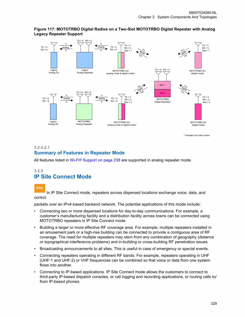
Figure 117: MOTOTRBO Digital Radios on a Two-Slot MOTOTRBO Digital Repeater with AnalogLegacy Repeater Support
MOTOTRBO SU(analog mode & digital mode)*
f3
f4analog
f3
f4
LegacyAnalog SU
RX = f3TX = f4
analogTX = f3RX = f4
TX = f5RX = f6
TX = f3RX = f4
TX = f1RX = f2Slot = 1
TX = f1RX = f2Slot = 1
TX = f1RX = f2Slot = 2
TX = f1RX = f2Slot = 2
LegacyAnalog Repeater
* changed via mode choice
f2s1
f1s1
MOTOTRBODigital Repeater*
RX = f1TX = f2
digital
f2s2
f1s2digital
f2s1
f1s1
digital
f2s2
f1s2
digital
MOTOTRBO SU(digital mode)
Slot 1
Slot 2
MOTOTRBO SU(digital mode)
LegacyAnalog SU
RX = f5TX = f6
MOTOTRBO SU(analog mode & digital mode)*
TX = f5RX = f6
f5
f6analog
MOTOTRBOAnalog Repeater
f5
f6analog
3.2.4.2.1Summary of Features in Repeater ModeAll features listed in Wi-Fi® Support on page 238 are supported in analog repeater mode.
3.2.5IP Site Connect Mode
IPSC In IP Site Connect mode, repeaters across dispersed locations exchange voice, data, and
control
packets over an IPv4-based backend network. The potential applications of this mode include:
• Connecting two or more dispersed locations for day-to-day communications. For example, acustomer’s manufacturing facility and a distribution facility across towns can be connected usingMOTOTRBO repeaters in IP Site Connect mode.
• Building a larger or more effective RF coverage area. For example, multiple repeaters installed inan amusement park or a high-rise building can be connected to provide a contiguous area of RFcoverage. The need for multiple repeaters may stem from any combination of geography (distanceor topographical interference problems) and in-building or cross-building RF penetration issues.
• Broadcasting announcements to all sites. This is useful in case of emergency or special events.
• Connecting repeaters operating in different RF bands. For example, repeaters operating in UHF(UHF-1 and UHF-2) or VHF frequencies can be combined so that voice or data from one systemflows into another.
• Connecting to IP-based applications. IP Site Connect mode allows the customers to connect tothird-party IP-based dispatch consoles, or call logging and recording applications, or routing calls to/from IP-based phones.
68007024085-NLChapter 3: System Components And Topologies
329
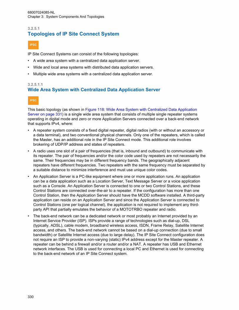
3.2.5.1Topologies of IP Site Connect System
IPSC
IP Site Connect Systems can consist of the following topologies:
• A wide area system with a centralized data application server.
• Wide and local area systems with distributed data application servers.
• Multiple wide area systems with a centralized data application server.
3.2.5.1.1Wide Area System with Centralized Data Application Server
IPSC
This basic topology (as shown in Figure 118: Wide Area System with Centralized Data ApplicationServer on page 331) is a single wide area system that consists of multiple single repeater systemsoperating in digital mode and zero or more Application Servers connected over a back-end networkthat supports IPv4, where:
• A repeater system consists of a fixed digital repeater, digital radios (with or without an accessory ora data terminal), and two conventional physical channels. Only one of the repeaters, which is calledthe Master, has an additional role in the IP Site Connect mode. This additional role involvesbrokering of UDP/IP address and states of repeaters.
• A radio uses one slot of a pair of frequencies (that is, inbound and outbound) to communicate withits repeater. The pair of frequencies and/or the color code used by repeaters are not necessarily thesame. Their frequencies may be in different frequency bands. The geographically adjacentrepeaters have different frequencies. Two repeaters with the same frequency must be separated bya suitable distance to minimize interference and must use unique color codes.
• An Application Server is a PC-like equipment where one or more application runs. An applicationcan be a data application such as a Location Server, Text Message Server or a voice applicationsuch as a Console. An Application Server is connected to one or two Control Stations, and theseControl Stations are connected over-the-air to a repeater. If the configuration has more than oneControl Station, then the Application Server should have the MCDD software installed. A third-partyapplication can reside on an Application Server and since the Application Server is connected toControl Stations (one per logical channel), the application is not required to implement any third-party API that partially emulates the behavior of a MOTOTRBO repeater and radio.
• The back-end network can be a dedicated network or most probably an Internet provided by anInternet Service Provider (ISP). ISPs provide a range of technologies such as dial-up, DSL(typically, ADSL), cable modem, broadband wireless access, ISDN, Frame Relay, Satellite Internetaccess, and others. The back-end network cannot be based on a dial-up connection (due to smallbandwidth) or Satellite Internet access (due to large delay). The IP Site Connect configuration doesnot require an ISP to provide a non-varying (static) IPv4 address except for the Master repeater. Arepeater can be behind a firewall and/or a router and/or a NAT. A repeater has USB and Ethernetnetwork interfaces. The USB is used for connecting a local PC and Ethernet is used for connectingto the back-end network of an IP Site Connect system.
68007024085-NLChapter 3: System Components And Topologies
330
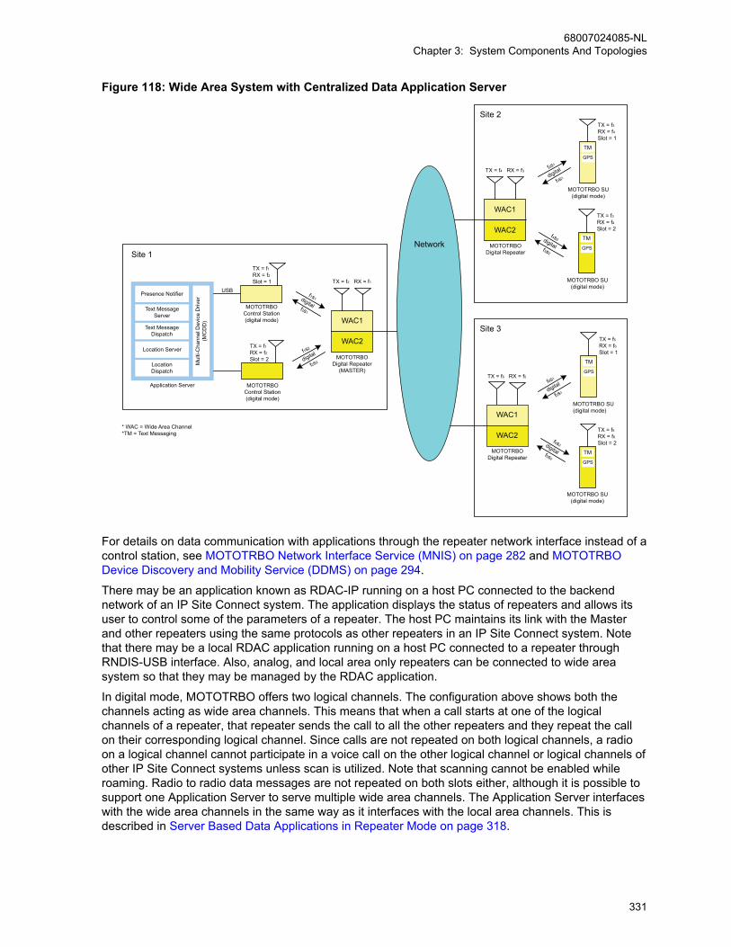
Figure 118: Wide Area System with Centralized Data Application Server
f1s1
f2s1
WAC1
RX = f1TX = f2
digital
f1s2
f2s2digital
f6s1
f5s1digital
f6s2
f5s2
digital
MOTOTRBO Control Station(digital mode)
MOTOTRBO Control Station(digital mode)
MOTOTRBO Digital Repeater
(MASTER)
Text MessageServer
Presence Notifier
Mul
ti-C
hann
el D
evic
e D
river
(MC
DD
)
Text MessageDispatch
Location Server
LocationDispatch
Application Server
USB
MOTOTRBODigital Repeater
RX = f3TX = f4
Network
WAC2
WAC1
WAC2
MOTOTRBODigital Repeater
RX = f5TX = f6
WAC1
WAC2
TX = f3RX = f4Slot = 1
MOTOTRBO SU(digital mode)
TM
GPS
TX = f3RX = f4Slot = 2
MOTOTRBO SU(digital mode)
TM
GPS
TX = f5RX = f6Slot = 1
TM
GPS
TX = f5RX = f6Slot = 2
MOTOTRBO SU(digital mode)
MOTOTRBO SU(digital mode)
TM
GPS
* WAC = Wide Area Channel*TM = Text Messaging
Site 1
Site 2
Site 3
TX = f1RX = f2Slot = 2
TX = f1RX = f2Slot = 1
f4s1
f3s1digital
f4s2
f3s2
digital
For details on data communication with applications through the repeater network interface instead of acontrol station, see MOTOTRBO Network Interface Service (MNIS) on page 282 and MOTOTRBODevice Discovery and Mobility Service (DDMS) on page 294.
There may be an application known as RDAC-IP running on a host PC connected to the backendnetwork of an IP Site Connect system. The application displays the status of repeaters and allows itsuser to control some of the parameters of a repeater. The host PC maintains its link with the Masterand other repeaters using the same protocols as other repeaters in an IP Site Connect system. Notethat there may be a local RDAC application running on a host PC connected to a repeater throughRNDIS-USB interface. Also, analog, and local area only repeaters can be connected to wide areasystem so that they may be managed by the RDAC application.
In digital mode, MOTOTRBO offers two logical channels. The configuration above shows both thechannels acting as wide area channels. This means that when a call starts at one of the logicalchannels of a repeater, that repeater sends the call to all the other repeaters and they repeat the callon their corresponding logical channel. Since calls are not repeated on both logical channels, a radioon a logical channel cannot participate in a voice call on the other logical channel or logical channels ofother IP Site Connect systems unless scan is utilized. Note that scanning cannot be enabled whileroaming. Radio to radio data messages are not repeated on both slots either, although it is possible tosupport one Application Server to serve multiple wide area channels. The Application Server interfaceswith the wide area channels in the same way as it interfaces with the local area channels. This isdescribed in Server Based Data Applications in Repeater Mode on page 318.
68007024085-NLChapter 3: System Components And Topologies
331

3.2.5.1.2Wide and Local Area Systems with Distributed Data Application ServersIt is possible that one of the logical wide area channels of the repeaters is configured for localcommunication only. In this case, each site has its own logical channel for local communication. This isuseful in case a customer need a significant load of local communication. This configuration offloadsthe local communication from the wide area channel.
Figure 119: Wide and Local Area System with Distributed Data Application Servers on page 332 showsan example of such configuration in which one of the logical channels (say, slot 2) is used in IP SiteConnect mode (wide area) and the other (slot 1) is used in digital repeater mode (local area). The callsoriginating on slot 1 are not sent to other repeaters. A customer should use slot 1 for local groupswhose members are expected to be present in the coverage area of the repeater; and slot 2 for groupswhose members are distributed over the coverage area of multiple repeaters.
Figure 119: Wide and Local Area System with Distributed Data Application Servers
WAC1
MOTOTRBODigital Repeater( MASTER )
Text MessageServer
Presence Notifier
Text MessageDispatch
Location Server
LocationDispatch
Application Server
USB
Network
LC1
* WAC = Wide Area Channel*LC = Local Channel*TM = Text Messaging
Site 1
WAC1
MOTOTRBODigital Repeater
MOTOTRBOControl Station(digital mode)
MOTOTRBOControl Station(digital mode)
Text MessageServer
Presence Notifier
Mul
ti-C
hann
el D
evic
e D
river
(MC
DD
)M
ulti-
Cha
nnel
Dev
ice
Driv
er(M
CD
D)
Text MessageDispatch
Location Server
LocationDispatch
Application Server
USB
LC2
Site 2
TX = f3RX = f4Slot = 2
TX = f1RX = f2Slot = 1
WAC1
MOTOTRBODigital Repeater
RX = f5
RX = f7
TX = f6
TX = f8
RX = f3TX = f4
RX = f1TX = f2
MOTOTRBOControl Station(digital mode)
MOTOTRBOControl Station(digital mode)
MOTOTRBOControl Station(digital mode)
Text MessageServer
Presence NotifierMulti-C
hannel Device D
river(M
CD
D)
Text MessageDispatch
Location Server
LocationDispatch
Application Server
USB
LC3
Site 3
TX = f5RX = f6Slot = 2
TX = f7RX = f8Slot = 1
TX = f7RX = f8Slot = 2
LC4
MOTOTRBODigital Repeater
LC5
f5s2
f6s2digital
f1s1
f2s1digital
f3s2
f4s2
digital
f7s1
f8s1digital
f8s2
f7s2
digital
For details on data communication with applications through the repeater network interface instead of acontrol station, see MOTOTRBO Network Interface Service (MNIS) on page 282 and MOTOTRBODevice Discovery and Mobility Service (DDMS) on page 294
The data messages sent over local channel 1 are not delivered to the Application Server 1 andtherefore, if required, each geographical location should have their own Application Server with theirown Presence Notifier. When a radio manually roams (changes dial positions) between a local areachannel and a wide area channel, the radio registers with its respective Presence Notifier. To facilitatethis, the radio ID of the control stations should be configured to be the same.
If a customer requires more local capacity at a location then it is possible to add more repeatersworking in Single-Site configuration and all the local slots of all the repeaters can share the sameApplication Server. In that case, the radios on the local channel are not be able to communicate withthe wide area channels’ Application Server.
3.2.5.1.3Multiple Wide Area Systems with a Centralized Data Application ServerIf a customer requires more wide area capacity, then it is possible to add another set of repeatersworking in IP Site Connect mode. It is possible for the repeaters to share the same Application Server,as shown in Figure 120: Multiple Wide Area Systems with Centralized Data Application Server on page
68007024085-NLChapter 3: System Components And Topologies
332
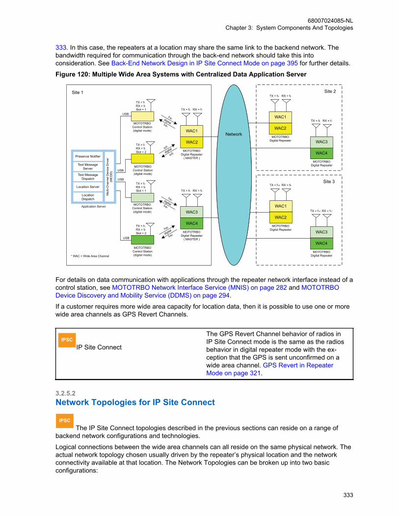
333. In this case, the repeaters at a location may share the same link to the backend network. Thebandwidth required for communication through the back-end network should take this intoconsideration. See Back-End Network Design in IP Site Connect Mode on page 395 for further details.
Figure 120: Multiple Wide Area Systems with Centralized Data Application Server
f1s1
f2s1
WAC1
MOTOTRBO Digital Repeater
( MASTER )
RX = f1TX = f2
s2f1
s2f2
MOTOTRBO Control Station(digital mode)
MOTOTRBO Control Station(digital mode)
Text MessageServer
Presence Notifier
Mul
ti-C
hann
el D
evic
e D
river
(MC
DD
)
Text MessageDispatch
Location Server
LocationDispatch
Application Server
MOTOTRBODigital Repeater
RX = f5TX = f6
WAC2
WAC1
WAC2
MOTOTRBODigital Repeater
RX = f9TX = f10
WAC1
WAC2
* WAC = Wide Area Channel
Site 1 Site 2
Site 3
TX = f1RX = f2Slot = 2
TX = f1RX = f2Slot = 1
MOTOTRBODigital Repeater
RX = f11TX = f12
WAC3
WAC4
f3s1
f4s1
WAC3
MOTOTRBODigital Repeater
( MASTER )
RX = f3TX = f4
f3s2
f4s2digital
digital
digital
digital
MOTOTRBO Control Station(digital mode)
MOTOTRBO Control Station(digital mode)
USB
WAC4TX = f3RX = f4Slot = 2
TX = f3RX = f4Slot = 1
MOTOTRBODigital Repeater
RX = f7TX = f8
WAC3
WAC4
USB
USB
USB
Network
For details on data communication with applications through the repeater network interface instead of acontrol station, see MOTOTRBO Network Interface Service (MNIS) on page 282 and MOTOTRBODevice Discovery and Mobility Service (DDMS) on page 294.
If a customer requires more wide area capacity for location data, then it is possible to use one or morewide area channels as GPS Revert Channels.
IPSCIP Site Connect
The GPS Revert Channel behavior of radios inIP Site Connect mode is the same as the radiosbehavior in digital repeater mode with the ex-ception that the GPS is sent unconfirmed on awide area channel. GPS Revert in RepeaterMode on page 321.
3.2.5.2Network Topologies for IP Site Connect
IPSC The IP Site Connect topologies described in the previous sections can reside on a range of
backend network configurations and technologies.
Logical connections between the wide area channels can all reside on the same physical network. Theactual network topology chosen usually driven by the repeater’s physical location and the networkconnectivity available at that location. The Network Topologies can be broken up into two basicconfigurations:
68007024085-NLChapter 3: System Components And Topologies
333

• Local Area Network Configuration
• Wide Area Network Configuration
But note that most network topologies will be a combination of both Local and Wide Area networkconfigurations. Each individual configuration will be described and discussed.
Note that the same network configurations can be used for Digital or Analog Repeaters, Enabled orDisabled Repeaters, Wide Area or Local Area Repeaters, RDAC-IP, or any other third-partydevice thatutilizes the IP Site Connect link establishment protocol.
3.2.5.2.1Local Area Network (LAN) Configuration
IPSC Customers that have high capacity network connectivity throughout their organization usually
have a desire to utilize their existing network for wide area connectivity.
IP Site Connect supports the following technologies:
• Private LANs
• Corporate LANs
• Private Wireless Systems
Exact configurations of Local Area Networks can vary greatly. As long as the devices are on the samenetwork, or have access to other networks through an internal router or NAT configurations, the IP SiteConnect system will operate correctly. It is also assumed that in these local configurations thatbandwidth is not an issue. Nevertheless, it is important for the system installer to understand thebandwidth that each IP Site Connect devices require in order to operate optimally. Network BandwidthConsiderations on page 396.
Figure 121: IP Site Connect devices connected through Local Area Network on page 335 shows asimple diagram of IP Site Connect devices located at different sites connected through a local areanetwork. Note that in this drawing the IP Site Connect devices could be in one or more Wide AreaSystems (more than one Master), could contain local area channels or even be an analog repeater, adisabled repeater, or RDAC IP application.
Only the repeaters acting as Masters require a local static IPv4 address, or a static DNS address, thatis mapped to a dynamically assigned IPv4 address. The other IP Site Connect devices use this localstatic IPv4 address or a static DNS address, to establish their link with the wide area system.
68007024085-NLChapter 3: System Components And Topologies
334
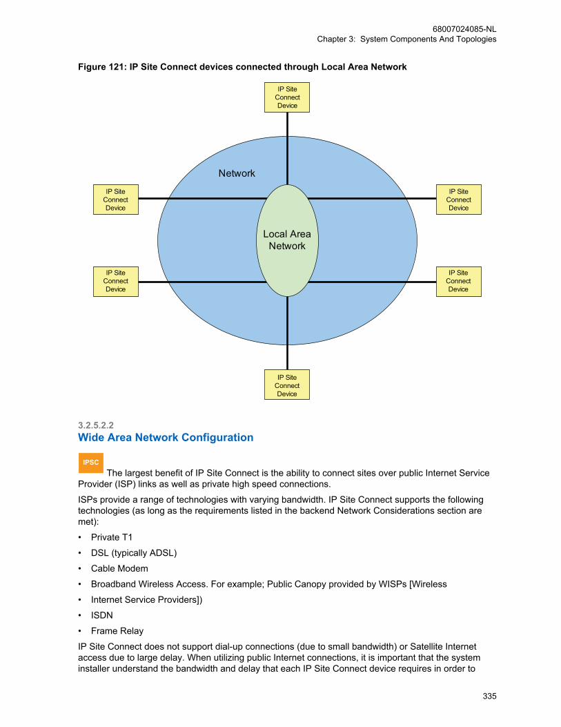
Figure 121: IP Site Connect devices connected through Local Area Network
IP SiteConnectDevice
IP SiteConnectDevice
IP SiteConnectDevice
IP SiteConnectDevice
IP SiteConnectDevice
IP SiteConnectDevice
Network
Local AreaNetwork
3.2.5.2.2Wide Area Network Configuration
IPSC The largest benefit of IP Site Connect is the ability to connect sites over public Internet Service
Provider (ISP) links as well as private high speed connections.
ISPs provide a range of technologies with varying bandwidth. IP Site Connect supports the followingtechnologies (as long as the requirements listed in the backend Network Considerations section aremet):
• Private T1
• DSL (typically ADSL)
• Cable Modem
• Broadband Wireless Access. For example; Public Canopy provided by WISPs [Wireless
• Internet Service Providers])
• ISDN
• Frame Relay
IP Site Connect does not support dial-up connections (due to small bandwidth) or Satellite Internetaccess due to large delay. When utilizing public Internet connections, it is important that the systeminstaller understand the bandwidth and delay that each IP Site Connect device requires in order to
68007024085-NLChapter 3: System Components And Topologies
335
operate optimally. They must also understand the details (bandwidth and delay) of the network link ateach site and between sites. For example, if connecting sites have long distances between them, thedelay of the entire link needs to be considered. Spanning continents connected via Satellite mayintroduce unacceptable delay. But, if the continents are connected via fiber optic there may not be anyissues.
Also keep in mind that because traffic from one repeater is sent to every repeater, the requiredbandwidth of the ISP link at one site is a function of the amount of other repeaters in the system.Adding a repeater will increase the required bandwidth at all sites. See Network BandwidthConsiderations on page 396.
A repeater can be (and is suggested to be) behind a router and/or a NAT and/or a firewall. Althoughnot required, it is highly suggested in order to protect against the undesired solicitations common overthe public Internet. Although IP Site Connect will work through most off-the-shelf devices, the followingrouter/NAT/firewalls are therefore suggested for use.
• HP – MSR2003 AC Router (supports “hair-pinning”)
• D-Link – EBR-2310
As previously described, peer-to-peer communications over the network can be optionallyauthenticated and are also encrypted end-to-end if enabled in the radios. If this is not consideredsufficient for a particular customer, IP Site Connect supports the ability to work through a Secure VPN(Virtual Private Network). Secure VPN is not a function of the IP Site Connect device but rather of therouter. It is important to note that VPN does add the need for additional bandwidth and may introduceadditional delay. This should be taken into consideration in bandwidth planning. The following SecureVPN router is suggested for use. See Network Bandwidth Considerations on page 396.
• Linksys 4 Port Gigabit Security Router with VPN: Model RVS4000.
Only the repeaters acting as Masters require a publicly accessible static IPv4 address from the InternetService Provider. The other IP Site Connect devices utilize this publicly accessible static IPv4 addressto establish their link with the wide area system. In addition, the router/NAT/firewall connected to theMaster require some configuration (open port) so that unsolicited messages from other repeaters canreach the Master repeater.
The repeaters acting as Masters can also be configured with a dynamically assigned IPv4 address aslong as this address is associated with a static DNS address. Anytime the IPv4 address for a Masterchanges, then the DNS server must be updated with the new address. The DNS Server utilized by allof the IP Site Connect devices must have an accurate IPv4 address for the Master. If the IPv4 addressbecomes invalid on the DNS Server, the IP Site Connect devices will NOT be able to establish theirlink with the wide area system and/or may lose an existing link. Once the IPv4 address for the Masteris valid again on the DNS Server, the devices will be able to link to the wide area system again. It is thejob of the entity assigning the IPv4 address to the Master to also update the DNS Server with theupdated IPv4 address. It should be noted that this feature is only available on SLR Series Repeaters.
The following diagram shows a simple diagram of IP Site Connect devices located at different sitesconnected through a wide area network.
Note that in this drawing the IP Site Connect devices could be in one or more Wide Area Systems (thatis, more than one Master), could contain local area channels or even be an analog repeater, a disabledrepeater, or RDAC IP application.
68007024085-NLChapter 3: System Components And Topologies
336

Figure 122: IP Site Connect Devices connected through Wide Area Network
Network
IP SiteConnectDevice
IP SiteConnectDevice
IP SiteConnectDevice
IP SiteConnectDevice
IP SiteConnectDevice
IP SiteConnectDevice
Wide AreaNetwork
Router
Router
Router
Router
3.2.5.2.3Wide and Local Area Network Configuration
IPSC
Most network topologies are a combination of both Local and Wide Area network configurations.
For example, there may be a need to link two or more sites with existing local networks together over apublic ISP, or maybe link one or more remote mountain RF site into a corporate network. When doingthis, there are a few extra precautions to consider that are not covered in the previous sections.
The number of IP Site Connect devices connected together behind a single wide area connection (thatis, behind one router) can have a large effect on the required bandwidth of the wide area link. Thebandwidth requirements of a wide area link are the summation of the bandwidth requirements of all IPdevices behind the router. In other words, if there are three IP Site Connect devices utilizing a singleISP link, it must have enough bandwidth to support all three. Recall that the traffic from one repeater issent to every repeater; therefore the required bandwidth of the ISP link at one site is a function of theamount of other sites in the system. Adding a repeater at one site increases the required bandwidth atall sites.
Similar to the Wide Area Network configurations, the repeaters acting as the Master will require apublicly accessible static IPv4 or DNS address from the Internet Service Provider. The other IP SiteConnect devices utilize this publicly accessible static IPv4 or DNS address to establish their link with
68007024085-NLChapter 3: System Components And Topologies
337
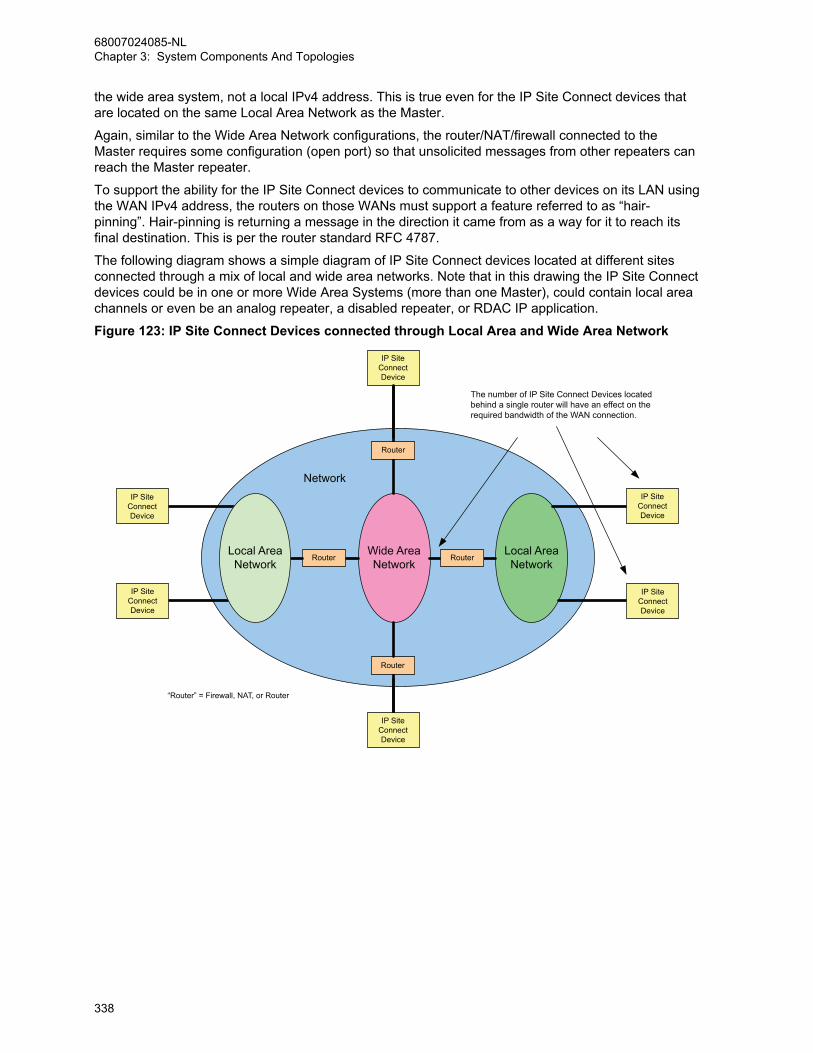
the wide area system, not a local IPv4 address. This is true even for the IP Site Connect devices thatare located on the same Local Area Network as the Master.
Again, similar to the Wide Area Network configurations, the router/NAT/firewall connected to theMaster requires some configuration (open port) so that unsolicited messages from other repeaters canreach the Master repeater.
To support the ability for the IP Site Connect devices to communicate to other devices on its LAN usingthe WAN IPv4 address, the routers on those WANs must support a feature referred to as “hair-pinning”. Hair-pinning is returning a message in the direction it came from as a way for it to reach itsfinal destination. This is per the router standard RFC 4787.
The following diagram shows a simple diagram of IP Site Connect devices located at different sitesconnected through a mix of local and wide area networks. Note that in this drawing the IP Site Connectdevices could be in one or more Wide Area Systems (more than one Master), could contain local areachannels or even be an analog repeater, a disabled repeater, or RDAC IP application.
Figure 123: IP Site Connect Devices connected through Local Area and Wide Area Network
Local AreaNetwork
RouterWide AreaNetwork
Router
Router
Router
Network
The number of IP Site Connect Devices locatedbehind a single router will have an effect on therequired bandwidth of the WAN connection.
IP SiteConnectDevice
IP SiteConnectDevice
IP SiteConnectDevice
IP SiteConnectDevice
IP SiteConnectDevice
IP SiteConnectDevice
Local AreaNetwork
“Router” = Firewall, NAT, or Router
68007024085-NLChapter 3: System Components And Topologies
338

3.2.5.3Summary of Features in IP Site Connect Mode
IPSC The following features are supported in IP Site Connect mode:
Table 62: Digital MOTOTRBO Radios in IP Site Connect Mode
Voice Fea-tures
SignalingFeatures
EmergencyHandling
Data Calls Other Features
Group Call PTT ID andAliasing
EmergencyAlarm
Text Messaging
Two WideArea Chan-nels (slot 1and slot 2)
Remote Di-agnosis andControl
Private Call Radio Inhibit EmergencyAlarm andCall
LocationTracking
Mix of WideArea and Lo-cal AreaChannels
Roaming
All Call Remote Mon-itor
EmergencyAlarm withVoice to Fol-low
Telemetry Scan* Wide AreaCoverage
Dual ToneMulti Fre-quency
Radio Check EmergencyRevert PerSite
Third-Party(ADP) Appli-cations
Polite to AllSystem Ac-cess
Time-outTimer
Voice Inter-rupt
Call Alert EmergencyVoice Inter-rupt
GPS RevertPer Site
Polite to OwnSystemChannel Ac-cess
Privacy
Digital Tele-phone Patch
RemoteVoice Dekey
– Data OverVoice Inter-rupt
ImpoliteChannel Ac-cess
–
* See Scan Considerations on page 144 for more information on the different scan modes supportedby different topologies.
The following section discusses some of the considerations to take while designing a MOTOTRBOsystem. It focuses more on how the user uses the system, and the configuration needed to support it.Although a basic system topology may already have been chosen, the next chapter helps dig deeperinto how the end user utilizes the system, and therefore gives additional ideas on how it should beconfigured.
3.2.6Capacity Plus Single Site Mode
CPSS Prior to R02.30.00, Capacity Plus Single Site allows up to six trunked repeaters (12 logical
channels) and twelve Data Revert repeaters (24 logical channels). For the system to operate properly,all the repeaters must have the same software version. From software version R02.30.00 onwards, upto eight Trunked Repeaters (16 logical channels) and twelve Data Revert Repeaters (24 logical
68007024085-NLChapter 3: System Components And Topologies
339

channels) are allowed. The Rest Channel IP address must be configured using a valid subnet IPaddress where the system resides, and cannot be left as 0.0.0.0.
In Capacity Plus Single Site mode, all the radios share the channels of all the trunked repeater(s). Theprobability of all channels being busy at the same instant is low. Hence, radio finds less blocking ofcalls compared to when only one channel is available to the radio. Similarly, for the same quality ofservice, sharing of channels allows more calls and thus increases channel capacity.
In Capacity Plus Single Site, a channel is configured either for trunking or for data revert. A radio has alist of all Trunked Channels and a list of Data Revert Channels. While configuring channels, observethe following rules:
• Both channels of a repeater should be used for the same purpose. This implies that if one channelof a repeater is a Trunked Channel, then the other channel is also a Trunked Channel. Similarly, ifone channel of a repeater is a Data Revert Channel, then the other channel is also a Data RevertChannel.
• The CPS provides a zone for keeping all the trunked and Data Revert Channels. The zone is called“Channel Pool”. All the trunked and Data Revert Channels should be kept in the “Channel Pool”.
3.2.6.1Topologies of Capacity Plus Single Site System
CPSS
Capacity Plus Single Site Systems can consist of the following topologies:
• A system with no data application server and local RDAC
• A system with no data application server and remote RDAC
• A system with a data application server on trunked channels
• A system with a data application server on revert channels
• A system with a dispatch station (console)
3.2.6.1.1System with No Data Application Server and Local RDAC
CPSS This configuration is the most basic of the Capacity Plus Single Site topologies. It does not
support a remote RDAC or data messages to or from a Server.
One of the repeaters has an additional role of “Master”; a broker for discovering repeaters. The Masterhas a static address (that is, IPv4 address and UDP port number), which is configured in all therepeaters and RDAC. Static address is an address that does not change with time. If the address ofthe Master changes, then all the repeaters and RDAC must be reconfigured with the new address. Toavoid the issue of needing to reconfigure all the devices that link with the Master when its IPv4 addresschanges, the user can configure all of the devices with a static DNS address for the Master instead.Anytime the IPv4 address for a Master changes, then the DNS server must be updated with the newIPv4 address. It is the job of the entity assigning the IPv4 address to the Master to also update theDNS Server with the updated IPv4 address to minimize any interruptions in connectivity to Master. Itshould be noted that the DNS feature is only available on SLR Series Repeaters.
68007024085-NLChapter 3: System Components And Topologies
340
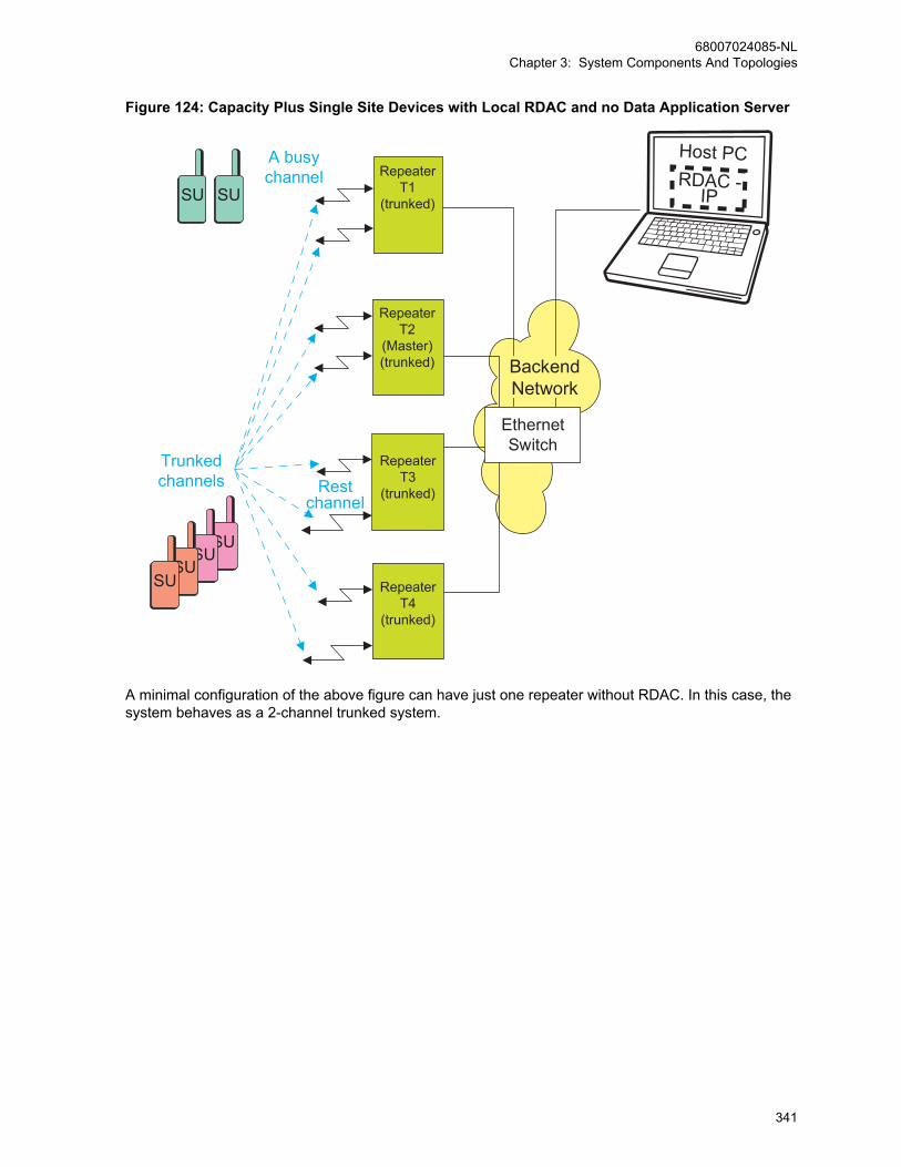
Figure 124: Capacity Plus Single Site Devices with Local RDAC and no Data Application Server
SU SU
SU SU
Restchannel
Trunkedchannels
Repeater T2
(Master)(trunked)
RepeaterT3
(trunked)
RepeaterT1
(trunked)SU SU
A busychannel
RepeaterT4
(trunked)
Host PC RDAC -
IP
EthernetSwitch
BackendNetwork
A minimal configuration of the above figure can have just one repeater without RDAC. In this case, thesystem behaves as a 2-channel trunked system.
68007024085-NLChapter 3: System Components And Topologies
341

Figure 125: 2-Channel Capacity Plus Single Site System without Data Application Server
SU SU
SU SU
Restchannel
RepeaterT1
(trunked)
A busychannel
Trunkedchannels
SU SU
3.2.6.1.2System with No Data Application Server and Remote RDAC
CPSS If RDAC is on a different IPv4 network, then the back-end network of Capacity Plus Single Site
should be connected to the external IP network using a router. In this case, use the static address ofthe Master, as seen from the other side of the router, to configure the repeaters and RDAC.
Note that the router may be required to do port-based network address translation for each repeater.Prior to software version R02.20.12, the router should support “hair-pinning” and have sufficientbandwidth to handle all the messages between repeaters. Hair-pinning is returning a message in thedirection it came from as a way for it to reach its final destination. This is per the router standard RFC4787.
In software version R02.20.12 or later, Capacity Plus Single Site can work with, or without hair-pinningcapabilities in the router. When a non-hair-pinning router is utilized, each repeater must be configuredwith a unique static IP address and a unique UDP port. The Rest Channel IP address must also beconfigured as a unique static IP address and a unique UDP port. The router must be configured to “noport address translation/port preservation for UDP” if a non-hair-pinning router is utilized.
68007024085-NLChapter 3: System Components And Topologies
342

Figure 126: Capacity Plus Single Site Devices with Remote RDAC and no Data ApplicationServer
SU SU
SU SU
Restchannel
Trunkedchannels
Repeater T2
(Master)(trunked)
RepeaterT3
(trunked)
RepeaterT1
(trunked)
SU SU
A busychannel
RepeaterT4
(trunked)
Host PC RDAC -
IP
EthernetSwitch
BackendNetwork
FW/Router
3.2.6.1.3System with Data Application Server on Trunked Channels
CPSS It is possible to send data messages to a Data Server over the Trunked Channels. This is
recommended for a system that requires sending a limited number of data messages to the Server.This configuration requires one or more Trunked Control Stations. The Server must not have theMCDD installed.
If there is more than one Trunked Control Station, the configuration should adhere to the followingrules:
• The maximum number of Trunked Control Stations should not be more than the number of
• Trunked Channels.
• To achieve a success rate of 90%, the number of data messages per minute per Trunked
• Control Station, should be less than 10. It is assumed here, that the payload of a data
• message is 50 bytes or characters long.
• The IDs of all Trunked Control Stations should be different.
• The radios should be grouped into ‘n’ sets, where ‘n’ is the number of Trunked Control
68007024085-NLChapter 3: System Components And Topologies
343
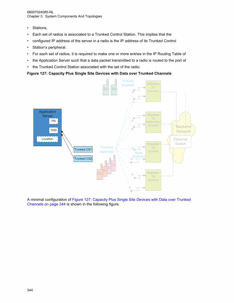
• Stations.
• Each set of radios is associated to a Trunked Control Station. This implies that the
• configured IP address of the server in a radio is the IP address of its Trunked Control
• Station’s peripheral.
• For each set of radios, it is required to make one or more entries in the IP Routing Table of
• the Application Server such that a data packet transmitted to a radio is routed to the port of
• the Trunked Control Station associated with the set of the radio.
Figure 127: Capacity Plus Single Site Devices with Data over Trunked Channels
SU SU
SU SU
Restchannel
Trunkedchannels
RepeaterT2
(Intermediary)(trunked)
RepeaterT1
(trunked)
RepeaterT3
(trunked)
RepeaterT4
(trunked)
SU SU
A busychannel
EthernetSwitch
BackendNetwork
Trunked CS1
Trunked CS2
ApplicationServer
PN
TMS
Location
A minimal configuration of Figure 127: Capacity Plus Single Site Devices with Data over TrunkedChannels on page 344 is shown in the following figure.
68007024085-NLChapter 3: System Components And Topologies
344
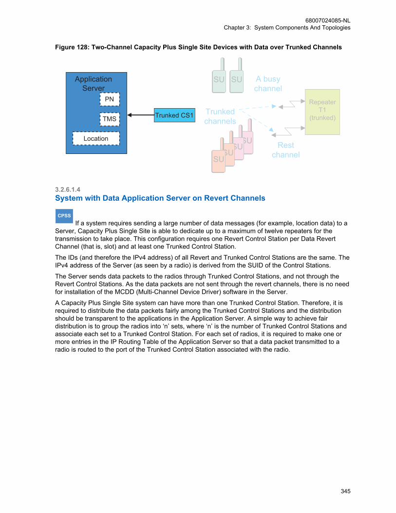
Figure 128: Two-Channel Capacity Plus Single Site Devices with Data over Trunked Channels
SU SU
SU SU
Restchannel
Trunkedchannels
RepeaterT1
(trunked)
SU SU A busychannel
Trunked CS1
ApplicationServer
PN
TMS
Location
3.2.6.1.4System with Data Application Server on Revert Channels
CPSS If a system requires sending a large number of data messages (for example, location data) to a
Server, Capacity Plus Single Site is able to dedicate up to a maximum of twelve repeaters for thetransmission to take place. This configuration requires one Revert Control Station per Data RevertChannel (that is, slot) and at least one Trunked Control Station.
The IDs (and therefore the IPv4 address) of all Revert and Trunked Control Stations are the same. TheIPv4 address of the Server (as seen by a radio) is derived from the SUID of the Control Stations.
The Server sends data packets to the radios through Trunked Control Stations, and not through theRevert Control Stations. As the data packets are not sent through the revert channels, there is no needfor installation of the MCDD (Multi-Channel Device Driver) software in the Server.
A Capacity Plus Single Site system can have more than one Trunked Control Station. Therefore, it isrequired to distribute the data packets fairly among the Trunked Control Stations and the distributionshould be transparent to the applications in the Application Server. A simple way to achieve fairdistribution is to group the radios into ‘n’ sets, where ‘n’ is the number of Trunked Control Stations andassociate each set to a Trunked Control Station. For each set of radios, it is required to make one ormore entries in the IP Routing Table of the Application Server so that a data packet transmitted to aradio is routed to the port of the Trunked Control Station associated with the radio.
68007024085-NLChapter 3: System Components And Topologies
345
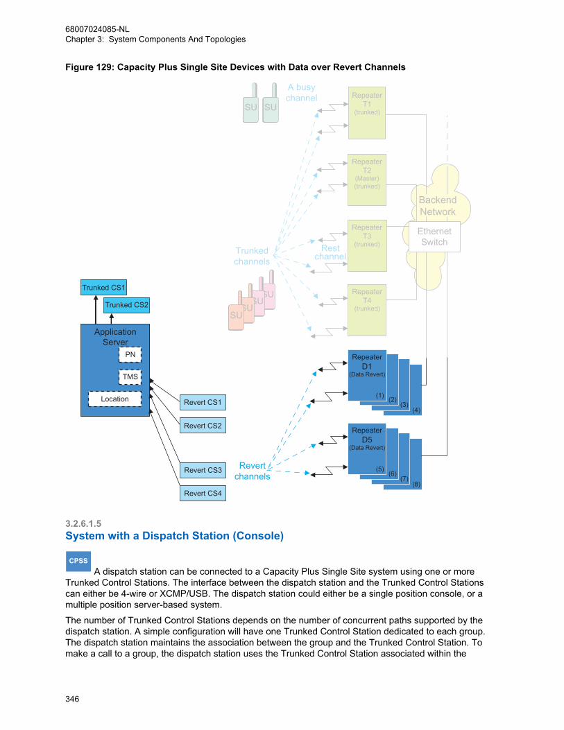
Figure 129: Capacity Plus Single Site Devices with Data over Revert Channels
SU SU
SU SU
Trunked CS1
Trunked CS2
(8)(7)
(6)
(4)(3)
ApplicationServer
PN
TMS
Location
RestchannelTrunked
channels
Repeater T2
(Master)(trunked)
SU SU
A busychannel
RepeaterT4
(trunked)
RepeaterT3
(trunked)
RepeaterT1
(trunked)
RepeaterD1
(Data Revert)
(1) (2)
(5)
RepeaterD5
(Data Revert)
EthernetSwitch
BackendNetwork
Revertchannels
Revert CS1
Revert CS2
Revert CS3
Revert CS4
3.2.6.1.5System with a Dispatch Station (Console)
CPSS A dispatch station can be connected to a Capacity Plus Single Site system using one or more
Trunked Control Stations. The interface between the dispatch station and the Trunked Control Stationscan either be 4-wire or XCMP/USB. The dispatch station could either be a single position console, or amultiple position server-based system.
The number of Trunked Control Stations depends on the number of concurrent paths supported by thedispatch station. A simple configuration will have one Trunked Control Station dedicated to each group.The dispatch station maintains the association between the group and the Trunked Control Station. Tomake a call to a group, the dispatch station uses the Trunked Control Station associated within the
68007024085-NLChapter 3: System Components And Topologies
346
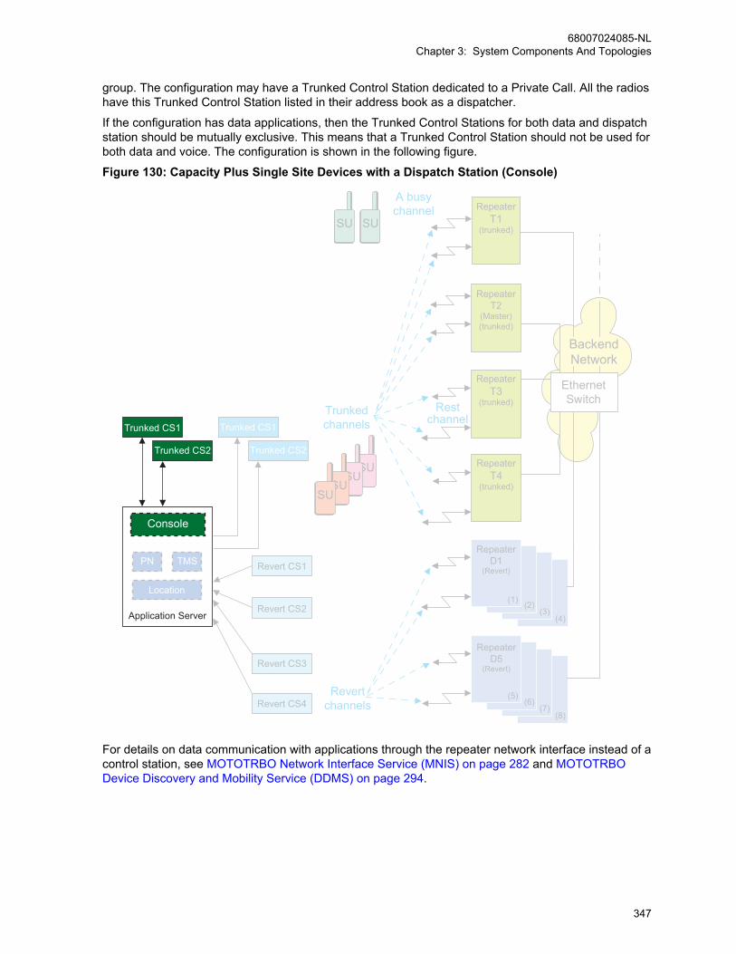
group. The configuration may have a Trunked Control Station dedicated to a Private Call. All the radioshave this Trunked Control Station listed in their address book as a dispatcher.
If the configuration has data applications, then the Trunked Control Stations for both data and dispatchstation should be mutually exclusive. This means that a Trunked Control Station should not be used forboth data and voice. The configuration is shown in the following figure.
Figure 130: Capacity Plus Single Site Devices with a Dispatch Station (Console)
SU SU
SU SU
Trunked CS1
Trunked CS2
Trunked CS1
Trunked CS2
(8)(7)
(6)
(4)(3)
Console
PN TMS
Location
Application Server
Restchannel
Trunkedchannels
Repeater T2
(Master)(trunked)
RepeaterT1
(trunked)
RepeaterT3
(trunked)
RepeaterT4
(trunked)
SU SU
A busychannel
RepeaterD1
(Revert)
RepeaterD5
(Revert)
(1) (2)
(5)
EthernetSwitch
BackendNetwork
Revertchannels
Revert CS1
Revert CS2
Revert CS3
Revert CS4
For details on data communication with applications through the repeater network interface instead of acontrol station, see MOTOTRBO Network Interface Service (MNIS) on page 282 and MOTOTRBODevice Discovery and Mobility Service (DDMS) on page 294.
68007024085-NLChapter 3: System Components And Topologies
347

3.2.7Capacity Plus Multi Site Mode (CPMS)
CPMS Capacity Plus Multi Site supports up to 15 sites with a maximum of 140 peers across all sites
and up to 12 Repeaters (24 logical channels) per site. At any given site, there can be up to eightTrunking Repeaters (16 logical channels) and up to 11 Data Revert Repeaters (22 logical channels),however the total number of Trunked Repeaters plus Data Revert Repeaters must not exceed 12. Forexample, if there are eight Trunked Repeaters at a site, then up to four Data Revert Repeaters can besupported at that site.
However, the number of Trunked Repeaters plus the number of Data Revert Repeaters must notexceed a total of 12. For example, if there are eight Trunked Repeaters at a site, only up to four DataRevert Repeaters can be supported at that site.
It is not a requirement to have the same number of repeaters at each site but all the repeaters at thesame site must have the same software version. A Capacity Plus Multi Site system supports local calls(that is, a local call is received by radios at only one site) and the number of repeaters at a site is afunction of the expected volume of the local calls. Additionally, due to co-channel interference or failureof repeaters, the number of available repeaters may be different at different sites.
All repeaters at a site must be on the same LAN, in other words, they must be behind the same routerand plugged into the same network switch. It is strongly recommended that no other device be presenton the LAN. For CPMS software versions R02.10.00 and prior, the router at the Master repeater’s siteshould be capable of hair-pinning, to ensure that the firewall is open to limited UDP and IP addresses.In software versions R02.20.00 and later, CPMS can work with, or without hair-pinning capabilities inthe router at the Master repeater’s site. When a non-hair-pinning router is utilized, each CPMSrepeater at the Master repeater’s site must be configured with a unique static IP address and a uniqueUDP port. The Rest Channel/Site IP address must also be configured as a unique static IP addressand a unique UDP port for the site. If a non-hair-pinning router is utilized, the router must be configuredto “no port address translation/port preservation for UDP”.
For an advanced security, a router with VPN capabilities can be selected. However, a VPN routerrequires at least 50% more ISP bandwidth than a non-VPN router. Thus, appropriate trade-offs need tobe considered between the ISP bandwidth and the desired level of system security. A secure routerusually contains firewall, network address translation, and encryption capabilities. The CPMS systemsupports operation over both secure and non-secure modes of the router.
Only repeaters with 32 MB of internal memory can support the CPMS configuration. Like an IP SiteConnect conventional system, every CPMS system needs one repeater to act as the Master. TheMaster repeater has a static IP address, while other repeaters have static IP addresses or obtain themdynamically from the ISP. All the repeaters in the CPMS configuration register with the Master usingthe static IP address of the Master. The CPMS system may have many repeater applications like theRDAC and MNIS that are considered as repeaters by the Master repeater. However, satellite receiversare not treated as repeaters. When the number of repeaters and these applications in a systemexceeds 140, a dedicated Master repeater must be deployed in the system. This dedicated Mastershould be added to a site as a Data Revert repeater, but adding it does not reduce the number of DataRevert repeaters that can be normally deployed at that site. This dedicated Master repeater shouldhave no RF-related activities such as CWID and OTA receiving/transmitting.
In CPMS, a channel is configured either for trunking or for data revert. But both channels of a repeatershould be used for the same purpose. This implies that if one channel of a repeater is a TrunkedChannel, then the other channel is also a Trunked Channel. Similarly, if one channel of a repeater is aData Revert Channel, then the other channel is also a Data Revert Channel. In CPMS, a Data RevertChannel can be configured either as a local Data Revert Channel, or as a wide area Data RevertChannel.
A Data Revert Channel could be either an Enhanced GPS Revert Channel or a normal Data RevertChannel. Each logical channel of a Data Revert Repeater can be independently configured either as
68007024085-NLChapter 3: System Components And Topologies
348
an Enhanced GPS Revert Channel or as a normal Data Revert Channel. A radio has a list of allTrunked Channels and a list of Data Revert Channels for each site.
Capacity Plus Multi Site can be deployed for various system topologies. Topologies of Capacity PlusMulti Site System on page 349 defines some of the key topologies.
3.2.7.1Topologies of Capacity Plus Multi Site System
CPMS
Capacity Plus Multi Site Systems can consist of the following topologies:
• A capacity plus multi site system with data over trunked channels (optional)
• A capacity plus multi site with data over local revert channels
• A capacity plus multi site with data over wide area revert channels
3.2.7.1.1Capacity Plus Multi Site System with Data Over Trunked Channels (optional)
CPMS
Figure 131: Capacity Plus Multi Site System with Data over Trunked Channels on page 350 shows abasic Capacity Plus Multi Site system having three sites. Site 1 and 2 has four trunked repeaters andsite 3 has three trunked repeaters. The number of repeaters at each site need not be the same. In thisconfiguration, all the repeaters are configured for trunked mode of operation - there is no Data RevertRepeater. One of the repeaters has an additional role of “Master”; a broker for discovering repeaters.The Master has a static address (IPv4 address and UDP port number), which is configured in all therepeaters. If the address of the Master changes, then all the repeaters must be reconfigured with thenew address.
To avoid the issue of needing to reconfigure all the devices that link with the Master when its IPv4address changes, you can configure all of the devices with a static DNS address for the Masterinstead. Anytime the IPv4 address for a Master changes, then the DNS server must be updated withthe new IPv4 address. It is the job of the entity assigning the IPv4 address to the Master to also updatethe DNS Server with the updated IPv4 address to minimize any interruptions in connectivity to Master.It should be noted that the DNS feature is only available on SLR Series Repeaters.
68007024085-NLChapter 3: System Components And Topologies
349

Figure 131: Capacity Plus Multi Site System with Data over Trunked Channels
PC 1 Server
BR 11
Router + Switch
Site 1 Site 3
BR 12
BR 14
Tr CS 1Tr CS 2
BR 13
BR 21
Router + Switch
BR 22
BR 24
BR 23
BR 31Intermediary
Router + Switch
BR 32
BR 33
BR 34
Site 2
CSCS
CSCS
CSCS
CSCS
It is possible to send data messages to a Data Server over the Trunked Channels. This isrecommended for a system that requires sending limited number of data messages to the server. If thedata has to be sent to and from the server, then one Conventional Control Station per TrunkedChannel and one or more Trunked Control Stations need to be added at a site in the basic topology. Inthis configuration, all the repeaters are configured for trunked mode of operation, where there is noRevert repeater. For this topology, the radio does not require a Revert channel list. The TrunkedControl Stations are configured with no talkgroups and therefore ignore the calls received over-the-air.A Trunked Control Station follows the Rest Channel and when requested by a PC server, transmits themessage sent by the server.
If there is more than one Trunked Control Station, the configuration should adhere to the followingrules.
• The maximum number of Trunked Control Stations should not exceed the number of the
• Trunked Channels.
• To achieve a success rate of 90%, the number of data messages per minute per Trunked
• Control Station, should be less than 10. It is assumed here, that the payload of a data
• message is 50 bytes or characters long.
• The IDs of all Trunked Control Stations should be different.
• The radios should be grouped into ‘n’ sets, where ‘n’ is the number of Trunked Control
• Stations.
• Each set of radios is associated to a Trunked Control Station. This implies that the
• configured IP address of the server in a radio is the IP address of its Trunked Control
• Station’s peripheral.
For each set of radios, it is required to make one or more entries in the IP Routing Table of theApplication Server such that a data packet transmitted to a radio is routed to the port of the TrunkedControl Station associated with the set of the radio.
68007024085-NLChapter 3: System Components And Topologies
350
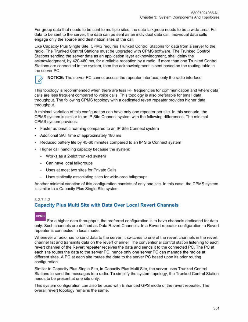
For group data that needs to be sent to multiple sites, the data talkgroup needs to be a wide-area. Fordata to be sent to the server, the data can be sent as an individual data call. Individual data callsengage only the source and destination sites of the call.
Like Capacity Plus Single Site, CPMS requires Trunked Control Stations for data from a server to theradio. The Trunked Control Stations must be upgraded with CPMS software. The Trunked ControlStations sending the server data as an application layer acknowledgment, shall delay theacknowledgment, by 420-480 ms, for a reliable reception by a radio. If more than one Trunked ControlStations are connected in the system, then the acknowledgment is sent based on the routing table inthe server PC.
NOTICE: The server PC cannot access the repeater interface, only the radio interface.
This topology is recommended when there are less RF frequencies for communication and where datacalls are less frequent compared to voice calls. This topology is also preferable for small datathroughput. The following CPMS topology with a dedicated revert repeater provides higher datathroughput.
A minimal variation of this configuration can have only one repeater per site. In this scenario, theCPMS system is similar to an IP Site Connect system with the following differences. The minimalCPMS system provides:
• Faster automatic roaming compared to an IP Site Connect system
• Additional SAT time of approximately 180 ms
• Reduced battery life by 45-60 minutes compared to an IP Site Connect system
• Higher call handling capacity because the system:
- Works as a 2-slot trunked system
- Can have local talkgroups
- Uses at most two sites for Private Calls
- Uses statically associating sites for wide-area talkgroups
Another minimal variation of this configuration consists of only one site. In this case, the CPMS systemis similar to a Capacity Plus Single Site system.
3.2.7.1.2Capacity Plus Multi Site with Data Over Local Revert Channels
CPMS For a higher data throughput, the preferred configuration is to have channels dedicated for data
only. Such channels are defined as Data Revert Channels. In a Revert repeater configuration, a Revertrepeater is connected in local mode.
Whenever a radio has to send data to the server, it switches to one of the revert channels in the revertchannel list and transmits data on the revert channel. The conventional control station listening to eachrevert channel of the Revert repeater receives the data and sends it to the connected PC. The PC ateach site routes the data to the server PC, hence only one server PC can manage the radios atdifferent sites. A PC at each site routes the data to the server PC based upon its prior routingconfiguration.
Similar to Capacity Plus Single Site, in Capacity Plus Multi Site, the server uses Trunked ControlStations to send the messages to a radio. To simplify the system topology, the Trunked Control Stationneeds to be present at one site only.
This system configuration can also be used with Enhanced GPS mode of the revert repeater. Theoverall revert topology remains the same.
68007024085-NLChapter 3: System Components And Topologies
351
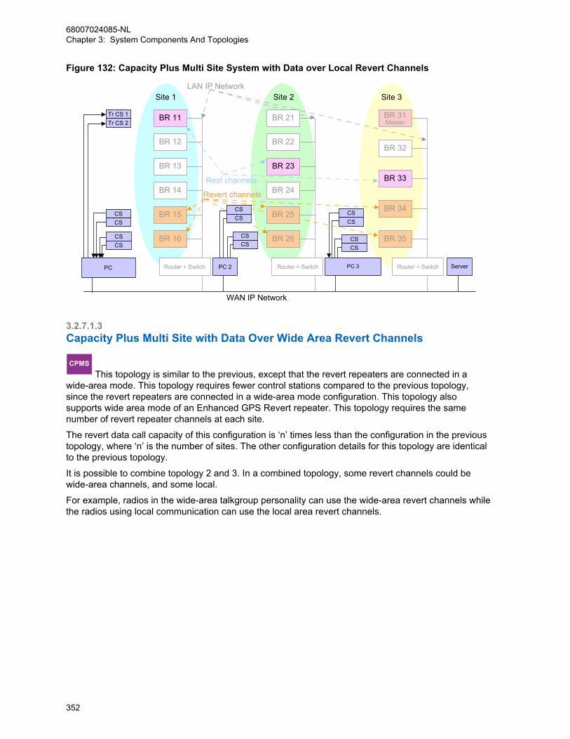
Figure 132: Capacity Plus Multi Site System with Data over Local Revert Channels
Site 1 Site 2 Site 3
WAN IP Network
LAN IP Network
Tr CS 1Tr CS 2
CSCS
CSCS
CSCS
CSCS
CSCS
CSCS
PC PC 2 PC 3 Server
Rest channels
Revert channels
Router + Switch
BR 21
BR 23
BR 24
BR 26
BR 22
BR 25
Router + Switch
BR 31Master
BR 33
BR 35
BR 32
BR 34
Router + Switch
BR 11
BR 13
BR 14
BR 16
BR 12
BR 15
3.2.7.1.3Capacity Plus Multi Site with Data Over Wide Area Revert Channels
CPMS This topology is similar to the previous, except that the revert repeaters are connected in a
wide-area mode. This topology requires fewer control stations compared to the previous topology,since the revert repeaters are connected in a wide-area mode configuration. This topology alsosupports wide area mode of an Enhanced GPS Revert repeater. This topology requires the samenumber of revert repeater channels at each site.
The revert data call capacity of this configuration is ‘n’ times less than the configuration in the previoustopology, where ‘n’ is the number of sites. The other configuration details for this topology are identicalto the previous topology.
It is possible to combine topology 2 and 3. In a combined topology, some revert channels could bewide-area channels, and some local.
For example, radios in the wide-area talkgroup personality can use the wide-area revert channels whilethe radios using local communication can use the local area revert channels.
68007024085-NLChapter 3: System Components And Topologies
352
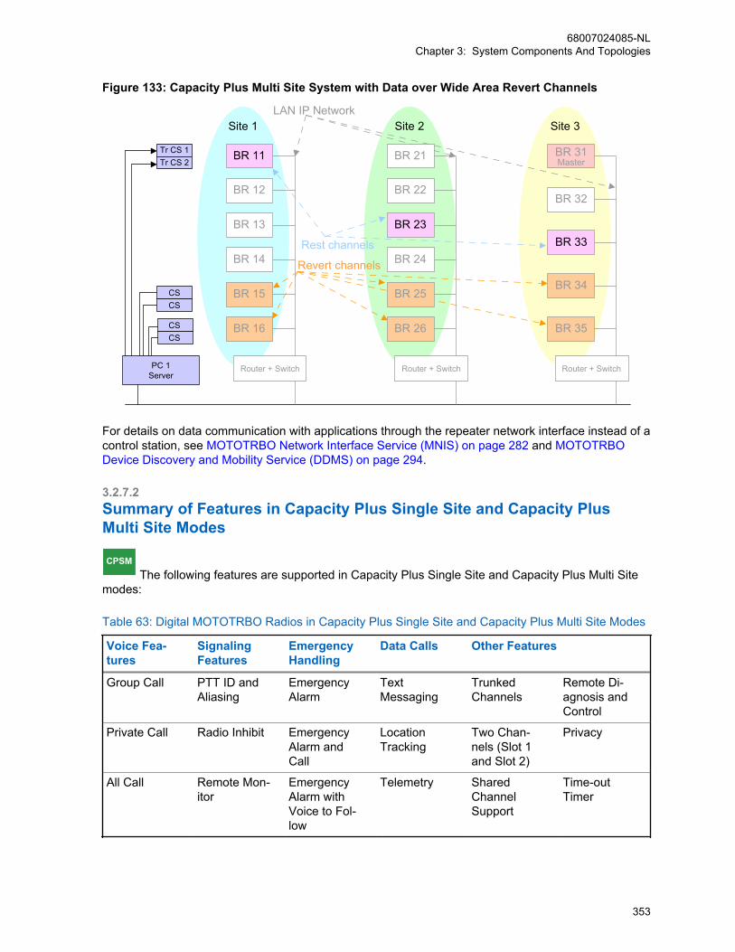
Figure 133: Capacity Plus Multi Site System with Data over Wide Area Revert Channels
Site 1 Site 2 Site 3LAN IP Network
Tr CS 1Tr CS 2
CSCS
CSCS
PC 1Server
Rest channels
Revert channels
Router + Switch
BR 21
BR 23
BR 24
BR 26
BR 22
BR 25
Router + Switch
BR 31Master
BR 33
BR 35
BR 32
BR 34
Router + Switch
BR 11
BR 13
BR 14
BR 16
BR 12
BR 15
For details on data communication with applications through the repeater network interface instead of acontrol station, see MOTOTRBO Network Interface Service (MNIS) on page 282 and MOTOTRBODevice Discovery and Mobility Service (DDMS) on page 294.
3.2.7.2Summary of Features in Capacity Plus Single Site and Capacity PlusMulti Site Modes
CPSM The following features are supported in Capacity Plus Single Site and Capacity Plus Multi Site
modes:
Table 63: Digital MOTOTRBO Radios in Capacity Plus Single Site and Capacity Plus Multi Site Modes
Voice Fea-tures
SignalingFeatures
EmergencyHandling
Data Calls Other Features
Group Call PTT ID andAliasing
EmergencyAlarm
Text Messaging
TrunkedChannels
Remote Di-agnosis andControl
Private Call Radio Inhibit EmergencyAlarm andCall
LocationTracking
Two Chan-nels (Slot 1and Slot 2)
Privacy
All Call Remote Mon-itor
EmergencyAlarm withVoice to Fol-low
Telemetry SharedChannelSupport
Time-outTimer
68007024085-NLChapter 3: System Components And Topologies
353

Voice Fea-tures
SignalingFeatures
EmergencyHandling
Data Calls Other Features
Dual ToneMulti Fre-quency
Radio Check EmergencyRevert Group
Third-Party(ADP) Appli-cations
Call Initiationby a Listen-ing Radio
Option Board
Voice Inter-rupt
Call Alert EmergencyVoice Inter-rupt
Data RevertChannels
– –
Digital Tele-phone Patch
RemoteVoice Dekey
– Data OverVoice Inter-rupt
– –
The System Design Considerations on page 362 section discusses some of the considerations to takewhile designing a MOTOTRBO system. It focuses more on how the user uses the system, and theconfiguration needed to support it. Although a basic system topology may already have been chosen,the System Design Considerations on page 362 section helps dig deeper into how the end user utilizesthe system, and therefore gives additional ideas on how it should be configured.
3.2.8Digital VotingDigital voting is available in the following system configurations:
• Digital Conventional Single Site
IPSCIP Site Connect
Digital Voting is available in IP Site Connect
CPSSCapacity Plus Single Site
Digital Voting is available in Capacity Plus Sin-gle Site
CPMSCapacity Plus Multi Site
Digital Voting is available in Capacity Plus MultiSite
When installing a receiver site (that may contain multiple receivers for Capacity Plus Single Site orCapacity Plus Multi Site system) in any of the system configurations, the receiver site must not be inthe same LAN that the voter site is in.
In order for the voting functionality to be working properly, the one way network delay between therepeater and any of its receivers must be less or equal to 40 milliseconds. Additionally, the networkasymmetry between the repeater and any of its receivers must be less or equal to 12 milliseconds. Thenetwork asymmetry is the absolute value of the time difference for an IP packet to travel from therepeater to the receiver, and from the receiver to the repeater. This applies to all systemconfigurations. Since the distance between the repeater and receiver is normally less or equal to 90miles (approximately 145 kilometers), most of the business grade IP networks are able to meet this 40milliseconds per 12 milliseconds network requirement.
68007024085-NLChapter 3: System Components And Topologies
354
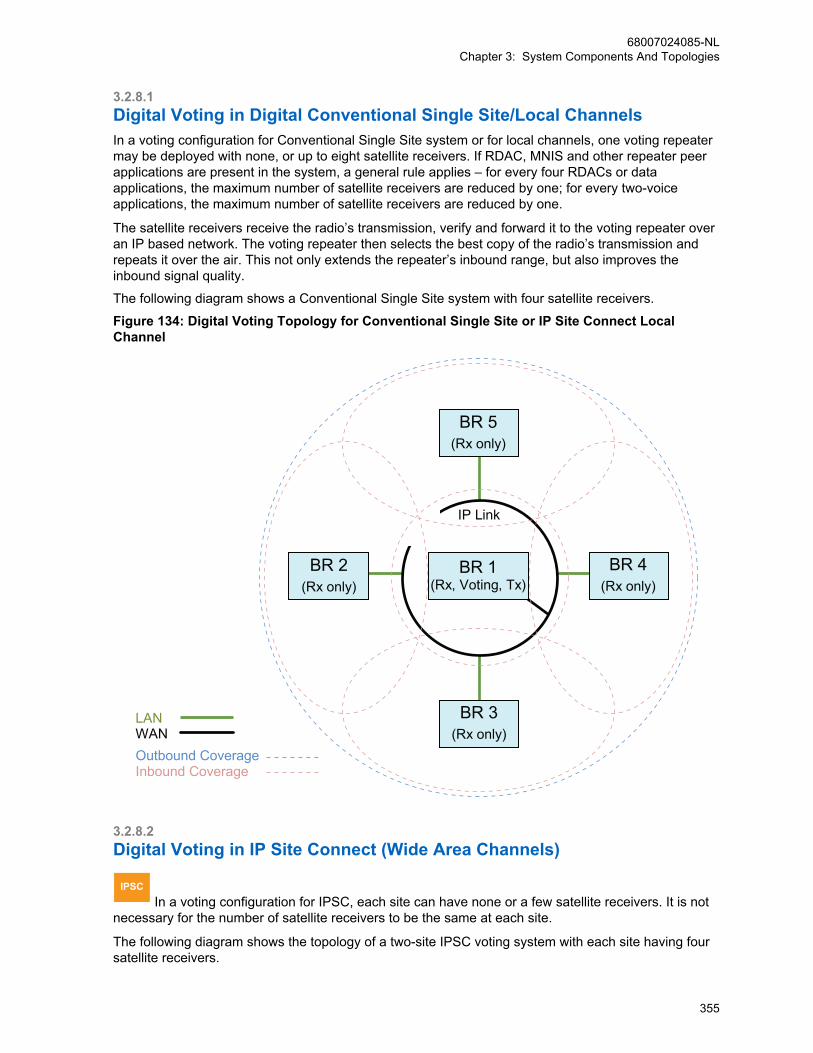
3.2.8.1Digital Voting in Digital Conventional Single Site/Local ChannelsIn a voting configuration for Conventional Single Site system or for local channels, one voting repeatermay be deployed with none, or up to eight satellite receivers. If RDAC, MNIS and other repeater peerapplications are present in the system, a general rule applies – for every four RDACs or dataapplications, the maximum number of satellite receivers are reduced by one; for every two-voiceapplications, the maximum number of satellite receivers are reduced by one.
The satellite receivers receive the radio’s transmission, verify and forward it to the voting repeater overan IP based network. The voting repeater then selects the best copy of the radio’s transmission andrepeats it over the air. This not only extends the repeater’s inbound range, but also improves theinbound signal quality.
The following diagram shows a Conventional Single Site system with four satellite receivers.
Figure 134: Digital Voting Topology for Conventional Single Site or IP Site Connect LocalChannel
BR 2(Rx only)
BR 5(Rx only)
BR 4(Rx only)
BR 3(Rx only)
Outbound CoverageInbound Coverage
IP Link
LANWAN
BR 1(Rx, Voting, Tx)
3.2.8.2Digital Voting in IP Site Connect (Wide Area Channels)
IPSC In a voting configuration for IPSC, each site can have none or a few satellite receivers. It is not
necessary for the number of satellite receivers to be the same at each site.
The following diagram shows the topology of a two-site IPSC voting system with each site having foursatellite receivers.
68007024085-NLChapter 3: System Components And Topologies
355
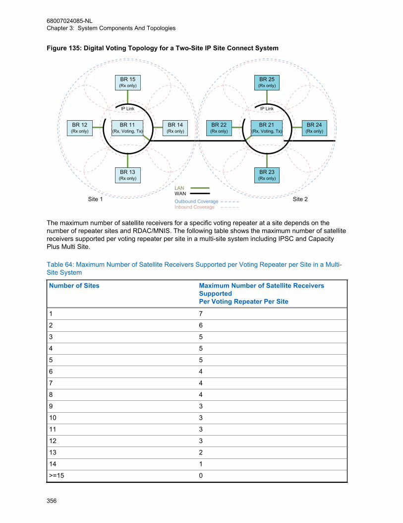
Figure 135: Digital Voting Topology for a Two-Site IP Site Connect System
BR 12(Rx only)
BR 15(Rx only)
BR 14(Rx only)
BR 13(Rx only)
Outbound CoverageInbound Coverage
IP Link
LANWAN
Site 1 Site 2
BR 11(Rx, Voting, Tx)
BR 22(Rx only)
BR 25(Rx only)
BR 24(Rx only)
BR 23(Rx only)
IP Link
BR 21(Rx, Voting, Tx)
The maximum number of satellite receivers for a specific voting repeater at a site depends on thenumber of repeater sites and RDAC/MNIS. The following table shows the maximum number of satellitereceivers supported per voting repeater per site in a multi-site system including IPSC and CapacityPlus Multi Site.
Table 64: Maximum Number of Satellite Receivers Supported per Voting Repeater per Site in a Multi-Site System
Number of Sites Maximum Number of Satellite ReceiversSupportedPer Voting Repeater Per Site
1 7
2 6
3 5
4 5
5 5
6 4
7 4
8 4
9 3
10 3
11 3
12 3
13 2
14 1
>=15 0
68007024085-NLChapter 3: System Components And Topologies
356

NOTICE: In general, for every four RDACs or data applications included in the system, themaximum number of satellite receivers is reduced by one. For every voice application includedin the system, voice console, for example, the maximum number is reduced by two.
3.2.8.3Digital Voting in Capacity Plus Single Site
CPSS In a Capacity Plus Single Site voting configuration, the maximum number of satellite receivers
supported for a RF channel is eight. If RDAC, MNIS and other repeater peer applications are in thesystem, in general, for every four RDACs or data applications, the maximum number of satellitereceivers are reduced by one. For every two voice applications, the maximum number of satellitereceivers are reduced by one.
In order to obtain the same Trunked Channel inbound/outbound coverage from channel to channel,each Trunked RF Channel requires a satellite receiver at any selected satellite receiver location.Hence, each Trunked RF Channel requires the same number of satellite receivers altogether. It isrecommended to place a satellite receiver for each Data Revert RF Channel to achieve the sameinbound/outbound coverage as the voice channels. However, this is not a requirement.
Figure 136: Digital Voting Topology for a Capacity Plus Single Site System on page 357 shows thevoting topology for Capacity Plus Single Site with two RF channels, where each channel has foursatellite receivers.
Figure 136: Digital Voting Topology for a Capacity Plus Single Site System
Outbound CoverageInbound Coverage
IP Link
LANWAN
BR 11(Rx,
Voting, Tx)
BR 22(Rx only)
BR 21(Rx only)
BR 42(Rx only)
BR 41(Rx only)
BR 52(Rx only)
BR 51(Rx only)
BR 32(Rx only)
BR 31(Rx only)
BR 12(Rx,
Voting, Tx)
RF Channel 1RF Channel 2
68007024085-NLChapter 3: System Components And Topologies
357
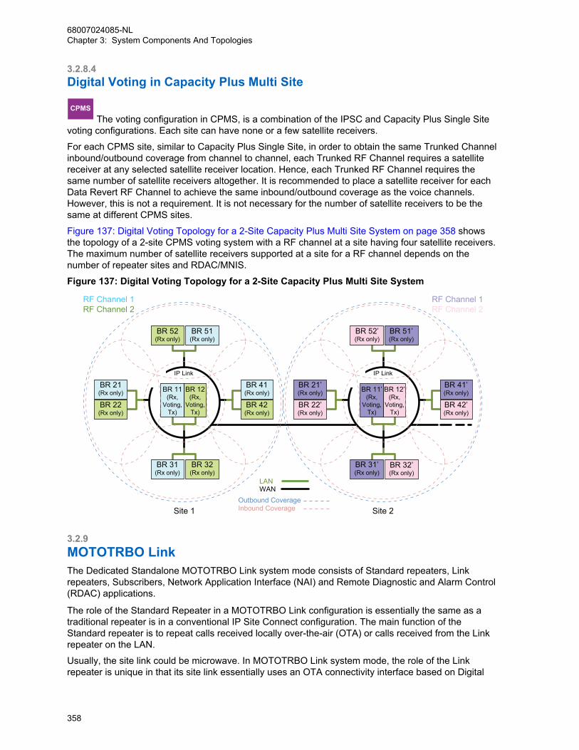
3.2.8.4Digital Voting in Capacity Plus Multi Site
CPMS The voting configuration in CPMS, is a combination of the IPSC and Capacity Plus Single Site
voting configurations. Each site can have none or a few satellite receivers.
For each CPMS site, similar to Capacity Plus Single Site, in order to obtain the same Trunked Channelinbound/outbound coverage from channel to channel, each Trunked RF Channel requires a satellitereceiver at any selected satellite receiver location. Hence, each Trunked RF Channel requires thesame number of satellite receivers altogether. It is recommended to place a satellite receiver for eachData Revert RF Channel to achieve the same inbound/outbound coverage as the voice channels.However, this is not a requirement. It is not necessary for the number of satellite receivers to be thesame at different CPMS sites.
Figure 137: Digital Voting Topology for a 2-Site Capacity Plus Multi Site System on page 358 showsthe topology of a 2-site CPMS voting system with a RF channel at a site having four satellite receivers.The maximum number of satellite receivers supported at a site for a RF channel depends on thenumber of repeater sites and RDAC/MNIS.
Figure 137: Digital Voting Topology for a 2-Site Capacity Plus Multi Site System
IP Link IP Link
Outbound CoverageInbound Coverage
LANWAN
Site 1 Site 2
BR 11(Rx,
Voting, Tx)
BR 22(Rx only)
BR 21(Rx only)
BR 42(Rx only)
BR 41(Rx only)
BR 52(Rx only)
BR 51(Rx only)
BR 32(Rx only)
BR 31(Rx only)
BR 12(Rx,
Voting, Tx)
BR 11’(Rx,
Voting, Tx)
BR 22’(Rx only)
BR 21’(Rx only)
BR 42’(Rx only)
BR 41’(Rx only)
BR 52’(Rx only)
BR 51’(Rx only)
BR 32’(Rx only)
BR 31’(Rx only)
BR 12’(Rx,
Voting, Tx)
RF Channel 1RF Channel 2
RF Channel 1RF Channel 2
3.2.9MOTOTRBO LinkThe Dedicated Standalone MOTOTRBO Link system mode consists of Standard repeaters, Linkrepeaters, Subscribers, Network Application Interface (NAI) and Remote Diagnostic and Alarm Control(RDAC) applications.
The role of the Standard Repeater in a MOTOTRBO Link configuration is essentially the same as atraditional repeater is in a conventional IP Site Connect configuration. The main function of theStandard repeater is to repeat calls received locally over-the-air (OTA) or calls received from the Linkrepeater on the LAN.
Usually, the site link could be microwave. In MOTOTRBO Link system mode, the role of the Linkrepeater is unique in that its site link essentially uses an OTA connectivity interface based on Digital
68007024085-NLChapter 3: System Components And Topologies
358
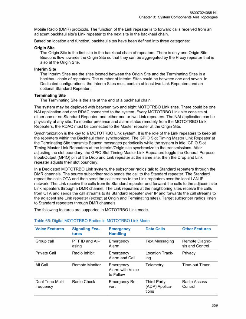
Mobile Radio (DMR) protocols. The function of the Link repeater is to forward calls received from anadjacent backhaul site’s Link repeater to the next site in the backhaul chain.
Based on location and function, backhaul sites have been defined into three categories:
Origin SiteThe Origin Site is the first site in the backhaul chain of repeaters. There is only one Origin Site.Beacons flow towards the Origin Site so that they can be aggregated by the Proxy repeater that isalso at the Origin Site.
Interim SiteThe Interim Sites are the sites located between the Origin Site and the Terminating Sites in abackhaul chain of repeaters. The number of Interim Sites could be between one and seven. InDedicated configurations, the Interim Sites must contain at least two Link Repeaters and anoptional Standard Repeater.
Terminating SiteThe Terminating Site is the site at the end of a backhaul chain.
The system may be deployed with between two and eight MOTOTRBO Link sites. There could be oneNAI application and one RDAC connected to the system. Every MOTOTRBO Link site consists ofeither one or no Standard Repeater, and either one or two Link repeaters. The NAI application can bephysically at any site. To monitor presence and alarm status remotely from the MOTOTRBO LinkRepeaters, the RDAC must be connected to the Master repeater at the Origin Site.
Synchronization is the key to a MOTOTRBO Link system. It is the role of the Link repeaters to keep allthe repeaters within the Backhaul chain synchronized. The GPIO Slot Timing Master Link Repeater atthe Terminating Site transmits Beacon messages periodically while the system is idle. GPIO SlotTiming Master Link Repeaters at the Interim/Origin site synchronize to the transmissions. Afteradjusting the slot boundary, the GPIO Slot Timing Master Link Repeaters toggle the General PurposeInput/Output (GPIO) pin of the Drop and Link repeater at the same site, then the Drop and Linkrepeater adjusts their slot boundary.
In a Dedicated MOTOTRBO Link system, the subscriber radios talk to Standard repeaters through theDMR channels. The source subscriber radio sends the call to the Standard repeater. The Standardrepeat the calls OTA and then send the call streams to the Link repeaters over the local LAN IPnetwork. The Link receive the calls from its Standard repeater and forward the calls to the adjacent siteLink repeaters through a DMR channel. The Link repeaters at the neighboring sites receive the callsfrom OTA and sends the call streams to its Standard repeater over IP and forwards the call streams tothe adjacent site Link repeater (except at Origin and Terminating sites). Target subscriber radios listento Standard repeaters through DMR channels.
The following features are supported in MOTOTRBO Link mode.
Table 65: Digital MOTOTRBO Radios in MOTOTRBO Link Mode
Voice Features Signaling Fea-tures
EmergencyHandling
Data Calls Other Features
Group call PTT ID and Ali-asing
EmergencyAlarm
Text Messaging Remote Diagno-sis and Control
Private Call Radio Inhibit EmergencyAlarm and Call
Location Track-ing
Privacy
All Call Remote Monitor EmergencyAlarm with Voiceto Follow
Telemetry Time-out Timer
Dual Tone Multi-frequency
Radio Check Emergency Re-vert
Third-Party(ADP) Applica-tions
Radio AccessControl
68007024085-NLChapter 3: System Components And Topologies
359

Voice Features Signaling Fea-tures
EmergencyHandling
Data Calls Other Features
NAI Phone Call Call Alert Emergency Im-polite Takeover
Polite to All Sys-tem Access
3.2.9.1MOTOTRBO Link Standalone TopologyThe following figure depicts the site nodes for a configuration with three backhaul sites. The maximumsize is nine sites with eight links to connect the adjacent sites of the chain.
The arrows in the diagram between the Link repeaters depict the flow of data through the RF networkbased on the Land Mobile Radio (LMR) channel frequency assignments. When a call is transmittedthrough the Link repeaters in the backhaul chain, it can be streamed over the wireline interface on theLAN at each site to the Standard repeater so that the call could be repeated locally.
The furthest distance between the origin and terminating sites for a call shall involve at most eight linksor hops to ensure a good customer experience. The more links being added increases the call set-uptime or the amount of time it takes before the user hears the talk permit tone on their subscriber radio.
Figure 138: Dedicated Standalone MOTOTRBO Link System
Tx 1
Rx 1
Rx 101
Tx 11Tx 21
Rx 11
Tx 2
Rx 2
Tx 101
Rx 201Tx 201
Rx 21
Tx 3
Rx 3
Origin Site
Switch
Interim Site Terminating Site
Standard BR1
Link BR11
Standard BR2
Backward Link BR21
Forward Link BR22
Standard BR3
Link BR31
IP
DMR DMR
IP
RDAC
NAI APP
LE Master
3.2.9.2MOTOTRBO Link Hybrid TopologyThe Dedicated Hybrid MOTOTRBO Link system consists of an IP Site Connect Backhaul network andStandalone MOTOTRBO Link Chains. The system may be deployed with one or up to 14 MOTOTRBOLink Chains.
If the IP Site Connect Digital MOTOTRBO Link or Network Application Interface (NAI) application ispresent in the IP Site Connect network, the maximum number of MOTOTRBO Link Chains is reduced.Adding one IP Site Connect MOTOTRBO Link Repeater reduces the maximum number ofMOTOTRBO Link Chains by one.
The Standard repeaters at the Origin Site are responsible for bridging the calls between the IP SiteConnect MOTOTRBO Link network and the MOTOTRBO Link Chains.
The following figure shows a Dedicated Hybrid MOTOTRBO Link system with two DedicatedStandalone MOTOTRBO Link Chains and two IP Site Connect MOTOTRBO Link Repeaters.
68007024085-NLChapter 3: System Components And Topologies
360
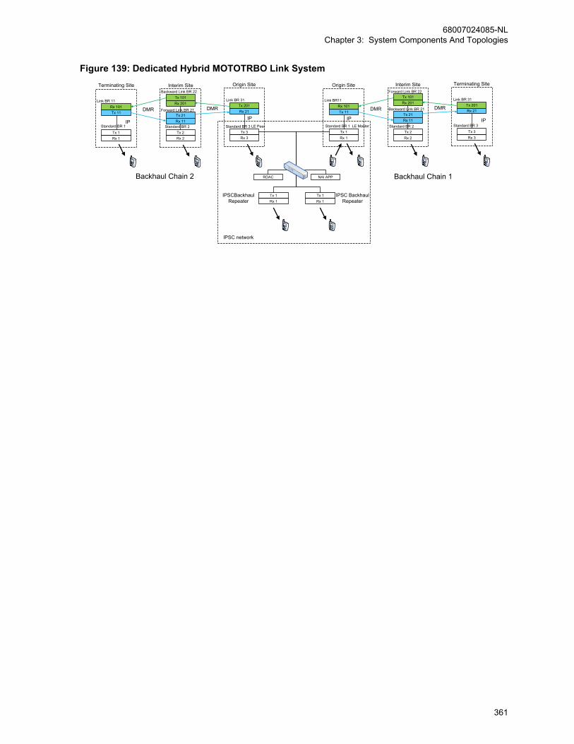
Figure 139: Dedicated Hybrid MOTOTRBO Link System
IPSCBackhaulRepeater
IPSC BackhaulRepeater
Tx 1Rx 1
Rx 101Tx 11 Tx 21
Rx 11
Tx 2Rx 2
Tx 101Rx 201 Tx 201
Rx 21
Tx 3Rx 3
Origin Site Interim Site Terminating Site
Standard BR 1
Link BR11
Standard BR 2
Backward Link BR 21
Forward Link BR 22
Standard BR 3
Link BR 31
IP
DMR DMR
IP
RDAC NAI APP
LE Master
Tx 1Rx 1
Rx 101Tx 11
Tx 21Rx 11
Tx 2Rx 2
Tx 101Rx 201 Tx 201
Rx 21
Tx 3Rx 3
Origin SiteInterim SiteTerminating Site
Standard BR 1
Link BR 11
Standard BR 2
Forward Link BR 21
Backward Link BR 22
Standard BR 3
Link BR 31
IP
DMR DMR
IPLE Peer
Tx 1Tx 1Rx 1Rx 1
IPSC network
Backhaul Chain 2 Backhaul Chain 1
68007024085-NLChapter 3: System Components And Topologies
361
Chapter 4
System Design ConsiderationsIPSC
Indicates IP Site Connect feature related content.
CPSSIndicates Capacity Plus Single Site feature related content.
CPMSIndicates Capacity Plus Multi Site feature related content.
CPSMIndicates Capacity Plus Single Site AND Capacity Plus Multi Siteshared feature related content.
4.1OverviewThis section describes various system configurations readers need to know before deciding how tobest support the needs and usage of their customers. It explains the usage supported on a singlerepeater system, as a guideline for design. It then identifies the customer needs that need to beconsidered when optimizing system performance. It continues to cover various other considerationsthat may need to be addressed during the design phase.
NOTICE: MOTOTRBO also supports server based data applications in repeater mode. Thisconfiguration consists of a PC (referred to as the Application Server) running the serversoftware connected to the radio infrastructure via a mobile radio or via the MNIS application.For details on data communication with applications through the repeater network interfaceinstead of a control station, refer to the applicable sections.All data application modules contained in this system planner are depictions of typical third-party data application modules and have been included simply to illustrate certain MOTOTRBOapplication enabling features.
4.2Analog-to-Digital Migration PlansSystem Migration is the process of moving from one operating platform to another. The followingsections elaborate system migration from a two-way radio platform to a digital two-way radio platform.
4.2.1Pre-Deployment System IntegrationWhere applicable, the dealer should perform system assembly, configuration, adjustment, and brieftesting of the MOTOTRBO system. Each component contains documentation necessary for systeminstallation and optimization. The benefits of staging a system in a controlled environment include:
• Equipment accountability in preparation for system assembly
• System assembly and programming in a controlled test environment
• Documentation of programming information
• Fabrication of cables and connectors
68007024085-NLChapter 4: System Design Considerations
362
• Test of complete functionality and initial level-setting for system optimization
4.2.2Preparing and Migratiing Analog to DigitalA Dynamic Mixed Mode repeater does not enable communication between legacy and MOTOTRBOdigital radios operating in digital mode. When the repeater receives an analog call, it retransmits indigital mode. When the repeater receives a digital call, it retransmits in digital mode. It is the scanningfeature in the subscriber that allows the MOTOTRBO radios, programmed with both analog and digitalchannels, to listen to analog calls from legacy analog radios. While the MOTOTRBO radio is listeningto an analog call through PL scanning, it talks back in digital mode, if keyed up within the call hangtime.
NOTICE: The MOTOTRBO radio needs to be in analog mode to initiate or return an analog callwith legacy analog radios.
Procedure:1 To migrate a system with a single non-MOTOTRBO repeater channel, radio users are
encouraged to use MOTOTRBO radios in digital direct mode/dual capacity direct mode.
This gives them an opportunity to familiarize themselves with the MOTOTRBO digital featureset, while communicating with legacy analog radios through the legacy analog repeater. If theanalog system does not use any PL/DPL encoding, then analog radios hear noise caused bydigital radio transmissions communicating in direct mode/dual capacity direct mode.Over time, as the number of MOTOTRBO radios increases, a cut-over day is pre-determined.On that day, the legacy analog repeater will be replaced by a MOTOTRBO digital repeater.Radio users communicate with each other in Talkaround while the new repeater is beinginstalled. Once the MOTOTRBO repeater is operational, MOTOTRBO radio users switch todigital repeater mode, while legacy analog radio users communicate in Talkaround.
2 To migrate a system with two repeater channels, MOTOTRBO radios are programmed with boththe current analog channels as well as future digital channels. A recommended approach is toplace all the analog channels in one ‘zone’, and all digital channels in another ‘zone’. Analogand digital channels are programmed into the MOTOTRBO radios to allow users tocommunicate on both repeaters. Scan Lists are configured to allow users to monitor both analogand digital voice transmissions.
Both the existing analog repeater and the MOTOTRBO repeater (in digital mode) should be set-up to operate side-by-side. This configuration requires two frequency pairs: one pair for theanalog repeater and one pair for the MOTOTRBO repeater. Users gradually migrate over to theMOTOTRBO repeater (for example, legacy analog radios are swapped for MOTOTRBO radios).Once every analog radio has been swapped with a MOTOTRBO radio, the legacy analogrepeater can be replaced with another MOTOTRBO digital repeater. The system is now fullydigital with two digital repeater channels.
3 To migrate a system with a single MOTOTRBO repeater channel, load/upgrade theMOTOTRBO repeater with firmware version R01.06.10 or later. Configure the repeater toDynamic Mixed Mode using the CPS. This configuration requires one frequency pair. Analogand digital channels are programmed into the MOTOTRBO radios to allow users tocommunicate through the same repeater. Scan Lists are configured to allow users to monitorboth analog and digital voice transmissions on the same frequency.
In Dynamic Mixed Mode, MOTOTRBO system does not enable some of the digital only featureslike IP Site Connect, Capacity Plus Single Site, Transmitter Interrupt and RDAC over IP. Thesystem allows digital and analog voice transmission at one site.Once every radio has been swapped with a MOTOTRBO radio, the MOTOTRBO repeater canbe reconfigured to fully operate in digital mode, therefore allowing the user to experience allavailable digital features.
68007024085-NLChapter 4: System Design Considerations
363

4.2.3New/Full System ReplacementThe new/full system replacement strategy involves replacing all existing equipment with MOTOTRBOequipment.
Typically, a new/full system replacement involves minimal downtime as the repeater is replacedimmediately with the MOTOTRBO digital repeater. Radio users carry their existing radios as well asMOTOTRBO radios on cut-over day. Initially, users continue to access the radio system in the samemanner as before. Once the analog repeater is removed from the system, the radio users switch todigital direct mode/dual capacity direct mode communication using MOTOTRBO radios. After theMOTOTRBO repeater is installed and becomes operational, radio users switch their MOTOTRBOradios to digital repeater mode.
The new/full system replacement relies on the MOTOTRBO equipment being properly programmedand tested before being deployed.
4.3New Frequency Licensing (Region Specific)The licensing process varies from region to region. Generally, before the license process begins,detailed information about the proposed radio system must be provided to the frequency coordinator,such as:
Frequency/ Frequency BandFrequency band or specific frequency it operates on.
Subscriber Radio CountThe number of radios that will operate on the system.
Output Power/ERPThe output power of the system amplifier, as well as the effective radiated power (ERP), which isthe system's power at the antenna.
Emission DesignatorsIncludes several pieces of vital information, such as modulation, signal, type of information and sizeof the channel. This determines the channel width your system will occupy. For MOTOTRBOsystems, the Emissions Designators are as follows:
• Data only: 7K60FXD
• Voice and Data: 7K60FXE
The first four values are defined as the ‘Necessary Bandwidth’. This can be derived from the 99%Energy Rule as defined in Title 47CFR2.989. The next two values are the ‘Modulation Type’ andthe ‘Signal Type’. The final value is the ‘Type of Information’ being sent. More information can befound with the region’s frequency coordinating committee.
International CoordinationFor stations near another country’s border, refer to a frequency coordinating committee for licensingfrequencies adjacent to that country.
Antenna InformationYou must also provide the following information about your antenna:
• Structure. The most common codes are:
• B – Building with side mounted antenna
• BANT – Building with antenna on top
• MAST – Self-supported structure
• PIPE – Pipe antenna
68007024085-NLChapter 4: System Design Considerations
364

• POLE – Any type of pole antenna
• TOWER – Free standing guyed structure used for communications purposes
• Height
• Antenna Height – Antenna height from ground to tip, in meters.
• Support Structure Height – If antenna is mounted on top of a building, it is the distance fromground to the top of the building. Check with the building management company for thisinformation.
• Coordinates – Latitude and longitude should be listed in degrees, minutes and seconds.
• Site Elevation – The antenna site ground elevation above sea level. This information shouldalways be in meters.
4.4Converting Existing 12.5/25 kHz LicensesThe process for converting 25 kHz to 12.5 kHz varies between regions. It is recommended to contactthe local frequency coordinator’s office to inquire how to re-file existing frequency allocations. Thereare also consultants that specialize in frequency coordination and can advise on the filing process. Inthe US, the following are general guidelines for frequency licenses:
Procedure:1 For existing 12.5 kHz license(s), the user must file an update to the emission designators
indicating 7K60FXE (for voice) and 7K60FXD (for data) for all applicable frequencies.
2 If the user has existing 25 kHz licenses(s), they must file an update to the emission designatorsto include 7K60FXE (for voice) and 7K60FXD (for data) for all applicable frequencies.
Typically, the user is then allowed to transmit a 12.5 kHz signal bandwidth at the same centerfrequency as the original 25 kHz license. Note that it is not a straightforward process to convertan existing 25 kHz license into a pair of 12.5 kHz channels. Users are generally NOT allowed tosplit their 25 kHz channel into two 12.5 kHz sub-channels that would operate off center from theoriginal license and adjacent to one another.
4.5Repeater Continuous Wave Identification (CWID)The repeater can be configured to transmit the CWID if required by the region. The CWID is alsoknown as the Base Station ID. The CWID is a transmission of the station in Morse code that takesplace every 15 minutes. This identification, as well as the transmit interval, can be configured in therepeater using the CPS.
To ensure proper Dynamic Mixed Mode operation, only exclusive CWID transmission is supported inMOTOTRBO repeater operating in Dynamic Mixed Mode. Mixed CWID is not supported in order to becompliant with the digital mode of operation. Furthermore, the exclusive CWID transmission cannot beinterrupted by either over-the-air transmissions or PTT transmissions by the repeater's accessories.
4.6Repeater Narrow IF FilterIf Adjacent Channel Selection (ACS) is poor, the following problems may occur:
• Near/far adjacent channel interference scenario at the Repeater’s receiver: With a currentprotection of 57 dB, if signal on adjacent channel is 57 dB above desired signal, then there is 3 dBRx degradation.
• Impact to voice: There is 3–5 dB range from no audio to acceptable DAQ 3.0 audio.
68007024085-NLChapter 4: System Design Considerations
365
• Impact to data: For confirmed data, there is 15 dB range that is impacted and results in more retriesand lower throughput.
Interference from adjacent channel can be reduced by reducing the receive bandwidth. DMRmodulation sideband power falls at 10 dB/kHz. 1 kHz narrowing of bandwidth would improve adjacentchannel protection by 5 dB on each side. Decreasing receiver bandwidth requires mechanism tocontrol reference oscillator drift over time (aging). Subscribers use high stability Repeater frequency topersistently tune the Subscriber reference oscillator. 900 MHz requires 0.1 ppm this option is alsoavailable for 800 MHz. To support current deployments with no impact to range, there is a need toallow selection of Narrow or Wide (existing) filter in the repeater through a CPS option. This isapplicable only to digital channels and not analog channels. Analog channels always use the defaultWide IF Filter. Selection of narrow IF Filter improves ACS by 3–4 dB and degrades the sensitivity by0.5 dB.
The following configurations are recommended for system deployment:
• For digital channels with adjacent channel separation of 12.5 kHz – select Narrow IF filter
• For digital channels with adjacent channel separation greater than 12.5 kHz – select Wide IF filter
4.7Digital Repeater LoadingThe designer is able to choose the number of channels required to support his customer’s expectedtraffic after understanding how much traffic a single slot (channel) can support. The amount of traffic ona channel is dependent on numerous variables, which are difficult to estimate exactly at design time.
Since MOTOTRBO comprises of Voice traffic, Text Messaging traffic, Location Tracking traffic,Registration and Signaling traffic, the previous voice traffic methods to gauge repeater capacity maynot be sufficient. Because this traffic is mostly initiated by the end user, it is difficult to predict how oftenit occurs. Standard usage profiles of existing customers have been created for voice and data services.These profiles act as a baseline for estimating how much traffic a user creates on a system. If thestandard profiles do not match your customer’s expected usage, further estimations based on the trendlines need to be considered. After the system is used, and real life usage is identified, furtheradjustments may be required.
4.7.1Assumptions and Precautions for Digital Repeater LoadingChannel loading analysis involves several assumptions:
• Generalized high-level view of data and voice services interaction represents true interaction.
• An estimated amount of blocking, interference, reliability, and call denials varies with the trafficprofile and could change some of the results used.
• An estimated number of radios using the location tracking feature (100%) and the rate of thosemessages for the high-end traffic profile (once every minute for every mobile) is used.
Given these assumptions, the chart presented can be used to provide customers with a general rule ofthumb for levels of user experience expected based on the number of users. In addition, for thisanalysis, the term “number of users” is used to indicate the number of active/participating usersgenerating traffic, and does not include the number of users who monitor the activity of other radios onthe channel.
4.7.2Voice and Data Traffic ProfileThe following table summarizes the standard traffic profiles for voice and data. The three traffic typesconsidered are voice calls (Group Calls and Private Calls), data transmitted for location tracking and
68007024085-NLChapter 4: System Design Considerations
366

text messaging. For each traffic type, two levels are set. One, is for the case of a typical low usage orlight traffic user, and the other is for a typical high usage or heavy traffic user. The voice and textmessaging profiles are derived using assumed typical behaviors.
These profiles act as a baseline for estimating how much traffic a user creates on a system. If thesestandard profiles do not match your customer’s expected usage, further estimations based on the trendlines need to be considered. Further, this is the profile of how all users on a channel will act together. Itis understandable that not all users will use this profile all the time. These profiles should be used toestimate the number of users per channel that yield an acceptable user experience.
Profile Name Traffic Type Call Description Traffic Per User Per Hour
High Voice Group Voice Call 10 second call, 2transmissionsper call
3.0 Calls perUser per Hour
90%
Individual VoiceCall
20 second call, 4transmissionsper call
10%
Low Voice Group Voice Call 10 second call, 2transmissionsper call
1.0 Calls perUser per Hour
90%
Individual VoiceCall
20 second call, 4transmissionsper call
10%
High GPS Location Up-dates
660 milliseconds(for Single Re-peater and IPSite Connect)per transmissionand540 milliseconds(for CapacityPlus Single Sitemode) per trans-mission
60 GPS Transmissions per User perHour For example, 1 Minute Update Period(Cadence)
Low GPS Location Up-dates
660 millisecondsper transmission
6 GPS Transmissions per User perHour For example, 10 Minute Update Peri-od (Cadence)
High Text Mes-saging
Text Messaging 100 charactersper message
2.5 Text Messages per User perHour
Low Text Mes-saging
Text Messaging 100 charactersper message
0.5 Text Messages per User perHour
4.7.3Estimate Loading (for Single Repeater and IP Site Connect)
IPSC
68007024085-NLChapter 4: System Design Considerations
367
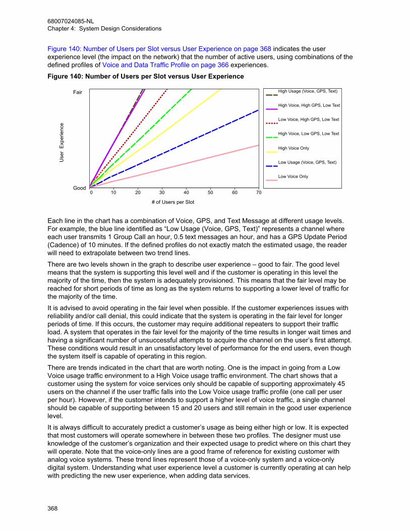
Figure 140: Number of Users per Slot versus User Experience on page 368 indicates the userexperience level (the impact on the network) that the number of active users, using combinations of thedefined profiles of Voice and Data Traffic Profile on page 366 experiences.
Figure 140: Number of Users per Slot versus User Experience
0 10 20 30 40 50 60 70
# of Users per Slot
High Usage (Voice, GPS, Text)
High Voice, High GPS, Low Text
Low Voice, High GPS, Low Text
High Voice, Low GPS, Low Text
High Voice Only
Low Usage (Voice, GPS, Text)
Low Voice Only
Use
r E
xper
ienc
e
Good
Fair
Each line in the chart has a combination of Voice, GPS, and Text Message at different usage levels.For example, the blue line identified as “Low Usage (Voice, GPS, Text)” represents a channel whereeach user transmits 1 Group Call an hour, 0.5 text messages an hour, and has a GPS Update Period(Cadence) of 10 minutes. If the defined profiles do not exactly match the estimated usage, the readerwill need to extrapolate between two trend lines.
There are two levels shown in the graph to describe user experience – good to fair. The good levelmeans that the system is supporting this level well and if the customer is operating in this level themajority of the time, then the system is adequately provisioned. This means that the fair level may bereached for short periods of time as long as the system returns to supporting a lower level of traffic forthe majority of the time.
It is advised to avoid operating in the fair level when possible. If the customer experiences issues withreliability and/or call denial, this could indicate that the system is operating in the fair level for longerperiods of time. If this occurs, the customer may require additional repeaters to support their trafficload. A system that operates in the fair level for the majority of the time results in longer wait times andhaving a significant number of unsuccessful attempts to acquire the channel on the user’s first attempt.These conditions would result in an unsatisfactory level of performance for the end users, even thoughthe system itself is capable of operating in this region.
There are trends indicated in the chart that are worth noting. One is the impact in going from a LowVoice usage traffic environment to a High Voice usage traffic environment. The chart shows that acustomer using the system for voice services only should be capable of supporting approximately 45users on the channel if the user traffic falls into the Low Voice usage traffic profile (one call per userper hour). However, if the customer intends to support a higher level of voice traffic, a single channelshould be capable of supporting between 15 and 20 users and still remain in the good user experiencelevel.
It is always difficult to accurately predict a customer’s usage as being either high or low. It is expectedthat most customers will operate somewhere in between these two profiles. The designer must useknowledge of the customer’s organization and their expected usage to predict where on this chart theywill operate. Note that the voice-only lines are a good frame of reference for existing customer withanalog voice systems. These trend lines represent those of a voice-only system and a voice-onlydigital system. Understanding what user experience level a customer is currently operating at can helpwith predicting the new user experience, when adding data services.
68007024085-NLChapter 4: System Design Considerations
368
Two other trends from the chart are also worth pointing out. The first is that the level of adding data(low traffic for location tracking and text messaging) does not cause a huge impact to the number ofusers supported. For example the lines for High Voice usage traffic (one with voice only and the otherwith the addition of low location tracking and text messaging) both show that supporting 15–20 activeusers on one channel will keep the system from approaching the stressed level. Similarly, both curvesfor the Low Voice traffic show that 30–35 users could be supported well on a single channel.
Another important note is that these trend lines are associated with a single slot of a MOTOTRBOrepeater. Since MOTOTRBO is a two-slot TDMA system, a customer that is upgrading from atraditional FDMA one channel conventional system will have the ability to split users into two slots. Forexample, if a high usage voice only customer is currently supporting 30–40 users on a single channel,they are most likely operating in a “fair” or “stressed” environment and will likely need to expand theirsystem. If they switch to a MOTOTRBO system, they can divide their users into the two availablechannels. This means a single channel now has only 15–20 users, which would bring the customerback to a good user experience level. Subsequently, adding on low usage data services on bothchannels will cause minimal impact to performance.
When GPS CSBK data is enabled, twice the number of radios can be supported with a similar GPSsuccess rate. However, if the voice and TMS traffic are increased along with the number of radios, thevoice and TMS user experience will drop.
4.7.4Estimate Loading (for Capacity Plus Single Site)
CPSS
The following charts, Figure 141: Number of Users Versus Number of Channels for Voice-Only Profileon page 370 and Figure 142: Number of Users Versus Number of Channels for Mixed Profiles on page371 indicate the number of Trunked Channels (slots) a Capacity Plus Single Site system requires for agiven user experience, for a given number of active users, and for different combinations of the Voiceand Data Traffic profiles as defined in Voice and Data Traffic Profile on page 366. It is assumed herethat the number of groups are more than the number of channels.
68007024085-NLChapter 4: System Design Considerations
369
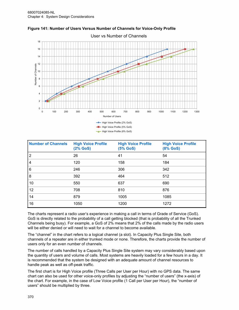
Figure 141: Number of Users Versus Number of Channels for Voice-Only Profile
0
2
4
6
8
10
12
14
16
18
0 100 200 300 400 500 600 700 800 900 1000 1100 1200 1300
Num
ber o
f Cha
nnel
s
Number of Users
User vs Number of Channels
High Voice Profile (2% GoS)
High Voice Profile (5% GoS)
High Voice Profile (8% GoS)
Number of Channels High Voice Profile (2% GoS)
High Voice Profile(5% GoS)
High Voice Profile(8% GoS)
2 26 41 54
4 120 158 184
6 246 306 342
8 392 464 512
10 550 637 690
12 708 810 876
14 879 1005 1085
16 1050 1200 1272
The charts represent a radio user’s experience in making a call in terms of Grade of Service (GoS).GoS is directly related to the probability of a call getting blocked (that is probability of all the TrunkedChannels being busy). For example, a GoS of 2% means that 2% of the calls made by the radio userswill be either denied or will need to wait for a channel to become available.
The “channel” in the chart refers to a logical channel (a slot). In Capacity Plus Single Site, bothchannels of a repeater are in either trunked mode or none. Therefore, the charts provide the number ofusers only for an even number of channels.
The number of calls handled by a Capacity Plus Single Site system may vary considerably based uponthe quantity of users and volume of calls. Most systems are heavily loaded for a few hours in a day. Itis recommended that the system be designed with an adequate amount of channel resources tohandle peak as well as off-peak traffic.
The first chart is for High Voice profile (Three Calls per User per Hour) with no GPS data. The samechart can also be used for other voice-only profiles by adjusting the “number of users” (the x-axis) ofthe chart. For example, in the case of Low Voice profile (1 Call per User per Hour), the “number ofusers” should be multiplied by three.
68007024085-NLChapter 4: System Design Considerations
370

Figure 142: Number of Users Versus Number of Channels for Mixed Profiles on page 371 is for mixedvoice and GPS data profile. It has two sets of graphs – one for High Voice with low GPS data and theother for Low Voice with low GPS data. Both voice and GPS data are using the Trunked Channels.Take note of the trend indicated in the chart. The number of users do not increase proportionally withthe number of channels. The rate increases as the number of channels increase. This is due to the factthat the efficiency of trunking increases with the increase in the number of channels.
Figure 142: Number of Users Versus Number of Channels for Mixed Profiles
0
2
4
6
8
10
12
14
16
18
0 200 400 600 800 1000 1200 1400 1600 1800 2000
Num
ber o
f Cha
nnel
s
Number of Users
Users vs Number of Channels
High Voice Low GSP (2% GoS)
High Voice Low GPS (5% GoS)
High Voice Low GPS (8% GoS)
Low Voice Low GPS (2% GoS)
Low Voice Low GPS (5% GoS)
Low Voice Low GPS (8% GoS)
Numberof Chan-nels
High Voice Low GPS Low Voice Low GPS
2% GoS 5% GoS 8% GoS 2% GoS 5% GoS 8% GoS
2 10 20 30 30 40 50
4 30 40 50 50 80 100
6 100 140 160 230 300 350
8 210 260 290 470 570 640
10 330 390 420 740 880 960
12 460 530 580 1020 1190 1300
14 600 680 780 1310 1500 1650
16 750 840 1000 1610 1820 2010
In the case of high GPS data, it is recommended that a Capacity Plus Single Site system haveexclusive channels for data called Data Revert Channels. Figure 143: Number of Location Updatesversus Number of Data Revert Channels on page 372 shows graph for high GPS data over revertchannels. A Data Revert repeater offers two Data Revert Channels and a revert channel can carry upto 20 location updates per minute with a success rate of 95% and 40 location updates per minute witha success rate of 85%. When GPS CSBK data is enabled, twice the number of radios can be
68007024085-NLChapter 4: System Design Considerations
371
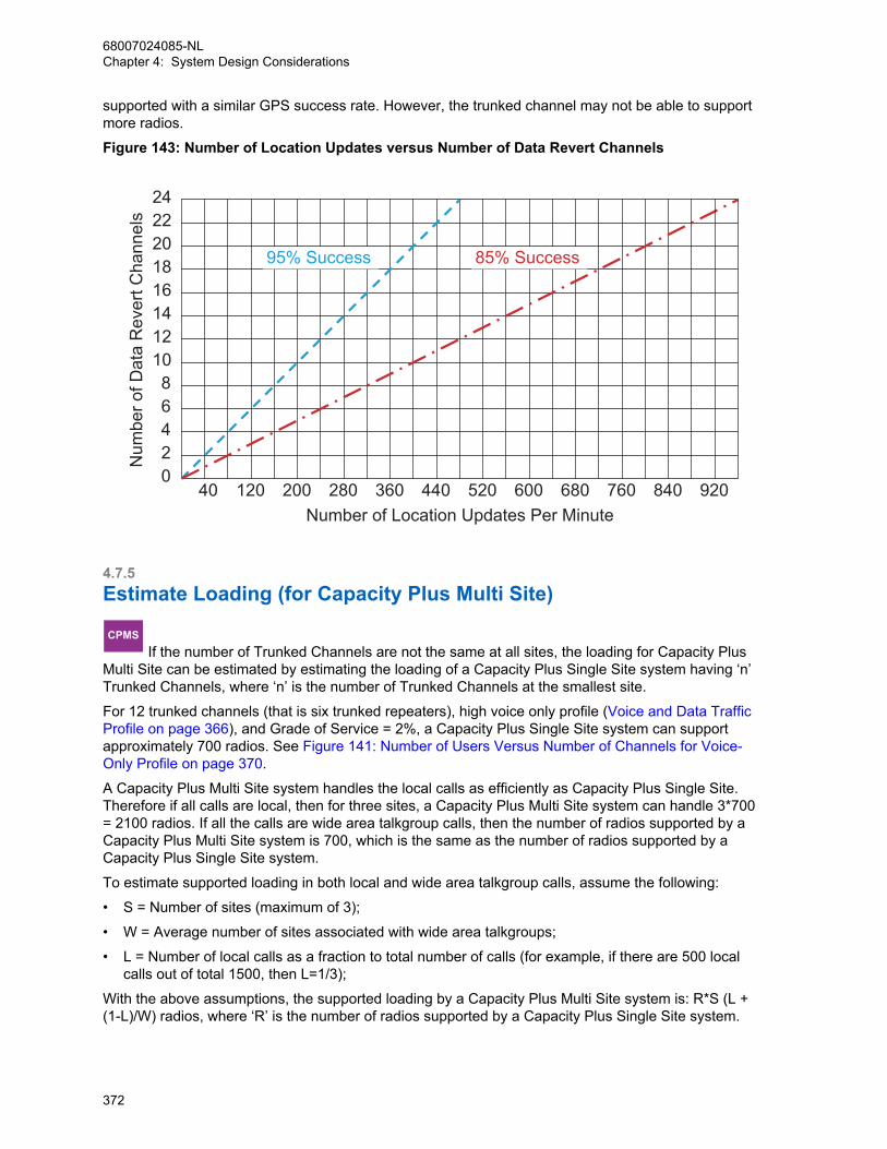
supported with a similar GPS success rate. However, the trunked channel may not be able to supportmore radios.
Figure 143: Number of Location Updates versus Number of Data Revert Channels
02468
1012141618202224
40 120 200 280 360 440 520 600 680 760 840 920
95% Success 85% Success
Number of Location Updates Per Minute
Num
ber o
f Dat
a R
ever
t Cha
nnel
s
4.7.5Estimate Loading (for Capacity Plus Multi Site)
CPMS If the number of Trunked Channels are not the same at all sites, the loading for Capacity Plus
Multi Site can be estimated by estimating the loading of a Capacity Plus Single Site system having ‘n’Trunked Channels, where ‘n’ is the number of Trunked Channels at the smallest site.
For 12 trunked channels (that is six trunked repeaters), high voice only profile (Voice and Data TrafficProfile on page 366), and Grade of Service = 2%, a Capacity Plus Single Site system can supportapproximately 700 radios. See Figure 141: Number of Users Versus Number of Channels for Voice-Only Profile on page 370.
A Capacity Plus Multi Site system handles the local calls as efficiently as Capacity Plus Single Site.Therefore if all calls are local, then for three sites, a Capacity Plus Multi Site system can handle 3*700= 2100 radios. If all the calls are wide area talkgroup calls, then the number of radios supported by aCapacity Plus Multi Site system is 700, which is the same as the number of radios supported by aCapacity Plus Single Site system.
To estimate supported loading in both local and wide area talkgroup calls, assume the following:
• S = Number of sites (maximum of 3);
• W = Average number of sites associated with wide area talkgroups;
• L = Number of local calls as a fraction to total number of calls (for example, if there are 500 localcalls out of total 1500, then L=1/3);
With the above assumptions, the supported loading by a Capacity Plus Multi Site system is: R*S (L +(1-L)/W) radios, where ‘R’ is the number of radios supported by a Capacity Plus Single Site system.
68007024085-NLChapter 4: System Design Considerations
372

Example: For 3 sites (S=3), 12 trunked channels, 2% Grade of Service, one third local calls (L=1/3),and an average of 2 sites associated with wide area talkgroups (W=2), a Capacity Plus Multi Site willbe able to support 700*3 (1/3 +(1-1/3)/2) = 1400 radios.
NOTICE: 700 is the number of radios supported by a 12-channel Capacity Plus Single Sitesystem at 2% Grade of Service.
If the number of trunked channels is different at all the sites, the loading for Capacity Plus Multi Sitecan be estimated by first estimating the loading of a Capacity Plus Multi Site system having ‘n’ trunkedchannels, where ‘n’ is the number of trunked channels at the smallest site.
Example: A Capacity Plus Multi Site system has four sites – A, B, C, and D. Sites A and B has twotrunked repeaters and sites C and D has three trunked repeaters. Then, for 2% Grade of Service, onethird local calls (L=1/3), and an average of 2 sites associated with wide area talkgroups (W=2), aCapacity Plus Multi Site will be able to support 120*4 (1/3 +(1-1/3)/2) = 320 radios. Note that ‘120’ isthe “number of users”, which comes from number of channels = 4 and 2% grade of service. If theadditional capacity at site C and D are designed for local calls, then Site C or Site D can support 240users (number of channels = 6), that is, an additional 120 users at Site C and an additional 120 usersat Site D. Thus, the total number of users supported by the system is 320 + 120 + 120 = 560 radios.
In the case of high GPS data, it is recommended for a Capacity Plus Multi Site system to haveexclusive channels for data defined as Data Revert Channels. The figure shows a graph for high GPSdata over revert channels. A Data Revert repeater offers two Data Revert Channels and a revertchannel can carry more than 20 location updates per minute with a success rate of 95% and 40location updates per minute with a success rate of 85%.
4.7.6Estimate Loading (for MOTOTRBO Link)Compared to a Single Repeater and IP Site Connect mode, MOTOTRBO Link mode introduces theconcept of over-the-air (OTA) hops and the Number of Backhaul Chains. The number of users that canbe supported per slot depends on the usage profile, number of backhaul sites and whether thecustomer has more than one backhaul chain. Due to the transmission delay introduced by OTA hopsbetween the repeater backhaul sites, the throughput of the system is lower than IP Site Connect mode.
Both figures indicate the user experience level that the number of active users, using combinations ofthe defined profiles of Voice and Data Traffic Profile on page 366 experiences in MOTOTRBO Linkmode.
The following figure is for the MOTOTRBO Link system which has one chain with three sites.
68007024085-NLChapter 4: System Design Considerations
373
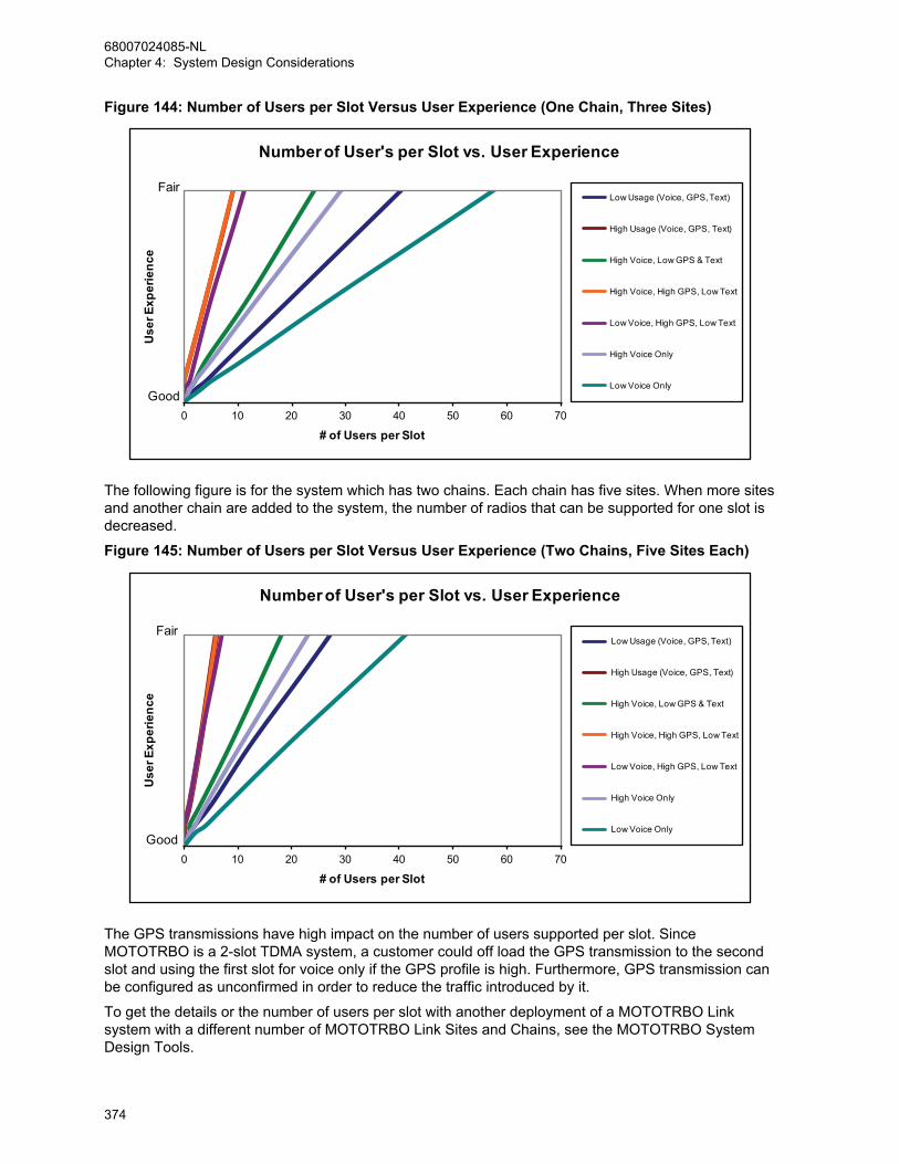
Figure 144: Number of Users per Slot Versus User Experience (One Chain, Three Sites)
0 10 20 30 40 50 60 70
Use
r Exp
erie
nce
# of Users per Slot
Number of User's per Slot vs. User Experience
Low Usage (Voice, GPS, Text)
High Usage (Voice, GPS, Text)
High Voice, Low GPS & Text
High Voice, High GPS, Low Text
Low Voice, High GPS, Low Text
High Voice Only
Low Voice Only
Fair
Good
The following figure is for the system which has two chains. Each chain has five sites. When more sitesand another chain are added to the system, the number of radios that can be supported for one slot isdecreased.
Figure 145: Number of Users per Slot Versus User Experience (Two Chains, Five Sites Each)
0 10 20 30 40 50 60 70
Use
r Exp
erie
nce
# of Users per Slot
Number of User's per Slot vs. User Experience
Low Usage (Voice, GPS, Text)
High Usage (Voice, GPS, Text)
High Voice, Low GPS & Text
High Voice, High GPS, Low Text
Low Voice, High GPS, Low Text
High Voice Only
Low Voice Only
Fair
Good
The GPS transmissions have high impact on the number of users supported per slot. SinceMOTOTRBO is a 2-slot TDMA system, a customer could off load the GPS transmission to the secondslot and using the first slot for voice only if the GPS profile is high. Furthermore, GPS transmission canbe configured as unconfirmed in order to reduce the traffic introduced by it.
To get the details or the number of users per slot with another deployment of a MOTOTRBO Linksystem with a different number of MOTOTRBO Link Sites and Chains, see the MOTOTRBO SystemDesign Tools.
68007024085-NLChapter 4: System Design Considerations
374
4.7.7Load Optimization (for Single Repeater and IP Site Connect)
IPSCIP Site Connect
The following contents in section Load Optimi-zation (for Single Repeater and IP Site Con-nect) on page 375 and all its subsections ex-plain about Loading Optimization in IP SiteConnect.
There are further considerations to take when configuring your MOTOTRBO system to ease the trafficload on a channel. These considerations should always be taken into account, especially if thedesigner is forced to operate outside of the “good” user experience range, although operating in such amanner is not recommended.
4.7.7.1Distribution of High Usage UsersIt is good design practice to identify and distribute high usage users and groups between slots of asingle repeater, or even other repeaters. This keeps the number of users that follow a high usagetraffic profile to a minimum per channel. Groups are generally assigned to operate on a particular slotof a repeater. Through discussions with the customer, the designer should identify high usage groupsand distribute them over different slots.
Groups and users that are on different slots cannot communicate with each other. They need tomanually change their selector knobs to communicate with the users and other groups on the otherslot. In most cases, this is not a problem since organizations can usually be broken into at least twogroups of users. But in the case where a customer only has one group of users who all need voicecommunication between each other at all times, then evenly distributing the voice and data loadbetween two channels becomes more complicated.
If there is only one group in a system, its users can be programmed to operate on a particular slot.Their Group Calls, Private Calls, text messages, location updates are transmitted on the programmedslot. This is an acceptable configuration, although it leaves the other slot completely unused. If thenumber of users and their usage grows, the slot may be unable to support their traffic. For example, ifa customer has 50 users with voice and GPS usage all on one time slot, their user experience may bepoor due to the traffic loading. It is highly recommended that the users in this case be broken into twounique groups of 25, and distributed between the slots.
In the event, that all users could be broken into two unique groups, but are required to maintain voicecommunication with each other, the solution is to split the same group across the two slots, and enablescan. One half of the group should be assigned to slot 1, and the other half assigned to the samegroup, but on slot 2. They should use the same group number. This can be done by having twochannels with the same frequencies but different slots, and with the same group as the TX CallMember. All radios should include both (and only) these two channels in their selected Scan List. Scanhang time duration should be set to the Group Call hang time duration in the repeater, which defaultsto two seconds. Talkback scan should always be enabled so that users can talkback during the scanhang time. When assigning all users to the same group, the use of scan primarily serves to aggregatethe multiple channels into a single logical channel for voice. Location data is transmitted out theselected channel when no voice is taking place. Therefore location data will be evenly distributedacross two slots. Note that when a voice call occurs, all radios are scaned and land on a particular slot.The other slot is empty at this time since all radios are monitoring the voice call.
The drawback of this operation, and why it is not generally recommended, is that this configurationessentially cuts the voice capacity of a repeater in half since only one voice call can take place at anygiven time, although this does allow for data transmission to occur at the same time on the differentslots of a repeater. Furthermore, if two radios transmit at the same time on different slots, some of theradios scan to one slot, and some scan to the other slot. It is not possible to predict the distribution
68007024085-NLChapter 4: System Design Considerations
375
since all radios are scanning. Also note, that while scanning, the probability of missing a voice headerand entering a call “late entry” increases, therefore missed audio may occur. Because of thesedrawbacks, it is highly recommended to break users into at least two unique groups and distributethem across slots, and only use this scanning strategy if completely necessary.
4.7.7.2Minimize Location Periodic Update RateThe high usage location profile defined assumes that every user on the channel has location capabilityand uses a one minute refresh rate. In actual fact, if every user actually has a one minute refresh rate,this increases the traffic loading tremendously. Users should be configured to use a 10 minute update,and to only increase individual radios to a one minute update rate during emergencies or specialsituations. Although each customer scenario may be different, knowing a user’s location every 10minutes is usually considered sufficient. If a user reports an emergency, his location update rate canbe increased by the location dispatcher for a short period of time. The minimum interval betweenupdates (High Cadence setting) can be set as low as 10 seconds, but with the concerns mentionedabove kept in mind.
In order to help visualize the impact of setting the Location Update Period between one minute and 10minutes, Figure 146: Number of Users Versus Location Update Period on page 377 was created usingthe data presented in . The following assumes a specific desired user experience (approximately mid-way between good and fair). The graph was plotted using the intersection of the Low GPS (10 minuteCadence) and High GPS (one minute Cadence) lines for High Voice and Low Voice with the desireduser experience design goal.
The chart provides a method to easily set the Location Update Period for a particular number of userson a channel, while keeping their voice usage in mind. The intersection between the number of usersand the Location Update Period should always be above the line for the applicable voice usage. Forexample, if a channel has 10 users, and the users have been determined to be High Voice users (threecalls per user per hour), then it is recommended that the Location Update Period be set to 3.5 minutesor higher (longer). Because it is very difficult to determine the true voice usage profile, theadministrator/dealer needs to make a judgment call on whether the usage leans towards the HighVoice Usage trend or the Low Voice Usage trend.
Although the impact is not substantial, it should be noted that using a high cadence location updaterate lowers the overall battery life of the radio since transmits often.
68007024085-NLChapter 4: System Design Considerations
376

Figure 146: Number of Users Versus Location Update Period
1
2
3
4
5
6
7
8
9
10Lo
catio
n U
pdat
e P
erio
d (M
in)
# of Users per Slot *on average, 1 in 5 transmissions
High Voice Usage ( 3 calls per user per hour)
Low Voice Usage ( 1 call per user per hour)
BAD REGION
GOOD REGION
0 5 10 15 20 25 30 35 40 45
The value chosen for the location periodic update rate directly affects scan performance. Most usersrealize that a radio pauses scanning when transmitting voice, and then resumes scanning once thevoice transmission is over. The more voice a user transmits, the less the radio is scanning, whichmeans, its probability of missing traffic increases. This is also true when transmitting data. The more aradio transmits data, the less it is scanning, and therefore the higher the probability of missing traffic.Additionally, if the channel used to transmit the data is busy, it takes longer to deliver the message;therefore the radio's scanning will be further interrupted. This means that the higher the locationperiodic update rate is for a radio, its scan performance degrades. This should be kept in mind whenusing scan with a high cadence location period update. It is recommended that radios be configured touse a 10-minute update, and that scanning radios should NEVER use a value lower than two minutes.
4.7.7.3Data Application Retry Attempts and IntervalsThe interval a data application will retry to send a message and the number of retries it will send if thetarget does not respond is configurable in the external data applications like Location and TextMessaging. The following table shows the default values provided:
External Data Application Number of Retries Interval Time Period be-tween Retries
Text Messaging 2 70 seconds
Location Application 3 30 seconds
It is recommended to not change the default values. If this value is lowered too low, messages maybecome unreliable when a user is on the system, but will free up some bandwidth if the user is notavailable. Increasing too high until it is past the default will increase the load on a channel although itmay increase the probability of delivering a message.
68007024085-NLChapter 4: System Design Considerations
377
4.7.7.4Optimize Data Application Outbound Message RateText Message and Location Applications both set the outbound message rate. The outbound messagerate is defined as the interval in-between subsequent messages sent by the applications to itsconnected control stations. It is important to note that the Application Server is connected to up to fourchannels, and is not aware of which channel is used to route a message. It is the function of the MCDDto track users, and send messages out the appropriate channel. Therefore, it is reasonable that theoutbound message rate setting is increased to a greater value than the default, if there is more thanone channel on a system. The default value for the text message server is 14 messages per minutedistributed uniformly. The default value for the Location Server is 20 messages per minute, distributeduniformly.
For example, if a system only has one data capable channel, and therefore only one control station,the default value of the Outbound Message Rate paces the messages appropriately to not overload thecontrol station or add excessive load to the channel. If there is more than one channel (two to fourchannels), and the users are distributed fairly evenly over these channels, the Outbound MessageRate could be increased, since only a portion of the messages is going to any single channel. It isdifficult to predict which channel users are registered on, and even harder to predict how manymessages are sent to a particular user on a particular channel.
It is recommended that the outbound pacing rates remain as default, though special considerations forGPS Revert are discussed in GPS Revert and Loading on page 378. If they are increased, and thetarget radios are not evenly distributed over multiple channels, one channel may experience excessloading. The MOTOTRBO radio can buffer only up to 10 messages. If there is RF congestion on thesystem, the radio may encounter a situation where its message transmit buffer becomes full. This isdue to the radio queuing up messages, because it cannot find an available slot to transmit data. Theradio cannot process new messages from the application, once its buffer becomes full.
4.7.7.5GPS Revert and LoadingThe GPS Revert feature supports the transmission of voice, control and non-location update datatransmissions on the Selected Channel, while off loading Location updates onto one or more GPSRevert Channels. A primary goal of the feature is to support location updates without degradingfeatures on the Selected Channel. The ultimate performance of the system will depend upon at leasttwo loading factors (1 and 2), while a third loading factor (3) needs to be considered if most radios arepowered on in a relatively short period of time. These factors are listed below.
• The average number of transmissions on the Selected Channel (Voice, Text Messaging, andothers).
• The average number of transmissions on a GPS Revert Channel.
• The peak number of transmissions on the Selected Channel to account for registration and periodicre-registration messaging.
The chart in Figure 147: Channel Loading with GPS Revert Channels on page 379 illustrates the Goodto Fair user experience area, for voice traffic loading on the selected channel and GPS traffic loadingon one or more GPS Revert Channels. Note that this only accounts for loading the first and secondfactors and assumes registration messaging is evenly spread throughout the day.
68007024085-NLChapter 4: System Design Considerations
378
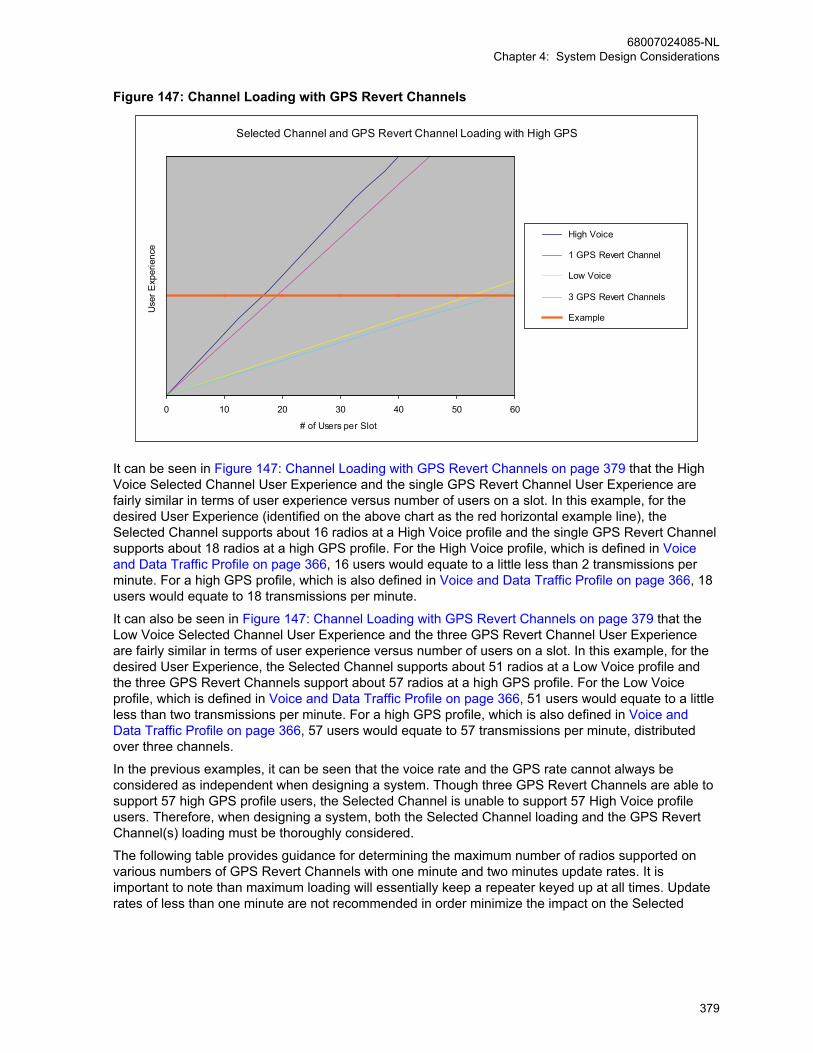
Figure 147: Channel Loading with GPS Revert Channels
Selected Channel and GPS Revert Channel Loading with High GPS
0 10 20 30 40 50 60
# of Users per Slot
Use
r Exp
erie
nce
High Voice
1 GPS Revert Channel
Low Voice
3 GPS Revert Channels
Example
It can be seen in Figure 147: Channel Loading with GPS Revert Channels on page 379 that the HighVoice Selected Channel User Experience and the single GPS Revert Channel User Experience arefairly similar in terms of user experience versus number of users on a slot. In this example, for thedesired User Experience (identified on the above chart as the red horizontal example line), theSelected Channel supports about 16 radios at a High Voice profile and the single GPS Revert Channelsupports about 18 radios at a high GPS profile. For the High Voice profile, which is defined in Voiceand Data Traffic Profile on page 366, 16 users would equate to a little less than 2 transmissions perminute. For a high GPS profile, which is also defined in Voice and Data Traffic Profile on page 366, 18users would equate to 18 transmissions per minute.
It can also be seen in Figure 147: Channel Loading with GPS Revert Channels on page 379 that theLow Voice Selected Channel User Experience and the three GPS Revert Channel User Experienceare fairly similar in terms of user experience versus number of users on a slot. In this example, for thedesired User Experience, the Selected Channel supports about 51 radios at a Low Voice profile andthe three GPS Revert Channels support about 57 radios at a high GPS profile. For the Low Voiceprofile, which is defined in Voice and Data Traffic Profile on page 366, 51 users would equate to a littleless than two transmissions per minute. For a high GPS profile, which is also defined in Voice andData Traffic Profile on page 366, 57 users would equate to 57 transmissions per minute, distributedover three channels.
In the previous examples, it can be seen that the voice rate and the GPS rate cannot always beconsidered as independent when designing a system. Though three GPS Revert Channels are able tosupport 57 high GPS profile users, the Selected Channel is unable to support 57 High Voice profileusers. Therefore, when designing a system, both the Selected Channel loading and the GPS RevertChannel(s) loading must be thoroughly considered.
The following table provides guidance for determining the maximum number of radios supported onvarious numbers of GPS Revert Channels with one minute and two minutes update rates. It isimportant to note than maximum loading will essentially keep a repeater keyed up at all times. Updaterates of less than one minute are not recommended in order minimize the impact on the Selected
68007024085-NLChapter 4: System Design Considerations
379

Channel features (voice, control and/or data). Care must also be taken to analyze if the SelectedChannel can accommodate the anticipated voice traffic for a large number of subscribers.
1 GPS Revert Chan-nel
2 GPS Revert Chan-nels
3 GPS Revert Chan-nels
Radios supported at1 minute update rate
20 40 60
Radios supported at2 minute update rate
40 80 120
When GPS CSBK data is enabled, twice the number of radios can be supported with a similar GPSsuccess rate. However, the home channel may not be able to support more radios.
Though GPS Revert Channels can significantly increase the number of radios providing locationupdates, it is important to remember that when powered up, an radio needs to register with bothPresence and Location Applications before it can send location updates. If a large number of radioshappen to be powered up in a relatively short period of time, the Selected Channel may becomeoverwhelmed with registration traffic and the system’s voice handling capacity will be impacted.Therefore, if this situation must occur, the following should be kept in mind.
• Keep voice traffic on the Selected Channel to a minimum. This causes the registration messages tobe queued in the radio and the control station.
• As a rule of thumb, expect about three successful registrations per minute. Therefore, a fleet of 60radios could require 20 minutes to successfully register. In order to minimize registration traffic, theradios can be gradually powered on at a rate of three per minute during the estimated time frame.
Generally, a GPS Revert Channel can support more radios when a lower GPS update rate (that islarger update period) is being used. On the contrary, the channel supports fewer radios if a higherupdate rate (that is smaller update period), is being used. The following chart illustrates the relationshipbetween the location update period and number of radios assigned to a particular GPS RevertChannel. When the CSBK data feature is enabled, twice the number of radios can be supported. Theblue line in Figure 148: Minimum Location Update Period versus Number of Subscribers on page 381illustrates this case.
Example: No more than 20 radios should be assigned to a particular GPS Revert Channel, if anupdate period of 60 seconds (that is 60 updates per hour) is desired.
Example: If 120 radios are assigned to use a GPS Revert Channel, the minimum recommendedupdate period is 360 seconds (that is 10 updates per hour).
Hence, some flexibility is provided as to whether a large number of radios with a slow update rate, or asmall number of radios with a fast update rate is used on a GPS Revert Channel. Alternatively,depending on whether having a large number of radios assigned to a GPS Revert Channel or having afast update rate is more desirable for a particular system, the system can be provisioned toaccommodate either scenario.
A higher GPS update rate can impact the service (voice, control and/or data) presented on the channelselected by the radio user because the radio spends a longer time transmitting its GPS location on theGPS Revert Channel. The recommended rate is to not exceed 60 GPS updates per hour per radio(that is 60-second GPS update period).
68007024085-NLChapter 4: System Design Considerations
380
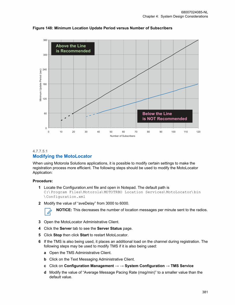
Figure 148: Minimum Location Update Period versus Number of Subscribers
Min
imum
Upd
ate
Per
iod
(sec
)360
300
Above the Lineis Recommended
240
180
120
60 Below the Lineis NOT Recommended
00 10 20 30 40 50 60 70 80 90 100 110 120
Number of Subscribers
4.7.7.5.1Modifying the MotoLocatorWhen using Motorola Solutions applications, it is possible to modify certain settings to make theregistration process more efficient. The following steps should be used to modify the MotoLocatorApplication:
Procedure:1 Locate the Configuration.xml file and open in Notepad. The default path is
C:\Program Files\Motorola\MOTOTRBO Location Services\MotoLocator\bin\Configuration.xml
2 Modify the value of “aveDelay” from 3000 to 6000.
NOTICE: This decreases the number of location messages per minute sent to the radios.
3 Open the MotoLocator Administrative Client.
4 Click the Server tab to see the Server Status page.
5 Click Stop then click Start to restart MotoLocator.
6 If the TMS is also being used, it places an additional load on the channel during registration. Thefollowing steps may be used to modify TMS if it is also being used:
a Open the TMS Administrative Client.
b Click on the Text Messaging Administrative Client.
c Click on Configuration Management → → System Configuration → TMS Serviced Modify the value of “Average Message Pacing Rate (msg/min)” to a smaller value than the
default value.
68007024085-NLChapter 4: System Design Considerations
381
NOTICE: The larger the number of initial registrations expected in a short amount oftime, the smaller this value should be. However, decreasing this value will impact therate at which text messages are sent from the TMS to the radios.
e Return to the main menu on the TMS Administrative Client.
f Click Stop then click Start to restart TMS.
4.7.7.6Enhanced GPS Revert – Loading and Reliability
IPSCIP Site Connect
This section is applicable to MOTOTRBO IPSite Connect Configurations
CPSSCapacity Plus
This section is applicable to MOTOTRBO Ca-pacity Plus Configurations
CPMSCapacity Plus Multi Site
This section is applicable to MOTOTRBO Ca-pacity Plus Multi Site Configurations
The number of subscribers supported on an Enhanced GPS slot is a function of the window size,(derived from the size of the location data), and the update rate. Additionally, the success rate of thelocation updates is also a function of the call duration on the selected/primary channel and the repeaterloading. The following figures illustrates the relationship between these variables.
The curves in Figure 149: 1-Minute Update Rate with a 10-second Call per Minute at 75% Loading onpage 383 illustrate the average location update success rate against the number of subscribers for a 1-minute update rate per subscriber, a 10-second call for the talkgroup per minute and 75% repeaterloading5. If there are no talkgroup calls, the subscribers would update 100% of the time as long as thenumber of subscribers are less than or equal to the maximum number of allocated reserved windows.(The maximum allocated reserved windows is the repeater loading.)
However, voice calls keeps a subscriber from sending location updates on its reserved slot. Hence thesubscriber makes a request to send in the data on the unreserved windows after the call. Therefore in Figure 149: 1-Minute Update Rate with a 10-second Call per Minute at 75% Loading on page 383, it isnoticeable that larger talkgroups (more subscribers) decreases the average success rate. This isbecause there are not enough unreserved windows to support all the missed reserved datatransmissions.
The CSBK data feature improves system capacity. The following figures describe the average locationupdate Figure 149: 1-Minute Update Rate with a 10-second Call per Minute at 75% Loading on page383 rate against the number of subscribers.
The curve in Figure 149: 1-Minute Update Rate with a 10-second Call per Minute at 75% Loading onpage 383 illustrates the average location update success rate against the number of subscribers for a1-minute update rate per subscriber, a 10-second call for the talkgroup per minute and 75% repeaterloading when the CSBK data feature is enabled for GPS data.
The curve in Figure 149: 1-Minute Update Rate with a 10-second Call per Minute at 75% Loading onpage 383 illustrates the average location update success rate against the number of subscribers for a1-minute update rate per subscriber, a 20-second call for the talkgroup per minute and 75% repeaterloading when the CSBK data feature is enabled for GPS data.
5 Loading refers to percentage of periodic window reservation.
68007024085-NLChapter 4: System Design Considerations
382
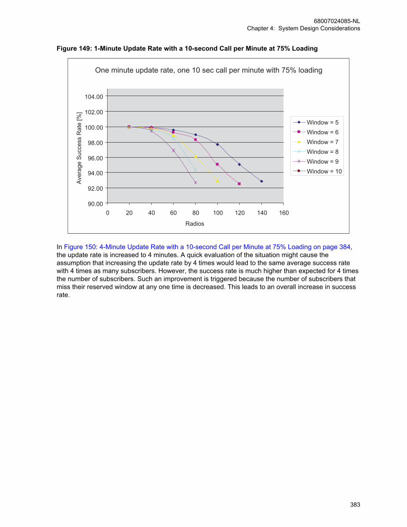
Figure 149: 1-Minute Update Rate with a 10-second Call per Minute at 75% Loading
One minute update rate, one 10 sec call per minute with 75% loading
90.00
92.00
94.00
96.00
98.00
100.00
102.00
104.00
0 20 40 60 80 100 120 140 160
Radios
Ave
rage
Suc
cess
Rat
e [%
]
Window = 5Window = 6Window = 7Window = 8Window = 9Window = 10
In Figure 150: 4-Minute Update Rate with a 10-second Call per Minute at 75% Loading on page 384,the update rate is increased to 4 minutes. A quick evaluation of the situation might cause theassumption that increasing the update rate by 4 times would lead to the same average success ratewith 4 times as many subscribers. However, the success rate is much higher than expected for 4 timesthe number of subscribers. Such an improvement is triggered because the number of subscribers thatmiss their reserved window at any one time is decreased. This leads to an overall increase in successrate.
68007024085-NLChapter 4: System Design Considerations
383

Figure 150: 4-Minute Update Rate with a 10-second Call per Minute at 75% Loading
Four minute update rate, one 10 sec call per minute with 75% loading
95.00
96.00
97.00
98.00
99.00
100.00
101.00
102.00
103.00
104.00
105.00
0 100 200 300 400 500 600 700
Radios
Ava
erag
e S
ucce
ss R
ate
[%]
Window = 5Window = 6Window = 7Window = 8Window = 9Window = 10
The curves in Figure 151: 1-Minute Update Rate with a 20-second Call per Minute at 75% Loading onpage 385 illustrates the average location update success rate against the number of subscribers for a1-minute update rate per subscriber, a 20-second call for the talkgroup per minute and 75% repeaterloading. In this situation, the call duration is very long (an update rate of 0.3) and many subscribersmiss their assigned update window. As the number of subscribers approaches the maximum numberof reserved windows, a large number of retries can be unsuccessful and the average success ratedrops.
68007024085-NLChapter 4: System Design Considerations
384
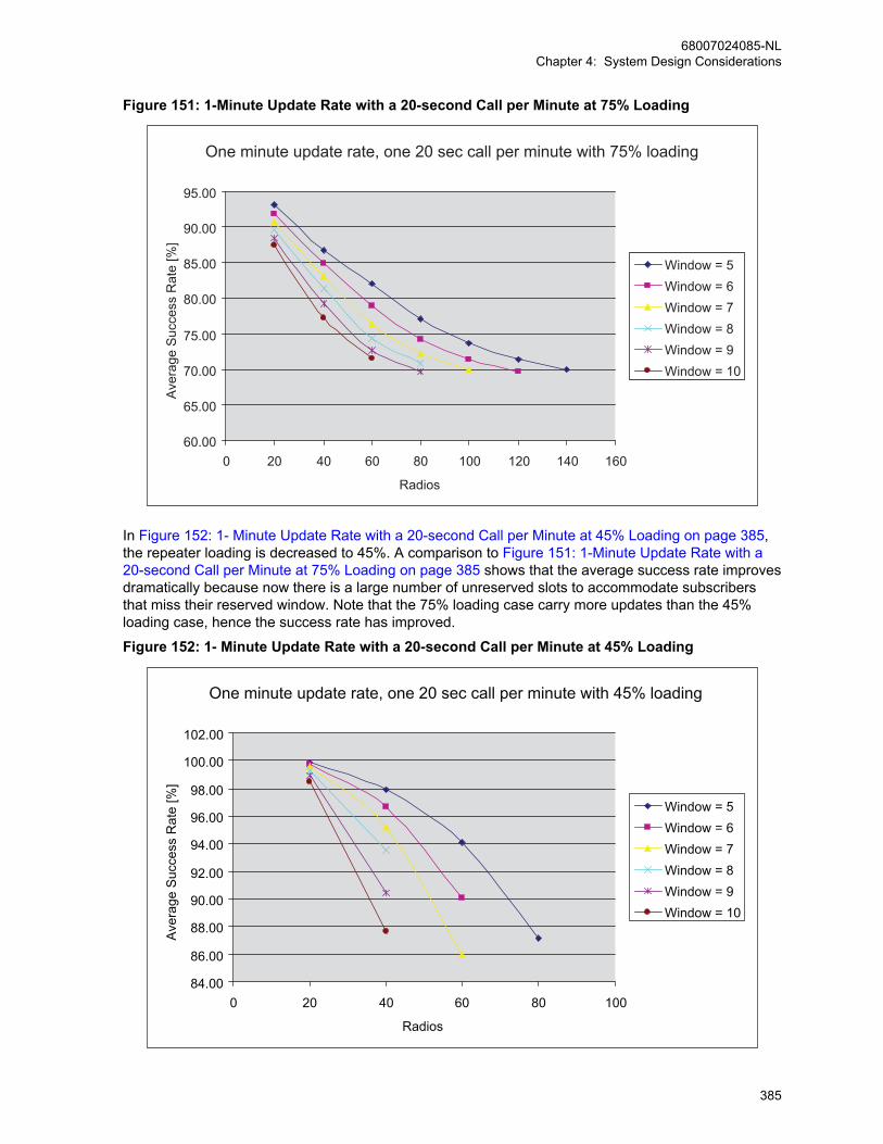
Figure 151: 1-Minute Update Rate with a 20-second Call per Minute at 75% Loading
One minute update rate, one 20 sec call per minute with 75% loading
60.00
65.00
70.00
75.00
80.00
85.00
90.00
95.00
0 20 40 60 80 100 120 140 160
Radios
Ave
rage
Suc
cess
Rat
e [%
]
Window = 5Window = 6Window = 7Window = 8Window = 9Window = 10
In Figure 152: 1- Minute Update Rate with a 20-second Call per Minute at 45% Loading on page 385,the repeater loading is decreased to 45%. A comparison to Figure 151: 1-Minute Update Rate with a20-second Call per Minute at 75% Loading on page 385 shows that the average success rate improvesdramatically because now there is a large number of unreserved slots to accommodate subscribersthat miss their reserved window. Note that the 75% loading case carry more updates than the 45%loading case, hence the success rate has improved.
Figure 152: 1- Minute Update Rate with a 20-second Call per Minute at 45% Loading
One minute update rate, one 20 sec call per minute with 45% loading
84.00
86.00
88.00
90.00
92.00
94.00
96.00
98.00
100.00
102.00
0 20 40 60 80 100
Radios
Ave
rage
Suc
cess
Rat
e [%
]
Window = 5Window = 6Window = 7Window = 8Window = 9Window = 10
68007024085-NLChapter 4: System Design Considerations
385
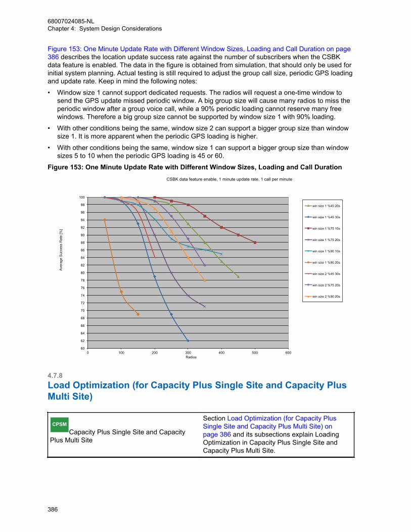
Figure 153: One Minute Update Rate with Different Window Sizes, Loading and Call Duration on page386 describes the location update success rate against the number of subscribers when the CSBKdata feature is enabled. The data in the figure is obtained from simulation, that should only be used forinitial system planning. Actual testing is still required to adjust the group call size, periodic GPS loadingand update rate. Keep in mind the following notes:
• Window size 1 cannot support dedicated requests. The radios will request a one-time window tosend the GPS update missed periodic window. A big group size will cause many radios to miss theperiodic window after a group voice call, while a 90% periodic loading cannot reserve many freewindows. Therefore a big group size cannot be supported by window size 1 with 90% loading.
• With other conditions being the same, window size 2 can support a bigger group size than windowsize 1. It is more apparent when the periodic GPS loading is higher.
• With other conditions being the same, window size 1 can support a bigger group size than windowsizes 5 to 10 when the periodic GPS loading is 45 or 60.
Figure 153: One Minute Update Rate with Different Window Sizes, Loading and Call Duration
60
62
64
66
68
70
72
74
76
78
80
82
84
86
88
90
92
94
96
98
100
0 100 200 300 400 500 600
Aver
age
Suc
cess
Rat
e [%
]
Radios
CSBK data feature enable, 1 minute update rate, 1 call per minute
win size 1 %45 20s
win size 1 %45 30s
win size 1 %75 10s
win size 1 %75 20s
win size 1 %90 10s
win size 1 %90 20s
win size 2 %45 30s
win size 2 %75 20s
win size 2 %90 20s
4.7.8Load Optimization (for Capacity Plus Single Site and Capacity PlusMulti Site)
CPSMCapacity Plus Single Site and Capacity
Plus Multi Site
Section Load Optimization (for Capacity PlusSingle Site and Capacity Plus Multi Site) onpage 386 and its subsections explain LoadingOptimization in Capacity Plus Single Site andCapacity Plus Multi Site.
68007024085-NLChapter 4: System Design Considerations
386
4.7.8.1Preference for Using a FrequencyThe Capacity Plus Single Site and Capacity Plus Multi Site systems are designed to operate efficientlyin a shared channel environment. The term “shared channel environment” is typically used when morethan one system uses the same frequency for communication within the same coverage area. Forsystem owners having licenses for shared use of frequencies, it is recommended to set a preferencelevel for the use of a frequency. A repeater whose frequencies have lower interference from othersystem(s) should be given higher preference level over the repeater whose frequencies have higherinterference. Repeaters with the same amount of interference should have the same preference level.For trunking operation, a Capacity Plus Single Site/Capacity Plus Multi Site system always prefers touse a repeater of a higher preference level over a repeater of lower preference level.
For system owners having a mix of shared frequency channel licenses and exclusive frequencylicenses, the repeaters with exclusive frequency licenses should have a higher preference level thanthe repeaters with shared frequency licenses.
4.7.8.2Improving Channel Capacity by Adjusting Hang TimesMOTOTRBO supports message trunking by keeping a channel reserved for the duration of hang timeafter a transmitting radio has unkeyed the microphone. During the hang time, only the members of theongoing call can start a transmission. The advantage of the message trunking is that it providesguaranteed access to the channel for the duration of a call. The disadvantage of the message trunkingis that the channel remains unused during the hang times. To improve channel utilization, a customermay choose to reduce the call hang time in the repeater. Experienced radio users respond quickly andtherefore require a shorter hang time.
Capacity Plus Single Site/Capacity Plus Multi Site allows a customer to program a near zero call hangtime in repeaters. By programming a zero call hang time, MOTOTRBO acts as if the channel isallocated for only one transmission and in this case, MOTOTRBO supports Transmission Trunking.
However, there are some trade-offs in reducing call hang time. The channel will no longer be reservedfor a group in the system. Thus, every time a group member of the same call presses PTT to initiate acall, the call will land on a different frequency channel. In some cases, some of the Group Callparticipants may switch to other high-priority Group Calls. While in other cases, the system maybecome busy with other calls and no channels are available to initiate the call.
Customers may choose to reduce call hang time from the default value rather than setting it to zerobased upon channel usage. If there are more members in a group, and if members of the group arereplying instantly to the Group Call, then lowering call hang time from the default value may improveoverall call throughput. However, if the group members are not replying instantly to the communicationand the channel still needs to be reserved, then call hang time should be increased. Call throughputreduces by increasing call hang time and vice versa.
Since all repeaters in the system needs to exhibit the same behavior, it is recommended that the samecall hang time is programmed in all trunked repeaters.
4.7.8.3Call PriorityA radio joins its most preferred call in the following conditions:
• The call that the radio was participating in, ends,
• A radio powers on, or returns from a fade when all Trunked Channels are not busy.
The preference list for a radio (in decreasing order) is an Emergency Call of interest, All Call, theradio’s transmit group, and the radio’s receive group list. The preference of groups in a radio’s receivegroup list are displayed in decreasing order.
68007024085-NLChapter 4: System Design Considerations
387
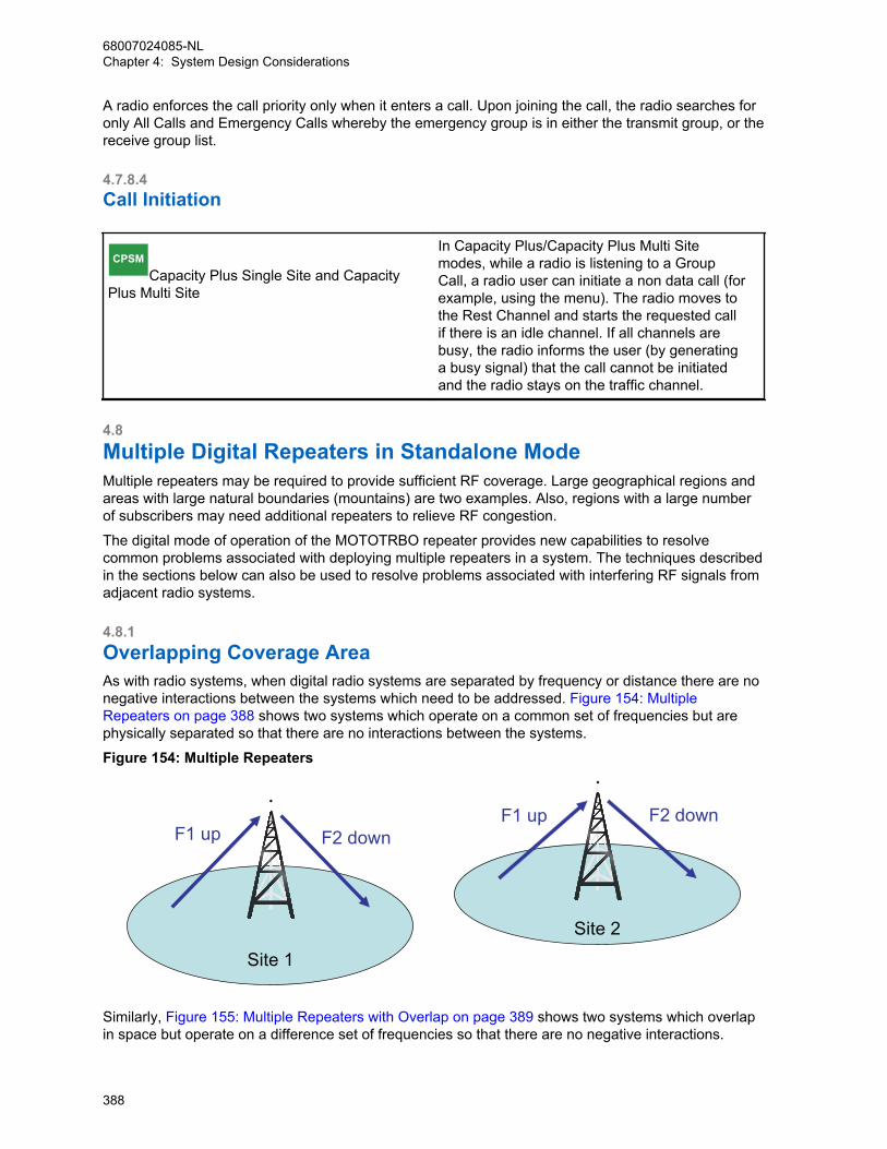
A radio enforces the call priority only when it enters a call. Upon joining the call, the radio searches foronly All Calls and Emergency Calls whereby the emergency group is in either the transmit group, or thereceive group list.
4.7.8.4Call Initiation
CPSMCapacity Plus Single Site and Capacity
Plus Multi Site
In Capacity Plus/Capacity Plus Multi Sitemodes, while a radio is listening to a GroupCall, a radio user can initiate a non data call (forexample, using the menu). The radio moves tothe Rest Channel and starts the requested callif there is an idle channel. If all channels arebusy, the radio informs the user (by generatinga busy signal) that the call cannot be initiatedand the radio stays on the traffic channel.
4.8Multiple Digital Repeaters in Standalone ModeMultiple repeaters may be required to provide sufficient RF coverage. Large geographical regions andareas with large natural boundaries (mountains) are two examples. Also, regions with a large numberof subscribers may need additional repeaters to relieve RF congestion.
The digital mode of operation of the MOTOTRBO repeater provides new capabilities to resolvecommon problems associated with deploying multiple repeaters in a system. The techniques describedin the sections below can also be used to resolve problems associated with interfering RF signals fromadjacent radio systems.
4.8.1Overlapping Coverage AreaAs with radio systems, when digital radio systems are separated by frequency or distance there are nonegative interactions between the systems which need to be addressed. Figure 154: MultipleRepeaters on page 388 shows two systems which operate on a common set of frequencies but arephysically separated so that there are no interactions between the systems.
Figure 154: Multiple Repeaters
F1 upF1 up
F2 downF2 down
Site 1
Site 2
Similarly, Figure 155: Multiple Repeaters with Overlap on page 389 shows two systems which overlapin space but operate on a difference set of frequencies so that there are no negative interactions.
68007024085-NLChapter 4: System Design Considerations
388
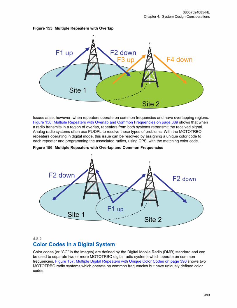
Figure 155: Multiple Repeaters with Overlap
F1 up F2 downF3 up F4 down
Site 1
Site 2
Issues arise, however, when repeaters operate on common frequencies and have overlapping regions. Figure 156: Multiple Repeaters with Overlap and Common Frequencies on page 389 shows that whena radio transmits in a region of overlap, repeaters from both systems retransmit the received signal.Analog radio systems often use PL/DPL to resolve these types of problems. With the MOTOTRBOrepeaters operating in digital mode, this issue can be resolved by assigning a unique color code toeach repeater and programming the associated radios, using CPS, with the matching color code.
Figure 156: Multiple Repeaters with Overlap and Common Frequencies
F2 down
F1 up
F2 down
Site 1Site 2
4.8.2Color Codes in a Digital SystemColor codes (or “CC” in the images) are defined by the Digital Mobile Radio (DMR) standard and canbe used to separate two or more MOTOTRBO digital radio systems which operate on commonfrequencies. Figure 157: Multiple Digital Repeaters with Unique Color Codes on page 390 shows twoMOTOTRBO radio systems which operate on common frequencies but have uniquely defined colorcodes.
68007024085-NLChapter 4: System Design Considerations
389
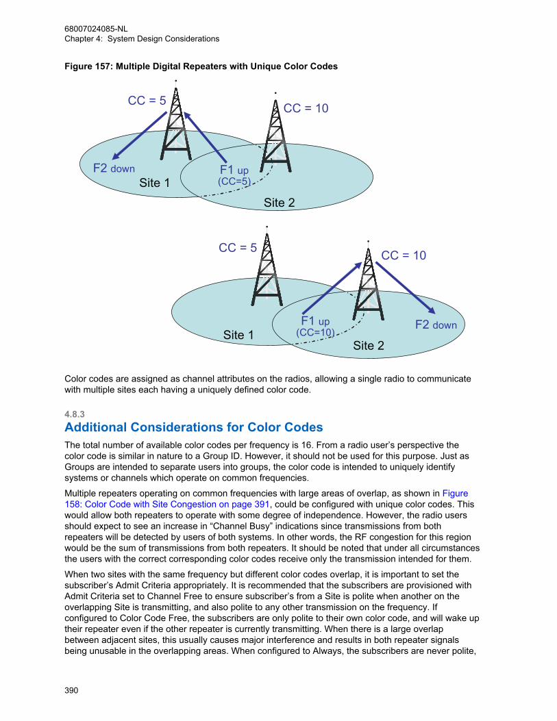
Figure 157: Multiple Digital Repeaters with Unique Color Codes
F1 up(CC=5)
F2 down
CC = 10CC = 5
Site 1Site 2
F1 up(CC=10) F2 down
CC = 10CC = 5
Site 1Site 2
Color codes are assigned as channel attributes on the radios, allowing a single radio to communicatewith multiple sites each having a uniquely defined color code.
4.8.3Additional Considerations for Color CodesThe total number of available color codes per frequency is 16. From a radio user’s perspective thecolor code is similar in nature to a Group ID. However, it should not be used for this purpose. Just asGroups are intended to separate users into groups, the color code is intended to uniquely identifysystems or channels which operate on common frequencies.
Multiple repeaters operating on common frequencies with large areas of overlap, as shown in Figure158: Color Code with Site Congestion on page 391, could be configured with unique color codes. Thiswould allow both repeaters to operate with some degree of independence. However, the radio usersshould expect to see an increase in “Channel Busy” indications since transmissions from bothrepeaters will be detected by users of both systems. In other words, the RF congestion for this regionwould be the sum of transmissions from both repeaters. It should be noted that under all circumstancesthe users with the correct corresponding color codes receive only the transmission intended for them.
When two sites with the same frequency but different color codes overlap, it is important to set thesubscriber’s Admit Criteria appropriately. It is recommended that the subscribers are provisioned withAdmit Criteria set to Channel Free to ensure subscriber’s from a Site is polite when another on theoverlapping Site is transmitting, and also polite to any other transmission on the frequency. Ifconfigured to Color Code Free, the subscribers are only polite to their own color code, and will wake uptheir repeater even if the other repeater is currently transmitting. When there is a large overlapbetween adjacent sites, this usually causes major interference and results in both repeater signalsbeing unusable in the overlapping areas. When configured to Always, the subscribers are never polite,
68007024085-NLChapter 4: System Design Considerations
390
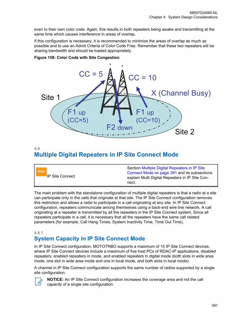
even to their own color code. Again, this results in both repeaters being awake and transmitting at thesame time which causes interference in areas of overlap.
If this configuration is necessary, it is recommended to minimize the areas of overlap as much aspossible and to use an Admit Criteria of Color Code Free. Remember that these two repeaters will besharing bandwidth and should be loaded appropriately.
Figure 158: Color Code with Site Congestion
F1 up(CC=5)
F2 down
CC = 10 CC = 5
F1 up(CC=10)
X (Channel Busy)Site 1
Site 2
4.9Multiple Digital Repeaters in IP Site Connect Mode
IPSCIP Site Connect
Section Multiple Digital Repeaters in IP SiteConnect Mode on page 391 and its subsectionsexplain Multi Digital Repeaters in IP Site Con-nect.
The main problem with the standalone configuration of multiple digital repeaters is that a radio at a sitecan participate only in the calls that originate at that site. The IP Site Connect configuration removesthis restriction and allows a radio to participate in a call originating at any site. In IP Site Connectconfiguration, repeaters communicate among themselves using a back-end wire line network. A calloriginating at a repeater is transmitted by all the repeaters in the IP Site Connect system. Since allrepeaters participate in a call, it is necessary that all the repeaters have the same call relatedparameters (for example, Call Hang Times, System Inactivity Time, Time Out Time).
4.9.1System Capacity in IP Site Connect ModeIn IP Site Connect configuration, MOTOTRBO supports a maximum of 15 IP Site Connect devices,where IP Site Connect devices include a maximum of five host PCs of RDAC-IP applications, disabledrepeaters, enabled repeaters in mode, and enabled repeaters in digital mode (both slots in wide areamode, one slot in wide area mode and one in local mode, and both slots in local mode).
A channel in IP Site Connect configuration supports the same number of radios supported by a singlesite configuration.
NOTICE: An IP Site Connect configuration increases the coverage area and not the callcapacity of a single site configuration.
68007024085-NLChapter 4: System Design Considerations
391

4.9.2Frequencies and Color Code ConsiderationsThe figure below shows an example of two IP Site Connect systems with overlapping coverage areas.The frequencies and color code of repeaters should follow the following rules:
• The geographically adjacent repeaters of an IP Site Connect system should use differentfrequencies. Their color code can be either same or different.
• If the frequencies of the geographically adjacent repeaters of two IP Site Connect systems are thesame, then their color codes should be different. It is not advisable to keep the same frequenciesbecause in areas of overlap, there will be destructive interference. Note that an IP Site Connectconfiguration does not support simulcast.
• If the frequencies of non-adjacent repeaters of an IP Site Connect system are the same, then theircolor codes should be different. It is not advisable to keep the same frequencies and color codebecause a roaming radio is not able to distinguish between them, and may use the wrong GPSRevert Channels or emergency system.
• A system may be sharing the channels with other systems over multiple sites. It is possible that twosystems (named here as Sys1 and Sys2) may be using the same (frequencies, color code) pair attwo different sites (say, Site1 and Site2). During automatic site search (Passive Site Search), aSys1’s radio at Site2 finds Sys2’s repeater and stays on that channel. This is not a desirablesituation. A way to avoid this situation is to ensure that all the (frequencies, color code) pairs of allthe overlapping systems are unique.
Figure 159: Example of Two IP Site Connect Systems with Overlapping Coverage Areas
F1 up F2 down F3 up F4 down F1 up F2 down
F1 up
F2 down
F7 up F3 up
F8 down
F4 down
Site 1 Site 2 Site 3
CC =5 CC =4 CC =5
IP Site ConnectSystem 2
4.9.3Considerations for the Back-End Network in IP Site Connect ModeThe back-end network can be a dedicated network or an Internet provided by an Internet ServiceProvider (ISP). ISPs provide a range of technologies such as dial-up, DSL (typically ADSL), Cablemodem, Broadband wireless access, Canopy, ISDN, Frame Relay, Satellite Internet access, andothers. In some cases dedicated links or networks can be effectively used or deployed, removing themonthly fees associated with public networks. The back-end network cannot be based on dial-upconnection (due to small bandwidth) or Satellite Internet access (due to large delay).
A repeater has three network interfaces: Ethernet, USB, and over-the-air. A repeater uses its Ethernetport to communicate among them using IPv4/UDP. Since UDP does not support confirmation, an IPSite Connect system provides its own acknowledgment and retries mechanism for critical activities.Note that the Ethernet port is not a default IP gateway of a repeater, that is an IP datagram arrivedfrom USB or over-the-air is not automatically routed to the Ethernet port.
68007024085-NLChapter 4: System Design Considerations
392

It is not necessary to get a static IPv4 addresses for IP Site Connect devices (except for the Master).The IPv4 address of an IP Site Connect device can be dynamic. In this case, the IPv4 address isallocated by a DHCP server. The dynamic nature of the IPv4 address implies that the address maychange every time it powers-on or even periodically (every few hours) while the IP Site Connect deviceis on. The dynamic address of a repeater is selected by selecting the DHCP option in the repeaterCPS. It is recommended that the lease time of the IPv4 address from the DHCP should be kept as longas possible. Note that a change in the IPv4 address of an IP Site Connect device causes shortdisruption of service for the device. For static IPv4 address, the DHCP option should not be selectedand the CPS user should provide the static IPv4 address, and the gateway’s IPv4 address andnetmask.
An IP Site Connect configuration uses a procedure called “Link Management” to keep an IP SiteConnect device aware of the presence, the current IPv4 addresses, and UDP ports of other IP SiteConnect devices. The Link Management requires only one of the repeaters (called an Master) to act asa broker of IPv4/UDP addresses. The Master gets a static IPv4 address from its ISP and the Master’sIPv4/UDP address is configured into all the IP Site Connect devices.
Alternatively, the Master can also be dynamically assigned an IPv4 address when all of the IP SiteConnect devices are configured with a static DNS address for the Master and a DNS Server. Anytimethe IPv4 address for a Master changes, then the DNS server must be updated with the new IPv4address. It is the job of the entity assigning the IPv4 address to the Master to also update the DNSServer with the updated IPv4 address to minimize any interruptions in connectivity to Master. This isoften times handled by the DHCP Server that does the IPv4 address assignments. The IP SiteConnect devices will determine the current IPv4 address of the Master by requesting the IPv4 from theDNS Server. When the Master stops responding to requests from an IP Site Connect device, then thedevice will check with the DNS Server to determine if the IPv4 of the Master has changed. If theaddress has changed, then it will acquire the new address and begin using the new IPv4 addressprovided by the DNS Server. It should be noted that the DNS feature is only available on SLR SeriesRepeaters.
The Master’s IPv4/UDP address refers to its address as seen from the back-end network. Note that afirewall/NAT may translate the address in customer network into another address in the back-endnetwork.
An IP Site Connect device registers its IPv4/UDP address during power-on and upon a change in itsIPv4/UDP address with the Master. The Master notifies to all the IP Site Connect devices whenever theIPv4 address of an IP Site Connect device changes. An IP Site Connect device maintains a table of thelatest IPv4 addresses of other IP Site Connect devices and it uses the table to send an IPv4/UDPmessage to another IP Site Connect device.
The IP Site Connect devices may be behind firewalls. For successful communication between two IPSite Connect devices (say R1 and R2), the firewall of R1 must be open for messages from R2 and viceversa. Since the IPv4/UDP address of an IP Site Connect device is dynamic, it is not possible tomanually configure the firewalls. The Link Management procedure overcomes this problem byperiodically, for example, setting the Keep FW Open Time to every 6 seconds, sending a dummymessage from R1 to R2 and vice versa. On a receipt of an outbound message (say, from R1 to R2),the R1’s firewall keeps itself open for a short duration of approximately 20 seconds for an inboundmessage from R2. An IP Site Connect device (say, R1) sends the dummy message to another IP SiteConnect device (say, R2) only if R1 has not sent any message to R2 in last Keep FW Open Time. Thevalue of Keep FW Open Time is customer-programmable and should be kept less than the duration forwhich the firewall remains open for inbound messages. Exchange of dummy messages between twoIP Site Connect devices also acts as a “Keep Alive” messages. They are required, even if there is nofirewall or the firewall is configured to keep itself open for any message transmitted to the IP SiteConnect device.
68007024085-NLChapter 4: System Design Considerations
393
4.9.3.1Automatic ReconfigurationAn IP Site Connect system automatically discovers the presence of a new IP Site Connect device. Thenew IP Site Connect device is configured with the IPv4/UDP address of the Master. On power-on, thenew IP Site Connect device informs its IPv4/UDP address to the Master and the Master informs all theother IP Site Connect devices about the presence of a new IP Site Connect device. This allows addingan IP Site Connect device to a live IP Site Connect system. This simplifies the installation/addition ofan IP Site Connect device as there is no need to take the system down and configure other IP SiteConnect devices with the IPv4/UDP address of the new IP Site Connect device.
The periodic link management messages between an IP Site Connect device and the Master also actas “keep alive” messages. In absence of messages from an IP Site Connect device for one minute, theMaster concludes that either the IP Site Connect device has failed or the network in-between and theMaster informs all the other IP Site Connect devices about the absence of the IP Site Connect device.An IP Site Connect device also maintains periodic link management messages with every other IP SiteConnect device. In absence of messages from another IP Site Connect device for one minute, the IPSite Connect device concludes that either the other IP Site Connect device has failed or the failure iswithin the network in between. Thus, the link management messages allow an IP Site Connect systemto reconfigure itself on failure of one or more IP Site Connect devices and the system continues toprovide services with the available IP Site Connect devices. In case of network failure, it is possiblethat an IP Site Connect system becomes multiple IP Site Connect systems, where each system has asubset of original set of IP Site Connect devices. All the new systems continue to provide the servicesthat are possible with their subset of IP Site Connect devices. Note that there will be only one systemthat has the Master. When the back-end network recovers, the multiple systems automatically becomeone system. When an IP Site Connect system has only one repeater, then both the slots of therepeater repeat only locally (that is over-the-air) as per the MOTOTRBO Single Site specifications.
A repeater operates in multiple modes such as disabled, locked, knocked down, enabled and , enabledand digital with voice/data or control services, and single or multiple site operation for each slot. Therepeater informs the Master whenever its mode of operation changes and the Master informs to all theother IP Site Connect devices. This allows the IP Site Connect system to adapt its operation when themode changes. Note that only an enabled and digital repeaters (with a channel enabled for multiplesite operation) participate in voice/data/control communication across multiple sites.
A disadvantage of link Management is that the Master becomes a single point of failure. But theconsequence of failure of the Master is limited. The IP Site Connect system continues to functionexcept that it is not possible to add an IP Site Connect device into the system. If an IP Site Connectdevice powers on, while the Master is in failed state, then it will not be able to join the IP Site Connectsystem. On failure of the Master, it is possible to switch a redundant IP Site Connect device to act asan Master. The static IPv4 address and the UDP port number of the redundant IP Site Connect deviceshould be same as that of the failed Master; otherwise all the IP Site Connect devices will require to bereconfigured with the IPv4 address and the UDP port number of the new Master.
To avoid the issue of needing to have the same static IPv4 address configured on both the primary andredundant Master repeaters, all of the IP Site Connect devices can be configured to use a static DNSaddress for the Master. The primary and redundant devices can still be configured with static IPv4addresses, but they could be unique when a static DNS address is used. In the event that the primaryMaster fails, then the DNS Server could be updated such that the static DNS address configured intoall of the IP Site Connect devices now maps to the IPv4 address of the redundant Master repeater. Tominimize any downtime, the DNS Server should be updated immediately with the IPv4 address of theredundant Master upon detection that the primary Master has failed. It should be noted that the DNSfeature is only available on SLR Series Repeaters.
68007024085-NLChapter 4: System Design Considerations
394
4.9.3.2Back-End Network Design in IP Site Connect ModeTo create a proper back-end network design, it is important to know its characteristics. This sectionexplains four issues dealt within the back-end network.
4.9.3.2.1Delay/Latency in IP Site Connect ModeBack-end network delay or latency is characterized as the amount of time it takes for voice to leave thesource repeater and reach the destination repeater. Three types of delay are inherent in the back-endnetworks:
• propagation delay
• serialization delay
• handling delay
Propagation delay is caused by the distance a signal must travel via light in fiber or as electricalimpulses in copper-based networks. A fiber network stretching halfway around the world (13,000 miles)induces a one-way delay of about 70 milliseconds.
Serialization delay is the amount of time it takes the source repeater to actually place a packet byte bybyte onto the back-end network interface. Generally, the effect of serialization delay on total delay isrelatively minimal but since IP Site Connect system sends a voice packet one-by-one to all therepeaters, the serialization delay for the last destination repeater is (# of repeaters - 1) times theserialization delay for the first destination repeater.
Handling delay defines many different types of delay caused by the devices (for example, securerouters) that forward the packet through the back-end network. A significant component of the handlingdelay is the queuing delay, which occurs when more packets are sent out to a network device than thedevice can handle at a given interval.
The CPS allows setting the Total Delay (that is sum of propagation delay, serialization delay, andhandling delay) to be High (90 ms) or Normal (60 ms) in both the repeaters and the radios. Note thatradios also support higher value (500 ms) of total delay, which should not be used in case of IP SiteConnect system. The default is Normal. This is used to derive values for other parameters such asArbitration Interval and Call Hang Times in repeaters and Ack Wait times in radios. For properfunctioning of an IP Site Connect system, all the repeaters and radios should have the same delaysetting.
It is recommended that propagation and handling delays between repeaters should be measured (forexample, by “pinging”) between all pairs of repeaters.
The total delay is equal to the maximum of the measured values + (# of repeaters - 1) * (1/2 +1000/BW in kbps) ms, where the BW is the available bandwidth of the back-end network.
If the total delay is less than 60 ms then the setting should be Normal. If the total delay is more than 60ms but less than 90 ms then the setting should be High. The IP Site Connect system will not worksatisfactorily, with occasional failure of arbitration, hang time and data link layer acknowledgments, fora back-end network having total delay of more than 90ms. The disadvantage of the setting at 90ms isthat there is an increase to audio throughput delay.
4.9.3.2.2JitterJitter is the variation of packet inter-arrival time. The source repeater is expected to transmit voicepackets at a regular interval (that is every 60 ms for one channel). These voice packets can be delayedthroughout the back-end network and may not arrive at that same regular interval at the destinationrepeater. The difference between when the packet is expected and when it is actually received iscalled Jitter.
68007024085-NLChapter 4: System Design Considerations
395
To overcome the effect of jitter, the IP Site Connect system employ a Jitter Buffer of fixed 60milliseconds. If a packet does not arrive at a destination repeater within the 60 ms after the expectedtime then the repeater assumes the packet is lost, replays a special erasure packet, and discards thelate arriving packet. Because a packet loss affects only 60 ms of speech, the average listener does notnotice the difference in voice quality. Thus, a jitter of more than 60 ms degrades the audio quality.
4.9.3.2.3Packet LossPacket loss in IP-based networks is both common and expected. To transport voice bursts in timelymanner, IP Site Connect system cannot use reliable transport mechanisms (that is confirmed packets)and therefore while designing and selecting the back-end network it is necessary to keep packet lossto a minimum. The IP Site Connect system responds to periodic packet loss by replaying either aspecial packet (in the case of voice) or the last received packet (in the case of data). In the case ofvoice, the ongoing call ends if six consecutive packets do not arrive within 60 ms of their expectedarrival time. In the case of data, the repeater waits for the expected number of packets (as per the dataheader) before ending the call.
4.9.3.2.4Network Bandwidth ConsiderationsBandwidth is the amount of data transferred to and from a network device, often referred to as the bitrate. Bandwidth is measured in bits per second or kilo-bits per second (kbps). When designing an IPSite Connect system, it is important to understand the needs of each IP Site Connect device so thatthe appropriately rated network connection for each site can be chosen.
If a customer has high speed network connections between sites, these calculations may not be asimportant, but if they are working on lower speed public Internet Service Providers (ISPs) it is goodpractice to understand these values and plan accordingly. If the minimum amount of bandwidth is notavailable, the end user may experience audio holes or even dropped calls. Radio to Radio Datamessaging or RDAC commands may not be successful on the first attempt, or may be dropped alltogether. In general, the quality of service may suffer if substantial bandwidth is not available.
Note that for most Internet Service Providers, the uplink bandwidth is the limiting factor. The downlinkbandwidth is usually multiple factors above the uplink bandwidth. Therefore, if the uplink requirementsare met, the downlink requirements are almost always acceptable. Some ISPs may state they providea particular bandwidth, but it is important to verify the promised bandwidth is available once the systemis installed and throughout operation. A sudden decrease in available bandwidth may cause thepreviously described symptoms.
It is also important to note that if the wide area network connection is utilized by other services (filetransfer, multimedia, web browsing, and other), then the IP Site Connect devices may not have theappropriate bandwidth when required and quality of service may suffer. It is suggested to remove orlimit these types of activities. In addition, overusage of the RDAC application itself may causeincreased strain on the network during times of High Voice activity. It is recommended that RDACcommands be kept to a minimum unless appropriate bandwidth has been allocated.
4.9.3.2.4.1Required Bandwidth CalculationsThe amount of bandwidth an IP Site Connect device requires is dependent on a of variety factors. Themost important factor to understand is that the bandwidth required for one particular device isdependent on how many other devices or peers it has in the IP Site Connect system. Equally importantis the type of devices.
Recall that an IP Site Connect system can contain repeaters that have two channels operating in widearea, one channel operating in wide area, or no channels operating in wide area, such as localchannels only. Channels, or slots, operating in local area mode do not send their voice traffic over the
68007024085-NLChapter 4: System Design Considerations
396

network. Recall that one repeater within the IP Site Connect system acts as the Master. This repeaterrequires some additional bandwidth. The IP Site Connect system may also contain repeaters, disabledrepeaters, and RDAC applications. These devices do not send voice over the network, but they dorequire the bandwidth to support the standard link management and control signaling.
For a quick reference, the graphs Figure 160: Required Bandwidth for Two Simple IP Site ConnectSystem Configurations on page 397 show the required bandwidth for two simple IP Site Connectsystem configurations. The first shows the required bandwidth for various size systems where everyrepeater in the system utilizes both channels, or slots, as wide area. The second shows the requiredbandwidth for various size systems where every repeater in the system utilizes one channel, or slot, aswide area, and the other channel, or slot, as local area. In each system, one RDAC is present, repeaterauthentication is enabled, and Secure VPN is not being utilized in the routers.
Figure 160: Required Bandwidth for Two Simple IP Site Connect System Configurations
600
500
400
300
200
100
02 4 6 8 10 1412
Bandwidth required vs Number of Repeaters( 2 Wide Area Channels, with RDAC )
Upl
ink
/ Dow
nlin
k B
andw
ith (
Kbp
s )
Number of Repeaters
Master
Non-Master
600
500
400
300
200
100
02 4 6 8 10 1412
Bandwidth required vs Number of Repeaters( 1 Wide Area Channel, with RDAC )
Upl
ink
/ Dow
nlin
k B
andw
ith (
Kbp
s )
Number of Repeaters
Master
Non-Master
Note that although the two examples above may represent typical IP Site Connect configurations, andmay provide a quick snapshot of the bandwidth requirements for a particular size system, morecomplicated configurations require additional calculations.
The following equation should be used to calculate the bandwidth for each IP Site Connect device inthe IP Site Connect system, and then added together at sites where multiple devices reside behind onewide area connection.
BWVC = 15 kbps = Bandwidth required to support Wide Area Voice or Data (1 slot)
BWLM = 6 kbps = Bandwidth required to support Link Management
BWIR = 3 kbps = Bandwidth required to support Master Messaging
BWRD = 55 kbps = Bandwidth required to support RDAC commands
Numberof WideAreaChannelPeers*for Slot 1
x BWVC kbps = kbps
Numberof WideAreaChannelPeers*for Slot 2
x BWVC kbps = kbps
68007024085-NLChapter 4: System Design Considerations
397

TotalNumberof IP SiteConnectPeers*
x BWLM kbps = kbps
If Mas-ter, TotalNumberof IP SiteConnectPeers*
x BWIR kbps = kbps
RDACTraffic
BWRD kbps
+
RequiredUplink/DownlinkBand-width
kbps
* Peer does not include self.
To help demonstrate the use of the above equation on a more complicated IP Site Connect system,take the following example system shown in the diagram below. This system has six total IP SiteConnect devices at three sites; five repeaters and one RDAC. Three of the repeaters have bothchannels configured as wide area, one has a wide area channel and a local channel, and the lastrepeater has two local channels. The routers are not utilizing Secure VPN.
Let us start with Repeater 1. Repeater 1 is an Master and has two wide area channels. The first widearea channel has three peers and the second wide area channel has two peers. Note that sinceRepeater 4 and Repeater 5 have local area channels, these are not considered wide area channelpeers. It is also important to remember that a peer does not include the device currently beingcalculated.
Each calculation provides enough bandwidth to support an RDAC command during times of highactivity. This assumes that only one RDAC command occurs at a time and is not utilized often. If it isexpected that multiple RDAC applications will be performing commands on repeaters often andsimultaneously, one might wish to increase the bandwidth to support these types of activities.
68007024085-NLChapter 4: System Design Considerations
398
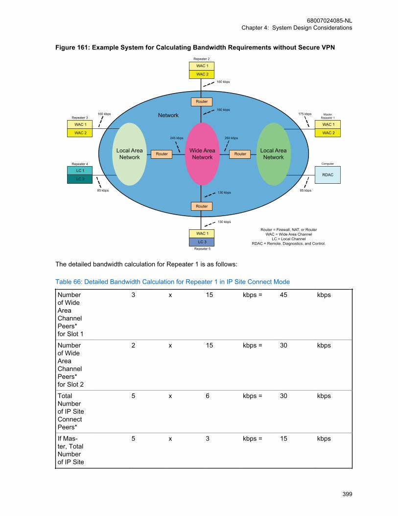
Figure 161: Example System for Calculating Bandwidth Requirements without Secure VPN
Router
Router
Router
Network
WAC 2
Local AreaNetwork
Router = Firewall, NAT, or RouterWAC = Wide Area Channel
LC = Local ChannelRDAC = Remote, Diagnostics, and Control.
RouterLocal AreaNetwork
Wide AreaNetwork
WAC 1
WAC 2
WAC 1
WAC 2
WAC 1
LC 2
LC 1 RDAC
LC 3
WAC 1
MasterRepeater 1
Repeater 2
Repeater 3
Repeater 4
Repeater 5
Computer
175 kbps
85 kbps
160 kbps
260 kbps
130 kbps
160 kbps
85 kbps
245 kbps
160 kbps
130 kbps
The detailed bandwidth calculation for Repeater 1 is as follows:
Table 66: Detailed Bandwidth Calculation for Repeater 1 in IP Site Connect Mode
Numberof WideAreaChannelPeers*for Slot 1
3 x 15 kbps = 45 kbps
Numberof WideAreaChannelPeers*for Slot 2
2 x 15 kbps = 30 kbps
TotalNumberof IP SiteConnectPeers*
5 x 6 kbps = 30 kbps
If Mas-ter, TotalNumberof IP Site
5 x 3 kbps = 15 kbps
68007024085-NLChapter 4: System Design Considerations
399
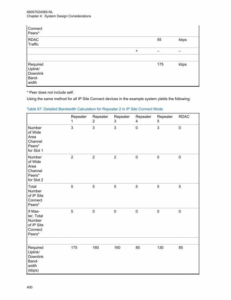
ConnectPeers*
RDACTraffic
55 kbps
+ – –
RequiredUplink/DownlinkBand-width
175 kbps
* Peer does not include self.
Using the same method for all IP Site Connect devices in the example system yields the following:
Table 67: Detailed Bandwidth Calculation for Repeater 2 in IP Site Connect Mode
Repeater1
Repeater2
Repeater3
Repeater4
Repeater5
RDAC
Numberof WideAreaChannelPeers*for Slot 1
3 3 3 0 3 0
Numberof WideAreaChannelPeers*for Slot 2
2 2 2 0 0 0
TotalNumberof IP SiteConnectPeers*
5 5 5 5 5 5
If Mas-ter, TotalNumberof IP SiteConnectPeers*
5 0 0 0 0 0
RequiredUplink/DownlinkBand-width(kbps)
175 160 160 85 130 85
68007024085-NLChapter 4: System Design Considerations
400

* Peer does not include self.
IP Site Connect devices behind a single router need to be added together to acquire the wide areanetwork bandwidth requirements. See the final bandwidth requirements in Figure 161: ExampleSystem for Calculating Bandwidth Requirements without Secure VPN on page 399.
NOTICE: A repeater or disabled repeater connected to the IP Site Connect system wouldrequire the same amount of traffic as a local only repeater (Repeater 4). But keep in mind that ifthe disabled repeater will eventually be enabled without disabling a different repeater, thebandwidth of the enabled repeater should be accounted for in the bandwidth plan.
4.9.3.2.4.2Required Bandwidth Calculations While Utilizing a Secure Virtual Private NetworkAs was discussed in previous chapters, peer-to-peer communications over the network are optionallyauthenticated and are also encrypted end-to-end if enabled in the radios. Voice and Data Privacy onpage 170 If this is not considered sufficient for a particular customer, IP Site Connect supports theability to work through a Secure Virtual Private Network (VPN). Secure VPN is not a function of the IPSite Connect device but rather of the router. It is important to note that Secure VPN does add the needfor additional bandwidth and may introduce additional delay.
For a quick reference, the graphs below show the required bandwidth for the two previously discussedsimple IP Site Connect system configurations, but in this case utilizing routers with Secure VPNenabled and repeater Authentication Disabled. When utilizing Secure VPN routers, repeaterauthentication is not necessary since the Secure VPN utilizes its own authentication.
As can be seen, the bandwidth requirements per device increase substantially. This should be takeninto account when planning for bandwidth.
Figure 162: Required Bandwidth Calculations While Utilizing a Secure Virtual Private Network
600
500
400
300
200
100
02 4 6 8 10 1412
Bandwidth Required vs Number of Repeaters( 2 Wide Area Channels, with RDAC, Secure VPN )
Upl
ink
/ Dow
nlin
k B
andw
ith (
Kbp
s )
Number of Repeaters
700
800
Master
Non-Master
600
500
400
300
200
100
02 4 6 8 10 1412
Bandwidth Required vs Number of Repeaters( 1 Wide Area Channel, with RDAC, Secure VPN )
Upl
ink
/ Dow
nlin
k B
andw
ith (
Kbp
s )
Number of Repeaters
700
800
Master
Non-Master
The following parameters should be used in the previous equation to calculate the bandwidthrequirements of each device in the system when secure VPN in the routers is enabled and repeaterauthentication is disabled.
BWVC = 23 kbps = Bandwidth required to support Wide Area Voice or Data with Secure VPN
BWLM = 5 kbps = Bandwidth required to support Link Management without authentication
BWIR = 4 kbps = Bandwidth required to support Master Messaging
68007024085-NLChapter 4: System Design Considerations
401

BWRD = 64 kbps = Bandwidth required to support RDAC commands
NOTICE: The preceding data was compiled using the Linksys EtherFast Cable/DSL VPNRouter with four-port switch. Model: BEFVP41. Other routers using different algorithms mayyield different results.
4.9.4Flow of Voice/Data/Control MessagesThe flow of voice/data/control messages from a radio to its repeater for an IP Site Connectconfiguration is the same as that of single-site configuration of MOTOTRBO system. The majorchanges in the flow of messages (between single site operations and multiple site operations) are inthe processing of a message in the repeaters and the additional delays introduced due to reasons suchas serialization, propagation, arbitration, and the nonalignment of slots between repeaters. This sectiondescribes the changes.
On receipt of a start up of a voice/data/control call from a radio over a slot, a repeater sends it over thebackend network to all the repeaters that are enabled, operating in digital mode, and the correspondingslot is configured for multiple site operation. This implies that at any time at most two calls are active inan IP Site Connect system if both slots are configured for multiple site operation.
In an IP Site Connect configuration, calls can start concurrently at more than one repeater and due todifferent messaging delay between repeaters, it is possible that different repeaters select different callsfor repeating over-the-air. To overcome this problem, on receipt of a start up of a voice/data/control calleither over-the-air (from a radio) or over the backend network (from other repeaters), a repeater startsan arbitration window for a duration of twice the Inter-Repeater Messaging Delay. At the end of thearbitration window, the repeater selects one of the calls received during this window using a procedurethat ensures that all the repeaters select the same call. After selection, a repeater starts repeating thebursts of the selected call. A disadvantage of the arbitration procedure is that it increases the SystemAccess Time.
The voice/data/control messages are sent burst by burst between repeaters. Like a single-site system,a repeater does no data link layer processing (for example, acknowledgment, decryption). If required,the voice and data messages are encrypted / decrypted by the source and destination radios. Arepeater sends the voice or data packet to other repeaters as it receives over-the-air. Also in case ofdata message, the destination radio sends the Ack/Nack and if required the Selective ARQ takes placebetween the source and destination radios and not between a radio and its repeater.
A call is a session of one or more transmissions from participating radios. To ensure continuitybetween transmissions, the single site configuration of MOTOTRBO has Hang Time, during which thechannel is reserved for participant(s) of the ongoing call. The IP Site Connect configuration extends theconcept of session to include Remote Monitor call, Individual and group data call, and CSBK Call (forexample, Call Alert, Radio Check, Inhibit/Uninhibit). The Hang Time ensures that a call continues withminimum interruptions.
The flow of data messages from a radio to an application (for example, Location or Text Messages) inan IP Site Connect system is similar to a single-site configuration of MOTOTRBO. A data packet flowsburst-by-burst to a Control Station connected to the Application Server. The Control Station assemblesthe bursts into a PDU. If the PDU is confirmed then the Control Station handles the data link layeracknowledgment. If the PDU is encrypted then the Control Station decrypts the PDU. The ControlStation strips the data link layer headers and forwards the resulting datagram to the Application Server.
All the data applications of the single site configuration of MOTOTRBO are compatible with IP SiteConnect configuration. An IP Site Connect configuration supports the revert channels, where a revertchannel can be a channel of another IP Site Connect system. The GPS data on a GPS Revert Channelare sent unconfirmed in IP Site Connect mode. This increases the throughput of the GPS data as thedata link layer acknowledgment over the back-end network is slower due to delays associated with theback-end network.
68007024085-NLChapter 4: System Design Considerations
402
4.9.5Security ConsiderationsThe single site configuration of MOTOTRBO offers three types of privacy mechanisms over-the-air –Basic Privacy, Enhanced Privacy, and AES. Voice and Data Privacy on page 170. The IP Site Connectconfiguration not only supports the three mechanisms, but also extends them over the back-endnetwork. A repeater does not decrypt the encrypted packets. It simply passes the packets as receivedover-the-air to other repeaters. Since the two mechanisms are not compatible, all the radios andrepeaters of an IP Site Connect system should support the same privacy mechanism. This should beensured during configuration. Note that the privacy mechanisms protects only the voice or datapayloads. They do not protect the voice or data headers, or control messages (CSBK) or systemmessages (between repeaters).
An IP Site Connect system optionally offers authentication of all the packets sent between IP SiteConnect devices. Each packet has a 10 bytes long cryptographic signature. The signature is createdusing Keyed-Hash Message Authentication Code (HMAC), which is a National Institute of Standardsand Technology (NIST) standard. The hashing is done using SHA-1 algorithm. The HMAC uses a 20bytes long symmetric keys and generates a 20 bytes long signature. To reduce the bandwidthrequirement over the back-end network, the 20 bytes long signature is truncated to 10 bytes beforeattaching to the packet. Packet authentication prevents an attacker from using an impersonator as anIP Site Connect device in order to get access to the IP Site Connect system. This feature, if selectedby a customer, requires the customer to manually configure the same key to all the IP Site Connectdevices. Note that the IP Site Connect system does not support rekeying remotely.
The HMAC authentication mechanism does not provide protection against the replay attacks. For amore secure authentication, an IP Site Connect configuration should use Secure VPN routers toconnect with the back-end network. Secure VPN routers can optionally provide confidentiality of all themessages including system messages (between IP Site Connect devices), control messages (CSBK),and voice or data headers. A disadvantage of using Secure VPN Routers is that the IP Site Connectrequires more inbound and outbound bandwidth from the ISP. The use of Secure VPN routers makethe authentication mechanism of IP Site Connect redundant and it is recommended that it should bedisabled. This saves some bandwidth over the back-end network.
4.9.6General Considerations When Setting Up the Network Connectionfor an IP Site Connect SystemNetwork setup and configuration varies significantly depending on the complexity of the equipment andIP network the system resides on. It is always wise to communicate with the Network Administratorduring installation and during the design phase as they are likely be the individuals configuring thenetwork equipment and own a great deal of knowledge in this area. Below is a short list of items tokeep in mind when setting up or when troubleshooting the networks of IP Site Connect systems.
• When assigning Static IP addresses within a Network, it must not conflict with another static IPaddress. As with any IP conflict, this can cause a disruption to the IP Site Connect traffic. Also,ensure that the static IP address does not fall into the DHCP assignable range. This can cause anIP conflict if the address is dynamically assigned to another device on the network.
• If other network devices are present on the same IP network as the IP Site Connect devices, it isgood practice to setup Quality of Service (QoS) rules in the Internet Router. This ensures that the IPSite Connect packets have priority over other traffic on the system. Not doing this could cause audioperformance degradation or lost transmissions when other devices on the system are excessivelyutilizing the network. There are various methods routers use to provide QoS. It is commonlyperformed by configuring a range of UDP ports or IP Addresses a specific amount of upstream anddownstream bandwidth. The default UDP port for IP Site Connect is 50000. For details oncalculating the required bandwidth, see Required Bandwidth Calculations on page 396.
68007024085-NLChapter 4: System Design Considerations
403
• Verify that the customer network equipment is not blocking the IP Addresses or UDP Ports (default50000) utilized by the IP Site Connect system. This is commonly done by a firewall or other securitydevice. Consult the customer’s Network Administrator or Internet Service Provider.
• Inquire with the Internet Service Provider if there are any caps on bandwidth usage per month.Some ISPs do not allow the customer to exceed a particular upload or download limit per month.Since IP Site Connect systems stream voice over the Internet, it may be possible to surpass thislimit on extremely high usage systems. As a reference point, a five site system under nominal loadcould use around 20GB per month, where as a 15 site system under nominal load could use around65GB per month. For most ISPs, this will not be an issue.
• When configuring routers with VPN links, it is wise to increase the IPSec Key Life Time (KLT)Timers to around 13 to 24 hours. It is recommended to set Phase 1 KLT to 24 hours, and Phase 2KLT to 13 hours. Some low-end routers cause a disruption to ongoing voice and data whenrenegotiating keys after the Key Life Time Timer expires. This is especially noticeable when multipleVPNs are configured with identical Key Life Time Timers since the router will need to re-calculatenumerous keys at the same time. It is best practice to offset the Key Life Time Timers of each VPNby 10 minutes.
4.9.7Considerations for Shared Use of a ChannelTo take care of shared use of a physical channel, a repeater (for example, green repeater) of an IPSite Connect system always monitor its Rx frequency and does not transmit if the Received SignalStrength Indicator (RSSI) from radio(s) of some other radio system is greater than a configurablethreshold. This ensures that an IP Site Connect system will not use a channel if another repeater, invicinity, is currently using the channel. The RSSI threshold is CPS programmable in the range of 40 dBto 130 dB. The threshold should be chosen wisely otherwise interference from background noise mayinhibit a repeater from transmitting. The RDAC application can be used to measure the inbound RSSIof an interfering signal if required.
The following figure shows the transmission of red radio interfering with the green repeater.
68007024085-NLChapter 4: System Design Considerations
404
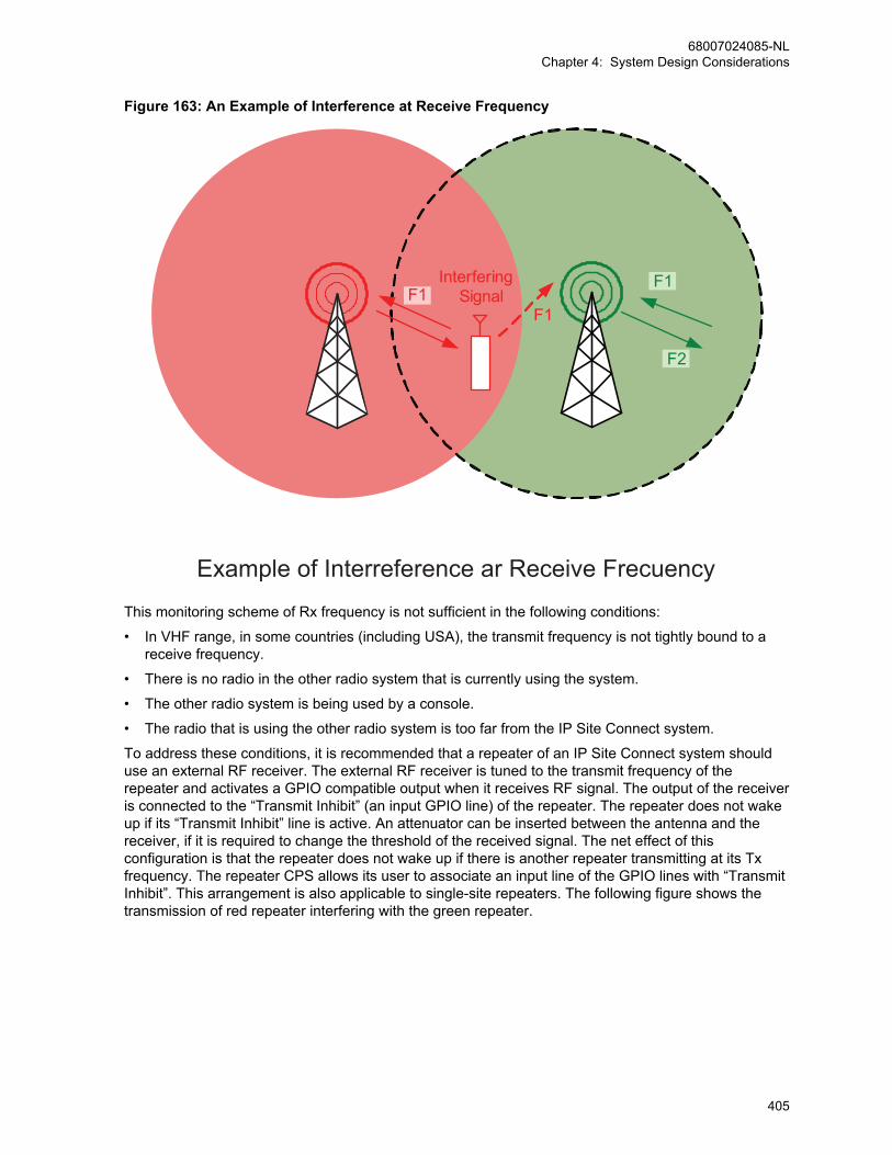
Figure 163: An Example of Interference at Receive Frequency
F1F1
F2
Interfering Signal
F1
Example of Interreference ar Receive FrecuencyThis monitoring scheme of Rx frequency is not sufficient in the following conditions:
• In VHF range, in some countries (including USA), the transmit frequency is not tightly bound to areceive frequency.
• There is no radio in the other radio system that is currently using the system.
• The other radio system is being used by a console.
• The radio that is using the other radio system is too far from the IP Site Connect system.
To address these conditions, it is recommended that a repeater of an IP Site Connect system shoulduse an external RF receiver. The external RF receiver is tuned to the transmit frequency of therepeater and activates a GPIO compatible output when it receives RF signal. The output of the receiveris connected to the “Transmit Inhibit” (an input GPIO line) of the repeater. The repeater does not wakeup if its “Transmit Inhibit” line is active. An attenuator can be inserted between the antenna and thereceiver, if it is required to change the threshold of the received signal. The net effect of thisconfiguration is that the repeater does not wake up if there is another repeater transmitting at its Txfrequency. The repeater CPS allows its user to associate an input line of the GPIO lines with “TransmitInhibit”. This arrangement is also applicable to single-site repeaters. The following figure shows thetransmission of red repeater interfering with the green repeater.
68007024085-NLChapter 4: System Design Considerations
405

Figure 164: An Example of Interference at Transmit Frequency
F2
InterferingSignal F1
F2
Example of Interference at Transmit Frequency
4.9.8Migration from Single Site SystemsThe hardware of radios (both portables and mobiles) and repeaters of a MOTOTRBO single sitesystem are fully compatible with the IP Site Connect configuration. To migrate to IP Site Connectsystem the customer is required to update the software of repeaters and reconfigure them. Some ofthe features of the single site radios may work in the IP Site Connect system but it is highlyrecommended that the software of the radios should also be updated. Data applications of single siteconfiguration are fully compatible with the IP Site Connect configuration.
4.9.9Migration from an Older IP Site Connect SystemIP Site Connect repeaters provide a robust migration for upcoming software versions for repeaters. IPSite Connect repeaters exchange their respective link protocol version information and validateinteroperability support when they detect repeaters having different firmware/software versions loads.
NOTICE: Assume an IP Site Connect system running on software version R01.05.00 is beingupgraded to R01.06.00. The upgraded R01.06.00 repeater initiates the discovery, exchangeslink protocol version information with the R01.05.00 repeaters, and synchronizes the protocolversions for optimal repeater operations.
While the repeater’s versioned IP link protocol provides a clean migration methodology betweenrepeater software versions, there are limitations associated with this feature. Repeaters support thecurrent and previous two releases. Hence, repeater operations and interoperability beyond theprevious two releases would result in incompatibility between repeaters. In such abnormal scenarios,
68007024085-NLChapter 4: System Design Considerations
406
customers are required to upgrade the system such that all repeaters operating on the system remaincompatible; meets the requirement of the current and previous two releases.
A service degradation is expected in scenarios that include multiple repeater firmware versions runningin the system. Therefore, usage of the same repeater firmware version throughout the system, andonly allow usage of different firmware versions during the upgrade period is preferred.
The IP Site Connect repeaters discover each other through the Master repeater (configurable via theCPS); which is a centralized entity of the system. The recommendation is to have the Master repeaterupgraded first to minimize system downtime, optimize IP link connectivity and improve system accesstime across the back-end IP network.
4.10Multiple Digital Repeaters in Capacity Plus Single Site
CPSSCapacity Plus Single Site
Section Multiple Digital Repeaters in CapacityPlus Single Site on page 407 and its subsec-tions explain Multi Digital Repeaters in CapacityPlus Single Site.
The main problem with the standalone configuration of multiple digital repeaters is that a radio can onlyuse one channel of a repeater at any instance of time. Capacity Plus Single Site resolves thisrestriction and allows a radio to use all the repeaters at a site. The sharing of repeaters improves theutilization of channels.
4.10.1System Capacity in Capacity Plus Single SiteIn Capacity Plus Single Site, from software version R02.30.00 onwards, MOTOTRBO supports amaximum of 20 back-end network devices (for example, repeaters and RDAC PC), where networkdevices include a maximum of eight trunked repeaters (16 Trunked Channels), twelve Data Revertrepeaters (24 revert channels), and five RDACs or similar applications.
A Capacity Plus Single Site channel mode supports more radios compared to a single repeaterconfiguration. The ID of radios in Capacity Plus Single Site ranges from 1 to 65535 (16 bit) and the IDof groups in Capacity Plus Single Site ranges from 1 to 254 (8 bit). The Group ID of 255 is reserved forAll Call.
When adding a new trunked repeater to a Capacity Plus Single Site system, all the radios should beconfigured with the channels of the new repeater, before the new repeater is connected to the CapacityPlus Single Site system.
4.10.2Frequencies and Color Code ConsiderationsAs Capacity Plus Single Site, is a single site trunking system, all the repeaters should use differentfrequencies. Their color code can be the same or different. A Capacity Plus Single Site system has theability to share RF channel(s) with other systems, but it is necessary to ensure that all channels in alloverlapping systems have a unique frequency pair and color code combination.
A Capacity Plus Single Site radio requires lists of all trunked and revert channels. This makes itnecessary to reprogram all the radios when a frequency is added to the system. If a Capacity PlusSingle Site system is to be expanded in the future, and if these frequencies are known, then it isrecommended to keep all future frequencies in the trunked list. Keeping additional trunked frequenciesin the radio marginally slows down the radio operations when the radio is powered on, or when theradio comes out of fade. But this prevents the need to reconfigure all the radios when new repeatersare added.
68007024085-NLChapter 4: System Design Considerations
407

If a Capacity Plus Single Site repeater needs to be removed from service for an upgrade or for repair,there is no need to reconfigure the radios. The MOTOTRBO Capacity Plus Single Site system can stilloperate as long as there is one Capacity Plus Single Site repeater functioning in the system.Additionally, there is no need to power down the whole MOTOTRBO system while removing or addinga repeater in the Capacity Plus Single Site system.
This recommendation is also true for revert channels but with a condition. A radio may experiencedelay in transmitting data over revert channels. During this delay, a radio may miss a call taking placeon the Trunked Channel.
4.10.3Considerations for the Back-End Network in Capacity Plus SingleSiteA Capacity Plus Single Site system requires a back-end network if it has more than one repeater. Theback-end network for Capacity Plus Single Site is a Local Area Network. In the simplest and mostcommon configuration, an Ethernet Switch is used to connect all repeaters. To add a remote RDAC, orthe MNIS, connect the Ethernet Switch to a Router that supports hair-pinning (see section for a list ofrecommended devices). This router is connected to either a dedicated network, or to the Internet(provided by an Internet Service Provider). Although Capacity Plus Single Site works with most off-the-shelf devices, the following Ethernet Switch is suggested for use.
• HP Procurve – 2530-24 (J9782A)
• Router – HP MSR2003 AC Router
A repeater has three network interfaces: Ethernet, USB, and over-the-air. A repeater uses its Ethernetport to communicate with other network devices using IPv4/UDP. Since UDP does not supportconfirmation, Capacity Plus Single Site provides its own acknowledgment and retry mechanism forcritical activities. The Ethernet port is not the default IP gateway of the repeater. An IP datagram thatarrives from USB or from over-the-air is not automatically routed to the Ethernet port.
Only the Master repeater needs a static IPv4 or DNS address. Other Capacity Plus Single Site devicesmay have either static or dynamic IPv4 addresses. Dynamic IPv4 addresses are allocated by a DHCPserver. The dynamic IPv4 addresses may change every time the Capacity Plus Single Site devicepowers-on or periodically (every few hours). To enable the use of dynamic addresses, select theDHCP option in the repeater codeplug via the CPS. The lease time of the IPv4 address from the DHCPserver should be kept as long as possible. A change in the IPv4 address of a device causes a shortdisruption of service. To enable the use of static IPv4 addresses, do not select the DHCP option;ensure the static IPv4 address, the gateway IPv4 address and netmask are provided.
Just like an IP Site Connect configuration, a Capacity Plus Single Site configuration uses “LinkManagement” to keep a device aware of the status, the current IPv4 address, and UDP port of otherdevices. For reference, see Considerations for the Back-End Network in IP Site Connect Mode on page 392 on Link Management in an IP Site Connect configuration. The LinkManagement requires only one of the repeaters (called a Master) to act as a broker of IPv4/UDPaddresses. The Master’s static IPv4 or DNS address, and UDP port are configured into all the CapacityPlus Single Site devices. When configured with a static DNS address, the IPv4 address for the masterwill be acquired from a DNS Server instead of being statically configured. The Master’s IPv4/UDPaddress refers to its address as seen from the back-end network. A firewall/NAT may translate theaddress in the customer network into another address on the back-end network.
68007024085-NLChapter 4: System Design Considerations
408
4.10.4Behaviors in Presence of FailuresA Capacity Plus Single Site system has no centralized controller and this makes it tolerant to failures. Itautomatically detects most types of failures, reconfigures itself, and continues to provide the servicesalthough with decreased capacity.
A repeater detects the failure of other repeaters or the back-end network. “Keep Alive” messages areperiodically exchanged between repeaters. The absence of such messages from a repeater indicates afailure of either that repeater or of the network in between. A failed repeater is not selected as a RestChannel repeater. If a Rest Channel repeater fails, a new Rest Channel is selected by the system.
To help a radio detect the failure of the Rest Channel repeater, the Rest Channel repeater periodicallybroadcasts system status over the Rest Channel. If a radio misses the broadcast, then it knows thateither the repeater has failed or it is not within the coverage area of the repeater and the radio startssearching for the Rest Channel.
When the back-end network switch fails, each repeater cannot connect to all other repeaters. Eachrepeater then starts working as a two-channel trunking system. At the time of the switch failure, allradios may be on the Rest Channel or busy on other channels. In the first instance, the call capacity isseverely impacted while in the second, radios on different channels are unable to communicate.
To resolve a failure of a revert channel repeater, a radio makes multiple attempts to transmit a datamessage on different channels.
If a Trunked Control Station fails, a set of radios do not receive data messages from the ApplicationServer.
4.10.5Adaptive Rest Channel Rotation (ARCR)Starting with software version R02.40.00 onwards, Capacity Plus Multi Site and Capacity Plus SingleSite System supports ARCR functionality. The ARCR functionality provides resilience to rarelyoccurring fault mechanisms that can occur in trunked systems and therefore applies to Capacity PlusMulti Site and Capacity Plus Single Site systems only. The functionality ensures that a rest channel isavailable even in the presence of very specific adverse channel conditions and protects the system inthe event of certain types of rarely occurring hardware failures.
The functionality adds additional resilience in the following scenarios:
• Co-channel interference on the uplink that is below the System RSSI detect threshold configured ina repeater but high enough to prevent the repeater from receiving all radios call request. A subsetof the above includes the deployment where:
- The ‘System RSSI’ detect threshold is intentionally set high to lower the likelihood of “losing”channel (for example, have it temporarily taken out of the trunk pool) due to a co-channellicensee’s activity. For example, it is set intentionally high to “tolerate” the negative effects ofsimultaneous co-channel use, albeit with some negative side effects on range performance.
- The System RSSI threshold isn’t set or isn’t set properly.
- Previously unknown/unanticipated co-channel interference occurring after commissioning due toa co-channel license being granted.
• Failures in the receiver line-up of a repeater, including:
- Receiver antenna issues (for example, broken and damaged)
- Receiver transmission line issues,
- Receiver antenna distribution network issues,
- Receiver hardware failure
• Inter-modulation (IM) Products:
68007024085-NLChapter 4: System Design Considerations
409
- Previously unknown/unanticipated interference due to a frequency being granted which results inan undesirable inter-modulation product
- Sites which use multiple antennas, potentially as many as two antennas (Tx and Rx) perrepeater at a site (for example, a large rooftop installation to provide sufficient separationbetween antennas, while saving the cost and complexity of a combining network).
- Operation in densely populated and changeable RF environments.
With ARCR functionality, a site of a system continues to operate and allow communication with otherworking channels (Repeater and the Hardware links) as long as there are working external RF links,Hardware links, and Repeaters on the site.
In nutshell, the ARCR functionality forces a rest channel to automatically move to another channel ifthere is no incoming call on the rest channel for a specific duration. The duration is adaptivelychanged, based on the volume of incoming calls. To ensure a guaranteed rest channel rotation in allcall volume conditions, the duration is limited between a minimum time that is equal to a ‘SIT + abeacon duration’ time and the maximum time which can be set via the CPS ‘Rest Channel TOT’ field.For proper operation, the Rest Channel TOT value must be same on all the repeaters of a site.
Guidelines for choosing Rest Channel TOT:
• The Rest Channel TOT is most effective during idle or low call volume condition. For the site wherethe repeaters have different channel preference level, it is suggested to use larger Rest ChannelTOT value, so that high-preference channels are more frequently utilized even during low callvolume conditions. Note that the force rest channel mechanism steers the rest channel through allpreference level repeaters in round-robin manner, whereas the incoming calls mechanism selectshigher preference channels more often than lower preference channels.
• Shorter Rest Channel TOT leads to faster Rest Channel rotation and better resilience to the failure,however may have minor impact to battery life, because radios receive new rest channelassignment information more often.
• The Rest channel rotation may cause minor delay in call access time during force rest channelswitching period. The Faster the rotation, the more frequent is such access time delays. Note theimpact of such delays should be unnoticeable to radio users.
• If necessary, the ARCR functionality can also be disabled completely by disabling Rest ChannelTOT value.
If a rest channel assignment is repeatedly force rotated from a specific repeater, while all otherchannels rotate as rest channels due to normal radio calls, the software algorithm suspects that theparticular channel has failed and reduces its rest channel preference to the lowest level. Consequently,that suspected repeater is used less, to minimize the likelihood of a rest channel becoming unavailableon that repeater and blocking system access. In due course, if a suspected repeater is found to beworking then the preference level is reverted back to the configured level.
4.10.6Limiting Interference to Other SystemsCapacity Plus Single Site is designed to be compatible with both exclusive and shared channels. Tohelp a radio detect the unavailability of a Rest Channel, the repeater periodically transmits a very shortsystem status message beacon. If the radio misses this transmission on a Rest Channel, then theradio is either not within the coverage area of the repeater or the repeater cannot transmit (due tointerference by other systems or a failure). The radio then starts searching for a new Rest Channel.The interval of periodic transmissions of the system status messages can be selected within certainlimits by an authorized technician. There are two points to consider:
• A more frequent beacon transmission helps a radio detect the unavailability of the Rest Channelfaster, and thus reduces the downtime caused by interference from other systems and improvescapacity. Hence, it is recommended to keep the beacon interval at the default value.
68007024085-NLChapter 4: System Design Considerations
410

• If the system incorporates a shared channel causing interference to other systems, the default valueof the beacon interval can be increased.
4.10.7Plan for Talkaround ModeIn Capacity Plus Single Site, a MOTOTRBO radio does not support Talkaround. To ensure acommunication channel is available when the Capacity Plus Single Site system is completely shutdown or when a radio has moved out of the coverage area, it is recommended to program at least onecommon channel in Talkaround mode, that is at least one of the channel knob position should beprogrammed for Talkaround mode.
The Talkaround mode configuration is useful when the Capacity Plus Single Site system fails or theradio is out of coverage area. All that a user needs to do is to switch to Talkaround personality.
The radio user may define their own protocol for when to switch to Talkaround mode. For example, allradio users may switch to Talkaround mode when their radio is not on the Capacity Plus Single Sitesystem for more than 10 minutes.
A customer may decide to plan the Talkaround mode configuration according to the number of groupsthat need such an operation. The available Talkaround mode frequencies should be distributed to thedifferent groups based on their call profiles. Radios users can use scan mode in Talkaround.
To detect if the Capacity Plus Single Site system is once again up and running, radio users mayperiodically switch to a Capacity Plus Single Site channel and observe the activity on the channel.
4.10.8Ways to Improve Battery LifeTo improve battery life of a portable radio, a user can switch the radio power to low power mode byusing the radio menu or power button. Low power mode improves battery life of a portable radiosignificantly over the high power mode.
When a user notices that the radio is not providing talk-permit tone for multiple PTT attempts in lowpower mode and that the signal strength bar is still visible, the radio should be switched to high powermode when initiating a call. When switching to different power modes, the radio user will not miss anyincoming calls. The call listening capability of radio does not change with the radio transmit power.
Additionally, a radio user may turn off the radio when calls are not expected or when the radio is out ofcoverage.
4.10.9MOTOTRBO Telemetry Connection DetailsFor more details about the telemetry GPIO pin assignments, see the MOTOTRBO Telemetry ADKGuide available.
4.10.10Considerations for Configuring Combined Firmware VersionsIn cases where legacy repeaters and other higher versions of repeaters needs to be connectedtogether, it is highly recommended to make one of the higher version repeaters as the Master repeater,to avoid service degradation issues.
In scenarios where the MTR3000 repeaters are combined with the MOTOTRBO repeaters, it ispossible that the MOTOTRBO repeater firmware is of a higher version than the MTR3000 repeaterfirmware. Configure the MOTOTRBO repeater as the Master repeater to avoid service degradation inthis scenario.
68007024085-NLChapter 4: System Design Considerations
411
4.10.11Upgrading from Capacity Plus Single Site
NOTICE: Repeaters running on software version RR02.30.00 or later are not interoperable withrepeaters running on software version before R02.30.00. Hence, if there is a repeater withsoftware version R02.30.00 or later present in a Capacity Plus Single Site system, all the otherrepeaters must be upgraded to R02.30.00 or later altogether.
When upgrading a Capacity Plus Single Site system, upgrade the Master first, followed by all otherrepeaters at the site. During the upgrade, the Capacity Plus Single Site system acts as two mutuallyexclusive systems, but calls are still supported. The radios remain tracking the legacy system until thelast legacy repeater is switched off and upgraded. Afterward, the radios locate the new system andoperate as normal.
4.11Multiple Digital Repeaters in Capacity Plus Multi Site
CPMSCapacity Plus Multi Site
Section Multiple Digital Repeaters in CapacityPlus Multi Site on page 412 and its subsectionsexplain Multi Digital Repeaters in Capacity PlusMulti Site.
4.11.1System Capacity in Capacity Plus Multi SiteIn a Capacity Plus Multi Site configuration, MOTOTRBO supports up to 15 sites, including host PCs,and a maximum of eight trunked repeaters per site. For the data revert repeaters at a site, up to 12 canbe supported. However, the number of trunked repeaters plus the number of data revert repeatersmust not exceed a total of 12. For example, if there are eight trunked repeaters at a site, only up to fourdata revert repeaters can be supported at that site.
An intermediary role may exist on a repeater which also has RF responsibilities in a system with 140 orless peers, which includes the trunked repeaters, data revert repeaters, RDAC, and data applications.
When the system has more than 140 peers, a dedicated intermediary role is required and it isrecommended to reside on a data revert repeater that has no RF responsibilities. The dedicatedrepeater site is allowed to have up to 13 repeaters which includes the trunked repeaters, data revertrepeaters, and the data revert repeater that the dedicated intermediary resides on. The system cansupport up to 200 peers.
A Capacity Plus Multi Site system supports more radios per channel compared to a single repeaterconfiguration or IPSC configuration. This is based on the following reasons:
• A customer can configure a talkgroup as a local talkgroup. The local talkgroup call is transmittedover-the-air at only one site.
• A customer can associate a set of sites with a talkgroup. The talkgroup call is transmitted over-the-air at only the associated sites.
• After initial handshakes, a Private Call is transmitted at either one or two sites only.
The radio and talkgroup IDs in Capacity Plus Multi Site are the same as the IDs in Capacity Plus SingleSite. The ID of radios in Capacity Plus Multi Site ranges from 1 to 65535 (that is, 16-bit) and the ID oftalkgroups in Capacity Plus Multi Site ranges from 1 to 254 (that is, 8-bit). The Group ID of 255 isreserved for All Call.
When adding a new trunked repeater to a Capacity Plus Multi Site system, all radios should beconfigured with the channels of the new repeater before the new repeater is connected to the system.Up to 160 personalities can be configured for the Capacity Plus Multi Side configuration, for a radio.
68007024085-NLChapter 4: System Design Considerations
412
4.11.2Considerations for Frequencies, Color Code, and InterferenceIn a Capacity Plus Multi Site system, the frequencies and color code of repeaters should satisfy thefollowing rules:
• All the repeaters at a site should use different frequencies. Their color code can be the same ordifferent.
• If the system incorporates a shared channel, then the beacons cause interference to other systems.In such scenarios, the value of the beacon interval can be increased.
• The repeaters of the non-adjacent sites of a Capacity Plus Multi Site system should use differentfrequencies and color code combinations. It is not advisable to keep the same frequencies andcolor code because a roaming radio is not able to distinguish between them, and may use incorrectData Revert Channels or an incorrect list of neighboring sites.
• A Capacity Plus Multi Site system can share one or more of its channels with other systems.However, it is necessary to ensure that all the overlapping channels of different systems have aunique frequency and color code combination. If the frequencies of the geographically adjacentrepeaters of two systems are the same, then their color codes should be different. It is not advisableto keep the same frequencies because in areas of overlap, destructive interference can occur.
• A system may be sharing the channels with other systems over multiple sites. It is possible that twosystems (named here as Sys1 and Sys2) may be using the same (frequencies, color code) pair attwo different sites (for example, Site1 and Site2). During automatic site search, a Sys1 radio atSite2 finds a Sys2 repeater and stays on that channel. This is not a desirable situation. One way toavoid this situation is to ensure that all the (frequencies, color code) pairs of all the overlappingsystems are unique.
To take care of shared use of a physical channel, a Capacity Plus Multi Site repeater always monitorsits Rx frequency and does not transmit if the RSSI from radio(s) of some other systems is greater thana configurable threshold. This ensures that a Capacity Plus Multi Site system does not use a channel ifanother repeater in the vicinity, is currently using the channel. The RSSI threshold is CPSprogrammable in the range of -40 dBm to -130 dBm. The threshold value should be chosen wisely. Avalue lower than the background noise, inhibits a repeater from transmitting due to interference frombackground noise. A value higher than the RSSI of the radio of some other system makes the systemunfriendly to systems sharing the frequency. The RDAC application can be used to measure theinbound RSSI of an interfering signal, if required.
The above Rx frequency monitoring scheme is deficient if the Capacity Plus Multi Site repeater isunable to deduce that an interfering signal is present on its outbound channel based on the presenceof an interfering radio transmission from another radio system on its inbound channel. This situationmay arise for any of the following reasons:
• There is no radio in the other radio system that is currently using the system.
• The other radio system is being used by a console.
• The radio that uses the other radio system is too far from the Capacity Plus Multi Site system.
To take care of the above conditions, it is recommended that a repeater of a Capacity Plus Multi Sitesystem should use an external RF receiver. The external RF receiver is tuned to the Tx frequency ofthe repeater and activates a GPIO compatible output when receiving a RF signal. The output of thereceiver is connected to the “Transmit Inhibit” (an input GPIO line) of the repeater. The repeater doesnot wake up if its “Transmit Inhibit” line is active. An attenuator can be inserted between the antennaand the receiver, if it is required to change the threshold of the received signal. The net effect of thisconfiguration is that the repeater does not wake up if there is another repeater transmitting at its Txfrequency. The repeater CPS allows the user to associate an input line of the GPIO lines with“Transmit Inhibit”. This arrangement is also applicable to single site repeaters.
Capacity Plus Multi Site is designed to be compatible with both exclusive and shared channels. To helpa radio detect that it is out of range of its repeater and to facilitate automatic roaming by the radio, the
68007024085-NLChapter 4: System Design Considerations
413
repeater periodically transmits a very short beacon. If the radio misses this transmission on a RestChannel, then the radio is either not within the coverage area of the repeater, or the repeater cannottransmit (for example, due to interference by other systems or a failure). The radio then startssearching for a new Rest Channel. The interval of periodic transmissions of the beacon can beselected within certain limits by an authorized technician. There are two points to consider:
• A more frequent beacon transmission helps a radio detect the “out of range” state faster, and thusreduces the downtime caused by interference from other systems and improves capacity. Hence, itis recommended to keep the beacon interval at the default value. This also makes the roamingfaster.
• If the system incorporates a shared channel causing interference to other systems, the default valueof the beacon interval can be increased.
4.11.3Considerations for the Back-End Network in Capacity Plus Multi SiteIn a Capacity Plus Multi Site system, the repeaters at a site are connected over a LAN. The repeatersat a site must be plugged into a switch that must be behind a router because Capacity Plus Multi Siteuses locally administered IP addresses. The router must support “NAT”6. In NAT, internal UDP/IPaddresses are translated to external UDP/IP addresses. In the simplest and most commonconfiguration, an Ethernet switch with a router is used to connect all the repeaters at a site. AlthoughCapacity Plus Multi Site works with most off-the-shelf network devices, the following Ethernet switchand router are suggested for use.
• Switch – HP Procurve 2530-24 (J9782A)
• Router – HP MSR2003 AC Router
A Capacity Plus Multi Site repeater uses IP Limited Broadcast Address (255.255.255.255) to distributea message to all the repeaters at a site. The broadcast messages may have some adverse effects onthe other devices present on the LAN. Therefore a Capacity Plus Multi Site configuration expects thatonly the Capacity Plus Multi Site repeaters are present on the LAN. This router is connected to either adedicated network, or to the Internet provided by an ISP.
Only the Master repeater needs a static IPv4 or DNS address. Other repeaters may have either staticor dynamic IPv4 addresses. The dynamic IPv4 addresses may change every time the network devicepowers-on or periodically every few hours. The lease time of the IPv4 address should be kept as largeas possible. A change in the IPv4 address of the network device causes a short disruption of service.
Just like an IP Site Connect configuration, a Capacity Plus Multi Site configuration uses “LinkManagement” to keep a device aware of the status, the current IPv4 address, and UDP port of otherrepeaters. The Link Management requires only the Master repeater to act as a broker of IPv4/UDPaddresses of repeaters. The Master’s static IPv4 or DNS address, and UDP port are configured into allthe Capacity Plus Multi Site devices. When configured with a static DNS address, the IPv4 address forthe master is acquired from a DNS Server instead of being statically configured. The Master’sIPv4/UDP address refers to its address as seen from the back-end network. A firewall/NAT maytranslate the address in the back-end network into another address in the customer network. The back-end network can be a dedicated network or an Internet. ISPs provide a range of technologies such asDSL (typically ADSL), cable modem, broadband wireless access, Canopy, ISDN, Frame Relay, andmore. In some cases, dedicated links or networks can be effectively used or deployed, removing themonthly fees associated with public networks. The back-end network cannot be based on dial-upconnection (due to small bandwidth) or Satellite Internet access (due to large delay).
6 Basic NAT provides translation for IP addresses only, and places the mapping into a NAT table.In other words, for packets outbound from the private network, the NAT router translates thesource IP address and related fields; for example, IP, UDP, and ICMP header checksums. Forinbound packets, the NAT router translates the destination IP address and related checksums forentries found in its translation table.
68007024085-NLChapter 4: System Design Considerations
414
A Capacity Plus Multi Site device registers its IPv4/UDP address during power-on and periodically withthe Master. The Master then notifies all the devices whenever the IPv4 address of a device changes.The devices may be behind firewalls. For successful communication between two devices (forexample, R1 and R2), the firewall of R1 must be open for messages from R2 and vice versa. Since theIPv4/UDP address of an IP Site Connect device is dynamic, it is not possible to manually configure thefirewalls. The Link Management procedure overcomes this problem by periodically sending a messagefrom R1 to R2 and vice versa. On a receipt of an outbound message (for example, from R1 to R2), theR1’s firewall keeps itself open for a short duration of approximately 20 seconds for an inboundmessage from R2. A device sends the dummy message to another device only if they are parties to thesame call.
Network setup and configuration varies significantly depending on the complexity of the equipment andIP network the system resides on. It is always wise to communicate with the Network Administratorduring installation and during the design phase as they are likely to be the individuals configuring thenetwork equipment and own a great deal of knowledge in this area. The following is a short list of itemsto keep in mind when setting up or when troubleshooting the networks of a Capacity Plus Multi Sitesystem.
• When assigning static IP addresses within a network, it must not conflict with another static IPaddress. Conflicting IP addresses can cause a disruption to the traffic. Additionally, ensure that thestatic IP address does not fall into the DHCP assignable range. This can cause an IP conflict if theaddress is dynamically assigned to another device on the network.
• If other network devices are present on the same back-end IP network, it is good practice to setupQuality of Service (QoS) rules in the Internet router. This ensures that the Capacity Plus Multi Sitepackets have priority over other traffic on the system. Failure in doing this could cause audioperformance degradation or lost transmissions when other devices on the system are excessivelyutilizing the network. There are various methods routers use to provide QoS. It is commonlyperformed by configuring a range of UDP ports or IP addresses a specific amount of upstream anddownstream bandwidth. The default UDP port for Capacity Plus Multi Site is 50000.
• Verify that the customer network equipment is not blocking the IP addresses or UDP ports utilizedby the Capacity Plus Multi Site system. This is commonly done by a firewall or other securitydevices. Consult the customer’s Network Administrator or ISP.
• Inquire with the ISP if there are any caps on bandwidth usage per month. Some ISPs do not allowthe customer to exceed a particular upload or download limit per month. Since Capacity Plus MultiSite systems stream voice over the Internet, it may be possible to surpass this limit on extremelyhigh usage systems.
• When configuring routers with VPN links, it is wise to increase the IPSec Key Life Time (KLT) timersto approximately 13 to 24 hours. It is recommended to set Phase 1 KLT to 24 hours, and Phase 2KLT to 13 hours. Some low-end routers cause a disruption to ongoing voice and data whenrenegotiating keys after the KLT timer expires. This is especially noticeable when multiple VPNs areconfigured with identical KLT timers since the router needs to re-calculate numerous keys at thesame time. It is best practice to offset the KLT timers of each VPN by 10 minutes.
4.11.3.1Back-End Network Characteristics in Capacity Plus Multi SiteTo create a proper back-end network design, it is important to know its characteristics. Back-EndNetwork Design in IP Site Connect Mode on page 395 explains the issues dealt with in the back-endnetwork of an IP Site Connect system. They are also applicable to the back-end network of a CapacityPlus Multi Site system.
68007024085-NLChapter 4: System Design Considerations
415

4.11.3.2Back-End Network Bandwidth ConsiderationsBandwidth is the amount of data transferred to and from a network device, often referred to as the bitrate. Bandwidth is measured in bits per second or kilobits per second (kbps). When designing an IPSite Connect system, it is important to understand the needs of each IP Site Connect device so thatthe appropriately rated network connection for each site can be chosen.
If a customer has high speed network connections between sites, these calculations may not be asimportant, but if they are working on lower speed public ISPs, it is good practice to understand thesevalues and plan accordingly. If the minimum amount of bandwidth is not available, the end user mayexperience audio holes or even dropped calls. Radio-to-radio data messaging or RDAC commandsmay not be successful on the first attempt, or may be dropped all together. In general, the QoS maysuffer if substantial bandwidth is not available.
For most ISPs, the uplink bandwidth is the limiting factor. The downlink bandwidth is usually multiplefactors above the uplink bandwidth. Therefore, if the uplink requirements are met, the downlinkrequirements are almost always acceptable. Some ISPs may state they provide a particular bandwidth,but it is important to verify the promised bandwidth is available throughout the operation and once thesystem is installed. A sudden decrease in available bandwidth may cause the previously describedsymptoms.
If the WAN connection is utilized by other services (file transfer, multimedia, web browsing, andothers), then the IP Site Connect devices may not have the appropriate bandwidth when required andthe QoS may suffer. It is suggested to remove or limit these types of activities. Additionally, excessiveusage of the RDAC application itself may cause increased strain on the network during times of HighVoice activity. It is recommended that RDAC commands be kept to a minimum, unless appropriatebandwidth has been allocated.
4.11.3.2.1Required Bandwidth Calculations
NOTICE: System Design Tool is the bandwidth calculation tool for Capacity Plus Multi Site isavailable on the Motorola Solutions Online website https://emeaonline.motorolasolutions.com
The tool allows System Administrators to plug in to the Capacity Plus Multi Site system configurationinformation to compute the IP bandwidth required for each site. Search for Capacity Plus Multi SiteBandwidth Calculator.
4.11.4Behaviors in Presence of FailuresA Capacity Plus Multi Site system has no centralized controller and this makes it inherently tolerant tofailures. The system automatically detects most types of failures, reconfigures itself, and continues toprovide the services although with decreased capacity. This section provides the consequences of thefailure of one or more entities of a Capacity Plus Multi Site system.
4.11.4.1Failure of the MasterIf the Master is the only static IP address in the Capacity Plus Multi Site system and it fails, and thenDHCP resets the dynamic IP addresses of the repeaters at one of the other sites before the staticmaster is replaced, that site loses connectivity with the rest of the Capacity Plus Multi Site systemsites. When the Master repeater is replaced, the site which had IP addresses reset can update theMaster’s routing table and regain connectivity with the other sites.
The consequences of a failure of the Master are limited. The system continues to function withexception that it is not possible to add a new site or repeater into the system. If a repeater powers on
68007024085-NLChapter 4: System Design Considerations
416
while the Master is in failed state, then the repeater is not be able to join the system. Upon failure ofthe Master, it is possible to switch to a redundant repeater to act as the Master. The static IPv4address and the UDP port number of the redundant repeater should be identical as that of the failedMaster. Otherwise all repeaters are require to be reconfigured with the IPv4 address and the UDP portnumber of the new Master.
To avoid the issue of needing to have the same static IPv4 address configured on both the primary andredundant Master repeaters, all of the repeaters can be configured to use a static DNS address for theMaster. The primary and redundant repeaters can still be configured with static IPv4 addresses, butthey could be unique when a static DNS address is used. In the event that the primary Master fails,then the DNS Server could be updated such that the static DNS address configured into all of therepeaters now maps to the IPv4 address of the redundant Master repeater. To minimize any downtime,the DNS Server should be updated immediately with the IPv4 address of the redundant Master upondetection that the primary Master has failed. It should be noted that the DNS feature is only availableon SLR Series Repeaters.
4.11.4.2Failure of a SiteIn absence of the periodic “Keep Alive” messages between a site and the Master, the Masterconcludes that either the IP Site Connect device or the network in-between has failed. The Masterinforms all the other sites about the absence of the failed site. The system continues to provideservices with the available sites. During a network failure, it is possible that a Capacity Plus Multi Sitesystem becomes multiple systems, whereby each system has a subset of the original set of sites. Allnew systems continue to provide the services that are possible with their subset of sites. Note thatthere is only one system that has the Master. When the backend network recovers, the multiplesystems automatically become one system again. When a system has only one site, then the systembehaves like a Capacity Plus Single Site system.
4.11.4.3Failure of a RepeaterA repeater broadcasts “Keep Alive” messages periodically over the LAN. This allows a repeater todetect the failure of another repeater at its site. A failed repeater is not selected as a Rest Channelrepeater. If a Rest Channel repeater fails, a new Rest Channel is then selected by the system.
To help a radio detect the failure of a Rest Channel repeater, an inactive Rest Channel repeaterperiodically broadcasts a beacon over the Rest Channel. If a radio misses the beacon(s), then it knowsthat either the repeater has failed, or it is not within the coverage area of the repeater. Hence, the radiostarts searching for a new Rest Channel.
4.11.4.4Failure of the LAN SwitchWhen the switch fails, a repeater cannot connect to other repeaters at its site. Each repeater thenstarts working as a two-channel trunking system. At the time of the switch failure, all radios may be onthe Rest Channel or busy on other channels. In the first instance, the call capacity is severely impactedwhile in the second, radios on different channels are unable to communicate.
68007024085-NLChapter 4: System Design Considerations
417
4.11.4.5Failure of the Back-End Network or RouterThe failure of a router disconnects the site from the rest of the system. The failure of the back-endnetwork may disconnect one or more sites. When a site gets disconnected, it reconfigures itself andstarts operating as a single site trunked system, that is like a Capacity Plus Single Site system.
Intermittent failures of the back-end network causes packet loss or excessive delay. Such failuresadversely affect wide area talkgroup calls. A wide area call may fail to start at all the associated sites.Capacity Plus Multi Site has built-in mechanisms to recover from such failures in a few seconds.
4.11.4.6Failure of a Revert RepeaterTo overcome the failure of a revert channel repeater, a radio makes multiple attempts to transmit adata message on different channels. If a Trunked Control Station fails, a set of radios do not receivedata messages from the Application Server.
4.11.5Automatic ReconfigurationA Capacity Plus Multi Site system automatically discovers the presence of a new entity such as arepeater, a site, or a Host PC. This new entity is configured with the IPv4/UDP address of the Master.Upon power-on, the new entity informs its IPv4/UDP address to the Master and the Master informs allthe other entities about the presence of a new entity. Hence, this allows adding a repeater, site, or HostPC to a live Capacity Plus Multi Site system. This simplifies the installation/addition of a Capacity PlusMulti Site entity as there is no need to take the system down and configure other entities with theIPv4/UDP address of the new entity.
A radio requires lists of all trunked and revert channels. This makes it necessary to reprogram all theradios when a physical channel (repeater) is added to the system. If a system is to be expanded in thefuture, and if these frequencies are known, then it is recommended to keep all future frequencies in thetrunked list. Keeping additional trunked frequencies in the radio marginally slows down the radiooperations when the radio is powered on, or when the radio comes out of fade. But this prevents theneed to reconfigure all the radios when new repeaters are added.
If a repeater needs to be removed from service for an upgrade or for repair, there is no need toreconfigure the radios. The MOTOTRBO Capacity Plus Multi Site system can still operate. Additionally,there is no need to power down the entire MOTOTRBO system while removing or adding a repeater inthe system.
4.11.6Security ConsiderationsMOTOTRBO offers three types of privacy mechanisms over-the-air – Basic Privacy, EnhancedPrivacy, and AES. In Capacity Plus Multi Site and IP Site Connect configurations, a repeater does notdecrypt the encrypted packets. It simply passes the packets as received over-the-air to otherrepeaters. Since the two privacy mechanisms are not compatible, all the radios and repeaters in asystem should support the same privacy mechanism. It is important to note that the repeaters requireEnhanced Privacy type for AES configuration.
NOTICE: The privacy mechanisms protect only the voice or data payloads. They do not protectthe voice or data headers, nor control messages, nor system messages (between repeaters).
Similar to IP Site Connect, a Capacity Plus Multi Site system optionally offers authentication of all thepackets sent between sites and host PCs. Packet authentication prevents an attacker from using animpersonator as a Capacity Plus Multi Site entity. This feature, if selected by a customer, requiresmanual configuration of the same key to all the entities.
68007024085-NLChapter 4: System Design Considerations
418
The above authentication mechanism does not provide protection against the replay attacks. For amore secure authentication, a Capacity Plus Multi Site configuration should use secure VPN routers toconnect with the back-end network. Secure VPN routers can optionally provide confidentiality of all themessages. However, a disadvantage of using these routers is that, the system requires more inboundand outbound bandwidth from the ISP. The use of these routers makes the authentication mechanismof IP Site Connect redundant and should be disabled to save some bandwidth over the back-endnetwork.
4.11.7MigrationThe hardware of radios are fully compatible with the Capacity Plus Multi Site configuration. Onlyrepeaters with 32 MB of internal memory can support the Capacity Plus Multi Site configuration.
While migrating multiple IP Site Connect or Capacity Plus Single Site systems into a Capacity PlusMulti Site system, it is important to ensure that the IDs of radios, radio IDs of the repeaters, and alsothe IDs of wide area talkgroups are unique.
In Capacity Plus Multi Site, both the Trunked Repeaters and the Data Revert repeaters have channelIDs. The range of the channel ID of a Data Revert repeater is 33 to 253.
In Capacity Plus Single Site and IP Site Connect systems, each personality of a radio has a RxTalkgroup List. In Capacity Plus Multi Site, each site of a radio has a Rx Talkgroup List.
4.11.7.1Migrating from IP Site ConnectTo migrate from one or more IP Site Connect system(s), the following tasks are required:
Procedure:1 Update the software of repeaters.
2 Update the software of radios.
3 Reconfigure both repeaters and radios. The reconfiguration should consider the following:
• The range of the Layer 2 ID of radios in Capacity Plus Multi Site is 1.65535 compared to1.16776415 in IP Site Connect.
• The range of the Layer 2 ID of talkgroups in Capacity Plus Multi Site is 1.254 compared to1.16776415 in IP Site Connect.
In IP Site Connect, a call over a wide area channel is transmitted over-the-air at all the sites. A callover a local channel is transmitted over-the-air at the source site only. Capacity Plus Multi Site doesnot have a local channel; allowing a customer to define a talkgroup as either local or wide-area in theMaster repeater. For a wide-area talkgroup, enumerating the sites where the wide-area talkgroup callwill be transmitted is allowed. Restricting the scope of a talkgroup to either local or to some sitesimproves the channel capacity of the system. Additionally, the ID of a local talkgroup can be reused atother sites and thus effectively increases the total number of talkgroup IDs. Unlike local channels, thelocal talkgroups do not require a radio user to change personality before PTT.
4.11.7.2Migrating from Capacity Plus Single SiteTo migrate from one or more Capacity Plus Single Site system(s), the following tasks are required:
Procedure:1 Update the software of repeaters.
68007024085-NLChapter 4: System Design Considerations
419
2 If the existing radios are going to operate at one site only, then it is not essential to update thesoftware of radios. A Capacity Plus Single Site radio continues to operate in a Capacity PlusMulti Site system, within one site, with the following restrictions:
• A call from a Capacity Plus Single Site radio at a site is not received by Capacity Plus SingleSite or Capacity Plus Multi Site radios at other sites. This implies that all the calls fromCapacity Plus Single Site radios are local.
• A Capacity Plus Single Site radio can receive a wide-area call only, but can not transmit.
• A call from a Capacity Plus Multi Site radio is received by the Capacity Plus Single Siteradios at the same site.
• All the talkgroups used by Capacity Plus Single Site radios should be defined as localtalkgroups in a Capacity Plus Multi Site system.
• In Capacity Plus Single Site, the Lost Detection Beacon Interval in the radio is higher thanthe repeater’s. In Capacity Plus Multi Site, the Lost Detection Beacon Interval must be thesame in both radios and repeaters.
4.11.8Upgrade from Capacity Plus Multi SiteRepeaters running on software version R02.20.12 or later are not interoperable with repeaters runningon software version prior to R02.20.12. Hence, if there is a repeater with software version R02.20.12 orlater present in a Capacity Plus Multi Site system, all the other repeaters will have to be upgraded toR02.20.12 or later altogether.
When upgrading a Capacity Plus Multi Site system, upgrade the Master first, followed by all otherrepeaters at the Master's site. Continue to upgrade all the repeaters at a non Master site, ensuringcompletion of all repeaters at the site, before moving on to another peer site. During the upgrade, theCapacity Plus Multi Site system acts as two mutually exclusive systems, but calls are still supportedwithin, just not across the two systems. Therefore wide area calls may not reach all intended sitesduring the migration. All radios should remain tracking the legacy system until the last legacy repeateris switched off and upgraded at its site, radios will then find the new system and operate as normal.
4.12Digital Voting
NOTICE: The MOTOTRBO digital voting is a proprietary feature introduced in R02.30.00 toresolve the imbalance inbound-outbound issue.
This section specifically documents the major control and monitor through CPS/RDAC for digital voting.Other control/monitor details can be found in corresponding CPS/RDAC manuals.
The devices affected by this feature are the repeaters, satellite receivers and radios. For repeaters andsatellite receivers, there are specific voting related software upgrades and configuration changes infirmware R02.30.02. However, for radios, there is none. Any radios running on software versionR01.12.02 for MOTOTRBO, R02.30.01 and above for MOTOTRBO 2.0 or later are voting enabled outof factory. For older radios, they need to be upgraded to R02.30.01 or later.
NOTICE: Unless specified otherwise, the control/monitor described in this section applies to allsystem configurations – Conventional Single Site, IPSC, Capacity Plus Single Site andCapacity Plus Multi Site.
68007024085-NLChapter 4: System Design Considerations
420

4.12.1Repeater to Receiver ConfigurationThe satellite receiver is not a new hardware device. It reuses the MTR3000 repeater, 32 MB DR seriesrepeater, and the MTR3000 Receiver only box. In order for these devices to be used as a satellitereceiver, they must be configured in the CPS.
CPSMCapacity Plus Single Site and Capacity
Plus Multi Site
In a Capacity Plus Single Site or Capacity PlusMulti Site system, the Rest Channel/Site IP ad-dress of a receiver is not used by the system,therefore it is not necessary to be the sameRest Channel/Site IP address in its voting re-peater. Keep it simple by setting the address as0.0.0.0, or a proper LAN address that the re-ceiver is in.
If Enhanced GPS is enabled in the system, the receiver must not be configured as a scheduler. Thismeans the periodic window reservation field in the “Enhanced GPS” section of the CPS must be set to“None” for both slots.
4.12.2Enable/Disable Digital VotingRepeaters: Voting can be enabled/disabled via CPS. When voting is disabled on a repeater, therepeater still performs as a regular repeater. However, the transmission of any call from its satellitereceivers will not be accepted.
Satellite Receivers: When the device is configured as a satellite receiver, the voting capability isprogrammed by default. If a particular satellite receiver needs to be taken down, the user candisconnect the satellite receiver from the system, power it down or use RDAC to disable it by using the“repeater disable” option.
4.12.3Digital Voting StatusDigital voting status is monitored through RDAC.
Repeater Voting Enabled/DisabledThis status displays whether the voting feature on a repeater is enabled or disabled.
Force VoteThis status indicates when the receiver is force voted.
Voting Status for Satellite ReceiversWhen voting is disabled on the repeater, RDAC does not display any voting status for its satellitereceivers even if there are satellite receivers physically connected to the repeater. When voting isenabled on the repeater, RDAC then displays each satellite receiver’s voting status. The repeaterpushes this information to the RDAC, and the update frequency is defined by the “Voting StatusUpdate Rate” that is configured via the RDAC. The following voting statuses are possible:
N/AThis is the default value. Before RDAC obtains any information, this value is displayed.
DisabledThe receiver is voting disabled.
68007024085-NLChapter 4: System Design Considerations
421

Not SyncedThe receiver is voting enabled but has not synchronized with the repeater. The satellite does notoperate in this state. This could happen during power up, or in a congested IP connection betweenthe receiver and the repeater.
SyncedThe receiver is voting enabled. It has synchronized with the repeater, but not receiving valid OTAtransmission.
ReceivingThe receiver is voting enabled, and is currently receiving valid transmission, but is not the votedwinner. While in this condition, RDAC also displays the signal quality estimation (SQE). The SQEresult is based on the voting parameters, and is categorized as “Excellent”, “Good”, “Fair”, “Poor”,and “Bad/Rejected”.
VotedThe receiver is voting enabled, currently receiving valid transmission, and is the voted winner.While in this condition, RDAC also displays the SQE based on the available voting parameters.
Voting Status for Internal Receivers (of the Repeater)The voting repeater has a built-in receiver, and is defined as the “internal receiver”. When voting isdisabled, RDAC does not display its internal receiver’s voting status. When voting is enabled,RDAC displays its internal receiver’s voting status. The repeater pushes this information to theRDAC, and the update frequency is defined by the “Voting Status Update Rate” that is configuredthrough RDAC. The following voting statuses are possible:
N/AThis is the default value. Before RDAC obtains any information, this value is displayed.
Not receivingThe receiver is not receiving any valid OTA transmission.
ReceivingIt is currently receiving valid transmission, but is not the voted winner. While in this condition, RDACalso displays the SQE based on the available voting parameters.
VotedIt is currently receiving valid transmission, and is the voted winner. While in this condition, RDACalso displays the SQE based on the available voting parameters.
Receiver Alarm/FailuresThe satellite receiver reuses repeater hardware like the alarms and failure reports. All existingrepeater alarms/failure reports, except for transmit only ones, are still available for the satellitereceivers.
NOTICE: The satellite receiver does not transmit over the air.
4.12.4Digital Voting Controls/ConfigurationsFor repeaters, there is no additional voting related configuration, except enabling/disabling the votingfeature.
For satellite receivers, the following controls/configurations are available:
Connected Voting Repeater/Radio IDA satellite receiver must be connected to a voting repeater through an IP LAN or WAN. In order forthe satellite receiver to operate correctly, it needs to know which voting repeater it is associated to.This can be configured by the CPS.
68007024085-NLChapter 4: System Design Considerations
422

Force Vote/CancelThere are situations when a particular satellite receiver or the repeater needs to be always selectedas the voted winner for a period of time. For example, a critical activity near a particular receiveroccurs, thus calls from that receiver need to have higher priority. This can be achieved throughforce vote from the RDAC. When the RDAC user force votes a particular satellite receiver/repeater,the transmission received from that particular receiver/repeater is always selected as the votedwinner, and repeated until force vote is canceled, or until the force voted receiver is disconnectedfrom the system.
Voting Status Update RateThis controls how often the voting status of the repeater and its satellite receivers should beupdated in RDAC. There are three control options:
NoneThe status is not pushed to the RDAC. This option reduces the traffic between the repeaters andthe RDAC, thus alleviates network traffic in the system.
NormalThe status is continuously pushed to the RDAC at an interval of every three (3) seconds. This is thedefault value.
DiagnosisThe status is continuously pushed to the RDAC at an interval of every one (1) second. This shouldbe used only for diagnosis purpose, because frequent status updates increase the IP traffic, andadd heavy workload into the system dramatically.
Voting Log Turn On/OffVoting log may be turned on/off for a specific voting repeater via RDAC. The update rate of thelogged information is decided by the “Voting Status Update Rate”. Once turned on, RDAC logs thefollowing voting related information for the repeater, and each of its satellite receivers:
• Repeater voting enable/disable status with PC time stamp
• Voting status of its receivers with PC time stamp
• Estimated network asymmetry and number of bursts arrived late with PC time stamp
DV Stability FactorThis is configured through CPS. This feature utilizes the crystal oscillator in the device, and theaccuracy of the crystal oscillator is decided by lots of factors such as receiver device age andenvironmental temperature. To achieve optimum system performance, 0.5 is the best default valueto handle all common situations and should not be changed. However, if constant timeslot swapdue to extreme non-network environmental conditions is observed between the receiver and itsvoting repeater, the value can be increased to solve this timeslot problem.
Existing RDAC ControlsThe satellite receiver reuses repeater hardware, like for example, repeater disable. All existingrepeater controls, except for transmit only ones, are still available for the satellite receivers.
4.13Digital Telephone Patch (DTP)
NOTICE: The MOTOTRBO Digital Telephone Patch is a Motorola Solutions proprietary featureintroduced in software version R01.08.00.
This section specifically documents the major configuration planning and error-prone configurationdetails for phone patch calls. Other configuration details can be found in corresponding CPS manuals.
NOTICE: Unless specified otherwise, the configuration described in this section applies to allsystem configurations – Conventional Single Site, IPSC, Capacity Plus Single Site andCapacity Plus Multi Site.
68007024085-NLChapter 4: System Design Considerations
423
4.13.1Enable/Disable Phone Gateway Repeater for Phone CallsWhen a repeater is connected to an APP box and used for phone calls, it is called a phone gatewayrepeater. Only phone gateway repeaters are capable of hosting phone calls. The repeater’s radio ID isused as the target ID representing the landline phone user in an individual phone call. Hence, the IDmust be different from any subscriber’s radio ID or other repeaters’ radio ID in the system.
The phone call duration is typically longer than a regular 2-way radio voice call. If the phone gatewayrepeater’s TOT is set to be too short, it is possible that the timer expires and causes a brief interruptionduring a phone call. In order to eliminate such interruption and to provide a better end-user experience,it is recommended to set the timer to 300 seconds or longer.
IPSCIP Site Connect
The APP box can be configured to supportnone, one or both of the channels of the phonegateway repeater for phone calls. If the APPbox needs to support phone calls on only one ofthe channels, this channel has to be enabled asthe phone gateway, while the other channel dis-abled on this repeater.In IPSC, the APP box may be configured tosupport one of the WACs, while another APPbox at a different site may be configured to sup-port the other WAC.
If the APP box needs to be used to supportphone calls on both channels, both channelsneed to be phone gateway enabled. If the APPbox cannot be used to support phone calls oneither channels (although physically connectedto the repeater), both channels need to bephone gateway disabled.
If there is a legacy repeater (prior to R01.08.00)on a WAC, any phone capable repeater needsto be phone gateway disabled for that particularWAC, because phone calls are not supported inlegacy repeaters.
In IPSC LACs configurations, once a repeaterchannel is phone gateway disabled, no phonecalls can take place on this channel. However,in IPSC WACs, there may still be phone callson the channel hosted by an APP box from an-other site.
CPSMCapacity Plus Single Site and Capacity
Plus Multi Site
Because the channels are trunked, the CPSconfiguration to support phone calls is at the re-peater level instead of the channel level. TheAPP box can only be configured to support ei-ther both or none of the channels of the phonegateway repeater for phone calls. The radio IDvalue of the phone gateway repeater must notexceed 65535 (0xFFFF).In Capacity Plus Single Site configurations,once a repeater channel is phone gateway dis-
68007024085-NLChapter 4: System Design Considerations
424

abled, no phone calls can take place on thischannel. In Capacity Plus Multi Site, phonecalls can be received from a remote site. How-ever, a radio can initiate the phone call onlyfrom its current site.
4.13.1.1Conventional Single SiteThe APP box can be configured to support none, one or both of the channels of the phone gatewayrepeater for phone calls. If the APP box needs to support phone calls on only one of the channels, thischannel has to be enabled as the phone gateway, while the other channel disabled on this repeater.
If the APP box needs to be used to support phone calls on both channels, both channels need to bephone gateway enabled. If the APP box cannot be used to support phone calls on either channels(although physically connected to the repeater), both channels need to be phone gateway disabled.
In Conventional Single Site configuration, once a repeater channel is phone gateway disabled, nophone calls can take place on this channel.
4.13.2Enable/Disable a Radio from Initiating/Receiving Phone CallsA radio’s capability of initiating/receiving phone calls can be enabled/disabled on a per digitalpersonality basis. This is especially useful if there is a need to prevent a radio from participating inphone calls on some particular channels.
This configuration capability is done by connecting or disconnecting a phone system to the channel onthe selected personality.
Conventional Single SiteIf a phone system is connected to the selected Home channel, the radio can initiate/receive phonecalls, Otherwise, phone capability is disabled.
IPSCIP Site Connect
IPSC LACsIf a phone system is connected to the select-ed Home channel, the radio can initiate/receive phone calls, Otherwise, phone capa-bility is disabled.
IPSC WACIf a phone system is connected to the select-ed Home channel (not the channel from theroaming list), the radio can initiate/receivephone calls from any site on the WAC. Oth-erwise, phone capability is disabled.
CPSSCapacity Plus Single Site
If a phone system is connected to any channelfrom the channel list on the selected digital per-sonality, the radio can initiate/receive phonecalls on that channel. Otherwise, phone capa-bility is disabled.
68007024085-NLChapter 4: System Design Considerations
425
CPMSCapacity Plus Multi Site
If a phone system is connected to any channelof the current site, the radio can initiate phonecalls. Otherwise, phone capability is disabled.However, a radio can receive a phone call if asite in the system has a phone system.
4.13.3Enable/Disable Pre-Configured Target IDA preconfigured target ID may be used for each phone gateway repeater, and this capability can beenabled or disabled through CPS. Once enabled, one default target ID can be preconfigured in thephone gateway repeater. Different phone gateway repeaters may use different preconfigured targetIDs.
4.13.4Phone Channel ConfigurationThis section provides information on Phone Channel Configuration.
4.13.4.1One APP Box per Repeater Through 4-wire InterfaceIn all system configurations, the physical connection for DTP is the 4-wire interface between therepeater and the APP box, which is identical to the APP configuration. The physical connection isthrough the repeater’s GPIO connector, with the following pins:
• TX Audio – Input impedance (AC) of 560 ohms, Single-ended
• RX Audio – Single-ended
• PTT – 5 v level GPIO
• COR – 5 v level GPIO
• Ground
4.13.4.2Single SiteWhen a repeater is connected to an APP box in a Single Site configuration, both channels of therepeater can be used as phone channels. The phone calls on either of these two phone channels usethe same APP box that is connected to the repeater.
Since both channels are phone channels, the radio or phone user is required to specify which channelto use when initiating the call. The radio user can manually switch to the phone channel where the callstarts on. The phone user can specify which channel to use when prompted for Target ID by therepeater.
4.13.4.3IP Site Connect
IPSC Each logical channel (either WAC or LAC) can only use at most, one APP box, and the APP
box can be connected to any repeater that is part of the logical channel. One APP box may support up
68007024085-NLChapter 4: System Design Considerations
426

to two logical channels if these two channels are on the same repeater that the APP box is connectedto. However, only one logical channel can be supported at a time.
Similar to the call initiation in a Single Site configuration, the radio or phone user needs to specifywhich channel to use when initiating the call. The radio user can manually switch to the phone channelwhere the call shall start on. The phone user can specify which channel to use when prompted forTarget ID by the repeater.
4.13.4.4Capacity Plus Single Site
CPSS When a repeater is connected to an APP box in a Capacity Plus Single Site configuration, both
channels of the repeater can be used as phone channels. The phone calls on either of these twophone channels use the same APP box that is connected to the repeater. In order to support phonecalls, all voice repeaters in the system need to be upgraded to R01.08.00 or later.
The radio user does not select which phone channel to use when initiating a phone call becauseCapacity Plus Single Site is a trunked system. The system instead selects an available phone channelautomatically for the call. When the phone user initiates the call, he/she calls the phone number of theAPP box or PBX, but does not specify which channel of the repeater to use.
4.13.4.5Capacity Plus Multi Site
CPMS When a repeater is connected to an APP box in a Capacity Plus Multi Site configuration, both
channels of the repeater can be used as phone channels. The phone calls on either of these twophone channels use the same APP box that is connected to the repeater. In order to support phonecalls, all voice repeaters in the system need to be upgraded to R02.01.00 or later.
The radio user does not select which phone channel to use when initiating a phone call becauseCapacity Plus Multi Site is a trunked system. The system automatically selects an available phonechannel of the local site for the call. When initiating a phone call, the phone user calls the phonenumber of the APP box or PBX, but does not specify which channel of the repeater to use.
The radio user can initiate an individual phone call or a local talkgroup phone call or a wide-areatalkgroup phone call based upon the selected personality. When roaming from one site to another, theradio user can only initiate the phone call on the roamed site. Initiating the phone call from the local siteto the phone capable repeater on the remote site is not supported in a Capacity Plus Multi Site system.
4.13.5APP Box ConfigurationThe DTP feature is designed to work with most of the COTS APP boxes. The APP box installed isrequired to have the type approval for the region that the system is deployed. One end of the APP boxis connected to the PSTN or an extension of a PBX box, while the other end is connected to aMOTOTRBO repeater through the 4-wire interface. To work with the MOTOTRBO system, the APPbox is required to be configured to use half-duplex mode. Depending on customer requirements andthe type of APP boxes, the following services can be optionally configured in the APP box:
Access and De-access Codes (10 characters maximum)• The access code is made up of an access command and a multi-digit access prefix.
Nomenclature may vary based on the types of APP boxes. The access command is typically theasterisk (*) sign, but is programmable in most phone patches. The command is used to wake upthe phone patch from the radio system, and is always required for most of the APP boxes. The
68007024085-NLChapter 4: System Design Considerations
427
multi-digit access prefix is used to limit radio user access and is optional. The prefix is usually upto four digits long. Some phone patches allow each prefix to be configurable to allow or blockcalls starting with 0, 1, 9, and so on. This essentially allows a group of radio users to haveaccess to local dialing.
• The de-access code is made up of a normal release command and a multi-digit release code.Nomenclature may vary based on the types of APP boxes. The normal release command istypically the hash (#) sign, but is programmable in most phone patches. The command is usedto hang-up the phone patch from the radio system, and is always required for most of the APPboxes. The multi-digit release code is optional, and only used to limit who can hang up a phonecall when required.
• Multi-digit access prefixes and multi-digit release codes can be linked within most phonepatches. This allows phone calls that are started with a particular access code to only be hungup on, with the linked de-access code. This is especially useful for Group Phone Calls since anyuser can attempt to hang up a phone call. Utilization of a particular access code for group callsthat is linked to a de-access code most Radio Users do not have limits who can hang up on aGroup Phone Call.
•
Phone Usage TOTThis defines the maximum duration of a phone call. If the phone call lasts longer than this timer, theAPP box ends the call automatically. It is recommended to configure this timer appropriatelyaccording to the customer’s phone usage.
Mobile Inactive TimerIf there is no radio activity for a period longer than the mobile inactive timer, the APP box ends thephone call automatically. It is recommended to configure this timer appropriately according to thecustomer’s phone usage.
Go Ahead ToneThe phone user hears this tone when the radio user de-keys. If this tone is provided by the APPbox, it is recommended to enable this option to improve the phone user’s experience during aphone patch call.
Busy Tone DisconnectWhen this APP option is enabled, the APP box ends the phone call once a PSTN busy tone isdetected. It is recommended to turn on this option if it is provided in the APP box.
For further information on how to connect the APP box to the repeater, and APP box tuning details,please refer to the respective repeater service manuals.
4.13.6Phone System ConfigurationThere are many phone related configurations that defines how a radio/repeater communicates with thePSTN and support phone calls in the radio system. To make the configurations easier, a data structurecalled “phone system” is introduced to group and encapsulate these configurations. Because radiosand repeaters act in different roles in a phone call, the configurations encapsulated in the phonesystem are different for radios and repeaters. The phone system in a repeater includes configurationssuch as de-access code, busy TOT and so on. The phone system in a radio includes configurationssuch as gateway ID, access code, and others.
4.13.6.1Radio Configuration in a Phone SystemFor a radio, multiple phone systems can be created and configured via CPS. The phone systemdefines how the radio interacts with the PSTN through a particular APP box, hence a valid phonesystem must have a corresponding APP box in the system. However, a radio may interact with the
68007024085-NLChapter 4: System Design Considerations
428
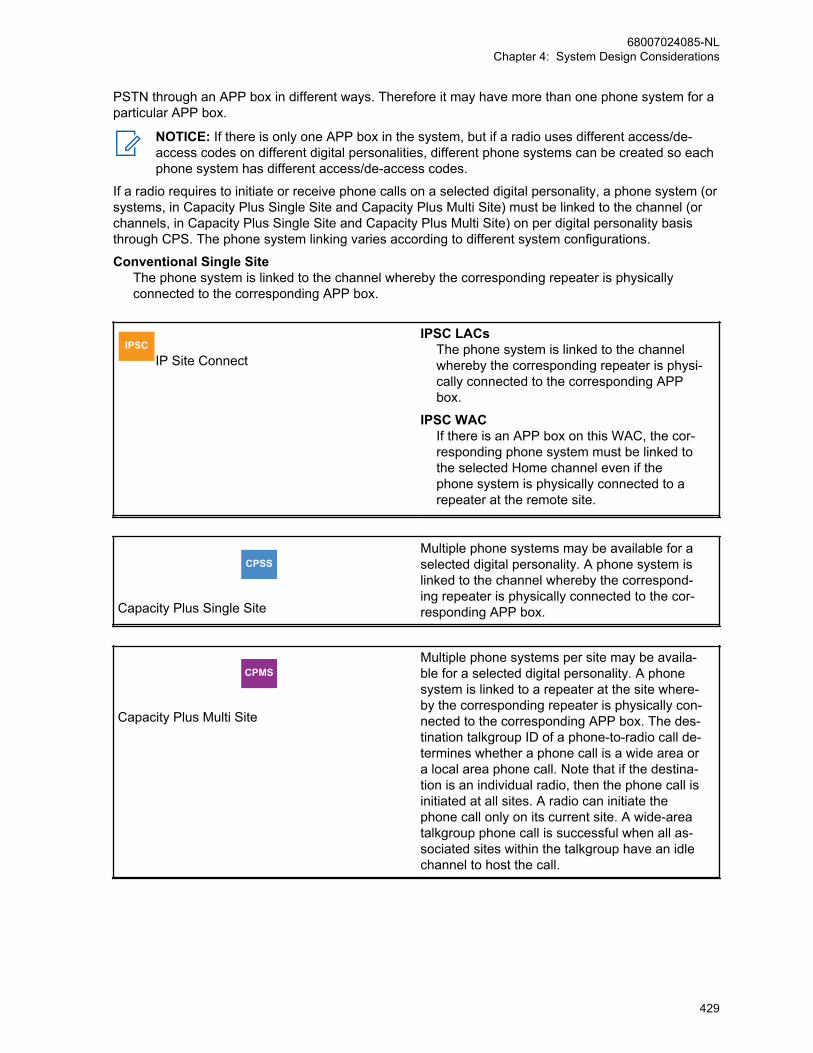
PSTN through an APP box in different ways. Therefore it may have more than one phone system for aparticular APP box.
NOTICE: If there is only one APP box in the system, but if a radio uses different access/de-access codes on different digital personalities, different phone systems can be created so eachphone system has different access/de-access codes.
If a radio requires to initiate or receive phone calls on a selected digital personality, a phone system (orsystems, in Capacity Plus Single Site and Capacity Plus Multi Site) must be linked to the channel (orchannels, in Capacity Plus Single Site and Capacity Plus Multi Site) on per digital personality basisthrough CPS. The phone system linking varies according to different system configurations.
Conventional Single SiteThe phone system is linked to the channel whereby the corresponding repeater is physicallyconnected to the corresponding APP box.
IPSCIP Site Connect
IPSC LACsThe phone system is linked to the channelwhereby the corresponding repeater is physi-cally connected to the corresponding APPbox.
IPSC WACIf there is an APP box on this WAC, the cor-responding phone system must be linked tothe selected Home channel even if thephone system is physically connected to arepeater at the remote site.
CPSS
Capacity Plus Single Site
Multiple phone systems may be available for aselected digital personality. A phone system islinked to the channel whereby the correspond-ing repeater is physically connected to the cor-responding APP box.
CPMS
Capacity Plus Multi Site
Multiple phone systems per site may be availa-ble for a selected digital personality. A phonesystem is linked to a repeater at the site where-by the corresponding repeater is physically con-nected to the corresponding APP box. The des-tination talkgroup ID of a phone-to-radio call de-termines whether a phone call is a wide area ora local area phone call. Note that if the destina-tion is an individual radio, then the phone call isinitiated at all sites. A radio can initiate thephone call only on its current site. A wide-areatalkgroup phone call is successful when all as-sociated sites within the talkgroup have an idlechannel to host the call.
68007024085-NLChapter 4: System Design Considerations
429

4.13.6.2Repeater Configuration in a Phone SystemFor a repeater, there is one and only one repeater-wide phone system. The user is allowed toconfigure the phone system but not allowed to create additional ones. Additionally, only the phonesystem in a phone gateway repeater needs to be configured.
4.13.7Access/De-access Code ConfigurationAccess and de-access codes are encapsulated in the phone system. Depending on the customerrequirements and the type of APP box installed in the system, access/de-access codes may beoptionally required to initiate/end phone calls. Different sets of access/de-access codes can be usedfor initiating/ending different types of calls (for example, long distance call, international call, etc). Thecodes are normally configured and supported in pairs in the APP box; if a particular access code isused to start the call, the corresponding paired de-access code must be used to end the call.
Additionally, administrator access/de-access codes may be used. The administrator codes have thehighest priority, and can be used whenever access/de-access code is required. For example, theadministrator de-access code can be used to end a phone call, regardless which access code wasused to initiate the call.
A system may have more than one APP box installed, and these boxes may be used to simply expandthe number of phone channels, or for different purposes. For example, one APP box may be used forinternational calls, while the other boxes to expand the number of channels. The access/de-accesscodes in these APP boxes may be configured similarly, or different depending on how phone privilegesare assigned among the radios users. The configuration also depends on whether the codes are to beentered by the radio users, or configured in the radios.
4.13.7.1Repeater ConfigurationIf a repeater is not used as a phone gateway repeater, there is no access/de-access codeconfiguration for the repeater.
However, if the repeater is used as a phone gateway repeater, a de-access code must be configured inthe repeater. This is mandatory even if the multi-digit release code part of the de-access code is notrequired; the normal release command part of the de-access code must be provisioned. The repeaterneeds the de-access code to end the phone call when the phone call needs to be ended by the radiosystem automatically, especially during an Emergency Alarm interrupt. Since the repeater can onlyhold one de-access code, this code configured in the repeater must be able to end any phone callsupported by the APP box that is connected to the repeater. If the APP box supports administratoraccess/de-access codes, multiple sets of codes can be used in the system, and the administrator de-access code needs to be programmed in the repeater. However, if the APP box does not supportadministrator access/de-access codes, only one de-access code can be used for this connected APPbox and the same de-access code must be programmed in the repeater.
NOTICE: The APP box can still use different sets of access/de-access codes, but the de-access codes must be the same.
Otherwise, the repeater may not be able to send the appropriate de-access code to end the call whenan Emergency is detected during a phone call.
Since a repeater only interacts with a connected APP box, the repeater configuration does not impacthow the access/de-access codes are configured in other APP boxes in the system.
68007024085-NLChapter 4: System Design Considerations
430
4.13.7.2Radio ConfigurationIf access/de-access codes are not required for phone calls, there is no related access/de-access codeconfiguration in the radio.
However, if required, the system can be programmed to have the codes stored in the radio and sentout automatically, or through some simple user interaction like pushing a button. Alternatively, thesystem can be programmed for the radio user to enter and send out the access/de-access codesmanually when needed.
When the codes are configured in the radio through CPS, the radio uses the code programmed for theforeseen channel automatically, before initiating or ending a phone call on that particular channel. Thisprocess is transparent to the user. Hence, there is no restriction on the usage of multiple sets ofaccess/de-access codes for a particular APP box, or whether different APP boxes in the system canuse different sets of access/de-access codes.
When the access/de-access codes are not programmed in the radio, the code configuration in the APPbox is different depending on the system configurations.
4.13.7.2.1Single Site or IPSC Systems
IPSC When a phone call is started, the radio user needs to select which channel to make the phone
call. Therefore, the radio user knows which channel and which APP box the phone call is occurring on,hence which access/de-access code to use. In these system configurations, multiple sets ofaccess/de-access codes can be used and the codes may differ in different APP boxes in the system.
4.13.7.2.2Capacity Plus Single Site and Capacity Plus Multi Site Systems
CPMS Because the phone channel is selected by the system automatically, the radio user does not
know the channel information when entering the access/de-access code. Therefore, multiple sets ofcodes can be used in a Capacity Plus Single Site system, but they must be the same in all the APPboxes if the codes need to be entered manually by the radio user.
4.13.8Dual Tone Multi Frequency (DTMF) ConfigurationDuring a phone call, the phone numbers are generated and go through the system in the form of DTMFtones. These DTMF tones interact with components that are not part of the MOTOTRBO system. Forexample, APP, PBX, PSTN, and others. Hence, the generated DTMF tones must be compliant with thelocal DTMF generating/receiving standards in order for these components to receive and understandthe DTMF tones generated from the MOTOTRBO system. The following DTMF parameters areconfigurable both in the radio and repeater via CPS:
• DTMF Tone Duration
• DTMF Inter-Tone Delay
NOTICE: DTMF Tone Level is a codeplug value, but not CPS configurable because it normallydoes not require change. DTMF Twist is not configurable and is always set to zero.
68007024085-NLChapter 4: System Design Considerations
431

4.13.9Ringing ModesWhen a radio user calls a phone user, the phone keeps ringing until the phone user answers. Or, theradio user ends the call, or the call gets timed out by the PSTN.
When a phone user calls a radio user, there is only one ringing mode. The radio continues to ring untilthe radio user answers the call, or the call gets timed out by the repeater.
When a phone user calls a radio group (talkgroup), there are two ringing modes. These modes areconfigurable in the repeater through CPS. The first method is where the radio keeps ringing until one ofthe targeted radio users answers the call by pushing PTT and talking back. Or, the call gets timed outby the repeater. The second ringing mode is to allow the phone user to talk immediately after the firstring. The second method allows phone users to talk first during a phone call.
4.13.10Enable/Disable Manual DialManual dial allows a radio user to enter the phone number manually using the radio keypad. Toprevent misuse of the phone services in the system, this manual dialing option can be enabled/disabled through CPS on a radio wide basis.
4.13.11Connecting APP Boxes to the Repeater in Capacity Plus Single Siteand Capacity Plus Multi Site
CPSM
In Capacity Plus Single Site, only the voice channel repeaters can be connected to the APP boxes tosupport phone calls. When connecting the APP boxes to the repeaters, it is highly recommended toconnect the APP boxes to the repeaters with lowest possible rest channel priorities first. This balancesthe traffic on the channels. In such a configuration, the non-phone calls are likely to occur on therepeaters with higher rest channel priorities, while phone calls occur on the repeaters with the lowestrest channel priorities.
4.13.12PBX Routing Configuration in Capacity Plus Single Site
CPSS PBX can be used with the DTP systems. However, if a repeater is disabled, the repeater does
not inform the PBX that it is disabled. In this scenario, the administrator needs to take action to ensurethat the PBX does not route the incoming call from the PSTN to the disabled repeater. Otherwise, thephone user is not able to connect to the radio users.
PBX may have different priorities when PBX assigns the extension lines for incoming calls from thePSTN. In Capacity Plus Single Site, the traffic on a channel with higher rest channel priority is normallyheavier than the channel with lower rest channel priority. Therefore, if the system has two or more APPboxes, it is recommended to have the PBX route the incoming phone call first to the APP boxes thatare connected to repeaters with lower rest channel priorities. As a result, this balances the voice trafficon all channels.
68007024085-NLChapter 4: System Design Considerations
432
4.14Transmit Interrupt System Design ConsiderationsTransmit Interrupt is a very powerful feature; it is capable of remotely dekeying a radio that istransmitting interruptible voice. Hence, limiting access to these features only to responsible and well-trained radio users is important.
If a radio operates on a channel that supports Direct Mode Transmit Interrupt features, then the “TXInterrupt Direct Mode Compatibility” CPS field should be enabled. This is necessary to minimizepotential collisions on the channel during a Direct Mode interruptible voice transmission. This field mustbe enabled in the CPS; both for Direct Mode channels where interruptible voice transmissions may bepresent, and Repeater Mode channels where interruptible voice transmissions may be made by someradios in Talkaround Mode. However, it is not necessary to enable this field for Repeater Modechannels where Talkaround mode is not supported by any radio.
4.14.1Interruptible RadiosThe first consideration associated to the Transmit Interrupt features is determining which radios’ voicetransmissions should be interruptible. For consistent behavior, the recommendation is that all radiosoperating on a channel should use interruptible voice transmission. However, it is desirable in someapplications, to provide a small number of radios (for example, normally supervisor radios) that are notinterruptible.
This sets up a system where supervisors have the ability to interrupt non-supervisor’s interruptiblevoice transmissions, but non-supervisors cannot interrupt supervisor’s voice transmissions, becausethe supervisor radios do not transmit interruptible voice. When the system is configured as such, boththe supervisor and non-supervisor radios may succeed at interrupting when a non-supervisor istransmitting interruptible voice, and fails at interrupting when a supervisor is transmitting uninterruptiblevoice. This situation may be perceived by some users as an inconsistent experience. If the system isset up in this manner, the users should be given training on the usage of Transmit Interrupt to betterunderstand the difference in experience.
4.14.2Voice InterruptDuring an interruptible voice transmission, a transmitting radio periodically checks its receive frequencyand determines whether another radio is requesting an interrupt. Therefore, interrupting radios musttransmit their interrupt signaling when the transmitting radio is checking its receive frequency. Whenonly one radio within a group is capable of Voice Interrupt (for example, a supervisor radio), then thatradio uses one of the periodic signaling intervals to signal an interrupt request, if an interrupt isrequested by the radio user.
When two radios are capable of Voice Interrupt (for example, two supervisor radios), it is possible thatboth radio users request a Voice Interrupt at nearly the same time (for example, during the timebetween two periodic signaling intervals). If this happens, it is likely that the interrupt procedure fails forboth radios, due to a signaling collision that occurs during the periodic signaling interval and neither ofthe radios succeed at obtaining a clear channel on which to transmit.
Extending this discussion to beyond two radios (for example, additional group members configuredwith Voice Interrupt capability), it becomes even more likely that more than one radio user requests aVoice Interrupt at nearly the same time, resulting in a signaling collision and a failed interruptprocedure. The likelihood of more than one radio user requesting a Voice Interrupt at nearly the sametime is difficult to predict or estimate, because this depends heavily on the usage characteristic profileof a particular system, operating procedures implemented by the system administrators, and thetraining provided to the radio users.
68007024085-NLChapter 4: System Design Considerations
433
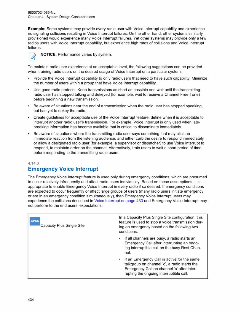
Example: Some systems may provide every radio user with Voice Interrupt capability and experienceno signaling collisions resulting in Voice Interrupt failures. On the other hand, other systems similarlyprovisioned would experience many Voice Interrupt failures. Yet other systems may provide only a fewradios users with Voice Interrupt capability, but experience high rates of collisions and Voice Interruptfailures.
NOTICE: Performance varies by system.
To maintain radio user experience at an acceptable level, the following suggestions can be providedwhen training radio users on the desired usage of Voice Interrupt on a particular system:
• Provide the Voice Interrupt capability to only radio users that need to have such capability. Minimizethe number of users within a group that have Voice Interrupt capability.
• Use good radio protocol. Keep transmissions as short as possible and wait until the transmittingradio user has stopped talking and dekeyed (for example, wait to receive a Channel Free Tone)before beginning a new transmission.
• Be aware of situations near the end of a transmission when the radio user has stopped speaking,but has yet to dekey the radio.
• Create guidelines for acceptable use of the Voice Interrupt feature; define when it is acceptable tointerrupt another radio user’s transmission. For example, Voice Interrupt is only used when late-breaking information has become available that is critical to disseminate immediately.
• Be aware of situations where the transmitting radio user says something that may elicit animmediate reaction from the listening audience, and either curb the desire to respond immediatelyor allow a designated radio user (for example, a supervisor or dispatcher) to use Voice Interrupt torespond, to maintain order on the channel. Alternatively, train users to wait a short period of timebefore responding to the transmitting radio users.
4.14.3Emergency Voice InterruptThe Emergency Voice Interrupt feature is used only during emergency conditions, which are presumedto occur relatively infrequently and affect radio users individually. Based on these assumptions, it isappropriate to enable Emergency Voice Interrupt in every radio if so desired. If emergency conditionsare expected to occur frequently or affect large groups of users (many radio users initiate emergencyor are in an emergency condition simultaneously), then Emergency Voice Interrupt users mayexperience the collisions described in Voice Interrupt on page 433 and Emergency Voice Interrupt maynot perform to the end users’ expectations.
CPSSCapacity Plus Single Site
In a Capacity Plus Single Site configuration, thisfeature is used to stop a voice transmission dur-ing an emergency based on the following twoconditions:
• If all channels are busy, a radio starts anEmergency Call after interrupting an ongo-ing interruptible call on the busy Rest Chan-nel.
• If an Emergency Call is active for the sametalkgroup on channel ‘c’, a radio starts theEmergency Call on channel ‘c’ after inter-rupting the ongoing interruptible call.
68007024085-NLChapter 4: System Design Considerations
434
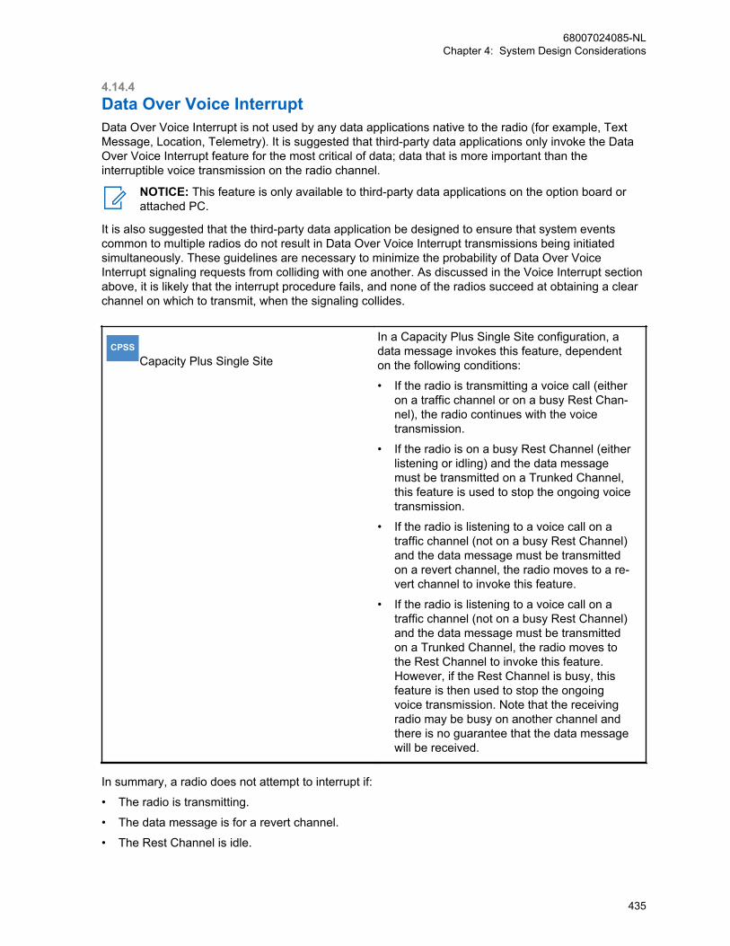
4.14.4Data Over Voice InterruptData Over Voice Interrupt is not used by any data applications native to the radio (for example, TextMessage, Location, Telemetry). It is suggested that third-party data applications only invoke the DataOver Voice Interrupt feature for the most critical of data; data that is more important than theinterruptible voice transmission on the radio channel.
NOTICE: This feature is only available to third-party data applications on the option board orattached PC.
It is also suggested that the third-party data application be designed to ensure that system eventscommon to multiple radios do not result in Data Over Voice Interrupt transmissions being initiatedsimultaneously. These guidelines are necessary to minimize the probability of Data Over VoiceInterrupt signaling requests from colliding with one another. As discussed in the Voice Interrupt sectionabove, it is likely that the interrupt procedure fails, and none of the radios succeed at obtaining a clearchannel on which to transmit, when the signaling collides.
CPSSCapacity Plus Single Site
In a Capacity Plus Single Site configuration, adata message invokes this feature, dependenton the following conditions:
• If the radio is transmitting a voice call (eitheron a traffic channel or on a busy Rest Chan-nel), the radio continues with the voicetransmission.
• If the radio is on a busy Rest Channel (eitherlistening or idling) and the data messagemust be transmitted on a Trunked Channel,this feature is used to stop the ongoing voicetransmission.
• If the radio is listening to a voice call on atraffic channel (not on a busy Rest Channel)and the data message must be transmittedon a revert channel, the radio moves to a re-vert channel to invoke this feature.
• If the radio is listening to a voice call on atraffic channel (not on a busy Rest Channel)and the data message must be transmittedon a Trunked Channel, the radio moves tothe Rest Channel to invoke this feature.However, if the Rest Channel is busy, thisfeature is then used to stop the ongoingvoice transmission. Note that the receivingradio may be busy on another channel andthere is no guarantee that the data messagewill be received.
In summary, a radio does not attempt to interrupt if:
• The radio is transmitting.
• The data message is for a revert channel.
• The Rest Channel is idle.
68007024085-NLChapter 4: System Design Considerations
435
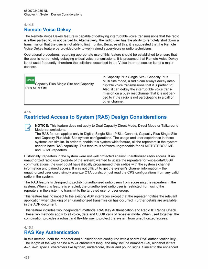
4.14.5Remote Voice DekeyThe Remote Voice Dekey feature is capable of dekeying interruptible voice transmissions that the radiois either partied to, or not partied to. Alternatively, the radio user has the ability to remotely shut down atransmission that the user is not able to first monitor. Because of this, it is suggested that the RemoteVoice Dekey feature be provided only to well-trained supervisors or radio technicians.
Operational procedures regarding appropriate use of this feature should be established to ensure thatthe user is not remotely dekeying critical voice transmissions. It is presumed that Remote Voice Dekeyis not used frequently, therefore the collisions described in the Voice Interrupt section is not a majorconcern.
CPSMCapacity Plus Single Site and Capacity
Plus Multi Site
In Capacity Plus Single Site / Capacity PlusMulti Site mode, a radio can always dekey inter-ruptible voice transmissions that it is partied to;Also, it can dekey the interruptible voice trans-mission on a busy rest channel that it is not par-tied to if the radio is not participating in a call onother channel.
4.15Restricted Access to System (RAS) Design Considerations
NOTICE: This feature does not apply to Dual Capacity Direct Mode, Direct Mode or TalkaroundMode transmissions.The RAS feature applies only to Digital, Single Site, IP Site Connect, Capacity Plus Single Siteand Capacity Plus Multi Site system configurations. The usage and user experience in thesesystems are similar. In order to enable this system wide feature, all the repeaters in the systemneed to have RAS capability. This feature is software upgradeable for all MOTOTRBO 8 MBand 32 MB repeaters.
Historically, repeaters in the system were not well protected against unauthorized radio access. If anunauthorized radio user (outside of the system) wanted to utilize the repeaters for voice/data/CSBKcommunications, the user could have illegally programmed their radios with the system’s channelinformation and gained access. It was not difficult to get the system’s channel information – theunauthorized user could simply analyze OTA bursts, or just read the CPS configurations from any validradio in the system.
The RAS feature is designed to prohibit unauthorized radio users from accessing the repeaters in thesystem. When this feature is enabled, the unauthorized radio user is restricted from using therepeaters in the system to transmit to the targeted user or user group.
This feature has no impact to the existing ADP interfaces except that the repeater notifies the relevantapplication when blocking of an unauthorized transmission has occurred. Further details are availablein the ADP document.
This feature includes two independent methods: RAS Key Authentication and Radio ID Range Check.These two methods apply to all voice, data and CSBK calls of repeater mode. When used together, thecombination provides a robust and flexible way to protect the system from unauthorized access.
4.15.1RAS Key AuthenticationIn this method, both the repeater and subscriber are configured with a secret RAS authentication key.The length of the key can be 6 to 24 characters long, and may include numbers 0–9, alphabet lettersA–Z, a–z, special characters like hyphen, underscore, dollar and pound signs. Similar to the enhanced
68007024085-NLChapter 4: System Design Considerations
436

privacy keys, the RAS authentication key cannot be read out through CPS or cloned from one deviceto another device once configured and written into the radio or repeater.
Therefore, an unauthorized user cannot see the key, nor clone more radios by simply obtaining a radioprogrammed with the valid key. Additionally, similar to the enhanced privacy keys, when configuring aRAS enabled radio, the user needs to remember and retype the key when writing back to the radiothrough CPS.
A subscriber uses its configured authentication key to encode the OTA bursts and generate a RASenabled transmission. Upon receiving the bursts, the repeater also uses its configured authenticationkey to decode the bursts. If the authentication keys in the subscriber and repeater are the same, therepeater is able to decode the bursts correctly and repeat the bursts. However, if the radio does nothave a RAS authentication key or its key does not match the one that is configured in the repeater, thedecoding process in the repeater fails and the transmission is blocked at the repeater. Therefore, thecall bursts from the unauthorized subscriber are not repeated and cannot reach the targeted user oruser group.
Each system only needs one RAS authentication key, all the repeaters in a system are provisionedwith only one key. To simplify the key configuration in a multi-repeater systems, the key only needs tobe configured in the master repeater. Subsequently, the key is propagated to all the other peerrepeaters automatically. The repeater, and eventually the system may be configured in only one of thethree RAS modes:
• RAS Disabled: When the repeaters are configured in RAS disabled mode, the RAS keyauthentication method is not used. Hence the system supports calls from RAS disabled subscribersand legacy subscribers, including third-party compatible subscribers, but not RAS enabledsubscribers.
• RAS Enabled: When the repeaters are configured in RAS enabled mode, only RAS enabledsubscribers with valid keys are supported and can successfully make calls through the repeater.
NOTICE: The system must not be configured in RAS enabled mode until all the repeatersand subscribers have been upgraded to have RAS capability. Otherwise, the repeaters orsubscribers that are not RAS capable will not be able to operate normally in the system.
• RAS Migration: When the repeaters are configured in the RAS migration mode, the repeateraccepts both DMR transmission and RAS enabled transmission in the repeater inbound. If theinbound is DMR transmission, the repeater repeats it out as is. If the inbound is RAS enabledtransmission, the repeater converts it to DMR transmission and repeats it out. Therefore, in the RASmigration mode, the system supports all subscribers including RAS disabled, RAS enabled with thevalid RAS key and legacy subscribers. The RAS migration mode is recommended when installing anew system, migrating a legacy system to RAS enabled mode, or in any cases where the systemneeds to support both legacy and RAS enabled subscribers.Example: When migrating a legacy system, the administrator may first provision the key to all therepeaters and let the system to operate in the RAS migration mode. Next, the administrator coulduse the CPS or OTAP to provision the key to all the subscribers in the system. Since the systemoperates in RAS migration mode, both the legacy subscribers and the RAS enabled subscriberswith the valid key can operate in the system normally and make successful calls through therepeater. After all the subscribers are provisioned with the key, the administrator can change thesystem to operate in RAS enabled mode to prevent any unauthorized subscribers from accessingthe system. Therefore, the RAS migration mode provides smooth system installation and migrationwithout interrupting the services.
However, a subscriber can be configured only in two RAS modes:
• RAS Enabled, or
• RAS Disabled.
When the subscriber is RAS disabled, it is not able to transmit or receive RAS enabled transmission,hence operates only in a RAS disabled or RAS migration system. When the radio is RAS enabled, it
68007024085-NLChapter 4: System Design Considerations
437
always transmits the RAS enabled bursts, but receives both DMR bursts and RAS enabled bursts.Therefore, RAS enabled subscribers can operate in RAS migration or RAS enabled systems.
A radio may operate in different systems and these systems may have different RAS keys; up to 16keys may be provisioned and associated to different digital personalities. When a digital personality isnot associated with a key, the radio is considered as RAS disabled when this personality is selected.When the digital personality is associated with a key, the radio is considered as RAS enabled, anduses the particular key that is associated. In this way, if the radio needs to operate in a differentsystem, the radio user can select the appropriate personality with the corresponding key.
When a RAS enabled subscriber transmits in Dual Capacity Direct Mode, Direct Mode, or TalkaroundMode, it always transmits DMR bursts. However, when receiving, it can receive both DMR bursts (fromother subscribers) and RAS enabled bursts (from the repeater outbound).
4.15.2Radio ID Range CheckIn this method, only the repeater needs to be configured through CPS. Up to 64 radio ID ranges maybe provisioned in the repeaters. For a multi-repeater system, all the repeaters need to be softwarecapable of the RAS feature. However, the configuration can and only needs to be done in the masterrepeater, and is propagated to other peer repeaters automatically.
Each of the radio ID ranges may be configured as allowed or left as un-configured. When the repeaterreceives a transmission from a subscriber, it checks whether the subscriber’s radio ID is within any ofthe allowed ranges. If it is, the repeater repeats this transmission. Otherwise, the repeater blocks thetransmission. In this way, the transmission from unauthorized subscriber users can be blocked.
In comparison to the RAS key authentication method, this method is much easier to use to configureand maintain the system, because only the repeater needs to be configured. However, this method hasdrawbacks if used alone, since the unauthorized user may figure out some allowed radio ID ranges byreading a valid subscriber, or analyzing the bursts over-the-air, or simply just guessing. The user canthen easily program radios with radio IDs in the allowed ranges.
Additionally, the radio ID check method can only prevent the unauthorized radio from transmitting to itstarget, but can not prevent it from receiving while the RAS key authentication method can performboth. For this reason, it is always recommended to use both methods together. The RAS keyauthentication provides a very robust way to prevent unauthorized repeater access and is extremelydifficult to hack. It can be used as the primary method.
Moreover, radio ID range check provides a flexible way to manage the system and make minorchanges.
Example: If the system is hosting customers A, B, and C, the system administrator could provision thewhole system with a RAS key and operate in the RAS enabled mode. Secondly, the systemadministrator could create different radio ID ranges for these three customers. If for some reason, acustomer, for instance, customer B needs to be excluded from the system temporarily, theadministrator could uncheck the radio ID ranges that customer B’s radios fall into, and the systemaccess of the radios in the entire range will be blocked. When customer B needs to be allowed backinto the system, the administrator can simply mark these radio ID ranges as allowed.
4.16Data Sub-System Design ConsiderationsThe following sections describes various data sub-system configurations readers need to know beforedeciding how to best support the needs and usage of their customers. It continues to cover variousother considerations that may need to be addressed during the design phase. It explains the IPnetwork configurations, licensing considerations, server power management considerations, telemetryconnection details, and MOTOTRBO Network Interface Service (MNIS) and Device Discovery andMobility Service (DDMS), as a guideline for design.
68007024085-NLChapter 4: System Design Considerations
438
4.16.1Computer and IP Network ConfigurationsThe data applications in a MOTOTRBO system utilize IP/UDP communications, therefore it isnecessary to design the IP configuration of the data capable devices. Although complex, it is importantto understand how data traffic is routed from one radio to another in a MOTOTRBO system. Thissection details the different connects, and where they are used within a MOTOTRBO system.
4.16.1.1Radio to Mobile Client Network ConnectivityAs described in earlier chapters, the MOTOTRBO radio connects to a computer through USB. Onceconnected, the PC detects the connection, loads a driver, and establishes a new network interface.This network interface looks similar to a LAN or WLAN network interface to the PC. The radio acts likea DHCP server providing the PC with an IP, and setting its own IP as the default gateway.
The Radio IP address used for this connection is programmed into the MOTOTRBO radio in thenetwork settings of the CPS. The Accessory IP value is not editable in the CPS. It is derived based onthe Radio IP. The first 3 octets are the same as the radio IP, the last octet will be the Radio IP value +1(for example, if the Radio IP is 192.168.10.1, the Accessory IP is automatically updated to192.168.10.2).
• Accessory IP – provided via DHCP to the Network Interface on the PC
• Radio IP – used by the Radio to communicate with the PC– provided to the PC as the default gateway
These IP addresses are only used for communication between the MOTOTRBO radio and theconnected PC. It is recommended that the default values (Radio IP: 192.168.10.1, Accessory IP:192.168.10.2) be used in all mobile client configurations. In other configurations where multipleMOTOTRBO radios are connected to one PC, these values need to be different to prevent IP conflicts.
If the default IP address programmed in the radio, or the one provided to the PC conflicts with othernetwork interfaces on the PC, then the Radio IP should be changed using the CPS. The radio alsoallows for the default UDP ports for the ARS, Text Message and Telemetry applications to be changedif there exists conflict within the PC. These UDP ports are required to be updated in the applicationconfiguration as well. Again, it is recommended that the default values be used whenever possible.
For best results, it is recommended that mobile clients do not have additional network interfaces.Additional static routes may need to be manually entered in the mobile client PC if multiple interfacesare present. It is also recommended that any applications that attempt to broadcast network traffic bedisabled in the PC. Unnecessary traffic sent to the MOTOTRBO radio may cause undesiredcongestion over-the-air.
The following figure displays the IP connectivity between the Mobile Client and the MOTOTRBO radio.Note that because these IP addresses are private and only used between the radio and the MobileClient, it is recommended that they be duplicated on all Radio/Mobile Client configurations in thesystem.
68007024085-NLChapter 4: System Design Considerations
439

Figure 165: Connectivity between the Mobile Client and the MOTOTRBO Radio
192.168.10.1 192.168.10.2
MOTOTRBO RadioMobile Client on a PC
USB
Radio IP = 192.168.10.1Accessory IP = 192.168.10.2Radio IP Netmask = 255.255.255.0 Default Gateway = 192.168.10.1
4.16.1.2Radio to Air Interface Network ConnectivityThe MOTOTRBO radio must have an IP address to communicate with the MOTOTRBO network andother radios. The radio and the system uses the Individual Radio ID and CAI Network Address toconstruct its Radio Network IP to ensure uniqueness. The Individual Radio ID is found in the GeneralSettings section of the radio CPS, and the CAI Network Address is found in the Network Settingssection.
A Radio ID in MOTOTRBO is a 24-bit number that can range from 1 to 16776415, and is written indecimal format in the CPS.
CPSMCapacity Plus Single Site and Capacity
Plus Multi Site
In Capacity Plus Single Site and Capacity PlusMulti Site, the Radio ID is a 16-bit number (from1 to 65535), which can be treated as a 24-bitnumber where the most significant 8 bits arezero.For example, the Radio ID 16776415 is repre-sented by a hexadecimal 24 bit number asFFFCDF. When broken into three 8-bit sec-tions, this becomes FF, FC, and DF. This indecimal is 255, 252, and 223. Therefore, a ra-dio that is configured with an Individual ID of16776415 and a CAI Network address of 12(the default), will have a Radio Network IP ad-dress of 12.255.252.223. Below are a few moreexamples (all assuming the default CAI Net-work address of 12):
Unit ID = 00012045Convert to Hexadecimal = 002F0D
68007024085-NLChapter 4: System Design Considerations
440
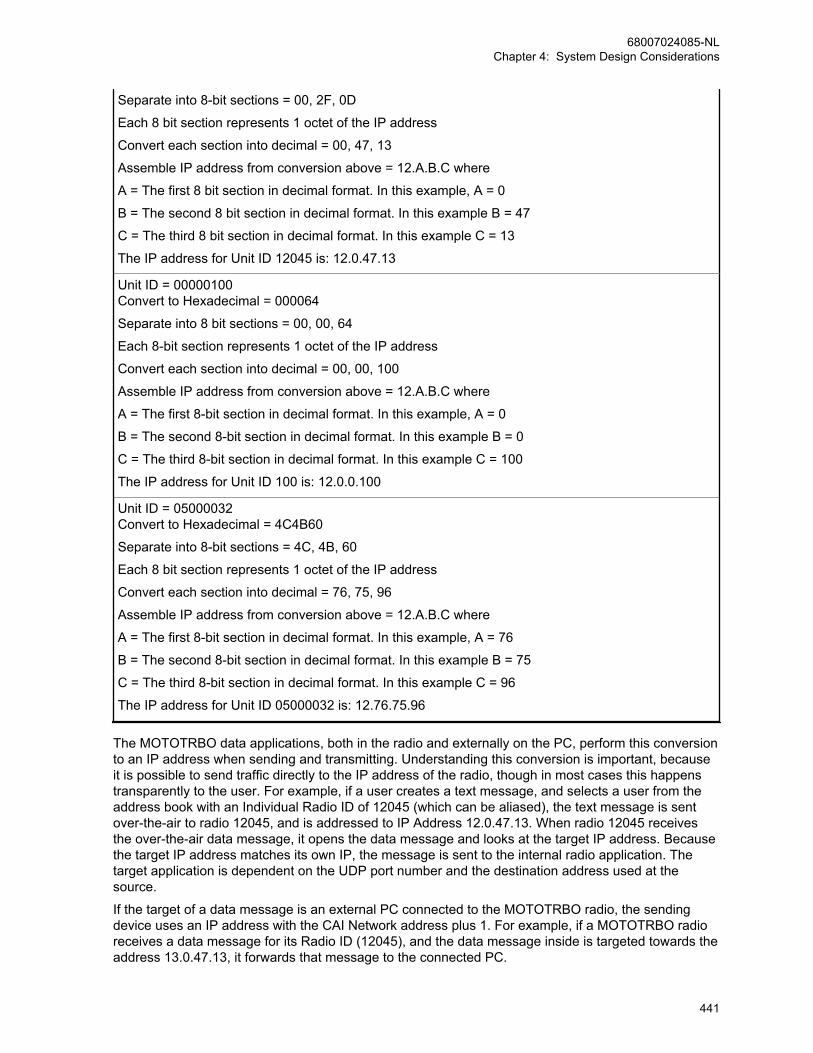
Separate into 8-bit sections = 00, 2F, 0D
Each 8 bit section represents 1 octet of the IP address
Convert each section into decimal = 00, 47, 13
Assemble IP address from conversion above = 12.A.B.C where
A = The first 8 bit section in decimal format. In this example, A = 0
B = The second 8 bit section in decimal format. In this example B = 47
C = The third 8 bit section in decimal format. In this example C = 13
The IP address for Unit ID 12045 is: 12.0.47.13
Unit ID = 00000100Convert to Hexadecimal = 000064
Separate into 8 bit sections = 00, 00, 64
Each 8-bit section represents 1 octet of the IP address
Convert each section into decimal = 00, 00, 100
Assemble IP address from conversion above = 12.A.B.C where
A = The first 8-bit section in decimal format. In this example, A = 0
B = The second 8-bit section in decimal format. In this example B = 0
C = The third 8-bit section in decimal format. In this example C = 100
The IP address for Unit ID 100 is: 12.0.0.100
Unit ID = 05000032Convert to Hexadecimal = 4C4B60
Separate into 8-bit sections = 4C, 4B, 60
Each 8 bit section represents 1 octet of the IP address
Convert each section into decimal = 76, 75, 96
Assemble IP address from conversion above = 12.A.B.C where
A = The first 8-bit section in decimal format. In this example, A = 76
B = The second 8-bit section in decimal format. In this example B = 75
C = The third 8-bit section in decimal format. In this example C = 96
The IP address for Unit ID 05000032 is: 12.76.75.96
The MOTOTRBO data applications, both in the radio and externally on the PC, perform this conversionto an IP address when sending and transmitting. Understanding this conversion is important, becauseit is possible to send traffic directly to the IP address of the radio, though in most cases this happenstransparently to the user. For example, if a user creates a text message, and selects a user from theaddress book with an Individual Radio ID of 12045 (which can be aliased), the text message is sentover-the-air to radio 12045, and is addressed to IP Address 12.0.47.13. When radio 12045 receivesthe over-the-air data message, it opens the data message and looks at the target IP address. Becausethe target IP address matches its own IP, the message is sent to the internal radio application. Thetarget application is dependent on the UDP port number and the destination address used at thesource.
If the target of a data message is an external PC connected to the MOTOTRBO radio, the sendingdevice uses an IP address with the CAI Network address plus 1. For example, if a MOTOTRBO radioreceives a data message for its Radio ID (12045), and the data message inside is targeted towards theaddress 13.0.47.13, it forwards that message to the connected PC.
68007024085-NLChapter 4: System Design Considerations
441
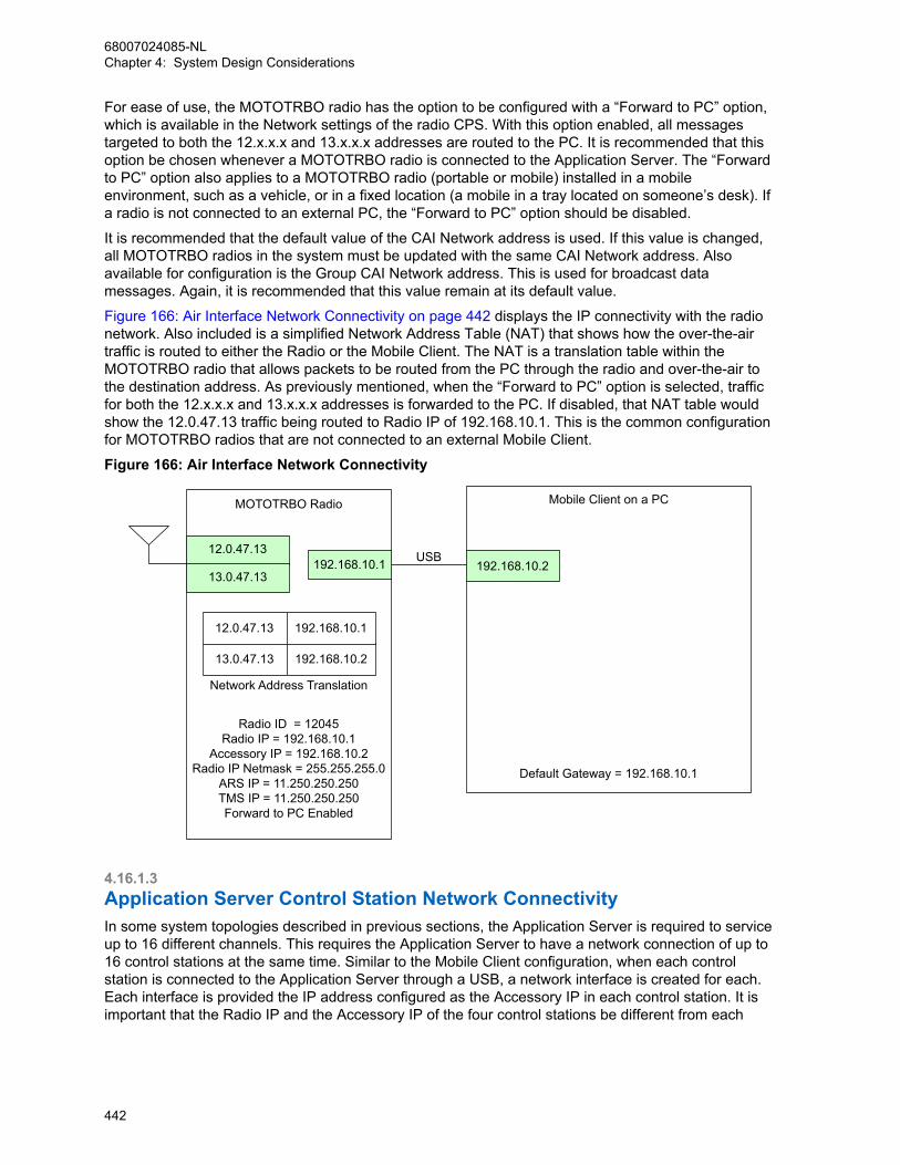
For ease of use, the MOTOTRBO radio has the option to be configured with a “Forward to PC” option,which is available in the Network settings of the radio CPS. With this option enabled, all messagestargeted to both the 12.x.x.x and 13.x.x.x addresses are routed to the PC. It is recommended that thisoption be chosen whenever a MOTOTRBO radio is connected to the Application Server. The “Forwardto PC” option also applies to a MOTOTRBO radio (portable or mobile) installed in a mobileenvironment, such as a vehicle, or in a fixed location (a mobile in a tray located on someone’s desk). Ifa radio is not connected to an external PC, the “Forward to PC” option should be disabled.
It is recommended that the default value of the CAI Network address is used. If this value is changed,all MOTOTRBO radios in the system must be updated with the same CAI Network address. Alsoavailable for configuration is the Group CAI Network address. This is used for broadcast datamessages. Again, it is recommended that this value remain at its default value.
Figure 166: Air Interface Network Connectivity on page 442 displays the IP connectivity with the radionetwork. Also included is a simplified Network Address Table (NAT) that shows how the over-the-airtraffic is routed to either the Radio or the Mobile Client. The NAT is a translation table within theMOTOTRBO radio that allows packets to be routed from the PC through the radio and over-the-air tothe destination address. As previously mentioned, when the “Forward to PC” option is selected, trafficfor both the 12.x.x.x and 13.x.x.x addresses is forwarded to the PC. If disabled, that NAT table wouldshow the 12.0.47.13 traffic being routed to Radio IP of 192.168.10.1. This is the common configurationfor MOTOTRBO radios that are not connected to an external Mobile Client.
Figure 166: Air Interface Network Connectivity
192.168.10.1
Radio ID = 12045Radio IP = 192.168.10.1
Accessory IP = 192.168.10.2Radio IP Netmask = 255.255.255.0
ARS IP = 11.250.250.250TMS IP = 11.250.250.250Forward to PC Enabled
12.0.47.13192.168.10.2
MOTOTRBO Radio Mobile Client on a PC
USB13.0.47.13
Default Gateway = 192.168.10.1
13.0.47.13 192.168.10.2
12.0.47.13 192.168.10.1
Network Address Translation
4.16.1.3Application Server Control Station Network ConnectivityIn some system topologies described in previous sections, the Application Server is required to serviceup to 16 different channels. This requires the Application Server to have a network connection of up to16 control stations at the same time. Similar to the Mobile Client configuration, when each controlstation is connected to the Application Server through a USB, a network interface is created for each.Each interface is provided the IP address configured as the Accessory IP in each control station. It isimportant that the Radio IP and the Accessory IP of the four control stations be different from each
68007024085-NLChapter 4: System Design Considerations
442
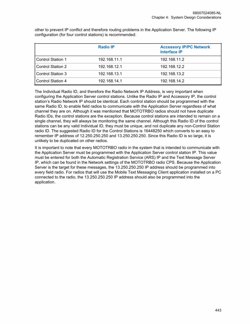
other to prevent IP conflict and therefore routing problems in the Application Server. The following IPconfiguration (for four control stations) is recommended:
Radio IP Accessory IP/PC NetworkInterface IP
Control Station 1 192.168.11.1 192.168.11.2
Control Station 2 192.168.12.1 192.168.12.2
Control Station 3 192.168.13.1 192.168.13.2
Control Station 4 192.168.14.1 192.168.14.2
The Individual Radio ID, and therefore the Radio Network IP Address, is very important whenconfiguring the Application Server control stations. Unlike the Radio IP and Accessory IP, the controlstation’s Radio Network IP should be identical. Each control station should be programmed with thesame Radio ID, to enable field radios to communicate with the Application Server regardless of whatchannel they are on. Although it was mentioned that MOTOTRBO radios should not have duplicateRadio IDs, the control stations are the exception. Because control stations are intended to remain on asingle channel, they will always be monitoring the same channel. Although this Radio ID of the controlstations can be any valid Individual ID, they must be unique, and not duplicate any non-Control Stationradio ID. The suggested Radio ID for the Control Stations is 16448250 which converts to an easy toremember IP address of 12.250.250.250 and 13.250.250.250. Since this Radio ID is so large, it isunlikely to be duplicated on other radios.
It is important to note that every MOTOTRBO radio in the system that is intended to communicate withthe Application Server must be programmed with the Application Server control station IP. This valuemust be entered for both the Automatic Registration Service (ARS) IP and the Text Message ServerIP, which can be found in the Network settings of the MOTOTRBO radio CPS. Because the ApplicationServer is the target for these messages, the 13.250.250.250 IP address should be programmed intoevery field radio. For radios that will use the Mobile Text Messaging Client application installed on a PCconnected to the radio, the 13.250.250.250 IP address should also be programmed into theapplication.
68007024085-NLChapter 4: System Design Considerations
443

Figure 167: Application Server Control Station Network Connectivity
192.168.11.2
Application Server
USB
USB192.168.12.2
192.168.11.1
Control Station
CH113.250.250.250
12.250.250.250
192.168.12.1
Control Station
CH213.250.250.250
12.250.250.250
Radio ID = 16448250Radio IP = 192.168.11.1
Accessory IP = 192.168.11.2Radio IP Netmask = 255.255.255.0
Forward to PC Enabled
Radio ID = 16448250Radio IP = 192.168.12.1
Accessory IP = 192.168.12.2Radio IP Netmask = 255.255.255.0
Forward to PC Enabled
192.168.11.2
192.168.11.1
13.250.250.250
12.250.250.250
192.168.12.2
Network Address Translation
Network Address Translation
192.168.12.1
13.250.250.250
12.250.250.250
*1644825010= FAFAFA16= 250.250.250
As previously discussed, the control stations should be configured with the option to “Forward to PC”so that all data traffic the control station receives is forwarded to the Application Server.
4.16.1.4Control Station ConsiderationsBecause the control stations connected to the Application Server act as the data gateway for thesystem, the control stations themselves do not require an Automatic Registration Service (ARS) IP andthe Text Message Server IP to be specified in their CPS Network settings. These fields should be leftblank. In addition, the control stations should also have the ARS and GPS options disabled. Thesesettings are not required for these control stations since they will be not be transmitting their own GPSor ARS anywhere. There is no need for these control stations to be ordered with GPS capability.
Although it is possible to use the control stations connected to the Application Server for voice, it ishighly recommended that they only act as data gateways. Since control stations (except for Trunked
68007024085-NLChapter 4: System Design Considerations
444

Control Stations) must remain on a single channel in order to receive the inbound data, it isrecommended that they only contain one channel in their channel list. The Trunked Control Stationsmust have a list of all Trunked Channels. Control stations should not have scan enabled. Thisguarantees that the Application Server is always monitoring the correct channel. Since the controlstations are only used for data, there is no need to program any receive or transmit Groups on thechannel. In other words, the Contact Name and the Group List can both be set to a value of None.Similarly, it is not necessary to provision any emergency settings either.
It is important to set the TX Preamble duration of the control station to be the same as the other radiosin the system. Since most data is targeted towards these control stations, the proper preamble must beutilized. Use the same guidelines for setting this duration in the control stations as was used in thefielded radios.
The admit criteria of the control station should match the settings which the other radios on the channelare provisioned for. The suggested setting is Color Code Free unless there are signals on the channelthat the data needs to avoid. If there are signals on the channel that the data needs to avoid, thenchoose Channel Free instead.
When considering other CPS options of the control station, it is a good rule of thumb to minimize thefeature options available. This guarantees that a user cannot accidentally place the control station in astate where it is not monitoring inbound data traffic.
In almost all scenarios, it is highly recommended that a mobile radio with an AC power adapter beutilized as the data gateway. Although a portable radio can temporarily be used for this purpose, it isnot recommended for long term installations. The primary reason why a mobile is recommended forthis purpose is its ability to remotely locate the RF antenna. This is important since computers and theircomponents are sometimes sensitive to RF power. Mobile antennas should be located away from theserver itself and isolated from each other. For example, if a server has four control stations connectedto it, it is recommended that the antennas be installed on the roof of the building and separated enoughfrom each other so that they do not interfere. This is also important since in-building coverage issometimes difficult to achieve. All inbound data messages pass through these control stations so it isimportant that they are within good RF coverage of the repeater. Additionally, a control station is leftpowered on all the time. A portable continuously powered on in a charger is more likely to encounterpower related failures.
In conventional systems, if a control station does power off or power cycles, host-specific routes areremoved from the Application Server's routing tables. In these situations, the Application Server toradio data increases the system load as it has to be transmitted by all connected control stations. Theactual load increase is based on the amount of Application Server to radio data. This load increasegradually dissipates as the radios re-register with the Presence Notifier and the host-specific routes areadded back into the routing table. However, it is recommended to connect control stations to anUninterrupted Power Supply (UPS) and are never powered off and on while radios are registered withthe Presence Notifier.
In trunked systems, if a Revert Control Station powers down, then the radio to the Application Serverdata increases the load on the rest of Revert Control Stations. When the failed Revert Control Stationspower on, the load is automatically distributed on all the Revert Control Stations. If a Trunked ControlStation powers down, then the Application Server is unable to send data to the radios allocated to thefailed Trunked Control Station. Therefore, it is recommended to connect Trunked Control Stations to anUninterrupted Power Supply (UPS) or to have redundant Trunked Control Stations.
During the registration process with the Presence Notifier, the radio is instructed to refresh itsregistration at a specific time interval. The default time interval is 4 hours, though this is a configurableparameter in the Presence Notifier. If the time interval is decreased, more registration messages aresent to keep the presence availability information fresh but the system load is increased. If this timeinterval is increased, the system load is decreased but the presence availability information maybecome stale.
In conventional systems, once a radio is registered with the Presence Notifier, the MCDD adds a routeto a routing table, so data messages from the Application Server to the radio are transmitted on the
68007024085-NLChapter 4: System Design Considerations
445

correct channel. However, if for some reason the host-specific route does not exist, then the GlobalRoute is used and the data message is transmitted from all control stations connected to theApplication Server. This scenario increases system loading during situations where there is ApplicationServer to radio data. An example of this would be network (Text Message Server) sourced textmessages targeted towards subscribers in the field.
4.16.1.5Multi-Channel Device Driver (MCDD) and Required Static RoutesIn conventional systems, the Application Server can have up to 16 different network interfaces thataccess the radio network.
In order for data messages targeted towards Radio Network IP addresses, such as 12.0.0.1 and12.0.47.13, to transmit out through a network interface with IP addresses 192.168.11.2 or192.168.12.2, the MCDD is required to add routes for each radio that registers with the PresenceNotifier. For example, when radio 12045 transmits a registration message to its programmed ARS IPaddress (for example, 12.0.47.13) on one of the channels monitored by a control station, the controlstation forwards that address to the Application Server through its network interface (for example,192.168.11.2). The MCDD then automatically adds a route for that radio IP (12.0.47.13 and13.0.47.13) to the 192.168.11.2 network interface. Once that is done, if a message from the ApplicationServer needs to reach 12.0.47.13 or 13.0.47.13, the message is routed to the 192.168.11.2 networkinterface, and therefore out the correct control station and correct channel that has registered radio12045. This is how data messages are sent out on the correct channel for a radio.
Additional steps are required to route multicast traffic. Multicast traffic is traffic destined for radiogroups. The routing table in the PC must be modified to allow for multicast traffic. Please see theMCDD install manual for details.
CPSSCapacity Plus Single Site
Installation of the MCDD is not required in Ca-pacity Plus Single Site.
4.16.1.6Application Server and Dispatcher Network ConnectivityAs described in previous sections, the Application Server can also be configured with a LANconnection to the Customer Enterprise Network (CEN). A few restrictions apply to the networkconfiguration between the Application Server and the Dispatch clients. In most customer cases, theLAN interface on the Application Server is connected to their pre-existing network. The onlyrequirement is that the assigned IP of the LAN network interface must not conflict with those assignedto the Network Interfaces of the Control Stations. Additionally, the Application Dispatchers (such asLocation Dispatch or Text Message Dispatch) must be connected through the customer CEN to theApplication Server. In order for the Text Message Server to forward e-mail text messages, theApplication Server must be connected to the Internet. If the network is configured to operate with afirewall, the programmed ports for the applications should be opened and allowed. Details of thisconfiguration can be found in the Text Message and Location Application install guides.
4.16.1.7MOTOTRBO Subject Line UsageA MOTOTRBO Text Message is comprised of three parts: A subject line, subject line delimiter andbody. The subject line delimiter is a carriage return (Unicode code point U+000D) and line feed(Unicode code point U+000A) character pair (CRLF). Therefore, anything up to the first CRLF withinthe Message is interpreted as the subject line and anything after the first CRLF is interpreted as thebody. The subject line is left blank if there are no characters before the first CRLF, or if no CRLF pairsare contained in the Message.
68007024085-NLChapter 4: System Design Considerations
446
When e-mail text messages are received by the Application Server the e-mail subject line and body areconverted into the MOTOTRBO Text Message subject line and body respectively.
The maximum length of a MOTOTRBO Text Message is technically 280 (140 for Matrix radio)characters according to the protocol. However, applications that support the use of Subject Lines mayreduce the number of the effective payload. The Customer Programming Software (CPS) and theapplications in the radios that create text messages limit the effective payload to 278 (138 for Matrixradio) characters. External applications that run on Personal Computers (PC) may further reduce theeffective payload to provide indications that messages have been truncated (for example replacing thelast character with a horizontal ellipse character '…'). E-mails that are longer than 278 (138 for Matrixcharacterizers) are truncated to fit. For example, if an e-mail is received with a 200 character subjectline and a 300 character body only the first 277 (137 for Matrix radio) characters of the subject line plusa horizontal ellipse '…' at the end is converted into the MOTOTRBO Text Message and the rest of thee-mail is discarded. In another example, if an e-mail is received with a 100 character subject line and a300 character body, then the 100 characters of the subject line and the first 177 (37 for Matrix radio)characters of the body with an ellipse added at the end is converted into the MOTOTRBO TextMessage format.
Radios replying to messages preserve the original message's subject line. In this manner, externalservices and solutions that use e-mail for communication can use the content of the subject line tocorrelate between e-mails that are sent and e-mails that are received. For example, an automatedservice could send out an e-mail with a unique ID string in the subject line. If a radio replies to themessage, it preserves the subject line with the unique ID string and the automated system can use theaddress and subject line of the message to know that a specific unit had replied to a specific message.
The number of characters allowed in a reply by a radio are equal to 278 (138 for Matrix radio)characters minus the number of characters in the subject line. For example, if an e-mail is sent with a30 character subject line and a 100 character body, the entire message is received by the radio. Whenthe radio replies to the message the subject line is automatically preserved leaving 248 (108 for Matrixradio) characters for the radio to reply with.
MOTOTRBO Text Messages that originate from the front panel of radios or the Text Messaging Clientthrough the Application Server and destined for e-mails addresses contains blank subject lines. Radiosdo not have the capability to create or modify a subject line from the front panel. The CPS does nothave the capability to create a subject line.
68007024085-NLChapter 4: System Design Considerations
447

4.16.1.8MOTOTRBO Example System IP PlanThe following diagram is an example of the information contained in the previous sections. Thisdiagram shows a configuration of multiple digital repeaters at a single site functioning in conventionalrepeater mode. It should be used as a guideline for configuring a MOTOTRBO System.
Figure 168: Example MOTOTRBO System IP Plan
192.168.0.2
192.168.11.2
Application Server
ApplicationDispatcher 2
Switch/Hub
192.168.0.4
ApplicationDispatcher 1
192.168.0.3
192.168.0.250
Router
32.1.1.0
192.168.0.200
USB
USB
USB
USB
192.168.12.2
192.168.13.2
192.168.14.2
Customer EnterpriseNetwork(CEN)
Radio Access Network(RAN)
Base Repeater
Base Repeater
DHCP Server
192.168.0.1
192.168.10.1
Radio ID = 12045Radio IP = 192.168.10.1Accessory IP = 192.168.10.2Radio IP Netmask = 255.255.255.0ARS IP = 13.250.250.250TMS IP = 13.250.250.250Forward to PC Enabled
Radio ID = 100Radio IP = 192.168.10.1Accessory IP = 192.168.10.2Radio IP Netmask = 255.255.255.0ARS IP = 13.250.250.250TMS IP = 13.250.250.250Forward to PC Enabled
12.0.47.13192.168.10.2
Mobile Client on a PC
USB13.0.47.13
Default Gateway = 192.168.10.1
13.0.47.13 192.168.10.2
12.0.47.13 192.168.10.1
192.168.11.1CH113.250.250.250
12.250.250.250
192.168.12.1CH213.250.250.250
12.250.250.250
192.168.11.2
Network Address Translation
192.168.11.1
13.250.250.250
12.250.250.250
192.168.12.2
192.168.12.1
13.250.250.250
12.250.250.250
192.168.13.1CH313.250.250.250
12.250.250.250
192.168.13.2
192.168.13.1
13.250.250.250
12.250.250.250
192.168.14.1
Control Station
Control Station
Control Station
Control Station
CH413.250.250.250
12.250.250.250
Radio ID = 16448250Radio IP = 192.168.14.1Accessory IP = 192.168.14.2Radio IP Netmask = 255.255.255.0Forward to PC Enabled
Radio ID = 16448250Radio IP = 192.168.13.1Accessory IP = 192.168.13.2Radio IP Netmask = 255.255.255.0Forward to PC Enabled
Radio ID = 16448250Radio IP = 192.168.12.1Accessory IP = 192.168.12.2Radio IP Netmask = 255.255.255.0Forward to PC Enabled
Radio ID = 16448250Radio IP = 192.168.11.1Accessory IP = 192.168.11.2Radio IP Netmask = 255.255.255.0Forward to PC Enabled
192.168.14.2
192.168.14.1
13.250.250.250
12.250.250.250
192.168.10.112.0.0.100
12.0.0.100 192.168.10.1
MOTOTRBO Radio
MOTOTRBO Radio
Internet(E-mail)
Network Address Translation
Network Address Translation
Network Address Translation
Network Address Translation
Network Address Translation
*1644825010=FAFAFA16=250.250.250
*RAN Configuration shown isonly an example
*CEN Configuration shown isonly an example
4.16.1.9Application Server Network Connection ConsiderationsBesides being connected to the radio network via the control station(s), the Application Server mayalso be connected to another network such as the Internet. When operating under these conditions, itis important to consider the following:
• Disable all protocol support except for TCP/IP.
• Ensure networking application messages are routed to the Ethernet connector or the wirelessnetwork interface and not to the network connection to the control station(s).
Sometimes, the Application Server is connected to the radio network via the control station(s). Whenoperating under these conditions, it is important to remember that all network traffic generated by theApplication Server is routed to the control station(s). In order to optimize the radio network, thesemessages should be kept to a minimum. The following items should minimize the amount of networktraffic being routed to the control station(s).
• Disable all protocol support except for TCP/IP.
• Turn off the PC wireless network interface.
• Do not launch any networking application (internet browser, e-mail, and others).
• Disable all automatic updates for network applications that are running in the background; such asvirus updates, IM updates, Windows updates, and others.
68007024085-NLChapter 4: System Design Considerations
448
4.16.1.10Reduction in Data Messages (When Radios Power On)When a radio powers on, up to eight data messages are exchanged between the radio and the Server.This may cause congestion in the channels if many radios are powered on within a short duration. Thesituation worsens if one or more data messages are lost due to the overflow of queues or poor RFtransmission conditions. A loss of message causes multiple retries both at the Data Link andApplication layers. These additional messages cause further congestion of the data channels.
An example of a use case where a set of mobile radios are powered on within a short period is a BusDepot. Buses have mobiles to facilitate the tracking of buses from a central location. The MOTOTRBOmobiles have built-in GPS receivers that send the location of a bus periodically. Generally, the busesleave the depot within a short period of each other. All the mobiles in the buses may power up withinthis period, jamming the channels and hence delaying the registration of mobiles. In this case, thelocations of buses are not available at the central location until the registration process completessuccessfully.
MOTOTRBO provides two mechanisms to reduce the number of data messages triggered by poweringa radio. The total reduction is up to one fourth of the original number of messages exchanged betweena radio and the Server, i.e. the number of data messages reduces to two. The two mechanisms aredescribed below.
The presence of a radio triggers a Text Messaging application to send a message to the radio. Thismessage is called the Service Availability message and it contains the IP address of the TextMessaging application and the services offered. To reduce the number of Service Availabilitymessages, a customer should do the following:
• Pre-configure the radio with the IP address (as seen by the radio) of the Text Messaging Serverusing CPS.
• Configure the Text Messaging application not to send the Service Availability message when theradio powers-on.
In the absence of the Service Availability message, a radio uses its preconfigured values for the IPaddress of the Text Messaging Server. If the Text Messaging Server sends the Service Availabilitymessage, then the radio overwrites its values with the values from the received message and stores itpersistently. The persistent storage of IP address avoids the need to send the Service Availabilitymessage if the IP address of the Text Messaging application remains the same. Upon change of the IPaddress, a customer should enable the Text Messaging application to send the Service Availabilitymessage. Once all the radios have received the Service Availability message, the customer candisable the sending of Service Availability messages.
The presence of a radio also triggers the Location Application to send two requests to the radio: onefor location update on emergency and the other for periodic location updates. To reduce the number ofmessages, the radio saves the requests persistently and the Location Application allows the customerto enable/disable the transmission of the requests, when a radio registers its presence. It is notpossible to configure requests in a radio using CPS. A radio without requests should undergo aninitialization process. During initialization, the Location Application sends the required location requeststo the radio. A radio needs to be initialized only once. If a customer needs to change the IP address orthe UDP port number of the Location Application, then the Location Application should delete therequests from all the radios before it changes its address. As it is not always possible to satisfy theabove condition, MOTOTRBO provides an alternative to delete all the requests in a radio using theCPS.
NOTICE: This feature was introduced in software version R01.05.00. Text Messaging andLocation Applications compatible with older software versions may not support this feature. Allcustomers are encouraged to verify their applications for feature compatibility.
68007024085-NLChapter 4: System Design Considerations
449
4.16.1.11Optimizing for Data ReliabilityIt is important to exercise care when optimizing voice quality in two way radio systems such asMOTOTRBO. This commonly consists of verifying if the RF signal, both inbound and outbound, isadequate enough in the desired areas to provide an acceptable level of voice quality. The radius fromthe transmitting tower that yields the acceptable level of voice quality is often referred to as thecoverage of the system. On the fringe of this coverage, voice quality may experience degradation dueto errors.
The human mind (with help from the vocoder) can mitigate the loss of a few random syllables ofspeech and still understand the intended meaning of a spoken sentence. However, when attempting todeliver data to the radios on the fringe, a data application cannot usually just ignore a few errors andstill understand the full message.
It is important to understand that there is a probability that data incurs an uncorrectable error whenreceived at particular signal strength, known as Block Error Rate. As the amount of data to betransmitted increases, there is an increasing probability the data message has an error. Because ofthis, it is more difficult to deliver a long data message without errors to the fringe than a short datamessage. Another way of looking at this is a short data message can be delivered farther away withouterrors than a long data message.
To optimize data for reliability, the user should:
• Use confirmed individual data
• Minimize application data payload size
• Disable UDP header compression
• Enable enhanced channel access
4.16.1.11.1Use Confirmed Individual DataMOTOTRBO radios can be configured to send individual data messages confirmed or unconfirmed atthe link layer. Group data messages (those targeted towards talkgroups) are always sent unconfirmed.If sending long data messages, it is always recommended to use individual confirmed messaging toachieve the best reliability.
When data is sent unconfirmed, the radios send their data messages to the target without any linklayer confirmation that it arrived successfully. When sending very short data messages, such as GPS,this method may be acceptable since short messages have a lower probability of arriving withuncorrectable errors. However, as previously described, long data messages have an increasedprobability of failure at the fringe. It is important to note that sending long unconfirmed data messagesmultiple times at the application layer only slightly increases the overall probability of success, sinceeach retry is as long as the first attempt, and therefore has the same probability of failure.
When data is sent confirmed, the radios send their data messages to the target with confirmation thateach segment within the data message arrived successfully. If one or more of the segments within thedata message was received with an uncorrectable error, the target responds to the source requestingonly the segments that had uncorrectable errors be resent. This is referred to as selective retries.Because retries are shorter, they have fewer segments than the original attempt and the probability ofsuccess increases. This increases the overall success rate of delivering long data messages to radiosin the fringe.
NOTICE: In software versions R02.20.00, an additional enhancement was made to theselective retry mechanism that increases the probability of success of individual confirmed datamessages even more. Therefore, it is recommended to upgrade for best reliability.
68007024085-NLChapter 4: System Design Considerations
450
4.16.1.11.2Minimize Application Data Payload SizeSome data applications may allow the size of their data messages sent over-the-air to be configured.This is sometimes referred to as their message fragmentation size. For best reliability, it isrecommended to utilize a message size less than, or equal to 256 bytes over-the-air. Data messageslonger than 256 bytes may have decreased coverage even when utilizing confirmed messaging.
4.16.1.11.3Disable UDP Header CompressionMOTOTRBO radios can be configured to perform UDP header compression. This feature reduces the28-byte UDP/IPv4 headers to four or eight bytes, but it requires an extra link layer header. The neteffect is the saving of 60 milliseconds for confirmed messages, or 120 milliseconds for unconfirmedmessages. For short data messages, such as GPS, this approximately reduces the transmission timeby 10% to 20%. However, for longer data message (256 bytes), the savings in transmission time isvery small and the extra header can decrease reliability in some instances.
Therefore, for best reliability, it is recommended to not utilize UDP header compression whentransmitting long data messages since the decrease in reliability is not worth the 60 to 120 millisecondssavings in delivery time of a long data message that may take seconds to complete.
4.16.1.11.4Enable Enhanced Channel AccessMOTOTRBO radios can be configured to utilize Enhanced Channel Access. Enhanced ChannelAccess can minimize the number of collisions between radios transmitting data by performing a highspeed handshake with the repeater. The high speed handshake takes approximately 120 millisecondsto complete. Collisions can result in both data messages becoming corrupt and therefore requiringeach to retransmit. When ECA is enabled on all radios, collisions are detected and mitigated byallowing one radio to gain access to the channel, while the other is held off. Therefore, it isrecommended to enable ECA for best reliability.
4.16.1.12Optimizing for Data ThroughputIf utilizing data applications that only send short data messages to radios in great RF coverage, theuser might wish to optimize for data throughput since reliability is not a primary concern. An example ofthis might be the GPS. Rather than utilizing extra bandwidth sending short messages reliably, it maybe more useful to minimize the size of the message even more so that messages can be sent moreoften. The loss of one GPS message is of little concern if another updated message shortly follows.
To optimize data for throughput when sending short messages in great RF coverage, the user should:
• Use unconfirmed individual data
• Enable UDP header compression
• Disable enhanced channel access
• Disable scanning and lower scan preamble
• Minimize battery saver preambles
4.16.1.12.1Unconfirmed Individual DataMOTOTRBO radios can be configured to send individual data messages confirmed or unconfirmed atthe link layer. Group data messages (those targeted towards talkgroups) are always sent unconfirmed.
68007024085-NLChapter 4: System Design Considerations
451

If sending short data messages, and if optimizing for throughput, the user should consider usingunconfirmed messaging.
When data is sent unconfirmed, the radios send their data messages to the target without any linklayer confirmation that it arrived successfully. If the message size is less than 144 bytes (in repeatermode) or 48 bytes (in Talkaround mode), then unconfirmed data messages have lower transmissiontime over-the-air than confirmed data messages.
Short messages have a low probability of arriving with unrecoverable errors. However, as previouslydescribed, long data messages have a higher probability of arriving with unrecoverable errors.Therefore sending long messages unconfirmed is only successful to radios within great RF coverage. Itis also important to note that sending long unconfirmed data messages multiple times at the applicationlayer only slightly increases the overall probability of success since each retry is as long as the firstattempt, and therefore has the same probability of failure.
NOTICE: If there are radios with software versions prior to R01.05.00 in the system, andreceiving individual data messages from newer radios, the newer radios should be configuredto use confirmed individual data messages only, to avoid interoperability issues.
4.16.1.12.2Enable UDP Header CompressionMOTOTRBO radios can be configured to perform UDP header compression, which reduces the 28-byte UDP/IPv4 headers to four or eight bytes, but requires an extra link layer header. The net effect isthe saving of 60 milliseconds for confirmed messages or 120 milliseconds for unconfirmed messages.For short data messages, such as the GPS, this approximately reduces the transmission time by 10%to 20%. If sending short data messages in great RF conditions, and if optimizing for throughput, oneshould consider utilizing UDP header compression.
A control station or a radio sends compressed data messages only if the feature is enabled, butprocesses compressed data messages even if the feature is disabled. A non-MOTOTRBO radio or alegacy MOTOTRBO radio with software versions prior to R01.05.00 cannot receive compressed datamessages and therefore this feature should be enabled in a control station only if all the radios in thesystem are MOTOTRBO radios with software versions R01.05.00 or later. This feature can be enabledin a control station or a radio selectively for data messages transmitted to one or more applications,that is based on the destination UDP port.
4.16.1.12.3Disable Enhanced Channel AccessMOTOTRBO radios can be configured to utilize ECA. The high speed handshake takes approximately120 milliseconds to complete. If optimizing for throughput, one should consider disabling ECA.
Enhanced Channel Access can minimize the number of collisions between radios transmitting data byperforming a high speed handshake with the repeater. Collisions can result in both data messagesbecoming corrupt and therefore requiring each to retransmit. When ECA is disabled, high volumeasynchronous messages from radios collide often, and if utilizing confirmed messaging results in bothdevices retransmitting, which ultimately results in lower throughput. If utilizing a synchronized datadelivery method, for example a request and reply method from a centralized server, collisions may notoccur as often.
4.16.1.12.4Disable Scanning and Lower Scan PreambleMOTOTRBO radios can be configured to utilize a data preamble, primarily utilized to reach scanningradios. The default value is 960 milliseconds, but can be configured substantially higher. When utilizingunconfirmed messaging, the data preamble adds to the overall length of each message. If utilizingconfirmed messaging, the data preamble is added to retransmissions only.
68007024085-NLChapter 4: System Design Considerations
452

If optimizing for throughput, one should consider disabling scan and lowering the scan preamble tozero. If there are scanning radios remaining, and a data preamble of the transmitting radio is set tozero, the scanning radios will most likely not receive the message.
If only sending data from fielded radios to a centralized data application, it is presumed the controlstations that are receiving the messages are not scanning. Therefore data preambles are not requiredon fielded radios.
4.16.1.12.5Minimize Battery Saver PreamblesMOTOTRBO radios can be configured to send battery saver preambles. These preambles are used toreach radios that have battery saver enabled. If optimizing for throughput, one should considerdisabling battery saver and disabling sending battery saver preambles. For a typical location message,this approximately reduces the transmission time by 10%.
If utilizing all mobiles, battery saver, and battery saver preambles are not required.
NOTICE: To avoid interoperability issues, it should be configured in the system that either all ornone of the radios send battery saver preambles. If there are radios with software versions priorto R01.05.00 in the system, they will always be expecting battery saver preambles, thereforeeither all the radios in the system should be configured to send battery saver preambles, or allupgraded to a newer release.
4.16.1.13Data Revert Channels for Capacity Plus Single Site and Capacity PlusMulti Site
CPSM MOTOTRBO in Single Repeater and IP Site Connect modes support the GPS Revert feature. In
Capacity Plus Single Site and Capacity Plus Multi Site, MOTOTRBO extends the GPS Revert featureto include all types of data messages transmitted to the Application Server. The Data Revert Channelfeature allows system operators a configurable option to offload all the data messages from radios to aServer onto programmed digital channels (called Data Revert Channels).
Data Revert Channels are different from Trunked Channels. Examples of data messages sent fromradios to a Server are registration messages, location responses, text messages to the Server, andtheir over-the-air acknowledgments.
Data Revert Channels are exclusively used for transporting data packets. They are also especiallyuseful for transporting location responses. They are not used for voice communication. However,Trunked Channels are not exclusively used for transporting voice. Data messages from one radio toanother, and from an Application Server to radio(s) are always sent through Trunked Channels. AsData Revert Channels offload most of the data communication from Trunked Channels, they facilitatemore voice communication over these channels.
There must be a Revert Control Station for each Data Revert Channel. If one channel of a repeater isused as a Data Revert Channel, then the other channel of the repeater is also used as a Data RevertChannel. Thus, the Revert Control Stations are always in a pair. The revert channel’s Control Stationreceives a data message from a radio, returns acknowledgment to the radio (if required), and forwardsthe message to the Application Server connected to the control station. The Revert Control Stationthen operates in single repeater mode but does not understand the trunking messages (for example,System Status CSBK) and does not tune to the Rest Channel. The revert channel’s control stationsstay tuned to its assigned revert channel.
In the GPS Revert feature (single repeater or an IP Site connect), a radio is programmed with only onerevert channel. However, for Data Revert in Capacity Plus Single Site and Capacity Plus Multi Site, aradio is programmed with a list of the revert channels. This allows a radio to look for more than onechannel (up to four channels) for transmission. This increases the probability of a successful
68007024085-NLChapter 4: System Design Considerations
453
transmission. Additionally, this increases the reliability of the transmission when a revert repeater isdown as the radio automatically looks for the next repeater. A radio uses the revert channels in around-robin fashion, distributing the load of data transmission fairly between the channels.
There is at least one Trunked Control Station, which is used by the Application Server to send a datamessage to a radio. A Trunked Control Station has the Capacity Plus Single Site or Capacity Plus MultiSite software installed and follows the Rest Channel as the Rest Channel changes. There may bemore than one Trunked Control Stations in the system. The required number depends on the numberof messages from the Application Server to radios. It is recommended to use a Trunked Control Stationfor every 20 messages, of 50-byte or character size payload, per minute.
To avoid misconfiguration, the CPS does not allow programming a trunked and revert channels in thesame list. The CPS only performs channel check but not actual frequency check. Thus, whileconfiguring the frequencies for the system, caution must be exercised to not use the same frequencyfor a revert channel and a Trunked Channel.
A Capacity Plus Single Site or a Capacity Plus Multi Site system can have more than one TrunkedControl Station, therefore a fair distribution of data packets among the Trunked Control Stations isrequired. For a simple way to achieve the fair distribution, follow these rules:
• The radios should be grouped into ‘n’ sets, where ‘n’ is the number of Trunked Control Stations.
• Each set of radios is associated to a Trunked Control Station.
• For each set of radios, it is required to make one or more entries in the IP Routing Table of theApplication Server such that a data packet transmitted to a radio is routed to the port of the TrunkedControl Station associated with the set of the radio.
The IPv4 address of the Server (as seen by a radio) is derived from the radio ID of the ControlStations. The example has two Revert Control Stations (shown in blue) and two Trunked ControlStations (shown in green). The example assumes that the IDs all radios are within 1 to 255. Theyhave been divided into two sets of 1 to 126 and 127 to 255.
NOTICE:Say a group of radios is defined as n..m where ‘n’ and ‘m’ are the lowest and highest IDs ofthe radios respectively, and there are two Trunked Control Stations. The radios should bedivided into two sets of radios, say n..p and p+1..m. Here, ‘p+1’ is a power of 2 (for example,4, 8, 16, 32, 64,...).
The sets of radios are non-overlapping. This means a radio is a member of one and only oneset.
Multiple groups can be allocated to a Trunked Control Station by having one entry per group in theIPv4 routing table of the Server.
For more details on how to configure the IP routing table, refer to the spreadsheet file MOTOTRBOText Messaging Installation Procedures for Supporting MOTOTRBO Capacity Plus Single Site.xls.(available only to customers of Motorola Solutions's MOTOTRBO Text Messaging application).
68007024085-NLChapter 4: System Design Considerations
454
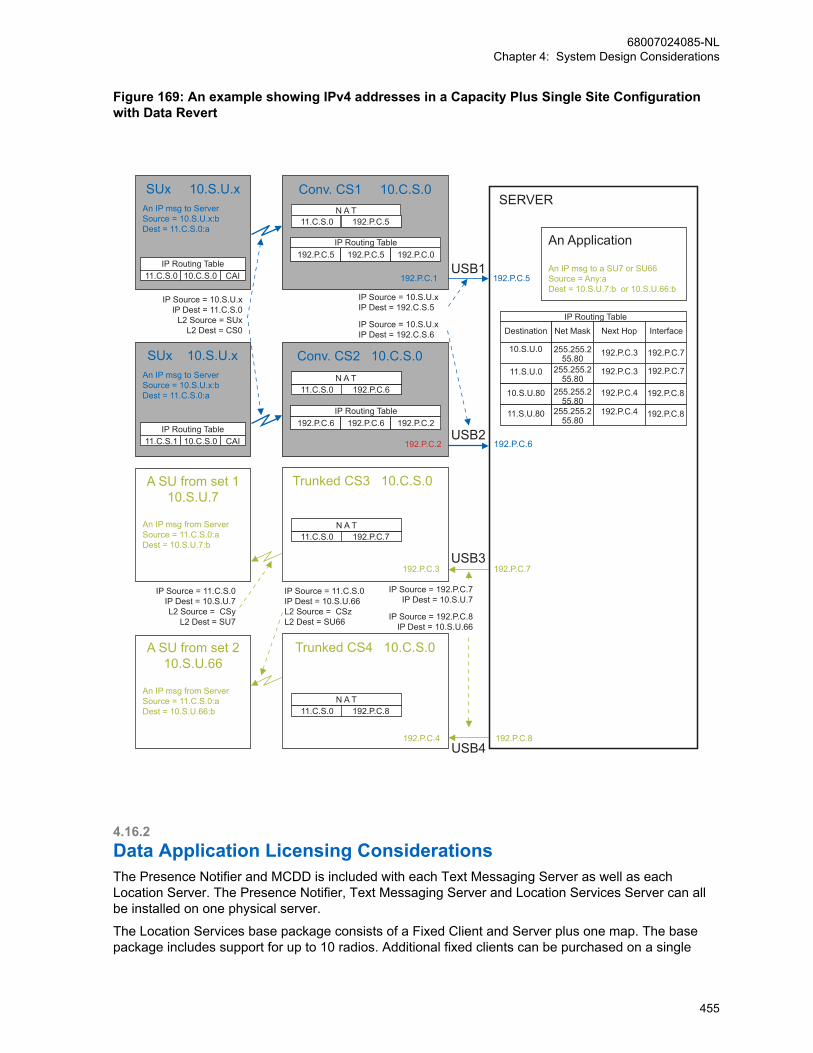
Figure 169: An example showing IPv4 addresses in a Capacity Plus Single Site Configurationwith Data Revert
SUx 10.S.U.xAn IP msg to ServerSource = 10.S.U.x:bDest = 11.C.S.0:a
IP Routing Table 11.C.S.0 10.C.S.0 CAI
IP Source = 10.S.U.xIP Dest = 11.C.S.0
L2 Source = SUxL2 Dest = CS0
SUx 10.S.U.xAn IP msg to ServerSource = 10.S.U.x:bDest = 11.C.S.0:a
A SU from set 110.S.U.7
An IP msg from Server Source = 11.C.S.0:a Dest = 10.S.U.7:b
IP Source = 11.C.S.0IP Dest = 10.S.U.7L2 Source = CSy
L2 Dest = SU7
A SU from set 210.S.U.66
An IP msg from Server Source = 11.C.S.0:a Dest = 10.S.U.66:b
192.P.C.4
Trunked CS4 10.C.S.0
IP Source = 11.C.S.0IP Dest = 10.S.U.66 L2 Source = CSzL2 Dest = SU66
USB3
USB4
IP Source = 192.P.C.7 IP Dest = 10.S.U.7
IP Source = 192.P.C.8
IP Dest = 10.S.U.66
192.P.C.3
Trunked CS3 10.C.S.0
192.P.C.2USB2
Conv. CS2 10.C.S.0
11.C.S.0 192.P.C.6N A T
USB1
IP Source = 10.S.U.xIP Dest = 192.C.S.5
IP Source = 10.S.U.xIP Dest = 192.C.S.6
192.P.C.1
192.P.C.5 192.P.C.5 192.P.C.0IP Routing Table
11.C.S.0 192.P.C.5N A T
Conv. CS1 10.C.S.0 SERVER
An Application
An IP msg to a SU7 or SU66Source = Any:aDest = 10.S.U.7:b or 10.S.U.66:b
192.P.C.5
IP Routing TableDestination
11.S.U.0
11.S.U.80
10.S.U.0
10.S.U.80
192.P.C.7
192.P.C.6
192.P.C.8
Next Hop Interface
192.P.C.4
192.P.C.4
192.P.C.3
192.P.C.3 192.P.C.7
192.P.C.7
192.P.C.8
192.P.C.8
Net Mask
255.255.255.80
255.255.255.80
255.255.255.80
255.255.255.80
IP Routing Table 11.C.S.1 10.C.S.0 CAI
192.P.C.6 192.P.C.6 192.P.C.2IP Routing Table
11.C.S.0 192.P.C.7N A T
11.C.S.0 192.P.C.8N A T
4.16.2Data Application Licensing ConsiderationsThe Presence Notifier and MCDD is included with each Text Messaging Server as well as eachLocation Server. The Presence Notifier, Text Messaging Server and Location Services Server can allbe installed on one physical server.
The Location Services base package consists of a Fixed Client and Server plus one map. The basepackage includes support for up to 10 radios. Additional fixed clients can be purchased on a single
68007024085-NLChapter 4: System Design Considerations
455

user basis. A mobile client is not available. Additional radio licenses can be purchased in groups of fiveradios.
The Text Messaging base package consists of a Fixed Client and Server. The base package includesradio licenses for up to 10 radios. Additional fixed clients can be purchased on a single user basis.Additional mobile clients can also be purchased on a single user basis. The mobile client comprises ofsoftware installed on a PC. Additional radio licenses can be purchased in groups of five radios.
Typically, one text message dispatcher is required per functional group. Multiple text messagedispatchers can be used if the functional group is large or if there are unique communicationrequirements. The text message dispatchers should have the users of their functional group in theiraddress book. If the dispatcher needs to dispatch text messages outside of the function group, theycan use the manual address entry feature of the Text Message Client.
4.16.3Mobile Terminal and Application Server Power ManagementConsiderationsThere are some considerations that have to be taken with regards to the Power Management settingson a PC being used for either a Mobile Terminal or Application Server.
It is recommended that the power management settings of the Application Server and Mobile Client bedisabled. Specifically the System Standby and System Hibernation settings should be set to Never.
It is crucial that the Application Server and Mobile Terminal always be active so that they can transmitand receive data messages. If the Application Server or Mobile Client is allowed to enter SystemStandby or System Hibernation, it will not respond to received data messages. The radio(s) connectedto the Application Server or Mobile Client queue the data until messages fail to be delivered. It is theresponsibility of the sending device to retry the failed message. A user requires to “awaken” theApplication Server or Mobile Client before it accepts messages again.
4.16.4MOTOTRBO Telemetry Connection DetailsFor more details about the telemetry GPIO pin assignments, see the MOTOTRBO Telemetry ADKGuide available.
4.16.5MOTOTRBO Network Interface Service (MNIS) and Device Discoveryand Mobility Service (DDMS)This section documents system design considerations related to MNIS and DDMS deployment in aMOTOTRBO system. It also covers MNIS and DDMS features and capabilities, data applicationdeployment considerations and considerations for migrating from control stations to MNIS baseddeployment. The DDMS is formerly known as the MOTOTRBO Presence Notifier.
The following basic considerations are important and must be noted:
• The MNIS application currently does not support voice and CSBK calls.
• If data support with MNIS and DDMS is desired, ensure that the data application supports MNISand DDMS.
• MNIS and DDMS configuration details can be found in their respective online and context help.Additional information can also be found at the MOTOTRBO ADP portal.
• Discuss with third-party data application vendor for any questions related to their application supportof MNIS and DDMS.
68007024085-NLChapter 4: System Design Considerations
456
4.16.5.1MNIS and DDMS Operation OverviewThe MNIS is a Windows service application, which supports data applications without requiring controlstations. MNIS acts as a gateway to the radio system for the data applications. It connects with theradio system over an IP network and utilizes the repeaters to transmit and receive data messagesbetween Data Application Servers and MOTOTRBO radios.
The MNIS has an identifier and MNIS Application ID. The ID is configured in the MNIS using theconfiguration GUI. The ID is used by the MNIS to receive and transmit on the radio network. The MNISApplication ID is used whenever the radio needs to communicate with the data application or viceversa. For example, the ARS and TMS Radio ID fields in the radios are configured to the MNISApplication ID. The data message from the radios to the ARS or TMS applications has the MNISApplication ID as the destination of the message. Likewise, the data message from ARS or TMSapplications to the radios has the MNIS Application ID as the source of the message. The MNISApplication ID is identical to the radio ID of the control stations. The fielded radios should not beconfigured with the radio ID that is same as the MNIS Application ID.
The MNIS is configured with the Master repeater’s IP address, which it uses to discover and connectwith the repeater system. Upon connection with the repeaters, the MNIS informs the repeaters of itsMNIS Application ID. When a fielded radio transmits a data message with the destination address ofthe MNIS Application ID, the repeater assembles the blocks of the data PDU received over-the-air andforwards to the MNIS. The MNIS in turn forwards the data message to the data application. When adata application sends a data message to a fielded radio, the MNIS forwards them to a repeater fortransmission over-the-air.
The radio’s presence and mobility management is handled separately by the MOTOTRBO DeviceDiscovery and Mobility Service (DDMS) application. The DDMS can be deployed with either the MNISor control station.
The MNIS and DDMS have multiple interfaces, as shown in Figure 170: MNIS and DDMS InterfaceOverview on page 458. The interfaces are described in the following sections.
68007024085-NLChapter 4: System Design Considerations
457

Figure 170: MNIS and DDMS Interface Overview
MOTOTRBO Network Interface Service (MNIS)
DDMS WatcherInterface
DataApplications
PresenceInformation
Mobility
Information
Application D
ata
AR
S M
essage
ARS
RepeaterSystem
IP NetworkNetwork Application Interface is enabled
using CPSRepeaters
SU
ARS OR
Application Data Application Data Interface
DDMS Watcher Interface
4.16.5.1.1Network Application InterfaceThe MNIS connects with the repeater system using the link establishment procedure of the repeatersystem. This requires the MNIS to be configured with the Master repeater’s IP address and UDP portnumber. Upon connection with the Master repeater, it discovers the IP addresses and port numbers ofall the repeaters in the system. Then, the MNIS establishes the link with the repeaters in the system.
Upon connection with the repeaters, the MNIS uses the repeater’s Network Application Interface andunderlying services to support data transmit and receive through the repeaters. The MNISencapsulates the applications UDP/IP data packet in the Network Application Interface packet andsends it to the repeater. The repeater transmits the data message over-the-air. Likewise when therepeater receives a message meant for the MNIS, it encapsulates the message in the NetworkApplication Interface’s data packet and sends it to the MNIS. The link establishment and NetworkApplication Interface procedures are transparent to the data application.
NOTICE: If using MNIS, all the repeaters in a system (IPSC, Capacity Plus Single Site, orCapacity Plus Multi Site) are required to have the Network Application Interface – Data optionenabled. If using MNIS with a single site repeater, the same option in the repeater must beenabled. Enabling this option in the repeaters can be done using the CPS.
68007024085-NLChapter 4: System Design Considerations
458
4.16.5.1.2Data Application InterfaceThe MNIS supports the standard UDP/IP based interface for data communication with the radio. Thisinterface is similar to the data communication via control stations.
In a control station deployment, data messages from the application are routed by the IP stack of thePC to the network adapter of the control station. The control station then receives the data messageand transmits over-the-air to the radio. The data message received by the control station from the over-the-air is sent to the IP stack of the PC from its network adapter. The IP stack of the PC routes the datamessage to the application.
When utilizing the MNIS the data messages from a data application are routed by the IP stack of thePC to the network adapter (also called the tunnel adapter) of the MNIS. The MNIS forwards the datamessage to the repeater for transmission over-the-air. The data message received by the repeater issent to the MNIS. The MNIS sends the data message to the IP stack of the PC from its tunnel adapter.The IP stack of the PC then routes the data message to the data application.
4.16.5.1.3DDMS Watcher InterfaceThe DDMS watcher interface is an interface for applications, including the MNIS, to obtain thepresence and mobility information of the radios from the DDMS. The DDMS maintains both the radiopresence and mobility information. It provides an interface to the MNIS, and the data application to getnotifications on change in the presence or mobility information of specified radios.
Presence InformationThe MNIS forwards the radio ARS message to the DDMS, which updates the radios presence. TheDDMS notifies data applications that have subscribed for presence through the watcher interface.
Mobility InformationThe radio’s mobility is the channel or site where the radio is present. The MNIS uses the mobilityinformation to route outbound data messages for transmission.
The MNIS determines the radio mobility information based on the channel and the site from where theARS is received. The watcher interface is then used to input the mobility information in DDMS. TheDDMS notifies mobility updates to an application, including the MNIS, that has subscribed for radio’smobility information.
4.16.5.1.4Flow of Messages DDMS and MNIS OperationFigure 171: Location Application with MNIS and DDMS in a Single Site Digital System on page 460shows the flow of messages to facilitate the Location Service with the MNIS and DDMS deployment.
68007024085-NLChapter 4: System Design Considerations
459

Figure 171: Location Application with MNIS and DDMS in a Single Site Digital System
TCPIP
AutomaticRegistration
Service
LocationApplication
UDPIP
IP Network
GPS/LRRPComponents
UDPIP
UDPIP
CAI5
3 1
1. Subscription2. Registration3. Notification4. Location Request5. Location Update
ARS
LRRPLRRP
GPSSignals
DDMSWatcher Interface
4
Radio ID = 100
ARS Radio ID = 1ARS IP = 13.0.0.1TMS Radio ID = 1TMS IP = 13.0.0.1
MNIS
MOTOTRBOTM
Radio
MNIS ApplicationID = 1
UDPIP
CAI
ARS2
2 2
44
5 5
1 The location application subscribes for the radio’s presence information with DDMS.
2 Upon power-up, the radio transmits an ARS message to register with the DDMS. The ARSmessage is then received by the repeater and sent to the MNIS. The MNIS routes the message tothe DDMS. The DDMS updates the radio’s mobility information based on the channel from wherethe ARS is received.
3 The DDMS notifies the location application of the presence of the radio.
4 The location application sends a location request which gets routed to the MNIS. The MNIS refersto the radio’s mobility information to determine where to transmit the location request and routes tothe appropriate repeater. The repeater transmits the location request to the radio.
5 The radio transmits its location updates, which are received by the repeater and sends to the MNIS.The MNIS routes the location updates to the location application.
4.16.5.2System Topology with MNISThe MNIS supports MOTOTRBO digital Single Site. It can connect with:
• Up to eight conventional repeater systems with wide or local area channels. It is recommended thatthe total number of logical channels1 of the repeater systems does not exceed 32.
IPSCIP Site Connect
The MNIS supports MOTOTRBO IP Site Con-nect. It can connect with:
• Up to eight IP Site Connect with wide or lo-cal area channels. It is recommended thatthe total number of logical channels1 of therepeater systems does not exceed 32, or
• An IPSC repeater system has:
- Two wide area logical channels, or
- A combination of wide and local area log-ical channels
CPSSCapacity Plus Single Site
The MNIS supports MOTOTRBO Capacity PlusSingle Site. MNIS can connect with one Capaci-ty Plus Single Site system.
68007024085-NLChapter 4: System Design Considerations
460

CPMSCapacity Plus Multi Site
The MNIS supports MOTOTRBO Capacity PlusMulti Site. MNIS can connect with one CapacityPlus Multi Site system.
4.16.5.2.1Multiple Conventional Systems TopologyFigure 172: Multiple Conventional Systems with MNIS on page 461 shows an example of a topologywith multiple IPSC and Single Site systems. The radios share the same data applications. Multiple dataapplications such as Location, Text, Telemetry, and others, can be deployed. In this systemconfiguration, the radios must have unique radio IDs across all repeater systems. The ARS and TMSServer addresses must be set to the MNIS Application ID.
Figure 172: Multiple Conventional Systems with MNIS
SU
SU
WAC 1
WAC 2
OTA
OTA
Data Applications
PC
IPNetwork
Router
IP
IP S
tack
DDMS
Repeater System 1
IP
MNISMNIS Application ID = 1
WAC 1
WAC 2
WAC 1
WAC 2
IP
WAC 1 IP
Repeater System 2
IPWAC 1 WAC 1 IP
LAC 1GPS revert Ch
LAC 1GPS revert Ch
LAC 2GPS revert Ch
SU
LAC 1
OTA
OTA
IP
Repeater System 3
WAC 2
SU
SUOTA
Data Application configuration in RadiosARS Radio ID = 1 ARS IP = 13.0.0.1 TMS Radio ID = 1 TMS IP = 13.0.0.1
Master Repeater
Master Repeater
Master Repeater
• In this deployment, with multi-channels, the radios must have ARS enabled. The radios’ mobility isupdated based on the channel from where the ARS is received. The MNIS uses the mobilityinformation to send outbound messages from the data application to the radio. Without mobilityinformation, the MNIS transmits the data message to all connected channels.
• The location application’s address is not configured in the radios. The radio determines the addressfrom the source address field of the location request message. Since the location request is sentfrom the MNIS, it carries the MNIS’ Application ID in the source address field.
• The GPS Revert Channels (or Enhanced GPS Revert Channels) can be configured as local or widearea. However, it is highly recommended to configure the GPS Revert Channel to local. There is noreason to have wide area GPS revert channels, if utilizing the MNIS. Wide area for GPS Revert wasrequired so that the data could be routed to one set of control stations over-the-air. With theexistence of the MNIS, the data received on local channels is routed to the data application over thenetwork. In general, local GPS Revert Channel increases the GPS capacity, since one wide areachannel can be replaced by numerous local channels.
68007024085-NLChapter 4: System Design Considerations
461
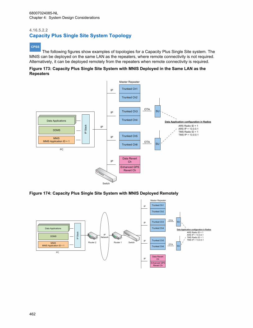
4.16.5.2.2Capacity Plus Single Site System Topology
CPSS The following figures show examples of topologies for a Capacity Plus Single Site system. The
MNIS can be deployed on the same LAN as the repeaters, where remote connectivity is not required.Alternatively, it can be deployed remotely from the repeaters when remote connectivity is required.
Figure 173: Capacity Plus Single Site System with MNIS Deployed in the Same LAN as theRepeaters
Trunked Ch1
Trunked Ch2
Trunked Ch3
Trunked Ch4
Trunked Ch5
Trunked Ch6
IP
IP
IP
OTASU
OTASU
Data RevertCh
Enhanced GPSRevert Ch
IP
IP
Data Applications
PC
Switch
IP S
tack
DDMS
MNISMNIS Application ID = 1
Data Application configuration in RadiosARS Radio ID = 1 ARS IP = 13.0.0.1 TMS Radio ID = 1 TMS IP = 13.0.0.1
Master Repeater
Figure 174: Capacity Plus Single Site System with MNIS Deployed Remotely
IPNetwork
Trunked Ch1
Trunked Ch2
Trunked Ch3
Trunked Ch4
Trunked Ch5
Trunked Ch6
IP
IP
IP
OTASU
OTASU
Data RevertCh
Enhanced GPSRevert Ch
IP
Data Applications
PC
IP S
tack
DDMS
MNISMNIS Application ID = 1
SwitchRouter 2 Router 1
Data Application configuration in RadiosARS Radio ID = 1 ARS IP = 13.0.0.1 TMS Radio ID = 1 TMS IP = 13.0.0.1
Master Repeater
68007024085-NLChapter 4: System Design Considerations
462
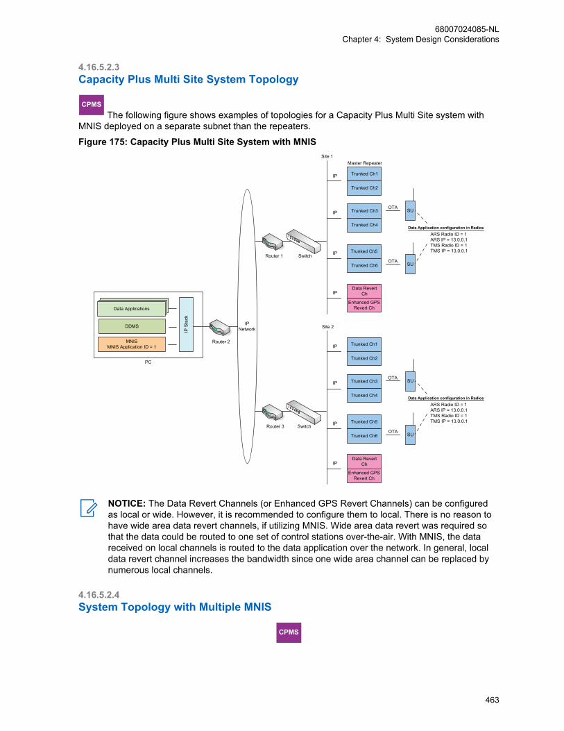
4.16.5.2.3Capacity Plus Multi Site System Topology
CPMS The following figure shows examples of topologies for a Capacity Plus Multi Site system with
MNIS deployed on a separate subnet than the repeaters.
Figure 175: Capacity Plus Multi Site System with MNIS
IPNetwork
Trunked Ch1
Site 1
Trunked Ch2
Trunked Ch3
Trunked Ch4
Trunked Ch5
Trunked Ch6
IP
IP
IP
OTASU
OTASU
Data RevertCh
Enhanced GPSRevert Ch
IP
Data Applications
PC
IP S
tack
DDMS
MNISMNIS Application ID = 1
Router 2
Data Application configuration in RadiosARS Radio ID = 1 ARS IP = 13.0.0.1 TMS Radio ID = 1 TMS IP = 13.0.0.1
SwitchRouter 1
Trunked Ch1
Site 2
Trunked Ch2
Trunked Ch3
Trunked Ch4
Trunked Ch5
Trunked Ch6
IP
IP
IP
OTASU
OTASU
Data RevertCh
Enhanced GPSRevert Ch
IP
Data Application configuration in RadiosARS Radio ID = 1 ARS IP = 13.0.0.1 TMS Radio ID = 1 TMS IP = 13.0.0.1
SwitchRouter 3
Master Repeater
NOTICE: The Data Revert Channels (or Enhanced GPS Revert Channels) can be configuredas local or wide. However, it is recommended to configure them to local. There is no reason tohave wide area data revert channels, if utilizing MNIS. Wide area data revert was required sothat the data could be routed to one set of control stations over-the-air. With MNIS, the datareceived on local channels is routed to the data application over the network. In general, localdata revert channel increases the bandwidth since one wide area channel can be replaced bynumerous local channels.
4.16.5.2.4System Topology with Multiple MNIS
CPMS
68007024085-NLChapter 4: System Design Considerations
463

In a system where two or more agencies are sharing the radio system, then the agencies can havetheir independent MNIS deployments.
NOTICE: Up to four MNIS can be deployed with the repeater system whether it is aconventional system or systems, Capacity Plus Single Site or Capacity Plus Multi Site systems.
Figure 176: Capacity Plus Multi Site System with Two MNIS on page 464 shows an example oftopology with two MNIS deployed in a Capacity Plus Multi Site system. The radios can be configured tocommunicate with either MNIS-1 or MNIS-2.
Figure 176: Capacity Plus Multi Site System with Two MNIS
IPNetwork
Trunked Ch1
Master Repeater
Trunked Ch2
Trunked Ch3
Trunked Ch4
Trunked Ch5
Trunked Ch6
IP
Site 1
IP
IP
OTASU
OTASU
Data RevertCh
Enhanced GPSRevert Ch
IP
Data Applications
PC
IP S
tack
DDMS
MNISMNIS Applicationa ID = 1
Router 2
Data Applications
PC
IP S
tack
DDMS
MNISMNIS Application ID = 2
Router 4
SwitchRouter 1
Data Application configuration in RadiosARS Radio ID = 2ARS IP = 13.0.0.2 TMS Radio ID = 2TMS IP = 13.0.0.2
Data Application configuration in RadiosARS Radio ID = 1 ARS IP = 13.0.0.1 TMS Radio ID = 1 TMS IP = 13.0.0.1
Trunked Ch1
Master Repeater
Trunked Ch2
Trunked Ch3
Trunked Ch4
Trunked Ch5
Trunked Ch6
IP
Site 2
IP
IP
OTASU
OTASU
Data RevertCh
Enhanced GPSRevert Ch
IP
SwitchRouter 3
Data Application configuration in RadiosARS Radio ID = 1 ARS IP = 13.0.0.1 TMS Radio ID = 1 TMS IP = 13.0.0.1
NOTICE: Once the Network Application Interface for data is enabled at the repeater, thenmultiple MNISs can be connected to it.
4.16.5.2.4.1Number of Repeater Sites with Multiple MNIS Deployment
IPSCIP Site Connect
One MNIS can be deployed on an IP Site Con-nect with up to 15 repeater sites.
CPMSCapacity Plus Multi Site
One MNIS can be deployed on a Capacity PlusMulti Site with up to 15 repeater sites.
68007024085-NLChapter 4: System Design Considerations
464
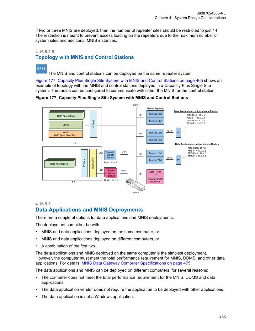
If two or three MNIS are deployed, then the number of repeater sites should be restricted to just 14.The restriction is meant to prevent excess loading on the repeaters due to the maximum number ofsystem sites and additional MNIS instances.
4.16.5.2.5Topology with MNIS and Control Stations
CPSS The MNIS and control stations can be deployed on the same repeater system.
Figure 177: Capacity Plus Single Site System with MNIS and Control Stations on page 465 shows anexample of topology with the MNIS and control stations deployed in a Capacity Plus Single Sitesystem. The radios can be configured to communicate with either the MNIS, or the control station.
Figure 177: Capacity Plus Single Site System with MNIS and Control Stations
Trunked Ch1
Trunked Ch2
Trunked Ch3
Trunked Ch4
Trunked Ch5
Trunked Ch6
IP
IP
IP
OTASU
OTASU
Data RevertCh
Enhanced GPSRevert Ch
IP
Data Applications
PC
IP S
tack
DDMS
MNISMNIS Application ID = 1
Data Application configuration in Radios
Site 1 Master Repeater
Data Applications
PC
IP S
tack
Data Application configuration in Radios
USB TrunkedControlStation
USB
Radio ID = 2
RevertControlStation
OTA
OTA
US
B D
river
Radio IDs = 2
ARS Radio ID = 2ARS IP = 13.0.0.2 TMS Radio ID = 2TMS IP = 13.0.0.2
ARS Radio ID = 1 ARS IP = 13.0.0.1 TMS Radio ID = 1 TMS IP = 13.0.0.1
Switch
4.16.5.3Data Applications and MNIS DeploymentsThere are a couple of options for data applications and MNIS deployments.
The deployment can either be with:
• MNIS and data applications deployed on the same computer, or
• MNIS and data applications deployed on different computers, or
• A combination of the first two.
The data applications and MNIS deployed on the same computer is the simplest deployment.However, the computer must meet the total performance requirement for MNIS, DDMS, and other dataapplications. For details, MNIS Data Gateway Computer Specifications on page 475.
The data applications and MNIS can be deployed on different computers, for several reasons:
• The computer does not meet the total performance requirement for the MNIS, DDMS and dataapplications.
• The data application vendor does not require the application to be deployed with other applications.
• The data application is not a Windows application.
68007024085-NLChapter 4: System Design Considerations
465

• Unstable data application can be prevented from interfering with the MNIS operation. An examplewould be an OS crash.
The MNIS has data message port forwarding support to facilitate deployment of data applications andMNIS on separate computers. Figure 178: Application and MNIS Deployed on Separate Computers onpage 466 shows this.
Figure 178: Application and MNIS Deployed on Separate Computers
PC 1
IP IP
IP forwardingEnabled
Port Forwarding Configuration in MNISUDP Port
TypeSource
Source
UDP PortType4001
4007
Forward IPAddress
172.16.0.3
172.16.0.4
172.16.0.2172.16.0.4
Radio ID =100
IP S
tack
DDMS
MNISMNIS App. ID = 1
PC 3
Location Packet Data afterPort forwarding
Port Type
UDP PortIP
Source
400112.0.0.100
Destination
4001172.16.03
IP S
tack
TMS
172.16.0.3
PC 2
IP S
tack
Location
MOTOTRBORepeater System
Router
OTASU
Routing path for routing data fromLocation app to MNIS
Nw destination
12.0.0.013.0.0.0224.0.0.0
Gateway
172.16.0.2172.16.0.2172.16.0.2
Interface
172.16.0.3172.16.0.3172.16.0.3
Location Packet Data afterPort forwarding
Port Type
UDP PortIP
Source
400112.0.0.100
Destination
400113.0.0.1
The MNIS needs to be configured to forward location and text data messages from the radios to thecomputers with Location and Text applications. The UDP port type configured is source port becausethe radios’ standard data services ports are fixed (with Location = 4001 and Text = 4007). The MNISalso allows selection of the destination port type. This option can be used for non-standard dataservices, such as third-party raw data. Configuration of port forwarding is not required when the dataapplication is deployed on the same computer as the MNIS. Therefore, no configuration of portforwarding is specified for the ARS data since the DDMS and MNIS are on the same PC.
The computers with the Location and Text applications require IP routes to be configured to routemessages from the data application to the computer with the MNIS. Figure 178: Application and MNISDeployed on Separate Computers on page 466 shows a route for data messages belonging to systemCAI network IDs = 12, 13 and 224. When the data applications and MNIS are on different subnets,then it must be ensured that the CAI network addresses can be routed between subnets. One commonway for doing this is to use a VPN. The computer with the MNIS requires the IP routing enabled. Thisallows the data message from applications to be internally forwarded to the tunnel adapter of theMNIS.
It is recommended that the DDMS be deployed on the same computer as the MNIS. This reduces theIP traffic on the network. The data applications are configured with the IP address of the computer withthe DDMS application and the DDMS watcher interface port.
When the data applications, MNIS and DDMS are deployed on the same computer, take note of thefollowing:
• Configuration of port forwarding in the MNIS is not required.
• Route paths for CAI network are not required to be added manually as MNIS sets themautomatically.
68007024085-NLChapter 4: System Design Considerations
466
• Enabling IP forwarding is not required.
4.16.5.4Mobility Management and Individual Data TransmissionThe DDMS, when deployed with MNIS tracks the radios’ mobility. The DDMS updates the radios’mobility based on the channel or site, from where the ARS message from the radio is received. TheMNIS and any other data application can subscribe with the DDMS for radio mobility information. TheDDMS provides radio mobility information upon subscription, and subsequently when the mobilityinformation gets updated. The DDMS stores the mobility information in persistent memory so that it isavailable following DDMS or MNIS power cycles. The mobility information is retained even when theradio becomes absent.
Upon power up, the MNIS subscribes with the DDMS to receive the mobility information. Followinginitial notification, it continues to receive mobility updates from the DDMS. The MNIS uses the radios’mobility information to route the outbound data from the data application. Only individual datamessages are routed in this manner.
IPSCIP Site Connect
In an IPSC system, the MNIS is aware of the lo-cal and wide area channels. If a radio is knownto be present on a local channel, then the datamessage is transmitted only on that local chan-nel. If the radio is known to be present on thewide area channel, then the data message istransmitted on the wide area channel. If the ra-dio is absent, but its mobility information isknown based on a previous registration, thenthe MNIS routes the data message based onthe last known mobility information. If the radi-os’ mobility information is not known, then themessage is routed to all the channels of thesystem, except the channels selected as datarevert. Sending individual data messages over-the-air on all channels wastes bandwidth.Therefore, it is always recommended that theARS feature is enabled.
CPSSCapacity Plus Single Site
In a Capacity Plus Single Site system, out-bound data messages are always routed to theRest Channel of the repeater. No data messag-es are routed to the revert channels.
CPMSCapacity Plus Multi Site
In an Capacity Plus Multi Site system, a radio’smobility is the site where the radio sends itsARS registration. If the radio’s mobility informa-tion and site are known by the MNIS, then thedata message is routed to the site. If the radio’smobility information is not known, then the datamessage is routed to an arbitrarily selected site.In both conditions, the data message is trans-mitted over-the-air to at most, two sites. In thefollowing scenario, it is transmitted to only onesite:
68007024085-NLChapter 4: System Design Considerations
467

• If ARS is enabled for site and systemchange, or
• If ARS is enabled for system change, andthe radio is still at the site where it has regis-tered.
If the MNIS is not able to route the message due to a loss of connection with the repeater system, orbecause of any other erroneous condition, then the data message is dropped and an ICMP message isreturned to the data application.
4.16.5.5Group MessagesData applications can receive or send group data messages via the MNIS. The MNIS supports grouplist configuration via its configuration GUI. The groups can be specified in a range to allow a largenumber of group affiliations. An example would be groups in the range of 1-100. The data messagestargeted to the specified groups are sent to the application. The group list can be defined based on thetype of system configuration:
• In a conventional system, one group list per slot (1 and 2) can be selected.
CPSSCapacity Plus Single Site
In a Capacity Plus Single Site system, onegroup list can be selected
CPMSCapacity Plus Multi Site
In a Capacity Plus Multi Site system, one grouplist per site can be selected.
The group list is also used for routing of outbound group messages from the data application. In aconventional system, if the target group is present only in the group list of slot 1, then the datamessage is routed to slot 1 only. If the target group is in the group list of slot 1 and slot 2, then the datamessage is routed to both slots. If the slot is configured as an IPSC local channel, then the groupmessage is routed to all local channels of that slot. If the group is not in any of the group list, then thedata message is routed to all the system channels. A group data message is not routed to a channelthat is configured as a Data Revert Channel.
CPSSCapacity Plus Single Site
In a Capacity Plus Single Site system, thegroup data message is routed to the RestChannel.
CPMSCapacity Plus Multi Site
In an Capacity Plus Multi Site system, if thegroup is a wide area group as provisioned inthe Master repeater, then the data message istransmitted at the sites associated with the widearea group. If the group is a local group, thenthe data message is routed and transmitted atthe sites where their group list contains the tar-get group. If the local group is present in multi-ple group lists, then it gets transmitted at themultiple sites.
68007024085-NLChapter 4: System Design Considerations
468

4.16.5.6Data PrivacyThe MNIS supports Basic Privacy, Enhanced Privacy, and AES mechanisms.
When privacy is enabled, the MNIS uses only one transmit key for scrambling the outbound message,this is true for all privacy types. For Basic Privacy, this transmit key is also used for descrambling theinbound messages. For Enhanced Privacy and AES Privacy, all the keys (up to 255) in its key list areused for descrambling the inbound messages.
It is recommended that all radios including the MNIS should have the same privacy settings. IfEnhanced Privacy and/or AES is being used, then the MNIS should have the transmit key of all theradios and radios should have the outbound key of the MNIS.
4.16.5.6.1MNIS Data Gateway Key and Key ListSimilar to a radio, a MNIS Data Gateway is configured with a Basic Privacy Key or an EnhancedPrivacy Key List, and/or an AES Privacy Key List. Each key list can contain up to 255 of the PrivacyKeys entered in its corresponding System Key List. A MNIS Data Gateway can receive Basic Privacy,Enhanced Privacy, AES Privacy, and No Privacy. In other words, it can receive all privacy types. TheMNIS Data Gateway can transmit Basic Privacy, Enhanced Privacy, AES Privacy, or No Privacy. Inother words it can only transmit with one privacy type.
It is recommended that the MNIS Data Gateway Key List contain all Privacy Keys utilized by radios itcommunicates with since radios utilize the Transmit Key of their selected personality when they senddata to the MNIS Data Gateway.
4.16.5.6.2MNIS Data Gateway Transmit Privacy Type and Privacy KeyA MNIS Data Gateway can transmit Basic Privacy, Enhanced Privacy, AES Privacy, or No Privacy. Inother words it can only transmit with one privacy type. For Basic Privacy, only one key is specified.When Enhanced or AES Privacy is utilized, a Transmit Key from the corresponding Radio Key Listmust be specified. The Transmit Privacy Key is fixed until re-configured using Radio Management.There is no standard method for the data application to dynamically select the MNIS Data Gateway'sTransmit Privacy Key.
4.16.5.6.3Privacy Reception in the MNIS Data GatewayThere are no configuration options to determine how the MNIS Data Gateway handles the reception ofunprotected (clear) or protected (encrypted) calls. A MNIS Data Gateway can receive Basic Privacy,Enhanced Privacy, AES Privacy, and No Privacy. In other words it can receive all the privacy types.
If a MNIS Data Gateway receives an unprotected (clear) call it decodes the call normally and forwardsthe data call to the data application. If a MNIS Data Gateway receives a protected (encrypted) call, andthere is a matching key (with matching Key ID and Privacy Type) in its Key List, then it decodes the calland forwards the data call to the data application.
68007024085-NLChapter 4: System Design Considerations
469

4.16.5.7Considerations for Advanced MNIS ConfigurationsThis section covers in detail a couple of parameters in MNIS configurations.
CPSMCapacity Plus Single Site and Capacity
Plus Multi Site
In Capacity Plus Single Site and Capacity PlusMulti Site configurations, the MNIS has an “Out-bound Data Limit” parameter. This parameterdefines the number of data messages that theMNIS can simultaneously transmit, and there-fore the maximum number of Trunked Channelsthat can be busy with data. In Capacity PlusMulti Site mode, the parameter can be config-ured per site. The parameter does not controlthe number of inbound data transmissions fromthe radio. The configuration ensures that theMNIS does not occupy channels more thanspecified. It does not control system data load-ing. See Digital Repeater Loading on page 366to determine the application data loading thatcan be supported by the system.
CPMSCapacity Plus Multi Site
In an Capacity Plus Multi Site configuration, theMNIS has an “Individual Data to RegisteredSite” parameter which can be enabled or disa-bled. When enabled, the data message is trans-mitted only at the site where the radio has reg-istered. If the radio roams, then it must re-regis-ter at the new site. This parameter should beenabled only when all the radios in the systemeither do not roam, or have ARS upon system/site change enabled. The enabling of the pa-rameter has a couple of benefits:
• The individual data is treated as a local call,and is therefore faster and does not involveother sites in a call setup.
• The call does not engage two sites.
The enabling of this parameter should be care-fully considered, as data delivery could bemissed when a radio roams, but unable to reg-ister immediately after roaming to the new site.
In conventional configurations, the MNIS has a “Conventional Channel Access” parameter that can beset to normal, which is the default setting, or data centric. If the selection is normal, then channelaccess for application data outbound transmissions follow the channel access rules similar to what theradios use. The repeater introduces a random delay when the channel is busy. The duration of thisdelay is between 0 - 1.8 seconds. After this delay, if the channel becomes idle, then the data messageis transmitted, or another random delay is introduced. This approach is used for collision avoidancewhen the channel is busy with radio activity. If the selection is data centric, then the random hold-off isnot introduced. The repeater transmits the data immediately after the channel becomes free.
68007024085-NLChapter 4: System Design Considerations
470

4.16.5.8DDMS Usage by MNISThe DDMS is required by the MNIS, and operation without DDMS is not recommended.
4.16.5.9Control Station Migration to MNISThe control stations can be replaced by the MNIS in systems where the control stations are being usedfor application data communication. In deployments where the control stations are used by voiceconsoles and data applications, it may still be beneficial to replace the control stations and monitordata revert channels. For IPSC or Capacity Plus Multi Site systems, the data revert channels can beconverted to local channels to increase revert data throughput, as control stations are not required inthe coverage range of the local channel.
The control stations can be replaced by MNIS without requiring any configuration changes to thefielded radios. This is shown in the following figures. Figure 179: System with Control Stations Used bya Voice Console and Data Applications on page 471depicts a MOTOTRBO system with controlstations used by a voice console and data applications. The data applications can be migrated toMNIS-based deployment as shown in. Since the fielded radios are configured with the control stationradio ID for the voice console contact and the ARS/TMS contact, the MNIS Application ID should beconfigured with the same ID to avoid configuration changes to the fielded radios. This can beaccomplished by upgrading the control station to firmware versions R02.06.10 or later. Using the CPS,select the “Voice Only” checkbox, which configures the radio being used as a control station to ignoredata calls received over-the-air. The voice console calls continue to be handled through the controlstation. The data application messages are handled through the MNIS. This option is also supported infirmware versions prior to R01.11.00.
Figure 179: System with Control Stations Used by a Voice Console and Data Applications
MOTOTRBORepeater System
Data Applications
PC1
IP S
tack
USB ControlStation
USB
Radio ID = 1
RevertControlStation
OTA
OTA
USB
Driv
er
Radio IDs = 1
SU
Radio ID = 100ARS, TMS Radio ID = 1Dispatcher Radio ID = 1
Voice Console
OTA
In Figure 180: System with a Control Stations Used by a Voice Console and MNIS Used by DataApplications on page 472 Two separate PCs are shown for clarity. The deployments can be on thesame PC.
68007024085-NLChapter 4: System Design Considerations
471

Figure 180: System with a Control Stations Used by a Voice Console and MNIS Used by DataApplications
MOTOTRBORepeater System
PC1
IP S
tack USB Control
Station
Radio ID = 1
OTA
US
B D
river
SUVoice Console OTA
PC2
DDMS
MNISMNIS Application ID = 1
IP S
tack
Data Applications
IP
DMR DataDisabled
Radio ID = 100ARS, TMS Radio ID = 1Dispatcher Radio ID = 1
NOTICE: The MNIS does not support L2 fragmented data. Ensure that the largest data size[Data Message + IP/UDP Header] transmitted from the radio is less than the Max TX PDU Sizeconfigured in the radios. If the largest data sent from the radio is greater than the Max TX PDUSize value in the radio, then the value needs to be reconfigured with a larger Max TX PDU Size.
4.16.5.10Considerations for the IP NetworkA reliable network is important for application data communication reliability. In the event of a networkfault, the MNIS could lose connectivity with the entire repeater system, or to some selected systemsites. The MNIS is designed to automatically establish the link with the repeaters after the network isrestored.
When the MNIS loses connection with a few sites/repeaters, but remains connected with other systemsites/repeaters, then the MNIS continues to receive and route data messages from the connectedsites/repeaters. Once the connection is restored, then the MNIS automatically resumes receiving andsending data with those sites or repeaters. No user intervention is required. The MOTOTRBO RDACapplication can monitor the presence of the MNIS on the network.
The MNIS sends/receives a data message as a single datagram whereby the size is dependent on themessage size, either received or sent, to the data application.
IP Datagram Size = Max Message Size + Overhead Size (120 bytes) where:
• Max message size could be the largest message size such as the text message size.
• Overhead size includes IP/UDP headers, protocol header, authentication, and others.
• The overhead does not include any VPN-related overhead.
The bandwidth requirement of the network between the MNIS and the repeater system is not large.The bandwidth required is for link establishment with the repeater system, and for receiving or sendingthe data messages to and from the radios.
The network bandwidth required by the MNIS is due to the Link Management IP traffic between theMNIS and the repeaters, and the IP traffic associated with the data messages sent and received fromthe MNIS. The following base values are used when estimating the network bandwidth due to MNIS:
Link Management BW per Repeater Peer = 1 kbpsMax IP BW due to Data Message per Channel = 7.5 kbps% Data Loading on Voice Channel = 40%
The following sections covers the formula for estimating the network bandwidth by one MNIS.
68007024085-NLChapter 4: System Design Considerations
472

4.16.5.10.1Estimation of Link Bandwidth Where MNIS Is DeployedTotal Number of Voice Channels in the System = V
Total Number of Data Revert Channels in the System = D
Total Number of Repeaters in the System = R
Downlink BW (IP traffic from repeater system to MNIS):
• Downlink BW (with Data Revert) = D*7.5 + R*1 kbps
• Downlink BW (without Data Revert) = V*7.5*0.4 + R*1 kbps
Uplink BW (IP traffic from MNIS to repeater system):
• Uplink BW = V*7.5*0.4 + R*1 kbps
4.16.5.10.2Estimation of Link Bandwidth at Repeater SitesIf the IP link bandwidth at the site is estimated for voice and data streaming to remote sites, thenadding bandwidth at the sites is not required. If the IP link bandwidth at the site is not estimated forvoice streaming as would be the case with single site, IP Site local channel or Capacity Plus SingleSite configurations, then the bandwidth estimate at the site is a follows:
Total Number of Voice Channels at the Site = v
Total Number of Data Channels at the Site = d
Total Number of Repeaters at the Site = r
Uplink BW (IP traffic from repeater site to MNIS):
• Uplink BW (with Data Revert) = d*7.5 + r*1 kbps
• Uplink BW (without Data Revert) = v*7.5*0.4 + r*1 kbps
Downlink BW (IP traffic from MNIS system to repeater site):
• Downlink BW = v*7.5*0.4 + r*1 kbps
There are a few other considerations to take note of:
• An IPSC wide area channel or a local area channel is considered as one channel.
• In Capacity Plus Single Site: Total number of voice channels (V or v) = Number of Trunked Repeaters*2.
• In Capacity Plus Multi Site:Number of Voice Channels (V) = Number of Trunked Repeaters in System*2. Number of Voice Channels per Site (v) = Number of Trunked Repeaters per Site*2.
• The generic formula for MNIS IP bandwidth calculation is:BW = BW due to data messages + BW due to Link Management
• In the case of multiple MNIS instances, the IP bandwidth due to data messages gets distributedbetween them based on data messages received or sent by them. The IP bandwidth due to linkmanagement does not get distributed.
• Additional bandwidth must be budgeted when a VPN is used.
4.16.5.10.3Considerations for Router with Networked ApplicationsAn application that connects with the repeater system utilizes the Link Management procedure. TheMNIS and RDAC are examples of applications that connect with the repeater system using thisprocedure. On the contrary, data applications like Location, Text, and others deployed with MNIS do
68007024085-NLChapter 4: System Design Considerations
473
not connect with the repeater system. To distinguish between them, an application that connects withthe repeater system are defined as a networked application.
The repeaters and the networked applications establish connection with each other in the MOTOTRBOsystem. In certain deployments, however, routers with hair-pinning support are required to enable theconnection between them.
The following table provides guidelines when a hair-pinning router is needed. The guidelines aregeneric and not specific to MNIS.
IPSCIP Site Connect
MOTOTRBO System Hair-pinning Router Method of Deployment
IP Site Connect Not Required Sites are joined together intothe same subnet using a VPN.
Required When a VPN is not used andmore than one networked ap-plications or repeaters are atthe same subnet, that subnetrequires one.
CPSSCapacity Plus Single Site
MOTOTRBO System Hair-pinning Router Method of Deployment
Capacity Plus Single Site Not Required All the networked applicationsand the repeaters are in thesame subnet.
Required When the networked applica-tions are deployed on a differ-ent subnet, the master site re-quires one.A non-repeater subnet withmore than one networked ap-plications also requires one.
CPMSCapacity Plus Multi Site
MOTOTRBO System Hair-pinning Router Method of Deployment
Capacity Plus Multi Site Not Required All the networked applicationsand the repeaters are in thesame subnet as the Master re-peater when deployed withR02.20.00 Capacity Plus MultiSite hair-pinning enhance-ments. The non-Master re-peater sites also do not re-quire them.
68007024085-NLChapter 4: System Design Considerations
474
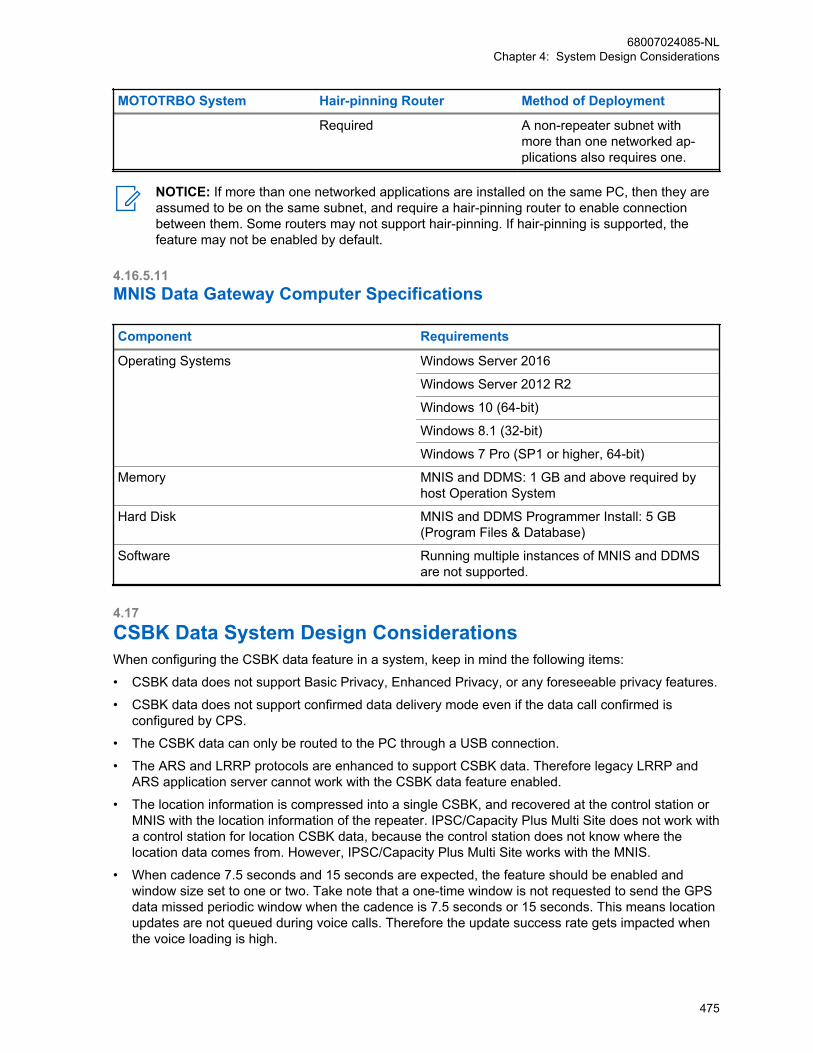
MOTOTRBO System Hair-pinning Router Method of Deployment
Required A non-repeater subnet withmore than one networked ap-plications also requires one.
NOTICE: If more than one networked applications are installed on the same PC, then they areassumed to be on the same subnet, and require a hair-pinning router to enable connectionbetween them. Some routers may not support hair-pinning. If hair-pinning is supported, thefeature may not be enabled by default.
4.16.5.11MNIS Data Gateway Computer Specifications
Component Requirements
Operating Systems Windows Server 2016
Windows Server 2012 R2
Windows 10 (64-bit)
Windows 8.1 (32-bit)
Windows 7 Pro (SP1 or higher, 64-bit)
Memory MNIS and DDMS: 1 GB and above required byhost Operation System
Hard Disk MNIS and DDMS Programmer Install: 5 GB(Program Files & Database)
Software Running multiple instances of MNIS and DDMSare not supported.
4.17CSBK Data System Design ConsiderationsWhen configuring the CSBK data feature in a system, keep in mind the following items:
• CSBK data does not support Basic Privacy, Enhanced Privacy, or any foreseeable privacy features.
• CSBK data does not support confirmed data delivery mode even if the data call confirmed isconfigured by CPS.
• The CSBK data can only be routed to the PC through a USB connection.
• The ARS and LRRP protocols are enhanced to support CSBK data. Therefore legacy LRRP andARS application server cannot work with the CSBK data feature enabled.
• The location information is compressed into a single CSBK, and recovered at the control station orMNIS with the location information of the repeater. IPSC/Capacity Plus Multi Site does not work witha control station for location CSBK data, because the control station does not know where thelocation data comes from. However, IPSC/Capacity Plus Multi Site works with the MNIS.
• When cadence 7.5 seconds and 15 seconds are expected, the feature should be enabled andwindow size set to one or two. Take note that a one-time window is not requested to send the GPSdata missed periodic window when the cadence is 7.5 seconds or 15 seconds. This means locationupdates are not queued during voice calls. Therefore the update success rate gets impacted whenthe voice loading is high.
68007024085-NLChapter 4: System Design Considerations
475

• The XCMP device to server raw data must not exceed seven bytes, otherwise the error indicationgets broadcasted to the XCMP device.
• The following is a list of limitations for GPS report:
- The distance between the radio and the repeater (receiving inbound GPS data over the air) mustnot exceed 130 miles (approximately 209 kilometers).
- Latitude system error horizontal distance of less than 8 feet (approximately 2.4 meters) isintroduced.
- Longitude system error horizontal distance of less than 6 feet (approximately 1.8 meters) isintroduced.
- Speed-horizontal of 1 knot accuracy, maximum 138 miles (approximately 222 kilometers) perhour, is supported by an Enhanced GPS scheduled channel when GPIO pin status change is notrequired.
- Direction-horizontal of 16 cardinal directions, is supported by an Enhanced GPS scheduledchannel when GPIO pin status change is not required.
- Info-Time of minutes and/or seconds, therefore suggested required maximum info age shall notexceed 50 minutes, is supported by an Enhanced GPS scheduled channel.
All radios, repeaters, MNIS, ARS and LRRP applications enabled with the CSBK data feature arebackward compatible with radios before R02.30.00. To ease migration, ARS is transmitted as CSBKdata when the feature is enabled through CPS per channel. The LRRP server knows if the radios havethe capability to transmit the LRRP report as CSBK data through the ARS registration. The LRRPreport cannot be transmitted as CSBK data when the channel is not enabled with CSBK data feature.Therefore, if the ARS message does not indicate CSBK data capability, the LRRP server should notsend the LRRP request to demand the radio to transmit LRRP report as CSBK data. If such LRRPrequests are sent before, the LRRP stop should be sent to the radio to cancel the request. There are afew considerations to take note of:
when enabling the CSBK data feature, adopt the following rules:
• ARS: When the feature is enabled by CPS, the radio sends the ARS registration as CSBK, thecontrol station, and MNIS sends the ARS registration to the ARS server with optional payload 0x100x80 when the ARS CSBK data is received.
• ARS: When the ARS server (DDMS) sends the Device Registration ACK with optional payload 0x100x80, the control station and MNIS sends the ACK as CSBK data.
• LRRP: When the CSBK data feature is enabled at a channel via CPS and the location requestcontains a LRRP token for CSBK location feature (0x40, 0x01, 0x41), the LRRP (GPS) messagewith location data is sent as CSBK.
• LRRP: When the CSBK data feature is enabled at a channel through CPS, the LRRP (GPS)message without location data (such as LRRP triggered answer) is sent as CSBK. If the messagecannot be carried in one single CSBK, it is sent as a DMR data packet.
4.18GPIO Triggered Event Driven and Distance Driven LocationUpdate System Design ConsiderationsWhen configuring the GPIO Triggered Event Driven and Distance Driven Location Update in a system,the following rules must be followed:
• To support GPIO Triggered Event Driven Location Update,
- For portable, the Cable Type should be configured as Generic or Telemetry or MotorolaSolutions if the cable is a smart Telemetry cable;
68007024085-NLChapter 4: System Design Considerations
476
- For both portable and mobile, the Feature of GPIO Physical Pins should be configured asGeneric Input or Telemetry VIO, and if Telemetry VIO is configured, the Action of such VIOshould be configured as output command because output command indicates the GPIO as aninput pin.
• For Distance Driven Location Update, to avoid triggering the update too often, it is recommended toconfigure the distance to be 100 meters or larger.
• For GPIO triggered event driven update, the location report cannot be guaranteed if two events aretriggered within 200ms.
• The GPIO Triggered Event Driven and Distance Driven Location Update is not sent periodically likethe interval triggered GPS update; therefore, the reliability may be a concern and needs to beaddressed. Some reliability considerations are as follows:
- Don’t configure the gap between the updating distances to be too large. If the gap between theupdating distances is reasonable, even if some location updates are missed over the air, thelocation tracking can still have enough updates;
- At the same time, keep a periodic location update with a long interval, so that the subscriber willnot be out of track when it’s not moving or moving slowly;
- At Non-EGPS Channel, use confirmed GPS update. Note that confirmed data delivery canincrease the reliability, but it also increases the time away from the home channel at the sametime;
4.19Customer Fleetmap DevelopmentIn a MOTOTRBO system, the system administrator can maximize the system's communicationeffectiveness by translating their organization's operation requirements into a list of supported features.The result of identifying and formalizing this information is often referred to as fleet mapping.
Fleet mapping can be thought of as:
• Assigning groups to the radios issued to personnel.
• Assigning groups to the dispatcher control positions.
• Assigning groups to channels and slots.
• Defining the feature subsets available to the personnel using the radios and dispatcher controlpositions.
A fleetmap determines how the radio communications for each user group of an organization iscontrolled. Through controlling communications between different user groups and between individualswithin a group, the organization can manage the radio communications system resources efficiently.Fleet mapping also provides a structured approach to the management of a large number of radiousers, and provides the opportunity to plan in advance for expansion or changes within anorganization.
Some of the factors that should be considered when creating or planning changes to the fleetmap are:
• Identifying a functional fleetmap design team
• Identifying radio users
• Organizing radio users into groups
• Assigning IDs and aliases
• Determining feature assignments:
- Private Calls
- All Call
68007024085-NLChapter 4: System Design Considerations
477

- PTT ID and Aliasing
- Radio Disable
- Remote Monitor
- Radio Check
- Call Alert
- Emergency Configurations
• Determining channel access requirements
• Determining subscriber programming requirements
• Determining data application access and requirements
4.19.1Identify a Functional Fleetmap Design Team To develop a fleetmap, a design team of key representatives from the customer’s system managers,technicians, and operators needs to be formed to create effective communications plans for radiousers and system operators.
4.19.2Identify Radio UsersThe system administrator needs to do the following to establish a fleetmap.
• Determine the customer’s organizational structure from a radio user’s perspective
• Consider the needs of portable and mobile radio users
• List all of the potential radio users in a single column on a spreadsheet
• Define the functional groups that use the system
• Group together radio users who need to communicate with each other on a regular basis
Typically, each functional group of radios has different communication requirements. Therefore, eachfunctional group has their own codeplug for their radios that differs from other functional groups.
Codeplug Function-al Group
UserName
Alias User ID Talks with Listensonly to
construction.ctb
Construc-tion
John John 1873 Construc-tion,Transport
Security
Construc-tion
Bob Bob 1835 Construc-tion,Transport
Security
Construc-tion
Rick Rick 542 Construc-tion,Transport
Security
security.ctb
Security Al Al 98 Security,Adminis-trative
-
Security Joe Joe 4762 Security,Adminis-trative
-
68007024085-NLChapter 4: System Design Considerations
478

Codeplug Function-al Group
UserName
Alias User ID Talks with Listensonly to
administrative.ctb
Adminis-trative
Frank Frank 6654 Adminis-trative, Se-curity
-
Adminis-trative
Mike Mike 19172 Adminis-trative, Se-curity
-
Adminis-trative
Steve Steve 78378 Adminis-trative, Se-curity
-
transport.ctb
Transport Lenny Lenny 23 Transport,Construc-tion
Security
Transport Carl Carl 2 Transport,Construc-tion
Security
4.19.3Radio Users Organized into GroupsOnce you have identified all of the individual users, associate them with groups. The communicationrequirements for one group may differ with the requirements of another group. Certain groups mayneed to communicate with multiple groups, in addition to their primary group. Therefore, identify theindividual radios and the corresponding groups that they need to communicate with. Also note that thegroup organization may be different from the organization’s formal reporting structure.
Determine the traffic patterns of the individual users and functional groups, so that channel, slot andgroup assignments can be associated with each user. Digital Repeater Loading on page 366 shouldprovide information to help decide the distribution of groups, logical channel assignments (slots) andphysical channel assignments.
When organizing the MOTOTRBO system, individual users, radios, and groups all have differentrequirements. Subsequently, they also have different parameters associated with them. Organize theradios, groups and slot assignments in a spreadsheet.
An example is shown in the following figure.
68007024085-NLChapter 4: System Design Considerations
479
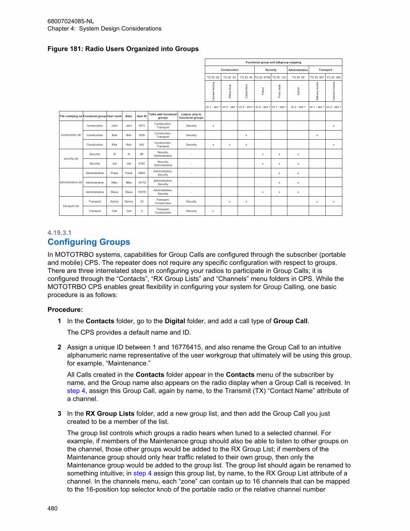
Figure 181: Radio Users Organized into Groups
Administrative
TG ID: 62 TG ID: 54 TG ID: 46 TG ID: 8766 TG ID: 123 TG ID: 99 TG ID: 997 TG ID: 368
Cem
ent f
acto
ry
Met
al s
hop
Car
pent
ers
Pat
rol
Fron
t des
k
Adm
in
Del
iver
y tru
cks
Cem
ent m
ixer
s
ch 1 - slot 1 ch 2 - slot 1 ch 2 - slot 1 ch 2 - slot 1 ch 1 - slot 1 ch 2 - slot 1 ch 1 - slot 1 ch 2 - slot 1
File codeplug as Functional group User name Alias User ID Talks with functionalgroups
Listens only tofunctional groups
Construction John John 1873 Construction,Transport Security x x
Construction Bob Bob 1835 Construction,Transport Security x x
Construction Rick Rick 542 Construction,Transport Security x x x x
Security Al Al 98 Security,Administrative - x x x
Security Joe Joe 4762 Security,Administrative - x x x
Administrative Frank Frank 6654 Administrative,Security - x x
Administrative Mike Mike 19172 Administrative,Security - x x
Administrative Steve Steve 78378 Administrative,Security - x x x
Transport Kenny Kenny 23 Transport,Construction Security x x x x
Transport Carl Carl 2 Transport,Construction Security x
transport.ctb
Functional group and talkgroup mapping
construction.ctb
security.ctb
administrative.ctb
Construction Security Transport
4.19.3.1Configuring GroupsIn MOTOTRBO systems, capabilities for Group Calls are configured through the subscriber (portableand mobile) CPS. The repeater does not require any specific configuration with respect to groups.There are three interrelated steps in configuring your radios to participate in Group Calls; it isconfigured through the “Contacts”, “RX Group Lists” and “Channels” menu folders in CPS. While theMOTOTRBO CPS enables great flexibility in configuring your system for Group Calling, one basicprocedure is as follows:
Procedure:1 In the Contacts folder, go to the Digital folder, and add a call type of Group Call.
The CPS provides a default name and ID.
2 Assign a unique ID between 1 and 16776415, and also rename the Group Call to an intuitivealphanumeric name representative of the user workgroup that ultimately will be using this group,for example, “Maintenance.”
All Calls created in the Contacts folder appear in the Contacts menu of the subscriber byname, and the Group name also appears on the radio display when a Group Call is received. In step 4, assign this Group Call, again by name, to the Transmit (TX) “Contact Name” attribute ofa channel.
3 In the RX Group Lists folder, add a new group list, and then add the Group Call you justcreated to be a member of the list.
The group list controls which groups a radio hears when tuned to a selected channel. Forexample, if members of the Maintenance group should also be able to listen to other groups onthe channel, those other groups would be added to the RX Group List; if members of theMaintenance group should only hear traffic related to their own group, then only theMaintenance group would be added to the group list. The group list should again be renamed tosomething intuitive; in step 4 assign this group list, by name, to the RX Group List attribute of achannel. In the channels menu, each “zone” can contain up to 16 channels that can be mappedto the 16-position top selector knob of the portable radio or the relative channel number
68007024085-NLChapter 4: System Design Considerations
480
selections on a mobile. Radio users that require more than 16 channels must organize them intomultiple folders in CPS, so that they can be accessed as “zones” in the radio menu. Zones, ifused, can and should also be given names.
4 In an appropriate folder, create a new digital channel. To fully define the channel, you mustassign the appropriate receive and transmit frequencies, and also select the TDMA slot number.
5 Add the group list defined in step 3 to the RX Group List attribute, followed by adding the digitalGroup Call to the TX Contact Name attribute. Also define the TX Admit Criteria.
6 Rename the channel to something intuitive, and assign it to a knob position.
The channel name is displayed on the radio whenever it is selected through the top knob on aportable or the up/down channel selection buttons on a mobile.If configured as described, radio users are able to place a Group Call simply by selecting thedefined channel and pressing PTT. Groups can also be selected from the Contacts menu ondisplay radios, as enabled in step 2. It is also possible to assign a Group Call to a radioprogrammable button (called a “one touch call” in CPS) so that users can place a Group Call atthe touch of a button.
4.19.4IDs and Aliases AssignmentsEach radio, group, and control station in the system must have a unique ID number and alias. Thereshould be no duplicate IDs on the system.
4.19.4.1Radio ID IdentificationRadio IDs for a MOTOTRBO system range between 1 and 16776415. There are two approaches toidentifying radio IDs:
Option AAs a general practice, create contiguous ID ranges, but allow room for future expansion. As anexample, a department has a current requirement for 1200 IDs. However, the department may need upto 2000 IDs in 12 months. Assigning the IDs during planning saves future re-programming of radiosand subscriber records.
Option BThe radio ID can be created so that each ID will provide certain information about the radio. Each digitin the Radio ID can represent a certain code or radio type.
68007024085-NLChapter 4: System Design Considerations
481
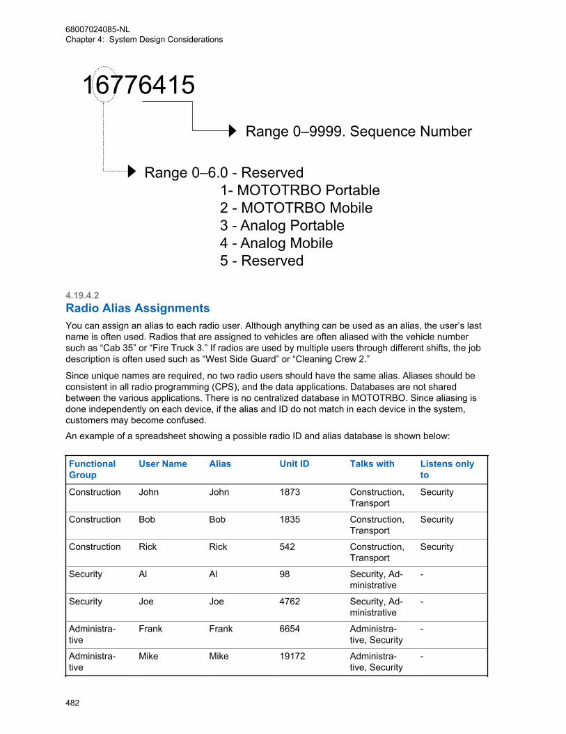
16776415Range 0–9999. Sequence Number
Range 0–6.0 - Reserved1- MOTOTRBO Portable2 - MOTOTRBO Mobile3 - Analog Portable4 - Analog Mobile5 - Reserved
4.19.4.2Radio Alias AssignmentsYou can assign an alias to each radio user. Although anything can be used as an alias, the user’s lastname is often used. Radios that are assigned to vehicles are often aliased with the vehicle numbersuch as “Cab 35” or “Fire Truck 3.” If radios are used by multiple users through different shifts, the jobdescription is often used such as “West Side Guard” or “Cleaning Crew 2.”
Since unique names are required, no two radio users should have the same alias. Aliases should beconsistent in all radio programming (CPS), and the data applications. Databases are not sharedbetween the various applications. There is no centralized database in MOTOTRBO. Since aliasing isdone independently on each device, if the alias and ID do not match in each device in the system,customers may become confused.
An example of a spreadsheet showing a possible radio ID and alias database is shown below:
FunctionalGroup
User Name Alias Unit ID Talks with Listens onlyto
Construction John John 1873 Construction,Transport
Security
Construction Bob Bob 1835 Construction,Transport
Security
Construction Rick Rick 542 Construction,Transport
Security
Security Al Al 98 Security, Ad-ministrative
-
Security Joe Joe 4762 Security, Ad-ministrative
-
Administra-tive
Frank Frank 6654 Administra-tive, Security
-
Administra-tive
Mike Mike 19172 Administra-tive, Security
-
68007024085-NLChapter 4: System Design Considerations
482

FunctionalGroup
User Name Alias Unit ID Talks with Listens onlyto
Administra-tive
Steve Steve 78378 Administra-tive, Security
-
Transport Lenny Lenny 23 Transport,Construction
Security
Transport Carl Carl 2 Transport,Construction
Security
4.19.4.3Group ID IdentificationsGroup IDs for a MOTOTRBO system range between 1 and 16776415. The same approach that is usedto identify radio IDs can be used for Group IDs. Group IDs are not centrally maintained or managed ina MOTOTRBO system. It is up to the system administrator to document the Group designation. Notethat these IDs must match those entered in other radios and data applications in order for the systemto operate correctly.
4.19.4.4Group Alias AssignmentsThe groups should also be consistent throughout the system. Display radios and data applicationsidentify groups by alias. Groups should be named with an alias the customer can easily understand.Highly abstract names often cause confusion.
When assigning aliases, consider character and subscriber limitations. Some radio models may allowmore or fewer characters than the data applications. Since aliasing is done independently in eachdevice, if the alias and ID do not match in each device in the system, customers may becomeconfused. The following figure is an example :
Administrative
TG ID: 62 TG ID: 54 TG ID: 46 TG ID: 8766 TG ID: 123 TG ID: 99 TG ID: 997 TG ID: 368
Cem
ent
fact
ory
Met
al
shop
Car
pent
ers
Pat
rol
Fron
t de
sk
Adm
in
Del
iver
ytru
cks
Cem
ent
mix
ers
ch 1 - slot 1 ch 2 - slot 1 ch 2 - slot 1 ch 2 - slot 1 ch 1 - slot 1 ch 2 - slot 1 ch 1 - slot 1 ch 2 - slot 1
Functional group and talkgroup mapping
Construction Security Transport
4.19.5Determine Which Channel Operates in Repeater Mode or DirectMode/Dual Capacity Direct ModeRepeater mode enables unit-to-unit communications using the repeater. Direct mode/dual capacitydirect mode enables unit-to-unit communications without using the repeater. Each channel on the radiois programmed to be either a direct mode channel, dual capacity direct mode or a repeater modechannel through the CPS.
Channels defined as Repeater channels in the CPS can be toggled to operate in Talkaround modethrough user selection from the menu or a programmable button. When this happens, the transmit
68007024085-NLChapter 4: System Design Considerations
483
frequency is set equal to the receive frequency, and this channel effectively performs like a DirectMode channel.
If a 12.5 kHz RF channel is used for dual capacity direct mode, both timeslots are provisioned for 6.25edirect mode only. Similar to repeater mode, 6.25e channels are configured via CPS to operate in eithertimeslot 1 or timeslot 2, and color code (0-14) can be provisioned differently in each timeslot. The fullrange of radio IDs and talkgroup IDs are available for use in 6.25e direct mode (dual capacity directmode).
4.19.6Supervisor Radios FeatureSupervisor radios are not defined in the CPS by any specific “Supervisor” option. Instead they aresubscribers that have supervisory options enabled. Supervisor radios are responsible foracknowledging Emergency Calls and alarms, and also perform administrative duties such as remotemonitor and selective radio inhibit. Some features should only be allowed to users that can use themresponsibly.
4.19.7Configuring the Private Calls FeatureIn MOTOTRBO systems, capabilities for Private Calls are configured through the subscriber (portableand mobile) CPS. The repeater does not require any specific configuration with respect to PrivateCalls. While the MOTOTRBO CPS enables great flexibility in configuring your system for PrivateCalling, one basic procedure is as follows:
Procedure:1 Program every MOTOTRBO radio in a system with an assigned a unique radio ID in the CPS.
a Go to the General Settings menu.
b In the Radio ID field, enter the radio ID.
2 In the Contacts folder, go to the Digital folder, and add a call type of Private Call.The CPS provides a default name and ID; assign the actual radio ID of the radio that is to beprivately called to this field.
3 Rename the call to an intuitive alphanumeric name (representative of the radio to beaddressed).
All Calls created in the “Contacts” folder appear in the “Contacts” menu of the subscriber byname, and this name also appears on the radio display when a Private Call is received. Ifconfigured as described, radio users are able to make Private Calls by selecting the Private Call,by name, from the radio’s Contacts menu. In addition, similar to assigning a Group Call to achannel as described, it is also possible to assign a Private Call to the TX Contact Nameattribute of a channel, so that users can place Private Calls by making the appropriate channelselection through the top knob on a portable or up/down channel select buttons on a mobile. It isalso possible to assign a Private Call to a radio programmable button (called a “one touch call”in CPS) so that users can place a Private Call at the touch of a button. These latter two methodsare the only methods for non-display radios to place Private Calls.A radio can, in practice, receive a Private Call from any other radio that is available on thechannel, regardless of whether the receiving radio has created a CPS Private Call entry for thatradio. The receiving radio displays the radio ID of the calling radio, rather than an alphanumericalias. Similarly, a radio can place a Private Call to any other radio by utilizing the “manualdialing” option in the radio’s menu; however, the user must know the Radio ID of the calledparty.
68007024085-NLChapter 4: System Design Considerations
484

4.19.8Configuring the All Call FeatureIn MOTOTRBO systems, capabilities for All Calls are configured through the subscriber (portable andmobile) CPS. The repeater does not require any specific configuration with respect to All Calls. Whilethe MOTOTRBO CPS enables great flexibility in configuring a system for All Calls, one basicprocedure is as follows:
Procedure:1 In the Contacts folder, go to the Digital folder, and add a call type of All Call.
The CPS provides a default name.
2 Rename the call to an intuitive alphanumeric name representative of the All Call feature.
All Calls created in the Contacts folder appear in the “Contacts” menu of the subscriber byname.If configured as described, a user would initiate an All Call by selecting the call, by name, fromthe radio’s Contacts menu. Additionally, similar to assigning a Group Call to a channel asdescribed, it is possible to assign an All Call to the TX Contact Name attribute of a channel, sothat users can place All Calls by making the appropriate channel selection through the top knobon a portable or up/down channel select buttons on a mobile. This is the only method for a non-display radio to place an All Call.
It is also possible to assign an All Call to a radio programmable button (called a “Number KeyQuick Contact Access” in the CPS), so that users can place an All Call at the touch of a button.However, this method to initiate an All Call, is only supported on the display portable radios andthrough a keypad microphone with the alphanumeric display mobiles.
Since All Calls are monitored by everyone on a slot, it is suggested that only supervisors begranted the ability to transmit All Calls.
4.19.9Radio Disable FeatureIn MOTOTRBO systems, Radio Disable is configured in the portable and mobile radio CPS. To allow aradio the ability to initiate this function, this option must be enabled in the CPS Menu settings. Topermit (or prevent) a given radio from decoding and responding to this command, this option must beconfigured in the CPS Signaling Systems settings.
Since the ability to disable a user could be misused, it is suggested that only supervisors be grantedthe ability to initiate a Radio Disable.
4.19.10Remote Monitor FeatureIn MOTOTRBO systems, Remote Monitor is configured in the portable and mobile radio CPS. To allowa radio the ability to initiate this function, this option must be enabled in the CPS Menu settings. Topermit (or prevent) a given radio from decoding and responding to this command, this option must beconfigured in the CPS Signaling Systems settings.
If a radio is configured to decode the remote monitor command, the duration that the target radiotransmits after receiving a Remote Monitor command can be set in the CPS Signaling Systemssettings of the target radio.
Since the ability to remotely monitor a user could be misused, it is suggested that only supervisors begranted the ability to initiate a Remote Monitor.
68007024085-NLChapter 4: System Design Considerations
485

4.19.11Radio Check FeatureIn MOTOTRBO systems, Radio Check is configured in the portable and mobile radio CPS. To allow aradio the ability to initiate this function, this option must be enabled in the CPS Menu settings. AllMOTOTRBO radios decode and respond to a Radio Check.
4.19.12Call Alert FeatureIn MOTOTRBO systems, Call Alert is configured in the portable and mobile radio CPS. To allow aradio the ability to initiate this function, this option must be enabled in the CPS Menu settings. AllMOTOTRBO radios decode and respond to a Call Alert.
4.19.13RX Only FeatureIn MOTOTRBO, a radio can be configured as a receive only (RX Only) device and does not transmit.The RX Only mode of operation is useful when a radio user monitors the radio communication, or inhospitals where RF transmission is harmful.
CPSSCapacity Plus Single Site
In Capacity Plus Single Site, Revert ControlStations should be configured as “RX Only” ra-dios, only if the data messages are transportedover-the-air as unconfirmed data messages.For confirmed data messages, an RX Only Re-vert Control Station does not send acknowl-edgement and a radio sends the same datamessage multiple times. Multiple transmissionswaste the air bandwidth and cause the server toreceive duplicate messages.
4.19.14Remote Voice Dekey FeatureIn MOTOTRBO systems, Remote Voice Dekey is configured in the portable and mobile radio CPS. Ifused in a repeater system, the repeater does not require any specific configuration with respect toRemote Voice Dekey. However, the repeater requires the use of Transmit Interrupt capable software.To allow a radio the ability to initiate this function, this feature must be enabled through the CPS. OnlyMOTOTRBO radios provisioned with the ability to be interrupted can dekey in response to the RemoteVoice Dekey command.
The Remote Voice Dekey feature can be used in direct, talkaround, or repeater modes of operation.
The Remote Voice Dekey feature is capable of remotely dekeying group voice calls and private voicecalls; Emergency Calls and non-Emergency Calls; and can be used regardless of whether the initiatingradio is a member of the call being remotely dekeyed. Since it is possible for this feature to remotelydekey a call that the radio is not unmuted to, the radio user may not be aware of the nature of the callthat is being remotely dekeyed. Accordingly, it is recommended that this feature be enabled only insupervisor radios and the radio users be trained on the proper use of the Remote Voice Dekey feature.
The Remote Voice Dekey feature is not capable of remotely dekeying All Calls or non-voice (data orcontrol) calls.
68007024085-NLChapter 4: System Design Considerations
486

4.19.15Emergency Handling ConfigurationConfiguring a communication system (like MOTOTRBO) to handle emergency situations requiressome up front design. In emergency situations, it is ideal that when a user initiates an emergency, theuser is immediately routed to someone who can handle his emergency situation. The previous sectionshave addressed some basic feature descriptions of how emergency can operate.
This section outlines in detail how to program the numerous devices in the system in order to meet theneeds of a customer’s emergency needs and also provide some guidance on choosing the availableoptions. It is recommended to review the sections in Digital Emergency on page 80 for emergencyexplanations.
It is important when creating an emergency handling plan to understand the customer’s existingemergency procedures. An interview with a representative in charge of emergency operations isusually required to fully understand the process. This information acts as a base for selecting aconfiguration.
4.19.15.1Emergency Handling User RolesThe first step is identifying a user's participation in the emergency handling plan. There are three majorroles to identify: Emergency Initiator, Monitoring Supervisor, and Acknowledging Supervisor.
An Emergency Initiator is a user that does not necessarily have any responsibility for handlingemergencies, but is expected, at some point to have an emergency that needs handling. This user’sradio is configured with either an emergency button or an external switch to initiate an emergency. Theradio needs to be programmed on how to contact a Supervisor based on the selected configuration.Alternatively, this radio can be programmed to give a non-persistent indication (display and/or audio)that the current call is an Emergency Call. This indicates to the user that he should avoid interferingwith the call taking place. The majority of users in a system will be considered Emergency Initiators.
A Monitoring Supervisor is a user that needs to know when an emergency occurs, but is not theindividual identified to handle and acknowledge emergencies. This user’s radio provides an indicationthat an Emergency Alarm has been received and provide an indication that an Emergency Call istaking place. This user does not transmit an acknowledgment to the Emergency Alarm. TheEmergency Alarm is persistent on the Monitoring Supervisor’s radio until manually cleared. Duplicateattempts of the same Emergency Alarm do not restart the Emergency indication. There can be multipleMonitoring Supervisors per group. A Monitoring Supervisor may also be an Emergency Initiator.
An Acknowledging Supervisor is the user specifically identified to respond to received emergencysituations. This user’s radio provides an indication that an Emergency Alarm has been received, andprovides an indication that an Emergency Call is taking place. In addition to the indications, this user’sradio is responsible for transmitting an acknowledgment to the Emergency Initiator. Until theEmergency Initiator receives the acknowledgment, Acknowledging Supervisor's radio continues totransmit its emergency alarm messages, until the Acknowledging Supervisor takes action to stop or theradio exhausts the number of programmed retries. It is important to note that the AcknowledgingSupervisor’s radio (not the user) sends the acknowledgment, when it receives the Emergency Alarm.Reception of an emergency alarm acknowledgment only guarantees that the radio received themessage, not the user. Because it is the responsibility of the Acknowledging Supervisor to stop theEmergency Initiator’s retries, duplicate attempts of the same Emergency Alarm restarts the emergencyindication if cleared. It is highly recommended that there only be one Acknowledging Supervisor pergroup and slot. If there is more than one, acknowledgment messages may interfere with each otherwhen transmitting, and cause a delay in acknowledging the Emergency Initiator. An AcknowledgingSupervisor may also be an Emergency Initiator.
These MOTOTRBO radios are configured to operate in each role by setting a few options using theCPS, as described in the following table. These options are configurable per channel, and thereforeper Group, Frequency and Slot. This means that a user can play a different role depending on the
68007024085-NLChapter 4: System Design Considerations
487
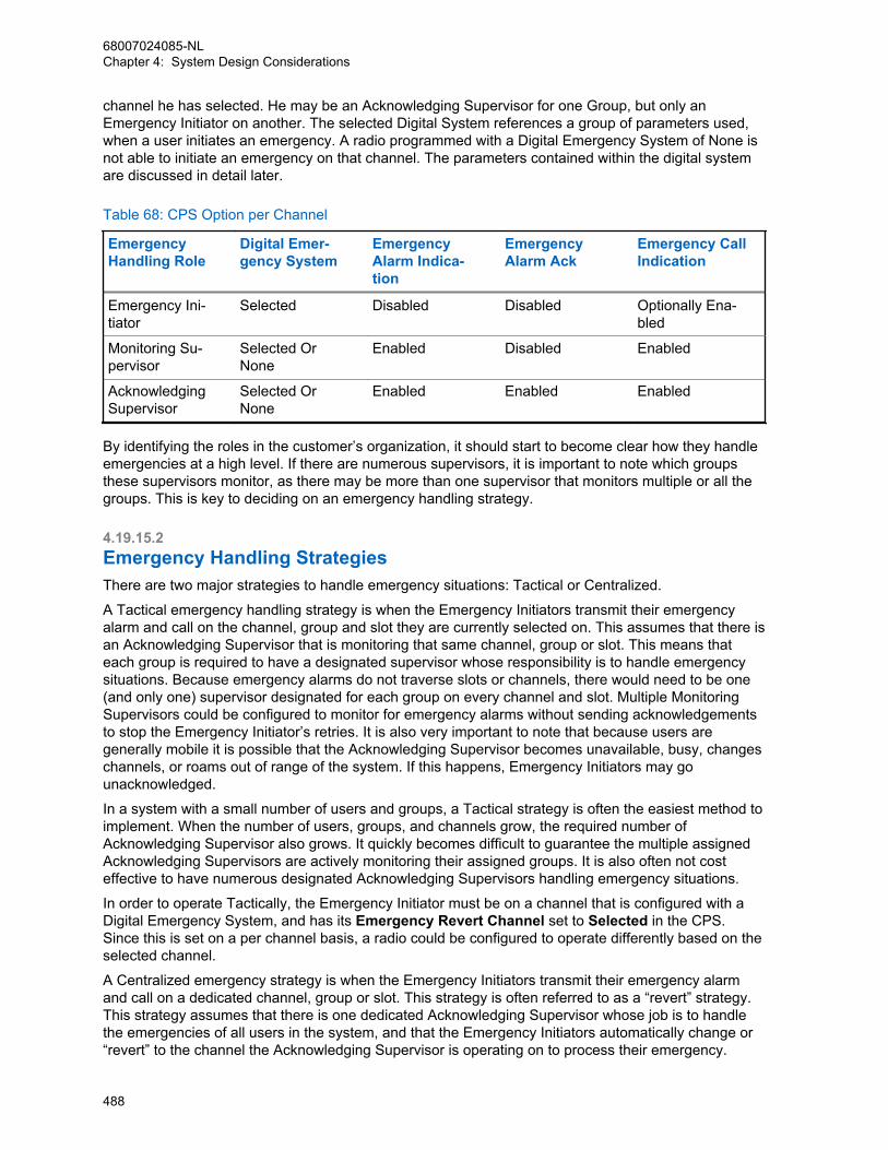
channel he has selected. He may be an Acknowledging Supervisor for one Group, but only anEmergency Initiator on another. The selected Digital System references a group of parameters used,when a user initiates an emergency. A radio programmed with a Digital Emergency System of None isnot able to initiate an emergency on that channel. The parameters contained within the digital systemare discussed in detail later.
Table 68: CPS Option per Channel
EmergencyHandling Role
Digital Emer-gency System
EmergencyAlarm Indica-tion
EmergencyAlarm Ack
Emergency CallIndication
Emergency Ini-tiator
Selected Disabled Disabled Optionally Ena-bled
Monitoring Su-pervisor
Selected OrNone
Enabled Disabled Enabled
AcknowledgingSupervisor
Selected OrNone
Enabled Enabled Enabled
By identifying the roles in the customer’s organization, it should start to become clear how they handleemergencies at a high level. If there are numerous supervisors, it is important to note which groupsthese supervisors monitor, as there may be more than one supervisor that monitors multiple or all thegroups. This is key to deciding on an emergency handling strategy.
4.19.15.2Emergency Handling StrategiesThere are two major strategies to handle emergency situations: Tactical or Centralized.
A Tactical emergency handling strategy is when the Emergency Initiators transmit their emergencyalarm and call on the channel, group and slot they are currently selected on. This assumes that there isan Acknowledging Supervisor that is monitoring that same channel, group or slot. This means thateach group is required to have a designated supervisor whose responsibility is to handle emergencysituations. Because emergency alarms do not traverse slots or channels, there would need to be one(and only one) supervisor designated for each group on every channel and slot. Multiple MonitoringSupervisors could be configured to monitor for emergency alarms without sending acknowledgementsto stop the Emergency Initiator’s retries. It is also very important to note that because users aregenerally mobile it is possible that the Acknowledging Supervisor becomes unavailable, busy, changeschannels, or roams out of range of the system. If this happens, Emergency Initiators may gounacknowledged.
In a system with a small number of users and groups, a Tactical strategy is often the easiest method toimplement. When the number of users, groups, and channels grow, the required number ofAcknowledging Supervisor also grows. It quickly becomes difficult to guarantee the multiple assignedAcknowledging Supervisors are actively monitoring their assigned groups. It is also often not costeffective to have numerous designated Acknowledging Supervisors handling emergency situations.
In order to operate Tactically, the Emergency Initiator must be on a channel that is configured with aDigital Emergency System, and has its Emergency Revert Channel set to Selected in the CPS.Since this is set on a per channel basis, a radio could be configured to operate differently based on theselected channel.
A Centralized emergency strategy is when the Emergency Initiators transmit their emergency alarmand call on a dedicated channel, group or slot. This strategy is often referred to as a “revert” strategy.This strategy assumes that there is one dedicated Acknowledging Supervisor whose job is to handlethe emergencies of all users in the system, and that the Emergency Initiators automatically change or“revert” to the channel the Acknowledging Supervisor is operating on to process their emergency.
68007024085-NLChapter 4: System Design Considerations
488
Because this Acknowledging Supervisor’s role is only to monitor for emergencies, it becomes easier tomanage his availability. Further steps can be taken to guarantee the availability of the AcknowledgingSupervisor. It is a good idea to locate the Acknowledging Supervisor’s radio in a good RF coveragearea of the system, so not to go out of range. Having a designated RF channel and slot that isspecifically used for managing emergencies, lowers the possibility of encountering a busy systemwhen there is heavy emergency traffic.
In larger systems the Acknowledging Supervisor’s role in a centralized configuration is often referred toas a Dispatcher. It is not expected that this Acknowledging Supervisor leave their location and actuallyresolve the emergency. Their role is to contact and dispatch other resources to handle the emergencythat was reported. The Acknowledging Supervisor is able to switch channels to dispatch assistance tothe Emergency Initiator, and then switch back to the emergency channel.
In some cases multiple Centralized configurations may be required. This is often needed when thenumber of users becomes too much for one Acknowledging Supervisor to handle, or if the customer’sorganization is broken into multiple organizations that have their own Acknowledging Supervisor. Thismay also be required if a system contains multiple repeaters with non-overlapping RF coverage. Whileoperating on one site, a radio may not be in range of another site, therefore if the radio were to revertto the other site to process an emergency, the radio may not be in the coverage range of the repeaterto complete the transmission. In this scenario, it is recommended that an Acknowledging Supervisor bedesignated for each RF coverage range. This would require a radio to be configured to revert tochannels within RF coverage of the selected channel.
In order to revert to a Centralized channel, the Emergency Initiator must select the channel that isconfigured with a Digital Emergency System, and has its Emergency Revert Channel set to thedesignated Emergency Channel in the CPS. Since this is configured on a per channel basis, a radiocould be configured to operate differently based on the selected channel. There are 32 DigitalEmergency Systems available. This means that one radio can be configured to revert to 32 differentchannels, depending on the configuration of the Digital Emergency System that is assigned to theselected channel.
It is not recommended that a Centralized emergency strategy be implemented using EmergencyInitiators operating Tactically and one Acknowledging Supervisor scanning multiple channels. Whenmultiple emergencies occur simultaneously it is more effective for the Emergency Initiators to come tothe Acknowledging Supervisor rather the Acknowledging Supervisor searching for the EmergencyInitiators.
4.19.15.3Acknowledging Supervisors in EmergencyThe emergency strategy of the Acknowledging Supervisor should be considered. Since this user is theone identified to handle emergencies, who should they attempt to contact if there is an emergency. In atactical environment, the user may only need to change or possible “revert” to another channel tocontact another Acknowledging Supervisor. In a centralized configuration with multiple dispatchers,one Acknowledging Supervisor dispatcher could be configured to revert to the other AcknowledgingSupervisor dispatcher. If there is no other individual to contact, the Acknowledging Supervisor maysimply wish to operate tactically, and transmit the emergency on the selected channel so that theMonitoring Supervisors can be contacted.
4.19.15.4Extended Emergency Call Hang TimeThe MOTOTRBO repeater reserves the channel for a short duration after a voice transmission. Bydefault the call hang time associated with an emergency is slightly larger than those for Group Callsand Private Calls. The repeater can be configured to extend the call hang time for Emergency Callseven longer to provide an additional opportunity for the Emergency Initiator or EmergencyAcknowledger to communicate without competing with other users.
68007024085-NLChapter 4: System Design Considerations
489
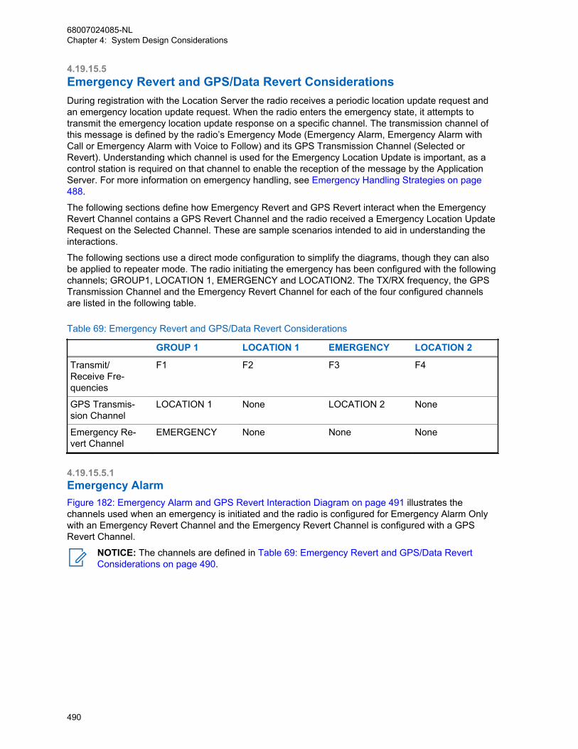
4.19.15.5Emergency Revert and GPS/Data Revert ConsiderationsDuring registration with the Location Server the radio receives a periodic location update request andan emergency location update request. When the radio enters the emergency state, it attempts totransmit the emergency location update response on a specific channel. The transmission channel ofthis message is defined by the radio’s Emergency Mode (Emergency Alarm, Emergency Alarm withCall or Emergency Alarm with Voice to Follow) and its GPS Transmission Channel (Selected orRevert). Understanding which channel is used for the Emergency Location Update is important, as acontrol station is required on that channel to enable the reception of the message by the ApplicationServer. For more information on emergency handling, see Emergency Handling Strategies on page488.
The following sections define how Emergency Revert and GPS Revert interact when the EmergencyRevert Channel contains a GPS Revert Channel and the radio received a Emergency Location UpdateRequest on the Selected Channel. These are sample scenarios intended to aid in understanding theinteractions.
The following sections use a direct mode configuration to simplify the diagrams, though they can alsobe applied to repeater mode. The radio initiating the emergency has been configured with the followingchannels; GROUP1, LOCATION 1, EMERGENCY and LOCATION2. The TX/RX frequency, the GPSTransmission Channel and the Emergency Revert Channel for each of the four configured channelsare listed in the following table.
Table 69: Emergency Revert and GPS/Data Revert Considerations
GROUP 1 LOCATION 1 EMERGENCY LOCATION 2
Transmit/Receive Fre-quencies
F1 F2 F3 F4
GPS Transmis-sion Channel
LOCATION 1 None LOCATION 2 None
Emergency Re-vert Channel
EMERGENCY None None None
4.19.15.5.1Emergency AlarmFigure 182: Emergency Alarm and GPS Revert Interaction Diagram on page 491 illustrates thechannels used when an emergency is initiated and the radio is configured for Emergency Alarm Onlywith an Emergency Revert Channel and the Emergency Revert Channel is configured with a GPSRevert Channel.
NOTICE: The channels are defined in Table 69: Emergency Revert and GPS/Data RevertConsiderations on page 490.
68007024085-NLChapter 4: System Design Considerations
490

Figure 182: Emergency Alarm and GPS Revert Interaction Diagram
MOTOTRBOControl Station(digital mode)
USB
USB
MOTOTRBOControl Station(digital mode)
MCDD
Application Server
Presence Notifier
Location Server
MOTOTRBO SU(digital mode)
MOTOTRBO SU(digital mode)
GPS
TX=f1RX=f1
TX=f2RX=f2
Loca
tion R
espo
nse
f 2
Location Request
Presence
f1
f1
f1
Em
g. A
larm
f 3f 3
2
1
The following describes the sequence of events.
1 The radio switches from the Selected Channel, f1, to the Emergency Revert Channel, f3. From herethe radio transmits the Emergency Alarm and waits for the acknowledgment. While waiting for theacknowledgment, the Emergency Location Update is held in queue.
68007024085-NLChapter 4: System Design Considerations
491

2 Once the acknowledgment is received the radio switches back to the selected channel, f1, andtransmits the Emergency Location Update.
Therefore, in this scenario the GPS Revert Channel associated with the Emergency Revert Channelhas no impact on the channel used to transmit the Emergency Location Update.
4.19.15.5.2Emergency Alarm and CallFigure 183: Emergency Alarm and Call and GPS Interaction Diagram on page 492 illustrates thechannels used when an emergency is initiated and the radio is configured for Emergency Alarm andCall with an Emergency Revert Channel and the Emergency Revert Channel is configured with a GPSRevert Channel.
Figure 183: Emergency Alarm and Call and GPS Interaction Diagram
MOTOTRBOControl Station(digital mode)
USB
USB
USB
USB
MOTOTRBOControl Station(digital mode)
MOTOTRBOControl Station(digital mode)
MOTOTRBOControl Station(digital mode)
MCDD
Application Server
Presence Notifier
Location Server
MOTOTRBO SU(digital mode)
MOTOTRBO SU(digital mode)
GPS
TX=f1RX=f1
TX=f2RX=f2
TX=f3RX=f3
TX=f4RX=f4
Loca
tion R
espo
nse
f 2
Location Response (Emg.)
f4
Location Request
Presence
f1
f1
f1
Location Request (Emg.)
Presence (Emg.)
f3
f3
f3
Em
g. A
larm
/Voi
ce
f 3f 3
1
2
4
3
NOTICE: The channels are defined in Table 69: Emergency Revert and GPS/Data RevertConsiderations on page 490.
The following describes the sequence of events.
1 The radio switches from the Selected Channel, f1, to the Emergency Revert Channel, f3. From herethe radio transmits the Emergency Alarm and waits for the acknowledgment. While waiting for theacknowledgment, the Emergency Location Update is held in queue.
68007024085-NLChapter 4: System Design Considerations
492
2 Once the acknowledgment is received, the radio switches to the Emergency Revert’s GPS RevertChannel, f4, and then transmits the Emergency Location Update.
3 After this transmission, the radio switches to the Emergency Revert Channel, f3, and while notbeing involved in voice calls, it registers.
NOTICE: This requires the Emergency Revert Channel to be ARS enabled.
4 After registration, periodic location updates are sent on the Emergency Revert’s GPS RevertChannel, f4, until the emergency is cleared.
This configuration in Figure 183: Emergency Alarm and Call and GPS Interaction Diagram on page492 is useful when a system needs to simultaneously support multiple Emergency Calls from multiplegroups on a single Emergency Revert Channel. The placement of Emergency Calls on the EmergencyRevert Channel and the location updates on a different channel significantly increases both emergencyvoice throughput and Location Update throughput while in the emergency state. It should be noted thatchanging the Emergency’s GPS Transmission Channel to either the Selected Channel, f1, or theEmergency Revert Channel, f3, removes one control station from the system. The actual configurationselected depends on actual customer requirements.
4.19.15.5.3Emergency Alarm with Voice to FollowFigure 184: Emergency Alarm with Voice to Follow and GPS Revert Interaction Diagram on page 494illustrates the channels used when an emergency is initiated and the radio is configured for EmergencyAlarm with Voice to Follow with an Emergency Revert Channel and the Emergency Revert Channel isconfigured with a GPS Revert Channel.
68007024085-NLChapter 4: System Design Considerations
493
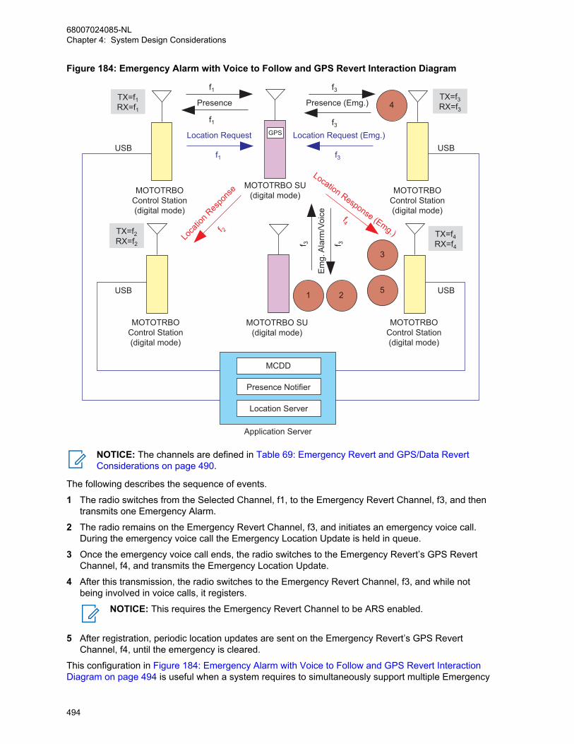
Figure 184: Emergency Alarm with Voice to Follow and GPS Revert Interaction Diagram
MOTOTRBOControl Station(digital mode)
USB
USB
USB
USB
MOTOTRBOControl Station(digital mode)
MOTOTRBOControl Station(digital mode)
MOTOTRBOControl Station(digital mode)
MCDD
Application Server
Presence Notifier
Location Server
MOTOTRBO SU(digital mode)
MOTOTRBO SU(digital mode)
GPS
TX=f1RX=f1
TX=f2RX=f2
TX=f3RX=f3
TX=f4RX=f4
Loca
tion R
espo
nse
f 2
Location Response (Emg.)
f4
Location Request
Presence
f1
f1
f1
Location Request (Emg.)
Presence (Emg.)
f3
f3
f3
Em
g. A
larm
/Voi
ce
f 3f 31 2
3
5
4
NOTICE: The channels are defined in Table 69: Emergency Revert and GPS/Data RevertConsiderations on page 490.
The following describes the sequence of events.
1 The radio switches from the Selected Channel, f1, to the Emergency Revert Channel, f3, and thentransmits one Emergency Alarm.
2 The radio remains on the Emergency Revert Channel, f3, and initiates an emergency voice call.During the emergency voice call the Emergency Location Update is held in queue.
3 Once the emergency voice call ends, the radio switches to the Emergency Revert’s GPS RevertChannel, f4, and transmits the Emergency Location Update.
4 After this transmission, the radio switches to the Emergency Revert Channel, f3, and while notbeing involved in voice calls, it registers.
NOTICE: This requires the Emergency Revert Channel to be ARS enabled.
5 After registration, periodic location updates are sent on the Emergency Revert’s GPS RevertChannel, f4, until the emergency is cleared.
This configuration in Figure 184: Emergency Alarm with Voice to Follow and GPS Revert InteractionDiagram on page 494 is useful when a system requires to simultaneously support multiple Emergency
68007024085-NLChapter 4: System Design Considerations
494
Calls from multiple groups on a single Emergency Revert Channel. The placement of Emergency Callson the Emergency Revert Channel and the location updates on a different channel significantlyincreases both emergency voice throughput and Location Update throughput while in the emergencystate. Changing the Emergency’s GPS Transmission Channel to either the Selected Channel, f1, or theEmergency Revert Channel, f3, removes one control station from the system. The actual configurationselected depends on actual customer requirements.
4.19.16Channel Access ConfigurationChannel access methods must be specified in the radio’s codeplug for each channel through the CPS,that is the TX (Transmit) parameters for each defined channel contains an Admit Criteria option thatmust be set to one of the three possible values described.
• Always,
• Channel Free, or
• Color Code Free.
An Admit Criteria of Always is sometimes referred to as “impolite channel access”. An Admit Criteria ofChannel Free is referred to as “polite to all”. Finally, an Admit Criteria of Color Code Free is referred toas “Polite to own color code”. In polite mode, the radio does not transmit on a channel if there is anyactivity detected on that channel. In impolite mode, the radio transmits on a channel regardless of anyactivity on that channel. When operating in impolite mode a radio user causes RF contention if there isanother call on the same slot currently in progress. See MOTOTRBO Channel Access on page 67.
Radio users provisioned for polite operation press their PTT to determine if they can transmit or not. ATalk Permit Tone or Talk Denial Tone indicates if they have been granted or denied access. Impoliteusers are allowed to transmit regardless if the channel is busy or idle, although they would still requireto wake the repeater.
The LED busy indication on the radios represents the presence of RF activity on the selected channeland is not specific to the digital slot currently being monitored. Therefore, if the LED indicates no RFactivity on the channel, the radio user can be sure their slot is idle. However, if the LED indicates thepresence of RF activity on the channel, the radio user does not know if their slot is actually idle or busy.If the radio users transmit when the LED indicates a busy channel, there is a chance their transmissionmay collide with another transmission. Care should be taken since RF collisions in digital mode mostlikely results in both transmissions not reaching their intended target. Therefore, it is highly recommendthat only well trained and disciplined radio users are configured to have impolite channel access.
4.19.17Zones and Channel Knob ProgrammingThe MOTOTRBO radio is capable of being programmed with up to 160 channels. Each radio has a 16-position selector knob/switch, in which various channels and call types can be programmed. In order tomaximize the programming capability of the radio, the concept of “zones” is introduced. Zones can becreated on the radio through the channels menu of the CPS. A “zone” can contain up to 16 channelsthat are mapped to the 16-position top selector knob of the portable radio or the channel numberselector on a mobile. Radio users that require more than 16 channels must organize them into multiplezones in the CPS, so that they can be accessed as “zones” in the radio menu.
From the radio menu, the user can navigate to the “zones” icon, select it, and switch to a differentzone. When in the different zone, the 16-position selector knob/switch is now programmed with thatzone’s channels and call types. It is recommended that the Zone should be given aliases that can beunderstood by the end user.
68007024085-NLChapter 4: System Design Considerations
495
4.20Base Station Identifications (BSI) Setting ConsiderationsBase Station Identification (BSI), sometimes referred to as CWID, is used to identify the licenseeoperating a repeater or base station. Some form of station identification is usually necessary to complywith the requirements of the local radio regulatory authority.
The transmission time of the Base Station ID (BSI) is proportional to the number of characters in theBSI. To improve channel efficiency, it is recommended to keep the BSI length short. The content of theBSI needs approval from regulatory bodies (for example, FCC in USA). Regulatory bodies and theirregulations may vary from nation to nation, thus customers are required to understand their ownnational laws and regulations while selecting BSI characters and its length.
BSI is available on the MOTOTRBO repeater when configured for analog or digital mode. In bothmodes, BSI is generated using a sinusoidal tone modulated on an FM carrier. The station transmits theconfigured Morse code alphanumeric sequence when one of two configured BSI timers has expired.The Exclusive BSI Timer is named TX Interval in CPS and the Mixed with Audio Timer is named MixMode Timer in CPS. The goal of these two timers is to minimize the impact to the ongoing traffic whilestill being compliant with regulatory authorities.
TX Interval is used to configure an “Exclusive BSI” which is sent the next time the repeater de-keys.The Mix Mode Timer is used to configure a “Mixed with Audio” which is mixed with the analog audio onthe channel. Mixed with Audio BSI is only utilized when configured for analog operation. Mixing BSIwith digital audio is not supported in MOTOTRBO.
When the Exclusive BSI Timer expires, the repeater transmits BSI the next time the repeater de-keys.This allows the BSI to be transmitted without disrupting on going voice, which is ideal. Furthermore, ifthe Exclusive BSI Timer expires while the repeater is not active (no subscriber activity) the repeaterdoes not wake up and send BSI. Instead, it waits until the next transmission occurs and then transmitsBSI upon de-key. BSI is only required during times of activity. Note that Exclusive BSI is interruptible inanalog mode if the repeater receives a radio transmission. If interrupted, the BSI is attempted again atthe next dekey. Also, whenever the repeater is forced to de-key due to a Time Out Timer expiring, ittakes the opportunity to transmit an Exclusive BSI. Exclusive BSI is non-interruptible in digital andDynamic Mixed modes.
When the “Mixed with Audio” BSI Timer expires, the repeater performs the BSI mixed with the on goingaudio on the channel. It is very important to note that there is a two minute hold-off timer when therepeater first keys up. The purpose of this additional hold-off timer is to make sure that the BSI is notmixed with audio immediately after being de-keyed for a long duration. This delay gives the repeater achance to transmit the exclusive BSI before interrupting the audio.
Both the Exclusive BSI Timer and the Mixed with Audio Timer are reset after completion of a BSItransmission.
It is recommended that the Exclusive BSI Timer (TX Interval) is set at 75% of the regulatory authority’srequired BSI period and the Mixed with Audio BSI (Mix Mode Timer) is set at 95% of the regulatoryauthority’s required BSI period. This way, the repeater begins attempting to send the BSI exclusivelywell before the required time. This interrupts the voice with mixed BSI as it gets closer to the requiredperiod if it has not found an opportunity to perform BSI exclusively.
BSI can be completely disabled by setting both the Exclusive BSI Timer and the Mixed with Audio BSITimer to 255 in the CPS. It is not a valid configuration to disable the Exclusive BSI and only have theMixed with Audio BSI enabled. This results in only Mixed with Audio BSI being sent in scenarios wherethe repeater is keyed for two minutes.
If the Exclusive BSI Timer is enabled, and the Mixed with Audio BSI is disabled, it is possible thatduring periods of heavy use, the BSI will not be generated within the configured time period. For , it isrecommended that the Mixed with Audio BSI is enabled at all times.
Since Mixed with Audio does not operate in digital mode or in Dynamic Mixed Mode, it is possible thatduring extended periods of high activity the repeater never has a chance to de-key, and would
68007024085-NLChapter 4: System Design Considerations
496
therefore never have a chance to send BSI. This is more likely on a highly loaded GPS only repeater.This should be combated by lowering the traffic on the channel or by lowering the subscriber inactivitytimer (SIT) in the repeater. This de-keys the repeater quicker between transmissions and provide ahigher chance of de-key and therefore a higher chance of sending Exclusive BSI in the desired timeframe.
Since Exclusive BSI is interruptible in analog mode, a situation may arise where extended periods ofhigh activity may cause the repeater to continually dekey, attempt BSI and then be interrupted byanother inbound transmission. The dekeying and re-keying of the repeater causes the hold off timer tobe reset and the Mixed with Audio BSI is never triggered unless a particular transmission lasts overtwo minutes. In this case, it is recommended that the hangtime be increased so that the repeater doesnot dekey between every transmission. If this period of high activity occurs longer than two minutes,the Mixed with Audio occurs, otherwise the Exclusive BSI occurs during a period of decreased trafficload.
It may not be desirable to enable Mixed with Audio BSI with the use of analog data (i.e. MDC or VRMdata). The mixing of the BSI with the analog signaling may most likely cause the signaling to becomecorrupted.
4.21GPS Revert Considerations (For Single Repeater and IP SiteConnect only)GPS revert, when used correctly, can significantly improve the integrated voice and location dataperformance of a system. To maximize location throughput while minimizing missed data (text,telemetry, and others) and voice transmissions, there are a number of factors that must be considered.
• Non-location update traffic should not be transmitted on the GPS Revert Channel when attemptingto maximize the Location load on the GPS Revert Channel.
• Avoid adding the GPS Revert Channel into the Scan List if the location load is high, as scanningradios often land on this channel and qualify traffic that is not for them. This can slow downscanning.
• While in repeater mode, avoid placing the alternate slot associated with GPS Revert Channel intothe Scan List if the location load is high. Scanning radios often land on this channel to qualify trafficthat is not for them. This can slow down scanning.
• For single site mode, the revert channel must be set to “Selected” on the radio used as the controlstation.
NOTICE: For IP Site Connect mode, the revert channel must be set to “Selected” on theradio used as the control station.
• It is not recommended to use a portable as a control station, but if a portable is used as a controlstation then battery saver mode should be disabled since the Location Update messages are notpreceded with preambles.
• Voice, data or control messages that are sent to an radio on the GPS Revert Channel are notreceived. The radio is only on the GPS Revert Channel to transmit location updates and it DOESNOT qualify activity on this channel.
• If group data is to be supported on a system, the inclusion of preambles should be added tominimize the occurrence of the group data message being missed while an radio is on the GPSRevert Channel.
• Avoid situations where a large number of subscribers are powered on in a relatively short period oftime as this causes a flood of registration messages that impacts the voice quality of service on theSelected Channel during the registration process. GPS Revert and Loading on page 378 forrecommendations on minimizing impact when using Motorola Solutions applications.
68007024085-NLChapter 4: System Design Considerations
497

• In order to minimize users from inadvertently changing a radio to the GPS Revert Channel, it isrecommended that the GPS Revert Channel(s) is placed in a different zone than the primary voiceand data channel(s).
4.22Enhanced GPS Revert ConsiderationsThe following is a summarized list of items to keep in mind when configuring the Enhanced GPSfeature in a system:
• All GPS and raw data messages from the option board and non-IP peripheral devices are notsupported over the Enhanced GPS Revert channel for one-time and periodic transmissions.
• If a repeater slot configured as “Enhanced GPS Revert” is power cycled, the subscriber’s GPSupdates scheduling begin again because the scheduling information is not stored in the repeater’smemory.
• The window size on all repeaters and subscribers should match.
• GPS data must be configured as “unconfirmed” on the GPS Revert channel on the radio.
• Enhanced GPS only requires to be enabled on the Enhanced GPS Revert channel of the radio, andnot on the Home channel. However, if header compression is planned for use, then this featureneeds to be enabled on the Home channel instead.
• For single site mode, the revert channel must be set to “Selected” on the radio used as the controlstation.
IPSCIP Site Connect For IP Site Connect mode, the revert channel
must be set to “Selected” on the radio used asthe control station.
• Only Enhanced GPS-configured subscribers can work on the Enhanced GPS Revert channel. Thisfeature do not support the following configurations:
- Legacy revert repeaters working with Enhanced GPS Revert subscribers
- Legacy subscribers working with Enhanced GPS Revert repeaters
- Legacy repeaters working with Enhanced GPS Revert repeaters in IP Site Connect mode
• An application making a periodic request with the Enhanced GPS feature should only make arequest with a cadence of 0.5, 1, 2, 4, and 8 minutes. When the window size is 1 or 2 with theCSBK data feature enabled, the application should only make a request with a cadence of 7.5, 15,30, 60 and 120 seconds. If the cadence is different, the subscriber responds with a LRRP errormessage “PROTOCOL_ELEMENT _NOT_SUPPORTED”. This is also valid for persistent requests.
• A radio can only have one periodic request at a time. If “Persistent Storage” is enabled on the radio,the user must send a Triggered-Location-Stop-Request from the application before sending a newperiodic request. If the user needs to change the application, then the user should either delete allrequests from the Persistent Storage through the CPS or ensure that a Triggered-Location-Stop-Request is sent from the first application before a new periodic request is sent by the newapplication.
• The ARS initialization delay feature is recommended if a customer plans to use Enhanced GPS in asystem that has many subscribers powering on at the same time and all of them need ARS. Thishelps to reduce ARS collisions at power up. More details in ARS Initialization Delay on page 113.
• If CWID is enabled, no GPS updates will be sent out while CWID is being transmitted. The user canchoose to disable CWID via the CPS if needed.
68007024085-NLChapter 4: System Design Considerations
498
• If there are free windows available in a system, these may be used by the repeater to go intohibernate mode. Hence, reserving more one-time windows (running at 60% or 45% capacity)increases the chances of hibernation. When the window size is reduced to 1 or 2 with the number ofsubscribers and GPS update rate unchanged, free windows available in a system increase, hencethe chances of hibernation increase accordingly. CPS configuration “Shared Channel Frequency”increases the chances of hibernation on the Enhanced GPS channel too. However, this leads tomore channel collision when the subscribers send window requests, because the configurationcauses the free windows to concentrate at the end of a data frame. Therefore the “Shared ChannelFrequency” configuration may not be necessary when the CSBK data feature is enabled withwindow size 1 or 2.
• The CSBK data feature is recommended when high system throughput is required. Refer to Table16: The System Throughput on page 112. However, there are some limitations to this feature.
4.22.1Single Site ModeIn Single Site Conventional mode, all location responses are sent over the repeater slot configured asEnhanced GPS revert. The following three configurations are possible:
• One slot configured as Enhanced GPS Revert and another slot for voice and data: In thisconfiguration, only location responses are sent over the Enhanced GPS Revert channel. Voice, textmessages, ARS, and other data are sent over the other slot.
• Both slots configured for Enhanced GPS Revert: This configuration is recommended if thenumber of subscribers sending location updates exceeds the capacity of one Enhanced GPS slot.In this case, a second repeater would be needed to support voice, text messages, ARS and otherdata.
• Alternative slot configured for Enhanced GPS Revert: This configures the alternative slot (thatis, the other slot) for enhanced GPS transmission instead of using a data revert channel on adifferent repeater. Because the subscriber is using the alternative slot of the same repeater as theGPS revert channel, it does not need to spend a lot of time (in sync) switching between differentrepeaters. This configuration can minimize audio holes, and the subscriber can even send GPSupdate while receiving voice calls. It also allows GPS data transmission in either CSBK data orpacket data format. However, CSBK data results in a smaller audio hole (~60ms or less) owing toits single burst format. This configuration is recommended to be used with the CSBK data format.
4.22.2Capacity Plus Single Site and Capacity Plus Multi Site Modes
CPSM In Capacity Plus and Capacity Plus Multi Site modes, all location responses and ARS
registration messages are sent over the repeater slot configured as Enhanced GPS revert. A datarevert repeater can be configured for Enhanced GPS revert and the following two configurations arepossible through the CPS:
• One slot configured as Enhanced GPS Revert and another slot for Data Revert: In thisconfiguration, GPS and ARS registration data are sent over the slot configured as Enhanced GPSrevert. All other data and voice either goes on the Data Revert slot or on the Trunked Channels.
• Both slots configured for Enhanced GPS Revert: This configuration is recommended if thenumber of subscribers sending location updates exceeds the capacity of the Enhanced GPSthroughput of one slot. In this configuration, a separate data revert repeater or trunked repeaterscan be used for other data such as voice, text messages, and server bound data.
68007024085-NLChapter 4: System Design Considerations
499
4.22.3IP Site Connect Mode
IPSC In IP Site Connect mode, GPS updates are routed on the slot configured as wide area
Enhanced GPS revert slot. Three configurations are possible through the CPS for a wide areaEnhanced GPS Revert system:
• One slot configured as Enhanced GPS Revert and another slot for voice and data: In thisconfiguration, one slot of all the peers in the network is configured for Enhanced GPS operationwhile the other slot can be used for voice, ARS, text messages, and all other server data.
• Both slots configured for Enhanced GPS Revert: This configuration is recommended if thenumber of subscribers sending location updates exceeds the capacity of the Enhanced GPSthroughput of one slot. In this configuration, the entire IP Site Connect system is used for sendinglocation updates only.
• Alternative slot configured for Enhanced GPS Revert: This configures the alternative slot (thatis, the other slot) of the same repeater for enhanced GPS transmission instead of using a datarevert channel on a different repeater. This configuration can be applied to both local channels orwide area channels. Because the subscriber is using the alternative slot of the same repeater as theGPS revert channel, it does not need to spend a lot of time (in sync) switching between differentrepeaters. This configuration can minimize audio holes, and the subscriber can even send GPSupdate while receiving voice calls. It also allows GPS data transmission in either CSBK data orpacket data format. However, CSBK data results in a smaller audio hole (~60ms or less) owing toits single burst format. This configuration is recommended to be used with the CSBK data format.
4.22.3.1Other Considerations
IPSC
• Only one repeater in the wide area Enhanced GPS Revert system should select a value for “PeriodWindow Reservation” in the CPS. All other repeaters should choose a value of “None” for this field.
If the inter-repeater communication delay is more than 60 milliseconds, then the window size shouldexceed seven.
4.23Enhanced Channel Access ConsiderationThe Enhanced Channel Access (ECA) feature is a channel access procedure in which a call initiatingradio transmits a channel access request and listens on the channel to determine the status of therequest. The radio continues with the transmission of the call only when access to the channel isobtained. Only one of the requesting radios can obtain channel access to proceed with the calltransmission. The ECA provides the ability to reserve a channel over-the-air for one of the call initiatingradios, and provide exclusive access to that radio for a short duration.
Enhanced Channel Access is a Motorola Solutions proprietary feature and is not defined in the DMRstandard.
68007024085-NLChapter 4: System Design Considerations
500
NOTICE: ECA is applicable only in repeater mode in Single Site Conventional mode ofoperation.
IPSCIP Site Connect
It is applicable only in repeater mode in IP SiteConnect mode of operation.
CPSS
Capacity Plus and Capacity Plus Multi Site
ECA is not required in Capacity Plus or Capaci-ty Plus Multi Site modes because their callstartup processes implicitly included ECA.
4.23.1Enhanced Channel Access Advantages• Improves voice/data call success rate by minimizing over-the-air call collisions due to multiple
radios keying up within close proximity
• Prevents call transmission when the radio is out of inbound range (but within the outbound range)and provides correct call status indication to the user
• Improves the GPS data success rate on the GPS revert channel by minimizing collisions
• Prioritized channel access for an initiating radio to proceed with a call, among other radios
4.23.2Enhanced Channel Access LimitationsEnhanced Channel Access is configurable on the radio and can be enabled or disabled on aconventional digital channel and GPS/Data Revert Channel.
When enabled in the radio, the repeater supports ECA on conventional digital channels. However, therepeater does not support this feature on Enhanced GPS and DMM channels.
IPSCIP Site Connect
Enhanced Channel Access is configurable onthe radio and can be enabled or disabled on aIPSC LACs, IPSC WACs.When enabled in the radio, the repeater sup-ports ECA on IPSC LACs, IPSC WACs.
However, the repeater does not support thisfeature on Enhanced GPS and DMM channels.
CPSSCapacity Plus
ECA is built into Capacity Plus Trunked Chan-nels and not configurable by the user. This fea-ture is disabled and not required when the En-hanced GPS feature is enabled on the channel,because each radio transmits during an as-signed time window.When enabled in the radio, the repeater sup-ports ECA on Capacity Plus Data Revert Chan-nels. However, the repeater does not supportthis feature on Enhanced GPS and DMM chan-nels.
68007024085-NLChapter 4: System Design Considerations
501
When enabled, ECA is applicable only to polite transmissions initiated by the radio user. If the AdmitCriteria in the radio is configured as Channel Free or Color Code Free, the radio applies the ECAprocedure when a voice call is initiated. If the Admit Criteria is configured as Always, the ECAprocedure is not applied. Data and CSBK calls are always polite transmissions, regardless of theconfigured Admit Criteria. Therefore, ECA is applied during call transmission if the feature is enabled.However, this slightly increases the system/voice access times for voice calls and latency for data,CSBK calls.
IPSCIP Site Connect
When a radio auto roams to a new site in anIPSC system configuration, the radio appliesthe ECA configuration from the roamed channeland the Admit Criteria from the selected chan-nel.
For phone calls occurring in all system configurations, ECA is enabled by default to achieve optimumperformance. It is also recommended to enable ECA on all radios accessing the channel to derivemaximum benefit from the feature.
NOTICE: For a correct and reliable operation, it is strongly recommended to upgrade therepeater firmware version to R01.08.00 or later, before initiating calls with the ECA featureenabled on the radio.
4.24Failure Preparedness – Direct Mode Fallback (Talkaround)
NOTICE: Occasionally, Talkaround mode is incorrectly referred to as “direct mode”, but theyare different. Direct mode is a mode of operation in a system environment whereby norepeaters are present. Talkaround mode is direct radio-to-radio communication for systems thatprimarily use a repeater but occasionally communicate without a repeater.
A repeater channel is defined by having different receive and transmit frequencies, and any channelthat is programmed with the CPS to have different receive and transmit frequencies are considered tobe a repeater channel and the MOTOTRBO radio expects a repeater operating on that channel. Theradio user receives an access-denied tone if there is no repeater available or if the radio is out of rangeof the repeater. Channels defined as repeater channels in CPS can be modified to operate inTalkaround mode through user selection from the menu or a programmable button. When a repeaterchannel is thus modified to operate in Talkaround mode, the transmit frequency is set equal to thereceive frequency, and it effectively becomes a direct mode channel. The system now performssimilarly to the direct mode topologies we have previously described.
4.25Failure Preparedness – Uninterrupted Power Supplies (BatteryBackup)To determine the UPS capacity, follow these simple steps:
Procedure:1 List all equipment to be protected by the UPS on a worksheet.
2 Read the nameplate data on each of the devices listed. Write down the voltage and amperagefor each device.
3 Multiply the voltage by the amperage of each device to calculate the Volt/Amps (VA).
Some equipment, such as PC power supplies, may be marked with a power consumptionmeasured in Watts.
68007024085-NLChapter 4: System Design Considerations
502
4 Convert Watts to VA by dividing Watts by 0.65 (for a power factor of 0.65), or multiply by 1.54.
The power factor refers to the relationship between the apparent power (volt-amps) required bythe device and the actual power (watts) produced by the device.
5 Total the VA for all devices designated to protect with the UPS and enter it in the “Subtotal” field.
6 Multiply the subtotal found in step 5 by 0.25 and enter it as the “Growth Factor”.
This number takes into account room for future growth. This growth factor allows for a 5% rate ofgrowth for each year over a five-year period.
7 Add the “Growth Factor” to the “Subtotal” to get the “Required VA”.
8 Select the appropriate UPS model by choosing a model that has a VA rating at least as large asthe “Required VA” that was calculated.
4.26Dynamic Mixed Mode System Design ConsiderationsDuring Dynamic Mixed Mode (DMM) operation, the repeater dynamically switches between and digitalmodes to transmit and digital calls. It is only supported in Single Site Conventional mode. A DynamicMixed Mode channel is a programmable channel in the repeater and the channel can be added usingthe CPS.
To support the DMM feature in the repeater, the following design rules have been laid out.
• Once a call type (or digital) has been qualified, the repeater does not attempt to qualify another calltype until the current call is complete, including the call hang time hang and channel hang time. Fordigital calls, the hang time needs to be expired on both logical channels. call type includes an over-the-air call or any operation (PTT, pin knockdown) on the 4-wire Repeater Interface (ARI) trying toaccess the repeater.
• Console device(s) are supported only when the repeater has not qualified an over-the-air digital call.An audible alert (channel busy tone) is generated over the speaker and Rx audio pins on the 4-wirerepeater interface to indicate that the channel is busy and that the console access has been denied.
• Only PL (DPL/TPL) squelch type repeat is supported in MOTOTRBO repeater as CSQ repeat is notsupported. However, if the receive squelch type is configured to CSQ, the received audio is sentover the Rx audio accessory pin for community repeater operation.
• To ensure proper Dynamic Mixed Mode operation, only exclusive CWID transmission is supportedin MOTOTRBO repeater operating in Dynamic Mixed Mode, while mixed CWID is not supported inorder to be compliant with the digital mode of operation. Furthermore, the exclusive CWIDtransmission cannot be interrupted by either over-the-air or repeater accessory PTT transmission.
4.26.1Configuring Considerations for a Dynamic Mixed Mode System A few repeater and subscriber configuration recommendations have been laid out to ensure properDynamic Mixed Mode (DMM) system operation.
Procedure:1 For analog repeater operation, configure the Rx and Tx squelch types as PL (TPL or DPL) in the
repeater.
The Dynamic Mixed Mode repeater does not repeat if Rx squelch is configured as CSQ.
2 Configure the Tx and Rx squelch types as PL (TPL or DPL) in both legacy analog andMOTOTRBO radios.
If Rx squelch type is configured as CSQ, the radios unmute to digital transmission and play outdigital noise.
68007024085-NLChapter 4: System Design Considerations
503

3 Configure the admit criteria of both analog and digital radios to be polite to each other.
MOTOTRBO radio configuration recommendations are provided in the table below. For legacyanalog radios, it is recommended to configure the polite rule as Busy Channel Lockout onWrong PL code.
4 If MOTOTRBO radios need to communicate on their digital channels with the legacy analogradios or with MOTOTRBO radios on analog channels, the digital channels can be configured toscan for analog channels by way of scanning DPL or TPL.
Scanning may result in an initial audio truncation and the truncation depends on the number ofscan members in the Scan List. To prevent loss of digital data transmission, it is recommendedto configure the preamble duration as per the recommendations listed in Scan Considerationson page 144.
5 It is recommended to have a digital channel as the home channel and add the analog channelsto the Scan List.
This is because the scanning radios can receive data messages only on the home channel.
6 Priority sampling and channel marking CPS configurations are recommended to be disabled inDynamic Mixed Mode system.
See Priority Sampling on page 142 and Channel Marking on page 143 for more details.
Some of the CPS configuration recommendations are listed in the following table.
Table 70: Dynamic Mixed Mode System CPS Configuration Recommendations
Repeater Configuration Description
Channel Add a new DMM channel and program the pa-rameters in that channel.
Repeater Type Configure this to Single Site. IP Site Master andIP Site Peer configurations are not supported inDynamic Mixed Mode system.
SIT Configure SIT so that the channel hang time(SIT – Group/Private/Emergency Call Hangtime) is as small as possible. This allows usersto get almost immediate channel access once adigital call ends.Channel Hang Time = SIT – Call Hang Time
When SIT = 7 seconds and Group Call hangtime = 5 seconds, Channel hang time = 2 sec-onds for that group voice call.
When SIT = 7 seconds and Private Call hangtime = 4 seconds, Channel hang time = 3 sec-onds for that private voice call.
Rx Squelch, Tx Squelch
Configure this to TPL or DPL for non-communi-ty repeater operation. Received audio is repeat-ed out.OR
Configure this to CSQ for community repeateroperation. Received audio is not repeated out.The audio is instead sent over the Rx audio ac-cessory pin.
68007024085-NLChapter 4: System Design Considerations
504
Repeater Configuration Description
Strip PL Check this box to ensure that PL is not addedto CWID.
TX Preamble Duration This duration depends on the number of scanmembers in the Scan List. See Scanning andPreamble on page 145 for more details.If the radios are required to scan analog chan-nels, then it is recommended that the digitalchannels scan as few in number of analogchannels as possible.
Rx Squelch Type Configure this to TPL or DPL.If configured for CSQ, the radios unmute to alldigital transmissions and play digital noise.
Tx Squelch Type Configure this to TPL or DPL.Repeater does not repeat if there is no PL in itsreceived signal.
Admit Criteria Configure analog channel Admit Criteria to“Correct PL”.See Polite to Other Analog System Operationon page 69 for more details.
Configure Digital channel Admit Criteria to“Channel Free”.
See Polite to All Operation on page 69 for moredetails.
Priority Scanning Disable priority scanning on all scan membersin the Scan List.
PL Type (in Scan List) It is recommended to configure this to Non-Pri-ority channel so that PL decoding is performedon non-priority Scan List member channels.
Channel Marker (in Scan List) Disable channel marker.
Talkback Check this box to allow the radio to talk back onthe channel it unmuted during the scan.
Tx Designated Channel Choose “Selected” or one of the configuredscan members as needed. However, it is notrecommended to configure the “Last ActiveChannel”.
Hang Time Configure this value to as small as possible sothat the radios can start scanning immediately.
Digital Hang Time In a DMM system, the repeater reserves thechannel for digital calls till the end of SIT + 1second. Since no analog calls are allowed untilthen, it is recommended to configure this to SIT+ 1 second.
RSSI Threshold Adjust this value based on the RF interferencelevel. See MOTOTRBO Channel Access onpage 67 for a more detailed description of thisfield.
68007024085-NLChapter 4: System Design Considerations
505
4.26.2Distribution Considerations in a Dynamic Mixed Mode SystemA digital transmission may occupy a repeater's physical channel for twice as long as an analogtransmission since there are two logical digital channels on each physical channel and transmissionsmay occur on each logical channel one after another. With a relatively small number of digital radios inDynamic Mixed Mode system, it is recommended to configure digital radios to operate on only onelogical channel during migration to provide fair channel access between and digital transmissions.
As more digital radios start replacing the analog radios, distribute some of the digital radios to use theother logical channel. It is important to note that heavy users of one category (analog or digital)occupies the channel longer than the users in the other category when they are in a polite systemconfiguration.
It is recommended to keep digital channel hang time to the minimum, or as low as possible, to allowfair channel access between analog and digital calls. However, with a smaller channel hang time, thesystem access time for digital calls may increase due to the fact that the radios need to wake up therepeater before calls.
4.27Advanced Over-the-Air Radio Programming ConfigurationsThe configuration software has some basic deployment options when OTAP is desired. The RadioManagement (RM) application works the same regardless of the underlying system architecture. Thereare no settings within the application for the specific system configuration, besides those to beprogrammed into the radios. This section highlights some special system configurations and someconsiderations that should be taken when utilizing them. Unless specifically noted, these configurationscan be used with or without a DDMS, with or without a remote RM Client, and up to 16 control stations.
NOTICE: Control station deployments with multiple channels require an MCDD and ARSmessages from the radios to update the routing.
4.27.1Control Station ConfigurationThe control station must be configured with the appropriate system type parameters for the channel orsystem being monitored. Additionally, the control stations connected to the Radio Management (RM)Server and Device Programmer must be configured with all the following parameters:
• Confirmed data enabled
• UDP header compression disabled
• All voice privacy keys utilized in the system
• Unique radio ID
• ECA enabled
Failure to properly set these parameters could result in diminished coverage, longer delivery andretrieval times, or no communication at all. These settings apply to all system types.
UDP header compression increases the number of lower layer headers, which decreases reliability.The decrease in reliability is not worth the benefits of the compression in case of large messages. ECAminimizes the impact of voice transmissions colliding with OTAP data. It is suggested that ECA isenabled on all radios within the system if OTAP is utilized.
In some configurations, the multiple control stations used by RM may have matching radio IDs.However, their radio ID should not match that of another radio in the field.
It is recommended to use next generation MOTOTRBO mobiles (R02.10.00 or later) as RM controlstations, since they assure minimal impact to the radio system performance during over-the-air
68007024085-NLChapter 4: System Design Considerations
506
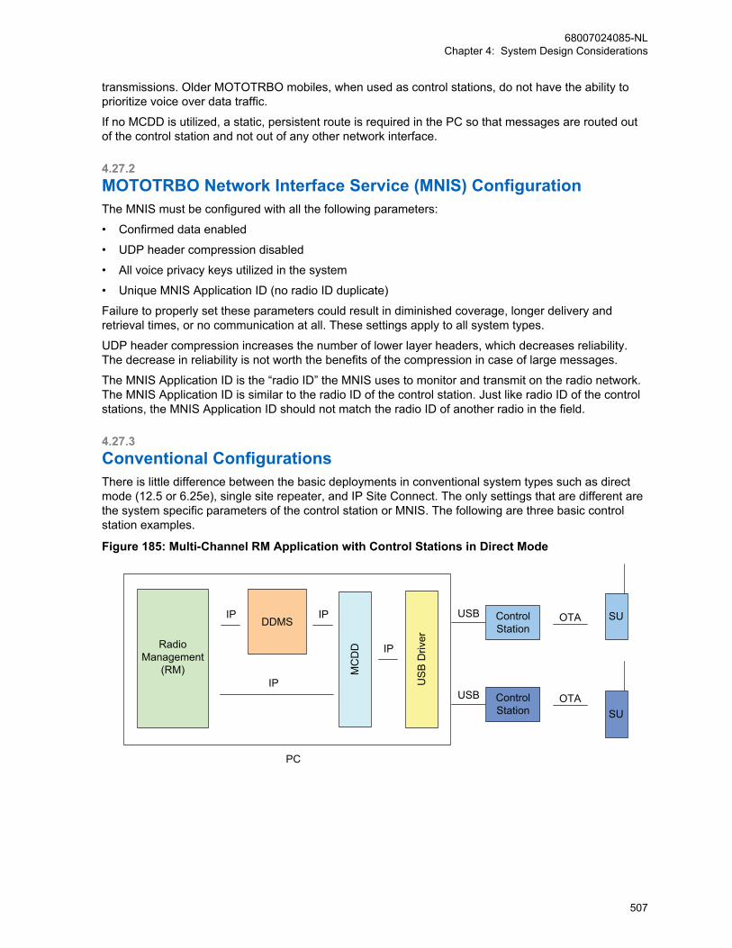
transmissions. Older MOTOTRBO mobiles, when used as control stations, do not have the ability toprioritize voice over data traffic.
If no MCDD is utilized, a static, persistent route is required in the PC so that messages are routed outof the control station and not out of any other network interface.
4.27.2MOTOTRBO Network Interface Service (MNIS) ConfigurationThe MNIS must be configured with all the following parameters:
• Confirmed data enabled
• UDP header compression disabled
• All voice privacy keys utilized in the system
• Unique MNIS Application ID (no radio ID duplicate)
Failure to properly set these parameters could result in diminished coverage, longer delivery andretrieval times, or no communication at all. These settings apply to all system types.
UDP header compression increases the number of lower layer headers, which decreases reliability.The decrease in reliability is not worth the benefits of the compression in case of large messages.
The MNIS Application ID is the “radio ID” the MNIS uses to monitor and transmit on the radio network.The MNIS Application ID is similar to the radio ID of the control station. Just like radio ID of the controlstations, the MNIS Application ID should not match the radio ID of another radio in the field.
4.27.3Conventional ConfigurationsThere is little difference between the basic deployments in conventional system types such as directmode (12.5 or 6.25e), single site repeater, and IP Site Connect. The only settings that are different arethe system specific parameters of the control station or MNIS. The following are three basic controlstation examples.
Figure 185: Multi-Channel RM Application with Control Stations in Direct Mode
MC
DD
DDMSIP
IP USB
Driv
er
IP
IPRadioManagement
(RM)
OTA
OTA
PC
ControlStation
USB
ControlStation
USB
SU
SU
68007024085-NLChapter 4: System Design Considerations
507
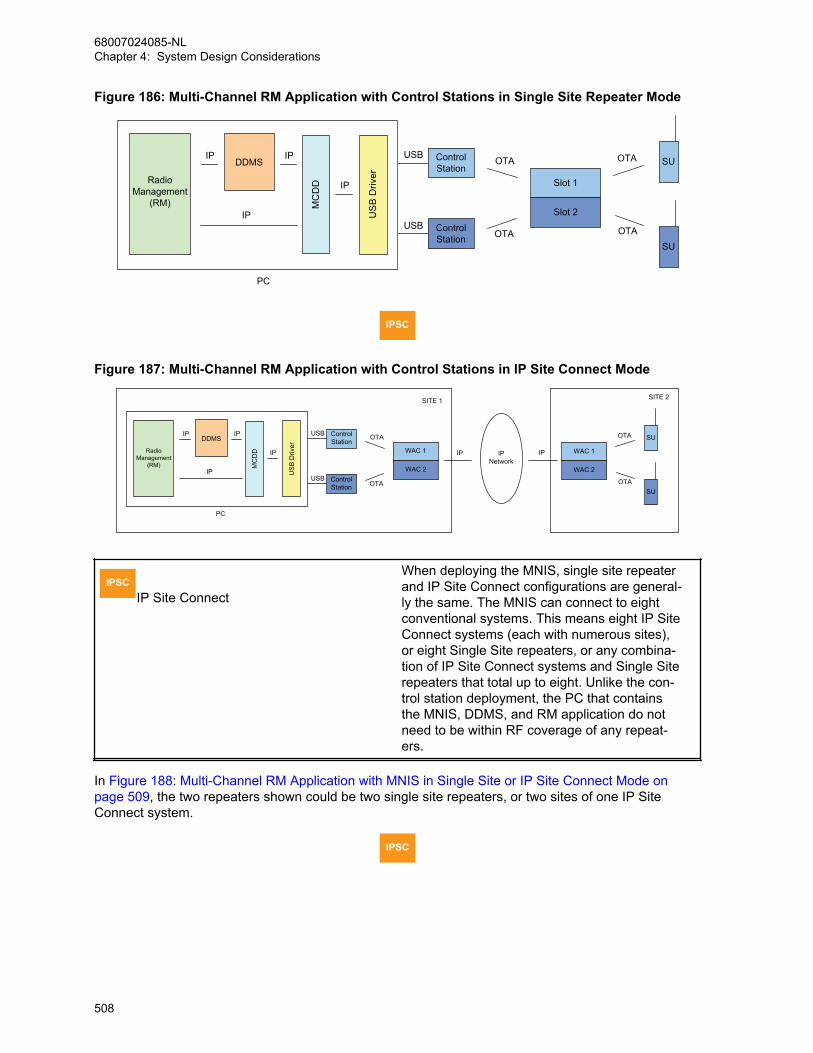
Figure 186: Multi-Channel RM Application with Control Stations in Single Site Repeater Mode
MC
DD
DDMSIP
IP US
B D
river
IP
IPRadioManagement
(RM)
PC
ControlStation
USB
ControlStation
USB
SU
SU
OTA
OTA
Slot 1
Slot 2
OTA
OTA
IPSC
Figure 187: Multi-Channel RM Application with Control Stations in IP Site Connect Mode
MC
DD
DDMSIP
IP USB
Driv
er
IP
IPRadioManagement
(RM)
PC
ControlStation
USB
ControlStation
USB
OTA
OTA
WAC 1
WAC 2
SU
SU
WAC 1
WAC 2
OTA
OTA
IP IPIPNetwork
SITE 1 SITE 2
IPSCIP Site Connect
When deploying the MNIS, single site repeaterand IP Site Connect configurations are general-ly the same. The MNIS can connect to eightconventional systems. This means eight IP SiteConnect systems (each with numerous sites),or eight Single Site repeaters, or any combina-tion of IP Site Connect systems and Single Siterepeaters that total up to eight. Unlike the con-trol station deployment, the PC that containsthe MNIS, DDMS, and RM application do notneed to be within RF coverage of any repeat-ers.
In Figure 188: Multi-Channel RM Application with MNIS in Single Site or IP Site Connect Mode onpage 509, the two repeaters shown could be two single site repeaters, or two sites of one IP SiteConnect system.
IPSC
68007024085-NLChapter 4: System Design Considerations
508

Figure 188: Multi-Channel RM Application with MNIS in Single Site or IP Site Connect Mode
SU
SU
Slot 1
Slot 2
OTA
OTADDMSIP
IP
IP
PC
Network Interface Service(MNIS)
IP IPNetwork
IP
Slot 1
Slot 2
IP
SU
SU
OTA
OTA
RadioManagement
(RM)
Radios are capable of manually changing between channels that are monitored by control stations orthe MNIS during an active over-the-air session.
IPSCIP Site Connect
Radios can also roam between sites of an IPSite Connect system during an active over-the-air session.
If radios move to channels not monitored by control stations or the MNIS, the over-the-air operationstops. When the radio returns to the monitored channel, and registers its presence, the over-the-airoperation starts again.
4.27.3.1RF Isolated Single Site RepeatersTo communicate with single site repeaters that are not within RF coverage of each other, multiple PCswith control stations must be set up, or set up one PC with a MNIS. Depending on RF coverage, onePC may be within RF coverage of multiple sites. In that scenario, more control stations can beconnected.
A remote RM Client can be used from a centralized location to contact both RM Servers.
NOTICE: It is important to note that one radio should not be configured in more than one RMServer. Therefore if there are radios that move from one site to another, monitored by adifferent RM Server, Device Programmer and control stations, they must only be populated inone of the RM Servers. Radios that do move between sites that are monitored by different RMServers/Device Programmers can only be contacted when they are on the channel monitoredby their RM Server. There is a DDMS and MCDD on both PCs.
68007024085-NLChapter 4: System Design Considerations
509
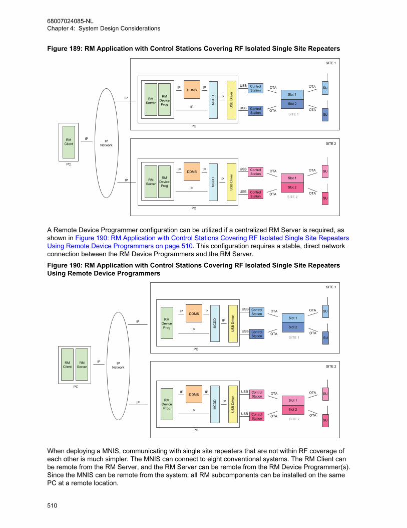
Figure 189: RM Application with Control Stations Covering RF Isolated Single Site Repeaters
ControlStation
USB
ControlStation
USB
SU
SU
OTA
OTA
Slot 1
Slot 2
OTA
OTA
ControlStation
USB
ControlStation
USB
SU
SU
OTA
OTA
Slot 1
Slot 2
OTA
OTA
RMDeviceProg
RMServer
PC
MC
DD
DDMSIP
IP US
B D
river
IP
IP
RMDeviceProg
RMServer
PCM
CD
D
DDMSIP
IP US
B D
river
IP
IP
SITE 2
SITE 1
RMClient
IP
PC
IPNetwork
IP
IP
SITE 1
SITE 2
A Remote Device Programmer configuration can be utilized if a centralized RM Server is required, asshown in Figure 190: RM Application with Control Stations Covering RF Isolated Single Site RepeatersUsing Remote Device Programmers on page 510. This configuration requires a stable, direct networkconnection between the RM Device Programmers and the RM Server.
Figure 190: RM Application with Control Stations Covering RF Isolated Single Site RepeatersUsing Remote Device Programmers
ControlStation
USB
ControlStation
USB
SU
SU
OTA
OTA
Slot 1
Slot 2
OTA
OTA
ControlStation
USB
ControlStation
USB
SU
SU
OTA
OTA
Slot 1
Slot 2
OTA
OTA
PC
MC
DD
DDMSIP
IP US
B D
river
IP
IP
RMDeviceProg
RMDeviceProg
PC
MC
DD
DDMSIP
IP US
B D
river
IP
IP
SITE 2
SITE 1
RMServer
RMClient
IP
PC
IPNetwork
IP
IP
SITE 1
SITE 2
When deploying a MNIS, communicating with single site repeaters that are not within RF coverage ofeach other is much simpler. The MNIS can connect to eight conventional systems. The RM Client canbe remote from the RM Server, and the RM Server can be remote from the RM Device Programmer(s).Since the MNIS can be remote from the system, all RM subcomponents can be installed on the samePC at a remote location.
68007024085-NLChapter 4: System Design Considerations
510

Figure 191: RM Application with MNIS Covering RF Isolated Single Site Repeaters
SU
SU
Slot 1
Slot 2
OTA
OTA
SU
SU
Slot 1
Slot 2
OTA
OTASITE 2
SITE 1
DDMSIP
IP
IP
PC
Network Interface Service(MNIS)
IP IPNetwork
IP
IP
RMDeviceProg
RMServer
RMClient
4.27.3.2Local Channel Support on IP Site Connect
IPSC On IP Site Connect systems that have local area channels at some of the sites, there are a
couple of configuration options available.
If the radios usually operate on the wide area channels, and infrequently change to the local channels,it may be easiest to have the Radio Management (RM) and control stations at one site monitoring thewide area channels only.
In this case, radios can only be programmed over-the-air when they become present on the wide areachannel monitored by the control stations. When they are on the local channels, they are consideredabsent.
If some of the radios always remain on the local channels, then it is necessary to have control stationsmonitoring them in order for the RM to contact the radios on that channel. Depending on RF coverageof each site and the location of the RM and control stations, all sites may not be reachable via RF fromone location. Therefore a second PC with control stations must be set up within RF coverage of thelocal channels of other sites.
A Remote Device Programmer configuration can be utilized as shown in Figure 192: RM Applicationwith Control Stations in IP Site Connect Mode Covering Local Channels with Remote DeviceProgrammers on page 512. A stable, direct network connection between the RM DeviceProgrammers and the RM Server is required.
68007024085-NLChapter 4: System Design Considerations
511
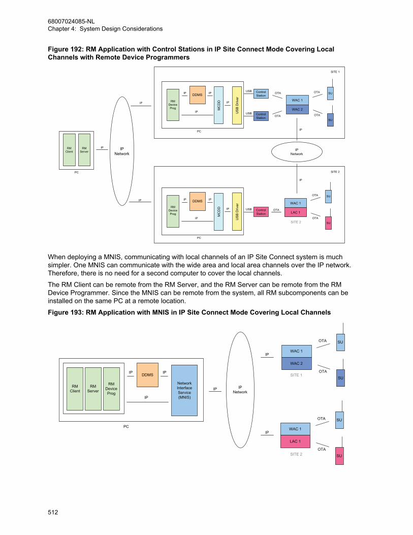
Figure 192: RM Application with Control Stations in IP Site Connect Mode Covering LocalChannels with Remote Device Programmers
ControlStation
USB
ControlStation
USB
SU
SU
OTA
OTA
WAC 1
WAC 2
OTA
OTA
ControlStation
USB
SU
SU
WAC 1
LAC 1
OTA
OTA
RMDeviceProg
RMDeviceProg
RMServer
RMClient
IP
PC
PC
IPNetwork
IP
IP
MC
DD
DDMSIP
IP US
B D
river
IP
IP
PC
MC
DD
DDMSIP
IP US
B D
river
IP
IP
SITE 2
SITE 1
OTA
IP
IPNetwork
IP
SITE 2
When deploying a MNIS, communicating with local channels of an IP Site Connect system is muchsimpler. One MNIS can communicate with the wide area and local area channels over the IP network.Therefore, there is no need for a second computer to cover the local channels.
The RM Client can be remote from the RM Server, and the RM Server can be remote from the RMDevice Programmer. Since the MNIS can be remote from the system, all RM subcomponents can beinstalled on the same PC at a remote location.
Figure 193: RM Application with MNIS in IP Site Connect Mode Covering Local Channels
SU
SU
WAC 1
WAC 2
OTA
OTADDMSIP
IP
IP
PC
Network Interface Service(MNIS)
IP IPNetwork
IP
RMDeviceProg
RMServer
RMClient
SU
SU
WAC 1
LAC 1
OTA
OTASITE 2
SITE 1
IP
68007024085-NLChapter 4: System Design Considerations
512

4.27.3.3Dynamic Mixed Mode (DMM)The Radio Management (RM) can configure radios over-the-air that are operating in digital mode on aDMM system. There are some limitations on performance. For example, when operating in DMM,analog voice transmissions do not have priority while an over-the-air operation is occurring. Once anover-the-air operation has started in digital mode, the repeater is kept in digital mode for its duration.This means an analog transmission cannot gain access to the system and receives a busy indicationfor the duration of the operation.
To mitigate this, a pacing option can be set within the RM Device Programmer so that there are timesof idle between each delivery or retrieval. The pacing duration is suggested to be greater than fiveminutes. This may provide the analog radio an opportunity to see an idle channel more often. It isrecommended that over-the-air configurations occur during non-peak hours, especially when operatingon a DMM system.
During an analog or digital voice transmission, the RM Application data is queued in the control station.
The MNIS does not support communication with repeaters operating in Dynamic Mixed Mode (DMM).
NOTICE: Because some radios may be scanning while operating in DMM, the data preambleon the control station may need to be increased to reach the target radios. This increases thesize of the data messages over-the-air, hence the overall time taken to perform an operationmay increase. Follow the standard rules for setting the preamble duration versus the number ofscan members.
Figure 194: RM Application in Dynamic Mixed Mode
MC
DD
DDMSIP
IP US
B D
river
IP
IPRadioManagement
(RM)
PC
ControlStation
USB
ControlStation
USB
SU
SU
OTA
OTA
Slot 1
Slot 2
OTA
OTAMixedMode
Repeater
AnalogConsole
4.27.4Capacity Plus Trunking Configurations
CPSS Four station control configurations are available with Capacity Plus. The major difference
between the configurations is how presence services are handled. The configurations are:
• One trunked control station without presence
• One trunked control station with presence
• One trunked control station and conventional control stations with presence
• One trunked control station and data revert control stations with presence
The following MNIS configurations are available for Capacity Plus:
• MNIS without Presence
• MNIS with Presence and No Data Revert
68007024085-NLChapter 4: System Design Considerations
513
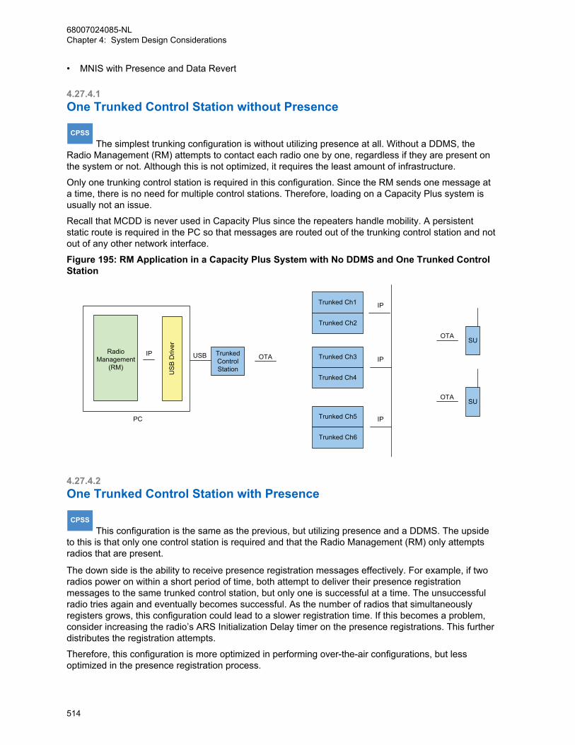
• MNIS with Presence and Data Revert
4.27.4.1One Trunked Control Station without Presence
CPSS The simplest trunking configuration is without utilizing presence at all. Without a DDMS, the
Radio Management (RM) attempts to contact each radio one by one, regardless if they are present onthe system or not. Although this is not optimized, it requires the least amount of infrastructure.
Only one trunking control station is required in this configuration. Since the RM sends one message ata time, there is no need for multiple control stations. Therefore, loading on a Capacity Plus system isusually not an issue.
Recall that MCDD is never used in Capacity Plus since the repeaters handle mobility. A persistentstatic route is required in the PC so that messages are routed out of the trunking control station and notout of any other network interface.
Figure 195: RM Application in a Capacity Plus System with No DDMS and One Trunked ControlStation
USB
USB
Driv
er
IP
OTA
PC
TrunkedControlStation
SU
Trunked Ch1
Trunked Ch2
Trunked Ch3
Trunked Ch4
Trunked Ch5
Trunked Ch6
IP
IP
IP
OTASU
OTARadio
Management(RM)
4.27.4.2One Trunked Control Station with Presence
CPSS This configuration is the same as the previous, but utilizing presence and a DDMS. The upside
to this is that only one control station is required and that the Radio Management (RM) only attemptsradios that are present.
The down side is the ability to receive presence registration messages effectively. For example, if tworadios power on within a short period of time, both attempt to deliver their presence registrationmessages to the same trunked control station, but only one is successful at a time. The unsuccessfulradio tries again and eventually becomes successful. As the number of radios that simultaneouslyregisters grows, this configuration could lead to a slower registration time. If this becomes a problem,consider increasing the radio’s ARS Initialization Delay timer on the presence registrations. This furtherdistributes the registration attempts.
Therefore, this configuration is more optimized in performing over-the-air configurations, but lessoptimized in the presence registration process.
68007024085-NLChapter 4: System Design Considerations
514

Figure 196: RM Application in a Capacity Plus System with a DDMS and One Trunked ControlStation
USB
OTA
TrunkedControlStation
SU
Trunked Ch1
Trunked Ch2
Trunked Ch3
Trunked Ch4
Trunked Ch5
Trunked Ch6
IP
IP
IP
OTASU
DDMSIP
IP USB
Driv
er
IP
PC
Radio ID = 1
ARS Radio ID = 1
ARS Radio ID = 1
OTARadio
Management(RM)
4.27.4.3One Trunked Control Station and Conventional Control Stations withPresence
CPSS To further optimize the reception of simultaneous presence registrations, conventional control
stations could be installed on every trunked channel for the sole purpose of receiving simultaneouspresence registration messages. Outgoing Radio Management (RM) application messages are sentthrough a single trunked control station through a static route in the PC. The conventional controlstation’s radio ID should match the ARS radio ID programmed in the radios and the trunked controlstation would have a unique radio ID. Although this configuration is optimized for presence registration,substantial additional hardware is required.
Figure 197: RM Application in a Capacity Plus System with a DDMS and One Trunked andNumerous Conventional Control Stations
USB TrunkedControlStation
Trunked Ch1
Trunked Ch2
Trunked Ch3
Trunked Ch4
Trunked Ch5
Trunked Ch6
IP
IP
IP
DDMSIP
IP USB
Driv
er
IP
PC
USB
OTASU
OTASU
ARS Radio ID = 2
ARS Radio ID = 2
Radio ID = 1
All 6 Radio IDs = 2
ConvControlStation
OTA
OTA
RadioManagement
(RM)
4.27.4.4One Trunked Control Station and Data Revert Control Stations withPresence
CPSS The Radio Management (RM) application operates with control stations on Capacity Plus
systems that have existing data revert channels, but it is important to note that the OTAP data is notsent on the revert channel. It is expected that the data revert channels exist for other data applications.
68007024085-NLChapter 4: System Design Considerations
515
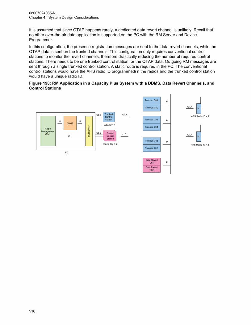
It is assumed that since OTAP happens rarely, a dedicated data revert channel is unlikely. Recall thatno other over-the-air data application is supported on the PC with the RM Server and DeviceProgrammer.
In this configuration, the presence registration messages are sent to the data revert channels, while theOTAP data is sent on the trunked channels. This configuration only requires conventional controlstations to monitor the revert channels, therefore drastically reducing the number of required controlstations. There needs to be one trunked control station for the OTAP data. Outgoing RM messages aresent through a single trunked control station. A static route is required in the PC. The conventionalcontrol stations would have the ARS radio ID programmedi n the radios and the trunked control stationwould have a unique radio ID.
Figure 198: RM Application in a Capacity Plus System with a DDMS, Data Revert Channels, andControl Stations
USB TrunkedControlStation
Trunked Ch1
Trunked Ch2
Trunked Ch3
Trunked Ch4
Trunked Ch5
Trunked Ch6
IP
IP
IP
DDMSIP
IP US
B D
river
IP
PC
USB
OTASU
OTASU
ARS Radio ID = 2
ARS Radio ID = 2
Radio ID = 1
Radio IDs = 2
RevertControlStation
OTA
OTA
Data RevertCh1
Data RevertCh2
IP
RadioManagement
(RM)
68007024085-NLChapter 4: System Design Considerations
516
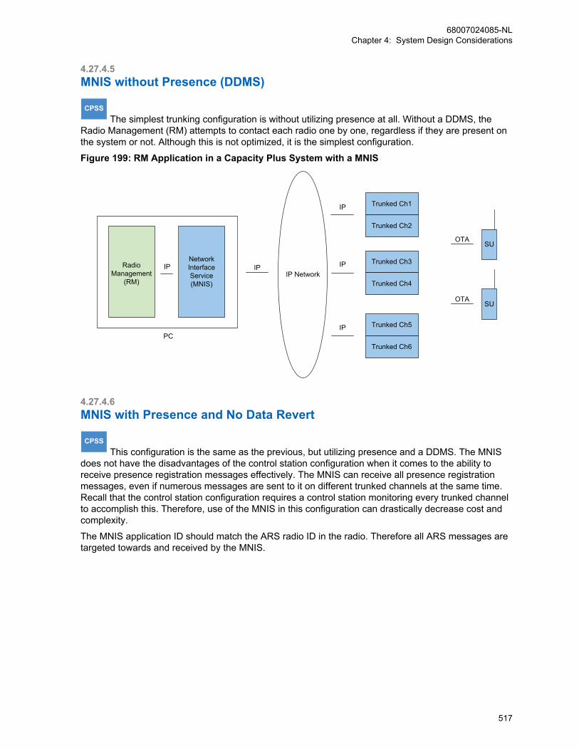
4.27.4.5MNIS without Presence (DDMS)
CPSS The simplest trunking configuration is without utilizing presence at all. Without a DDMS, the
Radio Management (RM) attempts to contact each radio one by one, regardless if they are present onthe system or not. Although this is not optimized, it is the simplest configuration.
Figure 199: RM Application in a Capacity Plus System with a MNIS
IP
PC
Network Interface Service(MNIS)
OTASU
Trunked Ch1
Trunked Ch2
Trunked Ch3
Trunked Ch4
Trunked Ch5
Trunked Ch6
IP
IP
IP
OTASU
IPIP Network
RadioManagement
(RM)
4.27.4.6MNIS with Presence and No Data Revert
CPSS This configuration is the same as the previous, but utilizing presence and a DDMS. The MNIS
does not have the disadvantages of the control station configuration when it comes to the ability toreceive presence registration messages effectively. The MNIS can receive all presence registrationmessages, even if numerous messages are sent to it on different trunked channels at the same time.Recall that the control station configuration requires a control station monitoring every trunked channelto accomplish this. Therefore, use of the MNIS in this configuration can drastically decrease cost andcomplexity.
The MNIS application ID should match the ARS radio ID in the radio. Therefore all ARS messages aretargeted towards and received by the MNIS.
68007024085-NLChapter 4: System Design Considerations
517
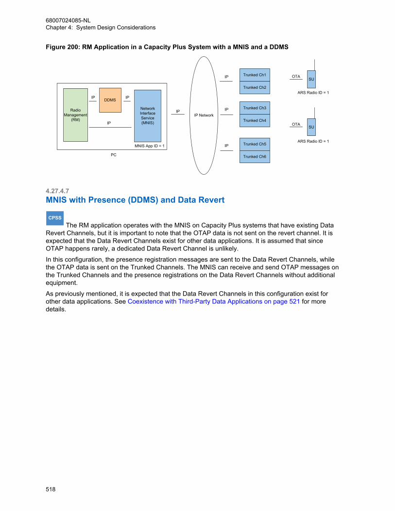
Figure 200: RM Application in a Capacity Plus System with a MNIS and a DDMS
DDMSIP
IP
IP
PC
Network Interface Service(MNIS)
Trunked Ch1
Trunked Ch2
Trunked Ch3
Trunked Ch4
Trunked Ch5
Trunked Ch6
IP
IP
IP
IPIP Network
OTASU
OTASU
ARS Radio ID = 1
ARS Radio ID = 1 MNIS App ID = 1
RadioManagement
(RM)
4.27.4.7MNIS with Presence (DDMS) and Data Revert
CPSS The RM application operates with the MNIS on Capacity Plus systems that have existing Data
Revert Channels, but it is important to note that the OTAP data is not sent on the revert channel. It isexpected that the Data Revert Channels exist for other data applications. It is assumed that sinceOTAP happens rarely, a dedicated Data Revert Channel is unlikely.
In this configuration, the presence registration messages are sent to the Data Revert Channels, whilethe OTAP data is sent on the Trunked Channels. The MNIS can receive and send OTAP messages onthe Trunked Channels and the presence registrations on the Data Revert Channels without additionalequipment.
As previously mentioned, it is expected that the Data Revert Channels in this configuration exist forother data applications. See Coexistence with Third-Party Data Applications on page 521 for moredetails.
68007024085-NLChapter 4: System Design Considerations
518
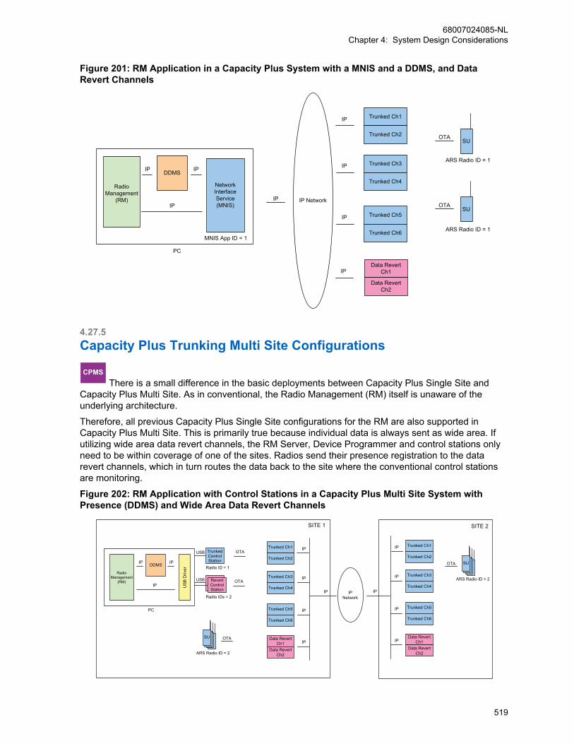
Figure 201: RM Application in a Capacity Plus System with a MNIS and a DDMS, and DataRevert Channels
Trunked Ch1
Trunked Ch2
Trunked Ch3
Trunked Ch4
Trunked Ch5
Trunked Ch6
IP
IP
IP
IP IP Network
Data RevertCh1
Data RevertCh2
IP
OTASU
OTASU
ARS Radio ID = 1
ARS Radio ID = 1
DDMSIP
IP
IP
PC
Network Interface Service(MNIS)
MNIS App ID = 1
RadioManagement
(RM)
4.27.5Capacity Plus Trunking Multi Site Configurations
CPMS There is a small difference in the basic deployments between Capacity Plus Single Site and
Capacity Plus Multi Site. As in conventional, the Radio Management (RM) itself is unaware of theunderlying architecture.
Therefore, all previous Capacity Plus Single Site configurations for the RM are also supported inCapacity Plus Multi Site. This is primarily true because individual data is always sent as wide area. Ifutilizing wide area data revert channels, the RM Server, Device Programmer and control stations onlyneed to be within coverage of one of the sites. Radios send their presence registration to the datarevert channels, which in turn routes the data back to the site where the conventional control stationsare monitoring.
Figure 202: RM Application with Control Stations in a Capacity Plus Multi Site System withPresence (DDMS) and Wide Area Data Revert Channels
USB TrunkedControlStation
Trunked Ch1
Trunked Ch2
Trunked Ch3
Trunked Ch4
Trunked Ch5
Trunked Ch6
IP
IP
IP
DDMSIP
IP US
B D
river
IP
PC
USB
Radio ID = 1
Radio IDs = 2
RevertControlStation
OTA
OTA
Data RevertCh1
Data RevertCh2
IP
Trunked Ch1
Trunked Ch2
Trunked Ch3
Trunked Ch4
Trunked Ch5
Trunked Ch6
IP
IP
IP
Data RevertCh1
Data RevertCh2
IP
IP IPIPNetwork
SITE 1 SITE 2
OTA
ARS Radio ID = 2
SU
OTA
ARS Radio ID = 2
SU
RadioManagement
(RM)
68007024085-NLChapter 4: System Design Considerations
519
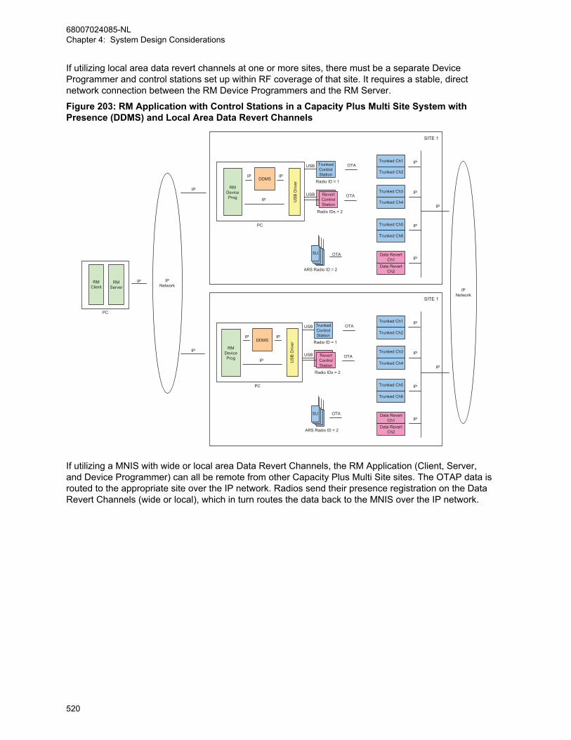
If utilizing local area data revert channels at one or more sites, there must be a separate DeviceProgrammer and control stations set up within RF coverage of that site. It requires a stable, directnetwork connection between the RM Device Programmers and the RM Server.
Figure 203: RM Application with Control Stations in a Capacity Plus Multi Site System withPresence (DDMS) and Local Area Data Revert Channels
USB TrunkedControlStation
Trunked Ch1
Trunked Ch2
Trunked Ch3
Trunked Ch4
Trunked Ch5
Trunked Ch6
IP
IP
IP
DDMSIP
IP US
B D
river
IP
PC
USB
Radio ID = 1
Radio IDs = 2
RevertControlStation
OTA
OTA
Data RevertCh1
Data RevertCh2
IP
IP
IPNetwork
SITE 1
OTA
ARS Radio ID = 2
SU
USB TrunkedControlStation
Trunked Ch1
Trunked Ch2
Trunked Ch3
Trunked Ch4
Trunked Ch5
Trunked Ch6
IP
IP
IP
DDMSIP
IP US
B D
river
IP
PC
USB
Radio ID = 1
Radio IDs = 2
RevertControlStation
OTA
OTA
Data RevertCh1
Data RevertCh2
IP
IP
SITE 1
OTA
ARS Radio ID = 2
SU
RMDeviceProg
RMServer
RMClient
IP
PC
IPNetwork
IP
IP
RMDeviceProg
If utilizing a MNIS with wide or local area Data Revert Channels, the RM Application (Client, Server,and Device Programmer) can all be remote from other Capacity Plus Multi Site sites. The OTAP data isrouted to the appropriate site over the IP network. Radios send their presence registration on the DataRevert Channels (wide or local), which in turn routes the data back to the MNIS over the IP network.
68007024085-NLChapter 4: System Design Considerations
520

Figure 204: RM Application with MNIS in a Capacity Plus Multi Site System with Presence andWide or Local Area Data Revert Channels
Trunked Ch1
Trunked Ch2
Trunked Ch3
Trunked Ch4
IP
IP
Data RevertCh1
Data RevertCh2
IP
IP
IPNetwork
SITE 3
SITE 1
OTA
ARS Radio ID = 2
SU
IP
DDMSIP
IP
IP
PC
NetworkInterfaceService(MNIS)
MNIS App ID = 2 Trunked Ch1
Trunked Ch2
Trunked Ch3
Trunked Ch4
IP
IP
Data RevertCh1
Data RevertCh2
IP
IP
SITE 2
OTA
ARS Radio ID = 2
SU
RadioManagement
(RM)
4.27.6Coexistence with Third-Party Data ApplicationsOTAP is supported on systems that have third-party data applications, but there are some specialconsiderations and configurations required. There are three combinations supported:
• RM and Third-Party Data Application with Control Stations
• RM and Third-Party Data Application with MNIS
• RM with MNIS and Third-Party Data Application with Control Stations
The following sections describe the three different combinations.
4.27.6.1RM and Third-Party Data Application with Control StationsIt is important to understand that although supported on the same system, the Radio Management(RM) Device Programmer are not supported on the same computer as a third-party data applicationwhen using control stations.
If a third-party data application utilizes a different message routing strategy than what is used by theRM and the MCDD, message delivery may become unreliable if on the same computer. Therefore, theRM Device Programmer should be installed on a different computer with a different set of controlstations than another third-party data application utilizing control stations.
Even if on different computers, a system level conflict may still remain. The RM application can utilizethe ARS messages sent by the radios to track presence and mobility. These messages are sent from
68007024085-NLChapter 4: System Design Considerations
521
the radios to the control stations associated with the RM. The ARS messages are used by the MCDDto keep track of which radios are present and which channel they are present on.
If the third-party data application does not utilize the ARS, then the radios can be programmed to sendtheir ARS messages to the RM control stations and no additional considerations are required.
If the third-party data application utilizes the ARS, then the radios must remain programmed to sendtheir ARS messages to the control stations connected to the third-party data application. In order forthe RM to also receive the ARS messages, the control stations associated with the RM must beprogrammed with an ARS Monitor ID that matches the radio ID of the third-party data application’scontrol stations. Additionally, the DDMS used by the RM must have the “Passive” option enabled. Asection below describes the passive presence and the ARS Monitoring ID configuration further.
If operating RM without presence and a DDMS, a configuration utilizing passive presence is notrequired.
4.27.6.2RM with MNIS and Third-Party Data Application with Control StationsThe MNIS should not be installed on a computer that also contains control stations. These twomethods have conflicting routing methods. Therefore, the Radio Management (RM) DeviceProgrammer and MNIS should be installed on a different computer than another third-party dataapplication utilizing control stations.
Even if on different computers, a system level conflict may still remain. The RM application can utilizethe ARS messages sent by the radios to track presence and mobility. These messages are sent fromthe radios to the MNIS associated with the RM. The ARS messages are used by the DDMS to keeptrack of which radios are present and which channel they are present on.
If the third-party data application does not utilize ARS, then the radios can be programmed to sendtheir ARS messages to the RM MNIS and no additional considerations are required.
If the third-party data application utilizes ARS, then the radios must remain programmed to send theirARS messages to the control stations connected to the third-party data application. In order for the RMto also receive the ARS messages, the MNIS associated with the RM must be programmed with anARS Monitor ID that matches the radio ID of the third-party data application’s control stations.Additionally, the DDMS used by the RM must have the “Passive” option enabled. A section belowdescribes the passive presence and the ARS Monitoring ID configuration further.
If operating RM without presence and a DDMS, a configuration utilizing passive presence is notrequired.
4.27.6.3RM and Third-Party Data Application with MNISThe Radio Management (RM) application and a third-party data application may reside on the samecomputer if they both utilize the MNIS and DDMS. The radios can be programmed to send their ARSmessages to the shared MNIS and tracked by the shared DDMS and no additional considerations arerequired. Check with the third-party data application vendor on whether they support MNIS and DDMS.
There are many third-party data applications available for MOTOTRBO. These applications may utilizeresources on the computer that conflicts with RM. If a conflict between a third-party data applicationand RM is discovered, or if the third-party data application vendor has requirements above cohabitationwith other applications, the applications can be installed on different computers, each with their ownMNIS, but they will need to share a DDMS. Both MNIS installations would be configured to referenceone DDMS installed on one of the computers. These computers must be in communication via an IPnetwork. The radios would be programmed to send their ARS messages to the MNIS that is on thesame computer as the DDMS. The DDMS shares the presence and mobility with both MNIS instances.
68007024085-NLChapter 4: System Design Considerations
522
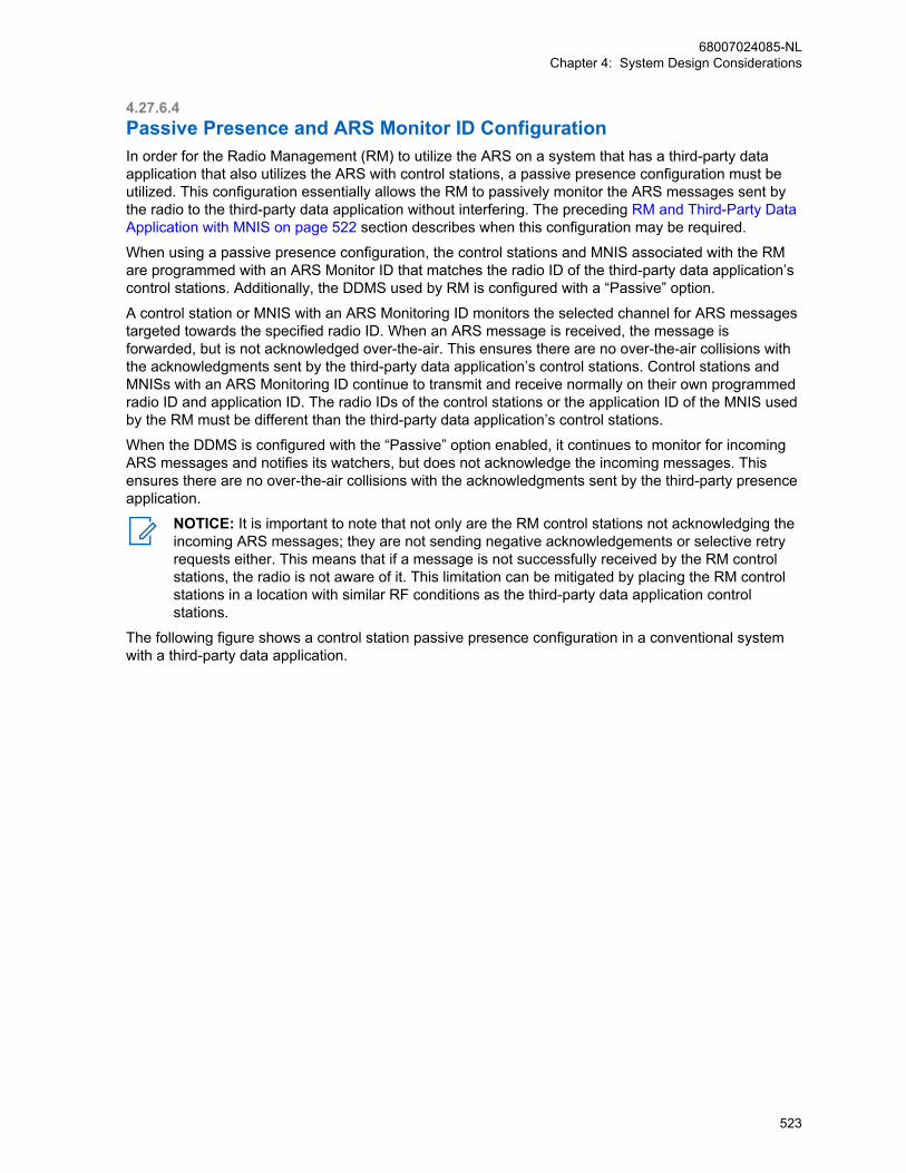
4.27.6.4Passive Presence and ARS Monitor ID ConfigurationIn order for the Radio Management (RM) to utilize the ARS on a system that has a third-party dataapplication that also utilizes the ARS with control stations, a passive presence configuration must beutilized. This configuration essentially allows the RM to passively monitor the ARS messages sent bythe radio to the third-party data application without interfering. The preceding RM and Third-Party DataApplication with MNIS on page 522 section describes when this configuration may be required.
When using a passive presence configuration, the control stations and MNIS associated with the RMare programmed with an ARS Monitor ID that matches the radio ID of the third-party data application’scontrol stations. Additionally, the DDMS used by RM is configured with a “Passive” option.
A control station or MNIS with an ARS Monitoring ID monitors the selected channel for ARS messagestargeted towards the specified radio ID. When an ARS message is received, the message isforwarded, but is not acknowledged over-the-air. This ensures there are no over-the-air collisions withthe acknowledgments sent by the third-party data application’s control stations. Control stations andMNISs with an ARS Monitoring ID continue to transmit and receive normally on their own programmedradio ID and application ID. The radio IDs of the control stations or the application ID of the MNIS usedby the RM must be different than the third-party data application’s control stations.
When the DDMS is configured with the “Passive” option enabled, it continues to monitor for incomingARS messages and notifies its watchers, but does not acknowledge the incoming messages. Thisensures there are no over-the-air collisions with the acknowledgments sent by the third-party presenceapplication.
NOTICE: It is important to note that not only are the RM control stations not acknowledging theincoming ARS messages; they are not sending negative acknowledgements or selective retryrequests either. This means that if a message is not successfully received by the RM controlstations, the radio is not aware of it. This limitation can be mitigated by placing the RM controlstations in a location with similar RF conditions as the third-party data application controlstations.
The following figure shows a control station passive presence configuration in a conventional systemwith a third-party data application.
68007024085-NLChapter 4: System Design Considerations
523
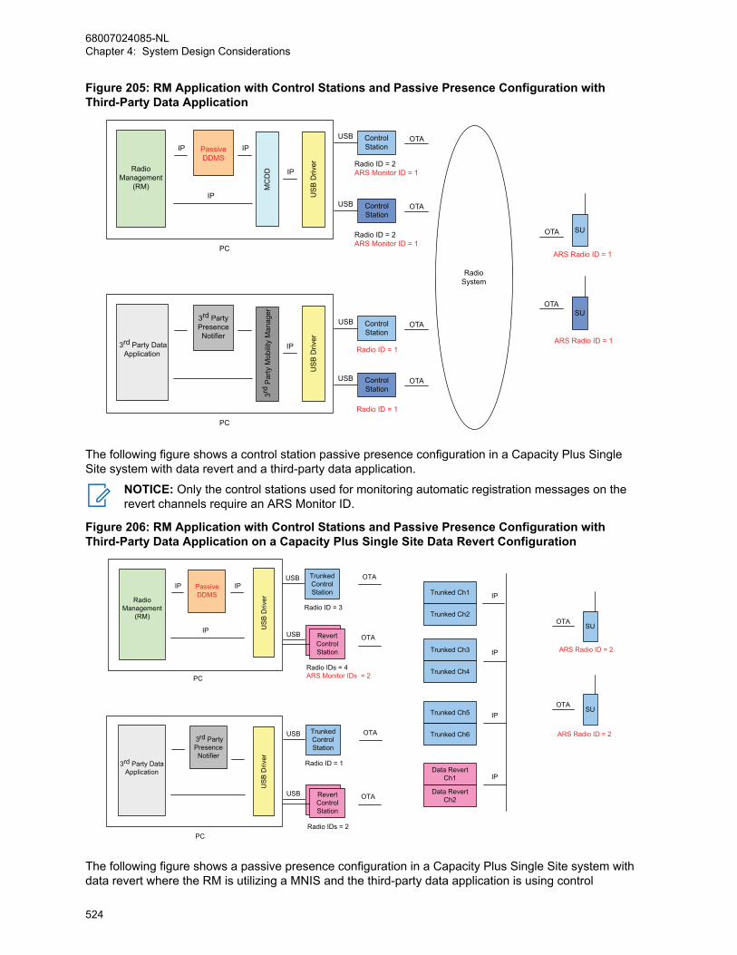
Figure 205: RM Application with Control Stations and Passive Presence Configuration withThird-Party Data Application
OTA
OTA
MC
DD
PassiveDDMS
IP
IP US
B D
river
IP
IP
RadioSystem
OTA
OTA
PC
ControlStation
USB
ControlStation
USB
SU
SUU
SB
Driv
er
IP
OTA
OTA
PC
ControlStation
USB
ControlStation
USB
3rd Party DataApplication
3rd
Par
ty M
obili
ty M
anag
er
3rd PartyPresenceNotifier
Radio ID = 2ARS Monitor ID = 1
Radio ID = 2ARS Monitor ID = 1
Radio ID = 1
Radio ID = 1
ARS Radio ID = 1
ARS Radio ID = 1
RadioManagement
(RM)
The following figure shows a control station passive presence configuration in a Capacity Plus SingleSite system with data revert and a third-party data application.
NOTICE: Only the control stations used for monitoring automatic registration messages on therevert channels require an ARS Monitor ID.
Figure 206: RM Application with Control Stations and Passive Presence Configuration withThird-Party Data Application on a Capacity Plus Single Site Data Revert Configuration
USB TrunkedControlStation
TrunkedControlStation Trunked Ch1
Trunked Ch2
Trunked Ch3
Trunked Ch4
Trunked Ch5
Trunked Ch6
IP
IP
IP
USB
OTASU
OTASU
ARS Radio ID = 2
ARS Radio ID = 2
Radio ID = 1
Radio IDs = 2
RevertControlStation
RevertControlStation
OTA
OTA
Data RevertCh1
Data RevertCh2
IP
USBIP
IP US
B D
river
IP
PC
USB
Radio ID = 3
Radio IDs = 4ARS Monitor IDs = 2
OTA
OTA
US
B D
river
PC
3rd Party DataApplication
3rd PartyPresenceNotifier
PassiveDDMS
RadioManagement
(RM)
The following figure shows a passive presence configuration in a Capacity Plus Single Site system withdata revert where the RM is utilizing a MNIS and the third-party data application is using control
68007024085-NLChapter 4: System Design Considerations
524

stations. The basic operation is the same as the control station configuration shown in Figure 206: RMApplication with Control Stations and Passive Presence Configuration with Third-Party DataApplication on a Capacity Plus Single Site Data Revert Configuration on page 524.
Figure 207: RM Application with MNIS and Passive Presence Configuration with Third-PartyData Application on a Capacity Plus Single Site Data Revert Configuration
USB TrunkedControlStation
Trunked Ch1
Trunked Ch2
Trunked Ch3
Trunked Ch4
Trunked Ch5
Trunked Ch6
IP
IP
IP
USB
OTASU
OTASU
ARS Radio ID = 2
ARS Radio ID = 2
Radio ID = 1
Radio IDs = 2
RevertControlStation
OTA
OTA
Data RevertCh1
Data RevertCh2
IP
US
B D
river
PC
3rd Party DataApplication
IP
PassiveDDMS
IP
IP
IP
PC
Network Interface Service(MNIS)
MNIS App ID = 3ARS Monitor ID = 2
RadioManagement
(RM)
3rd PartyPresenceNotifier
4.28Over-the-Air Authentication Key ManagementOver-the-air programming of a radio requires the system administrator to provide an authentication keythat matches the authentication key programmed in the radio. The provided authentication key mustmatch the authentication key in the radio prior to performing the first over-the-air operation. Thisensures that only a validated RM is communicating with a customer’s radio. This also ensures thatRadio Management (RM) is communicating with validated radios.
The initial authentication key (the key ID and key value) must be programmed in the radio via wiredCPS prior to the first over-the-air operation. The authentication key is set within RM the first time whenthe archive is imported. It can also be entered manually if an archive is not available.
The authentication key can be changed over-the-air if the current authentication key in the radio isknown. The system administrator only needs to update the current authentication key in the RM to thenew authentication key and deliver and switchover the configuration. The RM utilizes the currentauthentication key to authenticate the session, and then updates the radio’s authentication key with thenew authentication key. The new authentication key becomes the current authentication key oncesuccessfully switched over.
If the current authentication key in the radio is unknown, it can only be updated through wired CPS.Once updated, the archive should be imported into RM so that the authentication key updated in theradio becomes the current authentication key in RM.
68007024085-NLChapter 4: System Design Considerations
525
4.29Over-the-Air Privacy Key ManagementOTAP utilizes the standard data service privacy methods – AES, enhanced and basic. It isrecommended that privacy be enabled in the system if performing OTAP.
The encryption/decryption is performed at the control station or MNIS and at the end radio. The controlstation and MNIS can be configured for either basic, or enhanced privacy and/or AES. Therefore achannel must only contain radios that all have basic privacy or all have enhanced privacy if utilizingOTAP.
NOTICE: The control station or MNIS used for OTAP must contain all the privacy keys within allthe radios. The radios must contain the privacy key used for transmit by the control station orMNIS.
The privacy keys are used for both voice and data and can be different per radio. Since the controlstations and MNIS communicate with many radios, they a control station must contain all keys utilizedon the designated channel for conventional or on the system in trunking. If OTAP is utilized through acontrol station, a single conventional channel or a trunking system is limited to the number of enhancedprivacy keys and AES keys that can be contained within one control station (which is 16 keys forenhanced privacy and 16 keys for AES). Since the MNIS supports a large number of enhanced privacykeys (255) and AES keys (255), this limitation is not present if the MNIS is utilized.
Additionally, all radios must contain the key the control station or MNIS is using for transmit. There isno specific OTAP privacy key. The key designated for the selected channel is used for transmittingOTAP data.
4.29.1Updating the Privacy Keys in the SystemOver-the-air programming of privacy keys is supported. They can be updated within the RadioManagement (RM) and delivered to the radios, just like any other parameter. Although performing akey change on a system requires additional considerations to be taken since the keys are alsocontained within the control stations or MNIS used to deliver the keys to the radios.
The old and new keys must be in the control stations or MNIS if communication with the radios isrequired while transitioning. For example, if the radio registers its presence after it has switched over;the control station or MNIS is not able to receive the message if it does not have the new key. This canbe resolved by either provisioning the new keys into the MNIS or control station’s receive list (but stilltransmitting on old key), or by suppressing ARS after the switchover. Keeping the old and new keys inthe control station limits the number of usable keys in the system to half of what the control station canhold (16/2=8). The MNIS supports a large number of keys (255); therefore this limitation is not presentif the MNIS is utilized. Since there is only one basic privacy key per radio, it is not possible to containboth the old and new basic privacy keys.
NOTICE: At minimum, the privacy keys must be updated in the control station or MNIS aftersuccessfully delivering all the radio’s keys over-the-air, or future over-the-air operation to theupdated radios are not successful.
In order to program the control stations connected to the device programmer, the device programmercan be temporarily configured via a wired connection. This option can be found in the settings of thedevice programmer. The MNIS keys can be updated through the user interface.
Finally, since the new keys are delivered using the old keys, if it is believed that the old keys have beencompromised, wired CPS should be used to update the keys in the radios.
68007024085-NLChapter 4: System Design Considerations
526

4.30Performance of Over-the-Air ProgrammingThe performance of OTAP is commonly broken into two categories: performance in regard to time tocomplete an over-the-air operation and the impact of the over-the-air operation on other systemservices.
4.30.1Time to Complete Over-the-Air OperationsThere are three major over-the-air operations in Radio Management (RM): retrieval, delivery, and theswitchover. The time it takes to perform any of these operations is highly dependent on the details ofthe operation itself and the environment of the system.
The time to deliver or retrieve a new configuration is dependent on the following conditions:
• size of the configuration update
• number of radios being processed
• system loading
• RF environment
Because of these numerous dependencies, it may be difficult for the system administrator to exactlydetermine the time it takes to perform an operation over-the-air. However, if some typicalconfigurations and conditions are considered, then some typical times can be predicted that allow thesystem administrator to plan their time to some level of accuracy.
4.30.1.1Size of the Configuration UpdateThe first thing to understand is the relationship between the amount of configuration change and theamount of time it takes to transfer that change. Many items can be changed within the radioconfiguration, and each type of item changed has a different impact on the amount of data that needsto be transferred. There is generally no need to understand the entire relationship, but rather to simplyunderstand the impact of a large change and small change.
Only the differences between the Radio Management (RM) configuration and the radio configurationare transferred over-the-air. It is always recommended that a radio be read on the wire first so that onlyupdates need to be transferred over-the-air. Retrieving an entire configuration over-the-air or deliveringa completely new template to a radio over-the-air takes the largest amount of time.
The following figure provides some guidance between the number of address book entries updated oradded and the time it takes to deliver them to one radio in great RF conditions with no voice occurringon the channel or system. Great RF conditions are defined as middle of RF coverage and a stationaryradio.
NOTICE: Retrieval times are slightly shorter than delivery times in general, but for planningpurposes we are only showing delivery times.
68007024085-NLChapter 4: System Design Considerations
527
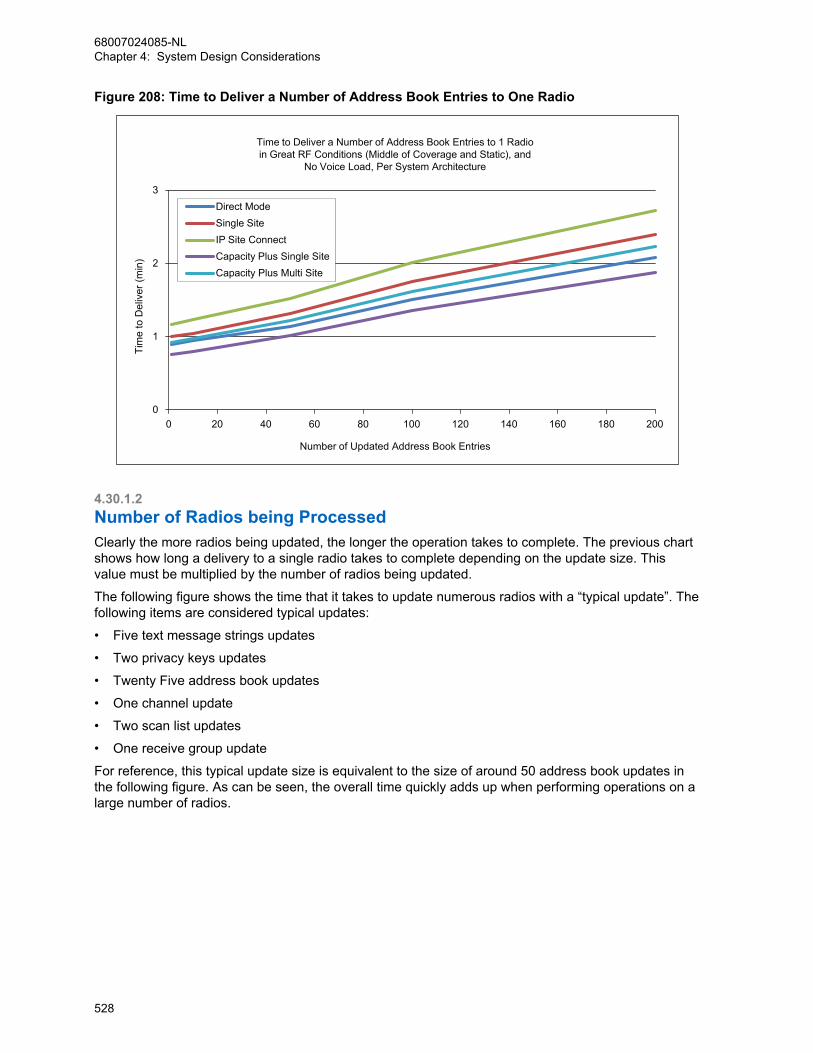
Figure 208: Time to Deliver a Number of Address Book Entries to One Radio
0
1
2
3
0 20 40 60 80 100 120 140 160 180 200
Tim
e to
Del
iver
(min
)
Number of Updated Address Book Entries
Time to Deliver a Number of Address Book Entries to 1 Radioin Great RF Conditions (Middle of Coverage and Static), and
No Voice Load, Per System Architecture
Direct ModeSingle SiteIP Site ConnectCapacity Plus Single SiteCapacity Plus Multi Site
4.30.1.2Number of Radios being ProcessedClearly the more radios being updated, the longer the operation takes to complete. The previous chartshows how long a delivery to a single radio takes to complete depending on the update size. Thisvalue must be multiplied by the number of radios being updated.
The following figure shows the time that it takes to update numerous radios with a “typical update”. Thefollowing items are considered typical updates:
• Five text message strings updates
• Two privacy keys updates
• Twenty Five address book updates
• One channel update
• Two scan list updates
• One receive group update
For reference, this typical update size is equivalent to the size of around 50 address book updates inthe following figure. As can be seen, the overall time quickly adds up when performing operations on alarge number of radios.
68007024085-NLChapter 4: System Design Considerations
528

Figure 209: Time to Deliver a Typical Change to a Number of Radios
0
10
20
30
40
50
60
70
80
90
0 5 10 15 20 25 30 35 40 45 50
Tim
e to
Del
iver
(min
)
Number of Radios
Time to Deliver a Typical Change to a Number of Radios in Great RF Conditions (Middle of Coverage and Static), and
No Voice Load, Per System Architecture
Direct Mode
Single Site
IP Site Connect
Capacity Plus Single Site
Capacity Plus Multi Site
As a rule of thumb, on an idle system, in great RF conditions, around 35-45 radios can get a typicalupdate in an hour. This rate may increase or decrease depending on the system architecture type. Thisof course assumes that all radios are present on the channel or system when the operation isscheduled. If a radio is not present, the operation continues to run until the radio becomes present, orthe operation is cancelled by the system administrator.
4.30.1.3System Loading and RF EnvironmentIt is always recommended to schedule over-the-air operations during times of low voice traffic andwhen the radios are stationary and in great RF coverage. However it is recognized that this is notalways possible.
The Radio Management (RM) shares the channel with voice and other data services. Therefore if voicetraffic loading is high at the time an over-the-air operation is scheduled, there is less bandwidthavailable for RM. Therefore the time to deliver increases as the RM waits for the voice to end.
In addition, if some of the target radios are in poor RF conditions, data delivery times can be longerdue to the need to retry any failed messages. Radios that are moving are affected more than those thatare stationary, therefore radios that are in vehicles or carried by hand while walking experience longerdelivery times. These conditions are always present, but become noticeable when sending many largedata messages.
Figure 210: Time to Deliver a Typical Change to a Number of Radios in Single Site Mode on page530 provides some expectations on delivery times for a typical change on a single site repeaterchannel with typical RF conditions and high voice usage.
The bottom of the thick line is the baseline time if all radios were in great RF conditions, stationary andthere was little voice (from Figure 209: Time to Deliver a Typical Change to a Number of Radios onpage 529). The remaining part of the line is the estimated amount of time with an expected distributionof RF conditions for each radio. The majority of the scenarios are towards the bottom and the lesslikely scenarios are towards the top.
68007024085-NLChapter 4: System Design Considerations
529

Note that this chart does not represent the worst case scenario since it is unlikely that all radios are inthe worst conditions. This is the expected distribution (thickness of line) for all conventionalarchitectures including direct mode, single site, and IP Site Connect. See Figure 209: Time to Deliver aTypical Change to a Number of Radios on page 529 for the estimated baseline in great RF conditions,stationary and with little voice.
Figure 210: Time to Deliver a Typical Change to a Number of Radios in Single Site Mode
0
20
40
60
80
100
120
140
160
180
0 5 10 15 20 25 30 35 40 45 50
Tim
e to
Del
iver
(min
)
Number of Radios
Time to Deliver a Typical Change to a Number of RadiosIn Single Site Mode with a Typical Distribution of RF Conditions and High Voice Usage
Great RF Conditions,No Voice Load
Poor RF Conditions,Heavy Voice Load
CPSSFigure 211: Time to Deliver a Typical Change to a Number of Radios in Capacity Plus Mode on
page 531 provides some expectations on delivery times for a typical change on a Capacity Plussystem with typical RF conditions and high voice usage. Note this is the expected distribution(thickness of line) for all trunking architectures including Capacity Plus and Capacity Plus Multi Site.See the previous charts for the estimated baseline (bottom of line) in great RF conditions, stationaryand with little voice.
68007024085-NLChapter 4: System Design Considerations
530

Figure 211: Time to Deliver a Typical Change to a Number of Radios in Capacity Plus Mode
0
20
40
60
80
100
120
140
160
180
0 5 10 15 20 25 30 35 40 45 50
Tim
e to
Del
iver
(min
)
Number of Radios
Time to Deliver a Typical Change to a Number of RadiosIn Capacity Plus Mode with a Typical Distribution of RF Conditions and High Voice Usage
Poor RF Conditions,Heavy Voice Load
Great RF Conditions,No Voice Load
4.30.2Performance Impact on Other ServicesPerforming a RM retrieval, delivery, or switchover over-the-air can have an impact on other services onthe channel or system. The three major impacts to consider are:
• Voice access time during an over-the-air operation
• Voice downtime during a switchover
• Data downtime during a switchover
4.30.2.1Voice Access Time during an Over-the-Air OperationAs previously mentioned, it is always recommended to schedule over-the-air operations during times oflow voice traffic and when the radios are stationary and in great RF coverage. But it is recognized thatthis is not always possible. In conventional modes, it has been established that voice traffic has animpact on the time it takes to perform Radio Management (RM) over-the-air operations, but theseoperations also have an impact on voice traffic
NOTICE: Radios with software versions prior to R02.10.00 do not have access to the channelduring an ongoing RM over-the-air operation. They most likely receives a talk prohibit tone,since the channel is busy processing data. All radios, regardless of software version, attemptingconfirmed private calls on a conventional channel while OTAP is occurring experience a lowsuccess rate. This is not just the radio being configured, but rather all radios on theconventional channel. To mitigate this, a pacing option can be set within the RM DeviceProgrammer so that there are times of idle between each delivery or retrieval. The pacingduration is suggested to be greater than five minutes.
Radios with software version R02.10.00 and later access the channel and temporarily interrupt ongoingRM over-the-air operations. This interruption procedure causes an increase to voice access time by onaverage of 1.5 seconds, and worst case 3.5 seconds. While waiting for the procedure to complete, theradio user hears a wait tone, followed by a talk permit tone. Display models also provide an indicationof when high volumes of data are occurring on the channel they are selected on. This notifies them that
68007024085-NLChapter 4: System Design Considerations
531

an update is occurring on the system and that their channel access may be slower than normal. This isnot just the radio being configured, but rather all radios on the conventional channel.
Voice access time for all radios is not affected during a RM over-the-air operation in Capacity PlusSingle Site or Capacity Plus Multi Site systems as each transmission occurs on its own channel.However, the radio currently being configured over-the-air experiences the increase to voice accesstime.
4.30.2.2Voice Downtime During a SwitchoverWhen the radio applies a delivered configuration, the radio must reset to apply the changes. Whileresetting the radio it is not able to transmit or receive voice over-the-air. A reset after a switchovertypically causes voice downtime for a single radio in the range of 20–22 seconds.
If multiple radios are being switched over, and critical communication parameters are being updated,voice downtime occurs on the system from when the first radio starts its reset to when the last radiofinishes its reset. During this time, there may be a mismatch in communication parameters acrossradios and therefore communication may be disrupted.
If using a non-zero switchover timer, the voice downtime can be as long as the switchover timer itselfsince some users may choose to delay their switchover.
When performing a delivery with switchover, each radio is switched over as the delivery occurs,therefore the voice downtime can be as long as it takes to deliver to all radios. See the charts inprevious sections.
To minimize voice downtime, it is recommended to deliver the configurations, and then schedule anindependent switchover with a zero value switchover timer and ARS suppression enabled. Otherdeliveries or retrievals should not be scheduled to occur at the same time as a switchover. This maycause a delivery to occur in between the switchovers, which increases the overall downtime. Thefollowing figure provides some expectations on how long the voice downtime is when in great RFconditions and no voice load in that scenario. This assumes all radios are present. Note that in poor RFconditions and in the presence of voice, these times can increase.
Figure 212: Voice Downtime when Switching Over a Number of Radios
0
1
2
3
4
0 5 10 15 20 25 30 35 40 45 50
Voi
ce D
ownt
ime
(min
)
Number of Selected Radios
Voice Downtime when Switching Over a Number of Radiosin Great RF Conditions (Middle of Coverage and Static), and No Voice Load
68007024085-NLChapter 4: System Design Considerations
532
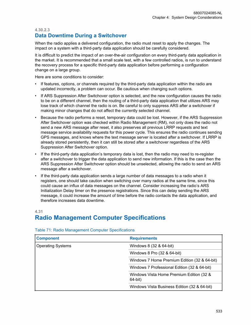
4.30.2.3Data Downtime During a SwitchoverWhen the radio applies a delivered configuration, the radio must reset to apply the changes. Theimpact on a system with a third-party data application should be carefully considered.
It is difficult to predict the impact of an over-the-air configuration on every third-party data application inthe market. It is recommended that a small scale test, with a few controlled radios, is run to understandthe recovery process for a specific third-party data application before performing a configurationchange on a large group.
Here are some conditions to consider:
• If features, options, or channels required by the third-party data application within the radio areupdated incorrectly, a problem can occur. Be cautious when changing such options.
• If ARS Suppression After Switchover option is selected, and the new configuration causes the radioto be on a different channel, then the routing of a third-party data application that utilizes ARS maylose track of which channel the radio is on. Be careful to only suppress ARS after a switchover ifmaking minor changes that do not affect the currently selected channel.
• Because the radio performs a reset, temporary data could be lost. However, if the ARS SuppressionAfter Switchover option was checked within Radio Management (RM), not only does the radio notsend a new ARS message after reset, it also preserves all previous LRRP requests and textmessage service availability requests for this power cycle. This ensures the radio continues sendingGPS messages, and knows where the text message server is located after a switchover. If LRRP isalready stored persistently, then it can still be stored after a switchover regardless of the ARSSuppression After Switchover option.
• If the third-party data application’s temporary data is lost, then the radio may need to re-registerafter a switchover to trigger the data application to send new information. If this is the case then theARS Suppression After Switchover option should be unselected, allowing the radio to send an ARSmessage after a switchover.
• If the third-party data application sends a large number of data messages to a radio when itregisters, one should take caution when switching over many radios at the same time, since thiscould cause an influx of data messages on the channel. Consider increasing the radio’s ARSInitialization Delay timer on the presence registrations. Since this can delay sending the ARSmessage, it could increase the amount of time before the radio contacts the data application, andtherefore increases data downtime.
4.31Radio Management Computer Specifications
Table 71: Radio Management Computer Specifications
Component Requirements
Operating Systems Windows 8 (32 & 64-bit)
Windows 8 Pro (32 & 64-bit)
Windows 7 Home Premium Edition (32 & 64-bit)
Windows 7 Professional Edition (32 & 64-bit)
Windows Vista Home Premium Edition (32 &64-bit)
Windows Vista Business Edition (32 & 64-bit)
68007024085-NLChapter 4: System Design Considerations
533

Component Requirements
Windows XP Home/Professional Edition withSP3 & Windows Installer 3.1 (32 & 64-bit)
Windows Server 2008 R2 (32 & 64-bit) (forServer Installations)
Memory RM Client / RM Server / RM Device Programm-er Install: 1 GB and above required by host Op-eration System
RM Server / RM Device Programmer Install: 1GB and above required by host Operation Sys-tem
RM Client Only Install: RAM required by hostOperation System
Hard Disk RM Client / RM Server / RM Device Programm-er Install: 5 GB (Program Files & Database)
RM Server / RM Device Programmer Install: 5GB (Program Files & Database)
RM Client Only Install: 400 MB (Program Files& Archive Files*)
* More space would be required if saving ar-chive files of your radios and device updatepackages. Each archive file or device updatepackage varies in size depending on the fea-tures of the radio.
Other (All Installs) USB ports (1 or more depending on systemconfiguration)
Network Connection
DVD Drive
Software Running multiple instances of the RM applica-tion on one computer is not recommended.
* When installing the RM Server on WindowsXP, the RM Client, Job Processor and DeviceProgrammer must be installed on the same ma-chine. For distributed RM systems, the RMServer requires Windows Server 2008, Win-dows 7, or Windows 8.
The MNIS and DDMS do not currently support Windows 8 or Windows Vista.
68007024085-NLChapter 4: System Design Considerations
534
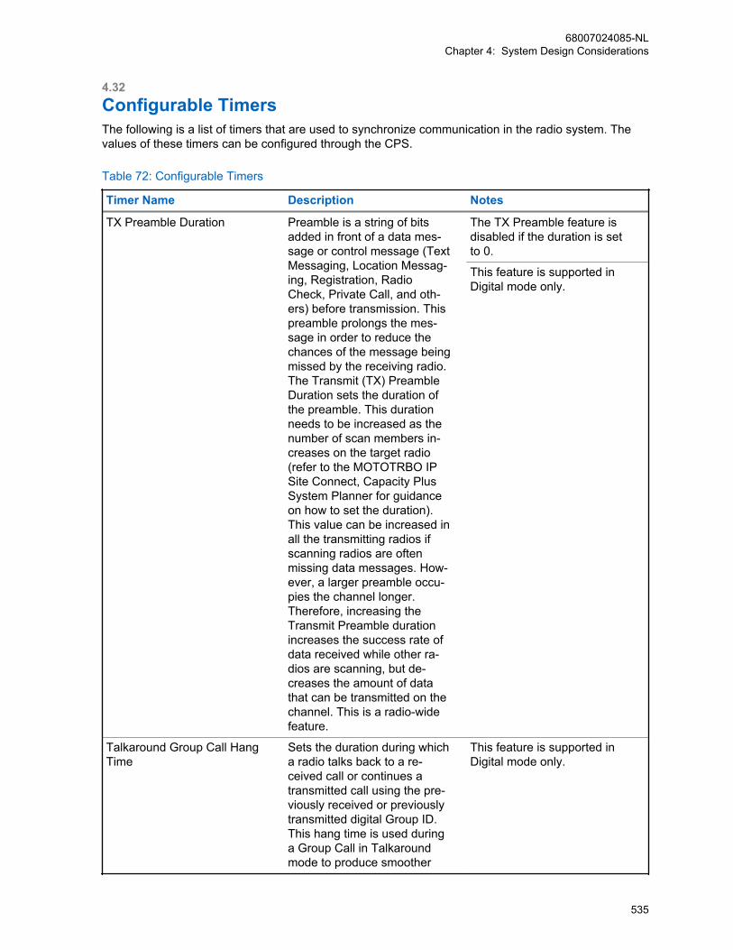
4.32Configurable TimersThe following is a list of timers that are used to synchronize communication in the radio system. Thevalues of these timers can be configured through the CPS.
Table 72: Configurable Timers
Timer Name Description Notes
TX Preamble Duration Preamble is a string of bitsadded in front of a data mes-sage or control message (TextMessaging, Location Messag-ing, Registration, RadioCheck, Private Call, and oth-ers) before transmission. Thispreamble prolongs the mes-sage in order to reduce thechances of the message beingmissed by the receiving radio.The Transmit (TX) PreambleDuration sets the duration ofthe preamble. This durationneeds to be increased as thenumber of scan members in-creases on the target radio(refer to the MOTOTRBO IPSite Connect, Capacity PlusSystem Planner for guidanceon how to set the duration).This value can be increased inall the transmitting radios ifscanning radios are oftenmissing data messages. How-ever, a larger preamble occu-pies the channel longer.Therefore, increasing theTransmit Preamble durationincreases the success rate ofdata received while other ra-dios are scanning, but de-creases the amount of datathat can be transmitted on thechannel. This is a radio-widefeature.
The TX Preamble feature isdisabled if the duration is setto 0.
This feature is supported inDigital mode only.
Talkaround Group Call HangTime
Sets the duration during whicha radio talks back to a re-ceived call or continues atransmitted call using the pre-viously received or previouslytransmitted digital Group ID.This hang time is used duringa Group Call in Talkaroundmode to produce smoother
This feature is supported inDigital mode only.
68007024085-NLChapter 4: System Design Considerations
535

Timer Name Description Notes
conversation. During this time,other radios can still transmitsince the channel is essential-ly idle. After the hang timer ex-pires, the radio transmits usingthe Contact Name specifiedfor this channel.
Talkaround Private Call HangTime
Sets the duration the radiokeeps the call setup after theuser releases the Push-to-Talk(PTT) button. This is to avoidsetting up the call again eachtime the user presses the PTTto transmit. This hang time isused during a Private Call inTalkaround mode to producesmoother conversation. Duringthis time, other radios can stilltransmit since the channel isessentially idle.
–
Subscriber Inactivity Timer The Subscriber Inactivity Tim-er (SIT) controls how long therepeater continues transmit-ting with absence of subscrib-er activity on the uplink. If therepeater is operating onshared-use frequencies, itcannot remain keyed indefi-nitely for the benefit of broad-casting synchronization sig-nals to radios. The repeater islikely de-keyed most of thetime; thereby requiring radiosto first activate the repeater(through the uplink frequency)and acquire synchronization(through the downlink frequen-cy) before completing the callsetup request and subsequentfirst transmission. The net re-sult of these extra proceduresis increased access time;therefore, it is desirable toavoid these steps, wheneverpossible. There is a trade-offto minimizing access time bykeeping the repeater keyed foras long as practically possible,while complying with the regu-lations regarding shared-usechannels, which essentially re-quire the repeater to de-key
The value of this feature mustbe equal to or greater than theHang Time (Group, Private orEmergency – whichever is thelongest).
This feature is disabled if Re-peater Mode is set to Analog.
68007024085-NLChapter 4: System Design Considerations
536
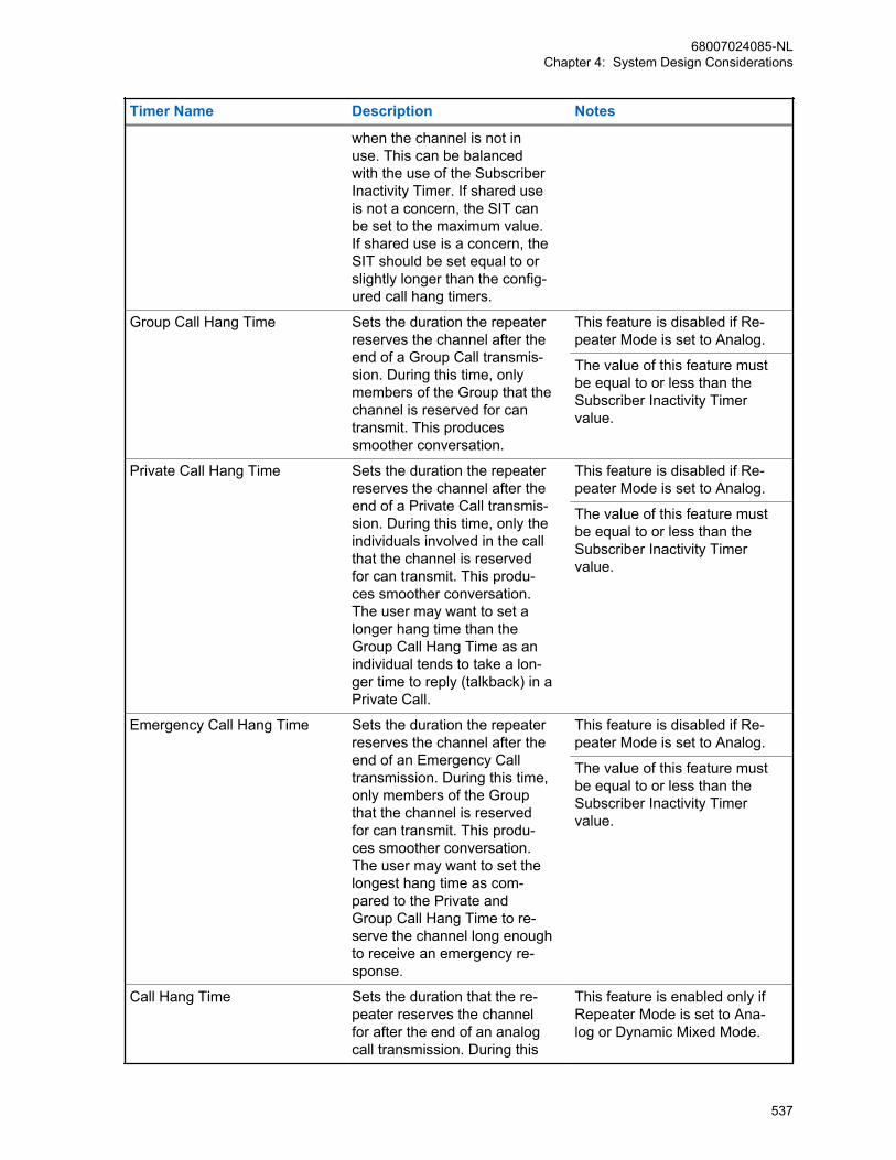
Timer Name Description Notes
when the channel is not inuse. This can be balancedwith the use of the SubscriberInactivity Timer. If shared useis not a concern, the SIT canbe set to the maximum value.If shared use is a concern, theSIT should be set equal to orslightly longer than the config-ured call hang timers.
Group Call Hang Time Sets the duration the repeaterreserves the channel after theend of a Group Call transmis-sion. During this time, onlymembers of the Group that thechannel is reserved for cantransmit. This producessmoother conversation.
This feature is disabled if Re-peater Mode is set to Analog.
The value of this feature mustbe equal to or less than theSubscriber Inactivity Timervalue.
Private Call Hang Time Sets the duration the repeaterreserves the channel after theend of a Private Call transmis-sion. During this time, only theindividuals involved in the callthat the channel is reservedfor can transmit. This produ-ces smoother conversation.The user may want to set alonger hang time than theGroup Call Hang Time as anindividual tends to take a lon-ger time to reply (talkback) in aPrivate Call.
This feature is disabled if Re-peater Mode is set to Analog.
The value of this feature mustbe equal to or less than theSubscriber Inactivity Timervalue.
Emergency Call Hang Time Sets the duration the repeaterreserves the channel after theend of an Emergency Calltransmission. During this time,only members of the Groupthat the channel is reservedfor can transmit. This produ-ces smoother conversation.The user may want to set thelongest hang time as com-pared to the Private andGroup Call Hang Time to re-serve the channel long enoughto receive an emergency re-sponse.
This feature is disabled if Re-peater Mode is set to Analog.
The value of this feature mustbe equal to or less than theSubscriber Inactivity Timervalue.
Call Hang Time Sets the duration that the re-peater reserves the channelfor after the end of an analogcall transmission. During this
This feature is enabled only ifRepeater Mode is set to Ana-log or Dynamic Mixed Mode.
68007024085-NLChapter 4: System Design Considerations
537
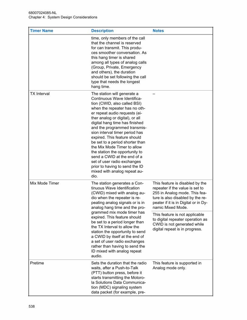
Timer Name Description Notes
time, only members of the callthat the channel is reservedfor can transmit. This produ-ces smoother conversation. Asthis hang timer is sharedamong all types of analog calls(Group, Private, Emergencyand others), the durationshould be set following the calltype that needs the longesthang time.
TX Interval The station will generate aContinuous Wave Identifica-tion (CWID, also called BSI)when the repeater has no oth-er repeat audio requests (ei-ther analog or digital), or alldigital hang time has finishedand the programmed transmis-sion interval timer period hasexpired. This feature shouldbe set to a period shorter thanthe Mix Mode Timer to allowthe station the opportunity tosend a CWID at the end of aset of user radio exchangesprior to having to send the IDmixed with analog repeat au-dio.
–
Mix Mode Timer The station generates a Con-tinuous Wave Identification(CWID) mixed with analog au-dio when the repeater is re-peating analog signals or is inanalog hang time and the pro-grammed mix mode timer hasexpired. This feature shouldbe set to a period longer thanthe TX Interval to allow thestation the opportunity to senda CWID by itself at the end ofa set of user radio exchangesrather than having to send theID mixed with analog repeataudio.
This feature is disabled by therepeater if the value is set to255 in Analog mode. This fea-ture is also disabled by the re-peater if it is in Digital or in Dy-namic Mixed Mode.
This feature is not applicableto digital repeater operation asCWID is not generated whiledigital repeat is in progress.
Pretime Sets the duration that the radiowaits, after a Push-to-Talk(PTT) button press, before itstarts transmitting the Motoro-la Solutions Data Communica-tion (MDC) signaling systemdata packet (for example, pre-
This feature is supported inAnalog mode only.
68007024085-NLChapter 4: System Design Considerations
538
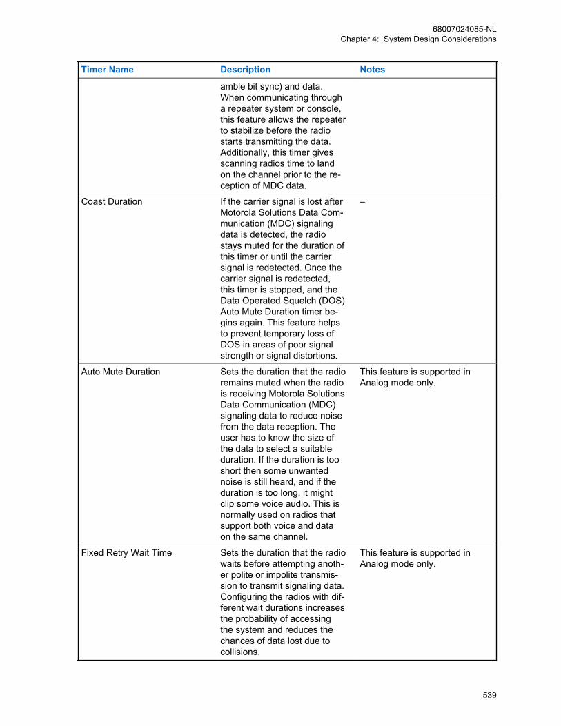
Timer Name Description Notes
amble bit sync) and data.When communicating througha repeater system or console,this feature allows the repeaterto stabilize before the radiostarts transmitting the data.Additionally, this timer givesscanning radios time to landon the channel prior to the re-ception of MDC data.
Coast Duration If the carrier signal is lost afterMotorola Solutions Data Com-munication (MDC) signalingdata is detected, the radiostays muted for the duration ofthis timer or until the carriersignal is redetected. Once thecarrier signal is redetected,this timer is stopped, and theData Operated Squelch (DOS)Auto Mute Duration timer be-gins again. This feature helpsto prevent temporary loss ofDOS in areas of poor signalstrength or signal distortions.
–
Auto Mute Duration Sets the duration that the radioremains muted when the radiois receiving Motorola SolutionsData Communication (MDC)signaling data to reduce noisefrom the data reception. Theuser has to know the size ofthe data to select a suitableduration. If the duration is tooshort then some unwantednoise is still heard, and if theduration is too long, it mightclip some voice audio. This isnormally used on radios thatsupport both voice and dataon the same channel.
This feature is supported inAnalog mode only.
Fixed Retry Wait Time Sets the duration that the radiowaits before attempting anoth-er polite or impolite transmis-sion to transmit signaling data.Configuring the radios with dif-ferent wait durations increasesthe probability of accessingthe system and reduces thechances of data lost due tocollisions.
This feature is supported inAnalog mode only.
68007024085-NLChapter 4: System Design Considerations
539
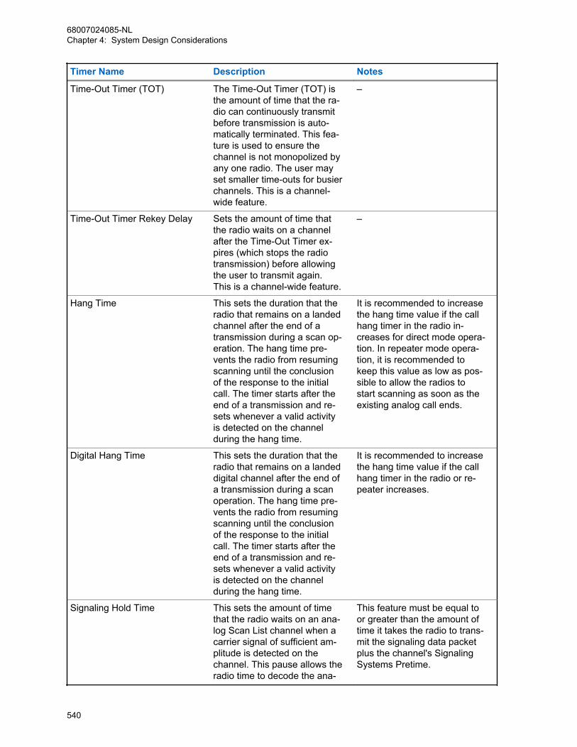
Timer Name Description Notes
Time-Out Timer (TOT) The Time-Out Timer (TOT) isthe amount of time that the ra-dio can continuously transmitbefore transmission is auto-matically terminated. This fea-ture is used to ensure thechannel is not monopolized byany one radio. The user mayset smaller time-outs for busierchannels. This is a channel-wide feature.
–
Time-Out Timer Rekey Delay Sets the amount of time thatthe radio waits on a channelafter the Time-Out Timer ex-pires (which stops the radiotransmission) before allowingthe user to transmit again.This is a channel-wide feature.
–
Hang Time This sets the duration that theradio that remains on a landedchannel after the end of atransmission during a scan op-eration. The hang time pre-vents the radio from resumingscanning until the conclusionof the response to the initialcall. The timer starts after theend of a transmission and re-sets whenever a valid activityis detected on the channelduring the hang time.
It is recommended to increasethe hang time value if the callhang timer in the radio in-creases for direct mode opera-tion. In repeater mode opera-tion, it is recommended tokeep this value as low as pos-sible to allow the radios tostart scanning as soon as theexisting analog call ends.
Digital Hang Time This sets the duration that theradio that remains on a landeddigital channel after the end ofa transmission during a scanoperation. The hang time pre-vents the radio from resumingscanning until the conclusionof the response to the initialcall. The timer starts after theend of a transmission and re-sets whenever a valid activityis detected on the channelduring the hang time.
It is recommended to increasethe hang time value if the callhang timer in the radio or re-peater increases.
Signaling Hold Time This sets the amount of timethat the radio waits on an ana-log Scan List channel when acarrier signal of sufficient am-plitude is detected on thechannel. This pause allows theradio time to decode the ana-
This feature must be equal toor greater than the amount oftime it takes the radio to trans-mit the signaling data packetplus the channel's SignalingSystems Pretime.
68007024085-NLChapter 4: System Design Considerations
540
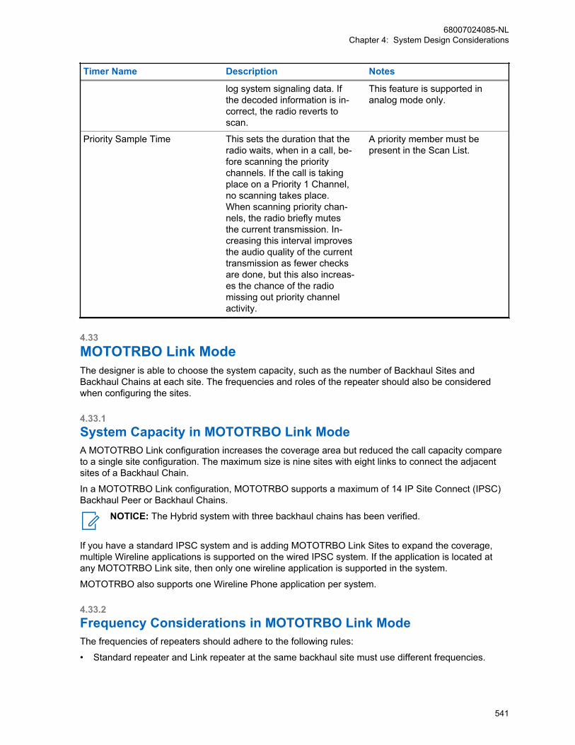
Timer Name Description Notes
log system signaling data. Ifthe decoded information is in-correct, the radio reverts toscan.
This feature is supported inanalog mode only.
Priority Sample Time This sets the duration that theradio waits, when in a call, be-fore scanning the prioritychannels. If the call is takingplace on a Priority 1 Channel,no scanning takes place.When scanning priority chan-nels, the radio briefly mutesthe current transmission. In-creasing this interval improvesthe audio quality of the currenttransmission as fewer checksare done, but this also increas-es the chance of the radiomissing out priority channelactivity.
A priority member must bepresent in the Scan List.
4.33MOTOTRBO Link ModeThe designer is able to choose the system capacity, such as the number of Backhaul Sites andBackhaul Chains at each site. The frequencies and roles of the repeater should also be consideredwhen configuring the sites.
4.33.1System Capacity in MOTOTRBO Link ModeA MOTOTRBO Link configuration increases the coverage area but reduced the call capacity compareto a single site configuration. The maximum size is nine sites with eight links to connect the adjacentsites of a Backhaul Chain.
In a MOTOTRBO Link configuration, MOTOTRBO supports a maximum of 14 IP Site Connect (IPSC)Backhaul Peer or Backhaul Chains.
NOTICE: The Hybrid system with three backhaul chains has been verified.
If you have a standard IPSC system and is adding MOTOTRBO Link Sites to expand the coverage,multiple Wireline applications is supported on the wired IPSC system. If the application is located atany MOTOTRBO Link site, then only one wireline application is supported in the system.
MOTOTRBO also supports one Wireline Phone application per system.
4.33.2Frequency Considerations in MOTOTRBO Link ModeThe frequencies of repeaters should adhere to the following rules:
• Standard repeater and Link repeater at the same backhaul site must use different frequencies.
68007024085-NLChapter 4: System Design Considerations
541
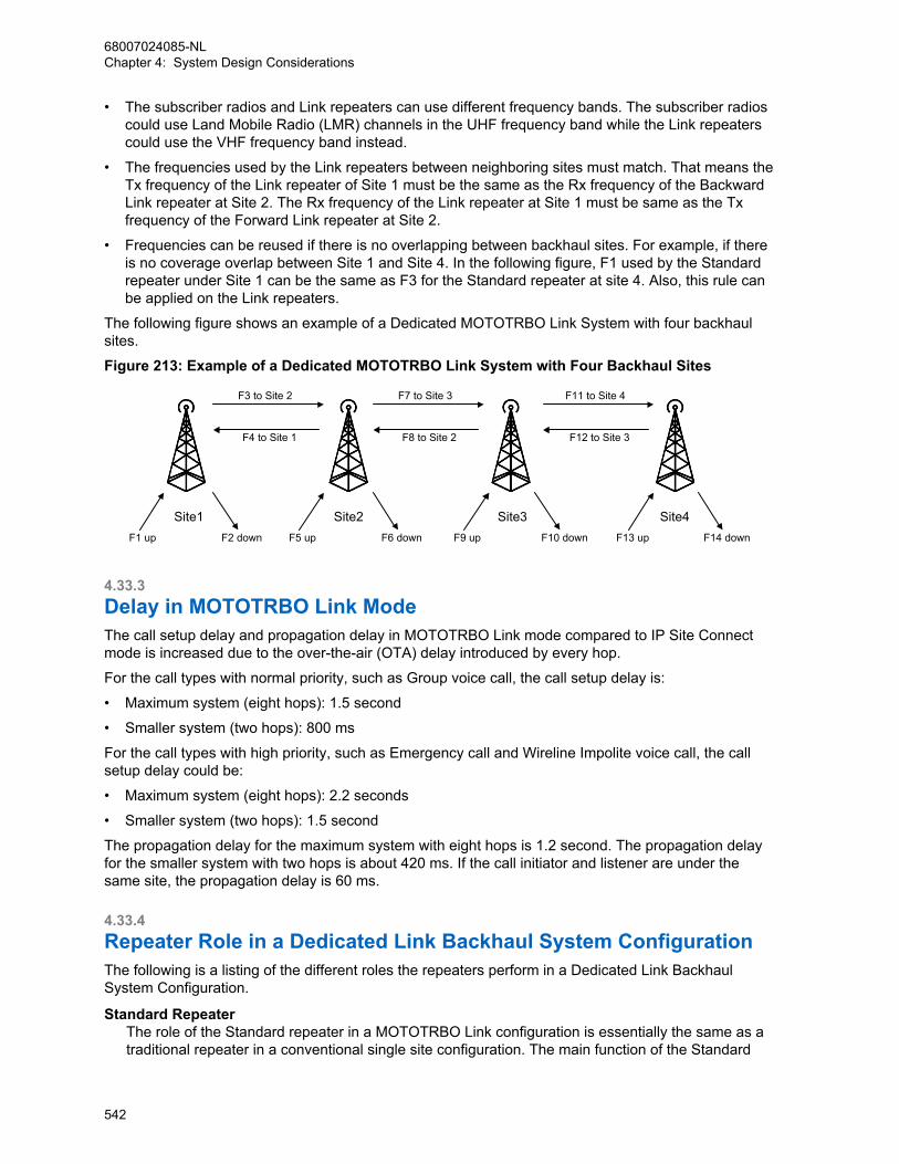
• The subscriber radios and Link repeaters can use different frequency bands. The subscriber radioscould use Land Mobile Radio (LMR) channels in the UHF frequency band while the Link repeaterscould use the VHF frequency band instead.
• The frequencies used by the Link repeaters between neighboring sites must match. That means theTx frequency of the Link repeater of Site 1 must be the same as the Rx frequency of the BackwardLink repeater at Site 2. The Rx frequency of the Link repeater at Site 1 must be same as the Txfrequency of the Forward Link repeater at Site 2.
• Frequencies can be reused if there is no overlapping between backhaul sites. For example, if thereis no coverage overlap between Site 1 and Site 4. In the following figure, F1 used by the Standardrepeater under Site 1 can be the same as F3 for the Standard repeater at site 4. Also, this rule canbe applied on the Link repeaters.
The following figure shows an example of a Dedicated MOTOTRBO Link System with four backhaulsites.
Figure 213: Example of a Dedicated MOTOTRBO Link System with Four Backhaul Sites
Site2 Site3 Site4Site1F2 downF1 up
F3 to Site 2 F7 to Site 3 F11 to Site 4
F4 to Site 1
F6 downF5 up
F8 to Site 2
F10 downF9 up
F12 to Site 3
F14 downF13 up
4.33.3Delay in MOTOTRBO Link ModeThe call setup delay and propagation delay in MOTOTRBO Link mode compared to IP Site Connectmode is increased due to the over-the-air (OTA) delay introduced by every hop.
For the call types with normal priority, such as Group voice call, the call setup delay is:
• Maximum system (eight hops): 1.5 second
• Smaller system (two hops): 800 ms
For the call types with high priority, such as Emergency call and Wireline Impolite voice call, the callsetup delay could be:
• Maximum system (eight hops): 2.2 seconds
• Smaller system (two hops): 1.5 second
The propagation delay for the maximum system with eight hops is 1.2 second. The propagation delayfor the smaller system with two hops is about 420 ms. If the call initiator and listener are under thesame site, the propagation delay is 60 ms.
4.33.4Repeater Role in a Dedicated Link Backhaul System ConfigurationThe following is a listing of the different roles the repeaters perform in a Dedicated Link BackhaulSystem Configuration.
Standard RepeaterThe role of the Standard repeater in a MOTOTRBO Link configuration is essentially the same as atraditional repeater in a conventional single site configuration. The main function of the Standard
68007024085-NLChapter 4: System Design Considerations
542

repeater is to repeat calls received locally over-the-air (OTA) or calls received from the Linkrepeater on the LAN.
Proxy RepeaterThe Proxy repeater is a special Standard repeater which is at the origin site and acts as theconnectivity bridge between the IP Site Connect WAN and the Digital Mobile Radio (DMR) channelconnectivity across the Backhaul Chain. The Proxy repeater also forwards Extended Control andManagement Protocol (XCMP) Messages from application peers and maintains presenceinformation for all the repeaters located along the Backhaul Chain. In a Hybrid MOTOTRBO Linkconfiguration, the Proxy repeater is the IP Site Connect backhaul repeater and may also be amaster or a slave peer in an IP Site Connect Backhaul network.
Link RepeaterThe role of the Link repeater in a MOTOTRBO Link configuration is unique in that it essentiallyreplaces the wireline connectivity interface with an OTA connectivity interface using a DMR-basedprotocol. The primary function of the Link repeater is to forward calls received from an adjacentbackhaul site’s Link repeater to the next site in the backhaul chain.The Link repeater should be the Slot Sync Master:
• Link repeater at Origin or Terminating site.
• Forward link repeater at Interim site (Direction from Terminating to Origin site).
IP Site Connector Backhaul RepeaterThe role of the IP Site Connect Backhaul repeater in a Hybrid MOTOTRBO Link configuration issimilar to a traditional repeater in a conventional IP Site Connect configuration.
Table 73: Standalone Dedicated-Link Backhaul Configuration
CPS/RM Options
BackhaulRode
Link Mode Site Type RepeaterType
Slot TimingMaster
IPSC BH Site
Proxy DedicatedLink
Origin Standard Re-peater
No No
Drop DedicatedLink
Interim/Terminating
Standard Re-peater
No No
Link DedicatedLink
Origin/Inter-im/Termina-tion
Link Repeat-er
Yes/No* No
* Based on Link repeater’s site type
Table 74: Hybrid Dedicated-Link Backhaul Configuration
CPS/RM Options
BackhaulRode
Link Mode Site Type RepeaterType
Slot TimingMaster
IPSC BH Site
Proxy DedicatedLink
Origin Standard Re-peater
No Yes
Drop DedicatedLink
Interim/Terminating
Standard Re-peater
No No
Link DedicatedLink
Origin/Inter-im/Termina-tion
Link Repeat-er
Yes/No* No
68007024085-NLChapter 4: System Design Considerations
543

CPS/RM Options
BackhaulRode
Link Mode Site Type RepeaterType
Slot TimingMaster
IPSC BH Site
IPSC BH None N/A N/A N/A Yes
* Based on Link repeater’s site type
4.33.5GPIO Pin ConfigurationsWithin a backhaul site, the repeaters synchronize themselves by using GPIO pins on the accessoryconnector allocated for Slot Synchronization.
The physical connection is through the repeater GPIO connector, with the following pins:
• DB25_23 - GPIO4: Site Slot Sync Input -- Slot Timing Master is No• DB25_8 - GPIO6: Site Slot Sync Output -- Slot Timing Master is YesFigure 214: GPIO Pin Configurations
Pin 9
Pin 8
Pin 9
Pin 23
Pin 9
13
25 14
1
Pin 23
DB25 MaleConnector
DB25 MaleConnector
DB25 MaleConnector
To Aux ConnectorOf Standard Repeater
To Aux Connector Of Forward Link
Repeater
To Aux Connector Of Backward Link
Repeater
Pin 9 –GndPin 8 –GPIO 6, Site Slot Sync OutputPin 23 –GPIO 4, Site Slot Sync Input
Pin 9
Pin 8
Pin 9
Pin 23
DB25 MaleConnector
DB25 MaleConnector
To Aux ConnectorOf Standard Repeater
To Aux ConnectorOf Link Repeater
68007024085-NLChapter 4: System Design Considerations
544
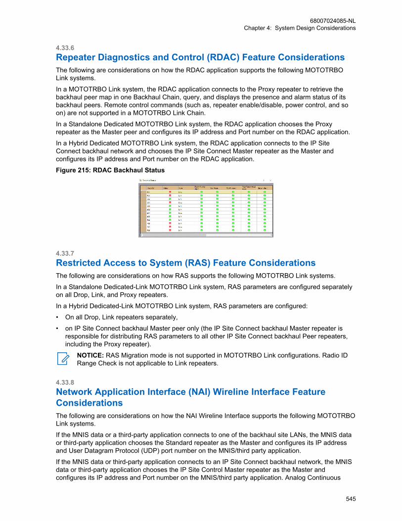
4.33.6Repeater Diagnostics and Control (RDAC) Feature ConsiderationsThe following are considerations on how the RDAC application supports the following MOTOTRBOLink systems.
In a MOTOTRBO Link system, the RDAC application connects to the Proxy repeater to retrieve thebackhaul peer map in one Backhaul Chain, query, and displays the presence and alarm status of itsbackhaul peers. Remote control commands (such as, repeater enable/disable, power control, and soon) are not supported in a MOTOTRBO Link Chain.
In a Standalone Dedicated MOTOTRBO Link system, the RDAC application chooses the Proxyrepeater as the Master peer and configures its IP address and Port number on the RDAC application.
In a Hybrid Dedicated MOTOTRBO Link system, the RDAC application connects to the IP SiteConnect backhaul network and chooses the IP Site Connect Master repeater as the Master andconfigures its IP address and Port number on the RDAC application.
Figure 215: RDAC Backhaul Status
4.33.7Restricted Access to System (RAS) Feature ConsiderationsThe following are considerations on how RAS supports the following MOTOTRBO Link systems.
In a Standalone Dedicated-Link MOTOTRBO Link system, RAS parameters are configured separatelyon all Drop, Link, and Proxy repeaters.
In a Hybrid Dedicated-Link MOTOTRBO Link system, RAS parameters are configured:
• On all Drop, Link repeaters separately,
• on IP Site Connect backhaul Master peer only (the IP Site Connect backhaul Master repeater isresponsible for distributing RAS parameters to all other IP Site Connect backhaul Peer repeaters,including the Proxy repeater).
NOTICE: RAS Migration mode is not supported in MOTOTRBO Link configurations. Radio IDRange Check is not applicable to Link repeaters.
4.33.8Network Application Interface (NAI) Wireline Interface FeatureConsiderationsThe following are considerations on how the NAI Wireline Interface supports the following MOTOTRBOLink systems.
If the MNIS data or a third-party application connects to one of the backhaul site LANs, the MNIS dataor third-party application chooses the Standard repeater as the Master and configures its IP addressand User Datagram Protocol (UDP) port number on the MNIS/third party application.
If the MNIS data or third-party application connects to an IP Site Connect backhaul network, the MNISdata or third-party application chooses the IP Site Control Master repeater as the Master andconfigures its IP address and Port number on the MNIS/third party application. Analog Continuous
68007024085-NLChapter 4: System Design Considerations
545
Wave Identification (CWID) is supported on both Drop and Link repeaters. The GPIO link master at theterminate site, which is the scheduler, schedules and sends out the CWID of all the repeaters in thebackhaul chain. None of the repeaters in the backhaul chain can send the CWID unless triggered bythe GPIO link master scheduler.
CWID configuration is set for each repeater within the backhaul chain by using existing configurationusing Customer Programming Software (CPS)/Radio Management (RM). All repeaters in the backhaulchain are either configured with CWID enabled or disabled.
It is recommended to configure a similar length of CWID characters for each repeater within thebackhaul chain to avoid asynchronous CWID transmission duration. If the length of the CWIDcharacters for each repeater is different, dummy characters could be added to fill the gap.
It is also recommended to configure all the repeaters in MOTOTRBO Link mode with the same CWIDtransmission interval. The CWID transmission interval should be larger than the Link Beacon Interval.For example, if the Link Beacon Interval is five minutes, the CWID transmission interval could beconfigured as ten minutes.
IP Site Connect backhaul repeaters send the CWID on their own pace without triggering from thescheduler (same as legacy conventional repeaters).
4.33.9Failure of the Terminating SiteThe terminating site Link repeater serves the role of the system timing Master in the Backhaul Chain.The terminating site Link repeater periodically transmits to the neighboring sites the Keep Alive BeaconCSBK messages while the system is idle in the Backhaul Chain. This synchronizes the timeslot timingand presence information within the Backhaul Chain. In absence of the periodic Keep Alive BeaconCSBK messages between a site and the timing master site, the Slot Sync Master Link repeaterconcludes that either the Timing Master repeater or the over-the-air (OTA) in-between has failed. TheSlot Sync Master of this site takes on the system Timing Master role and continues to provide servicewith available sites.
4.33.10Failure of the Interim or Origin SiteIn absence of the periodic Keep Alive Beacon CSBK messages between the two interim sites, theBackhaul Chain is divided into two independent Backhaul Chains with their own available sites. Whenthe Origin site fails, a Hybrid Backhaul system loses the connectivity between the IP Site Connectbackhaul networks and the Backhaul Chain.
4.33.11Failure of a LAN SwitchA repeater broadcasts “Keep Alive” messages periodically over the LAN to other repeaters at its site.When the LAN fails, a repeater detects the absence of the periodic “Keep Alive” messages. All radiosat this site lose the wide area connectivity with other remote sites. However, the Link repeaters are stillable to forward calls to its neighbor backhaul sites.
4.33.12Failure of a MOTOTRBO Link RepeaterA repeater detects the failure of another repeater at its site by the absence of the periodic “Keep Alive”messages from that repeater.
When the failure repeater is a:
68007024085-NLChapter 4: System Design Considerations
546
Standard RepeaterAll radios at this site loses connectivity to the system.
Proxy RepeaterHybrid Backhaul system loses connectivity between the IP Site Connect Backhaul networks withthe Backhaul Chain.
Slot Sync Slave Link RepeaterThe site loses the call connectivity with its neighbor sites in a backward direction.
Slot Sync Master Link RepeaterThe site fails to synchronize slot timing from the Backhaul Chain and loses the call connectivityfrom the Backhaul Chain eventually.
68007024085-NLChapter 4: System Design Considerations
547
Chapter 5
Sales and Service Support Tools5.1Purpose of This Section TestingThis section introduces the standard system layout, identifying each component’s role in servicing thesystem features listed in Module 2. This module is to help the reader understand what devices areneeded to support a particular system feature. It will also display the building blocks of the system froma subscriber only system to a mixed mode multi-repeater, data capable system.
5.2Applications OverviewThe three software applications listed below, and their associated drivers are available on the CD kitGMVN5141).
Name Application Overview
Customer Programming Software (CPS) CPS enables a dealer to program the device’sfeatures according to the customer require-ments. Navigating around the CPS is now easyand convenient with the addition of a help panethat displays topic-sensitive help instantly with-out the need to access the online help file.
AirTracer AirTracer has the ability to capture over-the-airdigital radio traffic and save the captured datainto a file. AirTracer can also retrieve and saveinternal error logs from MOTOTRBO radios.The saved files can be analyzed by trained Mo-torola Solutions personnel to suggest improve-ments in system configurations or to help iso-late problems.
Tuner Tuner is an application to tune and test sub-scriber and repeater products. Navigating thearound the Tuner is now easy and convenientwith the addition of a help pane that displaystopic-sensitive help instantly without the need toaccess the online help file.
5.3Service Equipment
5.3.1Recommended Test EquipmentThe list of equipment contained in the table below includes most of the standard test equipmentrequired for servicing Motorola Solutions portable radios, as well as several unique items designedspecifically for servicing this family of radios. The Characteristics column is included so that equivalent
68007024085-NLChapter 5: Sales and Service Support Tools
548
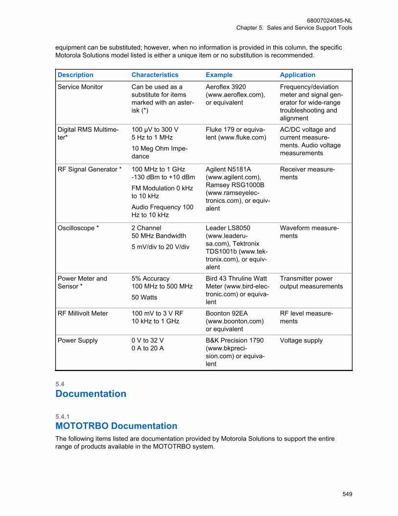
equipment can be substituted; however, when no information is provided in this column, the specificMotorola Solutions model listed is either a unique item or no substitution is recommended.
Description Characteristics Example Application
Service Monitor Can be used as asubstitute for itemsmarked with an aster-isk (*)
Aeroflex 3920(www.aeroflex.com),or equivalent
Frequency/deviationmeter and signal gen-erator for wide-rangetroubleshooting andalignment
Digital RMS Multime-ter*
100 µV to 300 V5 Hz to 1 MHz
10 Meg Ohm Impe-dance
Fluke 179 or equiva-lent (www.fluke.com)
AC/DC voltage andcurrent measure-ments. Audio voltagemeasurements
RF Signal Generator * 100 MHz to 1 GHz-130 dBm to +10 dBm
FM Modulation 0 kHzto 10 kHz
Audio Frequency 100Hz to 10 kHz
Agilent N5181A(www.agilent.com), Ramsey RSG1000B(www.ramseyelec-tronics.com), or equiv-alent
Receiver measure-ments
Oscilloscope * 2 Channel50 MHz Bandwidth
5 mV/div to 20 V/div
Leader LS8050(www.leaderu-sa.com), TektronixTDS1001b (www.tek-tronix.com), or equiv-alent
Waveform measure-ments
Power Meter andSensor *
5% Accuracy100 MHz to 500 MHz
50 Watts
Bird 43 Thruline WattMeter (www.bird-elec-tronic.com) or equiva-lent
Transmitter poweroutput measurements
RF Millivolt Meter 100 mV to 3 V RF10 kHz to 1 GHz
Boonton 92EA(www.boonton.com)or equivalent
RF level measure-ments
Power Supply 0 V to 32 V0 A to 20 A
B&K Precision 1790(www.bkpreci-sion.com) or equiva-lent
Voltage supply
5.4Documentation
5.4.1MOTOTRBO DocumentationThe following items listed are documentation provided by Motorola Solutions to support the entirerange of products available in the MOTOTRBO system.
68007024085-NLChapter 5: Sales and Service Support Tools
549

Motorola Solutions PartNumber
Name
GMLN4575D MOTOTRBO Publications CD
68012003064 DP 4801 / DP 4800 Portable User Guide
68012003065 DP 4801 / DP 4800 Portable Quick Reference Card
68012003066 DP 4601 / DP 4600 Portable User Guide
68012003067 DP 4601 / DP 4600 Portable Quick Reference Card
68012003068 DP 4401 / DP 4400 Portable User Guide
68012003069 DP 4401 / DP 4400 Portable Quick Reference Card
68012003070 DP 4801 / DP 4800 / DP 4601 / DP 4600 / DP 4401 Portable BasicService Manual
68012003071 DP 4801 / DP 4800 / DP 4601 / DP 4600 / DP 4401 Portable De-tailed Service Manual
68012003060 DM 4400 / DM 4401 Mobile User Guide
68012003061 DM 4600 / DM 4601 Mobile User Guide
68012003062 DM 4400 / DM 4401 Mobile Quick Reference Guide
68012003063 DM 4600 / DM 4601 Mobile Quick Reference Guide
68012003037 DM 4400 / DM 4401 / DM 4600 / DM 4601 Mobile Basic ServiceManual
68012003036 DM 4400 / DM 4401 / DM 4600 / DM 4601 Mobile Detailed ServiceManual
6878362A01 DM 4400 / DM 4401 / DM 4600 / DM 4601 Mobile Installation Man-ual
6866574D01 DP 340x Quick Reference Guide (Multilingual)
6866574D05 DP 340x User Guide
6866574D02 DP 360x Quick Reference Guide (Multilingual)
6866574D06 DP 360x User Guide
6866574D04 DP 3000 Series Accessory List Leaflet
6866574D35 DP 3000 Series Detailed Service Manual
6866574D29 DP 3000 Series Basic Service Manual
6866575D33 DM 3000 Series Basic Service Manual
6866575D40 DM 3000 Series Detailed Service Manual
6866575D01 DM 340x Quick Reference Guide (Multilingual)
6866575D05 DM 340x User Guide
6866575D02 DM 360x Quick Reference Guide (Multilingual)
6866575D06 DM 360x User Guide
6866575D04 DM 3000 Series Accessory List Leaflet
6866575D26 DM 3000 Series Installation Manual
6866576D03 DR 3000 Basic Service Manual
6866576D16 DR 3000 Detailed Service Manual
68007024085-NLChapter 5: Sales and Service Support Tools
550

Motorola Solutions PartNumber
Name
6866576D02 DR 3000 Installation Guide
5.4.2URLThe URLs listed are websites to provide further information about the MOTOTRBO system.
URL Name
www.tiaonline.org TSB-88 – Wireless Communications Systems-Performance in Noise and Interference-LimitedSituations, Recommended Methods for Tech-nology-Independent Modeling, Simulation, andVerification
https://mototrbodev.motorolasolutions.com MOTOTRBO Option Board ADK DevelopmentGuide on the MOTODEV Application Develop-ers website.
https://emeaonline.motorolasolutions.com Motorola Solutions Online website (contains thebandwidth calculation tool for Capacity PlusMulti Site)
68007024085-NLChapter 5: Sales and Service Support Tools
551
Appendix A
Control Station InstallationThe Data Revert Channel concept may require careful planning to achieve the expected data messagethroughput, as described in the loading sections of the IP Site Connect, Capacity Plus System Planner.This is especially true as the number of control stations in a location is increased to support larger datatraffic loads. Poorly designed installations may result in self-inflicted interference. The end result of thisinterference is often corrupted data messages, which increases the number of data message retries.This increase results in an additional load placed on the system.
A.1Data Bearer ServiceMOTOTRBO radios support both Unconfirmed and Confirmed data bearer services at Layer 2. Themethod selected impacts the transmit and receive roles that Revert Control Stations and either primarycontrol stations (conventional) or trunked control stations (Capacity Plus) play within a system. In turn,these roles can impact the installation. It should be noted that applications often implement their ownconfirmations at the application level (Layer 7); therefore the use of the Unconfirmed data bearerservice does not require that messages are unconfirmed by the receiving radio.
A.1.1Unconfirmed DataWhen Unconfirmed data is transmitted, it is transmitted to the receiver once. The receiver checks theintegrity of the entire data message (CRC check) and either passes this up to the application (CRCcheck passes) through the IP layer or discards the data (CRC check fails). The following is an exampleto highlight the roles played by the control stations.
For example, a text message is sent from a text message server to an individual radio in a CapacityPlus system. Here, the text message is routed from the server to a Trunked Control Station. When thecontrol station is allowed to transmit the data on the Rest Channel, it is transmitted once. The receivingradio then checks the integrity of the message and if the CRC check passes, the data is passed up tothe application. Upon receipt of the text message, the radio’s application is required to send anapplication layer acknowledgment to the server for confirmation. Here, the radio moves to a DataRevert Channel and when allowed, transmits the data once to a Revert Control Station. The receivingcontrol station checks the integrity of the message and if the CRC check passes, the data is passed upto the application. If the confirmation is not received by the application on the server, it attempts to retrythe message with the same procedure. Therefore, the use of the Unconfirmed Data Bearer Service canbe utilized with application layer acknowledgments to provide an end-to-end confirmed data process.
The following is a summary of the transmit and receive roles required of the various control stations inthe system utilizing Unconfirmed data.
• Revert Control Station (Conventional and Capacity Plus) – RX Only
• Primary Control Station (Conventional) – TX Only
• Trunked Control Station (Capacity Plus) – TX Only
NOTICE: When operating with Unconfirmed data, the Revert Control Stations may beconfigured to operate as RX Only.
68007024085-NLAppendix A: Control Station Installation
552

A.1.2Confirmed DataWhen Confirmed data is transmitted, it is transmitted to the receiver up to three times. The receiverchecks the integrity of each TDMA burst (CRC check) as well as the entire data message (CRC check)and either passes this up to the application (CRC check passes) through the IP layer or responds tothe initiating radio that select bursts or the entire message must be resent. Scenarios like retries do notchange the TX/RX roles played by the control stations. The following describes a first attempt successexample.
For example, a text message is sent from a text message server to an individual radio in a CapacityPlus system. Here, the text message is routed from the server to a Trunked Control Station. When thecontrol station is allowed to transmit the data on the Rest Channel, it is transmitted. The receiving radiochecks the integrity of the bursts and of the message. If the CRC check passes, it transmits a receivedconfirmation burst back to the Trunked Control Station as well as passes the data up to the application.Upon receipt of the text message, the radio’s application is required to send an application layeracknowledgment to the server for confirmation. Here, the radio moves to a Data Revert Channel andtransmits the data to a Revert Control Station when allowed. The receiving control station checks theintegrity of the bursts and of the message and if the CRC check passes, it transmits a receivedconfirmation burst back to the radio as well as passes the data up to the application.
The following is a summary of the transmit and receive roles required of the various control stations inthe system utilizing Confirmed data.
• Revert Control Station (Conventional and Capacity Plus) – RX and TX
• Primary Control Station (Conventional) – TX and RX
• Trunked Control Station (Capacity Plus) – TX and RX
NOTICE: When operating with Confirmed data, the Revert Control Stations cannot beconfigured to operate as RX Only.
A.2InterferenceWith multiple control stations operating in close proximity, it is important to isolate the transmittedsignals from the receivers. Typical types of interference to consider are Intermodulation and Desense(Blocking).
A.2.1IntermodulationIntermodulation (IM) occurs when two or more off channel signals “mix” in the receiver’s front-end tocreate a product that falls on the receive channel. This product effectively raises the noise floor of thereceiver and dictates a larger received signal to establish an acceptable Signal to Noise Ratio (SNR).Typical IM protection of the control station is around 75 dB. This protection diminishes when one of theinterferers is on the adjacent channel. Operating with self-inflicted IM due to frequency selection is notrecommended, as TX/RX isolations in excess of 80 dB (depends on interferer level and receiver level)may be required. Adequate frequency planning/selection may resolve this concern.
A.2.2Desense (Blocking)Desense or blocking occurs when a very strong off-channel signal begins to saturate the receiver’sfront end. This effectively raises the noise floor of the receiver and dictates a larger received signal toestablish an acceptable SNR. Typical desense protection of a control station is 100 dB. Everyinstallation must take this into consideration when designing the site installation.
68007024085-NLAppendix A: Control Station Installation
553
A.3Control Station Installation ConsiderationsMitigation techniques require isolating the transmitted signal from the receivers. Two general rules forgood design are:
• Place the receiving control station antennas in a location where they receive a strong RF signalfrom the source.
• Turn down the output power of the transmitting control stations to the minimum required power toestablish reliable communications.A strong receive signal can overcome elevated noise floors without impacting data reliability andturning down the TX power decreases the interfering signals that the receivers must tolerate. Thesegenerals rules have only one objective, which is to help achieve acceptable TX/RX isolation within areasonable budget. However, a stronger receive signal is not always better when IM issues exist.When the issue is caused by third order IM, every one dB of receive path loss degrades thereceivers’ sensitivity by one dB and improves IM performance by three dB. Two examples areprovided to illustrate this point when IM is not an issue.
50 watts (+47 dBm) of control station output power is required, and the typical receiver power levelinto the control station is -115 dBm. The difference between the TX and the RX power is 162 dB.Since the control station typically provides 100 dB of blocking protection, 62 dB of TX/RX isolation isrequired.
2 watts (+33 dBm) of control station output power is required, and the typical receiver power levelinto the control station is -95 dBm. The difference between the TX and the RX power is 128 dB.Since the control station typically provides 100 dB of blocking protection, 28 dB of TX/RX isolation isrequired. This comparatively, is much easier to obtain than in Example 1.
A.3.1Unconfirmed Data ConsiderationsThe Revert Control Stations only receive and never transmit. Therefore, there are no isolationrequirements between these stations. The installation could be as simple as using an individualantenna for each control station. The Primary or Trunked Control Stations only transmit and neverreceive. Therefore, there are no isolation requirements between these stations. The installation couldbe as simple as using an individual antenna for each control station.
However, the Revert and either the Primary or Trunked Control Stations may be in close proximity witheach other and there are isolation requirements between these different types of control stations.Assuming an IM free frequency plan was selected, the interference to account for is blocking. If thedifferent types of control stations must be in close proximity, consider adding an RX bandpass filter toattenuate the TX signals. If an IM free frequency plan is not possible, it is recommended to placecirculators on the transmitting control stations in order to minimize TX IM. An example of this type ofinstallation is illustrated in the following figure.
68007024085-NLAppendix A: Control Station Installation
554

Figure 216: Installation of Control Stations for Unconfirmed Data
Data RevertControl Station R
X
Combiner
TrunkingControl Station
Data RevertControl Station
Data RevertControl Station
Data RevertControl Station
TrunkingControl Station
Data RevertControl Station
Data RevertControl Station
RX
Filter
TrunkingControl Station
68007024085-NLAppendix A: Control Station Installation
555
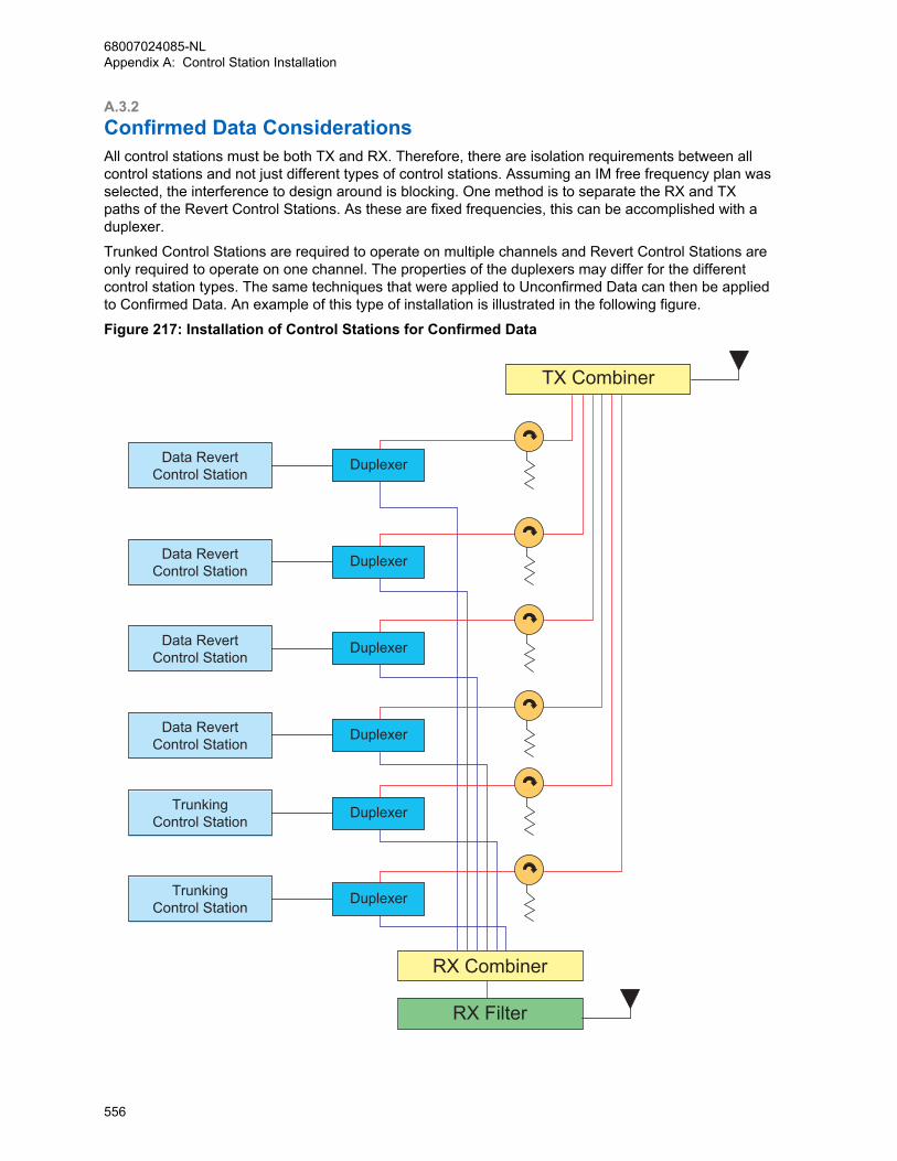
A.3.2Confirmed Data ConsiderationsAll control stations must be both TX and RX. Therefore, there are isolation requirements between allcontrol stations and not just different types of control stations. Assuming an IM free frequency plan wasselected, the interference to design around is blocking. One method is to separate the RX and TXpaths of the Revert Control Stations. As these are fixed frequencies, this can be accomplished with aduplexer.
Trunked Control Stations are required to operate on multiple channels and Revert Control Stations areonly required to operate on one channel. The properties of the duplexers may differ for the differentcontrol station types. The same techniques that were applied to Unconfirmed Data can then be appliedto Confirmed Data. An example of this type of installation is illustrated in the following figure.
Figure 217: Installation of Control Stations for Confirmed Data
RX Combiner
TX Combiner
RX Filter
TrunkingControl Station
TrunkingControl Station
Data RevertControl Station
Data RevertControl Station
Data RevertControl Station
Data RevertControl Station
Duplexer
Duplexer
Duplexer
Duplexer
Duplexer
Duplexer
68007024085-NLAppendix A: Control Station Installation
556
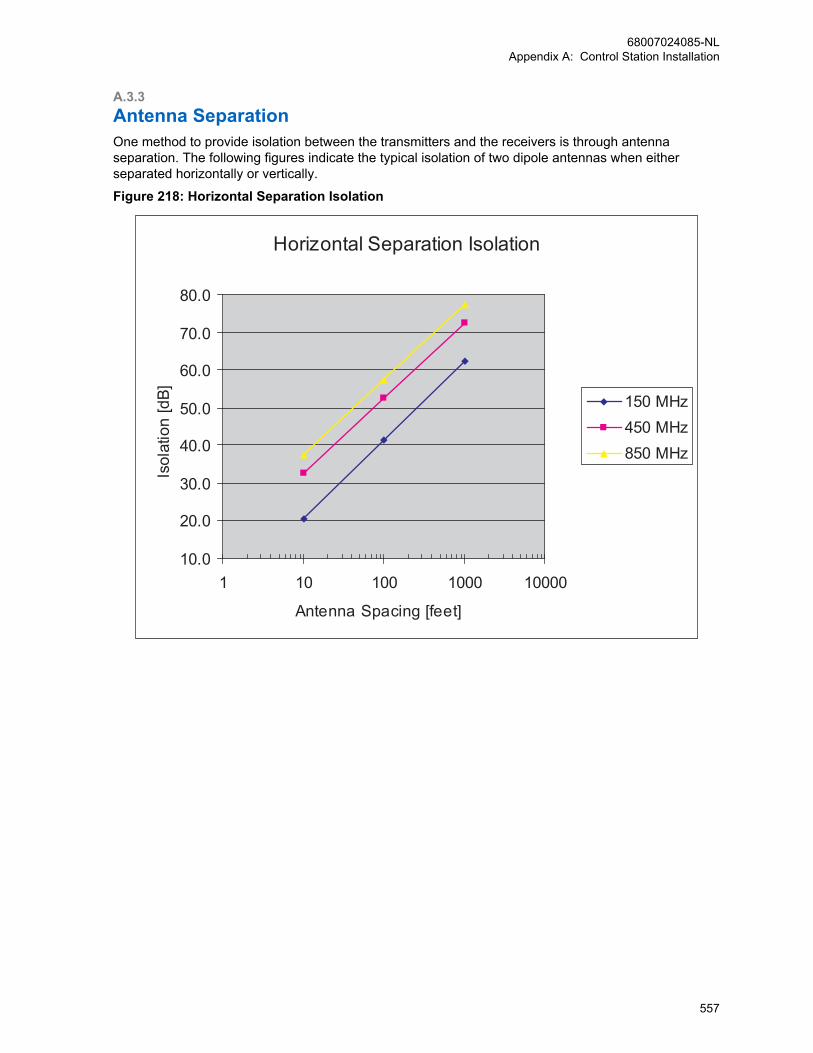
A.3.3Antenna SeparationOne method to provide isolation between the transmitters and the receivers is through antennaseparation. The following figures indicate the typical isolation of two dipole antennas when eitherseparated horizontally or vertically.
Figure 218: Horizontal Separation Isolation
Horizontal Separation Isolation
10.0
20.0
30.0
40.0
50.0
60.0
70.0
80.0
1 10 100 1000 10000
Antenna Spacing [feet]
Isol
atio
n [d
B] 150 MHz450 MHz850 MHz
68007024085-NLAppendix A: Control Station Installation
557
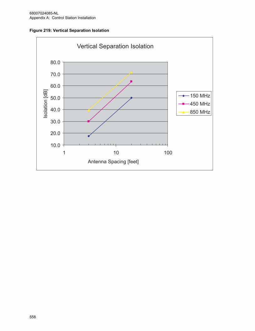
Figure 219: Vertical Separation Isolation
Vertical Separation Isolation
10.0
20.0
30.0
40.0
50.0
60.0
70.0
80.0
1 10 100
Antenna Spacing [feet]
Isol
atio
n [d
B]
150 MHz450 MHz850 MHz
68007024085-NLAppendix A: Control Station Installation
558
Related Documents