REV. 03/2013 P/N 01.00.001-EN PRODUCT GUIDE 2013 GAS ENGINE ACCESSORIES GAS REGULATION SENSOR SYSTEMS GAS ENGINE MANAGEMENT SPARK PLUGS IGNITION SYSTEMS

MOTORTECH Product Guide 2013
Mar 03, 2016
MOTORTECH Product Guide 2013
Welcome message from author
This document is posted to help you gain knowledge. Please leave a comment to let me know what you think about it! Share it to your friends and learn new things together.
Transcript

1
REV.
03/
2013
P/N
01.
00.0
01-E
N
PRODUCT GUIDE 2013
GAS
EN
GIN
E AC
CESS
ORI
ESG
AS
REG
ULA
TIO
NSE
NSO
R
SYST
EMS
GAS
EN
GIN
E M
ANAG
EMEN
TSP
ARK
PL
UG
SIG
NIT
ION
SY
STEM
S

COPYRIGHTThe copyright for any material used in the MOTORTECH publications is reserved. Any duplication or use of objects such as pictures or texts in other electronics or printed publications is not permitted without MOTORTECH's agreement.
TRADEMARK INFORMATIONMOTORTECH is not a part of nor affiliated with ALTRONIC®, CATERPILLAR®, CUMMINS®, WAUKESHA®. All OEM names and part numbers shown are for reference purpose only. All trademarks, logos, and symbols used or shown in the MOTORTECH publications are exclusive objects to the right of their owners and are used for reference purpose only.

3
88 WIRING RAIL SYSTEM 90 MOTORTECH AlphaRail − Wiring Rail System 92 Wiring Rail Kits 94 Ignition Kits
98 TOOLS AND TEST EQUIPMENT 100 SparkView 101 SparkScan1 102 Ignition Coil Tester 104 Ignition Pickup Simulator 105 ScopeLite 106 Tools and Workshop Equipment
108 SPARK PLUGS AND ACCESSORIES 110 MOTORTECH XT-Plugs 112 MOTORTECH XTL-Plugs 116 MOTORTECH MPC Spark Plugs 116 MOTORTECH ICP Spark Plugs 117 DENSO® Spark Plugs 124 Accessories and Tools
128 GAS ENGINE MANAGEMENT 130 ALL-IN-ONE 134 DetCon20 137 PowerView3 138 MOTORTECH AlphaRail − Wiring Rail System
140 SENSOR SYSTEMS 142 MOTORTECH AlphaRail − Wiring Rail System 144 Sensor Harnesses 147 Oxygen Sensors 148 MAP/MAT Sensors 149 Thermocouples
150 GAS REGULATION 152 VariFuel2 158 VariStep 159 EmCon5 162 Throttles 164 DUNGS® Gas Trains
166 GAS ENGINE ACCESSORIES 168 LLC – Liquid Level Controller 170 Coolant Filters 172 Lube Oil Filters 174 Cleaning Station
176 INDEX
TABLE OF CONTENTS
10 IGNITION CONTROLLERS 12 MIC5 Series 14 MIC4 Series 18 MICT 19 PowerView3 20 MIC850 Series 24 MIC500 Series
28 IGNITION COILS 30 NEW MOTORTECH Style 31 MOTORTECH Style 31 ALTRONIC® Style 32 CATERPILLAR® Style 33 Conversion Kits 34 Accessories 36 Flange Versions 38 Externally Mounted 39 Integral Standard Versions 40 Integral High Energy Versions
42 TRIGGERING 44 Pickups 47 Pickup Leads 48 Trigger Devices 50 Trigger Discs 52 Accessories
54 HIGH TENSION LEADS AND ACCESSORIES 56 High Tension Leads – PolyMotTM Style 60 High Tension Leads 61 Unshielded Safety Leads for Shielded Spark Plugs 63 Unshielded Safety Leads for Conventional Spark Plugs 64 Accessories 68 MOT-Blues – Shielded High Tension Leads 69 Conventional Shielded High Tension Leads 70 Terminal Kits
76 PRIMARY LEADS 78 Shielded Primary Leads − for MOTORTECH AlphaRail 80 Conventional Shielded Primary Leads
82 EXTENSIONS 84 Spark Plug Extension – PolyMotTM Style 86 Repair Kits for CATERPILLAR® Ignition Coils 87 Teflon Extensions for CATERPILLAR® Ignition Coils 87 Shielded Integral Ignition Coil Adaptor 87 Shielded Spark Plug Extensions
GAS
EN
GIN
E AC
CESS
ORI
ESG
AS
REG
ULA
TIO
NSE
NSO
R
SYST
EMS
GAS
EN
GIN
E M
ANAG
EMEN
TSP
ARK
PL
UG
SIG
NIT
ION
SY
STEM
S

4
WELCOME TO MOTORTECH
Welcome!
For those who fail to advance from what they have already achieved are quickly overtaken by the ever-changing demands of the market. This is why it pays to be innovative.
At MOTORTECH we have been working hard to meet the needs of our customers for almost 25 years. We always strive to be one decisive step ahead of the rest! This is how we have proven ourselves worthy of being your qualified partner for stationary gas engines. Therefore, it should come as no surprise that MOTORTECH places high value in innovation, in research and in development. With over 200 employees, more than 20% are now active in this dynamic area! The continuous new and further developments of our product line for ignitions, controls and monitoring of the com-bustion process, ensure maximum availability and efficiency of your gas engines. With greater efficiency comes fewer emissions which is good for our environment.
An example of our innovative strength is our new line of performance ignition coils. They were developed along with the new production technology used for manufac-turing at MOTORTECH.
If you have any questions or concern, please feel free to contact us. We guarantee you a solution for your gas engine.
Florian Virchow
Managing Director
MO
TORTECH
− W
E UPG
RADE G
AS ENG
INES
4

5
BENEFITS
Take advantage of our benefits
• Equipment for all kinds of stationary gas engines
• Development of hardware and software solutions
• Design and production of innovative system solutions and individual solutions
• Delivery and maintenance of ignition and control systems
• Extensive test procedures to assure highest levels of product safety
• Comprehensive technical support
• From problem analysis to new design
• Fastest possible delivery of gas engine accessories and replacement parts of all kinds
• Specialists in electronic controls and for gas engines used for CHP and compressor drives
• Installation and on-site repair – in emergencies and around the world, around the clock
MO
TORT
ECH
–
WO
RKIN
G F
OR
YOU
EV
ERYW
HER
E AL
L TH
E TI
ME!
5

6
INNOVATIVE DESIGN AND PRODUCTS
Innovative Design
We develop innovative hardware and software solutions for engine management that will keep your gas engine state-of-the-art for years to come. Our microproces-sor-controlled ignition, anti-knock control, temperature monitoring and CHP control (Combined Heat and Power) for gas engines exceed the most stringent future requirements. This includes interactive functions for all devices – like the integrati-on of TFT touch screens via CAN BUS interfaces that enable fast data exchange and visualization of important engine parameters.
On the mechanical side MOTORTECH is developing gas mixers and throttles for various engine sizes and gas qualities using computer-supported development and analysis tools like 3D-CAD. This means your gas engine will always deliver maxi-mum performance from nearly any type of gas.
Mechanical Products
Six high-tech CNC machining centers and other precision machines for processing metal and plastic parts are available for the production of mechanical products. To achieve the greatest reliability, we use state-of-the-art laser technology to weld and mark parts. We often develop and build our own manufacturing equipment. There are often no optimal production machines on the market to produce our special sys-tem components that meet our rigorous standards. This means that we can produce exactly those products our customers need.
Electronic Products
Our base modules are produced with state-of-the- art technology in small volume production runs in Germany and are marketed worldwide. These conditions make it possible to individually adapt the electronics to every engine type and set of re-quirements. Just plug it in and the engine runs. Replacement parts and components undergo extensive automatic test procedures and durability tests at MOTORTECH prior to their application. Even the smallest system component must satisfy the high quality requirements of our “Zero Failure Strategy”.
TAKE ADVAN
TAGE
OF 25 YEARS
OF EXPERIEN
CE!
6

7
QUALITY
Certified Quality
At MOTORTECH special emphasis is put on quality and safety, because neither you nor we can afford defects. That is why our entire company is DIN ISO 9001 certified. Additionally, MOTORTECH has passed the certification audit of the strictest auto-motive standard ISO TS 16949/2002 (similar to QS 9000) in 2004. In conjunction with ISO 9001, this certificate specifies Quality Management System requirements for development, production and any applicable assembly and maintenance of the specific products.
Safety Management System
"We live quality!" − That is also reflected in our high work safety standards. Thanks to our comprehensive Safety Management System, there have been no work-related accidents whatsoever at MOTORTECH in the last 20 years!
Sales Partner
All MOTORTECH subsidiaries and distributors are trained on a regular basis by experienced personnel to enable us to keep our comprehensive quality promise to even our most distant customers. MOTORTECH does not simply satisfy industry standards and requirements − we exceed them!
QU
ALIT
Y IS
WH
EN
THE
CUST
OM
ER R
ETU
RNS,
N
OT
THE
PRO
DU
CT!
7

8
MAINTENANCE, REPAIR, ON-SITE SERVICE
Service Team
Take advantage of MOTORTECH’s many years of technical expertise in maintenance, repair and service. Our team participates in an ongoing training program and is familiar with the technical and maintenance procedures of all commonly used systems. Our technicians will perform know how repairs using the latest test inst-ruments and tools, either at your company site or at our own workshops, even on products that we did not produce. Furthermore, to assure you with the best possible delivery anywhere in the world, MOTORTECH maintains an extensive inventory of parts and finished goods.
Always At Your Site
Regardless of which part of the globe we need to travel to, we know that the stakes are high, and therefore we also outperform the others. That is because we want everything to run smoothly at your site, everywhere and at anytime. This is entirely in keeping with our motto: Let us drop everything and work on your problem!
WH
EN TH
ING
S GET H
OT
OU
R SERVICE TEAM IS AT YO
UR SITE Q
UICKLY!
8

9
COMPLETE SERVICE
Consultation
MOTORTECH’s customer-focused know-how can provide support and consultation for your new developments, project planning, and problem analyses. Moreover, we are ready to assist you with advice and service at anytime. Just give us a call! You can be sure that our team will find an optimal solution for your particular problem area.
Warehousing
To assure you the best possible delivery anywhere in the world, MOTORTECH maintains an extensive inventory of parts and finished goods. Optimized order-processing and select global logistics partners deliver even the smallest of parts via a direct route to where they are needed.
Customer Training
Shared knowledge is multiplied knowledge. Our extensive training program is spe-cifically made for your technical and service employees. We can teach them about new developments in gas engine technology, and we invite all interested persons to discuss their experiences, either at our classrooms in Celle (Germany), New Orleans (USA) or at in-house training events at your company facilities.
MO
TORT
ECH
–
WO
RKIN
G F
OR
YOU
, EV
ERYW
HER
E AL
L TH
E TI
ME!
9

10

11
IGNITION CONTROLLERSYears ago, MOTORTECH has made the decision to become a key player in design and manufacturing of ignition controls for the Global Industrial Gas Engine Business. A large engineering staff develops hard and software plat-forms. Test facilities were put in place to stress our hardware by temperature, heat and vibration. Cooperation with engine manufacturers, packagers and end users have led to specific designs and arrangements that will ensure the best performance of the rotating equipment.
The new engine regulations and the growing biogas market, the developing mine gas industry and all other kinds of alternative fuel applications have raised strong demands for high energy, extended spark duration and very pre-cised timing. Coupled to the demand for lean burn strategies, efficiency and equipment availability MOTORTECH was forced to look at high technology for the future.

12
MOTORTECH IGNITION CONTROLLERMIC5
IGNITION CONTROLLERS
NEW
MIC5 Series Ignition Controllers
The latest MOTORTECH development convinces with a future oriented electronical concept for more power and a significantly higher degree of efficiency.
High ignition energy, accurate spark timing and diversified online diagnostics help to improve engine efficiency, spark plug life and availability of the equipment under the strictest emission regulati-ons. The controller is fully customer configurable via Laptop.
∙ 20 ignition output channels∙ Constant spark intensity via adjusted duration∙ 500 mJ primary energy ∙ Ignition diagnostics (primary and secondary) ∙ Fault memory with trend data ∙ Integrated CANopen and Modbus RTU interface ∙ Easy access per USB port
Technical Data & Features
• 18 to 32 VDC supply voltage
• 20 ignition outputs
• 250 VDC primary voltage
• 500 mJ primary energy
• 0.1° crankshaft accuracy
• Triggered by 1, 2 or 3 pickups
(magnetic, hall effect or inductive / configurable)
• Multiple timing control via
- Potentiometer
- Speed curve
- 0-20 mA analog input
- 0-10 V analog input
• Multiple energy control via MOST
(MOTORTECH Output Stage Technology)
• Programmable firing order
• 1 multipurpose output (GPO)
• 1 Auxiliary Synchronization Output (ASO) which
can support a detonation control system
(e.g. DetCon) or fuel injection pump controllers
• Ignition release input
• Go/NoGo output
• Overspeed shutdown function
• Access controlled
Ignition Diagnostic
• Run time data
• Alarm and error messages
• Data logging
• Primary and secondary misfire detection
• Cylinder individual high voltage calculation (kV)
• 6 LEDs provide a quick system state overview
Interfaces
• CAN Bus 2.0b interface (CANopen protocol J1939)
• RS485 interface (Modbus RTU)
• USB 1.1 interface
Configuration
• Fully configurable via Laptop with MICT software
(see page 18)
∙ Adjustable spark duration and intensity ∙ Constant spark intensity via adjusted
duration
MOTORTECH OUTPUT STAGE TECHNOLOGYMOST

13
Pickup Arrangements3-pickup arrangement for 4-stroke engines
1) Reset
Magnetic pickup (holes, pins, teeth, screws)
2) Speed
Magnetic pickup (holes, pins, teeth, screws)
3) Camshaft
Hall-Effect pickup (magnets)
alternative
3) Camshaft
Inductive pickup (pins, screws, slots)
1-pickup arrangement for 4-stroke engines
1) Camshaft
Hall-Effect pickup (disc with magnets)
alternative
1) Camshaft
Inductive pickup (disc with pins, screws,
slots / trigger device)
2-pickup arrangement for 2-stroke engines
1) Reset
Magnetic pickup (holes, pins, teeth, screws)
2) Speed
Magnetic pickup (holes, pins, teeth, screws)
Required Accessories
1 MIC5 ignition controller
2 Output harness*
3 Pickups*
4 Trigger pins & magnets
alternative
5 Trigger discs
alternative
- Trigger device
6 Pickup leads*
7 1 ignition coil per cylinder*
8 1 primary lead/high tension lead
per ignition coil*
Accessories
B Junction box
C AlphaRail – Wiring rail
System Enhancement
A DetCon20 – Detonation controller
D PowerView3 – HMI module
Description
V Camshaft
W Crankshaft
X Engine
Y Cylinder
Z Harness to connect ignition rail and junction box
* For detailed information about these products
please contact your local distributor.
0-5V / 4-20 mA
8
A
Y
1
7
2
B
C
X
Z
V W
MOTORTECH IGNITION RAIL SYSTEMAlphaRail
MOTORTECH DETONATION CONTROL SYSTEMDetCon20
6
3
5
4
MOTORTECH ENGINE INFORMATION MONITORPowerView3
CAN CAN
IGN
ITIO
N
SYST
EMS
D

14
MOTORTECH IGNITION CONTROLLERMIC4
IGNITION CONTROLLERS
MIC4 Series Ignition Controllers
The new economically attractive MOTORTECH development convinces with a future oriented electronical concept for more power and a signi-ficantly higher degree of efficiency.
High ignition energy, accurate spark timing and diversified online diagnostics help to improve engine efficiency, spark plug life and availability of the equipment under the strictest emission regulati-ons. The controller is fully customer configurable via Laptop.
∙ 16 ignition output channels∙ Constant spark intensity via adjusted duration∙ 300 mJ primary energy ∙ Ignition diagnostics (primary and secondary) ∙ Fault memory with trend data ∙ Integrated CANopen and Modbus RTU interface ∙ Easy access per USB port
Technical Data & Features
• 10 to 32 VDC supply voltage
• 8 / 16 ignition outputs
• 250 VDC primary voltage
• 300 mJ primary energy
• 0.1° crankshaft accuracy
• Triggered by 1, 2 or 3 pickups
(magnetic, hall effect or inductive / configurable)
• Multiple timing control via
- Potentiometer
- Speed curve
- 0-20 mA analog input
- 0-10 V analog input
• Multiple energy control via MOST
(MOTORTECH Output Stage Technology)
• Programmable firing order
• 1 multipurpose output (GPO)
• 1 Auxiliary Synchronization Output (ASO) which
can support a detonation control system
(e.g. DetCon) or fuel injection pump controllers
• Ignition release input
• Go/NoGo output
• Overspeed shutdown function
• Access controlled
Ignition Diagnostic
• Run time data
• Alarm and error messages
• Data logging
• Primary and secondary misfire detection
• Cylinder individual high voltage calculation (kV)
• 6 LEDs provide a quick system state overview
Interfaces
• CAN Bus 2.0b interface (CANopen protocol J1939)
• RS485 interface (Modbus RTU)
• USB 1.1 interface
Configuration
• Fully configurable via Laptop with MICT software
(see page 18)
Hardware
• Different housing styles available
• Coil driver board equipped with 8 or 16 ignition
outputs
∙ Adjustable spark duration and intensity ∙ Constant spark intensity via adjusted
duration
MOTORTECH OUTPUT STAGE TECHNOLOGYMOST

15
Pickup Arrangements3-pickup arrangement for 4-stroke engines
1) Reset
Magnetic pickup (holes, pins, teeth, screws)
2) Speed
Magnetic pickup (holes, pins, teeth, screws)
3) Camshaft
Hall-Effect pickup (magnets)
alternative
3) Camshaft
Inductive pickup (pins, screws, slots)
1-pickup arrangement for 4-stroke engines
1) Camshaft
Hall-Effect pickup (disc with magnets)
alternative
1) Camshaft
Inductive pickup (disc with pins, screws,
slots / trigger device)
2-pickup arrangement for 2-stroke engines
1) Reset
Magnetic pickup (holes, pins, teeth, screws)
2) Speed
Magnetic pickup (holes, pins, teeth, screws)
Required Accessories
1 MIC4 ignition controller
2 Output harness*
3 Pickups*
4 Trigger pins & magnets
alternative
5 Trigger discs
alternative
- Trigger device
6 Pickup leads*
7 1 ignition coil per cylinder*
8 1 primary lead/high tension lead
per ignition coil*
Accessories
B Junction box
C AlphaRail – Wiring rail
System Enhancement
A DetCon20 – Detonation controller
D PowerView3 – HMI module
Description
V Camshaft
W Crankshaft
X Engine
Y Cylinder
Z Harness to connect ignition rail and junction box
* For detailed information about these products
please contact your local distributor.
8
A
Y
1
7
2
B
C
X
Z
V W
MOTORTECH IGNITION RAIL SYSTEMAlphaRail
MOTORTECH DETONATION CONTROL SYSTEMDetCon20
6
3
5
4
MOTORTECH ENGINE INFORMATION MONITORPowerView3
0-5V / 4-20 mA
CAN CAN
IGN
ITIO
N
SYST
EMS
D

16
MIC4 Series Ignition Controllers – Standard Versions – Light Duty – MIL Style Connectors
Connector
P/N max. Outputs Connector Input Analog Input Output Pickup Voltage ASC Equivalent to
66.00.410-8 8 MIL Style 17 pole socket programmable via MICT not applicable
66.00.410-16 16 MIL Style 17 pole socket programmable via MICT not applicable
IGNITION CONTROLLERIGNITION CONTROLLERS
Housing Style “LD” (Light Duty)Standard configuration for applications in direct vicinity of gas engines in protec-ted environment. The electronic system is integrated in a solid aluminum housing.
• 17 pole military style connector (socket) for 8 and 16 ignition outputs• Plug connectors for input wiring• For ambient temperatures from -40°C to +60°C (-40°F to +140°F)• Protection rating IP54• 10,43 in. x 9,45 in. x 3,74 in. / 265 x 240 x 95 mm (L x W x H)
Housing Style “PM” (Panel Mount)Device configuration for assembly in control panels. Equipped with plug connectors for simple integration into the wiring system.
• Plug connectors for input and output wiring (8 and 16 ignition outputs)• For ambient temperatures from -20°C to +50°C (-4°F to +122°F)• Protection rating IP20• 11,10 in. x 7,87 in. x 2,64 in. / 282 x 200 x 67 mm (L x W x H)
Housing Style “HD” (Heavy Duty)When it‘s time to really get down to business. The Heavy Duty housing is 100 % reliable whether in hot desert sand or perpetual ice!
• 17 pole military style connector (socket) for 8 and 16 ignition outputs• Plug connectors for input wiring• For ambient temperatures from -40°C to +70°C (-40°F to +158°F)• Integrated cooling element for optimal heat dissapation• Protection rating IP65• 10,43 in. x 10,39 in. x 4,84 in. / 265 x 264 x 123 mm (L x W x H)
back
MIC4 Series Ignition Controllers – Standard Versions – Panel Mount – Plug Connector Style
Connector
P/N max. Outputs Connector Input Analog Input Output Pickup Voltage ASC Equivalent to
66.00.400-8 8 Plug connector Plug connector programmable via MICT not applicable
66.00.400-16 16 Plug connector Plug connector programmable via MICT not applicable
MOST
MIC4 Series Ignition Controllers – Standard Versions – Heavy Duty – MIL Style Connectors
Connector
P/N max. Outputs Connector Input Analog Input Output Pickup Voltage ASC Equivalent to
66.00.440-8 8 MIL Style 17 pole socket programmable via MICT not applicable
66.00.440-16 16 MIL Style 17 pole socket programmable via MICT not applicable
MOST
MOST
1
2
3
1
2
3

17
MIC4 Series Ignition Controllers – Special Version – Light Duty – MIL Style Connectors
Connector
P/N max. Outputs Connector Input Analog Input Output Pickup Voltage ASC Equivalent to
66.00.411-8 8 MIL Style 10 pole pin 10 pole socket programmable via MICT not applicable MIC500 P/N 06.00.520
66.00.412-16 12 MIL Style 10 pole pin 14 pole socket programmable via MICT not applicable MIC500 P/N 06.00.525
66.00.413-16 16 MIL Style 10 pole pin 19 pole socket programmable via MICT not applicable MIC500 P/N 06.00.525
66.00.414-161) 16 MIL Style 35 pole socket programmable via MICT not applicable MIC850 P/N 66.00.855-24/-24-D
66.00.415-8 8 MIL Style 6 pole pin 10 pole socket 10 pole pin programmable via MICT not applicable
CAT® G3300 / G3400 series P/N 163-6164 / ALTRONIC® DISN P/N 791808-x / MIC500 P/N 06.00.513
66.00.416-16 16 MIL Style 6 pole pin 10 pole pin 19 pole pin programmable via MICT not applicable
CAT® G3412 P/N 163-6108 / ALTRONIC® DISN P/N 791812-x / 791816-x / MIC500 P/N 06.00.514
66.00.417-8 8 MIL Style 7 pole pin 10 pole socket 10 pole pin programmable via MICT not applicable
WAUKESHA® CECVGF & VHP series 6 & 8 cyl.2) / MIC500 P/N 06.00.515-6/-8
66.00.418-16 16 MIL Style 7 pole pin 10 pole pin 19 pole pin programmable via MICT not applicable
WAUKESHA® CEC VGF & VHP series 12 & 16 Cyl.2) / MIC500 P/N 06.00.516/517
66.00.419-161) 16 MIL Style 14/17 pole socket programmable via MICT not applicable WOODWARD® IC9xx / MIC850
P/N 66.00.851-24/-24-D
66.00.420-16 12 MIL Style 14 pole socket programmable via MICT not applicable MIC850 P/N 66.00.855-12/-12-D
66.00.421-16 16 MIL Style 6 pole socket
10 pole socket 19 pole socket programmable via MICT not applicable MIC500 P/N 06.00.510
66.00.422-16 16 MIL Style 10 pole socket - 19 pole socket programmable via MICT not applicable MIC500 P/N 06.00.511
1) Maximum of 16 outputs available for this model. 2) When replacing CEC controller by MIC4 use of DSM control is not possible.
MOST
MIC4 Series Ignition Controllers – PowerView3 HMI Module
P/N Description
06.05.085 PowerView3 HMI module
06.05.086-F PowerView3 activation code for visualization of MIC4/MIC5 data1)
06.05.086-U PowerView3 activation code for visualization of MIC4/MIC5 data2)
1) Activation code has to be ordered separately with each PowerView3 HMI module. 2) Only available for upgrade of existing PowerView3 HMI module in the field.
MIC4 Series Ignition Controllers – Shielded Output Harnesses1) for Light Duty and Heavy Duty Ignition Controllers
P/N Description Connector Length Equivalent to
95.40.217-L Output harness for MIC4 Light Duty and Heavy Duty ignition controllers 17 pole pin, 180° "L"= 15/25/50 ft.
1) Customer has to supply flex conduit.
MIC4 Series Ignition Controllers – Junction Box
P/N Description
06.05.067 Junction box
IGN
ITIO
N
SYST
EMS

18
IGNITION CONTROLLERIGNITION CONTROLLERS
MOTORTECH INTEGRATED CONFIGURATION TOOLMICT
MICT – Motortech Integrated Configuration Tool
The MICT is the graphical user interface for all controllers of the MIC4 and MIC5 series. With a Laptop all configurations can be done and run time data of the engine can be checked and adjusted.• Language selectable• Microsoft Windows XP / Vista / 7 compatible• Included Data base offers engine information such as firing
order, firing sequence, number of ignition coils per cylinder and typical number of teeth on flywheel for easy engine configuration
• Print function of a given moment in the operation can be used for external problem analysis, etc.
• Context sensitive online help• Different access levels to avoid accidental misconfigurations
Sample Screens – Configuration
Parameter Set – Configuration VisualisationThe graphic display of the parameter set A and B offers a fast, visual control of the configured values.
Parameter SetThe MIC4 offers two sets of parameters for the necessary inputs in order to calculate the engine ignition timing, which e.g. can be used for a two gas quality operation. Furthermore the parameter sets can be visualized graphically.
Sample Screen – Runtime Data
Parameter Set – Energy SettingsFor start phase and normal operation of the engine, durations at different high voltage levels and ignition spark intensity can be adjusted with the advanced energy settings.
Breakdown VoltageThe MICT offers a lot of real time and detailed infor-mation about the status of each individual ignition output. Important data will be visually prepared, so that any irregularities will stand out easily. For example, secondary voltage will be displayed as bar graph, and the type of misfiring carries a warning light as symbol.

19
NEWMOTORTECH ENGINE INFORMATION MONITOR
PowerView3PowerView3 – HMI Module
The operating data of MIC4 and MIC5 series ignition cont-rollers will be completely visualized via HMI module (Human Machine Interface). The overview sheet shows the relevant information as engine speed, ignition timing and status of pickups, ignition outputs or active parameter set.
The PowerView3 also allows justification of various ignition parameters such as ignition timing and energy. Functions as the selftest for error diagnostics can also be executed via HMI module. The control keys guarantee simple navigation through different display pages and menus. All in all the PowerView3 HMI module is also able to provide error diagnostics on-site without requiring a laptop!
The PowerView3 is also available for data visualization of: • Detonation control (DetCon)• Temperature monitoring (available soon)
Sample Screens
PowerView3 – HMI Module
P/N Description
06.05.085 PowerView3 – HMI module
06.05.086-F PowerView3 – activation code for visualization of MIC4/MIC5 data1)
06.05.086-U PowerView3 – activation code for visualization of MIC4/MIC5 data2)
1) Activation code has to be ordered separately with each PowerView3 HMI module. 2) Only available for upgrade of existing PowerView3 HMI module in the field.
IGN
ITIO
N
SYST
EMS
MIC OverviewScreen shows the most important operating data of the connected ignition controller.
IgnitionMisfiring and estimated secondary voltage of each individual cylinder will be shown.
Secondary Voltages RecordingVisualization of secondary voltage trend data.

20
IGNITION CONTROLLERS
Technical data and features
• 24 ignition outputs
• 18 to 30 VDC supply voltage
• 300 VDC primary voltage
• 180 mJ of primary energy
• 0.1° crankshaft accuracy
• Triggered by 1, 2 or 3 pickups (configurable)
• Will fire accurately as low as 20 RPM
(slow start application)
• Multiple timing control via
- Potentiometer
- Speed curve
- 4-20mA analog input
- 0-5V analog input
• Multiple energy control via
- Manual setting
- Spark plug run time
- Automatic control of spark duration (ASC)
• 3 Multi purpose Outputs (GPO)
• 2 Auxiliary Synchronization Outputs (ASO) which
can support the DetCon20 detonation control
system and fuel injection pump controllers
• Overspeed shutdown function
• Large built in LC-Display with keyboard (optional)
in selectable languages
• Access controlled
Diagnostic
• Run time data
• Ignition timing and mapping
• Alarm and error messages
• Data logging
• Pickup voltage
• Input supply voltage
• Timers
• Circuit board temperatures
• Primary and secondary misfiring detection
• Cylinder individual high voltage reading (kV)
• etc.
Interfaces
• CAN Bus interface (CANOpen protocol)
• USB port
• SD-Card slot for firmware updates
Hardware
• Ignition controller can be equipped with one
(12 outputs) or two (24 outputs) coil driver boards
• Standard military style connectors
• 14 pole (socket) for 12 outputs
• 35 pole (socket) for 24 outputs
• Optional: graphical display and keyboard built
into front cover
• No separate wiring required!
MICT – MOTORTECH Ignition Configuration Tool
• Language selectable
• Windows PC based
• Graphical user interface
• Easy engine configuration by library based
preprogrammed information
• programmed parameters are evaluated during
input
• 24 configurable alarms
• Programmed timing and energy curves can be
monitored
• Print function of a given moment in the operation
can be used for external problem analysis via
E-Mail or any other data communication
MIC850 Series – Ignition Controllers
High ignition energy, accurate spark timing and diversified online diagnostics help to improve engine efficiency, spark plug life and availability of the equipment under the strictest emission regulations. The controller is fully customer confi-gurable via PC. Further fine tuning can be made by using the built in keyboard. Firmware updates can easily be made via implementing a SD-Card. An optional built in graphical display offers the customer an access to approx. 20 screens with online data. This includes the access to specific information as the cylin-der individual high voltage (kV) reading and the primary and secondary misfire detection.
MOTORTECH IGNITION CONTROLLERMIC850

21
The operating data of MIC850 ignition control devices will be completely visualised via HMI module (Human-Machine Inter-face). The overview sheet shows the relevant information. The MIC850 HMI module allows justification of various ignition parameters such as ignition timing and energy. Functions as
the selftest for error diagnostics via HMI module can also be executed. 8 control keys guarantee simple navigation through different display pages and menus. All in all, the MIC850 HMI module is also able to provide error diagnostics on-site without requiring a mobile PC!
MIC850 Series Ignition Controllers – HMI Module (optional)
Individual parameterization of those devices is explicitly de-scribed on various program pages. The parameters will alrea-dy be evaluated during data input and errors will be optically emphasized.Complex parameter coherences are graphically displayed in order to avoid any errors and for easier under-standing. A context depending support explains the individu-al parameters and their correlation. MICT operating time data
display reflects any operating time parameter and is perfectly qualified for diagnostic purposes and error correction. Prin-ting function for a given moment of time of the running period does support problem analysis. The backed up connection-oriented communication protocol between MICT and ignition guarantees an accurate data trans-fer even under difficult conditions on-site.
MICT – MOTORTECH Integrated Calibration Tool
Auto Spark ControlDisplay and adjustment options of the requested spark plug firing duration directly at the HMI-module.
Timing In this window you can adjust the reset position with the engine running. This is meant to compare the ignition timing of the display with the one mea-sured by timing light.
Schedule A Overview of the ignition timing adjustment of configuration A. Here you can directly see whether ignition timing adjustment takes place via an analog input or via speed curve. The current ignition timing will be displayed under „Global Timing“.
Engine Parameter The MICT refreshable engine library stores the engine data such as various manufacturers, series and types. It facilitates the system configuration and helps to avoid mistakes. Should you not find a certain engine in the list or the stated parameters do not correspond with your expectation, configura-tion can be set up as you like.
Parameter Set The MIC850 offers two sets of parameters for the necessary inputs in order to calculate the engine ignition timing, which e.g. can be used for a two gas quality operation. A basic value is pre-defined and specified for each parameter set, stating whether and how the potentiometer adjustment and the pending analog input signals (4-20 mA and 0-5V) must be taken into consideration.
Pickups The MIC850 renders support for systems with 1-3 active or passive pickups. Pickup configuration can either be set up by manual input or via selection of preprogrammed data sets.
IGN
ITIO
N
SYST
EMS

22
IGNITION CONTROLLERS
8
Pickup Arrangements3-pickup arrangement for 4-stroke engines
1) Reset
Magnetic pickup (holes, pins, teeth, screws)
2) Speed
Magnetic pickup (holes, pins, teeth, screws)
3) Camshaft
Hall-Effect pickup (magnets)
alternative
3) Camshaft
Inductive pickup (pins, screws, slots)
1-pickup arrangement for 4-stroke engines
1) Camshaft
Hall-Effect pickup (disc with magnets)
alternative
1) Camshaft
Inductive pickup (disc with pins, screws,
slots / trigger device)
2-pickup arrangement for 2-stroke engines
1) Reset
Magnetic pickup (holes, pins, teeth, screws)
2) Speed
Magnetic pickup (holes, pins, teeth, screws)
Required Accessories
1 MIC850 ignition controller
2 Output harness*
3 Pickups*
4 Trigger pins & magnets
alternative
5 Trigger discs
alternative
- Trigger device
6 Pickup leads*
7 1 ignition coil per cylinder*
8 1 primary lead/high tension lead
per ignition coil*
Accessories
B Junction box
C AlphaRail – Wiring rail
System Enhancement
A DetCon20 – Detonation controller
Description
V Camshaft
W Crankshaft
X Engine
Y Cylinder
Z Harness to connect ignition rail and junction box
* For detailed information about these products
please contact your local distributor.
A
Y
1
7
2
B
C
X
Z
V W
MOTORTECH IGNITION RAIL SYSTEMAlphaRail
MOTORTECH DETONATION CONTROL SYSTEMDetCon20
6
3
5
4
0-5V / 4-20 mA

23
MIC850 Series Ignition Controllers – Shielded Output Harnesses1) for Ignition Controllers P/N 66.00.851-24/-24-D
P/N Description Connector Length Equivalent to
95.40.414-L Output harness for P/N 66.00.851-24/-24-D 14 pole pin, 90° "L"= 15/25/50 ft.
95.40.417-L Output harness for P/N 66.00.851-24/-24-D 17 pole pin, 90° "L"= 15/25/50 ft.
1) Customer has to supply flex conduit.
MIC850 Series Ignition Controllers – Shielded Output Harnesses1) for Ignition Controllers P/N 66.00.855-12/-12-D / 66.00.855-24/-24-D
P/N Description Connector Length Equivalent to
95.40.414-L Output harness for P/N 66.00.855-12/-12-D 14 pole pin, 90° "L"= 15/25/50 ft.
95.40.435-L Output harness for P/N 66.00.855-24/-24-D 35 pole pin, 90° "L"= 15/25/50 ft.
1) Customer has to supply flex conduit.
MIC850 Series Ignition Controllers – Standard Versions – MIL Style Connectors
P/N max. Outputs Connector Output Connector Pickup Voltage HMI MOST Equivalent to
66.00.855-12 12 MIL Style 14 pole socket 24 VDC not applicable
66.00.855-12-D 12 MIL Style 14 pole socket 24 VDC x not applicable
66.00.855-24 24 MIL Style 35 pole socket 24 VDC not applicable
66.00.855-24-D 24 MIL Style 35 pole socket 24 VDC x not applicable
Conversion: 1 inch = 25,4 mm / 1 foot = 0,3 m
MIC850 Series Ignition Controllers – Junction Box
P/N Description
06.05.067 Junction box
MIC850 Series Ignition Controllers – Special Versions – MIL Style Connectors
P/N max. Outputs Connector Output Connector Pickup Voltage HMI MOST Equivalent to
66.00.851-24 24 MIL Style 14/17 pole socket 24 VDC not applicable WOODWARD® IC9xx
66.00.851-24-D 24 MIL Style 14/17 pole socket 24 VDC x not applicable WOODWARD® IC9xx
IGN
ITIO
N
SYST
EMS

24
IGNITION CONTROLLERS
MIC500 − The price attractive Ignition System
The MIC500 is a 16 Bit microprocessor controlled ignition unit for small and midsize engines from 2 to 16 cylinders. The cost effective control unit is fully programmable by the operator via PC or handheld programming tool. The single pickup system is triggered off a camshaft disc (4-stroke engine) or a crankshaft mounted disc (2-stroke engine). Ignition timing accuracy is approx. 0.25 degrees crankshaft.
The MIC500 is available in special versions to replace the • WAUKESHA® CEC® ignition box on the VGF and VHP
series engines• CATERPILLAR® ignition box for G3300 and G3400
series engines• ALTRONIC® DISN®
The unit is a physical drop in and only needs to be program-med for the application. For the advanced features see table below.
Technical data and features
• 10 to 30 VDC
• 300 VDC primary voltage
• 180 mJ ignition energy
• 2 to 16 ignition outputs
Interface
• RS232
Programming features
• Overspeed shut off
• Ignition timing via
- potentiometer
- 4-20 mA analog input
- Speed curve
Display
A small external display can be ordered optionally.
Linked to RS232 port it will display the following
information:
• Ignition timing
• Engine speed
• Ignition energy
• Analog input current
• Alarm and error messages
MOTORTECH IGNITION CONTROLLERMIC500

25
Pickup Arrangements 1- pickup arrangement for 4-stroke engines
1) Camshaft
Hall-Effect pickup (disc with magnets)
alternative
Inductive pickup (disc with pins, screws, slots)
1- pickup arrangement for 2-stroke engines
1) Reset
Magnetic pickup (holes, pins, teeth, screws)
Required Accessories
1 MIC500 ignition controller
2 Output harness*
3 Pickup*
4 Trigger pins & magnets
alternative
5 Trigger discs
alternative
Trigger device
6 Pickup lead*
7 1 ignition coil per cylinder*
8 1 primary lead/high tension lead
per ignition coil*
Accessories
B Junction box
C AlphaRail − Wiring rail
System Enhancement
A DetCon20 − Detonation controller
D RS232 Ignition display
Description
V Camshaft
W Crankshaft
X Engine
Y Cylinder
Z Harness to connect ignition rail and junction box
* For detailed information about these products
please contact your local distributor.
4-20 mA
8
A
Y
1
7
2
B
C
X
Z
V
MOTORTECH IGNITION RAIL SYSTEMAlphaRail
MOTORTECH DETONATION CONTROL SYSTEMDetCon20
6
5
3
4
RS232
IGN
ITIO
N
SYST
EMS
D

26
MIC500 Series Ignition Controllers – Non-Shielded Output Harnesses for Ignition Controllers P/N 06.00.520/525/530
P/N Description Connector Length Outputs
06.02.608-240 Output harness for P/N 06.00.520 10 pole pin, 180° 240 in. 8
06.02.612-240 Output harness for P/N 06.00.525 14 pole pin, 180° 240 in. 12
06.02.616-240 Output harness for P/N 06.00.530 19 pole pin, 180° 240 in. 16
MIC500 Series Ignition Controllers – Shielded Input Harnesses for Ignition Controllers P/N 06.00.520/525/530
P/N Description Connector Wire Length Conduit Length Pickup
95.30.501-80 Input harness for P/N 06.00.520/525/530 10 pole socket, 180° 160 in. 80 in. inductive
95.30.505-80 Input harness for P/N 06.00.520/525/530 10 pole socket, 180° 160 in. 80 in. magnetic
95.30.510-80 Input harness for P/N 06.00.520/525/530 10 pole socket, 180° 160 in. 80 in. hall-effect
MIC500 Series Ignition Controllers – Shielded Output Harnesses for Ignition Controllers P/N 06.00.520/525/530
P/N Description Connector Wire Length Conduit Length Outputs
95.30.608-80 Output harness for P/N 06.00.520 10 pole pin, 180° 160 in. 80 in. 8
95.30.608-160 Output harness for P/N 06.00.520 10 pole pin, 180° 240 in. 160 in. 8
95.30.608-300 Output harness for P/N 06.00.520 10 pole pin, 180° 380 in. 300 in. 8
95.30.612-80 Output harness for P/N 06.00.525 14 pole pin, 180° 160 in. 80 in. 12
95.30.612-160 Output harness for P/N 06.00.525 14 pole pin, 180° 240 in. 160 in. 12
95.30.612-300 Output harness for P/N 06.00.525 14 pole pin, 180° 380 in. 300 in. 12
95.30.616-80 Output harness for P/N 06.00.530 19 pole pin, 180° 160 in. 80 in. 16
95.30.616-160 Output harness for P/N 06.00.530 19 pole pin, 180° 240 in. 160 in. 16
95.30.616-300 Output harness for P/N 06.00.530 19 pole pin, 180° 380 in. 300 in. 16
MIC500 Series Ignition Controllers – Standard Versions – MIL Style Connectors
Connector
P/N max. Outputs Connector Input Analog Input Output Pickup Voltage MOST ASC Equivalent to
06.00.520 8 MIL Style 10 pole pin 10 pole socket 24 VDC not applicable not applicable
06.00.525 12 MIL Style 10 pole pin 14 pole socket 24 VDC not applicable not applicable
06.00.530 16 MIL Style 10 pole pin 19 pole socket 24 VDC not applicable not applicable
MIC500 Series Ignition Controllers – Special Versions – AMP Style Connectors
Connector
P/N max. Outputs Connector Input Analog Input Output Pickup Voltage MOST ASC Equivalent to
06.00.508 8 AMP Style 23 pole pin combinedwith input
combined with input 24 VDC not applicable not applicable WOODWARD® IC100
IGNITION CONTROLLERS
MIC500 Series Ignition Controllers – Non-Shielded Input Harnesses for Ignition Controllers P/N 06.00.520/525/530
P/N Description Connector Length Pickup
06.02.501-160 Input harness for P/N 06.00.520/525/530 10 pole socket, 180° 160 in. inductive
06.02.505-160 Input harness for P/N 06.00.520/525/530 10 pole socket, 180° 160 in. magnetic
06.02.510-160 Input harness for P/N 06.00.520/525/530 10 pole socket, 180° 160 in. hall-effect
Conversion: 1 inch = 25,4 mm / 1 foot = 0,3 m

27
MIC500 Series Ignition Controllers – Non-Shielded Input and Output Harnesses for Ignition Controller P/N 06.00.508
P/N Description Connector Length Pickup
06.01.001-160 Input and output harness for P/N 06.00.508 23 pole socket, 180° 160 in. inductive
06.01.101-160 Input and output harness for P/N 06.00.508 23 pole socket, 180° 160 in. magnetic
06.01.301-160 Input and output harness for P/N 06.00.508 23 pole socket, 180° 160 in. hall-effect
MIC500 Series Ignition Controllers – Special Versions – MIL Style Connectors
Connector
P/N max. Outputs Connector Input Analog Input Output Pickup Voltage MOST ASC Equivalent to
06.00.513 8 MIL Style 6 pole pin 10 pole socket 10 pole pin 8 VDC not applicable not applicable
CAT® G3300 / G3400 series P/N 163-6164 / ALTRONIC® DISN P/N 791808-x
06.00.514 16 MIL Style 6 pole pin 10 pole pin 19 pole pin 8 VDC not applicable not applicableCAT® G3412 P/N 163-6108 ALTRONIC® DISN P/N 791812-x / 791816-x
06.00.515-61) 8 MIL Style 7 pole pin 10 pole socket 10 pole pin 8 VDC not applicable not applicable WAUKESHA® CEC
VGF & VHP series 6 cyl.2)
06.00.515-81) 8 MIL Style 7 pole pin 10 pole socket 10 pole pin 8 VDC not applicable not applicable WAUKESHA® CEC
VGF series 8 cyl.2)
06.00.5161) 16 MIL Style 7 pole pin 10 pole pin 19 pole pin 8 VDC not applicable not applicable WAUKESHA® CEC VGF & VHP series 12 Cyl.2)
06.00.5171) 16 MIL Style 7 pole pin 10 pole pin 19 pole pin 8 VDC not applicable not applicable WAUKESHA® CEC VGF & VHP series 16 Cyl.2)
1) Ignition controller comes preprogrammed.2) When replacing CEC-controller by MIC500 use of DSM control is not possible.
MIC500 Series Ignition Controllers – Non-Shielded Input Harnesses for Ignition Controllers P/N 06.00.513/514/515-6/515-8/516/517
P/N Description Connector Length Pickup
06.02.011-80 Input harness for P/N 06.00.513/514 6 pole socket, 180° 80 in. hall-effect
06.31.034-80 Input harness for P/N 06.00.515-6/515-8/516/517 7 pole socket, 180° 80 in. hall-effect
MIC500 Series Ignition Controllers – Non-Shielded Analog Input Harnesses for Ignition Controllers P/N 06.00.513/514/515-6/515-8/516/517
P/N Description Connector Length
06.71.047 Analog input harness for P/N 06.00.513/515-6/515-8 10 pole pin, 180° 160 in.
06.02.022-160 Analog input harness for P/N 06.00.514/516/517 10 pole socket, 180° 160 in.
MIC500 Series Ignition Controllers – Non-Shielded Output Harnesses for Ignition Controllers P/N 06.00.513/514/515-6/515-8/516/517
P/N Description Connector Length Outputs
06.31.035-160 Output harness for P/N 06.00.513/515-6/515-8 10 pole socket, 180° 160 in. 8
06.02.010-160 Output harness for P/N 06.00.514/516/517 19 pole socket, 180° 160 in. 16
MIC500 Series Ignition Controllers – RS232 Ignition Display
P/N Description
06.05.040A RS232 ignition display for use with MIC500 series ignition controllers
MIC500 Series Ignition Controllers – Junction Box
P/N Description
06.05.067 Junction box
IGN
ITIO
N
SYST
EMS

28

29
IGNITION COILSThe demand for more specialized ignition coils has forced MOTORTECH to design and manufacture its own igniti-on coil product lines. From standard EPOXY molded ignition coils to shell type high energy coils and very special shielded and CSA certified versions, there is a wide variety of coils “Made in Europe“ available through the global product distribution network.
Lean burn gas engines, high voltage measuring (MOST – MOTORTECH Output stage technology and ASC – Auto Spark Control) or indicating systems (spark reference system) – all require very special coil characteristics. Not only the design but also the manufacturing processes are important. MOTORTECH ignition coils today are manu-factured in a semi automated process under vacuum and together with modern high speed winding equipment it is ensured that one coil is like the other. Designed for the toughest applications and built to last.

30
Non CSA Certified Ignition Coils Standard Versions – New MOTORTECH Style
Ignition coils are becoming more and more important in mo-dern, state of the art ignition systems. MOTORTECH made it its profession to develop a series of new high performance ignition coils produced in the European facilities and specially designed for use with newest technologies of MOTORTECH ignitions controllers:
• Applicable for MOST – MOTORTECH Output Stage Technology of MOTORTECH MIC4 and MIC5 ignition controllers
• Applicable for ASC – Automatic Spark Control of MOTORTECH MIC850 ignition controllers
• Ideally suited for ignition of alternative fuels such as biogas
IGNITION COILS
MOTORTECH IGNITION COILSMotCoils
Non CSA Certified Ignition Coils – Standard Versions – New MOTORTECH Style
P/N Supersedes Color Primary Termination HV Termination Polarity ASC MOST Equivalent to
06.50.100 red #10-32 UNF studs M6 (-) ground x x
06.50.102 red #10-32 UNF studs female (-) ground x x
06.50.104 blue #10-32 UNF studs M6 (-) ground not applicable x
06.50.105 blue #10-32 UNF studs female (-) ground not applicable x
MIC4/MIC5 with MOST * – MOTORTECH Output Stage Technology
∙ Adjustable spark duration and intensity
∙ Constant spark intensity via adjusted duration
* Patent pending
MOTORTECH OUTPUT STAGE TECHNOLOGYMOST MOST
CDI
100
50
100 200 300 400 500 600 700 800
variable
vari
able
Seco
ndar
y Cu
rren
t [m
A]
spark duration

31
A large amount of different EPOXY ignition coils with different ignition characteristics are available for non-shielded applications. A variety of short and long duration coils with female, male (SAE) or even screw type vspark plug lead termination allows the operator to pick the best for his application. MOTORTECH ignition coils are made to the highest quality stan-dards. A constant improvement of the manufacturing process has led to a product line that is unique when it comes to life time and repeatability of high voltage pattern and performance.
Non CSA Certified Ignition Coils – Standard Versions – MOTORTECH Style
P/N Supersedes Color Primary Termination HV Termination Polarity ASC MOST Equivalent to
06.50.001 consult factory black #10-32 UNF studs female (-) ground not applicable not applicable PPT2477P
06.50.002 06.50.001 black #10-32 UNF studs female (-) ground not applicable not applicable PPT2477L
06.50.003 06.50.007 black #10-32 UNF studs M6 (-) ground x not applicable
06.50.060 black #10-32 UNF studs M6 (-) ground not applicable not applicable
Thousands of smaller gas engines (including CUMMINS®) are equipped with a low cost ignition coil that is very limited to its high voltage output capability. MOTORTECH has taken up the customer complaints from the field and designed a new ignition coil that is nearly the same in physical dimensions, but eliminates all the weak aspects of the competitor‘s design.
For existing installations with ALTRONIC® ignition coils, MOTORTECH offers a series of replacement products. The ignition coils are designed to have the same characteristics in regards of standard and extended duration as well as the electrical characteristics to function with the ALTRONIC® pa-tented “Spark Reference“ high voltage indication system.See chart below for cross reference numbers.
Non CSA Certified Ignition Coils – Standard Versions – ALTRONIC® Style
P/N Supersedes Color Primary Termination HV Termination Polarity ASC MOST Equivalent to
06.50.053 black #10-32 UNF studs female (+) ground not applicable not applicable 291001
06.50.054 red #10-32 UNF studs female (-) ground not applicable not applicable 591010
06.50.055 blue #10-32 UNF studs female (-) ground not applicable not applicable 501061
Non CSA Certified Ignition Coils – Standard Versions – ALTRONIC® Style
P/N Supersedes Color Primary Termination HV Termination Polarity ASC MOST Equivalent to
06.50.103 black #10-32 UNF studs male (-) ground not applicable not applicable 591040
Non CSA Certified Ignition Coils – Standard Versions – MOTORTECH Style
Non CSA Certified Ignition Coils – Standard Versions – ALTRONIC® Style
Non CSA Certified Ignition Coils – Standard Versions – ALTRONIC® StyleIG
NIT
ION
SY
STEM
S

32
IGNITION COILS
The rising demand for specialized ignition coils has led MOTORTECH to the decision to design a new series of ignition coils, specially made for use with CATERPILLAR® gas engines.
• Compatible with original ignition coils• Support CATERPILLAR® ignition systems• Made in Europe
Non CSA Certified Ignition Coils – Standard Versions – For CATERPILLAR® G3400 & G3500 Series Gas Engines (Non CSA Applications)
P/N Color Primary Termination HV Termination Polarity ASC MOST Equivalent to
06.50.141 white DEUTSCH® connector female (-) ground not applicable not applicable 232-6348, 165-1591, 131-3277, 129-8802, 108-0615
06.50.1451) white DEUTSCH® connector female (-) ground not applicable x 232-6348, 165-1591, 131-3277, 129-8802, 108-0615
06.50.143 white DEUTSCH® connector female (-) ground not applicable not applicable 232-6352, 213-7443
06.50.1471) white DEUTSCH® connector female (-) ground not applicable x 232-6352, 213-7443
06.50.151 white DEUTSCH® connector female (-) ground not applicable not applicable 232-6346, 165-1589, 124-0749
06.50.1551) white DEUTSCH® connector female (-) ground not applicable x 232-6346, 165-1589, 124-0749
06.50.153 white DEUTSCH® connector female (-) ground not applicable not applicable 232-6350
06.50.1571) white DEUTSCH® connector female (-) ground not applicable x 232-6350
1) Ignition coils only for use with MIC4 and MIC5 ignition controllers.
MOTORTECH IGNITION COILSMotCoils
Non CSA Certified Ignition Coils – Standard Versions – For CATERPILLAR® G3400 & G3500 Series Gas Engines (CSA Applications)
P/N Color Primary Termination HV Termination Polarity ASC MOST Equivalent to
06.50.142 white DEUTSCH® connector female (-) ground not applicable not applicable 232-6349, 165-1592, 122-8070
06.50.1461) white DEUTSCH® connector female (-) ground not applicable x 232-6349, 165-1592, 122-8070
06.50.144 white DEUTSCH® connector female (-) ground not applicable not applicable 232-6353, 213-7444
06.50.1481) white DEUTSCH® connector female (-) ground not applicable x 232-6353, 213-7444
06.50.152 white DEUTSCH® connector female (-) ground not applicable not applicable 232-6347, 165-1590
06.50.1561) white DEUTSCH® connector female (-) ground not applicable x 232-6347, 165-1590
06.50.154 white DEUTSCH® connector female (-) ground not applicable not applicable 259-2078
06.50.1581) white DEUTSCH® connector female (-) ground not applicable x 259-2078
1) Ignition coils only for use with MIC4 and MIC5 ignition controllers.

33
Non CSA Certified Ignition Coils Standard Versions – For CATERPILLAR® G3520C & G3600 Series & Perkins 4016-E61TRS Gas Engines
P/N Color Primary Termination HV Termination Polarity ASC MOST Equivalent to
06.50.161 white DEUTSCH® connector female (-) ground not applicable not applicable 310-3180
06.50.1621) white DEUTSCH® connector female (-) ground not applicable x 310-3180
06.50.111 white DEUTSCH® connector female (-) ground not applicable not applicable 837/9, 10000-06176
1) Ignition coils only for use with MIC4 and MIC5 ignition controllers.
Non CSA Certified Ignition Coils – Accessories – Repair Kits for MOTORTECH Ignition Coils1) – For CATERPILLAR® G3400 and G3500 Series Gas Engines
P/N Description Fits Ignition Coil P/N Extension Length Extension Diameter
06.80.741 Ignition coil repair kit 06.50.141/06.50.145 95 mm 30 mm
06.80.742 Ignition coil repair kit 06.50.142/06.50.146 97 mm 30 mm
06.80.743 Ignition coil repair kit 06.50.143/06.50.147 107 mm 30 mm
06.80.744 Ignition coil repair kit 06.50.144/06.50.148 109 mm 30 mm
06.80.751 Ignition coil repair kit 06.50.151/06.50.155 118 mm 30 mm
06.80.752 Ignition coil repair kit 06.50.152/06.50.156 105 mm 30 mm
06.80.753 Ignition coil repair kit 06.50.153/06.50.157 112 mm 30 mm
06.80.754 Ignition coil repair kit 06.50.154/06.50.158 105 mm 30 mm
1) For suitable repair kits for CATERPILLAR® ignition coils, please refer to page 87.
Non CSA Certified Ignition Coils – Accessories – Spark Plug Extension for MOTORTECH/CATERPILLAR® Ignition Coil – For CATERPILLAR® G3520C and G3600 Series Gas Engines1)
P/N Description Resistance Fits Ignition Coil P/N Extension Length Extension Diameter Equivalent to
06.80.459H Spark plug extension 0 kΩ 06.50.161/06.50.162 248 mm 26 mm 283-5271, 308-1380
1) Supersedes spark plug extensions P/N 06.80.375H and 06.80.446H.
Non CSA Certified Ignition Coils Ignition Coil Conversion Kits for CUMMINS® Gas Engines
P/N Description
75.30.143Ignition coil conversion kit for CUMMINS® QSK60GIncludes flange ignition coil with diagnostic interface, adaptor flange with fastening material, spark plug extension
75.30.144Ignition coil conversion kit for CUMMINS® QSV81G/QSV91GIncludes flange ignition coil with diagnostic interface, adaptor flange with fastening material, spark plug extension
1) For primary lead options, please refer to page 79, 81.
IGN
ITIO
N
SYST
EMS
NEW

34
IGNITION COILS
Non CSA Certified Ignition Coils – Accessories – Boots for MOTORTECH Ignition Coils
Ignition Coil Side Outlet Ignition Coil 06.50. ...
P/N Figure Primary Secondary 90 ° 180 ° 003 053 054 055 060 100 102 103 104 105
06.80.037 1 x x x x x x x
06.84.082 2 x x x x x x
06.84.021 3 x x x1)
06.80.005 4 x x x x x x x
06.84.083 5 x x x x
06.80.006 6 x x x x
06.84.006 7 x x x x x x x
1) Two boots needed for each ignition coil.
Different ignition coil styles require different boots to seal the primary or secondary terminals. MOTORTECH boots are all made from highest grade of silicone (482 °F / 250 °C).
The boots will remain soft and flexible over a long time and protect the operator from touching any low or high voltage terminations. The boots also ensure that the critical areas stay clean and dry even in the worst environment.
Non CSA Certified Ignition Coils – Accessories – Boots for ALTRONIC® Ignition Coils
Outlet
P/N Figure Description 90 ° 180 ° Ignition Coil
06.80.037 1 Boot, primary side x 291001 / 591010 / 501061
06.80.036 2 Boot, primary side x 291001 / 591010 / 501061
1 2 3 4 5
1 2
6 7
Non CSA Certified Ignition Coils – Accessories

35
Non CSA Certified Ignition Coils – Accessories – Secondary Connections
Ignition Coil 06.50. ...
P/N Figure Description 003 053 054 055 060 100 102 103 104 105
06.80.030 1 Coil terminal, 180°, 1 kΩ resistor, requires P/N 06.80.126 x x x x x
06.80.091 2 Coil terminal, 180°, requires P/N 06.80.126 x1) x x1)
06.80.108 3 Crimp terminal base x x x x
06.80.116 4 Crimp terminal, 90°, requires P/N 06.80.108 x x
06.80.116-180 5 Crimp terminal, 180°, requires P/N 06.80.108 x x
06.80.126 6 Crimp terminal base x x x x1) x x x1) x
06.84.024 7 Coil terminal, 90°, including terminal P/N 02.85.920 x
06.84.025 8 Coil terminal, 180°, including terminal P/N 02.85.920 x
22.80.009 9 Coil terminal, 90°, 1 kΩ resistor, requires P/N 06.80.126 x x
1) When using SAE contact pin P/N 06.51.223.
1 2 3 4 5 6 7 8 9
Non CSA Certified Ignition Coils – Accessories
Ignition Coil 06.50. ...
P/N Figure Description 003 053 054 055 060 100 102 103 104 105
06.51.223 1 SAE contact pin x x
06.90.2641) 2 Accessory kit incl. fastening screws and nuts x x x x
02.85.1004 3 SAE spreading adaptor x x x x x
1) Comes with each New MOTORTECH Style ignition coil.
1 2 3
IGN
ITIO
N
SYST
EMS

36
MOTORTECH makes available the BLUE and RED flanged ignition coil as a replacement for the existing products sold by the engine manufacturers.
CSA Certified Ignition Coils – Flange Versions
CSA Certified Ignition Coils – Flange Versions
P/N Supersedes Color Primary Termination HV Termination Polarity ASC MOST Equivalent to
06.50.034 red MIL Style 3 pole pin female (-) ground not applicable not applicable 591012/69694F
06.50.035 blue MIL Style 3 pole pin female (-) ground not applicable not applicable 591018/(A)69694G
95.09.100 silver MIL Style 3 pole pin female (-) ground x x
95.09.133 silver MIL Style 3 pole pin female (+) ground not applicable not applicable
95.09.134 silver MIL Style 3 pole pin female (-) ground not applicable not applicable 591012/69694F
95.09.135 silver MIL Style 3 pole pin female (-) ground not applicable not applicable 591018/(A)69694G
IGNITION COILS

37
CSA Certified Ignition Coils – Flange Versions with Diagnostic Interface
P/N Supersedes Color Primary Termination HV Termination Polarity ASC MOST Equivalent to
95.09.150 silver MIL Style 3 pole pin female (-) ground x x
95.09.153 silver MIL Style 3 pole pin female (+) ground not applicable not applicable
95.09.1541) silver MIL Style 3 pole pin female (-) ground not applicable not applicable
95.09.1552) silver MIL Style 3 pole pin female (-) ground not applicable not applicable
95.09.1563) silver MIL Style 3 pole pin female (-) ground x x
1) Same coil winding as P/N 06.50.034 / 95.09.134, but with diagnostic interface. Thus also equivalent to P/N 591012 and 69694F. 2) Same coil winding as P/N 06.50.035 / 95.09.135, but with diagnostic interface. Thus also equivalent to P/N 591018 and 69694G / A69694G.3) Use of ignition coil only possible, if conversion kits P/N 75.30.143 or 75.30.144 previously were used.
NEW
MOTORTECH HIGH VOLTAGE INDICATORSparkView
MOTORTECH flanged ignition coils with diagnostic interface are designed for operators who want to monitor their high voltage traces in a simple way. Measuring high voltage peak (kV) and spark duration (μsec) of all cylinders of an engine with flange coils regularly, will allow easy maintenance of the equipment.
With a Scope Meter or the new MOTORTECH SparkView the operator can receive real time data.
CSA Certified Ignition Coils – Flange Versions with Diagnostic Interface
NEW
See page 100.
Additional BNC connector for high voltage measurement
IGN
ITIO
N
SYST
EMS
The SparkView is a new handheld de-vice developed by MOTORTECH that can monitor the high voltage required by the spark plug while the engine is running. With a measuring clamp or cable and the display for up to 40 kV, it is easy to determine the condition of the spark plugs and the time at which they need to be replaced.

38
IGNITION COILS
SHIELDED
CSA Certified Ignition Coils – Externally Mounted
Shielded – externally mounted – ignition coils are encapsu-lated in a steel housing with welded lids. A bracket is used to install the coils on a wiring rail or directly on the engine. This type of ignition coil is connected to the shielded spark plug by a braided high tension lead with a 3/4 in. or 1 in. termination. Primary voltage connection is made by a 2 or 3 pole military style screw connector. All parts meet the CSA Class I, Division 2, Group C/D.
CSA Certified Ignition Coils – Externally Mounted
P/N Supersedes Color Primary Termination HV Termination Polarity ASC MOST Equivalent to
95.09.005 silver MIL Style 3 pole pin 3/4-20 UNEF (-) ground x x
95.09.053 95.09.001 silver MIL Style 3 pole pin 3/4-20 UNEF (+) ground not applicable not applicable 291001-S/10-382080
95.09.054 95.09.003 silver MIL Style 3 pole pin 3/4-20 UNEF (-) ground not applicable not applicable 591010-S
95.09.055 95.09.002 silver MIL Style 3 pole pin 3/4-20 UNEF (-) ground not applicable not applicable 501061-S
95.08.003 95.08.001/95.08.002 silver MIL Style 2 pole pin 1-20 UNEF (-) ground x x PPT2477AD/ ADL/
10-382040-1

39
CSA Certified Ignition Coils – Integral Standard Versions
Integral ignition coils are designed to be mounted directly on a dual threaded spark plug. No spark plug lead is required. These ignition coils are mostly used in hazardous applica-tions. Coil life is effected by the temperature that is transfer-red into the coil by the spark plug. On occasions where the spark plug leaks high combustion pressure enters the ignition coil and forces the base coil to blow out of it`s housing. MOTORTECH has designed a top cover safety ring that will not allow this to happen. Also, the actual coil is located in upper end of the coil housing and is effected less by the temperature (cooler location).
CSA Certified Ignition Coils – Integral Standard Versions – 3 Pole Primary Connector Arrangement – ALTRONIC® Compatible
HV Termination
P/N Supersedes Color Length Primary Termination Outer Thread Inner Thread Polarity ASC MOST Equivalent to
95.09.030 95.09.010 silver 5.82 in. MIL Style 3 pole pin 1-20 UNEF
13/16-20 UNEF (-) ground not applicable not applicable 591007
95.09.031 95.09.011 silver 5.82 in. MIL Style 3 pole pin 1-20 UNEF
13/16-20 UNEF (+) ground not applicable not applicable 591008
95.09.040-6 95.09.012-6 silver 5.78 in. MIL Style 3 pole pin 13/16-20 UNEF (-) ground not applicable not applicable 591011A
95.09.040-10 95.09.012-10 silver 10.15 in. MIL Style 3 pole pin 13/16-20 UNEF (-) ground not applicable not applicable
95.09.040-12 95.09.012-12 silver 12.15 in. MIL Style 3 pole pin 13/16-20 UNEF (-) ground not applicable not applicable 591011B/
591011C
CSA Certified Ignition Coils – Integral Standard Versions – 2 Pole Primary Connector Arrangement
HV Termination
P/N Supersedes Color Length Primary Termination Outer Thread Inner Thread Polarity ASC MOST Equivalent to
95.08.030-6 95.08.010-6 silver 5.78 in. MIL Style 2 pole pin 1-20 UNEF
13/16-20 UNEF (-) ground not applicable not applicable PPT2477AA6
95.08.030-8 95.08.010-8 silver 8.15 in. MIL Style 2 pole pin 13/16-20 UNEF (-) ground not applicable not applicable PPT2477AA8
95.08.030-10 95.08.010-10 silver 10.15 in. MIL Style 2 pole pin 13/16-20 UNEF (-) ground not applicable not applicable PPT2477AA10
95.08.030-12 95.08.010-12 silver 12.15 in. MIL Style 2 pole pin 13/16-20 UNEF (-) ground not applicable not applicable PPT2477AA12
NEW HEX for easy installation/deinstallation
IGN
ITIO
N
SYST
EMS

40
Integral ignition coils are encapsulated in a steel housing to meet CSA requirements. For slow and mid speed engines it is favorable to have more spark energy available. MOTORTECH has a full line of these special coils with 3-pin primary con-nector for use with MOTORTECH MIC500, MIC850, MIC4 and MIC5 series ignition controllers (includes support of ASC and MOST) available in different length to meet the application and spark plug requirement. Safety First!
Conversion: 1 inch = 25,4 mm / 1 foot = 0,3 m
CSA Certified Ignition Coils – Integral High Energy Versions – 3 Pole Primary Connector Arrangement
HV Termination
P/N Supersedes Color Length Primary Termination Outer Thread Inner Thread Polarity ASC MOST Equivalent to
95.09.050-6 95.09.013-6 silver 5.50 in. MIL Style 3 pole pin 1-20 UNEF 13/16-20 UNEF (-) ground x x
95.09.060-111) silver 11.00 in. MIL Style 3 pole pin 13/16-20 UNEF (-) ground x x
95.09.060-12 95.09.013-12/95.09.021-12 silver 12.00 in. MIL Style 3 pole pin 13/16-20
UNEF (-) ground x x
95.09.060-14.5 95.09.021-14.5 silver 14.50 in. MIL Style 3 pole pin 13/16-20 UNEF (-) ground x x
1) For use on WAUKESHA® VHP-GSI with rain shield.
CSA Certified Ignition Coils – Integral High Energy Versions – 3 Pole Primary Connector Arrangement – ALTRONIC® Compatible
HV Termination
P/N Supersedes Color Length Primary Termination Outer Thread Inner Thread Polarity ASC MOST Equivalent to
95.09.051-6 silver 5.50 in. MIL Style 3 pole pin 1-20 UNEF 13/16-20 UNEF (-) ground not applicable not applicable
95.09.061-111) silver 11.00 in. MIL Style 3 pole pin 13/16-20 UNEF (-) ground not applicable not applicable
95.09.061-12 silver 12.00 in. MIL Style 3 pole pin 13/16-20 UNEF (-) ground not applicable not applicable
95.09.061-14.5 silver 14.50 in. MIL Style 3 pole pin 13/16-20 UNEF (-) ground not applicable not applicable
1) For use on WAUKESHA® VHP-GSI with rain shield.
CSA Certified Ignition Coils – Integral High Energy Versions
For existing installations with ALTRONIC® ignition controllers, MOTORTECH offers a special series of high energy integral ignition coils with 3-pin primary connector. The ignition coils
are designed to have the electrical characteristics to function with the ALTRONIC® patented “Spark Reference“ high voltage indication system.
CSA Certified Ignition Coils – Integral High Energy Versions – 3 Pole Primary Connector Arrangement – ALTRONIC® Compatible
IGNITION COILS

41
HV Termination
P/N Supersedes Color Length Primary Termination Outer Thread Inner Thread Polarity ASC MOST Equivalent to
95.08.040-6 95.08.020-6 silver 5.50 in. MIL Style 2 pole pin 1-20 UNEF 13/16-20 UNEF (-) ground x x PPT2477AB6
95.08.050-111) silver 11.00 in. MIL Style 2 pole pin 13/16-20 UNEF (-) ground x x
95.08.050-12 95.08.020-12/95.08.021-12 silver 12.00 in. MIL Style 2 pole pin 13/16-20
UNEF (-) ground x x PPT2477AB12
95.08.050-14.5 95.08.021-14.5 silver 14.50 in. MIL Style 2 pole pin 13/16-20 UNEF (-) ground x x
1) For use on WAUKESHA® VHP-GSI with rain shield.
CSA Certified Ignition Coils – Integral Standard and High Energy Versions – Accessories – Teflon Grommets
P/N Description Integral Ignition Coil Type Engine Make and Model
06.84.060 Teflon grommet standard / high energy CATERPILLAR® G3300 series
06.84.061 Teflon grommet standard / high energy CATERPILLAR® G3400 series
06.84.069 Teflon grommet standard / high energy WAUKESHA® VHP and VGF series
MOTORTECH high energy integral ignition coils are also available with 2-pole primary connector for use with
MOTORTECH MIC500, MIC850, MIC4 and MIC5 (includes sup-port of ASC and MOST feature) series ignition controllers.
CSA Certified Ignition Coils – Integral High Energy Versions – 2 Pole Primary Connector Arrangement
NEW HEX for easy installation/deinstallation
IGN
ITIO
N
SYST
EMS

42

43
TRIGGERINGAny Electronic Ignition System requires signals from the Crankshaft and/or from the Camshaft. These events are sensed by teeth, pins or holes on the flywheel and magnets or holes on the camshaft.
These events are being picked up by the appropriate pickups• Magnetic Pickup (MPU)• Hall Effect Pickup• Inductive Pickup
The generated signal will be used by the ignition controller to calculate the position of the camshaft, crankshaft as well as the speed of the rotating equipment.

44
TRIGGERING
Pickups
A wide range of special ignition pickups are available from MOTORTECH to allow service companies and operators to select what they need to do a professional installation.
High Quality, designed to meet the application and tempera-ture requirements, MOTORTECH Pickups will last and ensure you are not experiencing any unexpected shut downs.
Non CSA Certified Magnetic Pickups – Thread Size 5/8-18 UNF
P/N Figure Supersedes Thread Size Thread Length Trigger Equivalent to
66.60.001-125 1 06.60.101 5/8-18 UNF 1.25 in. Holes, Pins, Teeth, Screws
66.60.001-175 1 06.60.105 5/8-18 UNF 1.75 in. Holes, Pins, Teeth, Screws 691118-1
66.60.001-250 1 06.60.102 5/8-18 UNF 2.50 in. Holes, Pins, Teeth, Screws 691118-2
66.60.001-400 1 06.60.103 5/8-18 UNF 4.00 in. Holes, Pins, Teeth, Screws 691118-4
66.60.001-600 1 06.60.107 5/8-18 UNF 6.00 in. Holes, Pins, Teeth, Screws 691118-6
Non CSA Certified Hall Effect Pickups – Thread Size 5/8-18 UNF – Active Low
P/N Figure Supersedes Thread Size Thread Length Trigger Equivalent to
66.60.002-175 3 06.60.020 5/8-18 UNF 1.75 in. Magnets 791050-1
66.60.002-250 3 06.60.021 5/8-18 UNF 2.50 in. Magnets 791050-2
66.60.002-450 3 06.60.022 5/8-18 UNF 4.50 in. Magnets 791050-4
66.60.002-600 3 5/8-18 UNF 6.00 in. Magnets 791050-6
NON-SHIELDED
Conversion: 1 inch = 25,4 mm / 1 foot = 0,3 m
Non CSA Certified Magnetic Pickups – Thread Size 3/4-16 UNF
P/N Figure Supersedes Thread Size Thread Length Trigger Equivalent to
66.60.011-180 2 3/4-16 UNF 1.80 in. Holes, Pins, Teeth, Screws 791015-1
NEW

45
1 2 3 4
Conversion: 1 inch = 25,4 mm / 1 foot = 0,3 m
Non CSA Certified Hall Effect Pickups – Thread Size 5/8-18 UNF – Active High1)
P/N Figure Supersedes Thread Size Thread Length Trigger Equivalent to
66.60.012-175 3 5/8 in.-18UNF 1.75 in. Magnets 591014-1
66.60.012-250 3 5/8 in.-18UNF 2.50 in. Magnets 591014-2
66.60.012-450 3 5/8 in.-18UNF 4.50 in. Magnets 591014-4
66.60.012-600 3 5/8 in.-18UNF 6.00 in. Magnets 591014-6
1) For use with ALTRONIC® CPU90 / CPU95 / CPU2000 ignition controllers.
Non CSA Certified Inductive Pickups – Thread Size M12 x 1
P/N Figure Supersedes Thread Size Thread Length Trigger Equivalent to
66.60.003-60 4 06.60.027 / 06.60.042 M12x1 60 mm Pins, Screws, Slots
66.60.003-100 4 06.60.023 / 06.60.040 M12x1 100 mm Pins, Screws, Slots
Legend
screwsslots pinsmagnets holesteethIG
NIT
ION
SY
STEM
SIG
NIT
ION
SY
STEM
S

46
CSA Certified Hall Effect Pickups – Thread Size 5/8-18 UNF – Active Low
P/N Figure Supersedes Thread Size Thread Length Trigger Equivalent to
95.70.002-175 2 5/8-18 UNF 1.75 in. Magnets 791050-1
95.70.002-250 2 5/8-18 UNF 2.50 in. Magnets 791050-2
95.70.002-450 2 5/8-18 UNF 4.50 in. Magnets 791050-4
95.70.002-600 2 5/8-18 UNF 6.00 in. Magnets 791050-6
TRIGGERING
1 2 3 4
CSA Certified Hall Effect Pickups – Thread Size 5/8-18 UNF – Active High1)
P/N Figure Supersedes Thread Size Thread Length Trigger Equivalent to
95.70.012-175 2 5/8-18 UNF 1.75 in. Magnets 591014-1
95.70.012-250 2 5/8-18 UNF 2.50 in. Magnets 591014-2
95.70.012-450 2 5/8-18 UNF 4.50 in. Magnets 591014-4
95.70.012-600 2 5/8-18 UNF 6.00 in. Magnets 591014-6
1) For use with ALTRONIC® CPU90 / CPU95 / CPU2000 ignition controllers.
CSA Certified Inductive Pickups – Thread Size M12 x 1
P/N Figure Supersedes Thread Size Thread Length Trigger Equivalent to
95.70.003-60 3 M12x1 60 mm Pins, Screws, Slots
95.70.003-100 3 M12x1 100 mm Pins, Screws, Slots
Accessories – Thread Adaptor
P/N Figure Supersedes Outer Thread Inner Thread Length Equivalent to
06.60.908 4 5/8-18 UNF M12 x 1 40 mm
Legend
screwsslots pinsmagnets holesteeth
Conversion: 1 inch = 25,4 mm / 1 foot = 0,3 m
CSA Certified Magnetic Pickups – Thread Size 5/8-18 UNF
P/N Figure Supersedes Thread Size Thread Length Trigger Equivalent to
95.70.001-125 1 5/8-18 UNF 1.25 in. Holes, Pins, Teeth, Screws
95.70.001-175 1 5/8-18 UNF 1.75 in. Holes, Pins, Teeth, Screws 691118-1
95.70.001-250 1 5/8-18 UNF 2.50 in. Holes, Pins, Teeth, Screws 691118-2
95.70.001-400 1 5/8-18 UNF 4.00 in. Holes, Pins, Teeth, Screws 691118-4
95.70.001-600 1 5/8-18 UNF 6.00 in. Holes, Pins, Teeth, Screws 691118-6
SHIELDED

47
CSA Certified Magnetic Pickup Leads
P/N Figure Supersedes Connector Braid Length1) Adaptor to Outlet Box Equivalent to
95.60.010-L 4 2 pole socket, 180° "L"= 12/24/48/72/96 in. 1/2-14 NPT 593048-L
95.60.020-L 4 2 pole socket, 90° "L"= 12/24/48/72/96 in. 1/2-14 NPT 593054-L
1) Other lengths available on request.
1 2 3
Conversion: 1 inch = 25,4 mm / 1 foot = 0,3 m
The reliability of an electronic ignition system comes with its accessories. Every Pickup needs a lead to connect to the igni-tion controller and ensure that the signal is transmitted wit-hout any malfunctions. MOTORTECH offers high grade pickup leads that are all shielded against RFI interference. Preferably
a 90° Connector is used as it routes the wire downwards and puts less side load stress on the pickup.There are two lines of pickup leads available• NON shielded standard versions• Braided versions which meet CSA Class I; Division2; Group C
Pickup Leads
Non CSA Certified Magnetic Pickup Leads
P/N Figure Supersedes Connector Length Equivalent to
06.71.001-L 1 2 pole socket, 90° "L"= 5/15/25/50 ft.
Non CSA Certified Hall-Effect Pickup Leads
P/N Figure Supersedes Connector Length Equivalent to
06.71.002-L 2 3 pole socket, 90° "L"= 5/15/25/50 ft.
Non CSA Certified Inductive Pickup Leads
P/N Figure Supersedes Connector Length Equivalent to
06.71.007 3 4 pole socket, 90° 400 in.
CSA Certified Hall-Effect Pickup Leads
P/N Figure Supersedes Connector Braid Length 1) Adaptor to Outlet Box Equivalent to
95.60.030-L 5 3 pole socket, 180° "L"= 12/24/48/72/96 in. 1/2-14 NPT 593052-L
95.60.040-L 5 3 pole socket, 90° "L"= 12/24/48/72/96 in. 1/2-14 NPT 593057-L
1) Other lengths available on request.
CSA Certified Inductive Pickup Leads
P/N Figure Supersedes Connector Lead Length Adaptor to Outlet Box Equivalent to
95.60.050-400 6 4 pole socket, 90° 400 in. M12 x 1.5
4 5 6
IGN
ITIO
N
SYST
EMS

48
TRIGGERING
Trigger Devices
For applications where a trigger disc can not be mounted due to difficult camshaft access, a trigger device is available. This unit is mounted at the location where the ignition magneto was installed. A built in trigger disc will sense the events necessary to trigger the ignition control unit. One (1) to a maximum of eight (8) trigger events are possible.
This covers most of the engines up to 16 cylinders operated in the field today. A proper mounting flange can be selected from a variety of flange designs typically used in the industry. Heavy duty bea-rings and a smart product design offer a long operating life cycle. For specifica-tion help, call your nearest distributor and let him know which Magneto Part Number is installed today.
Specification Table
Before trying to specify the correct Trigger Device, please make available the Ignition Magneto Part Number. For details you might even want to look up the ALTRONIC® Application Chart. That Information will lead you to the MOTORTECH TriDev Part Number. If any help is required, please call your nearest MOTORTECH Sales Partner.
P/N 06.22. A B C - D - ENOTE: Pickup and lead have to be ordered separately.
A = Gear Ratio1 = 1:1
2 = 2:1
3 = 3:1
6 = 1.5:1
B = Rotation1 = CW (clockwise)
2 = CCW (counterclockwise)
C = Trigger Arrangement1 = 1 only - Pin
2 = 2+1 - Pin
3 = 3+1 - Pin
4 = 4+1 - Pin
6 = 6+1 - Pin
8 = 8+1 - Pin
9 = 1 only - Magnet
D = FlangeA = Flange mount, vertical, 1 slot
B = Base mount
D = Flange mount, horizontal, 3 in. pilot, 2 slots
G = Flange mount, horizontal, 2 slots
GL = Flange mount, horizontal, flex coupling
GN = Flange mount, horizontal, gear coupling
GO = Flange mount, horizontal, 2 slots
GV = Flange mount, vertical, 2 slots
GVN = Flange mount, vertical, gear coupling
J = Flange mount, vertical, 3 slots
E = Pickup Port ArrangementA = Pickup port - M12 x 1
F = Pickup port - 5/8-18 UNF1)
1) to be used for - C - Trigger Arrangement 9 (1 magnet) only.
MOTORTECH TRIGGERING DEVICESTriDev

49
Trigger Conversion Kits for CATERPILLAR® G3300 & G3400 Series
P/N Figure Supersedes Description Events
75.30.131 1 75.30.101 Trigger conversion kit for CATERPILLAR® G3306 6+1
75.30.131-1 1 75.30.119-1 /101-1 Trigger conversion kit for CATERPILLAR® G3304/3306 1
75.30.132 1 75.30.119 Trigger conversion kit for CATERPILLAR® G3304 4+1
75.30.133 1 75.30.100 Trigger conversion kit for CATERPILLAR® G3406 6+1
75.30.133-1 1 75.30.100-1 Trigger conversion kit for CATERPILLAR® G3406 1
Accessories for Trigger Conversion Kits for CATERPILLAR® G3300 & G3400 Series
P/N Figure Supersedes Description Engine
44.04.0051) 1a Fork spanner, swan-necked G3406
1) Needs to be ordered separately.
1 2 3 4
Basic Trigger Device for CATERPILLAR® G379 / G398 / G399
P/N Figure Supersedes Description Events
06.24.009 1) 2 Trigger device for CATERPILLAR® G379/G398/G399
1) Pickup and lead have to be ordered separately.
Trigger Devices for WHITE SUPERIOR® G825 & GT825
P/N Figure Supersedes Description Events
06.22.400-1 4 Trigger device for WHITE SUPERIOR® Model G825 / GT825 1
06.22.400-6 4 Trigger device for WHITE SUPERIOR® Model G825 / GT825 6+1
06.22.400-8 4 Trigger device for WHITE SUPERIOR® Model G825 / GT825 8+1
Trigger Device for MAN® E2842E302 & DOOSAN® GV222TI
P/N Figure Supersedes Description Events
06.23.001 5 Trigger device for MAN® E2842E302 & DOOSAN® GV222TI 6+1
Trigger Device for MAN® E2866E302
P/N Figure Supersedes Description Events
06.23.004 6 Trigger device for MAN® E2866E302 6+1
Trigger Conversion Kit for DOOSAN® GV222TI
P/N Figure Supersedes Description Events
75.30.137 1) 3 Trigger conversion kit for DOOSAN® GV222TI
1) Pickup and lead have to be ordered separately. Illustration shows mounted kit on camshaft gear.
1a
5 6
D = FlangeA = Flange mount, vertical, 1 slot
B = Base mount
D = Flange mount, horizontal, 3 in. pilot, 2 slots
G = Flange mount, horizontal, 2 slots
GL = Flange mount, horizontal, flex coupling
GN = Flange mount, horizontal, gear coupling
GO = Flange mount, horizontal, 2 slots
GV = Flange mount, vertical, 2 slots
GVN = Flange mount, vertical, gear coupling
J = Flange mount, vertical, 3 slots
IGN
ITIO
N
SYST
EMS

50
Trigger Discs
A large variety of different trigger discs is available to support upgrades performed by installing new electronic ignition systems on engines that used to be equipped with
mechanical driven magneto ignition. Select between univer-sal trigger discs with magnets, metal inlets or discs that are specially designed for particular engine models.
Trigger Discs with Magnets
P/N Supersedes Description Diameter Events Equivalent to
06.20.300 Trigger disc with magnet 5.00 in. 1
06.20.301 Trigger disc with magnet 7.45 in. 1
06.20.302 Trigger disc with magnets 5.00 in. 2+1
06.20.303 Trigger disc with magnets 7.45 in. 2+1
06.20.304 Trigger disc with magnets 5.00 in. 3+1
06.20.305 Trigger disc with magnets 7.45 in. 3+1
06.20.306 Trigger disc with magnets 5.00 in. 4+1 790114-1
06.20.307 Trigger disc with magnets 7.45 in. 4+1 790104-1
06.20.308 Trigger disc with magnets 5.00 in. 5+1 790115-1
06.20.309 Trigger disc with magnets 7.45 in. 5+1 790105-1
06.20.310 Trigger disc with magnets 3.40 in. 6+1 790165
06.20.311 Trigger disc with magnets 4.00 in. 6+1 790144
06.20.312 Trigger disc with magnets 5.00 in. 6+1 790169
06.20.313 Trigger disc with magnets 5.00 in. 6+1 790116-1
06.20.314 Trigger disc with magnets 7.45 in. 6+1 790106-1
06.20.315 Trigger disc with magnets 3.40 in. 8+1 790166
06.20.316 Trigger disc with magnets 5.00 in. 8+1 790118-1
06.20.317 Trigger disc with magnets 7.45 in. 8+1 790150
06.20.318 Trigger disc with magnets 7.45 in. 8+1 790108-1
06.20.319 Trigger disc with magnets 7.45 in. 8+1 790022
06.20.320 Trigger disc with magnets 5.00 in. 12+1 790132-1
06.20.321 Trigger disc with magnets 7.45 in. 12+1 790122-1
06.20.322 Trigger disc with magnets 7.45 in. 12+1 790151
06.20.323 Trigger disc with magnets 7.45 in. 12+1 790021
TRIGGERING
Conversion: 1 inch = 25,4 mm / 1 foot = 0,3 m

51
Trigger Discs with Magnets – Compatible with WAUKESHA® CEC
P/N Figure Supersedes Description Application Diameter Events Equivalent to
06.20.069-6 2 Trigger disc with magnets WAUKESHA® VHP series - 6 cylinders 7.45 in. 6+1 305805R
06.20.069-12 2 Trigger disc with magnets WAUKESHA® VHP series - 12 cylinders 7.45 in. 12+1 305805P
06.20.069-1 2 Trigger disc with magnet WAUKESHA® VHP series 7.45 in. 1
06.20.252 3 Trigger disc with magnets WAUKESHA® VHP series - 16 cylinders 5.35 in. 8+1 305805N
06.20.254 3 Trigger disc with magnet WAUKESHA® VHP series 5.35 in. 1
06.20.0251) 3 Trigger disc with magnets WAUKESHA® VHP series - 6 cylinders 7.45 in. 6+1 305805F
06.20.0261) 3 06.20.025-1 Trigger disc with magnets WAUKESHA® VHP series - 12 cylinders 7.45 in. 12+1 305805G
06.20.026-11) 3 Trigger disc with magnet WAUKESHA® VHP series 7.45 in. 1
06.20.045-6 3 Trigger disc with magnets WAUKESHA® VGF series - 6 cylinders 5.00 in. 6+1 305805
06.20.045-8 3 Trigger disc with magnets WAUKESHA® VGF series - 8 cylinders 5.00 in. 8+1 305805A
06.20.045-1 3 Trigger disc with magnet WAUKESHA® VGF series 5.00 in. 1
1) Comes with lock nut.
Trigger Disc for IVECO® 5.9
P/N Figure Supersedes Description Diameter Events Equivalent to
06.20.251 5 Trigger disc with metal inlets 11.50 in. 3+1
Trigger Discs with Metal Inlets
P/N Figure Supersedes Description Diameter Events Equivalent to
06.20.400 1 Trigger disc with metal inlets 7.45 in. 2+1 790302-1
06.20.401 1 Trigger disc with metal inlets 7.45 in. 3+1 790303-1
06.20.402 1 Trigger disc with metal inlets 5.00 in. 4+1 790314-1
06.20.403 1 Trigger disc with metal inlets 5.00 in. 6+1 790316-1
06.20.404 1 Trigger disc with metal inlets 5.00 in. 8+1 790318-1
1 2 3 4 5
Conversion: 1 inch = 25,4 mm / 1 foot = 0,3 m
Accessories for Trigger Discs for WAUKESHA® VHP Series
P/N Figure Supersedes Description Application Equivalent to
06.20.070 4 Hub for trigger discs WAUKESHA® VHP series A168368E
IGN
ITIO
N
SYST
EMS

52
1 2 3
Trigger Magnets
P/N Figure Supersedes Description Thread Length Equivalent to
06.60.900 1 Trigger magnet 1/4-20 UNC 0.65 in.
06.60.922 1 Trigger magnet M8x1.25 0.70 in. 720002
Trigger Reluctor Pin
P/N Figure Supersedes Description Diameter Length Equivalent to
06.80.104 2 Trigger reluctor pin 0.25 in. 0.75 in.
Installation Tool for Reluctor Pin
P/N Figure Description Equivalent to
44.99.011 3 Installation tool for reluctor pin
TRIGGERING

53
NOTES
IGN
ITIO
N
SYST
EMS

54

55
HIGH TENSION LEADS AND ACCESSORIESSince the mid of the 90‘s, MOTORTECH has become one of the leading manufacturers of unshielded and shielded high tension leads (spark plug leads). The PolyMotTM design, which was patented in 1996, has created a big change in the industry to more reliable equipment that is capable to transfer high voltages from the ignition coil to the spark plug. Increasing load demand, higher efficiencies and lean burn operation coupled to the use of alterna-tive gas qualities like bio gases have made it mandatory to have a good terminal connection to the coil as well as to the spark plug. A built in suppression resistor reduces the RFI noise that can be critical when electronic ignition is used and extra electrical spikes are recognized as pickup signal.
In the industry where Class I; Div 2 certification is required, MOTORTECH today offers the MotBlues – a shielded and CSA approved high tension lead – which does not have the poor performance as the standard shielded designs. The MotBlues has been accepted very well by the big integral compressor engine market.
HIGH TENSION LEADS AND ACCESSORIESSince the mid of the 90‘s, MOTORTECH has become one of the leading manufacturers of unshielded and shielded high tension leads (spark plug leads). The PolyMotTM design, which was patented in 1996, has created a big change in the industry to more reliable equipment that is capable to transfer high voltages from the ignition coil to the spark plug. Increasing load demand, higher efficiencies and lean burn operation coupled to the use of alterna-tive gas qualities like bio gases have made it mandatory to have a good terminal connection to the coil as well as to the spark plug. A built in suppression resistor reduces the RFI noise that can be critical when electronic ignition is used and extra electrical spikes are recognized as pickup signal.
In the industry where Class I; Div 2 certification is required, MOTORTECH today offers the MOT-Blues – a shielded and CSA approved high tension lead – which does not have the poor performance as the standard shielded de-signs. The MOT-Blues has been accepted very well by the big integral compressor engine market.

56
HIGH TENSION LEADS AND ACCESSORIES
High Tension Leads – PolyMotTM Style
The PolyMot™ high tension lead was globally patented in 1996. Since then more than half a million leads were manufactured to this patented design.
Patent No. 19611283
Features:
The unique structure has achieved tremendous reliability records in the field.
• Rigid design
• TEFLON extension up to 36 in. length
• 5 kΩ built in ceramic insert
• Reliable coil and spark plug terminal
• The blue silicone spark plug wire is specially designed and has a dielectric
strength of 68 kV
• Critical high voltage areas are protected with a silicone seal against
water and dirt
• Designed to match the engine model, the spark plug type and application
• Leads are labeled with P/N and production code for easy traceability
• Comes with 2 years warranty
Comparison between OEM part (slim) and MOTORTECH PolyMotTM
Perfect fit Water flood test
MOTORTECH SPARK PLUG LEADS & EXTENSIONSPolyMot™
Silicone Seal
Ceramic Insertwith 5 kΩ resistor

57
Please consult factory or your nearest MOTORTECH distributor to get the correct PolyMotTM high tension lead, specified for your engine application. Questionnaire for PolyMotTM specification.A Length of insulator
B Spark plug type
C Spark plug well inner diameter
D Spark plug well outer diameter
E Well to cover distance
F Length of wire
G Type of coil
Terminal to coil
Seal ring on spark plug insulator
Grommet to cover the spark plug well
Built in 5 kΩ ceramic resistor (recommended)
Engine mark and model
Lead output from teflon insulator
High Tension Lead Specification Chart
IGN
ITIO
N
SYST
EMS

58
HIGH TENSION LEADS AND ACCESSORIES
PolyMot High Tension Leads – for common Applications
P/N Engine Make Model PopularLength1)
Spark Plug
P/N SiliconeSeal Ring
ExtensionLength Resistance2) Lead Output
from ExtensionWire
LengthIgnition CoilConnection
06.85.908-L AJAX® 2802 L=22 in. 3076 06.84.059 6 in. 6 kΩ 180° 17 in. 6
06.85.751-L CATERPILLAR® G3400 series L=18 in. GE3-5 06.84.059 13 in. 5 kΩ 90° 18 in. 1
06.85.939-L CATERPILLAR® G3400 series L=18 in. GE3-5 06.84.059 13 in. 5 kΩ 90° 18 in. 5a
06.85.594-L CATERPILLAR® G3500 series L=16 in. GI3-1 06.84.040 15 in. 5 kΩ 90° 16 in. 1
06.85.954-L CATERPILLAR® G3500 series L=16 in. GI3-1 06.84.040 15 in. 6 kΩ 90° 16 in. 6
06.85.505-L CLARK® TLA-6 L=18 in. RW80N 06.84.040 11 in. 5 kΩ 90° 18 in. 5a
06.85.966-L CLARK® TCV-16 L=35 in. GK3-5 06.84.044 11 in. 5 kΩ 180° 24 in. 5a
06.85.670-L COOPER® GMV-8 L=12 in. RW77PP 06.84.040 11 in. 5 kΩ 90° 12 in. 5a
06.85.910-L COOPER® LSV-16 (Middle of Head) L=18 in. RW80PP 06.84.040 22 in. 5 kΩ 90° 18 in. 1
06.85.909-L COOPER® LSV-16 (Side of Head) L=24 in. RW80PP 06.84.040 14 in. 5 kΩ 90° 24 in. 1
06.85.083-L CUMMINS® 5.9 / GTA 8.3 L=22 in. GK3-5 06.84.033 6 in. 5 kΩ 180° 16 in. 4
06.85.683-L CUMMINS® G855 L=18 in. GK3-5 06.84.044 12 in. 5 kΩ 90° 18 in. 1
06.85.947-L CUMMINS® QSK60G L=8 in. GI3-5 06.84.040 15 in. 5 kΩ 90° 8 in. 1
06.85.946-L CUMMINS® QSV81G/QSV91G L=8 in. GI3-5 06.84.040 17 in. 5 kΩ 90° 8 in. 1
06.85.320H-L DEUTZ®/MWM® 234 series L=18 in. GE3-5 06.84.059 6 in. 5 kΩ 90° 18 in. 1
06.85.310H-L DEUTZ®/MWM® 616 series L=11 in. GL3-3 06.84.040 9 in. 5 kΩ 90° 11 in. 1
06.85.179-L DEUTZ®/MWM® 620 series L=20 in. GL3-3 06.84.040 10 in. 5 kΩ 90° 20 in. 1
06.85.178-L DEUTZ®/MWM® 620 series L=20 in. GL3-3 06.84.040 10 in. 5 kΩ 90° 20 in. 2
06.85.926-L IVECO® GE8291SRG75 L=20 in. GK3-5 06.84.044 10 in. 5 kΩ 90° 20 in. 1
06.85.487-L LIEBHERR® G924 / G926 L=18 in. GK3-5 06.84.033 6 in. 5 kΩ 180° 12 in. 2
06.85.873-L LIEBHERR® G926TI L=18 in. GK3-5 06.84.033 6 in. 5 kΩ 180° 12 in. 7
06.85.709H-L MAN® E0834E/LE / E0836E L=16 in. GK3-5 06.84.044 6 in. 5 kΩ 180° 10 in. 1
06.85.989-L MAN® E0834E/LE / E0836E L=16 in. GE3-5 06.84.059 6 in. 5 kΩ 180° 10 in. 1a
06.85.577H-L MAN® E0834E/LE / E0836E L=16 in. GK3-5 06.84.044 6 in. 5 kΩ 180° 10 in. 2
06.85.879-L MAN® E0834E/LE / E0836E L=16 in. GK3-5 06.84.044 6 in. 5 kΩ 180° 11 in. 4
06.85.717H-L MAN® E0834E/LE / E0836E L=24 in. GK3-5 06.84.044 6 in. 6 kΩ 180° 18 in. 6
06.85.839H-L MAN® E0834E/LE / E0836E L=16 in. GK3-5 06.84.044 6 in. 5 kΩ 180° 10 in. 7
06.85.580H-L MAN® E0836LE / E28 series L=18 in. GE3-5 06.84.059 6 in. 5 kΩ 180° 12 in. 1
06.85.988-L MAN® E0836LE / E28 series L=16 in. GK3-5 06.84.044 6 in. 5 kΩ 180° 10 in. 1a
06.85.415H-L MAN® E0836LE / E28 series L=16 in. GE3-5 06.84.059 6 in. 5 kΩ 180° 10 in. 2
06.85.836H-L MAN® E0836LE / E28 series L=16 in. GE3-5 06.84.059 6 in. 5 kΩ 180° 10 in. 7
06.85.929-L MAN® E2676LE202 L=20 in. GK3-5 06.84.044 11 in. 5 kΩ 180° 10 in. 7
06.85.959-L MAN® E3262LE202 L=22 in. GE3-5 06.84.059 10 in. 5 kΩ 180° 13 in. 7
06.85.271 WÄRTSILÄ® 25SG series GE3-5 06.84.059 17 in. 5 kΩ 90° 14 in. 4
06.85.272 WÄRTSILÄ® 25SG series GI3-1 06.84.040 17 in. 5 kΩ 90° 14 in. 4
06.85.948-L WÄRTSILÄ® 28SG series L=8 in. GI3-5 06.84.040 21 in. 5 kΩ 90° 8 in. 1
06.85.281 WÄRTSILÄ® 28SG series GI3-1 06.84.040 21 in. 5 kΩ 180° 14 in. 4
06.85.306-L WAUKESHA® VGF series L=18 in. GI3-1 06.84.040 12 in. 5 kΩ 90° 18 in. 1
06.85.326-L WAUKESHA® VGF series L=16 in. GI3-1 06.84.040 10 in. 5 kΩ 180° 6 in. 1
06.85.429-L WAUKESHA® VGF series L=14 in. GI3-1 06.84.040 11 in. 5 kΩ 90° 14 in. 1
06.85.666 WAUKESHA® VGF series GI3-1 06.84.040 12 in. 6 kΩ 90° 18 in. 6
06.85.423-L WAUKESHA® VHP GL series L=16 in. GT3-1 06.84.040 11 in. 5 kΩ 90° 16 in. 1
1) "-L" can be any length from 8 in. to 36 in. in 2 in. increments. For loose connector and 36 in. length add "-K" to part number (e.g. 06.85.908-K)2) For 0 kΩ resistance, please add "-0" to part number (e.g. 06.85.908-22-0).
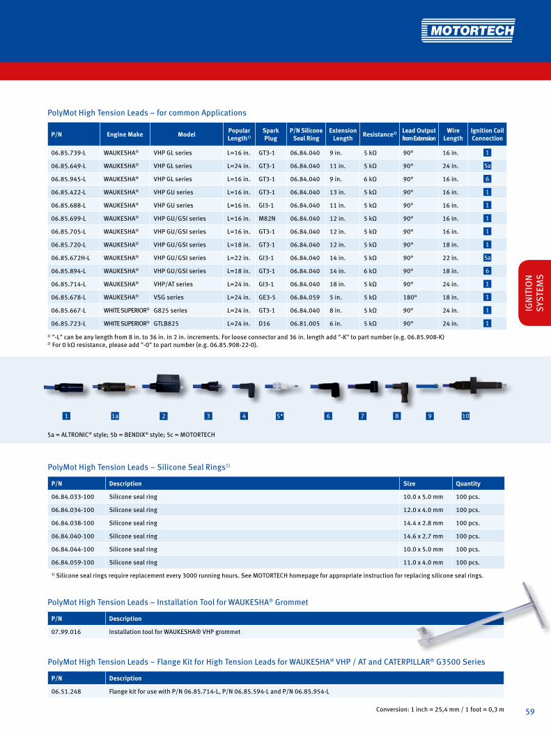
59
PolyMot High Tension Leads − Installation Tool for WAUKESHA® Grommet
P/N Description
07.99.016 Installation tool for WAUKESHA® VHP grommet
Conversion: 1 inch = 25,4 mm / 1 foot = 0,3 m
7 9 1085* 642 31a1
PolyMot High Tension Leads – for common Applications
P/N Engine Make Model PopularLength1)
Spark Plug
P/N SiliconeSeal Ring
ExtensionLength Resistance2) Lead Output
from ExtensionWire
LengthIgnition CoilConnection
06.85.739-L WAUKESHA® VHP GL series L=16 in. GT3-1 06.84.040 9 in. 5 kΩ 90° 16 in. 1
06.85.649-L WAUKESHA® VHP GL series L=24 in. GT3-1 06.84.040 11 in. 5 kΩ 90° 24 in. 5a
06.85.945-L WAUKESHA® VHP GL series L=16 in. GT3-1 06.84.040 9 in. 6 kΩ 90° 16 in. 6
06.85.422-L WAUKESHA® VHP GU series L=16 in. GT3-1 06.84.040 13 in. 5 kΩ 90° 16 in. 1
06.85.688-L WAUKESHA® VHP GU series L=16 in. GI3-1 06.84.040 11 in. 5 kΩ 90° 16 in. 1
06.85.699-L WAUKESHA® VHP GU/GSI series L=16 in. M82N 06.84.040 12 in. 5 kΩ 90° 16 in. 1
06.85.705-L WAUKESHA® VHP GU/GSI series L=16 in. GT3-1 06.84.040 12 in. 5 kΩ 90° 16 in. 1
06.85.720-L WAUKESHA® VHP GU/GSI series L=18 in. GT3-1 06.84.040 12 in. 5 kΩ 90° 18 in. 1
06.85.672H-L WAUKESHA® VHP GU/GSI series L=22 in. GI3-1 06.84.040 14 in. 5 kΩ 90° 22 in. 5a
06.85.894-L WAUKESHA® VHP GU/GSI series L=18 in. GT3-1 06.84.040 14 in. 6 kΩ 90° 18 in. 6
06.85.714-L WAUKESHA® VHP/AT series L=24 in. GI3-1 06.84.040 18 in. 5 kΩ 90° 24 in. 1
06.85.678-L WAUKESHA® VSG series L=24 in. GE3-5 06.84.059 5 in. 5 kΩ 180° 18 in. 1
06.85.667-L WHITE SUPERIOR® G825 series L=24 in. GT3-1 06.84.040 8 in. 5 kΩ 90° 24 in. 1
06.85.723-L WHITE SUPERIOR® GTLB825 L=24 in. D16 06.81.005 6 in. 5 kΩ 90° 24 in. 1
1) "-L" can be any length from 8 in. to 36 in. in 2 in. increments. For loose connector and 36 in. length add "-K" to part number (e.g. 06.85.908-K)2) For 0 kΩ resistance, please add "-0" to part number (e.g. 06.85.908-22-0).
PolyMot High Tension Leads − Silicone Seal Rings1)
P/N Description Size Quantity
06.84.033-100 Silicone seal ring 10.0 x 5.0 mm 100 pcs.
06.84.034-100 Silicone seal ring 12.0 x 4.0 mm 100 pcs.
06.84.038-100 Silicone seal ring 14.4 x 2.8 mm 100 pcs.
06.84.040-100 Silicone seal ring 14.6 x 2.7 mm 100 pcs.
06.84.044-100 Silicone seal ring 10.0 x 5.0 mm 100 pcs.
06.84.059-100 Silicone seal ring 11.0 x 4.0 mm 100 pcs.
1) Silicone seal rings require replacement every 3000 running hours. See MOTORTECH homepage for appropriate instruction for replacing silicone seal rings.
PolyMot High Tension Leads − Flange Kit for High Tension Leads for WAUKESHA® VHP / AT and CATERPILLAR® G3500 Series
P/N Description
06.51.248 Flange kit for use with P/N 06.85.714-L, P/N 06.85.594-L and P/N 06.85.954-L
5a = ALTRONIC® style; 5b = BENDIX® style; 5c = MOTORTECH
IGN
ITIO
N
SYST
EMS

60
HIGH TENSION LEADS AND ACCESSORIESNON-SHIELDED
High Tension Leads for CATERPILLAR® Gas Engines
P/N Supersedes Model PopularLength1) Spark Plug P/N Silicone
Seal RingExtension
Length Resistance2) Lead Outputfrom Extension
Wire Length
Ignition CoilConnection
06.88.009-L3) 06.88.008-L/-K G3300 series L=16 in. GE3-5 /GN3-1 06.84.059 3.75 in. 0 kΩ 180° 12 in. 1
06.88.010-L G3300 series L=16 in. GE3-5 06.84.059 4.25 in. 0 kΩ 180° 12 in. 2
06.85.751-L4) 06.88.003-L/-K06.85.687-L G3400 series L=18 in. GE3-5 06.84.059 13.00 in. 5 kΩ 90° 18 in. 1
06.85.939-L G3400 series L=18 in. GE3-5 06.84.059 13.00 in. 5 kΩ 90° 18 in. 5a
06.88.004-L G342/G379/G398/G399 L=20 in. GE3-5 06.84.059 4.25 in. 0 kΩ 180° 16 in. 2
06.88.005-L G342/G379/G398/G399 L=20 in. GN3-1 06.84.044 4.25 in. 0 kΩ 180° 16 in. 3
06.88.006-L 06.88.001-L/-K G342/G379/G398/G399 L=20 in. GE3-5 06.84.059 4.25 in. 0 kΩ 180° 16 in. 1
06.88.007-L 06.88.002-L/-K G342/G379/G398/G399 L=20 in. GI3-1 06.84.040 3.70 in. 0 kΩ 180° 16 in. 1
06.88.011-L G342/G379/G398/G399 L=20 in. GE3-5 06.84.059 4.25 in. 0 kΩ 180° 16 in. 9
06.85.674-L G342/G379/G398/G399 L=16 in. GT3-1 06.84.040 5.00 in. 0 kΩ 90° 16 in. 9
1) "-L" can be any length from 8 in. to 36 in. in 2 in. increments. For loose connector and 36 in. length add "-K" to part number (e.g. 06.85.751-K) 2) For 0 kΩ resistance, please add "-0" to part number (e.g. 06.85.939-18-0). 3) P/N 06.88.009-16 equivalent to P/N 7W2479. 4) P/N 06.85.751-18 equivalent to P/N 7W8542 / 2624855 / 2502149.
High Tension Leads – for common Applications
P/N Engine Make Model PopularLength1) Spark Plug P/N Silicone
Seal RingExtension
Length Resistance2) Lead Outputfrom Extension
Wire Length
Ignition CoilConnection
06.85.697-L AJAX® 230 L=20 in. GT3-1 06.84.040 5 in. 0 kΩ 90° 20 in. 1
06.85.698-L AJAX® 230 L=30 in. GT3-1 06.84.040 5 in. 0 kΩ 90° 30 in. 5a
06.85.719-L AJAX® 230 L=16 in. W18 06.81.017 5 in. 0 kΩ 90° 16 in. 1
06.85.773-L AJAX® 230 L=15 in. GT3-1 06.84.034 5 in. 0 kΩ 90° 15 in. 5a
06.85.860-L ARROW® VRG176/VRG220/VRG330 L=14 in. J6C / J8C 06.84.059 5 in. 1 kΩ 90° 14 in. 6
06.85.514-L CLARK® TLA-6 L=16 in. RW80N 06.84.038 8 in. 0 kΩ 90° 16 in. 5a
06.85.903-L3) CUMMINS® GTA 8.3 L=22 in. GK3-5 5 in. 5 kΩ 180° 17 in. 8
06.85.949-L DEUTZ® 2015 series L=10 in. 14GZ6-77-2 06.84.033 9 in. 6 kΩ 90° 10 in. 6
06.85.953-L DOOSAN® GV222TIC L=10 in. GK3-5 06.81.071 12 in. 5 kΩ 90° 10 in. 1
06.88.015-L INGERSOLL RAND® KVSR12 L=18 in. RW80N 06.84.040 4 in. 0 kΩ 180° 14 in. 5a
06.85.964-L LIEBHERR® G9408 L=20 in. GK3-5 06.81.071 6 in. 5 kΩ 180° 14 in. 2
06.85.690-L WHITE SUPERIOR® G825 series L=24 in. GK3-5 06.84.044 8 in. 0 kΩ 90° 24 in. 1
06.85.689-L WHITE SUPERIOR® G825 series (Lean Burn) L=24 in. GK3-5 06.84.044 4 in. 0 kΩ 90° 24 in. 1
06.85.695-L WHITE SUPERIOR® G825 series L=24 in. D14N 06.84.040 8 in. 0 kΩ 90° 24 in. 5a
1) "-L" can be any length from 8 in. to 36 in. in 2 in. increments. For loose connector and 36 in. length add "-K" to part number (e.g. 06.85.751-K) 2) For 0 kΩ resistance, please add "-0" to part number (e.g. 06.85.939-18-0). 3) P/N 06.85.903-22 equivalent to P/N 4989132.
5a = ALTRONIC® style; 5b = BENDIX® style; 5c = MOTORTECH
7 9 1085* 642 31a1

61
Unshielded Safety Leads for Shielded Spark Plugs
P/N1) SP Termination Well Depth
Spark Plug End
Ignition Coil End
InductivePickup Spacer
5KOhm Resistor Ignition Coil Equivalent to
09.02.1000-L 2.125 in. 180° 180° 291001-S, 501061-S, 591010-S USL2A-"L"A / AWH81-"L"
09.02.1001-L 2.125 in. 90° 180° 291001-S, 501061-S, 591010-S USL2LA-"L"A
09.02.1010-L 2.125 in. 180° 90° 291001-S, 501061-S, 591010-S USL2AL-"L"A
09.02.1011-L 2.125 in. 90° 90° 291001-S, 501061-S, 591010-S USL2LAL-"L"A
09.02.1100-L 2.125 in. 180° 180° x 291001-S, 501061-S, 591010-S USL2A-"L"AIPS
09.02.1101-L 2.125 in. 90° 180° x 291001-S, 501061-S, 591010-S USL2LA-"L"AIPS
09.02.1110-L 2.125 in. 180° 90° x 291001-S, 501061-S, 591010-S USL2AL-"L"AIPS
09.02.1111-L 2.125 in. 90° 90° x 291001-S, 501061-S, 591010-S USL2LAL-"L"AIPS
09.02.1200-L 2.125 in. 180° 180° x 291001-S, 501061-S, 591010-S RSL2A-"L"A
09.02.1201-L 2.125 in. 90° 180° x 291001-S, 501061-S, 591010-S RSL2LA-"L"A
09.02.1210-L 2.125 in. 180° 90° x 291001-S, 501061-S, 591010-S RSL2AL-"L"A
09.02.1211-L 2.125 in. 90° 90° x 291001-S, 501061-S, 591010-S RSL2LAL-"L"A
09.02.1300-L 2.125 in. 180° 180° x x 291001-S, 501061-S, 591010-S RSL2A-"L"AIPS
09.02.1301-L 2.125 in. 90° 180° x x 291001-S, 501061-S, 591010-S RSL2LA-"L"AIPS
09.02.1310-L 2.125 in. 180° 90° x x 291001-S, 501061-S, 591010-S RSL2AL-"L"AIPS
09.02.1311-L 2.125 in. 90° 90° x x 291001-S, 501061-S, 591010-S RSL2LAL-"L"AIPS
09.02.2000-L 2.125 in. 180° 180° 10-320790-1, 10-382040-1 USL2B-"L"A / AWH22-"L"
09.02.2001-L 2.125 in. 90° 180° 10-320790-1, 10-382040-1 USL2LB-"L"A
09.02.2010-L 2.125 in. 180° 90° 10-320790-1, 10-382040-1 USL2BL-"L"A
09.02.2011-L 2.125 in. 90° 90° 10-320790-1, 10-382040-1 USL2LBL-"L"A
09.02.2100-L 2.125 in. 180° 180° x 10-320790-1, 10-382040-1 USL2B-"L"AIPS
09.02.2101-L 2.125 in. 90° 180° x 10-320790-1, 10-382040-1 USL2LB-"L"AIPS
09.02.2110-L 2.125 in. 180° 90° x 10-320790-1, 10-382040-1 USL2BL-"L"AIPS
09.02.2111-L 2.125 in. 90° 90° x 10-320790-1, 10-382040-1 USL2LBL-"L"AIPS
09.02.2200-L 2.125 in. 180° 180° x 10-320790-1, 10-382040-1 RSL2B-"L"A
09.02.2201-L 2.125 in. 90° 180° x 10-320790-1, 10-382040-1 RSL2LB-"L"A
09.02.2210-L 2.125 in. 180° 90° x 10-320790-1, 10-382040-1 RSL2BL-"L"A
09.02.2211-L 2.125 in. 90° 90° x 10-320790-1, 10-382040-1 RSL2LBL-"L"A
09.02.2300-L 2.125 in. 180° 180° x x 10-320790-1, 10-382040-1 RSL2B-"L"AIPS
09.02.2301-L 2.125 in. 90° 180° x x 10-320790-1, 10-382040-1 RSL2LB-"L"AIPS
09.02.2310-L 2.125 in. 90° 90° x x 10-320790-1, 10-382040-1 RSL2LBL-"L"AIPS
09.02.2311-L 2.125 in. 180° 90° x x 10-320790-1, 10-382040-1 RSL2BL-"L"AIPS
1) "-L" can be any lead length from 8 in. to 36 in. in 2 in. increments.
Conversion: 1 inch = 25,4 mm / 1 foot = 0,3 m
End Coil Spark Plug EndL-
IGN
ITIO
N
SYST
EMS

62
HIGH TENSION LEADS AND ACCESSORIES
Unshielded Safety Leads for Shielded Spark Plugs
P/N1) SP Termination Well Depth
Spark Plug End
Ignition Coil End
InductivePickup Spacer
5KOhm Resistor Ignition Coil Equivalent to
09.02.3000-L 2.125 in. 180° 180° PPT2477AD, PPT2477AD-L USL2C-"L"A / AWH42-"L"
09.02.3001-L 2.125 in. 90° 180° PPT2477AD, PPT2477AD-L USL2LC-"L"A
09.02.3010-L 2.125 in. 180° 90° PPT2477AD, PPT2477AD-L USL2CL-"L"A
09.02.3011-L 2.125 in. 90° 90° PPT2477AD, PPT2477AD-L USL2LCL-"L"A
09.02.3100-L 2.125 in. 180° 180° x PPT2477AD, PPT2477AD-L USL2C-"L"AIPS
09.02.3101-L 2.125 in. 90° 180° x PPT2477AD, PPT2477AD-L USL2LC-"L"AIPS
09.02.3110-L 2.125 in. 180° 90° x PPT2477AD, PPT2477AD-L USL2CL-"L"AIPS
09.02.3111-L 2.125 in. 90° 90° x PPT2477AD, PPT2477AD-L USL2LCL-"L"AIPS
09.02.3200-L 2.125 in. 180° 180° x PPT2477AD, PPT2477AD-L RSL2C-"L"A
09.02.3201-L 2.125 in. 90° 180° x PPT2477AD, PPT2477AD-L RSL2LC-"L"A
09.02.3210-L 2.125 in. 180° 90° x PPT2477AD, PPT2477AD-L RSL2CL-"L"A
09.02.3211-L 2.125 in. 90° 90° x PPT2477AD, PPT2477AD-L RSL2LCL-"L"A
09.02.3300-L 2.125 in. 180° 180° x x PPT2477AD, PPT2477AD-L RSL2C-"L"AIPS
09.02.3301-L 2.125 in. 90° 180° x x PPT2477AD, PPT2477AD-L RSL2LC-"L"AIPS
09.02.3310-L 2.125 in. 180° 90° x x PPT2477AD, PPT2477AD-L RSL2CL-"L"AIPS
09.02.3311-L 2.125 in. 90° 90° x x PPT2477AD, PPT2477AD-L RSL2LCL-"L"AIPS
09.02.4000-L 2.125 in. 180° 180° 291001, 501061, 591010 USL2E-"L"A / AWH72-"L"
09.02.4001-L 2.125 in. 90° 180° 291001, 501061, 591010 USL2LE-"L"A
09.02.4100-L 2.125 in. 180° 180° x 291001, 501061, 591010 USL2E-"L"AIPS
09.02.4101-L 2.125 in. 90° 180° x 291001, 501061, 591010 USL2LE-"L"AIPS
09.02.4110-L 2.125 in. 180° 180° x 291001, 501061, 591010 USL2E-"L"A w. 06.80.030
09.02.4200-L 2.125 in. 180° 180° x 291001, 501061, 591010 RSL2E-"L"A
09.02.4201-L 2.125 in. 90° 180° x 291001, 501061, 591010 RSL2LE-"L"A
09.02.4300-L 2.125 in. 180° 180° x x 291001, 501061, 591010 RSL2E-"L"AIPS
09.02.4301-L 2.125 in. 90° 180° x x 291001, 501061, 591010 RSL2LE-"L"AIPS
09.02.5000-L 2.125 in. 180° 180° PPT2477P, PPT2477L USL2F-"L"A / AWH82-"L"
09.02.5001-L 2.125 in. 90° 180° PPT2477P, PPT2477L USL2LF-"L"A
09.02.5100-L 2.125 in. 180° 180° x PPT2477P, PPT2477L USL2F-"L"AIPS
09.02.5101-L 2.125 in. 90° 180° x PPT2477P, PPT2477L USL2LF-"L"AIPS
09.02.5200-L 2.125 in. 180° 180° x PPT2477P, PPT2477L RSL2F-"L"A
09.02.5201-L 2.125 in. 90° 180° x PPT2477P, PPT2477L RSL2LF-"L"A
09.02.5300-L 2.125 in. 180° 180° x x PPT2477P, PPT2477L RSL2F-"L"AIPS
09.02.5301-L 2.125 in. 90° 180° x x PPT2477P, PPT2477L RSL2LF-"L"AIPS
09.02.7000-L 2.125 in. 180° 180° Unshielded in Coil Box inst. USL2G-"L"A /AWH62-"L"
09.02.7001-L 2.125 in. 90° 180° Unshielded in Coil Box inst. USL2LG-"L"A
09.02.7100-L 2.125 in. 180° 180° x Unshielded in Coil Box inst. USL2G-"L"AIPS
09.02.7101-L 2.125 in. 90° 180° x Unshielded in Coil Box inst. USL2LG-"L"AIPS
09.02.7200-L 2.125 in. 180° 180° x Unshielded in Coil Box inst. RSL2G-"L"A
09.02.7201-L 2.125 in. 90° 180° x Unshielded in Coil Box inst. RSL2LG-"L"A
09.02.7300-L 2.125 in. 180° 180° x x Unshielded in Coil Box inst. RSL2G-"L"AIPS
09.02.7301-L 2.125 in. 90° 180° x x Unshielded in Coil Box inst. RSL2-LG-"L"AIPS
1) "-L" can be any lead length from 8 in. to 36 in. in 2 in. increments.

63
End Coil Spark Plug EndL-
Conversion: 1 inch = 25,4 mm / 1 foot = 0,3 m
Unshielded Safety Leads for Conventional Spark Plugs
P/N1) Fits max.Ceramic Diameter
Spark Plug End
Ignition Coil End
InductivePickup Spacer
5KOhm Resistor Ignition Coil Equivalent to
09.03.1000-L 0.485 in. 180° 180° 291001-S, 501061-S, 591010-S USLA14SPB-"L"A
09.03.4000-L 0.485 in. 180° 180° 291001, 501061, 591010 USLE14SPB-"L"A
09.04.1000-L 0.560 in. 180° 180° 291001-S, 501061-S, 591010-S USLA18SPB-"L"A
09.04.4000-L 0.560 in. 180° 180° 291001, 501061, 591010 USLE18SPB-"L"A
09.05.1000-L 0.485 in. 180° 180° 291001-S, 501061-S, 591010-S USLA35SPB-"L"A
09.05.4000-L 0.485 in. 180° 180° 291001, 501061, 591010 USLE35SPB-"L"A
09.06.1000-L 0.545 in. 180° 180° 291001-S, 501061-S, 591010-S USLA36SPB-"L"A
09.06.4000-L 0.545 in. 180° 180° 291001, 501061, 591010 USLE36SPB-"L"A
09.07.1000-L 0.385 in. 180° 180° 291001-S, 501061-S, 591010-S USLA45SPB-"L"A
09.07.4000-L 0.385 in. 180° 180° 291001, 501061, 591010 USLE45SPB-"L"A
09.08.1000-L 0.470 in. 180° 180° 291001-S, 501061-S, 591010-S USLA51SPB-"L"A
09.08.4000-L 0.470 in. 180° 180° 291001, 501061, 591010 USLE51SPB-"L"A
09.09.1000-L 0.580 in. 180° 180° 291001-S, 501061-S, 591010-S USLA78SPB-"L"A
09.09.2000-L 0.580 in. 180° 180° 10-320790-1, 10-382040-1 USLB78SPB-"L"A
09.09.4000-L 0.580 in. 180° 180° 291001, 501061, 591010 USLE78SPB-"L"A
09.10.1000-L Silicone Boot 180° 180° 291001-S, 501061-S, 591010-S USLASB180-"L"A
09.10.2000-L Silicone Boot 180° 180° 10-320790-1, 10-382040-1 USLBSB180-"L"A
09.10.3000-L Silicone Boot 180° 180° PPT2477AD, PPT2477ADL USLCSB180-"L"A
09.10.4000-L Silicone Boot 180° 180° 291001, 501061, 591010 USLESB180-"L"A
09.11.1000-L Silicone Boot 90° 180° 291001-S, 501061-S, 591010-S USLASL90-"L"A
09.11.2000-L Silicone Boot 90° 180° 10-320790-1, 10-382040-1 USLBSL90-"L"A
09.11.3000-L Silicone Boot 90° 180° PPT2477AD, PPT2477ADL USLCSL90-"L"A
09.11.4000-L Silicone Boot 90° 180° 291001, 501061, 591010 USLESL90-"L"A
09.12.1000-L Terminal 90° 180° 291001-S, 501061-S, 591010-S USLA18T22-"L"A
09.12.2000-L Terminal 90° 180° 10-320790-1, 10-382040-1 USLB18T22-"L"A
09.12.3000-L Terminal 90° 180° PPT2477AD, PPT2477ADL USLC18T22-"L"A
09.12.4000-L Terminal 90° 180° 291001, 501061, 591010 USLE18T22-"L"A
09.13.1000-L Terminal 180° 180° 291001-S, 501061-S, 591010-S USLA18T33-"L"A
09.13.2000-L Terminal 180° 180° 10-320790-1, 10-382040-1 USLB18T33-"L"A
09.13.3000-L Terminal 180° 180° PPT2477AD, PPT2477ADL USLC18T33-"L"A
09.13.4000-L Terminal 180° 180° 291001, 501061, 591010 USLE18T33-"L"A
1) "-L" can be any lead length from 8 in. to 36 in. in 2 in. increments.
IGN
ITIO
N
SYST
EMS

64
HIGH TENSION LEADS AND ACCESSORIES
Accessories – Ignition Cables – Nickel Plated Copper Wire
P/N Figure Description Color
02.85.757 1 Ignition cable, 7 mm silicone, 100 ft. spool, dielectric strength 68 kV, 17-19 stends blue
02.85.758 2 Ignition cable, 7 mm silicone, 100 ft. spool, dielectric strength 68 kV, 17-19 stends orange
Accessories – Ignition Cable – Stainless Steel Wire
P/N Figure Description Color
02.85.658 2 Ignition cable, 7 mm silicone, 100 ft. spool, dielectric strength 68 kV, 17-19 stends orange
Accessories – Silicone Hoses
P/N Figure Description Outer Diameter Color
02.85.965 3 Silicone hose, 100 ft. spool 12 mm blue
02.85.914 3 Silicone hose, 100 ft. spool 15 mm blue
02.85.865 3 Silicone hose, 100 ft. spool 12 mm orange
02.85.814 3 Silicone hose, 100 ft. spool 15 mm orange
Accessories – Inductive Pickup Spacer
P/N Figure Description Position Quantity
06.84.010-100 4 Inductive pickup spacer end of lead 100 pcs.
06.84.043-100 5 Inductive pickup spacer middle of lead 100 pcs.
1 2 3 4 6 75
Accessories – Spark Plug Terminals (for 14 mm Spark Plugs only)
P/N Figure Description Quantity
06.84.024-100 6 Spark plug terminal, 90°, silicone for use with 7 mm ignition cable, including terminal P/N 02.85.920 100 pcs.
06.84.025-100 7 Spark plug terminal, 180°, silicone for use with 7 mm ignition cable, including terminal P/N 02.85.920 100 pcs.
Conversion: 1 inch = 25,4 mm / 1 foot = 0,3 m

65
Accessories – Spark Plug Boots
P/N Figure Description Quantity
06.84.008-100 8 Spark plug boot, 90°, silicone for use with 7 mm ignition cable and terminal P/N 22.85.803 100 pcs.
06.84.009-100 9 Spark plug boot, 180°, silicone for use with 7 mm ignition cable and terminal P/N 22.85.802 100 pcs.
8 9 10 11 12 13 14 15 16 17
Accessories – Terminals for Spark Plug Boots
P/N Figure Description Quantity
02.85.920-100 10 Terminal, for use with spark plug boot P/N 06.84.024 and P/N 06.84.025 100 pcs.
22.85.802-100 11 Terminal, for use with spark plug boot P/N 06.84.009 100 pcs.
22.85.803-100 12 Terminal, for use with spark plug boot P/N 06.84.008 100 pcs.
Accessories – Spark Plug Terminals
P/N Figure Description Equivalent to Quantity
02.85.924-100 13 Spark plug terminal, 90°, for use with 7 mm ignition cable T-22 100 pcs.
02.85.925-100 14 Spark plug terminal, 180°, for use with 7 mm ignition cable T-33 100 pcs.
Accessories – Ignition Coil Terminals
P/N Figure Description Quantity
06.80.030-100 15 Ignition coil terminal, 180°, 1 kΩ resistance, requires crimp terminal P/N 06.80.126 100 pcs.
22.80.009-100 16 Ignition coil terminal, 90°, 1 kΩ resistance, requires crimp terminal P/N 06.80.126 100 pcs.
06.80.091-1001) 17 Ignition coil terminal, 180°, 1 kΩ resistance, requires crimp terminal P/N 06.80.126 100 pcs.
1) For ignition coils with positive secondary termination.
IGN
ITIO
N
SYST
EMS

66
HIGH TENSION LEADS AND ACCESSORIES
1 2 3 4 65
Accessories – Crimp Terminals
P/N Figure Description Quantity
06.80.012-100 1 Crimp terminal, 180°, for use with spreading adaptor P/N 02.85.1004 100 pcs.
06.80.116-100 2 Crimp terminal, 90°, for use with MOTORTECH style ignition coils 100 pcs.
06.80.116-180-100 3 Crimp terminal, 180°, for use with New MOTORTECH style ignition coils 100 pcs.
06.80.108-100 4 Crimp Terminal Base, for use with crimp terminals P/N 06.80.116-100 and P/N 06.80.116-180-100 100 pcs.
06.80.126-100 5 Crimp Terminal Base, for use ignition coil terminals P/N 06.80.030 and P/N 22.80.009 100 pcs.
Accessories – Spreading Adaptor
P/N Figure Description Quantity
02.85.1004-100 6 Spreading adaptor for ALTRONIC® style ignition coils 100 pcs.

67
7 8 9 10 11 12 13
Accessories – Silicone Seal Rings for High Tension Leads1)
P/N Figure Description Dimensions Quantity
06.84.033-100 11 Silicone seal ring 10.0 x 5.0 mm 100 pcs.
06.84.034-100 11 Silicone seal ring 12.0 x 4.0 mm 100 pcs.
06.84.038-100 11 Silicone seal ring 14.4 x 2.8 mm 100 pcs.
06.84.040-100 11 Silicone seal ring 14.6 x 2.7 mm 100 pcs.
06.84.044-100 11 Silicone seal ring 10.0 x 5.0 mm 100 pcs.
06.84.059-100 11 Silicone seal ring 11.0 x 4.0 mm 100 pcs.
1) Silicone seal rings require replacement every 3000 running hours. See MOTORTECH homepage for appropriate instruction for replacing silicone seal rings.
Accessories – Distance Collars
P/N Figure Description Quantity
06.86.001-100 7 Distance collar, for use with 7 mm ignition cable 100 pcs.
06.86.002-100 8 Distance collar, for use with 7 mm ignition cable 100 pcs.
06.86.003-100 9 Distance collar, for use with 7 mm ignition cable 100 pcs.
06.86.005-100 10 Distance collar, for use with 7 mm ignition cable 100 pcs.
Accessories – Grommets for CUMMINS® Ignition Coils
P/N Figure Description Color Quantity
06.84.048-100 12 Grommet, for use with CUMMINS® ignition coil P/N 3930027 orange 100 pcs.
06.84.053-100 13 Grommet, for use with CUMMINS® 8.3 ignition coil black 100 pcs.
Accessories – Silicone Seals for ALTRONIC®, BG®, CUMMINS® and WAUKESHA® Spark Plug Extensions
P/N Figure Description Color Quantity
06.84.047-100 14 Silicone seal, for 14 mm spark plug extension orange 100 pcs.
06.84.049-100 15 Silicone seal, for 18 mm spark plug extension blue 100 pcs.
14 15
IGN
ITIO
N
SYST
EMS

68
HIGH TENSION LEADS AND ACCESSORIES
MOT-Blues – Shielded High Tension Leads
There is an alternative to the commonly failing conventional shielded high tension lead. MOTORTECH has designed a CSA approved shielded spark plug lead for Class I, Division2, Group D that will perform better than the industry standard. There is no need to convert to non-shielded when you can not keep the engine running with the conventional leads.
SHIELDED HIGH TENSION LEADMOT-Blues
The MOT-Blues spark plug wire is specially designed for shielded CSA certified high tension leads. It consists of a multi layer design:
• Nickel plated copper core• 2 layers of silicone• Stainless steel braid• Silicone jacket
This design ensures that no humidity can be trapped in the lead.

69
MOT-Blues Shielded High Tension Leads for Externally Mounted Ignition Coils – MOTORTECH Style
P/N1) Description Ignition Coil Termination Spark Plug Termination Spark Plug Terminal Well Depth2) Equivalent to
95.91.030-L Shielded high tension lead 1-20 UNEF / 180° 180° 2 in. A755-L-2 / HT2400-L
-L
SHIELDED
MOT-Blues Shielded High Tension Leads for Externally Mounted Ignition Coils – ALTRONIC® Style
P/N1) Description Ignition Coil Termination Spark Plug Termination Spark Plug Terminal Well Depth2) Equivalent to
95.90.030-L Shielded high tension lead 3/4-20 UNEF / 180° 180° 2 in. 593030-L / HT2300-L
MOT-Blues Shielded High Tension Leads for MOTORTECH Igniter Assy Ignition Coils
P/N1) Description Ignition Coil Termination Spark Plug Termination Spark Plug Terminal Well Depth2) Equivalent to
95.91.031-L Shielded high tension lead M33x1.5 / 90° 180° 2 in.
1) Standard lead lengths = "L" = 10 in., 13 in., 16 in., 18 in., 20 in., 24 in., 30 in.; other lengths available on request. 2) Consult factory for 1 in. spark plug terminal well depth.All terminals made of ceramic. HEX-nut on spark plug side.
Conventional Shielded High Tension Leads for Externally Mounted Ignition Coils – MOTORTECH Style
P/N1) Description Ignition Coil Termination Spark Plug Termination Spark Plug Terminal Well Depth2) Equivalent to
95.85.030-L Shielded high tension lead 1-20 UNEF / 180° 180° 2 in. A755-L-2 / HT2400-L
Conventional Shielded High Tension Leads for Externally Mounted Ignition Coils – ALTRONIC® Style
P/N1) Description Ignition Coil Termination Spark Plug Termination Spark Plug Terminal Well Depth2) Equivalent to
95.90.030-L Shielded high tension lead 3/4-20 UNEF / 180° 180° 2 in. 593030-L / HT2300-L
Conventional Shielded High Tension Leads for MOTORTECH Igniter Assy Ignition Coils
P/N1) Description Ignition Coil Termination Spark Plug Termination Spark Plug Terminal Well Depth2) Equivalent to
95.85.031-L Shielded high tension lead M33x1.5 / 90° 180° 2 in.
1) Standard lead lengths = "L" = 10 in., 13 in., 16 in., 18 in., 20 in., 24 in., 30 in.; other lengths available on request. 2) Consult factory for 1 in. spark plug terminal well depth.All terminals made of ceramic. HEX-nut on spark plug side.
IGN
ITIO
N
SYST
EMS

70
HIGH TENSION LEADS AND ACCESSORIES
Terminal Kits for Shielded High Tension Leads – MOT-Blues (Metric)
P/N Figure Description Adaptor Spark Plug1) Equivalent to
02.85.1006 1 Terminal kit with stud thread size M3 3/4-20 UNEF, 2 in. terminal well depth
includes:
02.85.919 Cup & spring, M3
02.85.873 Insulator, KryptoMot
06.80.023 Threaded sleeve, M3
06.81.053 O-ring, Teflon
02.85.911 Nut, 3/4-20 UNEF SN-75K
02.85.875 Inner ferrule
02.85.869 Crimp tube
1) Consult factory for terminal kits to fit spark plugs with 3/4-20 UNEF thread and 1 in. terminal well depth.
Terminal Kits for Shielded High Tension Leads – MOT-Blues (Metric)
P/N Figure Description Adaptor Igniton Coil Equivalent to
02.85.1007 2 Terminal kit with stud thread size M3 3/4-20 UNEF, ALTRONIC® Style
includes:
02.85.919 Cup & spring, M3
02.85.612 Gasket 510493
02.85.872 Insulator, ceramic
02.85.929 Stud, M3
02.85.912 O-ring, silicone, 12x2 SOR-500
02.85.911 Nut, 3/4-20 UNEF SN-75K
02.85.875 Inner ferrule
02.85.869 Crimp tube
Terminal Kits for Shielded High Tension Leads – MOT-Blues (Metric)
P/N Figure Description Adaptor Igniton Coil Equivalent to
02.85.1008 3 Terminal kit with stud thread size M3 1-20 UNEF, MOTORTECH Style
includes:
02.85.919 Cup & spring, M3
02.85.611 Gasket
02.85.006 Insulator, ceramic
02.85.929 Stud, M3
06.81.046 O-ring, silicone, 12x2 SOR-602
02.85.610 Nut, 1-20 UNEF SN-FMOSK
02.85.875 Inner ferrule
02.85.869 Crimp tube
1 32

71
Terminal Kits for Shielded High Tension Leads – Conventional (Metric)
P/N Figure Description Adaptor Spark Plug Equivalent to
02.85.991 1 Terminal kit with stud thread size 3/48 UNC 3/4-20 UNEF, 1 in. terminal well depth
includes:
02.85.956 Stud, M3
02.85.913 Spring SP-3420
02.85.013 Spacer
06.81.098 O-ring, silicone, 8x2 SOR-375
02.85.944 Insulator, ceramic SC1
02.85.919 Cup & spring, M3
Terminal Kits for Shielded High Tension Leads – Conventional (Imperial)
P/N Figure Description Adaptor Spark Plug Equivalent to
02.85.991-2 2 Terminal kit with stud thread size 3/48 UNC 3/4-20 UNEF, 1 in. terminal well depth SC1K / 504205
includes:
02.85.918 Stud 3/48 UNC ST-44
02.85.913 Spring SP-3420
02.85.013 Spacer
06.81.098 O-ring, silicone, 8x2 SOR-375
02.85.944 Insulator, ceramic SC1
02.85.901 Cup & spring, 3/48 UNC VS/SSC / 510474
Terminal Kits for Shielded High Tension Leads – Conventional (Metric)
P/N Figure Description Adaptor Spark Plug Equivalent to
02.85.992 3 Terminal kit with stud thread size M3 3/4-20 UNEF, 2 in. terminal well depth
includes:
02.85.929 Stud M3
02.85.913 Spring SP-3420
02.85.013 Spacer
06.81.098 O-ring, silicone, 8x2 SOR-375
02.85.910 Insulator, ceramic SC2
02.85.919 Cup & spring, M3
1 32
IGN
ITIO
N
SYST
EMS

72
Terminal Kits for Shielded High Tension Leads – Conventional (Imperial)
P/N Figure Description Adaptor Spark Plug Equivalent to
02.85.979 2 Terminal kit with stud thread size 3/48 UNC 3/4-20 UNEF, 1 in. terminal well
includes:
02.85.944 Insulator, ceramic
02.85.973 Cup, 3/48 UNC
02.85.954 Spring
HIGH TENSION LEADS AND ACCESSORIES
Terminal Kits for Shielded High Tension Leads – Conventional (Metric)
P/N Figure Description Adaptor Igniton Coil Equivalent to
02.85.992-1 3 Terminal kit with stud thread size M3 3/4-20 UNEF, BENDIX® Style
includes:
02.85.929 Stud, M3
06.81.098 O-ring, silicone, 8x2 SOR-375
02.85.910 Insulator, ceramic SC2
02.85.919 Cup & spring, M3
Terminal Kits for Shielded High Tension Leads – Conventional (Imperial)
P/N Figure Description Adaptor Igniton Coil Equivalent to
02.85.992-3 4 Terminal kit with stud thread size 3/48 UNC 3/4-20 UNEF, BENDIX® Style
includes:
02.85.902 Stud, 3/48 UNC ST-1125 / 510473
02.85.013 Spacer
06.81.098 O-ring, silicone, 8x2 SOR-375
02.85.910 Insulator, ceramic SC2
02.85.901 Cup & spring, 3/48 UNC VS/SSC / 510474
Terminal Kits for Shielded High Tension Leads – Conventional (Imperial)
P/N Figure Description Adaptor Spark Plug Equivalent to
02.85.992-2 1 Terminal kit with stud thread size 3/48 UNC 3/4-20 UNEF, 2 in. terminal well SC2K / 504137
includes:
02.85.902 Stud 3/48 UNC ST-1125 / 510473
02.85.913 Spring SP-3420
02.85.013 Spacer
06.81.098 O-ring, silicone, 8x2 SOR-375
02.85.910 Insulator, ceramic SC2
02.85.901 Cup & spring, 3/48 UNC VS/SSC / 510474
1 3 42

73
Terminal Kits for Shielded High Tension Leads – Conventional (Metric)
P/N Figure Description Adaptor Igniton Coil Equivalent to
02.85.996 1 Terminal kit with stud thread size M3 3/4-20 UNEF, ALTRONIC® Style
includes:
02.85.929 Stud, M3
02.85.912 O-ring, silicone, 8x2 SOR-500
02.85.907 Insulator, ceramic ALTSS-2C
02.85.612 Gasket 510493
02.85.919 Cup & spring, M3
Terminal Kits for Shielded High Tension Leads – Conventional (Imperial)
P/N Figure Description Adaptor Igniton Coil Equivalent to
02.85.996-2 2 Terminal kit with stud thread size 3/48 UNC 3/4-20 UNEF, ALTRONIC® Style ALTSS-2
includes:
02.85.902 Stud, 3/48 UNC ST-1125 / 510473
02.85.912 O-ring, silicone, 8x2 SOR-500
02.85.907 Insulator, ceramic ALTSS-2C
02.85.612 Gasket 510493
02.85.901 Cup & spring, 3/48 UNC VS/SSC / 510474
Terminal Kits for Shielded High Tension Leads – Conventional (Metric)
P/N Figure Description Adaptor Igniton Coil Equivalent to
02.85.997 3 Terminal kit with stud thread size 3/48 UNC 1-20 UNEF, MOTORTECH Style
includes:
02.85.929 Stud, M3
06.81.059 O-ring
02.85.948 Insulator, ceramic
02.85.919 Cup & spring, M3
Terminal Kits for Shielded High Tension Leads – Conventional (Imperial)
P/N Figure Description Adaptor Igniton Coil Equivalent to
02.85.997-2 4 Terminal kit with stud thread size 3/48 UNC 1-20 UNEF, MOTORTECH Style
includes:
02.85.902 Stud, 3/48 UNC ST-1125 / 510473
06.81.059 O-ring
02.85.948 Insulator, ceramic
02.85.901 Cup & spring, 3/48 UNC VS/SSC / 510474
1 3 42
IGN
ITIO
N
SYST
EMS

74
HIGH TENSION LEADS AND ACCESSORIES
Terminal Kits for Non-Shielded High Tension Leads – Conventional (Metric)
P/N Figure Description Adaptor Ignition Coil Equivalent to
02.85.993 1 Terminal kit with stud thread size M3 3/4-20 UNEF, ALTRONIC® Style
includes:
06.84.006 Boot RB-ALT
02.85.911 Nut, 3/4-20 UNEF SN-75K
02.85.929 Stud, M3
02.85.906 O-ring, Teflon™, 14x2 TOR-560
02.85.912 O-ring, silicone, 12x2 SOR-500
02.85.928 Insulator, ceramic ALTOS-1C / 510695
02.85.612 Gasket 510493
02.85.919 Cup & spring, M3
Terminal Kits for Non-Shielded High Tension Leads - Conventional (Imperial)
P/N Figure Description Adaptor Ignition Coil Equivalent to
02.85.993-2 2 Terminal kit with stud thread size 3/48 UNC 3/4-20 UNEF, ALTRONIC® Style ALTOS-1 / 510480
includes:
06.84.006 Boot RB-ALT
02.85.911 Nut, 3/4-20 UNEF SN-75K
02.85.902 Stud 3/48 UNC ST-1125 / 510473
02.85.906 O-ring, Teflon™, 14x2 TOR-560
02.85.912 O-ring, silicone, 12x2 SOR-500
02.85.928 Insulator, ceramic ALTOS-1C / 510695
02.85.612 Gasket 510493
02.85.901 Cup & spring, 3/48 UNC VS/SSC / 510474
Terminal Kits for Non-Shielded High Tension Leads - Conventional (Metric)
P/N Figure Description Adaptor Ignition Coil Equivalent to
02.85.994 3 Terminal kit with stud thread size M3 3/4-20 UNEF, BENDIX® Style
includes:
06.84.006 Boot RB-ALT
02.85.911 Nut, 3/4-20 UNEF SN-75K
02.85.929 Stud, M3
02.85.906 O-ring, Teflon™, 14x2 TOR-560
02.85.912 O-ring, silicone, 12x2 SOR-500
02.85.903 Insulator, ceramic BENDOS-1C
02.85.919 Cup & spring, M3
1 32

75
Terminal Kits for Non-Shielded High Tension Leads - Conventional (Imperial)
P/N Figure Description Adaptor Ignition Coil Equivalent to
02.85.994-2 1 Terminal kit with stud thread size 3/48 UNC 3/4-20 UNEF, BENDIX® Style BENDOS-1
includes:
06.84.006 Boot RB-ALT
02.85.911 Nut, 3/4-20 UNEF SN-75K
02.85.902 Stud 3/48 UNC ST-1125 / 510473
02.85.906 O-ring, Teflon™, 14x2 TOR-560
02.85.912 O-ring, silicone, 12x2 SOR-500
02.85.903 Insulator, ceramic BENDOS-1C
02.85.901 Cup & spring, 3/48 UNC VS/SSC / 510474
Terminal Kits for Non-Shielded High Tension Leads - Conventional (Metric)
P/N Figure Description Adaptor Ignition Coil Equivalent to
02.85.995 2 Terminal kit with stud thread size M3 1-20 UNEF, MOTORTECH Style
includes:
06.84.006 Boot RB-ALT
02.85.610 Nut, 1-20 UNEF SN-FMOSK
02.85.929 Stud, M3
02.85.906 O-ring, Teflon™, 14x2 TOR-560
06.81.046 O-ring, silicone, 12x2 SOR-602
02.85.018 Insulator, ceramic FMOS-1C
02.85.611 Gasket
02.85.919 Cup & spring, M3
Terminal Kits for Non-Shielded High Tension Leads - Conventional (Imperial)
P/N Figure Description Adaptor Ignition Coil Equivalent to
02.85.995-2 3 Terminal kit with stud thread size 3/48 UNC 1-20 UNEF, MOTORTECH Style FMOS-1
includes:
06.84.006 Boot RB-ALT
02.85.610 Nut, 1-20 UNEF SN-FMOSK
02.85.902 Stud 3/48 UNC ST-1125 / 510473
02.85.906 O-ring, Teflon™, 14x2 TOR-560
06.81.046 O-ring, silicone, 12x2 SOR-602
02.85.018 Insulator, ceramic FMOS-1C
02.85.611 Gasket
02.85.901 Cup & spring, 3/48 UNC VS/SSC / 510474
1 32
IGN
ITIO
N
SYST
EMS

76

77
PRIMARY LEADSShielded ignition systems require all wiring to be approved for hazardous locations. MOTORTECH manufactures a wide range of shielded primary leads that meet the CSA Class I; Division2; Group C/D; T4 requirements.
A variety of leads is available to fit all common ignition coils and the MOTORTECH AlphaRail wiring rails. Heavy duty connectors (non cadmium plated) and a thick stainless steel braid with hydraulic ends will make this product live in a harsh environment.
PRIMARY LEADSShielded ignition systems require all wiring to be approved for hazardous locations. MOTORTECH manufactures a wide range of shielded primary leads that meet the CSA Class I, Division2, Group D requirements.
A variety of leads is available to fit all common ignition coils and the MOTORTECH AlphaRail wiring rails. Heavy duty connectors (non cadmium plated) and a thick stainless steel braid with hydraulic ends will make this product live in a harsh environment.

78
New Style Shielded Primary Leads
In addition to its conventional primary leads, MOTORTECH now offers a new type of primary lead that is produced with a special wire. The new primary leads are compliant with CSA Class I, Division 2, Group D, and they offer a significantly hig-her flexibility than conventional leads, shielded with braided steel, while being highly resistant to all kinds of environmen-tal conditions.
The multi-layer design of the wire is free of entrapped air and prevents the accumulation of condensed water which can result in high voltage flash-overs. Several different configu-rations with durable 90-degrees and 180-degrees 2-pole and 3-pole plugs are available.
PRIMARY LEADS
·Fine bare copper wire·PVC/Nylon insulation· Aluminum-plated foil and tinned copper braid·PVC jacket·Temperature range -40° C to +90° C (-40° F to +194° F)
This design ensures that no humidity can be trapped in the lead.
The new oil and UV resistant multi-conductor wire is specially designed for shielded CSA certified primary leads. It consists of a multi layer design:

79
SHIELDED
New Style Shielded Primary Leads for MOTORTECH AlphaRail Wiring Rails
P/N1) Supersedes Description Ignition Coil Connector Wiring Rail Connector Conductor Equivalent to
95.01.140-L Primary lead MIL Style 3 pole socket, 180° MIL Style 2 pole pin, 180° 2 wire 95.01.040-L
95.01.141-L Primary lead MIL Style 3 pole socket, 90° MIL Style 2 pole pin, 180° 2 wire 95.01.041-L
95.01.142-L Primary lead MIL Style 2 pole socket, 180° MIL Style 2 pole pin, 180° 2 wire 95.01.042-L
95.01.143-L Primary lead MIL Style 2 pole socket, 90° MIL Style 2 pole pin, 180° 2 wire 95.01.043-L
95.01.144-L Primary lead MIL Style 3 pole socket, 180° MIL Style 2 pole pin, 90° 2 wire 95.01.044-L
95.01.145-L Primary lead MIL Style 3 pole socket, 90° MIL Style 2 pole pin, 90° 2 wire 95.01.045-L
95.01.146-L Primary lead MIL Style 2 pole socket, 180° MIL Style 2 pole pin, 90° 2 wire 95.01.046-L
95.01.147-L Primary lead MIL Style 2 pole socket, 90° MIL Style 2 pole pin, 90° 2 wire 95.01.047-L
1) Standard lead lengths ("-L") = 6 in., 9 in., 12 in., 15 in., 18 in., 24 in., 30 in., 36 in., 42 in., 48 in., 54 in., 60 in., 72 in., 84 in.; other lengths available on request. Add suffix "-X" to part number for cross wired primary leads for positive grounded ignition systems.
Conventional Shielded Primary Leads for MOTORTECH AlphaRail Wiring Rails
P/N1) Supersedes Description Ignition Coil Connector Wiring Rail Connector Conductor Equivalent to
95.01.040-L Primary lead MIL Style 3 pole socket, 180° MIL Style 2 pole pin, 180° 2 wire
95.01.041-L Primary lead MIL Style 3 pole socket, 90° MIL Style 2 pole pin, 180° 2 wire
95.01.042-L Primary lead MIL Style 2 pole socket, 180° MIL Style 2 pole pin, 180° 2 wire
95.01.043-L Primary lead MIL Style 2 pole socket, 90° MIL Style 2 pole pin, 180° 2 wire
95.01.044-L Primary lead MIL Style 3 pole socket, 180° MIL Style 2 pole pin, 90° 2 wire
95.01.045-L Primary lead MIL Style 3 pole socket, 90° MIL Style 2 pole pin, 90° 2 wire
95.01.046-L Primary lead MIL Style 2 pole socket, 180° MIL Style 2 pole pin, 90° 2 wire
95.01.047-L Primary lead MIL Style 2 pole socket, 90° MIL Style 2 pole pin, 90° 2 wire
1) Standard lead lengths ("-L") = 6 in., 9 in., 12 in., 15 in., 18 in., 24 in., 30 in., 36 in., 42 in., 48 in., 54 in., 60 in., 72 in., 84 in.; other lengths available on request. Add suffix "-X" to part number for cross wired primary leads for positive grounded ignition systems.
-L Coil ConnectorRail Connector
IGN
ITIO
N
SYST
EMS

80
Conventional Shielded Primary Lead – 2 Pole Ignition Coil Connection – Special
P/N1) Supersedes Description Ignition Coil Connector Wiring Rail Connector Conductor Equivalent to
95.01.032-L Primary lead MIL Style 2 pole pin, 90° MIL Style 2 pole pin, 90° 2 Wire
1) Standard braid lengths ("-L") = 6 in., 9 in., 12 in., 15 in., 18 in., 24 in., 30 in., 36 in., 42 in., 48 in., 54 in., 60 in., 72 in., 84 in.; other lengths available on request.
PRIMARY LEADS
Conventional Shielded Primary Leads – 3 Pole Ignition Coil Connection
P/N1) Supersedes Description Ignition Coil Connector Wiring Rail Connector Conductor Equivalent to
95.01.010-L Primary lead MIL Style 3 pole socket, 180° 1/2-14 NPT, 180° 2 wire 593022-L
95.01.010-L-2 Primary lead MIL Style 3 pole socket, 180° 1/4-18 NPT, 180° 2 wire
95.01.010-L-3 Primary lead MIL Style 3 pole socket, 180° 3/8-18 NPT, 180° 2 wire
95.01.020-L Primary lead MIL Style 3 pole socket, 90° 1/2-14 NPT, 180° 2 wire 593027-L
95.01.020-L-2 Primary lead MIL Style 3 pole socket, 90° 1/4-18 NPT, 180° 2 wire
95.01.020-L-3 Primary lead MIL Style 3 pole socket, 90° 3/8-18 NPT, 180° 2 wire
95.01.021-L Primary lead MIL Style 3 pole socket, 90° 1/2-14 NPT, 180° 2 wire 593029-L
95.01.022-L2) Primary lead MIL Style 3 pole socket, 90° 1/2-14 NPT, 180° 2 wire 593036-L
95.01.023-L2) Primary lead MIL Style 3 pole socket, 180° 1/2-14 NPT, 180° 2 wire 593035-L
1) Standard braid lengths ("-L") = 6 in., 9 in., 12 in., 15 in., 18 in., 24 in., 30 in., 36 in., 42 in., 48 in., 54 in., 60 in., 72 in., 84 in., 96 in., 108 in., 120 in., 135 in., 138 in., 150 in.; other lengths available on request. 2) Wire length is double of braid length.
Conventional Shielded Primary Leads – 2 Pole Ignition Coil Connection
P/N1) Supersedes Description Ignition Coil Connector Wiring Rail Connector Conductor Equivalent to
95.06.010-L Primary lead MIL Style 2 pole socket, 180° 1/2-14 NPT, 180° 2 wire A754-L / LT2001-L
95.06.020-L Primary lead MIL Style 2 pole socket, 90° 1/2-14 NPT, 180° 2 wire B754-L / LT2011-L
95.06.030-L Primary lead MIL Style 2 pole socket, 180° 5/8-24 NPT, 90° 2 wire C754-L / LT2100-L
1) Standard braid lengths ("-L") = 6 in., 9 in., 12 in., 15 in., 18 in., 24 in., 30 in., 36 in., 42 in., 48 in., 54 in., 60 in., 72 in., 84 in., 96 in., 108 in., 120 in., 135 in., 138 in., 150 in.; other lengths available on request.
Conventional Shielded Primary Leads – 3 Pole Ignition Coil Connection - Special
P/N1) Supersedes Description Ignition Coil Connector Wiring Rail Connector Conductor Equivalent to
95.01.030-L Primary lead MIL Style 3 pole socket, 90° MIL Style 3 pole socket, 180° 2 Wire 539069-L
95.01.031-L Primary lead MIL Style 3 pole socket, 90° MIL Style 3 pole pin, 90° 2 Wire
95.01.033-L Primary lead MIL Style 3 pole socket, 90° MIL Style 3 pole socket, 180° 3 Wire
1) Standard braid lengths ("-L") = 6 in., 9 in., 12 in., 15 in., 18 in., 24 in., 30 in., 36 in., 42 in., 48 in., 54 in., 60 in., 72 in., 84 in.; other lengths available on request.
Conversion: 1 inch = 25,4 mm / 1 foot = 0,3 m
-L Coil ConnectorAdaptor
Outlet Box

81
Shielded Cable Assemblies
P/N1) Supersedes Description Ignition Coil Connector Wiring Rail Connector Conductor Equivalent to
95.01.012-111) Primary lead MIL Style 3 pole socket, 90° 3 pole socket, 90° 2 wire 593068-1
1) Standard braid length 11 in.; other lengths available on request.
Primary Leads for unshielded Ignition Coils
P/N Supersedes Description Ignition Coil Connector Wiring Rail Connector Conductor Equivalent to
06.30.111-601) Primary lead 2 wire, 180° MIL Style 3 pole socket, 180° 2 wire 583017-60KT
1) Standard lead length 60 inch; other lengths available on request.
Primary Leads for WAUKESHA®
P/N1) Supersedes Description Ignition Coil Connector Wiring Rail Connector Conductor Equivalent to
06.30.095-L Primary lead MIL Style 3 pole socket, 90° 3 pole socket, 180° 2 wire
06.30.107 Primary lead MIL Style 3 pole socket, 90° 3 pole socket, 180° 2 wire A740746
06.30.108 Primary lead 2 wire, 180° 3 pole socket, 180° 2 wire 740746B
1) Standard braid lengths ("-L") = 6 in., 9 in., 12 in., 15 in., 18 in., 24 in., 30 in., 36 in., 42 in., 48 in., 54 in., 60 in., 72 in., 84 in.; other lengths available on request.
Shielded Cable Assemblies
P/N1) Supersedes Description Ignition Coil Connector Wiring Rail Connector Conductor Equivalent to
95.01.011-L Cable assembly MIL Style 3 pole socket, 180° 1/2-14 NPT, 180° 3 wire
95.01.024-L Cable assembly MIL Style 3 pole socket, 90° 1/2-14 NPT, 180° 3 wire 593024-L
95.01.025-L Cable assembly MIL Style 4 pole socket, 90° 1/2-14 NPT, 180° 5 wire 593025-L
95.01.026-L Cable assembly MIL Style 5 pole socket, 90° 1/2-14 NPT, 180° 6 wire 593026-L
1) Standard braid lengths ("-L") = 6 in., 9 in., 12 in., 15 in., 18 in., 24 in., 30 in., 36 in., 42 in., 48 in., 54 in., 60 in., 72 in., 84 in.; other lengths available on request.
Primary Leads for CUMMINS® QSK60G and QSV81/91G Gas Engines
P/N Supersedes Description Ignition Coil Connector Wiring Rail Connector Conductor Equivalent to
06.30.142-141) Primary lead MIL Style 3 pole socket, 90° 3 pole socket, 180° 2 wire
1) Fits application only, if conversion kits P/N 75.30.143 or 75.30.144 previously were used; other lengths available on request.
Primary Leads for MOTORTECH AlphaRail Wiring Rails - For Non-Shielded Applications
P/N1) Supersedes Description Ignition Coil Connector Wiring Rail Connector Conductor Equivalent to
06.01.040-L Primary lead MIL Style 3 pole socket, 180° MIL Style 2 pole pin, 180° 2 wire
06.01.041-L Primary lead MIL Style 3 pole socket, 90° MIL Style 2 pole pin, 180° 2 wire
06.01.042-L Primary lead MIL Style 2 pole socket, 180° MIL Style 2 pole pin, 180° 2 wire
06.01.043-L Primary lead MIL Style 2 pole socket, 90° MIL Style 2 pole pin, 180° 2 wire
06.01.044-L Primary lead MIL Style 3 pole socket, 180° MIL Style 2 pole pin, 90° 2 wire
06.01.045-L Primary lead MIL Style 3 pole socket, 90° MIL Style 2 pole pin, 90° 2 wire
06.01.046-L Primary lead MIL Style 2 pole socket, 180° MIL Style 2 pole pin, 90° 2 wire
06.01.047-L Primary lead MIL Style 2 pole socket, 90° MIL Style 2 pole pin, 90° 2 wire
1) Standard lead lengths ("-L") = 6 in., 9 in., 12 in., 15 in., 18 in., 24 in., 30 in., 36 in., 42 in., 48 in., 54 in., 60 in., 72 in., 84 in.; other lengths available on request. Add suffix "-X" to part number for cross wired primary leads for positive grounded ignition systems.
NEW
IGN
ITIO
N
SYST
EMS
NEW

82

83
EXTENSIONSHundreds of different engine models in this industry call for a great number of variations of unshielded and shielded Spark Plug Extensions, Coil Extensions and Repair Kits. Main purpose of an extension is to ensure that the high voltage can pass from the ignition coil to the spark plug. MOTORTECH has engineered a great number of excellent designs for high end or low end markets.
EXTENSIONSHundreds of different engine models in this industry call for a great number of variations of unshielded and shielded Spark Plug Extensions, Coil Extensions and Repair Kits. Main purpose of an extension is to ensure that the high voltage can pass from the ignition coil to the spark plug. MOTORTECH has engineered a great number of excellent designs for high end or low end markets.

84
EXTENSIONS
Spark Plug Extensions − PolyMot™ Style
Besides all the successful spark plug leads, MOTORTECH has also designed a large number of spark plug extensions under the PolyMot™ patented design. These extensions are unique and offer several advantages when being compared to the OEM or aftermarket competiti-on. With the knowledge gathered in Ignition control and coil manufacturing, a lot of the details were implemented into these products.
• Built in 5 kΩ resistor for RFI supression• Internal silicone seal for spark plug insulator• Top thread for easy removal with special tool• Long life product
MOTORTECH SPARK PLUG LEADS & EXTENSIONSPolyMot™
Comparison between OEM and MOTORTECH Spark Plug Extension for CATERPILLAR® G3520C and G3600 Series Gas Engines
1 Extra silicone seal ring for better insulation of ignition coil and spark plug extension
2 Spark plug extensions made of high-quality TeflonTM for high dielectric strength
3 Innovative spring-loaded secondary terminal inside ensures proper and reliable connection to spark plug (patented design)
4 MOTORTECH silicone seal ring for better insulation of spark plug insulator
1 2 3 4
MOTORTECH Spark Plug Extension P/N 06.80.459H
CATERPILLAR® Spark Plug Extension P/N 308-1380

85
PolyMot Spark Plug Extensions
P/N Supersedes Engine Make Model ExtensionLength Resistance Spark Plug P/N Silicone
Seal RingThread onTop End Equivalent to
06.80.320-T 06.80.320/H/H-T/ 06.80.381H/H-T CATERPILLAR® G3500 series 11 in. 5 kΩ GI3-1/RB77WPCC 06.84.040 x 123-4710
06.80.319-T 06.80.319/H/H-T CATERPILLAR® G3600 series 11 in. 5 kΩ GI3-1/RB77WPCC 06.84.040 x 123-8641
06.80.202-T 06.80.202 COOPER® 2400G series 9 in. 5 kΩ GI3-1/RB77WPCC 06.84.040 656-701-003
06.80.755-T1) CUMMINS® QSK60G 13 in. 5 kΩ GI3-1/RB77WPCC 06.84.040 x
06.80.756-T1) CUMMINS® QSV81/91G 15 in. 5 kΩ GI3-1/RB77WPCC 06.84.040 x
06.80.460 WÄRSTSILÄ® 34SG series 18 in. 5 kΩ GI3-1/RB77WPCC 06.84.040 0012E002200
06.80.461 WÄRSTSILÄ® 34SG series 17 in. 5 kΩ GI3-1/RB77WPCC 06.84.040 0012E006500
06.80.469-T WAUKESHA® APG series 10 in. 5 kΩ GI3-1/RB77WPCC 06.84.040 x A211797M
06.80.206-T 06.80.206 WAUKESHA® AT25 series 15 in. 5 kΩ GT3-1/RM77N 06.84.040 x A211357Y
06.80.330-T 06.80.330 WAUKESHA® AT25GL series 15 in. 5 kΩ GI3-1/RB77WPCC 06.84.040 x A211797Y
06.80.213-T 06.80.213 WAUKESHA® AT27GL series 15 in. 5 kΩ GT3-1/RM77N 06.84.040 x A296064G
06.80.310-T 06.80.310 WAUKESHA® AT27GL-LR series 14 in. 5 kΩ GI3-1/RB77WPCC 06.84.040 x A296064H
06.80.309-T 06.80.309 WAUKESHA® VGF series 9 in. 5 kΩ GI3-1/RB77WPCC 06.84.040 x A211797J/A211797K
06.80.321-T 06.80.321/H/H-T WAUKESHA® VHP-GL series 13 in. 5 kΩ GI3-1/RB77WPCC 06.84.040 x A211797H/A211797P
06.80.340-T 06.80.340 WAUKESHA® VHP-4 series 13 in. 5 kΩ GI3-1/RB77WPCC 06.84.040 x A211797G
1) Fits application only, if conversion kits P/N 75.30.143 or 75.30.144 previously were used.
PolyMot Spark Plug Extensions – Removal Tool for Spark Plug Extensions with Thread on Top End
P/N Coil Connection
44.99.912 Spark plug extension removal tool
Extension Rods – Low Cost Style1)
P/N Description Primary Connection Secondary Connection Equivalent to
06.80.349-L2) Extension rod SAE snap-on attachment TCRC-"L"
06.80.376-L2) Extension rod SAE #8-32 screw-on attachment TCR-"L"
06.80.376-10 Extension rod SAE #8-32 screw-on attachment TCR-10WM / 207927A
1) We recommend using PolyMot high tension leads. 2) Standard lengths ("-L") = 3 in., 4 in., 5 in., 6 in., 8 in., 10 in., 12 in., 14 in., 16 in., 18 in., 20 in., 24 in.; other lengths available on request.
Conversion: 1 inch = 25,4 mm / 1 foot = 0,3 m
NON-SHIELDED
IGN
ITIO
N
SYST
EMS

86
Repair Kits for CATERPILLAR® Ignition Coils – for CATERPILLAR® G3400 and G3500 Series Gas Engines
P/N Figure Supersedes Description Application Extension Length Extension Diameter Fits Ignition Coil P/N
06.80.419H 1 Ignition coil repair kit G3400 - Non CSA 95 mm 30 mm 232-6348, 165-1591, 131-3277, 129-8802, 108-0615
06.80.742 1 06.80.418H Ignition coil repair kit G3400 - CSA 97 mm 30 mm 232-6349, 165-1592, 122-8070
06.80.420H 1 Ignition coil repair kit G3400 - Non CSA 107 mm 30 mm 232-6352, 213-7443
06.80.744 1 06.80.417H Ignition coil repair kit G3400 - CSA 109 mm 30 mm 232-6353, 213-7444
06.80.515H 1 06.80.315H Ignition coil repair kit G3500 - Non CSA 118 mm 30 mm 232-6346, 165-1589, 124-0749
06.80.752 1 06.80.415H Ignition coil repair kit G3500 - CSA 105 mm 30 mm 232-6347, 165-1590
06.80.480 1 Ignition coil repair kit G3500 - Non CSA 112 mm 30 mm 232-6350
06.80.754 1 06.80.415H Ignition coil repair kit G3500 - CSA 105 mm 30 mm 259-2078
Above Repair Kits contain following sub components
P/N P/N Extension including Seal P/N included Spark Plug Seal P/N included Extension Seal P/N Lip Seal P/N Secondary Terminal
06.80.419H 06.80.279H 06.84.059 06.81.051 02.85.881
06.80.742 06.80.742-2 06.84.059 06.81.084 06.81.051 06.51.134
06.80.420H 06.80.280H 06.84.059 06.81.051 06.51.136
06.80.744 06.80.744-2 06.84.059 06.81.084 06.81.051 06.51.133
06.80.515H 06.80.335H-1 06.84.040 06.81.051 02.85.881
06.80.752 06.80.752-2 06.84.040 06.81.084 06.81.051 02.85.870
06.80.480 06.80.481 06.84.040 06.81.051 02.85.881
06.80.754 06.80.754-2 06.84.040 06.81.084 06.81.051 02.85.870
EXTENSIONS
Repair Kits for MOTORTECH Ignition Coils – For CATERPILLAR® G3400 and G3500 Series Gas Engines
P/N Figure Description Application Extension Length Extension Diameter Fits Ignition Coil P/N
06.80.741 1 Ignition coil repair kit G3400 – Non CSA 95 mm 30 mm 06.50.141/06.50.145
06.80.742 1 Ignition coil repair kit G3400 – CSA 97 mm 30 mm 06.50.142/06.50.146
06.80.743 1 Ignition coil repair kit G3400 – Non CSA 107 mm 30 mm 06.50.143/06.50.147
06.80.744 1 Ignition coil repair kit G3400 – CSA 109 mm 30 mm 06.50.144/06.50.148
06.80.751 1 Ignition coil repair kit G3500 – Non CSA 118 mm 30 mm 06.50.151/06.50.155
06.80.752 1 Ignition coil repair kit G3500 – CSA 105 mm 30 mm 06.50.152/06.50.156
06.80.753 1 Ignition coil repair kit G3500 – Non CSA 112 mm 30 mm 06.50.153/06.50.157
06.80.754 1 Ignition coil repair kit G3500 – CSA 105 mm 30 mm 06.50.154/06.50.158
Conversion 1 inch = 25,4 mm / 1 foot = 0,3 m
NON-SHIELDED
Above Repair Kits contain following sub components
P/N P/N Extension including Seal P/N included Spark Plug Seal P/N included Extension Seal P/N Lip Seal P/N Secondary Terminal
06.80.741 06.80.741-2 06.84.059 06.81.051 02.85.881
06.80.742 06.80.742-2 06.84.059 06.81.084 06.81.051 06.51.134
06.80.743 06.80.743-2 06.84.059 06.81.051 06.51.136
06.80.744 06.80.744-2 06.84.059 06.81.084 06.81.051 06.51.133
06.80.751 06.80.751-2 06.84.040 06.81.051 02.85.881
06.80.752 06.80.752-2 06.84.040 06.81.084 06.81.051 02.85.870
06.80.753 06.80.753-2 06.84.040 06.81.051 02.85.881
06.80.754 06.80.754-2 06.84.040 06.81.084 06.81.051 02.85.870

87
SHIELDED
Spark Plug Extension for MOTORTECH/CATERPILLAR® Ignition Coil – For CATERPILLAR® G3520C and G3600 Series Gas Engines1)
P/N Figure Description Application Resistance Extension Length Extension Diameter Fits Ignition Coil P/N Equivalent to
06.80.459H 3 Spark Plug Extension G3520C/G3600 0 kΩ 248 mm 26 mm 06.50.161/06.50.162 283-5271,
308-1380
1) Supersedes spark plug extensions P/N 06.80.375H and 06.80.446H.
CSA Certified Integral Ignition Coil Adaptors for shielded Spark Plugs
P/N1) Figure Description Spark Plug Connection Terminal Well Depth Ignition Coil Connection Terminal Well Depth Equivalent to
95.07.010-L 4 Integral ignition coil adaptor 5/8-24 UNEF 1 in. 1-20 UNEF 2 in. BG E Series
95.07.011-L 4 Integral ignition coil adaptor 3/4-20 UNEF 1 in. 1-20 UNEF 2 in. 593120-L / M"L"-2C
95.07.012-L 4 Integral ignition coil adaptor 3/4-20 UNEF 2 in. 1-20 UNEF 2 in. 593130-L / M"L"1C
95.07.013-L 4 Integral ignition coil adaptor 13/16-20 UNEF 2 in. 1-20 UNEF 2 in. 593140-L
1) Standard lengths ("-L") = 1.5 in., 3 in., 6 in., 9 in., 11 in., 19 in.; other lengths available on request.
CSA Certified Extensions for shielded Spark Plugs
P/N1) Figure Description Spark Plug Connection Terminal Well Depth Ignition Coil Connection Terminal Well Depth Equivalent to
95.07.020-L 5 Shielded spark plug extension 5/8-24 UNEF 1 in. 5/8-24 UNEF 1 in.
95.07.021-L 5 Shielded spark plug extension 3/4-20 UNEF 1 in. 3/4-20 UNEF 1 in. M"L"-2S
95.07.022-L 5 Shielded spark plug extension 3/4-20 UNEF 2 in. 3/4-20 UNEF 2 in. M"L"-2E
95.07.023-L 5 Shielded spark plug extension 5/8-24 UNEF 1 in. 3/4-20 UNEF 2 in.
95.07.024-L 5 Shielded spark plug extension 3/4-20 UNEF 1 in. 3/4-20 UNEF 2 in.
1) Standard lengths ("-L") = 4 in., 5 in., 6 in., 8 in., 10 in., 12 in., 18 in.; other lengths available on request.
Teflon Extensions for CATERPILLAR® Ignition Coils
P/N Figure Description Extension Length Extension Diameter Equivalent to
06.80.356H 2 Teflon extension 118 mm 25 mm 133-5078
06.80.360H 2 Teflon extension 118 mm 30 mm 169-4295
IGN
ITIO
N
SYST
EMS
1 2 3 42

88

89
WIRING RAIL SYSTEMMOTORTECH wiring rails are available for ignition, detonation detection and thermocouple wiring.
They are made of stainless steel which performs better than aluminum in harsh environments and where operators use any kind of equipment to hold or stand on. Rigid military style connectors are securely fastened into stainless steel. No screws will come loose when the engine vibrates as the AlphaRail is assembled with watertight industrial rivets (used as joints in the aircraft industry). Rails are filled with special foam to ensure that all wires are separated from ground and will not vibrate and eventually short out to ground. It‘s a water proof design built to last in an uncovered environment.
Don‘t go low-tech and take the risk of engine down time because of equipment being under repair. Eliminate the need for constant rewiring, connector exchanges or straightening out weak and bent aluminum wiring rails.
WIRING RAIL SYSTEMSMOTORTECH wiring rails are available for ignition, detonation detection and thermocouple wiring.
They are made of stainless steel which performs better than aluminum in harsh environments and where operators use any kind of equipment to hold or stand on. Rigid military style connectors are securely fastened into stainless steel. No screws will come loose when the engine vibrates as the AlphaRail is assembled with watertight industrial rivets (used as joints in the aircraft industry). Rails are filled with special foam to ensure that all wires are separated from ground and will not vibrate and eventually short out to ground. It‘s a water proof design built to last in an uncovered environment.
Don‘t go low-tech and take the risk of engine down time because of equipment being under repair. Eliminate the need for constant rewiring, connector exchanges or straightening out weak and bent aluminum wiring rails.

90
WIRING RAIL SYSTEMS
MOTORTECH AlphaRail – Wiring Rail System for Ignition Control
MOTORTECH stainless steel, vibration resistant rail assembly will withstand any harsh environment commonly found in the oil & gas industry. Our proven design is made for engine manufacturers and the global aftermarket. Do not go Low-Tech and take the risk of engine down time because of equipment being under repair. Eliminate the need for constant rewiring, connector exchanges or straightening out weak and bent aluminum wiring rails.
• Made of stainless steel which performs better
than aluminum in harsh environments (and where
operators use any kind of equipment to hold or
stand on)
• Ignition rails may be specified with Ignition coils
mounted on the wiring rail or the coils can be
installed on-engine. Made to perfectly fit the
application
• Rigid military style connectors are securely fast-
ened into the stainless steel
• No screws will come loose when the engine vibra-
tes as the AlphaRail is assembled with watertight
industrial rivets (used as joints in the aircraft
industry!)
• Rails are filled with special foam to ensure that
all wires are separated from ground and will not
vibrate and eventually short out to ground
• Water proof design – built to last in uncovered
environment
• Repairable by MOTORETCH‘s assigned distribu-
tors in the event of mechanically damage
• No need for a timing light connector as
MOTORTECH offers a unique timing light. The
„ScopeLite“ is able to pick up the ignition signal
through shielded primary and secondary leads
MOTORTECH IGNITION RAIL SYSTEMAlphaRail

91
Application Chart – Common Igniton Wiring Rails
Engine InformationWiring Rail
Mounting Brackets Ignition Coil Harness Junction Box
Engine Make Engine ModelCylinder Arrange-
ment
Number of Cylinders
Amount of Ignition Coils per Cylinder
Ignition Wiring RailAmount of
Wiring Rails
Amount of Bracket
P/N 75.10.303
Amount of Flatbar
P/N 75.10.097
Amount of optional Flatbar P/N 75.10.120
Amount of optional Flatbar P/N 75.10.280
Amount of Ignition Coils
Amount of Harness
P/N 95.40.314-L
Amount of Junction Box P/N 6.05.067
AJAX DPC-300 In-Line 2 2 95.87.222-NAN-10 1 2 2 2 2 4 1 1
AJAX DPC-600 In-Line 3 2 95.87.323-NAN-10 1 2 2 2 2 6 1 1
CATERPILLAR G398 V-Type 12 1 95.86.611-NBN 2 8 8 8 8 12 2 1
CATERPILLAR G399 V-Type 16 1 95.86.811-NDN 2 8 8 8 8 16 2 1
CATERPILLAR G3304 In-Line 4 1 95.86.406-NAN 1 2 2 2 2 4 1 1
CATERPILLAR G3306 In-Line 6 1 95.86.606-NAN 1 2 2 2 2 6 1 1
CATERPILLAR G3406 In-Line 6 1 95.86.607-NAN 1 2 2 2 2 6 1 1
CATERPILLAR G3408 V-Type 8 1 95.86.407-NAN 2 4 4 4 4 8 2 1
CATERPILLAR G3516 V-Type 16 1 95.86.811-NAN 2 6 6 6 6 16 2 1
CATERPILLAR G3612 V-Type 12 1 95.86.618-NAN 2 6 6 6 6 12 2 1
COOPER BESSEMER G2408GTL In-Line 8 1 95.86.814-NAN 1 6 6 6 6 8 1 1
COOPER BESSEMER GMVA-10 V-Type 10 2 95.87.548-NGN-04 2 8 8 8 8 20 2 1
COOPER BESSEMER GMW_ -10 V-Type 10 2 95.87.541-NEN-10 2 8 8 8 8 20 2 1
DAEWOO GV TIR/CIR 158 V-Type 8 1 95.86.406-NAN 2 4 4 4 4 8 2 1
DeLAVAL HVA-12 V-Type 12 2 95.87.622-NAN-04 2 6 6 6 6 24 2 1
DEUTZ TBG 620 V16 V-Type 16 1 95.86.809-NAN 2 8 8 8 8 16 2 1
DEUTZ TCG 2015 V8 V-Type 8 1 95.86.410-NAN 2 4 4 4 4 8 2 1
DEUTZ TCG 2015 V6 V-Type 6 1 95.86.310-NAN 2 4 4 4 4 6 2 1
INGERSOLL RAND KVS-6 V-Type 6 2 95.87.344-NAN-04 2 6 6 6 6 12 2 1
INGERSOLL RAND PKVG -12 V-Type 12 1 95.86.627-NDN 2 8 8 8 8 12 2 1
INGERSOLL RAND PKVGR -12 V-Type 12 1 95.86.627-NFN 2 8 8 8 8 12 2 1
INGERSOLL RAND XVG -8 V-Type 8 1 95.86.437-NAN 2 4 4 4 4 8 2 1
MAN E2842E312 V-Type 12 1 95.86.606-NAN 2 4 4 4 4 12 2 1
SUPERIOR 6G825 In-Line 6 1 95.86.613-NAN 1 3 3 3 3 6 1 1
...
Specification Charts:
www.motortech.de
IGN
ITIO
N
SYST
EMS

92
WIRING RAIL SYSTEMS
Wiring Rail Kits for CATERPILLAR® G3300 Series Gas Engines – Shielded Ignition
P/N
95.75.025-1 Ignition wiring rail kit without ignition unit for CATERPILLAR® G3304• Incl. harness to ALTRONIC® magneto• Mounting bracket welded to the rail• G-lead connector• 4 shielded primary leads P/N 95.01.040-15 to fit ALTRONIC® 3 pole integral ignition coils• 1 Timing adaptor P/N 06.98.109
95.75.024-1 Ignition wiring rail kit without ignition unit for CATERPILLAR® G3306• Incl. harness to ALTRONIC® magneto• Mounting bracket welded to the rail• G-lead connector• 6 shielded primary leads P/N 95.01.040-15 to fit ALTRONIC® 3 pole integral ignition coils• 1 Timing adaptor P/N 06.98.109
Wiring Rail Kits for CATERPILLAR® G3600 Series Gas Engines – Ignition / Detonation
P/N Description Engine Make Engine Model Ignition Controller Ignition Coil Primary Lead Equivalent to
95.75.108 Wiring rail kit CATERPILLAR® G3606 not included not included 95.01.045-12 213-6308
95.75.103 Wiring rail kit CATERPILLAR® G3608 not included not included 95.01.045-12 219-9946
95.75.106 Wiring rail kit CATERPILLAR® G3612 not included not included 95.01.045-12 191-5007 / 191-5008
95.75.107 Wiring rail kit CATERPILLAR® G3616 not included not included 95.01.045-12 198-2938 / 198-2941
WIRING RAIL SYSTEMS
SHIELDED

93
Wiring Rail Kits for ARROW® Gas Engines – Shielded Ignition
P/N Description Engine Make Engine Model Ignition Controller Ignition Coil Primary Lead Equivalent to
95.75.055 Wiring rail kit ARROW® VRG176 06.00.520
95.75.056 Wiring rail kit ARROW® VRG220 06.00.520
95.75.057 Wiring rail kit ARROW® VRG330 06.00.520
Wiring Rail Kits for DEUTZ® Gas Engines
P/N Description Engine Make Engine Model Ignition Controller Ignition Coil High Tension Lead Equivalent to
77.75.015 Wiring rail kit DEUTZ® TBG620V12 not included 06.50.055 06.85.179-20
77.75.016 Wiring rail kit DEUTZ® TBG620V16 not included 06.50.055 06.85.179-20
Wiring Rail Kit for WAUKESHA® Gas Engines
P/N Description Engine Make Engine Model Ignition Controller Ignition Coil Primary Lead Equivalent to
95.75.048 Wiring rail kit WAUKESHA® VHP L7042 not included not included 95.01.041-24 740283
COMING SOON
IGN
ITIO
N
SYST
EMS
STOP

94
Ignition Kits for MAN® Gas Engines – Non-Shielded
P/N Description Engine Make Engine Model Ignition Controller Ignition Coil High Tension Lead Pickup
75.00.401 Ignition kit MAN® E0834E302/312/LE302 66.00.410-8 06.50.104 06.85.839H-16 66.60.003-60
75.00.359 Ignition kit MAN® E0834E302/312/LE302 06.00.520 06.50.100 06.85.839H-16 66.60.003-60
75.00.402 Ignition kit MAN® E0836E302/312 66.00.410-8 06.50.104 06.85.839H-16 66.60.003-60
75.00.366 Ignition kit MAN® E0836E302/312 06.00.525 06.50.100 06.85.839H-16 66.60.003-60
75.00.403 Ignition kit MAN® E0836LE202 66.00.410-8 06.50.104 06.85.836H-16 66.60.003-60
75.00.353 Ignition kit MAN® E0836LE202 06.00.525 06.50.100 06.85.836H-16 66.60.003-60
75.00.404 Ignition kit MAN® E2876E312/TE302 66.00.410-8 06.50.104 06.85.836H-16 66.60.003-60
75.00.347 Ignition kit MAN® E2876E312/TE302 06.00.520 06.50.100 06.85.836H-16 66.60.003-60
75.00.405 Ignition kit MAN® E2676LE202 66.00.410-8 06.50.104 06.85.929-20 66.60.003-60
75.00.406 Ignition kit MAN® E2876LE202/302 66.00.410-8 06.50.104 06.85.836H-16 66.60.003-60
75.00.352 Ignition kit MAN® E2876LE202/302 06.00.520 06.50.100 06.85.836H-16 66.60.003-60
75.00.407 Ignition kit MAN® E2848LE322 66.00.410-8 06.50.104 06.85.836H-16 66.60.003-100
75.00.348 Ignition kit MAN® E2848LE322 06.00.520 06.50.100 06.85.836H-16 66.60.003-100
75.00.408 Ignition kit MAN® E2842E/LE312 66.00.410-16 06.50.104 06.85.836H-16 66.60.003-100
75.00.356 Ignition kit MAN® E2842E/LE312 06.00.525 06.50.100 06.85.836H-16 66.60.003-100
75.00.409 Ignition kit MAN® E2842LE322 66.00.410-16 06.50.104 06.85.836H-16 66.60.003-100
75.00.349 Ignition kit MAN® E2842LE322 06.00.525 06.50.100 06.85.836H-16 66.60.003-100
75.00.410 Ignition kit MAN® E3262LE202 66.00.410-16 06.50.104 06.85.959-22 66.60.003-100
WIRING RAIL SYSTEMSWIRING RAIL SYSTEMSWIRING RAIL SYSTEMS
NON-SHIELDED

95
Ignition Kits for LIEBHERR® Gas Engines – Non-Shielded
P/N Description Engine Make Engine Model Ignition Controller Ignition Coil Spark Plug1) Pickup2)
75.00.433 Ignition kit LIEBHERR® G944 66.00.410-8 06.50.107 not included LIEBHERR® pickup
75.00.434 Ignition kit LIEBHERR® G946 66.00.410-8 06.50.107 not included LIEBHERR® pickup
75.00.435 Ignition kit LIEBHERR® G9508 66.00.410-8 06.50.107 not included LIEBHERR® pickup
75.00.436 Ignition kit LIEBHERR® G9512 66.00.410-16 06.50.107 not included LIEBHERR® pickup
1) MOTORTECH XTL PLUG P/N B432BEX9-A107 has to be ordered separately in required quantity.2) Scope of supply only includes pickup wiring.
IGN
ITIO
N
SYST
EMS
Ignition Kits for ARROW® Gas Engines – Non-Shielded
P/N Description Engine Make Engine Model Ignition Controller Ignition Coil High Tension Lead Pickup
75.00.288 Ignition kit ARROW® VRG176 06.00.520 06.50.102 06.85.860-14 66.60.001-125
75.00.289 Ignition kit ARROW® VRG220 06.00.520 06.50.102 06.85.860-14 66.60.001-125
75.00.290 Ignition kit ARROW® VRG330 06.00.520 06.50.102 06.85.860-14 66.60.001-125

96
WIRING RAIL SYSTEMS
The Century of Ignition Magnetos is over. Move forward to the generation of electronic ignition.
NON-SHIELDED
Ignition Kits for CATERPILLAR® Gas Engines – Non-Shielded
P/N Figure Description Engine Make Engine Model Ignition Controller Ignition Coil High Tension Lead Pickup1)
75.00.338 1 Ignition kit CATERPILLAR® G3304 06.00.520 06.50.102 06.88.009-18 66.60.003-60
75.00.337 2 Ignition kit CATERPILLAR® G3306 06.00.520 06.50.102 06.88.009-18 66.60.003-60
75.00.336 3 Ignition kit CATERPILLAR® G3406 06.00.520 06.50.102 06.85.751-16 66.60.003-60
1) Suitable trigger conversion kit included in each ignition kit.
Ignition Kits for CATERPILLAR® Gas Engines – Shielded
P/N Description Engine Make Engine Model Ignition Controller Ignition Coil1) High Tension Lead Pickup1)
95.75.338 Ignition kit CATERPILLAR® G3304 06.00.520 not included 95.01.040-16 95.70.003-60
95.75.337 Ignition kit CATERPILLAR® G3306 06.00.520 not included 95.01.040-16 95.70.003-60
95.75.336 Ignition kit CATERPILLAR® G3406 06.00.520 not included 95.01.040-16 95.70.003-60
1) Shielded ignition coils have to be ordered separately. P/N 95.09.040-6 for CATERPILLAR® G3304/G3306. P/N 95.09.040-12 for CATERPILLAR® G3406.2) Suitable trigger conversion kit included in each ignition kit.

97
2
3
1 Ignition Kit for CATERPILLAR® G3304
∙ Preprogrammed MIC520 ignition controller∙ Wiring rail with ignition coils and brackets∙ Harnesses for in- and output∙ Pickup∙ High tension leads∙ Mechanical trigger kit with disc and adapter ring/gaskets∙ Magneto drive cover plate and gasket
Ignition Kit for CATERPILLAR® G3306
∙ Preprogrammed MIC520 ignition controller∙ Wiring rail with ignition coils and brackets∙ Harnesses for in- and output∙ Pickup∙ High tension leads∙ Mechanical trigger kit with disc and adapter ring/gaskets∙ Magneto drive cover plate and gasket
Ignition Kit for CATERPILLAR® G3406
∙ Preprogrammed MIC520 ignition controller∙ Wiring rail with ignition coils and brackets∙ Harnesses for in- and output∙ Pickup∙ High tension leads∙ Mechanical trigger kit with disc and adapter ring/gaskets∙ Magneto drive cover plate and gasket
Optional available:
Tool for CATERPILLAR® G3406Fork spanner, swan-necked for easy removal of camshaft drive gear.
P/N 44.04.005
IGN
ITIO
N
SYST
EMS

98

99
TOOLS AND TEST EQUIPMENTService Engineers today are constantly under pressure to keep the engine downtime as short as possible. For this reason MOTORTECH has designed a wide range of test equipment and tools. Electrical problems can create frustration to those who have to deal with it on a daily base.
We try harder every day to design and manufacture what you are looking for!

100
1 2
TOOLS AND TEST EQUIPMENT
MOTORTECH HIGH VOLTAGE INDICATORSparkView
SparkView – High Voltage Indicator
The SparkView is a new handheld device developed by MOTORTECH that can monitor the high voltage required by the spark plug while the engine is running. With a measuring clamp or cable and the display for up to 40 kV, it is easy to determine the condition of the spark plugs and the time at which they need to be replaced. This guarantees a constant performance of the engine and a maximum utilization of the spark plugs.
Quick and comfortable monitoring on a running engine makes it possible to detect
• Wear of spark plugs
• Failure of the ignition system (damaged ignition coil, high tension lead or ignition controller)
• Faulty compression of a cylinder
SparkView – High Voltage Indicator
P/N Figure Description
06.90.099-100 1 SparkView high voltage indicator incl. SparkScan1 high voltage clamp P/N 06.90.100
06.90.099-105 2 SparkView high voltage indicator incl. BNC cable P/N 06.90.105
NEW

101
MOTORTECH IGNITION ACCESSORIESSparkScan1SparkScan1 – High Voltage Clamp
SparkScan is designed for operators who want to monitor their high voltage traces in a simple way. The inductive high voltage clamp is connected to a Scope. When attaching the clamp to a conventional spark plug wire (7mm), the probe measures the high voltage pulse and via scope screen the operator can analyse the trace.Measuring high voltage peak (kV) and spark duration (µsec) of all cylinders of an engine in a routine manner, will allow preventive maintenance of the equipment.
SparkScan1 – High Voltage Clamp
P/N Description Length
06.90.100 SparkScan1 high voltage clamp 2.0 m
Scope Meter – Digital Oscilloscope
P/N Description
06.98.005-110 Digital scope meter - 110V
06.98.005-220 Digital scope meter - 220V
BNC Cable for use with SparkView or Scope Meter
P/N Description Length
06.90.105 BNC cable 2.0 m
IGN
ITIO
N
SYST
EMS
Scope Meter – Digital Oscilloscope
The Digital scopemeter is a compact 20 MHz or 40MHz two channel scope. Ideal for troubleshooting industrial machinery, instrumentation, control and power systems.
The Scopemeter has unique features like connect-and-view and trendplot that simplify taking measurements and reduce troubleshooting time when working in the field or in industrial environments.

102
TOOLS AND TEST EQUIPMENT
Ignition Coil Tester
This test equipment is designed to offer service companies a professional tool to test all different kinds of coils that were sold by engine manufacturers or aftermarket companies. A built in CD ignition, high voltage clamp and a spark gap allow realistic testing.
MOTORTECH IGNITION COIL TESTERICT
Ignition Coil Tester – Adaptor Kits - Standard1) – including Teflon Ignition Coil Adaptors and Connecting Leads
Connections of included Lead
P/N Description Ignition Coil Ignition Coil Tester
06.98.054-1 Adaptor kit – CATERPILLAR® ignition coils DEUTSCH® connector XLR connector
06.98.054-2 Adaptor kit – ALTRONIC® ignition coils 2 pole XLR connector
06.98.054-3 Adaptor kit – MOTORTECH style ignition coils 2 pole XLR connector
06.98.054-4 Adaptor kit – Flange ignition coils MIL Style 3 pole socket, 180° XLR connector
06.98.054-5 Adaptor kit – CSA certified integral ignition coils, outer thread MIL Style 2/3 pole socket, 180° XLR connector
06.98.054-6 Adaptor kit – CSA certified integral ignition coils, inner thread MIL Style 2/3 pole socket, 180° XLR connector
06.98.054-7 Adaptor kit – CSA certified ignition coils, externally mounted MIL Style 2/3 pole socket, 180° XLR connector
1) All adaptor kits included in ignition coil tester.
Ignition Coil Tester
P/N Description
06.98.054 Ignition coil tester incl. adaptor kits for popular ignition coils
Ignition Coil Tester – Adaptor Kits – Non Standard – including Connecting Leads
Connections of included Lead
P/N Description Ignition Coil Ignition Coil Tester
06.70.192-5 Adaptor kit – CUMMINS® ignition coil P/N 3964547 4 pole, 180° XLR connector
06.70.192-6 Adaptor kit – GE JENBACHER® ignition coil P/N 369083 4 pole, 180° XLR connector

103
IGN
ITIO
N
SYST
EMS
Adaptor Kits – Standard
Test Arrangement
Test of CATERPILLAR® ignition coil Test of flange ignition coil
Oscilloscope not included in scope of supply. Oscilloscope not included in scope of supply.
Check of insulation by moving the grounding probe closely along the insulation surface.

104
TOOLS AND TEST EQUIPMENT
MOTORTECH IGNITION PICKUP SIMULATORIPS
Ignition Pickup Simulator
Who ever has been trying to troubleshoot electronic ignition has come to the conclusion that there are so many different things that can create problems. The ignition pickup simulator allows the operator to simulate all pickup signals that are supposed to be generated by the different pickups installed on flywheel and camshaft. This way the ignition can actually be triggered with the appropriate amount of trigger events while the engine is not cranking. The IPS can be programmed for single and multiple pickup signal frequency. A variety of adaptor harnesses is available to allow use of the IPS with different ignition controller brands and models.
IPS – Ignition Pickup Simulator
P/N Description
07.98.047 IPS Ignition Pickup Simulator
IPS – Ignition Pickup Simulator – Adaptor Kits1)
P/N Adaptor Kit for
07.70.001 IPS ADAPTOR KIT – WOODWARD® IC9xx series
07.70.002-12) IPS adaptor kit – MOTORTECH MIC500 (P/N 06.00.508) with inductive pickup
07.70.002-22) IPS adaptor kit – MOTORTECH MIC500 (P/N 06.00.508) with hall-effect pickup
07.70.002-32) IPS adaptor kit – MOTORTECH MIC500 (P/N 06.00.508) with magnetic pickup
07.70.003 IPS adaptor kit – MOTORTECH MIC500 (P/N 06.00.510)
07.70.004 IPS adaptor kit - MOTORTECH MIC500 (P/N 06.00.513/06.00.514), ALTRONIC® DISN, CATERPILLAR® 163-6164/163-6108
07.70.005 IPS ADAPTOR KIT – FAIRBANKS MORSE® IQ250
07.70.006 IPS adaptor kit – ALTRONIC® CPU95
07.70.009 IPS adaptor kit – MOTORTECH MIC500 (P/N 06.00.511)
07.70.010 IPS adaptor kit - MOTORTECH MIC500 (P/N 06.00.515-6/06.00.515-8/06.00.516/06.00.517), WAUKESHA® CEC (VHP/VGF series)
07.70.011 IPS adaptor kit – ALTRONIC® DIS
07.70.012 IPS ADAPTOR KIT – FAIRBANKS MORSE® IQ750
07.70.013 IPS adaptor kit – MOTORTECH MIC500 (P/N 06.00.520/06.00.525/06.00.530)
07.70.014 IPS adaptor kit – MOTORTECH MIC850 series
07.70.015 IPS adaptor kit – MOTORTECH MIC4/5 series
1) Need to be ordered separately.2) Also for use with WOODWARD® IC100 ignition controller.

105
MOTORTECH TIMING LIGHTScopeLiteMOTORTECH Timing Light
No need to open wiring outlet or junction boxes to get access to the ignition pulse! Self powered ScopeLite is designed to work with fully shielded ignition systems. A special clamp will pick up the small trigger signal through the braid of the shielded high tension lead. The signal is processed by the timing light and via LED Technology a sequence of flashes is generated. On applications where integral coils are used, the clamp can also be attached to the shielded primary lead. When timing is checked on engines with non-shielded spark plug wire, a selector switch needs to be pushed which then steps down sensitivity. An automatic time based Shut Off Function saves the 2 built in 9V batteries in case the operator forgets to turn off power. Make it easy and safe for the Operator!
ScopeLite – MOTORTECH Timing Light
P/N Description
06.98.100-200 ScopeLite LED timing light, incl. clamp, 200 in. standard connecting lead and carrying case
ScopeLite – MOTORTECH Timing Light – Connecting leads (Standard and Non Standard Lengths1))
P/N Description Length
06.90.104-100 ScopeLite connecting lead 100 in.
06.90.104-200 ScopeLite connecting lead 200 in.
06.90.104-300 ScopeLite connecting lead 300 in.
06.90.104-400 ScopeLite connecting lead 400 in.
06.90.104-600 ScopeLite connecting lead 600 in.
1) If non standard length is required, please order separately from above chart.
Conversion 1 inch = 25,4 mm / 1 foot = 0,3 m
IGN
ITIO
N
SYST
EMS

106
TOOLS AND TEST EQUIPMENT
High Tension Lead Removal Tool for MAN® Gas Engines
P/N Description
44.99.918 High tension lead removal tool for MAN® gas engines
Timing Light – Conventional Style
P/N Description Length
06.98.043-10 Timing light 10 ft.
06.98.043-30 Timing light 30 ft.
Installation Tool for Reluctor Pin
P/N Description
44.99.011 Installation tool for reluctor pin P/N 06.80.104
P/N Description
06.98.096 Digital protractor
Digital Protractor
The digital protractor is a compact rotational angle measuring tool. The unit is equipped with magnets for easy and flexible installation on flywheel, camshaft, pully or any other rotating shaft gear.
Workshop Equipment
P/N Picture Description
06.05.903-1 1 Spark plug test stand for M14 and M18 spark plugs
06.05.904-1 2 Engine simulator with 24 ignition coil rack
1 2
Conversion 1 inch = 25,4 mm / 1 foot = 0,3 m
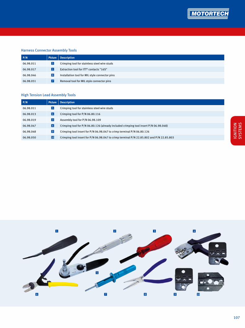
107
1 2 3 4
6 7 8 9
5
10
Harness Connector Assembly Tools
P/N Picture Description
06.98.011 5 Crimping tool for stainless steel wire studs
06.98.017 1 Extraction tool for ITT® contacts "16S"
06.98.046 8 Installation tool for MIL style connector pins
06.98.051 7 Removal tool for MIL style connector pins
High Tension Lead Assembly Tools
P/N Picture Description
06.98.011 5 Crimping tool for stainless steel wire studs
06.98.013 6 Crimping tool for P/N 06.80.116
06.98.019 3 Assembly tool for P/N 06.98.109
06.98.047 4 Crimping tool for P/N 06.80.126 (already included crimping tool insert P/N 06.98.048)
06.98.048 9 Crimping tool insert for P/N 06.98.047 to crimp terminal P/N 06.80.126
06.98.050 10 Crimping tool insert for P/N 06.98.047 to crimp terminal P/N 22.85.802 and P/N 22.85.803 IGN
ITIO
N
SYST
EMS

108

109
SPARK PLUGS AND ACCESSORIESAs the market changes due to emission regulations, new fuel qualities, higher energy ignition or only to the demand for higher efficiency, the request for better spark plugs has been raised. The Industrial Spark Plug manufacturers have done their homework and offer today all kinds of spark plugs with special electrode materials or even completely new firing end designs.
The Market is ready for Iridium Spark Plugs!

110
SPARK PLUGS AND ACCESSORIES
MOTORTECH Extended Barrel Spark Plugs
For certain applications extended barrel plugs are required. For example when the operator cannot get a conventional spark plug down the narrow spark plug well, he will need a special product that allows him to torque the plug from the top end. MOTORTECH offers an improved product to the market. Several of the known problems of products made by competitors are eliminated.
Besides an increase in reliability the spark plug run time nee-ded to be extended. To achieve this, MOTORTECH uses base plugs with Iridium alloy (J-Type) or Nickel/Aluminum alloy (X-Type) on center & ground electrode.
The “S2-Type” has a 5/8 in. male thread and used to be called the AIRCRAFT
STYLE spark plug. This spark plug is designed to
be connected to a shiel-ded high tension lead.
The “DCP-Type” has a female thread to adapt to
a short integral ignition coil. This combination is
popular in some applica-tions, where customers have had bad experien-ces with shielded high
tension leads.
The “C-Type” is an exten-ded barrel plug that has a conventional ceramic
insulator on the top end. This allows the use of a
standard spark plug boot. Preferable a connector
that includes a 5 kΩ resis-tor to suppress the RFI.
Features• No more trapped air in the extension barrel• No more condensation• No internal flash over• Built in ceramics• High dielectric strength• Rigid welds
MOTORTECH EXTENDED SPARK PLUGSXT-Plugs
The J-Type ground electrode ensures better combustion, particularly on lean burn gas engines.
The alternative X-Type double-stage electrodes are ideally suited for slow-speed gas engines.
MOTORTECH XT-PLUGS
MOTORTECH XT-PLUGS are available with three different termi-nal styles to be connected directly to a high tension lead or a short integral ignition coil.

111
A = Spark Plug StyleC = C Type
DCP = DCP Type
S2 = S2 Type
B = Thread SizeB4 = M14 x 1.25
B8 = M18 x 1.5
B7 = 7/8 in.
C = Thread Reach1 = 0.500 in.
2 = 0.600 in.
3 = 0.750 in.
D = Electrode Design1 = X-Type
2 = J-Type
E = Extended Barrel Length1)
BEX6 = 6 in.
BEX8 = 8 in.
BEX10 = 10 in.
BEX12 = 12 in.
BEX16 = 16 in.
F = Electrode Gap010 = 0.010 in. / 0.25 mm
012 = 0.012 in. / 0.30 mm
014 = 0.014 in. / 0.35 mm
1) Other barrel lenghts available on request.
Conversion 1 inch = 25,4 mm / 1 foot = 0,3 m
SPAR
K
PLU
GS
Recommended Tightening Torque1)
Thread Size Tightening Torque (Cast Iron Head)
M14 x 1.25 30-40 Nm 22-30 lb-ft
M18 x 1.5 50-60 Nm 37-44 lb-ft
7/8-18 70-80 Nm 52-59 lb-ft1) Please observe the tightening torques rendered by each engine manufacturer.
optional
P/N A B C D E - F
EC
B
Specification Table – MOTORTECH XT Plugs
A A AF
D

112
SPARK PLUGS AND ACCESSORIES
XTL-PlugsMOTORTECH EXTENDED SPARK PLUGS
5A = ALTRONIC® style; 5B = BENDIX® style; 5C = MOTORTECH style
6 8 975*42 31a1
SPARK PLUGS AND ACCESSORIES
MOTORTECH XTL-PLUGS for non shielded Applications
Based on the concept of the extended barrel spark plugs, MOTORTECH offers a new style of spark plug. MOTORTECH XTL-PLUGS are manufactured with an integrated 7 mm spark plug lead, which allows a direct connection to an externally mounted ignition.
MOTORTECH XTL-PLUGS can be ordered with different barrel and lead lengths, different lead outputs from the barrel and a wide range of ignition coil connectors. This guarantees a custom-made spark plug which definitely fits your application.
D
F
B
A
C
H
E
G
F
G
Available Connectors to Ignition Coil
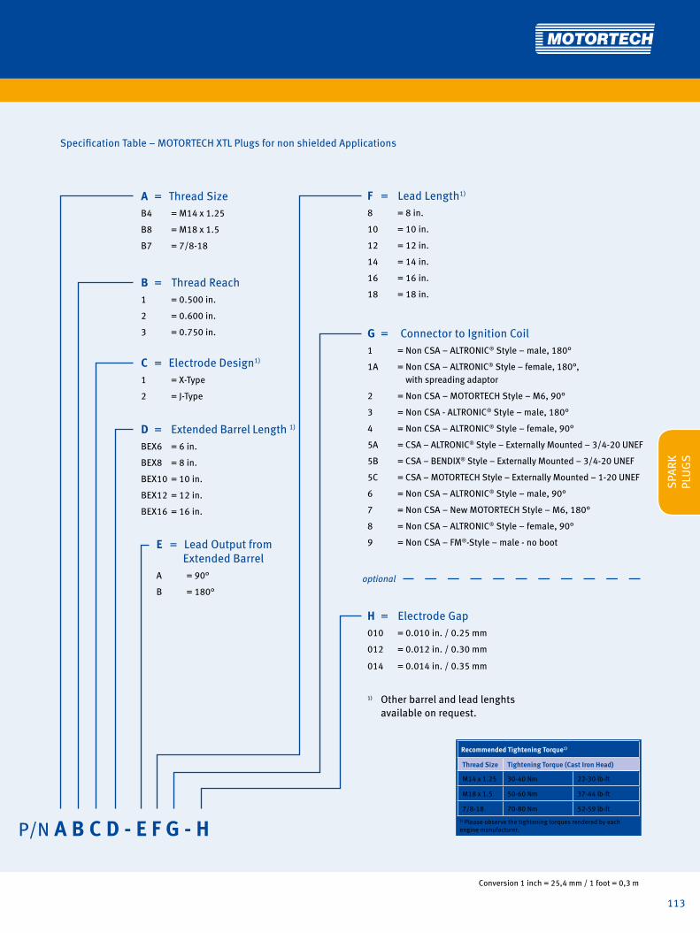
113
Conversion 1 inch = 25,4 mm / 1 foot = 0,3 m
A = Thread SizeB4 = M14 x 1.25
B8 = M18 x 1.5
B7 = 7/8-18
B = Thread Reach1 = 0.500 in.
2 = 0.600 in.
3 = 0.750 in.
C = Electrode Design1)
1 = X-Type
2 = J-Type
D = Extended Barrel Length 1)
BEX6 = 6 in.
BEX8 = 8 in.
BEX10 = 10 in.
BEX12 = 12 in.
BEX16 = 16 in.
E = Lead Output from Extended BarrelA = 90°
B = 180°
Specification Table – MOTORTECH XTL Plugs for non shielded Applications
P/N A B C D - E F G - H
SPAR
K
PLU
GS
F = Lead Length1)
8 = 8 in.
10 = 10 in.
12 = 12 in.
14 = 14 in.
16 = 16 in.
18 = 18 in.
G = Connector to Ignition Coil1 = Non CSA – ALTRONIC® Style – male, 180°
1A = Non CSA – ALTRONIC® Style – female, 180°, with spreading adaptor
2 = Non CSA – MOTORTECH Style – M6, 90°
3 = Non CSA - ALTRONIC® Style – male, 180°
4 = Non CSA – ALTRONIC® Style – female, 90°
5A = CSA – ALTRONIC® Style – Externally Mounted – 3/4-20 UNEF
5B = CSA – BENDIX® Style – Externally Mounted – 3/4-20 UNEF
5C = CSA – MOTORTECH Style – Externally Mounted – 1-20 UNEF
6 = Non CSA – ALTRONIC® Style – male, 90°
7 = Non CSA – New MOTORTECH Style – M6, 180°
8 = Non CSA – ALTRONIC® Style – female, 90°
9 = Non CSA – FM®-Style – male - no boot
H = Electrode Gap 010 = 0.010 in. / 0.25 mm
012 = 0.012 in. / 0.30 mm
014 = 0.014 in. / 0.35 mm
1) Other barrel and lead lenghts available on request.
optional
Recommended Tightening Torque1)
Thread Size Tightening Torque (Cast Iron Head)
M14 x 1.25 30-40 Nm 22-30 lb-ft
M18 x 1.5 50-60 Nm 37-44 lb-ft
7/8-18 70-80 Nm 52-59 lb-ft1) Please observe the tightening torques rendered by each engine manufacturer.

114
SPARK PLUGS AND ACCESSORIES
MOTORTECH XTL-PLUGS for shielded Applications
MOTORTECH XTL-PLUGS are also available for shielded appli-cations. To meet CSA requirements, this type of spark plug is fitted with an integrated and specially designed spark plug lead. This is also known from MOTORTECH´s MOT-Blues high tension leads. The multi layer design ensures that no humidity can be trapped in the lead.
MOTORTECH XTL-PLUGS can be ordered with different barrel and lead lengths and suitable ignition coil connectors, to allow direct connection to a shielded ignition coil. This guarantees a custom-made spark plug which definitely fits your application.
SPARK PLUGS AND ACCESSORIES
XTL-PlugsMOTORTECH EXTENDED SPARK PLUGS
SPARK PLUGS AND ACCESSORIES
EG
C
B
D
I
FH
The specially designed spark plug lead consists of a multi layer design:
• Nickel plated copper core• 2 layers of silicone• Stainless steel braid• Silicone jacket
This design ensures that no humidity can be trapped in the lead.

115
F = Lead Output from Extended BarrelB = 180°
H = Connector to Ignition Coil5A = CSA - ALTRONIC® Style – Externally Mounted – 3/4-20 UNEF
5B = CSA - BENDIX® Style–- Externally Mounted – 3/4-20 UNEF
5C = CSA - MOTORTECH Style – Externally Mounted – 1-20 UNEF
G = Lead Length1)
8 = 8 in.
10 = 10 in.
12 = 12 in.
14 = 14 in.
16 = 16 in.
18 = 18 in.
I = Electrode Gap010 = 0.010 in. / 0.25 mm
012 = 0.012 in. / 0.30 mm
014 = 0.014 in. / 0.35 mm
1) Other barrel and lead lenghts available on request.
Specification Table – MOTORTECH XTL Plugs for shielded Applications
A = Spark Plug StyleI = Shielded Application
B = Thread SizeB4 = M14 x 1.25
B8 = M18 x 1.5
B7 = 7/8-18
C = Thread Reach1 = 0.500 in.
2 = 0.600 in.
3 = 0.750 in.
D = Electrode Design1 = X-Type
2 = J-Type
E = Extended Barrel Length1)
BEX6 = 6 in.
BEX8 = 8 in.
BEX10= 10 in.
BEX12= 12 in.
BEX16= 16 in.
SPAR
K
PLU
GS
5*
P/N A B C D E - F G H - I
optional
Recommended Tightening Torque1)
Thread Size Tightening Torque (Cast Iron Head)
M14 x 1.25 30-40 Nm 22-30 lb-ft
M18 x 1.5 50-60 Nm 37-44 lb-ft
7/8-18 70-80 Nm 52-59 lb-ft1) Please observe the tightening torques rendered by each engine manufacturer.

116
SPARK PLUGS AND ACCESSORIES
P/N Description Thread Size Thread Reach Electrode Design Hex Thread Size Ignition Coil Equivalent to
ICPB412 ICP spark plug M14 x 1.25 0.500 in. J-Type 15/16 in. 13/16-20 UNEF RTL85G
ICPB432 ICP spark plug M14 x 1.25 0.750 in. J-Type 15/16 in. 13/16-20 UNEF RTN79G
ICPB812 ICP spark plug M18 x 1.5 0.500 in. J-Type 15/16 in. 13/16-20 UNEF RTM77N
ICPB832 ICP spark plug M18 x 1.5 0.750 in. J-Type 15/16 in. 13/16-20 UNEF RTB77WPCC
1) MOTORTECH ICP spark plugs only available in packs of 4 pcs.
For Operators who prefer to use a long integral ignition coil, MOTORTECH manufactures the dual threaded spark plugs.These are available in M14 and M18 thread sizes.
All plugs have iridium center and ground electrodes. For years these plugs have been successfully operated worldwide.
MOTORTECH ICP Spark Plugs with Dual Thread for use with Integral Ignition Coils1)
MOTORTECH introduces the new high quality pre-chamber spark plug series. First to come is the M18 x 1.5 with 3/4 in. thread reach.
• New design
• High quality electrode material
• Designed for long life
• Industrial rigid construction
Designed for use with
• CATERPILLAR® G3520C
• MTU® 4000 series
• DRESSER RAND GUASCOR® HGM and SFGM 560 series
MOTORTECH MPC Pre-Chamber Spark Plug1)
P/N Description Thread Size Thread Reach Electrode Design Hex Equivalent to
MPC1800 MPC spark plug M18 x 1.5 0.750 in. Pre-chamber 7/8 in.
1) MOTORTECH MPC spark plugs only available in packs of 4 pcs.
NEW

117Distribution partner for DENSO spark plugs
All D
ENSO
dat
a in
this
pag
e is
sup
plie
d by
DEN
SO. M
OTO
RTEC
H p
ublis
hes
this
info
rmat
ion
with
out l
iabi
lity
or re
spon
sibi
lity
for i
ts c
onte
nt, i
nteg
rity
and
acc
urac
y.
SPAR
K
PLU
GS

118
DENSO has launched the latest generation of hardwearing spark plugs − the DENSO DOUBLE IRIDIUM (DDI) spark plug. DDI spark plug technology improves and extends the spark plug's lifespan and requires significantly less maintenance than competitor spark plugs. The DDI spark plug is particularly effective when used in biogas engines. Try DENSO DDI spark plugs today.
Convergence laser weldingWedge by laser welding fixes Iridium alloy pad on groundelectrode securely, which realizes high reliability in high temperature combustion engine.
Proving longer lifeGap expansion is suppressed by Double Iridium Pads on both sides.
360° laser weldingSecure welding of the Iridium tip by "360° laser welding" can withstand all extreme engine conditions. Patent: Japan (2921524), USA (6078129)
This suppression of gap expansion results in a longer life than Iridium Saver.
(biogas)
Gap
exp
ansi
on
0 Hours
Anal
yzed
by
DEN
SO
Gap expansion
(biogas)
Requ
ired
Vol
tage
(kV)
0 Hours
Ignition Voltage limit
The above is analysed by DENSO
Convergence laser welding
Iridium alloy
360° Laser welding
Iridium alloy padElectrical
resistance welding Platinum alloy pad
The DDI's key to long plug life
Unique "Iridium alloy"A unique, high welding point "Iridium alloy" developed and patented by DENSO, dramatically improves wear resistance compared to other Iridium plug. Patent:Japan (2877035), UK (2302367), USA (6094000)
Iridium DesignIridium pads both on center electrode and on groundelectrode, to minimize spark gap expansion.

119
Key to high reliability
Highly Reliable Monolithic Resistor The Iridium Saver Plug guarantees high reliability for withstanding high combustion pressures by incorporating a stress resistant monolithic resistor that adheres to the resistor glass in the high temperature furnace. In addition, this eliminates interference to electronic equipment from high energy coil noise.
Conventional Plug
Newly Developed Ceramics Conventional Ceramics
NORMAL PLUG
Anal
yzed
by
DEN
SO
Special Nickel Plating With Better Corrosive Resistance
Better corrosive resistance for con-densed acid water. Exposure Test By Acid Steam Atmosphere.
Test length: 700 hoursTemperature: 90°CAcid Water: pH=2 An
alyz
ed b
y D
ENSO
High Dielectric Ceramics
Newly developed ceramics with finer grain, molded-in higher pressure and higher density prevents electrical breakdown of insulator.
up to 5kV
Transverse Rupture Strength Electrical Breakdown Voltage (kV)
Conventional Plug
10% up
All D
ENSO
dat
a in
this
pag
e is
sup
plie
d by
DEN
SO. M
OTO
RTEC
H p
ublis
hes
this
info
rmat
ion
with
out l
iabi
lity
or re
spon
sibi
lity
for i
ts c
onte
nt, i
nteg
rity
and
acc
urac
y.
SPAR
K
PLU
GS

120
DENSO's OEM expertise and commitment to innovation enables them to remain at the forefront of cutting-edge gas engine spark plug development. The unique and specialist technology used in the Iridium Saver and Iridium Saver Performer spark plugs range extends their lifespan, making them ideal for high-compression lean-burn engines. Iridium Saver and Iridium Performer spark plugs also help to maximise engine performance and deliver extra durability. Because they require minimal maintenance compared to standard plugs, Iridium Saver and Iridium Saver Performer spark plugs increase service interval times. Try DENSO's Iridium Saver or Iridium Saver Performer spark plugs today.
Platinum alloy pad
Cross Groove
Iridium alloy
360° Laser welding
Unique"Iridium alloy"A unique, high welding point "Iridium alloy" developed andpatented by DENSO, dramatically improves wear resistance compared to other Iridium plug.Patent: Japan (2877035), UK (2302367), USA (6094000)
360° laser weldingSecure welding of the Iridium tip by "360° laser welding" can withstand all extreme engine conditions.Patent: Japan (2921524), USA (6078129)
The Cross Groove Design
20 25 30
(Electric Field Strength)Weak Strong (spark easier)
4kVFEM
Ground Electrode
Center Electrode
Ground Electrode
Center Electrode
IRIDIUM SAVER PERFORMER
IRIDIUM SAVER
CONVENTIONAL PLUG
Ignition Voltage Limit
(V12 Engine, Natural Gas)
Conventional Plug
Requ
ired
Vol
tage
(kV)
0 Hours
Cross Groove design (M18 Spark Plug)4 small electrodes created by Cross Groove improve sparkingperformance and suppress dispersion in voltage value, for anoutstanding voltage decrease.Patent: USA(6215234)
Proving longer lifeRequired voltage is suppressed by 1) unique "Iridium alloy" 2) Cross Groove electrode, resulting in a longer life than conventional plug.
The SAVER's key to long plug life
The above is analysed by DENSO

121
IG 13
Initial GapNo Norminal Value
3 0.3 mm
4 0.4 mm
5 0.5 mm
for Gas Engines
- A
Terminal DesignNo SPEC.
none solid
A with nut
( )
Spark Plug Type and Installation Dimension
1. Iridium pad without cross groove on center electrode and Platinum pad on ground electrode.
3. For vehicle
5. Iridium pad without cross groove on center electrode and Iridium pad on ground electrode.
1. Iridium pad with cross groove on center electrode and Platinum pad on ground electrode.
3. Iridium pad without cross groove on center electrode and Platinum pad on ground electrode.
5. Iridium pad without cross groove on center electrode and Iridium pad on ground electrode.
Specifications and cross reference
All D
ENSO
dat
a in
this
pag
e is
sup
plie
d by
DEN
SO. M
OTO
RTEC
H p
ublis
hes
this
info
rmat
ion
with
out l
iabi
lity
or re
spon
sibi
lity
for i
ts c
onte
nt, i
nteg
rity
and
acc
urac
y.
Spark Plug Type and Installation DimensionNo Thread Hex Size Reach
E
M 14 x 1.25
20.8 mm
19 mm
N 12.7 mm
K 16 mm 19 mm
L
M 18 x 1.5
20.8 mm
20.6 mm
I
22.2 mm
T 13.8 mm
M14
M18
Cross Reference
CHAMPION® STITT® ALTRONIC® BERU®
RN79G (0.015) 407XL / R407XL J1463DP
14R-3CPU / 14-3CPU / 14R-5DPU / 14R-4CDP GE3-1 GE3-5
14R-4CIU (Z187) / 14R-4CIU2 (Z215) / 14R-4DIU2 (Z258) / 14R-4DIU3 GE3-5
RN79G (0.020) 14R-4CIU (Z205) GE5-1
RC78PYP / RC78PYP15 14FR-4DPUO GK3-1
GK3-5
RC78WYP15 14FR-4DIU
RL85G / RL15B 407L / R407L J1443DP 14R-5BPU / 14R-4ADP / 14R-5BIU GN3-1
RB77WPCC / KB77WPCC / RB77CC / PB78WPC
L1863IP 18GZ4-77 / 18GZ6-77-2 GI3-3 GI3-5 GI3-1
RB75N / RB75PP R807LL L1863B / L1863DP 18GZ20 GI3-3 GI3-5 GI3-1
RB75WPCC-1 18GZ5-77-2 GL3-3 GL3-5 GL3-1
RB76N / RB76PP R807LL 18GZ7 GI3-3 GI3-5 GI3-1
RM77N 807 / 827 / 847 / U827 / U847
L1843B18GZ22 GT3-1
RM77PP L1843IP
SPAR
K
PLU
GS

122
Spark Plugs M14
GN3-1 GK3-1 GK3-5GE3-1 GE5-1 GE3-5
Ø 6.4
Ø 6.4
10.2
10.2
Ø 10.5
Ø 12.2
Hex 16Hex 20.8
M14X1.25M14X1.25
50.4
70
19
12.7
Ø 6.4
10.2
Ø 12.2
Hex 20.8
M14X1.25
56.1
19
37.136.3
43
GE3-1 GE5-1 GN3-1 GK3-1
GE3-5 GK3-5
Solid terminalISO 14508
Solid terminalISO 14508
Solid terminalISO 14508
Inital Gap0.3 mm
Inital Gap0.5 mm
Inital Gap0.3 mm
Inital Gap0.3 mm
Inital Gap0.28 mm
Inital Gap0.28 mmDouble
IridiumDoubleIridium
Recommended Tightening Torque
Thread Size Lubricant on Thread
Tightening Torque (Cast Iron Head)
M14 x 1.25With lubricant 20 Nm 15 lb-ft
Without lubricant 30 Nm 22 lb-ft
M18 x 1.5With lubricant 30 Nm 22 lb-ft
Without lubricant 45 Nm 33 lb-ft

123
Spark Plugs M18
GL3-1 GL3-3 GL3-5 GT3-1GI3-1 GI3-3 GI3-5Ø 6.4
10.2 10.2
Ø 14.4 Ø 14.4
Hex 22.2Hex 20.8
M18X1.5 M18X1.5
89 89
20.6 20.6
63.5 65
Ø 6.4
Ø 6.4
10.2
Ø 14.4
Hex 22.2
M14X1.5
69.7
13.8
46.4
GI3-3 GL3-3
GI3-1 GL3-1
GI3-5 GL3-5
GT3-1
Solid terminalISO 14508
Solid terminalISO 14508
Solid terminalISO 14508
Inital Gap0.28 mm
Inital Gap0.28 mm
Inital Gap0.28 mm
Inital Gap0.28 mm
Inital Gap0.28 mm
Inital Gap0.28 mm
Inital Gap0.28 mmDouble
IridiumDoubleIridium
with cross groove with cross groove with cross groove
All D
ENSO
dat
a in
this
pag
e is
sup
plie
d by
DEN
SO. M
OTO
RTEC
H p
ublis
hes
this
info
rmat
ion
with
out l
iabi
lity
or re
spon
sibi
lity
for i
ts c
onte
nt, i
nteg
rity
and
acc
urac
y.
SPAR
K
PLU
GS

124
Torque Wrench
P/N Supersedes Description Drive
07.98.063 Torque wrench, 200 Nm/150 ft./lb. 1/2 in. / 3/8 in.
Extended Barrel Magnetic Spark Plug Sockets – 1/2 Inch Drive - Standard Versions1)
P/N Supersedes Description Hex Drive
07.99.022-1-L 07.99.021-L Magnetic spark plug socket 1 in. 1/2 in.
07.99.022-2-L 07.99.020-L Magnetic spark plug socket 15/16 in. 1/2 in.
07.99.022-3-L 07.99.019-L Magnetic spark plug socket 7/8 in. 1/2 in.
07.99.022-4-L 07.99.018-L Magnetic spark plug socket 13/16 in. 1/2 in.
1) Standard barrel lengths ("L") = 6 in., 12 in., 16 in., 18 in. Other lengths available on request.
Extended Barrel Magnetic Spark Plug Sockets – 1/2 Inch Drive - Special Versions
P/N Supersedes Description Hex Drive
07.99.022-3-36 Magnetic spark plug socket – NORDBERG® 7/8 in. 1/2 in.
07.99.022-6-6 Magnetic spark plug socket – MAN® 13/16 in. 1/2 in.
07.99.022-6-1 Magnetic spark plug socket – MAN®, Liebherr® 5/8 in. 1/2 in.
SPARK PLUGS AND ACCESSORIES
Seat & Thread Reconditioner
Use Seat & Thread Reconditioner to clean Cylinder Threads and Gasket Seats in one operation.
P/N Description
07.98.718 Thread lubricant (4 oz / 115 g)
Thread Lubricant
This lubricant is non-metallic and non-conductive. Guarantees easy spark plug removal and prevents thread damage. Also for use with seat & thread reconditioner.
P/N Description
44.01.000 Spark plug cleaning kit
44.01.009 Blasting grid, bottle (1.0 kg)1)
1) Spark plug cleaning kit already includes a package of blasting grit.
Spark Plug Cleaning Kit
Cleaning of the spark plug electrode area by using a special glass bead blaster extends spark plug life and reduces purchasing cost.
P/N Supersedes Description Thread Size Thread Reach
07.98.114-12 07.98.022 Seat & thread reconditioner M14 x 1.25 1/2 in.
07.98.114-34 07.98.023 Seat & thread reconditioner M14 x 1.25 3/4 in.
07.98.118-12 07.98.024 Seat & thread reconditioner M18 x 1.5 1/2 in.
07.98.118-34 07.98.025 Seat & thread reconditioner M18 x 1.5 3/4 in.
07.98.178-58 07.98.026 Seat & thread reconditioner 7/8-18 5/8 in.
07.98.178-78 07.98.026-1 Seat & thread reconditioner 7/8-18 7/8 in.

125
Spark Plug Cleaning Process Overview
NOTE: This is only a short operation overview. Before you use the spark plug cleaning kit, read and understand the original operating manual.
∙ Select the appropriate cleaning nozzle for the spark plug used based on the following list.
– small cleaning nozzle (dia. aperture: 12 mm/0.47'') for spark plugs with M14 thread
– large cleaning nozzle (dia. aperture: 18 mm/0.71'') for spark plugs with 7/8" or M18 thread
∙ Attach the cleaning nozzle.
∙ Screw the threaded spark plug end into the cleaning nozzle.∙ Hold the spark plug tightly during the entire cleaning
process.
∙ Actuate the trigger in spurts to perform the cleaning. The blasting grit is suctioned in and ejected to blast the
spark plug surface. The nozzle prevents the blasting grit from escaping. The blasting grit is collected in the dust collection bag.
∙ Check the result after a few cleaning blasts. All solid depo-sits and oil residue should have been lifted off the surface.
∙ Remove the loose residues with compressed air.∙ When you reuse the cleaned spark plug, adjust the
electrode gap.∙ Install new spark plug gasket.
SPAR
K
PLU
GS

126
SPARK PLUGS AND ACCESSORIES
P/N Description For Thread Size Quantity
02.85.015-100 Spark plug gasket M14 x 1.25 100 pcs.
02.85.015-500 Spark plug gasket M14 x 1.25 500 pcs.
02.85.015-1000 Spark plug gasket M14 x 1.25 1000 pcs.
02.85.015-5000 Spark plug gasket M14 x 1.25 5000 pcs.
02.85.016-100 Spark plug gasket M18 x 1.5 100 pcs.
02.85.016-500 Spark plug gasket M18 x 1.5 500 pcs.
02.85.016-1000 Spark plug gasket M18 x 1.5 1000 pcs.
02.85.016-5000 Spark plug gasket M18 x 1.5 5000 pcs.
02.85.017-100 Spark plug gasket 7/8-18 100 pcs.
02.85.017-500 Spark plug gasket 7/8-18 500 pcs.
02.85.017-1000 Spark plug gasket 7/8-18 1000 pcs.
02.85.017-5000 Spark plug gasket 7/8-18 5000 pcs.
Made of high quality folded zinc plated steel. To ensure proper spark plug installation and best heat tranfer, it is important to use a new gasket every time the spark plug is reinstalled.
Gaskets for Spark Plugs
Gaskets for Spark Plugs – MOTORTECH ICP Spark Plugs – Dual Threaded Version
P/N Supersedes Description Quantity
75.90.295-100 Spark plug gasket, copper 100 pcs.
P/N Supersedes Description
07.98.113 Gap setting tool incl. gap gauges 0.010 in./0.25 mm, 0.012 in./0.30 mm, 0.014 in./0.35 mm
Gap Setting Tool for MOTORTECH Spark Plugs with X-Type Electrode Design
A unique electrode design requires a special gapping tool. For spark plugs with X-Type double stage electrodes,MOTORTECH offers a new and specially designed tool. This makes regapping easy.

127
Gap Gauges for Bench Gap Setting Tool
P/N Supersedes Description Size
07.98.103-010 Gap gauge 0.010 in. / 0.25 mm
07.98.103-011 Gap gauge 0.011 in. / 0.28 mm
07.98.103-012 Gap gauge 0.012 in. / 0.30 mm
07.98.103-013 Gap gauge 0.013 in. / 0.33 mm
07.98.103-014 Gap gauge 0.014 in. / 0.35 mm
07.98.103-015 Gap gauge 0.015 in. / 0.38 mm
07.98.103-020 Gap gauge 0.020 in. / 0.51 mm
07.98.103-025 Gap gauge 0.025 in. / 0.64 mm
Gap Setting Tool for CHAMPION® Spark Plugs with N-Type Electrode Design
P/N Figure Supersedes Description Size
07.98.100-18 1 Handwheel M18 x 1.5
07.98.100-78 1 Handwheel 7/8-18
07.98.101 2 Spreader
07.98.102-010 3 Gap gauge 0.010 in. / 0.25 mm
07.98.102-013 3 Gap gauge 0.013 in. / 0.33 mm
07.98.102-015 3 Gap gauge 0.015 in. / 0.38 mm
07.98.102-020 3 Gap gauge 0.020 in. / 0.51 mm
07.98.102-025 3 Gap gauge 0.025 in. / 0.64 mm
SPAR
K
PLU
GS
P/N Supersedes Description Size
07.98.111 07.98.109 Bench gap setting tool
includes:
07.98.100-18 Handwheel M18 x 1.5
07.98.100-78 Handwheel 7/8-18
07.98.101 Spreader
07.98.103-012 Gap gauge 0.012 in. / 0.30 mm
07.98.103-015 Gap gauge 0.015 in. / 0.38 mm
07.98.103-020 Gap gauge 0.020 in. / 0.51 mm
Bench Gap Setting Tool for CHAMPION® Spark Plugs with N-Type Electrode Design
The more professional way to gap N-Type spark plugs is the bench mounted gapping tool. Each electrode is gapped individually.
1 2 3

128

129
GAS ENGINE MANAGEMENTThe All-In-One is a complete genset or CHP unit control system. Forget the days where a genset required multiple control boxes to be tied together to one system. We have included all functions, including lean burn control into one unit with large separate display. Tie up to 32 gensets together and connect yourself to the grid. This controller has the capabilities of a large PLC system at a much lower price !
GAS ENGINE MANAGEMENTThe All-In-One is a complete genset or CHP unit control system. Forget the days where a genset required multiple control boxes to be tied together to one system. We have included all functions, including lean burn control into one unit with large separate display. Tie up to 32 gensets together and connect yourself to the grid. This controller has the capabilities of a large PLC system at a much lower price !

130
GAS ENGINE MANAGEMENT
MOTORTECH GAS ENGINE MANAGEMENTALL-IN-ONEGas Engine Management − ALL-IN-ONE
For monitoring, controlling, regulating and system protection. ALL-IN-ONE.NT is an expandable controller for both single and multiple gen-sets operating in standby or parallel modes, espe-cially in cogeneration (CHP) and other complex applications.
Modular design (consisting of AIO.NT-controller and AIO.NT- or AIO.VISION-display) allows easy installation with the ability to add many different extension modules designed to suit indivi-dual customer requirements.
Built-in synchronizing, digital isochronous load sharing and air-fuel-ratio functions (requires additional dongle) allow a to-tal integrated solution for gen-sets in standby, island, parallel or mains parallel. Native co-operation of up to 32 gen-sets is a standard feature.
AIO.NT supports many standard ECU (electronic control unit) types and is specially designed to easily integrate new ones. A powerful graphic display with user-friendly controls allows any user whatever their ability to find the information they need. The display on the basic version is capable of display-ing graphical languages (e.g. Chinese).
Benefits
• Support of engines with ECU (Electronic control unit)
• Excellent configurability to match customer´s
needs exactly
• Complete integrated gen-set solution incorpora-
ting built-in PLC and signal sharing via CAN bus
– minimum external components needed
• Many communication options – easy remote
supervising and servicing
• Perfect price / performance ratio
• Gen-set performance log for easy problem tracing
• Air-Fuel-Ratio function for lean burn gas engines
Features
∙ CHP support (programmable PID loops and other
built-in PLC functions)
∙ Support of engines with ECU (J1939, Modbus
and other proprietary interfaces); alarm codes
displayed in text form
∙ Automatic synchronizing and power control (via
speed governor or ECU)
∙ Baseload, Import / Export, TempByPower
∙ Peak shaving
∙ Voltage and PF control (AVR)
∙ Generator measurement: U, I, Hz, kW, kVAr, kVA,
PF, kWh, kVAhr
∙ Mains measurement: U, I, Hz, kW, kVAr, PF
∙ Selectable measurement ranges for AC voltages
and currents – 120 / 277 V, 0–1 / 0–5 A
∙ Inputs and outputs configurable for various custo-
mer needs
∙ Controller redundancy
∙ 2× RS232 / RS485 interface with Modbus protocol
∙ Support; Analog / GSM / ISDN / CDMA modem
communication support; SMS messages; ECU
Modbus interface; secondary RS485 converter is
isolated
∙ Event-based history (up to 1000 records) with
customer-selectable list of stored values; RTC;
statistic values
∙ Integrated PLC programmable functions
∙ Interface to remote display units (3× AIO.NT- or
AIO.Vision-display)
∙ USB 2.0 slave interface
∙ Dimensions 284 × 180 mm (front panel)
∙ Sealed to IP65
Integrated fixed and configurable protections
∙ 3 phase integrated generator protections (U + f)
∙ IDMT overcurrent + shortcurrent protection
∙ Overload protection
∙ Reverse power protection
∙ Earth fault protection
∙ 3 phase integrated mains protections (U + f)
∙ Vector shift protection
∙ All binary / analog inputs free configurable for
various protection types: HistRecOnly / Alarm
Only / Alarm + History indication / Warning / Off
load / Slow stop / BreakerOpen&Cooldown /
Shutdown / Shutdown override / Mains protect /
sensor fail
∙ Phase rotation and phase sequence protection
∙ Additional 160 programmable protections
configurable for any measured value to create
customer-specific protections
∙ Application security

131
Generator∙ 3 Phase Monitoring∙ Over/Under Frequency∙ Over/Under Voltage∙ Interrupt free reverse synchronizing∙ Overload Protection∙ TempByPower load control∙ Reverse Power Protection∙ Load Surge Protection∙ Voltage and PF Control (AVR)
InteliPro∙ Designed to meet utility
protection requirements∙ Combines standard and
optional features∙ Advanced communications∙ Data/event logging
@
MCB GCB
LOAD
CAN
1
CAN2
Modem∙ Remote Control∙ Internet Bridge
PC Monitoring Tool∙ Visualization∙ Programming
GSM∙ Active/Passive calls∙ SMS Service
AIN8 / BIN16/8 / I-AOUT8 Modules etc.∙ Digital inputs (80 max)∙ Digital outputs (48 max)∙ Analog inputs (84 max)∙ Analog outputs (33 max)∙ All kind of sensors usable (programmable)∙ Status LEDs for In- and outputs
RS 232 / RS 485∙ Modbus∙ Direct PC-Connection∙ Modem Connection∙ SMS Managment∙ Active Calls∙ Internet
up to 32 gensets
up to 32 devices
MainsPro∙ Protective functionalities∙ Free assignment of 5 relay outputs∙ 4 binary switches to remotely
change operation of the unit∙ Last trip recorded in order to provide
the evidence of cause of trip
InteliMains∙ Import/Export∙ Load Sharing∙ Power Plant Managment∙ Grid Monitoring∙ Running Hours Optimization
or
Main Circuit Breaker∙ Control∙ Reverse Synchronization∙ Grid Monitoring
Load Monitoring∙ Base Load∙ Import/Export∙ Peak Shaving
Generator Circuit Breaker∙ Control Synchronization
Engine Managment (ECU)∙ Speed Measurement/Control∙ Engine Monitoring and Protection∙ Exhaust Gas Temperature monitoring∙ Air/Fuel Ratio Control∙ Start/Stop Routines
Ethernet (only AIO.NTC-BB)
GAS
EN
GIN
E M
ANAG
EMEN
T

132
GAS ENGINE MANAGEMENT
ALL-IN-ONE – Gas Engine Management – Dongles for ALL-IN-ONE.NT/.NTC Controllers
P/N Description
63.50.061 Hardware dongle for ALL-IN-ONE.NT/.NTC controllers - AFR-PCM• Enables single isolated parallel with mains• Power management operation (with CAN Bus)
63.50.062 Hardware dongle for ALL-IN-ONE.NT/.NTC Controllers - AFR-PCLSM+PMS• Enables multiple isolated parallel or multiple parallel with mains • Power management operation (with CAN Bus)• Digital load sharing• Digital VAr sharing
63.50.085 Hardware dongle for Mini-ALL-IN-ONE - miniAFR-PCM• Enables single isolated parallel with mains for applications up to 75 kW (el.)• Air/Fuel Ratio function for lean burn gas engines• For applications up to 75 kW (el.)
ALL-IN-ONE – Gas Engine Management – ALL-IN-ONE.NT/.NTC Controllers
P/N Description
63.50.102 ALL-IN-ONE.NT controller – cogeneration Gen-Set controller (incl. AFR control)
63.50.102-HSS ALL-IN-ONE.NT controller – cogeneration Gen-Set controller P/N 63.50.102 incl. plug-on module I-HSS-BIN6/10
63.50.104 ALL-IN-ONE.NTC controller – universal Gen-Set controller (incl. AFR control and AirGate® technology)
63.50.104-HSS ALL-IN-ONE.NTC controller – universal Gen-Set controller P/N 63.50.104 incl. plug-on module I-HSS-BIN6/10
63.50.082 Mini-ALL-IN-ONE controller – universal controller for small Gen-Sets (incl. AFR control)
AIO.NT/.NTC ControllersAIO.NTC ControllerP/n 63.50.104
AIO.NT ControllerP/N 63.50.102
ALL-IN-ONE – Gas Engine Management – Display Units for ALL-IN-ONE.NT/.NTC Controllers
P/N Description
63.50.105 ALL-IN-ONE.Vision display – 5.7 in. color display unit for ALL-IN-ONE.NT and ALL-IN-ONE.NTC controller
63.50.101 ALL-IN-ONE.Vision display – 8.0 in. color display unit for ALL-IN-ONE.NT and ALL-IN-ONE.NTC controller
63.50.115 ALL-IN-ONE.Vision display – 17.0 in. color display unit for ALL-IN-ONE.NT and ALL-IN-ONE.NTC controller for multiple Gen-Sets – touch screen
63.50.103 ALL-IN-ONE.NT display – detachable display unit for ALL-IN-ONE.NT and ALL-IN-ONE.NTC controller
• Optimizing number of running engines: Power management; kW, kVA or % load based
• Air/Fuel Ratio function for lean burn gas engines
Available Display Units for AIO.NT/.NTC Controllers
AIO.Vision (8.0 in.)P/N 63.50.101
AIO.Vision (17.0 in.)P/N 63.50.115
AIO.Vision (5.7 in.)P/N 63.50.105
AIO.NTP/N 63.50.103

133
ALL-IN-ONE - Gas Engine Management - Accessories
P/N Supersedes Description
63.50.002 Analog input module – AIN8
63.50.108 Analog input module (for thermocouples only) – AIN8TC
63.50.005 Binary input/output unit – IS-BIN16/8
63.50.007 Analog/binary input/output unit – IGS-PTM
63.50.007-HSS Analog/binary input/output unit P/N 63.50.007 incl. plug-on module I-HSS-BIN8
63.50.011 AVR interface module – IG-AVRi
63.50.010-100 Power supply transformer for IG-AVRi module, 100-120 VAC, 50-60 Hz
63.50.010-230 Power supply transformer for IG-AVRi module, 230-480 VAC, 50-60 Hz
63.50.054 Analog output module – I-AOUT8
63.50.075 63.50.006 Modem unit – I-LB+
63.50.112 63.50.022 Internet bridge communication module – IB-NT
63.50.088 CAN repeater – I-CR
IS-BIN 16/8P/N 63.50.005
IGS-PTMP/N 63.50.007
IAOUT8P/N 63.50.054
I-LB+P/N 63.50.075
IB-NTP/N 63.50.112
AIO.NT-Base BoxP/N 63.50.102
IG-AVRiP/N 63.50.011
IG-AVRi transP/N 63.50.010-xxx
Sample Control Panel
ALL-IN-ONE – Gas Engine Management – Other Controllers
P/N Description
63.50.064 Mains supervision controller – IM-NT
63.50.064-BTB Mains supervision controller Bus Tie Breaker – IM-NT BTB
63.50.064-MCB Mains supervision controller Main Circuit Breaker – IM-NT MCB
GAS
EN
GIN
E M
ANAG
EMEN
T
IS-AIN8P/N 63.50.002

134
Detonation Control System − DetCon20
The Gas Engine Operators are calling for increased power output from their engines. More load means higher temperatures, pressures and tougher operation. This mostly ends in catastrophic engine damages due to detonation or pre ignition.
As MOTORTECH has proven for years, detonation can be detected professionally with the DetCon20. Single cylinder sensors con-stantly monitor the sound level of the combustion chamber. If Detonation is detected the system will take steps to eliminate detonation immediately.Upgrade your engines and increase availability of the equipment!
GAS ENGINE MANAGEMENT
MOTORTECH DETONATION CONTROL SYSTEMDetCon20
Function
Once the controller detects soft detonation on one of
the sensors (this is a specific stage before real detona-
tion occurs), several steps will take place:
∙ Alarm signal turns on
∙ Ignition retard by 0-5 V or 4-20 mA analog output.
∙ If this action does not cure the detonation, the load
reduction output will be activated.
∙ If the load drop does not stop the engine from
detonating the engine STOP output will be activated.
... THIS FROM HAPPENING!
STOP
Detonation sensorCan be installed on any cylinder head bolt or stud. Measures the detonation signal and transfers it to the controller.
Detonation SoftwareDetCon20 comes with a WIN based Software package that allows the operator to analyze all data in real time on his PC.

135
USB
Up to 20 Detonation Sensors
CAN
Ignition Timing Control(0-5 VDC / 4-20 mA)
Power Supply 10-30 VDC
Binary Outputs
Alarm
Load Reduction
Engine Stop
ISU (Ignition Sensor Unit)(not required with MIC850, MIC4, MIC5)
Signal from Ignition Coil #1 Cylinder
Ignition Controller
HMI Display
USBCAN
AIO Display
Anal
og O
utpu
t
GAS
EN
GIN
E M
ANAG
EMEN
T

136
GAS ENGINE MANAGEMENT
DetCon20 – Detonation Control System – Control Units
P/N Description Gas Dual Fuel
43.00.0201) DetCon20 control unit, 20 outputs, CSA, IP20 x x
43.00.120 DetCon20 control unit, 20 outputs, CSA, in enclosure, includes ignition sensor unit x
43.00.2202) DetCon20 control unit, 20 outputs, CSA, in enclosure x
1) The control unit has to be installed in (CSA approved) control panel.2) For use with MIC4, MIC5 and MIC850 series ignition controllers. Ignition sensor unit is not required.
DetCon20 – Detonation Control System – Detonation Sensor (1 per Cylinder required)
P/N Description Gas Dual Fuel
43.20.001 Detonation sensor w/o lead, 2 pole x x
DetCon20 – Detonation Control System – Detonation Sensor Lead (1 per Detonation Sensor required)
P/N Description Gas Dual Fuel
43.30.004-60 Detonation sensor lead, 60 ft. x x
DetCon20 – Detonation Control System – ISU Ignition Sensor Unit (1 per System required)
P/N Description Gas Dual Fuel
43.20.002 ISU ignition sensor unit1) x
1) Not required if MIC4, MIC5, MIC850 or DetCon20 control unit P/N 43.00.120 is used.
DetCon20 – Detonation Control System –Inductive Pickup (1 per System required – Dual Fuel Applications only)
P/N Description Gas Dual Fuel
66.60.003-60 Inductive pickup, M12x1, 60 mm length x
66.60.003-100 Inductive pickup, M12x1, 100 mm length x
DetCon20 – Detonation Control System – Inductive Pickup Lead (1 per Pickup required – Dual Fuel Applications only)
P/N Description Connector Length Equivalent to Gas Dual Fuel
06.71.007 Inductive pickup lead 4 pole socket, 90° 400 in. x
DetCon20 – Detonation Control System – Trigger Reluctor Pin1) (1 per System required – Dual Fuel Applications only)
P/N Description Diameter Length Equivalent to Gas Dual Fuel
06.80.104 Trigger reluctor pin1) 0.25 in. 0.75 in. x
1) Please also see chapter TriDev Trigger Devices for possible triggering.

137
PowerView3 HMI Module
P/N Description
06.05.085 PowerView3 HMI module
06.05.087-F PowerView3 activation code for visualization of DetCon20 data1)
06.05.087-U PowerView3 activation code for visualization of DetCon20 data2)
1) Activation code has to be ordered separately with each PowerView3 HMI module. 2) Only available for upgrade of existing PowerView3 HMI module in the field.
GAS
EN
GIN
E M
ANAG
EMEN
T
NEWMOTORTECH ENGINE INFORMATION MONITOR
PowerView3PowerView3 – HMI Module
The operating data of DetCon20 Detonation Control System will be completely visualized via HMI module (Human Machi-ne Interface). The overview sheet shows the relevant infor-mation as engine knocking, knock intensity and status for activated load reduction or emergency shutdown of engine.
The control keys guarantee simple navigation through different display pages and menus. All in all the PowerView3 HMI module is also able to provide error diagnostics on-site without requiring a laptop!
The PowerView3 is also available for data visualization of: • Ignition Control (MIC4 and MIC5 series)• Temperature monitoring (available soon)
Sample Screens
DetCon OverviewScreen shows the most important operating data of the connected DetCon control unit.
Knocking IntensityVisualization of knocking intensity of each moni-tored cylinder. Different colors inform about the system status (Normal – Reduction – Critical).
Trending Knocking IntensityVisualization of knocking intensity trend data for each individual cylinder.

138
MOTORTECH AlphaRail – Wiring Rail System for Detonation Control
MOTORTECH Stainless Steel, vibration resistant rail assembly will withstand any harsh environment commonly found in oil & gas industry. Our proven design is made for engine manufac-turers and the global aftermarket. Do not go low-tech and take the risk of engine down time because of equipment being under repair. Eliminate the need for constant rewiring, connector exchanges or straightening out weak and bent aluminum wiring rails.
MOTORTECH WIRING RAIL SYSTEMAlphaRail
GAS ENGINE MANAGEMENT
• Made of stainless steel which performs better than alumi-num in harsh environments (and where operators use any kind of equipment to hold or stand on)
• Made to perfectly fit the application• Rigid military style connectors are securely fastened into
the stainless steel
• Rails are filled with special foam to ensure that all wires are separated from ground and will not vibrate and eventually short out to ground
• Water proof design – built to last in uncovered environment• Repairable by MOTORETCH‘s assigned distributors in the
event of mechanically damage

139
AlphaRail – Wiring Rail System for Detonation Control – Harness to connect Wiring Rail and DetCon20 Control Unit (1 per Rail required)
P/N Description Rail Connector Length
77.41.117-L Harness 17 pole pin, 180° "L"= 15/25/50 ft.
77.41.317-L Harness 17 pole pin, 90° "L"= 15/25/50 ft.
AlphaRail – Wiring Rail System for Detonation Control - Detonation Sensor (1 per Cylinder required)
P/N Description
43.20.001 Detonation sensor w/o lead, 2 pole
AlphaRail – Wiring Rail System for Detonation Control – Bracket Configuration
P/N1) Description
75.10.303 Bracket, 40x40 mm (standard)
75.10.097 Flat bar, 180° (standard)
75.10.120 Flat bar, 150°
75.10.280 Flat bar, 90°
1) For packs of ten please add suffix "-10" to part number.
AlphaRail – Wiring Rail System for Detonation Control – Accessories
P/N Description
15.07.134-1 3/4 in. connecting flex conduit
15.07.231-1 3/4 in. adaptor, junction box to connecting flex conduit
06.05.067 Junction box
AlphaRail – Wiring Rail System for Detonation Control – Lead to connect Detonation Sensor and Wiring Rail (1 per Sensor required)
P/N Description Sensor Connector Rail Connector Length
43.30.016-L Sensor lead 2 pole socket, 180° 3 pole socket, 180° "L"= 10/20/30/40/60 in.
AlphaRail – Wiring Rail System for Detonation Control – Wiring Rail
P/N Description
77.81.xxx-xx Call your nearest Motortech Distributor for detailed specification.
GAS
EN
GIN
E M
ANAG
EMEN
T

140

141
SENSOR SYSTEMSThe gas Engine Industry has changed rapidly over the last couple of years. Modern Engine Control Systems call for reliable sensors supplying the data for temperatures, pressures or oxygen content. MOTORTECH offers a variety of sensors that have a longer life expectancy and are made for industrial application rather than being automotive origin.
SENSOR SYSTEMSThe gas engine industry has changed rapidly during the last few years. Modern engine control systems call for reliable sensors supplying the data for temperatures, pressures or oxygen content.
MOTORTECH offers a variety of sensors that have a longer life expectancy and are made for industrial application rather than being automotive origin.

142
SENSOR SYSTEMS
The stainless steel wiring rails which are water tight due to a well approved foaming process, offer an easy and fast installation of accessory control systems such as• Pyrometer/temperature control • Gas valve systems
With individual outlet port connectors, the sensors can be in-dividually connected and easily wired to the rail. A disconnect able main harness routs all sensors to one main control unit or individual wiring boxes.
Details on the Pyrometer/ Thermocouple Wiring Rail:• Up to 10 exhaust sensor inputs per rail• Additionally 2 turbo charger thermocouples• All sensors need to be NiCr-Ni – Type K sensors
General Details:• Low voltage signals can be grouped in one rail. It is not
recommended to have low and high voltage signals in one rail. In this case, detonation sensors and thermocouple leads match perfectly.
• Ignition and gas valve control wire work together well.
MOTORTECH WIRING RAIL SYSTEMAlphaRailMOTORTECH AlphaRail – Wiring Rail System for Temperature Control
• Made of stainless steel which performs better than alumi-num in harsh environments (and where operators use any kind of equipment to hold or stand on)
• Made to perfectly fit the application• Rigid military style connectors are securely fastened into
the stainless steel
• Rails are filled with special foam to ensure that all wires are separated from ground and will not vibrate and eventually short out to ground
• Water proof design – built to last in uncovered environment• Repairable by MOTORETCH‘s assigned distributors in the
event of mechanically damage

143
AlphaRail – Wiring Rail System for Temperature Control – Bracket Configuration
P/N1) Description
75.10.303 Bracket, 40x40 mm (standard)
75.10.097 Flat bar, 180° (standard)
75.10.120 Flat bar, 150°
75.10.280 Flat bar, 90°
1) For packs of ten please add suffix "-10" to part number.
AlphaRail – Wiring Rail System for Temperature Control – Accessories
P/N Description
15.07.134-1 3/4 in. connecting flex conduit
15.07.231-1 3/4 in. adaptor, junction box to connecting flex conduit
06.05.067 Junction box
AlphaRail – Wiring Rail System for Temperature Control – Harness to connect Wiring Rail and Junction Box (1 per Rail required)
P/N Description Rail Connector Length Equivalent to
77.42.125L Harness 25 pole socket, 180° "L"= 15/25/50 ft.
77.42.325-L Harness 25 pole socket, 90° "L"= 15/25/50 ft.
AlphaRail – Wiring Rail System for Temperature Control – Thermocouples with Lead and Rail Connector (1 per Cylinder required)
P/N Description Rail Connector Length Equivalent to
56.01.180-L / -K1) Thermocouple, 180° 3 pole pin, 180° "L"= 10/20/25/30/40/60 in.
56.01.090-L / -K1) Thermocouple, 90° 3 pole pin, 180° "L"= 10/20/25/30/40/60 in.
1) Comes with loose connector and 177 in. lead length.
AlphaRail – Wiring Rail System for Temperature Control – Wiring Rail
P/N Description
77.82.xxx-xx Call your nearest MOTORTECH Distributor for detailed specification.
Conversion: 1 inch = 25,4 mm / 1 foot = 0,3 m
SEN
SOR
SY
STEM
S

144
SENSOR SYSTEMS
Conversion: 1 inch = 25,4 mm / 1 foot = 0,3 m
Sensor Harnesses for MAN® Gas Engines – MAN® E0834E302/312
P/N Description
06.30.024 Harness with all sensors for MAN® E0834E302/312
06.30.022 Connecting harness to PLC for MAN® E0834E302/312
Sensor Harnesses for MAN® Gas Engines – MAN® E0834LE302
P/N Description
06.30.101 Harness with all sensors for MAN® E0834LE302
06.30.102 Connecting harness to PLC for MAN® E0834LE302
Sensor Harnesses for MAN® Gas Engines – MAN® E0836E302/312
P/N Description
06.30.023 Harness with all sensors for MAN® E0836E302/312
06.30.022 Connecting harness to PLC for MAN® E0836E302/312
SENSOR SYSTEMS
Sensor Harnesses for MAN® Gas Engines
Modern gas engines are equipped with various kinds of sensors that enable the operators to monitor, process and evaluate important data continuously, e.g. with an ALL-IN-ONE gas engine management.MOTORTECH offers pre-configured sensor harnesses which are designed individually for each type of MAN® engine. All wires are embedded in a temperature-resistant and flexible insulation. The harness is individually customized for each type of engine, and therefore it is easy to install. The scope of supply1) includes all sensors necessary for the operation of the specific engine, and the following operational data can be obtained:
Pressure sensors for• Oil• Coolant water• Charge air
Temperature sensors for• Oil• Coolant water• Charge air
The wiring has a central plug that is mounted on the engine with a suitable bracket. MOTORTECH offers compatible har-nesses to connect the engine controller.
1) Scope of supply and design depends on the type of engine.
Speed sensors for• Speed control• Gas engine management
Connectors for• Exhaust temperature sensors• Actuator

145
Sensor Harnesses for MAN® Gas Engines – MAN® E2842E312
P/N Description
06.30.055 Harness with all sensors for MAN® E2842E312
06.30.056 Connecting harness to PLC for MAN® E2842E312
Sensor Harnesses for MAN® Gas Engines – MAN® E2842LE312
P/N Description
06.30.040 Harness with all sensors for MAN® E2842LE312
06.30.039 Adaptor harness for MAN® E2842LE312
06.30.041 Adaptor harness for MAN® E2842LE312
06.30.044 Connecting harness to PLC for MAN® E2842LE312
Sensor Harnesses for MAN® Gas Engines – MAN® E2842LE322
P/N Description
06.30.053 Harness with all sensors for MAN® E2842LE322
06.30.054 Connecting harness to PLC for MAN® E2842LE322
Sensor Harnesses for MAN® Gas Engines – MAN® E2876LE202/302
P/N Description
06.30.025 Harness with all sensors for MAN® E2876LE202/302
06.30.028 Connecting harness to PLC for MAN® E2876LE202/302
Sensor Harnesses for MAN® Gas Engines – MAN® E2848LE322
P/N Description
06.30.053 Harness with all sensors for MAN® E2848LE322
06.30.054 Connecting harness to PLC for MAN® E2848LE322
Sensor Harnesses for MAN® Gas Engines – MAN® E2876TE302
P/N Description
06.30.093 Harness with all sensors for MAN® E2876TE302
06.30.060 Connecting harness to PLC for MAN® E2876TE302
Sensor Harnesses for MAN® Gas Engines – MAN® E0836LE202
P/N Description
06.30.026 Harness with all sensors for MAN® E0836LE202
06.30.027 Connecting harness to PLC for MAN® E0836LE202
Sensor Harnesses for MAN® Gas Engines – MAN® E2876E312
P/N Description
06.30.042 Harness with all sensors for MAN® E2876E312
06.30.043 Connecting harness to PLC for MAN® E2876E312
SEN
SOR
SY
STEM
S

146
SENSOR SYSTEMS
Conversion: 1 inch = 25,4 mm / 1 foot = 0,3 m
Sensor Harnesses for LIEBHERR® Gas Engines – LIEBHERR® G946
P/N Description
06.30.104 Harness with all sensors for LIEBHERR® G946
06.30.060 Connecting harness to PLC for LIEBHERR® G946
Sensor Harnesses for LIEBHERR® Gas Engines – LIEBHERR® G9508
P/N Description
06.30.113 Harness with all sensors for LIEBHERR® G9508
06.30.060 Connecting harness to PLC for LIEBHERR® G9508
Sensor Harnesses for LIEBHERR® Gas Engines – LIEBHERR® G944
P/N Description
06.30.106 Harness with all sensors for LIEBHERR® G944
06.30.060 Connecting harness to PLC for LIEBHERR® G944
Sensor Harnesses for LIEBHERR® Gas Engines – LIEBHERR® G9512
P/N Description
06.30.116 Harness with all sensors for LIEBHERR® G9512
06.30.060 Connecting harness to PLC for LIEBHERR® G9512
SENSOR SYSTEMSSENSOR SYSTEMS
Sensor Harnesses for LIEBHERR® Gas Engines
MOTORTECH also offers pre-configured sensor harnesses for the latest generation of LIEBHERR® gas engines. All wires are embedded in a temperature-resistant and flexible insulation. The harness is individually customized for each type of engi-ne, and therefore it is easy to install. The scope of supply1) in-cludes all sensors necessary for the operation of the specific engine, and the following operational data can be obtained: Pressure sensors for• Oil• Coolant water• Charge air
Temperature sensors for• Oil• Coolant water• Charge air
The wiring has a central plug that is mounted on the engine with a suitable bracket. MOTORTECH offers compatible har-nesses to connect the engine controller.
1) Scope of supply and design depends on the type of engine.
Speed sensors for• Speed control• Gas engine control
Connector for• Actuator

147
UEGO Oxygen Sensor
P/N Figure Description Connector Length Equivalent
19.60.007 3 UEGO oxygen sensor 8 pole pin, 180° 15.75 in. DL08311001
19.71.013 UEGO oxygen sensor lead 8 pole socket, 180° 79.00 in. DL08311003
Sensors
For several years MOTORTECH offers Oxygen sensors that can be used as replacements for the OEM part. Shielded and unshielded versions can be selected.To increase life time of these critical sensors, there is also a stain-less steel hub available that is welded into the exhaust pipe.
A Heat shield can be screwed on top. This way the sensor does reach directly into the exhaust gas stream with all its deposits and the heat shield protects the sensor against tran-sient temperature from the hot exhaust manifold.
Oxygen Sensors for CATERPILLAR® G3400 and G3500 Series Gas Engines
P/N Figure Description Connector Length Equivalent
19.60.027 1 Oxygen sensor, non shielded 6 pole pin, 180° 10.00 in. 196-5391
19.60.029 2 Oxygen sensor, shielded 6 pole pin, 180° 51.00 In. 141-2494
Oxygen Sensor Harness for WAUKESHA®
P/N Figure Description Connector Length Equivalent
06.30.110 Oxygen sensor harness 9 pole pin, 180° 90.00 in. A740735
Conversion: 1 inch = 25,4 mm / 1 foot = 0,3 m
1 2 3
SEN
SOR
SY
STEM
S

148
SENSOR SYSTEMS
Conversion: 1 inch = 25,4 mm / 1 foot = 0,3 m
MAP − Manifold Absolute Pressure Sensor
P/N Description Connector Length Equivalent
19.60.002 MAP sensor 3 pole pin 6910-314
19.71.002 MAP sensor lead 3 pole socket, 180° 8.00 m DL08220604
Oxygen Sensor – Heated
P/N Description Connector Length
19.60.015 Oxygen sensor, heated 4 pole pin, 180° 0.35 m
19.71.015-2 Oxygen sensor lead 4 pole socket, 180° 2.00 m
19.71.015-3 Oxygen sensor lead 4 pole socket, 180° 3.00 m
19.71.015-15 Oxygen sensor lead 4 pole socket, 180° 15.00 m
19.71.015-30 Oxygen sensor lead 4 pole socket, 180° 30.00 m
Oxygen Sensor − Non Heated
P/N Description Connector Length
19.60.004 Oxygen sensor, non heated 2 pole pin, 180° 0.35 m
19.71.004-32 Oxygen sensor lead 2 pole socket, 180° 32.00 ft.
19.71.004-50 Oxygen sensor lead 3 pole socket, 180° 50.00 ft.
19.71.004-100 Oxygen sensor lead 4 pole socket, 180° 100.00 ft.
MAP − Manifold Absolute Pressure Sensors
P/N Supersedes Description Thread Pressure Range Equivalent
56.01.001 MAP Sensor G1/4 in. 0 - 10,0 bar
56.01.002 MAP Sensor G1/4 in. 0 - 6,0 bar
56.01.010 MAP Sensor G1/4 in. 0 - 16,0 bar
56.02.017 MAP-Sensor G1/4 in. 0 - 3,0 bar
MAT − Manifold Air Temperature Sensors
P/N Description Thread Fitting Length Equivalent
56.01.004 MAT Sensor G1/2 in. 50 mm
56.01.011 MAT Sensor G1/2 in. 75 mm
56.01.017 MAT Sensor G1/2 in. 100 mm
56.01.021 MAT Sensor G1/2 in. 50 mm
Accessories for Oxygen Sensors
P/N Description
19.60.022 Heat shield
19.60.023 Weld hub

149
Thermocouples (Type-K) – For AlphaRails – Wiring Rail System for Temperature Control
P/N Description Rail Connector Length Equivalent
56.01.180-10 Thermocouple, 180° 3 pole pin, 180° 10.00 in.
56.01.180-20 Thermocouple, 180° 3 pole pin, 180° 20.00 in.
56.01.180-25 Thermocouple, 180° 3 pole pin, 180° 25.00 in.
56.01.180-30 Thermocouple, 180° 3 pole pin, 180° 30.00 in.
56.01.180-40 Thermocouple, 180° 3 pole pin, 180° 40.00 in.
56.01.180-60 Thermocouple, 180° 3 pole pin, 180° 60.00 in.
56.01.180-K1) Thermocouple, 180° 3 pole pin, 180° 177.00 in.
56.01.090-10 Thermocouple, 90° 3 pole pin, 180° 10.00 in.
56.01.090-20 Thermocouple, 90° 3 pole pin, 180° 20.00 in.
56.01.090-25 Thermocouple, 90° 3 pole pin, 180° 25.00 in.
56.01.090-30 Thermocouple, 90° 3 pole pin, 180° 30.00 in.
56.01.090-40 Thermocouple, 90° 3 pole pin, 180° 40.00 in.
56.01.090-60 Thermocouple, 90° 3 pole pin, 180° 60.00 in.
56.01.090-K1) Thermocouple, 90° 3 pole pin, 180° 177.00 in.
1) Comes with loose connector and 177 in. lead length.
Thermocouples for WAUKESHA® Gas Engines (Type-K)
P/N Description Connector Length Equivalent
56.01.005-42 Thermocouple, 180° 3 pole socket, 180° 42.00 in. 295962
56.01.005-53 Thermocouple, 180° 3 pole socket, 180° 53.00 in. 295962A
56.01.005-70 Thermocouple, 180° 3 pole socket, 180° 70.00 in. 295962B
56.01.005-81 Thermocouple, 180° 3 pole socket, 180° 81.00 in. 295962C
Thermocouples for DEUTZ®/MWM® Gas Engines
P/N Description Engine Model
1229 6754 Thermocouple 616 series
1229 9487 Thermocouple 616 series
1229 3602 Thermocouple 620 series
1229 9387 Thermocouple 620 series
1229 2279 Thermocouple 2016 series
Conversion: 1 inch = 25,4 mm / 1 foot = 0,3 m
SEN
SOR
SY
STEM
S

150

151
GAS REGULATIONIn many countries of the world, alternative fuels like bio gases have taken over to become a major source for electricity production with gas engines. Due to the constantly changing quality or varying BTU levels, the demand for more sophisticated Air/Gas mixing equipment has increased. MOTORTECH has designed a line of ventury type mixers, their electronic controls and butterfly valves (throttles) to control the gas engines in a more accurate way.
GAS REGULATIONIn many countries of the world, alternative fuels like biogases have taken over to become a major source for electricity production with gas engines. Due to the constantly changing quality or varying BTU levels, the demand for more sophisticated air/gas mixing equipment has increased. MOTORTECH has designed a line of ventury type mixers, their electronic controls and butterfly valves (throttles) to control the gas engines in a more accurate way.

152
GAS REGULATION
VariFuel2 − Air/Fuel Ratio Mixer
The VariFuel2 is a high-tech variable venturi type mixer that can constantly adjust to any fuel changes and allows the engi-ne to operate at its most efficient point.Series 100, 140 and 200 are available for engines up to 1 MW. Coupled to an air/fuel ratio controller, lean-burn or stoichiometric, it precisely regulates the mixture. Very popular in applications where fuel quality constantly changes. Available for nearly all gas qualities: Natural gas, biogas, landfill gas, wood gas, mine gas.High precision stepper motor drive with exclusive reprogram-mable controller board. Totally flexible cross section adjust-ment with various flow bodies and flexible inlet and outlet configuration.
MOTORTECH AIR/FUEL RATIO MIXERVariFuel2
Stepper Motor Card Flow Bodies Gas Inlet Flanges Outlet Flange Kits
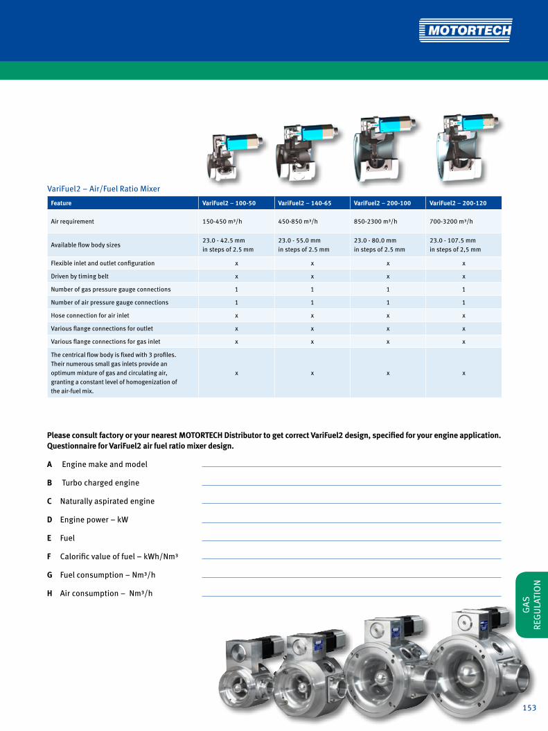
153
Please consult factory or your nearest MOTORTECH Distributor to get correct VariFuel2 design, specified for your engine application. Questionnaire for VariFuel2 air fuel ratio mixer design.
A Engine make and model
B Turbo charged engine
C Naturally aspirated engine
D Engine power – kW
E Fuel
F Calorific value of fuel – kWh/Nm³
G Fuel consumption – Nm³/h
H Air consumption – Nm³/h
VariFuel2 − Air/Fuel Ratio Mixer
Feature VariFuel2 – 100-50 VariFuel2 – 140-65 VariFuel2 – 200-100 VariFuel2 – 200-120
Air requirement 150-450 m³/h 450-850 m³/h 850-2300 m³/h 700-3200 m³/h
Available flow body sizes23.0 - 42.5 mmin steps of 2.5 mm
23.0 - 55.0 mmin steps of 2.5 mm
23.0 - 80.0 mmin steps of 2.5 mm
23.0 - 107.5 mmin steps of 2,5 mm
Flexible inlet and outlet configuration x x x x
Driven by timing belt x x x x
Number of gas pressure gauge connections 1 1 1 1
Number of air pressure gauge connections 1 1 1 1
Hose connection for air inlet x x x x
Various flange connections for outlet x x x x
Various flange connections for gas inlet x x x x
The centrical flow body is fixed with 3 profiles.Their numerous small gas inlets provide anoptimum mixture of gas and circulating air,granting a constant level of homogenization ofthe air-fuel mix.
x x x x
GAS
RE
GU
LATI
ON

154
GAS REGULATION
VariFuel2 Air/Fuel Ratio Mixer – Flow Bodies
P/N Description Diameter VF2-100-50 VF2-140-65 VF2-200-100 VF2-200-120
31.01.720-23.0-3 Flow body 23,0 mm x x x x
31.01.720-25.0-3 Flow body 25,0 mm x x x x
31.01.720-27.5-3 Flow body 27,5 mm x x x x
31.01.720-30.0-3 Flow body 30,0 mm x x x x
31.01.720-32.5-3 Flow body 32,5 mm x x x x
31.01.720-35.0-3 Flow body 35,0 mm x x x x
31.01.720-37.5-3 Flow body 37,5 mm x x x x
31.01.720-40.0-3 Flow body 40,0 mm x x x x
31.01.720-42.5-3 Flow body 42,5 mm x x x x
31.01.720-45.0-3 Flow body 45,0 mm x x x x
31.01.720-47.5-3 Flow body 47,5 mm x x x
31.01.720-50.0-3 Flow body 50,0 mm x x x
31.01.720-52.5-3 Flow body 52,5 mm x x x
31.01.720-55.0-3 Flow body 55,0 mm x x
31.01.720-57.5-3 Flow body 57,5 mm x x
31.01.720-60.0-3 Flow body 60,0 mm x x
31.01.720-62.5-3 Flow body 62,5 mm x x
31.01.720-65.0-3 Flow body 65,0 mm x x
31.01.720-67.5-3 Flow body 67,5 mm x x
31.01.720-70.0-3 Flow body 70,0 mm x x
31.01.720-72.5-3 Flow body 72,5 mm x x
31.01.720-75.0-3 Flow body 75,0 mm x x
31.01.720-77.5-3 Flow body 77,5 mm x x
31.01.720-80.0-3 Flow body 80,0 mm x x
31.01.720-82.5-3 Flow body 82,5 mm x
31.01.720-85.0-3 Flow body 85,0 mm x
VariFuel2 Air/Fuel Ratio Mixer – with Digital Stepper Motor
P/N Description
30.45.100-50D VariFuel2 air/fuel ratio mixer − series 100-50
30.45.140-65D VariFuel2 air/fuel ratio mixer − series 140-65
30.45.200-100D VariFuel2 air/fuel ratio mixer − series 200-100
30.45.200-120D VariFuel2 air/fuel ratio mixer − series 200-120
VariFuel2 Air/Fuel Ratio Mixer – Manually Adjustable
P/N Description
30.45.100-50M VariFuel2 air/fuel ratio mixer − series 100-50
30.45.140-65M VariFuel2 air/fuel ratio mixer − series 140-65
30.45.200-100M VariFuel2 air/fuel ratio mixer − series 200-100
30.45.200-120M VariFuel2 air/fuel ratio mixer − series 200-120
Conversion: 1 inch = 25,4 mm / 1 foot = 0,3 m

155
w
VariFuel2 Air/Fuel Ratio Mixer – Outlet Flange Kits
P/N Description VF2-100-50 VF2-140-65 VF2-200-100 VF2-200-120
31.01.764 Gas relaxation section for throttle, 50 x
31.01.765 Gas relaxation section for throttle, 100 x
31.01.766 Gas relaxation section for throttle, 50 x
31.01.768 Flange for MAN® E0834LE302/E0836LE202 x
31.01.752 Welding neck flange, DN100 x
31.01.750 Flange for MAN® E2876LE202/302 x
31.01.753 Flange for MAN® E0836LE202 x
31.01.755 Flange, DN65-PN6 x
31.01.757 Flange for throttle, 100 x
31.01.756 Flange for MAN® E2842E312 x
31.01.762 Gas relaxation section for throttle, 100 x
31.01.763 Gas relaxation section for throttle, 140 x
31.01.773 Flange for LIEBHERR® G934/G944 x
31.01.751 Welding neck flange, DN150 x x
31.01.759 Flange for MAN® E2876LE202/302 x x
31.01.754 Flange for MAN® E2842LE312 x x
31.01.758 Hose connection DN200 x x
31.01.760 Flange for MAN® E2848/42LE322 x x
31.01.761 Welding neck flange, DN150 – aluminum x x
31.01.767 Flange for DEUTZ® TCG2015V6/V8 x x
31.01.774 Flange for LIEBHERR® G936 x x
31.01.775 Flange for LIEBHERR® G9508 x x
31.01.776 Flange for LIEBHERR® G9512 x x
31.01.777 Flange for LIEBHERR® G946 x x
VariFuel2 Air/Fuel Ratio Mixer – Flow Bodies
P/N Description Diameter VF2-100-50 VF2-140-65 VF2-200-100 VF2-200-120
31.01.720-87.5-3 Flow body 87,5 mm x
31.01.720-90.0-3 Flow body 90,0 mm x
31.01.720-92.5-3 Flow body 92,5 mm x
31.01.720-95.0-3 Flow body 95,0 mm x
31.01.720-97.5-3 Flow body 97,5 mm x
31.01.720-100.0-3 Flow body 100,0 mm x
31.01.720-102.5-3 Flow body 102,5 mm x
31.01.720-105.0-3 Flow body 105,0 mm x
31.01.720-107.5-3 Flow body 107,5 mm x
GAS
RE
GU
LATI
ON

156
VariFuel2 Air/Fuel Ratio Mixer – Connecting Cable
P/N Description VF2-100-50D VF2-140-65D VF2-200-100D VF2-200-120D
31.01.942 VariFuel2 connecting cable, MIL Style 10 pole socket , 90° x x x x
VariFuel2 Air/Fuel Ratio Mixer – Stepper Motor Card VariStep1)
P/N Description VF2-100-50D VF2-140-65D VF2-200-100D VF2-200-120D
31.01.955 VariStep stepper motor card x x x x
1) For multiple mixer applications each VariFuel2 air/fuel ratio mixer needs a single VariStep stepper motor card. Supersedes the previous MOTORTECH stepper motor card P/N 31.01.950-100/-140/-200.
GAS REGULATION
Multiple Mixer Application
Gas Gas
VariFuel2A-Bank
VariFuel2B-Bank
Air
VariFuel2 Air/Fuel Ratio Mixer – Gas Inlet Flanges
P/N Description Thread VF2-100-50 VF2-140-65 VF2-200-100 VF2-200-120
31.01.359-075 Gas inlet flange G 3/4 x
31.01.359-100 Gas inlet flange G 1 x
31.01.359-125 Gas inlet flange G 1 1/4 x
31.01.359-075NPT Gas inlet flange 3/4 NPT x
31.01.359-100NPT Gas inlet flange 1 NPT x
31.01.359-125NPT Gas inlet flange 1 1/4 NPT x
30.30.102 Gas inlet flange G 1 x
30.30.103 Gas inlet flange G 1 1/4 x
30.30.104 Gas inlet flange G 1 1/2 x
30.30.102-NPT Gas inlet flange 1 NPT x
30.30.103-NPT Gas inlet flange 1 1/4 NPT x
30.30.104-NPT Gas inlet flange 1 1/2 NPT x
30.30.106 Gas inlet flange G 1 1/2 x x
30.30.107 Gas inlet flange G 2 x x
30.30.108 Gas inlet flange G 2 1/2 x x
30.30.106-NPT Gas inlet flange 1 1/2 NPT x x
30.30.107-NPT Gas inlet flange 2 NPT x x
30.30.108-NPT Gas inlet flange 2 1/2 NPT x x

157
w
VariFuel2 Air/Fuel Ratio Mixer – Signal Multiplier for 2 Mixer Applications1)
P/N Description VF2-100-50D VF2-140-65D VF2-200-100D VF2-200-120D
31.01.945 VariFuel2 signal multiplier x x x x
1) Not required if VariStep stepper motor card is used.
VariFuel2 Air/Fuel Ratio Mixer – Gaskets for Outlet Flange Kits1)
P/N VariFuel-Sided P/N Engine-Sided Included in Outlet Flange Kit P/N
31.01.365 03.90.050 Gas relaxation section for throttle, 50 31.01.764
31.01.365 03.90.100 Gas relaxation section for throttle, 100 31.01.765
31.01.858 03.90.050 Gas relaxation section for throttle, 50 31.01.766
31.01.858 31.01.365 Flange for MAN® E0834LE302/E0836LE202 31.01.768
31.01.809 Welding neck flange, DN100 31.01.752
31.01.809 31.01.876 Flange for MAN® E2876LE202/302 31.01.750
31.01.809 31.01.858 Flange for MAN® E0836LE202 31.01.753
31.01.809 31.01.867 Flange, DN65-PN6 31.01.755
31.01.809 03.90.100 Flange for throttle, 100 31.01.757
31.01.809 31.01.871 Flange for MAN® E2842E312 31.01.756
31.01.809 03.90.100 Gas relaxation section for throttle, 100 31.01.762
31.01.809 03.90.140 Gas relaxation section for throttle, 140 31.01.763
31.01.809 Flange for LIEBHERR® G934/G944 31.01.773
31.01.828 Welding neck flange, DN150 31.01.751
31.01.879 31.01.879 Flange for MAN® E2876LE202/302 31.01.759
31.01.828 31.01.863 Flange for MAN® E2842LE312 31.01.754
31.01.828 Hose connection DN200 31.01.758
31.01.828 31.01.828 Flange for MAN® E2848/42LE322 31.01.760
31.01.828 Welding neck flange, DN150 – aluminum 31.01.761
31.01.828 31.01.886 Flange for DEUTZ® TCG2015V6/V8 31.01.767
31.01.828 Flange for LIEBHERR® G936 31.01.774
31.01.828 Flange for LIEBHERR® G9508 31.01.775
31.01.828 Flange for LIEBHERR® G9512 31.01.776
31.01.828 Flange for LIEBHERR® G946 31.01.777
1) Gaskets included in each outlet flange kit.
VariFuel2 Air/Fuel Ratio Mixer – Accessories – Adjustment Tool for Belt Tension
P/N Description VF2-100-50D VF2-140-65D VF2-200-100D VF2-200-120D
31.01.948-100 VariFuel2 adjustment tool for belt tension x
31.01.948-140 VariFuel2 adjustment tool for belt tension x
31.01.948-200 VariFuel2 adjustment tool for belt tension x x
GAS
RE
GU
LATI
ON
NEW

158
GAS REGULATION
VariStep – Stepper Motor Card for VariFuel2 Air/Fuel Ratio Mixer
The stepper motor card made by MOTORTECH guarantees the ideal control of the various types of MOTORTECH VariFuel2 air/fuel ratio mixers.
• Precise mixer adjustment due to microstep operation• Error message memory• LEDs displaying unit status and activity• Combination of several units without signal
amplifier/splitter possible• Easy access per USB interface• Configuration via MICT software • Plug connectors• Protection type IP20• Installation on cap rail in switch cabinet• supersedes the previous MOTORTECH stepper motor card
P/N 31.01.950-100/ -140/ -200
VariStepMOTORTECH STEPPER MOTOR CARD
Technical Data
• 18 to 32 VDC
• -15°C up to +65°C ambient temperature
• 0-20 mA/0-10V analog input and output,
flexible configuration
• 5 digital inputs, 5 to 32 V compatible, DC-isolated
Communication
• CAN 2.0b
• RS485
• USB 1.1
Configuration
• Fully configurable via Laptop with MICT software
(see page 18)
• Manual procedure via push-button
Hardware
• Install in switch cabinet on cap rail
• Protection class IP 20
• Plug connectors
VariStep – Stepper Motor Card for VariFuel2 Air/Fuel Ratio Mixer
P/N Supersedes Description
31.01.955 31.01.950-100/-140/-200 VariStep stepper motor card

159
EmCon5 − Lean-Burn Emisson Controller
The EmCon5 is a lean-burn emission controller for gas engine co-generation units. It is designed to control the exhaust gas emission levels based on indirect measurements. Simply three input signals are required for the control purpose: manifold inlet pressure and temperature and engine load. The lambda sensor (oxygen sensor) is not required and a CH4 input signal is optional.Following initial measurements of the engine emission levels and successful analysis, the EmCon5 guarantees optimal ope-ration of the gas engine at the predefined emission limits.All controller parameters are freely programmable. The adjustments and modifications are made via the computer-program “WinScope”. It fits perfectly with the VariFuel2.
Features
• Standardized system available
• Operates without oxygen sensor
• Two gas qualities programmable
• Easy to use
• Available with complete sensor harness (optional)
• Data logging
• Flexible control for reliable operation with bio gas
MOTORTECH LEAN-BURN EMISSION CONTROLLEREmCon5
EmCon5 Lean-Burn Emission Controller – EmCon5 Control Unit
P/N Supersedes Description
63.02.011 EmCon5 lean burn emission control unitG
AS
REG
ULA
TIO
N

160
GAS REGULATION
Gas
Air
Air Filter
VariFuel2
Turbo ChargerMAPMAT
Throttle
Ball Valve Gas Valve
Gas FilterZERO Pressure
Regulator
Alarm/ Shutdown
MAT Warning
Mixer Warning
9-30 VDC Supply
Intercooler
Load
0-2
0 m
A
Mixer Control
Mixer Feedback
CH4
optio
nal
Engine Run
GCB Closed
Gas Selection

161
1 2 3 4
EmCon5 Lean-Burn Emission Controller – EmCon5 Manifold Air Temperature Sensors
P/N Figure Supersedes Description Thread Fitting Length
56.01.004 2 MAT sensor, PT100, two wire G 1/2 50 mm
56.01.011 2 MAT sensor, PT100, two wire G 1/2 75 mm
56.01.017 2 56.01.005 MAT sensor, PT100, two wire G 1/2 100 mm
56.01.021 2 MAT sensor, PT100, two wire G 1/2 50 mm
EmCon5 Lean-Burn Emission Controller – EmCon5 Sensor Harness
P/N Figure Supersedes Description
06.30.045 1 EmCon5 sensor harness including MAT sensor P/N 56.01.021 and MAP sensor P/N 56.02.017
EmCon5 Lean-Burn Emission Controller – EmCon5 Accessories
P/N Figure Supersedes Description
63.02.013 4 Load transducer 0-5 A --> 0-20 mA/4-20 mA/0-10 V/2-10 V
EmCon5 Lean-Burn Emission Controller – EmCon5 Manifold Absolute Pressure Sensor
P/N Figure Supersedes Description Thread Fitting Length
56.02.017 3 MAP sensor, 0 - 3,0 bar G 1/4
GAS
RE
GU
LATI
ON
EmCon5 Lean-Burn Emission Controller – EmCon5 Control Unit
P/N Supersedes Description
63.02.011 EmCon5 lean burn emission control unit

162
GAS REGULATION
Throttles for Naturally Aspirated and Turbocharged Engines
Various throttles are available. All moving parts are made of stainless steel to survive in the harshest environments including H2S.• Flange gaskets, lever, end stop and idle speed adjustment
included• Stainless steel ball bearings• Other sizes and custom made designs on request.• Applicable for temperatures up to 284 °F/140 °C,
high temperature types (-HT) up to 392 °F/200 °C
MOTORTECH THROTTLES/BUTTERFLY VALVESThrottles
D
C
ID
B
A
B
F
E
G
H

163
Throttles for Naturally Aspirated and Turbocharged Engines – Standard – Series 50 (41 - 42 mm)
P/N Supersedes Description A B C D E F G H Inner Diameter
30.40.051-42 30.40.050-42 Throttle 88 mm 57 mm 135 mm 100 mm 10 mm 96 mm 8 mm 40 mm 42 mm
30.40.051-42-HT Throttle 88 mm 57 mm 135 mm 100 mm 10 mm 96 mm 8 mm 40 mm 42 mm
Throttles for Naturally Aspirated and Turbocharged Engines – Standard – Series 100 (48 - 68 mm)
P/N Supersedes Description A B C D E F G H Inner Diameter
30.40.101-60 30.40.100-60 Throttle 113 mm 75 mm 160 mm 100 mm 10 mm 130 mm 11 mm 61 mm 60 mm
30.40.101-60-HT Throttle 113 mm 75 mm 160 mm 100 mm 10 mm 130 mm 11 mm 61 mm 60 mm
30.40.101-68 30.40.100-68 Throttle 113 mm 75 mm 160 mm 100 mm 10 mm 130 mm 11 mm 61 mm 68 mm
30.40.101-68-HT Throttle 113 mm 75 mm 160 mm 100 mm 10 mm 130 mm 11 mm 61 mm 68 mm
Conversion: 1 inch = 25,4 mm / 1 foot = 0,3 m
Throttles for Naturally Aspirated and Turbocharged Engines – Standard – Series 140 (73 - 85 mm)
P/N Supersedes Description A B C D E F G H Inner Diameter
30.40.141-75 30.40.140-75 Throttle 150 mm 95 mm 200 mm 150 mm 12 mm 166 mm 11 mm 76 mm 75 mm
30.40.141-75-HT Throttle 150 mm 95 mm 200 mm 150 mm 12 mm 166 mm 11 mm 76 mm 75 mm
30.40.141-80 30.40.140-80 Throttle 150 mm 95 mm 200 mm 150 mm 12 mm 166 mm 11 mm 76 mm 80 mm
30.40.141-80-HT Throttle 150 mm 95 mm 200 mm 150 mm 12 mm 166 mm 11 mm 76 mm 80 mm
30.40.141-85 30.40.140-85 Throttle 150 mm 95 mm 200 mm 150 mm 12 mm 166 mm 11 mm 76 mm 85 mm
30.40.141-85-HT Throttle 150 mm 95 mm 200 mm 150 mm 12 mm 166 mm 11 mm 76 mm 85 mm
Throttles for Naturally Aspirated and Turbocharged Engines – Standard – Series 150 (82 - 104 mm)
P/N Supersedes Description A B C D E F G H Inner Diameter
30.40.151-100 30.40.150-100 Throttle 150 mm 110 mm 200 mm 150 mm 12 mm 196 mm 9 mm 80 mm 100 mm
30.40.151-100-HT Throttle 150 mm 110 mm 200 mm 150 mm 12 mm 196 mm 9 mm 80 mm 100 mm
Throttles for Naturally Aspirated and Turbocharged Engines – Standard – Series 200 (98 - 125 mm)
P/N Supersedes Description A B C D E F G H Inner Diameter
30.40.201-100 30.40.200-100 Throttle 180 mm 126 mm 260 mm 150 mm 12 mm 200 mm 11 mm 110 mm 100 mm
30.40.201-100-HT Throttle 180 mm 126 mm 260 mm 150 mm 12 mm 200 mm 11 mm 110 mm 100 mm
30.40.201-105 30.40.200-105 Throttle 180 mm 126 mm 260 mm 150 mm 12 mm 200 mm 11 mm 110 mm 105 mm
30.40.201-105-HT Throttle 180 mm 126 mm 260 mm 150 mm 12 mm 200 mm 11 mm 110 mm 105 mm
30.40.201-115 30.40.200-115 Throttle 180 mm 126 mm 260 mm 150 mm 12 mm 200 mm 11 mm 110 mm 115 mm
30.40.201-115-HT Throttle 180 mm 126 mm 260 mm 150 mm 12 mm 200 mm 11 mm 110 mm 115 mm
Throttles for Naturally Aspirated and Turbocharged Engines – Special – IMPCO® Replacement Series 100/1401)
P/N Supersedes Description Inner Diameter Equivalent to
30.40.101-68AT2-7 Throttle 68 mm AT2-7
30.40.141-94AT2-9 Throttle 94 mm AT2-9
1) Common applications e.g. CATERPILLAR® G379 / G3306 / G3406, WAUKESHA® F1197
Throttles for Naturally Aspirated and Turbocharged Engines – Special – Series 160 for CATERPILLAR® G3400 and G3500 Series
P/N Supersedes Description Inner Diameter Equivalent to
30.40.161-106 Throttle 106 mm 7E1585 / 7E1589
GAS
RE
GU
LATI
ON

164
Dungs turns on the power.
Our Services • Customized engineering
• Production in accordance with relevant standards and regulations
• Gas Appliance Directive
• Pressure Equipment Directive category II & I
• Lists of parts, documentation and CAD drawings
• Tested functioning and leak- proofness (Factory certifi cate 2.1 according to EN 10204)
• Welded parts checked for strength with Inspection certifi cate 3.1 according to EN 10204
• X-ray welded joints
• Sandblasted and stove- enamelled welded parts RAL 1021
• Worldwide shipment including all custom formalities
MOTORTECH is offi cial distributor for DUNGS® gas trains.Contact MOTORTECH and get more information on which gas train solution is most adapted to your present and future needs.
Gas, Safety and Control Systems
GAS REGULATIONGAS REGULATION

165
Dungs turns on the power.
Our Services • Customized engineering
• Production in accordance with relevant standards and regulations
• Gas Appliance Directive
• Pressure Equipment Directive category II & I
• Lists of parts, documentation and CAD drawings
• Tested functioning and leak- proofness (Factory certifi cate 2.1 according to EN 10204)
• Welded parts checked for strength with Inspection certifi cate 3.1 according to EN 10204
• X-ray welded joints
• Sandblasted and stove- enamelled welded parts RAL 1021
• Worldwide shipment including all custom formalities
MOTORTECH is offi cial distributor for DUNGS® gas trains.Contact MOTORTECH and get more information on which gas train solution is most adapted to your present and future needs.
Gas, Safety and Control Systems
GAS
RE
GU
LATI
ON

166

167
GAS ENGINE ACCESSORIESBesides the key products like ignition, electronic controls, etc. MOTORTECH also offers several lines of accessory products that help the operators to cut cost on a long term strategy. Automatic liquid refilling systems with adju-stable alarm sensors as well as coolant and oil filters that are made from stainless steel and last for nearly ever.
This cuts the disposal cost of any operation and helps the environment.

168
GAS ENGINE ACCESSORIES
LLC – Liquid Level Controller
The MOTORTECH Liquid Level Controller can be used for applications with oil, water or coolant. The standard built-in MIN-level sensor monitors the liquid level and prevents the engine from running dry by a special signal – thus preventing any damage and unnecessary engine down times.
Additionally the level controller can be equipped with a maxi-mum of three optionally available liquid level sensors. Those Normally Closed (NC) sensors can be directly connected to the engine control unit.
MOTORTECH LIQUID LEVEL CONTROLLERLLC
Features
• Liquid level controller with built-in MIN level sensor
• Adjustable MIN and MAX sensors allow direct connection to a PLC
for switching a pump ON and OFF (optional)
• 1/2 NPTF inlet and outlet ports
• Liquid inlet shut off valve
• Cover made of stainless steel
• Easy and quick installation
• CSA Class I, Div 2, Group C, D

169
LLC – Liquid Level Controller – Base Unit
P/N Description
80.00.001-NC Base unit1) with NC (normally closed) / fail safe sensor, switch contact
1) MIN/MIN-sensor build in. Includes sensor lead.
8
3
21
4
5
PLC
LLC – Typical Installation
1 Vent outlet connection 1/2 NPTF
2 Optional vent outlet
connection 1/2 NPTF
3 Liquid inlet and shutoff valve
connection 1/2 NPTF
LLC – Liquid Level Controller – Mounting Brackets – 1 per Base Unit
P/N Description
80.00.010 Pipe mount bracket, 7/8 in.
80.00.011 Universal mount bracket
LLC – Liquid Level Controller – Sensor Kits – 1 - 3 Kits can be added to Base Unit1)
P/N Description
95.70.004-NC-KIT Sensor kit for NC (normally closed) Liquid Level Controller
1) Sensor kits have to be ordered separately. Each kit comes with sensor, sensor lead and bracket.
4 Liquid outlet connection 1/2 NPTF
5 MIN sensor
6 MAX sensor adjustable
7 MIN sensor adjustable
8 Liquid supply tank
185 mm
14,1
5 m
m
280
mm
20 mm
158
mm
7
6
Conversion: 1 inch = 25,4 mm / 1 foot = 0,3 m
GAS
EN
GIN
E AC
CESS
ORI
ES

170
GAS ENGINE ACCESSORIES
MOTORTECH CUSTOM MADE STAINLESS STEEL FILTERSCoolantFilterCoolant Filters for stationary and mobile applications
These bypass filters with stainless steel filter elements clean coolant liquids from all deposits. Elements can be washed and do not need to be disposed. Increases water pump life, cylinder head efficiency and equipment availability. Reduces service and maintenance cost.
Features
• Easy to install
• Cleans and maintains coolant system from rust
and contaminants
• Increases water pump life
• Reduces coolant deposits and increases cylinder
head efficiency and life
• Stainless steel filter elements can be cleaned –
NO WASTE
• Visual flow indicator (stationary applications)
• Easy to service – decreases maintenance cost
• Filter micron rating:
standard – 50 micron
optional – 25 micron
• Flow rate up to 30 GPM
Technical Advantage
• Inhibits electro-chemical degradation of
engine components. An industrial gas engine has
the characteristics of a large battery when coolant
is circulated through the engine block. Contami-
nants and suspended solids in the coolant act as
a conductor, which more readily allows current to
flow throughout the engine block, which degrades
EPDM, buna, rubber, viton, and soft metal or alloy
components / water pump bearings, impellers,
etc.
• Cleaned coolant inhibits corrosion on engine com-
ponents such as cylinder heads, cylinder liners
and seals, water pump impellers and bearings,
etc.
• Prevents „FLASH-OFF“ in the cylinder heads when
engine has an emergency stop; as the coolant can
properly dissipate thermal loads
• Inhibits scale deposits on all coolant passages
and interior thermal surfaces of the engine block.
stationary
mobile

171
Coolant Filters – Stationary Applications – Standard (for Temperatures up to 200 °F / 95 °C)
P/N Description Element Outside Diameter Element Length Micron Rating1) Stand Flow Indicator Application
25.00.009-50-30 Coolant filter 5.00 in. 9.00 in. 50 30.00 in. x stationary
25.00.009-50 Coolant filter 5.00 in. 9.00 in. 50 x stationary
25.00.009-50-B99 Coolant filter 5.00 in. 9.00 in. 50 x stationary
25.00.018-50-49 Coolant filter 5.00 in. 18.00 in. 50 49.00 in. x stationary
25.00.018-50 Coolant filter 5.00 in. 18.00 in. 50 x stationary
1) For 25 micron filter elements please change part number from -50 to -25.
Conversion: 1 inch = 25,4 mm / 1 foot = 0,3 m
Coolant Filters – Stationary Applications – High Temperature (for Temperatures 200 °F / 95 °C up to 400 °F / 205 °C)
P/N Description Element Outside Diameter Element Length Micron Rating1) Stand Flow Indicator Application
25.00.009-50-30-HT Coolant filter 5.00 in. 9.00 in. 50 30.00 in. x stationary
25.00.009-50-HT Coolant filter 5.00 in. 9.00 in. 50 x stationary
25.00.018-50-49-HT Coolant filter 5.00 in. 18.00 in. 50 49.00 in. x stationary
25.00.018-50-HT Coolant filter 5.00 in. 18.00 in. 50 x stationary
1) For 25 micron filter elements please change part number from -50 to -25.
Coolant Filters – Mobile Applications – Standard (for Temperatures up to 200 °F / 95 °C)
P/N Description Element Outside Diameter Element Length Micron Rating1) Stand Flow Indicator Application
25.00.408-50 Coolant filter 4.00 in. 8.00 in. 50 mobile
25.00.408-50-ST Coolant filter 4.00 in. 8.00 in. 50 24.00 in. mobile
25.00.409-50 Coolant filter 5.00 in. 9.00 in. 50 mobile
25.00.409-50-ST Coolant filter 5.00 in. 9.00 in. 50 24.00 in. mobile
25.00.409-50-FI Coolant filter 5.00 in. 9.00 in. 50 x mobile
25.00.409-50-FI-ST Coolant filter 5.00 in. 9.00 in. 50 24.00 in. x mobile
25.00.418-50 Coolant filter 5.00 in. 18.00 in. 50 mobile
25.00.418-50-ST Coolant filter 5.00 in. 18.00 in. 50 24.00 in. mobile
25.00.418-50-FI Coolant filter 5.00 in. 18.00 in. 50 x mobile
1) For 25 micron filter elements please change part number from -50 to -25.
Coolant Filters – Single Elements
P/N Description Element Outside Diameter Element Length Micron Rating1) Application
25.00.108-50 Coolant filter element 4.00 in. 8.00 in. 50 mobile
25.00.109-25 Coolant filter element 5.00 in. 9.00 in. 25 stationary
25.00.109-50 Coolant filter element 5.00 in. 9.00 in. 50 stationary / mobile
25.00.118-25 Coolant filter element 5.00 in. 18.00 in. 25 stationary
25.00.118-50 Coolant filter element 5.00 in. 18.00 in. 50 stationary / mobile
Coolant Filters – Shipping Cases for Elements
P/N Description Element Length Application
25.00.209 Shipping case 9.00 in. stationary / mobile
25.00.218 Shipping case 18.00 in. stationary / mobile
GAS
EN
GIN
E AC
CESS
ORI
ES

172
GAS ENGINE ACCESSORIES
CUSTOM MADE STAINLESS STEEL FILTERSLubeOilFilter
100% Stainless Steel Construction
Stainless steel micronic wire cloth available in micron ratings of 3-400 absolute. Welded serial #, ID tag
304 or 316, 20-gauge stainless steel perforated inner / outer tube 3/16 in. on 1/4 in. centers
High heat resistant adhesive attaches end caps to filter
Seals available in Buna-N, HSN, Teflon and Viton to suit your application
Over 800 different filters – all to your exact specifications
Custom made Stainless Steel Lube Oil Filters
Features
• Cleanable
• Consistent
• Environmentally friendly
• Reduce hazardous contaminants
• High payback
• Direct replacement
• Greater fluid flow
• Extends maintenance intervals
• Improves performance
• Provides predictive tool
• Reduces inventory
• Extends equipment life
Engine and compressor filters
Stainless steel replacement elements available for:
WAUKESHA®
WHITE SUPERIOR®
CATERPILLAR®
INGERSOLL RAND®
COOPER BESSEMER®
AJAX®
All filters are 100% stainless steel constructions.
Filters are available in ratings of 3-400 micron
absolute.
Standard seal buna „N“
- viton, silicone etc. - optional.
Process and hydraulic filters
Stainless steel replacement elements available for:
PECO®
PALL®
PEACOCK®
CUNO®
FILTERITE®
NOWATA®
SCHROEDER®
POROUS MEDIA®
FAIREY ARLON®
UCC®
STAUFF®
HERCULES®
GARDNER®
DENVER®
ATLAS®
CORPCO®
BALDWIN®
FACET®
FRAM®
HILCO®
REFILCO®
NUGENT®
VICKERS®
GRESEN®
HYCON®
PARKER®
HYTREX®

173
Stainless Steel Lube Filters – Element Kits1)
P/N Description Element Outside Diameter
Element Length
Micron Rating
Number of Elements Application Equivalent to
25.00.300-1-CA Lube filter element kit 7.00 in. 30.00 in. 38 1 CATERPILLAR® G3508/12/16
25.00.301-6-CA Lube filter element kit 7.00 in. 13.00 in. 38 6 CATERPILLAR® G3606/08/12/16
25.00.303-1-CA Lube filter element kit 5.00 in. 9.00 in. 38 1 CATERPILLAR® G3406/08
25.00.310-4-WA Lube filter element kit 3.00 in. 15.00 in. 25 4 WAUKESHA® 167602B
25.00.310-7-WA Lube filter element kit 3.00 in. 15.00 in. 25 7 WAUKESHA® 167602B
25.00.310-14WA Lube filter element kit 3.00 in. 15.00 in. 25 14 WAUKESHA® 167602B
25.00.311-4-WA Lube filter element kit 3.00 in. 30.00 in. 25 4 WAUKESHA® 168660B / 489493
25.00.311-7-WA Lube filter element kit 3.00 in. 30.00 in. 25 7 WAUKESHA® 168660B / 489493
25.00.312-1-WA Lube filter element kit 5.00 in. 7.00 in. 75 1 WAUKESHA® 208472B / 489488
25.00.313-1-WA Lube filter element kit 5.00 in. 10.00 in. 75 1 WAUKESHA® 208472C / 489489
25.00.314-10-WA Lube filter element kit 3.00 in. 30.00 in. 25 10 WAUKESHA® 168660H
25.00.320-3-WS Lube filter element kit 4.00 in. 18.00 in. 25 3 WHITE SUPERIOR® 6G/GT/GTL/GTLA-B
25.00.320-4-WS Lube filter element kit 4.00 in. 18.00 in. 25 4 WHITE SUPERIOR® 8G/GT/GTL/ GTLA-B/SGTB
25.00.320-5-WS Lube filter element kit 4.00 in. 18.00 in. 25 5 WHITE SUPERIOR® 12G/GT/GTL/GTLA-B/SGT/SGTA-B
25.00.320-7-WS Lube filter element kit 4.00 in. 18.00 in. 25 7 WHITE SUPERIOR® 16G/GT/GTL/GTLA-B/SGT/SGTA-B
25.00.330-1-AR Lube filter element kit 4.00 in. 9.00 in. 38 1 ARIEL® A-661 / A-0661
1) All steel lube filter element kits are supplied with a shipping case.
Conversion: 1 inch = 25,4 mm / 1 foot = 0,3 m
Stainless Steel Lube Filters – Single Elements
P/N Description Element Outside Diameter
Element Length
Micron Rating Number of Elements Application Equivalent to
25.00.300-CA Lube filter element kit 7.00 in. 30.00 in. 38 25.00.300-1-CA CATERPILLAR® (Triple Length Element)
25.00.301-CA Lube filter element kit 7.00 in. 13.00 in. 38 25.00.301-6-CA CATERPILLAR® 1W4136
25.00.302-CA Lube filter element kit 7.00 in. 10.00 in. 38 CATERPILLAR® 1R0726
25.00.303-CA Lube filter element kit 5.00 in. 9.00 in. 38 25.00.303-1-CA CATERPILLAR® 1R0716 / B99
25.00.310-WA Lube filter element kit 3.00 in. 15.00 in. 25 25.00.310-4/-7-WA WAUKESHA® 167602B
25.00.311-WA Lube filter element kit 3.00 in. 30.00 in. 25 25.00.311-4/-7-WA WAUKESHA® 168660B / 489493
25.00.312-WA Lube filter element kit 5.00 in. 7.00 in. 75 25.00.312-1-WA WAUKESHA® 208472B / 489488
25.00.313-WA Lube filter element kit 5.00 in. 10.00 in. 75 25.00.313.1-WA WAUKESHA® 208472C / 489489
25.00.314-WA Lube filter element kit 3.00 in. 30.00 in. 25 25.00.314-1-WA WAUKESHA® 168660H
25.00.315-WA Lube filter element kit 5.00 in. 17.00 in. 25 WAUKESHA® 489491 / 305351E
25.00.316-WA Lube filter element kit 4.00 in. 8.00 in. 25 WAUKESHA® 489495 / 304126
25.00.317-WA Lube filter element kit 5.00 in. 12.00 in. 25 WAUKESHA® 489490 / 305315C
25.00.318-WA Lube filter element kit 4.00 in. 16.00 in. 25 WAUKESHA® 172607 / 489522
25.00.320-WS Lube filter element kit 4.00 in. 18.00 in. 25 25.00.320-3/-4/-5/-7 WHITE SUPERIOR® 758-133
25.00.330-AR Lube filter element kit 4.00 in. 9.00 in. 38 25.00.330-1-AR ARIEL® A-661 / A-0661
25.00.335-EMD Lube filter element kit 6.00 in. 30.00 in. 38 EMD® Locomotive Engines 8345482
Stainless Steel Lube Filters – Accessories
P/N Description Element Kit
25.00.222 Pressure gauge, liquid filled
25.00.226 Grommet seal 25.00.311-WA
25.00.228 Grommet seal, Viton 25.00.300-CA / 25.00.302-CA
25.00.229 Seal kit 25.00.330-1-AR
25.00.231 Grommet seal, Viton 25.00.310-WA / 25.00.311-WA / 25.00.314-WA GAS
EN
GIN
E AC
CESS
ORI
ES

174
GAS ENGINE ACCESSORIES
CLEANING STATIONSUltraSonicUltrasonic Cleaning Station
• 2,000 Watts of ultrasonic cleaning power• All new, versatile size to meet a variety of parts
cleaning needs• Environmentally safe aqueous cleaning• Easy-to-operate controls for time, temperature
and cleaning cycle automation• Stainless steel tank construction• Dual filter system• Oil removing surface sparger• Optional on-board task light• Heavy-duty locking casters• High velocity ultrasonics, metallurgically attached
transducers• Ultrasonic frequency sweep to enhance cleaning
performance
UltraSonic Cleaning Station
P/N Description
25.00.001-1101) Complete ultrasonic cleaning station, 110V
Consisting of:• Ultrasonic cleaner • Soak tank • Backwash cabinet • Drying cabinet
Included Accessories:• 13 Watt high intensity inspection light• Roll polytubing• Bag sealer• Soak solution, two barrels• Detergent for ultrasonic, two 20 liter pails• Syphon pump for transfer of soak solution• Cleaning video and cleaning procedures• Layout drawing for setting up station• Cleaning detergent for two years
25.00.001-2201) Complete ultrasonic cleaning station, 220 V
Consisting of:• Ultrasonic cleaner • Soak tank • Backwash cabinet • Drying cabinet
Included Accessories:• 13 Watt high intensity inspection light• Roll polytubing• Bag sealer• Soak solution, two barrels• Detergent for ultrasonic, two 20 liter pails• Syphon pump for transfer of soak solution• Cleaning video and cleaning procedures• Layout drawing for setting up station• Cleaning detergent for two years
1) Does not include high pressure washer. Customer preference; 2000 PSI required

175
Soak Tank• Durable powder coated finish• Inside tank dimensions
48 in. x 20 in. x 16 in.• 1,500 Watt screw in heat element
with built in thermostat• 110 Volt power requirements• Castor wheels for easy movement
of unit• Hinged lid• Recirculation pump with 30 minute timer• Optional heated tank
Backwash Cabinet• Powder coated finish• Slotted subfloor parts rack• Water backsplash curtain• Adjustable parts rack• Solids sediment waste water
tank-3 stage• High pressure washer not included
Drying Cabinet• 4,800 Watt – 16000 BTU heating
unit 210 V• Durable powder coated finish• Inside cabinet dimensions
48 in. x 30 in. x 24 in.• 30 minute timer• Hinged door with latch closures
UltraSonic Cleaning Station – Console Style Unit• Inside tank dimensions
(40 in. long x 12 in. high x 40 in. deep)• Electric heater, thermostatically
controlled, 4,000 watts• Ultrasonics - 40 KHz, 3,000 watts
with pulse and sweep• Transducers mounted on one side
wall of tank• Mechanical timer (1 - 30 minutes)• Stainless steel lift cover• Power requirements 240 v, 10,
50/60 Hz, 8KVA
Cleaning Vessel• Filtration of the cleaning fluid to ena-
ble maximum cleaning effeciency and extend cleaning solution life
• Pump is 110 V• Filter unit consists of a stainless steel
P2 vessel with a 1/2 HP hi-tempera-ture pump, discharge and suction hose
UltraSonic Cleaning Station– Cabinet Model• Inside tank dimensions
(48 in. long x 16 in. high x 16 in. wide)• 25 KHz• Variable power controls• Built-in heater• “Neptune“ Generator with pulse
and sweep• All stainless 316L cabinet construction• Stainless lift off cover• Heavy duty castors• Recessed controls• Recessed tank drain• Available in 110 or 220 volt• 2 year warranty on all components
Further UltraSonic Cleaning Models and Accessories are availaible on request.
GAS
EN
GIN
E AC
CESS
ORI
ES

176
INDEX
807 . . . . . . . . . . . . . . . . . . . . . . 121
827 . . . . . . . . . . . . . . . . . . . . . . 121
847 . . . . . . . . . . . . . . . . . . . . . . 121
172607 . . . . . . . . . . . . . . . . . . . 175
291001 . . . . . . . . . . . . . . . . . . . . 31
295962 . . . . . . . . . . . . . . . . . . . 149
304126 . . . . . . . . . . . . . . . . . . . 175
305805 . . . . . . . . . . . . . . . . . . . . 51
369083 . . . . . . . . . . . . . . . . . . . 102
489488 . . . . . . . . . . . . . . . . . . . 175
489489 . . . . . . . . . . . . . . . . . . . 175
489490 . . . . . . . . . . . . . . . . . . . 175
489491 . . . . . . . . . . . . . . . . . . . 175
489493 . . . . . . . . . . . . . . . . . . . 175
489495 . . . . . . . . . . . . . . . . . . . 175
489522 . . . . . . . . . . . . . . . . . . . 175
501061 . . . . . . . . . . . . . . . . . . . . 31
504137 . . . . . . . . . . . . . . . . . . . . 72
504205 . . . . . . . . . . . . . . . . . . . . 71
510473 . . . . . . . . . . . . . . . . . . . . 72
510473 . . . . . . . . . . . . . . . . . . . . 73
510473 . . . . . . . . . . . . . . . . . . . . 74
510473 . . . . . . . . . . . . . . . . . . . . 75
510474 . . . . . . . . . . . . . . . . . . . . 71
510474 . . . . . . . . . . . . . . . . . . . . 72
510474 . . . . . . . . . . . . . . . . . . . . 73
510474 . . . . . . . . . . . . . . . . . . . . 74
510474 . . . . . . . . . . . . . . . . . . . . 75
510480 . . . . . . . . . . . . . . . . . . . . 74
510493 . . . . . . . . . . . . . . . . . . . . 70
510493 . . . . . . . . . . . . . . . . . . . . 73
510493 . . . . . . . . . . . . . . . . . . . . 74
510695 . . . . . . . . . . . . . . . . . . . . 74
591007 . . . . . . . . . . . . . . . . . . . . 39
591008 . . . . . . . . . . . . . . . . . . . . 39
591010 . . . . . . . . . . . . . . . . . . . . 31
591012 . . . . . . . . . . . . . . . . . . . . 36
591018 . . . . . . . . . . . . . . . . . . . . 36
591040 . . . . . . . . . . . . . . . . . . . . 31
720002 . . . . . . . . . . . . . . . . . . . . 52
740283 . . . . . . . . . . . . . . . . . . . . 93
790021 . . . . . . . . . . . . . . . . . . . . 50
790022 . . . . . . . . . . . . . . . . . . . . 50
790144 . . . . . . . . . . . . . . . . . . . . 50
790150 . . . . . . . . . . . . . . . . . . . . 50
790151 . . . . . . . . . . . . . . . . . . . . 50
790165 . . . . . . . . . . . . . . . . . . . . 50
790166 . . . . . . . . . . . . . . . . . . . . 50
790169 . . . . . . . . . . . . . . . . . . . . 50
2502149 . . . . . . . . . . . . . . . . . . . 60
2624855 . . . . . . . . . . . . . . . . . . . 60
3964547 . . . . . . . . . . . . . . . . . . 102
4989132 . . . . . . . . . . . . . . . . . . . 60
8345482 . . . . . . . . . . . . . . . . . . 175
0012E002200. . . . . . . . . . . . . . . 85
0012E006500. . . . . . . . . . . . . . . 85
02.85.006 . . . . . . . . . . . . . . . . . . 70
02.85.013 . . . . . . . . . . . . . . . . . . 71
02.85.013 . . . . . . . . . . . . . . . . . . 72
02.85.015-100 . . . . . . . . . . . . . 126
02.85.015-1000 . . . . . . . . . . . . 126
02.85.015-500 . . . . . . . . . . . . . 126
02.85.015-5000 . . . . . . . . . . . . 126
02.85.016-100 . . . . . . . . . . . . . 126
02.85.016-1000 . . . . . . . . . . . . 126
02.85.016-500 . . . . . . . . . . . . . 126
02.85.016-5000 . . . . . . . . . . . . 126
02.85.017-100 . . . . . . . . . . . . . 126
02.85.017-1000 . . . . . . . . . . . . 126
02.85.017-500 . . . . . . . . . . . . . 126
02.85.017-5000 . . . . . . . . . . . . 126
02.85.018 . . . . . . . . . . . . . . . . . . 75
02.85.1004 . . . . . . . . . . . . . . . . . 35
02.85.1004-100 . . . . . . . . . . . . . 66
02.85.1006 . . . . . . . . . . . . . . . . . 70
02.85.1007 . . . . . . . . . . . . . . . . . 70
02.85.1008 . . . . . . . . . . . . . . . . . 70
02.85.610 . . . . . . . . . . . . . . . . . . 70
02.85.610 . . . . . . . . . . . . . . . . . . 75
02.85.611 . . . . . . . . . . . . . . . . . . 70
02.85.611 . . . . . . . . . . . . . . . . . . 75
02.85.612 . . . . . . . . . . . . . . . . . . 70
02.85.612 . . . . . . . . . . . . . . . . . . 73
02.85.612 . . . . . . . . . . . . . . . . . . 74
02.85.658 . . . . . . . . . . . . . . . . . . 64
02.85.757 . . . . . . . . . . . . . . . . . . 64
02.85.758 . . . . . . . . . . . . . . . . . . 64
02.85.814 . . . . . . . . . . . . . . . . . . 64
02.85.865 . . . . . . . . . . . . . . . . . . 64
02.85.869 . . . . . . . . . . . . . . . . . . 70
02.85.870 . . . . . . . . . . . . . . . . . . 86
02.85.872 . . . . . . . . . . . . . . . . . . 70
02.85.873 . . . . . . . . . . . . . . . . . . 70
02.85.875 . . . . . . . . . . . . . . . . . . 70
02.85.881 . . . . . . . . . . . . . . . . . . 86
02.85.901 . . . . . . . . . . . . . . . . . . 71
02.85.901 . . . . . . . . . . . . . . . . . . 72
02.85.901 . . . . . . . . . . . . . . . . . . 73
02.85.901 . . . . . . . . . . . . . . . . . . 74
P/N Page P/N Page P/N Page

177
P/N Page P/N Page P/N PageP/N Page P/N Page P/N Page
02.85.901 . . . . . . . . . . . . . . . . . . 75
02.85.902 . . . . . . . . . . . . . . . . . . 72
02.85.902 . . . . . . . . . . . . . . . . . . 73
02.85.902 . . . . . . . . . . . . . . . . . . 74
02.85.902 . . . . . . . . . . . . . . . . . . 75
02.85.903 . . . . . . . . . . . . . . . . . . 74
02.85.903 . . . . . . . . . . . . . . . . . . 75
02.85.906 . . . . . . . . . . . . . . . . . . 74
02.85.906 . . . . . . . . . . . . . . . . . . 75
02.85.907 . . . . . . . . . . . . . . . . . . 73
02.85.910 . . . . . . . . . . . . . . . . . . 71
02.85.910 . . . . . . . . . . . . . . . . . . 72
02.85.911 . . . . . . . . . . . . . . . . . . 70
02.85.911 . . . . . . . . . . . . . . . . . . 74
02.85.911 . . . . . . . . . . . . . . . . . . 75
02.85.912 . . . . . . . . . . . . . . . . . . 70
02.85.912 . . . . . . . . . . . . . . . . . . 73
02.85.912 . . . . . . . . . . . . . . . . . . 74
02.85.912 . . . . . . . . . . . . . . . . . . 74
02.85.912 . . . . . . . . . . . . . . . . . . 75
02.85.913 . . . . . . . . . . . . . . . . . . 71
02.85.913 . . . . . . . . . . . . . . . . . . 72
02.85.914 . . . . . . . . . . . . . . . . . . 64
02.85.918 . . . . . . . . . . . . . . . . . . 71
02.85.919 . . . . . . . . . . . . . . . . . . 70
02.85.919 . . . . . . . . . . . . . . . . . . 71
02.85.919 . . . . . . . . . . . . . . . . . . 72
02.85.919 . . . . . . . . . . . . . . . . . . 73
02.85.919 . . . . . . . . . . . . . . . . . . 74
02.85.919 . . . . . . . . . . . . . . . . . . 75
02.85.920-100 . . . . . . . . . . . . . . 65
02.85.924-100 . . . . . . . . . . . . . . 65
02.85.925-100 . . . . . . . . . . . . . . 65
02.85.928 . . . . . . . . . . . . . . . . . . 74
02.85.929 . . . . . . . . . . . . . . . . . . 70
02.85.929 . . . . . . . . . . . . . . . . . . 71
02.85.929 . . . . . . . . . . . . . . . . . . 72
02.85.929 . . . . . . . . . . . . . . . . . . 73
02.85.929 . . . . . . . . . . . . . . . . . . 74
02.85.929 . . . . . . . . . . . . . . . . . . 75
02.85.944 . . . . . . . . . . . . . . . . . . 71
02.85.944 . . . . . . . . . . . . . . . . . . 72
02.85.948 . . . . . . . . . . . . . . . . . . 73
02.85.954 . . . . . . . . . . . . . . . . . . 72
02.85.956 . . . . . . . . . . . . . . . . . . 71
02.85.965 . . . . . . . . . . . . . . . . . . 64
02.85.973 . . . . . . . . . . . . . . . . . . 72
02.85.979 . . . . . . . . . . . . . . . . . . 72
02.85.991 . . . . . . . . . . . . . . . . . . 71
02.85.991-2 . . . . . . . . . . . . . . . . 71
02.85.992 . . . . . . . . . . . . . . . . . . 71
02.85.992-1 . . . . . . . . . . . . . . . . 72
02.85.992-2 . . . . . . . . . . . . . . . . 72
02.85.992-3 . . . . . . . . . . . . . . . . 72
02.85.993 . . . . . . . . . . . . . . . . . . 74
02.85.993-2 . . . . . . . . . . . . . . . . 74
02.85.994 . . . . . . . . . . . . . . . . . . 74
02.85.994-2 . . . . . . . . . . . . . . . . 75
02.85.995 . . . . . . . . . . . . . . . . . . 75
02.85.995-2 . . . . . . . . . . . . . . . . 75
02.85.996 . . . . . . . . . . . . . . . . . . 73
02.85.996-2 . . . . . . . . . . . . . . . . 73
02.85.997 . . . . . . . . . . . . . . . . . . 73
02.85.997-2 . . . . . . . . . . . . . . . . 73
03.90.050 . . . . . . . . . . . . . . . . . 157
03.90.100 . . . . . . . . . . . . . . . . . 157
03.90.140 . . . . . . . . . . . . . . . . . 157
06.00.508 . . . . . . . . . . . . . . . . . . 26
06.00.513 . . . . . . . . . . . . . . . . . . 27
06.00.514 . . . . . . . . . . . . . . . . . . 27
06.00.515-6 . . . . . . . . . . . . . . . . 27
06.00.515-8 . . . . . . . . . . . . . . . . 27
06.00.516 . . . . . . . . . . . . . . . . . . 27
06.00.517 . . . . . . . . . . . . . . . . . . 27
06.00.520 . . . . . . . . . . . . . . . . . . 26
06.00.525 . . . . . . . . . . . . . . . . . . 26
06.00.530 . . . . . . . . . . . . . . . . . . 26
06.01.001-160 . . . . . . . . . . . . . . 27
06.01.040-L . . . . . . . . . . . . . . . . 81
06.01.041-L . . . . . . . . . . . . . . . . 81
06.01.042-L . . . . . . . . . . . . . . . . 81
06.01.043-L . . . . . . . . . . . . . . . . 81
06.01.044-L . . . . . . . . . . . . . . . . 81
06.01.045-L . . . . . . . . . . . . . . . . 81
06.01.046-L . . . . . . . . . . . . . . . . 81
06.01.047-L . . . . . . . . . . . . . . . . 81
06.01.101-160 . . . . . . . . . . . . . . 27
06.01.301-160 . . . . . . . . . . . . . . 27
06.02.010-160 . . . . . . . . . . . . . . 27
06.02.011-80 . . . . . . . . . . . . . . . 27
06.02.022-160 . . . . . . . . . . . . . . 27
06.02.501-160 . . . . . . . . . . . . . . 26
06.02.505-160 . . . . . . . . . . . . . . 26
06.02.510-160 . . . . . . . . . . . . . . 26
06.02.608-240 . . . . . . . . . . . . . . 26
06.02.612-240 . . . . . . . . . . . . . . 26
06.02.616-240 . . . . . . . . . . . . . . 26
06.05.040A . . . . . . . . . . . . . . . . . 27
06.05.067 . . . . . . . . . . . . . . . . . . 17

178
INDEX
P/N Page P/N Page P/N Page
06.05.067 . . . . . . . . . . . . . . . . . . 23
06.05.067 . . . . . . . . . . . . . . . . . . 27
06.05.067 . . . . . . . . . . . . . . . . . 139
06.05.067 . . . . . . . . . . . . . . . . . 143
06.05.085 . . . . . . . . . . . . . . . . . . 17
06.05.085 . . . . . . . . . . . . . . . . . 137
06.05.086-F . . . . . . . . . . . . . . . . 17
06.05.086-U . . . . . . . . . . . . . . . . 17
06.05.087-F . . . . . . . . . . . . . . . 137
06.05.087-U . . . . . . . . . . . . . . . 137
06.05.903-1 . . . . . . . . . . . . . . . 106
06.05.904-1 . . . . . . . . . . . . . . . 106
06.20.025 . . . . . . . . . . . . . . . . . . 51
06.20.025-1 . . . . . . . . . . . . . . . . 51
06.20.026 . . . . . . . . . . . . . . . . . . 51
06.20.026-1 . . . . . . . . . . . . . . . . 51
06.20.045-1 . . . . . . . . . . . . . . . . 51
06.20.045-6 . . . . . . . . . . . . . . . . 51
06.20.045-8 . . . . . . . . . . . . . . . . 51
06.20.069-1 . . . . . . . . . . . . . . . . 51
06.20.069-12 . . . . . . . . . . . . . . . 51
06.20.069-6 . . . . . . . . . . . . . . . . 51
06.20.070 . . . . . . . . . . . . . . . . . . 51
06.20.251 . . . . . . . . . . . . . . . . . . 51
06.20.252 . . . . . . . . . . . . . . . . . . 51
06.20.254 . . . . . . . . . . . . . . . . . . 51
06.20.300 . . . . . . . . . . . . . . . . . . 50
06.20.301 . . . . . . . . . . . . . . . . . . 50
06.20.302 . . . . . . . . . . . . . . . . . . 50
06.20.303 . . . . . . . . . . . . . . . . . . 50
06.20.304 . . . . . . . . . . . . . . . . . . 50
06.20.305 . . . . . . . . . . . . . . . . . . 50
06.20.306 . . . . . . . . . . . . . . . . . . 50
06.20.307 . . . . . . . . . . . . . . . . . . 50
06.20.308 . . . . . . . . . . . . . . . . . . 50
06.20.309 . . . . . . . . . . . . . . . . . . 50
06.20.310 . . . . . . . . . . . . . . . . . . 50
06.20.311 . . . . . . . . . . . . . . . . . . 50
06.20.312 . . . . . . . . . . . . . . . . . . 50
06.20.313 . . . . . . . . . . . . . . . . . . 50
06.20.314 . . . . . . . . . . . . . . . . . . 50
06.20.315 . . . . . . . . . . . . . . . . . . 50
06.20.316 . . . . . . . . . . . . . . . . . . 50
06.20.317 . . . . . . . . . . . . . . . . . . 50
06.20.318 . . . . . . . . . . . . . . . . . . 50
06.20.319 . . . . . . . . . . . . . . . . . . 50
06.20.320 . . . . . . . . . . . . . . . . . . 50
06.20.321 . . . . . . . . . . . . . . . . . . 50
06.20.322 . . . . . . . . . . . . . . . . . . 50
06.20.323 . . . . . . . . . . . . . . . . . . 50
06.20.400 . . . . . . . . . . . . . . . . . . 51
06.20.401 . . . . . . . . . . . . . . . . . . 51
06.20.402 . . . . . . . . . . . . . . . . . . 51
06.20.403 . . . . . . . . . . . . . . . . . . 51
06.20.404 . . . . . . . . . . . . . . . . . . 51
06.22.400-1 . . . . . . . . . . . . . . . . 49
06.22.400-6 . . . . . . . . . . . . . . . . 49
06.22.400-8 . . . . . . . . . . . . . . . . 49
06.23.001 . . . . . . . . . . . . . . . . . . 49
06.23.004 . . . . . . . . . . . . . . . . . . 49
06.24.009 . . . . . . . . . . . . . . . . . . 49
06.30.022 . . . . . . . . . . . . . . . . . 144
06.30.022 . . . . . . . . . . . . . . . . . 144
06.30.023 . . . . . . . . . . . . . . . . . 144
06.30.024 . . . . . . . . . . . . . . . . . 144
06.30.025 . . . . . . . . . . . . . . . . . 145
06.30.026 . . . . . . . . . . . . . . . . . 145
06.30.027 . . . . . . . . . . . . . . . . . 145
06.30.028 . . . . . . . . . . . . . . . . . 145
06.30.039 . . . . . . . . . . . . . . . . . 145
06.30.040 . . . . . . . . . . . . . . . . . 145
06.30.041 . . . . . . . . . . . . . . . . . 145
06.30.042 . . . . . . . . . . . . . . . . . 145
06.30.043 . . . . . . . . . . . . . . . . . 145
06.30.044 . . . . . . . . . . . . . . . . . 145
06.30.045 . . . . . . . . . . . . . . . . . 161
06.30.053 . . . . . . . . . . . . . . . . . 145
06.30.054 . . . . . . . . . . . . . . . . . 145
06.30.055 . . . . . . . . . . . . . . . . . 145
06.30.056 . . . . . . . . . . . . . . . . . 145
06.30.060 . . . . . . . . . . . . . . . . . 145
06.30.060 . . . . . . . . . . . . . . . . . 146
06.30.093 . . . . . . . . . . . . . . . . . 145
06.30.095-L . . . . . . . . . . . . . . . . 81
06.30.101 . . . . . . . . . . . . . . . . . 144
06.30.102 . . . . . . . . . . . . . . . . . 144
06.30.104 . . . . . . . . . . . . . . . . . 146
06.30.106 . . . . . . . . . . . . . . . . . 146
06.30.107 . . . . . . . . . . . . . . . . . . 81
06.30.108 . . . . . . . . . . . . . . . . . . 81
06.30.110 . . . . . . . . . . . . . . . . . 147
06.30.111-60 . . . . . . . . . . . . . . . 81
06.30.113 . . . . . . . . . . . . . . . . . 146
06.30.116 . . . . . . . . . . . . . . . . . 146
06.30.142-14 . . . . . . . . . . . . . . . 81
06.31.034-80 . . . . . . . . . . . . . . . 27
06.31.035-160 . . . . . . . . . . . . . . 27
06.50.001 . . . . . . . . . . . . . . . . . . 31
06.50.002 . . . . . . . . . . . . . . . . . . 31

179
P/N Page P/N Page P/N PageP/N Page P/N Page P/N Page
06.50.003 . . . . . . . . . . . . . . . . . . 31
06.50.034 . . . . . . . . . . . . . . . . . . 36
06.50.035 . . . . . . . . . . . . . . . . . . 36
06.50.053 . . . . . . . . . . . . . . . . . . 31
06.50.054 . . . . . . . . . . . . . . . . . . 31
06.50.055 . . . . . . . . . . . . . . . . . . 31
06.50.060 . . . . . . . . . . . . . . . . . . 31
06.50.100 . . . . . . . . . . . . . . . . . . 30
06.50.102 . . . . . . . . . . . . . . . . . . 30
06.50.103 . . . . . . . . . . . . . . . . . . 31
06.50.104 . . . . . . . . . . . . . . . . . . 30
06.50.105 . . . . . . . . . . . . . . . . . . 30
06.50.111 . . . . . . . . . . . . . . . . . . 33
06.50.141 . . . . . . . . . . . . . . . . . . 32
06.50.142 . . . . . . . . . . . . . . . . . . 32
06.50.143 . . . . . . . . . . . . . . . . . . 32
06.50.144 . . . . . . . . . . . . . . . . . . 32
06.50.145 . . . . . . . . . . . . . . . . . . 32
06.50.146 . . . . . . . . . . . . . . . . . . 32
06.50.147 . . . . . . . . . . . . . . . . . . 32
06.50.148 . . . . . . . . . . . . . . . . . . 32
06.50.151 . . . . . . . . . . . . . . . . . . 32
06.50.152 . . . . . . . . . . . . . . . . . . 32
06.50.153 . . . . . . . . . . . . . . . . . . 32
06.50.154 . . . . . . . . . . . . . . . . . . 32
06.50.155 . . . . . . . . . . . . . . . . . . 32
06.50.156 . . . . . . . . . . . . . . . . . . 32
06.50.157 . . . . . . . . . . . . . . . . . . 32
06.50.158 . . . . . . . . . . . . . . . . . . 32
06.50.161 . . . . . . . . . . . . . . . . . . 33
06.50.162 . . . . . . . . . . . . . . . . . . 33
06.51.133 . . . . . . . . . . . . . . . . . . 86
06.51.134 . . . . . . . . . . . . . . . . . . 86
06.51.136 . . . . . . . . . . . . . . . . . . 86
06.51.223 . . . . . . . . . . . . . . . . . . 35
06.51.248 . . . . . . . . . . . . . . . . . . 59
06.60.020 . . . . . . . . . . . . . . . . . . 44
06.60.021 . . . . . . . . . . . . . . . . . . 44
06.60.022 . . . . . . . . . . . . . . . . . . 44
06.60.023 . . . . . . . . . . . . . . . . . . 45
06.60.027 . . . . . . . . . . . . . . . . . . 45
06.60.040 . . . . . . . . . . . . . . . . . . 45
06.60.042 . . . . . . . . . . . . . . . . . . 45
06.60.101 . . . . . . . . . . . . . . . . . . 44
06.60.102 . . . . . . . . . . . . . . . . . . 44
06.60.103 . . . . . . . . . . . . . . . . . . 44
06.60.105 . . . . . . . . . . . . . . . . . . 44
06.60.107 . . . . . . . . . . . . . . . . . . 44
06.60.900 . . . . . . . . . . . . . . . . . . 52
06.60.908 . . . . . . . . . . . . . . . . . . 46
06.60.922 . . . . . . . . . . . . . . . . . . 52
06.70.192-5 . . . . . . . . . . . . . . . 102
06.70.192-6 . . . . . . . . . . . . . . . 102
06.71.001-L . . . . . . . . . . . . . . . . 47
06.71.002-L . . . . . . . . . . . . . . . . 47
06.71.007 . . . . . . . . . . . . . . . . . . 47
06.71.007 . . . . . . . . . . . . . . . . . 136
06.71.047 . . . . . . . . . . . . . . . . . . 27
06.80.005 . . . . . . . . . . . . . . . . . . 34
06.80.006 . . . . . . . . . . . . . . . . . . 34
06.80.012-100 . . . . . . . . . . . . . . 66
06.80.023 . . . . . . . . . . . . . . . . . . 70
06.80.030 . . . . . . . . . . . . . . . . . . 35
06.80.030-100 . . . . . . . . . . . . . . 65
06.80.036 . . . . . . . . . . . . . . . . . . 34
06.80.037 . . . . . . . . . . . . . . . . . . 34
06.80.091 . . . . . . . . . . . . . . . . . . 35
06.80.091-100 . . . . . . . . . . . . . . 65
06.80.104 . . . . . . . . . . . . . . . . . . 52
06.80.104 . . . . . . . . . . . . . . . . . 136
06.80.108 . . . . . . . . . . . . . . . . . . 35
06.80.108-100 . . . . . . . . . . . . . . 66
06.80.116 . . . . . . . . . . . . . . . . . . 35
06.80.116-100 . . . . . . . . . . . . . . 66
06.80.116-180 . . . . . . . . . . . . . . 35
06.80.116-180-100 . . . . . . . . . . 66
06.80.126 . . . . . . . . . . . . . . . . . . 35
06.80.126-100 . . . . . . . . . . . . . . 66
06.80.202 . . . . . . . . . . . . . . . . . . 85
06.80.202-T . . . . . . . . . . . . . . . . 85
06.80.206 . . . . . . . . . . . . . . . . . . 85
06.80.206-T . . . . . . . . . . . . . . . . 85
06.80.213 . . . . . . . . . . . . . . . . . . 85
06.80.213-T . . . . . . . . . . . . . . . . 85
06.80.309 . . . . . . . . . . . . . . . . . . 85
06.80.309-T . . . . . . . . . . . . . . . . 85
06.80.310 . . . . . . . . . . . . . . . . . . 85
06.80.310-T . . . . . . . . . . . . . . . . 85
06.80.315H . . . . . . . . . . . . . . . . 86
06.80.319 . . . . . . . . . . . . . . . . . . 85
06.80.319H . . . . . . . . . . . . . . . . 85
06.80.319H-T . . . . . . . . . . . . . . . 85
06.80.319-T . . . . . . . . . . . . . . . . 85
06.80.320 . . . . . . . . . . . . . . . . . . 85
06.80.320H . . . . . . . . . . . . . . . . 85
06.80.320H-T . . . . . . . . . . . . . . . 85
06.80.320-T . . . . . . . . . . . . . . . . 85
06.80.321 . . . . . . . . . . . . . . . . . . 85
06.80.321H . . . . . . . . . . . . . . . . 85
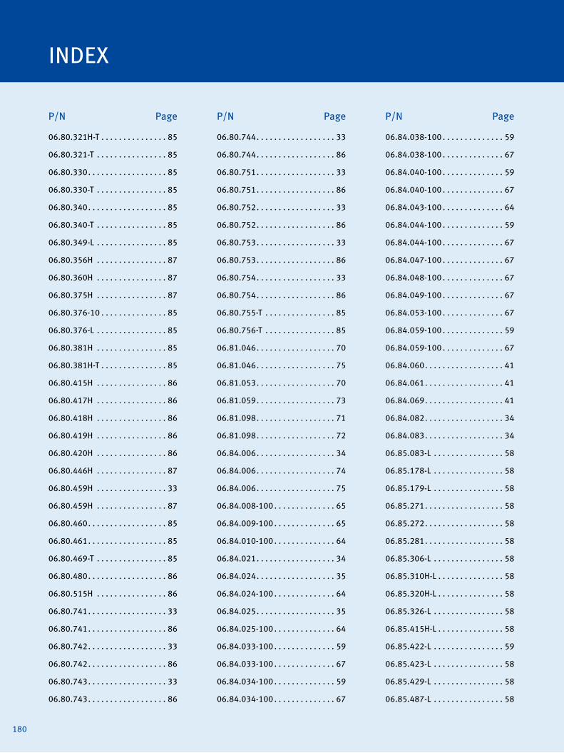
180
INDEX
P/N Page P/N Page P/N Page
06.80.321H-T . . . . . . . . . . . . . . . 85
06.80.321-T . . . . . . . . . . . . . . . . 85
06.80.330 . . . . . . . . . . . . . . . . . . 85
06.80.330-T . . . . . . . . . . . . . . . . 85
06.80.340 . . . . . . . . . . . . . . . . . . 85
06.80.340-T . . . . . . . . . . . . . . . . 85
06.80.349-L . . . . . . . . . . . . . . . . 85
06.80.356H . . . . . . . . . . . . . . . . 87
06.80.360H . . . . . . . . . . . . . . . . 87
06.80.375H . . . . . . . . . . . . . . . . 87
06.80.376-10 . . . . . . . . . . . . . . . 85
06.80.376-L . . . . . . . . . . . . . . . . 85
06.80.381H . . . . . . . . . . . . . . . . 85
06.80.381H-T . . . . . . . . . . . . . . . 85
06.80.415H . . . . . . . . . . . . . . . . 86
06.80.417H . . . . . . . . . . . . . . . . 86
06.80.418H . . . . . . . . . . . . . . . . 86
06.80.419H . . . . . . . . . . . . . . . . 86
06.80.420H . . . . . . . . . . . . . . . . 86
06.80.446H . . . . . . . . . . . . . . . . 87
06.80.459H . . . . . . . . . . . . . . . . 33
06.80.459H . . . . . . . . . . . . . . . . 87
06.80.460 . . . . . . . . . . . . . . . . . . 85
06.80.461 . . . . . . . . . . . . . . . . . . 85
06.80.469-T . . . . . . . . . . . . . . . . 85
06.80.480 . . . . . . . . . . . . . . . . . . 86
06.80.515H . . . . . . . . . . . . . . . . 86
06.80.741 . . . . . . . . . . . . . . . . . . 33
06.80.741 . . . . . . . . . . . . . . . . . . 86
06.80.742 . . . . . . . . . . . . . . . . . . 33
06.80.742 . . . . . . . . . . . . . . . . . . 86
06.80.743 . . . . . . . . . . . . . . . . . . 33
06.80.743 . . . . . . . . . . . . . . . . . . 86
06.80.744 . . . . . . . . . . . . . . . . . . 33
06.80.744 . . . . . . . . . . . . . . . . . . 86
06.80.751 . . . . . . . . . . . . . . . . . . 33
06.80.751 . . . . . . . . . . . . . . . . . . 86
06.80.752 . . . . . . . . . . . . . . . . . . 33
06.80.752 . . . . . . . . . . . . . . . . . . 86
06.80.753 . . . . . . . . . . . . . . . . . . 33
06.80.753 . . . . . . . . . . . . . . . . . . 86
06.80.754 . . . . . . . . . . . . . . . . . . 33
06.80.754 . . . . . . . . . . . . . . . . . . 86
06.80.755-T . . . . . . . . . . . . . . . . 85
06.80.756-T . . . . . . . . . . . . . . . . 85
06.81.046 . . . . . . . . . . . . . . . . . . 70
06.81.046 . . . . . . . . . . . . . . . . . . 75
06.81.053 . . . . . . . . . . . . . . . . . . 70
06.81.059 . . . . . . . . . . . . . . . . . . 73
06.81.098 . . . . . . . . . . . . . . . . . . 71
06.81.098 . . . . . . . . . . . . . . . . . . 72
06.84.006 . . . . . . . . . . . . . . . . . . 34
06.84.006 . . . . . . . . . . . . . . . . . . 74
06.84.006 . . . . . . . . . . . . . . . . . . 75
06.84.008-100 . . . . . . . . . . . . . . 65
06.84.009-100 . . . . . . . . . . . . . . 65
06.84.010-100 . . . . . . . . . . . . . . 64
06.84.021 . . . . . . . . . . . . . . . . . . 34
06.84.024 . . . . . . . . . . . . . . . . . . 35
06.84.024-100 . . . . . . . . . . . . . . 64
06.84.025 . . . . . . . . . . . . . . . . . . 35
06.84.025-100 . . . . . . . . . . . . . . 64
06.84.033-100 . . . . . . . . . . . . . . 59
06.84.033-100 . . . . . . . . . . . . . . 67
06.84.034-100 . . . . . . . . . . . . . . 59
06.84.034-100 . . . . . . . . . . . . . . 67
06.84.038-100 . . . . . . . . . . . . . . 59
06.84.038-100 . . . . . . . . . . . . . . 67
06.84.040-100 . . . . . . . . . . . . . . 59
06.84.040-100 . . . . . . . . . . . . . . 67
06.84.043-100 . . . . . . . . . . . . . . 64
06.84.044-100 . . . . . . . . . . . . . . 59
06.84.044-100 . . . . . . . . . . . . . . 67
06.84.047-100 . . . . . . . . . . . . . . 67
06.84.048-100 . . . . . . . . . . . . . . 67
06.84.049-100 . . . . . . . . . . . . . . 67
06.84.053-100 . . . . . . . . . . . . . . 67
06.84.059-100 . . . . . . . . . . . . . . 59
06.84.059-100 . . . . . . . . . . . . . . 67
06.84.060 . . . . . . . . . . . . . . . . . . 41
06.84.061 . . . . . . . . . . . . . . . . . . 41
06.84.069 . . . . . . . . . . . . . . . . . . 41
06.84.082 . . . . . . . . . . . . . . . . . . 34
06.84.083 . . . . . . . . . . . . . . . . . . 34
06.85.083-L . . . . . . . . . . . . . . . . 58
06.85.178-L . . . . . . . . . . . . . . . . 58
06.85.179-L . . . . . . . . . . . . . . . . 58
06.85.271 . . . . . . . . . . . . . . . . . . 58
06.85.272 . . . . . . . . . . . . . . . . . . 58
06.85.281 . . . . . . . . . . . . . . . . . . 58
06.85.306-L . . . . . . . . . . . . . . . . 58
06.85.310H-L . . . . . . . . . . . . . . . 58
06.85.320H-L . . . . . . . . . . . . . . . 58
06.85.326-L . . . . . . . . . . . . . . . . 58
06.85.415H-L . . . . . . . . . . . . . . . 58
06.85.422-L . . . . . . . . . . . . . . . . 59
06.85.423-L . . . . . . . . . . . . . . . . 58
06.85.429-L . . . . . . . . . . . . . . . . 58
06.85.487-L . . . . . . . . . . . . . . . . 58

181
P/N Page P/N Page P/N PageP/N Page P/N Page P/N Page
06.85.505-L . . . . . . . . . . . . . . . . 58
06.85.514-L . . . . . . . . . . . . . . . . 60
06.85.577H-L . . . . . . . . . . . . . . . 58
06.85.580H-L . . . . . . . . . . . . . . . 58
06.85.594-L . . . . . . . . . . . . . . . . 58
06.85.649-L . . . . . . . . . . . . . . . . 59
06.85.666 . . . . . . . . . . . . . . . . . . 58
06.85.667-L . . . . . . . . . . . . . . . . 59
06.85.670-L . . . . . . . . . . . . . . . . 58
06.85.672H-L . . . . . . . . . . . . . . . 59
06.85.674-L . . . . . . . . . . . . . . . . 60
06.85.678-L . . . . . . . . . . . . . . . . 59
06.85.683-L . . . . . . . . . . . . . . . . 58
06.85.687-L . . . . . . . . . . . . . . . . 60
06.85.688-L . . . . . . . . . . . . . . . . 59
06.85.689-L . . . . . . . . . . . . . . . . 60
06.85.690-L . . . . . . . . . . . . . . . . 60
06.85.695-L . . . . . . . . . . . . . . . . 60
06.85.697-L . . . . . . . . . . . . . . . . 60
06.85.698-L . . . . . . . . . . . . . . . . 60
06.85.699-L . . . . . . . . . . . . . . . . 59
06.85.705-L . . . . . . . . . . . . . . . . 59
06.85.709H-L . . . . . . . . . . . . . . . 58
06.85.714-L . . . . . . . . . . . . . . . . 59
06.85.717H-L . . . . . . . . . . . . . . . 58
06.85.719-L . . . . . . . . . . . . . . . . 60
06.85.720-L . . . . . . . . . . . . . . . . 59
06.85.723-L . . . . . . . . . . . . . . . . 59
06.85.739-L . . . . . . . . . . . . . . . . 59
06.85.751-L . . . . . . . . . . . . . . . . 58
06.85.751-L . . . . . . . . . . . . . . . . 60
06.85.773-L . . . . . . . . . . . . . . . . 60
06.85.836H-L . . . . . . . . . . . . . . . 58
06.85.839H-L . . . . . . . . . . . . . . . 58
06.85.860-L . . . . . . . . . . . . . . . . 60
06.85.873-L . . . . . . . . . . . . . . . . 58
06.85.879-L . . . . . . . . . . . . . . . . 58
06.85.894-L . . . . . . . . . . . . . . . . 59
06.85.903-L . . . . . . . . . . . . . . . . 60
06.85.908-L . . . . . . . . . . . . . . . . 58
06.85.909-L . . . . . . . . . . . . . . . . 58
06.85.910-L . . . . . . . . . . . . . . . . 58
06.85.926-L . . . . . . . . . . . . . . . . 58
06.85.929-L . . . . . . . . . . . . . . . . 58
06.85.939-L . . . . . . . . . . . . . . . . 58
06.85.939-L . . . . . . . . . . . . . . . . 60
06.85.945-L . . . . . . . . . . . . . . . . 59
06.85.946-L . . . . . . . . . . . . . . . . 58
06.85.947-L . . . . . . . . . . . . . . . . 58
06.85.948-L . . . . . . . . . . . . . . . . 58
06.85.949-L . . . . . . . . . . . . . . . . 60
06.85.953-L . . . . . . . . . . . . . . . . 60
06.85.954-L . . . . . . . . . . . . . . . . 58
06.85.959-L . . . . . . . . . . . . . . . . 58
06.85.964-L . . . . . . . . . . . . . . . . 60
06.85.966-L . . . . . . . . . . . . . . . . 58
06.85.988-L . . . . . . . . . . . . . . . . 58
06.85.989-L . . . . . . . . . . . . . . . . 58
06.86.001-100 . . . . . . . . . . . . . . 67
06.86.002-100 . . . . . . . . . . . . . . 67
06.86.003-100 . . . . . . . . . . . . . . 67
06.86.005-100 . . . . . . . . . . . . . . 67
06.88.001-K . . . . . . . . . . . . . . . . 60
06.88.001-L . . . . . . . . . . . . . . . . 60
06.88.002-K . . . . . . . . . . . . . . . . 60
06.88.002-L . . . . . . . . . . . . . . . . 60
06.88.003-K . . . . . . . . . . . . . . . . 60
06.88.003-L . . . . . . . . . . . . . . . . 60
06.88.004-L . . . . . . . . . . . . . . . . 60
06.88.005-L . . . . . . . . . . . . . . . . 60
06.88.006-L . . . . . . . . . . . . . . . . 60
06.88.007-L . . . . . . . . . . . . . . . . 60
06.88.008-K . . . . . . . . . . . . . . . . 60
06.88.008-L . . . . . . . . . . . . . . . . 60
06.88.009-L . . . . . . . . . . . . . . . . 60
06.88.010-L . . . . . . . . . . . . . . . . 60
06.88.011-L . . . . . . . . . . . . . . . . 60
06.88.015-L . . . . . . . . . . . . . . . . 60
06.90.099-100 . . . . . . . . . . . . . 100
06.90.099-105 . . . . . . . . . . . . . 100
06.90.100 . . . . . . . . . . . . . . . . . 101
06.90.104-100 . . . . . . . . . . . . . 105
06.90.104-200 . . . . . . . . . . . . . 105
06.90.104-300 . . . . . . . . . . . . . 105
06.90.104-400 . . . . . . . . . . . . . 105
06.90.104-600 . . . . . . . . . . . . . 105
06.90.105 . . . . . . . . . . . . . . . . . 101
06.90.264 . . . . . . . . . . . . . . . . . . 35
06.98.005-110 . . . . . . . . . . . . . 101
06.98.005-220 . . . . . . . . . . . . . 101
06.98.011 . . . . . . . . . . . . . . . . . 107
06.98.013 . . . . . . . . . . . . . . . . . 107
06.98.017 . . . . . . . . . . . . . . . . . 107
06.98.019 . . . . . . . . . . . . . . . . . 107
06.98.043-10 . . . . . . . . . . . . . . 106
06.98.043-30 . . . . . . . . . . . . . . 106
06.98.046 . . . . . . . . . . . . . . . . . 107
06.98.047 . . . . . . . . . . . . . . . . . 107
06.98.048 . . . . . . . . . . . . . . . . . 107

182
INDEX
P/N Page P/N Page P/N Page
06.98.050 . . . . . . . . . . . . . . . . . 107
06.98.051 . . . . . . . . . . . . . . . . . 107
06.98.054 . . . . . . . . . . . . . . . . . 102
06.98.054-1 . . . . . . . . . . . . . . . 102
06.98.054-2 . . . . . . . . . . . . . . . 102
06.98.054-3 . . . . . . . . . . . . . . . 102
06.98.054-4 . . . . . . . . . . . . . . . 102
06.98.054-5 . . . . . . . . . . . . . . . 102
06.98.054-6 . . . . . . . . . . . . . . . 102
06.98.054-7 . . . . . . . . . . . . . . . 102
06.98.096 . . . . . . . . . . . . . . . . . 106
06.98.100-200 . . . . . . . . . . . . . 105
07.70.001 . . . . . . . . . . . . . . . . . 104
07.70.002-1 . . . . . . . . . . . . . . . 104
07.70.002-2 . . . . . . . . . . . . . . . 104
07.70.002-3 . . . . . . . . . . . . . . . 104
07.70.003 . . . . . . . . . . . . . . . . . 104
07.70.004 . . . . . . . . . . . . . . . . . 104
07.70.005 . . . . . . . . . . . . . . . . . 104
07.70.006 . . . . . . . . . . . . . . . . . 104
07.70.009 . . . . . . . . . . . . . . . . . 104
07.70.010 . . . . . . . . . . . . . . . . . 104
07.70.011 . . . . . . . . . . . . . . . . . 104
07.70.012 . . . . . . . . . . . . . . . . . 104
07.70.013 . . . . . . . . . . . . . . . . . 104
07.70.014 . . . . . . . . . . . . . . . . . 104
07.70.015 . . . . . . . . . . . . . . . . . 104
07.98.047 . . . . . . . . . . . . . . . . . 104
07.98.063 . . . . . . . . . . . . . . . . . 124
07.98.100-18 . . . . . . . . . . . . . . 126
07.98.100-18 . . . . . . . . . . . . . . 127
07.98.100-78 . . . . . . . . . . . . . . 126
07.98.100-78 . . . . . . . . . . . . . . 127
07.98.101 . . . . . . . . . . . . . . . . . 126
07.98.101 . . . . . . . . . . . . . . . . . 127
07.98.102-010 . . . . . . . . . . . . . 127
07.98.102-013 . . . . . . . . . . . . . 127
07.98.102-015 . . . . . . . . . . . . . 127
07.98.102-020 . . . . . . . . . . . . . 127
07.98.102-025 . . . . . . . . . . . . . 127
07.98.103-010 . . . . . . . . . . . . . 127
07.98.103-011 . . . . . . . . . . . . . 127
07.98.103-012 . . . . . . . . . . . . . 126
07.98.103-012 . . . . . . . . . . . . . 127
07.98.103-013 . . . . . . . . . . . . . 127
07.98.103-014 . . . . . . . . . . . . . 127
07.98.103-015 . . . . . . . . . . . . . 126
07.98.103-015 . . . . . . . . . . . . . 127
07.98.103-020 . . . . . . . . . . . . . 126
07.98.103-020 . . . . . . . . . . . . . 127
07.98.103-025 . . . . . . . . . . . . . 127
07.98.111 . . . . . . . . . . . . . . . . . 126
07.98.114-12 . . . . . . . . . . . . . . 124
07.98.114-34 . . . . . . . . . . . . . . 124
07.98.118-12 . . . . . . . . . . . . . . 124
07.98.118-34 . . . . . . . . . . . . . . 124
07.98.178-58 . . . . . . . . . . . . . . 124
07.98.178-78 . . . . . . . . . . . . . . 124
07.98.718 . . . . . . . . . . . . . . . . . 124
07.99.016 . . . . . . . . . . . . . . . . . . 59
07.99.022-1-L. . . . . . . . . . . . . . 124
07.99.022-2-L. . . . . . . . . . . . . . 124
07.99.022-3-36 . . . . . . . . . . . . 124
07.99.022-3-L. . . . . . . . . . . . . . 124
07.99.022-4-L. . . . . . . . . . . . . . 124
07.99.022-6-1 . . . . . . . . . . . . . 124
07.99.022-6-6 . . . . . . . . . . . . . 124
09.02.1000-L . . . . . . . . . . . . . . . 61
09.02.1001-L . . . . . . . . . . . . . . . 61
09.02.1010-L . . . . . . . . . . . . . . . 61
09.02.1011-L . . . . . . . . . . . . . . . 61
09.02.1100-L . . . . . . . . . . . . . . . 61
09.02.1101-L . . . . . . . . . . . . . . . 61
09.02.1110-L . . . . . . . . . . . . . . . 61
09.02.1111-L . . . . . . . . . . . . . . . 61
09.02.1200-L . . . . . . . . . . . . . . . 61
09.02.1201-L . . . . . . . . . . . . . . . 61
09.02.1210-L . . . . . . . . . . . . . . . 61
09.02.1211-L . . . . . . . . . . . . . . . 61
09.02.1300-L . . . . . . . . . . . . . . . 61
09.02.1301-L . . . . . . . . . . . . . . . 61
09.02.1310-L . . . . . . . . . . . . . . . 61
09.02.1311-L . . . . . . . . . . . . . . . 61
09.02.2000-L . . . . . . . . . . . . . . . 61
09.02.2001-L . . . . . . . . . . . . . . . 61
09.02.2010-L . . . . . . . . . . . . . . . 61
09.02.2011-L . . . . . . . . . . . . . . . 61
09.02.2100-L . . . . . . . . . . . . . . . 61
09.02.2101-L . . . . . . . . . . . . . . . 61
09.02.2110-L . . . . . . . . . . . . . . . 61
09.02.2111-L . . . . . . . . . . . . . . . 61
09.02.2200-L . . . . . . . . . . . . . . . 61
09.02.2201-L . . . . . . . . . . . . . . . 61
09.02.2210-L . . . . . . . . . . . . . . . 61
09.02.2211-L . . . . . . . . . . . . . . . 61
09.02.2300-L . . . . . . . . . . . . . . . 61
09.02.2301-L . . . . . . . . . . . . . . . 61
09.02.2310-L . . . . . . . . . . . . . . . 61
09.02.2311-L . . . . . . . . . . . . . . . 61

183
P/N Page P/N Page P/N PageP/N Page P/N Page P/N Page
09.02.3000-L . . . . . . . . . . . . . . . 62
09.02.3001-L . . . . . . . . . . . . . . . 62
09.02.3010-L . . . . . . . . . . . . . . . 62
09.02.3011-L . . . . . . . . . . . . . . . 62
09.02.3100-L . . . . . . . . . . . . . . . 62
09.02.3101-L . . . . . . . . . . . . . . . 62
09.02.3110-L . . . . . . . . . . . . . . . 62
09.02.3111-L . . . . . . . . . . . . . . . 62
09.02.3200-L . . . . . . . . . . . . . . . 62
09.02.3201-L . . . . . . . . . . . . . . . 62
09.02.3210-L . . . . . . . . . . . . . . . 62
09.02.3211-L . . . . . . . . . . . . . . . 62
09.02.3300-L . . . . . . . . . . . . . . . 62
09.02.3301-L . . . . . . . . . . . . . . . 62
09.02.3310-L . . . . . . . . . . . . . . . 62
09.02.3311-L . . . . . . . . . . . . . . . 62
09.02.4000-L . . . . . . . . . . . . . . . 62
09.02.4001-L . . . . . . . . . . . . . . . 62
09.02.4100-L . . . . . . . . . . . . . . . 62
09.02.4101-L . . . . . . . . . . . . . . . 62
09.02.4110-L . . . . . . . . . . . . . . . 62
09.02.4200-L . . . . . . . . . . . . . . . 62
09.02.4201-L . . . . . . . . . . . . . . . 62
09.02.4300-L . . . . . . . . . . . . . . . 62
09.02.4301-L . . . . . . . . . . . . . . . 62
09.02.5000-L . . . . . . . . . . . . . . . 62
09.02.5001-L . . . . . . . . . . . . . . . 62
09.02.5100-L . . . . . . . . . . . . . . . 62
09.02.5101-L . . . . . . . . . . . . . . . 62
09.02.5200-L . . . . . . . . . . . . . . . 62
09.02.5201-L . . . . . . . . . . . . . . . 62
09.02.5300-L . . . . . . . . . . . . . . . 62
09.02.5301-L . . . . . . . . . . . . . . . 62
09.02.7000-L . . . . . . . . . . . . . . . 62
09.02.7001-L . . . . . . . . . . . . . . . 62
09.02.7100-L . . . . . . . . . . . . . . . 62
09.02.7101-L . . . . . . . . . . . . . . . 62
09.02.7200-L . . . . . . . . . . . . . . . 62
09.02.7201-L . . . . . . . . . . . . . . . 62
09.02.7300-L . . . . . . . . . . . . . . . 62
09.02.7301-L . . . . . . . . . . . . . . . 62
09.03.1000-L . . . . . . . . . . . . . . . 63
09.03.4000-L . . . . . . . . . . . . . . . 63
09.04.1000-L . . . . . . . . . . . . . . . 63
09.04.4000-L . . . . . . . . . . . . . . . 63
09.05.1000-L . . . . . . . . . . . . . . . 63
09.05.4000-L . . . . . . . . . . . . . . . 63
09.06.1000-L . . . . . . . . . . . . . . . 63
09.06.4000-L . . . . . . . . . . . . . . . 63
09.07.1000-L . . . . . . . . . . . . . . . 63
09.07.4000-L . . . . . . . . . . . . . . . 63
09.08.1000-L . . . . . . . . . . . . . . . 63
09.08.4000-L . . . . . . . . . . . . . . . 63
09.09.1000-L . . . . . . . . . . . . . . . 63
09.09.2000-L . . . . . . . . . . . . . . . 63
09.09.4000-L . . . . . . . . . . . . . . . 63
09.10.1000-L . . . . . . . . . . . . . . . 63
09.10.2000-L . . . . . . . . . . . . . . . 63
09.10.3000-L . . . . . . . . . . . . . . . 63
09.10.4000-L . . . . . . . . . . . . . . . 63
09.11.1000-L . . . . . . . . . . . . . . . 63
09.11.2000-L . . . . . . . . . . . . . . . 63
09.11.3000-L . . . . . . . . . . . . . . . 63
09.11.4000-L . . . . . . . . . . . . . . . 63
09.12.1000-L . . . . . . . . . . . . . . . 63
09.12.2000-L . . . . . . . . . . . . . . . 63
09.12.3000-L . . . . . . . . . . . . . . . 63
09.12.4000-L . . . . . . . . . . . . . . . 63
09.13.1000-L . . . . . . . . . . . . . . . 63
09.13.2000-L . . . . . . . . . . . . . . . 63
09.13.3000-L . . . . . . . . . . . . . . . 63
09.13.4000-L . . . . . . . . . . . . . . . 63
10000-06176 . . . . . . . . . . . . . . . 33
10-382040-1 . . . . . . . . . . . . . . . 38
10-382080 . . . . . . . . . . . . . . . . . 38
108-0615 . . . . . . . . . . . . . . . . . . 32
122-8070 . . . . . . . . . . . . . . . . . . 32
1229 2279 . . . . . . . . . . . . . . . . 149
1229 3602 . . . . . . . . . . . . . . . . 149
1229 6754 . . . . . . . . . . . . . . . . 149
1229 9387 . . . . . . . . . . . . . . . . 149
1229 9487 . . . . . . . . . . . . . . . . 149
123-4710 . . . . . . . . . . . . . . . . . . 85
123-8641 . . . . . . . . . . . . . . . . . . 85
124-0749 . . . . . . . . . . . . . . . . . . 32
129-8802 . . . . . . . . . . . . . . . . . . 32
131-3277 . . . . . . . . . . . . . . . . . . 32
133-5078 . . . . . . . . . . . . . . . . . . 87
141-2494 . . . . . . . . . . . . . . . . . 147
14-3CPU . . . . . . . . . . . . . . . . . . 121
14FR-4DIU . . . . . . . . . . . . . . . . . 121
14FR-4DPUO . . . . . . . . . . . . . . . 121
14R-3CPU . . . . . . . . . . . . . . . . . 121
14R-4ADP . . . . . . . . . . . . . . . . . 121
14R-4CDP . . . . . . . . . . . . . . . . . 121
14R-4CIU . . . . . . . . . . . . . . . . . . 121
14R-4CIU2 . . . . . . . . . . . . . . . . . 121
14R-4DIU2 . . . . . . . . . . . . . . . . 121
14R-5BIU . . . . . . . . . . . . . . . . . . 121

184
INDEX
P/N Page P/N Page P/N Page
14R-5BPU . . . . . . . . . . . . . . . . . 121
14R-5DPU . . . . . . . . . . . . . . . . . 121
14R-DIU3 . . . . . . . . . . . . . . . . . . 121
15.07.134-1 . . . . . . . . . . . . . . . 139
15.07.134-1 . . . . . . . . . . . . . . . 143
15.07.231-1 . . . . . . . . . . . . . . . 139
15.07.231-1 . . . . . . . . . . . . . . . 143
163-6108 . . . . . . . . . . . . . . . . . . 27
163-6108 . . . . . . . . . . . . . . . . . . 17
163-6164 . . . . . . . . . . . . . . . . . . 17
163-6164 . . . . . . . . . . . . . . . . . . 27
165-1589 . . . . . . . . . . . . . . . . . . 32
165-1590 . . . . . . . . . . . . . . . . . . 32
165-1591 . . . . . . . . . . . . . . . . . . 32
165-1592 . . . . . . . . . . . . . . . . . . 32
167602B . . . . . . . . . . . . . . . . . . 175
168660B . . . . . . . . . . . . . . . . . . 175
168660H . . . . . . . . . . . . . . . . . . 175
169-4295 . . . . . . . . . . . . . . . . . . 87
18GZ20 . . . . . . . . . . . . . . . . . . . 121
18GZ22 . . . . . . . . . . . . . . . . . . . 121
18GZ4-77 . . . . . . . . . . . . . . . . . 121
18GZ5-77-2 . . . . . . . . . . . . . . . 121
18GZ6-77-2 . . . . . . . . . . . . . . . 121
18GZ7 . . . . . . . . . . . . . . . . . . . . 121
19.60.002 . . . . . . . . . . . . . . . . . 148
19.60.004 . . . . . . . . . . . . . . . . . 148
19.60.007 . . . . . . . . . . . . . . . . . 147
19.60.015 . . . . . . . . . . . . . . . . . 148
19.60.022 . . . . . . . . . . . . . . . . . 148
19.60.023 . . . . . . . . . . . . . . . . . 148
19.60.027 . . . . . . . . . . . . . . . . . 147
19.60.029 . . . . . . . . . . . . . . . . . 147
19.71.002 . . . . . . . . . . . . . . . . . 148
19.71.004-100 . . . . . . . . . . . . . 148
19.71.004-32 . . . . . . . . . . . . . . 148
19.71.004-50 . . . . . . . . . . . . . . 148
19.71.013 . . . . . . . . . . . . . . . . . 147
19.71.015-15 . . . . . . . . . . . . . . 148
19.71.015-2 . . . . . . . . . . . . . . . 148
19.71.015-3 . . . . . . . . . . . . . . . 148
19.71.015-30 . . . . . . . . . . . . . . 148
191-5007 . . . . . . . . . . . . . . . . . . 92
191-5008 . . . . . . . . . . . . . . . . . . 92
196-5391 . . . . . . . . . . . . . . . . . 147
198-2938 . . . . . . . . . . . . . . . . . . 92
198-2941 . . . . . . . . . . . . . . . . . . 92
1R0716 . . . . . . . . . . . . . . . . . . . 175
1R0726 . . . . . . . . . . . . . . . . . . . 175
1W4136 . . . . . . . . . . . . . . . . . . 175
207927A . . . . . . . . . . . . . . . . . . . 85
208472B . . . . . . . . . . . . . . . . . . 175
208472C . . . . . . . . . . . . . . . . . . 175
213-6308 . . . . . . . . . . . . . . . . . . 92
213-7443 . . . . . . . . . . . . . . . . . . 32
213-7444 . . . . . . . . . . . . . . . . . . 32
219-9946 . . . . . . . . . . . . . . . . . . 92
22.80.009 . . . . . . . . . . . . . . . . . . 35
22.80.009-100 . . . . . . . . . . . . . . 65
22.85.802-100 . . . . . . . . . . . . . . 65
22.85.803-100 . . . . . . . . . . . . . . 65
232-6346 . . . . . . . . . . . . . . . . . . 32
232-6347 . . . . . . . . . . . . . . . . . . 32
232-6348 . . . . . . . . . . . . . . . . . . 32
232-6349 . . . . . . . . . . . . . . . . . . 32
232-6350 . . . . . . . . . . . . . . . . . . 32
232-6352 . . . . . . . . . . . . . . . . . . 32
232-6353 . . . . . . . . . . . . . . . . . . 32
25.00.001-110 . . . . . . . . . . . . . 176
25.00.001-220 . . . . . . . . . . . . . 176
25.00.009-50 . . . . . . . . . . . . . . 173
25.00.009-50-30 . . . . . . . . . . . 173
25.00.009-50-30-HT . . . . . . . . 173
25.00.009-50-B99 . . . . . . . . . . 173
25.00.009-50-HT . . . . . . . . . . . 173
25.00.018-50 . . . . . . . . . . . . . . 173
25.00.018-50-49 . . . . . . . . . . . 173
25.00.018-50-49-HT . . . . . . . . 173
25.00.018-50-HT . . . . . . . . . . . 173
25.00.108-50 . . . . . . . . . . . . . . 173
25.00.109-25 . . . . . . . . . . . . . . 173
25.00.109-50 . . . . . . . . . . . . . . 173
25.00.118-25 . . . . . . . . . . . . . . 173
25.00.118-50 . . . . . . . . . . . . . . 173
25.00.209 . . . . . . . . . . . . . . . . . 173
25.00.218 . . . . . . . . . . . . . . . . . 173
25.00.222 . . . . . . . . . . . . . . . . . 175
25.00.226 . . . . . . . . . . . . . . . . . 175
25.00.228 . . . . . . . . . . . . . . . . . 175
25.00.229 . . . . . . . . . . . . . . . . . 175
25.00.231 . . . . . . . . . . . . . . . . . 175
25.00.300-1-CA . . . . . . . . . . . . 175
25.00.300-CA . . . . . . . . . . . . . . 175
25.00.301-6-CA . . . . . . . . . . . . 175
25.00.301-CA . . . . . . . . . . . . . . 175
25.00.302-CA . . . . . . . . . . . . . . 175
25.00.303-1-CA . . . . . . . . . . . . 175
25.00.303-CA . . . . . . . . . . . . . . 175
25.00.310-14WA . . . . . . . . . . . 175

185
P/N Page P/N Page P/N PageP/N Page P/N Page P/N Page
25.00.310-4-WA . . . . . . . . . . . . 175
25.00.310-7-WA . . . . . . . . . . . . 175
25.00.310-WA . . . . . . . . . . . . . 175
25.00.311-4-WA . . . . . . . . . . . . 175
25.00.311-7-WA . . . . . . . . . . . . 175
25.00.311-WA . . . . . . . . . . . . . 175
25.00.312-1-WA . . . . . . . . . . . . 175
25.00.312-WA . . . . . . . . . . . . . 175
25.00.313-1-WA . . . . . . . . . . . . 175
25.00.313-WA . . . . . . . . . . . . . 175
25.00.314-10-WA . . . . . . . . . . . 175
25.00.314-WA . . . . . . . . . . . . . 175
25.00.315-WA . . . . . . . . . . . . . 175
25.00.316-WA . . . . . . . . . . . . . 175
25.00.317-WA . . . . . . . . . . . . . 175
25.00.318-WA . . . . . . . . . . . . . 175
25.00.320-3-WS . . . . . . . . . . . . 175
25.00.320-4-WS . . . . . . . . . . . . 175
25.00.320-5-WS . . . . . . . . . . . . 175
25.00.320-7-WS . . . . . . . . . . . . 175
25.00.320-WS . . . . . . . . . . . . . 175
25.00.330-1-AR . . . . . . . . . . . . 175
25.00.330-AR . . . . . . . . . . . . . . 175
25.00.335-EMD . . . . . . . . . . . . 175
25.00.408-50 . . . . . . . . . . . . . . 173
25.00.408-50-ST . . . . . . . . . . . 173
25.00.409-50 . . . . . . . . . . . . . . 173
25.00.409-50-FI . . . . . . . . . . . . 173
25.00.409-50-FI-ST . . . . . . . . . 173
25.00.409-50-ST . . . . . . . . . . . 173
25.00.418-50 . . . . . . . . . . . . . . 173
25.00.418-50-FI . . . . . . . . . . . . 173
25.00.418-50-ST . . . . . . . . . . . 173
259-2078 . . . . . . . . . . . . . . . . . . 32
283-5271 . . . . . . . . . . . . . . . . . . 33
283-5271 . . . . . . . . . . . . . . . . . . 87
291001-S . . . . . . . . . . . . . . . . . . 38
295962A . . . . . . . . . . . . . . . . . . 149
295962B . . . . . . . . . . . . . . . . . . 149
295962C . . . . . . . . . . . . . . . . . . 149
30.30.102 . . . . . . . . . . . . . . . . . 156
30.30.102-NPT . . . . . . . . . . . . . 156
30.30.103 . . . . . . . . . . . . . . . . . 156
30.30.103-NPT . . . . . . . . . . . . . 156
30.30.104 . . . . . . . . . . . . . . . . . 156
30.30.104-NPT . . . . . . . . . . . . . 156
30.30.106 . . . . . . . . . . . . . . . . . 156
30.30.106-NPT . . . . . . . . . . . . . 156
30.30.107 . . . . . . . . . . . . . . . . . 156
30.30.107-NPT . . . . . . . . . . . . . 156
30.30.108 . . . . . . . . . . . . . . . . . 156
30.30.108-NPT . . . . . . . . . . . . . 156
30.40.050-42 . . . . . . . . . . . . . . 163
30.40.051-42 . . . . . . . . . . . . . . 163
30.40.051-42-HT . . . . . . . . . . . 163
30.40.100-60 . . . . . . . . . . . . . . 163
30.40.100-68 . . . . . . . . . . . . . . 163
30.40.101-60 . . . . . . . . . . . . . . 163
30.40.101-60-HT . . . . . . . . . . . 163
30.40.101-68 . . . . . . . . . . . . . . 163
30.40.101-68AT2-7 . . . . . . . . . 163
30.40.101-68-HT . . . . . . . . . . . 163
30.40.140-75 . . . . . . . . . . . . . . 163
30.40.140-80 . . . . . . . . . . . . . . 163
30.40.140-85 . . . . . . . . . . . . . . 163
30.40.141-75 . . . . . . . . . . . . . . 163
30.40.141-75-HT . . . . . . . . . . . 163
30.40.141-80 . . . . . . . . . . . . . . 163
30.40.141-80-HT . . . . . . . . . . . 163
30.40.141-85 . . . . . . . . . . . . . . 163
30.40.141-85-HT . . . . . . . . . . . 163
30.40.141-94AT2-9 . . . . . . . . . 163
30.40.150-100 . . . . . . . . . . . . . 163
30.40.151-100 . . . . . . . . . . . . . 163
30.40.151-100-HT . . . . . . . . . . 163
30.40.161-106 . . . . . . . . . . . . . 163
30.40.200-100 . . . . . . . . . . . . . 163
30.40.200-105 . . . . . . . . . . . . . 163
30.40.200-115 . . . . . . . . . . . . . 163
30.40.201-100 . . . . . . . . . . . . . 163
30.40.201-100-HT . . . . . . . . . . 163
30.40.201-105 . . . . . . . . . . . . . 163
30.40.201-105-HT . . . . . . . . . . 163
30.40.201-115 . . . . . . . . . . . . . 163
30.40.201-115-HT . . . . . . . . . . 163
30.45.100-50D . . . . . . . . . . . . . 154
30.45.100-50M . . . . . . . . . . . . 154
30.45.140-65D . . . . . . . . . . . . . 154
30.45.140-65M . . . . . . . . . . . . 154
30.45.200-100D . . . . . . . . . . . . 154
30.45.200-100M . . . . . . . . . . . 154
30.45.200-120D . . . . . . . . . . . . 154
30.45.200-120M . . . . . . . . . . . 154
305315C . . . . . . . . . . . . . . . . . . 175
305351E . . . . . . . . . . . . . . . . . . 175
305805A . . . . . . . . . . . . . . . . . . . 51
305805F . . . . . . . . . . . . . . . . . . . 51
305805G . . . . . . . . . . . . . . . . . . . 51
305805N . . . . . . . . . . . . . . . . . . . 51
P/N Page P/N Page P/N Page

186
INDEX
P/N Page P/N Page P/N Page
305805P . . . . . . . . . . . . . . . . . . . 51
305805R . . . . . . . . . . . . . . . . . . . 51
308-1380 . . . . . . . . . . . . . . . . . . 33
308-1380 . . . . . . . . . . . . . . . . . . 87
31.01.359-075 . . . . . . . . . . . . . 156
31.01.359-075NPT . . . . . . . . . . 156
31.01.359-100 . . . . . . . . . . . . . 156
31.01.359-100NPT . . . . . . . . . . 156
31.01.359-125 . . . . . . . . . . . . . 156
31.01.359-125NPT . . . . . . . . . . 156
31.01.365 . . . . . . . . . . . . . . . . . 157
31.01.720-100.0-3 . . . . . . . . . 155
31.01.720-102.5-3 . . . . . . . . . 155
31.01.720-105.0-3 . . . . . . . . . 155
31.01.720-107.5-3 . . . . . . . . . 155
31.01.720-23.0-3 . . . . . . . . . . 154
31.01.720-25.0-3 . . . . . . . . . . 154
31.01.720-27.5-3 . . . . . . . . . . 154
31.01.720-30.0-3 . . . . . . . . . . 154
31.01.720-32.5-3 . . . . . . . . . . 154
31.01.720-35.0-3 . . . . . . . . . . 154
31.01.720-37.5-3 . . . . . . . . . . 154
31.01.720-40.0-3 . . . . . . . . . . 154
31.01.720-42.5-3 . . . . . . . . . . 154
31.01.720-45.0-3 . . . . . . . . . . 154
31.01.720-47.5-3 . . . . . . . . . . 154
31.01.720-50.0-3 . . . . . . . . . . 154
31.01.720-52.5-3 . . . . . . . . . . 154
31.01.720-55.0-3 . . . . . . . . . . 154
31.01.720-57.5-3 . . . . . . . . . . 154
31.01.720-60.0-3 . . . . . . . . . . 154
31.01.720-62.5-3 . . . . . . . . . . 154
31.01.720-65.0-3 . . . . . . . . . . 154
31.01.720-67.5-3 . . . . . . . . . . 154
31.01.720-70.0-3 . . . . . . . . . . 154
31.01.720-72.5-3 . . . . . . . . . . 154
31.01.720-75.0-3 . . . . . . . . . . 154
31.01.720-77.5-3 . . . . . . . . . . 154
31.01.720-80.0-3 . . . . . . . . . . 154
31.01.720-82.5-3 . . . . . . . . . . 154
31.01.720-85.0-3 . . . . . . . . . . 154
31.01.720-87.5-3 . . . . . . . . . . 155
31.01.720-90.0-3 . . . . . . . . . . 155
31.01.720-92.5-3 . . . . . . . . . . 155
31.01.720-95.0-3 . . . . . . . . . . 155
31.01.720-97.5-3 . . . . . . . . . . 155
31.01.750 . . . . . . . . . . . . . . . . . 155
31.01.751 . . . . . . . . . . . . . . . . . 155
31.01.752 . . . . . . . . . . . . . . . . . 155
31.01.753 . . . . . . . . . . . . . . . . . 155
31.01.754 . . . . . . . . . . . . . . . . . 155
31.01.755 . . . . . . . . . . . . . . . . . 155
31.01.756 . . . . . . . . . . . . . . . . . 155
31.01.757 . . . . . . . . . . . . . . . . . 155
31.01.758 . . . . . . . . . . . . . . . . . 155
31.01.759 . . . . . . . . . . . . . . . . . 155
31.01.760 . . . . . . . . . . . . . . . . . 155
31.01.761 . . . . . . . . . . . . . . . . . 155
31.01.762 . . . . . . . . . . . . . . . . . 155
31.01.763 . . . . . . . . . . . . . . . . . 155
31.01.764 . . . . . . . . . . . . . . . . . 155
31.01.765 . . . . . . . . . . . . . . . . . 155
31.01.766 . . . . . . . . . . . . . . . . . 155
31.01.767 . . . . . . . . . . . . . . . . . 155
31.01.768 . . . . . . . . . . . . . . . . . 155
31.01.773 . . . . . . . . . . . . . . . . . 155
31.01.774 . . . . . . . . . . . . . . . . . 155
31.01.775 . . . . . . . . . . . . . . . . . 155
31.01.776 . . . . . . . . . . . . . . . . . 155
31.01.777 . . . . . . . . . . . . . . . . . 155
31.01.809 . . . . . . . . . . . . . . . . . 157
31.01.828 . . . . . . . . . . . . . . . . . 157
31.01.858 . . . . . . . . . . . . . . . . . 157
31.01.863 . . . . . . . . . . . . . . . . . 157
31.01.867 . . . . . . . . . . . . . . . . . 157
31.01.871 . . . . . . . . . . . . . . . . . 157
31.01.876 . . . . . . . . . . . . . . . . . 157
31.01.879 . . . . . . . . . . . . . . . . . 157
31.01.886 . . . . . . . . . . . . . . . . . 157
31.01.942 . . . . . . . . . . . . . . . . . 156
31.01.945 . . . . . . . . . . . . . . . . . 157
31.01.948-100 . . . . . . . . . . . . . 157
31.01.948-140 . . . . . . . . . . . . . 157
31.01.948-200 . . . . . . . . . . . . . 157
31.01.955 . . . . . . . . . . . . . . . . . 156
31.01.955 . . . . . . . . . . . . . . . . . 158
310-3180 . . . . . . . . . . . . . . . . . . 33
407L . . . . . . . . . . . . . . . . . . . . . 121
407XL . . . . . . . . . . . . . . . . . . . . 121
43.00.020 . . . . . . . . . . . . . . . . . 136
43.00.120 . . . . . . . . . . . . . . . . . 136
43.00.220 . . . . . . . . . . . . . . . . . 136
43.20.001 . . . . . . . . . . . . . . . . . 136
43.20.001 . . . . . . . . . . . . . . . . . 139
43.20.002 . . . . . . . . . . . . . . . . . 136
43.30.004-60 . . . . . . . . . . . . . . 136
43.30.016-L . . . . . . . . . . . . . . . 139
44.01.000 . . . . . . . . . . . . . . . . . 124
44.01.009 . . . . . . . . . . . . . . . . . 124

187
P/N Page P/N Page P/N PageP/N Page P/N Page P/N Page
44.04.005 . . . . . . . . . . . . . . . . . . 49
44.99.011 . . . . . . . . . . . . . . . . . . 52
44.99.011 . . . . . . . . . . . . . . . . . 106
44.99.912 . . . . . . . . . . . . . . . . . . 85
44.99.918 . . . . . . . . . . . . . . . . . 106
501061-S . . . . . . . . . . . . . . . . . . 38
539069-L . . . . . . . . . . . . . . . . . . 80
56.01.001 . . . . . . . . . . . . . . . . . 148
56.01.002 . . . . . . . . . . . . . . . . . 148
56.01.004 . . . . . . . . . . . . . . . . . 148
56.01.004 . . . . . . . . . . . . . . . . . 161
56.01.005-42 . . . . . . . . . . . . . . 149
56.01.005-53 . . . . . . . . . . . . . . 149
56.01.005-70 . . . . . . . . . . . . . . 149
56.01.005-81 . . . . . . . . . . . . . . 149
56.01.010 . . . . . . . . . . . . . . . . . 148
56.01.011 . . . . . . . . . . . . . . . . . 148
56.01.011 . . . . . . . . . . . . . . . . . 161
56.01.017 . . . . . . . . . . . . . . . . . 148
56.01.017 . . . . . . . . . . . . . . . . . 161
56.01.021 . . . . . . . . . . . . . . . . . 148
56.01.021 . . . . . . . . . . . . . . . . . 161
56.01.090-10 . . . . . . . . . . . . . . 149
56.01.090-20 . . . . . . . . . . . . . . 149
56.01.090-25 . . . . . . . . . . . . . . 149
56.01.090-30 . . . . . . . . . . . . . . 149
56.01.090-40 . . . . . . . . . . . . . . 149
56.01.090-60 . . . . . . . . . . . . . . 149
56.01.090-K . . . . . . . . . . . . . . . 143
56.01.090-K . . . . . . . . . . . . . . . 149
56.01.090-L . . . . . . . . . . . . . . . 143
56.01.180-10 . . . . . . . . . . . . . . 149
56.01.180-20 . . . . . . . . . . . . . . 149
56.01.180-25 . . . . . . . . . . . . . . 149
56.01.180-30 . . . . . . . . . . . . . . 149
56.01.180-40 . . . . . . . . . . . . . . 149
56.01.180-60 . . . . . . . . . . . . . . 149
56.01.180-K . . . . . . . . . . . . . . . 143
56.01.180-K . . . . . . . . . . . . . . . 149
56.01.180-L . . . . . . . . . . . . . . . 143
56.02.017 . . . . . . . . . . . . . . . . . 148
56.02.017 . . . . . . . . . . . . . . . . . 161
583017-60KT . . . . . . . . . . . . . . . 81
591010-S . . . . . . . . . . . . . . . . . . 38
591011A . . . . . . . . . . . . . . . . . . . 39
591011B . . . . . . . . . . . . . . . . . . . 39
591011C . . . . . . . . . . . . . . . . . . . 39
591014-1 . . . . . . . . . . . . . . . . . . 45
591014-1 . . . . . . . . . . . . . . . . . . 46
591014-2 . . . . . . . . . . . . . . . . . . 45
591014-2 . . . . . . . . . . . . . . . . . . 46
591014-4 . . . . . . . . . . . . . . . . . . 45
591014-4 . . . . . . . . . . . . . . . . . . 46
591014-6 . . . . . . . . . . . . . . . . . . 45
591014-6 . . . . . . . . . . . . . . . . . . 46
593022-L . . . . . . . . . . . . . . . . . . 80
593024-L . . . . . . . . . . . . . . . . . . 81
593025-L . . . . . . . . . . . . . . . . . . 81
593026-L . . . . . . . . . . . . . . . . . . 81
593027-L . . . . . . . . . . . . . . . . . . 80
593029-L . . . . . . . . . . . . . . . . . . 80
593030-L . . . . . . . . . . . . . . . . . . 69
593035-L . . . . . . . . . . . . . . . . . . 80
593036-L . . . . . . . . . . . . . . . . . . 80
593048-L . . . . . . . . . . . . . . . . . . 47
593052-L . . . . . . . . . . . . . . . . . . 47
593054-L . . . . . . . . . . . . . . . . . . 47
593057-L . . . . . . . . . . . . . . . . . . 47
593068-1 . . . . . . . . . . . . . . . . . . 81
593120-L . . . . . . . . . . . . . . . . . . 87
593130-L . . . . . . . . . . . . . . . . . . 87
593140-L . . . . . . . . . . . . . . . . . . 87
63.02.011 . . . . . . . . . . . . . . . . . 159
63.02.011 . . . . . . . . . . . . . . . . . 161
63.02.013 . . . . . . . . . . . . . . . . . 161
63.50.002 . . . . . . . . . . . . . . . . . 133
63.50.005 . . . . . . . . . . . . . . . . . 133
63.50.007 . . . . . . . . . . . . . . . . . 133
63.50.007-HSS . . . . . . . . . . . . . 133
63.50.010-100 . . . . . . . . . . . . . 133
63.50.010-230 . . . . . . . . . . . . . 133
63.50.011 . . . . . . . . . . . . . . . . . 133
63.50.022 . . . . . . . . . . . . . . . . . 133
63.50.023 . . . . . . . . . . . . . . . . . 133
63.50.054 . . . . . . . . . . . . . . . . . 133
63.50.061 . . . . . . . . . . . . . . . . . 132
63.50.062 . . . . . . . . . . . . . . . . . 132
63.50.064 . . . . . . . . . . . . . . . . . 133
63.50.064-BTB . . . . . . . . . . . . . 133
63.50.064-MCB . . . . . . . . . . . . 133
63.50.075 . . . . . . . . . . . . . . . . . 133
63.50.076 . . . . . . . . . . . . . . . . . 133
63.50.078 . . . . . . . . . . . . . . . . . 133
63.50.082 . . . . . . . . . . . . . . . . . 132
63.50.085 . . . . . . . . . . . . . . . . . 132
63.50.088 . . . . . . . . . . . . . . . . . 133
63.50.101 . . . . . . . . . . . . . . . . . 132
63.50.102 . . . . . . . . . . . . . . . . . 132
63.50.102-HSS . . . . . . . . . . . . . 132
P/N Page P/N Page P/N Page

188
INDEX
P/N Page P/N Page P/N Page
63.50.103 . . . . . . . . . . . . . . . . . 132
63.50.104 . . . . . . . . . . . . . . . . . 132
63.50.104-HSS . . . . . . . . . . . . . 132
63.50.105 . . . . . . . . . . . . . . . . . 132
63.50.108 . . . . . . . . . . . . . . . . . 133
63.50.112 . . . . . . . . . . . . . . . . . 133
63.50.115 . . . . . . . . . . . . . . . . . 132
656-701-003 . . . . . . . . . . . . . . . 85
66.00.400-16 . . . . . . . . . . . . . . . 16
66.00.400-8 . . . . . . . . . . . . . . . . 16
66.00.410-16 . . . . . . . . . . . . . . . 16
66.00.410-8 . . . . . . . . . . . . . . . . 16
66.00.411-8 . . . . . . . . . . . . . . . . 17
66.00.412-16 . . . . . . . . . . . . . . . 17
66.00.413-16 . . . . . . . . . . . . . . . 17
66.00.414-16 . . . . . . . . . . . . . . . 17
66.00.415-8 . . . . . . . . . . . . . . . . 17
66.00.416-16 . . . . . . . . . . . . . . . 17
66.00.417-8 . . . . . . . . . . . . . . . . 17
66.00.418-16 . . . . . . . . . . . . . . . 17
66.00.419-16 . . . . . . . . . . . . . . . 17
66.00.420-16 . . . . . . . . . . . . . . . 17
66.00.421-16 . . . . . . . . . . . . . . . 17
66.00.422-16 . . . . . . . . . . . . . . . 17
66.00.440-16 . . . . . . . . . . . . . . . 16
66.00.440-8 . . . . . . . . . . . . . . . . 16
66.00.851-24 . . . . . . . . . . . . . . . 23
66.00.851-24-D . . . . . . . . . . . . . 23
66.00.855-12 . . . . . . . . . . . . . . . 23
66.00.855-12-D . . . . . . . . . . . . . 23
66.00.855-24 . . . . . . . . . . . . . . . 23
66.00.855-24-D . . . . . . . . . . . . . 23
66.60.001-125 . . . . . . . . . . . . . . 44
66.60.001-175 . . . . . . . . . . . . . . 44
66.60.001-250 . . . . . . . . . . . . . . 44
66.60.001-400 . . . . . . . . . . . . . . 44
66.60.001-600 . . . . . . . . . . . . . . 44
66.60.002-175 . . . . . . . . . . . . . . 44
66.60.002-250 . . . . . . . . . . . . . . 44
66.60.002-450 . . . . . . . . . . . . . . 44
66.60.002-600 . . . . . . . . . . . . . . 44
66.60.003-100 . . . . . . . . . . . . . . 45
66.60.003-100 . . . . . . . . . . . . . 136
66.60.003-60 . . . . . . . . . . . . . . . 45
66.60.003-60 . . . . . . . . . . . . . . 136
66.60.011-180 . . . . . . . . . . . . . . 44
66.60.012-175 . . . . . . . . . . . . . . 45
66.60.012-250 . . . . . . . . . . . . . . 45
66.60.012-450 . . . . . . . . . . . . . . 45
66.60.012-600 . . . . . . . . . . . . . . 45
6910-314 . . . . . . . . . . . . . . . . . 148
691118-1 . . . . . . . . . . . . . . . . . . 44
691118-1 . . . . . . . . . . . . . . . . . . 46
691118-2 . . . . . . . . . . . . . . . . . . 44
691118-2 . . . . . . . . . . . . . . . . . . 46
691118-4 . . . . . . . . . . . . . . . . . . 44
691118-4 . . . . . . . . . . . . . . . . . . 46
691118-6 . . . . . . . . . . . . . . . . . . 44
691118-6 . . . . . . . . . . . . . . . . . . 46
69694F . . . . . . . . . . . . . . . . . . . . 36
69694G . . . . . . . . . . . . . . . . . . . . 36
740746B . . . . . . . . . . . . . . . . . . . 81
75.00.288 . . . . . . . . . . . . . . . . . . 95
75.00.289 . . . . . . . . . . . . . . . . . . 95
75.00.290 . . . . . . . . . . . . . . . . . . 95
75.00.336 . . . . . . . . . . . . . . . . . . 96
75.00.337 . . . . . . . . . . . . . . . . . . 96
75.00.338 . . . . . . . . . . . . . . . . . . 96
75.00.347 . . . . . . . . . . . . . . . . . . 94
75.00.348 . . . . . . . . . . . . . . . . . . 94
75.00.349 . . . . . . . . . . . . . . . . . . 94
75.00.352 . . . . . . . . . . . . . . . . . . 94
75.00.353 . . . . . . . . . . . . . . . . . . 94
75.00.356 . . . . . . . . . . . . . . . . . . 94
75.00.359 . . . . . . . . . . . . . . . . . . 94
75.00.366 . . . . . . . . . . . . . . . . . . 94
75.00.401 . . . . . . . . . . . . . . . . . . 94
75.00.402 . . . . . . . . . . . . . . . . . . 94
75.00.403 . . . . . . . . . . . . . . . . . . 94
75.00.404 . . . . . . . . . . . . . . . . . . 94
75.00.405 . . . . . . . . . . . . . . . . . . 94
75.00.406 . . . . . . . . . . . . . . . . . . 94
75.00.407 . . . . . . . . . . . . . . . . . . 94
75.00.408 . . . . . . . . . . . . . . . . . . 94
75.00.409 . . . . . . . . . . . . . . . . . . 94
75.00.410 . . . . . . . . . . . . . . . . . . 94
75.00.433 . . . . . . . . . . . . . . . . . . 95
75.00.434 . . . . . . . . . . . . . . . . . . 95
75.00.435 . . . . . . . . . . . . . . . . . . 95
75.00.436 . . . . . . . . . . . . . . . . . . 95
75.10.097 . . . . . . . . . . . . . . . . . 139
75.10.097 . . . . . . . . . . . . . . . . . 143
75.10.120 . . . . . . . . . . . . . . . . . 139
75.10.120 . . . . . . . . . . . . . . . . . 143
75.10.280 . . . . . . . . . . . . . . . . . 139
75.10.280 . . . . . . . . . . . . . . . . . 143
75.10.303 . . . . . . . . . . . . . . . . . 139
75.10.303 . . . . . . . . . . . . . . . . . 143
75.30.100 . . . . . . . . . . . . . . . . . . 49

189
P/N Page P/N Page P/N PageP/N Page P/N Page P/N Page
75.30.100-1 . . . . . . . . . . . . . . . . 49
75.30.101 . . . . . . . . . . . . . . . . . . 49
75.30.101-1 . . . . . . . . . . . . . . . . 49
75.30.119 . . . . . . . . . . . . . . . . . . 49
75.30.119-1 . . . . . . . . . . . . . . . . 49
75.30.131 . . . . . . . . . . . . . . . . . . 49
75.30.131-1 . . . . . . . . . . . . . . . . 49
75.30.132 . . . . . . . . . . . . . . . . . . 49
75.30.133 . . . . . . . . . . . . . . . . . . 49
75.30.133-1 . . . . . . . . . . . . . . . . 49
75.30.137 . . . . . . . . . . . . . . . . . . 49
75.30.143 . . . . . . . . . . . . . . . . . . 33
75.30.144 . . . . . . . . . . . . . . . . . . 33
75.90.295-100 . . . . . . . . . . . . . 126
758-133 . . . . . . . . . . . . . . . . . . 175
77.41.117-L . . . . . . . . . . . . . . . 139
77.41.317-L . . . . . . . . . . . . . . . 139
77.42.125-L . . . . . . . . . . . . . . . 143
77.42.325-L . . . . . . . . . . . . . . . 143
77.75.015 . . . . . . . . . . . . . . . . . . 93
77.75.016 . . . . . . . . . . . . . . . . . . 93
790104-1 . . . . . . . . . . . . . . . . . . 50
790105-1 . . . . . . . . . . . . . . . . . . 50
790106-1 . . . . . . . . . . . . . . . . . . 50
790108-1 . . . . . . . . . . . . . . . . . . 50
790114-1 . . . . . . . . . . . . . . . . . . 50
790115-1 . . . . . . . . . . . . . . . . . . 50
790116-1 . . . . . . . . . . . . . . . . . . 50
790118-1 . . . . . . . . . . . . . . . . . . 50
790122-1 . . . . . . . . . . . . . . . . . . 50
790132-1 . . . . . . . . . . . . . . . . . . 50
790302-1 . . . . . . . . . . . . . . . . . . 51
790303-1 . . . . . . . . . . . . . . . . . . 51
790314-1 . . . . . . . . . . . . . . . . . . 51
790316-1 . . . . . . . . . . . . . . . . . . 51
790318-1 . . . . . . . . . . . . . . . . . . 51
791015-1 . . . . . . . . . . . . . . . . . . 44
791050-1 . . . . . . . . . . . . . . . . . . 44
791050-1 . . . . . . . . . . . . . . . . . . 46
791050-2 . . . . . . . . . . . . . . . . . . 44
791050-2 . . . . . . . . . . . . . . . . . . 46
791050-4 . . . . . . . . . . . . . . . . . . 44
791050-4 . . . . . . . . . . . . . . . . . . 46
791050-6 . . . . . . . . . . . . . . . . . . 44
791050-6 . . . . . . . . . . . . . . . . . . 46
791808-x . . . . . . . . . . . . . . . . . . 17
791808-x . . . . . . . . . . . . . . . . . . 27
791812-x . . . . . . . . . . . . . . . . . . 17
791812-x . . . . . . . . . . . . . . . . . . 27
791816-x . . . . . . . . . . . . . . . . . . 17
791816-x . . . . . . . . . . . . . . . . . . 27
7E1585 . . . . . . . . . . . . . . . . . . . 163
7E1589 . . . . . . . . . . . . . . . . . . . 163
7W2479 . . . . . . . . . . . . . . . . . . . 60
7W8542 . . . . . . . . . . . . . . . . . . . 60
80.00.001-NC . . . . . . . . . . . . . . 171
80.00.010 . . . . . . . . . . . . . . . . . 171
80.00.011 . . . . . . . . . . . . . . . . . 171
837/9 . . . . . . . . . . . . . . . . . . . . . 33
95.01.010-L . . . . . . . . . . . . . . . . 80
95.01.010-L-2 . . . . . . . . . . . . . . . 80
95.01.010-L-3 . . . . . . . . . . . . . . . 80
95.01.011-L . . . . . . . . . . . . . . . . 81
95.01.012-11 . . . . . . . . . . . . . . . 81
95.01.020-L . . . . . . . . . . . . . . . . 80
95.01.020-L-2 . . . . . . . . . . . . . . . 80
95.01.020-L-3 . . . . . . . . . . . . . . . 80
95.01.021-L . . . . . . . . . . . . . . . . 80
95.01.022-L . . . . . . . . . . . . . . . . 80
95.01.023-L . . . . . . . . . . . . . . . . 80
95.01.024-L . . . . . . . . . . . . . . . . 81
95.01.025-L . . . . . . . . . . . . . . . . 81
95.01.026-L . . . . . . . . . . . . . . . . 81
95.01.030-L . . . . . . . . . . . . . . . . 80
95.01.031-L . . . . . . . . . . . . . . . . 80
95.01.032-L . . . . . . . . . . . . . . . . 80
95.01.033-L . . . . . . . . . . . . . . . . 80
95.01.040-L . . . . . . . . . . . . . . . . 79
95.01.041-L . . . . . . . . . . . . . . . . 79
95.01.042-L . . . . . . . . . . . . . . . . 79
95.01.043-L . . . . . . . . . . . . . . . . 79
95.01.044-L . . . . . . . . . . . . . . . . 79
95.01.045-L . . . . . . . . . . . . . . . . 79
95.01.046-L . . . . . . . . . . . . . . . . 79
95.01.047-L . . . . . . . . . . . . . . . . 79
95.01.140-L . . . . . . . . . . . . . . . . 79
95.01.141-L . . . . . . . . . . . . . . . . 79
95.01.142-L . . . . . . . . . . . . . . . . 79
95.01.143-L . . . . . . . . . . . . . . . . 79
95.01.144-L . . . . . . . . . . . . . . . . 79
95.01.145-L . . . . . . . . . . . . . . . . 79
95.01.146-L . . . . . . . . . . . . . . . . 79
95.01.147-L . . . . . . . . . . . . . . . . 79
95.06.010-L . . . . . . . . . . . . . . . . 80
95.06.020-L . . . . . . . . . . . . . . . . 80
95.06.030-L . . . . . . . . . . . . . . . . 80
95.07.010-L . . . . . . . . . . . . . . . . 87
95.07.011-L . . . . . . . . . . . . . . . . 87
95.07.012-L . . . . . . . . . . . . . . . . 87

190
INDEX
P/N Page P/N Page P/N Page
95.07.013-L . . . . . . . . . . . . . . . . 87
95.07.020-L . . . . . . . . . . . . . . . . 87
95.07.021-L . . . . . . . . . . . . . . . . 87
95.07.022-L . . . . . . . . . . . . . . . . 87
95.07.023-L . . . . . . . . . . . . . . . . 87
95.07.024-L . . . . . . . . . . . . . . . . 87
95.08.001 . . . . . . . . . . . . . . . . . . 38
95.08.002 . . . . . . . . . . . . . . . . . . 38
95.08.003 . . . . . . . . . . . . . . . . . . 38
95.08.010-10 . . . . . . . . . . . . . . . 39
95.08.010-12 . . . . . . . . . . . . . . . 39
95.08.010-6 . . . . . . . . . . . . . . . . 39
95.08.010-8 . . . . . . . . . . . . . . . . 39
95.08.020-12 . . . . . . . . . . . . . . . 41
95.08.020-6 . . . . . . . . . . . . . . . . 41
95.08.021-12 . . . . . . . . . . . . . . . 41
95.08.021-14.5 . . . . . . . . . . . . . 41
95.08.030-10 . . . . . . . . . . . . . . . 39
95.08.030-12 . . . . . . . . . . . . . . . 39
95.08.030-6 . . . . . . . . . . . . . . . . 39
95.08.030-8 . . . . . . . . . . . . . . . . 39
95.08.040-6 . . . . . . . . . . . . . . . . 41
95.08.050-11 . . . . . . . . . . . . . . . 41
95.08.050-12 . . . . . . . . . . . . . . . 41
95.08.050-14.5 . . . . . . . . . . . . . 41
95.09.001 . . . . . . . . . . . . . . . . . . 38
95.09.002 . . . . . . . . . . . . . . . . . . 38
95.09.003 . . . . . . . . . . . . . . . . . . 38
95.09.005 . . . . . . . . . . . . . . . . . . 38
95.09.010 . . . . . . . . . . . . . . . . . . 39
95.09.011 . . . . . . . . . . . . . . . . . . 39
95.09.012-10 . . . . . . . . . . . . . . . 39
95.09.012-12 . . . . . . . . . . . . . . . 39
95.09.012-6 . . . . . . . . . . . . . . . . 39
95.09.013-12 . . . . . . . . . . . . . . . 40
95.09.013-6 . . . . . . . . . . . . . . . . 40
95.09.021-12 . . . . . . . . . . . . . . . 40
95.09.021-14.5 . . . . . . . . . . . . . 40
95.09.030 . . . . . . . . . . . . . . . . . . 39
95.09.031 . . . . . . . . . . . . . . . . . . 39
95.09.040-10 . . . . . . . . . . . . . . . 39
95.09.040-12 . . . . . . . . . . . . . . . 39
95.09.040-6 . . . . . . . . . . . . . . . . 39
95.09.050-6 . . . . . . . . . . . . . . . . 40
95.09.051-6 . . . . . . . . . . . . . . . . 40
95.09.053 . . . . . . . . . . . . . . . . . . 38
95.09.054 . . . . . . . . . . . . . . . . . . 38
95.09.055 . . . . . . . . . . . . . . . . . . 38
95.09.060-11 . . . . . . . . . . . . . . . 40
95.09.060-12 . . . . . . . . . . . . . . . 40
95.09.060-14.5 . . . . . . . . . . . . . 40
95.09.061-11 . . . . . . . . . . . . . . . 40
95.09.061-12 . . . . . . . . . . . . . . . 40
95.09.061-14.5 . . . . . . . . . . . . . 40
95.09.100 . . . . . . . . . . . . . . . . . . 36
95.09.133 . . . . . . . . . . . . . . . . . . 36
95.09.134 . . . . . . . . . . . . . . . . . . 36
95.09.135 . . . . . . . . . . . . . . . . . . 36
95.09.150 . . . . . . . . . . . . . . . . . . 37
95.09.153 . . . . . . . . . . . . . . . . . . 37
95.09.154 . . . . . . . . . . . . . . . . . . 37
95.09.155 . . . . . . . . . . . . . . . . . . 37
95.09.156 . . . . . . . . . . . . . . . . . . 37
95.30.501-80 . . . . . . . . . . . . . . . 26
95.30.505-80 . . . . . . . . . . . . . . . 26
95.30.510-80 . . . . . . . . . . . . . . . 26
95.30.608-160 . . . . . . . . . . . . . . 26
95.30.608-300 . . . . . . . . . . . . . . 26
95.30.608-80 . . . . . . . . . . . . . . . 26
95.30.612-160 . . . . . . . . . . . . . . 26
95.30.612-300 . . . . . . . . . . . . . . 26
95.30.612-80 . . . . . . . . . . . . . . . 26
95.30.616-160 . . . . . . . . . . . . . . 26
95.30.616-300 . . . . . . . . . . . . . . 26
95.30.616-80 . . . . . . . . . . . . . . . 26
95.40.217-L . . . . . . . . . . . . . . . . 17
95.40.414-L . . . . . . . . . . . . . . . . 23
95.40.414-L . . . . . . . . . . . . . . . . 23
95.40.417-L . . . . . . . . . . . . . . . . 23
95.40.435-L . . . . . . . . . . . . . . . . 23
95.60.010-L . . . . . . . . . . . . . . . . 47
95.60.020-L . . . . . . . . . . . . . . . . 47
95.60.030-L . . . . . . . . . . . . . . . . 47
95.60.040-L . . . . . . . . . . . . . . . . 47
95.60.050-400 . . . . . . . . . . . . . . 47
95.70.001-125 . . . . . . . . . . . . . . 46
95.70.001-175 . . . . . . . . . . . . . . 46
95.70.001-250 . . . . . . . . . . . . . . 46
95.70.001-400 . . . . . . . . . . . . . . 46
95.70.001-600 . . . . . . . . . . . . . . 46
95.70.002-175 . . . . . . . . . . . . . . 46
95.70.002-250 . . . . . . . . . . . . . . 46
95.70.002-450 . . . . . . . . . . . . . . 46
95.70.002-600 . . . . . . . . . . . . . . 46
95.70.003-100 . . . . . . . . . . . . . . 46
95.70.003-60 . . . . . . . . . . . . . . . 46
95.70.004-NC-KIT . . . . . . . . . . . 171
95.70.012-175 . . . . . . . . . . . . . . 46
95.70.012-250 . . . . . . . . . . . . . . 46

191
P/N Page P/N Page P/N Page
95.70.012-450 . . . . . . . . . . . . . . 46
95.70.012-600 . . . . . . . . . . . . . . 46
95.75.024-1 . . . . . . . . . . . . . . . . 92
95.75.025-1 . . . . . . . . . . . . . . . . 92
95.75.048 . . . . . . . . . . . . . . . . . . 93
95.75.055 . . . . . . . . . . . . . . . . . . 93
95.75.056 . . . . . . . . . . . . . . . . . . 93
95.75.057 . . . . . . . . . . . . . . . . . . 93
95.75.103 . . . . . . . . . . . . . . . . . . 92
95.75.106 . . . . . . . . . . . . . . . . . . 92
95.75.107 . . . . . . . . . . . . . . . . . . 92
95.75.108 . . . . . . . . . . . . . . . . . . 92
95.75.336 . . . . . . . . . . . . . . . . . . 96
95.75.337 . . . . . . . . . . . . . . . . . . 96
95.75.338 . . . . . . . . . . . . . . . . . . 96
95.80.030-L . . . . . . . . . . . . . . . . 69
95.85.030-L . . . . . . . . . . . . . . . . 69
95.85.031-L . . . . . . . . . . . . . . . . 69
95.90.030-L . . . . . . . . . . . . . . . . 69
95.91.030-L . . . . . . . . . . . . . . . . 69
95.91.031-L . . . . . . . . . . . . . . . . 69
A-0661 . . . . . . . . . . . . . . . . . . . 175
A168368E . . . . . . . . . . . . . . . . . . 51
A211357Y . . . . . . . . . . . . . . . . . . 85
A211797G . . . . . . . . . . . . . . . . . . 85
A211797H . . . . . . . . . . . . . . . . . . 85
A211797J . . . . . . . . . . . . . . . . . . 85
A211797K . . . . . . . . . . . . . . . . . . 85
A211797M . . . . . . . . . . . . . . . . . 85
A211797P . . . . . . . . . . . . . . . . . . 85
A211797Y . . . . . . . . . . . . . . . . . . 85
A296064G . . . . . . . . . . . . . . . . . . 85
A296064H . . . . . . . . . . . . . . . . . . 85
A-661 . . . . . . . . . . . . . . . . . . . . 175
A69694G . . . . . . . . . . . . . . . . . . . 36
A740735 . . . . . . . . . . . . . . . . . . 147
A740746 . . . . . . . . . . . . . . . . . . . 81
A754-L . . . . . . . . . . . . . . . . . . . . . 80
A755-L-2 . . . . . . . . . . . . . . . . . . . 69
A755-L-2 . . . . . . . . . . . . . . . . . . . 69
AFR-PCLSM+PMS . . . . . . . . . . . 132
AFR-PCM . . . . . . . . . . . . . . . . . . 132
AIN8 . . . . . . . . . . . . . . . . . . . . . . 133
AIN8TC . . . . . . . . . . . . . . . . . . . . 133
ALTOS-1 . . . . . . . . . . . . . . . . . . . . 74
ALTOS-1C . . . . . . . . . . . . . . . . . . . 74
ALTSS-2 . . . . . . . . . . . . . . . . . . . . 73
ALTSS-2C . . . . . . . . . . . . . . . . . . . 73
AT2-7 . . . . . . . . . . . . . . . . . . . . . 163
AT2-9 . . . . . . . . . . . . . . . . . . . . . 163
AWH22-"L" . . . . . . . . . . . . . . . . . 61
AWH42-"L" . . . . . . . . . . . . . . . . . 62
AWH62-"L" . . . . . . . . . . . . . . . . . 62
AWH72-"L" . . . . . . . . . . . . . . . . . 62
AWH81-"L" . . . . . . . . . . . . . . . . . 61
AWH82-"L" . . . . . . . . . . . . . . . . . 62
B432BEX9-A107 . . . . . . . . . . . . . 95
B754-L . . . . . . . . . . . . . . . . . . . . . 80
B99 . . . . . . . . . . . . . . . . . . . . . . 175
BENDOS-1 . . . . . . . . . . . . . . . . . 75
BENDOS-1C . . . . . . . . . . . . . . . . . 74
BENDOS-1C . . . . . . . . . . . . . . . . . 75
C754-L . . . . . . . . . . . . . . . . . . . . . 80
DL08220604 . . . . . . . . . . . . . . . 148
DL08311001 . . . . . . . . . . . . . . . 147
DL08311003 . . . . . . . . . . . . . . . 147
FMOS-1 . . . . . . . . . . . . . . . . . . . . 75
FMOS-1C . . . . . . . . . . . . . . . . . . . 75
GE3-1 . . . . . . . . . . . . . . . . . . . . 121
GE3-5 . . . . . . . . . . . . . . . . . . . . 121
GE5-1 . . . . . . . . . . . . . . . . . . . . 121
GI3-1 . . . . . . . . . . . . . . . . . . . . . 121
GI3-3 . . . . . . . . . . . . . . . . . . . . . 121
GI3-5 . . . . . . . . . . . . . . . . . . . . . 121
GK3-1 . . . . . . . . . . . . . . . . . . . . 121
GK3-5 . . . . . . . . . . . . . . . . . . . . 121
GL3-1 . . . . . . . . . . . . . . . . . . . . . 121
GL3-3 . . . . . . . . . . . . . . . . . . . . . 121
GL3-5 . . . . . . . . . . . . . . . . . . . . . 121
GN3-1 . . . . . . . . . . . . . . . . . . . . 121
GT3-1 . . . . . . . . . . . . . . . . . . . . . 121
HT2300-L. . . . . . . . . . . . . . . . . . . 69
HT2400-L. . . . . . . . . . . . . . . . . . . 69
I-AOUT8 . . . . . . . . . . . . . . . . . . . 133
IB-NT . . . . . . . . . . . . . . . . . . . . . 133
ICPB412 . . . . . . . . . . . . . . . . . . 116
ICPB432 . . . . . . . . . . . . . . . . . . 116
ICPB812 . . . . . . . . . . . . . . . . . . 116
ICPB832 . . . . . . . . . . . . . . . . . . 116
I-CR . . . . . . . . . . . . . . . . . . . . . . 133
IG-AVRi . . . . . . . . . . . . . . . . . . . 133
IGS-PTM . . . . . . . . . . . . . . . . . . 133
I-HSS-BIN8 . . . . . . . . . . . . . . . . 133
I-LB+ . . . . . . . . . . . . . . . . . . . . . 133
IM-NT . . . . . . . . . . . . . . . . . . . . . 133
IM-NT BTB . . . . . . . . . . . . . . . . . 133
IM-NT MCB . . . . . . . . . . . . . . . . 133
IS-BIN16/8 . . . . . . . . . . . . . . . . 133
J1443DP . . . . . . . . . . . . . . . . . . 121

192
INDEX
P/N Page P/N Page P/N Page
J1463DP . . . . . . . . . . . . . . . . . . 121
KB77WPCC . . . . . . . . . . . . . . . . 121
L1843B . . . . . . . . . . . . . . . . . . . 121
L1843IP . . . . . . . . . . . . . . . . . . . 121
L1863B . . . . . . . . . . . . . . . . . . . 121
L1863DP . . . . . . . . . . . . . . . . . . 121
L1863IP . . . . . . . . . . . . . . . . . . . 121
LT2001-L . . . . . . . . . . . . . . . . . . . 80
LT2011-L . . . . . . . . . . . . . . . . . . . 80
LT2100-L . . . . . . . . . . . . . . . . . . . 80
M"L"-1C . . . . . . . . . . . . . . . . . . . . 87
M"L"-2C . . . . . . . . . . . . . . . . . . . . 87
M"L"-2E . . . . . . . . . . . . . . . . . . . . 87
M"L"-2S . . . . . . . . . . . . . . . . . . . . 87
miniAFR-PCM . . . . . . . . . . . . . . 132
MPC1800 . . . . . . . . . . . . . . . . . 116
PB78WPC . . . . . . . . . . . . . . . . . 121
PPT2477AA10 . . . . . . . . . . . . . . . 39
PPT2477AA12 . . . . . . . . . . . . . . . 39
PPT2477AA6 . . . . . . . . . . . . . . . . 39
PPT2477AA8 . . . . . . . . . . . . . . . . 39
PPT2477AB12 . . . . . . . . . . . . . . . 41
PPT2477AB6 . . . . . . . . . . . . . . . . 41
PPT2477AD . . . . . . . . . . . . . . . . . 38
PPT2477ADL . . . . . . . . . . . . . . . . 38
PPT2477L . . . . . . . . . . . . . . . . . . 31
PPT2477P . . . . . . . . . . . . . . . . . . 31
R407L . . . . . . . . . . . . . . . . . . . . 121
R407XL . . . . . . . . . . . . . . . . . . . 121
R807LL . . . . . . . . . . . . . . . . . . . 121
RB75N . . . . . . . . . . . . . . . . . . . . 121
RB75PP . . . . . . . . . . . . . . . . . . . 121
RB75WPCC-1 . . . . . . . . . . . . . . . 121
RB76N . . . . . . . . . . . . . . . . . . . . 121
RB76PP . . . . . . . . . . . . . . . . . . . 121
RB77CC . . . . . . . . . . . . . . . . . . . 121
RB77WPCC . . . . . . . . . . . . . . . . 121
RB-ALT . . . . . . . . . . . . . . . . . . . . . 74
RB-ALT . . . . . . . . . . . . . . . . . . . . . 75
RC78PYP . . . . . . . . . . . . . . . . . . 121
RC78PYP15 . . . . . . . . . . . . . . . . 121
RC78WYP15 . . . . . . . . . . . . . . . 121
RL15B . . . . . . . . . . . . . . . . . . . . 121
RL85G . . . . . . . . . . . . . . . . . . . . 121
RM77N . . . . . . . . . . . . . . . . . . . 121
RM77PP. . . . . . . . . . . . . . . . . . . 121
RN79G . . . . . . . . . . . . . . . . . . . . 121
RSL2A-"L"A . . . . . . . . . . . . . . . . . 61
RSL2A-"L"AIPS . . . . . . . . . . . . . . 61
RSL2AL-"L"A . . . . . . . . . . . . . . . . 61
RSL2AL-"L"AIPS . . . . . . . . . . . . . 61
RSL2B-"L"A . . . . . . . . . . . . . . . . . 61
RSL2B-"L"AIPS . . . . . . . . . . . . . . 61
RSL2BL-"L"A . . . . . . . . . . . . . . . . 61
RSL2BL-"L"AIPS . . . . . . . . . . . . . 61
RSL2C-"L"A . . . . . . . . . . . . . . . . . 62
RSL2C-"L"AIPS . . . . . . . . . . . . . . 62
RSL2CL-"L"A . . . . . . . . . . . . . . . . 62
RSL2CL-"L"AIPS . . . . . . . . . . . . . 62
RSL2E-"L"A . . . . . . . . . . . . . . . . . 62
RSL2E-"L"AIPS . . . . . . . . . . . . . . 62
RSL2F-"L"A . . . . . . . . . . . . . . . . . 62
RSL2F-"L"AIPS . . . . . . . . . . . . . . 62
RSL2G-"L"A . . . . . . . . . . . . . . . . . 62
RSL2G-"L"AIPS . . . . . . . . . . . . . . 62
RSL2LA-"L"A . . . . . . . . . . . . . . . . 61
RSL2LA-"L"AIPS . . . . . . . . . . . . . 61
RSL2LAL-"L"A . . . . . . . . . . . . . . . 61
RSL2LAL-"L"AIPS . . . . . . . . . . . . 61
RSL2LB-"L"A . . . . . . . . . . . . . . . . 61
RSL2LB-"L"AIPS . . . . . . . . . . . . . 61
RSL2LBL-"L"A . . . . . . . . . . . . . . . 61
RSL2LBL-"L"AIPS . . . . . . . . . . . . 61
RSL2LC-"L"A . . . . . . . . . . . . . . . . 62
RSL2LC-"L"AIPS . . . . . . . . . . . . . 62
RSL2LCL-"L"A . . . . . . . . . . . . . . . 62
RSL2LCL-"L"AIPS . . . . . . . . . . . . . 62
RSL2LE-"L"A . . . . . . . . . . . . . . . . 62
RSL2LE-"L"AIPS . . . . . . . . . . . . . 62
RSL2LF-"L"A . . . . . . . . . . . . . . . . 62
RSL2LF-"L"AIPS . . . . . . . . . . . . . . 62
RSL2LG-"L"A . . . . . . . . . . . . . . . . 62
RSL2-LG-"L"AIPS . . . . . . . . . . . . . 62
RTB77WPCC . . . . . . . . . . . . . . . 116
RTL85G . . . . . . . . . . . . . . . . . . . 116
RTM77N . . . . . . . . . . . . . . . . . . . 116
RTN79G . . . . . . . . . . . . . . . . . . . 116
SC1 . . . . . . . . . . . . . . . . . . . . . . . 71
SC1K . . . . . . . . . . . . . . . . . . . . . . 71
SC2 . . . . . . . . . . . . . . . . . . . . . . . 71
SC2 . . . . . . . . . . . . . . . . . . . . . . . 72
SC2K . . . . . . . . . . . . . . . . . . . . . . 72
SN-75K . . . . . . . . . . . . . . . . . . . . 70
SN-75K . . . . . . . . . . . . . . . . . . . . 74
SN-75K . . . . . . . . . . . . . . . . . . . . 75
SN-FMOSK . . . . . . . . . . . . . . . . . . 70
SN-FMOSK . . . . . . . . . . . . . . . . . . 75
SOR-375 . . . . . . . . . . . . . . . . . . . 71
SOR-375 . . . . . . . . . . . . . . . . . . . 72

193
P/N Page P/N Page P/N Page
SOR-500 . . . . . . . . . . . . . . . . . . . 70
SOR-500 . . . . . . . . . . . . . . . . . . . 73
SOR-500 . . . . . . . . . . . . . . . . . . . 74
SOR-500 . . . . . . . . . . . . . . . . . . . 75
SOR-602 . . . . . . . . . . . . . . . . . . . 70
SOR-602 . . . . . . . . . . . . . . . . . . . 75
SP-3420 . . . . . . . . . . . . . . . . . . . 71
SP-3420 . . . . . . . . . . . . . . . . . . . 72
ST-1125 . . . . . . . . . . . . . . . . . . . . 72
ST-1125 . . . . . . . . . . . . . . . . . . . . 73
ST-1125 . . . . . . . . . . . . . . . . . . . . 74
ST-1125 . . . . . . . . . . . . . . . . . . . . 75
ST-44 . . . . . . . . . . . . . . . . . . . . . . 71
T-22 . . . . . . . . . . . . . . . . . . . . . . . 65
T-33 . . . . . . . . . . . . . . . . . . . . . . . 65
TCR-"L" . . . . . . . . . . . . . . . . . . . . 85
TCR-10WM . . . . . . . . . . . . . . . . . 85
TCRC-"L" . . . . . . . . . . . . . . . . . . . 85
TOR-560 . . . . . . . . . . . . . . . . . . . 74
TOR-560 . . . . . . . . . . . . . . . . . . . 75
U827 . . . . . . . . . . . . . . . . . . . . . 121
U847 . . . . . . . . . . . . . . . . . . . . . 121
USL2A-"L"A . . . . . . . . . . . . . . . . . 61
USL2A-"L"AIPS . . . . . . . . . . . . . . 61
USL2AL-"L"A . . . . . . . . . . . . . . . . 61
USL2AL-"L"AIPS . . . . . . . . . . . . . 61
USL2B-"L"A . . . . . . . . . . . . . . . . . 61
USL2B-"L"AIPS . . . . . . . . . . . . . . 61
USL2BL-"L"A . . . . . . . . . . . . . . . . 61
USL2BL-"L"AIPS . . . . . . . . . . . . . 61
USL2C-"L"A . . . . . . . . . . . . . . . . . 62
USL2C-"L"AIPS . . . . . . . . . . . . . . 62
USL2CL-"L"A . . . . . . . . . . . . . . . . 62
USL2CL-"L"AIPS . . . . . . . . . . . . . 62
USL2E-"L"A . . . . . . . . . . . . . . . . . 62
USL2E-"L"AIPS . . . . . . . . . . . . . . 62
USL2F-"L"A . . . . . . . . . . . . . . . . . 62
USL2F-"L"AIPS . . . . . . . . . . . . . . 62
USL2G-"L"A . . . . . . . . . . . . . . . . . 62
USL2G-"L"AIPS . . . . . . . . . . . . . . 62
USL2LA-"L"A . . . . . . . . . . . . . . . . 61
USL2LA-"L"AIPS . . . . . . . . . . . . . 61
USL2LAL-"L"A . . . . . . . . . . . . . . . 61
USL2LAL-"L"AIPS . . . . . . . . . . . . 61
USL2LB-"L"A . . . . . . . . . . . . . . . . 61
USL2LB-"L"AIPS . . . . . . . . . . . . . 61
USL2LBL-"L"A . . . . . . . . . . . . . . . 61
USL2LBL-"L"AIPS . . . . . . . . . . . . 61
USL2LC-"L"A . . . . . . . . . . . . . . . . 62
USL2LC-"L"AIPS . . . . . . . . . . . . . 62
USL2LCL-"L"A . . . . . . . . . . . . . . . 62
USL2LCL-"L"AIPS . . . . . . . . . . . . 62
USL2LE-"L"A . . . . . . . . . . . . . . . . 62
USL2LE-"L"AIPS . . . . . . . . . . . . . 62
USL2LF-"L"A . . . . . . . . . . . . . . . . 62
USL2LF-"L"AIPS . . . . . . . . . . . . . 62
USL2LG-"L"A . . . . . . . . . . . . . . . . 62
USL2LG-"L"AIPS . . . . . . . . . . . . . 62
USLA14SPB-"L"A . . . . . . . . . . . . 63
USLA18SPB-"L"A . . . . . . . . . . . . 63
USLA18T22-"L"A . . . . . . . . . . . . . 63
USLA18T33-"L"A . . . . . . . . . . . . . 63
USLA35SPB-"L"A . . . . . . . . . . . . 63
USLA36SPB-"L"A . . . . . . . . . . . . 63
USLA45SPB-"L"A . . . . . . . . . . . . 63
USLA51SPB-"L"A . . . . . . . . . . . . 63
USLA78SPB-"L"A . . . . . . . . . . . . 63
USLASB180-"L"A . . . . . . . . . . . . 63
USLASL90-"L"A . . . . . . . . . . . . . . 63
USLB18T22-"L"A . . . . . . . . . . . . 63
USLB18T33-"L"A . . . . . . . . . . . . 63
USLB78SPB-"L"A . . . . . . . . . . . . 63
USLBSB180-"L"A . . . . . . . . . . . . 63
USLBSL90-"L"A . . . . . . . . . . . . . . 63
USLC18T22-"L"A . . . . . . . . . . . . . 63
USLC18T33-"L"A . . . . . . . . . . . . . 63
USLCSB180-"L"A . . . . . . . . . . . . 63
USLCSL90-"L"A . . . . . . . . . . . . . . 63
USLE14SPB-"L"A . . . . . . . . . . . . 63
USLE18SPB-"L"A . . . . . . . . . . . . 63
USLE18T22-"L"A . . . . . . . . . . . . . 63
USLE18T33-"L"A . . . . . . . . . . . . . 63
USLE35SPB-"L"A . . . . . . . . . . . . 63
USLE36SPB-"L"A . . . . . . . . . . . . 63
USLE45SPB-"L"A . . . . . . . . . . . . 63
USLE51SPB-"L"A . . . . . . . . . . . . 63
USLE78SPB-"L"A . . . . . . . . . . . . 63
USLESB180-"L"A . . . . . . . . . . . . 63
USLESL90-"L"A . . . . . . . . . . . . . . 63
VS/SSC . . . . . . . . . . . . . . . . . . . . 71
VS/SSC . . . . . . . . . . . . . . . . . . . . 72
VS/SSC . . . . . . . . . . . . . . . . . . . . 73
VS/SSC . . . . . . . . . . . . . . . . . . . . 74
VS/SSC . . . . . . . . . . . . . . . . . . . . 75


Distributed by:
P/N 01.00.001-EN | MOTORTECH PRODUCT GUIDEREV. 03/2013
YOUR WAY TO MOTORTECHMOTORTECH GmbHHogrevestr. 21-2329223 CellePhone: +49 5141 - 93 99 0Fax: +49 5141 - 93 99 [email protected]
MOTORTECH AMERICAS LLC1400 Dealers AvenueNew Orleans, LA 70123Phone: +1 (504) 355 4212Fax: +1 (504) 355 4217 [email protected]
Office
Distributor
Headquarter
Related Documents


