LabVolt Series Datasheet Motor Winding Kit 589232 (8022-0E) * The product images shown in this document are for illustration purposes; actual products may vary. Please refer to the Specifications section of each product/item for all details. Festo Didactic reserves the right to change product images and specifications at any time without notice. Festo Didactic en 220 V - 60 Hz 08/2022

Welcome message from author
This document is posted to help you gain knowledge. Please leave a comment to let me know what you think about it! Share it to your friends and learn new things together.
Transcript

LabVolt Series
Datasheet
Motor Winding Kit589232 (8022-0E)
* The product images shown in this document are for illustration purposes; actual products may vary. Please refer to the Specifications section of each product/item for all details. Festo Didactic reserves the right to change product images and specifications at any time without notice.
Festo Didactic
en 220 V - 60 Hz
08/2022

Motor Winding Kit, LabVolt Series
© Festo Didactic 2
Table of Contents
General Description_________________________________________________________________________________ 2Optional Equipment Required to Operate the Rotating Machines ___________________________________________ 3Features & Benefits _________________________________________________________________________________ 3List of Equipment___________________________________________________________________________________ 3Manual ___________________________________________________________________________________________ 3Table of Contents of the Manual(s) ____________________________________________________________________ 3Courseware _______________________________________________________________________________________ 4Optional Equipment ________________________________________________________________________________ 4Optional Measurement ______________________________________________________________________________ 4Optional Manual(s) _________________________________________________________________________________ 4System Specifications_______________________________________________________________________________ 4Equipment Description ______________________________________________________________________________ 5Optional Equipment Description ______________________________________________________________________ 6
General DescriptionThe Motor Winding Kit offers a new approach to teaching construction techniques for electrical machines. Starting with basic components such as laminations, motor ends, and magnet wire, the Motor Winding Kit allows the assembly of a squirrel-cage induction motor, a wound-rotor induction motor, a three-phase synchronous machine, and a split-phase capacitor-start motor. All parts necessary for assembly of the four machines are included in the kit. Two types of stator laminations are included for winding a three-phase stator and a single-phase stator.
Three types of rotors are included in the kit: a squirrel-cage rotor (completely assembled), a rotor with open-slot laminations allowing the winding of a wound rotor, and a rotor with cruciform laminations and a damper assembly, allowing the winding of a four-pole synchronous machine rotor. The rotors are made of a double-ended stainless steel shaft on which the ball bearings and laminations are permanently assembled.
There is enough material supplied with the kit to wind each type of machine at least five times. All the necessary materials – lacing cord, slot insulators, insulating material, wooden wedges, and insulated magnet wire – are included. A hand-operated coil winder fitted with an adjustable mandrel and a turn counter facilitates the assembly of the different windings according to the specifications described in the instruction manual. All tools, such as the plastic mallet, scissors, wire stripper, soldering iron, and compass, are included in the kit.
The student manual gives winding data for each machine and describes all winding steps in detail. Once the rotor and stator have been wound, students follow a detailed machine assembly procedure. When the machine has been assembled, it is installed on the support module with clamps and wing nuts. The machine windings are connected to the associated terminals of the module through a polarized plug.
Each machine has its own interchangeable face overlay. The nominal rating and the winding schematics are silk-screened on the overlay. Machine components, such as capacitors, centrifugal switches, and potentiometers, are fastened to the machine or to its base with special fasteners without using a tool.
Once assembled, machines can be inserted into an EMS workstation and operated just like any preassembled machine. This allows the different characteristics of the machine to be determined. The workstation and equipment required to operate the assembled rotating machines are optional equipment. After completion, machine windings can be removed from the slots to reuse the stator and rotor laminations for another assembly.
Motor Winding Kit, LabVolt Series
3 © Festo Didactic
••••••
•••••
Features & Benefits
High-quality components designed for hands-on training purposesComplete assembly kit that can be reused many timesNominal rating and the winding schematics are silk-screened on the overlay to facilitate learningCost-efficientComplete curriculum with instructionsEstimated program duration: 40 hours
List of Equipment
Qty Description Model number
1 Winding Kit (Student Manual) ____________________________________________________ 589734 (26145-0E)1 Work Bench for the Motor Winding Kit _______________________________________________ 581375 (8120-10)1 Assembly Housing Module ________________________________________________________ 581376 (8163-00)1 Motor Winding Kit Parts __________________________________________________________ 592531 (8203-0E)1 Manual Coil Winder ______________________________________________________________ 581426 (8901-00)
Manual
Table of Contents of the Manual(s)Winding Kit (Workbook) (589734 (26145-0E))
1 Equipment familiarization2 Split-Phase Capacitor-Start Motor3 Three-Phase Squirrel Cage Induction Motor4 Three-Phase Wound-Rotor Induction Motor5 Synchronous Machine
••••••
Optional Equipment Required to Operate the Rotating MachinesThe rotating machines assembled using the Motor Winding Kit can be operated just like any preassembled machine. To do so, the following optional equipment is required:
Workstation, Model 8134-2, or Mobile Workstation, Model 8110-2Resistive Load, Model 8311Power Supply, Model 8821-2Connection Leads, Model 8951-LFour-Quadrant Dynamometer/Power Supply, Model 8960-BData Acquisition and Control Interface, Model 9063-B
Description Manual number
Winding Kit (Workbook) _____________________________________________________________589734 (26145-0E)
1 Required to operate the rotating machines assembled using the training system.2 Required to operate the wound-rotor rotating machines assembled using the training system.3 Required to operate the rotating machines assembled using the training system.4 Required to operate the rotating machines assembled using the training system.5 Required to operate the rotating machines assembled using the training system.6 Requires a 24 V AC power supply.7 A copy is already included with the system.8 A copy is already included with the system.
Motor Winding Kit, LabVolt Series
© Festo Didactic 4
Courseware
Qty Description Model number
1 Motor Winding Kit (Manuals on CD-ROM) ___________________________________________ 589737 (26145-AE)
Optional Equipment
Qty Description Model number
1 Resistive Load _________________________________________________________________ 579512 (8311-05) 1
1 Three-Phase Rheostat ___________________________________________________________ 586789 (8731-05) 2
1 Variable Three-Phase Power Supply _______________________________________________ 579610 (8821-2E) 3
1 Connection Lead Set ____________________________________________________________ 579638 (8951-L0) 4
1 Four-Quadrant Dynamometer/Power Supply with manual control _______________________ 579644 (8960-B5) 5
Optional Measurement
Qty Description Model number
1 Data Acquisition and Control Interface _____________________________________________ 579680 (9063-B0) 6
Optional Manual(s)
Qty Description Model number
1 Winding Kit (Workbook) ________________________________________________________ 589734 (26145-0E) 7
1 (Workbook) __________________________________________________________________ 590389 (26145-0E) 8
System SpecificationsParameter Value
Motor Winding Kit, LabVolt Series
5 © Festo Didactic
Equipment Description
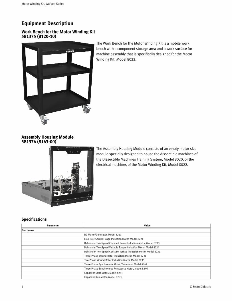
Work Bench for the Motor Winding Kit 581375 (8120-10)
The Work Bench for the Motor Winding Kit is a mobile work bench with a component storage area and a work surface for machine assembly that is specifically designed for the Motor Winding Kit, Model 8022.
Assembly Housing Module 581376 (8163-00)
The Assembly Housing Module consists of an empty motor-size module specially designed to house the dissectible machines of the Dissectible Machines Training System, Model 8020, or the electrical machines of the Motor Winding Kit, Model 8022.
SpecificationsParameter Value
Can house:
DC Motor/Generator, Model 8211
Four-Pole Squirrel-Cage Induction Motor, Model 8221
Dahlander Two-Speed Constant Power Induction Motor, Model 8223
Dahlander Two-Speed Variable Torque Induction Motor, Model 8224
Dahlander Two-Speed Constant Torque Induction Motor, Model 8225
Three-Phase Wound-Rotor Induction Motor, Model 8231
Two-Phase Wound-Rotor Induction Motor, Model 8233
Three-Phase Synchronous Motor/Generator, Model 8241
Three-Phase Synchronous Reluctance Motor, Model 8246
Capacitor-Start Motor, Model 8251
Capacitor-Run Motor, Model 8253

Motor Winding Kit, LabVolt Series
© Festo Didactic 6
Parameter Value
Universal Motor, Model 8254
Two-Value Capacitor Motor, Model 8259
Triple-Rate Motor, Model 8266
Squirrel-Cage Induction Motor
Wound-Rotor Induction Motor
Three-Phase Synchronous Machine
Split-Phase Capacitor-Start Motor
Motor Winding Kit Parts 592531 (8203-0E)The Motor Winding Kit Parts include the necessary materials - lacing cord, slot insulators, insulating material, wooden wedges, and insulated magnet wire - to construct five times all machines in the Motor Winding Kit, Model 8022.
Manual Coil Winder 581426 (8901-00)
The Manual Coil Winder is a hand-operated coil winder fitted with an adjustable mandrel and a turn counter. This equipment facilitates the construction of the different machine windings according to the specifications described in the instruction manual of the Motor Winding Kit, Model 8022.
Optional Equipment Description
Resistive Load (Optional) 579512 (8311-05)
The Resistive Load consists of a module housing nine wire-wound power resistors arranged in three identical banks. Each bank consists of three resistors connected in parallel that can be switched on or off with toggle switches to obtain various resistance values. This allows the total (equivalent) resistance of each bank to be increased or decreased by steps. Six safety banana jacks on the module front panel provide access to each resistor bank. The three resistor banks can be connected separately for operation in three-phase circuits. Also, the three resistor banks can be connected together for operation in single-phase circuits.
Motor Winding Kit, LabVolt Series
7 © Festo Didactic
The Resistive Load is commonly used in conjunction with other basic load modules, like the Inductive Load and the Capacitive Load to experiment with the effects of different types of load on a circuit.
SpecificationsParameter Value
Resistors
Quantity Three identical banks of three resistors
Resistance Values (Each Group) 1100/2200/4400 Ω
Nominal Voltage 220 V ac/dc
Resistance Value Accuracy ± 5%
Load at Nominal Voltage (Each Bank)
Power 11-77 W
Current 0.05-0.35 A
Steps Seven, of equal increment
Current Increment 0.05 A
Physical Characteristics
Dimensions (H x W x D) 154 x 287 x 410 mm (6.1 x 11.3 x 16.1 in)
Net Weight 4.5 kg (9.9 lb)
Color
Front panel color Red
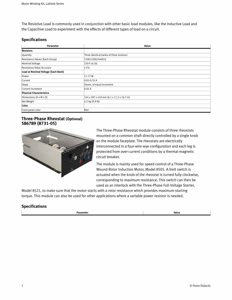
Three-Phase Rheostat (Optional) 586789 (8731-05)
The Three-Phase Rheostat module consists of three rheostats mounted on a common shaft directly controlled by a single knob on the module faceplate. The rheostats are electrically interconnected in a four-wire wye configuration and each leg is protected from over-current conditions by a thermal-magnetic circuit breaker.
The module is mainly used for speed control of a Three-Phase Wound-Rotor Induction Motor, Model 8505. A limit switch is actuated when the knob of the rheostat is turned fully clockwise, corresponding to maximum resistance. This switch can then be used as an interlock with the Three-Phase Full-Voltage Starter,
Model 8521, to make sure that the motor starts with a rotor resistance which provides maximum starting torque. This module can also be used for other applications where a variable power resistor is needed.
SpecificationsParameter Value

Motor Winding Kit, LabVolt Series
© Festo Didactic 8
Variable Three-Phase Power Supply (Optional) 579610 (8821-2E)
The Power Supply is enclosed in a full-size EMS module. It can be used to power most of the EMS modules of the Electricity and New Energy Training Equipment. This Power Supply provides dc power and ac power, both fixed and variable, single-phase and three-phase. Color-coded safety banana jacks provide access to all the power sources in the Power Supply. All these power sources can be used simultaneously, provided that the total current drawn does not exceed the maximum current rating. A built-in voltmeter with selector switch and liquid crystal display (LCD) indicates the voltage provided by any of the power sources. The input and outputs of the Power Supply are protected by independent circuit breakers.
SpecificationsParameter Value
Module Requirements
AC Power Network Installation3 phases (220/380 V – 60 Hz), star (wye) configuration including neutral and ground wires, protected by a 20 A circuit breaker
AC Power Network Connector NEMA L22-20
Maximum Current 10 A
Outputs (*see note)
Three-Phase Fixed AC 220/380 V – 10 A - 60 Hz
Three-Phase Variable AC 0-220/380 V – 3 A - 60 Hz
Variable DC 0-220 V – 5 A
Fixed DC 220 V – 1 A
Low Power AC 24 V – 3 A - 60 Hz
Included Accessories
3 m (10 ft) AC power cord (1)
Padlock (1)
Physical Characteristics
Dimensions (H x W x D) 308 x 287 x 495 mm (12.1 x 11.3 x 19.5 in)
Net Weight 18.4 kg (40.5 lb)
*Note
The Power Supply cannot supply all the amounts of current indicated by the current ratings on its front panel at the same time. The current indicated for the fixed ac three-phase output section can only be obtained if no current is drawn from any other section, because this section is protected by the main circuit breaker common to every section. If currents flow in other sections, the available current for the fixed ac three-phase output section decreases. The variable ac output section and the variable dc output section are protected by a common set of circuit breakers placed after the fixed ac three-phase output section, which means that the current capacity has to be shared between the two sections. For instance, if current of the variable dc output section is at 70% of its nominal value, current drawn from the variable ac output section should not exceed 30% of its nominal value. The fixed dc output section is also protected by circuit breakers placed after the fixed ac three-phase output section.
Connection Lead Set (Optional) 579638 (8951-L0)This Connection Lead Set consists of extra-flexible leads terminated with stacking 4 mm safety banana plugs. In addition, the set includes stacking 2 mm banana plug leads of the same length and color.
4mm: 20 x 30 cm yellow, 10 x 60 cm red, 4 x 90 cm blue. 2mm: 4 x 60 cm red.
SpecificationsParameter Value
4 mm Safety Banana Plug Leads Characteristics

Motor Winding Kit, LabVolt Series
9 © Festo Didactic
Parameter Value
Cross Section 1 mm² (1974 cmil)
Rated Current 19 A
Rated Voltage 600 V, CAT II
4 mm Safety Banana Plug Leads Quantities
Yellow, 30 cm (12 in) 20
Red, 60 cm (24 in) 10
Blue, 90 cm (36 in) 4
2 mm Safety Banana Plug Leads Characteristics
Cross Section 0.5 mm² (987 cmils)
Rated Current 10 A
Rated Voltage 30 V ac / 60 V dc
2 mm Safety Banana Plug Leads Quantities
Red, 60 cm (24 in) 4
Four-Quadrant Dynamometer/Power Supply with manual control (Optional) 579644 (8960-B5)
The Four-Quadrant Dynamometer/Power Supply is a highly versatile USB peripheral designed to be used in the Electric Power Technology Training Systems. Two operating modes are available: Dynamometer and Power Supply. A wide variety of user-selectable functions is available in each operating mode.
In the Dynamometer mode, the unit becomes a four-quadrant dynamometer that can act as either a fully configurable brake (i.e., a mechanical load) or a fully configurable prime mover (i.e., a motor drive). In the Power Supply mode, the unit becomes a four-quadrant power supply that can act as a dc voltage source, dc current source, ac power source, etc.
In each operating mode, key parameters related to the selected function are displayed. Speed, torque, mechanical power, and energy are displayed in the Dynamometer mode while voltage, current, electrical power, and energy are displayed in the Power Supply mode. Optional functions, such as a small wind-turbine emulator, a hydraulic turbine emulator, a solar panel emulator, battery chargers, an SDK (Software Development Kit) etc., can be added to the standard functions to further enhance the training possibilities of the Four-Quadrant Dynamometer/Power Supply.
Two modes are available to control the function which the Four-Quadrant Dynamometer/Power Supply performs: Manual and Computer-Based.
In the Manual control mode, the module operates as a stand-alone unit, and the function performed is selected, set, and monitored using front-panel mounted controls and display. This mode provides access to all basic functions. In the Computer-Based control mode, the function performed by the module is selected, set, and monitored using the LVDAC-EMS software. In this mode, communication between the Four-Quadrant Dynamometer/Power Supply and the host computer running the LVDAC-EMS software is achieved through a USB connection. This mode provides access to all basic functions, as well as to additional advanced functions.
9 Requires a PC running Windows 10 with a free USB 2.0 port.10 Requires a PC running Windows 10 with a free USB 2.0 port.11 Requires a PC running Windows 10 with a free USB 2.0 port.12 Requires a PC running Windows 10 with a free USB 2.0 port.13 Requires a PC running Windows 10 with a free USB 2.0 port.14 Requires a PC running Windows 10 with a free USB 2.0 port.15 Requires a PC running Windows 10 with a free USB 2.0 port.
Motor Winding Kit, LabVolt Series
© Festo Didactic 10
•
Model 8960-B includes the Four-Quadrant Dynamometer/Power Supply, Model 8960-3, with the following function set activated:
Standard Functions (Manual Control), Model 8968-1
Optional Controller
Qty Description Model number
1 Complete Function Set __________________________________________________________ 581435 (8968-00) 9
1 Standard Functions (computer-based control) Set ___________________________________ 581437 (8968-20) 10
1 Turbine Emulator Function Set ___________________________________________________ 579783 (8968-30) 11
1 Lead-Acid Battery Charger Function Set ___________________________________________ 581438 (8968-40) 12
1 Ni-MH Battery Charger Function Set ______________________________________________ 581439 (8968-50) 13
1 Solar Panel Emulator Function Set ________________________________________________ 581440 (8968-60) 14
1 Software Development Kit (SDK) _________________________________________________ 581441 (8968-70) 15
SpecificationsParameter Value
Power Requirements
Maximum Current 3 A
AC Power Network Installation 220 V - 60 Hz, must include live, neutral, and ground wires
Maximum Leakage Current 1.8 mA
Dynamometer Mode
Magnetic Torque 0 to 3 N·m (0 to 27 lbf·in)
Direction of Rotation CW / CCW
Speed 0 to 2500 r/min
Nominal Power 350 W
Power Supply Mode
DC Voltage 0 to ± 150 V
AC Voltage (RMS) 0 to 105 V (no-load)
DC Current 0 to ± 5 A
AC Current (RMS) 0 to 3.5 A
Maximum Output Power 500 W
AC Frequency 10 to 120 Hz
Control Functions
Activated Set Standard Functions (Manual Control), Model 8968-1
Liquid-Crystal Display (LCD) 76 mm (3 in), monochrome, background-illuminated, 240 x 160 dots
Control Inputs
Command Input 0 to ± 10 V
Thermistor Input 10 kΩ, type 1
Control Outputs
Shaft Encoder Quadrature encoder (A-B) - 360 pulses/revolution - TTL compatible
Torque Output Sensitivity 0.3 N·m/V (2.655 lbf·in/V)
Speed Output Sensitivity 500 r/min/V
Communication Port
Type USB 2.0
Physical Characteristics
Motor Winding Kit, LabVolt Series
11 © Festo Didactic
•
•••••
Parameter Value
Dimensions (H x W x D) 308 x 287 x 437 mm (12.1 x 11.3 x 17.2 in)
Net Weight 19.5 kg (43.0 lb)
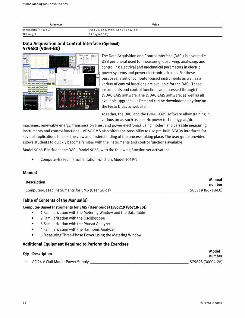
Data Acquisition and Control Interface (Optional) 579680 (9063-B0)
The Data Acquisition and Control Interface (DACI) is a versatile USB peripheral used for measuring, observing, analyzing, and controlling electrical and mechanical parameters in electric power systems and power electronics circuits. For these purposes, a set of computer-based instruments as well as a variety of control functions are available for the DACI. These instruments and control functions are accessed through the LVDAC-EMS software. The LVDAC-EMS software, as well as all available upgrades, is free and can be downloaded anytime on the Festo Didactic website.
Together, the DACI and the LVDAC-EMS software allow training in various areas such as electric power technology, ac/dc
machines, renewable energy, transmission lines, and power electronics using modern and versatile measuring instruments and control functions. LVDAC-EMS also offers the possibility to use pre-built SCADA interfaces for several applications to ease the view and understanding of the process taking place. The user guide provided allows students to quickly become familiar with the instruments and control functions available.
Model 9063-B includes the DACI, Model 9063, with the following function set activated:
Computer-Based Instrumentation Function, Model 9069-1
Table of Contents of the Manual(s)
Computer-Based Instruments for EMS (User Guide) (585219 (86718-E0))1 Familiarization with the Metering Window and the Data Table2 Familiarization with the Oscilloscope3 Familiarization with the Phasor Analyzer4 Familiarization with the Harmonic Analyzer5 Measuring Three-Phase Power Using the Metering Window
Additional Equipment Required to Perform the Exercises
Qty Description Model number
1 AC 24 V Wall Mount Power Supply _________________________________________________ 579698 (30004-2A)
Manual
Description Manual number
Computer-Based Instruments for EMS (User Guide) ______________________________________585219 (86718-E0)
16 For MatLab, LabView, etc.17 Software allowing the monitoring of up to 5 Stations through OPC.
Motor Winding Kit, LabVolt Series
© Festo Didactic 12
Optional Controller
Qty Description Model number
1 Complete Function Set ___________________________________________________________ 581451 (9069-00)1 Chopper/Inverter Control Function Set ______________________________________________ 581453 (9069-20)1 Thyristor Control Function Set _____________________________________________________ 581454 (9069-30)1 Home Energy Production Control Function Set ________________________________________ 581455 (9069-40)1 Three-Phase PWM Rectifier/Inverter Control Function Set _______________________________ 581456 (9069-50)1 BLDC Motor/PMSM Control Function Set ____________________________________________ 581457 (9069-60)1 High-Voltage DC (HVDC) Transmission System Control Function Set ______________________ 579790 (9069-70)1 Static Var Compensator (SVC) Control Function Set ____________________________________ 581458 (9069-80)1 Software Development Kit (SDK) _________________________________________________ 581459 (9069-90) 16
1 Synchronous Generator Control Function Set _________________________________________ 579788 (9069-A0)1 Static Synchronous Compensator (STATCOM) Control Function Set _______________________ 581460 (9069-B0)1 Doubly-Fed Induction Generator (DFIG) Control Function Set ____________________________ 587056 (9069-D0)
Optional Measurement
Qty Description Model number
1 SCADA for LVDAC-EMS ________________________________________________________ 8094377 (8973-00) 17
1 Synchroscope Function ___________________________________________________________ 579789 (9069-C0)1 Power Line Series Compensation Function Set ________________________________________ 581461 (9069-S0)
SpecificationsParameter Value
Insulated Voltage Inputs (4)
Range (Low / High Scales) -80 to +80 V / -800 to + 800 V (user-selectable through software)
Impedance (Low / High Scales) 326.6 kΩ / 3.25 MΩ
Bandwidth DC to 65 kHz (-3 dB)
Accuracy 1% (dc to 10 kHz)
Insulation 800 V
Maximum Voltage (Any Terminal vs GND) 283 V ac / 400 V dc
Measurement Category CAT II (283 V ac/400 V dc versus ground)
Insulated Current Inputs (4)
Range (Low / High Scales) -4 to +4 A / -40 to + 40 A (25 A rms)
Impedance (Low / High Scales) 5 mΩ / 50 mΩ
Bandwidth DC to 65 kHz (-3 dB)
Accuracy 1% (dc to 10 kHz)
Insulation 800 V
Maximum Voltage (Any Terminal vs GND) 283 V ac / 400 V dc
Measurement Category CAT II (283 V ac/400 V dc versus ground)
Analog Inputs (8)
Voltage Range -10 to +10 V
Impedance > 10 MΩ
Bandwidth DC to 125 kHz
Measured Parameters User-selectable through software
Parameter-to-Voltage Ratio User-determined through software
A/D Converter for Insulated and Analog Inputs (16)
Type Successive approximation
Resolution 12 bits
Integral Non-Linearity ≤ ±1.5 LSB

Motor Winding Kit, LabVolt Series
13 © Festo Didactic
Parameter Value
Differential Non-Linearity ≤ ±1 LSB
Maximum Sampling Rate 600 ksamples/s (one channel)
FIFO Buffer Size 16 ksamples
Analog Outputs (2)
Voltage Range -10 to +10 V
Operational Load Impedance > 600 Ω
D/A Converter for Analog Outputs (2)
Type Resistor string
Resolution 12 bits
Integral Non-Linearity ≤ ±8 LSB
Differential Non-Linearity -0.5 to +0.7 LSB
Digital Inputs (3)
Types Encoder (2), synchronization (1)
Signal Level 0-5 V (TTL compatible)
Maximum Input Frequency 50 kHz
Impedance 5 kΩ
Digital Outputs (9)
Types Control (6 on a DB9 connector and 2 on 2 mm banana jacks), synchronization (1 on a DB9 connector)
Signal Level 0-5 V (TTL compatible)
Maximum Output Frequency 20 kHz (software-limited)
Impedance 200 Ω
Control Functions
Activated Set Computer-Based Instrumentation Function, Model 9069-1
Computer I/O Interface USB 2.0 full speed via type-B receptacle
Power Requirements 24 V - 0.4 A - 50/60 Hz
Accessories
Included Accessories 2 m USB interconnection cable (1)
24 V power cable (1)
2 mm banana plug test leads (3)
DB9 connector control cable (1)
Physical Characteristics
Dimensions (H x W x D) 154 x 287 x 410 mm (6.1 x 11.3 x 16.1 in)
Net Weight 3.9 kg (8.6 lb)
Motor Winding Kit (Manuals on CD-ROM) (Optional) 589737 (26145-AE)
Manual
Description Manual number
(Workbook) _______________________________________________________________________590389 (26145-0E)

Motor Winding Kit, LabVolt Series
© Festo Didactic 14
Reflecting the commitment of Festo Didactic to high quality standards in product, design, development, production, installation, and service, our manufacturing and distribution facility has received the ISO 9001 certification.
Festo Didactic reserves the right to make product improvements at any time and without notice and is not responsible for typographical errors. Festo Didactic recognizes all product names used herein as trademarks or registered trademarks of their respective holders. © Festo Didactic Inc. 2022. All rights reserved.
Festo Didactic SE
Rechbergstrasse 373770 DenkendorfGermany
P. +49(0)711/3467-0F. +49(0)711/347-54-88500
Festo Didactic Inc.
607 Industrial Way WestEatontown, NJ 07724United States
P. +1-732-938-2000F. +1-732-774-8573
Festo Didactic Ltée/Ltd
675 rue du CarboneQuébec QC G2N 2K7Canada
P. +1-418-849-1000F. +1-418-849-1666
www.labvolt.com
www.festo-didactic.com
Related Documents