Motor Start Theory ME00107A

Welcome message from author
This document is posted to help you gain knowledge. Please leave a comment to let me know what you think about it! Share it to your friends and learn new things together.
Transcript
Motor Start Theory
ME00107A

Induction Motors Have Two Prime Functions
To convert electrical energy into mechanical energy in order to accelerate the motor and load to operating speed – Starting Function
To convert electrical energy into productive work output from the machine – Work Function

Motors consist of two major sections – The Stator and the Rotor
The stator consists of magnetic poles and stator windings within the frame of the motor.By variation of winding configuration and the contour of the stator laminations , the full load characteristics are determined
The motor speed is determined by the number of poles
The rotor consists of a cylindrical short-circuited winding around iron laminations The rotor design affects starting performance.The shape, position and material of the rotor bars affect the current drawn and torque produced during motor starting.
Motor Performance

Full load characteristics are well understood with factors such as motor speed,torque and efficiency being the typical selection criteria.
A motor‘s start performance characteristics are usually the least understood but set the limits of what can be achieved with either a full voltage or reduced voltage starter.
It is especially important to consider motor start characteristics when seeking to:- Minimise start current- Maximise start torque
Motor Performance

A motor‘s start performance can be identified by examining the motor data sheet.
The table details selected performance data for a range of 110kW motors.
Typical Motor DataMotor Speed FLC LRC LRT % FL Torque
(rpm) (amps) (%FLC) (%FLT) Ef’ncy @3xFLC
A 1470 191 600 263 93 65.8
B 1475 184 600 190 93.5 47.5
C 1475 191 570 150 92 41.6
D 1480 187 660 190 94.5 39.2
E 1470 185 550 120 92 36
F 1470 191 670 150 93 30.1
G 1480 190 780 200 94 29.6
H 1475 182 850 220 93.5 27.4
I 1480 190 670 120 94 24
Sample Of Typical 110kW Motors

The motor performs as a transformer with current induced in the rotor by the flux in the stator.
Maximum motor start current under full voltage start conditions is defined by the motor‘s Locked Rotor Current. (LRC) This is when the rotor is stationary
LRC levels vary considerably between motors
In the example, Motor H will draw 55% more current at start than Motor E.
Start Current
Motor Speed FLC LRC LRT % FL Torque(rpm) (amps) (%FLC) (%FLT) Ef’ncy @3xFLC
A 1470 191 600 263 93 65.8
B 1475 184 600 190 93.5 47.5
C 1475 191 570 150 92 41.6
D 1480 187 660 190 94.5 39.2
E 1470 185 550 120 92 36
F 1470 191 670 150 93 30.1
G 1480 190 780 200 94 29.6
H 1475 182 850 220 93.5 27.4
I 1480 190 670 120 94 24
LRC ranges from 550% to 850%
Sample Of Typical 110kW Motors
Torque-Speed Characteristic
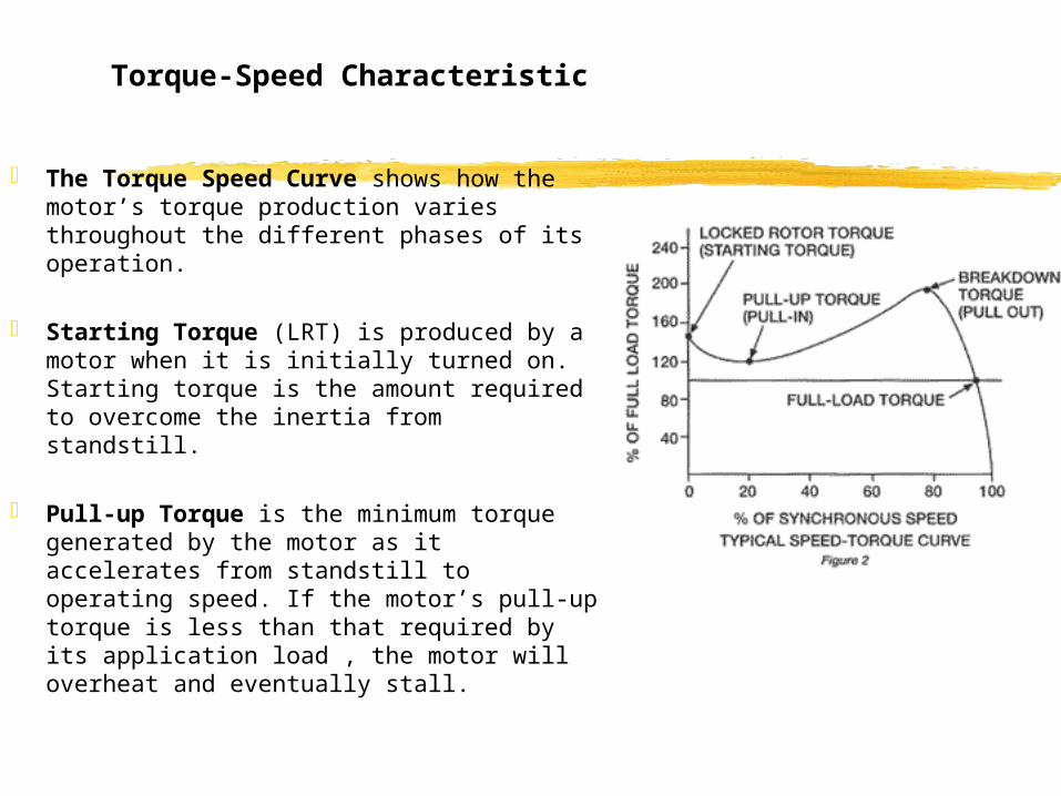
The Torque Speed Curve shows how the motor’s torque production varies throughout the different phases of its operation.
Starting Torque (LRT) is produced by a motor when it is initially turned on. Starting torque is the amount required to overcome the inertia from standstill.
Pull-up Torque is the minimum torque generated by the motor as it accelerates from standstill to operating speed. If the motor’s pull-up torque is less than that required by its application load , the motor will overheat and eventually stall.

Torque-Speed Characteristic
Breakdown Torque – is the greatest amount of torque a motor can attain without stalling.
Full Load Torque – is produced by a motor functioning at a rated speed and horsepower.
Synchronous speed – is the speed at which no torque is generated by the motor.This only occurs in motors that run while not connected to a load.
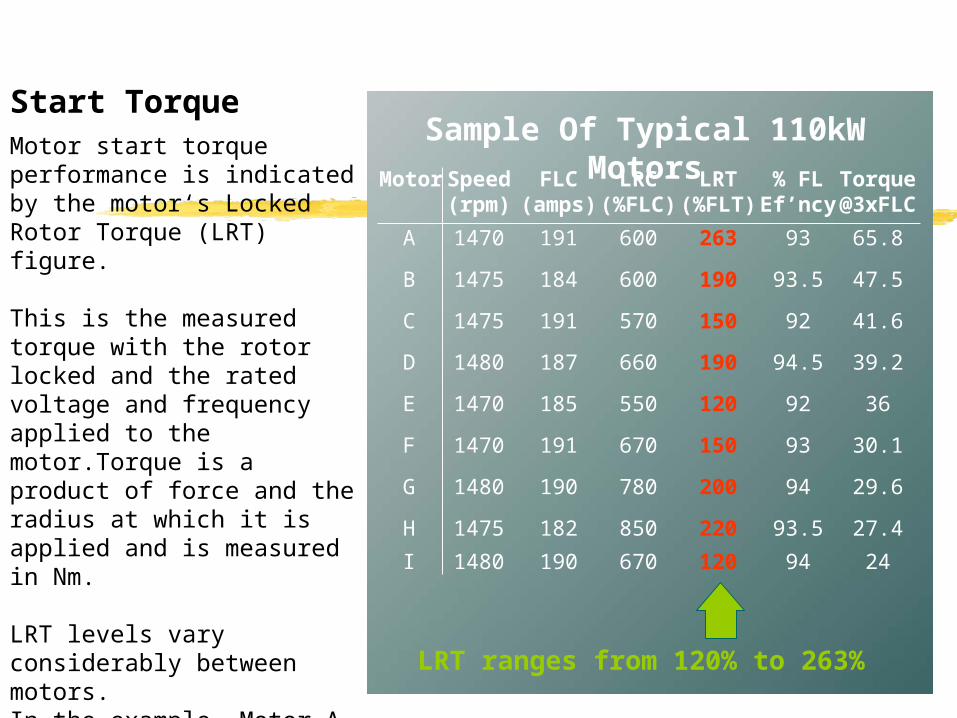
Motor start torque performance is indicated by the motor‘s Locked Rotor Torque (LRT) figure.
This is the measured torque with the rotor locked and the rated voltage and frequency applied to the motor.Torque is a product of force and the radius at which it is applied and is measured in Nm.
LRT levels vary considerably between motors.In the example, Motor A produces twice as much torque during start as Motor I.
Start Torque
Motor Speed FLC LRC LRT % FL Torque(rpm) (amps) (%FLC) (%FLT) Ef’ncy @3xFLC
A 1470 191 600 263 93 65.8
B 1475 184 600 190 93.5 47.5
C 1475 191 570 150 92 41.6
D 1480 187 660 190 94.5 39.2
E 1470 185 550 120 92 36
F 1470 191 670 150 93 30.1
G 1480 190 780 200 94 29.6
H 1475 182 850 220 93.5 27.4
I 1480 190 670 120 94 24
LRT ranges from 120% to 263%
Sample Of Typical 110kW Motors
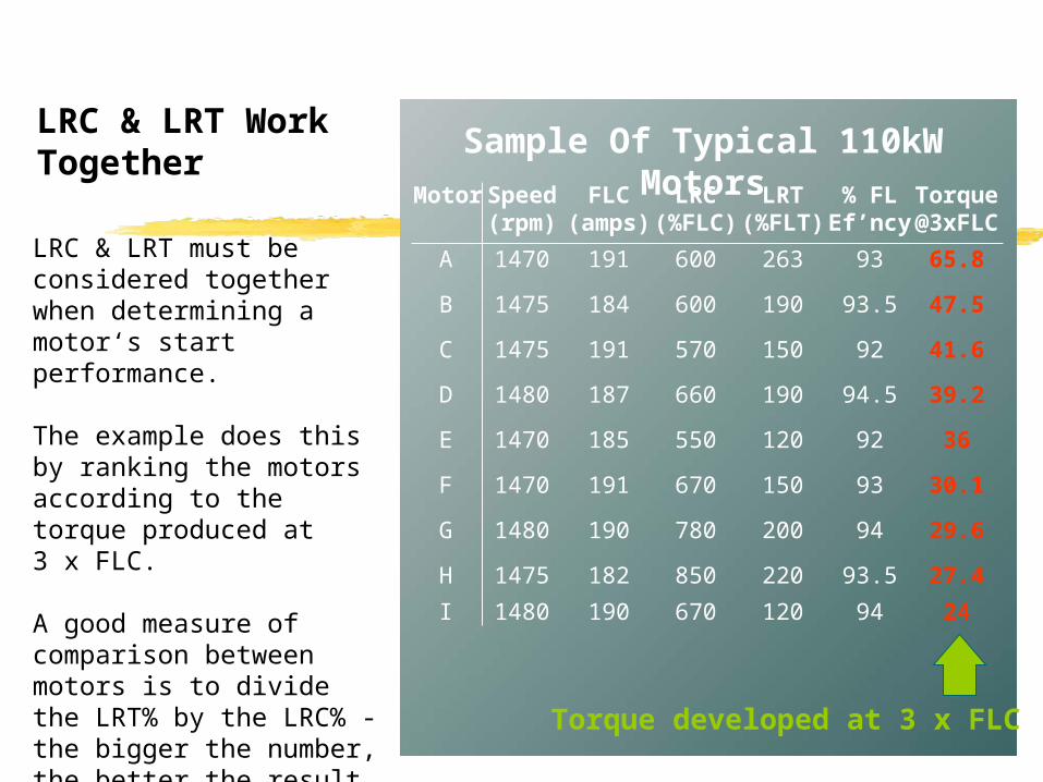
LRC & LRT must be considered together when determining a motor‘s start performance.
The example does this by ranking the motors according to the torque produced at 3 x FLC.
A good measure of comparison between motors is to divide the LRT% by the LRC% - the bigger the number, the better the result
LRC & LRT Work Together
Motor Speed FLC LRC LRT % FL Torque(rpm) (amps) (%FLC) (%FLT) Ef’ncy @3xFLC
A 1470 191 600 263 93 65.8
B 1475 184 600 190 93.5 47.5
C 1475 191 570 150 92 41.6
D 1480 187 660 190 94.5 39.2
E 1470 185 550 120 92 36
F 1470 191 670 150 93 30.1
G 1480 190 780 200 94 29.6
H 1475 182 850 220 93.5 27.4
I 1480 190 670 120 94 24
Sample Of Typical 110kW Motors
Torque developed at 3 x FLC

Motor Speed FLC LRC LRT % FL Torque(rpm) (amps) (%FLC) (%FLT) Ef’ncy @3xFLC
A 1470 191 600 263 93 65.8
B 1475 184 600 190 93.5 47.5
C 1475 191 570 150 92 41.6
D 1480 187 660 190 94.5 39.2
E 1470 185 550 120 92 36
F 1470 191 670 150 93 30.1
G 1480 190 780 200 94 29.6
H 1475 182 850 220 93.5 27.4
I 1480 190 670 120 94 24
Torque is reduced by the square of the current reduction.Eg:- If you halve the current the result will be ¼ motor torque
Motors B & G produce almost the same torque at full voltage.
Motor B produces 60% more start torque at 3 x FLC.
Reduced Voltage Starting Amplifies Motor Differences
Sample Of Typical 110kW Motors

Motor LRC LRT TORQUE (%FLC) (%FLT) @ 3 X FLC
A 600 263 65.8
B 600 190
C 570 150
D 660 190
Follow the example and calculate the start torque at 3 x FLC for motors B, C & D.
How To Calculate Start Torque
Start Torque = LRT x Start CurrentLRC( )
2
( )2
300%600%
65.8% = x263%
47.5
41.5
39.3

Selecting a motor with low Locked Rotor Current (LRC) and high Locked Rotor Torque (LRT) will:
- Reduce start current.
- Increase start torque.
- Reduce soft starter cost.
Summary
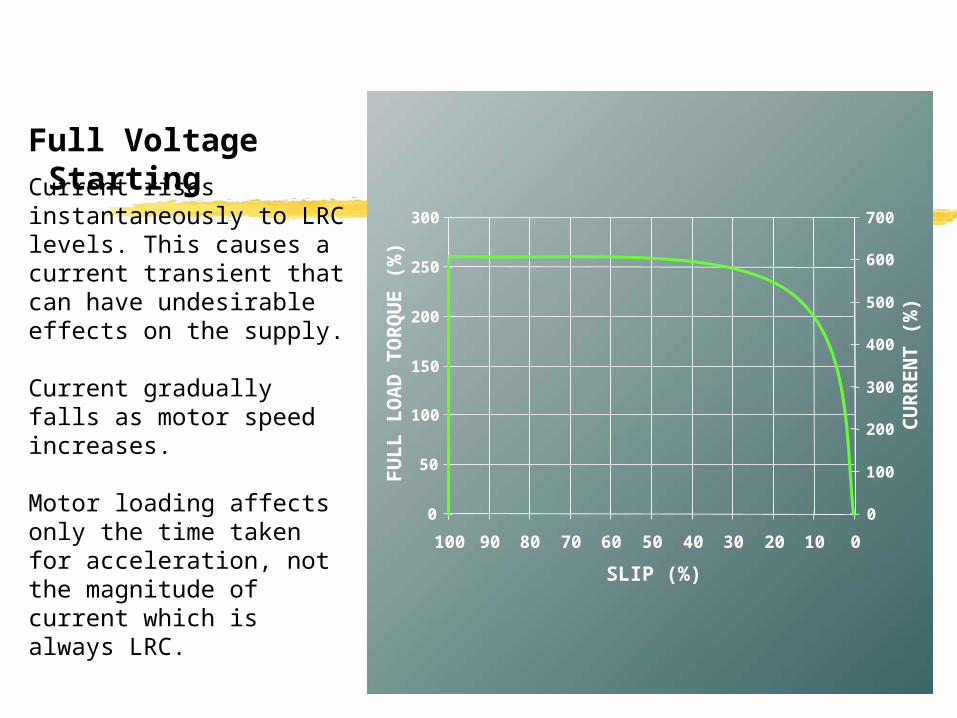
Current rises instantaneously to LRC levels. This causes a current transient that can have undesirable effects on the supply.
Current gradually falls as motor speed increases.
Motor loading affects only the time taken for acceleration, not the magnitude of current which is always LRC.
Full Voltage Starting
0
50
100
150
200
250
300
100 90 80 70 60 50 40 30 20 10 0
SLIP (%)
FU
LL
LO
AD
TO
RQ
UE
(%
)
0
100
200
300
400
500
600
700
CU
RR
EN
T (
%)

Full Voltage Starting
0
50
100
150
200
250
300
100 90 80 70 60 50 40 30 20 10 0
SLIP (%)
FU
LL
LO
AD
TO
RQ
UE
(%
)
0
100
200
300
400
500
600
700
CU
RR
EN
T (
%)
Torque rises instantaneously to LRT levels. This causes a torque transient that can be damaging.
Typical torque falls from LRT to Pull Out Torque before rising to Breakdown Torque just before full speed.

0
50
100
150
200
250
300
100 90 80 70 60 50 40 30 20 10 0
SLIP (%)
FU
LL
LO
AD
TO
RQ
UE
(%
)
0
100
200
300
400
500
600
700
CU
RR
EN
T (
%)
Full Voltage Starting Limitations
1. Current transient
1
2. Current magnitude2
3. Torque transient
3 4
4. Torque magnitude
Reduced voltage starting attempts to overcome these limitations by applying the voltage gradually.
100
80
60
40
20
0TIME
% VOLTS
START
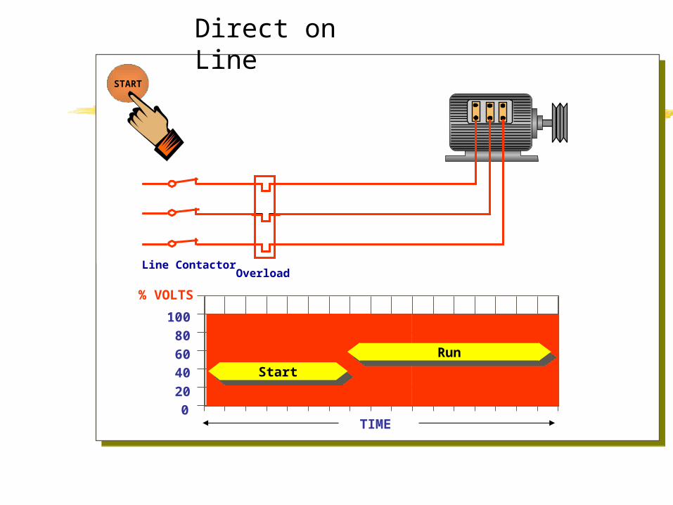
Line ContactorOverload
StartStartRunRun
Direct on Line

Electromechanical-- Primary Resistance-Auto-transformer- Star/Delta
Electronic- Soft Start
Reduced Voltage Starters
Primary ResistanceRUN
CONTACTOR
MOTOROVERLOADTHERMALSTART
RESISTORSLINE
CONTACTOR
3 ~M
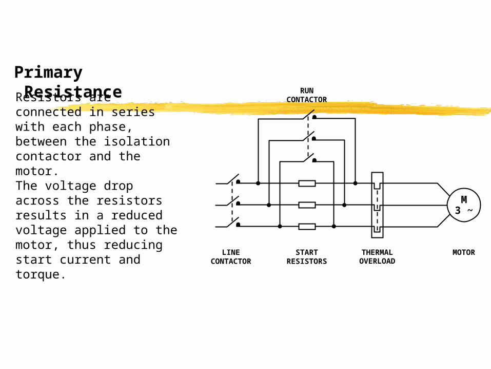
Resistors are connected in series with each phase, between the isolation contactor and the motor. The voltage drop across the resistors results in a reduced voltage applied to the motor, thus reducing start current and torque.

Set for 4 x FLC start current.
Primary Resistance
0
50
100
150
200
250
300
100 90 80 70 60 50 40 30 20 10 0
SLIP (%)
FU
LL
LO
AD
TO
RQ
UE
(%
)
0
100
200
300
400
500
600
700
CU
RR
EN
T (
%)
Limitations:- Difficult to change
resistance- Dissipate a lot of heat- Limited number of starts per
hour- Start characteristics change
between starts if resistors have not totally cooled
- Hard to start high inertia loads
Primary Resistance
0
50
100
150
200
250
300
100 90 80 70 60 50 40 30 20 10 0
SLIP (%)
FU
LL
LO
AD
TO
RQ
UE
(%
)
0
100
200
300
400
500
600
700
CU
RR
EN
T (
%)
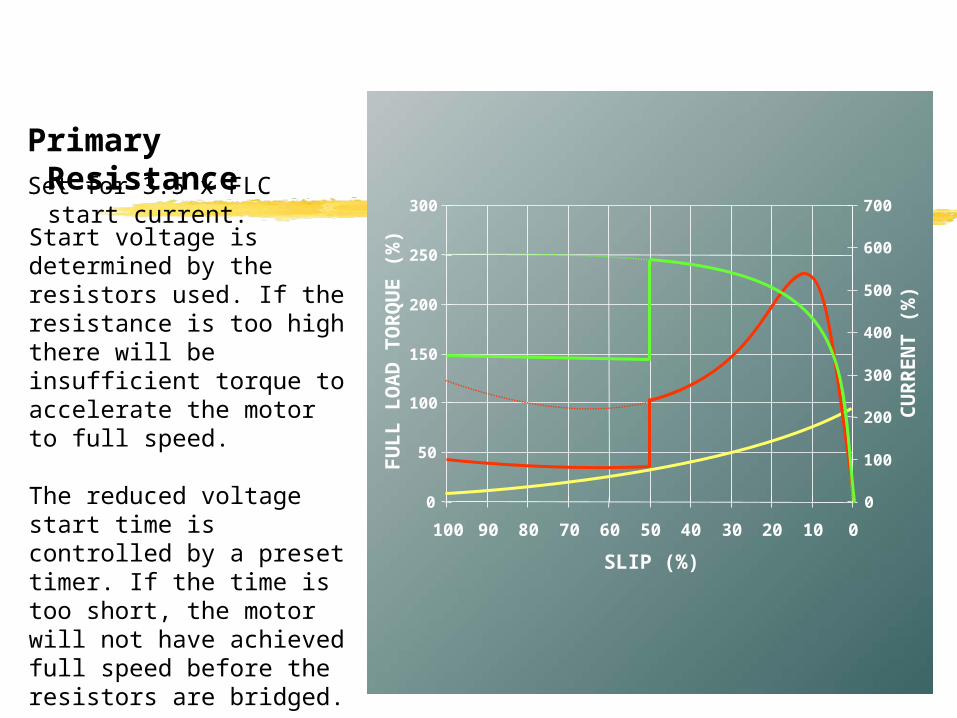
Set for 3.5 x FLC start current.
Start voltage is determined by the resistors used. If the resistance is too high there will be insufficient torque to accelerate the motor to full speed.
The reduced voltage start time is controlled by a preset timer. If the time is too short, the motor will not have achieved full speed before the resistors are bridged.

100
80
60
40
20
0TIME
% VOLTS
START
Line Contactor
Run Contactor
ResistorsOverload
StartStart
RunRun
Primary Resistance

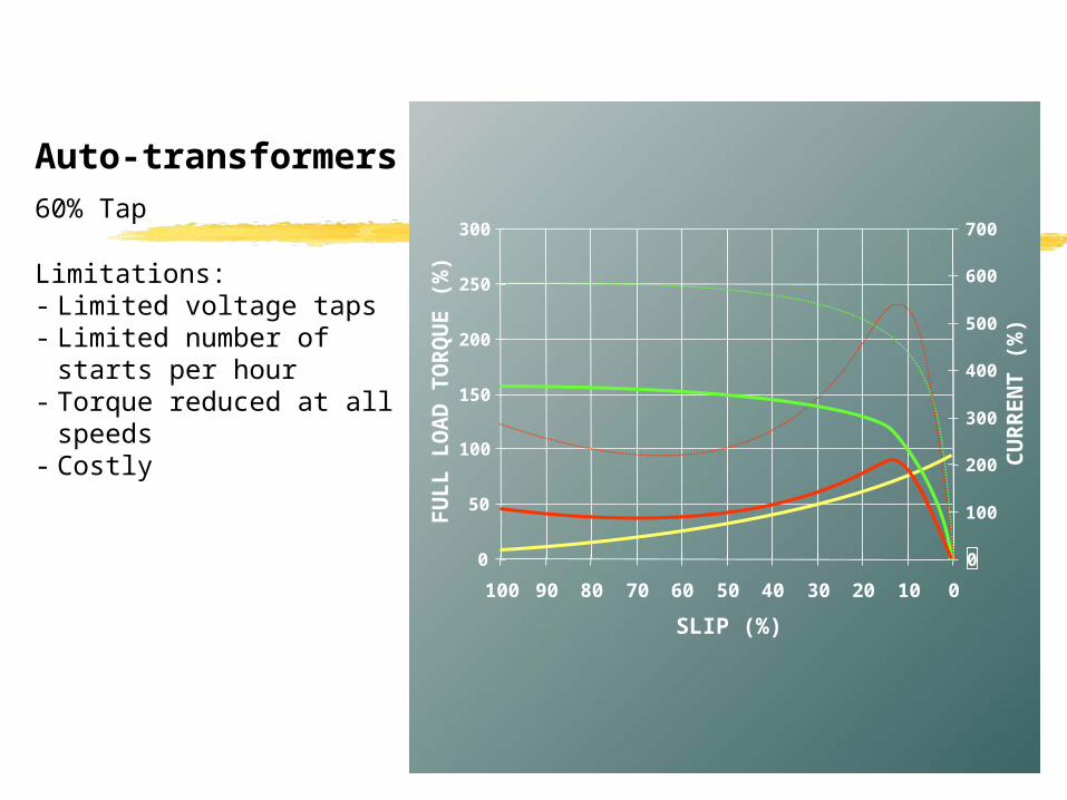
Auto-transformers
Thermal Overload
3 PhaseAuto Transformer
(B) Start Contactor
(A) Start ContactorRun
Contactor
3 ~M
The Auto-transformer Starter employs an auto-transformer to reduce the voltage during the start period. The transformer has a range of output voltage taps that can be used to set the start voltage.
The motor current is reduced by the start voltage reduction, and further reduced by the transformer action resulting in a line current less than the actual motor current.
0
50
100
150
200
250
300
100 90 80 70 60 50 40 30 20 10 0
SLIP (%)
FU
LL
LO
AD
TO
RQ
UE
(%
)
0
100
200
300
400
500
600
700
CU
RR
EN
T (
%)
60% Tap
Auto-transformers
Limitations:- Limited voltage taps- Limited number of starts per
hour- Torque reduced at all
speeds- Costly

0
50
100
150
200
250
300
100 90 80 70 60 50 40 30 20 10 0
SLIP (%)
FU
LL
LO
AD
TO
RQ
UE
(%
)
0
100
200
300
400
500
600
700
CU
RR
EN
T (
%)
50% Tap
The initial start voltage is set by tap selection, and the start time is controlled by a timer. If the start voltage is too low, or the start time incorrectly set, the transition to full voltage will occur with the motor at less than full speed, resulting in a high current and torque step.
Auto-transformers

100
80
60
40
20
0TIME
% VOLTS
START
Line Contactor
TransformerContactor
Star PointContactor
Overload
StartStart
RunRun
Auto-transformer

Star/Delta
Motor3~
ThermalOverload
StarContactor
DeltaContactor
MainContactor
The motor is initially connected in star configuration and then, after a preset time, the motor is disconnected from the supply and reconnected in delta configuration. The current and torque in the star configuration are one third of the full voltage current and torque when the motor is connected in delta.

Limitations:- No adjustment possible.- Open transition switching
between star and delta causes damaging current and torque transients.
Star/Delta
0
50
100
150
200
250
300
100 90 80 70 60 50 40 30 20 10 0
SLIP (%)
FU
LL
LO
AD
TO
RQ
UE
(%
)
0
100
200
300
400
500
600
700
CU
RR
EN
T (
%)
Insufficient torque to accelerate this load in star configuration.
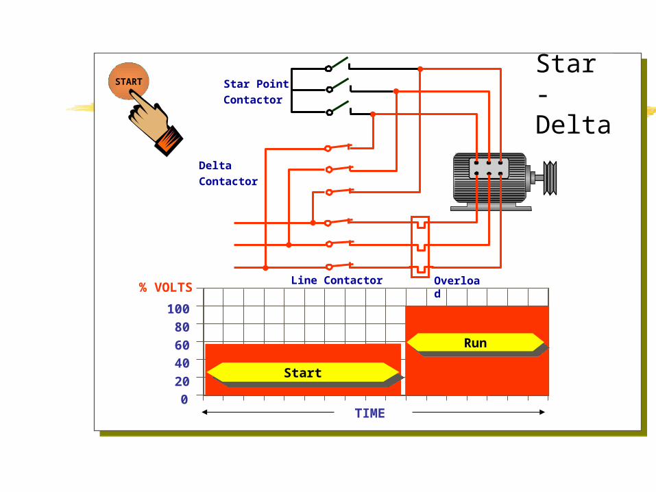
100
80
60
40
20
0TIME
% VOLTS
START
Line Contactor
DeltaContactor
Star PointContactor
Overload
StartStart
RunRun
Star - Delta

Open Transition Switching
Occurs when the starter goes through an open circuit stage in the switching sequence. Stage [1] connection to the reduced voltage; [2] disconnect from the reduced voltage (open circuit); [3] connect to the full voltage.
Open transition starting causes severe current & torque transients that can be more detrimental to the supply and the mechanical equipment than full voltage starting. When the motor is spinning and then disconnected from the supply, it acts as a generator. Output voltage can be the same amplitude as the supply. At the time of reclose there can still be significant voltage present at the motor terminals.
Voltage generated by the motor at the instant of reclose may be equal to the supply voltage but exactly out of phase. This equates to reclosing with twice the supply voltage on the motor. The result is a current of twice locked rotor current and a torque transient of four times locked rotor torque.
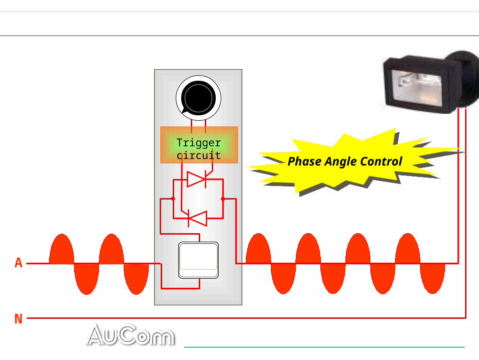
A
Phase Angle ControlPhase Angle Control
Trigger circuit
N
0
50
100
150
200
250
300
100 90 80 70 60 50 40 30 20 10 0
SLIP (%)
FU
LL
LO
AD
TO
RQ
UE
(%
)
0
100
200
300
400
500
600
700
CU
RR
EN
T (
%)
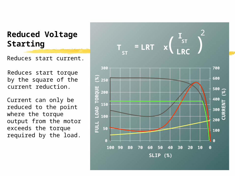
Reduced Voltage Starting
IST
= LRT xTST LRC( )
2
Reduces start torque by the square of the current reduction.
Current can only be reduced to the point where the torque output from the motor exceeds the torque required by the load.
Reduces start current.

Reduced Voltage Starting
To be effective, a reduced voltage starter must allow the motor to accelerate to around 90% speed before applying full voltage.
Below this speed the current will step through to almost LRC levels thus removing any benefit from the reduced voltage starter.
0
50
100
150
200
250
300
100 90 80 70 60 50 40 30 20 10 0
SLIP (%)
FU
LL
LO
AD
TO
RQ
UE
(%
)
0
100
200
300
400
500
600
700
CU
RR
EN
T (
%)
Small Reductionat 50% speed
Large Reductionat 95% speed
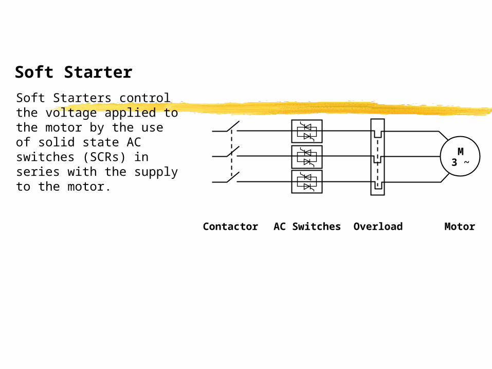
Soft Starter
MotorOverloadAC SwitchesContactor
M3 ~
Soft Starters control the voltage applied to the motor by the use of solid state AC switches (SCRs) in series with the supply to the motor.

- Minimum possible start current
- No current steps- No torque steps- Good start torque
characteristics
Soft Starter
0
50
100
150
200
250
300
100 90 80 70 60 50 40 30 20 10 0
SLIP (%)
FU
LL
LO
AD
TO
RQ
UE
(%
)
0
100
200
300
400
500
600
700
CU
RR
EN
T (
%)
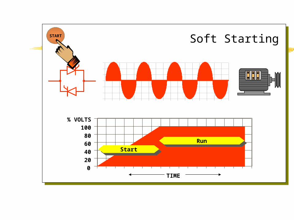
% VOLTS
100
80
60
40
20
0TIME
Soft StartingSTART
StartStartRunRun

Motor characteristics set the limits of what can be achieved with a soft starter.
Pay special attention to motor characteristics when:- it is important to minimise start current- it is important to maximise start torque- dealing with large motors (200kW +)
Summary

Soft start is technically the best reduced voltage starting system.
Star/Delta starting is the cheapest and most commonly employed reduced voltage starting system. However its performance characteristics are damaging.
Summary

Because;Because;
they reduce electrical and mechanical stresses beyond the
capabilities of electro-mechanical reduced voltage starters.
This further reduces machine downtime, increasing plant
productivity.
they reduce electrical and mechanical stresses beyond the
capabilities of electro-mechanical reduced voltage starters.
This further reduces machine downtime, increasing plant
productivity.
Note however, that the level of performance is dependant upon the design of the soft starter and functionality it
offers.
Note however, that the level of performance is dependant upon the design of the soft starter and functionality it
offers.
Why Use Soft StartersWhy Use Soft Starters
Related Documents