Instruction manual 339 revision: 1.7 Manual P/N: 1601-9103-AE GE publication code: GEK-113562N *1601-9103-AE* 339 Motor Protection System Motor protection and control GE Grid Solutions LISTED 52TL IND.CONT. EQ. E83849

Welcome message from author
This document is posted to help you gain knowledge. Please leave a comment to let me know what you think about it! Share it to your friends and learn new things together.
Transcript

Instruction manual339 revision: 1.7
Manual P/N: 1601-9103-AE
GE publication code: GEK-113562N
*1601-9103-AE*
339Motor Protection System
Motor protection and control
GEGrid Solutions
LISTED
52TL
IND.CONT. EQ.
E83849

© 2015 GE Multilin Incorporated. All rights reserved.
GE Multilin 339 Motor Protection System instruction manual for revision 1.7.
339 Motor Protection System, EnerVista, EnerVista Launchpad, and EnerVista SR3 Setup are trademarks or registered trademarks of GE Multilin Inc.
The contents of this manual are the property of GE Multilin Inc. This documentation is furnished on license and may not be reproduced in whole or in part without the permission of GE Multilin. The content of this manual is for informational use only and is subject to change without notice.
Part number: 1601-9103-AE (December 2015)
StorageStore the unit indoors in a cool, dry place. If possible, store in the original packaging. Follow the storage temperature range outlined in the Specifications.
To avoid deterioration of electrolytic capacitors, power up units that are stored in a de-energized state once per year, for one hour continuously.
This product cannot be disposed of as unsorted municipal waste in the European Union. For proper recycling return this product to your supplier or a designated collection point. For more information go to www.recyclethis.info.
Note GENERAL SAFETY PRECAUTIONS - 339
• Failure to observe and follow the instructions provided in the equipment manual(s) could cause irreversible damage to the equipment and could lead to property damage, personal injury and/or death.
• Before attempting to use the equipment, it is important that all danger and caution indicators are reviewed.
• If the equipment is used in a manner not specified by the manufacturer or functions abnormally, proceed with caution. Otherwise, the protection provided by the equipment may be impaired and can result in Impaired operation and injury.
• Caution: Hazardous voltages can cause shock, burns or death.
• Installation/service personnel must be familiar with general device test practices, electrical awareness and safety precautions must be followed.
• Before performing visual inspections, tests, or periodic maintenance on this device or associated circuits, isolate or disconnect all hazardous live circuits and sources of electric power.
• Failure to shut equipment off prior to removing the power connections could expose you to dangerous voltages causing injury or death.
• All recommended equipment that should be grounded and must have a reliable and un-compromised grounding path for safety purposes, protection against electromagnetic interference and proper device operation.
• Equipment grounds should be bonded together and connected to the facility’s main ground system for primary power.
• Keep all ground leads as short as possible.
• At all times, equipment ground terminal must be grounded during device operation and service.
• In addition to the safety precautions mentioned all electrical connections made must respect the applicable local jurisdiction electrical code.
• Before working on CTs, they must be short-circuited.
This product cannot be disposed of as unsorted municipal waste in the European Union. For proper recycling return this product to your supplier or a designated collection point. For more information go to www.recyclethis.info.

Safety words and definitionsThe following symbols used in this document indicate the following conditions
Note Indicates a hazardous situation which, if not avoided, will result in death or serious injury.
Note Indicates a hazardous situation which, if not avoided, could result in death or serious injury.
Note Indicates a hazardous situation which, if not avoided, could result in minor or moderate injury.
Note Indicates practices not related to personal injury.
For further assistanceFor product support, contact the information and call center as follows:
GE Grid Solutions650 Markland StreetMarkham, OntarioCanada L6C 0M1Worldwide telephone: +1 905 927 7070Europe/Middle East/Africa telephone: +34 94 485 88 54North America toll-free: 1 800 547 8629Fax: +1 905 927 5098Worldwide e-mail: [email protected] e-mail: [email protected]: http://www.gegridsolutions.com/multilin
339 MOTOR PROTECTION SYSTEM – INSTRUCTION MANUAL TOC–1
Table of Contents
1.INTRODUCTION Overview ................................................................................................................................1 - 1Description of the 339 Motor Protection System................................................1 - 1339 order codes..................................................................................................................1 - 6Specifications.......................................................................................................................1 - 6
Password security....................................................................................................................1 - 7Protection.....................................................................................................................................1 - 7Metering........................................................................................................................................1 - 10Data capture ..............................................................................................................................1 - 11Control ...........................................................................................................................................1 - 12Inputs .............................................................................................................................................1 - 13Outputs..........................................................................................................................................1 - 14Power supply ..............................................................................................................................1 - 14Communications ......................................................................................................................1 - 15Testing and certification .......................................................................................................1 - 15Physical .........................................................................................................................................1 - 16Environmental............................................................................................................................1 - 17
2.INSTALLATION Mechanical installation ...................................................................................................2 - 1Dimensions..................................................................................................................................2 - 1Product identification .............................................................................................................2 - 3Mounting ......................................................................................................................................2 - 3
Standard panel mount .........................................................................................................2 - 4Drawout unit withdrawal and insertion.........................................................................2 - 9IP20 Cover (optional) ...............................................................................................................2 - 9
Electrical installation ........................................................................................................2 - 11339 terminals .............................................................................................................................2 - 15
Terminal identification - Input/Output “E”...................................................................2 - 17Terminal identification - Input/Output “R”...................................................................2 - 21
Wire range...................................................................................................................................2 - 22RMIO module installation......................................................................................................2 - 23Internal RTD installation........................................................................................................2 - 25Phase sequence and transformer polarity...................................................................2 - 26Phase current inputs...............................................................................................................2 - 26Ground and CBCT inputs.......................................................................................................2 - 26Zero sequence CBCT installation ......................................................................................2 - 27Voltage inputs ............................................................................................................................2 - 28Control power ............................................................................................................................2 - 28Contact inputs ...........................................................................................................................2 - 29Trip and Close output relays ...............................................................................................2 - 29Serial communications ..........................................................................................................2 - 32IRIG-B .............................................................................................................................................2 - 33
3.INTERFACES Front control panel interface........................................................................................3 - 2Description ..................................................................................................................................3 - 2Display ...........................................................................................................................................3 - 3
Working with the Keypad....................................................................................................3 - 3LED status indicators..............................................................................................................3 - 4Relay messages ........................................................................................................................3 - 5
Default message .....................................................................................................................3 - 6Target messages.....................................................................................................................3 - 6Self-test errors..........................................................................................................................3 - 7
TOC–2 339 MOTOR PROTECTION SYSTEM – INSTRUCTION MANUAL
Flash messages .......................................................................................................................3 - 8Software setup....................................................................................................................3 - 9
Quick setup - Software interface......................................................................................3 - 9EnerVista SR3 Setup Software ...........................................................................................3 - 10
Hardware and software requirements.........................................................................3 - 10Installing the EnerVista SR3 Setup software ..............................................................3 - 10Upgrading the software.......................................................................................................3 - 13
Connecting EnerVista SR3 Setup to the relay ............................................................3 - 13Configuring serial communications...............................................................................3 - 13Using the Quick Connect feature ....................................................................................3 - 14Configuring Ethernet communications ........................................................................3 - 15Connecting to the relay........................................................................................................3 - 16
Working with setpoints and setpoint files ....................................................................3 - 17Engaging a device ..................................................................................................................3 - 17Entering setpoints...................................................................................................................3 - 18File support ................................................................................................................................3 - 19Using setpoints files...............................................................................................................3 - 19Downloading and saving setpoints files ......................................................................3 - 19Adding setpoints files to the environment ..................................................................3 - 20Creating a new setpoint file ...............................................................................................3 - 20Upgrading setpoint files to a new revision .................................................................3 - 21Printing setpoints and actual values .............................................................................3 - 22Printing actual values from a connected device .....................................................3 - 23Loading setpoints from a file.............................................................................................3 - 24Uninstalling files and clearing data................................................................................3 - 24
Upgrading relay firmware ...................................................................................................3 - 24Loading new relay firmware..............................................................................................3 - 25
Advanced EnerVista SR3 Setup features ......................................................................3 - 26Flexcurve editor .......................................................................................................................3 - 26Data logger ................................................................................................................................3 - 28Motor start data logger........................................................................................................3 - 29Transient recorder (Waveform capture).......................................................................3 - 31Protection summary..............................................................................................................3 - 34Password security ..................................................................................................................3 - 36
4.ACTUAL VALUES Actual values overview ...................................................................................................4 - 1A1 Status................................................................................................................................4 - 3
Motor status ...............................................................................................................................4 - 4Clock...............................................................................................................................................4 - 5Contact inputs ...........................................................................................................................4 - 6Output relays .............................................................................................................................4 - 6
Output relays - Breaker........................................................................................................4 - 6Output relays - Contactor ...................................................................................................4 - 7
Logic elements ..........................................................................................................................4 - 7Virtual inputs ..............................................................................................................................4 - 7Remote inputs ...........................................................................................................................4 - 7Remote outputs ........................................................................................................................4 - 7Contact inputs summary......................................................................................................4 - 8Output relays summary ........................................................................................................4 - 8Logic elements summary.....................................................................................................4 - 8GOOSE status.............................................................................................................................4 - 8GOOSE HDR status ..................................................................................................................4 - 9RTD temp summary................................................................................................................4 - 9
A2 Metering ..........................................................................................................................4 - 9Current ..........................................................................................................................................4 - 9Voltage..........................................................................................................................................4 - 10
339 MOTOR PROTECTION SYSTEM – INSTRUCTION MANUAL TOC–3
Power .............................................................................................................................................4 - 11Energy............................................................................................................................................4 - 11RTD temperature ......................................................................................................................4 - 11Clear energy................................................................................................................................4 - 12
A3 Records ............................................................................................................................4 - 12Datalogger...................................................................................................................................4 - 12Motor start data logger .........................................................................................................4 - 12Event records .............................................................................................................................4 - 12Transient records .....................................................................................................................4 - 29Learned data ..............................................................................................................................4 - 29Learned data recorder...........................................................................................................4 - 31Clear learned data ...................................................................................................................4 - 31Clear transient record ............................................................................................................4 - 31Clear event record ...................................................................................................................4 - 31
A4 Target messages .........................................................................................................4 - 32
5.QUICK SETUP - FRONT CONTROL PANEL
Quick Setup settings.........................................................................................................5 - 3
6.SETPOINTS Setpoints ................................................................................................................................6 - 1Setpoint entry methods.........................................................................................................6 - 2Common setpoints ..................................................................................................................6 - 3Logic diagrams..........................................................................................................................6 - 4Settings text abbreviations..................................................................................................6 - 4
S1 Relay setup .....................................................................................................................6 - 6Clock ...............................................................................................................................................6 - 7Password security....................................................................................................................6 - 9
Access passwords ..................................................................................................................6 - 10Communications ......................................................................................................................6 - 12
RS485 interface .......................................................................................................................6 - 12Ethernet.......................................................................................................................................6 - 13Modbus........................................................................................................................................6 - 14IEC60870-5-103 serial communication settings .....................................................6 - 14IEC60870-5-104 protocol....................................................................................................6 - 29DNP communication .............................................................................................................6 - 29SR3 IEC 61850 GOOSE details ...........................................................................................6 - 43
Event recorder ...........................................................................................................................6 - 44Transient recorder ...................................................................................................................6 - 45Datalogger...................................................................................................................................6 - 46Front panel ..................................................................................................................................6 - 47Installation ...................................................................................................................................6 - 48Preset statistics .........................................................................................................................6 - 49
S2 System Setup.................................................................................................................6 - 50Current sensing .........................................................................................................................6 - 50Voltage sensing.........................................................................................................................6 - 52Power system.............................................................................................................................6 - 52Motor..............................................................................................................................................6 - 53Switching device.......................................................................................................................6 - 54FlexCurves ...................................................................................................................................6 - 54VFD..................................................................................................................................................6 - 55
S3 Protection........................................................................................................................6 - 57Thermal Model ...........................................................................................................................6 - 61
Total Capacity Used register (TCU) .................................................................................6 - 61
TOC–4 339 MOTOR PROTECTION SYSTEM – INSTRUCTION MANUAL
Start protection........................................................................................................................6 - 62Thermal overload curves.....................................................................................................6 - 62Flexcurves...................................................................................................................................6 - 70Thermal protection setpoints............................................................................................6 - 72
Short circuit.................................................................................................................................6 - 76Mechanical Jam .......................................................................................................................6 - 79Undercurrent..............................................................................................................................6 - 81Current unbalance ..................................................................................................................6 - 84Load increase alarm...............................................................................................................6 - 87Ground fault ...............................................................................................................................6 - 88Neutral instantaneous overcurrent.................................................................................6 - 91Phase undervoltage................................................................................................................6 - 94Phase overvoltage...................................................................................................................6 - 98Underfrequency........................................................................................................................6 - 101Overfrequency...........................................................................................................................6 - 104Underpower................................................................................................................................6 - 107Negative sequence overvoltage.......................................................................................6 - 110Phase reversal ...........................................................................................................................6 - 112VT fuse fail ...................................................................................................................................6 - 112Acceleration protection ........................................................................................................ 6 - 113RTD protection...........................................................................................................................6 - 115Two-speed motor ....................................................................................................................6 - 121
Two-speed motor setup ......................................................................................................6 - 123High speed thermal protection ........................................................................................6 - 124High speed short circuit settings.....................................................................................6 - 124High speed acceleration......................................................................................................6 - 127High speed undercurrent....................................................................................................6 - 127
Neutral directional overcurrent.........................................................................................6 - 130S4 Control ..............................................................................................................................6 - 134
Virtual inputs ..............................................................................................................................6 - 135Logic elements ..........................................................................................................................6 - 136Breaker failure / Welded contactor.................................................................................6 - 152Start inhibit..................................................................................................................................6 - 155Emergency restart...................................................................................................................6 - 158Lockout reset .............................................................................................................................6 - 159Reset ..............................................................................................................................................6 - 159Breaker control .........................................................................................................................6 - 159
S5 Inputs/Outputs .............................................................................................................6 - 161Contact inputs ...........................................................................................................................6 - 164Output relays - Input/Output “E”.......................................................................................6 - 165
Output Relays - Breaker - Input/Output “E”................................................................6 - 166Output Relays - Contactor - Input/Output “E” ...........................................................6 - 174
Output relays Input/Output “R” .........................................................................................6 - 177Output Relays - Breaker - Input/Output “R”................................................................6 - 177Output Relays - Contactor - Input/Output “R”...........................................................6 - 183
Virtual inputs ..............................................................................................................................6 - 186
7.MAINTENANCE M1 Relay information.......................................................................................................7 - 3M2 Motor maintenance ..................................................................................................7 - 5M3 Breaker maintenance ..............................................................................................7 - 6
Trip coil..........................................................................................................................................7 - 6Close coil ......................................................................................................................................7 - 10Breaker trip counter................................................................................................................7 - 13Reset counters ..........................................................................................................................7 - 14
M4 Breaker monitor..........................................................................................................7 - 15
339 MOTOR PROTECTION SYSTEM – INSTRUCTION MANUAL TOC–5
M5 Relay maintenance....................................................................................................7 - 15Ambient temperature.............................................................................................................7 - 15
M6 Factory service ............................................................................................................7 - 18General maintenance ......................................................................................................7 - 18
In-service maintenance ........................................................................................................7 - 18Out-of-service maintenance...............................................................................................7 - 18Unscheduled maintenance (system interruption).....................................................7 - 18
A.APPENDIX Warranty ................................................................................................................................A - 1Repairs ....................................................................................................................................A - 2Change notes.......................................................................................................................A - 3
Manual Revision history ........................................................................................................A - 3

TOC–6 339 MOTOR PROTECTION SYSTEM – INSTRUCTION MANUAL
339 MOTOR PROTECTION SYSTEM – INSTRUCTION MANUAL 1–1
339 Motor Protection System
Chapter 1: Introduction
GEGrid Solutions
Introduction
Overview
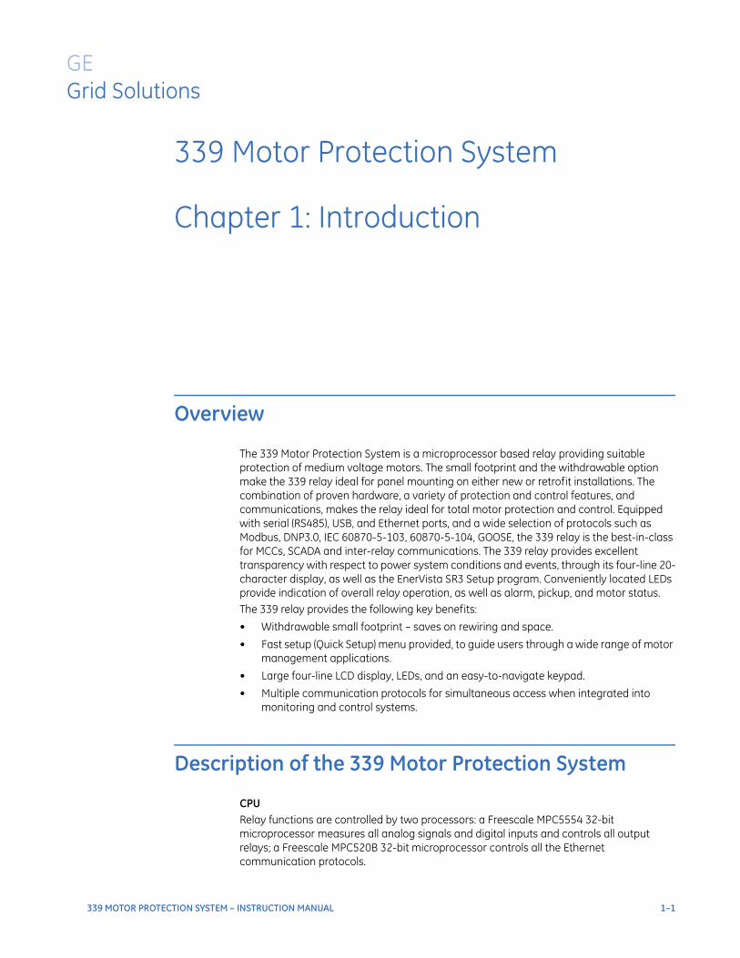
The 339 Motor Protection System is a microprocessor based relay providing suitable protection of medium voltage motors. The small footprint and the withdrawable option make the 339 relay ideal for panel mounting on either new or retrofit installations. The combination of proven hardware, a variety of protection and control features, and communications, makes the relay ideal for total motor protection and control. Equipped with serial (RS485), USB, and Ethernet ports, and a wide selection of protocols such as Modbus, DNP3.0, IEC 60870-5-103, 60870-5-104, GOOSE, the 339 relay is the best-in-class for MCCs, SCADA and inter-relay communications. The 339 relay provides excellent transparency with respect to power system conditions and events, through its four-line 20-character display, as well as the EnerVista SR3 Setup program. Conveniently located LEDs provide indication of overall relay operation, as well as alarm, pickup, and motor status.The 339 relay provides the following key benefits:
• Withdrawable small footprint – saves on rewiring and space.
• Fast setup (Quick Setup) menu provided, to guide users through a wide range of motor management applications.
• Large four-line LCD display, LEDs, and an easy-to-navigate keypad.
• Multiple communication protocols for simultaneous access when integrated into monitoring and control systems.
Description of the 339 Motor Protection System
CPURelay functions are controlled by two processors: a Freescale MPC5554 32-bit microprocessor measures all analog signals and digital inputs and controls all output relays; a Freescale MPC520B 32-bit microprocessor controls all the Ethernet communication protocols.
1–2 339 MOTOR PROTECTION SYSTEM – INSTRUCTION MANUAL
DESCRIPTION OF THE 339 MOTOR PROTECTION SYSTEM CHAPTER 1: INTRODUCTION
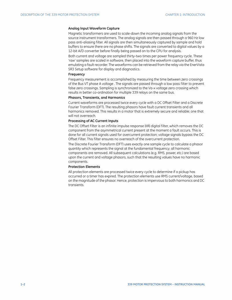
Analog Input Waveform CaptureMagnetic transformers are used to scale-down the incoming analog signals from the source instrument transformers. The analog signals are then passed through a 960 Hz low pass anti-aliasing filter. All signals are then simultaneously captured by sample and hold buffers to ensure there are no phase shifts. The signals are converted to digital values by a 12-bit A/D converter before finally being passed on to the CPU for analysis.Both current and voltage are sampled thirty-two times per power frequency cycle. These ‘raw’ samples are scaled in software, then placed into the waveform capture buffer, thus emulating a fault recorder. The waveforms can be retrieved from the relay via the EnerVista SR3 Setup software for display and diagnostics.FrequencyFrequency measurement is accomplished by measuring the time between zero crossings of the Bus VT phase A voltage . The signals are passed through a low pass filter to prevent false zero crossings. Sampling is synchronized to the Va-x voltage zero crossing which results in better co-ordination for multiple 339 relays on the same bus.Phasors, Transients, and HarmonicsCurrent waveforms are processed twice every cycle with a DC Offset Filter and a Discrete Fourier Transform (DFT). The resulting phasors have fault current transients and all harmonics removed. This results in a motor that is extremely secure and reliable; one that will not overreach.Processing of AC Current InputsThe DC Offset Filter is an infinite impulse response (IIR) digital filter, which removes the DC component from the asymmetrical current present at the moment a fault occurs. This is done for all current signals used for overcurrent protection; voltage signals bypass the DC Offset Filter. This filter ensures no overreach of the overcurrent protection.The Discrete Fourier Transform (DFT) uses exactly one sample cycle to calculate a phasor quantity which represents the signal at the fundamental frequency; all harmonic components are removed. All subsequent calculations (e.g. RMS, power, etc.) are based upon the current and voltage phasors, such that the resulting values have no harmonic components.Protection ElementsAll protection elements are processed twice every cycle to determine if a pickup has occurred or a timer has expired. The protection elements use RMS current/voltage, based on the magnitude of the phasor. Hence, protection is impervious to both harmonics and DC transients.
CHAPTER 1: INTRODUCTION DESCRIPTION OF THE 339 MOTOR PROTECTION SYSTEM
339 MOTOR PROTECTION SYSTEM – INSTRUCTION MANUAL 1–3
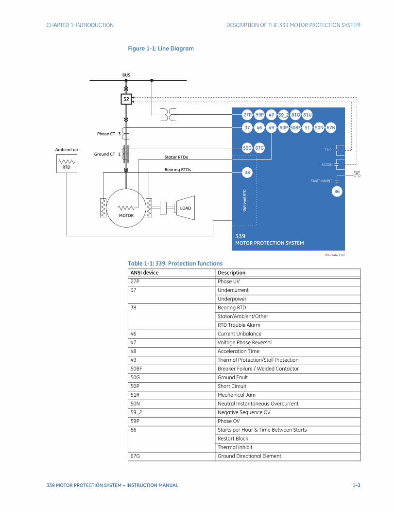
Figure 1-1: Line Diagram
Table 1-1: 339 Protection functions
896814A2.CDR
52
37 46 49 50P 50BF
49
MOTOR
LOAD
Stator RTDs
Bearing RTDs
Phase CT 3
Ground CT 1
BUS
339MOTOR PROTECTION SYSTEM
Ambient air
RTD
38
Op
tio
na
lR
TD
51
86
START
50N
TRIP
CLOSE
START INHIBIT
27P 59P 47 59_2 81O 81U59_2
67G50G
67N
ANSI device Description
27P Phase UV
37 Undercurrent
Underpower
38 Bearing RTD
Stator/Ambient/Other
RTD Trouble Alarm
46 Current Unbalance
47 Voltage Phase Reversal
48 Acceleration Time
49 Thermal Protection/Stall Protection
50BF Breaker Failure / Welded Contactor
50G Ground Fault
50P Short Circuit
51R Mechanical Jam
50N Neutral Instantaneous Overcurrent
59_2 Negative Sequence OV
59P Phase OV
66 Starts per Hour & Time Between Starts
Restart Block
Thermal Inhibit
67G Ground Directional Element

1–4 339 MOTOR PROTECTION SYSTEM – INSTRUCTION MANUAL
DESCRIPTION OF THE 339 MOTOR PROTECTION SYSTEM CHAPTER 1: INTRODUCTION
67N Neutral Directional Element
81O Overfrequency
81U Underfrequency
86 Lockout
VTFF VT Fuse Failure
ANSI device Description
CHAPTER 1: INTRODUCTION DESCRIPTION OF THE 339 MOTOR PROTECTION SYSTEM
339 MOTOR PROTECTION SYSTEM – INSTRUCTION MANUAL 1–5
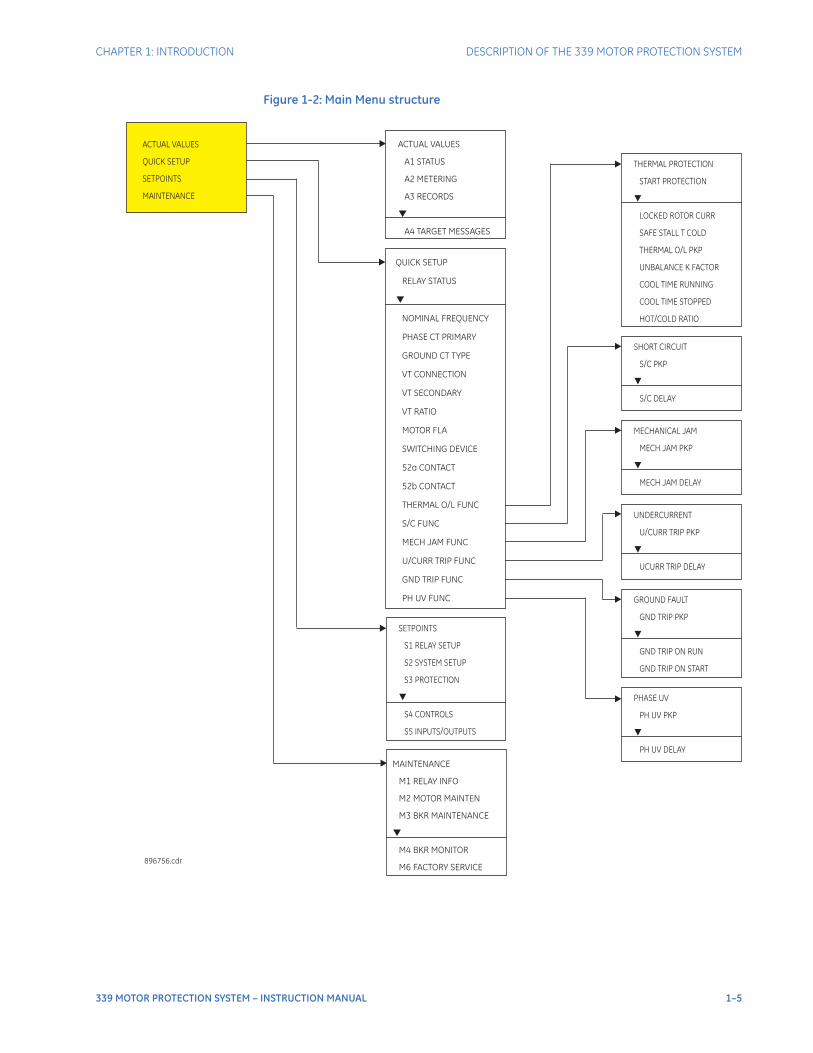
Figure 1-2: Main Menu structure
ACTUAL VALUES
QUICK SETUP
SETPOINTS
MAINTENANCE
ACTUAL VALUES
A1 STATUS
A2 METERING
A3 RECORDS
A4 TARGET MESSAGES
QUICK SETUP
RELAY STATUS
NOMINAL FREQUENCY
GROUND CT TYPE
VT CONNECTION
VT SECONDARY
VT RATIO
MOTOR FLA
THERMAL O/L FUNC
S/C FUNC
MECH JAM FUNC
U/CURR TRIP FUNC
GND TRIP FUNC
PH UV FUNC
PHASE CT PRIMARY
SWITCHING DEVICE
52a CONTACT
52b CONTACT
SETPOINTS
S1 RELAY SETUP
S2 SYSTEM SETUP
S3 PROTECTION
S4 CONTROLS
S5 INPUTS/OUTPUTS
MAINTENANCE
M1 RELAY INFO
M2 MOTOR MAINTEN
M3 BKR MAINTENANCE
M4 BKR MONITOR
M6 FACTORY SERVICE
896756.cdr
THERMAL PROTECTION
START PROTECTION
SAFE STALL T COLD
THERMAL O/L PKP
UNBALANCE K FACTOR
COOL TIME RUNNING
COOL TIME STOPPED
HOT/COLD RATIO
LOCKED ROTOR CURR
SHORT CIRCUIT
S/C PKP
S/C DELAY
MECHANICAL JAM
MECH JAM PKP
MECH JAM DELAY
UNDERCURRENT
U/CURR TRIP PKP
UCURR TRIP DELAY
GROUND FAULT
GND TRIP PKP
GND TRIP ON RUN
GND TRIP ON START
PHASE UV
PH UV PKP
PH UV DELAY
1–6 339 MOTOR PROTECTION SYSTEM – INSTRUCTION MANUAL
339 ORDER CODES CHAPTER 1: INTRODUCTION
339 order codes
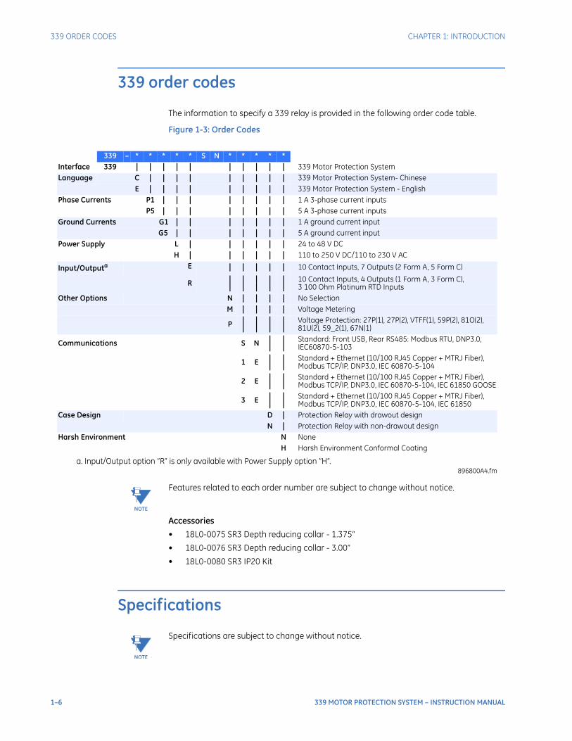
The information to specify a 339 relay is provided in the following order code table.
Figure 1-3: Order Codes
NOTE
NOTE: Features related to each order number are subject to change without notice.
Accessories
• 18L0-0075 SR3 Depth reducing collar - 1.375”
• 18L0-0076 SR3 Depth reducing collar - 3.00”
• 18L0-0080 SR3 IP20 Kit
Specifications
NOTE
NOTE: Specifications are subject to change without notice.
a. Input/Output option R is only available with Power Supply option H.896800A4.fm
339 * * * * * S N * * * * *Interface 339 | | | | | | | | | | 339 Motor Protection SystemLanguage C | | | | | | | | | 339 Motor Protection System- Chinese
E | | | | | | | | | 339 Motor Protection System - EnglishPhase Currents P1 | | | | | | | | 1 A 3-phase current inputs
P5 | | | | | | | | 5 A 3-phase current inputsGround Currents G1 | | | | | | | 1 A ground current input
G5 | | | | | | | 5 A ground current inputPower Supply L | | | | | | 24 to 48 V DC
H | | | | | | 110 to 250 V DC/110 to 230 V AC
Input/Outputa E | | | | | 10 Contact Inputs, 7 Outputs (2 Form A, 5 Form C)
R ||
||
||
||
||
10 Contact Inputs, 4 Outputs (1 Form A, 3 Form C), 3 100 Ohm Platinum RTD Inputs
Other Options N | | | | No SelectionM | | | | Voltage Metering
P ||
||
||
||
Voltage Protection: 27P(1), 27P(2), VTFF(1), 59P(2), 81O(2), 81U(2), 59_2(1), 67N(1)
Communications S N ||
||
Standard: Front USB, Rear RS485: Modbus RTU, DNP3.0, IEC60870-5-103
1 E ||
||
Standard + Ethernet (10/100 RJ45 Copper + MTRJ Fiber), Modbus TCP/IP, DNP3.0, IEC 60870-5-104
2 E ||
||
Standard + Ethernet (10/100 RJ45 Copper + MTRJ Fiber), Modbus TCP/IP, DNP3.0, IEC 60870-5-104, IEC 61850 GOOSE
3 E ||
||
Standard + Ethernet (10/100 RJ45 Copper + MTRJ Fiber), Modbus TCP/IP, DNP3.0, IEC 60870-5-104, IEC 61850
Case Design D | Protection Relay with drawout designN | Protection Relay with non-drawout design
Harsh Environment N NoneH Harsh Environment Conformal Coating
CHAPTER 1: INTRODUCTION SPECIFICATIONS
339 MOTOR PROTECTION SYSTEM – INSTRUCTION MANUAL 1–7
NOTE
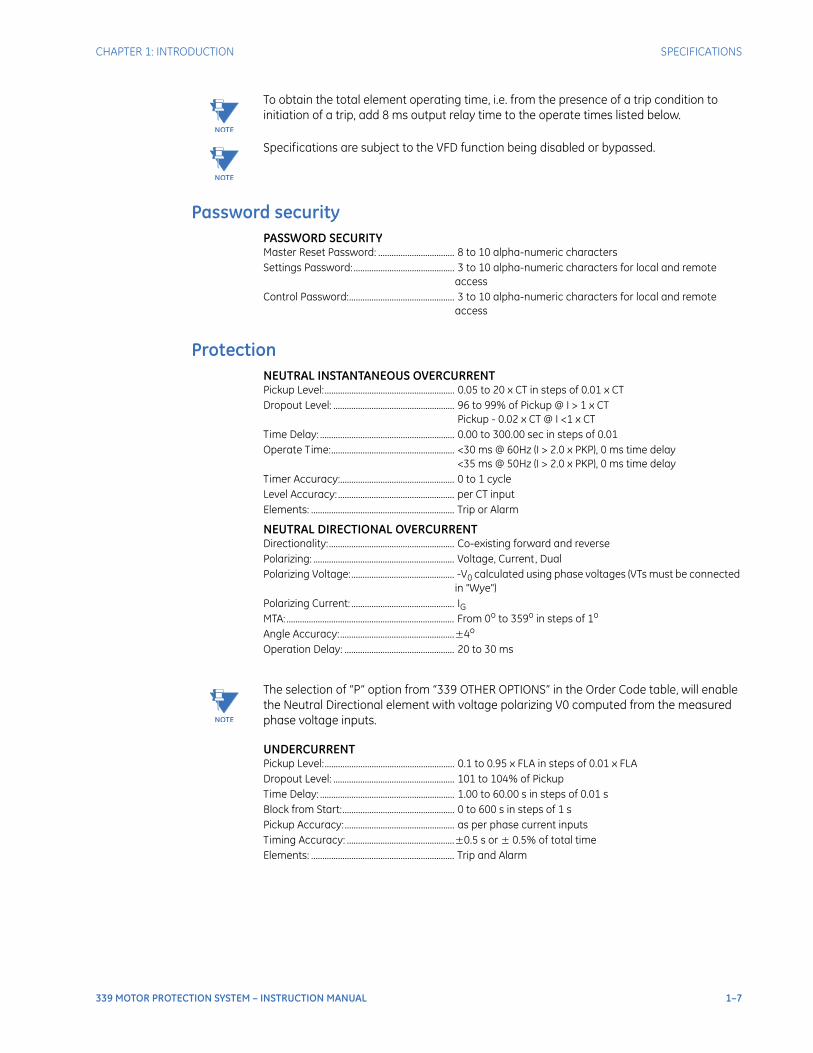
NOTE: To obtain the total element operating time, i.e. from the presence of a trip condition to initiation of a trip, add 8 ms output relay time to the operate times listed below.
NOTE
NOTE: Specifications are subject to the VFD function being disabled or bypassed.
Password securityPASSWORD SECURITYMaster Reset Password: .................................. 8 to 10 alpha-numeric charactersSettings Password: ............................................. 3 to 10 alpha-numeric characters for local and remote
accessControl Password:............................................... 3 to 10 alpha-numeric characters for local and remote
access
ProtectionNEUTRAL INSTANTANEOUS OVERCURRENTPickup Level:.......................................................... 0.05 to 20 x CT in steps of 0.01 x CTDropout Level: ...................................................... 96 to 99% of Pickup @ I > 1 x CT
Pickup - 0.02 x CT @ I <1 x CTTime Delay: ............................................................ 0.00 to 300.00 sec in steps of 0.01Operate Time:....................................................... <30 ms @ 60Hz (I > 2.0 x PKP), 0 ms time delay
<35 ms @ 50Hz (I > 2.0 x PKP), 0 ms time delayTimer Accuracy:................................................... 0 to 1 cycleLevel Accuracy: .................................................... per CT inputElements: ................................................................ Trip or Alarm
NEUTRAL DIRECTIONAL OVERCURRENTDirectionality:........................................................ Co-existing forward and reversePolarizing: ............................................................... Voltage, Current, DualPolarizing Voltage:.............................................. -V0 calculated using phase voltages (VTs must be connected
in "Wye")Polarizing Current: .............................................. IGMTA: ........................................................................... From 0o to 359o in steps of 1o
Angle Accuracy:...................................................±4o
Operation Delay: ................................................. 20 to 30 ms
NOTE
NOTE: The selection of “P” option from “339 OTHER OPTIONS” in the Order Code table, will enable the Neutral Directional element with voltage polarizing V0 computed from the measured phase voltage inputs.
UNDERCURRENTPickup Level:.......................................................... 0.1 to 0.95 x FLA in steps of 0.01 x FLADropout Level: ...................................................... 101 to 104% of PickupTime Delay: ............................................................ 1.00 to 60.00 s in steps of 0.01 sBlock from Start:.................................................. 0 to 600 s in steps of 1 sPickup Accuracy:................................................. as per phase current inputsTiming Accuracy: ................................................±0.5 s or ± 0.5% of total timeElements: ................................................................ Trip and Alarm
1–8 339 MOTOR PROTECTION SYSTEM – INSTRUCTION MANUAL
SPECIFICATIONS CHAPTER 1: INTRODUCTION
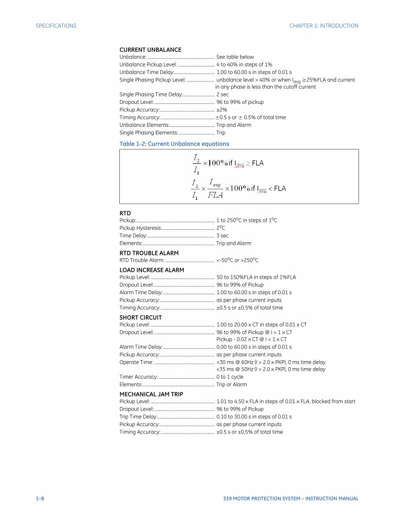
CURRENT UNBALANCEUnbalance: ............................................................ See table belowUnbalance Pickup Level: ................................. 4 to 40% in steps of 1%Unbalance Time Delay:.................................... 1.00 to 60.00 s in steps of 0.01 sSingle Phasing Pickup Level: ......................... unbalance level > 40% or when Iavg ≥25%FLA and current
in any phase is less than the cutoff currentSingle Phasing Time Delay:............................ 2 secDropout Level: ...................................................... 96 to 99% of pickupPickup Accuracy:................................................. ±2%Timing Accuracy: ................................................±0.5 s or ± 0.5% of total timeUnbalance Elements:........................................ Trip and AlarmSingle Phasing Elements: ................................ Trip
Table 1-2: Current Unbalance equations
RTDPickup:...................................................................... 1 to 250oC in steps of 1oCPickup Hysteresis:............................................... 2oCTime Delay:............................................................ 3 sec Elements: ................................................................ Trip and Alarm
RTD TROUBLE ALARMRTD Trouble Alarm: ............................................ <-50oC or >250oC
LOAD INCREASE ALARMPickup Level: ......................................................... 50 to 150%FLA in steps of 1%FLADropout Level: ...................................................... 96 to 99% of PickupAlarm Time Delay: .............................................. 1.00 to 60.00 s in steps of 0.01 sPickup Accuracy:................................................. as per phase current inputsTiming Accuracy: ................................................ ±0.5 s or ±0.5% of total time
SHORT CIRCUITPickup Level: ......................................................... 1.00 to 20.00 x CT in steps of 0.01 x CTDropout Level: ...................................................... 96 to 99% of Pickup @ I > 1 x CT
Pickup - 0.02 x CT @ I < 1 x CTAlarm Time Delay: .............................................. 0.00 to 60.00 s in steps of 0.01 sPickup Accuracy:................................................. as per phase current inputsOperate Time: ...................................................... <30 ms @ 60Hz (I > 2.0 x PKP), 0 ms time delay
<35 ms @ 50Hz (I > 2.0 x PKP), 0 ms time delayTimer Accuracy: .................................................. 0 to 1 cycleElements: ................................................................ Trip or Alarm
MECHANICAL JAM TRIPPickup Level: ......................................................... 1.01 to 4.50 x FLA in steps of 0.01 x FLA, blocked from startDropout Level: ...................................................... 96 to 99% of PickupTrip Time Delay:................................................... 0.10 to 30.00 s in steps of 0.01 sPickup Accuracy:................................................. as per phase current inputsTiming Accuracy: ................................................ ±0.5 s or ±0.5% of total time
CHAPTER 1: INTRODUCTION SPECIFICATIONS
339 MOTOR PROTECTION SYSTEM – INSTRUCTION MANUAL 1–9
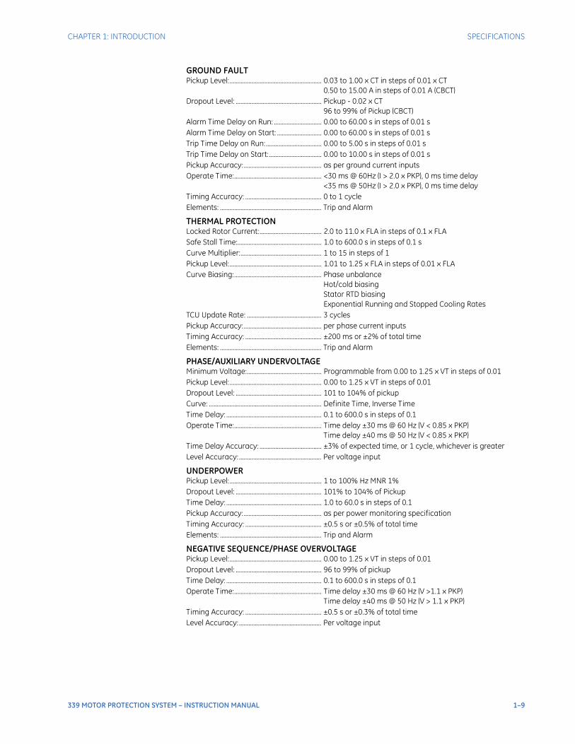
GROUND FAULTPickup Level:.......................................................... 0.03 to 1.00 x CT in steps of 0.01 x CT
0.50 to 15.00 A in steps of 0.01 A (CBCT)Dropout Level: ...................................................... Pickup - 0.02 x CT
96 to 99% of Pickup (CBCT)Alarm Time Delay on Run: .............................. 0.00 to 60.00 s in steps of 0.01 sAlarm Time Delay on Start: ............................ 0.00 to 60.00 s in steps of 0.01 sTrip Time Delay on Run:................................... 0.00 to 5.00 s in steps of 0.01 sTrip Time Delay on Start:................................. 0.00 to 10.00 s in steps of 0.01 sPickup Accuracy:................................................. as per ground current inputsOperate Time:....................................................... <30 ms @ 60Hz (I > 2.0 x PKP), 0 ms time delay
<35 ms @ 50Hz (I > 2.0 x PKP), 0 ms time delayTiming Accuracy: ................................................ 0 to 1 cycleElements: ................................................................ Trip and Alarm
THERMAL PROTECTIONLocked Rotor Current:....................................... 2.0 to 11.0 x FLA in steps of 0.1 x FLASafe Stall Time:..................................................... 1.0 to 600.0 s in steps of 0.1 sCurve Multiplier:................................................... 1 to 15 in steps of 1Pickup Level:.......................................................... 1.01 to 1.25 x FLA in steps of 0.01 x FLACurve Biasing:....................................................... Phase unbalance
Hot/cold biasing Stator RTD biasing Exponential Running and Stopped Cooling Rates
TCU Update Rate: ............................................... 3 cyclesPickup Accuracy:................................................. per phase current inputsTiming Accuracy: ................................................ ±200 ms or ±2% of total timeElements: ................................................................ Trip and Alarm
PHASE/AUXILIARY UNDERVOLTAGEMinimum Voltage:............................................... Programmable from 0.00 to 1.25 x VT in steps of 0.01Pickup Level:.......................................................... 0.00 to 1.25 x VT in steps of 0.01Dropout Level: ...................................................... 101 to 104% of pickupCurve: ....................................................................... Definite Time, Inverse TimeTime Delay: ............................................................ 0.1 to 600.0 s in steps of 0.1Operate Time:....................................................... Time delay ±30 ms @ 60 Hz (V < 0.85 x PKP)
Time delay ±40 ms @ 50 Hz (V < 0.85 x PKP)Time Delay Accuracy: ....................................... ±3% of expected time, or 1 cycle, whichever is greaterLevel Accuracy: .................................................... Per voltage input
UNDERPOWERPickup Level:.......................................................... 1 to 100% Hz MNR 1%Dropout Level: ...................................................... 101% to 104% of PickupTime Delay: ............................................................ 1.0 to 60.0 s in steps of 0.1Pickup Accuracy:................................................. as per power monitoring specificationTiming Accuracy: ................................................ ±0.5 s or ±0.5% of total timeElements: ................................................................ Trip and Alarm
NEGATIVE SEQUENCE/PHASE OVERVOLTAGEPickup Level:.......................................................... 0.00 to 1.25 x VT in steps of 0.01Dropout Level: ...................................................... 96 to 99% of pickupTime Delay: ............................................................ 0.1 to 600.0 s in steps of 0.1Operate Time:....................................................... Time delay ±30 ms @ 60 Hz (V >1.1 x PKP)
Time delay ±40 ms @ 50 Hz (V > 1.1 x PKP)Timing Accuracy: ................................................ ±0.5 s or ±0.3% of total timeLevel Accuracy: .................................................... Per voltage input
1–10 339 MOTOR PROTECTION SYSTEM – INSTRUCTION MANUAL
SPECIFICATIONS CHAPTER 1: INTRODUCTION
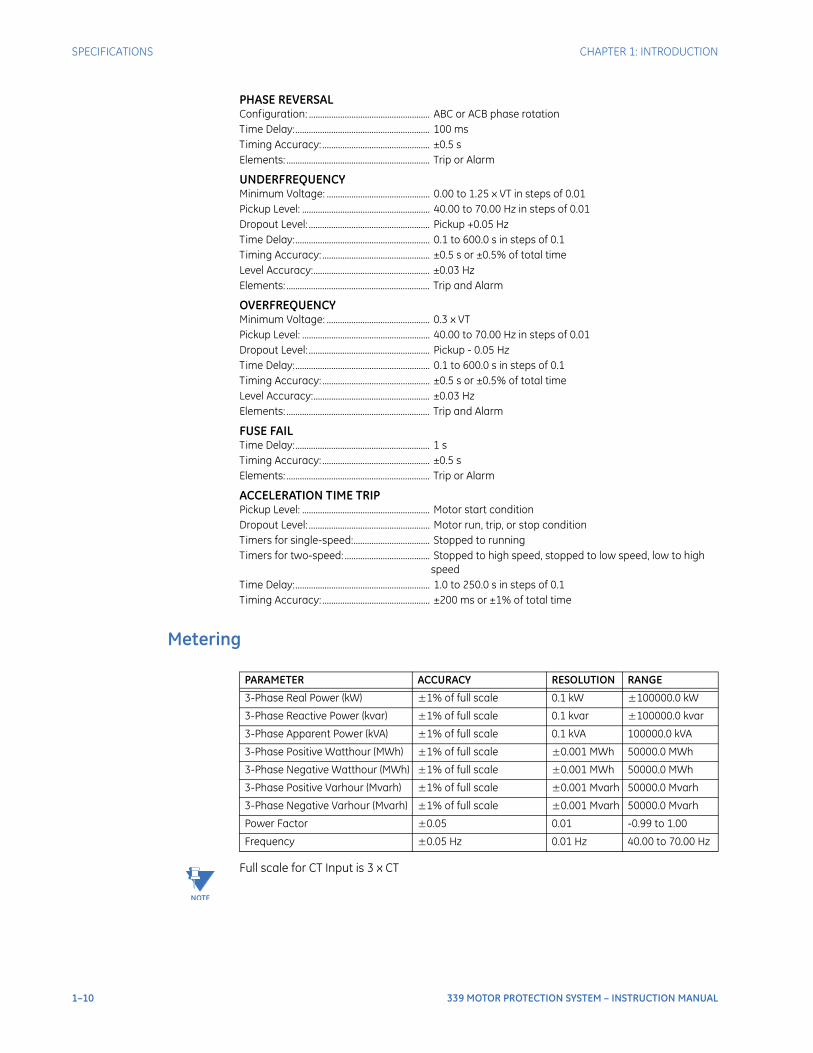
PHASE REVERSALConfiguration: ...................................................... ABC or ACB phase rotationTime Delay:............................................................ 100 msTiming Accuracy: ................................................ ±0.5 sElements: ................................................................ Trip or Alarm
UNDERFREQUENCYMinimum Voltage: .............................................. 0.00 to 1.25 x VT in steps of 0.01Pickup Level: ......................................................... 40.00 to 70.00 Hz in steps of 0.01Dropout Level: ...................................................... Pickup +0.05 HzTime Delay:............................................................ 0.1 to 600.0 s in steps of 0.1Timing Accuracy: ................................................ ±0.5 s or ±0.5% of total timeLevel Accuracy:.................................................... ±0.03 HzElements: ................................................................ Trip and Alarm
OVERFREQUENCYMinimum Voltage: .............................................. 0.3 x VTPickup Level: ......................................................... 40.00 to 70.00 Hz in steps of 0.01Dropout Level: ...................................................... Pickup - 0.05 HzTime Delay:............................................................ 0.1 to 600.0 s in steps of 0.1Timing Accuracy: ................................................ ±0.5 s or ±0.5% of total timeLevel Accuracy:.................................................... ±0.03 HzElements: ................................................................ Trip and Alarm
FUSE FAILTime Delay:............................................................ 1 sTiming Accuracy: ................................................ ±0.5 sElements: ................................................................ Trip or Alarm
ACCELERATION TIME TRIPPickup Level: ......................................................... Motor start conditionDropout Level: ...................................................... Motor run, trip, or stop conditionTimers for single-speed:.................................. Stopped to runningTimers for two-speed: ...................................... Stopped to high speed, stopped to low speed, low to high
speedTime Delay:............................................................ 1.0 to 250.0 s in steps of 0.1Timing Accuracy: ................................................ ±200 ms or ±1% of total time
Metering
NOTE
NOTE: Full scale for CT Input is 3 x CT
PARAMETER ACCURACY RESOLUTION RANGE
3-Phase Real Power (kW) ±1% of full scale 0.1 kW ±100000.0 kW
3-Phase Reactive Power (kvar) ±1% of full scale 0.1 kvar ±100000.0 kvar
3-Phase Apparent Power (kVA) ±1% of full scale 0.1 kVA 100000.0 kVA
3-Phase Positive Watthour (MWh) ±1% of full scale ±0.001 MWh 50000.0 MWh
3-Phase Negative Watthour (MWh) ±1% of full scale ±0.001 MWh 50000.0 MWh
3-Phase Positive Varhour (Mvarh) ±1% of full scale ±0.001 Mvarh 50000.0 Mvarh
3-Phase Negative Varhour (Mvarh) ±1% of full scale ±0.001 Mvarh 50000.0 Mvarh
Power Factor ±0.05 0.01 -0.99 to 1.00
Frequency ±0.05 Hz 0.01 Hz 40.00 to 70.00 Hz
CHAPTER 1: INTRODUCTION SPECIFICATIONS
339 MOTOR PROTECTION SYSTEM – INSTRUCTION MANUAL 1–11
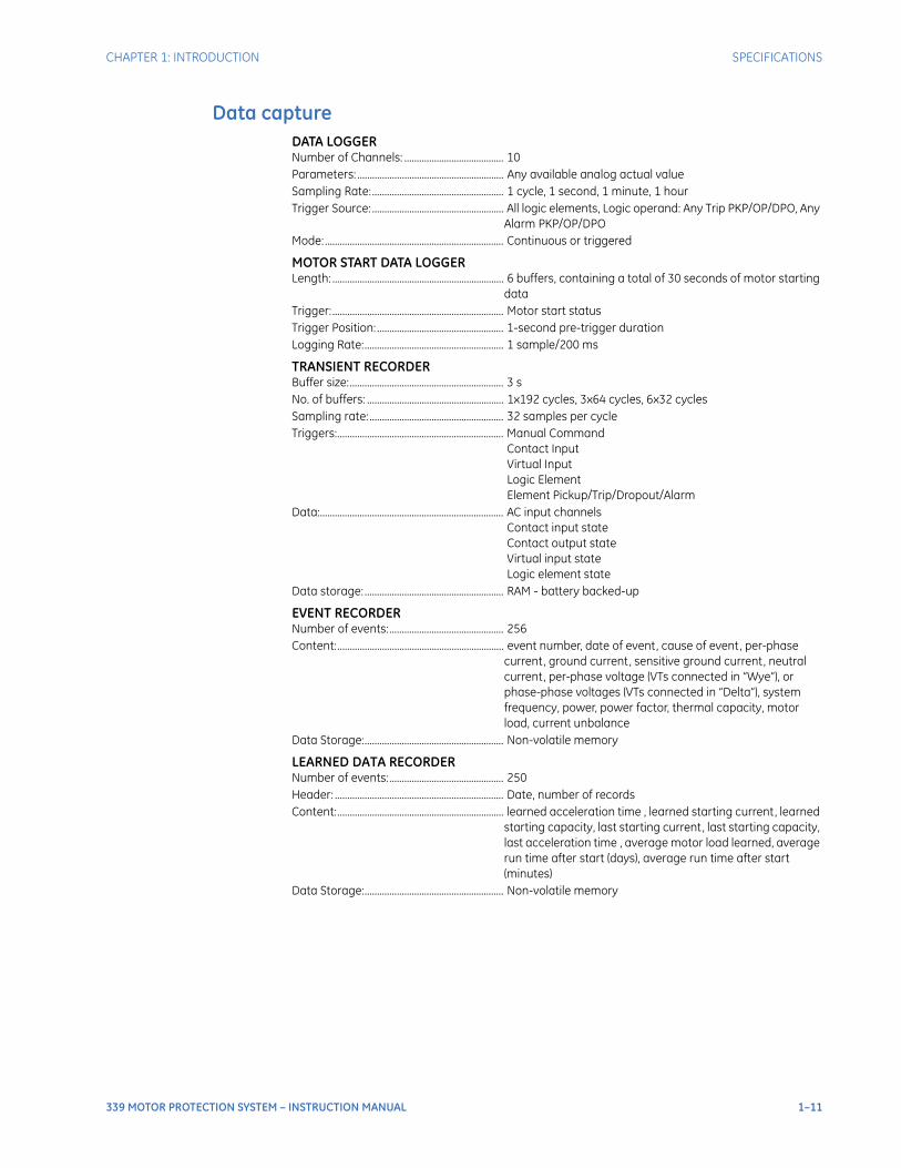
Data captureDATA LOGGERNumber of Channels: ........................................ 10Parameters: ........................................................... Any available analog actual valueSampling Rate:..................................................... 1 cycle, 1 second, 1 minute, 1 hourTrigger Source: ..................................................... All logic elements, Logic operand: Any Trip PKP/OP/DPO, Any
Alarm PKP/OP/DPOMode: ........................................................................ Continuous or triggered
MOTOR START DATA LOGGERLength: ..................................................................... 6 buffers, containing a total of 30 seconds of motor starting
dataTrigger:..................................................................... Motor start statusTrigger Position: ................................................... 1-second pre-trigger durationLogging Rate:........................................................ 1 sample/200 ms
TRANSIENT RECORDERBuffer size:.............................................................. 3 s No. of buffers: ....................................................... 1x192 cycles, 3x64 cycles, 6x32 cyclesSampling rate: ...................................................... 32 samples per cycleTriggers:................................................................... Manual Command
Contact Input Virtual Input Logic Element Element Pickup/Trip/Dropout/Alarm
Data:.......................................................................... AC input channels Contact input state Contact output state Virtual input state Logic element state
Data storage: ........................................................ RAM - battery backed-up
EVENT RECORDERNumber of events:.............................................. 256 Content:................................................................... event number, date of event, cause of event, per-phase
current, ground current, sensitive ground current, neutral current, per-phase voltage (VTs connected in “Wye”), or phase-phase voltages (VTs connected in “Delta”), system frequency, power, power factor, thermal capacity, motor load, current unbalance
Data Storage:........................................................ Non-volatile memory
LEARNED DATA RECORDERNumber of events:.............................................. 250 Header: .................................................................... Date, number of recordsContent:................................................................... learned acceleration time , learned starting current, learned
starting capacity, last starting current, last starting capacity, last acceleration time , average motor load learned, average run time after start (days), average run time after start (minutes)
Data Storage:........................................................ Non-volatile memory
1–12 339 MOTOR PROTECTION SYSTEM – INSTRUCTION MANUAL
SPECIFICATIONS CHAPTER 1: INTRODUCTION
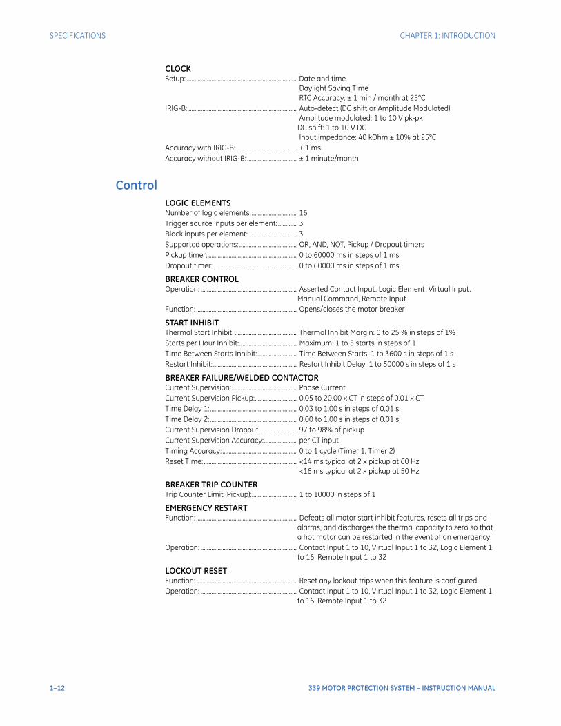
CLOCKSetup: ....................................................................... Date and time
Daylight Saving Time RTC Accuracy: ± 1 min / month at 25°C
IRIG-B: ...................................................................... Auto-detect (DC shift or Amplitude Modulated) Amplitude modulated: 1 to 10 V pk-pk DC shift: 1 to 10 V DC Input impedance: 40 kOhm ± 10% at 25°C
Accuracy with IRIG-B: ....................................... ± 1 msAccuracy without IRIG-B: ................................ ± 1 minute/month
ControlLOGIC ELEMENTSNumber of logic elements: ............................. 16Trigger source inputs per element: ............ 3Block inputs per element: ............................... 3Supported operations: ..................................... OR, AND, NOT, Pickup / Dropout timersPickup timer: ......................................................... 0 to 60000 ms in steps of 1 msDropout timer:...................................................... 0 to 60000 ms in steps of 1 ms
BREAKER CONTROLOperation: .............................................................. Asserted Contact Input, Logic Element, Virtual Input,
Manual Command, Remote InputFunction: ................................................................. Opens/closes the motor breaker
START INHIBITThermal Start Inhibit: ........................................ Thermal Inhibit Margin: 0 to 25 % in steps of 1%Starts per Hour Inhibit:..................................... Maximum: 1 to 5 starts in steps of 1Time Between Starts Inhibit: ......................... Time Between Starts: 1 to 3600 s in steps of 1 sRestart Inhibit: ...................................................... Restart Inhibit Delay: 1 to 50000 s in steps of 1 s
BREAKER FAILURE/WELDED CONTACTORCurrent Supervision:.......................................... Phase CurrentCurrent Supervision Pickup:........................... 0.05 to 20.00 x CT in steps of 0.01 x CTTime Delay 1: ........................................................ 0.03 to 1.00 s in steps of 0.01 sTime Delay 2: ........................................................ 0.00 to 1.00 s in steps of 0.01 sCurrent Supervision Dropout: ....................... 97 to 98% of pickupCurrent Supervision Accuracy:..................... per CT inputTiming Accuracy: ................................................ 0 to 1 cycle (Timer 1, Timer 2)Reset Time: ............................................................ <14 ms typical at 2 x pickup at 60 Hz
<16 ms typical at 2 x pickup at 50 Hz
BREAKER TRIP COUNTERTrip Counter Limit (Pickup):............................. 1 to 10000 in steps of 1
EMERGENCY RESTARTFunction: ................................................................. Defeats all motor start inhibit features, resets all trips and
alarms, and discharges the thermal capacity to zero so that a hot motor can be restarted in the event of an emergency
Operation: .............................................................. Contact Input 1 to 10, Virtual Input 1 to 32, Logic Element 1 to 16, Remote Input 1 to 32
LOCKOUT RESETFunction: ................................................................. Reset any lockout trips when this feature is configured.Operation: .............................................................. Contact Input 1 to 10, Virtual Input 1 to 32, Logic Element 1
to 16, Remote Input 1 to 32
CHAPTER 1: INTRODUCTION SPECIFICATIONS
339 MOTOR PROTECTION SYSTEM – INSTRUCTION MANUAL 1–13
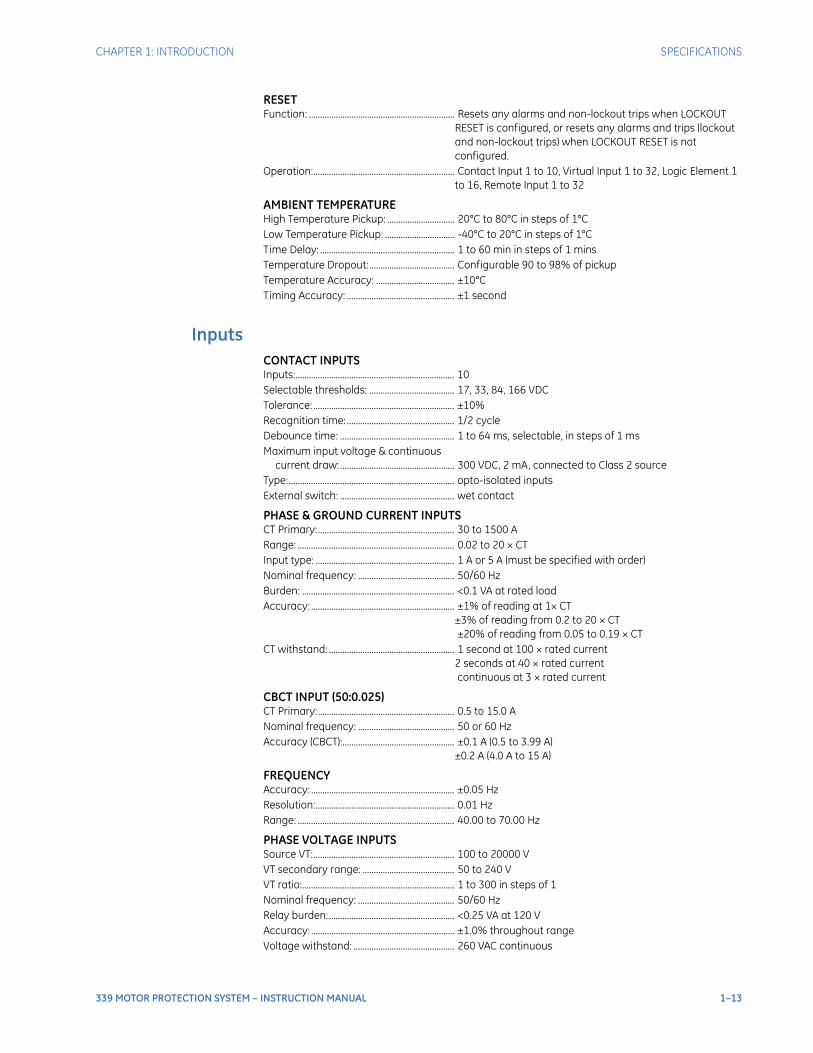
RESETFunction: ................................................................. Resets any alarms and non-lockout trips when LOCKOUT
RESET is configured, or resets any alarms and trips (lockout and non-lockout trips) when LOCKOUT RESET is not configured.
Operation:............................................................... Contact Input 1 to 10, Virtual Input 1 to 32, Logic Element 1 to 16, Remote Input 1 to 32
AMBIENT TEMPERATUREHigh Temperature Pickup: .............................. 20°C to 80°C in steps of 1°CLow Temperature Pickup: ............................... -40°C to 20°C in steps of 1°CTime Delay: ............................................................ 1 to 60 min in steps of 1 minsTemperature Dropout:...................................... Configurable 90 to 98% of pickupTemperature Accuracy: ................................... ±10°CTiming Accuracy: ................................................ ±1 second
InputsCONTACT INPUTSInputs:....................................................................... 10Selectable thresholds: ...................................... 17, 33, 84, 166 VDCTolerance: ............................................................... ±10%Recognition time: ................................................ 1/2 cycleDebounce time: ................................................... 1 to 64 ms, selectable, in steps of 1 msMaximum input voltage & continuous
current draw:................................................... 300 VDC, 2 mA, connected to Class 2 sourceType:.......................................................................... opto-isolated inputsExternal switch: ................................................... wet contact
PHASE & GROUND CURRENT INPUTSCT Primary:............................................................. 30 to 1500 ARange: ...................................................................... 0.02 to 20 × CTInput type: .............................................................. 1 A or 5 A (must be specified with order)Nominal frequency: ........................................... 50/60 HzBurden: .................................................................... <0.1 VA at rated loadAccuracy: ................................................................ ±1% of reading at 1× CT
±3% of reading from 0.2 to 20 × CT ±20% of reading from 0.05 to 0.19 × CT
CT withstand: ........................................................ 1 second at 100 × rated current 2 seconds at 40 × rated current continuous at 3 × rated current
CBCT INPUT (50:0.025)CT Primary:............................................................. 0.5 to 15.0 ANominal frequency: ........................................... 50 or 60 HzAccuracy (CBCT):.................................................. ±0.1 A (0.5 to 3.99 A)
±0.2 A (4.0 A to 15 A)
FREQUENCYAccuracy: ................................................................ ±0.05 HzResolution:.............................................................. 0.01 HzRange: ...................................................................... 40.00 to 70.00 Hz
PHASE VOLTAGE INPUTSSource VT:............................................................... 100 to 20000 VVT secondary range: ......................................... 50 to 240 VVT ratio:.................................................................... 1 to 300 in steps of 1Nominal frequency: ........................................... 50/60 HzRelay burden:........................................................ <0.25 VA at 120 VAccuracy: ................................................................ ±1.0% throughout rangeVoltage withstand: ............................................. 260 VAC continuous
1–14 339 MOTOR PROTECTION SYSTEM – INSTRUCTION MANUAL
SPECIFICATIONS CHAPTER 1: INTRODUCTION
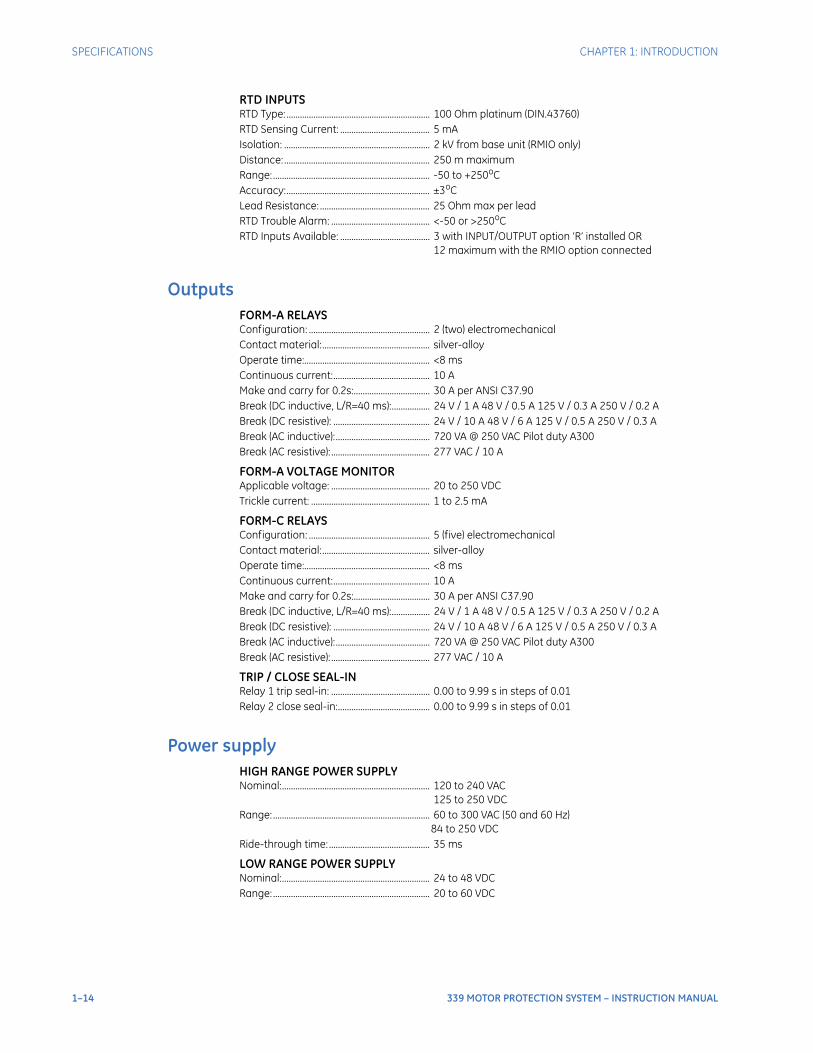
RTD INPUTSRTD Type: ................................................................ 100 Ohm platinum (DIN.43760)RTD Sensing Current: ........................................ 5 mAIsolation: ................................................................. 2 kV from base unit (RMIO only)Distance: ................................................................. 250 m maximumRange: ...................................................................... -50 to +250oCAccuracy:................................................................ ±3oCLead Resistance: ................................................. 25 Ohm max per leadRTD Trouble Alarm: ............................................ <-50 or >250oCRTD Inputs Available: ........................................ 3 with INPUT/OUTPUT option ‘R’ installed OR
12 maximum with the RMIO option connected
OutputsFORM-A RELAYSConfiguration: ...................................................... 2 (two) electromechanicalContact material:................................................ silver-alloyOperate time:........................................................ <8 msContinuous current:........................................... 10 AMake and carry for 0.2s:.................................. 30 A per ANSI C37.90Break (DC inductive, L/R=40 ms):................. 24 V / 1 A 48 V / 0.5 A 125 V / 0.3 A 250 V / 0.2 ABreak (DC resistive): ........................................... 24 V / 10 A 48 V / 6 A 125 V / 0.5 A 250 V / 0.3 ABreak (AC inductive):.......................................... 720 VA @ 250 VAC Pilot duty A300Break (AC resistive): ............................................ 277 VAC / 10 A
FORM-A VOLTAGE MONITORApplicable voltage: ............................................ 20 to 250 VDCTrickle current: ..................................................... 1 to 2.5 mA
FORM-C RELAYSConfiguration: ...................................................... 5 (five) electromechanicalContact material:................................................ silver-alloyOperate time:........................................................ <8 msContinuous current:........................................... 10 AMake and carry for 0.2s:.................................. 30 A per ANSI C37.90Break (DC inductive, L/R=40 ms):................. 24 V / 1 A 48 V / 0.5 A 125 V / 0.3 A 250 V / 0.2 ABreak (DC resistive): ........................................... 24 V / 10 A 48 V / 6 A 125 V / 0.5 A 250 V / 0.3 ABreak (AC inductive):.......................................... 720 VA @ 250 VAC Pilot duty A300Break (AC resistive): ............................................ 277 VAC / 10 A
TRIP / CLOSE SEAL-INRelay 1 trip seal-in: ............................................ 0.00 to 9.99 s in steps of 0.01Relay 2 close seal-in:......................................... 0.00 to 9.99 s in steps of 0.01
Power supplyHIGH RANGE POWER SUPPLYNominal:.................................................................. 120 to 240 VAC
125 to 250 VDCRange: ...................................................................... 60 to 300 VAC (50 and 60 Hz)
84 to 250 VDCRide-through time: ............................................. 35 ms
LOW RANGE POWER SUPPLYNominal:.................................................................. 24 to 48 VDCRange: ...................................................................... 20 to 60 VDC
CHAPTER 1: INTRODUCTION SPECIFICATIONS
339 MOTOR PROTECTION SYSTEM – INSTRUCTION MANUAL 1–15
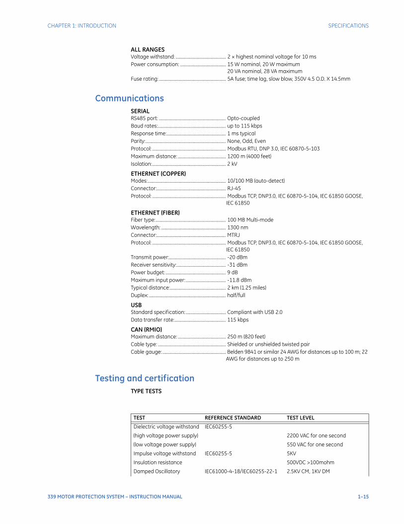
ALL RANGESVoltage withstand: ............................................. 2 × highest nominal voltage for 10 msPower consumption: ......................................... 15 W nominal, 20 W maximum
20 VA nominal, 28 VA maximumFuse rating: ............................................................ 5A fuse; time lag, slow blow, 350V 4.5 O.D. X 14.5mm
CommunicationsSERIALRS485 port: ............................................................ Opto-coupledBaud rates:............................................................. up to 115 kbpsResponse time:..................................................... 1 ms typicalParity:........................................................................ None, Odd, EvenProtocol: .................................................................. Modbus RTU, DNP 3.0, IEC 60870-5-103Maximum distance: ........................................... 1200 m (4000 feet)Isolation:.................................................................. 2 kV
ETHERNET (COPPER)Modes:...................................................................... 10/100 MB (auto-detect)Connector:.............................................................. RJ-45Protocol: .................................................................. Modbus TCP, DNP3.0, IEC 60870-5-104, IEC 61850 GOOSE,
IEC 61850
ETHERNET (FIBER)Fiber type:............................................................... 100 MB Multi-modeWavelength: .......................................................... 1300 nmConnector:.............................................................. MTRJProtocol: .................................................................. Modbus TCP, DNP3.0, IEC 60870-5-104, IEC 61850 GOOSE,
IEC 61850Transmit power:................................................... -20 dBmReceiver sensitivity:............................................ -31 dBmPower budget: ...................................................... 9 dBMaximum input power: .................................... -11.8 dBmTypical distance:.................................................. 2 km (1.25 miles)Duplex: ..................................................................... half/full
USBStandard specification: .................................... Compliant with USB 2.0Data transfer rate:.............................................. 115 kbps
CAN (RMIO)Maximum distance: ........................................... 250 m (820 feet)Cable type: ............................................................. Shielded or unshielded twisted pairCable gauge: ......................................................... Belden 9841 or similar 24 AWG for distances up to 100 m; 22
AWG for distances up to 250 m
Testing and certificationTYPE TESTS
TEST REFERENCE STANDARD TEST LEVEL
Dielectric voltage withstand IEC60255-5
(high voltage power supply) 2200 VAC for one second
(low voltage power supply) 550 VAC for one second
Impulse voltage withstand IEC60255-5 5KV
Insulation resistance 500VDC >100mohm
Damped Oscillatory IEC61000-4-18/IEC60255-22-1 2.5KV CM, 1KV DM
1–16 339 MOTOR PROTECTION SYSTEM – INSTRUCTION MANUAL
SPECIFICATIONS CHAPTER 1: INTRODUCTION
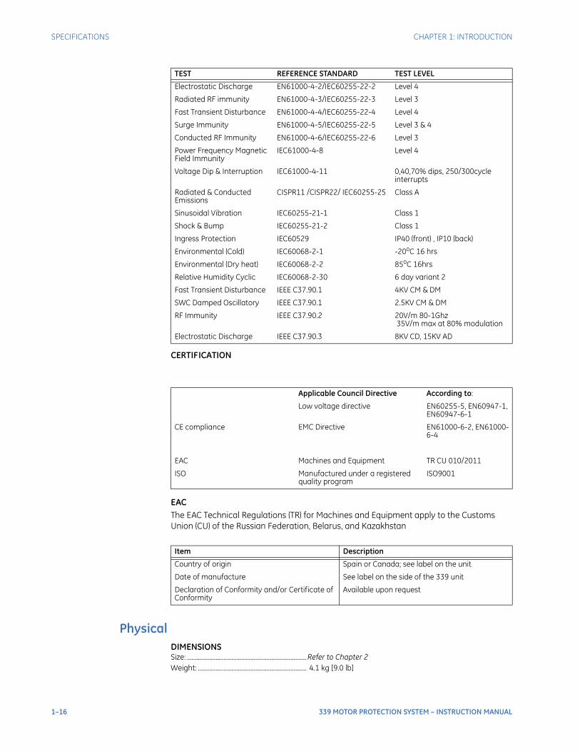
CERTIFICATION
EACThe EAC Technical Regulations (TR) for Machines and Equipment apply to the Customs Union (CU) of the Russian Federation, Belarus, and Kazakhstan
PhysicalDIMENSIONSSize: ........................................................................... Refer to Chapter 2Weight: .................................................................... 4.1 kg [9.0 lb]
Electrostatic Discharge EN61000-4-2/IEC60255-22-2 Level 4
Radiated RF immunity EN61000-4-3/IEC60255-22-3 Level 3
Fast Transient Disturbance EN61000-4-4/IEC60255-22-4 Level 4
Surge Immunity EN61000-4-5/IEC60255-22-5 Level 3 & 4
Conducted RF Immunity EN61000-4-6/IEC60255-22-6 Level 3
Power Frequency Magnetic Field Immunity
IEC61000-4-8 Level 4
Voltage Dip & Interruption IEC61000-4-11 0,40,70% dips, 250/300cycle interrupts
Radiated & Conducted Emissions
CISPR11 /CISPR22/ IEC60255-25 Class A
Sinusoidal Vibration IEC60255-21-1 Class 1
Shock & Bump IEC60255-21-2 Class 1
Ingress Protection IEC60529 IP40 (front) , IP10 (back)
Environmental (Cold) IEC60068-2-1 -20oC 16 hrs
Environmental (Dry heat) IEC60068-2-2 85oC 16hrs
Relative Humidity Cyclic IEC60068-2-30 6 day variant 2
Fast Transient Disturbance IEEE C37.90.1 4KV CM & DM
SWC Damped Oscillatory IEEE C37.90.1 2.5KV CM & DM
RF Immunity IEEE C37.90.2 20V/m 80-1Ghz 35V/m max at 80% modulation
Electrostatic Discharge IEEE C37.90.3 8KV CD, 15KV AD
Applicable Council Directive According to:
Low voltage directive EN60255-5, EN60947-1, EN60947-6-1
CE compliance EMC Directive EN61000-6-2, EN61000-6-4
EAC Machines and Equipment TR CU 010/2011
ISO Manufactured under a registered quality program
ISO9001
Item Description
Country of origin Spain or Canada; see label on the unit
Date of manufacture See label on the side of the 339 unit
Declaration of Conformity and/or Certificate of Conformity
Available upon request
TEST REFERENCE STANDARD TEST LEVEL
CHAPTER 1: INTRODUCTION SPECIFICATIONS
339 MOTOR PROTECTION SYSTEM – INSTRUCTION MANUAL 1–17
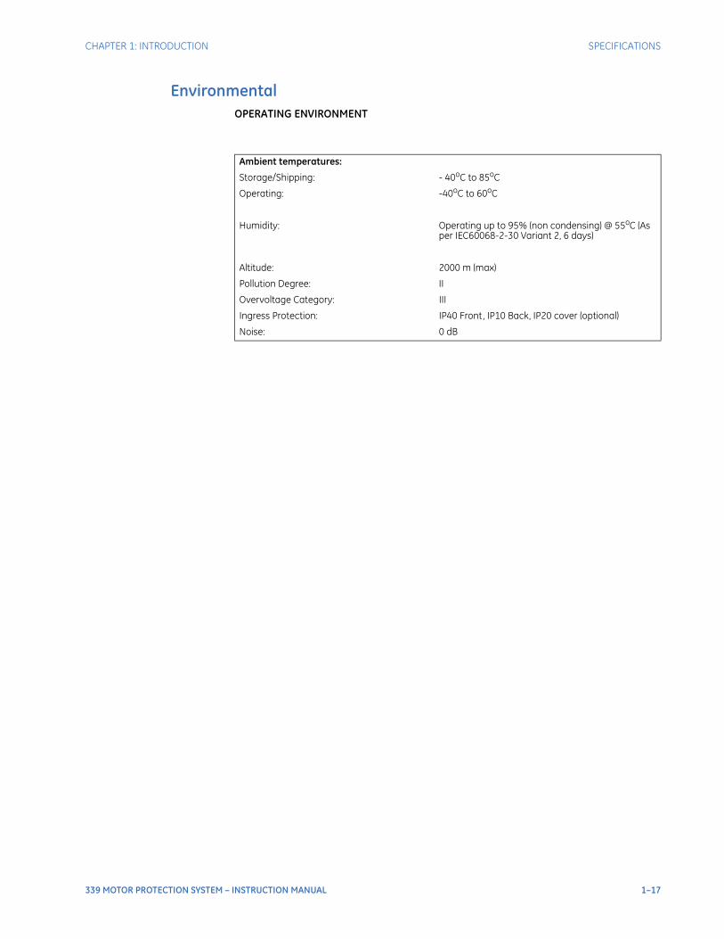
EnvironmentalOPERATING ENVIRONMENT
Ambient temperatures:
Storage/Shipping: - 40oC to 85oC
Operating: -40oC to 60oC
Humidity: Operating up to 95% (non condensing) @ 55oC (As per IEC60068-2-30 Variant 2, 6 days)
Altitude: 2000 m (max)
Pollution Degree: II
Overvoltage Category: III
Ingress Protection: IP40 Front, IP10 Back, IP20 cover (optional)
Noise: 0 dB

1–18 339 MOTOR PROTECTION SYSTEM – INSTRUCTION MANUAL
SPECIFICATIONS CHAPTER 1: INTRODUCTION
339 MOTOR PROTECTION SYSTEM – INSTRUCTION MANUAL 2–1
339 Motor Protection System
Chapter 2: Installation
GEGrid Solutions
Installation
Mechanical installation
This section describes the mechanical installation of the 339 system, including dimensions for mounting and information on module withdrawal and insertion.
DimensionsThe dimensions of the 339 are shown below. Additional dimensions for mounting and panel cutouts are shown in the following sections.
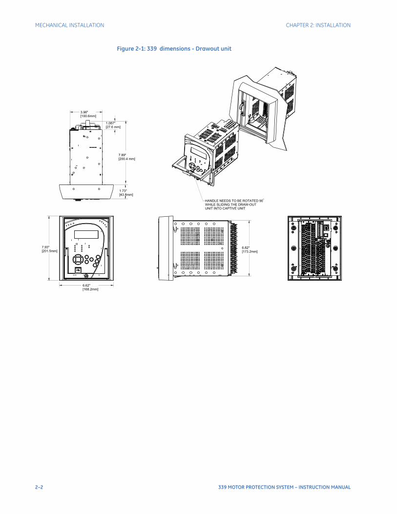
2–2 339 MOTOR PROTECTION SYSTEM – INSTRUCTION MANUAL
MECHANICAL INSTALLATION CHAPTER 2: INSTALLATION
Figure 2-1: 339 dimensions - Drawout unit
1 0 77 6
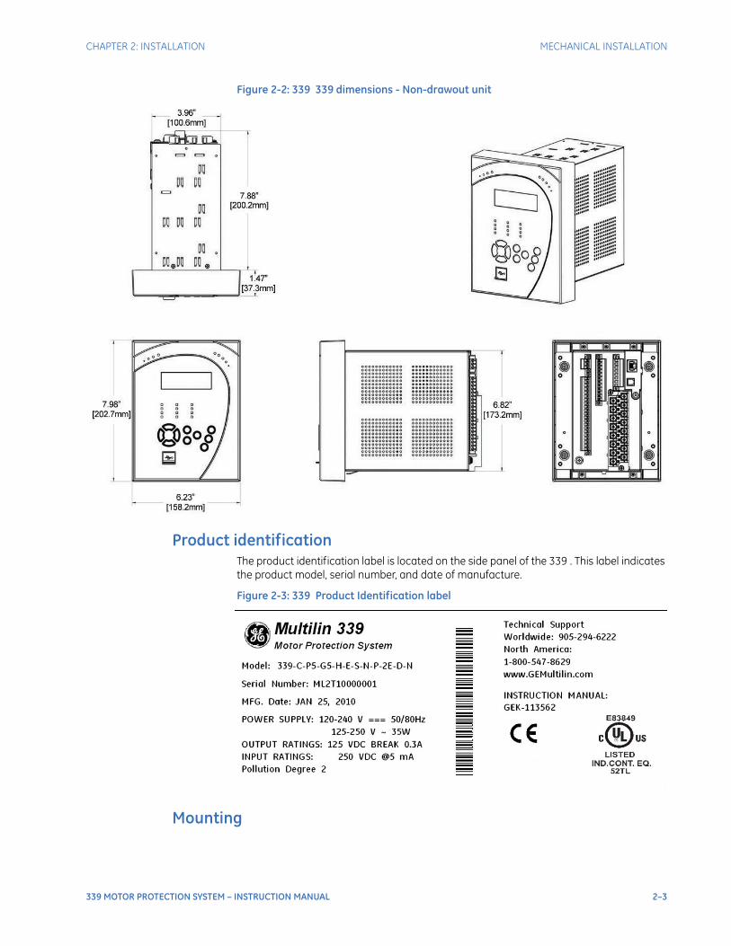
CHAPTER 2: INSTALLATION MECHANICAL INSTALLATION
339 MOTOR PROTECTION SYSTEM – INSTRUCTION MANUAL 2–3
Figure 2-2: 339 339 dimensions - Non-drawout unit
Product identificationThe product identification label is located on the side panel of the 339 . This label indicates the product model, serial number, and date of manufacture.
Figure 2-3: 339 Product Identification label
Mounting
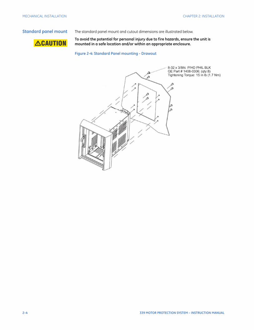
2–4 339 MOTOR PROTECTION SYSTEM – INSTRUCTION MANUAL
MECHANICAL INSTALLATION CHAPTER 2: INSTALLATION
Standard panel mount The standard panel mount and cutout dimensions are illustrated below.CAUTION: To avoid the potential for personal injury due to fire hazards, ensure the unit is
mounted in a safe location and/or within an appropriate enclosure.
Figure 2-4: Standard Panel mounting - Drawout
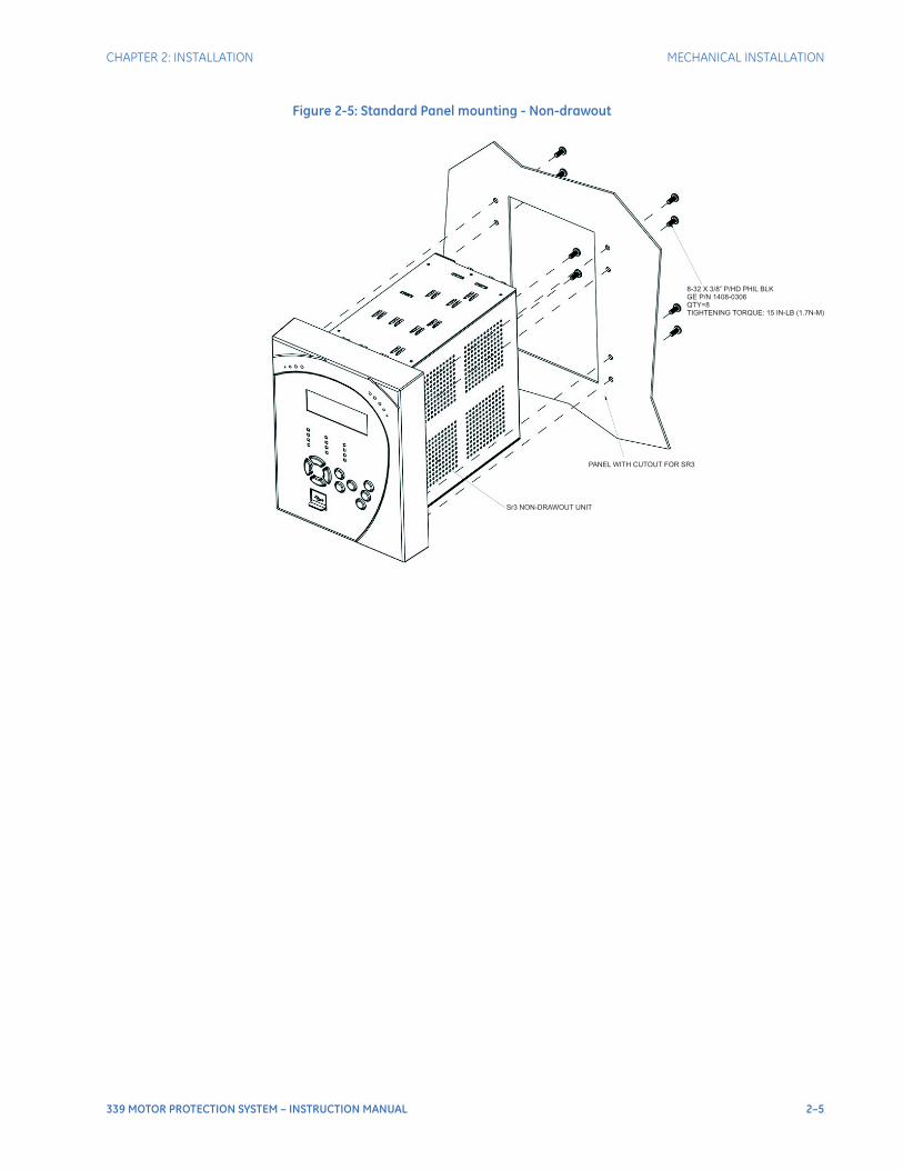
CHAPTER 2: INSTALLATION MECHANICAL INSTALLATION
339 MOTOR PROTECTION SYSTEM – INSTRUCTION MANUAL 2–5
Figure 2-5: Standard Panel mounting - Non-drawout
Sr3 NON-DRAWOUT UNIT
PANEL WITH CUTOUT FOR SR3
8-32 X 3/8” P/HD PHIL BLKGE P/N 1408-0306QTY=8TIGHTENING TORQUE: 15 IN-LB (1.7N-M)
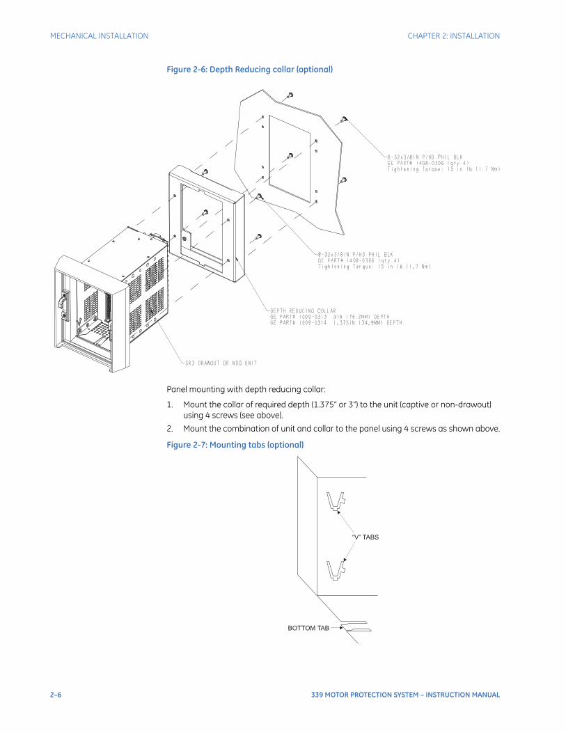
2–6 339 MOTOR PROTECTION SYSTEM – INSTRUCTION MANUAL
MECHANICAL INSTALLATION CHAPTER 2: INSTALLATION
Figure 2-6: Depth Reducing collar (optional)
Panel mounting with depth reducing collar:
1. Mount the collar of required depth (1.375” or 3”) to the unit (captive or non-drawout) using 4 screws (see above).
2. Mount the combination of unit and collar to the panel using 4 screws as shown above.
Figure 2-7: Mounting tabs (optional)
BOTTOM TAB
“V” TABS
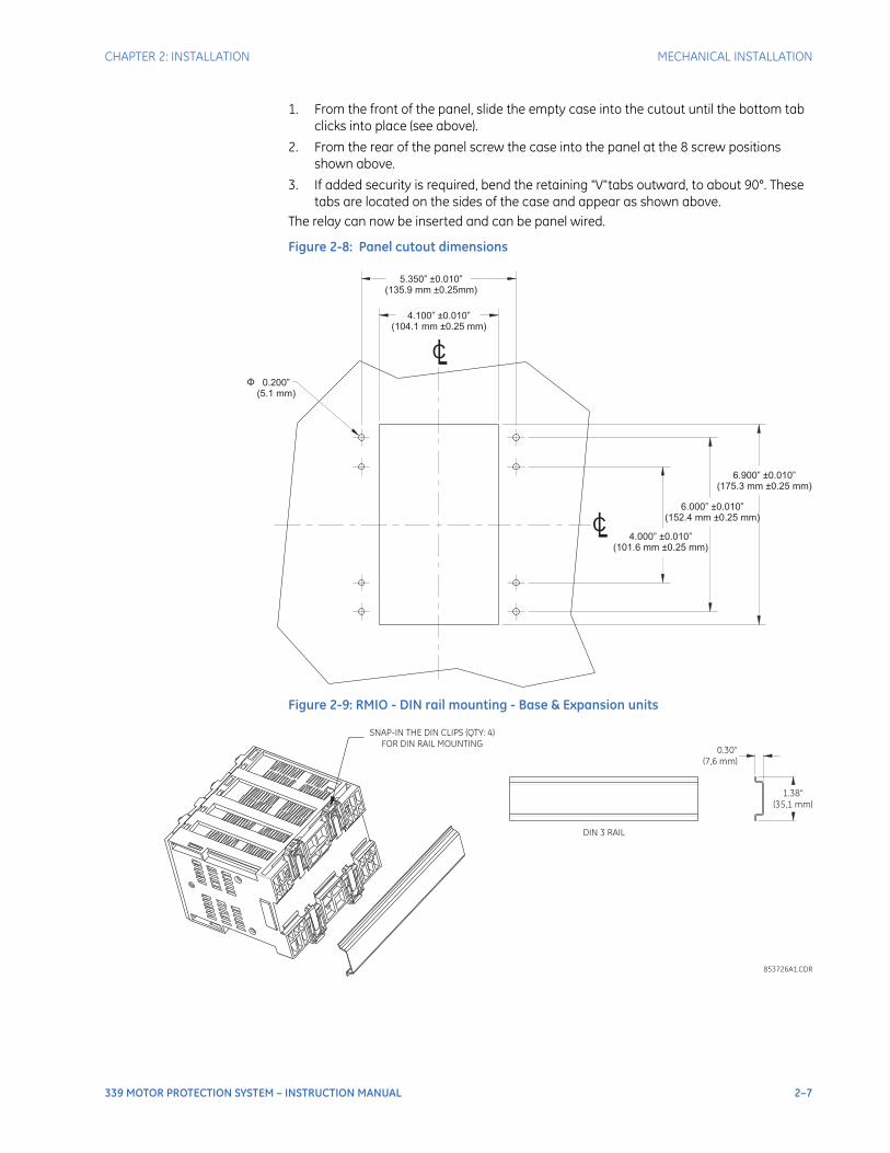
CHAPTER 2: INSTALLATION MECHANICAL INSTALLATION
339 MOTOR PROTECTION SYSTEM – INSTRUCTION MANUAL 2–7
1. From the front of the panel, slide the empty case into the cutout until the bottom tab clicks into place (see above).
2. From the rear of the panel screw the case into the panel at the 8 screw positions shown above.
3. If added security is required, bend the retaining "V"tabs outward, to about 90°. These tabs are located on the sides of the case and appear as shown above.
The relay can now be inserted and can be panel wired.
Figure 2-8: Panel cutout dimensions
Figure 2-9: RMIO - DIN rail mounting - Base & Expansion units
5.350” 0.010”(135.9 mm 0.25mm)
±±
4.100” 0.010”(104.1 mm 0.25 mm)
±±
0.200”(5.1 mm)
Φ
6.900” 0.010”(175.3 mm 0.25 mm)
±±
6.000” 0.010”(152.4 mm 0.25 mm)
±±
4.000” 0.010”(101.6 mm 0.25 mm)
±±
CL
CL
SNAP-IN THE DIN CLIPS (QTY: 4)
FOR DIN RAIL MOUNTING0.30”
(7,6 mm)
1.38”
(35,1 mm)
DIN 3 RAIL
853726A1.CDR
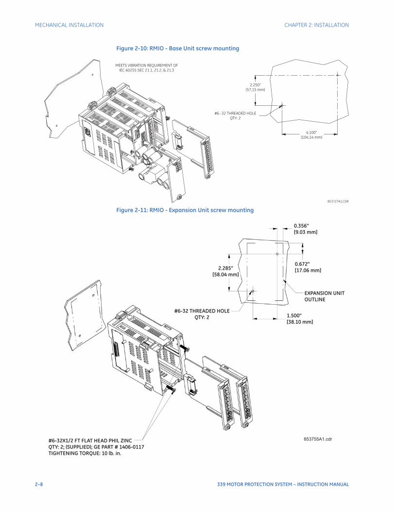
2–8 339 MOTOR PROTECTION SYSTEM – INSTRUCTION MANUAL
MECHANICAL INSTALLATION CHAPTER 2: INSTALLATION
Figure 2-10: RMIO - Base Unit screw mounting
Figure 2-11: RMIO - Expansion Unit screw mounting
MEETS VIBRATION REQUIREMENT OF
IEC 60255 SEC 21.1, 21.2, & 21.3
2.250”
(57,15 mm)
#6 -32 THREADED HOLE
QTY: 2
4.100”
(104,14 mm)
853727A1.CDR
#6-32X1/2 FT FLAT HEAD PHIL ZINCQTY: 2; (SUPPLIED); GE PART # 1406-0117TIGHTENING TORQUE: 10 lb. in.
0.356”[9.03 mm]
0.672”[17.06 mm]
1.500”[38.10 mm]
EXPANSION UNITOUTLINE
2.285”[58.04 mm]
#6-32 THREADED HOLEQTY: 2
853755A1.cdr
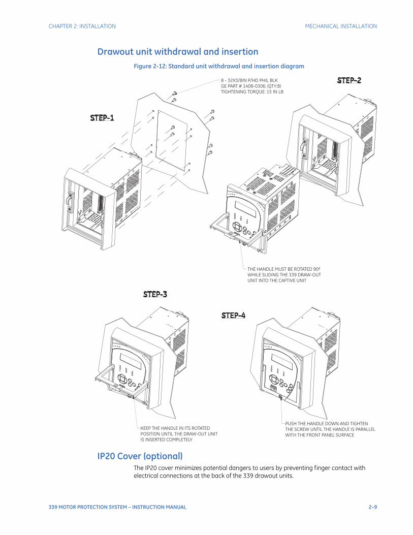
CHAPTER 2: INSTALLATION MECHANICAL INSTALLATION
339 MOTOR PROTECTION SYSTEM – INSTRUCTION MANUAL 2–9
Drawout unit withdrawal and insertionFigure 2-12: Standard unit withdrawal and insertion diagram
IP20 Cover (optional)The IP20 cover minimizes potential dangers to users by preventing finger contact with electrical connections at the back of the 339 drawout units.
KEEP THE HANDLE IN ITS ROTATED
POSITION UNTIL THE DRAW-OUT UNIT
IS INSERTED COMPLETELY
PUSH THE HANDLE DOWN AND TIGHTEN
THE SCREW UNTIL THE HANDLE IS PARALLEL
WITH THE FRONT PANEL SURFACE
THE HANDLE MUST BE ROTATED 90
WHILE SLIDING THE 339 DRAW-OUT
UNIT INTO THE CAPTIVE UNIT
⁰
8 - 32X3/8IN P/HD PHIL BLK
GE PART # 1408-0306; (QTY:8)
TIGHTENING TORQUE: 15 IN LB
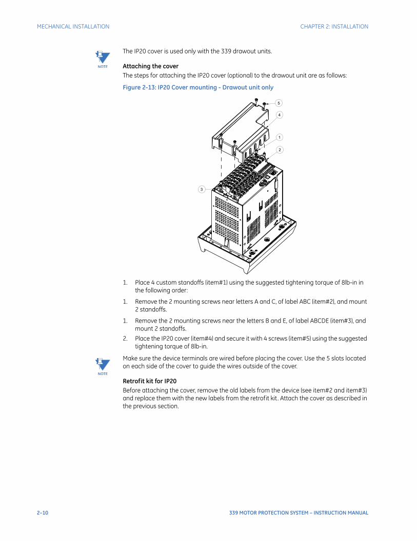
2–10 339 MOTOR PROTECTION SYSTEM – INSTRUCTION MANUAL
MECHANICAL INSTALLATION CHAPTER 2: INSTALLATION
NOTE
NOTE: The IP20 cover is used only with the 339 drawout units.
Attaching the coverThe steps for attaching the IP20 cover (optional) to the drawout unit are as follows:
Figure 2-13: IP20 Cover mounting - Drawout unit only
1. Place 4 custom standoffs (item#1) using the suggested tightening torque of 8lb-in in the following order:
1. Remove the 2 mounting screws near letters A and C, of label ABC (item#2), and mount 2 standoffs.
1. Remove the 2 mounting screws near the letters B and E, of label ABCDE (item#3), and mount 2 standoffs.
2. Place the IP20 cover (item#4) and secure it with 4 screws (item#5) using the suggested tightening torque of 8lb-in.
NOTE
NOTE: Make sure the device terminals are wired before placing the cover. Use the 5 slots located on each side of the cover to guide the wires outside of the cover.
Retrofit kit for IP20Before attaching the cover, remove the old labels from the device (see item#2 and item#3) and replace them with the new labels from the retrofit kit . Attach the cover as described in the previous section.
1
2
3
4
5

CHAPTER 2: INSTALLATION ELECTRICAL INSTALLATION
339 MOTOR PROTECTION SYSTEM – INSTRUCTION MANUAL 2–11
Electrical installation
Figure 2-14: Typical Wiring Diagram - Drawout - Input/Output Option “E”
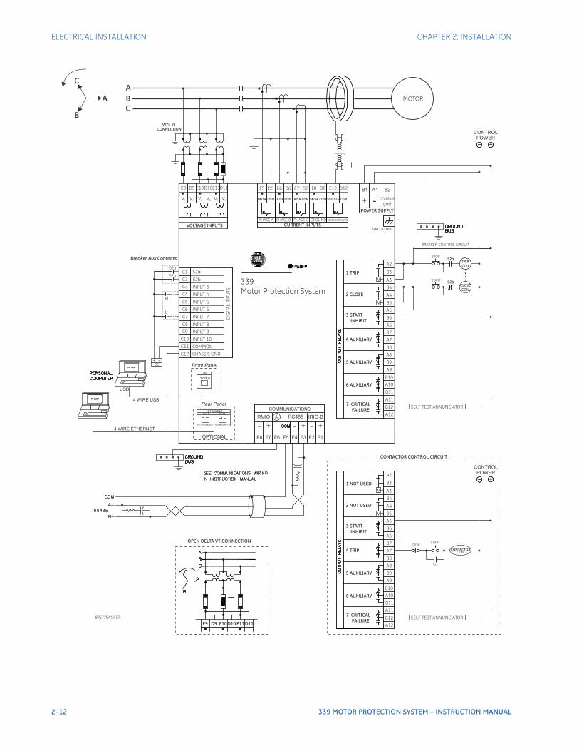
2–12 339 MOTOR PROTECTION SYSTEM – INSTRUCTION MANUAL
ELECTRICAL INSTALLATION CHAPTER 2: INSTALLATION
896729A1.CDR
POWER SUPPLY
B1 A1 B2
+ - chassisgnd
C1C2C3C4
C5C6C7C8C9
C10
DIG
ITAL
INPU
TS
52a52bINPUT 3INPUT 4INPUT 5INPUT 6INPUT 7INPUT 8
ETHERNETRJ45 MTRJ
10/100 BASE-T 100 BASE-FX
USB
TYPE B
A5
A6
A7
A2
A3
A4
A8
A9
A10
A11
A12
B3
B4
B5
B6
B7
B8
B9
B10
B11
B12
V
V
4 WIRE USB
4 WIRE ETHERNET
USB
+
F5 F4 F3
-- ++RS485 IRIG-B
F6F8
COMMUNICATIONS
CONTROLPOWER
ABC
E5 D5 E6 D6 E7 D7 E8 D8
1A/5A
VOLTAGE INPUTS
WYE VTCONNECTION
E9 D9 E10D10E11D11
VA VA VB VB VC VC
7 CRITICAL FAILURE
3 START INHIBIT
4 AUXILIARY
5 AUXILIARY
6 AUXILIARY
2 CLOSE
1 TRIP
OPTIONAL
Front Panel
Rear Panel
339Motor Protection System
52a
Breaker Aux Contacts
E12 D12
CURRENT INPUTS
1A/5A 1A/5A 1A/5ACOM COM COM COM COM50:0.025
PHASE A PHASE B PHASE C GROUND SENS GROUND
MOTOR
DC+
SELF TEST ANNUNCIATOR
TRIPCOIL
CLOSECOIL
BREAKER CONTROL CIRCUIT
A5
A6
A7
A2
A3
A4
A8
A9
A10
A11
A12
B3
B4
B5
B6
B7
B8
B9
B10
B11
B12
V
V
+
7 CRITICAL FAILURE
3 START INHIBIT
4 TRIP
5 AUXILIARY
6 AUXILIARY
2 NOT USED
1 NOT USED
SELF TEST ANNUNCIATOR
CONTACTORCOIL
STARTSTOP
CC
STOP
START
52a
52b
CONTROLPOWER
H
L
A
B
C
C11C12
COMMONCHASSIS GND
INPUT 9INPUT 10
CONTACTOR CONTROL CIRCUIT
F2 F1
- +RMIO
F7
52b
OPEN DELTA VT CONNECTION
E9 D9 E10D10 E11 D11
GND STUD
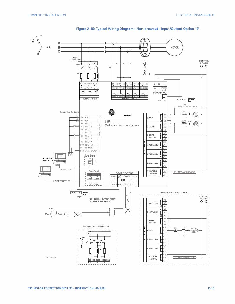
CHAPTER 2: INSTALLATION ELECTRICAL INSTALLATION
339 MOTOR PROTECTION SYSTEM – INSTRUCTION MANUAL 2–13
Figure 2-15: Typical Wiring Diagram - Non-drawout - Input/Output Option “E”
896704A1.CDR
POWER SUPPLY
L N
+ - chassisgnd
B1B2B3B4
B5B6B7B8B9
B10
DIG
ITAL
INPU
TS
52a52bINPUT 3INPUT 4INPUT 5INPUT 6INPUT 7INPUT 8
ETHERNETRJ45 MTRJ
10/100 BASE-T 100 BASE-FX
USB
TYPE B
A7
A9
A11
A1
A3
A5
A13
A15
A17
A19
A21
A2
A4
A6
A8
A10
A12
A14
A16
A18
A20
V
V
4 WIRE USB
4 WIRE ETHERNET
USB
+
C5 C4 C3
-- ++RS485 IRIG-B
C6C8
COMMUNICATIONS
CONTROLPOWER
ABC
E5 D5 E6 D6 E7 D7 E8 D8
1A/5A
VOLTAGE INPUTS
WYE VTCONNECTION
E9 D9 E10D10E11D11
VA VA VB VB VC VC
7 CRITICAL FAILURE
3 START INHIBIT
4 AUXILIARY
5 AUXILIARY
6 AUXILIARY
2 CLOSE
1 TRIP
OPTIONAL
Front Panel
Rear Panel
339Motor Protection System
52a
Breaker Aux Contacts
E12 D12
CURRENT INPUTS
1A/5A 1A/5A 1A/5ACOM COM COM COM COM50:0.025
PHASE A PHASE B PHASE C GROUND SENS GROUND
MOTOR
DC+
SELF TEST ANNUNCIATOR
TRIPCOIL
CLOSECOIL
BREAKER CONTROL CIRCUIT
A7
A9
A11
A1
A3
A5
A13
A15
A17
A19
A21
A2
A4
A6
A8
A10
A12
A14
A16
A18
A20
V
V
+
7 CRITICAL FAILURE
3 START INHIBIT
4 TRIP
5 AUXILIARY
6 AUXILIARY
2 NOT USED
1 NOT USED
SELF TEST ANNUNCIATOR
CONTACTORCOIL
STARTSTOP
CC
STOP
START
52a
52b
CONTROLPOWER
H
L
A
B
C
B11B12
COMMONCHASSIS GND
INPUT 9INPUT 10
CONTACTOR CONTROL CIRCUIT
C2 C1
- +RMIO
C7
52b
OPEN DELTA VT CONNECTION
E9 D9 E10D10 E11 D11
GND STUD
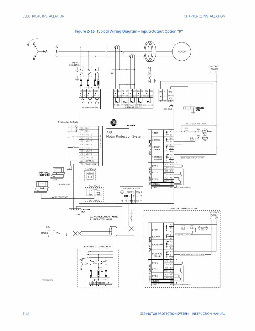
2–14 339 MOTOR PROTECTION SYSTEM – INSTRUCTION MANUAL
ELECTRICAL INSTALLATION CHAPTER 2: INSTALLATION
Figure 2-16: Typical Wiring Diagram - Input/Output Option “R”
896703A1.CDR
POWER SUPPLY
B1 A1 B2
+ - chassisgnd
C1C2C3C4
C5C6C7C8C9
C10
DIG
ITAL
INPU
TS
52a52bINPUT 3INPUT 4INPUT 5INPUT 6INPUT 7INPUT 8
ETHERNETRJ45 MTRJ
10/100 BASE-T 100 BASE-FX
USB
TYPE B
B5
B6
B7
B3
B4
B8
B9
B10
B11
A3
A4
A5
A6
A7
A8
A9
A10
A114 WIRE USB
4 WIRE ETHERNET
USB
+
F5 F4 F3
- +RS485 IRIG-B
F6
COMMUNICATIONS
CONTROLPOWER
ABC
E5 D5 E6 D6 E7 D7 E8 D8
1A/5A
VOLTAGE INPUTS
WYE VTCONNECTION
E9 D9 E10D10E11D11
VA VA VB VB VC VC
4 CRITICAL FAILURE
3 START INHIBIT
RTD 1
RTD 2
RTD 3
RETURN
SHIELD
RTD
TEM
P SE
NSI
NG
2 CLOSE
1 TRIP
OPTIONAL
Front Panel
Rear Panel
339Motor Protection System
52a
Breaker Aux Contacts
E12 D12
CURRENT INPUTS
1A/5A 1A/5A 1A/5ACOM COM COM COM COM50:0.025
PHASE A PHASE B PHASE C GROUND SENS GROUND
MOTOR
DC+
SELF TEST ANNUNCIATOR
TRIPCOIL
CLOSECOIL
BREAKER CONTROL CIRCUIT
STOP
START
52a
52b
H
L
A
B
C
C11C12
COMMONCHASSIS GND
INPUT 9INPUT 10
CONTACTOR CONTROL CIRCUIT
F2 F1
- +
52b
OPEN DELTA VT CONNECTION
E9 D9 E10D10 E11 D11
GND STUD
HOT
COMP
HOT
HOT
COMP
COMP
USE SHIELDED WIRE
B5
B6
B7
A3
A4
B8
B9
B10
B11
B3
B4
A5
A6
A7
A8
A9
A10
A11
4 CRITICAL FAILURE
3 AUXILIARY
RTD 1
RTD 2
RTD 3
RETURN
SHIELD
RTD
TEM
P SE
NSI
NG
2 ALARM
1 TRIP
HOT
COMP
HOT
HOT
COMP
COMP
USE SHIELDED WIRE
A2
+
CONTACTORCOIL
STARTSTOP
CC
CONTROLPOWER
GENERAL ALARM
SELF TEST ANNUNCIATOR
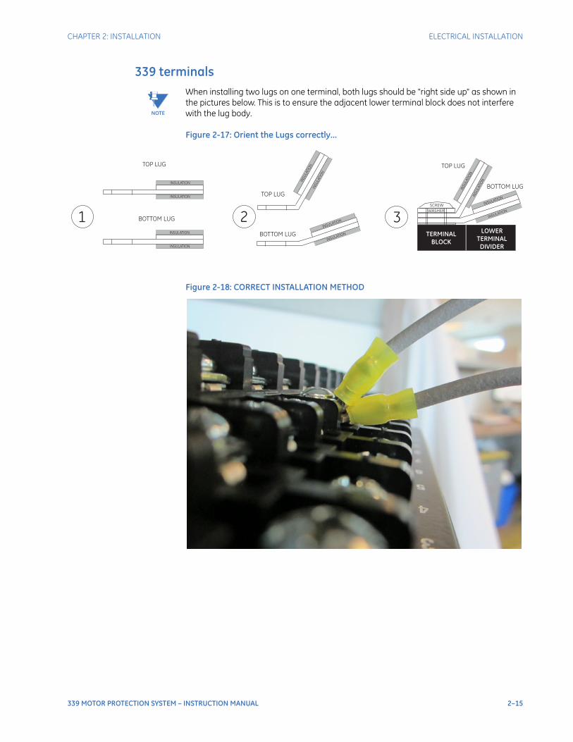
CHAPTER 2: INSTALLATION ELECTRICAL INSTALLATION
339 MOTOR PROTECTION SYSTEM – INSTRUCTION MANUAL 2–15
339 terminals
NOTE
NOTE: When installing two lugs on one terminal, both lugs should be "right side up" as shown in the pictures below. This is to ensure the adjacent lower terminal block does not interfere with the lug body.
Figure 2-17: Orient the Lugs correctly...
Figure 2-18: CORRECT INSTALLATION METHOD
SCREW
WASHER
LOWERTERMINALDIVIDER
TERMINALBLOCK
1 2 3
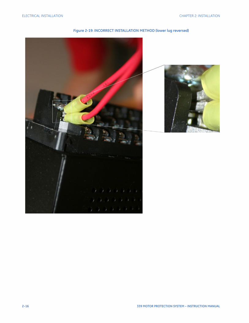
2–16 339 MOTOR PROTECTION SYSTEM – INSTRUCTION MANUAL
ELECTRICAL INSTALLATION CHAPTER 2: INSTALLATION
Figure 2-19: INCORRECT INSTALLATION METHOD (lower lug reversed)
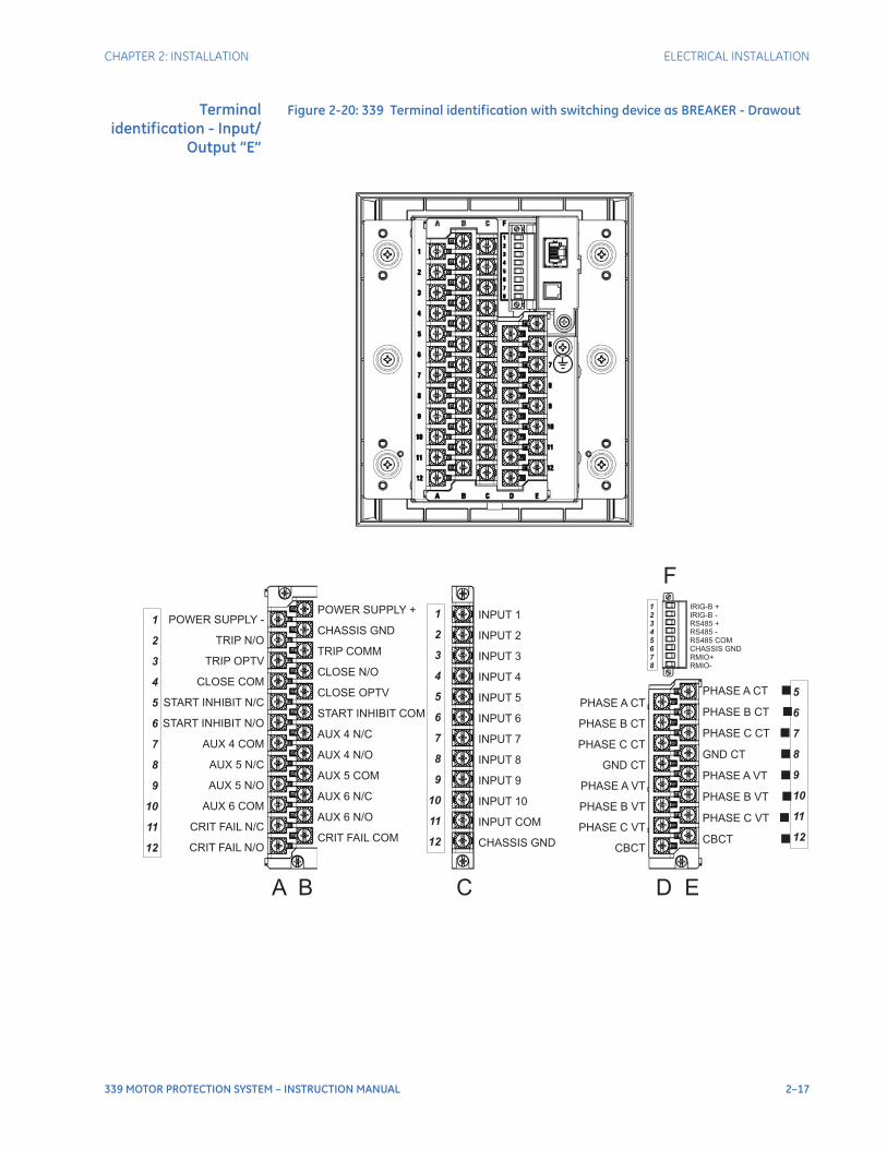
CHAPTER 2: INSTALLATION ELECTRICAL INSTALLATION
339 MOTOR PROTECTION SYSTEM – INSTRUCTION MANUAL 2–17
Terminalidentification - Input/
Output “E”
Figure 2-20: 339 Terminal identification with switching device as BREAKER - Drawout
INPUT 1
INPUT 2
INPUT 3
INPUT 4
INPUT 5
INPUT 6
INPUT 7
INPUT 8
INPUT 9
INPUT 10
INPUT COM
CHASSIS GND
PHASE A CT
PHASE B CT
PHASE C CT
GND CT
PHASE A VT
PHASE B VT
PHASE C VT
CBCT
PHASE A CT
PHASE B CT
PHASE C CT
GND CT
PHASE A VT
PHASE B VT
PHASE C VT
CBCT
IRIG-B +IRIG-B -RS485 +RS485 -RS485 COMCHASSIS GNDRMIO+RMIO-
POWER SUPPLY +
CHASSIS GND
TRIP COMM
CLOSE N/O
CLOSE OPTV
START INHIBIT COM
AUX 4 N/C
AUX 4 N/O
AUX 5 COM
AUX 6 N/C
AUX 6 N/O
CRIT FAIL COM
POWER SUPPLY -
TRIP N/O
TRIP OPTV
CLOSE COM
START INHIBIT N/C
START INHIBIT N/O
AUX 4 COM
AUX 5 N/C
AUX 5 N/O
AUX 6 COM
CRIT FAIL N/C
CRIT FAIL N/O
1
2
3
4
5
6
7
8
9
10
11
12
1
2
3
4
5
6
7
8
9
10
11
12
5
6
7
8
9
10
11
12
A B C D E
F1
2
3
4
5
6
7
8
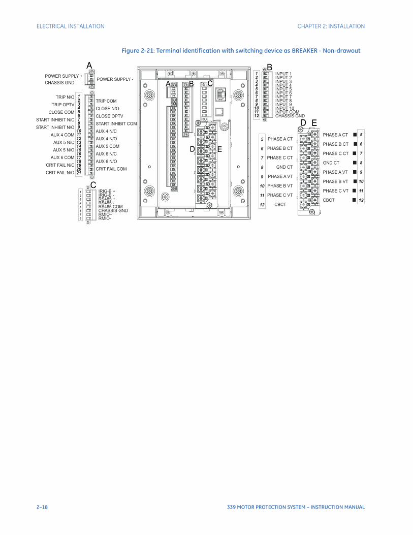
2–18 339 MOTOR PROTECTION SYSTEM – INSTRUCTION MANUAL
ELECTRICAL INSTALLATION CHAPTER 2: INSTALLATION
Figure 2-21: Terminal identification with switching device as BREAKER - Non-drawout
INPUT 1INPUT 2INPUT 3INPUT 4INPUT 5INPUT 6INPUT 7INPUT 8INPUT 9INPUT 10INPUT COMCHASSIS GND
123456789
101112
PHASE A CT
PHASE B CT
PHASE C CT
GND CT
PHASE A VT
PHASE B VT
PHASE C VT
CBCT
PHASE A CT
PHASE B CT
PHASE C CT
GND CT
PHASE A VT
PHASE B VT
PHASE C VT
CBCT
5
6
7
8
9
10
11
12
POWER SUPPLY -POWER SUPPLY +
CHASSIS GND
TRIP COM
CLOSE N/O
CLOSE OPTV
START INHIBIT COM
AUX 4 N/C
AUX 4 N/O
AUX 5 COM
AUX 6 N/C
AUX 6 N/O
CRIT FAIL COM
123456789
101112131415161718192021
IRIG-B +IRIG-B -RS485 +RS485 -RS485 COMCHASSIS GNDRMIO+RMIO-
1
2
3
4
5
6
7
8
5
6
7
8
9
10
11
12
TRIP N/O
TRIP OPTV
CLOSE COM
ART INHIBIT N/C
ART INHIBIT N/O
AUX 4 COM
AUX 5 N/C
AUX 5 N/O
AUX 6 COM
CRIT FAIL N/C
CRIT FAIL N/O
ST
ST
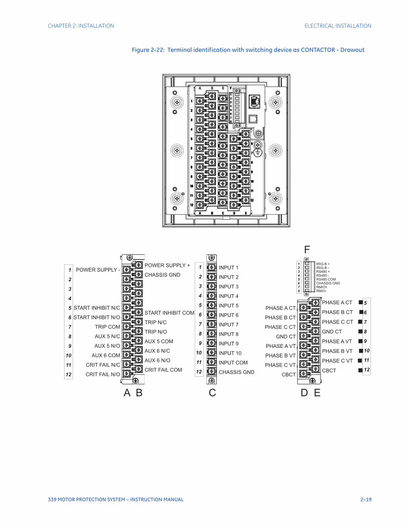
CHAPTER 2: INSTALLATION ELECTRICAL INSTALLATION
339 MOTOR PROTECTION SYSTEM – INSTRUCTION MANUAL 2–19
Figure 2-22: Terminal identification with switching device as CONTACTOR - Drawout
INPUT 1
INPUT 2
INPUT 3
INPUT 4
INPUT 5
INPUT 6
INPUT 7
INPUT 8
INPUT 9
INPUT 10
INPUT COM
CHASSIS GND
PHASE A CT
PHASE B CT
PHASE C CT
GND CT
PHASE A VT
PHASE B VT
PHASE C VT
CBCT
PHASE A CT
PHASE B CT
PHASE C CT
GND CT
PHASE A VT
PHASE B VT
PHASE C VT
CBCT
IRIG-B +IRIG-B -RS485 +RS485 -RS485 COMCHASSIS GNDRMIO+RMIO-
POWER SUPPLY +
CHASSIS GND
START INHIBIT COM
TRIP N/C
TRIP N/O
AUX 5 COM
AUX 6 N/C
AUX 6 N/O
CRIT FAIL COM
POWER SUPPLY -
START INHIBIT N/C
START INHIBIT N/O
TRIP COM
AUX 5 N/C
AUX 5 N/O
AUX 6 COM
CRIT FAIL N/C
CRIT FAIL N/O
1
2
3
4
5
6
7
8
9
10
11
12
1
2
3
4
5
6
7
8
9
10
11
12
5
6
7
8
9
10
11
12
A B C D E
F1
2
3
4
5
6
7
8
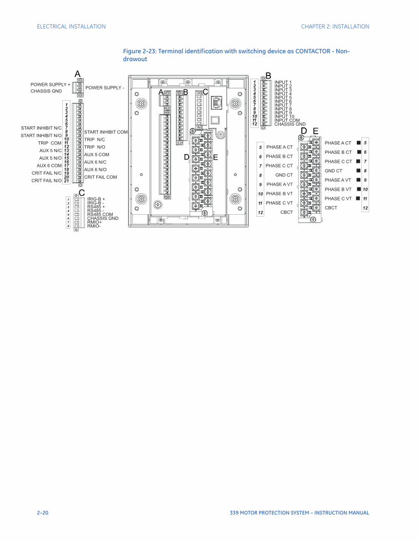
2–20 339 MOTOR PROTECTION SYSTEM – INSTRUCTION MANUAL
ELECTRICAL INSTALLATION CHAPTER 2: INSTALLATION
Figure 2-23: Terminal identification with switching device as CONTACTOR - Non-drawout
INPUT 1INPUT 2INPUT 3INPUT 4INPUT 5INPUT 6INPUT 7INPUT 8INPUT 9INPUT 10INPUT COMCHASSIS GND
123456789
101112
PHASE A CT
PHASE B CT
PHASE C CT
GND CT
PHASE A VT
PHASE B VT
PHASE C VT
CBCT
PHASE A CT
PHASE B CT
PHASE C CT
GND CT
PHASE A VT
PHASE B VT
PHASE C VT
CBCT
5
6
7
8
9
10
11
12
POWER SUPPLY -POWER SUPPLY +
CHASSIS GND
START INHIBIT N/C
START INHIBIT N/O
TRIP COM
AUX 5 N/C
AUX 5 N/O
AUX 6 COM
CRIT FAIL N/C
CRIT FAIL N/O
START INHIBIT COM
TRIP N/C
TRIP N/O
AUX 5 COM
AUX 6 N/C
AUX 6 N/O
CRIT FAIL COM
123456789
101112131415161718192021
IRIG-B +IRIG-B -RS485 +RS485 -RS485 COMCHASSIS GNDRMIO+RMIO-
1
2
3
4
5
6
7
8
5
6
7
8
9
10
11
12
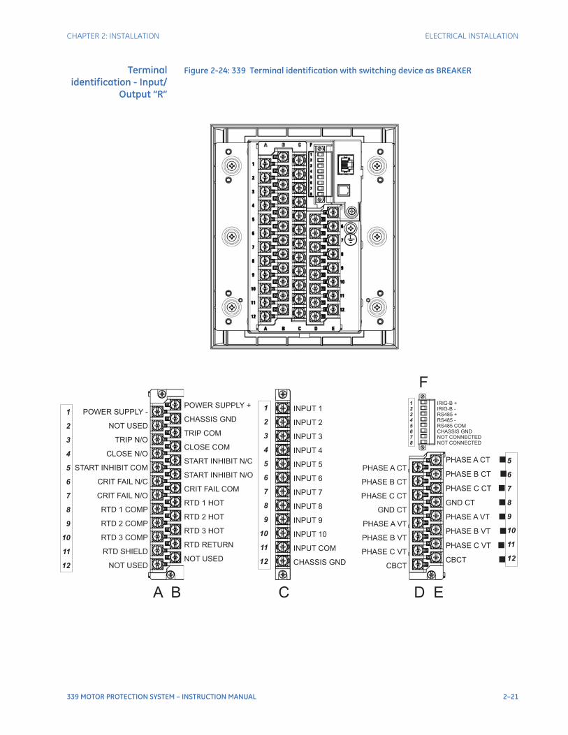
CHAPTER 2: INSTALLATION ELECTRICAL INSTALLATION
339 MOTOR PROTECTION SYSTEM – INSTRUCTION MANUAL 2–21
Terminalidentification - Input/
Output “R”
Figure 2-24: 339 Terminal identification with switching device as BREAKER
INPUT 1
INPUT 2
INPUT 3
INPUT 4
INPUT 5
INPUT 6
INPUT 7
INPUT 8
INPUT 9
INPUT 10
INPUT COM
CHASSIS GND
PHASE A CT
PHASE B CT
PHASE C CT
GND CT
PHASE A VT
PHASE B VT
PHASE C VT
CBCT
PHASE A CT
PHASE B CT
PHASE C CT
GND CT
PHASE A VT
PHASE B VT
PHASE C VT
CBCT
IRIG-B +IRIG-B -RS485 +RS485 -RS485 COMCHASSIS GNDNOT CONNECTEDNOT CONNECTED
POWER SUPPLY +
CHASSIS GND
TRIP COM
CLOSE COM
START INHIBIT N/O
RTD 1 HOT
NOT USED
START INHIBIT N/C
CRIT FAIL COM
RTD 2 HOT
RTD 3 HOT
RTD RETURN
POWER SUPPLY -
NOT USED
CLOSE N/O
START INHIBIT COM
CRIT FAIL N/C
RTD 1 COMP
NOT USED
TRIP N/O
CRIT FAIL N/O
RTD 2 COMP
RTD 3 COMP
RTD SHIELD
1
2
3
4
5
6
7
8
9
10
11
12
1
2
3
4
5
6
7
8
9
10
11
12
5
6
7
8
9
10
11
12
A B C D E
F1
2
3
4
5
6
7
8
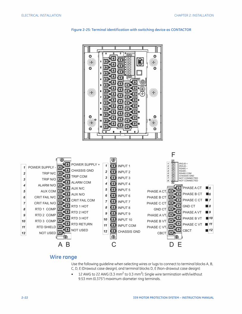
2–22 339 MOTOR PROTECTION SYSTEM – INSTRUCTION MANUAL
ELECTRICAL INSTALLATION CHAPTER 2: INSTALLATION
Figure 2-25: Terminal identification with switching device as CONTACTOR
Wire rangeUse the following guideline when selecting wires or lugs to connect to terminal blocks A, B, C, D, E (Drawout case design), and terminal blocks D, E (Non-drawout case design):
• 12 AWG to 22 AWG (3.3 mm2 to 0.3 mm2): Single wire termination with/without 9.53 mm (0.375”) maximum diameter ring terminals.
INPUT 1
INPUT 2
INPUT 3
INPUT 4
INPUT 5
INPUT 6
INPUT 7
INPUT 8
INPUT 9
INPUT 10
INPUT COM
CHASSIS GND
PHASE A CT
PHASE B CT
PHASE C CT
GND CT
PHASE A VT
PHASE B VT
PHASE C VT
CBCT
PHASE A CT
PHASE B CT
PHASE C CT
GND CT
PHASE A VT
PHASE B VT
PHASE C VT
CBCT
IRIG-B +IRIG-B -RS485 +RS485 -RS485 COMCHASSIS GNDNOT CONNECTEDNOT CONNECTED
POWER SUPPLY +
CHASSIS GND
AUX N/C
AUX N/O
RTD 1 HOT
TRIP COM
ALARM COM
CRIT FAIL COM
RTD 2 HOT
RTD 3 HOT
RTD RETURN
NOT USED
POWER SUPPLY -
RTD 1 COMP
TRIP N/C
TRIP N/O
ALARM N/O
AUX COM
CRIT FAIL N/C
CRIT FAIL N/O
RTD 2 COMP
RTD 3 COMP
RTD SHIELD
NOT USED
1
2
3
4
5
6
7
8
9
10
11
12
1
2
3
4
5
6
7
8
9
10
11
12
5
6
7
8
9
10
11
12
A B C D E
F1
2
3
4
5
6
7
8
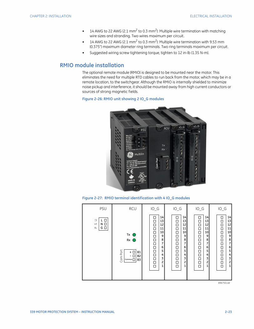
CHAPTER 2: INSTALLATION ELECTRICAL INSTALLATION
339 MOTOR PROTECTION SYSTEM – INSTRUCTION MANUAL 2–23
• 14 AWG to 22 AWG (2.1 mm2 to 0.3 mm2): Multiple wire termination with matching wire sizes and stranding. Two wires maximum per circuit.
• 14 AWG to 22 AWG (2.1 mm2 to 0.3 mm2): Multiple wire termination with 9.53 mm (0.375”) maximum diameter ring terminals. Two ring terminals maximum per circuit.
• Suggested wiring screw tightening torque, tighten to 12 in-lb (1.35 N-m).
RMIO module installationThe optional remote module (RMIO) is designed to be mounted near the motor. This eliminates the need for multiple RTD cables to run back from the motor, which may be in a remote location, to the switchgear. Although the RMIO is internally shielded to minimize noise pickup and interference, it should be mounted away from high current conductors or sources of strong magnetic fields.
Figure 2-26: RMIO unit showing 2 IO_G modules
Figure 2-27: RMIO terminal identification with 4 IO_G modules
Tx
Rx
IO_GIO_GRCUPSU
PS
U LNG
Co
mP
ort
+-
Common
B1B2B3
1413121110
987654321
1413121110
987654321
896750.cdr
IO_GIO_G
1413121110
987654321
1413121110
987654321
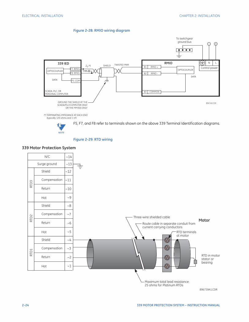
2–24 339 MOTOR PROTECTION SYSTEM – INSTRUCTION MANUAL
ELECTRICAL INSTALLATION CHAPTER 2: INSTALLATION
Figure 2-28: RMIO wiring diagram
NOTE
NOTE: F5, F7, and F8 refer to terminals shown on the above 339 Terminal Identification diagrams.
Figure 2-29: RTD wiring
SCADA, PLC, OR
PERSONAL COMPUTER
OPTOCOUPLER
DATA
RMIOSHIELD
896740.CDR
(*) TERMINATING IMPEDANCE AT EACH END
(typically 120 ohms and 1 nF)
TWISTED PAIR
RMIO +
RMIO -
COMMON
GROUND THE SHIELD AT THE
SCADA/PLC/COMPUTER ONLY
OR THE MM300 ONLY
DATA
OPTOCOUPLER
B1
B2
B3
ZT
(*)339 IED
F7: RMIO+
F5: COM
F8: RMIO-
– +
To switchgear
ground bus
Control power
LN
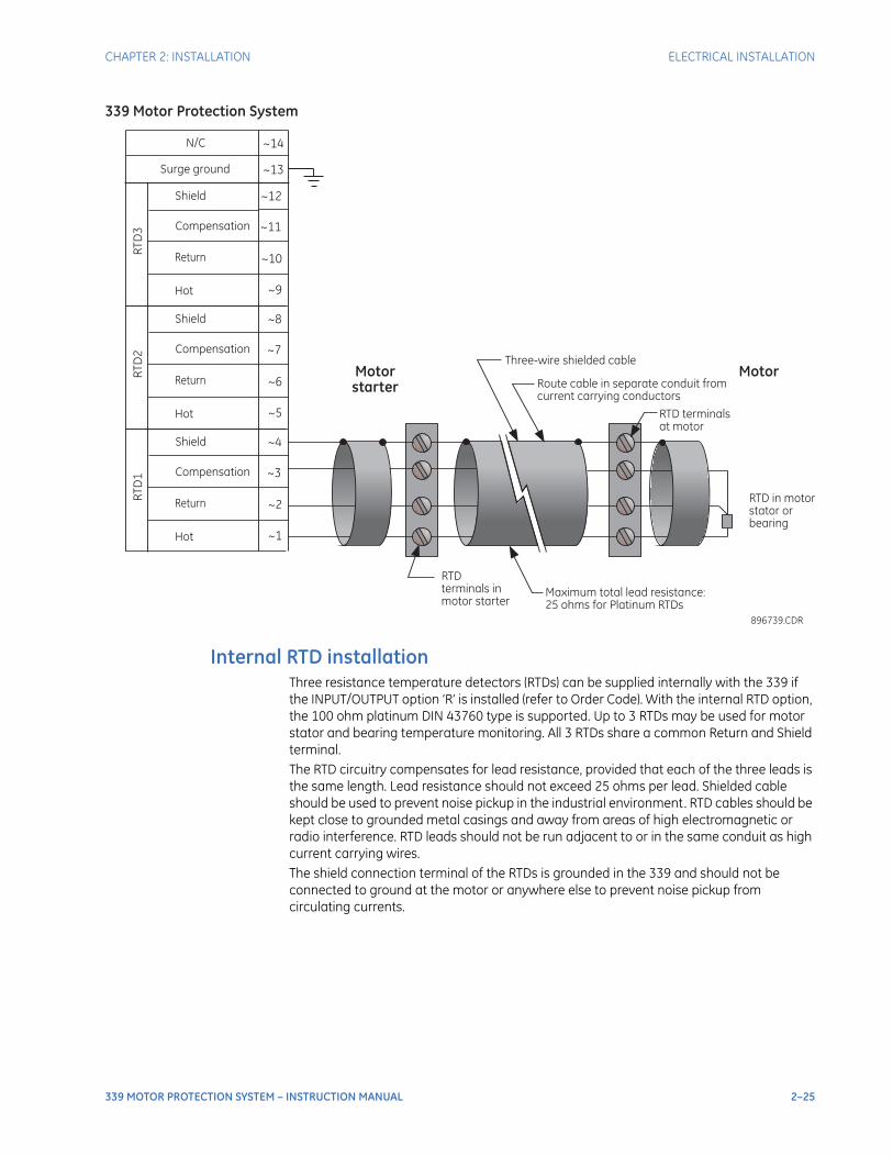
CHAPTER 2: INSTALLATION ELECTRICAL INSTALLATION
339 MOTOR PROTECTION SYSTEM – INSTRUCTION MANUAL 2–25
Internal RTD installationThree resistance temperature detectors (RTDs) can be supplied internally with the 339 if the INPUT/OUTPUT option ‘R’ is installed (refer to Order Code). With the internal RTD option, the 100 ohm platinum DIN 43760 type is supported. Up to 3 RTDs may be used for motor stator and bearing temperature monitoring. All 3 RTDs share a common Return and Shield terminal.The RTD circuitry compensates for lead resistance, provided that each of the three leads is the same length. Lead resistance should not exceed 25 ohms per lead. Shielded cable should be used to prevent noise pickup in the industrial environment. RTD cables should be kept close to grounded metal casings and away from areas of high electromagnetic or radio interference. RTD leads should not be run adjacent to or in the same conduit as high current carrying wires.The shield connection terminal of the RTDs is grounded in the 339 and should not be connected to ground at the motor or anywhere else to prevent noise pickup from circulating currents.
Motorstarter
MotorThree-wire shielded cable
RTD
terminals in
motor starter
RTD terminals
at motor
Maximum total lead resistance:
25 ohms for Platinum RTDs
Route cable in separate conduit from
current carrying conductors
RTD in motor
stator or
bearing
896739.CDR
339 Motor Protection System
Surge ground ~13
~4
~3
~2
~1
Compensation
Return
Hot
Shield
RT
D1
~8
~7
~6
~5
Compensation
Return
Hot
Shield
RT
D2
~12
~11
~10
~9
Compensation
Return
Hot
Shield
RT
D3
N/C ~14
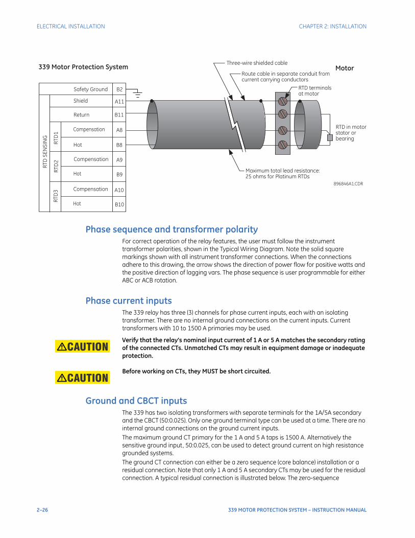
2–26 339 MOTOR PROTECTION SYSTEM – INSTRUCTION MANUAL
ELECTRICAL INSTALLATION CHAPTER 2: INSTALLATION
Phase sequence and transformer polarityFor correct operation of the relay features, the user must follow the instrument transformer polarities, shown in the Typical Wiring Diagram. Note the solid square markings shown with all instrument transformer connections. When the connections adhere to this drawing, the arrow shows the direction of power flow for positive watts and the positive direction of lagging vars. The phase sequence is user programmable for either ABC or ACB rotation.
Phase current inputsThe 339 relay has three (3) channels for phase current inputs, each with an isolating transformer. There are no internal ground connections on the current inputs. Current transformers with 10 to 1500 A primaries may be used.
CAUTION: Verify that the relay’s nominal input current of 1 A or 5 A matches the secondary rating of the connected CTs. Unmatched CTs may result in equipment damage or inadequate protection.
CAUTION: Before working on CTs, they MUST be short circuited.
Ground and CBCT inputsThe 339 has two isolating transformers with separate terminals for the 1A/5A secondary and the CBCT (50:0.025). Only one ground terminal type can be used at a time. There are no internal ground connections on the ground current inputs.The maximum ground CT primary for the 1 A and 5 A taps is 1500 A. Alternatively the sensitive ground input, 50:0.025, can be used to detect ground current on high resistance grounded systems.The ground CT connection can either be a zero sequence (core balance) installation or a residual connection. Note that only 1 A and 5 A secondary CTs may be used for the residual connection. A typical residual connection is illustrated below. The zero-sequence
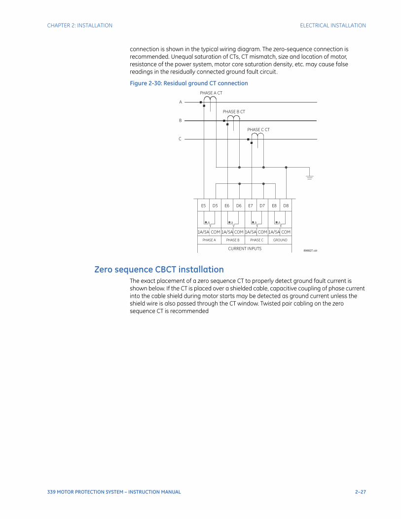
CHAPTER 2: INSTALLATION ELECTRICAL INSTALLATION
339 MOTOR PROTECTION SYSTEM – INSTRUCTION MANUAL 2–27
connection is shown in the typical wiring diagram. The zero-sequence connection is recommended. Unequal saturation of CTs, CT mismatch, size and location of motor, resistance of the power system, motor core saturation density, etc. may cause false readings in the residually connected ground fault circuit.
Figure 2-30: Residual ground CT connection
Zero sequence CBCT installationThe exact placement of a zero sequence CT to properly detect ground fault current is shown below. If the CT is placed over a shielded cable, capacitive coupling of phase current into the cable shield during motor starts may be detected as ground current unless the shield wire is also passed through the CT window. Twisted pair cabling on the zero sequence CT is recommended
896827.cdrCURRENT INPUTS
PHASE A PHASE B PHASE C GROUND
1A/5A COMCOM COM COM1A/5A 1A/5A 1A/5A
E5 D5 E6 E7 E8D6 D7 D8
PHASE A CT
PHASE B CT
PHASE C CT
A
B
C
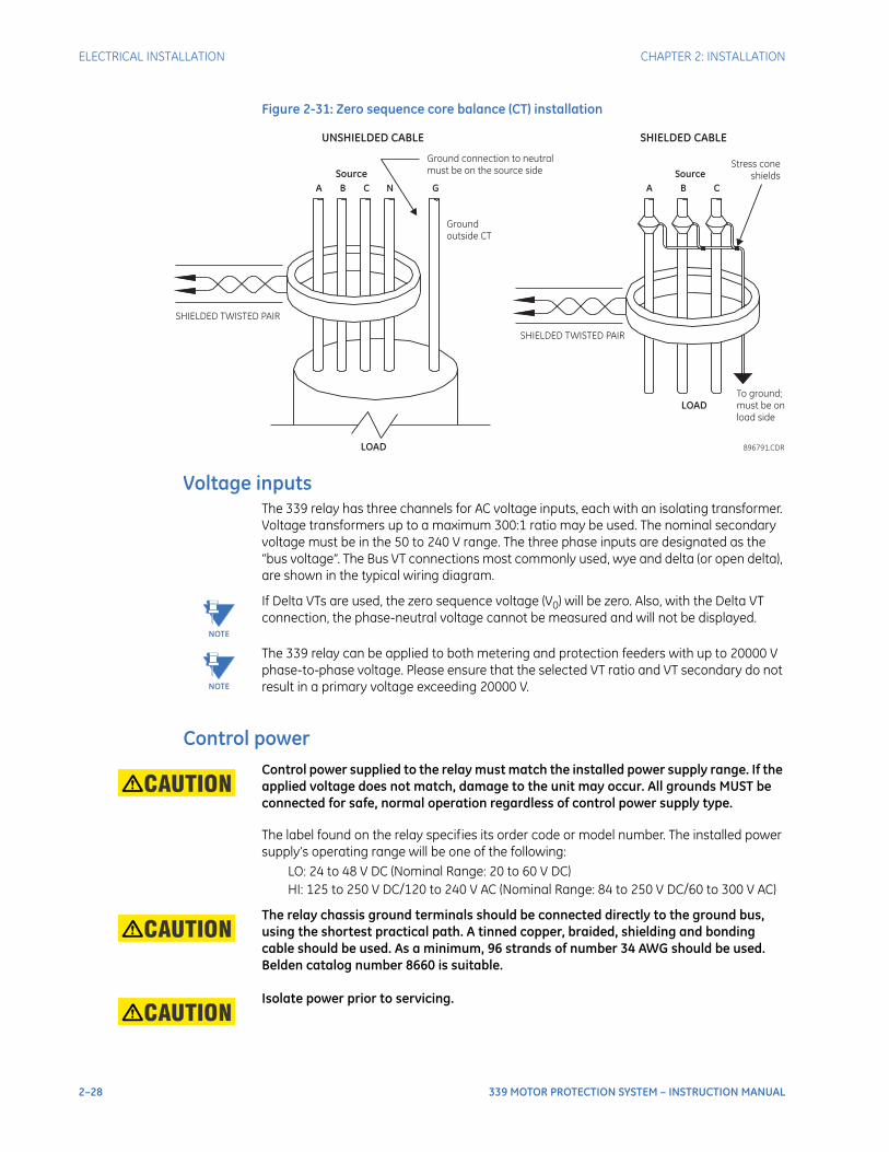
2–28 339 MOTOR PROTECTION SYSTEM – INSTRUCTION MANUAL
ELECTRICAL INSTALLATION CHAPTER 2: INSTALLATION
Figure 2-31: Zero sequence core balance (CT) installation
Voltage inputsThe 339 relay has three channels for AC voltage inputs, each with an isolating transformer. Voltage transformers up to a maximum 300:1 ratio may be used. The nominal secondary voltage must be in the 50 to 240 V range. The three phase inputs are designated as the “bus voltage”. The Bus VT connections most commonly used, wye and delta (or open delta), are shown in the typical wiring diagram.
NOTE
NOTE: If Delta VTs are used, the zero sequence voltage (V0) will be zero. Also, with the Delta VT connection, the phase-neutral voltage cannot be measured and will not be displayed.
NOTE
NOTE: The 339 relay can be applied to both metering and protection feeders with up to 20000 V phase-to-phase voltage. Please ensure that the selected VT ratio and VT secondary do not result in a primary voltage exceeding 20000 V.
Control powerCAUTION: Control power supplied to the relay must match the installed power supply range. If the
applied voltage does not match, damage to the unit may occur. All grounds MUST be connected for safe, normal operation regardless of control power supply type.
The label found on the relay specifies its order code or model number. The installed power supply’s operating range will be one of the following:
LO: 24 to 48 V DC (Nominal Range: 20 to 60 V DC)HI: 125 to 250 V DC/120 to 240 V AC (Nominal Range: 84 to 250 V DC/60 to 300 V AC)
CAUTION: The relay chassis ground terminals should be connected directly to the ground bus, using the shortest practical path. A tinned copper, braided, shielding and bonding cable should be used. As a minimum, 96 strands of number 34 AWG should be used. Belden catalog number 8660 is suitable.
CAUTION: Isolate power prior to servicing.
Ground connection to neutral
must be on the source side
UNSHIELDED CABLE
LOAD
A B C N G
Ground
outside CT
Source
LOAD
SHIELDED CABLE
896791.CDR
A B C
Source
To ground;
must be on
load side
Stress cone
shields
SHIELDED TWISTED PAIR
SHIELDED TWISTED PAIR
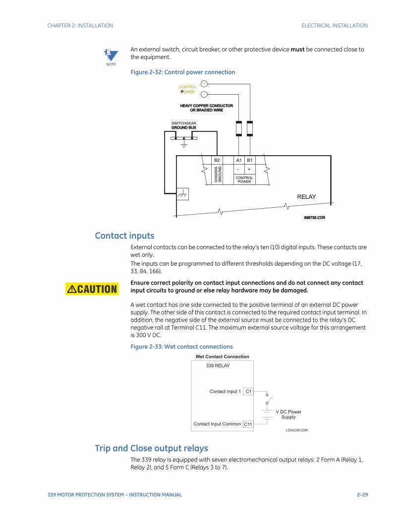
CHAPTER 2: INSTALLATION ELECTRICAL INSTALLATION
339 MOTOR PROTECTION SYSTEM – INSTRUCTION MANUAL 2–29
NOTE
NOTE: An external switch, circuit breaker, or other protective device must be connected close to the equipment.
Figure 2-32: Control power connection
Contact inputsExternal contacts can be connected to the relay’s ten (10) digital inputs. These contacts are wet only.The inputs can be programmed to different thresholds depending on the DC voltage (17, 33, 84, 166).
CAUTION: Ensure correct polarity on contact input connections and do not connect any contact input circuits to ground or else relay hardware may be damaged.
A wet contact has one side connected to the positive terminal of an external DC power supply. The other side of this contact is connected to the required contact input terminal. In addition, the negative side of the external source must be connected to the relay’s DC negative rail at Terminal C11. The maximum external source voltage for this arrangement is 300 V DC.
Figure 2-33: Wet contact connections
Trip and Close output relaysThe 339 relay is equipped with seven electromechanical output relays: 2 Form A (Relay 1, Relay 2), and 5 Form C (Relays 3 to 7).
PPOWER
OR BRAIDED WIREOR BRAIDED WIRE
HEAVY COPPER CONDUCTORHEAVY COPPER CONDUCTOR
GROUND BUSGROUND BUS
SWITCHGEAR
-
+
GR
OU
ND
B2 A1 B1
+-
CH
AS
SIS
RELAY
CONTROL
898735.CDR898735.CDR
CONTROLPOWER
Wet Contact Connection
339 RELAY
C1Contact Input 1
Contact Input Common C11
V DC PowerSupply
LOGICIN.CDR
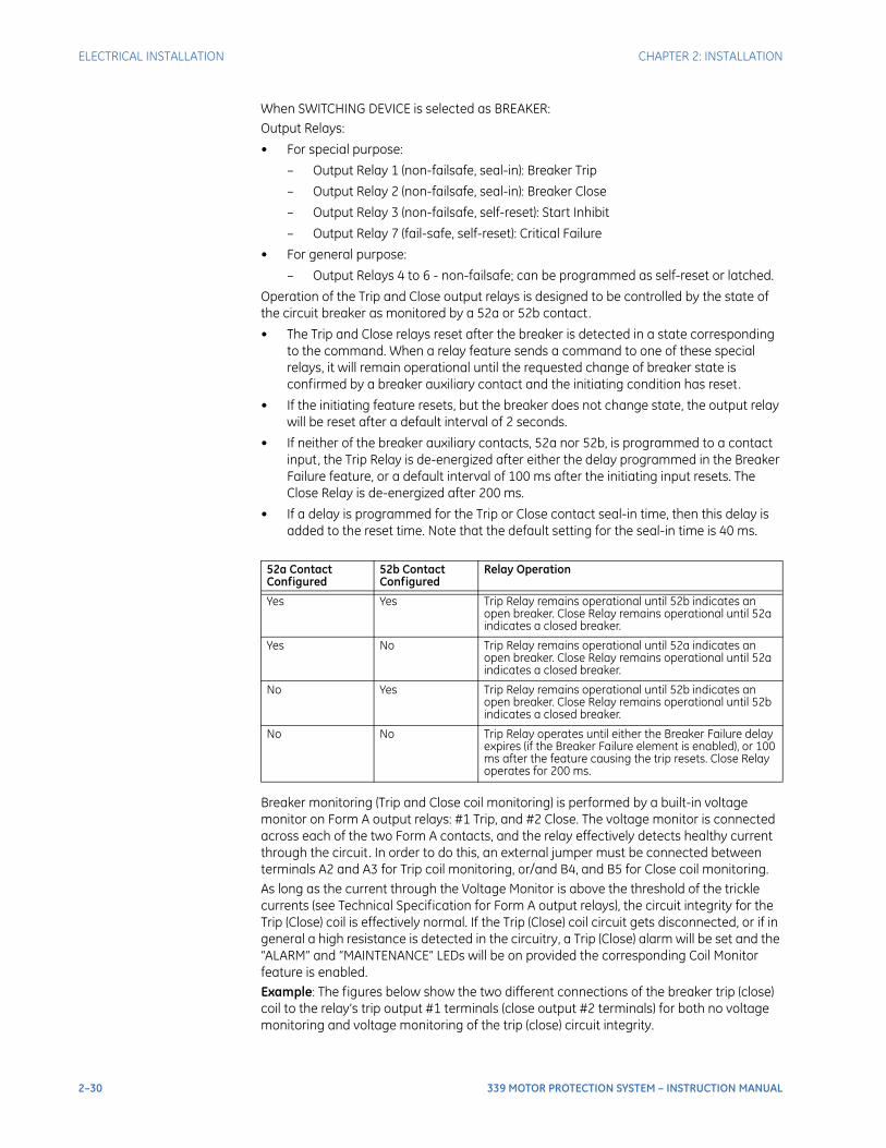
2–30 339 MOTOR PROTECTION SYSTEM – INSTRUCTION MANUAL
ELECTRICAL INSTALLATION CHAPTER 2: INSTALLATION
When SWITCHING DEVICE is selected as BREAKER:Output Relays:
• For special purpose:
– Output Relay 1 (non-failsafe, seal-in): Breaker Trip
– Output Relay 2 (non-failsafe, seal-in): Breaker Close
– Output Relay 3 (non-failsafe, self-reset): Start Inhibit
– Output Relay 7 (fail-safe, self-reset): Critical Failure
• For general purpose:
– Output Relays 4 to 6 - non-failsafe; can be programmed as self-reset or latched.
Operation of the Trip and Close output relays is designed to be controlled by the state of the circuit breaker as monitored by a 52a or 52b contact.
• The Trip and Close relays reset after the breaker is detected in a state corresponding to the command. When a relay feature sends a command to one of these special relays, it will remain operational until the requested change of breaker state is confirmed by a breaker auxiliary contact and the initiating condition has reset.
• If the initiating feature resets, but the breaker does not change state, the output relay will be reset after a default interval of 2 seconds.
• If neither of the breaker auxiliary contacts, 52a nor 52b, is programmed to a contact input, the Trip Relay is de-energized after either the delay programmed in the Breaker Failure feature, or a default interval of 100 ms after the initiating input resets. The Close Relay is de-energized after 200 ms.
• If a delay is programmed for the Trip or Close contact seal-in time, then this delay is added to the reset time. Note that the default setting for the seal-in time is 40 ms.
Breaker monitoring (Trip and Close coil monitoring) is performed by a built-in voltage monitor on Form A output relays: #1 Trip, and #2 Close. The voltage monitor is connected across each of the two Form A contacts, and the relay effectively detects healthy current through the circuit. In order to do this, an external jumper must be connected between terminals A2 and A3 for Trip coil monitoring, or/and B4, and B5 for Close coil monitoring. As long as the current through the Voltage Monitor is above the threshold of the trickle currents (see Technical Specification for Form A output relays), the circuit integrity for the Trip (Close) coil is effectively normal. If the Trip (Close) coil circuit gets disconnected, or if in general a high resistance is detected in the circuitry, a Trip (Close) alarm will be set and the “ALARM” and “MAINTENANCE” LEDs will be on provided the corresponding Coil Monitor feature is enabled. Example: The figures below show the two different connections of the breaker trip (close) coil to the relay’s trip output #1 terminals (close output #2 terminals) for both no voltage monitoring and voltage monitoring of the trip (close) circuit integrity.
52a Contact Configured
52b Contact Configured
Relay Operation
Yes Yes Trip Relay remains operational until 52b indicates an open breaker. Close Relay remains operational until 52a indicates a closed breaker.
Yes No Trip Relay remains operational until 52a indicates an open breaker. Close Relay remains operational until 52a indicates a closed breaker.
No Yes Trip Relay remains operational until 52b indicates an open breaker. Close Relay remains operational until 52b indicates a closed breaker.
No No Trip Relay operates until either the Breaker Failure delay expires (if the Breaker Failure element is enabled), or 100 ms after the feature causing the trip resets. Close Relay operates for 200 ms.
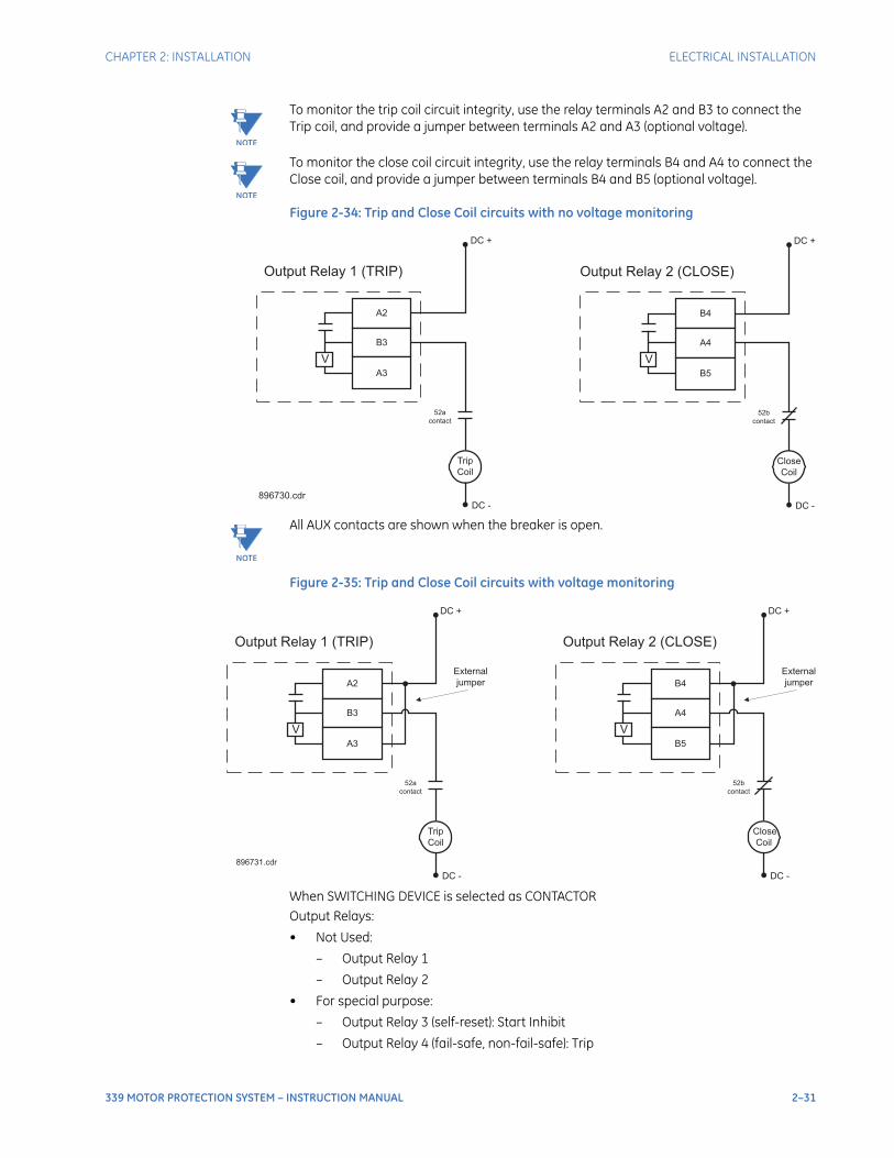
CHAPTER 2: INSTALLATION ELECTRICAL INSTALLATION
339 MOTOR PROTECTION SYSTEM – INSTRUCTION MANUAL 2–31
NOTE
NOTE: To monitor the trip coil circuit integrity, use the relay terminals A2 and B3 to connect the Trip coil, and provide a jumper between terminals A2 and A3 (optional voltage).
NOTE
NOTE: To monitor the close coil circuit integrity, use the relay terminals B4 and A4 to connect the Close coil, and provide a jumper between terminals B4 and B5 (optional voltage).
Figure 2-34: Trip and Close Coil circuits with no voltage monitoring
NOTE
NOTE: All AUX contacts are shown when the breaker is open.
Figure 2-35: Trip and Close Coil circuits with voltage monitoring
When SWITCHING DEVICE is selected as CONTACTOROutput Relays:
• Not Used:
– Output Relay 1
– Output Relay 2
• For special purpose:
– Output Relay 3 (self-reset): Start Inhibit
– Output Relay 4 (fail-safe, non-fail-safe): Trip
V
A2
B3
A3
Trip
Coil
DC +
DC -
Output Relay 1 (TRIP)
52a
contact
V
B4
A4
B5
Close
Coil
DC +
DC -
Output Relay 2 (CLOSE)
52b
contact
896730.cdr
V
A2
B3
A3
Trip
Coil
DC +
DC -
Output Relay 1 (TRIP)
52a
contact
External
jumper
896731.cdr
V
B4
A4
B5
Close
Coil
DC +
DC -
Output Relay 2 (CLOSE)
52b
contact
External
jumper
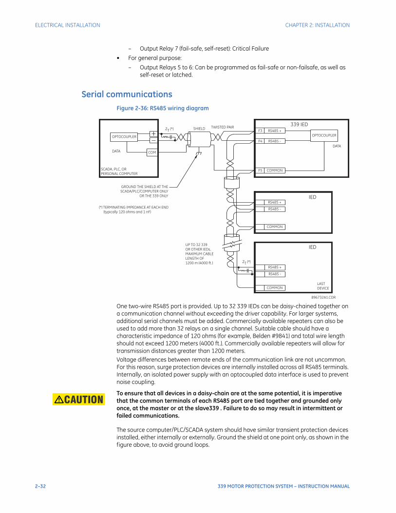
2–32 339 MOTOR PROTECTION SYSTEM – INSTRUCTION MANUAL
ELECTRICAL INSTALLATION CHAPTER 2: INSTALLATION
– Output Relay 7 (fail-safe, self-reset): Critical Failure
• For general purpose:
– Output Relays 5 to 6: Can be programmed as fail-safe or non-failsafe, as well as self-reset or latched.
Serial communicationsFigure 2-36: RS485 wiring diagram
One two-wire RS485 port is provided. Up to 32 339 IEDs can be daisy-chained together on a communication channel without exceeding the driver capability. For larger systems, additional serial channels must be added. Commercially available repeaters can also be used to add more than 32 relays on a single channel. Suitable cable should have a characteristic impedance of 120 ohms (for example, Belden #9841) and total wire length should not exceed 1200 meters (4000 ft.). Commercially available repeaters will allow for transmission distances greater than 1200 meters.Voltage differences between remote ends of the communication link are not uncommon. For this reason, surge protection devices are internally installed across all RS485 terminals. Internally, an isolated power supply with an optocoupled data interface is used to prevent noise coupling.
CAUTION: To ensure that all devices in a daisy-chain are at the same potential, it is imperative that the common terminals of each RS485 port are tied together and grounded only once, at the master or at the slave339 . Failure to do so may result in intermittent or failed communications.
The source computer/PLC/SCADA system should have similar transient protection devices installed, either internally or externally. Ground the shield at one point only, as shown in the figure above, to avoid ground loops.
SCADA, PLC, OR
PERSONAL COMPUTER
COM
OPTOCOUPLER
DATA
339 IEDSHIELD
896732A1.CDR
UP TO 32 339
OR OTHER IEDs,
MAXIMUM CABLE
LENGTH OF
1200 m (4000 ft.)
LAST
DEVICE
(*) TERMINATING IMPEDANCE AT EACH END
(typically 120 ohms and 1 nF)
TWISTED PAIR
ZT
(*)
RS485 +
RS485 -
COMMON
RS485 +
RS485 -
COMMON
IED
RS485 +
IED
RS485 -
COMMON
GROUND THE SHIELD AT THE
SCADA/PLC/COMPUTER ONLY
OR THE 339 ONLY
DATA
OPTOCOUPLER
F3
F4
F5
ZT
(*)
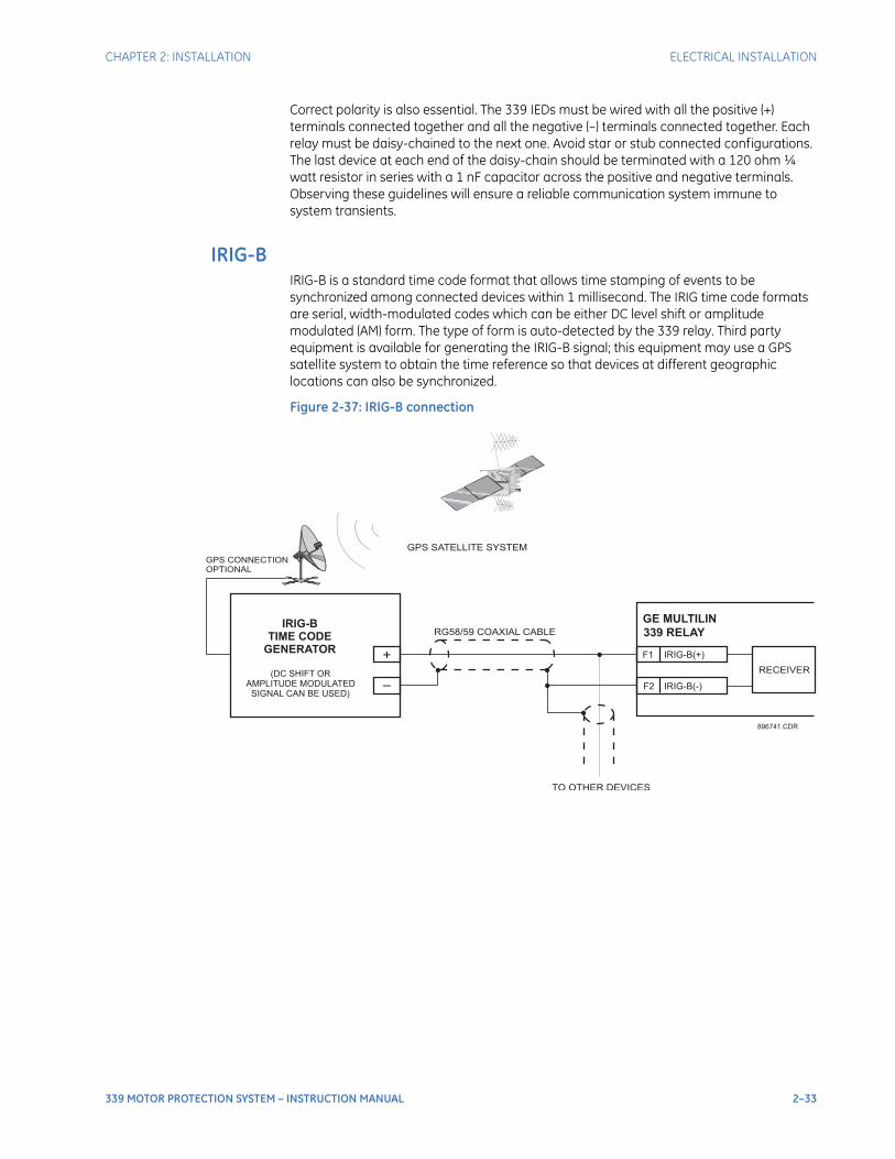
CHAPTER 2: INSTALLATION ELECTRICAL INSTALLATION
339 MOTOR PROTECTION SYSTEM – INSTRUCTION MANUAL 2–33
Correct polarity is also essential. The 339 IEDs must be wired with all the positive (+) terminals connected together and all the negative (–) terminals connected together. Each relay must be daisy-chained to the next one. Avoid star or stub connected configurations. The last device at each end of the daisy-chain should be terminated with a 120 ohm ¼ watt resistor in series with a 1 nF capacitor across the positive and negative terminals. Observing these guidelines will ensure a reliable communication system immune to system transients.
IRIG-BIRIG-B is a standard time code format that allows time stamping of events to be synchronized among connected devices within 1 millisecond. The IRIG time code formats are serial, width-modulated codes which can be either DC level shift or amplitude modulated (AM) form. The type of form is auto-detected by the 339 relay. Third party equipment is available for generating the IRIG-B signal; this equipment may use a GPS satellite system to obtain the time reference so that devices at different geographic locations can also be synchronized.
Figure 2-37: IRIG-B connection
GE MULTILIN
339 RELAY
IRIG-B(-)
RECEIVER
TO OTHER DEVICES
RG58/59 COAXIAL CABLE
GPS SATELLITE SYSTEM
GPS CONNECTIONOPTIONAL
IRIG-B(+)F1
F2
+
–
896741.CDR
IRIG-B
TIME CODE
GENERATOR
(DC SHIFT ORAMPLITUDE MODULATED
SIGNAL CAN BE USED)

2–34 339 MOTOR PROTECTION SYSTEM – INSTRUCTION MANUAL
ELECTRICAL INSTALLATION CHAPTER 2: INSTALLATION

339 MOTOR PROTECTION SYSTEM – INSTRUCTION MANUAL 3–1
339 Motor Protection System
Chapter 3: Interfaces
GEGrid Solutions
Interfaces
There are two methods of interfacing with the 339 Motor Protection System .
• Interfacing via the relay keypad and display.
• Interfacing via the EnerVista SR3 Setup software.
This section provides an overview of the interfacing methods available with the 339 using the relay control panel and EnerVista SR3 Setup software. For additional details on interface parameters (for example, settings, actual values, etc.), refer to the individual chapters.
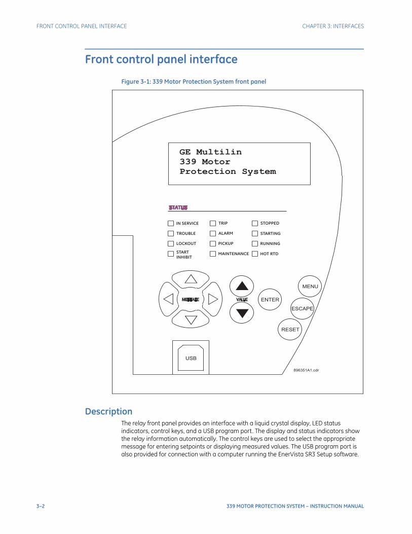
3–2 339 MOTOR PROTECTION SYSTEM – INSTRUCTION MANUAL
FRONT CONTROL PANEL INTERFACE CHAPTER 3: INTERFACES
Front control panel interface
Figure 3-1: 339 Motor Protection System front panel
DescriptionThe relay front panel provides an interface with a liquid crystal display, LED status indicators, control keys, and a USB program port. The display and status indicators show the relay information automatically. The control keys are used to select the appropriate message for entering setpoints or displaying measured values. The USB program port is also provided for connection with a computer running the EnerVista SR3 Setup software.
◁ ▷
ENTER
MENU
ESCAPE
RESET
896351A1.cdr
USB
GE Multilin
339 Motor
Protection System
IN SERVICE
TROUBLE
LOCKOUT
STARTINHIBIT
TRIP
ALARM
PICKUP
MAINTENANCE
STOPPED
STARTING
RUNNING
HOT RTD
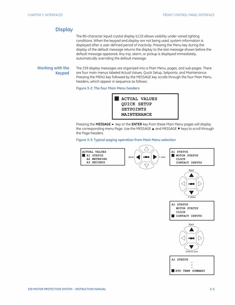
CHAPTER 3: INTERFACES FRONT CONTROL PANEL INTERFACE
339 MOTOR PROTECTION SYSTEM – INSTRUCTION MANUAL 3–3
DisplayThe 80-character liquid crystal display (LCD) allows visibility under varied lighting conditions. When the keypad and display are not being used, system information is displayed after a user-defined period of inactivity. Pressing the Menu key during the display of the default message returns the display to the last message shown before the default message appeared. Any trip, alarm, or pickup is displayed immediately, automatically overriding the default message.
Working with theKeypad
The 339 display messages are organized into a Main Menu, pages, and sub-pages. There are four main menus labeled Actual Values, Quick Setup, Setpoints, and Maintenance. Pressing the MENU key followed by the MESSAGE key scrolls through the four Main Menu headers, which appear in sequence as follows:
Figure 3-2: The four Main Menu headers
Pressing the MESSAGE key or the ENTER key from these Main Menu pages will display the corresponding menu Page. Use the MESSAGE and MESSAGE keys to scroll through the Page headers.
Figure 3-3: Typical paging operation from Main Menu selection
ACTUAL VALUES
QUICK SETUP
SETPOINTS
MAINTENANCE
MOTOR STATUS
A1 STATUS
CLOCK
CONTACT INPUTS
ACTUAL VALUES
A1 STATUS
A2 METERING
A3 RECORDS
CLOCK
A1 STATUS
CONTACT INPUTS
MOTOR STATUS
A1 STATUS
RTD TEMP SUMMARY
...
2 clicks
◁ ▷
◁ ▷
Click to end
Back
Back
Back 1 click

3–4 339 MOTOR PROTECTION SYSTEM – INSTRUCTION MANUAL
FRONT CONTROL PANEL INTERFACE CHAPTER 3: INTERFACES
When the display shows SETPOINTS, pressing the MESSAGE key or the ENTER key will display the page headers of programmable parameters (referred to as setpoints in the manual). When the display shows ACTUAL VALUES, pressing the MESSAGE key or the ENTER key displays the page headers of measured parameters (referred to as actual values in the manual). Each page is broken down further into logical sub-pages of messages. The MESSAGE and MESSAGE keys are used to navigate through the sub-pages. A summary of the setpoints and actual values pages can be found in the Chapters : Setpoints and Actual Values, respectively.The ENTER key is dual purpose. It is used to enter the sub-pages and to store altered setpoint values into memory to complete the change. The MESSAGE key can also be used to enter sub-pages but not to store altered setpoints.The ESCAPE key or the MESSAGE key can be used to exit the sub-pages.The VALUE keys are used to scroll through the possible choices of an enumerated setpoint. They also decrement and increment numerical setpoints. The RESET key resets any latched conditions that are not currently active. This includes resetting latched output relays, latched Trip LEDs, breaker operation failure, and trip / close coil failures.The MESSAGE and MESSAGE keys scroll through any active conditions in the relay. Diagnostic messages are displayed indicating the state of protection and monitoring elements that are picked up, operating, or latched.
LED status indicators• IN SERVICE: Green
– Turns "ON" when the relay does not have any major self-test error.
– Minor self-test targets will not de-activate the LED.
• TROUBLE: Amber
– Turns "ON" when either a major or minor self-test error has occurred.
– Will be latched "ON" for major self-test errors, except for "RELAY NOT READY".
– Will be self-resetting for minor self-test errors.
• TRIP: Red
– Turns "ON" when a protection element has been assigned to trip and the element has been activated.
– Will be latched "ON" until a reset command occurs.
– Turns "OFF" when a reset has been initiated through the front panel, communications, or digital inputs, and the fault has been cleared.
• ALARM: Amber
– Flashes "ON" and "OFF" when a protection, control, or maintenance element has been assigned to alarm and the element has been activated.
– Will be latched "ON" if "Latched Alarm" is set and the fault has been cleared.
– Will be self-resetting if "Alarm" is set and the fault has been cleared.
– Turns "OFF" when a reset has been initiated through the front panel or communications, and the fault has been cleared, if "Latched Alarm" is set.
• PICKUP: Amber
– Turns "ON" when a protection element setting threshold has been exceeded. LED will turn "OFF" when the values go below the threshold.
• MAINTENANCE: Amber
– Turns "ON" when either the Trip or the Close Coil Monitor element is activated, or the Trip Counter has exceeded the programmed value.
CHAPTER 3: INTERFACES FRONT CONTROL PANEL INTERFACE
339 MOTOR PROTECTION SYSTEM – INSTRUCTION MANUAL 3–5
• LOCKOUT: Red
– Turns "ON" when the following elements are activated:
Thermal OverloadShort CircuitMechanical JamGround Fault.
– Can be reset only by emergency restart or lockout reset, if they are enabled.
– If the above are not enabled, a normal reset will turn the LED "OFF".
• START INHIBIT: Red
– Turns "ON" when the Start Inhibit element is activated.
– Self-resetting when the inhibit is no longer present.
• STOPPED: Default to Red
– LED color is programmable. Turns "ON" when the motor status is "Stopped".
• STARTING: Default to Amber
– LED color is programmable. Turns "ON" when the motor status is "Starting".
• RUNNING: Default to Green
– LED color is programmable. Turns "ON" when the motor status is "Running".
• HOT RTD: Amber
– Turns "ON" when either a RTD Alarm or Trip has been activated.
– Self-resetting when the fault is no longer present.
Relay messages
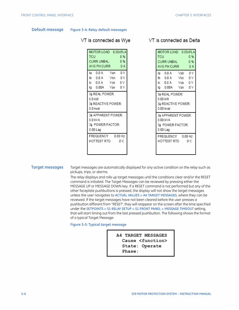
3–6 339 MOTOR PROTECTION SYSTEM – INSTRUCTION MANUAL
FRONT CONTROL PANEL INTERFACE CHAPTER 3: INTERFACES
Default message Figure 3-4: Relay default messages
Target messages Target messages are automatically displayed for any active condition on the relay such as pickups, trips, or alarms.The relay displays and rolls up target messages until the conditions clear and/or the RESET command is initiated. The Target Messages can be reviewed by pressing either the MESSAGE UP or MESSAGE DOWN key. If a RESET command is not performed but any of the other faceplate pushbuttons is pressed, the display will not show the target messages unless the user navigates to ACTUAL VALUES > A4 TARGET MESSAGES, where they can be reviewed. If the target messages have not been cleared before the user presses a pushbutton different from “RESET”, they will reappear on the screen after the time specified under the SETPOINTS > S1 RELAY SETUP > S1 FRONT PANEL > MESSAGE TIMEOUT setting, that will start timing out from the last pressed pushbutton. The following shows the format of a typical Target Message:
Figure 3-5: Typical target message
A4 TARGET MESSAGES
Cause <function>
State: Operate
Phase:
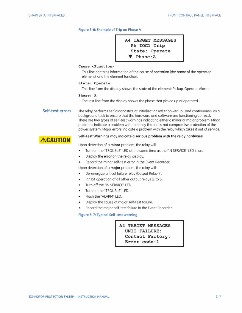
CHAPTER 3: INTERFACES FRONT CONTROL PANEL INTERFACE
339 MOTOR PROTECTION SYSTEM – INSTRUCTION MANUAL 3–7
Figure 3-6: Example of Trip on Phase A
Cause <Function>
This line contains information of the cause of operation (the name of the operated element), and the element function.
State: Operate
This line from the display shows the state of the element: Pickup, Operate, Alarm.
Phase: A
The last line from the display shows the phase that picked up or operated.
Self-test errors The relay performs self diagnostics at initialization (after power up), and continuously as a background task to ensure that the hardware and software are functioning correctly. There are two types of self-test warnings indicating either a minor or major problem. Minor problems indicate a problem with the relay that does not compromise protection of the power system. Major errors indicate a problem with the relay which takes it out of service.
CAUTION: Self-Test Warnings may indicate a serious problem with the relay hardware!
Upon detection of a minor problem, the relay will:
• Turn on the "TROUBLE" LED at the same time as the "IN SERVICE" LED is on.
• Display the error on the relay display.
• Record the minor self-test error in the Event Recorder.
Upon detection of a major problem, the relay will:
• De-energize critical failure relay (Output Relay 7).
• Inhibit operation of all other output relays (1 to 6).
• Turn off the "IN SERVICE" LED.
• Turn on the "TROUBLE" LED.
• Flash the "ALARM" LED.
• Display the cause of major self-test failure.
• Record the major self-test failure in the Event Recorder.
Figure 3-7: Typical Self-test warning
A4 TARGET MESSAGES
Ph IOC1 Trip
State: Operate
Phase:A
A4 TARGET MESSAGES
UNIT FAILURE:
Contact Factory:
Error code:1
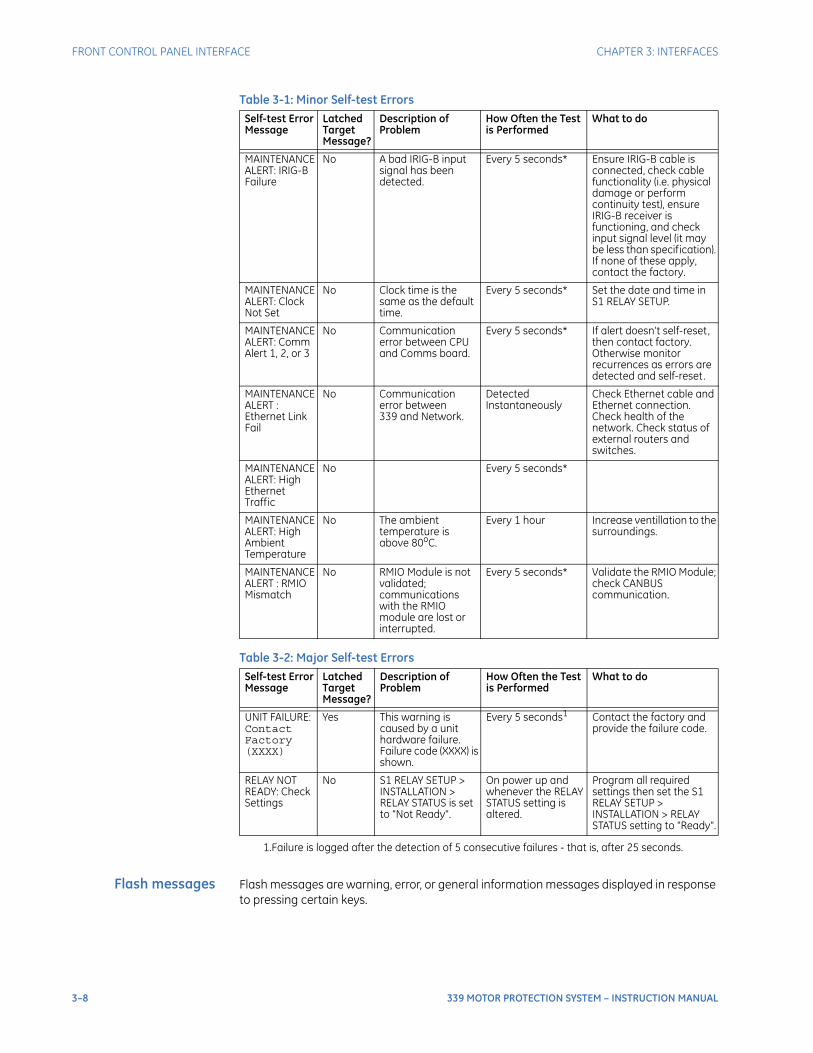
3–8 339 MOTOR PROTECTION SYSTEM – INSTRUCTION MANUAL
FRONT CONTROL PANEL INTERFACE CHAPTER 3: INTERFACES
Table 3-1: Minor Self-test Errors
Table 3-2: Major Self-test Errors
Flash messages Flash messages are warning, error, or general information messages displayed in response to pressing certain keys.
Self-test Error Message
Latched Target Message?
Description of Problem
How Often the Test is Performed
What to do
MAINTENANCE ALERT: IRIG-B Failure
No A bad IRIG-B input signal has been detected.
Every 5 seconds* Ensure IRIG-B cable is connected, check cable functionality (i.e. physical damage or perform continuity test), ensure IRIG-B receiver is functioning, and check input signal level (it may be less than specification). If none of these apply, contact the factory.
MAINTENANCE ALERT: Clock Not Set
No Clock time is the same as the default time.
Every 5 seconds* Set the date and time in S1 RELAY SETUP.
MAINTENANCE ALERT: Comm Alert 1, 2, or 3
No Communication error between CPU and Comms board.
Every 5 seconds* If alert doesn’t self-reset, then contact factory. Otherwise monitor recurrences as errors are detected and self-reset.
MAINTENANCEALERT : Ethernet Link Fail
No Communication error between 339 and Network.
Detected Instantaneously
Check Ethernet cable and Ethernet connection. Check health of the network. Check status of external routers and switches.
MAINTENANCEALERT: High Ethernet Traffic
No Every 5 seconds*
MAINTENANCEALERT: High Ambient Temperature
No The ambient temperature is above 80oC.
Every 1 hour Increase ventillation to the surroundings.
MAINTENANCEALERT : RMIO Mismatch
No RMIO Module is not validated; communications with the RMIO module are lost or interrupted.
Every 5 seconds* Validate the RMIO Module; check CANBUS communication.
Self-test Error Message
Latched Target Message?
Description of Problem
How Often the Test is Performed
What to do
UNIT FAILURE: Contact Factory (XXXX)
Yes This warning is caused by a unit hardware failure. Failure code (XXXX) is shown.
Every 5 seconds1
1.Failure is logged after the detection of 5 consecutive failures - that is, after 25 seconds.
Contact the factory and provide the failure code.
RELAY NOT READY: Check Settings
No S1 RELAY SETUP > INSTALLATION > RELAY STATUS is set to "Not Ready".
On power up and whenever the RELAY STATUS setting is altered.
Program all required settings then set the S1 RELAY SETUP > INSTALLATION > RELAY STATUS setting to "Ready".
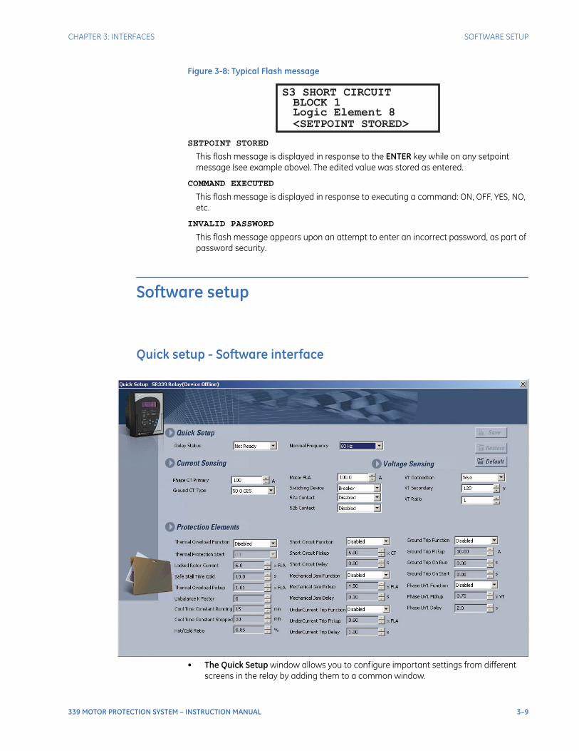
CHAPTER 3: INTERFACES SOFTWARE SETUP
339 MOTOR PROTECTION SYSTEM – INSTRUCTION MANUAL 3–9
Figure 3-8: Typical Flash message
SETPOINT STORED
This flash message is displayed in response to the ENTER key while on any setpoint message (see example above). The edited value was stored as entered.
COMMAND EXECUTED
This flash message is displayed in response to executing a command: ON, OFF, YES, NO, etc.
INVALID PASSWORD
This flash message appears upon an attempt to enter an incorrect password, as part of password security.
Software setup
Quick setup - Software interface
• The Quick Setup window allows you to configure important settings from different screens in the relay by adding them to a common window.
BLOCK 1Logic Element 8
S3 SHORT CIRCUIT
<SETPOINT STORED>

3–10 339 MOTOR PROTECTION SYSTEM – INSTRUCTION MANUAL
SOFTWARE SETUP CHAPTER 3: INTERFACES
• The Quick Setup window options are available for online devices or setpoint files.
• The Quick Setup Window option is accessed from the "Tree" which launches on clicking.
EnerVista SR3 Setup SoftwareAlthough settings can be entered manually using the control panel keys, a PC can be used to download setpoints through the communications port. The EnerVista SR3 Setup software makes this as convenient as possible. With theEnerVista SR3 Setup 339 relay running, it is possible to:
• Program and modify settings
• Load and save setting files to and from a disk
• Read actual values
• Monitor status
• Read pre-trip data and event records
• Get help on any topic
• Upgrade the 339 firmware
The EnerVista SR3 Setup software allows immediate access to all 339 features with easy to use pull down menus in the familiar Windows environment. This section provides the necessary information to install the 339 EnerVista SR3 Setup , upgrade the relay firmware, and write and edit setting files.The EnerVista SR3 Setup software can run without a 339 connected to the computer. In this case, settings may be saved to a file for future use. If a 339 is connected to a PC and communications are enabled, the 339 can be programmed from the setting screens. In addition, measured values, status and trip messages can be displayed with the actual value screens.
Hardware andsoftware
requirements
The following requirements must be met for the EnerVista SR3 Setup software.
• Windows 7 (32-bit or 64-bit) or Windows 8.1 (32-bit or 64-bit)
The EnerVista SR3 Setup software can be installed from either the GE EnerVista CD or the GE Multilin website at http://www.gegridsolutions.com/multilin.
Installing theEnerVista SR3 Setup
software
After ensuring the minimum requirements indicated earlier, use the following procedure to install the EnerVista SR3 Setup software from the enclosed GE EnerVista CD.
1. Insert the GE EnerVista CD into your CD-ROM drive.
2. Follow the installation instructions to install the no-charge EnerVista software on the local PC.
3. When installation is complete, start the EnerVista Launchpad application.
4. Click the IED Setup section of the LaunchPad toolbar.
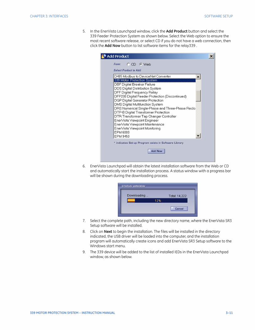
CHAPTER 3: INTERFACES SOFTWARE SETUP
339 MOTOR PROTECTION SYSTEM – INSTRUCTION MANUAL 3–11
5. In the EnerVista Launchpad window, click the Add Product button and select the 339 Feeder Protection System as shown below. Select the Web option to ensure the most recent software release, or select CD if you do not have a web connection, then click the Add Now button to list software items for the relay339 .
6. EnerVista Launchpad will obtain the latest installation software from the Web or CD and automatically start the installation process. A status window with a progress bar will be shown during the downloading process.
7. Select the complete path, including the new directory name, where the EnerVista SR3 Setup software will be installed.
8. Click on Next to begin the installation. The files will be installed in the directory indicated, the USB driver will be loaded into the computer, and the installation program will automatically create icons and add EnerVista SR3 Setup software to the Windows start menu.
9. The 339 device will be added to the list of installed IEDs in the EnerVista Launchpad window, as shown below.

3–12 339 MOTOR PROTECTION SYSTEM – INSTRUCTION MANUAL
SOFTWARE SETUP CHAPTER 3: INTERFACES
If you are going to communicate from your computer to the 339 Relay using the USB port:
10. Plug the USB cable into the USB port on the 339 Relay then into the USB port on your computer.
11. Launch EnerVista SR3 Setup from LaunchPad.
12. In EnerVista > Device Setup:
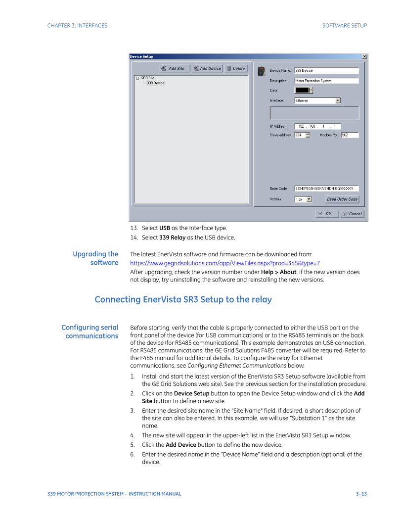
CHAPTER 3: INTERFACES SOFTWARE SETUP
339 MOTOR PROTECTION SYSTEM – INSTRUCTION MANUAL 3–13
13. Select USB as the Interface type.
14. Select 339 Relay as the USB device.
Upgrading thesoftware
The latest EnerVista software and firmware can be downloaded from:https://www.gegridsolutions.com/app/ViewFiles.aspx?prod=345&type=7After upgrading, check the version number under Help > About. If the new version does not display, try uninstalling the software and reinstalling the new versions.
Connecting EnerVista SR3 Setup to the relay
Configuring serialcommunications
Before starting, verify that the cable is properly connected to either the USB port on the front panel of the device (for USB communications) or to the RS485 terminals on the back of the device (for RS485 communications). This example demonstrates an USB connection. For RS485 communications, the GE Grid Solutions F485 converter will be required. Refer to the F485 manual for additional details. To configure the relay for Ethernet communications, see Configuring Ethernet Communications below.
1. Install and start the latest version of the EnerVista SR3 Setup software (available from the GE Grid Solutions web site). See the previous section for the installation procedure.
2. Click on the Device Setup button to open the Device Setup window and click the Add Site button to define a new site.
3. Enter the desired site name in the "Site Name" field. If desired, a short description of the site can also be entered. In this example, we will use “Substation 1” as the site name.
4. The new site will appear in the upper-left list in the EnerVista SR3 Setup window.
5. Click the Add Device button to define the new device.
6. Enter the desired name in the "Device Name" field and a description (optional) of the device.
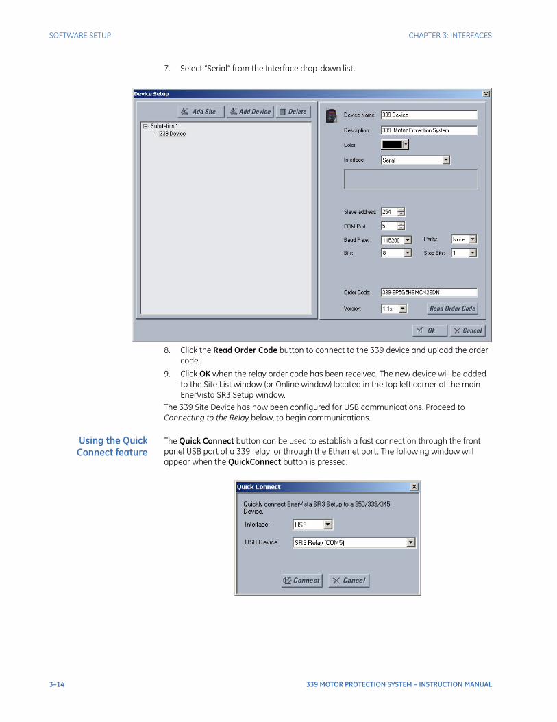
3–14 339 MOTOR PROTECTION SYSTEM – INSTRUCTION MANUAL
SOFTWARE SETUP CHAPTER 3: INTERFACES
7. Select “Serial” from the Interface drop-down list.
8. Click the Read Order Code button to connect to the 339 device and upload the order code.
9. Click OK when the relay order code has been received. The new device will be added to the Site List window (or Online window) located in the top left corner of the main EnerVista SR3 Setup window.
The 339 Site Device has now been configured for USB communications. Proceed to Connecting to the Relay below, to begin communications.
Using the QuickConnect feature
The Quick Connect button can be used to establish a fast connection through the front panel USB port of a 339 relay, or through the Ethernet port. The following window will appear when the QuickConnect button is pressed:
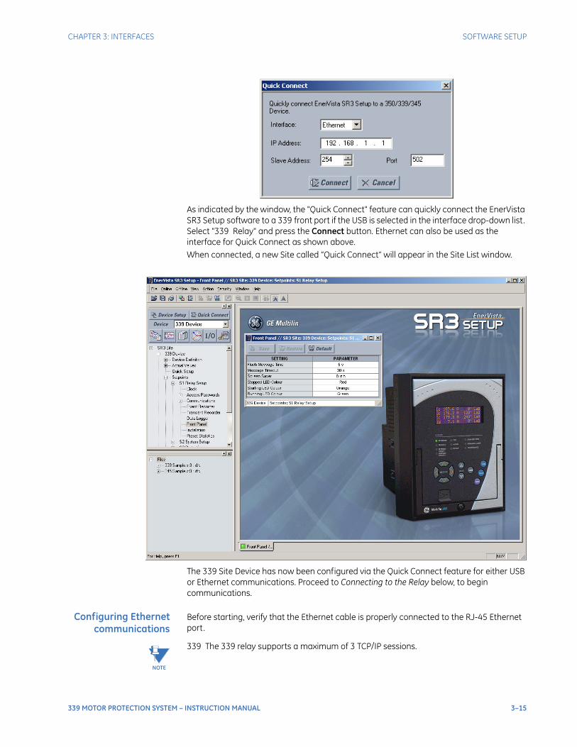
CHAPTER 3: INTERFACES SOFTWARE SETUP
339 MOTOR PROTECTION SYSTEM – INSTRUCTION MANUAL 3–15
As indicated by the window, the "Quick Connect" feature can quickly connect the EnerVista SR3 Setup software to a 339 front port if the USB is selected in the interface drop-down list. Select "339 Relay" and press the Connect button. Ethernet can also be used as the interface for Quick Connect as shown above.When connected, a new Site called “Quick Connect” will appear in the Site List window.
The 339 Site Device has now been configured via the Quick Connect feature for either USB or Ethernet communications. Proceed to Connecting to the Relay below, to begin communications.
Configuring Ethernetcommunications
Before starting, verify that the Ethernet cable is properly connected to the RJ-45 Ethernet port.
NOTE
NOTE: 339 The 339 relay supports a maximum of 3 TCP/IP sessions.
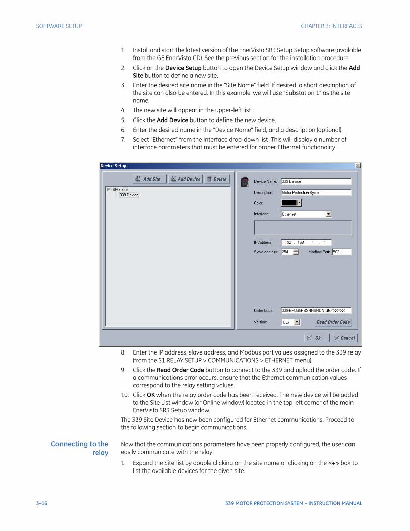
3–16 339 MOTOR PROTECTION SYSTEM – INSTRUCTION MANUAL
SOFTWARE SETUP CHAPTER 3: INTERFACES
1. Install and start the latest version of the EnerVista SR3 Setup Setup software (available from the GE EnerVista CD). See the previous section for the installation procedure.
2. Click on the Device Setup button to open the Device Setup window and click the Add Site button to define a new site.
3. Enter the desired site name in the "Site Name" field. If desired, a short description of the site can also be entered. In this example, we will use “Substation 1” as the site name.
4. The new site will appear in the upper-left list.
5. Click the Add Device button to define the new device.
6. Enter the desired name in the "Device Name" field, and a description (optional).
7. Select “Ethernet” from the Interface drop-down list. This will display a number of interface parameters that must be entered for proper Ethernet functionality.
8. Enter the IP address, slave address, and Modbus port values assigned to the 339 relay (from the S1 RELAY SETUP > COMMUNICATIONS > ETHERNET menu).
9. Click the Read Order Code button to connect to the 339 and upload the order code. If a communications error occurs, ensure that the Ethernet communication values correspond to the relay setting values.
10. Click OK when the relay order code has been received. The new device will be added to the Site List window (or Online window) located in the top left corner of the main EnerVista SR3 Setup window.
The 339 Site Device has now been configured for Ethernet communications. Proceed to the following section to begin communications.
Connecting to therelay
Now that the communications parameters have been properly configured, the user can easily communicate with the relay.
1. Expand the Site list by double clicking on the site name or clicking on the «+» box to list the available devices for the given site.
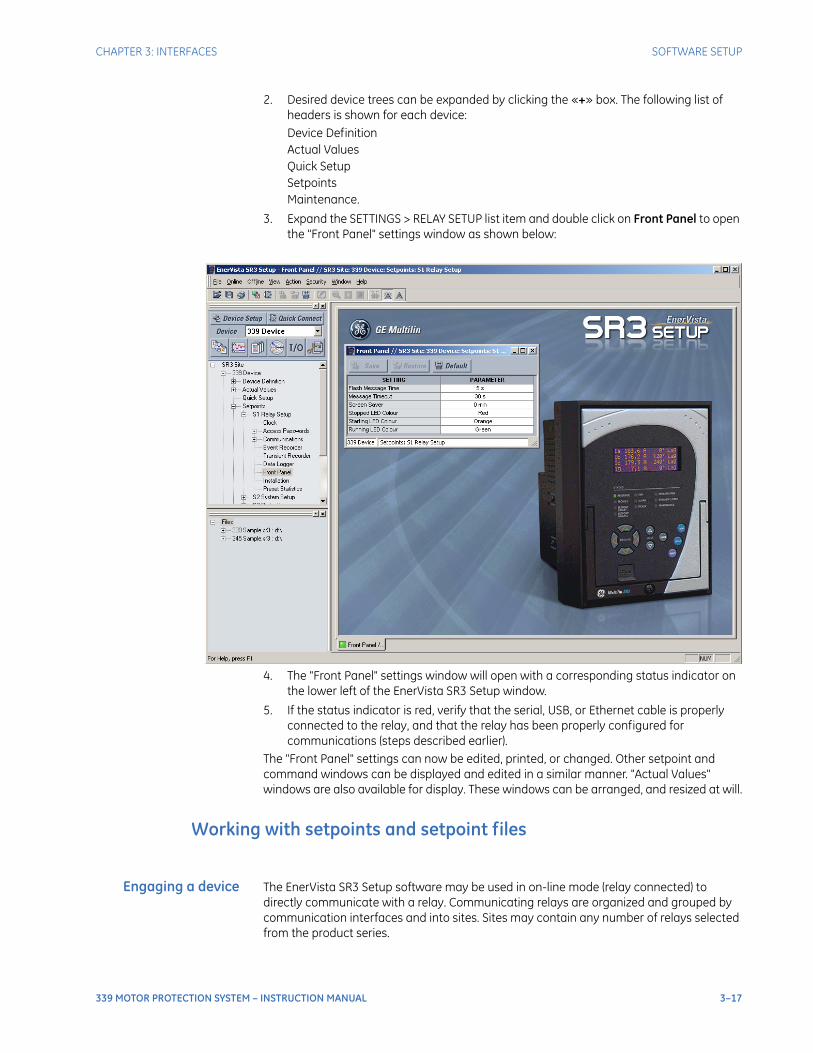
CHAPTER 3: INTERFACES SOFTWARE SETUP
339 MOTOR PROTECTION SYSTEM – INSTRUCTION MANUAL 3–17
2. Desired device trees can be expanded by clicking the «+» box. The following list of headers is shown for each device:Device DefinitionActual ValuesQuick SetupSetpointsMaintenance.
3. Expand the SETTINGS > RELAY SETUP list item and double click on Front Panel to open the "Front Panel" settings window as shown below:
4. The "Front Panel" settings window will open with a corresponding status indicator on the lower left of the EnerVista SR3 Setup window.
5. If the status indicator is red, verify that the serial, USB, or Ethernet cable is properly connected to the relay, and that the relay has been properly configured for communications (steps described earlier).
The "Front Panel" settings can now be edited, printed, or changed. Other setpoint and command windows can be displayed and edited in a similar manner. "Actual Values" windows are also available for display. These windows can be arranged, and resized at will.
Working with setpoints and setpoint files
Engaging a device The EnerVista SR3 Setup software may be used in on-line mode (relay connected) to directly communicate with a relay. Communicating relays are organized and grouped by communication interfaces and into sites. Sites may contain any number of relays selected from the product series.
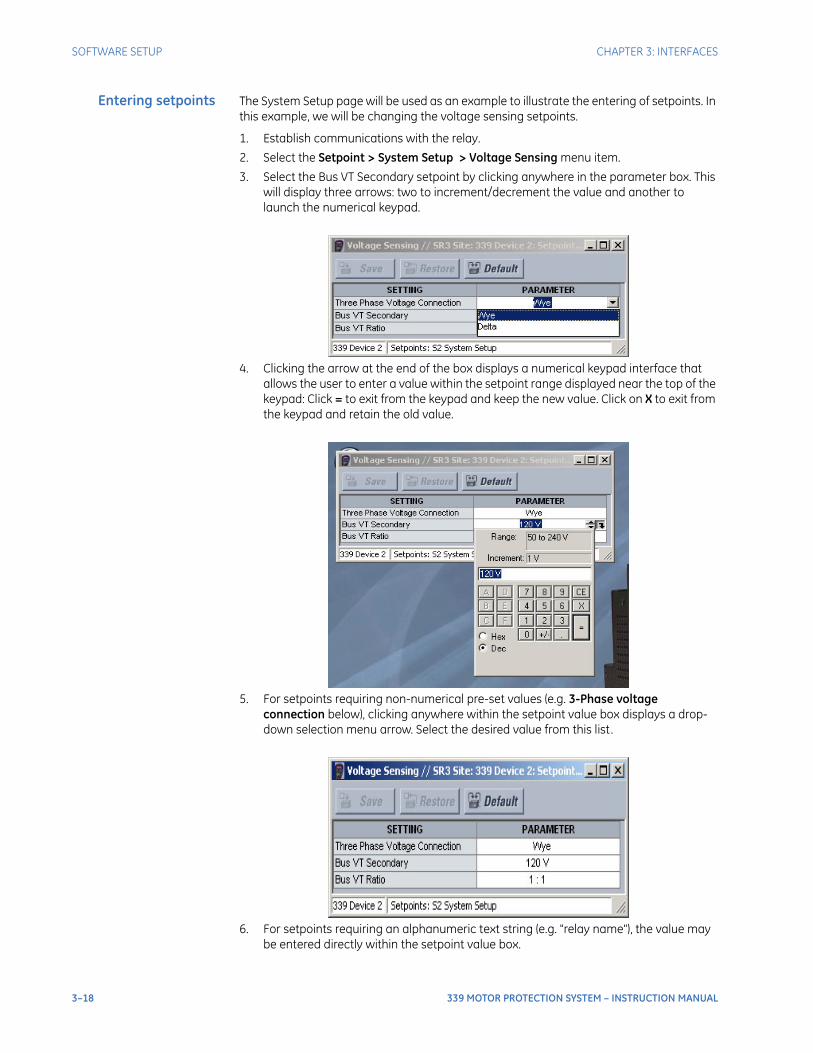
3–18 339 MOTOR PROTECTION SYSTEM – INSTRUCTION MANUAL
SOFTWARE SETUP CHAPTER 3: INTERFACES
Entering setpoints The System Setup page will be used as an example to illustrate the entering of setpoints. In this example, we will be changing the voltage sensing setpoints.
1. Establish communications with the relay.
2. Select the Setpoint > System Setup > Voltage Sensing menu item.
3. Select the Bus VT Secondary setpoint by clicking anywhere in the parameter box. This will display three arrows: two to increment/decrement the value and another to launch the numerical keypad.
4. Clicking the arrow at the end of the box displays a numerical keypad interface that allows the user to enter a value within the setpoint range displayed near the top of the keypad: Click = to exit from the keypad and keep the new value. Click on X to exit from the keypad and retain the old value.
5. For setpoints requiring non-numerical pre-set values (e.g. 3-Phase voltage connection below), clicking anywhere within the setpoint value box displays a drop-down selection menu arrow. Select the desired value from this list.
6. For setpoints requiring an alphanumeric text string (e.g. "relay name"), the value may be entered directly within the setpoint value box.

CHAPTER 3: INTERFACES SOFTWARE SETUP
339 MOTOR PROTECTION SYSTEM – INSTRUCTION MANUAL 3–19
7. In the Setpoint > System Setup > Voltage Sensing dialog box, click on Save to save the values into the relay339 . Click YES to accept any changes and exit the window. Click Restore to retain previous values. Click Default to restore Default values.
File support Opening any EnerVista SR3 Setup file will automatically launch the application or provide focus to the already opened application. If the file is a settings file (has a ‘SR3’ extension) which had been removed from the Settings List tree menu, it will be added back to the Settings List tree.New files will be automatically added to the tree.
Using setpoints files The EnerVista SR3 Setup software interface supports three ways of handling changes to relay settings:
• In off-line mode (relay disconnected) to create or edit relay settings files for later download to communicating relays.
• Directly modifying relay settings while connected to a communicating relay, then saving the settings when complete.
• Creating/editing settings files while connected to a communicating relay, then saving them to the relay when complete.
Settings files are organized on the basis of file names assigned by the user. A settings file contains data pertaining to the following types of relay settings:
• Device Definition
• Relay Setup
• System Setup
• Protection
• Control
• Inputs/Outputs
Factory default values are supplied and can be restored after any changes.The EnerVista SR3 Setup displays relay setpoints with the same hierarchy as the front panel display.
Downloading andsaving setpoints files
Back up a copy of the in-service settings for each commissioned 339 unit, so as to revert to the commissioned settings after inadvertent, unauthorized, or temporary setting changes are made, after the settings default due to firmware upgrade, or when the unit has to be replaced. This section describes how to backup settings to a file and how to use that file to restore settings to the original relay or to a replacement relaySetpoints must be saved to a file on the local PC before performing any firmware upgrades. Saving setpoints is also highly recommended before making any setpoint changes or creating new setpoint files.The setpoint files in the EnerVista SR3 Setup window are accessed in the Files Window. Use the following procedure to download and save setpoint files to a local PC.
1. Ensure that the site and corresponding device(s) have been properly defined and configured as shown in Connecting EnerVista SR3 Setup to the Relay, above.
2. Select the desired device from the site list.
3. Select the Online > Read Device Settings from Device menu item, or right-click on the device and select Read Device Settings to obtain settings information from the device.
4. After a few seconds of data retrieval, the software will request the name and destination path of the setpoint file. The corresponding file extension will be automatically assigned. Press Receive to complete the process. A new entry will be added to the tree, in the File pane, showing path and file name for the setpoint file.
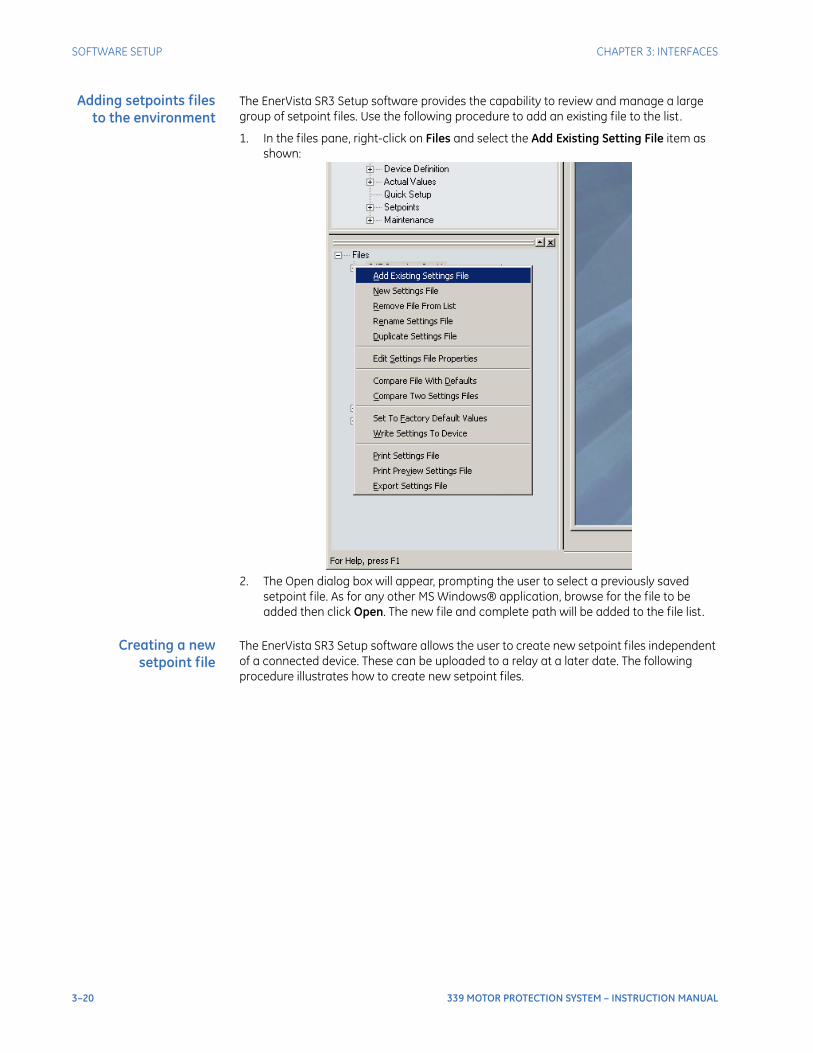
3–20 339 MOTOR PROTECTION SYSTEM – INSTRUCTION MANUAL
SOFTWARE SETUP CHAPTER 3: INTERFACES
Adding setpoints filesto the environment
The EnerVista SR3 Setup software provides the capability to review and manage a large group of setpoint files. Use the following procedure to add an existing file to the list.
1. In the files pane, right-click on Files and select the Add Existing Setting File item as shown:
2. The Open dialog box will appear, prompting the user to select a previously saved setpoint file. As for any other MS Windows® application, browse for the file to be added then click Open. The new file and complete path will be added to the file list.
Creating a newsetpoint file
The EnerVista SR3 Setup software allows the user to create new setpoint files independent of a connected device. These can be uploaded to a relay at a later date. The following procedure illustrates how to create new setpoint files.
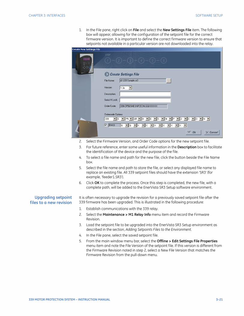
CHAPTER 3: INTERFACES SOFTWARE SETUP
339 MOTOR PROTECTION SYSTEM – INSTRUCTION MANUAL 3–21
1. In the File pane, right click on File and select the New Settings File item. The following box will appear, allowing for the configuration of the setpoint file for the correct firmware version. It is important to define the correct firmware version to ensure that setpoints not available in a particular version are not downloaded into the relay.
2. Select the Firmware Version, and Order Code options for the new setpoint file.
3. For future reference, enter some useful information in the Description box to facilitate the identification of the device and the purpose of the file.
4. To select a file name and path for the new file, click the button beside the File Name box.
5. Select the file name and path to store the file, or select any displayed file name to replace an existing file. All 339 setpoint files should have the extension ‘SR3’ (for example, ‘feeder1.SR3’).
6. Click OK to complete the process. Once this step is completed, the new file, with a complete path, will be added to the EnerVista SR3 Setup software environment.
Upgrading setpointfiles to a new revision
It is often necessary to upgrade the revision for a previously saved setpoint file after the 339 firmware has been upgraded. This is illustrated in the following procedure:
1. Establish communications with the 339 relay.
2. Select the Maintenance > M1 Relay Info menu item and record the Firmware Revision.
3. Load the setpoint file to be upgraded into the EnerVista SR3 Setup environment as described in the section, Adding Setpoints Files to the Environment.
4. In the File pane, select the saved setpoint file.
5. From the main window menu bar, select the Offline > Edit Settings File Properties menu item and note the File Version of the setpoint file. If this version is different from the Firmware Revision noted in step 2, select a New File Version that matches the Firmware Revision from the pull-down menu.
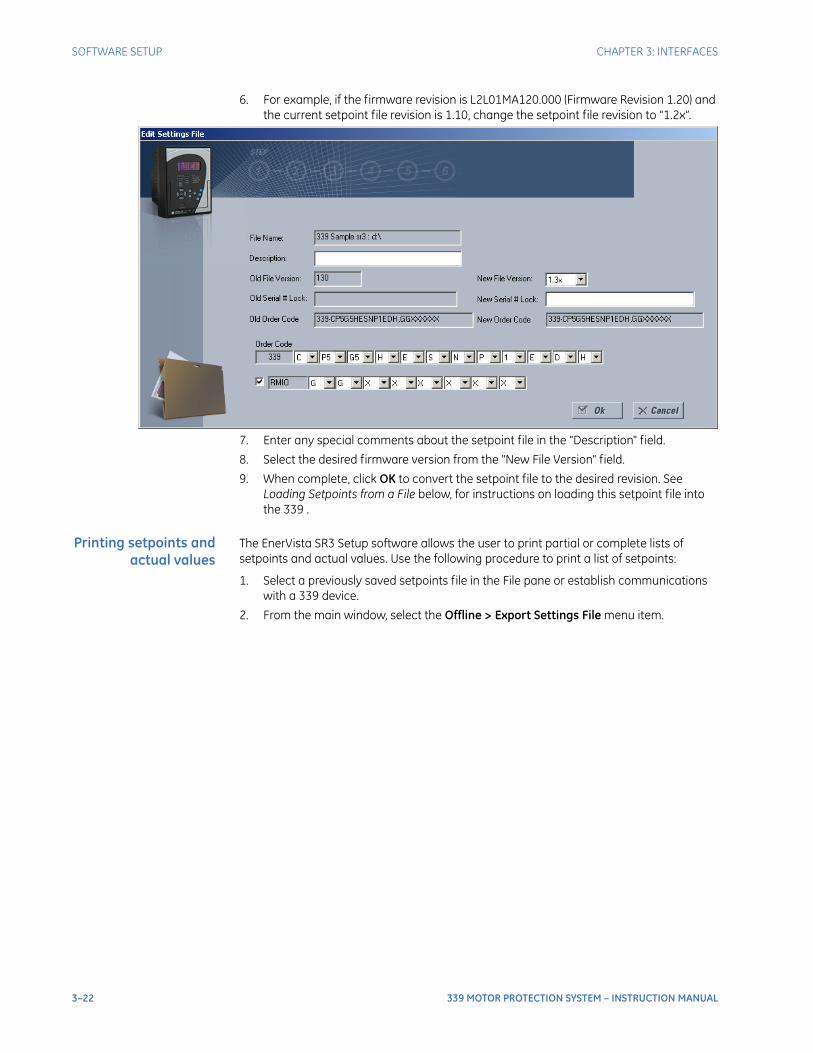
3–22 339 MOTOR PROTECTION SYSTEM – INSTRUCTION MANUAL
SOFTWARE SETUP CHAPTER 3: INTERFACES
6. For example, if the firmware revision is L2L01MA120.000 (Firmware Revision 1.20) and the current setpoint file revision is 1.10, change the setpoint file revision to “1.2x”.
7. Enter any special comments about the setpoint file in the "Description" field.
8. Select the desired firmware version from the "New File Version" field.
9. When complete, click OK to convert the setpoint file to the desired revision. See Loading Setpoints from a File below, for instructions on loading this setpoint file into the 339 .
Printing setpoints andactual values
The EnerVista SR3 Setup software allows the user to print partial or complete lists of setpoints and actual values. Use the following procedure to print a list of setpoints:
1. Select a previously saved setpoints file in the File pane or establish communications with a 339 device.
2. From the main window, select the Offline > Export Settings File menu item.
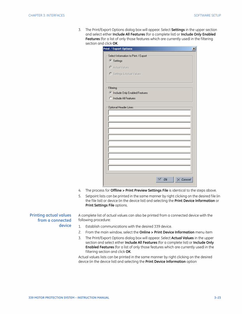
CHAPTER 3: INTERFACES SOFTWARE SETUP
339 MOTOR PROTECTION SYSTEM – INSTRUCTION MANUAL 3–23
3. The Print/Export Options dialog box will appear. Select Settings in the upper section and select either Include All Features (for a complete list) or Include Only Enabled Features (for a list of only those features which are currently used) in the filtering section and click OK.
4. The process for Offline > Print Preview Settings File is identical to the steps above.
5. Setpoint lists can be printed in the same manner by right clicking on the desired file (in the file list) or device (in the device list) and selecting the Print Device Information or Print Settings File options.
Printing actual valuesfrom a connected
device
A complete list of actual values can also be printed from a connected device with the following procedure:
1. Establish communications with the desired 339 device.
2. From the main window, select the Online > Print Device Information menu item
3. The Print/Export Options dialog box will appear. Select Actual Values in the upper section and select either Include All Features (for a complete list) or Include Only Enabled Features (for a list of only those features which are currently used) in the filtering section and click OK.
Actual values lists can be printed in the same manner by right clicking on the desired device (in the device list) and selecting the Print Device Information option
3–24 339 MOTOR PROTECTION SYSTEM – INSTRUCTION MANUAL
SOFTWARE SETUP CHAPTER 3: INTERFACES
Loading setpointsfrom a file
CAUTION: An error message will occur when attempting to download a setpoint file with a revision number that does not match the relay firmware. If the firmware has been upgraded since saving the setpoint file, see Upgrading Setpoint Files to a New Revision, above, for instructions on changing the revision number of a setpoint file.
The following procedure illustrates how to load setpoints from a file. Before loading a setpoints file, it must first be added to the EnerVista SR3 Setup environment as described in the section, Adding Setpoints Files to the Environment.
1. Select the previously saved setpoints file from the File pane of the EnerVista SR3 Setup software main window.
2. Select the Offline > Edit Settings File Properties menu item and verify that the corresponding file is fully compatible with the hardware and firmware version of the target relay. If the versions are not identical, see Upgrading Setpoint Files to a New Revision, above, for details on changing the setpoints file version.
3. Right-click on the selected file and select the Write Settings File to Device item.
4. Select the target relay from the list of devices shown and click Send. If there is an incompatibility, an "Incompatible Device" error message will occur:
If there are no incompatibilities between the target device and the settings file, the data will be transferred to the relay. An indication of the percentage completed will be shown in the bottom of the main window.
Uninstalling files andclearing data
The unit can be decommissioned by turning off the power to the unit and disconnecting the wires to it . Files can be cleared after uninstalling the EnerVista software or 339 device, for example to comply with data security regulations. On the computer, settings files can be identified by the .sr3 extension.To clear the current settings file do the following:
1. Create a default settings file.
2. Write the default settings file to the relay.
3. Delete all other files with the .sr3 extension.
4. Delete any other data files , which can be in standard formats, such as COMTRADE or .csv.
You cannot directly erase the flash memory, but all records and settings in that memory can be deleted. Do this using these commands:ACTUAL VALUES > RECORDS
• EVENT RECORDS > CLEAR
• TRANSIENT RECORDS > CLEAR
Upgrading relay firmwareTo upgrade the 339 firmware, follow the procedures listed in this section. Upon successful completion of this procedure, the 339 will have new firmware installed with the factory default setpoints.The latest firmware files are available from the GE Grid Solutions website at http://www.gegridsolutions.com.
NOTE
NOTE: EnerVista SR3 Setup software prevents incompatible firmware from being loaded into a 339 relay.
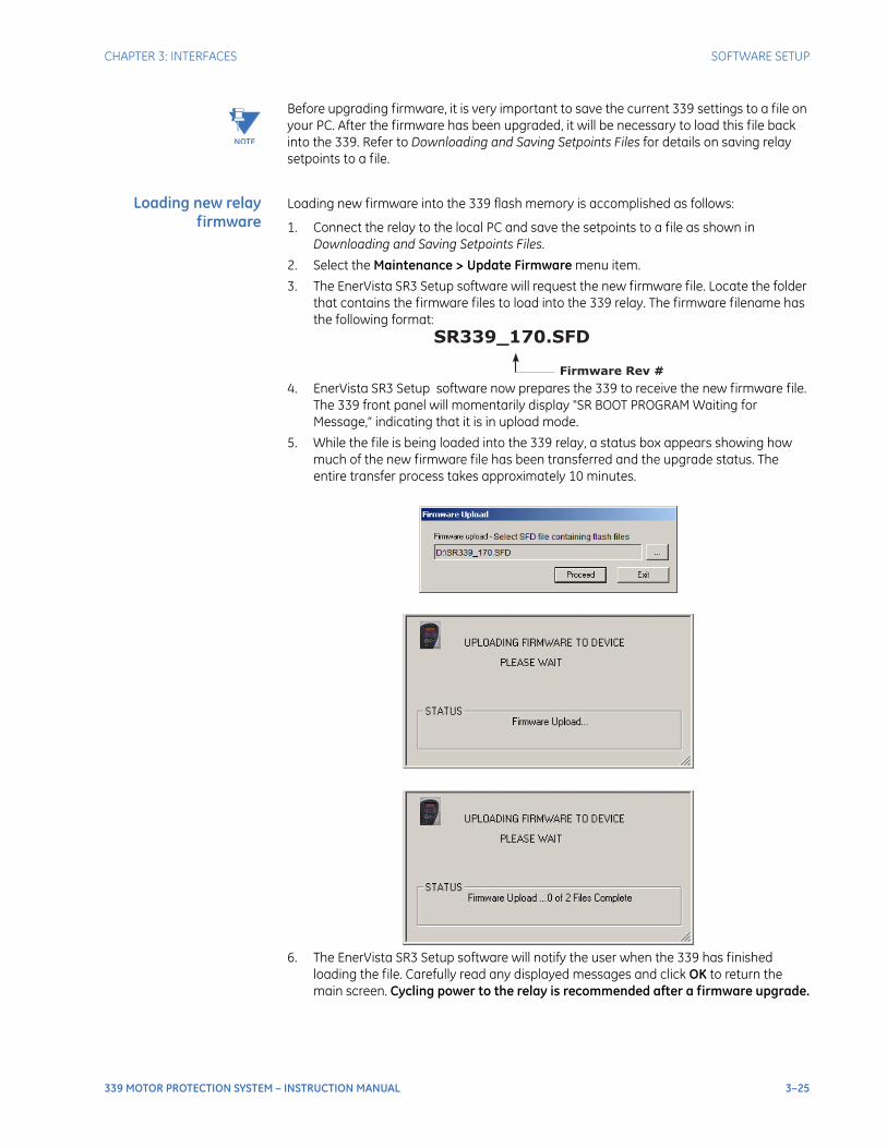
CHAPTER 3: INTERFACES SOFTWARE SETUP
339 MOTOR PROTECTION SYSTEM – INSTRUCTION MANUAL 3–25
NOTE
NOTE: Before upgrading firmware, it is very important to save the current 339 settings to a file on your PC. After the firmware has been upgraded, it will be necessary to load this file back into the 339. Refer to Downloading and Saving Setpoints Files for details on saving relay setpoints to a file.
Loading new relayfirmware
Loading new firmware into the 339 flash memory is accomplished as follows:
1. Connect the relay to the local PC and save the setpoints to a file as shown in Downloading and Saving Setpoints Files.
2. Select the Maintenance > Update Firmware menu item.
3. The EnerVista SR3 Setup software will request the new firmware file. Locate the folder that contains the firmware files to load into the 339 relay. The firmware filename has the following format:
4. EnerVista SR3 Setup software now prepares the 339 to receive the new firmware file. The 339 front panel will momentarily display "SR BOOT PROGRAM Waiting for Message,” indicating that it is in upload mode.
5. While the file is being loaded into the 339 relay, a status box appears showing how much of the new firmware file has been transferred and the upgrade status. The entire transfer process takes approximately 10 minutes.
6. The EnerVista SR3 Setup software will notify the user when the 339 has finished loading the file. Carefully read any displayed messages and click OK to return the main screen. Cycling power to the relay is recommended after a firmware upgrade.

3–26 339 MOTOR PROTECTION SYSTEM – INSTRUCTION MANUAL
SOFTWARE SETUP CHAPTER 3: INTERFACES
After successfully updating the 339 firmware, the relay will not be operational and will require setpoint programming. To communicate with the relay, the communication settings may have to be manually reprogrammed.When communications are established, the saved setpoints must be reloaded back into the relay. See Loading Setpoints from a File for details.Modbus addresses assigned to firmware modules, features, settings, and corresponding data items (i.e. default values, min/max values, data type, and item size) may change slightly from version to version of the firmware. Addresses are rearranged when new features are added or existing features are enhanced or modified.
Advanced EnerVista SR3 Setup features
Flexcurve editor The FlexCurve Editor is designed to allow the user to graphically view and edit the FlexCurve. The Flexcurve Editor screen is shown below:
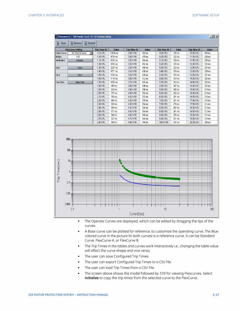
CHAPTER 3: INTERFACES SOFTWARE SETUP
339 MOTOR PROTECTION SYSTEM – INSTRUCTION MANUAL 3–27
• The Operate Curves are displayed, which can be edited by dragging the tips of the curves
• A Base curve can be plotted for reference, to customize the operating curve. The Blue colored curve in the picture (in both curves) is a reference curve. It can be Standard Curve, FlexCurve A, or FlexCurve B.
• The Trip Times in the tables and curves work interactively i.e., changing the table value will affect the curve shape and vice versa.
• The user can save Configured Trip Times.
• The user can export Configured Trip Times to a CSV file
• The user can load Trip Times from a CSV File
• The screen above shows the model followed by 339 for viewing Flexcurves. Select Initialize to copy the trip times from the selected curve to the FlexCurve.
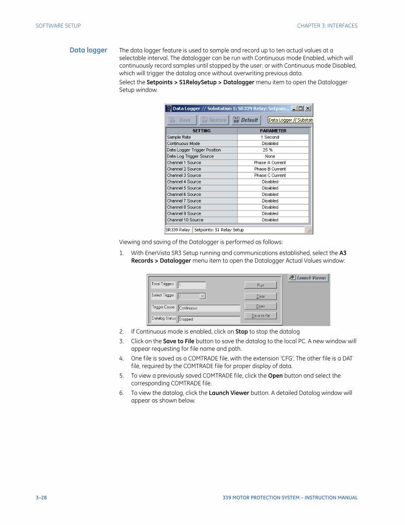
3–28 339 MOTOR PROTECTION SYSTEM – INSTRUCTION MANUAL
SOFTWARE SETUP CHAPTER 3: INTERFACES
Data logger The data logger feature is used to sample and record up to ten actual values at a selectable interval. The datalogger can be run with Continuous mode Enabled, which will continuously record samples until stopped by the user; or with Continuous mode Disabled, which will trigger the datalog once without overwriting previous data.Select the Setpoints > S1RelaySetup > Datalogger menu item to open the Datalogger Setup window.
Viewing and saving of the Datalogger is performed as follows:
1. With EnerVista SR3 Setup running and communications established, select the A3 Records > Datalogger menu item to open the Datalogger Actual Values window:
2. If Continuous mode is enabled, click on Stop to stop the datalog
3. Click on the Save to File button to save the datalog to the local PC. A new window will appear requesting for file name and path.
4. One file is saved as a COMTRADE file, with the extension ‘CFG’. The other file is a DAT file, required by the COMTRADE file for proper display of data.
5. To view a previously saved COMTRADE file, click the Open button and select the corresponding COMTRADE file.
6. To view the datalog, click the Launch Viewer button. A detailed Datalog window will appear as shown below.
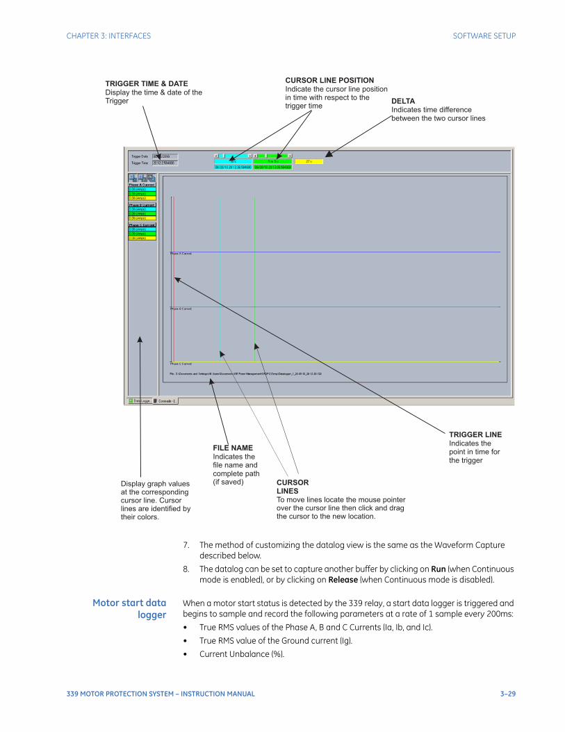
CHAPTER 3: INTERFACES SOFTWARE SETUP
339 MOTOR PROTECTION SYSTEM – INSTRUCTION MANUAL 3–29
7. The method of customizing the datalog view is the same as the Waveform Capture described below.
8. The datalog can be set to capture another buffer by clicking on Run (when Continuous mode is enabled), or by clicking on Release (when Continuous mode is disabled).
Motor start datalogger
When a motor start status is detected by the 339 relay, a start data logger is triggered and begins to sample and record the following parameters at a rate of 1 sample every 200ms:
• True RMS values of the Phase A, B and C Currents (Ia, Ib, and Ic).
• True RMS value of the Ground current (Ig).
• Current Unbalance (%).
Display graph valuesat the correspondingcursor line. Cursorlines are identified bytheir colors.
CURSOR
LINES
To move lines locate the mouse pointerover the cursor line then click and dragthe cursor to the new location.
DELTA
Indicates time differencebetween the two cursor lines
TRIGGER LINE
Indicates thepoint in time forthe trigger
FILE NAME
Indicates thefile name andcomplete path(if saved)
TRIGGER TIME & DATE
Display the time & date of theTrigger
CURSOR LINE POSITION
Indicate the cursor line positionin time with respect to thetrigger time
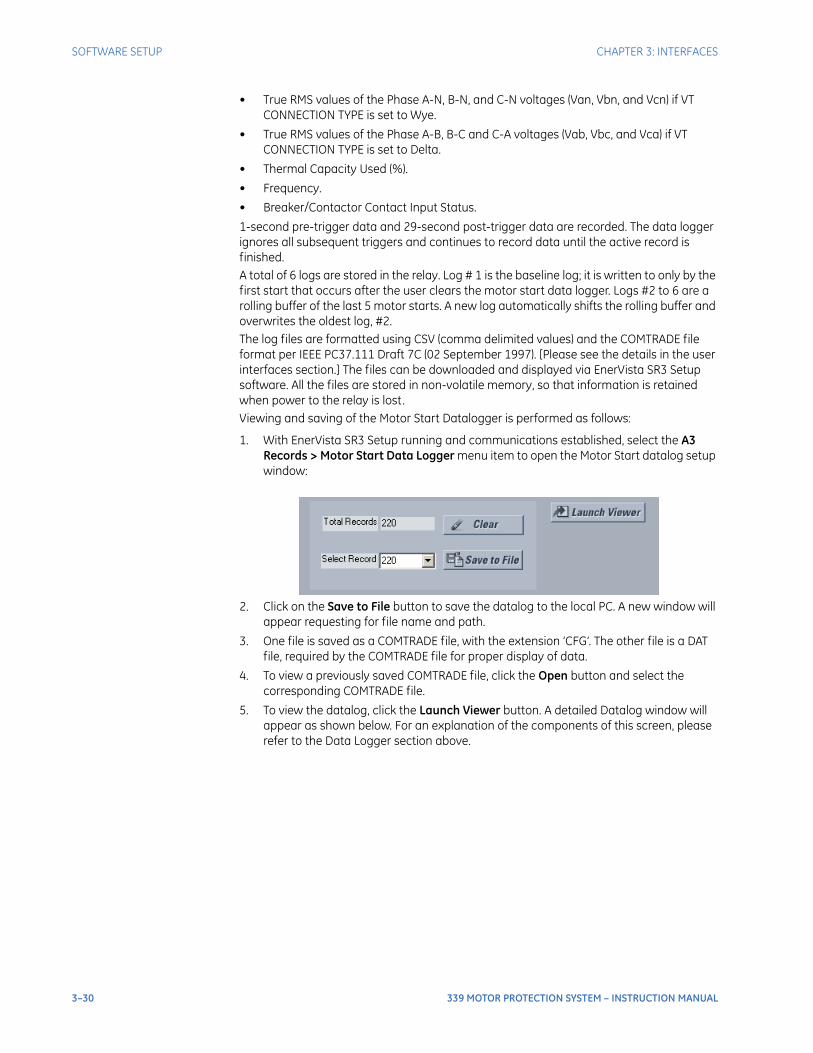
3–30 339 MOTOR PROTECTION SYSTEM – INSTRUCTION MANUAL
SOFTWARE SETUP CHAPTER 3: INTERFACES
• True RMS values of the Phase A-N, B-N, and C-N voltages (Van, Vbn, and Vcn) if VT CONNECTION TYPE is set to Wye.
• True RMS values of the Phase A-B, B-C and C-A voltages (Vab, Vbc, and Vca) if VT CONNECTION TYPE is set to Delta.
• Thermal Capacity Used (%).
• Frequency.
• Breaker/Contactor Contact Input Status.
1-second pre-trigger data and 29-second post-trigger data are recorded. The data logger ignores all subsequent triggers and continues to record data until the active record is finished.A total of 6 logs are stored in the relay. Log # 1 is the baseline log; it is written to only by the first start that occurs after the user clears the motor start data logger. Logs #2 to 6 are a rolling buffer of the last 5 motor starts. A new log automatically shifts the rolling buffer and overwrites the oldest log, #2. The log files are formatted using CSV (comma delimited values) and the COMTRADE file format per IEEE PC37.111 Draft 7C (02 September 1997). [Please see the details in the user interfaces section.] The files can be downloaded and displayed via EnerVista SR3 Setup software. All the files are stored in non-volatile memory, so that information is retained when power to the relay is lost. Viewing and saving of the Motor Start Datalogger is performed as follows:
1. With EnerVista SR3 Setup running and communications established, select the A3 Records > Motor Start Data Logger menu item to open the Motor Start datalog setup window:
2. Click on the Save to File button to save the datalog to the local PC. A new window will appear requesting for file name and path.
3. One file is saved as a COMTRADE file, with the extension ‘CFG’. The other file is a DAT file, required by the COMTRADE file for proper display of data.
4. To view a previously saved COMTRADE file, click the Open button and select the corresponding COMTRADE file.
5. To view the datalog, click the Launch Viewer button. A detailed Datalog window will appear as shown below. For an explanation of the components of this screen, please refer to the Data Logger section above.
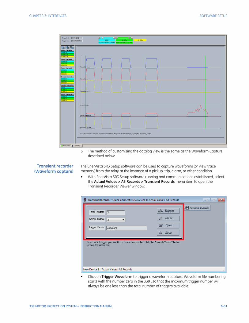
CHAPTER 3: INTERFACES SOFTWARE SETUP
339 MOTOR PROTECTION SYSTEM – INSTRUCTION MANUAL 3–31
6. The method of customizing the datalog view is the same as the Waveform Capture described below.
Transient recorder(Waveform capture)
The EnerVista SR3 Setup software can be used to capture waveforms (or view trace memory) from the relay at the instance of a pickup, trip, alarm, or other condition.
• With EnerVista SR3 Setup software running and communications established, select the Actual Values > A3 Records > Transient Records menu item to open the Transient Recorder Viewer window.
• Click on Trigger Waveform to trigger a waveform capture. Waveform file numbering starts with the number zero in the 339 , so that the maximum trigger number will always be one less than the total number of triggers available.
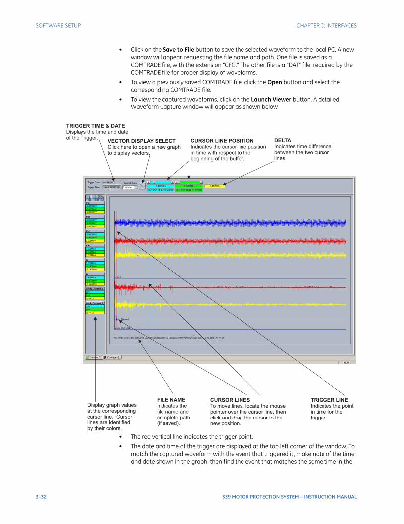
3–32 339 MOTOR PROTECTION SYSTEM – INSTRUCTION MANUAL
SOFTWARE SETUP CHAPTER 3: INTERFACES
• Click on the Save to File button to save the selected waveform to the local PC. A new window will appear, requesting the file name and path. One file is saved as a COMTRADE file, with the extension "CFG." The other file is a "DAT" file, required by the COMTRADE file for proper display of waveforms.
• To view a previously saved COMTRADE file, click the Open button and select the corresponding COMTRADE file.
• To view the captured waveforms, click on the Launch Viewer button. A detailed Waveform Capture window will appear as shown below.
• The red vertical line indicates the trigger point.
• The date and time of the trigger are displayed at the top left corner of the window. To match the captured waveform with the event that triggered it , make note of the time and date shown in the graph, then find the event that matches the same time in the
Display graph valuesat the correspondingcursor line. Cursorlines are identifiedby their colors.
FILE NAME
Indicates thefile name andcomplete path(if saved).
CURSOR LINES
To move lines, locate the mousepointer over the cursor line, thenclick and drag the cursor to thenew position.
TRIGGER LINE
Indicates the pointin time for thetrigger.
TRIGGER TIME & DATE
Displays the time and dateof the Trigger.
VECTOR DISPLAY SELECT
Click here to open a new graphto display vectors.
CURSOR LINE POSITION
Indicates the cursor line positionin time with respect to thebeginning of the buffer.
DELTA
Indicates time differencebetween the two cursorlines.
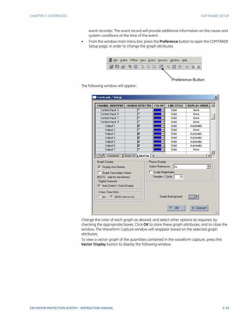
CHAPTER 3: INTERFACES SOFTWARE SETUP
339 MOTOR PROTECTION SYSTEM – INSTRUCTION MANUAL 3–33
event recorder. The event record will provide additional information on the cause and system conditions at the time of the event.
• From the window main menu bar, press the Preference button to open the COMTRADE Setup page, in order to change the graph attributes.
The following window will appear:
Change the color of each graph as desired, and select other options as required, by checking the appropriate boxes. Click OK to store these graph attributes, and to close the window. The Waveform Capture window will reappear based on the selected graph attributes.To view a vector graph of the quantities contained in the waveform capture, press the Vector Display button to display the following window:
Preference Button
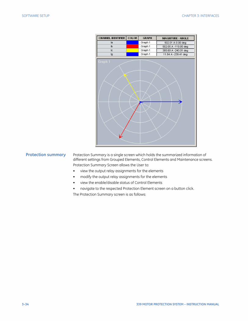
3–34 339 MOTOR PROTECTION SYSTEM – INSTRUCTION MANUAL
SOFTWARE SETUP CHAPTER 3: INTERFACES
Protection summary Protection Summary is a single screen which holds the summarized information of different settings from Grouped Elements, Control Elements and Maintenance screens.Protection Summary Screen allows the User to:
• view the output relay assignments for the elements
• modify the output relay assignments for the elements
• view the enable/disable status of Control Elements
• navigate to the respected Protection Element screen on a button click.
The Protection Summary screen is as follows:
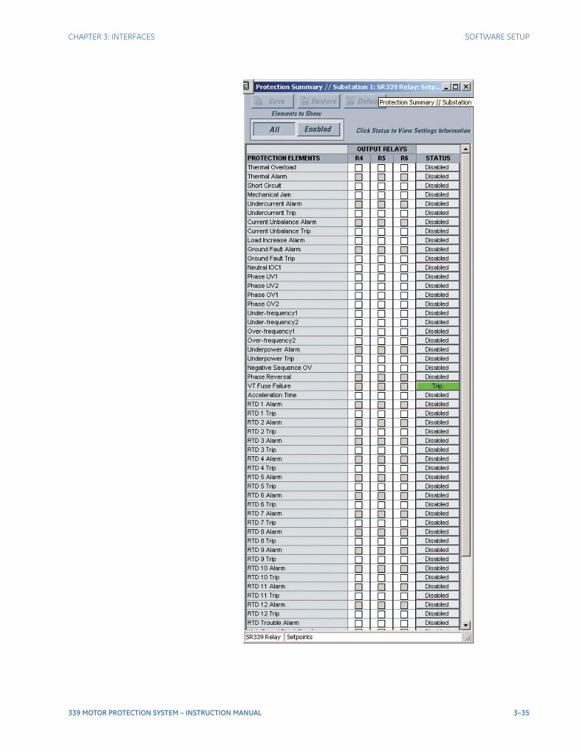
CHAPTER 3: INTERFACES SOFTWARE SETUP
339 MOTOR PROTECTION SYSTEM – INSTRUCTION MANUAL 3–35
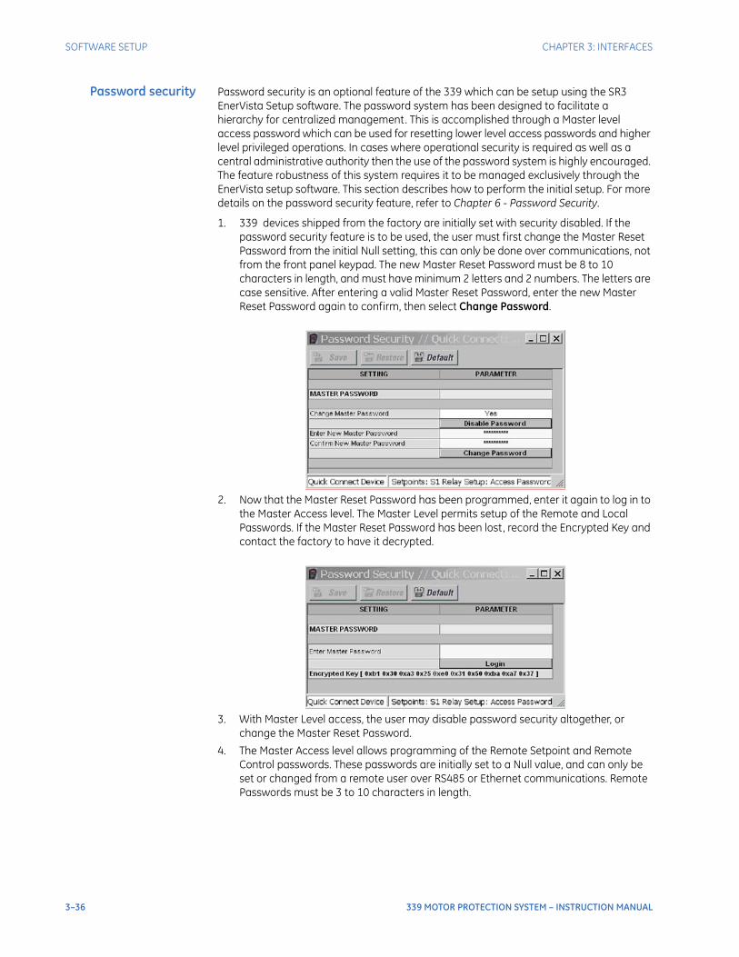
3–36 339 MOTOR PROTECTION SYSTEM – INSTRUCTION MANUAL
SOFTWARE SETUP CHAPTER 3: INTERFACES
Password security Password security is an optional feature of the 339 which can be setup using the SR3 EnerVista Setup software. The password system has been designed to facilitate a hierarchy for centralized management. This is accomplished through a Master level access password which can be used for resetting lower level access passwords and higher level privileged operations. In cases where operational security is required as well as a central administrative authority then the use of the password system is highly encouraged. The feature robustness of this system requires it to be managed exclusively through the EnerVista setup software. This section describes how to perform the initial setup. For more details on the password security feature, refer to Chapter 6 - Password Security.
1. 339 devices shipped from the factory are initially set with security disabled. If the password security feature is to be used, the user must first change the Master Reset Password from the initial Null setting, this can only be done over communications, not from the front panel keypad. The new Master Reset Password must be 8 to 10 characters in length, and must have minimum 2 letters and 2 numbers. The letters are case sensitive. After entering a valid Master Reset Password, enter the new Master Reset Password again to confirm, then select Change Password.
2. Now that the Master Reset Password has been programmed, enter it again to log in to the Master Access level. The Master Level permits setup of the Remote and Local Passwords. If the Master Reset Password has been lost, record the Encrypted Key and contact the factory to have it decrypted.
3. With Master Level access, the user may disable password security altogether, or change the Master Reset Password.
4. The Master Access level allows programming of the Remote Setpoint and Remote Control passwords. These passwords are initially set to a Null value, and can only be set or changed from a remote user over RS485 or Ethernet communications. Remote Passwords must be 3 to 10 characters in length.
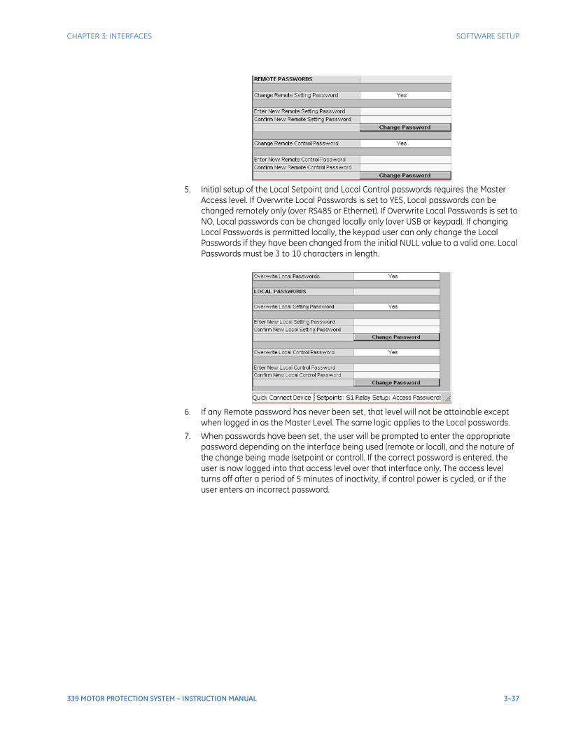
CHAPTER 3: INTERFACES SOFTWARE SETUP
339 MOTOR PROTECTION SYSTEM – INSTRUCTION MANUAL 3–37
5. Initial setup of the Local Setpoint and Local Control passwords requires the Master Access level. If Overwrite Local Passwords is set to YES, Local passwords can be changed remotely only (over RS485 or Ethernet). If Overwrite Local Passwords is set to NO, Local passwords can be changed locally only (over USB or keypad). If changing Local Passwords is permitted locally, the keypad user can only change the Local Passwords if they have been changed from the initial NULL value to a valid one. Local Passwords must be 3 to 10 characters in length.
6. If any Remote password has never been set, that level will not be attainable except when logged in as the Master Level. The same logic applies to the Local passwords.
7. When passwords have been set, the user will be prompted to enter the appropriate password depending on the interface being used (remote or local), and the nature of the change being made (setpoint or control). If the correct password is entered, the user is now logged into that access level over that interface only. The access level turns off after a period of 5 minutes of inactivity, if control power is cycled, or if the user enters an incorrect password.

3–38 339 MOTOR PROTECTION SYSTEM – INSTRUCTION MANUAL
SOFTWARE SETUP CHAPTER 3: INTERFACES
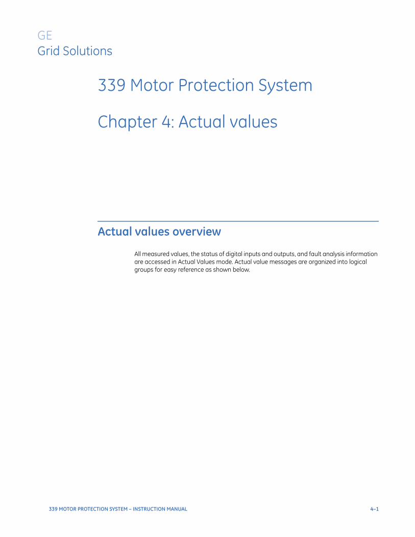
339 MOTOR PROTECTION SYSTEM – INSTRUCTION MANUAL 4–1
339 Motor Protection System
Chapter 4: Actual values
GEGrid Solutions
Actual values
Actual values overview
All measured values, the status of digital inputs and outputs, and fault analysis information are accessed in Actual Values mode. Actual value messages are organized into logical groups for easy reference as shown below.
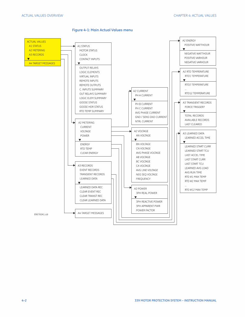
4–2 339 MOTOR PROTECTION SYSTEM – INSTRUCTION MANUAL
ACTUAL VALUES OVERVIEW CHAPTER 4: ACTUAL VALUES
Figure 4-1: Main Actual Values menu
A2 METERING
CURRENT
VOLTAGE
POWER
ENERGY
RTD TEMP
CLEAR ENERGY
A1 STATUS
MOTOR STATUS
CLOCK
CONTACT INPUTS
OUTPUT RELAYS
LOGIC ELEMENTS
VIRTUAL INPUTS
REMOTE INPUTS
REMOTE OUTPUTS
C. INPUTS SUMMARY
OUT RELAYS SUMMARY
LOGIC ELEM SUMMARY
GOOSE STATUS
GOOSE HDR STATUS
RTD TEMP SUMMARY
ACTUAL VALUES
A1 STATUS
A2 METERING
A3 RECORDS
A4 TARGET MESSAGES
896760A1.cdr
A3 RECORDS
LEARNED DATA
LEARNED DATA REC
CLEAR LEARNED DATA
EVENT RECORDS
TRANSIENT RECORDS
CLEAR EVENT REC
CLEAR TRANST REC
A4 TARGET MESSAGES
A2 VOLTAGE
AN VOLTAGE
BN VOLTAGE
CN VOLTAGE
AVG PHASE VOLTAGE
AB VOLTAGE
BC VOLTAGE
CA VOLTAGE
AVG LINE VOLTAGE
NEG SEQ VOLTAGE
FREQUENCY
A2 POWER
3PH REAL POWER
3PH REACTIVE POWER
3PH APPARENT PWR
POWER FACTOR
A2 ENERGY
POSITIVE WATTHOUR
NEGATIVE WATTHOUR
POSITIVE VARHOUR
NEGATIVE VARHOUR
A2 RTD TEMPERATURE
RTD1 TEMPERATURE
RTD2 TEMPERATURE
...
RTD12 TEMPERATURE
A3 TRANSIENT RECORDS
AVAILABLE RECORDS
FORCE TRIGGER?
TOTAL RECORDS
LAST CLEARED
A2 CURRENT
PH A CURRENT
PH B CURRENT
PH C CURRENT
AVG PHASE CURRENT
GND / SENS GND CURRENT
NTRL CURRENT
A3 LEARNED DATA
LEARNED START TCU
LEARNED ACCEL TIME
LEARNED START CURR
LAST ACCEL TIME
LAST START CURR
LAST START TCU
LEARNED AVG LOAD
AVG RUN TIME
RTD #1 MAX TEMP
RTD #2 MAX TEMP
...
RTD #12 MAX TEMP
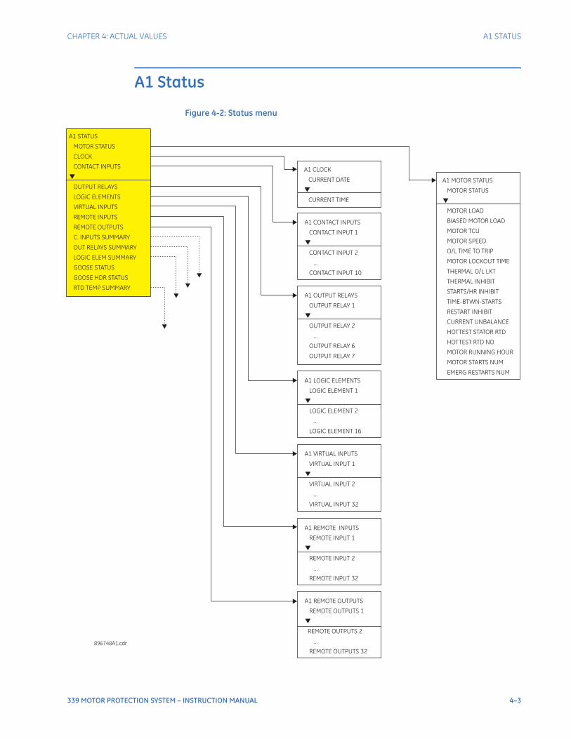
CHAPTER 4: ACTUAL VALUES A1 STATUS
339 MOTOR PROTECTION SYSTEM – INSTRUCTION MANUAL 4–3
A1 Status
Figure 4-2: Status menu
A1 CONTACT INPUTS
CONTACT INPUT 1
CONTACT INPUT 2
...
CONTACT INPUT 10
A1 CLOCK
CURRENT DATE
CURRENT TIME
A1 STATUS
MOTOR STATUS
CLOCK
CONTACT INPUTS
LOGIC ELEMENTS
VIRTUAL INPUTS
REMOTE INPUTS
REMOTE OUTPUTS
C. INPUTS SUMMARY
OUT RELAYS SUMMARY
LOGIC ELEM SUMMARY
GOOSE STATUS
GOOSE HDR STATUS
RTD TEMP SUMMARY
OUTPUT RELAYS
896748A1.cdr
A1 OUTPUT RELAYS
OUTPUT RELAY 1
OUTPUT RELAY 2
...
OUTPUT RELAY 6
OUTPUT RELAY 7
A1 LOGIC ELEMENTS
LOGIC ELEMENT 1
2
...
16
LOGIC ELEMENT
LOGIC ELEMENT
A1 VIRTUAL INPUTS
1
2
...
32
VIRTUAL INPUT
VIRTUAL INPUT
VIRTUAL INPUT
A1 REMOTE INPUTS
1
2
...
32
REMOTE INPUT
REMOTE INPUT
REMOTE INPUT
A1 OUTPUTS
1
2
...
32
REMOTE
REMOTE OUTPUTS
REMOTE OUTPUTS
REMOTE OUTPUTS
A1 MOTOR STATUS
MOTOR STATUS
MOTOR LOAD
BIASED MOTOR LOAD
MOTOR TCU
MOTOR SPEED
O/L TIME TO TRIP
MOTOR LOCKOUT TIME
THERMAL O/L LKT
THERMAL INHIBIT
STARTS/HR INHIBIT
TIME-BTWN-STARTS
RESTART INHIBIT
CURRENT UNBALANCE
HOTTEST STATOR RTD
HOTTEST RTD NO
MOTOR RUNNING HOUR
MOTOR STARTS NUM
EMERG RESTARTS NUM
4–4 339 MOTOR PROTECTION SYSTEM – INSTRUCTION MANUAL
A1 STATUS CHAPTER 4: ACTUAL VALUES
Motor statusMOTOR STATUS
Range: Tripped, Stopped, Starting, Running, Overload
The motor status is tripped following any protection trip operation or lockout. After all protection trips and lockout have cleared, the tripped motor status can be reset from the front panel reset key, by closure of the reset or lockout reset contact input, or via communications. The emergency restart function also resets tripped status.
When the motor status is stopped, detection of phase current above the FLA changes the status to starting. Running status follows starting when the current then drops below FLA. Running status continues as long as phase current greater than 5% of CT is detected. To accommodate applications where current does not rise above the thermal overload pickup setting on start, running status is also declared when the contact inputs indicate the motor is online. When phase current falls below 5% of CT the status changes to stopped. To accommodate applications where motor idle current is less than 5% CT, a further requirement to change status to stopped is that the contact inputs do not indicate the motor is online.
For single speed applications, an enabled 52a contact input closed or an enabled 52b contact input open is taken as indication of motor online. If both are enabled, the relay assumes the motor is online if the 52a contact is closed and the 52b contact is open.
For two speed applications, closure either of the High Speed Switch contact input or of the Low Speed Switch contact input is indication of motor online. If either 52a or 52b contact input is enabled, a further requirement is that these indicate the breaker is closed.
Use of these contact inputs (52a Contact, 52b Contact, High Speed Switch, Low Speed Switch) for motor online detection is optional, but is recommended to ensure proper detection of motor running, especially in cases where the starting current is less than the thermal overload pickup setting or motor idle current is less than 5% of CT.
MOTOR LOAD
Displays the average 3-phase motor current (Iavg) per-unit on an FLA base.
BIASED MOTOR LOAD
Displays the equivalent motor heating current (Ieq) per-unit on an FLA base. Refer to Thermal Protection section.
MOTOR TCU
Displays the Thermal Capacity Used.
MOTOR SPEED
Indicates the motor running speed per the speed switch input. This value is seen only when the setting "Enable 2-SPD Motor" is enabled.
O/L TIME TO TRIP
Displays the remainder of the thermal overload trip time when the current is above the thermal overload pick-up setting.
THERMAL INHIBIT
Time in seconds left until the Thermal Start Inhibit expires. Has a value of zero if this feature is set to OFF, or if the time has expired.
STARTS/HR INHIBIT
Time in seconds left until the Starts per Hour feature’s inhibit expires. Has a value of zero if this feature is set to OFF, or if the time has expired.
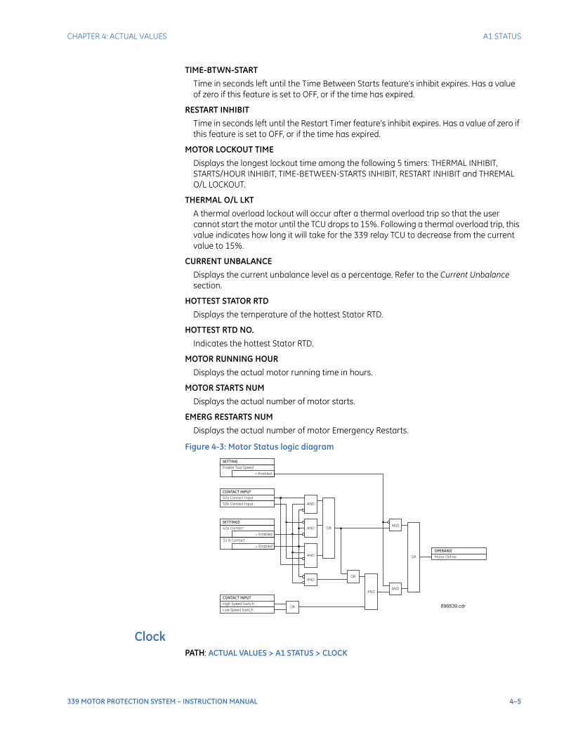
CHAPTER 4: ACTUAL VALUES A1 STATUS
339 MOTOR PROTECTION SYSTEM – INSTRUCTION MANUAL 4–5
TIME-BTWN-START
Time in seconds left until the Time Between Starts feature’s inhibit expires. Has a value of zero if this feature is set to OFF, or if the time has expired.
RESTART INHIBIT
Time in seconds left until the Restart Timer feature’s inhibit expires. Has a value of zero if this feature is set to OFF, or if the time has expired.
MOTOR LOCKOUT TIME
Displays the longest lockout time among the following 5 timers: THERMAL INHIBIT, STARTS/HOUR INHIBIT, TIME-BETWEEN-STARTS INHIBIT, RESTART INHIBIT and THREMAL O/L LOCKOUT.
THERMAL O/L LKT
A thermal overload lockout will occur after a thermal overload trip so that the user cannot start the motor until the TCU drops to 15%. Following a thermal overload trip, this value indicates how long it will take for the 339 relay TCU to decrease from the current value to 15%.
CURRENT UNBALANCE
Displays the current unbalance level as a percentage. Refer to the Current Unbalance section.
HOTTEST STATOR RTD
Displays the temperature of the hottest Stator RTD.
HOTTEST RTD NO.
Indicates the hottest Stator RTD.
MOTOR RUNNING HOUR
Displays the actual motor running time in hours.
MOTOR STARTS NUM
Displays the actual number of motor starts.
EMERG RESTARTS NUM
Displays the actual number of motor Emergency Restarts.
Figure 4-3: Motor Status logic diagram
ClockPATH: ACTUAL VALUES > A1 STATUS > CLOCK
CONTACT INPUT
52a Contact Input
SETTINGS
52b Contact Input
SETTING
= Enabled
Enable Two Speed
OPERAND
Motor Online
AND
AND ORAND
CONTACT INPUT
High Speed Switch
Low Speed SwitchOR
ANDOR
ANDAND
OR
= Enabled
52a Contact
= Enabled
52 b Contact
AND
896839.cdr
4–6 339 MOTOR PROTECTION SYSTEM – INSTRUCTION MANUAL
A1 STATUS CHAPTER 4: ACTUAL VALUES
CURRENT DATEFeb 12 2009
Range: Date in format shown
Indicates today’s date.
CURRENT TIME09:17:12
Range: Time in format shown
Indicates the current time of day.
Contact inputsPATH: ACTUAL VALUES > A1 STATUS > CONTACT INPUTS
52a (CI #1)OFF
Range: Off, On
Shows the input status when connected to a 52a breaker auxiliary contact.
52b (CI #2)OFF
Range: Off, On
Shows the breaker status when connected to a 52b breaker auxiliary contact.
CONTACT INPUT 3 to 10OFF
Range: Off, On
Message displays the state of the contact input. The message “ON” indicates that the contact input is energized, and message “OFF” indicates a de-energized contact.
Output relaysPATH: ACTUAL VALUES > A1 STATUS > OUTPUT RELAYS
Output relays -Breaker
Output Relay #1 (TRIP)OFF
Range: Off, On
The “ON” state of Output Relay #1 (Breaker TRIP) shows that a TRIP command has been sent to the breaker.
Output Relay #2 (CLOSE)OFF
Range: Off, On
The “ON” state of Output Relay #2 (Breaker CLOSE) shows that a CLOSE command has been sent to the breaker.
Output Relay #3 (START INHIBIT)OFF
Range: Off, On
Output Relay #4 to #6 (AUXILIARY OUTPUT RELAYS)OFF
Range: Off, On
Output Relay #7 (CRITICAL FAILURE)Range: Off, On
The "ON" state indicates that the relay is in-service.

CHAPTER 4: ACTUAL VALUES A1 STATUS
339 MOTOR PROTECTION SYSTEM – INSTRUCTION MANUAL 4–7
Output relays -Contactor
Output Relay #1 (Not Used)Output Relay #2 (Not Used)Output Relay #3 (START INHIBIT)OFF
Range: Off, On
The "ON" state of Output Relay #3 (Start Inhibit) shows that a "block motor start" command has been sent to the contactor.
Output Relay #4 (Contactor TRIP)Range: Off, On
The "OFF" state of Output Relay #4 (Contactor TRIP) shows that a "TRIP" command has been sent to the contactor.
Output Relay #5 to #6 (AUXILIARY OUTPUT RELAYS)Range: Off, On
Output Relay #7 (CRITICAL FAILURE RELAY)Range: Off, On
The "ON" state indicates that the relay is in service.
Logic elementsPATH: ACTUAL VALUES > A1 STATUS > LOGIC ELEMENTS
LOGIC ELEMENT 1 to 16OFF
Range: Off, On
The state “ON” or “OFF” for each logic element depends on its programmed logic: triggering inputs, blocking inputs, plus any pickup, and/or reset time delay.
Virtual inputsThe state of all virtual inputs is displayed here. PATH: ACTUAL VALUES > A1 STATUS > VIRTUAL INPUTS
VIRTUAL INPUTS 1 to 32OFF
Range: Off, On
Remote inputsThe state of all remote inputs is displayed here. PATH: ACTUAL VALUES > A1 STATUS > REMOTE INPUTS
REMOTE INPUTS 1 to 32OFF
Range: Off, On
Remote outputsThe state of all active remote outputs is displayed here. PATH: ACTUAL VALUES > A1 STATUS > REMOTE OUTPUTS
REMOTE OUTPUTS 1 to 32OFF
Range: Off, On
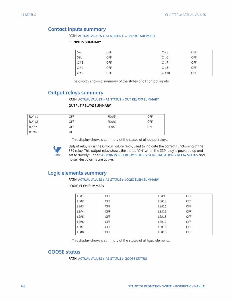
4–8 339 MOTOR PROTECTION SYSTEM – INSTRUCTION MANUAL
A1 STATUS CHAPTER 4: ACTUAL VALUES
Contact inputs summaryPATH: ACTUAL VALUES > A1 STATUS > C. INPUTS SUMMARY
C. INPUTS SUMMARY
The display shows a summary of the states of all contact inputs.
Output relays summaryPATH: ACTUAL VALUES > A1 STATUS > OUT RELAYS SUMMARY
OUTPUT RELAYS SUMMARY
This display shows a summary of the states of all output relays.
NOTE
NOTE: Output relay #7 is the Critical Failure relay, used to indicate the correct functioning of the 339 relay. This output relay shows the status "ON" when the 339 relay is powered up and set to "Ready" under SETPOINTS > S1 RELAY SETUP > S1 INSTALLATION > RELAY STATUS and no self-test alarms are active.
Logic elements summaryPATH: ACTUAL VALUES > A1 STATUS > LOGIC ELEM SUMMARY
LOGIC ELEM SUMMARY
This display shows a summary of the states of all logic elements.
GOOSE statusPATH: ACTUAL VALUES > A1 STATUS > GOOSE STATUS
52a OFF CI#5 OFF
52b OFF CI#6 OFF
CI#3 OFF CI#7 OFF
CI#4 OFF CI#8 OFF
CI#9 OFF CI#10 OFF
RLY #1 OFF RLY#5 OFF
RLY #2 OFF RLY#6 OFF
RLY#3 OFF RLY#7 ON
RLY#4 OFF
LE#1 OFF LE#9 OFF
LE#2 OFF LE#10 OFF
LE#3 OFF LE#11 OFF
LE#4 OFF LE#12 OFF
LE#5 OFF LE#13 OFF
LE#6 OFF LE#14 OFF
LE#7 OFF LE#15 OFF
LE#8 OFF LE#16 OFF
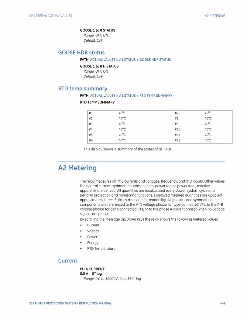
CHAPTER 4: ACTUAL VALUES A2 METERING
339 MOTOR PROTECTION SYSTEM – INSTRUCTION MANUAL 4–9
GOOSE 1 to 8 STATUSRange: OFF, ONDefault: OFF
GOOSE HDR statusPATH: ACTUAL VALUES > A1 STATUS > GOOSE HDR STATUS
GOOSE 1 to 8 H.STATUSRange: OFF, ONDefault: OFF
RTD temp summaryPATH: ACTUAL VALUES > A1 STATUS > RTD TEMP SUMMARY
RTD TEMP SUMMARY
This display shows a summary of the states of all RTDs.
A2 Metering
The relay measures all RMS currents and voltages, frequency, and RTD inputs. Other values like neutral current, symmetrical components, power factor, power (real, reactive, apparent), are derived. All quantities are recalculated every power system cycle and perform protection and monitoring functions. Displayed metered quantities are updated approximately three (3) times a second for readability. All phasors and symmetrical components are referenced to the A-N voltage phasor for wye-connected VTs; to the A-B voltage phasor for delta connected VTs; or to the phase A current phasor when no voltage signals are present.By scrolling the Message Up/Down keys the relay shows the following metered values:
• Current
• Voltage
• Power
• Energy
• RTD Temperature
CurrentPH A CURRENT0.0 A 0o lag
Range: 0.0 to 30000 A, 0 to 359o lag
#1 40oC #7 40oC
#2 40oC #8 40oC
#3 40oC #9 40oC
#4 40oC #10 40oC
#5 40oC #11 40oC
#6 40oC #12 40oC

4–10 339 MOTOR PROTECTION SYSTEM – INSTRUCTION MANUAL
A2 METERING CHAPTER 4: ACTUAL VALUES
PH B CURRENT0.0 A 0o lag
Range: 0.0 to 30000 A, 0 to 359o lag
PH C CURRENT0.0 A 0o lag
Range: 0.0 to 30000 A, 0 to 359o lag
NTRL CURRENT0.0 A 0o lag
Range: 0.0 to 30000 A, 0 to 359o lag
GND CURRENT0.0 A 0o lag
Range: 0.0 to 30000 A, 0 to 359o lag
GND CURRENT is shown when the GROUND CT TYPE is set to "1A Secondary" or "5A Secondary".
SENS GND CURRENT0.00 A 0o lag
Range: 0.00 to 15.00 A, 0 to 359o lag
SENS GND CURRENT is shown when the GROUND CT TYPE is set to "50:0.025".
NEG SEQ CURRENT0.0 A 0o lag
Range: 0.0 to 30000 A, 0 to 359o lag
VoltageAN VOLTAGE0 V 0o lag
Range: 0 to 65535 V
BN VOLTAGE0 V 0o lag
Range: 0 to 65535 V
CN VOLTAGE0 V 0o lag
Range: 0 to 65535 V
AVG VOLTAGE0 V 0o lag
Range: 0 to 65535 V
AB VOLTAGE0 V 0o lag
Range: 0 to 65535 V
BC VOLTAGE0 V 0o lag
Range: 0 to 65535 V
CA VOLTAGE0 V 0o lag
Range: 0 to 65535 V
NTRL VOLTAGE0 V 0o lag
Range: 0 to 65535 V
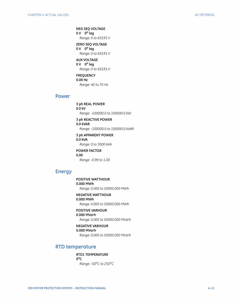
CHAPTER 4: ACTUAL VALUES A2 METERING
339 MOTOR PROTECTION SYSTEM – INSTRUCTION MANUAL 4–11
NEG SEQ VOLTAGE0 V 0o lag
Range: 0 to 65535 V
ZERO SEQ VOLTAGE0 V 0o lag
Range: 0 to 65535 V
AUX VOLTAGE0 V 0o lag
Range: 0 to 65535 V
FREQUENCY0.00 Hz
Range: 40 to 70 Hz
Power3 ph REAL POWER0.0 kV
Range: -100000.0 to 100000.0 kW
3 ph REACTIVE POWER0.0 kVAR
Range: -100000.0 to 100000.0 kVAR
3 ph APPARENT POWER0.0 kVA
Range: 0 to 3000 kVA
POWER FACTOR0.00
Range: -0.99 to 1.00
EnergyPOSITIVE WATTHOUR0.000 MWh
Range: 0.000 to 50000.000 MWh
NEGATIVE WATTHOUR0.000 MWh
Range: 0.000 to 50000.000 MWh
POSITIVE VARHOUR0.000 MVarh
Range: 0.000 to 50000.000 MVarh
NEGATIVE VARHOUR0.000 MVarh
Range: 0.000 to 50000.000 MVarh
RTD temperatureRTD1 TEMPERATURE0oC
Range: -50oC to 250oC
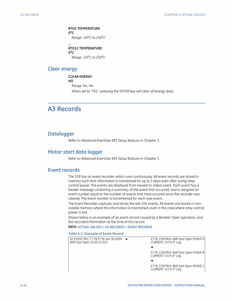
4–12 339 MOTOR PROTECTION SYSTEM – INSTRUCTION MANUAL
A3 RECORDS CHAPTER 4: ACTUAL VALUES
RTD2 TEMPERATURE0oC
Range: -50oC to 250oC
...RTD12 TEMPERATURE0oC
Range: -50oC to 250oC
Clear energyCLEAR ENERGYNO
Range: No, Yes
When set to "YES," pressing the ENTER key will clear all energy data.
A3 Records
DataloggerRefer to Advanced EnerVista SR3 Setup features in Chapter 3.
Motor start data loggerRefer to Advanced EnerVista SR3 Setup features in Chapter 3.
Event recordsThe 339 has an event recorder which runs continuously. All event records are stored in memory such that information is maintained for up to 3 days even after losing relay control power. The events are displayed from newest to oldest event. Each event has a header message containing a summary of the event that occurred, and is assigned an event number equal to the number of events that have occured since the recorder was cleared. The event number is incremented for each new event.The Event Recorder captures and stores the last 256 events. All events are stored in non-volatile memory where the information is maintained, even in the case where relay control power is lost. Shown below is an example of an event record caused by a Breaker Open operation, and the recorded information at the time of this record.PATH: ACTUAL VALUES > A3 RECORDS > EVENT RECORDS
Table 4-1: Example of Event Record
A3 EVENT REC T:778 E778 Jan 30,2009 BKR Stat Open 16:30:23.324
E778, CONTROL BKR Stat Open PHASE A CURRENT: 0.0 A 0° Lag
E778, CONTROL BKR Stat Open PHASE B CURRENT: 0.0 A 0° Lag
E778, CONTROL BKR Stat Open PHASE C CURRENT: 0.0 A 0° Lag
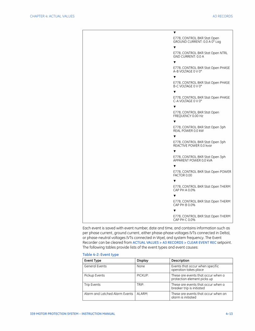
CHAPTER 4: ACTUAL VALUES A3 RECORDS
339 MOTOR PROTECTION SYSTEM – INSTRUCTION MANUAL 4–13
Each event is saved with event number, date and time, and contains information such as per phase current, ground current, either phase-phase voltages (VTs connected in Delta), or phase-neutral voltages (VTs connected in Wye), and system frequency. The Event Recorder can be cleared from ACTUAL VALUES > A3 RECORDS > CLEAR EVENT REC setpoint. The following tables provide lists of the event types and event causes:
Table 4-2: Event type
E778, CONTROL BKR Stat Open GROUND CURRENT: 0.0 A 0° Lag
E778, CONTROL BKR Stat Open NTRL GND CURRENT: 0.0 A
E778, CONTROL BKR Stat Open PHASE A-B VOLTAGE 0 V 0°
E778, CONTROL BKR Stat Open PHASE B-C VOLTAGE 0 V 0°
E778, CONTROL BKR Stat Open PHASE C-A VOLTAGE 0 V 0°
E778, CONTROL BKR Stat Open FREQUENCY 0.00 Hz
E778, CONTROL BKR Stat Open 3ph REAL POWER 0.0 kW
E778, CONTROL BKR Stat Open 3ph REACTIVE POWER 0.0 kvar
E778, CONTROL BKR Stat Open 3ph APPARENT POWER 0.0 kVA
E778, CONTROL BKR Stat Open POWER FACTOR 0.00
E778, CONTROL BKR Stat Open THERM CAP PH A 0.0%
E778, CONTROL BKR Stat Open THERM CAP PH B 0.0%
E778, CONTROL BKR Stat Open THERM CAP PH C 0.0%
Event Type Display Description
General Events None Events that occur when specific operation takes place
Pickup Events PICKUP: These are events that occur when a protection element picks up
Trip Events TRIP: These are events that occur when a breaker trip is initiated
Alarm and Latched Alarm Events ALARM: These are events that occur when an alarm is initiated
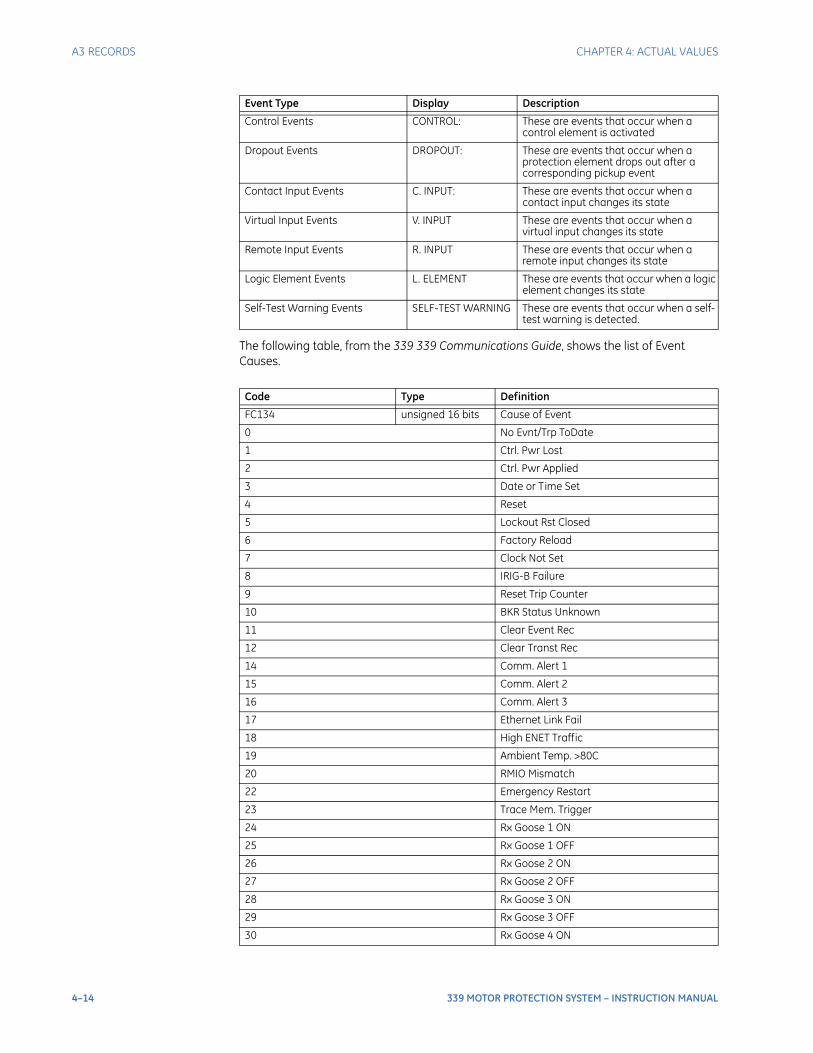
4–14 339 MOTOR PROTECTION SYSTEM – INSTRUCTION MANUAL
A3 RECORDS CHAPTER 4: ACTUAL VALUES
The following table, from the 339 339 Communications Guide, shows the list of Event Causes.
Control Events CONTROL: These are events that occur when a control element is activated
Dropout Events DROPOUT: These are events that occur when a protection element drops out after a corresponding pickup event
Contact Input Events C. INPUT: These are events that occur when a contact input changes its state
Virtual Input Events V. INPUT These are events that occur when a virtual input changes its state
Remote Input Events R. INPUT These are events that occur when a remote input changes its state
Logic Element Events L. ELEMENT These are events that occur when a logic element changes its state
Self-Test Warning Events SELF-TEST WARNING These are events that occur when a self-test warning is detected.
Code Type Definition
FC134 unsigned 16 bits Cause of Event
0 No Evnt/Trp ToDate
1 Ctrl. Pwr Lost
2 Ctrl. Pwr Applied
3 Date or Time Set
4 Reset
5 Lockout Rst Closed
6 Factory Reload
7 Clock Not Set
8 IRIG-B Failure
9 Reset Trip Counter
10 BKR Status Unknown
11 Clear Event Rec
12 Clear Transt Rec
14 Comm. Alert 1
15 Comm. Alert 2
16 Comm. Alert 3
17 Ethernet Link Fail
18 High ENET Traffic
19 Ambient Temp. >80C
20 RMIO Mismatch
22 Emergency Restart
23 Trace Mem. Trigger
24 Rx Goose 1 ON
25 Rx Goose 1 OFF
26 Rx Goose 2 ON
27 Rx Goose 2 OFF
28 Rx Goose 3 ON
29 Rx Goose 3 OFF
30 Rx Goose 4 ON
Event Type Display Description
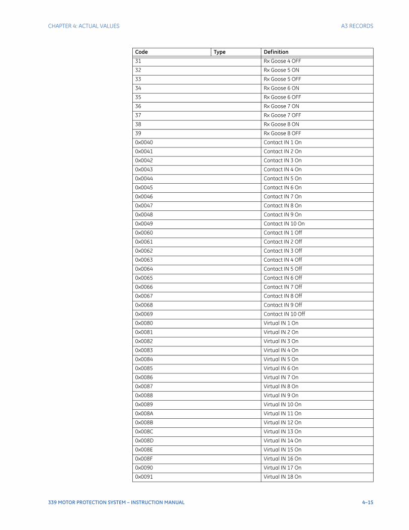
CHAPTER 4: ACTUAL VALUES A3 RECORDS
339 MOTOR PROTECTION SYSTEM – INSTRUCTION MANUAL 4–15
31 Rx Goose 4 OFF
32 Rx Goose 5 ON
33 Rx Goose 5 OFF
34 Rx Goose 6 ON
35 Rx Goose 6 OFF
36 Rx Goose 7 ON
37 Rx Goose 7 OFF
38 Rx Goose 8 ON
39 Rx Goose 8 OFF
0x0040 Contact IN 1 On
0x0041 Contact IN 2 On
0x0042 Contact IN 3 On
0x0043 Contact IN 4 On
0x0044 Contact IN 5 On
0x0045 Contact IN 6 On
0x0046 Contact IN 7 On
0x0047 Contact IN 8 On
0x0048 Contact IN 9 On
0x0049 Contact IN 10 On
0x0060 Contact IN 1 Off
0x0061 Contact IN 2 Off
0x0062 Contact IN 3 Off
0x0063 Contact IN 4 Off
0x0064 Contact IN 5 Off
0x0065 Contact IN 6 Off
0x0066 Contact IN 7 Off
0x0067 Contact IN 8 Off
0x0068 Contact IN 9 Off
0x0069 Contact IN 10 Off
0x0080 Virtual IN 1 On
0x0081 Virtual IN 2 On
0x0082 Virtual IN 3 On
0x0083 Virtual IN 4 On
0x0084 Virtual IN 5 On
0x0085 Virtual IN 6 On
0x0086 Virtual IN 7 On
0x0087 Virtual IN 8 On
0x0088 Virtual IN 9 On
0x0089 Virtual IN 10 On
0x008A Virtual IN 11 On
0x008B Virtual IN 12 On
0x008C Virtual IN 13 On
0x008D Virtual IN 14 On
0x008E Virtual IN 15 On
0x008F Virtual IN 16 On
0x0090 Virtual IN 17 On
0x0091 Virtual IN 18 On
Code Type Definition
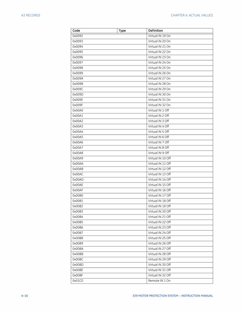
4–16 339 MOTOR PROTECTION SYSTEM – INSTRUCTION MANUAL
A3 RECORDS CHAPTER 4: ACTUAL VALUES
0x0092 Virtual IN 19 On
0x0093 Virtual IN 20 On
0x0094 Virtual IN 21 On
0x0095 Virtual IN 22 On
0x0096 Virtual IN 23 On
0x0097 Virtual IN 24 On
0x0098 Virtual IN 25 On
0x0099 Virtual IN 26 On
0x009A Virtual IN 27 On
0x009B Virtual IN 28 On
0x009C Virtual IN 29 On
0x009D Virtual IN 30 On
0x009E Virtual IN 31 On
0x009F Virtual IN 32 On
0x00A0 Virtual IN 1 Off
0x00A1 Virtual IN 2 Off
0x00A2 Virtual IN 3 Off
0x00A3 Virtual IN 4 Off
0x00A4 Virtual IN 5 Off
0x00A5 Virtual IN 6 Off
0x00A6 Virtual IN 7 Off
0x00A7 Virtual IN 8 Off
0x00A8 Virtual IN 9 Off
0x00A9 Virtual IN 10 Off
0x00AA Virtual IN 11 Off
0x00AB Virtual IN 12 Off
0x00AC Virtual IN 13 Off
0x00AD Virtual IN 14 Off
0x00AE Virtual IN 15 Off
0x00AF Virtual IN 16 Off
0x00B0 Virtual IN 17 Off
0x00B1 Virtual IN 18 Off
0x00B2 Virtual IN 19 Off
0x00B3 Virtual IN 20 Off
0x00B4 Virtual IN 21 Off
0x00B5 Virtual IN 22 Off
0x00B6 Virtual IN 23 Off
0x00B7 Virtual IN 24 Off
0x00B8 Virtual IN 25 Off
0x00B9 Virtual IN 26 Off
0x00BA Virtual IN 27 Off
0x00BB Virtual IN 28 Off
0x00BC Virtual IN 29 Off
0x00BD Virtual IN 30 Off
0x00BE Virtual IN 31 Off
0x00BF Virtual IN 32 Off
0x01C0 Remote IN 1 On
Code Type Definition
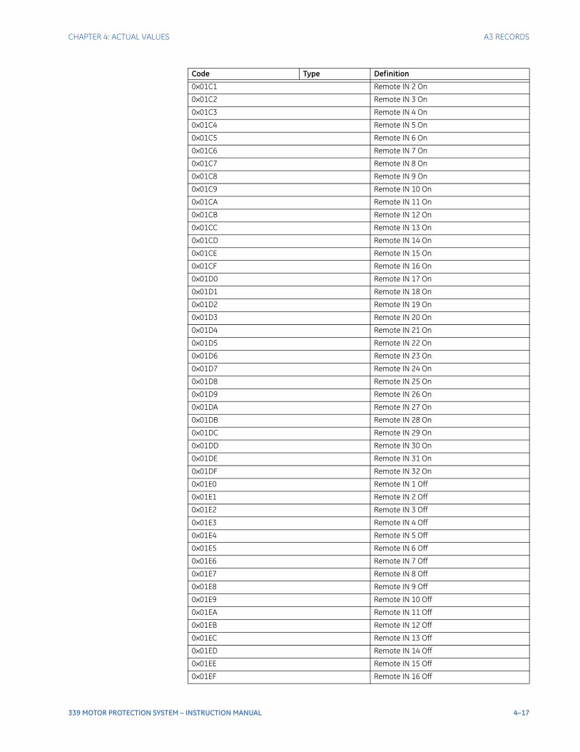
CHAPTER 4: ACTUAL VALUES A3 RECORDS
339 MOTOR PROTECTION SYSTEM – INSTRUCTION MANUAL 4–17
0x01C1 Remote IN 2 On
0x01C2 Remote IN 3 On
0x01C3 Remote IN 4 On
0x01C4 Remote IN 5 On
0x01C5 Remote IN 6 On
0x01C6 Remote IN 7 On
0x01C7 Remote IN 8 On
0x01C8 Remote IN 9 On
0x01C9 Remote IN 10 On
0x01CA Remote IN 11 On
0x01CB Remote IN 12 On
0x01CC Remote IN 13 On
0x01CD Remote IN 14 On
0x01CE Remote IN 15 On
0x01CF Remote IN 16 On
0x01D0 Remote IN 17 On
0x01D1 Remote IN 18 On
0x01D2 Remote IN 19 On
0x01D3 Remote IN 20 On
0x01D4 Remote IN 21 On
0x01D5 Remote IN 22 On
0x01D6 Remote IN 23 On
0x01D7 Remote IN 24 On
0x01D8 Remote IN 25 On
0x01D9 Remote IN 26 On
0x01DA Remote IN 27 On
0x01DB Remote IN 28 On
0x01DC Remote IN 29 On
0x01DD Remote IN 30 On
0x01DE Remote IN 31 On
0x01DF Remote IN 32 On
0x01E0 Remote IN 1 Off
0x01E1 Remote IN 2 Off
0x01E2 Remote IN 3 Off
0x01E3 Remote IN 4 Off
0x01E4 Remote IN 5 Off
0x01E5 Remote IN 6 Off
0x01E6 Remote IN 7 Off
0x01E7 Remote IN 8 Off
0x01E8 Remote IN 9 Off
0x01E9 Remote IN 10 Off
0x01EA Remote IN 11 Off
0x01EB Remote IN 12 Off
0x01EC Remote IN 13 Off
0x01ED Remote IN 14 Off
0x01EE Remote IN 15 Off
0x01EF Remote IN 16 Off
Code Type Definition
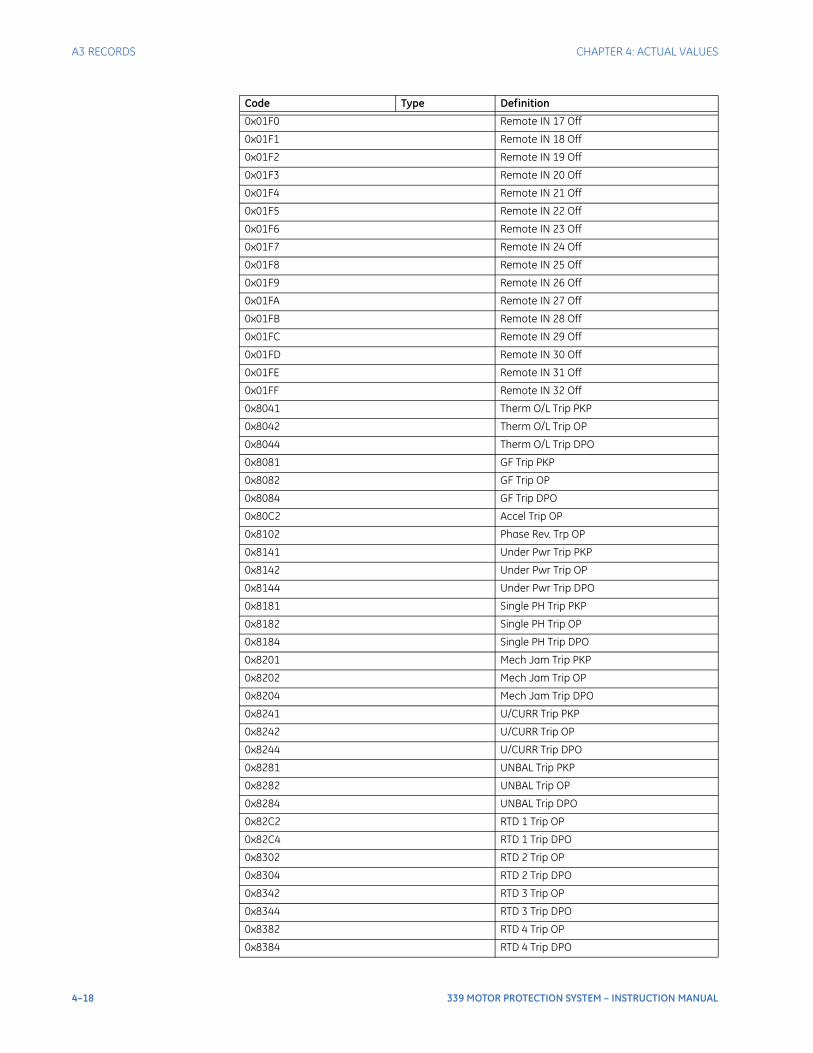
4–18 339 MOTOR PROTECTION SYSTEM – INSTRUCTION MANUAL
A3 RECORDS CHAPTER 4: ACTUAL VALUES
0x01F0 Remote IN 17 Off
0x01F1 Remote IN 18 Off
0x01F2 Remote IN 19 Off
0x01F3 Remote IN 20 Off
0x01F4 Remote IN 21 Off
0x01F5 Remote IN 22 Off
0x01F6 Remote IN 23 Off
0x01F7 Remote IN 24 Off
0x01F8 Remote IN 25 Off
0x01F9 Remote IN 26 Off
0x01FA Remote IN 27 Off
0x01FB Remote IN 28 Off
0x01FC Remote IN 29 Off
0x01FD Remote IN 30 Off
0x01FE Remote IN 31 Off
0x01FF Remote IN 32 Off
0x8041 Therm O/L Trip PKP
0x8042 Therm O/L Trip OP
0x8044 Therm O/L Trip DPO
0x8081 GF Trip PKP
0x8082 GF Trip OP
0x8084 GF Trip DPO
0x80C2 Accel Trip OP
0x8102 Phase Rev. Trp OP
0x8141 Under Pwr Trip PKP
0x8142 Under Pwr Trip OP
0x8144 Under Pwr Trip DPO
0x8181 Single PH Trip PKP
0x8182 Single PH Trip OP
0x8184 Single PH Trip DPO
0x8201 Mech Jam Trip PKP
0x8202 Mech Jam Trip OP
0x8204 Mech Jam Trip DPO
0x8241 U/CURR Trip PKP
0x8242 U/CURR Trip OP
0x8244 U/CURR Trip DPO
0x8281 UNBAL Trip PKP
0x8282 UNBAL Trip OP
0x8284 UNBAL Trip DPO
0x82C2 RTD 1 Trip OP
0x82C4 RTD 1 Trip DPO
0x8302 RTD 2 Trip OP
0x8304 RTD 2 Trip DPO
0x8342 RTD 3 Trip OP
0x8344 RTD 3 Trip DPO
0x8382 RTD 4 Trip OP
0x8384 RTD 4 Trip DPO
Code Type Definition
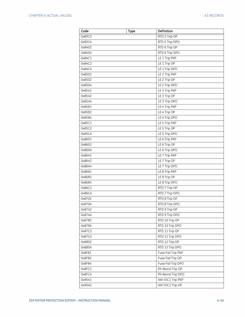
CHAPTER 4: ACTUAL VALUES A3 RECORDS
339 MOTOR PROTECTION SYSTEM – INSTRUCTION MANUAL 4–19
0x83C2 RTD 5 Trip OP
0x83C4 RTD 5 Trip DPO
0x8402 RTD 6 Trip OP
0x8404 RTD 6 Trip DPO
0x84C1 LE 1 Trip PKP
0x84C2 LE 1 Trip OP
0x84C4 LE 1 Trip DPO
0x8501 LE 2 Trip PKP
0x8502 LE 2 Trip OP
0x8504 LE 2 Trip DPO
0x8541 LE 3 Trip PKP
0x8542 LE 3 Trip OP
0x8544 LE 3 Trip DPO
0x8581 LE 4 Trip PKP
0x8582 LE 4 Trip OP
0x8584 LE 4 Trip DPO
0x85C1 LE 5 Trip PKP
0x85C2 LE 5 Trip OP
0x85C4 LE 5 Trip DPO
0x8601 LE 6 Trip PKP
0x8602 LE 6 Trip OP
0x8604 LE 6 Trip DPO
0x8641 LE 7 Trip PKP
0x8642 LE 7 Trip OP
0x8644 LE 7 Trip DPO
0x8681 LE 8 Trip PKP
0x8682 LE 8 Trip OP
0x8684 LE 8 Trip DPO
0x86C2 RTD 7 Trip OP
0x86C4 RTD 7 Trip DPO
0x8702 RTD 8 Trip OP
0x8704 RTD 8 Trip DPO
0x8742 RTD 9 Trip OP
0x8744 RTD 9 Trip DPO
0x8782 RTD 10 Trip OP
0x8784 RTD 10 Trip DPO
0x87C2 RTD 11 Trip OP
0x87C4 RTD 11 Trip DPO
0x8802 RTD 12 Trip OP
0x8804 RTD 12 Trip DPO
0x8F81 Fuse Fail Trip PKP
0x8F82 Fuse Fail Trip OP
0x8F84 Fuse Fail Trip DPO
0x8FC2 Ph Revrsl Trip OP
0x8FC4 Ph Revrsl Trip DPO
0x9041 Ntrl IOC1 Trip PKP
0x9042 Ntrl IOC1 Trip OP
Code Type Definition
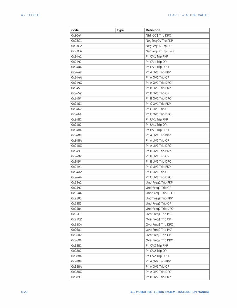
4–20 339 MOTOR PROTECTION SYSTEM – INSTRUCTION MANUAL
A3 RECORDS CHAPTER 4: ACTUAL VALUES
0x9044 Ntrl IOC1 Trip DPO
0x93C1 NegSeq OV Trp PKP
0x93C2 NegSeq OV Trp OP
0x93C4 NegSeq OV Trp DPO
0x9441 Ph OV1 Trip PKP
0x9442 Ph OV1 Trip OP
0x9444 Ph OV1 Trip DPO
0x9449 Ph A OV1 Trip PKP
0x944A Ph A OV1 Trip OP
0x944C Ph A OV1 Trip DPO
0x9451 Ph B OV1 Trip PKP
0x9452 Ph B OV1 Trip OP
0x9454 Ph B OV1 Trip DPO
0x9461 Ph C OV1 Trip PKP
0x9462 Ph C OV1 Trip OP
0x9464 Ph C OV1 Trip DPO
0x9481 Ph UV1 Trip PKP
0x9482 Ph UV1 Trip OP
0x9484 Ph UV1 Trip DPO
0x9489 Ph A UV1 Trip PKP
0x948A Ph A UV1 Trip OP
0x948C Ph A UV1 Trip DPO
0x9491 Ph B UV1 Trip PKP
0x9492 Ph B UV1 Trip OP
0x9494 Ph B UV1 Trip DPO
0x94A1 Ph C UV1 Trip PKP
0x94A2 Ph C UV1 Trip OP
0x94A4 Ph C UV1 Trip DPO
0x9541 UndrFreq1 Trip PKP
0x9542 UndrFreq1 Trip OP
0x9544 UndrFreq1 Trip DPO
0x9581 UndrFreq2 Trip PKP
0x9582 UndrFreq2 Trip OP
0x9584 UndrFreq2 Trip DPO
0x95C1 OverFreq1 Trip PKP
0x95C2 OverFreq1 Trip OP
0x95C4 OverFreq1 Trip DPO
0x9601 OverFreq2 Trip PKP
0x9602 OverFreq2 Trip OP
0x9604 OverFreq2 Trip DPO
0x9881 Ph OV2 Trip PKP
0x9882 Ph OV2 Trip OP
0x9884 Ph OV2 Trip DPO
0x9889 Ph A OV2 Trip PKP
0x988A Ph A OV2 Trip OP
0x988C Ph A OV2 Trip DPO
0x9891 Ph B OV2 Trip PKP
Code Type Definition
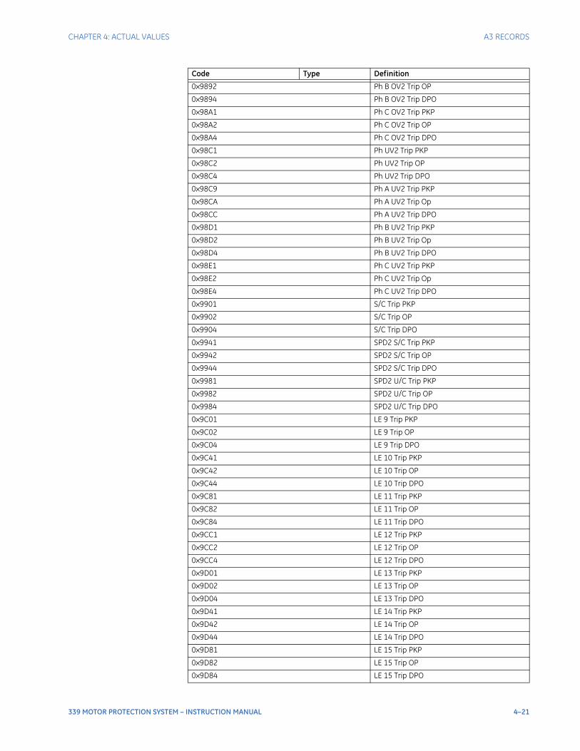
CHAPTER 4: ACTUAL VALUES A3 RECORDS
339 MOTOR PROTECTION SYSTEM – INSTRUCTION MANUAL 4–21
0x9892 Ph B OV2 Trip OP
0x9894 Ph B OV2 Trip DPO
0x98A1 Ph C OV2 Trip PKP
0x98A2 Ph C OV2 Trip OP
0x98A4 Ph C OV2 Trip DPO
0x98C1 Ph UV2 Trip PKP
0x98C2 Ph UV2 Trip OP
0x98C4 Ph UV2 Trip DPO
0x98C9 Ph A UV2 Trip PKP
0x98CA Ph A UV2 Trip Op
0x98CC Ph A UV2 Trip DPO
0x98D1 Ph B UV2 Trip PKP
0x98D2 Ph B UV2 Trip Op
0x98D4 Ph B UV2 Trip DPO
0x98E1 Ph C UV2 Trip PKP
0x98E2 Ph C UV2 Trip Op
0x98E4 Ph C UV2 Trip DPO
0x9901 S/C Trip PKP
0x9902 S/C Trip OP
0x9904 S/C Trip DPO
0x9941 SPD2 S/C Trip PKP
0x9942 SPD2 S/C Trip OP
0x9944 SPD2 S/C Trip DPO
0x9981 SPD2 U/C Trip PKP
0x9982 SPD2 U/C Trip OP
0x9984 SPD2 U/C Trip DPO
0x9C01 LE 9 Trip PKP
0x9C02 LE 9 Trip OP
0x9C04 LE 9 Trip DPO
0x9C41 LE 10 Trip PKP
0x9C42 LE 10 Trip OP
0x9C44 LE 10 Trip DPO
0x9C81 LE 11 Trip PKP
0x9C82 LE 11 Trip OP
0x9C84 LE 11 Trip DPO
0x9CC1 LE 12 Trip PKP
0x9CC2 LE 12 Trip OP
0x9CC4 LE 12 Trip DPO
0x9D01 LE 13 Trip PKP
0x9D02 LE 13 Trip OP
0x9D04 LE 13 Trip DPO
0x9D41 LE 14 Trip PKP
0x9D42 LE 14 Trip OP
0x9D44 LE 14 Trip DPO
0x9D81 LE 15 Trip PKP
0x9D82 LE 15 Trip OP
0x9D84 LE 15 Trip DPO
Code Type Definition
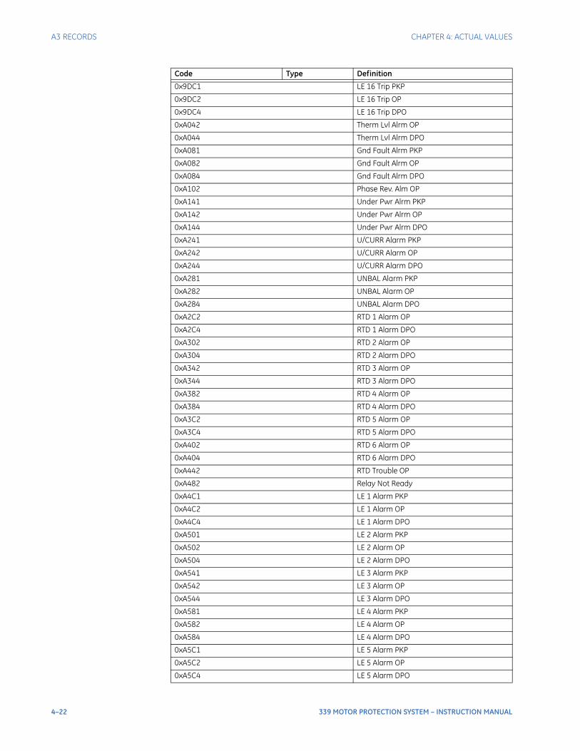
4–22 339 MOTOR PROTECTION SYSTEM – INSTRUCTION MANUAL
A3 RECORDS CHAPTER 4: ACTUAL VALUES
0x9DC1 LE 16 Trip PKP
0x9DC2 LE 16 Trip OP
0x9DC4 LE 16 Trip DPO
0xA042 Therm Lvl Alrm OP
0xA044 Therm Lvl Alrm DPO
0xA081 Gnd Fault Alrm PKP
0xA082 Gnd Fault Alrm OP
0xA084 Gnd Fault Alrm DPO
0xA102 Phase Rev. Alm OP
0xA141 Under Pwr Alrm PKP
0xA142 Under Pwr Alrm OP
0xA144 Under Pwr Alrm DPO
0xA241 U/CURR Alarm PKP
0xA242 U/CURR Alarm OP
0xA244 U/CURR Alarm DPO
0xA281 UNBAL Alarm PKP
0xA282 UNBAL Alarm OP
0xA284 UNBAL Alarm DPO
0xA2C2 RTD 1 Alarm OP
0xA2C4 RTD 1 Alarm DPO
0xA302 RTD 2 Alarm OP
0xA304 RTD 2 Alarm DPO
0xA342 RTD 3 Alarm OP
0xA344 RTD 3 Alarm DPO
0xA382 RTD 4 Alarm OP
0xA384 RTD 4 Alarm DPO
0xA3C2 RTD 5 Alarm OP
0xA3C4 RTD 5 Alarm DPO
0xA402 RTD 6 Alarm OP
0xA404 RTD 6 Alarm DPO
0xA442 RTD Trouble OP
0xA482 Relay Not Ready
0xA4C1 LE 1 Alarm PKP
0xA4C2 LE 1 Alarm OP
0xA4C4 LE 1 Alarm DPO
0xA501 LE 2 Alarm PKP
0xA502 LE 2 Alarm OP
0xA504 LE 2 Alarm DPO
0xA541 LE 3 Alarm PKP
0xA542 LE 3 Alarm OP
0xA544 LE 3 Alarm DPO
0xA581 LE 4 Alarm PKP
0xA582 LE 4 Alarm OP
0xA584 LE 4 Alarm DPO
0xA5C1 LE 5 Alarm PKP
0xA5C2 LE 5 Alarm OP
0xA5C4 LE 5 Alarm DPO
Code Type Definition
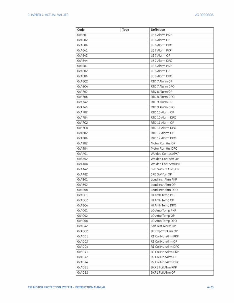
CHAPTER 4: ACTUAL VALUES A3 RECORDS
339 MOTOR PROTECTION SYSTEM – INSTRUCTION MANUAL 4–23
0xA601 LE 6 Alarm PKP
0xA602 LE 6 Alarm OP
0xA604 LE 6 Alarm DPO
0xA641 LE 7 Alarm PKP
0xA642 LE 7 Alarm OP
0xA644 LE 7 Alarm DPO
0xA681 LE 8 Alarm PKP
0xA682 LE 8 Alarm OP
0xA684 LE 8 Alarm DPO
0xA6C2 RTD 7 Alarm OP
0xA6C4 RTD 7 Alarm DPO
0xA702 RTD 8 Alarm OP
0xA704 RTD 8 Alarm DPO
0xA742 RTD 9 Alarm OP
0xA744 RTD 9 Alarm DPO
0xA782 RTD 10 Alarm OP
0xA784 RTD 10 Alarm DPO
0xA7C2 RTD 11 Alarm OP
0xA7C4 RTD 11 Alarm DPO
0xA802 RTD 12 Alarm OP
0xA804 RTD 12 Alarm DPO
0xA982 Motor Run Hrs OP
0xA984 Motor Run Hrs DPO
0xAA01 Welded ContactrPKP
0xAA02 Welded Contactr OP
0xAA04 Welded ContactrDPO
0xAA42 SPD SW Not Cnfg OP
0xAA82 SPD SW Fail OP
0xAB01 Load Incr Alrm PKP
0xAB02 Load Incr Alrm OP
0xAB04 Load Incr Alrm DPO
0xABC1 HI Amb Temp PKP
0xABC2 HI Amb Temp OP
0xABC4 HI Amb Temp DPO
0xAC01 LO Amb Temp PKP
0xAC02 LO Amb Temp OP
0xAC04 LO Amb Temp DPO
0xAC42 Self Test Alarm OP
0xACC2 BKRTrpCntrAlrm OP
0xAD01 R1 CoilMonAlrm PKP
0xAD02 R1 CoilMonAlrm OP
0xAD04 R1 CoilMonAlrm DPO
0xAD41 R2 CoilMonAlrm PKP
0xAD42 R2 CoilMonAlrm OP
0xAD44 R2 CoilMonAlrm DPO
0xAD81 BKR1 Fail Alrm PKP
0xAD82 BKR1 Fail Alrm OP
Code Type Definition
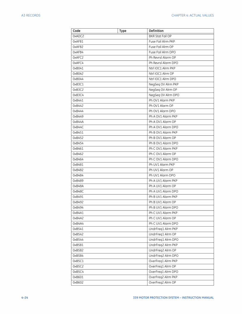
4–24 339 MOTOR PROTECTION SYSTEM – INSTRUCTION MANUAL
A3 RECORDS CHAPTER 4: ACTUAL VALUES
0xADC2 BKR Stat Fail OP
0xAF81 Fuse Fail Alrm PKP
0xAF82 Fuse Fail Alrm OP
0xAF84 Fuse Fail Alrm DPO
0xAFC2 Ph Revrsl Alarm OP
0xAFC4 Ph Revrsl Alarm DPO
0xB041 Ntrl IOC1 Alrm PKP
0xB042 Ntrl IOC1 Alrm OP
0xB044 Ntrl IOC1 Alrm DPO
0xB3C1 NegSeq OV Alrm PKP
0xB3C2 NegSeq OV Alrm OP
0xB3C4 NegSeq OV Alrm DPO
0xB441 Ph OV1 Alarm PKP
0xB442 Ph OV1 Alarm OP
0xB444 Ph OV1 Alarm DPO
0xB449 Ph A OV1 Alarm PKP
0xB44A Ph A OV1 Alarm OP
0xB44C Ph A OV1 Alarm DPO
0xB451 Ph B OV1 Alarm PKP
0xB452 Ph B OV1 Alarm OP
0xB454 Ph B OV1 Alarm DPO
0xB461 Ph C OV1 Alarm PKP
0xB462 Ph C OV1 Alarm OP
0xB464 Ph C OV1 Alarm DPO
0xB481 Ph UV1 Alarm PKP
0xB482 Ph UV1 Alarm OP
0xB484 Ph UV1 Alarm DPO
0xB489 Ph A UV1 Alarm PKP
0xB48A Ph A UV1 Alarm OP
0xB48C Ph A UV1 Alarm DPO
0xB491 Ph B UV1 Alarm PKP
0xB492 Ph B UV1 Alarm OP
0xB494 Ph B UV1 Alarm DPO
0xB4A1 Ph C UV1 Alarm PKP
0xB4A2 Ph C UV1 Alarm OP
0xB4A4 Ph C UV1 Alarm DPO
0xB541 UndrFreq1 Alrm PKP
0xB542 UndrFreq1 Alrm OP
0xB544 UndrFreq1 Alrm DPO
0xB581 UndrFreq2 Alrm PKP
0xB582 UndrFreq2 Alrm OP
0xB584 UndrFreq2 Alrm DPO
0xB5C1 OverFreq1 Alrm PKP
0xB5C2 OverFreq1 Alrm OP
0xB5C4 OverFreq1 Alrm DPO
0xB601 OverFreq2 Alrm PKP
0xB602 OverFreq2 Alrm OP
Code Type Definition
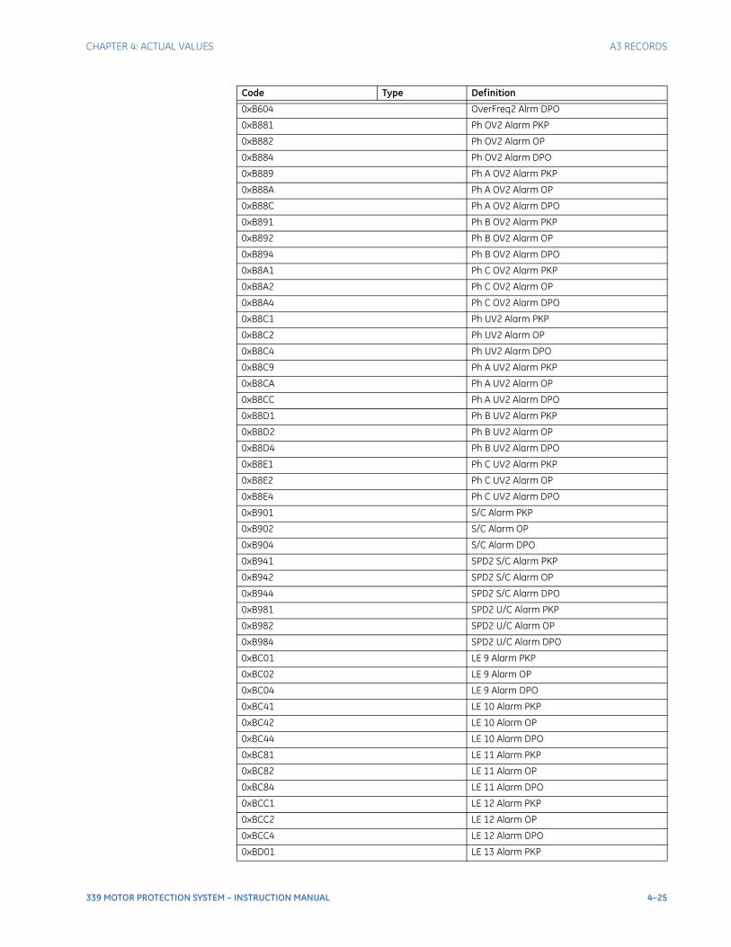
CHAPTER 4: ACTUAL VALUES A3 RECORDS
339 MOTOR PROTECTION SYSTEM – INSTRUCTION MANUAL 4–25
0xB604 OverFreq2 Alrm DPO
0xB881 Ph OV2 Alarm PKP
0xB882 Ph OV2 Alarm OP
0xB884 Ph OV2 Alarm DPO
0xB889 Ph A OV2 Alarm PKP
0xB88A Ph A OV2 Alarm OP
0xB88C Ph A OV2 Alarm DPO
0xB891 Ph B OV2 Alarm PKP
0xB892 Ph B OV2 Alarm OP
0xB894 Ph B OV2 Alarm DPO
0xB8A1 Ph C OV2 Alarm PKP
0xB8A2 Ph C OV2 Alarm OP
0xB8A4 Ph C OV2 Alarm DPO
0xB8C1 Ph UV2 Alarm PKP
0xB8C2 Ph UV2 Alarm OP
0xB8C4 Ph UV2 Alarm DPO
0xB8C9 Ph A UV2 Alarm PKP
0xB8CA Ph A UV2 Alarm OP
0xB8CC Ph A UV2 Alarm DPO
0xB8D1 Ph B UV2 Alarm PKP
0xB8D2 Ph B UV2 Alarm OP
0xB8D4 Ph B UV2 Alarm DPO
0xB8E1 Ph C UV2 Alarm PKP
0xB8E2 Ph C UV2 Alarm OP
0xB8E4 Ph C UV2 Alarm DPO
0xB901 S/C Alarm PKP
0xB902 S/C Alarm OP
0xB904 S/C Alarm DPO
0xB941 SPD2 S/C Alarm PKP
0xB942 SPD2 S/C Alarm OP
0xB944 SPD2 S/C Alarm DPO
0xB981 SPD2 U/C Alarm PKP
0xB982 SPD2 U/C Alarm OP
0xB984 SPD2 U/C Alarm DPO
0xBC01 LE 9 Alarm PKP
0xBC02 LE 9 Alarm OP
0xBC04 LE 9 Alarm DPO
0xBC41 LE 10 Alarm PKP
0xBC42 LE 10 Alarm OP
0xBC44 LE 10 Alarm DPO
0xBC81 LE 11 Alarm PKP
0xBC82 LE 11 Alarm OP
0xBC84 LE 11 Alarm DPO
0xBCC1 LE 12 Alarm PKP
0xBCC2 LE 12 Alarm OP
0xBCC4 LE 12 Alarm DPO
0xBD01 LE 13 Alarm PKP
Code Type Definition
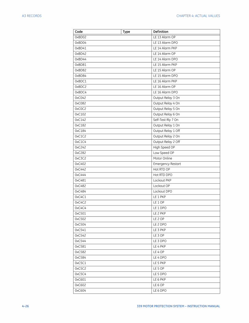
4–26 339 MOTOR PROTECTION SYSTEM – INSTRUCTION MANUAL
A3 RECORDS CHAPTER 4: ACTUAL VALUES
0xBD02 LE 13 Alarm OP
0xBD04 LE 13 Alarm DPO
0xBD41 LE 14 Alarm PKP
0xBD42 LE 14 Alarm OP
0xBD44 LE 14 Alarm DPO
0xBD81 LE 15 Alarm PKP
0xBD82 LE 15 Alarm OP
0xBD84 LE 15 Alarm DPO
0xBDC1 LE 16 Alarm PKP
0xBDC2 LE 16 Alarm OP
0xBDC4 LE 16 Alarm DPO
0xC042 Output Relay 3 On
0xC082 Output Relay 4 On
0xC0C2 Output Relay 5 On
0xC102 Output Relay 6 On
0xC142 Self-Test Rly 7 On
0xC182 Output Relay 1 On
0xC184 Output Relay 1 Off
0xC1C2 Output Relay 2 On
0xC1C4 Output Relay 2 Off
0xC242 High Speed OP
0xC282 Low Speed OP
0xC3C2 Motor Online
0xC402 Emergency Restart
0xC442 Hot RTD OP
0xC444 Hot RTD DPO
0xC481 Lockout PKP
0xC482 Lockout OP
0xC484 Lockout DPO
0xC4C1 LE 1 PKP
0xC4C2 LE 1 OP
0xC4C4 LE 1 DPO
0xC501 LE 2 PKP
0xC502 LE 2 OP
0xC504 LE 2 DPO
0xC541 LE 3 PKP
0xC542 LE 3 OP
0xC544 LE 3 DPO
0xC581 LE 4 PKP
0xC582 LE 4 OP
0xC584 LE 4 DPO
0xC5C1 LE 5 PKP
0xC5C2 LE 5 OP
0xC5C4 LE 5 DPO
0xC601 LE 6 PKP
0xC602 LE 6 OP
0xC604 LE 6 DPO
Code Type Definition
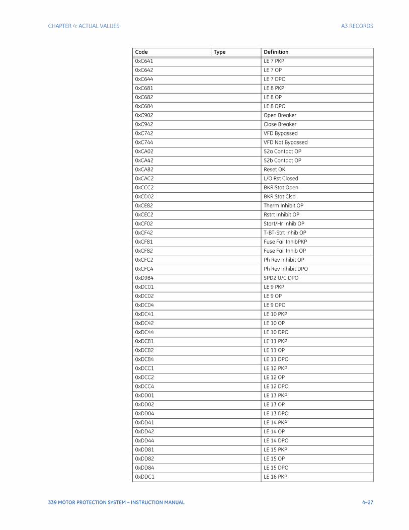
CHAPTER 4: ACTUAL VALUES A3 RECORDS
339 MOTOR PROTECTION SYSTEM – INSTRUCTION MANUAL 4–27
0xC641 LE 7 PKP
0xC642 LE 7 OP
0xC644 LE 7 DPO
0xC681 LE 8 PKP
0xC682 LE 8 OP
0xC684 LE 8 DPO
0xC902 Open Breaker
0xC942 Close Breaker
0xC742 VFD Bypassed
0xC744 VFD Not Bypassed
0xCA02 52a Contact OP
0xCA42 52b Contact OP
0xCA82 Reset OK
0xCAC2 L/O Rst Closed
0xCCC2 BKR Stat Open
0xCD02 BKR Stat Clsd
0xCE82 Therm Inhibit OP
0xCEC2 Rstrt Inhibit OP
0xCF02 Start/Hr Inhib OP
0xCF42 T-BT-Strt Inhib OP
0xCF81 Fuse Fail InhibPKP
0xCF82 Fuse Fail Inhib OP
0xCFC2 Ph Rev Inhibit OP
0xCFC4 Ph Rev Inhibit DPO
0xD984 SPD2 U/C DPO
0xDC01 LE 9 PKP
0xDC02 LE 9 OP
0xDC04 LE 9 DPO
0xDC41 LE 10 PKP
0xDC42 LE 10 OP
0xDC44 LE 10 DPO
0xDC81 LE 11 PKP
0xDC82 LE 11 OP
0xDC84 LE 11 DPO
0xDCC1 LE 12 PKP
0xDCC2 LE 12 OP
0xDCC4 LE 12 DPO
0xDD01 LE 13 PKP
0xDD02 LE 13 OP
0xDD04 LE 13 DPO
0xDD41 LE 14 PKP
0xDD42 LE 14 OP
0xDD44 LE 14 DPO
0xDD81 LE 15 PKP
0xDD82 LE 15 OP
0xDD84 LE 15 DPO
0xDDC1 LE 16 PKP
Code Type Definition
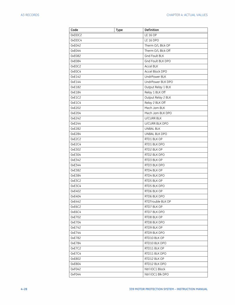
4–28 339 MOTOR PROTECTION SYSTEM – INSTRUCTION MANUAL
A3 RECORDS CHAPTER 4: ACTUAL VALUES
0xDDC2 LE 16 OP
0xDDC4 LE 16 DPO
0xE042 Therm O/L Blck OP
0xE044 Therm O/L Blck Off
0xE082 Gnd Fault BLK
0xE084 Gnd Fault BLK DPO
0xE0C2 Accel BLK
0xE0C4 Accel Block DPO
0xE142 UndrPower BLK
0xE144 UndrPower BLK DPO
0xE182 Output Relay 1 BLK
0xE184 Relay 1 BLK Off
0xE1C2 Output Relay 2 BLK
0xE1C4 Relay 2 BLK Off
0xE202 Mech Jam BLK
0xE204 Mech Jam BLK DPO
0xE242 U/CURR BLK
0xE244 U/CURR BLK DPO
0xE282 UNBAL BLK
0xE284 UNBAL BLK DPO
0xE2C2 RTD1 BLK OP
0xE2C4 RTD1 BLK DPO
0xE302 RTD2 BLK OP
0xE304 RTD2 BLK DPO
0xE342 RTD3 BLK OP
0xE344 RTD3 BLK DPO
0xE382 RTD4 BLK OP
0xE384 RTD4 BLK DPO
0xE3C2 RTD5 BLK OP
0xE3C4 RTD5 BLK DPO
0xE402 RTD6 BLK OP
0xE404 RTD6 BLK DPO
0xE442 RTDTrouble BLK OP
0xE6C2 RTD7 BLK OP
0xE6C4 RTD7 BLK DPO
0xE702 RTD8 BLK OP
0xE704 RTD8 BLK DPO
0xE742 RTD9 BLK OP
0xE744 RTD9 BLK DPO
0xE782 RTD10 BLK OP
0xE784 RTD10 BLK DPO
0xE7C2 RTD11 BLK OP
0xE7C4 RTD11 BLK DPO
0xE802 RTD12 BLK OP
0xE804 RTD12 BLK DPO
0xF042 Ntrl IOC1 Block
0xF044 Ntrl IOC1 Blk DPO
Code Type Definition
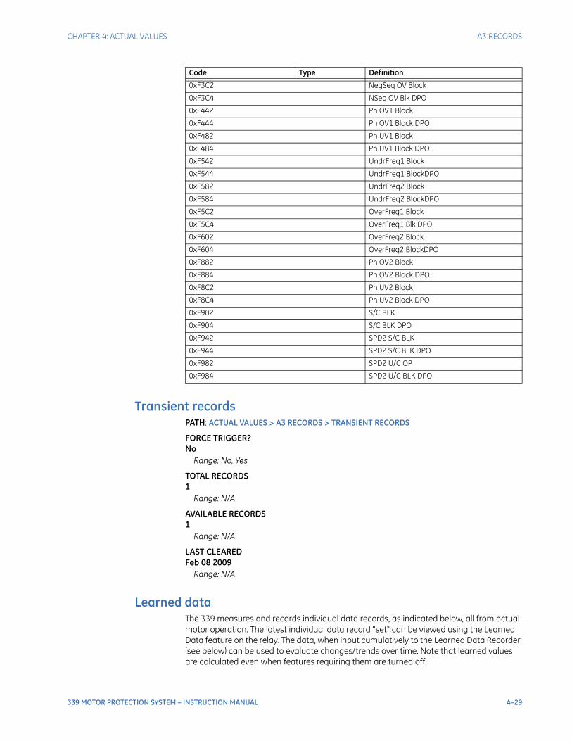
CHAPTER 4: ACTUAL VALUES A3 RECORDS
339 MOTOR PROTECTION SYSTEM – INSTRUCTION MANUAL 4–29
Transient recordsPATH: ACTUAL VALUES > A3 RECORDS > TRANSIENT RECORDS
FORCE TRIGGER?No
Range: No, Yes
TOTAL RECORDS1
Range: N/A
AVAILABLE RECORDS1
Range: N/A
LAST CLEAREDFeb 08 2009
Range: N/A
Learned dataThe 339 measures and records individual data records, as indicated below, all from actual motor operation. The latest individual data record "set" can be viewed using the Learned Data feature on the relay. The data, when input cumulatively to the Learned Data Recorder (see below) can be used to evaluate changes/trends over time. Note that learned values are calculated even when features requiring them are turned off.
0xF3C2 NegSeq OV Block
0xF3C4 NSeq OV Blk DPO
0xF442 Ph OV1 Block
0xF444 Ph OV1 Block DPO
0xF482 Ph UV1 Block
0xF484 Ph UV1 Block DPO
0xF542 UndrFreq1 Block
0xF544 UndrFreq1 BlockDPO
0xF582 UndrFreq2 Block
0xF584 UndrFreq2 BlockDPO
0xF5C2 OverFreq1 Block
0xF5C4 OverFreq1 Blk DPO
0xF602 OverFreq2 Block
0xF604 OverFreq2 BlockDPO
0xF882 Ph OV2 Block
0xF884 Ph OV2 Block DPO
0xF8C2 Ph UV2 Block
0xF8C4 Ph UV2 Block DPO
0xF902 S/C BLK
0xF904 S/C BLK DPO
0xF942 SPD2 S/C BLK
0xF944 SPD2 S/C BLK DPO
0xF982 SPD2 U/C OP
0xF984 SPD2 U/C BLK DPO
Code Type Definition

4–30 339 MOTOR PROTECTION SYSTEM – INSTRUCTION MANUAL
A3 RECORDS CHAPTER 4: ACTUAL VALUES
Clearing motor data (ACTUAL VALUES > A3 RECORDS > CLEAR LEARNED DATA) resets all these values to their default settings.
NOTE
NOTE: Each of the learned features discussed below should not be used until at least five (5) successful motor starts and stops have occurred.
LEARNED ACCEL TIMERange: 0.0 to 250.0 s in steps of 0.1 s
The learned acceleration time is the Learned Acceleration Time measured at the time the record was saved. Acceleration time is the amount of time the motor takes to reach the running state from stopped. A successful motor start is one in which the motor reaches the running state.
If acceleration time is relatively consistent, the learned acceleration time plus suitable margin may be used to manually fine-tune the acceleration protection setting.
LEARNED START CURRRange: 0.0 to 10000.0 A in steps of 0.1 A
The learned starting current is the Learned Starting Current measured at the time the record was saved. Starting current is measured 200 ms after the transition of motor status from stopped to starting, which should ensure that the measured current is symmetrical. A successful motor start is one in which the motor reaches the running state.
LEARNED START TCURange: 0 to 100% in steps of 1
The learned start thermal capacity is the Learned Thermal Capacity Used at the time the record was saved. Start thermal capacity used is the amount of thermal capacity used during starting. A successful motor start is one in which the motor reaches the running state.
If the thermal capacity used during starting is relatively consistent, the learned start thermal capacity used value plus suitable margin may be used to manually fine-tune the thermal start inhibit margin. See the Start Inhibit section of this manual for a description of how the learned start thermal capacity used is calculated.
LAST ACCEL TIMERange: 0.0 to 250.0 s in steps of 0.1 s
The last acceleration time is the Last Acceleration Time measured at the time the record was saved.
LAST START CURRRange: 0.0 to 10000.0 A in steps of 0.1 A
The last starting current is the Last Starting Current measured at the time the record was saved.
LAST START TCURange: 0 to 100% in steps of 1
The last start thermal capacity used is the Last Thermal Capacity Used at the time the record was saved.
LEARNED AVG LOADRange: 0.00 to 20.00 x FLA in steps of 0.01 x FLA
Learned average load is the Average Motor Current, expressed as a multiple of FLA, experienced over the last 15 running minutes. Samples are taken once a second. In the case of two-speed motors with different FLA values for the two speeds, the FLA used for each current sample is the one in effect at the time that sample was taken.

CHAPTER 4: ACTUAL VALUES A3 RECORDS
339 MOTOR PROTECTION SYSTEM – INSTRUCTION MANUAL 4–31
AVG RUN TIMERange: Hours, Minutes
The average Run Time of the last five starts at the time the record was saved.
RTD 1 to 12 MAX TEMPERATURERange: -50 to 250°C
The maximum temperature experienced by each of the RTDs.
Once a second each of the RTD temperature values is captured. For each RTD, if the captured RTD temperature value is greater than the RDT maximum temperature already stored, the RDT maximum temperature is set to this latest captured RTD temperature value. The RTD maximum temperature values are maintained in non-volatile memory to carry over a relay power interruption.
Learned data recorderThe Learned Data Recorder measures and records up to 250 data record "sets," as indicated in the Learned Data section above, all from actual motor operation. This data can be used to evaluate changes/trends over time. Note that learned values are calculated even when features requiring them are turned off.Clearing motor data (ACTUAL VALUES > A3 RECORDS > CLEAR LEARNED DATA) resets all these values to their default settings.
LEARNED DATA RECRange: #xxxx1 of xx250 in steps of 1
This value indicates the number of learned data records saved to date. Only the latest 250 records can be viewed.
DATE OF RECORDRange: Month, Day, Year
This value is the date on which the record was saved.
Clear learned dataCLEAR LEARNED DATANo
Range: No, Yes
When set to "Yes," pressing the ENTER key will clear all learned data.
Clear transient recordPATH: ACTUAL VALUES > A3 RECORDS > CLEAR TRANST REC
CLEAR TRANST RECORDNo
Range: No, Yes
When set to "Yes," pressing the ENTER key will clear all transient records.
Clear event recordPATH: ACTUAL VALUES > A3 RECORDS > CLEAR EVENT REC
CLEAR EVENT RECORDNo
Range: No, Yes
When set to "Yes," pressing the ENTER key will clear all event records.
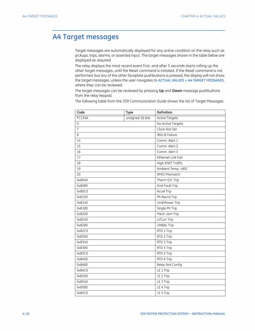
4–32 339 MOTOR PROTECTION SYSTEM – INSTRUCTION MANUAL
A4 TARGET MESSAGES CHAPTER 4: ACTUAL VALUES
A4 Target messages
Target messages are automatically displayed for any active condition on the relay such as pickups, trips, alarms, or asserted input. The target messages shown in the table below are displayed as required. The relay displays the most recent event first, and after 5 seconds starts rolling up the other target messages, until the Reset command is initiated. If the Reset command is not performed, but any of the other faceplate pushbuttons is pressed, the display will not show the target messages, unless the user navigates to ACTUAL VALUES > A4 TARGET MESSAGES, where they can be reviewed. The target messages can be reviewed by pressing Up and Down message pushbuttons from the relay keypad.The following table from the 339 Communication Guide shows the list of Target Messages.
Code Type Definition
FC134A unsigned 16 bits Active Targets
0 No Active Targets
7 Clock Not Set
8 IRIG-B Failure
14 Comm. Alert 1
15 Comm. Alert 2
16 Comm. Alert 3
17 Ethernet Link Fail
18 High ENET Traffic
19 Ambient Temp. >80C
20 RMIO Mismatch
0x8040 Therm O/L Trip
0x8080 Gnd Fault Trip
0x80C0 Accel Trip
0x8100 Ph Revrsl Trip
0x8140 UndrPower Trip
0x8180 Single Ph Trip
0x8200 Mech Jam Trip
0x8240 U/Curr Trip
0x8280 UNBAL Trip
0x82C0 RTD 1 Trip
0x8300 RTD 2 Trip
0x8340 RTD 3 Trip
0x8380 RTD 4 Trip
0x83C0 RTD 5 Trip
0x8400 RTD 6 Trip
0x8480 Relay Not Config
0x84C0 LE 1 Trip
0x8500 LE 2 Trip
0x8540 LE 3 Trip
0x8580 LE 4 Trip
0x85C0 LE 5 Trip
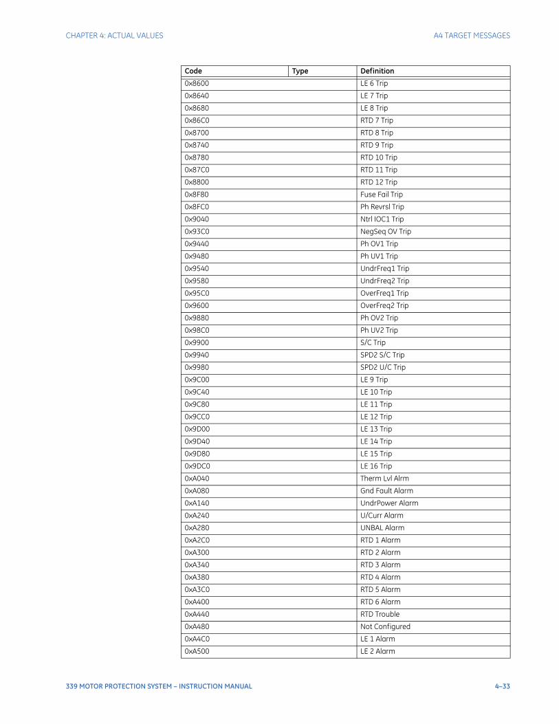
CHAPTER 4: ACTUAL VALUES A4 TARGET MESSAGES
339 MOTOR PROTECTION SYSTEM – INSTRUCTION MANUAL 4–33
0x8600 LE 6 Trip
0x8640 LE 7 Trip
0x8680 LE 8 Trip
0x86C0 RTD 7 Trip
0x8700 RTD 8 Trip
0x8740 RTD 9 Trip
0x8780 RTD 10 Trip
0x87C0 RTD 11 Trip
0x8800 RTD 12 Trip
0x8F80 Fuse Fail Trip
0x8FC0 Ph Revrsl Trip
0x9040 Ntrl IOC1 Trip
0x93C0 NegSeq OV Trip
0x9440 Ph OV1 Trip
0x9480 Ph UV1 Trip
0x9540 UndrFreq1 Trip
0x9580 UndrFreq2 Trip
0x95C0 OverFreq1 Trip
0x9600 OverFreq2 Trip
0x9880 Ph OV2 Trip
0x98C0 Ph UV2 Trip
0x9900 S/C Trip
0x9940 SPD2 S/C Trip
0x9980 SPD2 U/C Trip
0x9C00 LE 9 Trip
0x9C40 LE 10 Trip
0x9C80 LE 11 Trip
0x9CC0 LE 12 Trip
0x9D00 LE 13 Trip
0x9D40 LE 14 Trip
0x9D80 LE 15 Trip
0x9DC0 LE 16 Trip
0xA040 Therm Lvl Alrm
0xA080 Gnd Fault Alarm
0xA140 UndrPower Alarm
0xA240 U/Curr Alarm
0xA280 UNBAL Alarm
0xA2C0 RTD 1 Alarm
0xA300 RTD 2 Alarm
0xA340 RTD 3 Alarm
0xA380 RTD 4 Alarm
0xA3C0 RTD 5 Alarm
0xA400 RTD 6 Alarm
0xA440 RTD Trouble
0xA480 Not Configured
0xA4C0 LE 1 Alarm
0xA500 LE 2 Alarm
Code Type Definition
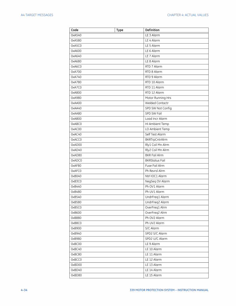
4–34 339 MOTOR PROTECTION SYSTEM – INSTRUCTION MANUAL
A4 TARGET MESSAGES CHAPTER 4: ACTUAL VALUES
0xA540 LE 3 Alarm
0xA580 LE 4 Alarm
0xA5C0 LE 5 Alarm
0xA600 LE 6 Alarm
0xA640 LE 7 Alarm
0xA680 LE 8 Alarm
0xA6C0 RTD 7 Alarm
0xA700 RTD 8 Alarm
0xA740 RTD 9 Alarm
0xA780 RTD 10 Alarm
0xA7C0 RTD 11 Alarm
0xA800 RTD 12 Alarm
0xA980 Motor Running Hrs
0xAA00 Welded Contactr
0xAA40 SPD SW Not Config
0xAA80 SPD SW Fail
0xAB00 Load Incr Alarm
0xABC0 HI Ambient Temp
0xAC00 LO Ambient Temp
0xAC40 Self Test Alarm
0xACC0 BKRTrpCntrAlrm
0xAD00 Rly1 Coil Mn Alrm
0xAD40 Rly2 Coil Mn Alrm
0xAD80 BKR Fail Alrm
0xADC0 BKRStatus Fail
0xAF80 Fuse Fail Alrm
0xAFC0 Ph Revrsl Alrm
0xB040 Ntrl IOC1 Alarm
0xB3C0 NegSeq OV Alarm
0xB440 Ph OV1 Alarm
0xB480 Ph UV1 Alarm
0xB540 UndrFreq1 Alarm
0xB580 UndrFreq2 Alarm
0xB5C0 OverFreq1 Alrm
0xB600 OverFreq2 Alrm
0xB880 Ph OV2 Alarm
0xB8C0 Ph UV2 Alarm
0xB900 S/C Alarm
0xB940 SPD2 S/C Alarm
0xB980 SPD2 U/C Alarm
0xBC00 LE 9 Alarm
0xBC40 LE 10 Alarm
0xBC80 LE 11 Alarm
0xBCC0 LE 12 Alarm
0xBD00 LE 13 Alarm
0xBD40 LE 14 Alarm
0xBD80 LE 15 Alarm
Code Type Definition
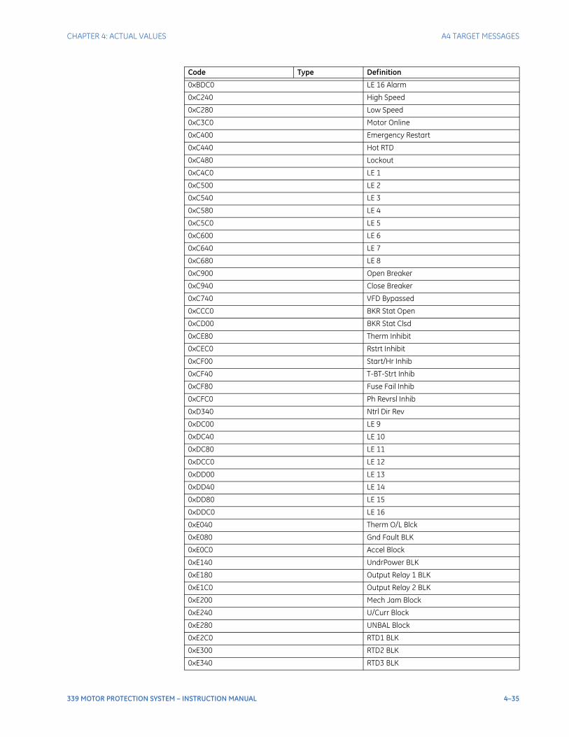
CHAPTER 4: ACTUAL VALUES A4 TARGET MESSAGES
339 MOTOR PROTECTION SYSTEM – INSTRUCTION MANUAL 4–35
0xBDC0 LE 16 Alarm
0xC240 High Speed
0xC280 Low Speed
0xC3C0 Motor Online
0xC400 Emergency Restart
0xC440 Hot RTD
0xC480 Lockout
0xC4C0 LE 1
0xC500 LE 2
0xC540 LE 3
0xC580 LE 4
0xC5C0 LE 5
0xC600 LE 6
0xC640 LE 7
0xC680 LE 8
0xC900 Open Breaker
0xC940 Close Breaker
0xC740 VFD Bypassed
0xCCC0 BKR Stat Open
0xCD00 BKR Stat Clsd
0xCE80 Therm Inhibit
0xCEC0 Rstrt Inhibit
0xCF00 Start/Hr Inhib
0xCF40 T-BT-Strt Inhib
0xCF80 Fuse Fail Inhib
0xCFC0 Ph Revrsl Inhib
0xD340 Ntrl Dir Rev
0xDC00 LE 9
0xDC40 LE 10
0xDC80 LE 11
0xDCC0 LE 12
0xDD00 LE 13
0xDD40 LE 14
0xDD80 LE 15
0xDDC0 LE 16
0xE040 Therm O/L Blck
0xE080 Gnd Fault BLK
0xE0C0 Accel Block
0xE140 UndrPower BLK
0xE180 Output Relay 1 BLK
0xE1C0 Output Relay 2 BLK
0xE200 Mech Jam Block
0xE240 U/Curr Block
0xE280 UNBAL Block
0xE2C0 RTD1 BLK
0xE300 RTD2 BLK
0xE340 RTD3 BLK
Code Type Definition
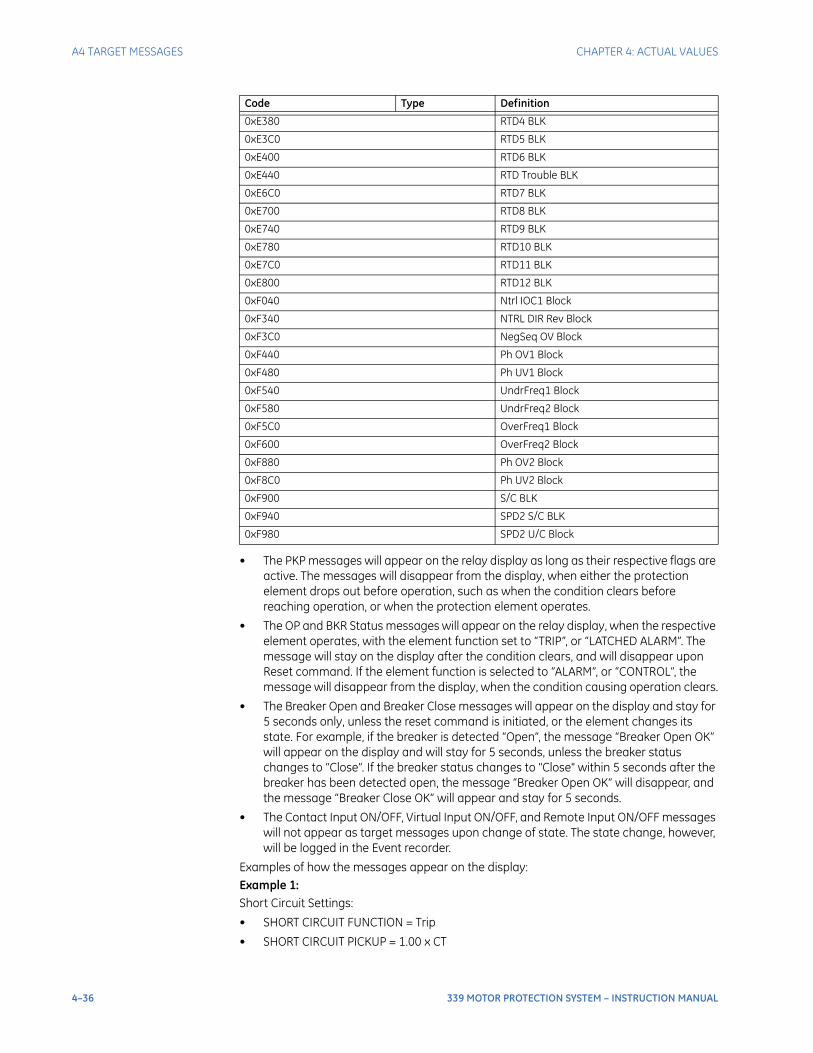
4–36 339 MOTOR PROTECTION SYSTEM – INSTRUCTION MANUAL
A4 TARGET MESSAGES CHAPTER 4: ACTUAL VALUES
• The PKP messages will appear on the relay display as long as their respective flags are active. The messages will disappear from the display, when either the protection element drops out before operation, such as when the condition clears before reaching operation, or when the protection element operates.
• The OP and BKR Status messages will appear on the relay display, when the respective element operates, with the element function set to “TRIP”, or “LATCHED ALARM”. The message will stay on the display after the condition clears, and will disappear upon Reset command. If the element function is selected to “ALARM”, or “CONTROL”, the message will disappear from the display, when the condition causing operation clears.
• The Breaker Open and Breaker Close messages will appear on the display and stay for 5 seconds only, unless the reset command is initiated, or the element changes its state. For example, if the breaker is detected “Open”, the message “Breaker Open OK” will appear on the display and will stay for 5 seconds, unless the breaker status changes to “Close”. If the breaker status changes to "Close" within 5 seconds after the breaker has been detected open, the message “Breaker Open OK” will disappear, and the message “Breaker Close OK” will appear and stay for 5 seconds.
• The Contact Input ON/OFF, Virtual Input ON/OFF, and Remote Input ON/OFF messages will not appear as target messages upon change of state. The state change, however, will be logged in the Event recorder.
Examples of how the messages appear on the display:Example 1:Short Circuit Settings:
• SHORT CIRCUIT FUNCTION = Trip
• SHORT CIRCUIT PICKUP = 1.00 x CT
0xE380 RTD4 BLK
0xE3C0 RTD5 BLK
0xE400 RTD6 BLK
0xE440 RTD Trouble BLK
0xE6C0 RTD7 BLK
0xE700 RTD8 BLK
0xE740 RTD9 BLK
0xE780 RTD10 BLK
0xE7C0 RTD11 BLK
0xE800 RTD12 BLK
0xF040 Ntrl IOC1 Block
0xF340 NTRL DIR Rev Block
0xF3C0 NegSeq OV Block
0xF440 Ph OV1 Block
0xF480 Ph UV1 Block
0xF540 UndrFreq1 Block
0xF580 UndrFreq2 Block
0xF5C0 OverFreq1 Block
0xF600 OverFreq2 Block
0xF880 Ph OV2 Block
0xF8C0 Ph UV2 Block
0xF900 S/C BLK
0xF940 SPD2 S/C BLK
0xF980 SPD2 U/C Block
Code Type Definition
CHAPTER 4: ACTUAL VALUES A4 TARGET MESSAGES
339 MOTOR PROTECTION SYSTEM – INSTRUCTION MANUAL 4–37
• SHORT CIRCUIT DELAY = 0.20 s
When current greater than the SHORT CIRCUIT pickup level is applied, the 3339 50 display shows the following target message:
A4 TARGET MESSAGESShort Circuit TripSTATE: PKP
After the 200 ms time delay expires, the display shows the following message only:A4 TARGET MESSAGESShort Circuit TripSTATE: OP
Example 2:Phase Short Circuit Settings:
• SHORT CIRCUIT FUNCTION = Latched Alarm
• SHORT CIRCUIT PICKUP = 1.00 x CT
• SHORT CIRCUIT DELAY = 0.20 s
When current greater than the Short Circuit pickup level is applied, the 339 display shows the following target message:
A4 TARGET MESSAGESPh Short Circuit AlarmSTATE: PKP
After the 200 ms time delay expires, the display shows the following message only:A4 TARGET MESSAGESPh Short Circuit AlarmSTATE: OP
Example 3:Phase Short Circuit Settings:
• SHORT CIRCUIT FUNCTION = Alarm
• SHORT CIRCUIT PICKUP = 1.00 x CT
• SHORT CIRCUIT DELAY = 0.20 s
When current greater than the Short Circuit pickup level is applied, the 339 display shows the following target message:
A4 TARGET MESSAGESPh Short Circuit AlarmSTATE: PKP
After the 200 ms time delay expires, the display shows the following message only:A4 TARGET MESSAGESPh Short Circuit AlarmSTATE: OP
NOTE
NOTE: Once the condition clears, the target message will disappear.

4–38 339 MOTOR PROTECTION SYSTEM – INSTRUCTION MANUAL
A4 TARGET MESSAGES CHAPTER 4: ACTUAL VALUES

339 MOTOR PROTECTION SYSTEM – INSTRUCTION MANUAL 5–1
339 Motor Protection System
Chapter 5: Quick setup - Front control panel
GEGrid Solutions
Quick setup - Front control panel
The “Quick Setup” utility is part of the 339 relay main menu, and can be used for quick and easy programming. Power system parameters, and settings for some simple over-current elements can be easily set. Use the “Quick Setup” utility to program the following:Relay Status
• Relay Status
Power System Data:
• Nominal Frequency
• Phase CT Primary
• Ground CT Type
• VT Connection
• VT Secondary
• VT Ratio
Protection:
• Thermal Overload
• Short Circuit
• Mechanical Jam
• Undercurrent
• Ground Fault
• Phase Undervoltage
Motor Data:
• Motor FLA
• Switching Device
• 52a Contact
• 52b Contact
NOTE
NOTE: Ensure the relay is in "Relay Ready" state before using Quick Setup.
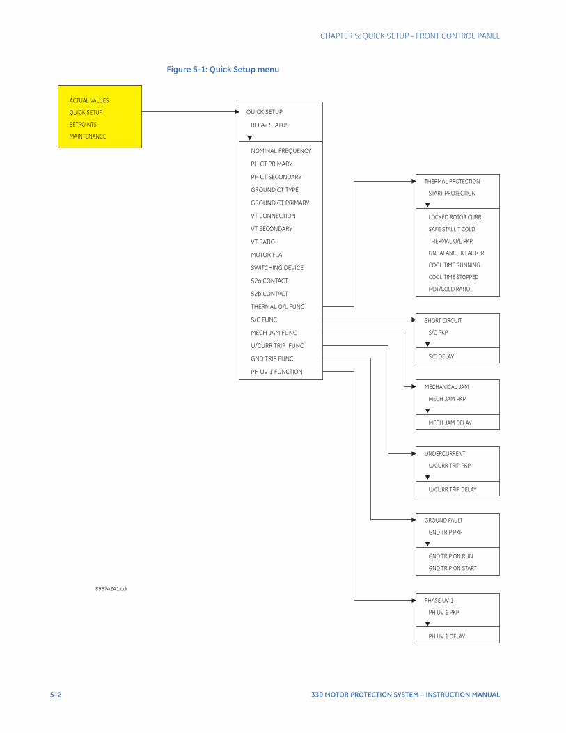
5–2 339 MOTOR PROTECTION SYSTEM – INSTRUCTION MANUAL
CHAPTER 5: QUICK SETUP - FRONT CONTROL PANEL
Figure 5-1: Quick Setup menu
ACTUAL VALUES
QUICK SETUP
SETPOINTS
MAINTENANCE
QUICK SETUP
RELAY STATUS
VT CONNECTION
VT SECONDARY
VT RATIO
MOTOR FLA
SWITCHING DEVICE
52a CONTACT
52b CONTACT
THERMAL O/L FUNC
S/C FUNC
MECH JAM FUNC
U/CURR TRIP FUNC
GND TRIP FUNC
PH UV 1 FUNCTION
NOMINAL FREQUENCY
PH CT PRIMARY
PH CT SECONDARY
GROUND CT TYPE
GROUND CT PRIMARY
896742A1.cdr
SHORT CIRCUIT
S/C PKP
S/C DELAY
MECHANICAL JAM
MECH JAM PKP
MECH JAM DELAY
UNDERCURRENT
U/CURR TRIP PKP
U/CURR TRIP DELAY
GROUND FAULT
GND TRIP PKP
GND TRIP ON RUN
GND TRIP ON START
PHASE UV 1
PH UV 1 PKP
PH UV 1 DELAY
THERMAL PROTECTION
START PROTECTION
LOCKED ROTOR CURR
SAFE STALL T COLD
THERMAL O/L PKP
UNBALANCE K FACTOR
COOL TIME RUNNING
COOL TIME STOPPED
HOT/COLD RATIO
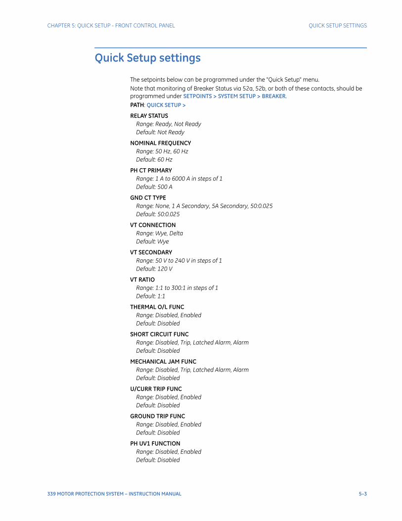
CHAPTER 5: QUICK SETUP - FRONT CONTROL PANEL QUICK SETUP SETTINGS
339 MOTOR PROTECTION SYSTEM – INSTRUCTION MANUAL 5–3
Quick Setup settings
The setpoints below can be programmed under the "Quick Setup" menu.Note that monitoring of Breaker Status via 52a, 52b, or both of these contacts, should be programmed under SETPOINTS > SYSTEM SETUP > BREAKER.PATH: QUICK SETUP >
RELAY STATUSRange: Ready, Not ReadyDefault: Not Ready
NOMINAL FREQUENCYRange: 50 Hz, 60 HzDefault: 60 Hz
PH CT PRIMARYRange: 1 A to 6000 A in steps of 1Default: 500 A
GND CT TYPERange: None, 1 A Secondary, 5A Secondary, 50:0.025Default: 50:0.025
VT CONNECTIONRange: Wye, DeltaDefault: Wye
VT SECONDARYRange: 50 V to 240 V in steps of 1Default: 120 V
VT RATIORange: 1:1 to 300:1 in steps of 1Default: 1:1
THERMAL O/L FUNCRange: Disabled, EnabledDefault: Disabled
SHORT CIRCUIT FUNCRange: Disabled, Trip, Latched Alarm, AlarmDefault: Disabled
MECHANICAL JAM FUNCRange: Disabled, Trip, Latched Alarm, AlarmDefault: Disabled
U/CURR TRIP FUNCRange: Disabled, EnabledDefault: Disabled
GROUND TRIP FUNCRange: Disabled, EnabledDefault: Disabled
PH UV1 FUNCTIONRange: Disabled, EnabledDefault: Disabled

5–4 339 MOTOR PROTECTION SYSTEM – INSTRUCTION MANUAL
QUICK SETUP SETTINGS CHAPTER 5: QUICK SETUP - FRONT CONTROL PANEL
NOTE
NOTE: The settings changed using the Quick Setup menu, are available for review and modification by navigating through S1 RELAY SETUP, S2 SYSTEM SETUP, and S3 PROTECTION in the SETPOINTS main menu.

339 MOTOR PROTECTION SYSTEM – INSTRUCTION MANUAL 6–1
339 Motor Protection System
Chapter 6: Setpoints
GEGrid Solutions
Setpoints
Setpoints
The 339 has a considerable number of programmable setpoints, all of which make the relay extremely flexible. These setpoints have been grouped into a variety of pages and subpages as shown below. Each Setpoints menu has a section that describes in detail the setpoints found on that menu.
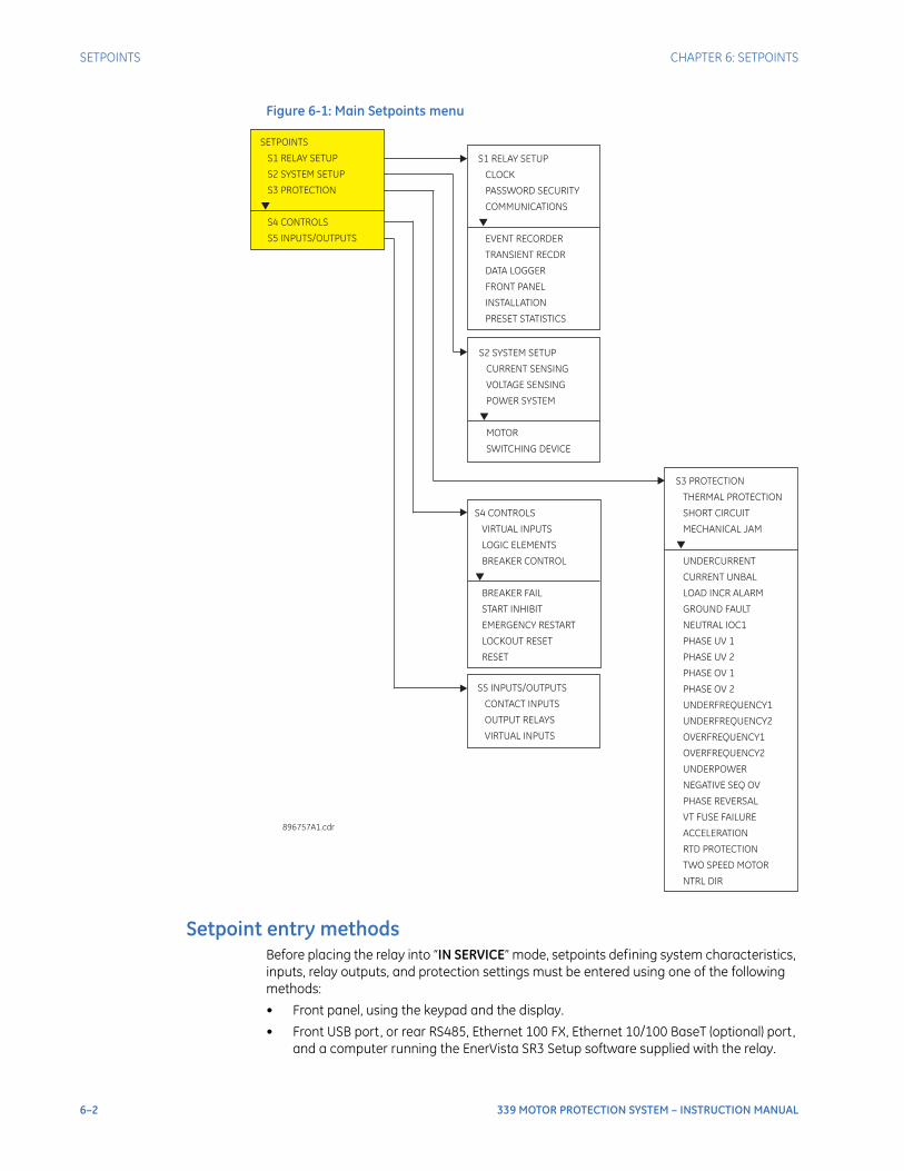
6–2 339 MOTOR PROTECTION SYSTEM – INSTRUCTION MANUAL
SETPOINTS CHAPTER 6: SETPOINTS
Figure 6-1: Main Setpoints menu
Setpoint entry methodsBefore placing the relay into “IN SERVICE” mode, setpoints defining system characteristics, inputs, relay outputs, and protection settings must be entered using one of the following methods:
• Front panel, using the keypad and the display.
• Front USB port, or rear RS485, Ethernet 100 FX, Ethernet 10/100 BaseT (optional) port, and a computer running the EnerVista SR3 Setup software supplied with the relay.
S5 INPUTS/OUTPUTS
CONTACT INPUTS
OUTPUT RELAYS
VIRTUAL INPUTS
S4 CONTROLS
VIRTUAL INPUTS
LOGIC ELEMENTS
BREAKER FAIL
START INHIBIT
EMERGENCY RESTART
LOCKOUT RESET
RESET
BREAKER CONTROL
S2 SYSTEM SETUP
CURRENT SENSING
VOLTAGE SENSING
POWER SYSTEM
MOTOR
SWITCHING DEVICE
S1 RELAY SETUP
CLOCK
PASSWORD SECURITY
COMMUNICATIONS
EVENT RECORDER
TRANSIENT RECDR
DATA LOGGER
FRONT PANEL
INSTALLATION
PRESET STATISTICS
SETPOINTS
S1 RELAY SETUP
S2 SYSTEM SETUP
S3 PROTECTION
S4 CONTROLS
S5 INPUTS/OUTPUTS
896757A1.cdr
S3 PROTECTION
SHORT CIRCUIT
MECHANICAL JAM
UNDERCURRENT
CURRENT UNBAL
LOAD INCR ALARM
GROUND FAULT
NEUTRAL IOC1
PHASE UV 1
PHASE OV 1
UNDERFREQUENCY1
NEGATIVE SEQ OV
PHASE REVERSAL
VT FUSE FAILURE
ACCELERATION
RTD PROTECTION
TWO SPEED MOTOR
NTRL DIR
THERMAL PROTECTION
PHASE UV 2
PHASE OV 2
UNDERFREQUENCY2
OVERFREQUENCY1
OVERFREQUENCY2
UNDERPOWER

CHAPTER 6: SETPOINTS SETPOINTS
339 MOTOR PROTECTION SYSTEM – INSTRUCTION MANUAL 6–3
• Rear serial RS485, and a SCADA system running user-written software.
Any of these methods can be used to enter the same information. A computer, however, makes entry much easier. Files can be stored and downloaded for fast, error free entry when a computer is used. To facilitate this process, the GE EnerVista CD with the EnerVista SR3 Setup software is supplied with the relay.The relay leaves the factory with setpoints programmed to default values, and these values are shown throughout the setpoint message illustrations. Some of these factory default values can be left unchanged whenever they satisfy the application.At a minimum, the S2 SYSTEM SETUP setpoints must be entered for the system to function correctly. To safeguard against the installation of a relay into which setpoints have not been entered, the Relay Not Ready self-test warning is displayed. In addition, the critical failure relay will be de-energized. Once the relay has been programmed for the intended application, the S1 RELAY SETUP/ INSTALLATION/ RELAY STATUS setpoint should be changed from “Not Ready” (the default) to “Ready”.
Common setpointsTo make the application of this device as simple as possible, similar methods of operation and similar types of setpoints are incorporated in various features. Rather than repeat operation descriptions for this class of setpoint throughout the manual, a general description is presented in this overview. Details that are specific to a particular feature are included in the discussion of the feature. The form and nature of these setpoints is described below.
• FUNCTION setpoint: The <ELEMENT_NAME> FUNCTION setpoint determines the operational characteristic of each feature. The range for these setpoints is two or more of: “Disabled”, “Enabled”, “Trip”, “Alarm”, “Latched Alarm”, and “Control”.
If <ELEMENT_NAME > FUNCTION: “Disabled”, the feature is not operational. If <ELEMENT_NAME > FUNCTION: “Enabled”, the feature is operational.If <ELEMENT_NAME > FUNCTION: “Trip”, then the feature is operational. When an output is generated, the feature declares a Trip condition, and operates the Trip relay (output relay 1), any other selected aux. output relays, and displays the appropriate trip message.If <ELEMENT_NAME> FUNCTION: “Alarm” or “Latched Alarm”, then the feature is operational. When an output is generated, the feature declares an “Alarm” condition which operates any selected aux.output relays and displays the appropriate alarm message. Not every Alarm function with the “Alarm” or “Latched Alarm” feature has the condition available to select an auxiliary output; in some cases a Logic Element has to be used for this purpose
• Output Relay * setpoint: The <ELEMENT_NAME> OUTPUT RELAY * setpoint selects the relays required to operate when the feature generates an output. The range is any combination of the assignable Auxiliary relays.
• PICKUP setpoint: The <ELEMENT_NAME> PICKUP setpoint selects the threshold above which the measured parameter causes an output from the measuring element.
• DELAY setpoint: The <ELEMENT_NAME> DELAY setpoint selects a fixed time interval to delay an input signal from appearing at the output. The time from a contact input change of state or an AC parameter input level change to a contact closure of the 1 Trip relay, is the time selected as time delay in this setpoint plus approximately up to 2 power frequency periods.

6–4 339 MOTOR PROTECTION SYSTEM – INSTRUCTION MANUAL
SETPOINTS CHAPTER 6: SETPOINTS
Logic diagramsThe logic diagrams provide a complete comprehensive understanding of the operation of each feature. These sequential logic diagrams illustrate how each setpoint, input parameter, and internal logic is used in the feature to obtain an output. In addition to these logic diagrams, written descriptions are provided in the setpoints chapter which includes each feature.
• Settings: Shown as a block with a heading labeled ‘SETTING’. The exact wording of the displayed setpoint message identifies the setpoint. Major functional setpoint selections are listed below the name and are incorporated in the logic.
• Compensator Blocks: Shown as a block with an inset box labeled ‘RUN’ with the associated pickup/dropout setpoint shown directly above. Element operation of the detector is controlled by the signal entering the ‘RUN’ inset. The measurement/ comparison can only be performed if a logic ‘1’ is provided at the ‘RUN’ input. The relationship between setpoint and input parameter is indicated by the following symbols: “<” (less than) " >” (greater than), etc.
• Time Delays: Shown as a block with either pickup, drop-out, or both; times in milliseconds or seconds. If the delay is adjustable, associated delay setpoint is shown with block SETPOINT on the top of the delay block.
• LED Indicators: Shown as the following schematic symbol, . The exact wording of the front panel label identifies the indicator.
• Logic: Described with basic logic gates (AND, OR, XOR, NAND, NOR). The inverter (logical NOT), is shown as a circle: .
Settings text abbreviationsThe following abbreviations are used in the setpoints pages.
• Acceleration time: ACCEL TIME; ACCEL T
• Alarm: ALM, ALRM
• ASDU: ASD
• Auxiliary: AUX
• Average: AVG
• Average Line Voltage: Vav
• Block: BLK, BLCK
• Contactor: CONT
• Control: Ctrl
• CT Secondary: CT SEC
• Current: CURR
• Current Unbalance: CURR UNBAL
• Delay: DLY
• Emergency Restarts: EMERG RESTARTS
• Function: FUNC, FUNCTN
• Ground: GND
• High Speed: SPD2
• Hour: Hr
• Initiate: INILoad Increase: LOAD INCRLogic Element: LE; LOGIC E
• Maintenance: MAINTEN, MAINT
• Mechanical Jam: MECH JAM
• Neutral: NTRL

CHAPTER 6: SETPOINTS SETPOINTS
339 MOTOR PROTECTION SYSTEM – INSTRUCTION MANUAL 6–5
• O/L: overload
• Password: PSWD, PSW
• Preset: PRST
• Protection: PROT
• POWER: PWR
• Primary: PRIM
• Protection: PROT
• Recorder: RECDR
• Relay: RLY
• Reset: RST
• Short Circuit: S/C
• High Speed: HIGH SPD
• Speed2: SPD2
• START: STAT
• Temperature: TEMP
• Thermal Capacity Used: TCU
• Thermal Overload: THERMAL O/L
• Time Constant: TIME CONS
• Transient Recorder: TRANSIENT RECDR
• Two-speed Motor: 2-SPD MOTOR
• Undercurrent: U/CURR; U/C
• Underfrequency: UNDRFREQ
• Undervoltage: UV
• Overvoltage: OV
• Underpower: U/POWER; U/P
• Voltage: VOLT
• Welded Contactor: WELDED CONT
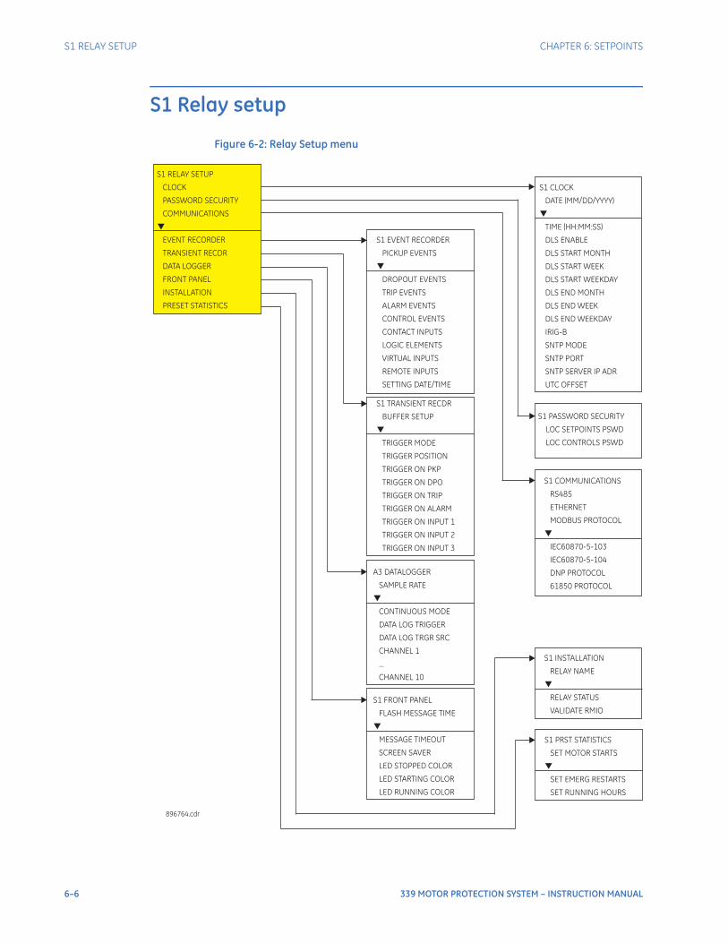
6–6 339 MOTOR PROTECTION SYSTEM – INSTRUCTION MANUAL
S1 RELAY SETUP CHAPTER 6: SETPOINTS
S1 Relay setup
Figure 6-2: Relay Setup menu
S1 PASSWORD SECURITY
LOC SETPOINTS PSWD
LOC CONTROLS PSWD
S1 CLOCK
DATE (MM/DD/YYYY)
TIME (HH:MM:SS)
DLS ENABLE
DLS START MONTH
DLS START WEEK
DLS END MONTH
DLS END WEEK
IRIG-B
SNTP MODE
SNTP PORT
SNTP SERVER IP ADR
UTC OFFSET
DLS START WEEKDAY
DLS END WEEKDAY
S1 RELAY SETUP
CLOCK
PASSWORD SECURITY
COMMUNICATIONS
EVENT RECORDER
TRANSIENT RECDR
FRONT PANEL
INSTALLATION
PRESET STATISTICS
DATA LOGGER
896764.cdr
S1 COMMUNICATIONS
RS485
ETHERNET
DNP PROTOCOL
61850 PROTOCOL
MODBUS PROTOCOL
IEC60870-5-103
IEC60870-5-104
S1 EVENT RECORDER
PICKUP EVENTS
TRIP EVENTS
ALARM EVENTS
CONTROL EVENTS
DROPOUT EVENTS
CONTACT INPUTS
LOGIC ELEMENTS
VIRTUAL INPUTS
REMOTE INPUTS
SETTING DATE/TIME
S1 FRONT PANEL
MESSAGE TIMEOUT
SCREEN SAVER
FLASH MESSAGE TIME
LED STOPPED COLOR
LED STARTING COLOR
LED RUNNING COLOR
S1 INSTALLATION
RELAY NAME
RELAY STATUS
VALIDATE RMIO
S1 TRANSIENT RECDR
TRIGGER MODE
TRIGGER POSITION
BUFFER SETUP
TRIGGER ON PKP
TRIGGER ON DPO
TRIGGER ON TRIP
TRIGGER ON ALARM
TRIGGER ON INPUT 1
TRIGGER ON INPUT 2
TRIGGER ON INPUT 3
A3 DATALOGGER
CONTINUOUS MODE
SAMPLE RATE
DATA LOG TRIGGER
DATA LOG TRGR SRC
CHANNEL 1
...
CHANNEL 10
S1 PRST STATISTICS
SET MOTOR STARTS
SET EMERG RESTARTS
SET RUNNING HOURS

CHAPTER 6: SETPOINTS S1 RELAY SETUP
339 MOTOR PROTECTION SYSTEM – INSTRUCTION MANUAL 6–7
ClockThe 339 relay has an internal real time clock that performs time stamping via IRIG-B for various features such as the event and transient recorders. This time stamping is available with the IRIG-B signal connected to the relay terminals and set to “Enabled”. When an IRIG-B device is connected to the relay terminals, the relay detects the DC shift or the Amplitude Modulated signal automatically. Time stamping on multiple relays can be synchronized to ± 1.0 ms with the use of IRIG-B input. Time stamping is also optionally available using SNTP.Time synchronization priority uses the IRIG-B and SNTP protocols - via Modbus, IEC60870-5-103, IEC60870-5-104, or DNP commands - as follows:IRIG-B has the highest priority, so any other source of synchronization should be rejected if IRIG-B is the synchronization source and an IRIG-B signal is available.SNTP has the second highest priority, so if IRIG-B is not the synchronization source but SNTP is, then any other source of synchronization should be rejected.Synchronization commands are all eventually translated into a MODBUS function, and as such are blocked from the MODBUS layer as required.Any synchronization commands other than Modbus, IEC60870-5-103, IEC60870-5-104, or DNP will be accepted only if IRIG-B and SNTP are not the synchronization sources. There is no prioritization amongst synchronization commands. A synchronization command issued from DNP for example, can be directly followed by another from MODBUS, for example.The following path is available using the keypad. For instructions on how to use the keypad, please refer to Chapter 3 - Working with the Keypad.PATH: SETPOINTS > S1 RELAY SETUP > CLOCK
DATE: (MM/DD/YYYY)Range: Month: Jan, Feb, Mar, Apr, May, Jun, Jul, Aug, Sep, Oct, Nov, Dec Day: 1 to 31 Year: 2009 to 2099Default: Jan 15 2009
This setting sets the date in the specified format.
TIME: (HH:MM:SS)Range: 0 to 23: 0 to 59: 0 to59Default: 03:15:50
This setting sets the time in the specified format.
DLS ENABLERange: Disabled, EnabledDefault: Disabled
With DLS Enabled, the main CPU has to maintain the information regarding AV.m_DaylightSavingsActive, because it is necessary in the comms CPU to translate from localtime to UTC in 61850 protocol. In addition, if SNTP is enabled, the main CPU will receive UTC time from comms CPU and it needs to apply this in order to pass it to localtime.
Without any other synchronization, DLS correction is applied only at 0200 hours on daylight saving months.
PATH: SETPOINTS > S1 RELAY SETUP > CLOCK > DLS ENABLE [ENABLED]
DLS START MONTH:Range: Not Set, January, February, March, April, May, June, July, August, September, October, November, DecemberDefault: Not Set
This setting sets the month for the DLS start time.
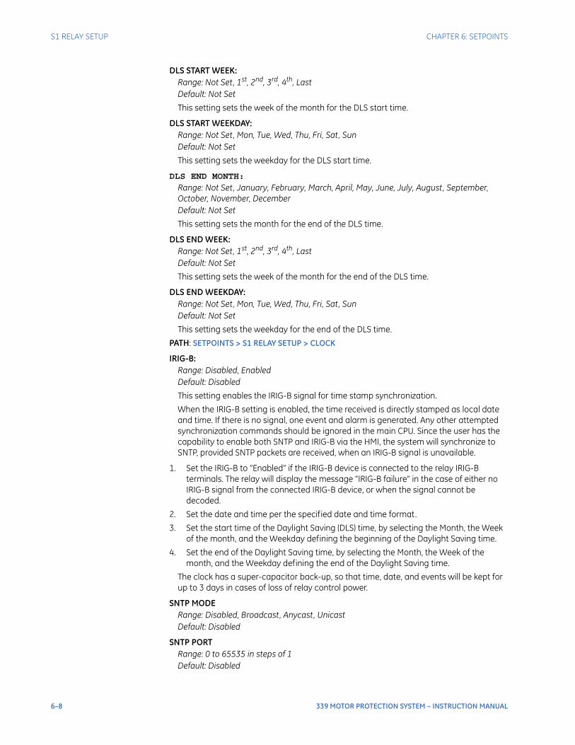
6–8 339 MOTOR PROTECTION SYSTEM – INSTRUCTION MANUAL
S1 RELAY SETUP CHAPTER 6: SETPOINTS
DLS START WEEK:Range: Not Set, 1st, 2nd, 3rd, 4th, LastDefault: Not Set
This setting sets the week of the month for the DLS start time.
DLS START WEEKDAY:Range: Not Set, Mon, Tue, Wed, Thu, Fri, Sat, SunDefault: Not Set
This setting sets the weekday for the DLS start time.
DLS END MONTH:
Range: Not Set, January, February, March, April, May, June, July, August, September, October, November, DecemberDefault: Not Set
This setting sets the month for the end of the DLS time.
DLS END WEEK:Range: Not Set, 1st, 2nd, 3rd, 4th, LastDefault: Not Set
This setting sets the week of the month for the end of the DLS time.
DLS END WEEKDAY:Range: Not Set, Mon, Tue, Wed, Thu, Fri, Sat, SunDefault: Not Set
This setting sets the weekday for the end of the DLS time.
PATH: SETPOINTS > S1 RELAY SETUP > CLOCK
IRIG-B:Range: Disabled, EnabledDefault: Disabled
This setting enables the IRIG-B signal for time stamp synchronization.
When the IRIG-B setting is enabled, the time received is directly stamped as local date and time. If there is no signal, one event and alarm is generated. Any other attempted synchronization commands should be ignored in the main CPU. Since the user has the capability to enable both SNTP and IRIG-B via the HMI, the system will synchronize to SNTP, provided SNTP packets are received, when an IRIG-B signal is unavailable.
1. Set the IRIG-B to “Enabled” if the IRIG-B device is connected to the relay IRIG-B terminals. The relay will display the message “IRIG-B failure” in the case of either no IRIG-B signal from the connected IRIG-B device, or when the signal cannot be decoded.
2. Set the date and time per the specified date and time format.
3. Set the start time of the Daylight Saving (DLS) time, by selecting the Month, the Week of the month, and the Weekday defining the beginning of the Daylight Saving time.
4. Set the end of the Daylight Saving time, by selecting the Month, the Week of the month, and the Weekday defining the end of the Daylight Saving time.
The clock has a super-capacitor back-up, so that time, date, and events will be kept for up to 3 days in cases of loss of relay control power.
SNTP MODERange: Disabled, Broadcast, Anycast, UnicastDefault: Disabled
SNTP PORTRange: 0 to 65535 in steps of 1Default: Disabled
CHAPTER 6: SETPOINTS S1 RELAY SETUP
339 MOTOR PROTECTION SYSTEM – INSTRUCTION MANUAL 6–9
SNTP SERVER IP ADRRange: Standard IP Address FormatDefault: 000.000.000.000
UTC OFFSETRange: -24.00 hours to 24.00 hours in steps of 0.01 hoursDefault: 00.00 hours
NOTE
NOTE: Refer to the 339 Communications Guide for details on SNTP MODE, SNTP PORT, and SNTP SERVER IP ADR.
Password securityPassword security features are designed into the relay to provide protection against unauthorized setpoint changes and control. The relay has programmable passwords for both Local and Remote access, which can be used to allow setpoint changes and command execution from both the front panel and the communications ports. These passwords consist of 3 to 10 alphanumeric characters. The Local and the Remote passwords are initially set after entering in a Master Reset Password (MRP). The Master Reset Password (MRP) is set to “NULL” when the relay is shipped from the factory. When the MRP is programmed to “NULL” all password security is disabled.. The remote user may choose to allow the local user to change the local passwords.Each interface (RS485, Ethernet, USB, and front panel keypad) is independent of one another, meaning that enabling setpoint access on one interface does not enable access for any of the other interfaces (i.e., the password must be explicitly entered via the interface from which access is desired).The EnerVista SR3 Setup software incorporates a facility for programming the relay’s passwords as well as enabling/disabling setpoint access. For example, when an attempt is made to modify a setpoint but access is restricted, the program will prompt the user to enter the password and send it to the relay before the setpoint can actually be written to the relay. If a SCADA system is used for relay programming, it is up to the programmer to incorporate appropriate security for the application.Aside from being logged out of security, which allows the user to read setpoints and actual values only, three levels of security access are provided: Setpoint Level, Control Level, and Master Level. The Setpoint and Control Levels can be attained either locally using the Local passwords (USB port and keypad), or remotely using the Remote passwords (RS485 and Ethernet ports). The user can have either Setpoint or Control Level active, but not both simultaneously from the same interface. The Master Level is used for setting and resetting of passwords, and includes all Setpoint and Control Level access rights. The Master Level cannot be attained from the keypad. The Master Reset Password must be 8 to 10 characters in length, and must contain at least 2 letters and 2 numbers. The Master Level can define whether the local user is permitted to change Local Passwords without having to enter the Master Level. The Master Reset Password is encrypted, and is not viewable from the keypad. If the Master Reset Password is lost, the user should contact the factory to decrypt the Master Reset Password.After password entry, the access level is maintained until a period of 5 minutes of inactivity has elapsed, after which the password must be re-entered. A power-loss or entering in the wrong password will log the user out of security.Further definition of the access levels is described as follows:SETPOINT LEVEL
• Changing settings under QUICK SETUP menu
• Changing settings under the SETPOINTS menu except the features requiring control access listed below
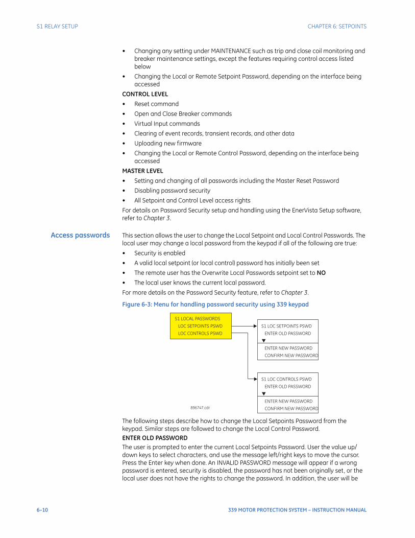
6–10 339 MOTOR PROTECTION SYSTEM – INSTRUCTION MANUAL
S1 RELAY SETUP CHAPTER 6: SETPOINTS
• Changing any setting under MAINTENANCE such as trip and close coil monitoring and breaker maintenance settings, except the features requiring control access listed below
• Changing the Local or Remote Setpoint Password, depending on the interface being accessed
CONTROL LEVEL
• Reset command
• Open and Close Breaker commands
• Virtual Input commands
• Clearing of event records, transient records, and other data
• Uploading new firmware
• Changing the Local or Remote Control Password, depending on the interface being accessed
MASTER LEVEL
• Setting and changing of all passwords including the Master Reset Password
• Disabling password security
• All Setpoint and Control Level access rights
For details on Password Security setup and handling using the EnerVista Setup software, refer to Chapter 3.
Access passwords This section allows the user to change the Local Setpoint and Local Control Passwords. The local user may change a local password from the keypad if all of the following are true:
• Security is enabled
• A valid local setpoint (or local control) password has initially been set
• The remote user has the Overwrite Local Passwords setpoint set to NO
• The local user knows the current local password.
For more details on the Password Security feature, refer to Chapter 3.
Figure 6-3: Menu for handling password security using 339 keypad
The following steps describe how to change the Local Setpoints Password from the keypad. Similar steps are followed to change the Local Control Password.ENTER OLD PASSWORDThe user is prompted to enter the current Local Setpoints Password. User the value up/down keys to select characters, and use the message left/right keys to move the cursor. Press the Enter key when done. An INVALID PASSWORD message will appear if a wrong password is entered, security is disabled, the password has not been originally set, or the local user does not have the rights to change the password. In addition, the user will be
S1 LOCAL PASSWORDS
LOC SETPOINTS PSWD
LOC CONTROLS PSWD
896747.cdr
S1 LOC SETPOINTS PSWD
ENTER NEW
CONFIRM NEW
ENTER OLD PASSWORD
PASSWORD
PASSWORD
S1 LOC CONTROLS PSWD
ENTER NEW PASSWORD
CONFIRM NEW PASSWORD
ENTER OLD PASSWORD

CHAPTER 6: SETPOINTS S1 RELAY SETUP
339 MOTOR PROTECTION SYSTEM – INSTRUCTION MANUAL 6–11
automatically logged out of security from the keypad. If the correct password was entered, the user is now logged in to the Setpoints Level from the keypad, and will be prompted to enter a new password.ENTER NEW PASSWORDThe user is prompted to enter a new Local Setpoints Password. A valid password is alphanumeric, and is 3 to 10 characters in length. An INVALID PASSWORD message will appear if the new password does not meet the password requirements. If a valid password was entered, the user will be prompted to re-enter the new password.CONFIRM PASSWORDThe user is prompted to re-enter the new Local Setpoints Password. If the passwords do not match, an ENTRY MISMATCH message will appear, the password will remain unchanged, and the user will be returned to the Enter New Password page. If the passwords match, a PASSWORD CHANGED message will appear indicating the Local Setpoints Password has successfully been updated.
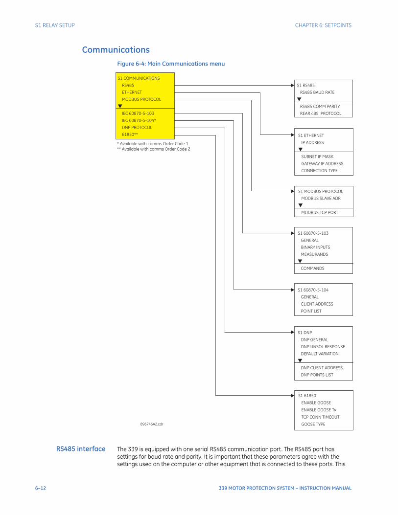
6–12 339 MOTOR PROTECTION SYSTEM – INSTRUCTION MANUAL
S1 RELAY SETUP CHAPTER 6: SETPOINTS
CommunicationsFigure 6-4: Main Communications menu
RS485 interface The 339 is equipped with one serial RS485 communication port. The RS485 port has settings for baud rate and parity. It is important that these parameters agree with the settings used on the computer or other equipment that is connected to these ports. This
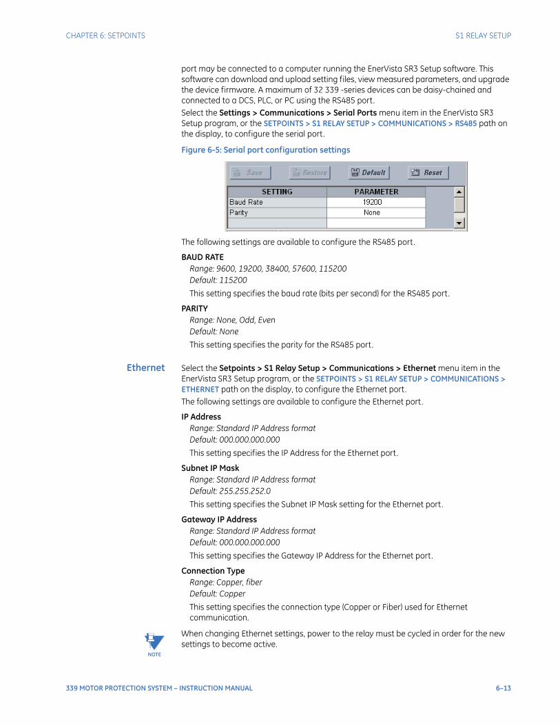
CHAPTER 6: SETPOINTS S1 RELAY SETUP
339 MOTOR PROTECTION SYSTEM – INSTRUCTION MANUAL 6–13
port may be connected to a computer running the EnerVista SR3 Setup software. This software can download and upload setting files, view measured parameters, and upgrade the device firmware. A maximum of 32 339 -series devices can be daisy-chained and connected to a DCS, PLC, or PC using the RS485 port.Select the Settings > Communications > Serial Ports menu item in the EnerVista SR3 Setup program, or the SETPOINTS > S1 RELAY SETUP > COMMUNICATIONS > RS485 path on the display, to configure the serial port.
Figure 6-5: Serial port configuration settings
The following settings are available to configure the RS485 port.
BAUD RATERange: 9600, 19200, 38400, 57600, 115200Default: 115200
This setting specifies the baud rate (bits per second) for the RS485 port.
PARITYRange: None, Odd, EvenDefault: None
This setting specifies the parity for the RS485 port.
Ethernet Select the Setpoints > S1 Relay Setup > Communications > Ethernet menu item in the EnerVista SR3 Setup program, or the SETPOINTS > S1 RELAY SETUP > COMMUNICATIONS > ETHERNET path on the display, to configure the Ethernet port.The following settings are available to configure the Ethernet port.
IP AddressRange: Standard IP Address formatDefault: 000.000.000.000
This setting specifies the IP Address for the Ethernet port.
Subnet IP MaskRange: Standard IP Address formatDefault: 255.255.252.0
This setting specifies the Subnet IP Mask setting for the Ethernet port.
Gateway IP AddressRange: Standard IP Address formatDefault: 000.000.000.000
This setting specifies the Gateway IP Address for the Ethernet port.
Connection TypeRange: Copper, fiberDefault: Copper
This setting specifies the connection type (Copper or Fiber) used for Ethernet communication.
NOTE
NOTE: When changing Ethernet settings, power to the relay must be cycled in order for the new settings to become active.
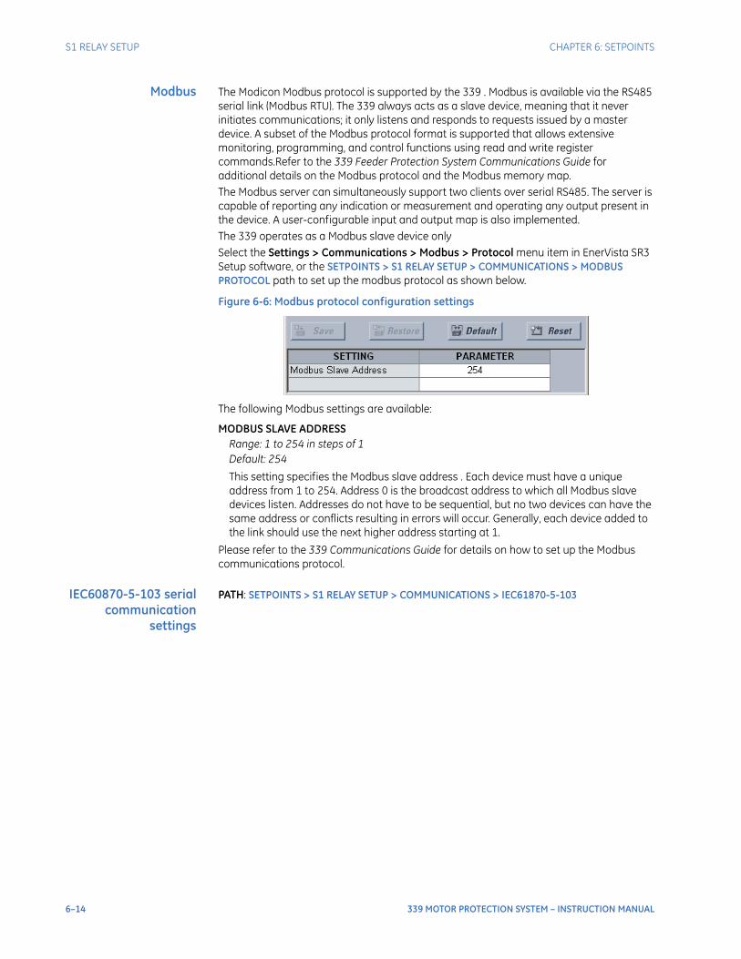
6–14 339 MOTOR PROTECTION SYSTEM – INSTRUCTION MANUAL
S1 RELAY SETUP CHAPTER 6: SETPOINTS
Modbus The Modicon Modbus protocol is supported by the 339 . Modbus is available via the RS485 serial link (Modbus RTU). The 339 always acts as a slave device, meaning that it never initiates communications; it only listens and responds to requests issued by a master device. A subset of the Modbus protocol format is supported that allows extensive monitoring, programming, and control functions using read and write register commands.Refer to the 339 Feeder Protection System Communications Guide for additional details on the Modbus protocol and the Modbus memory map.The Modbus server can simultaneously support two clients over serial RS485. The server is capable of reporting any indication or measurement and operating any output present in the device. A user-configurable input and output map is also implemented.The 339 operates as a Modbus slave device onlySelect the Settings > Communications > Modbus > Protocol menu item in EnerVista SR3 Setup software, or the SETPOINTS > S1 RELAY SETUP > COMMUNICATIONS > MODBUS PROTOCOL path to set up the modbus protocol as shown below.
Figure 6-6: Modbus protocol configuration settings
The following Modbus settings are available:
MODBUS SLAVE ADDRESSRange: 1 to 254 in steps of 1Default: 254
This setting specifies the Modbus slave address . Each device must have a unique address from 1 to 254. Address 0 is the broadcast address to which all Modbus slave devices listen. Addresses do not have to be sequential, but no two devices can have the same address or conflicts resulting in errors will occur. Generally, each device added to the link should use the next higher address starting at 1.
Please refer to the 339 Communications Guide for details on how to set up the Modbus communications protocol.
IEC60870-5-103 serialcommunication
settings
PATH: SETPOINTS > S1 RELAY SETUP > COMMUNICATIONS > IEC61870-5-103
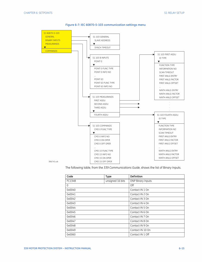
CHAPTER 6: SETPOINTS S1 RELAY SETUP
339 MOTOR PROTECTION SYSTEM – INSTRUCTION MANUAL 6–15
Figure 6-7: IEC 60870-5-103 communication settings menu
The following table, from the 339 Communications Guide, shows the list of Binary Inputs.
S1 103 FIRST ASDU
ID TYPE
FUNCTION TYPE
INFORMATION NO
SCAN TIMEOUT
FIRST ANLG ENTRY
FIRST ANLG FACTOR
FIRST ANLG OFFSET
...
NINTH ANLG ENTRY
NINTH ANLG FACTOR
NINTH ANLG OFFSET
S1 103 GENERAL
SLAVE ADDRESS
SYNCH TIMEOUT
896745.cdr
S1 103 MEASURANDS
FIRST ASDU
SECOND ASDU
THIRD ASDU
FOURTH ASDU
S1 60870-5-103
GENERAL
BINARY INPUTS
MEASURANDS
COMMANDS
S1 103 COMMANDS
CMD 0 FUNC TYPE
CMD 0 INFO NO
CMD 0 ON OPER
CMD 0 OFF OPER
...
CMD 15 FUNC TYPE
CMD 15 INFO NO
CMD 15 ON OPER
CMD 15 OFF OPER
S1 103 FOURTH ASDU
ID TYPE
FUNCTION TYPE
INFORMATION NO
SCAN TIMEOUT
FIRST ANLG ENTRY
FIRST ANLG FACTOR
FIRST ANLG OFFSET
...
NINTH ANLG ENTRY
NINTH ANLG FACTOR
NINTH ANLG OFFSET
S1 103 B INPUTS
POINT 0
POINT 0 FUNC TYPE
POINT 0 INFO NO
...
POINT 63
POINT 63 FUNC TYPE
POINT 63 INFO NO
.
.
.
.
Code Type Definition
FC134B unsigned 16 bits DNP Binary Inputs
0 Off
0x0040 Contact IN 1 On
0x0041 Contact IN 2 On
0x0042 Contact IN 3 On
0x0043 Contact IN 4 On
0x0044 Contact IN 5 On
0x0045 Contact IN 6 On
0x0046 Contact IN 7 On
0x0047 Contact IN 8 On
0x0048 Contact IN 9 On
0x0049 Contact IN 10 On
0x0060 Contact IN 1 Off
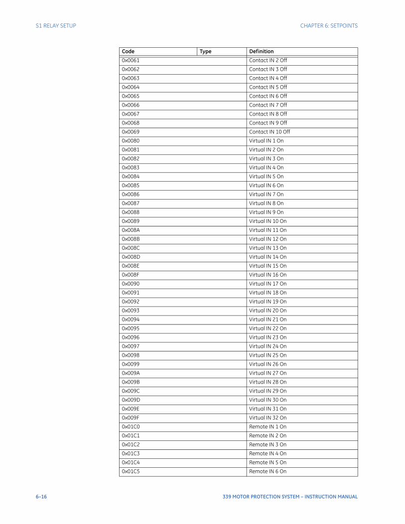
6–16 339 MOTOR PROTECTION SYSTEM – INSTRUCTION MANUAL
S1 RELAY SETUP CHAPTER 6: SETPOINTS
0x0061 Contact IN 2 Off
0x0062 Contact IN 3 Off
0x0063 Contact IN 4 Off
0x0064 Contact IN 5 Off
0x0065 Contact IN 6 Off
0x0066 Contact IN 7 Off
0x0067 Contact IN 8 Off
0x0068 Contact IN 9 Off
0x0069 Contact IN 10 Off
0x0080 Virtual IN 1 On
0x0081 Virtual IN 2 On
0x0082 Virtual IN 3 On
0x0083 Virtual IN 4 On
0x0084 Virtual IN 5 On
0x0085 Virtual IN 6 On
0x0086 Virtual IN 7 On
0x0087 Virtual IN 8 On
0x0088 Virtual IN 9 On
0x0089 Virtual IN 10 On
0x008A Virtual IN 11 On
0x008B Virtual IN 12 On
0x008C Virtual IN 13 On
0x008D Virtual IN 14 On
0x008E Virtual IN 15 On
0x008F Virtual IN 16 On
0x0090 Virtual IN 17 On
0x0091 Virtual IN 18 On
0x0092 Virtual IN 19 On
0x0093 Virtual IN 20 On
0x0094 Virtual IN 21 On
0x0095 Virtual IN 22 On
0x0096 Virtual IN 23 On
0x0097 Virtual IN 24 On
0x0098 Virtual IN 25 On
0x0099 Virtual IN 26 On
0x009A Virtual IN 27 On
0x009B Virtual IN 28 On
0x009C Virtual IN 29 On
0x009D Virtual IN 30 On
0x009E Virtual IN 31 On
0x009F Virtual IN 32 On
0x01C0 Remote IN 1 On
0x01C1 Remote IN 2 On
0x01C2 Remote IN 3 On
0x01C3 Remote IN 4 On
0x01C4 Remote IN 5 On
0x01C5 Remote IN 6 On
Code Type Definition
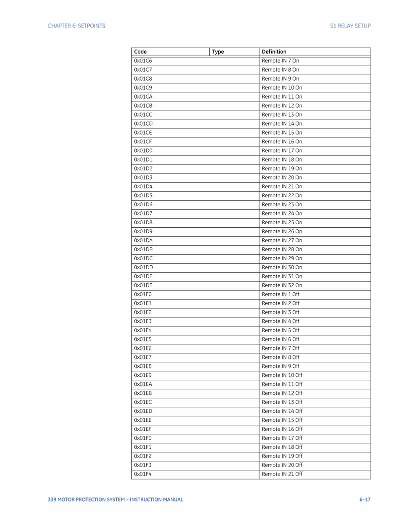
CHAPTER 6: SETPOINTS S1 RELAY SETUP
339 MOTOR PROTECTION SYSTEM – INSTRUCTION MANUAL 6–17
0x01C6 Remote IN 7 On
0x01C7 Remote IN 8 On
0x01C8 Remote IN 9 On
0x01C9 Remote IN 10 On
0x01CA Remote IN 11 On
0x01CB Remote IN 12 On
0x01CC Remote IN 13 On
0x01CD Remote IN 14 On
0x01CE Remote IN 15 On
0x01CF Remote IN 16 On
0x01D0 Remote IN 17 On
0x01D1 Remote IN 18 On
0x01D2 Remote IN 19 On
0x01D3 Remote IN 20 On
0x01D4 Remote IN 21 On
0x01D5 Remote IN 22 On
0x01D6 Remote IN 23 On
0x01D7 Remote IN 24 On
0x01D8 Remote IN 25 On
0x01D9 Remote IN 26 On
0x01DA Remote IN 27 On
0x01DB Remote IN 28 On
0x01DC Remote IN 29 On
0x01DD Remote IN 30 On
0x01DE Remote IN 31 On
0x01DF Remote IN 32 On
0x01E0 Remote IN 1 Off
0x01E1 Remote IN 2 Off
0x01E2 Remote IN 3 Off
0x01E3 Remote IN 4 Off
0x01E4 Remote IN 5 Off
0x01E5 Remote IN 6 Off
0x01E6 Remote IN 7 Off
0x01E7 Remote IN 8 Off
0x01E8 Remote IN 9 Off
0x01E9 Remote IN 10 Off
0x01EA Remote IN 11 Off
0x01EB Remote IN 12 Off
0x01EC Remote IN 13 Off
0x01ED Remote IN 14 Off
0x01EE Remote IN 15 Off
0x01EF Remote IN 16 Off
0x01F0 Remote IN 17 Off
0x01F1 Remote IN 18 Off
0x01F2 Remote IN 19 Off
0x01F3 Remote IN 20 Off
0x01F4 Remote IN 21 Off
Code Type Definition
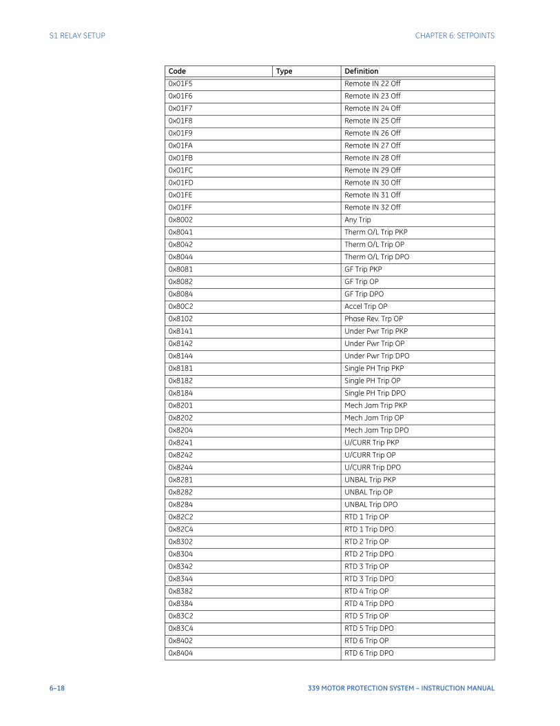
6–18 339 MOTOR PROTECTION SYSTEM – INSTRUCTION MANUAL
S1 RELAY SETUP CHAPTER 6: SETPOINTS
0x01F5 Remote IN 22 Off
0x01F6 Remote IN 23 Off
0x01F7 Remote IN 24 Off
0x01F8 Remote IN 25 Off
0x01F9 Remote IN 26 Off
0x01FA Remote IN 27 Off
0x01FB Remote IN 28 Off
0x01FC Remote IN 29 Off
0x01FD Remote IN 30 Off
0x01FE Remote IN 31 Off
0x01FF Remote IN 32 Off
0x8002 Any Trip
0x8041 Therm O/L Trip PKP
0x8042 Therm O/L Trip OP
0x8044 Therm O/L Trip DPO
0x8081 GF Trip PKP
0x8082 GF Trip OP
0x8084 GF Trip DPO
0x80C2 Accel Trip OP
0x8102 Phase Rev. Trp OP
0x8141 Under Pwr Trip PKP
0x8142 Under Pwr Trip OP
0x8144 Under Pwr Trip DPO
0x8181 Single PH Trip PKP
0x8182 Single PH Trip OP
0x8184 Single PH Trip DPO
0x8201 Mech Jam Trip PKP
0x8202 Mech Jam Trip OP
0x8204 Mech Jam Trip DPO
0x8241 U/CURR Trip PKP
0x8242 U/CURR Trip OP
0x8244 U/CURR Trip DPO
0x8281 UNBAL Trip PKP
0x8282 UNBAL Trip OP
0x8284 UNBAL Trip DPO
0x82C2 RTD 1 Trip OP
0x82C4 RTD 1 Trip DPO
0x8302 RTD 2 Trip OP
0x8304 RTD 2 Trip DPO
0x8342 RTD 3 Trip OP
0x8344 RTD 3 Trip DPO
0x8382 RTD 4 Trip OP
0x8384 RTD 4 Trip DPO
0x83C2 RTD 5 Trip OP
0x83C4 RTD 5 Trip DPO
0x8402 RTD 6 Trip OP
0x8404 RTD 6 Trip DPO
Code Type Definition
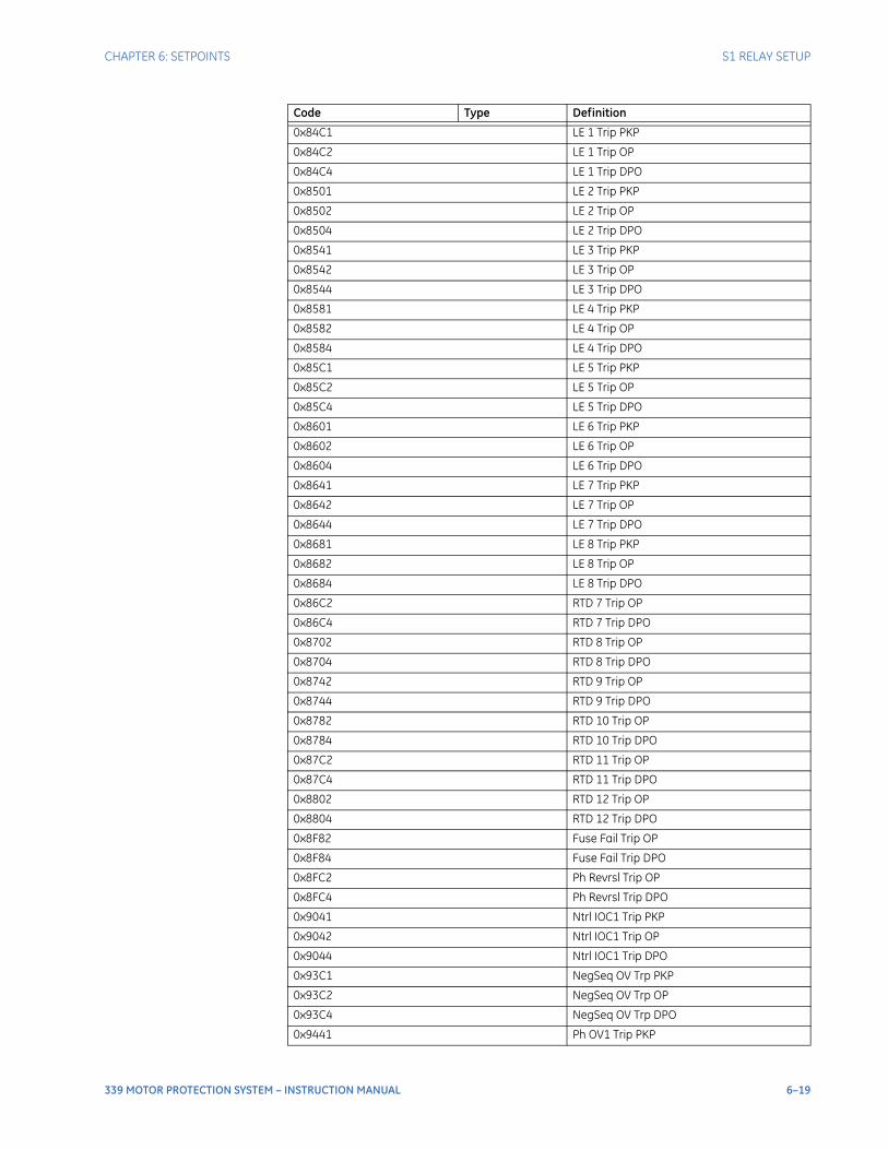
CHAPTER 6: SETPOINTS S1 RELAY SETUP
339 MOTOR PROTECTION SYSTEM – INSTRUCTION MANUAL 6–19
0x84C1 LE 1 Trip PKP
0x84C2 LE 1 Trip OP
0x84C4 LE 1 Trip DPO
0x8501 LE 2 Trip PKP
0x8502 LE 2 Trip OP
0x8504 LE 2 Trip DPO
0x8541 LE 3 Trip PKP
0x8542 LE 3 Trip OP
0x8544 LE 3 Trip DPO
0x8581 LE 4 Trip PKP
0x8582 LE 4 Trip OP
0x8584 LE 4 Trip DPO
0x85C1 LE 5 Trip PKP
0x85C2 LE 5 Trip OP
0x85C4 LE 5 Trip DPO
0x8601 LE 6 Trip PKP
0x8602 LE 6 Trip OP
0x8604 LE 6 Trip DPO
0x8641 LE 7 Trip PKP
0x8642 LE 7 Trip OP
0x8644 LE 7 Trip DPO
0x8681 LE 8 Trip PKP
0x8682 LE 8 Trip OP
0x8684 LE 8 Trip DPO
0x86C2 RTD 7 Trip OP
0x86C4 RTD 7 Trip DPO
0x8702 RTD 8 Trip OP
0x8704 RTD 8 Trip DPO
0x8742 RTD 9 Trip OP
0x8744 RTD 9 Trip DPO
0x8782 RTD 10 Trip OP
0x8784 RTD 10 Trip DPO
0x87C2 RTD 11 Trip OP
0x87C4 RTD 11 Trip DPO
0x8802 RTD 12 Trip OP
0x8804 RTD 12 Trip DPO
0x8F82 Fuse Fail Trip OP
0x8F84 Fuse Fail Trip DPO
0x8FC2 Ph Revrsl Trip OP
0x8FC4 Ph Revrsl Trip DPO
0x9041 Ntrl IOC1 Trip PKP
0x9042 Ntrl IOC1 Trip OP
0x9044 Ntrl IOC1 Trip DPO
0x93C1 NegSeq OV Trp PKP
0x93C2 NegSeq OV Trp OP
0x93C4 NegSeq OV Trp DPO
0x9441 Ph OV1 Trip PKP
Code Type Definition
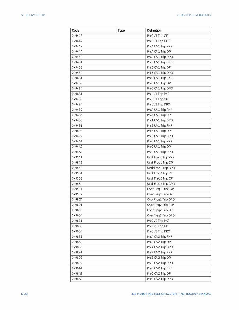
6–20 339 MOTOR PROTECTION SYSTEM – INSTRUCTION MANUAL
S1 RELAY SETUP CHAPTER 6: SETPOINTS
0x9442 Ph OV1 Trip OP
0x9444 Ph OV1 Trip DPO
0x9449 Ph A OV1 Trip PKP
0x944A Ph A OV1 Trip OP
0x944C Ph A OV1 Trip DPO
0x9451 Ph B OV1 Trip PKP
0x9452 Ph B OV1 Trip OP
0x9454 Ph B OV1 Trip DPO
0x9461 Ph C OV1 Trip PKP
0x9462 Ph C OV1 Trip OP
0x9464 Ph C OV1 Trip DPO
0x9481 Ph UV1 Trip PKP
0x9482 Ph UV1 Trip OP
0x9484 Ph UV1 Trip DPO
0x9489 Ph A UV1 Trip PKP
0x948A Ph A UV1 Trip OP
0x948C Ph A UV1 Trip DPO
0x9491 Ph B UV1 Trip PKP
0x9492 Ph B UV1 Trip OP
0x9494 Ph B UV1 Trip DPO
0x94A1 Ph C UV1 Trip PKP
0x94A2 Ph C UV1 Trip OP
0x94A4 Ph C UV1 Trip DPO
0x9541 UndrFreq1 Trip PKP
0x9542 UndrFreq1 Trip OP
0x9544 UndrFreq1 Trip DPO
0x9581 UndrFreq2 Trip PKP
0x9582 UndrFreq2 Trip OP
0x9584 UndrFreq2 Trip DPO
0x95C1 OverFreq1 Trip PKP
0x95C2 OverFreq1 Trip OP
0x95C4 OverFreq1 Trip DPO
0x9601 OverFreq2 Trip PKP
0x9602 OverFreq2 Trip OP
0x9604 OverFreq2 Trip DPO
0x9881 Ph OV2 Trip PKP
0x9882 Ph OV2 Trip OP
0x9884 Ph OV2 Trip DPO
0x9889 Ph A OV2 Trip PKP
0x988A Ph A OV2 Trip OP
0x988C Ph A OV2 Trip DPO
0x9891 Ph B OV2 Trip PKP
0x9892 Ph B OV2 Trip OP
0x9894 Ph B OV2 Trip DPO
0x98A1 Ph C OV2 Trip PKP
0x98A2 Ph C OV2 Trip OP
0x98A4 Ph C OV2 Trip DPO
Code Type Definition
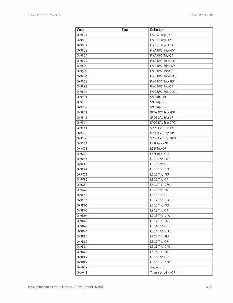
CHAPTER 6: SETPOINTS S1 RELAY SETUP
339 MOTOR PROTECTION SYSTEM – INSTRUCTION MANUAL 6–21
0x98C1 Ph UV2 Trip PKP
0x98C2 Ph UV2 Trip OP
0x98C4 Ph UV2 Trip DPO
0x98C9 Ph A UV2 Trip PKP
0x98CA Ph A UV2 Trip OP
0x98CC Ph A UV2 Trip DPO
0x98D1 Ph B UV2 Trip PKP
0x98D2 Ph B UV2 Trip OP
0x98D4 Ph B UV2 Trip DPO
0x98E1 Ph C UV2 Trip PKP
0x98E2 Ph C UV2 Trip OP
0x98E4 Ph C UV2 Trip DPO
0x9901 S/C Trip PKP
0x9902 S/C Trip OP
0x9904 S/C Trip DPO
0x9941 SPD2 S/C Trip PKP
0x9942 SPD2 S/C Trip OP
0x9944 SPD2 S/C Trip DPO
0x9981 SPD2 U/C Trip PKP
0x9982 SPD2 U/C Trip OP
0x9984 SPD2 U/C Trip DPO
0x9C01 LE 9 Trip PKP
0x9C02 LE 9 Trip OP
0x9C04 LE 9 Trip DPO
0x9C41 LE 10 Trip PKP
0x9C42 LE 10 Trip OP
0x9C44 LE 10 Trip DPO
0x9C81 LE 11 Trip PKP
0x9C82 LE 11 Trip OP
0x9C84 LE 11 Trip DPO
0x9CC1 LE 12 Trip PKP
0x9CC2 LE 12 Trip OP
0x9CC4 LE 12 Trip DPO
0x9D01 LE 13 Trip PKP
0x9D02 LE 13 Trip OP
0x9D04 LE 13 Trip DPO
0x9D41 LE 14 Trip PKP
0x9D42 LE 14 Trip OP
0x9D44 LE 14 Trip DPO
0x9D81 LE 15 Trip PKP
0x9D82 LE 15 Trip OP
0x9D84 LE 15 Trip DPO
0x9DC1 LE 16 Trip PKP
0x9DC2 LE 16 Trip OP
0x9DC4 LE 16 Trip DPO
0xA002 Any Alarm
0xA042 Therm Lvl Alrm OP
Code Type Definition
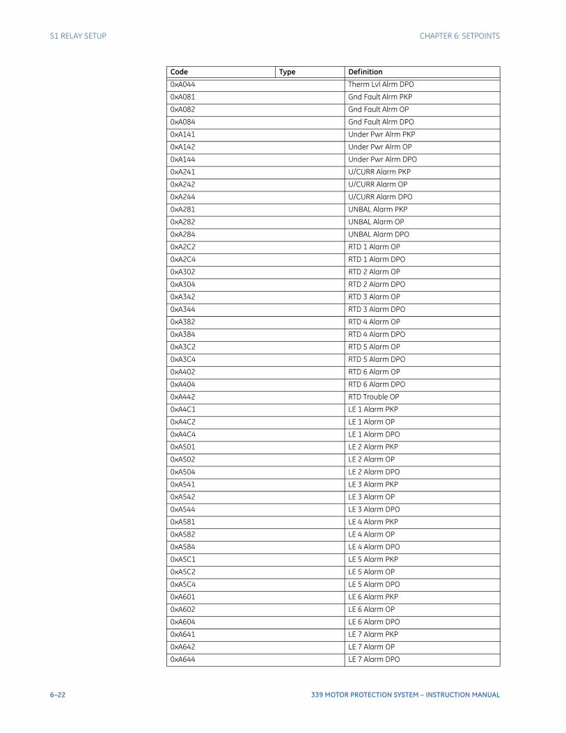
6–22 339 MOTOR PROTECTION SYSTEM – INSTRUCTION MANUAL
S1 RELAY SETUP CHAPTER 6: SETPOINTS
0xA044 Therm Lvl Alrm DPO
0xA081 Gnd Fault Alrm PKP
0xA082 Gnd Fault Alrm OP
0xA084 Gnd Fault Alrm DPO
0xA141 Under Pwr Alrm PKP
0xA142 Under Pwr Alrm OP
0xA144 Under Pwr Alrm DPO
0xA241 U/CURR Alarm PKP
0xA242 U/CURR Alarm OP
0xA244 U/CURR Alarm DPO
0xA281 UNBAL Alarm PKP
0xA282 UNBAL Alarm OP
0xA284 UNBAL Alarm DPO
0xA2C2 RTD 1 Alarm OP
0xA2C4 RTD 1 Alarm DPO
0xA302 RTD 2 Alarm OP
0xA304 RTD 2 Alarm DPO
0xA342 RTD 3 Alarm OP
0xA344 RTD 3 Alarm DPO
0xA382 RTD 4 Alarm OP
0xA384 RTD 4 Alarm DPO
0xA3C2 RTD 5 Alarm OP
0xA3C4 RTD 5 Alarm DPO
0xA402 RTD 6 Alarm OP
0xA404 RTD 6 Alarm DPO
0xA442 RTD Trouble OP
0xA4C1 LE 1 Alarm PKP
0xA4C2 LE 1 Alarm OP
0xA4C4 LE 1 Alarm DPO
0xA501 LE 2 Alarm PKP
0xA502 LE 2 Alarm OP
0xA504 LE 2 Alarm DPO
0xA541 LE 3 Alarm PKP
0xA542 LE 3 Alarm OP
0xA544 LE 3 Alarm DPO
0xA581 LE 4 Alarm PKP
0xA582 LE 4 Alarm OP
0xA584 LE 4 Alarm DPO
0xA5C1 LE 5 Alarm PKP
0xA5C2 LE 5 Alarm OP
0xA5C4 LE 5 Alarm DPO
0xA601 LE 6 Alarm PKP
0xA602 LE 6 Alarm OP
0xA604 LE 6 Alarm DPO
0xA641 LE 7 Alarm PKP
0xA642 LE 7 Alarm OP
0xA644 LE 7 Alarm DPO
Code Type Definition
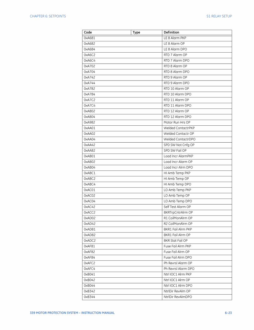
CHAPTER 6: SETPOINTS S1 RELAY SETUP
339 MOTOR PROTECTION SYSTEM – INSTRUCTION MANUAL 6–23
0xA681 LE 8 Alarm PKP
0xA682 LE 8 Alarm OP
0xA684 LE 8 Alarm DPO
0xA6C2 RTD 7 Alarm OP
0xA6C4 RTD 7 Alarm DPO
0xA702 RTD 8 Alarm OP
0xA704 RTD 8 Alarm DPO
0xA742 RTD 9 Alarm OP
0xA744 RTD 9 Alarm DPO
0xA782 RTD 10 Alarm OP
0xA784 RTD 10 Alarm DPO
0xA7C2 RTD 11 Alarm OP
0xA7C4 RTD 11 Alarm DPO
0xA802 RTD 12 Alarm OP
0xA804 RTD 12 Alarm DPO
0xA982 Motor Run Hrs OP
0xAA01 Welded ContactrPKP
0xAA02 Welded Contactr OP
0xAA04 Welded ContactrDPO
0xAA42 SPD SW Not Cnfg OP
0xAA82 SPD SW Fail OP
0xAB01 Load Incr AlarmPKP
0xAB02 Load Incr Alarm OP
0xAB04 Load Incr Alrm DPO
0xABC1 HI Amb Temp PKP
0xABC2 HI Amb Temp OP
0xABC4 HI Amb Temp DPO
0xAC01 LO Amb Temp PKP
0xAC02 LO Amb Temp OP
0xAC04 LO Amb Temp DPO
0xAC42 Self Test Alarm OP
0xACC2 BKRTrpCntrAlrm OP
0xAD02 R1 CoilMonAlrm OP
0xAD42 R2 CoilMonAlrm OP
0xAD81 BKR1 Fail Alrm PKP
0xAD82 BKR1 Fail Alrm OP
0xADC2 BKR Stat Fail OP
0xAF81 Fuse Fail Alrm PKP
0xAF82 Fuse Fail Alrm OP
0xAF84 Fuse Fail Alrm DPO
0xAFC2 Ph Revrsl Alarm OP
0xAFC4 Ph Revrsl Alarm DPO
0xB041 Ntrl IOC1 Alrm PKP
0xB042 Ntrl IOC1 Alrm OP
0xB044 Ntrl IOC1 Alrm DPO
0xB342 NtrlDir RevAlm OP
0xB344 NtrlDir RevAlmDPO
Code Type Definition
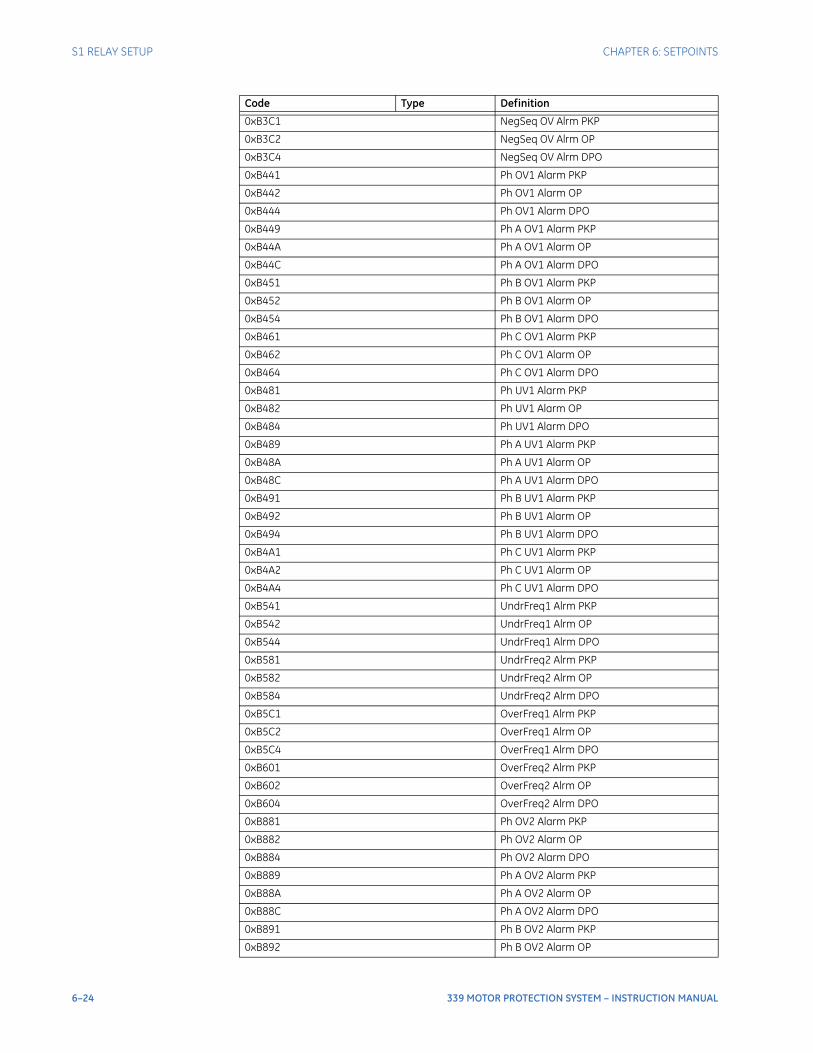
6–24 339 MOTOR PROTECTION SYSTEM – INSTRUCTION MANUAL
S1 RELAY SETUP CHAPTER 6: SETPOINTS
0xB3C1 NegSeq OV Alrm PKP
0xB3C2 NegSeq OV Alrm OP
0xB3C4 NegSeq OV Alrm DPO
0xB441 Ph OV1 Alarm PKP
0xB442 Ph OV1 Alarm OP
0xB444 Ph OV1 Alarm DPO
0xB449 Ph A OV1 Alarm PKP
0xB44A Ph A OV1 Alarm OP
0xB44C Ph A OV1 Alarm DPO
0xB451 Ph B OV1 Alarm PKP
0xB452 Ph B OV1 Alarm OP
0xB454 Ph B OV1 Alarm DPO
0xB461 Ph C OV1 Alarm PKP
0xB462 Ph C OV1 Alarm OP
0xB464 Ph C OV1 Alarm DPO
0xB481 Ph UV1 Alarm PKP
0xB482 Ph UV1 Alarm OP
0xB484 Ph UV1 Alarm DPO
0xB489 Ph A UV1 Alarm PKP
0xB48A Ph A UV1 Alarm OP
0xB48C Ph A UV1 Alarm DPO
0xB491 Ph B UV1 Alarm PKP
0xB492 Ph B UV1 Alarm OP
0xB494 Ph B UV1 Alarm DPO
0xB4A1 Ph C UV1 Alarm PKP
0xB4A2 Ph C UV1 Alarm OP
0xB4A4 Ph C UV1 Alarm DPO
0xB541 UndrFreq1 Alrm PKP
0xB542 UndrFreq1 Alrm OP
0xB544 UndrFreq1 Alrm DPO
0xB581 UndrFreq2 Alrm PKP
0xB582 UndrFreq2 Alrm OP
0xB584 UndrFreq2 Alrm DPO
0xB5C1 OverFreq1 Alrm PKP
0xB5C2 OverFreq1 Alrm OP
0xB5C4 OverFreq1 Alrm DPO
0xB601 OverFreq2 Alrm PKP
0xB602 OverFreq2 Alrm OP
0xB604 OverFreq2 Alrm DPO
0xB881 Ph OV2 Alarm PKP
0xB882 Ph OV2 Alarm OP
0xB884 Ph OV2 Alarm DPO
0xB889 Ph A OV2 Alarm PKP
0xB88A Ph A OV2 Alarm OP
0xB88C Ph A OV2 Alarm DPO
0xB891 Ph B OV2 Alarm PKP
0xB892 Ph B OV2 Alarm OP
Code Type Definition
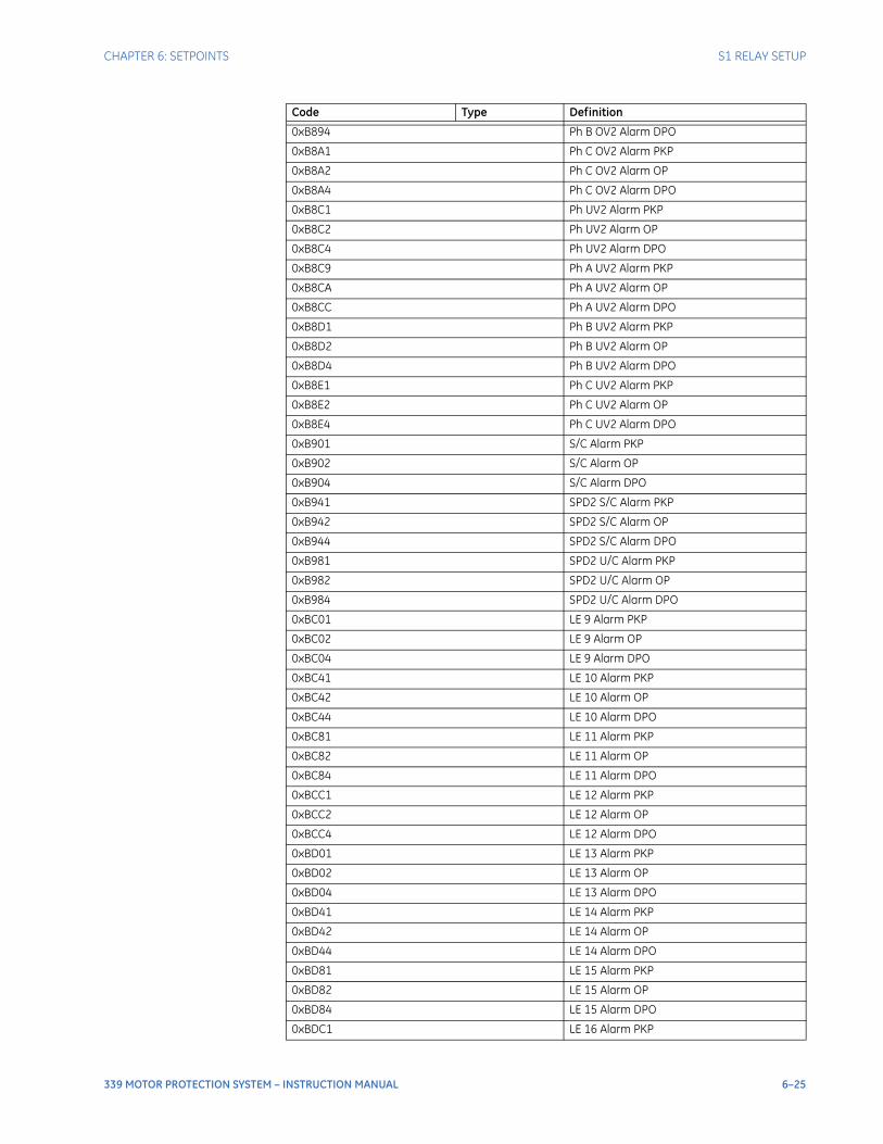
CHAPTER 6: SETPOINTS S1 RELAY SETUP
339 MOTOR PROTECTION SYSTEM – INSTRUCTION MANUAL 6–25
0xB894 Ph B OV2 Alarm DPO
0xB8A1 Ph C OV2 Alarm PKP
0xB8A2 Ph C OV2 Alarm OP
0xB8A4 Ph C OV2 Alarm DPO
0xB8C1 Ph UV2 Alarm PKP
0xB8C2 Ph UV2 Alarm OP
0xB8C4 Ph UV2 Alarm DPO
0xB8C9 Ph A UV2 Alarm PKP
0xB8CA Ph A UV2 Alarm OP
0xB8CC Ph A UV2 Alarm DPO
0xB8D1 Ph B UV2 Alarm PKP
0xB8D2 Ph B UV2 Alarm OP
0xB8D4 Ph B UV2 Alarm DPO
0xB8E1 Ph C UV2 Alarm PKP
0xB8E2 Ph C UV2 Alarm OP
0xB8E4 Ph C UV2 Alarm DPO
0xB901 S/C Alarm PKP
0xB902 S/C Alarm OP
0xB904 S/C Alarm DPO
0xB941 SPD2 S/C Alarm PKP
0xB942 SPD2 S/C Alarm OP
0xB944 SPD2 S/C Alarm DPO
0xB981 SPD2 U/C Alarm PKP
0xB982 SPD2 U/C Alarm OP
0xB984 SPD2 U/C Alarm DPO
0xBC01 LE 9 Alarm PKP
0xBC02 LE 9 Alarm OP
0xBC04 LE 9 Alarm DPO
0xBC41 LE 10 Alarm PKP
0xBC42 LE 10 Alarm OP
0xBC44 LE 10 Alarm DPO
0xBC81 LE 11 Alarm PKP
0xBC82 LE 11 Alarm OP
0xBC84 LE 11 Alarm DPO
0xBCC1 LE 12 Alarm PKP
0xBCC2 LE 12 Alarm OP
0xBCC4 LE 12 Alarm DPO
0xBD01 LE 13 Alarm PKP
0xBD02 LE 13 Alarm OP
0xBD04 LE 13 Alarm DPO
0xBD41 LE 14 Alarm PKP
0xBD42 LE 14 Alarm OP
0xBD44 LE 14 Alarm DPO
0xBD81 LE 15 Alarm PKP
0xBD82 LE 15 Alarm OP
0xBD84 LE 15 Alarm DPO
0xBDC1 LE 16 Alarm PKP
Code Type Definition
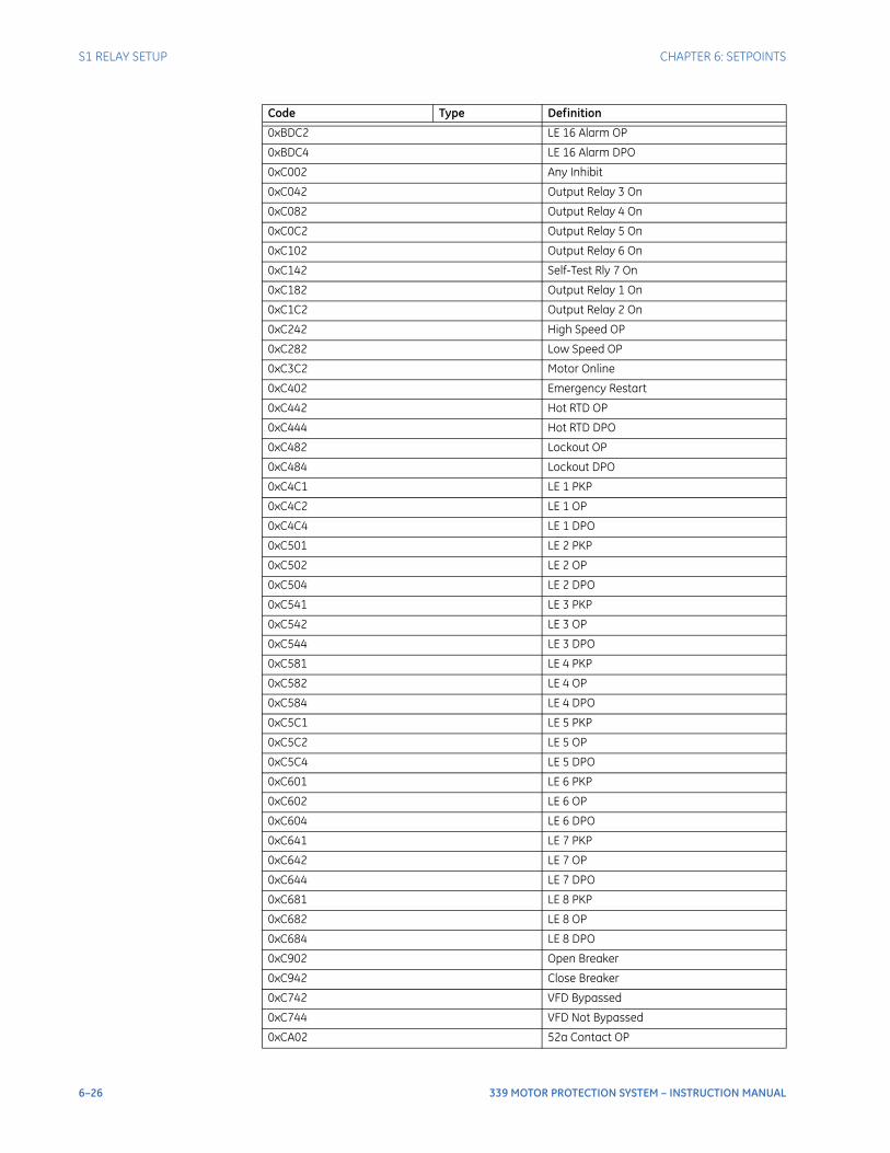
6–26 339 MOTOR PROTECTION SYSTEM – INSTRUCTION MANUAL
S1 RELAY SETUP CHAPTER 6: SETPOINTS
0xBDC2 LE 16 Alarm OP
0xBDC4 LE 16 Alarm DPO
0xC002 Any Inhibit
0xC042 Output Relay 3 On
0xC082 Output Relay 4 On
0xC0C2 Output Relay 5 On
0xC102 Output Relay 6 On
0xC142 Self-Test Rly 7 On
0xC182 Output Relay 1 On
0xC1C2 Output Relay 2 On
0xC242 High Speed OP
0xC282 Low Speed OP
0xC3C2 Motor Online
0xC402 Emergency Restart
0xC442 Hot RTD OP
0xC444 Hot RTD DPO
0xC482 Lockout OP
0xC484 Lockout DPO
0xC4C1 LE 1 PKP
0xC4C2 LE 1 OP
0xC4C4 LE 1 DPO
0xC501 LE 2 PKP
0xC502 LE 2 OP
0xC504 LE 2 DPO
0xC541 LE 3 PKP
0xC542 LE 3 OP
0xC544 LE 3 DPO
0xC581 LE 4 PKP
0xC582 LE 4 OP
0xC584 LE 4 DPO
0xC5C1 LE 5 PKP
0xC5C2 LE 5 OP
0xC5C4 LE 5 DPO
0xC601 LE 6 PKP
0xC602 LE 6 OP
0xC604 LE 6 DPO
0xC641 LE 7 PKP
0xC642 LE 7 OP
0xC644 LE 7 DPO
0xC681 LE 8 PKP
0xC682 LE 8 OP
0xC684 LE 8 DPO
0xC902 Open Breaker
0xC942 Close Breaker
0xC742 VFD Bypassed
0xC744 VFD Not Bypassed
0xCA02 52a Contact OP
Code Type Definition
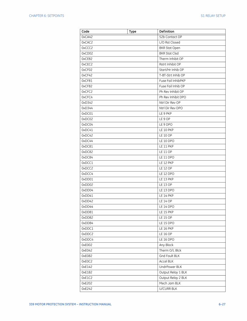
CHAPTER 6: SETPOINTS S1 RELAY SETUP
339 MOTOR PROTECTION SYSTEM – INSTRUCTION MANUAL 6–27
0xCA42 52b Contact OP
0xCAC2 L/O Rst Closed
0xCCC2 BKR Stat Open
0xCD02 BKR Stat Clsd
0xCE82 Therm Inhibit OP
0xCEC2 Rstrt Inhibit OP
0xCF02 Start/Hr Inhib OP
0xCF42 T-BT-Strt Inhib OP
0xCF81 Fuse Fail InhibPKP
0xCF82 Fuse Fail Inhib OP
0xCFC2 Ph Rev Inhibit OP
0xCFC4 Ph Rev Inhibit DPO
0xD342 Ntrl Dir Rev OP
0xD344 Ntrl Dir Rev DPO
0xDC01 LE 9 PKP
0xDC02 LE 9 OP
0xDC04 LE 9 DPO
0xDC41 LE 10 PKP
0xDC42 LE 10 OP
0xDC44 LE 10 DPO
0xDC81 LE 11 PKP
0xDC82 LE 11 OP
0xDC84 LE 11 DPO
0xDCC1 LE 12 PKP
0xDCC2 LE 12 OP
0xDCC4 LE 12 DPO
0xDD01 LE 13 PKP
0xDD02 LE 13 OP
0xDD04 LE 13 DPO
0xDD41 LE 14 PKP
0xDD42 LE 14 OP
0xDD44 LE 14 DPO
0xDD81 LE 15 PKP
0xDD82 LE 15 OP
0xDD84 LE 15 DPO
0xDDC1 LE 16 PKP
0xDDC2 LE 16 OP
0xDDC4 LE 16 DPO
0xE002 Any Block
0xE042 Therm O/L Blck
0xE082 Gnd Fault BLK
0xE0C2 Accel BLK
0xE142 UndrPower BLK
0xE182 Output Relay 1 BLK
0xE1C2 Output Relay 2 BLK
0xE202 Mech Jam BLK
0xE242 U/CURR BLK
Code Type Definition
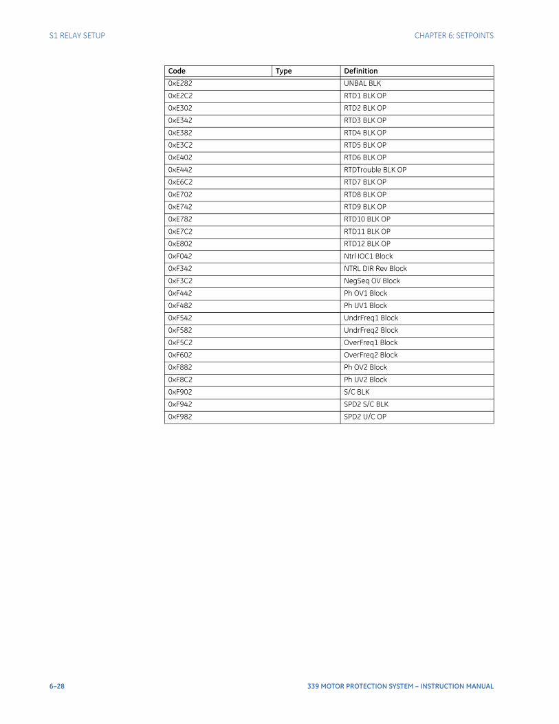
6–28 339 MOTOR PROTECTION SYSTEM – INSTRUCTION MANUAL
S1 RELAY SETUP CHAPTER 6: SETPOINTS
0xE282 UNBAL BLK
0xE2C2 RTD1 BLK OP
0xE302 RTD2 BLK OP
0xE342 RTD3 BLK OP
0xE382 RTD4 BLK OP
0xE3C2 RTD5 BLK OP
0xE402 RTD6 BLK OP
0xE442 RTDTrouble BLK OP
0xE6C2 RTD7 BLK OP
0xE702 RTD8 BLK OP
0xE742 RTD9 BLK OP
0xE782 RTD10 BLK OP
0xE7C2 RTD11 BLK OP
0xE802 RTD12 BLK OP
0xF042 Ntrl IOC1 Block
0xF342 NTRL DIR Rev Block
0xF3C2 NegSeq OV Block
0xF442 Ph OV1 Block
0xF482 Ph UV1 Block
0xF542 UndrFreq1 Block
0xF582 UndrFreq2 Block
0xF5C2 OverFreq1 Block
0xF602 OverFreq2 Block
0xF882 Ph OV2 Block
0xF8C2 Ph UV2 Block
0xF902 S/C BLK
0xF942 SPD2 S/C BLK
0xF982 SPD2 U/C OP
Code Type Definition
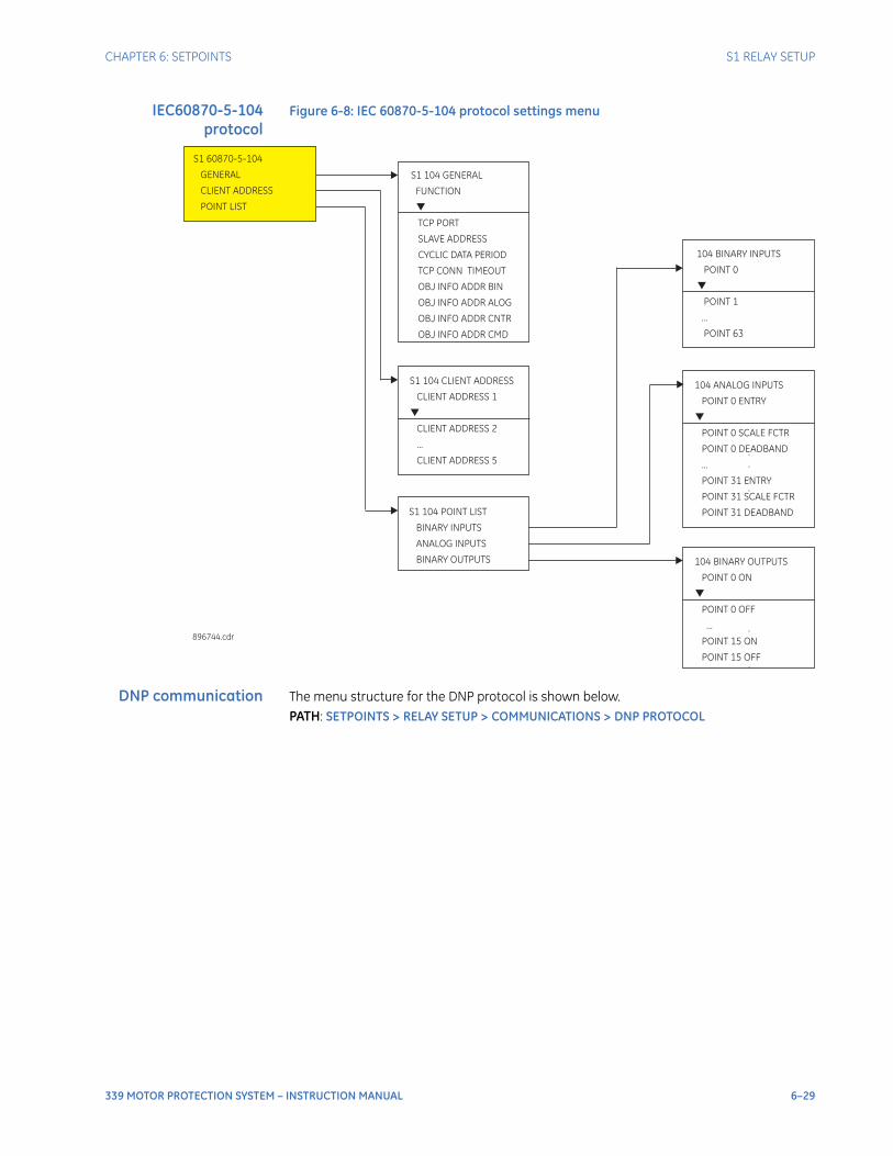
CHAPTER 6: SETPOINTS S1 RELAY SETUP
339 MOTOR PROTECTION SYSTEM – INSTRUCTION MANUAL 6–29
IEC60870-5-104protocol
Figure 6-8: IEC 60870-5-104 protocol settings menu
DNP communication The menu structure for the DNP protocol is shown below.PATH: SETPOINTS > RELAY SETUP > COMMUNICATIONS > DNP PROTOCOL
104 BINARY INPUTS
POINT 0
POINT 1
...
POINT 63
S1 104 GENERAL
FUNCTION
CYCLIC DATA PERIOD
TCP CONN TIMEOUT
OBJ INFO ADDR BIN
TCP PORT
SLAVE ADDRESS
OBJ INFO ADDR ALOG
OBJ INFO ADDR CNTR
OBJ INFO ADDR CMD
896744.cdr
S1 104 POINT LIST
BINARY INPUTS
ANALOG INPUTS
BINARY OUTPUTS
S1 60870-5-104
GENERAL
CLIENT ADDRESS
POINT LIST
104 ANALOG INPUTS
POINT 0 ENTRY
POINT 0 SCALE FCTR
POINT 0 DEADBAND
...
POINT 31 ENTRY
POINT 31 SCALE FCTR
POINT 31 DEADBAND
S1 104 CLIENT ADDRESS
CLIENT ADDRESS 1
CLIENT ADDRESS 2
...
CLIENT ADDRESS 5
.
.
.
.
104 BINARY OUTPUTS
POINT 0 ON
POINT 0 OFF
...
POINT 15 ON
POINT 15 OFF
.
.
.
.
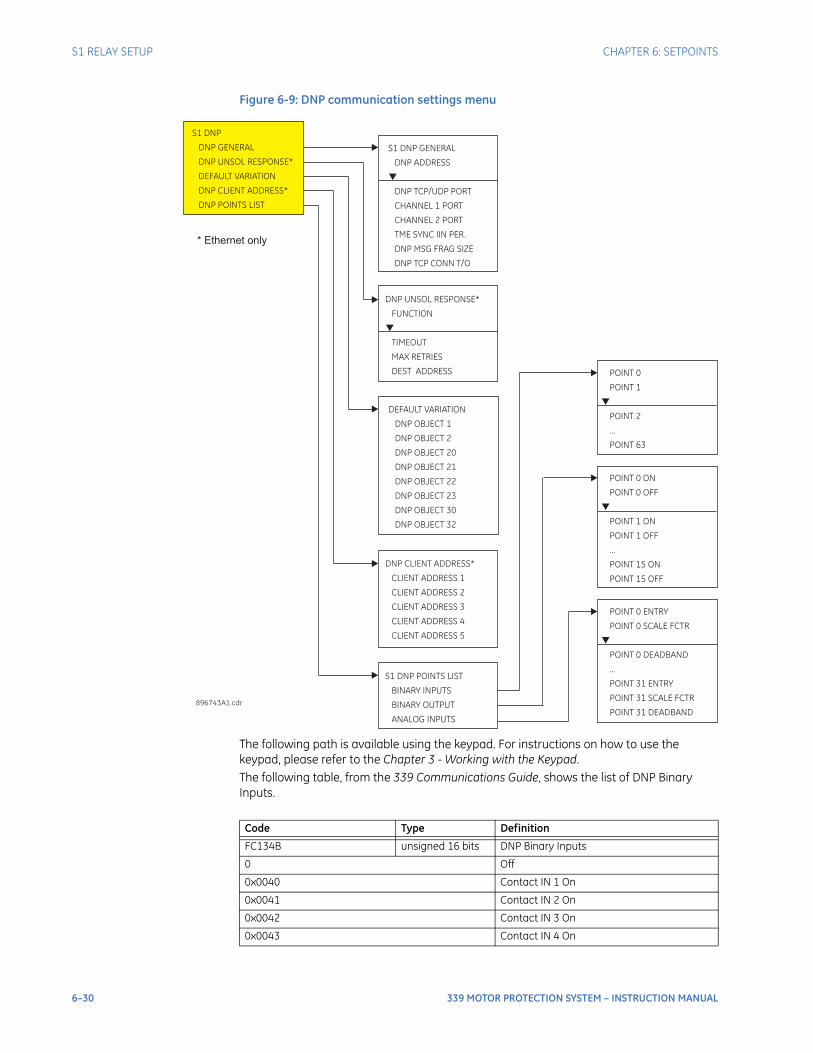
6–30 339 MOTOR PROTECTION SYSTEM – INSTRUCTION MANUAL
S1 RELAY SETUP CHAPTER 6: SETPOINTS
Figure 6-9: DNP communication settings menu
The following path is available using the keypad. For instructions on how to use the keypad, please refer to the Chapter 3 - Working with the Keypad.The following table, from the 339 Communications Guide, shows the list of DNP Binary Inputs.
S1 DNP GENERAL
DNP ADDRESS
DNP TCP/UDP PORT
CHANNEL 1 PORT
CHANNEL 2 PORT
TME SYNC IIN PER.
DNP MSG FRAG SIZE
DNP TCP CONN T/O
S1 DNP
DNP GENERAL
DNP UNSOL RESPONSE*
DEFAULT VARIATION
DNP CLIENT ADDRESS*
DNP POINTS LIST
896743A1.cdr
DNP CLIENT ADDRESS*
CLIENT ADDRESS 1
CLIENT ADDRESS 2
CLIENT ADDRESS 3
CLIENT ADDRESS 4
CLIENT ADDRESS 5
POINT 0
...
POINT 1
POINT 2
POINT 63
S1 DNP POINTS LIST
BINARY INPUTS
BINARY OUTPUT
ANALOG INPUTS
POINT 0 ENTRY
...
POINT 0 SCALE FCTR
POINT 0 DEADBAND
POINT 31 ENTRY
POINT 31 SCALE FCTR
POINT 31 DEADBAND
POINT 0 ON
...
POINT 0 OFF
POINT 1 ON
POINT 1 OFF
POINT 15 ON
POINT 15 OFF
DEFAULT VARIATION
DNP OBJECT 1
DNP OBJECT 2
DNP OBJECT 20
DNP OBJECT 21
DNP OBJECT 22
DNP OBJECT 23
DNP OBJECT 30
DNP OBJECT 32
DNP UNSOL RESPONSE*
FUNCTION
TIMEOUT
MAX RETRIES
DEST ADDRESS
* Ethernet only
Code Type Definition
FC134B unsigned 16 bits DNP Binary Inputs
0 Off
0x0040 Contact IN 1 On
0x0041 Contact IN 2 On
0x0042 Contact IN 3 On
0x0043 Contact IN 4 On
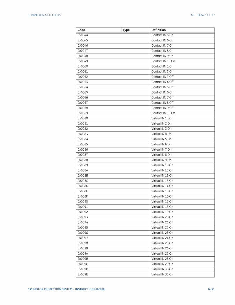
CHAPTER 6: SETPOINTS S1 RELAY SETUP
339 MOTOR PROTECTION SYSTEM – INSTRUCTION MANUAL 6–31
0x0044 Contact IN 5 On
0x0045 Contact IN 6 On
0x0046 Contact IN 7 On
0x0047 Contact IN 8 On
0x0048 Contact IN 9 On
0x0049 Contact IN 10 On
0x0060 Contact IN 1 Off
0x0061 Contact IN 2 Off
0x0062 Contact IN 3 Off
0x0063 Contact IN 4 Off
0x0064 Contact IN 5 Off
0x0065 Contact IN 6 Off
0x0066 Contact IN 7 Off
0x0067 Contact IN 8 Off
0x0068 Contact IN 9 Off
0x0069 Contact IN 10 Off
0x0080 Virtual IN 1 On
0x0081 Virtual IN 2 On
0x0082 Virtual IN 3 On
0x0083 Virtual IN 4 On
0x0084 Virtual IN 5 On
0x0085 Virtual IN 6 On
0x0086 Virtual IN 7 On
0x0087 Virtual IN 8 On
0x0088 Virtual IN 9 On
0x0089 Virtual IN 10 On
0x008A Virtual IN 11 On
0x008B Virtual IN 12 On
0x008C Virtual IN 13 On
0x008D Virtual IN 14 On
0x008E Virtual IN 15 On
0x008F Virtual IN 16 On
0x0090 Virtual IN 17 On
0x0091 Virtual IN 18 On
0x0092 Virtual IN 19 On
0x0093 Virtual IN 20 On
0x0094 Virtual IN 21 On
0x0095 Virtual IN 22 On
0x0096 Virtual IN 23 On
0x0097 Virtual IN 24 On
0x0098 Virtual IN 25 On
0x0099 Virtual IN 26 On
0x009A Virtual IN 27 On
0x009B Virtual IN 28 On
0x009C Virtual IN 29 On
0x009D Virtual IN 30 On
0x009E Virtual IN 31 On
Code Type Definition
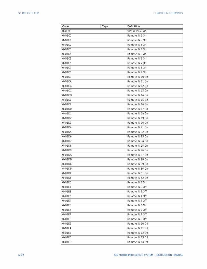
6–32 339 MOTOR PROTECTION SYSTEM – INSTRUCTION MANUAL
S1 RELAY SETUP CHAPTER 6: SETPOINTS
0x009F Virtual IN 32 On
0x01C0 Remote IN 1 On
0x01C1 Remote IN 2 On
0x01C2 Remote IN 3 On
0x01C3 Remote IN 4 On
0x01C4 Remote IN 5 On
0x01C5 Remote IN 6 On
0x01C6 Remote IN 7 On
0x01C7 Remote IN 8 On
0x01C8 Remote IN 9 On
0x01C9 Remote IN 10 On
0x01CA Remote IN 11 On
0x01CB Remote IN 12 On
0x01CC Remote IN 13 On
0x01CD Remote IN 14 On
0x01CE Remote IN 15 On
0x01CF Remote IN 16 On
0x01D0 Remote IN 17 On
0x01D1 Remote IN 18 On
0x01D2 Remote IN 19 On
0x01D3 Remote IN 20 On
0x01D4 Remote IN 21 On
0x01D5 Remote IN 22 On
0x01D6 Remote IN 23 On
0x01D7 Remote IN 24 On
0x01D8 Remote IN 25 On
0x01D9 Remote IN 26 On
0x01DA Remote IN 27 On
0x01DB Remote IN 28 On
0x01DC Remote IN 29 On
0x01DD Remote IN 30 On
0x01DE Remote IN 31 On
0x01DF Remote IN 32 On
0x01E0 Remote IN 1 Off
0x01E1 Remote IN 2 Off
0x01E2 Remote IN 3 Off
0x01E3 Remote IN 4 Off
0x01E4 Remote IN 5 Off
0x01E5 Remote IN 6 Off
0x01E6 Remote IN 7 Off
0x01E7 Remote IN 8 Off
0x01E8 Remote IN 9 Off
0x01E9 Remote IN 10 Off
0x01EA Remote IN 11 Off
0x01EB Remote IN 12 Off
0x01EC Remote IN 13 Off
0x01ED Remote IN 14 Off
Code Type Definition
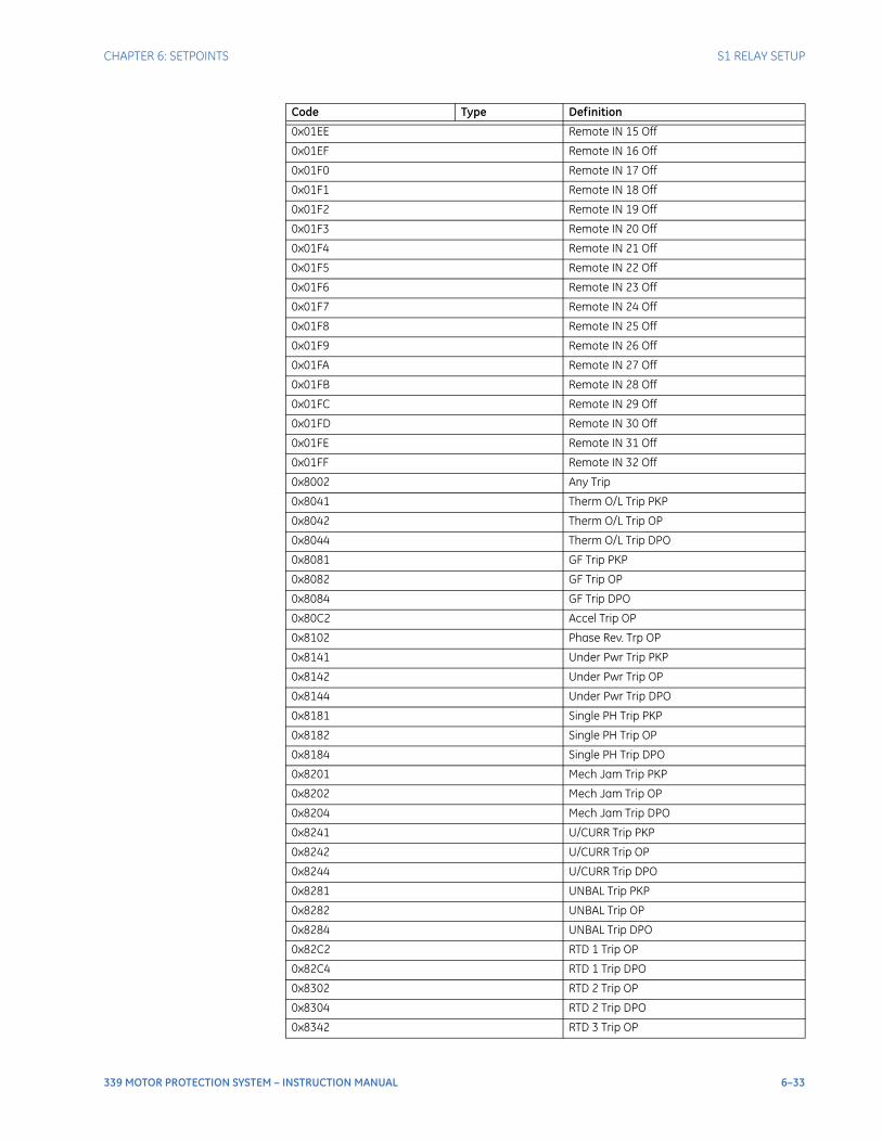
CHAPTER 6: SETPOINTS S1 RELAY SETUP
339 MOTOR PROTECTION SYSTEM – INSTRUCTION MANUAL 6–33
0x01EE Remote IN 15 Off
0x01EF Remote IN 16 Off
0x01F0 Remote IN 17 Off
0x01F1 Remote IN 18 Off
0x01F2 Remote IN 19 Off
0x01F3 Remote IN 20 Off
0x01F4 Remote IN 21 Off
0x01F5 Remote IN 22 Off
0x01F6 Remote IN 23 Off
0x01F7 Remote IN 24 Off
0x01F8 Remote IN 25 Off
0x01F9 Remote IN 26 Off
0x01FA Remote IN 27 Off
0x01FB Remote IN 28 Off
0x01FC Remote IN 29 Off
0x01FD Remote IN 30 Off
0x01FE Remote IN 31 Off
0x01FF Remote IN 32 Off
0x8002 Any Trip
0x8041 Therm O/L Trip PKP
0x8042 Therm O/L Trip OP
0x8044 Therm O/L Trip DPO
0x8081 GF Trip PKP
0x8082 GF Trip OP
0x8084 GF Trip DPO
0x80C2 Accel Trip OP
0x8102 Phase Rev. Trp OP
0x8141 Under Pwr Trip PKP
0x8142 Under Pwr Trip OP
0x8144 Under Pwr Trip DPO
0x8181 Single PH Trip PKP
0x8182 Single PH Trip OP
0x8184 Single PH Trip DPO
0x8201 Mech Jam Trip PKP
0x8202 Mech Jam Trip OP
0x8204 Mech Jam Trip DPO
0x8241 U/CURR Trip PKP
0x8242 U/CURR Trip OP
0x8244 U/CURR Trip DPO
0x8281 UNBAL Trip PKP
0x8282 UNBAL Trip OP
0x8284 UNBAL Trip DPO
0x82C2 RTD 1 Trip OP
0x82C4 RTD 1 Trip DPO
0x8302 RTD 2 Trip OP
0x8304 RTD 2 Trip DPO
0x8342 RTD 3 Trip OP
Code Type Definition

6–34 339 MOTOR PROTECTION SYSTEM – INSTRUCTION MANUAL
S1 RELAY SETUP CHAPTER 6: SETPOINTS
0x8344 RTD 3 Trip DPO
0x8382 RTD 4 Trip OP
0x8384 RTD 4 Trip DPO
0x83C2 RTD 5 Trip OP
0x83C4 RTD 5 Trip DPO
0x8402 RTD 6 Trip OP
0x8404 RTD 6 Trip DPO
0x84C1 LE 1 Trip PKP
0x84C2 LE 1 Trip OP
0x84C4 LE 1 Trip DPO
0x8501 LE 2 Trip PKP
0x8502 LE 2 Trip OP
0x8504 LE 2 Trip DPO
0x8541 LE 3 Trip PKP
0x8542 LE 3 Trip OP
0x8544 LE 3 Trip DPO
0x8581 LE 4 Trip PKP
0x8582 LE 4 Trip OP
0x8584 LE 4 Trip DPO
0x85C1 LE 5 Trip PKP
0x85C2 LE 5 Trip OP
0x85C4 LE 5 Trip DPO
0x8601 LE 6 Trip PKP
0x8602 LE 6 Trip OP
0x8604 LE 6 Trip DPO
0x8641 LE 7 Trip PKP
0x8642 LE 7 Trip OP
0x8644 LE 7 Trip DPO
0x8681 LE 8 Trip PKP
0x8682 LE 8 Trip OP
0x8684 LE 8 Trip DPO
0x86C2 RTD 7 Trip OP
0x86C4 RTD 7 Trip DPO
0x8702 RTD 8 Trip OP
0x8704 RTD 8 Trip DPO
0x8742 RTD 9 Trip OP
0x8744 RTD 9 Trip DPO
0x8782 RTD 10 Trip OP
0x8784 RTD 10 Trip DPO
0x87C2 RTD 11 Trip OP
0x87C4 RTD 11 Trip DPO
0x8802 RTD 12 Trip OP
0x8804 RTD 12 Trip DPO
0x8F82 Fuse Fail Trip OP
0x8F84 Fuse Fail Trip DPO
0x8FC2 Ph Revrsl Trip OP
0x8FC4 Ph Revrsl Trip DPO
Code Type Definition
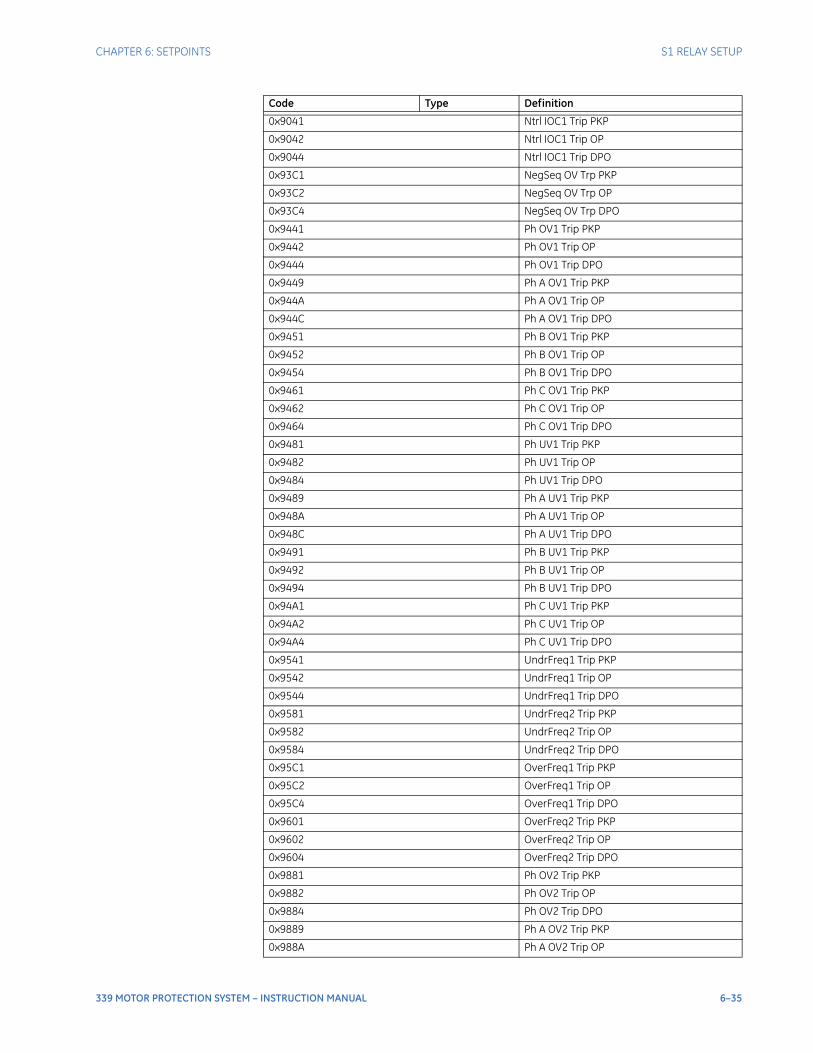
CHAPTER 6: SETPOINTS S1 RELAY SETUP
339 MOTOR PROTECTION SYSTEM – INSTRUCTION MANUAL 6–35
0x9041 Ntrl IOC1 Trip PKP
0x9042 Ntrl IOC1 Trip OP
0x9044 Ntrl IOC1 Trip DPO
0x93C1 NegSeq OV Trp PKP
0x93C2 NegSeq OV Trp OP
0x93C4 NegSeq OV Trp DPO
0x9441 Ph OV1 Trip PKP
0x9442 Ph OV1 Trip OP
0x9444 Ph OV1 Trip DPO
0x9449 Ph A OV1 Trip PKP
0x944A Ph A OV1 Trip OP
0x944C Ph A OV1 Trip DPO
0x9451 Ph B OV1 Trip PKP
0x9452 Ph B OV1 Trip OP
0x9454 Ph B OV1 Trip DPO
0x9461 Ph C OV1 Trip PKP
0x9462 Ph C OV1 Trip OP
0x9464 Ph C OV1 Trip DPO
0x9481 Ph UV1 Trip PKP
0x9482 Ph UV1 Trip OP
0x9484 Ph UV1 Trip DPO
0x9489 Ph A UV1 Trip PKP
0x948A Ph A UV1 Trip OP
0x948C Ph A UV1 Trip DPO
0x9491 Ph B UV1 Trip PKP
0x9492 Ph B UV1 Trip OP
0x9494 Ph B UV1 Trip DPO
0x94A1 Ph C UV1 Trip PKP
0x94A2 Ph C UV1 Trip OP
0x94A4 Ph C UV1 Trip DPO
0x9541 UndrFreq1 Trip PKP
0x9542 UndrFreq1 Trip OP
0x9544 UndrFreq1 Trip DPO
0x9581 UndrFreq2 Trip PKP
0x9582 UndrFreq2 Trip OP
0x9584 UndrFreq2 Trip DPO
0x95C1 OverFreq1 Trip PKP
0x95C2 OverFreq1 Trip OP
0x95C4 OverFreq1 Trip DPO
0x9601 OverFreq2 Trip PKP
0x9602 OverFreq2 Trip OP
0x9604 OverFreq2 Trip DPO
0x9881 Ph OV2 Trip PKP
0x9882 Ph OV2 Trip OP
0x9884 Ph OV2 Trip DPO
0x9889 Ph A OV2 Trip PKP
0x988A Ph A OV2 Trip OP
Code Type Definition
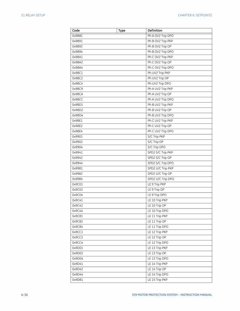
6–36 339 MOTOR PROTECTION SYSTEM – INSTRUCTION MANUAL
S1 RELAY SETUP CHAPTER 6: SETPOINTS
0x988C Ph A OV2 Trip DPO
0x9891 Ph B OV2 Trip PKP
0x9892 Ph B OV2 Trip OP
0x9894 Ph B OV2 Trip DPO
0x98A1 Ph C OV2 Trip PKP
0x98A2 Ph C OV2 Trip OP
0x98A4 Ph C OV2 Trip DPO
0x98C1 Ph UV2 Trip PKP
0x98C2 Ph UV2 Trip OP
0x98C4 Ph UV2 Trip DPO
0x98C9 Ph A UV2 Trip PKP
0x98CA Ph A UV2 Trip OP
0x98CC Ph A UV2 Trip DPO
0x98D1 Ph B UV2 Trip PKP
0x98D2 Ph B UV2 Trip OP
0x98D4 Ph B UV2 Trip DPO
0x98E1 Ph C UV2 Trip PKP
0x98E2 Ph C UV2 Trip OP
0x98E4 Ph C UV2 Trip DPO
0x9901 S/C Trip PKP
0x9902 S/C Trip OP
0x9904 S/C Trip DPO
0x9941 SPD2 S/C Trip PKP
0x9942 SPD2 S/C Trip OP
0x9944 SPD2 S/C Trip DPO
0x9981 SPD2 U/C Trip PKP
0x9982 SPD2 U/C Trip OP
0x9984 SPD2 U/C Trip DPO
0x9C01 LE 9 Trip PKP
0x9C02 LE 9 Trip OP
0x9C04 LE 9 Trip DPO
0x9C41 LE 10 Trip PKP
0x9C42 LE 10 Trip OP
0x9C44 LE 10 Trip DPO
0x9C81 LE 11 Trip PKP
0x9C82 LE 11 Trip OP
0x9C84 LE 11 Trip DPO
0x9CC1 LE 12 Trip PKP
0x9CC2 LE 12 Trip OP
0x9CC4 LE 12 Trip DPO
0x9D01 LE 13 Trip PKP
0x9D02 LE 13 Trip OP
0x9D04 LE 13 Trip DPO
0x9D41 LE 14 Trip PKP
0x9D42 LE 14 Trip OP
0x9D44 LE 14 Trip DPO
0x9D81 LE 15 Trip PKP
Code Type Definition
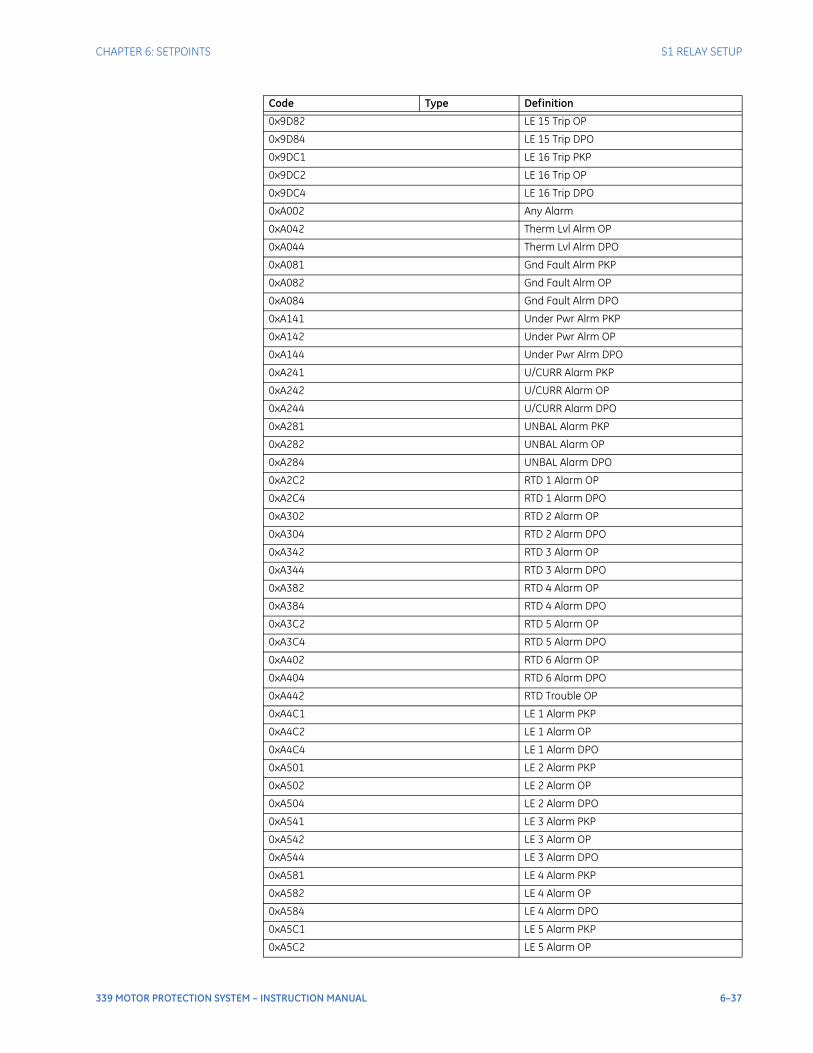
CHAPTER 6: SETPOINTS S1 RELAY SETUP
339 MOTOR PROTECTION SYSTEM – INSTRUCTION MANUAL 6–37
0x9D82 LE 15 Trip OP
0x9D84 LE 15 Trip DPO
0x9DC1 LE 16 Trip PKP
0x9DC2 LE 16 Trip OP
0x9DC4 LE 16 Trip DPO
0xA002 Any Alarm
0xA042 Therm Lvl Alrm OP
0xA044 Therm Lvl Alrm DPO
0xA081 Gnd Fault Alrm PKP
0xA082 Gnd Fault Alrm OP
0xA084 Gnd Fault Alrm DPO
0xA141 Under Pwr Alrm PKP
0xA142 Under Pwr Alrm OP
0xA144 Under Pwr Alrm DPO
0xA241 U/CURR Alarm PKP
0xA242 U/CURR Alarm OP
0xA244 U/CURR Alarm DPO
0xA281 UNBAL Alarm PKP
0xA282 UNBAL Alarm OP
0xA284 UNBAL Alarm DPO
0xA2C2 RTD 1 Alarm OP
0xA2C4 RTD 1 Alarm DPO
0xA302 RTD 2 Alarm OP
0xA304 RTD 2 Alarm DPO
0xA342 RTD 3 Alarm OP
0xA344 RTD 3 Alarm DPO
0xA382 RTD 4 Alarm OP
0xA384 RTD 4 Alarm DPO
0xA3C2 RTD 5 Alarm OP
0xA3C4 RTD 5 Alarm DPO
0xA402 RTD 6 Alarm OP
0xA404 RTD 6 Alarm DPO
0xA442 RTD Trouble OP
0xA4C1 LE 1 Alarm PKP
0xA4C2 LE 1 Alarm OP
0xA4C4 LE 1 Alarm DPO
0xA501 LE 2 Alarm PKP
0xA502 LE 2 Alarm OP
0xA504 LE 2 Alarm DPO
0xA541 LE 3 Alarm PKP
0xA542 LE 3 Alarm OP
0xA544 LE 3 Alarm DPO
0xA581 LE 4 Alarm PKP
0xA582 LE 4 Alarm OP
0xA584 LE 4 Alarm DPO
0xA5C1 LE 5 Alarm PKP
0xA5C2 LE 5 Alarm OP
Code Type Definition
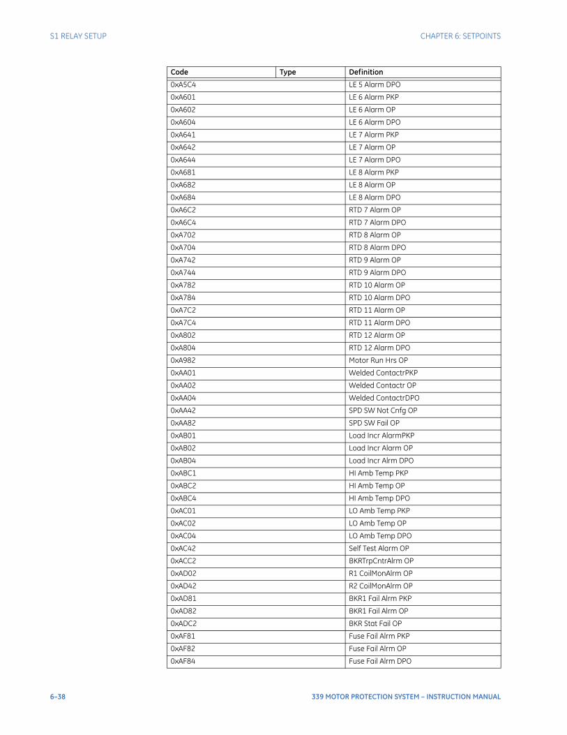
6–38 339 MOTOR PROTECTION SYSTEM – INSTRUCTION MANUAL
S1 RELAY SETUP CHAPTER 6: SETPOINTS
0xA5C4 LE 5 Alarm DPO
0xA601 LE 6 Alarm PKP
0xA602 LE 6 Alarm OP
0xA604 LE 6 Alarm DPO
0xA641 LE 7 Alarm PKP
0xA642 LE 7 Alarm OP
0xA644 LE 7 Alarm DPO
0xA681 LE 8 Alarm PKP
0xA682 LE 8 Alarm OP
0xA684 LE 8 Alarm DPO
0xA6C2 RTD 7 Alarm OP
0xA6C4 RTD 7 Alarm DPO
0xA702 RTD 8 Alarm OP
0xA704 RTD 8 Alarm DPO
0xA742 RTD 9 Alarm OP
0xA744 RTD 9 Alarm DPO
0xA782 RTD 10 Alarm OP
0xA784 RTD 10 Alarm DPO
0xA7C2 RTD 11 Alarm OP
0xA7C4 RTD 11 Alarm DPO
0xA802 RTD 12 Alarm OP
0xA804 RTD 12 Alarm DPO
0xA982 Motor Run Hrs OP
0xAA01 Welded ContactrPKP
0xAA02 Welded Contactr OP
0xAA04 Welded ContactrDPO
0xAA42 SPD SW Not Cnfg OP
0xAA82 SPD SW Fail OP
0xAB01 Load Incr AlarmPKP
0xAB02 Load Incr Alarm OP
0xAB04 Load Incr Alrm DPO
0xABC1 HI Amb Temp PKP
0xABC2 HI Amb Temp OP
0xABC4 HI Amb Temp DPO
0xAC01 LO Amb Temp PKP
0xAC02 LO Amb Temp OP
0xAC04 LO Amb Temp DPO
0xAC42 Self Test Alarm OP
0xACC2 BKRTrpCntrAlrm OP
0xAD02 R1 CoilMonAlrm OP
0xAD42 R2 CoilMonAlrm OP
0xAD81 BKR1 Fail Alrm PKP
0xAD82 BKR1 Fail Alrm OP
0xADC2 BKR Stat Fail OP
0xAF81 Fuse Fail Alrm PKP
0xAF82 Fuse Fail Alrm OP
0xAF84 Fuse Fail Alrm DPO
Code Type Definition
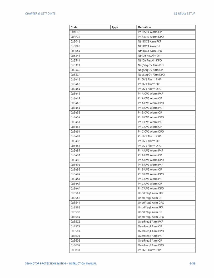
CHAPTER 6: SETPOINTS S1 RELAY SETUP
339 MOTOR PROTECTION SYSTEM – INSTRUCTION MANUAL 6–39
0xAFC2 Ph Revrsl Alarm OP
0xAFC4 Ph Revrsl Alarm DPO
0xB041 Ntrl IOC1 Alrm PKP
0xB042 Ntrl IOC1 Alrm OP
0xB044 Ntrl IOC1 Alrm DPO
0xB342 NtrlDir RevAlm OP
0xB344 NtrlDir RevAlmDPO
0xB3C1 NegSeq OV Alrm PKP
0xB3C2 NegSeq OV Alrm OP
0xB3C4 NegSeq OV Alrm DPO
0xB441 Ph OV1 Alarm PKP
0xB442 Ph OV1 Alarm OP
0xB444 Ph OV1 Alarm DPO
0xB449 Ph A OV1 Alarm PKP
0xB44A Ph A OV1 Alarm OP
0xB44C Ph A OV1 Alarm DPO
0xB451 Ph B OV1 Alarm PKP
0xB452 Ph B OV1 Alarm OP
0xB454 Ph B OV1 Alarm DPO
0xB461 Ph C OV1 Alarm PKP
0xB462 Ph C OV1 Alarm OP
0xB464 Ph C OV1 Alarm DPO
0xB481 Ph UV1 Alarm PKP
0xB482 Ph UV1 Alarm OP
0xB484 Ph UV1 Alarm DPO
0xB489 Ph A UV1 Alarm PKP
0xB48A Ph A UV1 Alarm OP
0xB48C Ph A UV1 Alarm DPO
0xB491 Ph B UV1 Alarm PKP
0xB492 Ph B UV1 Alarm OP
0xB494 Ph B UV1 Alarm DPO
0xB4A1 Ph C UV1 Alarm PKP
0xB4A2 Ph C UV1 Alarm OP
0xB4A4 Ph C UV1 Alarm DPO
0xB541 UndrFreq1 Alrm PKP
0xB542 UndrFreq1 Alrm OP
0xB544 UndrFreq1 Alrm DPO
0xB581 UndrFreq2 Alrm PKP
0xB582 UndrFreq2 Alrm OP
0xB584 UndrFreq2 Alrm DPO
0xB5C1 OverFreq1 Alrm PKP
0xB5C2 OverFreq1 Alrm OP
0xB5C4 OverFreq1 Alrm DPO
0xB601 OverFreq2 Alrm PKP
0xB602 OverFreq2 Alrm OP
0xB604 OverFreq2 Alrm DPO
0xB881 Ph OV2 Alarm PKP
Code Type Definition
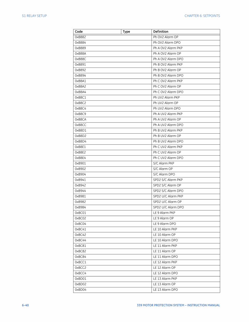
6–40 339 MOTOR PROTECTION SYSTEM – INSTRUCTION MANUAL
S1 RELAY SETUP CHAPTER 6: SETPOINTS
0xB882 Ph OV2 Alarm OP
0xB884 Ph OV2 Alarm DPO
0xB889 Ph A OV2 Alarm PKP
0xB88A Ph A OV2 Alarm OP
0xB88C Ph A OV2 Alarm DPO
0xB891 Ph B OV2 Alarm PKP
0xB892 Ph B OV2 Alarm OP
0xB894 Ph B OV2 Alarm DPO
0xB8A1 Ph C OV2 Alarm PKP
0xB8A2 Ph C OV2 Alarm OP
0xB8A4 Ph C OV2 Alarm DPO
0xB8C1 Ph UV2 Alarm PKP
0xB8C2 Ph UV2 Alarm OP
0xB8C4 Ph UV2 Alarm DPO
0xB8C9 Ph A UV2 Alarm PKP
0xB8CA Ph A UV2 Alarm OP
0xB8CC Ph A UV2 Alarm DPO
0xB8D1 Ph B UV2 Alarm PKP
0xB8D2 Ph B UV2 Alarm OP
0xB8D4 Ph B UV2 Alarm DPO
0xB8E1 Ph C UV2 Alarm PKP
0xB8E2 Ph C UV2 Alarm OP
0xB8E4 Ph C UV2 Alarm DPO
0xB901 S/C Alarm PKP
0xB902 S/C Alarm OP
0xB904 S/C Alarm DPO
0xB941 SPD2 S/C Alarm PKP
0xB942 SPD2 S/C Alarm OP
0xB944 SPD2 S/C Alarm DPO
0xB981 SPD2 U/C Alarm PKP
0xB982 SPD2 U/C Alarm OP
0xB984 SPD2 U/C Alarm DPO
0xBC01 LE 9 Alarm PKP
0xBC02 LE 9 Alarm OP
0xBC04 LE 9 Alarm DPO
0xBC41 LE 10 Alarm PKP
0xBC42 LE 10 Alarm OP
0xBC44 LE 10 Alarm DPO
0xBC81 LE 11 Alarm PKP
0xBC82 LE 11 Alarm OP
0xBC84 LE 11 Alarm DPO
0xBCC1 LE 12 Alarm PKP
0xBCC2 LE 12 Alarm OP
0xBCC4 LE 12 Alarm DPO
0xBD01 LE 13 Alarm PKP
0xBD02 LE 13 Alarm OP
0xBD04 LE 13 Alarm DPO
Code Type Definition
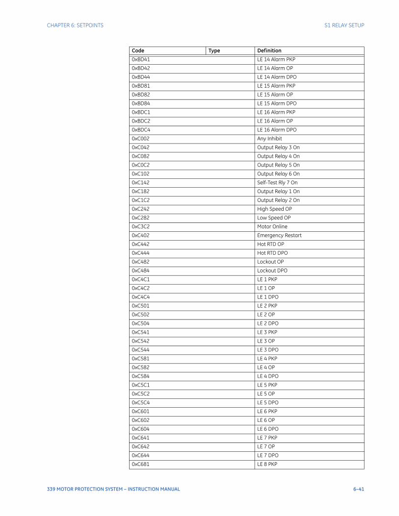
CHAPTER 6: SETPOINTS S1 RELAY SETUP
339 MOTOR PROTECTION SYSTEM – INSTRUCTION MANUAL 6–41
0xBD41 LE 14 Alarm PKP
0xBD42 LE 14 Alarm OP
0xBD44 LE 14 Alarm DPO
0xBD81 LE 15 Alarm PKP
0xBD82 LE 15 Alarm OP
0xBD84 LE 15 Alarm DPO
0xBDC1 LE 16 Alarm PKP
0xBDC2 LE 16 Alarm OP
0xBDC4 LE 16 Alarm DPO
0xC002 Any Inhibit
0xC042 Output Relay 3 On
0xC082 Output Relay 4 On
0xC0C2 Output Relay 5 On
0xC102 Output Relay 6 On
0xC142 Self-Test Rly 7 On
0xC182 Output Relay 1 On
0xC1C2 Output Relay 2 On
0xC242 High Speed OP
0xC282 Low Speed OP
0xC3C2 Motor Online
0xC402 Emergency Restart
0xC442 Hot RTD OP
0xC444 Hot RTD DPO
0xC482 Lockout OP
0xC484 Lockout DPO
0xC4C1 LE 1 PKP
0xC4C2 LE 1 OP
0xC4C4 LE 1 DPO
0xC501 LE 2 PKP
0xC502 LE 2 OP
0xC504 LE 2 DPO
0xC541 LE 3 PKP
0xC542 LE 3 OP
0xC544 LE 3 DPO
0xC581 LE 4 PKP
0xC582 LE 4 OP
0xC584 LE 4 DPO
0xC5C1 LE 5 PKP
0xC5C2 LE 5 OP
0xC5C4 LE 5 DPO
0xC601 LE 6 PKP
0xC602 LE 6 OP
0xC604 LE 6 DPO
0xC641 LE 7 PKP
0xC642 LE 7 OP
0xC644 LE 7 DPO
0xC681 LE 8 PKP
Code Type Definition
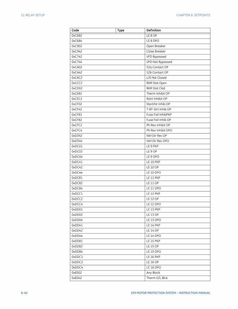
6–42 339 MOTOR PROTECTION SYSTEM – INSTRUCTION MANUAL
S1 RELAY SETUP CHAPTER 6: SETPOINTS
0xC682 LE 8 OP
0xC684 LE 8 DPO
0xC902 Open Breaker
0xC942 Close Breaker
0xC742 VFD Bypassed
0xC744 VFD Not Bypassed
0xCA02 52a Contact OP
0xCA42 52b Contact OP
0xCAC2 L/O Rst Closed
0xCCC2 BKR Stat Open
0xCD02 BKR Stat Clsd
0xCE82 Therm Inhibit OP
0xCEC2 Rstrt Inhibit OP
0xCF02 Start/Hr Inhib OP
0xCF42 T-BT-Strt Inhib OP
0xCF81 Fuse Fail InhibPKP
0xCF82 Fuse Fail Inhib OP
0xCFC2 Ph Rev Inhibit OP
0xCFC4 Ph Rev Inhibit DPO
0xD342 Ntrl Dir Rev OP
0xD344 Ntrl Dir Rev DPO
0xDC01 LE 9 PKP
0xDC02 LE 9 OP
0xDC04 LE 9 DPO
0xDC41 LE 10 PKP
0xDC42 LE 10 OP
0xDC44 LE 10 DPO
0xDC81 LE 11 PKP
0xDC82 LE 11 OP
0xDC84 LE 11 DPO
0xDCC1 LE 12 PKP
0xDCC2 LE 12 OP
0xDCC4 LE 12 DPO
0xDD01 LE 13 PKP
0xDD02 LE 13 OP
0xDD04 LE 13 DPO
0xDD41 LE 14 PKP
0xDD42 LE 14 OP
0xDD44 LE 14 DPO
0xDD81 LE 15 PKP
0xDD82 LE 15 OP
0xDD84 LE 15 DPO
0xDDC1 LE 16 PKP
0xDDC2 LE 16 OP
0xDDC4 LE 16 DPO
0xE002 Any Block
0xE042 Therm O/L Blck
Code Type Definition
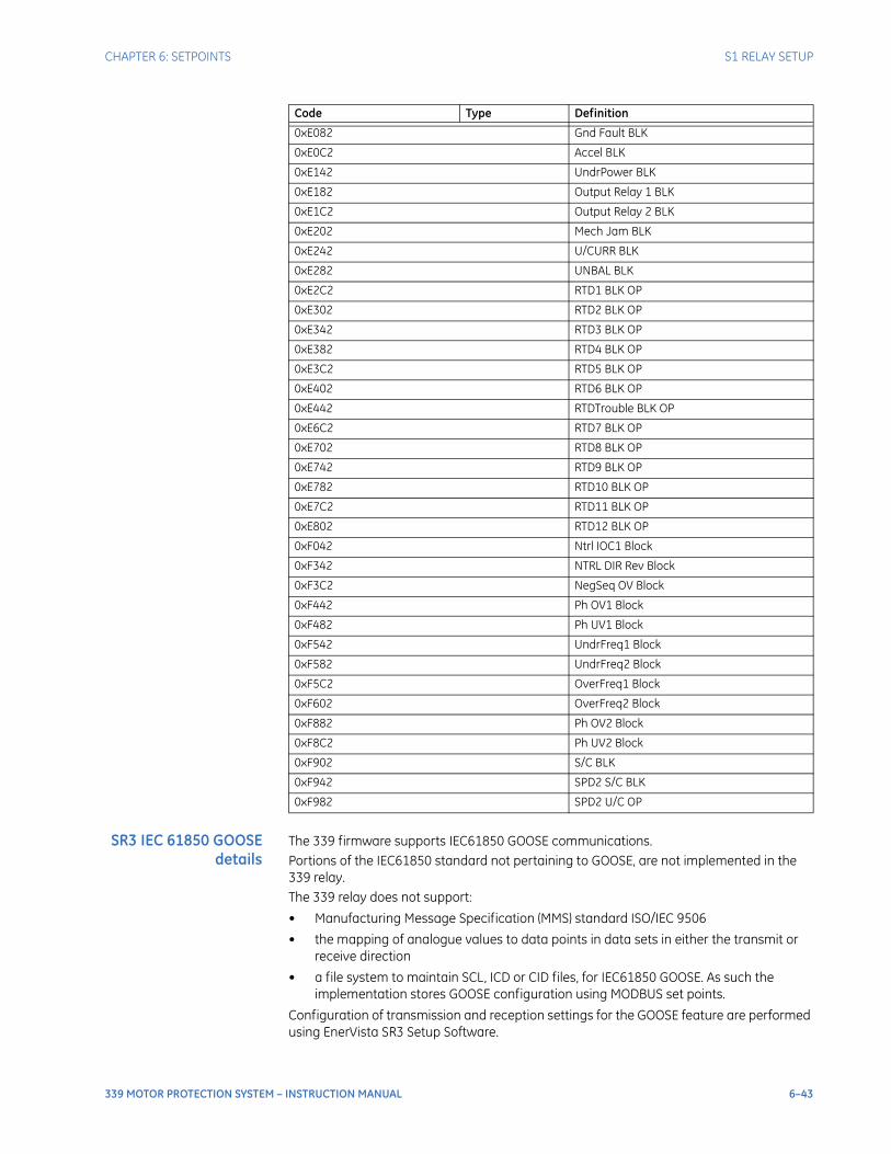
CHAPTER 6: SETPOINTS S1 RELAY SETUP
339 MOTOR PROTECTION SYSTEM – INSTRUCTION MANUAL 6–43
SR3 IEC 61850 GOOSEdetails
The 339 firmware supports IEC61850 GOOSE communications.Portions of the IEC61850 standard not pertaining to GOOSE, are not implemented in the 339 relay.The 339 relay does not support:
• Manufacturing Message Specification (MMS) standard ISO/IEC 9506
• the mapping of analogue values to data points in data sets in either the transmit or receive direction
• a file system to maintain SCL, ICD or CID files, for IEC61850 GOOSE. As such the implementation stores GOOSE configuration using MODBUS set points.
Configuration of transmission and reception settings for the GOOSE feature are performed using EnerVista SR3 Setup Software.
0xE082 Gnd Fault BLK
0xE0C2 Accel BLK
0xE142 UndrPower BLK
0xE182 Output Relay 1 BLK
0xE1C2 Output Relay 2 BLK
0xE202 Mech Jam BLK
0xE242 U/CURR BLK
0xE282 UNBAL BLK
0xE2C2 RTD1 BLK OP
0xE302 RTD2 BLK OP
0xE342 RTD3 BLK OP
0xE382 RTD4 BLK OP
0xE3C2 RTD5 BLK OP
0xE402 RTD6 BLK OP
0xE442 RTDTrouble BLK OP
0xE6C2 RTD7 BLK OP
0xE702 RTD8 BLK OP
0xE742 RTD9 BLK OP
0xE782 RTD10 BLK OP
0xE7C2 RTD11 BLK OP
0xE802 RTD12 BLK OP
0xF042 Ntrl IOC1 Block
0xF342 NTRL DIR Rev Block
0xF3C2 NegSeq OV Block
0xF442 Ph OV1 Block
0xF482 Ph UV1 Block
0xF542 UndrFreq1 Block
0xF582 UndrFreq2 Block
0xF5C2 OverFreq1 Block
0xF602 OverFreq2 Block
0xF882 Ph OV2 Block
0xF8C2 Ph UV2 Block
0xF902 S/C BLK
0xF942 SPD2 S/C BLK
0xF982 SPD2 U/C OP
Code Type Definition
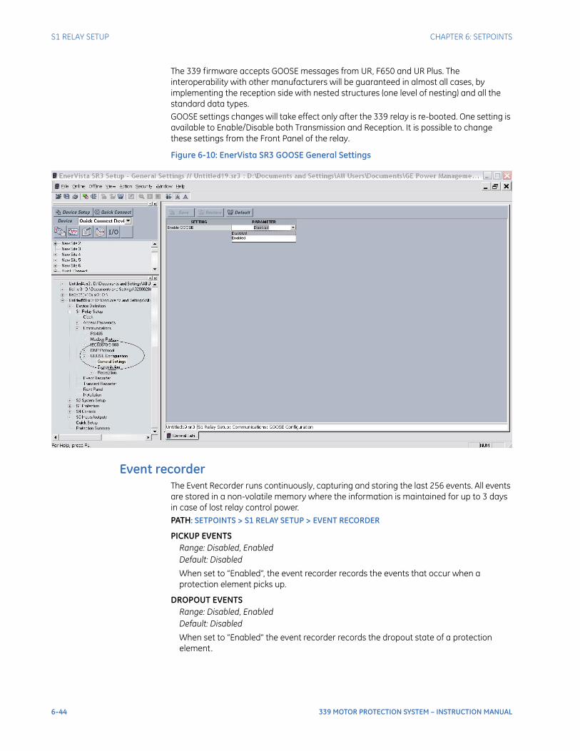
6–44 339 MOTOR PROTECTION SYSTEM – INSTRUCTION MANUAL
S1 RELAY SETUP CHAPTER 6: SETPOINTS
The 339 firmware accepts GOOSE messages from UR, F650 and UR Plus. The interoperability with other manufacturers will be guaranteed in almost all cases, by implementing the reception side with nested structures (one level of nesting) and all the standard data types.GOOSE settings changes will take effect only after the 339 relay is re-booted. One setting is available to Enable/Disable both Transmission and Reception. It is possible to change these settings from the Front Panel of the relay.
Figure 6-10: EnerVista SR3 GOOSE General Settings
Event recorderThe Event Recorder runs continuously, capturing and storing the last 256 events. All events are stored in a non-volatile memory where the information is maintained for up to 3 days in case of lost relay control power. PATH: SETPOINTS > S1 RELAY SETUP > EVENT RECORDER
PICKUP EVENTSRange: Disabled, EnabledDefault: Disabled
When set to “Enabled”, the event recorder records the events that occur when a protection element picks up.
DROPOUT EVENTSRange: Disabled, EnabledDefault: Disabled
When set to “Enabled” the event recorder records the dropout state of a protection element.
CHAPTER 6: SETPOINTS S1 RELAY SETUP
339 MOTOR PROTECTION SYSTEM – INSTRUCTION MANUAL 6–45
TRIP EVENTSRange: Disabled, EnabledDefault: Enabled
The trip events include all programmed relay elements set to trip the breaker. The text “TRIP” followed by the name of the operated element is recorded.
ALARM EVENTSRange: Disabled, EnabledDefault: Enabled
These events include the elements programmed as an “ALARM” or “LATCHED ALARM” function, which detect power system conditions considered as an alarm.
CONTROL EVENTSRange: Disabled, EnabledDefault: Enabled
If set to “Enabled”, the event recorder records events caused by the performance of the programmed control elements.
CONTACT INPUTSRange: Disabled, EnabledDefault: Enabled
When set to “Enabled”, the event recorder will record the event, when a contact input changes its state.
LOGIC ELEMENTRange: Disabled, EnabledDefault: Enabled
When set to “Enabled”, the event recorder records the events, which occur upon state change of any programmed logic element.
VIRTUAL INPUTSRange: Disabled, EnabledDefault: Enabled
When set to “Enabled”, the event recorder records the events, which occur upon state changes of any virtual input.
REMOTE INPUTSRange: Disabled, EnabledDefault: Enabled
When set to “Enabled”, the event recorder records the events, which occur upon state change of any programmed remote input.
Transient recorderThe Transient Recorder contains waveforms captured at the same sampling rate as the other relay data at the point of trigger. By default, data is captured for the analog current and voltage inputs - Ia, Ib, Ic, Ig, Va, Vb, Vc, and Vx when relay is ordered with CTs and VTs, or only analog current inputs Ia, Ib, Ic, and Ig when relay is ordered without VTs. Triggering of the transient recorder occurs, when an event is detected, causing a pickup, trip, dropout, or alarm, any one of which has been "Enabled" to activate the trigger. The transient recorder trigger may also be activated when any of the selected trigger inputs 1 to 3 is detected as having “On” status. The following path is available using the keypad. For instructions on how to use the keypad, please refer to Chapter 3 - Working with the Keypad.PATH: SETPOINTS > S1 RELAY SETUP > TRANSIENT RECDR
6–46 339 MOTOR PROTECTION SYSTEM – INSTRUCTION MANUAL
S1 RELAY SETUP CHAPTER 6: SETPOINTS
BUFFER SETUPRange: 1 x 192, 3 x 64, 6 x 32Default: 1 x 192
Each selection from the range is expressed by two numbers; the first identifies the number of records, whereas the second stands for the number of cycles per record.
TRIGGER MODERange: Overwrite, ProtectedDefault: Overwrite
When the “Overwrite” setting is selected, the new records overwrite the old ones, meaning the relay will always keep the newest records. In “Protected” mode, the relay will keep the number of records corresponding to the selected number, only without overwriting.
TRIGGER POSITIONRange: 0 to 100% in steps of 1%Default: 20%
This setting indicates the location of the trigger with respect to the selected length of record. For example at 20% selected trigger position, the length of each record will be split on 20% pre-trigger data, and 80% post-trigger data.
TRIGGER ON PKPRange: Off, OnDefault: Off
Selection of “Yes” setting enables triggering for the recorder upon Pickup condition detected from any protection or control element.
TRIGGER ON DPORange: Off, OnDefault: Off
Selection of “Yes” setting enables triggering for the recorder upon a Dropout condition detected from any protection or control element.
TRIGGER ON TRIPRange: Off, OnDefault: Off
Selection of “Yes” setting enables triggering for the recorder upon Trip condition detected from any protection or control element.
TRIGGER ON ALARMRange: Off, OnDefault: Off
Selection of “Yes” setting enables triggering for the recorder upon Alarm condition detected from any protection or control element.
TRIGGER ON INPUT 1 to 3Range: Off, Contact Input 1 to 10, Virtual Input 1 to 32, Remote Input 1 to 32, Logic Element 1 to 16Default: Off
Selection of input or logic element from the settings range enables triggering input for the recorder. A record will be triggered if the status of the selected input changes to “On”.
DataloggerThe following setpoints are available:
CHAPTER 6: SETPOINTS S1 RELAY SETUP
339 MOTOR PROTECTION SYSTEM – INSTRUCTION MANUAL 6–47
SAMPLE RATERange: 1 cycle, 1 second, 1 minute, 1 hourDefault: 1 second
Determines how often data is stored in the data log.
CONTINUOUS MODERange: Disabled, EnabledDefault: Disabled
Determines whether or not the trigger data is overwritten with new data. Enabled will overwrite the previous trigger data with new trigger data. When Disabled, the data log will run until filled with 256 samples. Continuous Mode should be used when the data is stored externally by a polling system. The sample rate should be chosen to match the poll rate of the external program.
TRIGGER POSITIONRange: 0 to 100% steps of 1%Default: 25%
Percentage of the sample buffer used for pretrigger samples.
TRIGGER SOURCERange: Command, Logic Element 1 to 8, Any Trip Pickup, Any Trip, Any Trip Dropout, Any Alarm Pickup, Any Alarm, Any Alarm Dropout, Any InhibitDefault: Command
Selects a trigger source. Command is always active. Logic Elements can be used to create combinations of trigger sources.
CHANNEL 1 SOURCERange: Disabled, Phase A Current, Phase B Current, Phase C Current, Average Phase Current, Motor Load, Current Unbalance, Ground Current, System Frequency, Vab, Vbc, Vca, Van, Vbn, Vcn, Power Factor, Real Power (kW), Reactive Power (kvar), Apparent Power (kVA), Positive Watthours, Positive Varhours, Hottest Stator RTD, Thermal Capacity Used, RTD #1, RTD #2, RTD #3, RTD #4, RTD #5, RTD #6, RTD #7, RTD #8, RTD #9, RTD #10, RTD #11, RTD #12Default: Disabled
Selects the data to be stored for each sample of the data log channel.
NOTE
NOTE: Sources and Defaults for Channels 2 to 10 are the same as those for Channel 1.
Front panelThe user can send a message to the display, that will override any normal message by sending text through Modbus. Refer to the 339 Feeder Protection System Communications Guide for register details.PATH: SETPOINTS > S1 RELAY SETUP > FRONT PANEL
FLASH MESSAGE TIMERange: 1 s to 65535 sDefault: 5 s
Flash messages are status, warning, error, or information messages displayed for several seconds in response to certain key presses during setting programming. These messages override any normal messages. The duration of a flash message on the display can be changed to accommodate different reading rates.

6–48 339 MOTOR PROTECTION SYSTEM – INSTRUCTION MANUAL
S1 RELAY SETUP CHAPTER 6: SETPOINTS
MESSAGE TIMEOUTRange: 1 s to 65535 sDefault: 30 s
If the keypad is inactive for a period of time, the relay automatically reverts to a default message. The inactivity time is modified via this setting to ensure messages remain on the screen long enough during programming or reading of actual values.
SCREEN SAVERRange: Off, 1 min to 10000 minDefault: Off
The life of the LCD backlight can be prolonged by enabling the Screen Saver mode.
If the keypad is inactive for the selected period of time, the relay automatically shuts off the LCD screen. Any activity (keypress, alarm, trip, or target message) will restore screen messages.
LED STOPPED COLORRange: None, Red, Green, OrangeDefault: Red
Allows the user to select the color of the LED indicator for Motor Stopped status.
LED STARTING COLORRange: None, Red, Green, OrangeDefault: Orange
Allows the user to select the color of the LED indicator for Motor Starting status.
LED RUNNING COLORRange: None, Red, Green, OrangeDefault: Green
Allows the user to select the color of the LED indicator for Motor Running status.
InstallationPATH: SETPOINTS > S1 RELAY SETUP > INSTALLATION
RELAY NAMERange: Motor Name, Alpha-numeric (18 characters)Default: Motor Name
The RELAY NAME setting allows the user to uniquely identify a relay. This name will appear on generated reports. This name is also used to identify specific devices which are engaged in automatically sending/receiving data over the communications channel.
RELAY STATUSRange: Not Ready, ReadyDefault: Not Ready
Allows the user to activate/deactivate the relay. The relay is not operational when set to "Not Ready."
VALIDATE RMIORange: Yes, NoDefault: No
The 339 relay allows remote metering and programming for up to 12 RTDs via a .CANBUS-based RMIO module. Refer to Chapter 2 - RMIO Installation for details. The 339 will automatically detect the installed RMIO cards when the relay is booted, at which time the user must send a YES command to validate the RMIO. Otherwise the 339 relay will issue a RMIO MISMATCH self-test error. It is recommended to power cycle the 339 after validating the RMIO module.
CHAPTER 6: SETPOINTS S1 RELAY SETUP
339 MOTOR PROTECTION SYSTEM – INSTRUCTION MANUAL 6–49
Preset statisticsThese commands can be used to preset the motor statistic data on new installations or existing installations where new equipment has been installed.PATH: SETPOINTS > S1 RELAY SETUP > PRESET STATISTICS
SET MOTOR STARTSRange: 0 to 50000 in steps of 1Default: 0
This command presets the number of motor starts.
SET EMERG RESTARTSRange: 0 to 50000 in steps of 1Default: 0
This command presets the number of motor emergency restarts.
SET RUNNING HOURSRange: 0 to 65535 in steps of 1Default: 0
This command presets the value of motor running hours.
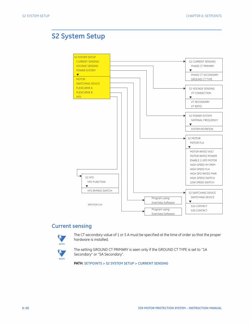
6–50 339 MOTOR PROTECTION SYSTEM – INSTRUCTION MANUAL
S2 SYSTEM SETUP CHAPTER 6: SETPOINTS
S2 System Setup
Current sensing
NOTE
NOTE: The CT secondary value of 1 or 5 A must be specified at the time of order so that the proper hardware is installed.
NOTE
NOTE: The setting GROUND CT PRIMARY is seen only if the GROUND CT TYPE is set to “1A Secondary” or “5A Secondary”.
PATH: SETPOINTS > S2 SYSTEM SETUP > CURRENT SENSING
S2 CURRENT SENSING PHASE CT PRIMARY
PHASE CT SECONDARY GROUND CT TYPE
S2 SYSTEM SETUP CURRENT SENSING VOLTAGE SENSING POWER SYSTEM
MOTOR SWITCHING DEVICE FLEXCURVE A FLEXCURVE B VFD
896765A3.cdr
S2 SWITCHING DEVICE SWITCHING DEVICE
52a CONTACT 52b CONTACT
S2 MOTOR MOTOR FLA
MOTOR RATED VOLT MOTOR RATED POWER ENABLE 2-SPD MOTOR HIGH SPEED PH PRIM HIGH SPEED FLA HIGH SPD RATED PWR HIGH SPEED SWITCH LOW SPEED SWITCH
S2 VOLTAGE SENSING VT CONNECTION
VT SECONDARY VT RATIO
S2 POWER SYSTEM NOMINAL FREQUENCY
SYSTEM ROTATION
Program usingEnerVista Software
Program usingEnerVista Software
S2 VFD VFD FUNCTION
VFD BYPASS SWITCH
CHAPTER 6: SETPOINTS S2 SYSTEM SETUP
339 MOTOR PROTECTION SYSTEM – INSTRUCTION MANUAL 6–51
PHASE CT PRIMARYRange: 10 to 1500 A in steps of 1 ADefault: 100 A
The phase CT should be chosen so that the FLA is no less than 50% of the rated phase CT primary. Ideally, the phase CT primary should be chosen so that the FLA is 100% of the phase CT primary or slightly less; never more.
PHASE CT SECONDARYRange: 1 A or 5 ADefault: 5 A
Configurable 1 A or 5 A secondary, available with Phase Current option ‘P0’ installed. Enter the rated phase CT secondary current of the three-phase current transformers.
GROUND CT TYPE
Range: 50:0.025, 1A Secondary, 5A Secondary, NoneDefault: 50:0.025
Depending on this setting, the current measured by the Ground Fault Protection element can be either the Core Balance CT current or the fourth CT input current.
The 339 has an isolating transformer with 1A or 5A Ground CT terminals and CBCT 50:0.025 terminals. Only one ground CT input tap should be used on a given unit. There are no internal ground connections on the ground current inputs.
For high-resistance grounded systems, sensitive ground current detection is possible if the Core Balance CT (CBCT) 50:0.025 is used. For example, in mining applications where earth leakage current must be measured for personnel safety, primary ground current as low as 0.25A may be detected with the GE Multilin 50:0.025 CT. For these applications, select the setting GROUND CT TYPE as “50:0.025”.
For solid or low-resistance grounded systems where fault currents may be quite large, ground sensing is possible with a zero-sequence CT or residually connected phase CTs as shown in the figure below. For these applications, select the setting GROUND CT TYPE as “1A secondary” or “5A secondary”. If the connection is residual, the Ground CT secondary and primary values should be set the same as those of the Phase CT. If however, the connection is zero-sequence CT, the Ground CT secondary and primary values must be entered as per the selected CT. The Ground CT should be selected such that the potential fault current does not exceed 20 times the primary rating. When relaying class CTs are purchased, this precaution will ensure that the Ground CT does not saturate under fault conditions.
GROUND CT PRIMARY
Range: 30 TO 1500 A in steps of 1 ADefault: 100 A
Set the Ground CT primary when the setting GROUND CT TYPE is selected as “1A secondary” or “5A secondary”.
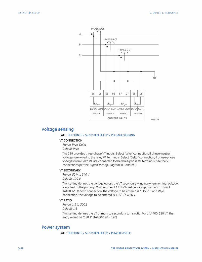
6–52 339 MOTOR PROTECTION SYSTEM – INSTRUCTION MANUAL
S2 SYSTEM SETUP CHAPTER 6: SETPOINTS
Voltage sensingPATH: SETPOINTS > S2 SYSTEM SETUP > VOLTAGE SENSING
VT CONNECTIONRange: Wye, DeltaDefault: Wye
The 339 provides three-phase VT inputs. Select “Wye” connection, if phase-neutral voltages are wired to the relay VT terminals. Select “Delta” connection, if phase-phase voltages from Delta VT are connected to the three-phase VT terminals. See the VT connections per the Typical Wiring Diagram in Chapter 2.
VT SECONDARYRange: 50 V to 240 VDefault: 120 V
This setting defines the voltage across the VT secondary winding when nominal voltage is applied to the primary. On a source of 13.8kV line-line voltage, with a VT ratio of 14400:120 V delta connection, the voltage to be entered is “115 V”. For a Wye connection, the voltage to be entered is 115/ √3 = 66 V.
VT RATIORange: 1:1 to 300:1Default: 1:1
This setting defines the VT primary to secondary turns ratio. For a 14400: 120 VT, the entry would be “120:1” (14400/120 = 120).
Power systemPATH: SETPOINTS > S2 SYSTEM SETUP > POWER SYSTEM
896827.cdrCURRENT INPUTS
PHASE A PHASE B PHASE C GROUND
1A/5A COMCOM COM COM1A/5A 1A/5A 1A/5A
E5 D5 E6 E7 E8D6 D7 D8
PHASE A CT
PHASE B CT
PHASE C CT
A
B
C
CHAPTER 6: SETPOINTS S2 SYSTEM SETUP
339 MOTOR PROTECTION SYSTEM – INSTRUCTION MANUAL 6–53
NOMINAL FREQUENCYRange: 60 Hz, 50 HzDefault: 60 Hz
Enter the nominal power system frequency here. This value is used as a default to set theoptimal digital sampling rate.
SYSTEM ROTATIONRange: ABC, ACB, Default: ABC
Enter the phase sequence of the power system.
MotorMOTOR FLA
Range: 15.0 to 1500.0 A in steps of 0.1 ADefault: 100 A
This setting is used to specify the Full Load Amp for normal (Low) Speed.
MOTOR RATED VOLTRange: 100 to 20000 VAC in steps of 1 VDefault: 3000 V
This setting is used to specify the Rated Voltage of the motor.
MOTOR RATED POWERRange: 100 to 10000 kW in steps of 1 kWDefault: 3000 kW
This setting is used to specify the Rated Power of the motor at normal (Low) speed.
ENABLE 2-SPD MOTORRange: Disabled, EnabledDefault: Disabled
This setting is used to enable two-speed motor functionality. When this setting is selected as Disabled, all two-speed motor functionalities will be disabled, and all other two-speed motor related settings are hidden.
HI SPEED PRIM30 to 1500 A in steps of 1 ADefault: 100 A
This setting is used to specify the Phase CT primary for High Speed.
HIGH SPEED FLARange: 15.0 to 1500.0 A in steps of 0.1 ADefault: 100.0 A
This setting is used to specify the Full Load Amp for High Speed.
HIGH SPEED RATED PWRRange: 100 to 10000 kW in steps of 1 kWDefault: 3000 kW
This setting is used to specify the rated power for High Speed.

6–54 339 MOTOR PROTECTION SYSTEM – INSTRUCTION MANUAL
S2 SYSTEM SETUP CHAPTER 6: SETPOINTS
HIGH SPEED SWITCHRange: Off, Contact Input 1 to 10, Virtual Input 1 through 32, Logic element 1 through 16, Remote Input 1 to 32Default: Off
For use in two speed motor applications only, to monitor the high speed contactor position. The status of this switch is used by the relay to select between the normal settings used for low speed operation and the high speed settings, and to ensure that in high speed operation the relay maintains running status when current draw is very low. Use a form-a (normally open) auxiliary contact of the high speed (speed 2) contactor.
LOW SPEED SWITCHRange: Off, Contact Input 1 to 10, Virtual Input 1 through 32, Logic element 1 through 16, Remote Input 1 to 32Default: Off
For use in two speed motor applications only, to monitor the low speed contactor position. The status of this switch is used by the relay to ensure that in low speed operation the relay maintains running status when current draw is very low. Use a form-a (normally open) auxiliary contact of the low speed (speed 1) contactor.
Switching device52a CONTACT
Range: Disabled, EnabledDefault: Disabled
The 52a contact function is permanently assigned to contact input number 1. It in single-speed applications, when enabled, closure of this contact informs the relay that the motor is connected to the line (online) and therefore the motor is running. It is recommended that this contact be connected to a form-a (normally open) auxiliary contact of the breaker/contactor, to ensure the relay maintains running status when motor current draw is very low. The 52b contact (see below) has the same function, and is for use when only a form-b (normally closed) auxiliary contact is available.
In two-speed applications, this contact is intended for monitoring the circuit breaker where there is a circuit breaker as well as a high speed contactor and a low speed contactor. When enabled and closed, and when one of the contactors is closed, the relay maintains running status even when the motor current is very small.
52b CONTACTRange: Disabled, EnabledDefault: Disabled
The 52b contact function is permanently assigned to contact input 2. It performs the same function as the 52a contact, but with a form-b (normally closed) rather than a form-a (normally) auxiliary contact of the breaker/contactor.
If both 52a contact and 52b contact are enabled, the relay assumes the motor online if the 52a contact is closed and the 52b contact is open.
FlexCurvesThere are two user-programmable FlexCurves™ available with the 339 system, labeled A and B.For details on FlexCurves please refer to S3 Protection/Thermal Protection in this manual.
NOTE
NOTE: The Standard Curve and Flexcurves A and B are available for programming under EnerVista SR3 Setup software.
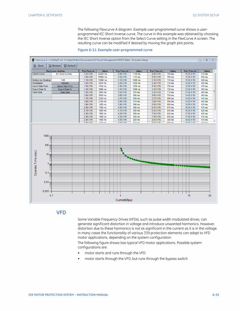
CHAPTER 6: SETPOINTS S2 SYSTEM SETUP
339 MOTOR PROTECTION SYSTEM – INSTRUCTION MANUAL 6–55
The following Flexcurve A diagram: Example user-programmed curve shows a user-programmed IEC Short Inverse curve. The curve in this example was obtained by choosing the IEC Short Inverse option from the Select Curve setting in the FlexCurve A screen. The resulting curve can be modified if desired by moving the graph plot points.
Figure 6-11: Example user-programmed curve
VFDSome Variable Frequency Drives (VFDs), such as pulse width modulated drives, can generate significant distortion in voltage and introduce unwanted harmonics. However, distortion due to these harmonics is not as significant in the current as it is in the voltage. In many cases the functionality of various 339 protection elements can adapt to VFD motor applications, depending on the system configuration.The following figure shows two typical VFD motor applications. Possible system configurations are:
• motor starts and runs through the VFD
• motor starts through the VFD, but runs through the bypass switch
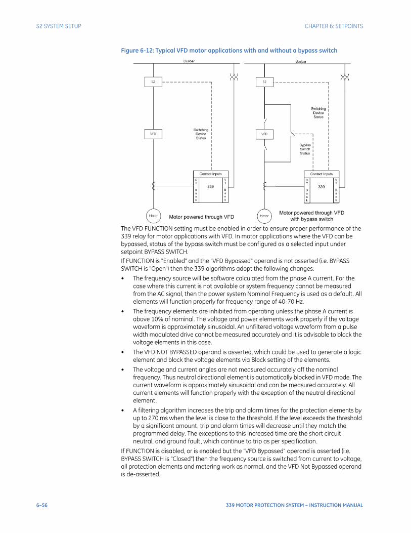
6–56 339 MOTOR PROTECTION SYSTEM – INSTRUCTION MANUAL
S2 SYSTEM SETUP CHAPTER 6: SETPOINTS
Figure 6-12: Typical VFD motor applications with and without a bypass switch
The VFD FUNCTION setting must be enabled in order to ensure proper performance of the 339 relay for motor applications with VFD. In motor applications where the VFD can be bypassed, status of the bypass switch must be configured as a selected input under setpoint BYPASS SWITCH. If FUNCTION is "Enabled" and the "VFD Bypassed" operand is not asserted (i.e. BYPASS SWITCH is "Open") then the 339 algorithms adopt the following changes:
• The frequency source will be software calculated from the phase A current. For the case where this current is not available or system frequency cannot be measured from the AC signal, then the power system Nominal Frequency is used as a default. All elements will function properly for frequency range of 40-70 Hz.
• The frequency elements are inhibited from operating unless the phase A current is above 10% of nominal. The voltage and power elements work properly if the voltage waveform is approximately sinusoidal. An unfiltered voltage waveform from a pulse width modulated drive cannot be measured accurately and it is advisable to block the voltage elements in this case.
• The VFD NOT BYPASSED operand is asserted, which could be used to generate a logic element and block the voltage elements via Block setting of the elements.
• The voltage and current angles are not measured accurately off the nominal frequency. Thus neutral directional element is automatically blocked in VFD mode. The current waveform is approximately sinusoidal and can be measured accurately. All current elements will function properly with the exception of the neutral directional element.
• A filtering algorithm increases the trip and alarm times for the protection elements by up to 270 ms when the level is close to the threshold. If the level exceeds the threshold by a significant amount, trip and alarm times will decrease until they match the programmed delay. The exceptions to this increased time are the short circuit , neutral, and ground fault, which continue to trip as per specification.
If FUNCTION is disabled, or is enabled but the "VFD Bypassed" operand is asserted (i.e. BYPASS SWITCH is "Closed") then the frequency source is switched from current to voltage, all protection elements and metering work as normal, and the VFD Not Bypassed operand is de-asserted.
CHAPTER 6: SETPOINTS S3 PROTECTION
339 MOTOR PROTECTION SYSTEM – INSTRUCTION MANUAL 6–57
Voltage inputs to the 339 motor protection relay are normally measured at the busbar side of the VFD where they are substantially sinusoidal. Since the output phase voltages from a VFD are not sinusoidal and are distorted due to harmonics generated by the VFD, blocking the voltage elements via the Block setting using the “VFD Not Bypassed” operand is recommended. On the other hand, when voltages are measured at the motor side of the VFD, voltages at the motor terminals and relay inputs are same, thus blocking the voltage elements is not required. In addition, significant distortion in the voltage waveforms is not always the case and really depends on the VFD type. If the input voltages are substantially sinusoidal, which can be verified from 339 metering, oscillography, and the data logger, then blocking the voltage elements is not required.PATH: SETPOINTS > S2 SYSTEM SETUP > VFD
FUNCTIONRange: Disable, EnabledDefault: Disabled
This setting enables VFD support.
BYPASS SWITCHRange: Off, Contact Input 1 to 10, Virtual Input 1 to 32, Remote Input 1 to 32, Logic Element 1 to 16Default: Off
This setting defines the source used to determine if the motor is powered by the VFD or directly from the AC source through the bypass switch. The "VFD Bypassed" operand will be asserted when VFD is bypassed i.e. motor is directly powered by the AC system or the utility. This operand can be used to generate a Logic Element for blocking voltage based elements via the Block setting if this operand is not asserted i.e. VFD is not bypassed.
NOTE
NOTE: Blocking the voltage based elements via the Block setting of the desired elements is highly recommended if "VFD Not Bypassed" is asserted
S3 Protection
339 protection functions include:
• Thermal Protection
• Short Circuit
• Ground Fault
• Mechanical Jam
• Undercurrent
• Current Unbalance
• Load Increase
• Neutral IOC
• Neutral Directional OC
• RTD Protection
• Phase Undervoltage
• Phase Overvoltage
• Overfrequency
• Underfrequency
• Underpower
• Voltage Phase Reversal

6–58 339 MOTOR PROTECTION SYSTEM – INSTRUCTION MANUAL
S3 PROTECTION CHAPTER 6: SETPOINTS
• VT Fuse Fail
• Negative Sequence Overvoltage
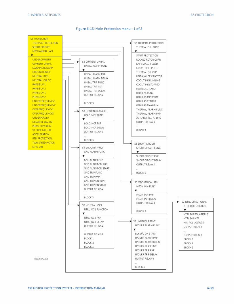
CHAPTER 6: SETPOINTS S3 PROTECTION
339 MOTOR PROTECTION SYSTEM – INSTRUCTION MANUAL 6–59
Figure 6-13: Main Protection menu - 1 of 2
S3 PROTECTION
SHORT CIRCUIT
MECHANICAL JAM
UNDERCURRENT
CURRENT UNBAL
LOAD INCR ALARM
GROUND FAULT
NEUTRAL IOC1
NEUTRAL DIR OC
PHASE UV 1
PHASE OV 1
UNDERFREQUENCY1
NEGATIVE SEQ OV
PHASE REVERSAL
VT FUSE FAILURE
ACCELERATION
RTD PROTECTION
TWO SPEED MOTOR
NTRL DIR
THERMAL PROTECTION
PHASE UV 2
PHASE OV 2
UNDERFREQUENCY2
OVERFREQUENCY1
OVERFREQUENCY2
UNDERPOWER
S3 THERMAL PROTECTION
THERMAL O/L FUNC
START PROTECTION
LOCKED ROTOR CURR
SAFE STALL T COLD
CURVE MULTIPLIER
THERMAL O/L PKP
UNBALANCE K FACTOR
COOL TIME RUNNING
COOL TIME STOPPED
HOT/COLD RATIO
RTD BIAS FUNC
...
BLOCK 3
RTD BIAS MINIMUM
RTD BIAS CENTER
RTD BIAS MAXIMUM
THERMAL ALARM FUNC
THERMAL ALARM PKP
AUTO RST TCU 15%
OUTPUT RELAY 4
≤
S3 SHORT CIRCUIT
SHORT CIRCUIT FUNC
PKP
DELAY
OUTPUT RELAY 4
BLOCK 3
SHORT CIRCUIT
SHORT CIRCUIT
...
896758A2. cdr
S3 MECHANICAL JAM
MECH JAM FUNC
MECH JAM PKP
MECH JAM DELAY
OUTPUT RELAY 4
BLOCK 3
...
S3 UNDERCURRENT
U/CURR ALARM FUNC
BLK U/C ON START
OUTPUT RELAY 4
...
BLOCK 3
U/CURR ALARM PKP
U/CURR ALARM DELAY
U/CURR TRIP FUNC
U/CURR TRIP PKP
U/CURR TRIP DELAY
S3 CURRENT UNBAL
UNBAL ALARM FUNC
OUTPUT RELAY 4
...
BLOCK 3
UNBAL ALARM PKP
UNBAL ALARM DELAY
UNBAL TRIP FUNC
UNBAL TRIP PKP
UNBAL TRIP DELAY
S3 LOAD INCR ALARM
LOAD INCR FUNC
LOAD
LOAD
OUTPUT RELAY 4
...
BLOCK 3
INCR PKP
INCR DELAY
S3 GROUND FAULT
GND ALARM FUNC
GND ALARM ON RUN
GND ALARM ON START
GND TRIP FUNC
GND TRIP ON RUN
GND TRIP ON START
OUTPUT RELAY 4
...
BLOCK 3
GND ALARM PKP
GND TRIP PKP
S3 NEUTRAL IOC1
OUTPUT RELAY 4
...
OUTPUT RELAY 6
BLOCK 1
BLOCK 2
BLOCK 3
NTRL IOC1 FUNCTION
NTRL IOC1 PKP
NTRL IOC1 DELAY
S3 NTRL DIRECTIONAL
NTRL DIR FUNCTION
NTRL DIR POLARIZING
NTRL DIR MTA
MIN POL VOLTAGE
OUTPUT RELAY 3
...
OUTPUT RELAY 6
BLOCK 1
BLOCK 2
BLOCK 3
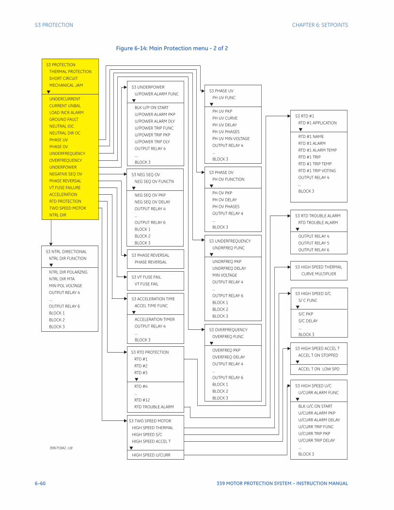
6–60 339 MOTOR PROTECTION SYSTEM – INSTRUCTION MANUAL
S3 PROTECTION CHAPTER 6: SETPOINTS
Figure 6-14: Main Protection menu - 2 of 2
S3 TWO SPEED MOTOR
HIGH SPEED THERMAL
HIGH SPEED S/C
HIGH SPEED ACCEL T
HIGH SPEED U/CURR
S3 RTD PROTECTION
RTD #1
RTD TROUBLE ALARM
RTD #2
RTD #3
RTD #4
...
RTD #12
896759A2. cdr
S3 RTD TROUBLE ALARM
RTD TROUBLE ALARM
OUTPUT RELAY 4
OUTPUT RELAY 6
OUTPUT RELAY 5
S3 RTD #1
RTD #1 APPLICATION
RTD #1 NAME
RTD #1 ALARM
RTD #1 ALARM TEMP
....
BLOCK 3
RTD #1 TRIP
RTD #1 TRIP TEMP
RTD #1 TRIP VOTING
OUTPUT RELAY 4
S3 HIGH SPEED THERMAL
CURVE MULTIPLIER
S3 HIGH SPEED ACCEL T
ACCEL T ON STOPPED
ACCEL T ON LOW SPD
S3 HIGH SPEED U/C
U/CURR ALARM FUNC
BLK U/C ON START
U/CURR ALARM PKP
U/CURR ALARM DELAY
U/CURR TRIP FUNC
U/CURR TRIP PKP
U/CURR TRIP DELAY
...
BLOCK 3
S3 PROTECTION
SHORT CIRCUIT
MECHANICAL JAM
UNDERCURRENT
CURRENT UNBAL
LOAD INCR ALARM
GROUND FAULT
NEUTRAL IOC
NEUTRAL DIR OC
PHASE UV
PHASE OV
UNDERFREQUENCY
PHASE REVERSAL
VT FUSE FAILURE
ACCELERATION
RTD PROTECTION
TWO SPEED MOTOR
NTRL DIR
THERMAL PROTECTION
OVERFREQUENCY
UNDERPOWER
NEGATIVE SEQ OV
S3 ACCELERATION TIME
ACCELERATION TIMER
OUTPUT RELAY 4
BLOCK 3
ACCEL TIME FUNC
...
S3 UNDERPOWER
BLK U/P ON START
U/POWER ALARM PKP
U/POWER ALARM DLY
U/POWER TRIP FUNC
OUTPUT RELAY 4
...
BLOCK 3
U/POWER ALARM FUNC
U/POWER TRIP PKP
U/POWER TRIP DLY
S3 VT FUSE FAIL
VT FUSE FAIL
S3 PHASE REVERSAL
PHASE REVERSAL
S3 HIGH SPEED S/C
S/ C FUNC
S/C PKP
S/C DELAY
...
BLOCK 3
S3 NEG SEQ OV
OUTPUT RELAY 4
...
OUTPUT RELAY 6
BLOCK 1
BLOCK 2
BLOCK 3
NEG SEQ OV FUNCTN
NEG SEQ OV PKP
NEG SEQ OV DELAY
S3 OVERFREQUENCY
OUTPUT RELAY 4
...
OUTPUT RELAY 6
BLOCK 1
BLOCK 2
BLOCK 3
OVERFREQ FUNC
OVERFREQ PKP
OVERFREQ DELAY
S3 UNDERFREQUENCY
OUTPUT RELAY 4
...
OUTPUT RELAY 6
BLOCK 1
BLOCK 2
BLOCK 3
UNDRFREQ FUNC
UNDRFREQ PKP
UNDRFREQ DELAY
MIN VOLTAGE
S3 PHASE OV
OUTPUT RELAY 4
...
BLOCK 3
PH OV FUNCTION
PH OV PKP
PH OV DELAY
PH OV PHASES
S3 PHASE UV
OUTPUT RELAY 4
...
BLOCK 3
PH UV FUNC
PH UV PKP
PH UV CURVE
PH UV DELAY
PH UV PHASES
PH UV MIN VOLTAGE
S3 NTRL DIRECTIONAL
NTRL DIR FUNCTION
NTRL DIR POLARZNG
NTRL DIR MTA
MIN POL VOLTAGE
....
OUTPUT RELAY 6
BLOCK 1
OUTPUT RELAY 4
BLOCK 2
BLOCK 3
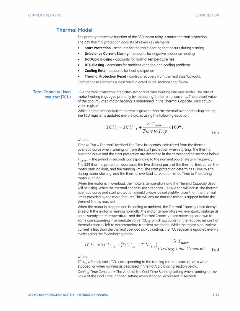
CHAPTER 6: SETPOINTS S3 PROTECTION
339 MOTOR PROTECTION SYSTEM – INSTRUCTION MANUAL 6–61
Thermal ModelThe primary protective function of the 339 motor relay is motor thermal protection. The 339 thermal protection consists of seven key elements:
• Start Protection - accounts for the rapid heating that occurs during starting
• Unbalance Current Biasing - accounts for negative sequence heating
• Hot/Cold Biasing - accounts for normal temperature rise
• RTD Biasing - accounts for ambient variation and cooling problems
• Cooling Rate - accounts for heat dissipation
• Thermal Protection Reset - controls recovery from thermal trips/lockouts.
Each of these elements is described in detail in the sections that follow.
Total Capacity Usedregister (TCU)
339 thermal protection integrates stator and rotor heating into one model. The rate of motor heating is gauged primarily by measuring the terminal currents. The present value of the accumulated motor heating is maintained in the Thermal Capacity Used actual value register. While the motor’s equivalent current is greater than the thermal overload pickup setting, the TCU register is updated every 3 cycles using the following equation:
Eq. 1
where:Time to Trip = Thermal Overload Trip Time in seconds, calculated from the thermal overload curve when running, or from the start protection when starting. The thermal overload curve and the start protection are described in the corresponding sections below.Tsystem = the period in seconds corresponding to the nominal power system frequency.The 339 thermal protection addresses the two distinct parts of the thermal limit curve: the motor starting limit, and the running limit. The start protection determines Time to Trip during motor starting, and the thermal overload curve determines Time to Trip during motor running.When the motor is in overload, the motor’s temperature and the Thermal Capacity Used will be rising. When the thermal capacity used reaches 100%, a trip will occur. The thermal overload curve and start protection should always be set slightly lower than the thermal limits provided by the manufacturer. This will ensure that the motor is tripped before the thermal limit is reached.When the motor is stopped and is cooling to ambient, the Thermal Capacity Used decays to zero. If the motor is running normally, the motor temperature will eventually stabilize at some steady state temperature, and the Thermal Capacity Used moves up or down to some corresponding intermediate value TCUSS, which accounts for the reduced amount of thermal capacity left to accommodate transient overloads. While the motor’s equivalent current is less than the thermal overload pickup setting, the TCU register is updated every 3 cycles using the following equation:
Eq. 2
where:TCUSS = Steady state TCU corresponding to the running terminal current; zero when stopped, or when running as described in the hot/cold biasing section below.Cooling Time Constant = The value of the Cool Time Running setting when running, or the value of the Cool Time Stopped setting when stopped, expressed in seconds.
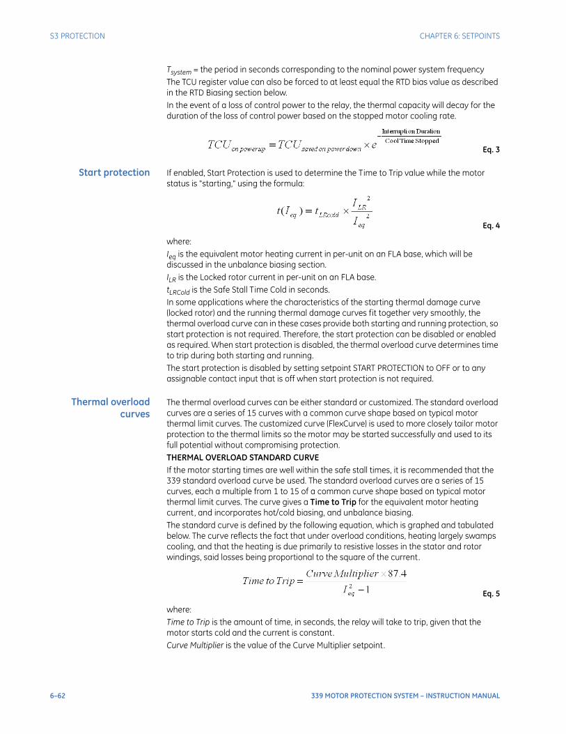
6–62 339 MOTOR PROTECTION SYSTEM – INSTRUCTION MANUAL
S3 PROTECTION CHAPTER 6: SETPOINTS
Tsystem = the period in seconds corresponding to the nominal power system frequencyThe TCU register value can also be forced to at least equal the RTD bias value as described in the RTD Biasing section below.In the event of a loss of control power to the relay, the thermal capacity will decay for the duration of the loss of control power based on the stopped motor cooling rate.
Eq. 3
Start protection If enabled, Start Protection is used to determine the Time to Trip value while the motor status is "starting," using the formula:
Eq. 4
where: Ieq is the equivalent motor heating current in per-unit on an FLA base, which will be discussed in the unbalance biasing section. ILR is the Locked rotor current in per-unit on an FLA base. tLRCold is the Safe Stall Time Cold in seconds.In some applications where the characteristics of the starting thermal damage curve (locked rotor) and the running thermal damage curves fit together very smoothly, the thermal overload curve can in these cases provide both starting and running protection, so start protection is not required. Therefore, the start protection can be disabled or enabled as required. When start protection is disabled, the thermal overload curve determines time to trip during both starting and running.The start protection is disabled by setting setpoint START PROTECTION to OFF or to any assignable contact input that is off when start protection is not required.
Thermal overloadcurves
The thermal overload curves can be either standard or customized. The standard overload curves are a series of 15 curves with a common curve shape based on typical motor thermal limit curves. The customized curve (FlexCurve) is used to more closely tailor motor protection to the thermal limits so the motor may be started successfully and used to its full potential without compromising protection. THERMAL OVERLOAD STANDARD CURVEIf the motor starting times are well within the safe stall times, it is recommended that the 339 standard overload curve be used. The standard overload curves are a series of 15 curves, each a multiple from 1 to 15 of a common curve shape based on typical motor thermal limit curves. The curve gives a Time to Trip for the equivalent motor heating current, and incorporates hot/cold biasing, and unbalance biasing. The standard curve is defined by the following equation, which is graphed and tabulated below. The curve reflects the fact that under overload conditions, heating largely swamps cooling, and that the heating is due primarily to resistive losses in the stator and rotor windings, said losses being proportional to the square of the current.
Eq. 5
where: Time to Trip is the amount of time, in seconds, the relay will take to trip, given that the motor starts cold and the current is constant. Curve Multiplier is the value of the Curve Multiplier setpoint.

CHAPTER 6: SETPOINTS S3 PROTECTION
339 MOTOR PROTECTION SYSTEM – INSTRUCTION MANUAL 6–63
Ieq is the equivalent motor heating current per-unit on an FLA base. However, the value of Ieq is limited in this equation, to 8.0, in order to prevent the overload from acting as an instantaneous element, and responding to short circuits.For example, a motor with a stall current (also known as locked rotor current) of 8 times its FLA, with a Curve Multiplier of 7, if stalled from a cold state, would trip in:
Eq. 6
This would respect a Safe Stall Time Cold of 10 seconds.
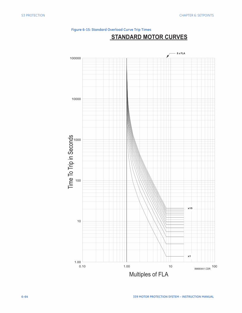
6–64 339 MOTOR PROTECTION SYSTEM – INSTRUCTION MANUAL
S3 PROTECTION CHAPTER 6: SETPOINTS
Figure 6-15: Standard Overload Curve Trip Times
STANDARD MOTOR CURVES
8 x FLA
x1
x15
100000
10000
1000
100
10
1.00
0.10 1.00
Multiples of FLA
Tim
eTo
Trip
inS
econ
ds
10 100896804A1.CDR
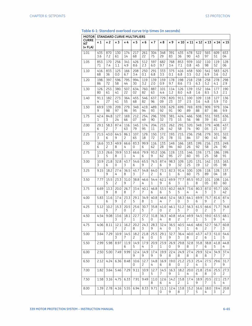
CHAPTER 6: SETPOINTS S3 PROTECTION
339 MOTOR PROTECTION SYSTEM – INSTRUCTION MANUAL 6–65
Table 6-1: Standard overload curve trip times (in seconds)
MOTOR CURRENT (× FLA)
STANDARD CURVE MULTIPLIERS
× 1 × 2 × 3 × 4 × 5 × 6 × 7 × 8 × 9 × 10 × 11 × 12 × 13 × 14 × 15
1.01 4353.6
8707.2
13061
17414
21768
26122
30475
34829
39183
43536
47890
52243
56597
60951
65304
1.05 853.71
1707.4
2561.1
3414.9
4268.6
5122.3
5976.0
6829.7
7683.4
8537.1
9390.8
10245
11098
11952
12806
1.10 416.68
833.36
1250.0
1666.7
2083.4
2500.1
2916.8
3333.5
3750.1
4166.8
4583.5
5000.2
5416.9
5833.6
6250.2
1.20 198.86
397.72
596.58
795.44
994.30
1193.2
1392.0
1590.9
1789.7
1988.6
2187.5
2386.3
2585.2
2784.1
2982.9
1.30 126.80
253.61
380.41
507.22
634.02
760.82
887.63
1014.4
1141.2
1268.0
1394.8
1521.6
1648.5
1775.3
1902.1
1.40 91.14
182.27
273.41
364.55
455.68
546.82
637.96
729.09
820.23
911.37
1002.5
1093.6
1184.8
1275.9
1367.0
1.50 69.99
139.98
209.97
279.96
349.95
419.94
489.93
559.92
629.91
699.90
769.89
839.88
909.87
979.86
1049.9
1.75 42.41
84.83
127.24
169.66
212.07
254.49
296.90
339.32
381.73
424.15
466.56
508.98
551.39
593.81
636.22
2.00 29.16
58.32
87.47
116.63
145.79
174.95
204.11
233.26
262.42
291.58
320.74
349.90
379.05
408.21
437.37
2.25 21.53
43.06
64.59
86.12
107.65
129.18
150.72
172.25
193.78
215.31
236.84
258.37
279.90
301.43
322.96
2.50 16.66
33.32
49.98
66.64
83.30
99.96
116.62
133.28
149.94
166.60
183.26
199.92
216.58
233.24
249.90
2.75 13.33
26.65
39.98
53.31
66.64
79.96
93.29
106.62
119.95
133.27
146.60
159.93
173.25
186.58
199.91
3.00 10.93
21.86
32.80
43.73
54.66
65.59
76.52
87.46
98.39
109.32
120.25
131.19
142.12
153.05
163.98
3.25 9.15 18.29
27.44
36.58
45.73
54.87
64.02
73.16
82.31
91.46
100.60
109.75
118.89
128.04
137.18
3.50 7.77 15.55
23.32
31.09
38.87
46.64
54.41
62.19
69.96
77.73
85.51
93.28
101.05
108.83
116.60
3.75 6.69 13.39
20.08
26.78
33.47
40.17
46.86
53.56
60.25
66.95
73.64
80.34
87.03
93.73
100.42
4.00 5.83 11.66
17.49
23.32
29.15
34.98
40.81
46.64
52.47
58.30
64.13
69.96
75.79
81.62
87.45
4.25 5.12 10.25
15.37
20.50
25.62
30.75
35.87
41.00
46.12
51.25
56.37
61.50
66.62
71.75
76.87
4.50 4.54 9.08 13.63
18.17
22.71
27.25
31.80
36.34
40.88
45.42
49.97
54.51
59.05
63.59
68.14
4.75 4.06 8.11 12.17
16.22
20.28
24.33
28.39
32.44
36.50
40.55
44.61
48.66
52.72
56.77
60.83
5.00 3.64 7.29 10.93
14.57
18.22
21.86
25.50
29.15
32.79
36.43
40.08
43.72
47.36
51.01
54.65
5.50 2.99 5.98 8.97 11.96
14.95
17.94
20.93
23.91
26.90
29.89
32.88
35.87
38.86
41.85
44.84
6.00 2.50 5.00 7.49 9.99 12.49
14.99
17.49
19.99
22.48
24.98
27.48
29.98
32.48
34.97
37.47
6.50 2.12 4.24 6.36 8.48 10.60
12.72
14.84
16.96
19.08
21.20
23.32
25.44
27.55
29.67
31.79
7.00 1.82 3.64 5.46 7.29 9.11 10.93
12.75
14.57
16.39
18.21
20.04
21.86
23.68
25.50
27.32
7.50 1.58 3.16 4.75 6.33 7.91 9.49 11.08
12.66
14.24
15.82
17.41
18.99
20.57
22.15
23.74
8.00 1.39 2.78 4.16 5.55 6.94 8.33 9.71 11.10
12.49
13.88
15.27
16.65
18.04
19.43
20.82
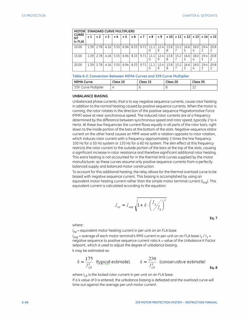
6–66 339 MOTOR PROTECTION SYSTEM – INSTRUCTION MANUAL
S3 PROTECTION CHAPTER 6: SETPOINTS
Table 6-2: Conversion Between NEMA Curves and 339 Curve Multiplier
UNBALANCE BIASINGUnbalanced phase currents, that is to say negative sequence currents, cause rotor heating in addition to the normal heating caused by positive sequence currents. When the motor is running, the rotor rotates in the direction of the positive-sequence Magnetomotive Force (MMF) wave at near synchronous speed. The induced rotor currents are at a frequency determined by the difference between synchronous speed and rotor speed, typically 2 to 4 Hertz. At these low frequencies the current flows equally in all parts of the rotor bars, right down to the inside portion of the bars at the bottom of the slots. Negative-sequence stator current on the other hand causes an MMF wave with a rotation opposite to rotor rotation, which induces rotor current with a frequency approximately 2 times the line frequency: 100 Hz for a 50 Hz system or 120 Hz for a 60 Hz system. The skin effect at this frequency restricts the rotor current to the outside portion of the bars at the top of the slots, causing a significant increase in rotor resistance and therefore significant additional rotor heating. This extra heating is not accounted for in the thermal limit curves supplied by the motor manufacturer, as these curves assume only positive sequence currents from a perfectly balanced supply and balanced motor construction.To account for this additional heating, the relay allows for the thermal overload curve to be biased with negative sequence current. This biasing is accomplished by using an equivalent motor heating current rather than the simple motor terminal current (Iavg). This equivalent current is calculated according to the equation:
Eq. 7
where: Ieq = equivalent motor heating current in per-unit on an FLA base Iavg = average of each motor terminal’s RMS current in per-unit on an FLA base I2 / I1 = negative sequence to positive sequence current ratio k = value of the Unbalance K Factor setpoint, which is used to adjust the degree of unbalance biasing.k may be estimated as:
Eq. 8
where ILR is the locked rotor current in per-unit on an FLA base.If a k value of 0 is entered, the unbalance biasing is defeated and the overload curve will time out against the average per-unit motor current.
10.00 1.39 2.78 4.16 5.55 6.94 8.33 9.71 11.10
12.49
13.88
15.27
16.65
18.04
19.43
20.82
15.00 1.39 2.78 4.16 5.55 6.94 8.33 9.71 11.10
12.49
13.88
15.27
16.65
18.04
19.43
20.82
20.00 1.39 2.78 4.16 5.55 6.94 8.33 9.71 11.10
12.49
13.88
15.27
16.65
18.04
19.43
20.82
NEMA Curve Class 10 Class 15 Class 20 Class 30
339 Curve Multiplier 4 6 8 12
MOTOR CURRENT (× FLA)
STANDARD CURVE MULTIPLIERS
× 1 × 2 × 3 × 4 × 5 × 6 × 7 × 8 × 9 × 10 × 11 × 12 × 13 × 14 × 15
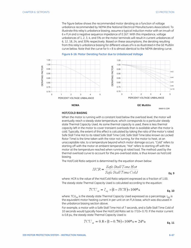
CHAPTER 6: SETPOINTS S3 PROTECTION
339 MOTOR PROTECTION SYSTEM – INSTRUCTION MANUAL 6–67
The figure below shows the recommended motor derating as a function of voltage unbalance recommended by NEMA (the National Electrical Manufacturers Association). To illustrate this relay’s unbalance biasing, assume a typical induction motor with an inrush of 6 x FLA and a negative sequence impedance of 0.167. With this impedance, voltage unbalances of 1, 2, 3, 4, and 5% on the motor terminals will result in current unbalances of 6, 12, 18, 24, and 30% respectively. Based on these assumptions, the derating resulting from this relay’s unbalance biasing for different values of k is as illustrated in the GE Multilin curve below. Note that the curve for k = 8 is almost identical to the NEMA derating curve.
Figure 6-16: Motor Derating Factor due to Unbalanced Voltage
HOT/COLD BIASINGWhen the motor is running with a constant load below the overload level, the motor will eventually reach a steady state temperature, which corresponds to a particular steady state Thermal Capacity Used. As some thermal capacity is used, there is less thermal capacity left in the motor to cover transient overloads than is available when the motor is cold. Typically, the extent of this effect is calculated by taking the ratio of the motor’s rated Safe Stall Time Hot to its rated Safe Stall Time Cold. Safe Stall Time (also known as Locked Rotor Time) is the time taken with the rotor not turning, for the motor to heat, at an unacceptable rate, to a temperature beyond which motor damage occurs. “Cold” refers to starting off with the motor at ambient temperature, “Hot” refers to starting off with the motor at the temperature reached when running at rated load. The method used by the thermal overload curve to account for the pre-overload state, is thus known as hot/cold biasing.The Hot/Cold Ratio setpoint is determined by the equation shown below:
Eq. 9
where: HCR is the value of the Hot/Cold Ratio setpoint expressed as a fraction of 1.00. The steady state Thermal Capacity Used is calculated according to the equation:
Eq. 10
where: TCUss is the steady state Thermal Capacity Used expressed as a percentage. Ieq is the equivalent motor heating current in per-unit on an FLA base, which was discussed in the unbalance biasing section above.For example, a motor with a Safe Stall Time Hot of 7 seconds, and a Safe Stall Time Cold of 10 seconds would typically have the Hot/Cold Ratio set to 7/10= 0.70. If the motor current is 0.8 pu, the steady state Thermal Capacity Used is:
Eq. 11
896815.CDR
0.70
0.75
0.80
0.85
0.90
0.95
1.00
1.05
0 1 2 3 4 5
PERCENT VOLTAGE UNBALANCE
DE
RAT
ING
FA
CT
OR
NEMA
k=2
k=4
k=6
k=8
k=10
0.70
0.75
0.80
0.85
0.90
0.95
1.00
1.05
0 1 2 3 4 5
PERCENT VOLTAGE UNBALANCE
DE
RA
TIN
GFA
CTO
R
GE Multilin
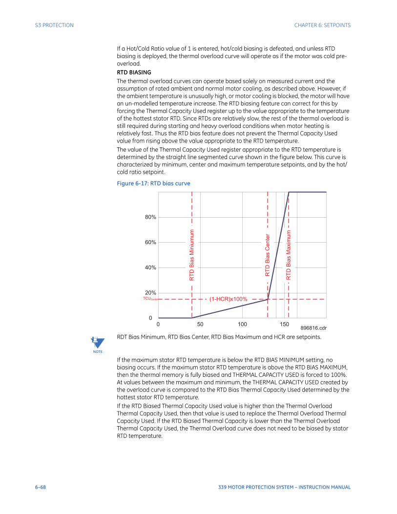
6–68 339 MOTOR PROTECTION SYSTEM – INSTRUCTION MANUAL
S3 PROTECTION CHAPTER 6: SETPOINTS
If a Hot/Cold Ratio value of 1 is entered, hot/cold biasing is defeated, and unless RTD biasing is deployed, the thermal overload curve will operate as if the motor was cold pre-overload.RTD BIASINGThe thermal overload curves can operate based solely on measured current and the assumption of rated ambient and normal motor cooling, as described above. However, if the ambient temperature is unusually high, or motor cooling is blocked, the motor will have an un-modelled temperature increase. The RTD biasing feature can correct for this by forcing the Thermal Capacity Used register up to the value appropriate to the temperature of the hottest stator RTD. Since RTDs are relatively slow, the rest of the thermal overload is still required during starting and heavy overload conditions when motor heating is relatively fast. Thus the RTD bias feature does not prevent the Thermal Capacity Used value from rising above the value appropriate to the RTD temperature.The value of the Thermal Capacity Used register appropriate to the RTD temperature is determined by the straight line segmented curve shown in the figure below. This curve is characterized by minimum, center and maximum temperature setpoints, and by the hot/cold ratio setpoint.
Figure 6-17: RTD bias curve
NOTE
NOTE: RDT Bias Minimum, RTD Bias Center, RTD Bias Maximum and HCR are setpoints.
If the maximum stator RTD temperature is below the RTD BIAS MINIMUM setting, no biasing occurs. If the maximum stator RTD temperature is above the RTD BIAS MAXIMUM, then the thermal memory is fully biased and THERMAL CAPACITY USED is forced to 100%. At values between the maximum and minimum, the THERMAL CAPACITY USED created by the overload curve is compared to the RTD Bias Thermal Capacity Used determined by the hottest stator RTD temperature.If the RTD Biased Thermal Capacity Used value is higher than the Thermal Overload Thermal Capacity Used, then that value is used to replace the Thermal Overload Thermal Capacity Used. If the RTD Biased Thermal Capacity is lower than the Thermal Overload Thermal Capacity Used, the Thermal Overload curve does not need to be biased by stator RTD temperature.
TCUCenter
80%
60%
40%
20%
0500 100 150
RT
DB
ias
Min
ium
um
RT
DB
ias
Ce
nte
r
RT
DB
ias
Ma
xim
um
(1-HCR)x100%
896816.cdr
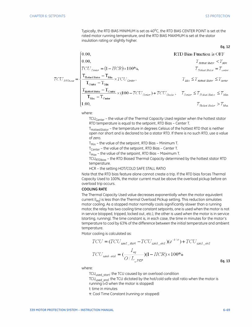
CHAPTER 6: SETPOINTS S3 PROTECTION
339 MOTOR PROTECTION SYSTEM – INSTRUCTION MANUAL 6–69
Typically, the RTD BIAS MINIMUM is set as 40oC, the RTD BIAS CENTER POINT is set at the rated motor running temperature, and the RTD BIAS MAXIMUM is set at the stator insulation rating or slightly higher.
Eq. 12
where: TCUCenter – the value of the Thermal Capacity Used register when the hottest stator RTD temperature is equal to the setpoint, RTD Bias – Center T.THottestStator – the temperature in degrees Celsius of the hottest RTD that is neither open nor short and is declared to be a stator RTD. If there is no such RTD, use a value of zero.TMin – the value of the setpoint, RTD Bias – Minimum T.TCenter – the value of the setpoint, RTD Bias – Center T.TMax – the value of the setpoint, RTD Bias – Maximum T.TCURTDbias – the RTD Biased Thermal Capacity determined by the hottest stator RTD temperature.HCR – the setting HOT/COLD SAFE STALL RATIO
Note that the RTD bias feature alone cannot create a trip. If the RTD bias forces Thermal Capacity Used to 100%, the motor current must be above the overload pickup before an overload trip occurs.COOLING RATEThe Thermal Capacity Used value decreases exponentially when the motor equivalent current (Ieq) is less than the Thermal Overload Pickup setting. This reduction simulates motor cooling. As a stopped motor normally cools significantly slower than a running motor, the relay has two cooling time constant setpoints, one is used when the motor is not in service (stopped, tripped, locked out, etc.), the other is used when the motor is in service (starting, running). The time constant is, in each case, the time in minutes for the motor’s temperature to cool by 63% of the difference between the initial temperature and ambient temperature.Motor cooling is calculated as:
Eq. 13
where: TCUused_start: the TCU caused by an overload conditionTCUused_end: the TCU dictated by the hot/cold safe stall ratio when the motor is running (=0 when the motor is stopped)t: time in minutesτ: Cool Time Constant (running or stopped)
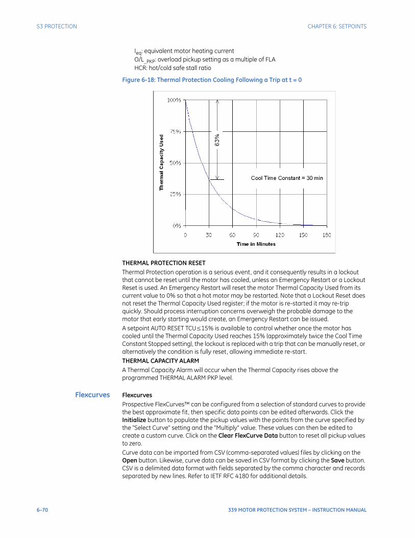
6–70 339 MOTOR PROTECTION SYSTEM – INSTRUCTION MANUAL
S3 PROTECTION CHAPTER 6: SETPOINTS
Ieq: equivalent motor heating current O/L_PKP: overload pickup setting as a multiple of FLAHCR: hot/cold safe stall ratio
Figure 6-18: Thermal Protection Cooling Following a Trip at t = 0
THERMAL PROTECTION RESETThermal Protection operation is a serious event, and it consequently results in a lockout that cannot be reset until the motor has cooled, unless an Emergency Restart or a Lockout Reset is used. An Emergency Restart will reset the motor Thermal Capacity Used from its current value to 0% so that a hot motor may be restarted. Note that a Lockout Reset does not reset the Thermal Capacity Used register; if the motor is re-started it may re-trip quickly. Should process interruption concerns overweigh the probable damage to the motor that early starting would create, an Emergency Restart can be issued.A setpoint AUTO RESET TCU≤15% is available to control whether once the motor has cooled until the Thermal Capacity Used reaches 15% (approximately twice the Cool Time Constant Stopped setting), the lockout is replaced with a trip that can be manually reset, or alternatively the condition is fully reset, allowing immediate re-start.THERMAL CAPACITY ALARMA Thermal Capacity Alarm will occur when the Thermal Capacity rises above the programmed THERMAL ALARM PKP level.
Flexcurves FlexcurvesProspective FlexCurves™ can be configured from a selection of standard curves to provide the best approximate fit , then specific data points can be edited afterwards. Click the Initialize button to populate the pickup values with the points from the curve specified by the "Select Curve" setting and the "Multiply" value. These values can then be edited to create a custom curve. Click on the Clear FlexCurve Data button to reset all pickup values to zero.Curve data can be imported from CSV (comma-separated values) files by clicking on the Open button. Likewise, curve data can be saved in CSV format by clicking the Save button. CSV is a delimited data format with fields separated by the comma character and records separated by new lines. Refer to IETF RFC 4180 for additional details.
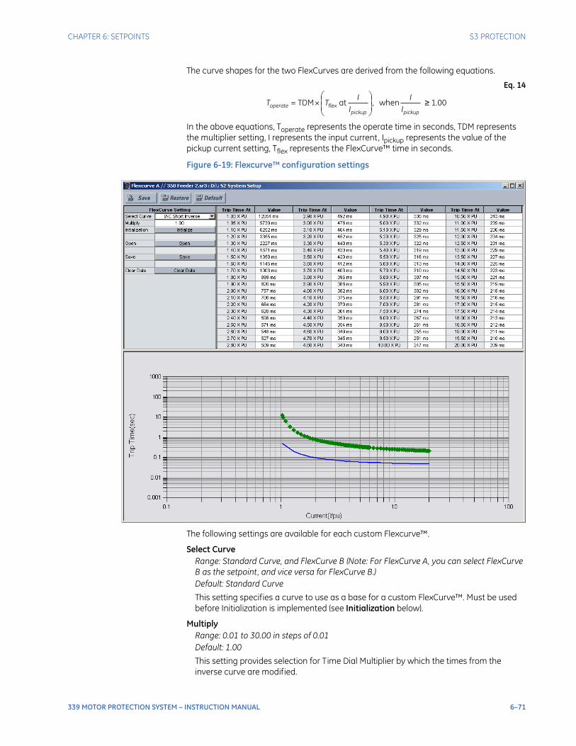
CHAPTER 6: SETPOINTS S3 PROTECTION
339 MOTOR PROTECTION SYSTEM – INSTRUCTION MANUAL 6–71
The curve shapes for the two FlexCurves are derived from the following equations.
Eq. 14
In the above equations, Toperate represents the operate time in seconds, TDM represents the multiplier setting, I represents the input current, Ipickup represents the value of the pickup current setting, Tflex represents the FlexCurve™ time in seconds.
Figure 6-19: Flexcurve™ configuration settings
The following settings are available for each custom Flexcurve™.
Select CurveRange: Standard Curve, and FlexCurve B (Note: For FlexCurve A, you can select FlexCurve B as the setpoint, and vice versa for FlexCurve B.)Default: Standard Curve
This setting specifies a curve to use as a base for a custom FlexCurve™. Must be used before Initialization is implemented (see Initialization below).
MultiplyRange: 0.01 to 30.00 in steps of 0.01Default: 1.00
This setting provides selection for Time Dial Multiplier by which the times from the inverse curve are modified.

6–72 339 MOTOR PROTECTION SYSTEM – INSTRUCTION MANUAL
S3 PROTECTION CHAPTER 6: SETPOINTS
Initialization
Used after specifying a curve to use as a base for a custom FlexCurve™ (see Select Curve and Multiply above). When the Initialize FlexCurve button is clicked, the pickup settings will be populated with values specified by the curve selected in this setting.
1.03 × Pickup, ..., 20.00 × PickupRange: 0 to 65535 ms in steps of 1Default: 0 ms
These settings specify the time to operate at the following pickup levels 1.03 to 20.00. This data is converted into a continuous curve by linear interpolation between data points. To enter a custom FlexCurve™, enter the operate time for each selected pickup point.
Thermal protectionsetpoints
PATH: SETPOINTS > S3 PROTECTION > THERMAL PROTECTION
THERMAL O/L FUNCRange: Disabled, EnabledDefault: Disabled
START PROTECTIONRange: Off, On, Contact Input 1 to 10, Virtual Input 1 to 32, Remote Input 1 to 32, Logic Element 1 to 16Default: Off
By setting the START PROTECTION setpoint to OFF, Start Protection can be disabled. Thermal protection will therefore go directly to the running condition and the Thermal Overload Curve will be employed to protect the connected load.
LOCKED ROTOR CURRENTRange: 2 to 11xFLA in steps of 0.1xFLADefault: 6xFLA
This is the steady state motor current with the rotor locked, when supplied from a source at rated voltage and frequency.
SAFE STALL T COLDRange: 1.0 to 600.0 sec in steps of 0.1 secDefault: 10.0 sec
This setting is given as the Safe Stall Time Cold.
THERMAL O/L CURVERange: Standard, FlexCurveDefault: Standard
When FlexCurve is selected, the 339 relay used motor speed indication to apply FlexCurve A or FlexCurve B. Flex curve A is active when the motor is running at low speed. Flex curve B is active when the motor is running at high speed. If two-speed function is not deployed, only FlexCurve A is active.
CURVE MULTIPLIERRange: 1 to 15 in steps of 1Default: 4
Fits the Standard Overload Curve to the thermal characteristics of the protected motor.
THERMAL O/L PKPRange: 1.01 to 1.25xFLA in steps of 0.01xFLADefault: 1.01xFLA
The Thermal Overload Pickup setting defines the current level at which the motor is considered to be overloaded. The Overload Curve is cut off at current values below this pickup value. Normally, the Thermal Overload Pickup Setting is set slightly above the

CHAPTER 6: SETPOINTS S3 PROTECTION
339 MOTOR PROTECTION SYSTEM – INSTRUCTION MANUAL 6–73
motor Service Factor, to account for inherent load measuring errors (CTs and limited relay accuracy). The typical total inaccuracy factor is 8 to 10%; as such, for motors with a thermal capability at rated service factor of 1 or 1.15, the Thermal Overload Pickup level should be set as 1.10 or 1.25, respectively.
The Thermal Capacity Used value decreases exponentially when the motor equivalent current (Ieq) is less than the Thermal Overload Pickup setting.
UNBALANCE K FACTORRange: 0 to 19 in steps of 1Default: 0
Sets the degree of unbalance biasing used by the Thermal Overload Curve. Zero disables the unbalance bias.
COOL TIME RUNNINGRange: 1 to 1000 min in steps of 1 minDefault: 15 min
Sets the Cooling Time Constant used by the Thermal Overload Curve when the motor is in service. Enter the time in minutes for the motor to cool by 63% of the difference between the initial and ambient temperature when the motor is running at rated speed.
COOL TIME STOPPEDRange: 1 to 1000 min in steps of 1 minDefault: 30 min
Sets the Cooling Time Constant used by the Thermal Overload Curve when the motor is not in service. Enter the time in minutes for the motor to cool by 63% of the difference between the initial and ambient temperature when the motor is stopped.
HOT/COLD RATIORange: 0.01 to 1.00 in steps of 0.01Default: 0.85
This setpoint controls the Hot/Cold Bias and RTD Bias features. If the safe stall time hot/cold cannot be determined from the motor specification, a typical value of 0.85 is suggested. If a HCR value of 1 is programmed, Hot/Cold Biasing is defeated.
RTD BIAS FUNCRange: Disabled, EnabledDefault: Disabled
Sets to disable or enable RTD Bias function.
RTD BIAS MINIMUMRange: 0 to 130oC in steps of 1oCDefault: 40oC
Sets the stator RTD temperature appropriate for a Thermal Capacity Used value of zero. If RTD Bias is to be deployed, enter the rated ambient temperature.
RTD BIAS CENTERRange: 40 to 155oC in steps of 1oCDefault: 110oC
Sets the stator RTD temperature appropriate for the steady state Thermal Capacity Used at rated full load motor current. If RTD Bias is to be deployed, enter the rated full load motor running temperature.
RTD BIAS MAXIMUMRange: 130 to 250oC in steps of 1oCDefault: 130oC
Sets the stator RTD temperature appropriate for a Thermal Capacity Used value of 100%. If RTD Bias is to be deployed, enter the stator insulation temperature rating.

6–74 339 MOTOR PROTECTION SYSTEM – INSTRUCTION MANUAL
S3 PROTECTION CHAPTER 6: SETPOINTS
THERMAL ALARM FUNCRange: Disabled, EnabledDefault: Disabled
Sets to enable or disable the Thermal Capacity Alarm function.
THERMAL ALARM PKPRange: 10% to 100% in steps of 1%Default: 75%
Sets the amount of the Thermal Capacity Used where the Thermal Capacity Alarm will be issued.
AUTORESET TCU≤15%Range: Auto, ManualDefault: Manual
If this Setpoint is set to AUTO, an automatic reset of an overload lockout occurs after the Thermal Capacity Used has dropped to 15%. When set to MANUAL, the lockout is replaced with a trip when the motor cools. This trip must be reset by the control panel, a remote contact, or a communication command, before the motor can be restarted.
OUTPUT RELAY 4 to 6 / OUTPUT RELAY 5 to 6Range: Do Not Operate, OperateDefault: Do Not Operate
Any assignable output relay can be selected to operate upon Thermal Protection (Start Protection and Thermal Overload Curve) operation. When the SWITCHING DEVICE is selected as BREAKER, the assignable output relays will be Output Relay 4~6. When the SWITCHING DEVICE is selected as CONTACTOR, the assignable output relays will be Output Relay 5~6.
BLOCK 1 to 3Range: Off, Contact Input 1 to 10, Virtual Input 1 to 32, Remote Input 1 to 32, Logic Element 1 to 16Default: Off
Three blocking inputs are provided for Thermal Protection. When any of the selected blocking inputs turns ON, Thermal Protection will be blocked.
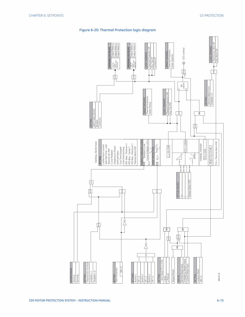
CHAPTER 6: SETPOINTS S3 PROTECTION
339 MOTOR PROTECTION SYSTEM – INSTRUCTION MANUAL 6–75
Figure 6-20: Thermal Protection logic diagram
OR
AN
D
AN
D
AN
D
SE
TT
ING
Off
=0
Sta
rt
Pro
tec
tio
n
TH
ER
MA
LO
VE
RLO
AD
CU
RV
E
Sta
nd
ard
cu
rv
e
STA
RT
PR
OT
EC
TIO
N
Cu
rv
eM
ult
iplie
rx
87
.4
I-
12
eq
t(I
)e
q=
t LR
co
ldx
I2
LR
I2
eq
t(I
)e
q=
SE
TT
ING
Th
erm
alO
/L
Fu
nc
tio
n
En
ab
led
=1
SE
TT
ING
S
BLO
CK
1
Off
=0
BLO
CK
2
AN
D
BLO
CK
3
Off
=0
Off
=0
MO
TO
RS
TA
TU
S
Sta
rti
ng
Ru
nn
ing
OR
RU
N
TH
ER
MA
LM
EM
OR
Y
TC
Used
=t
I
TC
Used
RT
D=
TC M
AX
STA
TO
R
TC
U1
5%
RE
SE
TTC
UTO
0%
TC
U>
Th
erm
alA
larm
PK
P
TC
U=
10
0%
I eq
O
/L
PK
P
RU
N
AC
TU
AL
VA
LU
ES
Ho
tte
st
Sta
tor
RT
D
I av
g
I 1 I 2
SE
TT
ING
Au
toR
ese
tTC
U1
5%
=A
uto
=M
an
ua
l
INP
UT
S
Re
mo
teR
ese
tIn
pu
t
SE
TT
ING
Lo
ck
ou
tR
ese
t
Off
=0
Em
erg
en
cy
Re
sta
rt
Inp
ut
Lo
ck
ou
tR
ese
tIn
pu
t
Ke
yp
ad
Re
se
t
AN
D
OR
OR
OR
OR
AN
D
OR
OR
OR
OR
AN
D
AN
D
NV
LA
TC
H
S R
AN
D
LO
GIC
OP
ER
AN
D
Th
erm
alP
rote
cti
on
PK
P
LO
GIC
OP
ER
AN
D
Th
erm
al
OP
Pro
tec
tio
n
An
yT
rip
OP
-L
ED
:L
oc
ko
ut
SE
TT
ING
Th
erm
alA
larm
Fu
nc
Dis
ab
led
=0
AN
D
LO
GIC
OP
ER
AN
D
Th
erm
alLV
LA
lrm
OP
An
yA
larm
OP
Un
ba
lan
ce
KF
ac
tor
Ho
t/C
old
Ra
tio
Co
olT
ime
Sto
pp
ed
RT
DB
ias
-M
inim
um
T
RT
DB
ias
-C
en
ter
T
RT
DB
ias
-M
ax
imu
mT
Th
erm
alO
/L
PK
P
Th
erm
alA
larm
PK
P
Co
olT
ime
Ru
nn
ing
Cu
rv
eM
ult
iplie
r
Sa
feS
tall
Tim
e-
Co
ld
Lo
cke
dR
oto
rC
urr
en
t
SE
TT
ING
S
TH
ER
MA
LP
RO
TE
CT
ION
TA
RG
ET
ME
SS
AG
E
Th
erm
alP
rote
cti
on
:
Sta
te:P
icku
p
TA
RG
ET
ME
SS
AG
E
Th
erm
al
:
Sta
te:O
pe
rate
Pro
tec
tio
n
SE
TT
ING
SW
ITC
HIN
GD
EV
ICE
Bre
ake
r
Co
nta
cto
r
AS
SIG
NA
BL
EA
UX
RE
LA
YS
Ou
tpu
tR
ela
y4
Ou
tpu
tR
ela
y5
Ou
tpu
tR
ela
y6
Op
era
te
ou
tpu
t
rela
ys
up
on
se
lec
tio
n
AS
SIG
NA
BL
EA
UX
RE
LA
YS
Ou
tpu
tR
ela
y5
Ou
tpu
tR
ela
y6
Op
era
te
ou
tpu
t
rela
ys
up
on
se
lec
tio
nA
ND
AN
D
89
6L
H2
.cd
r
An
yT
rip
PK
P
Dis
ab
led
=0
Lo
ck
ou
tO
P
6–76 339 MOTOR PROTECTION SYSTEM – INSTRUCTION MANUAL
S3 PROTECTION CHAPTER 6: SETPOINTS
Short circuitIf Short Circuit is enabled, a trip or alarm occurs once the magnitude of any phase current exceeds the setting S/C PKP for the time specified by the setting S/C DELAY.A second independent Short Circuit protection element is provided for High Speed. If two-speed functionality is enabled, the 339 relay relies on the motor speed indication to switch the Short Circuit settings as per the motor running speed, so the main Short Circuit is only active when the motor is running at low speed, and the High Speed Short Circuit is only active when the motor is running at high speed. If two-speed functionality is not deployed, only the main Short Circuit is active, and the High Speed Short Circuit is disabled.Short Circuit operation is a serious event, and therefore results in a lockout that cannot be reset unless an Emergency Restart or a Lockout Reset is issued.
NOTE
NOTE: Warning: care must be taken when turning on this feature. If the interrupting device (contactor or circuit breaker) is not rated to break the fault current, the function of this feature should not be programmed as TRIP. Alternatively, this feature may be programmed as ALARM or LATCHED ALARM and assigned to an auxiliary relay connected to an upstream device which is capable of breaking the fault current.
PATH: SETPOINTS > S3 PROTECTION > SHORT CIRCUIT
S/C FUNCRange: Disabled, Latched Alarm, Alarm, TripDefault: Disabled
The selection of the Latched Alarm, Alarm, or Trip setting enables the Short Circuit function. If the operating condition is satisfied when Trip is selected as the function, the “LOCKOUT” LED will be turned on, and the logic operand ANY TRIP OP will be asserted, which in turn will operate the “TRIP” LED and trip output relay. If Alarm is selected, the “ALARM” LED will flash upon Short Circuit operation, and will automatically reset when the activating condition clears. If Latched Alarm is selected, the “ALARM” LED will flash upon Short Circuit operation, and will stay “ON” after the condition clears, until a reset command is initiated. The TRIP output relay will not operate if the Latched Alarm or Alarm function is selected. Any assignable output relays can be selected to operate when the setting S/C FUNC is selected as Latched Alarm, Alarm, or Trip.
S/C PKPRange: 1.00 to 20.00xCT in steps of 0.01xCTDefault: 6.00xCT
This setting specifies a pickup threshold for the Short Circuit.
S/C DELAYRange: 0.00 to 60.00 s in steps of 0.01 sDefault: 0.00 s
This setting specifies a time delay for the Short Circuit.
OUTPUT RELAY 4 to 6 / OUTPUT RELAY 5 to 6Range: Do not operate, OperateDefault: Do not operate
Any assignable output relay can be selected to operate upon Short Circuit operation. When the SWITCHING DEVICE is selected as BREAKER, the assignable output relays will be Output Relay 4 to 6. When the SWITCHING DEVICE is selected as CONTACTOR, the assignable output relays will be Output Relay 5 to 6.

CHAPTER 6: SETPOINTS S3 PROTECTION
339 MOTOR PROTECTION SYSTEM – INSTRUCTION MANUAL 6–77
BLOCK 1 to 3Range: Off, Contact Input 1 to 10, Virtual Input 1 to 32, Remote Input 1 to 32, Logic Element 1 to 16Default: Off
Three blocking inputs are provided for the Short Circuit feature. When any of the selected blocking inputs is on, the Short Circuit function is blocked.
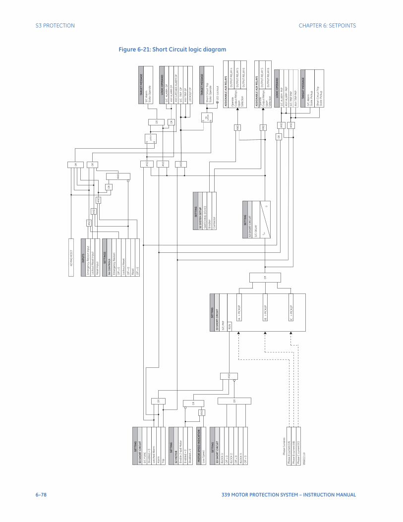
6–78 339 MOTOR PROTECTION SYSTEM – INSTRUCTION MANUAL
S3 PROTECTION CHAPTER 6: SETPOINTS
Figure 6-21: Short Circuit logic diagram
SE
TT
I NG
Ph
ase
Ac
urr
en
t(IA
)
RU
N
SE
TT
ING
S/C
FU
NC
Dis
ab
led
=0
La
tch
ed
Ala
rm
S/C
PK
P
S/C
DE
LA
Y
Ph
ase
Bc
urr
en
t(IB
)
Ph
ase
Cc
urr
en
t(IC
)
Ala
rm
Ph
ase
Cu
rre
nts
Op
era
te
Ou
tpu
tR
ela
ys
Up
on
Se
lec
tio
n
OU
TP
UT
RE
LA
Y4
OU
TP
UT
RE
LA
Y5
OU
TP
UT
RE
LA
Y6
Tri
p
SE
TT
ING
BLO
CK
1:
Off
=0
BLO
CK
2:
Off
=0
BLO
CK
3:
Off
=0
IB>
PIC
KU
P
IA>
PIC
KU
P
IC>
PIC
KU
P
SE
TT
I NG
S/C
AL
AR
MP
KP
t PK
P
0
S R
LA
TC
H
89
68
12
. cd
r
LOG
ICO
PE
RA
ND
S/C
AL
AR
MO
P
LOG
ICO
PE
RA
ND
SE
TT
I NG
S2
MO
TO
R
En
ab
le2
-sp
dM
oto
r
En
ab
led
=0
MO
TO
RS
PE
ED
IND
ICA
TIO
N
Lo
wS
pe
ed
OR
OR
AN
D
OR
AN
D
AN
D
AN
D
OR
OR
AN
D
AN
D
INP
UT
S
Em
erg
en
cy
Re
sta
rt
Inp
ut
Lo
ck
ou
tR
ese
tIn
pu
t
SE
TT
ING
S
Off
=0
Lo
ck
ou
tR
ese
t
Off
=0
Em
erg
en
cy
Re
sta
rt
S4
CO
NT
RO
LS
S/C
Ala
rm
Sta
te:O
pe
rate
TAR
GE
TM
ES
SA
GE
AN
YA
LA
RM
OP
S/C
TR
IPO
P
AN
YT
RIP
OP
S R
NV
LA
TC
HS
ho
rt
Cir
cu
itT
rip
Sta
te:O
pe
rate
TAR
GE
TM
ES
SA
GE
AS
SIG
NA
BL
EA
UX
RE
LA
YS
AN
D
Op
era
te
Ou
tpu
tR
ela
ys
Up
on
Se
lec
tio
n
OU
TP
UT
RE
LA
Y5
OU
TP
UT
RE
LA
Y6
AN
D
AN
YA
LA
RM
PK
P
S/C
TR
IPP
KP
AN
YT
RIP
PK
P
AN
D
AN
D
OR
S3
SH
OR
TC
IRC
UIT
S3
SH
OR
TC
IRC
UIT
S3
SH
OR
TC
IRC
UIT
AN
D
OR
SE
TT
ING
SW
ITC
HIN
GD
EV
ICE
Bre
ake
r
Co
nta
cto
r
S2
SY
ST
EM
SE
TU
P
S3
SH
OR
TC
IRC
UIT
OR
Re
se
tIn
pu
t
Re
se
t
Off
=0
AN
D
OR
KE
YP
AD
RE
SE
T
LE
D:L
oc
ko
ut
AN
YL
ATC
HE
DA
LA
RM
OP
AS
SIG
NA
BL
EA
UX
RE
LA
YS
S/C
Ala
rm
Sta
te:P
icku
p
TAR
GE
TM
ES
SA
GE
Sh
ort
Cir
cu
itT
rip
Sta
te:P
icku
p
OR
AN
D
Dis
ab
led
=0
LO
CK
OU
TO
P
CHAPTER 6: SETPOINTS S3 PROTECTION
339 MOTOR PROTECTION SYSTEM – INSTRUCTION MANUAL 6–79
Mechanical JamA motor load can become constrained (mechanical jam) during starting or running. The starting current magnitude alone cannot provide a definitive indication of a mechanical jam, so the starting load jams are detected by monitoring acceleration time and speed. However, the running current magnitude can indicate load jams. Therefore, the Mechanical Jam element is specially designed to operate for running load jams. After a motor has started and reached the running state, a trip or alarm occurs should the magnitude of any phase current exceed the setting MECH JAM PKP for a period of time specified by the setting MECH JAM DELAY. The thermal protection element will also operate during mechanical jams but after a delay when the thermal capacity reaches 100%. Not only does the Mechanical Jam protect the motor by taking it off-line quicker than the thermal protection, it may also prevent or limit damage to the driven equipment in the event of a locked rotor during running.The Mechanical Jam is armed as long as the motor status is not STARTING. When two-speed functionality is deployed, the 339 will block Mechanical Jam Protection during the acceleration time from Low Speed to High Speed until the motor current has dropped below overload pickup level. At that point of time when the motor reached the high speed running stage, the Mechanical Jam will be enabled with the High Speed FLA.The MECH JAM PKP level should be set higher than motor loading during normal operation, but lower than the motor stall level. Normally the delay is set to the minimum time delay or set so that no nuisance trips occur due to momentary load fluctuations.Mechanical Jam operation is a serious event, and therefore results in a lockout that cannot be reset unless an Emergency Restart or a Lockout Reset is issued.PATH: SETPOINTS > S3 PROTECTION > MECHANICAL JAM
MECH JAM FUNCRange: Disabled, EnabledDefault: Disabled
MECH JAM PKPRange: 1.01 to 4.50xFLA in steps of 0.01xFLADefault: 4.50xFLA
This setting defines the excessive current condition that identifies a mechanical jam. As the element is not armed during motor starting, this threshold can be set below the starting current.
MECH JAM DELAYRange: 0.00 to 30.00 s in steps of 0.01 sDefault: 0.10 s
This setting specifies the pickup delay for the Mechanical Jam.
OUTPUT RELAY 4 to 6 / OUTPUT RELAY 5 to 6Range: Do not operate, OperateDefault: Do not operate
Any assignable output relay can be selected to operate upon Mechanical Jam operation. When the SWITCHING DEVICE is selected as BREAKER, the assignable output relays will be Output Relay 4 to 6. When the SWITCHING DEVICE is selected as CONTACTOR, the assignable output relays will be Output Relay 5 to 6.
BLOCK 1 to 3Range: Off, Contact Input 1 to 10, Virtual Input 1 to 32, Remote Input 1 to 32, Logic Element 1 to 16Default: Off
Three blocking inputs are provided for the Mechanical Jam feature. When any of the selected blocking inputs is on, the Mechanical Jam function is blocked.
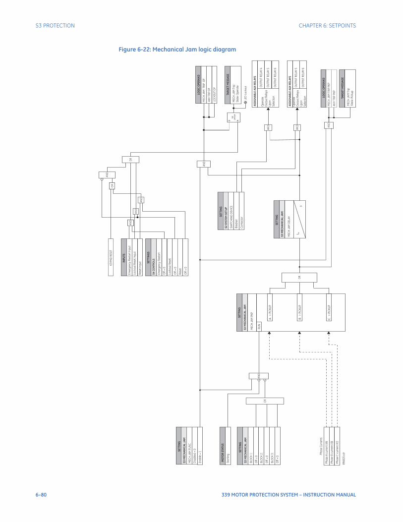
6–80 339 MOTOR PROTECTION SYSTEM – INSTRUCTION MANUAL
S3 PROTECTION CHAPTER 6: SETPOINTS
Figure 6-22: Mechanical Jam logic diagram
SET
TIN
G
Ph
ase
Ac
urr
en
t(IA
)
RU
N
SET
TIN
G
ME
CH
JA
MF
UN
C
Dis
ab
led
=0
En
ab
le=
1
ME
CH
JA
MP
KP
ME
CH
JA
MD
EL
AY
Ph
ase
Bc
urr
en
t(IB
)
Ph
ase
Cc
urr
en
t(IC
)
Ph
ase
Cu
rre
nts
Op
era
te
Ou
tpu
tR
ela
ys
Up
on
Se
lec
tio
n
OU
TP
UT
RE
LA
Y4
OU
TP
UT
RE
LA
Y5
OU
TP
UT
RE
LA
Y6
SET
TIN
G
BLO
CK
1:
Off
=0
BLO
CK
2:
Off
=0
BLO
CK
3:
Off
=0
IB>
PIC
KU
P
IA>
PIC
KU
P
IC>
PIC
KU
P
SET
TIN
G
t PK
P
0
89
68
20
.cd
r
LOG
ICO
PER
AN
D
LOG
ICO
PER
AN
D
MO
TOR
STAT
US
Sta
rtin
g
OR
AN
D
OR
AN
D
OR
AN
D
AN
D
INPU
TS
Em
erg
en
cy
Re
sta
rtIn
pu
t
Lo
ck
ou
tR
ese
tIn
pu
t
SET
TIN
GS
Off
=0
Lo
ck
ou
tR
ese
t
Off
=0
Em
erg
en
cy
Re
sta
rt
S4C
ON
TRO
LS
ME
CH
JA
MT
RIP
OP
AN
YT
RIP
OP
S R
NV
LA
TC
HM
EC
HJA
MT
rip
Sta
te:O
pe
rate
TAR
GE
TM
ESSA
GE
ASS
IGN
AB
LEA
UX
REL
AYS
AN
D
Op
era
te
Ou
tpu
tR
ela
ys
Up
on
Se
lec
tio
n
OU
TP
UT
RE
LA
Y5
OU
TP
UT
RE
LA
Y6
AN
D
ME
CH
JA
MT
RIP
PK
P
AN
YT
RIP
PK
P
AN
D
S3M
ECH
AN
ICA
LJA
M
S3M
ECH
AN
ICA
LJ A
M
S3M
ECH
AN
ICA
LJA
M
SET
TIN
G
SW
ITC
HIN
GD
EV
ICE
Bre
ake
r
Co
nta
cto
r
S2SY
STEM
SETU
P
S3M
ECH
AN
ICA
LJ A
M
Re
se
tIn
pu
t
Re
se
t
Off
=0
AN
D
KE
YP
AD
RE
SE
T
LE
D:L
oc
ko
ut
ASS
IGN
AB
LEA
UX
REL
AYS
TAR
GE
TM
ESSA
GE
ME
CH
JA
MT
rip
Sta
te:P
icku
p
OR
AN
DA
ND
AN
D
LO
CK
OU
TO
P
CHAPTER 6: SETPOINTS S3 PROTECTION
339 MOTOR PROTECTION SYSTEM – INSTRUCTION MANUAL 6–81
UndercurrentWhen the motor is in the running state, an alarm will occur if the magnitude of any phase current falls below the undercurrent alarm pickup level for the time specified by the undercurrent alarm delay. Furthermore, a trip will occur if the magnitude of any phase current falls below the undercurrent trip pickup level for the time specified by the undercurrent trip delay. The alarm and trip pickup levels should be set lower than the lowest motor loading during normal operations.For example, if a pump is cooled by the liquid it pumps, loss of load may mean that the pump overheats. In this case, enable the undercurrent feature. If the motor loading should never fall below 75% FLA, even for short durations, the Undercurrent Trip Pickup could be set to “70% FLA” and the Undercurrent Alarm Pickup be set to “75% FLA”. The Undercurrent Trip Delay and Undercurrent Alarm Delay settings are typically set as quick as possible, i.e. 1.00 second.The Undercurrent element is active only when the motor is running and is blocked upon the initiation of a motor start for a period of time defined by the setting BLK U/C ON START. This block may be used to allow pumps to build up head before the undercurrent element trips or alarms.A second independent Undercurrent Protection element is provided for High Speed. If two-speed functionality is enabled, the 339 relay relies on the motor speed indication to switch the undercurrent settings as per the motor running speed, so the main Undercurrent Protection element is only active when the motor is running at low speed, and the High Speed Undercurrent Protection element is only active when the motor is running at high speed. If two-speed functionality is not deployed, only the main Undercurrent is active, and the High Speed Undercurrent is disabled.PATH:SETPOINTS > S3 PROTECTION > UNDERCURRENT
U/CURR ALARM FUNCRange: Disabled, EnabledDefault: Disabled
This setting enables the Undercurrent alarm functionality.
BLK U/C ON STARTRange: 0 to 600 s in steps of 1 sDefault: 0 s
This setting specifies the length of time to block the undercurrent function when the motor is starting. The undercurrent element is active only when the motor is running and is blocked for a period of time specified by this setting, upon the initiation of a motor start. A value of 0 s specifies that the feature is not blocked from start.
U/CURR ALARM PKPRange: 1% to 100% FLA in steps of 1% FLADefault: 70% FLA
This setting specifies a pickup threshold for the alarm stage. The alarm pickup threshold should be less than the motor load current during normal operation.
U/CURR ALARM DELAYRange: 1.00 to 60.00 s in steps of 0.01 sDefault: 1.00 s
This setting specifies a time delay for the alarm stage. The time delay should be long enough to overcome any short lowering of the current (e.g. during system faults).
U/CURR TRIP FUNCRange: Disabled, EnabledDefault: Disabled
This setting enables the Undercurrent trip functionality.
6–82 339 MOTOR PROTECTION SYSTEM – INSTRUCTION MANUAL
S3 PROTECTION CHAPTER 6: SETPOINTS
U/CURR TRIP PKPRange: 1% to 100% FLA in steps of 1% FLADefault: 60% FLA
This setting specifies a pickup threshold for the trip stage. This setting is typically set at a level less than the corresponding setting for the alarm stage.
U/CURR TRIP DELAYRange: 1.00 to 60.00 s in steps of 0.01 sDefault: 1.00 s
This setting specifies a time delay for the trip stage. The time delay should be long enough to overcome any short lowering of the current (e.g. during system faults).
OUTPUT RELAY 4 to 6 / OUTPUT RELAY 5 to 6Range: Do not operate, OperateDefault: Do not operate
Any assignable output relay can be selected to operate upon Undercurrent operation. When the SWITCHING DEVICE is selected as BREAKER, the assignable output relays will be Output Relay 4 to 6. When the SWITCHING DEVICE is selected as CONTACTOR, the assignable output relays will be Output Relay 5 to 6.
To select any assignable output relays to operate upon the Undercurrent Alarm operation, assign the Logic Operand "UNDERCURRENT ALARM OP" or "Any Alarm OP" to a Logic Element.
BLOCK 1 to 3Range: Off, Contact Input 1 to 10, Virtual Input 1 to 32, Remote Input 1 to 32, Logic Element 1 to 16Default: Off
Three blocking inputs are provided for the Undercurrent feature. When any of the selected blocking inputs is on, the Undercurrent function is blocked.
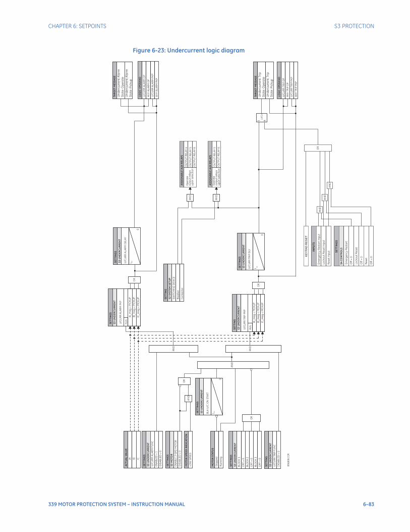
CHAPTER 6: SETPOINTS S3 PROTECTION
339 MOTOR PROTECTION SYSTEM – INSTRUCTION MANUAL 6–83
Figure 6-23: Undercurrent logic diagram
89
68
08
. CD
R
S3
UN
DE
RC
UR
RE
NT
MO
TO
RS
TAT
US
Sto
pp
ed
AN
D
IA_
ma
g<
PIC
KU
P
S3
UN
DE
RC
UR
RE
NT
U/C
UR
RT
RIP
PK
P
RU
N
IB_
ma
g<
PIC
KU
P
IC_
ma
g<
PIC
KU
P
IA_
ma
g<
PIC
KU
P
S3
UN
DE
RC
UR
RE
NT
U/C
UR
RA
LA
RM
PK
P
RU
N
IB_
ma
g<
PIC
KU
P
IC_
ma
g<
PIC
KU
P
OR
OR
S3
UN
DE
RC
UR
RE
NT
U/C
UR
RA
LA
RM
DE
LA
Y
t PK
P
0
LOG
ICO
PE
RA
ND
U/C
UR
RT
RIP
OP
AN
YT
RIP
OP
S3
UN
DE
RC
UR
RE
NT
U/C
UR
RT
RIP
DLY
t PK
P
0
LOG
ICO
PE
RA
ND
U/C
UR
RA
LA
RM
OP
AN
YA
LA
RM
OP
S R
LA
TC
H
AN
D
AN
D
S3
UN
DE
RC
UR
RE
NT
U/C
UR
RT
RIP
FU
NC
DIS
AB
LE
D=
0
S3
UN
DE
RC
UR
RE
NT
BL
KU
/C
ON
STA
RT
t BL
K
0
BLO
CK
1
BLO
CK
2
BLO
CK
3
OF
F=
0
OF
F=
0
OF
F=
0
OR
S3
UN
DE
RC
UR
RE
NT
U/C
UR
RA
LA
RM
FU
NC
EN
AB
LE
D=
1
IA
AC
TU
AL
VA
LUE
IB IC
OU
TP
UT
RE
LA
Y5
OU
TP
UT
RE
LA
Y6
Op
era
te
ou
tpu
tre
lay
s
up
on
se
lec
tio
nR
un
nin
g
S2
MO
TO
R
EN
AB
LE
2-S
PD
MO
TO
R
DIS
AB
LE
D=
0
MO
TO
RS
PE
ED
IND
ICA
TIO
N
LO
WS
PE
ED
OR
AN
D
U/C
UR
RT
RIP
PK
P
U/C
UR
RA
LA
RM
PK
P
SE
TT
ING
S
SE
TT
ING
S
SE
TT
I NG
S
SE
TT
ING
SE
TT
ING
S
SE
TT
ING
S
SE
TT
I NG
SE
TT
ING
S
SE
TT
I NG
S
SW
ITC
HIN
GD
EV
ICE
Bre
ake
r
Co
nta
cto
r
AN
D
OU
TP
UT
RE
LA
Y4
OU
TP
UT
RE
LA
Y5
OU
TP
UT
RE
LA
Y6
Op
era
te
ou
tpu
tre
lay
s
up
on
se
lec
tio
nA
ND
TAR
GE
TM
ES
SA
GE
Un
de
rcu
rre
nt
Ala
rm
Sta
te:O
pe
rate
Un
de
rcu
rre
nt
Ala
rm
Sta
te:P
icku
p
TAR
GE
TM
ES
SA
GE
Un
de
rcu
rre
nt
Tri
p
Sta
te:O
pe
rate
Un
de
rcu
rre
nt
Tri
p
Sta
te:P
icku
p
OR
AN
D
AN
D
INP
UT
S
Em
erg
en
cy
Re
sta
rt
Inp
ut
Lo
ck
ou
tR
ese
tIn
pu
t
SE
TT
I NG
S
Off
=0
Lo
ck
ou
tR
ese
t
Off
=0
Em
erg
en
cy
Re
sta
rt
S4
CO
NT
RO
LS
AN
YA
LA
RM
PK
P
SE
TT
ING
S2
SY
ST
EM
SE
TU
P
AS
SIG
NA
BL
EA
UX
RE
LA
YS
AS
SIG
NA
BL
EA
UX
RE
LA
YS
AN
YT
RIP
PK
P
KE
YP
AD
RE
SE
T
AN
DR
ese
tIn
pu
t
Re
se
t
Off
=0
DIS
AB
LE
D=
0
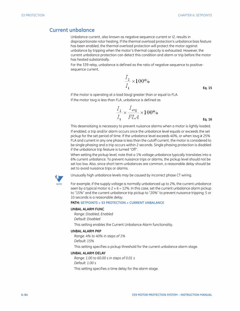
6–84 339 MOTOR PROTECTION SYSTEM – INSTRUCTION MANUAL
S3 PROTECTION CHAPTER 6: SETPOINTS
Current unbalanceUnbalance current, also known as negative sequence current or I2, results in disproportionate rotor heating. If the thermal overload protection’s unbalance bias feature has been enabled, the thermal overload protection will protect the motor against unbalance by tripping when the motor’s thermal capacity is exhausted. However, the current unbalance protection can detect this condition and alarm or trip before the motor has heated substantially. For the 339 relay, unbalance is defined as the ratio of negative-sequence to positive-sequence current,
Eq. 15
if the motor is operating at a load (Iavg) greater than or equal to FLA. If the motor Iavg is less than FLA, unbalance is defined as
Eq. 16
This desensitizing is necessary to prevent nuisance alarms when a motor is lightly loaded. If enabled, a trip and/or alarm occurs once the unbalance level equals or exceeds the set pickup for the set period of time. If the unbalance level exceeds 40%, or when Iavg ≥ 25% FLA and current in any one phase is less than the cutoff current, the motor is considered to be single phasing and a trip occurs within 2 seconds. Single phasing protection is disabled if the unbalance trip feature is turned “Off”.When setting the pickup level, note that a 1% voltage unbalance typically translates into a 6% current unbalance. To prevent nuisance trips or alarms, the pickup level should not be set too low. Also, since short term unbalances are common, a reasonable delay should be set to avoid nuisance trips or alarms.
NOTE
NOTE: Unusually high unbalance levels may be caused by incorrect phase CT wiring.
For example, if the supply voltage is normally unbalanced up to 2%, the current unbalance seen by a typical motor is 2 × 6 = 12%. In this case, set the current unbalance alarm pickup to “15%” and the current unbalance trip pickup to “20%” to prevent nuisance tripping; 5 or 10 seconds is a reasonable delay.PATH: SETPOINTS > S3 PROTECTION > CURRENT UNBALANCE
UNBAL ALARM FUNCRange: Disabled, EnabledDefault: Disabled
This setting enables the Current Unbalance Alarm functionality.
UNBAL ALARM PKPRange: 4% to 40% in steps of 1%Default: 15%
This setting specifies a pickup threshold for the current unbalance alarm stage.
UNBAL ALARM DELAYRange: 1.00 to 60.00 s in steps of 0.01 sDefault: 1.00 s
This setting specifies a time delay for the alarm stage.

CHAPTER 6: SETPOINTS S3 PROTECTION
339 MOTOR PROTECTION SYSTEM – INSTRUCTION MANUAL 6–85
UNBAL TRIP FUNCRange: Disabled, EnabledDefault: Disabled
This setting enables the Current Unbalance Trip functionality.
UNBAL TRIP PKPRange: 4% to 40% in steps of 1%Default: 30%
This setting specifies a pickup threshold for the current unbalance trip stage. This setting should be greater than the corresponding setting for the alarm stage.
UNBAL TRIP DELAYRange: 1.00 to 60.00 s in steps of 0.01 sDefault: 1.00 s
This setting specifies a time delay for the trip stage.
OUTPUT RELAY 4 to 6 / OUTPUT RELAY 5 to 6Range: Do not operate, OperateDefault: Do not operate
Any assignable output relay can be selected to operate upon Current Unbalance operation. When the SWITCHING DEVICE is selected as BREAKER, the assignable output relays will be Output Relay 4 to 6. When the SWITCHING DEVICE is selected as CONTACTOR, the assignable output relays will be Output Relay 5 to 6.
To select any assignable output relays to operate upon the Unbalance Alarm operation, assign the Logic Operand "UNBALANCE ALARM OP" or "Any Alarm OP" to a Logic Element.
BLOCK 1 to 3Range: Off, Contact Input 1 to 10, Virtual Input 1 to 32, Remote Input 1 to 32, Logic Element 1 to 16Default: Off
Three blocking inputs are provided for the Current Unbalance feature. When any of the selected blocking inputs is on, the Current Unbalance function is blocked.
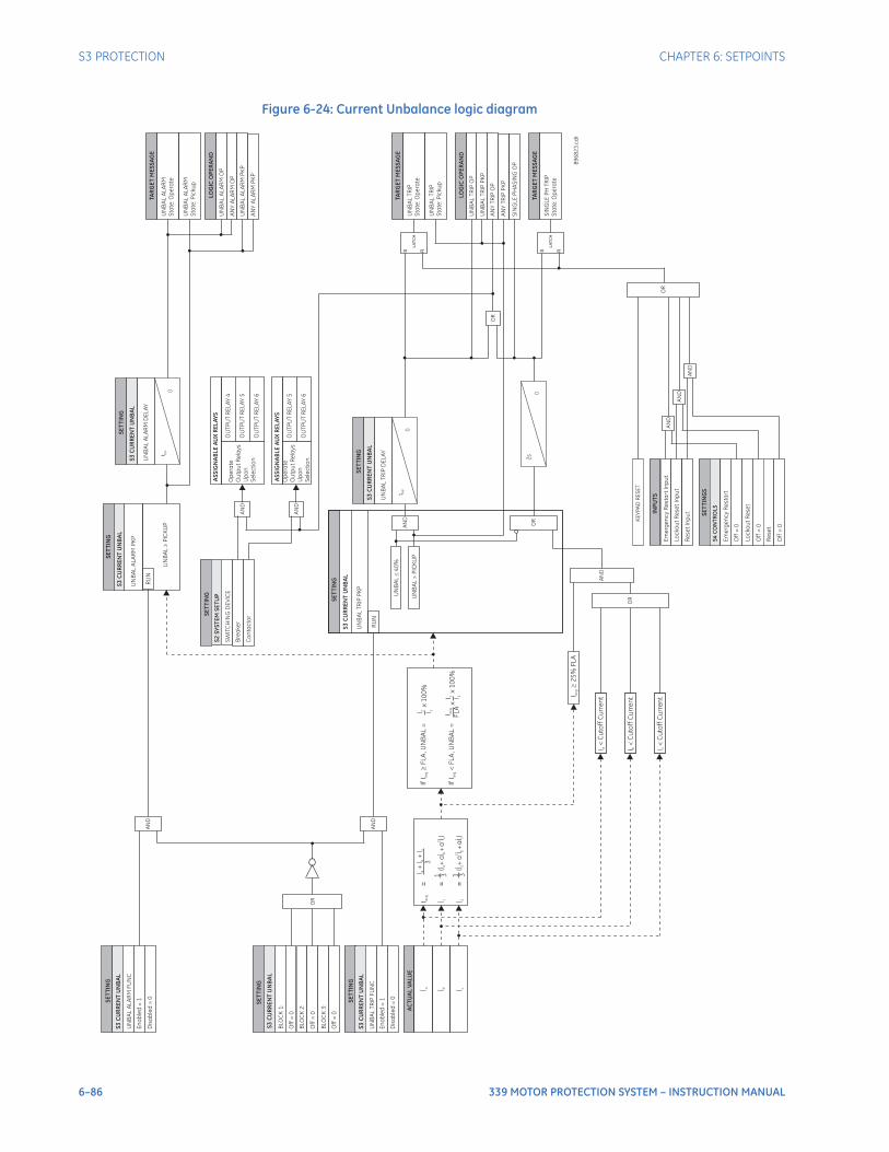
6–86 339 MOTOR PROTECTION SYSTEM – INSTRUCTION MANUAL
S3 PROTECTION CHAPTER 6: SETPOINTS
Figure 6-24: Current Unbalance logic diagram
UN
BA
LA
LA
RM
DE
LA
Y
SE
TT
ING
t PK
P
0
S3
CU
RR
EN
TU
NB
AL
LOG
ICO
PE
RA
ND
AN
YA
LA
RM
OP
UN
BA
LA
LA
RM
PK
P
AN
YA
LA
RM
PK
P
UN
BA
LA
LA
RM
OP
AN
D
AN
D
AN
D
INP
UT
S
Em
erg
en
cy
Re
sta
rt
Inp
ut
Lo
ck
ou
tR
ese
tIn
pu
t
SE
TT
ING
S
Off
=0
Lo
ck
ou
tR
ese
t
Off
=0
Em
erg
en
cy
Re
sta
rt
S4
CO
NT
RO
LS
Re
se
tIn
pu
t
Re
se
t
Off
=0
AN
D
OR
KE
YP
AD
RE
SE
T
Op
era
te
Ou
tpu
tR
ela
ys
Up
on
Se
lec
tio
n
OU
TP
UT
RE
LA
Y4
OU
TP
UT
RE
LA
Y5
OU
TP
UT
RE
LA
Y6
AS
SIG
NA
BL
EA
UX
RE
LA
YS
Op
era
te
Ou
tpu
tR
ela
ys
Up
on
Se
lec
tio
n
OU
TP
UT
RE
LA
Y5
OU
TP
UT
RE
LA
Y6
AS
SIG
NA
BL
EA
UX
RE
LA
YS
SE
TT
ING
BLO
CK
1:
Off
=0
BLO
CK
2:
Off
=0
BLO
CK
3:
Off
=0
OR
S3
CU
RR
EN
TU
NB
AL
SE
TT
ING
RU
N
UN
BA
LT
RIP
PK
P
UN
BA
L>
PIC
KU
P
UN
BA
L4
0%
UN
BA
LT
RIP
DE
LA
Y
SE
TT
ING
t PK
P
0
S3
CU
RR
EN
TU
NB
AL
SE
TT
ING
RU
N
UN
BA
LA
LA
RM
PK
P
UN
BA
LP
ICK
UP
LOG
ICO
PE
RA
ND
UN
BA
LT
RIP
PK
P
AN
YT
RIP
OP
AN
YT
RIP
PK
P
UN
BA
LT
RIP
OP
SE
TT
ING
SW
ITC
HIN
GD
EV
ICE
Bre
ake
r
Co
nta
cto
r
S2
SY
ST
EM
SE
TU
P
AN
D
AN
D
UN
BA
LA
LA
RM
Sta
te:O
pe
rate
TAR
GE
TM
ES
SA
GE
UN
BA
LT
RIP
Sta
te:O
pe
rate
TAR
GE
TM
ES
SA
GE
UN
BA
LT
RIP
Sta
te:P
icku
p
UN
BA
LA
LA
RM
Sta
te:P
icku
p
S R
LA
TC
H
SIN
GL
EP
HA
SIN
GO
P
SIN
GL
EP
HT
RIP
Sta
te:O
pe
rate
TAR
GE
TM
ES
SA
GE
S R
LA
TC
H
OR
OR
AN
D
OR
2s
0
I av
g
25
%F
LA
I<
Cu
rre
nt
aC
uto
ff
I<
bC
urr
en
tC
uto
ff
I<
cC
urr
en
tC
uto
ff
SE
TT
ING
UN
BA
LA
LA
RM
FU
NC
En
ab
led
=1
S3
CU
RR
EN
TU
NB
AL
SE
TT
ING
UN
BA
LT
RIP
FU
NC
En
ab
led
=1
S3
CU
RR
EN
TU
NB
AL
AN
D
AN
D
AC
TU
AL
VA
LUE
İ a İ b İ c
I av
g
İ 1 İ 2
= = =
I+
I+
Ia
bc
3
(+
aİ a
İİ
bc
+a
)2
(+
aİ a
2
İİ
bc
+a
)
IfI
FL
A,U
NB
AL
=a
vg
IfI
FL
A,U
NB
AL
=a
vg
I 2 I 1x
10
0%
I 2 I 1
I av
g
FL
Ax
89
68
23
.cd
r
1 13 3
S3
CU
RR
EN
TU
NB
AL
S3
CU
RR
EN
TU
NB
AL
x1
00
%
Dis
ab
led
=0
Dis
ab
led
=0
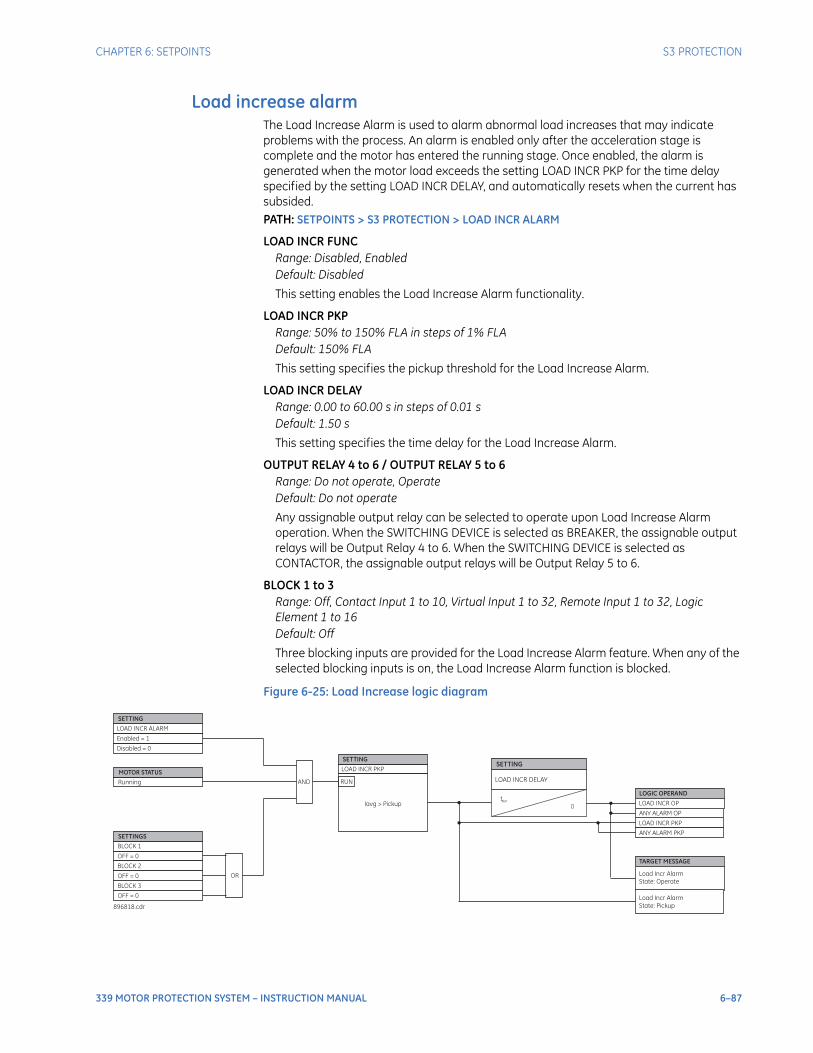
CHAPTER 6: SETPOINTS S3 PROTECTION
339 MOTOR PROTECTION SYSTEM – INSTRUCTION MANUAL 6–87
Load increase alarmThe Load Increase Alarm is used to alarm abnormal load increases that may indicate problems with the process. An alarm is enabled only after the acceleration stage is complete and the motor has entered the running stage. Once enabled, the alarm is generated when the motor load exceeds the setting LOAD INCR PKP for the time delay specified by the setting LOAD INCR DELAY, and automatically resets when the current has subsided.PATH: SETPOINTS > S3 PROTECTION > LOAD INCR ALARM
LOAD INCR FUNCRange: Disabled, EnabledDefault: Disabled
This setting enables the Load Increase Alarm functionality.
LOAD INCR PKPRange: 50% to 150% FLA in steps of 1% FLADefault: 150% FLA
This setting specifies the pickup threshold for the Load Increase Alarm.
LOAD INCR DELAYRange: 0.00 to 60.00 s in steps of 0.01 sDefault: 1.50 s
This setting specifies the time delay for the Load Increase Alarm.
OUTPUT RELAY 4 to 6 / OUTPUT RELAY 5 to 6Range: Do not operate, OperateDefault: Do not operate
Any assignable output relay can be selected to operate upon Load Increase Alarm operation. When the SWITCHING DEVICE is selected as BREAKER, the assignable output relays will be Output Relay 4 to 6. When the SWITCHING DEVICE is selected as CONTACTOR, the assignable output relays will be Output Relay 5 to 6.
BLOCK 1 to 3Range: Off, Contact Input 1 to 10, Virtual Input 1 to 32, Remote Input 1 to 32, Logic Element 1 to 16Default: Off
Three blocking inputs are provided for the Load Increase Alarm feature. When any of the selected blocking inputs is on, the Load Increase Alarm function is blocked.
Figure 6-25: Load Increase logic diagram
BLOCK 1
BLOCK 2
BLOCK 3
OFF = 0
OFF = 0
OFF = 0
SETTINGS
OR
Running
MOTOR STATUS
LOAD INCR ALARM
SETTING
Enabled = 1
AND
LOAD INCR PKP
SETTING
Iavg > Pickup
RUN LOAD INCR DELAY
SETTING
tPKP
0LOAD INCR OP
LOAD INCR PKP
LOGIC OPERAND
ANY ALARM OP
ANY ALARM PKP
Load Incr Alarm
State: Operate
TARGET MESSAGE
Load Incr Alarm
State: Pickup896818.cdr
Disabled = 0

6–88 339 MOTOR PROTECTION SYSTEM – INSTRUCTION MANUAL
S3 PROTECTION CHAPTER 6: SETPOINTS
Ground faultWhen motor stator windings become wet or otherwise suffer insulation deterioration, low magnitude leakage currents often precede complete failure and resultant destructive fault currents. Ground fault protection provides early detection of such leakage current, so that the motor can be taken off line in time to limit motor damage.Depending on the setting S2 SYSTEM SETUP > CURRENT SENSING > GROUND CT TYPE, the current measured by this element is either the Core Balance CT (CBCT) current, the fourth CT input current, or the sum of the first three CT inputs’ currents. For high resistance grounded systems, sensitive ground current detection is possible if the CBCT 50:0.025 input is used. To use the CBCT 50:0.025 input, select “50:0.025” for the Ground CT Type. On solidly grounded systems where fault currents may be quite large, the 1A or 5A secondary ground CT input should be used for either zero-sequence or residual ground sensing. If the connection is residual, the Ground CT secondary and primary values should be the same as the phase CT. If, however, the connection is zero-sequence, the Ground CT secondary and primary values must be entered. The Ground Fault protection alarms or trips when the ground current magnitude exceeds the set pickup for the set time. A ground fault trip is a serious event, and therefore results in a lockout that cannot be reset unless an Emergency Restart or a Lockout Reset is issued.Various situations (e.g. contactor bounce) may cause transient ground currents during motor starting that may exceed the Ground Fault pickup levels for a very short period of time. The delay can be fine tuned to an application such that it still responds very quickly, but rides through normal operational disturbances. Normally, the Ground Fault time delays are set as short as possible, that is, 0.00 seconds. Time to trip may have to be increased if nuisance tripping occurs.Special care must be taken when the ground input is wired to the phase CTs in a residual connection. When a motor starts, the starting current (typically 6 × FLA for an induction motor) has an asymmetrical or DC component. This momentary DC component will cause each of the phase CTs to react differently, and cause a net current into the ground input of the relay. A 20 ms block of the ground fault elements when the motor starts normally enables the relay to ride through this momentary ground current signal.
NOTE
NOTE: The settings GND ALARM PKP and GND TRIP PKP are entered in units of ‘xCT’ if the setting GROUND CT TYPE is programmed as “1A Secondary” or “5A Secondary,” or in units of ‘A’ if the setting GROUND CT TYPE is programmed as “50:0.025”.
PATH: SETPOINTS > S3 PROTECTION > GROUND FAULT
GND ALARM FUNCRange: Disabled, EnabledDefault: Disabled
This setting enables the Ground Fault Alarm functionality.
GND ALARM PKPGround CT Type = 1A Secondary, 5A Secondary:Range: 0.03 to 1.00xCT in steps of 0.01xCTDefault: 0.10xCTGround CT Type = 50:0.025:Range: 0.50 to 15.00 A in steps of 0.01 ADefault: 10.00 A
This setting specifies the Pickup threshold for the Alarm stage.
CHAPTER 6: SETPOINTS S3 PROTECTION
339 MOTOR PROTECTION SYSTEM – INSTRUCTION MANUAL 6–89
GND ALARM ON RUNRange: 0.00 to 60.00 s in steps of 0.01 sDefault: 0.00 s
This setting specifies the amount of time by which motor ground current must exceed pickup to generate an alarm when the motor is in running condition.
GND ALARM ON STARTRange: 0.00 to 60.00 s in steps of 0.01 sDefault: 0.00 s
This setting specifies the amount of time by which motor ground current must exceed pickup to generate an alarm when the motor is in starting condition.
GND TRIP FUNCRange: Disabled, EnabledDefault: Disabled
This setting enables the Ground Fault Trip functionality.
GND TRIP PKPGround CT Type = 1A Secondary, 5A Secondary:Range: 0.03 to 1.00xCT in steps of 0.01xCTDefault: 0.10xCTGround CT Type = 50:0.025:Range: 0.50 to 15.00 A in steps of 0.01 ADefault: 10.00 A
This setting specifies the Pickup threshold for the Trip stage.
GND TRIP ON RUNRange: 0.00 to 5.00 s in steps of 0.01 sDefault: 0.00 s
This setting specifies the amount of time by which motor ground current must exceed pickup to generate a Trip when the motor is in running condition.
GND TRIP ON STARTRange: 0.00 to 10.00 s in steps of 0.01 sDefault: 0.00 s
This setting specifies the amount of time by which motor ground current must exceed pickup to generate a Trip when the motor is in starting condition.
OUTPUT RELAY 4 to 6 / OUTPUT RELAY 5 to 6Range: Do not operate, OperateDefault: Do not operate
Any assignable output relay can be selected to operate upon Ground Fault operation. When the SWITCHING DEVICE is selected as BREAKER, the assignable output relays will be Output Relay 4 to 6. When the SWITCHING DEVICE is selected as CONTACTOR, the assignable output relays will be Output Relay 5 to 6.
To select any assignable output relays to operate upon the Ground Fault Alarm operation, assign the Logic Operand "GROUND FAULT ALARM OP" or "Any Alarm OP" to a Logic Element.
BLOCK 1 to 3Range: Off, Contact Input 1 to 10, Virtual Input 1 to 32, Remote Input 1 to 32, Logic Element 1 to 16Default: Off
Three blocking inputs are provided for the Ground Fault feature. When any of the selected blocking inputs is on, the Ground Fault function is blocked.
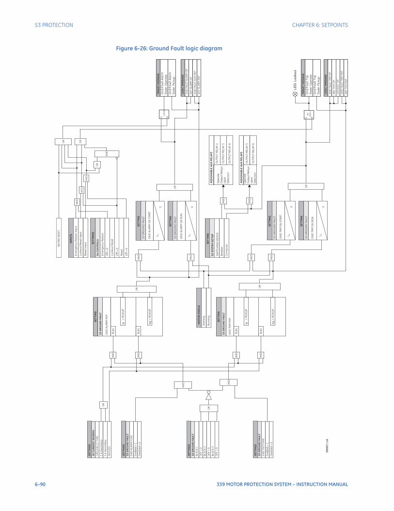
6–90 339 MOTOR PROTECTION SYSTEM – INSTRUCTION MANUAL
S3 PROTECTION CHAPTER 6: SETPOINTS
Figure 6-26: Ground Fault logic diagram
LO
GIC
OP
ER
AN
D
GN
DFA
ULT
TR
IPO
P
AN
YT
RIP
OP
LO
GIC
OP
ER
AN
D
GN
DFA
ULT
AL
AR
MO
P
AN
YA
LA
RM
OP
S R
NV
LA
TC
H
GN
DFA
ULT
TR
IPP
KP
GN
DFA
ULT
AL
MP
KP
TAR
GE
TM
ES
SA
GE
Gn
dF
au
ltA
larm
Sta
te:O
pe
rate
S R
LA
TC
H
Gn
dF
au
ltA
larm
Sta
te:P
icku
p
TAR
GE
TM
ES
SA
GE
Gn
dF
au
ltT
rip
Sta
te:O
pe
rate
Gn
dF
au
ltT
rip
Sta
te:P
icku
p
AN
YA
LA
RM
PK
P
AN
YT
RIP
PK
P
OR
GN
DA
LA
RM
ON
STA
RT
SE
TT
ING
t PK
P
0
S3
GR
OU
ND
FA
ULT
GN
DA
LA
RM
ON
RU
N
SE
TT
ING
t PK
P
0
S3
GR
OU
ND
FA
ULT
GN
DT
RIP
ON
STA
RT
SE
TT
I NG
t PK
P
0
S3
GR
OU
ND
FA
ULT
GN
DT
RIP
ON
RU
N
SE
TT
I NG
t PK
P
0
S3
GR
OU
ND
FA
ULT
OR
SE
TT
ING
RU
N
GN
DA
LA
RM
PK
P
Isg
>P
ICK
UP
Ig>
PIC
KU
P
S3
GR
OU
ND
F AU
LT
SE
TT
ING
RU
N
GN
DT
RIP
PK
P
Isg
>P
ICK
UP
Ig>
PIC
KU
P
S3
GR
OU
ND
F AU
LT
RU
N
RU
NO
R OR
AN
D
AN
D
AN
D
AN
D
AN
D
AN
D
AN
D
AN
D
Op
era
te
Ou
tpu
tR
ela
ys
Up
on
Se
lec
tio
n
OU
TP
UT
RE
LA
Y4
OU
TP
UT
RE
LA
Y5
OU
TP
UT
RE
LA
Y6
AS
SIG
NA
BL
EA
UX
RE
LA
YS
AN
D
Op
era
te
Ou
tpu
tR
ela
ys
Up
on
Se
lec
tio
n
OU
TP
UT
RE
LA
Y5
OU
TP
UT
RE
LA
Y6
AN
D
AS
SIG
NA
BL
EA
UX
RE
LA
YS
MO
TO
RS
TAT
US
Sta
rti
ng
Ru
nn
ing
SE
TT
I NG
SW
ITC
HIN
GD
EV
ICE
Bre
ake
r
Co
nta
cto
r
S2
SY
ST
EM
SE
TU
P
89
68
21
.cd
r
AN
D
AN
D
S3
GR
OU
ND
F AU
LT
BLO
CK
1
BLO
CK
2
BLO
CK
3
OF
F=
0
OF
F=
0
OF
F=
0
OR
SE
TT
ING
S
S3
GR
OU
ND
F AU
LT
GN
DA
LA
RM
FU
NC
En
ab
led
=1
SE
TT
ING
S
S2
CU
RR
EN
TS
EN
SIN
G
GR
OU
ND
CT
TY
PE
5A
Se
co
nd
ary
1A
Se
co
nd
ary
50
:0.0
25
SE
TT
ING
S
S3
GR
OU
ND
FAU
LT
GN
DT
RIP
FU
NC
En
ab
led
=1
SE
TT
ING
S
OR
LE
D:Lockout
Dis
ab
led
=0
Dis
ab
led
=0
OR
AN
D
AN
D
INP
UT
S
Em
erg
en
cy
Re
sta
rt
Inp
ut
Lo
ck
ou
tR
ese
tIn
pu
t
SE
TT
ING
S
Off
=0
Lo
ck
ou
tR
ese
t
Off
=0
Em
erg
en
cy
Re
sta
rt
S4
CO
NT
RO
LS
Re
se
tIn
pu
t
Re
se
t
Off
=0
AN
D
OR
KE
YP
AD
RE
SE
T
OR
AN
D
LO
CK
OU
TO
P
CHAPTER 6: SETPOINTS S3 PROTECTION
339 MOTOR PROTECTION SYSTEM – INSTRUCTION MANUAL 6–91
Neutral instantaneous overcurrentThe relay has one Instantaneous Overcurrent protection. The settings of this function are applied to the calculated neutral current for producing pickup and trip flags. The Neutral IOC pickup flag is asserted, when the neutral current is above the PKP value. The Neutral IOC operate flag is asserted if the element stays picked up for the time defined by the Neutral IOC Delay setting. If the pickup time delay is set to 0.00 seconds, the pickup and operate flags will be asserted at the same time. The element drops from pickup without operation, if the neutral current drops below 96 to 99% of the pickup value. The following path is available using the keypad. For instructions on how to use the keypad, please refer to Chapter 3 - Working with the Keypad.PATH: SETPOINTS > S3 PROTECTION > NEUTRAL IOC
NTRL IOC1 FUNCTIONRange: Disabled, Latched Alarm, Alarm, TripDefault: Disabled
The selection of the Latched Alarm, Alarm, or Trip setting enables the Neutral IOC function. The output relay #1 “Trip” will operate if the Neutral IOC function is selected as Trip, and the neutral current calculated by the relay satisfies the operating condition set by the settings. The “ALARM” LED will not turn on if the neutral IOC operates when set to function Trip. The “ALARM” LED will flash upon Neutral IOC operation with the IOC function selected as Alarm and will self-reset when this operation clears. If Latched Alarm is selected as an IOC function, the “ALARM” LED will flash during IOC operation and will stay “ON” after the operating condition clears, until the reset command is initiated. The output relay #1 “Trip” will not operate if the Latched Alarm or Alarm setting is selected. Any assignable output relay can be selected to operate when the Neutral IOC function - Latched Alarm, Alarm, or Trip - is selected.
NTRL IOC PKPRange: 0.05 to 20 x CT in steps of 0.01 x CTDefault: 1.00 x CT
This setting sets the neutral instantaneous overcurrent pickup level specified as times CT.
NTRL IOC DELAYRange: 0.00 to 300 s in steps of 0.01 sDefault: 0.00 s
This setting provides selection for the pickup time delay, used to delay the protection operation.
NTRL IOC DIRECTIONRange: Disabled, Forward, ReverseDefault: Disabled
This setting provides control to the Neutral IOC function in terms of permitting operation upon fault conditions in the selected current flow direction, and blocking it when faults occur in the opposite direction.
OUTPUT RELAY 4 to 6 / OUTPUT RELAY 5 to 6Range: Do not operate, OperateDefault: Do not operate
Any assignable output relay can be selected to operate upon Neutral IOC operation. When the SWITCHING DEVICE is selected as BREAKER, the assignable output relays will be Output Relay 4 to 6. When the SWITCHING DEVICE is selected as CONTACTOR, the assignable output relays will be Output Relay 5 to 6.

6–92 339 MOTOR PROTECTION SYSTEM – INSTRUCTION MANUAL
S3 PROTECTION CHAPTER 6: SETPOINTS
BLOCK 1 to 3Range: Off, Contact Input 1 to 10, Virtual Input 1 to 32, Remote Input 1 to 32, Logic Element 1 to 16Default: Off
Three blocking inputs are provided for the Neutral IOC feature. When any of the selected blocking inputs is on, the Neutral IOC function is blocked. The available selections for each block can be any Contact input, Virtual Input, Remote Input, or Logic Element.
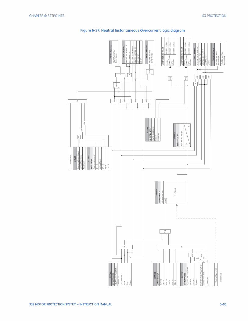
CHAPTER 6: SETPOINTS S3 PROTECTION
339 MOTOR PROTECTION SYSTEM – INSTRUCTION MANUAL 6–93
Figure 6-27: Neutral Instantaneous Overcurrent logic diagram
SE
TT
I NG
RU
N
SE
TT
ING
SE
TT
ING
NE
UT
RA
LIO
CF
UN
CT
ION
NE
UT
RA
LIO
CD
IRE
CT
ION
Dis
ab
led
=0
Fo
rw
ard
La
tch
ed
Ala
rm
Dis
ab
led
NE
UT
RA
LIO
CD
EL
AY
Ala
rm
Re
ve
rse
Cu
rre
nt
inR
eve
rse
Fro
mN
EU
TR
AL
DIR
EC
TIO
NA
L
Cu
rre
nt
OK
Op
era
te
Ou
tpu
tR
ela
ys
Up
on
Se
lec
tio
n
OU
TP
UT
RE
LA
Y4
OU
TP
UT
RE
LA
Y5
OU
TP
UT
RE
LA
Y6
Tri
p
SE
TT
I NG
BLO
CK
1:
Off
=0
BLO
CK
2:
Off
=0
BLO
CK
3:
Off
=0
SE
TT
I NG
NE
UT
RA
LIO
CA
LA
RM
PK
P
t PK
P
S R
LA
TC
H
89
68
30
A1
.cd
r
LOG
ICO
PE
RA
ND
NE
UT
RA
LIO
CA
LA
RM
OP
LOG
ICO
PE
RA
ND
OR
OR
AN
D
AN
D
AN
D
AN
D
AN
D
AN
D
OR
AN
D
AN
D
INP
UT
S
Em
erg
en
cy
Re
sta
rt
Inp
ut
Lo
ck
ou
tR
ese
tIn
pu
t
SE
TT
ING
S
Off
=0
Lo
ck
ou
tR
ese
t
Off
=0
Em
erg
en
cy
Re
sta
rt
S4
CO
NT
RO
LS
NE
UT
RA
LIO
CA
larm
Sta
te:O
pe
rate
TAR
GE
TM
ES
SA
GE
AN
YA
LA
RM
OP
NE
UT
RA
LIO
CT
RIP
OP
AN
YT
RIP
OP
S R
LA
TC
HN
EU
TR
AL
IOC
Tri
p
Sta
te:O
pe
rate
TAR
GE
TM
ES
SA
GE
AS
SIG
NA
BL
EA
UX
RE
LA
YS
AN
D
Op
era
te
Ou
tpu
tR
ela
ys
Up
on
Se
lec
tio
n
OU
TP
UT
RE
LA
Y5
OU
TP
UT
RE
LA
Y6
AN
D
AN
YA
LA
RM
PK
P
NE
UT
RA
LIO
CT
RIP
PK
P
AN
YT
RIP
PK
P
AN
D
AN
D
OR
S3
NE
UT
RA
LIO
C
S3
NE
UT
RA
LIO
C
S3
NE
UT
RA
LIO
C
S3
NE
UT
RA
LIO
C
SE
TT
I NG
SW
ITC
HIN
GD
EV
ICE
Bre
ake
r
Co
nta
cto
r
S2
SY
ST
EM
SE
TU
P
S3
NE
UT
RA
LIO
C
OR
Re
se
tIn
pu
t
Re
se
t
Off
=0
AN
D
OR
KE
YP
AD
RE
SE
T
AN
YL
ATC
HE
DA
LA
RM
OP
AS
SIG
NA
BL
EA
UX
RE
LA
YS
NE
UT
RA
LIO
CA
larm
Sta
te:P
icku
p
TAR
GE
TM
ES
SA
GE
NE
UT
RA
LIO
CT
rip
Sta
te:P
icku
p
0
IN>
PIC
KU
P
NE
UT
RA
LIO
CP
KP
Ne
utr
alC
urr
en
t(IN
)
Co
ntr
ol
AN
D
LE
IP
KP
AN
D
LE
IO
P
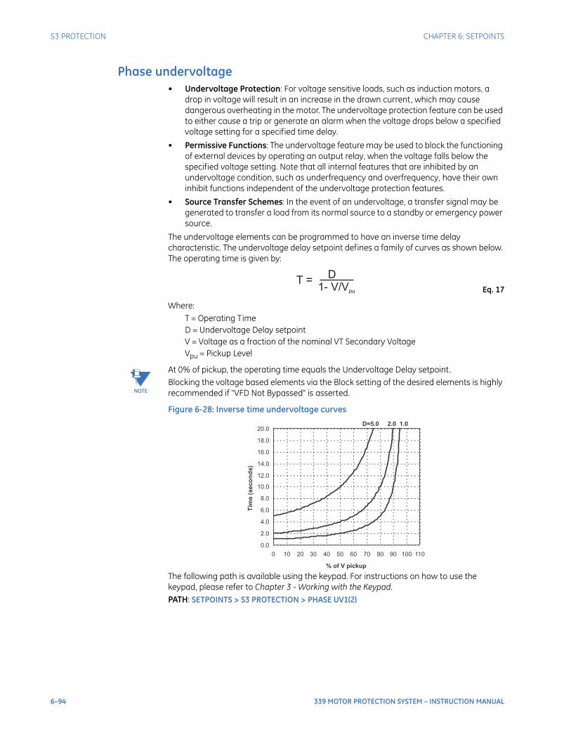
6–94 339 MOTOR PROTECTION SYSTEM – INSTRUCTION MANUAL
S3 PROTECTION CHAPTER 6: SETPOINTS
Phase undervoltage• Undervoltage Protection: For voltage sensitive loads, such as induction motors, a
drop in voltage will result in an increase in the drawn current, which may cause dangerous overheating in the motor. The undervoltage protection feature can be used to either cause a trip or generate an alarm when the voltage drops below a specified voltage setting for a specified time delay.
• Permissive Functions: The undervoltage feature may be used to block the functioning of external devices by operating an output relay, when the voltage falls below the specified voltage setting. Note that all internal features that are inhibited by an undervoltage condition, such as underfrequency and overfrequency, have their own inhibit functions independent of the undervoltage protection features.
• Source Transfer Schemes: In the event of an undervoltage, a transfer signal may be generated to transfer a load from its normal source to a standby or emergency power source.
The undervoltage elements can be programmed to have an inverse time delay characteristic. The undervoltage delay setpoint defines a family of curves as shown below. The operating time is given by:
Eq. 17
Where: T = Operating TimeD = Undervoltage Delay setpoint V = Voltage as a fraction of the nominal VT Secondary VoltageVpu = Pickup Level
NOTE
NOTE: At 0% of pickup, the operating time equals the Undervoltage Delay setpoint.Blocking the voltage based elements via the Block setting of the desired elements is highly recommended if "VFD Not Bypassed" is asserted.
Figure 6-28: Inverse time undervoltage curves
The following path is available using the keypad. For instructions on how to use the keypad, please refer to Chapter 3 - Working with the Keypad.PATH: SETPOINTS > S3 PROTECTION > PHASE UV1(2)
T =D
1- V/Vpu
D=5.0 2.0 1.0
0.0
2.0
4.0
6.0
8.0
10.0
12.0
14.0
16.0
18.0
20.0
0 10 20 30 40 50 60 70 80 90 100 110
% of V pickup
Tim
e(s
eco
nd
s)
CHAPTER 6: SETPOINTS S3 PROTECTION
339 MOTOR PROTECTION SYSTEM – INSTRUCTION MANUAL 6–95
PH UV FUNCTIONRange: Disabled, Alarm, Latched Alarm, TripDefault: Disabled
The selection of the Latched Alarm, Alarm, or Trip setting enables the Phase Undervoltage function. If the operating condition is satisfied when Trip is selected as the function, the logic operand ANY TRIP OP will be asserted, which in turn will activate the “TRIP” LED and operate the “Trip” output relay. If Alarm is selected, the “ALARM” LED will flash upon Phase Undervoltage operation, and will automatically reset when the activating condition clears. If Latched Alarm is selected, the “ALARM” LED will flash upon Phase Undervoltage operation, and will stay “ON” after the condition clears, until a reset command is initiated. The TRIP output relay will not operate if the Latched Alarm or Alarm function is selected. Any assignable output relays can be selected to operate when the setting PH UV FUNCTION is selected as Latched Alarm, Alarm, or Trip.
PH UV PKPRange: 0.00 to 1.25 x VT in steps of 0.01Default: 0.75 x VT
This setting defines the phase UV pickup level, and it is usually set to a level, below which the drawn current may cause dangerous motor overheating conditions.
PH UV CURVERange: Definite Time, Inverse TimeDefault: Inverse Time
This setting selects the type of timing-inverse time/definite time to define the time of undervoltage operation based on the selected UV time delay, and the actual undervoltage condition with respect to the selected UV pickup.
PH UV DELAYRange: 0.1 to 600.0 sec in steps of 0.1 secDefault: 2.0 s
This setting specifies the time delay used by the selected “PHASE UV CURVE” type of timing, to calculate the time before UV operation.
PH UV PHASESRange: Any One, Any Two, All ThreeDefault: Any One
This setting selects the combination of undervoltage conditions with respect to the number of phase voltages under the undervoltage pickup setting. Selection of “Any Two” or “All Three” would effectively rule out the case of single VT fuse failure.
PH UV MIN VOLTAGERange: 0.00 to 1.25 x VT in steps of 0.01Default: 0.30 x VT
The minimum operating voltage level is programmable to prevent undesired UV operation before voltage becomes available.
OUTPUT RELAY 4 to 6 / OUTPUT RELAY 5 to 6Range: Do not operate, OperateDefault: Do not operate
Any assignable output relay can be selected to operate upon Phase Undervoltage operation. When the SWITCHING DEVICE is selected as BREAKER, the assignable output relays will be Output Relay 4 to 6. When the SWITCHING DEVICE is selected as CONTACTOR, the assignable output relays will be Output Relay 5 to 6.

6–96 339 MOTOR PROTECTION SYSTEM – INSTRUCTION MANUAL
S3 PROTECTION CHAPTER 6: SETPOINTS
BLOCK 1/2/3Range: Off, Contact Input 1 to 10, Virtual Input1 to 32, Remote Input 1 to 32, Logic Element 1 to 16Default:Off
Three blocking inputs are provided for Phase UV. When any of the selected blocking inputs is on, the Phase UV function is blocked. The available selections for each block can be any Contact input, Virtual Input, Remote Input, or Logic Element.
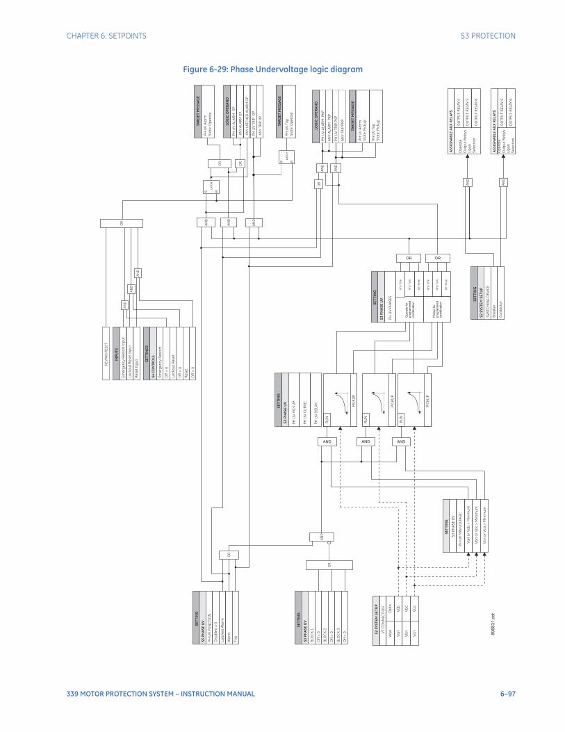
CHAPTER 6: SETPOINTS S3 PROTECTION
339 MOTOR PROTECTION SYSTEM – INSTRUCTION MANUAL 6–97
Figure 6-29: Phase Undervoltage logic diagram
SE
TT
ING
PH
UV
FU
NC
TIO
N
Dis
ab
led
=0
La
tch
ed
Ala
rm
Ala
rm
Op
era
te
Ou
tpu
tR
ela
ys
Up
on
Se
lec
tio
n
OU
TP
UT
RE
LA
Y4
OU
TP
UT
RE
LA
Y5
OU
TP
UT
RE
LA
Y6
Tri
p
SE
TT
ING
BLO
CK
1:
Off
=0
BLO
CK
2:
Off
=0
BLO
CK
3:
Off
=0
PH
UV
AL
AR
MP
KP
S R
LA
TC
H
89
68
31
. cd
r
LOG
ICO
PE
RA
ND
PH
UV
AL
AR
MO
P
LOG
ICO
PE
RA
ND
OR
OR
AN
D
AN
D
AN
D
AN
D
OR
AN
D
AN
D
INP
UT
S
Em
erg
en
cy
Re
sta
rt
Inp
ut
Lo
ck
ou
tR
ese
tIn
pu
t
SE
TT
ING
S
Off
=0
Lo
ck
ou
tR
ese
t
Off
=0
Em
erg
en
cy
Re
sta
rt
S4
CO
NT
RO
LS
PH
UV
Ala
rm
Sta
te:O
pe
rate
TAR
GE
TM
ES
SA
GE
AN
YA
LA
RM
OP
PH
UV
TR
IPO
P
AN
YT
RIP
OP
S R
LA
TC
HP
HU
VT
rip
Sta
te:O
pe
rate
TAR
GE
TM
ES
SA
GE
AS
SIG
NA
BL
EA
UX
RE
LA
YS
AN
D
Op
era
te
Ou
tpu
tR
ela
ys
Up
on
Se
lec
tio
n
OU
TP
UT
RE
LA
Y5
OU
TP
UT
RE
LA
Y6
AN
D
AN
YA
LA
RM
PK
P
PH
UV
TR
IPP
KP
AN
YT
RIP
PK
P
AN
D
AN
D
OR
S3
PH
AS
EU
V
SE
TT
ING
SW
ITC
HIN
GD
EV
ICE
Bre
ake
r
Co
nta
cto
r
S2
SY
ST
EM
SE
TU
P
S3
PH
AS
EU
V
OR
Re
se
tIn
pu
t
Re
se
t
Off
=0
AN
D
OR
KE
YP
AD
RE
SE
T
AN
YL
ATC
HE
DA
LA
RM
OP
AS
SIG
NA
BL
EA
UX
RE
LA
YS
PH
UV
Ala
rm
Sta
te:P
icku
p
TAR
GE
TM
ES
SA
GE
PH
UV
Tri
p
Sta
te:P
icku
p
S3
PH
AS
EU
V
Va
b
PH
UV
PIC
KU
P:
PH
UV
CU
RV
E:
PH
UV
DE
LA
Y:
Vb
c
Vc
a
RU
N
RU
N
RU
N
PIC
KU
P
Va
n
Vb
n
Vc
n
PIC
KU
P
PIC
KU
P
Va
no
rV
ab
>M
inim
um
Vb
no
rV
bc
>M
inim
um
Vc
no
rV
ca
>M
inim
um
PH
UV
MIN
VO
LTA
GE
:
S3
PH
AS
EU
V
AND AND AND
De
lta
Wy
e
All
Th
ree
An
yO
ne
An
yT
wo
Op
era
tefo
rp
rog
ram
me
dco
mb
ina
tio
n
An
yT
wo
An
yO
ne
All
Th
ree
S3
PH
AS
EU
V
PH
UV
PH
AS
ES
OR OR
Pic
ku
pfo
rp
rog
ram
me
dco
mb
ina
tio
n
89
68
31
.cd
r
SE
TT
I NG
SE
TT
ING
VT
CO
NN
EC
TIO
N
S2
SY
ST
EM
SE
TU
PS
ET
TI N
G

6–98 339 MOTOR PROTECTION SYSTEM – INSTRUCTION MANUAL
S3 PROTECTION CHAPTER 6: SETPOINTS
Phase overvoltageAn overvoltage on a running motor with a constant load results in decreased current. However, iron and copper losses increase, causing an increase in motor temperature. The current overload element will not pickup this condition and provide adequate protection. Therefore, the overvoltage element may be useful for protecting the motor in the event of a sustained overvoltage condition. The 339 provides 2 Phase Overvoltage elements. Each element can be set to either cause a trip or generate an alarm when the input voltage exceeds the pickup level for a specified time delay. If it is desirable to have an alarm before a trip occurs, the user can set the function of one Phase Overvoltage element to ALARM, and the function of the other element to TRIP. For wye-connected VT, the input voltage is phase-to-ground voltage; for delta-connected VT, the input voltage is phase-to-phase voltage. The Phase Overvoltage operation can be set for phase combinations including “Any One”, “Any Two” and “All Three”. If overvoltage tripping is enabled, and the setting PH OV PHASES is set for “Any One”, a trip will occur once the magnitude of any input voltage (wye-connected VT: phase-to-ground voltage; delta-connected VT: phase-to-phase voltage) exceeds the pickup level for a period of time specified by the time delay. On the other hand, if overvoltage trip is enabled, and the setting PH OV PHASES is set for “All Three”, a trip will occur only when the magnitudes of all three input voltages exceed the pickup level for a period of time specified by the time delay.The following path is available using the keypad. For instructions on how to use the keypad, please refer to Chapter 3 - Working with the Keypad.
NOTE
NOTE: Blocking the voltage based elements via the Block setting of the desired elements is highly recommended if "VFD Not Bypassed" is asserted.
PATH: SETPOINTS > S3 PROTECTION > PHASE OV1(2)
PH OV FUNCTIONRange: Disabled, Alarm, Latched Alarm, TripDefault: Disabled
The selection of the Latched Alarm, Alarm, or Trip setting enables the Phase Overvoltage function. If the operating condition is satisfied when Trip is selected as the function, the logic operand ANY TRIP OP will be asserted, which in turn will activate the “TRIP” LED and operate the “Trip” output relay. If Alarm is selected, the “ALARM” LED will flash upon Phase Overvoltage operation, and will automatically reset when the activating condition clears. If Latched Alarm is selected, the “ALARM” LED will flash upon Phase Overvoltage operation, and will stay “ON” after the condition clears, until a reset command is initiated. The TRIP output relay will not operate if the Latched Alarm or Alarm function is selected. Any assignable output relays can be selected to operate when the setting PH OV FUNCTION is selected as Latched Alarm, Alarm, or Trip.
PH OV PKPRange: 0.00 to 1.25 x VT in steps of 0.01Default: 1.25 x VT
This setting defines the Phase OV pickup level.
PH OV DELAYRange: 0.1 to 600.0 sec in steps of 0.1Default: 2.0 s
This setting specifies the time delay before Phase OV operation.
PH OV PHASESRange: Any One, Any Two, All ThreeDefault: All Three
This setting selects the combination of overvoltage conditions with respect to the number of phase voltages over the overvoltage pickup setting.
CHAPTER 6: SETPOINTS S3 PROTECTION
339 MOTOR PROTECTION SYSTEM – INSTRUCTION MANUAL 6–99
OUTPUT RELAY 4 to 6 / OUTPUT RELAY 5 to 6Range: Do not operate, OperateDefault: Do not operate
Any assignable output relay can be selected to operate upon Phase Overvoltage operation. When the SWITCHING DEVICE is selected as BREAKER, the assignable output relays will be Output Relay 4 to 6. When the SWITCHING DEVICE is selected as CONTACTOR, the assignable output relays will be Output Relay 5 to 6.
BLOCK 1/2/3Range: Off, Contact Input 1 to 10, Virtual Input 1 to 32, Remote Input 1 to 32, Logic Element 1 to 16Default: Off
Three blocking inputs are provided for Phase OV. When any of the selected blocking inputs is on, the Phase OV function is blocked. The available selections for each block can be any Contact input, Virtual Input, Remote Input, or Logic Element.
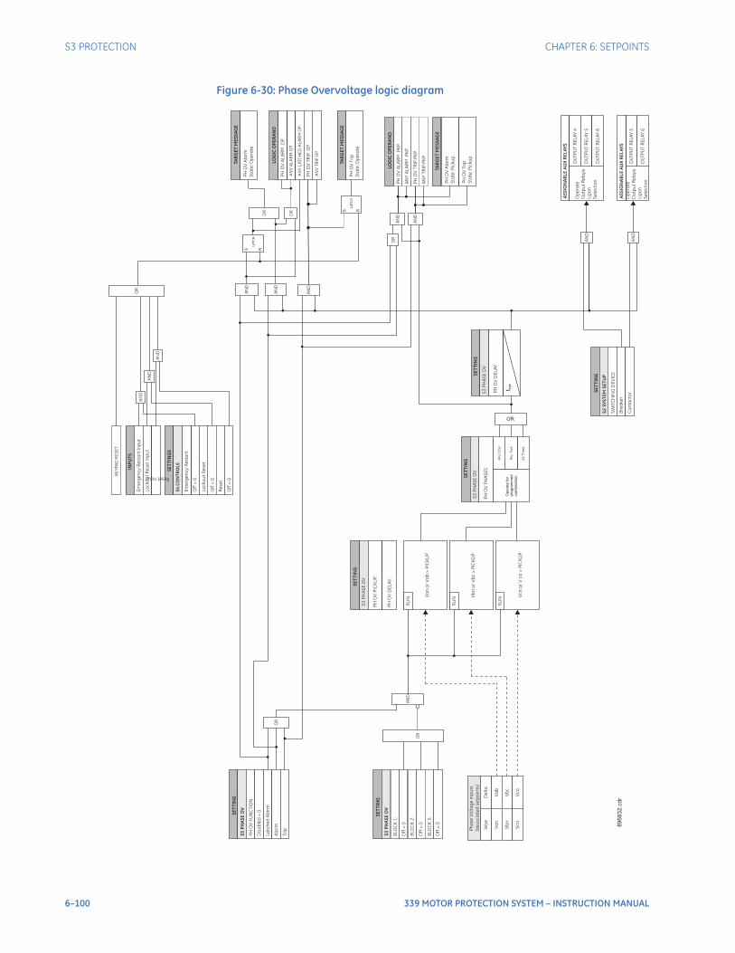
6–100 339 MOTOR PROTECTION SYSTEM – INSTRUCTION MANUAL
S3 PROTECTION CHAPTER 6: SETPOINTS
Figure 6-30: Phase Overvoltage logic diagram
SE
TT
ING
PH
OV
FU
NC
TIO
N
Dis
ab
led
=0
La
tch
ed
Ala
rm
Ala
rm
Op
era
te
Ou
tpu
tR
ela
ys
Up
on
Se
lec
tio
n
OU
TP
UT
RE
LA
Y4
OU
TP
UT
RE
LA
Y5
OU
TP
UT
RE
LA
Y6
Tri
p
SE
TT
I NG
BLO
CK
1:
Off
=0
BLO
CK
2:
Off
=0
BLO
CK
3:
Off
=0
PH
OV
AL
AR
MP
KP
S R
LA
TC
H
89
68
31
. cd
r
LOG
ICO
PE
RA
ND
PH
OV
AL
AR
MO
P
LOG
ICO
PE
RA
ND
OR
OR
AN
D
AN
D
AN
D
AN
D
OR
AN
D
AN
D
INP
UT
S
Em
erg
en
cy
Re
sta
rt
Inp
ut
Lo
ck
ou
tR
ese
tIn
pu
t
SE
TT
ING
S
Off
=0
Lo
ck
ou
tR
ese
t
Off
=0
Em
erg
en
cy
Re
sta
rt
S4
CO
NT
RO
LS
PH
OV
Ala
rm
Sta
te:O
pe
rate
TAR
GE
TM
ES
SA
GE
AN
YA
LA
RM
OP
PH
OV
TR
IPO
P
AN
YT
RIP
OP
S R
LA
TC
HP
HO
VT
rip
Sta
te:O
pe
rate
TAR
GE
TM
ES
SA
GE
AS
SIG
NA
BL
EA
UX
RE
LA
YS
AN
D
Op
era
te
Ou
tpu
tR
ela
ys
Up
on
Se
lec
tio
n
OU
TP
UT
RE
LA
Y5
OU
TP
UT
RE
LA
Y6
AN
D
AN
YA
LA
RM
PK
P
PH
OV
TR
IPP
KP
AN
YT
RIP
PK
P
AN
D
AN
D
OR
S3
PH
AS
EO
V
SE
TT
ING
SW
ITC
HIN
GD
EV
ICE
Bre
ake
r
Co
nta
cto
r
S2
SY
ST
EM
SE
TU
P
S3
PH
AS
EO
V
OR
ResetInput
Re
se
t
Off
=0
AN
D
OR
KE
YP
AD
RE
SE
T
AN
YL
ATC
HE
DA
LA
RM
OP
AS
SIG
NA
BL
EA
UX
RE
LA
YS
PH
OV
Ala
rm
Sta
te:P
icku
p
TAR
GE
TM
ES
SA
GE
PH
OV
Tri
p
Sta
te:P
icku
p
S3
PH
AS
EO
V
Va
b
PH
OV
PIC
KU
P:
PH
OV
DE
LA
Y:
Vb
c
Vc
a
RU
N
RU
N
RU
N
Vc
no
rV
ca
>P
ICK
UP
Va
n
Vb
n
Vc
n
Vb
no
rV
bc
>P
ICK
UP
Va
no
rV
ab
>P
ICK
UP
De
lta
Wy
e
All
Th
ree
Op
era
tefo
rp
rog
ram
me
dco
mb
ina
tio
n
An
yT
wo
An
yO
ne
SE
TT
ING
PH
OV
PH
AS
ES
OR
89
68
32
.cd
r
SE
TT
I NG
Ph
ase
Vo
lta
ge
Inp
uts
(asso
cia
ted
se
tpo
ints
)S
ET
TI N
G
PH
OV
DE
LA
Y
t PK
P
S3
PH
AS
EO
V
S3
PH
AS
EO
V

CHAPTER 6: SETPOINTS S3 PROTECTION
339 MOTOR PROTECTION SYSTEM – INSTRUCTION MANUAL 6–101
UnderfrequencyThe 339 provides 2 Underfrequency Protection elements. Each element can be set to either cause a trip or generate an alarm when the frequency of the input voltage (wye-connected VT: VAN; delta-connected VT: VAB) drops below the pickup level for a specified time delay. If it is desirable to have an alarm before a trip occurs, the user can set the function of one Underfrequency element to ALARM, and the function of another element to TRIP. The Underfrequency element is blocked VAN is below the set MIN VOLTAGE. This setting may be used to prevent nuisance alarms or trips when the bus is not energized. If a dead source is desirable to be considered as a fault condition, set this setting to “0.00xVT”.This feature may be useful for load shedding applications on large motors. It could also be used to load shed an entire feeder if the trip was assigned to an upstream breaker.Underfrequency can also be used to detect loss of power to a synchronous motor. Due to motor generation, sustained voltage may prevent quick detection of power loss. Therefore, to quickly detect the loss of system power, the decaying frequency of the generated voltage as the motor slows can be used.The following path is available using the keypad. For instructions on how to use the keypad, please refer to Chapter 3 - Working with the Keypad.PATH: SETPOINTS > S3 PROTECTION > UNDER-FREQUENCY1(2)
NOTE
NOTE: When "VFD Not Bypassed" is asserted, frequency source is software calculated from the phase A current. The underfrequency element is inhibited from operating unless this current is above 10% of nominal.
UNDRFREQ 1(2) FUNCRange: Disabled, Alarm, Latched Alarm, TripDefault: Disabled
The selection of the Latched Alarm, Alarm, or Trip setting enables the Underfrequency function. If the operating condition is satisfied when Trip is selected as the function, the logic operand ANY TRIP OP will be asserted, which in turn will activate the “TRIP” LED and operate the “Trip” output relay. If Alarm is selected, the “ALARM” LED will flash upon Underfrequency operation, and will automatically reset when the activating condition clears. If Latched Alarm is selected, the "ALARM” LED will flash upon Underfrequency operation, and will stay “ON” after the condition clears, until a reset command is initiated. The TRIP output relay will not operate if the Latched Alarm or Alarm function is selected. Any assignable output relays can be selected to operate when the setting UNDRFREQ FUNC is selected as Latched Alarm, Alarm, or Trip.
UNDERFREQ PKPRange: 40.00 to 70.00 Hz in steps of 0.01 HzDefault: 59.00 Hz
This setting defines the Underfrequency pickup level; it is usually set to a frequency level considered dangerous for the stability of the system.
UNDRFREQ DELAYRange: 0.1 to 600.0 sec in steps of 0.1 secDefault: 2.0 s
This setting specifies the time delay before Underfrequency operation.
MIN VOLTAGERange: 0.00 to 1.25 x VT in steps of 0.01 x VTDefault: 0.70 x VT
The minimum operating voltage level is programmable to prevent undesired Underfrequency operation before voltage VAN becomes available, such as on faults cleared by downstream protection or fuses. This setting is not used in VFD mode.
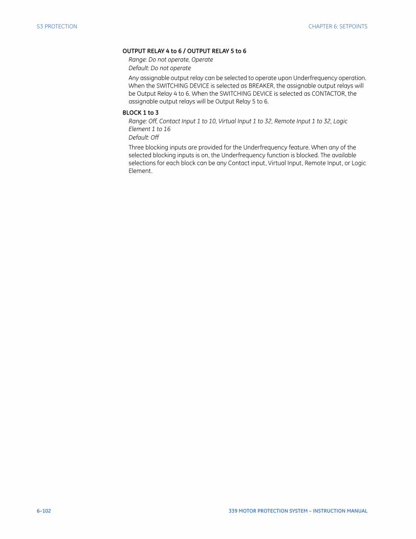
6–102 339 MOTOR PROTECTION SYSTEM – INSTRUCTION MANUAL
S3 PROTECTION CHAPTER 6: SETPOINTS
OUTPUT RELAY 4 to 6 / OUTPUT RELAY 5 to 6Range: Do not operate, OperateDefault: Do not operate
Any assignable output relay can be selected to operate upon Underfrequency operation. When the SWITCHING DEVICE is selected as BREAKER, the assignable output relays will be Output Relay 4 to 6. When the SWITCHING DEVICE is selected as CONTACTOR, the assignable output relays will be Output Relay 5 to 6.
BLOCK 1 to 3Range: Off, Contact Input 1 to 10, Virtual Input 1 to 32, Remote Input 1 to 32, Logic Element 1 to 16Default: Off
Three blocking inputs are provided for the Underfrequency feature. When any of the selected blocking inputs is on, the Underfrequency function is blocked. The available selections for each block can be any Contact input, Virtual Input, Remote Input, or Logic Element.
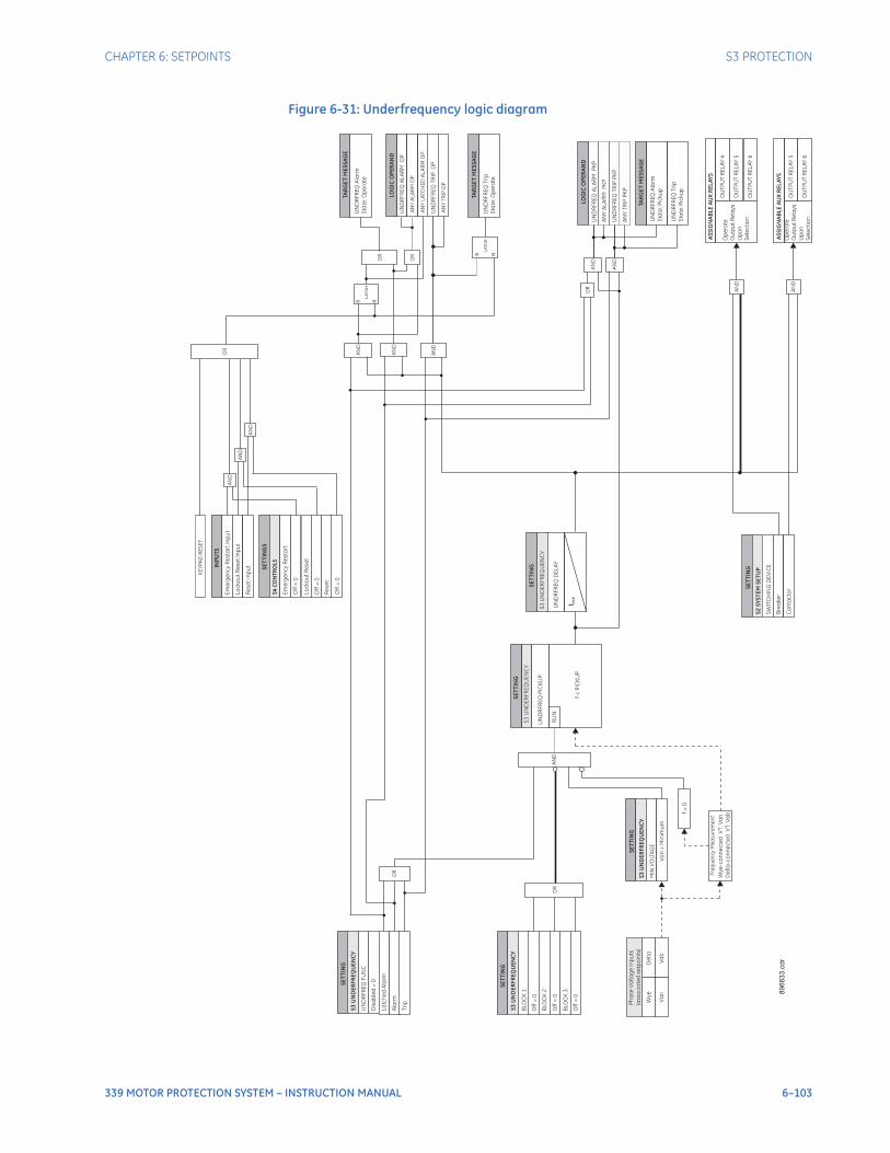
CHAPTER 6: SETPOINTS S3 PROTECTION
339 MOTOR PROTECTION SYSTEM – INSTRUCTION MANUAL 6–103
Figure 6-31: Underfrequency logic diagram
SE
TT
ING
UN
DR
FR
EQ
FU
NC
Dis
ab
led
=0
La
tch
ed
Ala
rm
Ala
rm
Op
era
te
Ou
tpu
tR
ela
ys
Up
on
Se
lec
tio
n
OU
TP
UT
RE
LA
Y4
OU
TP
UT
RE
LA
Y5
OU
TP
UT
RE
LA
Y6
Tri
p
SE
TT
ING
BLO
CK
1:
Off
=0
BLO
CK
2:
Off
=0
BLO
CK
3:
Off
=0
UN
DR
FR
EQ
AL
AR
MP
KP
S R
LA
TC
H
LOG
ICO
PE
RA
ND
UN
DR
FR
EQ
AL
AR
MO
P
LOG
ICO
PE
RA
ND
OR
OR
AN
D
AN
D
AN
D
AN
D
OR
AN
D
AN
D
INP
UT
S
Em
erg
en
cy
Re
sta
rt
Inp
ut
Lo
ck
ou
tR
ese
tIn
pu
t
SE
TT
ING
S
Off
=0
Lo
ck
ou
tR
ese
t
Off
=0
Em
erg
en
cy
Re
sta
rt
S4
CO
NT
RO
LS
UN
DR
FR
EQ
Ala
rm
Sta
te:O
pe
rate
TAR
GE
TM
ES
SA
GE
AN
YA
LA
RM
OP
UN
DR
FR
EQ
TR
IPO
P
AN
YT
RIP
OP
S R
LA
TC
HU
ND
RF
RE
QT
rip
Sta
te:O
pe
rate
TAR
GE
TM
ES
SA
GE
AS
SIG
NA
BL
EA
UX
RE
LA
YS
AN
D
Op
era
te
Ou
tpu
tR
ela
ys
Up
on
Se
lec
tio
n
OU
TP
UT
RE
LA
Y5
OU
TP
UT
RE
LA
Y6
AN
D
AN
YA
LA
RM
PK
P
UN
DR
FR
EQ
TR
IPP
KP
AN
YT
RIP
PK
P
AN
D
AN
D
OR
S3
UN
DE
RF
RE
QU
EN
CY
SE
TT
ING
SW
ITC
HIN
GD
EV
ICE
Bre
ake
r
Co
nta
cto
r
S2
SY
ST
EM
SE
TU
P
S3
UN
DE
RF
RE
QU
EN
CY
OR
Re
se
tIn
pu
t
Re
se
t
Off
=0
AN
D
OR
KE
YP
AD
RE
SE
T
AN
YL
ATC
HE
DA
LA
RM
OP
AS
SIG
NA
BL
EA
UX
RE
LA
YS
UN
DR
FR
EQ
Ala
rm
Sta
te:P
icku
p
TAR
GE
TM
ES
SA
GE
UN
DR
FR
EQ
Tri
p
Sta
te:P
icku
p
S3
UN
DE
RF
RE
QU
EN
CY
Va
b
UN
DR
FR
EQ
PIC
KU
P:
RU
N
Va
n
f<
PIC
KU
P
De
lta
Wy
e 896833.c
dr
SE
TT
ING
Ph
ase
Vo
lta
ge
Inp
uts
(asso
cia
ted
se
tpo
ints
)
SE
TT
ING
UN
DR
FR
EQ
DE
LA
Y
t PK
P
S3
UN
DE
RF
RE
QU
EN
CY
Fre
qu
en
cy
Me
asu
rem
en
t
Wy
e-c
on
ne
cte
dV
T:V
an
De
lta
-c
on
ne
cte
dV
T:V
ab
SE
TT
I NG
MIN
VO
LTA
GE
Va
n>
Min
imu
m
S3
UN
DE
RF
RE
QU
EN
CY
f=
0

6–104 339 MOTOR PROTECTION SYSTEM – INSTRUCTION MANUAL
S3 PROTECTION CHAPTER 6: SETPOINTS
OverfrequencyThe 339 provides 2 Overfrequency Protection elements. Each element can be set to either cause a trip or generate an alarm when the frequency of the input voltage (wye-connected VT: Van; delta-connected VT: Vab) exceeds the pickup level for a specified time delay. If it is desirable to have an alarm before a trip occurs, the user can set the function of one Overfrequency element to ALARM, and the function of the other element to TRIP.This feature may be useful for load shedding applications on large motors. It could also be used to load shed an entire feeder if the trip was assigned to an upstream breaker.The overfrequency feature is inhibited from operating unless the phase A voltage is above 30% of nominal. When the supply source is energized, the overfrequency delay timer will only be allowed to time when the 30% threshold is exceeded and the frequency is above the programmed pickup level. In the same way, when an overfrequency condition starts the overfrequency delay timer and the phase A voltage falls below the 30% threshold before the timer has expired, the element will reset without operating.The following path is available using the keypad. For instructions on how to use the keypad, please refer to Chapter 3 - Working with the Keypad.
NOTE
NOTE: When "VFD Not Bypassed" is asserted, frequency source is software calculated from the phase A current. The overfrequency element is inhibited from operating unless this current is above 10% of nominal. A minium voltage is not required.
PATH: SETPOINTS > S3 PROTECTION > OVER-FREQUENCY1(2)
OVERFREQ FUNCTIONRange: Disabled, Alarm, Latched Alarm, TripDefault: Disabled
The selection of Latched Alarm, Alarm, or Trip setting enables the Overfrequency Function. If the operating condition is satisfied when Trip is selected as the function, the logic operand ANY TRIP OP will be asserted, which in turn will activate the “TRIP” LED and operate the “Trip” output relay. If Alarm is selected, the “ALARM” LED will flash upon overfrequency operation, and will automatically reset when the activating condition clears. If Latched Alarm is selected, the “ALARM” LED will flash upon overfrequency operation, and will stay “ON” after the condition clears, until a reset command is initiated. The TRIP output relay will not operate if the Latched Alarm or Alarm function is selected. Any assignable output relays can be selected to operate when the setting OVERFREQ FUNC is selected as Latched Alarm, Alarm, or Trip.
OVERFREQ PKPRange: 40.00 to 70.00 Hz in steps of 0.01Default: 60.50 Hz
This setting defines the Overfrequency pickup level, and it is usually set to a frequency level considered dangerous for the stability of the system.
OVERFREQ DELAYRange: 0.1 to 600.0 s in steps of 0.1Default: 2.0 s
This setting specifies the time delay before overfrequency operation.
OUTPUT RELAY 4 to 6 / OUTPUT RELAY 5 to 6Range: Do not operate, OperateDefault: Do not operate
Any assignable output relay can be selected to operate upon Overfrequency operation. When the SWITCHING DEVICE is selected as BREAKER, the assignable output relays will be Output Relay 4 to 6. When the SWITCHING DEVICE is selected as CONTACTOR, the assignable output relays will be Output Relay 5 to 6.

CHAPTER 6: SETPOINTS S3 PROTECTION
339 MOTOR PROTECTION SYSTEM – INSTRUCTION MANUAL 6–105
BLOCK 1 to 3Range: Off, Contact Input 1 to 10, Virtual Input 1 to 32, Remote Input 1 to 32, Logic Element 1 to 16Default: Off
Three blocking inputs are provided for the Overfrequency feature. When any of the selected blocking inputs is on, the Overfrequency function is blocked. The available selections for each block can be any Contact input, Virtual Input, Remote Input, or Logic Element.
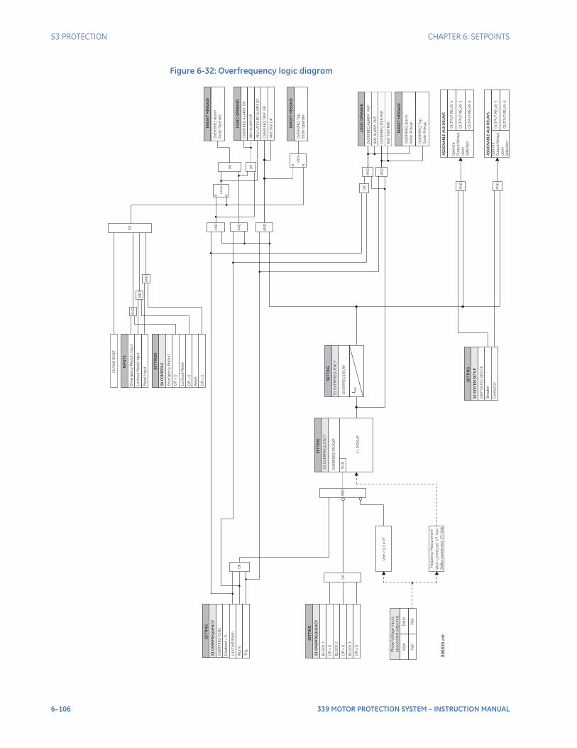
6–106 339 MOTOR PROTECTION SYSTEM – INSTRUCTION MANUAL
S3 PROTECTION CHAPTER 6: SETPOINTS
Figure 6-32: Overfrequency logic diagram
SE
TT
ING
OV
ER
FR
EQ
FU
NC
Dis
ab
led
=0
La
tch
ed
Ala
rm
Ala
rm
Op
era
te
Ou
tpu
tR
ela
ys
Up
on
Se
lec
tio
n
OU
TP
UT
RE
LA
Y4
OU
TP
UT
RE
LA
Y5
OU
TP
UT
RE
LA
Y6
Tri
p
SE
TT
ING
BLO
CK
1:
Off
=0
BLO
CK
2:
Off
=0
BLO
CK
3:
Off
=0
OV
ER
FR
EQ
AL
AR
MP
KP
S R
LA
TC
H
LOG
ICO
PE
RA
ND
OV
ER
FR
EQ
AL
AR
MO
P
LOG
ICO
PE
RA
ND
OR
OR
AN
D
AN
D
AN
D
AN
D
OR
AN
D
AN
D
INP
UT
S
Em
erg
en
cy
Re
sta
rt
Inp
ut
Lo
ck
ou
tR
ese
tIn
pu
t
SE
TT
ING
S
Off
=0
Lo
ck
ou
tR
ese
t
Off
=0
Em
erg
en
cy
Re
sta
rt
S4
CO
NT
RO
LS
OV
ER
FR
EQ
Ala
rm
Sta
te:O
pe
rate
TAR
GE
TM
ES
SA
GE
AN
YA
LA
RM
OP
OV
ER
FR
EQ
TR
IPO
P
AN
YT
RIP
OP
S R
LA
TC
HO
VE
RF
RE
QT
rip
Sta
te:O
pe
rate
TAR
GE
TM
ES
SA
GE
AS
SIG
NA
BL
EA
UX
RE
LA
YS
AN
D
Op
era
te
Ou
tpu
tR
ela
ys
Up
on
Se
lec
tio
n
OU
TP
UT
RE
LA
Y5
OU
TP
UT
RE
LA
Y6
AN
D
AN
YA
LA
RM
PK
P
OV
ER
FR
EQ
TR
IPP
KP
AN
YT
RIP
PK
P
AN
D
AN
D
OR
S3
OV
ER
FR
EQ
UE
NC
Y
SE
TT
I NG
SW
ITC
HIN
GD
EV
ICE
Bre
ake
r
Co
nta
cto
r
S2
SY
ST
EM
SE
TU
P
S3
OV
ER
FR
EQ
UE
NC
Y
OR
Re
se
tIn
pu
t
Re
se
t
Off
=0
AN
D
OR
KE
YP
AD
RE
SE
T
AN
YL
ATC
HE
DA
LA
RM
OP
AS
SIG
NA
BL
EA
UX
RE
LA
YS
OV
ER
FR
EQ
Ala
rm
Sta
te:P
icku
p
TAR
GE
TM
ES
SA
GE
OV
ER
FR
EQ
Tri
p
Sta
te:P
icku
p
S3
OV
ER
FR
EQ
UE
NC
Y
Va
b
OV
ER
FR
EQ
PIC
KU
P:
RU
N
Va
n
f>
PIC
KU
P
De
lta
Wy
e
896836.c
dr
SE
TT
ING
Ph
ase
Vo
lta
ge
Inp
uts
(asso
cia
ted
se
tpo
ints
)
SE
TT
ING
OV
ER
FR
EQ
DE
LA
Y
t PK
P
S3
OV
ER
FR
EQ
UE
NC
Y
Va
n<
0.3
xV
T
Fre
qu
en
cy
Me
asu
rem
en
t
Wy
e-c
on
ne
cte
dV
T:V
an
De
lta
-c
on
ne
cte
dV
T:V
ab

CHAPTER 6: SETPOINTS S3 PROTECTION
339 MOTOR PROTECTION SYSTEM – INSTRUCTION MANUAL 6–107
UnderpowerThe Underpower element responds to total three-phase real power measured from the phase currents and voltages.When the motor is in the running state, a trip or/and alarm will occur once the magnitude of three-phase real power falls below the pickup level for a period of time specified by the Delay. The pickup levels are based on Motor Nameplate Rated Power (MNR) and should be set lower than the lowest motor loading during normal operations.For example, underpower may be used to detect loss of load conditions. Loss of load conditions will not always cause a significant loss of current. Power is a more accurate representation of loading and may be used for more sensitive detection of load loss or pump cavitations. This may be especially useful for detecting process related problems.
NOTE
NOTE: The Underpower element is blocked if the VT Fuse Fail element is active; indicating which valid voltage inputs are not available due to fuse failure.
NOTE
NOTE: A Block Underpower on Start feature is available to the user. The Block Underpower element is active only when the motor is running and is blocked upon the initiation of a motor start for a period of time defined by the setting BLK U/P ON START. This block may be used to allow pumps to build up head before the underpower element trips or alarms.
NOTE
NOTE: Blocking this unit via the Block setting is highly recommended if "VFD Not Bypassed" is asserted.
PATH: SETPOINTS > S3 PROTECTION > UNDERPOWER
U/POWER ALARM FUNCRange: Disabled, EnabledDefault: Disabled
This setting enables the Underpower Alarm functionality.
BLK U/P ON STARTRange: 0 to 60 s in steps of 1 sDefault: 0 s
This setting specifies the length of time to block the underpower function when motor is starting. The underpower element is active only when the motor is running and is blocked upon the initiation of a motor start for a period of time specified by this setting. A value of 0 specifies that the feature is not blocked from start.
U/POWER ALARM PKPRange: 1% to 100% MNRDefault: 70% MNR
This setting specifies a pickup threshold for the Alarm stage. The alarm pickup threshold should be less than the motor load during normal operation.
U/POWER ALARM DLYRange: 0.1 to 60.0 s in steps of 0.1 sDefault: 0.1 s
This setting specifies a time delay for the alarm stage. The time delay should be long enough to overcome any short lowering of the load (e.g. during system faults).
U/POWER TRIP FUNCRange: Disabled, EnabledDefault: Disabled
This setting enables the Underpower Trip functionality.
6–108 339 MOTOR PROTECTION SYSTEM – INSTRUCTION MANUAL
S3 PROTECTION CHAPTER 6: SETPOINTS
U/POWER TRIP PKPRange: 1% to 100% MNRDefault: 60% MNR
This setting specifies a pickup threshold for the trip stage. This setting is typically set at a level less than the corresponding setting for the alarm stage.
U/POWER TRIP DLYRange: 0.1 to 60.0 s in steps of 0.1 sDefault: 0.1 s
This setting specifies a time delay for the trip stage. The time delay should be long enough to overcome any short lowering of the load (e.g. during system faults).
OUTPUT RELAY 4 to 6 / OUTPUT RELAY 5 to 6Range: Do Not Operate, OperateDefault: Do Not Operate
Any assignable output relay can be selected to operate upon underpower operation. When the SWITCHING DEVICE is selected as BREAKER, the assignable output relays will be Output Relay 4 to 6. When the SWITCHING DEVICE is selected as CONTACTOR, the assignable output relays will be Output Relay 5 to 6.
To select any assignable output relays to operate upon the Underpower Alarm operation, assign the Logic Operand "UNDERPOWER ALARM OP" or "Any Alarm OP" to a Logic Element.
BLOCK 1 to 3Range: Off, Contact Input 1 to 10, Virtual Input 1 to 32, Remote Input 1 to 32, Logic Element 1 to 16Default: Off
There are three blocking inputs provided for the underpower feature. When any of the selected blocking inputs is on, the underpower function is blocked.
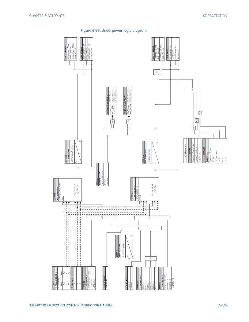
CHAPTER 6: SETPOINTS S3 PROTECTION
339 MOTOR PROTECTION SYSTEM – INSTRUCTION MANUAL 6–109
Figure 6-33: Underpower logic diagram
89
68
22
. CD
R
S3
UN
DE
RP
OW
ER
MO
TO
RS
TAT
US
Sto
pp
ed
AN
D
S3
UN
DE
RP
OW
ER
U/P
OW
ER
TR
IPP
KP
RU
N
S3
UN
DE
RP
OW
ER
RU
N
P=
P+
P+
P3
ph
ab
c
S3
UN
DE
RP
OW
ER
U/P
OW
ER
AL
AR
MD
EL
AY
t PK
P
0
LOG
ICO
PE
RA
ND
U/P
OW
ER
TR
IPO
P
AN
YT
RIP
OP
S3
UN
DE
RP
OW
ER
U/P
OW
ER
TR
IPD
LY
t PK
P
0
LOG
ICO
PE
RA
ND
U/P
OW
ER
AL
AR
MO
P
AN
YA
LA
RM
OP
S R
LA
TC
H
AN
D
AN
D
S3
UN
DE
RP
OW
ER
U/P
OW
ER
TR
IPF
UN
C
EN
AB
LE
D=
1
S3
UN
DE
RP
OW
ER
BL
KU
/P
ON
STA
RT
t BL
K
0
BLO
CK
1
BLO
CK
2
BLO
CK
3
OF
F=
0
OF
F=
0
OF
F=
0
OR
S3
UN
DE
RP
OW
ER
U/P
OW
ER
AL
AR
MF
UN
C
EN
AB
LE
D=
1
IA
AC
TU
AL
VA
LUE
IB IC
OU
TP
UT
RE
LA
Y5
OU
TP
UT
RE
LA
Y6
Op
era
te
ou
tpu
tre
lay
s
up
on
se
lec
tio
nR
un
nin
g
U/P
OW
ER
TR
IPP
KP
U/P
OW
ER
AL
AR
MP
KP
SE
TT
ING
S
SE
TT
I NG
S
SE
TT
I NG
SE
TT
ING
S
SE
TT
ING
S
SE
TT
ING
SE
TT
ING
S
SE
TT
I NG
S
SW
ITC
HIN
GD
EV
ICE
Bre
ake
r
Co
nta
cto
r
AN
D
OU
TP
UT
RE
LA
Y4
OU
TP
UT
RE
LA
Y5
OU
TP
UT
RE
LA
Y6
Op
era
te
ou
tpu
tre
lay
s
up
on
se
lec
tio
nA
ND
TAR
GE
TM
ES
SA
GE
Un
de
rpo
we
rA
larm
Sta
te:O
pe
rate
Un
de
rpo
we
rA
larm
Sta
te:P
icku
p
TAR
GE
TM
ES
SA
GE
Un
de
rpo
we
rT
rip
Sta
te:O
pe
rate
Un
de
rpo
we
rT
rip
Sta
te:P
icku
p
OR
AN
D
AN
D
INP
UT
S
Em
erg
en
cy
Re
sta
rt
Inp
ut
Lo
ck
ou
tR
ese
tIn
pu
t
SE
TT
I NG
S
Off
=0
Lo
ck
ou
tR
ese
t
Off
=0
Em
erg
en
cy
Re
sta
rt
S4
CO
NT
RO
LS
AN
YA
LA
RM
PK
P
SE
TT
ING
S2
SY
ST
EM
SE
TU
P
AS
SIG
NA
BL
EA
UX
RE
LA
YS
AS
SIG
NA
BL
EA
UX
RE
LA
YS
AN
YT
RIP
PK
P
KE
YP
AD
RE
SE
T
AN
DR
ese
tIn
pu
t
Re
se
t
Off
=0
P<
Pic
ku
p3
ph
P=
P+
P+
Po
pa
bc
P<
Pic
ku
po
p
S2
VO
LTA
GE
SE
NS
ING
VT
CO
NN
EC
TIO
N
SE
TT
ING
S
Wye
De
lta
Van
Vbn
Vcn
Vab
Vbc
Vca
U/P
OW
ER
AL
AR
MP
ICK
UP
Fu
seF
ail
ure
LOG
ICO
PE
RA
ND
DIS
AB
LE
D=
0
DIS
AB
LE
D=
0
6–110 339 MOTOR PROTECTION SYSTEM – INSTRUCTION MANUAL
S3 PROTECTION CHAPTER 6: SETPOINTS
Negative sequence overvoltageThe relay has one Negative Sequence Overvoltage element. The negative sequence overvoltage may be used to detect the loss of one, or two phases of the source, a reversed voltage phase sequence, or non-system voltage conditions.The following path is available using the keypad. For instructions on how to use the keypad, please refer to Chapter 3 - Working with the Keypad.PATH: SETPOINTS > S3 PROTECTION > NEGATIVE SEQ OV
NEG SEQ OV FUNCTNRange: Disabled, Alarm, Latched Alarm, TripDefault: Disabled
The selection of the Latched Alarm, Alarm, or Trip setting enables the Negative Sequence OV function. The output relay #1 “Trip” will operate, if the function is selected as a Trip and the negative sequence voltage computed by the relay is above the NEG SEQ OV PKP setting for a time greater than the selected NEG SEQ OV DELAY time. The “ALARM” LED will not turn on if the neg. sequence OV function is set to Trip. The “ALARM” LED will flash upon an OV operating condition with the neg. sequence OV function selected as Alarm, and will self-reset, when the operating condition clears. If Latched Alarm is selected as a Neg. Seq. OV function, the “ALARM” LED will flash during the OV condition, and will stay “ON” after the condition clears, until the reset command is initiated. The output relay #1 “Trip” will not operate if the Latched Alarm or Alarm setting is selected. Any or all of the output relays 3 to 6 can be selected to operate when the NEG SEQ OV FUNCTN is selected as Latched Alarm, Alarm, or Trip.
NEG SEQ OV PKPRange: 0.00 to 1.25 x VT in steps of 0.01Default: 0.30 x VT
This setting defines the negative sequence OV pickup level.
NEG SEQ OV DELAYRange: 0.1 to 600.0 sec in steps of 0.1 secDefault: 2.0 s
This setting specifies the time delay before negative sequence OV operation.
OUTPUT RELAY 4 to 6 / OUTPUT RELAY 5 to 6Range: Do not operate, OperateDefault: Do not operate
Any assignable output relay can be selected to operate upon Negative Sequence Overvoltage operation. When the SWITCHING DEVICE is selected as BREAKER, the assignable output relays will be Output Relay 4 to 6. When the SWITCHING DEVICE is selected as CONTACTOR, the assignable output relays will be Output Relay 5 to 6.
BLOCK 1/2/3Range: Off, Contact Input 1 to 10, Virtual Input 1 to 32, Remote Input 1 to 32, Logic Element 1 to 16Default: Off
Three blocking inputs are provided for Negative Sequence Overvoltage. When any of the selected blocking inputs is on, the NEG SEQ OV function is blocked. The available selections for each block can be any Contact input, Virtual Input, Remote Input, or Logic Element.
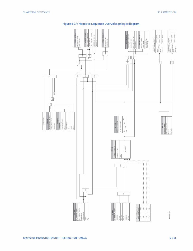
CHAPTER 6: SETPOINTS S3 PROTECTION
339 MOTOR PROTECTION SYSTEM – INSTRUCTION MANUAL 6–111
Figure 6-34: Negative Sequence Overvoltage logic diagram
SE
TT
ING
NE
GS
EQ
OV
FU
NC
TN
Dis
ab
led
=0
La
tch
ed
Ala
rm
Ala
rm
Op
era
te
Ou
tpu
tR
ela
ys
Up
on
Se
lec
tio
n
OU
TP
UT
RE
LA
Y4
OU
TP
UT
RE
LA
Y5
OU
TP
UT
RE
LA
Y6
Tri
p
SE
TT
I NG
BLO
CK
1:
Off
=0
BLO
CK
2:
Off
=0
BLO
CK
3:
Off
=0
NE
GS
EQ
OV
AL
AR
MP
KP
S R
LA
TC
H
89
68
31
. cd
r
LOG
ICO
PE
RA
ND
NE
GS
EQ
OV
AL
AR
MO
P
LOG
ICO
PE
RA
ND
OR
OR
AN
D
AN
D
AN
D
AN
D
OR
AN
D
AN
D
INP
UT
S
Em
erg
en
cy
Re
sta
rt
Inp
ut
Lo
ck
ou
tR
ese
tIn
pu
t
SE
TT
ING
S
Off
=0
Lo
ck
ou
tR
ese
t
Off
=0
Em
erg
en
cy
Re
sta
rt
S4
CO
NT
RO
LS
NE
GS
EQ
OV
Ala
rm
Sta
te:O
pe
rate
TAR
GE
TM
ES
SA
GE
AN
YA
LA
RM
OP
NE
GS
EQ
OV
TR
IPO
P
AN
YT
RIP
OP
S R
LA
TC
HN
EG
SE
QO
VT
rip
Sta
te:O
pe
rate
TAR
GE
TM
ES
SA
GE
AS
SIG
NA
BL
EA
UX
RE
LA
YS
AN
D
Op
era
te
Ou
tpu
tR
ela
ys
Up
on
Se
lec
tio
n
OU
TP
UT
RE
LA
Y5
OU
TP
UT
RE
LA
Y6
AN
D
AN
YA
LA
RM
PK
P
NE
GS
EQ
OV
TR
IPP
KP
AN
YT
RIP
PK
P
AN
D
AN
D
OR
S3
NE
GA
TIV
ES
EQ
OV
SE
TT
ING
SW
ITC
HIN
GD
EV
ICE
Bre
ake
r
Co
nta
cto
r
S2
SY
ST
EM
SE
TU
P
S3
NE
GA
TIV
ES
EQ
OV
OR
Re
se
tIn
pu
t
Re
se
t
Off
=0
AN
D
OR
KE
YP
AD
RE
SE
T
AN
YL
ATC
HE
DA
LA
RM
OP
AS
SIG
NA
BL
EA
UX
RE
LA
YS
NE
GS
EQ
OV
Ala
rm
Sta
te:P
icku
p
TAR
GE
TM
ES
SA
GE
NE
GS
EQ
OV
Tri
p
Sta
te:P
icku
p
S3
NE
GA
TIV
ES
EQ
OV
Va
b
NE
GS
EQ
OV
PK
P:
Vb
c
Vc
a
RU
N
Va
n
Vb
n
Vc
n
V>
PIC
KU
P2
De
lta
Wy
e
896835.c
dr
SE
TT
ING
Ph
ase
Vo
lta
ge
Inp
uts
(asso
cia
ted
se
tpo
ints
)
SE
TT
I NG
NE
GS
EQ
OV
DE
LA
Y
t PK
P
S3
NE
GA
TIV
ES
EQ
OV
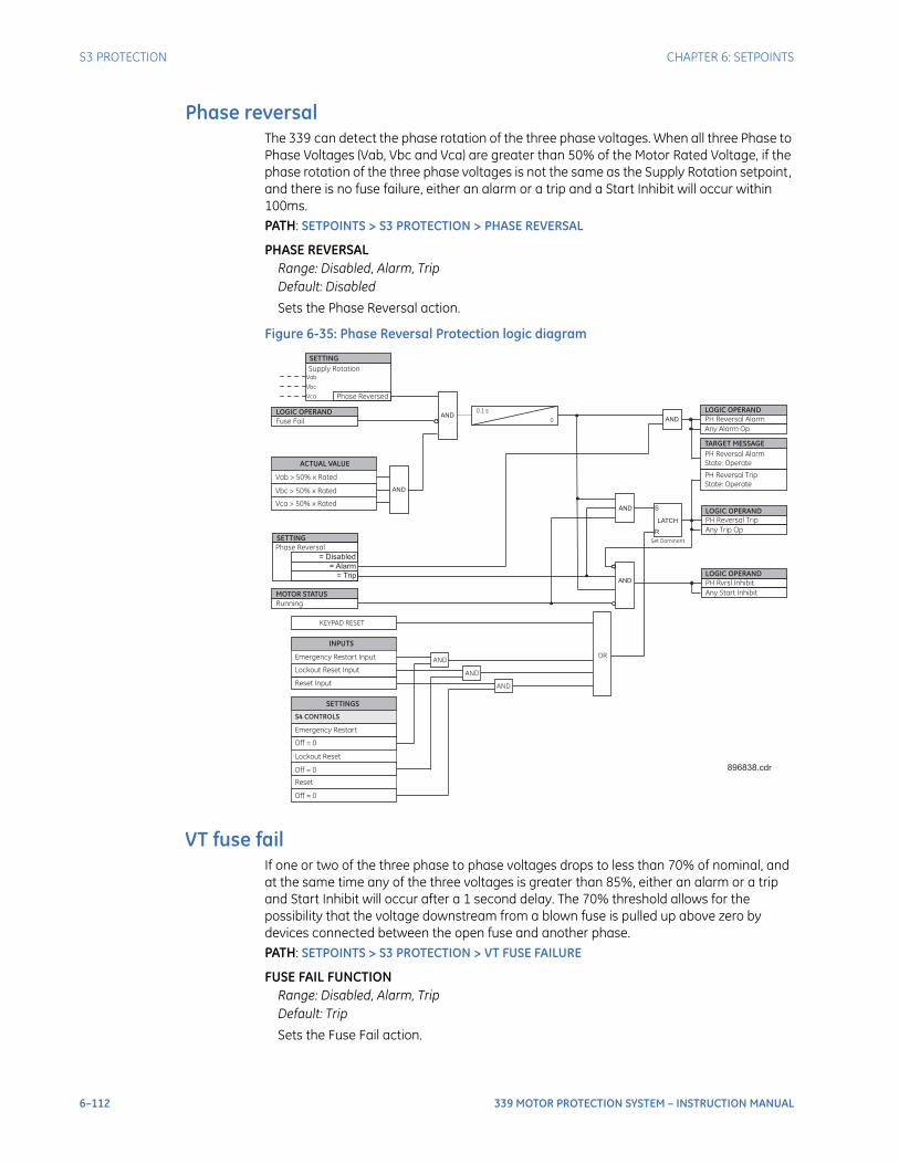
6–112 339 MOTOR PROTECTION SYSTEM – INSTRUCTION MANUAL
S3 PROTECTION CHAPTER 6: SETPOINTS
Phase reversalThe 339 can detect the phase rotation of the three phase voltages. When all three Phase to Phase Voltages (Vab, Vbc and Vca) are greater than 50% of the Motor Rated Voltage, if the phase rotation of the three phase voltages is not the same as the Supply Rotation setpoint, and there is no fuse failure, either an alarm or a trip and a Start Inhibit will occur within 100ms.PATH: SETPOINTS > S3 PROTECTION > PHASE REVERSAL
PHASE REVERSALRange: Disabled, Alarm, TripDefault: Disabled
Sets the Phase Reversal action.
Figure 6-35: Phase Reversal Protection logic diagram
VT fuse failIf one or two of the three phase to phase voltages drops to less than 70% of nominal, and at the same time any of the three voltages is greater than 85%, either an alarm or a trip and Start Inhibit will occur after a 1 second delay. The 70% threshold allows for the possibility that the voltage downstream from a blown fuse is pulled up above zero by devices connected between the open fuse and another phase.PATH: SETPOINTS > S3 PROTECTION > VT FUSE FAILURE
FUSE FAIL FUNCTIONRange: Disabled, Alarm, TripDefault: Trip
Sets the Fuse Fail action.
Set Dominant
LATCH
S
R
AND LOGIC OPERAND
PH Rvrsl Inhibit
PH Reversal Trip
LOGIC OPERAND
AND0.1 s
0
LOGIC OPERANDPH Reversal AlarmAND
SETTING
= Disabled
= Trip
Phase Reversal
= Alarm
Fuse Fail
LOGIC OPERAND
Phase Reversed
Vbc
SETTING
Supply Rotation
Vca
Vab
AND
AND
AND
INPUTS
Emergency Restart Input
Lockout Reset Input
SETTINGS
Off = 0
Lockout Reset
Off = 0
Emergency Restart
S4 CONTROLS
Reset Input
Reset
Off = 0
AND
OR
KEYPAD RESET
TARGET MESSAGE
PH Reversal Alarm
State: Operate
PH Reversal Trip
State: Operate
896838.cdr
ACTUAL VALUE
Vab > 50% x Rated
Vbc > 50% x Rated
Vca > 50% x Rated
AND
Running
MOTOR STATUS
Any Alarm Op
Any Trip Op
Any Start Inhibit
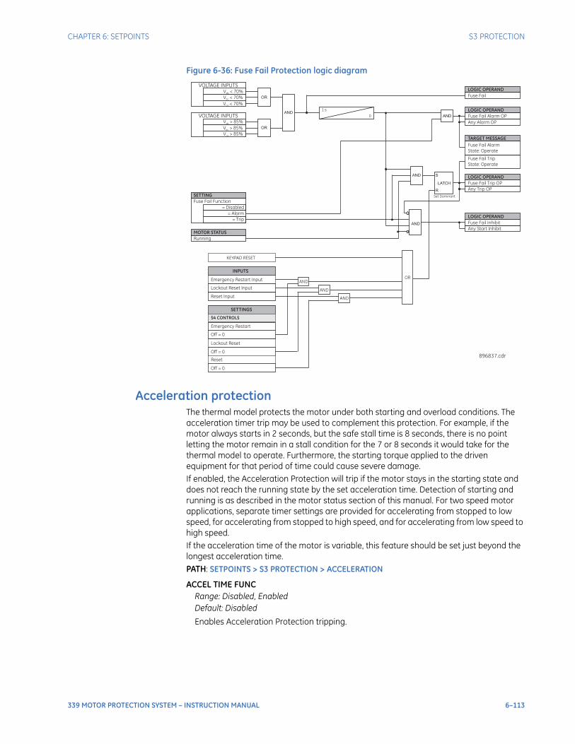
CHAPTER 6: SETPOINTS S3 PROTECTION
339 MOTOR PROTECTION SYSTEM – INSTRUCTION MANUAL 6–113
Figure 6-36: Fuse Fail Protection logic diagram
Acceleration protectionThe thermal model protects the motor under both starting and overload conditions. The acceleration timer trip may be used to complement this protection. For example, if the motor always starts in 2 seconds, but the safe stall time is 8 seconds, there is no point letting the motor remain in a stall condition for the 7 or 8 seconds it would take for the thermal model to operate. Furthermore, the starting torque applied to the driven equipment for that period of time could cause severe damage.If enabled, the Acceleration Protection will trip if the motor stays in the starting state and does not reach the running state by the set acceleration time. Detection of starting and running is as described in the motor status section of this manual. For two speed motor applications, separate timer settings are provided for accelerating from stopped to low speed, for accelerating from stopped to high speed, and for accelerating from low speed to high speed.If the acceleration time of the motor is variable, this feature should be set just beyond the longest acceleration time.PATH: SETPOINTS > S3 PROTECTION > ACCELERATION
ACCEL TIME FUNCRange: Disabled, EnabledDefault: Disabled
Enables Acceleration Protection tripping.
Set Dominant
LATCH
S
R
AND LOGIC OPERAND
Fuse Fail Inhibit
Fuse Fail Trip OP
LOGIC OPERAND
AND
LOGIC OPERAND
Fuse FailV < 70%
ab
OR
Running
MOTOR STATUS
AND
OR
1 s
0
LOGIC OPERAND
Fuse Fail Alarm OPAND
SETTING
= Disabled
= Trip
Fuse Fail Function
= Alarm
V < 70%bc
V < 70%ca
V > 85%ab
V > 85%bc
V > 85%ca
896837.cdr
AND
AND
INPUTS
Emergency Restart Input
Lockout Reset Input
SETTINGS
Off = 0
Lockout Reset
Off = 0
Emergency Restart
S4 CONTROLS
Reset Input
Reset
Off = 0
AND
OR
KEYPAD RESET
TARGET MESSAGE
Fuse Fail Alarm
State: Operate
Fuse Fail Trip
State: Operate
Any Alarm OP
Any Trip OP
Any Start Inhibit
VOLTAGE INPUTS
VOLTAGE INPUTS

6–114 339 MOTOR PROTECTION SYSTEM – INSTRUCTION MANUAL
S3 PROTECTION CHAPTER 6: SETPOINTS
ACCELERATION TIMERRange: 1.0 to 250.0 s in steps of 0.1 sDefault: 10 s
In single-speed motor applications, sets the maximum acceleration time before tripping. In two speed motor applications, sets the maximum acceleration time before tripping when low speed starting from a stopped condition.
OUTPUT RELAY 4 to 6 / OUTPUT RELAY 5 to 6Range: Do Not Operate, OperateDefault: Do Not Operate
Any assignable output relay can be selected to operate upon Acceleration Trip operation. When the SWITCHING DEVICE is selected as BREAKER, the assignable output relays will be Output Relay 4 to 6. When the SWITCHING DEVICE is selected as CONTACTOR, the assignable output relays will be Output Relay 5 to 6.
BLOCK 1 to 3Range: Off, Contact Input 1 to 10, Virtual Input 1 to 32, Remote Input 1 to 32, Logic Element 1 to 16Default: Off
Three blocking inputs are provided for the Acceleration feature. When any of the selected blocking inputs is ON, the Acceleration function is blocked.
TWO-SPEED MOTOR APPLICATIONPATH: SETPOINTS > S3 PROTECTION > TWO SPEED MOTOR > HIGH SPEED ACCEL T
ACCEL T ON STOPPEDRange: 1.0 to 250.0 s in steps of 0.1 sDefault: 10.0 s
When a two-speed motor starts directly at high speed, this setting specifies the maximum acceleration time before tripping.
ACCEL T ON LOW SPDRange: 1.0 to 250.0 s in steps of 0.1 sDefault: 10.0 s
When a two-speed motor is switched from a low-to-high speed, this setting specifies the maximum acceleration time before tripping.
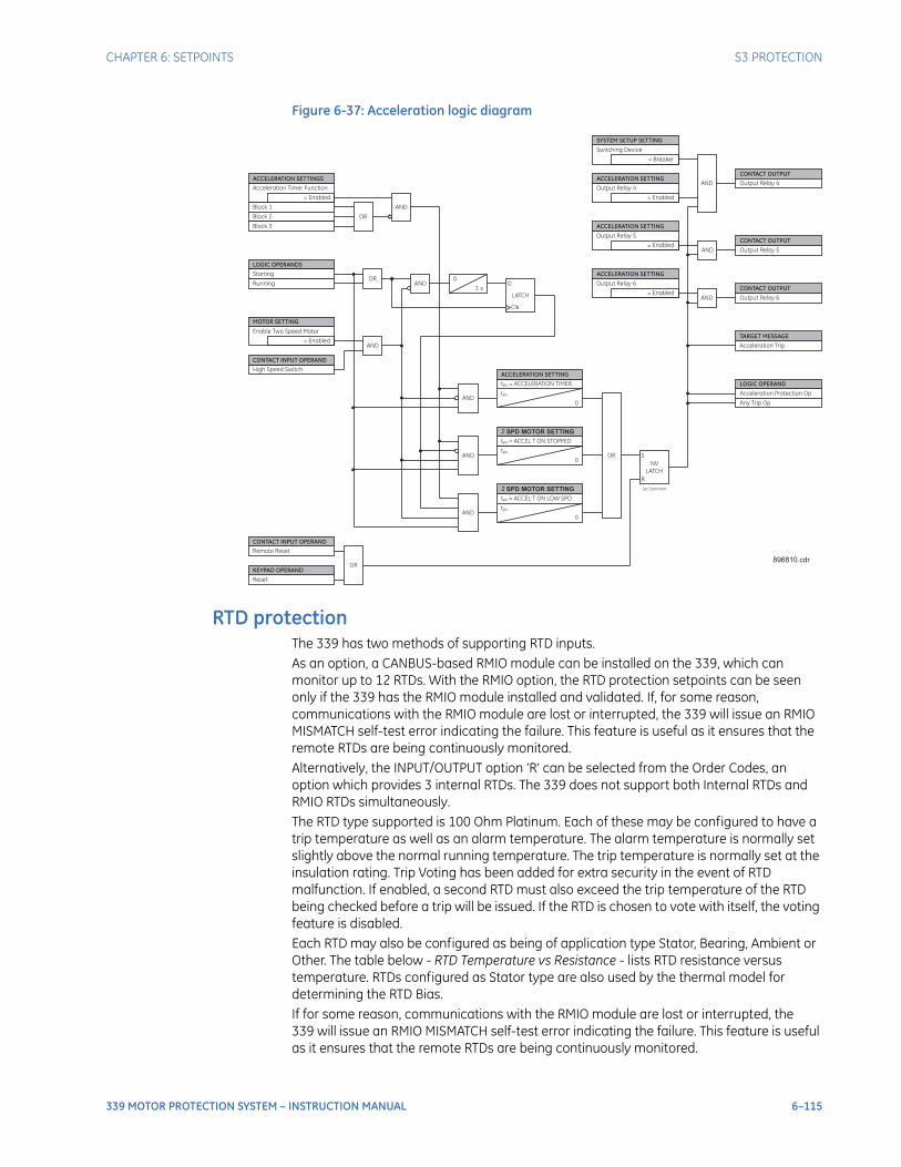
CHAPTER 6: SETPOINTS S3 PROTECTION
339 MOTOR PROTECTION SYSTEM – INSTRUCTION MANUAL 6–115
Figure 6-37: Acceleration logic diagram
RTD protectionThe 339 has two methods of supporting RTD inputs.As an option, a CANBUS-based RMIO module can be installed on the 339, which can monitor up to 12 RTDs. With the RMIO option, the RTD protection setpoints can be seen only if the 339 has the RMIO module installed and validated. If, for some reason, communications with the RMIO module are lost or interrupted, the 339 will issue an RMIO MISMATCH self-test error indicating the failure. This feature is useful as it ensures that the remote RTDs are being continuously monitored.Alternatively, the INPUT/OUTPUT option ‘R’ can be selected from the Order Codes, an option which provides 3 internal RTDs. The 339 does not support both Internal RTDs and RMIO RTDs simultaneously.The RTD type supported is 100 Ohm Platinum. Each of these may be configured to have a trip temperature as well as an alarm temperature. The alarm temperature is normally set slightly above the normal running temperature. The trip temperature is normally set at the insulation rating. Trip Voting has been added for extra security in the event of RTD malfunction. If enabled, a second RTD must also exceed the trip temperature of the RTD being checked before a trip will be issued. If the RTD is chosen to vote with itself, the voting feature is disabled.Each RTD may also be configured as being of application type Stator, Bearing, Ambient or Other. The table below - RTD Temperature vs Resistance - lists RTD resistance versus temperature. RTDs configured as Stator type are also used by the thermal model for determining the RTD Bias.If for some reason, communications with the RMIO module are lost or interrupted, the 339 will issue an RMIO MISMATCH self-test error indicating the failure. This feature is useful as it ensures that the remote RTDs are being continuously monitored.
LOGIC OPERANDS
Starting
Running
= Enabled
Enable Two Speed Motor
High Speed Switch
MOTOR SETTING
AND
ORAND
0
1 s
ANDtpu
0
tpu = ACCELERATION TIMER
LATCH
D
Clk
AND
2 SPD MOTOR SETTING
tpu
0
tpu = ACCEL T ON STOPPED
ANDtpu
0
tpu = ACCEL T ON LOW SPD
OR
= Enabled
Acceleration Timer Function
ACCELERATION SETTINGS
CONTACT INPUT OPERAND
Block 1
Block 2
Block 3
OR
AND
AND
= Enabled
Output Relay 4
CONTACT OUTPUT
Output Relay 4ACCELERATION SETTING
ACCELERATION SETTING
2 SPD MOTOR SETTING
AND= Enabled
Output Relay 5CONTACT OUTPUT
Output Relay 5
ACCELERATION SETTING
AND= Enabled
Output Relay 6CONTACT OUTPUT
Output Relay 6
ACCELERATION SETTING
TARGET MESSAGE
Acceleration Trip
LOGIC OPERAND
Acceleration Protection Op
= Breaker
Switching Device
SYSTEM SETUP SETTING
Any Trip Op
Remote Reset
CONTACT INPUT OPERAND
Reset
KEYPAD OPERANDOR
Set Dominant
NV
LATCH
S
R
896810.cdr
6–116 339 MOTOR PROTECTION SYSTEM – INSTRUCTION MANUAL
S3 PROTECTION CHAPTER 6: SETPOINTS
PATH: SETPOINTS > S3 PROTECTION > RTD PROTECTION > RTD #1(12)
RTD #1 to 12 APPLICATIONRange: None, Stator, Bearing, Ambient, OtherDefault: None
Sets the application type.
RTD #1 to 12 NAMERange: 1 to 18 charactersDefault: RTD 1(12)
Sets the RTD programmable name.
RTD #1 to 12 ALARMRange: Disabled, EnabledDefault: Disabled
This setting enables the RTD #1 to 12 Alarm functionality.
RTD #1 to 12 ALARM TEMPRange: 1oC to 250oC in steps of 1oCDefault: 130oC
Sets the Alarm temperature.
RTD #1 to 12 TRIPRange: Disabled, EnabledDefault: Disabled
This setting enables the RTD #1 to 12 Trip functionality.
RTD #1 to 12 TRIP TEMPRange: 1oC to 250oC in steps of 1oCDefault: 155oC
Sets the Trip temperature.
RTD #1 to 12 TRIP VOTINGRange: Off, RTD #1 to 12Default: Off
Sets the redundant RTD that must also exceed this RTD’s trip temperature for a trip to occur.
OUTPUT RELAYSRange: Do Not Operate, OperateDefault: Do Not Operate
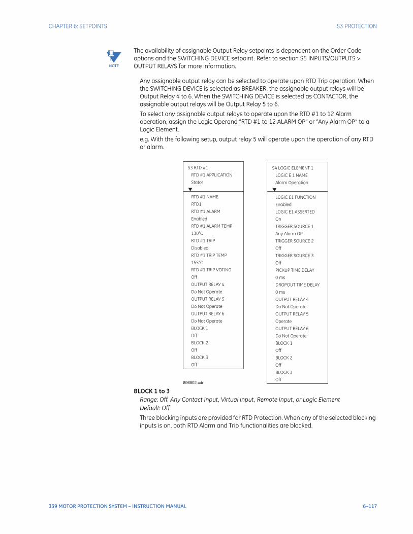
CHAPTER 6: SETPOINTS S3 PROTECTION
339 MOTOR PROTECTION SYSTEM – INSTRUCTION MANUAL 6–117
NOTE
NOTE: The availability of assignable Output Relay setpoints is dependent on the Order Code options and the SWITCHING DEVICE setpoint. Refer to section S5 INPUTS/OUTPUTS > OUTPUT RELAYS for more information.
Any assignable output relay can be selected to operate upon RTD Trip operation. When the SWITCHING DEVICE is selected as BREAKER, the assignable output relays will be Output Relay 4 to 6. When the SWITCHING DEVICE is selected as CONTACTOR, the assignable output relays will be Output Relay 5 to 6.
To select any assignable output relays to operate upon the RTD #1 to 12 Alarm operation, assign the Logic Operand “RTD #1 to 12 ALARM OP” or “Any Alarm OP” to a Logic Element.
e.g. With the following setup, output relay 5 will operate upon the operation of any RTD or alarm.
BLOCK 1 to 3Range: Off, Any Contact Input, Virtual Input, Remote Input, or Logic ElementDefault: Off
Three blocking inputs are provided for RTD Protection. When any of the selected blocking inputs is on, both RTD Alarm and Trip functionalities are blocked.
S3 RTD #1
RTD #1 APPLICATION
Stator
RTD #1 NAME
RTD1
RTD #1 ALARM
Enabled
RTD #1 ALARM TEMP
130 C
Do Not Operate
BLOCK 1
Off
°
RTD #1 TRIP
Disabled
RTD #1 TRIP TEMP
RTD #1 TRIP VOTING
Off
OUTPUT RELAY 4
155 C
OUTPUT RELAY 5
Do Not Operate
OUTPUT RELAY 6
Do Not Operate
BLOCK 2
Off
BLOCK 3
Off
°
S4 LOGIC ELEMENT 1
LOGIC E 1 NAME
Alarm Operation
LOGIC E1 FUNCTION
Enabled
LOGIC E1 ASSERTED
On
TRIGGER SOURCE 1
Any Alarm OP
TRIGGER SOURCE 2
Off
TRIGGER SOURCE 3
Off
PICKUP TIME DELAY
0 ms
DROPOUT TIME DELAY
0 ms
OUTPUT RELAY 4
Do Not Operate
OUTPUT RELAY 5
Operate
OUTPUT RELAY 6
Do Not Operate
BLOCK 1
Off
BLOCK 2
Off
BLOCK 3
Off
896802.cdr
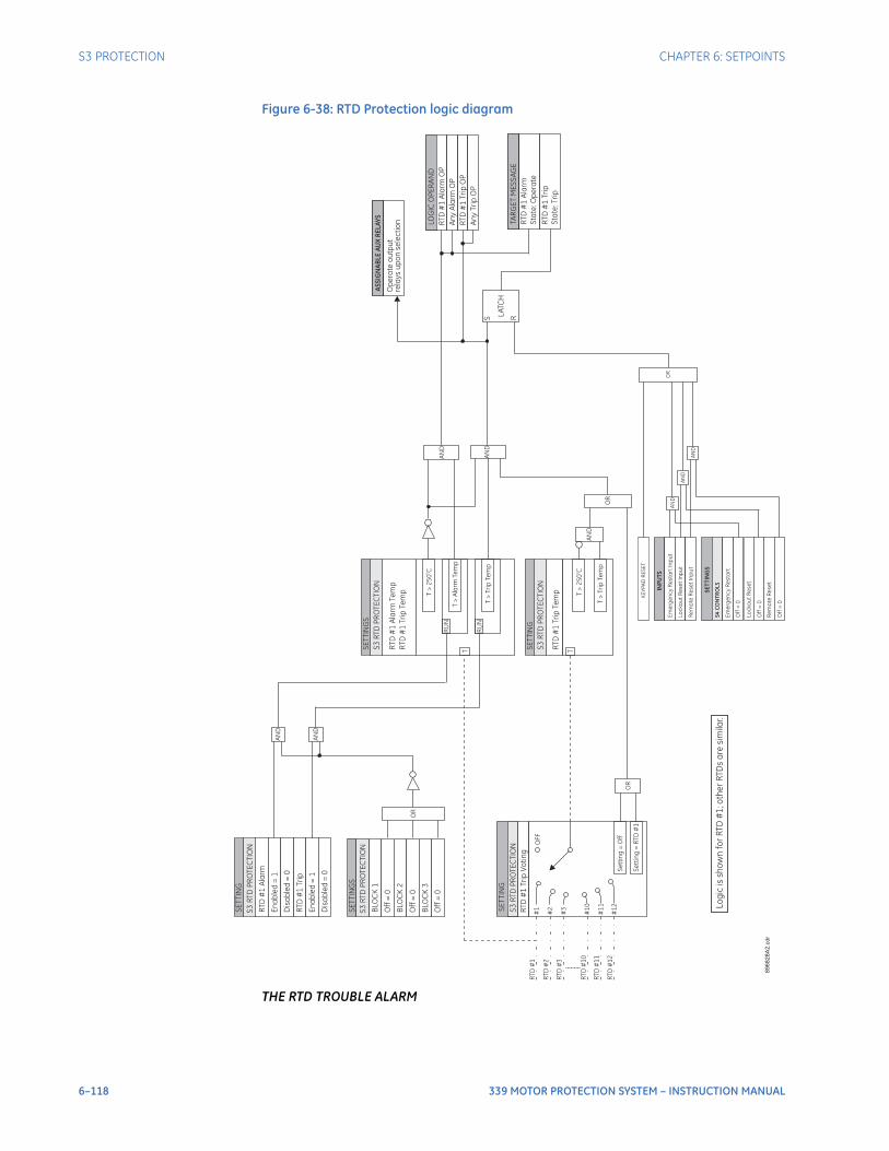
6–118 339 MOTOR PROTECTION SYSTEM – INSTRUCTION MANUAL
S3 PROTECTION CHAPTER 6: SETPOINTS
Figure 6-38: RTD Protection logic diagram
THE RTD TROUBLE ALARM
OR
SE
TT
ING
S
SE
TT
ING
RT
D#
1A
larm
En
ab
led
=1
SE
TT
ING
S
BLO
CK
1
Off
=0
BLO
CK
2
AN
D
BLO
CK
3
Off
=0
Off
=0
AN
D
RU
N
SE
TT
ING
S3
RT
DP
RO
TE
CT
ION
RT
D#
1T
rip
Vo
tin
g
OR
LA
TC
H
S R
LO
GIC
OP
ER
AN
D
RT
D#
1A
larm
OP
An
yA
larm
OP
TA
RG
ET
ME
SS
AG
E
RT
D#
1A
larm
Sta
te:O
pe
rate
AS
SIG
NA
BL
EA
UX
RE
LA
YS
Op
era
teo
utp
ut
rela
ys
up
on
se
lec
tio
n
89
68
28
A2
.cd
r
RT
D#
1T
rip
OP
An
yT
rip
OP
S3
RT
DP
RO
TE
CT
ION
RT
D#
1T
rip
En
ab
led
=1
S3
RT
DP
RO
TE
CT
ION
RT
D#
1A
larm
Te
mp
RT
D#
1T
rip
Te
mp T
>2
50
Co
T>
Ala
rmTe
mp
T>
Tri
pTe
mp
RU
N
T
SE
TT
ING
S3
RT
DP
RO
TE
CT
ION
RT
D#
1T
rip
Te
mp T
>2
50
Co
T>
Tri
pTe
mp
T
AN
D
OR
AN
D
AN
D
RT
D#
1T
rip
Sta
te:T
rip
AN
D
AN
D
INP
UT
S
Em
erg
en
cy
Re
sta
rt
Inp
ut
Lo
ck
ou
tR
ese
tIn
pu
t
SE
TT
ING
S
Off
=0
Lo
ck
ou
tR
ese
t
Off
=0
Em
erg
en
cy
Re
sta
rt
S4
CO
NT
RO
LS
Re
mo
teR
ese
tIn
pu
t
Re
mo
teR
ese
t
Off
=0
AN
D
OR
KE
YP
AD
RE
SE
T
Lo
gic
issh
ow
nfo
rR
TD
#1
;o
the
rR
TD
sa
resim
ila
r.
RT
D#
1
RT
D#
2
RT
D#
3
RT
D#
10
RT
D#
11
RT
D#
12
#1
#2
#3
#1
0
#1
1
#1
2
OF
F
Se
ttin
g=
Off
Se
ttin
g=
RT
D#
1
S3
RT
DP
RO
TE
CT
ION
Dis
ab
led
=0
Dis
ab
led
=0
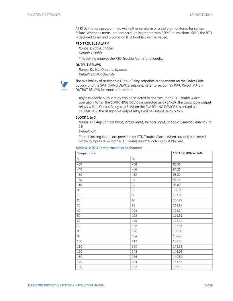
CHAPTER 6: SETPOINTS S3 PROTECTION
339 MOTOR PROTECTION SYSTEM – INSTRUCTION MANUAL 6–119
All RTDs that are programmed with either an alarm or a trip are monitored for sensor failure. When the measured temperature is greater than 250ºC or less than -50ºC, the RTD is declared failed and a common RTD trouble alarm is issued.
RTD TROUBLE ALARMRange: Disable, EnableDefault: Disable
This setting enables the RTD Trouble Alarm functionality.
OUTPUT RELAYSRange: Do Not Operate, OperateDefault: Do Not Operate
NOTE
NOTE: The availability of assignable Output Relay setpoints is dependent on the Order Code options and the SWITCHING DEVICE setpoint. Refer to section S5 INPUTS/OUTPUTS > OUTPUT RELAYS for more information.
Any assignable output relay can be selected to operate upon RTD Trouble Alarm operation. When the SWITCHING DEVICE is selected as BREAKER, the assignable output relays will be Output Relay 4 to 6. When the SWITCHING DEVICE is selected as CONTACTOR, the assignable output relays will be Output Relay 5 to 6.
BLOCK 1 to 3Range: Off, Any Contact Input, Virtual Input, Remote Input, or Logic Element Element 1 to 16Default: Off
Three blocking inputs are provided for RTD Trouble Alarm. When any of the selected blocking inputs is on, both RTD Trouble Alarm functionality is blocked.
Table 6-3: RTD Temperature vs Resistance
Temperature 100 Ω Pt (DIN 43760)
oC oF
–50 –58 80.31
–40 –40 84.27
–30 –22 88.22
–20 –4 92.16
–10 14 96.09
0 32 100.00
10 50 103.90
20 68 107.79
30 86 111.67
40 104 115.54
50 122 119.39
60 140 123.24
70 158 127.07
80 176 130.89
90 194 134.70
100 212 138.50
110 230 142.29
120 248 146.06
130 266 149.82
140 284 153.58
150 302 157.32
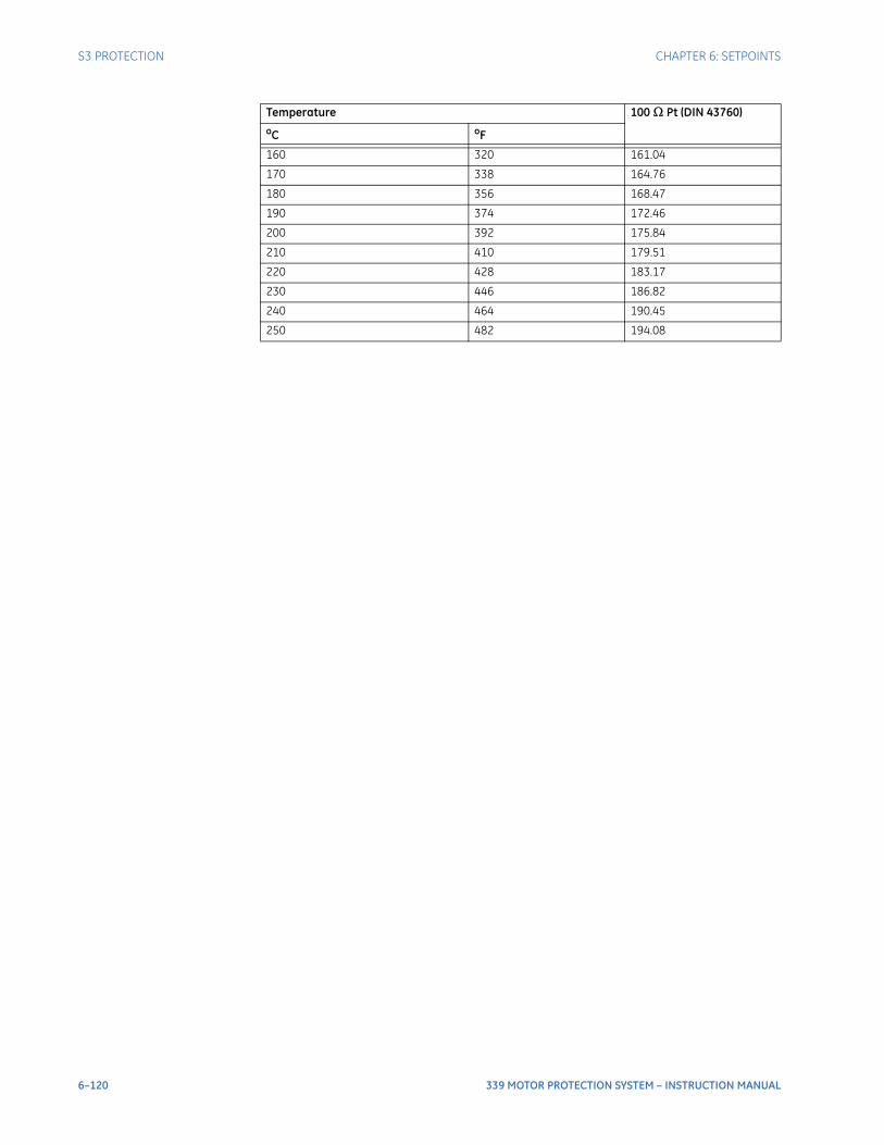
6–120 339 MOTOR PROTECTION SYSTEM – INSTRUCTION MANUAL
S3 PROTECTION CHAPTER 6: SETPOINTS
160 320 161.04
170 338 164.76
180 356 168.47
190 374 172.46
200 392 175.84
210 410 179.51
220 428 183.17
230 446 186.82
240 464 190.45
250 482 194.08
Temperature 100 Ω Pt (DIN 43760)
oC oF
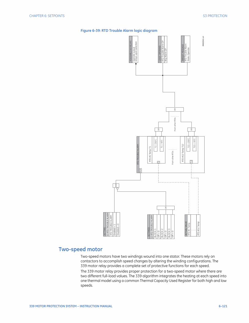
CHAPTER 6: SETPOINTS S3 PROTECTION
339 MOTOR PROTECTION SYSTEM – INSTRUCTION MANUAL 6–121
Figure 6-39: RTD Trouble Alarm logic diagram
Two-speed motorTwo-speed motors have two windings wound into one stator. These motors rely on contactors to accomplish speed changes by altering the winding configurations. The 339 motor relay provides a complete set of protective functions for each speed.The 339 motor relay provides proper protection for a two-speed motor where there are two different full-load values. The 339 algorithm integrates the heating at each speed into one thermal model using a common Thermal Capacity Used Register for both high and low speeds.
OR
SE
TT
ING
RT
DT
RO
UB
LE
AL
AR
M
En
ab
led
=1
S3
RT
DT
RO
UB
LE
AL
AR
M
AN
D
BLO
CK
1
Off
=0
BLO
CK
2
BLO
CK
3
Off
=0
Off
=0
LO
GIC
OP
ER
AN
D
RT
DT
rou
ble
Ala
rmO
P
An
yA
larm
OP
TA
RG
ET
ME
SS
AG
E
RT
DT
rou
ble
Ala
rm
Sta
te:O
pe
rate
89
68
29
A2
.cd
r
S3
RT
DT
RO
UB
LE
AL
AR
M
RT
D#
12
Te
mp
T1
2
T1
2O
R
RT
D#
1Te
mp
T1 T1
>2
50
Co
T1
<-5
0C
o
T1
OR
RT
DT
RO
UB
LE
AL
AR
M
T1
2>
25
0C
o
T1
2<
-5
0C
o
AC
TU
AL
VA
LU
E
RT
D#
1Te
mp
RT
D#
12
Te
mp
SE
TT
ING
S
RU
N
Fro
mo
the
rR
TD
s
OR
Fro
mo
the
rR
TD
s
Dis
ab
led
=0
AS
SIG
NA
BL
EA
UX
RE
LA
YS
Op
era
teo
utp
ut
rela
ys
up
on
se
lec
tio
n
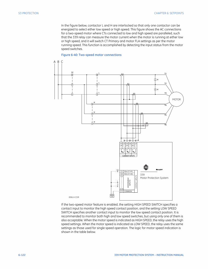
6–122 339 MOTOR PROTECTION SYSTEM – INSTRUCTION MANUAL
S3 PROTECTION CHAPTER 6: SETPOINTS
In the figure below, contactor L and H are interlocked so that only one contactor can be energized to select either low speed or high speed. This figure shows the AC connections for a two-speed motor where CTs connected to low and high speed are paralleled, such that the 339 relay can measure the motor current when the motor is running at either low or high speed, and it will switch CT Primary and motor FLA settings as per the motor running speed. This function is accomplished by detecting the input status from the motor speed switches.
Figure 6-40: Two-speed motor connections
If the two-speed motor feature is enabled, the setting HIGH SPEED SWITCH specifies a contact input to monitor the high speed contact position, and the setting LOW SPEED SWITCH specifies another contact input to monitor the low speed contact position. It is recommended to monitor both high and low speed switches, but using only one of them is also acceptable. When the motor speed is indicated as HIGH SPEED, the relay uses the high speed settings. When the motor speed is indicated as LOW SPEED, the relay uses the same settings as those used for single speed operation. The logic for motor speed indication is shown in the table below.
896LH.CDR
C1
C2
C3
C10
C11
CO
NTA
CT
INP
UT
S
52a (C1 #1)
52b (C1 #2)
COMMON
E5 D5 E6 D6 E7 D7
IA IA IB IB IC IC
339
Motor Protection System
52a
A B C
MOTOR
CURRENT INPUTS
AS
SIG
NA
BL
EIN
PU
TS
+ -DC
L
L
L
H
H
H
L
H
H
T1
T2
T3
T4
T5
T6
H
52
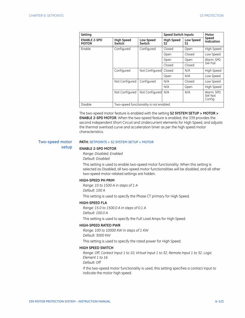
CHAPTER 6: SETPOINTS S3 PROTECTION
339 MOTOR PROTECTION SYSTEM – INSTRUCTION MANUAL 6–123
The two-speed motor feature is enabled with the setting S2 SYSTEM SETUP > MOTOR > ENABLE 2-SPD MOTOR. When the two-speed feature is enabled, the 339 provides the second independent Short Circuit and Undercurrent elements for High Speed, and adjusts the thermal overload curve and acceleration timer as per the high speed motor characteristics.
Two-speed motorsetup
PATH: SETPOINTS > S2 SYSTEM SETUP > MOTOR
ENABLE 2-SPD MOTORRange: Disabled, EnabledDefault: Disabled
This setting is used to enable two-speed motor functionality. When this setting is selected as Disabled, all two-speed motor functionalities will be disabled, and all other two-speed motor-related settings are hidden.
HIGH-SPEED PH PRIMRange: 10 to 1500 A in steps of 1 ADefault: 100 A
This setting is used to specify the Phase CT primary for High Speed.
HIGH-SPEED FLARange: 15.0 to 1500.0 A in steps of 0.1 ADefault: 100.0 A
This setting is used to specify the Full Load Amps for High Speed.
HIGH-SPEED RATED PWRRange: 100 to 10000 KW in steps of 1 KWDefault: 3000 KW
This setting is used to specify the rated power for High Speed.
HIGH SPEED SWITCHRange: Off, Contact Input 1 to 10, Virtual Input 1 to 32, Remote Input 1 to 32, Logic Element 1 to 16Default: Off
If the two-speed motor functionality is used, this setting specifies a contact input to indicate the motor high speed.
Setting Speed Switch Inputs Motor Speed IndicationENABLE 2-SPD
MOTORHigh Speed Switch
Low Speed Switch
High Speed S2
Low Speed S1
Enable Configured Configured Closed Open High Speed
Open Closed Low Speed
Open Open Alarm: SPD SW Fail
Closed Closed
Configured Not Configured Closed N/A High Speed
Open N/A Low Speed
Not Configured Configured N/A Closed Low Speed
N/A Open High Speed
Not Configured Not Configured N/A N/A Alarm: SPD SW Not Config
Disable Two-speed functionality is not enabled.

6–124 339 MOTOR PROTECTION SYSTEM – INSTRUCTION MANUAL
S3 PROTECTION CHAPTER 6: SETPOINTS
LOW SPEED SWITCHRange: Off, Contact Input 1 to 10, Virtual Input 1 to 32, Remote Input 1 to 32, Logic Element 1 to 8Default: Off
If the two-speed motor functionality is used, this setting specifies a contact input to indicate the motor low speed.
High speed thermalprotection
When the two-speed functionality is enabled, the 339 will switch settings between S3 PROTECTION > THERMAL PROTECTION and S3 PROTECTION > TWO SPEED MOTOR > HIGH SPEED THERMAL to ensure proper parameters are applied to each speed. The motor thermal characteristics for high and low speed can be different, so separate FLA and curve selections are provided for high speed operation. In applications where the motor has the same thermal characteristics for both low and high speed, set the high speed Thermal O/L Curve to be the same as the main settings.For a single speed motor where the two-speed functionality is disabled, the 339 will apply S3 PROTECTION > THERMAL PROTECTION settings to protect the motor. PATH: SETPOINTS > S3 PROTECTION > TWO SPEED MOTOR > HIGH SPEED THERMAL
CURVE MULTIPLIERRange: 1 to 15 in steps of 1Default: 4
This setting is used to fit a standard overload curve to the thermal characteristics of the protected motor when it is running at High Speed.
High speed shortcircuit settings
When two-speed functionality is enabled, a second independent Short Circuit element is provided for High Speed. When the motor is running at high speed and any phase current exceeds the high speed short circuit pickup level for the high speed short circuit time delay, the high speed short circuit protection will be activated. In cases where the switching device is a contactor, which is not designed to cut off fault current, the function of short circuit can be set as either Latched Alarm or Alarm, so the assigned auxiliary output relay will be activated and signal an upstream breaker to trip.PATH: SETPOINTS > S3 PROTECTION > TWO SPEED MOTOR > HIGH SPEED S/C
S/C FUNCRange: Disabled, Latched Alarm, Alarm, TripDefault: Disabled
The selection of the Latched Alarm, Alarm or Trip setting enables the High Speed Short Circuit function. If the operating condition is satisfied when Trip is selected as the function, the “LOCKOUT” LED will be turned on, and the logic operand ANY TRIP OP will be asserted, which in turn will operate the “TRIP” LED and the trip output relay. If Alarm is selected, the “ALARM” LED will flash upon the short circuit protection operation, and will automatically reset when the activating condition clears. If Latched Alarm is selected, the “ALARM” LED will flash upon short circuit protection operation, and will stay “ON” after the condition clears, until a Reset command is initiated. The TRIP output relay will not operate if the Latched Alarm or Alarm function is selected. Any assignable output relays can be selected to operate when the setting S/C FUNC is selected as Latched Alarm, Alarm, or Trip.
S/C PKPRange: 1.00 to 20.00xCT in steps of 0.01xCTDefault: 6.00xCT
This setting specifies a pickup threshold for the High Speed Short Circuit function.
CHAPTER 6: SETPOINTS S3 PROTECTION
339 MOTOR PROTECTION SYSTEM – INSTRUCTION MANUAL 6–125
S/C DELAYRange: 0.00 to 60.00 s in steps of 0.01 sDefault: 0.00 s
This setting specifies a time delay for the High Speed Short Circuit function.
OUTPUT RELAY 4 to 6 / OUTPUT RELAY 5 to 6Range: Do Not Operate, OperateDefault: Do Not Operate
Any assignable output relay can be selected to operate upon High Speed Short Circuit operation. When the SWITCHING DEVICE is selected as BREAKER, the assignable output relays will be Output Relay 4 to 6. When the SWITCHING DEVICE is selected as CONTACTOR, the assignable output relays will be Output Relay 5 to 6.
BLOCK 1 to 3Range: Off, Contact Input 1 to 10, Virtual Input 1 to 32, Remote Input 1 to 32, Logic Element 1 to 16Default: Off
Three blocking inputs are provided for the High Speed Short Circuit function. When any of the selected blocking inputs is on, the high speed Short Circuit is blocked.
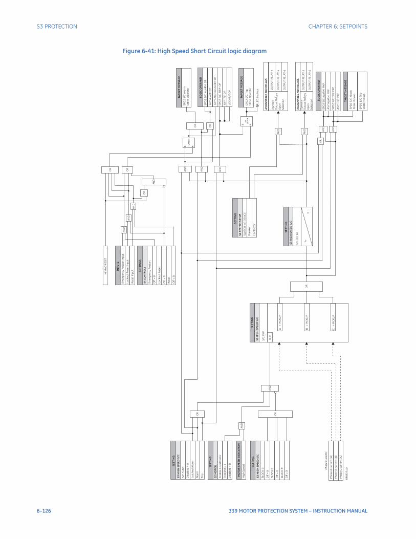
6–126 339 MOTOR PROTECTION SYSTEM – INSTRUCTION MANUAL
S3 PROTECTION CHAPTER 6: SETPOINTS
Figure 6-41: High Speed Short Circuit logic diagram
SE
TT
ING
Ph
ase
Ac
urr
en
t(IA
)
RU
N
SE
TT
ING
S/C
FU
NC
Dis
ab
led
=0
La
tch
ed
Ala
rm
S/C
PK
P
S/C
DE
LA
Y
Ph
ase
Bc
urr
en
t(IB
)
Ph
ase
Cc
urr
en
t(IC
)
Ala
rm
Ph
ase
Cu
rre
nts
Op
era
te
Ou
tpu
tR
ela
ys
Up
on
Se
lec
tio
n
OU
TP
UT
RE
LA
Y4
OU
TP
UT
RE
LA
Y5
OU
TP
UT
RE
LA
Y6
Tri
p
SE
TT
I NG
BLO
CK
1:
Off
=0
BLO
CK
2:
Off
=0
BLO
CK
3:
Off
=0
IB>
PIC
KU
P
IA>
PIC
KU
P
IC>
PIC
KU
P
SE
TT
I NG
SP
D2
S/C
AL
AR
MP
KP
t PK
P
0
S R
LA
TC
H
89
68
19
.cd
r
LOG
ICO
PE
RA
ND
SP
D2
S/C
AL
AR
MO
P
LOG
ICO
PE
RA
ND
SE
TT
ING
S2
MO
TO
R
En
ab
le2
-sp
dM
oto
r
En
ab
led
=1
MO
TO
RS
PE
ED
IND
ICA
TIO
N
Hig
hS
pe
ed
OR
OR
AN
D
OR
AN
D
AN
D
AN
D
OR
SP
D2
S/C
Ala
rm
Sta
te:O
pe
rate
TAR
GE
TM
ES
SA
GE
AN
YA
LA
RM
OP
SP
D2
S/C
TR
IPO
P
AN
YT
RIP
OP
S R
NV
LA
TC
HS
PD
2S
/C
Tri
p
Sta
te:O
pe
rate
TAR
GE
TM
ES
SA
GE
AS
SIG
NA
BL
EA
UX
RE
LA
YS
AN
D
Op
era
te
Ou
tpu
tR
ela
ys
Up
on
Se
lec
tio
n
OU
TP
UT
RE
LA
Y5
OU
TP
UT
RE
LA
Y6
AN
D
AN
YA
LA
RM
PK
P
SP
D2
S/C
TR
IPP
KP
AN
YT
RIP
PK
P
AN
D
AN
D
OR
S3
HIG
HS
PE
ED
S/C
S3
HIG
HS
PE
ED
S/C
S3
HIG
HS
PE
ED
S/C
AN
D
SE
TT
ING
SW
ITC
HIN
GD
EV
ICE
Bre
ake
r
Co
nta
cto
r
S2
SY
ST
EM
SE
TU
P
S3
HIG
HS
PE
ED
S/C
OR
LE
D:L
oc
ko
ut
AN
YL
ATC
HE
DA
LA
RM
OP
AS
SIG
NA
BL
EA
UX
RE
LA
YS
SP
D2
S/C
Ala
rm
Sta
te:P
icku
p
TAR
GE
TM
ES
SA
GE
SP
D2
S/C
Tri
p
Sta
te:P
icku
p
Dis
ab
led
=0
OR
AN
D
AN
D
INP
UT
S
Em
erg
en
cy
Re
sta
rt
Inp
ut
Lo
ck
ou
tR
ese
tIn
pu
t
SE
TT
ING
S
Off
=0
Lo
ck
ou
tR
ese
t
Off
=0
Em
erg
en
cy
Re
sta
rt
S4
CO
NT
RO
LS
Re
se
tIn
pu
t
Re
se
t
Off
=0
AN
D
OR
KE
YP
AD
RE
SE
T
OR
AN
D
LO
CK
OU
TO
P

CHAPTER 6: SETPOINTS S3 PROTECTION
339 MOTOR PROTECTION SYSTEM – INSTRUCTION MANUAL 6–127
High speedacceleration
When two-speed functionality is enabled, the main acceleration timer is used for low speed starting (a start in low speed from a stopped condition). Two additional acceleration timers are provided for high speed starting. One timer is for a start in high speed from a stopped condition, another timer is for the transition from low speed to high speed. Selection of acceleration timers is as described in the Acceleration section of this manual.
High speedundercurrent
If two-speed functionality is enabled, the 339 relay relies on the motor speed indication to switch the undercurrent settings as per the motor running speed, so the main Undercurrent Protection element is only active when the motor is running at low speed, and the High Speed Undercurrent Protection element is only active when the motor is running at high speed. If two-speed functionality is not deployed, only the main Short Circuit is active, and the High Speed Short Circuit is disabled.PATH: SETPOINTS > S3 PROTECTION > TWO SPEED MOTOR > HIGH SPEED U/CURR
U/CURR ALARM FUNCRange: Disabled, EnabledDefault: Disabled
This setting is used to enable the High Speed Undercurrent Alarm function.
BLK U/C ON STARTRange: 0 to 600 s in steps of 1 sDefault: 0 s
This setting is used to specify a time delay to block undercurrent function when the motor is starting to High Speed. If this setting is programmed as 0, the undercurrent function will not be blocked from start.
U/CURR ALARM PKPRange: 0.10 to 0.95xFLA in steps of 0.01xFLADefault: 0.70xFLA
This setting specifies a pickup threshold for the Alarm stage. This threshold should be set lower than motor load current during normal operation.
U/CURR ALARM DELAYRange: 1.00 to 60.00 s in steps of 0.01 sDefault: 1.00 s
This setting specifies a time delay for the Alarm stage. This time delay should be set long enough to overcome short lowering of the current such as during system faults.
U/CURR TRIP FUNCRange: Disabled, EnabledDefault: Disabled
This setting is used to enable the High Speed Undercurrent Trip function.
U/CURR TRIP PKPRange: 0.10 to 0.95xFLA in steps of 0.01xFLADefault: 0.60xFLA
This setting specifies a pickup threshold for the Trip stage. This threshold should be set lower than the threshold for the Alarm stage.
U/CURR TRIP DELAYRange: 1.00 to 60.00 s in steps of 0.01 sDefault: 1.00 s
This setting specifies a time delay for the Trip stage. This time delay should be set long enough to overcome short lowering of the current such as during system faults.
6–128 339 MOTOR PROTECTION SYSTEM – INSTRUCTION MANUAL
S3 PROTECTION CHAPTER 6: SETPOINTS
OUTPUT RELAY 4 to 6 / OUTPUT RELAY 5 to 6Range: Do Not Operate, OperateDefault: Do Not Operate
Any assignable output relay can be selected to operate upon High Speed Undercurrent operation. When the SWITCHING DEVICE is selected as BREAKER, the assignable output relays will be Output Relay 4 to 6. When the SWITCHING DEVICE is selected as CONTACTOR, the assignable output relays will be Output Relay 5 to 6.
To select any assignable output relays to operate upon the Undercurrent Alarm operation, assign the Logic Operand "UNDERCURRENT ALARM OP" or "Any Alarm OP" to a Logic Element.
BLOCK 1 to 3Range: Off, Contact Input 1 to 10, Virtual Input 1 to 32, Remote Input 1 to 32, Logic Element 1 to 16Default: Off
Three blocking inputs are provided for the High Speed Undercurrent function. When any of the selected blocking inputs is on, the High Speed Undercurrent is blocked.
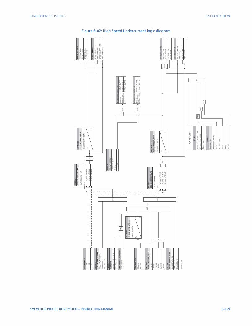
CHAPTER 6: SETPOINTS S3 PROTECTION
339 MOTOR PROTECTION SYSTEM – INSTRUCTION MANUAL 6–129
Figure 6-42: High Speed Undercurrent logic diagram
89
68
17
. CD
R
S3
HIG
HS
PE
ED
U/C
UR
R
MO
TO
RS
TAT
US
Sto
pp
ed
AN
D
IA_
ma
g<
PIC
KU
P
S3
HIG
HS
PE
ED
U/C
UR
R
U/C
UR
RT
RIP
PK
P
RU
N
IB_
ma
g<
PIC
KU
P
IC_
ma
g<
PIC
KU
P
IA_
ma
g<
PIC
KU
P
S3
HIG
HS
PE
ED
U/C
UR
R
U/C
UR
RA
LA
RM
PK
P
RU
N
IB_
ma
g<
PIC
KU
P
IC_
ma
g<
PIC
KU
P
OR
OR
S3
HIG
HS
PE
ED
U/C
UR
R
U/C
UR
RA
LA
RM
DE
LA
Y
t PK
P
0
LOG
ICO
PE
RA
ND
SP
D2
U/C
TR
IPO
P
AN
YT
RIP
OP
S3
HIG
HS
PE
ED
U/C
UR
R
U/C
UR
RT
RIP
DE
LA
Y
t PK
P
0
LOG
ICO
PE
RA
ND
SP
D2
U/C
AL
AR
MO
P
AN
YA
LA
RM
OP
S R
LA
TC
H
AN
D
AN
D
S3
HIG
HS
PE
ED
U/C
UR
R
U/C
UR
RT
RIP
FU
NC
EN
AB
LE
D=
1
S3
HIG
HS
PE
ED
U/C
UR
R
BL
KU
/C
ON
STA
RT
t BL
K
0
BLO
CK
1
BLO
CK
2
BLO
CK
3
OF
F=
0
OF
F=
0
OF
F=
0
OR
S3
HIG
HS
PE
ED
U/C
UR
R
U/C
UR
RA
LA
RM
FU
NC
EN
AB
LE
D=
1
IA
AC
TU
AL
VA
LUE
IB IC
OU
TP
UT
RE
LA
Y5
OU
TP
UT
RE
LA
Y6
Op
era
te
ou
tpu
tre
lay
s
up
on
se
lec
tio
nR
un
nin
g
S2
MO
TO
R
EN
AB
LE
2-S
PD
MO
TO
R
DIS
AB
LE
D=
0
MO
TO
RS
PE
ED
IND
ICA
TIO
N
HIG
HS
PE
ED
AN
D
SP
D2
U/C
TR
IPP
KP
SP
D2
U/C
AL
AR
MP
KP
SE
TT
ING
S
SE
TT
I NG
S
SE
TT
I NG
S
SE
TT
I NG
SE
TT
ING
S
SE
TT
ING
S
SE
TT
I NG
SE
TT
I NG
S
SE
TT
I NG
S
SW
ITC
HIN
GD
EV
ICE
Bre
ake
r
Co
nta
cto
r
AN
D
OU
TP
UT
RE
LA
Y4
OU
TP
UT
RE
LA
Y5
OU
TP
UT
RE
LA
Y6
Op
era
te
ou
tpu
tre
lay
s
up
on
se
lec
tio
nA
ND
TAR
GE
TM
ES
SA
GE
SP
D2
U/C
Ala
rm
Sta
te:O
pe
rate
SP
D2
U/C
Ala
rm
Sta
te:P
icku
p
TAR
GE
TM
ES
SA
GE
SP
D2
U/C
Tri
p
Sta
te:O
pe
rate
SP
D2
U/C
Tri
p
Sta
te:P
icku
p
OR
AN
D
AN
D
INP
UT
S
Em
erg
en
cy
Re
sta
rt
Inp
ut
Lo
ck
ou
tR
ese
tIn
pu
t
SE
TT
ING
S
Off
=0
Lo
ck
ou
tR
ese
t
Off
=0
Em
erg
en
cy
Re
sta
rt
S4
CO
NT
RO
LS
AN
YA
LA
RM
PK
P
SE
TT
I NG
S2
SY
ST
EM
SE
TU
P
AS
SIG
NA
BL
EA
UX
RE
LA
YS
AS
SIG
NA
BL
EA
UX
RE
LA
YS
AN
YT
RIP
PK
P
KE
YP
AD
RE
SE
T
AN
DR
ese
tIn
pu
t
Re
se
t
Off
=0
DIS
AB
LE
D=
0
DIS
AB
LE
D=
0
6–130 339 MOTOR PROTECTION SYSTEM – INSTRUCTION MANUAL
S3 PROTECTION CHAPTER 6: SETPOINTS
Neutral directional overcurrentThe Neutral Directional element is used to discriminate between faults that occur in the forward direction, and faults that occur in the reverse direction. The Neutral Directional element can be used either individually for control or alarm by energizing the auxiliary output relays, or as a part of the Neutral Time, or Instantaneous, over-current elements to define the tripping direction. (See the setup for Neutral TOC, and Neutral IOC elements.)The polarizing signal for the Neutral Directional element can be set to be either voltage (zero sequence voltage), current (measured ground current), or dual (both). The polarizing voltage for the Neutral directional element is calculated as follows:
Eq. 18
Please note that the phase VT inputs must be connected in Wye.When “Voltage” polarization is selected, the direction is determined by comparing the angle between the operating current and the voltage, and the set MTA angle. In cases where the voltage drops below the setting of the minimum polarizing voltage, the neutral directional element defaults to the Forward direction.When “Current” polarizing is selected, the direction of the neutral current is determined with reference to the direction of the measured ground current . The fault is detected in the Forward direction when the ground current typically flowing from the ground point into the neutral current is within ± 90° of the polarizing current. Otherwise the direction is detected as Reverse. The neutral direction defaults to Forward if the polarizing ground current drops below 5% of the ground CT. The diagram below shows the regions for detection of neutral current Forward and Reverse directions with respect to the zero sequence voltage and the selected Maximum Torque Angle (MTA).
NOTE
NOTE: The Neutral Directional element is blocked in VFD mode.
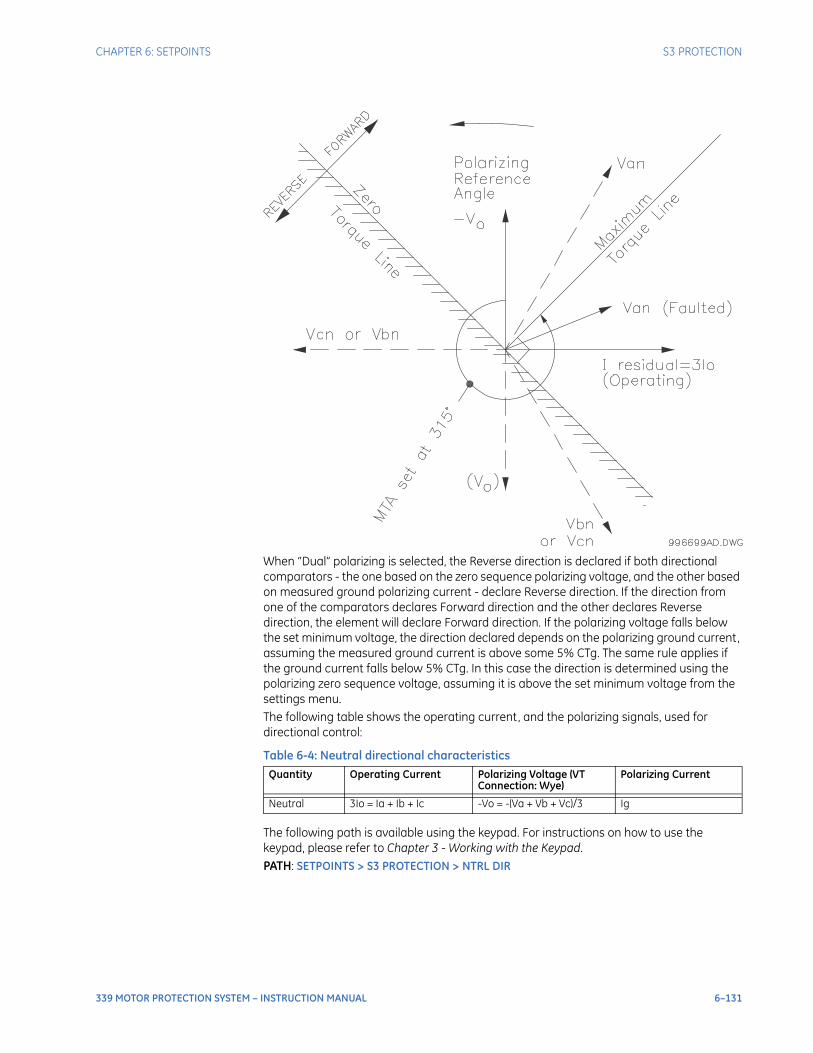
CHAPTER 6: SETPOINTS S3 PROTECTION
339 MOTOR PROTECTION SYSTEM – INSTRUCTION MANUAL 6–131
When “Dual” polarizing is selected, the Reverse direction is declared if both directional comparators - the one based on the zero sequence polarizing voltage, and the other based on measured ground polarizing current - declare Reverse direction. If the direction from one of the comparators declares Forward direction and the other declares Reverse direction, the element will declare Forward direction. If the polarizing voltage falls below the set minimum voltage, the direction declared depends on the polarizing ground current, assuming the measured ground current is above some 5% CTg. The same rule applies if the ground current falls below 5% CTg. In this case the direction is determined using the polarizing zero sequence voltage, assuming it is above the set minimum voltage from the settings menu.The following table shows the operating current, and the polarizing signals, used for directional control:
Table 6-4: Neutral directional characteristics
The following path is available using the keypad. For instructions on how to use the keypad, please refer to Chapter 3 - Working with the Keypad.PATH: SETPOINTS > S3 PROTECTION > NTRL DIR
Quantity Operating Current Polarizing Voltage (VT Connection: Wye)
Polarizing Current
Neutral 3Io = Ia + Ib + Ic -Vo = -(Va + Vb + Vc)/3 Ig
6–132 339 MOTOR PROTECTION SYSTEM – INSTRUCTION MANUAL
S3 PROTECTION CHAPTER 6: SETPOINTS
NTRL DIR FUNCTIONRange: Disabled, Latched Alarm, Alarm, ControlDefault: Disabled
When an Alarm function is selected, the alarm LED will flash upon detection of Reverse direction, and will drop out when the direction changes to Forward. When Latched Alarm is selected, the alarm LED will flash upon detection of Reverse direction, and will stay lit (latched) after the direction changes to Forward. The alarm LED can be reset, by issuing a Reset command. Detection of Reverse direction when the Control function is selected, does not trigger the alarm LED.
NTRL DIR POLARIZINGRange: Voltage, Current, DualDefault: Voltage
This setting specifies the voltage polarizing signal for the detection of Forward and Reverse directions.
NTRL DIR MTARange: 0° to 359° Lead in steps of 1°Default: 315°
This setting sets the Maximum Torque Angle (MTA), for the Neutral Directional element to define the regions of Forward and Reverse directions. For Voltage polarizing, enter the maximum torque angle by which the operating current leads the polarizing voltage. This is the angle of maximum sensitivity.
MIN POL VOLTAGERange: 0.05 to 1.25 x VT in steps of 0.01Default: 0.05 x VT
This setting affects only cases where voltage or dual polarizing is selected. The minimum zero sequence voltage level must be selected to prevent operation due to normal system unbalances, or voltage transformer errors. Set the minimum zero sequence voltage level to 2% of VT for well balanced systems, and 1% of VT accuracy. For systems with high resistance grounding or floating neutrals, this setting can be as high as 20%. The default of 5% of VT is appropriate for most solidly grounded systems.
OUTPUT RELAY 3 to 6Range: Do not operate, OperateDefault: Do not operate
Any or all of the output relays 3 to 6 can be selected to operate upon Neutral Directional operation. The selection of relay outputs operation is available no matter whether Latched Alarm, Alarm, or Trip function is selected.
BLOCK 1/2/3Range: Off, Contact Input 1 to 10, Virtual Input 1 to 32, Remote Input 1 to 32, Logic Element 1 to 16Default: Off
Three blocking inputs are provided in the Neutral Directional menu. One blocking input going “high” is enough to block the function. The selection for each block can be Contact input, Virtual Input, Remote Input, or Logic Element.
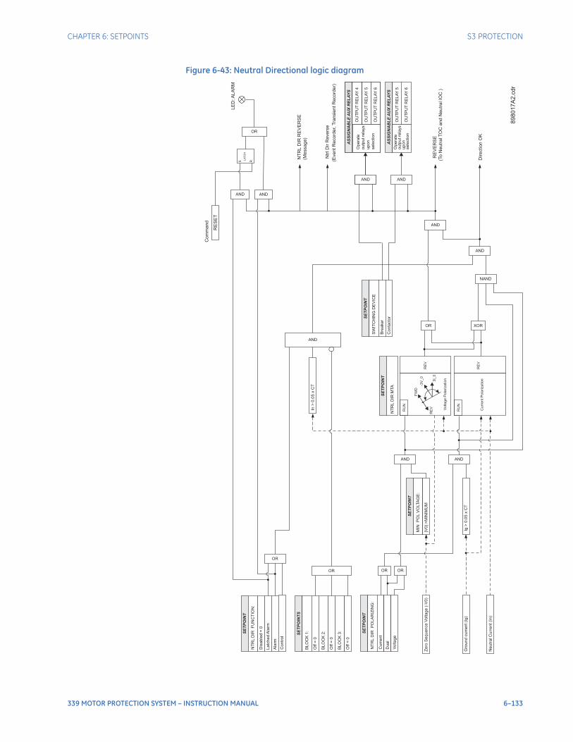
CHAPTER 6: SETPOINTS S3 PROTECTION
339 MOTOR PROTECTION SYSTEM – INSTRUCTION MANUAL 6–133
Figure 6-43: Neutral Directional logic diagram
Zero
Sequence
Voltage
(-V
0)
SE
TP
OIN
T
NT
RL
DIR
FU
NC
TIO
N:
Dis
able
d=
0
Latc
hed
Ala
rm
SE
TP
OIN
TS
BLO
CK
1:
Off
=0
BLO
CK
2:
Off
=0
BLO
CK
3:
Off
=0
OR
NT
RL
DIR
RE
VE
RS
E
(To
Neutr
alT
OC
and
Neutr
alIO
C)
Ala
rm
OR
OR
RE
VE
RS
E
(Message)
AND
AS
SIG
NA
BL
EA
UX
RE
LA
YS
Opera
te
outp
utre
lays
upon
sele
ction
OU
TP
UT
RE
LA
Y5
OU
TP
UT
RE
LA
Y6
OU
TP
UT
RE
LA
Y4
Contr
ol
Neutr
alC
urr
ent(I
n)
Gro
und
curr
ent(I
g)
Voltage
Pola
rization
-3V
_0
3I_
0
FW
D
RE
V
RE
V
RU
N
SE
TP
OIN
T
NT
RL
DIR
MTA
Curr
ent
Pola
rization
RE
V
RU
N
SE
TP
OIN
T
NT
RL
DIR
PO
LA
RIZ
ING
:
Curr
ent
Dual
Voltage
OR OR
SE
TP
OIN
T
MIN
PO
LV
OLTA
GE
:
|V0|>
MIN
IMU
M
AND
Ig>
0.0
5x
CT
AND
In>
0.0
5x
CT
AND
OR XOR
AND
NAND
AND
Ntr
lD
irR
evers
e
(EventR
ecord
er,
Tra
nsie
ntR
ecord
er)
Direction
OK
LE
D:A
LA
RM
RE
SE
T
Com
mand
AND
S R
LA
TC
H
89
80
17
A2
.cd
r
AND
AS
SIG
NA
BL
EA
UX
RE
LA
YS
Opera
te
outp
utre
lays
upon
sele
ction
OU
TP
UT
RE
LA
Y5
OU
TP
UT
RE
LA
Y6
OU
TP
UT
RE
LA
Y4
AND
AS
SIG
NA
BL
EA
UX
RE
LA
YS
Opera
teoutp
utre
lays
upon
sele
ction
OU
TP
UT
RE
LA
Y6
OU
TP
UT
RE
LA
Y5
AND
SE
TP
OIN
T
SW
ITC
HIN
GD
EV
ICE
Bre
aker
Conta
cto
r
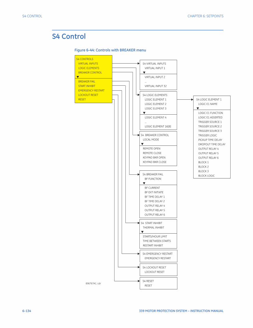
6–134 339 MOTOR PROTECTION SYSTEM – INSTRUCTION MANUAL
S4 CONTROL CHAPTER 6: SETPOINTS
S4 Control
Figure 6-44: Controls with BREAKER menu
S4 CONTROLS
VIRTUAL INPUTS
LOGIC ELEMENTS
BREAKER CONTROL
BREAKER FAIL
START INHIBIT
EMERGENCY RESTART
LOCKOUT RESET
RESET
S4 EMERGENCY RESTART
EMERGENCY RESTART
S4 BREAKER CONTROL
LOCAL MODE
REMOTE OPEN
REMOTE CLOSE
KEYPAD BKR OPEN
KEYPAD BKR CLOSE
896767A1. cdr
S4 VIRTUAL INPUTS
...
VIRTUAL INPUT 1
VIRTUAL INPUT 2
VIRTUAL INPUT 32
S4 LOGIC ELEMENTS
...
LOGIC ELEMENT 1
LOGIC ELEMENT 2
LOGIC ELEMENT 3
LOGIC ELEMENT 4
LOGIC ELEMENT 16[8]
S4 BREAKER FAIL
BF FUNCTION
BF CURRENT
BF EXT INITIATE
BF TIME DELAY 1
OUTPUT RELAY 6
BF TIME DELAY 2
OUTPUT RELAY 4
OUTPUT RELAY 5
S4 LOCKOUT RESET
RESETLOCKOUT
S4 RESET
RESET
S4 START INHIBIT
TIME BETWEEN STARTS
RESTART INHIBIT
THERMAL INHIBIT
STARTS/HOUR LIMIT
S4 LOGIC ELEMENT 1
LOGIC E1 NAME
LOGIC E1 FUNCTION
LOGIC E1 ASSERTED
TRIGGER SOURCE 1
TRIGGER SOURCE 2
TRIGGER SOURCE 3
TRIGGER LOGIC
PICKUP TIME DELAY
DROPOUT TIME DELAY
OUTPUT RELAY 4
OUTPUT RELAY 5
OUTPUT RELAY 6
BLOCK 1
BLOCK 2
BLOCK 3
BLOCK LOGIC
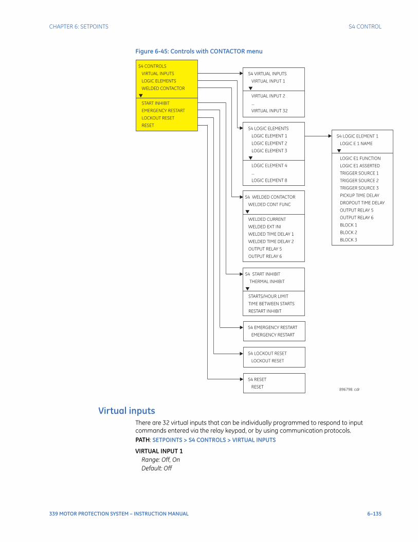
CHAPTER 6: SETPOINTS S4 CONTROL
339 MOTOR PROTECTION SYSTEM – INSTRUCTION MANUAL 6–135
Figure 6-45: Controls with CONTACTOR menu
Virtual inputsThere are 32 virtual inputs that can be individually programmed to respond to input commands entered via the relay keypad, or by using communication protocols.PATH: SETPOINTS > S4 CONTROLS > VIRTUAL INPUTS
VIRTUAL INPUT 1Range: Off, OnDefault: Off
S4 CONTROLS
VIRTUAL INPUTS
LOGIC ELEMENTS
WELDED CONTACTOR
START INHIBIT
EMERGENCY RESTART
LOCKOUT RESET
RESET
S4 EMERGENCY RESTART
EMERGENCY RESTART
S4 WELDED CONTACTOR
WELDED CURRENT
WELDED EXT INI
WELDED TIME DELAY 1
OUTPUT RELAY 5
OUTPUT RELAY 6
WELDED CONT FUNC
WELDED TIME DELAY 2
896798. cdr
S4 VIRTUAL INPUTS
...
VIRTUAL INPUT 1
VIRTUAL INPUT 2
VIRTUAL INPUT 32
S4 LOGIC ELEMENTS
...
LOGIC ELEMENT 1
LOGIC ELEMENT 2
LOGIC ELEMENT 3
LOGIC ELEMENT 4
LOGIC ELEMENT 8
S4 LOCKOUT RESET
RESETLOCKOUT
S4 RESET
RESET
S4 START INHIBIT
TIME BETWEEN STARTS
RESTART INHIBIT
THERMAL INHIBIT
STARTS/HOUR LIMIT
S4 LOGIC ELEMENT 1
LOGIC E 1 NAME
LOGIC E1 FUNCTION
LOGIC E1 ASSERTED
TRIGGER SOURCE 1
TRIGGER SOURCE 2
TRIGGER SOURCE 3
PICKUP TIME DELAY
DROPOUT TIME DELAY
OUTPUT RELAY 5
OUTPUT RELAY 6
BLOCK 1
BLOCK 2
BLOCK 3
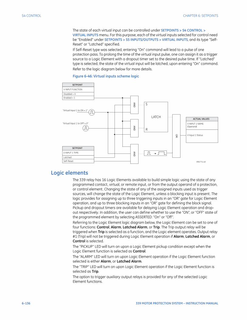
6–136 339 MOTOR PROTECTION SYSTEM – INSTRUCTION MANUAL
S4 CONTROL CHAPTER 6: SETPOINTS
The state of each virtual input can be controlled under SETPOINTS > S4 CONTROL > VIRTUAL INPUTS menu. For this purpose, each of the virtual inputs selected for control need be “Enabled” under SETPOINTS > S5 INPUTS/OUTPUTS > VIRTUAL INPUTS, and its type “Self-Reset” or “Latched” specified.If Self-Reset type was selected, entering “On” command will lead to a pulse of one protection pass. To prolong the time of the virtual input pulse, one can assign it as a trigger source to a Logic Element with a dropout timer set to the desired pulse time. If “Latched” type is selected, the state of the virtual input will be latched, upon entering “On” command.Refer to the logic diagram below for more details.
Figure 6-46: Virtual inputs scheme logic
Logic elementsThe 339 relay has 16 Logic Elements available to build simple logic using the state of any programmed contact, virtual, or remote input, or from the output operand of a protection, or control element. Changing the state of any of the assigned inputs used as trigger sources, will change the state of the Logic Element, unless a blocking input is present. The logic provides for assigning up to three triggering inputs in an “OR” gate for Logic Element operation, and up to three blocking inputs in an “OR” gate for defining the block signal. Pickup and dropout timers are available for delaying Logic Element operation and drop-out respectively. In addition, the user can define whether to use the “ON”, or “OFF” state of the programmed element by selecting ASSERTED: “On” or “Off”. Referring to the Logic Element logic diagram below, the Logic Element can be set to one of four functions: Control, Alarm, Latched Alarm, or Trip. The Trip output relay will be triggered when Trip is selected as a function, and the Logic element operates. Output relay #1 (Trip) will not be triggered during Logic Element operation if Alarm, Latched Alarm, or Control is selected.The “PICKUP” LED will turn on upon a Logic Element pickup condition except when the Logic Element function is selected as Control. The “ALARM” LED will turn on upon Logic Element operation if the Logic Element function selected is either Alarm, or Latched Alarm. The “TRIP” LED will turn on upon Logic Element operation if the Logic Element function is selected as Trip. The option to trigger auxiliary output relays is provided for any of the selected Logic Element functions.
SETPOINT
V INPUT FUNCTION
Disabled = 0
Enabled = 1
AN
D
SETPOINT
V INPUT 1 TYPE
Latched
Self-Reset
AN
DA
ND
“Virtual Input 1 to ON = 1"
“Virtual Input 1 to OFF = 0"
S
R
LATCH
OR
ACTUAL VALUES
V INPUT 1 NAME:
(Operand)
V Input 1 Status
896774.cdr
CHAPTER 6: SETPOINTS S4 CONTROL
339 MOTOR PROTECTION SYSTEM – INSTRUCTION MANUAL 6–137
The following path is available using the keypad. For instructions on how to use the keypad, please refer to Chapter 3 - Working with the Keypad.PATH: SETPOINTS > S4 CONTROLS > S4 LOGIC ELEMENTS
LE1(16) FUNCTIONRange: Disabled, Control, Alarm, Latched Alarm, TripDefault: Disabled
This setting defines the use of the Logic Element. When Trip is selected as a function, the Logic Element will trigger Output Relay # 1 (Trip) upon operation.
LE1(16) ASSERTEDRange: On, OffDefault: Off
This setting defines the Logic Element state “On” or “Off” to be used as an output. The asserted “On” selection provides an output “high” when the LE is "On". If asserted “Off” is selected, then the LE output will be “high”, when the LE is “Off”.
TRIGGER SOURCE 1, 2, 3Range: Off, Any input from the list of inputsDefault: Off
Each of the three trigger sources is configurable by allowing the assigning of an input selected from a list of inputs. This input can be a contact input, a virtual input, a remote input, or an output flag from a protection, or control element.
TRIGGER LOGICRange: OR, ANDDefault: OR
This setting defines trigger source operation as either “OR” or “AND”. When set to “OR” any of the inputs will trigger the Logic Element. When set to “AND” all three sources must be asserted before the Logic Element is triggered.
PKP TIME DELAYRange: 0 to 60000 ms in steps of 1 msDefault: 0 ms
This setting specifies the pickup time delay before Logic Element operation.
DPO TIME DELAYRange: 0 to 60000 ms in steps of 1 msDefault: 0 ms
This setting specifies the time delay from a reset timer that starts upon expiry of the pickup time delay and prolongs the operation of the Logic Element until this time expires.
BLOCK 1, 2, 3Range: Off, Any input from the list of inputsDefault: Off
Each of the three blocks is configurable by allowing the assigning of an input selected from a list of inputs. This input can be a contact input, a virtual input, a remote input, or an output flag from a protection, or control element, as well as an input from any of the other seven logic inputs.
BLOCK LOGICRange: OR, ANDDefault: OR
This setting defines block source operation as either “OR” or “AND”. When set to “OR” any of the inputs will block the Logic Element. When set to “AND” all three sources must be asserted before the Logic Element is blocked.

6–138 339 MOTOR PROTECTION SYSTEM – INSTRUCTION MANUAL
S4 CONTROL CHAPTER 6: SETPOINTS
OUTPUT RELAYS 4 to 6 / OUTPUT RELAYS 5 to 6Range: Do not operate, OperateDefault: Do not operate
Any assignable output relay can be selected to operate upon a Logic Element operating condition. When the SWITCHING DEVICE is selected as BREAKER, the assignable output relays will be Output Relays 4 to 6. When the SWITCHING DEVICE is selected as CONTACTOR, the assignable output relays will be Output Relays 5 to 6. The selection of auxiliary relay outputs is available no matter whether the Control, Alarm, Latched Alarm, or Trip function is selected.
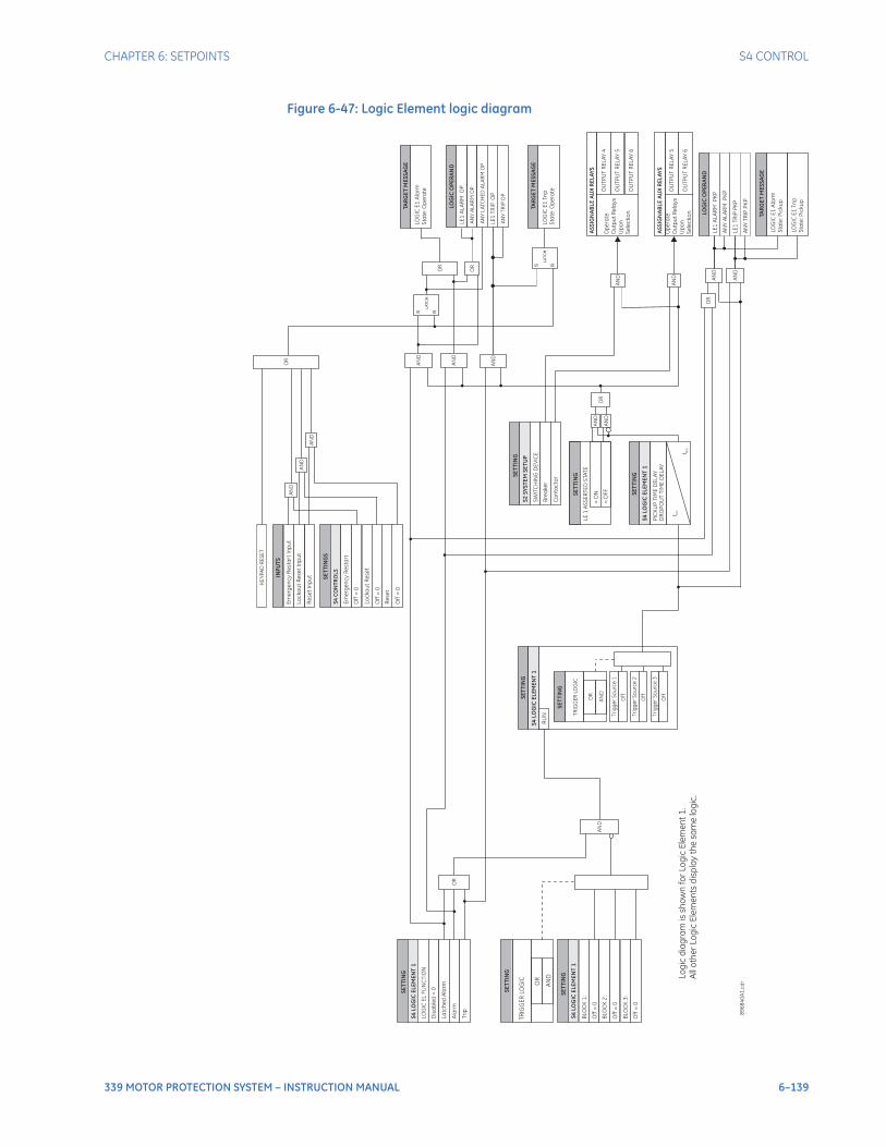
CHAPTER 6: SETPOINTS S4 CONTROL
339 MOTOR PROTECTION SYSTEM – INSTRUCTION MANUAL 6–139
Figure 6-47: Logic Element logic diagram
SE
TT
ING
RU
N
SE
TT
I NG
LO
GIC
EL
FU
NC
TIO
N
Dis
ab
led
=0
La
tch
ed
Ala
rm
PIC
KU
PT
IME
DE
LA
Y
Ala
rm
Op
era
te
Ou
tpu
tR
ela
ys
Up
on
Se
lec
tio
n
OU
TP
UT
RE
LA
Y4
OU
TP
UT
RE
LA
Y5
OU
TP
UT
RE
LA
Y6
Tri
p
SE
TT
I NG
BLO
CK
1:
Off
=0
BLO
CK
2:
Off
=0
BLO
CK
3:
Off
=0
SE
TT
I NG
LE
1A
LA
RM
PK
P
t PK
P
S R
LA
TC
H
89
68
40
A1
.cd
r
LOG
ICO
PE
RA
ND
LE
1A
LA
RM
OP
LOG
ICO
PE
RA
ND
OR
AN
D
AN
D
AN
D
AN
D
OR
AN
D
AN
D
INP
UT
S
Em
erg
en
cy
Re
sta
rt
Inp
ut
Lo
ck
ou
tR
ese
tIn
pu
t
SE
TT
ING
S
Off
=0
Lo
ck
ou
tR
ese
t
Off
=0
Em
erg
en
cy
Re
sta
rt
S4
CO
NT
RO
LS
LO
GIC
E1
Ala
rm
Sta
te:O
pe
rate
TAR
GE
TM
ES
SA
GE
AN
YA
LA
RM
OP
LE
1T
RIP
OP
AN
YT
RIP
OP
S R
LA
TC
HLO
GIC
E1
Tri
p
Sta
te:O
pe
rate
TAR
GE
TM
ES
SA
GE
AS
SIG
NA
BL
EA
UX
RE
LA
YS
AN
D
Op
era
te
Ou
tpu
tR
ela
ys
Up
on
Se
lec
tio
n
OU
TP
UT
RE
LA
Y5
OU
TP
UT
RE
LA
Y6
AN
D
AN
YA
LA
RM
PK
P
LE
1T
RIP
PK
P
AN
YT
RIP
PK
P
AN
D
AN
D
OR
S4
LOG
ICE
LE
ME
NT
1
S4
LOG
ICE
LE
ME
NT
1
S4
LOG
ICE
LE
ME
NT
1
SE
TT
I NG
SW
ITC
HIN
GD
EV
ICE
Bre
ake
r
Co
nta
cto
r
S2
SY
ST
EM
SE
TU
P
S4
LOG
ICE
LE
ME
NT
1
OR
Re
se
tIn
pu
t
Re
se
t
Off
=0
AN
D
OR
KE
YP
AD
RE
SE
T
AN
YL
ATC
HE
DA
LA
RM
OP
AS
SIG
NA
BL
EA
UX
RE
LA
YS
LO
GIC
E1
Ala
rm
Sta
te:P
icku
p
TAR
GE
TM
ES
SA
GE
LO
GIC
E1
Tri
p
Sta
te:P
icku
p
Tri
gg
er
So
urc
e1
Off
Tri
gg
er
So
urc
e2
Off
Tri
gg
er
So
urc
e3
Off
SE
TT
ING
=O
N
=O
FF
LE
1A
SS
ER
TE
DS
TA
TE
AN
D
AN
D
OR
t DP
O
DR
OP
OU
TT
IME
DE
LA
Y
Lo
gic
dia
gra
mis
sh
ow
nfo
rL
og
icE
lem
en
t1
.
All
oth
er
Lo
gic
Ele
me
nts
dis
pla
yth
esa
me
log
ic.
TR
IGG
ER
LO
GIC
SE
TT
I NG
AN
D
OR
TR
IGG
ER
LO
GIC
SE
TT
I NG
AN
D
OR
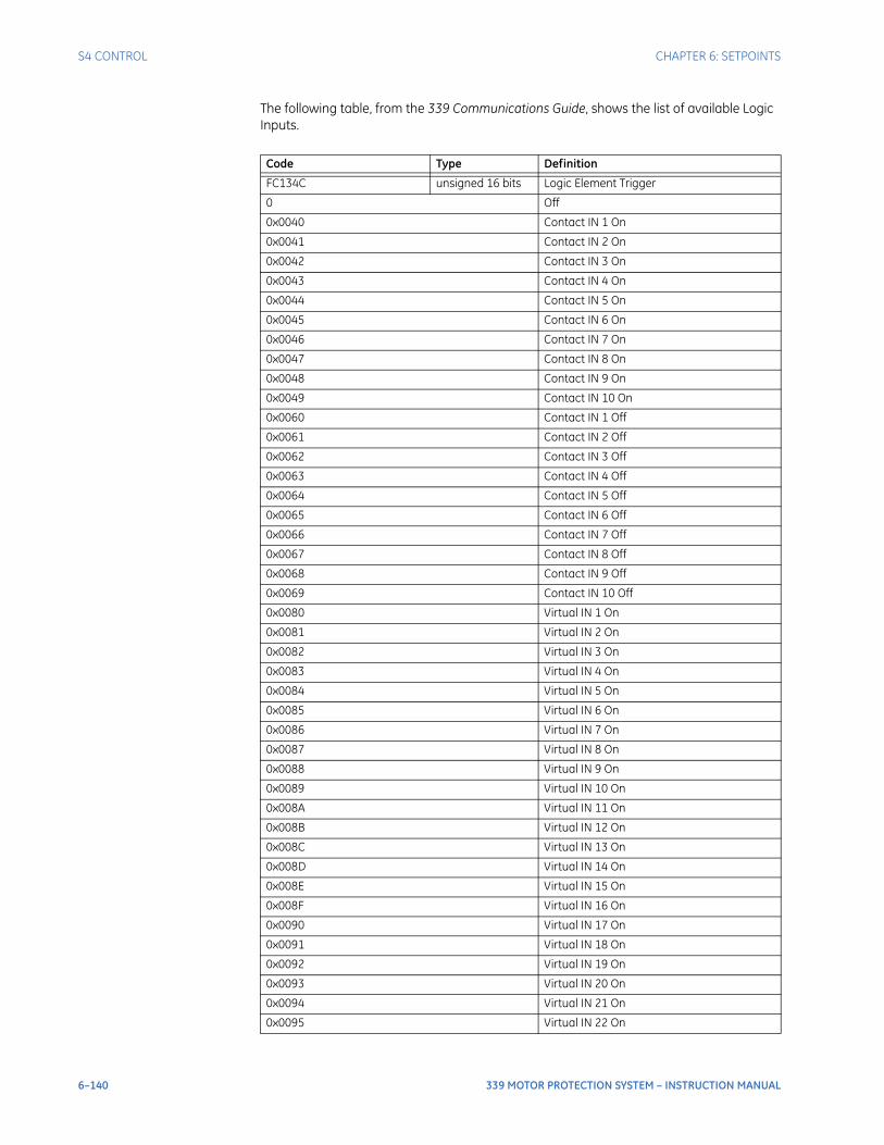
6–140 339 MOTOR PROTECTION SYSTEM – INSTRUCTION MANUAL
S4 CONTROL CHAPTER 6: SETPOINTS
The following table, from the 339 Communications Guide, shows the list of available Logic Inputs.
Code Type Definition
FC134C unsigned 16 bits Logic Element Trigger
0 Off
0x0040 Contact IN 1 On
0x0041 Contact IN 2 On
0x0042 Contact IN 3 On
0x0043 Contact IN 4 On
0x0044 Contact IN 5 On
0x0045 Contact IN 6 On
0x0046 Contact IN 7 On
0x0047 Contact IN 8 On
0x0048 Contact IN 9 On
0x0049 Contact IN 10 On
0x0060 Contact IN 1 Off
0x0061 Contact IN 2 Off
0x0062 Contact IN 3 Off
0x0063 Contact IN 4 Off
0x0064 Contact IN 5 Off
0x0065 Contact IN 6 Off
0x0066 Contact IN 7 Off
0x0067 Contact IN 8 Off
0x0068 Contact IN 9 Off
0x0069 Contact IN 10 Off
0x0080 Virtual IN 1 On
0x0081 Virtual IN 2 On
0x0082 Virtual IN 3 On
0x0083 Virtual IN 4 On
0x0084 Virtual IN 5 On
0x0085 Virtual IN 6 On
0x0086 Virtual IN 7 On
0x0087 Virtual IN 8 On
0x0088 Virtual IN 9 On
0x0089 Virtual IN 10 On
0x008A Virtual IN 11 On
0x008B Virtual IN 12 On
0x008C Virtual IN 13 On
0x008D Virtual IN 14 On
0x008E Virtual IN 15 On
0x008F Virtual IN 16 On
0x0090 Virtual IN 17 On
0x0091 Virtual IN 18 On
0x0092 Virtual IN 19 On
0x0093 Virtual IN 20 On
0x0094 Virtual IN 21 On
0x0095 Virtual IN 22 On
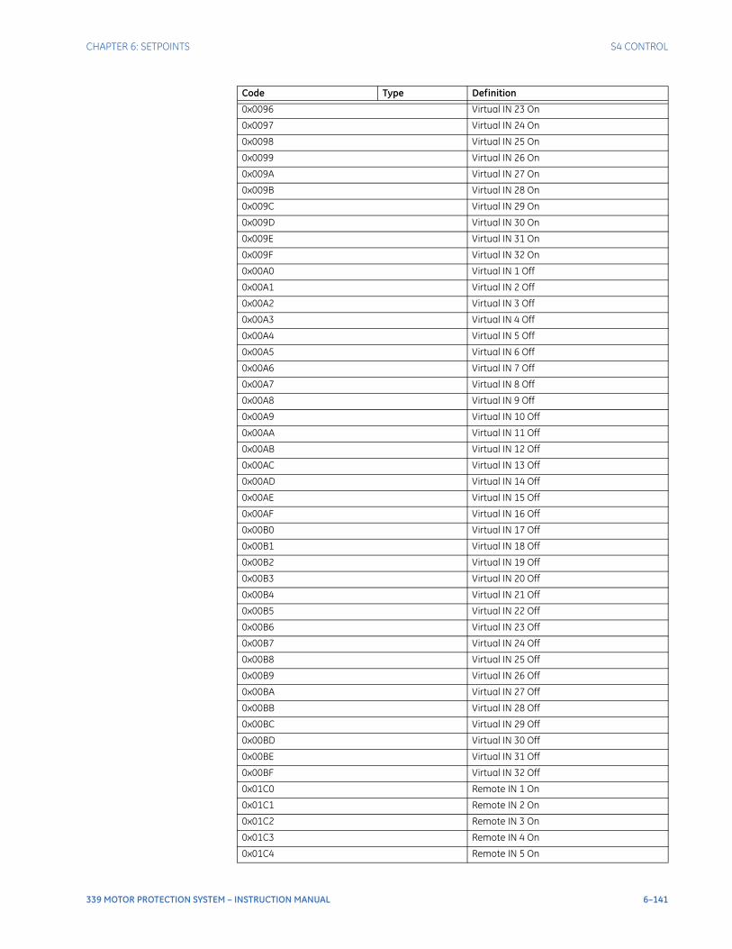
CHAPTER 6: SETPOINTS S4 CONTROL
339 MOTOR PROTECTION SYSTEM – INSTRUCTION MANUAL 6–141
0x0096 Virtual IN 23 On
0x0097 Virtual IN 24 On
0x0098 Virtual IN 25 On
0x0099 Virtual IN 26 On
0x009A Virtual IN 27 On
0x009B Virtual IN 28 On
0x009C Virtual IN 29 On
0x009D Virtual IN 30 On
0x009E Virtual IN 31 On
0x009F Virtual IN 32 On
0x00A0 Virtual IN 1 Off
0x00A1 Virtual IN 2 Off
0x00A2 Virtual IN 3 Off
0x00A3 Virtual IN 4 Off
0x00A4 Virtual IN 5 Off
0x00A5 Virtual IN 6 Off
0x00A6 Virtual IN 7 Off
0x00A7 Virtual IN 8 Off
0x00A8 Virtual IN 9 Off
0x00A9 Virtual IN 10 Off
0x00AA Virtual IN 11 Off
0x00AB Virtual IN 12 Off
0x00AC Virtual IN 13 Off
0x00AD Virtual IN 14 Off
0x00AE Virtual IN 15 Off
0x00AF Virtual IN 16 Off
0x00B0 Virtual IN 17 Off
0x00B1 Virtual IN 18 Off
0x00B2 Virtual IN 19 Off
0x00B3 Virtual IN 20 Off
0x00B4 Virtual IN 21 Off
0x00B5 Virtual IN 22 Off
0x00B6 Virtual IN 23 Off
0x00B7 Virtual IN 24 Off
0x00B8 Virtual IN 25 Off
0x00B9 Virtual IN 26 Off
0x00BA Virtual IN 27 Off
0x00BB Virtual IN 28 Off
0x00BC Virtual IN 29 Off
0x00BD Virtual IN 30 Off
0x00BE Virtual IN 31 Off
0x00BF Virtual IN 32 Off
0x01C0 Remote IN 1 On
0x01C1 Remote IN 2 On
0x01C2 Remote IN 3 On
0x01C3 Remote IN 4 On
0x01C4 Remote IN 5 On
Code Type Definition
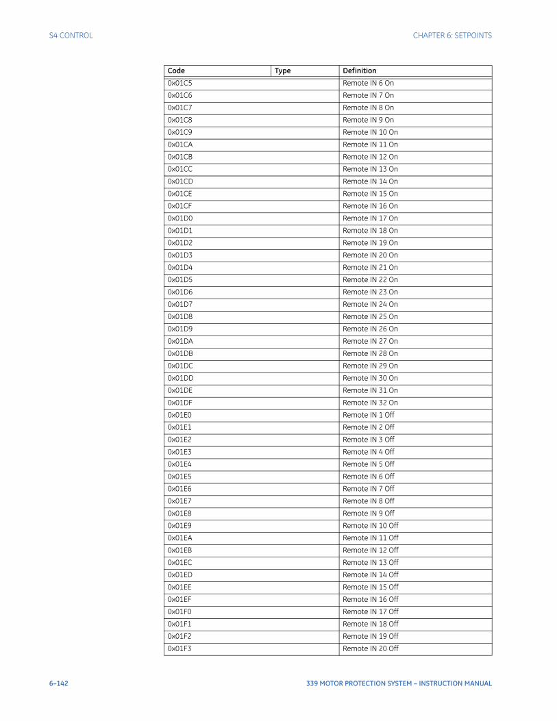
6–142 339 MOTOR PROTECTION SYSTEM – INSTRUCTION MANUAL
S4 CONTROL CHAPTER 6: SETPOINTS
0x01C5 Remote IN 6 On
0x01C6 Remote IN 7 On
0x01C7 Remote IN 8 On
0x01C8 Remote IN 9 On
0x01C9 Remote IN 10 On
0x01CA Remote IN 11 On
0x01CB Remote IN 12 On
0x01CC Remote IN 13 On
0x01CD Remote IN 14 On
0x01CE Remote IN 15 On
0x01CF Remote IN 16 On
0x01D0 Remote IN 17 On
0x01D1 Remote IN 18 On
0x01D2 Remote IN 19 On
0x01D3 Remote IN 20 On
0x01D4 Remote IN 21 On
0x01D5 Remote IN 22 On
0x01D6 Remote IN 23 On
0x01D7 Remote IN 24 On
0x01D8 Remote IN 25 On
0x01D9 Remote IN 26 On
0x01DA Remote IN 27 On
0x01DB Remote IN 28 On
0x01DC Remote IN 29 On
0x01DD Remote IN 30 On
0x01DE Remote IN 31 On
0x01DF Remote IN 32 On
0x01E0 Remote IN 1 Off
0x01E1 Remote IN 2 Off
0x01E2 Remote IN 3 Off
0x01E3 Remote IN 4 Off
0x01E4 Remote IN 5 Off
0x01E5 Remote IN 6 Off
0x01E6 Remote IN 7 Off
0x01E7 Remote IN 8 Off
0x01E8 Remote IN 9 Off
0x01E9 Remote IN 10 Off
0x01EA Remote IN 11 Off
0x01EB Remote IN 12 Off
0x01EC Remote IN 13 Off
0x01ED Remote IN 14 Off
0x01EE Remote IN 15 Off
0x01EF Remote IN 16 Off
0x01F0 Remote IN 17 Off
0x01F1 Remote IN 18 Off
0x01F2 Remote IN 19 Off
0x01F3 Remote IN 20 Off
Code Type Definition
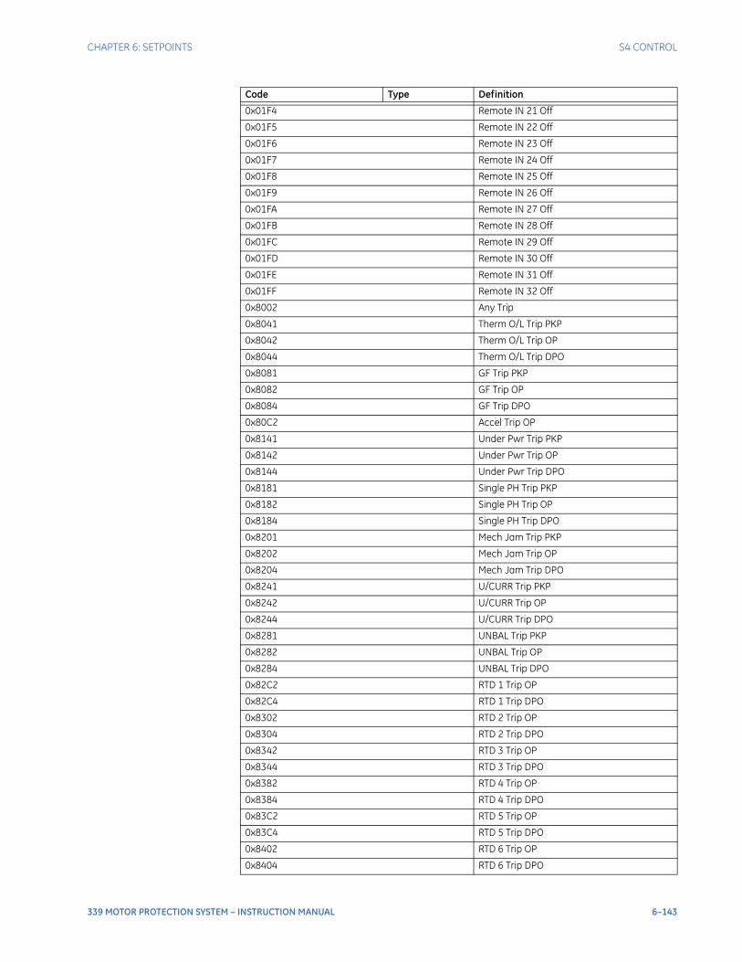
CHAPTER 6: SETPOINTS S4 CONTROL
339 MOTOR PROTECTION SYSTEM – INSTRUCTION MANUAL 6–143
0x01F4 Remote IN 21 Off
0x01F5 Remote IN 22 Off
0x01F6 Remote IN 23 Off
0x01F7 Remote IN 24 Off
0x01F8 Remote IN 25 Off
0x01F9 Remote IN 26 Off
0x01FA Remote IN 27 Off
0x01FB Remote IN 28 Off
0x01FC Remote IN 29 Off
0x01FD Remote IN 30 Off
0x01FE Remote IN 31 Off
0x01FF Remote IN 32 Off
0x8002 Any Trip
0x8041 Therm O/L Trip PKP
0x8042 Therm O/L Trip OP
0x8044 Therm O/L Trip DPO
0x8081 GF Trip PKP
0x8082 GF Trip OP
0x8084 GF Trip DPO
0x80C2 Accel Trip OP
0x8141 Under Pwr Trip PKP
0x8142 Under Pwr Trip OP
0x8144 Under Pwr Trip DPO
0x8181 Single PH Trip PKP
0x8182 Single PH Trip OP
0x8184 Single PH Trip DPO
0x8201 Mech Jam Trip PKP
0x8202 Mech Jam Trip OP
0x8204 Mech Jam Trip DPO
0x8241 U/CURR Trip PKP
0x8242 U/CURR Trip OP
0x8244 U/CURR Trip DPO
0x8281 UNBAL Trip PKP
0x8282 UNBAL Trip OP
0x8284 UNBAL Trip DPO
0x82C2 RTD 1 Trip OP
0x82C4 RTD 1 Trip DPO
0x8302 RTD 2 Trip OP
0x8304 RTD 2 Trip DPO
0x8342 RTD 3 Trip OP
0x8344 RTD 3 Trip DPO
0x8382 RTD 4 Trip OP
0x8384 RTD 4 Trip DPO
0x83C2 RTD 5 Trip OP
0x83C4 RTD 5 Trip DPO
0x8402 RTD 6 Trip OP
0x8404 RTD 6 Trip DPO
Code Type Definition
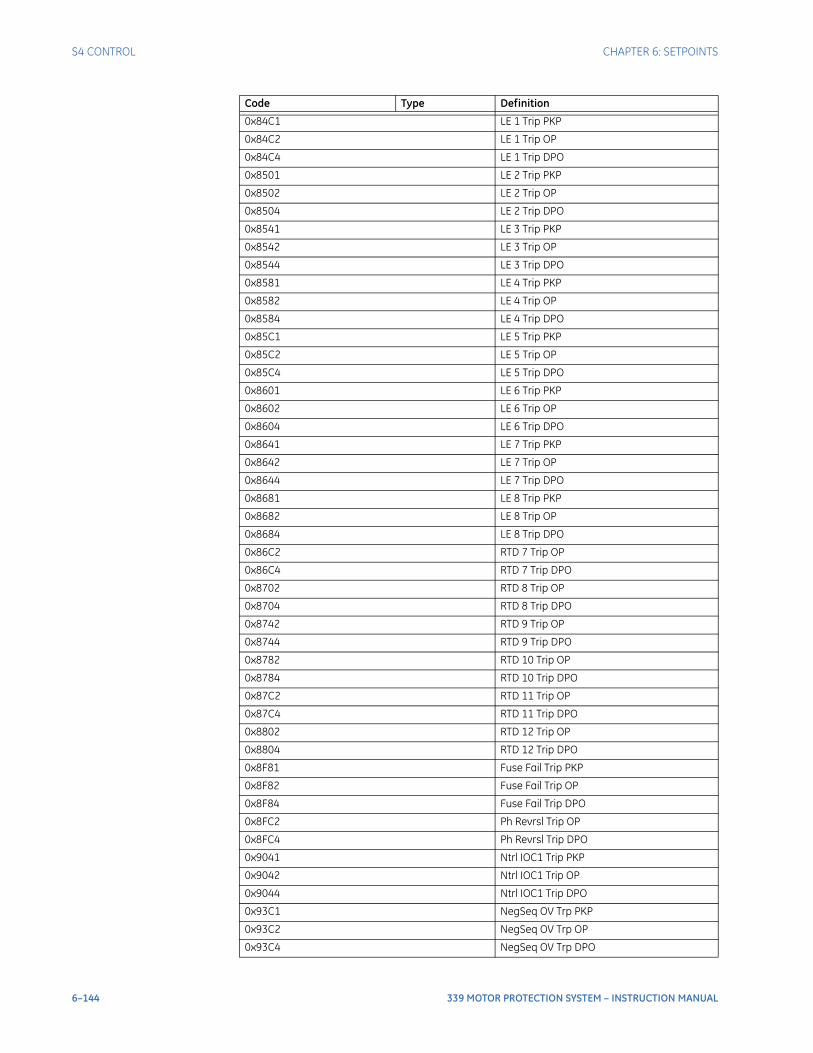
6–144 339 MOTOR PROTECTION SYSTEM – INSTRUCTION MANUAL
S4 CONTROL CHAPTER 6: SETPOINTS
0x84C1 LE 1 Trip PKP
0x84C2 LE 1 Trip OP
0x84C4 LE 1 Trip DPO
0x8501 LE 2 Trip PKP
0x8502 LE 2 Trip OP
0x8504 LE 2 Trip DPO
0x8541 LE 3 Trip PKP
0x8542 LE 3 Trip OP
0x8544 LE 3 Trip DPO
0x8581 LE 4 Trip PKP
0x8582 LE 4 Trip OP
0x8584 LE 4 Trip DPO
0x85C1 LE 5 Trip PKP
0x85C2 LE 5 Trip OP
0x85C4 LE 5 Trip DPO
0x8601 LE 6 Trip PKP
0x8602 LE 6 Trip OP
0x8604 LE 6 Trip DPO
0x8641 LE 7 Trip PKP
0x8642 LE 7 Trip OP
0x8644 LE 7 Trip DPO
0x8681 LE 8 Trip PKP
0x8682 LE 8 Trip OP
0x8684 LE 8 Trip DPO
0x86C2 RTD 7 Trip OP
0x86C4 RTD 7 Trip DPO
0x8702 RTD 8 Trip OP
0x8704 RTD 8 Trip DPO
0x8742 RTD 9 Trip OP
0x8744 RTD 9 Trip DPO
0x8782 RTD 10 Trip OP
0x8784 RTD 10 Trip DPO
0x87C2 RTD 11 Trip OP
0x87C4 RTD 11 Trip DPO
0x8802 RTD 12 Trip OP
0x8804 RTD 12 Trip DPO
0x8F81 Fuse Fail Trip PKP
0x8F82 Fuse Fail Trip OP
0x8F84 Fuse Fail Trip DPO
0x8FC2 Ph Revrsl Trip OP
0x8FC4 Ph Revrsl Trip DPO
0x9041 Ntrl IOC1 Trip PKP
0x9042 Ntrl IOC1 Trip OP
0x9044 Ntrl IOC1 Trip DPO
0x93C1 NegSeq OV Trp PKP
0x93C2 NegSeq OV Trp OP
0x93C4 NegSeq OV Trp DPO
Code Type Definition
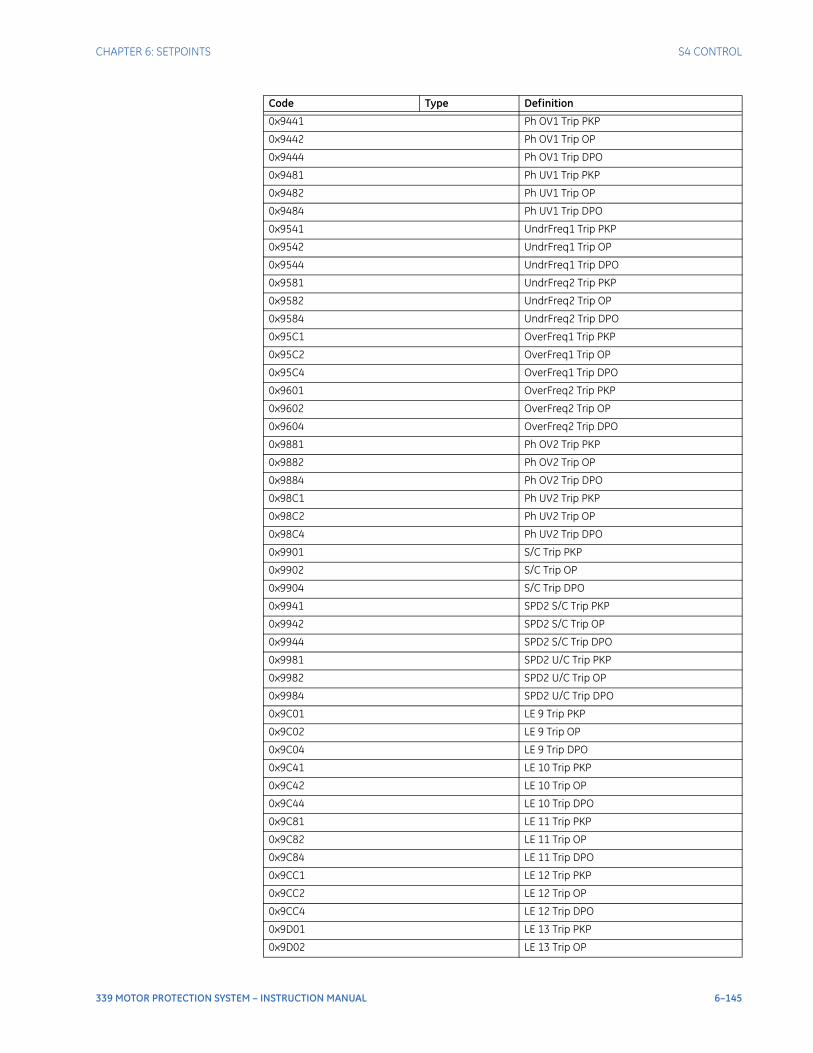
CHAPTER 6: SETPOINTS S4 CONTROL
339 MOTOR PROTECTION SYSTEM – INSTRUCTION MANUAL 6–145
0x9441 Ph OV1 Trip PKP
0x9442 Ph OV1 Trip OP
0x9444 Ph OV1 Trip DPO
0x9481 Ph UV1 Trip PKP
0x9482 Ph UV1 Trip OP
0x9484 Ph UV1 Trip DPO
0x9541 UndrFreq1 Trip PKP
0x9542 UndrFreq1 Trip OP
0x9544 UndrFreq1 Trip DPO
0x9581 UndrFreq2 Trip PKP
0x9582 UndrFreq2 Trip OP
0x9584 UndrFreq2 Trip DPO
0x95C1 OverFreq1 Trip PKP
0x95C2 OverFreq1 Trip OP
0x95C4 OverFreq1 Trip DPO
0x9601 OverFreq2 Trip PKP
0x9602 OverFreq2 Trip OP
0x9604 OverFreq2 Trip DPO
0x9881 Ph OV2 Trip PKP
0x9882 Ph OV2 Trip OP
0x9884 Ph OV2 Trip DPO
0x98C1 Ph UV2 Trip PKP
0x98C2 Ph UV2 Trip OP
0x98C4 Ph UV2 Trip DPO
0x9901 S/C Trip PKP
0x9902 S/C Trip OP
0x9904 S/C Trip DPO
0x9941 SPD2 S/C Trip PKP
0x9942 SPD2 S/C Trip OP
0x9944 SPD2 S/C Trip DPO
0x9981 SPD2 U/C Trip PKP
0x9982 SPD2 U/C Trip OP
0x9984 SPD2 U/C Trip DPO
0x9C01 LE 9 Trip PKP
0x9C02 LE 9 Trip OP
0x9C04 LE 9 Trip DPO
0x9C41 LE 10 Trip PKP
0x9C42 LE 10 Trip OP
0x9C44 LE 10 Trip DPO
0x9C81 LE 11 Trip PKP
0x9C82 LE 11 Trip OP
0x9C84 LE 11 Trip DPO
0x9CC1 LE 12 Trip PKP
0x9CC2 LE 12 Trip OP
0x9CC4 LE 12 Trip DPO
0x9D01 LE 13 Trip PKP
0x9D02 LE 13 Trip OP
Code Type Definition
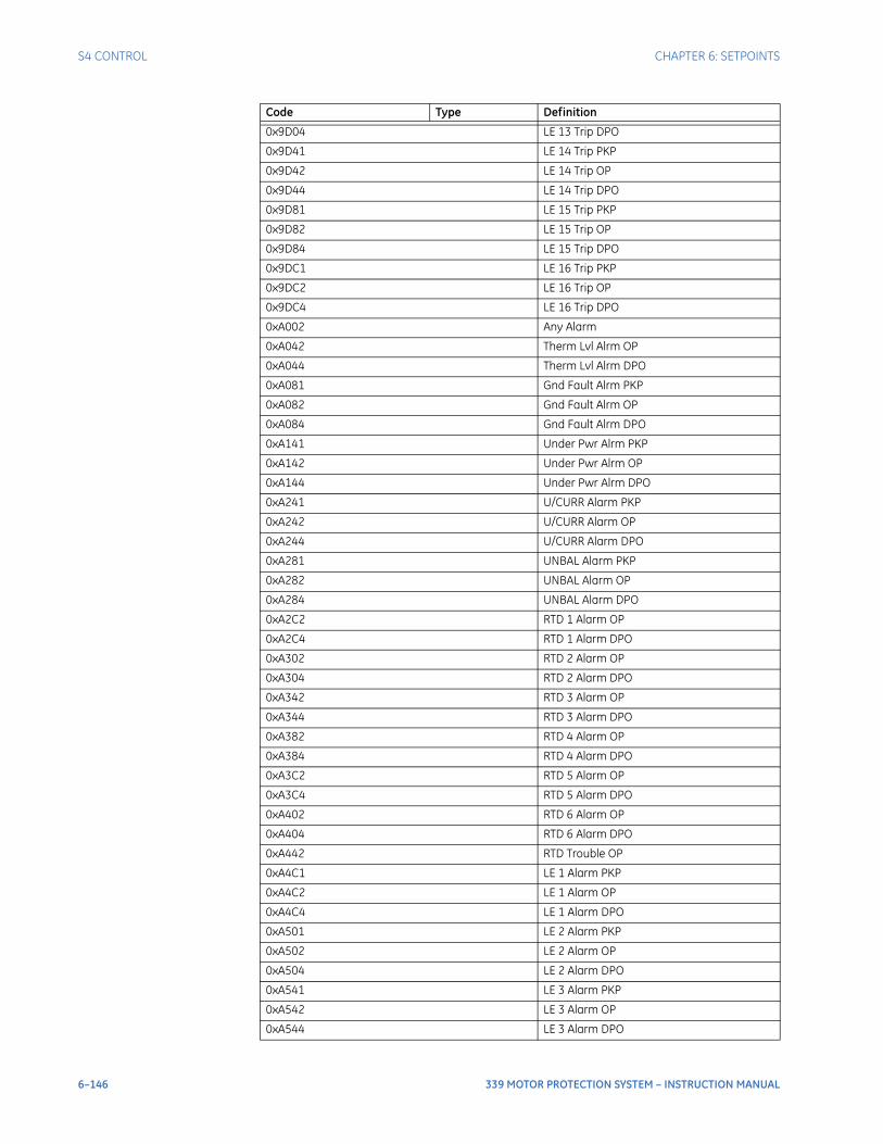
6–146 339 MOTOR PROTECTION SYSTEM – INSTRUCTION MANUAL
S4 CONTROL CHAPTER 6: SETPOINTS
0x9D04 LE 13 Trip DPO
0x9D41 LE 14 Trip PKP
0x9D42 LE 14 Trip OP
0x9D44 LE 14 Trip DPO
0x9D81 LE 15 Trip PKP
0x9D82 LE 15 Trip OP
0x9D84 LE 15 Trip DPO
0x9DC1 LE 16 Trip PKP
0x9DC2 LE 16 Trip OP
0x9DC4 LE 16 Trip DPO
0xA002 Any Alarm
0xA042 Therm Lvl Alrm OP
0xA044 Therm Lvl Alrm DPO
0xA081 Gnd Fault Alrm PKP
0xA082 Gnd Fault Alrm OP
0xA084 Gnd Fault Alrm DPO
0xA141 Under Pwr Alrm PKP
0xA142 Under Pwr Alrm OP
0xA144 Under Pwr Alrm DPO
0xA241 U/CURR Alarm PKP
0xA242 U/CURR Alarm OP
0xA244 U/CURR Alarm DPO
0xA281 UNBAL Alarm PKP
0xA282 UNBAL Alarm OP
0xA284 UNBAL Alarm DPO
0xA2C2 RTD 1 Alarm OP
0xA2C4 RTD 1 Alarm DPO
0xA302 RTD 2 Alarm OP
0xA304 RTD 2 Alarm DPO
0xA342 RTD 3 Alarm OP
0xA344 RTD 3 Alarm DPO
0xA382 RTD 4 Alarm OP
0xA384 RTD 4 Alarm DPO
0xA3C2 RTD 5 Alarm OP
0xA3C4 RTD 5 Alarm DPO
0xA402 RTD 6 Alarm OP
0xA404 RTD 6 Alarm DPO
0xA442 RTD Trouble OP
0xA4C1 LE 1 Alarm PKP
0xA4C2 LE 1 Alarm OP
0xA4C4 LE 1 Alarm DPO
0xA501 LE 2 Alarm PKP
0xA502 LE 2 Alarm OP
0xA504 LE 2 Alarm DPO
0xA541 LE 3 Alarm PKP
0xA542 LE 3 Alarm OP
0xA544 LE 3 Alarm DPO
Code Type Definition
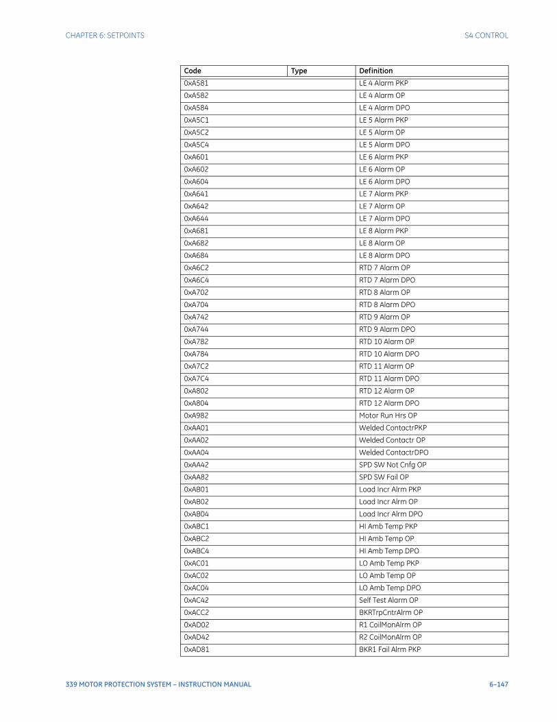
CHAPTER 6: SETPOINTS S4 CONTROL
339 MOTOR PROTECTION SYSTEM – INSTRUCTION MANUAL 6–147
0xA581 LE 4 Alarm PKP
0xA582 LE 4 Alarm OP
0xA584 LE 4 Alarm DPO
0xA5C1 LE 5 Alarm PKP
0xA5C2 LE 5 Alarm OP
0xA5C4 LE 5 Alarm DPO
0xA601 LE 6 Alarm PKP
0xA602 LE 6 Alarm OP
0xA604 LE 6 Alarm DPO
0xA641 LE 7 Alarm PKP
0xA642 LE 7 Alarm OP
0xA644 LE 7 Alarm DPO
0xA681 LE 8 Alarm PKP
0xA682 LE 8 Alarm OP
0xA684 LE 8 Alarm DPO
0xA6C2 RTD 7 Alarm OP
0xA6C4 RTD 7 Alarm DPO
0xA702 RTD 8 Alarm OP
0xA704 RTD 8 Alarm DPO
0xA742 RTD 9 Alarm OP
0xA744 RTD 9 Alarm DPO
0xA782 RTD 10 Alarm OP
0xA784 RTD 10 Alarm DPO
0xA7C2 RTD 11 Alarm OP
0xA7C4 RTD 11 Alarm DPO
0xA802 RTD 12 Alarm OP
0xA804 RTD 12 Alarm DPO
0xA982 Motor Run Hrs OP
0xAA01 Welded ContactrPKP
0xAA02 Welded Contactr OP
0xAA04 Welded ContactrDPO
0xAA42 SPD SW Not Cnfg OP
0xAA82 SPD SW Fail OP
0xAB01 Load Incr Alrm PKP
0xAB02 Load Incr Alrm OP
0xAB04 Load Incr Alrm DPO
0xABC1 HI Amb Temp PKP
0xABC2 HI Amb Temp OP
0xABC4 HI Amb Temp DPO
0xAC01 LO Amb Temp PKP
0xAC02 LO Amb Temp OP
0xAC04 LO Amb Temp DPO
0xAC42 Self Test Alarm OP
0xACC2 BKRTrpCntrAlrm OP
0xAD02 R1 CoilMonAlrm OP
0xAD42 R2 CoilMonAlrm OP
0xAD81 BKR1 Fail Alrm PKP
Code Type Definition
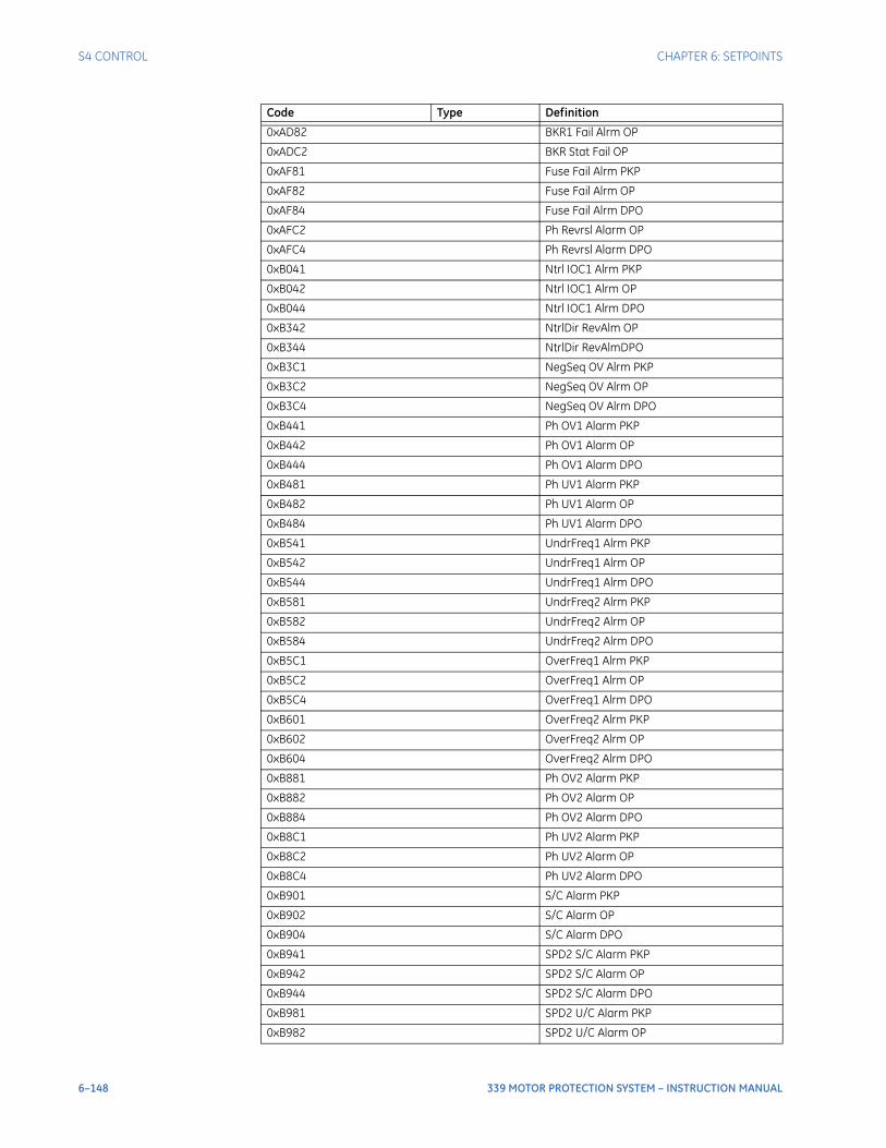
6–148 339 MOTOR PROTECTION SYSTEM – INSTRUCTION MANUAL
S4 CONTROL CHAPTER 6: SETPOINTS
0xAD82 BKR1 Fail Alrm OP
0xADC2 BKR Stat Fail OP
0xAF81 Fuse Fail Alrm PKP
0xAF82 Fuse Fail Alrm OP
0xAF84 Fuse Fail Alrm DPO
0xAFC2 Ph Revrsl Alarm OP
0xAFC4 Ph Revrsl Alarm DPO
0xB041 Ntrl IOC1 Alrm PKP
0xB042 Ntrl IOC1 Alrm OP
0xB044 Ntrl IOC1 Alrm DPO
0xB342 NtrlDir RevAlm OP
0xB344 NtrlDir RevAlmDPO
0xB3C1 NegSeq OV Alrm PKP
0xB3C2 NegSeq OV Alrm OP
0xB3C4 NegSeq OV Alrm DPO
0xB441 Ph OV1 Alarm PKP
0xB442 Ph OV1 Alarm OP
0xB444 Ph OV1 Alarm DPO
0xB481 Ph UV1 Alarm PKP
0xB482 Ph UV1 Alarm OP
0xB484 Ph UV1 Alarm DPO
0xB541 UndrFreq1 Alrm PKP
0xB542 UndrFreq1 Alrm OP
0xB544 UndrFreq1 Alrm DPO
0xB581 UndrFreq2 Alrm PKP
0xB582 UndrFreq2 Alrm OP
0xB584 UndrFreq2 Alrm DPO
0xB5C1 OverFreq1 Alrm PKP
0xB5C2 OverFreq1 Alrm OP
0xB5C4 OverFreq1 Alrm DPO
0xB601 OverFreq2 Alrm PKP
0xB602 OverFreq2 Alrm OP
0xB604 OverFreq2 Alrm DPO
0xB881 Ph OV2 Alarm PKP
0xB882 Ph OV2 Alarm OP
0xB884 Ph OV2 Alarm DPO
0xB8C1 Ph UV2 Alarm PKP
0xB8C2 Ph UV2 Alarm OP
0xB8C4 Ph UV2 Alarm DPO
0xB901 S/C Alarm PKP
0xB902 S/C Alarm OP
0xB904 S/C Alarm DPO
0xB941 SPD2 S/C Alarm PKP
0xB942 SPD2 S/C Alarm OP
0xB944 SPD2 S/C Alarm DPO
0xB981 SPD2 U/C Alarm PKP
0xB982 SPD2 U/C Alarm OP
Code Type Definition
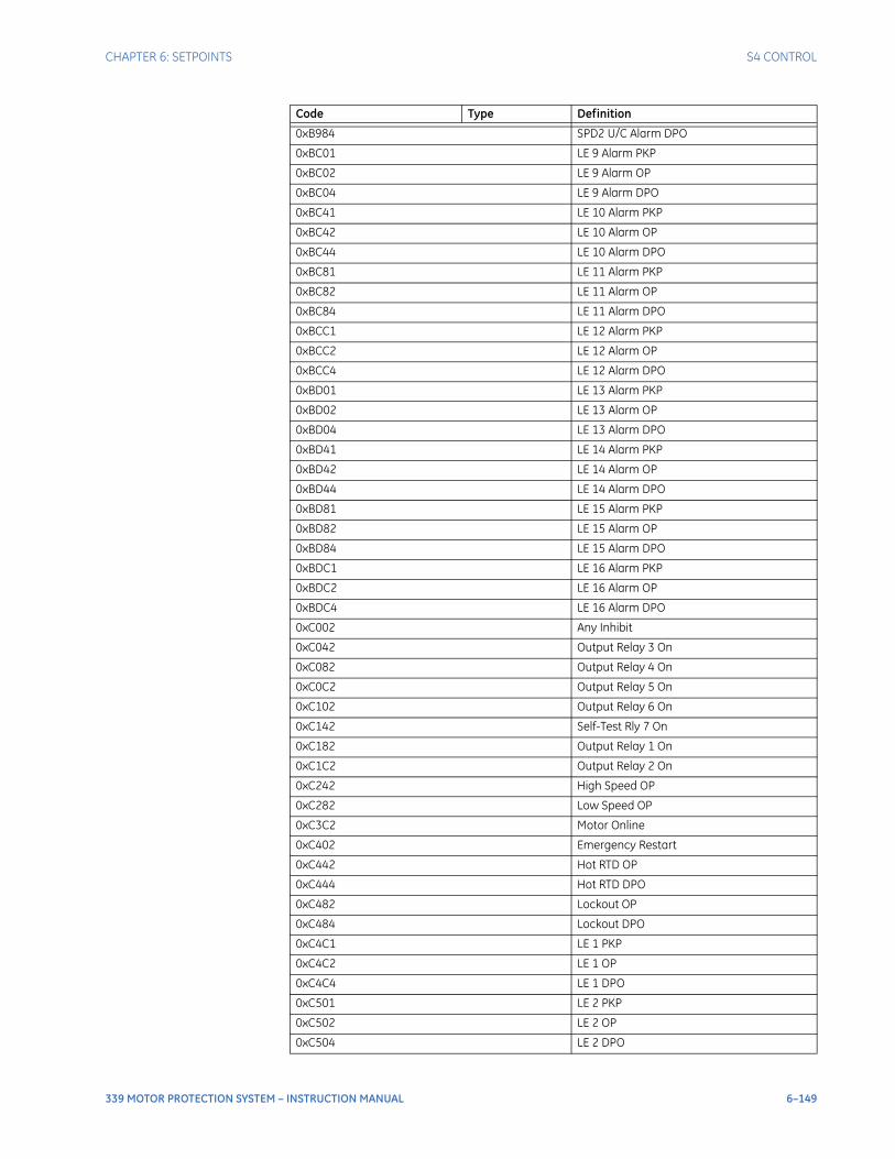
CHAPTER 6: SETPOINTS S4 CONTROL
339 MOTOR PROTECTION SYSTEM – INSTRUCTION MANUAL 6–149
0xB984 SPD2 U/C Alarm DPO
0xBC01 LE 9 Alarm PKP
0xBC02 LE 9 Alarm OP
0xBC04 LE 9 Alarm DPO
0xBC41 LE 10 Alarm PKP
0xBC42 LE 10 Alarm OP
0xBC44 LE 10 Alarm DPO
0xBC81 LE 11 Alarm PKP
0xBC82 LE 11 Alarm OP
0xBC84 LE 11 Alarm DPO
0xBCC1 LE 12 Alarm PKP
0xBCC2 LE 12 Alarm OP
0xBCC4 LE 12 Alarm DPO
0xBD01 LE 13 Alarm PKP
0xBD02 LE 13 Alarm OP
0xBD04 LE 13 Alarm DPO
0xBD41 LE 14 Alarm PKP
0xBD42 LE 14 Alarm OP
0xBD44 LE 14 Alarm DPO
0xBD81 LE 15 Alarm PKP
0xBD82 LE 15 Alarm OP
0xBD84 LE 15 Alarm DPO
0xBDC1 LE 16 Alarm PKP
0xBDC2 LE 16 Alarm OP
0xBDC4 LE 16 Alarm DPO
0xC002 Any Inhibit
0xC042 Output Relay 3 On
0xC082 Output Relay 4 On
0xC0C2 Output Relay 5 On
0xC102 Output Relay 6 On
0xC142 Self-Test Rly 7 On
0xC182 Output Relay 1 On
0xC1C2 Output Relay 2 On
0xC242 High Speed OP
0xC282 Low Speed OP
0xC3C2 Motor Online
0xC402 Emergency Restart
0xC442 Hot RTD OP
0xC444 Hot RTD DPO
0xC482 Lockout OP
0xC484 Lockout DPO
0xC4C1 LE 1 PKP
0xC4C2 LE 1 OP
0xC4C4 LE 1 DPO
0xC501 LE 2 PKP
0xC502 LE 2 OP
0xC504 LE 2 DPO
Code Type Definition
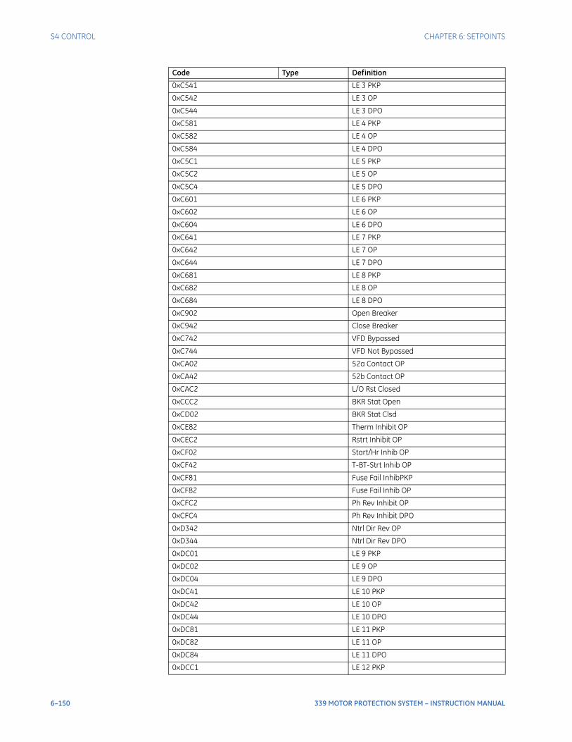
6–150 339 MOTOR PROTECTION SYSTEM – INSTRUCTION MANUAL
S4 CONTROL CHAPTER 6: SETPOINTS
0xC541 LE 3 PKP
0xC542 LE 3 OP
0xC544 LE 3 DPO
0xC581 LE 4 PKP
0xC582 LE 4 OP
0xC584 LE 4 DPO
0xC5C1 LE 5 PKP
0xC5C2 LE 5 OP
0xC5C4 LE 5 DPO
0xC601 LE 6 PKP
0xC602 LE 6 OP
0xC604 LE 6 DPO
0xC641 LE 7 PKP
0xC642 LE 7 OP
0xC644 LE 7 DPO
0xC681 LE 8 PKP
0xC682 LE 8 OP
0xC684 LE 8 DPO
0xC902 Open Breaker
0xC942 Close Breaker
0xC742 VFD Bypassed
0xC744 VFD Not Bypassed
0xCA02 52a Contact OP
0xCA42 52b Contact OP
0xCAC2 L/O Rst Closed
0xCCC2 BKR Stat Open
0xCD02 BKR Stat Clsd
0xCE82 Therm Inhibit OP
0xCEC2 Rstrt Inhibit OP
0xCF02 Start/Hr Inhib OP
0xCF42 T-BT-Strt Inhib OP
0xCF81 Fuse Fail InhibPKP
0xCF82 Fuse Fail Inhib OP
0xCFC2 Ph Rev Inhibit OP
0xCFC4 Ph Rev Inhibit DPO
0xD342 Ntrl Dir Rev OP
0xD344 Ntrl Dir Rev DPO
0xDC01 LE 9 PKP
0xDC02 LE 9 OP
0xDC04 LE 9 DPO
0xDC41 LE 10 PKP
0xDC42 LE 10 OP
0xDC44 LE 10 DPO
0xDC81 LE 11 PKP
0xDC82 LE 11 OP
0xDC84 LE 11 DPO
0xDCC1 LE 12 PKP
Code Type Definition
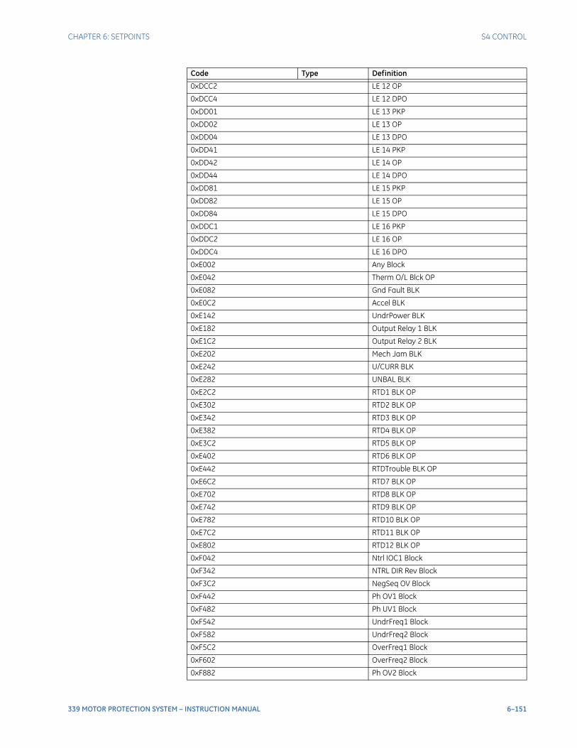
CHAPTER 6: SETPOINTS S4 CONTROL
339 MOTOR PROTECTION SYSTEM – INSTRUCTION MANUAL 6–151
0xDCC2 LE 12 OP
0xDCC4 LE 12 DPO
0xDD01 LE 13 PKP
0xDD02 LE 13 OP
0xDD04 LE 13 DPO
0xDD41 LE 14 PKP
0xDD42 LE 14 OP
0xDD44 LE 14 DPO
0xDD81 LE 15 PKP
0xDD82 LE 15 OP
0xDD84 LE 15 DPO
0xDDC1 LE 16 PKP
0xDDC2 LE 16 OP
0xDDC4 LE 16 DPO
0xE002 Any Block
0xE042 Therm O/L Blck OP
0xE082 Gnd Fault BLK
0xE0C2 Accel BLK
0xE142 UndrPower BLK
0xE182 Output Relay 1 BLK
0xE1C2 Output Relay 2 BLK
0xE202 Mech Jam BLK
0xE242 U/CURR BLK
0xE282 UNBAL BLK
0xE2C2 RTD1 BLK OP
0xE302 RTD2 BLK OP
0xE342 RTD3 BLK OP
0xE382 RTD4 BLK OP
0xE3C2 RTD5 BLK OP
0xE402 RTD6 BLK OP
0xE442 RTDTrouble BLK OP
0xE6C2 RTD7 BLK OP
0xE702 RTD8 BLK OP
0xE742 RTD9 BLK OP
0xE782 RTD10 BLK OP
0xE7C2 RTD11 BLK OP
0xE802 RTD12 BLK OP
0xF042 Ntrl IOC1 Block
0xF342 NTRL DIR Rev Block
0xF3C2 NegSeq OV Block
0xF442 Ph OV1 Block
0xF482 Ph UV1 Block
0xF542 UndrFreq1 Block
0xF582 UndrFreq2 Block
0xF5C2 OverFreq1 Block
0xF602 OverFreq2 Block
0xF882 Ph OV2 Block
Code Type Definition
6–152 339 MOTOR PROTECTION SYSTEM – INSTRUCTION MANUAL
S4 CONTROL CHAPTER 6: SETPOINTS
Breaker failure / Welded contactorThe Breaker Failure or Welded Contactor function monitors the phase currents, after a trip command from the protection elements is initiated, or a logic operand programmed as BF EXT INITIATE / WELDED EXT INI is asserted. The external initiating logic operand can be a Contact Input, a Virtual Input, a Remote Input, or an output from a Logic Element. If any phase current is above the set current level after the programmed time delay, a BREAKER FAILURE will be declared when BREAKER was chosen for SWITCHING DEVICE, or a WELDED CONTACTOR will be declared when CONTACTOR was chosen for SWITCHING DEVICE, and the selected output relays will be activated. The time delay should be set slightly longer than the breaker or contactor operating time.To provide user flexibility, the 339 has included two programmable timers for the Breaker Failure / Welded Contactor function. The timers can be used singularly or in combination with each other. BF/Welded Time Delay 1 starts counting down once a trip condition is recognized or the programmed logic operand is asserted. BF/Welded Time Delay 2 does not begin counting down until BF/Welded Time Delay 1 has expired and one of the phase currents is above the setting BF/Welded Current. If one of the delays is not required, simply program the unwanted timer to its minimum value.
NOTE
NOTE: When the switching device is selected as CONTACTOR, this feature is displayed as WELDED CONTACTOR.
The following path is available using the keypad. For instructions on how to use the keypad, please refer to Chapter 3 - Working with the Keypad.PATH: SETPOINTS > S4 CONTROLS > BREAKER FAIL (WELDED CONTACTOR)
BF FUNCTION / WELDED CONT FUNCRange: Disabled, Alarm, Latched AlarmDefault: Disabled
This setting enables the Breaker failure or Welded Contactor functionality. If the operating condition is satisfied when ALARM is selected as the function, the LED “ALARM” will flash upon the activating condition, and will automatically reset when the condition clears. If Latched Alarm is selected, the LED “ALARM” will flash upon the activating condition, and will stay “ON” after the condition clears, until a reset command is initiated. Any assignable output relays can be selected to operate when this function is enabled.
BF CURRENT / WELDED CURRENTRange: 0.05 to 20.00 x CT in steps of 0.01Default: 1.00 x CT
This setting specifies the current level monitored by the Breaker Failure / Welded Contactor logic. Program this setting to a current level that can detect the lowest expected fault current on the protected breaker/contactor.
0xF8C2 Ph UV2 Block
0xF902 S/C BLK
0xF942 SPD2 S/C BLK
0xF982 SPD2 U/C BLK OP
Code Type Definition
CHAPTER 6: SETPOINTS S4 CONTROL
339 MOTOR PROTECTION SYSTEM – INSTRUCTION MANUAL 6–153
BF EXT INITIATE / WELDED EXT INIRange: Off, Contact Input 1 to 10, Virtual Input 1 to 32, Remote Input 1 to 32, Logic Element 1 to 16Default: Off
This setting allows the user to select a logic operand to externally initiate the Breaker Failure / Welded Contactor logic.
BF TIME DELAY 1 / WELDED TIME DELAY 1Range: 0.03 to 1.00 s in steps of 0.01 sDefault: 0.10 s
This timer starts when breaker trip command is issued from any of the protection elements, or a programmed external initiating logic operand is asserted.
BF TIME DELAY 2 / WELDED TIME DELAY 2Range: 0.00 to 1.00 s in steps of 0.01 sDefault: 0.00 s
This timer does not start until a trip command is recognized, timer BF / WELDED TIME DELAY1 has expired, and at least one of the phase currents is above the setting BF / WELDED CURRENT.
OUTPUT RELAY 4 to 6 / OUTPUT RELAY 5 to 6Range: Do not operate, OperateDefault: Do not operate
Any assignable output relay can be selected to operate upon Breaker Failure / Welded Contactor operation. When the SWITCHING DEVICE is selected as BREAKER, the assignable output relays will be Output Relay 4 to 6. When the SWITCHING DEVICE is selected as CONTACTOR, the assignable output relays will be Output Relay 5 to 6.
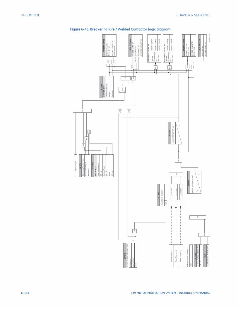
6–154 339 MOTOR PROTECTION SYSTEM – INSTRUCTION MANUAL
S4 CONTROL CHAPTER 6: SETPOINTS
Figure 6-48: Breaker Failure / Welded Contactor logic diagram
LOG
ICO
PE
RA
ND
BF
AL
AR
MO
P
AN
YA
LA
RM
OP
AN
YL
ATC
HE
DA
LA
RM
OP
WE
LD
ED
AL
AR
MO
P
S R
LA
TC
H
AN
D
AN
D
AN
D
INP
UT
S
Em
erg
en
cy
Re
sta
rt
Inp
ut
Lo
ck
ou
tR
ese
tIn
pu
t
SE
TT
ING
S
Off
=0
Lo
ck
ou
tR
ese
t
Off
=0
Em
erg
en
cy
Re
sta
rt
S4
CO
NT
RO
LS
Re
se
tIn
pu
t
Re
se
t
Off
=0
AN
D
OR
KE
YP
AD
RE
SE
T
Op
era
te
Ou
tpu
tR
ela
ys
Up
on
Se
lec
tio
n
OU
TP
UT
RE
LA
Y4
OU
TP
UT
RE
LA
Y5
OU
TP
UT
RE
LA
Y6
AS
SIG
NA
BL
EA
UX
RE
LA
YS
Op
era
te
Ou
tpu
tR
ela
ys
Up
on
Se
lec
tio
n
OU
TP
UT
RE
LA
Y5
OU
TP
UT
RE
LA
Y6
AS
SIG
NA
BL
EA
UX
RE
LA
YS
SE
TT
I NG
RU
N
BF
/W
EL
DE
DC
UR
RE
NT
I>
PIC
KU
PbI
>P
ICK
UP
a
BF
/W
EL
DE
DT
IME
DE
LA
Y2
SE
TT
I NG
t PK
P
0
LOG
ICO
PE
RA
ND
WE
LD
ED
AL
AR
MP
KP
BF
AL
AR
MP
KP
AN
D
BR
EA
KE
RFA
ILU
RE
Sta
te:O
pe
rate
TAR
GE
TM
ES
SA
GE
BR
EA
KE
RFA
ILU
RE
Sta
te:P
icku
p
TAR
GE
TM
ES
SA
GE
WE
LD
ED
CO
NTA
CTO
R
Sta
te:P
icku
p
WE
LD
ED
CO
NTA
CTO
R
Sta
te:O
pe
rate
SE
TT
ING
Dis
ab
led
=0
BF
FU
NC
TIO
N/W
EL
DE
DC
ON
TF
UN
C
OR
89
68
24
.cd
r
SE
TT
I NG
SW
ITC
HIN
GD
EV
ICE
Bre
ake
r
Co
nta
cto
r
S2
SY
ST
EM
SE
TU
P
I>
PIC
KU
Pc
OR
AN
D
AN
D
AN
D
AN
D
AN
D
AN
D
AN
D
OR
OR
AN
D
AN
D
SE
TT
I NG
Off
=0
BF
EX
TIN
ITIA
TE
/W
EL
DE
DE
XT
INI
INP
UT
BF
/W
EL
DE
DE
XT
INIT
IAT
EIN
PU
T
TR
IP
Fro
mP
rote
cti
on
Op
era
tio
n
OR
AN
D
BF
/W
EL
DE
DT
IME
DE
LA
Y1
SE
TT
ING
t PK
P
0
La
tch
ed
Ala
rm
Ala
rm
Ph
ase
AC
urr
en
t(I
)a
Ph
ase
BC
urr
en
t(I
)b
Ph
ase
CC
urr
en
t(I
)c
CHAPTER 6: SETPOINTS S4 CONTROL
339 MOTOR PROTECTION SYSTEM – INSTRUCTION MANUAL 6–155
Start inhibitThermal Start InhibitThis function is provided to inhibit starting of a motor if there is insufficient thermal capacity available for a successful start. The motor start inhibit logic algorithm is defined by the Thermal Inhibit setpoint. If this setpoint is set to “0”, starts are inhibited until thermal capacity used decays to a level of 15%. If this setpoint is set greater than zero, starts are inhibited while the available thermal capacity is less than the learned thermal capacity used at start.
NOTE
NOTE: The margin should be set to zero if the load varies for different starts.
The learned thermal capacity used at start is the largest thermal capacity used value calculated by the thermal model from the last five successful starts, plus a settable margin. The margin is a percentage of this largest of five. A successful motor start is one in which the motor reaches the Running state. See the Start/Stop section of this manual for a description of Running state logic. When the motor information is reset, a value of 85% is used for the learned thermal capacity used until displaced by 5 subsequent successful starts. This 85% default requires the thermal capacity used to decay to the same 15% level required when the margin setting is zero.For example, if the thermal capacity used for the last 5 starts is 24, 23, 27, 26 and 20% respectively, and the set margin is 25%, the learned starting capacity used at start is Maximum(24%+23%+27%+26%+20%) x (1+25%/100%) = 34%. If the motor stops with a thermal capacity used of 90%, a start inhibit will be issued until the motor cools to 100% - 34% = 66%. If the stopped cool time constant is set to 30 minutes, the inhibit time will be:
Eq. 19
If instead the set margin is zero, the inhibit time will be:
Eq. 20
Starts per Hour InhibitThis element defines the number of start attempts allowed in any 60 minutes interval. Once the set number of starts has occurred in the last 60 minutes, start controls are inhibited until the oldest start contributing to the inhibit is more than 60 minutes old. This element assumes a motor start is occurring when the relay measures the transition of no motor current to some value of motor current. At this point, one of the Starts/Hour timers is loaded with 60 minutes. Even unsuccessful start attempts will be logged as starts for this feature. Once the motor is stopped, the number of starts within the past hour is compared to the number of starts allowable. If the two numbers are the same, the Start Inhibit Output Relay will be activated to block the motor start. If a block occurs, the lockout time will be equal to the longest time elapsed since a start within the past hour, subtracted from one hour.For example, if STARTS/HOUR LIMIT is programmed at “2”:
• One start occurs at T = 0 minutes
• A second start occurs at T = 17 minutes
• The motor is stopped at T = 33 minutes
• A block occurs
• The lockout time would be 1 hour – 33minutes = 27 minutes
Time Between Starts Inhibit
6–156 339 MOTOR PROTECTION SYSTEM – INSTRUCTION MANUAL
S4 CONTROL CHAPTER 6: SETPOINTS
This function enforces a settable minimum time duration between two successive start attempts. A time delay is initiated with every start attempt, and a restart is not allowed until the specified interval has lapsed. This timer feature may be useful in enforcing the duty limits of starting resistors or starting autotransformers. It may also be used to restrict jogging.This element assumes a motor start is occurring when the relay measures the transition of no motor current to some value of motor current. At this point, the Time Between Starts timer is loaded with the entered time. Even unsuccessful start attempts will be logged as starts for this feature. Once the motor is stopped, if the time elapsed since the most recent start is less than the TIME BETWEEN START setting, the Start Inhibit Output Relay will be activated to block the motor start. If a block occurs, the lockout time will be equal to the time elapsed since the most recent start subtracted from the TIME BETWEEN START setting.For example, if TIME BETWEEN START is programmed as 25 min:
• A start occurs at T = 0 minutes
• The motor is stopped at T = 12 minutes
• A block occurs
• The lockout time would be 25 minutes – 12 minutes = 13 minutes
Restart InhibitThe Restart Inhibit feature may be used to ensure that a certain amount of time passes between the time a motor is stopped and the restarting of that motor. This timer feature may be very useful for some process applications or motor considerations. If a motor is on a down-hole pump, after the motor stops, the liquid may fall back down the pipe and spin the rotor backwards. It would be very undesirable to start the motor at this time.
NOTE
NOTE: This element assumes a motor stop is occurring when the relay measures the transition of some value of motor current to no motor current.
NOTE
NOTE: For each of these features, non-volatile memory is used to make it behave as if it continues to operate while control power is lost.
THERMAL INHIBITRange: OFF, 0 to 25% in steps of 1%Default: 10%
OFF disables thermal start inhibits. 0% causes starts to be inhibited until the value of thermal capacity used calculated by the thermal model drops to 15% or less. Setting values in the range of 1 to 25% specify the margin to be included in the calculation of the learned thermal capacity used at start, and cause starts to be inhibited until the value of thermal capacity used drops to the learned thermal capacity used at start or less.
STARTS/HOUR LIMITRange: OFF, 1 to 5 in steps of 1Default: OFF
Sets the number of starts in the last 60 minutes at which count start control is inhibited. OFF defeats this feature.
TIME BETWEEN STARTSRange: OFF, 1 to 3600 s in steps of 1 sDefault: OFF
Sets the amount of time following a start before the next start control is permitted to prevent restart attempts in quick succession (jogging). OFF defeats this feature.
CHAPTER 6: SETPOINTS S4 CONTROL
339 MOTOR PROTECTION SYSTEM – INSTRUCTION MANUAL 6–157
RESTART INHIBITRange: OFF, 1 to 50000 s in steps of 1 sDefault: OFF
Sets the amount of time following a stop before a start control is permitted. OFF defeats this feature.
OUTPUT RELAY 3Range: Operate, Do Not OperateDefault: Operate
Only shown if INPUT/OUTPUT option ‘R’ is installed and SWITCHING DEVICE is programmed as CONTACTOR.
This output relay can be selected to operate while any Start Inhibit is active. This setpoint is available only with 339 INPUT/OUTPUT option ‘R’, and when the SWITCHING DEVICE is selected as CONTACTOR, otherwise Output Relay 3 will be automatically assigned for Start Inhibits. If this output relay is programmed to OPERATE, it is recommended that the OUTPUT TYPE be programmed to SELF-RESET in S5 OUTPUT RELAYS > RLY3 AUXILIARY.
Refer to the S5 OUTPUT RELAYS section for details on Start Inhibit relay wiring and logic diagrams.
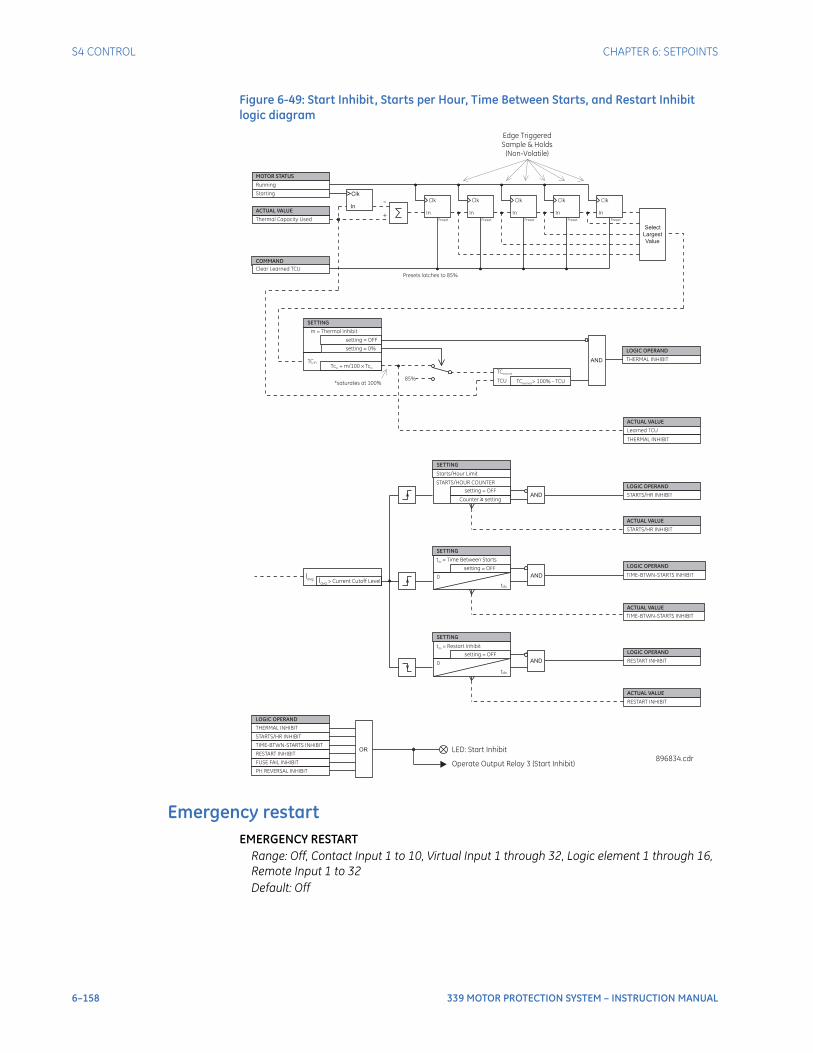
6–158 339 MOTOR PROTECTION SYSTEM – INSTRUCTION MANUAL
S4 CONTROL CHAPTER 6: SETPOINTS
Figure 6-49: Start Inhibit, Starts per Hour, Time Between Starts, and Restart Inhibit logic diagram
Emergency restartEMERGENCY RESTART
Range: Off, Contact Input 1 to 10, Virtual Input 1 through 32, Logic element 1 through 16, Remote Input 1 to 32Default: Off
STARTS/HOUR COUNTER
SETTING
t = Time Between Startsdo
0
tdo
LOGIC OPERAND
TIME-BTWN-STARTS INHIBIT
ACTUAL VALUE
TIME-BTWN-STARTS INHIBIT
setting = OFF
ANDI
avg> Current Cutoff Level
Iavg
SETTING
t = Restart Inhibitdo
0
tdo
LOGIC OPERAND
RESTART INHIBIT
ACTUAL VALUE
RESTART INHIBIT
setting = OFF
AND
Starts/Hour Limit
ACTUAL VALUE
STARTS/HR INHIBIT
Counter setting≥AND
setting = OFF
SETTING
LOGIC OPERAND
STARTS/HR INHIBIT
MOTOR STATUS
Running
Starting Clk
In
Thermal Capacity Used
-
+
Clk
In
Clk
In
Clk
In
Clk
In
Clk
In
Select
Largest
Value
Edge Triggered
Sample & Holds
(Non-Volatile)
SETTING
m = Thermal Inhibit
setting = OFF
setting = 0%
TCin
LOGIC OPERAND
THERMAL INHIBIT
ACTUAL VALUE
ACTUAL VALUE
ANDTc + m/100 x Tc
in in
TClearned
TCU85%
Learned TCU
*saturates at 100%
COMMAND
Clear Learned TCU
Preset PresetPresetPresetPreset
Presets latches to 85%
THERMAL INHIBIT
896834.cdr
TC > 100% - TCUlearned
LOGIC OPERAND
THERMAL INHIBIT
STARTS/HR INHIBIT
TIME-BTWN-STARTS INHIBIT
RESTART INHIBIT
FUSE FAIL INHIBIT
PH REVERSAL INHIBIT
OR LED: Start Inhibit
Operate Output Relay 3 (Start Inhibit)
CHAPTER 6: SETPOINTS S4 CONTROL
339 MOTOR PROTECTION SYSTEM – INSTRUCTION MANUAL 6–159
CAUTION: All relay protection is defeated while the Emergency Restart contact input is closed.
Emergency restart is for use in situations where continuation of the process driven by the motor is more important than protecting the motor itself. Closing this contact input discharges the thermal capacity used register to zero, resets the Starts/Hour Block count, resets the Time Between Starts Block timer, and resets all trips and alarms so that a hot motor may be restarted. Therefore, while the Emergency Restart contact input terminals are shorted, the trip output relay will remain in its normal non-trip state. As the name implies, this feature should only be used in an emergency – using it otherwise defeats the purpose of the relay, namely, protecting the motor.
Lockout resetLOCKOUT RESET
Range: Off, Contact Input 1 to 10, Virtual Input 1 through 32, Logic element 1 through 16, Remote Input 1 to 32Default: Off
Closing this contact input resets any lockouts, as well as any trips or latched alarms provided that the condition that caused the lockout, alarm or trip is no longer present. If there is a lockout time pending, the start inhibit output will not reset until the lockout time has expired.
ResetRESET
Range: Off, Contact Input 1 to 10, Virtual Input 1 through 32, Logic element 1 through 16, Remote Input 1 to 32Default: Off
Reset allows a pushbutton or other device located external to the relay to perform the same functions as the reset pushbutton on the relay faceplate. Closing this contact input resets any trips or latched alarms provided that the condition that caused the alarm or trip is no longer present. Lockouts and start inhibits are also reset if the lockout reset setting is Off.
Breaker controlThe Breaker Control menu is designed to trip and close the breaker from the relay either remotely (LOCAL MODE setting set to "OFF," or the selected contact input deselected) or locally (the input from the LOCAL MODE setpoint asserted). While in LOCAL MODE, the REMOTE OPEN and CLOSE setpoints are not active.
NOTE
NOTE: The Breaker Control feature is available only when the SWITCHING DEVICE is selected as BREAKER.
The following path is available using the keypad. For instructions on how to use the keypad, please refer to Chapter 3 - Working with the Keypad.PATH: SETPOINTS > S4 CONTROLS > BREAKER CONTROL
LOCAL MODERange: Off, Contact Input 1 to 10, Virtual Input 1 to 32, Remote Input 1 to 32, Logic Elements 1 to 16Default: Off
The LOCAL MODE setting places the relay in local mode. The relay is in Remote Mode, if not forced into Local Mode by this setpoint (i.e. LOCAL MODE set to "OFF," or the selected input de-asserted).
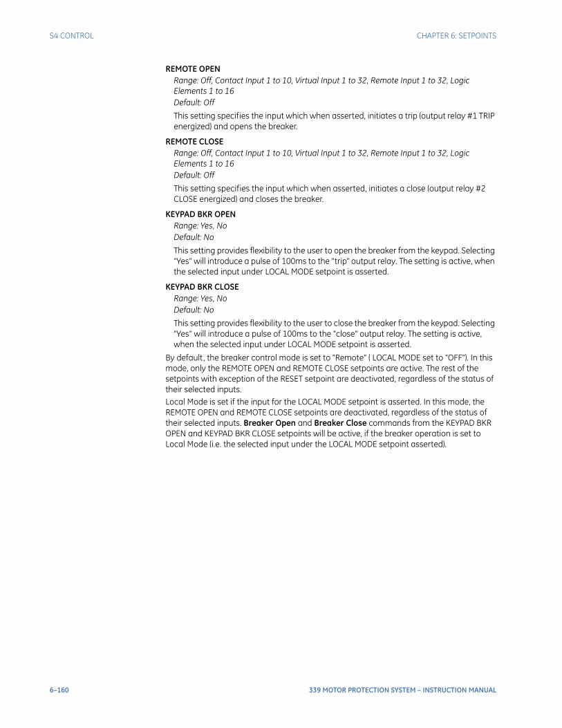
6–160 339 MOTOR PROTECTION SYSTEM – INSTRUCTION MANUAL
S4 CONTROL CHAPTER 6: SETPOINTS
REMOTE OPENRange: Off, Contact Input 1 to 10, Virtual Input 1 to 32, Remote Input 1 to 32, Logic Elements 1 to 16Default: Off
This setting specifies the input which when asserted, initiates a trip (output relay #1 TRIP energized) and opens the breaker.
REMOTE CLOSERange: Off, Contact Input 1 to 10, Virtual Input 1 to 32, Remote Input 1 to 32, Logic Elements 1 to 16Default: Off
This setting specifies the input which when asserted, initiates a close (output relay #2 CLOSE energized) and closes the breaker.
KEYPAD BKR OPENRange: Yes, NoDefault: No
This setting provides flexibility to the user to open the breaker from the keypad. Selecting “Yes” will introduce a pulse of 100ms to the "trip" output relay. The setting is active, when the selected input under LOCAL MODE setpoint is asserted.
KEYPAD BKR CLOSERange: Yes, NoDefault: No
This setting provides flexibility to the user to close the breaker from the keypad. Selecting “Yes” will introduce a pulse of 100ms to the "close" output relay. The setting is active, when the selected input under LOCAL MODE setpoint is asserted.
By default, the breaker control mode is set to "Remote" ( LOCAL MODE set to "OFF"). In this mode, only the REMOTE OPEN and REMOTE CLOSE setpoints are active. The rest of the setpoints with exception of the RESET setpoint are deactivated, regardless of the status of their selected inputs. Local Mode is set if the input for the LOCAL MODE setpoint is asserted. In this mode, the REMOTE OPEN and REMOTE CLOSE setpoints are deactivated, regardless of the status of their selected inputs. Breaker Open and Breaker Close commands from the KEYPAD BKR OPEN and KEYPAD BKR CLOSE setpoints will be active, if the breaker operation is set to Local Mode (i.e. the selected input under the LOCAL MODE setpoint asserted).
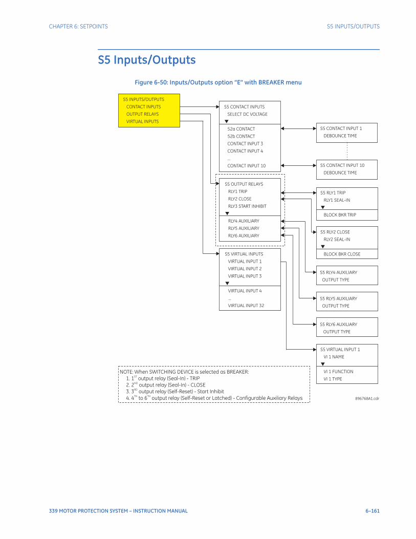
CHAPTER 6: SETPOINTS S5 INPUTS/OUTPUTS
339 MOTOR PROTECTION SYSTEM – INSTRUCTION MANUAL 6–161
S5 Inputs/Outputs
Figure 6-50: Inputs/Outputs option “E” with BREAKER menu
S5 CONTACT INPUTS
SELECT DC VOLTAGE
52a CONTACT
52b CONTACT
CONTACT INPUT 3
...
CONTACT INPUT 10
CONTACT INPUT 4
S5 INPUTS/OUTPUTS
CONTACT INPUTS
OUTPUT RELAYS
VIRTUAL INPUTS
896768A1.cdr
S5 OUTPUT RELAYS
RLY1 TRIP
RLY2 CLOSE
RLY3 START INHIBIT
RLY4 AUXILIARY
RLY5 AUXILIARY
RLY6 AUXILIARY
S5 VIRTUAL INPUTS
VIRTUAL INPUT 1
VIRTUAL INPUT 2
VIRTUAL INPUT 3
VIRTUAL INPUT 4
...
VIRTUAL INPUT 32
S5 RLY6 AUXILIARY
OUTPUT TYPE
S5 RLY2 CLOSE
RLY2 SEAL-IN
BLOCK BKR CLOSE
S5 RLY1 TRIP
RLY1 SEAL-IN
BLOCK BKR TRIP
S5 CONTACT INPUT 10
DEBOUNCE TIME
S5 CONTACT INPUT 1
DEBOUNCE TIME
S5 RLY4 AUXILIARY
OUTPUT TYPE
S5 RLY5 AUXILIARY
OUTPUT TYPE
S5 VIRTUAL INPUT 1
VI 1 NAME
VI 1 FUNCTION
VI 1 TYPE
NOTE: When SWITCHING DEVICE is selected as BREAKER:
1. 1 output relay (Seal-In) - TRIP
2.
ST
2 output relay (Seal-In) - CLOSE
3. 3 output relay (Self-Reset) - Start Inhibit
4. 4 to 6 output relay (Self-Reset or Latched) - Configurable Auxiliary Relays
ND
RD
TH TH
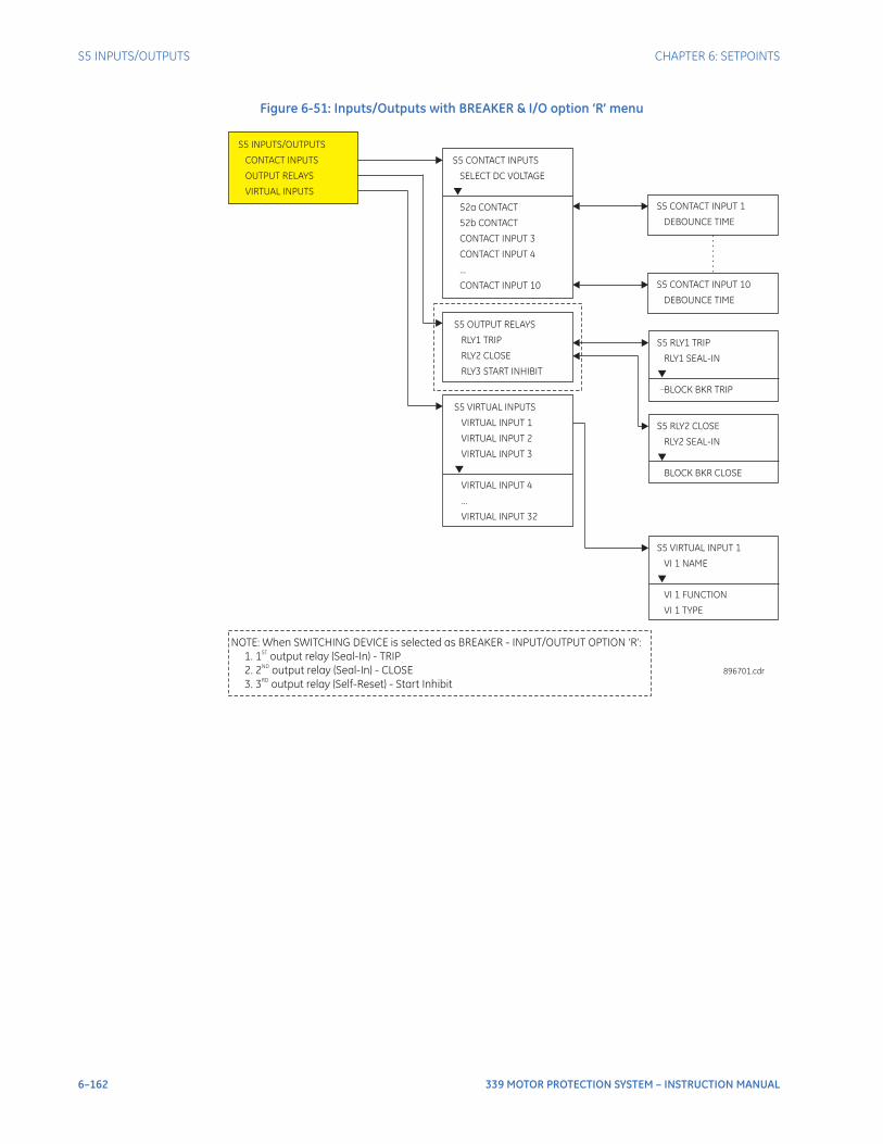
6–162 339 MOTOR PROTECTION SYSTEM – INSTRUCTION MANUAL
S5 INPUTS/OUTPUTS CHAPTER 6: SETPOINTS
Figure 6-51: Inputs/Outputs with BREAKER & I/O option ‘R’ menu
S5 CONTACT INPUTS
SELECT DC VOLTAGE
52a CONTACT
52b CONTACT
CONTACT INPUT 3
...
CONTACT INPUT 10
CONTACT INPUT 4
S5 INPUTS/OUTPUTS
CONTACT INPUTS
OUTPUT RELAYS
VIRTUAL INPUTS
896701.cdr
S5 OUTPUT RELAYS
RLY1 TRIP
RLY2 CLOSE
RLY3 START INHIBIT
S5 VIRTUAL INPUTS
VIRTUAL INPUT 1
VIRTUAL INPUT 2
VIRTUAL INPUT 3
VIRTUAL INPUT 4
...
VIRTUAL INPUT 32
S5 RLY2 CLOSE
RLY2 SEAL-IN
BLOCK BKR CLOSE
S5 RLY1 TRIP
RLY1 SEAL-IN
BLOCK BKR TRIP
S5 CONTACT INPUT 10
DEBOUNCE TIME
S5 CONTACT INPUT 1
DEBOUNCE TIME
S5 VIRTUAL INPUT 1
VI 1 NAME
VI 1 FUNCTION
VI 1 TYPE
NOTE: When SWITCHING DEVICE is selected as BREAKER - INPUT/OUTPUT OPTION ‘R’:
1. 1 output relay (Seal-In) - TRIP
2.
ST
2 output relay (Seal-In) - CLOSE
3. 3 output relay (Self-Reset) - Start Inhibit
ND
RD
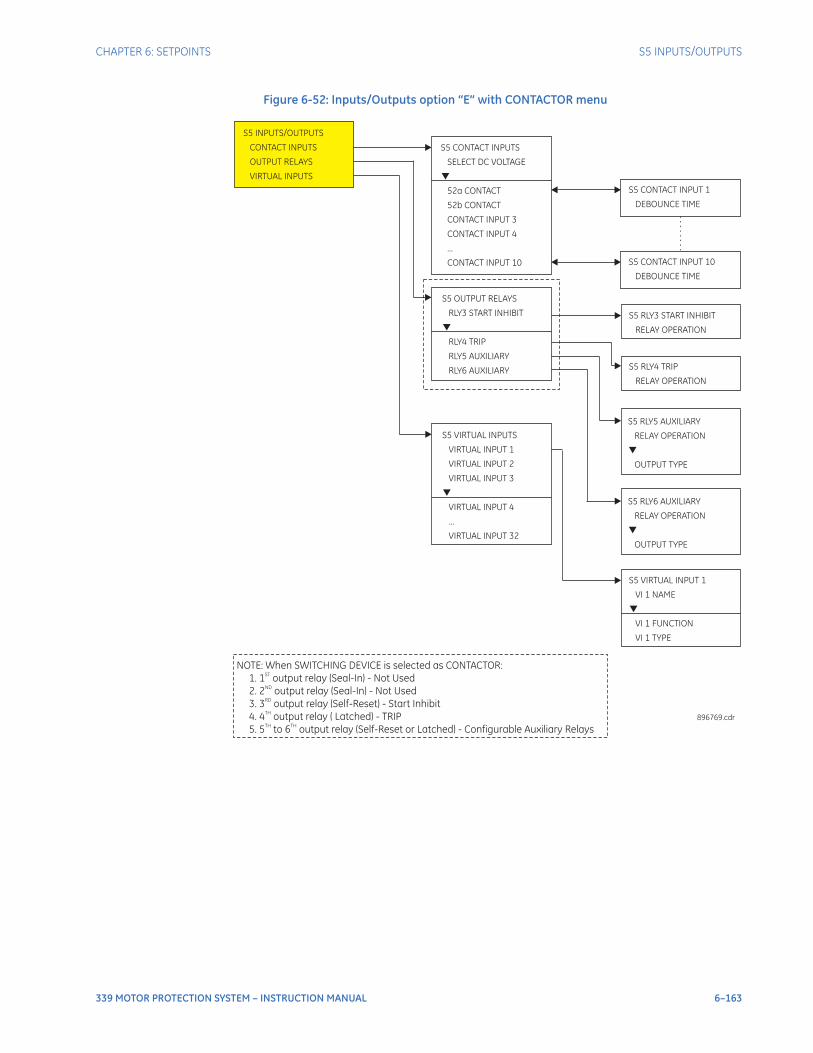
CHAPTER 6: SETPOINTS S5 INPUTS/OUTPUTS
339 MOTOR PROTECTION SYSTEM – INSTRUCTION MANUAL 6–163
Figure 6-52: Inputs/Outputs option “E” with CONTACTOR menu
S5 CONTACT INPUTS
SELECT DC VOLTAGE
52a CONTACT
52b CONTACT
CONTACT INPUT 3
...
CONTACT INPUT 10
CONTACT INPUT 4
S5 INPUTS/OUTPUTS
CONTACT INPUTS
OUTPUT RELAYS
VIRTUAL INPUTS
896769.cdr
S5 OUTPUT RELAYS
RLY3 START INHIBIT
RLY4 TRIP
RLY5 AUXILIARY
RLY6 AUXILIARY
S5 VIRTUAL INPUTS
VIRTUAL INPUT 1
VIRTUAL INPUT 2
VIRTUAL INPUT 3
VIRTUAL INPUT 4
...
VIRTUAL INPUT 32
S5 RLY3 START INHIBIT
RELAY OPERATION
S5 CONTACT INPUT 10
DEBOUNCE TIME
S5 CONTACT INPUT 1
DEBOUNCE TIME
S5 RLY5 AUXILIARY
RELAY OPERATION
OUTPUT TYPE
S5 VIRTUAL INPUT 1
VI 1 NAME
VI 1 FUNCTION
VI 1 TYPE
NOTE: When SWITCHING DEVICE is selected as CONTACTOR:
1. 1 output relay (Seal-In) - Not Used
2.
ST
2 output relay (Seal-In) - Not Used
3. 3 output relay (Self-Reset) - Start Inhibit
4. 4 output relay ( Latched) - TRIP
5. 5 to 6 output relay (Self-Reset or Latched) - Configurable Auxiliary Relays
ND
RD
TH
TH TH
S5 RLY4 TRIP
RELAY OPERATION
S5 RLY6 AUXILIARY
RELAY OPERATION
OUTPUT TYPE
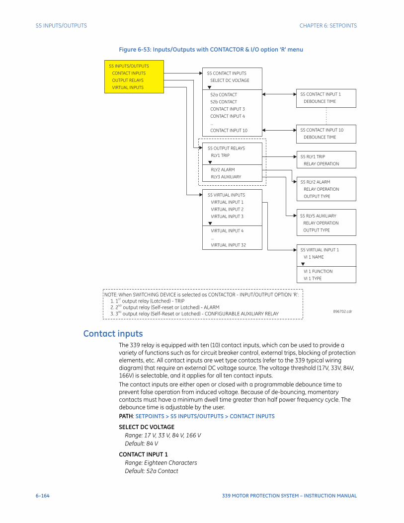
6–164 339 MOTOR PROTECTION SYSTEM – INSTRUCTION MANUAL
S5 INPUTS/OUTPUTS CHAPTER 6: SETPOINTS
Figure 6-53: Inputs/Outputs with CONTACTOR & I/O option ‘R’ menu
Contact inputsThe 339 relay is equipped with ten (10) contact inputs, which can be used to provide a variety of functions such as for circuit breaker control, external trips, blocking of protection elements, etc. All contact inputs are wet type contacts (refer to the 339 typical wiring diagram) that require an external DC voltage source. The voltage threshold (17V, 33V, 84V, 166V) is selectable, and it applies for all ten contact inputs. The contact inputs are either open or closed with a programmable debounce time to prevent false operation from induced voltage. Because of de-bouncing, momentary contacts must have a minimum dwell time greater than half power frequency cycle. The debounce time is adjustable by the user.PATH: SETPOINTS > S5 INPUTS/OUTPUTS > CONTACT INPUTS
SELECT DC VOLTAGERange: 17 V, 33 V, 84 V, 166 VDefault: 84 V
CONTACT INPUT 1Range: Eighteen CharactersDefault: 52a Contact
S5 CONTACT INPUTS
SELECT DC VOLTAGE
52a CONTACT
52b CONTACT
CONTACT INPUT 3
...
CONTACT INPUT 10
CONTACT INPUT 4
S5 INPUTS/OUTPUTS
CONTACT INPUTS
OUTPUT RELAYS
VIRTUAL INPUTS
896702.cdr
S5 OUTPUT RELAYS
RLY1 TRIP
RLY2 ALARM
RLY3 AUXILIARY
S5 VIRTUAL INPUTS
VIRTUAL INPUT 1
VIRTUAL INPUT 2
VIRTUAL INPUT 3
VIRTUAL INPUT 4
...
VIRTUAL INPUT 32
S5 RLY1 TRIP
RELAY OPERATION
S5 CONTACT INPUT 10
DEBOUNCE TIME
S5 CONTACT INPUT 1
DEBOUNCE TIME
S5 RLY5 AUXILIARY
RELAY OPERATION
OUTPUT TYPE
S5 VIRTUAL INPUT 1
VI 1 NAME
VI 1 FUNCTION
VI 1 TYPE
NOTE: When SWITCHING DEVICE is selected as CONTACTOR - INPUT/OUTPUT OPTION ‘R’:
1. 1 output relay (Latched) - TRIP
2.
ST
2 output relay (Self-reset or Latched) - ALARM
3. 3 output relay (Self-Reset or Latched) - CONFIGURABLE AUXILIARY RELAY
ND
RD
S5 RLY2 ALARM
RELAY OPERATION
OUTPUT TYPE
CHAPTER 6: SETPOINTS S5 INPUTS/OUTPUTS
339 MOTOR PROTECTION SYSTEM – INSTRUCTION MANUAL 6–165
CONTACT INPUT 2Range: Eighteen CharactersDefault: 52b Contact
CONTACT INPUT X [3 to 10]Range: Eighteen CharactersDefault: Input X
DEBOUNCE TIME
CONTACT INPUT X [1 TO 10]
Range: 1 to 64 ms in steps of 1 msDefault: 2 ms
Each of the contact inputs can be named to reflect the function it represents within the application. Up to 18 alpha-numeric characters are available for names. The debounce time is used to discriminate between oscillating inputs. The state will be recognized if the input is maintained for a period consisting of the protection pass plus the debounce setting.
NOTE
NOTE: Contact Input 1 and Contact Input 2 are named by the factory as 52a and 52b respectively and are used for monitoring the breaker open/close state when wired to the breakers auxiliary contacts 52a and 52b.
Output relays - Input/Output “E”The 339 relay is equipped with seven electromechanical output relays: 2 form A relays (Relay 1 and Relay 2), and 5 form C relays (Relays 3 to 7). Depending on the setting S2 SYSTEM SETUP > SWITCHING DEVICE, these output relays function differently per the application of BREAKER and CONTACTOR.
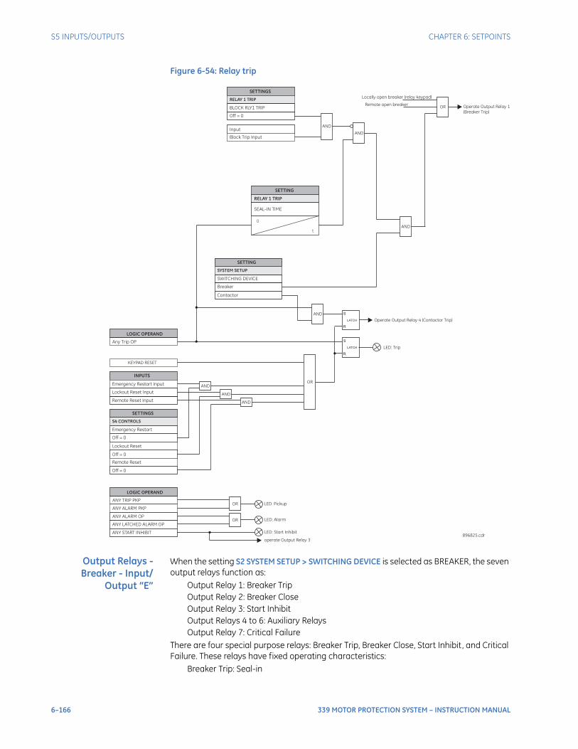
6–166 339 MOTOR PROTECTION SYSTEM – INSTRUCTION MANUAL
S5 INPUTS/OUTPUTS CHAPTER 6: SETPOINTS
Figure 6-54: Relay trip
Output Relays -Breaker - Input/
Output “E”
When the setting S2 SYSTEM SETUP > SWITCHING DEVICE is selected as BREAKER, the seven output relays function as:
Output Relay 1: Breaker TripOutput Relay 2: Breaker CloseOutput Relay 3: Start InhibitOutput Relays 4 to 6: Auxiliary RelaysOutput Relay 7: Critical Failure
There are four special purpose relays: Breaker Trip, Breaker Close, Start Inhibit, and Critical Failure. These relays have fixed operating characteristics:
Breaker Trip: Seal-in
SEAL-IN TIME
SETTING
0
RELAY 1 TRIP
AND
SETTINGS
Off = 0
Input
BLOCK RLY1 TRIP
RELAY 1 TRIP
Block Trip Input
S
R
LATCH
SETTING
Breaker
Contactor
SWITCHING DEVICE
SYSTEM SETUP
AND
AND
t
LOGIC OPERAND
ANY ALARM PKP
ANY ALARM OP
ANY LATCHED ALARM OP
ANY TRIP PKP
LOGIC OPERAND
Any Trip OP
AND
S
R
LATCH
OR
OR
LED: Trip
LED: Pickup
LED: Alarm
Operate Output Relay 4 (Contactor Trip)
Operate Output Relay 1
(Breaker Trip)
896825.cdr
AND
AND
INPUTS
Emergency Restart Input
Lockout Reset Input
SETTINGS
Off = 0
Lockout Reset
Off = 0
Emergency Restart
S4 CONTROLS
Remote Reset Input
Remote Reset
Off = 0
AND
OR
KEYPAD RESET
OR
Locally open breaker (relay keypad)
Remote open breaker
ANY START INHIBIT LED: Start Inhibit
operate Output Relay 3
CHAPTER 6: SETPOINTS S5 INPUTS/OUTPUTS
339 MOTOR PROTECTION SYSTEM – INSTRUCTION MANUAL 6–167
Breaker Close: Seal-inStart Inhibit: Self-resetCritical Failure: Self-reset
The user can configure an Auxiliary Relay as either latched or self-reset. Logic diagrams for each Output Relay are provided for detailed explanation of their operation.Operation of the BREAKER TRIP and BREAKER CLOSE relays is controlled by the state of the circuit breaker as monitored by a 52a or 52b contact.
• The Trip and Close relays reset after the breaker is detected in a state corresponding to the command. When a relay feature sends a command to one of these special relays, it will remain operational until the requested change of breaker state is confirmed by a breaker auxiliary contact and the initiating condition has reset.
• If the initiating feature resets, but the breaker does not change state, the output relay will be reset after a default interval of 2 seconds.
• If neither of the breaker auxiliary contacts, 52a nor 52b, is programmed to a logic input, the Trip Relay is de-energized after either the delay programmed in the Breaker Failure feature, or a default interval of 100 ms after the initiating input resets. The Close Relay is de-energized after 200 ms.
• If a delay is programmed for the Trip or Close contact seal-in time, then this delay is added to the reset time. Note that the default setting for the seal-in time is 40 ms.
Output Relay 1 "Breaker Trip" - Input/Output “E”The following path is available using the keypad. For instructions on how to use the keypad, please refer to Chapter 3 - Working with the Keypad.PATH: SETPOINTS > S5 INPUTS/OUTPUTS > OUTPUT RELAYS > RLY 1 TRIP
SEAL IN TIMERange: 0.00 to 9.99 s in steps of 0.01Default: 0.04 s
This setting defines the time to be added to the reset time of the Relay 1 Trip output, thus extending its pulse width. This is useful for those applications where the 52 contacts reporting the breaker state are faster than the 52 contacts that are responsible for interrupting the coil current.
BLOCK RLY 1 TRIPRange: Off, Contact Input 1 to 10, Virtual Input 1 to 32, Remote Input 1 to 32, Logic Elements 1 to 16Default: Off
This setting defines a block to the Trip Output relay. When the selected input is asserted, the Trip Output relay will be blocked.
52a Contact Configured
52b Contact Configured
Relay Operation
Yes Yes Trip Relay remains operational until 52b indicates an open breaker. Close Relay remains operational until 52a indicates a closed breaker.
Yes No Trip Relay remains operational until 52a indicates an open breaker. Close Relay remains operational until 52a indicates a closed breaker.
No Yes Trip Relay remains operational until 52b indicates an open breaker. Close Relay remains operational until 52b indicates a closed breaker.
No No Trip Relay operates until either the Breaker Failure delay expires (if the Breaker Failure element is enabled), or 100 ms after the feature causing the trip resets. Close Relay operates for 200 ms.
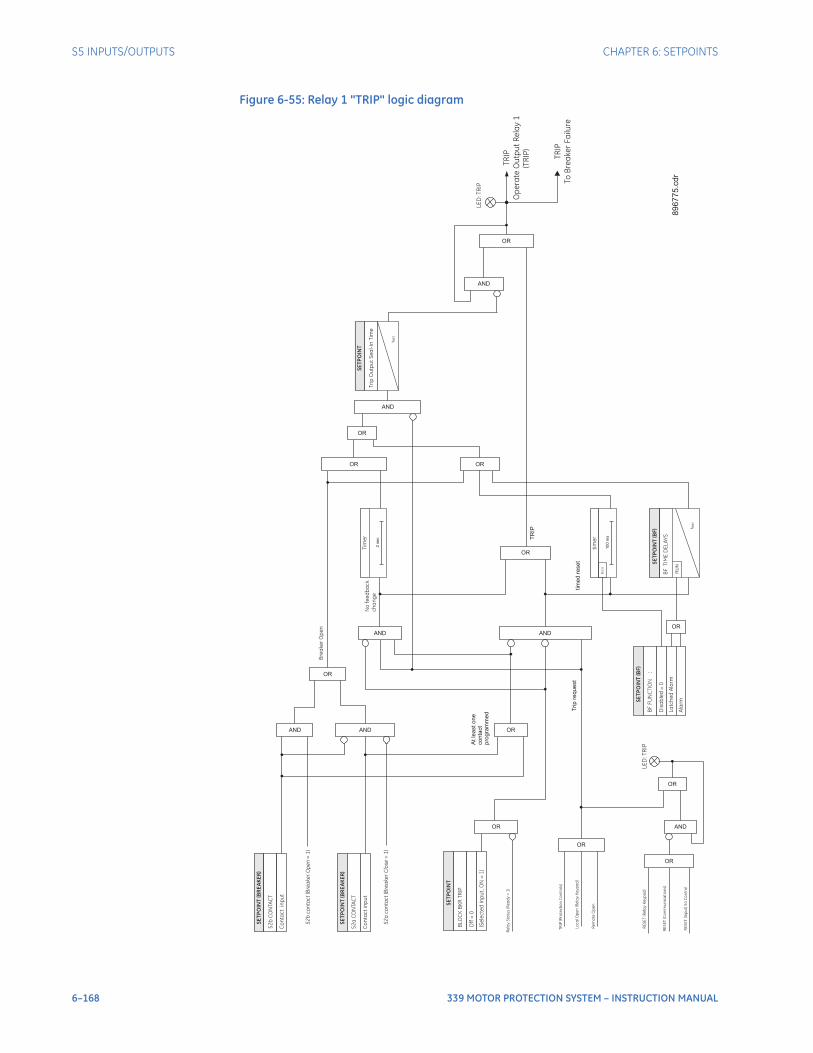
6–168 339 MOTOR PROTECTION SYSTEM – INSTRUCTION MANUAL
S5 INPUTS/OUTPUTS CHAPTER 6: SETPOINTS
Figure 6-55: Relay 1 "TRIP" logic diagram
TR
IP(P
rote
cti
on
Co
ntr
ols
)
Trip
req
ue
st
SE
TP
OIN
T(B
RE
AK
ER
)
52
bC
ON
TA
CT
Co
nta
ct
inp
ut
SE
TP
OIN
T(B
RE
AK
ER
)
52
aC
ON
TA
CT
Co
nta
ct
inp
ut
AND
OR
52
bco
nta
ct
(Bre
ake
rO
pe
n=
1)
AND
Bre
ake
rO
pe
n
OR
At
lea
st
on
eco
nta
ct
pro
gra
mm
ed
AND
OR
TR
IP
No
fee
db
ac
k
ch
an
ge
OR
tim
ed
rese
t
SE
TP
OIN
T(B
F)
BF
FU
NC
TIO
N:
Dis
ab
led
=0
La
tch
ed
Ala
rm
Ala
rm
BF
TIM
ED
EL
AY
S
SE
TP
OIN
T(B
F)
RU
N
OR
OR
OR
AND
AND
Tri
pO
utp
ut
Se
al-
InT
ime
SE
TP
OIN
T
t RS
T
AND
LE
D:T
RIP
OR
Lo
ca
lO
pe
n(R
ela
yK
ey
pa
d)
Re
mo
teO
pe
n
Re
lay
Sta
tus
(Re
ad
y=
1)
RE
SE
T(R
ela
yK
ey
pa
d)
RE
SE
T(C
om
mu
nic
ati
on
s)
RE
SE
T(In
pu
t)S
4C
on
tro
l
OR
LE
D:T
RIP
AND
OR
tim
er
100
ms
RU
N
OR
t RS
T
SE
TP
OIN
T
BLO
CK
BK
RT
RIP
Off
=0
(Se
lec
ted
Inp
ut,O
N=
1)
OR
Tim
er
2sec
89
67
75
.cd
r
TR
IP
Op
era
teO
utp
ut
Re
lay
1
TR
IP
To
Bre
ake
rF
ailu
re
(TR
IP)
52
aco
nta
ct
(Bre
ake
rC
lose
=1
)
CHAPTER 6: SETPOINTS S5 INPUTS/OUTPUTS
339 MOTOR PROTECTION SYSTEM – INSTRUCTION MANUAL 6–169
Output Relay 2 "Breaker Close" - Input/Output “E”PATH: SETPOINTS > S5 INPUTS/OUTPUTS > OUTPUT RELAYS > RLY 2 CLOSE
SEAL IN TIMERange: 0.00 to 9.99 s in steps of 0.01Default: 0.04 s
This setting defines the time to be added to the reset time of the Relay 2 Close output, thus extending its pulse width. This is useful for those applications where the 52 contacts reporting the breaker state are faster than the 52 contacts that are responsible for interrupting the coil current.
BLOCK RLY 2 CLOSERange: Off, Contact Input 1 to 10, Virtual Input 1 to 32, Remote Input 1 to 32, Logic Elements 1 to 16Default: Off
This setting defines a block to the Close Output relay. When the selected input is asserted, the Close Output relay will be blocked. The block function can be useful for breaker maintenance purposes.
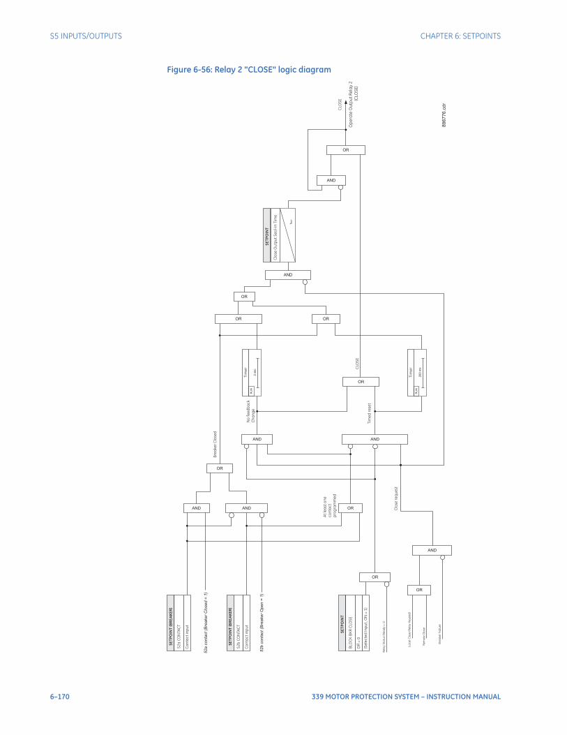
6–170 339 MOTOR PROTECTION SYSTEM – INSTRUCTION MANUAL
S5 INPUTS/OUTPUTS CHAPTER 6: SETPOINTS
Figure 6-56: Relay 2 "CLOSE" logic diagram
Clo
se
req
ue
st
SE
TP
OIN
T(B
RE
AK
ER
)
52
aC
ON
TA
CT
Co
nta
ct
inp
ut
SE
TP
OIN
T(B
RE
AK
ER
)
52
bC
ON
TA
CT
Co
nta
ct
inp
ut
AND
OR
52
aco
nta
ct(B
rea
ke
rC
lose
d=
1)
AND
52b
conta
ct(B
reaker
Open
=1)
Bre
ake
rC
lose
d
OR
At
lea
st
on
e
co
nta
ct
pro
gra
mm
ed
AND
OR
CLO
SE
No
fee
db
ac
k
Ch
an
ge
OR
Tim
ed
rese
t
OR
OR
OR
AND
AND
Clo
se
Ou
tpu
tS
ea
l-In
Tim
e
SE
TP
OIN
T
t RS
T
AND
CLO
SE
Op
era
teO
utp
ut
Re
lay
2
(CLO
SE
)
OR
Lo
ca
lC
lose
(Re
lay
Ke
yp
ad
)
Re
mo
teC
lose
Re
lay
Sta
tus
(Re
ad
y=
1)
Tim
er
20
0m
s
RU
N
SE
TP
OIN
T
BLO
CK
BK
RC
LO
SE
Off
=0
(Se
lec
ted
Inp
ut,O
N=
1)
OR
AND
Bre
ake
rF
ailu
re
Tim
er
2se
c
RU
N
89
67
76
.cd
r
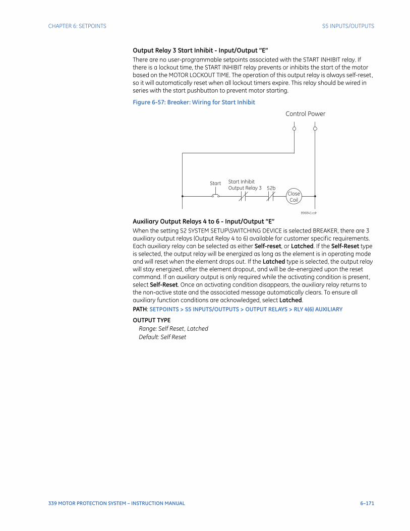
CHAPTER 6: SETPOINTS S5 INPUTS/OUTPUTS
339 MOTOR PROTECTION SYSTEM – INSTRUCTION MANUAL 6–171
Output Relay 3 Start Inhibit - Input/Output “E”There are no user-programmable setpoints associated with the START INHIBIT relay. If there is a lockout time, the START INHIBIT relay prevents or inhibits the start of the motor based on the MOTOR LOCKOUT TIME. The operation of this output relay is always self-reset, so it will automatically reset when all lockout timers expire. This relay should be wired in series with the start pushbutton to prevent motor starting.
Figure 6-57: Breaker: Wiring for Start Inhibit
Auxiliary Output Relays 4 to 6 - Input/Output “E”When the setting S2 SYSTEM SETUP\SWITCHING DEVICE is selected BREAKER, there are 3 auxiliary output relays (Output Relay 4 to 6) available for customer specific requirements. Each auxiliary relay can be selected as either Self-reset, or Latched. If the Self-Reset type is selected, the output relay will be energized as long as the element is in operating mode and will reset when the element drops out. If the Latched type is selected, the output relay will stay energized, after the element dropout, and will be de-energized upon the reset command. If an auxiliary output is only required while the activating condition is present, select Self-Reset. Once an activating condition disappears, the auxiliary relay returns to the non-active state and the associated message automatically clears. To ensure all auxiliary function conditions are acknowledged, select Latched.PATH: SETPOINTS > S5 INPUTS/OUTPUTS > OUTPUT RELAYS > RLY 4(6) AUXILIARY
OUTPUT TYPERange: Self Reset, LatchedDefault: Self Reset
Control Power
Start Start Inhibit
Output Relay 3 52b
Close
Coil
896841.cdr
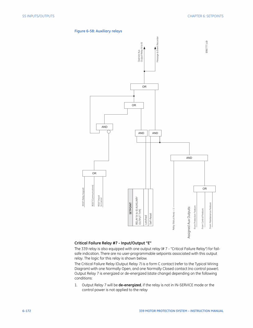
6–172 339 MOTOR PROTECTION SYSTEM – INSTRUCTION MANUAL
S5 INPUTS/OUTPUTS CHAPTER 6: SETPOINTS
Figure 6-58: Auxiliary relays
Critical Failure Relay #7 - Input/Output “E”The 339 relay is also equipped with one output relay (# 7 - “Critical Failure Relay”) for fail-safe indication. There are no user-programmable setpoints associated with this output relay. The logic for this relay is shown below.The Critical Failure Relay (Output Relay 7) is a form C contact (refer to the Typical Wiring Diagram) with one Normally Open, and one Normally Closed contact (no control power). Output Relay 7 is energized or de-energized (state change) depending on the following conditions:
1. Output Relay 7 will be de-energized, if the relay is not in IN-SERVICE mode or the control power is not applied to the relay
Fro
mP
rote
cti
on
Fe
atu
re
OR
Fro
mC
on
tro
lF
ea
ture
Fro
mM
ain
ten
an
ce
Fe
atu
re
Assig
ne
dA
ux
Ou
tpu
ts:
AND
Re
lay
Sta
tus
(Re
ad
y=
1)
SE
TP
OIN
T
RE
LA
Y(4
to6
)A
UX
ILIA
RY
OU
TP
UT
TY
PE
La
tch
ed
Se
lf-R
ese
t
AND AND
OR
AND
OR
RE
SE
T(R
ela
yK
ey
pa
d)
RE
SE
T(C
om
mu
nic
ati
on
s)
RE
SE
T(In
pu
t)
S4
Co
ntr
ol
OR
Op
era
teA
ux
Ou
tpu
tR
ela
y(4
to6
)
Me
ssa
ge
&E
ve
nt
Re
co
rde
r
89
67
77
. cd
r
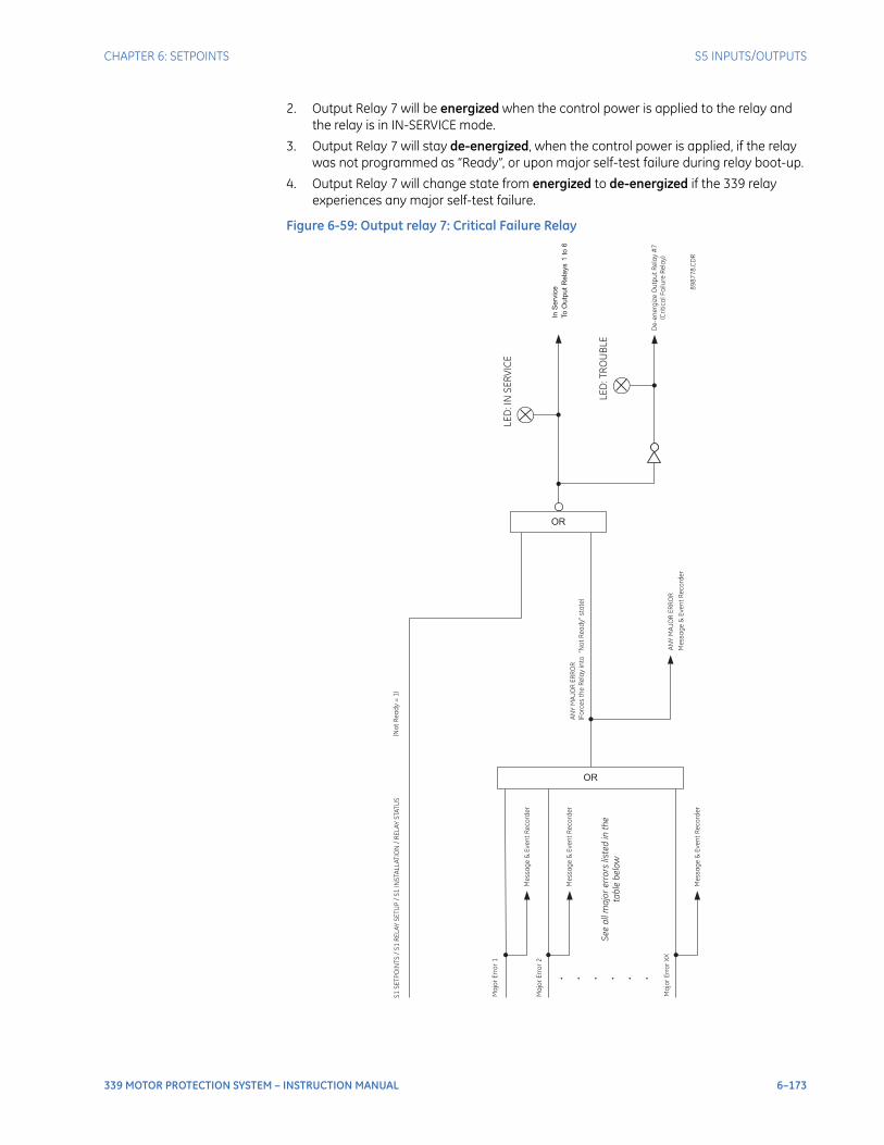
CHAPTER 6: SETPOINTS S5 INPUTS/OUTPUTS
339 MOTOR PROTECTION SYSTEM – INSTRUCTION MANUAL 6–173
2. Output Relay 7 will be energized when the control power is applied to the relay and the relay is in IN-SERVICE mode.
3. Output Relay 7 will stay de-energized, when the control power is applied, if the relay was not programmed as “Ready”, or upon major self-test failure during relay boot-up.
4. Output Relay 7 will change state from energized to de-energized if the 339 relay experiences any major self-test failure.
Figure 6-59: Output relay 7: Critical Failure Relay
AN
YM
AJO
RE
RR
OR
(Fo
rce
sth
eR
ela
yin
to“N
ot
Re
ad
y”
sta
te)
OR
S1
SE
TP
OIN
TS
/S
1R
EL
AY
SE
TU
P/
S1
INS
TA
LL
AT
ION
/R
EL
AY
STA
TU
S(N
ot
Re
ad
y=
1)
LE
D:IN
SE
RV
ICE
OR
. . . . . .
Me
ssa
ge
&E
ve
nt
Re
co
rde
r
Ma
jor
Err
or
1
Se
ea
llm
ajo
re
rro
rsliste
din
the
tab
leb
elo
w
To
Ou
tpu
tR
ela
ys
1to
6
InS
erv
ice
De
-e
ne
rgiz
eO
utp
ut
Re
lay
#7
(Cri
tic
alF
ailu
reR
ela
y)
LE
D:T
RO
UB
LE
89
87
78
. CD
R
Ma
jor
Err
or
2
Me
ssa
ge
&E
ve
nt
Re
co
rde
r
Ma
jor
Err
or
XX
Me
ssa
ge
&E
ve
nt
Re
co
rde
r
AN
YM
AJO
RE
RR
OR
Me
ssa
ge
&E
ve
nt
Re
co
rde
r

6–174 339 MOTOR PROTECTION SYSTEM – INSTRUCTION MANUAL
S5 INPUTS/OUTPUTS CHAPTER 6: SETPOINTS
Output Relays -Contactor - Input/
Output “E”
When the setting S2 SYSTEM SETUP > SWITCHING DEVICE is selected as CONTACTOR, the seven output relays function as:
Output Relay 1: Not UsedOutput Relay 2: Not UsedOutput Relay 3: Start InhibitOutput Relay 4: Contactor TripOutput Relays 5 to 6: Auxiliary RelaysOutput Relay 7: Critical Failure
There are three special purpose relays: Start Inhibit, Contactor Trip, and Critical Failure. These relays have fixed operating characteristics:
Start Inhibit: Self-resetContactor Trip: LatchedCritical Failure: Self-reset, Failsafe
The user can configure an Auxiliary Relay as either Latched or Self-reset. Output Relays 1 to 6 can be programmed to be in either Non-failsafe or Failsafe operation mode.
Non-failsafe: the relay coil is not energized in its non-active state. Loss of control power will cause the relay to remain in the non-active state; i.e. a non-failsafe trip relay will not cause a trip on loss of control power.Failsafe: the relay coil is energized in its non-active state. Loss of control power will cause the relay to go into its active state; i.e. a failsafe trip relay will cause a trip on loss of control power.
Output Relay 1 "Not Used" - Input/Output “E”When the setting S2 SYSTEM SETUP > SWITCHING DEVICE is selected as CONTACTOR, this output relay is not used.
Output Relay 2 "Not Used" - Input/Output “E”When the setting S2 SYSTEM SETUP > SWITCHING DEVICE is selected as CONTACTOR, this output relay is not used.
Output Relay 3 Start Inhibit - Input/Output “E”The Start Inhibit relay (Output Relay 3) is a form C contact with one Normally Open and one Normally Close contacts. This relay can be programmed as either Non-failsafe or Failsafe operation mode. Wiring of the Start Inhibit relay contacts will depend on the user’s selection of operation mode. If Non-failsafe operation is selected, wire the Normally Close contact of Start Inhibit output relay to the contactor control circuit; if Fail-safe operation is selected, wire the Normally Open contact to the control circuit.The following path is available using the keypad. For instructions on how to use the keypad, please refer to Chapter 3 - Working with the Keypad.PATH: SETPOINTS > S5 INPUTS/OUTPUTS > OUTPUT RELAYS > RLY 3 START INHIB
RELAY OPERATIONRange: Non-Failsafe, FailsafeDefault: Non-failsafe
Output Relay 4 Contactor Trip - Input/Output “E”When the setting S2 SYSTEM > SWITCHING DEVICE is selected as CONTACTOR, a protection trip is always issued as a latched operation. The Trip relay (Output Relay 4) can be programmed as either Non-failsafe or Failsafe operation mode. Wiring of the Trip relay contacts will depend on this configuration. For maximum motor protection, program the trip relay to be failsafe and wire the contactor to the Normally Open trip relay terminals, referring to Figure 40, below. When control power is lost to the 339 , the contactor will trip to ensure maximum protection. If process considerations are more important than protection, program non-failsafe and wire the contactor to the Normally Close trip relay terminals, referring to Figure 39 below. When control power to the 339 is lost, no protection
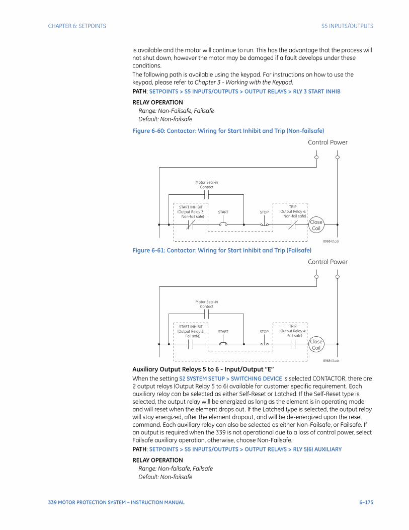
CHAPTER 6: SETPOINTS S5 INPUTS/OUTPUTS
339 MOTOR PROTECTION SYSTEM – INSTRUCTION MANUAL 6–175
is available and the motor will continue to run. This has the advantage that the process will not shut down, however the motor may be damaged if a fault develops under these conditions.The following path is available using the keypad. For instructions on how to use the keypad, please refer to Chapter 3 - Working with the Keypad.PATH: SETPOINTS > S5 INPUTS/OUTPUTS > OUTPUT RELAYS > RLY 3 START INHIB
RELAY OPERATIONRange: Non-Failsafe, FailsafeDefault: Non-failsafe
Figure 6-60: Contactor: Wiring for Start Inhibit and Trip (Non-failsafe)
Figure 6-61: Contactor: Wiring for Start Inhibit and Trip (Failsafe)
Auxiliary Output Relays 5 to 6 - Input/Output “E”When the setting S2 SYSTEM SETUP > SWITCHING DEVICE is selected CONTACTOR, there are 2 output relays (Output Relay 5 to 6) available for customer specific requirement. Each auxiliary relay can be selected as either Self-Reset or Latched. If the Self-Reset type is selected, the output relay will be energized as long as the element is in operating mode and will reset when the element drops out. If the Latched type is selected, the output relay will stay energized, after the element dropout, and will be de-energized upon the reset command. Each auxiliary relay can also be selected as either Non-Failsafe, or Failsafe. If an output is required when the 339 is not operational due to a loss of control power, select Failsafe auxiliary operation, otherwise, choose Non-Failsafe. PATH: SETPOINTS > S5 INPUTS/OUTPUTS > OUTPUT RELAYS > RLY 5(6) AUXILIARY
RELAY OPERATIONRange: Non-failsafe, FailsafeDefault: Non-failsafe
Control Power
START
START INHIBIT
(Output Relay 3:
Non-fail safe)
Close
Coil
896842.cdr
STOP
TRIP
(Output Relay 4:
Non-fail safe)
Motor Seal-in
Contact
Control Power
START
START INHIBIT
(Output Relay 3:
Fail safe)
Close
Coil
896843.cdr
STOP
TRIP
(Output Relay 4:
Fail safe)
Motor Seal-in
Contact
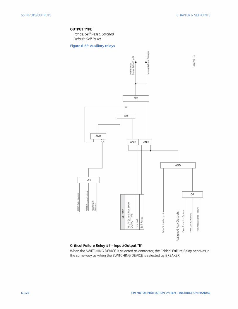
6–176 339 MOTOR PROTECTION SYSTEM – INSTRUCTION MANUAL
S5 INPUTS/OUTPUTS CHAPTER 6: SETPOINTS
OUTPUT TYPERange: Self Reset, LatchedDefault: Self Reset
Figure 6-62: Auxiliary relays
Critical Failure Relay #7 - Input/Output “E”When the SWITCHING DEVICE is selected as contactor, the Critical Failure Relay behaves in the same way as when the SWITCHING DEVICE is selected as BREAKER.
Fro
mP
rote
cti
on
Fe
atu
re
OR
Fro
mC
on
tro
lF
ea
ture
Fro
mM
ain
ten
an
ce
Fe
atu
re
Assig
ne
dA
ux
Ou
tpu
ts:
ANDR
ela
yS
tatu
s(R
ea
dy
=1
)
SE
TP
OIN
T
RE
LA
Y(5
to6
)A
UX
ILIA
RY
OU
TP
UT
TY
PE
La
tch
ed
Se
lf-R
ese
tAND AND
OR
AND
OR
RE
SE
T(R
ela
yK
ey
pa
d)
RE
SE
T(C
om
mu
nic
ati
on
s)
RE
SE
T(In
pu
t)
S4
Co
ntr
ol
OR
Op
era
teA
ux
Ou
tpu
tR
ela
y(5
to6
)
Me
ssa
ge
&E
ve
nt
Re
co
rde
r
89
67
89
. cd
r
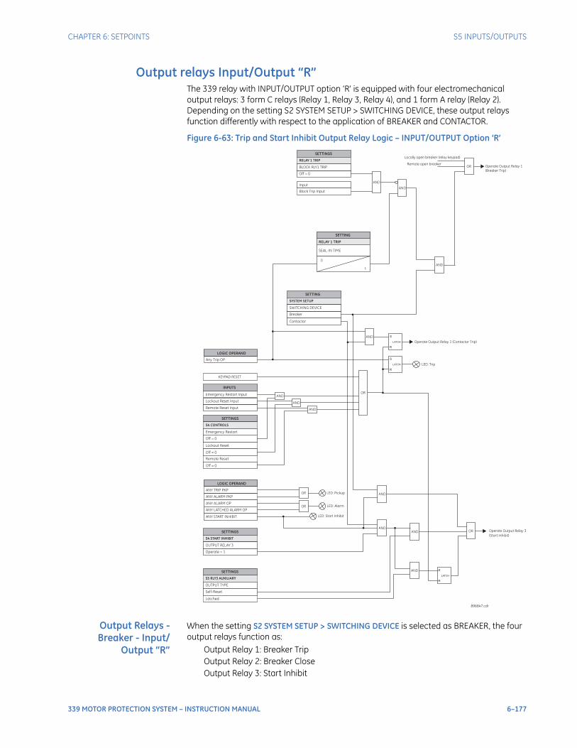
CHAPTER 6: SETPOINTS S5 INPUTS/OUTPUTS
339 MOTOR PROTECTION SYSTEM – INSTRUCTION MANUAL 6–177
Output relays Input/Output “R”The 339 relay with INPUT/OUTPUT option ‘R’ is equipped with four electromechanical output relays: 3 form C relays (Relay 1, Relay 3, Relay 4), and 1 form A relay (Relay 2). Depending on the setting S2 SYSTEM SETUP > SWITCHING DEVICE, these output relays function differently with respect to the application of BREAKER and CONTACTOR.
Figure 6-63: Trip and Start Inhibit Output Relay Logic – INPUT/OUTPUT Option ‘R’
Output Relays -Breaker - Input/
Output “R”
When the setting S2 SYSTEM SETUP > SWITCHING DEVICE is selected as BREAKER, the four output relays function as:
Output Relay 1: Breaker TripOutput Relay 2: Breaker CloseOutput Relay 3: Start Inhibit
SEAL-IN TIME
SETTING
0
RELAY 1 TRIP
AND
SETTINGS
Off = 0
Input
BLOCK RLY1 TRIP
RELAY 1 TRIP
Block Trip Input
S
R
LATCH
SETTING
Breaker
Contactor
SWITCHING DEVICE
SYSTEM SETUP
AND
AND
t
LOGIC OPERAND
ANY ALARM PKP
ANY ALARM OP
ANY LATCHED ALARM OP
ANY TRIP PKP
LOGIC OPERAND
Any Trip OP
AND
AND
AND
AND OR
AND
S
S
R
R
LATCH
LATCH
OR
OR
LED: Trip
LED: Pickup
LED: Alarm
Operate Output Relay 1 (Contactor Trip)
Operate Output Relay 1
(Breaker Trip)
896847.cdr
AND
AND
INPUTS
Emergency Restart Input
Lockout Reset Input
SETTINGS
SETTINGS
SETTINGS
Off = 0
Operate = 1
Self-Reset
Lockout Reset
Latched
Off = 0
Emergency Restart
OUTPUT RELAY 3
OUTPUT TYPE
S4 CONTROLS
S4 START INHIBIT
S5 RLY3 AUXILIARY
Remote Reset Input
Remote Reset
Off = 0
AND
OR
KEYPAD RESET
OR
Locally open breaker (relay keypad)
Remote open breaker
ANY START INHIBIT LED: Start Inhibit
Operate Output Relay 3
(Start Inhibit)

6–178 339 MOTOR PROTECTION SYSTEM – INSTRUCTION MANUAL
S5 INPUTS/OUTPUTS CHAPTER 6: SETPOINTS
Output Relay 4: Critical FailureThese four special purpose relays have fixed operating characteristics:
Breaker Trip: Seal-inBreaker Close: Seal-inStart Inhibit: Non-failsafe, Self-resetCritical Failure: Failsafe, Self-reset
There are no configurable Auxiliary Relays in this case. Logic diagrams for each Output Relay are provided for detailed explanation of their operation.The logic of the BREAKER TRIP, BREAKER CLOSE, START INHIBIT, and CRITICAL FAILURE relays with INPUT/OUTPUT Option ‘R’ is the same as for the other INPUT/OUTPUT options (Option ‘E’), with the exception that the CRITICAL FAILURE relay is assigned to Output Relay 4 instead of Output Relay 7, as shown below.
Output Relay 1 "Breaker Trip" - Input/Output “R”The following path is available using the keypad. For instructions on how to use the keypad, please refer to Chapter 3 - Working with the Keypad.PATH: SETPOINTS > S5 INPUTS/OUTPUTS > OUTPUT RELAYS > RLY 1 TRIP
SEAL IN TIMERange: 0.00 to 9.99 s in steps of 0.01Default: 0.04 s
This setting defines the time to be added to the reset time of the Relay 1 Trip output, thus extending its pulse width. This is useful for those applications where the 52 contacts reporting the breaker state are faster than the 52 contacts that are responsible for interrupting the coil current.
BLOCK RLY 1 TRIPRange: Off, Contact Input 1 to 10, Virtual Input 1 to 32, Remote Input 1 to 32, Logic Elements 1 to 16Default: Off
This setting defines a block to the Trip Output relay. When the selected input is asserted, the Trip Output relay will be blocked.
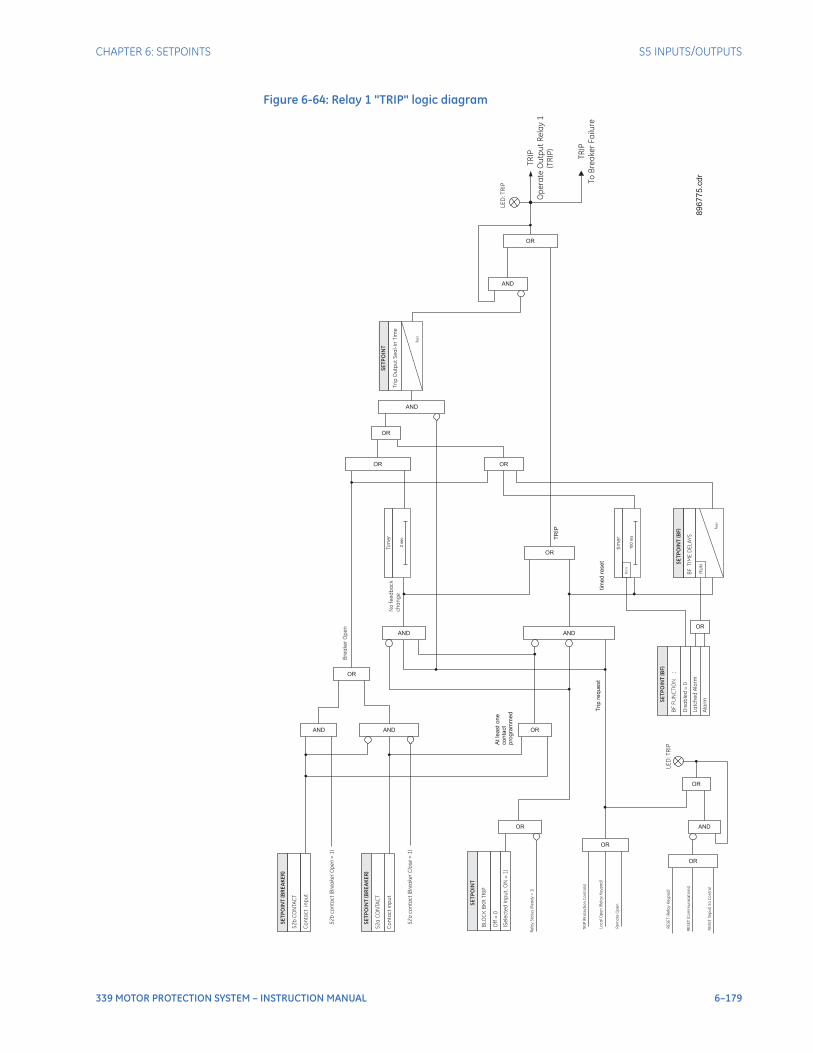
CHAPTER 6: SETPOINTS S5 INPUTS/OUTPUTS
339 MOTOR PROTECTION SYSTEM – INSTRUCTION MANUAL 6–179
Figure 6-64: Relay 1 "TRIP" logic diagram
TR
IP(P
rote
cti
on
Co
ntr
ols
)
Trip
req
ue
st
SE
TP
OIN
T(B
RE
AK
ER
)
52
bC
ON
TA
CT
Co
nta
ct
inp
ut
SE
TP
OIN
T(B
RE
AK
ER
)
52
aC
ON
TA
CT
Co
nta
ct
inp
ut
AND
OR
52
bco
nta
ct
(Bre
ake
rO
pe
n=
1)
AND
Bre
ake
rO
pe
n
OR
At
lea
st
on
eco
nta
ct
pro
gra
mm
ed
AND
ORT
RIP
No
fee
db
ac
k
ch
an
ge
OR
tim
ed
rese
t
SE
TP
OIN
T(B
F)
BF
FU
NC
TIO
N:
Dis
ab
led
=0
La
tch
ed
Ala
rm
Ala
rm
BF
TIM
ED
EL
AY
S
SE
TP
OIN
T(B
F)
RU
N
OR
OR
OR
AND
AND
Tri
pO
utp
ut
Se
al-
InT
ime
SE
TP
OIN
T
t RS
T
AND
LE
D:T
RIP
OR
Lo
ca
lO
pe
n(R
ela
yK
ey
pa
d)
Re
mo
teO
pe
n
Re
lay
Sta
tus
(Re
ad
y=
1)
RE
SE
T(R
ela
yK
ey
pa
d)
RE
SE
T(C
om
mu
nic
ati
on
s)
RE
SE
T(In
pu
t)S
4C
on
tro
l
OR
LE
D:T
RIP
AND
OR
tim
er
100
ms
RU
NOR
t RS
T
SE
TP
OIN
T
BLO
CK
BK
RT
RIP
Off
=0
(Se
lec
ted
Inp
ut,O
N=
1)
OR
Tim
er
2sec
89
67
75
.cd
r
TR
IP
Op
era
teO
utp
ut
Re
lay
1
TR
IP
To
Bre
ake
rF
ailu
re
(TR
IP)
52
aco
nta
ct
(Bre
ake
rC
lose
=1
)
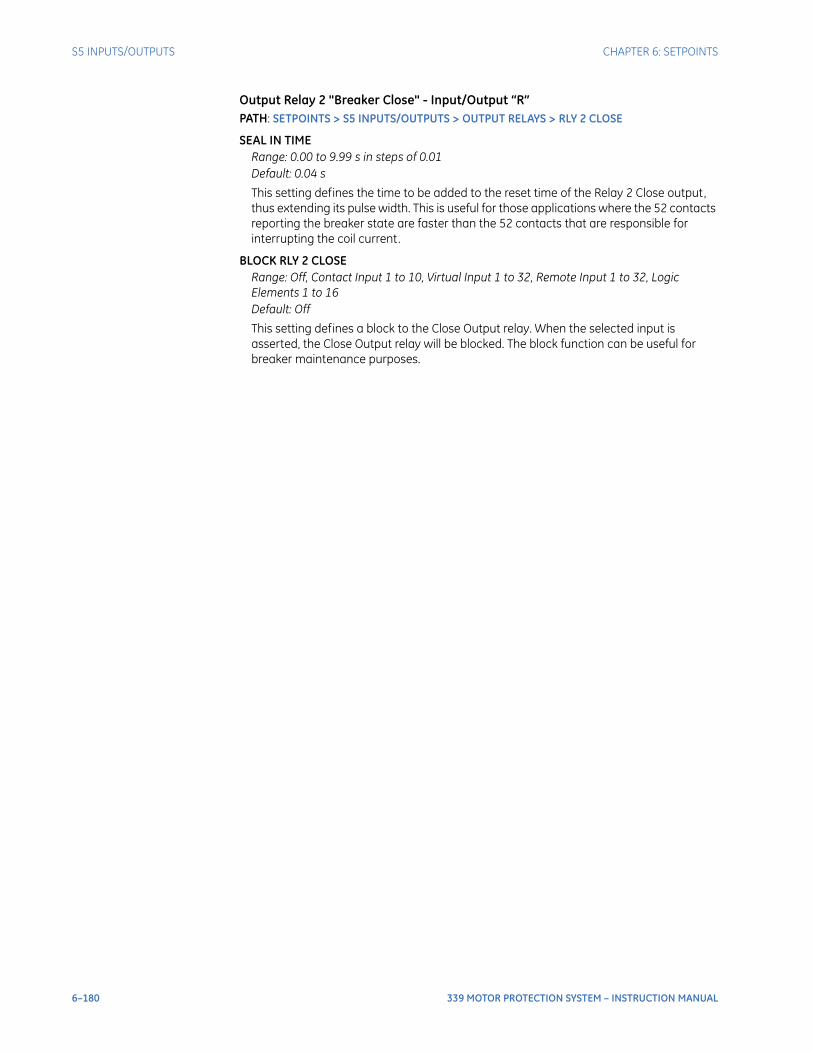
6–180 339 MOTOR PROTECTION SYSTEM – INSTRUCTION MANUAL
S5 INPUTS/OUTPUTS CHAPTER 6: SETPOINTS
Output Relay 2 "Breaker Close" - Input/Output “R”PATH: SETPOINTS > S5 INPUTS/OUTPUTS > OUTPUT RELAYS > RLY 2 CLOSE
SEAL IN TIMERange: 0.00 to 9.99 s in steps of 0.01Default: 0.04 s
This setting defines the time to be added to the reset time of the Relay 2 Close output, thus extending its pulse width. This is useful for those applications where the 52 contacts reporting the breaker state are faster than the 52 contacts that are responsible for interrupting the coil current.
BLOCK RLY 2 CLOSERange: Off, Contact Input 1 to 10, Virtual Input 1 to 32, Remote Input 1 to 32, Logic Elements 1 to 16Default: Off
This setting defines a block to the Close Output relay. When the selected input is asserted, the Close Output relay will be blocked. The block function can be useful for breaker maintenance purposes.
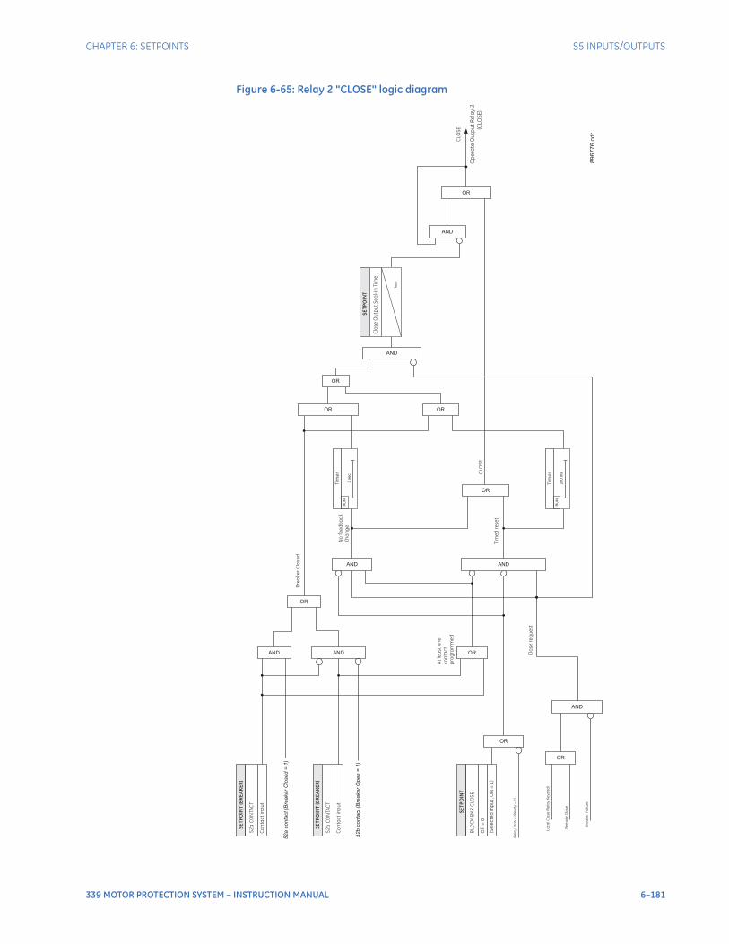
CHAPTER 6: SETPOINTS S5 INPUTS/OUTPUTS
339 MOTOR PROTECTION SYSTEM – INSTRUCTION MANUAL 6–181
Figure 6-65: Relay 2 "CLOSE" logic diagram
Clo
se
req
ue
st
SE
TP
OIN
T(B
RE
AK
ER
)
52
aC
ON
TA
CT
Co
nta
ct
inp
ut
SE
TP
OIN
T(B
RE
AK
ER
)
52
bC
ON
TA
CT
Co
nta
ct
inp
ut
AND
OR
52
aco
nta
ct(B
rea
ke
rC
lose
d=
1)
AND
52b
conta
ct(B
reaker
Open
=1)
Bre
ake
rC
lose
d
OR
At
lea
st
on
e
co
nta
ct
pro
gra
mm
ed
AND
OR
CLO
SE
No
fee
db
ac
k
Ch
an
ge
OR
Tim
ed
rese
t
OR
OR
OR
AND
AND
Clo
se
Ou
tpu
tS
ea
l-In
Tim
e
SE
TP
OIN
T
t RS
T
AND
CLO
SE
Op
era
teO
utp
ut
Re
lay
2
(CLO
SE
)
OR
Lo
ca
lC
lose
(Re
lay
Ke
yp
ad
)
Re
mo
teC
lose
Re
lay
Sta
tus
(Re
ad
y=
1)
Tim
er
20
0m
s
RU
N
SE
TP
OIN
T
BLO
CK
BK
RC
LO
SE
Off
=0
(Se
lec
ted
Inp
ut,O
N=
1)
OR
AND
Bre
ake
rF
ailu
re
Tim
er
2se
c
RU
N
89
67
76
.cd
r
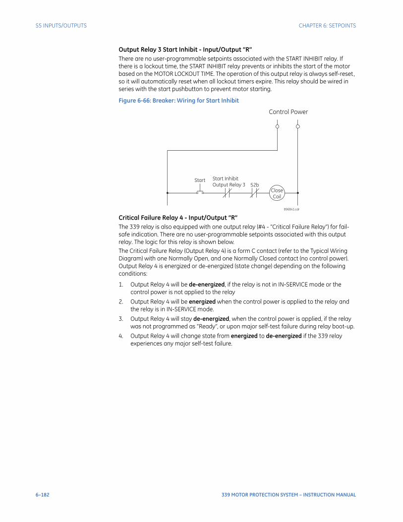
6–182 339 MOTOR PROTECTION SYSTEM – INSTRUCTION MANUAL
S5 INPUTS/OUTPUTS CHAPTER 6: SETPOINTS
Output Relay 3 Start Inhibit - Input/Output “R”There are no user-programmable setpoints associated with the START INHIBIT relay. If there is a lockout time, the START INHIBIT relay prevents or inhibits the start of the motor based on the MOTOR LOCKOUT TIME. The operation of this output relay is always self-reset, so it will automatically reset when all lockout timers expire. This relay should be wired in series with the start pushbutton to prevent motor starting.
Figure 6-66: Breaker: Wiring for Start Inhibit
Critical Failure Relay 4 - Input/Output “R”The 339 relay is also equipped with one output relay (#4 - “Critical Failure Relay”) for fail-safe indication. There are no user-programmable setpoints associated with this output relay. The logic for this relay is shown below.The Critical Failure Relay (Output Relay 4) is a form C contact (refer to the Typical Wiring Diagram) with one Normally Open, and one Normally Closed contact (no control power). Output Relay 4 is energized or de-energized (state change) depending on the following conditions:
1. Output Relay 4 will be de-energized, if the relay is not in IN-SERVICE mode or the control power is not applied to the relay
2. Output Relay 4 will be energized when the control power is applied to the relay and the relay is in IN-SERVICE mode.
3. Output Relay 4 will stay de-energized, when the control power is applied, if the relay was not programmed as “Ready”, or upon major self-test failure during relay boot-up.
4. Output Relay 4 will change state from energized to de-energized if the 339 relay experiences any major self-test failure.
Control Power
Start Start Inhibit
Output Relay 3 52b
Close
Coil
896841.cdr
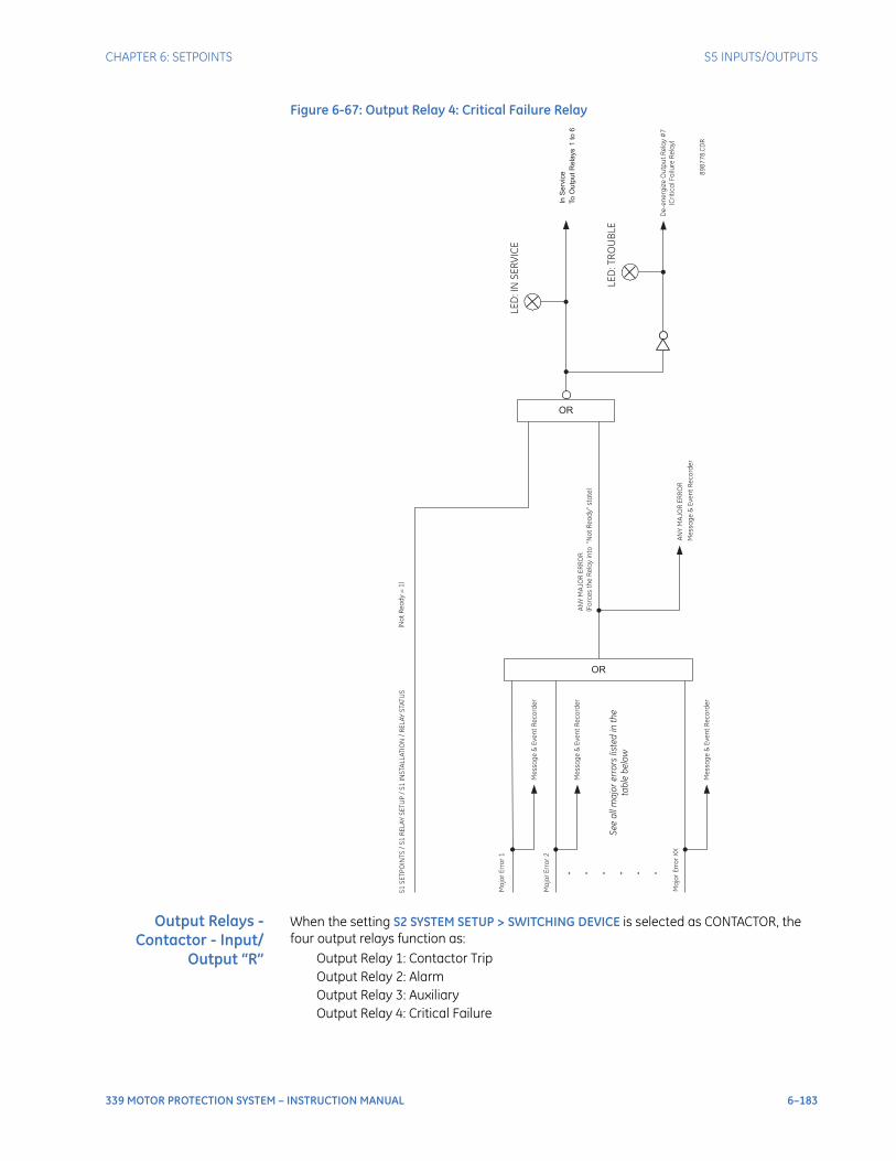
CHAPTER 6: SETPOINTS S5 INPUTS/OUTPUTS
339 MOTOR PROTECTION SYSTEM – INSTRUCTION MANUAL 6–183
Figure 6-67: Output Relay 4: Critical Failure Relay
Output Relays -Contactor - Input/
Output “R”
When the setting S2 SYSTEM SETUP > SWITCHING DEVICE is selected as CONTACTOR, the four output relays function as:
Output Relay 1: Contactor TripOutput Relay 2: AlarmOutput Relay 3: AuxiliaryOutput Relay 4: Critical Failure
AN
YM
AJO
RE
RR
OR
(Fo
rce
sth
eR
ela
yin
to“N
ot
Re
ad
y”
sta
te)
ORS
1S
ET
PO
INT
S/
S1
RE
LA
YS
ET
UP
/S
1IN
STA
LL
AT
ION
/R
EL
AY
STA
TU
S(N
ot
Re
ad
y=
1)
LE
D:IN
SE
RV
ICE
OR
. . . . . .
Me
ssa
ge
&E
ve
nt
Re
co
rde
r
Ma
jor
Err
or
1
Se
ea
llm
ajo
re
rro
rsliste
din
the
tab
leb
elo
w
To
Ou
tpu
tR
ela
ys
1to
6
InS
erv
ice
De
-e
ne
rgiz
eO
utp
ut
Re
lay
#7
(Cri
tic
alF
ailu
reR
ela
y)
LE
D:T
RO
UB
LE
89
87
78
. CD
R
Ma
jor
Err
or
2
Me
ssa
ge
&E
ve
nt
Re
co
rde
r
Ma
jor
Err
or
XX
Me
ssa
ge
&E
ve
nt
Re
co
rde
r
AN
YM
AJO
RE
RR
OR
Me
ssa
ge
&E
ve
nt
Re
co
rde
r
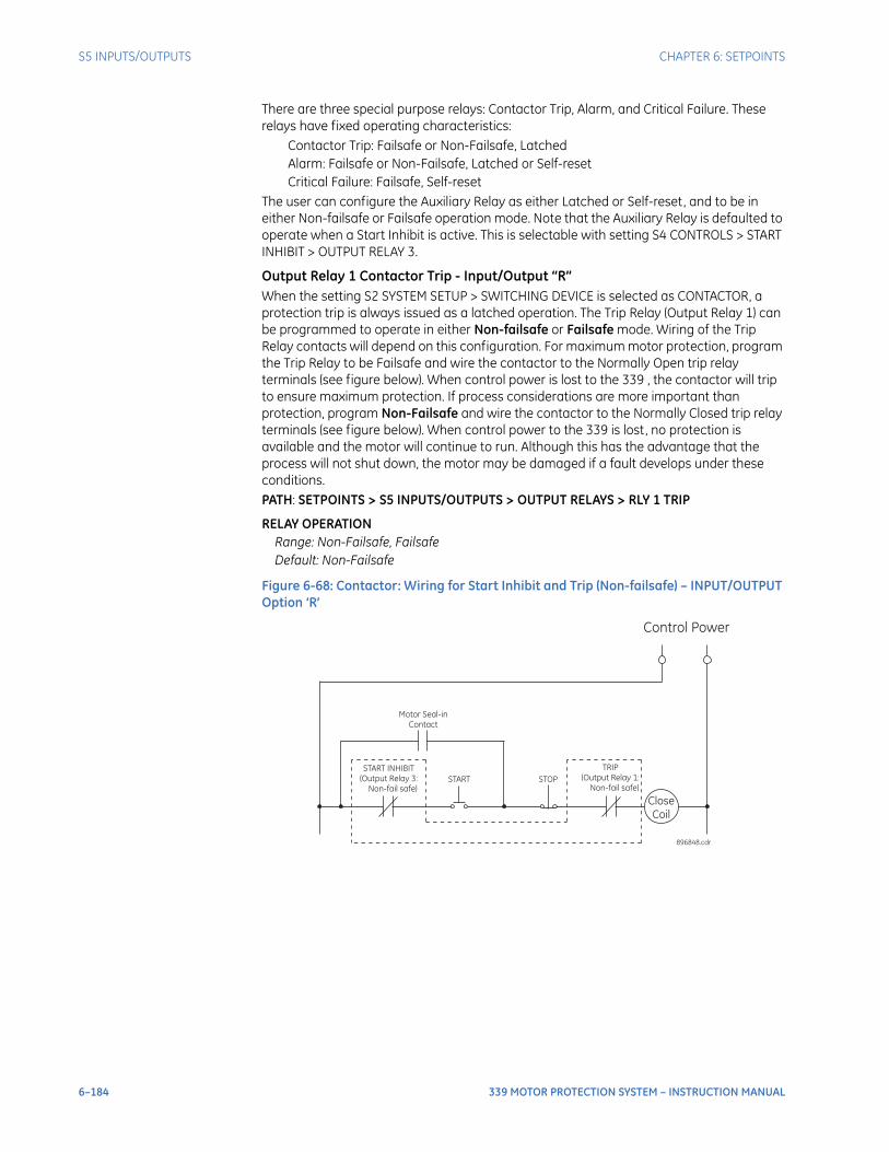
6–184 339 MOTOR PROTECTION SYSTEM – INSTRUCTION MANUAL
S5 INPUTS/OUTPUTS CHAPTER 6: SETPOINTS
There are three special purpose relays: Contactor Trip, Alarm, and Critical Failure. These relays have fixed operating characteristics:
Contactor Trip: Failsafe or Non-Failsafe, LatchedAlarm: Failsafe or Non-Failsafe, Latched or Self-resetCritical Failure: Failsafe, Self-reset
The user can configure the Auxiliary Relay as either Latched or Self-reset, and to be in either Non-failsafe or Failsafe operation mode. Note that the Auxiliary Relay is defaulted to operate when a Start Inhibit is active. This is selectable with setting S4 CONTROLS > START INHIBIT > OUTPUT RELAY 3.
Output Relay 1 Contactor Trip - Input/Output “R”When the setting S2 SYSTEM SETUP > SWITCHING DEVICE is selected as CONTACTOR, a protection trip is always issued as a latched operation. The Trip Relay (Output Relay 1) can be programmed to operate in either Non-failsafe or Failsafe mode. Wiring of the Trip Relay contacts will depend on this configuration. For maximum motor protection, program the Trip Relay to be Failsafe and wire the contactor to the Normally Open trip relay terminals (see figure below). When control power is lost to the 339 , the contactor will trip to ensure maximum protection. If process considerations are more important than protection, program Non-Failsafe and wire the contactor to the Normally Closed trip relay terminals (see figure below). When control power to the 339 is lost, no protection is available and the motor will continue to run. Although this has the advantage that the process will not shut down, the motor may be damaged if a fault develops under these conditions.PATH: SETPOINTS > S5 INPUTS/OUTPUTS > OUTPUT RELAYS > RLY 1 TRIP
RELAY OPERATIONRange: Non-Failsafe, FailsafeDefault: Non-Failsafe
Figure 6-68: Contactor: Wiring for Start Inhibit and Trip (Non-failsafe) – INPUT/OUTPUT Option ‘R’
Control Power
START
START INHIBIT
(Output Relay 3:
Non-fail safe)
Close
Coil
896848.cdr
STOP
TRIP
(Output Relay 1:
Non-fail safe)
Motor Seal-in
Contact
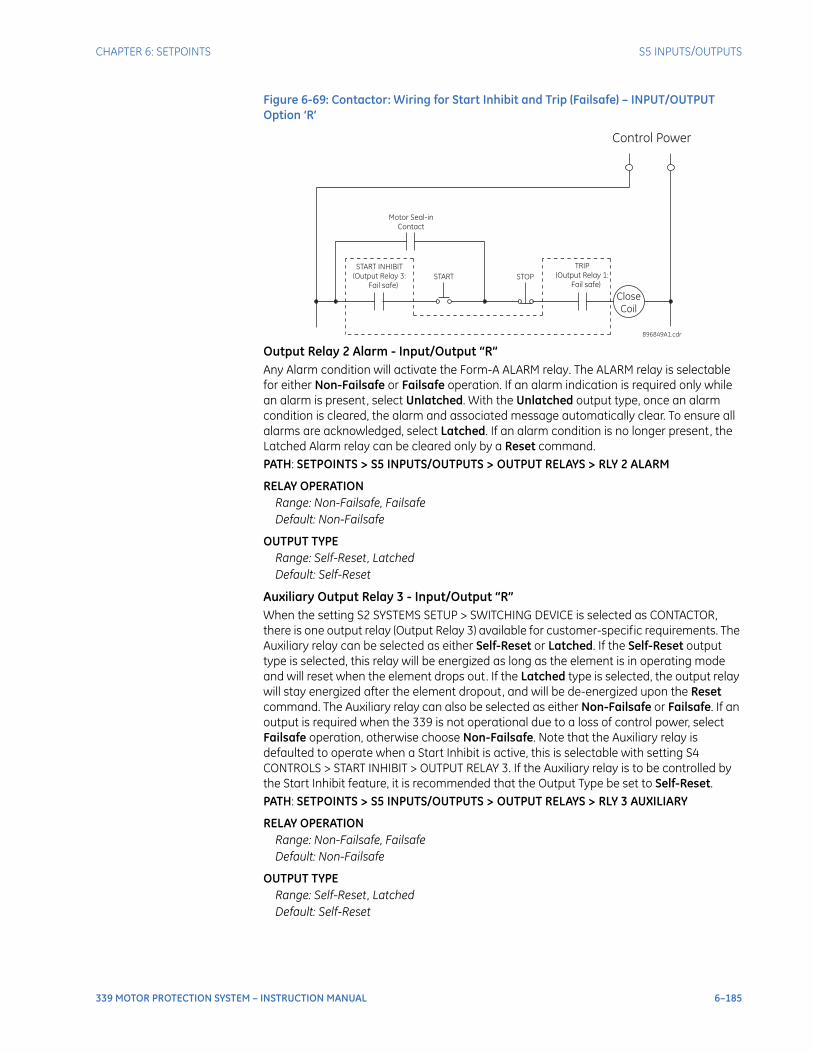
CHAPTER 6: SETPOINTS S5 INPUTS/OUTPUTS
339 MOTOR PROTECTION SYSTEM – INSTRUCTION MANUAL 6–185
Figure 6-69: Contactor: Wiring for Start Inhibit and Trip (Failsafe) – INPUT/OUTPUT Option ‘R’
Output Relay 2 Alarm - Input/Output “R”Any Alarm condition will activate the Form-A ALARM relay. The ALARM relay is selectable for either Non-Failsafe or Failsafe operation. If an alarm indication is required only while an alarm is present, select Unlatched. With the Unlatched output type, once an alarm condition is cleared, the alarm and associated message automatically clear. To ensure all alarms are acknowledged, select Latched. If an alarm condition is no longer present, the Latched Alarm relay can be cleared only by a Reset command.PATH: SETPOINTS > S5 INPUTS/OUTPUTS > OUTPUT RELAYS > RLY 2 ALARM
RELAY OPERATIONRange: Non-Failsafe, FailsafeDefault: Non-Failsafe
OUTPUT TYPERange: Self-Reset, LatchedDefault: Self-Reset
Auxiliary Output Relay 3 - Input/Output “R”When the setting S2 SYSTEMS SETUP > SWITCHING DEVICE is selected as CONTACTOR, there is one output relay (Output Relay 3) available for customer-specific requirements. The Auxiliary relay can be selected as either Self-Reset or Latched. If the Self-Reset output type is selected, this relay will be energized as long as the element is in operating mode and will reset when the element drops out. If the Latched type is selected, the output relay will stay energized after the element dropout, and will be de-energized upon the Reset command. The Auxiliary relay can also be selected as either Non-Failsafe or Failsafe. If an output is required when the 339 is not operational due to a loss of control power, select Failsafe operation, otherwise choose Non-Failsafe. Note that the Auxiliary relay is defaulted to operate when a Start Inhibit is active, this is selectable with setting S4 CONTROLS > START INHIBIT > OUTPUT RELAY 3. If the Auxiliary relay is to be controlled by the Start Inhibit feature, it is recommended that the Output Type be set to Self-Reset.PATH: SETPOINTS > S5 INPUTS/OUTPUTS > OUTPUT RELAYS > RLY 3 AUXILIARY
RELAY OPERATIONRange: Non-Failsafe, FailsafeDefault: Non-Failsafe
OUTPUT TYPERange: Self-Reset, LatchedDefault: Self-Reset
Control Power
START
START INHIBIT
(Output Relay 3:
Fail safe)
Close
Coil
896849A1.cdr
STOP
TRIP
(Output Relay 1:
Fail safe)
Motor Seal-in
Contact
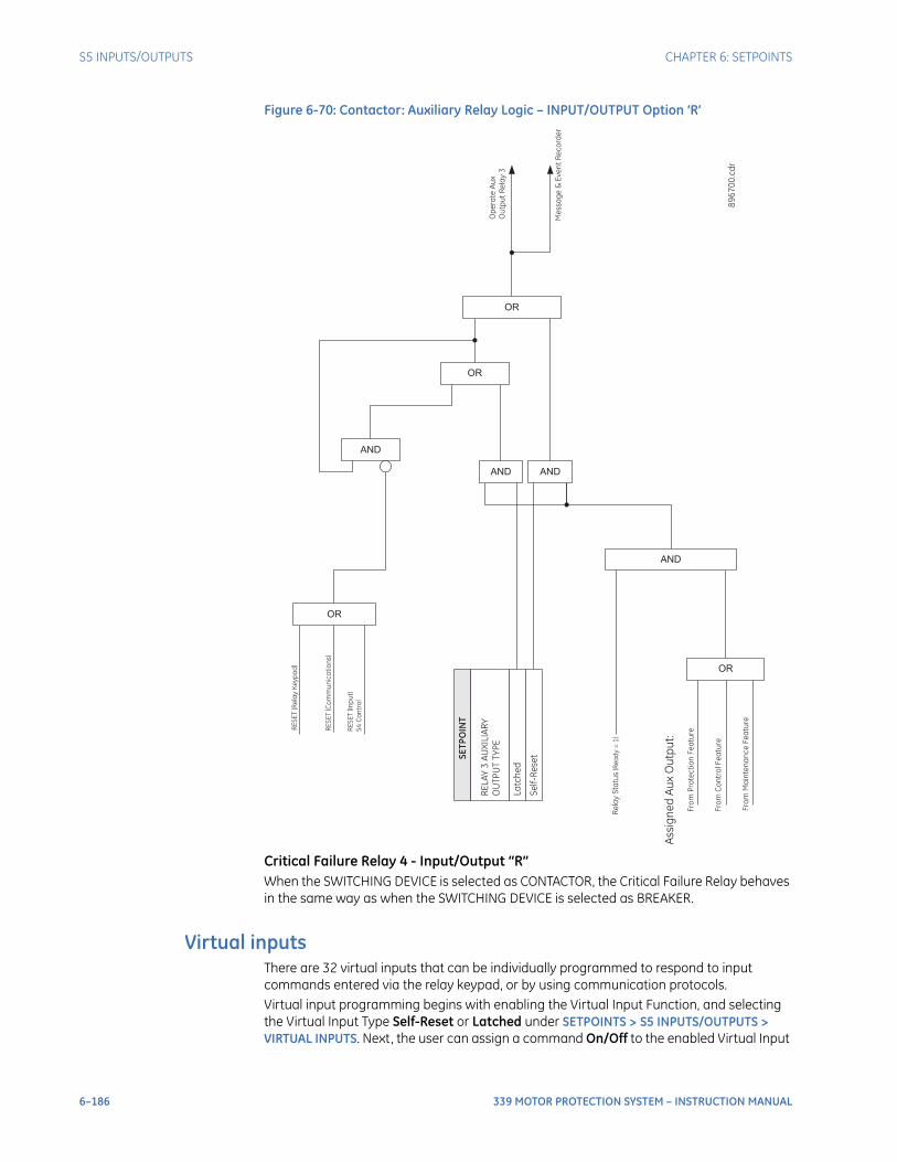
6–186 339 MOTOR PROTECTION SYSTEM – INSTRUCTION MANUAL
S5 INPUTS/OUTPUTS CHAPTER 6: SETPOINTS
Figure 6-70: Contactor: Auxiliary Relay Logic – INPUT/OUTPUT Option ‘R’
Critical Failure Relay 4 - Input/Output “R”When the SWITCHING DEVICE is selected as CONTACTOR, the Critical Failure Relay behaves in the same way as when the SWITCHING DEVICE is selected as BREAKER.
Virtual inputsThere are 32 virtual inputs that can be individually programmed to respond to input commands entered via the relay keypad, or by using communication protocols.Virtual input programming begins with enabling the Virtual Input Function, and selecting the Virtual Input Type Self-Reset or Latched under SETPOINTS > S5 INPUTS/OUTPUTS > VIRTUAL INPUTS. Next, the user can assign a command On/Off to the enabled Virtual Input
Fro
mP
rote
cti
on
Fe
atu
re
OR
Fro
mC
on
tro
lF
ea
ture
Fro
mM
ain
ten
an
ce
Fe
atu
re
Assig
ne
dA
ux
Ou
tpu
t:
AND
Re
lay
Sta
tus
(Re
ad
y=
1)
SE
TP
OIN
T
RE
LA
Y3
AU
XIL
IAR
Y
OU
TP
UT
TY
PE
La
tch
ed
Se
lf-R
ese
t
AND AND
OR
AND
OR
RE
SE
T(R
ela
yK
ey
pa
d)
RE
SE
T(C
om
mu
nic
ati
on
s)
RE
SE
T(In
pu
t)
S4
Co
ntr
ol
OR
Op
era
teA
ux
Ou
tpu
tR
ela
y3
Me
ssa
ge
&E
ve
nt
Re
co
rde
r
89
67
00
. cd
r
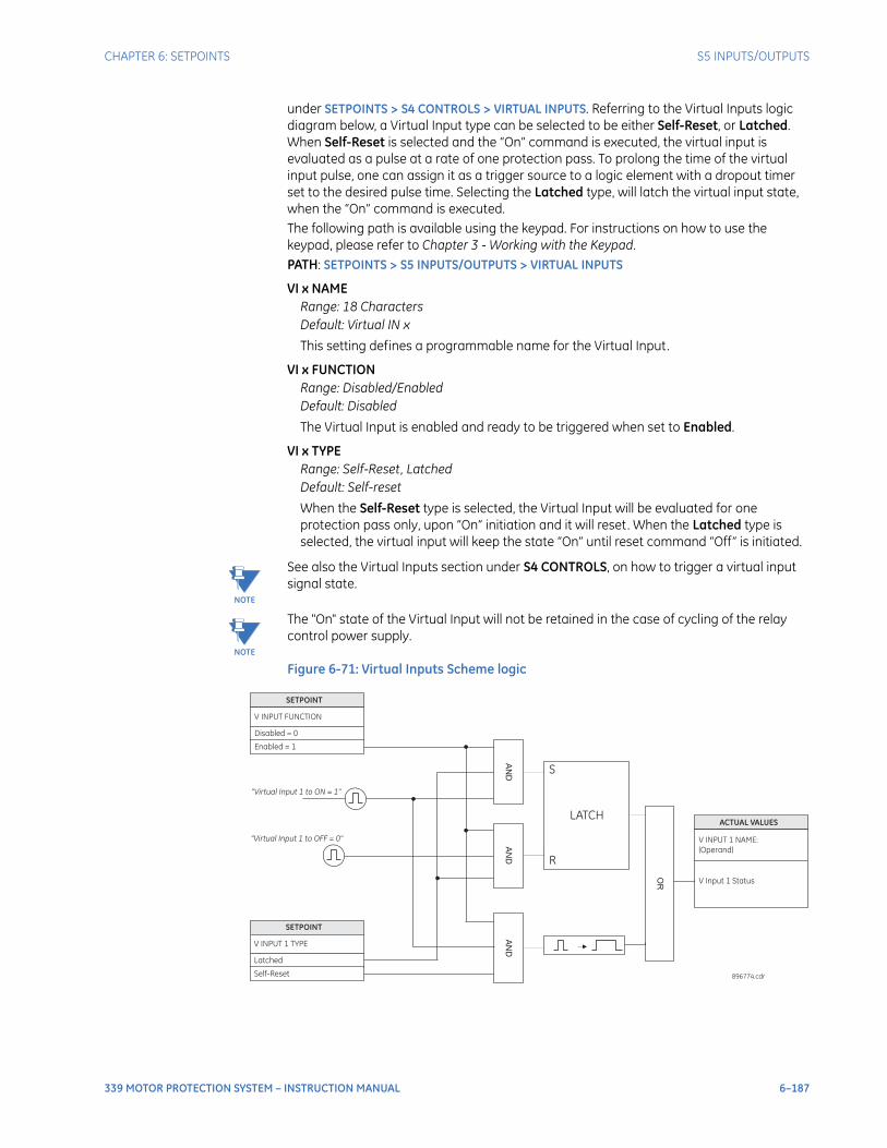
CHAPTER 6: SETPOINTS S5 INPUTS/OUTPUTS
339 MOTOR PROTECTION SYSTEM – INSTRUCTION MANUAL 6–187
under SETPOINTS > S4 CONTROLS > VIRTUAL INPUTS. Referring to the Virtual Inputs logic diagram below, a Virtual Input type can be selected to be either Self-Reset, or Latched. When Self-Reset is selected and the “On” command is executed, the virtual input is evaluated as a pulse at a rate of one protection pass. To prolong the time of the virtual input pulse, one can assign it as a trigger source to a logic element with a dropout timer set to the desired pulse time. Selecting the Latched type, will latch the virtual input state, when the “On” command is executed. The following path is available using the keypad. For instructions on how to use the keypad, please refer to Chapter 3 - Working with the Keypad.PATH: SETPOINTS > S5 INPUTS/OUTPUTS > VIRTUAL INPUTS
VI x NAMERange: 18 CharactersDefault: Virtual IN x
This setting defines a programmable name for the Virtual Input.
VI x FUNCTIONRange: Disabled/EnabledDefault: Disabled
The Virtual Input is enabled and ready to be triggered when set to Enabled.
VI x TYPERange: Self-Reset, LatchedDefault: Self-reset
When the Self-Reset type is selected, the Virtual Input will be evaluated for one protection pass only, upon “On” initiation and it will reset. When the Latched type is selected, the virtual input will keep the state “On” until reset command “Off” is initiated.
NOTE
NOTE: See also the Virtual Inputs section under S4 CONTROLS, on how to trigger a virtual input signal state.
NOTE
NOTE: The "On" state of the Virtual Input will not be retained in the case of cycling of the relay control power supply.
Figure 6-71: Virtual Inputs Scheme logic
SETPOINT
V INPUT FUNCTION
Disabled = 0
Enabled = 1
AN
D
SETPOINT
V INPUT 1 TYPE
Latched
Self-Reset
AN
DA
ND
“Virtual Input 1 to ON = 1"
“Virtual Input 1 to OFF = 0"
S
R
LATCH
OR
ACTUAL VALUES
V INPUT 1 NAME:
(Operand)
V Input 1 Status
896774.cdr

6–188 339 MOTOR PROTECTION SYSTEM – INSTRUCTION MANUAL
S5 INPUTS/OUTPUTS CHAPTER 6: SETPOINTS
339 MOTOR PROTECTION SYSTEM – INSTRUCTION MANUAL 7–1
339 Motor Protection System
Chapter 7: Maintenance
GEGrid Solutions
Maintenance
Information about the relay and the breaker can be obtained through the features included in the Maintenance page.
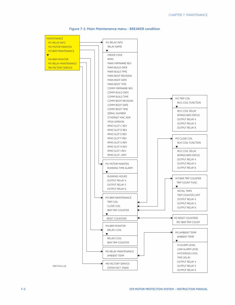
7–2 339 MOTOR PROTECTION SYSTEM – INSTRUCTION MANUAL
CHAPTER 7: MAINTENANCE
Figure 7-1: Main Maintenance menu - BREAKER condition
M6 FACTORY SERVICE
ENTER FACT. PSWD
M4 BKR MONITOR
RELAY1 COIL
RELAY2 COIL
BKR TRIP COUNTER
M1 RELAY INFO
RELAY NAME
ORDER CODE
RMIO
MAIN FIRMWARE REV
MAIN BUILD DATE
MAIN BUILD TIME
MAIN BOOT REVISION
MAIN BOOT DATE
MAIN BOOT TIME
COMM FIRMWARE REV
COMM BUILD DATE
COMM BUILD TIME
COMM BOOT REVISION
COMM BOOT DATE
COMM BOOT TIME
SERIAL NUMBER
ETHERNET MAC ADR
FPGA VERSION
RMIO SLOT C REV
RMIO SLOT D REV
RMIO SLOT E REV
RMIO SLOT F REV
RMIO SLOT G REV
RMIO SLOT H REV
RMIO SLOT I REV
RMIO SLOT J REV
MAINTENANCE
M1 RELAY INFO
M2 MOTOR MAINTEN
M3 BKR MAINTENANCE
M4 BKR MONITOR
M5 RELAY MAINTENANCE
M6 FACTORY SERVICE
M3 TRIP COIL
RLY1 COIL FUNCTION
RLY1 COIL DELAY
BYPASS BKR STATUS
OUTPUT RELAY 4
OUTPUT RELAY 5
OUTPUT RELAY 6
896761A1.cdr
M3 BKR MAINTENANCE
TRIP COIL
CLOSE COIL
BKR TRIP COUNTER
RESET COUNTERS
M3 RESET COUNTERS
RST BKR TRIP COUNT
M3 BKR TRIP COUNTER
TRIP COUNT FUNC
INITIAL TRIPS
TRIP COUNTER LIMIT
OUTPUT RELAY 4
OUTPUT RELAY 6
OUTPUT RELAY 5
M3 CLOSE COIL
RLY2 COIL FUNCTION
RLY2 COIL DELAY
BYPASS BKR STATUS
OUTPUT RELAY 4
OUTPUT RELAY 5
OUTPUT RELAY 6
M2 MOTOR MAINTEN
RUNNING TIME ALARM
RUNNING HOURS
OUTPUT RELAY 4
OUTPUT RELAY 5
OUTPUT RELAY 6
M5 RELAY MAINTENANCE
AMBIENT TEMP
M5 AMBIENT TEMP
AMBIENT TEMP
LOW ALARM LEVEL
HYSTERESIS LEVEL
TIME DELAY
OUTPUT RELAY 4
OUTPUT RELAY 5
OUTPUT RELAY 6
HI ALARM LEVEL
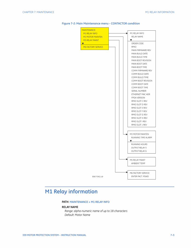
CHAPTER 7: MAINTENANCE M1 RELAY INFORMATION
339 MOTOR PROTECTION SYSTEM – INSTRUCTION MANUAL 7–3
Figure 7-2: Main Maintenance menu - CONTACTOR condition
M1 Relay information
PATH: MAINTENANCE > M1 RELAY INFO
RELAY NAMERange: alpha-numeric name of up to 18 characters Default: Motor Name
896770A2.cdr
M6 FACTORY SERVICE
ENTER FACT. PSWD
M1 RELAY INFO
RELAY NAME
ORDER CODE
RMIO
MAIN FIRMWARE REV
MAIN BUILD DATE
MAIN BUILD TIME
MAIN BOOT REVISION
MAIN BOOT DATE
MAIN BOOT TIME
COMM FIRMWARE REV
COMM BUILD DATE
COMM BUILD TIME
COMM BOOT REVISION
COMM BOOT DATE
COMM BOOT TIME
SERIAL NUMBER
ETHERNET MAC ADR
FPGA VERSION
RMIO SLOT C REV
RMIO SLOT D REV
RMIO SLOT E REV
RMIO SLOT F REV
RMIO SLOT G REV
RMIO SLOT H REV
RMIO SLOT I REV
RMIO SLOT J REV
MAINTENANCE
M1 RELAY INFO
M2 MOTOR MAINTEN
M5 RELAY MAINT
M6 FACTORY SERVICE
M3 MOTOR MAINTEN
RUNNING TIME ALARM
RUNNING HOURS
OUTPUT RELAY 5
OUTPUT RELAY 6
M5 RELAY MAINT
AMBIENT TEMP
7–4 339 MOTOR PROTECTION SYSTEM – INSTRUCTION MANUAL
M1 RELAY INFORMATION CHAPTER 7: MAINTENANCE
ORDER CODE339-EP5G5HESNP2EDN
This screen shows the relay Order Code.
RMIORange: G, GG, GGG, GGGG
Displays the validated RMIO. This value will be seen only if the RMIO module is installed.
MAIN FIRMWARE REVISION1.41
This screen shows the relay Main Firmware Revision.
MAIN BUILD DATEAug 16 2010
This screen shows the relay Main Firmware Build Date.
MAIN BUILD TIME16:32:38
This screen shows the relay Main Firmware Build Time.
MAIN BOOT REVISION1.20
This screen shows the relay Main Boot Code Revision.
MAIN BOOT DATEDec 11 2009
This screen shows the relay Main Boot Code Build Date.
MAIN BOOT TIME10:44:54
This screen shows the relay Main Boot Code Build Time.
COMM FIRMWARE REVISION1.41
This screen shows the relay Comm Code Revision.
COMM BUILD DATEAug 16 2010
This screen shows the relay Comm Code Build Date.
COMM BUILD TIME17:51:38
This screen shows the relay Comm Code Build Time.
COMM BOOT REVISION1.20
This screen shows the relay Comm Boot Code Revision.
COMM BOOT TIME11:47:17
This screen shows the relay Comm Boot Code Build Time.
SERIAL NUMBERML0A08M00133
Each 339 relay has a unique serial number.
ETHERNET MAC ADR00:A0F4:00:0B:78
This screen shows the Ethernet MAC Address of the relay.
CHAPTER 7: MAINTENANCE M2 MOTOR MAINTENANCE
339 MOTOR PROTECTION SYSTEM – INSTRUCTION MANUAL 7–5
FPGA VERSION1.00
This screen shows the FPGA Version.
RMIO SLOT C REV1.75
RMIO SLOT D REV1.75
RMIO SLOT E REV1.75
RMIO SLOT F REV1.75
RMIO SLOT G REV1.75
RMIO SLOT H REV1.75
RMIO SLOT I REV1.75
RMIO SLOT J REV1.75
M2 Motor maintenance
PATH: MAINTENANCE > M2 MOTOR MAINTEN
When the motor running time exceeds the setting RUNNING HOURS, a "Motor Running Hrs Alarm” is generated, and this alarm can be assigned to any available auxiliary output relays. To clear the counter for “Motor Running Hours”, use the command “S1 RELAY SETUP / PRESET STATISTICS / SET RUNNING HOURS” to preset this value to 0.
RUNNING TIME ALARMRange: Disabled, EnabledDefault: Disabled
This setting enables the Motor Running Time Alarm functionality. If this feature is not required, set this setting to Disabled.
RUNNING HOURSRange: 0 to 65535 hrs in steps of 1 hrDefault: 0 hrs
This setting specifies a motor running time above which an alarm should be issued.
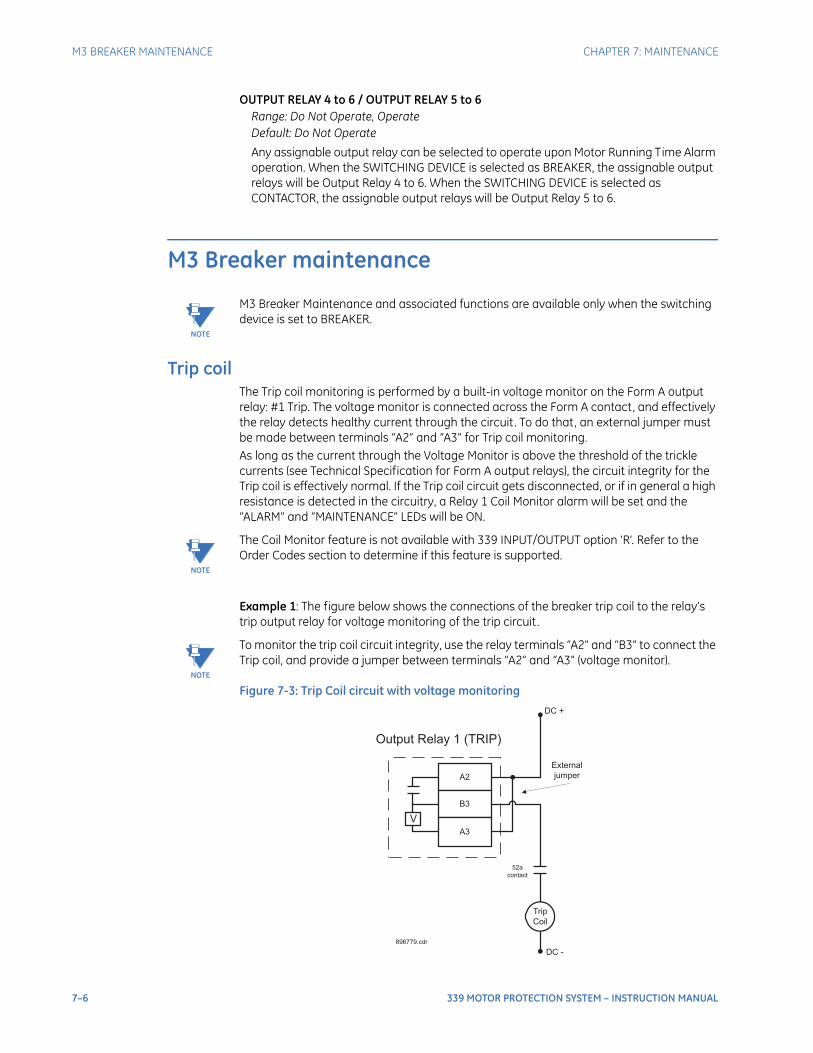
7–6 339 MOTOR PROTECTION SYSTEM – INSTRUCTION MANUAL
M3 BREAKER MAINTENANCE CHAPTER 7: MAINTENANCE
OUTPUT RELAY 4 to 6 / OUTPUT RELAY 5 to 6Range: Do Not Operate, OperateDefault: Do Not Operate
Any assignable output relay can be selected to operate upon Motor Running Time Alarm operation. When the SWITCHING DEVICE is selected as BREAKER, the assignable output relays will be Output Relay 4 to 6. When the SWITCHING DEVICE is selected as CONTACTOR, the assignable output relays will be Output Relay 5 to 6.
M3 Breaker maintenance
NOTE
NOTE: M3 Breaker Maintenance and associated functions are available only when the switching device is set to BREAKER.
Trip coilThe Trip coil monitoring is performed by a built-in voltage monitor on the Form A output relay: #1 Trip. The voltage monitor is connected across the Form A contact, and effectively the relay detects healthy current through the circuit. To do that, an external jumper must be made between terminals “A2” and “A3” for Trip coil monitoring. As long as the current through the Voltage Monitor is above the threshold of the trickle currents (see Technical Specification for Form A output relays), the circuit integrity for the Trip coil is effectively normal. If the Trip coil circuit gets disconnected, or if in general a high resistance is detected in the circuitry, a Relay 1 Coil Monitor alarm will be set and the “ALARM” and “MAINTENANCE” LEDs will be ON.
NOTE
NOTE: The Coil Monitor feature is not available with 339 INPUT/OUTPUT option ‘R’. Refer to the Order Codes section to determine if this feature is supported.
.
Example 1: The figure below shows the connections of the breaker trip coil to the relay’s trip output relay for voltage monitoring of the trip circuit.
NOTE
NOTE: To monitor the trip coil circuit integrity, use the relay terminals “A2” and “B3” to connect the Trip coil, and provide a jumper between terminals “A2” and “A3” (voltage monitor).
Figure 7-3: Trip Coil circuit with voltage monitoring
External
jumper
V
A2
B3
A3
Trip
Coil
DC +
DC -
Output Relay 1 (TRIP)
52a
contact
896779.cdr
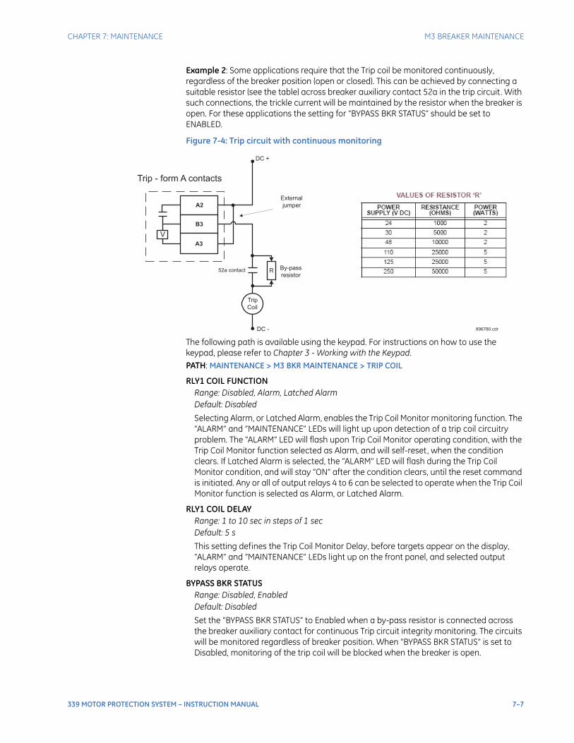
CHAPTER 7: MAINTENANCE M3 BREAKER MAINTENANCE
339 MOTOR PROTECTION SYSTEM – INSTRUCTION MANUAL 7–7
Example 2: Some applications require that the Trip coil be monitored continuously, regardless of the breaker position (open or closed). This can be achieved by connecting a suitable resistor (see the table) across breaker auxiliary contact 52a in the trip circuit. With such connections, the trickle current will be maintained by the resistor when the breaker is open. For these applications the setting for “BYPASS BKR STATUS” should be set to ENABLED.
Figure 7-4: Trip circuit with continuous monitoring
The following path is available using the keypad. For instructions on how to use the keypad, please refer to Chapter 3 - Working with the Keypad.PATH: MAINTENANCE > M3 BKR MAINTENANCE > TRIP COIL
RLY1 COIL FUNCTIONRange: Disabled, Alarm, Latched AlarmDefault: Disabled
Selecting Alarm, or Latched Alarm, enables the Trip Coil Monitor monitoring function. The “ALARM” and “MAINTENANCE” LEDs will light up upon detection of a trip coil circuitry problem. The “ALARM” LED will flash upon Trip Coil Monitor operating condition, with the Trip Coil Monitor function selected as Alarm, and will self-reset, when the condition clears. If Latched Alarm is selected, the “ALARM” LED will flash during the Trip Coil Monitor condition, and will stay “ON” after the condition clears, until the reset command is initiated. Any or all of output relays 4 to 6 can be selected to operate when the Trip Coil Monitor function is selected as Alarm, or Latched Alarm.
RLY1 COIL DELAYRange: 1 to 10 sec in steps of 1 secDefault: 5 s
This setting defines the Trip Coil Monitor Delay, before targets appear on the display, “ALARM” and “MAINTENANCE” LEDs light up on the front panel, and selected output relays operate.
BYPASS BKR STATUSRange: Disabled, EnabledDefault: Disabled
Set the “BYPASS BKR STATUS” to Enabled when a by-pass resistor is connected across the breaker auxiliary contact for continuous Trip circuit integrity monitoring. The circuits will be monitored regardless of breaker position. When “BYPASS BKR STATUS” is set to Disabled, monitoring of the trip coil will be blocked when the breaker is open.
Trip
Coil
DC -
R By-pass
resistor52a contact
External
jumper
V
A2
B3
A3
DC +
Trip - form A contacts
896780.cdr

7–8 339 MOTOR PROTECTION SYSTEM – INSTRUCTION MANUAL
M3 BREAKER MAINTENANCE CHAPTER 7: MAINTENANCE
OUTPUT RELAY 4 to 6Range: Do not operate, OperateDefault: Do not operate
Any, or all, of output relays 4 to 6 can be selected to operate upon detection of Trip Coil, or a Trip coil circuitry problem. The selection of the relay outputs operation is available no matter whether the Alarm, or Latched Alarm, function is selected.
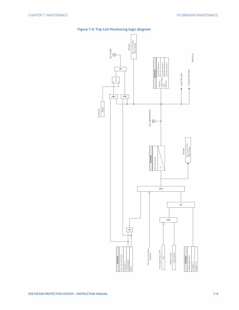
CHAPTER 7: MAINTENANCE M3 BREAKER MAINTENANCE
339 MOTOR PROTECTION SYSTEM – INSTRUCTION MANUAL 7–9
Figure 7-5: Trip Coil Monitoring logic diagram
SE
TP
OIN
T
RLY
1C
OIL
FU
NC
TIO
N:
Dis
ab
led
=0
La
tch
ed
Ala
rm
Ev
en
tR
ec
ord
er
Tra
nsie
nt
Re
co
rde
r
Ala
rm
OR
OR
AND
SE
TP
OIN
T:
Op
era
te
ou
tpu
tre
lay
s
up
on
se
lec
tio
n
OU
TP
UT
RE
LA
Y5
OU
TP
UT
RE
LA
Y6
OU
TP
UT
RE
LA
Y4
Rly
1C
oil
Mn
Alr
m
Sta
te:O
pe
rate
Me
ssa
ge
Tri
pC
oil
cu
rre
nt
ab
ove
thre
sh
old
AND
OR
52
a/b
INP
UT
S
Bre
ake
rC
lose
d
Tri
p
Fro
mo
utp
ut
rela
y1
TR
IP
SE
TP
OIN
T
BY
PA
SS
BK
RS
TA
TU
S
En
ab
led
=1
Dis
ab
le=
0
AND
RLY
1C
OIL
DE
LA
Y:
SE
TP
OIN
T
t PK
P
LE
D:M
AIN
TE
NA
NC
E
Me
ssa
ge
LE
D:A
LA
RM
RE
SE
T
Co
mm
an
d
AND
S R
LA
TC
H
89
67
84
.cd
r
Rly
1C
oil
Mn
Alr
m
Sta
te:P
icku
p
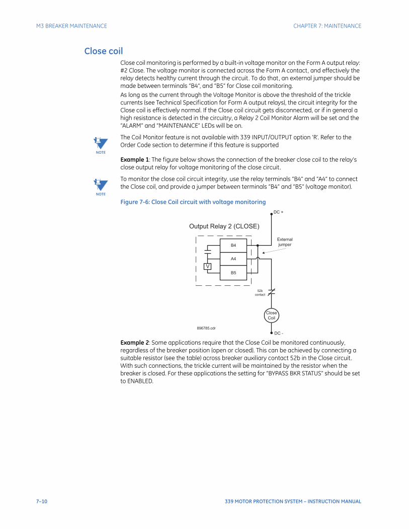
7–10 339 MOTOR PROTECTION SYSTEM – INSTRUCTION MANUAL
M3 BREAKER MAINTENANCE CHAPTER 7: MAINTENANCE
Close coilClose coil monitoring is performed by a built-in voltage monitor on the Form A output relay: #2 Close. The voltage monitor is connected across the Form A contact, and effectively the relay detects healthy current through the circuit. To do that, an external jumper should be made between terminals “B4”, and “B5” for Close coil monitoring. As long as the current through the Voltage Monitor is above the threshold of the trickle currents (see Technical Specification for Form A output relays), the circuit integrity for the Close coil is effectively normal. If the Close coil circuit gets disconnected, or if in general a high resistance is detected in the circuitry, a Relay 2 Coil Monitor Alarm will be set and the “ALARM” and “MAINTENANCE” LEDs will be on.
NOTE
NOTE: The Coil Monitor feature is not available with 339 INPUT/OUTPUT option ‘R’. Refer to the Order Code section to determine if this feature is supported
Example 1: The figure below shows the connection of the breaker close coil to the relay’s close output relay for voltage monitoring of the close circuit.
NOTE
NOTE: To monitor the close coil circuit integrity, use the relay terminals “B4” and “A4” to connect the Close coil, and provide a jumper between terminals “B4” and “B5” (voltage monitor).
Figure 7-6: Close Coil circuit with voltage monitoring
Example 2: Some applications require that the Close Coil be monitored continuously, regardless of the breaker position (open or closed). This can be achieved by connecting a suitable resistor (see the table) across breaker auxiliary contact 52b in the Close circuit. With such connections, the trickle current will be maintained by the resistor when the breaker is closed. For these applications the setting for “BYPASS BKR STATUS” should be set to ENABLED.
External
jumper
V
B4
A4
B5
Close
Coil
DC +
DC -
Output Relay 2 (CLOSE)
52b
contact
896785.cdr
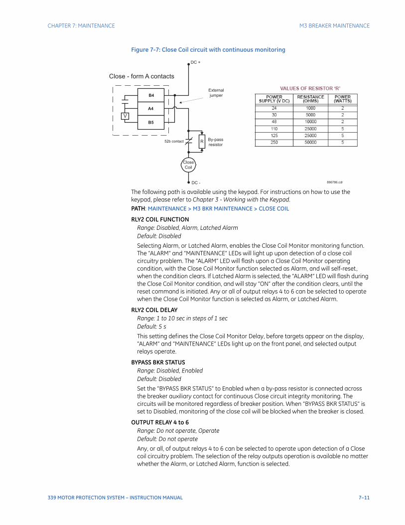
CHAPTER 7: MAINTENANCE M3 BREAKER MAINTENANCE
339 MOTOR PROTECTION SYSTEM – INSTRUCTION MANUAL 7–11
Figure 7-7: Close Coil circuit with continuous monitoring
The following path is available using the keypad. For instructions on how to use the keypad, please refer to Chapter 3 - Working with the Keypad.PATH: MAINTENANCE > M3 BKR MAINTENANCE > CLOSE COIL
RLY2 COIL FUNCTIONRange: Disabled, Alarm, Latched AlarmDefault: Disabled
Selecting Alarm, or Latched Alarm, enables the Close Coil Monitor monitoring function. The “ALARM” and “MAINTENANCE” LEDs will light up upon detection of a close coil circuitry problem. The “ALARM” LED will flash upon a Close Coil Monitor operating condition, with the Close Coil Monitor function selected as Alarm, and will self-reset, when the condition clears. If Latched Alarm is selected, the “ALARM” LED will flash during the Close Coil Monitor condition, and will stay “ON” after the condition clears, until the reset command is initiated. Any or all of output relays 4 to 6 can be selected to operate when the Close Coil Monitor function is selected as Alarm, or Latched Alarm.
RLY2 COIL DELAYRange: 1 to 10 sec in steps of 1 secDefault: 5 s
This setting defines the Close Coil Monitor Delay, before targets appear on the display, “ALARM” and “MAINTENANCE” LEDs light up on the front panel, and selected output relays operate.
BYPASS BKR STATUSRange: Disabled, EnabledDefault: Disabled
Set the “BYPASS BKR STATUS” to Enabled when a by-pass resistor is connected across the breaker auxiliary contact for continuous Close circuit integrity monitoring. The circuits will be monitored regardless of breaker position. When “BYPASS BKR STATUS” is set to Disabled, monitoring of the close coil will be blocked when the breaker is closed.
OUTPUT RELAY 4 to 6Range: Do not operate, OperateDefault: Do not operate
Any, or all, of output relays 4 to 6 can be selected to operate upon detection of a Close coil circuitry problem. The selection of the relay outputs operation is available no matter whether the Alarm, or Latched Alarm, function is selected.
Close
Coil
DC -
R By-pass
resistor52b contact
External
jumper
V
B4
B5
DC +
Close - form A contacts
896786.cdr
A4
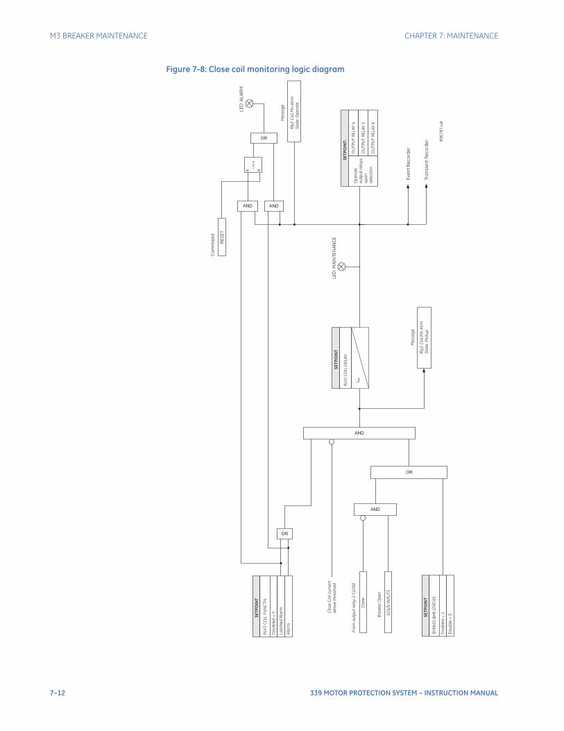
7–12 339 MOTOR PROTECTION SYSTEM – INSTRUCTION MANUAL
M3 BREAKER MAINTENANCE CHAPTER 7: MAINTENANCE
Figure 7-8: Close coil monitoring logic diagram
SE
TP
OIN
T
RLY
2C
OIL
FU
NC
TN
:
Dis
ab
led
=0
La
tch
ed
Ala
rm
Ev
en
tR
ec
ord
er
Tra
nsie
nt
Re
co
rde
r
Ala
rm
OR
OR
AND
SE
TP
OIN
T:
Op
era
te
ou
tpu
tre
lay
s
up
on
se
lec
tio
n
OU
TP
UT
RE
LA
Y5
OU
TP
UT
RE
LA
Y6
OU
TP
UT
RE
LA
Y4
Rly
2C
oil
Mn
Alr
m
Sta
te:O
pe
ra
te
Me
ssa
ge
Clo
se
Co
ilcu
rre
nt
ab
ove
thre
sh
old
AND
OR
52
a/b
INP
UT
S
Bre
ake
rO
pe
n
Clo
se
Fro
mo
utp
ut
rela
y2
CLO
SE
SE
TP
OIN
T
BY
PA
SS
BK
RS
TA
TU
S
En
ab
led
=1
Dis
ab
le=
0
AND
RLY
2C
OIL
DE
LA
Y:
SE
TP
OIN
T
t PK
P
LE
D:M
AIN
TE
NA
NC
E
Me
ssa
ge
LE
D:A
LA
RM
RE
SE
T
Co
mm
an
d
AND
S R
LA
TC
H
89
67
87
.cd
r
Rly
2C
oil
Mn
Alr
m
Sta
te:P
icku
p
CHAPTER 7: MAINTENANCE M3 BREAKER MAINTENANCE
339 MOTOR PROTECTION SYSTEM – INSTRUCTION MANUAL 7–13
Breaker trip counterWhen the total number of breaker trips detected reaches the TRIP COUNTER LIMIT setpoint, an output will occur.The following path is available using the keypad. For instructions on how to use the keypad, please refer to Chapter 3 - Working with the Keypad.PATH: MAINTENANCE > M3 BKR MAINTENANCE > BKR TRIP COUNTER
TRIP COUNT FUNCRange: Disabled, Alarm, Latched AlarmDefault: Disabled
The selection of the Latched Alarm, or Alarm setting enables the BKR Trip Counter function. The “ALARM” LED will turn on when the Total breaker trips reaches the TRIP COUNTER LIMIT setting. The “ALARM” LED will flash when the BKR Trip Counter reaches the TRIP COUNTER LIMIT setting with function selected as Alarm, and will reset, when the trip counter is reset. The “ALARM” LED will latch when Latched Alarm is selected, until the counter is reset, and the Reset command is initiated.
Any or all of output relays 4 to 6 can be selected to operate when the number of breaker trips reaches the “TRIP COUNTER LIMIT,” regardless of the selected trip counter function.
INITIAL TRIPSRange: 0 to 10000 in steps of 1Default: 0
This setting defines the number of breaker trips, that occurred before enabling the breaker trip counter for breaker monitoring.
TRIP COUNTER LIMITRange: 1 to 10000 trips in steps of 1Default: 1 trip
This setting defines the limit number for breaker trips. The BKR TRIP COUNTER will operate and produce an output if the number of breaker trips reaches the set limit.
OUTPUT RELAY 4 to 6Range: Do not operate, OperateDefault: Do not operate
Any, or all, of output relays 4 to 6 can be selected to operate, upon the BKR TRIP COUNTER condition.
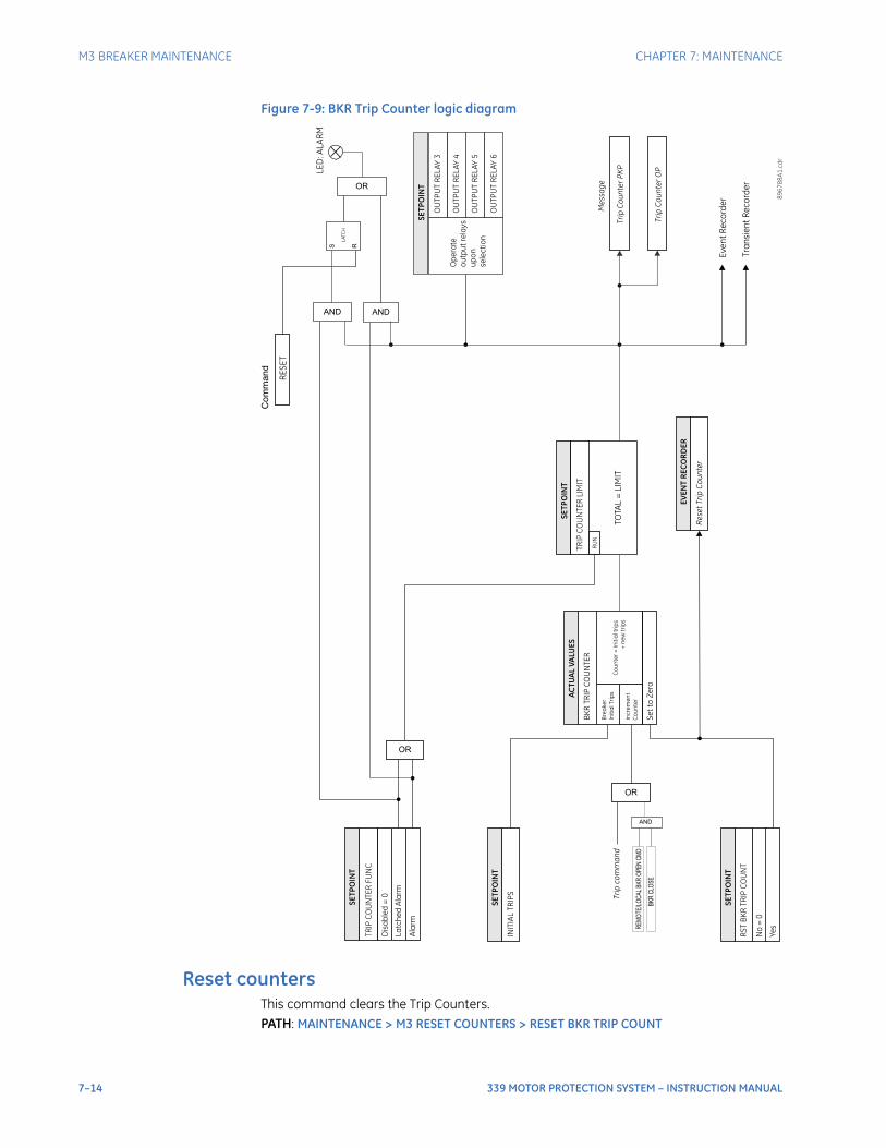
7–14 339 MOTOR PROTECTION SYSTEM – INSTRUCTION MANUAL
M3 BREAKER MAINTENANCE CHAPTER 7: MAINTENANCE
Figure 7-9: BKR Trip Counter logic diagram
Reset countersThis command clears the Trip Counters.PATH: MAINTENANCE > M3 RESET COUNTERS > RESET BKR TRIP COUNT
TOTA
L =
LIM
IT
OR
RUN
SETP
OIN
T
Even
t Rec
orde
r
Tran
sien
t Rec
orde
r
SETP
OIN
T
Ope
rate
outp
ut re
lays
upon
sele
ctio
n
OU
TPU
T RE
LAY
4
OU
TPU
T RE
LAY
5
OU
TPU
T RE
LAY
6
OU
TPU
T RE
LAY
3
Trip
Cou
nter
PKP
Trip
Cou
nter
OP
Mes
sage
SETP
OIN
T
TRIP
CO
UN
TER
FUN
C
Dis
able
d =
0
Latc
hed
Alar
m
Alar
m
OR
OR
AND
Trip
com
man
d
INIT
IAL
TRIP
S
SETP
OIN
T
Incr
emen
tCo
unte
r
TRIP
CO
UN
TER
LIM
ITBK
R TR
IP C
OU
NTE
R
ACTU
AL V
ALU
ES
Brea
ker
Initi
al T
rips
Coun
ter =
Initi
al tr
ips
+ ne
w tr
ips
RST
BKR
TRIP
CO
UN
T
SETP
OIN
T
No
= 0
Yes
Set t
o Ze
ro
LED
: ALA
RM
RESE
T
Com
man
d
AND
S R
LATC
H
8967
88A1
.cdr
EVEN
T RE
CORD
ER
Rese
t Trip
Cou
nter
REMO
TE/LO
CAL B
KR O
PEN
CMD
BKR
CLOS
E
AND
CHAPTER 7: MAINTENANCE M4 BREAKER MONITOR
339 MOTOR PROTECTION SYSTEM – INSTRUCTION MANUAL 7–15
RST BKR TRIP COUNTRange: No, YesDefault: No
Entering a "Yes" command will clear the Trip Counters, and an event - "Reset Trip Counter" - will be recorded
M4 Breaker monitor
The status of the breaker trip and close coils, as well as the trip and close circuits, can be monitored under MAINTENANCE > M4 BKR MONITOR. In the case where a breaker coil or circuit fails, the relay will display the message "Unhealthy" for the corresponding coil.Further information on the breaker is provided under BKR TRIP COUNTER, which displays the number of trips. The counter can be reset under M3 RESET COUNTERS > RST BKR TRIP COUNT set to "Yes".PATH: MAINTENANCE > M4 BKR MONITOR
RELAY1 COILHealthy
Range: Healthy, Unhealthy
RELAY2 COILHealthy
Range: Healthy, Unhealthy
BKR TRIP COUNTER5
Range: 0 to 50000 trips
M5 Relay maintenance
Ambient temperatureThe SR3 has a temperature monitor feature that measures the ambient temperature around the chassis of the relay. The relay extrapolates the ambient temperature from an internal temperature sensor inside the product. This feature can be used to signal the customer that the product is being subjected to temperatures that can degrade the product life and proper action should be initiated. For example the air conditioning, heating or ventilation system should be checked. The purpose of the feature is to measure the immediate temperature around the product. There are several factors that can alter the measurement that need to be considered for the application of this feature.
• Any forced air flow or obstructions that can interrupt even distribution of the ambient temperature.
• Installation of the relay should be for normal operation (CT, VT, inputs, outputs).
PATH: MAINTENANCE > M5 RELAY MAINTENANCE > AMBIENT TEMP
7–16 339 MOTOR PROTECTION SYSTEM – INSTRUCTION MANUAL
M5 RELAY MAINTENANCE CHAPTER 7: MAINTENANCE
AMBIENT TEMPERATURERange: Disabled, Alarm, Latched AlarmDefault: Disabled
This setting enables the ambient temperature functionality. If the operating condition is satisfied when Alarm is selected as the function, the “ALARM” LED will flash upon the activating condition, and will automatically reset when the condition clears. If Latched Alarm is selected, the LED “ALARM” will flash upon the activating condition, and will stay “ON” after the condition clears, until a reset command is initiated. Any assignable output relays can be selected to operate when this function is enabled.
HI ALARM LEVELRange: 20°C to 80°C in steps of 1°CDefault: 60°C
This setting specifies the temperature level monitored by the Ambient Temperature Alarm high logic. The alarm will occur when the temperature remains above this level.
LOW ALARM LEVELRange: -40°C to 20°C in steps of 1°CDefault: 10°C
This setting specifies the temperature level monitored by the Ambient Temperature Alarm low logic. The alarm will occur when the temperature remains below this level.
HYSTERESIS LEVELRange: 2°C to 10°C in steps of 1°CDefault: 2°C
This setting allows the user to select the dropout level for the feature.
TIME DELAYRange: 1 to 60 min in steps of 1 minDefault: 1 min
This timer starts when either the high or low level thresholds have exceeded their respective levels.
OUTPUT RELAY 4 to 6 / OUTPUT RELAY 5 to 6Range: Do Not Operate, OperateDefault: Do Not Operate
Any assignable output relay can be selected to operate upon Ambient Temperature Alarm operation. When the SWITCHING DEVICE is selected as BREAKER, the assignable output relays will be Output Relay 4 to 6. When the SWITCHING DEVICE is selected as CONTACTOR, the assignable output relays will be Output Relay 5 to 6.
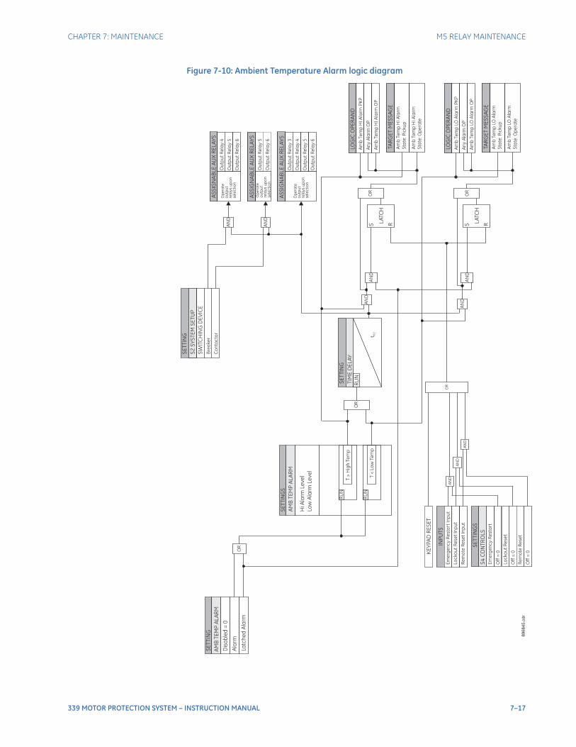
CHAPTER 7: MAINTENANCE M5 RELAY MAINTENANCE
339 MOTOR PROTECTION SYSTEM – INSTRUCTION MANUAL 7–17
Figure 7-10: Ambient Temperature Alarm logic diagram
SE
TT
ING
S
SE
TT
ING
RU
N
LA
TC
H
S R
LO
GIC
OP
ER
AN
D
Am
bTe
mp
HI
Ala
rmP
KP
An
yA
larm
OP
TA
RG
ET
ME
SS
AG
E
Am
bTe
mp
HI
Ala
rm
Sta
te:P
icku
p
SE
TT
ING
SW
ITC
HIN
GD
EV
ICE
Bre
ake
r
Co
nta
cto
rA
SS
IGN
AB
LE
AU
XR
EL
AY
S
Ou
tpu
tR
ela
y4
Ou
tpu
tR
ela
y5
Ou
tpu
tR
ela
y6
Op
era
te
ou
tpu
t
rela
ys
up
on
se
lec
tio
n
AS
SIG
NA
BL
EA
UX
RE
LA
YS
Ou
tpu
tR
ela
y5
Ou
tpu
tR
ela
y6
Op
era
te
ou
tpu
t
rela
ys
up
on
se
lec
tio
nA
ND
AN
D
89
68
45
.cd
r
Am
bTe
mp
HI
Ala
rmO
P
AM
BT
EM
PA
LA
RM
Ala
rm
La
tch
ed
Ala
rm
AM
BT
EM
PA
LA
RM
HiA
larm
Le
ve
l
Lo
wA
larm
Le
ve
l
T>
Hig
hTe
mp
T<
Lo
wTe
mp
RU
N
OR
S2
SY
ST
EM
SE
TU
P
Am
bTe
mp
HI
Ala
rm
Sta
te:O
pe
rate
AN
D
AN
D
INP
UT
S
Em
erg
en
cy
Re
sta
rt
Inp
ut
Lo
ck
ou
tR
ese
tIn
pu
t
SE
TT
ING
S
Off
=0
Lo
ck
ou
tR
ese
t
Off
=0
Em
erg
en
cy
Re
sta
rt
S4
CO
NT
RO
LS
Re
mo
teR
ese
tIn
pu
t
Re
mo
teR
ese
t
Off
=0
AN
D
OR
KE
YP
AD
RE
SE
T
Dis
ab
led
=0
SE
TT
ING
TIM
ED
EL
AY
RU
N
t RS
T
AS
SIG
NA
BL
EA
UX
RE
LA
YS
Ou
tpu
tR
ela
y3
Ou
tpu
tR
ela
y4
Ou
tpu
tR
ela
y5
Op
era
te
ou
tpu
t
rela
ys
up
on
se
lec
tio
n
Ou
tpu
tR
ela
y6
OR
AN
DO
RA
ND
LA
TC
H
S R
LO
GIC
OP
ER
AN
D
Am
bTe
mp
LO
Ala
rmP
KP
An
yA
larm
OP
TA
RG
ET
ME
SS
AG
E
Am
bTe
mp
LO
Ala
rm
Sta
te:P
icku
p
Am
bTe
mp
LO
Ala
rmO
P
Am
bTe
mp
LO
Ala
rm
Sta
te:O
pe
rate
OR
AN
D
AN
D

7–18 339 MOTOR PROTECTION SYSTEM – INSTRUCTION MANUAL
M6 FACTORY SERVICE CHAPTER 7: MAINTENANCE
M6 Factory service
This feature is reserved for use by GE Multilin personnel for testing and calibration purposes.
General maintenance
The 339 requires minimal maintenance. As a microprocessor-based relay, its characteristics do not change over time. The expected service life of a 339 is 20 years when the environment and electrical conditions are within stated specifications.While the 339 performs continual self-tests, it is recommended that maintenance be scheduled with other system maintenance. This maintenance can involve in-service, out-of-service, or unscheduled maintenance.
In-service maintenance1. Visual verification of the analog values integrity, such as voltage and current (in
comparison to other devices on the corresponding system).
2. Visual verification of active alarms, relay display messages, and LED indications.
3. Visual inspection for any damage, corrosion, dust, or loose wires.
4. Event recorder file download with further events analysis.
Out-of-service maintenance1. Check wiring connections for firmness.
2. Analog values (currents, voltages, RTDs, analog inputs) injection test and metering accuracy verification. Calibrated test equipment is required.
3. Protection elements setting verification (analog values injection or visual verification of setting file entries against relay settings schedule).
4. Contact inputs and outputs verification. This test can be conducted by direct change of state forcing or as part of the system functional testing.
5. Visual inspection for any damage, corrosion, or dust.
6. Event recorder file download with further events analysis.FASTPATH: To avoid deterioration of electrolytic capacitors, power up units that are stored in a de-
energized state once per year, for one hour continuously.
Unscheduled maintenance (system interruption)• View the event recorder and oscillography for correct operation of inputs, outputs, and
elements.

339 MOTOR PROTECTION SYSTEM – INSTRUCTION MANUAL A–1
339 Motor Protection System
Appendix
GEGrid Solutions
Appendix
Warranty
For products shipped as of 1 October 2013, GE warrants most of its GE manufactured products for 10 years. For warranty details including any limitations and disclaimers, see our Terms and Conditions at https://www.gegridsolutions.com/multilin/warranty.htmFor products shipped before 1 October 2013, the standard 24-month warranty applies.

A–2 339 MOTOR PROTECTION SYSTEM – INSTRUCTION MANUAL
REPAIRS
Repairs
The firmware and software can be upgraded without return of the device to the factory.For issues not solved by troubleshooting, the process to return the device to the factory for repair is as follows:
• Contact a GE Grid Solutions Technical Support Center. Contact information is found in the first chapter.
• Obtain a Return Materials Authorization (RMA) number from the Technical Support Center.
• Verify that the RMA and Commercial Invoice received have the correct information.
• Tightly pack the unit in a box with bubble wrap, foam material, or styrofoam inserts or packaging peanuts to cushion the item(s). You may also use double boxing whereby you place the box in a larger box that contains at least 5 cm of cushioning material.
• Ship the unit by courier or freight forwarder, along with the Commercial Invoice and RMA, to the factory.
Customers are responsible for shipping costs to the factory, regardless of whether the unit is under warranty.
• Fax a copy of the shipping information to the GE Grid Solutions service department.
Use the detailed return procedure outlined at
https://www.gegridsolutions.com/multilin/support/ret_proc.htm
The current warranty and return information are outlined at
https://www.gegridsolutions.com/multilin/warranty.htm
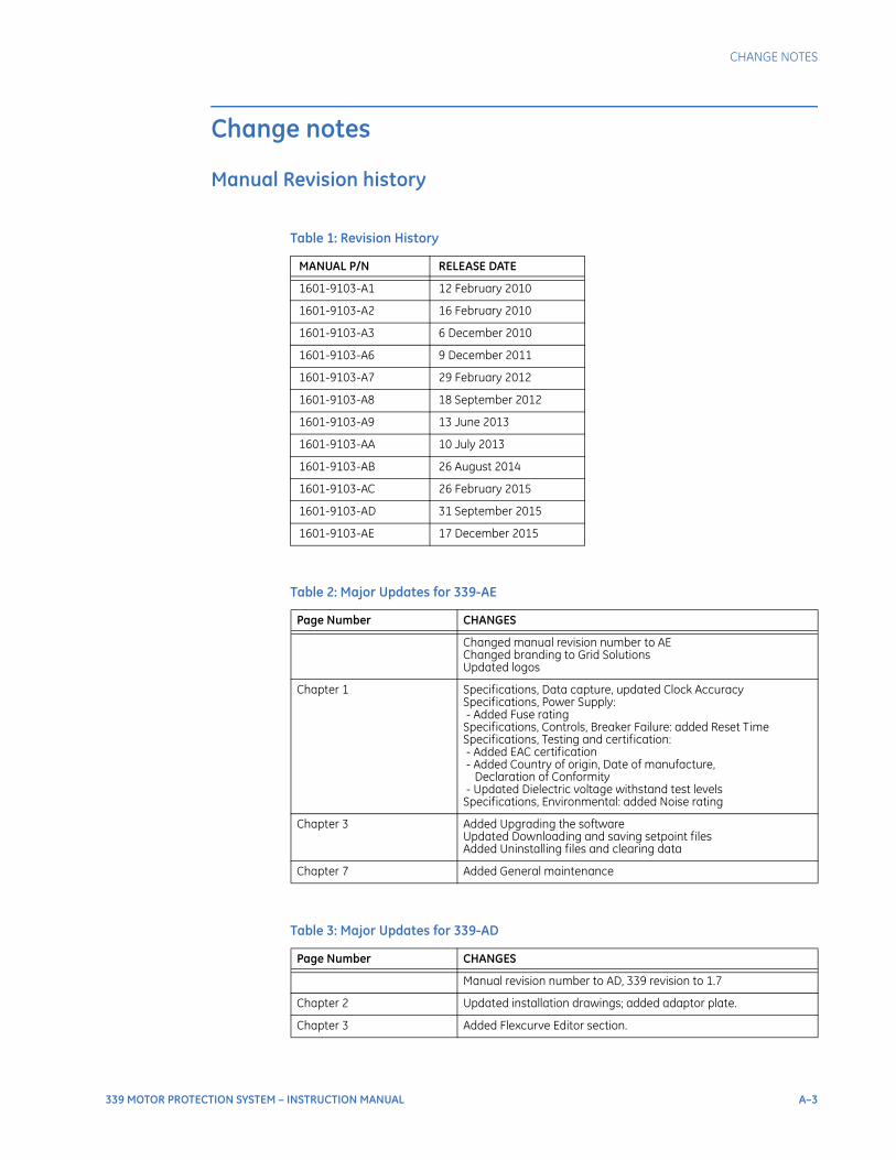
CHANGE NOTES
339 MOTOR PROTECTION SYSTEM – INSTRUCTION MANUAL A–3
Change notes
Manual Revision history
Table 1: Revision History
MANUAL P/N RELEASE DATE
1601-9103-A1 12 February 2010
1601-9103-A2 16 February 2010
1601-9103-A3 6 December 2010
1601-9103-A6 9 December 2011
1601-9103-A7 29 February 2012
1601-9103-A8 18 September 2012
1601-9103-A9 13 June 2013
1601-9103-AA 10 July 2013
1601-9103-AB 26 August 2014
1601-9103-AC 26 February 2015
1601-9103-AD 31 September 2015
1601-9103-AE 17 December 2015
Table 2: Major Updates for 339-AE
Page Number CHANGES
Changed manual revision number to AEChanged branding to Grid SolutionsUpdated logos
Chapter 1 Specifications, Data capture, updated Clock AccuracySpecifications, Power Supply: - Added Fuse ratingSpecifications, Controls, Breaker Failure: added Reset TimeSpecifications, Testing and certification: - Added EAC certification - Added Country of origin, Date of manufacture, Declaration of Conformity - Updated Dielectric voltage withstand test levelsSpecifications, Environmental: added Noise rating
Chapter 3 Added Upgrading the softwareUpdated Downloading and saving setpoint filesAdded Uninstalling files and clearing data
Chapter 7 Added General maintenance
Table 3: Major Updates for 339-AD
Page Number CHANGES
Manual revision number to AD, 339 revision to 1.7
Chapter 2 Updated installation drawings; added adaptor plate.
Chapter 3 Added Flexcurve Editor section.
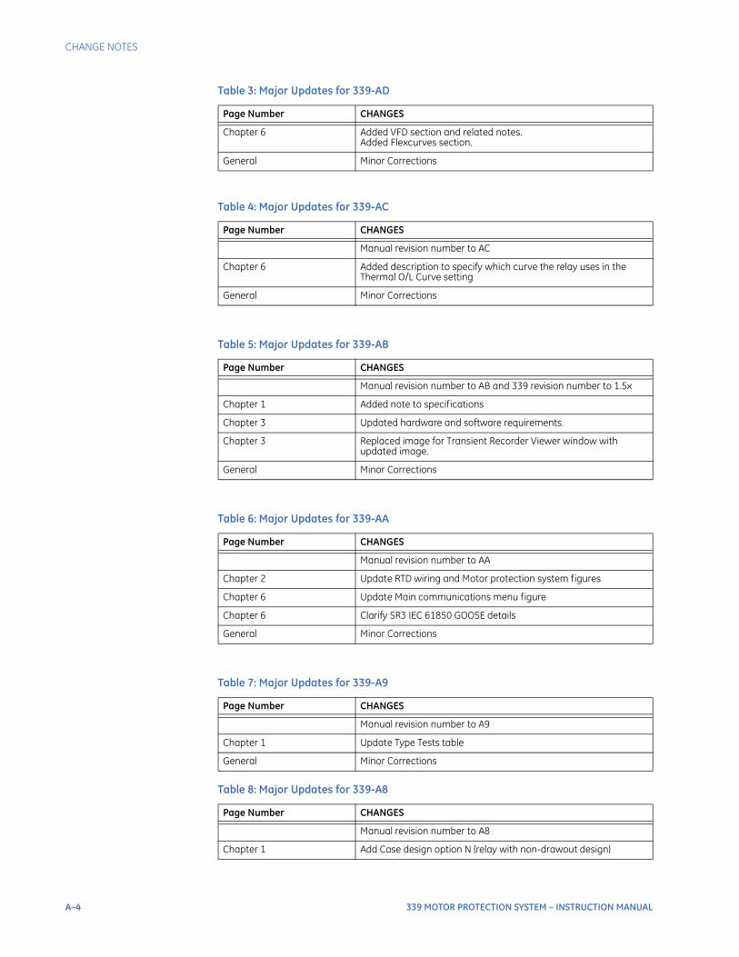
A–4 339 MOTOR PROTECTION SYSTEM – INSTRUCTION MANUAL
CHANGE NOTES
Chapter 6 Added VFD section and related notes.Added Flexcurves section.
General Minor Corrections
Table 4: Major Updates for 339-AC
Page Number CHANGES
Manual revision number to AC
Chapter 6 Added description to specify which curve the relay uses in the Thermal O/L Curve setting
General Minor Corrections
Table 5: Major Updates for 339-AB
Page Number CHANGES
Manual revision number to AB and 339 revision number to 1.5x
Chapter 1 Added note to specifications
Chapter 3 Updated hardware and software requirements.
Chapter 3 Replaced image for Transient Recorder Viewer window with updated image.
General Minor Corrections
Table 6: Major Updates for 339-AA
Page Number CHANGES
Manual revision number to AA
Chapter 2 Update RTD wiring and Motor protection system figures
Chapter 6 Update Main communications menu figure
Chapter 6 Clarify SR3 IEC 61850 GOOSE details
General Minor Corrections
Table 7: Major Updates for 339-A9
Page Number CHANGES
Manual revision number to A9
Chapter 1 Update Type Tests table
General Minor Corrections
Table 8: Major Updates for 339-A8
Page Number CHANGES
Manual revision number to A8
Chapter 1 Add Case design option N (relay with non-drawout design)
Table 3: Major Updates for 339-AD
Page Number CHANGES
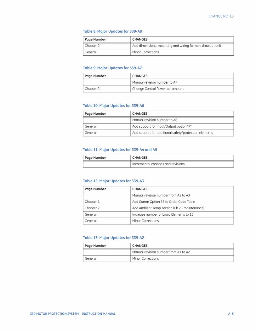
CHANGE NOTES
339 MOTOR PROTECTION SYSTEM – INSTRUCTION MANUAL A–5
Chapter 2 Add dimensions, mounting and wiring for non-drawout unit
General Minor Corrections
Table 9: Major Updates for 339-A7
Page Number CHANGES
Manual revision number to A7
Chapter 2 Change Control Power parameters
Table 10: Major Updates for 339-A6
Page Number CHANGES
Manual revision number to A6
General Add support for Input/Output option "R"
General Add support for additional safety/protection elements
Table 11: Major Updates for 339-A4 and A5
Page Number CHANGES
Incremental changes and revisions
Table 12: Major Updates for 339-A3
Page Number CHANGES
Manual revision number from A2 to A3
Chapter 1 Add Comm Option 3E to Order Code Table
Chapter 7 Add Ambient Temp section (Ch 7 - Maintenance)
General Increase number of Logic Elements to 16
General Minor Corrections
Table 13: Major Updates for 339-A2
Page Number CHANGES
Manual revision number from A1 to A2
General Minor Corrections
Table 8: Major Updates for 339-A8
Page Number CHANGES

A–6 339 MOTOR PROTECTION SYSTEM – INSTRUCTION MANUAL
CHANGE NOTES
Related Documents

![8913385 Protection Motor Tutorial[1]](https://static.cupdf.com/doc/110x72/546e231cb4af9f0d238b458f/8913385-protection-motor-tutorial1.jpg)