Unclassified NEA/CSNI/R(2001)10 Organisation de Coopération et de Développement Economiques Organisation for Economic Co-operation and Development 27-Jul-2001 ___________________________________________________________________________________________ English text only NUCLEAR ENERGY AGENCY COMMITTEE ON THE SAFETY OF NUCLEAR INSTALLATIONS ICDE Project Report: Collection and Analysis of Common-Cause Failures of Motor Operated Valves February 2001 JT00111244 Document complet disponible sur OLIS dans son format d’origine Complete document available on OLIS in its original format NEA/CSNI/R(2001)10 Unclassified English text only

Welcome message from author
This document is posted to help you gain knowledge. Please leave a comment to let me know what you think about it! Share it to your friends and learn new things together.
Transcript

Unclassified NEA/CSNI/R(2001)10
Organisation de Coopération et de Développement EconomiquesOrganisation for Economic Co-operation and Development 27-Jul-2001___________________________________________________________________________________________
English text onlyNUCLEAR ENERGY AGENCYCOMMITTEE ON THE SAFETY OF NUCLEAR INSTALLATIONS
ICDE Project Report: Collection and Analysis of Common-Cause Failures of Motor Operated Valves
February 2001
JT00111244
Document complet disponible sur OLIS dans son format d’origineComplete document available on OLIS in its original format
NE
A/C
SNI/R
(2001)10U
nclassified
English text only
NEA/CSNI/R(2001)10
2
Pursuant to Article 1 of the Convention signed in Paris on 14th December 1960, and which came into force on 30thSeptember 1961, the Organisation for Economic Co-operation and Development (OECD) shall promote policies designed:
− to achieve the highest sustainable economic growth and employment and a rising standard of living in Membercountries, while maintaining financial stability, and thus to contribute to the development of the world economy;
− to contribute to sound economic expansion in Member as well as non-member countries in the process of economicdevelopment; and
− to contribute to the expansion of world trade on a multilateral, non-discriminatory basis in accordance withinternational obligations.
The original Member countries of the OECD are Austria, Belgium, Canada, Denmark, France, Germany, Greece,Iceland, Ireland, Italy, Luxembourg, the Netherlands, Norway, Portugal, Spain, Sweden, Switzerland, Turkey, the United Kingdomand the United States. The following countries became Members subsequently through accession at the dates indicated hereafter:Japan (28th April 1964), Finland (28th January 1969), Australia (7th June 1971), New Zealand (29th May 1973), Mexico (18thMay 1994), the Czech Republic (21st December 1995), Hungary (7th May 1996), Poland (22nd November 1996), Korea (12thDecember 1996) and the Slovak Republic (14th December 2000). The Commission of the European Communities takes part in thework of the OECD (Article 13 of the OECD Convention).
NUCLEAR ENERGY AGENCY
The OECD Nuclear Energy Agency (NEA) was established on 1st February 1958 under the name of the OEECEuropean Nuclear Energy Agency. It received its present designation on 20th April 1972, when Japan became its firstnon-European full Member. NEA membership today consists of 27 OECD Member countries: Australia, Austria, Belgium,Canada, Czech Republic, Denmark, Finland, France, Germany, Greece, Hungary, Iceland, Ireland, Italy, Japan, Luxembourg,Mexico, the Netherlands, Norway, Portugal, Republic of Korea, Spain, Sweden, Switzerland, Turkey, the United Kingdom and theUnited States. The Commission of the European Communities also takes part in the work of the Agency.
The mission of the NEA is:
− to assist its Member countries in maintaining and further developing, through international co-operation, thescientific, technological and legal bases required for a safe, environmentally friendly and economical use of nuclearenergy for peaceful purposes, as well as
− to provide authoritative assessments and to forge common understandings on key issues, as input to governmentdecisions on nuclear energy policy and to broader OECD policy analyses in areas such as energy and sustainabledevelopment.
Specific areas of competence of the NEA include safety and regulation of nuclear activities, radioactive wastemanagement, radiological protection, nuclear science, economic and technical analyses of the nuclear fuel cycle, nuclear law andliability, and public information. The NEA Data Bank provides nuclear data and computer program services for participatingcountries.
In these and related tasks, the NEA works in close collaboration with the International Atomic Energy Agency inVienna, with which it has a Co-operation Agreement, as well as with other international organisations in the nuclear field.
© OECD 2001Permission to reproduce a portion of this work for non-commercial purposes or classroom use should be obtained through the Centre françaisd’exploitation du droit de copie (CCF), 20, rue des Grands-Augustins, 75006 Paris, France, Tel. (33-1) 44 07 47 70, Fax (33-1) 46 34 67 19, forevery country except the United States. In the United States permission should be obtained through the Copyright Clearance Center, CustomerService, (508)750-8400, 222 Rosewood Drive, Danvers, MA 01923, USA, or CCC Online: http://www.copyright.com/. All other applications forpermission to reproduce or translate all or part of this book should be made to OECD Publications, 2, rue André-Pascal, 75775 Paris Cedex 16,France.
NEA/CSNI/R(2001)10
3
COMMITTEE ON THE SAFETY OF NUCLEAR INSTALLATIONS
The Committee on the Safety of Nuclear Installations (CSNI) of the OECD Nuclear EnergyAgency (NEA) is an international committee made up of senior scientists and engineers. It was set up in1973 to develop, and co-ordinate the activities of the Nuclear Energy Agency concerning the technicalaspects of the design, construction and operation of nuclear installations insofar as they affect the safety ofsuch installations. The Committee’s purpose is to foster international co-operation in nuclear safety amongthe OECD Member countries.
The CSNI constitutes a forum for the exchange of technical information and for collaborationbetween organisations, which can contribute, from their respective backgrounds in research, development,engineering or regulation, to these activities and to the definition of the programme of work. It also reviewsthe state of knowledge on selected topics on nuclear safety technology and safety assessment, includingoperating experience. It initiates and conducts programmes identified by these reviews and assessments inorder to overcome discrepancies, develop improvements and reach international consensus on technicalissues of common interest. It promotes the co-ordination of work in different Member countries includingthe establishment of co-operative research projects and assists in the feedback of the results to participatingorganisations. Full use is also made of traditional methods of co-operation, such as information exchanges,establishment of working groups, and organisation of conferences and specialist meetings.
The greater part of the CSNI’s current programme is concerned with the technology of waterreactors. The principal areas covered are operating experience and the human factor, reactor coolant systembehaviour, various aspects of reactor component integrity, the phenomenology of radioactive releases inreactor accidents and their confinement, containment performance, risk assessment, and severe accidents.The Committee also studies the safety of the nuclear fuel cycle, conducts periodic surveys of the reactorsafety research programmes and operates an international mechanism for exchanging reports on safetyrelated nuclear power plant accidents.
In implementing its programme, the CSNI establishes co-operative mechanisms with NEA’sCommittee on Nuclear Regulatory Activities (CNRA), responsible for the activities of the Agencyconcerning the regulation, licensing and inspection of nuclear installations with regard to safety. It also co-operates with NEA’s Committee on Radiation Protection and Public Health and NEA’s Radioactive WasteManagement Committee on matters of common interest.
* * * * * * * * * * * *
The opinions expressed and the arguments employed in this document are the responsibility ofthe authors and do not necessarily represent those of the OECD.
Requests for additional copies of this report should be addressed to:
Nuclear Safety DivisionOECD Nuclear Energy AgencyLe Seine St-Germain12 blvd. des Iles92130 Issy-les-MoulineauxFrance
NEA/CSNI/R(2001)10
4
IPSN/GRS
ICDE Project Report:Collection and Analysis of Common-
Cause Failures of Motor OperatedValves
A. Kreuser, GRSV. Schulze, GRS
J. Tirira, IPSN
Institut de Protection et de Sûreté Nucléaire (IPSN), Franceand
Gesellschaft für Anlagen- und Reaktorsicherheit (GRS), Germany
February 2001

NEA/CSNI/R(2001)10
5
ABSTRACT
This report documents a study performed on the set of common cause failures (CCF) of motor operatedvalves (MOV). The data studied here were derived from the International CCF Data Exchange (ICDE)database, to which several countries have submitted CCF event data. The purpose of the ICDE is to allowmultiple countries to collaborate and exchange CCF data to enhance the quality of risk analyses thatinclude CCF modeling. Because CCF events are typically rare events, most countries do not experienceenough CCF events to perform meaningful analyses. Data combined from several countries, however,yields sufficient data for more rigorous analyses. This report is the result of an in-depth review of theMOV events and presents several insights about them. The objective of this document is to look beyondthe CCF parameter estimates that can be obtained from the CCF data, to gain further understanding of whyCCF events occur and what measures may be taken to prevent, or at least mitigate the effect of MOV CCFevents. The report presents details of the ICDE project, a quantitative presentation of the MOV events, anda discussion of some engineering aspects of the events.

NEA/CSNI/R(2001)10
6
CONTENTS
ABSTRACT .................................................................................................................................... 5
CONTENTS .................................................................................................................................... 6
EXECUTIVE SUMMARY ............................................................................................................. 8
ACRONYMS................................................................................................................................... 9
1. INTRODUCTION ..................................................................................................................... 10
2. ICDE PROJECT ........................................................................................................................ 11
2.1 Background ......................................................................................................................................... 112.2 Objectives of the ICDE Project........................................................................................................... 112.3 Scope of the ICDE Project .................................................................................................................. 122.4 Reporting and Documentation ............................................................................................................ 122.5 Data Collection Status......................................................................................................................... 122.6 ICDE Coding Format and Coding Guidelines .................................................................................... 122.7 Protection of Proprietary Rights.......................................................................................................... 12
3. DEFINITION OF COMMON-CAUSE EVENTS AND ICDE EVENTS ................................ 13
4. COMPONENT DESCRIPTION ............................................................................................... 15
4.1 General Description of the Component............................................................................................... 154.2 Component Boundaries....................................................................................................................... 164.3 Subcomponent Descriptions................................................................................................................ 16
4.3.1 Valve ............................................................................................................................. 164.3.2 Actuator ......................................................................................................................... 164.3.3 Motor ............................................................................................................................. 164.3.4 Limit and torque switches ............................................................................................. 164.3.5 Power supply ................................................................................................................. 164.3.6 Component specific logic and control equipment ......................................................... 16
4.4 Event Boundary................................................................................................................................... 18
5. MOV EVENT COLLECTION AND CODING GUIDELINES .............................................. 19
5.1 Basic Unit for ICDE Event Collection................................................................................................ 195.2 Time Frame for ICDE Event Exchange .............................................................................................. 195.3 Coding Rules and Exceptions ............................................................................................................. 195.4 Functional Fault Modes ...................................................................................................................... 20
6. OVERVIEW OF DATABASE CONTENT ............................................................................. 21

NEA/CSNI/R(2001)10
7
7. OVERVIEW OF EVENTS BY FAILURE MODE AND DEGREE OF FAILURE ............... 28
8 FAILURE CAUSE CATEGORIES........................................................................................... 35
8.1 Human error aspects............................................................................................................................ 368.1.1 Design error of original materials ............................................................................ 378.1.2 Design error of backfitted material .......................................................................... 388.1.3 Maintenance or operation procedure error during restoration ................................. 388.1.4 Maintenance human performance error during restoration...................................... 388.1.5 Maintenance or operation procedure error during test............................................. 388.1.6 Maintenance or operation human performance error during test............................. 38
8.2 Technical Fault Aspects of MOV CCF............................................................................................... 398.2.1 Operating medium influences .................................................................................. 418.2.2 Technical effects ...................................................................................................... 41
9. SUMMARY AND CONCLUSIONS ....................................................................................... 43
10. REFERENCES ....................................................................................................................... 44

NEA/CSNI/R(2001)10
8
EXECUTIVE SUMMARY
This study examined 87 events in the International CCF Data Exchange (ICDE) database by tabulating thedata and observing trends. Once trends were identified, individual events were reviewed for insights.
The database contains information developed during the original entry of the events that was used in thisstudy. This information includes root cause, coupling factor, exposed population size, and correctiveaction. As part of this study, these events were reviewed again and additional categorizations of the datawere included. Those categories included the degree of failure, affected subsystem, and detection method.
This study begins with an overview of the entire data set (Section 6). Charts and tables are providedexhibiting the event count for each of these event parameters. This section forms the baseline for the MOVcomponent.
Section 7 contains charts that demonstrate the distribution of the same events further refined by failuremode (fail-to-open, fail-to-close and internal leakage) for each event parameter. Each of these charts isreplicated with the further distinction that only those events classified as partial or complete are included.Distinctions are drawn as these parameters shift.
Section 8 contains the results of an analysis on failure cause categories. For this, the events have beenanalysed and characterised regarding the human error aspects and the technical aspects of the observedfailure.
Especially this approach focuses on root causes of common cause failures. So there are errors in thecalculation during design that caused false stroke forces. Wearing is a widespread effect. Thesubcomponent "limit switch" caused also a substantial amount of CCF. Failures on locking out duringmaintenance actions were also conspicuous. There are further failure effects that caused CCF in not such alarge and determinant scope. For example appeared in the study the selection of unsuited service media(mostly lubricants), the selection of improper materials, and assembly faults.
NEA/CSNI/R(2001)10
9
ACRONYMS
CCCG common cause component group
CCF common cause failure
ECCS emergency core cooling system
ICDE International Common Cause Failure Data Exchange
IRS Incident Reporting System
LOCA loss-of-coolant accident
MOV motor operated valve
NEA Nuclear Energy Agency
OECD Organisation for Economic Cooperation and Development
PRA probabilistic risk assessment
PSA probabilistic safety assessment
RPS reactor protection system
WGOE Working Group on Operating Experience

NEA/CSNI/R(2001)10
10
ICDE Project ReportCollection and Analysis of Common-Cause Failures of Motor
Operated Valves
1. INTRODUCTION
This report presents an overview of the exchange of motor operated valves (MOV) common cause failure(CCF) data among several countries. The objectives of this report are the following:
− To describe the data profile in the ICDE database for motor operated valves and to developqualitative insights in the nature of the reported events, expressed by root causes, couplingfactors, and corrective actions; and
− To develop the failure mechanisms and phenomena involved in the events, their relationshipto the root causes, and possibilities for improvement.
The ICDE Project was organized to exchange CCF data among countries. A brief description of theproject, its objectives, and the participating countries is contained in Section 2. Section 3 presents adefinition of common cause failure. Section 4 presents a description of the motor operated valve and ashort description of the subcomponents that comprise it. An overview of the data is presented in Section 5.Section 6 contains a description of the data by failure mode and also a comparison of complete CCF eventswith all of the events collected in this effort. Section 7 discusses the events by root cause, and Section 8summarizes the events by subsystem. A summary and conclusions are presented in Section 9.

NEA/CSNI/R(2001)10
11
2. ICDE PROJECT
This section contains information about the ICDE Project.
2.1 Background
Several member countries of OECD/NEA established the ICDE Project to encourage multilateral co-operation in the collection and analysis of data relating to CCF events.
The project was initiated in August 1994 in Sweden and was discussed at meetings in both Sweden andFrance in 1995. A coding benchmark exercise was defined which was evaluated at meetings held inGermany and in USA in 1996. Subsequently, the exchange of centrifugal pump data was defined; the firstphase of this exchange was evaluated at meetings in Switzerland and in France in 1997.
The ICDE project is operated under the umbrella of the OECD/NEA whose representative for this purposeis the Secretariat for the Working Group for Operating Experience.
The ICDE project member countries and their sponsoring organisations are:
− Canada : AECB
− Finland : STUK
− France : IPSN
− Germany : GRS
− Spain : CSN
− Sweden : SKI
− Switzerland : HSK
− United Kingdom : NII
− United States : NRC
2.2 Objectives of the ICDE Project
The objectives of the ICDE project are:
− To collect and analyse CCF events in the long term so as to better understand such events,their causes, and their prevention.
− To generate qualitative insights into the root causes of CCF events, which can then be usedto derive approaches or mechanisms for their prevention or for mitigating theirconsequences.

NEA/CSNI/R(2001)10
12
− To establish a mechanism for the efficient feedback of experience gained on CCFphenomena, including the development of defences against their occurrence, such asindicators for risk based inspections.
2.3 Scope of the ICDE Project
The ICDE Project is envisaged as including all possible events of interest, comprising complete, partial,and incipient CCF events, called “ICDE events” in this report. The project covers the key components ofthe main safety systems, including centrifugal pumps, diesel generators, motor operated valves, poweroperated relief valves, safety relief valves, check valves, reactor protection system (RPS) circuit breakers,batteries and transmitters.
In the long term, a broad basis for quantification of CCF events could be established, if the participatingorganisations wish to do so.
2.4 Reporting and Documentation
All reports and documents related to the ICDE project can be accessed through the OECD/NEA web site[2].
2.5 Data Collection Status
Data are collected in an MS ACCESS based databank implemented and maintained at ES-Konsult,Sweden, the appointed NEA clearing house. The databank is regularly updated. The clearinghouse andthe project group operate it.
2.6 ICDE Coding Format and Coding Guidelines
An ICDE coding format was developed for collecting the ICDE event data for the ICDE database.Definition and guidance are provided in the ICDE coding guidelines [3].
2.7 Protection of Proprietary Rights
Incident Reporting System (IRS) procedures for protecting confidential information have been adopted.The co-ordinators in the participating countries are responsible for maintaining proprietary rights. The datacollected in the clearinghouse database are password protected and are only available to ICDE participantswho have provided data.
NEA/CSNI/R(2001)10
13
3. DEFINITION OF COMMON-CAUSE EVENTS AND ICDE EVENTS
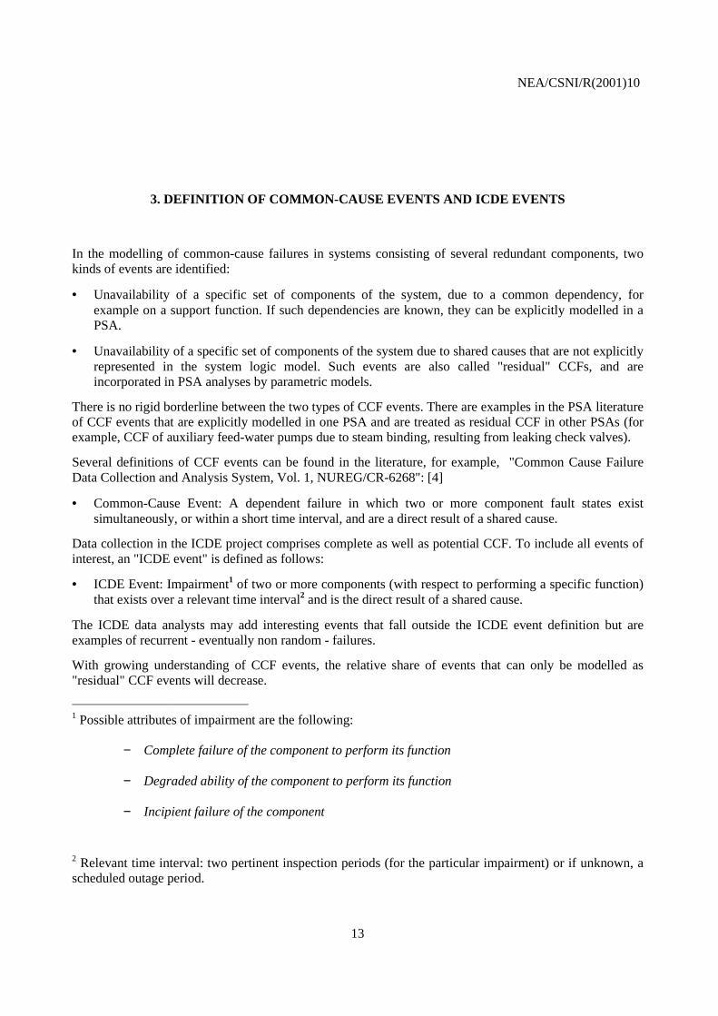
In the modelling of common-cause failures in systems consisting of several redundant components, twokinds of events are identified:
• Unavailability of a specific set of components of the system, due to a common dependency, forexample on a support function. If such dependencies are known, they can be explicitly modelled in aPSA.
• Unavailability of a specific set of components of the system due to shared causes that are not explicitlyrepresented in the system logic model. Such events are also called "residual" CCFs, and areincorporated in PSA analyses by parametric models.
There is no rigid borderline between the two types of CCF events. There are examples in the PSA literatureof CCF events that are explicitly modelled in one PSA and are treated as residual CCF in other PSAs (forexample, CCF of auxiliary feed-water pumps due to steam binding, resulting from leaking check valves).
Several definitions of CCF events can be found in the literature, for example, "Common Cause FailureData Collection and Analysis System, Vol. 1, NUREG/CR-6268": [4]
• Common-Cause Event: A dependent failure in which two or more component fault states existsimultaneously, or within a short time interval, and are a direct result of a shared cause.
Data collection in the ICDE project comprises complete as well as potential CCF. To include all events ofinterest, an "ICDE event" is defined as follows:
• ICDE Event: Impairment1 of two or more components (with respect to performing a specific function)that exists over a relevant time interval2 and is the direct result of a shared cause.
The ICDE data analysts may add interesting events that fall outside the ICDE event definition but areexamples of recurrent - eventually non random - failures.
With growing understanding of CCF events, the relative share of events that can only be modelled as"residual" CCF events will decrease.
1 Possible attributes of impairment are the following:
− Complete failure of the component to perform its function
− Degraded ability of the component to perform its function
− Incipient failure of the component
2 Relevant time interval: two pertinent inspection periods (for the particular impairment) or if unknown, ascheduled outage period.

NEA/CSNI/R(2001)10
14
NEA/CSNI/R(2001)10
15
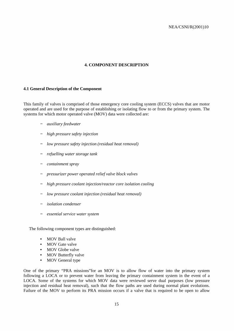
4. COMPONENT DESCRIPTION
4.1 General Description of the Component
This family of valves is comprised of those emergency core cooling system (ECCS) valves that are motoroperated and are used for the purpose of establishing or isolating flow to or from the primary system. Thesystems for which motor operated valve (MOV) data were collected are:
− auxiliary feedwater
− high pressure safety injection
− low pressure safety injection (residual heat removal)
− refuelling water storage tank
− containment spray
− pressurizer power operated relief valve block valves
− high pressure coolant injection/reactor core isolation cooling
− low pressure coolant injection (residual heat removal)
− isolation condenser
− essential service water system
The following component types are distinguished:
• MOV Ball valve• MOV Gate valve• MOV Globe valve• MOV Butterfly valve• MOV General type
One of the primary “PRA missions”for an MOV is to allow flow of water into the primary systemfollowing a LOCA or to prevent water from leaving the primary containment system in the event of aLOCA. Some of the systems for which MOV data were reviewed serve dual purposes (low pressureinjection and residual heat removal), such that the flow paths are used during normal plant evolutions.Failure of the MOV to perform its PRA mission occurs if a valve that is required to be open to allow

NEA/CSNI/R(2001)10
16
injection or cooling fails to open, or if a valve that is required to close to isolate secondary parts of theECCS after a LOCA fails to close.
4.2 Component Boundaries
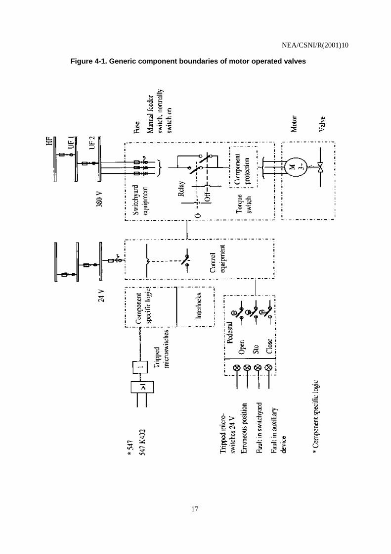
The component for this study is the MOV, comprised of a valve with its internal piece-part componentsand a motor operator. The operator includes the circuit breaker, power leads, and other local protectivedevices, open/close limit switches, torque switches, and the motor. The control circuit that induces a closeor open signal to an MOV is not included within the MOV boundary if it also controls other componentfunctions, such as other valve actions, pump starts and functions modeled in PRA, (the schematic diagramin figure 4.1 shows the generic component boundaries for MOVs).
4.3 Subcomponent Descriptions
This section contains a brief description of each of the subcomponents that comprise the motor operatedvalve. These descriptions are intended only to provide a general overview of the most common MOVs.
4.3.1 Valve
The valve subcomponent includes the housing, the seals, the packing, the disk, and the seat.
4.3.2 Actuator
The actuator includes the gear, the clutch, and the stem.
4.3.3 Motor
The electrical motor provides motive force to open or close the valve.
4.3.4 Limit and torque switches
The limit and torque switches provide information about the position of the valve. This information is usedto indicate the position of the valve and to stop the motor after actuation of the valve. Limit and torqueswitches are part of the component protection system.
4.3.5 Power supply
The power supply consists of the switchyard equipment, including the contactor or switch, and the fuses.
4.3.6 Component specific logic and control equipment
The component specific logic and control equipment functions to start, stop, and provide operationalcontrol and protective trips for the MOV.
NEA/CSNI/R(2001)10
17
Figure 4-1. Generic component boundaries of motor operated valves

NEA/CSNI/R(2001)10
18
4.4 Event Boundary
The main “PRA mission” for an MOV is to allow flow of water into the primary system following a LOCAor to prevent water from leaving the primary containment system in the event of a LOCA.
Some of the systems for which MOV data were reviewed serve dual purposes (low pressure injection andresidual heat removal), such that the flow paths are used during normal plant evolutions. Failure of theMOV to perform its PRA mission occurs if a valve that is required to be open to allow injection or coolingflow fails to open, or if a valve that is required to close to isolate secondary parts of the ECCS after aLOCA fails to close.
NEA/CSNI/R(2001)10
19
5. MOV EVENT COLLECTION AND CODING GUIDELINES
5.1 Basic Unit for ICDE Event Collection
The basic set for MOV data collection is the "exposed population" (EP: set of components exposed to thesame failure cause). The number of valves in an exposed population depends on the specific failureidentified in the event analysis.
In general the exposed population shall be in the same system for the components identified but could bemodified depending on the linkage of CCF events by failure mechanism or causal factors.
The elements of the exposed population will normally have similar test intervals. Similar in this contextmeans a factor of not more than 2 between minimum and maximum.
The determination of the exposed population is left to the event reviewer and the reviewer’s knowledge ofthe relation of system design, operation and testing.
5.2 Time Frame for ICDE Event Exchange
The minimum period of exchange covered a period of 5 years for each plant.
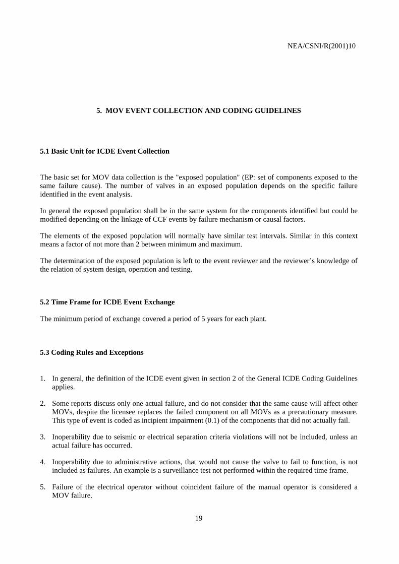
5.3 Coding Rules and Exceptions
1. In general, the definition of the ICDE event given in section 2 of the General ICDE Coding Guidelinesapplies.
2. Some reports discuss only one actual failure, and do not consider that the same cause will affect otherMOVs, despite the licensee replaces the failed component on all MOVs as a precautionary measure.This type of event is coded as incipient impairment (0.1) of the components that did not actually fail.
3. Inoperability due to seismic or electrical separation criteria violations will not be included, unless anactual failure has occurred.
4. Inoperability due to administrative actions, that would not cause the valve to fail to function, is notincluded as failures. An example is a surveillance test not performed within the required time frame.
5. Failure of the electrical operator without coincident failure of the manual operator is considered aMOV failure.

NEA/CSNI/R(2001)10
20
6. Failure of the MOV to cycle in the required time (as opposed to mission time) will not be considered afailure, either CCF or independent, if the MOV reached its intended state.
5.4 Functional Fault Modes
The following functional fault modes were used to analyze MOV data:
1. Failure to open (FO)
2. Failure to close (FC)
3. Internal Leakage (IL)
4. External Leakage (EL)

NEA/CSNI/R(2001)10
21
6. OVERVIEW OF DATABASE CONTENT
CCF data for the MOV component have been collected. Organisations from Finland, France, Germany,Sweden, Switzerland and the United States contributed data to this data exchange. Eighty-seven (87)ICDE events were reported from nuclear power plants (pressurised water reactors and boiling waterreactors). One event was reported twice, the original record and an update. Therefore only the updatedrecord was included in the study. These 86 events are used only in the failure mode summary. Five eventsare reported two times in the database. Each of these events was reported for two failure modes -- “failureto open” and “failure to close.” These events are only counted once for the statistical analyses, except thefailure mode analysis. Thus, the total number of events for the study is 81 events.
Table 6-1 summarizes, by failure mode, the MOV ICDE events used in this study. Complete CCF eventsare CCF events in which each component fails completely due to the same cause and within a short timeinterval. Due to the low number (5) of observed complete CCF events no further detailed statisticalanalysis of this particular subclass of ICDE events is done in this study. A further subclass of ICDE eventsare partial CCF events having at least two completely failed components. This subclass contains 24 eventsand includes the complete CCF events.
Regarding the coded failure modes, there seems to be no rigid borderline between “failure to close” and“internal leakage” events. Looking at the verbal event descriptions, some of the “failure to close” eventsmight also have been coded as “internal leakage” events and vice versa.
Table 6-1. Summary statistics of MOV data.
Degree of FailureObservedEvent reports
received TotalPartial Complete
ICDE events Failure to open 38 14 3 Failure to close 34 8 1 External leakage 1 1 1 Internal leakage 9 0 0 No failure mode 4 1 0
Total 86 24 5
Table 6-2 summarizes the root causes of the analysed events. Figure 6-1 shows the distribution of CCFevents by root cause. Design, Manufacture or Construction inadequacy accounts for about 31 percent of theevents. An example is a failure of valves as a result of an improper friction factor. Internal Parts of thevalves accounts for about 30 percent. In this group are for instance events by failure due to weak valvestems. Other important contributions are Procedure, accounting for 13 percent (e.g. lack of lubricant

NEA/CSNI/R(2001)10
22
because of missing instructions), and Human Actions, accounting for 12 percent (e.g. incorrect torqueswitch setting).
Table 6-2. Root causes distribution
ICDE Code Numberof events Percent
Abnormal stress 3 ∼ 4Components notmodeled in PSA
1 ∼ 1
Design etc. 25 ∼ 31Human actions 10 ∼ 12Internal parts 24 ∼ 30
Maintenance notcaptured by human
1 ∼ 1
Others 6 ∼ 7Procedure 11 ∼ 13
Total 81
Table 6.3 summarizes the coupling factors of the analysed events, and Figure 6-2 shows this distribution.The dominant coupling factor, Operational Procedure or Staff, accounts for 38 percent of the events. Thesystematic wrong setting of limit switches is an example of an event belonging to this group. Hardware(component part) accounts for 26 percent and Hardware Design for 17 percent. The other coupling factorsare equally distributed. An event revealing inadequate actuators to achieve minimum required closingthrusts is an example of a coupling factor in the hardware group. An example for a coupling factor"hardware design" is the occurrence of some stems or stem nuts where the thread was worn out.
Table 6-3. Coupling factors distribution
ICDE Code Numberof events Percent
Environmental 2 ∼ 2Hardware 21 ∼ 26
Hardware design 14 ∼ 17Hardware quality 1 ∼ 1
Maintenance 3 ∼ 4Procedure 5 ∼ 6
Operational 31 ∼ 38Operation staff 2 ∼ 2
Operation procedure 2 ∼ 2Total 81

NEA/CSNI/R(2001)10
23
Table 6-4 summarizes the corrective actions and Figure 6-3 shows the distribution of identified possiblecorrective actions for CCF events analyzed. The dominant corrective action, administrative/ proceduralcontrol, accounts for 41 percent. Example events of this group are the revision of procedures to avoidprematurely locking of valves during plant shutdown, a revision of procedures to avoid excessive torque onvalves by hand wheel, and recalculation of incorrectly calculated torque switch set-point. Maintenanceprogram modifications each account for 21 percent of the corrective actions. Specific maintenance anddesign modification account for 11 percent. The remaining events are about equally distributed among theremaining actions (fixing components, additional diversity, others).
Table 6-4. Corrective actions
ICDE Code Numberof events Percent
Administrative control 33 ∼ 41Specific maintenance 9 ∼ 11Design modification 9 ∼ 11
Diversity 5 ∼ 6Test 17 ∼ 21
Fixing of component 4 ∼ 5Other 4 ∼ 5Total 81
Table 6-5 summarizes the number of exposed components (here called exposed size) in the exposedpopulation. Figure 6-4 shows the distribution of the events by exposed size. The exposed size ranges from2 to 27. Two exposed sizes are dominant: four valves (28%) and eight valves (27%). The exposed size oftwo valves accounting for 13 percent and six valves for 19 percent. The others sizes are equally distributed.
Table 6-5. Exposed component
ExposedSize
Numberof events Percent
2 11 ∼ 133 3 ∼ 44 23 ∼ 285 1 ∼ 16 15 ∼ 198 22 ∼ 27
10 1 ∼ 115 1 ∼ 117 1 ∼ 124 1 ∼ 127 2 ∼ 2
Total 81
NEA/CSNI/R(2001)10
24
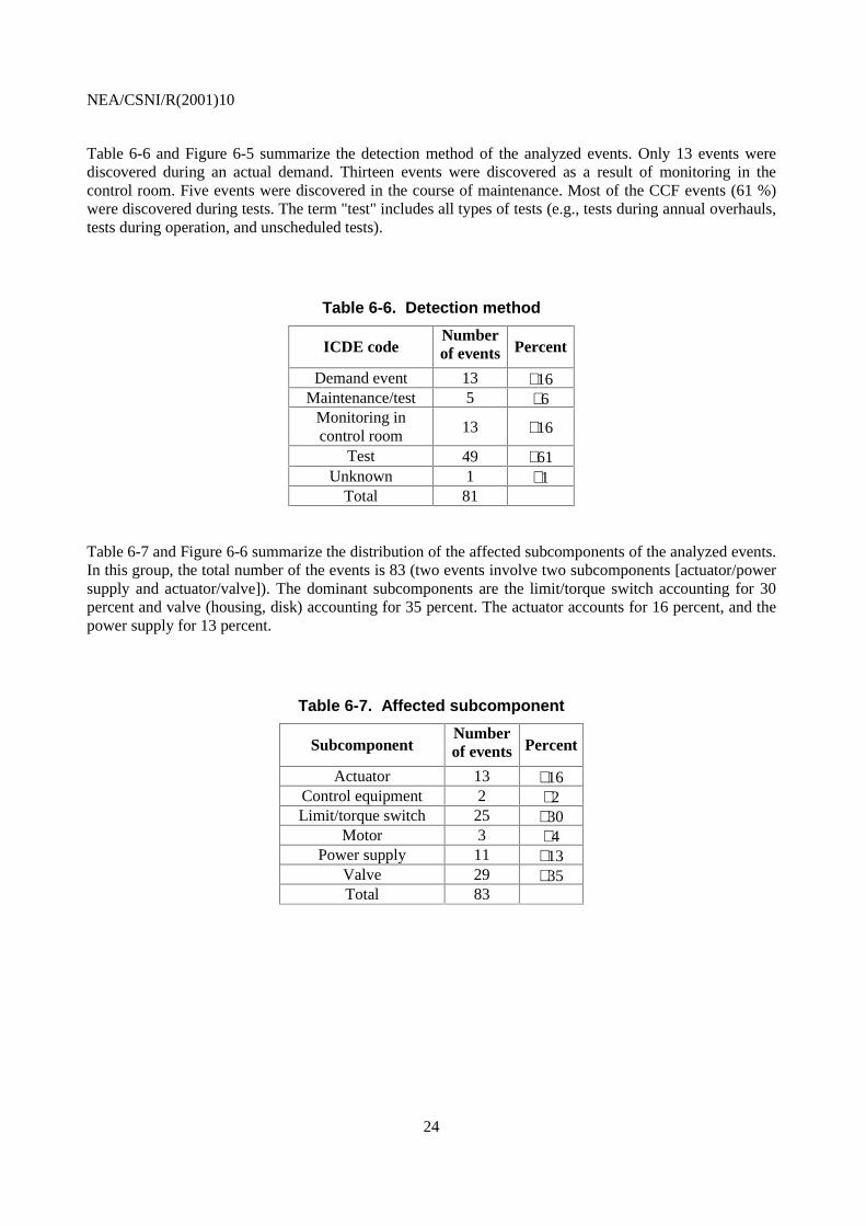
Table 6-6 and Figure 6-5 summarize the detection method of the analyzed events. Only 13 events werediscovered during an actual demand. Thirteen events were discovered as a result of monitoring in thecontrol room. Five events were discovered in the course of maintenance. Most of the CCF events (61 %)were discovered during tests. The term "test" includes all types of tests (e.g., tests during annual overhauls,tests during operation, and unscheduled tests).
Table 6-6. Detection method
ICDE codeNumberof events Percent
Demand event 13 ∼ 16Maintenance/test 5 ∼ 6
Monitoring incontrol room 13 ∼ 16
Test 49 ∼ 61Unknown 1 ∼ 1
Total 81
Table 6-7 and Figure 6-6 summarize the distribution of the affected subcomponents of the analyzed events.In this group, the total number of the events is 83 (two events involve two subcomponents [actuator/powersupply and actuator/valve]). The dominant subcomponents are the limit/torque switch accounting for 30percent and valve (housing, disk) accounting for 35 percent. The actuator accounts for 16 percent, and thepower supply for 13 percent.
Table 6-7. Affected subcomponent
SubcomponentNumberof events Percent
Actuator 13 ∼ 16Control equipment 2 ∼ 2Limit/torque switch 25 ∼ 30
Motor 3 ∼ 4Power supply 11 ∼ 13
Valve 29 ∼ 35Total 83

NEA/CSNI/R(2001)10
25
Figure 6-1. Root cause distribution
0
5
10
15
20
25
30
Env
ironm
ent
Sta
te o
f oth
erco
mpo
nent
(s)
Des
ign
etc.
Hum
an
Inte
rnal
toco
mpo
nent
Mai
nten
ance
Pro
cedu
re
Oth
er
Root causes
No
. of
Eve
nts
Figure 6-2. Coupling factors distribution
0
5
10
15
20
25
30
35
40
45
50
Env
ironm
enta
l
Har
dwar
e
Ope
ratio
ns
Coupling Factors
No
. of
Eve
nts

NEA/CSNI/R(2001)10
26
Figure 6-3. Corrective action distribution
0
5
10
15
20
25
30
35
Adm
inis
trat
ive
Mai
nt./O
p.P
ract
ices
Des
ign
Mod
ifica
tions
Div
ersi
ty
Sep
arat
ion
Tes
t/Mai
nten
ance
polic
ies
Fix
ing
ofC
ompo
nent
Oth
er
Corrective Actions
No
. of
Eve
nts
Figure 6-4. Exposed group size distribution
0
5
10
15
20
25
2 3 4 5 6 8 10 15 17 24 27
Exposed Group Size
No
. of
Eve
nts

NE
A/C
SNI/R
(2001)10
27
Figure 6-6. Subsystem distribution
0 5 10 15 20 25 30 35
Valve
Power Supply
Motor
Actuator
Logic/ControlEquipement
Limit/TorqueSwitch
Su
bsystem
No. of Events
Figure 6-5. Detection m
ethod distribution
0 10 20 30 40 50 60
Demand event
Maintenance/Test
Monitoring/Control room
Test
Unknown
Detection M
ethod
No. of Events

NEA/CSNI/R(2001)10
28
7. OVERVIEW OF EVENTS BY FAILURE MODE AND DEGREE OF FAILURE
This section discusses the CCF events by failure mode and contrasts the distributions of partial CCF eventswith the distributions of the total group. A discussion of degree of failure is included in Section 6. Due tothe low number (5) of events with failure modes “external leakage” and “no failure mode indicated,” theseevents are not included in the analysis in this section. As this section discusses events by failure mode, thefive events that are coded both for failure to open and failure to close are counted separately. Thus, theanalysis in this section covers 81 ICDE events.
Table 7-1 summarizes the number of events by root cause and failure mode. Figures 7-1 and 7-2 show theroot cause distributions for all CCF events and the distribution of partial CCF events by failure mode. TheDesign root cause contribution and the Internal to Component/Piece Part contribution are the mostimportant in the total group. Other major contribution comes from the human actions root cause and fromthe procedure inadequacy root cause. Examples of the root causes are given in Section 6. In the group ofpartial CCF events, these four root causes are nearly equally distributed. However, the compositionbetween failure to open and failure to close shifts a little to more failure to open events in the partial CCFgroup. There are no internal leakage events in the partial CCF group.
Table 7-1. Root cause distribution for all ICDE events
Failure Mode Root Cause Number ofevents
Number ofpartial CCF
Failure to close Abnormal Environmental Stress 3 2State of other components 1 1Design, manufacture orconstruction inadequacy
11 2
Human actions 4 1Internal to component, piece part 9 0Maintenance 0 0Other 2 0Procedure inadequacy 4 2
Failure to open Abnormal Environmental Stress 0 0State of other components 1 0Design, manufacture orconstruction inadequacy
11 5
Human actions 5 4Internal to component, piece part 10 3Maintenance 1 0Other 5 0Procedure inadequacy 5 0
Internal Human actions 1 0leakage Internal to component, piece part 7 0
Procedure inadequacy 1 0

NEA/CSNI/R(2001)10
29
Table 7-2 summarizes the events by coupling factor and failure mode. Figures 7-3 and 7-4 show thedistributions of CCF events for coupling factors for all events and partial CCF events by failure mode. Inboth group of events the operations coupling factor group is dominant, followed by the hardware couplingfactor group. The environmental coupling factor group has no importance. The hardware coupling factorgroup has the same importance as the operations coupling factor in the failure to open mode for all events.In the internal leakage failure mode operations coupling factor is the only one.
Table 7-2. Coupling factor on failure mode
Failure Mode Coupling factor Number ofevents
Number ofpartial CCF
Failure to close Environmental 2 1Hardware 13 3Operations 19 4
Failure to open Hardware 19 6Operations 19 8
Internal leakage Operations 9 0
Table 7-3 shows the number of events by corrective action and failure mode. Figures 7-5 and 7-6 show thedistributions of CCF events for corrective actions for all events and partial CCF events by failure mode.The most important corrective action identified in this study is general administrative/procedure control. Asecond important corrective action concerns test and maintenance policies in the all events group whereasthis corrective action has no importance in the partial CCF group. The dominance of the generaladministrative/procedure control and test and maintenance policies corrective action in the failure to closemode is stronger as in the failure to open mode. In the internal leakage failure mode test and maintenancepolicies corrective actions appear slightly more important than the general administrative/procedure controlcorrective actions.
Table 7-3. Corrective action on failure mode
Failure Mode Root Cause Number ofevents
Number ofpartial CCF
Failure to close Administrative 18 5Maintenance/operation practices 2 1Design modifications 1 0Diversity 1 1Test/Maintenance policies 9 0Fixing of components 1 0Other 2 1
Failure to open Administrative 15 7Maintenance/operation practices 6 3Design modifications 5 2Diversity 4Test/Maintenance policies 3 1Fixing of components 2 1Other 3 0
Internal leakage Administrative 3 0Maintenance/operation practices 1 0Test/Maintenance policies 5 0

NEA/CSNI/R(2001)10
30
Table 7-4 shows the number of events by subcomponent and failure mode. Figures 7-7 and 7-8 show thedistributions of CCF events for subcomponent for all events and complete CCF events by failure mode.There is no significant difference in the distributions for the failure-to-open and failure-to-close failuremodes for the actuator, control equipment, limit/torque switch, and motor. For the power supply failuremode failure to open is dominant, whereas for valve failure mode failure to close is dominant. As can beexpected failure mode internal leakage is only attributed to the subcomponent valve. The distribution offailure modes does not shift for the group of partial CCF events. Most important subcomponents for partialCCF events are the subcomponents actuator, limit/torque switch, and power supply.
Table 7-4. Affected subcomponent by failure mode
Failure mode Subcomponent Number ofevents
Number ofpartial CCF
Failure to close Actuator 7 4Limit switch 14 2Motor 1 1Power supply 2 1Valve 11 1
Failure to open Actuator 6 2Control equipment 1 1Limit switch 16 3Motor 2 1Power supply 9 6Valve 5 2
Internal leakage Valve 9 0

NEA/CSNI/R(2001)10
31
Figure 7-2. Root cause on failure mode for partial CCF
0
1
2
3
4
5
6
Env
ironm
ent
Des
ign/
Man
ufac
ture
Hum
an
Inte
rnal
Pro
cedu
reIn
adeq
uacy
Root Cause
No
. of
Eve
nts
Failure to Close Failure to Open Internal Leakage
Figure 7-1. Root cause distribution for all ICDE events
0
2
4
6
8
10
12E
nviro
nmen
t
Sta
te/O
ther
Com
pone
nts
Des
ign/
Man
ufac
ture
Hum
an
Inte
rnal
Mai
nten
ance
Oth
er
Pro
cedu
reIn
adeq
uacy
Root Cause
No
. of
Eve
nts
Failure to Close Failure to Open Internal Leakage

NEA/CSNI/R(2001)10
32
Figure 7-4. Coupling factor on failure mode for partial CCF events
0
1
2
3
4
5
6
7
8
9
Env
ironm
enta
l
Har
dwar
e
Ope
ratio
nal
Coupling Factors
No
. of
Eve
nts
Failure to Close Failure to Open Internal Leakage
Figure 7-3. Coupling factor on failure mode for all ICDE events
0
2
4
6
8
10
12
14
16
18
20
Env
ironm
enta
l
Har
dwar
e
Ope
ratio
nal
Coupling Factors
No
. of
Eve
nts
Failure to Close Failure to Open Internal Leakage

NEA/CSNI/R(2001)10
33
Figure 7-5. Corrective action on failure mode for all CCF events
0
2
4
6
8
10
12
14
16
18
20
Adm
in
Mai
nten
ance
/Op
Pra
ctic
es
Des
ign
Mod
ifica
tions
Div
ersi
ty
Fun
ctio
nal/S
patia
l S
epar
atio
n
Fix
ing
of
Com
pone
nts
Oth
er
Corrective Actions
No
. of
Eve
nts
Failure to Close Failure to Open Internal Leakage
Figure 7-6. Corrective action on failure mode for partial CCF events
0
1
2
3
4
5
6
7
8
Adm
inis
trat
ive
Mai
nten
ance
/Op
Pra
ctic
es
Des
ign
Mod
ifica
tions
Div
ersi
ty
Tes
t/Mai
nt
Pol
icie
s
Fix
ing
of
Com
pone
nt
Oth
er
Corrective Actions
No
. of
Eve
nts
Failure to Close Failure to Open Internal Leakage

NEA/CSNI/R(2001)10
34
Figure 7-8. Affected subcomponent on failure mode for partial CCF events
0
1
2
3
4
5
6
7
Val
ve
Pow
er S
uppl
y
Mot
or
Act
uato
r
Logi
c/C
ontr
ol
Equ
ipem
ent
Lim
it/T
orqu
e S
witc
h
Subcomponent
No
. of
Eve
nts
Failure to Close Failure to Open Internal Leakage
Figure 7-7. Affected subcomponent on failure mode for all CCF events
0
2
4
6
8
10
12
14
16
18
Val
ve
Pow
er S
uppl
y
Mot
or
Act
uato
r
Logi
c/C
ontr
olE
quip
emen
t
Lim
it/T
orqu
eS
witc
h
Subcomponent
No
. of
Eve
nts
Failure to Close Failure to Open Internal Leakage
NEA/CSNI/R(2001)10
35
8. FAILURE CAUSE CATEGORIES
The 81 ICDE events reported for MOVs from nuclear power plants have been analysed and characterisedregarding the human error aspects and the technical aspects of the observed failures. For this purpose afurther coding system with respect to fault categories was introduced. This coding system has a strongstructure. Categorising of the events follows a decision tree. Categorising is done separately for humanerror aspects and technical fault aspects. Within the assessment of the technical fault aspects operatingmedium influences and technical effects are separately treated.
Human actions are determinative in view of the root causes of all events. That means every technical faultcan be connected to a human error. The point of time and the circumstances of the human error can be verymanifold. For instance, it is possible that during the design of an MOV a potential force remainsunconsidered and the detection of this construction respectively dimension error has an effect only yearsafterwards. In this case, beside the technical effect on a subcomponent making the component MOVunavailable, the human error during design has to be considered as a failure cause.
By connecting the above described grouping of events by technical and human cause categories and theknowledge about the affected subcomponents it is possible to focus on failure centres and their causes.
This approach of evaluating events was created during handling of the MOV events. Of cause, not allavailable descriptions of the events are appropriate for a comprehensive, deep failure analysis regardingthis human error analysis pattern. Even licensee event reports, which often were taken as the basis for theICDE event reports, are frequently not expressive enough. So there are many events for which it is notpossible to assign clearly human errors regarding the created categories.
The classification of the events was done during one workshop of the ICDE working group. The basis ofthe classification was the event description and coding in the ICDE database. The analysis shows that morethan 50 % of the events could be assigned either to human error categories or to technical fault categories.For about 30 % of the events both human errors and technical faults have been identified.
NEA/CSNI/R(2001)10
36
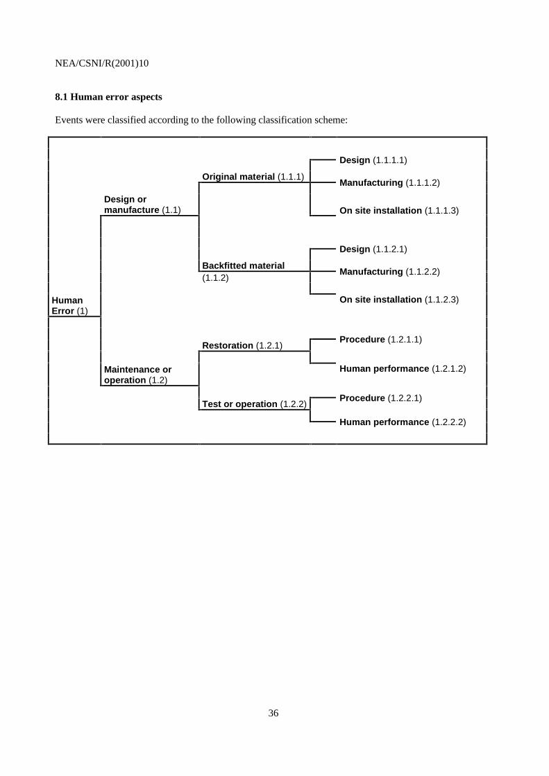
8.1 Human error aspects
Events were classified according to the following classification scheme:
Design (1.1.1.1)
Original material (1.1.1)Manufacturing (1.1.1.2)
Design ormanufacture (1.1) On site installation (1.1.1.3)
Design (1.1.2.1)
Backfitted material(1.1.2)
Manufacturing (1.1.2.2)
HumanError (1)
On site installation (1.1.2.3)
Restoration (1.2.1)Procedure (1.2.1.1)
Maintenance oroperation (1.2)
Human performance (1.2.1.2)
Test or operation (1.2.2)Procedure (1.2.2.1)
Human performance (1.2.2.2)
NEA/CSNI/R(2001)10
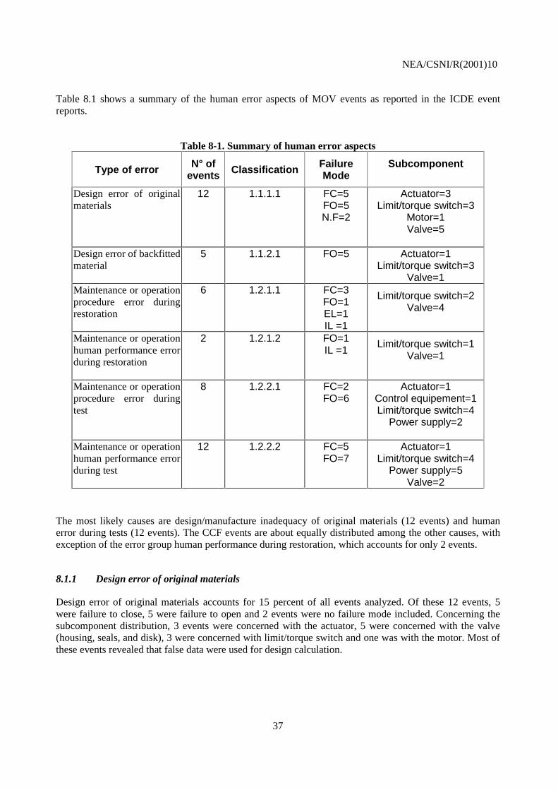
37
Table 8.1 shows a summary of the human error aspects of MOV events as reported in the ICDE eventreports.
Table 8-1. Summary of human error aspects
Type of error N° ofevents Classification Failure
ModeSubcomponent
Design error of originalmaterials
12 1.1.1.1 FC=5FO=5N.F=2
Actuator=3Limit/torque switch=3
Motor=1Valve=5
Design error of backfittedmaterial
5 1.1.2.1 FO=5 Actuator=1Limit/torque switch=3
Valve=1Maintenance or operationprocedure error duringrestoration
6 1.2.1.1 FC=3FO=1EL=1IL =1
Limit/torque switch=2Valve=4
Maintenance or operationhuman performance errorduring restoration
2 1.2.1.2 FO=1IL =1
Limit/torque switch=1Valve=1
Maintenance or operationprocedure error duringtest
8 1.2.2.1 FC=2FO=6
Actuator=1Control equipement=1Limit/torque switch=4
Power supply=2
Maintenance or operationhuman performance errorduring test
12 1.2.2.2 FC=5FO=7
Actuator=1Limit/torque switch=4
Power supply=5Valve=2
The most likely causes are design/manufacture inadequacy of original materials (12 events) and humanerror during tests (12 events). The CCF events are about equally distributed among the other causes, withexception of the error group human performance during restoration, which accounts for only 2 events.
8.1.1 Design error of original materials
Design error of original materials accounts for 15 percent of all events analyzed. Of these 12 events, 5were failure to close, 5 were failure to open and 2 events were no failure mode included. Concerning thesubcomponent distribution, 3 events were concerned with the actuator, 5 were concerned with the valve(housing, seals, and disk), 3 were concerned with limit/torque switch and one was with the motor. Most ofthese events revealed that false data were used for design calculation.

NEA/CSNI/R(2001)10
38
8.1.2 Design error of backfitted material
Design error of backfitted materials accounts for about 6 percent of 81 events analyzed. All 5 events werefailure to open. The subcomponents involved were 3 events with limit/torque switch, one event with valveand one with actuator. An example for this group are events caused by the choice of an improper pinionkey material leading to sheared motor pinion keys.
8.1.3 Maintenance or operation procedure error during restoration
This type accounts for about 7 percent of 81 events analyzed. From these 6 events, 3 were failure to close,1 was failure to open, 1 was external leakage and 1 was internal leakage. The subcomponent distribution is4 events involved with valve (housing, seals, and disk) and 2 with limit/torque switch. It should be notedthat the only one event in the MOV database notified as an external leakage is in this group. The cause ofthe body to bonnet leak of this event was due to improper installation of the retaining ring.
8.1.4 Maintenance human performance error during restoration
Only two events were notified for this type of failure classification. One of them was failure to open tied tothe limit/torque switch and the other was valve internal leakage due to an inadequate mounting of valvedisks.
8.1.5 Maintenance or operation procedure error during test
Procedure error during test accounts for about 10 percent of 81 events. Of these 8 events, 2 were failure toclose and 6 were failure to open. Concerning the subcomponent distribution, 4 events were concerned withan incorrect setting of torque limit switches, 1 was involved with control equipment, 1 was involved withthe actuator and 2 were with the power supply. Observed failure mechanisms were e.g. lack of regularmaintenance or failures in locking procedures.
8.1.6 Maintenance or operation human performance error during test
Human performance error during test accounts for 15 percent of all events analyzed. Of these 12 events,5 were failure to close and 7 were failure to open. The subcomponent involved were power supply(5 events, e.g. locking failure), limit/torque switch (4 events, e.g. not correctly adjusted limit switches),valve (2 events, e.g. unsuitable grease or contact spray) and actuator (1).

NEA/CSNI/R(2001)10
39
8.2 TECHNICAL FAULT ASPECTS OF MOV CCF
This section contains an analysis of technical fault categories. Within the assessment of the technical faultaspects operating medium influences and technical effects are separately treated. The medium groupcontains media that causes technical faults. Both working medium (mostly water) and service medium(including lubricants and electric current) are considered in this branch. That most technical faults appearin connection with damage or material destruction of elements is used for grouping the events regardingtheir technical effect.
Events were classified according to the following classification scheme:
Missingmedium (2.1.1)
Working or service medium (incl.lubricants, electric current) (2.1)
Wrong medium (2.1.2.1)
Unsuitedmedium (2.1.2) Polluted medium (2.1.2.2)
Technicalfault (2)
Other unsuited parameterof medium (pressure,temperature etc.) (2.1.2.3)
Mechanical (2.2.1.1)
By overloading(2.2.1) Thermal (2.2.1.2)
Material / Device (2.2)Chemical (2.2.1.3)
Mechanical (wear and tear,erosion, corrosion) (2.2.2.1)
By wear (2.2.2)Thermal (2.2.2.2)
Chemical (degradation andcorrosion) (2.2.2.3)
NEA/CSNI/R(2001)10
40
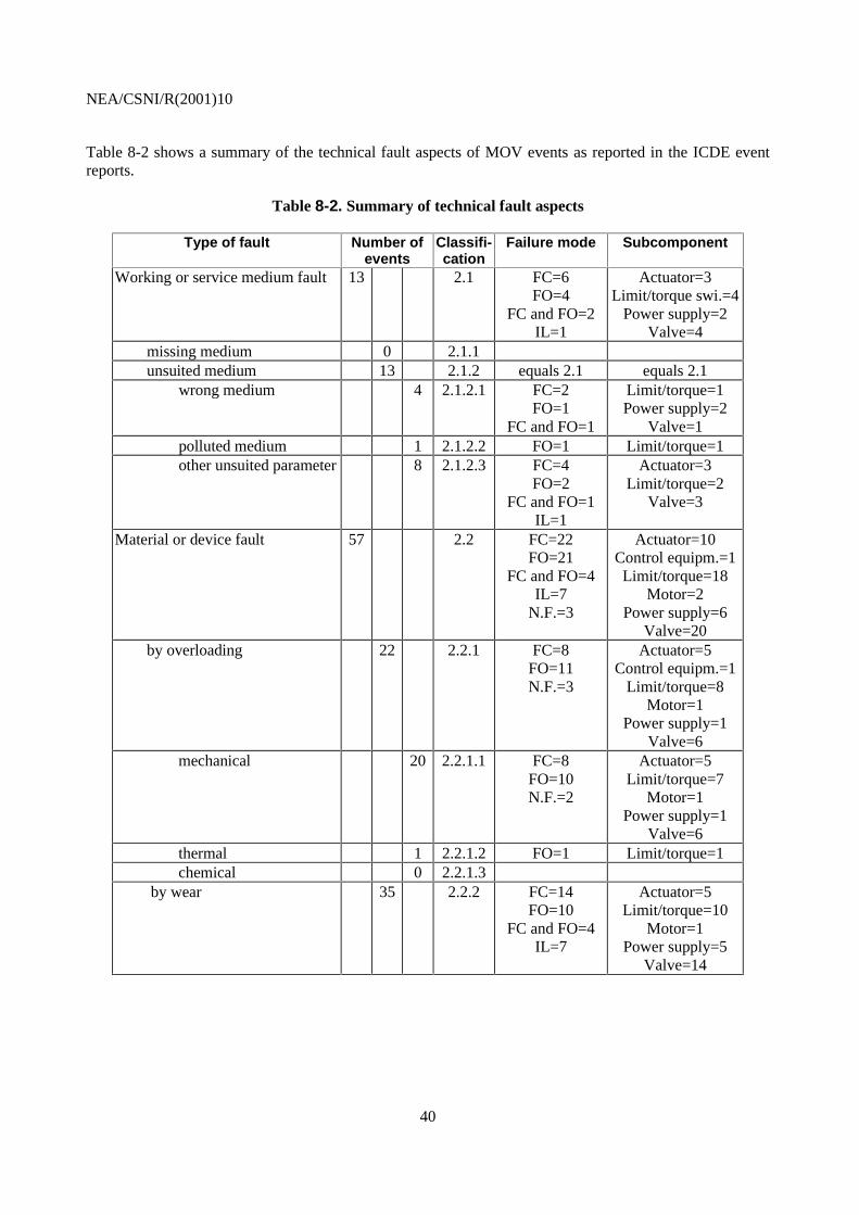
Table 8-2 shows a summary of the technical fault aspects of MOV events as reported in the ICDE eventreports.
Table 8-2. Summary of technical fault aspects
Type of fault Number ofevents
Classifi-cation
Failure mode Subcomponent
Working or service medium fault 13 2.1 FC=6FO=4
FC and FO=2IL=1
Actuator=3Limit/torque swi.=4
Power supply=2Valve=4
missing medium 0 2.1.1 unsuited medium 13 2.1.2 equals 2.1 equals 2.1 wrong medium 4 2.1.2.1 FC=2
FO=1FC and FO=1
Limit/torque=1Power supply=2
Valve=1 polluted medium 1 2.1.2.2 FO=1 Limit/torque=1 other unsuited parameter 8 2.1.2.3 FC=4
FO=2FC and FO=1
IL=1
Actuator=3Limit/torque=2
Valve=3
Material or device fault 57 2.2 FC=22FO=21
FC and FO=4IL=7
N.F.=3
Actuator=10Control equipm.=1Limit/torque=18
Motor=2Power supply=6
Valve=20 by overloading 22 2.2.1 FC=8
FO=11N.F.=3
Actuator=5Control equipm.=1
Limit/torque=8Motor=1
Power supply=1Valve=6
mechanical 20 2.2.1.1 FC=8FO=10N.F.=2
Actuator=5Limit/torque=7
Motor=1Power supply=1
Valve=6 thermal 1 2.2.1.2 FO=1 Limit/torque=1 chemical 0 2.2.1.3 by wear 35 2.2.2 FC=14
FO=10FC and FO=4
IL=7
Actuator=5Limit/torque=10
Motor=1Power supply=5
Valve=14
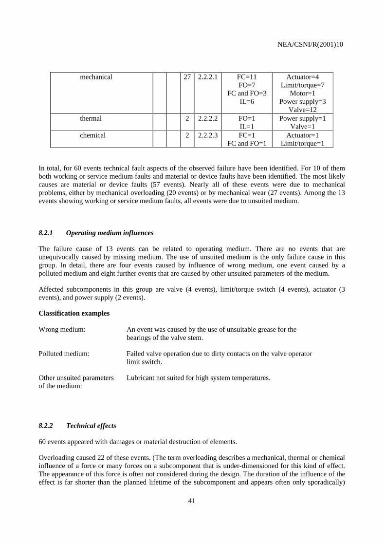
NEA/CSNI/R(2001)10
41
mechanical 27 2.2.2.1 FC=11FO=7
FC and FO=3IL=6
Actuator=4Limit/torque=7
Motor=1Power supply=3
Valve=12 thermal 2 2.2.2.2 FO=1
IL=1Power supply=1
Valve=1 chemical 2 2.2.2.3 FC=1
FC and FO=1Actuator=1
Limit/torque=1
In total, for 60 events technical fault aspects of the observed failure have been identified. For 10 of themboth working or service medium faults and material or device faults have been identified. The most likelycauses are material or device faults (57 events). Nearly all of these events were due to mechanicalproblems, either by mechanical overloading (20 events) or by mechanical wear (27 events). Among the 13events showing working or service medium faults, all events were due to unsuited medium.
8.2.1 Operating medium influences
The failure cause of 13 events can be related to operating medium. There are no events that areunequivocally caused by missing medium. The use of unsuited medium is the only failure cause in thisgroup. In detail, there are four events caused by influence of wrong medium, one event caused by apolluted medium and eight further events that are caused by other unsuited parameters of the medium.
Affected subcomponents in this group are valve (4 events), limit/torque switch (4 events), actuator (3events), and power supply (2 events).
Classification examples
Wrong medium: An event was caused by the use of unsuitable grease for thebearings of the valve stem.
Polluted medium: Failed valve operation due to dirty contacts on the valve operatorlimit switch.
Other unsuited parametersof the medium:
Lubricant not suited for high system temperatures.
8.2.2 Technical effects
60 events appeared with damages or material destruction of elements.
Overloading caused 22 of these events. (The term overloading describes a mechanical, thermal or chemicalinfluence of a force or many forces on a subcomponent that is under-dimensioned for this kind of effect.The appearance of this force is often not considered during the design. The duration of the influence of theeffect is far shorter than the planned lifetime of the subcomponent and appears often only sporadically)
NEA/CSNI/R(2001)10
42
This group is mainly formed by events caused by mechanical overloading (20). There is one event causedby thermal and no event that is caused by chemical overloading. The precise classification of one eventwas not possible. About 25 % of the events in the mechanical overloading group showed some kind ofunder-dimensioning leading to insufficient operating thrust under design basis conditions.
Affected subcomponents in this group are limit/torque switch (7 events), valve (6 events), actuator (5events), motor (1 event), and power supply (1 event).
Thirty-five events were caused by wear. (The term wear describes a mechanical, thermal or chemicalinfluence of a force or many forces on a subcomponent that is under-dimensioned for this kind of effect.The appearance of this force is mostly considered in the design. The duration of the influence of the effectis often long lasting and does in general not consist of countable single events.) In detail there are 28events caused by mechanical wear, two events by thermal and two events by chemical wear. The preciseclassification of four events was not possible.
Affected subcomponents in the mechanical wear group are valve (12 events), limit/torque switch (7events), actuator (4 events), power supply (3 events) and motor (1 event). About 70 % of the valve eventsdue to mechanical wear lead to internal leakage. Nearly half of the limit/torque switch events were due toset-point drift.
Classification examples
Mechanical overloading: An event that is caused by a sheared motor pinion key and can beattributed to improper key material.
Thermal overloading: Pressure locking
Mechanical wear: Reopening of valves after closure caused by reduced friction betweenscrew and stem nut below self locking due to frequent actuationduring tests.
Thermal wear: Worn out valve seats due to cyclic fatigue
Chemical wear: Oxidation on torque switch contacts

NEA/CSNI/R(2001)10
43
9. SUMMARY AND CONCLUSIONS
This study examined 81 events in the ICDE database by tabulating the data and observing trends. Oncetrends were identified, individual events were reviewed for insights.
The database contains information developed during the original entry of the events that was used in thisstudy. This information includes root cause, coupling factor, detection method ,size, and corrective action.As part of this study, these events were reviewed again and additional categories of the data were included.Those categories included the degree of failure, the affected subcomponent, the kind of human failure, andthe kind of technical failure.
This study begins with an overview of the data set. Charts and tables are provided which show the eventcount for the event parameters. There are charts that demonstrate the distribution of the events furtherrefined by failure mode, root causes, coupling factors, corrective actions, number of exposed components,detection method, and affected subcomponents. There are charts that demonstrate the distribution of eventseven further refined into groups of the total group and partial CCF events.
Testing is the dominant mode for detecting common cause failures. The used term "test" summarized allkind of tests like tests during annual overhauls, tests during operation, and unscheduled tests.
The report contains a further grouping according to a decision tree that shows the distribution of the sameevents further refined by kind of human and technical failures. The analysis shows that more than 50 % ofthe events could be assigned either to human error categories or to technical fault categories. For about30% of the events, both human errors and technical faults have been identified.
This approach especially focuses on root causes of common cause failures. So there are errors in thecalculation during design that caused false stroke forces. Wearing is a widespread effect. Thesubcomponent "limit switch" caused also a substantial amount of CCF. Failures on locking out duringmaintenance actions were also conspicuous. There are further failure effects that caused CCF in not such alarge and determinant scope. For example appeared in the study the selection of unsuited service media(mostly lubricants), the selection of improper materials, and assembly faults.
.

NEA/CSNI/R(2001)10
44
10. REFERENCES
1. International common-cause failure data exchange (ICDE) project, terms and conditions.OECD/NEA, 1998.
2. OECD/NEA’s web site: http://www.nea.fr. ICDE project documentation, 1995-1998.
3. ICDE Coding Guidelines (NEA/SEN/SIN/WG1(98)3).
4. Marshall, F. M., D. M. Rasmuson, and A. Mosleh, 1998. Common Cause Failure Data Collectionand Analysis System, Volume 1 Overview, U.S. Nuclear Regulatory Commission, NUREG/CR-6268, INEEL/EXT-97-00696, June.
Related Documents