- 1 - Motor Actuators Basics

Welcome message from author
This document is posted to help you gain knowledge. Please leave a comment to let me know what you think about it! Share it to your friends and learn new things together.
Transcript
- 1 -
Motor Actuators Basics
- 2 -
Note:
All specifications and other information are not guaranteed and are subject to change without notice.
Prior to any new usage of JE motor actuators it is recommended to contact Johnson Electric.
All information below and content of links are subject to the disclaimer
of the Johnson Electric website
- 3 -
Contents Overview ....................................................................................................................................................................... 4
Classification ............................................................................................................................................................. 5 DC Motors ................................................................................................................................................................. 6 Universal Motors ....................................................................................................................................................... 7 BLDC Motors ............................................................................................................................................................. 8 Synchronous Motors ................................................................................................................................................. 9 Stepper Motors ........................................................................................................................................................ 10 Shaded Pole Motors ................................................................................................................................................ 11 Solenoids ................................................................................................................................................................. 12 Piezo Motors ........................................................................................................................................................... 13
DC Motors ................................................................................................................................................................... 14 Basics ...................................................................................................................................................................... 15
Encoders.............................................................................................................................................................. 23 BLDC Motors ............................................................................................................................................................. 24
Basics ...................................................................................................................................................................... 25 Closed Loop Speed Control ................................................................................................................................ 30
Stepper Motors ........................................................................................................................................................... 31 Basics ...................................................................................................................................................................... 32
Gearmotors ................................................................................................................................................................. 45 Basics ...................................................................................................................................................................... 46
Motor mounting .................................................................................................................................................... 52 Linear motors .............................................................................................................................................................. 53
Basics ...................................................................................................................................................................... 54
- 4 -
Overview
- 5 -
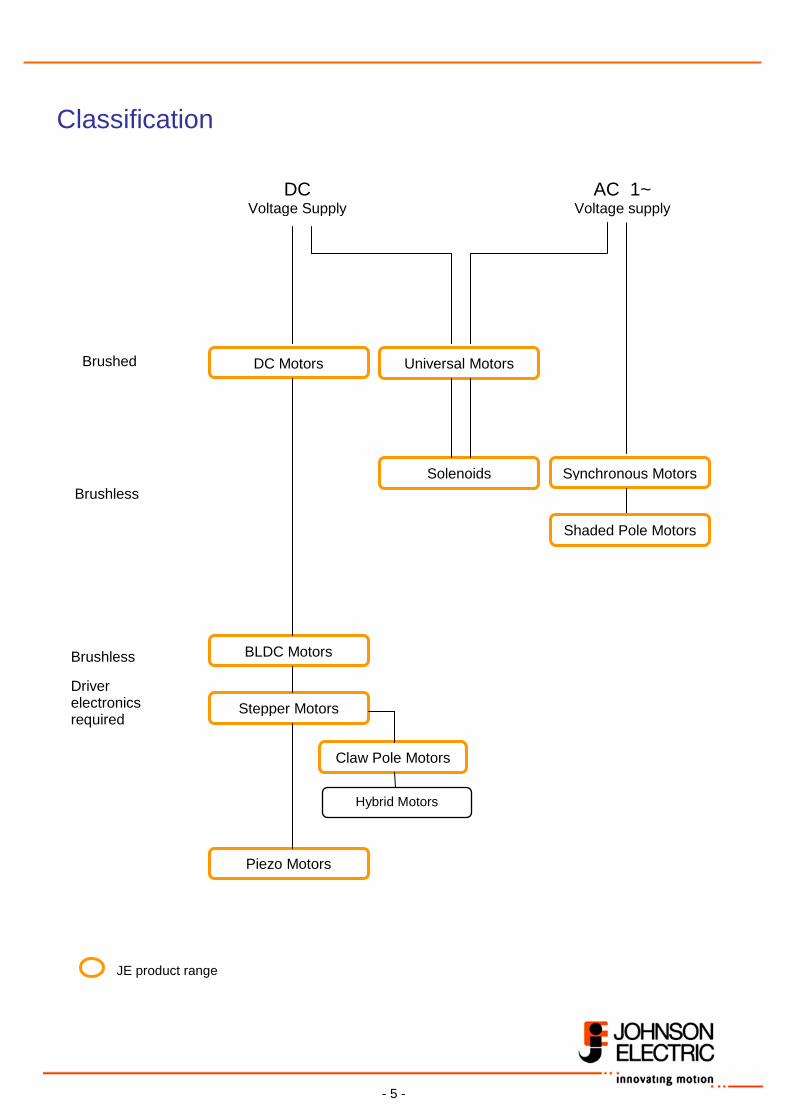
Classification
DC Voltage Supply
AC 1~ Voltage supply
Universal Motors
Hybrid Motors
Stepper Motors
Claw Pole Motors
Synchronous Motors
Piezo Motors
Solenoids
DC Motors
BLDC Motors
Brushless
Brushless Driver electronics required
Brushed
JE product range
Shaded Pole Motors
- 6 -
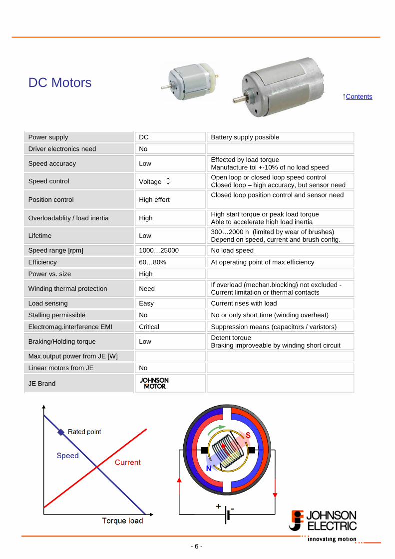
DC Motors Contents
Power supply DC Battery supply possible
Driver electronics need No
Speed accuracy Low Effected by load torque Manufacture tol +-10% of no load speed
Speed control Voltage ↕ Open loop or closed loop speed control Closed loop – high accuracy, but sensor need
Position control High effort Closed loop position control and sensor need
Overloadablity / load inertia High High start torque or peak load torque Able to accelerate high load inertia
Lifetime Low 300…2000 h (limited by wear of brushes) Depend on speed, current and brush config.
Speed range [rpm] 1000…25000 No load speed
Efficiency 60…80% At operating point of max.efficiency
Power vs. size High
Winding thermal protection Need If overload (mechan.blocking) not excluded - Current limitation or thermal contacts
Load sensing Easy Current rises with load
Stalling permissible No No or only short time (winding overheat)
Electromag.interference EMI Critical Suppression means (capacitors / varistors)
Braking/Holding torque Low Detent torque Braking improveable by winding short circuit
Max.output power from JE [W]
Linear motors from JE No
JE Brand
- 7 -
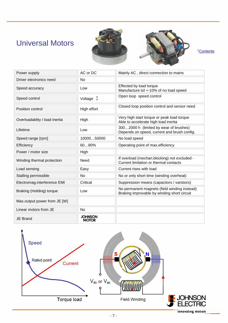
Universal Motors Contents
Power supply AC or DC Mainly AC , direct connection to mains
Driver electronics need No
Speed accuracy Low Effected by load torque Manufacture tol +-10% of no load speed
Speed control Voltage ↕ Open loop speed control
Position control High effort Closed loop position control and sensor need
Overloadablity / load inertia High Very high start torque or peak load torque Able to accelerate high load inertia
Lifetime Low 300…2000 h (limited by wear of brushes) Depends on speed, current and brush config.
Speed range [rpm] 10000…50000 No load speed
Efficiency 60…80% Operating point of max.efficiency
Power / motor size High
Winding thermal protection Need If overload (mechan.blocking) not excluded - Current limitation or thermal contacts
Load sensing Easy Current rises with load
Stalling permissible No No or only short time (winding overheat)
Electromag.interference EMI Critical Suppression means (capacitors / varistors)
Braking (Holding) torque Low No permanent magnets (field winding instead) Braking improvable by winding short circuit
Max.output power from JE [W]
Linear motors from JE No
JE Brand
- 8 -
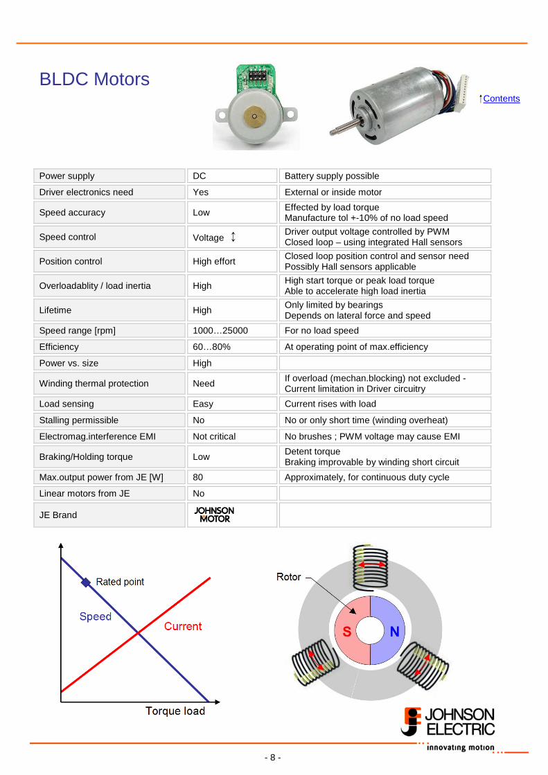
BLDC Motors Contents
Power supply DC Battery supply possible
Driver electronics need Yes External or inside motor
Speed accuracy Low Effected by load torque Manufacture tol +-10% of no load speed
Speed control Voltage ↕ Driver output voltage controlled by PWM Closed loop – using integrated Hall sensors
Position control High effort Closed loop position control and sensor need Possibly Hall sensors applicable
Overloadablity / load inertia High High start torque or peak load torque Able to accelerate high load inertia
Lifetime High Only limited by bearings Depends on lateral force and speed
Speed range [rpm] 1000…25000 For no load speed
Efficiency 60…80% At operating point of max.efficiency
Power vs. size High
Winding thermal protection Need If overload (mechan.blocking) not excluded - Current limitation in Driver circuitry
Load sensing Easy Current rises with load
Stalling permissible No No or only short time (winding overheat)
Electromag.interference EMI Not critical No brushes ; PWM voltage may cause EMI
Braking/Holding torque Low Detent torque Braking improvable by winding short circuit
Max.output power from JE [W] 80 Approximately, for continuous duty cycle
Linear motors from JE No
JE Brand
- 9 -
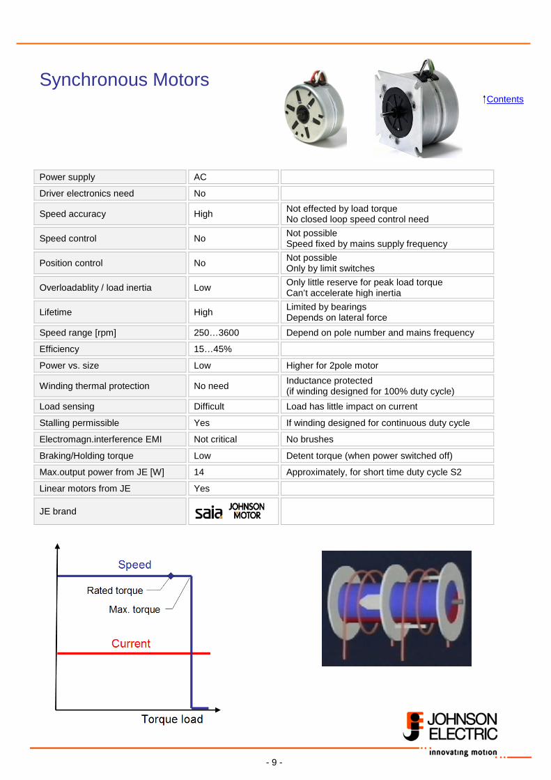
Synchronous Motors Contents Power supply AC
Driver electronics need No
Speed accuracy High Not effected by load torque No closed loop speed control need
Speed control No Not possible Speed fixed by mains supply frequency
Position control No Not possible Only by limit switches
Overloadablity / load inertia Low Only little reserve for peak load torque Can’t accelerate high inertia
Lifetime High Limited by bearings Depends on lateral force
Speed range [rpm] 250…3600 Depend on pole number and mains frequency
Efficiency 15…45%
Power vs. size Low Higher for 2pole motor
Winding thermal protection No need Inductance protected (if winding designed for 100% duty cycle)
Load sensing Difficult Load has little impact on current
Stalling permissible Yes If winding designed for continuous duty cycle
Electromagn.interference EMI Not critical No brushes
Braking/Holding torque Low Detent torque (when power switched off)
Max.output power from JE [W] 14 Approximately, for short time duty cycle S2
Linear motors from JE Yes
JE brand
- 10 -
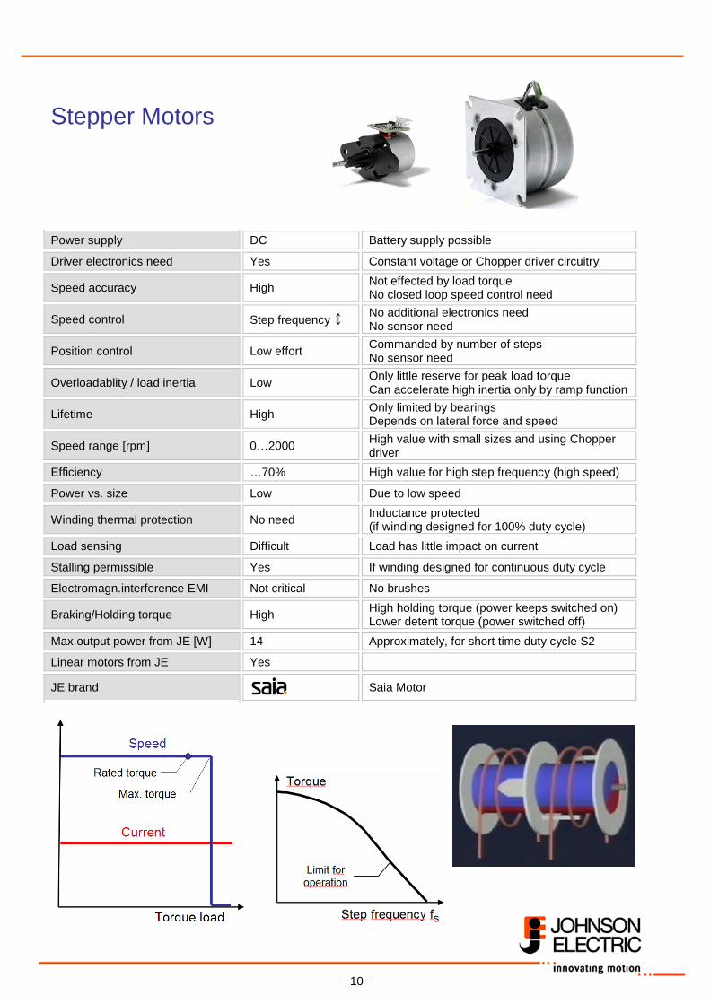
Stepper Motors Contents
Power supply DC Battery supply possible
Driver electronics need Yes Constant voltage or Chopper driver circuitry
Speed accuracy High Not effected by load torque No closed loop speed control need
Speed control Step frequency ↕ No additional electronics need No sensor need
Position control Low effort Commanded by number of steps No sensor need
Overloadablity / load inertia Low Only little reserve for peak load torque Can accelerate high inertia only by ramp function
Lifetime High Only limited by bearings Depends on lateral force and speed
Speed range [rpm] 0…2000 High value with small sizes and using Chopper driver
Efficiency …70% High value for high step frequency (high speed)
Power vs. size Low Due to low speed
Winding thermal protection No need Inductance protected (if winding designed for 100% duty cycle)
Load sensing Difficult Load has little impact on current
Stalling permissible Yes If winding designed for continuous duty cycle
Electromagn.interference EMI Not critical No brushes
Braking/Holding torque High High holding torque (power keeps switched on) Lower detent torque (power switched off)
Max.output power from JE [W] 14 Approximately, for short time duty cycle S2
Linear motors from JE Yes
JE brand Saia Motor
- 11 -
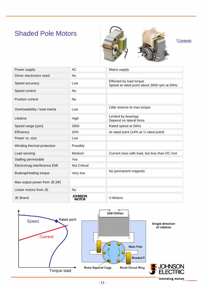
Shaded Pole Motors Contents
Power supply AC Mains supply
Driver electronics need No
Speed accuracy Low Effected by load torque Speed at rated point about 2600 rpm at 50Hz
Speed control No
Position control No
Overloadablity / load inertia Low Little reserve to max.torque
Lifetime High Limited by bearings Depend on lateral force
Speed range [rpm] 2600 Rated speed at 50Hz
Efficiency 20% At rated point (14% at ½ rated point)
Power vs. size Low
Winding thermal protection Possibly
Load sensing Medium Current rises with load, but less than DC mot
Stalling permissible Yes
Electromag.interference EMI Not Critical
Braking/Holding torque Very low No permanent magnets
Max.output power from JE [W]
Linear motors from JE No
JE Brand V-Motors
- 12 -
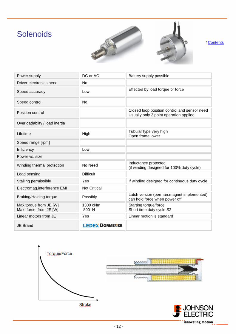
Solenoids Contents
Power supply DC or AC Battery supply possible
Driver electronics need No
Speed accuracy Low Effected by load torque or force
Speed control No
Position control Closed loop position control and sensor need Usually only 2 point operation applied
Overloadablity / load inertia
Lifetime High Tubular type very high Open frame lower
Speed range [rpm]
Efficiency Low
Power vs. size
Winding thermal protection No Need Inductance protected (if winding designed for 100% duty cycle)
Load sensing Difficult
Stalling permissible Yes If winding designed for continuous duty cycle
Electromag.interference EMI Not Critical
Braking/Holding torque Possibly Latch version (perman.magnet implemented) can hold force when power off
Max.torque from JE [W] Max. force from JE [W]
1300 cNm 800 N
Starting torque/force Short time duty cycle S2
Linear motors from JE Yes Linear motion is standard
JE Brand
- 13 -
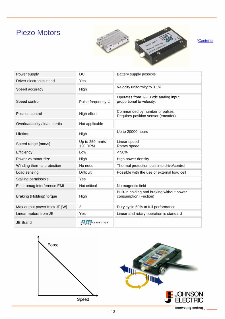
Piezo Motors Contents
Power supply DC Battery supply possible
Driver electronics need Yes
Speed accuracy High Velocity uniformity to 0.1%
Speed control Pulse frequency ↕ Operates from +/-10 vdc analog input proportional to velocity.
Position control High effort Commanded by number of pulses Requires position sensor (encoder)
Overloadablity / load inertia Not applicable
Lifetime High Up to 20000 hours
Speed range [mm/s] Up to 250 mm/s 120 RPM
Linear speed Rotary speed
Efficiency Low < 50%
Power vs.motor size High High power density
Winding thermal protection No need Thermal protection built into drive/control
Load sensing Difficult Possible with the use of external load cell
Stalling permissible Yes
Electromag.interference EMI Not critical No magnetic field
Braking (Holding) torque High Built-in holding and braking without power consumption (Friction)
Max.output power from JE [W] 2 Duty cycle 50% at full performance
Linear motors from JE Yes Linear and rotary operation is standard
JE Brand
- 14 -
DC Motors
- 15 -
Basics
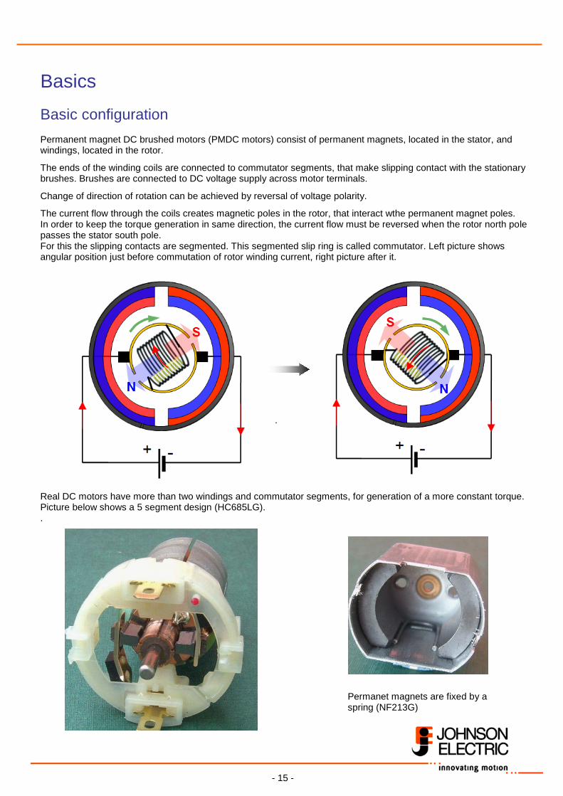
Basic configuration Permanent magnet DC brushed motors (PMDC motors) consist of permanent magnets, located in the stator, and windings, located in the rotor.
The ends of the winding coils are connected to commutator segments, that make slipping contact with the stationary brushes. Brushes are connected to DC voltage supply across motor terminals.
Change of direction of rotation can be achieved by reversal of voltage polarity.
The current flow through the coils creates magnetic poles in the rotor, that interact wthe permanent magnet poles. In order to keep the torque generation in same direction, the current flow must be reversed when the rotor north pole passes the stator south pole. For this the slipping contacts are segmented. This segmented slip ring is called commutator. Left picture shows angular position just before commutation of rotor winding current, right picture after it.
.
Real DC motors have more than two windings and commutator segments, for generation of a more constant torque. Picture below shows a 5 segment design (HC685LG). .
Permanet magnets are fixed by a spring (NF213G)
- 16 -
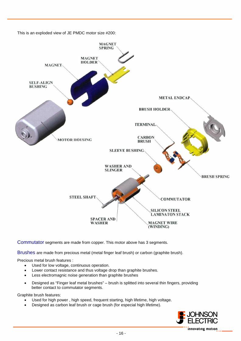
This is an exploded view of JE PMDC motor size #200: Commutator segments are made from copper. This motor above has 3 segments. Brushes are made from precious metal (metal finger leaf brush) or carbon (graphite brush).
Precious metal brush features : • Used for low voltage, continuous operation. • Lower contact resistance and thus voltage drop than graphite brushes. • Less electromagnic noise generation than graphite brushes
• Designed as “Finger leaf metal brushes” – brush is splitted into several thin fingers, providing better contact to commutator segments.
Graphite brush features: • Used for high power , high speed, frequent starting, high lifetime, high voltage. • Designed as carbon leaf brush or cage brush (for especial high lifetime).
- 17 -
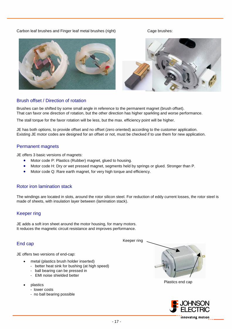
Carbon leaf brushes and Finger leaf metal brushes (right) Cage brushes: Brush offset / Direction of rotation
Brushes can be shifted by some small angle in reference to the permanent magnet (brush offset). That can favor one direction of rotation, but the other direction has higher sparkling and worse performance.
The stall torque for the favor rotation will be less, but the max. efficiency point will be higher.
JE has both options, to provide offset and no offset (zero oriented) according to the customer application. Existing JE motor codes are designed for an offset or not, must be checked if to use them for new application.
Permanent magnets JE offers 3 basic versions of magnets:
• Motor code P: Plastics (Rubber) magnet, glued to housing. • Motor code H: Dry or wet pressed magnet, segments held by springs or glued. Stronger than P. • Motor code Q: Rare earth magnet, for very high torque and efficiency.
Rotor iron lamination stack The windings are located in slots, around the rotor silicon steel. For reduction of eddy current losses, the rotor steel is made of sheets, with insulation layer between (lamination stack).
Keeper ring JE adds a soft iron sheet around the motor housing, for many motors. It reduces the magnetic circuit resistance and improves performance.
End cap JE offers two versions of end-cap:
• metal (plastics brush holder inserted) - better heat sink for bushing (at high speed)
- ball bearing can be pressed in - EMI noise shielded better • plastics
- lower costs - no ball bearing possible
Keeper ring
Plastics end cap
- 18 -
EMI noise suppression Brushed DC motors generate EMI (ElectroMagnetic Interference) noise, whenever the brushes change from one to another commutator segment. The higher the supply voltage, speed and current - the higher the noise emission. The emission also depends on number of segments (i.e. voltage drop between neighbouring segments). The noise is emitted by two ways:
• Conduction along power supply wires • Radiation through the air
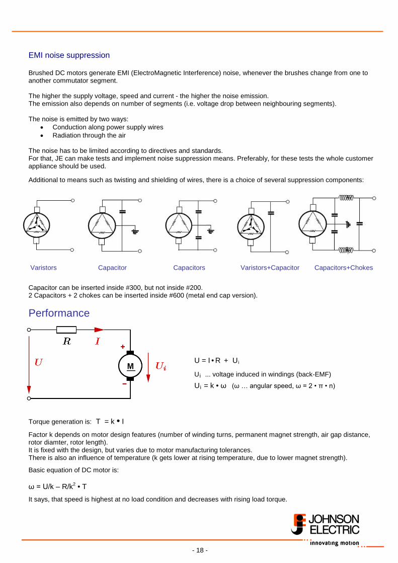
The noise has to be limited according to directives and standards. For that, JE can make tests and implement noise suppression means. Preferably, for these tests the whole customer appliance should be used. Additional to means such as twisting and shielding of wires, there is a choice of several suppression components: Varistors Capacitor Capacitors Varistors+Capacitor Capacitors+Chokes
Capacitor can be inserted inside #300, but not inside #200. 2 Capacitors + 2 chokes can be inserted inside #600 (metal end cap version).
Performance
U = I • R + Ui
Ui ... voltage induced in windings (back-EMF)
Ui = k • ω (ω … angular speed, ω = 2 • π • n) Torque generation is: T = k • I
Factor k depends on motor design features (number of winding turns, permanent magnet strength, air gap distance, rotor diamter, rotor length). It is fixed with the design, but varies due to motor manufacturing tolerances. There is also an influence of temperature (k gets lower at rising temperature, due to lower magnet strength).
Basic equation of DC motor is: ω = U/k – R/k2 • T
It says, that speed is highest at no load condition and decreases with rising load torque.
- 19 -
Losses and Efficiency No-load losses PO:
Friction losses at bearings and at brushes, Hysteresis and Eddy current losses. As these losses must be covered by a no-load torque and hence no-load current – there are also no-load current losses in the winding: IO
2 x R. Load losses:
At rising load torque, the current and thus winding current losses increase. Winding current is maximum when rotor is stalled: Ploss max = U2 / R At point of max.efficiency there is best ratio Pmech / Pel = Pmech /(U • I). Efficiency at this point is about η = (1 - √ IO/Istall)2 At point of max.mechanical output power, the speed is half of no-load speed. Output power Pmech max is little less than U2 / 4 R. Lifetime DC motor lifetime is limited by wear of brushes. It depends on
• Speed (commutator surface speed) • Current load (average current and peaks, start/stop frequency) • Brush configuration, brush material (see above) and commutator design
Typical lifetime of JE PMDC motors ranges from 300 hours (small motors) to about 2000 hours (larger motor sizes, cage brushes, continuous operation of rather low output power).
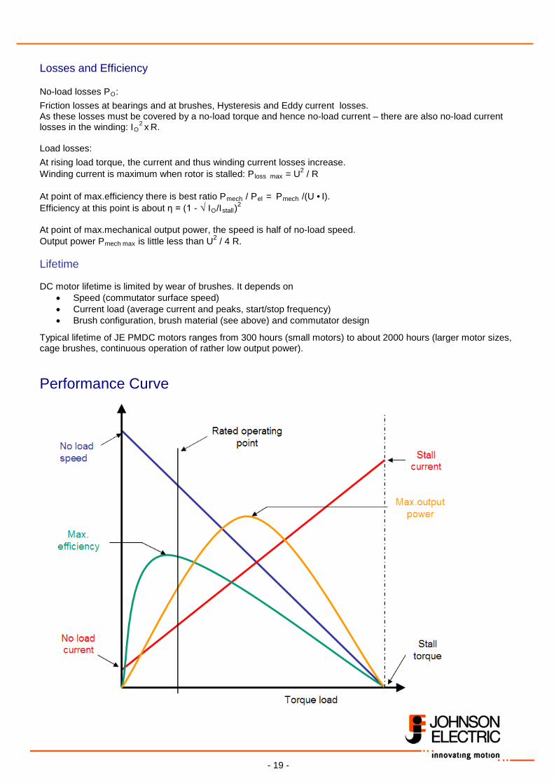
Performance Curve
- 20 -
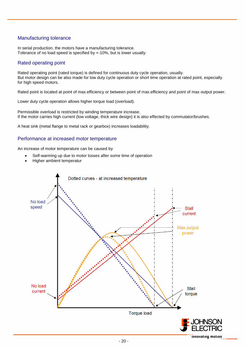
Manufacturing tolerance In serial production, the motors have a manufacturing tolerance. Tolerance of no load speed is specified by +-10%, but is lower usually. Rated operating point Rated operating point (rated torque) is defined for continuous duty cycle operation, usually. But motor design can be also made for low duty cycle operation or short time operation at rated point, especially for high speed motors. Rated point is located at point of max.efficiency or between point of max.efficiency and point of max output power. Lower duty cycle operation allows higher torque load (overload). Permissible overload is restricted by winding temperature increase. If the motor carries high current (low voltage, thick wire design) it is also effected by commutator/brushes. A heat sink (metal flange to metal rack or gearbox) increases loadability. Performance at increased motor temperature An increase of motor temperature can be caused by
• Self-warming up due to motor losses after some time of operation • Higher ambient temperatur
- 21 -
There are two effects: Permanent magnet strength decreases – causing higher no load speed
Winding resistance increases – causing lower stall current.
Both effects reduce stall torque value.
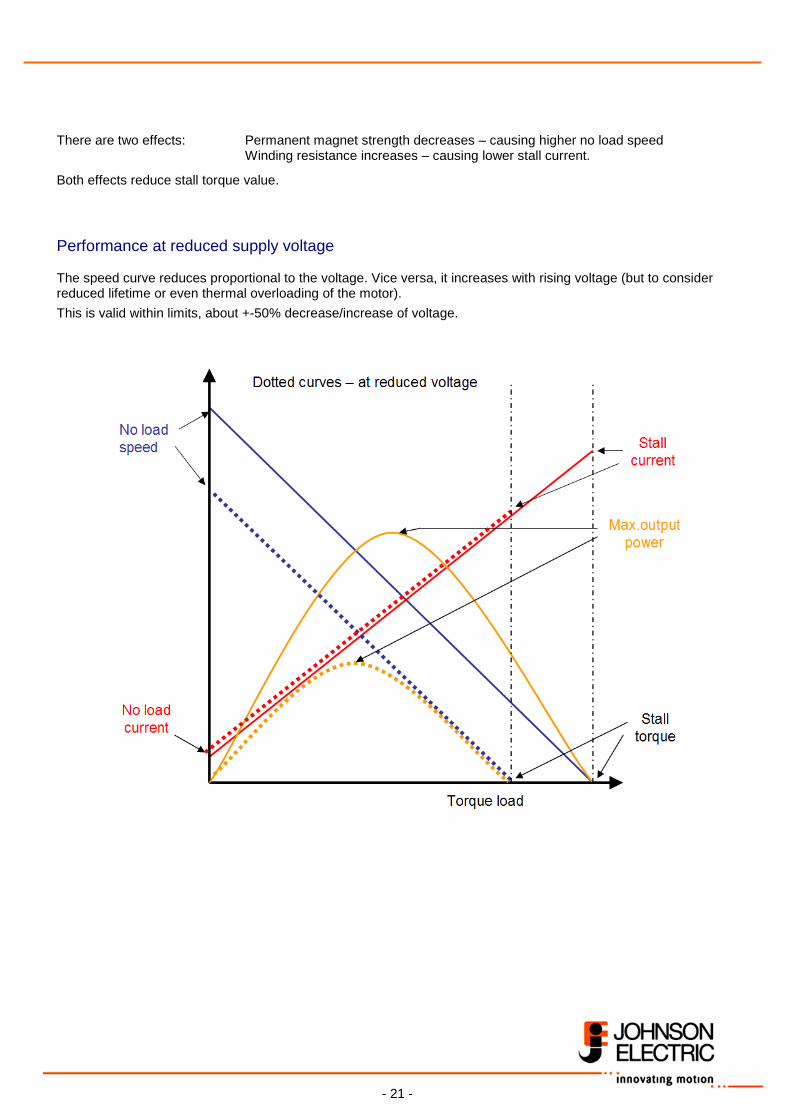
Performance at reduced supply voltage The speed curve reduces proportional to the voltage. Vice versa, it increases with rising voltage (but to consider reduced lifetime or even thermal overloading of the motor).
This is valid within limits, about +-50% decrease/increase of voltage.
- 22 -
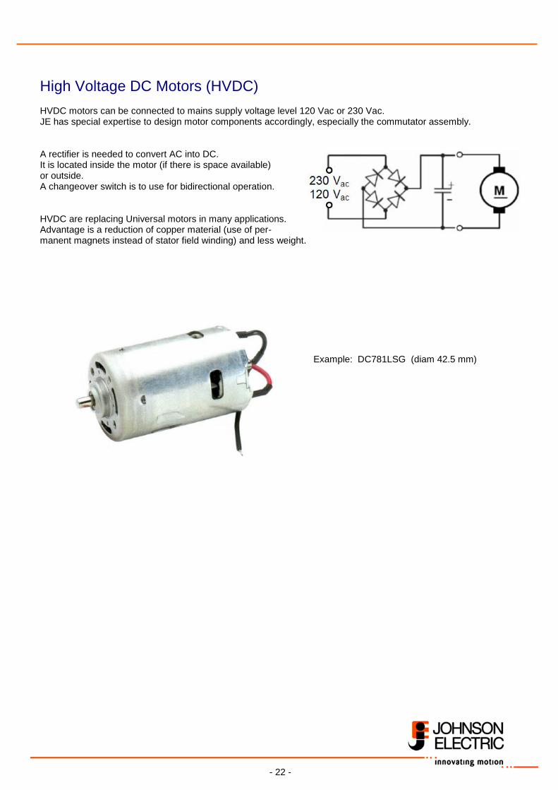
High Voltage DC Motors (HVDC) HVDC motors can be connected to mains supply voltage level 120 Vac or 230 Vac. JE has special expertise to design motor components accordingly, especially the commutator assembly. A rectifier is needed to convert AC into DC. It is located inside the motor (if there is space available) or outside. A changeover switch is to use for bidirectional operation. HVDC are replacing Universal motors in many applications. Advantage is a reduction of copper material (use of per- manent magnets instead of stator field winding) and less weight.
Example: DC781LSG (diam 42.5 mm)
- 23 -
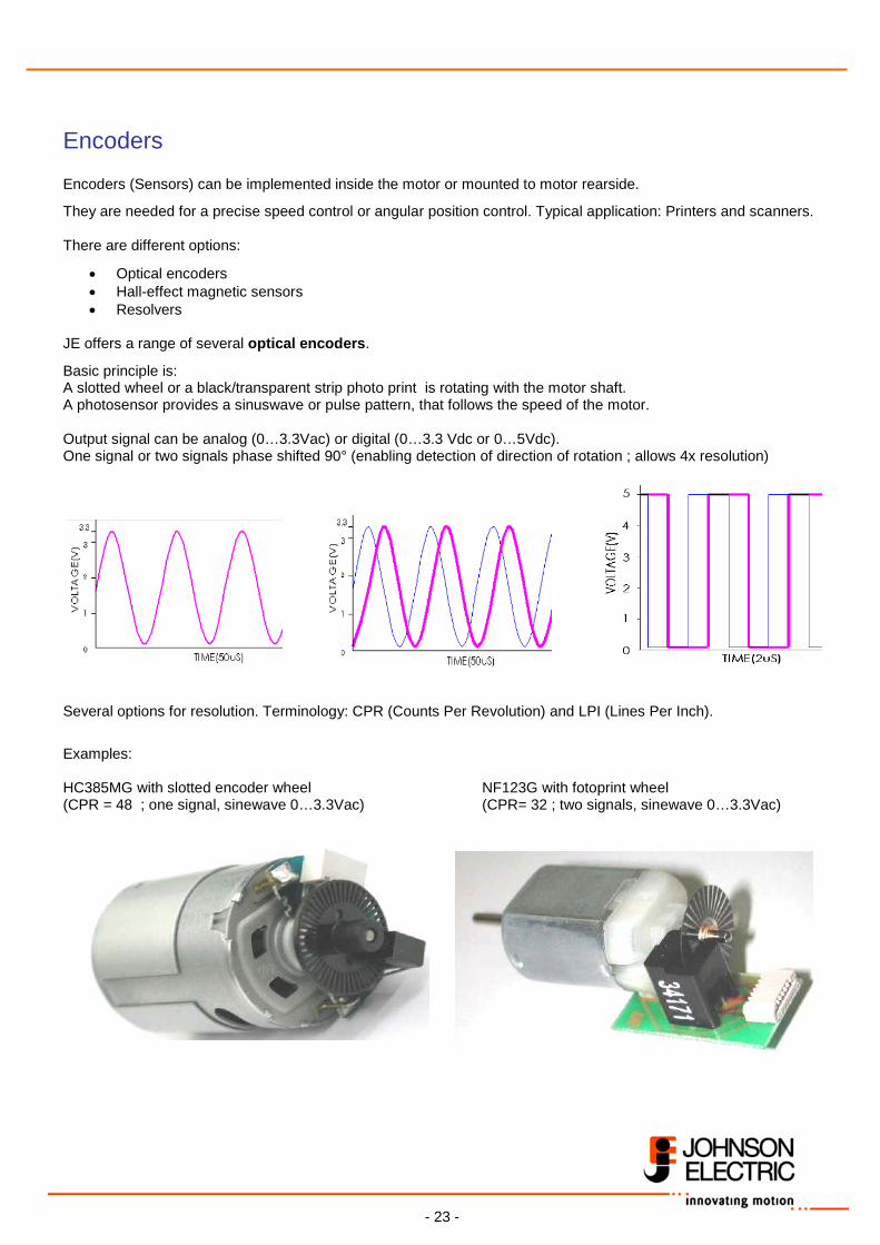
Encoders Encoders (Sensors) can be implemented inside the motor or mounted to motor rearside.
They are needed for a precise speed control or angular position control. Typical application: Printers and scanners. There are different options:
• Optical encoders • Hall-effect magnetic sensors • Resolvers
JE offers a range of several optical encoders.
Basic principle is: A slotted wheel or a black/transparent strip photo print is rotating with the motor shaft. A photosensor provides a sinuswave or pulse pattern, that follows the speed of the motor. Output signal can be analog (0…3.3Vac) or digital (0…3.3 Vdc or 0…5Vdc). One signal or two signals phase shifted 90° (enabling detection of direction of rotation ; allows 4x resolution) Several options for resolution. Terminology: CPR (Counts Per Revolution) and LPI (Lines Per Inch). Examples: HC385MG with slotted encoder wheel NF123G with fotoprint wheel (CPR = 48 ; one signal, sinewave 0…3.3Vac) (CPR= 32 ; two signals, sinewave 0…3.3Vac)
- 24 -
BLDC Motors
- 25 -
Basics Contents
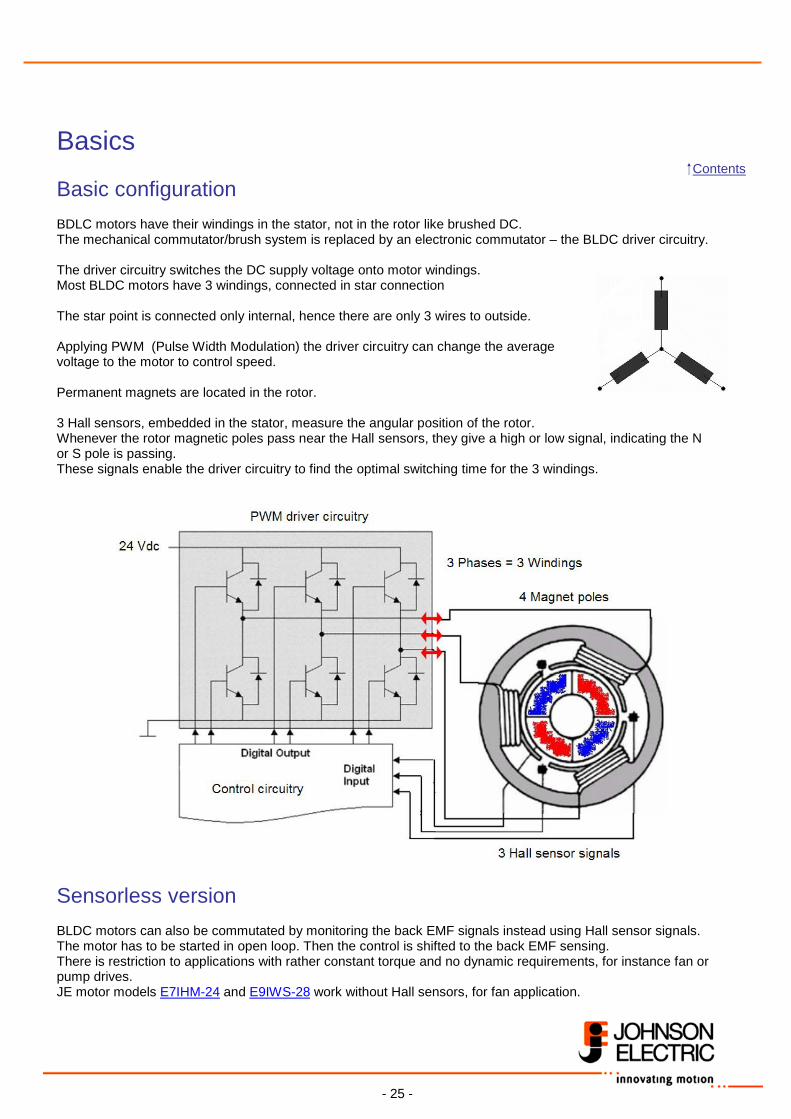
Basic configuration BDLC motors have their windings in the stator, not in the rotor like brushed DC. The mechanical commutator/brush system is replaced by an electronic commutator – the BLDC driver circuitry. The driver circuitry switches the DC supply voltage onto motor windings. Most BLDC motors have 3 windings, connected in star connection The star point is connected only internal, hence there are only 3 wires to outside. Applying PWM (Pulse Width Modulation) the driver circuitry can change the average voltage to the motor to control speed. Permanent magnets are located in the rotor. 3 Hall sensors, embedded in the stator, measure the angular position of the rotor. Whenever the rotor magnetic poles pass near the Hall sensors, they give a high or low signal, indicating the N or S pole is passing. These signals enable the driver circuitry to find the optimal switching time for the 3 windings.
Sensorless version BLDC motors can also be commutated by monitoring the back EMF signals instead using Hall sensor signals. The motor has to be started in open loop. Then the control is shifted to the back EMF sensing. There is restriction to applications with rather constant torque and no dynamic requirements, for instance fan or pump drives. JE motor models E7IHM-24 and E9IWS-28 work without Hall sensors, for fan application.
- 26 -
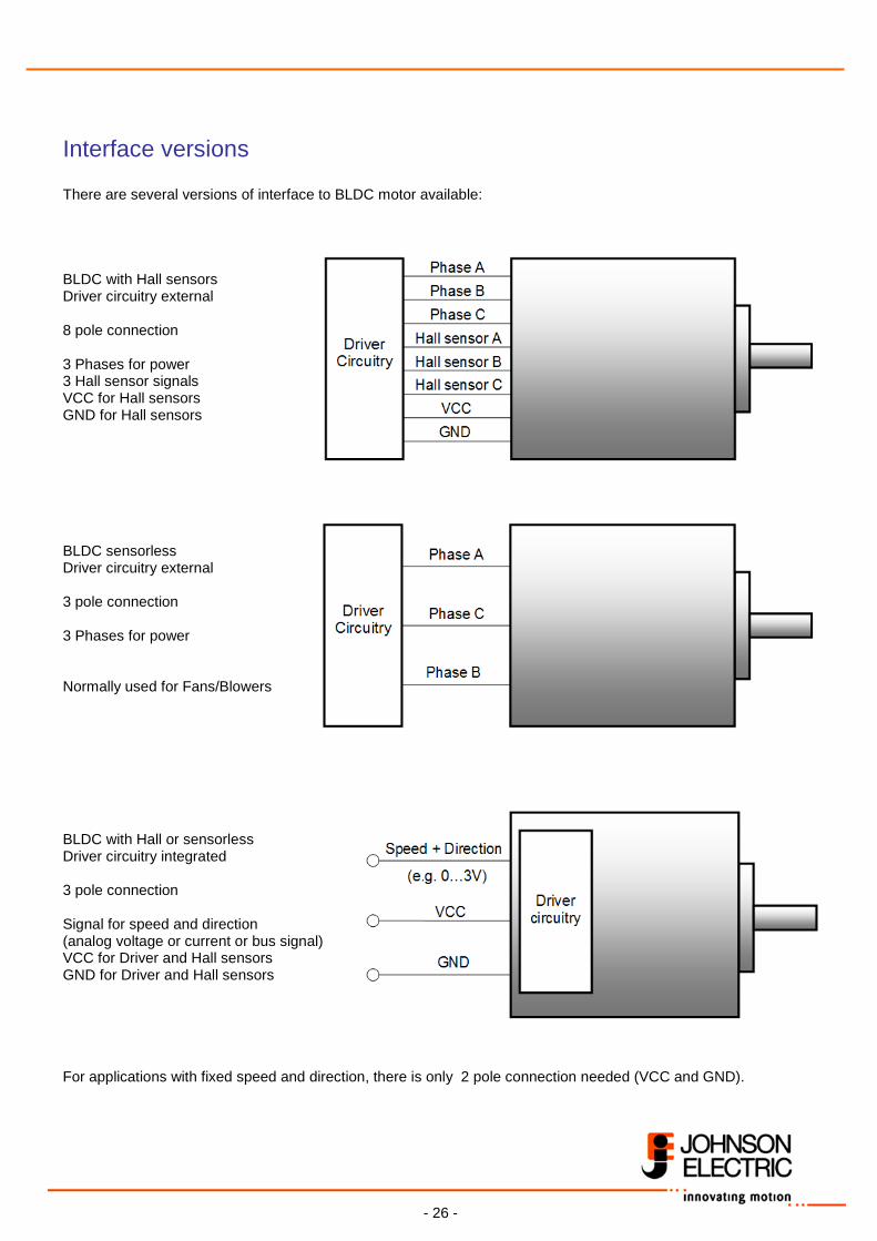
Interface versions There are several versions of interface to BLDC motor available: BLDC with Hall sensors Driver circuitry external 8 pole connection 3 Phases for power 3 Hall sensor signals VCC for Hall sensors GND for Hall sensors BLDC sensorless Driver circuitry external 3 pole connection 3 Phases for power Normally used for Fans/Blowers BLDC with Hall or sensorless Driver circuitry integrated 3 pole connection Signal for speed and direction (analog voltage or current or bus signal) VCC for Driver and Hall sensors GND for Driver and Hall sensors For applications with fixed speed and direction, there is only 2 pole connection needed (VCC and GND).
- 27 -
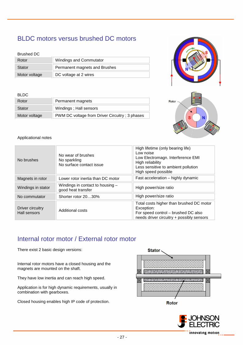
BLDC motors versus brushed DC motors Brushed DC Rotor Windings and Commutator
Stator Permanent magnets and Brushes
Motor voltage DC voltage at 2 wires BLDC Rotor Permanent magnets
Stator Windings ; Hall sensors
Motor voltage PWM DC voltage from Driver Circuitry ; 3 phases Applicational notes
No brushes No wear of brushes No sparkling No surface contact issue
High lifetime (only bearing life) Low noise Low Electromagn. Interference EMI High reliability Less sensitive to ambient pollution High speed possible
Magnets in rotor Lower rotor inertia than DC motor Fast acceleration – highly dynamic
Windings in stator Windings in contact to housing – good heat transfer High power/size ratio
No commutator Shorter rotor 20…30% High power/size ratio
Driver circuitry Hall sensors Additional costs
Total costs higher than brushed DC motor Exception: For speed control – brushed DC also needs driver circuitry + possibly sensors
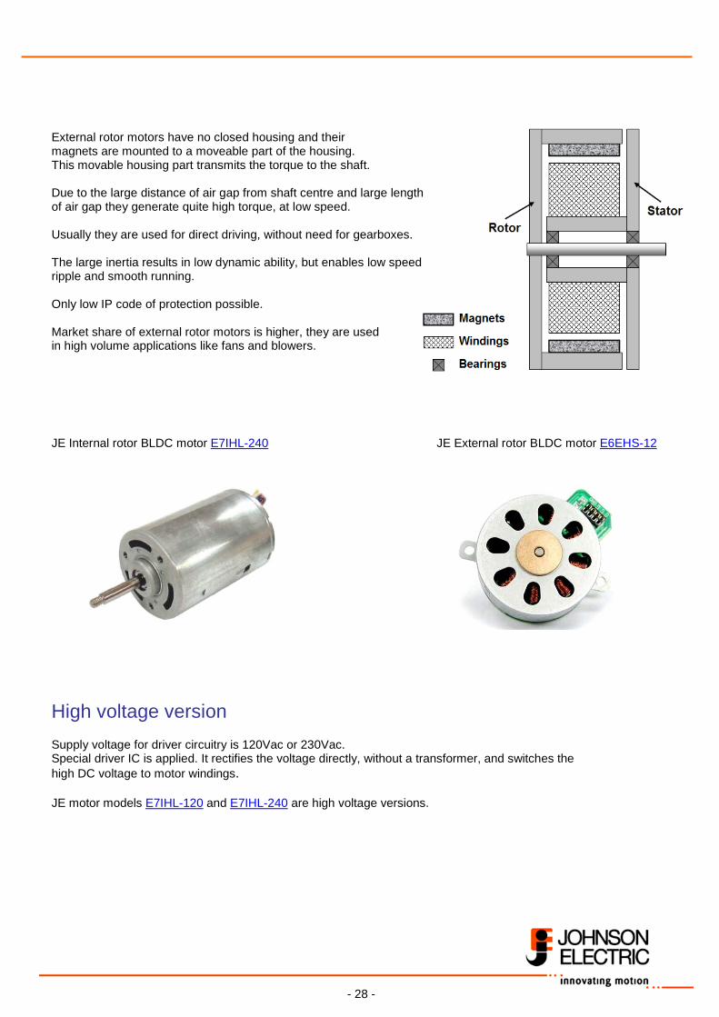
Internal rotor motor / External rotor motor There exist 2 basic design versions: Internal rotor motors have a closed housing and the magnets are mounted on the shaft. They have low inertia and can reach high speed. Application is for high dynamic requirements, usually in combination with gearboxes. Closed housing enables high IP code of protection.
- 28 -
External rotor motors have no closed housing and their magnets are mounted to a moveable part of the housing. This movable housing part transmits the torque to the shaft. Due to the large distance of air gap from shaft centre and large length of air gap they generate quite high torque, at low speed. Usually they are used for direct driving, without need for gearboxes. The large inertia results in low dynamic ability, but enables low speed ripple and smooth running. Only low IP code of protection possible. Market share of external rotor motors is higher, they are used in high volume applications like fans and blowers. JE Internal rotor BLDC motor E7IHL-240 JE External rotor BLDC motor E6EHS-12
High voltage version Supply voltage for driver circuitry is 120Vac or 230Vac. Special driver IC is applied. It rectifies the voltage directly, without a transformer, and switches the high DC voltage to motor windings. JE motor models E7IHL-120 and E7IHL-240 are high voltage versions.
- 29 -
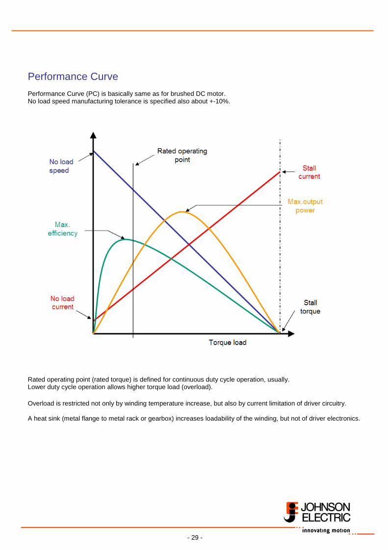
Performance Curve Performance Curve (PC) is basically same as for brushed DC motor. No load speed manufacturing tolerance is specified also about +-10%. Rated operating point (rated torque) is defined for continuous duty cycle operation, usually. Lower duty cycle operation allows higher torque load (overload). Overload is restricted not only by winding temperature increase, but also by current limitation of driver circuitry. A heat sink (metal flange to metal rack or gearbox) increases loadability of the winding, but not of driver electronics.
- 30 -
3 PWM Driver circuitry M
Actual value 0…3V
Speed Set value Control
Circuitry (PI controller)
3
Hall sensor signals
+ - 0…3V
A
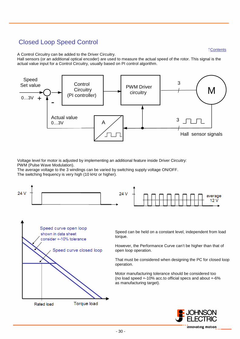
Closed Loop Speed Control Contents A Control Circuitry can be added to the Driver Circuitry. Hall sensors (or an additional optical encoder) are used to measure the actual speed of the rotor. This signal is the actual value input for a Control Circuitry, usually based on PI control algorithm.
Voltage level for motor is adjusted by implementing an additional feature inside Driver Circuitry: PWM (Pulse Wave Modulation). The average voltage to the 3 windings can be varied by switching supply voltage ON/OFF. The switching frequency is very high (10 kHz or higher).
Speed can be held on a constant level, independent from load torque. However, the Performance Curve can’t be higher than that of open loop operation. That must be considered when designing the PC for closed loop operation. Motor manufacturing tolerance should be considered too (no load speed +-10% acc.to official specs and about +-6% as manufacturing target).
- 31 -
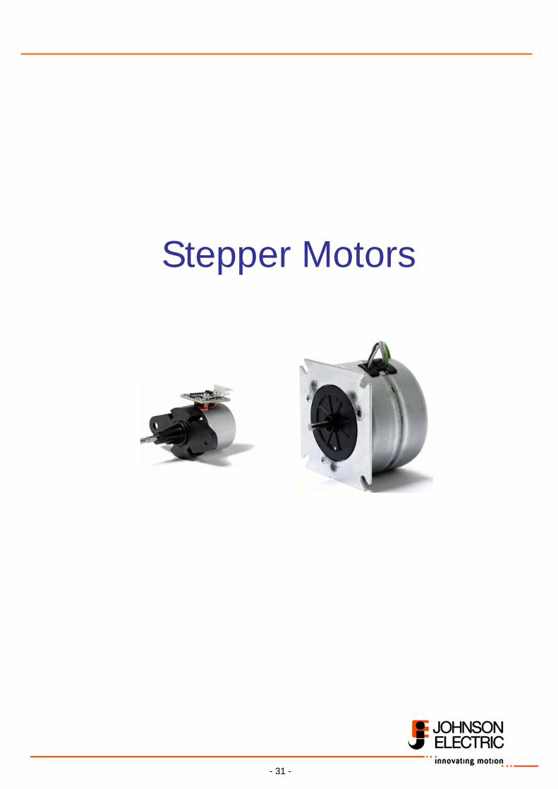
Stepper Motors
- 32 -
Basics
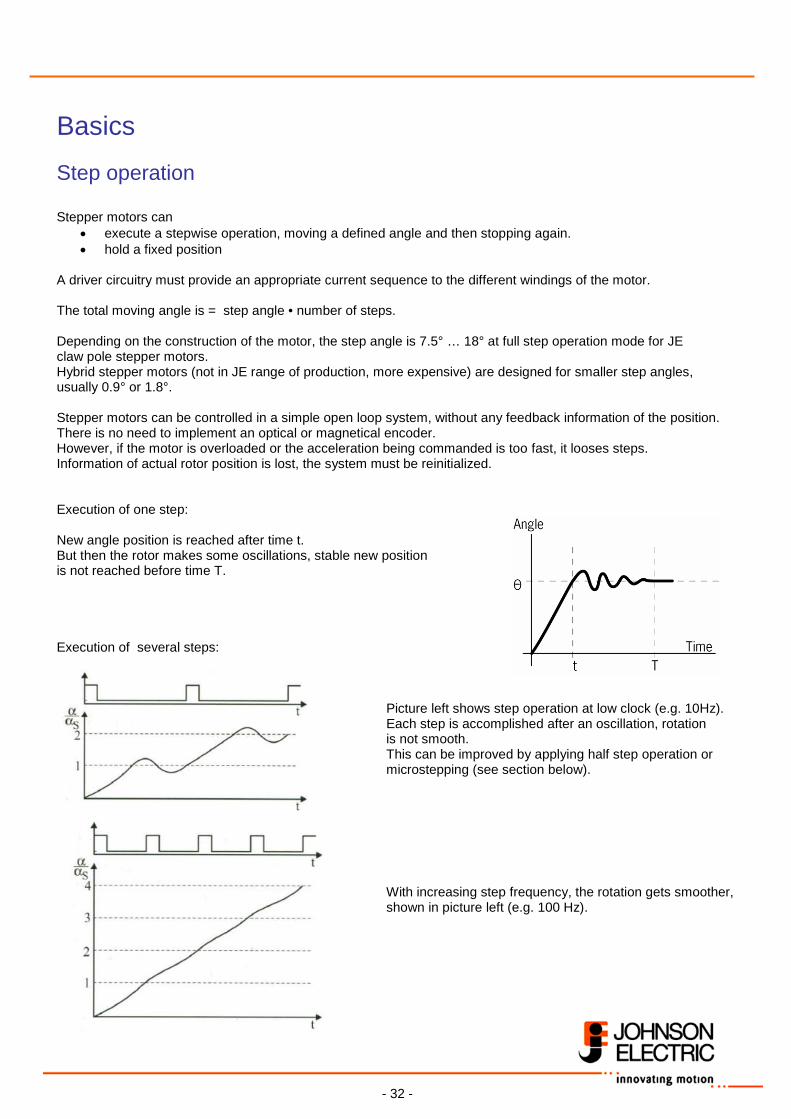
Step operation Stepper motors can
• execute a stepwise operation, moving a defined angle and then stopping again. • hold a fixed position
A driver circuitry must provide an appropriate current sequence to the different windings of the motor. The total moving angle is = step angle • number of steps. Depending on the construction of the motor, the step angle is 7.5° … 18° at full step operation mode for JE claw pole stepper motors. Hybrid stepper motors (not in JE range of production, more expensive) are designed for smaller step angles, usually 0.9° or 1.8°. Stepper motors can be controlled in a simple open loop system, without any feedback information of the position. There is no need to implement an optical or magnetical encoder. However, if the motor is overloaded or the acceleration being commanded is too fast, it looses steps. Information of actual rotor position is lost, the system must be reinitialized. Execution of one step: New angle position is reached after time t. But then the rotor makes some oscillations, stable new position is not reached before time T. Execution of several steps:
Picture left shows step operation at low clock (e.g. 10Hz). Each step is accomplished after an oscillation, rotation is not smooth. This can be improved by applying half step operation or microstepping (see section below).
With increasing step frequency, the rotation gets smoother, shown in picture left (e.g. 100 Hz).
- 33 -
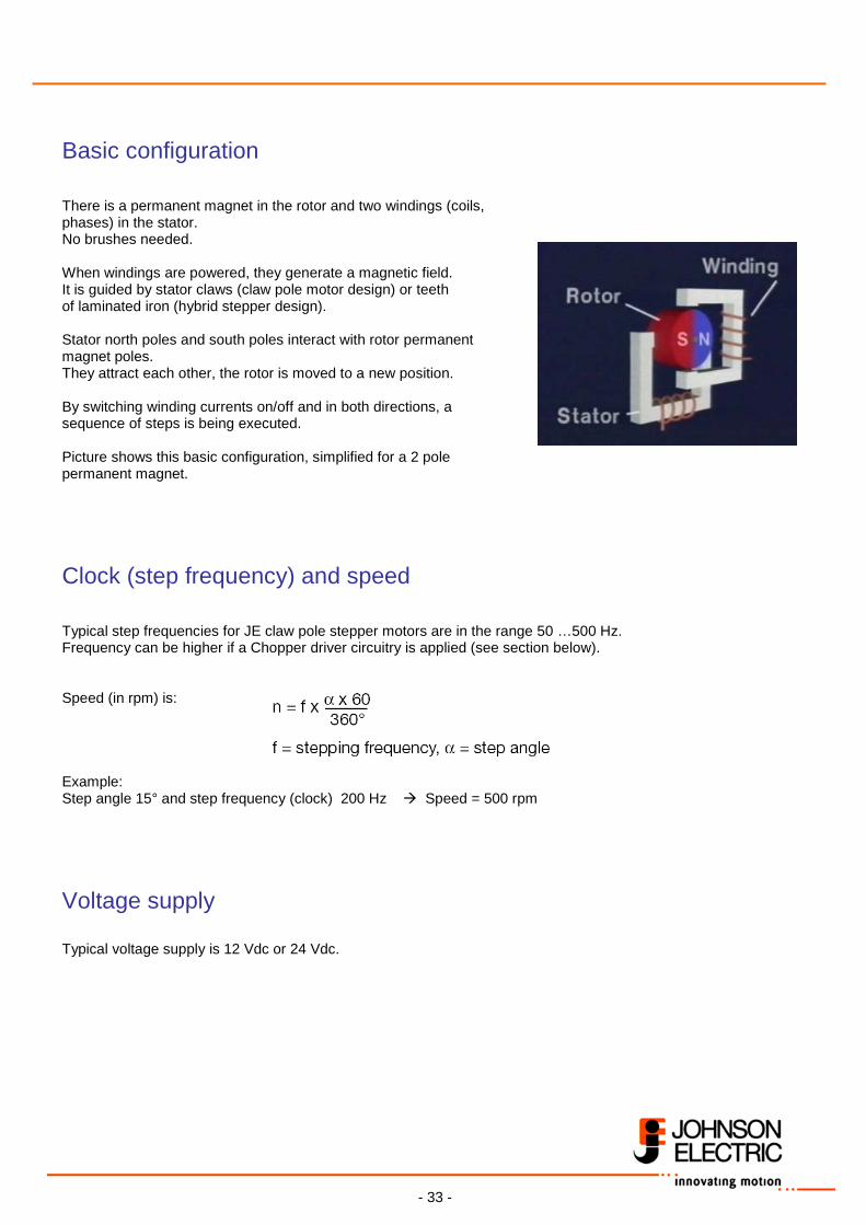
Basic configuration There is a permanent magnet in the rotor and two windings (coils, phases) in the stator. No brushes needed. When windings are powered, they generate a magnetic field. It is guided by stator claws (claw pole motor design) or teeth of laminated iron (hybrid stepper design). Stator north poles and south poles interact with rotor permanent magnet poles. They attract each other, the rotor is moved to a new position. By switching winding currents on/off and in both directions, a sequence of steps is being executed. Picture shows this basic configuration, simplified for a 2 pole permanent magnet.
Clock (step frequency) and speed Typical step frequencies for JE claw pole stepper motors are in the range 50 …500 Hz. Frequency can be higher if a Chopper driver circuitry is applied (see section below). Speed (in rpm) is: Example: Step angle 15° and step frequency (clock) 200 Hz Speed = 500 rpm
Voltage supply Typical voltage supply is 12 Vdc or 24 Vdc.
- 34 -
Stepping modes Stepper motors can be operated in four different operational modes:
• Full step operation • Half step operation • Wave mode • Microstepping operation
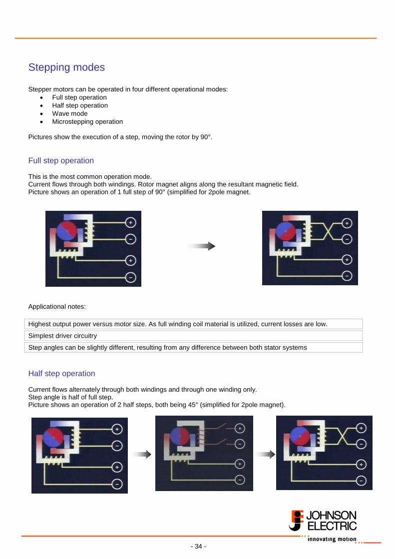
Pictures show the execution of a step, moving the rotor by 90°. Full step operation This is the most common operation mode. Current flows through both windings. Rotor magnet aligns along the resultant magnetic field. Picture shows an operation of 1 full step of 90° (simplified for 2pole magnet. Applicational notes: Highest output power versus motor size. As full winding coil material is utilized, current losses are low.
Simplest driver circuitry
Step angles can be slightly different, resulting from any difference between both stator systems Half step operation Current flows alternately through both windings and through one winding only. Step angle is half of full step. Picture shows an operation of 2 half steps, both being 45° (simplified for 2pole magnet).
- 35 -
Applicational notes: Step angle resolution is doubled.
Smoother running at low step frequencies (clock).
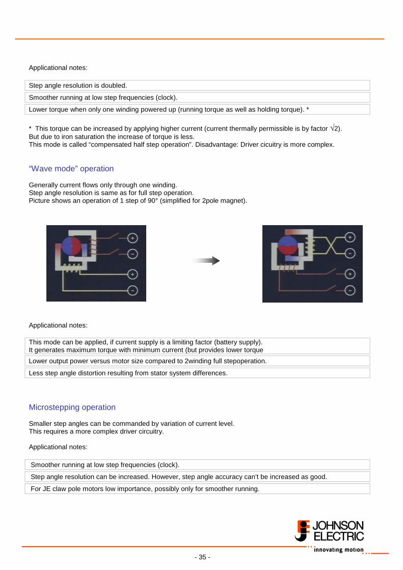
Lower torque when only one winding powered up (running torque as well as holding torque). * * This torque can be increased by applying higher current (current thermally permissible is by factor √2). But due to iron saturation the increase of torque is less. This mode is called “compensated half step operation”. Disadvantage: Driver cicuitry is more complex. “Wave mode” operation Generally current flows only through one winding. Step angle resolution is same as for full step operation. Picture shows an operation of 1 step of 90° (simplified for 2pole magnet). Applicational notes: This mode can be applied, if current supply is a limiting factor (battery supply). It generates maximum torque with minimum current (but provides lower torque Lower output power versus motor size compared to 2winding full stepoperation.
Less step angle distortion resulting from stator system differences. Microstepping operation Smaller step angles can be commanded by variation of current level. This requires a more complex driver circuitry. Applicational notes: Smoother running at low step frequencies (clock).
Step angle resolution can be increased. However, step angle accuracy can’t be increased as good.
For JE claw pole motors low importance, possibly only for smoother running.
- 36 -
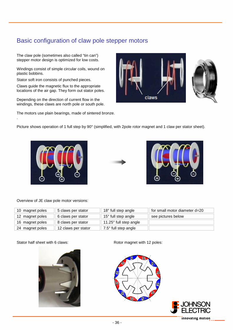
Basic configuration of claw pole stepper motors The claw pole (sometimes also called “tin can”) stepper motor design is optimized for low costs. Windings consist of simple circular coils, wound on plastic bobbins.
Stator soft iron consists of punched pieces.
Claws guide the magnetic flux to the appropriate locations of the air gap. They form out stator poles. Depending on the direction of current flow in the windings, these claws are north pole or south pole. The motors use plain bearings, made of sintered bronze. . Picture shows operation of 1 full step by 90° (simplified, with 2pole rotor magnet and 1 claw per stator sheet).
Overview of JE claw pole motor versions: 10 magnet poles 5 claws per stator 18° full step angle for small motor diameter d=20 12 magnet poles 6 claws per stator 15° full step angle see pictures below 16 magnet poles 8 claws per stator 11.25° full step angle 24 magnet poles 12 claws per stator 7.5° full step angle Stator half sheet with 6 claws: Rotor magnet with 12 poles:
- 37 -
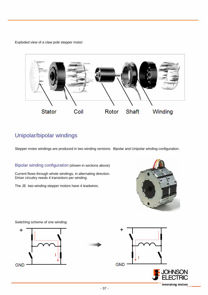
Exploded view of a claw pole stepper motor:
Unipolar/bipolar windings Stepper motor windings are produced in two winding versions: Bipolar and Unipolar winding configuration. Bipolar winding configuration (shown in sections above) Current flows through whole windings, in alternating direction. Driver circuitry needs 4 transistors per winding. The JE two-winding stepper motors have 4 leadwires. Switching scheme of one winding:
- 38 -
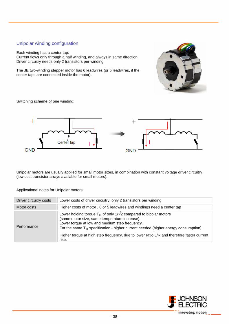
Unipolar winding configuration Each winding has a center tap. Current flows only through a half winding, and always in same direction. Driver circuitry needs only 2 transistors per winding. The JE two-winding stepper motor has 6 leadwires (or 5 leadwires, if the center taps are connected inside the motor). Switching scheme of one winding: Unipolar motors are usually applied for small motor sizes, in combination with constant voltage driver circuitry (low cost transistor arrays available for small motors). Applicational notes for Unipolar motors: Driver circuitry costs Lower costs of driver circuitry, only 2 transistors per winding
Motor costs Higher costs of motor , 6 or 5 leadwires and windings need a center tap
Performance
Lower holding torque TH of only 1/√2 compared to bipolar motors (same motor size, same temperature increase). Lower torque at low and medium step frequency. For the same TH specification - higher current needed (higher energy consumption).
Higher torque at high step frequency, due to lower ratio L/R and therefore faster current rise.
- 39 -
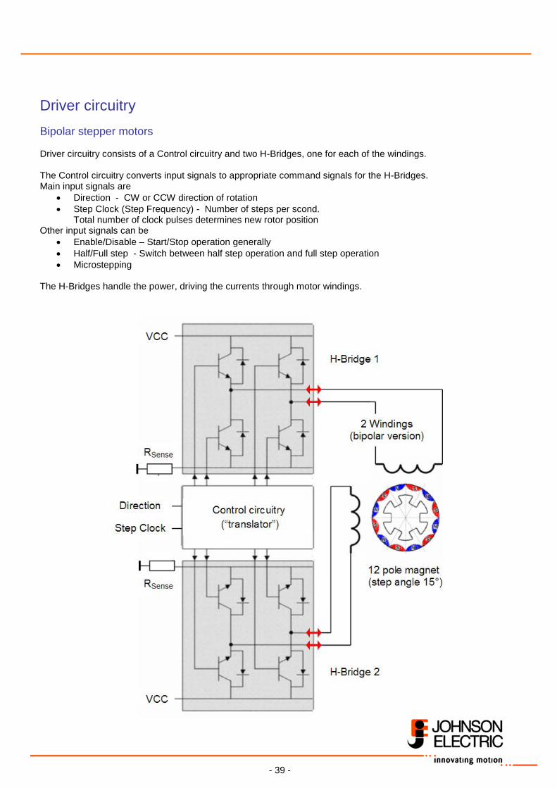
Driver circuitry Bipolar stepper motors Driver circuitry consists of a Control circuitry and two H-Bridges, one for each of the windings. The Control circuitry converts input signals to appropriate command signals for the H-Bridges. Main input signals are
• Direction - CW or CCW direction of rotation • Step Clock (Step Frequency) - Number of steps per scond.
Total number of clock pulses determines new rotor position Other input signals can be
• Enable/Disable – Start/Stop operation generally • Half/Full step - Switch between half step operation and full step operation • Microstepping
The H-Bridges handle the power, driving the currents through motor windings.
- 40 -
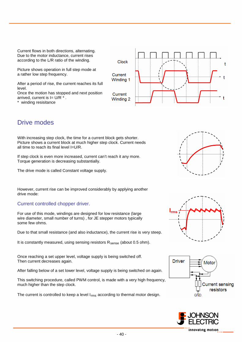
Current flows in both directions, alternating. Due to the motor inductance, current rises according to the L/R ratio of the winding. Picture shows operation in full step mode at a rather low step frequency. After a period of rise, the current reaches its full level. Once the motion has stopped and next position arrived, current is I= U/R * . * winding resisitance
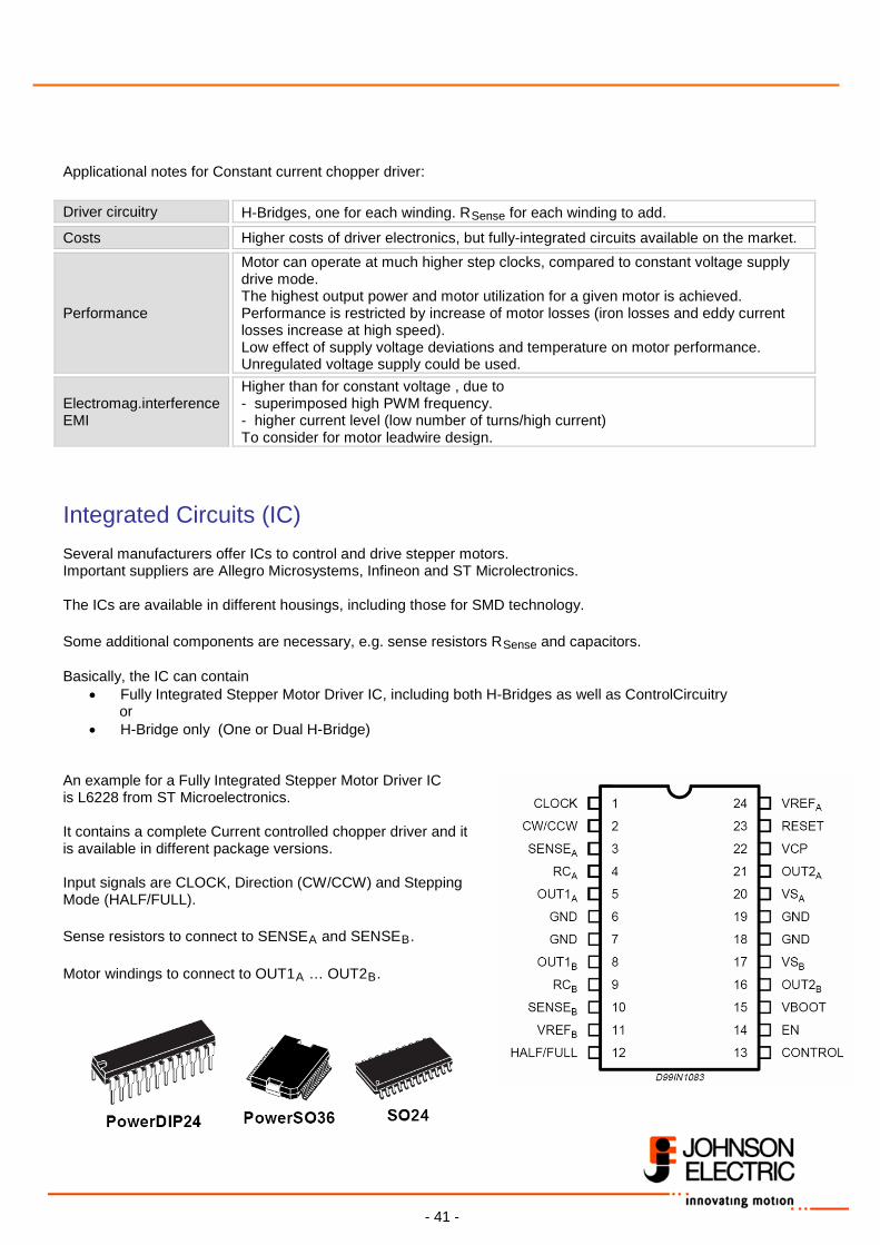
Drive modes With increasing step clock, the time for a current block gets shorter. Picture shows a current block at much higher step clock. Current needs all time to reach its final level I=U/R. If step clock is even more increased, current can’t reach it any more. Torque generation is decreasing substantially. The drive mode is called Constant voltage supply. However, current rise can be improved considerably by applying another drive mode: Current controlled chopper driver. For use of this mode, windings are designed for low resistance (large wire diameter, small number of turns) , for JE stepper motors typically some few ohms. Due to that small resistance (and also inductance), the current rise is very steep. It is constantly measured, using sensing resistors Rsense (about 0.5 ohm). Once reaching a set upper level, voltage supply is being switched off. Then current decreases again. After falling below of a set lower level, voltage supply is being switched on again. This switching procedure, called PWM control, is made with a very high frequency, much higher than the step clock. The current is controlled to keep a level Irms according to thermal motor design.
- 41 -
Applicational notes for Constant current chopper driver: Driver circuitry H-Bridges, one for each winding. RSense for each winding to add.
Costs Higher costs of driver electronics, but fully-integrated circuits available on the market.
Performance
Motor can operate at much higher step clocks, compared to constant voltage supply drive mode. The highest output power and motor utilization for a given motor is achieved. Performance is restricted by increase of motor losses (iron losses and eddy current losses increase at high speed). Low effect of supply voltage deviations and temperature on motor performance. Unregulated voltage supply could be used.
Electromag.interference EMI
Higher than for constant voltage , due to - superimposed high PWM frequency. - higher current level (low number of turns/high current) To consider for motor leadwire design.
Integrated Circuits (IC) Several manufacturers offer ICs to control and drive stepper motors. Important suppliers are Allegro Microsystems, Infineon and ST Microlectronics. The ICs are available in different housings, including those for SMD technology. Some additional components are necessary, e.g. sense resistors RSense and capacitors. Basically, the IC can contain
• Fully Integrated Stepper Motor Driver IC, including both H-Bridges as well as ControlCircuitry or
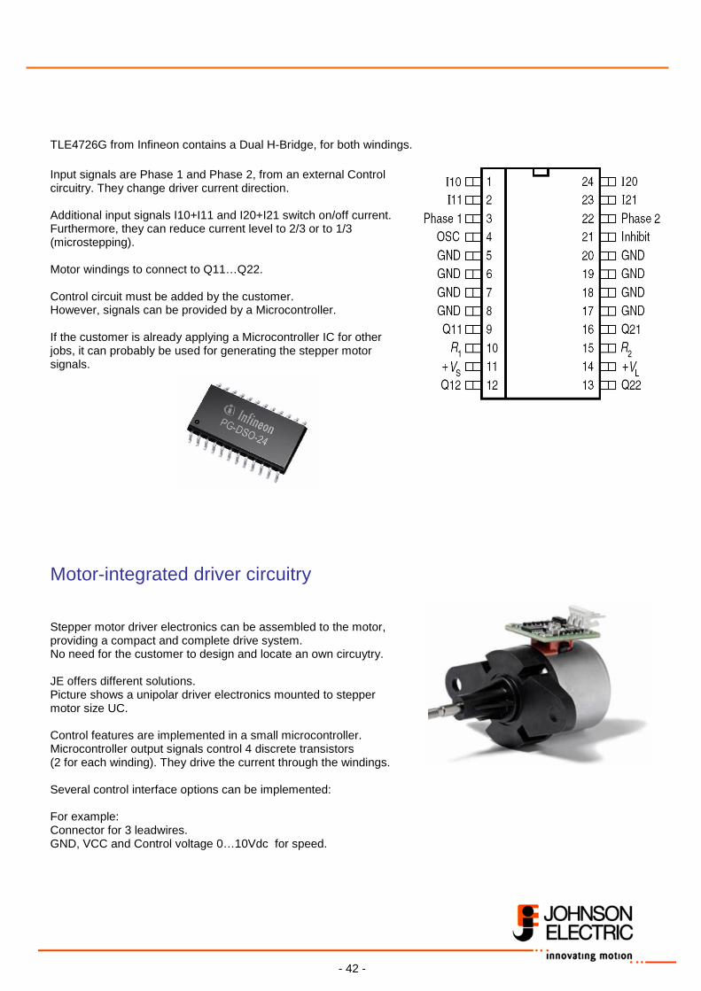
• H-Bridge only (One or Dual H-Bridge) An example for a Fully Integrated Stepper Motor Driver IC is L6228 from ST Microelectronics. It contains a complete Current controlled chopper driver and it is available in different package versions. Input signals are CLOCK, Direction (CW/CCW) and Stepping Mode (HALF/FULL). Sense resistors to connect to SENSEA and SENSEB. Motor windings to connect to OUT1A … OUT2B.
- 42 -
TLE4726G from Infineon contains a Dual H-Bridge, for both windings. Input signals are Phase 1 and Phase 2, from an external Control circuitry. They change driver current direction. Additional input signals I10+I11 and I20+I21 switch on/off current. Furthermore, they can reduce current level to 2/3 or to 1/3 (microstepping). Motor windings to connect to Q11…Q22. Control circuit must be added by the customer. However, signals can be provided by a Microcontroller. If the customer is already applying a Microcontroller IC for other jobs, it can probably be used for generating the stepper motor signals.
Motor-integrated driver circuitry Stepper motor driver electronics can be assembled to the motor, providing a compact and complete drive system. No need for the customer to design and locate an own circuytry. JE offers different solutions. Picture shows a unipolar driver electronics mounted to stepper motor size UC. Control features are implemented in a small microcontroller. Microcontroller output signals control 4 discrete transistors (2 for each winding). They drive the current through the windings. Several control interface options can be implemented: For example: Connector for 3 leadwires. GND, VCC and Control voltage 0…10Vdc for speed.
- 43 -
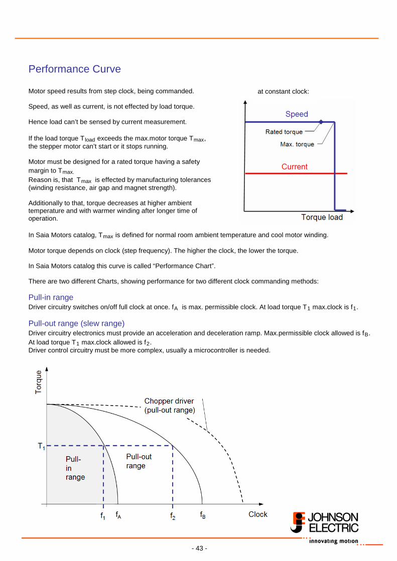
Performance Curve Motor speed results from step clock, being commanded. Speed, as well as current, is not effected by load torque. Hence load can’t be sensed by current measurement. If the load torque Tload exceeds the max.motor torque Tmax, the stepper motor can’t start or it stops running. Motor must be designed for a rated torque having a safety margin to Tmax. Reason is, that Tmax is effected by manufacturing tolerances (winding resistance, air gap and magnet strength). Additionally to that, torque decreases at higher ambient temperature and with warmer winding after longer time of operation. In Saia Motors catalog, Tmax is defined for normal room ambient temperature and cool motor winding. Motor torque depends on clock (step frequency). The higher the clock, the lower the torque. In Saia Motors catalog this curve is called “Performance Chart”. There are two different Charts, showing performance for two different clock commanding methods: Pull-in range Driver circuitry switches on/off full clock at once. fA is max. permissible clock. At load torque T1 max.clock is f1. Pull-out range (slew range) Driver circuitry electronics must provide an acceleration and deceleration ramp. Max.permissible clock allowed is fB. At load torque T1 max.clock allowed is f2. Driver control circuitry must be more complex, usually a microcontroller is needed.
at constant clock:
- 44 -
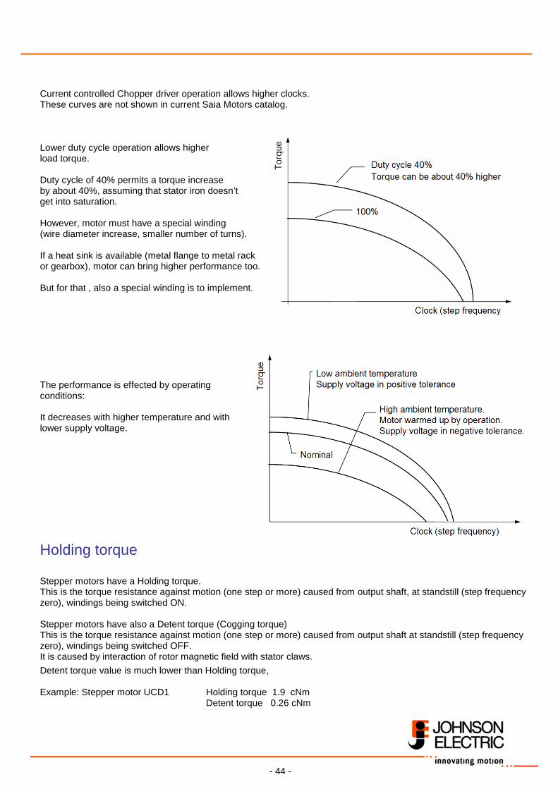
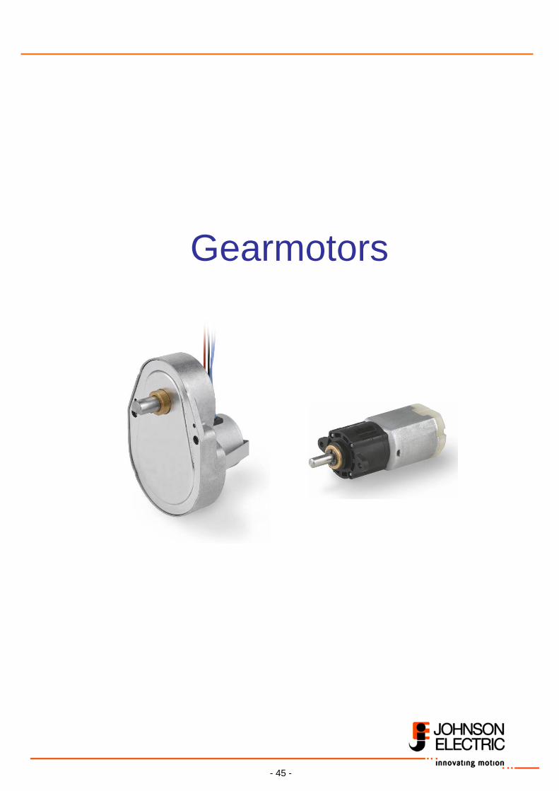
Current controlled Chopper driver operation allows higher clocks. These curves are not shown in current Saia Motors catalog. Lower duty cycle operation allows higher load torque. Duty cycle of 40% permits a torque increase by about 40%, assuming that stator iron doesn’t get into saturation. However, motor must have a special winding (wire diameter increase, smaller number of turns). If a heat sink is available (metal flange to metal rack or gearbox), motor can bring higher performance too. But for that , also a special winding is to implement. The performance is effected by operating conditions: It decreases with higher temperature and with lower supply voltage.
Holding torque Stepper motors have a Holding torque. This is the torque resistance against motion (one step or more) caused from output shaft, at standstill (step frequency zero), windings being switched ON. Stepper motors have also a Detent torque (Cogging torque) This is the torque resistance against motion (one step or more) caused from output shaft at standstill (step frequency zero), windings being switched OFF. It is caused by interaction of rotor magnetic field with stator claws.
Detent torque value is much lower than Holding torque, Example: Stepper motor UCD1 Holding torque 1.9 cNm Detent torque 0.26 cNm
- 45 -
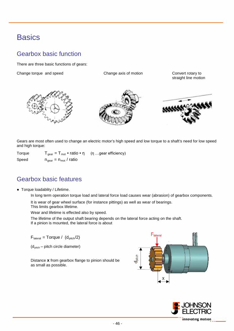
Gearmotors
- 46 -
Basics Gearbox basic function There are three basic functions of gears: Change torque and speed Change axis of motion Convert rotary to
straight line motion
Gears are most often used to change an electric motor’s high speed and low torque to a shaft’s need for low speed and high torque:
Torque Tgear = Tmot • ratio • η (η …gear efficiency)
Speed ngear = nmot / ratio
Gearbox basic features ● Torque loadablity / Lifetime.
In long term operation torque load and lateral force load causes wear (abrasion) of gearbox components.
It is wear of gear wheel surface (for instance pittings) as well as wear of bearings. This limits gearbox lifetime.
Wear and lifetime is effected also by speed.
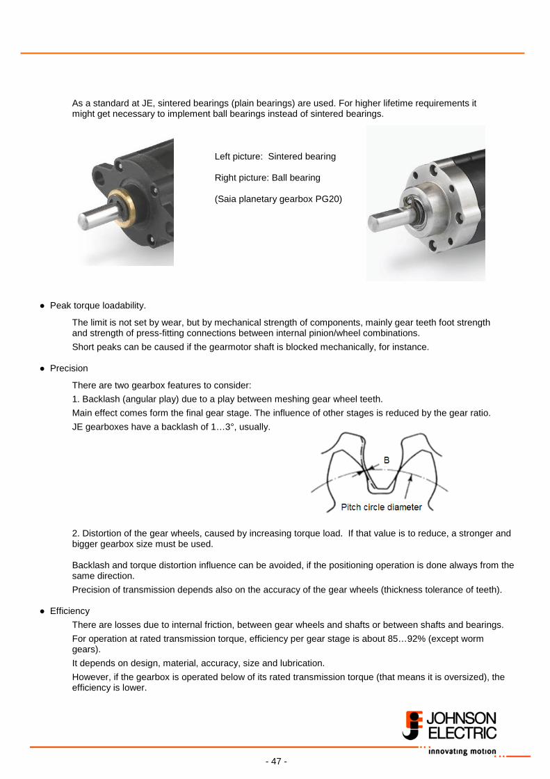
The lifetime of the output shaft bearing depends on the lateral force acting on the shaft. If a pinion is mounted, the lateral force is about Flateral = Torque / (dpitch/2) (dpitch – pitch circle diameter) Distance x from gearbox flange to pinion should be as small as possible.
- 47 -
As a standard at JE, sintered bearings (plain bearings) are used. For higher lifetime requirements it might get necessary to implement ball bearings instead of sintered bearings.
Left picture: Sintered bearing
Right picture: Ball bearing
(Saia planetary gearbox PG20)
● Peak torque loadability.
The limit is not set by wear, but by mechanical strength of components, mainly gear teeth foot strength and strength of press-fitting connections between internal pinion/wheel combinations.
Short peaks can be caused if the gearmotor shaft is blocked mechanically, for instance.
● Precision
There are two gearbox features to consider:
1. Backlash (angular play) due to a play between meshing gear wheel teeth.
Main effect comes form the final gear stage. The influence of other stages is reduced by the gear ratio.
JE gearboxes have a backlash of 1…3°, usually. 2. Distortion of the gear wheels, caused by increasing torque load. If that value is to reduce, a stronger and bigger gearbox size must be used. Backlash and torque distortion influence can be avoided, if the positioning operation is done always from the same direction.
Precision of transmission depends also on the accuracy of the gear wheels (thickness tolerance of teeth). ● Efficiency
There are losses due to internal friction, between gear wheels and shafts or between shafts and bearings.
For operation at rated transmission torque, efficiency per gear stage is about 85…92% (except worm gears).
It depends on design, material, accuracy, size and lubrication.
However, if the gearbox is operated below of its rated transmission torque (that means it is oversized), the efficiency is lower.
- 48 -
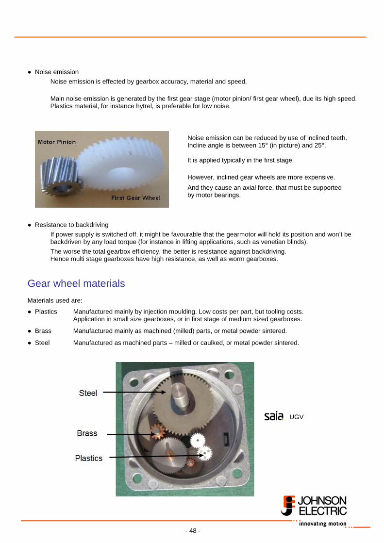
● Noise emission
Noise emission is effected by gearbox accuracy, material and speed.
Main noise emission is generated by the first gear stage (motor pinion/ first gear wheel), due its high speed.
Plastics material, for instance hytrel, is preferable for low noise.
Noise emission can be reduced by use of inclined teeth. Incline angle is between 15° (in picture) and 25°.
It is applied typically in the first stage.
However, inclined gear wheels are more expensive.
And they cause an axial force, that must be supported by motor bearings.
● Resistance to backdriving
If power supply is switched off, it might be favourable that the gearmotor will hold its position and won’t be backdriven by any load torque (for instance in lifting applications, such as venetian blinds).
The worse the total gearbox efficiency, the better is resistance against backdriving. Hence multi stage gearboxes have high resistance, as well as worm gearboxes.
Gear wheel materials Materials used are:
● Plastics Manufactured mainly by injection moulding. Low costs per part, but tooling costs. Application in small size gearboxes, or in first stage of medium sized gearboxes.
● Brass Manufactured mainly as machined (milled) parts, or metal powder sintered.
● Steel Manufactured as machined parts – milled or caulked, or metal powder sintered.
UGV
- 49 -
Metal powder sintered parts have advantage of low costs, but need tooling. JE has powder metal sintering capability, with a lot of expertise.
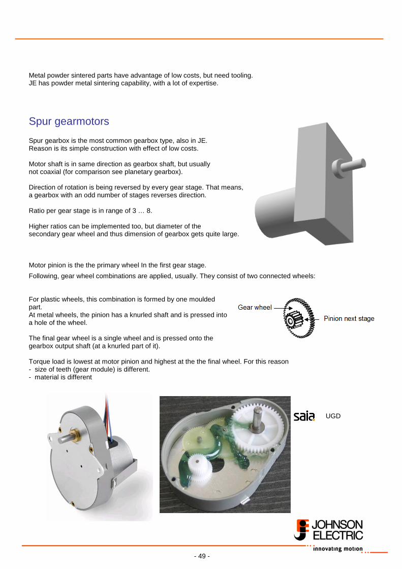
Spur gearmotors Spur gearbox is the most common gearbox type, also in JE. Reason is its simple construction with effect of low costs. Motor shaft is in same direction as gearbox shaft, but usually not coaxial (for comparison see planetary gearbox). Direction of rotation is being reversed by every gear stage. That means, a gearbox with an odd number of stages reverses direction. Ratio per gear stage is in range of 3 … 8. Higher ratios can be implemented too, but diameter of the secondary gear wheel and thus dimension of gearbox gets quite large. Motor pinion is the the primary wheel In the first gear stage.
Following, gear wheel combinations are applied, usually. They consist of two connected wheels: For plastic wheels, this combination is formed by one moulded part. At metal wheels, the pinion has a knurled shaft and is pressed into a hole of the wheel. The final gear wheel is a single wheel and is pressed onto the gearbox output shaft (at a knurled part of it). Torque load is lowest at motor pinion and highest at the the final wheel. For this reason - size of teeth (gear module) is different. - material is different UGD
- 50 -
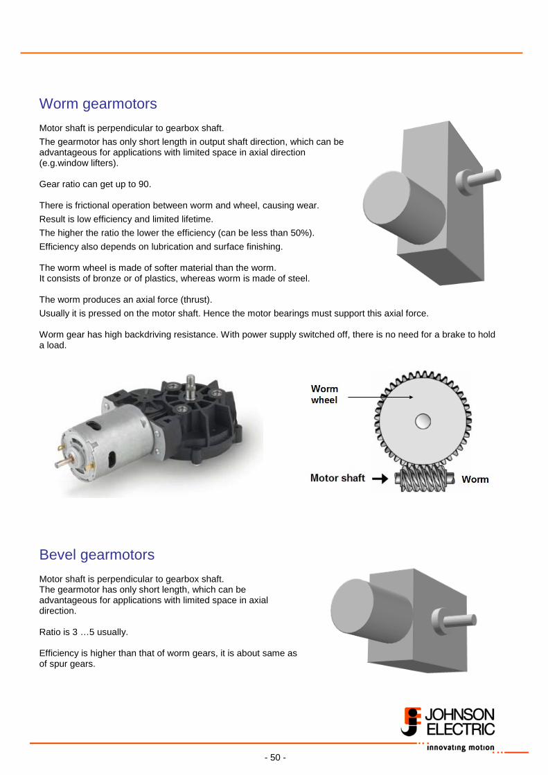
Worm gearmotors Motor shaft is perpendicular to gearbox shaft.
The gearmotor has only short length in output shaft direction, which can be advantageous for applications with limited space in axial direction (e.g.window lifters). Gear ratio can get up to 90. There is frictional operation between worm and wheel, causing wear.
Result is low efficiency and limited lifetime.
The higher the ratio the lower the efficiency (can be less than 50%).
Efficiency also depends on lubrication and surface finishing. The worm wheel is made of softer material than the worm. It consists of bronze or of plastics, whereas worm is made of steel. The worm produces an axial force (thrust).
Usually it is pressed on the motor shaft. Hence the motor bearings must support this axial force. Worm gear has high backdriving resistance. With power supply switched off, there is no need for a brake to hold a load.
Bevel gearmotors Motor shaft is perpendicular to gearbox shaft. The gearmotor has only short length, which can be advantageous for applications with limited space in axial direction. Ratio is 3 …5 usually. Efficiency is higher than that of worm gears, it is about same as of spur gears.
- 51 -
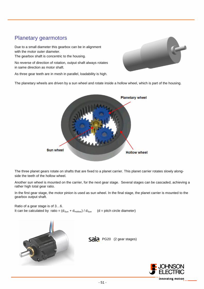
Planetary gearmotors Due to a small diameter this gearbox can be in alignment with the motor outer diameter. The gearbox shaft is concentric to the housing.
No reverse of direction of rotation, output shaft always rotates in same direction as motor shaft.
As three gear teeth are in mesh in parallel, loadability is high. The planetary wheels are driven by a sun wheel and rotate inside a hollow wheel, which is part of the housing. The three planet gears rotate on shafts that are fixed to a planet carrier. This planet carrier rotates slowly along- side the teeth of the hollow wheel.
Another sun wheel is mounted on the carrier, for the next gear stage. Several stages can be cascaded, achieving a rather high total gear ratio.
In the first gear stage, the motor pinion is used as sun wheel. In the final stage, the planet carrier is mounted to the gearbox output shaft. Ratio of a gear stage is of 3…6. It can be calculated by ratio = (dSun + dHollow) / dSun (d = pitch circle diameter)
PG20 (2 gear stages)
- 52 -
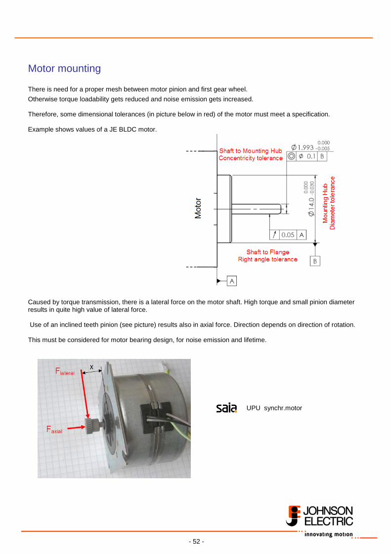
Motor mounting There is need for a proper mesh between motor pinion and first gear wheel.
Otherwise torque loadability gets reduced and noise emission gets increased. Therefore, some dimensional tolerances (in picture below in red) of the motor must meet a specification. Example shows values of a JE BLDC motor.
Caused by torque transmission, there is a lateral force on the motor shaft. High torque and small pinion diameter results in quite high value of lateral force. Use of an inclined teeth pinion (see picture) results also in axial force. Direction depends on direction of rotation. This must be considered for motor bearing design, for noise emission and lifetime.
UPU synchr.motor
- 53 -
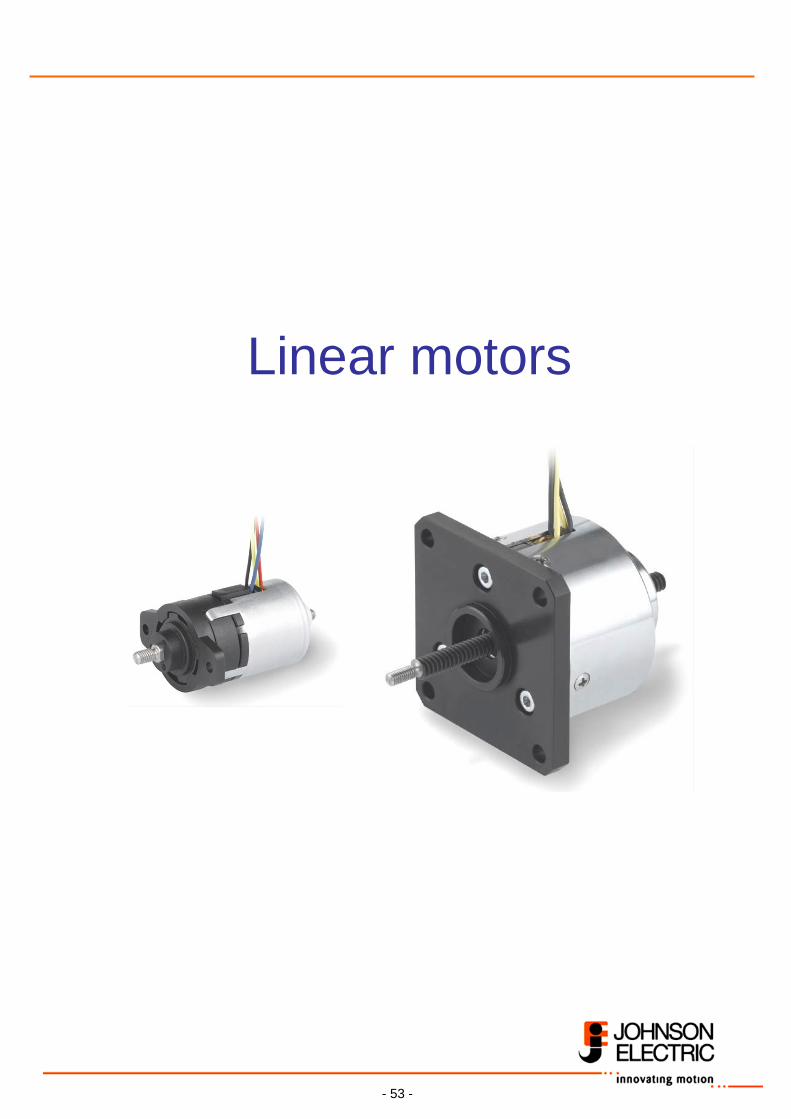
Linear motors
- 54 -
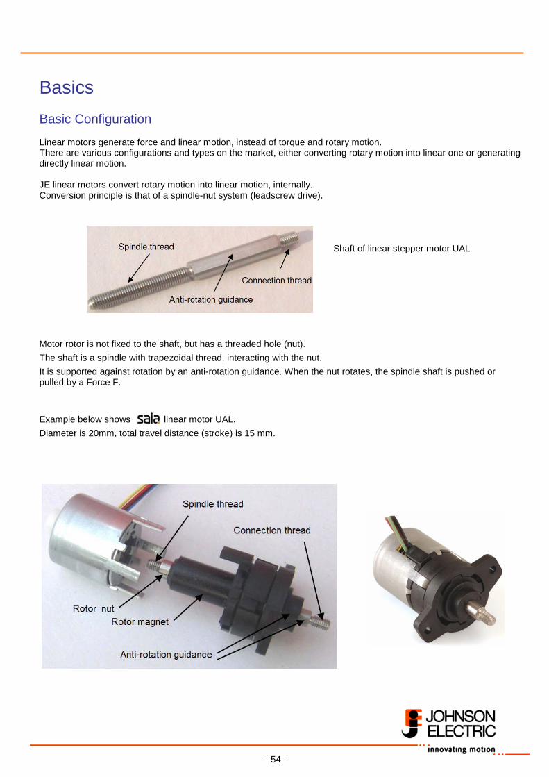
Basics Basic Configuration Linear motors generate force and linear motion, instead of torque and rotary motion. There are various configurations and types on the market, either converting rotary motion into linear one or generating directly linear motion. JE linear motors convert rotary motion into linear motion, internally. Conversion principle is that of a spindle-nut system (leadscrew drive). Shaft of linear stepper motor UAL Motor rotor is not fixed to the shaft, but has a threaded hole (nut).
The shaft is a spindle with trapezoidal thread, interacting with the nut.
It is supported against rotation by an anti-rotation guidance. When the nut rotates, the spindle shaft is pushed or pulled by a Force F.
Example below shows linear motor UAL.
Diameter is 20mm, total travel distance (stroke) is 15 mm.
- 55 -
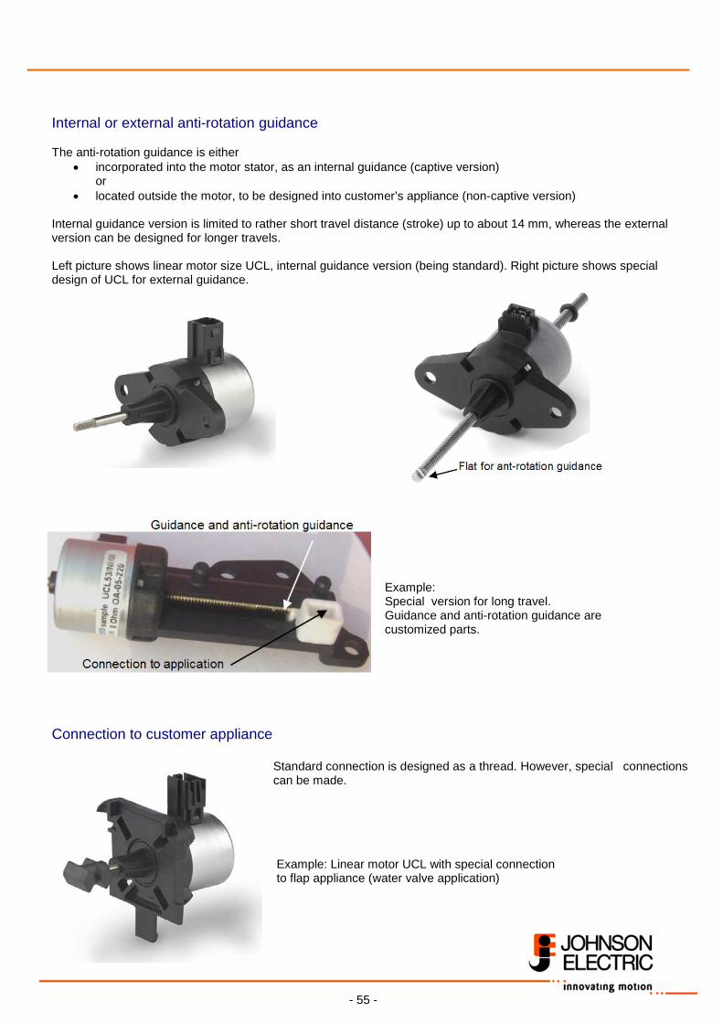
Internal or external anti-rotation guidance The anti-rotation guidance is either
• incorporated into the motor stator, as an internal guidance (captive version) or
• located outside the motor, to be designed into customer’s appliance (non-captive version) Internal guidance version is limited to rather short travel distance (stroke) up to about 14 mm, whereas the external version can be designed for longer travels. Left picture shows linear motor size UCL, internal guidance version (being standard). Right picture shows special design of UCL for external guidance.
Example: Special version for long travel. Guidance and anti-rotation guidance are customized parts.
Connection to customer appliance
Standard connection is designed as a thread. However, special connections can be made. Example: Linear motor UCL with special connection to flap appliance (water valve application)
- 56 -
JE linear motors are available, as stepper and synchronous motors, in several sizes. Smaller motor sizes UAL and UCL have one ball bearing, at the frontside. Large size ULE is equipped with ball bearings frontside as well as rearside. Basic Features Lead and Travel speed
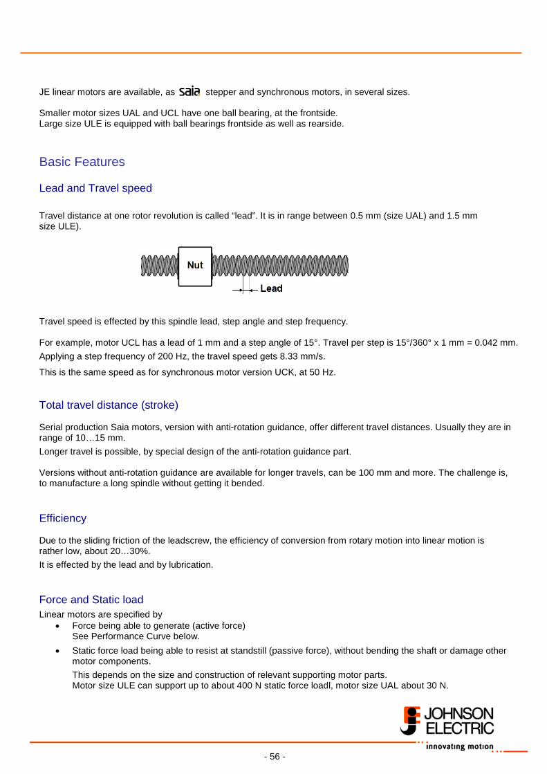
Travel distance at one rotor revolution is called “lead”. It is in range between 0.5 mm (size UAL) and 1.5 mm size ULE).
Travel speed is effected by this spindle lead, step angle and step frequency. For example, motor UCL has a lead of 1 mm and a step angle of 15°. Travel per step is 15°/360° x 1 mm = 0.042 mm.
Applying a step frequency of 200 Hz, the travel speed gets 8.33 mm/s.
This is the same speed as for synchronous motor version UCK, at 50 Hz. Total travel distance (stroke) Serial production Saia motors, version with anti-rotation guidance, offer different travel distances. Usually they are in range of 10…15 mm.
Longer travel is possible, by special design of the anti-rotation guidance part. Versions without anti-rotation guidance are available for longer travels, can be 100 mm and more. The challenge is, to manufacture a long spindle without getting it bended. Efficiency Due to the sliding friction of the leadscrew, the efficiency of conversion from rotary motion into linear motion is rather low, about 20…30%.
It is effected by the lead and by lubrication. Force and Static load
Linear motors are specified by • Force being able to generate (active force)
See Performance Curve below.
• Static force load being able to resist at standstill (passive force), without bending the shaft or damage other motor components.
This depends on the size and construction of relevant supporting motor parts. Motor size ULE can support up to about 400 N static force loadl, motor size UAL about 30 N.
- 57 -
Lateral force on shaft Customer appliances should be designed to avoid any lateral force on the shaft. The guidance of captive version motors can support some few Newtons.
Non-captive motors can’t accept any lateral force, customer must implement a proper giuidance with support. Furthermore, the shaft must be aligned precisely to the motor axis. The permissible angular deviation is only about 0.5°. Lifetime
Due to the sliding friction of the spindle-nut system, the motor lifetime is restricted. Usually it is specified by number of cycles. Typical customer requirement is several 100k cycles.
Specification must include load force and speed, but also lateral force (only very small value permissible) and operating temperature. End stop, shaft locking
If there are no electrical limit switches located in the application, the shaft will hit mechanical end stops. It is either an internal end stop (in pulling direction) or an external one. If the stepper motor is not switched off, it will continue to hit against the end stop, oscillating with step frequency.
For this reason it must be switched off. This can be done time controlled or better by electronic end stop detection (see section Learn more). When hitting the end stop, the force acting on the shaft and on the shaft-rotor connection is higher than during motion, due to an additional shock stress. This can cause a locking (clamping) of the shaft. The shaft might not be able to leave this end position again. The same can happen, if the shaft rests a longer time in this end position and substantial temperature change occurs. Sensitivity for shaft locking depends on the features of the end stop (hard stop or more flexible one) as well as on spindle lead and spindle thread design. If the stepper motor is operated by current controlled chopper driver circuitry, the current and thus force can be increased for starting operation from end stop. Backdriving resistance Due to the low leadscrew efficiency there is a high backdrive resistance. However, backdrive resistance can’t be guaranteed. Vibrations can cause motion, if the motor is switched off. Backlash (axial play) There is a backlash caused by clearance between spindle and nut and an additional backlash caused by some distortion with rising force.
Applying rated force in +- direction, the backlash is in range of about 0.2 to 0.4 mm. After longer time of operation it can increase due to some wear of the nut thread.
- 58 -
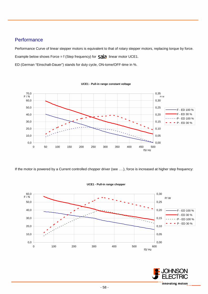
Performance Performance Curve of linear stepper motors is equivalent to that of rotary stepper motors, replacing torque by force. Example below shows Force = f (Step frequency) for linear motor UCE1. ED (German “Einschalt-Dauer”) stands for duty cycle, ON-tome/OFF-time in %.
UCE1 - Pull-in range constant voltage
0,0
10,0
20,0
30,0
40,0
50,0
60,0
70,0
0 50 100 150 200 250 300 350 400 450 500fS/ Hz
F / N
0,00
0,05
0,10
0,15
0,20
0,25
0,30
0,35
F - ED 100 %F - ED 30 %P - ED 100 %P - ED 30 %
P/ W
If the motor is powered by a Current controlled chopper driver (see ….), force is increased at higher step frequency:
UCE1 - Pull-in range chopper
0,0
10,0
20,0
30,0
40,0
50,0
60,0
0 100 200 300 400 500 600fS/ Hz
F / N
0,00
0,05
0,10
0,15
0,20
0,25
0,30
F - ED 100 %F - ED 30 %P - ED 100 %P - ED 30 %
P/ W
- 59 -
Special designs and subassemblies Several special designs are available for motors:
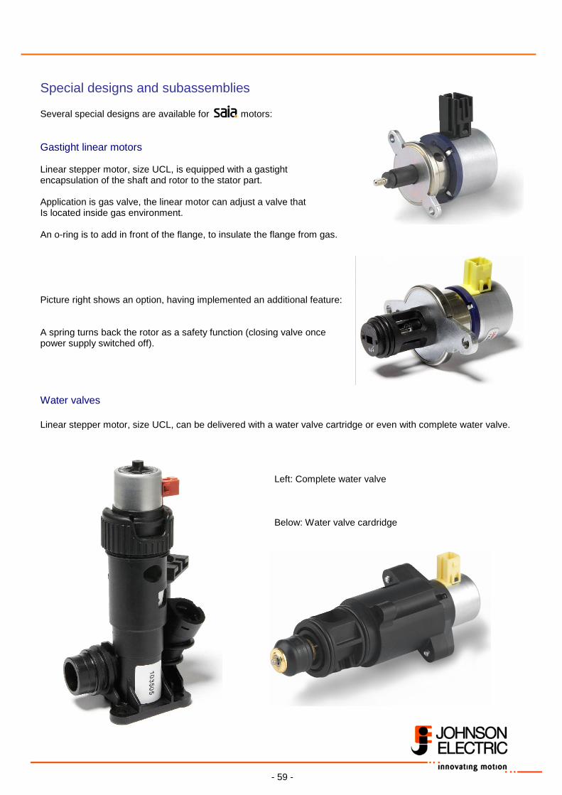
Gastight linear motors Linear stepper motor, size UCL, is equipped with a gastight encapsulation of the shaft and rotor to the stator part. Application is gas valve, the linear motor can adjust a valve that Is located inside gas environment. An o-ring is to add in front of the flange, to insulate the flange from gas. Picture right shows an option, having implemented an additional feature: A spring turns back the rotor as a safety function (closing valve once power supply switched off). Water valves Linear stepper motor, size UCL, can be delivered with a water valve cartridge or even with complete water valve. Left: Complete water valve
Below: Water valve cardridge
- 60 -
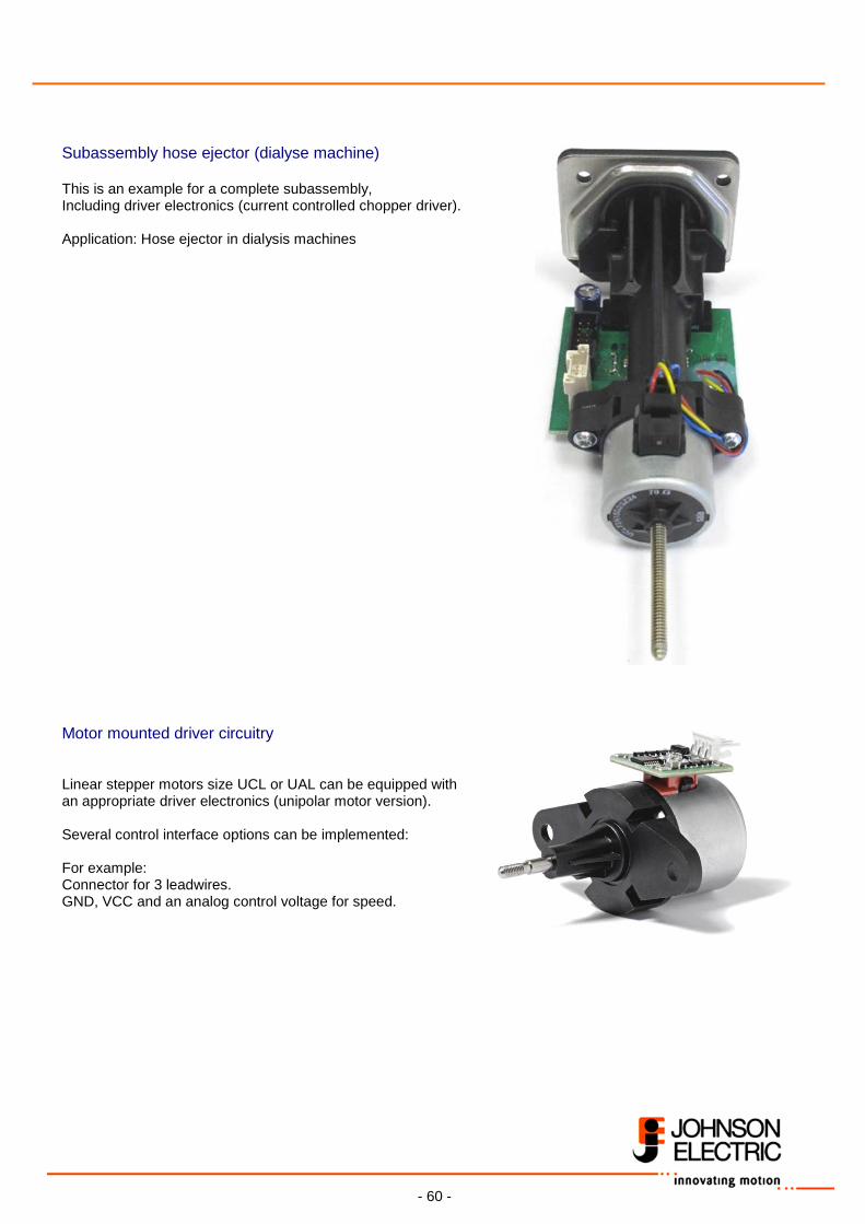
Subassembly hose ejector (dialyse machine) This is an example for a complete subassembly, Including driver electronics (current controlled chopper driver). Application: Hose ejector in dialysis machines Motor mounted driver circuitry
Linear stepper motors size UCL or UAL can be equipped with an appropriate driver electronics (unipolar motor version). Several control interface options can be implemented: For example: Connector for 3 leadwires. GND, VCC and an analog control voltage for speed.
Related Documents