G. Bebis et al. (Eds.): ISVC 2007, Part II, LNCS 4842, pp. 152–161, 2007. © Springer-Verlag Berlin Heidelberg 2007 Motion Projection for Floating Object Detection Zhao-Yi Wei 1 , Dah-Jye Lee 1 , David Jilk 2 , and Robert Schoenberger 3 1 Dept. of Electrical and Computer Eng., Brigham Young University, Provo, UT USA 2 eCortex, Inc., Boulder, CO USA 3 Symmetron, LLC a division of ManTech International Corp. Fairfax, VA USA Abstract. Floating mines are a significant threat to the safety of ships in thea- tres of military or terrorist conflict. Automating mine detection is difficult, due to the unpredictable environment and high requirements for robustness and ac- curacy. In this paper, a floating mine detection algorithm using motion analysis methods is proposed. The algorithm aims to locate suspicious regions in the scene using contrast and motion information, specifically regions that exhibit certain predefined motion patterns. Throughput of the algorithm is improved with a parallel pipelined data flow. Moreover, this data flow enables further computational performance improvements though special hardware such as field programmable gate arrays (FPGA) or Graphics Processing Units (GPUs). Experimental results show that this algorithm is able to detect mine regions in the video with reasonable false positive and minimum false negative rates. 1 Introduction Of the 18 U.S. ships damaged by air and naval weapons since 1950, 14 were by mines [1]. In the early 1980s, the U.S. Navy began development of new mine countermea- sures (MCM) forces [2]. This included two classes of mine warfare ships: Avenger Class and Osprey Class. These ships were equipped with sonar and video systems, cable cutters and a mine detonating device that can be released and detonated by re- mote control [2-3]. In the 1990s, predecessors of the U.S. Navy’s DDG-1000 program began the process of developing a family of advanced technology multi-mission sur- face combatants. The successful detection and classification of floating objects, espe- cially mines, will be essential to the security of these ships. Moreover, to decrease the on-board manpower, partial or extensive automation of tedious, full-attention tasks such as floating mine detection and classification is important. Sonar and video systems [4-5] can be applied to detect floating mines. Unfortu- nately, the wide variation in surface mine and other target signatures, combined with ship motion and the greater impact in shallow water of surface acoustic interactions, reverberation, bubble fields, mixed salinity and currents, organic matter and debris, high amounts of clutter due to bottom features, and other phenomena on the perform- ance of sonar systems, limit the ability of both the sonar system and its operator to detect and classify floating objects with a sufficiently high probability of detection and low probability of false alarm. Further, unlike sonar, a video system is passive and thus does not have a negative impact on the environment. A video-based floating mine detection system thus has advantages over sonar.

Welcome message from author
This document is posted to help you gain knowledge. Please leave a comment to let me know what you think about it! Share it to your friends and learn new things together.
Transcript
G. Bebis et al. (Eds.): ISVC 2007, Part II, LNCS 4842, pp. 152–161, 2007. © Springer-Verlag Berlin Heidelberg 2007
Motion Projection for Floating Object Detection
Zhao-Yi Wei1, Dah-Jye Lee1, David Jilk2, and Robert Schoenberger3
1 Dept. of Electrical and Computer Eng., Brigham Young University, Provo, UT USA 2 eCortex, Inc., Boulder, CO USA
3 Symmetron, LLC a division of ManTech International Corp. Fairfax, VA USA
Abstract. Floating mines are a significant threat to the safety of ships in thea-tres of military or terrorist conflict. Automating mine detection is difficult, due to the unpredictable environment and high requirements for robustness and ac-curacy. In this paper, a floating mine detection algorithm using motion analysis methods is proposed. The algorithm aims to locate suspicious regions in the scene using contrast and motion information, specifically regions that exhibit certain predefined motion patterns. Throughput of the algorithm is improved with a parallel pipelined data flow. Moreover, this data flow enables further computational performance improvements though special hardware such as field programmable gate arrays (FPGA) or Graphics Processing Units (GPUs). Experimental results show that this algorithm is able to detect mine regions in the video with reasonable false positive and minimum false negative rates.
1 Introduction
Of the 18 U.S. ships damaged by air and naval weapons since 1950, 14 were by mines [1]. In the early 1980s, the U.S. Navy began development of new mine countermea-sures (MCM) forces [2]. This included two classes of mine warfare ships: Avenger Class and Osprey Class. These ships were equipped with sonar and video systems, cable cutters and a mine detonating device that can be released and detonated by re-mote control [2-3]. In the 1990s, predecessors of the U.S. Navy’s DDG-1000 program began the process of developing a family of advanced technology multi-mission sur-face combatants. The successful detection and classification of floating objects, espe-cially mines, will be essential to the security of these ships. Moreover, to decrease the on-board manpower, partial or extensive automation of tedious, full-attention tasks such as floating mine detection and classification is important.
Sonar and video systems [4-5] can be applied to detect floating mines. Unfortu-nately, the wide variation in surface mine and other target signatures, combined with ship motion and the greater impact in shallow water of surface acoustic interactions, reverberation, bubble fields, mixed salinity and currents, organic matter and debris, high amounts of clutter due to bottom features, and other phenomena on the perform-ance of sonar systems, limit the ability of both the sonar system and its operator to detect and classify floating objects with a sufficiently high probability of detection and low probability of false alarm. Further, unlike sonar, a video system is passive and thus does not have a negative impact on the environment. A video-based floating mine detection system thus has advantages over sonar.
Motion Projection for Floating Object Detection 153
The detection system as a whole receives input in the form of RGB as well as in-frared (IR) video streams, and identifies floating objects of interest. Results reported in this paper use recorded video as input. All video clips are approximately 30 to 60 seconds long, taken from a fixed onshore position over six days. Resolution of all clips is 640x480 pixels. Although the RGB and IR data maintain a consistent rela-tionship to each other, they are not perfectly aligned and are therefore processed inde-pendently by the same processing algorithm. Most clips contain at least one floating object and most floating objects in these clips are either mine-like or buoy-like. Dif-ferent clips have different zooming characteristics. Weather and lighting conditions vary significantly over the course of video acquisition.
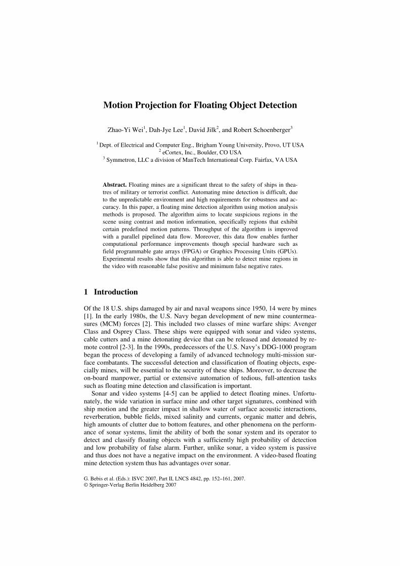
The structure of the whole system is shown in Figure 1. A mine detection module is located at the front of the system, extracting suspicious regions and higher level descriptors such as region area, shape, and motion from the raw video. These data are fed into the mine recognition module for further classification. The output of the mine recognition module is post-processed to obtain a final identification result. This paper focuses on mine detection: other processing modules are outside the scope of this paper.
Fig. 1. System structure overview
We propose a robust and accurate floating mine detection algorithm. This algo-
rithm uses contrast and motion as the two key features to distinguish floating objects from the background. Due to application-specific requirements, robustness means producing a low false negative rate under all possible environmental conditions. In other words, the mine detection module should not miss any suspicious regions in the scene. Accuracy means a low false alarm rate with the prerequisite of low false nega-tives. In order to avoid the limitations of traditional motion estimation algorithms, an efficient and accurate motion correspondence approach is proposed, which extracts regions with certain motion patterns. Experiments show our mine detection algorithm does an excellent job of identifying objects of interest, and it is generally successful at excluding sunlight glint and other very short-lived distractors in any conditions.
The paper is organized as follows: In section 2, the overall structure of the detec-tion algorithm and the reasons for such structure are discussed. In section 3, the for-mulation of each step in the framework is introduced. Intermediate results along the data flow of the pipeline are shown as well. Experimental results are shown in Section 4. Conclusions and future work are presented in Section 5.

154 Z.-Y. Wei et al.
2 Algorithm Overview
The objective of the mine detection module is to identify candidate target locations in the scene. A “multi-scale” algorithm that uses both contrast detection and motion estimation is developed to handle different sized objects. Small regions of high inten-sity contrast are initially selected as candidate regions. Relative motion of these regions is estimated and analyzed. Regions which do not match specified motion characteristics are excluded from further processing. Morphological operations and temporal smoothing are performed on the motion analysis results, and outputs from different image scales are combined to reach a final decision, resulting in a list of candidate mine regions for each frame. Other information such as region size, shape, and motion are also generated for the subsequent recognition module.
Mine recognition is a pattern recognition problem. Using features provided by the detection module, recognition has two objectives: first to remove false positives, par-ticularly waves, from the set candidate regions; and second to identify the category of each remaining target object. Although mine recognition is not the focus of this pa-per, a robust and accurate pre-processing algorithm for detection can provide fewer false positives and better feature data to the recognition algorithms, improving the results and computational performance of the system a whole.
3 Floating Mine Detection Algorithm
3.1 Problem Description and Analysis
The objective of the mine detection algorithm is to identify regions of interest in video of ocean scenes under a variety of circumstances, including variable sea and lighting conditions, variable target shapes and colors, and distractors such as waves, sun glare, and debris in the scene. The algorithm must have a miss rate very close to zero, and within that constraint should attempt to minimize the false positive rate. Reducing false positives further is the goal of the subsequent processing modules.
The approach used in this paper relies on contrast and motion. A few example video frames will illustrate the principles involved. In Fig. 2 (a), the water back-ground is a relatively uniform region, while the mine, highlighted manually in a box, is slightly darker. In other cases, mines could be much darker or brighter than the background, or even a different color. It should be noted that if there is very little contrast between the mine and the background, it would be difficult for a human or any algorithm to detect it. Generally, we assume that either the IR or RGB video will provide enough contrast between the background and the object for detection to be feasible.
Based on the above observation, candidate pixels can be selected by identifying those with a certain minimum amount of contrast to the average of a small surround-ing region. We determined that grayscale intensity contrast is adequate, thus avoiding the extra computational cost for color processing. Contrast information is far more reliable than simple intensity thresholding because of large variations in lighting and mine brightness under anticipated conditions.

Motion Projection for Floating Object Detection 155
However, contrast information alone is not sufficient for candidate pixel selection. In Fig. 2 (b), the regions highlighted in boxes contain pixels with higher grayscale intensity than the immediate background regions. This contrast is caused by moving waves, thus they should not be classified as mines. Other distractors such as sun glint and non-floating objects may also exhibit significant intensity contrast from the im-mediate background.
Many of these distractors can be eliminated by using motion information. In par-ticular, we observe that mines and distractors have distinct motion patterns. In Fig. 2 (c), all highlighted regions are true mines except the rightmost one, which is actually a bird flying across the scene from right to left. It cannot be distinguished from the targets from a single frame, but by discerning its motion over multiple frames, it is clearly not a floating object.
With the above analysis, a mine detection algorithm was designed as shown in Fig. 3. The components of the algorithm are discussed individually in the following subsections.
(a) (b) (c)
Fig. 2. (a) uniform background with a dark object, (b) distractors with brighter grayscale inten-sity, and (c) dark objects and one distractor with different motion pattern
Fig. 3. Mine detection algorithm diagram
3.2 Processing Module Formulation
3.2.1 Multi-scale Scheme As shown in Fig. 3, a multi-scale scheme is used in the algorithm, for two reasons. First, mine size varies and is unknown. The multi-scale scheme accommodates
156 Z.-Y. Wei et al.
different mine sizes. Second, a multi-scale scheme is highly efficient for computing image attributes. Input video is first down-sampled to several different scales. A Gaussian filter is applied to the image to avoid aliasing, then it is down-sampled by a power of two. In our tests, the image was only down-sampled once (by a factor of two). Subsequent processing stages, which are applied to each of these scales, are: candidate pixel selection, motion estimation/analysis, and spatial-temporal smoothing. Results from the different scales can be fused together to reach a final decision. In the current implementation, results from different scales are retained and displayed for comparison. The improvement obtained by applying the multi-scale scheme will be shown in the next subsection.
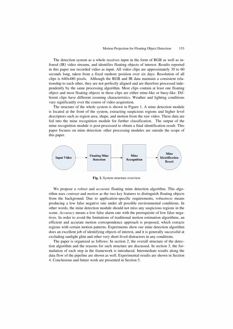
3.2.2 Candidate Pixel Selection We denote the video at scale i as Vi(x, y, t) where x, y, and t are the spatial-temporal coordinates, such that t=1, 2,···2n+1 and i=1, 2,···N. n represents the number of frames before and after the middle frame that are needed for processing. As will be mentioned in the next section, 2n+1 temporally sequential frames are used to calcu-late the point motion correspondence for the middle frame, i.e. the n+1th frame. The temporal window of interest moves from frame to frame along the temporal axis.
As discussed before, the mine should have sufficiently different intensity from its background. For candidate pixel selection, only the center frame Vi(x, y, n+1) is needed. The center frame is divided into “blocks” of 80×80 pixels out of a total of 640×480 pixels. We denote the intensity value at one pixel (x, y) as p(x, y), and the mean intensity and standard deviation of the current block Bk as bk and σk. The value of the candidate mask at (x, y) can be calculated as
⎩⎨⎧
⋅<−⋅≥−
=.),(),( if ,0
.),(),( if ,1),(
kk
kk
nyxbyxp
nyxbyxpyxC
σσ
σ
σ (1)
where nσ controls the number of the initial candidates that will be selected. If the value of nσ is high, only pixels with intensity value very different from their back-ground are selected. A mine could be missed if it has an intensity value very close to the background. If nσ is low, pixels with intensity value close to the background will be successfully selected, but at the cost of increasing false positives.
Another consideration is the block size. Our assumption is that the mine is small compared to the block size and its intensity value is different from the average inten-sity of pixels in the block. If the mine is large and occupies most of the block, the average intensity of the block will be close to the average mine intensity. In this case, it is very likely that the pixels of the mine will not be selected as candidates. The multi-scale scheme is helpful here as well.
Fig. 4 (a) shows an original frame from a video clip, with the corresponding de-tected candidate pixels shown in Fig. 4 (b). Besides pixels in the mine region, some false positive pixels are detected. These false positives can be removed by motion analysis. Fig. 5 (a) shows an original frame from a video clip, and its candidate pixels are shown in Fig. 5 (b). In this case the mine size is close to the block size, biasing the average intensity of the block and hence reducing the contrast between the mine and the average intensity value. Figs. 4 (b) and 5 (b) are obtained from the full image

Motion Projection for Floating Object Detection 157
(a) (b) (c)
Fig. 4. (a) A video frame with a small mine, (b) candidate pixel selection result, and (c) mine detection result using motion projection
(a) (b) (c)
Fig. 5. (a) A video frame with a large mine, (b) candidate pixel selection result using full image scale, and (c) candidate pixel selection result using multiple scales
scale. Fig. 5 (b) shows the drawback of processing at just one scale. Fig. 5 (c) shows the fusion result of candidate selection with multiple scales.
3.2.3 Motion Estimation/Analysis The purpose of motion estimation is to discriminate the mines from other distractors with distinct motion patterns. Existing motion estimation algorithms can be roughly divided into two broad categories: block matching and optical flow.
Block matching algorithms [8-9] attempt to match a block of pixels to adjacent blocks, centered within a certain distance of the original, in the subsequent frame or frames. The size of the block to be matched and the searching radius and strategy are critical to the performance of the algorithm. However, for the problem we are ad-dressing here, the target size is not predictable, thus there will be no single optimal block size. Moreover, for very small or distant targets, there is little texture in the region of interest, reducing the performance of block matching even where the block size is appropriate.
Optical flow algorithms [10-11] are based on the brightness constancy assumption. They need strong regularity of brightness to suppress noise and obtain accurate re-sults. However, the algorithm will fail in scenes like Fig. 2 (b). Motion of small ob-jects will be severely distorted because of the lack of such regularity.
In this case, point correspondence algorithms, which are suitable for calculating small region motion, could be applied. Point correspondence algorithms normally define a motion model and then optimize the model to obtain the motion correspon-dence [12] from two or more frames. Extensive effort has gone into enhancing the accuracy of correspondence algorithms by improving the motion model and

158 Z.-Y. Wei et al.
optimization techniques, at the cost of the processing speed. Unfortunately, the high computational cost is not acceptable in a real-time application. For a more complete survey on point correspondence algorithms, refer to [12].
In this paper, we propose a motion correspondence algorithm that we call “motion projection,” to efficiently estimate motion with high accuracy. This algorithm makes two simple assumptions: the first is the brightness constancy assumption; the second is the constancy of motion across frames.
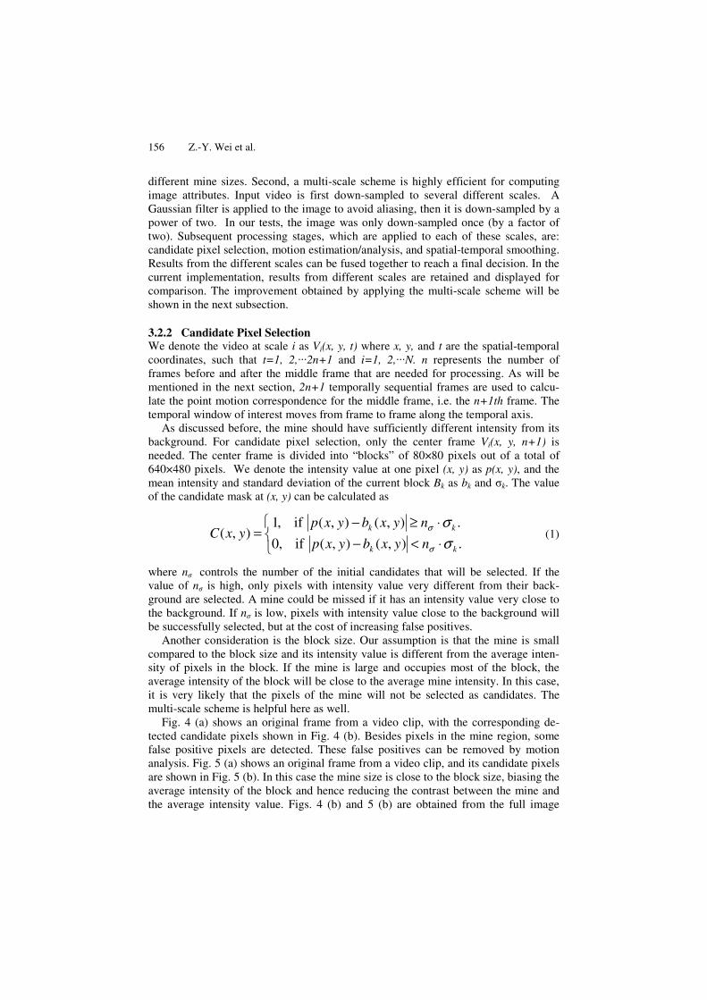
Consider a pixel of interest V(x, y, t) and a square block of size N×N that centers at this pixel. Here N=2n+1 where n is half of the window size. As shown in Fig. 6, the window and the window centering at the same pixel in the preceding and subsequent n frames can be stacked upon each other to become two N×N×(n+1) volumes, called forward and backward volumes, respectively. From the center pixel in the middle frame to each pixel in the end frame (the t+nth frame in the forward volume and the t-nth frame in the backward volume), there are N2 trajectories each denoted as
},,{ 221F
N
FF DDD … and },,{ 221B
N
BB DDD … . Each trajectory is the set of n+1 pixels which
line up in the spatio-temporal domain. The true motion trajectories for forward and backward volumes can be formulated as
⎭⎬⎫
⎩⎨⎧ === 22,1)),((min)( NjDDDD F
j
FFFtrue jkk
…σσ (2)
⎭⎬⎫
⎩⎨⎧ === 22,1)),((min)( NjDDDD B
j
BBBtrue jkk
…σσ (3)
where )( B
jDσ is the variance along trajectory B
jD . One difficulty is that the intersec-
tions of the trajectory and each frame may not fall on the exact grid points. To handle this, we could select the intensity value closer to the intersection, or use interpolation techniques to generate the value. In this paper we use the former method to simplify the design.
The goal of motion estimation is to detect regions with consistent motion, i.e., constant velocity over the period of the projection. This process will filter out glare or glint, which is a common distractor in this application. An individual glare element has a very short visibility cycle, and also shows large changes in brightness. Thus its motion trajectory does not stay constant and it can be distinguished from mines. Wave elements exhibit consistent motion and cannot be isolated from targets from that fac-tor alone. However, they also exhibit more generally horizontal movement, whereas floating objects, including mines, exhibit primarily vertical motion. In the current version of the algorithm, a minor bias is given to vertical motion in the filtering of targets. This distinction is ripe for further research, as wave motion will be generally consistent across the field of view and over different waves, and will differ from that of mines. Figs. 4 (c) and 5 (c) show the motion estimation/analysis result of the clip shown in Figs. 4 and 5. Although some pixels on the target surface are filtered out, many false positives in the image are also removed.
Motion Projection for Floating Object Detection 159
(a) (b)
Fig. 6. (a) Forward motion project volume and (b) Backward motion project volume
3.2.4 Spatial-Temporal Smoothing In some cases, the motion estimation/analysis result contains noise and non-mine distractors even after the previous filtering, for example from wave motion. Accord-ing to the observation of motion difference between the object and background, spa-tio-temporal smoothing is carried out to retain only the motion regions which have consistency in spatio-temporal domain. Filtering is performed by simply counting the number of pixels exhibiting consistent motion from the motion estimation and analy-sis, and removing pixels that have a score below a threshold. Currently, the threshold is one-half of the mask size. For example, if the mask is an 11x11x11 volume, there must be at least five pixels with consistent motion to pass the filter.
3.3 Computational Cost and Algorithm Architecture
As discussed earlier, the entire computation as described above is concatenated and pipelined. Also some of the previous modules break the data into blocks which can be processed in parallel. The goal of this design is to use simple but reliable processing to improve the overall performance and performance at each step. Further, modules with a smaller computational cost (e.g., candidate pixel selection) are positioned at beginning of the pipeline, so that computationally expensive modules (e.g., motion estimation/analysis) are applied only to a selected subset of pixels. A similar architec-ture is applied in [7], where the mine detection algorithm could be denoted as “Front-End Analysis” and the subsequent recognition and post-processing stages are called “High-level Analysis”.
Currently the entire computation process requires approximately 5-7 seconds per frame on a Pentium duo-core PC in the Matlab development environment. Some parts of the code, such as motion estimation/analysis, is optimized using C code interfaced via the “mex” framework. Because of its modular, pipelined design, the algorithm could also be easily implemented for higher performance using hardware accelerators such as DSPs or GPUs, or directly in hardware (such as FPGAs) to achieve high-speed processing at or near the camera frame rate. Further, its simple design enables further improvement of results by incorporating additional modules where appropriate.
160 Z.-Y. Wei et al.
4 Experiment
The objective of this algorithm is to detect all possible mine candidates and provide a good candidate list for further processing such as high-level motion analysis and ob-ject recognition. Due to the nature of the application and the fact that this algorithm is a pre-processing component of the overall solution; false positives are more tolerable than false negatives. Thus in the candidate pixel module, nσ is set to a small value so that virtually every visible non-uniform region is detected using Equation (1). Al-though this approach generates a large number of false positives, many are filtered out in the subsequent motion estimation/analysis module as well as in the spatio-temporal smoothing module. From the binary mask indicating mine pixel locations, we treat connected sets of pixels as a single object. The output of the overall algorithm is a set of centroids, bounding boxes, and the number of pixels of each of these potential mine objects.
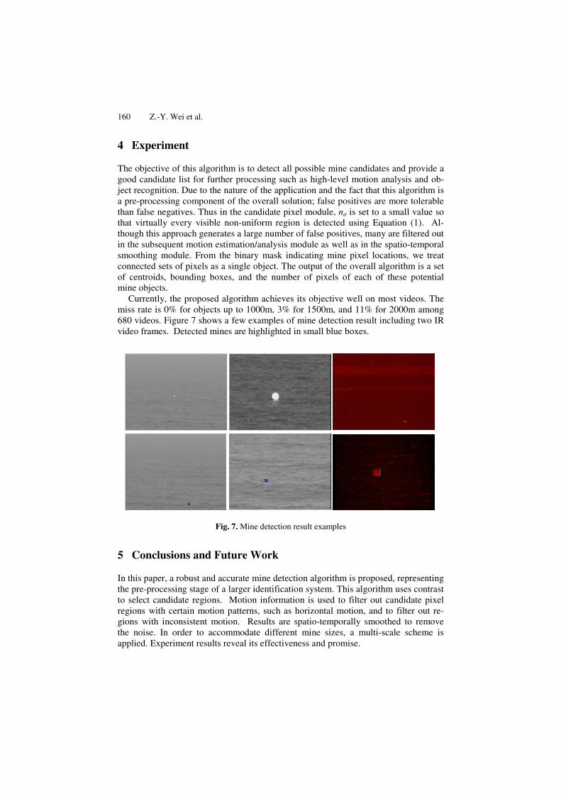
Currently, the proposed algorithm achieves its objective well on most videos. The miss rate is 0% for objects up to 1000m, 3% for 1500m, and 11% for 2000m among 680 videos. Figure 7 shows a few examples of mine detection result including two IR video frames. Detected mines are highlighted in small blue boxes.
Fig. 7. Mine detection result examples
5 Conclusions and Future Work
In this paper, a robust and accurate mine detection algorithm is proposed, representing the pre-processing stage of a larger identification system. This algorithm uses contrast to select candidate regions. Motion information is used to filter out candidate pixel regions with certain motion patterns, such as horizontal motion, and to filter out re-gions with inconsistent motion. Results are spatio-temporally smoothed to remove the noise. In order to accommodate different mine sizes, a multi-scale scheme is applied. Experiment results reveal its effectiveness and promise.

Motion Projection for Floating Object Detection 161
Future work will include deploying higher level vision techniques to recognize mines based on the information from the mine detection algorithm. This is expected to further lower the false positive rate. The mine detection algorithm can also be op-timized using special hardware to achieve real-time computing.
Acknowledgments
This material is based upon work supported by the Naval Sea Systems Command under Contract No. N65538-07-M-0042. Any opinions, findings and conclusions or recommendations expressed in this material are those of the author(s) and do not necessarily reflect the views of the Naval Sea Systems Command, nor of their respective companies or BYU.
References
1. Skinners, D.: Mine Countermeasures (MCM) Sensor Technology Drivers. In: SPIE Pro-ceedings Detection Technologies for Mines and Minelike Targets, vol. 2496 (1995)
2. http://peos.crane.navy.mil/mine/default.htm 3. http://www.cmwc.navy.mil/default.aspx 4. Zimmerman, C., Coolidge, M.: The Forgotten Threat of Attack by Sea: Using 3D Sonar to
Detect Terrorist Swimmers and Mines. In: IEEE Conference on Technologies for Home-land Security (2002)
5. Dobeck, G.J., Hyland, J.: Sea mine detection and classification using side-looking sonars. In: SPIE Proceedings Annual International Symposium on Aerospace/Defense Sensing, Simulation and Control, pp. 442–453 (1995)
6. Chen, Y., Nguyen, T.Q.: Sea Mine Detection Based on Multiresolution Analysis and Noise Whitening. Technical Report (1999)
7. Burt, P.J.: A Pyramid-based Front-end Processor for Dynamic Vision Applications. Pro-ceedings of the IEEE 90, 1188–1200 (2002)
8. Huang, Y., Chen, C., Tsai, C., Shen, C., Chen, L.: Survey on Block Matching Motion Es-timation Algorithms and Architectures with New Results. The Journal of VLSI Signal Processing 42, 297–320 (2006)
9. Love, N.S., Kamath, C.: An Empirical Study of Block Matching Techniques for the Detec-tion of Moving Objects. LLNL Technical Report UCRL-TR-218038 (2006)
10. Horn, B.K.P., Schunck, B.G.: Determining Optical Flow. Artificial Intelligence 17, 185–203 (1981)
11. Lucas, B.D., Kanade, T.: An iterative image registration technique with an application to stereo vision. In: Proceedings of Image Understanding Workshop, pp. 121–130 (1981)
12. Shafique, K., Shah, M.: A Noniterative Greedy Algorithm for Multiframe Point Corre-spondence. IEEE Trans. on PAMI 27, 51–65 (2005)
Related Documents


