05.2007 Edition SIMOTION Motion Control Technology Objects Synchronous Operation, Cam Function Manual s Preface, Contents Synchronous Operation I Distributed Synchronous Operation II Synchronous Operation IPO - IPO_2 III Cam IV Index

Welcome message from author
This document is posted to help you gain knowledge. Please leave a comment to let me know what you think about it! Share it to your friends and learn new things together.
Transcript
05.2007 Edition
SIMOTION
Motion Control Technology Objects Synchronous Operation, Cam
Function Manual
s
Preface, Contents
Synchronous OperationI
Distributed Synchronous OperationII
Synchronous Operation IPO - IPO_2III
CamIV
Index
Copyright Siemens AG 2007 All Rights Reserved
The reproduction, transmission or use of this document or its contents is not permitted without express written authority. Violation of this rule can lead to claims for damage compensation. All rights reserved, es-pecially for granting patents or for GM registration.
Siemens AGAutomation & DrivesMotion Control SystemsPO Box 3180, D-91050 ErlangenGermany
Liability Disclaimer
We have checked that the contents of this document correspond to the hardware and software described. Since deviations cannot be pre-cluded entirely, we cannot guarantee full agreement. The data in this document is regularly checked and the necessary corrections are in-cluded in the following editions.
© Siemens AG 2007Subject to change without prior notice.
Safety information
This manual contains information that must be observed to ensure your personal safety and to prevent property damage. Notices referring to your personal safety are highlighted in the manual by a safety alert symbol; notices referring to property damage only have no safety alert symbol. These notices shown below are graded according to the level of danger:
If more than one level of danger exists, the warning notice for the highest level of danger is used. If a warn-ing with a warning triangle is to indicate physical injury, the same warning may also contain information about damage to property.
Qualified personnel
The device/system may only be set up and operated in conjunction with this documentation. Only quali-fied personnel should be allowed to commission and operate the device/system. Qualified personnel as referred to in the safety guidelines in this documentation are those who are authorized to start up, earth and label units, systems and circuits in accordance with the relevant safety standards.
Correct usage
Please note the following:
Trademarks
All names identified by ® are registered trademarks of the Siemens AG. The remaining trademarks in this publication may be trademarks whose use by third parties for their own purposes could violate the rights of the owner.
Dangerindicates that death or serious injury will result if proper precautions are not taken.
Warningindicates that death or serious injury may result if proper precautions are not taken.
Cautionwith a safety alert symbol, indicates that minor personal injury may result if proper precautions are not taken.
Cautionwithout a safety alert symbol, indicates that property damage may result if proper precautions are not taken.
Noticemeans an undesirable result or state can occur if the corresponding instruction is not followed.
WarningThe device may be used only for the applications described in the catalog and in the technical description, and only in combination with the equipment, components and devices of other manufacturers where rec-ommended or permitted by Siemens.
Correct transport, storage, installation and assembly, as well as careful operation and maintenance, are required to ensure that the product operates safely and without faults.
Siemens Aktiengesellschaft SIMOTION Motion Control Technology Objects Synchronous Operation, Cam
Preface-3© Siemens AG 2007 All Rights ReservedSIMOTION Motion Control Technology Objects Synchronous Operation, Cam, 05.2007 Edition
Preface
This document is part of the Description of System and Functions documen-tation package.
Scope of validity
This manual is valid for SIMOTION SCOUT V4.1:
• SIMOTION SCOUT V4.1 (engineering system for the SIMOTION product family),
in combination with
• SIMOTION Kernel V4.1, V4.0, V3.2, V3.1 or V3.0
• SIMOTION technology packages Cam, Cam_ext (Kernel V3.2 and later) and TControl in the version for the respective kernel (including technology pack-ages Gear, Position and Basic MC up to Kernel V3.0).
Chapters in this manual
The following is a list of chapters included in this manual along with a description of the information presented in each chapter.
• Synchronous Operation (Part I)
Function of the synchronous operation, i.e., the synchronous operation rela-tionship between a master object and a following axis
• Distributed Synchronous Operation (part II)
Function of distributed synchronous operation, i.e. synchronous operation across different controllers
• Synchronous Operation IPO - IPO_2 (part III)
Function of synchronous operation with master object and following axis in different interpolator cycle clocks (IPO or IPO_2)
• Cam (part IV)
Function of the Cam technology object
• Index
Keyword index for locating information
Preface
Preface-4 © Siemens AG 2007 All Rights ReservedSIMOTION Motion Control Technology Objects Synchronous Operation, Cam, 05.2007 Edition
SIMOTION documentation
An overview of the SIMOTION documentation is provided in a separate list of ref-erences.
The list of references is supplied on the "SIMOTION SCOUT" CD.
The SIMOTION documentation consists of 9 documentation packages containing approximately 50 SIMOTION documents and documents on other products (e.g. SINAMICS).
The following documentation packages are available for SIMOTION V4.1:
• SIMOTION Engineering System Handling
• SIMOTION Description of System and Functions
• SIMOTION Diagnosis
• SIMOTION Programming
• SIMOTION Programming Reference Lists
• SIMOTION C2xx
• SIMOTION P350
• SIMOTION D4xx
• SIMOTION Additional Documentation
Hotline and Internet addresses
If you have any questions, please contact our hotline (worldwide):
Siemens Internet address
The latest information about SIMOTION products, product support and FAQs can be found on the Internet at:
A&D Technical Support:
Phone: +49 (180) 50 50 222Fax: +49 (180) 50 50 223E-mail: [email protected]: http://www.siemens.de/automation/support-request
If you have any questions, suggestions, or corrections regarding the documen-tation, please fax or e-mail them to:
Fax: +49 (9131) 98 63315E-mail: [email protected]
− General information
http://www.siemens.de/simotion (German)http://www.siemens.com/simotion (International)
− Product support:
http://support.automation.siemens.com/WW/view/de/10805436
Preface
Preface-5© Siemens AG 2007 All Rights ReservedSIMOTION Motion Control Technology Objects Synchronous Operation, Cam, 05.2007 Edition
Further assistance
We also offer introductory courses to help you familiarize yourself with SIMOTION.
Please contact your regional training center or the central training center in D-90027 Nuremberg, phone +49 (911) 895 3202 for more information.
Preface
Preface-6 © Siemens AG 2007 All Rights ReservedSIMOTION Motion Control Technology Objects Synchronous Operation, Cam, 05.2007 Edition
Contents
Contents-7© Siemens AG 2007 All Rights ReservedSIMOTION Motion Control Technology Objects Synchronous Operation, Cam, 05.2007 Edition
Contents
Part I Synchronous Operation
1 Overview of Synchronous Operation . . . . . . . . . . . . . . . . . . . . . . . . . . . . . . . . . . . . 1-131.1 Function overview . . . . . . . . . . . . . . . . . . . . . . . . . . . . . . . . . . . . . . . . . . . . . 1-13
2 Fundamentals of Synchronous Operation . . . . . . . . . . . . . . . . . . . . . . . . . . . . . . . . 2-212.1 Gearing . . . . . . . . . . . . . . . . . . . . . . . . . . . . . . . . . . . . . . . . . . . . . . . . . . . . . 2-222.2 Synchronous velocity operation . . . . . . . . . . . . . . . . . . . . . . . . . . . . . . . . . . 2-272.3 Camming . . . . . . . . . . . . . . . . . . . . . . . . . . . . . . . . . . . . . . . . . . . . . . . . . . . . 2-282.4 Setpoint / actual value coupling. . . . . . . . . . . . . . . . . . . . . . . . . . . . . . . . . . . 2-382.4.1 Actual value coupling with extrapolation . . . . . . . . . . . . . . . . . . . . . . . . . . . . 2-392.4.2 Actual value coupling with tolerance window . . . . . . . . . . . . . . . . . . . . . . . . 2-412.5 Synchronizing . . . . . . . . . . . . . . . . . . . . . . . . . . . . . . . . . . . . . . . . . . . . . . . . 2-422.5.1 Synchronization criterion/synchronization position . . . . . . . . . . . . . . . . . . . . 2-452.5.2 Synchronization direction . . . . . . . . . . . . . . . . . . . . . . . . . . . . . . . . . . . . . . . 2-502.5.3 Position of synchronization range relative to synchronization position . . . . . 2-512.5.4 Synchronization via a specifiable master value distance . . . . . . . . . . . . . . . 2-532.5.5 Synchronization profile based on specifiable dynamic response parameters
(time reference) . . . . . . . . . . . . . . . . . . . . . . . . . . . . . . . . . . . . . . . . . . . . . . . 2-542.5.6 Leading synchronization with synchronization profile based on dynamic
response parameters . . . . . . . . . . . . . . . . . . . . . . . . . . . . . . . . . . . . . . . . . . 2-562.5.7 Trailing synchronization with synchronization profile based on dynamic
response parameters . . . . . . . . . . . . . . . . . . . . . . . . . . . . . . . . . . . . . . . . . . 2-572.5.8 Settings for evaluation of the master value behavior during synchronization 2-592.5.9 Monitoring the synchronization . . . . . . . . . . . . . . . . . . . . . . . . . . . . . . . . . . . 2-612.5.10 Display of the synchronous position . . . . . . . . . . . . . . . . . . . . . . . . . . . . . . . 2-632.5.11 "Synchronous" status during synchronization . . . . . . . . . . . . . . . . . . . . . . . . 2-652.6 Desynchronization. . . . . . . . . . . . . . . . . . . . . . . . . . . . . . . . . . . . . . . . . . . . . 2-662.6.1 Desynchronization criterion/desynchronization position . . . . . . . . . . . . . . . . 2-672.6.2 Desynchronization via a specifiable master value distance . . . . . . . . . . . . . 2-682.6.3 Desynchronization profile based on specifiable dynamic response
parameters . . . . . . . . . . . . . . . . . . . . . . . . . . . . . . . . . . . . . . . . . . . . . . . . . . 2-682.6.4 Position of synchronization range relative to desynchronization position . . . 2-692.7 Dynamic response effect on slave values . . . . . . . . . . . . . . . . . . . . . . . . . . . 2-702.8 Switching of the master value source . . . . . . . . . . . . . . . . . . . . . . . . . . . . . . 2-722.8.1 Master value switchover without dynamic response . . . . . . . . . . . . . . . . . . . 2-722.8.2 Master value switchover with dynamic response . . . . . . . . . . . . . . . . . . . . . 2-732.8.3 Master value switchover with next synchronization (V4.1 and higher) . . . . . 2-742.9 Superimposed synchronous operation . . . . . . . . . . . . . . . . . . . . . . . . . . . . . 2-752.10 Synchronous operation monitoring . . . . . . . . . . . . . . . . . . . . . . . . . . . . . . . . 2-792.11 Simulation mode . . . . . . . . . . . . . . . . . . . . . . . . . . . . . . . . . . . . . . . . . . . . . . 2-82
Contents
Contents-8 © Siemens AG 2007 All Rights ReservedSIMOTION Motion Control Technology Objects Synchronous Operation, Cam, 05.2007 Edition
2.12 Examples of synchronization operations as a function of the output position on the slave value side . . . . . . . . . . . . . . . . . . . . . . . . . . . . . . . . . . . . . . . . . 2-83
2.12.1 Synchronization via a specifiable master value distance . . . . . . . . . . . . . . . 2-832.12.2 Synchronization profile based on specifiable dynamic response parameters 2-852.13 Examples. . . . . . . . . . . . . . . . . . . . . . . . . . . . . . . . . . . . . . . . . . . . . . . . . . . . 2-892.13.1 Examples of typical synchronization operations . . . . . . . . . . . . . . . . . . . . . . 2-892.13.2 Example of offset and scaling on the synchronous object . . . . . . . . . . . . . 2-1012.13.3 Example of applying offset as superimposition . . . . . . . . . . . . . . . . . . . . . . 2-1042.14 Special actions . . . . . . . . . . . . . . . . . . . . . . . . . . . . . . . . . . . . . . . . . . . . . . 2-1072.14.1 Redefining the axis position during active synchronous operation . . . . . . . 2-1072.14.2 Retaining a synchronous operation connection with _disableAxis() . . . . . . 2-1092.14.3 Substitution of velocity gearing with absolute synchronous operation . . . . 2-1102.14.4 Canceling active and pending synchronous operations . . . . . . . . . . . . . . . 2-1102.14.5 Adapt the synchronization velocity to the master value velocity . . . . . . . . 2-111
3 Configuring Synchronous Operation . . . . . . . . . . . . . . . . . . . . . . . . . . . . . . . . . . . 3-1133.1 Creating an axis with synchronous operation . . . . . . . . . . . . . . . . . . . . . . . 3-1143.2 Assigning master values and cams. . . . . . . . . . . . . . . . . . . . . . . . . . . . . . . 3-1173.3 Assigning parameters/defaults for synchronous operation . . . . . . . . . . . . . 3-1193.3.1 Gearing . . . . . . . . . . . . . . . . . . . . . . . . . . . . . . . . . . . . . . . . . . . . . . . . . . . . 3-1203.3.2 Synchronous velocity operation . . . . . . . . . . . . . . . . . . . . . . . . . . . . . . . . . 3-1213.3.3 Camming . . . . . . . . . . . . . . . . . . . . . . . . . . . . . . . . . . . . . . . . . . . . . . . . . . . 3-1223.3.4 Gearing synchronization . . . . . . . . . . . . . . . . . . . . . . . . . . . . . . . . . . . . . . . 3-1243.3.5 Synchronizing the gear . . . . . . . . . . . . . . . . . . . . . . . . . . . . . . . . . . . . . . . . 3-1263.3.6 Position reference during synchronization . . . . . . . . . . . . . . . . . . . . . . . . . 3-1273.3.7 Desynchronizing the gear . . . . . . . . . . . . . . . . . . . . . . . . . . . . . . . . . . . . . . 3-1283.3.8 Position reference during desynchronization . . . . . . . . . . . . . . . . . . . . . . . 3-1283.3.9 Camming synchronization . . . . . . . . . . . . . . . . . . . . . . . . . . . . . . . . . . . . . . 3-1293.3.10 Cam synchronization. . . . . . . . . . . . . . . . . . . . . . . . . . . . . . . . . . . . . . . . . . 3-1313.3.11 Cam desynchronization. . . . . . . . . . . . . . . . . . . . . . . . . . . . . . . . . . . . . . . . 3-1323.3.12 Dynamic response. . . . . . . . . . . . . . . . . . . . . . . . . . . . . . . . . . . . . . . . . . . . 3-1323.3.13 Master dynamic response . . . . . . . . . . . . . . . . . . . . . . . . . . . . . . . . . . . . . . 3-1353.4 Set synchronization . . . . . . . . . . . . . . . . . . . . . . . . . . . . . . . . . . . . . . . . . . . 3-1363.5 Configuring synchronous operation monitoring. . . . . . . . . . . . . . . . . . . . . . 3-138
4 Synchronous Operation Programming / References . . . . . . . . . . . . . . . . . . . . . . 4-1394.1 Overview of commands. . . . . . . . . . . . . . . . . . . . . . . . . . . . . . . . . . . . . . . . 4-1404.1.1 Commands for reading out function values. . . . . . . . . . . . . . . . . . . . . . . . . 4-1434.1.2 Commands for command tracking . . . . . . . . . . . . . . . . . . . . . . . . . . . . . . . 4-1434.1.3 Commands for resetting states and errors . . . . . . . . . . . . . . . . . . . . . . . . . 4-1454.2 Command processing . . . . . . . . . . . . . . . . . . . . . . . . . . . . . . . . . . . . . . . . . 4-1464.2.1 Interaction between the following axis and the synchronous object . . . . . . 4-1464.2.2 Command execution . . . . . . . . . . . . . . . . . . . . . . . . . . . . . . . . . . . . . . . . . . 4-1474.2.3 Command transition conditions . . . . . . . . . . . . . . . . . . . . . . . . . . . . . . . . . . 4-1504.3 Error handling . . . . . . . . . . . . . . . . . . . . . . . . . . . . . . . . . . . . . . . . . . . . . . . 4-1524.3.1 Local alarm response . . . . . . . . . . . . . . . . . . . . . . . . . . . . . . . . . . . . . . . . . 4-1524.3.2 Error handling in the user program . . . . . . . . . . . . . . . . . . . . . . . . . . . . . . . 4-153
Contents
Contents-9© Siemens AG 2007 All Rights ReservedSIMOTION Motion Control Technology Objects Synchronous Operation, Cam, 05.2007 Edition
Part II Distributed Synchronous Operation
5 Overview of Distributed Synchronous Operation . . . . . . . . . . . . . . . . . . . . . . . . . 5-1575.1 Function overview . . . . . . . . . . . . . . . . . . . . . . . . . . . . . . . . . . . . . . . . . . . . 5-158
6 Fundamentals of Distributed Synchronous Operation . . . . . . . . . . . . . . . . . . . . . 6-1616.1 Boundary conditions . . . . . . . . . . . . . . . . . . . . . . . . . . . . . . . . . . . . . . . . . . 6-1626.1.1 Rules for the communication/topology for distributed operation
using PROFIBUS . . . . . . . . . . . . . . . . . . . . . . . . . . . . . . . . . . . . . . . . . . . . 6-1626.1.2 Rules for the communication/topology for the distribution
using PROFINET IO with IRT (V4.0 or later). . . . . . . . . . . . . . . . . . . . . . . . 6-1686.2 Compensations for distributed synchronous operation . . . . . . . . . . . . . . . . 6-1696.2.1 Compensation on master value side by means of setpoint output delay . . 6-1726.2.2 Compensation on the slave value side using master setpoint extrapolation 6-1746.2.3 Permissible combinations for cycle clock offset compensation
in distributed synchronous operation. . . . . . . . . . . . . . . . . . . . . . . . . . . . . . 6-1756.2.4 Cycle clock offset calculation using a command . . . . . . . . . . . . . . . . . . . . . 6-1756.3 Operating axes with distributed synchronous operation . . . . . . . . . . . . . . . 6-1766.3.1 Life-sign monitoring . . . . . . . . . . . . . . . . . . . . . . . . . . . . . . . . . . . . . . . . . . . 6-1766.3.2 Operating states . . . . . . . . . . . . . . . . . . . . . . . . . . . . . . . . . . . . . . . . . . . . . 6-177
7 Configuring Distributed Synchronous Operation . . . . . . . . . . . . . . . . . . . . . . . . . 7-1817.1 Creating SIMOTION devices with SCOUT . . . . . . . . . . . . . . . . . . . . . . . . . 7-1827.2 Creating connection(s) with HW Config . . . . . . . . . . . . . . . . . . . . . . . . . . . 7-1837.3 Creating synchronous operation connection(s) with SCOUT . . . . . . . . . . . 7-1857.4 Synchronizing the interfaces . . . . . . . . . . . . . . . . . . . . . . . . . . . . . . . . . . . . 7-1877.5 Generating a synchronous operation configuration. . . . . . . . . . . . . . . . . . . 7-1887.6 Possible errors . . . . . . . . . . . . . . . . . . . . . . . . . . . . . . . . . . . . . . . . . . . . . . 7-189
8 Configuring Distributed Synchronous Operation across Projects (V4.1 and higher) . 8-1918.1 Overview . . . . . . . . . . . . . . . . . . . . . . . . . . . . . . . . . . . . . . . . . . . . . . . . . . . 8-1928.2 Network configuration with HW Config . . . . . . . . . . . . . . . . . . . . . . . . . . . . 8-1938.3 PROFIBUS communication configuration . . . . . . . . . . . . . . . . . . . . . . . . . . 8-1968.3.1 Creating and configuring a master object project . . . . . . . . . . . . . . . . . . . . 8-1968.3.2 Creating and configuring a following axis project . . . . . . . . . . . . . . . . . . . . 8-1988.4 Communication via PROFINET IO with IRTtop. . . . . . . . . . . . . . . . . . . . . . 8-2018.4.1 Creating and configuring a master object project . . . . . . . . . . . . . . . . . . . . 8-2018.4.2 Creating and configuring a following axis project . . . . . . . . . . . . . . . . . . . . 8-2028.5 Proxy objects. . . . . . . . . . . . . . . . . . . . . . . . . . . . . . . . . . . . . . . . . . . . . . . . 8-2038.5.1 Proxy object types . . . . . . . . . . . . . . . . . . . . . . . . . . . . . . . . . . . . . . . . . . . . 8-2038.5.2 Creating proxy objects. . . . . . . . . . . . . . . . . . . . . . . . . . . . . . . . . . . . . . . . . 8-2038.5.3 Configuring proxy objects . . . . . . . . . . . . . . . . . . . . . . . . . . . . . . . . . . . . . . 8-2048.5.4 Configuring proxy objects with SIMOTION scripting . . . . . . . . . . . . . . . . . . 8-2058.6 Interconnection options . . . . . . . . . . . . . . . . . . . . . . . . . . . . . . . . . . . . . . . . 8-2068.7 Synchronizing the interface . . . . . . . . . . . . . . . . . . . . . . . . . . . . . . . . . . . . . 8-2088.8 Switching over to an external master value source. . . . . . . . . . . . . . . . . . . 8-208
Contents
Contents-10 © Siemens AG 2007 All Rights ReservedSIMOTION Motion Control Technology Objects Synchronous Operation, Cam, 05.2007 Edition
Part III Synchronous Operation IPO - IPO_2
9 Overview of Synchronous Operation IPO - IPO_2. . . . . . . . . . . . . . . . . . . . . . . . . 9-2119.1 Function overview . . . . . . . . . . . . . . . . . . . . . . . . . . . . . . . . . . . . . . . . . . . . 9-212
10 Fundamentals of Synchronous Operation IPO - IPO_2 . . . . . . . . . . . . . . . . . . . 10-21510.1 Boundary conditions . . . . . . . . . . . . . . . . . . . . . . . . . . . . . . . . . . . . . . . . . 10-21610.2 Operation of Synchronous Operation IPO - IPO_2 . . . . . . . . . . . . . . . . . . 10-218
11 Configuring Synchronous Operation IPO - IPO_2 . . . . . . . . . . . . . . . . . . . . . . . 11-22111.1 Creating Synchronous Operation IPO - IPO_2 in SCOUT . . . . . . . . . . . . 11-222
Part IV Cam
12 Overview of Cam. . . . . . . . . . . . . . . . . . . . . . . . . . . . . . . . . . . . . . . . . . . . . . . . . . . 12-22512.1 Function overview . . . . . . . . . . . . . . . . . . . . . . . . . . . . . . . . . . . . . . . . . . . 12-226
13 Fundamentals of Cam . . . . . . . . . . . . . . . . . . . . . . . . . . . . . . . . . . . . . . . . . . . . . . 13-22913.1 Definition . . . . . . . . . . . . . . . . . . . . . . . . . . . . . . . . . . . . . . . . . . . . . . . . . . 13-23013.2 Normalization . . . . . . . . . . . . . . . . . . . . . . . . . . . . . . . . . . . . . . . . . . . . . . 13-23213.3 Scaling and offset . . . . . . . . . . . . . . . . . . . . . . . . . . . . . . . . . . . . . . . . . . . 13-23313.4 Interpolation. . . . . . . . . . . . . . . . . . . . . . . . . . . . . . . . . . . . . . . . . . . . . . . . 13-23513.5 Inversion . . . . . . . . . . . . . . . . . . . . . . . . . . . . . . . . . . . . . . . . . . . . . . . . . . 13-24013.6 Motion laws in accordance with VDI . . . . . . . . . . . . . . . . . . . . . . . . . . . . . 13-24213.6.1 Motion tasks . . . . . . . . . . . . . . . . . . . . . . . . . . . . . . . . . . . . . . . . . . . . . . . 13-24213.6.2 Defining a cam for a motion task using segments. . . . . . . . . . . . . . . . . . . 13-244
14 Configuring Cams. . . . . . . . . . . . . . . . . . . . . . . . . . . . . . . . . . . . . . . . . . . . . . . . . . 14-24514.1 Creating a cam . . . . . . . . . . . . . . . . . . . . . . . . . . . . . . . . . . . . . . . . . . . . . 14-24614.2 Defining cams . . . . . . . . . . . . . . . . . . . . . . . . . . . . . . . . . . . . . . . . . . . . . . 14-24714.3 Interconnecting cams . . . . . . . . . . . . . . . . . . . . . . . . . . . . . . . . . . . . . . . . 14-247
15 Cam Programming / References . . . . . . . . . . . . . . . . . . . . . . . . . . . . . . . . . . . . . . 15-24915.1 Overview of commands. . . . . . . . . . . . . . . . . . . . . . . . . . . . . . . . . . . . . . . 15-25015.1.1 Commands for the definition . . . . . . . . . . . . . . . . . . . . . . . . . . . . . . . . . . . 15-25115.1.2 Commands for reading out function values. . . . . . . . . . . . . . . . . . . . . . . . 15-25315.1.3 Commands for resetting states and errors . . . . . . . . . . . . . . . . . . . . . . . . 15-25415.1.4 Commands for command tracking . . . . . . . . . . . . . . . . . . . . . . . . . . . . . . 15-25415.2 Command processing . . . . . . . . . . . . . . . . . . . . . . . . . . . . . . . . . . . . . . . . 15-25515.2.1 Programming and sequence model . . . . . . . . . . . . . . . . . . . . . . . . . . . . . 15-25515.3 Local alarm reactions . . . . . . . . . . . . . . . . . . . . . . . . . . . . . . . . . . . . . . . . 15-256
© Siemens AG 2007 All Rights ReservedSIMOTION Motion Control Technology Objects Synchronous Operation, Cam, 05.2007 Edition
Part ISynchronous Operation
This chapter describes the functions of the synchronous operation technology.
It introduces you to the setting and configuration functions and provides informa-tion about the boundary conditions and the operating characteristics of synchro-nous operation.
Content
Chapter 1 Overview of Synchronous Operation 1-13
Chapter 2 Fundamentals of Synchronous Operation 2-21
Chapter 3 Configuring Synchronous Operation 3-113
Chapter 4 Synchronous Operation Programming / References 4-139

© Siemens AG 2007 All Rights ReservedSIMOTION Motion Control Technology Objects Synchronous Operation, Cam, 05.2007 Edition
1-13© Siemens AG 2007 All Rights ReservedSIMOTION Motion Control Technology Objects Synchronous Operation, Cam, 05.2007 Edition
Overview of Synchronous Operation 1This chapter provides information on the basic function and application of the Synchronous Operation technology.
Synchronous operation functions are taking on greater and greater significance in automation engineering. The progress in open-loop and closed-loop control engineering and the availability of increasingly more powerful systems mean that solely mechanical solutions are more and more frequently being replaced with "electronic" variants.
The synchronous operation functions of the SIMOTION technology provide the option to replace rigid mechanical connections with "control engineering", thus producing more flexible, maintenance-friendly solutions.
Content
1.1 Function overview 1-13
1.1 Function overviewThe synchronous operation functionality in SIMOTION is provided by the synchronous object.
A leading object (master) generates a master value, which is processed by the synchronous object according to specific criteria (gear ratio, scaling, offset, cam) and assigned to the following axis (slave) as a reference variable.
Mechanical modelThe mechanical model for a synchronous operation relationship is, for example, a gear with a drive wheel and an output wheel or output wheels.
The model for camming could be a cam gear with a mechanical cam and sam-pling mechanism.
A coupling to enable and disable the following motion on-the-fly is also used as a model.
Overview of Synchronous Operation
1-14 © Siemens AG 2007 All Rights ReservedSIMOTION Motion Control Technology Objects Synchronous Operation, Cam, 05.2007 Edition
Synchronous operation functionsThe following synchronous operation functions can be implemented:
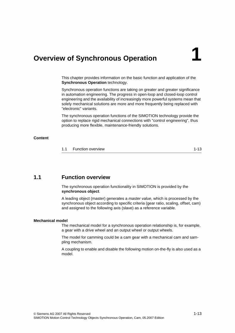
• With gearing, a linear transmission function between a master value and a fol-lowing axis can be achieved using control engineering, same as could be achieved mechanically using a gear. A gear ratio can be specified for use in linear mapping of the leading axis position onto the following axis position.
Figure 1-1 Gearing synchronous operation function (mechanical example)
• With synchronous velocity operation, a constant velocity coupling is imple-mented. (V3.1 and higher)
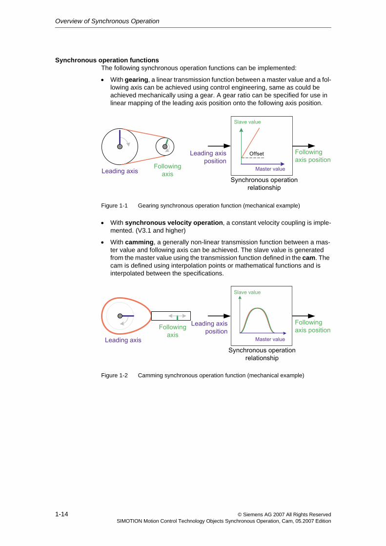
• With camming, a generally non-linear transmission function between a mas-ter value and following axis can be achieved. The slave value is generated from the master value using the transmission function defined in the cam. The cam is defined using interpolation points or mathematical functions and is interpolated between the specifications.
Figure 1-2 Camming synchronous operation function (mechanical example)
Overview of Synchronous Operation
1-15© Siemens AG 2007 All Rights ReservedSIMOTION Motion Control Technology Objects Synchronous Operation, Cam, 05.2007 Edition
Sequence of a synchronous operationThe synchronous operation of a following axis to a master value using the SIMOTION synchronous operation functions is divided into three phases:
• Synchronization
• Synchronized traversing
• Desynchronization
Within these phases, there are several options for influencing the synchronous operation functions.
Synchronization/desynchronizationSynchronous operation to the master value during synchronization or desynchro-nization can be defined differently depending on the application.
It is determined based on:
• Synchronization criterion/synchronization position
• Synchronization direction
• Position of synchronization range relative to synchronization position
• Synchronization profile
See Synchronizing (Section 2.5)
ObjectsA synchronous operation relationship exists between the following objects:
• At least one leading object (master), a technology object that provides the master value, for example, a positioning axis or an external encoder
• A following axis, comprising:
− A following axis (slave)
− One or two synchronous objects
− And, possibly, one or more cams
A synchronous object is automatically created as a separate object when an axis with synchronous operation technology is created.
Overview of Synchronous Operation
1-16 © Siemens AG 2007 All Rights ReservedSIMOTION Motion Control Technology Objects Synchronous Operation, Cam, 05.2007 Edition
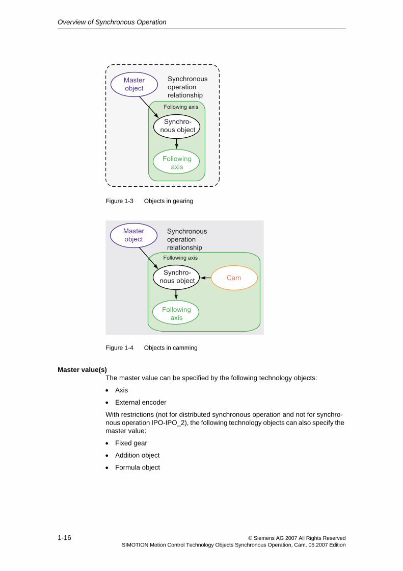
Figure 1-3 Objects in gearing
Figure 1-4 Objects in camming
Master value(s)The master value can be specified by the following technology objects:
• Axis
• External encoder
With restrictions (not for distributed synchronous operation and not for synchro-nous operation IPO-IPO_2), the following technology objects can also specify the master value:
• Fixed gear
• Addition object
• Formula object
Overview of Synchronous Operation
1-17© Siemens AG 2007 All Rights ReservedSIMOTION Motion Control Technology Objects Synchronous Operation, Cam, 05.2007 Edition
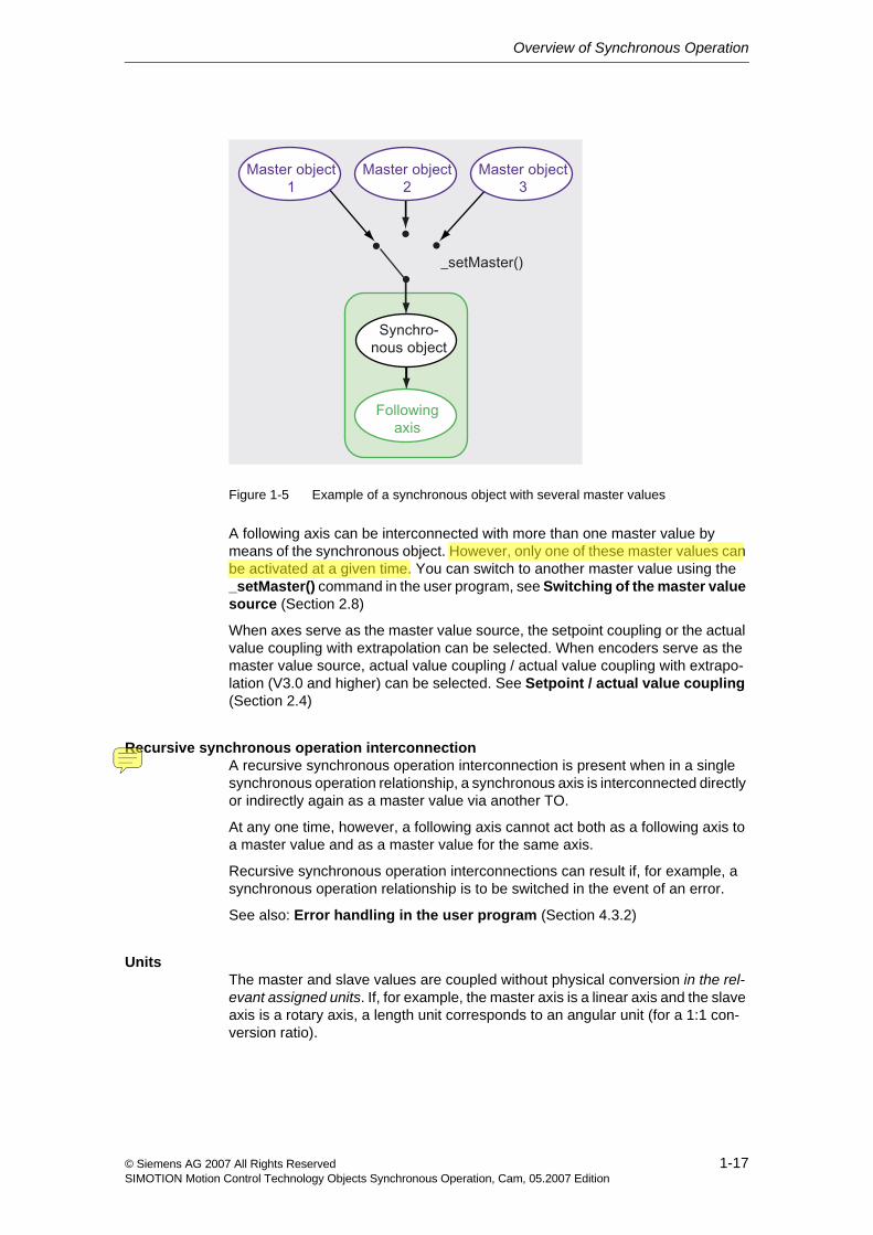
Figure 1-5 Example of a synchronous object with several master values
A following axis can be interconnected with more than one master value by means of the synchronous object. However, only one of these master values can be activated at a given time. You can switch to another master value using the _setMaster() command in the user program, see Switching of the master value source (Section 2.8)
When axes serve as the master value source, the setpoint coupling or the actual value coupling with extrapolation can be selected. When encoders serve as the master value source, actual value coupling / actual value coupling with extrapo-lation (V3.0 and higher) can be selected. See Setpoint / actual value coupling (Section 2.4)
Recursive synchronous operation interconnectionA recursive synchronous operation interconnection is present when in a single synchronous operation relationship, a synchronous axis is interconnected directly or indirectly again as a master value via another TO.
At any one time, however, a following axis cannot act both as a following axis to a master value and as a master value for the same axis.
Recursive synchronous operation interconnections can result if, for example, a synchronous operation relationship is to be switched in the event of an error.
See also: Error handling in the user program (Section 4.3.2)
UnitsThe master and slave values are coupled without physical conversion in the rel-evant assigned units. If, for example, the master axis is a linear axis and the slave axis is a rotary axis, a length unit corresponds to an angular unit (for a 1:1 con-version ratio).
CN1LH0N2
Highlight
CN1LH0N2
Note
递归的
Overview of Synchronous Operation
1-18 © Siemens AG 2007 All Rights ReservedSIMOTION Motion Control Technology Objects Synchronous Operation, Cam, 05.2007 Edition
Modulo behaviorDifferent modulo ranges on the master value object and the slave axis are taken into account on the synchronous object.
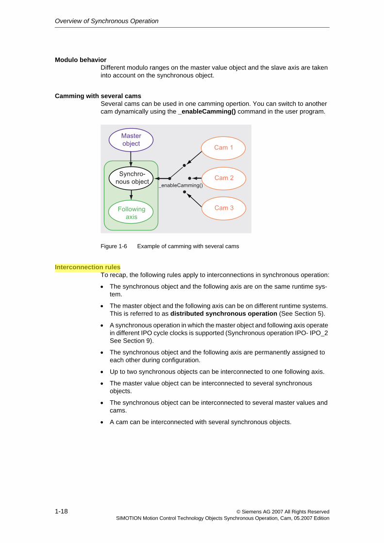
Camming with several camsSeveral cams can be used in one camming opertion. You can switch to another cam dynamically using the _enableCamming() command in the user program.
Figure 1-6 Example of camming with several cams
Interconnection rulesTo recap, the following rules apply to interconnections in synchronous operation:
• The synchronous object and the following axis are on the same runtime sys-tem.
• The master object and the following axis can be on different runtime systems. This is referred to as distributed synchronous operation (See Section 5).
• A synchronous operation in which the master object and following axis operate in different IPO cycle clocks is supported (Synchronous operation IPO- IPO_2 See Section 9).
• The synchronous object and the following axis are permanently assigned to each other during configuration.
• Up to two synchronous objects can be interconnected to one following axis.
• The master value object can be interconnected to several synchronous objects.
• The synchronous object can be interconnected to several master values and cams.
• A cam can be interconnected with several synchronous objects.
CN1LH0N2
Highlight
CN1LH0N2
Underline
CN1LH0N2
Underline
Overview of Synchronous Operation
1-19© Siemens AG 2007 All Rights ReservedSIMOTION Motion Control Technology Objects Synchronous Operation, Cam, 05.2007 Edition
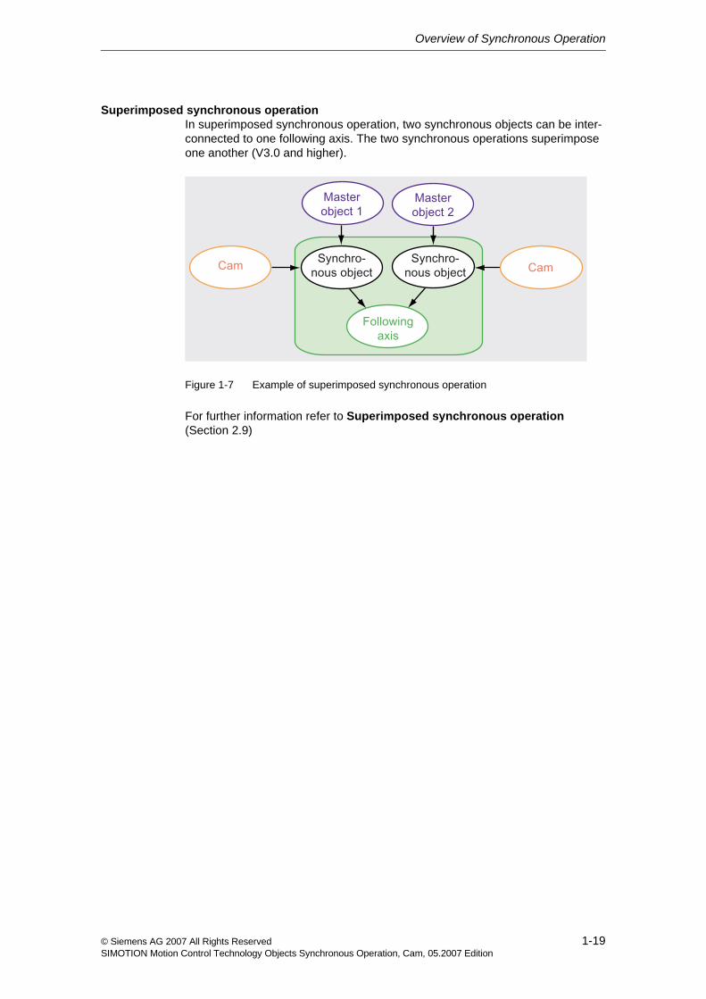
Superimposed synchronous operationIn superimposed synchronous operation, two synchronous objects can be inter-connected to one following axis. The two synchronous operations superimpose one another (V3.0 and higher).
Figure 1-7 Example of superimposed synchronous operation
For further information refer to Superimposed synchronous operation (Section 2.9)
Overview of Synchronous Operation
1-20 © Siemens AG 2007 All Rights ReservedSIMOTION Motion Control Technology Objects Synchronous Operation, Cam, 05.2007 Edition
2-21© Siemens AG 2007 All Rights ReservedSIMOTION Motion Control Technology Objects Synchronous Operation, Cam, 05.2007 Edition
Fundamentals of Synchronous Operation 2This chapter describes the functionality of the synchronous operation technology.
Content
2.1 Gearing 2-22
2.2 Synchronous velocity operation 2-27
2.3 Camming 2-28
2.4 Setpoint / actual value coupling 2-38
2.5 Synchronizing 2-42
2.6 Desynchronization 2-66
2.7 Dynamic response effect on slave values 2-70
2.8 Switching of the master value source 2-72
2.9 Superimposed synchronous operation 2-75
2.10 Synchronous operation monitoring 2-79
2.11 Simulation mode 2-82
2.12 Examples of synchroniszation operations as a function of the output position on the slave value side 2-78
2.13 Examples 2-89
2.14 Special actions 2-107
Fundamentals of Synchronous Operation
2-22 © Siemens AG 2007 All Rights ReservedSIMOTION Motion Control Technology Objects Synchronous Operation, Cam, 05.2007 Edition
2.1 Gearing
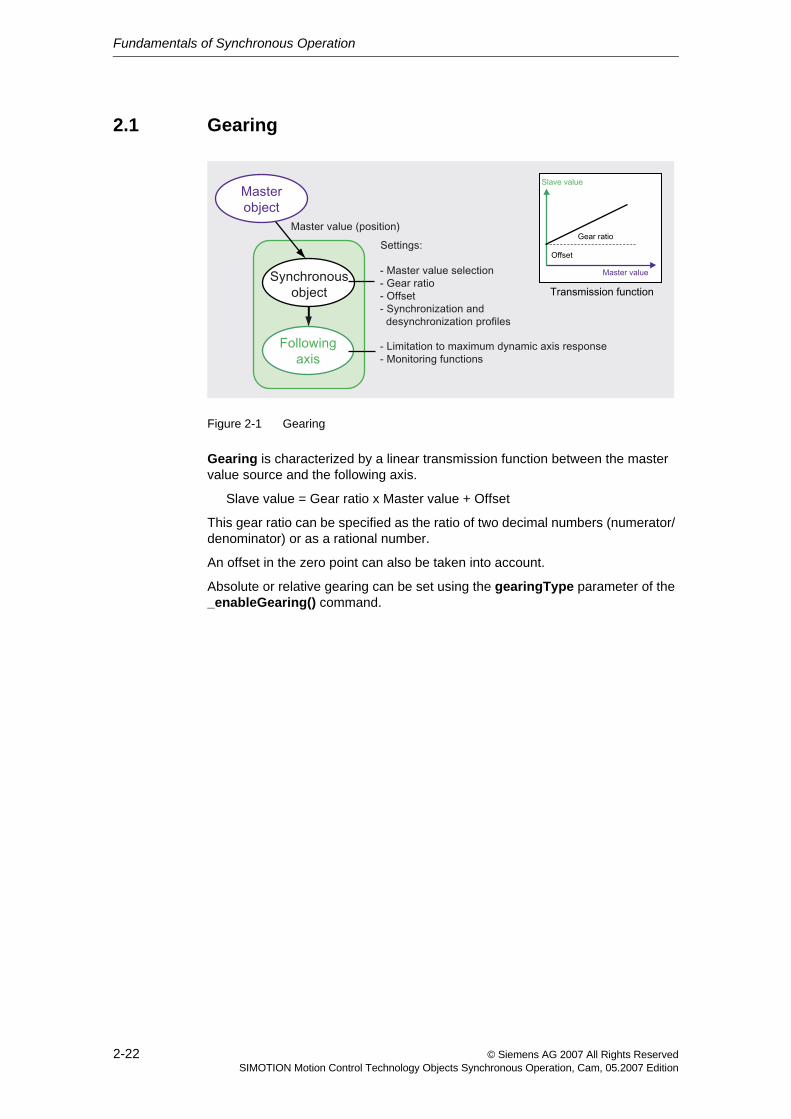
Figure 2-1 Gearing
Gearing is characterized by a linear transmission function between the master value source and the following axis.
Slave value = Gear ratio x Master value + Offset
This gear ratio can be specified as the ratio of two decimal numbers (numerator/ denominator) or as a rational number.
An offset in the zero point can also be taken into account.
Absolute or relative gearing can be set using the gearingType parameter of the _enableGearing() command.
Fundamentals of Synchronous Operation
2-23© Siemens AG 2007 All Rights ReservedSIMOTION Motion Control Technology Objects Synchronous Operation, Cam, 05.2007 Edition
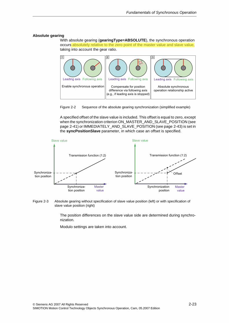
Absolute gearingWith absolute gearing (gearingType=ABSOLUTE), the synchronous operation occurs absolutely relative to the zero point of the master value and slave value, taking into account the gear ratio.
Figure 2-2 Sequence of the absolute gearing synchronization (simplified example)
A specified offset of the slave value is included. This offset is equal to zero, except when the synchronization criterion ON_MASTER_AND_SLAVE_POSITION (see page 2-41) or IMMEDIATELY_AND_SLAVE_POSITION (see page 2-43) is set in the syncPositionSlave parameter, in which case an offset is specified.
Figure 2-3 Absolute gearing without specification of slave value position (left) or with specification of slave value position (right)
The position differences on the slave value side are determined during synchro-nization.
Modulo settings are taken into account.
CN1LH0N2
Highlight
Fundamentals of Synchronous Operation
2-24 © Siemens AG 2007 All Rights ReservedSIMOTION Motion Control Technology Objects Synchronous Operation, Cam, 05.2007 Edition
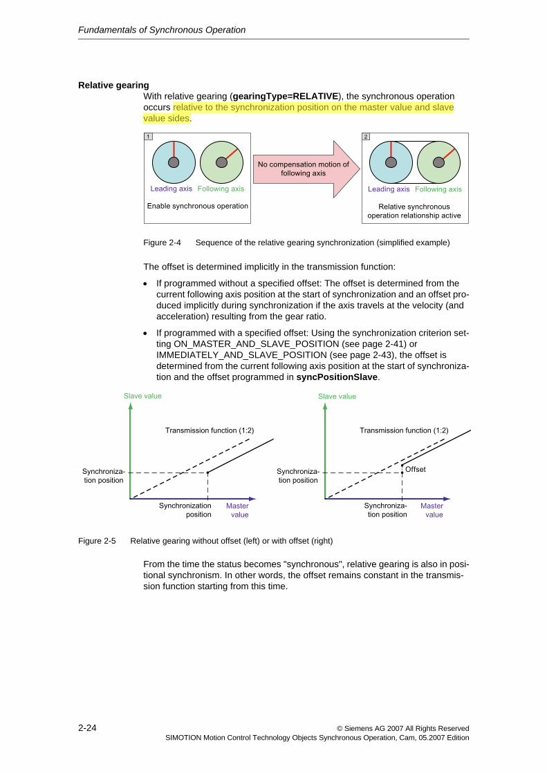
Relative gearingWith relative gearing (gearingType=RELATIVE), the synchronous operation occurs relative to the synchronization position on the master value and slave value sides.
Figure 2-4 Sequence of the relative gearing synchronization (simplified example)
The offset is determined implicitly in the transmission function:
• If programmed without a specified offset: The offset is determined from the current following axis position at the start of synchronization and an offset pro-duced implicitly during synchronization if the axis travels at the velocity (and acceleration) resulting from the gear ratio.
• If programmed with a specified offset: Using the synchronization criterion set-ting ON_MASTER_AND_SLAVE_POSITION (see page 2-41) or IMMEDIATELY_AND_SLAVE_POSITION (see page 2-43), the offset is determined from the current following axis position at the start of synchroniza-tion and the offset programmed in syncPositionSlave.
Figure 2-5 Relative gearing without offset (left) or with offset (right)
From the time the status becomes "synchronous", relative gearing is also in posi-tional synchronism. In other words, the offset remains constant in the transmis-sion function starting from this time.
CN1LH0N2
Highlight
Fundamentals of Synchronous Operation
2-25© Siemens AG 2007 All Rights ReservedSIMOTION Motion Control Technology Objects Synchronous Operation, Cam, 05.2007 Edition
Gear ratioThe gear ratio is used to define the transmission function of the gearing between the master value and slave value.
The gear ratio corresponds to the slope of the transmission function.
It can entered in the gearingMode parameter of the _enableGearing() command as a fraction or a floating point number.
• As fraction (gearingMode=GEARING_WITH_FRACTION)
The gear ratio is specified as a fraction (slave value difference / master value difference) using the following function parameters:
− gearingRatioType: Type of gear ratio specification (directly or via replace-ment values)
− gearingNumerator: Value for direct specification of the gear ratio numer-ator
− gearingDenominator: Value for direct specification of the gear ratio denominator
• As floating-point number (gearingMode=GEARING_WITH_FRACTION)
The gear ratio is specified as a floating-point number using the following func-tion parameters:
− gearingRatioType: Type of gear ratio specification (directly or via replace-ment values)
− gearingRatio: Value for direct specification of the floating-point gear ratio number
Disadvantage: Gear ratios such as 1/3 ≈ 0.333 are subject to rounding errors!
The long-term effect is to be taken into account with modulo axes.
If master and slave axes are configured as modulo axes, to ensure the long-term stability of the gear, the gear ratio is preferably to be entered as a nomina-tor/denominator ratio. If this is not possible, a LREAL value with corresponding decimal places should be used.
Direction of gearingThe gear ratio can be set in the same direction or in the opposite direction (corre-sponding to a negative gear ratio) using the direction parameter of the _enableGearing() command.
• For POSITIVE, traversal is made in the same direction as the master values, this means that the axes run in the same direction.
• For NEGATIVE, traversal is made in the opposite to master values, this means that the axes run in the opposite direction.
CN1LH0N2
Underline
Fundamentals of Synchronous Operation
2-26 © Siemens AG 2007 All Rights ReservedSIMOTION Motion Control Technology Objects Synchronous Operation, Cam, 05.2007 Edition
• With CURRENT, the direction of the current slave value is maintained; this, along with the direction of the master value, results in a positive or negative coupling, which is then maintained for the entire command execution time (that is, if the master value direction changes, then the slave direction changes, as well).
• REVERSE means movement in the inverse direction of the slave values.
If the slave values are at a standstill at the time the command is enabled, the fol-lowing conversion is performed: CURRENT becomes POSITIVE and REVERSE becomes NEGATIVE.
Change in the offsetThe activationMode parameter of the _setGearingOffset() command specifies when the offset takes effect. (V3.1 and higher)
The changeover applies as follows:
• For the next synchronous operation and all subsequent synchronous opera-tions if DEFAULT_VALUE is set
• For the current synchronous operation only if ACTUAL_VALUE is set
• For the current synchronous operation and all subsequent synchronous oper-ations if ACTUAL_AND_DEFAULT_VALUE is set
Note the following:
• If the synchronization operation of the _enableGearing() command is not yet active, the specified offset is carried out without compensation, that is, it is included directly.
• If the _setGearingOffset() command is programmed to current values during synchronization, the offset does not take effect until after synchronization. A compensation movement takes place.
Apply offset as superimpositionThe dynamicReference parameter of the _setGearingOffset() command can be used to specify whether the dynamic response parameters refer to the total motion or the motion difference (V3.2 and higher).
• TOTAL_MOVE: Dynamic response parameters refer to the total motion. (Default)
The transition process is determined completely using the offset values and the dynamic response parameters.
• OFFSET_MOVE: Dynamic response parameters refer to the motion differ-ence.
The transition process is determined based on the current synchronous oper-ation definition as superimposed motion with the specified dynamic response values.
Note: When master value velocity is constant, the dynamic transitions have a sim-ilar form and differ as a result of the dynamic response parameters that act differ-ently.
See Example of applying offset as superimposition (Section 2.13.3)
CN1LH0N2
Underline
Fundamentals of Synchronous Operation
2-27© Siemens AG 2007 All Rights ReservedSIMOTION Motion Control Technology Objects Synchronous Operation, Cam, 05.2007 Edition
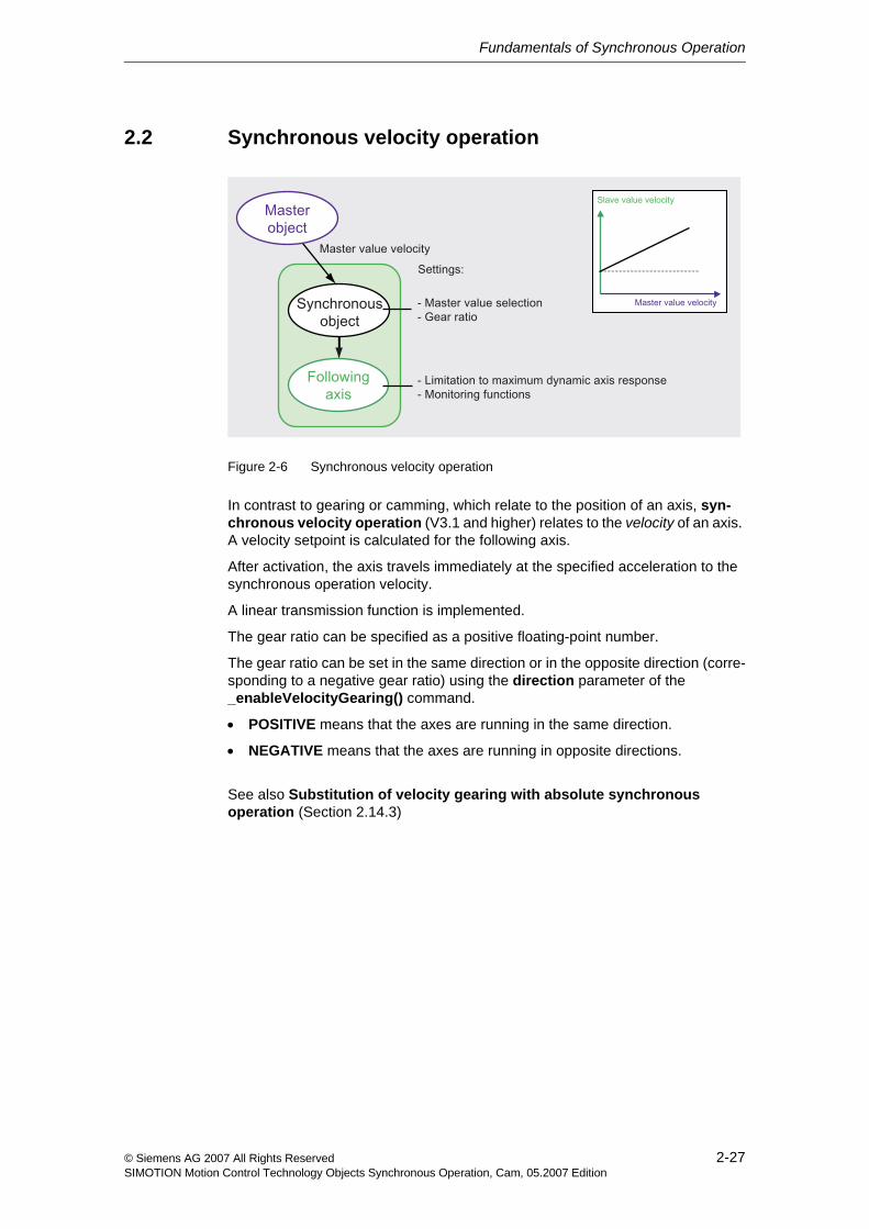
2.2 Synchronous velocity operation
Figure 2-6 Synchronous velocity operation
In contrast to gearing or camming, which relate to the position of an axis, syn-chronous velocity operation (V3.1 and higher) relates to the velocity of an axis. A velocity setpoint is calculated for the following axis.
After activation, the axis travels immediately at the specified acceleration to the synchronous operation velocity.
A linear transmission function is implemented.
The gear ratio can be specified as a positive floating-point number.
The gear ratio can be set in the same direction or in the opposite direction (corre-sponding to a negative gear ratio) using the direction parameter of the _enableVelocityGearing() command.
• POSITIVE means that the axes are running in the same direction.
• NEGATIVE means that the axes are running in opposite directions.
See also Substitution of velocity gearing with absolute synchronous operation (Section 2.14.3)
Fundamentals of Synchronous Operation
2-28 © Siemens AG 2007 All Rights ReservedSIMOTION Motion Control Technology Objects Synchronous Operation, Cam, 05.2007 Edition
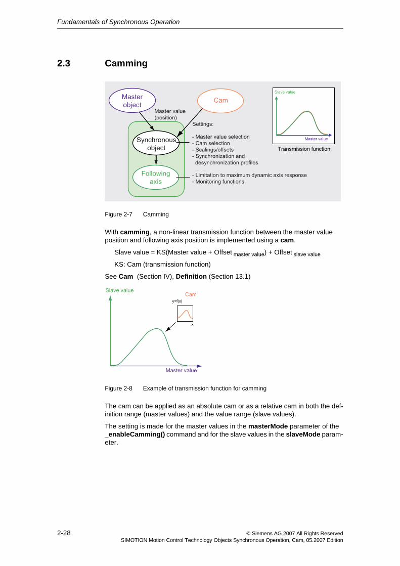
2.3 Camming
Figure 2-7 Camming
With camming, a non-linear transmission function between the master value position and following axis position is implemented using a cam.
Slave value = KS(Master value + Offset master value) + Offset slave value
KS: Cam (transmission function)
See Cam (Section IV), Definition (Section 13.1)
Figure 2-8 Example of transmission function for camming
The cam can be applied as an absolute cam or as a relative cam in both the def-inition range (master values) and the value range (slave values).
The setting is made for the master values in the masterMode parameter of the _enableCamming() command and for the slave values in the slaveMode param-eter.
CN1LH0N2
Underline
Fundamentals of Synchronous Operation
2-29© Siemens AG 2007 All Rights ReservedSIMOTION Motion Control Technology Objects Synchronous Operation, Cam, 05.2007 Edition
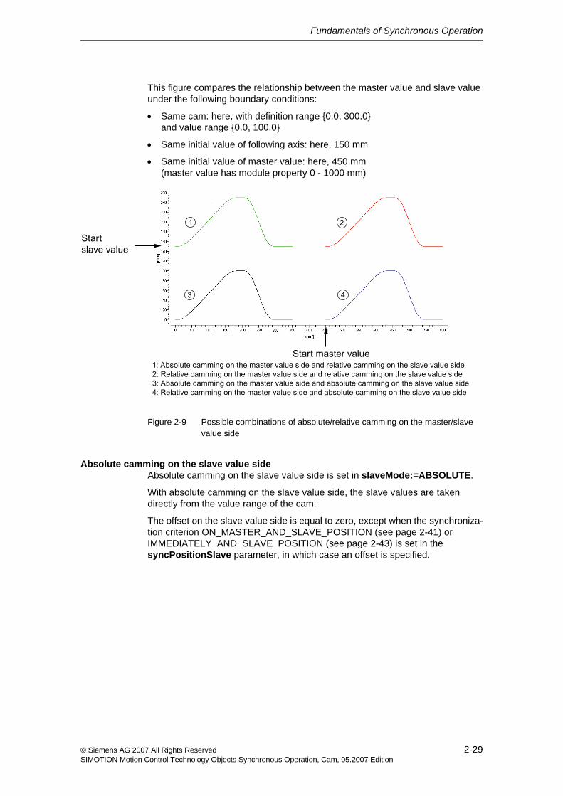
This figure compares the relationship between the master value and slave value under the following boundary conditions:
• Same cam: here, with definition range {0.0, 300.0} and value range {0.0, 100.0}
• Same initial value of following axis: here, 150 mm
• Same initial value of master value: here, 450 mm (master value has module property 0 - 1000 mm)
Figure 2-9 Possible combinations of absolute/relative camming on the master/slave value side
Absolute camming on the slave value sideAbsolute camming on the slave value side is set in slaveMode:=ABSOLUTE.
With absolute camming on the slave value side, the slave values are taken directly from the value range of the cam.
The offset on the slave value side is equal to zero, except when the synchroniza-tion criterion ON_MASTER_AND_SLAVE_POSITION (see page 2-41) or IMMEDIATELY_AND_SLAVE_POSITION (see page 2-43) is set in the syncPositionSlave parameter, in which case an offset is specified.
Fundamentals of Synchronous Operation
2-30 © Siemens AG 2007 All Rights ReservedSIMOTION Motion Control Technology Objects Synchronous Operation, Cam, 05.2007 Edition
Relative camming on the slave value sideRelative camming on the slave value side is set in slaveMode:=RELATIVE.
With relative camming on the slave value side, the initial value of the cam is offset to the slave value position at the start of synchronization.
The offset on the slave value side is determined as follows:
• If programmed without a specified offset, the offset is determined from the off-set of the cam initial value to the slave value position at the start of synchroni-zation
• If programmed with a specified offset in the synchronization criterion setting ON_MASTER_AND_SLAVE_POSITION (see page 2-41) or IMMEDIATELY_AND_SLAVE_POSITION (see page 2-43), the offset is determined from the offset of the cam initial value to the slave value position at the start of synchronization plus the offset programmed in the syncPosi-tionSlave parameter.
From the time the status becomes "synchronous", the offset on the slave value side remains constant in the transmission function.
Absolute camming on the master value sideAbsolute camming on the master value side is set in masterMode:=ABSOLUTE.
With absolute camming on the master value side, the master values are assigned directly to the definition range of the cam.
The synchronization position on the master value side can be the starting point of the cam or any other point in the definition range of the cam.
The offset on the master value side is equal to zero.
The camStartPositionMaster parameter is not evaluated.
Relative camming on the master value sideRelative camming on the master value side is set in masterMode:=RELATIVE.
With relative camming on the master value side, the synchronization position on the master value side is assigned to the position within the cam definition range specified in the camStartPositionMaster parameter.
The offset on the master value side is determined from the difference of the syn-chronization position on the master value side and the value specified in the camStartPositionMaster parameter.
If the position specified in camStartPositionMaster is not within the definition range of the cam, alarm "40017 Cam starting point is outside the definition range" is generated.
From the time the status becomes "synchronous", the offset on the master value side remains constant in the transmission function.
Fundamentals of Synchronous Operation
2-31© Siemens AG 2007 All Rights ReservedSIMOTION Motion Control Technology Objects Synchronous Operation, Cam, 05.2007 Edition
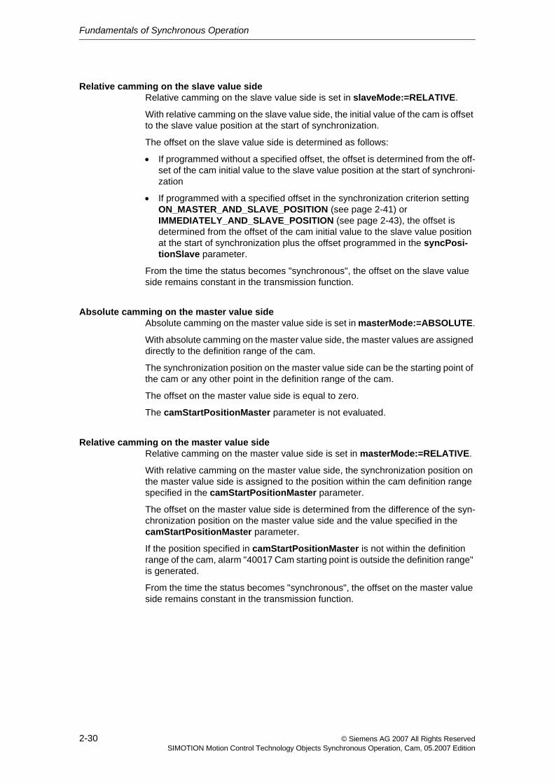
Non-cyclic/cyclic cam applicationThe cammingMode parameter of the _enableCamming() command can be used to set the cam for either a non-cyclic application or a cyclic application.
Figure 2-10 Non-cyclic cam application
• Non-cyclic (NOCYCLIC) means that the cam is applied exactly once in the defined master value range. When the end point or starting point of the cam is reached, the cam terminates itself.
If the master value range is run through again in the same direction or it is run through after a reversal in the opposite direction, the cam is not applied again.
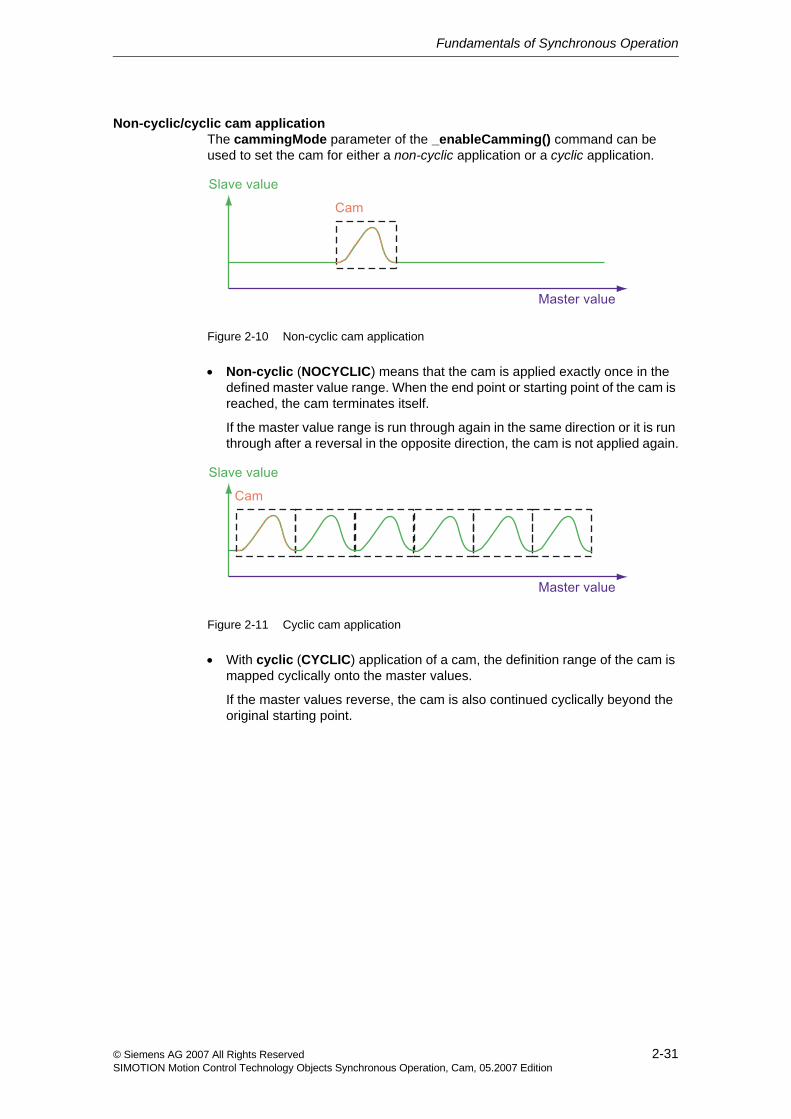
Figure 2-11 Cyclic cam application
• With cyclic (CYCLIC) application of a cam, the definition range of the cam is mapped cyclically onto the master values.
If the master values reverse, the cam is also continued cyclically beyond the original starting point.
Fundamentals of Synchronous Operation
2-32 © Siemens AG 2007 All Rights ReservedSIMOTION Motion Control Technology Objects Synchronous Operation, Cam, 05.2007 Edition
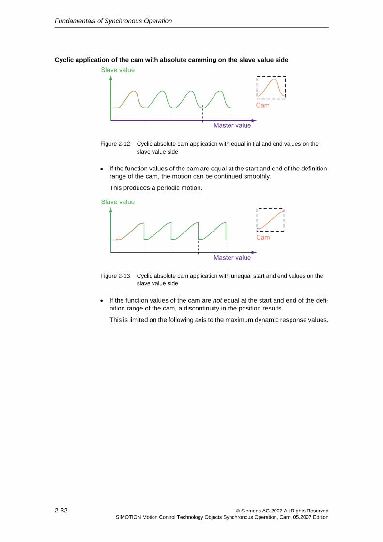
Cyclic application of the cam with absolute camming on the slave value side
Figure 2-12 Cyclic absolute cam application with equal initial and end values on the slave value side
• If the function values of the cam are equal at the start and end of the definition range of the cam, the motion can be continued smoothly.
This produces a periodic motion.
Figure 2-13 Cyclic absolute cam application with unequal start and end values on the slave value side
• If the function values of the cam are not equal at the start and end of the defi-nition range of the cam, a discontinuity in the position results.
This is limited on the following axis to the maximum dynamic response values.
Fundamentals of Synchronous Operation
2-33© Siemens AG 2007 All Rights ReservedSIMOTION Motion Control Technology Objects Synchronous Operation, Cam, 05.2007 Edition
Cyclic application of a cam with relative camming on the slave value side
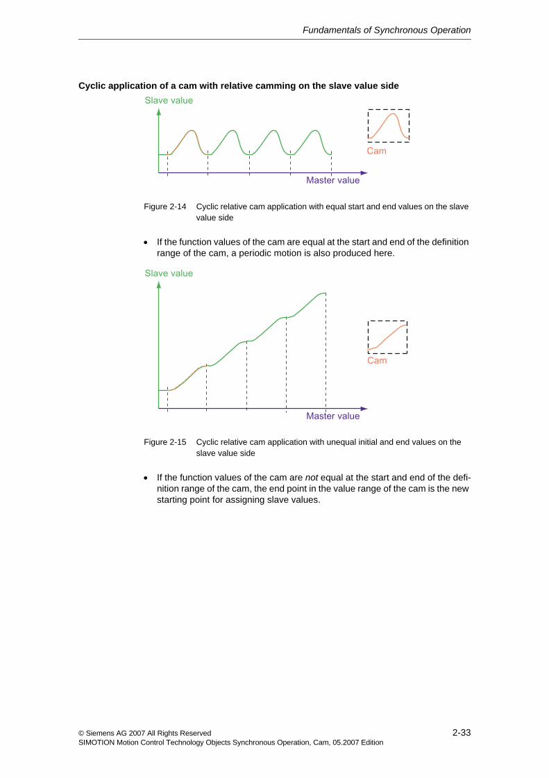
Figure 2-14 Cyclic relative cam application with equal start and end values on the slave value side
• If the function values of the cam are equal at the start and end of the definition range of the cam, a periodic motion is also produced here.
Figure 2-15 Cyclic relative cam application with unequal initial and end values on the slave value side
• If the function values of the cam are not equal at the start and end of the defi-nition range of the cam, the end point in the value range of the cam is the new starting point for assigning slave values.
Fundamentals of Synchronous Operation
2-34 © Siemens AG 2007 All Rights ReservedSIMOTION Motion Control Technology Objects Synchronous Operation, Cam, 05.2007 Edition
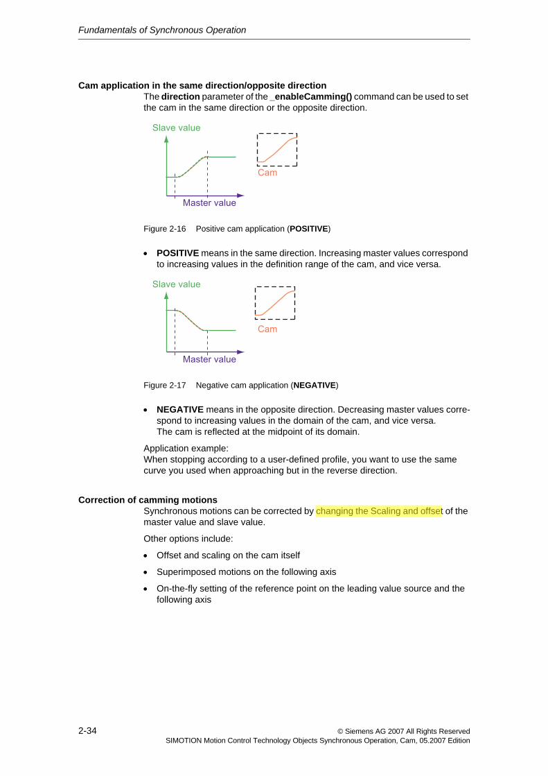
Cam application in the same direction/opposite direction The direction parameter of the _enableCamming() command can be used to set the cam in the same direction or the opposite direction.
Figure 2-16 Positive cam application (POSITIVE)
• POSITIVE means in the same direction. Increasing master values correspond to increasing values in the definition range of the cam, and vice versa.
Figure 2-17 Negative cam application (NEGATIVE)
• NEGATIVE means in the opposite direction. Decreasing master values corre-spond to increasing values in the domain of the cam, and vice versa.The cam is reflected at the midpoint of its domain.
Application example:When stopping according to a user-defined profile, you want to use the same curve you used when approaching but in the reverse direction.
Correction of camming motionsSynchronous motions can be corrected by changing the Scaling and offset of the master value and slave value.
Other options include:
• Offset and scaling on the cam itself
• Superimposed motions on the following axis
• On-the-fly setting of the reference point on the leading value source and the following axis
CN1LH0N2
Underline
CN1LH0N2
Underline
CN1LH0N2
Underline
CN1LH0N2
Highlight
Fundamentals of Synchronous Operation
2-35© Siemens AG 2007 All Rights ReservedSIMOTION Motion Control Technology Objects Synchronous Operation, Cam, 05.2007 Edition
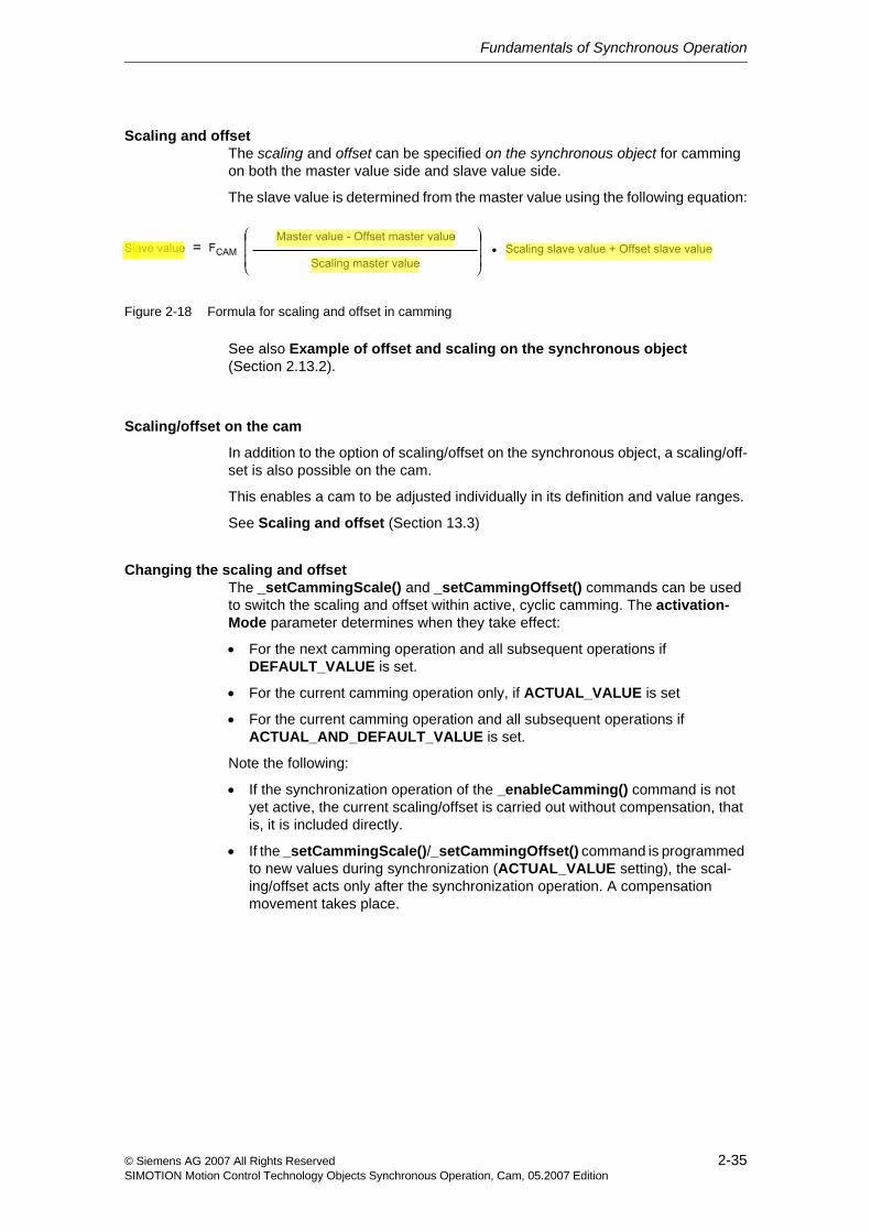
Scaling and offsetThe scaling and offset can be specified on the synchronous object for camming on both the master value side and slave value side.
The slave value is determined from the master value using the following equation:
Figure 2-18 Formula for scaling and offset in camming
See also Example of offset and scaling on the synchronous object (Section 2.13.2).
Scaling/offset on the cam
In addition to the option of scaling/offset on the synchronous object, a scaling/off-set is also possible on the cam.
This enables a cam to be adjusted individually in its definition and value ranges.
See Scaling and offset (Section 13.3)
Changing the scaling and offsetThe _setCammingScale() and _setCammingOffset() commands can be used to switch the scaling and offset within active, cyclic camming. The activation-Mode parameter determines when they take effect:
• For the next camming operation and all subsequent operations if DEFAULT_VALUE is set.
• For the current camming operation only, if ACTUAL_VALUE is set
• For the current camming operation and all subsequent operations if ACTUAL_AND_DEFAULT_VALUE is set.
Note the following:
• If the synchronization operation of the _enableCamming() command is not yet active, the current scaling/offset is carried out without compensation, that is, it is included directly.
• If the _setCammingScale()/_setCammingOffset() command is programmed to new values during synchronization (ACTUAL_VALUE setting), the scal-ing/offset acts only after the synchronization operation. A compensation movement takes place.
CN1LH0N2
Highlight
CN1LH0N2
Highlight
CN1LH0N2
Highlight
Fundamentals of Synchronous Operation
2-36 © Siemens AG 2007 All Rights ReservedSIMOTION Motion Control Technology Objects Synchronous Operation, Cam, 05.2007 Edition
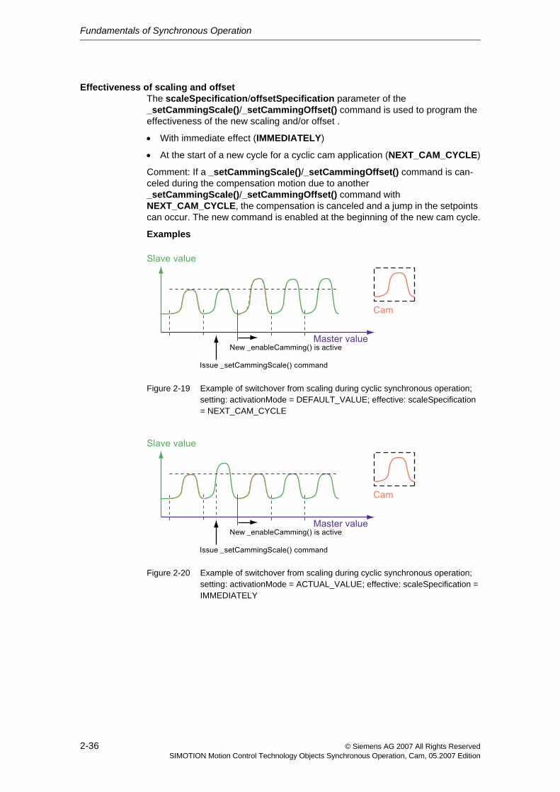
Effectiveness of scaling and offsetThe scaleSpecification/offsetSpecification parameter of the _setCammingScale()/_setCammingOffset() command is used to program the effectiveness of the new scaling and/or offset .
• With immediate effect (IMMEDIATELY)
• At the start of a new cycle for a cyclic cam application (NEXT_CAM_CYCLE)
Comment: If a _setCammingScale()/_setCammingOffset() command is can-celed during the compensation motion due to another _setCammingScale()/_setCammingOffset() command with NEXT_CAM_CYCLE, the compensation is canceled and a jump in the setpoints can occur. The new command is enabled at the beginning of the new cam cycle.
Examples
Figure 2-19 Example of switchover from scaling during cyclic synchronous operation; setting: activationMode = DEFAULT_VALUE; effective: scaleSpecification = NEXT_CAM_CYCLE
Figure 2-20 Example of switchover from scaling during cyclic synchronous operation; setting: activationMode = ACTUAL_VALUE; effective: scaleSpecification = IMMEDIATELY
Fundamentals of Synchronous Operation
2-37© Siemens AG 2007 All Rights ReservedSIMOTION Motion Control Technology Objects Synchronous Operation, Cam, 05.2007 Edition
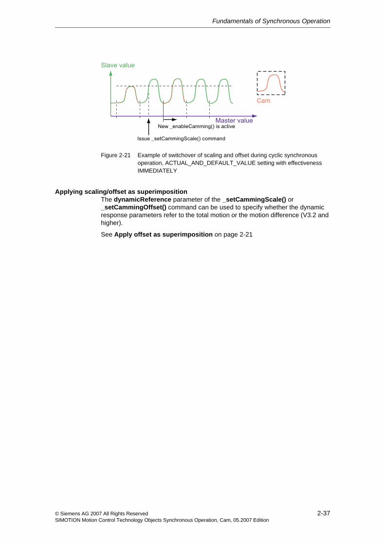
Figure 2-21 Example of switchover of scaling and offset during cyclic synchronous operation, ACTUAL_AND_DEFAULT_VALUE setting with effectiveness IMMEDIATELY
Applying scaling/offset as superimpositionThe dynamicReference parameter of the _setCammingScale() or _setCammingOffset() command can be used to specify whether the dynamic response parameters refer to the total motion or the motion difference (V3.2 and higher).
See Apply offset as superimposition on page 2-21
Fundamentals of Synchronous Operation
2-38 © Siemens AG 2007 All Rights ReservedSIMOTION Motion Control Technology Objects Synchronous Operation, Cam, 05.2007 Edition
2.4 Setpoint / actual value coupling
Overview
When an axis is used as a master value object, the following can be configured for the synchronous operation:
• Setpoint coupling: The setpoint of the axis is used as the master value for the following axis.
This is advantageous if the setpoint is specified by the control for both the leading axis and the following axis and the axes are to behave synchronously to each other.
In general, setpoint coupling is recommended for purposes of signal quality.
• Actual value coupling with extrapolation (V3.0 and higher): The actual value of an axis is used as the master value for the following axis.
It is possible to extrapolate the actual value in order to compensate for delay times associated with actual value measurement, actual value and master value processing in the control, and dynamic follow-up response of the follow-ing axis. Because the actual values are equal to the setpoints for the virtual axis, an extrapolated setpoint can be set.
When an external encoder is used as a master value object, the following can be configured for the synchronous operation:
• Actual value coupling: The actual value of an external encoder is used as the master value for the following axis.
• Actual value coupling with extrapolation (V3.0 and higher): It is possible to extrapolate the actual value in order to compensate for delay times associated with actual value measurement, actual value and master value processing in the control, and dynamic follow-up response of the following axis.
A tolerance window with respect to the actual value behavior can be specified for the actual value coupling (See Section 2.4.2).
CN1LH0N2
Underline
CN1LH0N2
Highlight
Fundamentals of Synchronous Operation
2-39© Siemens AG 2007 All Rights ReservedSIMOTION Motion Control Technology Objects Synchronous Operation, Cam, 05.2007 Edition
2.4.1 Actual value coupling with extrapolation
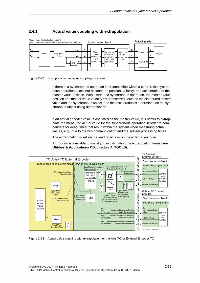
Figure 2-22 Principle of actual value coupling (overview)
If there is a synchronous operation interconnection within a control, the synchro-nous operation takes into account the position, velocity, and acceleration of the master value position. With distributed synchronous operation, the master value position and master value velocity are transferred between the distributed master value and the synchronous object, and the acceleration is determined on the syn-chronous object using differentiation.
If an actual encoder value is assumed as the master value, it is useful to extrap-olate the measured actual value for the synchronous operation in order to com-pensate for dead times that result within the system when measuring actual values, e.g., due to the bus communication and the system processing times.
The extrapolation is set on the leading axis or on the external encoder.
A program is available to assist you in calculating the extrapolation times (see Utilities & Applications CD, directory 4_TOOLS).
Figure 2-23 Actual value coupling with extrapolation for the Axis TO or External Encoder TO
Fundamentals of Synchronous Operation
2-40 © Siemens AG 2007 All Rights ReservedSIMOTION Motion Control Technology Objects Synchronous Operation, Cam, 05.2007 Edition
Filtering of actual positionThe actual position value for the synchronous operation can be filtered separately for the extrapolation using a PT2 filter. (V4.1 and higher)
The filter for the actual position value of the axis is set using the typeOfAxis.extrapolation.positionFilter.T1 and typeOfAxis.extrapolation.positionFilter.T2 configuration data.
The filter acts on the actual position for the extrapolation.
The velocity for the extrapolation is taken over from the actual values of the axis or External Encoder before application of the smoothing filter (typeOfAxis.smoothingFilter).
Filtering of actual velocityThe position is extrapolated based on the filtered or averaged velocity value.
• TypeofAxis.Extrapolation.filter.timeConstant: Time used for averaging or time constant for filtering
• TypeofAxis.Extrapolation.extrapolationTime: Time specification for extrapolation
Extrapolation is not performed if 0.0 is specified.
The extrapolated values (position and velocity) can be monitored (extrapolation-Data system variable).
The extrapolation compensates for the local delays that result from use of the actual value instead of the setpoint.
Switch for the velocity master value during master value extrapolationThe TypeofAxis.Extrapolation.extrapolatedVelocitySwitch configuration data element can be used to generate the velocity master value from the extrapolated position master value through differentiation or, alternatively, the extrapolated velocity master value for the synchronous operation can be used.
DisplayThe extrapolated and filtered values are indicated in the following system variables:
• extrapolationData.position
• extrapolationData.velocity
• extrapolationData.filteredPosition
• extrapolationData.filteredVelocity
• extrapolationData.acceleration
Fundamentals of Synchronous Operation
2-41© Siemens AG 2007 All Rights ReservedSIMOTION Motion Control Technology Objects Synchronous Operation, Cam, 05.2007 Edition
Reduction in reaction times/dead timesThe Execution.executionLevel:=SERVO setting on the master value object, e.g., External Encoder TO, can be configured in the Synchronous Object TO and Following Axis TO to enable execution of the IPO system component of the mas-ter value, synchronous operation, and axis in the servo after the actual value mea-surement.
For further information, refer to Motion Control Technology Objects Axis Elec-tric/Hydraulic, External Encoder Function Manual, "Motion Execution/Interpo-lator"
2.4.2 Actual value coupling with tolerance window
If the master value is superimposed with high-frequency noise signals that cannot be followed by the synchronous operation, this can cause the dynamic limits to be exceeded or the master value to briefly change directions during synchronization.
In the typeOfAxis.extrapolation.toleranceRange configuration data on the leading axis or external encoder, a tolerance window can be set around the actual position (V3.1 and higher), for example to prevent the dynamic limits from being exceeded on the following axis in the case of a master value with high-frequency noise signals or to prevent direction changes during synchronization.
Fundamentals of Synchronous Operation
2-42 © Siemens AG 2007 All Rights ReservedSIMOTION Motion Control Technology Objects Synchronous Operation, Cam, 05.2007 Edition
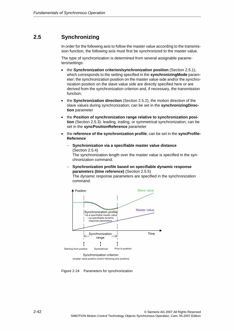
2.5 SynchronizingIn order for the following axis to follow the master value according to the transmis-sion function, the following axis must first be synchronized to the master value.
The type of synchronization is determined from several assignable parame-ters/settings:
• the Synchronization criterion/synchronization position (Section 2.5.1), which corresponds to the setting specified in the synchronizingMode param-eter; the synchronization position on the master value side and/or the synchro-nization position on the slave value side are directly specified here or are derived from the synchronization criterion and, if necessary, the transmission function;
• the Synchronization direction (Section 2.5.2), the motion direction of the slave values during synchronization; can be set in the synchronizingDirec-tion parameter
• the Position of synchronization range relative to synchronization posi-tion (Section 2.5.3): leading, trailing, or symmetrical synchronization; can be set in the syncPositionReference parameter
• the reference of the synchronization profile; can be set in the syncProfile-Reference
− Synchronization via a specifiable master value distance (Section 2.5.4)The synchronization length over the master value is specified in the syn-chronization command.
− Synchronization profile based on specifiable dynamic response parameters (time reference) (Section 2.5.5)The dynamic response parameters are specified in the synchronization command.
Figure 2-24 Parameters for synchronization
Fundamentals of Synchronous Operation
2-43© Siemens AG 2007 All Rights ReservedSIMOTION Motion Control Technology Objects Synchronous Operation, Cam, 05.2007 Edition
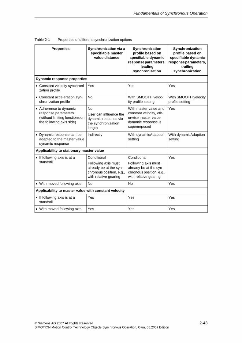
Table 2-1 Properties of different synchronization options
Properties Synchronization via a specifiable master
value distance
Synchronization profile based on
specifiable dynamic response parameters,
leading synchronization
Synchronization profile based on
specifiable dynamic response parameters,
trailing synchronization
Dynamic response properties
• Constant velocity synchroni-zation profile
Yes Yes Yes
• Constant acceleration syn-chronization profile
No With SMOOTH veloc-ity profile setting
With SMOOTH velocity profile setting
• Adherence to dynamic response parameters (without limiting functions on the following axis side)
NoUser can influence the dynamic response via the synchronization length
With master value and constant velocity, oth-erwise master value dynamic response is superimposed
Yes
• Dynamic response can be adapted to the master value dynamic response
Indirectly With dynamicAdaption setting
With dynamicAdaption setting
Applicability to stationary master value
• If following axis is at a standstill
ConditionalFollowing axis must already be at the syn-chronous position, e.g., with relative gearing
ConditionalFollowing axis must already be at the syn-chronous position, e.g., with relative gearing
Yes
• With moved following axis No No Yes
Applicability to master value with constant velocity
• If following axis is at a standstill
Yes Yes Yes
• With moved following axis Yes Yes Yes
Fundamentals of Synchronous Operation
2-44 © Siemens AG 2007 All Rights ReservedSIMOTION Motion Control Technology Objects Synchronous Operation, Cam, 05.2007 Edition
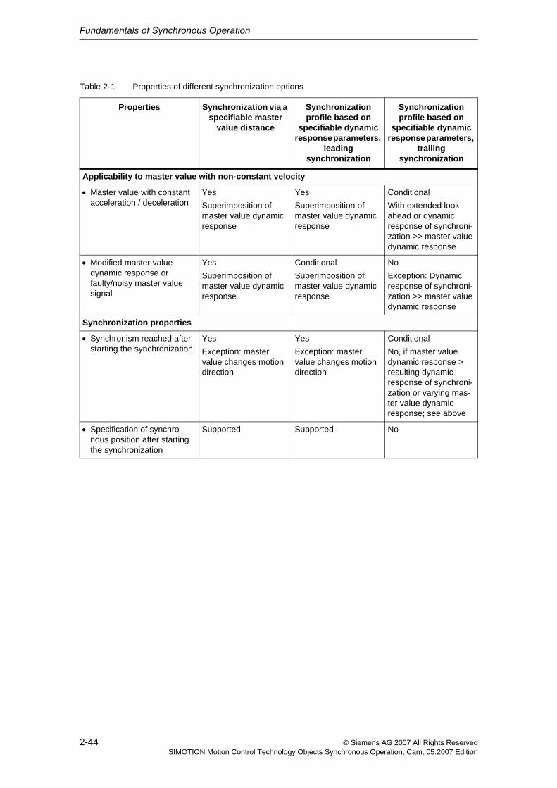
Applicability to master value with non-constant velocity
• Master value with constant acceleration / deceleration
YesSuperimposition of master value dynamic response
YesSuperimposition of master value dynamic response
ConditionalWith extended look-ahead or dynamic response of synchroni-zation >> master value dynamic response
• Modified master value dynamic response or faulty/noisy master value signal
YesSuperimposition of master value dynamic response
ConditionalSuperimposition of master value dynamic response
NoException: Dynamic response of synchroni-zation >> master value dynamic response
Synchronization properties
• Synchronism reached after starting the synchronization
YesException: master value changes motion direction
YesException: master value changes motion direction
ConditionalNo, if master value dynamic response > resulting dynamic response of synchroni-zation or varying mas-ter value dynamic response; see above
• Specification of synchro-nous position after starting the synchronization
Supported Supported No
Table 2-1 Properties of different synchronization options
Properties Synchronization via a specifiable master
value distance
Synchronization profile based on
specifiable dynamic response parameters,
leading synchronization
Synchronization profile based on
specifiable dynamic response parameters,
trailing synchronization
Fundamentals of Synchronous Operation
2-45© Siemens AG 2007 All Rights ReservedSIMOTION Motion Control Technology Objects Synchronous Operation, Cam, 05.2007 Edition
2.5.1 Synchronization criterion/synchronization position
The synchronization criterion can be set for synchronization using the syn-chronizingMode parameter of the _enableGearing() / _enableCamming() or _disableGearing() / _disableCamming() command as follows.
Synchronization can take place over several modulo ranges of the master value or slave value.
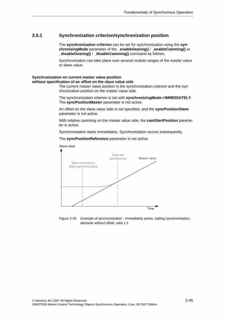
Synchronization on current master value position without specification of an offset on the slave value side
The current master value position is the synchronization criterion and the syn-chronization position on the master value side.
The synchronization criterion is set with synchronizingMode:=IMMEDIATELY. The syncPositionMaster parameter is not active.
An offset on the slave value side is not specified, and the syncPositionSlave parameter is not active.
With relative camming on the master value side, the camStartPosition parame-ter is active.
Synchronization starts immediately. Synchronization occurs subsequently.
The syncPositionReference parameter is not active.
Figure 2-25 Example of synchronization - immediately active, trailing synchronization, absolute without offset, ratio 1:1
Fundamentals of Synchronous Operation
2-46 © Siemens AG 2007 All Rights ReservedSIMOTION Motion Control Technology Objects Synchronous Operation, Cam, 05.2007 Edition
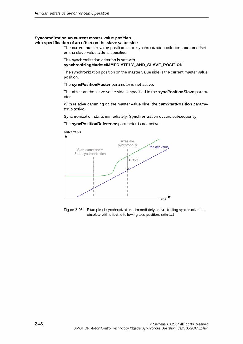
Synchronization on current master value position with specification of an offset on the slave value side
The current master value position is the synchronization criterion, and an offset on the slave value side is specified.
The synchronization criterion is set with synchronizingMode:=IMMEDIATELY_AND_SLAVE_POSITION.
The synchronization position on the master value side is the current master value position.
The syncPositionMaster parameter is not active.
The offset on the slave value side is specified in the syncPositionSlave param-eter
With relative camming on the master value side, the camStartPosition parame-ter is active.
Synchronization starts immediately. Synchronization occurs subsequently.
The syncPositionReference parameter is not active.
Figure 2-26 Example of synchronization - immediately active, trailing synchronization, absolute with offset to following axis position, ratio 1:1
Fundamentals of Synchronous Operation
2-47© Siemens AG 2007 All Rights ReservedSIMOTION Motion Control Technology Objects Synchronous Operation, Cam, 05.2007 Edition
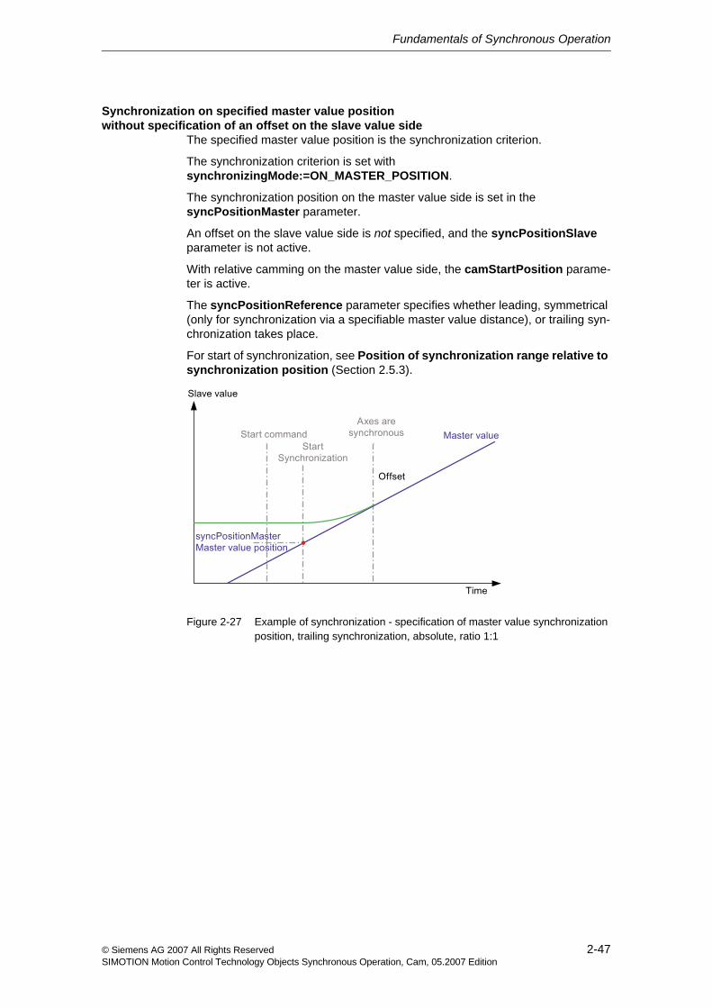
Synchronization on specified master value position without specification of an offset on the slave value side
The specified master value position is the synchronization criterion.
The synchronization criterion is set with synchronizingMode:=ON_MASTER_POSITION.
The synchronization position on the master value side is set in the syncPositionMaster parameter.
An offset on the slave value side is not specified, and the syncPositionSlave parameter is not active.
With relative camming on the master value side, the camStartPosition parame-ter is active.
The syncPositionReference parameter specifies whether leading, symmetrical (only for synchronization via a specifiable master value distance), or trailing syn-chronization takes place.
For start of synchronization, see Position of synchronization range relative to synchronization position (Section 2.5.3).
Figure 2-27 Example of synchronization - specification of master value synchronization position, trailing synchronization, absolute, ratio 1:1
Fundamentals of Synchronous Operation
2-48 © Siemens AG 2007 All Rights ReservedSIMOTION Motion Control Technology Objects Synchronous Operation, Cam, 05.2007 Edition
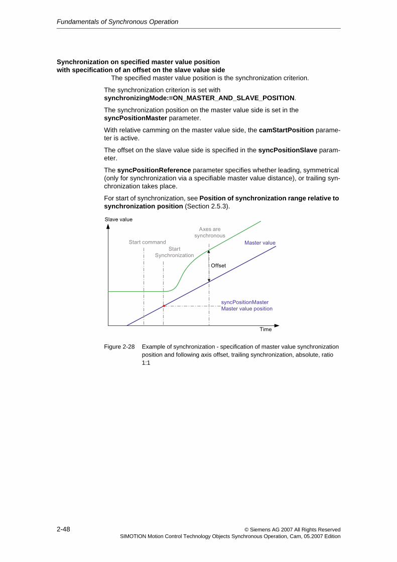
Synchronization on specified master value position with specification of an offset on the slave value side
withThe specified master value position is the synchronization criterion.
The synchronization criterion is set with synchronizingMode:=ON_MASTER_AND_SLAVE_POSITION.
The synchronization position on the master value side is set in the syncPositionMaster parameter.
With relative camming on the master value side, the camStartPosition parame-ter is active.
The offset on the slave value side is specified in the syncPositionSlave param-eter.
The syncPositionReference parameter specifies whether leading, symmetrical (only for synchronization via a specifiable master value distance), or trailing syn-chronization takes place.
For start of synchronization, see Position of synchronization range relative to synchronization position (Section 2.5.3).
Figure 2-28 Example of synchronization - specification of master value synchronization position and following axis offset, trailing synchronization, absolute, ratio 1:1
Fundamentals of Synchronous Operation
2-49© Siemens AG 2007 All Rights ReservedSIMOTION Motion Control Technology Objects Synchronous Operation, Cam, 05.2007 Edition
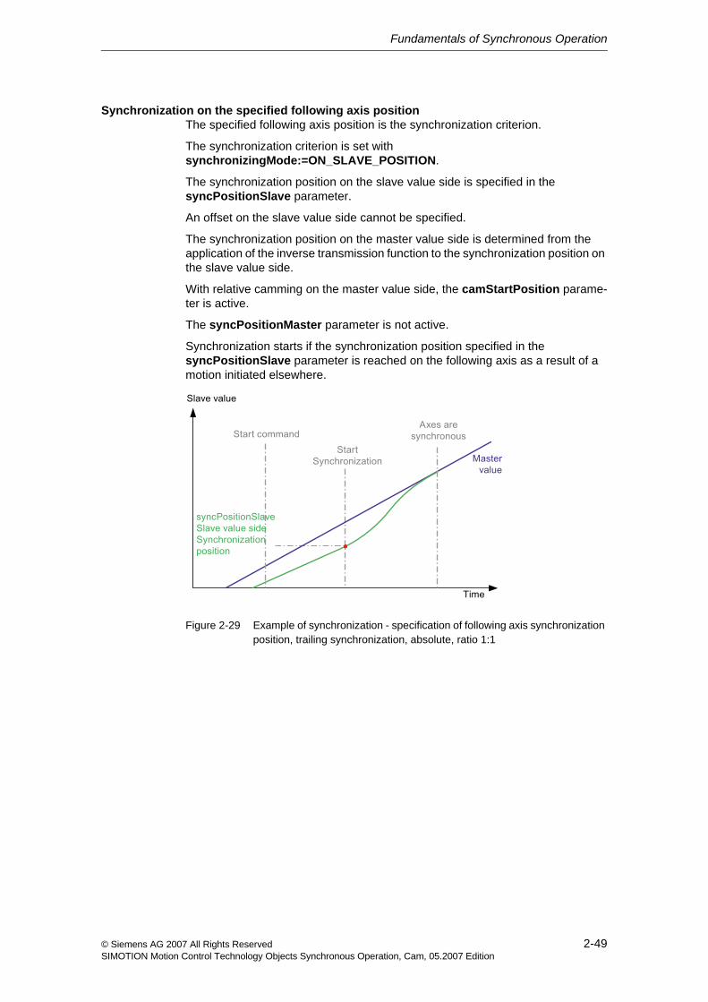
Synchronization on the specified following axis positionThe specified following axis position is the synchronization criterion.
The synchronization criterion is set with synchronizingMode:=ON_SLAVE_POSITION.
The synchronization position on the slave value side is specified in the syncPositionSlave parameter.
An offset on the slave value side cannot be specified.
The synchronization position on the master value side is determined from the application of the inverse transmission function to the synchronization position on the slave value side.
With relative camming on the master value side, the camStartPosition parame-ter is active.
The syncPositionMaster parameter is not active.
Synchronization starts if the synchronization position specified in the syncPositionSlave parameter is reached on the following axis as a result of a motion initiated elsewhere.
Figure 2-29 Example of synchronization - specification of following axis synchronization position, trailing synchronization, absolute, ratio 1:1
Fundamentals of Synchronous Operation
2-50 © Siemens AG 2007 All Rights ReservedSIMOTION Motion Control Technology Objects Synchronous Operation, Cam, 05.2007 Edition
Synchronization at the end of the current camming cycleThe master value position at the end of the current camming cycle is the synchro-nization criterion.
This setting can only be assigned in conjunction with relative camming on the master value side and already active camming.
The synchronization criterion is set with synchronizingMode:=AT_THE_END_OF_CAM_CYCLE.
The synchronization position on the master value side is the master value position at the end of the current camming cycle.
The syncPositionMaster parameter is not active.
With relative camming on the master value side, the camStartPosition parame-ter is active.
An offset on the slave value side cannot be specified, and the syncPositionSlave parameter is not active.
The syncPositionReference parameter specifies whether leading, symmetrical (only for synchronization via a specifiable master value distance), or trailing syn-chronization takes place.
2.5.2 Synchronization direction
The synchronizingDirection parameter of the synchronous operation com-mands can be used to specify the direction of the motion for synchronization.
If a specific synchronization direction is specified, the synchronization motion is in this direction only.
The synchronization direction of the following axis in the synchronization phase can be specified with the synchronizingDirection parameter in the _enableGearing(), _disableGearing(), _enableCamming(), and _disableCamming() commands (V3.1 and higher).
This function is relevant, for example, for axes, for which synchronization is pos-sible in both directions.
For information on axes with backstop, refer to Motion Control Technology Objects Axis Electric/Hydraulic, External Encoder "Manipulated Variable Lim-itation (Backstop)"
Fundamentals of Synchronous Operation
2-51© Siemens AG 2007 All Rights ReservedSIMOTION Motion Control Technology Objects Synchronous Operation, Cam, 05.2007 Edition
Synchronization with direction specification can be set as follows.
• Maintain present system behavior (SYSTEM_DEFINED): This corresponds to the shortest path setting, however the direction of motion is maintained for the axis motion.
• Maintain direction of the following axis (SAME_DIRECTION): The current direction of motion on the following axis is maintained during the synchronization phase.
− The direction of motion of the following axis is maintained during the syn-chronization at master value standstill.
− The synchronization occurs in the positive direction during synchronization at both the master value standstill and the following axis standstill.
• POSITIVE_DIRECTION setting: A positive synchronization direction is defined.
• NEGATIVE_DIRECTION setting: A negative synchronization direction is defined.
• SHORTEST_WAY setting: Synchronize to the shortest way, regardless of which direction of motion results in the synchronization phase.
With this setting, however, the possibility exists that a direction reversal can occur during the synchronization operation.
2.5.3 Position of synchronization range relative to synchronization position
The position of the synchronization range relative to the synchronization position can be set with the syncPositionReference parameter of the _enableGearing() or _enableCamming() command:
• Synchronize before the specified synchronization position: leading synchro-nization (syncPositionReference:=BE_SYNCHRONOUS_AT_POSITION)
− The end point of the synchronization is specified via the synchronization criterion.
− The starting point of the synchronization is determined for synchronization via a specifiable master value distance from the specified synchronization length and is calculated with reference to the dynamic response parame-ters of the system according to the specified dynamic response values and the master value behavior.
Fundamentals of Synchronous Operation
2-52 © Siemens AG 2007 All Rights ReservedSIMOTION Motion Control Technology Objects Synchronous Operation, Cam, 05.2007 Edition
• Synchronize starting from the specified synchronization position: trailing syn-chronization (syncPositionRefer-ence:=SYNCHRONIZE_WHEN_POSITION_REACHED)
− The starting point of the synchronization is specified directly or implicitly (by means of the following axis position).
− The end point of the synchronization is calculated for synchronization via a specifiable master value distance from the specified synchronization length and is calculated with reference to the dynamic response parameters of the system according to the dynamic response parameters and the master value behavior.
• Symmetrically relative to the specified synchronization position (syncPosi-tionReference:=SYNCHRONIZE_SYMMETRIC)
− With synchronization via a specifiable master value distance, the starting point and end point of the synchronization is determined from the master value positions and the specified synchronization length.
− Synchronization with the SYNCHRONIZE_SYMMETRIC specification is not possible with a synchronization profile using specifiable dynamic response parameters (RELATE_SYNC_PROFILE_TO_TIME). This com-mand is rejected with TO alarm "30001: illegal parameter".
Synchronization starts under the following conditions:
• With trailing synchronization: when the synchronization position on the master value side or slave value side is reached
• With symmetrical synchronization: when the master value has reached the synchronization position, reduced by half the synchronization length in the motion direction of the master value
• With leading synchronization: when the synchronization position on the mas-ter value side is reached, reduced by the synchronization length in the motion direction
Note the following:
• With trailing synchronization and absolute synchronous operation, the follow-ing axis distance to be traveled according to the transmission function based on the progress of the master value must be applied too.
For this reason, leading synchronization should be used whenever possible.
• With synchronization criterion synchronizingMode:=IMMEDIATELY or IMMEDIATELY_AND_SLAVE_POSITION, trailing synchronization exists implicitly.
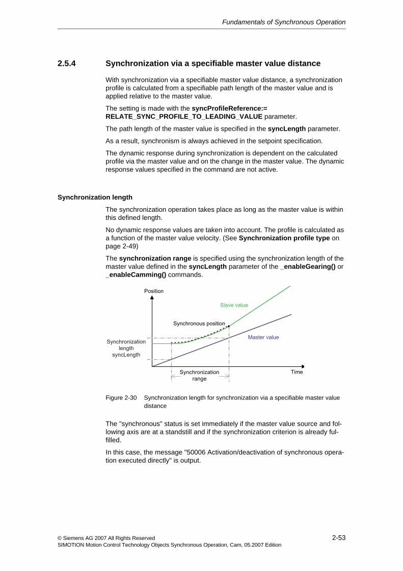
Fundamentals of Synchronous Operation
2-53© Siemens AG 2007 All Rights ReservedSIMOTION Motion Control Technology Objects Synchronous Operation, Cam, 05.2007 Edition
2.5.4 Synchronization via a specifiable master value distance
With synchronization via a specifiable master value distance, a synchronization profile is calculated from a specifiable path length of the master value and is applied relative to the master value.
The setting is made with the syncProfileReference:= RELATE_SYNC_PROFILE_TO_LEADING_VALUE parameter.
The path length of the master value is specified in the syncLength parameter.
As a result, synchronism is always achieved in the setpoint specification.
The dynamic response during synchronization is dependent on the calculated profile via the master value and on the change in the master value. The dynamic response values specified in the command are not active.
Synchronization length
The synchronization operation takes place as long as the master value is within this defined length.
No dynamic response values are taken into account. The profile is calculated as a function of the master value velocity. (See Synchronization profile type on page 2-49)
The synchronization range is specified using the synchronization length of the master value defined in the syncLength parameter of the _enableGearing() or _enableCamming() commands.
Figure 2-30 Synchronization length for synchronization via a specifiable master value distance
The "synchronous" status is set immediately if the master value source and fol-lowing axis are at a standstill and if the synchronization criterion is already ful-filled.
In this case, the message "50006 Activation/deactivation of synchronous opera-tion executed directly" is output.
Fundamentals of Synchronous Operation
2-54 © Siemens AG 2007 All Rights ReservedSIMOTION Motion Control Technology Objects Synchronous Operation, Cam, 05.2007 Edition
Synchronization profile type
The synchronization profile type for synchronization with master value reference is set using the syncingMotion.velocityMode configuration data element:
• The CONTINUOUS setting (default) calculates the synchronization profile with constant position and constant velocity, but not with constant acceleration.
The slave value is synchronized using a polynomial profile and the master value. The resulting velocity and acceleration of the following axis for the syn-chronization are thus dependent on the synchronization length and the dynamic response of the master value during synchronization.
• The NON_CONTINUOUS setting calculates the synchronization profile using the specified master value length with constant position only in the slave value behavior.
The slave value is synchronized using a linear profile and the master value.
2.5.5 Synchronization profile based on specifiable dynamic response parameters (time reference)
When this synchronization profile is used, a synchronization profile is calculated according to the specified dynamic response parameters and the master value dynamic response that exists at the start of the profile. The profile is applied according to the master value for leading synchronization and according to time for trailing synchronization.
The setting is made with the syncProfileReference:= RELATE_SYNC_PROFILE_TO_TIME parameter.
The dynamic response for the synchronization is specified in the dynamic response parameters for the synchronous operation commands.
A constant velocity (TRAPEZOIDAL) or constant acceleration (SMOOTH) veloc-ity profile can be specified in the velocityProfile parameter.
For synchronization with a synchronization profile based on dynamic response parameters and with constant acceleration, any reversing that takes place during synchronization is at zero acceleration in the reversion point.
The synchronization profile based on dynamic response parameters can be applied:
• For leading synchronization (See Section 2.5.6)
• For trailing synchronization (See Section 2.5.7)
Symmetrical synchronization is not possible.
See also: Position of synchronization range relative to synchronization position (Section 2.5.3)
Fundamentals of Synchronous Operation
2-55© Siemens AG 2007 All Rights ReservedSIMOTION Motion Control Technology Objects Synchronous Operation, Cam, 05.2007 Edition
Application
A synchronization profile based on dynamic response parameters is especially suited for:
• Time-optimized synchronization, according to dynamic response specifica-tions
Adaptation to the dynamic response of the master value (leading and trailing synchroniza-tion)
If the current dynamic response variables of the master value are larger than the dynamic response parameters of the synchronization command, the parameters can be automatically adapted to the dynamic response parameters. (V3.1 and higher)
An adaptation of the synchronization dynamic response to the target dynamic response can be assigned on the synchronous object under Settings (syncing-Motion.synchronizingAdaption).
If dynamic response adaptation is disabled, the synchronization dynamic response is no longer adapted to the required target dynamic response. This can lead to the situation where during trailing synchronization, the synchronous axis can no longer synchronize with the leading axis. During leading synchronization, the synchronization motion may not be started under certain circumstances.
The permissible magnification of the specified dynamic response values for mak-ing up a constant path difference is specified using the magnification factor (sync-ingMotion.overdriveFactor) under Settings.
The magnification factor relates to the dynamic response of the master value. At 100% magnification, the dynamic response of the synchronization is adapted to the current dynamic response of the master value, taking into account the trans-mission. When overDriveFactor > 100% is set and in effect, the "'synchronous" status can also be established if the master value is in the acceleration or decel-eration phase during synchronization.
If an overdrive is applied, alarm 40012 "Dynamic limitations (type: ...) are violated" is output on the synchronous object.
Application: If a low synchronization velocity is selected in the command, the adaptation is set and a corresponding magnification factor is selected, the synchronization velocity of the following axis can be adapted to the master value velocity (See Section 2.14.5).
Direction-dependent dynamic response
Direction-dependent or direction-independent effectiveness of the programmed dynamic response values can be set with syncingMotion.directionDynamic. (Default: NO)
See Motion Control Technology Objects Axis Electric/Hydraulic, External Encoder Function Manual, "Dynamic limits"
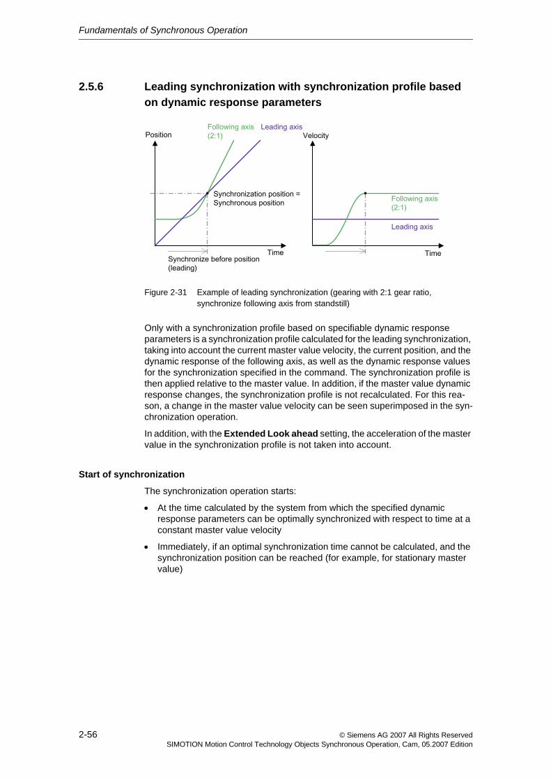
Fundamentals of Synchronous Operation
2-56 © Siemens AG 2007 All Rights ReservedSIMOTION Motion Control Technology Objects Synchronous Operation, Cam, 05.2007 Edition
2.5.6 Leading synchronization with synchronization profile based on dynamic response parameters
Figure 2-31 Example of leading synchronization (gearing with 2:1 gear ratio, synchronize following axis from standstill)
Only with a synchronization profile based on specifiable dynamic response parameters is a synchronization profile calculated for the leading synchronization, taking into account the current master value velocity, the current position, and the dynamic response of the following axis, as well as the dynamic response values for the synchronization specified in the command. The synchronization profile is then applied relative to the master value. In addition, if the master value dynamic response changes, the synchronization profile is not recalculated. For this rea-son, a change in the master value velocity can be seen superimposed in the syn-chronization operation.
In addition, with the Extended Look ahead setting, the acceleration of the master value in the synchronization profile is not taken into account.
Start of synchronization
The synchronization operation starts:
• At the time calculated by the system from which the specified dynamic response parameters can be optimally synchronized with respect to time at a constant master value velocity
• Immediately, if an optimal synchronization time cannot be calculated, and the synchronization position can be reached (for example, for stationary master value)
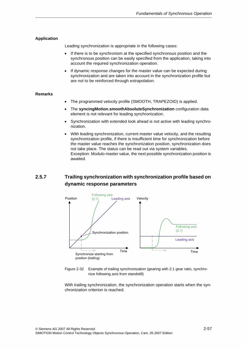
Fundamentals of Synchronous Operation
2-57© Siemens AG 2007 All Rights ReservedSIMOTION Motion Control Technology Objects Synchronous Operation, Cam, 05.2007 Edition
Application
Leading synchronization is appropriate in the following cases:
• If there is to be synchronism at the specified synchronous position and the synchronous position can be easily specified from the application, taking into account the required synchronization operation.
• If dynamic response changes for the master value can be expected during synchronization and are taken into account in the synchronization profile but are not to be reinforced through extrapolation.
Remarks
• The programmed velocity profile (SMOOTH, TRAPEZOID) is applied.
• The syncingMotion.smoothAbsoluteSynchronization configuration data element is not relevant for leading synchronization.
• Synchronization with extended look ahead is not active with leading synchro-nization.
• With leading synchronization, current master value velocity, and the resulting synchronization profile, if there is insufficient time for synchronization before the master value reaches the synchronization position, synchronization does not take place. The status can be read out via system variables. Exception: Modulo master value, the next possible synchronization position is awaited.
2.5.7 Trailing synchronization with synchronization profile based on dynamic response parameters
Figure 2-32 Example of trailing synchronization (gearing with 2:1 gear ratio, synchro-nize following axis from standstill)
With trailing synchronization, the synchronization operation starts when the syn-chronization criterion is reached.
Fundamentals of Synchronous Operation
2-58 © Siemens AG 2007 All Rights ReservedSIMOTION Motion Control Technology Objects Synchronous Operation, Cam, 05.2007 Edition
Taking into account the current master value velocity and the specified dynamic response values, the system calculates and executes a time-related synchroniza-tion profile such that synchronization is achieved as fast as possible.
The current master value acceleration is taken into account when calculating the synchronization profile only when extended look ahead is specified. (See Trailing synchronization with extended look ahead on page 2-54)
If a master value change greater than the maximum permissible value causes the synchronization profile to be recalculated, the profile starts out according to the existing velocity and, if extended look ahead is enabled, the existing acceleration, such that changing dynamic response values of the master value can produce significant changes in the motion of the following axis!
Application
Trailing synchronization is appropriate in the following cases:
• When the current master value position must be used directly as the synchro-nization position.
• When no dynamic response changes of the master value during synchroniza-tion are expected.
• When other reasons dictate that synchronization can take place only after the synchronization position.
Depending on the position of the slave value at the synchronous position, large dynamic response motions of the slave value may occur because in order to comply with the dynamic limits, taking into account the master value dynamic response, the following must occur:
− Synchronism must be achieved
− If there are dynamic response changes for the master value, the (antici-pated) position changes of the master value must be made up for.
Remarks
Trailing synchronization is not suitable for non-constant velocity and acceleration of the master value, i.e., if the acceleration/deceleration is changed perpetually.
Smooth synchronization
Absolute trailing synchronization with consideration of jerk
The syncingMotion.smoothAbsoluteSynchronization configuration data ele-ment can be used to specify whether a smooth velocity profile is supported during the succeeding synchronization. (V3.2 and higher)
The synchronization process is not calculated subject to change on account of adjustments to the master value velocity.
• Provision for jerk can be made during absolute synchronization by setting syncingMotion.smoothAbsoluteSynchronization:=YES.
• A setting of NO (default) means that jerk will not be taken into account during absolute synchronization, even with velocity profile SMOOTH.
Fundamentals of Synchronous Operation
2-59© Siemens AG 2007 All Rights ReservedSIMOTION Motion Control Technology Objects Synchronous Operation, Cam, 05.2007 Edition
Trailing synchronization with extended look aheadThe synchronization with extended look-ahead allows a constant accelera-tion/deceleration of the master value to be used during the synchronization.
• With synchronization with standard look ahead, the position and the velocity are included in the synchronization calculation.
• With synchronization with extended look ahead, an acceleration/deceleration is also included in the synchronization calculation (V3.2 and higher).
The function can be activated via the synchronizeWithLookAhead parame-ter of the _enableGearing() command.
Extended look-ahead can be preset on the synchronous object via system variable userdefault.gearingSettings.synchronizeWithLookAhead (V4.0 and higher).
2.5.8 Settings for evaluation of the master value behavior during synchronization
• Toleration of a master value reversal during synchronization: To prevent a cancellation of the synchronization option in the event of a direction reversal of the master value, a maximum master value reversal can be specified in the syncingMotion.masterReversionTolerance configuration data on the syn-chronous object (V4.0 and higher).
The specification of a tolerance is useful, in particular, for a distributed syn-chronous operation, where master value noise can cause a master value reversal through extrapolation.
• Toleration of master value velocity changes during synchronization: The tolerance of master value velocity changes can be set in the syncingMo-tion.maximumOfMasterChange configuration data element. (Default: 20%)
When synchronizing with synchronization profile based on master value dis-tance, changes in the master value in excess of what is specified the configu-ration data cause an error message to be output and the synchronization profile to be recalculated.
When synchronizing with synchronization profile based on dynamic response parameters and with leading synchronization, changes in the master value velocity in excess of what is specified the configuration data cause an error message to be output. The profile is not recalculated.
When synchronizing with synchronization profile based on dynamic response parameters and with trailing synchronization, the configuration data element is not active. A change in the master value velocity produces an immediate reac-tion.
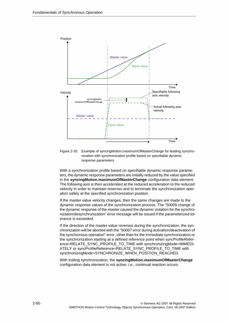
Fundamentals of Synchronous Operation
2-60 © Siemens AG 2007 All Rights ReservedSIMOTION Motion Control Technology Objects Synchronous Operation, Cam, 05.2007 Edition
Figure 2-33 Example of syncingMotion.maximumOfMasterChange for leading synchro-nization with synchronization profile based on specifiable dynamic response parameters
With a synchronization profile based on specifiable dynamic response parame-ters, the dynamic response parameters are initially reduced by the value specified in the syncingMotion.maximumOfMasterChange configuration data element. The following axis is then accelerated at the reduced acceleration to the reduced velocity in order to maintain reserves and to terminate the synchronization oper-ation safely at the specified synchronization position.
If the master value velocity changes, then the same changes are made to the dynamic response values of the synchronization process. The "50009 change of the dynamic response of the master caused the dynamic violation for the synchro-nization/desynchronization" error message will be issued if the parameterized tol-erance is exceeded.
If the direction of the master value reverses during the synchronization, the syn-chronization will be aborted with the "50007 error during activation/deactivation of the synchronous operation" error, other than for the immediate synchronization or the synchronization starting at a defined reference point when syncProfileRefer-ence=RELATE_SYNC_PROFILE_TO_TIME with synchronizingMode=IMMEDI-ATELY or syncProfileReference=RELATE_SYNC_PROFILE_TO_TIME with synchronizingMode=SYNCHRONIZE_WHEN_POSITION_REACHED.
With trailing synchronization, the syncingMotion.maximumOfMasterChange configuration data element is not active, i.e., continual reaction occurs.
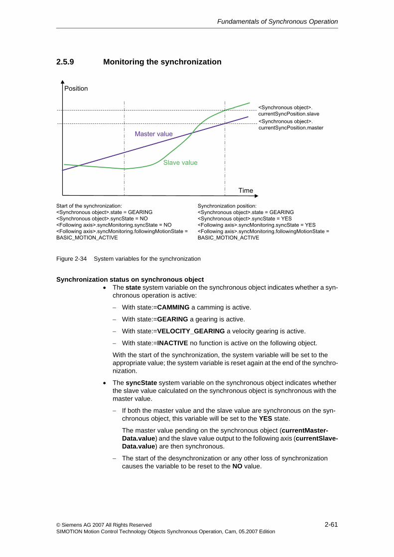
Fundamentals of Synchronous Operation
2-61© Siemens AG 2007 All Rights ReservedSIMOTION Motion Control Technology Objects Synchronous Operation, Cam, 05.2007 Edition
2.5.9 Monitoring the synchronization
Figure 2-34 System variables for the synchronization
Synchronization status on synchronous object• The state system variable on the synchronous object indicates whether a syn-
chronous operation is active:
− With state:=CAMMING a camming is active.
− With state:=GEARING a gearing is active.
− With state:=VELOCITY_GEARING a velocity gearing is active.
− With state:=INACTIVE no function is active on the following object.
With the start of the synchronization, the system variable will be set to the appropriate value; the system variable is reset again at the end of the synchro-nization.
• The syncState system variable on the synchronous object indicates whether the slave value calculated on the synchronous object is synchronous with the master value.
− If both the master value and the slave value are synchronous on the syn-chronous object, this variable will be set to the YES state.
The master value pending on the synchronous object (currentMaster-Data.value) and the slave value output to the following axis (currentSlave-Data.value) are then synchronous.
− The start of the desynchronization or any other loss of synchronization causes the variable to be reset to the NO value.
Fundamentals of Synchronous Operation
2-62 © Siemens AG 2007 All Rights ReservedSIMOTION Motion Control Technology Objects Synchronous Operation, Cam, 05.2007 Edition
Any restrictions of the slave value passed by the following axis because of the limitation to the maximum dynamic response values and the associated non-synchronism of the leading and following axis are not reflected in the state of the syncState variable on the synchronous object.
See Motion Control Technology Objects Axis Electric/Hydraulic, Exter-nal Encoder Function Manual, "Monitoring / limiting functions"
• The respective synchronization position of the master and slave values, i.e. the position from where the leading and following axes run synchronous is contained in the currentSyncPosition system variable on the synchronous object.See Display of the synchronous position (Section 2.5.10).
• The status of the synchronization can be queried using the synchronizing-State system variable on the synchronous object (V3.2 and higher).
− WAITING_FOR_SYNC_POSITION: Waiting for master value synchroniza-tion position
− WAITING_FOR_CHANGE_OF_MASTER_DIRECTION: Waiting for mas-ter value direction reversal
− SYNCHRONIZING_NOT_POSSIBLE: Synchronization is not possible
− SYNCHRONIZING: Synchronization in progress
− INACTIVE: Synchronization phase is not active
− WAITING_FOR_MERGE: Synchronization command issued but not yet active
• The execution status of the active command for enabling and disabling is described in the enableCommand and disableCommand system variables.
− INACTIVE means that no command is configured.
− WAITING_FOR_START means that the command is executed during slave value generation, and that it is waiting for the synchronization crite-rion to be reached.
− ACTIVE means that synchronization is active and that the operation is syn-chronous.
− If there are two commands during slave value generation, both system vari-ables can take on a value not equal to INACTIVE. If both are enable com-mands, the status of the current command is displayed (the state of the next command is always WAITING_FOR_START).
• The relevant active command parameter and the parameter for synchroniza-tion are grouped together and can be read out in the effectiveData system variable structure.
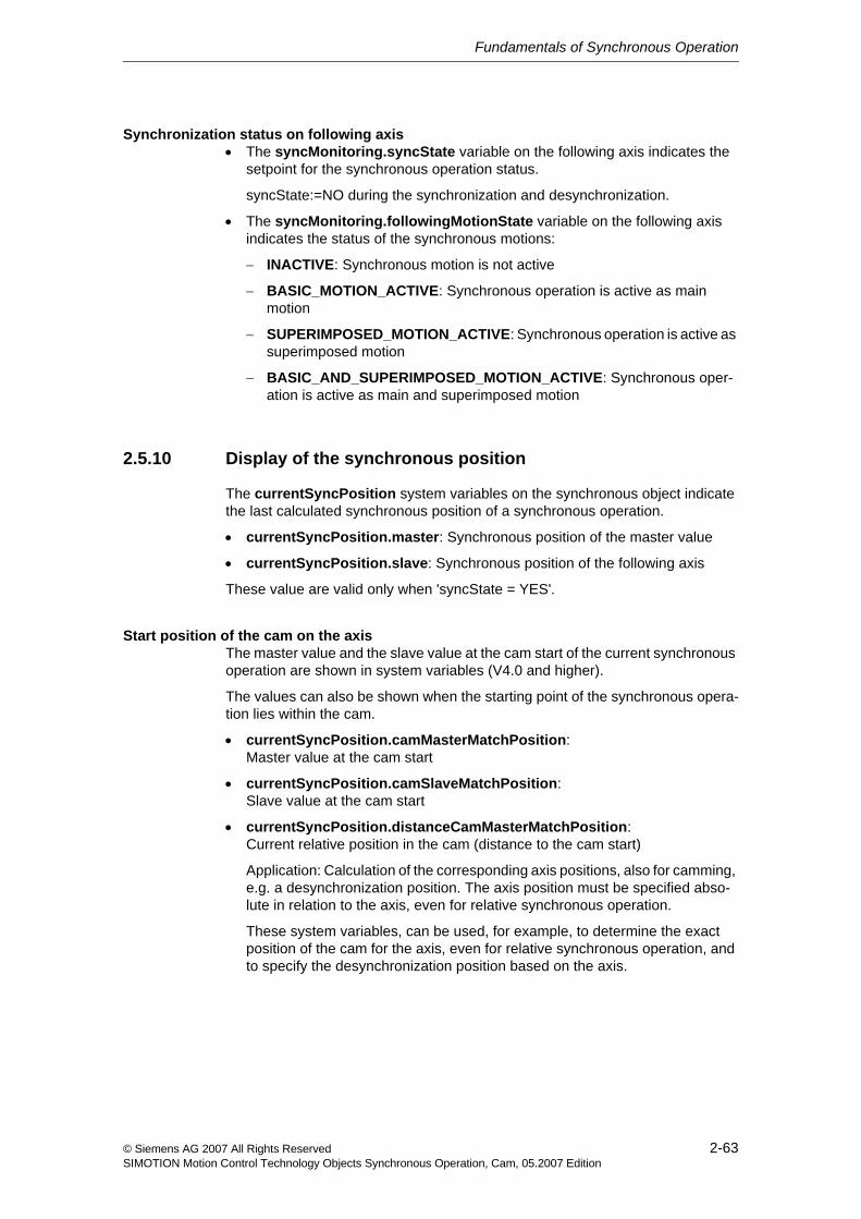
Fundamentals of Synchronous Operation
2-63© Siemens AG 2007 All Rights ReservedSIMOTION Motion Control Technology Objects Synchronous Operation, Cam, 05.2007 Edition
Synchronization status on following axis• The syncMonitoring.syncState variable on the following axis indicates the
setpoint for the synchronous operation status.
syncState:=NO during the synchronization and desynchronization.
• The syncMonitoring.followingMotionState variable on the following axis indicates the status of the synchronous motions:
− INACTIVE: Synchronous motion is not active
− BASIC_MOTION_ACTIVE: Synchronous operation is active as main motion
− SUPERIMPOSED_MOTION_ACTIVE: Synchronous operation is active as superimposed motion
− BASIC_AND_SUPERIMPOSED_MOTION_ACTIVE: Synchronous oper-ation is active as main and superimposed motion
2.5.10 Display of the synchronous position
The currentSyncPosition system variables on the synchronous object indicate the last calculated synchronous position of a synchronous operation.
• currentSyncPosition.master: Synchronous position of the master value
• currentSyncPosition.slave: Synchronous position of the following axis
These value are valid only when 'syncState = YES'.
Start position of the cam on the axisThe master value and the slave value at the cam start of the current synchronous operation are shown in system variables (V4.0 and higher).
The values can also be shown when the starting point of the synchronous opera-tion lies within the cam.
• currentSyncPosition.camMasterMatchPosition: Master value at the cam start
• currentSyncPosition.camSlaveMatchPosition: Slave value at the cam start
• currentSyncPosition.distanceCamMasterMatchPosition: Current relative position in the cam (distance to the cam start)
Application: Calculation of the corresponding axis positions, also for camming, e.g. a desynchronization position. The axis position must be specified abso-lute in relation to the axis, even for relative synchronous operation.
These system variables, can be used, for example, to determine the exact position of the cam for the axis, even for relative synchronous operation, and to specify the desynchronization position based on the axis.
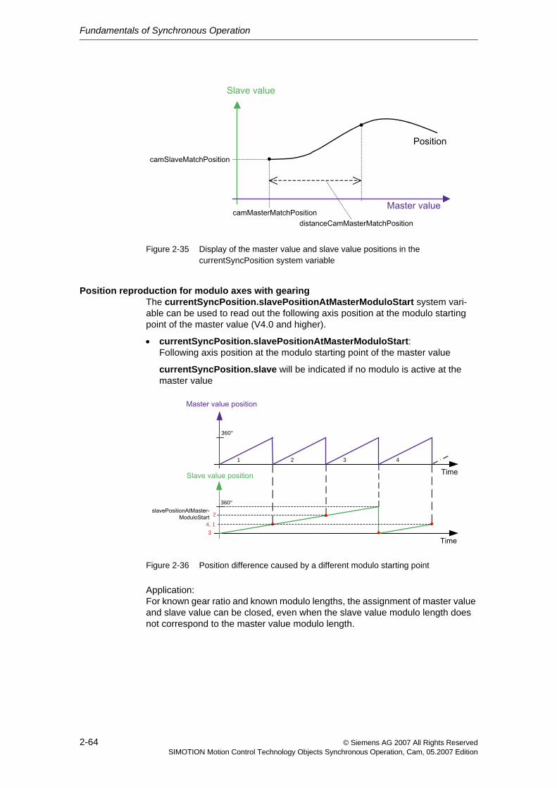
Fundamentals of Synchronous Operation
2-64 © Siemens AG 2007 All Rights ReservedSIMOTION Motion Control Technology Objects Synchronous Operation, Cam, 05.2007 Edition
Figure 2-35 Display of the master value and slave value positions in the currentSyncPosition system variable
Position reproduction for modulo axes with gearingThe currentSyncPosition.slavePositionAtMasterModuloStart system vari-able can be used to read out the following axis position at the modulo starting point of the master value (V4.0 and higher).
• currentSyncPosition.slavePositionAtMasterModuloStart: Following axis position at the modulo starting point of the master value
currentSyncPosition.slave will be indicated if no modulo is active at the master value
Figure 2-36 Position difference caused by a different modulo starting point
Application:For known gear ratio and known modulo lengths, the assignment of master value and slave value can be closed, even when the slave value modulo length does not correspond to the master value modulo length.
360°
360°
1 4 3 2
4, 1 3
2
Fundamentals of Synchronous Operation
2-65© Siemens AG 2007 All Rights ReservedSIMOTION Motion Control Technology Objects Synchronous Operation, Cam, 05.2007 Edition
2.5.11 "Synchronous" status during synchronization
• With synchronization via a specifiable master value distance, the "synchro-nous" status is achieved at the end of the synchronization distance.
• With synchronization using a synchronization profile based on specifiable dynamic response parameters and with leading synchronization, the "syn-chronous" status is achieved when the synchronization position is reached (in this case, the synchronization position is the same as the synchronous posi-tion).
Synchronism exists in the synchronous point in the position, velocity, and acceleration (only with velocity profile SMOOTH).
• With synchronization using a synchronization profile based on specifiable dynamic response parameters and with trailing synchronization, the "synchro-nous" status is achieved when synchronism exists in the position, velocity, and acceleration (only with profile SMOOTH and syncingMotion.smoothAbsoluteSynchronization:=YES) in accordance with the transmission function.
With relative gearing without offset, the position is not evaluated during the syn-chronization.
Fundamentals of Synchronous Operation
2-66 © Siemens AG 2007 All Rights ReservedSIMOTION Motion Control Technology Objects Synchronous Operation, Cam, 05.2007 Edition
2.6 DesynchronizationDesynchronization refers to the termination of the synchronous operation.
The desynchronization is defined by several parameters/settings:
• the Desynchronization criterion/desynchronization position (Section 2.6.1)
• the Position of synchronization range relative to desynchronization posi-tion (Section 2.6.4)
• the desynchronization profile
− Desynchronization via a specifiable master value distance (Section 2.6.2)The synchronization length is specified in the desynchronization com-mand.
− Desynchronization profile based on specifiable dynamic response parameters (Section 2.6.3)The dynamic response parameters are specified in the desynchronization command.
Fundamentals of Synchronous Operation
2-67© Siemens AG 2007 All Rights ReservedSIMOTION Motion Control Technology Objects Synchronous Operation, Cam, 05.2007 Edition
2.6.1 Desynchronization criterion/desynchronization position
The desynchronization criterion/desynchronization position is specified in syncOffMode.
• Desynchronization on the current master value position, immediate desyn-chronization
Desynchronization on the current master value position is set in syncOffMode:=IMMEDIATELY.
Only trailing desynchronization can occur.
The setting in the syncOffPositionReference parameter is not active.
The syncOffPositionMaster parameter is not active.
The syncOffPositionSlave parameter is not active.
• Desynchronization on a specified master value position
Desynchronization on a specified master value position is set in syncOffMode:=ON_MASTER_POSITION.
The syncOffPositionReference parameter can be used to set leading, sym-metrical (only with desynchronization via master value distance), and trailing desynchronization.
The desynchronization position on the master value side is set in the syncOffPositionMaster parameter.
The syncOffPositionSlave parameter is not active.
• Desynchronization on a specified slave value position
Desynchronization on a specified slave value position is set in syncOffMode:=ON_SLAVE_POSITION.
The syncOffPositionReference parameter can be used to set leading, sym-metrical (only with desynchronization via master value distance), and trailing desynchronization.
The desynchronization position on the slave value side is specified in the syncOffPositionSlave parameter.
The syncOffPositionMaster parameter is not active.
• Desynchronization at end of cam cycle
Desynchronization at the end of the cam cycle is set in syncOffMode:=AT_THE_END_OF_CAM_CYCLE.
The syncOffPositionMaster parameter is not active.
The syncOffPositionSlave parameter is not active.
Fundamentals of Synchronous Operation
2-68 © Siemens AG 2007 All Rights ReservedSIMOTION Motion Control Technology Objects Synchronous Operation, Cam, 05.2007 Edition
2.6.2 Desynchronization via a specifiable master value distance
Desynchronization via a specifiable master value distance is set in the syncProfileReference:=RELATE_SYNC_PROFILE_TO_LEADING_VALUE parameter.
The slave values travel to zero velocity while the master value travels through the desynchronization length.
The desynchronization length is specified in the syncOffLength parameter.
See also Synchronization via a specifiable master value distance (Section 2.5.4).
2.6.3 Desynchronization profile based on specifiable dynamic response parameters
Desynchronization based on specifiable dynamic response parameters is set in the syncProfileReference:=RELATE_SYNC_PROFILE_TO_TIME parameter.
The slave values travel to zero velocity with the dynamic response values speci-fied in the desynchronization command according to the specified desynchroni-zation criterion.
See also Synchronization profile based on specifiable dynamic response parameters (time reference) (Section 2.5.5).
Fundamentals of Synchronous Operation
2-69© Siemens AG 2007 All Rights ReservedSIMOTION Motion Control Technology Objects Synchronous Operation, Cam, 05.2007 Edition
2.6.4 Position of synchronization range relative to desynchroni-zation position
The position of the synchronization range relative to the desynchronization posi-tion can be specified more precisely with the syncPositionReference parameter of the _disableGearing() or _disableCamming() commands:
• Desynchronization before the specified desynchronization position
Desynchronization before the specified desynchronization position is set with the syncOffPositionReference:=AXIS_STOPPED_AT_POSITION parame-ter.
The slave value travels to zero velocity to the specified desynchronization position.
• Desynchronization starting from the specified desynchronization position
Desynchronization starting from the specified desynchronization position is set with the syncOffPositionreference:=BEGIN_TO_STOP_WHEN_POSITION_REACHED parameter.
The slave value travels to zero velocity starting from the specified desynchro-nization position.
• Desynchronization symmetrical relative to the specified desynchronization position
Desynchronization symmetrical relative to the specified desynchronization position is set with the syncOffPositionrefer-ence:=STOP_SYMMETRIC_WITH_POSITION parameter.
The slave value travels to zero velocity symmetrically relative to the specified desynchronization position.
The setting is not possible for the desynchronization profile based on dynamic response parameters.
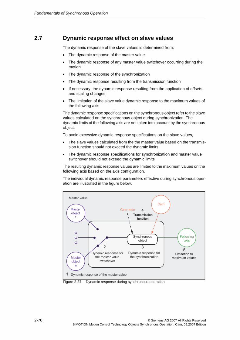
Fundamentals of Synchronous Operation
2-70 © Siemens AG 2007 All Rights ReservedSIMOTION Motion Control Technology Objects Synchronous Operation, Cam, 05.2007 Edition
2.7 Dynamic response effect on slave valuesThe dynamic response of the slave values is determined from:
• The dynamic response of the master value
• The dynamic response of any master value switchover occurring during the motion
• The dynamic response of the synchronization
• The dynamic response resulting from the transmission function
• If necessary, the dynamic response resulting from the application of offsets and scaling changes
• The limitation of the slave value dynamic response to the maximum values of the following axis
The dynamic response specifications on the synchronous object refer to the slave values calculated on the synchronous object during synchronization. The dynamic limits of the following axis are not taken into account by the synchronous object.
To avoid excessive dynamic response specifications on the slave values,
• The slave values calculated from the the master value based on the transmis-sion function should not exceed the dynamic limits
• The dynamic response specifications for synchronization and master value switchover should not exceed the dynamic limits
The resulting dynamic response values are limited to the maximum values on the following axis based on the axis configuration.
The individual dynamic response parameters effective during synchronous oper-ation are illustrated in the figure below.
Figure 2-37 Dynamic response during synchronous operation
Fundamentals of Synchronous Operation
2-71© Siemens AG 2007 All Rights ReservedSIMOTION Motion Control Technology Objects Synchronous Operation, Cam, 05.2007 Edition
Legend:
1. The dynamic response of the master value is determined by the motion.
2. The dynamic response of the master value switchover can be specified using the _setMaster() command.
See Switching of the master value source (Section 2.8)
3. Synchronization/desynchronization and compensation:
− Without dynamic specification during synchronization via a specifiable master value distance (RELATE_SYNC_PROFILE_TO_LEADING_VALUE)
− Synchronization profile based on specifiable dynamic response parame-ters (time reference) (RELATE_SYNC_PROFILE_TO_TIME)
The dynamic response values/limitations on the synchronous object apply to gearing or camming only during synchronization/desynchronization and for the application of corrections, but not in the 'synchronous' status.
See Synchronizing (Section 2.5), Desynchronization (Section 2.6)
4. The dynamic response specification for the following axis is determined by the synchronous object and the gear ratio.The synchronous object is not subject to any dynamic limitation in the 'syn-chronous' status.
5. The dynamic response specification of the following axis is limited to the max-imum axial dynamic.
Configuration data: TypeOfAxis.MaxAcceleration/MaxVelocity/MaxJerk
System variables: plusLimitsOfDynamics/minusLimitsOfDynamics
The minimum of these values is applied.
See Motion Control Technology Objects Axis Electric/Hydraulic, Exter-nal Encoder Function Manual, "Dynamic limits"
The maximum axial jerk for monitoring and limiting of the response specifica-tion of the synchronous operation is only applied when synchronous operation monitoring with consideration for jerk is activated.
The setting for synchronous operation monitoring has no effect on the calcu-lated synchronous operation dynamic specification, this is valid for example during synchronization.See Synchronous operation monitoring (Section 2.10)
Alarm "40202 Dynamic response of the synchronous operation setpoint can-not be achieved" is generated if the values for velocity or accelaration as cal-culated by the synchronous operation exceed the active axial limits. If the values of the following axis are limited consequently or in cases of dynamically non-constant synchronous operation values (caused for example by jumps in the leading values), there is an error in the values of the following axis.See Synchronous operation monitoring (Section 2.10)
The maximum jerk on the axis can be exceeded during synchronization and desynchronization if the jerk setting in the synchronization parameters on the synchronous object is greater than the maximum jerk on the axis.To prevent this, an alarm reaction can be configured, for example.
Fundamentals of Synchronous Operation
2-72 © Siemens AG 2007 All Rights ReservedSIMOTION Motion Control Technology Objects Synchronous Operation, Cam, 05.2007 Edition
2.8 Switching of the master value sourceIf more than one master value is assigned to a following axis, the master value source can be selected or switched to with the _setMaster() command on the synchronous object.
If a synchronous object is assigned to multiple master values, a random master value source is selected internally following system startup. The correct master value source must be specified in the user program.
The master value source can be switched "on-the-fly".
When it is enabled, the master values are referenced to the units system of the current master value source.
A relative or absolute synchronous operation influences the transition process.
The master value transition can be set with and without dynamic response using the transientBehavior parameter of the _setMaster() command (V3.2 and higher):
• DIRECT: Without dynamic response (default)
• WITH_DYNAMICS: With dynamic response
• WITH_NEXT_SYNCHRONIZING: With next synchronization (V4.1 and higher)
2.8.1 Master value switchover without dynamic response
The transition behavior when the master value source is switched over is different for absolute synchronous operation and relative synchronous operation.
• With relative synchronous operation, an additional slave value difference occurs only if the dynamic master values are different with regard to velocity and acceleration.
• With absolute synchronous operation, a non-continuous master value transi-tion can occur. Discontinuities in the slave values are limited to the maximum dynamic axis parameters on the following axis. A compensation movement is generated in certain circumstances.
Different modulo settings of the master value sources are taken into account.
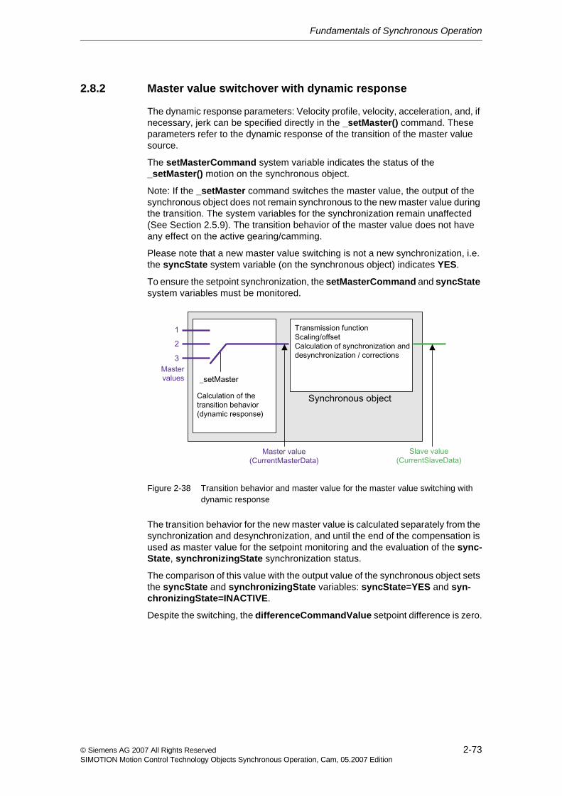
Fundamentals of Synchronous Operation
2-73© Siemens AG 2007 All Rights ReservedSIMOTION Motion Control Technology Objects Synchronous Operation, Cam, 05.2007 Edition
2.8.2 Master value switchover with dynamic response
The dynamic response parameters: Velocity profile, velocity, acceleration, and, if necessary, jerk can be specified directly in the _setMaster() command. These parameters refer to the dynamic response of the transition of the master value source.
The setMasterCommand system variable indicates the status of the _setMaster() motion on the synchronous object.
Note: If the _setMaster command switches the master value, the output of the synchronous object does not remain synchronous to the new master value during the transition. The system variables for the synchronization remain unaffected (See Section 2.5.9). The transition behavior of the master value does not have any effect on the active gearing/camming.
Please note that a new master value switching is not a new synchronization, i.e. the syncState system variable (on the synchronous object) indicates YES.
To ensure the setpoint synchronization, the setMasterCommand and syncState system variables must be monitored.
Figure 2-38 Transition behavior and master value for the master value switching with dynamic response
The transition behavior for the new master value is calculated separately from the synchronization and desynchronization, and until the end of the compensation is used as master value for the setpoint monitoring and the evaluation of the sync-State, synchronizingState synchronization status.
The comparison of this value with the output value of the synchronous object sets the syncState and synchronizingState variables: syncState=YES and syn-chronizingState=INACTIVE.
Despite the switching, the differenceCommandValue setpoint difference is zero.
Fundamentals of Synchronous Operation
2-74 © Siemens AG 2007 All Rights ReservedSIMOTION Motion Control Technology Objects Synchronous Operation, Cam, 05.2007 Edition
2.8.3 Master value switchover with next synchronization (V4.1 and higher)
The master value switchover is active together with the next _enableCamming()/_enableGearing() synchronization command, whereby all specifications refer to the new master value.
The dynamic response values in the setMaster() command are not active because the dynamic response values of the synchronization command are active during synchronization.
The system variable stateSetMasterCommand indicates:
• Master value switchover is not active (INACTIVE)
• Master value switchover is active, switchover occurs directly (TRANSIENT_BEHAVIOR_DIRECT)
• Master value switchover is active, switchover occurs with dynamic response values (TRANSIENT_BEHAVIOR_WITH_DYNAMICS)
• Master value switchover is active, switchover occurs with next synchronization (TRANSIENT_BEHAVIOR_WITH_NEXT_SYNC)
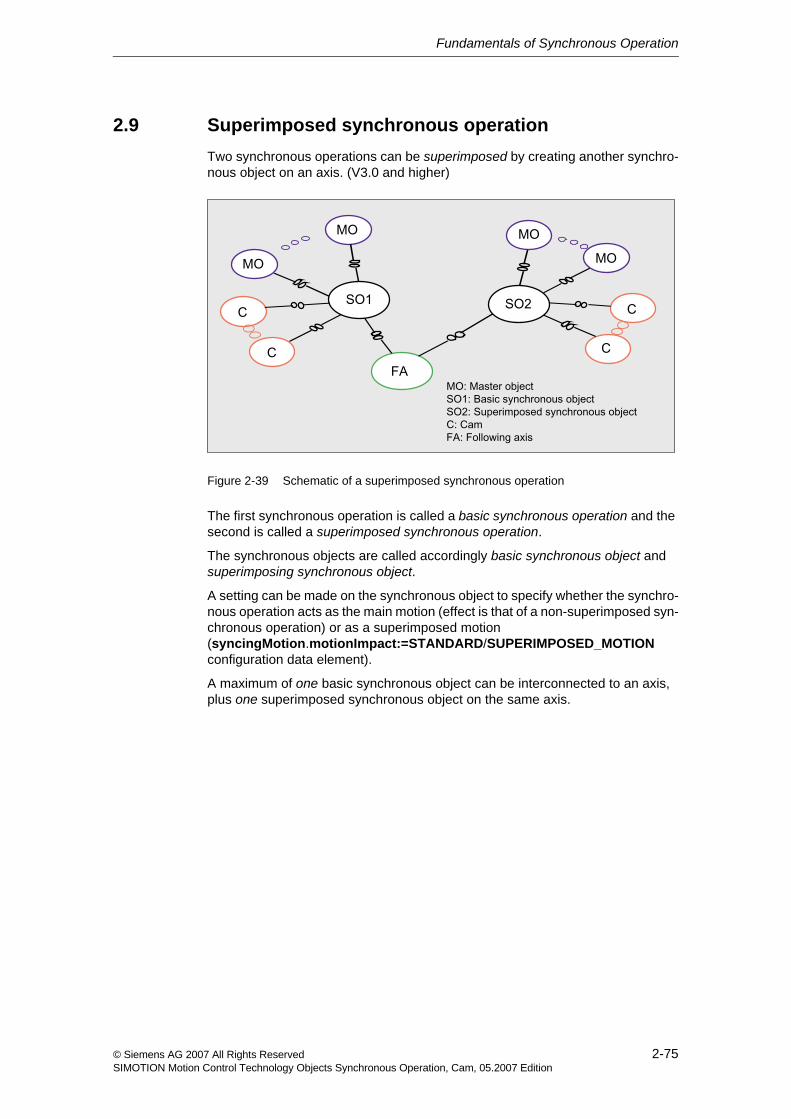
Fundamentals of Synchronous Operation
2-75© Siemens AG 2007 All Rights ReservedSIMOTION Motion Control Technology Objects Synchronous Operation, Cam, 05.2007 Edition
2.9 Superimposed synchronous operationTwo synchronous operations can be superimposed by creating another synchro-nous object on an axis. (V3.0 and higher)
Figure 2-39 Schematic of a superimposed synchronous operation
The first synchronous operation is called a basic synchronous operation and the second is called a superimposed synchronous operation.
The synchronous objects are called accordingly basic synchronous object and superimposing synchronous object.
A setting can be made on the synchronous object to specify whether the synchro-nous operation acts as the main motion (effect is that of a non-superimposed syn-chronous operation) or as a superimposed motion (syncingMotion.motionImpact:=STANDARD/SUPERIMPOSED_MOTION configuration data element).
A maximum of one basic synchronous object can be interconnected to an axis, plus one superimposed synchronous object on the same axis.
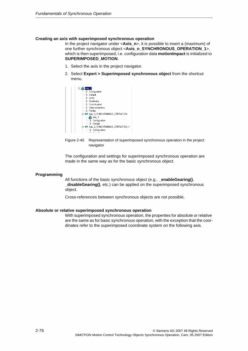
Fundamentals of Synchronous Operation
2-76 © Siemens AG 2007 All Rights ReservedSIMOTION Motion Control Technology Objects Synchronous Operation, Cam, 05.2007 Edition
Creating an axis with superimposed synchronous operationIn the project navigator under <Axis_n>, it is possible to insert a (maximum) of one further synchronous object <Axis_n_SYNCHRONOUS_OPERATION_1>, which is then superimposed, i.e. configuration data motionImpact is initialized to SUPERIMPOSED_MOTION.
1. Select the axis in the project navigator.
2. Select Expert > Superimposed synchronous object from the shortcut menu.
Figure 2-40 Representation of superimposed synchronous operation in the project navigator
The configuration and settings for superimposed synchronous operation are made in the same way as for the basic synchronous object.
ProgrammingAll functions of the basic synchronous object (e.g., _enableGearing(), _disableGearing(), etc.) can be applied on the superimposed synchronous object.
Cross-references between synchronous objects are not possible.
Absolute or relative superimposed synchronous operationWith superimposed synchronous operation, the properties for absolute or relative are the same as for basic synchronous operation, with the exception that the coor-dinates refer to the superimposed coordinate system on the following axis.
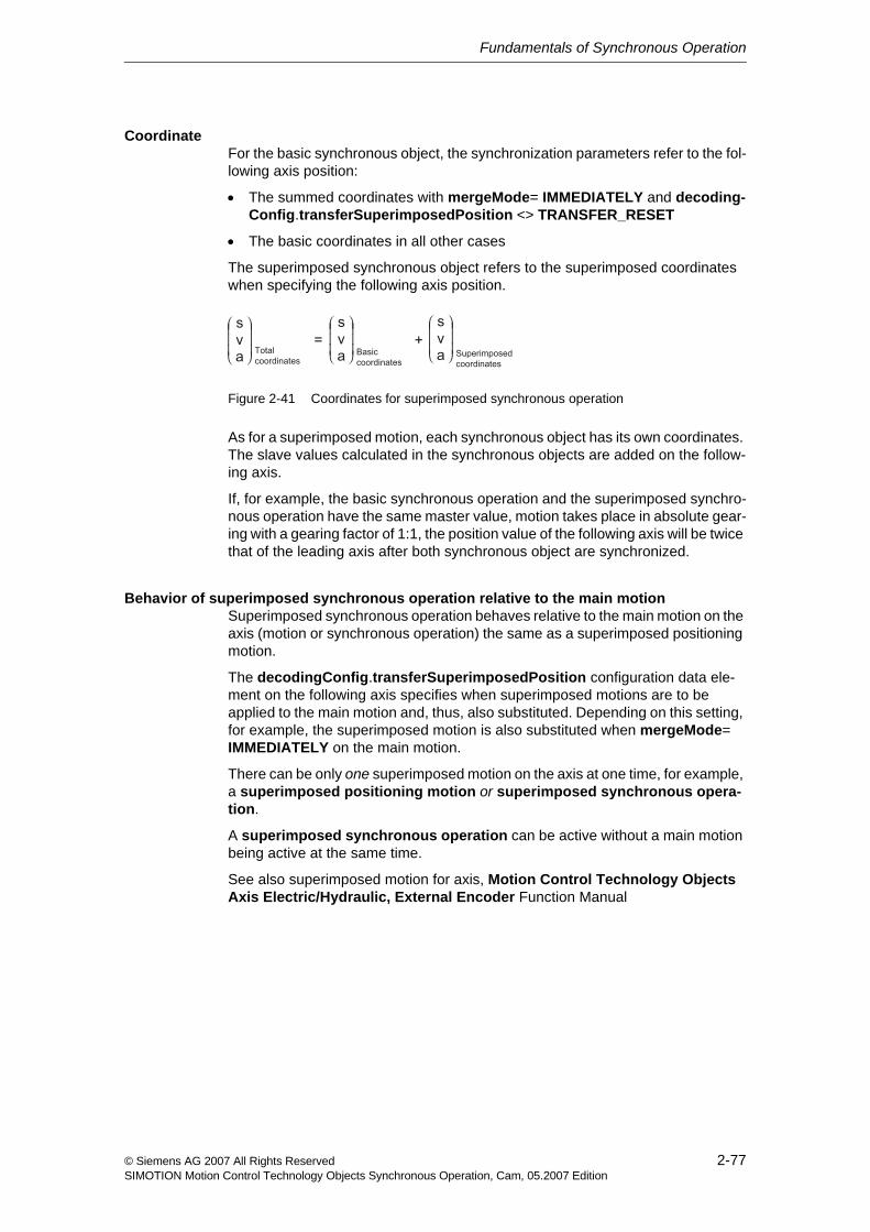
Fundamentals of Synchronous Operation
2-77© Siemens AG 2007 All Rights ReservedSIMOTION Motion Control Technology Objects Synchronous Operation, Cam, 05.2007 Edition
CoordinateFor the basic synchronous object, the synchronization parameters refer to the fol-lowing axis position:
• The summed coordinates with mergeMode= IMMEDIATELY and decoding-Config.transferSuperimposedPosition <> TRANSFER_RESET
• The basic coordinates in all other cases
The superimposed synchronous object refers to the superimposed coordinates when specifying the following axis position.
Figure 2-41 Coordinates for superimposed synchronous operation
As for a superimposed motion, each synchronous object has its own coordinates. The slave values calculated in the synchronous objects are added on the follow-ing axis.
If, for example, the basic synchronous operation and the superimposed synchro-nous operation have the same master value, motion takes place in absolute gear-ing with a gearing factor of 1:1, the position value of the following axis will be twice that of the leading axis after both synchronous object are synchronized.
Behavior of superimposed synchronous operation relative to the main motionSuperimposed synchronous operation behaves relative to the main motion on the axis (motion or synchronous operation) the same as a superimposed positioning motion.
The decodingConfig.transferSuperimposedPosition configuration data ele-ment on the following axis specifies when superimposed motions are to be applied to the main motion and, thus, also substituted. Depending on this setting, for example, the superimposed motion is also substituted when mergeMode= IMMEDIATELY on the main motion.
There can be only one superimposed motion on the axis at one time, for example, a superimposed positioning motion or superimposed synchronous opera-tion.
A superimposed synchronous operation can be active without a main motion being active at the same time.
See also superimposed motion for axis, Motion Control Technology Objects Axis Electric/Hydraulic, External Encoder Function Manual
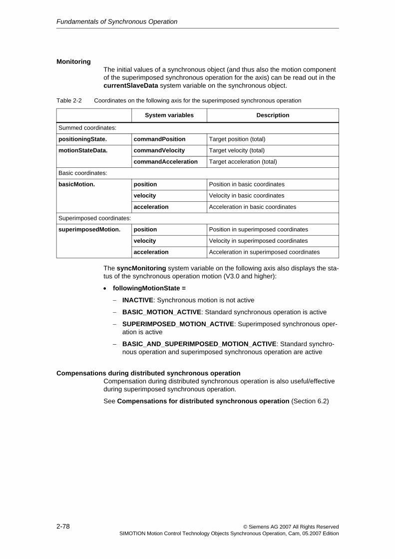
Fundamentals of Synchronous Operation
2-78 © Siemens AG 2007 All Rights ReservedSIMOTION Motion Control Technology Objects Synchronous Operation, Cam, 05.2007 Edition
MonitoringThe initial values of a synchronous object (and thus also the motion component of the superimposed synchronous operation for the axis) can be read out in the currentSlaveData system variable on the synchronous object.
The syncMonitoring system variable on the following axis also displays the sta-tus of the synchronous operation motion (V3.0 and higher):
• followingMotionState =
− INACTIVE: Synchronous motion is not active
− BASIC_MOTION_ACTIVE: Standard synchronous operation is active
− SUPERIMPOSED_MOTION_ACTIVE: Superimposed synchronous oper-ation is active
− BASIC_AND_SUPERIMPOSED_MOTION_ACTIVE: Standard synchro-nous operation and superimposed synchronous operation are active
Compensations during distributed synchronous operationCompensation during distributed synchronous operation is also useful/effective during superimposed synchronous operation.
See Compensations for distributed synchronous operation (Section 6.2)
Table 2-2 Coordinates on the following axis for the superimposed synchronous operation
System variables Description
Summed coordinates:
positioningState. commandPosition Target position (total)
motionStateData. commandVelocity Target velocity (total)
commandAcceleration Target acceleration (total)
Basic coordinates:
basicMotion. position Position in basic coordinates
velocity Velocity in basic coordinates
acceleration Acceleration in basic coordinates
Superimposed coordinates:
superimposedMotion. position Position in superimposed coordinates
velocity Velocity in superimposed coordinates
acceleration Acceleration in superimposed coordinates
Fundamentals of Synchronous Operation
2-79© Siemens AG 2007 All Rights ReservedSIMOTION Motion Control Technology Objects Synchronous Operation, Cam, 05.2007 Edition
Synchronous operation monitoring/statusesIf basic synchronous operation and superimposed synchronous operation are active, the synchronized status (syncMonitoring.syncState) is only set if both synchronous operations are synchronized.
Example: A synchronous operation is started. After synchronization, the synchro-nous operation is assigned "synchronized" status. Now another synchronous operation is started. The "synchronized" status disappears for the duration of the synchronization and is not reset until the synchronization of the second synchro-nous operation is complete.
The variables and monitoring on the axis refer to the total synchronous operation.
Error messages (synchronous operation errors on the following axis) are regis-tered on all interconnected synchronous objects.
2.10 Synchronous operation monitoringThe slave values calculated by the synchronous object (currentSlaveData) and any additional setpoints on the axis are limited on the following axis to the maxi-mum dynamic response values. The deviation in the slave values resulting from this limitation is monitored.
The current maximum limits for velocity and acceleration (and jerk) on the axis influence this monitoring process.
See Motion Control Technology Objects Axis Electric/Hydraulic, External Encoder Function Manual, "Dynamic limits"
The syncMonitoring system variables on the following axis indicate setpoint and actual value differences:
• differenceCommandValue shows the difference between the setpoint gener-ated on the synchronous object and the setpoint executable on the axis taking into account the dynamic limits.
• differenceActualValue displays the difference between the synchronous operation setpoint (currentSlaveData) and the associated actual axis value.
• limitCommandValue indicates that the difference between the calculated slave value and the executable setpoint exceeds the permissible tolerance.
Setpoint errorThe slave values calculated by the synchronous operation are limited on the axis to the maximum dynamic response values of the axes. This can cause the set-points on the axis to change.
Any resulting difference between the calculated slave value of the synchronous object (currentSlaveData) and the executable setpoint is indicated in syncMon-itoring.differenceCommandValue on the following axis.
The syncMonitoring.syncState synchronization status on the following axis is set according to the syncState on the synchronous object. Exception: Superimposed synchronous operation (Section 2.9)
Fundamentals of Synchronous Operation
2-80 © Siemens AG 2007 All Rights ReservedSIMOTION Motion Control Technology Objects Synchronous Operation, Cam, 05.2007 Edition
The following comparison must be performed to determine whether the following axis is synchronized on the setpoint value side:
(<Following axis>.syncMonitoring.syncState = YES) AND (<following axis>.syncMonitoring.differenceCommandValue = 0)
Actual value errorThe difference between the slave value calculated from the synchronous opera-tion (currentSlaveData) and the actual value on the axis can be queried with the syncMonitoring.differenceActualValue system variable on the following axis, provided no superimposed motion is present (See Section 2.9).
For a drive-related actual value, please see Monitoring the synchronization (Section 2.5.9)
Velocity gearing monitoringThe syncMonitoring system variable on the following axis also displays the sta-tus of the velocity gearing (V3.1 and higher):
• differenceCommandVelocity: velocity difference on the setpoint side between the velocity setpoint calculated on the synchronous object (currentSlaveData) and the executable velocity on the following axis (only applies to synchronous velocity operation).
• differenceActualVelocity: velocity difference on the actual value side between the velocity setpoint calculated on the synchronous object (cur-rentSlaveData) and the executable velocity on the following axis (only applies to synchronous velocity operation).
ConfigurationThe synchronous operation monitoring is set on the following axis under Monitor-ing - Synchronous operation monitoring (GearingPosTolerance configura-tion data element).
Limiting and monitoring the setpoint error:
• With setting enableCommandValue := INACTIVE:
− Dynamic limiting of the setpoint occurs without jerk
− The resulting setpoint error is not monitored
• With setting enableCommandValue := ACTIVE_WITHOUT_JERK:
− Dynamic limiting of the setpoint occurs without jerk
− The resulting setpoint error is monitored
• With setting enableCommandValue := ACTIVE_WITH_JERK:
− Dynamic limiting of the setpoint occurs with jerk
− The resulting setpoint error is monitored
Note: with distributed synchronous operation with extrapolation on the following axis, the setpoint monitoring with jerk setting is not appropriate.
The actual value deviation monitoring is set in GearingPosTolerance.enableAc-tualValue.
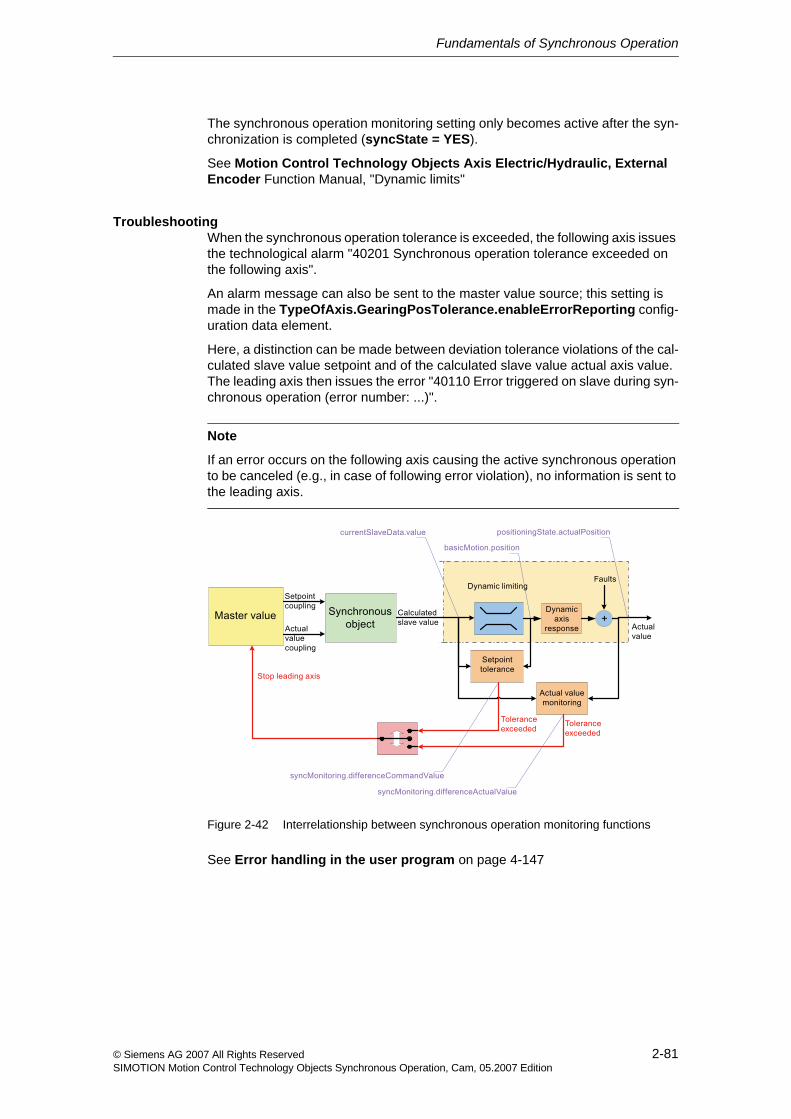
Fundamentals of Synchronous Operation
2-81© Siemens AG 2007 All Rights ReservedSIMOTION Motion Control Technology Objects Synchronous Operation, Cam, 05.2007 Edition
The synchronous operation monitoring setting only becomes active after the syn-chronization is completed (syncState = YES).
See Motion Control Technology Objects Axis Electric/Hydraulic, External Encoder Function Manual, "Dynamic limits"
TroubleshootingWhen the synchronous operation tolerance is exceeded, the following axis issues the technological alarm "40201 Synchronous operation tolerance exceeded on the following axis".
An alarm message can also be sent to the master value source; this setting is made in the TypeOfAxis.GearingPosTolerance.enableErrorReporting config-uration data element.
Here, a distinction can be made between deviation tolerance violations of the cal-culated slave value setpoint and of the calculated slave value actual axis value. The leading axis then issues the error "40110 Error triggered on slave during syn-chronous operation (error number: ...)".
Figure 2-42 Interrelationship between synchronous operation monitoring functions
See Error handling in the user program on page 4-147
Note
If an error occurs on the following axis causing the active synchronous operation to be canceled (e.g., in case of following error violation), no information is sent to the leading axis.
Fundamentals of Synchronous Operation
2-82 © Siemens AG 2007 All Rights ReservedSIMOTION Motion Control Technology Objects Synchronous Operation, Cam, 05.2007 Edition
2.11 Simulation modeA synchronous operation can be switched to simulation, i.e. the values on the syn-chronous object will be calculated but not output to the following axis.
The synchronous operation simulation can be activated and deactivated at any time provided there are no faults present.
The simulation [ACTIVE/INACTIVE] system variable provides information about the simulation status of the axis.
Application: Retaining a synchronous operation connection with _disableAxis() (Section 2.14.2)
Commands for the simulation operation• The _enableFollowingObjectSimulation() command sets a synchronous
operation into simulation mode. The synchronous values are calculated, but are not output to the following axis. This can be done at any time.
However, the axis states are taken into account when the slave values are generated.
• The _disableFollowingObjectSimulation() command resets the synchro-nous operation relationship out of simulation mode.
The synchronous values are output again to the following axis.
If there is a difference between the setpoint calculated on the synchronous operation and the setpoint present on the axis, or a superimposed motion has occurred, only a dynamic limitation caused by the maximum values of the fol-lowing axis occurs.
Configuration data for the simulation operationThe disableSynchronousOperation can be used to specify whether the syn-chronous operation remains active even when the axis enables are canceled.
• If NO (default), the synchronous operation is also canceled in simulation mode if the enables on the following axis have been canceled.
• If YES, the synchronous operation is not canceled in simulation mode if the enables on the following axis have been canceled while synchronous opera-tion is in simulation mode. Any synchronous operation commands that are undergoing execution are retained.
Fundamentals of Synchronous Operation
2-83© Siemens AG 2007 All Rights ReservedSIMOTION Motion Control Technology Objects Synchronous Operation, Cam, 05.2007 Edition
2.12 Examples of synchronization operations as a function of the output position on the slave value sideExamination of synchronization operationsTogether with the master value behavior, the output position of the following axis relative to the synchronous position on the following axis side largely determines the characteristic of the synchronization profile.
2.12.1 Synchronization via a specifiable master value distance
Influence of output position of the following axis
Example:
• Absolute 1:1 gear without offset
• Constant master value velocity
• Slave value at start of synchronization at standstill
• Synchronization over a master value distance
• Velocity profile type CONTINUOUS for synchronization
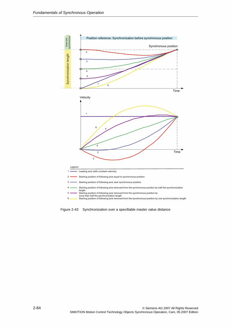
Fundamentals of Synchronous Operation
2-84 © Siemens AG 2007 All Rights ReservedSIMOTION Motion Control Technology Objects Synchronous Operation, Cam, 05.2007 Edition
Figure 2-43 Synchronization over a specifiable master value distance
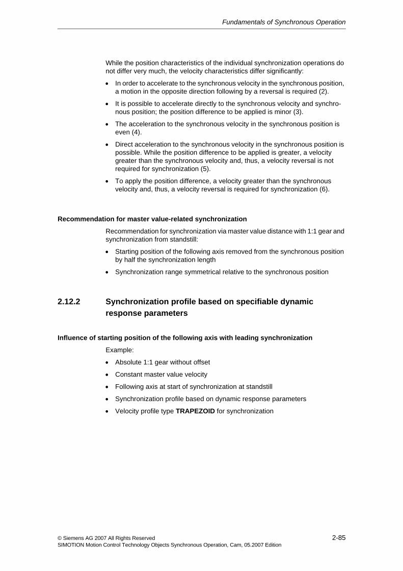
Fundamentals of Synchronous Operation
2-85© Siemens AG 2007 All Rights ReservedSIMOTION Motion Control Technology Objects Synchronous Operation, Cam, 05.2007 Edition
While the position characteristics of the individual synchronization operations do not differ very much, the velocity characteristics differ significantly:
• In order to accelerate to the synchronous velocity in the synchronous position, a motion in the opposite direction following by a reversal is required (2).
• It is possible to accelerate directly to the synchronous velocity and synchro-nous position; the position difference to be applied is minor (3).
• The acceleration to the synchronous velocity in the synchronous position is even (4).
• Direct acceleration to the synchronous velocity in the synchronous position is possible. While the position difference to be applied is greater, a velocity greater than the synchronous velocity and, thus, a velocity reversal is not required for synchronization (5).
• To apply the position difference, a velocity greater than the synchronous velocity and, thus, a velocity reversal is required for synchronization (6).
Recommendation for master value-related synchronization
Recommendation for synchronization via master value distance with 1:1 gear and synchronization from standstill:
• Starting position of the following axis removed from the synchronous position by half the synchronization length
• Synchronization range symmetrical relative to the synchronous position
2.12.2 Synchronization profile based on specifiable dynamic response parameters
Influence of starting position of the following axis with leading synchronization
Example:
• Absolute 1:1 gear without offset
• Constant master value velocity
• Following axis at start of synchronization at standstill
• Synchronization profile based on dynamic response parameters
• Velocity profile type TRAPEZOID for synchronization
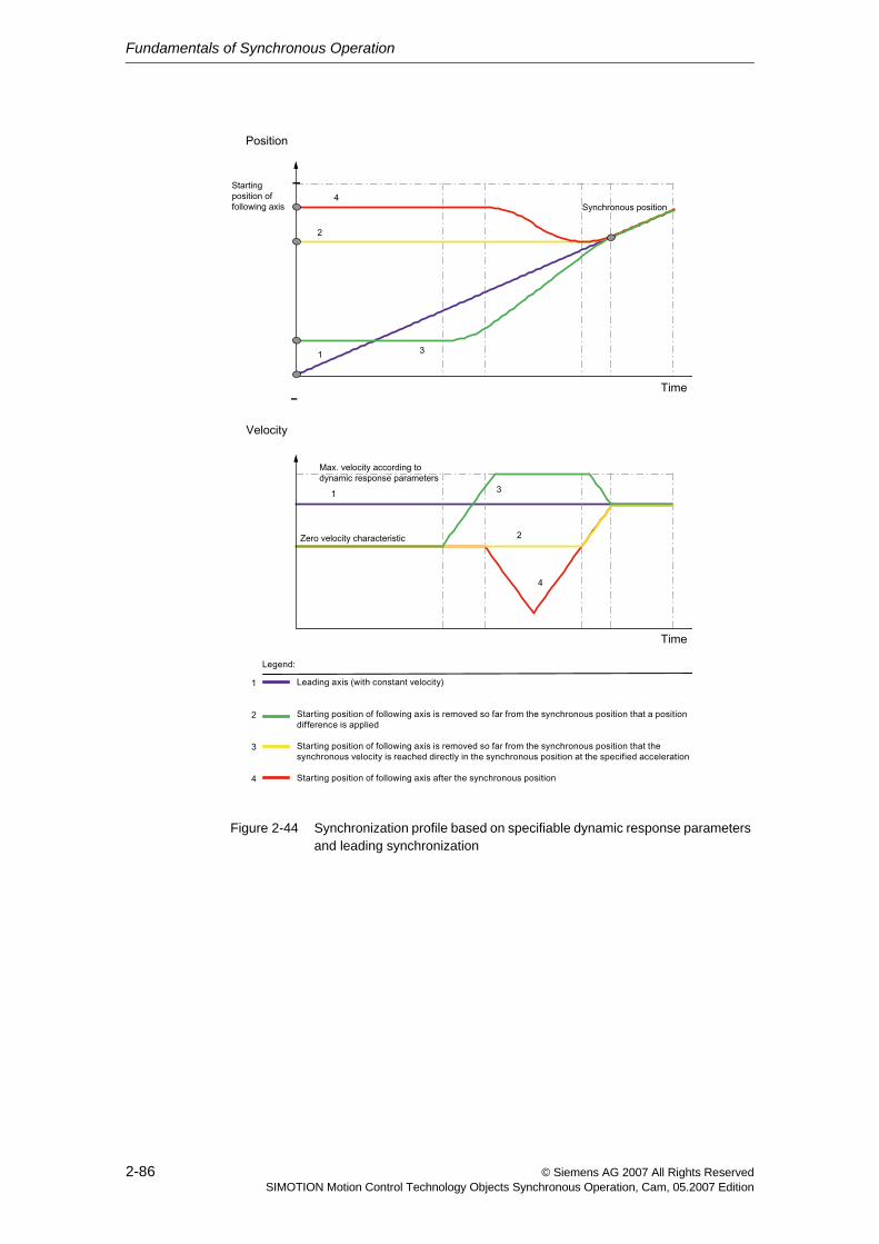
Fundamentals of Synchronous Operation
2-86 © Siemens AG 2007 All Rights ReservedSIMOTION Motion Control Technology Objects Synchronous Operation, Cam, 05.2007 Edition
Figure 2-44 Synchronization profile based on specifiable dynamic response parameters and leading synchronization
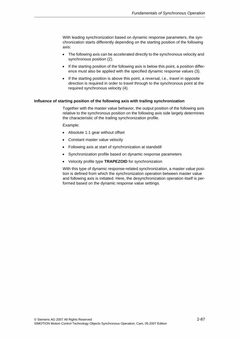
Fundamentals of Synchronous Operation
2-87© Siemens AG 2007 All Rights ReservedSIMOTION Motion Control Technology Objects Synchronous Operation, Cam, 05.2007 Edition
With leading synchronization based on dynamic response parameters, the syn-chronization starts differently depending on the starting position of the following axis:
• The following axis can be accelerated directly to the synchronous velocity and synchronous position (2).
• If the starting position of the following axis is below this point, a position differ-ence must also be applied with the specified dynamic response values (3).
• If the starting position is above this point, a reversal, i.e., travel in opposite direction is required in order to travel through to the synchronous point at the required synchronous velocity (4).
Influence of starting position of the following axis with trailing synchronization
Together with the master value behavior, the output position of the following axis relative to the synchronous position on the following axis side largely determines the characteristic of the trailing synchronization profile.
Example:
• Absolute 1:1 gear without offset
• Constant master value velocity
• Following axis at start of synchronization at standstill
• Synchronization profile based on dynamic response parameters
• Velocity profile type TRAPEZOID for synchronization
With this type of dynamic response-related synchronization, a master value posi-tion is defined from which the synchronization operation between master value and following axis is initiated. Here, the desynchronization operation itself is per-formed based on the dynamic response value settings.
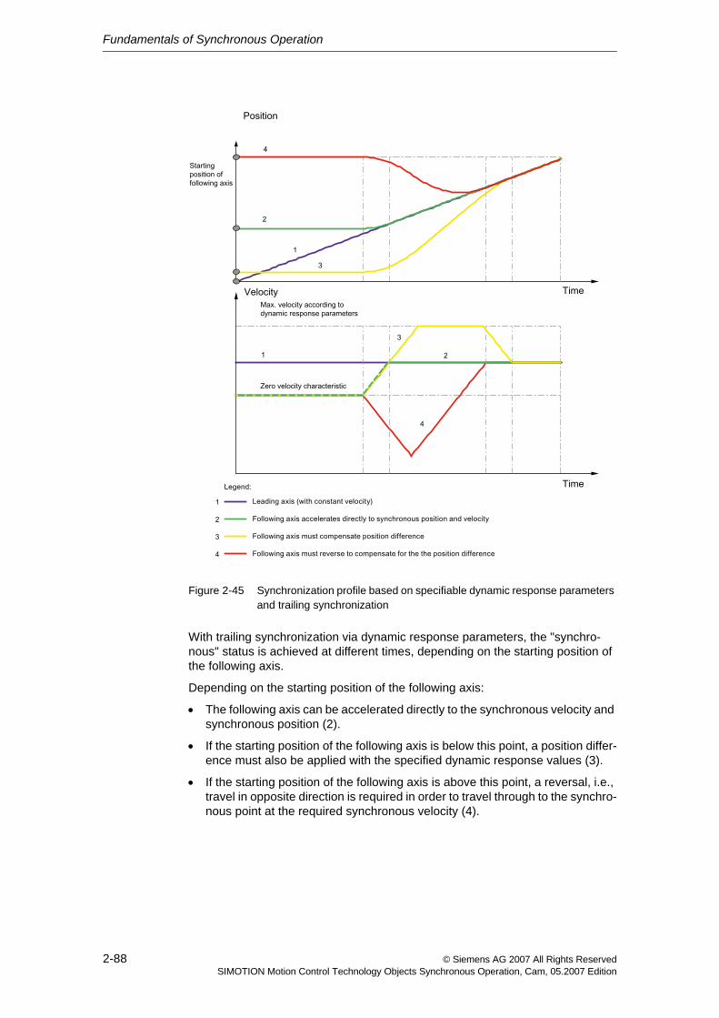
Fundamentals of Synchronous Operation
2-88 © Siemens AG 2007 All Rights ReservedSIMOTION Motion Control Technology Objects Synchronous Operation, Cam, 05.2007 Edition
Figure 2-45 Synchronization profile based on specifiable dynamic response parameters and trailing synchronization
With trailing synchronization via dynamic response parameters, the "synchro-nous" status is achieved at different times, depending on the starting position of the following axis.
Depending on the starting position of the following axis:
• The following axis can be accelerated directly to the synchronous velocity and synchronous position (2).
• If the starting position of the following axis is below this point, a position differ-ence must also be applied with the specified dynamic response values (3).
• If the starting position of the following axis is above this point, a reversal, i.e., travel in opposite direction is required in order to travel through to the synchro-nous point at the required synchronous velocity (4).
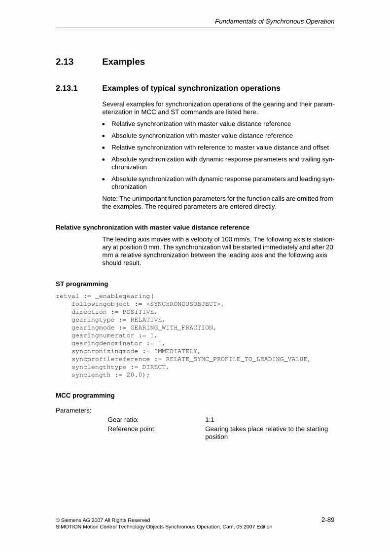
Fundamentals of Synchronous Operation
2-89© Siemens AG 2007 All Rights ReservedSIMOTION Motion Control Technology Objects Synchronous Operation, Cam, 05.2007 Edition
2.13 Examples
2.13.1 Examples of typical synchronization operations
Several examples for synchronization operations of the gearing and their param-eterization in MCC and ST commands are listed here.
• Relative synchronization with master value distance reference
• Absolute synchronization with master value distance reference
• Relative synchronization with reference to master value distance and offset
• Absolute synchronization with dynamic response parameters and trailing syn-chronization
• Absolute synchronization with dynamic response parameters and leading syn-chronization
Note: The unimportant function parameters for the function calls are omitted from the examples. The required parameters are entered directly.
Relative synchronization with master value distance reference
The leading axis moves with a velocity of 100 mm/s. The following axis is station-ary at position 0 mm. The synchronization will be started immediately and after 20 mm a relative synchronization between the leading axis and the following axis should result.
ST programming
retval := _enablegearing( followingobject := <SYNCHRONOUSOBJECT>, direction := POSITIVE, gearingtype := RELATIVE, gearingmode := GEARING_WITH_FRACTION, gearingnumerator := 1, gearingdenominator := 1, synchronizingmode := IMMEDIATELY, syncprofilereference := RELATE_SYNC_PROFILE_TO_LEADING_VALUE, synclengthtype := DIRECT, synclength := 20.0);
MCC programming
Parameters:Gear ratio: 1:1Reference point: Gearing takes place relative to the starting
position
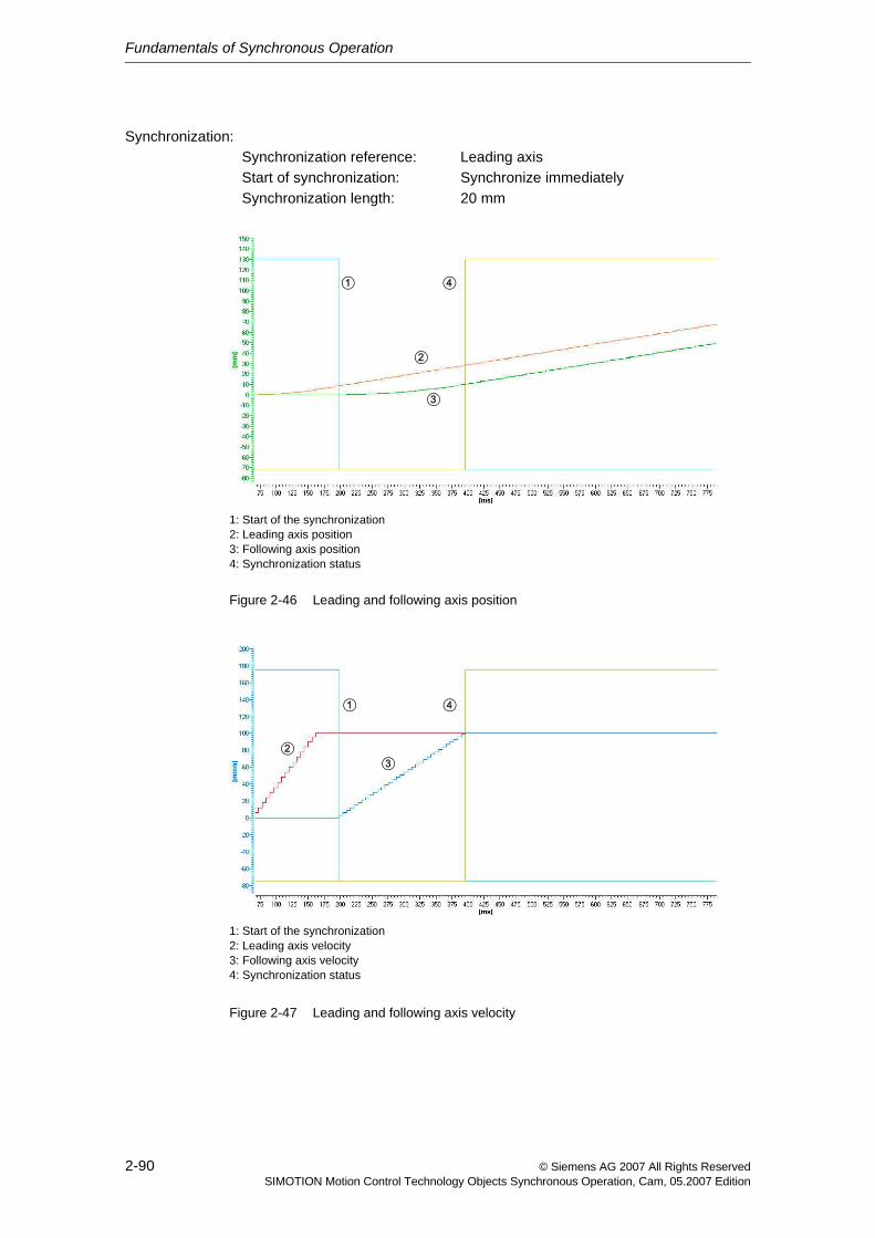
Fundamentals of Synchronous Operation
2-90 © Siemens AG 2007 All Rights ReservedSIMOTION Motion Control Technology Objects Synchronous Operation, Cam, 05.2007 Edition
Figure 2-46 Leading and following axis position
Figure 2-47 Leading and following axis velocity
Synchronization:Synchronization reference: Leading axisStart of synchronization: Synchronize immediatelySynchronization length: 20 mm
1: Start of the synchronization2: Leading axis position3: Following axis position4: Synchronization status
41
2
3
1: Start of the synchronization2: Leading axis velocity3: Following axis velocity4: Synchronization status
41
23
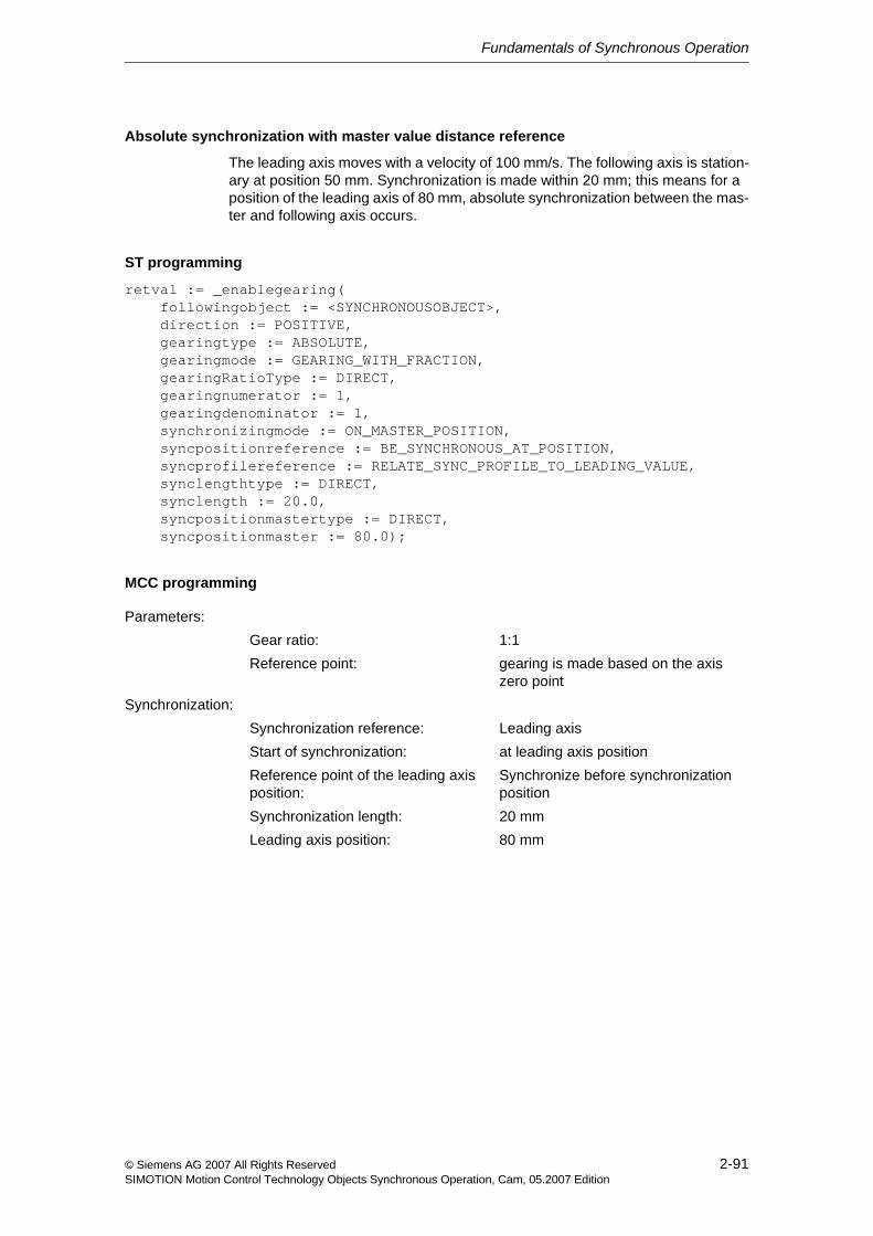
Fundamentals of Synchronous Operation
2-91© Siemens AG 2007 All Rights ReservedSIMOTION Motion Control Technology Objects Synchronous Operation, Cam, 05.2007 Edition
Absolute synchronization with master value distance reference
The leading axis moves with a velocity of 100 mm/s. The following axis is station-ary at position 50 mm. Synchronization is made within 20 mm; this means for a position of the leading axis of 80 mm, absolute synchronization between the mas-ter and following axis occurs.
ST programming
retval := _enablegearing( followingobject := <SYNCHRONOUSOBJECT>, direction := POSITIVE, gearingtype := ABSOLUTE, gearingmode := GEARING_WITH_FRACTION, gearingRatioType := DIRECT, gearingnumerator := 1, gearingdenominator := 1, synchronizingmode := ON_MASTER_POSITION, syncpositionreference := BE_SYNCHRONOUS_AT_POSITION, syncprofilereference := RELATE_SYNC_PROFILE_TO_LEADING_VALUE, synclengthtype := DIRECT, synclength := 20.0, syncpositionmastertype := DIRECT, syncpositionmaster := 80.0);
MCC programming
Parameters:Gear ratio: 1:1Reference point: gearing is made based on the axis
zero pointSynchronization:
Synchronization reference: Leading axisStart of synchronization: at leading axis positionReference point of the leading axis position:
Synchronize before synchronization position
Synchronization length: 20 mmLeading axis position: 80 mm
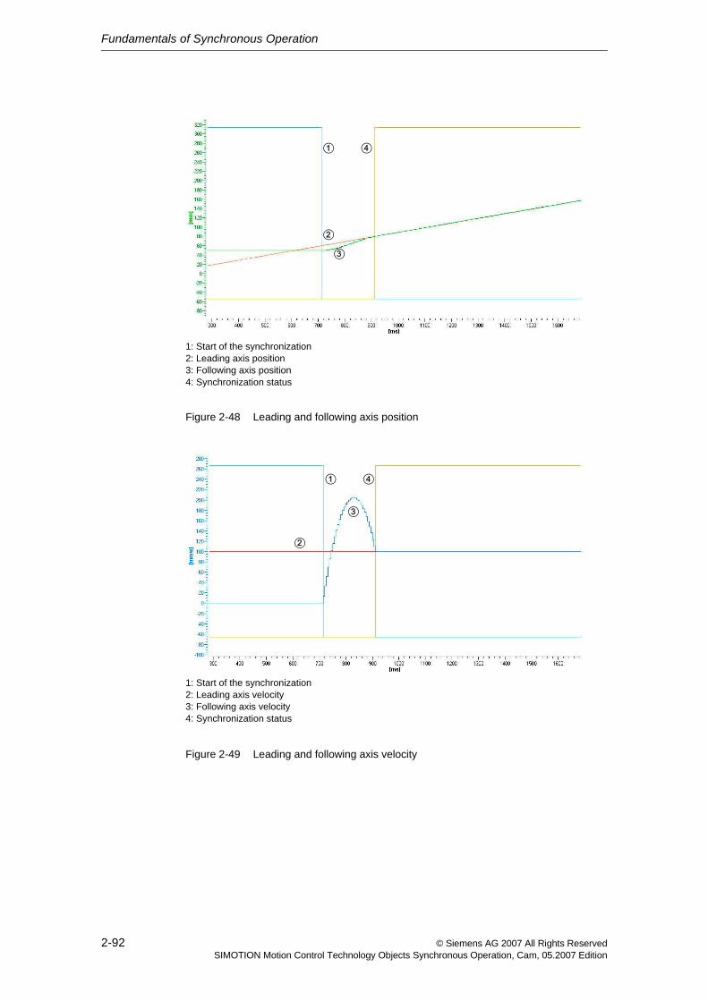
Fundamentals of Synchronous Operation
2-92 © Siemens AG 2007 All Rights ReservedSIMOTION Motion Control Technology Objects Synchronous Operation, Cam, 05.2007 Edition
Figure 2-48 Leading and following axis position
Figure 2-49 Leading and following axis velocity
1: Start of the synchronization2: Leading axis position3: Following axis position4: Synchronization status
2
3
1 4
1: Start of the synchronization2: Leading axis velocity3: Following axis velocity4: Synchronization status
2
3
1 4
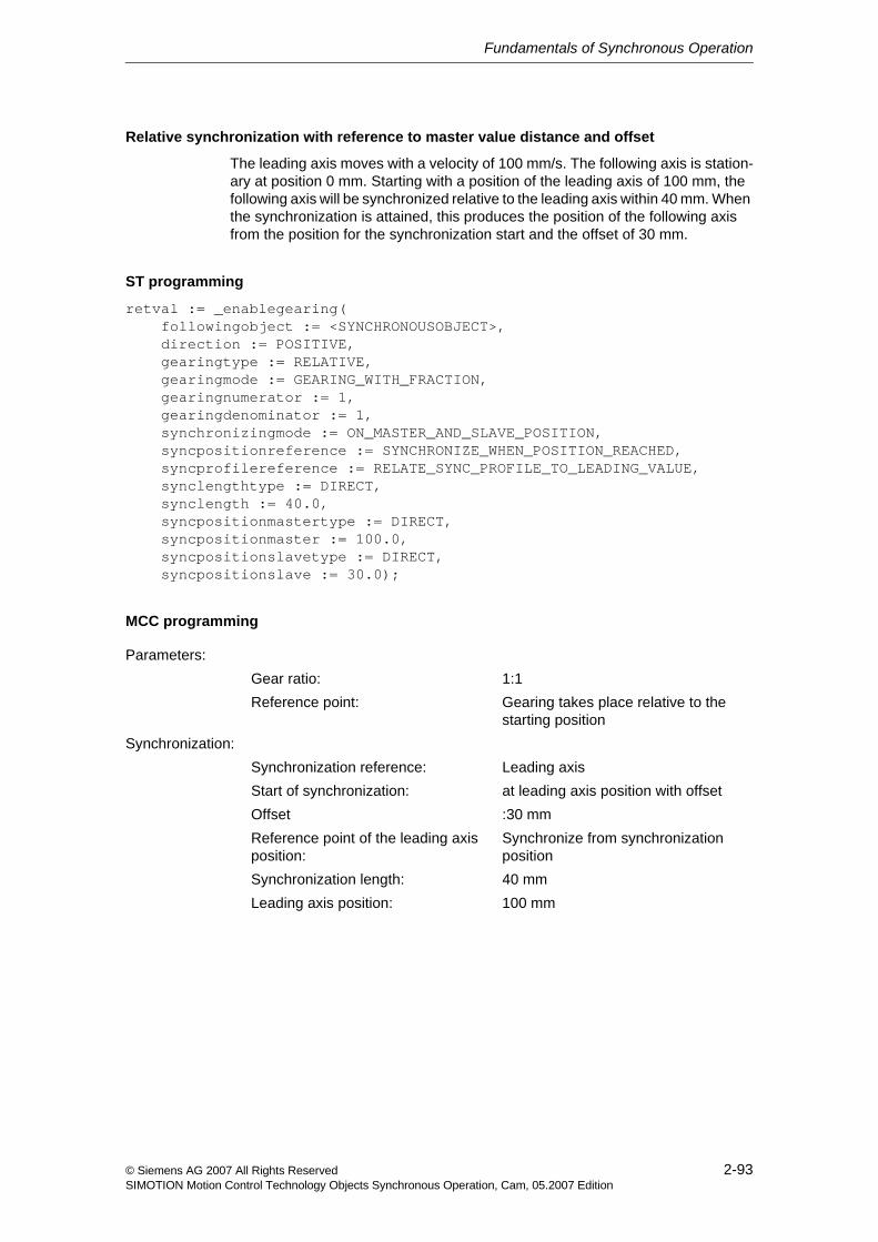
Fundamentals of Synchronous Operation
2-93© Siemens AG 2007 All Rights ReservedSIMOTION Motion Control Technology Objects Synchronous Operation, Cam, 05.2007 Edition
Relative synchronization with reference to master value distance and offset
The leading axis moves with a velocity of 100 mm/s. The following axis is station-ary at position 0 mm. Starting with a position of the leading axis of 100 mm, the following axis will be synchronized relative to the leading axis within 40 mm. When the synchronization is attained, this produces the position of the following axis from the position for the synchronization start and the offset of 30 mm.
ST programming
retval := _enablegearing( followingobject := <SYNCHRONOUSOBJECT>, direction := POSITIVE, gearingtype := RELATIVE, gearingmode := GEARING_WITH_FRACTION, gearingnumerator := 1, gearingdenominator := 1, synchronizingmode := ON_MASTER_AND_SLAVE_POSITION, syncpositionreference := SYNCHRONIZE_WHEN_POSITION_REACHED, syncprofilereference := RELATE_SYNC_PROFILE_TO_LEADING_VALUE, synclengthtype := DIRECT, synclength := 40.0, syncpositionmastertype := DIRECT, syncpositionmaster := 100.0, syncpositionslavetype := DIRECT, syncpositionslave := 30.0);
MCC programming
Parameters:Gear ratio: 1:1Reference point: Gearing takes place relative to the
starting positionSynchronization:
Synchronization reference: Leading axisStart of synchronization: at leading axis position with offsetOffset :30 mmReference point of the leading axis position:
Synchronize from synchronization position
Synchronization length: 40 mmLeading axis position: 100 mm
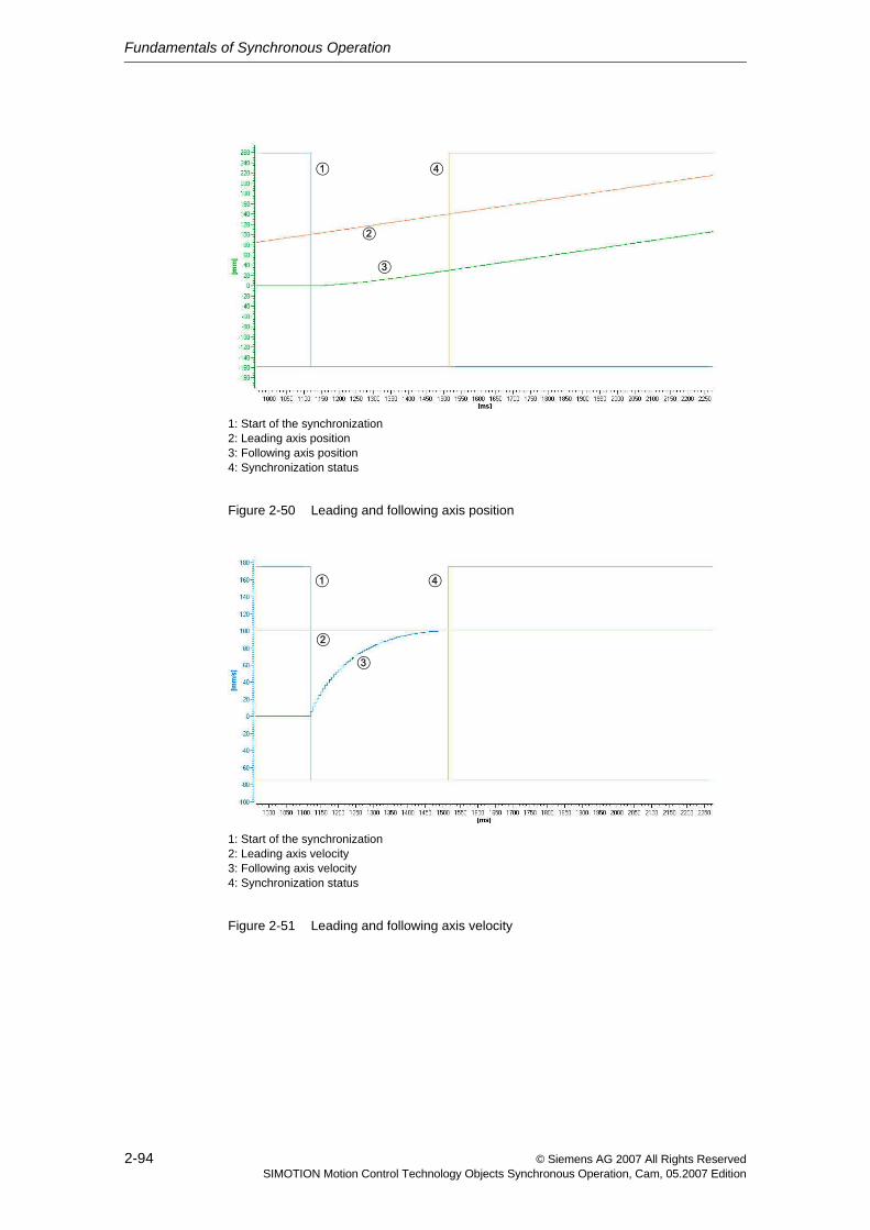
Fundamentals of Synchronous Operation
2-94 © Siemens AG 2007 All Rights ReservedSIMOTION Motion Control Technology Objects Synchronous Operation, Cam, 05.2007 Edition
Figure 2-50 Leading and following axis position
Figure 2-51 Leading and following axis velocity
1: Start of the synchronization2: Leading axis position3: Following axis position4: Synchronization status
2
3
1 4
1: Start of the synchronization2: Leading axis velocity3: Following axis velocity4: Synchronization status
2
3
1 4
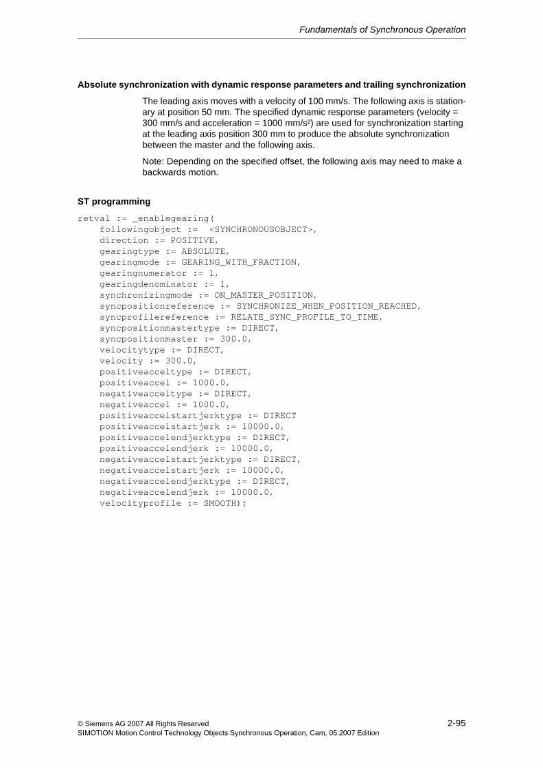
Fundamentals of Synchronous Operation
2-95© Siemens AG 2007 All Rights ReservedSIMOTION Motion Control Technology Objects Synchronous Operation, Cam, 05.2007 Edition
Absolute synchronization with dynamic response parameters and trailing synchronization
The leading axis moves with a velocity of 100 mm/s. The following axis is station-ary at position 50 mm. The specified dynamic response parameters (velocity = 300 mm/s and acceleration = 1000 mm/s²) are used for synchronization starting at the leading axis position 300 mm to produce the absolute synchronization between the master and the following axis.
Note: Depending on the specified offset, the following axis may need to make a backwards motion.
ST programming
retval := _enablegearing( followingobject := <SYNCHRONOUSOBJECT>, direction := POSITIVE, gearingtype := ABSOLUTE, gearingmode := GEARING_WITH_FRACTION, gearingnumerator := 1, gearingdenominator := 1, synchronizingmode := ON_MASTER_POSITION, syncpositionreference := SYNCHRONIZE_WHEN_POSITION_REACHED, syncprofilereference := RELATE_SYNC_PROFILE_TO_TIME, syncpositionmastertype := DIRECT, syncpositionmaster := 300.0, velocitytype := DIRECT, velocity := 300.0, positiveacceltype := DIRECT, positiveaccel := 1000.0, negativeacceltype := DIRECT, negativeaccel := 1000.0, positiveaccelstartjerktype := DIRECT positiveaccelstartjerk := 10000.0, positiveaccelendjerktype := DIRECT, positiveaccelendjerk := 10000.0, negativeaccelstartjerktype := DIRECT, negativeaccelstartjerk := 10000.0, negativeaccelendjerktype := DIRECT, negativeaccelendjerk := 10000.0, velocityprofile := SMOOTH);
Fundamentals of Synchronous Operation
2-96 © Siemens AG 2007 All Rights ReservedSIMOTION Motion Control Technology Objects Synchronous Operation, Cam, 05.2007 Edition
MCC programming
Note: For a motion with continuous velocity profile, the enable of the jerk-limited synchronization syncingMotion.smoothAbsoluteSynchronization:=YES for absolute synchronous operation relationships should be set on the synchronous object.
Figure 2-52 Leading and following axis position
Parameters:Gear ratio: 1:1Reference point: gearing is made based on the axis
zero pointSynchronization:
Synchronization reference: TimeStart of synchronization: at leading axis positionReference point of the leading axis position:
Synchronize from synchronization position
Leading axis position: 300 mmDynamic response:
Velocity: 300 mm/sDeceleration: 1000 mm/s²Jerk: 10000 mm/ s³Velocity profile: Constant
1: Start of the synchronization2: Leading axis position3: Following axis position4: Synchronization status
2
3
1 4
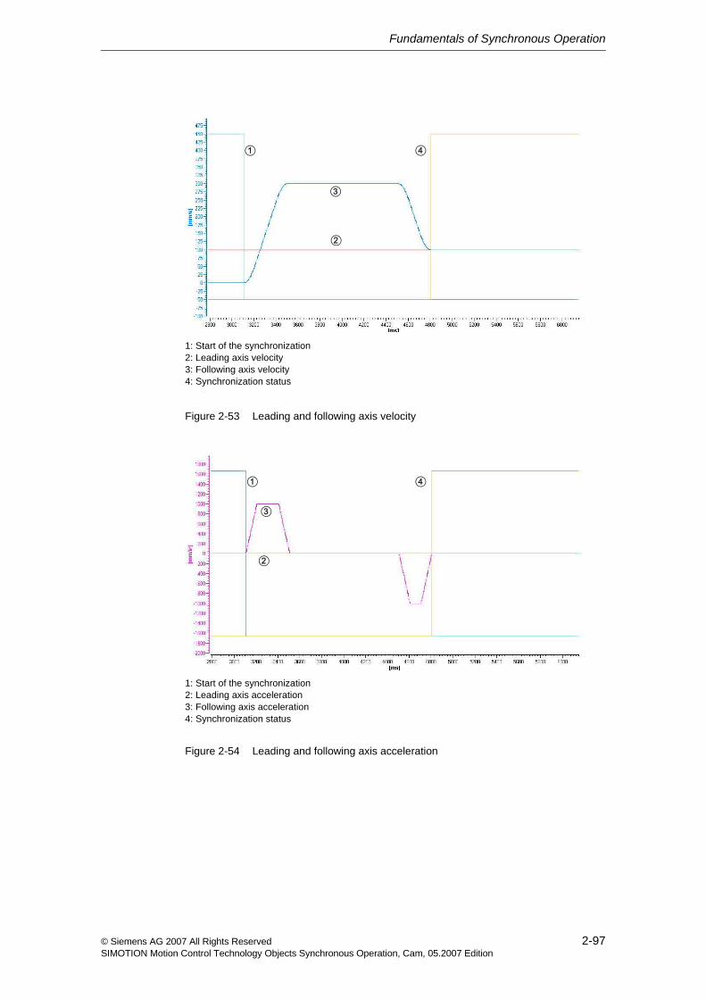
Fundamentals of Synchronous Operation
2-97© Siemens AG 2007 All Rights ReservedSIMOTION Motion Control Technology Objects Synchronous Operation, Cam, 05.2007 Edition
Figure 2-53 Leading and following axis velocity
Figure 2-54 Leading and following axis acceleration
1: Start of the synchronization2: Leading axis velocity3: Following axis velocity4: Synchronization status
2
3
1 4
1: Start of the synchronization2: Leading axis acceleration3: Following axis acceleration4: Synchronization status
2
3
1 4
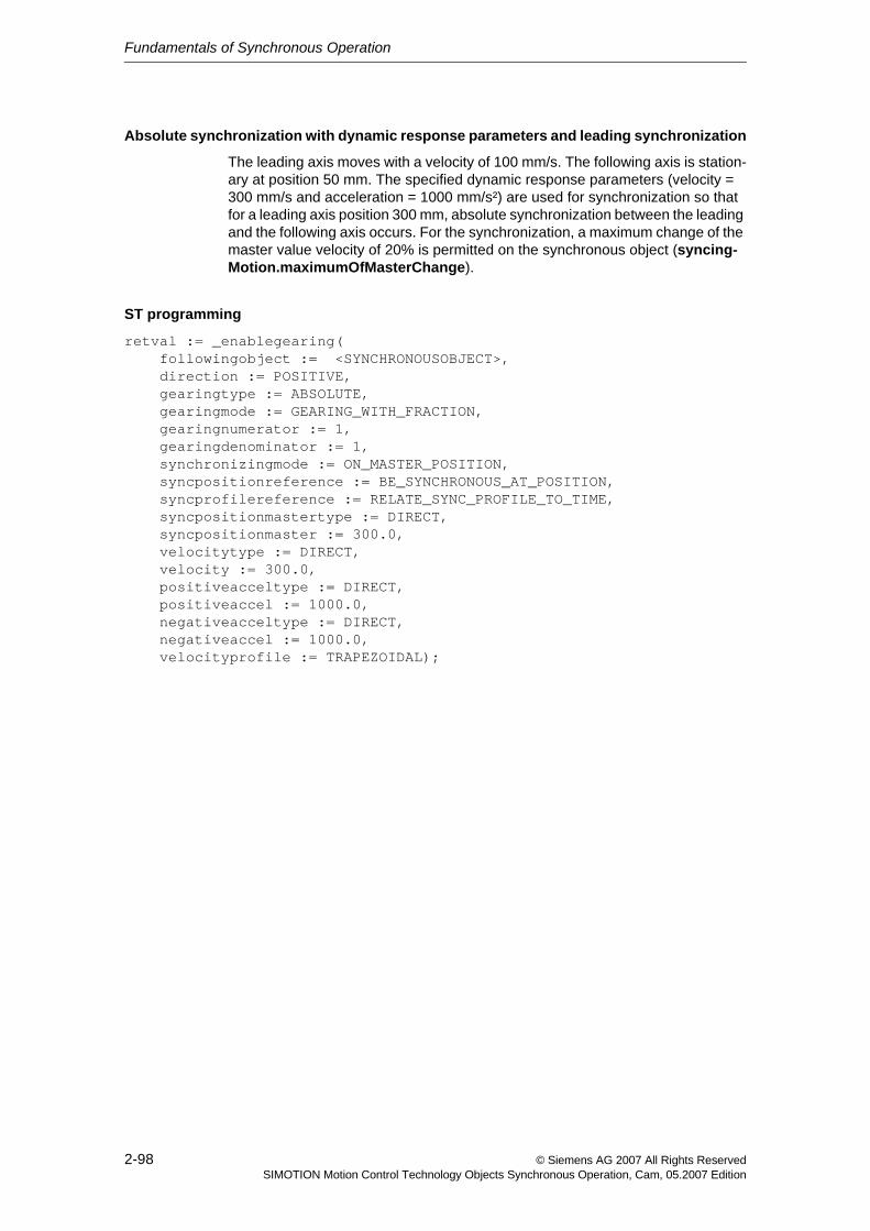
Fundamentals of Synchronous Operation
2-98 © Siemens AG 2007 All Rights ReservedSIMOTION Motion Control Technology Objects Synchronous Operation, Cam, 05.2007 Edition
Absolute synchronization with dynamic response parameters and leading synchronization
The leading axis moves with a velocity of 100 mm/s. The following axis is station-ary at position 50 mm. The specified dynamic response parameters (velocity = 300 mm/s and acceleration = 1000 mm/s²) are used for synchronization so that for a leading axis position 300 mm, absolute synchronization between the leading and the following axis occurs. For the synchronization, a maximum change of the master value velocity of 20% is permitted on the synchronous object (syncing-Motion.maximumOfMasterChange).
ST programming
retval := _enablegearing( followingobject := <SYNCHRONOUSOBJECT>, direction := POSITIVE, gearingtype := ABSOLUTE, gearingmode := GEARING_WITH_FRACTION, gearingnumerator := 1, gearingdenominator := 1, synchronizingmode := ON_MASTER_POSITION, syncpositionreference := BE_SYNCHRONOUS_AT_POSITION, syncprofilereference := RELATE_SYNC_PROFILE_TO_TIME, syncpositionmastertype := DIRECT, syncpositionmaster := 300.0, velocitytype := DIRECT, velocity := 300.0, positiveacceltype := DIRECT, positiveaccel := 1000.0, negativeacceltype := DIRECT, negativeaccel := 1000.0, velocityprofile := TRAPEZOIDAL);
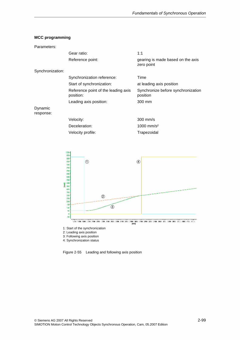
Fundamentals of Synchronous Operation
2-99© Siemens AG 2007 All Rights ReservedSIMOTION Motion Control Technology Objects Synchronous Operation, Cam, 05.2007 Edition
MCC programming
Figure 2-55 Leading and following axis position
Parameters:Gear ratio: 1:1Reference point: gearing is made based on the axis
zero pointSynchronization:
Synchronization reference: TimeStart of synchronization: at leading axis positionReference point of the leading axis position:
Synchronize before synchronization position
Leading axis position: 300 mmDynamic response:
Velocity: 300 mm/sDeceleration: 1000 mm/s²Velocity profile: Trapezoidal
1: Start of the synchronization2: Leading axis position3: Following axis position4: Synchronization status
2
3
1 4
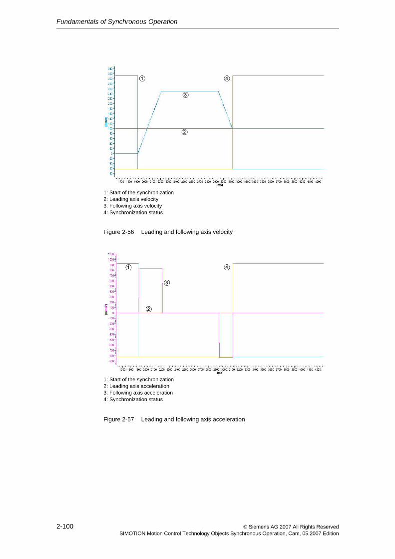
Fundamentals of Synchronous Operation
2-100 © Siemens AG 2007 All Rights ReservedSIMOTION Motion Control Technology Objects Synchronous Operation, Cam, 05.2007 Edition
Figure 2-56 Leading and following axis velocity
Figure 2-57 Leading and following axis acceleration
1: Start of the synchronization2: Leading axis velocity3: Following axis velocity4: Synchronization status
2
3
1 4
1: Start of the synchronization2: Leading axis acceleration3: Following axis acceleration4: Synchronization status
2
3
1 4
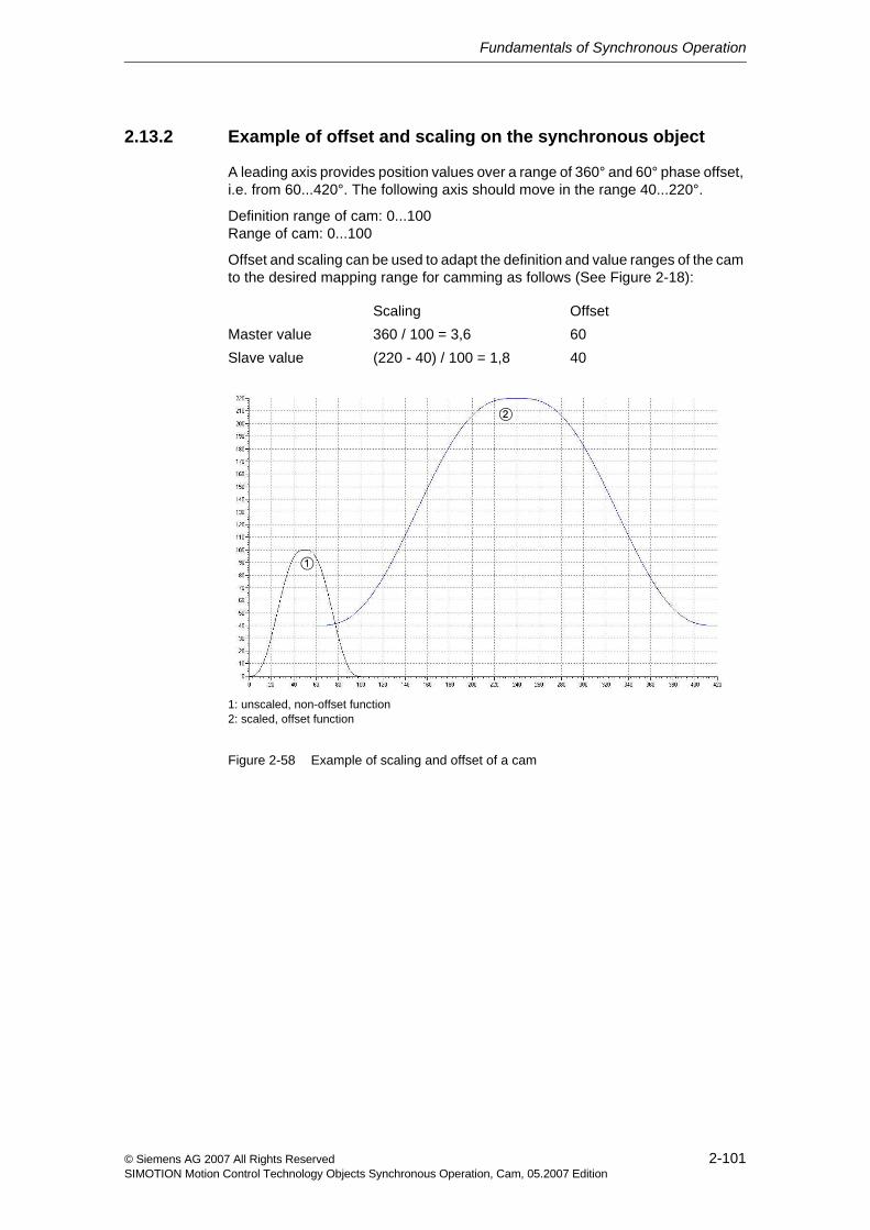
Fundamentals of Synchronous Operation
2-101© Siemens AG 2007 All Rights ReservedSIMOTION Motion Control Technology Objects Synchronous Operation, Cam, 05.2007 Edition
2.13.2 Example of offset and scaling on the synchronous object
A leading axis provides position values over a range of 360° and 60° phase offset, i.e. from 60...420°. The following axis should move in the range 40...220°.
Definition range of cam: 0...100Range of cam: 0...100
Offset and scaling can be used to adapt the definition and value ranges of the cam to the desired mapping range for camming as follows (See Figure 2-18):
Figure 2-58 Example of scaling and offset of a cam
Scaling OffsetMaster value 360 / 100 = 3,6 60Slave value (220 - 40) / 100 = 1,8 40
1: unscaled, non-offset function2: scaled, offset function
2
1
Fundamentals of Synchronous Operation
2-102 © Siemens AG 2007 All Rights ReservedSIMOTION Motion Control Technology Objects Synchronous Operation, Cam, 05.2007 Edition
In the following programming example, the offset and scaling commands on the synchronous object take effect the next time camming is activated:
ST programming
(*scaling of the master value*)retval:= _setCammingScale( followingobject := <SYNCHRONOUSOBJECT>, scalingRange := MASTER_RANGE, scaleValue := 3.6, activationMode := DEFAULT_VALUE );
(*scaling of the slave value*)retval:= _setCammingScale( followingobject := <SYNCHRONOUSOBJECT>, scalingRange := SLAVE_RANGE, scaleValue := 1.8, activationMode := DEFAULT_VALUE );
(*offset on the master value side*)retval:= _setCammingOffset( followingobject := <SYNCHRONOUSOBJECT>, offsetRange:= MASTER_RANGE, offsetMode:= ABSOLUTE, offsetValue:= 60.0, activationMode := DEFAULT_VALUE );
(*offset on the slave value side*)retval:= _setCammingOffset( followingobject := <SYNCHRONOUSOBJECT>, offsetRange:= SLAVE_RANGE, offsetMode:= ABSOLUTE, offsetValue:= 40.0, activationMode := DEFAULT_VALUE );
Fundamentals of Synchronous Operation
2-103© Siemens AG 2007 All Rights ReservedSIMOTION Motion Control Technology Objects Synchronous Operation, Cam, 05.2007 Edition
MCC programming
<Set scaling on the camming>:for the master value
<Set scaling on the camming>:for the slave value
<Set offset on the camming>:for the master value
<Set offset on the camming>:for the slave value
Parameters:
Range: Master value range
Offset: 3.6
Effect: on following commands
Parameters:
Range: Slave value range
Offset: 1.8
Effect: on following commands
Parameters:
Range: Master value range
Offset: 60.0
Mode: Absolute
Effect: on following commands
Parameters:
Range: Slave value range
Offset: 40.0
Mode: Absolute
Effect: on following commands

Fundamentals of Synchronous Operation
2-104 © Siemens AG 2007 All Rights ReservedSIMOTION Motion Control Technology Objects Synchronous Operation, Cam, 05.2007 Edition
2.13.3 Example of applying offset as superimposition
The following example shows the two dynamic corrections of the dynamic-Reference parameter in their different effects using an accelerating master value.
Example: Leading and following axis for a synchronous operation of 1:1 are abso-lutely synchronous, accelerate with 100 mm/s². The offset on the master value side of -50 mm is implemented using _setGearingOffset() with a programmed correction velocity of 300 mm/s and a correction acceleration of 3000 mm/s² using a constant acceleration velocity profile.
ST programming
retval := _setGearingOffset( followingobject := <SYNCHRONOUSOBJECT>, offsetRange:= MASTER_RANGE, offsetMode := RELATIVE, offsetValue:= -50.0, velocityType := DIRECT, velocity := 300.0, positiveAccelType := DIRECT, positiveAccel:= 3000.0, negativeAccelType := DIRECT, negativeAccel := 3000.0, velocityProfile:=TRAPEZOIDAL, activationMode := ACTUAL_VALUE, dynamicReference := TOTAL_MOVE / OFFSET_MOVE);
Note: When the master value velocity is constant, the dynamic transitions have a generally identical form and differ only as a result of the dynamic response param-eters that act differently.
Figure 2-59 Leading and following axis position for dynamicReference:= TOTAL_MOVE
1: Leading axis position2: Following axis position
2
1
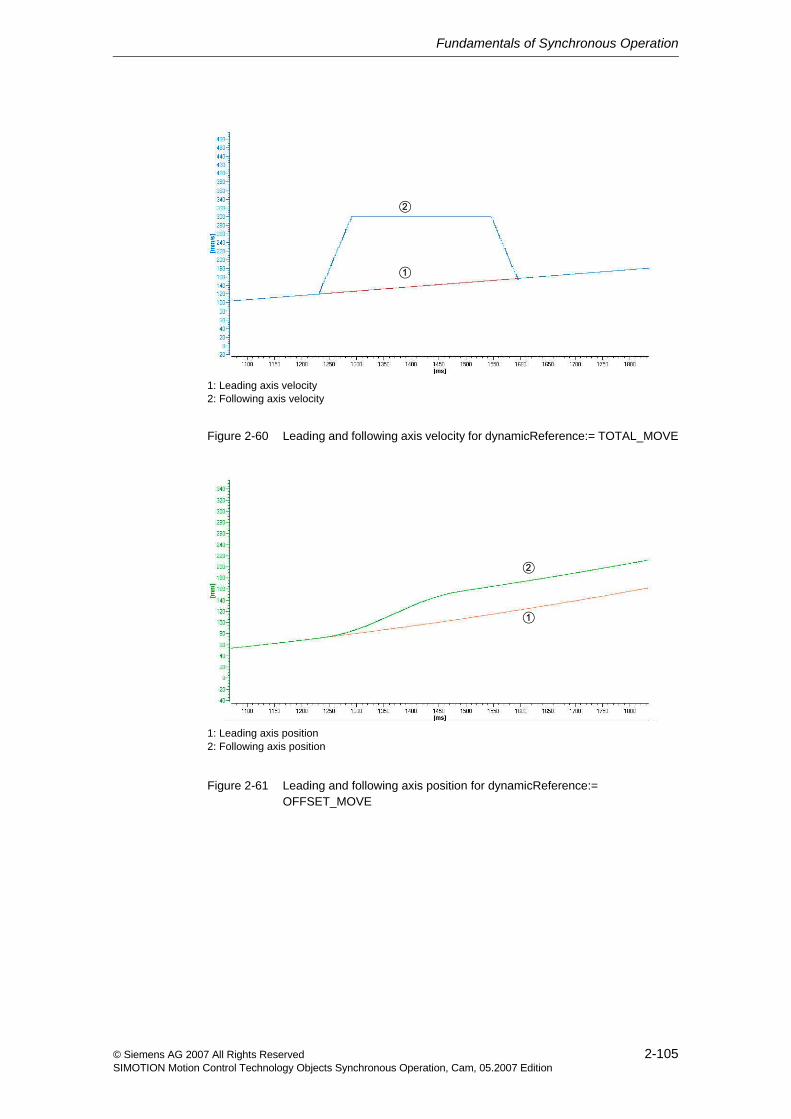
Fundamentals of Synchronous Operation
2-105© Siemens AG 2007 All Rights ReservedSIMOTION Motion Control Technology Objects Synchronous Operation, Cam, 05.2007 Edition
Figure 2-60 Leading and following axis velocity for dynamicReference:= TOTAL_MOVE
Figure 2-61 Leading and following axis position for dynamicReference:= OFFSET_MOVE
1: Leading axis velocity2: Following axis velocity
2
1
1: Leading axis position2: Following axis position
2
1
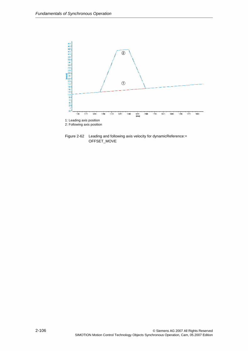
Fundamentals of Synchronous Operation
2-106 © Siemens AG 2007 All Rights ReservedSIMOTION Motion Control Technology Objects Synchronous Operation, Cam, 05.2007 Edition
Figure 2-62 Leading and following axis velocity for dynamicReference:= OFFSET_MOVE
1: Leading axis position2: Following axis position
2
1
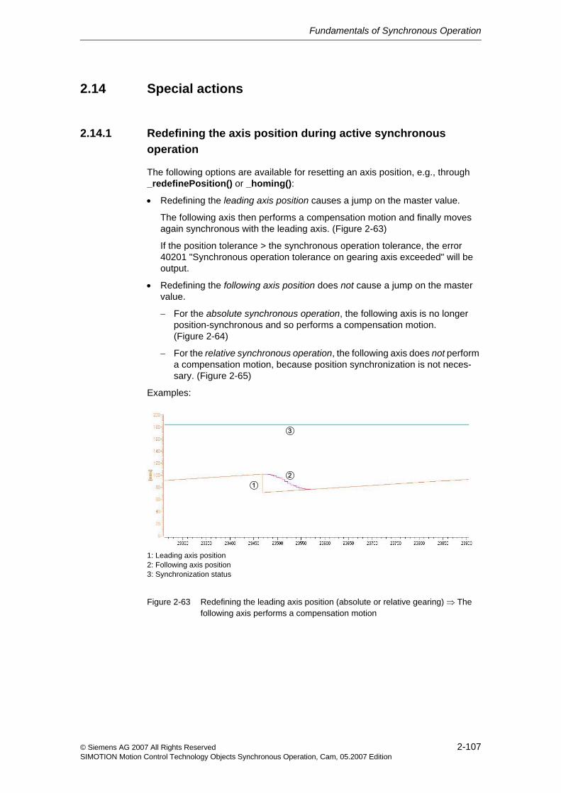
Fundamentals of Synchronous Operation
2-107© Siemens AG 2007 All Rights ReservedSIMOTION Motion Control Technology Objects Synchronous Operation, Cam, 05.2007 Edition
2.14 Special actions
2.14.1 Redefining the axis position during active synchronous operation
The following options are available for resetting an axis position, e.g., through _redefinePosition() or _homing():
• Redefining the leading axis position causes a jump on the master value.
The following axis then performs a compensation motion and finally moves again synchronous with the leading axis. (Figure 2-63)
If the position tolerance > the synchronous operation tolerance, the error 40201 "Synchronous operation tolerance on gearing axis exceeded" will be output.
• Redefining the following axis position does not cause a jump on the master value.
− For the absolute synchronous operation, the following axis is no longer position-synchronous and so performs a compensation motion. (Figure 2-64)
− For the relative synchronous operation, the following axis does not perform a compensation motion, because position synchronization is not neces-sary. (Figure 2-65)
Examples:
Figure 2-63 Redefining the leading axis position (absolute or relative gearing) ⇒ The following axis performs a compensation motion
1: Leading axis position2: Following axis position3: Synchronization status
21
3

Fundamentals of Synchronous Operation
2-108 © Siemens AG 2007 All Rights ReservedSIMOTION Motion Control Technology Objects Synchronous Operation, Cam, 05.2007 Edition
Figure 2-64 Redefining the following axis position for the absolute gearing ⇒ The fol-lowing axis performs a compensation motion
Figure 2-65 Redefining the following axis position for the relative gearing ⇒ The follow-ing axis does not perform a compensation motion
1: Leading axis position2: Following axis position3: Synchronization status
2
1
3
1: Leading axis position2: Following axis position3: Synchronization status
2
1
3
Fundamentals of Synchronous Operation
2-109© Siemens AG 2007 All Rights ReservedSIMOTION Motion Control Technology Objects Synchronous Operation, Cam, 05.2007 Edition
2.14.2 Retaining a synchronous operation connection with _disableAxis()
If the following axis is no longer able to apply the generated synchronous set-points, e.g. due to the removal of enables or an error reaction, an active synchro-nous connection is closed.
It is possible to retain the synchronous connection by using synchronous opera-tion in simulation mode and setting configuration data DecodingConfig.disable-SynchronousOperation=YES on the synchronous object.
See Simulation mode (Section 2.11)
The existing synchronous connection remains active except in the following situ-ations:
• Restart of following axis (_restartAxis())
• Invalid actual values on the following axis
When simulation mode is terminated, the current synchronous setpoints are applied immediately as axis setpoints.
Remove the axis from the synchronous operation interconnection, and return it(Example: Opening and closing of safety doors)
Removing axis from the synchronous operation interconnection:
1. Stop the leading axis.
2. Switch the synchronous operation to simulation mode.
3. DecodingConfig.disableSynchronousOperation on the synchronous object must be set to YES. As a result, the synchronous operation connection is not disconnected on _disableAxis.
4. If a superimposed motion has been performed (e.g. for correcting):
− Save the position of the superimposed coordinate in a user variable.
− Perform _redefinePosition() in of coordinate 2 to absolute position 0.
5. Cancel the controller enables (_disableAxis()). This will clear the drives. The axis goes into follow-up mode / "control" on the axes is deleted.
Return the axis to the synchronous operation interconnection:
1. Reconnect the controller enables.
2. If necessary, use _redefinePosition() to pass the saved actual position as an absolute position to the coordinate 2.
3. Reactivate axis/drive with _enableAxis().
4. Switch synchronous operation back from simulation mode.
A compensation motion will be performed if the setpoints for the synchronous object and the setpoints on the axis do not match.
Fundamentals of Synchronous Operation
2-110 © Siemens AG 2007 All Rights ReservedSIMOTION Motion Control Technology Objects Synchronous Operation, Cam, 05.2007 Edition
2.14.3 Substitution of velocity gearing with absolute synchronous operation
A synchronous velocity operation cannot be substituted directly with an absolute synchronous operation. Immediately afterwards, only a relative synchronous operation can be executed.
If an attempt is made to execute an absolute synchronous operation immediately after a velocity gearing, the following technological alarm is output: 50110: "An absolute position synchronous operation cannot be called following a velocity synchronous operation." (V3.2 and higher)
Procedure:
• Switch a relative position-controlled synchronous operation in between for at least one IPO cycle. (mergeMode = IMMEDIATELY and then a waitTime with Time = 0 sec)
2.14.4 Canceling active and pending synchronous operations
If gearing or camming is active and another gearing or camming operation is started, the first _disableCamming()/disableGearing() command ends the syn-chronous operation to be synchronized, and the second _disableCamming()/_disableGearing() command ends the active synchronous operation.
Alternatively, in V4.1 and higher the synchronous operation commands can be canceled using the commandId associated with the command. The _cancelFollowingObjectCommand() command can be used to cancel the syn-chronous operation command by specifying the commandId in the commandTo-BeCancelled parameter. This removes the synchronous operation command from the command buffer.
This means that a pending command for the synchronization can be canceled, for example, if the application recognizes that resynchronization is not to occur.
Fundamentals of Synchronous Operation
2-111© Siemens AG 2007 All Rights ReservedSIMOTION Motion Control Technology Objects Synchronous Operation, Cam, 05.2007 Edition
2.14.5 Adapt the synchronization velocity to the master value velocity
If, for absolute synchronization, the synchronization velocity must be adapted to the master value velocity, proceed as follows:
1. Set the synchronization velocity initially to a value less than the resulting syn-chronization velocity.
2. Set adaption.
3. Set an appropriate magnification factor.
See Adaptation to the dynamic response of the master value (leading and trailing synchronization) on page 2-50
This allows the synchronization velocity of the following axis to be adapted to the master value velocity.
If the synchronization velocity is to be restricted, the magnification factor must be reduced accordingly.
For further information refer to Synchronizing (Section 2.5)
Fundamentals of Synchronous Operation
2-112 © Siemens AG 2007 All Rights ReservedSIMOTION Motion Control Technology Objects Synchronous Operation, Cam, 05.2007 Edition
3-113© Siemens AG 2007 All Rights ReservedSIMOTION Motion Control Technology Objects Synchronous Operation, Cam, 05.2007 Edition
Configuring Synchronous Operation 3This section shows you how to create and configure axes with synchronous operation in the SIMOTION SCOUT.
As a requirement, you must have already created master axes or external encod-ers, as well as cams.
Content
3.1 Creating an axis with synchronous operation 3-114
3.2 Assigning master values and cams 3-117
3.3 Assigning parameters/defaults for synchronous operation 3-119
3.4 Set synchronization 3-136
3.5 Configuring synchronous operation monitoring 3-138
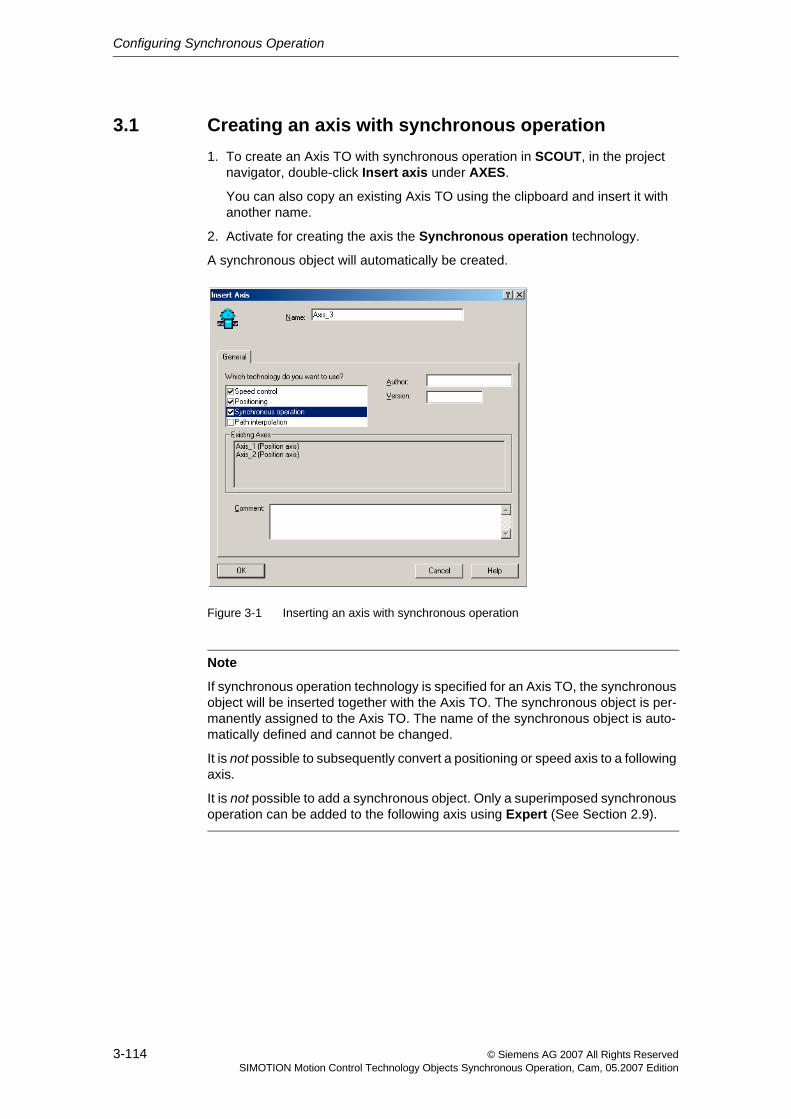
Configuring Synchronous Operation
3-114 © Siemens AG 2007 All Rights ReservedSIMOTION Motion Control Technology Objects Synchronous Operation, Cam, 05.2007 Edition
3.1 Creating an axis with synchronous operation1. To create an Axis TO with synchronous operation in SCOUT, in the project
navigator, double-click Insert axis under AXES.
You can also copy an existing Axis TO using the clipboard and insert it with another name.
2. Activate for creating the axis the Synchronous operation technology.
A synchronous object will automatically be created.
Figure 3-1 Inserting an axis with synchronous operation
Note
If synchronous operation technology is specified for an Axis TO, the synchronous object will be inserted together with the Axis TO. The synchronous object is per-manently assigned to the Axis TO. The name of the synchronous object is auto-matically defined and cannot be changed.
It is not possible to subsequently convert a positioning or speed axis to a following axis.
It is not possible to add a synchronous object. Only a superimposed synchronous operation can be added to the following axis using Expert (See Section 2.9).
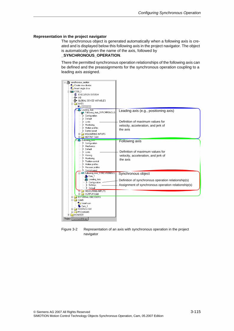
Configuring Synchronous Operation
3-115© Siemens AG 2007 All Rights ReservedSIMOTION Motion Control Technology Objects Synchronous Operation, Cam, 05.2007 Edition
Representation in the project navigatorThe synchronous object is generated automatically when a following axis is cre-ated and is displayed below this following axis in the project navigator. The object is automatically given the name of the axis, followed by _SYNCHRONOUS_OPERATION.
There the permitted synchronous operation relationships of the following axis can be defined and the preassignments for the synchronous operation coupling to a leading axis assigned.
Figure 3-2 Representation of an axis with synchronous operation in the project navigator
Leading axis (e.g., positioning axis)
Definition of maximum values for velocity, acceleration, and jerk of the axis
Definition of maximum values for velocity, acceleration, and jerk of the axis
Definition of synchronous operation relationship(s)Assignment of synchronous operation relationship(s)
Synchronous object
Following axis
Configuring Synchronous Operation
3-116 © Siemens AG 2007 All Rights ReservedSIMOTION Motion Control Technology Objects Synchronous Operation, Cam, 05.2007 Edition
The assignment of the master values and cams is indicated in the project naviga-tor using links:
• For the Synchronous object: Links to the master values (axes, external encoders, addition objects, formula objects, and fixed gears) as well as cams
• For the technology objects used: Link to the synchronous object
• For the master values (axes, external encoders, addition objects, formula objects, and fixed gears): Link to the synchronous object
Superimposed synchronous operation
If a superimposed synchronous operation relationship to another master value is also to be established, an additional synchronous object can be placed below the following axis via the context menu for the following axis (Expert > Insert super-imposed synchronous object) (See Section 2.9).
The standard and superimposed synchronous operation relationships then affect the following axis additively by means of the two master values.
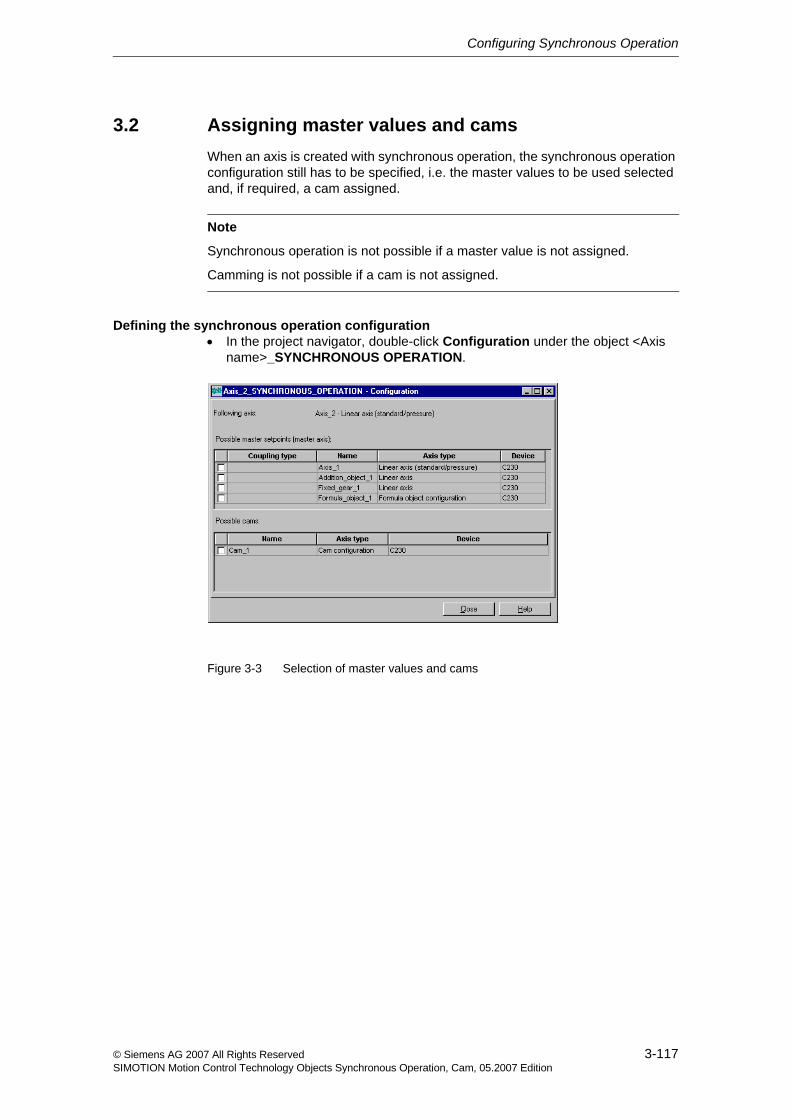
Configuring Synchronous Operation
3-117© Siemens AG 2007 All Rights ReservedSIMOTION Motion Control Technology Objects Synchronous Operation, Cam, 05.2007 Edition
3.2 Assigning master values and camsWhen an axis is created with synchronous operation, the synchronous operation configuration still has to be specified, i.e. the master values to be used selected and, if required, a cam assigned.
Defining the synchronous operation configuration• In the project navigator, double-click Configuration under the object <Axis
name>_SYNCHRONOUS OPERATION.
Figure 3-3 Selection of master values and cams
Note
Synchronous operation is not possible if a master value is not assigned.
Camming is not possible if a cam is not assigned.
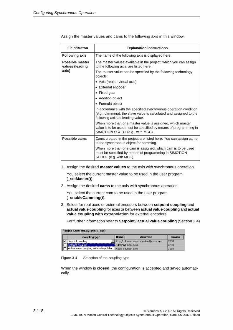
Configuring Synchronous Operation
3-118 © Siemens AG 2007 All Rights ReservedSIMOTION Motion Control Technology Objects Synchronous Operation, Cam, 05.2007 Edition
Assign the master values and cams to the following axis in this window.
1. Assign the desired master values to the axis with synchronous operation.
You select the current master value to be used in the user program (_setMaster()).
2. Assign the desired cams to the axis with synchronous operation.
You select the current cam to be used in the user program (_enableCamming()).
3. Select for real axes or external encoders between setpoint coupling and actual value coupling for axes or between actual value coupling and actual value coupling with extrapolation for external encoders.
For further information refer to Setpoint / actual value coupling (Section 2.4)
Figure 3-4 Selection of the coupling type
When the window is closed, the configuration is accepted and saved automati-cally.
Field/Button Explanation/instructions
Following axis The name of the following axis is displayed here.
Possible master values (leading axis)
The master values available in the project, which you can assign to the following axis, are listed here.The master value can be specified by the following technology objects:• Axis (real or virtual axis)• External encoder• Fixed gear• Addition object• Formula objectIn accordance with the specified synchronous operation condition (e.g., camming), the slave value is calculated and assigned to the following axis as leading value.When more than one master value is assigned, which master value is to be used must be specified by means of programming in SIMOTION SCOUT (e.g., with MCC).
Possible cams Cams created in the project are listed here. You can assign cams to the synchronous object for camming.When more than one cam is assigned, which cam is to be used must be specified by means of programming in SIMOTION SCOUT (e.g. with MCC).
Configuring Synchronous Operation
3-119© Siemens AG 2007 All Rights ReservedSIMOTION Motion Control Technology Objects Synchronous Operation, Cam, 05.2007 Edition
3.3 Assigning parameters/defaults for synchronous operation• In the project navigator, double-click Default under the object <Axis
name>_SYNCHRONOUS OPERATION.
In Default window, you define the replacement values for calling the synchronous operation functions (_enableGearing(), _enableVelocityGearing() and _enableCamming() or _disableGearing(), _disableVelocityGearing() and _disableCamming()).
These replacement values are only evaluated when in the associated function calls for the synchronization/desynchronization (ST and LAD/FBD or MCC) no special settings are made.
You can set parameters for the following functionality:
• Gearing (Section 3.3.1)
• Synchronous velocity operation (Section 3.3.2)
• Camming (Section 3.3.3)
• Gearing synchronization (Section 3.3.4)
• Camming synchronization (Section 3.3.9)
• Dynamic response (Section 3.3.12)
• Master dynamic response (Section 3.3.13)
Further Information
• For information about function, see Chapter 1 and Chapter 2.
• For information about programming, see Chapter 4.
• The meaning of the dialog window parameters and their permissible value ranges can be found in the SIMOTION reference lists.
Note
All tabs are always available for default settings. Only parameters used for the rel-evant functionality are evaluated.
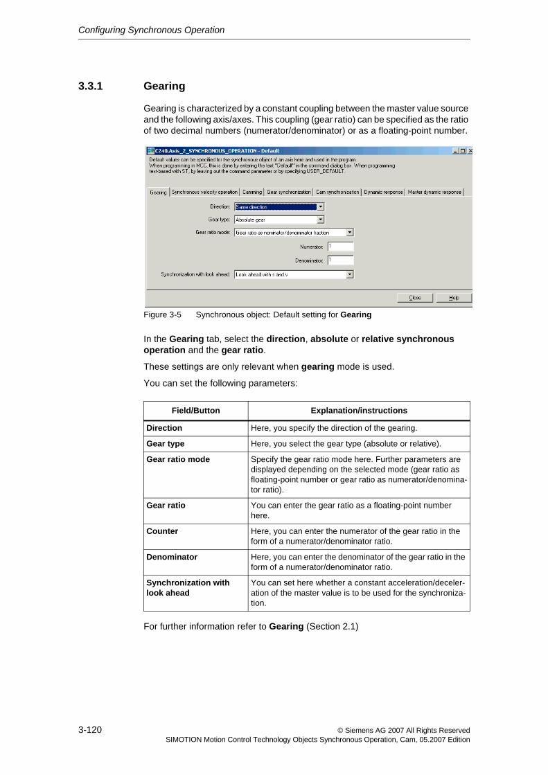
Configuring Synchronous Operation
3-120 © Siemens AG 2007 All Rights ReservedSIMOTION Motion Control Technology Objects Synchronous Operation, Cam, 05.2007 Edition
3.3.1 Gearing
Gearing is characterized by a constant coupling between the master value source and the following axis/axes. This coupling (gear ratio) can be specified as the ratio of two decimal numbers (numerator/denominator) or as a floating-point number.
Figure 3-5 Synchronous object: Default setting for Gearing
In the Gearing tab, select the direction, absolute or relative synchronous operation and the gear ratio.
These settings are only relevant when gearing mode is used.
You can set the following parameters:
For further information refer to Gearing (Section 2.1)
Field/Button Explanation/instructions
Direction Here, you specify the direction of the gearing.
Gear type Here, you select the gear type (absolute or relative).
Gear ratio mode Specify the gear ratio mode here. Further parameters are displayed depending on the selected mode (gear ratio as floating-point number or gear ratio as numerator/denomina-tor ratio).
Gear ratio You can enter the gear ratio as a floating-point number here.
Counter Here, you can enter the numerator of the gear ratio in the form of a numerator/denominator ratio.
Denominator Here, you can enter the denominator of the gear ratio in the form of a numerator/denominator ratio.
Synchronization with look ahead
You can set here whether a constant acceleration/deceler-ation of the master value is to be used for the synchroniza-tion.
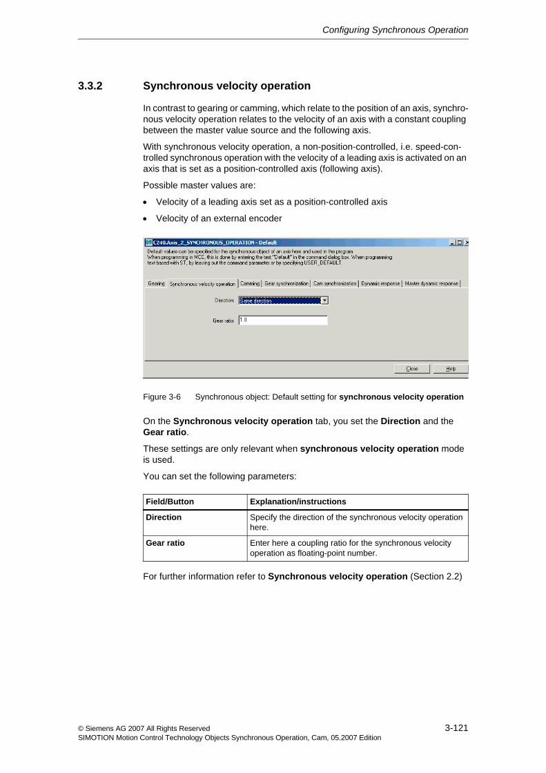
Configuring Synchronous Operation
3-121© Siemens AG 2007 All Rights ReservedSIMOTION Motion Control Technology Objects Synchronous Operation, Cam, 05.2007 Edition
3.3.2 Synchronous velocity operation
In contrast to gearing or camming, which relate to the position of an axis, synchro-nous velocity operation relates to the velocity of an axis with a constant coupling between the master value source and the following axis.
With synchronous velocity operation, a non-position-controlled, i.e. speed-con-trolled synchronous operation with the velocity of a leading axis is activated on an axis that is set as a position-controlled axis (following axis).
Possible master values are:
• Velocity of a leading axis set as a position-controlled axis
• Velocity of an external encoder
Figure 3-6 Synchronous object: Default setting for synchronous velocity operation
On the Synchronous velocity operation tab, you set the Direction and the Gear ratio.
These settings are only relevant when synchronous velocity operation mode is used.
You can set the following parameters:
For further information refer to Synchronous velocity operation (Section 2.2)
Field/Button Explanation/instructions
Direction Specify the direction of the synchronous velocity operation here.
Gear ratio Enter here a coupling ratio for the synchronous velocity operation as floating-point number.
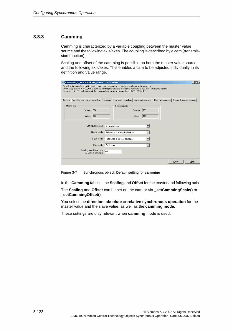
Configuring Synchronous Operation
3-122 © Siemens AG 2007 All Rights ReservedSIMOTION Motion Control Technology Objects Synchronous Operation, Cam, 05.2007 Edition
3.3.3 Camming
Camming is characterized by a variable coupling between the master value source and the following axis/axes. The coupling is described by a cam (transmis-sion function).
Scaling and offset of the camming is possible on both the master value source and the following axis/axes. This enables a cam to be adjusted individually in its definition and value range.
Figure 3-7 Synchronous object: Default setting for camming
In the Camming tab, set the Scaling and Offset for the master and following axis.
The Scaling and Offset can be set on the cam or via _setCammingScale() or _setCammingOffset().
You select the direction, absolute or relative synchronous operation for the master value and the slave value, as well as the camming mode.
These settings are only relevant when camming mode is used.
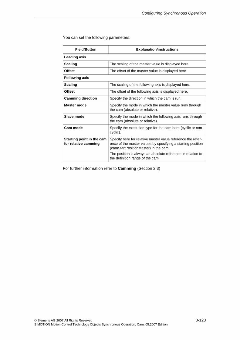
Configuring Synchronous Operation
3-123© Siemens AG 2007 All Rights ReservedSIMOTION Motion Control Technology Objects Synchronous Operation, Cam, 05.2007 Edition
You can set the following parameters:
For further information refer to Camming (Section 2.3)
Field/Button Explanation/instructions
Leading axis
Scaling The scaling of the master value is displayed here.
Offset The offset of the master value is displayed here.
Following axis
Scaling The scaling of the following axis is displayed here.
Offset The offset of the following axis is displayed here.
Camming direction Specify the direction in which the cam is run.
Master mode Specify the mode in which the master value runs through the cam (absolute or relative).
Slave mode Specify the mode in which the following axis runs through the cam (absolute or relative).
Cam mode Specify the execution type for the cam here (cyclic or non-cyclic).
Starting point in the cam for relative camming
Specify here for relative master value reference the refer-ence of the master values by specifying a starting position (camStartPositionMaster) in the cam.The position is always an absolute reference in relation to the definition range of the cam.
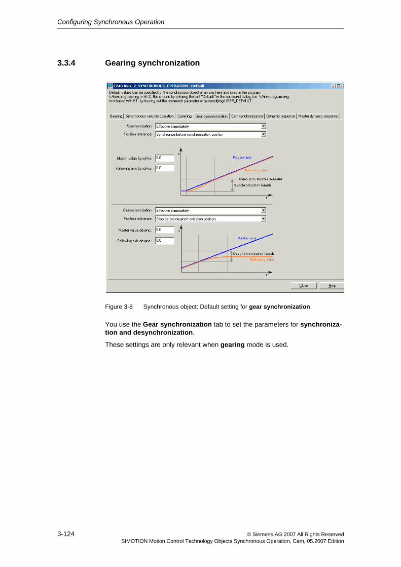
Configuring Synchronous Operation
3-124 © Siemens AG 2007 All Rights ReservedSIMOTION Motion Control Technology Objects Synchronous Operation, Cam, 05.2007 Edition
3.3.4 Gearing synchronization
Figure 3-8 Synchronous object: Default setting for gear synchronization
You use the Gear synchronization tab to set the parameters for synchroniza-tion and desynchronization.
These settings are only relevant when gearing mode is used.
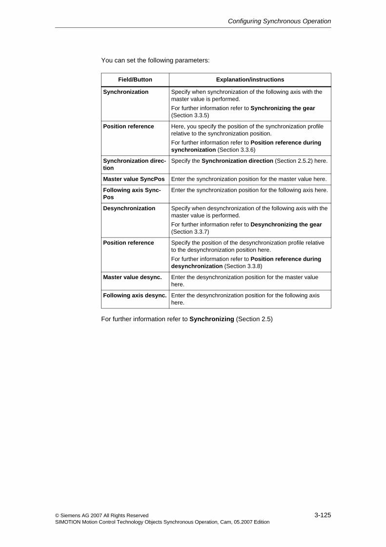
Configuring Synchronous Operation
3-125© Siemens AG 2007 All Rights ReservedSIMOTION Motion Control Technology Objects Synchronous Operation, Cam, 05.2007 Edition
You can set the following parameters:
For further information refer to Synchronizing (Section 2.5)
Field/Button Explanation/instructions
Synchronization Specify when synchronization of the following axis with the master value is performed.For further information refer to Synchronizing the gear (Section 3.3.5)
Position reference Here, you specify the position of the synchronization profile relative to the synchronization position.For further information refer to Position reference during synchronization (Section 3.3.6)
Synchronization direc-tion
Specify the Synchronization direction (Section 2.5.2) here.
Master value SyncPos Enter the synchronization position for the master value here.
Following axis Sync-Pos
Enter the synchronization position for the following axis here.
Desynchronization Specify when desynchronization of the following axis with the master value is performed.For further information refer to Desynchronizing the gear (Section 3.3.7)
Position reference Specify the position of the desynchronization profile relative to the desynchronization position here.For further information refer to Position reference during desynchronization (Section 3.3.8)
Master value desync. Enter the desynchronization position for the master value here.
Following axis desync. Enter the desynchronization position for the following axis here.
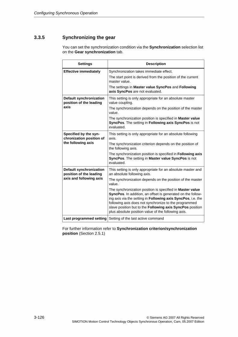
Configuring Synchronous Operation
3-126 © Siemens AG 2007 All Rights ReservedSIMOTION Motion Control Technology Objects Synchronous Operation, Cam, 05.2007 Edition
3.3.5 Synchronizing the gear
You can set the synchronization condition via the Synchronization selection list on the Gear synchronization tab.
For further information refer to Synchronization criterion/synchronization position (Section 2.5.1)
Settings Description
Effective immediately Synchronization takes immediate effect.The start point is derived from the position of the current master value.The settings in Master value SyncPos and Following axis SyncPos are not evaluated.
Default synchronization position of the leading axis
This setting is only appropriate for an absolute master value coupling.The synchronization depends on the position of the master value.The synchronization position is specified in Master value SyncPos. The setting in Following axis SyncPos is not evaluated.
Specified by the syn-chronization position of the following axis
This setting is only appropriate for an absolute following axis.The synchronization criterion depends on the position of the following axis.The synchronization position is specified in Following axis SyncPos. The setting in Master value SyncPos is not evaluated.
Default synchronization position of the leading axis and following axis
This setting is only appropriate for an absolute master and an absolute following axis.The synchronization depends on the position of the master value.The synchronization position is specified in Master value SyncPos. In addition, an offset is generated on the follow-ing axis via the setting in Following axis SyncPos, i.e. the following axis does not synchronize to the programmed slave position but to the Following axis SyncPos position plus absolute position value of the following axis.
Last programmed setting Setting of the last active command
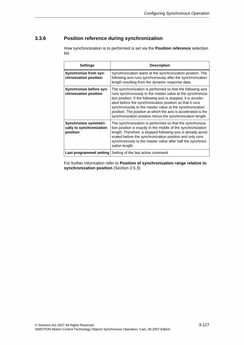
Configuring Synchronous Operation
3-127© Siemens AG 2007 All Rights ReservedSIMOTION Motion Control Technology Objects Synchronous Operation, Cam, 05.2007 Edition
3.3.6 Position reference during synchronization
How synchronization is to performed is set via the Position reference selection list.
For further information refer to Position of synchronization range relative to synchronization position (Section 2.5.3)
Settings Description
Synchronize from syn-chronization position
Synchronization starts at the synchronization position. The following axis runs synchronously after the synchronization length resulting from the dynamic response data.
Synchronize before syn-chronization position
The synchronization is performed so that the following axis runs synchronously to the master value at the synchroniza-tion position. If the following axis is stopped, it is acceler-ated before the synchronization position so that it runs synchronously to the master value at the synchronization position. The position at which the axis is accelerated is the synchronization position minus the synchronization length.
Synchronize symmetri-cally to synchronization position
The synchronization is performed so that the synchroniza-tion position is exactly in the middle of the synchronization length. Therefore, a stopped following axis is already accel-erated before the synchronization position and only runs synchronously to the master value after half the synchroni-zation length.
Last programmed setting Setting of the last active command
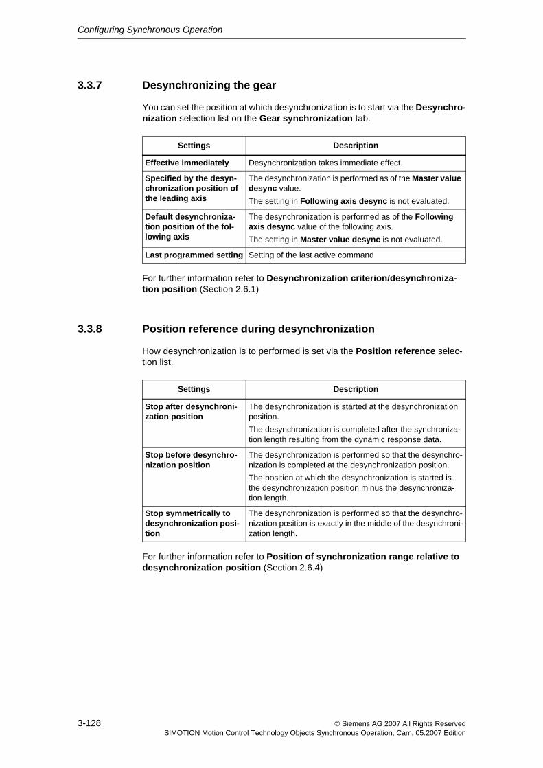
Configuring Synchronous Operation
3-128 © Siemens AG 2007 All Rights ReservedSIMOTION Motion Control Technology Objects Synchronous Operation, Cam, 05.2007 Edition
3.3.7 Desynchronizing the gear
You can set the position at which desynchronization is to start via the Desynchro-nization selection list on the Gear synchronization tab.
For further information refer to Desynchronization criterion/desynchroniza-tion position (Section 2.6.1)
3.3.8 Position reference during desynchronization
How desynchronization is to performed is set via the Position reference selec-tion list.
For further information refer to Position of synchronization range relative to desynchronization position (Section 2.6.4)
Settings Description
Effective immediately Desynchronization takes immediate effect.
Specified by the desyn-chronization position of the leading axis
The desynchronization is performed as of the Master value desync value.The setting in Following axis desync is not evaluated.
Default desynchroniza-tion position of the fol-lowing axis
The desynchronization is performed as of the Following axis desync value of the following axis.The setting in Master value desync is not evaluated.
Last programmed setting Setting of the last active command
Settings Description
Stop after desynchroni-zation position
The desynchronization is started at the desynchronization position.The desynchronization is completed after the synchroniza-tion length resulting from the dynamic response data.
Stop before desynchro-nization position
The desynchronization is performed so that the desynchro-nization is completed at the desynchronization position.The position at which the desynchronization is started is the desynchronization position minus the desynchroniza-tion length.
Stop symmetrically to desynchronization posi-tion
The desynchronization is performed so that the desynchro-nization position is exactly in the middle of the desynchroni-zation length.
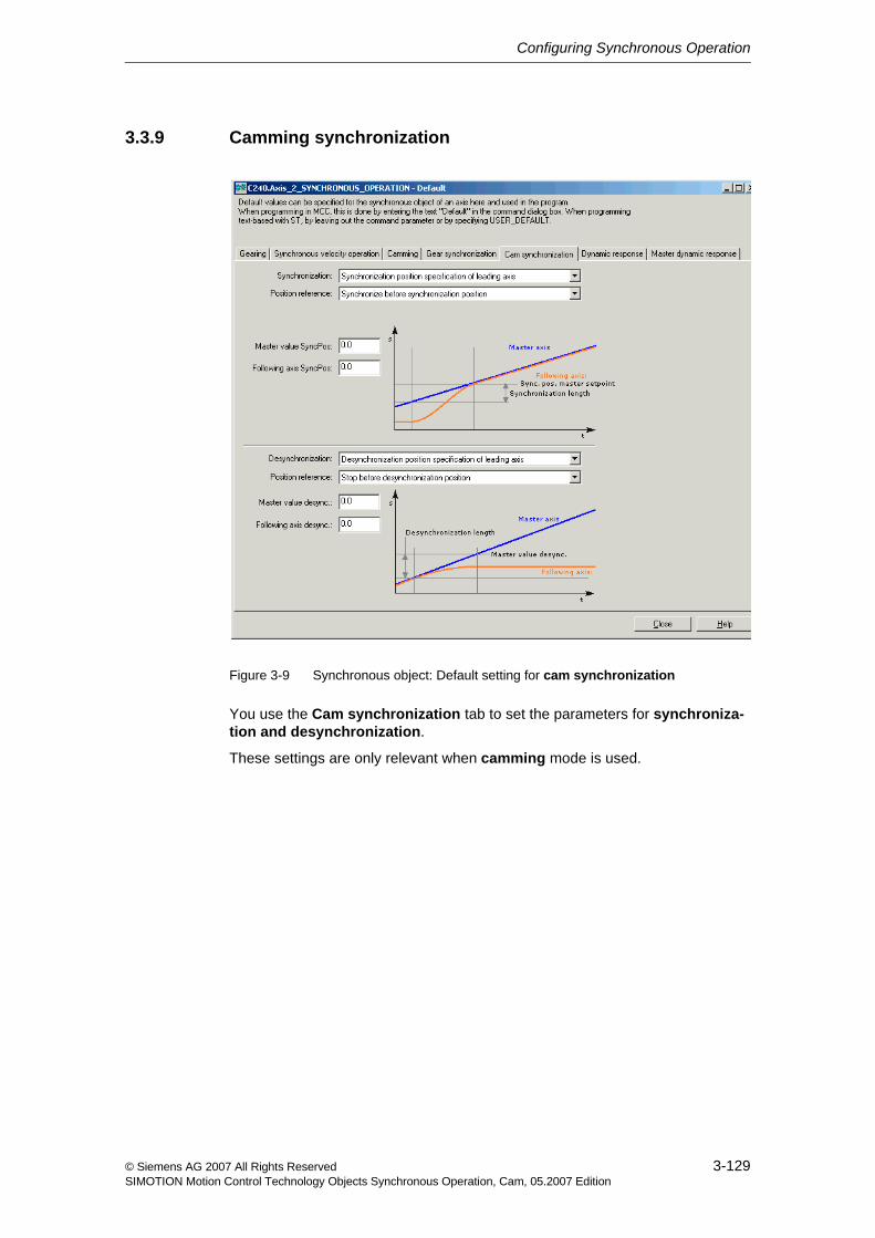
Configuring Synchronous Operation
3-129© Siemens AG 2007 All Rights ReservedSIMOTION Motion Control Technology Objects Synchronous Operation, Cam, 05.2007 Edition
3.3.9 Camming synchronization
Figure 3-9 Synchronous object: Default setting for cam synchronization
You use the Cam synchronization tab to set the parameters for synchroniza-tion and desynchronization.
These settings are only relevant when camming mode is used.
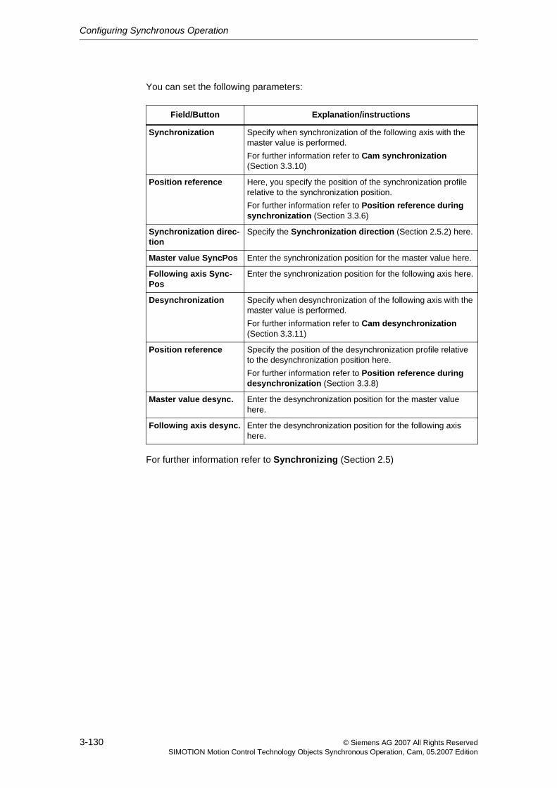
Configuring Synchronous Operation
3-130 © Siemens AG 2007 All Rights ReservedSIMOTION Motion Control Technology Objects Synchronous Operation, Cam, 05.2007 Edition
You can set the following parameters:
For further information refer to Synchronizing (Section 2.5)
Field/Button Explanation/instructions
Synchronization Specify when synchronization of the following axis with the master value is performed.For further information refer to Cam synchronization (Section 3.3.10)
Position reference Here, you specify the position of the synchronization profile relative to the synchronization position.For further information refer to Position reference during synchronization (Section 3.3.6)
Synchronization direc-tion
Specify the Synchronization direction (Section 2.5.2) here.
Master value SyncPos Enter the synchronization position for the master value here.
Following axis Sync-Pos
Enter the synchronization position for the following axis here.
Desynchronization Specify when desynchronization of the following axis with the master value is performed.For further information refer to Cam desynchronization (Section 3.3.11)
Position reference Specify the position of the desynchronization profile relative to the desynchronization position here.For further information refer to Position reference during desynchronization (Section 3.3.8)
Master value desync. Enter the desynchronization position for the master value here.
Following axis desync. Enter the desynchronization position for the following axis here.
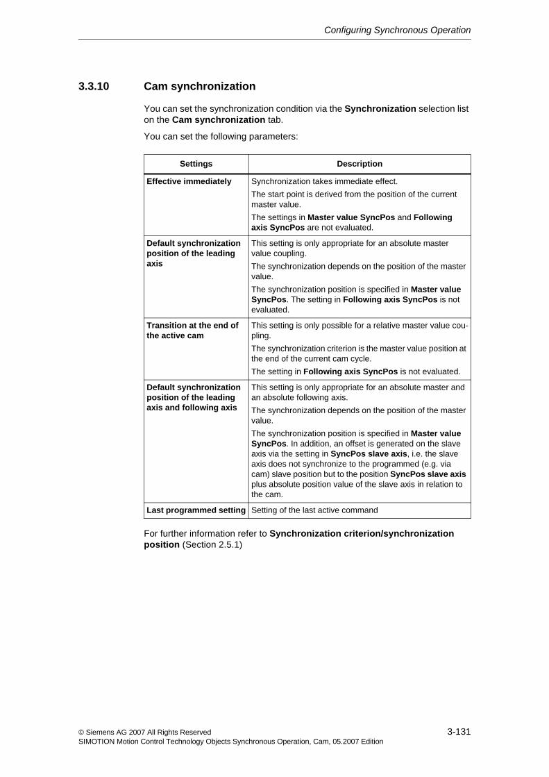
Configuring Synchronous Operation
3-131© Siemens AG 2007 All Rights ReservedSIMOTION Motion Control Technology Objects Synchronous Operation, Cam, 05.2007 Edition
3.3.10 Cam synchronization
You can set the synchronization condition via the Synchronization selection list on the Cam synchronization tab.
You can set the following parameters:
For further information refer to Synchronization criterion/synchronization position (Section 2.5.1)
Settings Description
Effective immediately Synchronization takes immediate effect.The start point is derived from the position of the current master value.The settings in Master value SyncPos and Following axis SyncPos are not evaluated.
Default synchronization position of the leading axis
This setting is only appropriate for an absolute master value coupling.The synchronization depends on the position of the master value.The synchronization position is specified in Master value SyncPos. The setting in Following axis SyncPos is not evaluated.
Transition at the end of the active cam
This setting is only possible for a relative master value cou-pling.The synchronization criterion is the master value position at the end of the current cam cycle.The setting in Following axis SyncPos is not evaluated.
Default synchronization position of the leading axis and following axis
This setting is only appropriate for an absolute master and an absolute following axis.The synchronization depends on the position of the master value.The synchronization position is specified in Master value SyncPos. In addition, an offset is generated on the slave axis via the setting in SyncPos slave axis, i.e. the slave axis does not synchronize to the programmed (e.g. via cam) slave position but to the position SyncPos slave axis plus absolute position value of the slave axis in relation to the cam.
Last programmed setting Setting of the last active command
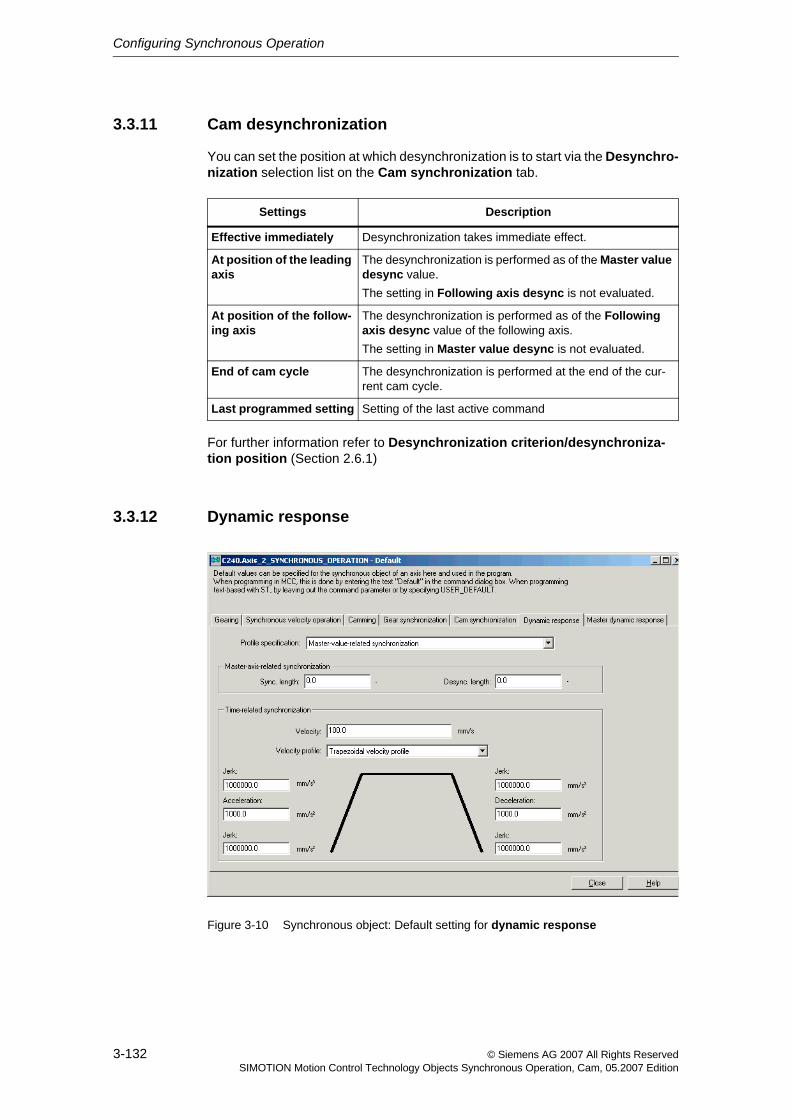
Configuring Synchronous Operation
3-132 © Siemens AG 2007 All Rights ReservedSIMOTION Motion Control Technology Objects Synchronous Operation, Cam, 05.2007 Edition
3.3.11 Cam desynchronization
You can set the position at which desynchronization is to start via the Desynchro-nization selection list on the Cam synchronization tab.
For further information refer to Desynchronization criterion/desynchroniza-tion position (Section 2.6.1)
3.3.12 Dynamic response
Figure 3-10 Synchronous object: Default setting for dynamic response
Settings Description
Effective immediately Desynchronization takes immediate effect.
At position of the leading axis
The desynchronization is performed as of the Master value desync value.The setting in Following axis desync is not evaluated.
At position of the follow-ing axis
The desynchronization is performed as of the Following axis desync value of the following axis.The setting in Master value desync is not evaluated.
End of cam cycle The desynchronization is performed at the end of the cur-rent cam cycle.
Last programmed setting Setting of the last active command
Configuring Synchronous Operation
3-133© Siemens AG 2007 All Rights ReservedSIMOTION Motion Control Technology Objects Synchronous Operation, Cam, 05.2007 Edition
In the Dynamic response tab, you make the basic settings for synchronization and desynchronization.
You can enter the following profile settings:
• Master-axis-related synchronization
See Synchronization via a specifiable master value distance (Section 2.5.4)
• Time-related synchronization
See Synchronization profile based on specifiable dynamic response parameters (time reference) (Section 2.5.5)
Dynamic response parameters are used for:
• Time-related synchronization
• Compensatory motions on the synchronous object
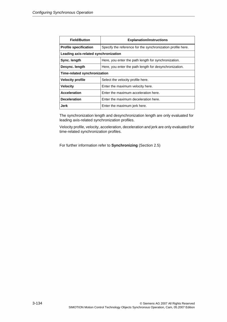
Configuring Synchronous Operation
3-134 © Siemens AG 2007 All Rights ReservedSIMOTION Motion Control Technology Objects Synchronous Operation, Cam, 05.2007 Edition
The synchronization length and desynchronization length are only evaluated for leading axis-related synchronization profiles.
Velocity profile, velocity, acceleration, deceleration and jerk are only evaluated for time-related synchronization profiles.
For further information refer to Synchronizing (Section 2.5)
Field/Button Explanation/instructions
Profile specification Specify the reference for the synchronization profile here.
Leading axis-related synchronization
Sync. length Here, you enter the path length for synchronization.
Desync. length Here, you enter the path length for desynchronization.
Time-related synchronization
Velocity profile Select the velocity profile here.
Velocity Enter the maximum velocity here.
Acceleration Enter the maximum acceleration here.
Deceleration Enter the maximum deceleration here.
Jerk Enter the maximum jerk here.
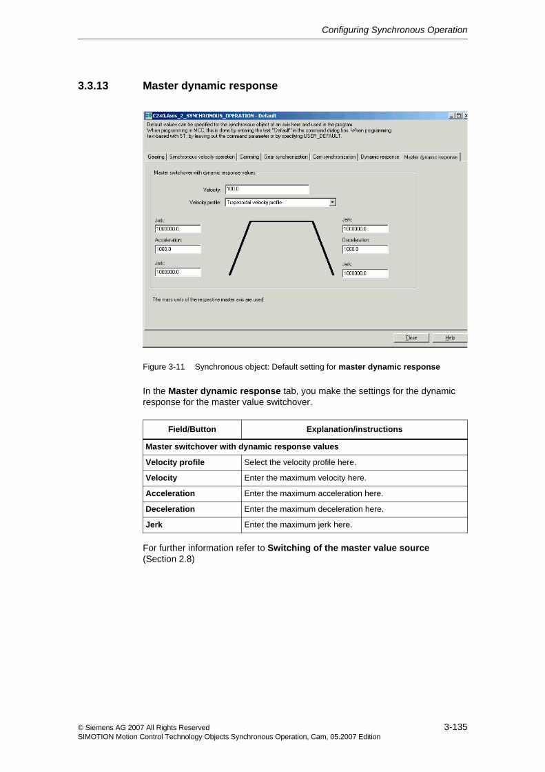
Configuring Synchronous Operation
3-135© Siemens AG 2007 All Rights ReservedSIMOTION Motion Control Technology Objects Synchronous Operation, Cam, 05.2007 Edition
3.3.13 Master dynamic response
Figure 3-11 Synchronous object: Default setting for master dynamic response
In the Master dynamic response tab, you make the settings for the dynamic response for the master value switchover.
For further information refer to Switching of the master value source (Section 2.8)
Field/Button Explanation/instructions
Master switchover with dynamic response values
Velocity profile Select the velocity profile here.
Velocity Enter the maximum velocity here.
Acceleration Enter the maximum acceleration here.
Deceleration Enter the maximum deceleration here.
Jerk Enter the maximum jerk here.
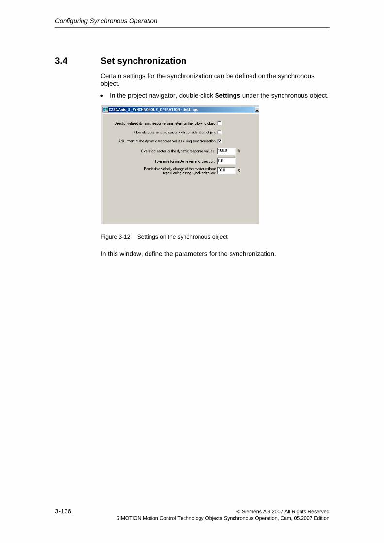
Configuring Synchronous Operation
3-136 © Siemens AG 2007 All Rights ReservedSIMOTION Motion Control Technology Objects Synchronous Operation, Cam, 05.2007 Edition
3.4 Set synchronizationCertain settings for the synchronization can be defined on the synchronous object.
• In the project navigator, double-click Settings under the synchronous object.
Figure 3-12 Settings on the synchronous object
In this window, define the parameters for the synchronization.
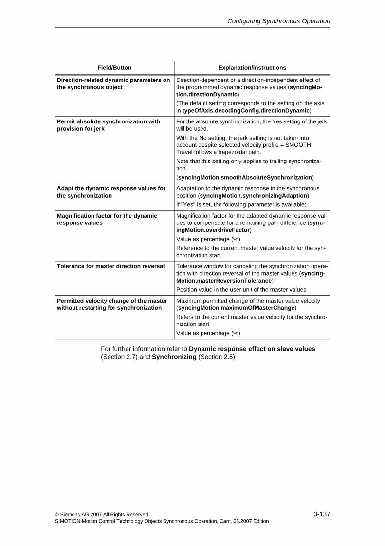
Configuring Synchronous Operation
3-137© Siemens AG 2007 All Rights ReservedSIMOTION Motion Control Technology Objects Synchronous Operation, Cam, 05.2007 Edition
For further information refer to Dynamic response effect on slave values (Section 2.7) and Synchronizing (Section 2.5)
Field/Button Explanation/instructions
Direction-related dynamic parameters on the synchronous object
Direction-dependent or a direction-independent effect of the programmed dynamic response values (syncingMo-tion.directionDynamic)(The default setting corresponds to the setting on the axis in typeOfAxis.decodingConfig.directionDynamic)
Permit absolute synchronization with provision for jerk
For the absolute synchronization, the Yes setting of the jerk will be used. With the No setting, the jerk setting is not taken into account despite selected velocity profile = SMOOTH. Travel follows a trapezoidal path. Note that this setting only applies to trailing synchroniza-tion.(syncingMotion.smoothAbsoluteSynchronization)
Adapt the dynamic response values for the synchronization
Adaptation to the dynamic response in the synchronous position (syncingMotion.synchronizingAdaption)If "Yes" is set, the following parameter is available:
Magnification factor for the dynamic response values
Magnification factor for the adapted dynamic response val-ues to compensate for a remaining path difference (sync-ingMotion.overdriveFactor)Value as percentage (%)Reference to the current master value velocity for the syn-chronization start
Tolerance for master direction reversal Tolerance window for canceling the synchronization opera-tion with direction reversal of the master values (syncing-Motion.masterReversionTolerance)Position value in the user unit of the master values
Permitted velocity change of the master without restarting for synchronization
Maximum permitted change of the master value velocity (syncingMotion.maximumOfMasterChange)Refers to the current master value velocity for the synchro-nization startValue as percentage (%)
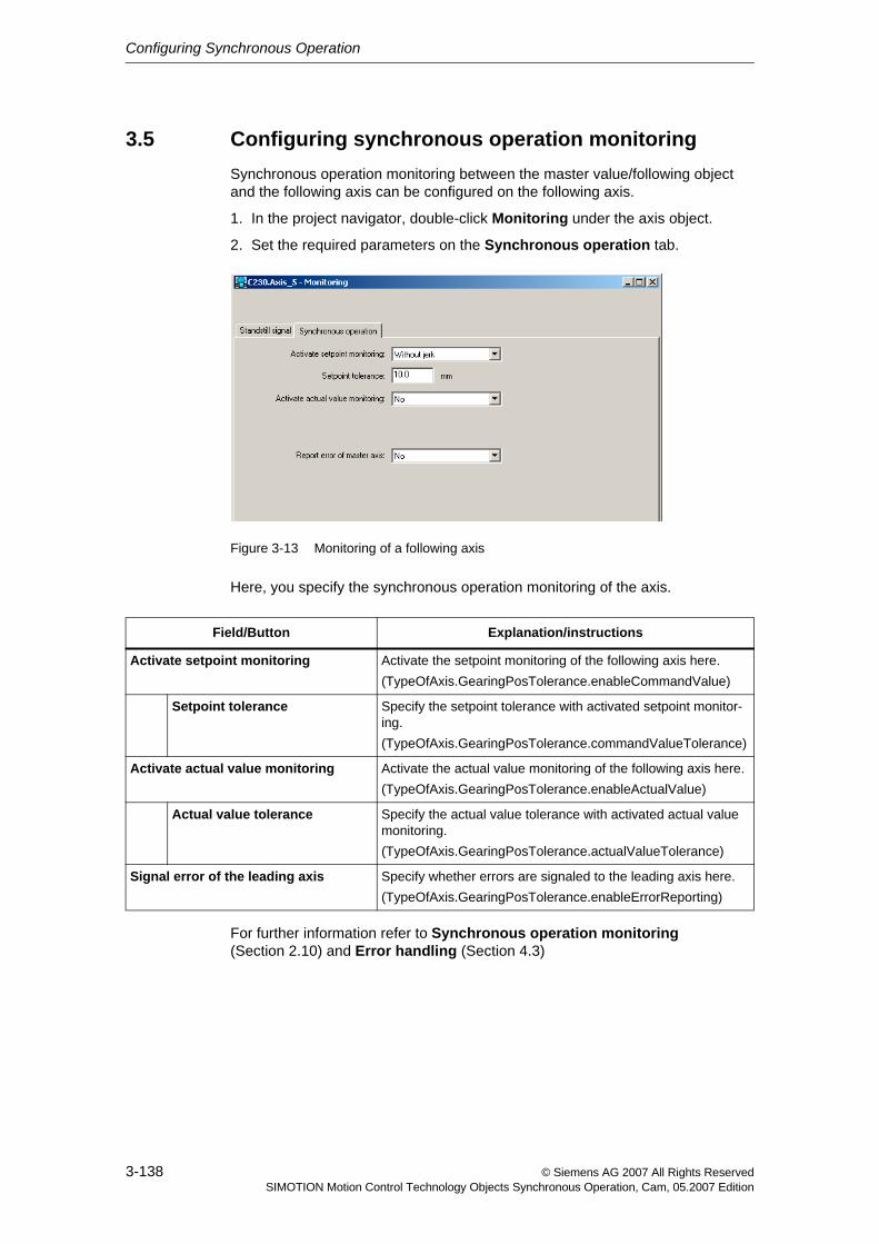
Configuring Synchronous Operation
3-138 © Siemens AG 2007 All Rights ReservedSIMOTION Motion Control Technology Objects Synchronous Operation, Cam, 05.2007 Edition
3.5 Configuring synchronous operation monitoringSynchronous operation monitoring between the master value/following object and the following axis can be configured on the following axis.
1. In the project navigator, double-click Monitoring under the axis object.
2. Set the required parameters on the Synchronous operation tab.
Figure 3-13 Monitoring of a following axis
Here, you specify the synchronous operation monitoring of the axis.
For further information refer to Synchronous operation monitoring (Section 2.10) and Error handling (Section 4.3)
Field/Button Explanation/instructions
Activate setpoint monitoring Activate the setpoint monitoring of the following axis here.(TypeOfAxis.GearingPosTolerance.enableCommandValue)
Setpoint tolerance Specify the setpoint tolerance with activated setpoint monitor-ing.(TypeOfAxis.GearingPosTolerance.commandValueTolerance)
Activate actual value monitoring Activate the actual value monitoring of the following axis here.(TypeOfAxis.GearingPosTolerance.enableActualValue)
Actual value tolerance Specify the actual value tolerance with activated actual value monitoring.(TypeOfAxis.GearingPosTolerance.actualValueTolerance)
Signal error of the leading axis Specify whether errors are signaled to the leading axis here.(TypeOfAxis.GearingPosTolerance.enableErrorReporting)
4-139© Siemens AG 2007 All Rights ReservedSIMOTION Motion Control Technology Objects Synchronous Operation, Cam, 05.2007 Edition
Synchronous Operation Programming / References 4
This chapter contains an overview of the commands of the technology object Synchronous Operation and information the local alarm response.
You can find a complete list of all commands and their syntax, the system vari-ables and error messages in the SIMOTION Reference Lists.
Content
4.1 Overview of commands 4-140
4.2 Command processing 4-146
4.3 Error handling 4-152
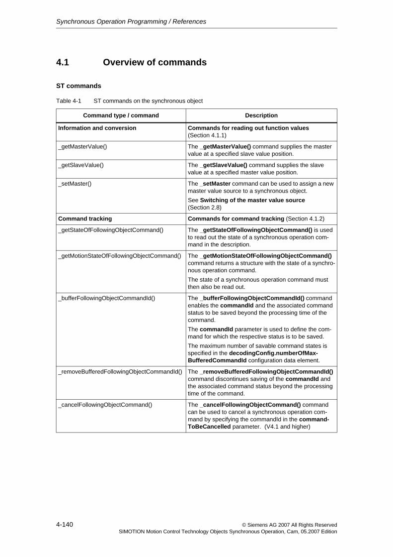
Synchronous Operation Programming / References
4-140 © Siemens AG 2007 All Rights ReservedSIMOTION Motion Control Technology Objects Synchronous Operation, Cam, 05.2007 Edition
4.1 Overview of commands
ST commands
Table 4-1 ST commands on the synchronous object
Command type / command Description
Information and conversion Commands for reading out function values (Section 4.1.1)
_getMasterValue() The _getMasterValue() command supplies the master value at a specified slave value position.
_getSlaveValue() The _getSlaveValue() command supplies the slave value at a specified master value position.
_setMaster() The _setMaster command can be used to assign a new master value source to a synchronous object.See Switching of the master value source (Section 2.8)
Command tracking Commands for command tracking (Section 4.1.2)
_getStateOfFollowingObjectCommand() The _getStateOfFollowingObjectCommand() is used to read out the state of a synchronous operation com-mand in the description.
_getMotionStateOfFollowingObjectCommand() The _getMotionStateOfFollowingObjectCommand() command returns a structure with the state of a synchro-nous operation command.The state of a synchronous operation command must then also be read out.
_bufferFollowingObjectCommandId() The _bufferFollowingObjectCommandId() command enables the commandId and the associated command status to be saved beyond the processing time of the command.The commandId parameter is used to define the com-mand for which the respective status is to be saved.The maximum number of savable command states is specified in the decodingConfig.numberOfMax-BufferedCommandId configuration data element.
_removeBufferedFollowingObjectCommandId() The _removeBufferedFollowingObjectCommandId() command discontinues saving of the commandId and the associated command status beyond the processing time of the command.
_cancelFollowingObjectCommand() The _cancelFollowingObjectCommand() command can be used to cancel a synchronous operation com-mand by specifying the commandId in the command-ToBeCancelled parameter. (V4.1 and higher)
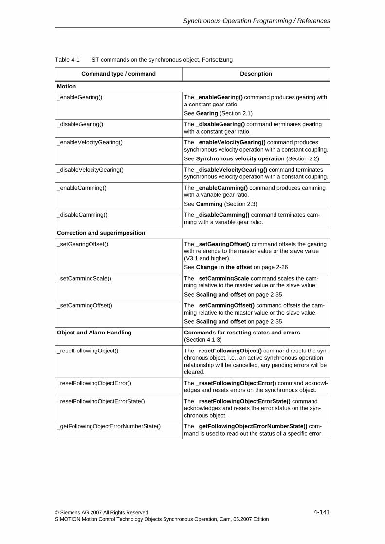
Synchronous Operation Programming / References
4-141© Siemens AG 2007 All Rights ReservedSIMOTION Motion Control Technology Objects Synchronous Operation, Cam, 05.2007 Edition
Motion
_enableGearing() The _enableGearing() command produces gearing with a constant gear ratio.See Gearing (Section 2.1)
_disableGearing() The _disableGearing() command terminates gearing with a constant gear ratio.
_enableVelocityGearing() The _enableVelocityGearing() command produces synchronous velocity operation with a constant coupling.See Synchronous velocity operation (Section 2.2)
_disableVelocityGearing() The _disableVelocityGearing() command terminates synchronous velocity operation with a constant coupling.
_enableCamming() The _enableCamming() command produces camming with a variable gear ratio.See Camming (Section 2.3)
_disableCamming() The _disableCamming() command terminates cam-ming with a variable gear ratio.
Correction and superimposition
_setGearingOffset() The _setGearingOffset() command offsets the gearing with reference to the master value or the slave value (V3.1 and higher).See Change in the offset on page 2-26
_setCammingScale() The _setCammingScale command scales the cam-ming relative to the master value or the slave value.See Scaling and offset on page 2-35
_setCammingOffset() The _setCammingOffset() command offsets the cam-ming relative to the master value or the slave value.See Scaling and offset on page 2-35
Object and Alarm Handling Commands for resetting states and errors (Section 4.1.3)
_resetFollowingObject() The _resetFollowingObject() command resets the syn-chronous object, i.e., an active synchronous operation relationship will be cancelled, any pending errors will be cleared.
_resetFollowingObjectError() The _resetFollowingObjectError() command acknowl-edges and resets errors on the synchronous object.
_resetFollowingObjectErrorState() The _resetFollowingObjectErrorState() command acknowledges and resets the error status on the syn-chronous object.
_getFollowingObjectErrorNumberState() The _getFollowingObjectErrorNumberState() com-mand is used to read out the status of a specific error
Table 4-1 ST commands on the synchronous object, Fortsetzung
Command type / command Description
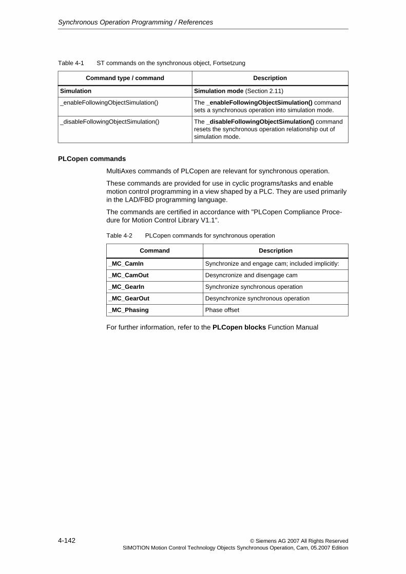
Synchronous Operation Programming / References
4-142 © Siemens AG 2007 All Rights ReservedSIMOTION Motion Control Technology Objects Synchronous Operation, Cam, 05.2007 Edition
PLCopen commands
MultiAxes commands of PLCopen are relevant for synchronous operation.
These commands are provided for use in cyclic programs/tasks and enable motion control programming in a view shaped by a PLC. They are used primarily in the LAD/FBD programming language.
The commands are certified in accordance with "PLCopen Compliance Proce-dure for Motion Control Library V1.1".
For further information, refer to the PLCopen blocks Function Manual
Simulation Simulation mode (Section 2.11)
_enableFollowingObjectSimulation() The _enableFollowingObjectSimulation() command sets a synchronous operation into simulation mode.
_disableFollowingObjectSimulation() The _disableFollowingObjectSimulation() command resets the synchronous operation relationship out of simulation mode.
Table 4-1 ST commands on the synchronous object, Fortsetzung
Command type / command Description
Table 4-2 PLCopen commands for synchronous operation
Command Description
_MC_CamIn Synchronize and engage cam; included implicitly:
_MC_CamOut Desyncronize and disengage cam
_MC_GearIn Synchronize synchronous operation
_MC_GearOut Desynchronize synchronous operation
_MC_Phasing Phase offset
Synchronous Operation Programming / References
4-143© Siemens AG 2007 All Rights ReservedSIMOTION Motion Control Technology Objects Synchronous Operation, Cam, 05.2007 Edition
4.1.1 Commands for reading out function values
Commands that calculate values and supply them as return values are available for reading out master value positions and slave value positions in pairs:
• The _getSlaveValue() command supplies the slave value at a specified mas-ter value position.
When several master values have the same slave value, an approximation value can be specified for the master value.
− slavePositionType:=CURRENT returns the current value.
− slavePositionType:=DIRECT returns in slavePosition the specified approximation value.
• The _getMasterValue() command supplies the master value at a specified slave value position.
When several slave values have the same master value, an approximation value can be specified for the slave value.
− masterPositionType:=CURRENT returns the current value.
− masterPositionType:=DIRECT returns in masterPosition the specified approximation value.
The commands only supply the correct position if a synchronous relationship is active and synchronized.
4.1.2 Commands for command tracking
• The _getStateOfFollowingObjectCommand() command returns the pro-cessing status of a synchronous operation command:
− ACTIVE: The command is being executed.
− NON_EXISTENT: The command has completed or the commandID is unknown.
− WAITING: Command is decoded, but execution not yet begun.
− WAITING_FOR_SYNC_START: The command is waiting for synchronous start.
Synchronous Operation Programming / References
4-144 © Siemens AG 2007 All Rights ReservedSIMOTION Motion Control Technology Objects Synchronous Operation, Cam, 05.2007 Edition
• The _getMotionStateOfFollowingObjectCommand() command returns a structure with the processing status of a command.
− functionResult specifies the error code.
− motionCommandIdState returns the current phase of the motion of the queried command.
− abortId specifies the command abort reason.
The abort reason is specified for the alarm 30002 "Command aborted (rea-son: <abortId>, command type: ...)".
For further information, refer to Motion Control Technology Objects Axis Electric/Hydraulic, External Encoder Function Manual, "Reading current phase of motion"
• The _bufferFollowingObjectCommandId() command can be used to query the command state even after the command has been completed or canceled.
• With _removeBufferedFollowingObjectCommandId(), the command should be explicitly removed from the command management of the TO after it has been evaluated.
The number of motion commands that the MotionBuffer can accept can be spec-ified using the followingObjectType.DecodingConfigInfo.numberOf-MaxbufferedCommandId configuration data.
The sequence of programmed commands can be read out by means of system variables.See Monitoring the synchronization (Section 2.5.9)
Canceling/deleting a synchronous operation commandThe _cancelFollowingObjectCommand() command can be used to cancel a synchronous operation command by specifying the commandId in the com-mandToBeCancelled parameter (V4.1 and higher). This removes the synchro-nous operation command from the command buffer and, if necessary, also from the IPO.
The synchronous operation motion is canceled with the local reaction FOLLOWING_OBJECT_DISABLE.
See also _cancelAxisCommand()/_cancelExternalEncoderCommand() for Axis/External Encoder TO
See Motion Control Technology Objects Axis Electric/Hydraulic, External Encoder Function Manual, "Canceling/deleting an axis command"
Synchronous Operation Programming / References
4-145© Siemens AG 2007 All Rights ReservedSIMOTION Motion Control Technology Objects Synchronous Operation, Cam, 05.2007 Edition
4.1.3 Commands for resetting states and errors
• The _resetFollowingObject() command resets the synchronous object, i.e., an active synchronous operation relationship will be cancelled, and any pend-ing errors will be cleared.
The command can be process for a pending error response (e.g. DECODE_STOP).
All active commands and commands pending in the buffer are aborted. Changed default values can be reset using the userDefaultData=:=ACTIVATE_CONFIGURATION_DATA parameter. Aborting commands by resetting the synchronous operation function does not generate any warnings.
With parameter deleteSynchronizingCommandsOnly (V3.2 and higher), the waiting and active commands can be removed directly, without having to reset the entire technology object.
• The _resetFollowingObjectError() command acknowledges and resets errors on the synchronous object.
The command can be executed when an error response (for example, DECODE_STOP) is pending.
A particular error or all errors can be ordered to be reset. The error response changes to the response with the highest priority of the still pending errors. It is terminated with a negative acknowledgment for any errors that cannot be acknowledged at this point. If all errors can be reset, the error response changes to NONE.
• The _getFollowingObjectErrorNumberState() command is used to read out the status of a specific error
Synchronous Operation Programming / References
4-146 © Siemens AG 2007 All Rights ReservedSIMOTION Motion Control Technology Objects Synchronous Operation, Cam, 05.2007 Edition
4.2 Command processing
4.2.1 Interaction between the following axis and the synchronous object
The synchronous object and the Axis TO have a reciprocal effect on each other depending on their respective operating modes and which commands are in effect.
Thus, errors and alarms in the TO axis have a direct effect on the synchronous object functions. For example, if a technology alarm triggers a stop response in the following axis, the synchronous motion is also stopped.
If an error is pending on the synchronous object only, the following axis can still position but can no longer perform synchronous operation.
The following responses by the Axis TO, which can be read in the errorReaction system variable, affect the synchronous object:
• MOTION_STOPCauses braking of the synchronous motion at the maximum values.
• MOTION_EMERGENCY_STOPCauses braking of the synchronous motion at the maximum values.
• MOTION_EMERGENCY_ABORTCauses braking of the synchronous motion at the maximum values.
• FEEDBACK_EMERGENCY_STOPEmergency stop ramp at the setpoint output (IPO)
• OPEN_POSITION_CONTROLSpeed setpoint equals zero
• RELEASE_DISABLERemoves the controller enable
Synchronous operation is aborted for all responses indicated.
Note
Errors on the synchronous object do not have any effect on the enables / error response of the following axis.
Note
If the disableSynchronousOperation configuration data element is set to YES and simulation is active on the synchronous object, the synchronous operation function is not canceled on the stop reaction or when the _disableAxis() com-mand is executed.
The synchronous operation function is aborted with alarm "20005 Device type:..., log. address:... failed" if a valid actual value is not present, e.g., if the axis is restarted.
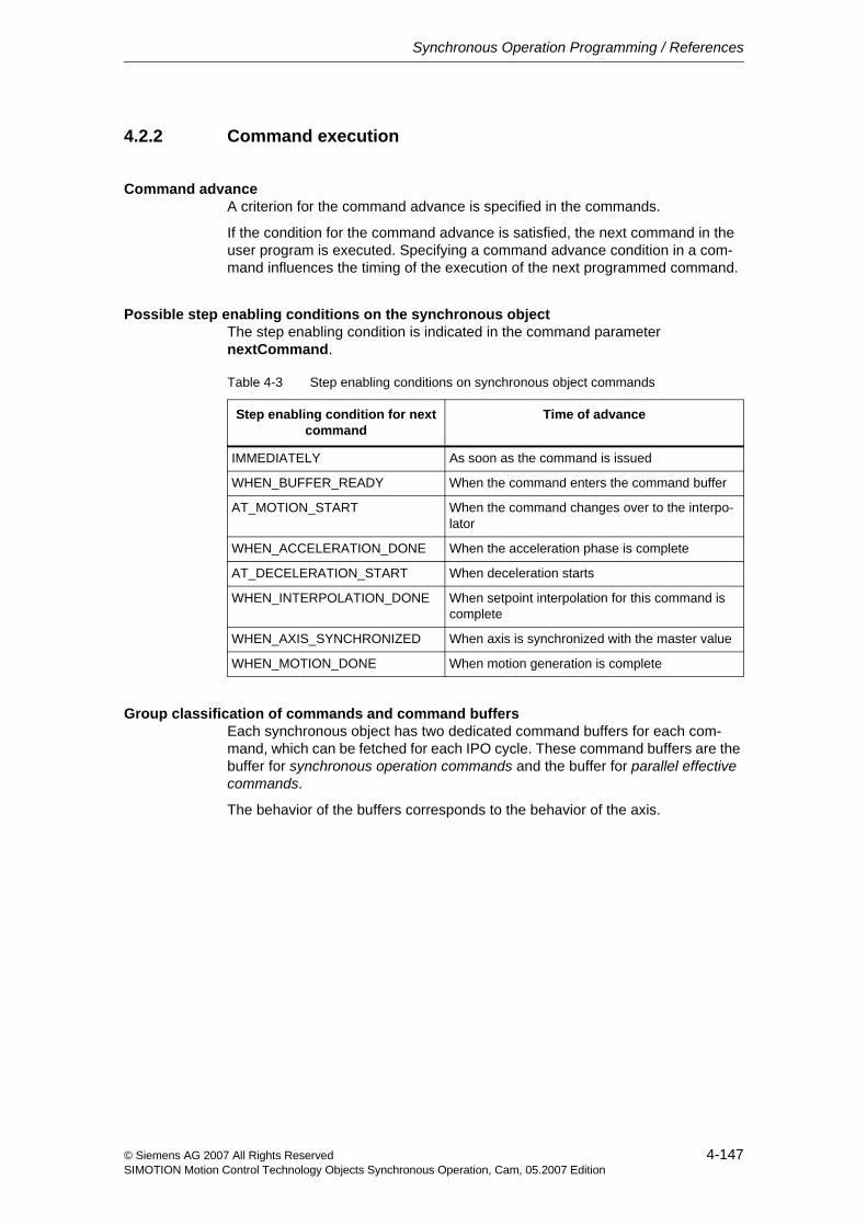
Synchronous Operation Programming / References
4-147© Siemens AG 2007 All Rights ReservedSIMOTION Motion Control Technology Objects Synchronous Operation, Cam, 05.2007 Edition
4.2.2 Command execution
Command advanceA criterion for the command advance is specified in the commands.
If the condition for the command advance is satisfied, the next command in the user program is executed. Specifying a command advance condition in a com-mand influences the timing of the execution of the next programmed command.
Possible step enabling conditions on the synchronous objectThe step enabling condition is indicated in the command parameter nextCommand.
Group classification of commands and command buffersEach synchronous object has two dedicated command buffers for each com-mand, which can be fetched for each IPO cycle. These command buffers are the buffer for synchronous operation commands and the buffer for parallel effective commands.
The behavior of the buffers corresponds to the behavior of the axis.
Table 4-3 Step enabling conditions on synchronous object commands
Step enabling condition for next command
Time of advance
IMMEDIATELY As soon as the command is issued
WHEN_BUFFER_READY When the command enters the command buffer
AT_MOTION_START When the command changes over to the interpo-lator
WHEN_ACCELERATION_DONE When the acceleration phase is complete
AT_DECELERATION_START When deceleration starts
WHEN_INTERPOLATION_DONE When setpoint interpolation for this command is complete
WHEN_AXIS_SYNCHRONIZED When axis is synchronized with the master value
WHEN_MOTION_DONE When motion generation is complete
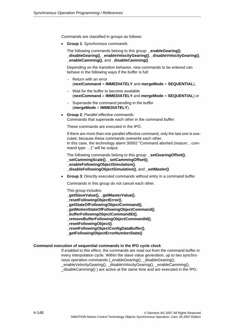
Synchronous Operation Programming / References
4-148 © Siemens AG 2007 All Rights ReservedSIMOTION Motion Control Technology Objects Synchronous Operation, Cam, 05.2007 Edition
Commands are classified in groups as follows:
• Group 1: Synchronous commands
The following commands belong to this group: _enableGearing(), _disableGearing(), _enableVelocityGearing(), _disableVelocityGearing(), _enableCamming(), and _disableCamming()
Depending on the transition behavior, new commands to be entered can behave in the following ways if the buffer is full:
− Return with an error (nextCommand = IMMEDIATELY and mergeMode = SEQUENTIAL),
− Wait for the buffer to become available (nextCommand ≠ IMMEDIATELY and mergeMode = SEQUENTIAL) or
− Supersede the command pending in the buffer (mergeMode = IMMEDIATELY).
• Group 2: Parallel effective commands: Commands that supersede each other in the command buffer.
These commands are executed in the IPO.
If there are more than one parallel effective command, only the last one is exe-cuted, because these commands overwrite each other. In this case, the technology alarm 30002 "Command aborted (reason: , com-mand type: ...)" will be output.
The following commands belong to this group: _setGearingOffset(), _setCammingScale(), _setCammingOffset(), _enableFollowingObjectSimulation(), _disableFollowingObjectSimulation(), and _setMaster()
• Group 3: Directly executed commands without entry in a command buffer
Commands in this group do not cancel each other.
This group includes: _getSlaveValue(), _getMasterValue(), _resetFollowingObjectError(), _getStateOfFollowingObjectCommand(), _getMotionStateOfFollowingObjectCommand(), _bufferFollowingObjectCommandID(), _removeBufferFollowingObjectCommandId(), _resetFollowingObject(), _resetFollowingObjectConfigDataBuffer(), _getFollowingObjectErrorNumberState()
Command execution of sequential commands in the IPO cycle clockIf enabled to this effect, the commands are read out from the command buffer in every interpolation cycle. Within the slave value generation, up to two synchro-nous operation commands (_enableGearing(), _disableGearing(), _enableVelocityGearing(), _disableVelocityGearing(), _enableCamming(), _disableCamming() ) are active at the same time and are executed in the IPO.
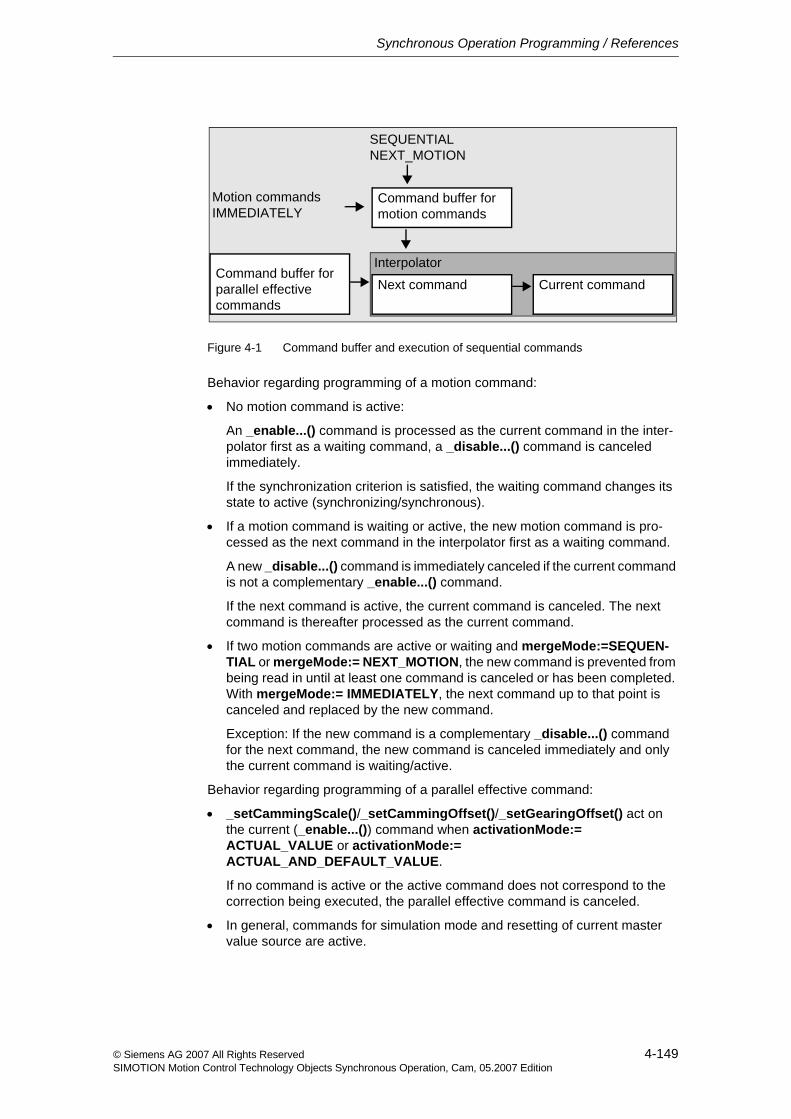
Synchronous Operation Programming / References
4-149© Siemens AG 2007 All Rights ReservedSIMOTION Motion Control Technology Objects Synchronous Operation, Cam, 05.2007 Edition
Figure 4-1 Command buffer and execution of sequential commands
Behavior regarding programming of a motion command:
• No motion command is active:
An _enable...() command is processed as the current command in the inter-polator first as a waiting command, a _disable...() command is canceled immediately.
If the synchronization criterion is satisfied, the waiting command changes its state to active (synchronizing/synchronous).
• If a motion command is waiting or active, the new motion command is pro-cessed as the next command in the interpolator first as a waiting command.
A new _disable...() command is immediately canceled if the current command is not a complementary _enable...() command.
If the next command is active, the current command is canceled. The next command is thereafter processed as the current command.
• If two motion commands are active or waiting and mergeMode:=SEQUEN-TIAL or mergeMode:= NEXT_MOTION, the new command is prevented from being read in until at least one command is canceled or has been completed. With mergeMode:= IMMEDIATELY, the next command up to that point is canceled and replaced by the new command.
Exception: If the new command is a complementary _disable...() command for the next command, the new command is canceled immediately and only the current command is waiting/active.
Behavior regarding programming of a parallel effective command:
• _setCammingScale()/_setCammingOffset()/_setGearingOffset() act on the current (_enable...()) command when activationMode:= ACTUAL_VALUE or activationMode:= ACTUAL_AND_DEFAULT_VALUE.
If no command is active or the active command does not correspond to the correction being executed, the parallel effective command is canceled.
• In general, commands for simulation mode and resetting of current master value source are active.
Next command Current command
Command buffer for motion commands
Motion commandsIMMEDIATELY
SEQUENTIALNEXT_MOTION
Command buffer for parallel effective commands
Interpolator
Synchronous Operation Programming / References
4-150 © Siemens AG 2007 All Rights ReservedSIMOTION Motion Control Technology Objects Synchronous Operation, Cam, 05.2007 Edition
4.2.3 Command transition conditions
The transition behavior is set in the command parameter mergeMode in the commands.
The transition behavior affects the execution of the queued commands on the synchronous object. An active command can thus affect the execution of a com-mand of another task.
The mergeMode on the synchronous object commands also determines the behavior of the following axis commands.
• A command issued with mergeMode = IMMEDIATELY clears the command buffer and overwrites the IPO (next command).
The current command is executed. The next command is substituted.
• A command issued with mergeMode = NEXT_MOTION will be executed after the completion of the active command and the deletion of pending commands. It overwrites the command buffer.
• A command issued with mergeMode = SEQUENTIAL will be executed after the completion of the active command and the motion. The command will be entered into the command buffer when it is empty; if the command buffer is not empty, the command waits.
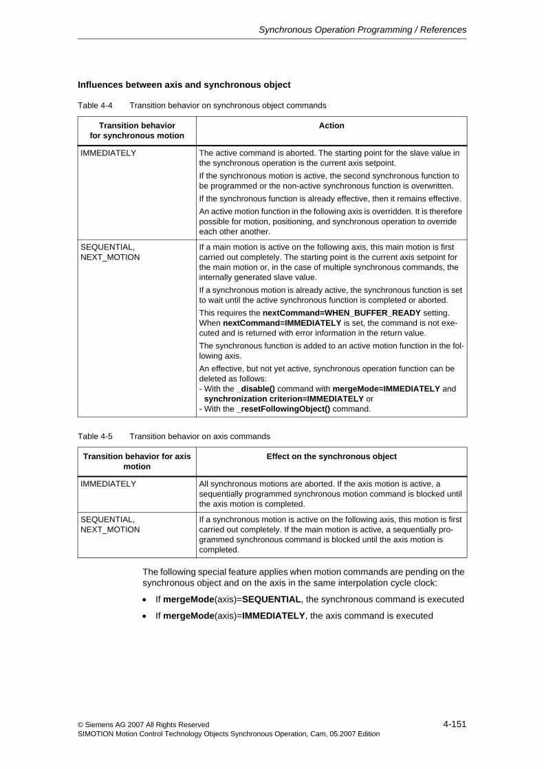
Synchronous Operation Programming / References
4-151© Siemens AG 2007 All Rights ReservedSIMOTION Motion Control Technology Objects Synchronous Operation, Cam, 05.2007 Edition
Influences between axis and synchronous object
The following special feature applies when motion commands are pending on the synchronous object and on the axis in the same interpolation cycle clock:
• If mergeMode(axis)=SEQUENTIAL, the synchronous command is executed
• If mergeMode(axis)=IMMEDIATELY, the axis command is executed
Table 4-4 Transition behavior on synchronous object commands
Transition behavior for synchronous motion
Action
IMMEDIATELY The active command is aborted. The starting point for the slave value in the synchronous operation is the current axis setpoint.If the synchronous motion is active, the second synchronous function to be programmed or the non-active synchronous function is overwritten.If the synchronous function is already effective, then it remains effective.An active motion function in the following axis is overridden. It is therefore possible for motion, positioning, and synchronous operation to override each other another.
SEQUENTIAL, NEXT_MOTION
If a main motion is active on the following axis, this main motion is first carried out completely. The starting point is the current axis setpoint for the main motion or, in the case of multiple synchronous commands, the internally generated slave value.If a synchronous motion is already active, the synchronous function is set to wait until the active synchronous function is completed or aborted.This requires the nextCommand=WHEN_BUFFER_READY setting. When nextCommand=IMMEDIATELY is set, the command is not exe-cuted and is returned with error information in the return value.The synchronous function is added to an active motion function in the fol-lowing axis.An effective, but not yet active, synchronous operation function can be deleted as follows: - With the _disable() command with mergeMode=IMMEDIATELY and - synchronization criterion=IMMEDIATELY or - With the _resetFollowingObject() command.
Table 4-5 Transition behavior on axis commands
Transition behavior for axis motion
Effect on the synchronous object
IMMEDIATELY All synchronous motions are aborted. If the axis motion is active, a sequentially programmed synchronous motion command is blocked until the axis motion is completed.
SEQUENTIAL, NEXT_MOTION
If a synchronous motion is active on the following axis, this motion is first carried out completely. If the main motion is active, a sequentially pro-grammed synchronous command is blocked until the axis motion is completed.
Synchronous Operation Programming / References
4-152 © Siemens AG 2007 All Rights ReservedSIMOTION Motion Control Technology Objects Synchronous Operation, Cam, 05.2007 Edition
4.3 Error handling
4.3.1 Local alarm response
Local alarm responses are specified by means of the system.
The following responses are possible:
• NONENo response
• DECODE_STOPAbort command execution, the current synchronous operation function remains active.
• FOLLOWING_OBJECT_DISABLEAbort the command execution and the current synchronous operation func-tion.
An error can be reset with _resetFollowingObject() or _resetFollowingObjectError()
Note
The stop responses are listed in order of increasing priority.
Global alarm responses can be set in the alarm configuration in the technology object; these can also be set to require Power On.
For further information, see Motion Control Basic Functions, "Configuring technological alarms"
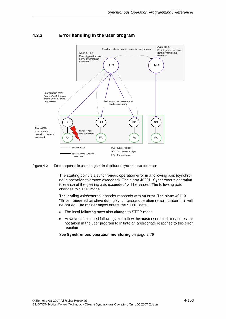
Synchronous Operation Programming / References
4-153© Siemens AG 2007 All Rights ReservedSIMOTION Motion Control Technology Objects Synchronous Operation, Cam, 05.2007 Edition
4.3.2 Error handling in the user program
Figure 4-2 Error response in user program in distributed synchronous operation
The starting point is a synchronous operation error in a following axis (synchro-nous operation tolerance exceeded). The alarm 40201 "Synchronous operation tolerance of the gearing axis exceeded" will be issued. The following axis changes to STOP mode.
The leading axis/external encoder responds with an error. The alarm 40110 "Error triggered on slave during synchronous operation (error number: ...)" will be issued. The master object enters the STOP state.
• The local following axes also change to STOP mode.
• However, distributed following axes follow the master setpoint if measures are not taken in the user program to initiate an appropriate response to this error reaction.
See Synchronous operation monitoring on page 2-79

Synchronous Operation Programming / References
4-154 © Siemens AG 2007 All Rights ReservedSIMOTION Motion Control Technology Objects Synchronous Operation, Cam, 05.2007 Edition
© Siemens AG 2007 All Rights ReservedSIMOTION Motion Control Technology Objects Synchronous Operation, Cam, 05.2007 Edition
Part IIDistributed Synchronous Operation
This part describes the Distributed Synchronous Operation function (V3.0 and higher).
It introduces you to the operating principle and provides information about the technological boundary conditions as well as the operating characteristics of dis-tributed synchronous operation.
You are shown how to create and configure a distributed synchronous operation.
Content
Chapter 5 Overview of Distributed Synchronous Operation 5-157
Chapter 6 Fundamentals of Distributed Synchronous Operation 6-161
Chapter 7 Configuring Distributed Synchronous Operation 7-181
Chapter 8 Configuring Distributed Synchronous Operation across Projects (V4.1 and higher) 8-185

© Siemens AG 2007 All Rights ReservedSIMOTION Motion Control Technology Objects Synchronous Operation, Cam, 05.2007 Edition
5-157© Siemens AG 2007 All Rights ReservedSIMOTION Motion Control Technology Objects Synchronous Operation, Cam, 05.2007 Edition
Overview of Distributed Synchronous Operation 5
This chapter provides information on the basic function and application of the Distributed Synchronous Operation technology object.
Content
5.1 Function overview 5-158
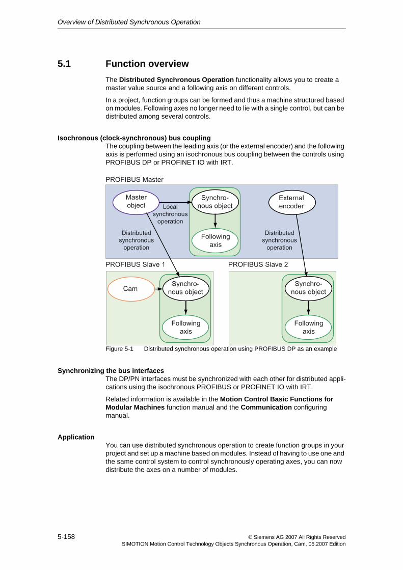
Overview of Distributed Synchronous Operation
5-158 © Siemens AG 2007 All Rights ReservedSIMOTION Motion Control Technology Objects Synchronous Operation, Cam, 05.2007 Edition
5.1 Function overviewThe Distributed Synchronous Operation functionality allows you to create a master value source and a following axis on different controls.
In a project, function groups can be formed and thus a machine structured based on modules. Following axes no longer need to lie with a single control, but can be distributed among several controls.
Isochronous (clock-synchronous) bus couplingThe coupling between the leading axis (or the external encoder) and the following axis is performed using an isochronous bus coupling between the controls using PROFIBUS DP or PROFINET IO with IRT.
Figure 5-1 Distributed synchronous operation using PROFIBUS DP as an example
Synchronizing the bus interfacesThe DP/PN interfaces must be synchronized with each other for distributed appli-cations using the isochronous PROFIBUS or PROFINET IO with IRT.
Related information is available in the Motion Control Basic Functions for Modular Machines function manual and the Communication configuring manual.
ApplicationYou can use distributed synchronous operation to create function groups in your project and set up a machine based on modules. Instead of having to use one and the same control system to control synchronously operating axes, you can now distribute the axes on a number of modules.
Overview of Distributed Synchronous Operation
5-159© Siemens AG 2007 All Rights ReservedSIMOTION Motion Control Technology Objects Synchronous Operation, Cam, 05.2007 Edition
Mode of functioning/compensationsWith distributed synchronous operation, the interpolator cycle clocks of the mas-ter object and the following axis can be offset. As a result of the required commu-nication, there is also an offset in the calculation of related signals (master value source and remote following axis).
The cycle clock offset can be compensated with the following measures:
• Compensation on master value side by means of setpoint output delay
• Compensation of the slave value side using master setpoint extrapolation
See Compensations for distributed synchronous operation (Section 6.2)

Overview of Distributed Synchronous Operation
5-160 © Siemens AG 2007 All Rights ReservedSIMOTION Motion Control Technology Objects Synchronous Operation, Cam, 05.2007 Edition
6-161© Siemens AG 2007 All Rights ReservedSIMOTION Motion Control Technology Objects Synchronous Operation, Cam, 05.2007 Edition
Fundamentals of Distributed Synchronous Operation 6
This chapter describes the boundary conditions for the creation of a distributed synchronous operation, the properties, and the operating characteristics as well as the error handling.
Content
6.1 Boundary conditions 6-162
6.2 Compensations for distributed synchronous operation 6-169
6.3 Operating axes with distributed synchronous operation 6-176
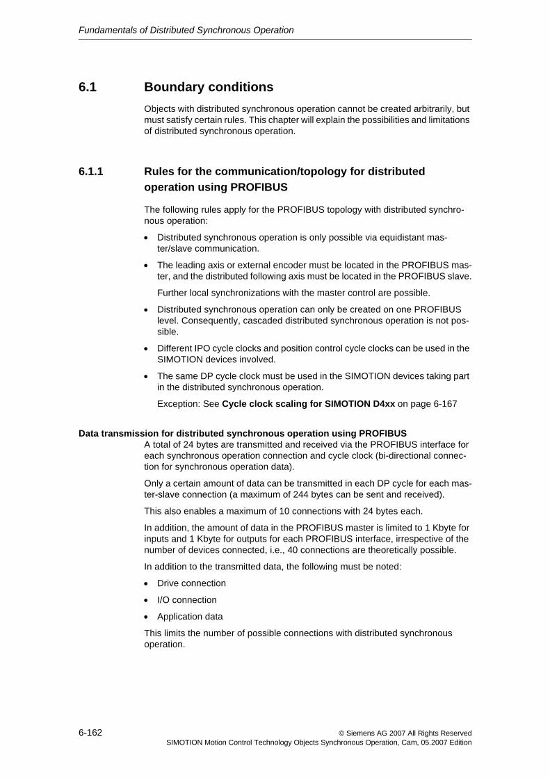
Fundamentals of Distributed Synchronous Operation
6-162 © Siemens AG 2007 All Rights ReservedSIMOTION Motion Control Technology Objects Synchronous Operation, Cam, 05.2007 Edition
6.1 Boundary conditionsObjects with distributed synchronous operation cannot be created arbitrarily, but must satisfy certain rules. This chapter will explain the possibilities and limitations of distributed synchronous operation.
6.1.1 Rules for the communication/topology for distributed operation using PROFIBUS
The following rules apply for the PROFIBUS topology with distributed synchro-nous operation:
• Distributed synchronous operation is only possible via equidistant mas-ter/slave communication.
• The leading axis or external encoder must be located in the PROFIBUS mas-ter, and the distributed following axis must be located in the PROFIBUS slave.
Further local synchronizations with the master control are possible.
• Distributed synchronous operation can only be created on one PROFIBUS level. Consequently, cascaded distributed synchronous operation is not pos-sible.
• Different IPO cycle clocks and position control cycle clocks can be used in the SIMOTION devices involved.
• The same DP cycle clock must be used in the SIMOTION devices taking part in the distributed synchronous operation.
Exception: See Cycle clock scaling for SIMOTION D4xx on page 6-167
Data transmission for distributed synchronous operation using PROFIBUSA total of 24 bytes are transmitted and received via the PROFIBUS interface for each synchronous operation connection and cycle clock (bi-directional connec-tion for synchronous operation data).
Only a certain amount of data can be transmitted in each DP cycle for each mas-ter-slave connection (a maximum of 244 bytes can be sent and received).
This also enables a maximum of 10 connections with 24 bytes each.
In addition, the amount of data in the PROFIBUS master is limited to 1 Kbyte for inputs and 1 Kbyte for outputs for each PROFIBUS interface, irrespective of the number of devices connected, i.e., 40 connections are theoretically possible.
In addition to the transmitted data, the following must be noted:
• Drive connection
• I/O connection
• Application data
This limits the number of possible connections with distributed synchronous operation.
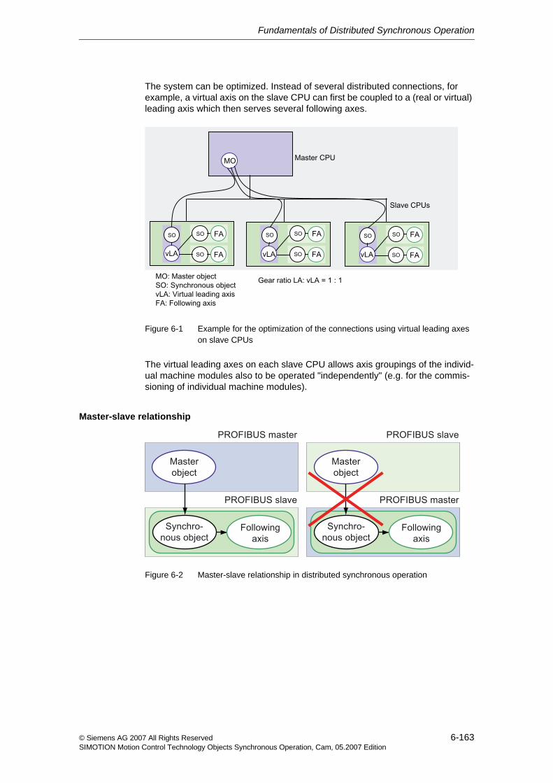
Fundamentals of Distributed Synchronous Operation
6-163© Siemens AG 2007 All Rights ReservedSIMOTION Motion Control Technology Objects Synchronous Operation, Cam, 05.2007 Edition
The system can be optimized. Instead of several distributed connections, for example, a virtual axis on the slave CPU can first be coupled to a (real or virtual) leading axis which then serves several following axes.
Figure 6-1 Example for the optimization of the connections using virtual leading axes on slave CPUs
The virtual leading axes on each slave CPU allows axis groupings of the individ-ual machine modules also to be operated "independently" (e.g. for the commis-sioning of individual machine modules).
Master-slave relationship
Figure 6-2 Master-slave relationship in distributed synchronous operation

Fundamentals of Distributed Synchronous Operation
6-164 © Siemens AG 2007 All Rights ReservedSIMOTION Motion Control Technology Objects Synchronous Operation, Cam, 05.2007 Edition
Connection between axis and synchronous objectThe synchronous object and, if appropriate, the cam must be located on the slave control, together with the following axis. The master value source (axis or external encoder) is always located on the master control.
Figure 6-3 Following axis and synchronous object on the same control
CascadingA distributed synchronous operation can be interconnected with a series-con-nected local synchronous operation on the slave control.
Figure 6-4 Cascading of distributed synchronous operation with series-connected local synchronous operation
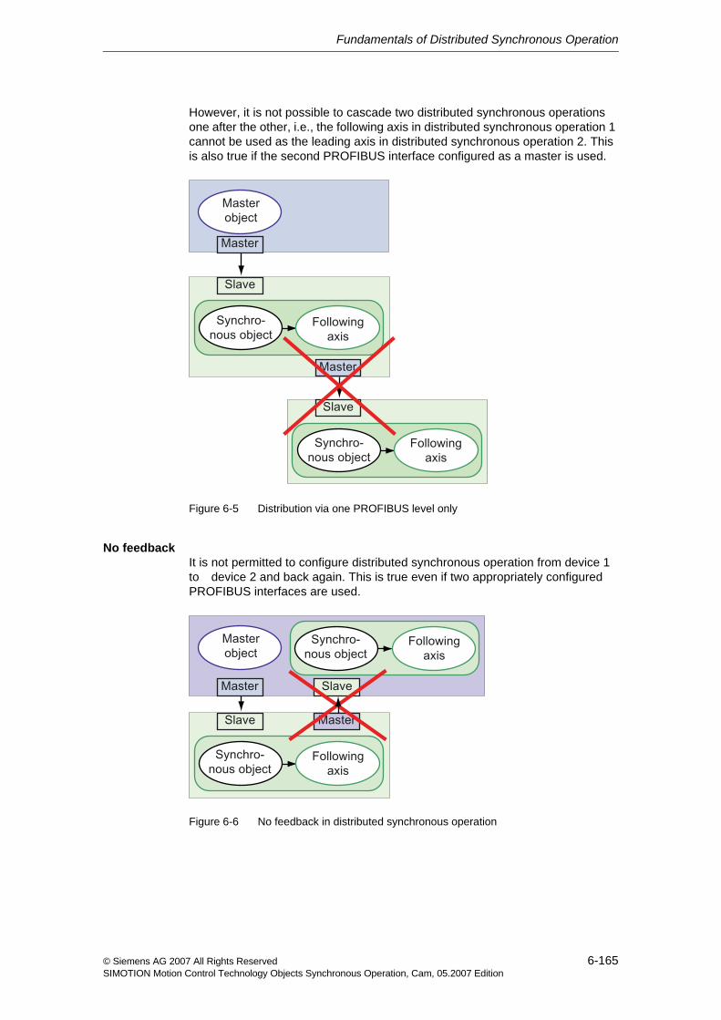
Fundamentals of Distributed Synchronous Operation
6-165© Siemens AG 2007 All Rights ReservedSIMOTION Motion Control Technology Objects Synchronous Operation, Cam, 05.2007 Edition
However, it is not possible to cascade two distributed synchronous operations one after the other, i.e., the following axis in distributed synchronous operation 1 cannot be used as the leading axis in distributed synchronous operation 2. This is also true if the second PROFIBUS interface configured as a master is used.
Figure 6-5 Distribution via one PROFIBUS level only
No feedbackIt is not permitted to configure distributed synchronous operation from device 1 to device 2 and back again. This is true even if two appropriately configured PROFIBUS interfaces are used.
Figure 6-6 No feedback in distributed synchronous operation
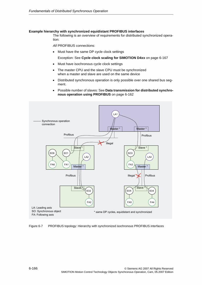
Fundamentals of Distributed Synchronous Operation
6-166 © Siemens AG 2007 All Rights ReservedSIMOTION Motion Control Technology Objects Synchronous Operation, Cam, 05.2007 Edition
Example hierarchy with synchronized equidistant PROFIBUS interfacesThe following is an overview of requirements for distributed synchronized opera-tion:
All PROFIBUS connections:
• Must have the same DP cycle clock settings
Exception: See Cycle clock scaling for SIMOTION D4xx on page 6-167
• Must have isochronous cycle clock settings
• The master CPU and the slave CPU must be synchronized when a master and slave are used on the same device
• Distributed synchronous operation is only possible over one shared bus seg-ment.
• Possible number of slaves: See Data transmission for distributed synchro-nous operation using PROFIBUS on page 6-162
Figure 6-7 PROFIBUS topology: Hierarchy with synchronized isochronous PROFIBUS interfaces
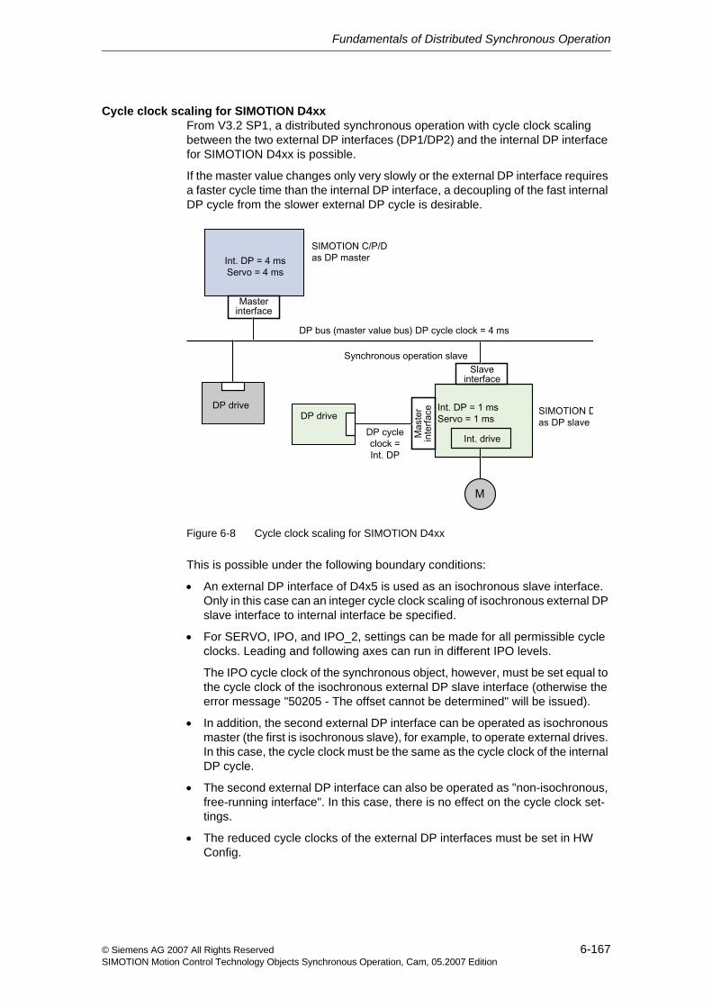
Fundamentals of Distributed Synchronous Operation
6-167© Siemens AG 2007 All Rights ReservedSIMOTION Motion Control Technology Objects Synchronous Operation, Cam, 05.2007 Edition
Cycle clock scaling for SIMOTION D4xxFrom V3.2 SP1, a distributed synchronous operation with cycle clock scaling between the two external DP interfaces (DP1/DP2) and the internal DP interface for SIMOTION D4xx is possible.
If the master value changes only very slowly or the external DP interface requires a faster cycle time than the internal DP interface, a decoupling of the fast internal DP cycle from the slower external DP cycle is desirable.
Figure 6-8 Cycle clock scaling for SIMOTION D4xx
This is possible under the following boundary conditions:
• An external DP interface of D4x5 is used as an isochronous slave interface. Only in this case can an integer cycle clock scaling of isochronous external DP slave interface to internal interface be specified.
• For SERVO, IPO, and IPO_2, settings can be made for all permissible cycle clocks. Leading and following axes can run in different IPO levels.
The IPO cycle clock of the synchronous object, however, must be set equal to the cycle clock of the isochronous external DP slave interface (otherwise the error message "50205 - The offset cannot be determined" will be issued).
• In addition, the second external DP interface can be operated as isochronous master (the first is isochronous slave), for example, to operate external drives. In this case, the cycle clock must be the same as the cycle clock of the internal DP cycle.
• The second external DP interface can also be operated as "non-isochronous, free-running interface". In this case, there is no effect on the cycle clock set-tings.
• The reduced cycle clocks of the external DP interfaces must be set in HW Config.
Fundamentals of Distributed Synchronous Operation
6-168 © Siemens AG 2007 All Rights ReservedSIMOTION Motion Control Technology Objects Synchronous Operation, Cam, 05.2007 Edition
6.1.2 Rules for the communication/topology for the distribution using PROFINET IO with IRT (V4.0 or later)
The distributed synchronous operation between SIMOTION devices using PROFINET IO with IRT uses the controller-controller internetwork traffic for PROFINET IO to exchange the synchronous operation data.
Differences to PROFIBUS
There are the following differences compared with the distributed synchronous operation with PROFIBUS (Chapter 6.1.1):
• Master object and following axis / synchronous object can be located on any controllers. (PROFINET IO with IRT does not have any communications mas-ter and communications slave as for PROFIBUS.)
• A cascading of distributed synchronous operations is possible over more than one level.
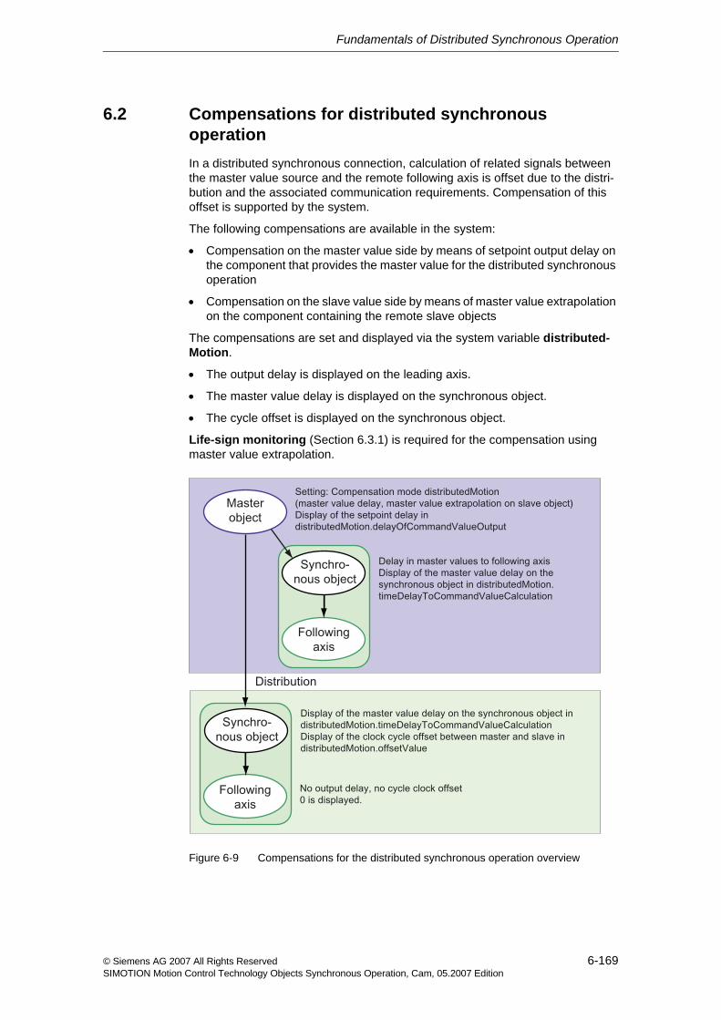
Fundamentals of Distributed Synchronous Operation
6-169© Siemens AG 2007 All Rights ReservedSIMOTION Motion Control Technology Objects Synchronous Operation, Cam, 05.2007 Edition
6.2 Compensations for distributed synchronous operationIn a distributed synchronous connection, calculation of related signals between the master value source and the remote following axis is offset due to the distri-bution and the associated communication requirements. Compensation of this offset is supported by the system.
The following compensations are available in the system:
• Compensation on the master value side by means of setpoint output delay on the component that provides the master value for the distributed synchronous operation
• Compensation on the slave value side by means of master value extrapolation on the component containing the remote slave objects
The compensations are set and displayed via the system variable distributed-Motion.
• The output delay is displayed on the leading axis.
• The master value delay is displayed on the synchronous object.
• The cycle offset is displayed on the synchronous object.
Life-sign monitoring (Section 6.3.1) is required for the compensation using master value extrapolation.
Figure 6-9 Compensations for the distributed synchronous operation overview
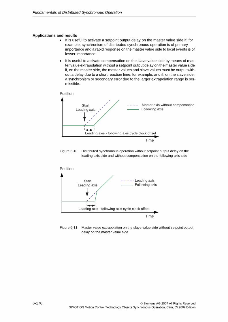
Fundamentals of Distributed Synchronous Operation
6-170 © Siemens AG 2007 All Rights ReservedSIMOTION Motion Control Technology Objects Synchronous Operation, Cam, 05.2007 Edition
Applications and results• It is useful to activate a setpoint output delay on the master value side if, for
example, synchronism of distributed synchronous operation is of primary importance and a rapid response on the master value side to local events is of lesser importance.
• It is useful to activate compensation on the slave value side by means of mas-ter value extrapolation without a setpoint output delay on the master value side if, on the master side, the master values and slave values must be output with-out a delay due to a short reaction time, for example, and if, on the slave side, a synchronism or secondary error due to the larger extrapolation range is per-missible.
Figure 6-10 Distributed synchronous operation without setpoint output delay on the leading axis side and without compensation on the following axis side
Figure 6-11 Master value extrapolation on the slave value side without setpoint output delay on the master value side
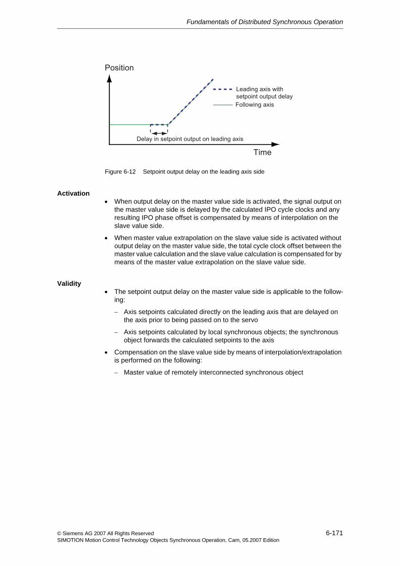
Fundamentals of Distributed Synchronous Operation
6-171© Siemens AG 2007 All Rights ReservedSIMOTION Motion Control Technology Objects Synchronous Operation, Cam, 05.2007 Edition
Figure 6-12 Setpoint output delay on the leading axis side
Activation• When output delay on the master value side is activated, the signal output on
the master value side is delayed by the calculated IPO cycle clocks and any resulting IPO phase offset is compensated by means of interpolation on the slave value side.
• When master value extrapolation on the slave value side is activated without output delay on the master value side, the total cycle clock offset between the master value calculation and the slave value calculation is compensated for by means of the master value extrapolation on the slave value side.
Validity• The setpoint output delay on the master value side is applicable to the follow-
ing:
− Axis setpoints calculated directly on the leading axis that are delayed on the axis prior to being passed on to the servo
− Axis setpoints calculated by local synchronous objects; the synchronous object forwards the calculated setpoints to the axis
• Compensation on the slave value side by means of interpolation/extrapolation is performed on the following:
− Master value of remotely interconnected synchronous object
Fundamentals of Distributed Synchronous Operation
6-172 © Siemens AG 2007 All Rights ReservedSIMOTION Motion Control Technology Objects Synchronous Operation, Cam, 05.2007 Edition
6.2.1 Compensation on master value side by means of setpoint output delay
The compensation on the master value side using setpoint output delay of the dis-tributed synchronous operation will be activated for the master object.
Compensation on the master value side results in the following:
• Output of setpoints calculated for the axis, delayed by n IPO cycle clocks, to the servo/position controller of the axis
• Output of setpoints from a local synchronous object interconnected to the leading axis or external encoder, delayed by n IPO cycle clocks, to the inter-connected following axis
The number of IPO cycle clocks is calculated from the maximum cycle clock offset across all distributed synchronous relationships with the master value source. The number of IPO cycle clocks (integer), which contains the total delay, is calcu-lated.
When compensation on the master value side by means of setpoint output delay is deactivated, setpoints are output to the axis and the master value is forwarded to and evaluated on local synchronous objects without delay.
Activating compensation on the master value side by means of setpoint output delayCompensation on the master value side by means of setpoint output delay is acti-vated/deactivated in the (TypeOfAxis.)distributedMotion.enableDelayOfCom-mandValueOutput configuration data element on the leading axis or external encoder.
• NO: Compensation on master value side is deactivated
The master immediately outputs the setpoint value.
The slave performs the extrapolation.
• YES: Compensation on master value side is activated
Setpoint output delay on the master value side, simultaneous start, and no overshoot (the following axis also has a delayed start.)
Disadvantage of YES: A reaction to an event on the master is less likely to occur.
When activated, a setpoint output delay on the axis always acts.
Cycle clock offset calculationThe system automatically calculates the maximum cycle clock offset after a tran-sition from STOP/STOPU to RUN.
The determination of the cycle clock offset also runs after the restart of one of the involved axes or external encoders and after cancel/restore of the connection.
The status of the cycle clock offset calculation is indicated in the distributed-Motion.stateOfOffsetCalculation system variable on the leading axis and on the remote distributed synchronous object. The cycle clock offset is not yet
Fundamentals of Distributed Synchronous Operation
6-173© Siemens AG 2007 All Rights ReservedSIMOTION Motion Control Technology Objects Synchronous Operation, Cam, 05.2007 Edition
determined for status INVALID, the cycle clock offset cannot be determined. The leading axis / external encoder issues the technological alarm "40304 Offset can-not be determined".
The compensation on the master value or slave value side requires that the deter-mination of the offset be activated in the (TypeOfAxis.)distributedMo-tion.enableOffsetCompensation configuration data on the leading axis or external encoder.
Setpoint output delayThe absolute value of the setpoint output delay can be read out by means of the distributedMotion.delayOfCommandValueOutput system variable on the leading axis.
The time is indicated in the distributedMotion.timeDelayToCommandValue-Calculation system variable on the synchronous object of the remote following axis.
The status of the setpoint output delay is indicated in the distributed-Motion.stateOfDelayValue system variable on the leading axis or external encoder and on the remote synchronous object.
• If the status is INVALID, the setpoint output delay is not activated.
• If the status is VALID, the setpoint output delay is active.
The maximum permissible delay for setpoint output is 10 interpolation cycle clocks.
If the delay is greater than 10 interpolation cycle clocks, two alarms are output on the master value axis or external encoder: "40124 Offset cannot be compen-sated" and "40125 Setpoint output delay on the master side is deactivated".
If a local interconnected following axis is acting as the master value for a distrib-uted synchronous operation, the same setting should be made on the first master value and on the local following axis with reference to the effective compensa-tions on the master value side.
Fundamentals of Distributed Synchronous Operation
6-174 © Siemens AG 2007 All Rights ReservedSIMOTION Motion Control Technology Objects Synchronous Operation, Cam, 05.2007 Edition
6.2.2 Compensation on the slave value side using master setpoint extrapolation
When compensation on the master value side by means of setpoint output delay is not activated, the compensation on the slave value side performs a linear extrapolation using the two most recent master values received in order to com-pensate for the cycle clock offset.
In the event that master values are lost, the two most recent master values received are used for the extrapolation.
Activating compensation on the slave value side using master setpoint extrapolationCompensation on the slave value side (interpolation/extrapolation) is set in the (TypeOfAxis.)distributedMotion.enableOffsetCompensation configuration data on the leading axis or external encoder. The offset calculation is activated if this configuration data is changed.
Display of setpoint output delay time on the master value sideSetpoint output delay time on the master value side is indicated in the distributedMotion.timeDelayToCommandValueCalculation system variable on the synchronous object.
This delay time is generally greater than the offset calculated across all remote synchronous relationships.
The distributedMotion.timeDelayToCommandValueCalculation system vari-able on the remote synchronous object corresponds to the distributed-Motion.delayOfCommandValueOutput system variable of the associated master value object.
Status of calculation of compensation on the slave value sideThe status of the calculation of compensation on the slave value side is indicated by means of the distributedMotion.stateOfOffsetCalculation system variable on the synchronous object as well as on the master value source/leading axis.
Cycle clock offset calculationThe system automatically calculates the maximum cycle clock offset after a tran-sition from STOP/STOPU to RUN.
The determination of the cycle clock offset also runs after the restart of one of the involved axes or external encoders and after cancel/restore of the connection.
The status of the cycle clock offset calculation is indicated by means of the distributedMotion.stateOfDelayValue system variable on the synchronous object as well as on the master value source.
If a command is transmitted to the synchronous object before completion of the cycle clock offset calculation, a technology alarm is output ("50204 Offset calcu-lation is active").
If the cycle clock offset cannot be calculated, the synchronous object outputs a technology alarm ("50205 Offset cannot be calculated").
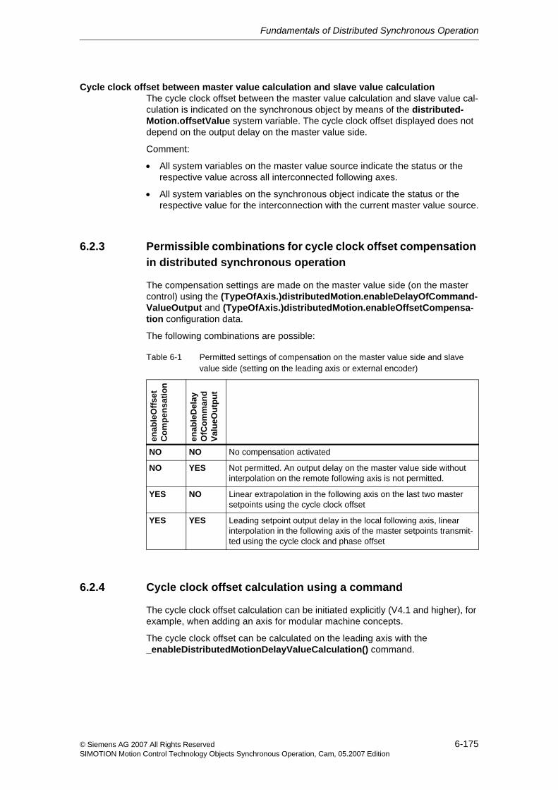
Fundamentals of Distributed Synchronous Operation
6-175© Siemens AG 2007 All Rights ReservedSIMOTION Motion Control Technology Objects Synchronous Operation, Cam, 05.2007 Edition
Cycle clock offset between master value calculation and slave value calculationThe cycle clock offset between the master value calculation and slave value cal-culation is indicated on the synchronous object by means of the distributed-Motion.offsetValue system variable. The cycle clock offset displayed does not depend on the output delay on the master value side.
Comment:
• All system variables on the master value source indicate the status or the respective value across all interconnected following axes.
• All system variables on the synchronous object indicate the status or the respective value for the interconnection with the current master value source.
6.2.3 Permissible combinations for cycle clock offset compensation in distributed synchronous operation
The compensation settings are made on the master value side (on the master control) using the (TypeOfAxis.)distributedMotion.enableDelayOfCommand-ValueOutput and (TypeOfAxis.)distributedMotion.enableOffsetCompensa-tion configuration data.
The following combinations are possible:
6.2.4 Cycle clock offset calculation using a command
The cycle clock offset calculation can be initiated explicitly (V4.1 and higher), for example, when adding an axis for modular machine concepts.
The cycle clock offset can be calculated on the leading axis with the _enableDistributedMotionDelayValueCalculation() command.
Table 6-1 Permitted settings of compensation on the master value side and slave value side (setting on the leading axis or external encoder)
enab
leO
ffset
Com
pens
atio
n
enab
leD
elay
OfC
omm
and
Valu
eOut
put
NO NO No compensation activated
NO YES Not permitted. An output delay on the master value side without interpolation on the remote following axis is not permitted.
YES NO Linear extrapolation in the following axis on the last two master setpoints using the cycle clock offset
YES YES Leading setpoint output delay in the local following axis, linear interpolation in the following axis of the master setpoints transmit-ted using the cycle clock and phase offset
Fundamentals of Distributed Synchronous Operation
6-176 © Siemens AG 2007 All Rights ReservedSIMOTION Motion Control Technology Objects Synchronous Operation, Cam, 05.2007 Edition
This command acts on the master value and all cascades below it for which this master value applies in its cascade. Active synchronous operation commands are aborted when the cycle clock offset calculation is started.
If there are multiple master values at the top level, the command must be called on each object.
Note:
• Do not set a compensation on the master value side.
• An extrapolation can be set on the slave value side.
6.3 Operating axes with distributed synchronous operationThis chapter will introduce you to the special features of operation with distributed synchronous operation.
6.3.1 Life-sign monitoring
The leading axis/external encoder and the remote following object exchange life signs in order for each to confirm that the application is running correctly on the other.
For example, a distributed synchronous operation connection can be adversely affected by a fault on the bus (such as, message frame repetition).
Life-sign monitoring is implemented in the form of one life-sign counter in the lead-ing axis/external encoder and the synchronous object for each distributed syn-chronous operation.
The process could be described as a "clock comparison".
The life sign is sent from the synchronous object to the leading axis/external encoder and vice-versa (bidirectional life-sign monitoring).
The life-sign counters are incremented on the source side in each interpolator cycle clock, and the current value is transmitted to the relevant partner, where it is compared to an expected value. If the life-sign counter values differ from the expected values, an error will be output.
Life-sign monitoring is only active if both SIMOTION devices are in RUN mode.
Failure limitA parameter can be assigned to permit the life sign to fail n times before an error is output.
This is set using the (TypeOfAxis.)DistributedMotion.numberOfLifeSignFail-ures configuration data (default: 1).
The failure limit can be set on the leading axis or external encoder and on the fol-lowing axes.
Fundamentals of Distributed Synchronous Operation
6-177© Siemens AG 2007 All Rights ReservedSIMOTION Motion Control Technology Objects Synchronous Operation, Cam, 05.2007 Edition
Extrapolation in the event of a failure
In the event of a life-sign failure (and the subsequent failure of the master value) that does not trigger an error (n > 0), the last available master setpoint is extrap-olated.
Fault reactionAn error reaction is activated if the number of failures exceeds the assigned value n. The life-sign error is indicated on the following axis and the leading axis/exter-nal encoder. Consequently, the error reaction is applied to both of the following:
• Leading axis/external encoder: 40301 Loss of slave connection to the dis-tributed control in the distributed synchronous operation
• Synchronous object: 50201 Loss of connection on the assigned control to the master in the distributed synchronous operation
Activating/deactivating life-sign monitoringThe life-sign monitoring can be enabled/disabled using the (TypeOfAxis.)dis-tributedMotion.enableLifeSignMonitoring configuration data on the leading axis / external encoder and the synchronous object (default: YES).
Status signalLife-sign monitoring must be activated on all participating objects or deactivated on all participating objects.
If this is not the case, a single alarm is output on the leading axis/external encoder or synchronous object to indicate that life-sign monitoring has been deactivated:
• Leading axis/external encoder: 40302 Life-sign monitoring for slave deacti-vated in distributed synchronous operation
• Synchronous object: 50202 Life-sign monitoring for master deactivated in distributed synchronous operation
The distributedMotion.lifeSignError system variable on both the leading axis/external encoder and synchronous object can be used to check whether life-signs have failed.
When life-sign monitoring is activated, the assigned tolerated life-sign monitoring failures in (TypeOfAxis.)DistributedMotion.numberOfLifeSignFailures must be identical.
6.3.2 Operating states
Note that in order for distributed synchronous operation to function, the master CPU and the slave CPU must both be in RUN mode.
The connection for distributed synchronous operation does not occur automati-cally unless both are in RUN mode.
Fundamentals of Distributed Synchronous Operation
6-178 © Siemens AG 2007 All Rights ReservedSIMOTION Motion Control Technology Objects Synchronous Operation, Cam, 05.2007 Edition
Association with life-sign monitoringIf life-sign monitoring is deactivated ((TypeOfAxis.)distributedMotion.enable-LifeSignMonitoring = No) and a transition occurs from RUN to STOP/STOPU, the master CPU outputs a technological alarm (life-sign error 50201) to all con-nected slave CPUs.
Synchronization statusThe following device-related system variables on the slave indicate the status of synchronization:
• StateofDPinterfaceSynchonization: only relevant if DP of PROFIBUS is equidistant
• StateofDPslaveSynchonization: only relevant if DP of PROFIBUS is not equidistant
Direction reversal of the master value for the synchronizationA maximum master value reversal can be defined in the configuration data sync-ingMotion.masterReversionTolerance on the synchronous object (V4.0 and higher).
The specification of a tolerance is useful, in particular, for a distributed synchro-nous operation, where master value noise for actual value coupling can cause a master value reversal due to extrapolation.
See Actual value coupling with tolerance window (Section 2.4.2)
Error handlingDuring distributed synchronous operation, only the "Synchronous operation toler-ance exceeded" error is reported from the following axis to the leading axis. If the following axis cannot synchronize, this is not reported to the master object!
The error transfer must be configured: by means of the synchronous operation monitoring wizard on the following axis of the slave or by means of the Typeof-Axis.GearingPosTolerance.enableErrorReporting configuration data.
Additional errors are not reported.
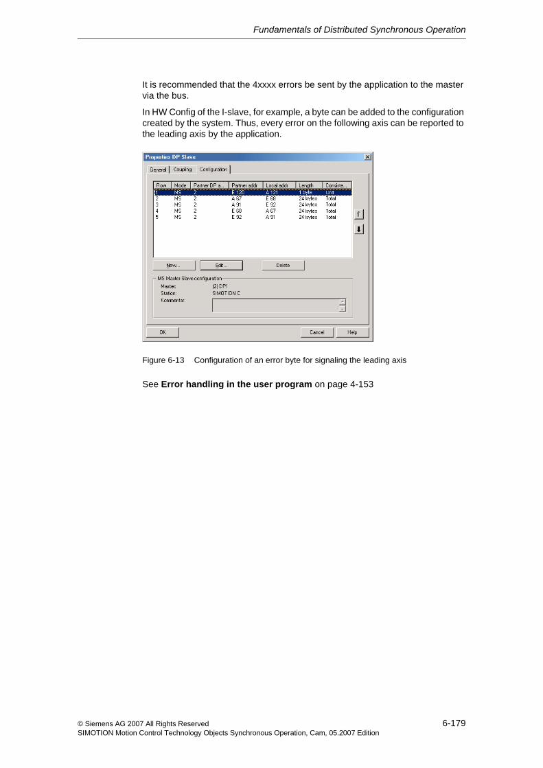
Fundamentals of Distributed Synchronous Operation
6-179© Siemens AG 2007 All Rights ReservedSIMOTION Motion Control Technology Objects Synchronous Operation, Cam, 05.2007 Edition
It is recommended that the 4xxxx errors be sent by the application to the master via the bus.
In HW Config of the I-slave, for example, a byte can be added to the configuration created by the system. Thus, every error on the following axis can be reported to the leading axis by the application.
Figure 6-13 Configuration of an error byte for signaling the leading axis
See Error handling in the user program on page 4-153
Fundamentals of Distributed Synchronous Operation
6-180 © Siemens AG 2007 All Rights ReservedSIMOTION Motion Control Technology Objects Synchronous Operation, Cam, 05.2007 Edition
7-181© Siemens AG 2007 All Rights ReservedSIMOTION Motion Control Technology Objects Synchronous Operation, Cam, 05.2007 Edition
Configuring Distributed Synchronous Operation 7
This chapter describes how to create and configure devices and objects with dis-tributed synchronous operation and how to download them to the system.
As a requirement, you must have already created master axes or external encod-ers, as well as cams.
A sample project for distributed synchronous operation can be found under FAQ on the SIMOTION Utilities & Applications CD.
Content
7.1 Creating SIMOTION devices with SCOUT 7-182
7.2 Creating connection(s) with HW Config 7-183
7.3 Creating synchronous operation connection(s) with SCOUT 7-185
7.4 Synchronizing the interfaces 7-187
7.5 Generating a synchronous operation configuration 7-188
7.6 Possible errors 7-189
Configuring Distributed Synchronous Operation
7-182 © Siemens AG 2007 All Rights ReservedSIMOTION Motion Control Technology Objects Synchronous Operation, Cam, 05.2007 Edition
7.1 Creating SIMOTION devices with SCOUT
Master CPU and slave CPU
First, use HW Config in SIMOTION SCOUT to create two or more SIMOTION devices in the project:
• One device configured as a master
• One or more devices configured as slaves
Use the following practical procedure:
1. First create the slave in HW Config.
2. Then create the master in HW Config and connect the slave (which is already configured).
3. In order to compile with HW Config, a connection must be established between the two devices (output byte 0 to input byte 0).
Note
The same Kernel versions must be available for the master and all slaves.
Note
Addresses entered by SIMOTION SCOUT for axis communication may not be changed.
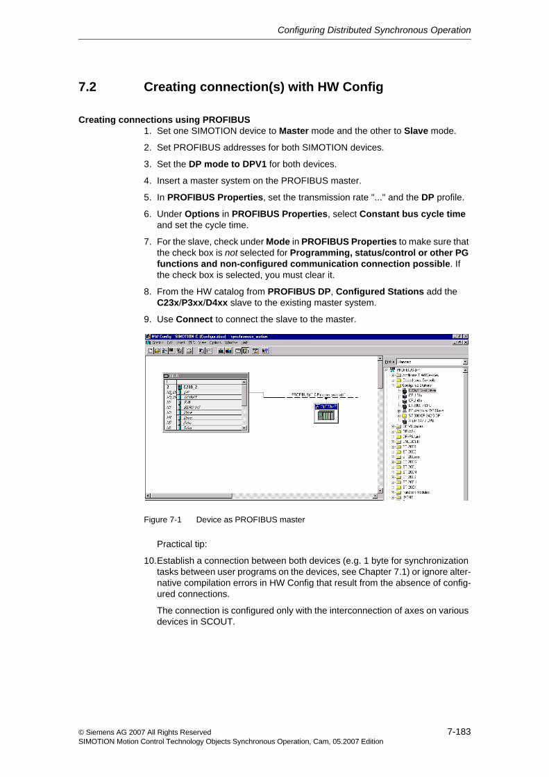
Configuring Distributed Synchronous Operation
7-183© Siemens AG 2007 All Rights ReservedSIMOTION Motion Control Technology Objects Synchronous Operation, Cam, 05.2007 Edition
7.2 Creating connection(s) with HW Config
Creating connections using PROFIBUS1. Set one SIMOTION device to Master mode and the other to Slave mode.
2. Set PROFIBUS addresses for both SIMOTION devices.
3. Set the DP mode to DPV1 for both devices.
4. Insert a master system on the PROFIBUS master.
5. In PROFIBUS Properties, set the transmission rate "..." and the DP profile.
6. Under Options in PROFIBUS Properties, select Constant bus cycle time and set the cycle time.
7. For the slave, check under Mode in PROFIBUS Properties to make sure that the check box is not selected for Programming, status/control or other PG functions and non-configured communication connection possible. If the check box is selected, you must clear it.
8. From the HW catalog from PROFIBUS DP, Configured Stations add the C23x/P3xx/D4xx slave to the existing master system.
9. Use Connect to connect the slave to the master.
Figure 7-1 Device as PROFIBUS master
Practical tip:
10.Establish a connection between both devices (e.g. 1 byte for synchronization tasks between user programs on the devices, see Chapter 7.1) or ignore alter-native compilation errors in HW Config that result from the absence of config-ured connections.
The connection is configured only with the interconnection of axes on various devices in SCOUT.
Configuring Distributed Synchronous Operation
7-184 © Siemens AG 2007 All Rights ReservedSIMOTION Motion Control Technology Objects Synchronous Operation, Cam, 05.2007 Edition
Creating connections using PROFINET IO with IRTThe creation of a distributed synchronous operation requires that at least two IO controllers are connected with each other using IRT; a complete IRT configur-ing does not need to have been performed:
1. Set the IP addresses. Recommendation: fixed IP addresses
2. Use HW Config to create the two devices.
3. Configure the IRT operation by setting synchronization type SyncSlave for one of the devices and SyncMaster for the other device.
This creates the HW Config for distributed synchronous operation. The configur-ing of the axes and the interconnection of the axes is the same as for PROFIBUS.
Save and compile in SCOUT automatically creates the data to be exchanged for the distributed synchronous operation between the CPUs.
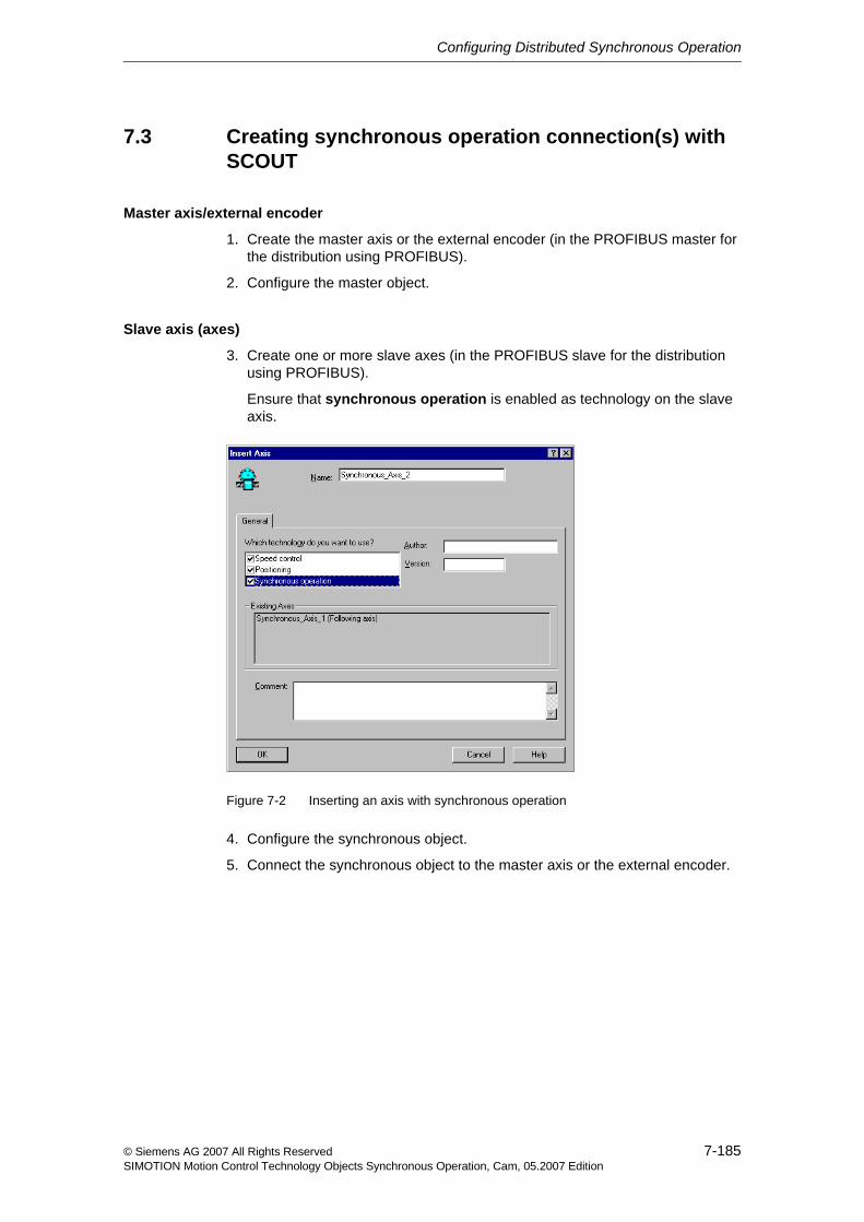
Configuring Distributed Synchronous Operation
7-185© Siemens AG 2007 All Rights ReservedSIMOTION Motion Control Technology Objects Synchronous Operation, Cam, 05.2007 Edition
7.3 Creating synchronous operation connection(s) with SCOUT
Master axis/external encoder
1. Create the master axis or the external encoder (in the PROFIBUS master for the distribution using PROFIBUS).
2. Configure the master object.
Slave axis (axes)
3. Create one or more slave axes (in the PROFIBUS slave for the distribution using PROFIBUS).
Ensure that synchronous operation is enabled as technology on the slave axis.
Figure 7-2 Inserting an axis with synchronous operation
4. Configure the synchronous object.
5. Connect the synchronous object to the master axis or the external encoder.
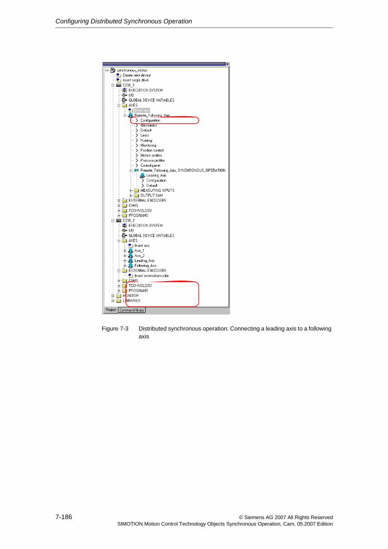
Configuring Distributed Synchronous Operation
7-186 © Siemens AG 2007 All Rights ReservedSIMOTION Motion Control Technology Objects Synchronous Operation, Cam, 05.2007 Edition
Figure 7-3 Distributed synchronous operation: Connecting a leading axis to a following axis
Configuring Distributed Synchronous Operation
7-187© Siemens AG 2007 All Rights ReservedSIMOTION Motion Control Technology Objects Synchronous Operation, Cam, 05.2007 Edition
7.4 Synchronizing the interfacesBefore distributed synchronous operation can be used on the slave side (e.g. con-figuration of the C230-2 X8: connection to master CPU X9: connection to drive, both with isochronous mode), both interfaces must be synchronized. This can be done automatically in the startup task of the slave CPU using the _enableDpInterfaceSynchronizationMode() (dpInterfaceSyncMode: =AUTOMATIC_INTERFACE_SYNCHRONIZATION) function call; otherwise, the function must be issued later explicitly (_synchronizeDpInterface()).
The _synchronizeDpInterface() function can only be successfully executed when the _enableDpInterfaceSynchronizationMode() function has been called with the MASTER_SLAVE_ALARMMESSAGES_1 parameter.
Further information is available in the Motion Control Basic Functions for Modular Machines Function Manual.
Status
The system variable stateOfDpInterfaceSynchronization = DP_INTERFACES_SYNCHRONIZED on the slave indicates whether the two interfaces are synchronized (a requirement for error-free distributed synchronous operation).
Configuring Distributed Synchronous Operation
7-188 © Siemens AG 2007 All Rights ReservedSIMOTION Motion Control Technology Objects Synchronous Operation, Cam, 05.2007 Edition
7.5 Generating a synchronous operation configuration
Compiling the project
• Call the Save and Compile All function.
The system will automatically compile the PROFIBUS IO configuration data in HW Config for the 24 bytes of send and receive info for the distributed synchro-nous operation.
The configuration is generated and checked for consistency.
Downloading the project
• Download the project to both SIMOTION devices.
The system downloads the synchronous operation configuration to the SIMOTION devices.
Note
Only at this point can it be determined whether the network resources are suffi-cient. If they are not, an error message will be generated to this effect.
There must be no errors during the compilation process, otherwise it will not be possible to download the project.
Note
There is no internal mechanism in the SIMOTION Kernel for checking the consis-tency of downloaded projects among multiple devices, e.g. during startup. Con-sistent downloads can only be ensured using the download operation in SIMOTION SCOUT.
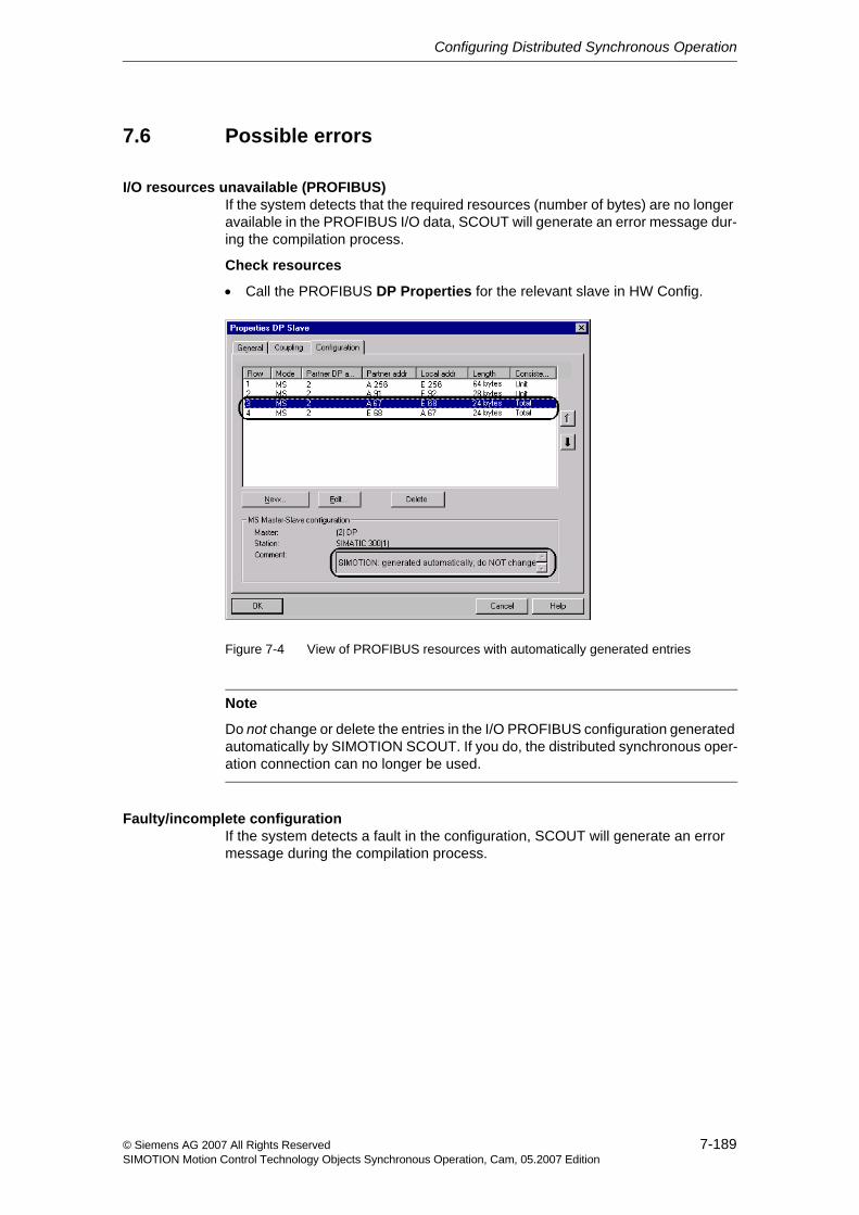
Configuring Distributed Synchronous Operation
7-189© Siemens AG 2007 All Rights ReservedSIMOTION Motion Control Technology Objects Synchronous Operation, Cam, 05.2007 Edition
7.6 Possible errors
I/O resources unavailable (PROFIBUS)If the system detects that the required resources (number of bytes) are no longer available in the PROFIBUS I/O data, SCOUT will generate an error message dur-ing the compilation process.
Check resources
• Call the PROFIBUS DP Properties for the relevant slave in HW Config.
Figure 7-4 View of PROFIBUS resources with automatically generated entries
Faulty/incomplete configurationIf the system detects a fault in the configuration, SCOUT will generate an error message during the compilation process.
Note
Do not change or delete the entries in the I/O PROFIBUS configuration generated automatically by SIMOTION SCOUT. If you do, the distributed synchronous oper-ation connection can no longer be used.
Configuring Distributed Synchronous Operation
7-190 © Siemens AG 2007 All Rights ReservedSIMOTION Motion Control Technology Objects Synchronous Operation, Cam, 05.2007 Edition
Leading axis not readyWhen the distributed synchronous operation is to be started, it must be ensured through the application that the leading axis is ready.
If this is not the case, for example, if _enableGearing() is executed on the follow-ing axis even though the leading axis is not ready, the command is aborted with error "50102 Master is not assigned/configured or is faulty (reason: ...)"
8-191© Siemens AG 2007 All Rights ReservedSIMOTION Motion Control Technology Objects Synchronous Operation, Cam, 05.2007 Edition
Configuring Distributed Synchronous Operation across Projects (V4.1 and higher) 8
8.1 Overview 8-192
8.2 Network configuration with HW Config 8-193
8.3 PROFIBUS communication configuration 8-196
8.4 Communication via PROFINET IO with IRTtop 8-201
8.5 Proxy objects 8-203
8.6 Interconnection options 8-206
8.7 Synchronizing the interface 8-208
8.8 Switching over to an external master value source 8-208
Configuring Distributed Synchronous Operation across Projects (V4.1 and higher)
8-192 © Siemens AG 2007 All Rights ReservedSIMOTION Motion Control Technology Objects Synchronous Operation, Cam, 05.2007 Edition
8.1 OverviewIn V4.1 and higher, it is possible to configure a distributed synchronous operation across projects.
If you need to configure a distributed synchronous operation between a master object and a synchronous object on an external device that is located in another project, you can no longer interconnect the two objects directly.
Now, to configure the interconnection to an external object, there are proxy objects that represent the relevant external object in a project.
Thus, the interconnection is configured by means of proxy objects, rather than directly between the master object and the synchronous object.
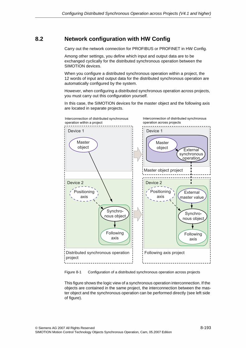
Configuring Distributed Synchronous Operation across Projects (V4.1 and higher)
8-193© Siemens AG 2007 All Rights ReservedSIMOTION Motion Control Technology Objects Synchronous Operation, Cam, 05.2007 Edition
8.2 Network configuration with HW ConfigCarry out the network connection for PROFIBUS or PROFINET in HW Config.
Among other settings, you define which input and output data are to be exchanged cyclically for the distributed synchronous operation between the SIMOTION devices.
When you configure a distributed synchronous operation within a project, the 12 words of input and output data for the distributed synchronous operation are automatically configured by the system.
However, when configuring a distributed synchronous operation across projects, you must carry out this configuration yourself.
In this case, the SIMOTION devices for the master object and the following axis are located in separate projects.
Figure 8-1 Configuration of a distributed synchronous operation across projects
This figure shows the logic view of a synchronous operation interconnection. If the objects are contained in the same project, the interconnection between the mas-ter object and the synchronous operation can be performed directly (see left side of figure).
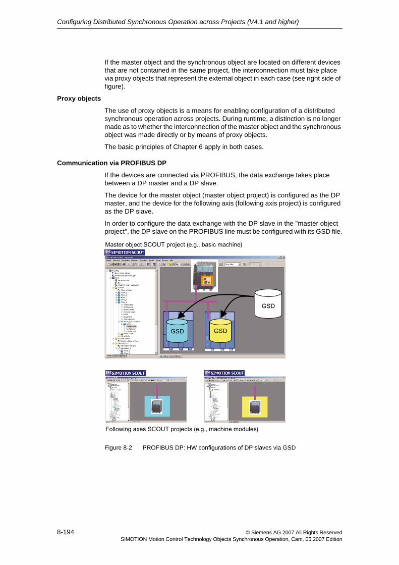
Configuring Distributed Synchronous Operation across Projects (V4.1 and higher)
8-194 © Siemens AG 2007 All Rights ReservedSIMOTION Motion Control Technology Objects Synchronous Operation, Cam, 05.2007 Edition
If the master object and the synchronous object are located on different devices that are not contained in the same project, the interconnection must take place via proxy objects that represent the external object in each case (see right side of figure).
Proxy objects
The use of proxy objects is a means for enabling configuration of a distributed synchronous operation across projects. During runtime, a distinction is no longer made as to whether the interconnection of the master object and the synchronous object was made directly or by means of proxy objects.
The basic principles of Chapter 6 apply in both cases.
Communication via PROFIBUS DP
If the devices are connected via PROFIBUS, the data exchange takes place between a DP master and a DP slave.
The device for the master object (master object project) is configured as the DP master, and the device for the following axis (following axis project) is configured as the DP slave.
In order to configure the data exchange with the DP slave in the "master object project", the DP slave on the PROFIBUS line must be configured with its GSD file.
Figure 8-2 PROFIBUS DP: HW configurations of DP slaves via GSD
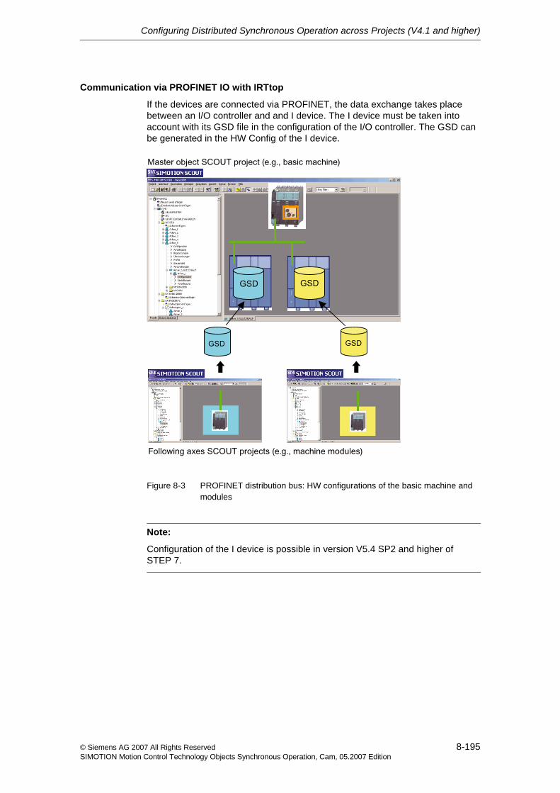
Configuring Distributed Synchronous Operation across Projects (V4.1 and higher)
8-195© Siemens AG 2007 All Rights ReservedSIMOTION Motion Control Technology Objects Synchronous Operation, Cam, 05.2007 Edition
Communication via PROFINET IO with IRTtop
If the devices are connected via PROFINET, the data exchange takes place between an I/O controller and and I device. The I device must be taken into account with its GSD file in the configuration of the I/O controller. The GSD can be generated in the HW Config of the I device.
Figure 8-3 PROFINET distribution bus: HW configurations of the basic machine and modules
Note:
Configuration of the I device is possible in version V5.4 SP2 and higher of STEP 7.
Configuring Distributed Synchronous Operation across Projects (V4.1 and higher)
8-196 © Siemens AG 2007 All Rights ReservedSIMOTION Motion Control Technology Objects Synchronous Operation, Cam, 05.2007 Edition
8.3 PROFIBUS communication configurationIn the following sections, projects for the master object and following axis are created for communication via PROFIBUS.
8.3.1 Creating and configuring a master object project
Create a new project with SIMOTION SCOUT. Create a new SIMOTION device. This project is the "master object" project.
In the "master object" project, open the HW Config of the SIMOTION device.
1. Set the operating mode.
Open the Properties dialog box on the DP interface. On the Operating Mode tab, select DP Master as the Operating Mode. For the DP Mode, set DPV1.
2. Set the PROFIBUS address.
On the General tab, click Properties under Interface. The Properties dialog box opens for the PROFIBUS interface. Select an address for the device.
Make sure to use this PROFIBUS address later for the proxy device in the "following axis" project.
3. Select a subnet for the master object.
In the Properties dialog box for the PROFIBUS interface, select a subnet or create a new one.
4. Open the Properties dialog box for the subnet. Select the Network settings tab and set the following parameters:
− Transmission rate: according to your project parameters
− Profile: DP
− Click Options. Select Equidistant bus cycle and set the DP cycle time in Equidistant DP Cycle.
Make sure you set the same transmission rate and equidistant DP cycle as in the "following axis" project.
5. In HW Config, add the slave that was configured in the "following axis" project (e.g., C230, P350, etc.) to the existing master system.
You can find this slave in the HW catalog under PROFIBUS DP, Additional field devices, PLC, SIMATIC.
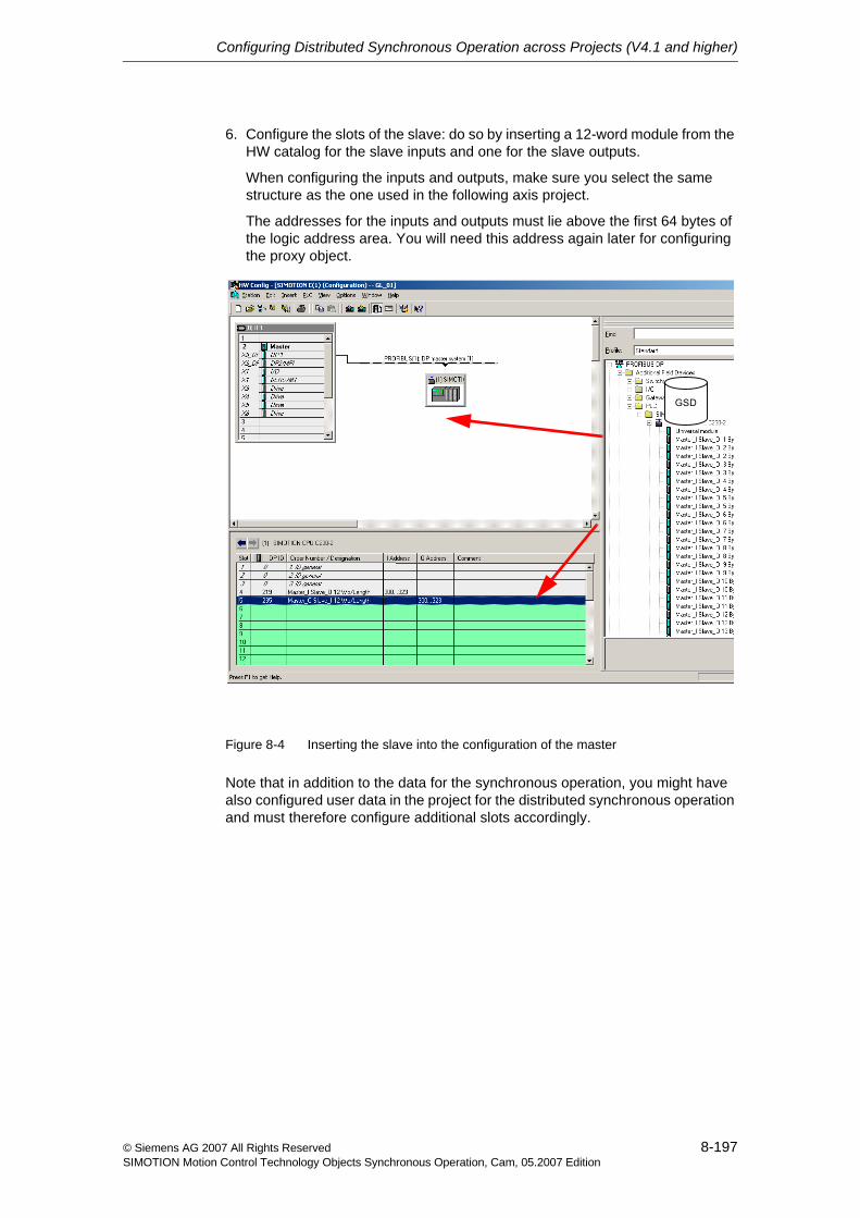
Configuring Distributed Synchronous Operation across Projects (V4.1 and higher)
8-197© Siemens AG 2007 All Rights ReservedSIMOTION Motion Control Technology Objects Synchronous Operation, Cam, 05.2007 Edition
6. Configure the slots of the slave: do so by inserting a 12-word module from the HW catalog for the slave inputs and one for the slave outputs.
When configuring the inputs and outputs, make sure you select the same structure as the one used in the following axis project.
The addresses for the inputs and outputs must lie above the first 64 bytes of the logic address area. You will need this address again later for configuring the proxy object.
Figure 8-4 Inserting the slave into the configuration of the master
Note that in addition to the data for the synchronous operation, you might have also configured user data in the project for the distributed synchronous operation and must therefore configure additional slots accordingly.
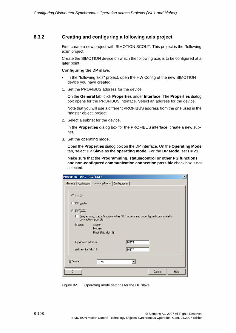
Configuring Distributed Synchronous Operation across Projects (V4.1 and higher)
8-198 © Siemens AG 2007 All Rights ReservedSIMOTION Motion Control Technology Objects Synchronous Operation, Cam, 05.2007 Edition
8.3.2 Creating and configuring a following axis project
First create a new project with SIMOTION SCOUT. This project is the "following axis" project.
Create the SIMOTION device on which the following axis is to be configured at a later point.
Configuring the DP slave:
• In the "following axis" project, open the HW Config of the new SIMOTION device you have created.
1. Set the PROFIBUS address for the device.
On the General tab, click Properties under Interface. The Properties dialog box opens for the PROFIBUS interface. Select an address for the device.
Note that you will use a different PROFIBUS address from the one used in the "master object' project.
2. Select a subnet for the device.
In the Properties dialog box for the PROFIBUS interface, create a new sub-net.
3. Set the operating mode.
Open the Properties dialog box on the DP interface. On the Operating Mode tab, select DP Slave as the operating mode. For the DP Mode, set DPV1.
Make sure that the Programming, status/control or other PG functions and non-configured communication connection possible check box is not selected.
Figure 8-5 Operating mode settings for the DP slave
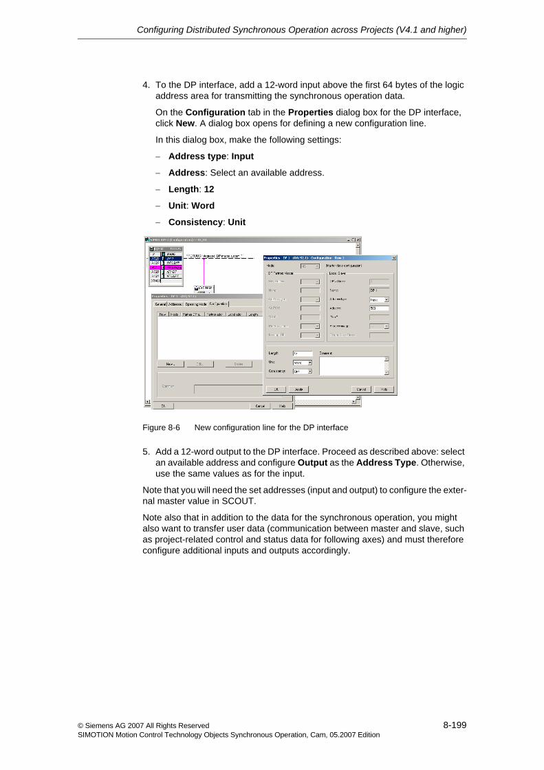
Configuring Distributed Synchronous Operation across Projects (V4.1 and higher)
8-199© Siemens AG 2007 All Rights ReservedSIMOTION Motion Control Technology Objects Synchronous Operation, Cam, 05.2007 Edition
4. To the DP interface, add a 12-word input above the first 64 bytes of the logic address area for transmitting the synchronous operation data.
On the Configuration tab in the Properties dialog box for the DP interface, click New. A dialog box opens for defining a new configuration line.
In this dialog box, make the following settings:
− Address type: Input
− Address: Select an available address.
− Length: 12
− Unit: Word
− Consistency: Unit
Figure 8-6 New configuration line for the DP interface
5. Add a 12-word output to the DP interface. Proceed as described above: select an available address and configure Output as the Address Type. Otherwise, use the same values as for the input.
Note that you will need the set addresses (input and output) to configure the exter-nal master value in SCOUT.
Note also that in addition to the data for the synchronous operation, you might also want to transfer user data (communication between master and slave, such as project-related control and status data for following axes) and must therefore configure additional inputs and outputs accordingly.
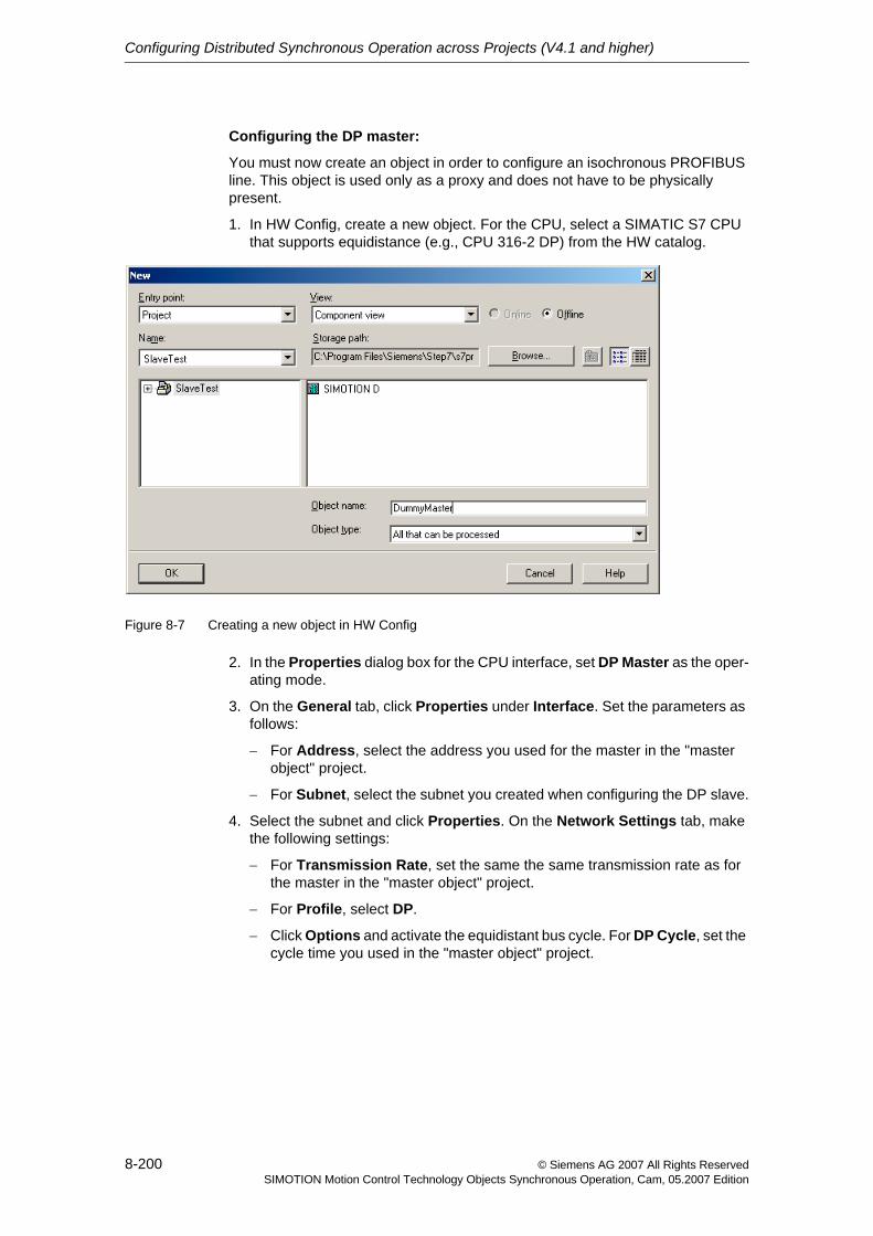
Configuring Distributed Synchronous Operation across Projects (V4.1 and higher)
8-200 © Siemens AG 2007 All Rights ReservedSIMOTION Motion Control Technology Objects Synchronous Operation, Cam, 05.2007 Edition
Configuring the DP master:
You must now create an object in order to configure an isochronous PROFIBUS line. This object is used only as a proxy and does not have to be physically present.
1. In HW Config, create a new object. For the CPU, select a SIMATIC S7 CPU that supports equidistance (e.g., CPU 316-2 DP) from the HW catalog.
Figure 8-7 Creating a new object in HW Config
2. In the Properties dialog box for the CPU interface, set DP Master as the oper-ating mode.
3. On the General tab, click Properties under Interface. Set the parameters as follows:
− For Address, select the address you used for the master in the "master object" project.
− For Subnet, select the subnet you created when configuring the DP slave.
4. Select the subnet and click Properties. On the Network Settings tab, make the following settings:
− For Transmission Rate, set the same the same transmission rate as for the master in the "master object" project.
− For Profile, select DP.
− Click Options and activate the equidistant bus cycle. For DP Cycle, set the cycle time you used in the "master object" project.
Configuring Distributed Synchronous Operation across Projects (V4.1 and higher)
8-201© Siemens AG 2007 All Rights ReservedSIMOTION Motion Control Technology Objects Synchronous Operation, Cam, 05.2007 Edition
8.4 Communication via PROFINET IO with IRTtopIn the following sections, projects for the master object and following axis are created for communication via PROFINET IO.
8.4.1 Creating and configuring a master object project
Create a new project with SIMOTION SCOUT. Create the SIMOTION device on which the master object is to be configured at a later point. This project is the "master object" project.
In the "master object" project, open the HW Config of the new SIMOTION device.
1. For a SIMOTION device without an integrated PROFINET interface, insert a PROFINET module into the slot provided for this purpose on the SIMOTION device.
2. Connect the PROFINET interface to a subnet and define the settings for IP address, Subnet Mask, and Router.
3. Define the synchronization type of the PROFINET interface.
Select Sync Slave if a sync master already exists on another PROFINET device for the preselected sync domain. Otherwise set Sync Master as the Synchronization type.
4. Set the required send cycle clock on the Sync Domain of the PROFINET interface.
5. Insert the proxy for the I device on the subnet. The proxy for the I device is located in the hardware catalog under PROFINET IO, already configured stations.
6. When you insert the proxy for the I device, the logic addresses for the cyclic input and output data of HW Config are preassigned. If necessary, correct these addresses before continuing with the configuration of the proxy objects in SCOUT.
7. Make sure the device name of the proxy for the I device corresponds to the device name that was assigned when the I device was configured.
Configuring Distributed Synchronous Operation across Projects (V4.1 and higher)
8-202 © Siemens AG 2007 All Rights ReservedSIMOTION Motion Control Technology Objects Synchronous Operation, Cam, 05.2007 Edition
8.4.2 Creating and configuring a following axis project
First create a new project with SIMOTION SCOUT. This project is the "following axis" project.
Create the SIMOTION device on which the following axis is to be configured at a later point.
1. For a SIMOTION device without an integrated PROFINET interface, insert a PROFINET module into the slot provided for this purpose on the SIMOTION device.
2. Assign the device name for the PROFINET interface of the I device.
3. Connect the PROFINET interface to a subnet and define the settings for IP address, Subnet Mask, and Router.
4. Set the Synchronization Type to Not Synchronized.
5. Activate the I device mode and the option that activates the PROFINET inter-face from the higher-level I/O controller.
6. Configure the send cycle clock for the I/O data of the I device. You must also set this cycle clock when subsequently configuring the Sync domain of the I/O controller.
7. For the PROFINET interface, create 12 words of input data and 12 words of output data. You will need the base address later when configuring the proxy object in SCOUT.
Note also that in addition to the data for the synchronous operation, you might also want to transfer user data (communication between master and slave, such as project-related control and status data for following axes) and must therefore configure additional inputs and outputs accordingly.
8. Generate the GSD file for the I device. You will need this file as the proxy of the I device in the project of the PROFINET IO controller.
In the Options menu, select Create GSD for I Device. Select the relevant I device and the name of the proxy, and install the GSD.
If the project for the PROFINET IO controller is not to be executed with the same engineering system, you must export the GSD file. The GSD file must then be imported in the HW Config of the other engineering system.
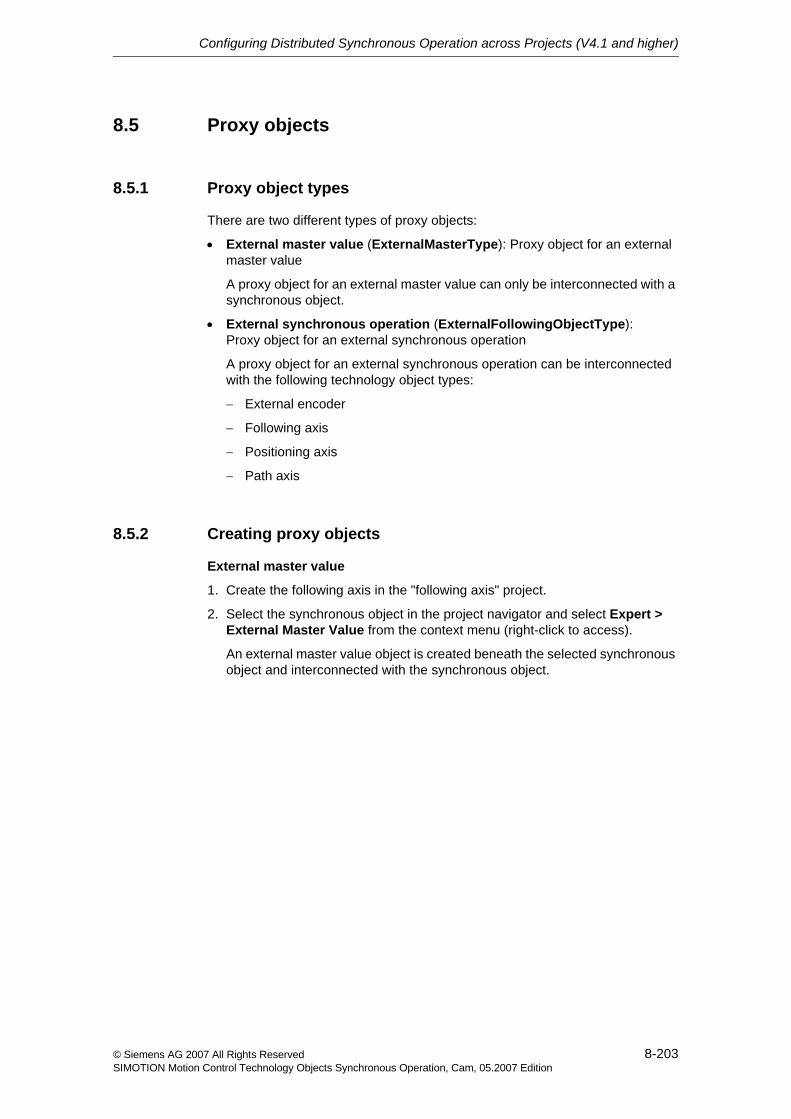
Configuring Distributed Synchronous Operation across Projects (V4.1 and higher)
8-203© Siemens AG 2007 All Rights ReservedSIMOTION Motion Control Technology Objects Synchronous Operation, Cam, 05.2007 Edition
8.5 Proxy objects
8.5.1 Proxy object types
There are two different types of proxy objects:
• External master value (ExternalMasterType): Proxy object for an external master value
A proxy object for an external master value can only be interconnected with a synchronous object.
• External synchronous operation (ExternalFollowingObjectType): Proxy object for an external synchronous operation
A proxy object for an external synchronous operation can be interconnected with the following technology object types:
− External encoder
− Following axis
− Positioning axis
− Path axis
8.5.2 Creating proxy objects
External master value
1. Create the following axis in the "following axis" project.
2. Select the synchronous object in the project navigator and select Expert > External Master Value from the context menu (right-click to access).
An external master value object is created beneath the selected synchronous object and interconnected with the synchronous object.
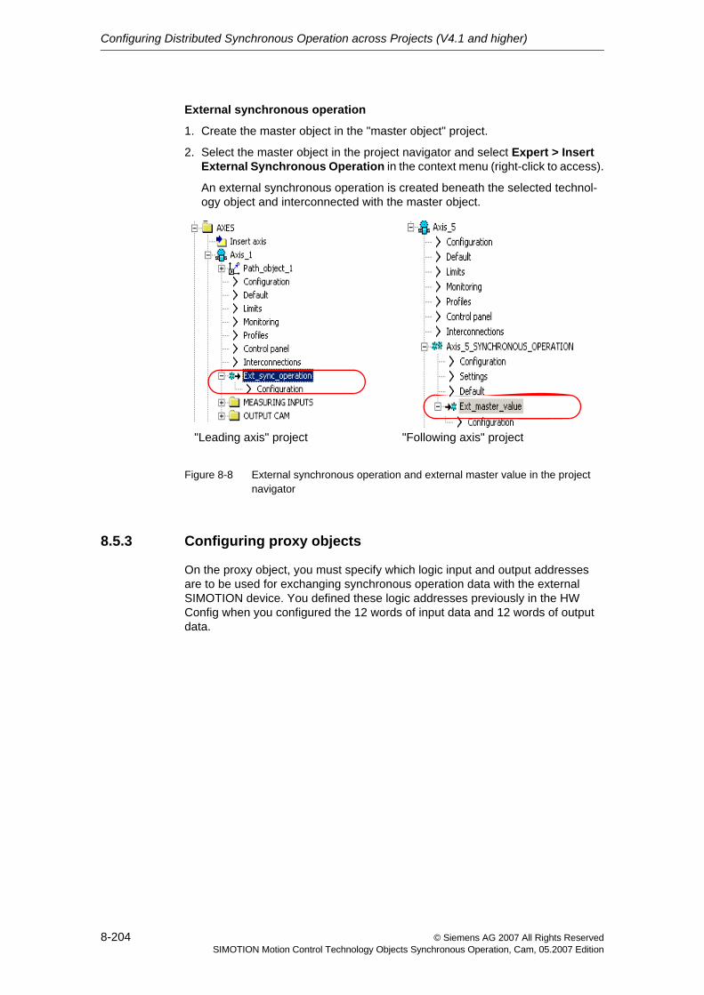
Configuring Distributed Synchronous Operation across Projects (V4.1 and higher)
8-204 © Siemens AG 2007 All Rights ReservedSIMOTION Motion Control Technology Objects Synchronous Operation, Cam, 05.2007 Edition
External synchronous operation
1. Create the master object in the "master object" project.
2. Select the master object in the project navigator and select Expert > Insert External Synchronous Operation in the context menu (right-click to access).
An external synchronous operation is created beneath the selected technol-ogy object and interconnected with the master object.
Figure 8-8 External synchronous operation and external master value in the project navigator
8.5.3 Configuring proxy objects
On the proxy object, you must specify which logic input and output addresses are to be used for exchanging synchronous operation data with the external SIMOTION device. You defined these logic addresses previously in the HW Config when you configured the 12 words of input data and 12 words of output data.
"Leading axis" project "Following axis" project
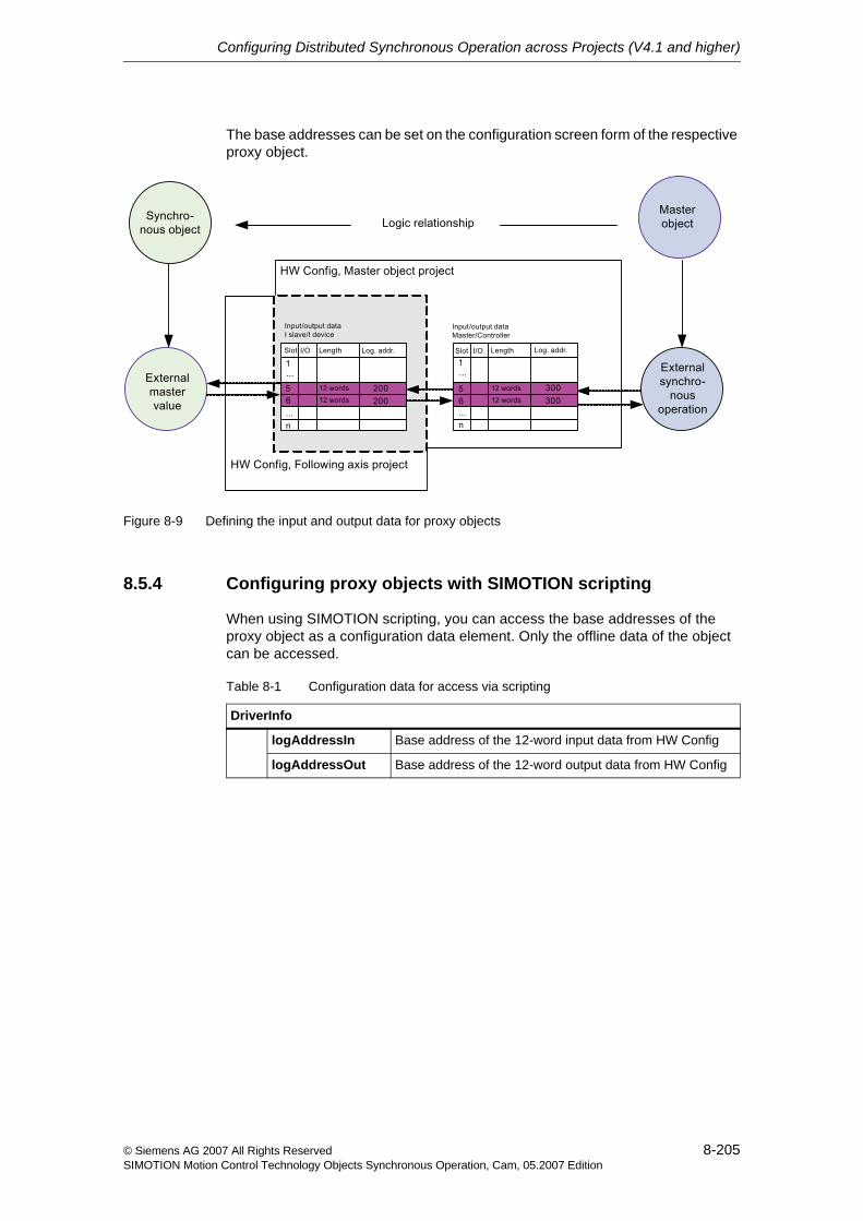
Configuring Distributed Synchronous Operation across Projects (V4.1 and higher)
8-205© Siemens AG 2007 All Rights ReservedSIMOTION Motion Control Technology Objects Synchronous Operation, Cam, 05.2007 Edition
The base addresses can be set on the configuration screen form of the respective proxy object.
Figure 8-9 Defining the input and output data for proxy objects
8.5.4 Configuring proxy objects with SIMOTION scripting
When using SIMOTION scripting, you can access the base addresses of the proxy object as a configuration data element. Only the offline data of the object can be accessed.
Table 8-1 Configuration data for access via scripting
DriverInfo
logAddressIn Base address of the 12-word input data from HW Config
logAddressOut Base address of the 12-word output data from HW Config
Configuring Distributed Synchronous Operation across Projects (V4.1 and higher)
8-206 © Siemens AG 2007 All Rights ReservedSIMOTION Motion Control Technology Objects Synchronous Operation, Cam, 05.2007 Edition
8.6 Interconnection optionsIn general, proxy objects can be interconnected with a maximum of one technol-ogy object. The following figure shows the interconnection options.
Figure 8-10 Interconnection options for proxy objects
In order to interconnect multiple synchronous objects to one external master value, you must create an additional synchronous operation with a virtual axis, to which the external master value proxy object will be connected. In this case, the additional virtual axis acts as a master value source for multiple synchronous objects (See Figure 8-11).
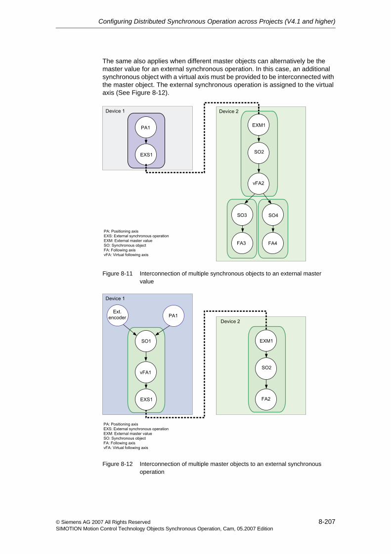
Configuring Distributed Synchronous Operation across Projects (V4.1 and higher)
8-207© Siemens AG 2007 All Rights ReservedSIMOTION Motion Control Technology Objects Synchronous Operation, Cam, 05.2007 Edition
The same also applies when different master objects can alternatively be the master value for an external synchronous operation. In this case, an additional synchronous object with a virtual axis must be provided to be interconnected with the master object. The external synchronous operation is assigned to the virtual axis (See Figure 8-12).
Figure 8-11 Interconnection of multiple synchronous objects to an external master value
Figure 8-12 Interconnection of multiple master objects to an external synchronous operation
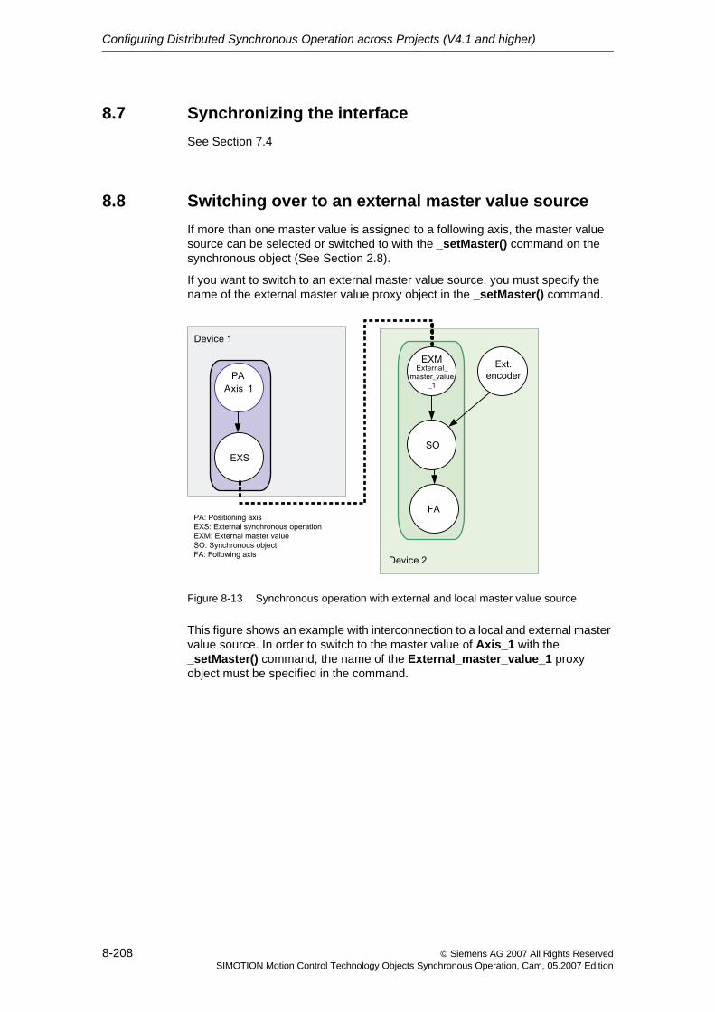
Configuring Distributed Synchronous Operation across Projects (V4.1 and higher)
8-208 © Siemens AG 2007 All Rights ReservedSIMOTION Motion Control Technology Objects Synchronous Operation, Cam, 05.2007 Edition
8.7 Synchronizing the interfaceSee Section 7.4
8.8 Switching over to an external master value sourceIf more than one master value is assigned to a following axis, the master value source can be selected or switched to with the _setMaster() command on the synchronous object (See Section 2.8).
If you want to switch to an external master value source, you must specify the name of the external master value proxy object in the _setMaster() command.
Figure 8-13 Synchronous operation with external and local master value source
This figure shows an example with interconnection to a local and external master value source. In order to switch to the master value of Axis_1 with the _setMaster() command, the name of the External_master_value_1 proxy object must be specified in the command.
© Siemens AG 2007 All Rights ReservedSIMOTION Motion Control Technology Objects Synchronous Operation, Cam, 05.2007 Edition
Part IIISynchronous Operation IPO - IPO_2
This chapter describes the synchronous operation IPO - IPO_2 function (V3.2 and higher). Synchronous operation can be configured such that higher-priority axes are calculated in the IPO interpolator cycle clock and lower-priority axes in the IPO_2 interpolator cycle clock.
It introduces you to the operating principle and technological boundary conditions of synchronous operation with master object and following axis in different inter-polator cycle clocks (IPO or IPO_2).
You are shown how to create and configure a synchronous operation in different interpolator cycle clocks.
Content
Chapter 9 Overview of Synchronous Operation IPO - IPO_2 9-211
Chapter 10 Fundamentals of Synchronous Operation IPO - IPO_2 10-215
Chapter 11 Configuring Synchronous Operation IPO - IPO_2 11-221

© Siemens AG 2007 All Rights ReservedSIMOTION Motion Control Technology Objects Synchronous Operation, Cam, 05.2007 Edition
9-211© Siemens AG 2007 All Rights ReservedSIMOTION Motion Control Technology Objects Synchronous Operation, Cam, 05.2007 Edition
Overview of Synchronous Operation IPO - IPO_2 9
This chapter provides information on the basic function and application of syn-chronous operation between two axes, calculated in different interpolation cycle clocks.
Content
9.1 Function overview 9-212
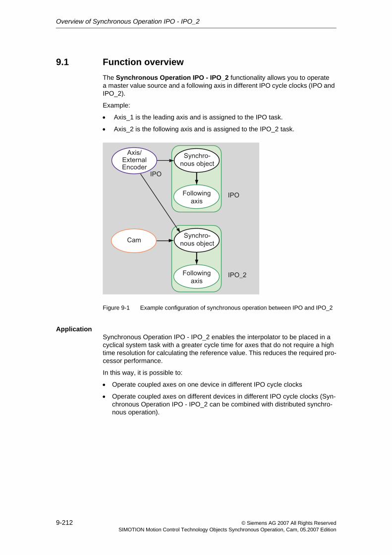
Overview of Synchronous Operation IPO - IPO_2
9-212 © Siemens AG 2007 All Rights ReservedSIMOTION Motion Control Technology Objects Synchronous Operation, Cam, 05.2007 Edition
9.1 Function overviewThe Synchronous Operation IPO - IPO_2 functionality allows you to operate a master value source and a following axis in different IPO cycle clocks (IPO and IPO_2).
Example:
• Axis_1 is the leading axis and is assigned to the IPO task.
• Axis_2 is the following axis and is assigned to the IPO_2 task.
Figure 9-1 Example configuration of synchronous operation between IPO and IPO_2
ApplicationSynchronous Operation IPO - IPO_2 enables the interpolator to be placed in a cyclical system task with a greater cycle time for axes that do not require a high time resolution for calculating the reference value. This reduces the required pro-cessor performance.
In this way, it is possible to:
• Operate coupled axes on one device in different IPO cycle clocks
• Operate coupled axes on different devices in different IPO cycle clocks (Syn-chronous Operation IPO - IPO_2 can be combined with distributed synchro-nous operation).
Overview of Synchronous Operation IPO - IPO_2
9-213© Siemens AG 2007 All Rights ReservedSIMOTION Motion Control Technology Objects Synchronous Operation, Cam, 05.2007 Edition
Mode of functioning/compensationsThe phase error, which results from processing in a succession of different cycles, can be compensated for in the same way as for distributed synchronous operation:
• Compensation on master value side by means of setpoint output delay
• Compensation of the slave value side by means of master value extrapolation
See Compensations on page 10-218
Overview of Synchronous Operation IPO - IPO_2
9-214 © Siemens AG 2007 All Rights ReservedSIMOTION Motion Control Technology Objects Synchronous Operation, Cam, 05.2007 Edition
10-215© Siemens AG 2007 All Rights ReservedSIMOTION Motion Control Technology Objects Synchronous Operation, Cam, 05.2007 Edition
Fundamentals of Synchronous Operation IPO - IPO_2 10
This chapter describes the boundary conditions for the creation of a Synchro-nous Operation IPO - IPO_2.
Content
10.1 Boundary conditions 10-216
10.2 Operation of Synchronous Operation IPO - IPO_2 10-218
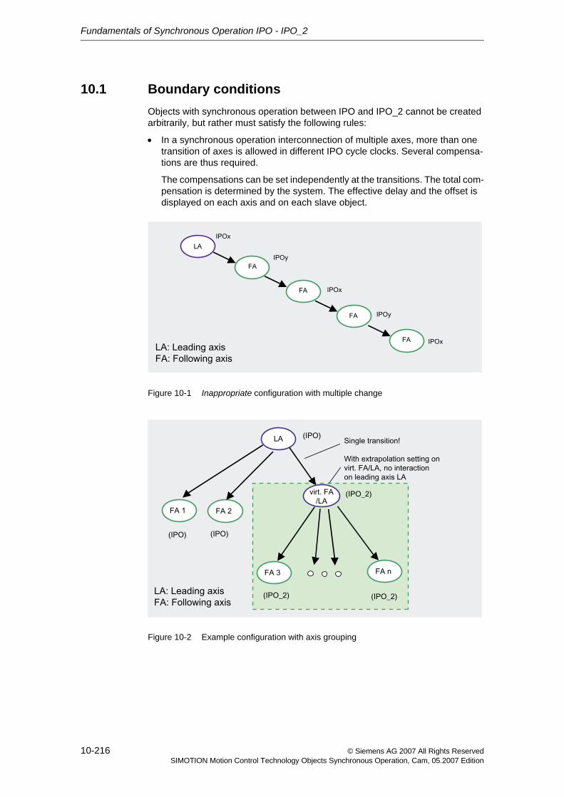
Fundamentals of Synchronous Operation IPO - IPO_2
10-216 © Siemens AG 2007 All Rights ReservedSIMOTION Motion Control Technology Objects Synchronous Operation, Cam, 05.2007 Edition
10.1 Boundary conditionsObjects with synchronous operation between IPO and IPO_2 cannot be created arbitrarily, but rather must satisfy the following rules:
• In a synchronous operation interconnection of multiple axes, more than one transition of axes is allowed in different IPO cycle clocks. Several compensa-tions are thus required.
The compensations can be set independently at the transitions. The total com-pensation is determined by the system. The effective delay and the offset is displayed on each axis and on each slave object.
Figure 10-1 Inappropriate configuration with multiple change
Figure 10-2 Example configuration with axis grouping
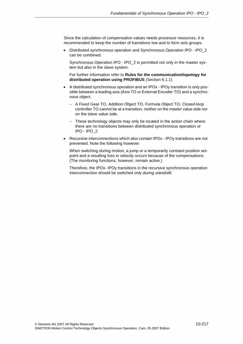
Fundamentals of Synchronous Operation IPO - IPO_2
10-217© Siemens AG 2007 All Rights ReservedSIMOTION Motion Control Technology Objects Synchronous Operation, Cam, 05.2007 Edition
Since the calculation of compensation values needs processor resources, it is recommended to keep the number of transitions low and to form axis groups.
• Distributed synchronous operation and Synchronous Operation IPO - IPO_2 can be combined.
Synchronous Operation IPO - IPO_2 is permitted not only in the master sys-tem but also in the slave system.
For further information refer to Rules for the communication/topology for distributed operation using PROFIBUS (Section 6.1.1)
• A distributed synchronous operation and an IPOx - IPOy transition is only pos-sible between a leading axis (Axis TO or External Encoder TO) and a synchro-nous object.
− A Fixed Gear TO, Addition Object TO, Formula Object TO, Closed-loop controller TO cannot be at a transition, neither on the master value side nor on the slave value side.
− These technology objects may only be located in the action chain where there are no transitions between distributed synchronous operation or IPO - IPO_2.
• Recursive interconnections which also contain IPOx - IPOy transitions are not prevented. Note the following however:
When switching during motion, a jump or a temporarily constant position set-point and a resulting loss in velocity occurs because of the compensations. (The monitoring functions, however, remain active.)
Therefore, the IPOx- IPOy transitions in the recursive synchronous operation interconnection should be switched only during standstill.
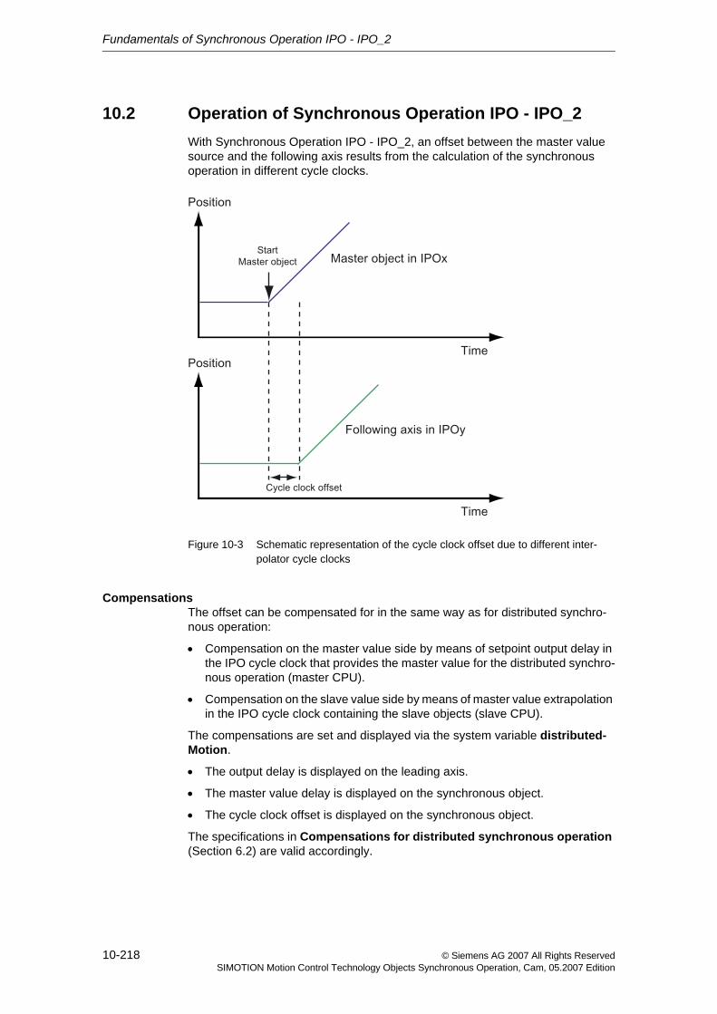
Fundamentals of Synchronous Operation IPO - IPO_2
10-218 © Siemens AG 2007 All Rights ReservedSIMOTION Motion Control Technology Objects Synchronous Operation, Cam, 05.2007 Edition
10.2 Operation of Synchronous Operation IPO - IPO_2With Synchronous Operation IPO - IPO_2, an offset between the master value source and the following axis results from the calculation of the synchronous operation in different cycle clocks.
Figure 10-3 Schematic representation of the cycle clock offset due to different inter-polator cycle clocks
CompensationsThe offset can be compensated for in the same way as for distributed synchro-nous operation:
• Compensation on the master value side by means of setpoint output delay in the IPO cycle clock that provides the master value for the distributed synchro-nous operation (master CPU).
• Compensation on the slave value side by means of master value extrapolation in the IPO cycle clock containing the slave objects (slave CPU).
The compensations are set and displayed via the system variable distributed-Motion.
• The output delay is displayed on the leading axis.
• The master value delay is displayed on the synchronous object.
• The cycle clock offset is displayed on the synchronous object.
The specifications in Compensations for distributed synchronous operation (Section 6.2) are valid accordingly.
Fundamentals of Synchronous Operation IPO - IPO_2
10-219© Siemens AG 2007 All Rights ReservedSIMOTION Motion Control Technology Objects Synchronous Operation, Cam, 05.2007 Edition
Information on compensations• Compensations can be set differently on different master objects.
• If "Extrapolation" is set as the compensation mode, the output delay on the master CPU is zero. In this way, there is no effect on other higher-level master values and their compensation calculation. This allows you to form axis groups.
• It is not possible to specify interpolation on the following axis without master value delay on the leading axis.
• With the "No compensation" setting, the master values are taken over as the exist.
− Therefore a transition from the slower IPO to the faster IPO is possible but not technically practical.
− A transition from the faster IPO to the slower IPO is possible, but is asso-ciated with a phase offset.
Life-sign monitoringThe life-sign monitoring is also active for Synchronous Operation IPO - IPO_2 and takes effect, for example, with level overflows.
The specifications in Operating axes with distributed synchronous operation (Section 6.3) are valid accordingly.

Fundamentals of Synchronous Operation IPO - IPO_2
10-220 © Siemens AG 2007 All Rights ReservedSIMOTION Motion Control Technology Objects Synchronous Operation, Cam, 05.2007 Edition
11-221© Siemens AG 2007 All Rights ReservedSIMOTION Motion Control Technology Objects Synchronous Operation, Cam, 05.2007 Edition
Configuring Synchronous Operation IPO - IPO_2 11
This chapter describes how to create and configure devices and objects with Synchronous Operation IPO - IPO_2.
Content
11.1 Creating Synchronous Operation IPO - IPO_2 in SCOUT 11-222
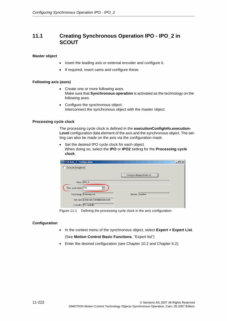
Configuring Synchronous Operation IPO - IPO_2
11-222 © Siemens AG 2007 All Rights ReservedSIMOTION Motion Control Technology Objects Synchronous Operation, Cam, 05.2007 Edition
11.1 Creating Synchronous Operation IPO - IPO_2 in SCOUT
Master object
• Insert the leading axis or external encoder and configure it.
• If required, insert cams and configure these.
Following axis (axes)
• Create one or more following axes.Make sure that Synchronous operation is activated as the technology on the following axes.
• Configure the synchronous object.Interconnect the synchronous object with the master object.
Processing cycle clock
The processing cycle clock is defined in the executionConfigInfo.execution-Level configuration data element of the axis and the synchronous object. The set-ting can also be made on the axis via the configuration mask.
• Set the desired IPO cycle clock for each object.When doing so, select the IPO or IPO2 setting for the Processing cycle clock.
Figure 11-1 Defining the processing cycle clock in the axis configuration
Configuration
• In the context menu of the synchronous object, select Expert > Expert List.
(See Motion Control Basic Functions, "Expert list")
• Enter the desired configuration (see Chapter 10.2 and Chapter 6.2).
© Siemens AG 2007 All Rights ReservedSIMOTION Motion Control Technology Objects Synchronous Operation, Cam, 05.2007 Edition
Part IVCam
This chapter describes the functions of the Cam technology.object.
It introduces you to the functions for creation and definition of cams and provides information on boundary conditions and operating characteristics of cams.
Content
Chapter 12 Overview of Cam 12-225
Chapter 13 Fundamentals of Cam 13-229
Chapter 14 Configuring Cams 14-245
Chapter 15 Cam Programming / References 15-249

© Siemens AG 2007 All Rights ReservedSIMOTION Motion Control Technology Objects Synchronous Operation, Cam, 05.2007 Edition
12-225© Siemens AG 2007 All Rights ReservedSIMOTION Motion Control Technology Objects Synchronous Operation, Cam, 05.2007 Edition
Overview of Cam 12This chapter provides information on the basic function and application of the Cam technology object.
Content
12.1 Function overview 12-226
Overview of Cam
12-226 © Siemens AG 2007 All Rights ReservedSIMOTION Motion Control Technology Objects Synchronous Operation, Cam, 05.2007 Edition
12.1 Function overviewThe Cam technology object can be used to define a transmission function and apply it with other technology objects.
A cam describes the dependency of an output variable on an input variable.
• An input variable could be the actual position of a leading axis, a virtual master value source, or the time.
• Output variable could be used as the set position of a following axis, the set-point profile, or the pressure/force profile.
The Cam technology object is a stand-alone technology object, which can be interconnected with other technology objects.
ApplicationAt present, a Cam technology object can be used with the following objects:
• With a synchronous object as a transmission function
• With an Axis technology object, e.g.
− as a velocity, position, or pressure profile
− as a valve characteristic in the hydraulic axis setting
DefinitionA Cam technology object describes a function y = f(x) in sections. The sections can be defined using interpolation points or by segments (using polynomials).
Cams are dimensionless. No physical units are used to define them.
Creation and storageCams can be created using the SIMOTION parameter assignment tool in the engineering system (CamEdit) or using the CamTool add-on.
Cam objects cannot be created by the user program. In order to define a cam in the user program, the object must have been created previously.
Cams are stored by device and can be assigned to each applicable object of this device. Multi-device cams are not possible.
Scaling and offsetCams can be scaled in subranges or overall via commands from the user pro-gram, even if you have defined the cam using the parameter assignment system.
For further information, refer to Scaling and offset (Section 13.3)
Overview of Cam
12-227© Siemens AG 2007 All Rights ReservedSIMOTION Motion Control Technology Objects Synchronous Operation, Cam, 05.2007 Edition
InterpolationIf a curve is defined using segments, it is possible to fill gaps in the definition range by interpolation.
If the cam is defined by interpolation points, the characteristic is interpolated. You can select from a variety of interpolation methods.
For further information, refer to Interpolation (Section 13.4)
ResettingResetting a cam causes the contents of the cam to be reset. The reset command deletes previously defined interpolation points or segments.
The reset command sets the scaling factor to 1 and the offset to 0.
If the cam is interpolated, it must be reset before being defined in the user pro-gram.
Access protectionAt any one time, only one write action can be performed on the cam.
At any one time, any number of read actions can be performed on the cam.
Several write or read actions cannot be performed concurrently.
Overview of Cam
12-228 © Siemens AG 2007 All Rights ReservedSIMOTION Motion Control Technology Objects Synchronous Operation, Cam, 05.2007 Edition
13-229© Siemens AG 2007 All Rights ReservedSIMOTION Motion Control Technology Objects Synchronous Operation, Cam, 05.2007 Edition
Fundamentals of Cam 13This chapter describes the functionality of the Cam technology object.
Content
13.1 Definition 13-230
13.2 Normalization 13-232
13.3 Scaling and offset 13-233
13.4 Interpolation 13-235
13.5 Inversion 13-240
13.6 Motion laws in accordance with VDI 13-242
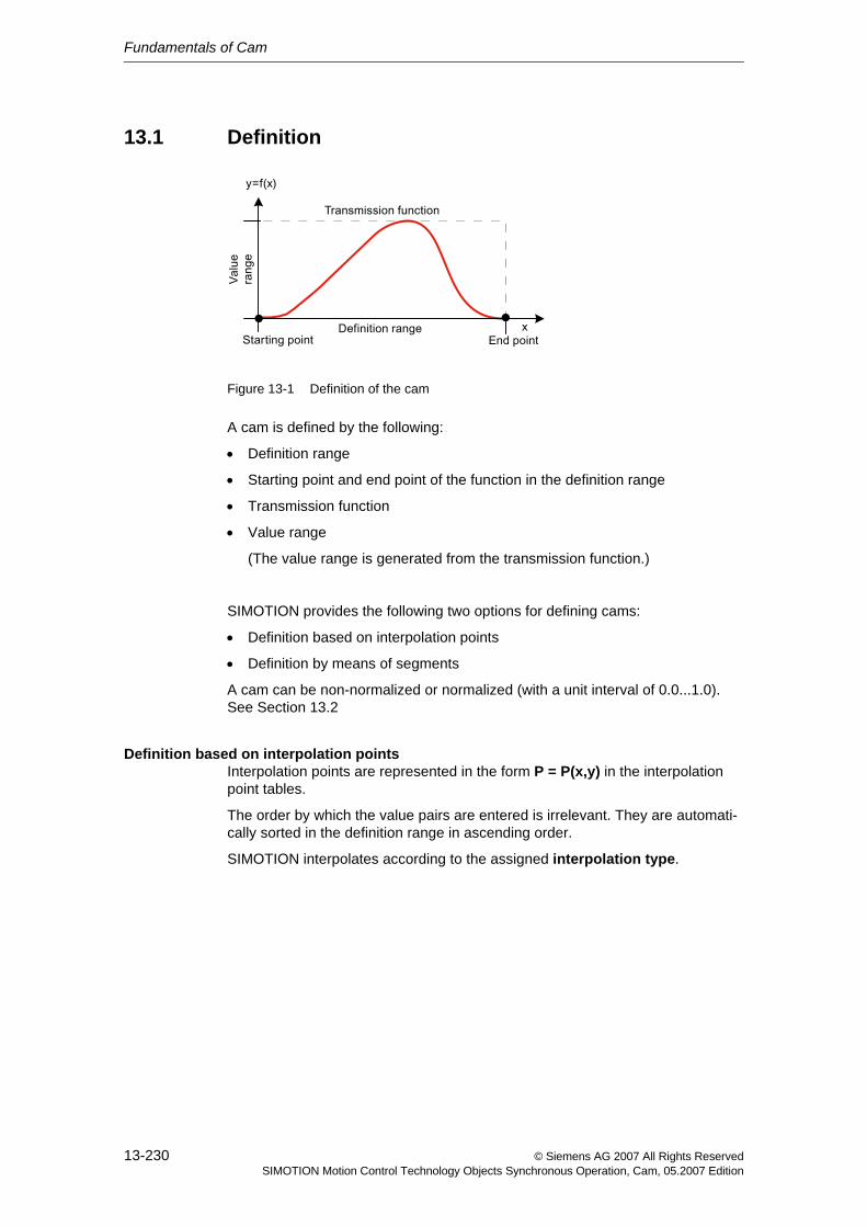
Fundamentals of Cam
13-230 © Siemens AG 2007 All Rights ReservedSIMOTION Motion Control Technology Objects Synchronous Operation, Cam, 05.2007 Edition
13.1 Definition
Figure 13-1 Definition of the cam
A cam is defined by the following:
• Definition range
• Starting point and end point of the function in the definition range
• Transmission function
• Value range
(The value range is generated from the transmission function.)
SIMOTION provides the following two options for defining cams:
• Definition based on interpolation points
• Definition by means of segments
A cam can be non-normalized or normalized (with a unit interval of 0.0...1.0). See Section 13.2
Definition based on interpolation pointsInterpolation points are represented in the form P = P(x,y) in the interpolation point tables.
The order by which the value pairs are entered is irrelevant. They are automati-cally sorted in the definition range in ascending order.
SIMOTION interpolates according to the assigned interpolation type.
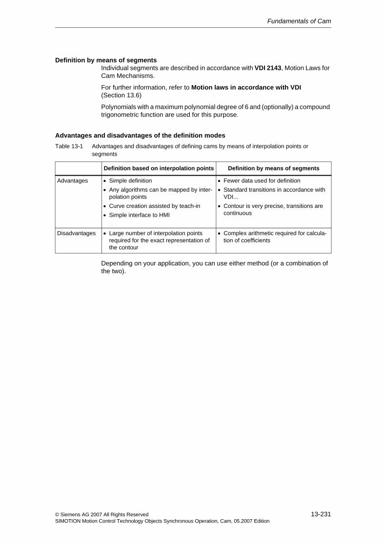
Fundamentals of Cam
13-231© Siemens AG 2007 All Rights ReservedSIMOTION Motion Control Technology Objects Synchronous Operation, Cam, 05.2007 Edition
Definition by means of segmentsIndividual segments are described in accordance with VDI 2143, Motion Laws for Cam Mechanisms.
For further information, refer to Motion laws in accordance with VDI (Section 13.6)
Polynomials with a maximum polynomial degree of 6 and (optionally) a compound trigonometric function are used for this purpose.
Advantages and disadvantages of the definition modes
Depending on your application, you can use either method (or a combination of the two).
Table 13-1 Advantages and disadvantages of defining cams by means of interpolation points or segments
Definition based on interpolation points Definition by means of segments
Advantages • Simple definition• Any algorithms can be mapped by inter-
polation points• Curve creation assisted by teach-in• Simple interface to HMI
• Fewer data used for definition• Standard transitions in accordance with
VDI...• Contour is very precise, transitions are
continuous
Disadvantages • Large number of interpolation points required for the exact representation of the contour
• Complex arithmetic required for calcula-tion of coefficients
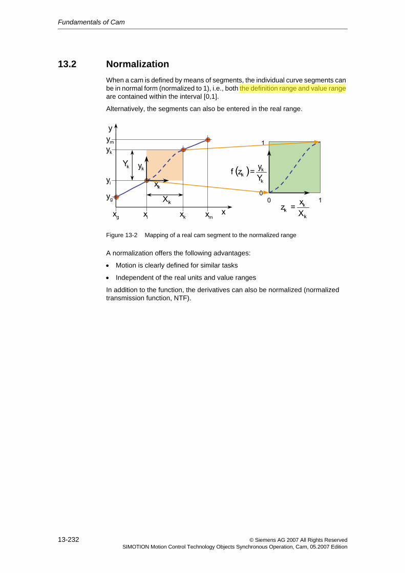
Fundamentals of Cam
13-232 © Siemens AG 2007 All Rights ReservedSIMOTION Motion Control Technology Objects Synchronous Operation, Cam, 05.2007 Edition
13.2 NormalizationWhen a cam is defined by means of segments, the individual curve segments can be in normal form (normalized to 1), i.e., both the definition range and value range are contained within the interval [0,1].
Alternatively, the segments can also be entered in the real range.
Figure 13-2 Mapping of a real cam segment to the normalized range
A normalization offers the following advantages:
• Motion is clearly defined for similar tasks
• Independent of the real units and value ranges
In addition to the function, the derivatives can also be normalized (normalized transmission function, NTF).
CN1LH0N2
Highlight
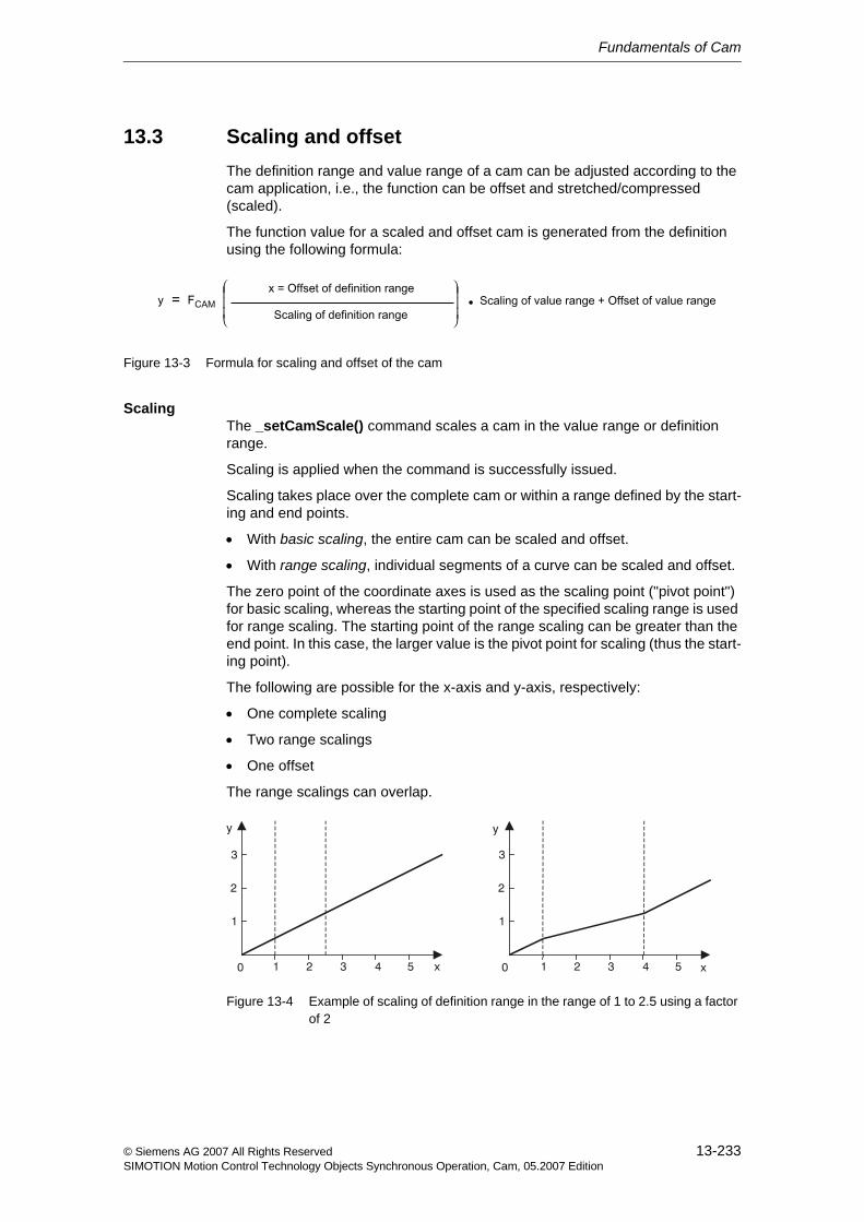
Fundamentals of Cam
13-233© Siemens AG 2007 All Rights ReservedSIMOTION Motion Control Technology Objects Synchronous Operation, Cam, 05.2007 Edition
13.3 Scaling and offsetThe definition range and value range of a cam can be adjusted according to the cam application, i.e., the function can be offset and stretched/compressed (scaled).
The function value for a scaled and offset cam is generated from the definition using the following formula:
Figure 13-3 Formula for scaling and offset of the cam
ScalingThe _setCamScale() command scales a cam in the value range or definition range.
Scaling is applied when the command is successfully issued.
Scaling takes place over the complete cam or within a range defined by the start-ing and end points.
• With basic scaling, the entire cam can be scaled and offset.
• With range scaling, individual segments of a curve can be scaled and offset.
The zero point of the coordinate axes is used as the scaling point ("pivot point") for basic scaling, whereas the starting point of the specified scaling range is used for range scaling. The starting point of the range scaling can be greater than the end point. In this case, the larger value is the pivot point for scaling (thus the start-ing point).
The following are possible for the x-axis and y-axis, respectively:
• One complete scaling
• Two range scalings
• One offset
The range scalings can overlap.
Figure 13-4 Example of scaling of definition range in the range of 1 to 2.5 using a factor of 2
0
2
3
1
1 2 3 4 5 0
2
3
1
1 2 3 4 5x
y
x
y
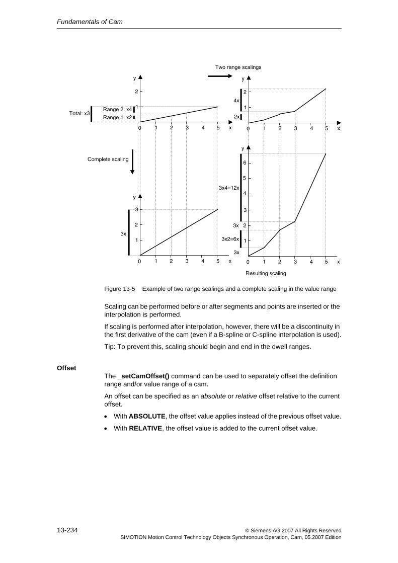
Fundamentals of Cam
13-234 © Siemens AG 2007 All Rights ReservedSIMOTION Motion Control Technology Objects Synchronous Operation, Cam, 05.2007 Edition
Figure 13-5 Example of two range scalings and a complete scaling in the value range
Scaling can be performed before or after segments and points are inserted or the interpolation is performed.
If scaling is performed after interpolation, however, there will be a discontinuity in the first derivative of the cam (even if a B-spline or C-spline interpolation is used).
Tip: To prevent this, scaling should begin and end in the dwell ranges.
OffsetThe _setCamOffset() command can be used to separately offset the definition range and/or value range of a cam.
An offset can be specified as an absolute or relative offset relative to the current offset.
• With ABSOLUTE, the offset value applies instead of the previous offset value.
• With RELATIVE, the offset value is added to the current offset value.
0
2
1
1 2 3 4 5 x
y
0
2
3
1
1 2 3 4 5 x
y
2x
4x
3x
0
2
1
1 2 3 4 5 x
y
0
2
3
1
1 2 3 4 5 x
y
5
6
4
3x2=6x
3x4=12x
3x
3x
Fundamentals of Cam
13-235© Siemens AG 2007 All Rights ReservedSIMOTION Motion Control Technology Objects Synchronous Operation, Cam, 05.2007 Edition
13.4 InterpolationIf a curve is defined using segments, it is possible to fill gaps in the definition range by interpolation.
When the cam is defined using interpolation, the following checks are per-formed:
• A plausibility check is performed, i.e., the curve definition is checked (for duplicate values in the definition range, for example).
• Missing ranges are added (interpolated).
• Continuity and junction conditions in boundary points are checked.
Note
Once the interpolation is performed, new segments or interpolation points can only be inserted after resetting the cam.
If an attempt is made to insert new segments or interpolation points without first resetting the cam, the attempt is rejected and the return value for the function pro-vides error information. Previously defined interpolation points and segments are deleted when the cam is reset.
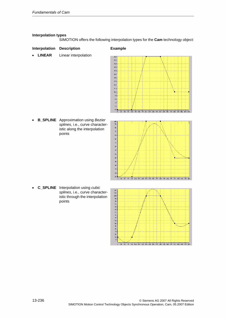
Fundamentals of Cam
13-236 © Siemens AG 2007 All Rights ReservedSIMOTION Motion Control Technology Objects Synchronous Operation, Cam, 05.2007 Edition
Interpolation typesSIMOTION offers the following interpolation types for the Cam technology object:
Interpolation Description Example
• LINEAR Linear interpolation
• B_SPLINE Approximation using Bezier splines, i.e., curve character-istic along the interpolation points
• C_SPLINE Interpolation using cubic splines, i.e., curve character-istic through the interpolation points
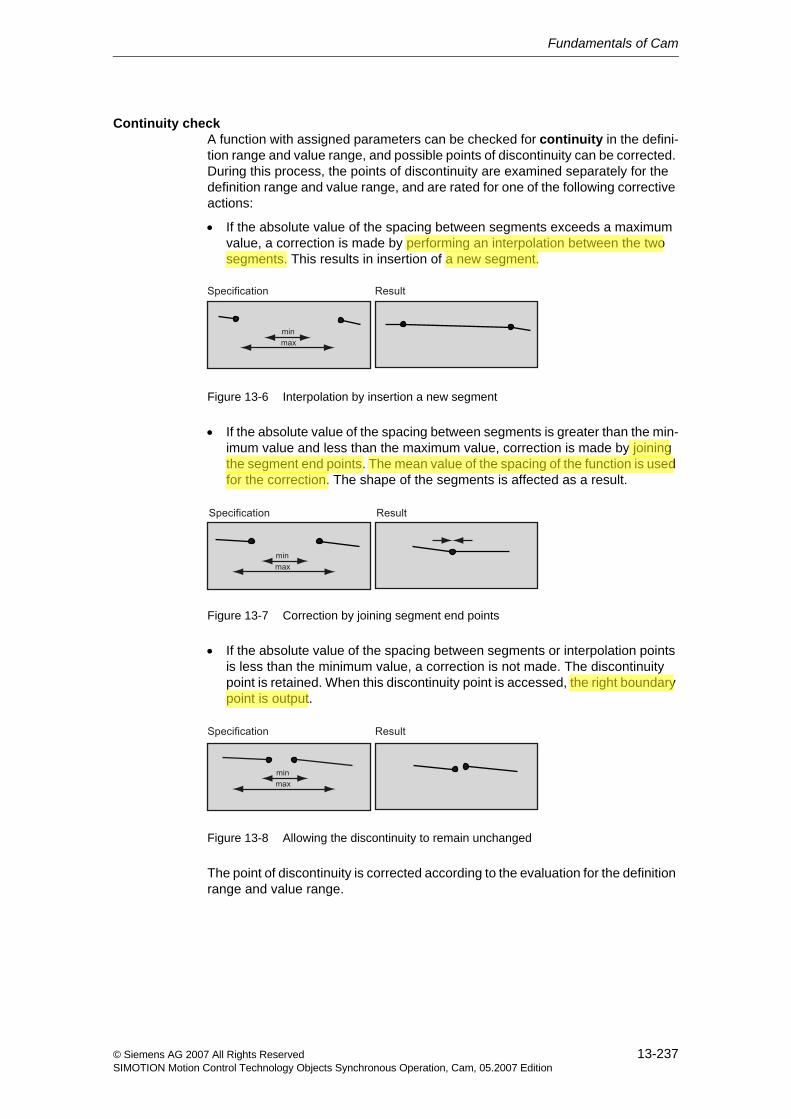
Fundamentals of Cam
13-237© Siemens AG 2007 All Rights ReservedSIMOTION Motion Control Technology Objects Synchronous Operation, Cam, 05.2007 Edition
Continuity checkA function with assigned parameters can be checked for continuity in the defini-tion range and value range, and possible points of discontinuity can be corrected. During this process, the points of discontinuity are examined separately for the definition range and value range, and are rated for one of the following corrective actions:
• If the absolute value of the spacing between segments exceeds a maximum value, a correction is made by performing an interpolation between the two segments. This results in insertion of a new segment.
Figure 13-6 Interpolation by insertion a new segment
• If the absolute value of the spacing between segments is greater than the min-imum value and less than the maximum value, correction is made by joining the segment end points. The mean value of the spacing of the function is used for the correction. The shape of the segments is affected as a result.
Figure 13-7 Correction by joining segment end points
• If the absolute value of the spacing between segments or interpolation points is less than the minimum value, a correction is not made. The discontinuity point is retained. When this discontinuity point is accessed, the right boundary point is output.
Figure 13-8 Allowing the discontinuity to remain unchanged
The point of discontinuity is corrected according to the evaluation for the definition range and value range.
CN1LH0N2
Highlight
CN1LH0N2
Highlight
CN1LH0N2
Highlight
CN1LH0N2
Highlight
CN1LH0N2
Highlight
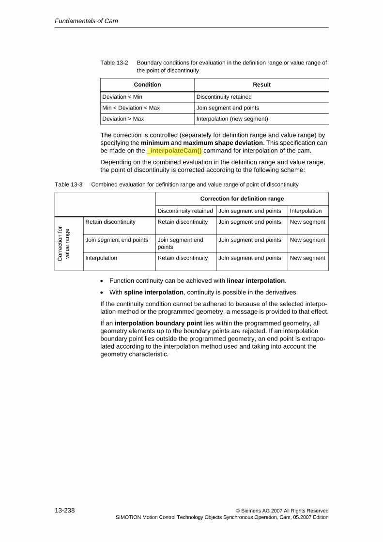
Fundamentals of Cam
13-238 © Siemens AG 2007 All Rights ReservedSIMOTION Motion Control Technology Objects Synchronous Operation, Cam, 05.2007 Edition
The correction is controlled (separately for definition range and value range) by specifying the minimum and maximum shape deviation. This specification can be made on the _interpolateCam() command for interpolation of the cam.
Depending on the combined evaluation in the definition range and value range, the point of discontinuity is corrected according to the following scheme:
• Function continuity can be achieved with linear interpolation.
• With spline interpolation, continuity is possible in the derivatives.
If the continuity condition cannot be adhered to because of the selected interpo-lation method or the programmed geometry, a message is provided to that effect.
If an interpolation boundary point lies within the programmed geometry, all geometry elements up to the boundary points are rejected. If an interpolation boundary point lies outside the programmed geometry, an end point is extrapo-lated according to the interpolation method used and taking into account the geometry characteristic.
Table 13-2 Boundary conditions for evaluation in the definition range or value range of the point of discontinuity
Condition Result
Deviation < Min Discontinuity retained
Min < Deviation < Max Join segment end points
Deviation > Max Interpolation (new segment)
Table 13-3 Combined evaluation for definition range and value range of point of discontinuity
Correction for definition range
Discontinuity retained Join segment end points Interpolation
Cor
rect
ion
for
valu
e ra
nge
Retain discontinuity Retain discontinuity Join segment end points New segment
Join segment end points Join segment end points
Join segment end points New segment
Interpolation Retain discontinuity Join segment end points New segment
CN1LH0N2
Highlight
Fundamentals of Cam
13-239© Siemens AG 2007 All Rights ReservedSIMOTION Motion Control Technology Objects Synchronous Operation, Cam, 05.2007 Edition
Continuity on boundary pointsWhen assigning parameters to a cam object, you can make three different set-tings in the Interpolation tab.
These settings specify how the runtime system should handle discontinuity at the boundaries of the cam. The created curve may be displayed differently in SCOUT than as used later in the runtime system.
• Non-cyclic: Not constant at the boundary points
The runtime system uses the cam as specified, including all discontinuities at the boundaries, even if it is applied cyclically. However, the acceleration limits and moment inertia of the mechanical system / drive are the governing factors.
• Cyclic absolute: Position-continuous in the boundary points
The runtime system converts the cam in such a way that is position-continuous and velocity-continuous at the boundaries during cyclic operation, which can cause changes to occur in the characteristic.
• Cyclic relative: Constant velocity in the boundary points
The runtime system calculates the cam in such a way that is has constant velocity at the boundaries during cyclic operation - within mathematical limits, which can cause changes to occur in the characteristic.
Overlapping segmentsIn the case of overlapping segments, segment validity can be defined using the following options:
• Segments after the segment starting points are valid
• Segments up to the segment end points are valid
• Valid segments are determined by the chronological order of insertion.
This behavior is set using the _resetCam() command.
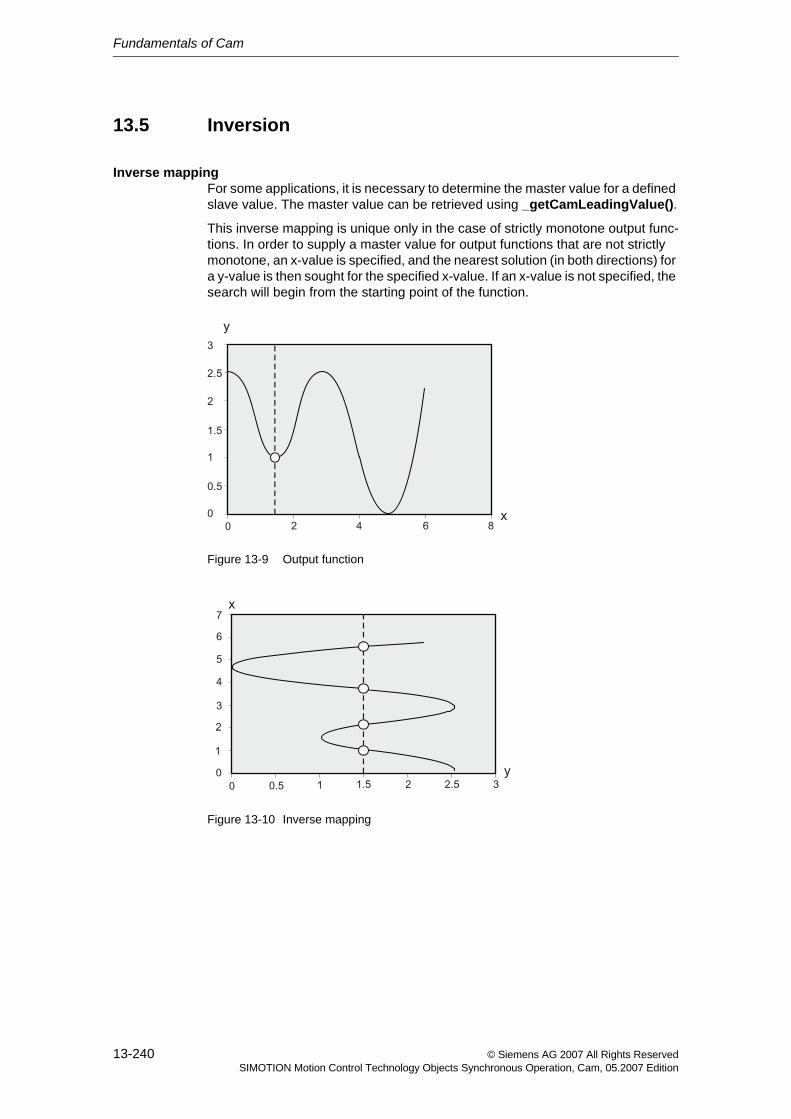
Fundamentals of Cam
13-240 © Siemens AG 2007 All Rights ReservedSIMOTION Motion Control Technology Objects Synchronous Operation, Cam, 05.2007 Edition
13.5 Inversion
Inverse mappingFor some applications, it is necessary to determine the master value for a defined slave value. The master value can be retrieved using _getCamLeadingValue().
This inverse mapping is unique only in the case of strictly monotone output func-tions. In order to supply a master value for output functions that are not strictly monotone, an x-value is specified, and the nearest solution (in both directions) for a y-value is then sought for the specified x-value. If an x-value is not specified, the search will begin from the starting point of the function.
Figure 13-9 Output function
Figure 13-10 Inverse mapping
Fundamentals of Cam
13-241© Siemens AG 2007 All Rights ReservedSIMOTION Motion Control Technology Objects Synchronous Operation, Cam, 05.2007 Edition
Inversion during interpolationThe option exists to invert a cam during preparation/interpolation and to store the cam in both the non-inverted and inverted shape (V3.0 and higher).
Setting via configuration data camRepresentation
Advantage: Inverted data are accessed more quickly when the master value associated with the slave value is read out.
Disadvantage: More memory is always required on the runtime system.
Note
The inverted shape of the cam cannot be represented.
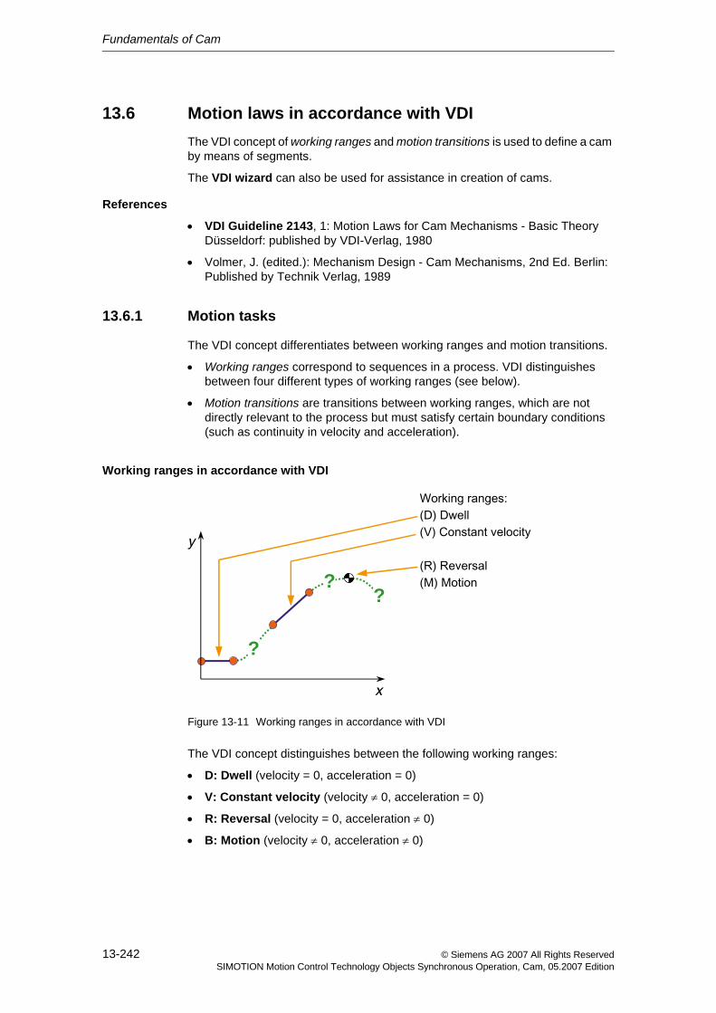
Fundamentals of Cam
13-242 © Siemens AG 2007 All Rights ReservedSIMOTION Motion Control Technology Objects Synchronous Operation, Cam, 05.2007 Edition
13.6 Motion laws in accordance with VDIThe VDI concept of working ranges and motion transitions is used to define a cam by means of segments.
The VDI wizard can also be used for assistance in creation of cams.
References
• VDI Guideline 2143, 1: Motion Laws for Cam Mechanisms - Basic Theory Düsseldorf: published by VDI-Verlag, 1980
• Volmer, J. (edited.): Mechanism Design - Cam Mechanisms, 2nd Ed. Berlin: Published by Technik Verlag, 1989
13.6.1 Motion tasks
The VDI concept differentiates between working ranges and motion transitions.
• Working ranges correspond to sequences in a process. VDI distinguishes between four different types of working ranges (see below).
• Motion transitions are transitions between working ranges, which are not directly relevant to the process but must satisfy certain boundary conditions (such as continuity in velocity and acceleration).
Working ranges in accordance with VDI
Figure 13-11 Working ranges in accordance with VDI
The VDI concept distinguishes between the following working ranges:
• D: Dwell (velocity = 0, acceleration = 0)
• V: Constant velocity (velocity ≠ 0, acceleration = 0)
• R: Reversal (velocity = 0, acceleration ≠ 0)
• B: Motion (velocity ≠ 0, acceleration ≠ 0)
x
y
?
? ?
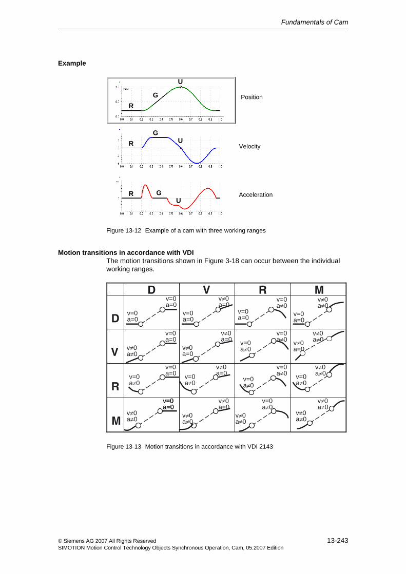
Fundamentals of Cam
13-243© Siemens AG 2007 All Rights ReservedSIMOTION Motion Control Technology Objects Synchronous Operation, Cam, 05.2007 Edition
Example
Figure 13-12 Example of a cam with three working ranges
Motion transitions in accordance with VDIThe motion transitions shown in Figure 3-18 can occur between the individual working ranges.
Figure 13-13 Motion transitions in accordance with VDI 2143
RG
U
RG
U
R GU
Position
Velocity
Acceleration
v=0a=0
v=0a=0
v≠0a=0
v≠0a=0
v=0a=0
v≠0a=0
v=0a≠0
v=0a≠0
v=0a=0
v=0a≠0
v=0a=0
v≠0a≠0
v≠0a≠0
v=0a=0
v=0a=0v=0
a≠0
v=0a=0
v≠0a≠0
v=0a=0v=0a=0
v≠0a=0
v≠0a=0
v=0a≠0
v≠0a≠0
v=0a≠0v=0
a≠0
M
R
V
D
MRVD
v≠0a≠0
v=0a≠0
v≠0a≠0
v≠0a≠0
v≠0a≠0v≠0
a=0
v=0a≠0
v≠0a≠0
Fundamentals of Cam
13-244 © Siemens AG 2007 All Rights ReservedSIMOTION Motion Control Technology Objects Synchronous Operation, Cam, 05.2007 Edition
13.6.2 Defining a cam for a motion task using segments
Definition of working rangesThe working ranges of a motion task are usually specified by the process.
Example:
1. A tool waits on a production line for a piece to pass by (dwell).
2. The tool is synchronized to the work piece and performs an action on the work piece (constant velocity).
3. The tool then returns to the waiting position (reversal).
The process starts over from the beginning.
• In order to implement this sequence, the segments of a cam corresponding to the working ranges must first be created.
Creating a motion transitionNow the "only" things left to define are the motion transitions that satisfy certain conditions (e.g. jerk-free motion).
• This requires that the motion transition first be transformed to the normalized range.
For further information, refer to Normalization (Section 13.2)
• The boundary conditions, i.e., positions, velocities, and accelerations, must then be taken into account on the segment borders.
• In order to apply a polynomial defined in such a way, it must be transformed back into the real range.
14-245© Siemens AG 2007 All Rights ReservedSIMOTION Motion Control Technology Objects Synchronous Operation, Cam, 05.2007 Edition
Configuring Cams 14Cams can be created with SIMOTION SCOUT or the optional SIMOTION CamTool add-on. In addition, the curve characteristic can also be defined by a user program during runtime.
This section shows you how to create, define, and configure cams in SIMOTION SCOUT.
Content
14.1 Creating a cam 14-246
14.2 Defining cams 14-247
14.3 Interconnecting cams 14-247
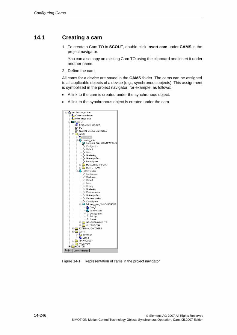
Configuring Cams
14-246 © Siemens AG 2007 All Rights ReservedSIMOTION Motion Control Technology Objects Synchronous Operation, Cam, 05.2007 Edition
14.1 Creating a cam1. To create a Cam TO in SCOUT, double-click Insert cam under CAMS in the
project navigator.
You can also copy an existing Cam TO using the clipboard and insert it under another name.
2. Define the cam.
All cams for a device are saved in the CAMS folder. The cams can be assigned to all applicable objects of a device (e.g., synchronous objects). This assignment is symbolized in the project navigator, for example, as follows:
• A link to the cam is created under the synchronous object.
• A link to the synchronous object is created under the cam.
Figure 14-1 Representation of cams in the project navigator
Configuring Cams
14-247© Siemens AG 2007 All Rights ReservedSIMOTION Motion Control Technology Objects Synchronous Operation, Cam, 05.2007 Edition
14.2 Defining cams
Defining with CamEditCamEdit can be used to describe cams by means of either interpolation points or segments. These two methods cannot be combined.
If the cam is to be created from segments using polynomials, SIMOTION SCOUT provides the VDI Wizard to assist in creation of the cam.
Defining with CamToolCamTool is an add-on to the SIMOTION SCOUT engineering system providing a graphical option for creation of cams.
The add-on is supplied with its own documentation.
Defining in STSIMOTION provides various commands for creation of cams from the application.
In ST, cams can be defined by specifying interpolation points, segments, interpo-lation type, and scaling.
For further information, refer to Commands for the definition (Section 15.1.1)
14.3 Interconnecting camsCams are assigned in the respective application.
For related information, refer to the descriptions for the corresponding technology objects.
Note
A cam is only calculated during runtime in the runtime system.
To see what a cam actually looks like, it must be uploaded from the runtime.
If the cam is modified during runtime and the original cam is downloaded again, the cam must be recompiled in SIMOTION SCOUT.
Configuring Cams
14-248 © Siemens AG 2007 All Rights ReservedSIMOTION Motion Control Technology Objects Synchronous Operation, Cam, 05.2007 Edition
15-249© Siemens AG 2007 All Rights ReservedSIMOTION Motion Control Technology Objects Synchronous Operation, Cam, 05.2007 Edition
Cam Programming / References 15This chapter contains an overview of the commands of the Cam technology object and information about the local alarm reaction.
Content
15.1 Overview of commands 15-250
15.2 Command processing 15-255
15.3 Local alarm reactions 15-256
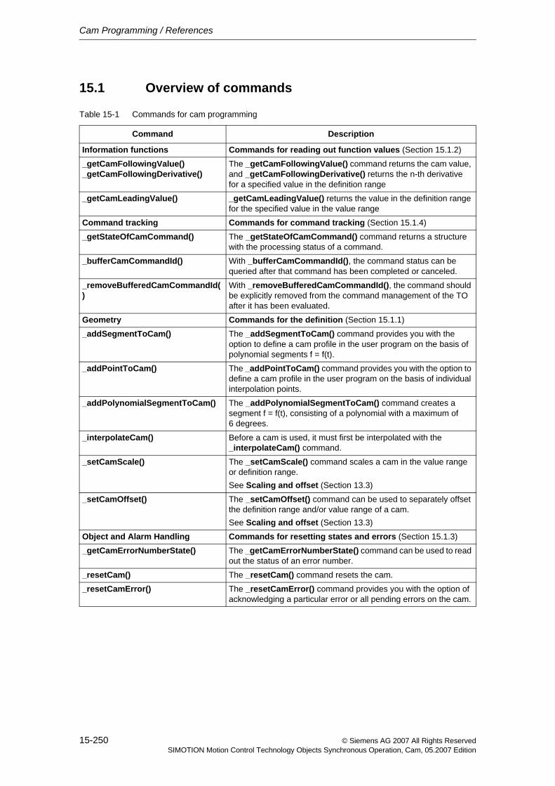
Cam Programming / References
15-250 © Siemens AG 2007 All Rights ReservedSIMOTION Motion Control Technology Objects Synchronous Operation, Cam, 05.2007 Edition
15.1 Overview of commands
Table 15-1 Commands for cam programming
Command Description
Information functions Commands for reading out function values (Section 15.1.2)
_getCamFollowingValue()_getCamFollowingDerivative()
The _getCamFollowingValue() command returns the cam value, and _getCamFollowingDerivative() returns the n-th derivative for a specified value in the definition range
_getCamLeadingValue() _getCamLeadingValue() returns the value in the definition range for the specified value in the value range
Command tracking Commands for command tracking (Section 15.1.4)
_getStateOfCamCommand() The _getStateOfCamCommand() command returns a structure with the processing status of a command.
_bufferCamCommandId() With _bufferCamCommandId(), the command status can be queried after that command has been completed or canceled.
_removeBufferedCamCommandId()
With _removeBufferedCamCommandId(), the command should be explicitly removed from the command management of the TO after it has been evaluated.
Geometry Commands for the definition (Section 15.1.1)
_addSegmentToCam() The _addSegmentToCam() command provides you with the option to define a cam profile in the user program on the basis of polynomial segments f = f(t).
_addPointToCam() The _addPointToCam() command provides you with the option to define a cam profile in the user program on the basis of individual interpolation points.
_addPolynomialSegmentToCam() The _addPolynomialSegmentToCam() command creates a segment f = f(t), consisting of a polynomial with a maximum of 6 degrees.
_interpolateCam() Before a cam is used, it must first be interpolated with the _interpolateCam() command.
_setCamScale() The _setCamScale() command scales a cam in the value range or definition range.See Scaling and offset (Section 13.3)
_setCamOffset() The _setCamOffset() command can be used to separately offset the definition range and/or value range of a cam.See Scaling and offset (Section 13.3)
Object and Alarm Handling Commands for resetting states and errors (Section 15.1.3)
_getCamErrorNumberState() The _getCamErrorNumberState() command can be used to read out the status of an error number.
_resetCam() The _resetCam() command resets the cam.
_resetCamError() The _resetCamError() command provides you with the option of acknowledging a particular error or all pending errors on the cam.
Cam Programming / References
15-251© Siemens AG 2007 All Rights ReservedSIMOTION Motion Control Technology Objects Synchronous Operation, Cam, 05.2007 Edition
15.1.1 Commands for the definition
Interpolation points, segments, or a combination of the two can be used to describe cams.
Commands for the following actions are available for modifying the definition of a cam:
• Adding segments (_addSegmentToCam())
• Adding interpolation points (_addPointToCam())
• Adding a polynomial segment (_addPolynomialSegmentToCam())
• Interpolation (_interpolateCam())
Programming a camWhen the cam is created, the order in which the cam is edited plays a role.
If the shape of the cam is dependent on parameters and undergoes a change, the cam must be reset before each redefinition using the _resetCam() command. The cam can also be reset prior to the first calculation without triggering an error message. This command "erases" the cam. That is, the interpolation is cleared, and the points and segments are removed. The technology object is retained but is empty.
The interpolation points and/or segments are then placed side-by-side in the appropriate order. As with CamEdit, the interpolation points can be in any order and will be sorted automatically.
• This is accomplished using the _addPointToCam() command (addition of an interpolation point), the _addSegmentToCam() command (addition of a seg-ment) or _addPolynomialSegmentToCam() command (addition of a polyno-mial segment).
• Use the _resetCam() command to define cam behavior for overlapping seg-ments/ranges.
• If the shape of the cam is described completely, interpolation is performed using the _interpolateCam() command.
Subsequent addition of one or more points or segments, or modification of points or segments is not possible. In this case, the cam must be reset and recreated.

Cam Programming / References
15-252 © Siemens AG 2007 All Rights ReservedSIMOTION Motion Control Technology Objects Synchronous Operation, Cam, 05.2007 Edition
Adding segments (_addSegmentToCam())The _addSegmentToCam() command provides you with the option to define a cam profile in the user program on the basis of polynomial segments f = f(t). Individual segments consist of a polynomial with a maximum of 6 degrees and a trigonometric component.
The polynomial parameters, amplitude, period, and phase of a sine function must be entered in standard form.
The transformation parameters must be specified in the basic cam representation (without scaling or offset) or in the actual cam representation (with scaling, offset).
The definition range values of the cam must always be increasing, i.e. specified in the positive direction.
Adding interpolation points (_addPointToCam())The _addPointToCam() command provides you with the option to define a cam profile in the user program on the basis of individual interpolation points. In so doing, you can choose to specify values either for a scaled and offset range or a range that is not scaled and offset.
The definition range values of the cam must always be increasing, i.e. specified in the positive direction.
Adding a polynomial segment (_addPolynomialSegmentToCam())The _addPolynomialSegmentToCam() command creates a segment f = f(t), consisting of a polynomial with a maximum of 6 degrees.
The polynomial parameters are input in the real range.
Interpolation (_interpolateCam())Before a cam is used, it must be interpolated.
The interpolation defines the connections between points, between segments and between a point and a segment.
For further information, refer to Interpolation (Section 13.4)
Cam Programming / References
15-253© Siemens AG 2007 All Rights ReservedSIMOTION Motion Control Technology Objects Synchronous Operation, Cam, 05.2007 Edition
15.1.2 Commands for reading out function values
The following commands can be used to read out individual function values from curve characteristics.
• The _getCamLeadingValue() command supplies the value in the definition range (master value) for the specified value in the value range (slave value).
Since this relationship is not always unique, a reference value can be speci-fied. See Inversion (Section 13.5)
• The _getCamFollowingValue() command supplies the cam with a specified value in the definition range (master value).
• The _getCamFollowingDerivative() command can be used to obtain the n-th derivative of the function for a specified value in the definition range (V4.0 and higher).
The derivativeOrder parameter can be used to select the n-th derivative.
This allows, for example, the application to replace specific cams and so take account of the velocity, acceleration, etc.
The leadingPositionMode parameter can be used for the commands to specify whether scaling and offset is to be used (ACTUAL) or not (BASIC).
Graphic output
Curves can be read out from the controller and graphically displayed using Cam-Edit.
Note
By default, the cam is graphically displayed in the standard form in CamEdit. If scaling and/or offsetting of the cam is required, representation in scaled form must be explicitly enabled.
Cam Programming / References
15-254 © Siemens AG 2007 All Rights ReservedSIMOTION Motion Control Technology Objects Synchronous Operation, Cam, 05.2007 Edition
15.1.3 Commands for resetting states and errors
• When the synchronous operation function is in inactive state, the _resetCam() command has the following effect:
− The cam is reset to the initial state.
− Pending errors are deleted.
− The geometry and the corrections are deleted.
− The system variables are reset according to parameters.
When an active cam that is connected to a synchronous operation function by means of the _enableCamming() command is reset, an error message is issued, which requires acknowledgement. The _resetCam() command cannot be executed.
• The _resetCamError() command provides you with the option of acknowledg-ing a particular error or all pending errors on the cam.
It is terminated with a negative acknowledgment for any errors that cannot be acknowledged at this point.
15.1.4 Commands for command tracking
• The _getStateOfCamCommand() command returns a structure with the pro-cessing status of a command.
− functionResult specifies the error code.
− commandIdState returns the current state of the cam.
− abortId specifies the command abort reason.
The abort reason is specified for the alarm 30002 "Command aborted (reason: <abortId>, command type ...)".
Also see _getMotionStateOfAxisCommand() for the Axis TO.
For further information, refer to Motion Control Technology Objects Axis Electric/Hydraulic, External Encoder Function Manual, "Reading current phase of motion"
• The _bufferCamCommandId() command can be used to query the command state even after the command has been completed or canceled.
• With _removeBufferedCamCommandId(), the command should be explicitly removed from the command management of the TO after it has been evalu-ated.
The number of motion commands that the MotionBuffer can accept can be specified using the camType.DecodingConfigInfo.numberOfMaxbuffered-CommandId configuration data.
Further information is available in the SIMOTION reference lists.
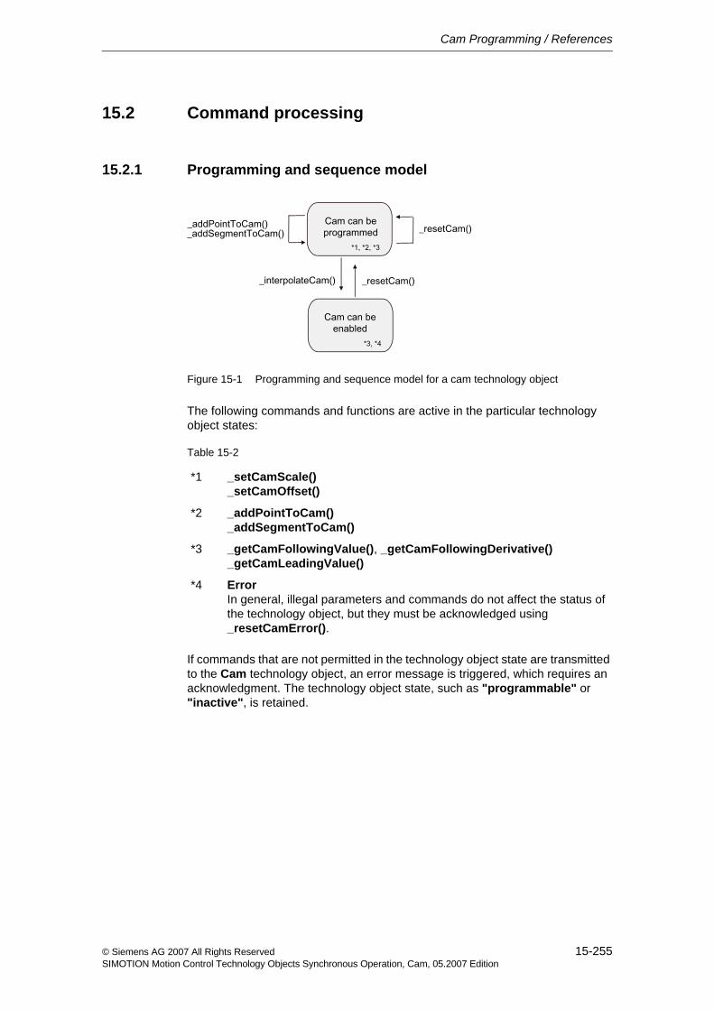
Cam Programming / References
15-255© Siemens AG 2007 All Rights ReservedSIMOTION Motion Control Technology Objects Synchronous Operation, Cam, 05.2007 Edition
15.2 Command processing
15.2.1 Programming and sequence model
Figure 15-1 Programming and sequence model for a cam technology object
The following commands and functions are active in the particular technology object states:
If commands that are not permitted in the technology object state are transmitted to the Cam technology object, an error message is triggered, which requires an acknowledgment. The technology object state, such as "programmable" or "inactive", is retained.
Table 15-2
*1 _setCamScale()_setCamOffset()
*2 _addPointToCam()_addSegmentToCam()
*3 _getCamFollowingValue(), _getCamFollowingDerivative()_getCamLeadingValue()
*4 ErrorIn general, illegal parameters and commands do not affect the status of the technology object, but they must be acknowledged using _resetCamError().
Cam Programming / References
15-256 © Siemens AG 2007 All Rights ReservedSIMOTION Motion Control Technology Objects Synchronous Operation, Cam, 05.2007 Edition
15.3 Local alarm reactionsThe settings for local alarm reactions are made by means of the system.
The following reactions are possible:
• NONENo reaction
• DECODE_STOPCommand preparation is aborted.
Following a _resetCam() or _resetCamError(), the Cam technology object can again be edited.
Index-257© Siemens AG 2007 All Rights ReservedSIMOTION Motion Control Technology Objects Synchronous Operation, Cam, 05.2007 Edition
Index
AAbsolute gearing 23Access protection
to the cam 227Actual value coupling 38
with tolerance window 41Actual value error 80Axis
Removing from the synchronous operation interconnection 109
BBasic scaling 233Basic synchronous operation 75Bezier splines 236Boundary conditions
Distributed synchronous operation 162Synchronous operation IPO - IPO_2 216
CCam 15, 223, 226
Access protection 227Assigning 117Configuring 245Creating 246Defining 247Defining with segments 244Definition 230Fundamentals 229Interconnecting 247Interpolation 235Inversion 240Normalization 232Overview 225Programming 249Programming model 255Resetting 227Scaling and shift 233Self-terminating 31
Cam synchronizationAssigning parameters/defaults 129
Camming 14, 28Assigning parameters/defaults 122
CascadingIn distributed synchronous operation 164
Command bufferSynchronous operation 147
Command executionSynchronous operation 147
Command processingIn the IPO cycle clock 148Synchronous operation 146
Command trackingduring synchronous operation 143
CompensationsFor distributed synchronous operation
169Synchronous operation IPO - IPO_2 218
ConfiguringCam 245Distributed synchronous operation 181Distributed synchronous operation,
across projects 191Synchronous operation 113Synchronous operation IPO - IPO_2 221
Constant velocity 242Continuity at boundary points
Cam 239Continuity check 237Cubic splines 236Cycle clock scaling
Distributed synchronous operation 167Cyclic
Camming 31Cyclic application 31
DDefinition
Cam 230Commands for cam 251
Desynchronization 66Desynchronization position 69Direction 50
Camming 34Gearing 25
Index
Index-258 © Siemens AG 2007 All Rights ReservedSIMOTION Motion Control Technology Objects Synchronous Operation, Cam, 05.2007 Edition
Distributed synchronous operation 155, 158Boundary conditions 162Cascading 164Compensations 169Configuring 181Configuring across projects 191Fundamentals 161Life-sign monitoring 176Master-slave relationship 163Operating modes 177Overview 157Rules for topology 162With cycle clock scaling 167
Distributed synchronous operation across projects 192
Dwell 242Dynamic response
Assigning parameters/defaults 132during synchronization 70
EError reaction
For cam 256Error response
during synchronous operation 152Extended look-ahead 59
FFactory setting (default)
Cam synchronization 129Camming 122Dynamic response 132Gear synchronization 124Gearing 120Master dynamic response 135Synchronous velocity operation 121
FilteringPosition for actual value coupling 40Velocity for actual value coupling 40
Following axis 13, 15Fundamentals
Cam 229Distributed synchronous operation 161Synchronous operation 21Synchronous operation IPO - IPO_2 215
GGear ratio 22
Gearing 25Synchronous velocity operation 27
Gear synchronizationAssigning parameters/defaults 124
Gearing 14, 22Assigning parameters/defaults 120
IInterconnection 18Interpolation
Cam 235Interpolation point table 230Interpolation points 230Interpolation type 230Interpolation types 236Inverse mapping 240Inversion
Cam 240IPO cycle clock
Command processing 148
LLeading axis 13Leading synchronization
with synchronization profile based on specifiable dynamic response parameters 56
Life-sign monitoringIn distributed synchronous operation 176
Linear interpolation 238Local alarm reaction
For cam 256Local alarm response
during synchronous operation 152Look-ahead 59
MMaster 13Master dynamic response
Assigning parameters/defaults 135Master value 13, 16
Assigning 117Master value source
switching over 72Master value switchover
With dynamic response 73With next synchronization 74
Master-slave relationshipIn distributed synchronous operation 163
MonitoringSynchronous operation 79
Motion 242Motion laws in accordance with VDI 242Motion tasks
In accordance with VDI 242Motion transition
Creating 244
Index
Index-259© Siemens AG 2007 All Rights ReservedSIMOTION Motion Control Technology Objects Synchronous Operation, Cam, 05.2007 Edition
Motion transitionsIn accordance with VDI 242, 243
NNon-cyclic
Camming 31Non-cyclic application 31Normalization
Cam 232Normalized transmission function 232
OOffset
Cam 234Camming 35Changing 26, 35Effectiveness 36Gearing 22
Operating modesIn distributed synchronous operation 177
Overlapping segmentsCam 239
OverviewCam 225Distributed synchronous operation 157Synchronous operation 13
PParallel effective commands 147Polynomials 226, 231Position
Desynchronization position relative to synchronization range 69
Synchronization position relative to synchronization range 51
ProgrammingCam 249Synchronous operation 139
Programming modelCam 255
Protective doorsOpening and closing 109
Proxy objects 194
RRange scaling 233Reading out function values
Synchronous operation 143
Readout of function valuesCommands for cam 253
Recursive synchronous operation interconnection 17
Reference value 13References
Cam 249Synchronous operation 139
Relative gearing 24Resetting
Cam 227Resetting of states and errors
Commands for cam 254Reversal 242Reversing function 240
SScaling
Cam 233Camming 35Changing 35Effectiveness 36
Segments 231Self-terminating 31Setpoint error 79Settings
on the synchronous object 136Shape deviation 238Simulation mode
Synchronous operation 82Slave 13Spline interpolation 238Standstill
of the master value 53Status
of synchronization 61Superimposed synchronous operation 19, 75Synchronization 15, 42
Dynamic response 70Status 61via a specifiable master value distance 53with direction specification 50with extended look-ahead 59
Synchronization criterion 45Synchronization position 51Synchronization/desynchronization 15Synchronous commands 147Synchronous object 13, 15
Settings 136
Index
Index-260 © Siemens AG 2007 All Rights ReservedSIMOTION Motion Control Technology Objects Synchronous Operation, Cam, 05.2007 Edition
Synchronous operation 11Absolute, gear 23Assigning parameters/defaults 119Command buffer 147Command execution 147Command processing 146configuring 113Creating 114Distributed 157Distributed, across projects 192Fundamentals 21IPO - IPO_2 211Monitoring 79Overview 13Programming 139Recursive 17Relative, gear 24Simulation mode 82Superimposed 75
Synchronous operation configurationDefining 117
Synchronous operation IPO - IPO_2Boundary conditions 216Compensations 218configuring 221Fundamentals 215
Synchronous operation relationship 15
Synchronous velocity operation 14, 27Assigning parameters/defaults 121
TTO
Cam 226Synchronous operation 13
Toggleof the master value source 72
Tolerance windowfor actual value coupling 41
TopologyRules for distributed synchronous
operation using PROFIBUS 162Trailing synchronization 57Transmission function
Gearing 22
VVDI
Motion laws 242VDI Guideline 2143 242
WWorking ranges
Defining 244In accordance with VDI 242
Related Documents