Motion-adaptive alternate gamma drive for flicker-free motion-blur reduction in 100/120-Hz LCD TV Taesung Kim (SID Member) Bo Ye Chung Phan Vu Nikhil Balram (SID Senior Member) Hugo Steemers Abstract — LCD motion blur is a well-known phenomenon, and several approaches have been developed to address it. This includes very-high-performance approaches based on motion-compen- sated frame rate conversion (MC-FRC) and very-low-cost approaches based on impulsive driving. Impulsive-driving schemes are attractive because of their low cost, but suffer from two significant issues – loss of luminance and large-area flicker. A new impulsive-driving approach using motion- adaptive alternate gamma driving (MA-AGD), which removes motion blur and preserves the original luminance level without causing large-area flicker, is proposed. Keywords — MA-AGD, motion-blur reduction, 120 Hz, alternative gamma driving, motion adaptive. DOI # 10.1889/JSID17.3.203 1 Background Flat-panel displays, represented by LCDs, surpassed CRT display on the market in a much faster pace than expected. So they are all around us in our everyday life in the form of big or small electronics devices, and they provide very good aspects in terms of image quality and form factors compared to that of legacy CRT displays, which are much bulkier and heavier. However, behind those crispier, slimmer, andlighter aspects, there are several characteristics that LCDs are inferior to CRT, and in most cases, they are motion-related artifacts. Historically, there have been three separate artifacts related to frame rates of video signal and motion. Firstly, judder caused by low frame rates such as 24 fps for film material, and this can be considered as temporal aliasing as well. When an object moves fast, 24-fps video capture by a camera, it makes the motion look jerky, and this happens mostly with film content which is usually recorded at 24 fps. Secondly, there is also another type of judder caused by reconstruction at non-integer multiples when we want to display low-frame-rate content such as film at higher frame rate required by most displays. This can be considered as reconstruction judder as well, and the classical example of that is the 3:2 pull-down pattern that is used to convert film from 24 to 60 frames or fields per second (fps). Thirdly, fast-moving objects may be blurred if they are displayed on sample–and–hold-type displays such as LCDs. Because LCD pixels are always on during the entire frame time, any moving objects appear to the eyes as if they remained in one position and then jumped to the next. In an emissive display such as a CRT or PDP where the phosphor emits light showing the object in one position and then decays to black and then lights up again for the next frame with the object in the new position, the eye perceives the motion to be very smooth; the “dark period” is filtered out by a low- pass-filter response of the eye that is referred to as “persist- ence of vision.” In an always-on display such as an LCD, the light from a moving object appears to be smeared every time it jumps from one frame to the next and thus we get “motion blur.” In order to mitigate a long-lasting motion-blur issue in LCDs which in turn is also known as a hold-type display, higher-frame-rate driving at 100/120 Hz and impulsive driv- ing were invented and used as the two most representative methods. Figure 1 shows how these schemes are different in driving pixels. Conventional 60 Hz is represented by a black sold line as a reference of comparison, and MC-FRC represented by a blue dotted line is to create one more step between two frames in consideration of motion. Assuming the intermediate frame can be exactly recreated in terms of shape, the image hold time is reduced to one-half, which in turn improves the motion-blur performance by a factor of 2. Extended revised version of a paper presented at Display Week 2008 (SID ‘08) held May 20–23, 2008 in Los Angeles, California. The authors are with Marvell Semiconductor, Inc., Digital Entertainment Unit, 5488 Marvell Lane, Santa Clara, CA 95054; telphone 408/222-9268, fax –9499, e-mail: [email protected]. © Copyright 2009 Society for Information Display 1071-0922/09/1703-0203$1.00 FIGURE 1 — The luminance variation of each driving scheme. (a) Native response of liquid-crystal molecules. (b) Boosted response by RTC. Journal of the SID 17/3, 2009 203

Welcome message from author
This document is posted to help you gain knowledge. Please leave a comment to let me know what you think about it! Share it to your friends and learn new things together.
Transcript
Motion-adaptive alternate gamma drive for flicker-free motion-blur reductionin 100/120-Hz LCD TV
Taesung Kim (SID Member)Bo YeChung Phan VuNikhil Balram (SID Senior Member)Hugo Steemers
Abstract — LCD motion blur is a well-known phenomenon, and several approaches have beendeveloped to address it. This includes very-high-performance approaches based on motion-compen-sated frame rate conversion (MC-FRC) and very-low-cost approaches based on impulsive driving.Impulsive-driving schemes are attractive because of their low cost, but suffer from two significantissues – loss of luminance and large-area flicker. A new impulsive-driving approach using motion-adaptive alternate gamma driving (MA-AGD), which removes motion blur and preserves the originalluminance level without causing large-area flicker, is proposed.
Keywords — MA-AGD, motion-blur reduction, 120 Hz, alternative gamma driving, motion adaptive.
DOI # 10.1889/JSID17.3.203
1 BackgroundFlat-panel displays, represented by LCDs, surpassed CRTdisplay on the market in a much faster pace than expected.So they are all around us in our everyday life in the form ofbig or small electronics devices, and they provide very goodaspects in terms of image quality and form factors comparedto that of legacy CRT displays, which are much bulkier andheavier. However, behind those crispier, slimmer, and lighteraspects, there are several characteristics that LCDs areinferior to CRT, and in most cases, they are motion-relatedartifacts.
Historically, there have been three separate artifactsrelated to frame rates of video signal and motion.
Firstly, judder caused by low frame rates such as 24 fpsfor film material, and this can be considered as temporalaliasing as well. When an object moves fast, 24-fps videocapture by a camera, it makes the motion look jerky, and thishappens mostly with film content which is usually recordedat 24 fps.
Secondly, there is also another type of judder causedby reconstruction at non-integer multiples when we want todisplay low-frame-rate content such as film at higher framerate required by most displays. This can be considered asreconstruction judder as well, and the classical example ofthat is the 3:2 pull-down pattern that is used to convert filmfrom 24 to 60 frames or fields per second (fps).
Thirdly, fast-moving objects may be blurred if they aredisplayed on sample–and–hold-type displays such as LCDs.Because LCD pixels are always on during the entire frametime, any moving objects appear to the eyes as if they remainedin one position and then jumped to the next. In an emissivedisplay such as a CRT or PDP where the phosphor emitslight showing the object in one position and then decays toblack and then lights up again for the next frame with the
object in the new position, the eye perceives the motion tobe very smooth; the “dark period” is filtered out by a low-pass-filter response of the eye that is referred to as “persist-ence of vision.” In an always-on display such as an LCD, thelight from a moving object appears to be smeared every timeit jumps from one frame to the next and thus we get “motionblur.”
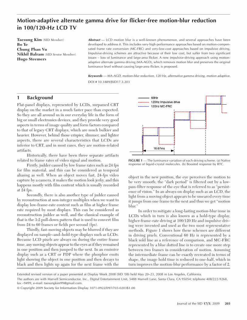
In order to mitigate a long-lasting motion-blur issue inLCDs which in turn is also known as a hold-type display,higher-frame-rate driving at 100/120 Hz and impulsive driv-ing were invented and used as the two most representativemethods. Figure 1 shows how these schemes are differentin driving pixels. Conventional 60 Hz is represented by ablack sold line as a reference of comparison, and MC-FRCrepresented by a blue dotted line is to create one more stepbetween two frames in consideration of motion. Assumingthe intermediate frame can be exactly recreated in terms ofshape, the image hold time is reduced to one-half, which inturn improves the motion-blur performance by a factor of 2.
Extended revised version of a paper presented at Display Week 2008 (SID ‘08) held May 20–23, 2008 in Los Angeles, California.
The authors are with Marvell Semiconductor, Inc., Digital Entertainment Unit, 5488 Marvell Lane, Santa Clara, CA 95054; telphone 408/222-9268,fax –9499, e-mail: [email protected].
© Copyright 2009 Society for Information Display 1071-0922/09/1703-0203$1.00
FIGURE 1 — The luminance variation of each driving scheme. (a) Nativeresponse of liquid-crystal molecules. (b) Boosted response by RTC.
Journal of the SID 17/3, 2009 203
However, the recreation of intermediate frames require asophisticated image-processing algorithm which increasesthe system cost by adding one more large SOC chip eitheron the video board or on the TCON board. We will deal withthe later in this paper. Lastly, the red dotted curve repre-sents the case of impulsive driving, and we can see that oneoriginal frame is divided into two sub-frames and the firstframe is boosted and the second one is dimmed (or viceversa). The second frame, which is darker than the firstframe, gives an impulsive effect and the first frame compen-sates the luminance loss caused by the dimmed image. It hasbeen said that perceived motion blur is approximately pro-portional to the amount of time the displayed image isexposed to the eyes. Therefore, impulsive driving is alsoable to reduce the image hold time to one-half so thatmotion performance can be improved accordingly.
While MC-FRC (motion-compensated frame-rateconversion) technology has been rapidly adopted as an ultimatesolution for better motion performance, impulsive-drivingtechnology, despite its simple and cheap implementation,has always been in the research mode due to its side effects.Flicker and luminance loss are two major drawbacks ofimpulsive-driving technologies, keeping them from beingcommercialized. In terms of luminance loss, there is a wayto compensate the light loss by applying alternate gammadrive (AGD), which makes one frame darker to give theimpulsive effect and another frame brighter to compensatefor it by making the average brightness level even. However,flicker is almost impossible to eliminate completely becauseits generation principle conflicts with impulsive driving.1
Flicker, in principle, is less likely to be perceived bythe eyes when objects are in motion; however, it becomesannoying in static images, particularly for regions with mid-gray levels. Furthermore, the continuous changing of theluminance level due to impulsive driving exacerbates theeffects of flicker.2 If impulsive driving is applied to a staticimage, it is very difficult to precisely characterize the LCD-panel gamma, tune the optical symmetry, and thus screenflicker could be easier visible. In addition, when impulsivedriving is used for static images, response-time compensa-tion (RTC) which is normally temperature dependent andperformed with poor accuracy also aggravates the problemand further deteriorates the image quality. The higher accu-racy that is required in RTC calculation leads to higherimplementation cost. All these aspects are due to the factthat impulsive driving turns the static image into dynamicimage in terms of liquid-crystal dynamics. Therefore, theobvious conclusion is that impulsive driving is most suitablefor moving images, and hold-type driving, i.e., conventionaldriving, is better for static images in getting brighter images.
Therefore, in this paper, we will try to come up with anidea of how we can optimize the mode of operation accord-ing to video content. And by applying the right scheme tothe right situation, we can achieve two conflicting aspectsbeing improved simultaneously.
2 Problem statements on motion-blur-reduction solutions
2.1 Motion-compensated frame-rateconversion
Recreation of intermediate frames requires very intensivehardware computation to process all information. So, for themost cases, separate SOC chips with multi-million gatecounts are needed. And, also due to vast amount of the com-putation, huge power is consumed by making the junctiontemperature of the chip to easily go up to over 70°, whichrequires a heat-sink to be installed. Even the simplest algo-rithm will need to use more than 1-million gate counts toperform the frame up-conversion function. And the mostimportant part of this scheme is to minimize the amount oferror caused by the algorithm. Knowing that no algorithm isperfect in the reconstruction of intermediate frames, theproblem is how to minimize the amount of image-process-ing artifact. The worst case from this perspective is whenfilm content with a 24-Hz refresh rate are processed. In orderto have a 120-Hz refresh rate, four more frames have to besynthesized out of one original frame. Because 80% of totaloutput frames are reconstructed, it will be much more vis-ible if there are any algorithm-related errors or artifacts.Most of the MC-FRC algorithms available today have a fea-ture that can go into simple repeat mode if there are toomany errors in the interpolated frame. Therefore, the moreerrors that occur, the more times the chip will be running inrepeat mode, which means there is no improvement inmotion-blur performance. The last problem in regards toMC-FRC technology is that it may incur a too high bill ofmaterial (BOM) cost to the system because separate a PCboard has to be used to perform this function, and in addi-tion to the PC board itself, there are so many additionalparts to be placed on the board, including the LVDS Tx/Rx,DRAM for the frame buffer, connectors, and cables. Withall things considered, although MC-FRC is a quite efficientway to reduce motion-blur artifacts, it is expensive.
2.2 Impulsive drivingThere is another common way to improve the motion per-formance of hold-type displays: impulsive driving. Becauseit involves the insertion of dark or black frames betweenoriginal frames, the overall average luminance is propor-tional to the time that dark or black frames are inserted. Asthe simplest example, we can consider the case of insertingone dark frame every other original frame, and in this casethe time occupied by dark frames will be 50% of total frametime. This means that the average luminance could be reducedup to 50% in the end. However, this luminance loss can eas-ily be compensated for by boosting another frame, and wecall it as alternate gamma drive (AGD). Due to the slowperception mechanism of the human visual system, lumi-nance fluctuation occurring in AGD, if it is higher than aspecific threshold rate such as 60 Hz, is averaged out and
204 Kim et al. / Flicker-free motion-blur reduction in 100/120-Hz LCD TV
perceived as a constant value to the eyes. However, if theamplitude of luminance fluctuation in AGD or black-frameinsertion is so extreme, then it will manifest itself to theform of flicker. A serious drawback of impulsive driving isthat it becomes very tricky to accurately tune the gammacurve of the panel because it converts a static image into adynamic image. Although the image itself does not have anymovement, liquid crystal changes its state continuously. Theonly thing we can see is the average luminance of the pixeldue to the slow nature of the human visual system. However,since liquid crystal keeps moving continuously, all opticaldynamics associated with LC molecules are applied, includ-ing slow response time. This response-time issue will beanalyzed in more detail later in this paper, but one thing weshould know from this perspective is that if anything goeswrong in the static image, it shall definitely be visible toviewer.
3 RTC in a stationary image
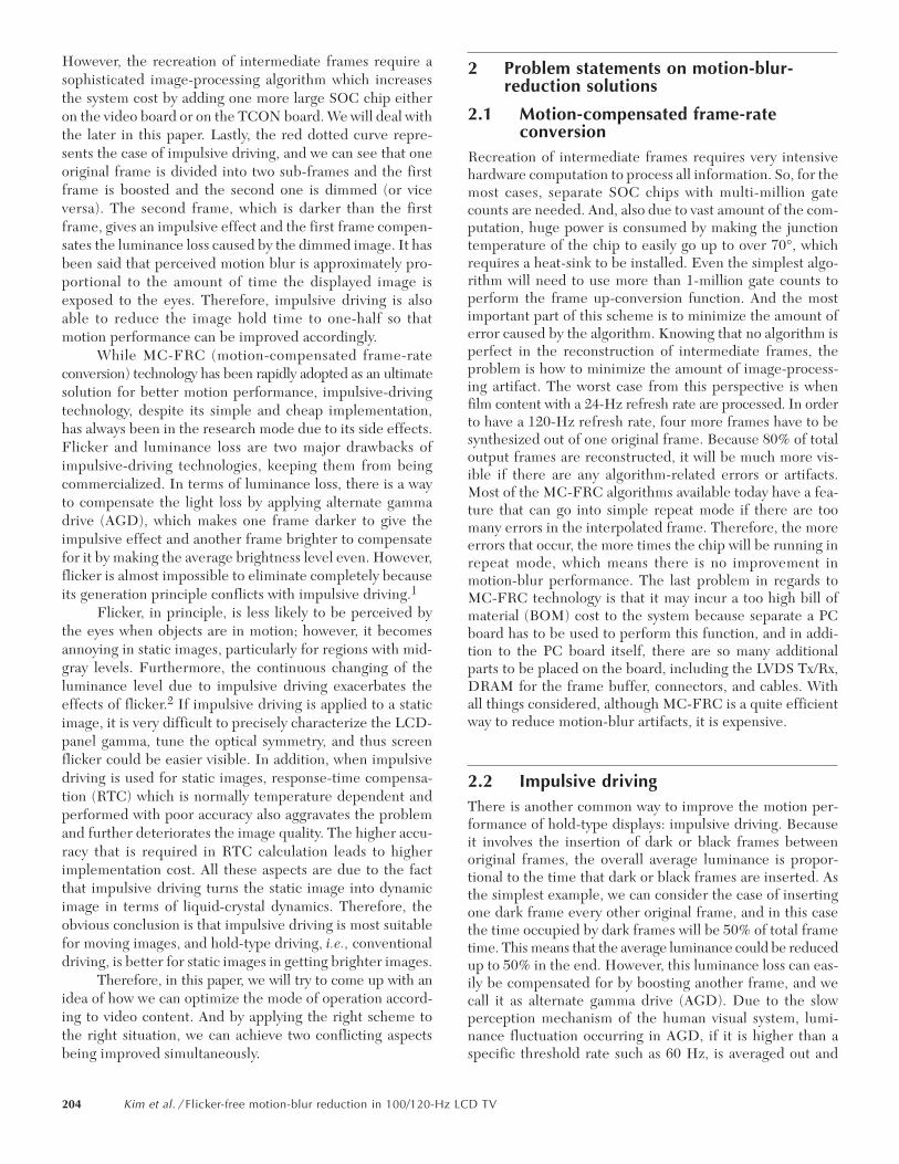
3.1 RTC basicsLet’s go over the basics of response-time compensation becauseit plays a very important role in this paper. Figure 2 showsthe luminance profile over frames with or without RTCapplied. As is well known, native liquid crystal will slowly
respond to an applied voltage change so that the transitioncould be completed after several frames, which is not desir-able for moving-picture displays. But by utilizing the char-acteristics that the response speed of liquid crystal isproportional to the applied voltage, we can temporarilyapply higher voltage or data to accelerate the transition forone frame and return it back to the target value as shown inFig. 2(b).3 One thing we should notice from this case is thatvoltage boost occurs only if the data changes. Without datachange, the RTC circuit does not do anything and simply isbypassed. Therefore, a great deal of approximation is com-monly used in RTC calculation for simpler implementationbecause a moving picture can hide temporary errors of theimage.
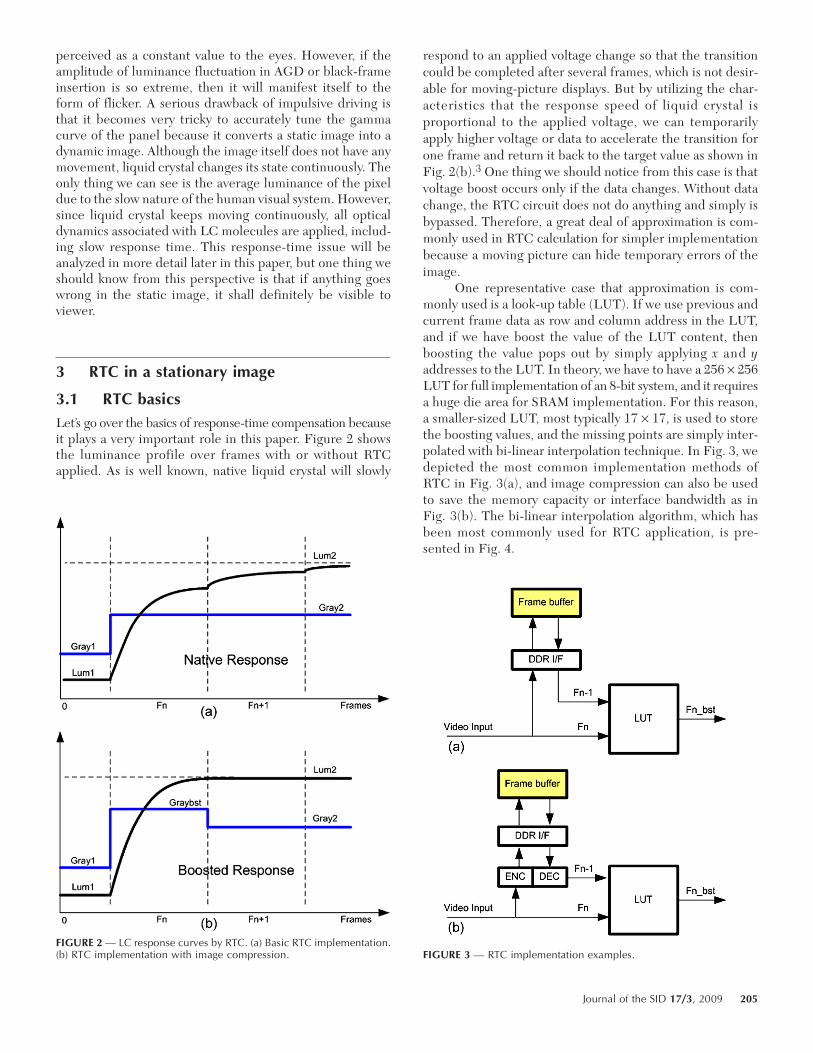
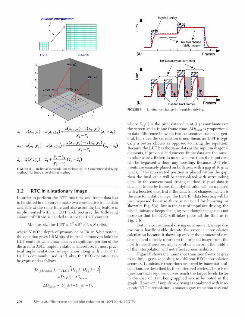
One representative case that approximation is com-monly used is a look-up table (LUT). If we use previous andcurrent frame data as row and column address in the LUT,and if we have boost the value of the LUT content, thenboosting the value pops out by simply applying x and yaddresses to the LUT. In theory, we have to have a 256 × 256LUT for full implementation of an 8-bit system, and it requiresa huge die area for SRAM implementation. For this reason,a smaller-sized LUT, most typically 17 × 17, is used to storethe boosting values, and the missing points are simply inter-polated with bi-linear interpolation technique. In Fig. 3, wedepicted the most common implementation methods ofRTC in Fig. 3(a), and image compression can also be usedto save the memory capacity or interface bandwidth as inFig. 3(b). The bi-linear interpolation algorithm, which hasbeen most commonly used for RTC application, is pre-sented in Fig. 4.
FIGURE 2 — LC response curves by RTC. (a) Basic RTC implementation.(b) RTC implementation with image compression. FIGURE 3 — RTC implementation examples.
Journal of the SID 17/3, 2009 205
3.2 RTC in a stationary imageIn order to perform the RTC function, one frame data hasto be stored in memory to make two consecutive frame dataavailable at the same time and also assuming the feature isimplemented with an LUT architecture, the followingamount of SRAM is needed to store the LUT content:
Memory size for LUT = 2N × 2N × 3 × N (bits),
where N is the depth of primary color. In an 8-bit system,the equation gives 1.6 Mbits of internal memory to hold theLUT contents which may occupy a significant portion of thedie area in ASIC implementation. Therefore, in most prac-tical implementations, interpolation along with a 17 × 17LUT is commonly used. And, also, the RTC operation canbe expressed as follows:
where Di,j(t) is the pixel data value at (i, j) coordinates onthe screen and τ is one frame time. ∆Dboost is proportionalto data difference between two consecutive frames in gen-eral, but since the correlation is non-linear, an LUT is typi-cally a better choice as opposed to using the equation.Because the LUT has the same data as the input in diagonalelements, if previous and current frame data are the same,in other words, if there is no movement, then the input datawill be bypassed without any boosting. Because LUT ele-ments are coarsely placed on both axes with a gap of 16 graylevels, if the intersected position is placed within the gap,then the final value will be interpolated with surroundingdata. In the conventional driving method, if pixel data ischanged frame by frame, the original value will be replacedwith a boosted one. But if the data is not changed, which isthe case for a static image, the LUT for data boosting will bejust bypassed because there is no need for boosting, asshown in Fig. 5(a). But in the case of impulsive driving, thepixel luminance keeps changing even though image does notmove so that the RTC still takes place all the time as inFig. 5(b).
But in a conventional driving environment, image dis-tortion is hardly visible despite the error in interpolationcalculation because it shows up only at the moment of datachange, and quickly returns to the original image from thenext frame. Therefore, any type of data error in the middleof the interpolation will not affect screen visibility.
Figure 6 shows the luminance transition from one grayto multiple grays according to different RTC interpolationaccuracy. Luminance transitions occurred by inaccurate cal-culations are described by the dotted red circles. There is noquestion that response curves reach the target levels fasterin the case of RTC being applied as can be noted in thegraph. However, if impulsive driving is combined with inac-curate RTC interpolation, a smooth gray transition may end
D t f D t D t
D t D
D D t D t
i j boosted i j i j
i j boost
boost i j i j
, , ,
,
, ,
( ) ( ), ( )
( )
( ) ( ),
- LUT= -
= +
µ - -
t
t
D
D
FIGURE 4 — Bi-linear interpolation technique. (a) Conventional drivingmethod. (b) Impulsive-driving method.
FIGURE 5 — Luminance change in impulsive driving.
206 Kim et al. / Flicker-free motion-blur reduction in 100/120-Hz LCD TV
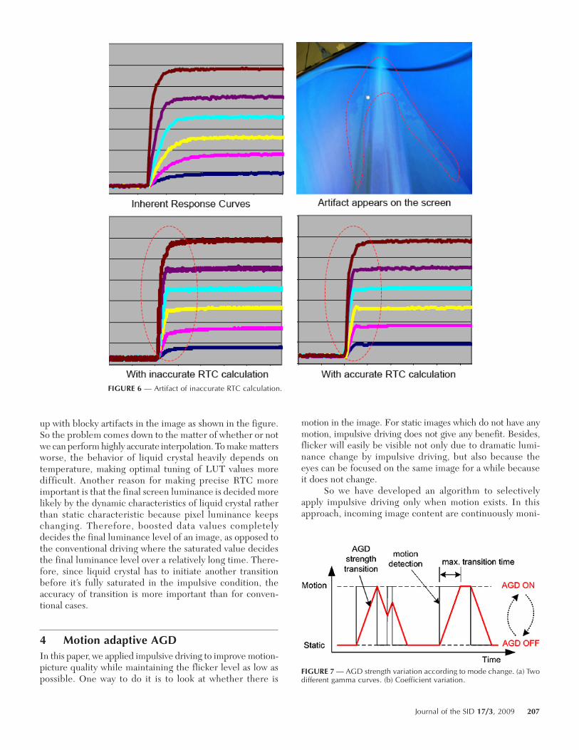
up with blocky artifacts in the image as shown in the figure.So the problem comes down to the matter of whether or notwe can perform highly accurate interpolation. To make mattersworse, the behavior of liquid crystal heavily depends ontemperature, making optimal tuning of LUT values moredifficult. Another reason for making precise RTC moreimportant is that the final screen luminance is decided morelikely by the dynamic characteristics of liquid crystal ratherthan static characteristic because pixel luminance keepschanging. Therefore, boosted data values completelydecides the final luminance level of an image, as opposed tothe conventional driving where the saturated value decidesthe final luminance level over a relatively long time. There-fore, since liquid crystal has to initiate another transitionbefore it’s fully saturated in the impulsive condition, theaccuracy of transition is more important than for conven-tional cases.
4 Motion adaptive AGDIn this paper, we applied impulsive driving to improve motion-picture quality while maintaining the flicker level as low aspossible. One way to do it is to look at whether there is
motion in the image. For static images which do not have anymotion, impulsive driving does not give any benefit. Besides,flicker will easily be visible not only due to dramatic lumi-nance change by impulsive driving, but also because theeyes can be focused on the same image for a while becauseit does not change.
So we have developed an algorithm to selectivelyapply impulsive driving only when motion exists. In thisapproach, incoming image content are continuously moni-
FIGURE 6 — Artifact of inaccurate RTC calculation.
FIGURE 7 — AGD strength variation according to mode change. (a) Twodifferent gamma curves. (b) Coefficient variation.
Journal of the SID 17/3, 2009 207
tored in order to detect global motion. If a significantamount of motion is detected, alternate gamma driving(AGD)4 is enabled to minimize motion blur. When the in-put data is determined to have no significant motion, AGDis accordingly disabled in an intelligent manner. The tran-sition between two driving methods will be visible if itoccurs abruptly. This is due to the large amount of lumi-nance change between two different modes which in turncauses a large-area flicker effect. Even a small luminancechange can be recognized if it occurs globally and quickly.To avoid this flicker problem, a fading IN/OUT circuit isintroduced to this design to create smooth and gradualchange during switching as illustrated in Fig. 7. In order toexplain the process in a more analytical way, we definedAGD strength as data swing amplitude among frames as inEq. (1).
AGD strength = |∆+ + ∆–|, (1)
where ∆+ is the increased component from the input dataand ∆– is the decreased component from the input data.
Note that the AGD strength does not immediately fol-low the motion detection signal but gradually rises and fallsas dictated by the fading logic as characterized in Eqs.(1)–(3); increasing AGD strength further improves themotion-blur reduction by giving higher swing amplitude,but also causes an increase in the amount of flicker. So, theproblem is how to separate two cases and make them inde-pendently controllable.
In general, the AGD process can be represented asfollows:
Dout.n = Din.n + (–1)n ⋅ ∆(d,n), (2)
where ∆(d,n) = ∆+, n = 0, 2, 4... and ∆–, n = 1, 3, 5 ..., n isframe number, d is data value, and ∆ is the gain value forboosting. The gain value is added or subtracted from theoriginal data according to frame order. So even-numberedframes will get brighter, and odd-numbered frames will getdarker because of the additional term. For smooth transi-tion, gain factor C(m) is included in the equation to modu-late the boosting value as expressed in Eq. (3). In thecurrent implementation, we use pre-calculated values of∆(d,n) to reduce the hardware complexity.
Dout.n = Din.n + (–1)n ⋅ C(m) ⋅ ∆(d,n), (3)
where ∆(d,n) = ∆+, n = 0, 2, 4... and ∆–, n = 1, 3, 5... .Note that m is the motion-detection result and C(m)
varies from 0 to 1 during the transition period. C(m) = 0implies that the AGD is off and thus the AGD function isbypassed, whereas when C(m) = 1, AGD is in full-strengthmode. The gain factor C(m) is increased upon motion detec-tion and decreased when motion stops. If the step is smallenough and transition takes place over a long period of time,the human eye is not able to perceive any luminance change.When there are some intervals between the two edges of themotion-detection curve, the gain factor C(m) is increased upto 1 or decreased down to 0. If another edge comes before
the current period ends, then the second edge triggers anothertransition.
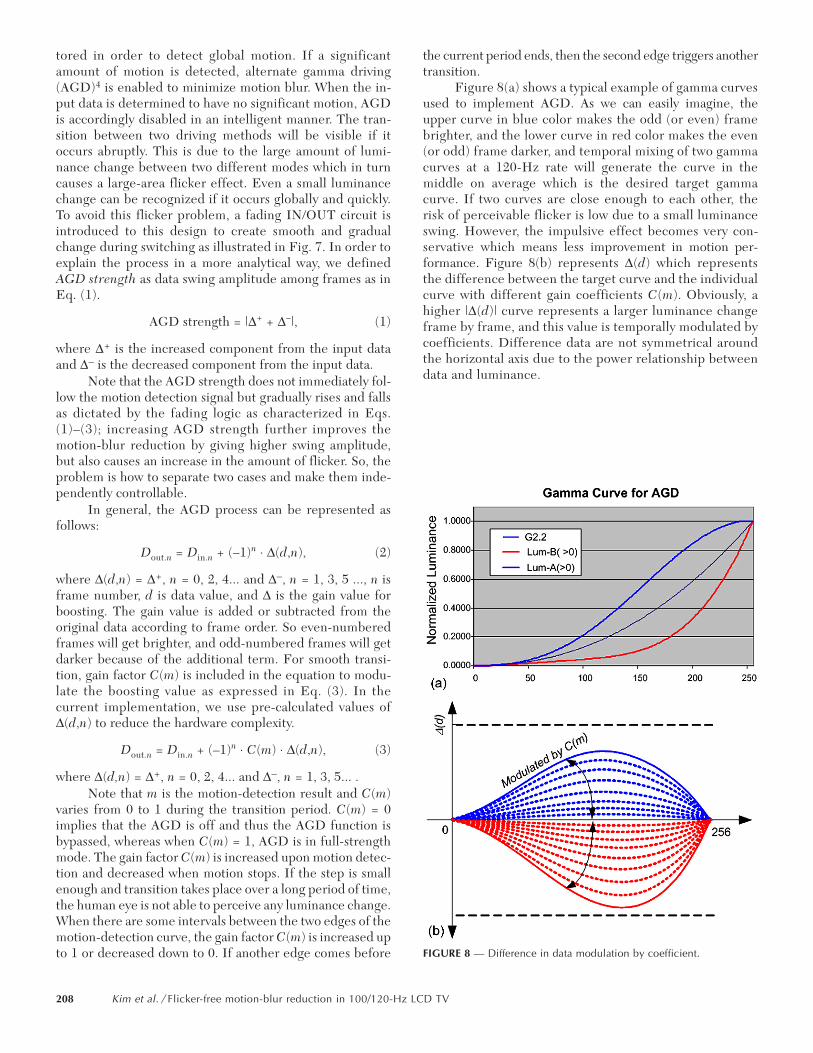
Figure 8(a) shows a typical example of gamma curvesused to implement AGD. As we can easily imagine, theupper curve in blue color makes the odd (or even) framebrighter, and the lower curve in red color makes the even(or odd) frame darker, and temporal mixing of two gammacurves at a 120-Hz rate will generate the curve in themiddle on average which is the desired target gammacurve. If two curves are close enough to each other, therisk of perceivable flicker is low due to a small luminanceswing. However, the impulsive effect becomes very con-servative which means less improvement in motion per-formance. Figure 8(b) represents ∆(d) which representsthe difference between the target curve and the individualcurve with different gain coefficients C(m). Obviously, ahigher |∆(d)| curve represents a larger luminance changeframe by frame, and this value is temporally modulated bycoefficients. Difference data are not symmetrical aroundthe horizontal axis due to the power relationship betweendata and luminance.
FIGURE 8 — Difference in data modulation by coefficient.
208 Kim et al. / Flicker-free motion-blur reduction in 100/120-Hz LCD TV
5 Hardware implementation
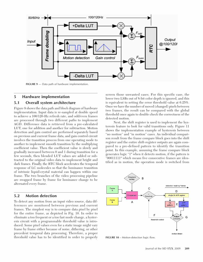
5.1 Overall system architectureFigure 9 shows the data path and block diagram of hardwareimplementation. Input data is re-sampled at double speedto achieve a 100/120-Hz refresh rate, and odd/even framesare processed through two different paths to implementAGD. Difference data is retrieved from a pre-calculatedLUT, one for addition and another for subtraction. Motiondetection and gain control are performed separately basedon previous and current frame data, and gain control circuitinvolves the transition process from one operating mode toanother to implement smooth transition by the multiplyingcoefficient value. Then the coefficient value is slowly andgradually increased between 0 and 1 during transition for afew seconds, then blended LUT values are added or sub-tracted to the original video data to implement bright anddark frames. Finally, the RTC block accelerates the temporalresponse of LC molecules so that the luminance transitionof intrinsic liquid-crystal material can happen within oneframe. The two branches of the video processing pipelineare swapped frame by frame for luminance change to bealternated every frame.
5.2 Motion detectionTo detect any motion from an input video source, data dif-ferences are monitored between previous and currentframes. The simplest way is to compare data pixel by pixelfor the entire frame, as depicted in Fig. 10. In order toeliminate a too frequent or a too fast mode change, a hyster-esis circuit with a programmable threshold value is intro-duced. Some pixel values even for a static image might varyframe by frame either because of noise, dithering, or otherprecedent temporal data processing. Therefore, a properthreshold value has to be identified in order to properly
screen those unwanted cases. For this specific case, thelower two LSBs out of 8-bit color depth is ignored, and thisis equivalent to setting the error threshold value at 6.25%.Once we have the number of moved (changed) pixels betweentwo frames, the result can be compared with the globalthreshold once again to double check the correctness of thedetected motion.
Next, the shift register is used to implement the hys-teresis feature to look for valid transitions only. Figure 11shows the implementation example of hysteresis between“no motion” and “in motion” cases. An individual compari-son result from the frame compare block goes into the shiftregister and the entire shift-register outputs are again com-pared to a pre-defined pattern to identify the transitionpoint. In this example, assuming the frame compare blockgenerates logic “1" when it detects motion, if the pattern is”00011111" which means five consecutive frames are iden-tified as in motion, the operation mode is switched from
FIGURE 9 — Data path of hardware implementation.
FIGURE 10 – Motion-detection logic flow.
Journal of the SID 17/3, 2009 209
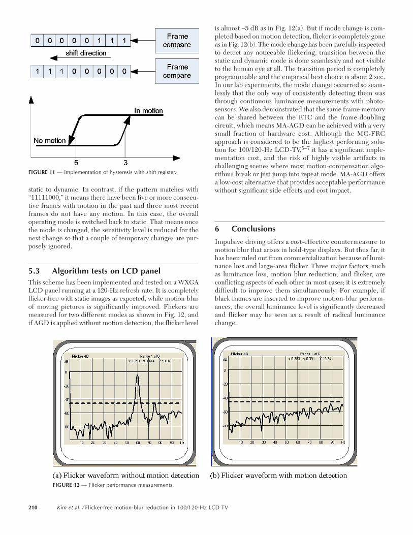
static to dynamic. In contrast, if the pattern matches with“11111000,” it means there have been five or more consecu-tive frames with motion in the past and three most recentframes do not have any motion. In this case, the overalloperating mode is switched back to static. That means oncethe mode is changed, the sensitivity level is reduced for thenext change so that a couple of temporary changes are pur-posely ignored.
5.3 Algorithm tests on LCD panelThis scheme has been implemented and tested on a WXGALCD panel running at a 120-Hz refresh rate. It is completelyflicker-free with static images as expected, while motion blurof moving pictures is significantly improved. Flickers aremeasured for two different modes as shown in Fig. 12, andif AGD is applied without motion detection, the flicker level
is almost –5 dB as in Fig. 12(a). But if mode change is com-pleted based on motion detection, flicker is completely goneas in Fig. 12(b). The mode change has been carefully inspectedto detect any noticeable flickering, transition between thestatic and dynamic mode is done seamlessly and not visibleto the human eye at all. The transition period is completelyprogrammable and the empirical best choice is about 2 sec.In our lab experiments, the mode change occurred so seam-lessly that the only way of consistently detecting them wasthrough continuous luminance measurements with photo-sensors. We also demonstrated that the same frame memorycan be shared between the RTC and the frame-doublingcircuit, which means MA-AGD can be achieved with a verysmall fraction of hardware cost. Although the MC-FRCapproach is considered to be the highest performing solu-tion for 100/120-Hz LCD-TV,5–7 it has a significant imple-mentation cost, and the risk of highly visible artifacts inchallenging scenes where most motion-compensation algo-rithms break or just jump into repeat mode. MA-AGD offersa low-cost alternative that provides acceptable performancewithout significant side effects and cost impact.
6 Conclusions
Impulsive driving offers a cost-effective countermeasure tomotion blur that arises in hold-type displays. But thus far, ithas been ruled out from commercialization because of lumi-nance loss and large-area flicker. Three major factors, suchas luminance loss, motion blur reduction, and flicker, areconflicting aspects of each other in most cases; it is extremelydifficult to improve them simultaneously. For example, ifblack frames are inserted to improve motion-blur perform-ances, the overall luminance level is significantly decreasedand flicker may be seen as a result of radical luminancechange.
FIGURE 11 — Implementation of hysteresis with shift register.
FIGURE 12 — Flicker performance measurements.
210 Kim et al. / Flicker-free motion-blur reduction in 100/120-Hz LCD TV
In this paper, we have suggested a motion adaptivealgorithm to effectively handle several critical cases in theiroptimal operating state. In other words, the best drivingscenario for static images is to drive with a conventionalhold-type driving method because of its higher luminanceefficiency. Whereas the images with motion have to bedriven with impulsive-type driving in order to minimize theamount of motion blur associated with moving edges. Althoughimpulsive driving might increase the risk of flicker visibility,human eyes are more likely to become less sensitive toflicker when images are in motion. However, because tran-sitions between different driving methods require hugeluminance changes, the moment of transition easily becomesvisible if the transition is done abruptly. Therefore, a smoothand gradual switching method has been introduced to makethe transitions invisible.
Since high-frame-rate driving has become prettymuch common technology because of market requirements,any price premium on extra cost for this will disappear soon.From this perspective, the extra cost for high-frame-ratedriving has to be minimized by all means, and thus theMA-AGD algorithm proposed in this paper can be a goodalternative to expensive solutions such as MC-FRC.
References1 M. Baba and G. Itoh, “A novel LCD system for high quality motion
pictures by motion-adaptive black-insertion-ratio control,” Proc. IDW‘06, DES2-2 (2006).
2 T. Kim, B. Park, B. Shin, B. H. Berkeley, and S. S. Kim, “Response timecompensation for black frame insertion,” SID Symposium Digest 37,1793–1796 (2006).
3 R. I. McCartney, “A liquid crystal display response time compensationfeature integrated into an LCD panel timing controller,” SID Sympo-sium Digest 34, 1350–1353 (2003).
4 T. Kim, B-H. Shin, H. S. Nam, B. H. Berkeley, and S. S. Kim, “Ad-vanced impulsive-driving technique for Super-PVA panel,” J. Soc. Info.Display 16, No. 1, 177–182 (2008).
5 S. S. Kim, N. D. Kim, B. H. Berkeley, B. H. You, H. Nam, J-H. Park,and J. Lee, “Distinguished paper: Novel TFT-LCD technology formotion blur reduction using 120-Hz driving with McFi,” SID Sympo-sium Digest 38, 1003–1006 (2007).
6 Y. Yoshida, T. Fujine, K. Yamamoto, H. Furukawa, M. Ueno, Y. Kikuchi,S. Kohashikawa, A. Yamada, N. Takeda, and M. Sugino, “A develop-ment of large-screen full-HD LCD TV with frame-rate-conversiontechnology,” SID Symposium Digest 38, 1721–1724 (2007).
7 N. Balram, M. Biswas, V. Namboodiri, K. Patankar, S. Garg, and T. Kim,“Advanced video processing for full-HD high frame rate LCD TV,”Proc. IDW ‘07, 325–328 (2007).
Taesung Kim is currently at Apple, Inc., where hejoined in 2008 as a Principal Display Architect.He was with Marvell Semiconductor, Inc., as aprincipal technologist in the displays area. Hereceived his B.S. degree in electrical engineeringfrom Hanyang University in 1990 and his M.S.and Ph.D. degrees in electrical engineering fromthe Korea Advanced Institute of Science and Tech-nology (KAIST) in 1992 and 2003, where he con-ducted research on high-speed serial interface
links. He joined Samsung AMLCD in 1990, where his work focused onthe development of LCD modules. His earlier accomplishments includedthe development of a 3.1-in. LCD for projection TV, 14.2-in. LCD for TV,
and a 17-in. SXGA LCD for monitor applications. In 1996, he developeda 22-in. VGA TFT-LCD for TV application, and a 30-in. UXGA panel forhigh-end professional monitor use in 1997. At that time, these panelswere recorded as the world’s largest and highest resolution LCD mod-ules. After completing his Ph.D. he returned to Samsung in 2003, wherehe was in charge of the advanced technology group for algorithm devel-opment, high-end LCD timing-controller design, FPGA evaluation ofnew driving schemes, next-generation LCD interface circuits, and advancedLCD driving schemes for TV applications. He has been active with SIDas a technical session organizer and as a member of the SID ProgramCommittee. He has also served as a committee member for the IDWconference and as an associate editor for the J. Soc. Info. Display.
Bo Ye has been with Marvell Semiconductor, Inc.,since 2005 as a Senior Staff Design Engineer inthe Data Storage Department. He received hisB.S. degree in electrical engineering fromHuaqiao University in 1991 and his M.S. degreein CE from the University of Southern California(USC) in 1995. Before he joined Marvell heworked for several others companies in variousfields, such as analog, networking, testing,graphic, and security. He holds several U.S. pat-
ents in graphic processes. He is also a member of SID, TCG, and IEEE.
Chung Phan Vu has been working as a DesignEngineer at Marvell Semiconductor for more than5 years. He has been working in the ASIC designfield for more than 15 years in various areas includ-ing networking, microcontroller, Firewire, system-on-chip, MPEG2, cable networking, and more.He received his B.S. degree from the University ofCalifornia at Davis, and his M.S. degree from Cali-fornia State University at San Jose.
Nikhil Balram has over 20 years of experience inthe area of digital signal/image/video/displayprocessing and is a well-recognized figure in thedisplay and consumer electronics industries. Hehas served as an executive at several public com-panies in these industries including Faroudja, Sage,Genesis Microchip, SONICblue and NationalSemiconductor. At Faroudja Laboratories as VicePresident of Advanced Technology, he was respon-sible for conceiving and driving the company
strategy to transform Faroudja from a high-end niche video systemsprovider to a mainstream consumer IC vendor. While at Faroudja, heplayed a major role in the creation of Video2000, the first comprehen-sive video benchmark in the PC industry, launched in February 2000.The video quality test patterns authored by him have become a defactobenchmark widely used in the consumer electronics and display indus-tries. After Sage Inc, merged with Faroudja, he served as Executive VicePresident and General Manager of the newly formed Consumer Productsgroup. Under his tenure, the company developed 4 product families ofdisplay and video processors including the FLI2200 and FLI2300, andachieved design wins in over 80 products from over 20 top CE OEMs inflat-panel LCD and Plasma TVs, digital TVs, DVD players, and digitalprojectors. He conceived and launched the highly successful DCDi® byFaroudja branding strategy, which is used by many leading OEMs. Healso conceived and launched the Faroudja certification program and the
Journal of the SID 17/3, 2009 211
Faroudja patent licensing program. After Genesis Microchip’s mergerwith Sage Inc., he briefly served as Vice President of Consumer Prod-ucts, responsible for defining and driving consumer ICs for the jointcompany. After leaving Genesis, he joined SONICblue as Vice Presidentfor Connected Home Products. He was responsible for the P&L for Con-nected Home products that included the acclaimed ReplayTV product-line. He managed and successfully launched SONICblue’s firstmass-market Digital Video Recorder, the RTV5000 series. AfterSONICblue, he joined National Semiconductor as Chief TechnologyOfficer for the Displays Group and most recently served as GeneralManager of their High-Definition Products division. At National, he pro-vided strategic guidance for the development and launch of the PPDS®
architecture for next-generation LCD-TV panels, led the development ofthe first QuietVideo¿ suite of technologies and launched the AVC2500family of video format converters that were used by leading CE compa-nies. In May, 2006 he joined Marvell Semiconductor Inc., as Vice Presi-dent and General Manager of the Digital Entertainment Business Unitwhich develops innovative IC solutions for the worldwide consumerelectronics market. In 2007, he launched the DE2700 family of adaptivedigital video format converter ICs which uses Marvel’s Qdeo¿ videotechnology to produce world-class image quality from a variety ofsources ranging from low-resolution iPod and YouTube video, all theway up to Full-HD content from blue-laser media or broadcast. Dr. Bal-ram has over 35 technical publications and over a dozen filed or issuedU.S. patents and applications, and has given invited lectures and key-notes at major conferences around the world. He has a B.S., M.S., andPh.D. in electrical engineering, all from Carnegie Mellon University.
Hugo Steemers joined Marvell’s Digital Entertain-ment Business Unit in 2006 with responsibilitiesfor business development and strategic marketingof consumer-electronics products. Previously, heserved as the Director of Strategic Marketing inthe Display Group at National Semiconductor.Prior experience includes Director of ProductDevelopment and Director of Strategic Marketingat Silicon Image, where he worked on DVI andHDMI technologies. He also was Senior Engineer-
ing Manager at National Semiconductor for the LCOS light-valve pro-gram and has held a number of engineering positions at Xerox PARC’sdisplay program. He has been active in industry standards bodies anddisplay-technology conferences. He is a past program and general chairof the Society for Information Display. He holds a B.S. degree in semi-conductor physics from Imperial College, University of London, Lon-don, England, and both a M.S. and Ph.D. degrees in semiconductorphysics from the University of Dundee, Dundee, Scotland.
212 Kim et al. / Flicker-free motion-blur reduction in 100/120-Hz LCD TV
Related Documents