GA-K8NE AMD Socket 754 Processor Motherboard User's Manual Rev. 2004 12ME-K8NE-2004R * The WEEE marking on the product indicates this product must not be disposed of with user's other household waste and must be handed over to a designated collection point for the recycling of waste electrical and electronic equipment!! * The WEEE marking applies only in European Union's member states.

Motherboard Manual k8ne 2.0 e
Nov 08, 2014
Welcome message from author
This document is posted to help you gain knowledge. Please leave a comment to let me know what you think about it! Share it to your friends and learn new things together.
Transcript

GA-K8NEAMD Socket 754 Processor Motherboard
User's ManualRev. 200412ME-K8NE-2004R
* The WEEE marking on the product indicates this product must not be disposed of with user's other household wasteand must be handed over to a designated collection point for the recycling of waste electrical and electronic equipment!!
* The WEEE marking applies only in European Union's member states.

Sep. 20, 2005
MotherboardGA-K8NE
Motherboard
GA
-K8N
E
Sep. 20, 2005

Copyright© 2005 GIGA-BYTE TECHNOLOGY CO., LTD. All rights reserved.The trademarks mentioned in the manual are legally registered to their respective companies.
NoticeThe written content provided with this product is the property of Gigabyte.No part of this manual may be reproduced, copied, translated, or transmitted in any form or by anymeans without Gigabyte's prior written permission. Specifications and features are subject tochange without prior notice.
Product Manual ClassificationIn order to assist in the use of this product, Gigabyte has categorized the user manual in thefollowing:
For quick installation, please refer to the "Hardware Installation Guide" included with theproduct.
For detailed product information and specifications, please carefully read the "Product User Manual".
For detailed information related to Gigabyte's unique features, please go to "TechnologyGuide" section on Gigabyte's website to read or download the information you need.
For more product details, please click onto Gigabyte's website at www.gigabyte.com.tw

- 4 -
Table of Contents
GA-K8NE Motherboard Layout ...................................................................................... 6Block Diagram ................................................................................................................ 7
Chapter 1 Hardware Installation .................................................................................... 91-1 Considerations Prior to Installation .................................................................... 91-2 Feature Summary .......................................................................................... 101-3 Installation of the CPU and Heatsink .............................................................. 12
1-3-1 Installation of the CPU ......................................................................................... 121-3-2 Installation of the Heatsink .................................................................................. 13
1-4 Installation of Memory .................................................................................... 131-5 Installation of Expansion Cards ...................................................................... 151-6 I/O Back Panel Introduction ........................................................................... 161-7 Connectors Introduction .................................................................................. 17
Chapter 2 BIOS Setup ................................................................................................ 27The Main Menu (For example: BIOS Ver. : F1b) ...................................................... 282-1 Standard CMOS Features ............................................................................. 302-2 Advanced BIOS Features .............................................................................. 322-3 Integrated Peripherals ..................................................................................... 342-4 Power Management Setup ............................................................................. 372-5 PnP/PCI Configurations ................................................................................. 392-6 PC Health Status ........................................................................................... 402-7 MB Intelligent Tweaker(M.I.T.) ....................................................................... 432-8 Top Performance ............................................................................................. 442-9 Load Optimized Defaults ................................................................................. 442-10 Set Supervisor/User Password ..................................................................... 452-11 Save & Exit Setup ......................................................................................... 462-12 Exit Without Saving ....................................................................................... 46

- 5 -
Chapter 3 Drivers Installation ...................................................................................... 473-1 Install Chipset Drivers .................................................................................... 473-2 Software Application ....................................................................................... 483-3 Software Information ....................................................................................... 483-4 Hardware Information ..................................................................................... 493-5 Contact Us ..................................................................................................... 49
Chapter 4 Appendix ................................................................................................... 514-1 Unique Software Utilities ................................................................................ 51
4-1-1 EasyTune 5 Introduction ..................................................................................... 524-1-2 Xpress Recovery Introduction ........................................................................... 534-1-3 Flash BIOS Method Introduction ........................................................................ 564-1-4 Serial ATA BIOS Setting Utility Introduction ...................................................... 654-1-5 2- / 4- / 6- / 8- Channel Audio Function Introduction ...................................... 71
4-2 Troubleshooting ............................................................................................... 75

- 6 -
GA-K8NE Motherboard Layout
ATX
MS/KB
LPT
COMA
IDE2 IDE1
ATX_12V
Socket 754
USB
USB
LAN
SPDIF_O
SPDIF_I
COMB
IT8712
nVIDIA®
nForceTM 4(-4X)
PCI1
PCI2
F_US
B2
F_US
B1
CISATAII0
SYS_FANF_PANEL
PCI3
CD_IN
PCIE_16
SATAII2
F_US
B3
DDR3
DDR2
DDR1
FDD
CODEC
BIOS
GA-K8NE
CPU_FAN
BAT
CLR_CMOS
AUDIO1
F_AUDIO
Marvell phyAUDIO2
PCIE_1
PCIE_2
PWR_
LED
SATAII1
SATAII3

- 7 -
Block Diagram
(Note) Because of CPU limitations, if you want to install DDR400 memory modules in your system, pleaseinstall either one double-sided or two single-sided DDR400 memory modules. The DDR400 speedwill drop down to DDR333 if you install two double-sided or three single-sided DDR400 memorymodules.
Line-
Out
MIC
Line-
InSP
DIF
InSP
DIF
Out
Side
Spe
aker
Out
Cent
er/S
ubwo
ofer
Spe
aker
Out
Surro
und
Spea
ker O
ut
nVIDIA®
nForce4(-4X)
24MHz
33MHz
4 Serial ATA
ATA33/66/100/133IDE Channels
PCICLK(33MHz)
3PCI
PCI Bus
10 USBPorts
Floppy
PS/2 KB/Mouse
LPT Port
PCI-ECLK(100MHz)
LPC BUS
CODEC
2 PCI Express x 1
RJ45
PCI Express x 1 Bus
PCI-ECLK(100MHz)
BIOS
PCI Express x 16
DDR 400(Note)/333/266/200MHz DIMM
DDR RAM
AMD K8Socket 754
CPU
CPUCLK+/-(200MHz)
Hyper Transport Bus
IT8712COM Ports
x 1 x 1
Marvellphy

- 8 -
Hardware Installation- 9 -
English1-1 Considerations Prior to InstallationPreparing Your ComputerThe motherboard contains numerous delicate electronic circuits and components which canbecome damaged as a result of electrostatic discharge (ESD). Thus, prior to installation, pleasefollow the instructions below:1. Please turn off the computer and unplug its power cord.2. When handling the motherboard, avoid touching any metal leads or connectors.3. It is best to wear an electrostatic discharge (ESD) cuff when handling electronic components
(CPU, RAM).4. Prior to installing the electronic components, please have these items on top of an antistatic
pad or within a electrostatic shielding container.5. Please verify that the power supply is switched off before unplugging the power supply
connector from the motherboard.
Installation Notices1. Prior to installation, please do not remove the stickers on the motherboard. These stickers
are required for warranty validation.2. Prior to the installation of the motherboard or any hardware, please first carefully read the
information in the provided manual.3. Before using the product, please verify that all cables and power connectors are connected.4. To prevent damage to the motherboard, please do not allow screws to come in contact with
the motherboard circuit or its components.5. Please make sure there are no leftover screws or metal components placed on the motherboard
or within the computer casing.6. Please do not place the computer system on an uneven surface.7. Turning on the computer power during the installation process can lead to damage to system
components as well as physical harm to the user.8. If you are uncertain about any installation steps or have a problem related to the use of the
product, please consult a certified computer technician.
Instances of Non-Warranty1. Damage due to natural disaster, accident or human cause.2. Damage as a result of violating the conditions recommended in the user manual.3. Damage due to improper installation.4. Damage due to use of uncertified components.5. Damage due to use exceeding the permitted parameters.6. Product determined to be an unofficial Gigabyte product.
Chapter 1Hardware Installation

GA-K8NE Motherboard - 10 -
Engl
ish CPU Socket 754 for AMD AthlonTM 64 processor (K8)1600MH/z system busSupports core frequencies in excess of 3000+ and faster
Chipset nVIDIA® nForce4(-4X) ChipsetSupported on the Win 2000/XP operating systems
Memory 3 DDR DIMM memory slots (supports up to 3GB memory)Supports DDR 400 (Note 1)/333/266/200 DIMM
Slots 1 PCI Express x 16 slot2 PCI Express x 1 slots3 PCI slots
IDE Connections 2 IDE connection (UDMA 33/ATA 66/ATA 100/ATA 133), allows connection of4 IDE devicesSupported on the Win 2000/XP operating systems
FDD Connections 1 FDD connection, allows connection of 2 FDD devicesOnboard SATA 4 Serial ATA ports from nVIDIA® nForce4(-4X) controller (SATAII0_1, SATAII2_3)
Supported on the Win 2000/XP operating systemsPeripherals 1 parallel port supporting Normal/EPP/ECP mode
1 serial port (COMA), onboard COMB connection10 USB 2.0/1.1 ports (rear x 4, front x 6 via cable)1 front audio connector1 PS/2 keyboard port1 PS/2 mouse port
Onboard LAN Onboard Marvell 88E1111/88E1115 chip (10/100/1000 Mbit)1 RJ 45 portSupported on the Win 2000/XP operating systems
Onboard Audio ALC850 CODEC (UAJ)Supports 2 / 4 / 6 / 8 channel audio (Note 2)
Supports Line In ; Line Out (Front Speaker Out) ; MIC ; Surround Speaker Out(Rear Speaker Out) ; Center/Subwoofer Speaker Out ;Side Speaker Out connectionSupports SPDIF In/Out connectionCD In
I/O Control IT8712
1-2 Feature Summary
(Note 1) Because of CPU limitations, if you want to install DDR400 memory modules in your system,please install either one double-sided or two single-sided DDR400 memory modules. TheDDR400 speed will drop down to DDR333 if you install two double-sided or three single-sidedDDR400 memory modules.
(Note 2) To set up an 8 channel audio configuration, you must use Audio Combo Kit (optional device).

Hardware Installation- 11 -
English
Hardware Monitor System voltage detectionCPU temperature detectionCPU / System fan speed detectionCPU warning temperatureCPU fan failure warningCPU smart fan control (Note 3)
Onboard SATA RAID Onboard nForce4(-4X) chipset (SATAII0_1, SATAII2_3)- supports data striping (RAID 0) or mirroring (RAID 1) function or
striping + mirroring (RAID 0+1)- supports data transfer rate of up to 150 MB/s- supports hot plugging function- supports a maximum of 4 SATA connectionsSupported on the Win 2000/XP operating systems
BIOS Use of licensed AWARD BIOSSupports Q-Flash
Additional Features Supports @BIOSSupports EasyTune (Note 4)
Overclocking Over Voltage via BIOS (DDR)Form Factor ATX form factor; 30.5cm x 22.4cm
(Note 3) Whether the CPU fan speed control function is supported will depend on the CPU cooler youinstall.
(Note 4) EasyTune functions may vary depending on different motherboards.

GA-K8NE Motherboard - 12 -
Engl
ish
1-3 Installation of the CPU and Heatsink
Before installing the CPU, please comply with the following conditions:1. Please make sure that the motherboard supports the CPU.2. Please take note of the one indented corner of the CPU. If you install the CPU in the wrong
direction, the CPU will not insert properly. If this occurs, please change the insert directionof the CPU.
3. Please add an even layer of heat sink paste between the CPU and heatsink.4. Please make sure the heatsink is installed on the CPU prior to system use, otherwise
overheating and permanent damage of the CPU may occur.5. Please set the CPU host frequency in accordance with the processor specifications. It is not
recommended that the system bus frequency be set beyond hardware specifications since itdoes not meet the required standards for the peripherals. If you wish to set the frequencybeyond the proper specifications, please do so according to your hardware specificationsincluding the CPU, graphics card, memory, hard drive, etc.
1-3-1 Installation of the CPU
Check the processor pins to see that none are bent. Move the socket lever to the unlocked position as shownin Figure 1.(90o to the plane of the motherboard) prior to inserting the processor. The pin 1 location isdesignated on the processor by a copper triangle that matches up to a triangle on the socket as shown inFigure 2. Align the processor to the socket and gently lower it into place. Do not force the processor into thesocket.
Fig.1Position lever at a 90 degree angle.Socket lever
Fig.2Pin 1 location on the socket and processor.Gently place the CPU into position making sure that the CPU pins fitperfectly into their holes. Once the CPU is positioned into its socket,place one finger down on the middle of the CPU and gently press themetal lever back into its original position.
Please use extra care when installing the CPU. The CPU will not fit if positioned incorrectly.Rather than applying force, please change the positioning of the CPU.

Hardware Installation- 13 -
English
1-3-2 Installation of the Heatsink
The heat sink may adhere to the CPU as a result of hardening of the heat sink paste. To preventsuch an occurrence, it is suggested that either thermal tape rather than heat sink paste be used forheat dissipation or using extreme care when removing the heat sink.
Fig.1Before installing the heat sink, please first add an even layer of heat sinkpaste on the surface of the CPU. Install all the heat sink components (Pleaserefer to the heat sink manual for detailed installation instructions).
Fig.2Please connect the heat sink power connector to the CPU_FAN connectorlocated on the motherboard so that the heat sink can properly function toprevent CPU overheating.
Before installing the memory modules, please comply with the following conditions:1. Please make sure that the memory used is supported by the motherboard. It is
recommended that memory of similar capacity, specifications and brand be used.2. Before installing or removing memory modules, please make sure that the computer power
is switched off to prevent hardware damage.3. Memory modules have a foolproof insertion design. A memory module can be installed in
only one direction. If you are unable to insert the module, please switch the direction.
1-4 Installation of Memory
The motherboard supports DDR memory modules, whereby BIOS will automatically detect memory capacityand specifications. Memory modules are designed so that they can be inserted only in one direction. Thememory capacity used can differ with each slot.
Notch
DDR
GA-K8NE Motherboard - 14 -
Engl
ish
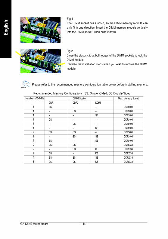
Fig.1The DIMM socket has a notch, so the DIMM memory module canonly fit in one direction. Insert the DIMM memory module verticallyinto the DIMM socket. Then push it down.
Fig.2Close the plastic clip at both edges of the DIMM sockets to lock theDIMM module.Reverse the installation steps when you wish to remove the DIMMmodule.
Recommended Memory Configurations (SS: Single -Sided, DS:Double-Sided)Number of DIMMs
11111122222233
DIMM Socket Max. Memory SpeedDDR1 DDR2 DDR3SS -- -- DDR 400-- SS -- DDR 400-- -- SS DDR 400DS -- -- DDR 400-- DS -- DDR 400-- -- DS DDR 400SS SS -- DDR 400-- SS SS DDR 400SS -- SS DDR 400DS DS -- DDR 333-- DS DS DDR 333DS -- DS DDR 333SS SS SS DDR 333DS DS DS DDR 333
Please refer to the recommended memory configuration table below before installing memory.

Hardware Installation- 15 -
English
1-5 Installation of Expansion CardsYou can install your expansion card by following the steps outlined below:1. Read the related expansion card's instruction document before install the expansion card into the
computer.2. Remove your computer's chassis cover, screws and slot bracket from the computer.3. Press the expansion card firmly into expansion slot in motherboard.4. Be sure the metal contacts on the card are indeed seated in the slot.5. Replace the screw to secure the slot bracket of the expansion card.6. Replace your computer's chassis cover.7. Power on the computer, if necessary, setup BIOS utility of expansion card from BIOS.8. Install related driver from the operating system.
Installing a PCI Express x 16 expansion card:
Please carefully pull out the small white-drawable bar at the end of the PCI Expressx 16 slot when you try to install/uninstall theVGA card. Please align the VGA card to theonboard PCI Express x 16 slot and pressfirmly down on the slot. Make sure your VGAcard is locked by the small white-drawablebar.

GA-K8NE Motherboard - 16 -
Engl
ish
1-6 I/O Back Panel Introduction
PS/2 Keyboard and PS/2 Mouse ConnectorTo install a PS/2 port keyboard and mouse, plug the mouse to the upper port (green) and the keyboard to thelower port (purple).Parallel PortThe parallel port allows connection of a printer, scanner and other peripheral devices.SPDIF_I (SPDIF In)Use SPDIF In feature only when your device has digital output function.SPDIF_O (SPDIF Out)The SPDIF output is capable of providing digital audio to external speakers or compressed AC3
• data to an external Dolby Digital Decoder.COM A (Serial Port)Connects to serial-based mouse or data processing devices.USB portBefore you connect your device(s) into USB connector(s), please make sure your device(s) such asUSB keyboard, mouse, scanner, zip, speaker...etc. have a standard USB interface. Also make sureyour OS supports USB controller. If your OS does not support USB controller, please contact OSvendor for possible patch or driver upgrade. For more information please contact your OS or device(s)vendors.LAN PortThe provided Internet connection is Gigabit Ethernet, providing data transfer speeds of10/100/1000Mbps.Line InDevices like CD-ROM, walkman etc. can be connected to Line In jack.Line Out (Front Speaker Out)Connect the stereo speakers, earphone or front surround speakers to this connector.MIC InMicrophone can be connected to MIC In jack.Center/Subwoofer Speaker OutConnect the Center/Subwoofer speakers to this connector.Rear Speaker OutConnect the rear surround speakers to this connector.

Hardware Installation- 17 -
English
1-7 Connectors Introduction
Side Speaker OutConnect the side surround speakers to this connector.
You can use audio software to configure 2-/4-/6-/8-channel audio functioning.
1) ATX_12V2) ATX (Power Connector)3) CPU_FAN4) SYS_FAN5) FDD6) IDE1 / IDE27) SATAII0_1/SATAII2_38) F_PANEL
9) PWR_LED10) F_AUDO11) CD_IN12) F_USB1 / F_USB2/F_USB313) COMB14) C I15) CLR_CMOS16) BAT
1
2
6
1213
4
3
8
11
16
15 5
7
10
14 9

GA-K8NE Motherboard - 18 -
Engl
ish
1/2) ATX_12V / ATX (Power Connector)With the use of the power connector, the power supply can supply enough stable power to all thecomponents on the motherboard. Before connecting the power connector, please make sure that allcomponents and devices are properly installed. Align the power connector with its proper location onthe motherboard and connect tightly.The ATX_12V power connector mainly supplies power to the CPU. If the ATX_12V power connector is not connected, the system will not start.Caution!Please use a power supply that is able to handle the system voltage requirements. It isrecommended that a power supply that can withstand high power consumption be used (300W orgreater). If a power supply is used that does not provide the required power, the result can lead to anunstable system or a system that is unable to start.If you use a 24-pin ATX power supply, please remove the small cover on the power connector
on the motherboard before plugging in the power cord ; Otherwise, please do not remove it.
Pin No. Definition1 GND2 GND3 +12V4 +12V
1 13
2412
1
3
2
4
Pin No. Definition1 3.3V2 3.3V3 GND4 +5V5 GND6 +5V7 GND8 Power Good9 5V SB(stand by +5V)10 +12V11 +12V(Only for 24pins ATX)12 3.3V(Only for 24pins ATX)13 3.3V14 -12V15 GND16 PS_ON(soft On/Off)17 GND18 GND19 GND20 -5V21 +5V22 +5V23 +5V(Only for 24pins ATX)24 GND(Only for 24pins ATX)

Hardware Installation- 19 -
English
3/4) CPU_FAN / SYS_FAN (Cooler Fan Power Connector)The cooler fan power connector supplies a +12V power voltage via a 3-pin power connector andpossesses a foolproof connection design.Most coolers are designed with color-coded power connector wires. A red power connector wireindicates a positive connection and requires a +12V power voltage. The black connector wire is theground wire (GND).Please remember to connect the power to the cooler to prevent system overheating and failure.Caution!Please remember to connect the power to the CPU fan to prevent CPU overheating and failure.
CPU_FAN/SYS_FAN
Pin No. Definition1 GND2 +12V3 Sense
1
5) FDD (FDD Connector)The FDD connector is used to connect the FDD cable while the other end of the cable connects to theFDD drive. The types of FDD drives supported are: 360KB, 720KB, 1.2MB, 1.44MB and 2.88MB.Please connect the red power connector wire to the pin1 position.
2 34
1 33

GA-K8NE Motherboard - 20 -
Engl
ish
6) IDE1 / IDE2 (IDE Connector)An IDE device connects to the computer via an IDE connector. One IDE connector can connect to oneIDE cable, and the single IDE cable can then connect to two IDE devices (hard drive or optical drive). Ifyou wish to connect two IDE devices, please set the jumper on one IDE device as Master and the otheras Slave (for information on settings, please refer to the instructions located on the IDE device).
7) SATAII0_1 / SATAII2_3 (Serial ATA Connector)Serial ATA can provide up to150MB/s transfer rate. Please refer to the BIOS setting for the Serial ATAand install the proper driver in order to work properly.
Pin No. Definition1 GND2 TXP3 TXN4 GND5 RXN6 RXP7 GND
17
2
40
1
39
IDE2 IDE1
1 7

Hardware Installation- 21 -
English
8) F_PANEL (Front Panel Jumper)Please connect the power LED, PC speaker, reset switch and power switch etc of your chassis frontpanel to the F_PANEL connector according to the pin assignment below.
HD (IDE Hard Disk Active LED) (Blue) Pin 1: LED anode(+)Pin 2: LED cathode(-)
SPEAK (Speaker Connector) (Amber) Pin 1: PowerPin 2- Pin 3: NCPin 4: Data(-)
RES (Reset Switch) (Green) Open: NormalClose: Reset Hardware System
PW (Power Switch) (Red) Open: NormalClose: Power On/Off
MSG(Message LED/Power/Sleep LED) Pin 1: LED anode(+)(Yellow) Pin 2: LED cathode(-)NC ( Purple) NC
12
1920
HD-
HD+ RE
S+RE
S- NC
IDE Hard Disk Active LED
Reset Switch
SPEA
K-
MSG-
MSG+
PW-
PW+
Message LED/Power/
Sleep LED
Speaker Connector
SPEA
K+
PowerSwitch

GA-K8NE Motherboard - 22 -
Engl
ish
10) F_AUDIO (Front Audio Panel Connector)If you want to use Front Audio connector, you must remove 5-6, 9-10 Jumper.In order to utilize the front audio header, your chassis must have front audio connector. Also pleasemake sure the pin assignments for the cable are the same as the pin assignments for the front audioheader. To find out if the chassis you are buying support front audio connector, please contact yourdealer. Please note, you can have the alternative of using front audio connector or of using rear audioconnector to play sound.
Pin No. Definition1 MIC2 GND3 MIC_BIAS4 POWER5 FrontAudio(R)6 Rear Audio (R)/ Return R7 NC8 No Pin9 FrontAudio (L)10 Rear Audio (L)/ Return L
1
10 9
2
9) PWR_LEDPWR_LED is connect with the system power indicator to indicate whether the system is on/off. Itwill blink when the system enters suspend mode.
1
Pin No. Definition1 MPD+2 MPD-3 MPD-

Hardware Installation- 23 -
English
12) F_ USB1 / F_USB2 / F_USB3 (Front USB Connector)Be careful with the polarity of the front USB connector. Check the pin assignment carefully while youconnect the front USB cable, incorrect connection between the cable and connector will make thedevice unable to work or even damage it. For optional front USB cable, please contact your local dealer.
Pin No. Definition1 Power2 Power3 USB DX-4 USB Dy-5 USB DX+6 USB Dy+7 GND8 GND9 No Pin10 NC
2
10
1
9
11) CD_IN (CD In Connector)Connect CD-ROM or DVD-ROM audio out to the connector.
Pin No. Definition1 CD-L2 GND3 GND4 CD-R
1

GA-K8NE Motherboard - 24 -
Engl
ish
14) CI (Chassis Intrusion, Case Open)This 2-pin connector allows your system to detect if the chassis cover is removed. You can checkthe "Case Opened" status in BIOS Setup.
1Pin No. Definition
1 Signal2 GND
13) COMB (COMB Connector)Be careful with the polarity of the COMB connector. Check the pin assignments while you connectthe COMB cable. Please contact your nearest dealer for optional COMB cable.
Pin No. Definition1 NDCDB-2 NSINB3 NSOUTB4 NDTRB-5 GND6 NDSRB-7 NRTSB-8 NCTSB-9 NRIB-10 No Pin
10
9
2
1
Hardware Installation- 25 -
English
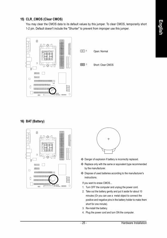
16) BAT (Battery)
Danger of explosion if battery is incorrectly replaced.
Replace only with the same or equivalent type recommendedby the manufacturer.
Dispose of used batteries according to the manufacturer'sinstructions.
If you want to erase CMOS...1. Turn OFF the computer and unplug the power cord.2. Take out the battery gently and put it aside for about 10
minutes (Or you can use a metal object to connect thepositive and negative pins in the battery holder to make themshort for one minute).
3. Re-install the battery.4. Plug the power cord and turn ON the computer.
15) CLR_CMOS (Clear CMOS)You may clear the CMOS data to its default values by this jumper. To clear CMOS, temporarily short1-2 pin. Default doesn't include the "Shunter" to prevent from improper use this jumper.
Open: Normal
Short: Clear CMOS1
1

GA-K8NE Motherboard - 26 -
Engl
ish

BIOS Setup- 27 -
EnglishBIOS (Basic Input and Output System) includes a CMOS SETUP utility which allows user to configurerequired settings or to activate certain system features.The CMOS SETUP saves the configuration in the CMOS SRAM of the motherboard.When the power is turned off, the battery on the motherboard supplies the necessary power to the CMOSSRAM.When the power is turned on, pushing the <Del> button during the BIOS POST (Power-On Self Test) willtake you to the CMOS SETUP screen. You can enter the BIOS setup screen by pressing "Ctrl + F1".When setting up BIOS for the first time, it is recommended that you save the current BIOS to a disk in theevent that BIOS needs to be reset to its original settings. If you wish to upgrade to a new BIOS, eitherGIGABYTE's Q-Flash or @BIOS utility can be used.Q-Flash allows the user to quickly and easily update or backup BIOS without entering the operating system.@BIOS is a Windows-based utility that does not require users to boot to DOS before upgrading BIOS butdirectly download and update BIOS from the Internet.
CONTROL KEYS< > < > < > < > Move to select item<Enter> Select Item<Esc> Main Menu - Quit and not save changes into CMOS Status Page Setup Menu
and Option Page Setup Menu - Exit current page and return to Main Menu<Page Up> Increase the numeric value or make changes<Page Down> Decrease the numeric value or make changes<F1> General help, only for Status Page Setup Menu and Option Page Setup Menu<F2> Item Help<F5> Restore the previous CMOS value from CMOS, only for Option Page Setup Menu<F7> Load the Optimized Defaults<F8> Q-Flash utility<F9> System Information<F10> Save all the CMOS changes, only for Main Menu
Main MenuThe on-line description of the highlighted setup function is displayed at the bottom of the screen.Status Page Setup Menu / Option Page Setup MenuPress <F1> to pop up a small help window that describes the appropriate keys to use and the possibleselections for the highlighted item. To exit the Help Window press <Esc>.
Chapter 2 BIOS Setup
Because BIOS flashing is potentially risky, please do it with caution and avoid inadequateoperation that may result in system malfunction.

GA-K8NE Motherboard - 28 -
Engl
ish
The Main Menu (For example: BIOS Ver. : F1b)Once you enter Award BIOS CMOS Setup Utility, the Main Menu (as figure below) will appear on the screen.Use arrow keys to select among the items and press <Enter> to accept or enter the sub-menu.
Standard CMOS FeaturesThis setup page includes all the items in standard compatible BIOS.Advanced BIOS FeaturesThis setup page includes all the items of Award special enhanced features.Integrated PeripheralsThis setup page includes all onboard peripherals.Power Management SetupThis setup page includes all the items of Green function features.PnP/PCI ConfigurationThis setup page includes all the configurations of PCI & PnP ISA resources.PC Health StatusThis setup page is the System auto detect Temperature, voltage, fan, speed.MB Intelligent Tweaker(M.I.T.)This setup page is control CPU clock and frequency ratio.Top PerformanceIf you wish to maximize the performance of your system, enable Top Performance.Load Optimized DefaultsOptimized Defaults indicates the value of the system parameters which the system would be inbest performance configuration.
If you can't find the setting you want, please press "Ctrl+F1" to search the advanced option hidden.
The BIOS Setup menus described in this chapter are for reference only and may differ from theexact settings for your motherboard.
CMOS Setup Utility-Copyright (C) 1984-2005 Award Software
Standard CMOS Features
Advanced BIOS FeaturesIntegrated Peripherals
Power Management Setup
PnP/PCI ConfigurationsPC Health Status
MB Intelligent Tweaker(M.I.T.)
Top Performance
Load Optimized DefaultsSet Supervisor Password
Set User Password
Save & Exit SetupExit Without Saving
ESC: Quit : Select ItemF8: Q-Flash F10: Save & Exit Setup
Time, Date, Hard Disk Type...

BIOS Setup- 29 -
English
Set Supervisor PasswordChange, set, or disable password. It allows you to limit access to the system and Setup, or just to Setup.Set User PasswordChange, set, or disable password. It allows you to limit access to the system.Save & Exit SetupSave CMOS value settings to CMOS and exit setup.Exit Without SavingAbandon all CMOS value changes and exit setup.
GA-K8NE Motherboard - 30 -
Engl
ish
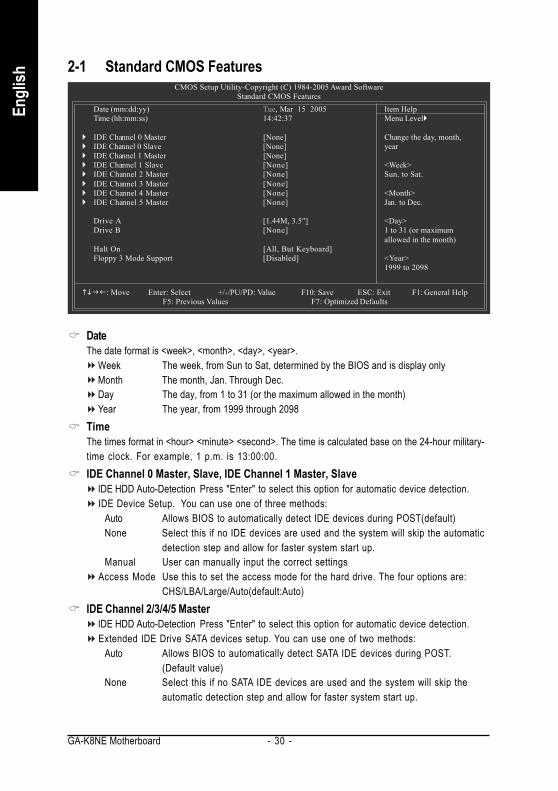
2-1 Standard CMOS Features
DateThe date format is <week>, <month>, <day>, <year>.
Week The week, from Sun to Sat, determined by the BIOS and is display onlyMonth The month, Jan. Through Dec.Day The day, from 1 to 31 (or the maximum allowed in the month)Year The year, from 1999 through 2098
TimeThe times format in <hour> <minute> <second>. The time is calculated base on the 24-hour military-time clock. For example, 1 p.m. is 13:00:00.IDE Channel 0 Master, Slave, IDE Channel 1 Master, Slave
IDE HDD Auto-Detection Press "Enter" to select this option for automatic device detection.IDE Device Setup. You can use one of three methods:
Auto Allows BIOS to automatically detect IDE devices during POST(default)None Select this if no IDE devices are used and the system will skip the automatic
detection step and allow for faster system start up.Manual User can manually input the correct settings
Access Mode Use this to set the access mode for the hard drive. The four options are:CHS/LBA/Large/Auto(default:Auto)
IDE Channel 2/3/4/5 MasterIDE HDD Auto-Detection Press "Enter" to select this option for automatic device detection.Extended IDE Drive SATA devices setup. You can use one of two methods:
Auto Allows BIOS to automatically detect SATA IDE devices during POST.(Default value)
None Select this if no SATA IDE devices are used and the system will skip theautomatic detection step and allow for faster system start up.
CMOS Setup Utility-Copyright (C) 1984-2005 Award SoftwareStandard CMOS Features
Date (mm:dd:yy) Tue, Mar 15 2005Time (hh:mm:ss) 14:42:37
IDE Channel 0 Master [None]IDE Channel 0 Slave [None]IDE Channel 1 Master [None]IDE Channel 1 Slave [None]IDE Channel 2 Master [None]IDE Channel 3 Master [None]IDE Channel 4 Master [None]IDE Channel 5 Master [None]
Drive A [1.44M, 3.5"]Drive B [None]
Halt On [All, But Keyboard]Floppy 3 Mode Support [Disabled]
: Move Enter: Select +/-/PU/PD: Value F10: Save ESC: Exit F1: General Help F5: Previous Values F7: Optimized Defaults
Item HelpMenu Level
Change the day, month,year
<Week>Sun. to Sat.
<Month>Jan. to Dec.
<Day>1 to 31 (or maximumallowed in the month)
<Year>1999 to 2098

BIOS Setup- 31 -
English
Access Mode Use this to set the access mode for the hard drive. The two options are:Large/Auto(default:Auto)
Capacity Capacity of currently installed hard disk.Hard drive information should be labeled on the outside drive casing. Enter the appropriate optionbased on this information.
Cylinder Number of cylindersHead Number of headsPrecomp Write precompLanding Zone Landing zoneSector Number of sectors
Drive A / Drive BThe category identifies the types of floppy disk drive A or drive B that has been installed in thecomputer.
None No floppy drive installed360K, 5.25" 5.25 inch PC-type standard drive; 360K byte capacity.1.2M, 5.25" 5.25 inch AT-type high-density drive; 1.2M byte capacity
(3.5 inch when 3 Mode is Enabled).720K, 3.5" 3.5 inch double-sided drive; 720K byte capacity1.44M, 3.5" 3.5 inch double-sided drive; 1.44M byte capacity. (Default value)2.88M, 3.5" 3.5 inch double-sided drive; 2.88M byte capacity.
Halt onThe category determines whether the computer will stop if an error is detected during power up.
No Errors The system boot will not stop for any error that may be detected and youwill be prompted.
All Errors Whenever the BIOS detects a non-fatal error the system will be stopped.All, But Keyboard The system boot will not stop for a keyboard error; it will stop for all other
errors. (Default value)All, But Diskette The system boot will not stop for a disk error; it will stop for all other errors.All, But Disk/Key The system boot will not stop for a keyboard or disk error; it will stop for all
other errors.Floppy 3 Mode Support (for Japan Area)
Disabled Normal Floppy Drive. (Default value)Drive A Drive A is 3 mode Floppy Drive.Drive B Drive B is 3 mode Floppy Drive.Both Drive A & B are 3 mode Floppy Drives.

GA-K8NE Motherboard - 32 -
Engl
ish
2-2 Advanced BIOS Features
Hard Disk Boot PrioritySelect boot sequence for onboard(or add-on cards) SCSI, RAID, etc.Use < > or < > to select a device, then press<+> to move it up, or <-> to move it down the list. Press<ESC> to exit this menu.First / Second / Third Boot Device
Floppy Select your boot device priority by Floppy.LS120 Select your boot device priority by LS120.Hard Disk Select your boot device priority by Hard Disk.CDROM Select your boot device priority by CDROM.ZIP Select your boot device priority by ZIP.USB-FDD Select your boot device priority by USB-FDD.USB-ZIP Select your boot device priority by USB-ZIP.USB-CDROM Select your boot device priority by USB-CDROM.USB-HDD Select your boot device priority by USB-HDD.Legacy LAN Select your boot device priority by Legacy LAN.Disabled Disable this function.
Boot Up Floppy SeekDuring POST, BIOS will determine the floppy disk drive installed is 40 or 80 tracks. 360K type is 40tracks 720K, 1.2M and 1.44M are all 80 tracks.
Enabled BIOS searches for floppy disk drive to determine it is 40 or 80 tracks. Note that BIOScan not tell from 720K, 1.2M or 1.44M drive type as they are all 80 tracks.
Disabled BIOS will not search for the type of floppy disk drive by track number. Note thatthere will not be any warning message if the drive installed is 360K. (Default value)
CMOS Setup Utility-Copyright (C) 1984-2005 Award SoftwareAdvanced BIOS Features
Hard Disk Boot Priority [Press Enter]First Boot Device [Floppy]Second Boot Device [Hard Disk]Third Boot Device [CDROM]Boot Up Floopy Seek [Disabled]Password Check [Setup]Init Display First [PEG]
: Move Enter: Select +/-/PU/PD: Value F10: Save ESC: Exit F1: General Help F5: Previous Values F7: Optimized Defaults
Item HelpMenu Level
Select Hard Disk BootDevice Priority

BIOS Setup- 33 -
English
Password CheckSystem The system can not boot and can not access to Setup page will be denied if the
correct password is not entered at the prompt.Setup The system will boot, but access to Setup will be denied if the correct password is
not entered at the prompt. (Default value)Init Display FirstThis feature allows you to select the first initiation of the monitor display from which card when youinstall a PCI card and a PCI Express VGA card on the motherboard.
PEG Set Init display first to PCI Express VGA card. (Default value)PCI slot Set Init display first to PCI.

GA-K8NE Motherboard - 34 -
Engl
ish
2-3 Integrated Peripherals
On-Chip IDE Channel0Enabled Enable onboard 1st channel IDE port. (Default value)Disabled Disable onboard 1st channel IDE port.
On-Chip IDE Channel1Enabled Enable onboard 2nd channel IDE port. (Default value)Disabled Disable onboard 2nd channel IDE port.
IDE DMA transfer accessEnabled Enable IDE DMA transfer access. (Default value)Disabled Disable this function.
CMOS Setup Utility-Copyright (C) 1984-2005 Award SoftwareIntegrated Peripherals
On-Chip IDE Channel0 [Enabled]On-Chip IDE Channel1 [Enabled]IDE DMA transfer access [Enabled]On-Chip MAC Lan [Auto]NV IDE/SATA RAID function [Enabled]IDE Primary Master RAID [Disabled]IDE Primary Slave RAID [Disabled]IDE Secndry Master RAID [Disabled]IDE Secndry Slave RAID [Disabled]NV Serial-ATA 1 [Enabled]NV SATA 1 Primary RAID [Disabled]NV SATA 1 Secondary RAID [Disabled]NV Serial-ATA 2 [Enabled]NV SATA 2 Primary RAID [Disabled]NV SATA 2 Secondary RAID [Disabled]IDE Prefetch Mode [Enabled]USB Memory Type [SHADOW]AC97 Audio [Auto]Onboard Serial Port 1 [3F8/IRQ4]
: Move Enter: Select +/-/PU/PD: Value F10: Save ESC: Exit F1: General Help F5: Previous Values F7: Optimized Defaults
Item HelpMenu Level
CMOS Setup Utility-Copyright (C) 1984-2005 Award SoftwareIntegrated Peripherals
: Move Enter: Select +/-/PU/PD: Value F10: Save ESC: Exit F1: General Help F5: Previous Values F7: Optimized Defaults
Item HelpMenu Level
Onboard Serial Port 2 [2F8/IRQ3]Onboard Parallel Port [378/IRQ7]Parallel Port Mode [SPP]
x ECP Mode Use DMA 3On-Chip USB [V1.1+V2.0]Legacy USB Keyboard/Storage [Disabled]Legacy (DOS) USB Mouse [Disabled]Legacy USB Storage detect [Enabled]

BIOS Setup- 35 -
English
On-Chip MAC LanAuto Auto-detect onboard LAN chip function. (Default value)Disabled Disable onboard LAN chip function.
NV IDE/SATA RAID functionEnabled Enable NV IDE/SATA RAID function. (Default value)Disabled Disable this function.
IDE Primary Master RAIDEnabled Enable 1st master channel IDE RAID function.Disabled Disable this function. (Default value)
IDE Primary Slave RAIDEnabled Enable 1st slave channel IDE RAID function.Disabled Disable this function. (Default value)
IDE Secndry Master RAIDEnabled Enable 2nd master channel IDE RAID function.Disabled Disable this function. (Default value)
IDE Secndry Slave RAIDEnabled Enable 2nd slave channel IDE RAID function.Disabled Disable this function. (Default value)
NV Serial-ATA 1Enabled Enable Serial ATA 1 supported. (Default value)Disabled Disable Serial ATA 1 supported.
NV SATA 1 Primary RAIDEnabled Enable 1st SATA primary RAID function.Disabled Disable this function. (Default value)
NV SATA 1 Secondary RAIDEnabled Enable 1st SATA secondary RAID function.Disabled Disable this function. (Default value)
NV Serial-ATA 2Enabled Enable Serial ATA 2 supported. (Default value)Disabled Disable Serial ATA 2 supported.
NV SATA 2 Primary RAIDEnabled Enable 2nd SATA primary RAID function.Disabled Disable this function. (Default value)
NV SATA 2 Secondary RAIDEnabled Enable 2nd SATA secondary RAID function.Disabled Disable this function. (Default value)
IDE Prefetch ModeEnabled Enable IDE Prefetch mode. (Default value)Disabled Disable IDE Prefetch mode.

GA-K8NE Motherboard - 36 -
Engl
ish
USB Memory TypeSHADOW Set USB memory type to SHADOW. (Default value)Base Memory(640K) Set USB memory type to base memory(640K).
AC97 AudioAuto Enable onboard AC'97 audio function. (Default value)Disabled Disable this function.
Onboard Serial Port 1Auto BIOS will automatically setup the Serial port 1 address.3F8/IRQ4 Enable onboard Serial port 1 and address is 3F8/IRQ4. (Default value)2F8/IRQ3 Enable onboard Serial port 1 and address is 2F8/IRQ3.3E8/IRQ4 Enable onboard Serial port 1 and address is 3E8/IRQ4.2E8/IRQ3 Enable onboard Serial port 1 and address is 2E8/IRQ3.Disabled Disable onboard Serial port 1.
Onboard Serial Port 2Auto BIOS will automatically set up the Serial port 2 address.3F8/IRQ4 Enable onboard Serial port 2 and address is 3F8/IRQ4.2F8/IRQ3 Enable onboard Serial port 2 and address is 2F8/IRQ3. (Default value)3E8/IRQ4 Enable onboard Serial port 2 and address is 3E8/IRQ4.2E8/IRQ3 Enable onboard Serial port 2 and address is 2E8/IRQ3.Disabled Disable onboard Serial port 2.
Onboard Parallel PortDisabled Disable onboard LPT port.378/IRQ7 Enable onboard LPT port and address is 378/IRQ7. (Default value)278/IRQ5 Enable onboard LPT port and address is 278/IRQ5.3BC/IRQ7 Enable onboard LPT port and address is 3BC/IRQ7.
Parallel Port ModeSPP Using Parallel port as Standard Parallel Port. (Default value)EPP Using Parallel port as Enhanced Parallel Port.ECP Using Parallel port as Extended Capabilities Port.ECP+EPP Using Parallel port as ECP and EPP mode.
ECP Mode Use DMA3 Set ECP Mode Use DMA to 3. (Default value)1 Set ECP Mode Use DMA to 1.
On-Chip USBDisabled Disable this function if you are not using onboard USB function.V1.1+V2.0 Enable USB 1.1 and USB 2.0 controller. (Default value)V1.1 Enable only USB 1.1 controller.
Legacy USB Keyboard/StorageEnabled Enable USB keyboard support in the MS-DOS environment.Disabled Disable this function. (Default value)

BIOS Setup- 37 -
English
2-4 Power Management Setup
ACPI Suspend TypeS1(POS) Set ACPI suspend type to S1/POS(Power On Suspend). (Default value)S3(STR) Set ACPI suspend type to S3/STR(Suspend To RAM).
Soft-Off by Power buttonInstant-off Press power button then Power off instantly. (Default value)Delay 4 Sec Press power button 4 seconds to Power off. Enter suspend if button is pressed less
than 4 seconds.PME Event Wake UpThis feature requires an ATX power supply that provides at least 1A on the 5VSB lead.
Disabled Disable this function. (Default value)Enabled Enable PME as wake up event.
Modem Ring OnAn incoming call via modem can awake the system from any suspend state.
Disabled Disable Modem Ring on function. (Default value)Enabled Enable Modem Ring on function.
CMOS Setup Utility-Copyright (C) 1984-2005 Award SoftwarePower Management Setup
ACPI Suspend Type [S1(POS)]Soft-Off by Power button [Instant-off]PME Event Wake Up [Disabled]Modem Ring On [Disabled]USB Resume from Suspend [Disabled]Power-On by Alarm [Disabled]
x Day of Month Alarm Everydayx Time (hh:mm:ss) Alarm 0 : 0 : 0
Power On By Mouse [Disabled]Power On By Keyboard [Disabled]
x KB Power ON Function EnterAC BACK Function [Soft-Off]
: Move Enter: Select +/-/PU/PD: Value F10: Save ESC: Exit F1: General Help F5: Previous Values F7: Optimized Defaults
Item HelpMenu Level
Legacy (DOS) USB MouseEnabled Enable USB mouse support in the MS-DOS environment.Disabled Disable this function. (Default value)
Legacy USB Storage detectEnabled Enable USB storage detect function. (Default value)Disabled Disable this function.

GA-K8NE Motherboard - 38 -
Engl
ish
USB Resume from SuspendDisabled Disable this function. (Default value)Enabled Enable USB device wake up system from suspend type.
Power-On by AlarmYou can set "Resume by Alarm" item to enabled and key in Date/Time to power on system.
Disabled Disable this function. (Default value)Enabled Enable alarm function to POWER ON system.
If Power-On by Alarm is Enabled.Day of Month Alarm : Everyday, 1~31Time (hh: mm: ss) Alarm : (0~23) : (0~59) : (0~59)
Power On By MouseDisabled Disable this function. (Default value)Double Click Double click on PS/2 mouse left button to power on the system.
Power On By KeyboardDisabled Disable this function. (Default value)Password Enter from 1 to 5 characters to set the Keyboard Power On Password.Any KEY Press any key to power on the system.Keyboard 98 If your keyboard have "POWER Key" button, you can press the key to power on the
system.KB Power ON FunctionWhen "Power On by Keyboard" set at Password, you can set the password here.
Enter Input password (from 1 to 5 characters) and press Enter to set the KeyboardPower On password.
AC BACK FunctionSoft-Off When AC-power back to the system, the system will be in "Off" state.
(Default value)Full-On When AC-power back to the system, the system always in "On" state.
BIOS Setup- 39 -
English
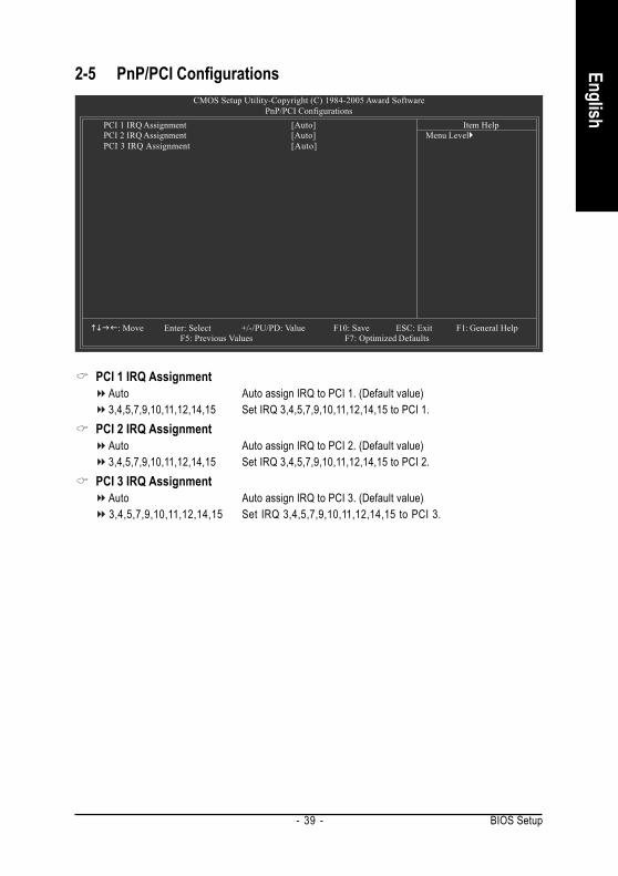
2-5 PnP/PCI Configurations
PCI 1 IRQ AssignmentAuto Auto assign IRQ to PCI 1. (Default value)3,4,5,7,9,10,11,12,14,15 Set IRQ 3,4,5,7,9,10,11,12,14,15 to PCI 1.
PCI 2 IRQ AssignmentAuto Auto assign IRQ to PCI 2. (Default value)3,4,5,7,9,10,11,12,14,15 Set IRQ 3,4,5,7,9,10,11,12,14,15 to PCI 2.
PCI 3 IRQ AssignmentAuto Auto assign IRQ to PCI 3. (Default value)3,4,5,7,9,10,11,12,14,15 Set IRQ 3,4,5,7,9,10,11,12,14,15 to PCI 3.
CMOS Setup Utility-Copyright (C) 1984-2005 Award SoftwarePnP/PCI Configurations
PCI 1 IRQ Assignment [Auto]PCI 2 IRQ Assignment [Auto]PCI 3 IRQ Assignment [Auto]
: Move Enter: Select +/-/PU/PD: Value F10: Save ESC: Exit F1: General Help F5: Previous Values F7: Optimized Defaults
Item HelpMenu Level
GA-K8NE Motherboard - 40 -
Engl
ish
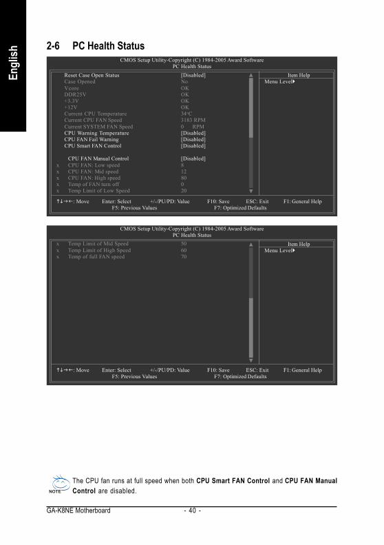
2-6 PC Health StatusCMOS Setup Utility-Copyright (C) 1984-2005 Award Software
PC Health StatusReset Case Open Status [Disabled]Case Opened NoVcore OKDDR25V OK+3.3V OK+12V OKCurrent CPU Temperature 34oCCurrent CPU FAN Speed 3183 RPMCurrent SYSTEM FAN Speed 0 RPMCPU Warning Temperature [Disabled]CPU FAN Fail Warning [Disabled]CPU Smart FAN Control [Disabled]
CPU FAN Manual Control [Disabled]x CPU FAN: Low speed 8x CPU FAN: Mid speed 12x CPU FAN: High speed 80x Temp of FAN turn off 0x Temp Limit of Low Speed 20
: Move Enter: Select +/-/PU/PD: Value F10: Save ESC: Exit F1: General Help F5: Previous Values F7: Optimized Defaults
Item HelpMenu Level
CMOS Setup Utility-Copyright (C) 1984-2005 Award SoftwarePC Health Status
: Move Enter: Select +/-/PU/PD: Value F10: Save ESC: Exit F1: General Help F5: Previous Values F7: Optimized Defaults
Item HelpMenu Level
x Temp Limit of Mid Speed 50x Temp Limit of High Speed 60x Temp of full FAN speed 70
The CPU fan runs at full speed when both CPU Smart FAN Control and CPU FAN ManualControl are disabled.

BIOS Setup- 41 -
English
Reset Case Open StatusDisabled Don't reset case open status. (Default value)Enabled Clear case open status at next boot.
Case OpenedIf the case is closed, "Case Opened" will show "No".If the case have been opened, "Case Opened" will show "Yes".If you want to reset "Case Opened" value, set "Reset Case Open Status" to "Enabled" and saveCMOS, your computer will restart.Current Voltage(V) Vcore / DDR25V / +3.3V / +12V
Detect system's voltage status automatically.Current CPU Temperature
Detect CPU temperature automatically.Current CPU/SYSTEM FAN Speed (RPM)
Detect CPU/SYSTEM fan speed status automatically.CPU Warning Temperature
60oC / 140oF Monitor CPU temperature at 60oC / 140oF.70oC / 158oF Monitor CPU temperature at 70oC / 158oF.80oC / 176oF Monitor CPU temperature at 80oC / 176oF.90oC / 194oF Monitor CPU temperature at 90oC / 194oF.Disabled Disable this function. (Default value)
CPU FAN Fail WarningDisabled Disable CPU fan fail warning function. (Default value)Enabled Enable CPU fan fail warning function.
CPU Smart FAN Control (Note)
Disabled Disable this function. (Default Value)Enabled When this function is enabled, CPU fan will run at different speed depending
on CPU temperature. Users can adjust the fan speed with Easy Tunebased on their requirements.
CPU FAN Manual ControlCPU Smart Fan Control will become disabled when this item is enabled.
Enabled Enable the CPU fan manual control function.Disabled Disable the CPU fan manual control function. (Default value)
CPU FAN: Low SpeedSet the parameter of the CPU fan speed.
The CPU FAN: Low Speed option configures the speed of the CPU fan when the CPU temperatureis below the temperature set in Temp Limit of Mid Speed. The parameter can be adjusted from0~127. Higher parameter means faster CPU fan speed. (Default parameter: 8)
The CPU fan runs at full speed when both CPU Smart FAN Control and CPU FAN ManualControl are disabled.
(Note) Whether the CPU fan speed control function is supported will depend on the CPU cooler youinstall.
GA-K8NE Motherboard - 42 -
Engl
ish
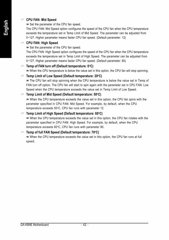
CPU FAN: Mid SpeedSet the parameter of the CPU fan speed.
The CPU FAN: Mid Speed option configures the speed of the CPU fan when the CPU temperatureexceeds the temperature set in Temp Limit of Mid Speed. The parameter can be adjusted from0~127. Higher parameter means faster CPU fan speed. (Default parameter: 12)CPU FAN: High Speed
Set the parameter of the CPU fan speed.The CPU FAN: High Speed option configures the speed of the CPU fan when the CPU temperatureexceeds the temperature set in Temp Limit of High Speed. The parameter can be adjusted from0~127. Higher parameter means faster CPU fan speed. (Default parameter: 80)Temp of FAN turn off (Default temperature: 0oC)
When the CPU temperature is below the value set in this option, the CPU fan will stop spinning.Temp Limit of Low Speed (Default temperature: 20oC)
The CPU fan will stop spinning when the CPU temperature is below the value set in Temp ofFAN turn off option. The CPU fan will start to spin again with the parameter set in CPU FAN: LowSpeed when the CPU temperature exceeds the value set in Temp Limit of Low Speed.Temp Limit of Mid Speed (Default temperature: 50oC)
When the CPU temperature exceeds the value set in this option, the CPU fan spins with theparameter specified in CPU FAN: Mid Speed. For example, by default, when the CPUtemperature exceeds 50oC, CPU fan runs with parameter 12.Temp Limit of High Speed (Default temperature: 60oC)
When the CPU temperature exceeds the value set in this option, the CPU fan rotates with theparameter specified in CPU FAN: High Speed. For example, by default, when the CPUtemperature exceeds 60oC, CPU fan runs with parameter 80.Temp of full FAN Speed (Default temperature: 70oC)
When the CPU temperature exceeds the value set in this option, the CPU fan runs at fullspeed.

BIOS Setup- 43 -
English
2-7 MB Intelligent Tweaker(M.I.T.)
CPU Frequency200 ~ 456 Set CPU frequency from 200Mhz to 456Mhz.
K8 CPU Clock RatioDefault Set K8 CPU Clock Ratio to CPU factory default.
(Default value)x5 1000Mhz ~ x10 2000Mhz Set K8 CPU Clock Ratio from x5 1000Mhz to x10 2000Mhz.
CPU Spread SpectrumDisabled Disable CPU Spread Spectrum.Center Spread Set CPU Spread Spectrum to Center Spread. (Default value)
PCIE Clock100Mhz ~ 150Mhz Set PCI-E clock from 100Mhz to 150Mhz.
Robust Graphics BoosterSelect the options can enhance the VGA graphics card bandwidth to get higher performance.
Auto Set Robust Graphics Booster to Auto. (Default value)Fast Set Robust Graphics Booster to Fast.Turbo Set Robust Graphics Booster to Turbo.
DDR voltage controlPlease note that by overclocking your system through the increase of the DDR voltage, damageto the memory may occur.
Normal Set DDR voltage control to Normal. (Default value)+0.1V Set DDR voltage control to +0.1V.+0.2V Set DDR voltage control to +0.2V.
Incorrect using these features may cause your system broken. For power end-user use only.
CMOS Setup Utility-Copyright (C) 1984-2005 Award SoftwareMB Intelligent Tweaker(M.I.T.)
CPU Frequency [200]K8 CPU Clock Ratio [Default]CPU Spread Spectrum [Center Spread]PCIE Clock [100Mhz]Robust Graphics Booster [Auto]DDR voltage control [Normal]
: Move Enter: Select +/-/PU/PD: Value F10: Save ESC: Exit F1: General Help F5: Previous Values F7: Optimized Defaults
Item HelpMenu Level

GA-K8NE Motherboard - 44 -
Engl
ish
2-8 Top Performance
If you wish to maximize the performance of your system, enable "Top Performance."Disabled Disable this function. (Default Value)Enabled Enable Top Performance function.
"Top Performance" will increase H/W working speed. Different system configuration (both H/Wcomponent and OS) will effect the result. For example, the same H/W configuration might not runproperly with Windows XP, but works smoothly with Windows NT. Therefore, if your system is notperform enough, the reliability or stability problem will appear sometimes, and we will recommend youdisabling the option to avoid the problem as mentioned above.
2-9 Load Optimized Defaults
Selecting this field loads the factory defaults for BIOS and Chipset Features which the system automaticallydetects.
CMOS Setup Utility-Copyright (C) 1984-2005 Award Software
Standard CMOS FeaturesAdvanced BIOS Features
Integrated Peripherals
Power Management SetupPnP/PCI Configurations
PC Health Status
MB Intelligent Tweaker(M.I.T.)
ESC: Quit : Select ItemF8: Q-Flash F10: Save & Exit Setup
Load Optimized Defaults
Top PerformanceLoad Optimized Defaults
Set Supervisor Password
Set User PasswordSave & Exit Setup
Exit Without Saving
Load Optimized Defaults (Y/N)? N
CMOS Setup Utility-Copyright (C) 1984-2005 Award Software
Standard CMOS Features
Advanced BIOS Features
Integrated PeripheralsPower Management Setup
PnP/PCI Configurations
PC Health StatusMB Intelligent Tweaker(M.I.T.)
Esc: Quit : Select ItemF8: Q-Flash F10: Save & Exit Setup
Load Fail-Safe Defaults
Top Performance
Load Optimized Defaults
Set Supervisor PasswordSet User Password
Save & Exit Setup
Exit Without Saving
Top Performance
Disabled.........................[ ]Enabled..........................[ ]
: Move ENTER: AcceptESC: Abort

BIOS Setup- 45 -
English
2-10 Set Supervisor/User Password
When you select this function, the following message will appear at the center of the screen to assist you increating a password.Type the password, up to eight characters, and press <Enter>. You will be asked to confirm the password.Type the password again and press <Enter>. You may also press <Esc> to abort the selection and not entera password.To disable password, just press <Enter> when you are prompted to enter password. A message"PASSWORD DISABLED" will appear to confirm the password being disabled. Once the password is disabled,the system will boot and you can enter Setup freely.The BIOS Setup program allows you to specify two separate passwords:SUPERVISOR PASSWORD and a USER PASSWORD. When disabled, anyone may access all BIOS Setupprogram function. When enabled, the Supervisor password is required for entering the BIOS Setup programand having full configuration fields, the User password is required to access only basic items.If you select "System" at "Password Check" in Advance BIOS Features Menu, you will be prompted for thepassword every time the system is rebooted or any time you try to enter Setup Menu.If you select "Setup" at "Password Check" in Advance BIOS Features Menu, you will be prompted only whenyou try to enter Setup.
CMOS Setup Utility-Copyright (C) 1984-2005 Award Software
Standard CMOS Features
Advanced BIOS FeaturesIntegrated Peripherals
Power Management Setup
PnP/PCI ConfigurationsPC Health Status
MB Intelligent Tweaker(M.I.T.)
ESC: Quit : Select ItemF8: Q-Flash F10: Save & Exit Setup
Change/Set/Disable Password
Top Performance
Load Optimized DefaultsSet Supervisor Password
Set User Password
Save & Exit SetupExit Without Saving
Enter Password:

GA-K8NE Motherboard - 46 -
Engl
ish
2-11 Save & Exit Setup
Type "Y" will quit the Setup Utility and save the user setup value to RTC CMOS.Type "N" will return to Setup Utility.
2-12 Exit Without Saving
Type "Y" will quit the Setup Utility without saving to RTC CMOS.Type "N" will return to Setup Utility.
CMOS Setup Utility-Copyright (C) 1984-2005 Award Software
Standard CMOS Features
Advanced BIOS FeaturesIntegrated Peripherals
Power Management Setup
PnP/PCI ConfigurationsPC Health Status
MB Intelligent Tweaker(M.I.T.)
ESC: Quit : Select ItemF8: Q-Flash F10: Save & Exit Setup
Abandon all Data
Top Performance
Load Optimized DefaultsSet Supervisor Password
Set User Password
Save & Exit SetupExit Without Saving
Quit Without Saving (Y/N)? N
CMOS Setup Utility-Copyright (C) 1984-2005 Award Software
Standard CMOS Features
Advanced BIOS FeaturesIntegrated Peripherals
Power Management Setup
PnP/PCI ConfigurationsPC Health Status
MB Intelligent Tweaker(M.I.T.)
ESC: Quit : Select ItemF8: Q-Flash F10: Save & Exit Setup
Save Data to CMOS
Top Performance
Load Optimized DefaultsSet Supervisor Password
Set User Password
Save & Exit SetupExit Without Saving
Save to CMOS and EXIT (Y/N)? Y

Drivers Installation- 47 -
EnglishPictures below are shown in Windows XP.Insert the driver CD-title that came with your motherboard into your CD-ROM drive, the driverCD-title will auto start and show the installation guide. If not, please double click the CD-ROMdevice icon in "My computer", and execute the Setup.exe.
Chapter 3Drivers Installation
3-1 Install Chipset DriversAfter insert the driver CD, "Xpress Install" will scan automatically the system and then list all the drivers thatrecommended to install. The "Xpress Install" uses the"Click and Go" technology to install the driversautomatically. Just select the drivers you want then click the "GO" button. The "Xpress Install" will executethe installation for you automatically.
Some device drivers will restart your system automatically. After restarting your system the "XpressInstall" will continue to install other drivers.System will reboot automatically after install the drivers, afterward you can install others application.
For USB2.0 driver support under Windows XP operating system, please use Windows ServicePack. After install Windows Service Pack, it will show a question mark "?" in "Universal Serial Buscontroller" under "Device Manager". Please remove the question mark and restart the system(System will auto-detect the right USB2.0 driver).
GA-K8NE Motherboard - 48 -
Engl
ish
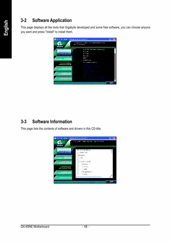
3-2 Software ApplicationThis page displays all the tools that Gigabyte developed and some free software, you can choose anyoneyou want and press "install" to install them.
3-3 Software InformationThis page lists the contents of software and drivers in this CD-title.

Drivers Installation- 49 -
English
3-4 Hardware InformationThis page lists all device you have for this motherboard.
3-5 Contact UsPlease see the last page for details.

GA-K8NE Motherboard - 50 -
Engl
ish

Appendix- 51 -
English
Chapter 4 Appendix4-1 Unique Software Utilities
M.I.T. (Motherboard Intelligent Tweaker)Motherboard Intelligent Tweaker (M.I.T.) allows user to access and change BIOS featuresettings with relative speed and ease. Through GIGABYTE M.I.T. feature the user is no longerrequired to switch into different modes within BIOS setup in order to change system settingssuch as the CPU system bus, memory timings or to enabled Gigabyte's uniqueC.I.A. 2 and M.I.B. 2 features. M.I.T.'s integration of all platform performance settings into asingle mode now gives any user the ability to control and enhance their computer system tothe desired level.
C.I.A.2 (CPU Intelligent Accelerator 2)GIGABYTE CPU Intelligent Accelerator 2(C.I.A. 2) is designed to automatically adjust CPUcomputing power to maximize system performance. When enabled, the program detects thecurrent CPU loading and automatically accelerates the CPU computing performance to allowfor a faster and smoother execution of programs. When the function is disabled, the CPU isreturned to its initial status.
M.I.B.2 (Memory Intelligent Booster 2)Built on the original M.I.B., the new Memory Intelligent Booster 2 (M.I.B. 2) is designed espe-cially to maximize memory performance and boost memory bandwidth up to 10%. With addedbranded memory module information, users are able to opt imize memoryperformance by selecting from a recommended memory module list.
S.O.S. (System Overclock Saver)System Overclock Saver (S.O.S.) is a unique feature that eliminates system boot-up errorsresulting from system over-enhancement by the user. With GIGABYTE's proprietaryS.O.S. feature, users no longer need to open up the PC chassis and short-circuit the "ClearCMOS" pins or the battery on the motherboard to reset the system back to factory defaultsettings. Instead, S.O.S. automatically resets the overclocked system settings back to theirfactory defaults to provide a more user-friendly and reliable platform for users.
Download CenterDownload Center allows users to quickly download and update their BIOS as well as the latestdrivers for their system. Download Center automatically runs a system check of the user PCand provides the user with the current system information as well as displaying a detailed listof all new drivers with the option for download.
C.O.M. (Corporate Online Management)A web-based system management tool that allows system hardware information such as CPU,memory, graphics card, etc. to be monitored and controlled via the Internet, C.O.M. allowscorporate MIS engineers to easily maintain corporate computers such as providing the mostup-to-date drivers and BIOS. (Do not use C.O.M. and @BIOS at the same time.)
U-PLUS D.P.S. (Universal Plus Dual Power System)The U-Plus Dual Power System (U-Plus DPS) is a revolutionary eight-phase power circuit builtfor ultimate system protection. Designed to withstand varying current levels and changes, theU-Plus D.P.S. provides an immensely durable and stable power circuit to the CPU for solidsystem stability. These characteristics make it the ideal companion with the latest LGA775Intel® Pentium® 4 Processor as well as future Intel® processors. As well, 4 blue LED's aremounted on the U-Plus D.P.S. for intelligent indication of system loading.
(Not all model support these Unique Software Utilities, please check your MB features.)
GA-K8NE Motherboard - 52 -
Engl
ish
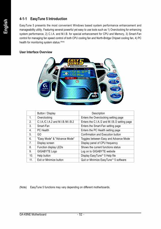
4-1-1 EasyTune 5 IntroductionEasyTune 5 presents the most convenient Windows based system performance enhancement andmanageability utility. Featuring several powerful yet easy to use tools such as 1) Overclocking for enhancingsystem performance, 2) C.I.A. and M.I.B. for special enhancement for CPU and Memory, 3) Smart-Fancontrol for managing fan speed control of both CPU cooling fan and North-Bridge Chipset cooling fan, 4) PChealth for monitoring system status.(Note)
User Interface Overview
(Note) EasyTune 5 functions may vary depending on different motherboards.
Button / Display Description1. Overclocking Enters the Overclocking setting page2. C.I.A./C.I.A.2 and M.I.B./M.I.B.2 Enters the C.I.A./2 and M.I.B./2 setting page3. Smart-Fan Enters the Smart-Fan setting page4. PC Health Enters the PC Health setting page5. GO Confirmation and Execution button6. "Easy Mode" & "Advance Mode" Toggles between Easy and Advance Mode7. Display screen Display panel of CPU frequency8. Function display LEDs Shows the current functions status9. GIGABYTE Logo Log on to GIGABYTE website10. Help button Display EasyTuneTM 5 Help file11. Exit or Minimize button Quit or Minimize EasyTuneTM 5 software
Appendix- 53 -
English
4-1-2 Xpress Recovery Introduction
What is Xpress Recovery ?Xpress Recovery is a utility used to back up and restore an OS partition.If the hard drive is not working properly, the user can restore the drive toits original state.
1. Supports FAT16, FAT32, and NTFS formats2. Must be connected to the IDE1 Master3. Allows installation of only one OS4. Must be used with an IDE hard disk supporting HPA5. The first partition must be set as the boot partition. When the boot partition is backed up,
please do not alter its size.6. Xpress Recovery is recommended when using Ghost to return boot manager to NTFS
format.
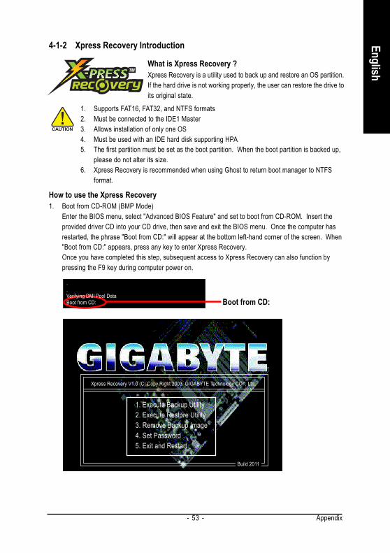
How to use the Xpress Recovery1. Boot from CD-ROM (BMP Mode)
Enter the BIOS menu, select "Advanced BIOS Feature" and set to boot from CD-ROM. Insert theprovided driver CD into your CD drive, then save and exit the BIOS menu. Once the computer hasrestarted, the phrase "Boot from CD:" will appear at the bottom left-hand corner of the screen. When"Boot from CD:" appears, press any key to enter Xpress Recovery.Once you have completed this step, subsequent access to Xpress Recovery can also function bypressing the F9 key during computer power on.
Xpress Recovery V1.0 (C) Copy Right 2003. GIGABYTE Technology CO. , Ltd.
1. Execute Backup Utility2. Execute Restore Utility3. Remove Backup Image4. Set Password5. Exit and Restart
Build 2011
Boot from CD:
.
.Verifying DMI Pool DataBoot from CD:

GA-K8NE Motherboard - 54 -
Engl
ish
2. Press F9 during powering on the computer. (Text Mode)
Xpress Recovery V1.0 (C) Copy Right 2003. GIGABYTE Technology CO. , Ltd.
1. Execute Backup Utility2. Execute Restore Utility3. Remove Backup Image4. Set Password5. Exit and Restart
1. If you have already entered Xpress Recovery by booting from the CD-ROM, you canenter Xpress Recovery in the future by pressing the F9 key.
2. System storage capacity as well as drive reading/writing speed will affect backup speed.3. It is recommended that Xpress Recovery be immediately installed after OS and all
required driver and software installations are complete.
Award Modular BIOS v6.00PG, An Energy Star AllyCopyright (C) 1984-2004, Award Software, Inc.
Intel 865PE AGPSet BIOS for 8IPE1000MT F1Check System Health OK...
Press DEL to enter SETUP / Q-Flash, F9 For Xpress Recovery08/16/2002-I845GE-6A69YG01C-00
F9 For Xpress Recovery

Appendix- 55 -
English
1. Execute Backup Utility:Press B to Backup your System or Esc to ExitThe backup utility will automatically scan your system and back up data as a backup image in your harddrive.
Not all systems support access to Xpress Recovery by pressing the F9 key during computerpower on. If this is the case, please use the boot from CD-ROM method to enter XpressRecovery.
2. Execute Restore Utility:This program will recover your system to factory default.Press R to restore your system back to factory default or press Esc to exitRestores backup image to original state.
3. Remove Backup Image:Remove backup image. Are you sure? (Y/N)Remove the backup image.
4. Set Password:Please input a 4-16 character long password (a-z or 0-9) or press Esc to exitYou can set a password to enter Xpress Recovery to protect your hard disk data. Once this is done,password input will be required to enter Xpress Recovery during the next as well as subsequent systemrestarts. If you wish to remove the need for password entry, please select "Set Password" and under"New Password/Confirm Password", make sure there is no entry and then press "Enter" to removepassword requirement.
5. Exit and Restart:Exit and restart your computer.
GA-K8NE Motherboard - 56 -
Engl
ish
4-1-3 Flash BIOS Method IntroductionMethod 1 : Q-FlashTM UtilityQ-FlashTM is a BIOS flash utility embedded in Flash ROM. With this utility,users only have to stay in the BIOS menu when they want to updateBIOS. Q-Flash?allows users to flash BIOS without any utility in DOS or
Windows. Using Q-FlashTM indicating no more fooling around with any complicated instructions andoperating system since it is in the BIOS menu.
Please note that because updating BIOS has potential risk, please do it with caution!! We aresorry that Gigabyte Technology Co., Ltd is not responsible for damages of system because ofincorrect manipulation of updating BIOS to avoid any claims from end-users.
Before You Begin:Before you start updating BIOS with the Q-FlashTM utility, please follow the steps below first.
1. Download the latest BIOS for your motherboard from Gigabyte's website.2. Extract the BIOS file downloaded and save the BIOS file (the one with model name.Fxx. For
example, 8KNXPU.Fba) to a floppy disk.3. Reboot your PC and press Del to enter BIOS menu.
The BIOS upgrading guides below are separated into two parts.If your motherboard has dual-BIOS, please refer to Part One.If your motherboard has single-BIOS, please refer to Part Two.
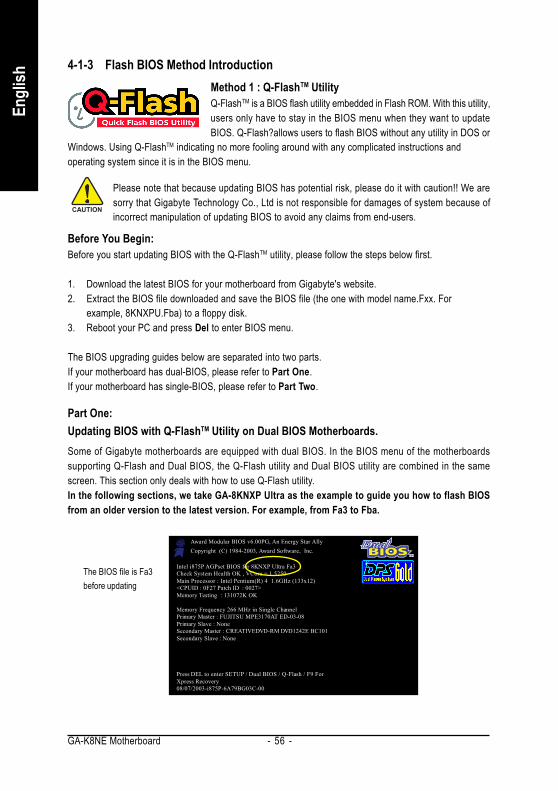
Part One:Updating BIOS with Q-FlashTM Utility on Dual BIOS Motherboards.Some of Gigabyte motherboards are equipped with dual BIOS. In the BIOS menu of the motherboardssupporting Q-Flash and Dual BIOS, the Q-Flash utility and Dual BIOS utility are combined in the samescreen. This section only deals with how to use Q-Flash utility.In the following sections, we take GA-8KNXP Ultra as the example to guide you how to flash BIOSfrom an older version to the latest version. For example, from Fa3 to Fba.
Intel i875P AGPset BIOS for 8KNXP Ultra Fa3Check System Health OK , VCore = 1.5250Main Processor : Intel Pentium(R) 4 1.6GHz (133x12)<CPUID : 0F27 Patch ID : 0027>Memory Testing : 131072K OK
Memory Frequency 266 MHz in Single ChannelPrimary Master : FUJITSU MPE3170AT ED-03-08Primary Slave : NoneSecondary Master : CREATIVEDVD-RM DVD1242E BC101Secondary Slave : None
Press DEL to enter SETUP / Dual BIOS / Q-Flash / F9 ForXpress Recovery08/07/2003-i875P-6A79BG03C-00
Award Modular BIOS v6.00PG, An Energy Star AllyCopyright (C) 1984-2003, Award Software, Inc.
The BIOS file is Fa3before updating

Appendix- 57 -
English
Entering the Q-FlashTM utility:
CMOS Setup Utility-Copyright (C) 1984-2004 Award Software
Standard CMOS FeaturesAdvanced BIOS FeaturesIntegrated PeripheralsPower Management SetupPnP/PCI ConfigurationsPC Health StatusMB Intelligent Tweaker(M.I.T.)
Select LanguageLoad Fail-Safe DefaultsLoad Optimized DefaultsSet Supervisor PasswordSet User PasswordSave & Exit SetupExit Without Saving
ESC: Quit F3: Change LanguageF8: Dual BIOS/Q-Flash F10: Save & Exit Setup
Time, Date, Hard Disk Type...
Step 2: Press F8 button on your keyboard and then Y button to enter the Dual BIOS/Q-Flash utility.
Step1: To use Q-Flash utility, you must press Del in the boot screen to enter BIOS menu.
Exploring the Q-FlashTM / Dual BIOS utility screenThe Q-Flash / Dual BIOS utility screen consists of the following key components.
Task menu for Dual BIOS utility:Contains the names of eight tasks and two item showing information about the BIOS ROM type. Blocking atask and pressing Enter key on your keyboard to enable execution of the task.Task menu for Q-Flash utility:Contains the names of four tasks. Blocking a task and pressing Enter key on your keyboard to enable execu-tion of the task.Action bar:Contains the names of four actions needed to operate the Q-Flash/Dual BIOS utility. Pressing the buttonsmentioned on your keyboards to perform these actions.
Dual BIOS UtilityBoot From......................................... Main BiosMain ROM Type/Size.............................SST 49LF003A 512K Backup ROM Type/Size.........................SST 49LF003A 512K
Wide Range Protection DisableBoot From Main Bios
Auto Recovery EnableHalt On Error Disable
Copy Main ROM Data to BackupLoad Default Settings
Save Settings to CMOSQ-Flash Utility
Load Main BIOS from FloppyLoad Backup BIOS from Floppy
Save Main BIOS to FloppySave Backup BIOS to Floppy
Enter : Run :Move ESC:Reset F10:Power Off
Task menu forDual BIOSutility
Task menu forQ-FlashTM utility
Dual BIOS utility bar
Q-FlashTM utility titlebar
Action bar

GA-K8NE Motherboard - 58 -
Engl
ish
Dual BIOS UtilityBoot From......................................... Main BiosMain ROM Type/Size.............................SST 49LF003A 512K Backup ROM Type/Size.........................SST 49LF003A 512K
Wide Range Protection DisableBoot From Main Bios
Auto Recovery EnableHalt On Error Disable
Copy Main ROM Data to BackupLoad Default Settings
Save Settings to CMOSQ-Flash Utility
Load Main BIOS from FloppyLoad Backup BIOS from Floppy
Save Main BIOS to FloppySave Backup BIOS to Floppy
Enter : Run :Move ESC:Reset F10:Power Off
Using the Q-FlashTM utility:This section tells you how to update BIOS using the Q-Flash utility. As described in the "Before you begin"section above, you must prepare a floppy disk having the BIOS file for your motherboard and insert it to yourcomputer. If you have already put the floppy disk into your system and have entered the Q-Flash utility,please follow the steps below to flash BIOS.
Steps:1. Press arrow buttons on your keyboard to move the light bar to "Load Main BIOS from Floppy" item in
the Q-Flash menu and press Enter button.Later, you will see a box pop up showing the BIOS files you previously downloaded to the floppy disk.
If you want to save the current BIOS for backup purpose, you can begin Step 1 with "Save MainBIOS to Floppy" item.
2. Move to the BIOS file you want to flash and press Enter. In this example, we only download one BIOS file to the floppy disk so only one BIOS file, 8KNXPU.Fba, is listed.
Please confirm again you have the correct BIOS file for your motherboard.
1 file(s) found8KNXPU.Fba 512K
Total size : 1.39M Free size : 911.50KF5 : Refresh DEL : Delete
BIOS file in the floppydisk.
Dual BIOS UtilityBoot From......................................... Main BiosMain ROM Type/Size.............................SST 49LF003A 512K Backup ROM Type/Size.........................SST 49LF003A 512K
Wide Range Protection DisableBoot From Main Bios
Auto Recovery EnableHalt On Error Disable
Copy Main ROM Data to BackupLoad Default Settings
Save Settings to CMOSQ-Flash Utility
Load Main BIOS from FloppyLoad Backup BIOS from Floppy
Save Main BIOS to FloppySave Backup BIOS to Floppy
Enter : Run :Move ESC:Reset F10:Power Off
Reading BIOS file from floppy ...>>>>>>>>>>>>>>.....................
Don't Turn Off Power or Reset System
Do not turn off power orreset your system at thisstage!!
After pressing Enter, you'll then see the progress of reading the BIOS file from the floppy disk.
After BIOS file is read, you'll see a confirmation dialog box asking you "Are you sure to update BIOS?"

Appendix- 59 -
English
3. Press Y button on your keyboard after you are sure to update BIOS. Then it will begin to update BIOS. The progress of updating BIOS will be displayed.
Dual BIOS UtilityBoot From......................................... Main BiosMain ROM Type/Size.............................SST 49LF003A 512K Backup ROM Type/Size.........................SST 49LF003A 512K
Wide Range Protection DisableBoot From Main Bios
Auto Recovery EnableHalt On Error Disable
Copy Main ROM Data to BackupLoad Default Settings
Save Settings to CMOSQ-Flash Utility
Load Main BIOS from FloppyLoad Backup BIOS from Floppy
Save Main BIOS to FloppySave Backup BIOS to Floppy
Enter : Run :Move ESC:Reset F10:Power Off
!! Copy BIOS completed - Pass !!
Please press any key to continue
Please do not take out the floppy disk when it begins flashing BIOS.
4. Press any keys to return to the Q-Flash menu when the BIOS updating procedure is completed.
You can repeat Step 1 to4 to f lash the backupBIOS, too.
Dual BIOS UtilityBoot From......................................... Main BiosMain ROM Type/Size.............................SST 49LF003A 512K Backup ROM Type/Size.........................SST 49LF003A 512K
Wide Range Protection DisableBoot From Main Bios
Auto Recovery EnableHalt On Error Disable
Copy Main ROM Data to BackupLoad Default Settings
Save Settings to CMOSQ-Flash Utility
Load Main BIOS from FloppyLoad Backup BIOS from Floppy
Save Main BIOS to FloppySave Backup BIOS to Floppy
Enter : Run :Move ESC:Reset F10:Power Off
Are you sure to RESET ?
[Enter] to continure or [Esc] to abort...
5. Press Esc and then Y button to exit the Q-Flash utility. The computer will restart automatically afteryou exit Q-Flash.
After system reboots, you may find the BIOS version on your boot screen becomes the one you flashed.
Intel i875P AGPset BIOS for 8KNXP Ultra FbaCheck System Health OK , VCore = 1.5250Main Processor : Intel Pentium(R) 4 1.6GHz (133x12)<CPUID : 0F27 Patch ID : 0027>Memory Testing : 131072K OK
Memory Frequency 266 MHz in Single ChannelPrimary Master : FUJITSU MPE3170AT ED-03-08Primary Slave : NoneSecondary Master : CREATIVEDVD-RM DVD1242E BC101Secondary Slave : None
Press DEL to enter SETUP / Dual BIOS / Q-Flash / F9 ForXpress Recovery09/23/2003-i875P-6A79BG03C-00
Award Modular BIOS v6.00PG, An Energy Star AllyCopyright (C) 1984-2003, Award Software, Inc.
The BIOS filebecomes Fab afterupdating.

GA-K8NE Motherboard - 60 -
Engl
ish
CMOS Setup Utility-Copyright (C) 1984-2004 Award Software
Standard CMOS FeaturesAdvanced BIOS FeaturesIntegrated PeripheralsPower Management SetupPnP/PCI ConfigurationsPC Health StatusMB Intelligent Tweaker(M.I.T.)
ESC: Quit F3: Change LanguageF8: Dual BIOS/Q-Flash F10: Save & Exit Setup
Time, Date, Hard Disk Type...
6. Press Del to enter BIOS menu after system reboots. When you are in BIOS menu, move toLoad Fail-Safe Defaults item and press Enter to load BIOS Fail-Safe Defaults. Normally the systemredetects all devices after BIOS has been upgraded. Therefore, we highly recommend reloading theBIOS defaults after BIOS has been upgraded.
Select LanguageLoad Fail-Safe DefaultsLoad Optimized DefaultsSet Supervisor PasswordSet User PasswordSave & Exit SetupExit Without Saving
Load Fail-Safe Defaults (Y/N)? Y
Press Y on your keyboard to load defaults.
CMOS Setup Utility-Copyright (C) 1984-2004 Award Software
Standard CMOS FeaturesAdvanced BIOS FeaturesIntegrated PeripheralsPower Management SetupPnP/PCI ConfigurationsPC Health StatusMB Intelligent Tweaker(M.I.T.)
ESC: Quit F3: Change LanguageF8: Dual BIOS/Q-Flash F10: Save & Exit Setup
Time, Date, Hard Disk Type...
7. Select Save & Exit Setup item to save the settings to CMOS and exit the BIOS menu.System will reboot after you exit the BIOS menu. The procedure is completed.
Select LanguageLoad Fail-Safe DefaultsLoad Optimized DefaultsSet Supervisor PasswordSet User PasswordSave & Exit SetupExit Without Saving
Save to CMOS and EXIT (Y/N)? Y
Press Y on your keyboard to save and exit.Part Two:Updating BIOS with Q-FlashTM Utility on Single-BIOS Motherboards.This part guides users of single-BIOS motherboards how to update BIOS using the Q-FlashTM utility.
CMOS Setup Utility-Copyright (C) 1984-2004 Award Software
Standard CMOS FeaturesAdvanced BIOS FeaturesIntegrated PeripheralsPower Management SetupPnP/PCI ConfigurationsPC Health StatusMB Intelligent Tweaker(M.I.T.)
Top PerformanceLoad Fail-Safe DefaultsLoad Optimized DefaultsSet Supervisor PasswordSet User PasswordSave & Exit SetupExit Without Saving
ESC: Quit F3: Change LanguageF8: Q-Flash F10: Save & Exit Setup
Time, Date, Hard Disk Type...

Appendix- 61 -
English
Exploring the Q-FlashTM utility screenThe Q-FlashBIOS utility screen consists of the following key components.
Task menu for Q-Flash utility:Contains the names of three tasks. Blocking a task and pressing Enter key on your keyboard to enableexecution of the task.Action bar:Contains the names of four actions needed to operate the Q-Flash utility. Pressing the buttons mentioned onyour keyboards to perform these actions.Using the Q-FlashTM utility:This section tells you how to update BIOS using the Q-Flash utility. As described in the "Before you begin"section above, you must prepare a floppy disk having the BIOS file for your motherboard and insert it to yourcomputer. If you have already put the floppy disk into your system and have entered the Q-Flash utility,please follow the steps below to flash BIOS.Steps:1. Press arrow buttons on your keyboard to move the light bar to "Update BIOS from Floppy" item in the
Q-Flash menu and press Enter button.Later, you will see a box pop up showing the BIOS files you previously downloaded to the floppy disk.
If you want to save the current BIOS for backup purpose, you can begin Step 1 with "Save BIOSto Floppy" item.
2. Move to the BIOS file you want to flash and press Enter. In this example, we only download one BIOS file to the floppy disk so only one BIOS file, 8GE800.F4, is listed.
Please confirm again you have the correct BIOS file for your motherboard.
Q-Flash Utility V1.30 Flash Type/Size.................................SST 49LF003A 256K
Keep DMI Data EnableUpdate BIOS from Floppy
Save BIOS to FloppyEnter : Run :Move ESC:Reset F10:Power Off
1 file(s) found8GE800.F4 256K
Total size : 1.39M Free size : 1.14MF5 : Refresh DEL : Delete
BIOS file in the floppydisk.
Q-Flash Utility V1.30 Flash Type/Size.................................SST 49LF003A 256K
Keep DMI Data EnableUpdate BIOS from Floppy
Save BIOS to FloppyEnter : Run :Move ESC:Reset F10:Power Off
Reading BIOS file from floppy ...>>>>>>>>>>>>>>.....................
Don't Turn Off Power or Reset System
Do not turn off power orreset your system atthis stage!!
After BIOS file is read, you'll see a confirmation dialog box asking you "Are you sure to update BIOS?"
Please do not take out the floppy disk when it begins flashing BIOS.
Q-Flash Utility V1.30 Flash Type/Size.................................SST 49LF003A 256K
Keep DMI Data EnableUpdate BIOS from Floppy
Save BIOS to FloppyEnter : Run :Move ESC:Reset F10:Power Off
Task menu forQ-FlashTM utility
Q-FlashTM utility bar
Action bar

GA-K8NE Motherboard - 62 -
Engl
ish
3. Press Y button on your keyboard after you are sure to update BIOS.Then it will begin to update BIOS. The progress of updating BIOS will be shown at the same time.
Q-Flash Utility V1.30 Flash Type/Size.................................SST 49LF003A 256K
Keep DMI Data EnableUpdate BIOS from Floppy
Save BIOS to FloppyEnter : Run :Move ESC:Reset F10:Power Off
Updating BIOS Now>>>>>>>>>>>>>>>>>>>.........................
Don't Turn Off Power or Reset System
Do not turn off power orreset your systemat this stage!!
4. Press any keys to return to the Q-Flash menu when the BIOS updating procedure is completed.
Q-Flash Utility V1.30 Flash Type/Size.................................SST 49LF003A 256K
Keep DMI Data EnableUpdate BIOS from Floppy
Save BIOS to FloppyEnter : Run :Move ESC:Reset F10:Power Off
!! Copy BIOS completed - Pass !!
Please press any key to continue
5. Press Esc and then Y button to exit the Q-Flash utility. The computer will restart automatically afteryou exit Q-Flash.
Q-Flash Utility V1.30 Flash Type/Size.................................SST 49LF003A 256K
Keep DMI Data EnableUpdate BIOS from Floppy
Save BIOS to FloppyEnter : Run :Move ESC:Reset F10:Power Off
Are you sure to RESET ?
[Enter] to continure or [Esc] to abort...
After system reboots, you may find the BIOS version on your boot screen becomes the one you flashed.
Intel 845GE AGPSet BIOS for 8GE800 F4Check System Health OKMain Processor : Intel Pentium(R) 4 1.7GHz (100x17.0)<CPUID : 0F0A Patch ID : 0009>Memory Testing : 122880K OK + 8192K Shared Memory
Primary Master : FUJITSU MPE3170AT ED-03-08Primary Slave : NoneSecondary Master : CREATIVEDVD-RM DVD1242E BC101Secondary Slave : None
Press DEL to enter SETUP / Q-Flash03/18/2003-I845GE-6A69YG01C-00
Award Modular BIOS v6.00PG, An Energy Star AllyCopyright (C) 1984-2003, Award Software, Inc.
The BIOS filebecomes F4 afterupdating
6. Press Del to enter BIOS menu after system reboots and "Load BIOS Fail-Safe Defaults". See howto Load BIOS Fail-Safe Defaults, please kindly refer to Step 6 to 7 in Part One.
Congratulation!! You have updated BIOS successfully!!
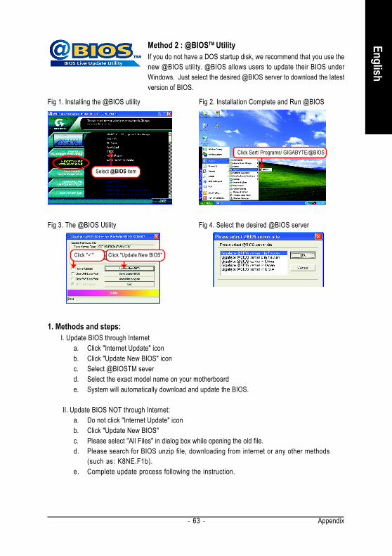
Appendix- 63 -
English
Method 2 : @BIOSTM UtilityIf you do not have a DOS startup disk, we recommend that you use thenew @BIOS utility. @BIOS allows users to update their BIOS underWindows. Just select the desired @BIOS server to download the latestversion of BIOS.
1. Methods and steps:I. Update BIOS through Internet
a. Click "Internet Update" iconb. Click "Update New BIOS" iconc. Select @BIOSTM severd. Select the exact model name on your motherboarde. System will automatically download and update the BIOS.
II. Update BIOS NOT through Internet:a. Do not click "Internet Update" iconb. Click "Update New BIOS"c. Please select "All Files" in dialog box while opening the old file.d. Please search for BIOS unzip file, downloading from internet or any other methods
(such as: K8NE.F1b).e. Complete update process following the instruction.
Fig 1. Installing the @BIOS utility Fig 2. Installation Complete and Run @BIOS
Fig 3. The @BIOS Utility Fig 4. Select the desired @BIOS server
Click Sart/ Programs/ GIGABYTE/@BIOS
Click " " Click "Update New BIOS"
Select @BIOS item
GA-K8NE Motherboard - 64 -
Engl
ish
III. Save BIOSIn the very beginning, there is "Save Current BIOS" icon shown in dialog box. It means to save thecurrent BIOS version.
IV. Check out supported motherboard and Flash ROM:In the very beginning, there is "About this program" icon shown in dialog box. It can help you check outwhich kind of motherboard and which brand of Flash ROM are supported.
2. Note:I. In method I, if it shows two or more motherboard's model names to be selected, please make
sure your motherboard's model name again. Selecting wrong model name will cause thesystem unbooted.
II. In method II, be sure that motherboard's model name in BIOS unzip file are the same as yourmotherboard's. Otherwise, your system won't boot.
III. In method I, if the BIOS file you need cannot be found in @BIOSTM server, please go ontoGigabyte's web site for downloading and updating it according to method II.
IV. Please note that any interruption during updating will cause system unbooted.V. Do not use @BIOS and C.O.M. (Corporate Online Management) at the same time.

Appendix- 65 -
English
4-1-4 Serial ATA BIOS Setting Utility IntroductionRAID LevelsRAID (Redundant Array of Independent Disks) is a method of combining two hard disk drives into one logicalunit. The advantage of an Array is to provide better performance or data fault tolerance. Fault tolerance isachieved through data redundant operation, where if one drives fails, a mirrored copy of the data can befound on another drive. This can prevent data loss if the operating system fails or hangs. The individual diskdrives in an array are called members. The configuration information of each member is recorded in thereserved sector that identifies the drive as a member. All disk members in a formed disk array are recognizedas a single physical drive to the operating system.Hard disk drives can be combined together through a few different methods. The different methods arereferred to as different RAID levels. Different RAID levels represent different performance levels, securitylevels and implementation costs. The RAID levels which the nVIDIA® nForce4 chipset supports are RAID 0,RAID 1, RAID 0+RAID 1 and JBOD.
RAID 0 (Striping)RAID 0 reads and writes sectors of data interleaved between multiple drives. If any disk member fails, itaffects the entire array. The disk array data capacity is equal to the number of drive members times thecapacity of the smallest member. The striping block size can be set from 4KB to 128KB. RAID 0 doesnot support fault tolerance.
RAID 1 (Mirroring)RAID 1 writes duplicate data onto a pair of drives and reads both sets of data in parallel. If one of themirrored drives suffers a mechanical failure or does not respond, the remaining drive will continue to function.Due to redundancy, the drive capacity of the array is the capacity of the smallest drive. Under a RAID 1setup, an extra drive called the spare drive can be attached. Such a drive will be activated to replace a faileddrive that is part of a mirrored array. Due to the fault tolerance, if any RAID 1 drive fails, data access will notbe affected as long as there are other working drives in the array.
RAID 0+1 (Striping + Mirroring)RAID 0+1 combines the performance of data striping (RAID 0) and the fault tolerance of disk mirroring (RAID1). Data is striped across multiple drives and duplicated on another set of drives.
JBOD (Spanning)A spanning disk array is equal to the sum of the all drives when the drives used are having different capacities.Spanning stores data onto a drive until it is full, then proceeds to store files onto the next drive in the array.When any disk member fails, the failure affects the entire array. JBOD is not really a RAID and does notsupport fault tolerance.

GA-K8NE Motherboard - 66 -
Engl
ish
Please follow the steps below to construct a complete RAID array:1) Have ready your hard drives for RAID construction.
Note: To achieve best performance, it is recommended that the hard drives used are of similar makeand storage capacity.
2) Please attach the hard drive connectors to their appropriate location on the motherboard ie. IDE, SCSI,or SATA.
3) Enter the motherboard BIOS and locate RAID setup (Please refer to the section on Integrated Peripherals).4) Enter RAID setup in the BIOS and select the RAID type (For instance, enter F10 to select NVIDIA RAID;
Ctrl + S to select Silicon Image).5) Complete driver installation.6) Complete RAID utility installation.More information on steps 4 and 5 is provided. (For more detailed setup information, please visit our websiteat http:\\www.gigabyte.com.tw to read or download the information you need.)
Configuring the NVIDIA RAID BIOSThe NVRAID BIOS setup lets you choose the RAID array type and which hard drives you want to make partof the array.Entering the RAID BIOS Setup1. After rebooting your computer, wait until you see the RAID software prompting you to press F10. TheRAID prompt appears as part of the system POST and boot process prior to loading the OS. You have a fewseconds to press F10 before the window disappears.
Press F10.The NVIDIA RAID Utility - Define a New Array window appears (as Figure below).
NVIDIA RAID IDE ROM BIOS 4.81Copyright (C) 2004 NVIDIA Corp.
Detecting array ...
Press F10 to enter RAID setup utility ...
NVIDIA RAID Utility Jan 12 2005- Define a New Array -
RAID Mode: Mirroring Striping Block: Optimal
Free DisksLoc Disk Model Name
1.0.M Maxtor 6Y080M01.1.M Maxtor 6Y080M0
Array DisksLoc Disk Model Name
[ ] Add
[ ] Del
[ESC] Quit [F6] Back [F7] Finish [TAB] Navigate [ ] Select [ENTER] Popup

Appendix- 67 -
English
Using the "Define a New Array" WindowIf necessary, press the tab key to move from field to field until the appropriate field is highlighted.Selecting the RAID ModeBy default, this is set to Mirroring. To change to a different RAID mode, press the down arrow key until themode that you want appears in the RAID Mode box - either Mirroring, Striping, Spanning, or Stripe Mirroring.Selecting the Striping Block SizeStriping block size is given in kilobytes, and affects how data is arranged on the disk. It is recommended toleave this value at the default Optimal, which is 64KB, but the values can be between 4 KB and 128 KB.Assigning the DisksThe disks that you enabled from the RAID Config BIOS setup page appear in the Free Disks block. Theseare the drives that are available for use as RAID array disks. To designate a free disk to be used as a RAIDarray disk,1. Tab to the Free Disks section. The first disk in the list is selected.2. Move it from the Free Disks block to the Array Disks block by pressing the rightarrow key ( ). The first disk in the list is moved, and the next disk in the list is selected and ready to be moved.3. Continue pressing the right-arrow key ( ) until all the disks that you want to use as RAID array disks appear in the Array Disks block.
NVIDIA RAID Utility Jan 12 2005- Define a New Array -
RAID Mode: Mirroring Striping Block: Optimal
Free DisksLoc Disk Model Name
Array DisksLoc Disk Model Name
[ ] Add
[ ] Del
[ESC] Quit [F6] Back [F7] Finish [TAB] Navigate [ ] Select [ENTER] Popup
1.0.M Maxtor 6Y080M01.1.M Maxtor 6Y080M0

GA-K8NE Motherboard - 68 -
Engl
ish
Completing the RAID BIOS SetupAfter assigning your RAID array disks, press F7. The Clear disk data prompt appears.
Press Y if you want to wipe out all the data from the RAID array, otherwise press N. You must choose Yes ifthe drives were previously used as RAID drives. The Array List window appears, where you can review theRAID arrays that you have set up.You can select a disk array as boot device if you want to boot operating system from an array. Use the arrowkeys to select the array, then press B to specify the array as bootable.
NVIDIA RAID Utility Jan 12 2005- Define a New Array -
RAID Mode: Mirroring Striping Block: Optimal
Free DisksLoc Disk Model Name
Array DisksLoc Disk Model Name
[ ] Add
[ ] Del
[ESC] Quit [F6] Back [F7] Finish [TAB] Navigate [ ] Select [ENTER] Popup
1.0.M Maxtor 6Y080M01.1.M Maxtor 6Y080M0
Clear disk data ?
[Y] YES [N] NO
NVIDIA RAID Utility Jan 12 2005- Array List -
[Ctrl-X] Exit [ ] Select [B] Set Boot [N] New Array [ENTER] Detail
Boot Id Status Vendor Array Model Name
Yes 2 Healthy NVIDIA MIRROR 76.33G
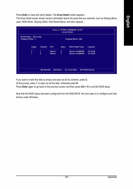
Appendix- 69 -
English
Press Enter to view and verify details. The Array Detail screen appears.The Array Detail screen shows various information about the array that you selected, such as Striping Blockused, RAID Mode, Striping Width, Disk Model Name, and disk capacity.
If you want to mark this disk as empty and wipe out all its contents, press C.At the prompt, press Y to wipe out all the data, otherwise press N.Press Enter again to go back to the previous screen and then press Ctrl + X to exit the RAID setup.
Now that the RAID setup has been configured from the RAID BIOS, the next step is to configure and loaddrivers under Windows.
Array 2 : NVIDIA MIRROR 76.33G- Array Detail -
RAID Mode: MirroringStriping Width : 1 Striping Block: 64K
Adapt Channel M/S Index Disk Model Name Capacity
1 1 Master 0 Maxtor 6Y080M0 76.33GB1 0 Master 1 Maxtor 6Y080M0 76.33GB
[R] Rebuild [D] Delete [C] Clear Disk [ENTER] Return

GA-K8NE Motherboard - 70 -
Engl
ish
Installing the RAID driversTo install operating system onto a serial ATA hard disk successfully, you need to install the SATA controllerdriver during OS installation. Without the driver, the hard disk may not be recognized during the Windowssetup process. First of all, copy the driver for the SATA controller from the motherboard driver CD-ROM to afloppy disk. See the instructions below about how to copy the driver in MS-DOS mode(Note1). Prepare a startupdisk that has CD-ROM support and a blank formatted floppy disk.
Step 1: Insert the prepared startup disk and motherboard driver CD-ROM in your system. Boot from thestartup disk. Once at the A:\> prompt, change to the CD-ROM drive (example: D:\>). At the D:\> prompt, typethe following two commands. Press ENTER after each command (Fig.1):
cd bootdrv
menu
Step 2: When the controller menu (Fig.2) appears, remove the startup disk and insert the blank formatteddisk. Select the controller driver by pressing the corresponding letter from the menu. Your system will thenautomatically zip and transfer this driver file to the floppy disk. Press 0 to exit when finished.
Fig.1 Fig. 2
Step 3: After completing the steps, boot from the Windows installation disk to install the RAID drivers.Press F6 as soon as you see the "Press F6 if you need to install a third party SCSI or RAID driver" message,then supply serial ATA controller driver by this floppy disk. Follow the on-screen instructions to complete theinstallation.
(Each time you add a new hard drive to a RAID array, the RAID driver will have to be installed underWindows once for that hard drive. After that, the driver will not have to be installed.)
(Note 1): For users without a startup disk.Use an alternative system and insert the GIGABYTE motherboard drive CD-ROM. From the CD-ROM drive (example: D:\) double click the MENU.exe file in the BootDrv folder. A command promptwindow will open similar to that in Fig. 2.

Appendix- 71 -
English
4-1-5 2- / 4- / 6- / 8- Channel Audio Function Introduction
Line Out
Stereo Speakers Connection and Settings:We recommend that you use the speaker with amplifier to acquire the best sound effect if the stereo outputis applied.
STEP 1:Connect the stereo speakers or earphone to "LineOut".
STEP 2 :Following installation of the audio driver, you find a
Sound Effect icon on the lower right hand taskbar.Click the icon to select the function.
Following pictures are in Windows XP.
Introduction of audio connectors:You may connect CD-ROM/DVD-ROM, walkman orothers audio input to Line In.The front channels or earphone can be connected toLine Out (Front Speaker Out).Connect microphone to Mic In.Connect the rear channels to Rear Speaker Out.Connect the Center/Subwoofer channels to Center/Subwoofer Speaker Out.Connect the side channels to Side Speaker Out.
This motherboard provide 6 audio connector. You are able to use 2-/4-/6-/8-channnels audio feature by audio software selection.
Rear Speaker Out
Center/SubwooferSpeaker Out
Side SpeakerOut
Line In
Line Out(Front Speaker Out)
Mic In
To set up an 8 channel audio configuration, you must use Audio Combo Kit (optional device).

GA-K8NE Motherboard - 72 -
Engl
ish
STEP 3:Click "Speaker Configuration" then click on theleft selection bar and select "2CH Speaker" tocomplete 2 channel audio configuration.
4 Channel Audio Setup
STEP 1 :Connect the front channels to "Front Speaker Out",the rear channels to "Rear Speaker Out".
STEP 2 :Following installation of the audio driver, you find a
Sound Effect icon on the lower right hand taskbar.Click the icon to select the function.
STEP 3:Click "Speaker Configuration" then click on theleft selection bar and select "4CH Speaker" tocomplete 4 channel audio configuration.
Front Speaker Out
Rear Speaker Out

Appendix- 73 -
English
6 Channel Audio Setup
STEP 1 :Connect the front channels to "Front Speaker Out",the rear channels to "Rear Speaker Out", and theCenter/Subwoofer channels to "Center/SubwooferSpeaker Out".
STEP 2 :Following installation of the audio driver, you find a
Sound Effect icon on the lower right hand taskbar.Click the icon to select the function.
STEP 3:Click "Speaker Configuration" then click on theleft selection bar and select "6CH Speaker" tocomplete 6 channel audio configuration.
Front Speaker Out
Rear Speaker Out
Center/SubwooferSpeaker Out

GA-K8NE Motherboard - 74 -
Engl
ish
8 Channel Audio Setup
STEP 1 :Connect the front channels to "Front Speaker Out",the rear channels to "Rear Speaker Out", the Center/Subwoofer channels to "Center/Subwoofer SpeakerOut", and the side channels to "Side Speaker Out".
STEP 2 :Following installation of the audio driver, you find a
Sound Effect icon on the lower right hand taskbar.Click the icon to select the function.
STEP 3:Click "Speaker Configuration" then click on theleft selection bar and select "6CH Speaker" tocomplete 6 channel audio configuration.
Sound Effect Configuration:At the sound effect menu, users can adjust soundoption settings as desired.
Side Speaker Out
Front Speaker Out
Rear Speaker Out
Center/SubwooferSpeaker Out

Appendix- 75 -
English
4-2 TroubleshootingBelow is a collection of general asked questions. To check general asked questions based on a specificmotherboard model, please log on to http://www.gigabyte.com.tw
Question 1: I cannot see some options that were included in previous BIOS after updating BIOS. Why?Answer: Some advanced options are hidden in new BIOS version. Please press Ctrl and F1 keys afterentering BIOS menu and you will be able to see these options.
Questions 2: Why is the light of my keyboard/optical mouse still on after computer shuts down?Answer: In some boards, a small amount of electricity is kept on standby after computer shuts down andthat's why the light is still on.
Question 3: How do I clear CMOS?Answer: If your board has a Clear CMOS jumper, please refer to the Clear CMOS steps in the manual. If yourboard doesn't have such jumper, you can take off the on-board battery to leak voltage to clear CMOS.Please refer to the steps below:
Steps:1. Turn off power.2. Disconnect the power cord from MB.3. Take out the battery gently and put it aside for about 10 minutes (Or you can use a metal object to
connect the positive and negative pins in the battery holder to makethem short for one minute).4. Re-insert the battery to the battery holder.5. Connect power cord to MB again and turn on power.6. Press Del to enter BIOS and load Fail-Safe Defaults(or load Optimized Defaults).7. Save changes and reboot the system.
Question 4: Why do I still get a weak sound after turning up the speaker to the maximum volume?Answer: Please make sure the speaker you are using is equipped with an internal amplifier. If not, pleasechange another speaker with power/amplifier and try again later.
Question 5: Sometimes I hear different continuous beeps from computer after system boots up. What dothese beeps usually stand for?Answer: The beep codes below may help you identify the possible computer problems. However, they areonly for reference purposes. The situations might differ from case to case.
AMI BIOS Beep Codes*Computer gives 1 short beep when system boots successfully.*Except for beep code 8, these codes are always fatal.
1 beep Refresh failure2 beeps Parity error3 beeps Base 64K memory failure4 beeps Timer not operational5 beeps Processor error6 beeps 8042 - gate A20 failure7 beeps Processor exception interrupt error8 beeps Display memory read/write failure9 beeps ROM checksum error10 beeps CMOS shutdown register read/write error11 beeps Cache memory bad
AWARD BIOS Beep Codes1 short: System boots successfully2 short: CMOS setting error1 long 1 short: DRAM or M/B error1 long 2 short: Monitor or display card error1 long 3 short: Keyboard error1 long 9 short: BIOS ROM errorContinuous long beeps: DRAM errorContinuous short beeps: Power error

GA-K8NE Motherboard - 76 -
Engl
ish

Appendix- 77 -
English

GA-K8NE Motherboard - 78 -
Engl
ish

Appendix- 79 -
English
Contact Us
Taiwan (Headquarters)GIGA-BYTE TECHNOLOGY CO., LTD.Address: No.6, Bau Chiang Road, Hsin-Tien, Taipei 231,Taiwan TEL: +886-2-8912-4888 FAX: +886-2-8912-4003Tech. Support :http://tw.giga-byte.com/TechSupport/ServiceCenter.htmNon-Tech. Support(Sales/Marketing) :http://ggts.gigabyte.com.tw/nontech.aspWEB address (English): http://www.gigabyte.com.twWEB address (Chinese): http://chinese.giga-byte.com U.S.A.
G.B.T. INC.TEL: +1-626-854-9338 FAX: +1-626-854-9339Tech. Support :http://tw.giga-byte.com/TechSupport/ServiceCenter.htmNon-Tech. Support(Sales/Marketing) :http://ggts.gigabyte.com.tw/nontech.aspWEB address : http://www.giga-byte.com Germany
G.B.T. TECHNOLOGY TRADING GMBHTech. Support :http://tw.giga-byte.com/TechSupport/ServiceCenter.htmNon-Tech. Support(Sales/Marketing) :http://ggts.gigabyte.com.tw/nontech.aspWEB address : http://www.gigabyte.de
JapanNIPPON GIGA-BYTE CORPORATIONWEB address : http://www.gigabyte.co.jp Singapore
GIGA-BYTE SINGAPORE PTE. LTD.Tech. Support :http://tw.giga-byte.com/TechSupport/ServiceCenter.htmNon-Tech. Support(Sales/Marketing) :http://ggts.gigabyte.com.tw/nontech.aspWEB address: http://www.gigabyte.com.sg U.K.
G.B.T. TECH. CO., LTD.Tech. Support :http://tw.giga-byte.com/TechSupport/ServiceCenter.htmNon-Tech. Support(Sales/Marketing) :http://ggts.gigabyte.com.tw/nontech.aspWEB address : http://uk.giga-byte.com The Netherlands
GIGA-BYTE TECHNOLOGY B.V.Tech. Support :http://tw.giga-byte.com/TechSupport/ServiceCenter.htmNon-Tech. Support(Sales/Marketing) :http://ggts.gigabyte.com.tw/nontech.aspWEB address : http://www.giga-byte.nl

GA-K8NE Motherboard - 80 -
Engl
ish
ChinaNINGBO G.B.T. TECH. TRADING CO., LTD.Tech. Support :http://tw.giga-byte.com/TechSupport/ServiceCenter.htmNon-Tech. Support(Sales/Marketing) :http://ggts.gigabyte.com.tw/nontech.aspWEB address : http://www.gigabyte.com.cnShanghaiTEL: +86-021-63410999 FAX: +86-021-63410100BeijingTEL: +86-10-62102838 FAX: +86-10-62102848WuhanTEL: +86-27-87851061 FAX: +86-27-87851330GuangZhouTEL: +86-20-87586074 FAX: +86-20-85517843ChengduTEL: +86-28-85236930 FAX: +86-28-85256822XianTEL: +86-29-85531943 FAX: +86-29-85539821ShenyangTEL: +86-24-23960918 FAX: +86-24-23960918-809 Australia
GIGABYTE TECHNOLOGY PTY. LTD.Tech. Support :http://tw.giga-byte.com/TechSupport/ServiceCenter.htmNon-Tech. Support(Sales/Marketing) :http://ggts.gigabyte.com.tw/nontech.aspWEB address : http://www.giga-byte.com.au France
GIGABYTE TECHNOLOGY FRANCE S.A.R.L.Tech. Support :http://tw.giga-byte.com/TechSupport/ServiceCenter.htmNon-Tech. Support(Sales/Marketing) :http://ggts.gigabyte.com.tw/nontech.aspWEB address : http://www.gigabyte.fr
RussiaMoscow Representative Office Of GIGA-BYTE Technology Co.,Ltd.Tech. Support :http://tw.giga-byte.com/TechSupport/ServiceCenter.htmNon-Tech. Support(Sales/Marketing) :http://ggts.gigabyte.com.tw/nontech.aspWEB address : http://www.gigabyte.ru Poland
Office of GIGA-BYTE TECHNOLOGY Co., Ltd. in POLANDTech. Support :http://tw.giga-byte.com/TechSupport/ServiceCenter.htmNon-Tech. Support(Sales/Marketing) :http://ggts.gigabyte.com.tw/nontech.aspWEB address : http://www.gigabyte.pl Serbia & Montenegro
Representative Office Of GIGA-BYTE Technology Co., Ltd. inSERBIA & MONTENEGROTech. Support :http://tw.giga-byte.com/TechSupport/ServiceCenter.htmNon-Tech. Support(Sales/Marketing) :http://ggts.gigabyte.com.tw/nontech.aspWEB address: http://www.gigabyte.co.yu Czech Republic
Representative Office Of GIGA-BYTE Technology Co., Ltd. inCZECH REPUBLICTech. Support :http://tw.giga-byte.com/TechSupport/ServiceCenter.htmNon-Tech. Support(Sales/Marketing) :http://ggts.gigabyte.com.tw/nontech.aspWEB address: http://www.gigabyte.cz Romania
Representative Office Of GIGA-BYTE Technology Co., Ltd. inRomaniaTech. Support :http://tw.giga-byte.com/TechSupport/ServiceCenter.htmNon-Tech. Support(Sales/Marketing) :http://ggts.gigabyte.com.tw/nontech.aspWEB address: http://www.gigabyte.com.ro
Related Documents