GA-8I865GME-775 Intel ® Pentium ® 4 LGA775 Processor Motherboard User's Manual Rev. 1002 12ME-865GMET-1002R * The WEEE marking on the product indicates this product must not be disposed of with user's other household waste and must be handed over to a designated collection point for the recycling of waste electrical and electronic equipment!! * The WEEE marking applies only in European Union's member states.

Motherboard Manual Ga-8i865gme-775 e
Oct 24, 2014
Welcome message from author
This document is posted to help you gain knowledge. Please leave a comment to let me know what you think about it! Share it to your friends and learn new things together.
Transcript

GA-8I865GME-775Intel® Pentium® 4 LGA775 Processor Motherboard
User's ManualRev. 100212ME-865GMET-1002R
* The WEEE marking on the product indicates this product must not be disposed of with user's other household wasteand must be handed over to a designated collection point for the recycling of waste electrical and electronic equipment!!
* The WEEE marking applies only in European Union's member states.

Motherboard
GA
-8I865GM
E-775
Feb. 13, 2006
Feb. 13, 2006
MotherboardGA-8I865GM
E-775

Copyright© 2006 GIGA-BYTE TECHNOLOGY CO., LTD. All rights reserved.The trademarks mentioned in the manual are legally registered to their respective companies.
NoticeThe written content provided with this product is the property of Gigabyte.No part of this manual may be reproduced, copied, translated, or transmitted in any form or by anymeans without Gigabyte's prior written permission. Specifications and features are subject tochange without prior notice.
Product Manual ClassificationIn order to assist in the use of this product, Gigabyte has categorized the user manual in thefollowing:
For detailed product information and specifications, please carefully read the "User’s Manual."
For detailed information related to Gigabyte's unique features, please go to the "TechnologyGuide" section on Gigabyte’s website to read or download the information you need.
For more product details, please visit Gigabyte's website at www.gigabyte.com.tw

- 4 -
Table of Contents
Item Checklist ................................................................................................................. 6GA-8I865GME-775 Motherboard Layout ....................................................................... 7Block Diagram ................................................................................................................ 8
Chapter 1 Hardware Installation ..................................................................................... 91-1 Considerations Prior to Installation .................................................................... 91-2 Feature Summary .......................................................................................... 101-3 Installation of the CPU and Heatsink .............................................................. 12
1-3-1 Installation of the CPU ......................................................................................... 121-3-2 Installation of the Heatsink .................................................................................. 13
1-4 Installation of Memory .................................................................................... 141-5 Installation of Expansion Cards ...................................................................... 151-6 I/O Back Panel Introduction ........................................................................... 161-7 Connectors Introduction .................................................................................. 17
Chapter 2 BIOS Setup ................................................................................................ 27The Main Menu (For example: BIOS Ver. : D5) ....................................................... 282-1 Standard CMOS Features ............................................................................. 302-2 Advanced BIOS Features .............................................................................. 322-3 Integrated Peripherals ..................................................................................... 342-4 Power Management Setup ............................................................................. 372-5 PnP/PCI Configurations ................................................................................. 392-6 PC Health Status ........................................................................................... 402-7 Frequency/Voltage Control ............................................................................. 422-8 Load Fail-Safe Defaults ................................................................................... 432-9 Load Optimized Defaults ................................................................................. 432-10 Set Supervisor/User Password ..................................................................... 442-11 Save & Exit Setup ......................................................................................... 452-12 Exit Without Saving ....................................................................................... 45

- 5 -
Chapter 3 Drivers Installation ...................................................................................... 473-1 Install Chipset Drivers .................................................................................... 473-2 Software Applications ..................................................................................... 483-3 Driver CD Information .................................................................................... 483-4 Hardware Information ..................................................................................... 493-5 Contact Us ..................................................................................................... 49
Chapter 4 Appendix ................................................................................................... 514-1 Unique Software Utilities ................................................................................ 51
4-1-1 EasyTune 5 Introduction ..................................................................................... 524-1-2 Xpress Recovery2 Introduction ......................................................................... 534-1-3 Flash BIOS Method Introduction ........................................................................ 554-1-4 2 / 4 / 6 Channel Audio Function Introduction ................................................. 64
4-2 Troubleshooting ............................................................................................... 67
- 6 -
Item ChecklistIDE Cable x 1Serial ATA Cable x 1 I/O Shield
* The items listed above are for reference only, and are subject to change without notice.
Optional Accessories2 Ports USB2.0 Cable (Part Number: 12CR1-1UB030-51)

- 7 -
GA-8I865GME-775 Motherboard Layout
KB_MS
COMA
LPT
CPU_FAN
ATX
FDD
ATX_12V
LGA775
CI
PWR_LED
PCI3
F_PANEL
F_USB1
BATCODEC
SATA0
BIOS
SYS _FAN
PCI1
PCI2
IT8712
CLR_
CMOS
SATA1
GA-8
I865G
ME-7
75
CD_IN
F_AUDIO
VGA
IDE2
IDE1
ICH5
AGPDD
R1
Intel 865GUSB_LAN
AUDIO
R_USB
DDR2
EP82562G

- 8 -
Block Diagram
Line-
Out
MIC
LGA775Processor
CPUCLK+/-(133/200MHz)
AGPCLK(66MHz)
33MHz
HostInterface
Intel865G
GMCHGMCHCLK (66MHz)
66MHz
48MHz
DDR 400/333/266MHz DIMM
14.318MHz33MHz
IT8712
2 Serial ATA
ATA33/66/100IDE Channels
14.318MHz
BIOS
Line-
In
PCICLK(33MHz)
3 PCI
PCI Bus
EP82562G
RJ45
6 USBPorts
Dual Channel Memory
Floppy
PS/2 KB/Mouse
LPT Port
COM Port
VGAAGP 8X/4X
HCLK (133/200MHz)
IntelICH5
AC97
Lin
k
AC97CODEC

Hardware Installation- 9 -
English1-1 Considerations Prior to InstallationPreparing Your ComputerThe motherboard contains numerous delicate electronic circuits and components which canbecome damaged as a result of electrostatic discharge (ESD). Thus, prior to installation, pleasefollow the instructions below:1. Please turn off the computer and unplug its power cord.2. When handling the motherboard, avoid touching any metal leads or connectors.3. It is best to wear an electrostatic discharge (ESD) cuff when handling electronic components
(CPU, RAM).4. Prior to installing the electronic components, please have these items on top of an antistatic pad or
within a electrostatic shielding container.5. Please verify that the power supply is switched off before unplugging the power supply connector
from the motherboard.
Installation Notices1. Prior to installation, please do not remove the stickers on the motherboard. These stickers are required
for warranty validation.2. Prior to the installation of the motherboard or any hardware, please first carefully read the information
in the provided manual.3. Before using the product, please verify that all cables and power connectors are connected.4. To prevent damage to the motherboard, please do not allow screws to come in contact with the
motherboard circuit or its components.5. Please make sure there are no leftover screws or metal components placed on the motherboard or
within the computer casing.6. Please do not place the computer system on an uneven surface.7. Turning on the computer power during the installation process can lead to damage to system
components as well as physical harm to the user.8. If you are uncertain about any installation steps or have a problem related to the use of the product,
please consult a certified computer technician.
Instances of Non-Warranty1. Damage due to natural disaster, accident or human cause.2. Damage as a result of violating the conditions recommended in the user manual.3. Damage due to improper installation.4. Damage due to use of uncertified components.5. Damage due to use exceeding the permitted parameters.6. Product determined to be an unofficial Gigabyte product.
Chapter 1 Hardware Installation

GA-8I865GME-775 Motherboard - 10 -
Engl
ish
1-2 Feature SummaryCPU Supports LGA775 Intel® Processor Pentium® 4(Note 1)
L2 cache varies with CPUFront Side Bus Supports 800/533MHz FSBChipset Northbridge:Intel® 865G
Southbridge: Intel® ICH5LAN Onboard EP82562G chip(10/100Mbit)Audio Onboard ALC653 chip
Supports 2 / 4 / 6 channel audioSupports CD In connection
Storage Intel® ICH5 Southbrigde- 1 FDD connector, allowing connection of 2 FDD devices- 2 IDE connectors (IDE1/IDE2) with UDMA 33/ATA 66/ATA 100 support,
allowing connection of 4 IDE devices- 2 SATA connectors (SATA0/SATA1), allowing connection of 2 SATA
devicesO.S Support Microsoft Windows 2000/XPMemory 2 DDR DIMM memory slots (supports up to 2GB memory)
Supports dual channel DDR400/333/266 DIMMSupports 2.5V DDR DIMMs
Expanstion Slots 1 AGP slot 4X/8X (1.5V)3 PCI slots
Internal Connectors 1 20-pin ATX power connector1 4-pin ATX 12V power connector1 floppy connector2 IDE connectors2 SATA connectors1 CPU fan connector1 system fan connector1 front panel connector1 front audio connector1 CD In connector1 power LED connector1 USB 2.0/1.1 connectors for additional 2 ports by cables
Rear Panel I/O 1 PS/2 keyboard port1 PS/2 mouse port1 parallel port1 serial port (COMA)1 VGA port4 USB 2.0/1.1 ports1 RJ-45 port3 audio jacks (Line In / Line Out / MIC In)

Hardware Installation- 11 -
English
I/O Control IT8712 chipHardware Monitor System voltage detection
CPU temperature detectionCPU / System fan speed detectionCPU warning temperatureCPU / System fan failure warningCPU smart fan control
BIOS 1 3Mbit flash ROMUse of licensed AWARD BIOS
Additional Features Supports @BIOSSupports Download CenterSupports Q-FlashSupports EasyTune (only supports Hardware Monitor function)(Note 2)
Supports Xpress InstallSupports Xpress Recovery2Supports Xpress Rescue
Bundle Software Norton Internet Security (OEM version)Form Factor Micro ATX form factor; 24.4cm x 21.2cm
(Note 1) For further CPU support information, please go to GIGABYTE's website.(Note 2) EasyTune functions may vary depending on different motherboards.

GA-8I865GME-775 Motherboard - 12 -
Engl
ish
1-3 Installation of the CPU and Heatsink
Before installing the CPU, please comply with the following conditions:1. Please make sure that the motherboard supports the CPU.2. Please take note of the one indented corner of the CPU. If you install the CPU
in the wrong direction, the CPU will not insert properly. If this occurs, please changethe insert direction of the CPU.
3. Please add an even layer of heat sink paste between the CPU and heatsink.4. Please make sure the heatsink is installed on the CPU prior to system use, otherwise
overheating and permanent damage of the CPU may occur.5. Please set the CPU host frequency in accordance with the processor specifications. It is not
recommended that the system bus frequency be set beyond hardware specifications since itdoes not meet the required standards for the peripherals. If you wish to set the frequencybeyond the proper specifications, please do so according to your hardware specificationsincluding the CPU, graphics card, memory, hard drive, etc.
HT functionality requirement content :Enabling the functionality of Hyper-Threading Technology for your computer system requires allof the following platform components:- CPU: An Intel® Pentium 4 Processor with HT Technology- Chipset: An Intel® Chipset that supports HT Technology- BIOS: A BIOS that supports HT Technology and has it enabled- OS: An operation system that has optimizations for HT Technology
1-3-1 Installation of the CPUFig. 1Gently lift the metallever located on theCPU socket to theupright position.
Metal LeverFig. 2Remove the plast iccovering on the CPUsocket.
Fig. 3Notice the small goldcolored tr iangle lo-cated on the edge oft h e C P U s o c k e t .Align the indented cor-ner of the CPU with
Fig. 4Once the CPU isproperly inserted,please replace theplastic covering andpush the metal leverback into its originalposition.the triangle and gently insert the CPU into position.
(Grasping the CPU firmly between your thumband forefinger, carefully place it into the socket in astraight and downwards motion. Avoid twisting orbending motions that might cause damage to theCPU during installation.)

Hardware Installation- 13 -
English
1-3-2 Installation of the Heatsink
Fig.1Please apply an even layer of heatsink paste onthe surface of the installed CPU.
The heatsink may adhere to the CPU as a result of hardening of the heatsink paste.To preventsuch an occurrence, it is suggested that either thermal tape rather than heat sink paste be usedfor heat dissipation or using extreme care when removing the heatsink.
Fig. 6Finally, please attach the power connector of theheatsink to the CPU fan header located on themotherboard.
Fig. 3Place the heatsink atop the CPU and make surethe push pins aim to the pin hole on themotherboard.Pressing down the push pinsdiagonally.
Fig. 2(Turning the push pin along the direction of arrowis to remove the heatsink, on the contrary, is toinstall.)Please note the direction of arrow sign on the malepush pin doesn't face inwards before installation.(This instruction is only for Intel boxed fan)
Fig. 4Please make sure the Male and Female push pinare jo ined closely. ( for detai led instal lat ioninstructions, please refer to the heatsink installationsection of the user manual)
Fig. 5Please check the back of motherboard afterinstalling. If the push pin is inserted as the picture,the installation is complete.
Male Push Pin
Female Push Pin
The top of Female Push Pin
GA-8I865GME-775 Motherboard - 14 -
Engl
ish Before installing the memory modules, please comply with the following conditions:1. Please make sure that the memory used is supported by the motherboard. It is recommended that
memory of similar capacity, specif ications and brand be used.2 . Before instal l ing or removing memory modules, please make sure that the computer
power is switched off to prevent hardware damage.3 . Memory modules have a foolproof insert ion design. A memory module can be
installed in only one direction. If you are unable to insert the module, please switch thedirection.
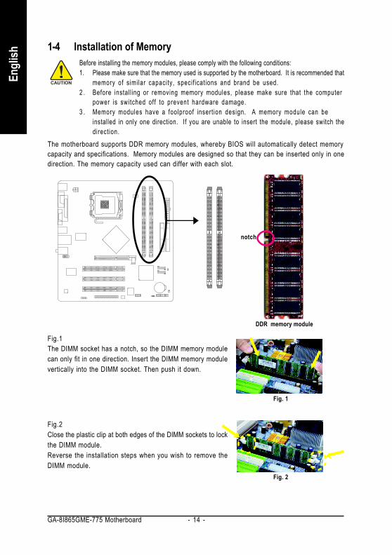
1-4 Installation of Memory
The motherboard supports DDR memory modules, whereby BIOS will automatically detect memorycapacity and specifications. Memory modules are designed so that they can be inserted only in onedirection. The memory capacity used can differ with each slot.
DDR memory module
notch
Fig.1The DIMM socket has a notch, so the DIMM memory modulecan only fit in one direction. Insert the DIMM memory modulevertically into the DIMM socket. Then push it down.
Fig.2Close the plastic clip at both edges of the DIMM sockets to lockthe DIMM module.Reverse the installation steps when you wish to remove theDIMM module.
Fig. 1
Fig. 2
Hardware Installation- 15 -
English
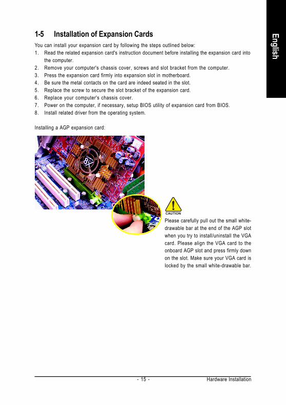
1-5 Installation of Expansion CardsYou can install your expansion card by following the steps outlined below:1. Read the related expansion card's instruction document before installing the expansion card into
the computer.2. Remove your computer's chassis cover, screws and slot bracket from the computer.3. Press the expansion card firmly into expansion slot in motherboard.4. Be sure the metal contacts on the card are indeed seated in the slot.5. Replace the screw to secure the slot bracket of the expansion card.6. Replace your computer's chassis cover.7. Power on the computer, if necessary, setup BIOS utility of expansion card from BIOS.8. Install related driver from the operating system.
Installing a AGP expansion card:
Please carefully pull out the small white-drawable bar at the end of the AGP slotwhen you try to install/uninstall the VGAcard. Please align the VGA card to theonboard AGP slot and press firmly downon the slot. Make sure your VGA card islocked by the small white-drawable bar.

GA-8I865GME-775 Motherboard - 16 -
Engl
ish
1-6 I/O Back Panel Introduction
PS/2 Keyboard and PS/2 Mouse ConnectorTo install a PS/2 port keyboard and mouse, plug the mouse to the upper port (green) and the keyboard to thelower port (purple).Parallel PortThe parallel port allows connection of a printer, scanner and other peripheral devices.
Serial Port (COMA) Devices like mouses, modems, and etc. can be connected to Serial port.
VGA PortMonitor can be connected to VGA port.USB portBefore you connect your device(s) into USB connector(s), please make sure your device(s) suchas USB keyboard, mouse, scanner, zip, speaker...etc. have a standard USB interface. Also makesure your OS supports USB controller. If your OS does not support USB controller, please con-tact OS vendor for possible patch or driver upgrade. For more information please contact yourOS or device(s) vendors.LAN PortThe LAN port provides Internet connection.Line InDevices like CD-ROM, walkman etc. can be connected to Line In jack.Line Out (Front Speaker Out)Connect the stereo speakers, earphone or front surround speakers to this connector.MIC InMicrophone can be connected to MIC In jack.
You can use audio software to configure 2-/4-/6- channel audio functioning.
Hardware Installation- 17 -
English
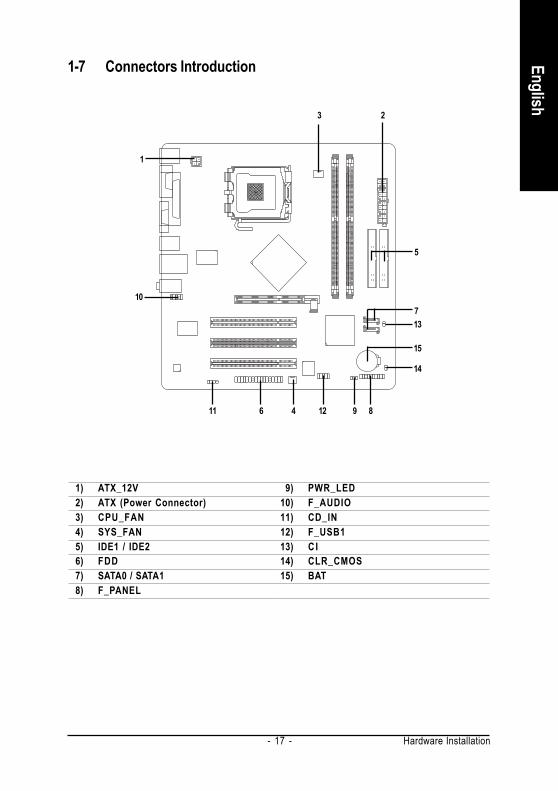
1-7 Connectors Introduction
1) ATX_12V2) ATX (Power Connector)3) CPU_FAN4) SYS_FAN5) IDE1 / IDE26) FDD7) SATA0 / SATA18) F_PANEL
9) PWR_LED10) F_AUDIO11) CD_IN12) F_USB113) C I14) CLR_CMOS15) BAT
3
1
2
13
15
14
86 124 9
7
5
10
11

GA-8I865GME-775 Motherboard - 18 -
Engl
ish
1/2) ATX_12V/ATX (Power Connector)With the use of the power connector, the power supply can supply enough stable power to allthe components on the motherboard. Before connecting the power connector, please make surethat all components and devices are properly installed. Align the power connector with itsproper location on the motherboard and connect tightly.The ATX_12V power connector mainly supplies power to the CPU. If the ATX_12V powerconnector is not connected, the system will not start.Caution!Please use a power supply that is able to handle the system voltage requirements. It isrecommended that a power supply that can withstand high power consumption be used (300Wor greater). If a power supply is used that does not provide the required power, the result canlead to an unstable system or a system that is unable to start.
Pin No. Definition1 GND2 GND3 +12V4 +12V
13
24
Pin No. Definition1 3.3V2 3.3V3 GND4 +5V5 GND6 +5V7 GND8 Power Good9 5V SB (stand by +5V)10 +12V11 3.3V12 -12V13 GND14 PS_ON(soft on/off)15 GND16 GND17 GND18 -5V19 +5V20 +5V
1
10 20
11
Hardware Installation- 19 -
English
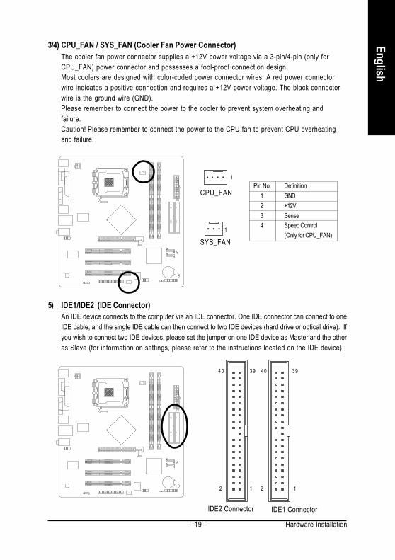
3/4) CPU_FAN / SYS_FAN (Cooler Fan Power Connector)The cooler fan power connector supplies a +12V power voltage via a 3-pin/4-pin (only forCPU_FAN) power connector and possesses a fool-proof connection design.Most coolers are designed with color-coded power connector wires. A red power connectorwire indicates a positive connection and requires a +12V power voltage. The black connectorwire is the ground wire (GND).Please remember to connect the power to the cooler to prevent system overheating andfailure.Caution! Please remember to connect the power to the CPU fan to prevent CPU overheatingand failure.
CPU_FAN
SYS_FAN1
Pin No. Definition1 GND2 +12V3 Sense4 Speed Control
(Only for CPU_FAN)
5) IDE1/IDE2 (IDE Connector)An IDE device connects to the computer via an IDE connector. One IDE connector can connect to oneIDE cable, and the single IDE cable can then connect to two IDE devices (hard drive or optical drive). Ifyou wish to connect two IDE devices, please set the jumper on one IDE device as Master and the otheras Slave (for information on settings, please refer to the instructions located on the IDE device).
40
2 1
40 39
2 1
39
IDE2 Connector IDE1 Connector
1
GA-8I865GME-775 Motherboard - 20 -
Engl
ish
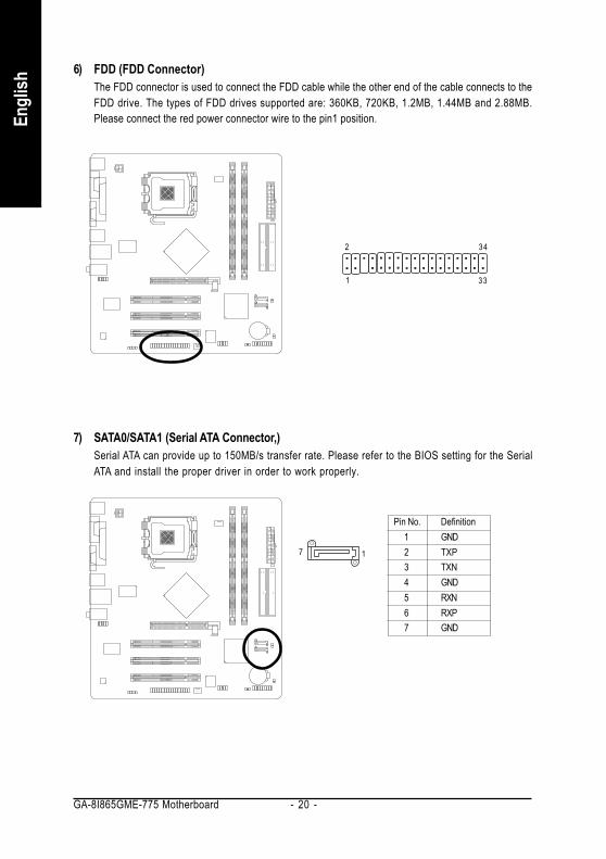
6) FDD (FDD Connector)The FDD connector is used to connect the FDD cable while the other end of the cable connects to theFDD drive. The types of FDD drives supported are: 360KB, 720KB, 1.2MB, 1.44MB and 2.88MB.Please connect the red power connector wire to the pin1 position.
7) SATA0/SATA1 (Serial ATA Connector,)Serial ATA can provide up to 150MB/s transfer rate. Please refer to the BIOS setting for the SerialATA and install the proper driver in order to work properly.
Pin No. Definition1 GND2 TXP3 TXN4 GND5 RXN6 RXP7 GND
7 1
1
342
33

Hardware Installation- 21 -
English
8) F_PANEL (Front Panel Connector)Please connect the power LED, PC speaker, reset switch and power switch etc. of your chassisfront panel to the F_PANEL connector according to the pin assignments below.
HD (IDE Hard Disk Active LED) Pin 1: LED anode(+)Pin 2: LED cathode(-)
SPEAK (Speaker Connector) Pin 1: PowerPin 2- Pin 3: NCPin 4: Data(-)
RES (Reset Switch) Open: NormalClose: Reset Hardware System
PW (Power Switch) Open: NormalClose: Power On/Off
MSG(Message LED/Power/Sleep LED) Pin 1: LED anode(+)Pin 2: LED cathode(-)
NC NC
12
1920
HD-
HD+ RE
S+RE
S- NC
IDE Hard Disk Active LED
Reset Switch
SPEA
K-
MSG-
MSG+
PW-
PW+
Message LED/Power/
Sleep LED
Speaker Connector
SPEA
K+
PowerSwitch

GA-8I865GME-775 Motherboard - 22 -
Engl
ish
9) PWR_LEDThe PWR_LED connector is connected with the system power indicator to indicate whether thesystem is on/off. It will blink when the system enters suspend mode.
Pin No. Definition1 MPD+2 MPD-3 MPD-
10) F_AUDIO (Front Audio Panel Connector)If you want to use Front Audio connector, you must remove 5-6, 9-10 Jumper. In order to utilize thefront audio header, your chassis must have front audio connector. Also please make sure the pinassigments on the cable are the same as the pin assigments on the MB header. To find out if thechassis you are buying support front audio connector, please contact your dealer.Please note,you can have the alternative of using front audio connector or of using rear audio connector to playsound.
2
9
10
1
Pin No. Definition1 MIC2 GND3 MIC_BIAS4 POWER5 FrontAudio(R)6 Rear Audio (R)/ Return R7 NC8 No Pin9 FrontAudio (L)10 Rear Audio (L)/ Return L
1
Hardware Installation- 23 -
English
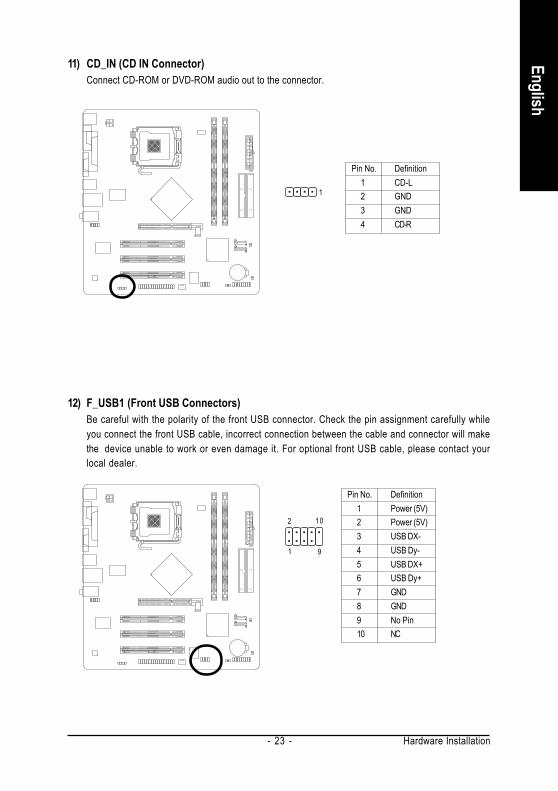
11) CD_IN (CD IN Connector)Connect CD-ROM or DVD-ROM audio out to the connector.
Pin No. Definition1 CD-L2 GND3 GND4 CD-R
1
12) F_USB1 (Front USB Connectors)Be careful with the polarity of the front USB connector. Check the pin assignment carefully whileyou connect the front USB cable, incorrect connection between the cable and connector will makethe device unable to work or even damage it. For optional front USB cable, please contact yourlocal dealer.
Pin No. Definition1 Power (5V)2 Power (5V)3 USB DX-4 USB Dy-5 USB DX+6 USB Dy+7 GND8 GND9 No Pin10 NC
9
2 10
1

GA-8I865GME-775 Motherboard - 24 -
Engl
ish
13) CI (Chassis Intrusion, Case Open)This 2-pin connector allows your system to detect if the chassis cover is removed. You can checkthe "Case Opened" status in BIOS Setup.
1 Pin No. Definition1 Signal2 GND
14) CLR_CMOS (Clear CMOS)You may clear the CMOS data to its default values by this jumper. To clear CMOS, temporarilyshort pins 1-2. To prevent improper use of this header, we do not include a jumper on it.
Open: Normal
Short: Clear CMOS1
1

Hardware Installation- 25 -
English
15) BAT (Battery)
Danger of explosion if battery is incorrectly replaced.
Replace only with the same or equivalent typerecommended by the manufacturer.
Dispose of used batteries according to the manufacturer'sinstructions.
If you want to erase CMOS...1. Turn OFF the computer and unplug the power cord.2. Take out the battery gently and put it aside for about 10
minutes (Or you can use a metal object to connect thepositive and negative pins in the battery holder to makethem short for one minute).
3. Re-install the battery.4. Plug the power cord and turn ON the computer.

GA-8I865GME-775 Motherboard - 26 -
Engl
ish

BIOS Setup- 27 -
EnglishBIOS (Basic Input and Output System) includes a CMOS SETUP utility which allows user to configurerequired settings or to activate certain system features.The CMOS SETUP saves the configuration in the CMOS SRAM of the motherboard.When the power is turned off, the battery on the motherboard supplies the necessary power to the CMOSSRAM.When the power is turned on, pushing the <Del> button during the BIOS POST (Power-On Self Test) willtake you to the CMOS SETUP screen. You can enter the BIOS setup screen by pressing "Ctrl + F1".When setting up BIOS for the first time, it is recommended that you save the current BIOS to a disk in theevent that BIOS needs to be reset to its original settings. If you wish to upgrade to a new BIOS, eitherGIGABYTE's Q-Flash or @BIOS utility can be used.Q-Flash allows the user to quickly and easily update or backup BIOS without entering the operating system.@BIOS is a Windows-based utility that does not require users to boot to DOS before upgrading BIOS butdirectly download and update BIOS from the Internet.
Main MenuThe on-line description of the highlighted setup function is displayed at the bottom of the screen.Status Page Setup Menu / Option Page Setup MenuPress <F1> to pop up a small help window that describes the appropriate keys to use and the possibleselections for the highlighted item. To exit the Help Window press <Esc>.
Chapter 2 BIOS Setup
Because BIOS flashing is potentially risky, please do it with caution and avoid inadequateoperation that may result in system malfunction.
CONTROL KEYS< >< >< >< > Move to select item<Enter> Select Item<Esc> Main Menu - Quit and not save changes into CMOS Status Page Setup Menu
and Option Page Setup Menu - Exit current page and return to Main Menu<Page Up> Increase the numeric value or make changes<Page Down> Decrease the numeric value or make changes<F1> General help, only for Status Page Setup Menu and Option Page Setup Menu<F2> Item Help<F5> Restore the previous CMOS value from CMOS, only for Option Page Setup
Menu<F6> Load the file-safe default CMOS value from BIOS default table<F7> Load the Optimized Defaults<F8> Q-Flash utility<F9> System Information<F10> Save all the CMOS changes, only for Main Menu

GA-8I865GME-775 Motherboard - 28 -
Engl
ish
<F12> For Boot Menu
Award Modular BIOS v6.00PG, An Energy Star AllyCopyright (C) 1984-2006, Award Software, Inc.
GA-8I865GME-775 D5....
<DEL>:BIOS Setup/Q-Flash, <F9>: Xpress Recovery2, <F12>For Boot Menu01/27/2006- i865G-6A79AG0UC-00
<F12> : For Boot MenuSelect boot sequence for onboard (or add-on cards) device.
Use < > or < > to select a device, then press enter to accept . Press <ESC> to exit this menu.Boot Menu
FloppyLS120Hard DiskCDROMZIPUSB-FDDUSB-ZIPUSB-CDROMUSB-HDDLAN
== Select a Boot First device ==
:Move Enter :Accept ESC:Exit
The Main Menu (For example: BIOS Ver. : D5)Once you enter Award BIOS CMOS Setup Utility, the Main Menu (as figure below) will appear on thescreen. Use arrow keys to select among the items and press <Enter> to accept or enter the sub-menu.
If you can't find the setting you want, please press "Ctrl+F1" to search the advanced optionhidden.Please Load Optimized Defaults in the BIOS when somehow the system works not stable asusual. This action makes the system reset to the default for stability.The BIOS Setup menus described in this chapter are for reference only and may differ from theexact settings for your motherboard.
CMOS Setup Utility-Copyright (C) 1984-2006 Award Software
Standard CMOS FeaturesAdvanced BIOS FeaturesIntegrated PeripheralsPower Management SetupPnP/PCI ConfigurationsPC Health StatusFrequency/Voltage Control
Load Fail-Safe DefaultsLoad Optimized DefaultsSet Supervisor PasswordSet User PasswordSave & Exit SetupExit Without Saving
ESC: Quit : Select ItemF8: Q-Flash F10: Save & Exit Setup
Time, Date, Hard Disk Type...

BIOS Setup- 29 -
English
Standard CMOS FeaturesThis setup page includes all the items in standard compatible BIOS.Advanced BIOS FeaturesThis setup page includes all the items of Award special enhanced features.Integrated PeripheralsThis setup page includes all onboard peripherals.Power Management SetupThis setup page includes all the items of Green function features.PnP/PCI ConfigurationThis setup page includes all the configurations of PCI & PnP ISA resources.PC Health StatusThis setup page is the System auto detect Temperature, voltage, fan, speed.Frequency/Voltage ControlThis setup page is control CPU clock and frequency ratio.Load Fail-Safe DefaultsFail-Safe Defaults indicates the value of the system parameters which the system would be in safeconfiguration.Load Optimized DefaultsOptimized Defaults indicates the value of the system parameters which the system would be inbest performance configuration.Set Supervisor PasswordChange, set, or disable password. It allows you to limit access to the system and Setup, or justto Setup.Set User PasswordChange, set, or disable password. It allows you to limit access to the system.Save & Exit SetupSave CMOS value settings to CMOS and exit setup.Exit Without SavingAbandon all CMOS value changes and exit setup.
GA-8I865GME-775 Motherboard - 30 -
Engl
ish
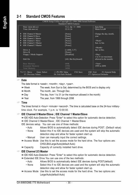
2-1 Standard CMOS Features
DateThe date format is <week>, <month>, <day>, <year>.
Week The week, from Sun to Sat, determined by the BIOS and is display onlyMonth The month, Jan. Through Dec.Day The day, from 1 to 31 (or the maximum allowed in the month)Year The year, from 1999 through 2098
TimeThe times format in <hour> <minute> <second>. The time is calculated base on the 24-hour military-time clock. For example, 1 p.m. is 13:00:00.IDE Channel 0 Master/Slave ; IDE Channel 1 Master/Slave
IDE HDD Auto-Detection Press "Enter" to select this option for automatic device detection.IDE Channel 0 Master/Slave ; IDE Channel 1 Master/Slave
IDE devices setup. You can use one of three methods:• Auto Allows BIOS to automatically detect IDE devices during POST. (Default value)• None Select this if no IDE devices are used and the system will skip the automatic
detection step and allow for faster system start up.• Manual User can manually input the correct settings.
Access Mode Use this to set the access mode for the hard drive. The four options are:CHS/LBA/Large/Auto(default:Auto)
Capacity Capacity of currectly installed hard drive.IDE Channel 2/3 Master
IDE HDD Auto-Detection Press "Enter" to select this option for automatic device detection.Extended IDE Drive You can use one of the two methods:
• Auto Allows BIOS to automatically detect IDE devices during POST(default)• None Select this if no IDE devices are used and the system will skip the automatic
detection step and allow for faster system start up.Access Mode Use this to set the access mode for the hard drive. The two options are:
Large/Auto(default:Auto)
CMOS Setup Utility-Copyright (C) 1984-2006 Award SoftwareStandard CMOS Features
Date (mm:dd:yy) Wed, Jan 11 2006Time (hh:mm:ss) 22:31:24
IDE Channel 0 Master [None]IDE Channel 0 Slave [None]IDE Channel 1 Master [None]IDE Channel 1 Slave [None]IDE Channel 2 Master [None]IDE Channel 3 Master [None]
Drive A [1.44M, 3.5"]Drive B [None]Floppy 3 Mode Support [Disabled]
Halt On [All, But Keyboard]
Base Memory 640KExtended Memory 239MTotal Memory 240M
: Move Enter: Select +/-/PU/PD: Value F10: Save ESC: Exit F1: General Help F5: Previous Values F6: Fail-Safe Default F7: Optimized Defaults
Item HelpMenu Level
Change the day, month,year
<Week>Sun. to Sat.
<Month>Jan. to Dec.
<Day>1 to 31 (or maximumallowed in the month)
<Year>1999 to 2098

BIOS Setup- 31 -
English
Capacity Capacity of currently installed hard drive.Hard drive information should be labeled on the outside drive casing. Enter the appropriate optionbased on this information.
Cylinder Number of cylindersHead Number of headsPrecomp Write precompLanding Zone Landing zoneSector Number of sectors
Drive A / Drive BThe category identifies the types of floppy disk drive A or drive B that has been installed in the computer.
None No floppy drive installed360K, 5.25" 5.25 inch PC-type standard drive; 360K byte capacity.1.2M, 5.25" 5.25 inch AT-type high-density drive; 1.2M byte capacity
(3.5 inch when 3 Mode is Enabled).720K, 3.5" 3.5 inch double-sided drive; 720K byte capacity1.44M, 3.5" 3.5 inch double-sided drive; 1.44M byte capacity.2.88M, 3.5" 3.5 inch double-sided drive; 2.88M byte capacity.
Floppy 3 Mode Support (for Japan Area)Disabled Normal Floppy Drive. (Default value)Drive A Drive A is 3 mode Floppy Drive.Drive B Drive B is 3 mode Floppy Drive.Both Drive A & B are 3 mode Floppy Drives.
Halt onThe category determines whether the computer will stop if an error is detected during power up.
No Errors The system boot will not stop for any error that may be detected and youwill be prompted.
All Errors Whenever the BIOS detects a non-fatal error the system will be stopped.All, But Keyboard The system boot will not stop for a keyboard error; it will stop for all other
errors. (Default value)All, But Diskette The system boot will not stop for a disk error; it will stop for all other errors.All, But Disk/Key The system boot will not stop for a keyboard or disk error; it will stop for all
other errors.MemoryThe category is display-only which is determined by POST (Power On Self Test) of the BIOS.
Base MemoryThe POST of the BIOS will determine the amount of base (or conventional) memory installed in thesystem.The value of the base memory is typically 512K for systems with 512K memory installed on themotherboard, or 640K for systems with 640K or more memory installed on the motherboard.
Extended MemoryThe BIOS determines how much extended memory is present during the POST.This is the amount of memory located above 1 MB in the CPU's memory address map.
Total MemoryThis item displays the memory size that used.

GA-8I865GME-775 Motherboard - 32 -
Engl
ish
2-2 Advanced BIOS Features
Hard Disk Boot PrioritySelect boot sequence for onboard(or add-on cards) SCSI, RAID, etc.Use < > or < > to select a device, then press<+> to move it up, or <-> to move it down the list. Press<ESC> to exit this menu.First / Second / Third Boot Device
Floppy Select your boot device priority by Floppy.LS120 Select your boot device priority by LS120.Hard Disk Select your boot device priority by Hard Disk.CDROM Select your boot device priority by CDROM.ZIP Select your boot device priority by ZIP.USB-FDD Select your boot device priority by USB-FDD.USB-ZIP Select your boot device priority by USB-ZIP.USB-CDROM Select your boot device priority by USB-CDROM.USB-HDD Select your boot device priority by USB-HDD.LAN Select your boot device priority by LAN.Disabled Disable this function.
Password CheckSystem The system can not boot and can not access to Setup page will be denied if the
correct password is not entered at the prompt.Setup The system will boot, but access to Setup will be denied if the correct password
is not entered at the prompt. (Default value)
CMOS Setup Utility-Copyright (C) 1984-2006 Award SoftwareAdvanced BIOS Features
Hard Disk Boot Priority [Press Enter]First Boot Device [Floppy]Second Boot Device [Hard Disk]Third Boot Device [CDROM]Password Check [Setup]
# CPU Hyper-Threading [Enabled]Limit CPUID Max. to 3 [Disabled]No-Execute Memory Protect (Note) [Enabled]CPU Enhanced Halt (C1E) (Note) [Enabled]CPU Thermal Monitor 2(TM2) (Note) [Enabled]CPU EIST Function (Note) [Enabled]Init Display First [PCI]On-Chip Frame Buffer Size [16MB]
: Move Enter: Select +/-/PU/PD: Value F10: Save ESC: Exit F1: General Help F5: Previous Values F6: Fail-Safe Default F7: Optimized Defaults
Item HelpMenu Level
Select Hard Disk BootDevice Priority
(Note) This item will show up when you install a processor that supports this function.

BIOS Setup- 33 -
English
CPU Hyper-ThreadingEnabled Enables CPU Hyper Threading Feature. Please note that this feature is only
working for operating system with multi processors mode supported.(Default value)
Disabled Disables CPU Hyper Threading.Limit CPUID Max. to 3
Enabled Limit CPUID Maximum value to 3 when use older OS like NT4.Disabled Disables CPUID Limit for windows XP. (Default value)
No-Execute Memory Protect (Note)
Enabled Enable No-Execute Memory Protect function.(Default value)Disabled Disable No-Execute Memory Protect function.
CPU Enhanced Halt (C1E) (Note)
Enabled Enable CPU Enhanced Halt (C1E) function.(Default value)Disabled Disable CPU Enhanced Halt (C1E) function.
CPU Thermal Monitor 2 (TM2) (Note)
Enabled Enable CPU Thermal Monitor 2 (TM2) function.(Default value)Disabled Disable CPU Thermal Monitor 2 (TM2) function.
CPU EIST Function (Note)
Enabled Enable CPU EIST function.(Default value)Disabled Disable CPU EIST function.
Init Display FirstSelect the first initiation of the monitor display from onboard/AGP or PCI VGA card.
PCI Set Init Display First to PCI VGA card. (Default value)Onboard/AGP Set Init Display First to onboard/AGP VGA card.
On-Chip Frame Buffer Size1MB Set on-chip frame buffer size to 1MB.4MB Set on-chip frame buffer size to 4MB.8MB Set on-chip frame buffer size to 8MB.16MB Set on-chip frame buffer size to 16MB. (Default value)32MB Set on-chip frame buffer size to 32MB.
(Note) This item will show up when you install a processor that supports this function.

GA-8I865GME-775 Motherboard - 34 -
Engl
ish
2-3 Integrated Peripherals
On-Chip Primary PCI IDEEnabled Enable onboard 1st channel IDE port. (Default value)Disabled Disable onboard 1st channel IDE port.
On-Chip Secondary PCI IDEEnabled Enable onboard 2nd channel IDE port. (Default value)Disabled Disable onboard 2nd channel IDE port.
On-Chip SATADisabled Disable onboard Seria ATA function.Auto When there is no device to be plugged in IDE1 or IDE2, SATA controller will
remap to IDE controller. (Default value)Manual Set SATA mode manually from "SATA Port0 configure as" item.
SATA Port0 configure asIDE Pri. Master Set SATA controller to compatible mode. This mode will remap SATA Port 0
to IDE Primary Master.IDE Pri. Slave Set SATA controller to compatible mode. This mode will remap SATA Port 0
to IDE Primary Slave.IDE Sec. Master Set SATA controller to compatible mode. This mode will remap SATA Port 0
to IDE Secondary Master.IDE Sec. Slave Set SATA controller to compatible mode. This mode will remap SATA Port 0
to IDE Secondary Slave.SATA Port0 Set SATA controller to native mode(Serial ATA mode - SATA Port 0). This
mode is only supported by Windows XP or later. (Default value)SATA Port1 Set SATA controller to native mode(Serial ATA mode - SATA Port 1). This
mode is only supported by Windows XP or later.
CMOS Setup Utility-Copyright (C) 1984-2006 Award SoftwareIntegrated Peripherals
On-Chip Primary PCI IDE [Enabled]On-Chip Secondary PCI IDE [Enabled]On-Chip SATA [Auto]
x SATA Port0 configure as SATA Port0SATA Port1 configure as SATA Port1USB Controller [Enabled]USB 2.0 Controller [Enabled]USB Keyboard Support [Disabled]USB Mouse Support [Disabled]Legacy USB storage detect [Enabled]AC97 Audio [Auto]Onboard H/W LAN [Enabled]OnBoard LAN Boot ROM [Disabled]Onboard Serial Port 1 [3F8/IRQ4]Onboard Parallel Port [378/IRQ7]Parallel Port Mode [SPP]
x ECP Mode Use DMA 3
: Move Enter: Select +/-/PU/PD: Value F10: Save ESC: Exit F1: General HelpF5: Previous Values F6: Fail-Safe Default F7: Optimized Defaults
Item HelpMenu Level

BIOS Setup- 35 -
English
SATA Port1 configure asThe setting depends on "SATA Port0 configure as" item setting. (Default: SATA Port1)
USB ControllerEnabled Enable USB controller. (Default value)Disabled Disable USB controller.
USB 2.0 ControllerYou can disable this function if you are not using onboard USB 2.0 feature.
Enabled Enable USB 2.0 controller. (Default value)Disabled Disable USB 2.0 controller.
USB Keyboard SupportEnabled Enable USB keyboard support.Disabled Disable USB keyboard support. (Default value)
USB Mouse SupportEnabled Enable USB mouse support.Disabled Disable USB mouse support. (Default value)
Legacy USB storage detectEnabled Enable USB storage detect function. (Default value)Disabled Disable this function.
AC97 AudioAuto Enable onboard AC'97 audio function. (Default value)Disabled Disable this function.
Onboard H/W LANEnabled Enable onboard H/W LAN function. (Default value)Disabled Disable this function.
OnBoard LAN Boot ROMThis function decide whether to invoke the boot ROM of the onboard LAN chip.
Enabled Enable this function.Disabled Disable this function. (Default value)
Onboard Serial Port 1Auto BIOS will automatically setup the Serial port 1 address.3F8/IRQ4 Enable onboard Serial port 1 and address is 3F8. (Default value)2F8/IRQ3 Enable onboard Serial port 1 and address is 2F8.3E8/IRQ4 Enable onboard Serial port 1 and address is 3E8.2E8/IRQ3 Enable onboard Serial port 1 and address is 2E8.Disabled Disable onboard Serial port 1.

GA-8I865GME-775 Motherboard - 36 -
Engl
ish
Onboard Parallel PortDisabled Disable onboard LPT port.378/IRQ7 Enable onboard LPT port and address is 378/IRQ7. (Default value)278/IRQ5 Enable onboard LPT port and address is 278/IRQ5.3BC/IRQ7 Enable onboard LPT port and address is 3BC/IRQ7.
Parallel Port ModeSPP Using Parallel port as Standard Parallel Port. (Default value)EPP Using Parallel port as Enhanced Parallel Port.ECP Using Parallel port as Extended Capabilities Port.ECP+EPP Using Parallel port as ECP and EPP mode.
ECP Mode Use DMA3 Set ECP Mode Use DMA to 3. (Default value)1 Set ECP Mode Use DMA to 1.

BIOS Setup- 37 -
English
2-4 Power Management Setup
ACPI Suspend TypeS1(POS) Set ACPI suspend type to S1/POS(Power On Suspend). (Default value)S3(STR) Set ACPI suspend type to S3/STR(Suspend To RAM).
Power LED in S1 stateBlinking In standby mode(S1), poer LED will blink. (Default value)Dual/OFF In standby mode(S1):
a. If use single color LED, power LED will turn off.b. If use dual color LED, power LED will turn to another color.
Off by Power buttonInstant-off Press power button then Power off instantly. (Default value)Delay 4 Sec. Press power button 4 sec. to Power off. Enter suspend if button is pressed less
than 4 seconds.PME Event Wake UpThis feature requires an ATX power supply that provides at least 1A on the 5VSB lead.
Disabled Disable this function.Enabled Enable PME as wake up event. (Default value)
ModemRingOn/WakeOnLanAn incoming call via modem can awake the system from any suspend state or an input signalcomes from the other client server on the LAN can awake the system from any suspend state.
Disabled Disable Modem Ring On / Wake On LAN function.Enabled Enable Modem Ring On / Wake On LAN function. (Default value)
Resume by AlarmYou can set "Resume by Alarm" item to enabled and key in Date/Time to power on system.
Disabled Disable this function. (Default value)Enabled Enable alarm function to POWER ON system.
If Resume by Alarm is Enabled.Date (of Month) Alarm : Everyday, 1~31Time (hh: mm: ss) Alarm : (0~23) : (0~59) : (0~59)
CMOS Setup Utility-Copyright (C) 1984-2006 Award SoftwarePower Management Setup
ACPI Suspend Type [S1(POS)]Power LED in S1 state [Blinking]Off by Power button [Instant-off]PME Event Wake Up [Enabled]ModemRingOn/WakeOnLan [Enabled]Resume by Alarm [Disabled]
x Date (of Month) Alarm Everdayx Time (hh:mm:ss) Alarm 0 : 0 : 0
Power On By Mouse [Disabled]Power On By Keyboard [Disabled]
x KB Power ON Password EnterAC BACK Function [Soft-Off]
: Move Enter: Select +/-/PU/PD: Value F10: Save ESC: Exit F1: General HelpF5: Previous Values F6: Fail-Safe Default F7: Optimized Defaults
Item HelpMenu Level

GA-8I865GME-775 Motherboard - 38 -
Engl
ish
Power On By MouseDisabled Disabled this function. (Default value)Double Click Double click on PS/2 mouse left button to power on the system.
Power On By KeyboardDisabled Disabled this function. (Default value)Password Enter from 1 to 5 characters to set the keyboard power on password.Keyboard 98 If your keyboard have "POWER Key" button, you can press the key to power
on the system.KB Power ON PasswordWhen "Power On by Keyboard" set at Password, you can set the password here.
Enter Input password(from 1 to 5 characters) and press Enter to set the password.AC BACK Function
Soft-Off When AC-power back to the system, the system will be in "Off" state.(Default value)
Full-On When AC-power back to the system, the system always in "On" state.
BIOS Setup- 39 -
English
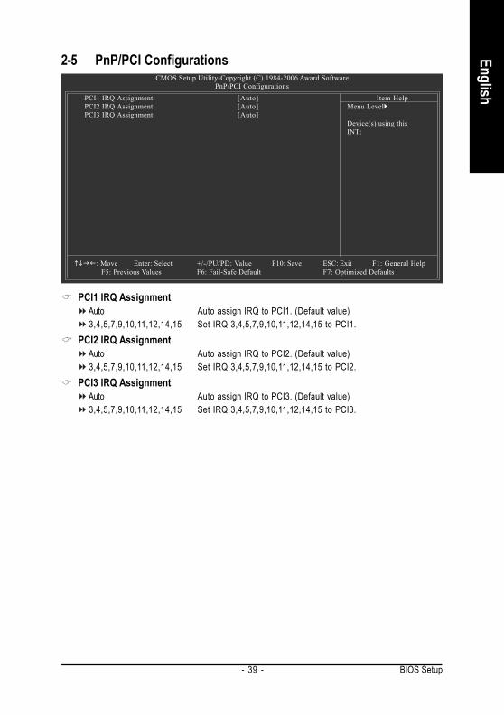
2-5 PnP/PCI Configurations
PCI1 IRQ AssignmentAuto Auto assign IRQ to PCI1. (Default value)3,4,5,7,9,10,11,12,14,15 Set IRQ 3,4,5,7,9,10,11,12,14,15 to PCI1.
PCI2 IRQ AssignmentAuto Auto assign IRQ to PCI2. (Default value)3,4,5,7,9,10,11,12,14,15 Set IRQ 3,4,5,7,9,10,11,12,14,15 to PCI2.
PCI3 IRQ AssignmentAuto Auto assign IRQ to PCI3. (Default value)3,4,5,7,9,10,11,12,14,15 Set IRQ 3,4,5,7,9,10,11,12,14,15 to PCI3.
CMOS Setup Utility-Copyright (C) 1984-2006 Award SoftwarePnP/PCI Configurations
PCI1 IRQ Assignment [Auto]PCI2 IRQ Assignment [Auto]PCI3 IRQ Assignment [Auto]
: Move Enter: Select +/-/PU/PD: Value F10: Save ESC: Exit F1: General HelpF5: Previous Values F6: Fail-Safe Default F7: Optimized Defaults
Item HelpMenu Level
Device(s) using thisINT:

GA-8I865GME-775 Motherboard - 40 -
Engl
ish
2-6 PC Health Status
Reset Case Open StatusDisabled Don't reset case open status. (Default value)Enabled Clear case open status at next boot.
Case OpenedIf the case is closed, "Case Opened" will show "No".If the case have been opened, "Case Opened" will show "Yes".If you want to reset "Case Opened" value, set "Reset Case Open Status" to "Enabled" and saveCMOS, your computer will restart.Current Voltage(V) Vcore / DDR25V / +3.3V / +12V
Detect system's voltage status automatically.Current CPU Temperature
Detect CPU temperature automatically.Current CPU/SYSTEM FAN Speed (RPM)
Detect CPU/SYSTEM Fan speed status automatically.CPU Warning Temperature
60oC / 140oF Monitor CPU temperature at 60oC / 140oF.70oC / 158oF Monitor CPU temperature at 70oC / 158oF.80oC / 176oF Monitor CPU temperature at 80oC / 176oF.90oC / 194oF Monitor CPU temperature at 90oC / 194oF.Disabled Disable this function. (Default value)
CPU/SYSTEM FAN Fail WarningDisabled Fan warning function disable. (Default value)Enabled Fan warning function enable.
CMOS Setup Utility-Copyright (C) 1984-2006 Award SoftwarePC Health Status
Reset Case Open Status [Disabled]Case Opened NoVcore OKDDR25V OK+3.3V OK+12V OKCurrent CPU Temperature 45oCCurrent CPU FAN Speed 3245 RPMCurrent SYSTEM FAN Speed 0 RPMCPU Warning Temperature [Disabled]CPU FAN Fail Warning [Disabled]SYSTEM FAN Fail Warning [Disabled]CPU Smart FAN Control [Enabled]CPU Smart FAN Mode [Auto]
: Move Enter: Select +/-/PU/PD: Value F10: Save ESC: Exit F1: General HelpF5: Previous Values F6: Fail-Safe Defaults F7: Optimized Defaults
Item HelpMenu Level

BIOS Setup- 41 -
English
CPU Smart FAN ControlDisabled Disable this function.Enabled When this function is enabled, CPU fan will run at different speed depending on
CPU temperature. Users can adjust the fan speed with Easy Tune based ontheir requirements. (Default Value)
CPU Smart FAN ModeThis option is available only when CPU Smart FAN Control is enabled.
Auto BIOS autodetects the type of CPU fan you installed and sets the optimal CPUSmart FAN control mode for it. (Default Value)
Voltage Set to Voltage when you use a CPU fan with a 3-pin fan power cable.PWM Set to PWM when you use a CPU fan with a 4-pin fan power cable.
Note: In fact, the Voltage option can be used for CPU fans with 3-pin or 4-pin power cables.However, some 4-pin CPU fan power cables are not designed following Intel 4-Wire fans PWMcontrol specifications. With such CPU fans, selecting PWM will not effectively reduce the fanspeed.

GA-8I865GME-775 Motherboard - 42 -
Engl
ish
2-7 Frequency/Voltage Control
CPU Clock Ratio (Note)
This setup option will automatically assign by CPU detection.The option will display "Locked" and read only if the CPU ratio is not changeable.Memory Frequency ForWrong frequency may make system can't boot, clear CMOS to overcome wrong frequency issue. for FSB(Front Side Bus) frequency=533MHz,
2.0 Memory Frequency = Host clock X 2.0.2.5 Memory Frequency = Host clock X 2.5.Auto Set Memory frequency by DRAM SPD data. (Default value)
for FSB(Front Side Bus) frequency=800MHz,2.0 Memory Frequency = Host clock X 2.0.1.66 Memory Frequency = Host clock X 1.66.1.33 Memory Frequency = Host clock X 1.33.Auto Set Memory frequency by DRAM SPD data. (Default value)
Memory Frequency (Mhz)The values depend on "CPU Host Frequency(Mhz)" item.
Incorrect using these features may cause your system broken. For power end-user use only.
CMOS Setup Utility-Copyright (C) 1984-2006 Award SoftwareFrequency/Voltage Control
CPU Clock Ratio (Note) [18X]Memory Frequency For [Auto]Memory Frequency (Mhz) 266
: Move Enter: Select +/-/PU/PD: Value F10: Save ESC: Exit F1: General HelpF5: Previous Values F6: Fail-Safe Defaults F7: Optimized Defaults
Item HelpMenu Level
(Note) This item will show up when you install a processor which supports this function.

BIOS Setup- 43 -
English
2-8 Load Fail-Safe Defaults
Fail-Safe defaults contain the most appropriate values of the system parameters that allow minimumsystem performance.
CMOS Setup Utility-Copyright (C) 1984-2006 Award Software
Standard CMOS FeaturesAdvanced BIOS FeaturesIntegrated PeripheralsPower Management SetupPnP/PCI ConfigurationsPC Health StatusFrequency/Voltage Control
ESC: Quit : Select ItemF8: Q-Flash F10: Save & Exit Setup
Load Fail-Safe Defaults
Load Fail-Safe DefaultsLoad Optimized DefaultsSet Supervisor PasswordSet User PasswordSave & Exit SetupExit Without Saving
Load Fail-Safe Defaults (Y/N)? N
2-9 Load Optimized Defaults
Selecting this field loads the factory defaults for BIOS and Chipset Features which the system automati-cally detects.
CMOS Setup Utility-Copyright (C) 1984-2006 Award Software
Standard CMOS FeaturesAdvanced BIOS FeaturesIntegrated PeripheralsPower Management SetupPnP/PCI ConfigurationsPC Health StatusFrequency/Voltage Control
ESC: Quit : Select ItemF8: Q-Flash F10: Save & Exit Setup
Load Optimized Defaults
Load Fail-Safe DefaultsLoad Optimized DefaultsSet Supervisor PasswordSet User PasswordSave & Exit SetupExit Without Saving
Load Optimized Defaults (Y/N)? N

GA-8I865GME-775 Motherboard - 44 -
Engl
ish
2-10 Set Supervisor/User Password
When you select this function, the following message will appear at the center of the screen to assistyou in creating a password.Type the password, up to eight characters, and press <Enter>. You will be asked to confirm thepassword. Type the password again and press <Enter>. You may also press <Esc> to abort theselection and not enter a password.To disable password, just press <Enter> when you are prompted to enter password. A message"PASSWORD DISABLED" will appear to confirm the password being disabled. Once the password isdisabled, the system will boot and you can enter Setup freely.The BIOS Setup program allows you to specify two separate passwords:SUPERVISOR PASSWORD and a USER PASSWORD. When disabled, anyone may access all BIOSSetup program function. When enabled, the Supervisor password is required for entering the BIOSSetup program and having full configuration fields, the User password is required to access only basicitems.If you select "System" at "Password Check" in Advance BIOS Features Menu, you will be promptedfor the password every time the system is rebooted or any time you try to enter Setup Menu.If you select "Setup" at "Password Check" in Advance BIOS Features Menu, you will be prompted onlywhen you try to enter Setup.
CMOS Setup Utility-Copyright (C) 1984-2006 Award Software
Standard CMOS FeaturesAdvanced BIOS FeaturesIntegrated PeripheralsPower Management SetupPnP/PCI ConfigurationsPC Health StatusFrequency/Voltage Control
ESC: Quit : Select ItemF8: Q-Flash F10: Save & Exit Setup
Change/Set/Disable Password
Load Fail-Safe DefaultsLoad Optimized DefaultsSet Supervisor PasswordSet User PasswordSave & Exit SetupExit Without Saving
Enter Password:

BIOS Setup- 45 -
English
2-11 Save & Exit Setup
Type "Y" will quit the Setup Utility and save the user setup value to RTC CMOS.Type "N" will return to Setup Utility.
2-12 Exit Without Saving
Type "Y" will quit the Setup Utility without saving to RTC CMOS.Type "N" will return to Setup Utility.
CMOS Setup Utility-Copyright (C) 1984-2006 Award Software
Standard CMOS FeaturesAdvanced BIOS FeaturesIntegrated PeripheralsPower Management SetupPnP/PCI ConfigurationsPC Health StatusFrequency/Voltage Control
ESC: Quit : Select ItemF8: Q-Flash F10: Save & Exit Setup
Save Data to CMOS
Load Fail-Safe DefaultsLoad Optimized DefaultsSet Supervisor PasswordSet User PasswordSave & Exit SetupExit Without SavingSave to CMOS and EXIT (Y/N)? Y
CMOS Setup Utility-Copyright (C) 1984-2006 Award Software
Standard CMOS FeaturesAdvanced BIOS FeaturesIntegrated PeripheralsPower Management SetupPnP/PCI ConfigurationsPC Health StatusFrequency/Voltage Control
ESC: Quit : Select ItemF8: Q-Flash F10: Save & Exit Setup
Abandon all Data
Load Fail-Safe DefaultsLoad Optimized DefaultsSet Supervisor PasswordSet User PasswordSave & Exit SetupExit Without Saving
Quit Without Saving (Y/N)? N

GA-8I865GME-775 Motherboard - 46 -
Engl
ish

Drivers Installation- 47 -
English
Chapter 3Drivers InstallationPictures below are shown in Windows XP.(1) Please make sure to install the latest service pack for Windows after OS installation andbefore installing motherboard drivers.(2) Insert the driver CD that came with your motherboard into your CD-ROM drive, the driverCD will auto start and installation screen will appear. If not, please double click the CD-ROMdevice icon in My computer or execute the Setup.exe in the root directory of the driver CD.
3-1 Install Chipset DriversAfter insert the driver CD, "Xpress Install" will scan automatically the system and then list all the driversthat recommended to install. The "Xpress Install" uses the"Click and Go" technology to install thedrivers automatically. Just select the drivers you want then click the "GO" button. The "Xpress Install"will execute the installation for you automatically.
Some device drivers will restart your system automatically. After restarting your system the"Xpress Install" will continue to install other drivers.System will reboot automatically after install the drivers, afterward you can install othersapplication.
For USB2.0 driver support under Windows XP operating system, please use WindowsService Pack. After install Windows Service Pack, it will show a question mark "?" in"Universal Serial Bus controller" under "Device Manager". Please remove the question markand restart the system (System will auto-detect the right USB2.0 driver).

GA-8I865GME-775 Motherboard - 48 -
Engl
ish
3-2 Software ApplicationsThis page displays all the tools that Gigabyte developed and some free software. You can click an itemto install it.
3-3 Driver CD InformationThis page lists the contents of software and drivers in this CD-title.

Drivers Installation- 49 -
English
3-4 Hardware InformationThis page lists all device you have for this motherboard.
3-5 Contact UsYou can also see the last page of this manual for contacts information details.

GA-8I865GME-775 Motherboard - 50 -
Engl
ish
Appendix- 51 -
English
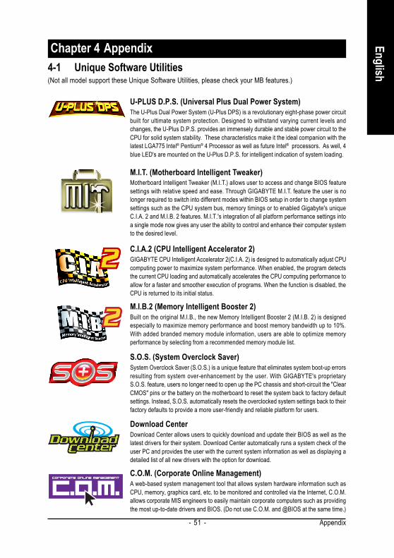
Chapter 4 Appendix4-1 Unique Software Utilities
M.I.T. (Motherboard Intelligent Tweaker)Motherboard Intelligent Tweaker (M.I.T.) allows user to access and change BIOS featuresettings with relative speed and ease. Through GIGABYTE M.I.T. feature the user is nolonger required to switch into different modes within BIOS setup in order to change systemsettings such as the CPU system bus, memory timings or to enabled Gigabyte's uniqueC.I.A. 2 and M.I.B. 2 features. M.I.T.'s integration of all platform performance settings intoa single mode now gives any user the ability to control and enhance their computer systemto the desired level.
C.I.A.2 (CPU Intelligent Accelerator 2)GIGABYTE CPU Intelligent Accelerator 2(C.I.A. 2) is designed to automatically adjust CPUcomputing power to maximize system performance. When enabled, the program detectsthe current CPU loading and automatically accelerates the CPU computing performance toallow for a faster and smoother execution of programs. When the function is disabled, theCPU is returned to its initial status.
M.I.B.2 (Memory Intelligent Booster 2)Built on the original M.I.B., the new Memory Intelligent Booster 2 (M.I.B. 2) is designedespecially to maximize memory performance and boost memory bandwidth up to 10%.With added branded memory module information, users are able to optimize memoryperformance by selecting from a recommended memory module list.
S.O.S. (System Overclock Saver)System Overclock Saver (S.O.S.) is a unique feature that eliminates system boot-up errorsresulting from system over-enhancement by the user. With GIGABYTE's proprietaryS.O.S. feature, users no longer need to open up the PC chassis and short-circuit the "ClearCMOS" pins or the battery on the motherboard to reset the system back to factory defaultsettings. Instead, S.O.S. automatically resets the overclocked system settings back to theirfactory defaults to provide a more user-friendly and reliable platform for users.
Download CenterDownload Center allows users to quickly download and update their BIOS as well as thelatest drivers for their system. Download Center automatically runs a system check of theuser PC and provides the user with the current system information as well as displaying adetailed list of all new drivers with the option for download.
C.O.M. (Corporate Online Management)A web-based system management tool that allows system hardware information such asCPU, memory, graphics card, etc. to be monitored and controlled via the Internet, C.O.M.allows corporate MIS engineers to easily maintain corporate computers such as providingthe most up-to-date drivers and BIOS. (Do not use C.O.M. and @BIOS at the same time.)
U-PLUS D.P.S. (Universal Plus Dual Power System)The U-Plus Dual Power System (U-Plus DPS) is a revolutionary eight-phase power circuitbuilt for ultimate system protection. Designed to withstand varying current levels andchanges, the U-Plus D.P.S. provides an immensely durable and stable power circuit to theCPU for solid system stability. These characteristics make it the ideal companion with thelatest LGA775 Intel® Pentium® 4 Processor as well as future Intel® processors. As well, 4blue LED's are mounted on the U-Plus D.P.S. for intelligent indication of system loading.
(Not all model support these Unique Software Utilities, please check your MB features.)

GA-8I865GME-775 Motherboard - 52 -
Engl
ish
4-1-1 EasyTune 5 IntroductionEasyTune 5 presents the most convenient Windows based system performance enhancement andmanageability utility. Featuring several powerful yet easy to use tools such as 1) Overclocking for enhancingsystem performance, 2) C.I.A. and M.I.B. for special enhancement for CPU and Memory, 3) Smart-Fancontrol for managing fan speed control of both CPU cooling fan and North-Bridge Chipset cooling fan, 4) PChealth for monitoring system status.(Note)
User Interface Overview
(Note) EasyTune 5 functions may vary depending on different motherboards.
Button / Display Description1. Overclocking Enters the Overclocking setting page2. C.I.A./C.I.A.2 and M.I.B./M.I.B.2 Enters the C.I.A./2 and M.I.B./2 setting page3. Smart-Fan Enters the Smart-Fan setting page4. PC Health Enters the PC Health setting page5. GO Confirmation and Execution button6. "Easy Mode" & "Advance Mode" Toggles between Easy and Advance Mode7. Display screen Display panel of CPU frequency8. Function display LEDs Shows the current functions status9. GIGABYTE Logo Log on to GIGABYTE website10. Help button Display EasyTuneTM 5 Help file11. Exit or Minimize button Quit or Minimize EasyTuneTM 5 software

Appendix- 53 -
English
4-1-2 Xpress Recovery2 IntroductionXpress Recovery2 is designed to provide quick backup and restora-tion of hard disk data. Supporting Microsoft operating systems includingWindows XP/2000/NT/98/Me and DOS, and file systems includingFAT16, FAT32, and NTFS, Xpress Recovery2 is able to back up data
How to use the Xpress Recovery2Initial access by booting from CD-ROM and subsequent access by pressing the F9 key:Steps: After entering BIOS Setup, go to Advanced BIOS Feature and set to boot from CD-ROM. Save
the settings and exit the BIOS Setup. Insert the provided driver CD into your CD-ROM drive. Uponsystem restart, the message which says "Boot from CD/DVD:" will appear in the bottom left cornerof the screen. Press any key to enter Xpress Recovery2.After the steps above are completed, subsequent access to Xpress Recovery2 can be madeby simply pressing the <F9> key during system power-on.
Boot from CD/DVD:
.
.Boot from CD/DVD:Press any key to startup XpressRecovery2.....
1. If you have already entered Xpress Recovery2 by booting from the CD-ROM, you canenter Xpress Recovery2 by pressing the <F9> key in the future.
2. System storage capacity and the reading/writing speed of the hard disk will affectthe data backup speed.
3. It is recommended that Xpress Recovery2 be immediately installed once you com-plete installations of OS and all required drivers as well as software.
on hard disks on PATA and SATA IDE controllers. After Xpress Recovery2 is executed from CD-ROMfor the first time, it will stay permanent in your hard disk. If you wish to run Xpress Recovery2 later, youcan simply press F9 during system bootup to enter Xpress Recovery2 without the CD-ROM.
System requirements:1. Intel x86 platforms2. At least 64M bytes of system memory3. VESA-supported VGA cards
<F9> Xpress Recovery2
Award Modular BIOS v6.00PG, An Energy Star AllyCopyright (C) 1984-2006, Award Software, Inc.
GA-8I865GME-775 D5....
<DEL>:BIOS Setup/Q-Flash, <F9>: Xpress Recovery2, <F12>For Boot Menu01/27/2006- i865G-6A79AG0UC-00

GA-8I865GME-775 Motherboard - 54 -
Engl
ish
1. RESTORE:Restore the backed-up data to your hard disk.(This button will not appear if there is no backupfile.)
2. BACKUP:Back up data from hard disk.
3. REMOVE:Remove previously-created backup filesto release disk space.(This button will not appear if there is no backupfile.)
4. REBOOT:Exit the main screen and restart the system.
The Main Screen of Xpress Recovery2
Limitations:1. Not compatible to Xpress Recovery.2. For the use of Xpress Recovery2, a primary partition must be reserved.3. Xpress Recovery2 will store the backup file at the end of the hard disk, so free space available
on the hard disk for the backup file must be allocated in advance. (A minimum 4GB is recom-mended but the actual space is dependent on the size of the data to be backed up)
4. Capable of backing up hard disks installed with Windows operating systems including DOS andWindows XP/2000/NT/9x/Me.
5. USB hard disks are currently not supported.6. Does not support RAID/AHCI (class code 0104/0106) hard disks.7. Capable of backing up and restoring only the first physical hard disk.Hard disks detection sequence is as follows:
a. PATA IDE primary channelb. PATA IDE secondary channelc . SATA IDE channel 1d. SATA IDE channel 2e. SATA IDE channel 3f. SATA IDE channel 4
Precautions:1. When using hard disks with more than 128G under Windows 2000, be sure to execute the
EnableBigLba.exe program from the driver CD before data backup.2. It is normal that data backup takes longer time than data restoration.3. Xpress Recovery2 is compliant with the GPL regulations.4. On a few motherboards based on Nvidia chipsets, BIOS update is required for Xpress Recovery2
to correctly identify RAID and SATA IDE mode. Please contact your motherboard manufacturer.5. Xpress Recovery2 supports only PATA hard disks and not SATA hard disks on the following
motherboards (As this is a BIOS-related issue, it can be solved by BIOS update)GA-K8UGA-K8U-9GA-K8NXP-SLIGA-K8N Ultra-SLIGA-K8N Pro-SLI
GA-K8NXP-9GA-K8N Ultra-9GA-K8NF-9 (PCB Ver. 1.0)GA-K8NE (PCB Ver. 1.0)GA-K8NMF-9
GA-8N-SLI RoyalGA-8N-SLI ProGA-8N-SLI

Appendix- 55 -
English
4-1-3 Flash BIOS Method IntroductionMethod 1 : Q-FlashTM UtilityQ-FlashTM is a BIOS flash utility embedded in Flash ROM. With this utility,users only have to stay in the BIOS menu when they want to updateBIOS. Q-FlashTM allows users to flash BIOS without any utility in
DOS or Windows. Using Q-FlashTM indicating no more fooling around with any complicated instructionsand operating system since it is in the BIOS menu.
Please note that because updating BIOS has potential risk, please do it with caution!! We aresorry that Gigabyte Technology Co., Ltd is not responsible for damages of system because ofincorrect manipulation of updating BIOS to avoid any claims from end-users.
Before You Begin:Before you start updating BIOS with the Q-FlashTM utility, please follow the steps below first.
1. Download the latest BIOS for your motherboard from Gigabyte's website.2. Extract the BIOS file downloaded and save the BIOS file (the one with model name.Fxx. For
example, 8KNXPU.Fba) to a floppy disk.3. Reboot your PC and press Del to enter BIOS menu.
The BIOS upgrading guides below are separated into two parts.If your motherboard has dual-BIOS, please refer to Part One.If your motherboard has single-BIOS, please refer to Part Two.
Part One:Updating BIOS with Q-FlashTM Utility on Dual BIOS Motherboards.Some of Gigabyte motherboards are equipped with dual BIOS. In the BIOS menu of the motherboardssupporting Q-Flash and Dual BIOS, the Q-Flash utility and Dual BIOS utility are combined in the samescreen. This section only deals with how to use Q-Flash utility.In the following sections, we take GA-8KNXP Ultra as the example to guide you how to flash BIOSfrom an older version to the latest version. For example, from Fa3 to Fba.
Intel i875P AGPset BIOS for 8KNXP Ultra Fa3Check System Health OK , VCore = 1.5250Main Processor : Intel Pentium(R) 4 1.6GHz (133x12)<CPUID : 0F27 Patch ID : 0027>Memory Testing : 131072K OK
Memory Frequency 266 MHz in Single ChannelPrimary Master : FUJITSU MPE3170AT ED-03-08Primary Slave : NoneSecondary Master : CREATIVEDVD-RM DVD1242E BC101Secondary Slave : None
Press DEL to enter SETUP / Dual BIOS / Q-Flash / F9 ForXpress Recovery08/07/2003-i875P-6A79BG03C-00
Award Modular BIOS v6.00PG, An Energy Star AllyCopyright (C) 1984-2003, Award Software, Inc.
The BIOS file is Fa3before updating

GA-8I865GME-775 Motherboard - 56 -
Engl
ish
Entering the Q-FlashTM utility:
CMOS Setup Utility-Copyright (C) 1984-2004 Award Software
Standard CMOS FeaturesAdvanced BIOS FeaturesIntegrated PeripheralsPower Management SetupPnP/PCI ConfigurationsPC Health StatusMB Intelligent Tweaker(M.I.T.)
Select LanguageLoad Fail-Safe DefaultsLoad Optimized DefaultsSet Supervisor PasswordSet User PasswordSave & Exit SetupExit Without Saving
ESC: Quit F3: Change LanguageF8: Dual BIOS/Q-Flash F10: Save & Exit Setup
Time, Date, Hard Disk Type...
Step 2: Press F8 button on your keyboard and then Y button to enter the Dual BIOS/Q-Flash utility.
Step1: To use Q-Flash utility, you must press Del in the boot screen to enter BIOS menu.
Exploring the Q-FlashTM / Dual BIOS utility screenThe Q-Flash / Dual BIOS utility screen consists of the following key components.
Task menu for Dual BIOS utility:Contains the names of eight tasks and two item showing information about the BIOS ROM type. Blocking atask and pressing Enter key on your keyboard to enable execution of the task.Task menu for Q-Flash utility:Contains the names of four tasks. Blocking a task and pressing Enter key on your keyboard to enable execu-tion of the task.Action bar:Contains the names of four actions needed to operate the Q-Flash/Dual BIOS utility. Pressing the buttonsmentioned on your keyboards to perform these actions.
Dual BIOS UtilityBoot From......................................... Main BiosMain ROM Type/Size.............................SST 49LF003A 512K Backup ROM Type/Size.........................SST 49LF003A 512K
Wide Range Protection DisableBoot From Main Bios
Auto Recovery EnableHalt On Error Disable
Copy Main ROM Data to BackupLoad Default Settings
Save Settings to CMOSQ-Flash Utility
Load Main BIOS from FloppyLoad Backup BIOS from Floppy
Save Main BIOS to FloppySave Backup BIOS to Floppy
Enter : Run :Move ESC:Reset F10:Power Off
Task menu forDual BIOSutility
Task menu forQ-FlashTM utility
Dual BIOS utility bar
Q-FlashTM utility titlebar
Action bar
Appendix- 57 -
English
Dual BIOS UtilityBoot From......................................... Main BiosMain ROM Type/Size.............................SST 49LF003A 512K Backup ROM Type/Size.........................SST 49LF003A 512K
Wide Range Protection DisableBoot From Main Bios
Auto Recovery EnableHalt On Error Disable
Copy Main ROM Data to BackupLoad Default Settings
Save Settings to CMOSQ-Flash Utility
Load Main BIOS from FloppyLoad Backup BIOS from Floppy
Save Main BIOS to FloppySave Backup BIOS to Floppy
Enter : Run :Move ESC:Reset F10:Power Off
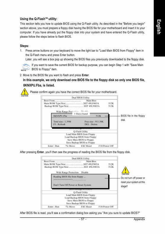
Using the Q-FlashTM utility:This section tells you how to update BIOS using the Q-Flash utility. As described in the "Before you begin"section above, you must prepare a floppy disk having the BIOS file for your motherboard and insert it to yourcomputer. If you have already put the floppy disk into your system and have entered the Q-Flash utility,please follow the steps below to flash BIOS.
Steps:1. Press arrow buttons on your keyboard to move the light bar to "Load Main BIOS from Floppy" item in
the Q-Flash menu and press Enter button.Later, you will see a box pop up showing the BIOS files you previously downloaded to the floppy disk.
If you want to save the current BIOS for backup purpose, you can begin Step 1 with "Save MainBIOS to Floppy" item.
2. Move to the BIOS file you want to flash and press Enter. In this example, we only download one BIOS file to the floppy disk so only one BIOS file, 8KNXPU.Fba, is listed.
Please confirm again you have the correct BIOS file for your motherboard.
1 file(s) found8KNXPU.Fba 512K
Total size : 1.39M Free size : 911.50KF5 : Refresh DEL : Delete
BIOS file in the floppydisk.
Dual BIOS UtilityBoot From......................................... Main BiosMain ROM Type/Size.............................SST 49LF003A 512K Backup ROM Type/Size.........................SST 49LF003A 512K
Wide Range Protection DisableBoot From Main Bios
Auto Recovery EnableHalt On Error Disable
Copy Main ROM Data to BackupLoad Default Settings
Save Settings to CMOSQ-Flash Utility
Load Main BIOS from FloppyLoad Backup BIOS from Floppy
Save Main BIOS to FloppySave Backup BIOS to Floppy
Enter : Run :Move ESC:Reset F10:Power Off
Reading BIOS file from floppy ...>>>>>>>>>>>>>>.....................
Don't Turn Off Power or Reset System
Do not turn off power orreset your system at thisstage!!
After pressing Enter, you'll then see the progress of reading the BIOS file from the floppy disk.
After BIOS file is read, you'll see a confirmation dialog box asking you "Are you sure to update BIOS?"

GA-8I865GME-775 Motherboard - 58 -
Engl
ish
3. Press Y button on your keyboard after you are sure to update BIOS. Then it will begin to update BIOS. The progress of updating BIOS will be displayed.
Dual BIOS UtilityBoot From......................................... Main BiosMain ROM Type/Size.............................SST 49LF003A 512K Backup ROM Type/Size.........................SST 49LF003A 512K
Wide Range Protection DisableBoot From Main Bios
Auto Recovery EnableHalt On Error Disable
Copy Main ROM Data to BackupLoad Default Settings
Save Settings to CMOSQ-Flash Utility
Load Main BIOS from FloppyLoad Backup BIOS from Floppy
Save Main BIOS to FloppySave Backup BIOS to Floppy
Enter : Run :Move ESC:Reset F10:Power Off
!! Copy BIOS completed - Pass !!
Please press any key to continue
Please do not take out the floppy disk when it begins flashing BIOS.
4. Press any keys to return to the Q-Flash menu when the BIOS updating procedure is completed.
You can repeat Step 1 to4 to f lash the backupBIOS, too.
Dual BIOS UtilityBoot From......................................... Main BiosMain ROM Type/Size.............................SST 49LF003A 512K Backup ROM Type/Size.........................SST 49LF003A 512K
Wide Range Protection DisableBoot From Main Bios
Auto Recovery EnableHalt On Error Disable
Copy Main ROM Data to BackupLoad Default Settings
Save Settings to CMOSQ-Flash Utility
Load Main BIOS from FloppyLoad Backup BIOS from Floppy
Save Main BIOS to FloppySave Backup BIOS to Floppy
Enter : Run :Move ESC:Reset F10:Power Off
Are you sure to RESET ?
[Enter] to continure or [Esc] to abort...
5. Press Esc and then Y button to exit the Q-Flash utility. The computer will restart automatically afteryou exit Q-Flash.
After system reboots, you may find the BIOS version on your boot screen becomes the one you flashed.
Intel i875P AGPset BIOS for 8KNXP Ultra FbaCheck System Health OK , VCore = 1.5250Main Processor : Intel Pentium(R) 4 1.6GHz (133x12)<CPUID : 0F27 Patch ID : 0027>Memory Testing : 131072K OK
Memory Frequency 266 MHz in Single ChannelPrimary Master : FUJITSU MPE3170AT ED-03-08Primary Slave : NoneSecondary Master : CREATIVEDVD-RM DVD1242E BC101Secondary Slave : None
Press DEL to enter SETUP / Dual BIOS / Q-Flash / F9 ForXpress Recovery09/23/2003-i875P-6A79BG03C-00
Award Modular BIOS v6.00PG, An Energy Star AllyCopyright (C) 1984-2003, Award Software, Inc.
The BIOS filebecomes Fab afterupdating.
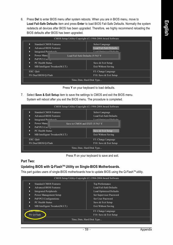
Appendix- 59 -
English
CMOS Setup Utility-Copyright (C) 1984-2004 Award Software
Standard CMOS FeaturesAdvanced BIOS FeaturesIntegrated PeripheralsPower Management SetupPnP/PCI ConfigurationsPC Health StatusMB Intelligent Tweaker(M.I.T.)
ESC: Quit F3: Change LanguageF8: Dual BIOS/Q-Flash F10: Save & Exit Setup
Time, Date, Hard Disk Type...
6. Press Del to enter BIOS menu after system reboots. When you are in BIOS menu, move toLoad Fail-Safe Defaults item and press Enter to load BIOS Fail-Safe Defaults. Normally the systemredetects all devices after BIOS has been upgraded. Therefore, we highly recommend reloading theBIOS defaults after BIOS has been upgraded.
Select LanguageLoad Fail-Safe DefaultsLoad Optimized DefaultsSet Supervisor PasswordSet User PasswordSave & Exit SetupExit Without Saving
Load Fail-Safe Defaults (Y/N)? Y
Press Y on your keyboard to load defaults.
CMOS Setup Utility-Copyright (C) 1984-2004 Award Software
Standard CMOS FeaturesAdvanced BIOS FeaturesIntegrated PeripheralsPower Management SetupPnP/PCI ConfigurationsPC Health StatusMB Intelligent Tweaker(M.I.T.)
ESC: Quit F3: Change LanguageF8: Dual BIOS/Q-Flash F10: Save & Exit Setup
Time, Date, Hard Disk Type...
7. Select Save & Exit Setup item to save the settings to CMOS and exit the BIOS menu.System will reboot after you exit the BIOS menu. The procedure is completed.
Select LanguageLoad Fail-Safe DefaultsLoad Optimized DefaultsSet Supervisor PasswordSet User PasswordSave & Exit SetupExit Without Saving
Save to CMOS and EXIT (Y/N)? Y
Press Y on your keyboard to save and exit.Part Two:Updating BIOS with Q-FlashTM Utility on Single-BIOS Motherboards.This part guides users of single-BIOS motherboards how to update BIOS using the Q-FlashTM utility.
CMOS Setup Utility-Copyright (C) 1984-2004 Award Software
Standard CMOS FeaturesAdvanced BIOS FeaturesIntegrated PeripheralsPower Management SetupPnP/PCI ConfigurationsPC Health StatusMB Intelligent Tweaker(M.I.T.)
Top PerformanceLoad Fail-Safe DefaultsLoad Optimized DefaultsSet Supervisor PasswordSet User PasswordSave & Exit SetupExit Without Saving
ESC: Quit F3: Change LanguageF8: Q-Flash F10: Save & Exit Setup
Time, Date, Hard Disk Type...
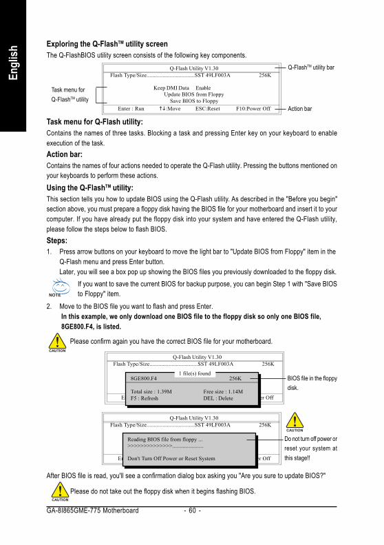
GA-8I865GME-775 Motherboard - 60 -
Engl
ish
Exploring the Q-FlashTM utility screenThe Q-FlashBIOS utility screen consists of the following key components.
Task menu for Q-Flash utility:Contains the names of three tasks. Blocking a task and pressing Enter key on your keyboard to enableexecution of the task.Action bar:Contains the names of four actions needed to operate the Q-Flash utility. Pressing the buttons mentioned onyour keyboards to perform these actions.Using the Q-FlashTM utility:This section tells you how to update BIOS using the Q-Flash utility. As described in the "Before you begin"section above, you must prepare a floppy disk having the BIOS file for your motherboard and insert it to yourcomputer. If you have already put the floppy disk into your system and have entered the Q-Flash utility,please follow the steps below to flash BIOS.Steps:1. Press arrow buttons on your keyboard to move the light bar to "Update BIOS from Floppy" item in the
Q-Flash menu and press Enter button.Later, you will see a box pop up showing the BIOS files you previously downloaded to the floppy disk.
If you want to save the current BIOS for backup purpose, you can begin Step 1 with "Save BIOSto Floppy" item.
2. Move to the BIOS file you want to flash and press Enter. In this example, we only download one BIOS file to the floppy disk so only one BIOS file, 8GE800.F4, is listed.
Please confirm again you have the correct BIOS file for your motherboard.
Q-Flash Utility V1.30 Flash Type/Size.................................SST 49LF003A 256K
Keep DMI Data EnableUpdate BIOS from Floppy
Save BIOS to FloppyEnter : Run :Move ESC:Reset F10:Power Off
1 file(s) found8GE800.F4 256K
Total size : 1.39M Free size : 1.14MF5 : Refresh DEL : Delete
BIOS file in the floppydisk.
Q-Flash Utility V1.30 Flash Type/Size.................................SST 49LF003A 256K
Keep DMI Data EnableUpdate BIOS from Floppy
Save BIOS to FloppyEnter : Run :Move ESC:Reset F10:Power Off
Reading BIOS file from floppy ...>>>>>>>>>>>>>>.....................
Don't Turn Off Power or Reset System
Do not turn off power orreset your system atthis stage!!
After BIOS file is read, you'll see a confirmation dialog box asking you "Are you sure to update BIOS?"
Please do not take out the floppy disk when it begins flashing BIOS.
Q-Flash Utility V1.30 Flash Type/Size.................................SST 49LF003A 256K
Keep DMI Data EnableUpdate BIOS from Floppy
Save BIOS to FloppyEnter : Run :Move ESC:Reset F10:Power Off
Task menu forQ-FlashTM utility
Q-FlashTM utility bar
Action bar

Appendix- 61 -
English
3. Press Y button on your keyboard after you are sure to update BIOS.Then it will begin to update BIOS. The progress of updating BIOS will be shown at the same time.
Q-Flash Utility V1.30 Flash Type/Size.................................SST 49LF003A 256K
Keep DMI Data EnableUpdate BIOS from Floppy
Save BIOS to FloppyEnter : Run :Move ESC:Reset F10:Power Off
Updating BIOS Now>>>>>>>>>>>>>>>>>>>.........................
Don't Turn Off Power or Reset System
Do not turn off power orreset your systemat this stage!!
4. Press any keys to return to the Q-Flash menu when the BIOS updating procedure is completed.
Q-Flash Utility V1.30 Flash Type/Size.................................SST 49LF003A 256K
Keep DMI Data EnableUpdate BIOS from Floppy
Save BIOS to FloppyEnter : Run :Move ESC:Reset F10:Power Off
!! Copy BIOS completed - Pass !!
Please press any key to continue
5. Press Esc and then Y button to exit the Q-Flash utility. The computer will restart automatically afteryou exit Q-Flash.
Q-Flash Utility V1.30 Flash Type/Size.................................SST 49LF003A 256K
Keep DMI Data EnableUpdate BIOS from Floppy
Save BIOS to FloppyEnter : Run :Move ESC:Reset F10:Power Off
Are you sure to RESET ?
[Enter] to continure or [Esc] to abort...
After system reboots, you may find the BIOS version on your boot screen becomes the one you flashed.
Intel 845GE AGPSet BIOS for 8GE800 F4Check System Health OKMain Processor : Intel Pentium(R) 4 1.7GHz (100x17.0)<CPUID : 0F0A Patch ID : 0009>Memory Testing : 122880K OK + 8192K Shared Memory
Primary Master : FUJITSU MPE3170AT ED-03-08Primary Slave : NoneSecondary Master : CREATIVEDVD-RM DVD1242E BC101Secondary Slave : None
Press DEL to enter SETUP / Q-Flash03/18/2003-I845GE-6A69YG01C-00
Award Modular BIOS v6.00PG, An Energy Star AllyCopyright (C) 1984-2003, Award Software, Inc.
The BIOS filebecomes F4 afterupdating
6. Press Del to enter BIOS menu after system reboots and "Load BIOS Fail-Safe Defaults". See howto Load BIOS Fail-Safe Defaults, please kindly refer to Step 6 to 7 in Part One.
Congratulation!! You have updated BIOS successfully!!

GA-8I865GME-775 Motherboard - 62 -
Engl
ish
Method 2 : @BIOSTM UtilityIf you do not have a DOS startup disk, we recommend that you use thenew @BIOS utility. @BIOS allows users to update their BIOS underWindows. Just select the desired @BIOS server to download the latestversion of BIOS.
1. Methods and steps:I. Update BIOS through Internet
a. Click "Internet Update" iconb. Click "Update New BIOS" iconc. Select @BIOSTM severd. Select the exact model name on your motherboarde. System will automatically download and update the BIOS.
II. Update BIOS NOT through Internet:a. Do not click "Internet Update" iconb. Click "Update New BIOS"c. Please select "All Files" in dialog box while opening the old file.d. Please search for BIOS unzip file, downloading from internet or any other methods (such as:
8I865GME-775.D5).e. Complete update process following the instruction.
Fig 1. Installing the @BIOS utility Fig 2. Installation Complete and Run @BIOS
Fig 3. The @BIOS Utility Fig 4. Select the desired @BIOS server
Click Sart/ Programs/ GIGABYTE/@BIOS
Click " " Click "Update New BIOS"
Select @BIOS item

Appendix- 63 -
English
III. Save BIOSIn the very beginning, there is "Save Current BIOS" icon shown in dialog box. It means to save thecurrent BIOS version.
IV. Check out supported motherboard and Flash ROM:In the very beginning, there is "About this program" icon shown in dialog box. It can help you check outwhich kind of motherboard and which brand of Flash ROM are supported.
2. Note:I. In method I, if it shows two or more motherboard's model names to be selected, please make
sure your motherboard's model name again. Selecting wrong model name will cause thesystem unbooted.
II. In method II, be sure that motherboard's model name in BIOS unzip file are the same as yourmotherboard's. Otherwise, your system won't boot.
III. In method I, if the BIOS file you need cannot be found in @BIOSTM server, please go ontoGigabyte's web site for downloading and updating it according to method II.
IV. Please note that any interruption during updating will cause system unbooted.V. Do not use @BIOS and C.O.M. (Corporate Online Management) at the same time.

GA-8I865GME-775 Motherboard - 64 -
Engl
ish
4-1-4 2 / 4 / 6 Channel Audio Function Introduction
STEP 1:Connect the stereo speakers or earphone to"Line Out."
STEP 3:On the AC97 Audio Configuration menu, click theSpeaker Configuration tab and select the2-channel mode for stereo speaker output checkbox.
2 Channel Audio SetupWe recommend that you use speakers with amplifier to get the best sound effect if the stereo output isapplied.
Line Out
STEP 2:After installing the audio driver, you'll find a SoundEffect icon on the lower right hand taskbar. Clickthe icon to select the function.

Appendix- 65 -
English
4 Channel Analog Audio Output Mode
STEP 1:Connect the front channels to "Line Out,"the rear channels to "Line In."
STEP 3:On the AC97 Audio Configuration menu, click theSpeaker Configuration tab and select the 4-chan-nel mode for 4 speaker output check box.Clear the Only SURROUND-KIT check box and pressOK.
When the Environment setting is None, thesound would be performed as stereo mode(2-channel output). Please select other settings (ex:Living Room) for 4-channel output.
Line In
Line Out
STEP 2:After installing the audio driver, you'll find a SoundEffect icon on the lower right hand taskbar. Clickthe icon to select the function.

GA-8I865GME-775 Motherboard - 66 -
Engl
ish Use the back audio panel to connect the audio outputwithout any additional module.STEP 1:Connect the front channels to "Line Out",the rearchannels to "Line In", and the Center/Subwoofer chan-nels to "MIC In".
Basic 6 Channel Analog Audio Output Mode
STEP 3:On the AC97 Audio Configuration menu, click theSpeaker Configuration tab and select the 6-chan-nel mode for 5.1 speaker output check box.Clear the Only SURROUND-KIT check box and pressOK.
Line Out
Line In
MIC In
STEP 2:After installing the audio driver, you'll find a SoundEffect icon on the lower right hand taskbar. Clickthe icon to select the function.
When the Environment setting is None, thesound would be performed as stereo mode(2-channel output). Please select the other settingsfor 6 channels output.

Appendix- 67 -
English
4-2 TroubleshootingBelow is a collection of general asked questions. To check general asked questions based on a specificmotherboard model, please log on to http://www.gigabyte.com.tw
Question 1: I cannot see some options that were included in previous BIOS after updating BIOS. Why?Answer: Some advanced options are hidden in new BIOS version. Please press Ctrl and F1 keys afterentering BIOS menu and you will be able to see these options.
Questions 2: Why is the light of my keyboard/optical mouse still on after computer shuts down?Answer: In some boards, a small amount of electricity is kept on standby after computer shuts down andthat's why the light is still on.
Question 3: How do I clear CMOS?Answer: If your board has a Clear CMOS jumper, please refer to the Clear CMOS steps in the manual. If yourboard doesn't have such jumper, you can take off the on-board battery to leak voltage to clear CMOS.Please refer to the steps below:
Steps:1. Turn off power.2. Disconnect the power cord from MB.3. Take out the battery gently and put it aside for about 10 minutes (Or you can use a metal object to
connect the positive and negative pins in the battery holder to makethem short for one minute).4. Re-insert the battery to the battery holder.5. Connect power cord to MB again and turn on power.6. Press Del to enter BIOS and load Fail-Safe Defaults(or load Optimized Defaults).7. Save changes and reboot the system.
Question 4: Why do I still get a weak sound after turning up the speaker to the maximum volume?Answer: Please make sure the speaker you are using is equipped with an internal amplifier. If not, pleasechange another speaker with power/amplifier and try again later.
Question 5: Sometimes I hear different continuous beeps from computer after system boots up. What dothese beeps usually stand for?Answer: The beep codes below may help you identify the possible computer problems. However, they areonly for reference purposes. The situations might differ from case to case.
AMI BIOS Beep Codes*Computer gives 1 short beep when system boots successfully.*Except for beep code 8, these codes are always fatal.
1 beep Refresh failure2 beeps Parity error3 beeps Base 64K memory failure4 beeps Timer not operational5 beeps Processor error6 beeps 8042 - gate A20 failure7 beeps Processor exception interrupt error8 beeps Display memory read/write failure9 beeps ROM checksum error10 beeps CMOS shutdown register read/write error11 beeps Cache memory bad
AWARD BIOS Beep Codes1 short: System boots successfully2 short: CMOS setting error1 long 1 short: DRAM or M/B error1 long 2 short: Monitor or display card error1 long 3 short: Keyboard error1 long 9 short: BIOS ROM errorContinuous long beeps: DRAM errorContinuous short beeps: Power error

GA-8I865GME-775 Motherboard - 68 -
Engl
ish

Appendix- 69 -
English

GA-8I865GME-775 Motherboard - 70 -
Engl
ish

Appendix- 71 -
English
Contact Us
Taiwan (Headquarters)GIGA-BYTE TECHNOLOGY CO., LTD.Address: No.6, Bau Chiang Road, Hsin-Tien, Taipei 231,Taiwan TEL: +886-2-8912-4888 FAX: +886-2-8912-4003Tech. Support :http://tw.giga-byte.com/TechSupport/ServiceCenter.htmNon-Tech. Support(Sales/Marketing) :http://ggts.gigabyte.com.tw/nontech.aspWEB address (English): http://www.gigabyte.com.twWEB address (Chinese): http://chinese.giga-byte.com U.S.A.
G.B.T. INC.TEL: +1-626-854-9338 FAX: +1-626-854-9339Tech. Support :http://tw.giga-byte.com/TechSupport/ServiceCenter.htmNon-Tech. Support(Sales/Marketing) :http://ggts.gigabyte.com.tw/nontech.aspWEB address : http://www.giga-byte.com Germany
G.B.T. TECHNOLOGY TRADING GMBHTech. Support :http://tw.giga-byte.com/TechSupport/ServiceCenter.htmNon-Tech. Support(Sales/Marketing) :http://ggts.gigabyte.com.tw/nontech.aspWEB address : http://www.gigabyte.de
JapanNIPPON GIGA-BYTE CORPORATIONWEB address : http://www.gigabyte.co.jp Singapore
GIGA-BYTE SINGAPORE PTE. LTD.Tech. Support :http://tw.giga-byte.com/TechSupport/ServiceCenter.htmNon-Tech. Support(Sales/Marketing) :http://ggts.gigabyte.com.tw/nontech.aspWEB address: http://www.gigabyte.com.sg U.K.
G.B.T. TECH. CO., LTD.Tech. Support :http://tw.giga-byte.com/TechSupport/ServiceCenter.htmNon-Tech. Support(Sales/Marketing) :http://ggts.gigabyte.com.tw/nontech.aspWEB address : http://uk.giga-byte.com The Netherlands
GIGA-BYTE TECHNOLOGY B.V.Tech. Support :http://tw.giga-byte.com/TechSupport/ServiceCenter.htmNon-Tech. Support(Sales/Marketing) :http://ggts.gigabyte.com.tw/nontech.aspWEB address : http://www.giga-byte.nl
GA-8I865GME-775 Motherboard - 72 -
Engl
ish
ChinaNINGBO G.B.T. TECH. TRADING CO., LTD.Tech. Support :http://tw.giga-byte.com/TechSupport/ServiceCenter.htmNon-Tech. Support(Sales/Marketing) :http://ggts.gigabyte.com.tw/nontech.aspWEB address : http://www.gigabyte.com.cnShanghaiTEL: +86-021-63410999 FAX: +86-021-63410100BeijingTEL: +86-10-62102838 FAX: +86-10-62102848WuhanTEL: +86-27-87851061 FAX: +86-27-87851330GuangZhouTEL: +86-20-87586074 FAX: +86-20-85517843ChengduTEL: +86-28-85236930 FAX: +86-28-85256822XianTEL: +86-29-85531943 FAX: +86-29-85539821ShenyangTEL: +86-24-23960918 FAX: +86-24-23960918-809 Australia
GIGABYTE TECHNOLOGY PTY. LTD.Tech. Support :http://tw.giga-byte.com/TechSupport/ServiceCenter.htmNon-Tech. Support(Sales/Marketing) :http://ggts.gigabyte.com.tw/nontech.aspWEB address : http://www.giga-byte.com.au France
GIGABYTE TECHNOLOGY FRANCE S.A.R.L.Tech. Support :http://tw.giga-byte.com/TechSupport/ServiceCenter.htmNon-Tech. Support(Sales/Marketing) :http://ggts.gigabyte.com.tw/nontech.aspWEB address : http://www.gigabyte.fr
RussiaMoscow Representative Office Of GIGA-BYTE Technology Co.,Ltd.Tech. Support :http://tw.giga-byte.com/TechSupport/ServiceCenter.htmNon-Tech. Support(Sales/Marketing) :http://ggts.gigabyte.com.tw/nontech.aspWEB address : http://www.gigabyte.ru Poland
Office of GIGA-BYTE TECHNOLOGY Co., Ltd. in POLANDTech. Support :http://tw.giga-byte.com/TechSupport/ServiceCenter.htmNon-Tech. Support(Sales/Marketing) :http://ggts.gigabyte.com.tw/nontech.aspWEB address : http://www.gigabyte.pl Serbia & Montenegro
Representative Office Of GIGA-BYTE Technology Co., Ltd. inSERBIA & MONTENEGROTech. Support :http://tw.giga-byte.com/TechSupport/ServiceCenter.htmNon-Tech. Support(Sales/Marketing) :http://ggts.gigabyte.com.tw/nontech.aspWEB address: http://www.gigabyte.co.yu Czech Republic
Representative Office Of GIGA-BYTE Technology Co., Ltd. inCZECH REPUBLICTech. Support :http://tw.giga-byte.com/TechSupport/ServiceCenter.htmNon-Tech. Support(Sales/Marketing) :http://ggts.gigabyte.com.tw/nontech.aspWEB address: http://www.gigabyte.cz Romania
Representative Office Of GIGA-BYTE Technology Co., Ltd. inRomaniaTech. Support :http://tw.giga-byte.com/TechSupport/ServiceCenter.htmNon-Tech. Support(Sales/Marketing) :http://ggts.gigabyte.com.tw/nontech.aspWEB address: http://www.gigabyte.com.ro
Related Documents