Owner's Manual Moscad-L Remote Terminal Unit 68P02951C50-B 2951C50B.book Page 1 Sunday, May 12, 2002 9:15 AM

Welcome message from author
This document is posted to help you gain knowledge. Please leave a comment to let me know what you think about it! Share it to your friends and learn new things together.
Transcript

2951C50B.book Page 1 Sunday, May 12, 2002 9:15 AM
Owner's Manual
Moscad-L
Remote Terminal
Unit
68P02951C50-B

2951C50B.book Page 2 Sunday, May 12, 2002 9:15 AM
Warranty Disclaimer
Computer Software CopyrightsThe Motorola products described in this instruction manual may include copyrighted Motorola computer programs stored in semiconductor memories or other media. Laws in the United States and other countries preserve for Motorola certain exclusive rights for copyrighted computer pro-grams, including the exclusive right to copy or reproduce in any form the copyrighted computer program. Accordingly, any copyrighted Motorola computer programs contained in the Motorola products described in this instruction manual may not be copied or reproduced in any manner without the express written permission of Motorola. Furthermore, the purchase of Motorola products shall not be deemed to grant either directly or by implication, estoppel or otherwise, any license under the copyrights, patents or patent applications of Motorola, except for the normal non-exclusive, royalty free license to use that arises by operation of law in the sale of a product.
Commercial Warranty (Standard)Motorola radio communications products are warranted to be free from defects in material and workmanship for a period of ONE (1) YEAR, (except for crystals and channel elements which are warranted for a period of ten (10) years) from the date of shipment. Parts, including crystals and channel elements, will be replaced and labor will be provided free of charge for the full war-ranty period. Thereafter purchaser must pay for the labor involved in repairing the product or replacing the parts at the prevailing rates together with any transportation charges to or from the place where warranty service is provided. This express warranty is extended by Motorola Com-munications and Electronics, Inc., 1301 E. Algonquin Road, Schaumburg, Illinois 60196, to the original purchaser only, and only to those purchasing for purpose of leasing or solely for com-mercial, industrial, or governmental use.THIS WARRANTY IS GIVEN IN LIEU OF ALL OTHER WARRANTIES EXPRESSED OR IMPLIED WHICH ARE SPECIFICALLY EXCLUDED, INCLUDING WARRANTIES OF MERCHANTABILITY OR FITNESS FOR A PARTICULAR PURPOSE. IN NO EVENT SHALL MOTOROLA BE LIABLE FOR INCIDENTAL OR CONSEQUENTIAL DAMAGES TO THE FULL EXTENT SUCH MAY BE DISCLAIMED BY LAW.In the event of a defect, malfunction or failure to conform to specifications established by Seller, or if appropriate, to specifications accepted by Seller in writing, during the period shown, Motor-ola, at its option, will either repair or replace the product or refund the purchase price thereof, and such action on the part of Motorola shall be the full extent of Motorola's liability hereunder.This warranty is void if:a. the product is used in other than its normal and customary manner;b. the product has been subject to misuse, accident, neglect or damage;c. unauthorized alterations or repairs have been made, or unapproved parts used in the equip-ment.This warranty extends only to individual products, batteries are excluded. Because each radio system is unique, Motorola disclaims liability for range, coverage, or operation of the system as a whole under this warranty except by a separate written agreement signed by an officer of Motorola.
2951C50B.book Page i Sunday, May 12, 2002 9:15 AM
MOTOROLA and the Stylized M Logo are registered in the U.S. Patent and Trademark Office. All other product or service names are the property of their respective owners.
68P02951C50-BMay 2002
CONTENTS
INTRODUCTIONScope of this Manual . . . . . . . . . . . . . . . . . . . . . . . . . . . . . . . . . . . . . . . . . . . . 9General Description . . . . . . . . . . . . . . . . . . . . . . . . . . . . . . . . . . . . . . . . . . . . . 9Model Options . . . . . . . . . . . . . . . . . . . . . . . . . . . . . . . . . . . . . . . . . . . . . . . . . 10
I/O Modules . . . . . . . . . . . . . . . . . . . . . . . . . . . . . . . . . . . . . . . . . . . . . . . . 10Line, RS232 and RS485 Communication Interfaces . . . . . . . . . . . . . . 11Power Supply and Battery . . . . . . . . . . . . . . . . . . . . . . . . . . . . . . . . . . . . 11Miscellaneous . . . . . . . . . . . . . . . . . . . . . . . . . . . . . . . . . . . . . . . . . . . . . . 11
INSTALLATIONGeneral . . . . . . . . . . . . . . . . . . . . . . . . . . . . . . . . . . . . . . . . . . . . . . . . . . . . . . . . 13Wall Mounting . . . . . . . . . . . . . . . . . . . . . . . . . . . . . . . . . . . . . . . . . . . . . . . . . 13
Wall Mounting With Brackets . . . . . . . . . . . . . . . . . . . . . . . . . . . . . . . . 14Wall Mounting With Mounting Plate . . . . . . . . . . . . . . . . . . . . . . . . . . 17Wall Mounting On a Panel . . . . . . . . . . . . . . . . . . . . . . . . . . . . . . . . . . . 17Wall Mounting With Housing . . . . . . . . . . . . . . . . . . . . . . . . . . . . . . . . . 18
Connections . . . . . . . . . . . . . . . . . . . . . . . . . . . . . . . . . . . . . . . . . . . . . . . . . . . . 20Ground Connection . . . . . . . . . . . . . . . . . . . . . . . . . . . . . . . . . . . . . . . . . . 20Power Connections . . . . . . . . . . . . . . . . . . . . . . . . . . . . . . . . . . . . . . . . . . 20User Connections to I/O Modules . . . . . . . . . . . . . . . . . . . . . . . . . . . . . 20Battery Connection . . . . . . . . . . . . . . . . . . . . . . . . . . . . . . . . . . . . . . . . . . 21Radio Connection . . . . . . . . . . . . . . . . . . . . . . . . . . . . . . . . . . . . . . . . . . . 21Interconnection Diagram . . . . . . . . . . . . . . . . . . . . . . . . . . . . . . . . . . . . . 21
Installation of Plug-in Modules . . . . . . . . . . . . . . . . . . . . . . . . . . . . . . . . . . 21Label Panel . . . . . . . . . . . . . . . . . . . . . . . . . . . . . . . . . . . . . . . . . . . . . . . . . 22
Replacement of Plug-in Modules . . . . . . . . . . . . . . . . . . . . . . . . . . . . . . . . 22Miscellaneous . . . . . . . . . . . . . . . . . . . . . . . . . . . . . . . . . . . . . . . . . . . . . . . . . . 23
Closing the Housing Door . . . . . . . . . . . . . . . . . . . . . . . . . . . . . . . . . . . . 23Antenna Placement . . . . . . . . . . . . . . . . . . . . . . . . . . . . . . . . . . . . . . . . . . 23
© Motorola, Inc. 2002

ii MOSCAD-L
2951C50B.book Page ii Sunday, May 12, 2002 9:15 AM
POWER CONNECTIONSElectrical Connection . . . . . . . . . . . . . . . . . . . . . . . . . . . . . . . . . . . . . . . . . . . 25Operation . . . . . . . . . . . . . . . . . . . . . . . . . . . . . . . . . . . . . . . . . . . . . . . . . . . . . . 26
Controls, Indicators and Connectors . . . . . . . . . . . . . . . . . . . . . . . . . . . 27Removal and Installation . . . . . . . . . . . . . . . . . . . . . . . . . . . . . . . . . . . . . . . . 28
Removing the Power Supply Module . . . . . . . . . . . . . . . . . . . . . . . . . . 28Installing the Power Supply Module . . . . . . . . . . . . . . . . . . . . . . . . . . . 28
Replaceable Parts . . . . . . . . . . . . . . . . . . . . . . . . . . . . . . . . . . . . . . . . . . . . . . . 28
CPU MODULE FRN2341Overview . . . . . . . . . . . . . . . . . . . . . . . . . . . . . . . . . . . . . . . . . . . . . . . . . . . . . . 29
Location of the CPU Module . . . . . . . . . . . . . . . . . . . . . . . . . . . . . . . . . 30Connections . . . . . . . . . . . . . . . . . . . . . . . . . . . . . . . . . . . . . . . . . . . . . . . . 30
Controls and Indicators . . . . . . . . . . . . . . . . . . . . . . . . . . . . . . . . . . . . . . . . . 30LED Control . . . . . . . . . . . . . . . . . . . . . . . . . . . . . . . . . . . . . . . . . . . . . . . 31Software Downloading . . . . . . . . . . . . . . . . . . . . . . . . . . . . . . . . . . . . . . 31CPU Reset . . . . . . . . . . . . . . . . . . . . . . . . . . . . . . . . . . . . . . . . . . . . . . . . . 31
LED Display Indications . . . . . . . . . . . . . . . . . . . . . . . . . . . . . . . . . . . . . . . . 32Connectors . . . . . . . . . . . . . . . . . . . . . . . . . . . . . . . . . . . . . . . . . . . . . . . . . . . . . 32Removal and Installation . . . . . . . . . . . . . . . . . . . . . . . . . . . . . . . . . . . . . . . . 34
Removing the CPU module . . . . . . . . . . . . . . . . . . . . . . . . . . . . . . . . . . . 34Installing a CPU module . . . . . . . . . . . . . . . . . . . . . . . . . . . . . . . . . . . . . 34
16 DI MODULE FRN5823Overview . . . . . . . . . . . . . . . . . . . . . . . . . . . . . . . . . . . . . . . . . . . . . . . . . . . . . . 35Installation . . . . . . . . . . . . . . . . . . . . . . . . . . . . . . . . . . . . . . . . . . . . . . . . . . . . . 36
Module Location . . . . . . . . . . . . . . . . . . . . . . . . . . . . . . . . . . . . . . . . . . . . 36Connections . . . . . . . . . . . . . . . . . . . . . . . . . . . . . . . . . . . . . . . . . . . . . . . . 36
Removal and Installation . . . . . . . . . . . . . . . . . . . . . . . . . . . . . . . . . . . . . . . . 38Removing a 16 DI Module . . . . . . . . . . . . . . . . . . . . . . . . . . . . . . . . . . . 38Installing a 16 DI Module . . . . . . . . . . . . . . . . . . . . . . . . . . . . . . . . . . . . 38
LED Panel . . . . . . . . . . . . . . . . . . . . . . . . . . . . . . . . . . . . . . . . . . . . . . . . . . . . . 38Setting the LED Display to the Relevant Module . . . . . . . . . . . . . . . . 38
Replaceable Parts . . . . . . . . . . . . . . . . . . . . . . . . . . . . . . . . . . . . . . . . . . . . . . . 39

contents iii
2951C50B.book Page iii Sunday, May 12, 2002 9:15 AM
MIXED I/O MODULE FRN5819A, FRN5820AOverview . . . . . . . . . . . . . . . . . . . . . . . . . . . . . . . . . . . . . . . . . . . . . . . . . . . . . . 41Model Options . . . . . . . . . . . . . . . . . . . . . . . . . . . . . . . . . . . . . . . . . . . . . . . . . 42Installation . . . . . . . . . . . . . . . . . . . . . . . . . . . . . . . . . . . . . . . . . . . . . . . . . . . . . 42
Module Location . . . . . . . . . . . . . . . . . . . . . . . . . . . . . . . . . . . . . . . . . . . . 42Connections . . . . . . . . . . . . . . . . . . . . . . . . . . . . . . . . . . . . . . . . . . . . . . . . 42
Removal and Installation . . . . . . . . . . . . . . . . . . . . . . . . . . . . . . . . . . . . . . . . 44Removing a Mixed I/O Module . . . . . . . . . . . . . . . . . . . . . . . . . . . . . . . 44Installing a Mixed I/O Module . . . . . . . . . . . . . . . . . . . . . . . . . . . . . . . . 44
LED Panel . . . . . . . . . . . . . . . . . . . . . . . . . . . . . . . . . . . . . . . . . . . . . . . . . . . . . 44Setting the LED Display to the Relevant Module . . . . . . . . . . . . . . . . 44
Replaceable Parts . . . . . . . . . . . . . . . . . . . . . . . . . . . . . . . . . . . . . . . . . . . . . . . 45
8 DO MODULE FRN5825, FRN5826Overview . . . . . . . . . . . . . . . . . . . . . . . . . . . . . . . . . . . . . . . . . . . . . . . . . . . . . . 47Installation . . . . . . . . . . . . . . . . . . . . . . . . . . . . . . . . . . . . . . . . . . . . . . . . . . . . . 48
Module Location . . . . . . . . . . . . . . . . . . . . . . . . . . . . . . . . . . . . . . . . . . . . 48Connections . . . . . . . . . . . . . . . . . . . . . . . . . . . . . . . . . . . . . . . . . . . . . . . . 48
Removal and Installation . . . . . . . . . . . . . . . . . . . . . . . . . . . . . . . . . . . . . . . . 50Removing a 8 DO Module . . . . . . . . . . . . . . . . . . . . . . . . . . . . . . . . . . . 50Installing a 8 DO Module . . . . . . . . . . . . . . . . . . . . . . . . . . . . . . . . . . . . 50
LED Panel . . . . . . . . . . . . . . . . . . . . . . . . . . . . . . . . . . . . . . . . . . . . . . . . . . . . . 50Setting the LED Display to the Relevant Module . . . . . . . . . . . . . . . . 50
Replaceable Parts . . . . . . . . . . . . . . . . . . . . . . . . . . . . . . . . . . . . . . . . . . . . . . . 52
8 OPEN COLLECTOR DO FCN6045AOverview . . . . . . . . . . . . . . . . . . . . . . . . . . . . . . . . . . . . . . . . . . . . . . . . . . . . . . 53Installation . . . . . . . . . . . . . . . . . . . . . . . . . . . . . . . . . . . . . . . . . . . . . . . . . . . . . 54
Module Location . . . . . . . . . . . . . . . . . . . . . . . . . . . . . . . . . . . . . . . . . . . . 54Connections . . . . . . . . . . . . . . . . . . . . . . . . . . . . . . . . . . . . . . . . . . . . . . . . 54
Removal and Installation . . . . . . . . . . . . . . . . . . . . . . . . . . . . . . . . . . . . . . . . 56Removing a 8 DO Module . . . . . . . . . . . . . . . . . . . . . . . . . . . . . . . . . . . 56Installing a 8 DO Module . . . . . . . . . . . . . . . . . . . . . . . . . . . . . . . . . . . . 56
LED Panel . . . . . . . . . . . . . . . . . . . . . . . . . . . . . . . . . . . . . . . . . . . . . . . . . . . . . 56Setting the LED Display to the Relevant Module . . . . . . . . . . . . . . . . 56
Replaceable Parts . . . . . . . . . . . . . . . . . . . . . . . . . . . . . . . . . . . . . . . . . . . . . . . 58
iv MOSCAD-L
2951C50B.book Page iv Sunday, May 12, 2002 9:15 AM
16 DI (110VAC) FRN5939Overview . . . . . . . . . . . . . . . . . . . . . . . . . . . . . . . . . . . . . . . . . . . . . . . . . . . . . . 59Installation . . . . . . . . . . . . . . . . . . . . . . . . . . . . . . . . . . . . . . . . . . . . . . . . . . . . . 60
Module Location . . . . . . . . . . . . . . . . . . . . . . . . . . . . . . . . . . . . . . . . . . . . 60Connections . . . . . . . . . . . . . . . . . . . . . . . . . . . . . . . . . . . . . . . . . . . . . . . . 60
Removal and Installation . . . . . . . . . . . . . . . . . . . . . . . . . . . . . . . . . . . . . . . . 62Removing a 16 DI Module . . . . . . . . . . . . . . . . . . . . . . . . . . . . . . . . . . . 62Installing a 16 DI Module . . . . . . . . . . . . . . . . . . . . . . . . . . . . . . . . . . . . 62
LED Panel . . . . . . . . . . . . . . . . . . . . . . . . . . . . . . . . . . . . . . . . . . . . . . . . . . . . . 62Setting the LED Display to the Relevant Module . . . . . . . . . . . . . . . . 62
Replaceable Parts . . . . . . . . . . . . . . . . . . . . . . . . . . . . . . . . . . . . . . . . . . . . . . . 64
16 OPEN COLLECTOR DO FCN6046AOverview . . . . . . . . . . . . . . . . . . . . . . . . . . . . . . . . . . . . . . . . . . . . . . . . . . . . . . 65Installation . . . . . . . . . . . . . . . . . . . . . . . . . . . . . . . . . . . . . . . . . . . . . . . . . . . . . 66
Module Location . . . . . . . . . . . . . . . . . . . . . . . . . . . . . . . . . . . . . . . . . . . . 66Connections . . . . . . . . . . . . . . . . . . . . . . . . . . . . . . . . . . . . . . . . . . . . . . . . 66
Removal and Installation . . . . . . . . . . . . . . . . . . . . . . . . . . . . . . . . . . . . . . . . 68Removing a 16 DO Module . . . . . . . . . . . . . . . . . . . . . . . . . . . . . . . . . . 68Installing a 16 DO Module . . . . . . . . . . . . . . . . . . . . . . . . . . . . . . . . . . . 68
LED Panel . . . . . . . . . . . . . . . . . . . . . . . . . . . . . . . . . . . . . . . . . . . . . . . . . . . . . 68Setting the LED Display to the Relevant Module . . . . . . . . . . . . . . . . 68
Replaceable Parts . . . . . . . . . . . . . . . . . . . . . . . . . . . . . . . . . . . . . . . . . . . . . . . 70
24 DI & 8 DO FCN6102AOverview . . . . . . . . . . . . . . . . . . . . . . . . . . . . . . . . . . . . . . . . . . . . . . . . . . . . . . 71Installation . . . . . . . . . . . . . . . . . . . . . . . . . . . . . . . . . . . . . . . . . . . . . . . . . . . . . 72
Module Location . . . . . . . . . . . . . . . . . . . . . . . . . . . . . . . . . . . . . . . . . . . . 72Connections . . . . . . . . . . . . . . . . . . . . . . . . . . . . . . . . . . . . . . . . . . . . . . . . 72
Removal and Installation . . . . . . . . . . . . . . . . . . . . . . . . . . . . . . . . . . . . . . . . 74Removing a 24 DI/8 DO Module . . . . . . . . . . . . . . . . . . . . . . . . . . . . . . 74Installing a 24 DI/8 DO Module . . . . . . . . . . . . . . . . . . . . . . . . . . . . . . . 74
LED Panel . . . . . . . . . . . . . . . . . . . . . . . . . . . . . . . . . . . . . . . . . . . . . . . . . . . . . 74Setting the LED Display to the Relevant Module . . . . . . . . . . . . . . . . 74
Digital Inputs Overview . . . . . . . . . . . . . . . . . . . . . . . . . . . . . . . . . . . . . . . . 76Digital Outputs Overview . . . . . . . . . . . . . . . . . . . . . . . . . . . . . . . . . . . . . . . 76Replaceable Parts . . . . . . . . . . . . . . . . . . . . . . . . . . . . . . . . . . . . . . . . . . . . . . . 76

contents v
2951C50B.book Page v Sunday, May 12, 2002 9:15 AM
6 ANALOG INPUTS FRN5827, FRN5828, FRN5829, FRN5830Overview . . . . . . . . . . . . . . . . . . . . . . . . . . . . . . . . . . . . . . . . . . . . . . . . . . . . . . 77Installation . . . . . . . . . . . . . . . . . . . . . . . . . . . . . . . . . . . . . . . . . . . . . . . . . . . . . 78
Module Location . . . . . . . . . . . . . . . . . . . . . . . . . . . . . . . . . . . . . . . . . . . . 78Connections . . . . . . . . . . . . . . . . . . . . . . . . . . . . . . . . . . . . . . . . . . . . . . . . 78
Removal and Installation . . . . . . . . . . . . . . . . . . . . . . . . . . . . . . . . . . . . . . . . 80Removing a 6 AI Module . . . . . . . . . . . . . . . . . . . . . . . . . . . . . . . . . . . . 80Installing a 6 AI Module . . . . . . . . . . . . . . . . . . . . . . . . . . . . . . . . . . . . . 80
LED Panel . . . . . . . . . . . . . . . . . . . . . . . . . . . . . . . . . . . . . . . . . . . . . . . . . . . . . 80Setting the LED Display to the Relevant Module . . . . . . . . . . . . . . . . 80
Replaceable Parts . . . . . . . . . . . . . . . . . . . . . . . . . . . . . . . . . . . . . . . . . . . . . . . 82
4 ANALOG OUTPUTS FTN8039Overview . . . . . . . . . . . . . . . . . . . . . . . . . . . . . . . . . . . . . . . . . . . . . . . . . . . . . . 83Installation . . . . . . . . . . . . . . . . . . . . . . . . . . . . . . . . . . . . . . . . . . . . . . . . . . . . . 84
Module Location . . . . . . . . . . . . . . . . . . . . . . . . . . . . . . . . . . . . . . . . . . . . 84Connections . . . . . . . . . . . . . . . . . . . . . . . . . . . . . . . . . . . . . . . . . . . . . . . . 84
Removal and Installation . . . . . . . . . . . . . . . . . . . . . . . . . . . . . . . . . . . . . . . . 86Removing a 4 AO Module . . . . . . . . . . . . . . . . . . . . . . . . . . . . . . . . . . . 86Installing a 4 AO Module . . . . . . . . . . . . . . . . . . . . . . . . . . . . . . . . . . . . 86
LED Panel . . . . . . . . . . . . . . . . . . . . . . . . . . . . . . . . . . . . . . . . . . . . . . . . . . . . . 86Setting the LED Display to the Relevant Module . . . . . . . . . . . . . . . . 86
Replaceable Parts . . . . . . . . . . . . . . . . . . . . . . . . . . . . . . . . . . . . . . . . . . . . . . . 88
HT1000 OR MTS2000 RADIOOverview . . . . . . . . . . . . . . . . . . . . . . . . . . . . . . . . . . . . . . . . . . . . . . . . . . . . . . 89Connections . . . . . . . . . . . . . . . . . . . . . . . . . . . . . . . . . . . . . . . . . . . . . . . . . . . . 89Operation . . . . . . . . . . . . . . . . . . . . . . . . . . . . . . . . . . . . . . . . . . . . . . . . . . . . . . 89Removing the Radio . . . . . . . . . . . . . . . . . . . . . . . . . . . . . . . . . . . . . . . . . . . . 89Installing the Radio . . . . . . . . . . . . . . . . . . . . . . . . . . . . . . . . . . . . . . . . . . . . . 90
vi MOSCAD-L
2951C50B.book Page vi Sunday, May 12, 2002 9:15 AM
GENERAL PORTABLE RADIO INTERFACE BOARD FRN5936A
Overview . . . . . . . . . . . . . . . . . . . . . . . . . . . . . . . . . . . . . . . . . . . . . . . . . . . . . . 91Installation . . . . . . . . . . . . . . . . . . . . . . . . . . . . . . . . . . . . . . . . . . . . . . . . . . . . . 92
Unit Location . . . . . . . . . . . . . . . . . . . . . . . . . . . . . . . . . . . . . . . . . . . . . . . 92Connections . . . . . . . . . . . . . . . . . . . . . . . . . . . . . . . . . . . . . . . . . . . . . . . . 92Specifications . . . . . . . . . . . . . . . . . . . . . . . . . . . . . . . . . . . . . . . . . . . . . . 94
Replaceable Parts . . . . . . . . . . . . . . . . . . . . . . . . . . . . . . . . . . . . . . . . . . . . . . . 95Communication Cable . . . . . . . . . . . . . . . . . . . . . . . . . . . . . . . . . . . . . . . . . . 95
LINE INTERFACE UNITOverview . . . . . . . . . . . . . . . . . . . . . . . . . . . . . . . . . . . . . . . . . . . . . . . . . . . . . . 97Options . . . . . . . . . . . . . . . . . . . . . . . . . . . . . . . . . . . . . . . . . . . . . . . . . . . . . . . . 97Installation . . . . . . . . . . . . . . . . . . . . . . . . . . . . . . . . . . . . . . . . . . . . . . . . . . . . . 98
Unit Location . . . . . . . . . . . . . . . . . . . . . . . . . . . . . . . . . . . . . . . . . . . . . . . 98Connections . . . . . . . . . . . . . . . . . . . . . . . . . . . . . . . . . . . . . . . . . . . . . . . . 98
Removal and Installation . . . . . . . . . . . . . . . . . . . . . . . . . . . . . . . . . . . . . . . 103Removing the Line Interface Unit . . . . . . . . . . . . . . . . . . . . . . . . . . . . 103Installing a Line Interface Unit . . . . . . . . . . . . . . . . . . . . . . . . . . . . . . . 103Diagnostic LEDs . . . . . . . . . . . . . . . . . . . . . . . . . . . . . . . . . . . . . . . . . . . 103
Replaceable Parts . . . . . . . . . . . . . . . . . . . . . . . . . . . . . . . . . . . . . . . . . . . . . . 104
RS232 MULTIPLEXEROverview . . . . . . . . . . . . . . . . . . . . . . . . . . . . . . . . . . . . . . . . . . . . . . . . . . . . . 105Installation . . . . . . . . . . . . . . . . . . . . . . . . . . . . . . . . . . . . . . . . . . . . . . . . . . . . 106
Unit Location . . . . . . . . . . . . . . . . . . . . . . . . . . . . . . . . . . . . . . . . . . . . . . 106Connections . . . . . . . . . . . . . . . . . . . . . . . . . . . . . . . . . . . . . . . . . . . . . . . 107
Removal and Installation . . . . . . . . . . . . . . . . . . . . . . . . . . . . . . . . . . . . . . . 107Removing the RS232 Multiplexer . . . . . . . . . . . . . . . . . . . . . . . . . . . . 107Installing a RS232 Multiplexer . . . . . . . . . . . . . . . . . . . . . . . . . . . . . . . 108Diagnostic LEDs . . . . . . . . . . . . . . . . . . . . . . . . . . . . . . . . . . . . . . . . . . . 108
RS485 CONNECTION BOARDOverview . . . . . . . . . . . . . . . . . . . . . . . . . . . . . . . . . . . . . . . . . . . . . . . . . . . . . 109Installation . . . . . . . . . . . . . . . . . . . . . . . . . . . . . . . . . . . . . . . . . . . . . . . . . . . . 109
Unit Location . . . . . . . . . . . . . . . . . . . . . . . . . . . . . . . . . . . . . . . . . . . . . . 109Connections . . . . . . . . . . . . . . . . . . . . . . . . . . . . . . . . . . . . . . . . . . . . . . . . . . . 110

contents vii
2951C50B.book Page vii Sunday, May 12, 2002 9:15 AM
Removal and Replacement . . . . . . . . . . . . . . . . . . . . . . . . . . . . . . . . . . . . . 110Removing the RS485 Connection Board . . . . . . . . . . . . . . . . . . . . . . 110Installing a RS485 Connection Board . . . . . . . . . . . . . . . . . . . . . . . . . 110
APPENDIX A: CABLES AND ADAPTORSGeneral . . . . . . . . . . . . . . . . . . . . . . . . . . . . . . . . . . . . . . . . . . . . . . . . . . . . . . . 111RTU-to-Computer/Terminal Connections . . . . . . . . . . . . . . . . . . . . . . . 111RTU-to-Modem Asynchronous Connection . . . . . . . . . . . . . . . . . . . . . 112RTU-to-Modem Synchronous Connection (DTE-to-DCE) . . . . . . . 114RTU-to-RTU Connection . . . . . . . . . . . . . . . . . . . . . . . . . . . . . . . . . . . . . . 115
RTU-to-Multiple RTUs Time Synchronization Using SYNCH Broadcast (via Port 1B) . . . . . . . . . . . . . . . . . . . . . . . . . . . . . . . . . . . . . 115RTU-to-RTU Asynchronous Communications Connection . . . . . . 115RTU-to-RTU Synchronous Communications Connection (via port 1B) . . . . . . . . . . . . . . . . . . . . . . . . . . . . . . . . . . . . 117RTU-to-RTU RS-232 Synchronous Communications Connection (via port 3) . . . . . . . . . . . . . . . . . . . . . . . . . . . . . . . . . . . . . 118
Connecting a User Port to a Printer . . . . . . . . . . . . . . . . . . . . . . . . . . . . . 119Transformer to Power Supply Cable FKN4463A . . . . . . . . . . . . . . . . 120External 20-40VDC, 14-28VAC Cable FKN4466A . . . . . . . . . . . . . 120Solar Panel to Power Supply Module Cable FKN4469A . . . . . . . . . 121Suppression Core . . . . . . . . . . . . . . . . . . . . . . . . . . . . . . . . . . . . . . . . . . . . . . 121
Installation . . . . . . . . . . . . . . . . . . . . . . . . . . . . . . . . . . . . . . . . . . . . . . . . 121

viii MOSCAD-L
2951C50B.book Page viii Sunday, May 12, 2002 9:15 AM

2951C50B.book Page 9 Sunday, May 12, 2002 9:15 AM
INTRODUCTION
Scope of this ManualThis manual provides instructions for the installation and operation of the MOSCAD-LTM Remote Terminal Unit (RTU). It also provides on-site replacement instructions for RTU elements that do not necessarily require shop level assistance.
This manual covers the basic RTU and most communications and I/O options. The online help of the MOSCAD RTU Programming Tool Box (Model F23 16) contains additional information on the RTU.
For servicing the MOSCAD-L refer to the Service Manual on CD-R p/n 98-08901C08.
General DescriptionThe RTU is a remotely located terminal used for monitoring and control of local equipment. The unit can operate in a stand-alone mode as well as serve as an intelligent node on a distributed processing system.
The RTU is a modular unit, consisting of the following items installed in a housing: transformer, battery, CPU, power supply module, up to three I/O modules, radio (optional) and interface equipment. The following chapters of this manual describe both basic and optional modules.
The RTU housing is suitable for either direct or plate wall mounting.
The MOSCAD-L RTU is enclosed in a IP66 standard plastic housing. Figure 1 provides a general view of a basic MOSCAD-L RTU.

10 MOSCAD-L
2951C50B.book Page 10 Sunday, May 12, 2002 9:15 AM
Figure 1 MOSCAD-L RTU - General View with Housing
Model Options
I/O ModulesThe MOSCAD-L RTU can incorporate up to three modules, installed in three I/O slots. All modules interface with other user equipment through wire line.
The following type of modules are available:
• 16 DI module (Vll5)• Mixed I/O module, 2EE, 8DI,2AI (4-20 mA) (V436) (V245 with
2ML)• 8 D0 module (V608 EE) (V508 ML)• 8 open collector DO module (V314)• 16 DI (110VAC) module (V349)• 16 open collector DO module (V616)• 24 DI and 8 DO module (V380)• 6 analog inputs module (V278)• 4 analog outputs module (V118)The MOSCAD-L RTU is supplied with a special transparent Label in which information pertaining to the I/O modules can be inserted.
INTRODUCTION 11
2951C50B.book Page 11 Sunday, May 12, 2002 9:15 AM
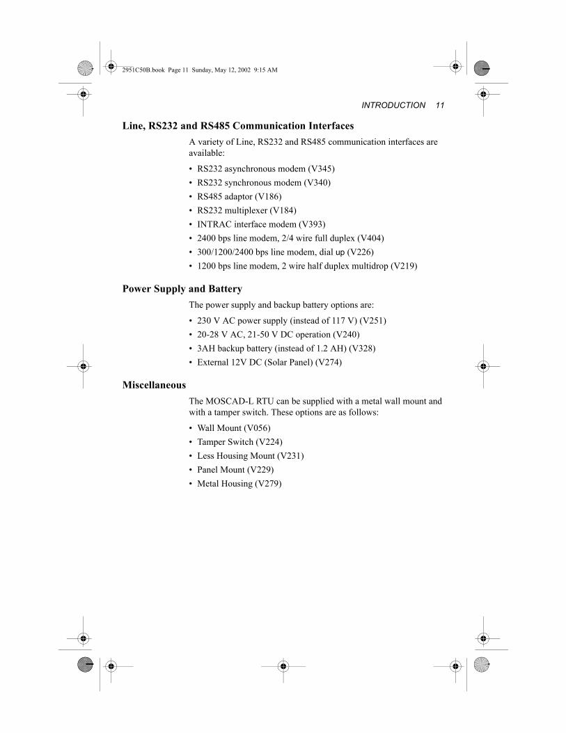
Line, RS232 and RS485 Communication InterfacesA variety of Line, RS232 and RS485 communication interfaces are available:
• RS232 asynchronous modem (V345)• RS232 synchronous modem (V340)• RS485 adaptor (V186)• RS232 multiplexer (V184)• INTRAC interface modem (V393)• 2400 bps line modem, 2/4 wire full duplex (V404)• 300/1200/2400 bps line modem, dial up (V226)• 1200 bps line modem, 2 wire half duplex multidrop (V219)
Power Supply and BatteryThe power supply and backup battery options are:
• 230 V AC power supply (instead of 117 V) (V251)• 20-28 V AC, 21-50 V DC operation (V240)• 3AH backup battery (instead of 1.2 AH) (V328)• External 12V DC (Solar Panel) (V274)
MiscellaneousThe MOSCAD-L RTU can be supplied with a metal wall mount and with a tamper switch. These options are as follows:
• Wall Mount (V056)• Tamper Switch (V224)• Less Housing Mount (V231)• Panel Mount (V229)• Metal Housing (V279)

12 MOSCAD-L
2951C50B.book Page 12 Sunday, May 12, 2002 9:15 AM

2951C50B.book Page 13 Sunday, May 12, 2002 9:15 AM
INSTALLATION
GeneralMOSCAD-L SAFETY SUMMARY
Power Connections:
1. The customer shall be responsible to use a 6A disconnect device (circuit breaker) in series to the AC power cable, according to the local electrical standards and requirements.
2. The AC power lines shall have a cross area of 0.75mm square minimum.
3. The triangle label with the broken arrow inside, means “Be aware, No double insulation”.
4. The customer shall be responsible to use a conduit with a 16mm diameter for the AC power lines connection.
This chapter covers the following installation procedures:
Wall mounting
Connections
Module Replacement
Wall MountingThe following housing installation procedures refer to NEMA4 type plastic housing. The dimensions of the housing are: width – 37.6 cm (14.8"), height – 28 cm (10.92"), depth – 21.6 cm (8.42") (seeFigure 2).
!Warning
The MOSCAD-L should be installed by qualified and authorized technicians. If the installation involves high-voltage connections, technicians must be specifically qualified to handle high voltage.

14 MOSCAD-L
2951C50B.book Page 14 Sunday, May 12, 2002 9:15 AM
The housing can be installed directly, using the four supplied brackets, or with a metal mounting plate (optional).
Before installing the MOSCAD-L RTU with the housing, verify that there is sufficient space around the housing.The space required depends on the manner of installation and direction of the brackets (see Figure 4 and Figure 5).
Wall Mounting With BracketsFour mounting brackets are provided, one for each corner of the RTU (see Figure 4 and Figure 5). To mount the RTU using the mounting brackets, proceed as follows:1. Fasten the mounting brackets to the back corners of the housing
(see Figure 3). The brackets can be mounted horizontally or vertically.
Figure 2Dimensions of MOSCAD-L RTU Plastic Housing
28.0
21.6
37.6

Installation 15
2951C50B.book Page 15 Sunday, May 12, 2002 9:15 AM
2. Choose the means of mounting appropriate for the site (type of screws, etc.) and mount the RTU on the wall, using the mounting brackets. The length of the screws used should not exceed 14 mm.
The part numbers of the parts required for wall mounting with brackets are:
Figure 3Installation of Mounting Brackets
0780559K01 Corner Mounting Bracket
0380346L01 Screw, Hex Head M 6.0 x 1, L=14M
FHN5840A Four corner mounting brackets with screw kit

16 MOSCAD-L
2951C50B.book Page 16 Sunday, May 12, 2002 9:15 AM
Figure 4Bracket Installation Dimensions, with Vertical Brackets (mm)
Figure 5Bracket Installation Dimensions, with Horizontal Brackets (mm)
284
295
321
371
259
224
�10
355

Installation 17
2951C50B.book Page 17 Sunday, May 12, 2002 9:15 AM
Wall Mounting With Mounting PlateA mounting plate can be ordered for wall mounting of the RTU (see Figure 6). To mount the RTU using a mounting plate, proceed as follows:1. Fasten the wall mounting plate to the wall.2. Lift the RTU housing above the plate, and slide the mounting
plate into place (see Figure 6).
The part number of wall mounting kit is FHN5889A.
Wall Mounting On a PanelConvenient installation of the MOSCAD-L RTU on a panel requires the following available space:
Width: 35cm (14”)
Height: 38cm (15”)
Depth: 25cm (10”)
Four holes are provided, one in each corner of the RTU, for wall mounting of the RTU. Figure 7 shows the distance between the holes.
NoteNote
You must leave at least 28 cm free space above the mounting plate for insertion of the RTU housing.
Figure 6Mounting Plate
� 7.0 TYP.4
128 mm
130
mm

18 MOSCAD-L
2951C50B.book Page 18 Sunday, May 12, 2002 9:15 AM
Choose the mounting means (screws, etc.) appropriate for the site and mount the RTU on the wall.
Wall Mounting With HousingThe following housing installation procedure refer to the NEMA4 type housings.
The NEMA4 housing size is:
Width: 38cm (15”)
Height: 38cm (15”)
Depth: 21cm (8.26”)
Convenient installation of the MOSCAD-L RTU with the NEMA4 housing requires the following available space.
Width: 44cm (17.5”)
Height: 44cm (17.5”)
Depth: 28cm (11”)
Figure 7RTU Chassis Installation Dimensions
Installation 19
2951C50B.book Page 19 Sunday, May 12, 2002 9:15 AM
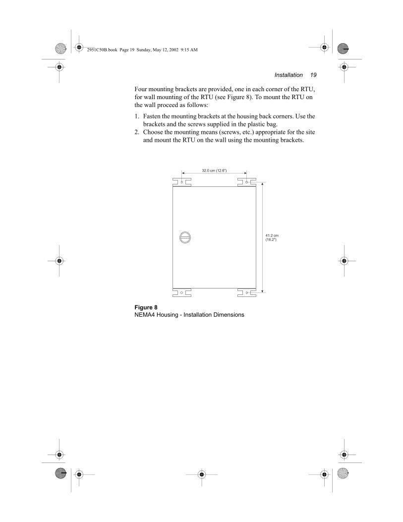
Four mounting brackets are provided, one in each corner of the RTU, for wall mounting of the RTU (see Figure 8). To mount the RTU on the wall proceed as follows:
1. Fasten the mounting brackets at the housing back corners. Use the brackets and the screws supplied in the plastic bag.
2. Choose the mounting means (screws, etc.) appropriate for the site and mount the RTU on the wall using the mounting brackets.
Figure 8NEMA4 Housing - Installation Dimensions
32.0 cm (12.6")
41.2 cm(16.2")
20 MOSCAD-L
2951C50B.book Page 20 Sunday, May 12, 2002 9:15 AM
Connections
Ground ConnectionConnect the grounding cable directly to the protective grounding strip located at the bottom left corner of the housing (see Figure 1).
Power ConnectionsThe transformer is installed in the bottom left hand part of the housing (see Figure 1).
Use the supplied cable connectors to connect the live wire to the live input and neutral wire neutral input.
For further details, refer to the separate chapter in this manual pertaining to power connection instructions.
For instructions regarding power supply connections, refer to the separate chapter in this manual.
User Connections to I/O ModulesFor instructions regarding user connections to the I/O modules, refer to the separate chapter in this manual pertaining to the specific module.
NoteNote
Verify that all power and ground connections are made in accordance with local standards.
To comply with CE standards, the ferrites must be installed on I/O cables and/or at communication port 3 and on grounding wire FKN 4463.
NoteNote
Verify that the voltage of the transformer unit is compatible with the local power supply.
!Caution
If you have a 20-28VAC or 21-50VDC power supply, use cable FKN4466 to connect directly to the PWR IN of the Power Supply Module. If you need to power the unit from a 12VDC source, cable FKN4469 is the proper cable for this source of power. Please note that the wiring of the two cables are different (see 68P02951C50 Appendix A). Do not apply 24VAC or 24VDC to a 12VDC input, as this will damage electrical components
Installation 21
2951C50B.book Page 21 Sunday, May 12, 2002 9:15 AM
Battery ConnectionThe RTU is supplied with the battery disconnected in order to prevent battery leakage. Connect the battery cable to BAT on the power supply module.
Radio ConnectionConnect the radio (when supplied) to AUX connector on the power supply module. Verify that the radio button is set to ON.
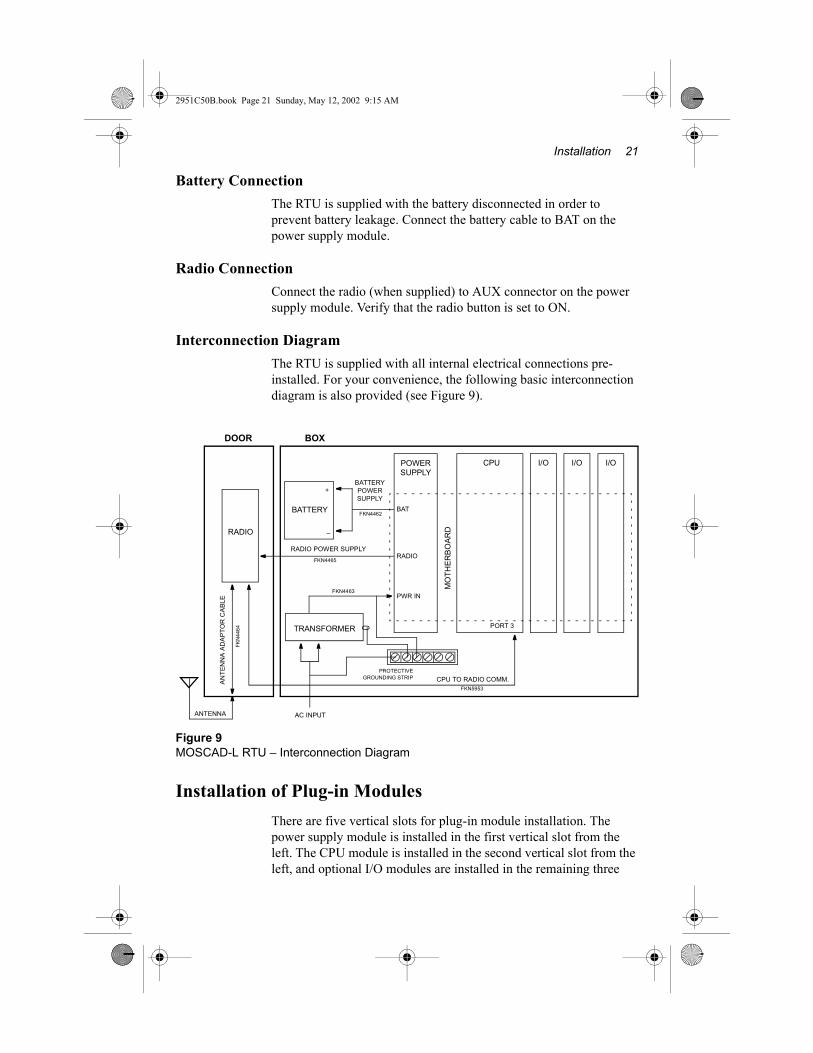
Interconnection DiagramThe RTU is supplied with all internal electrical connections pre-installed. For your convenience, the following basic interconnection diagram is also provided (see Figure 9).
Installation of Plug-in ModulesThere are five vertical slots for plug-in module installation. The power supply module is installed in the first vertical slot from the left. The CPU module is installed in the second vertical slot from the left, and optional I/O modules are installed in the remaining three
Figure 9MOSCAD-L RTU – Interconnection Diagram
POWER SUPPLY
CPU
BATTERY
RADIO
MO
THER
BOAR
D
RADIO
BAT
PORT 3
+
–
ANTENNA
PROTECTIVEGROUNDING STRIP CPU TO RADIO COMM.
RADIO POWER SUPPLY
BATTERY POWER SUPPLY
AN
TEN
NA
AD
APT
OR
CA
BLE
FKN
4464
FKN4462
FKN4465
FKN5953
TRANSFORMER
PWR INFKN4463
AC INPUT
I/O I/O I/O
DOOR BOX

22 MOSCAD-L
2951C50B.book Page 22 Sunday, May 12, 2002 9:15 AM
vertical slots, in accordance with the site configuration instructions provided in the Programming Tool Box. A Line Interface Unit, RS232 Multiplexer or RS485 adaptor can be installed in the horizontal space (above the vertical slots). All modules ordered are pre-installed in the factory.
Label PanelThe MOSCAD-L RTU is supplied with a transparent label panel in which information pertaining to the various I/O modules can be inserted. Pull the label panel out of its slot and swing it into place in front of the I/O modules. You can now insert labels detailing the connections of each module into the relevant slot.
Replacement of Plug-in ModulesFor details on the installation and replacement of the CPU module, 16 DI modules, Mixed I/O modules, Line Interface Unit modules, RS232 Multiplexer module or RS485 adaptor, see the relevant sections.
!Warning
Verify that the DC power is off before removing or installing a module.

Installation 23
2951C50B.book Page 23 Sunday, May 12, 2002 9:15 AM
Miscellaneous
Closing the Housing DoorThe door of the housing does not latch shut when the lock is in a horizontal position. To close the housing properly, use a coin or screwdriver to turn the latch 90 degrees counter-clockwise to a vertical position. In the vertical position, the door latches shut when swung closed. Once the door is latched, verify that the lock is exactly vertical.
Antenna PlacementThe antenna should not be placed on top of the plastic housing.
Closed Open
!Warning
An antenna placed on top of the plastic housing produces strong electromagnetic fields that could be harmful to the electronics of the MOSCAD-L RTU and to people in the vicinity.

24 MOSCAD-L
2951C50B.book Page 24 Sunday, May 12, 2002 9:15 AM
2951C50B.book Page 25 Sunday, May 12, 2002 9:15 AM
POWER CONNECTIONS
Electrical Connection
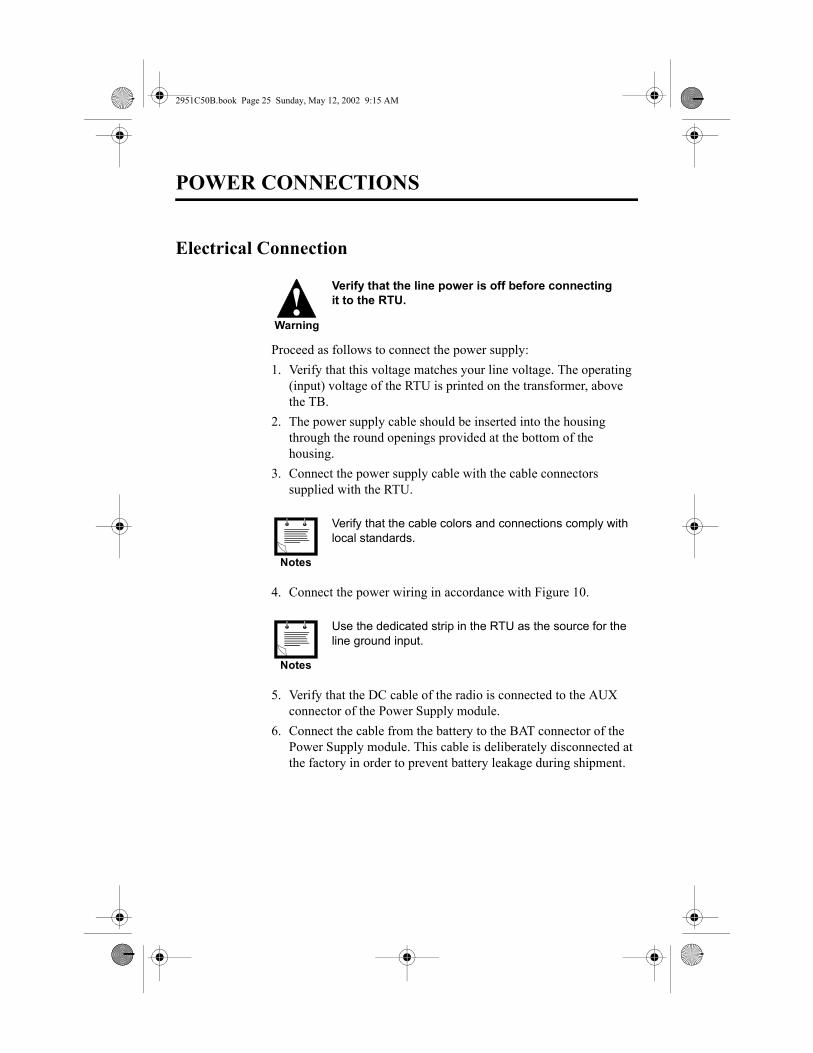
Proceed as follows to connect the power supply:1. Verify that this voltage matches your line voltage. The operating
(input) voltage of the RTU is printed on the transformer, above the TB.
2. The power supply cable should be inserted into the housing through the round openings provided at the bottom of the housing.
3. Connect the power supply cable with the cable connectors supplied with the RTU.
4. Connect the power wiring in accordance with Figure 10.
5. Verify that the DC cable of the radio is connected to the AUX connector of the Power Supply module.
6. Connect the cable from the battery to the BAT connector of the Power Supply module. This cable is deliberately disconnected at the factory in order to prevent battery leakage during shipment.
!Warning
Verify that the line power is off before connecting it to the RTU.
Notes
Verify that the cable colors and connections comply with local standards.
Notes
Use the dedicated strip in the RTU as the source for the line ground input.

26 MOSCAD-L
2951C50B.book Page 26 Sunday, May 12, 2002 9:15 AM
If you have a 20-28 VAC or 21-50 VDC power supply or solar panel, you can connect this input directly to the PWR connector on the Power Supply module, without using a transformer.
For detailed cable connections - see appendix A.
OperationTo turn the RTU on, set the DC switch on the front panel of the Power Supply module to the ON position.
Figure 10Connection of the 230 VAC/24 VA or 117 VAC/24 VAC Transformer
TRANSFORMER
To Grounding Strip
AC Input
L ~N 0
To Power Supply ModulePWR Connector
NoteNote
There are three fuses inside the Power Supply module front panel, to protect the input and output circuits. If the unit is not operating, one of the fuses may have burnt out.

Power Connections 27
2951C50B.book Page 27 Sunday, May 12, 2002 9:15 AM
Controls, Indicators and ConnectorsThe controls, indicators and connectors of the Power Supply module are described in Figure 11 below:.
Figure 11Power Supply Module Front Panel
ON
PWRIN
AUX – DC output connector. Supplies 12 VDC power to radio.
BAT – Connector. Used for interconnecting 12 VDC power between the Power Supply module and the battery.
Indicator – Lit when the Power Supply module is connected to 20-28 VAC/21-50 VDC.
PowerSupply
BAT
AUX
DC
OFF
PWR
DC ON/OFF – Switch. Controls the DC output of the Power Supply module.
F2 4A (Slow Blow) – Fuse for output circuit,Located inside the panel.
F1 4A (Slow Blow) – Fuse for input circuitLocated inside the panel.
PWR IN – Connector. 20-28 VAC/21-50 VDC input to Power Supply module,pin 2&4. 12VDC pin 1&3.
F3 4A (Slow Blow) – Fuse for solar panel input, Located inside the panel.

28 MOSCAD-L
2951C50B.book Page 28 Sunday, May 12, 2002 9:15 AM
Removal and Installation
Removing the Power Supply ModuleTo remove the Power Supply module from the RTU, proceed as follows:1. Turn off the DC power.2. Disconnect all connections from the Power Supply module.3. Pull out the module by pressing the bottom snap.
Installing the Power Supply ModuleTo install a Power Supply module into the RTU, proceed as follows:1. Turn off the DC power2. Slide the Power Supply module into the left RTU slot until the
snaps click into place.3. Reconnect all power supply connections.4. Turn on the DC power.
Replaceable Parts
!Warning
Verify that the DC power is turned off before removing or replacing modules in the RTU.
Part No. Description
6502069C09 Fuse F1/F2/F3 4A T 5 x 20
2951C50B.book Page 29 Sunday, May 12, 2002 9:15 AM
CPU MODULE FRN2341
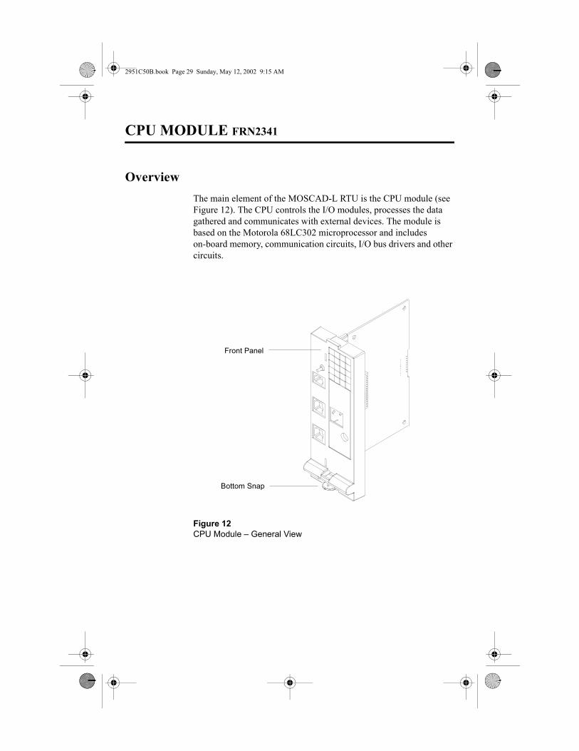
OverviewThe main element of the MOSCAD-L RTU is the CPU module (see Figure 12). The CPU controls the I/O modules, processes the data gathered and communicates with external devices. The module is based on the Motorola 68LC302 microprocessor and includes on-board memory, communication circuits, I/O bus drivers and other circuits.
Figure 12CPU Module – General View
Front Panel
Bottom Snap

30 MOSCAD-L
2951C50B.book Page 30 Sunday, May 12, 2002 9:15 AM
Location of the CPU ModuleThe CPU module is pre-installed in the second slot from the left.
ConnectionsThe specific connections depend on the model ordered and on the various options (radio, line, etc.). See the relevant sections for further instructions.
Controls and IndicatorsThe push-button is used to activate the LED panel, to toggle the LED panel so that it displays the status of the CPU or of one of the optional modules, to initiate software downloading to the CPU, and to erase user flash memory.
Figure 13CPU Module – Front Panel
Pushbutton
Port 1A
Port 1B
Port 2
Port 3
LED Panel

CPU MODULE FRN2341 31
2951C50B.book Page 31 Sunday, May 12, 2002 9:15 AM
LED ControlDisplay On/AdvanceWhen the display is off, pressing the pushbutton once, momentarily, activates the display. Every consecutive momentary depression of the pushbutton advances the display to the next module, in the following order: CPU > M1 (I/O Module 1) > M2 (I/O Module 2) > M3 (I/O Module 3). The next depression of the push-button will return the display to the CPU.Display OffWhen the display is programmed to turn off after a pre-defined time-out (set through the Toolbox Site configuration), if the pushbutton is not pressed for this timeout the display will turn off automatically.LED TestWhen the pushbutton is pressed continuously for a few seconds, all LEDs light up simultaneously. When the pushbutton is released, the LEDs turn off.User Flash EraseAfter power-up, all LEDs light up. To erase User Flash, press the pushbutton while the LEDs are lit. All the LEDs flash three times.Now, release the pushbutton.
Alternatively, press the pushbutton continuously for at least 40 seconds at any time to erase the User Flash.
Software DownloadingDuring power up, press the push-button continuously. This will cause the CPU to enter bootstrap downloading mode in which the FLASH is programmed from a PC connected to Port 2 of the CPU module. The CPU LED will begin to blink at 1 Hz, indicating that the CPU module has entered bootstrap downloading mode. If after 120 seconds no bootstrap software is loaded and executed, the normal power-up procedure is performed.
CPU ResetTo reset the CPU, turn the Power Supply switch off and on again.

32 MOSCAD-L
2951C50B.book Page 32 Sunday, May 12, 2002 9:15 AM
LED Display IndicationsA matrix of 5 � 4 LEDs is used for diagnostics and testing of the CPU module and I/O modules (see Figure 14). The top row indicates to which module (CPU, M1, M2 or M3) the LED panel is set.
ConnectorsThe CPU ports are designed for the following uses:
PORT 1A– Data port (RS-485)PORT 1B– Data port (RS-232)PORT 2 – Data port (RS-232)PORT 3 – Data port (RS-232), radio or line connection.
Ports 2 and 3 can work simultaneously with each other and with either port 1A or port 1B. Ports 1A and 1B cannot work simultaneously.
NoteNote
The blue numerals on the LED panel are I/O indications. Refer to the appropriate I/O module section for more details on these LEDs.
Figure 14LED Panel
CPU M1 M2 M3
LOAD CONF APPL MON1 5 9 13
RST Tx1 Tx2 Tx32 6 10 14
ERR Rx1 Rx2 Rx33 7 11 15
BAT CM1 CM2 CM34 8 12 16

CPU MODULE FRN2341 33
2951C50B.book Page 33 Sunday, May 12, 2002 9:15 AM
The following table describes the functions of the diagnostic LEDs, controls and connectors, when set to the CPU module (CPU LED on):
Name On / Flashing Function / Indication
CPU Flashing CPU is in bootstrap mode.
M1 Flashing Failure in M1 module.
M2 Flashing Failure in M2 module.
M3 Flashing Failure in M3 module.
LOAD On Configuration definition or application program is being downloaded to FLASH memory.
CONF On A site configuration definition has been loaded into FLASH memory.
APPL On An application program has been loaded into FLASH memory.
Flashing One of the following:– The program is in STOP SCAN state, for the Tool Box
Application Programmer’s monitoring program to perform diagnostics operations.
– The application run-time is too long. Could be caused by an error in the Ladder diagram program, such as an infinite loop.
– The application program is in STOP state. This occurs when the Programming Tool Box’s Hardware Test & Calibration Program is performing a hardware test.
MON On The monitoring program of the Tool Box Application Programmer is executing on-line monitoring of the RTU.
TX1 On The RTU is transmitting data via Port 1
TX2 On The RTU is transmitting data via Port 2
TX3 On The RTU is transmitting data via Port 3
RX1 On The RTU is receiving data via Port 1
RX2 On The RTU is receiving data via Port 2
RX3 On The RTU is receiving data via Port 3
CM1 On The communication channel used by Port 1 is busy.
CM2 On The communication channel used by Port 2 is busy.
CM3 On The communication channel used by Port 3 is busy.

34 MOSCAD-L
2951C50B.book Page 34 Sunday, May 12, 2002 9:15 AM
Removal and Installation
Removing the CPU moduleTo remove the CPU module from the RTU, proceed as follows:1. Turn off the DC power.2. Disconnect all connections from the CPU ports.3. Press the snap at the bottom of the CPU and pull the CPU out.
Installing a CPU moduleTo install a CPU module in the RTU, proceed as follows:1. Turn off the DC power.2. Slide the CPU module into the CPU slot until the snap clicks into
place.3. Connect the CPU ports.
RST Flashing The CPU is resetting (usually by the watchdog timer),i.e. indicates that the software is not running properly.
ERR On One of the following malfunctions:– Illegal state detected in the software– Module/board missing– Other malfunctions
ERR Flashing CPU Failure. The type of failure is indicated by other LEDs in the matrix.
BAT On Low battery voltage.
Name On / Flashing Function / Indication
!Warning
Verify that the DC power is turned off before removing or installing a module

2951C50B.book Page 35 Sunday, May 12, 2002 9:15 AM
16 DI MODULE FRN5823
OverviewThe 16 Digital Input (DI) (see Figure 15) can receive up to 16 isolated status inputs from the user equipment. The 16 DI module transfers the data to the CPU module.
Each of the 16 discrete inputs withstands high line noise due to software controlled filters. The discrete inputs can also be utilized as slow speed counters (up to 50 Hz).
Figure 1516 Digital Input (DI) Module
Upper Snap
Bottom Snap
RemovableTerminalBlocks (TB)

36 MOSCAD-L
2951C50B.book Page 36 Sunday, May 12, 2002 9:15 AM
Installation
Module LocationThe 16 DI module should be located in the slot designated by the Site Configuration Program (Programming Tool Box).
ConnectionsPunch a hole at the relevant location and of the appropriate size in one of the perforated circles at the bottom of the RTU housing and thread the wires through the opening. These wires are connected to the user interface TB located at the front of the 16 DI module.
After defining the sensors, controls and I/O module locations using the Site Configuration Program (Programming Tool Box), connect all input connections and TB pin definitions according to this configuration.
Pull out the transparent Label Panel located to the right of the module slots and insert the label with the TB pin connections and definitions into the appropriate slot.
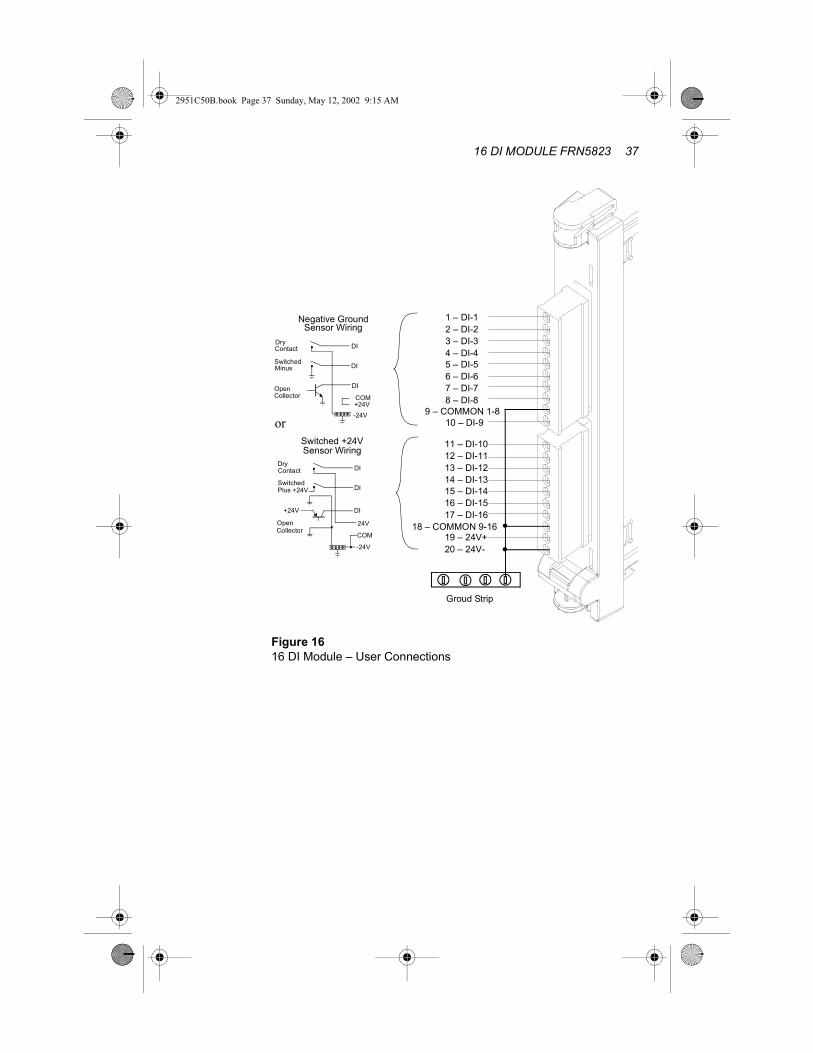
Figure 16 illustrates the 16 DI TB connections. These connections also appear on the label designed to be inserted in the transparent label panel, where you can add a note regarding the function of each connection.
NoteNote
Ensure that the plug with connections 1-10 is inserted into the upper TB and that the plug with connections 11-20 is inserted into the lower TB.
16 DI MODULE FRN5823 37
2951C50B.book Page 37 Sunday, May 12, 2002 9:15 AM
.
Figure 1616 DI Module – User Connections
1 – DI-12 – DI-23 – DI-34 – DI-45 – DI-56 – DI-67 – DI-78 – DI-8
9 – COMMON 1-810 – DI-9
11 – DI-1012 – DI-1113 – DI-1214 – DI-1315 – DI-1416 – DI-1517 – DI-16
18 – COMMON 9-1619 – 24V+20 – 24V-
Groud Strip
DI
DI
DI
+24V-24V
COM
Negative GroundSensor Wiring
DryContact
SwitchedMinus
Open Collector
DI
DI
DI
24V
-24V
COM
Switched +24VSensor Wiring
DryContact
SwitchedPlus +24V
Open Collector
+24V
or

38 MOSCAD-L
2951C50B.book Page 38 Sunday, May 12, 2002 9:15 AM
Removal and Installation
Removing a 16 DI ModuleTo remove a 16 DI module from the RTU, proceed as follows:1. Turn off the DC power.2. Open the label panel and slide it into place.3. Disconnect the plugs from the module TBs.4. Pull out the module by pressing the top and bottom snaps.
Installing a 16 DI ModuleTo install a 16 DI module in the RTU, proceed as follows:1. Turn off the DC power.2. Slide the module into the appropriate RTU slot until the snaps
click into place.3. Reconnect the plugs into the module TBs, verifying that
connections no. 1-10 and 11-20 are in the correct order.
LED PanelA matrix of 5 � 4 LEDs, located on the CPU module, is used for diagnostics and testing of the CPU and I/O modules (see Figure 17). The top row indicates to which module (CPU, M1, M2 or M3) the LED panel is set, and the blue numerals on the LED panel are I/O indications.
Setting the LED Display to the Relevant ModuleIf the display is off, press the pushbutton once, momentarily, to activate the LED panel. Every consecutive momentary depression of the pushputton will advance the display to the next module, in the following order: CPU > M1 (I/O Module 1) > M2 (I/O Module 2) > M3 (I/O Module 3). The next depression of the push-button will return the display to the CPU. Verify that the relevant LED is lit.
!Warning
Verify that the DC power is turned off before removing or installing a module.

16 DI MODULE FRN5823 39
2951C50B.book Page 39 Sunday, May 12, 2002 9:15 AM
The table below describes the functions of the diagnostic LEDs when set to the 16 DI module, i.e. the relevant LED in the top row (M1, M2 or M3) is on. These indications also appear on the label designed to be inserted in the transparent Label Panel
Replaceable Parts
Figure 17LED Panel
LED No. Indication LED No. Indication
1 DI-1 9 DI-9
2 DI-2 10 DI-10
3 DI-3 11 DI-11
4 DI-4 12 DI-12
5 DI-5 13 DI-13
6 DI-6 14 DI-14
7 DI-7 15 DI-15
8 DI-8 16 DI-16
CPU M1 M2 M3
LOAD CONF APPL MON1 5 9 13
RST Tx1 Tx2 Tx32 6 10 14
ERR Rx1 Rx2 Rx33 7 11 15
BAT CM1 CM2 CM34 8 12 16
Part No. Description
3108509G18 User connections plug 10-pin

40 MOSCAD-L
2951C50B.book Page 40 Sunday, May 12, 2002 9:15 AM

2951C50B.book Page 41 Sunday, May 12, 2002 9:15 AM
MIXED I/O MODULE FRN5819A, FRN5820A
OverviewThe Mixed I/O module (see Figure 18) is designed to provide a combination of different functions, as follows:
• It can receive up to two optically isolated analog inputs (AI). The module converts the input analog data into digital format and transfers the digital data to the CPU module.
• It can receive up to eight isolated status inputs (DI). The data is transferred to the CPU module.
• It can provide two relay outputs for controlling user devices. Relays K1 and K2 are Single Pole Single Throw (SPST), normally open (NO) relays.
Figure 18Mixed I/O 8 DI, 2 Relay EE/2 Relay ML, 2AI 4-20mA
Upper Snap
Bottom Snap
RemovableTerminalBlocks (TB)

42 MOSCAD-L
2951C50B.book Page 42 Sunday, May 12, 2002 9:15 AM
Model OptionsAvailable Mixed I/O module standard options:• 2EE, 8DI, 2AI (4-20 mA)• 2ML, 8DI, 2AI (4-20 mA)
Installation
Module LocationThe Mixed I/O module should be located in the slot designated by the Site Configuration Program (Programming Tool Box).
ConnectionsPunch a hole at the relevant location and of the appropriate size in one of the perforated circles at the bottom of the RTU housing and thread the wires through the opening. These wires are connected to the user interface TB located at the front of the Mixed I/O module.
After defining the sensors, controls and I/O module locations using the Site Configuration Program (Programming Tool Box), connect all input connections and TB pin definitions according to this configuration.
Pull out the transparent Label Panel located to the left of the module slots and insert a label with the TB pin connections and definitions into the appropriate slot.
Figure 19 illustrates the Mixed I/O TB connections. These connections also appear on the label designed to be inserted in the transparent label panel, where you can add a note regarding the function of each connection.
NoteNote
Ensure that the plug with connections 1-10 is inserted into the upper TB and the plug with connections 11-20 is inserted in the lower TB.

MIXED I/O MODULE FRN5819A, FRN5820A 43
2951C50B.book Page 43 Sunday, May 12, 2002 9:15 AM
AI Input
+
+
-
-AI Input
DC Power Supply
4-WireTransmitter
+
-DC Power Supply
2-WireTransmitter + -
Or
+
-
.
Figure 19Mixed I/O Module – 8DI,2EE/2ML Relay, 2AI - User Connectors
2 – AI-1-3 – AI-2+4 – AI-2-5 – PGND6 – DI-17 – DI-28 – DI-39 – DI-410 – DI-5
11 – DI-612 – DI-713 – DI-814 – COMMON15 – K1-NO16 – K1-C17 – K2-NO18 – K2-C19 – 24V+20 – 24V-
Analog 1
Analog 2
ControlledDevice
-
-
+
+
Ground Strip
1. Relay Contacts Ratings:- Max switching power = 60W 120VA- Max switching Voltage = 220VDC, 250VAC- Max switching current = 2A DC/AC2. Relays are shown in the normal (non active) state.3. For best performance, the wires from user analog sensors should be shielded.
1 – AI-1+
K1
K2
DI
DI
DI
+24V-24V
COM
Negative GroundSensor Wiring
DryContact
SwitchedMinus
Open Collector
DI
DI
DI
+24V
-24V
COM
Switched +24VSensor Wiring
DryContact
SwitchedPlus +24V
Open Collector
+24V
or

44 MOSCAD-L
2951C50B.book Page 44 Sunday, May 12, 2002 9:15 AM
Removal and Installation
Removing a Mixed I/O ModuleTo remove a mixed I/O module from the RTU, proceed as follows:1. Turn off the DC power.2. Open the label panel and slide it into place.3. Disconnect the plugs from the module TBs.4. Pull out the mixed I/O module by pressing the top and bottom
snaps.
Installing a Mixed I/O ModuleTo install a Mixed I/O module in the RTU, proceed as follows:1. Turn off the DC power.2. Slide the module into the appropriate RTU slot until the snaps
click into place.3. Reconnect the plugs into the module TBs, verifying that
connections no. 1-10 and 11-20 are in the correct order.
LED PanelA matrix of 5 ��4 LEDs, located on the CPU module, is used for diagnostics and testing of the CPU and I/O modules (see Figure 20). The top row indicates to which module (CPU, M1, M2 or M3) the LED panel is set, and the blue numerals on the LED panel are I/O indications.
Setting the LED Display to the Relevant ModuleIf the LEDs are off, press the pushbutton once, momentarily, to activate the LED panel. Every consecutive momentary depression of the pushputton will advance the display to the next module, in the following order: CPU > M1 (I/O Module 1) > M2 (I/O Module 2) > M3 (I/O Module 3). The next depression of the push-button will return the display to the CPU. Verify that the relevant LED is lit.
!Warning
Verify that the DC power is turned off before removing or installing a module.

MIXED I/O MODULE FRN5819A, FRN5820A 45
2951C50B.book Page 45 Sunday, May 12, 2002 9:15 AM
The following table describes the functions of the diagnostic LEDs, controls and connectors, when set to the 16 DI module, i.e. the relevant LED in the top row (M1, M2 or M3) is on. These indications also appear on the label designed to be inserted in the transparent Label Panel.
Replaceable Parts
Figure 20LED Panel
LED No. Indication LED No. Indication
1 DI-1 9 DO-1
2 DI-2 10 DO-2
3 DI-3 11
4 DI-4 12
5 DI-5 13 UDF-1
6 DI-6 14 OVF-1
7 DI-7 15 UDF-2
8 DI-8 16 OVF-2
CPU M1 M2 M3
LOAD CONF APPL MON1 5 9 13
RST Tx1 Tx2 Tx32 6 10 14
ERR Rx1 Rx2 Rx33 7 11 15
BAT CM1 CM2 CM34 8 12 16
Part No. Description
3108509G18 User connections plug

46 MOSCAD-L
2951C50B.book Page 46 Sunday, May 12, 2002 9:15 AM

2951C50B.book Page 47 Sunday, May 12, 2002 9:15 AM
8 DO MODULE FRN5825, FRN5826
Overview
The 8 DO (Digital Output) module (see Figure 21) has 8 relay out-puts to drive user equipment.
The module is controlled by the CPU module and transfer feedback signals, generated by the auxiliary relays contacts.
Four of the relays (Kl to K4) are Single Pole Double Throw (SPDT), with one normally open contact (NO) and one normally closed con-tact (NC), and are referred as “Form C” relays.
The other four relays, namely KS to K8, are Single Pole Single Throw (SPST) normally open (NO), and are referred as “Form A” relays.
The outputs of the relays Kl to K8 are either Magnetically Latched (ML) FRN5826A or Electrically Energized (EE) FRN5825A, depending on the module option. The outputs of the magnetically latched relays maintain their state in case of power off or module failure, while the outputs of the electrically latched relays return to the non energized state in case of power off or module failure.
Figure 218 Digital Output (DO) Module - General View.
Upper Snap
Bottom Snap
RemovableTerminalBlocks (TB)

48 MOSCAD-L
2951C50B.book Page 48 Sunday, May 12, 2002 9:15 AM
Installation
Module Location
The 8 DO module should be located in the slot designated by the SiteConfiguration Program (Programming Tool Box).
Connections
Connect wires from the relay output TB, located on module frontpanel, to user equipment.
For NEMA4X housing, thread the wires through the opening at thebottom of the box.
Pull out the transparent Label Panel located to the right of the module slots and insert the label with the TB pin connections and definitions into the appropriate slot.
.
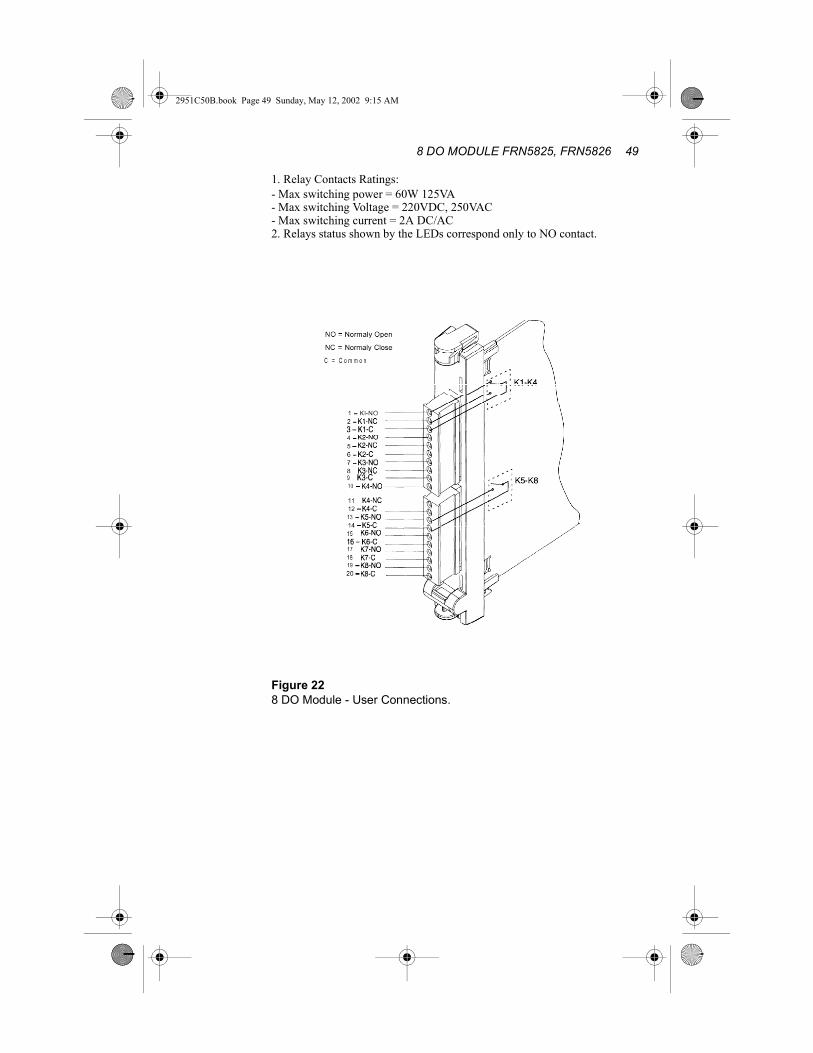
Figure 22 illustrates the 8 DO TB connections. These connections also appear on the label designed to be inserted in the transparent label panel, where you can add a note regarding the function of each connection.
NoteNote
Ensure that the plug with connections l-l 0 is inserted into the upper TB and that the plug with connections 11-20 isinserted into the lower TB.
8 DO MODULE FRN5825, FRN5826 49
2951C50B.book Page 49 Sunday, May 12, 2002 9:15 AM
1. Relay Contacts Ratings:- Max switching power = 60W 125VA- Max switching Voltage = 220VDC, 250VAC- Max switching current = 2A DC/AC2. Relays status shown by the LEDs correspond only to NO contact.
Figure 228 DO Module - User Connections.

50 MOSCAD-L
2951C50B.book Page 50 Sunday, May 12, 2002 9:15 AM
Removal and Installation.
Removing a 8 DO ModuleTo remove a 8 DO module from the RTU, proceed as follows:
1. Turn off the DC power.2. Open the label panel and slide it into place.3. Disconnect the plugs from the module TBS.4. Pull out the module by pressing the top and bottom snaps.
Installing a 8 DO ModuleTo install a 8 DO module in the RTU, proceed as follows:
1. Turn off the DC power.2. Slide the module into the appropriate RTU slot until the snaps
click into place.3. Reconnect the plugs into the module TBs, verifying that
connections no. 1- 10 and 1 l-20 are in the correct order.
LED PanelA matrix of 5 x 4 LEDs, located on the CPU module, is used for diagnostics and testing of the CPU and I/O modules (see Figure 23). The top row indicates to which module (CPU, Ml, M2 or M3) the LED panel is set, and the blue numerals on the LED panel are I/O indications.
Setting the LED Display to the Relevant ModuleIf the display is off, press the pushbutton once, momentarily, to activate the LED panel. Every consecutive momentary depression of the pushputton will advance the display to the next module, in the following order: CPU > Ml (I/O Module 1) > M2 (I/O Module 2) > M3 (I/O Module 3). The next depression of the push-button will return the display to the CPU. Verify that the relevant LED is lit.
!Warning
Verify that the DC power is turned off before removingor installing a module.

8 DO MODULE FRN5825, FRN5826 51
2951C50B.book Page 51 Sunday, May 12, 2002 9:15 AM
Figure 23LED Panel
The table below describes the functions of the diagnostic LEDs when set to the 8 DO module, i.e. the relevant LED in the top row (Ml, M2 or M3) is on. These indications also appear on the label designed to be inserted in the transparent Label Panel.
LED lit - contact is connected to Common.LED off - contact is disconnected from Common
LED No. Indication LED No. Indication
1 Kl -NO 9 Not Used
2 K2-NO IO Not Used
3 K3-NO 11 Not Used
4 K4-NO 1 2 Not Used
5 K5-NO 1 3 Not Used
6 K6-NO 1 4 Not Used
7 K7-NO 1 5 Not Used
8 K8-NO 1 6 Not Used
CPU M1 M2 M3LOADCONF APPL MON
1 5 9 13RST Tx1 Tx2 Tx3
2 6 10 14ERR Rx1 Rx2 Rx3
3 7 11 15BAT CM1 CM2 CM3
4 8 12 16

52 MOSCAD-L
2951C50B.book Page 52 Sunday, May 12, 2002 9:15 AM
Replaceable Parts
Part No. Description
3108509618 User connections plug 1 O-pin

2951C50B.book Page 53 Sunday, May 12, 2002 9:15 AM
8 OPEN COLLECTOR DO FCN6045A
OverviewThe 8 Open Collector Digital Output (OCDO) module (see Figure 24) has 8 transistor outputs to drive user equipment.
The module is controlled by the CPU module and transfer feedback signals.
The other four relays, namely K1 to K8, are Single Pole Single Throw (SPST) normally open (NO), and are referred as “Form A” relays.The transistors Kl to K8 are Electrically Energized (EE) FCN6045A, The outputs of the electrically energized transistor return to the non energized state in case of power off or module failure.
Figure 248 Open Collector Digital Output (OCDO) Module
RemovableTerminalBlocks (TB)
Upper Snap
Buttom Snap

54 MOSCAD-L
2951C50B.book Page 54 Sunday, May 12, 2002 9:15 AM
Installation
Module LocationThe 8 (OCDO) module should be located in the slot designated by the Site Configuration Program (Programming Tool Box). Same as the 8DO EE relays output.
ConnectionsConnect wires from the relay output TB, located on module front panel, to user equipment.
For NEMA4X housing, thread the wires through the opening at the bottom of the box.
Pull out the transparent Label Panel located to the right of the module slots and insert the label with the TB pin connections and definitions into the appropriate slot.
Figure 25 illustrates the 8 DO TB connections. These connections also appear on the label designed to be inserted in the transparent label panel, where you can add a note regarding the function of each connection.
NoteNote
Ensure that the plug with connections l-l 0 is inserted into the upper TB and that the plug with connections 11-20 is inserted into the lower TB.

8 OPEN COLLECTOR DO FCN6045A 55
2951C50B.book Page 55 Sunday, May 12, 2002 9:15 AM
1. Transistor outputs Ratings:- Max switching power = 15W- Max switching Voltage = 30VDC- Max switching current = 0.5A DC2. Transistor status shown by the LEDs correspond only to NO contact.
Figure 258 OCDO Module - User Connections.
1 - K1-NO2 - K2-NO3 - K3-NO4 - K4-NO5 - K5-NO6 - K6-NO7 - K7-NO8 - K8-NO9 - Comm1PGND
NO = Normly OpenComm1 = Common 1PGND = Protective Ground

56 MOSCAD-L
2951C50B.book Page 56 Sunday, May 12, 2002 9:15 AM
Removal and Installation.
Removing a 8 DO ModuleTo remove a 8 OCDO module from the RTU, proceed as follows:
1. Turn off the DC power.2. Open the label panel and slide it into place.3. Disconnect the plugs from the module TBS.4. Pull out the module by pressing the top and bottom snaps.
Installing a 8 DO ModuleTo install a 8 OCDO module in the RTU, proceed as follows:
1. Turn off the DC power.2. Slide the module into the appropriate RTU slot until the snaps
click into place.3. Reconnect the plugs into the module TBs, verifying that
connections no. 1- 10 and 1 l-20 are in the correct order.
LED PanelA matrix of 5 x 4 LEDs, located on the CPU module, is used for diagnostics and testing of the CPU and I/O modules (see Figure 26).
The top row indicates to which module (CPU, Ml, M2 or M3) the LED panel is set, and the blue numerals on the LED panel are I/O indications.
Setting the LED Display to the Relevant ModuleIf the display is off, press the pushbutton once, momentarily, to activate the LED panel. Every consecutive momentary depression of the pushputton will advance the display to the next module, in the following order: CPU > Ml (I/O Module 1) > M2 (I/O Module 2) > M3 (I/O Module 3). The next depression of the push-button will return the display to the CPU. Verify that the relevant LED is lit.
!Warning
Verify that the DC power is turned off before removingor installing a module.

8 OPEN COLLECTOR DO FCN6045A 57
2951C50B.book Page 57 Sunday, May 12, 2002 9:15 AM
Figure 26LED Panel
The table below describes the functions of the diagnostic LEDs when set to the 8 OCDO module, i.e. the relevant LED in the top row (Ml, M2 or M3) is on. These indications also appear on the label designed to be inserted in the transparent Label Panel.
LED lit - contact is connected to Common.LED off - contact is disconnected from Common
LED No. Indication LED No. Indication
1 Kl -NO 9 Not Used
2 K2-NO IO Not Used
3 K3-NO 11 Not Used
4 K4-NO 1 2 Not Used
5 K5-NO 1 3 Not Used
6 K6-NO 1 4 Not Used
7 K7-NO 1 5 Not Used
8 K8-NO 1 6 Not Used
CPU M1 M2 M3LOAD CONF APPL MON
1 5 9 13RST Tx1 Tx2 Tx3
2 6 10 14ERR Rx1 Rx2 Rx3
3 7 11 15BAT CM1 CM2 CM3
4 8 12 16

58 MOSCAD-L
2951C50B.book Page 58 Sunday, May 12, 2002 9:15 AM
Replaceable Parts
Part No. Description
3108509618 User connections plug 1 O-pin

2951C50B.book Page 59 Sunday, May 12, 2002 9:15 AM
16 DI (110VAC) FRN5939
OverviewThe 16 Digital Input (DI) (see Figure 27) can receive up to 16 isolated status inputs from the user equipment. The 16 DI module transfers the data to the CPU module.
Each of the 16 discrete inputs withstands high line noise due to software controlled filters.
Figure 2716 Digital Input (DI) Module
Upper Snap
Bottom Snap
RemovableTerminalBlocks (TB)

60 MOSCAD-L
2951C50B.book Page 60 Sunday, May 12, 2002 9:15 AM
Installation
Module LocationThe 16 DI module should be located in the slot designated by the Site Configuration Program (Programming Tool Box).
ConnectionsPunch a hole at the relevant location and of the appropriate size in one of the perforated circles at the bottom of the RTU housing and thread the wires through the opening. These wires are connected to the user interface TB located at the front of the 16 DI module.
After defining the sensors, controls and I/O module locations using the Site Configuration Program (Programming Tool Box), connect all input connections and TB pin definitions according to this configuration.
Pull out the transparent Label Panel located to the right of the module slots and insert the label with the TB pin connections and definitions into the appropriate slot.
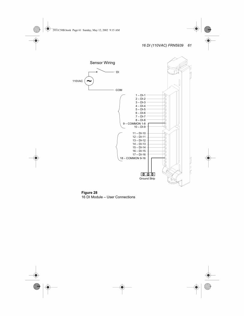
Figure 28 illustrates the 16 DI TB connections. These connections also appear on the label designed to be inserted in the transparent label panel, where you can add a note regarding the function of each connection.
NoteNote
Ensure that the plug with connections 1-10 is inserted into the upper TB and that the plug with connections 11-20 is inserted into the lower TB.
16 DI (110VAC) FRN5939 61
2951C50B.book Page 61 Sunday, May 12, 2002 9:15 AM
.
Figure 2816 DI Module – User Connections
1 – DI-12 – DI-23 – DI-34 – DI-45 – DI-56 – DI-67 – DI-78 – DI-8
9 – COMMON 1-810 – DI-9
11 – DI-1012 – DI-1113 – DI-1214 – DI-1315 – DI-1416 – DI-1517 – DI-16
18 – COMMON 9-16
Ground Strip
DI
COM
~
Sensor Wiring
110VAC

62 MOSCAD-L
2951C50B.book Page 62 Sunday, May 12, 2002 9:15 AM
Removal and Installation
Removing a 16 DI ModuleTo remove a 16 DI module from the RTU, proceed as follows:1. Turn off the DC power.2. Open the label panel and slide it into place.3. Disconnect the plugs from the module TBs.4. Pull out the module by pressing the top and bottom snaps.
Installing a 16 DI ModuleTo install a 16 DI module in the RTU, proceed as follows:1. Turn off the DC power.2. Slide the module into the appropriate RTU slot until the snaps
click into place.3. Reconnect the plugs into the module TBs, verifying that
connections no. 1-10 and 11-20 are in the correct order.
LED PanelA matrix of 5 � 4 LEDs, located on the CPU module, is used for diagnostics and testing of the CPU and I/O modules (see Figure 29). The top row indicates to which module (CPU, M1, M2 or M3) the LED panel is set, and the blue numerals on the LED panel are I/O indications.
Setting the LED Display to the Relevant ModuleIf the display is off, press the pushbutton once, momentarily, to activate the LED panel. Every consecutive momentary depression of the pushputton will advance the display to the next module, in the following order: CPU > M1 (I/O Module 1) > M2 (I/O Module 2) >
!Warning!
Warning
Verify that the DC power is turned off before removing or installing a module.
!Caution
Do not connect the110V input lines to the module before installing the module in the MOSCAD-L unit. Follow local regulations regarding high Voltage when handling the MOSCAD-L unit.

16 DI (110VAC) FRN5939 63
2951C50B.book Page 63 Sunday, May 12, 2002 9:15 AM
M3 (I/O Module 3). The next depression of the push-button will return the display to the CPU. Verify that the relevant LED is lit.
The table below describes the functions of the diagnostic LEDs when set to the 16 DI module, i.e. the relevant LED in the top row (M1, M2 or M3) is on. These indications also appear on the label designed to be inserted in the transparent Label Panel
Figure 29LED Panel
LED No. Indication LED No. Indication
1 DI-1 9 DI-9
2 DI-2 10 DI-10
3 DI-3 11 DI-11
4 DI-4 12 DI-12
5 DI-5 13 DI-13
6 DI-6 14 DI-14
7 DI-7 15 DI-15
8 DI-8 16 DI-16
CPU M1 M2 M3
LOAD CONF APPL MON1 5 9 13
RST Tx1 Tx2 Tx32 6 10 14
ERR Rx1 Rx2 Rx33 7 11 15
BAT CM1 CM2 CM34 8 12 16

64 MOSCAD-L
2951C50B.book Page 64 Sunday, May 12, 2002 9:15 AM
Replaceable Parts
Part No. Description
3108509G18 User connections plug 10-pin

2951C50B.book Page 65 Sunday, May 12, 2002 9:15 AM
16 OPEN COLLECTOR DO FCN6046A
OverviewThe 16 Open Collector Digital Output (OCDO) module has 16 transistor outputs to drive user equipment. (See Figure 30) The module is controlled by the CPU module and transfer feedback signals.
The 16 open collector transistors, namely K1 to K16, are Single Pole Single Throw (SPST) normally open (NO), and are referred as “Form A” relays.
The transistors Kl to K16 are Electrically Energized (EE). The outputs of the electrically energized transistor return to the non- energized state in case of power off or module failure.16 Open Collector Digital Output (OCDO) Module
Figure 3016 Open Collector Digital Output (OCDO) Module
Upper Snap
Bottom Snap
RemovableTerminalBlocks (TB)

66 MOSCAD-L
2951C50B.book Page 66 Sunday, May 12, 2002 9:15 AM
Installation
Module LocationThe 16 (OCDO) module should be located in the slot designated by the Site Configuration Program of the MOSCAD Programming ToolBox) (System V8.04 and above + ToolBox V8.50 Service Pack 1 and above.)
ConnectionsConnect wires from the output TB, located on module front panel, to user equipment.
For NEMA4X housing, thread the wires through the opening at the bottom of the box.
Figure 31 illustrates the 16 DO TB connections. These connections also appear on the label designed to be inserted in the transparent label panel, where you can add a note regarding the function of each connection.
NoteNote
Ensure that the plug with connections 1-10 is inserted into the upper TB and that the plug with connections 11-20 is inserted into the lower TB. Use wire gauge < 16 AWG.

16 OPEN COLLECTOR DO FCN6046A 67
2951C50B.book Page 67 Sunday, May 12, 2002 9:15 AM
1. Transistor outputs Ratings:• - Max switching power = 15W• - Max switching Voltage = 30VDC• - Max switching current = 0.5A DC2. Transistor status shown by the LEDs correspond only to NO contact.
Figure 3116 OCDO Module - User Connections
K1
K9
NO = Normally OpenComm1 = Common 1PGND = Protective Ground
11-K9-NO12-K10-NO13-K11-NO14-K12-NO15-K13-NO16-K14-NO17-K15-NO18-K16-NO19-Comm220-PGND
1 - K1-NO2 - K2-NO3 - K3-NO4 - K4-NO5 - K5-NO6 - K6-NO7 - K7-NO8 - K8-NO9 - Comm110-PGND
68 MOSCAD-L
2951C50B.book Page 68 Sunday, May 12, 2002 9:15 AM
Removal and Installation.
Removing a 16 DO ModuleTo remove a 16 OCDO module from the RTU, proceed as follows:
1. Turn off the DC power.2. Disconnect the plugs from the module TBS.3. Pull out the module by pressing the top and bottom snaps.
Installing a 16 DO ModuleTo install a 16 OCDO module in the RTU, proceed as follows:
1. Turn off the DC power.2. Slide the module into the appropriate RTU slot until the snaps
click into place.3. Reconnect the plugs into the module TBs, verifying that
connections no. 1- 10 and 1l-20 are in the correct order.
LED PanelA matrix of 5 x 4 LEDs, located on the CPU module, is used for diagnostics and testing of the CPU and I/O modules (see Figure 32).
The top row indicates to which module (CPU, Ml, M2 or M3) the LED panel is set, and the blue numerals on the LED panel are I/O indications.
Setting the LED Display to the Relevant ModuleIf the display is off, press the pushbutton once, momentarily, to activate the LED panel. Every consecutive momentary depression of the pushputton will advance the display to the next module, in the following order: CPU > Ml (I/O Module 1) > M2 (I/O Module 2) > M3 (I/O Module 3). The next depression of the push-button will return the display to the CPU. Verify that the relevant LED is lit.
!Warning
Verify that the DC power is turned off before removing or installing a module.

16 OPEN COLLECTOR DO FCN6046A 69
2951C50B.book Page 69 Sunday, May 12, 2002 9:15 AM
Figure 32LED Panel
The table below describes the functions of the diagnostic LEDs when set to the 16 OCDO module, i.e. the relevant LED in the top row (Ml, M2 or M3) is on. These indications also appear on the label designed to be inserted in the transparent Label Panel
LED lit - collector is connected to Common.LED off - collector is disconnected from Common
LED No. Indication LED No. Indication
1 Kl -NO 9 K9 - NO
2 K2-NO I0 K10 - NO
3 K3-NO 11 K11 - NO
4 K4-NO 12 K12 - NO
5 K5-NO 13 K13 - NO
6 K6-NO 14 K14 - NO
7 K7-NO 15 K15 - NO
8 K8-NO 16 K16 - NO
CPU M1 M2 M3
LOAD CONF APPL MON1 5 9 13
RST Tx1 Tx2 Tx32 6 10 14
ERR Rx1 Rx2 Rx33 7 11 15
BAT CM1 CM2 CM34 8 12 16
70 MOSCAD-L
2951C50B.book Page 70 Sunday, May 12, 2002 9:15 AM
Replaceable Parts
Part No. Description
3108509G18 User connections plug 10-pin

2951C50B.book Page 71 Sunday, May 12, 2002 9:15 AM
24 DI & 8 DO FCN6102A
OverviewThe 24 Digital Input/8 Digital Output (Open Collector) module (see Figure 33) can receive up to 24 isolated status inputs from the user equipment and activate up to 8 EE (Electrically Energized) Open Collector outputs. The module transfers the data to the CPU module.
Each of the first 16 discrete inputs withstands high line noise due to software controlled filters. The other eight inputs are hardware filtered only. The first 16 discrete inputs can also be utilized as slow speed counters up to 50 Hz, using an interrupt mechanism.
Figure 3324 DI/8 DO Module
Upper Snap
Bottom Snap
RemovableTerminalBlocks (TB)

72 MOSCAD-L
2951C50B.book Page 72 Sunday, May 12, 2002 9:15 AM
Installation
Module LocationThe 24 DI/8 DO module should be located in the slot designated by the Site Configuration Program of the MOSCAD Programming ToolBox (System V8.04 and above + ToolBox V8.50 Service Pack 1 and above.)
ConnectionsPunch a hole of the appropriate size at the relevant location in one of the perforated circles at the bottom of the RTU housing and thread the wires through the opening. These wires are connected to the user interface TB located at the front of the module.
After defining the sensors, controls and I/O module locations using the Site Configuration Program (MOSCAD Programming Tool Box), connect all input connections and TB pin definitions according to this configuration.
Figure 34 illustrates the 24 DI/8 DO TB connections. These connections also appear on the label designed to be inserted in the transparent label panel, where you can add a note regarding the function of each connection.
NoteNoteNoteNoteNoteNoteNoteNoteNoteNoteNoteNoteNoteNoteNoteNoteNoteNote
Ensure that the plug with connections 1-10 is inserted into the upper TB, that the plug with connections 11-20 is inserted into the second TB, that the plug with connec-tions 21-30 is inserted into the third TB, and that the plug with connections 31-40 is inserted into the fourth TB.Use wire gauge 20-24 AWG.

24 DI & 8 DO FCN6102A 73
2951C50B.book Page 73 Sunday, May 12, 2002 9:15 AM
1. Transistor outputs Ratings:- Max switching power = 6W- Max switching voltage = 30V DC- Max switching current = 0.2A DC
2. Transistor status shown by the LEDs corresponds only to NO contact.
Figure 3424 DI/8 DO Module - User Connections
K4 C K1-4K5 K6 K7 K8 C K5-8PGND24V+24V-
DI 1 DI 2 DI 3 DI 4 DI 5 DI 6 DI 7 DI 8 C 1-8 DI 9
DI 10 DI 11DI 12 DI 13 DI 14 DI 15 DI 16 C 9-16DI 17DI 18
DI 19 DI 20DI 21 DI 22 DI 23 DI 24 C17-24 K1K2K3
DI
DI
DI
24V
-24V
COM
Switched +24VSensor Wiring
DryContact
SwitchedPlus +24V
Open Collector
+24V

74 MOSCAD-L
2951C50B.book Page 74 Sunday, May 12, 2002 9:15 AM
Removal and Installation.
Removing a 24 DI/8 DO ModuleTo remove a 24 DI/8 DO module from the RTU, proceed as follows:
1. Turn off the DC power.2. Disconnect the plugs from the module TBS.3. Pull out the module by pressing the top and bottom snaps.
Installing a 24 DI/8 DO ModuleTo install a 24 DI/8 DO module in the RTU, proceed as follows:
1. Turn off the DC power.2. Slide the module into the appropriate RTU slot until the snaps
click into place.3. Reconnect the plugs into the module TBs, verifying that
connections are in the correct order. (no. 1- 10 in the upper TB, 1l-20 in the next TB, etc.
LED PanelA matrix of 5 x 4 LEDs, located on the CPU module, is used fordiagnostics and testing of the CPU and I/O modules (see Figure 35).
The top row indicates to which module (CPU, Ml, M2 or M3) the LED panel is set, and the blue numerals on the LED panel are I/O indications.
Setting the LED Display to the Relevant ModuleIf the display is off, press the pushbutton once, momentarily, to activate the LED panel. Every consecutive momentary depression of the pushputton will advance the display to the next module, in the following order: CPU > Ml (I/O Module 1) > M2 (I/O Module 2) > M3 (I/O Module 3). The next depression of the push-button will return the display to the CPU. Verify that the relevant LED is lit.
!Warning
Verify that the DC power is turned off before removing or installing a module.

24 DI & 8 DO FCN6102A 75
2951C50B.book Page 75 Sunday, May 12, 2002 9:15 AM
Figure 35LED Panel
The table below describes the functions of the diagnostic LEDs when set to the 24 DI/8 DO module, i.e. the relevant LED in the top row (Ml, M2 or M3) is on. These indications also appear on the label designed to be inserted in the transparent Label Panel.
LED No. Indication LED No. Indication LED No. Indication
13 & 1 DI - 1 14 & 1 DI - 13 15 & 1 K - 1
13 & 2 DI - 2 14 & 2 DI - 14 15 & 2 K - 2
13 & 3 DI - 3 14 & 3 DI - 15 15 & 3 K - 3
13 & 4 DI - 4 14 & 4 DI - 16 15 & 4 K - 4
13 & 5 DI - 5 14 & 5 DI - 17 15 & 5 K - 5
13 & 6 DI - 6 14 & 6 DI - 18 15 & 6 K - 6
13 & 7 DI - 7 14 & 7 DI - 19 15 & 7 K - 7
13 & 8 DI - 8 14 & 8 DI - 20 15 & 8 K - 8
13 & 9 DI - 9 14 & 9 DI - 21
13 & 10 DI - 10 14 & 10 DI - 22
13 & 11 DI - 11 14 & 11 DI - 23
CPU M1 M2 M3
LOADCONF APPL MON1 5 9 13
RST Tx1 Tx2 Tx32 6 10 14
ERR Rx1 Rx2 Rx33 7 11 15
BAT CM1 CM2 CM34 8 12 16

76 MOSCAD-L
2951C50B.book Page 76 Sunday, May 12, 2002 9:15 AM
Digital Inputs OverviewThe 24 Digital Input (DI) entries provide wet digital inputs that may also be used as low-speed counters under application control. The FCN6102A low-voltage module accepts voltage inputs in the 10-56V DC range and provides an isolated 24V DC wetting voltage so the open/closed state of dry-contact sensors may be determined. (See Figure 2 for the wiring suggestions.) Each of the inputs are opto-isolated from the remaining circuitry on the module to provide the highest possible input surge immunity. The module utilitzes connectors with the FK-MC 0,5-ST plugs based on spring energy technology.
Digital Outputs OverviewThe 8 Open Collector Digital Output (OCDO) module has 8 transistor outputs to drive user equipment. The module is controlled by the CPU module and transfer feedback signals.
All transistors, namely K1 - K8, are open (NO) and are similar to Form A relays. The transistors K1 - K8 are Electrically Energized (EE). The outputs of the electrically energized transistor return to the non energized state in case of power off or module failure.
Replaceable Parts
13 & 12 DI - 12 14 & 12 DI - 24
LED No. Indication LED No. Indication LED No. Indication
Part No. Description
3186607U07 User connections plug 10-pin
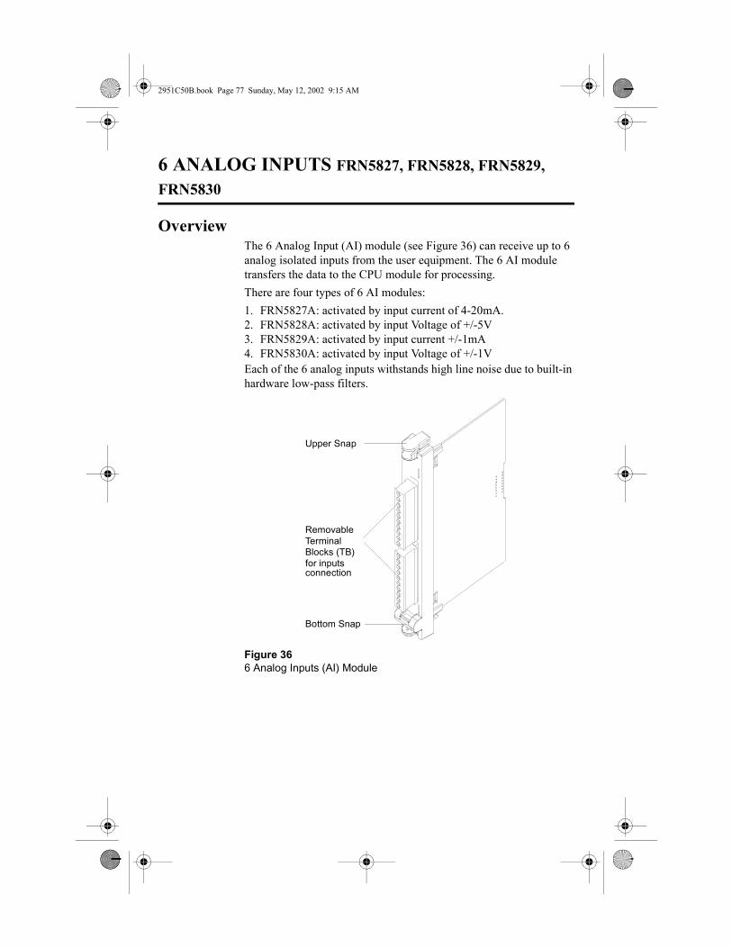
2951C50B.book Page 77 Sunday, May 12, 2002 9:15 AM
6 ANALOG INPUTS FRN5827, FRN5828, FRN5829, FRN5830
OverviewThe 6 Analog Input (AI) module (see Figure 36) can receive up to 6 analog isolated inputs from the user equipment. The 6 AI module transfers the data to the CPU module for processing.There are four types of 6 AI modules:1. FRN5827A: activated by input current of 4-20mA.2. FRN5828A: activated by input Voltage of +/-5V3. FRN5829A: activated by input current +/-1mA4. FRN5830A: activated by input Voltage of +/-1VEach of the 6 analog inputs withstands high line noise due to built-in hardware low-pass filters.
Figure 366 Analog Inputs (AI) Module
Upper Snap
Bottom Snap
RemovableTerminalBlocks (TB)for inputs connection

78 MOSCAD-L
2951C50B.book Page 78 Sunday, May 12, 2002 9:15 AM
Installation
Module LocationThe 6 AI Module should be located in the slot designated by the Site Configuration program (MOSCAD Programming Tool Box).
ConnectionsPunch a hole at the relevant location and of the appropriate size in one of the perforated circles at the bottom of the RTU housing and thread the wires through the opening. These wires are connected to the user interface TB located at the front of the 6 AI module.
Connect all the sensor connections to the TB terminals according to the configuration definition in the Site Configuration Program program (MOSCAD Programming Tool Box).
Specify the function of each TB pin on the label given in the transparent label panel.
Figure 37 illustrates the 6 AI TB connections.
NoteNote
Ensure that the plug with connections 1-10 is inserted into the upper TB and that the plug with connections 11-20 is inserted into the lower TB.

6 ANALOG INPUTS FRN5827, FRN5828, FRN5829, FRN5830 79
2951C50B.book Page 79 Sunday, May 12, 2002 9:15 AM
.
Figure 376 AI Module – User Connections
1 – AI-1+2 – AI-1-3 – AI-2+4 – AI-2-5 - PGND6 - PGND7 – AI-3+8 – AI-3-9 – AI-4+10 – AI-4-
11 – AI-5+12 – AI-5-13 – AI-6+14 - PGND15 - PGND

80 MOSCAD-L
2951C50B.book Page 80 Sunday, May 12, 2002 9:15 AM
Removal and Installation
Removing a 6 AI ModuleTo remove a 6 AI Module from the RTU, proceed as follows:
1. Turn off the DC power.2. Open the label panel and slide it into place.3. Disconnect the plugs from the module TBs.4. Pull out the module by pressing the top and bottom snaps.
Installing a 6 AI ModuleTo install a 6 AI Module in the RTU, proceed as follows:
1. Turn off the DC power.2. Slide the module into the appropriate RTU slot until the snaps
click into place.3. Reconnect the plugs into the module TBs, verifying that
connections no. 1-10 and 11-15 are in the correct order.
LED PanelA matrix of 5 � 4 LEDs, located on the CPU module, is used for diagnostics and testing of the CPU and the 6 AI modules (see Figure 38). The top row indicates to which module the LED display is set (CPU, M1, M2 or M3), and the blue numerals on the LED panel are the active input indications.
Setting the LED Display to the Relevant ModuleIf the display is off, press momentarily the pushbutton to activate the LED panel. Consecutive momentary depression of the pushputton advances the display to the next module, in the following order: CPU > M1 (I/O Module 1) > M2 (I/O Module 2) > M3 (I/O Module 3). The next depression of the pushbutton will return the display to the CPU.
!Warning
Verify that the DC power is turned off before removing or installing a module.

6 ANALOG INPUTS FRN5827, FRN5828, FRN5829, FRN5830 81
2951C50B.book Page 81 Sunday, May 12, 2002 9:15 AM
The table below describes the functions of the diagnostic CPU module LEDs when set to the 6 AI module.
Figure 38LED Panel
LED No. Indication
1 AI-1 input current or Voltage is lower than specified
2 AI-1 input current or Voltage is higher than specified
3 AI-2 input current or Voltage is lower than specified
4 AI-2 input current or Voltage is higher than specified
5 AI-3 input current or Voltage is lower than specified
6 AI-3 input current or Voltage is higher than specified
7 AI-4 input current or Voltage is lower than specified
8 AI-4 input current or Voltage is higher than specified
9 AI-5 input current or Voltage is lower than specifieda
10 AI-5 input current or Voltage is higher than specified
11 AI-6 input current or Voltage is lower than specified
12 AI-6 input current or Voltage is higher than specified
CPU M1 M2 M3
LOAD CONF APPL MON1 5 9 13
RST Tx1 Tx2 Tx32 6 10 14
ERR Rx1 Rx2 Rx33 7 11 15
BAT CM1 CM2 CM34 8 12 16

82 MOSCAD-L
2951C50B.book Page 82 Sunday, May 12, 2002 9:15 AM
Replaceable Parts
Part No. Description
3108509G18 User connections plug 10-pin

2951C50B.book Page 83 Sunday, May 12, 2002 9:15 AM
4 ANALOG OUTPUTS FTN8039
OverviewThe 4 Analog Outputs (AO) module (see Figure 39) provides 4 optically isolated analog channels for controlling user devices.
Each channel has two separate outputs: 4-20mA and 0-5V interface industry standard outputs. Only one of the outputs can be used in a particular channel - either current or voltage.
Figure 394 Analog Outputs (AO) Module
Upper Snap
Bottom Snap
RemovableTerminalBlocks (TB)for Outputs connection

84 MOSCAD-L
2951C50B.book Page 84 Sunday, May 12, 2002 9:15 AM
Installation
Module LocationThe 4 AO Module should be located in the slot designated by the Site Configuration program (MOSCAD Programming Tool Box).
ConnectionsPunch a hole at the relevant location and of the appropriate size in one of the perforated circles at the bottom of the RTU housing and thread the wires through the opening. These wires (20 AWG gage, twisted pair wires are recommended) are connected to the TBs, located at the front of the 4 AO module (see Figure 40).
Connect the controlled equipment to the TBs according to the configuration definition in the Site Configuration program (MOSCAD Programming ToolBox).
Specify the function of each TB point on the label given in the transparent label panel.
This module supports both internal and external power supply sources to drive the analog outputs.
When the internal P.S option is set, and the MOSCAD-L AC power supply fails - all outputs that serve as current source are lowered to zero, to save battery energy. Outputs that serve as voltage source maintain normal operation. When the battery power drops below 10.8 V the CPU shuts down, and after 16 seconds all outputs are lowered to zero.
When using an external P.S source (see Figure 40), all outputs resume normal operation during MOSCAD-L AC power supply fail. This can happen as long as the battery level remains above 10.8 V. When the battery power drops below 10.8 V the CPU shuts down and after 16 seconds all outputs are lowered to zero.
Perform the following steps to select external or internal P.S source:
1. To select an external P.S, place jumper P3 (see Figure 40) on pins 1 and 2 on the analog output board option, or pins 3 and 2 for internal P.S.
NoteNote
Ensure that the plug with connections 1-10 is inserted into the upper TB connector and that the plug with connections 11-20 is inserted into the lower TB connector.

4 ANALOG OUTPUTS FTN8039 85
2951C50B.book Page 85 Sunday, May 12, 2002 9:15 AM
2. Configure the analog output module using the MOSCAD Programming ToolBox application.
.
NoteNote
To ensure proper operation, verify that the GND terminal is grounded at all times (see Figure 40).
Figure 404 AO Module – User Connections
Vout 1Ret 1Iout 1
Vout 2
Iout 2Ret 2
Ret 3Vout 3
Iout 3
Ret 4Vout 4
Iout 4External Power
Supply
Load <750��(24V)Load <250��(12V)
Load �5KVoltage Load
Current Load
24V or 12V DC
+-
321
Jumper P3
GND

86 MOSCAD-L
2951C50B.book Page 86 Sunday, May 12, 2002 9:15 AM
Removal and Installation
Removing a 4 AO ModuleTo remove a 4 AO Module from the RTU, proceed as follows:
1. Turn off the DC power.2. Disconnect the plugs from the module.3. Pull out the module by pressing the top and bottom snaps.
Installing a 4 AO ModuleTo install a 4 AO Module in the RTU, proceed as follows:
1. Turn off the DC power.2. Slide the module into the appropriate RTU slot until the snaps
click into place.3. Reconnect the plugs into the module, verifying that connections
are in the correct order.
LED PanelA matrix of 5 � 4 LEDs, located on the CPU module, is used for diagnostics and testing of the CPU and the 4 AO modules (see Figure 41). The top row indicates to which module the LED display is set (CPU, Module 1, Module 2 or Module 3), and the blue numerals on the LED panel are the active output indications.
Setting the LED Display to the Relevant ModuleIf the display is off, press momentarily the pushbutton to activate the LED panel. Consecutive momentary depression of thepushbutton advances the display to the next module, in the following order: CPU > M1 (I/O Module 1) > M2 (I/O Module 2) > M3 (I/O Module 3). The next depression of the pushbutton will return the display to the CPU.
!Warning
Verify that the DC power is turned off before removing or installing a module.

4 ANALOG OUTPUTS FTN8039 87
2951C50B.book Page 87 Sunday, May 12, 2002 9:15 AM
The table below describes the functions of the diagnostic CPU module LEDs when set to the 4 AO module.
Figure 41LED Panel
LED No. Indication
1 UPD1 - The UPD LED blinks when channel 1 is being updated.
2 UCAL1 - This LED turns ON when the output calibration factor (Vout or Iout) is out of range.
3 Vout1 output is active.
4 Iout1 output is active.
5 UPD2 - The UPD LED blinks when channel 2 is being updated.
6 UCAL2 -This LED turns ON when the output calibration factor (Vout or Iout) is out of range.
7 Vout2 output is active.
8 Iout2 output is active.
9 UPD3 - The UPD LED blinks when channel 3 is being updated.
10 UCAL3 -This LED turns ON when the output calibration factor (Vout or Iout) is out of range.
11 Vout3 output is active.
CPU M1 M2 M3
LOAD CONF APPL MON1 5 9 13
RST Tx1 Tx2 Tx32 6 10 14
ERR Rx1 Rx2 Rx33 7 11 15
BAT CM1 CM2 CM34 8 12 16

88 MOSCAD-L
2951C50B.book Page 88 Sunday, May 12, 2002 9:15 AM
Replaceable Parts
12 Iout3 output is active.
13 UPD4 -The UPD LED blinks when channel 4 is being updated.
14 UCAL4 -This LED turns ON when the output calibration factor (Vout or Iout) is out of range.
15 Vout4 output is active.
16 Iout4 output is active.
LED No. Indication
Part No. Description
3108509G18 User connections plug 10-pin

2951C50B.book Page 89 Sunday, May 12, 2002 9:15 AM
HT1000 OR MTS2000 RADIO
OverviewThe RTU can be supplied with a HTl000 or MTS2000 radio for transmission of data to a remote location.
The radio is pre-installed on the door of the RTU housing (refer toFigure 1).
ConnectionsVerify that the radio DC cable is connected to connector (AUX) on the Power Supply.
Verify that the radio communication cable is connected to the connector on the panel of the radio adaptor unit on one end, and to Port 3 of the CPU at the other end. Screw the antenna cable into the antenna connector at the bottom of the RTU housing.
OperationSet the radio ON/OFF knob to the ON position.
Removing the RadioTo remove the radio from the RTU, proceed as follows:
1. Turn off the DC power.2. Disconnect the DC power and antenna cables from the radio.
NoteNote
In case that another radio type is being used, refer to the dedicated instructions supplied with the radio.
NoteNote
The volume at which the radio is set is insignificant. How-ever, to minimize battery power consumption in case of a power failure, it is recommended to set the volume tothe minimum.

90 MOSCAD-L
2951C50B.book Page 90 Sunday, May 12, 2002 9:15 AM
3. Disconnect the communication cable.4. Remove the screw securing the radio mounting bracket to the
door.
Installing the RadioTo install the radio on the RTU, proceed as follows:
1. Turn off the DC power.2. Place the radio and secure the screw of the radio mounting
bracket to the door.3. Reconnect the communication cable.4. Reconnect the DC power and antenna cables to the radio.

2951C50B.book Page 91 Sunday, May 12, 2002 9:15 AM
GENERAL PORTABLE RADIO INTERFACE BOARD FRN5936A
OverviewThe General Conventional Portable Radio Interface kit (FRN5936A) (see Figure 42) enables the MOSCAD-L unit to perform radio data communication by using other radio types that comply with the physical and data interface specifications detailed in this document.
The interface board uses an on-board power supply that serves the radio in use. The power supply provides various output voltages (6, 7.5, 9, 9.5 or 10.5 VDC) to enable the connection of wide range of radios. The output voltage is selected by setting a jumper on the interface board. The default voltage setting is 7.5 VDC.
Figure 42General Portable Radio Interface Board.
3A
3AG Fuse-3A SB
10.5 to 16V DC IN from power supply
DC OUT to radio (optional)
DC OUT to radio
HAND SET for voice communication
CPU control from CPU Module
AUDIO to radio
Selection Jumper Output Power

92 MOSCAD-L
2951C50B.book Page 92 Sunday, May 12, 2002 9:15 AM
Installation
Unit LocationThe interface board is held by the horizontal snaps, located on top of the modules in MOSCAD-L unit (see Figure 43).
ConnectionsFollow the instructions below for connecting the interface board. Note that the items mentioned in the brackets correspond to Figure 44.
1. Connect audio communication cable FKN4798A (see item 1) between the port marked “AUDIO” of the interface board and radio socket marked ‘EAR-MIC.
2. Connect control cable FKN5953A (see item 2) between the CPU port of the interface module and port 3 of the CPU module.
3. Connect DC Output cable FKN4468A (see item 3) from the interface board to the radio power input.
Figure 43General Portable Radio Interface Board – Installation Location
Installation Location of the Interface Board

GENERAL PORTABLE RADIO INTERFACE BOARD FRN5936A 93
2951C50B.book Page 93 Sunday, May 12, 2002 9:15 AM
4. Connect DC Input cable FKN4800A (see item 4) from the power supply module (AUX connector) to DC IN input of the interface board.
Figure 44.General Portable Radio Interface Board - Wire Connections
Interface Board
CPU ModuleP.S Module
ToRadio
Data
Antenna
DC
Item1Item 2
Item 3
Item 4

94 MOSCAD-L
2951C50B.book Page 94 Sunday, May 12, 2002 9:15 AM
Specifications
Input Voltage: 10.5 to 16 VDC.
Output Voltage: 7.5VDC @ 2A (Default) without jumpers.6VDC @ 2A.9VDC @ 2A @ 11.5 VDC minimum input.9.5VDC @ 2A @ 11.5 VDC minimum input.10.5VDC @1.5A @ 13 VDC minimum input.
P.S Standby Current:
30 mA typical without radio.
Current Limit: 2.5A ±10% typical (2.8 A maximum).
Line and Load Regulation: ±5% from nominal voltage.
Output ripple: 20mV RMS typ. 100mV RMS max.
PTT: Current: Up to 200 mA.
Active By (56 Ohm typical): low impedance between TX line and GND. Not active: high impedance between TX line and GND.
AGC Dynamic Range (on receive signal from the radio):
Input = 80mV to 1V pp; output = 1V pp ±20% (typical); 1.6 V maximum.
Channel Monitoring Active “high” (DC level on receive signal �1.5 VDC to the radio supply Voltage.
Transmit Audio Output(to MIC radio input): 5 to 6mV (±10%) RMS. typ. for nominal TX
deviation (1.3 to 2.2Khz @12.5 Khz or 2 to 4 Khz @ 25 Khz channel space radio).
Transmit Audio Input(modem output from MOSCAD): 130 to 190 mV RMS typical.

GENERAL PORTABLE RADIO INTERFACE BOARD FRN5936A 95
2951C50B.book Page 95 Sunday, May 12, 2002 9:15 AM
Replaceable Parts
Communication Cable
Figure 45Communication Cable FKN4798 - Pin Description
Connections: Input voltage: one connector MOLEX 2 contacts.Output voltage: one connector MOLEX 2 contacts or one TB 2contacts.Handset (opt): one RJ45 8 contacts.Audio & Signal Inputs: one RJ45 8 contacts.GND, Rx&Tx Signals output: one RJ45 6 contacts.
Part No. Description
FRN5934A General Conventional Portable Radio Interface Board.
FKN4798A Communication Cable.
FKN5953A Control Cable.
FKN4468A DC Out Cable.
FKN4800A DC Input Cable.
3108509G10 User connection plugs 2-pin.
Interface Board Side6Pin RJ45 Connector
Pin 1 Radio-Rx (black wire)Pin 2 GND (blue wire)
Pin 6 Tx-Data (white wire)GND
Tx-Data
Radio-Rx
Radio Side

96 MOSCAD-L
2951C50B.book Page 96 Sunday, May 12, 2002 9:15 AM

2951C50B.book Page 97 Sunday, May 12, 2002 9:15 AM
LINE INTERFACE UNIT
OverviewThe Line Interface Unit provides the interface required to connect the internal line modem (installed in the CPU) to various types of communication lines.
The unit transmitting level is –10 dBm into 600 � impedance. The receiving dynamic range is –3 dBm to –47 dBm. The unit’s line impedance is 600 � in both receiving and transmitting states.
OptionsThere are several optional Line Interface Units, each of which supports a different type of communication line. The following table details the available options:
Type Description
Tel Line(FRN1985)
Interface the internal modem to a telephone line. The telephone line interface operates in full-duplex mode.
Multi-drop(FRN1986)
This option allows the CPU internal line modem to communicate with several modems in other RTUs using a single pair of wires. The multi-drop interface operates in half-duplex mode.Note: Only the 1200 BPS internal line modem is supported by the multi-drop option.
Leased Line (FRN1987)
This option enables the connection of the CPU internal line modem to a communication line using a dedicated pair or two pairs of wires. The leased line interface operates in full-duplex mode.

98 MOSCAD-L
2951C50B.book Page 98 Sunday, May 12, 2002 9:15 AM
Installation
Unit LocationThe unit is pre-installed in the horizontal snap in at the top of the frame (above the CPU and I/O modules), see Figure 46.
ConnectionsFollow the Internal Connection instructions below for all options, and the specific External Connection instructions corresponding to the option being installed.• Internal Connections1. Connect communication cable FKN5953 between the port
marked “FROM MODEM” of the line interface unit and port 3 of the CPU.
NoteNote
The Line Interface Unit can only be operated when the Internal Modem board (FRN5669A or FRN5639A) is installed in the CPU module.
Figure 46Line Interface Unit – Installation Location
NoteNote
The RS232 Multiplexer, RS485 adaptor and Line Interface Unit are installed in the same place, and are mutually exclusive, i.e. only one of these modules can be installed in the RTU.
Installation Location for Line Interface Unit

Line Interface Unit 99
2951C50B.book Page 99 Sunday, May 12, 2002 9:15 AM
2. Connect a grounding wire between terminal 6 of the TB connector located on the Line Interface Unit and the protective ground strip located at the left side of the RTU housing.
• External ConnectionsPunch a hole at the relevant location and of the appropriate size in one of the perforated circles at the bottom of the RTU housing and thread the wires through the opening.
Telephone Line Option (See Figure 47)
There are two options for connecting the line wire to the Line Interface Unit:
– If the telephone line has an RJ11 connector, plug it into the LINE connector on the unit’s front panel.
or:
– If the telephone line is comprised of two wires, connect the wires to terminals 1 and 2 of the unit’s front panel TB. The polarity is insignificant.
Figure 47Line Interface Unit – Telephone Line Option Electrical Connections
PROT. GND
Telephone Line
Telephone Line
Telephone Cable with RJ11
To CPU
Option
LEDs6
54
3 21

100 MOSCAD-L
2951C50B.book Page 100 Sunday, May 12, 2002 9:15 AM
Multi-Drop Option (See Figure 48)
Connect the line wires to terminals 4 and 5 of the Line interface Unit’s front panel TB.Leased Line Option (Figure 48)
This option supports both two and four wire connections. Follow the relevant instructions below.
Figure 48Line Interface Unit – Multi-Drop Option Electrical Connections
PROT. GND
Line
To CPU
Leds
65
43 2
1

Line Interface Unit 101
2951C50B.book Page 101 Sunday, May 12, 2002 9:15 AM
Two-Wire Line Connection
1. Set both switches of dip-switch 2W/4W SELECT on the Line Interface Unit’s front panel to position 2W.
2. There are two options to connect the line wire to the Line Interface Unit:
– If the telephone line has an RJ11 connector, plug it into the 2-WIRE LINE connector on the unit’s front panel.
or:
– If the telephone line does not have an RJ11 connector, connect the wires to terminals 1 and 2 of the unit’s front panel TB. The polarity is insignificant.
Figure 49Line Interface Unit – 2W Leased Line Option Electrical Connections
PROT. GND 2W Tx/Rx
Leased Line
Optional Telephone Cable with RJ11 connectors
To CPU
Dip Switch in 2W position
65
43 2
1
2W Tx/Rx Leased Line

102 MOSCAD-L
2951C50B.book Page 102 Sunday, May 12, 2002 9:15 AM
Four-Wire Line Connection
1. Set both switches of dip-switch 2W/4W SELECT on the front panel of the Line Interface Unit to position 4W.
2. Connect the TX line wires to terminals 1 and 2 of the unit’s front panel TB. The polarity is insignificant. Note that this line should be connected to the RX input of the line’s interface (modem), at the other end of the line.
Figure 50Line Interface Unit – 4W Leased Line Option Electrical Connections
Figure 51Typical 4-Wire Line Modem Interconnection
PROT. GND
To CPU
Dip Switch in 4W position
65
43 2
1
4W Leased Line
Tx
Rx
Tx
Rx

Line Interface Unit 103
2951C50B.book Page 103 Sunday, May 12, 2002 9:15 AM
3. Connect the RX line wires to terminals 4 and 5 of the TB on the front panel of the unit. The polarity is insignificant. Note that this line should be connected to the TX input of the line interface (modem) at the other end of the line.
Removal and Installation
Removing the Line Interface UnitTo remove the Line Interface Unit from the RTU, proceed as follows:1. Turn off the DC power.2. Disconnect the Line Interface Unit connections.3. Pull out the module by pressing the side snaps.
Installing a Line Interface Unit
To install a Line Interface Unit in the RTU, proceed as follows:1. Turn off the DC power2. Slide the module into its rack until the snaps click into place.3. Reconnect the Line Interface Unit connections.
Diagnostic LEDsThe LED indications of the Line Interface Unit are described below:
Telephone Line Option
OFF HOOK – Indicates that the modem is in off-hook state (lit).
RING – Indicates an incoming call ring (lit).
Multi-Drop Option
TX – Indicates transmission from the modem (lit).
!Warning
Verify that the DC power is turned off before removing or installing a module
NoteNote
If you are installing a new Line Interface Unit, remove it from the plastic cover and install the bare board in its place in the RTU housing.

104 MOSCAD-L
2951C50B.book Page 104 Sunday, May 12, 2002 9:15 AM
Replaceable Parts
Part No. Description
FKN5953A CPU-to-radio communication cable
2808508G10 Modem connection TB (6 contacts)

2951C50B.book Page 105 Sunday, May 12, 2002 9:15 AM
RS232 MULTIPLEXER
OverviewThe RS232 Multiplexer provides RS232 serial port expansion from one input port to four expansion ports.
The RS232 Multiplexer can be configured to 16 different operating modes. Eight operating modes are predefined and eight are reserved for future use. The RS232 Multiplexer can be programmed using the Programming Tool Box or any other program that can communicate by RS232.
The RS232 Multiplexer input port serves both as a data port and as a programming port. Input signals RTS and DTS distinguish between the data and programming modes.
Figure 52RS232 Multiplexer
INPUT
EXP. 1
EXP. 2
EXP. 3
EXP. 4
RS232 MULTIPLEXER
Expansion Port 4
Expansion Port 3
Expansion Port 2
Expansion Port 1
To DataCommunicationEquipment
Input Port to DataTerminal Equipment
POWER
MOD. SEL/ERR
FAULT
POW IN(12V)
POW OUT(12V)

106 MOSCAD-L
2951C50B.book Page 106 Sunday, May 12, 2002 9:15 AM
The initial data transfer rate is 9600 bps. Once the RS232 Multiplexer is programmed, the data communication rate can be configured at a rate between 300 and 19200 bps.
Installation
Unit LocationThe unit is pre-installed in the horizontal slot at the top of the frame (above the CPU and I/O modules), as shown in Figure 53.
NoteNote
For additional information on the use and programming of the RS232 Multiplexer, see the RS232 Multiplexer Owner’s Manual (68P02950C40).
Figure 53RS232 Multiplexer – Installation Location
NoteNote
The RS232 Multiplexer, RS485 Multiplexer and Line Interface Unit are installed in the same slot, and are mutually exclusive, i.e. only one of these modules can be installed in the RTU.
Installation Location for RS232Multiplexer
RS232 Multiplexer 107
2951C50B.book Page 107 Sunday, May 12, 2002 9:15 AM
ConnectionsProceed as follows to connect the RS232 multiplexer:1. Connect power cable FKN4090 from PS Module “AUX” to the
PWR IN connector. The green POWER LED will turn on.2. Connect communication cable FKN5953 between the Multiplexer
Input port and the CPU RS232 port.3. Connect additional communication cables from expansion ports
EXP1, EXP2, EXP3 or EXP4 to the user.
4. Punch a hole at the relevant location and of the appropriate size in one of the perforated circles at the bottom of the RTU housing and thread the external connection cables through the opening.
5. Connect the communication cables to your RS232 devices
Removal and Installation
Removing the RS232 MultiplexerTo remove the RS232 Multiplexer from the RTU, proceed as follows:1. Turn off the DC power.2. Disconnect all RS232 Multiplexer input and output connections.3. Pull out the RS232 Multiplexer by pressing the side snaps.
NoteNote
If the length of communication cable FKN5953 (80 cm) may not be sufficient for external connections, use a longer cable.
NoteNote
You can use the RS232 Power outlet to connect additional multiplexers.
!Warning
Verify that the DC power is turned off before removing or replacing modules in the RTU.
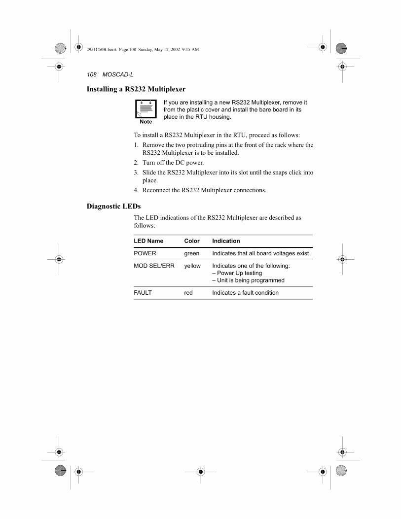
108 MOSCAD-L
2951C50B.book Page 108 Sunday, May 12, 2002 9:15 AM
Installing a RS232 Multiplexer
To install a RS232 Multiplexer in the RTU, proceed as follows:1. Remove the two protruding pins at the front of the rack where the
RS232 Multiplexer is to be installed.2. Turn off the DC power.3. Slide the RS232 Multiplexer into its slot until the snaps click into
place.4. Reconnect the RS232 Multiplexer connections.
Diagnostic LEDsThe LED indications of the RS232 Multiplexer are described as follows:
NoteNote
If you are installing a new RS232 Multiplexer, remove it from the plastic cover and install the bare board in its place in the RTU housing.
LED Name Color Indication
POWER green Indicates that all board voltages exist
MOD SEL/ERR yellow Indicates one of the following:– Power Up testing– Unit is being programmed
FAULT red Indicates a fault condition

2951C50B.book Page 109 Sunday, May 12, 2002 9:15 AM
RS485 CONNECTION BOARD
OverviewThe RS485 Connection Board provides RS485 serial port expansion from one input port to six expansion ports.
Installation
Unit LocationThe unit is pre-installed in the horizontal slot at the top of the frame (above the CPU and I/O modules), see Figure 54.
Figure 54RS485 Connection Board - Installation Location.
NoteNote
The RS232 Multiplexer, RS485 Connection Board and Line Interface Unit are installed in the same place, and are mutually exclusive, i.e. only one of these modules can be installed in the RTU
Installation Location for RS485Multiplexer

110 MOSCAD-L
2951C50B.book Page 110 Sunday, May 12, 2002 9:15 AM
ConnectionsTo connect the RS485 Connection Board proceed as follows:
1. Connect communication cable between the Multiplexer Input port and the CPU RS485 port (port 1A).
2. Punch a hole at the relevant location and of the appropriate size in one of the perforated circles at the bottom of the RTU housing and thread the external connection cables through the opening.
3. Connect the communication cables (FKN4400) to your RS485 devices.
Removal and Replacement
Removing the RS485 Connection BoardTo remove the RS485 Connection Board from the RTU, proceed as follows:
1. Turn off the DC power.2. Disconnect all RS485 Connection Board input and output
connections.3. Pull out the RS485 Multiplexer by pressing the side snaps.
Installing a RS485 Connection Board.
To install a RS485 Connection Board in the RTU, proceed as fol-lows:1. Turn off the DC power.2. Slide the RS485 Connection Board into its slot until the snaps
click into place.3. Reconnect the RS485 Connection Board connections.
!Warning
Verify that the DC power is turned off before removingor replacing modules in the RTU.
NoteNote
If you are installing a new RS485 Connection Board,remove it from the plastic cover and install the bare boardin its place in the RTU housing.

2951C50B.book Page 111 Sunday, May 12, 2002 9:15 AM
APPENDIX A: CABLES AND ADAPTORS
GeneralThis appendix provides supplementary data on cables and adaptors used in various MOSCAD-L systems. The following applications are covered:• RTU-to-computer/terminal connections• RTU-to-modem connections• RTU-to-RTU connections• Connecting a user port to a printer• Transformer to power supply module• External 20-40VDC, 14-28VAC Cable • Solar panel to power supply Cable
RTU-to-Computer/Terminal ConnectionsFor a 25-pin or 9-pin D-type connector, use the FLN6457 cable kit, in order to connect one of the RTU RS-232 ports to a computer or terminal. The kit includes a cable with RJ45 modular jacks on both ends, a RJ45 to 25-pin female D-Type adaptor, and an RJ45 to 9-pin D-Type adaptor.
The RTU port configuration is as follows:
CPU Port No.
Used with Piggyback Board
Toolbox Definition
1B – RS-232 UART Local Computer (MDLC)
2 – RS-232 UART Local Computer (MDLC)
3 FRN5655A RS-232 UART Local Computer (MDLC)
3 FRN5724A RS-232 UART Local Computer (MDLC)
NoteNote
When a User Port is defined as Computer/Terminal with DTR support:1. The RTU will not transmit unless it receives a DTR=on
signal from the computer/terminal.2. The RTU will not receive unless it receives a DTR=on
signal from the computer/terminal.

112 MOSCAD-L
2951C50B.book Page 112 Sunday, May 12, 2002 9:15 AM
.
RTU-to-Modem Asynchronous ConnectionFor a 9-pin or 25-pin connections, use the FLN6458 cable kit to connect one of the MOSCAD-L RTU RS-232 ports asynchronously to a modem (The RTU serves as DTE). The kit includes a cable with RJ45 modular jacks on both ends and a RJ45 to 9-pin and 25-pin male D-Type adaptor (see Figure 56). The possible RTU configurations are detailed below:
Figure 55RJ45-to-D-Type Female Connector Adaptor
J1(RJ45)
J2(25-PIN D-TYPE)
Tx_DATA
Rx_DATA
RTS
CTS
DSR
GND
DTR
Rec_LINE (DCD)
2
1
5
8
7
4
3
6
(3) 2
(2) 3
(7) 4
(8) 5
(6) 6
(5) 7
(4) 20
(1) 8
Tx_DATA
Rx_DATA
RTS
CTS
DSR
GND
DTR
Rec_LINE (DCD)
(9-PIN D-TYPE)
RJ45Connector
Pin No. 1Pin No. 8
CPU Port No.
Used with Piggyback Board
Toolbox Definition
2 – RS-232 UART External Modem (MDLC)
3 FRN5655A RS-232 Asynchronous External Modem, Full Duplex or Multi-Drop Half Duplex
3 FRN5724A RS-232 Asynchronous External Modem, Full Duplex or Multi-Drop Half Duplex

Appendix A: Cables and Adaptors 113
2951C50B.book Page 113 Sunday, May 12, 2002 9:15 AM
.
Notes
1. Before transmitting, the RTU sends a RTS=on signal to the modem, and will not transmit unless it receives a feedback CTS=on signal from the modem.
2. The RTU will not receive unless it receives a DCD=on signal from the modem.
3. When using a modem in auto-answer mode (connected to a computer port) for remote service, the RTU does not support the RTS/CTS protocol, as the port is designed to operate with a local computer as well as with a modem. Refer to the jumper settings detailed in the Utilities section of the Programming Tool Box Operating Instructions manual.
Figure 56RJ45-to-D-Type Male Connector Adaptor
J1(RJ45)
J2(25-PIN D-TYPE)
Tx_DATA
Rx_DATA
RTS
CTS
GND
DTR
Rec_LINE (DCD)
+12V
1
2
6
3
4
8
5
7
(3) 2
(2) 3
(7) 4
(8) 5
(5) 7
(4) 20
(1) 8
Tx_DATA
Rx_DATA
RTS
CTS
GND
DTR
Rec_LINE (DCD)
NOT USED
(9-PIN D-TYPE)
RJ45Connector
Pin No. 1Pin No. 8

114 MOSCAD-L
2951C50B.book Page 114 Sunday, May 12, 2002 9:15 AM
RTU-to-Modem Synchronous Connection (DTE-to-DCE)Use the FLN6704A cable kit to connect one of the MOSCAD-L RTU RS-232 ports to a modem synchronously (the RTU serves as a DTE). The kit includes a cable with RJ45 modular jacks on both ends and a RJ45 to 25-pin female D-Type adaptor (see Figure 57). The possible RTU configurations are detailed below:
.
CPU Port No.
Used with Piggyback Board
Toolbox Definition
3 FRN5654A RS-232 Synchronous External Modem, Full Duplex or Multi-Drop Half Duplex, Darcom Modem, Darcom Master/Repeater
3 FRN5724A RS-232 Asynchronous External Modem, Full Duplex or Multi-Drop Half Duplex, Darcom Modem, Darcom Master/Repeater
Figure 57RJ45-to-D-Type Male Connector Adaptor
J1(RJ45)
J2(25-PIN D-TYPE)
Tx_DATA
Rx_DATA
RTS
CTS
GND
TxCLK
Rec_LINE
RxCLK
1
2
6
3
4
8
5
7
2
3
4
5
7
15
8
Tx_DATA
Rx_DATA
RTS
CTS
GND
TxCLK
Rec_LINE
TxCLK17
RJ45Connector
Pin No. 1Pin No. 8

Appendix A: Cables and Adaptors 115
2951C50B.book Page 115 Sunday, May 12, 2002 9:15 AM
RTU-to-RTU Connection
RTU-to-Multiple RTUs Time Synchronization Using SYNCH Broadcast (via Port 1B)
The interconnection diagram below describes the Time Synchronization method which uses a SYNCH broadcast via port 1B (refer to Figure 58).
RTU-to-RTU Asynchronous Communications ConnectionThis section provides data on the cable recommended for the RTU-to-RTU RS-232 asynchronous interconnection (not supplied) (refer to Figure 59). The following table defines the RTU port for this connection type.
Figure 58Time Synchronization using SYNCH Broadcast – Interconnection Diagram
SITE A(SYNCHRONIZING SITE)
TxDATA
TxCLK
GND
1
6
4
PORT1B
BROADCASTING TRANSMISSION ONLY
2 3 4
RxDATA
RxCLK
GND
SITE B
2 3 4
RxDATA
RxCLK
GND
SITE C
PORT1B
PORT1B
RJ45Connector
Pin No. 1Pin No. 8

116 MOSCAD-L
2951C50B.book Page 116 Sunday, May 12, 2002 9:15 AM
CPU Port No.
Used with Piggyback Board
Toolbox Definition
1B – RS-232 UART RTU-to-RTU (MDLC)
2 – RS-232 UART RTU-to-RTU (MDLC)
3 FRN5655A RS-232 UART RTU-to-RTU (MDLC)
3 FRN5724A RS-232 UART RTU-to-RTU (MDLC)
NoteNote
When the connector is facing upwards, the lefthand pin is Pin No. 1, and the righthand pin is Pin No. 8.
Figure 59RTU-to-RTU RS-232 Asynchronous Communications Cable
J1(RJ45)
J2(RJ45)
Tx_DATA
Rx_DATA
CTS
GND
DCD
RTS
+12V
DTR
1
2
3
4
5
6
7
8
1
2
3
4
5
6
7
Tx_DATA
Rx_DATA
CTS
GND
DCD
RTS
+12V
DTR8NOT CONNECTED NOT CONNECTED
RJ45Connector
Pin No. 1Pin No. 8

Appendix A: Cables and Adaptors 117
2951C50B.book Page 117 Sunday, May 12, 2002 9:15 AM
RTU-to-RTU Synchronous Communications Connection (via port 1B)This section provides data on the cable recommended for RTU-to-RTU RS-232 synchronous communications via RTU port 1B (not available) (see Figure 60). The cable should be connected to the CPU as follows:
CPU PortNo.
Used with Piggyback Board
Toolbox Definition
1B – RS-232 Synchronous RTU-to-RTU (MDLC) Full Duplex or Half Duplex
NoteNote
When the connector is facing upwards, the lefthand pin is Pin No. 1, and the righthand pin is Pin No. 8.
Figure 60RTU-to-RTU Synchronous Communications Cable
Tx_DATA
J1(RJ45)
J2(RJ45)
TxDATA
RxDATA
RxCLK
GND
TxCLK
1
2
3
4
5
6
7
8
1
2
3
4
5
6
7
Rx_DATA
RxCLK
GND
TxCLK
8
RJ45Connector
Pin No. 1Pin No. 8

118 MOSCAD-L
2951C50B.book Page 118 Sunday, May 12, 2002 9:15 AM
RTU-to-RTU RS-232 Synchronous Communications Connection (via port 3)
This section provides data on the cable recommended for RTU-to-RTU RS-232 synchronous communications via RTU port 3 (not supplied) (see Figure 61). The cable should be connected to the CPU as follows:
CPU Port No.
Used with Piggyback Board
Toolbox Definition
3 FRN5654A RS-232 Synchronous External Modem, Full Duplex or Multi-Drop Half Duplex
3 FRN5724A RS-232 Synchronous External Modem, Full Duplex or Multi-Drop Half Duplex
NoteNote
When the connector is facing upwards, the lefthand pin is Pin No. 1, and the righthand pin is Pin No. 8.
Figure 61RTU-to-RTU Synchronous Communications Cable
J1(RJ45)
J2(RJ45)
TxDATA
RxDATA
Ready_In
GND
Ready_Out
RxCLK
TxCLK
1
2
3
4
5
6
7
8
1
2
3
4
5
6
7
TxDATA
8
Ready_Out
RxCLK
TxCLK
RxDATA
GND
Ready_In
RJ45Connector
Pin No. 1Pin No. 8
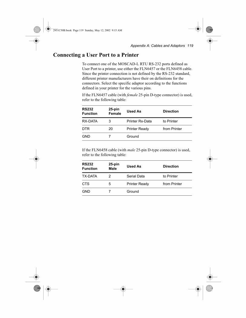
Appendix A: Cables and Adaptors 119
2951C50B.book Page 119 Sunday, May 12, 2002 9:15 AM
Connecting a User Port to a PrinterTo connect one of the MOSCAD-L RTU RS-232 ports defined as User Port to a printer, use either the FLN6457 or the FLN6458 cable. Since the printer connection is not defined by the RS-232 standard, different printer manufacturers have their on definitions for the connectors. Select the specific adaptor according to the functions defined in your printer for the various pins.
If the FLN6457 cable (with female 25-pin D-type connector) is used, refer to the following table:
If the FLN6458 cable (with male 25-pin D-type connector) is used, refer to the following table:
RS232 Function
25-pin Female Used As Direction
RX-DATA 3 Printer Rx-Data to Printer
DTR 20 Printer Ready from Printer
GND 7 Ground
RS232 Function
25-pin Male Used As Direction
TX-DATA 2 Serial Data to Printer
CTS 5 Printer Ready from Printer
GND 7 Ground

120 MOSCAD-L
2951C50B.book Page 120 Sunday, May 12, 2002 9:15 AM
Transformer to Power Supply Cable FKN4463ATo connect the transformer to the power supply module, use the FKN 4463A kit (see Figure 62).
Figure 62Transformer to Power Supply Cable FKN4463A
External 20-40VDC, 14-28VAC Cable FKN4466ATo connect external power AC/DC supply to the power supply module, use the FKN4466A kit (see Figure 63).
Figure 63External 20-40VDC, 14-28VAC Cable FKN4466A
Transformer Power Supply Module
To transformer load
To Ground strip
To transfer load
Red
Black
2 Vin_p
3 Pgnd
4 Vin_n
1 Solar_pNot used
Transformer Power Supply Module
+ (21-50VDC) or (20-28VAC)
Ground
- (21-50VDC)or (20-28VAC)
Red
Black
2 Vin_p
3 Pgnd
4 Vin_n
1 Solar_pNot used
2 4
1 3
2 4
1 3

Appendix A: Cables and Adaptors 121
2951C50B.book Page 121 Sunday, May 12, 2002 9:15 AM
Solar Panel to Power Supply Module Cable FKN4469ATo connect the solar panel to the power supply, use the power supply module FKN4469A kit (see Figure 64).
Figure 64Solar Panel to Power Supply Module Cable FKN4469A
Suppression CoreThe Suppression Core is used to reduce radiated emission, generated by conductors and to protect from fast transient events. The use of suppression core is required for the I/O cables to comply with 89/336 EEC directives.
Ordering part numbers:
Motorola - FLN9080A
Manufacturer: Fair Rite - 0443164251
InstallationFor installing the suppression core, see Figure 65.
Solar Panel Power Supply Module
+ Solar Panel Red
Black
1 Solar_p
2 Vin_p
3 Pgrd
Not used
4 Vin_nNot used
- Solar Panel
2 4
1 3
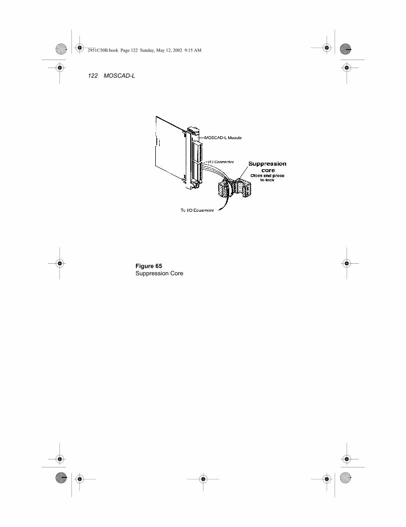
122 MOSCAD-L
2951C50B.book Page 122 Sunday, May 12, 2002 9:15 AM
Figure 65Suppression Core

2951C50B.book Page 123 Sunday, May 12, 2002 9:15 AM

2951C50B.book Page 124 Sunday, May 12, 2002 9:15 AM
MOTOROLA and the Stylized M Logo are registered in the U.S. Patent and Trademark Office. All other product or service names are the property of their respective owners. © Motorola, Inc. 2002
68P02951C50-B
@6802951C50@May 2002
Related Documents


