Copyright © 2011 Corbin Russwin, Inc., an ASSA ABLOY Group company. All rights reserved. Reproduction in whole or in part without the express written permission of Corbin Russwin, Inc. is prohibited. MORTISE LOCK INSTALLATION INSTRUCTIONS INSPIRE TM ROSELESS DESIGNER TRIM FM 340 Rev. 2/11

Welcome message from author
This document is posted to help you gain knowledge. Please leave a comment to let me know what you think about it! Share it to your friends and learn new things together.
Transcript
Copyright © 2011 Corbin Russwin, Inc., an ASSA ABLOY Group company. All rights reserved. Reproduction in whole or in part without the express written permission of Corbin Russwin, Inc. is prohibited.
MORTISE LOCKINSTALLATION INSTRUCTIONS
INSPIRETM ROSELESS DESIGNER TRIMFM 340
Rev. 2/11
INSTALLATION INSTRUCTIONSINSPIRETM Mortise Trim InstructionsFM 340 Rev. 2/11
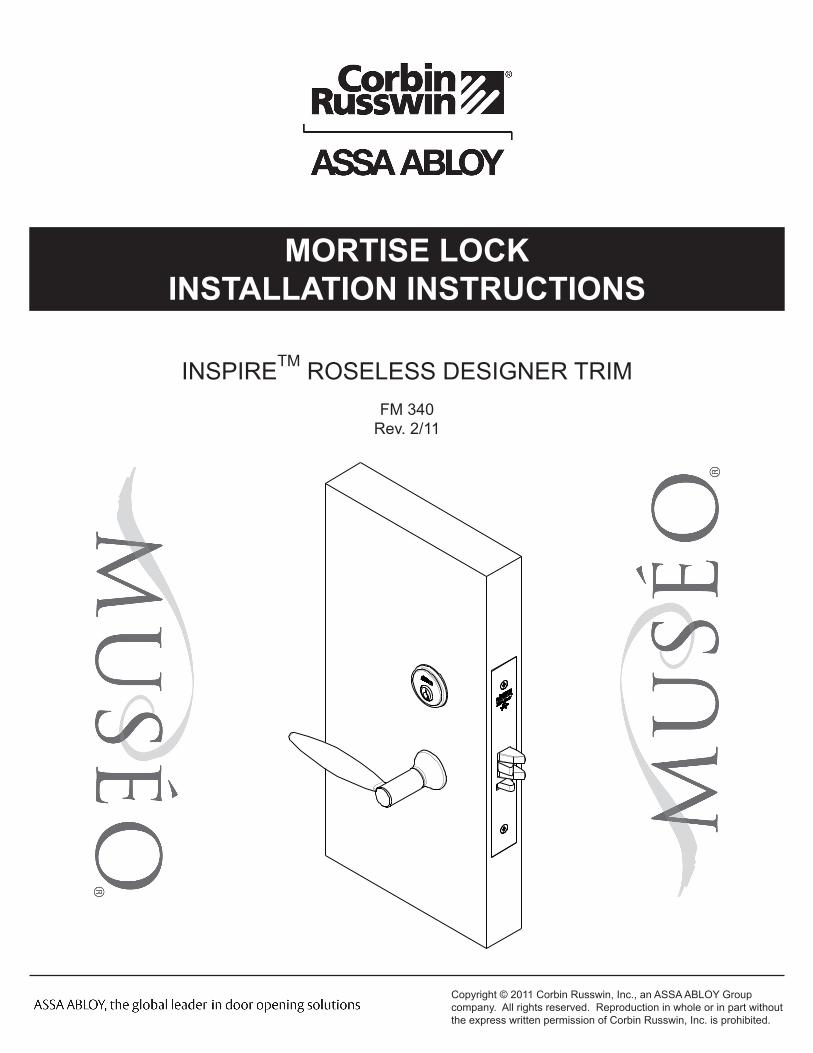
TABLE OF CONTENTS:DOOR PREPARATION
ML2000 LOCK HANDING
FULL WORKING TRIM (STD)
HALF WORKING TRIM (M30)
FULL DUMMY TRIM (ML2070)
HALF DUMMY TRIM (ML2050)
CYLINDER / TURN-PIECE
1
2
3
6
10
8
9
LOCK HANDING IS CRITICAL TO ENSURE LOCK FUNCTIONS PROPERLY
Copyright © 2011 Corbin Russwin, Inc., an ASSA ABLOY Group company. All rights reserved. Reproduction in whole or in part without the express written permission of Corbin Russwin, Inc. is prohibited.
1
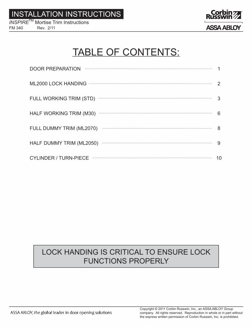
DOOR PREPARATION:
FULL WORKING TRIM:
HALF WORKING TRIM:
FULL DUMMY TRIM:
HALF DUMMY TRIM:
T31183
T31184
T31186
T31187
TEMPLATE
ALL TEMPLATES CAN BE FOUND ATWWW.CORBINRUSSWIN.COM/Library/Templates
Copyright © 2011 Corbin Russwin, Inc., an ASSA ABLOY Group company. All rights reserved. Reproduction in whole or in part without the express written permission of Corbin Russwin, Inc. is prohibited.
INSTALLATION INSTRUCTIONSINSPIRETM Mortise Trim InstructionsFM 340 Rev. 2/11
2
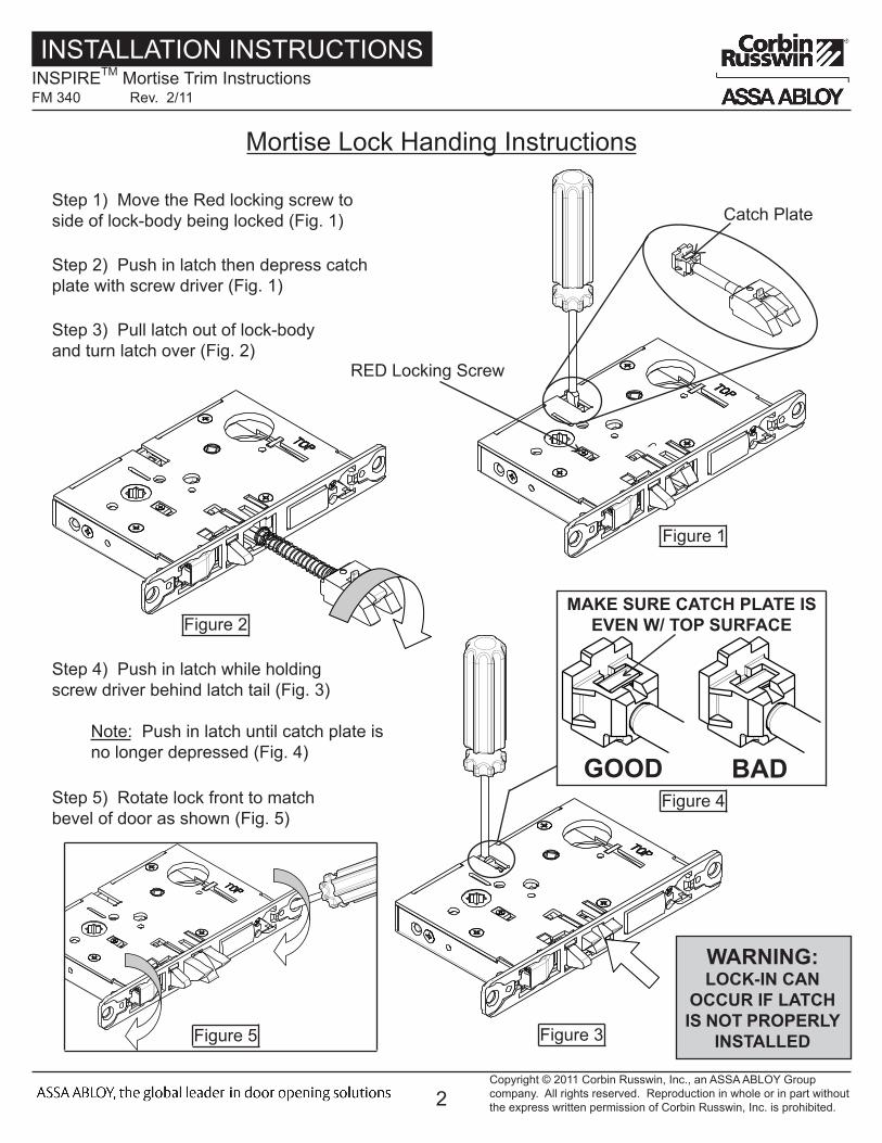
Mortise Lock Handing Instructions
RED Locking Screw
Step 1) Move the Red locking screw to side of lock-body being locked (Fig. 1)
Step 2) Push in latch then depress catch plate with screw driver (Fig. 1)
Catch Plate
Step 3) Pull latch out of lock-body and turn latch over (Fig. 2)
Figure 1
Figure 2
Figure 3
Step 4) Push in latch while holding screw driver behind latch tail (Fig. 3)
Note: Push in latch until catch plate is no longer depressed (Fig. 4)
Figure 5
Step 5) Rotate lock front to match bevel of door as shown (Fig. 5)
MAKE SURE CATCH PLATE IS EVEN W/ TOP SURFACE
GOOD BADFigure 4
WARNING: LOCK-IN CAN
OCCUR IF LATCH IS NOT PROPERLY
INSTALLED
Copyright © 2011 Corbin Russwin, Inc., an ASSA ABLOY Group company. All rights reserved. Reproduction in whole or in part without the express written permission of Corbin Russwin, Inc. is prohibited.
INSTALLATION INSTRUCTIONSINSPIRETM Mortise Trim InstructionsFM 340 Rev. 2/11

3
FULL TRIM (STD) INSTALLATIONStep 1) Install strike with shorter 3/4” mounting screws
Step 2) Insert mortise lock into door and hand tighten longer 1” mounting screws
Step 3) Install spacer blocks on both sides of lock-body with 1/4” Fillister Head Screws
Note: Align tabs on spacer with cutouts on lock-body
MAKE SURE LOCK IS UNLOCKED
Step 4) Install adapter plates on both sides of door using 1/2” Flat Head Screws
Copyright © 2011 Corbin Russwin, Inc., an ASSA ABLOY Group company. All rights reserved. Reproduction in whole or in part without the express written permission of Corbin Russwin, Inc. is prohibited.
INSTALLATION INSTRUCTIONSINSPIRETM Mortise Trim InstructionsFM 340 Rev. 2/11
4
4
6
Spindles
Keypad ribbon cable
Outsideof Door
Installation of Outside Escutcheon
2A. For fire rated doors feed ribbon cable connector and ground wire from outside escutcheon through the fire stop plate.
2B. For non-fire rated doors, feed ribbon cable connector and ground wire from outside escutcheon through weather seal gasket (if used), then conduit sleeve in door (not shown).
3. With outside lever horizontal, insert mounting posts into the door. Make certain the lever spindle is properly engaged in lock. (see diagram and Note A. below) Screw cylinder into mortise lockbody make certain the cylinder orientation is in the correct position (see diagram below) . Using the 7/64 Allen wrench provided, hand tighten (5-10 in. lbs.) the cap screw to prevent unscrewing of the cylinder. Turn the key to make certain that the locking mechanism (latch, deadbolt, key) functions correctly. Tighten (2) #12 x 1" lockbody screws. Remove Allen wrench.
Installation Instructions
Groundwire
Gasket (optional)
CAUT IONDOOR MUST REMAIN OPEN
DURING INSTALLATION.USE DOOR STOP.
NOTE: Key and cylinder must be rotated as shown
Correct Incorrect
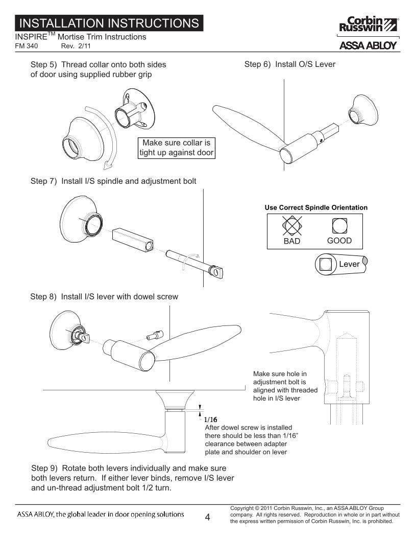
Use Correct Spindle Orientation
STANDARD MUSÉO
GASKET APPLICATION:Peel off the adhesive protective paper from gasket. Feed Trim assembly motor harness through gasket opening as shown and firmly press gasket to escutcheon, aligning edge of gasket with the edge of the escutcheon.
1. For exterior applications, an optional M99 Weatherseal Gasketing Kit can be ordered when a device is ordered. this kit includes gaskets and a conduit. When ordering the kit separately, order part number 794F929. The gaskets may be used as a seal between the escutcheon and the door surfaces.
NOTE A.For MUSÉO Lever collections ONLY.Rotate adapter bushing as neededto insure horizontal lever position and maximum thread engaging lever - adapter bushing.
LeverLever
GOODBAD
Step 5) Thread collar onto both sides of door using supplied rubber grip
Step 7) Install I/S spindle and adjustment bolt
Step 8) Install I/S lever with dowel screw
Step 6) Install O/S Lever
Make sure hole in adjustment bolt is aligned with threaded hole in I/S lever
After dowel screw is installed there should be less than 1/16” clearance between adapter plate and shoulder on lever
Step 9) Rotate both levers individually and make sure both levers return. If either lever binds, remove I/S lever and un-thread adjustment bolt 1/2 turn.
Copyright © 2011 Corbin Russwin, Inc., an ASSA ABLOY Group company. All rights reserved. Reproduction in whole or in part without the express written permission of Corbin Russwin, Inc. is prohibited.
INSTALLATION INSTRUCTIONSINSPIRETM Mortise Trim InstructionsFM 340 Rev. 2/11
Make sure collar is tight up against door
5
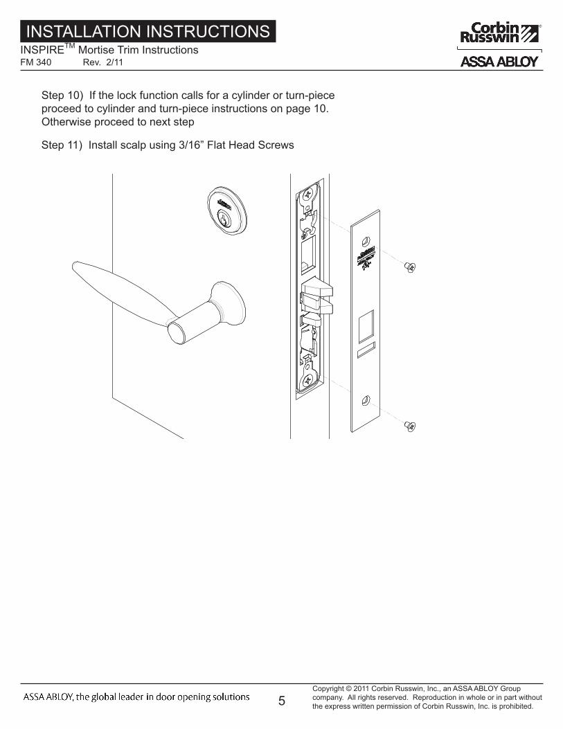
Step 10) If the lock function calls for a cylinder or turn-piece proceed to cylinder and turn-piece instructions on page 10. Otherwise proceed to next step
Step 11) Install scalp using 3/16” Flat Head Screws
Copyright © 2011 Corbin Russwin, Inc., an ASSA ABLOY Group company. All rights reserved. Reproduction in whole or in part without the express written permission of Corbin Russwin, Inc. is prohibited.
INSTALLATION INSTRUCTIONSINSPIRETM Mortise Trim InstructionsFM 340 Rev. 2/11
6
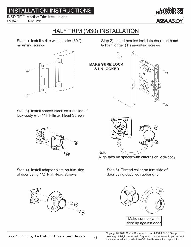
HALF TRIM (M30) INSTALLATIONStep 1) Install strike with shorter (3/4”) mounting screws
Step 2) Insert mortise lock into door and hand tighten longer (1”) mounting screws
MAKE SURE LOCK IS UNLOCKED
Step 3) Install spacer block on trim side of lock-body with 1/4” Fillister Head Screws
Step 4) Install adapter plate on trim side of door using 1/2” Flat Head Screws
Step 5) Thread collar on trim side of door using supplied rubber grip
Copyright © 2011 Corbin Russwin, Inc., an ASSA ABLOY Group company. All rights reserved. Reproduction in whole or in part without the express written permission of Corbin Russwin, Inc. is prohibited.
INSTALLATION INSTRUCTIONSINSPIRETM Mortise Trim InstructionsFM 340 Rev. 2/11
Note: Align tabs on spacer with cutouts on lock-body
Make sure collar is tight up against door

7
4
6
Spindles
Keypad ribbon cable
Outsideof Door
Installation of Outside Escutcheon
2A. For fire rated doors feed ribbon cable connector and ground wire from outside escutcheon through the fire stop plate.
2B. For non-fire rated doors, feed ribbon cable connector and ground wire from outside escutcheon through weather seal gasket (if used), then conduit sleeve in door (not shown).
3. With outside lever horizontal, insert mounting posts into the door. Make certain the lever spindle is properly engaged in lock. (see diagram and Note A. below) Screw cylinder into mortise lockbody make certain the cylinder orientation is in the correct position (see diagram below) . Using the 7/64 Allen wrench provided, hand tighten (5-10 in. lbs.) the cap screw to prevent unscrewing of the cylinder. Turn the key to make certain that the locking mechanism (latch, deadbolt, key) functions correctly. Tighten (2) #12 x 1" lockbody screws. Remove Allen wrench.
Installation Instructions
Groundwire
Gasket (optional)
CAUT IONDOOR MUST REMAIN OPEN
DURING INSTALLATION.USE DOOR STOP.
NOTE: Key and cylinder must be rotated as shown
Correct Incorrect
Use Correct Spindle Orientation
STANDARD MUSÉO
GASKET APPLICATION:Peel off the adhesive protective paper from gasket. Feed Trim assembly motor harness through gasket opening as shown and firmly press gasket to escutcheon, aligning edge of gasket with the edge of the escutcheon.
1. For exterior applications, an optional M99 Weatherseal Gasketing Kit can be ordered when a device is ordered. this kit includes gaskets and a conduit. When ordering the kit separately, order part number 794F929. The gaskets may be used as a seal between the escutcheon and the door surfaces.
NOTE A.For MUSÉO Lever collections ONLY.Rotate adapter bushing as neededto insure horizontal lever position and maximum thread engaging lever - adapter bushing.
LeverLever
GOODBAD
Step 6) Install I/S spindle and adjustment bolt
Step 7) Install I/S lever with dowel screw
Make sure hole in adjustment bolt is aligned with threaded hole in I/S lever
After dowel screw is installed there should be less than 1/16” clearance between adapter plate and shoulder on lever
Step 8) Rotate both levers individually and make sure both levers return. If either lever binds, remove I/S lever and un-thread adjustment bolt 1/2 turn.
Step 10) If the lock function calls for a cylinder or turn-piece proceed to cylinder and turn-piece instructions on page 10. Otherwise proceed to next step
Step 11) Install scalp using 3/16” Flat Head Screws
Copyright © 2011 Corbin Russwin, Inc., an ASSA ABLOY Group company. All rights reserved. Reproduction in whole or in part without the express written permission of Corbin Russwin, Inc. is prohibited.
INSTALLATION INSTRUCTIONSINSPIRETM Mortise Trim InstructionsFM 340 Rev. 2/11
8
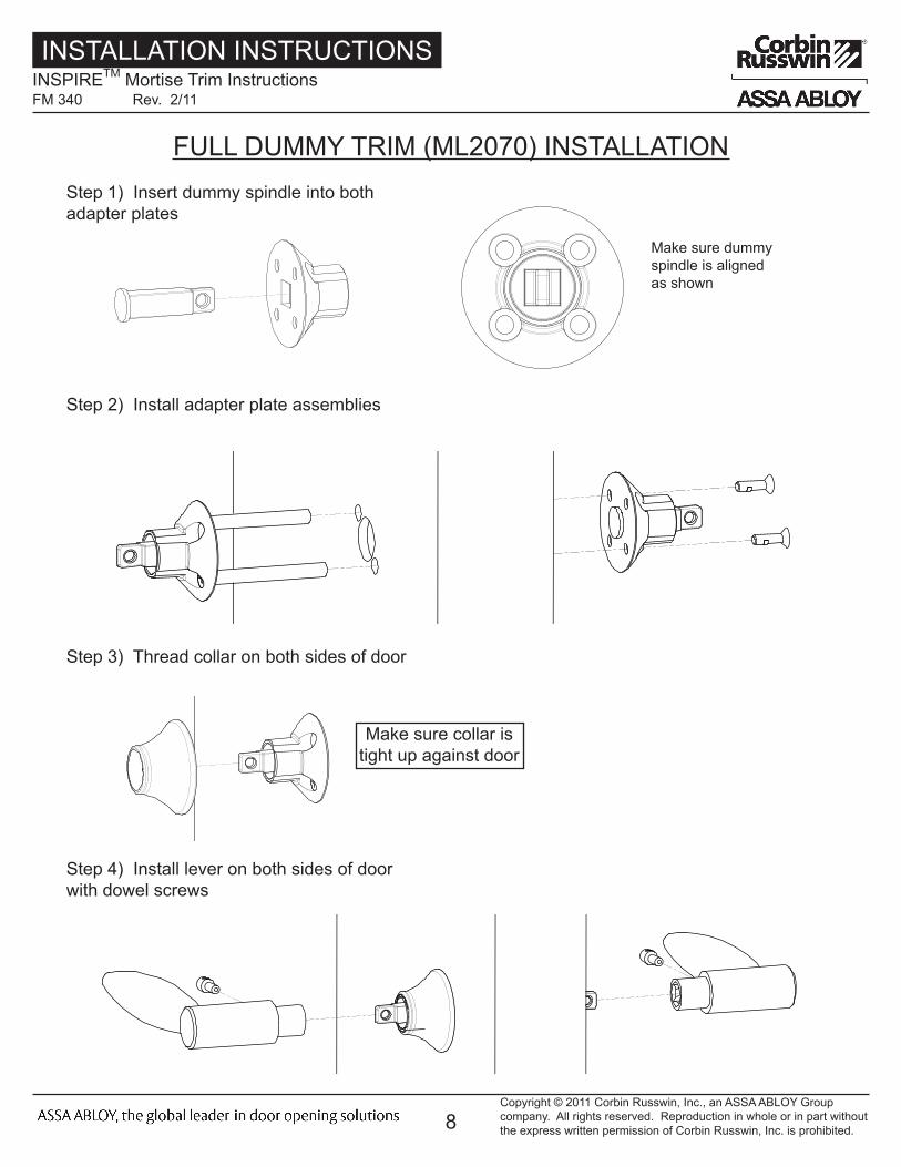
FULL DUMMY TRIM (ML2070) INSTALLATIONStep 1) Insert dummy spindle into both adapter plates
Make sure dummy spindle is aligned as shown
Step 2) Install adapter plate assemblies
Step 3) Thread collar on both sides of door
Step 4) Install lever on both sides of door with dowel screws
Copyright © 2011 Corbin Russwin, Inc., an ASSA ABLOY Group company. All rights reserved. Reproduction in whole or in part without the express written permission of Corbin Russwin, Inc. is prohibited.
INSTALLATION INSTRUCTIONSINSPIRETM Mortise Trim InstructionsFM 340 Rev. 2/11
Make sure collar is tight up against door
9
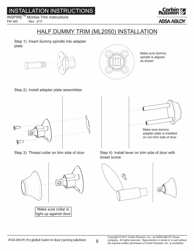
HALF DUMMY TRIM (ML2050) INSTALLATIONStep 1) Insert dummy spindle into adapter plate
Make sure dummy spindle is aligned as shown
Step 2) Install adapter plate assemblies
Make sure dummy adapter plate is installed on non-trim side of door
Step 3) Thread collar on trim side of door Step 4) Install lever on trim side of door with dowel screw
Copyright © 2011 Corbin Russwin, Inc., an ASSA ABLOY Group company. All rights reserved. Reproduction in whole or in part without the express written permission of Corbin Russwin, Inc. is prohibited.
INSTALLATION INSTRUCTIONSINSPIRETM Mortise Trim InstructionsFM 340 Rev. 2/11
Make sure collar is tight up against door
10
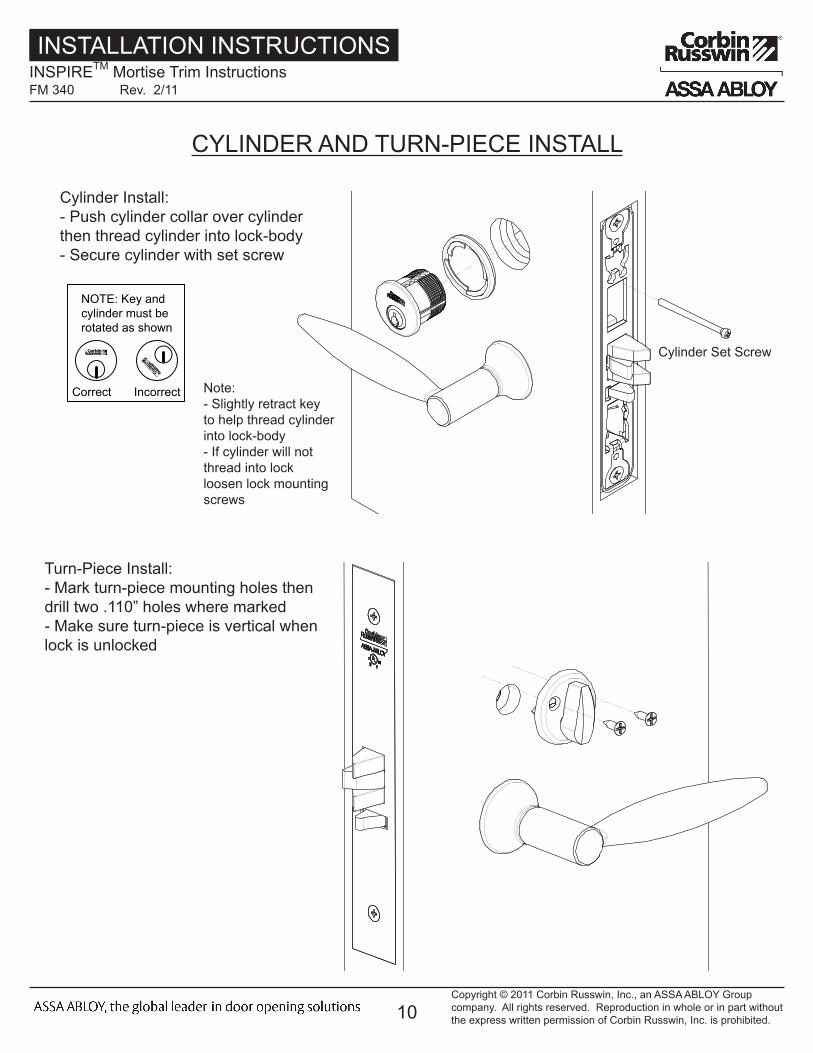
CYLINDER AND TURN-PIECE INSTALL
Cylinder Install: - Push cylinder collar over cylinder then thread cylinder into lock-body - Secure cylinder with set screw
4
6
Spindles
Keypad ribbon cable
Outsideof Door
Installation of Outside Escutcheon
2A. For fire rated doors feed ribbon cable connector and ground wire from outside escutcheon through the fire stop plate.
2B. For non-fire rated doors, feed ribbon cable connector and ground wire from outside escutcheon through weather seal gasket (if used), then conduit sleeve in door (not shown).
3. With outside lever horizontal, insert mounting posts into the door. Make certain the lever spindle is properly engaged in lock. (see diagram and Note A. below) Screw cylinder into mortise lockbody make certain the cylinder orientation is in the correct position (see diagram below) . Using the 7/64 Allen wrench provided, hand tighten (5-10 in. lbs.) the cap screw to prevent unscrewing of the cylinder. Turn the key to make certain that the locking mechanism (latch, deadbolt, key) functions correctly. Tighten (2) #12 x 1" lockbody screws. Remove Allen wrench.
Installation Instructions
Groundwire
Gasket (optional)
CAUT IONDOOR MUST REMAIN OPEN
DURING INSTALLATION.USE DOOR STOP.
NOTE: Key and cylinder must be rotated as shown
Correct Incorrect
Use Correct Spindle Orientation
STANDARD MUSÉO
GASKET APPLICATION:Peel off the adhesive protective paper from gasket. Feed Trim assembly motor harness through gasket opening as shown and firmly press gasket to escutcheon, aligning edge of gasket with the edge of the escutcheon.
1. For exterior applications, an optional M99 Weatherseal Gasketing Kit can be ordered when a device is ordered. this kit includes gaskets and a conduit. When ordering the kit separately, order part number 794F929. The gaskets may be used as a seal between the escutcheon and the door surfaces.
NOTE A.For MUSÉO Lever collections ONLY.Rotate adapter bushing as neededto insure horizontal lever position and maximum thread engaging lever - adapter bushing.
LeverLever Note: - Slightly retract key to help thread cylinder into lock-body - If cylinder will not thread into lock loosen lock mounting screws
Cylinder Set Screw
Turn-Piece Install: - Mark turn-piece mounting holes then drill two .110” holes where marked - Make sure turn-piece is vertical when lock is unlocked
Copyright © 2011 Corbin Russwin, Inc., an ASSA ABLOY Group company. All rights reserved. Reproduction in whole or in part without the express written permission of Corbin Russwin, Inc. is prohibited.
INSTALLATION INSTRUCTIONSINSPIRETM Mortise Trim InstructionsFM 340 Rev. 2/11
Related Documents