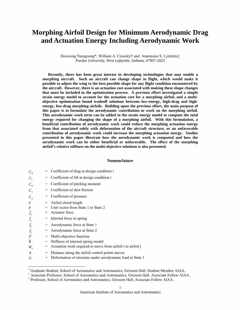
American Institute of Aeronautics and Astronautics 1 Morphing Airfoil Design for Minimum Aerodynamic Drag and Actuation Energy Including Aerodynamic Work Howoong Namgoong*, William A. Crossley† and Anastasios S. Lyrintzis‡ Purdue University, West Lafayette, Indiana, 47907-2023 Recently, there has been great interest in developing technologies that may enable a morphing aircraft. Such an aircraft can change shape in flight, which would make it possible to adjust the wing to the best possible shape for any flight condition encountered by the aircraft. However, there is an actuation cost associated with making these shape changes that must be included in the optimization process. A previous effort investigated a simple strain energy model to account for the actuation cost for a morphing airfoil, and a multi- objective optimization found tradeoff solutions between low-energy, high-drag and high- energy, low-drag morphing airfoils. Building upon the previous effort, the main purpose of this paper is to formulate the aerodynamic contribution to work on the morphing airfoil. This aerodynamic work term can be added to the strain energy model to compute the total energy required for changing the shape of a morphing airfoil. With this formulation, a beneficial contribution of aerodynamic work could reduce the morphing actuation energy from that associated solely with deformation of the aircraft structure, or an unfavorable contribution of aerodynamic work could increase the morphing actuation energy. Studies presented in this paper illustrate how the aerodynamic work is computed and how the aerodynamic work can be either beneficial or unfavorable. The effect of the morphing airfoil’s relative stiffness on the multi-objective solutions is also presented. Nomenclature i d C = Coefficient of drag at design condition i i l C = Coefficient of lift at design condition i m C = Coefficient of pitching moment f C = Coefficient of skin friction p C = Coefficient of pressure c = Airfoil chord length e = Unit vector from State 1 to State 2 a f = Actuator force s f = Internal force in spring 1 f = Aerodynamic force at State 1 2 f = Aerodynamic force at State 2 F = Multi-objective function k = Stiffness of internal spring model ij W = Actuation work required to move from airfoil i to airfoil j x = Distance along the airfoil control points moves 1 δ = Deformation of structure under aerodynamic load at State 1 * Graduate Student, School of Aeronautics and Astronautics, Grissom Hall, Student Member AIAA. † Associate Professor, School of Aeronautics and Astronautics, Grissom Hall, Associate Fellow AIAA. ‡ Professor, School of Aeronautics and Astronautics, Grissom Hall, Associate Fellow AIAA.

Welcome message from author
This document is posted to help you gain knowledge. Please leave a comment to let me know what you think about it! Share it to your friends and learn new things together.
Transcript
American Institute of Aeronautics and Astronautics
1
Morphing Airfoil Design for Minimum Aerodynamic Drag and Actuation Energy Including Aerodynamic Work
Howoong Namgoong*, William A. Crossley† and Anastasios S. Lyrintzis‡ Purdue University, West Lafayette, Indiana, 47907-2023
Recently, there has been great interest in developing technologies that may enable a morphing aircraft. Such an aircraft can change shape in flight, which would make it possible to adjust the wing to the best possible shape for any flight condition encountered by the aircraft. However, there is an actuation cost associated with making these shape changes that must be included in the optimization process. A previous effort investigated a simple strain energy model to account for the actuation cost for a morphing airfoil, and a multi-objective optimization found tradeoff solutions between low-energy, high-drag and high-energy, low-drag morphing airfoils. Building upon the previous effort, the main purpose of this paper is to formulate the aerodynamic contribution to work on the morphing airfoil. This aerodynamic work term can be added to the strain energy model to compute the total energy required for changing the shape of a morphing airfoil. With this formulation, a beneficial contribution of aerodynamic work could reduce the morphing actuation energy from that associated solely with deformation of the aircraft structure, or an unfavorable contribution of aerodynamic work could increase the morphing actuation energy. Studies presented in this paper illustrate how the aerodynamic work is computed and how the aerodynamic work can be either beneficial or unfavorable. The effect of the morphing airfoil’s relative stiffness on the multi-objective solutions is also presented.
Nomenclature
idC = Coefficient of drag at design condition i
ilC = Coefficient of lift at design condition i
mC = Coefficient of pitching moment
fC = Coefficient of skin friction
pC = Coefficient of pressure c = Airfoil chord length e = Unit vector from State 1 to State 2
af = Actuator force
sf = Internal force in spring
1f = Aerodynamic force at State 1
2f = Aerodynamic force at State 2 F = Multi-objective function k = Stiffness of internal spring model
ijW = Actuation work required to move from airfoil i to airfoil j x = Distance along the airfoil control points moves
1δ = Deformation of structure under aerodynamic load at State 1
* Graduate Student, School of Aeronautics and Astronautics, Grissom Hall, Student Member AIAA. † Associate Professor, School of Aeronautics and Astronautics, Grissom Hall, Associate Fellow AIAA. ‡ Professor, School of Aeronautics and Astronautics, Grissom Hall, Associate Fellow AIAA.

American Institute of Aeronautics and Astronautics
2
I. Introduction RECENTLY developed smart material techniques can change the shape of the aircraft while maintaining necessary stiffness1. This advancement draws our attention to the design of a single aircraft that has multi-mission capability and aerodynamic efficiency through morphing of the wing2,3. The morphing aircraft could
adjust the wing to the optimal shape for any flight condition encountered by the aircraft. This adaptation will improve the aerodynamic performance of the aircraft4. However, morphing aircraft requires an extra mechanism to change the wing shape. Therefore, to account for the total performance benefits of morphing aircraft, a new design strategy is needed to embrace the variation of the wing shape in the optimization process that addresses the effort needed to morph the shape of the airfoil.
Generally, in developing the objectives for aerodynamic optimization, a multi-point problem formulation5 is used for airfoil or wing design. A weighted sum of drag coefficients, computed at various design flight conditions, serves as the objective, and constraints ensure that the lift coefficient matches specified values at each of the flight conditions. The resulting shape has performance that is essentially a compromise over the flight conditions. In the case of a morphing aircraft, the wing would be able to change its shape during flight. It would be possible to adjust the wing shape to the best possible shape for any flight condition encountered by the aircraft; this would suggest that the morphing airfoil could be designed using a series of single-point problem formulations. However, there is an actuator effort or “cost” associated with these shape changes. Thus, the effort required to effect the morphing must be included in the optimization process.
A previous effort by the authors6 investigated a multiobjective optimization strategy in which aerodynamic performance (minimizing drag) and actuation effort (minimizing strain energy) associated with a morphing airfoil shape are optimized. One issue in morphing aircraft optimization is how to model the morphing cost. In previous research, Prock7 et al suggested using a simple strain energy model for morphing aircraft design. This strain energy model is based on the assumption that the strain energy stored in the deformed airfoil structure is proportional to the energy required for the actuation. However, the internal spring actuation model used in the previous study neglected the effect of aerodynamic forces on the energy needed for the shape change. This effect should not be neglected, because it could impact the optimal airfoil shapes. If the stiffness of the wing is very high, the strain energy associated with deforming the airfoil structure will be much higher than the energy associated with aerodynamic work on the airfoil. In this case, the strain energy would be adequate for evaluating the actuation energy. However, if the stiffness of the wing is low, which is required for ease of deformation, the aerodynamic forces may have a measurable impact on the actuator energy, and should be included in the energy model.
Several works8,9,10,11 have investigated the actuation energy for unconventionally actuated wings. Most of the works have focused on measuring the aerodynamic work for control energy requirements but have not investigated including aerodynamic work to potentially reduce the actuation energy for a morphing airfoil. The main purpose of this paper is to formulate the aerodynamic work on the morphing airfoil. In this paper, the aerodynamic work is added to the strain energy term in the internal spring model to compute the total energy required for changing the shape of a morphing airfoil. The suggested actuation energy (morphing cost) model would be more realistic compared to the simple strain energy model and suggests the possibility of designing a morphing airfoil that exploits the airflow to reduce the input actuation energy. This improved energy model is then used in multiobjective studies to design morphing airfoils.
II. Representative Problem A high-altitude, long-endurance sensor craft problem12 (see Figure 1) provides a representative problem for a
morphing airfoil. To improve the efficiency of the aircraft over a 40-hour constant altitude, constant speed loiter, the airfoil shape would change shape to minimize drag at a decreasing lift coefficient. The multiobjective optimization approach described in Ref. 6 is also applied in this paper. It is assumed that the energy needed to change the airfoil shape is proportional to the actuation system weight and to the power needed by the actuation system. To account for the actuation energy of morphing devices, an internal spring model is used (see below). Based upon system studies from the Air Force Research Labs, the required airfoil lift coefficients are known at various times during the long loiter segment. The flight conditions at three points in time provide the airfoil shape design conditions. These are
R
Figure 1. Notional high-altitude, long
endurance aircraft concept

American Institute of Aeronautics and Astronautics
3
summarized in Table 1.
Table 1. Airfoil design conditions Condition 1 Condition 2 Condition 3 Design lift coefficient 1.52 1.18 0.85 Mach number 0.6 0.6 0.6 Reynolds number 1.5×10⁶ 1.5×10⁶ 1.5×10⁶
For aerodynamic analysis, the well-known XFOIL13 code is selected as a function evaluator. XFOIL provides
rapid calculation of lift and drag coefficient, while allowing for a good resolution of the airfoil shape and incorporating viscous effects. To pose the airfoil shape optimization problem, the design variables describing the airfoil shape are needed6. The modified Hicks-Henne14,15 shape functions are used here to represent an airfoil. The design variables are multipliers that determine the magnitude of the shape function as it is added to the baseline airfoil shape. The y-coordinate positions of the upper and lower surface of the airfoil are then described as functions of the x-coordinate position using the following equation:
∑ξ+= )()()( Airfoil Base xfxyxy ii (1)
Where ξi are the design variables; and fi, the shape functions (i =1, 16 here). The NACA0012 airfoil is used as a base airfoil and the upper and lower bound of design variables (ξi) are set to 0.015 and -0.015 each (more details can be found in Ref. 16).
III. Actuation Energy Model If an airfoil morphing mechanism has been designed, then a model of this mechanism should be used to measure
energy required to effect the shape changes. Without a specific mechanism, there are several ways to model the actuation energy needed to change the airfoil shape. The approach here uses energy associated with a number of linear springs that represent the internal structure of the airfoil.
A. Internal Spring Model One of the actuation energy models uses the idea that the strain energy in a structure stored in a structure is
proportional to the square of the change in length of the structure. An extension of the internal linear spring model concept suggested by Prock, et. al7 is used to model strain energy associated with deforming the airfoil structure. This model assumes that a series of springs connect the upper and lower airfoil surfaces; as the airfoil morphs, the springs deform, which corresponds to an amount of strain energy. Figure 2 presents a simple illustration of this model.
The total strain energy stored in the internal springs as a result of the shape change from the blue shape to the green shape can be computed using Equation (2).
∑∑==
Δ=Δ=n
ii
i
n
iii L
LEALkU
1
2
1
2
21
21
(2)
In this equation, U is the strain energy; ki, is the spring constant for each individual spring, EA is the spring axial stiffness, and ΔLi is the deformation of each spring.
B. Internal Spring Model Including Aerodynamic Load The pressure distribution acting on an airfoil can be represented by a series of forces acting at control points.
The direction and magnitude of these forces depend on both the flight condition and the local shape of the airfoil. Figure 3 displays two airfoils, each designed to minimize drag at a different lift coefficient. The aerodynamic forces acting on the airfoil are presented as vectors, and the two plots show that if the airfoil shape and flight conditions
Internal springs connecting upper and lower surface
icL )/(Δ
icL )/(
Springs contract (or expand) to meet new airfoil shape Figure 2. Internal linear spring model for
strain energy

American Institute of Aeronautics and Astronautics
4
change, the aerodynamic force distribution also changes. Because the goal of the morphing airfoil is to change the shape of the airfoil, there is a possibility to acquire some assistance from the aerodynamic force or that the actuation effort needs to overcome both the aerodynamic force and the structural stiffness.
The simple spring model is used for the representation of the airfoil structure. In this simple model, deforming the airfoil shape is modeled by deformation of the linear springs connecting the upper and lower surfaces of the airfoil. Figure 4 shows the normal component of the aerodynamic force calculated from the pressure coefficient Cp acting on each control point of the two airfoils. The tangential component of the aerodynamic force is comparatively small, so it is not drawn in Figure 4.
Figure 5 provides an illustration of how the aerodynamic and actuator forces are combined to effect a shape change from state 1 to state 2. At each shape in Figure 5, equilibrium of the forces is maintained. For clarity, only one control point is presented here. When the aerodynamic load is not included, the work done by the actuator to move the airfoil from State-1 to State-2 in Figure 5 (a) can be described by Equation (3). Because the force and deformation have a linear elastic relationship for the spring, the actuation work required to change the shape is given by Equation (4).
energy)(strain 2)actuator(12energy)strain ( 1 UWU =+ (3)
-0.2 -0.1 0 0.1 0.2 0.3 0.4 0.5 0.6 0.7 0.8 0.9 1 1.1X
-0.5
-0.4
-0.3
-0.2
-0.1
0
0.1
0.2
0.3
0.4
0.5
0.6
Y
-0.2 -0.1 0 0.1 0.2 0.3 0.4 0.5 0.6 0.7 0.8 0.9 1 1.1X
-0.5
-0.4
-0.3
-0.2
-0.1
0
0.1
0.2
0.3
0.4
0.5
0.6
Y
Figure 3. Aerodynamic force distributions on the optimized airfoil surface, State-1 (Cl = 0.85)
(left), State-2 (Cl = 1.52) (right)
-0.2 -0.1 0 0.1 0.2 0.3 0.4 0.5 0.6 0.7 0.8 0.9 1 1.1
X
-0.5
-0.4
-0.3
-0.2
-0.1
0
0.1
0.2
0.3
0.4
0.5
0.6
Y
Figure 4. Normal component of aerodynamic force acting on the surface of the airfoil at state-1 (Cl=0.85)
and state-2 (Cl=1.52)
1f
2f
ef •1
ef •2
eLΔ

American Institute of Aeronautics and Astronautics
5
22
1
2
112)actuator(12
21 LkkxdxxdfUUW a Δ==⋅=−= ∫∫ (4)
When the aerodynamic force also acts on the airfoil structure as in Figure 5 (b), the aerodynamic work term needs to be included in the energy/work equation.
energy)(strain 2)caerodynami(12)actuator(12energy)strain ( 1 )( UWWU =++ (5)
Thus, the corresponding actuation work becomes
)caerodynami(1212)actuator(12 )( WUUW −−= (6)
If we assume that the aerodynamic force, af , acting on the spring varies linearly from State-1 to State-2 as the
airfoil changes from Shape 1 to Shape 2, then the work done by the aerodynamic force can be given by Equation (7). The integral of the aerodynamic force is replaced by the average aerodynamic force.
LefefLeffdreffrdfW aero Δ⋅+⋅=Δ⋅⎟⎟⎠
⎞⎜⎜⎝
⎛ +=⋅⎟⎟
⎠
⎞⎜⎜⎝
⎛ +=⋅= ∫ ∫ )(
21
22 2121
2
1
2
1
21)caerodynami(12
(7)
Substituting Equation (4) and (7) into Equation (6), provides Equation (8) that computes the actuation work at one single control point.
LefefLkW Δ⋅+⋅−Δ= )(21
21
212
)actuator(12 (8)
IV. Stiffness Approximation (Sensorcraft Application) Because the actual airfoil structure and morphing mechanism are replaced with linear springs, the spring
constant k in Equation (8) is unknown and needs to be defined. This definition governs the stiffness of the airfoil. As a starting point, it is assumed that one specific spring under the maximum aerodynamic force at State-1 is deformed about 0.001c (1/1000 of the chord length). This would represent a very minimal deformation of the airfoil under the aerodynamic load.
11 δkef =⋅ (9)
Figure 5. Forces applied on linear spring actuator model
LΔ
1δ
2f af
k k
State 2
sf
sf
State 1
1f
(b) aerodynamic load included
LΔaf
k k
State 2
sf
State 1
(a) no aerodynamic load
L

American Institute of Aeronautics and Astronautics
6
where, 001.0001.01 == cδ
efck ⋅= 1*1000 (10)
To define the reference value for k, two airfoil shapes designed for two different flight conditions are chosen (condition 1 and condition 3 in Table 1). From the flow solver (XFOIL), the pressure coefficient Cp and friction coefficient Cf values can be obtained at each control point (See Figure 6). The unit tangential vector t and unit normal vector n of each panel can be calculated from the panel geometry. Therefore, the total aerodynamic force at each control point is obtained by the following equation.
])*()*[( 111111 11tdsCndsCqf fp += (11)
Figure 7 presents the aerodynamic force terms calculated using Equation (11), at each control point of the
selected airfoils from Figure 4. A total of 140 control points are presented, and they are counted in the counter clockwise direction. Thus, ‘0’ is for the upper trailing edge control point, ‘70’ for the leading edge and ‘140’ for the lower surface trailing edge and so on.
From the values of 11 / qef ⋅ and 22 / qef ⋅ in Figure 7, the value 0.03, which is near the largest value at any control point, is selected for 11 / qef ⋅ to assume the stiffness value (See Equation (12)). Because the actuator needs to be big enough to overcome the largest value, the largest possible value is selected as a typical value.
Panel length:
Control Point
dsn
tPanel length:
Control Point
dsn
tdsn
t
Figure 6. Panel distribution on the airfoil
0 20 40 60 80 100 120 140-0.02
-0.01
0
0.01
0.02
0.03
0.04
Control point
Figure 7. Aerodynamic force distribution at each control point
11 / qef ⋅
22 / qef ⋅

American Institute of Aeronautics and Astronautics
7
03.01
1 =⋅
qef (12)
From Equations (9) and (12), the stiffness can be assumed as Equation (13). This is based on the assumption that the selected spring is displaced 0.001c by the aerodynamic force shown in Equation (12). This reference stiffness is applied to all the other springs.
130qk = (13)
Then, the substitution of Equation (13) into Equation (8) results in the following equation
⎥⎥⎦
⎤
⎢⎢⎣
⎡⎟⎟⎠
⎞⎜⎜⎝
⎛Δ
⋅+⋅−Δ= L
qefefLqW
1
2121)actuator(12
)(302
(14)
This is the work the actuator must do to move the airfoil control point from shape 1 to shape 2. If this is negative, this indicates the airloads could move the airfoil shape. In the sensorcraft problem, where the speed and altitude are the same for both design conditions, Equation (14) can be rearranged as follows:
])//(30.[ 12112
)actuator(12 LqefqefLConstW Δ⋅+⋅−Δ= (15)
Where, ])*()*[(/ 111111 11tdsCndsCqf fp +=
])*()*[(/ 222212 22tdsCndsCqf fp +=
Because the value of q1 is not changed by the geometry variation, but by the flight condition, q1 can be considered as constant in Equation 15. For the total actuator work needed to morph the airfoil shape, Equation 15 is used for each spring modeled in the airfoil, and these terms are added together.
V. N-Branch Tournament Genetic Algorithm In this research, the N-Branch Tournament Genetic Algorithm (GA)17,18 is used as the multi-objective search
algorithm. A genetic algorithm is a computational representation of natural selection observed in biological populations19. A GA has the ability to search highly multimodal, discontinuous design spaces and also locates designs at, or near, the global optimum without requiring a good initial design point. Because the min-max objective formulation will have discontinuous derivatives and because airfoil shape design problems appear to frequently have local minima, the GA provides a search method that would not be hindered by these issues.
Many different versions of modified Genetic Algorithm have been used for multi-objective optimization. An appropriately modified Genetic Algorithm approach can generate a large number of designs that represent the Pareto set for a multi-objective problem with similar computational effort required to solve a single objective problem with a genetic algorithm. The N-Branch Tournament Genetic Algorithm differs from non-dominance ranking approaches such as Multi-Objective Genetic Algorithm (MOGA)20 because it uses the selection operator to perform multi-objective design rather than formulation of a single fitness function. In the N-branch tournament selection, designs compete once on a fitness value associated with each objective, and the result of each run of the GA is a representation of the Pareto optimal set of designs.
Commonly, using a GA for design optimization is computationally expensive. To increase the computational time efficiency, a manager-worker type parallelization is applied to convert a serial GA into a parallel program, following the approach of Reference 21.
Equation (16) is the problem statement for this optimization. In this energy objective formulation, only W12 and W23 are considered instead of W12, W23 and W31. Because the weight of the sensorcraft decreases during the flight, changing the airfoil from the design condition 3 to 1 (See Table 1), which requires actuation work W31, is a comparatively rare situation. From this multiobjective formulation, the resulting airfoil set is expected to have a small actuation energy and a low drag at the lift, increasing the benefits of aircraft morphing.

American Institute of Aeronautics and Astronautics
8
Minimize: ⎪⎭
⎪⎬⎫
⎪⎩
⎪⎨⎧
++=
)31
31
31(100
),(
321
2312
ddd CCC
WWMaxF (16)
Subject to: il lC C= (i=1,2,3)
To investigate the effect of the aerodynamic work term in the actuation energy formulation, two N-branch GA runs are performed using two sets of different actuation energy formulations shown in Table 2.
Table 2. Actuation energy formulation
Aerodynamic load included case Strain energy only case
⎥⎦
⎤⎢⎣
⎡Δ⋅+⋅−Δ= ∑
=
n
iii iiii
LqefqefLW1
12212
1212 ))//(30(100
⎥⎦
⎤⎢⎣
⎡Δ⋅+⋅−Δ= ∑
=
n
iii iiii
LqefqefLW1
23322
2323 ))//(30(100
⎥⎦
⎤⎢⎣
⎡Δ= ∑
=
n
ii
LW1
21212 )30(100
⎥⎦
⎤⎢⎣
⎡Δ= ∑
=
n
ii
LW1
22323 )30(100
With no consideration of the energy needed to change the morphing airfoil’s shape, the airfoil would be able to
adjust so that its performance at any given flight conditions would match the result of a single point optimization at the flight condition shown in Table 3. Each problem results in a single shape that minimizes Cd at each condition. These are intended to represent the best possible aerodynamic shapes for the airfoils.
Another possible “aerodynamics-only” formulation is multi-point approach. The multi-point approach uses the weighted sum of drag coefficients as the objective function shown in Table 3. This approach finds a single fixed geometry shape that compromises between all three flight conditions. The lift coefficient constraints are satisfied by trimming the airfoil. This aerodynamics tradeoff results in an airfoil with higher drag at each specific flight condition compared to the corresponding single-point optimized airfoils. Because a single airfoil shape is acquired by this approach, the airfoil requires no strain energy.
Table 3. Objectives for aerodynamics-only formulation
Three single point airfoil designs Multi-point optimization
Minimize: idC
Subject to: ill CC = )3,2,1( =i
Minimize: 321 3
131
31
ddd CCC ++
Subject to: ill CC = )3,2,1( =i
These two “aerodynamics-only” solutions are composing the extremes of the Pareto set and shown in Figure 8
for comparison. The single-point design results have lower drag than the multi-point design results, as expected. This is because the single-point designs have only one objective which is to minimize drag at one flight condition, but the multi-point design solution is a compromise solution over all three flight conditions. The multi-point solution is a minimum energy solution, because the result of the multi-point design is a single airfoil. The three single-point shapes are the best possible aerodynamic solution, while the multi-point shape is the best possible energy solution.
One thousand generations (which is considered sufficient, because after about 600 generations the Pareto set does not change much for this problem) are calculated for each N-branch GA run. Figure 8 compares the Pareto-set of the aerodynamic load-included designs versus the strain energy-only designs. Figure 8 shows that the objective values are not very different for the two sets of results. One of the possible reasons for this similarity is that it is very difficult to find airfoils that satisfy the high design lift constraint with a low drag coefficient. The Pareto-set shows that the aerodynamic force is acting adversely in most of the region. For this sensorcraft example, the total actuation energy is larger for designs including aerodynamic work in the energy objective than designs found using strain energy alone for morphing airfoil designs with drag objectives below about 0.83. The reason why the very low energy solutions appear to gain assistance from the aerodynamic load at the expense of drag performance would

American Institute of Aeronautics and Astronautics
9
be that there are many possible designs which have small relative energy compared to possible designs with small drag.
Figures 9-11 compare shapes of the morphing airfoil designs found including aerodynamic work in the energy objective with shapes found using strain energy only. The y-axis is exaggerated to see the airfoil shape differences. These comparisons are made for designs near three different drag objective values (0.85, 0.78 and 0.75) in the Pareto sets. Including the aerodynamic work term does not greatly affect the resulting aerodynamic shapes. The most notable differences between shapes found with and without aerodynamic work are visible near the trailing edges of the shapes with F2=0.85, as shown in Figure 11.
A majority of the morphing airfoil designs found when the aerodynamic load is included require higher energy than the designs found using strain energy only, even though the airfoil shapes are generally similar. This can be seen in Figure 8 where the aerodynamic load included designs appear above and to the right of the strain energy only designs. This means, the designs including aerodynamic work require more actuation energy compared to the strain-energy-only design. Only small actuation energy, large drag designs appear to get assistance from the aerodynamic work.
0.7
0.75
0.8
0.85
0.9
0.95
0 20 40 60 80F 1 (Energy Objective)
F 2 (D
rag
Obj
ectiv
e)
Aerodynamic load includedStrain energy onlyMulti-PointSingle-Point
Figure 8. Pareto front comparison (GA generation 1000)
0 0.25 0.5 0.75 1X
-0.1
-0.05
0
0.05
0.1
0.15
Y
Design Cl=0.85Design Cl=1.18Design Cl=1.52
Aerodynamic Load Included
0 0.25 0.5 0.75 1X
-0.1
-0.05
0
0.05
0.1
0.15
Y
Design Cl=0.85Design Cl=1.18Design Cl=1.52
Strain Energy Only
Figure 9. Comparison of F2=0.75

American Institute of Aeronautics and Astronautics
10
VI. Effect of Stiffness Variation Finally, the effect of changing the stiffness of the airfoil on the energy based design is investigated. To do this,
two additional stiffness values (k=10q, k=50q) are applied and an N-branch GA run is performed for each stiffness value. Changing the stiffness implies varying the relative importance of the aerodynamic force term in the objective function described in Equation (14). For example, a low stiffness of the airfoil means it is flexible or easy to deform. Thus a flexible airfoil requires small strain energy to deform, but the aerodynamic load term is not affected by stiffness change. Figure 12 shows that the Pareto set variation when the stiffness of the airfoil changes. Three different stiffnesses (k=10q, k=30q, k=50q) are applied in three different runs. Figure 12 also includes results obtained neglecting the aerodynamic load for all cases. The shape and location of the Pareto front shifts as the stiffness changes in Figure 12. As might be expected, the morphing airfoils found with lower stiffness have lower energy objective values than higher stiffness morphing airfoils at similar drag objective values. The strain energy-only design values for k=50q and k=10q in Figure 12 were obtained from multiplying factors to the k=30q designs because the designs are not affected by changing stiffness when the strain energy-only formulation shown in Table 2 is used. To see the differences between the designed airfoil shapes, designs near the drag objectives 0.85 and 0.75 are examined. Figure 13 compares the airfoil shapes for the drag objective value near 0.85, and Figure 14 shows the airfoil shapes for the drag objective near 0.75. Figures 13 and 14 indicate that the designed airfoil shapes of the Pareto front are not significantly affected by the selected range of stiffness variation. (Again, the y-axis is exaggerated for clarity) Only small differences of the trailing edge shape are seen in Figure 13, when the design lift coefficient is low (Cl =0.85) and the drag objective is high (F2=0.85). One of the possible reasons for this small difference is using the linear spring model with uniform stiffness for all the control points.
0 0.25 0.5 0.75 1X
-0.1
-0.05
0
0.05
0.1
0.15
Y
Design Cl=0.85Design Cl=1.18Design Cl=1.52
Aerodynamic Load Included
0 0.25 0.5 0.75 1X
-0.1
-0.05
0
0.05
0.1
0.15
Y
Design Cl=0.85Design Cl=1.18Design Cl=1.52
Strain Energy Only
Figure 11. Comparison of F2=0.85
0 0.25 0.5 0.75 1X
-0.1
-0.05
0
0.05
0.1
0.15
Y
Design Cl=0.85Design Cl=1.18Design Cl=1.52
Aerodynamic Load Included
0 0.25 0.5 0.75 1X
-0.1
-0.05
0
0.05
0.1
0.15
Y
Design Cl=0.85Design Cl=1.18Design Cl=1.52
Strain Energy Only
Figure 10. Comparison of F2=0.78

American Institute of Aeronautics and Astronautics
11
0.7
0.75
0.8
0.85
0.9
0.95
0 10 20 30 40 50
F 1 (Energy Objective)
F 2 (D
rag
Obj
ectiv
e) Aerodynamic load included (k=50q)Strain energy only (k=50q)Aerodynamic load included (k=30q)Strain energy only (k=30q)Aerodynamci load included (k=10q)Strain energy only (k=10q)
Figure 12. Pareto front for different stiffness.
0 0.25 0.5 0.75 1X
-0.1
-0.05
0
0.05
0.1
0.15
Y
k=10q (Cl=0.85)k=50q (Cl=0.85)k=30q (Cl=0.85)
0 0.25 0.5 0.75 1X
-0.1
-0.05
0
0.05
0.1
0.15Y
k=10q (Cl=1.52)k=30q (Cl=1.52)k=50q (Cl=1.52)
Figure 13. Airfoil shape comparison [Drag objective (0.85)]
0 0.25 0.5 0.75 1X
-0.1
-0.05
0
0.05
0.1
0.15
Y
k=10q (Cl=0.85)k=30q (Cl=0.85)k=50q (Cl=0.85)
0 0.25 0.5 0.75 1X
-0.1
-0.05
0
0.05
0.1
0.15
Y
k=10q (Cl=1.52)k=30q (Cl=1.52)k=50q (Cl=1.52)
Figure 14. Airfoil shape comparison [Drag objective (0.75)]

American Institute of Aeronautics and Astronautics
12
With little difference in the shapes found for various stiffnesses, a further investigation using a much lower stiffness was desired. To do this, the sensorcraft problem is simplified to have only two design conditions as presented in Equation (17). Also, the lower stiffness value k=1q is applied. This multiobjective problem is then solved again using stiffness values k=30q and k=50q.
Minimize: ⎪⎭
⎪⎬⎫
⎪⎩
⎪⎨⎧
+=
)21
21(100
21
12
dd CC
WF (17)
Subject to: 52.11=lC , 85.0
2=lC
Where, ⎥⎦
⎤⎢⎣
⎡Δ⋅+⋅−Δ= ∑
=
n
iii iiii
LqefqefLW1
12212
1212 ))//(30(100 or (18)
⎥⎦
⎤⎢⎣
⎡Δ= ∑
=
n
ii
LW1
21212 )30(100 , k=1q, 30q, 50q (19)
These problems were solved using Equation (18) to include the effect of aerodynamic pressure on the total actuation energy. After these solutions were obtained, the energy required to make the shape change without considering aerodynamic work was calculated via Equation (19).
Figure 15 shows the Pareto fronts found after N-branch GA runs using the different stiffness values. In this figure, curves using both the values of the strain energy term and the values of the total actuation energy are shown. The difference between these two curves for a given value of q represents the contribution of the aerodynamic work term. For the curves obtained with k=50q, there is little relative difference between the energy objective values; however, it appears that the total energy is slightly higher than the strain energy, which implies that the actuation must work against the structural stiffness and against the aerodynamic pressure. For either k=30q or k=50q, the relative difference is so small that the strain energy term clearly dominates the total energy objective.
However, in the case of k=1q, where the airfoil structure is more flexible, the aerodynamic work term becomes important. From the previous assumptions in Equations (9) and (12), k=1q means that the selected spring is displaced 0.03c by the aerodynamic forces shown in Equation (12). Figure 16 is a rescaled picture of Figure 15 to
0.75
0.8
0.85
0.9
0.95
1
1.05
1.1
-5 15 35 55 75
F 1 (Energy Objective)
F 2 (D
rag
Obj
ectiv
e) k=50q (Total actuation energy)k=50q (Strain energy)k=30q (Total actuation energy)k=30q (Strain energy)k=1q (Total actuation energy)k=1q (Strain energy)
Figure 15. Pareto front comparison (k=q, k=30q, k=50q)

American Institute of Aeronautics and Astronautics
13
present the Pareto set when k=1q. Figure 16 shows that the total actuation energy trend is different from the strain energy trend for designs on the Pareto front. Because the solutions were obtained using F1 that measured the total actuation energy, this curve shows a comparatively smooth trend of increasing energy to decrease the drag objective. However, when examining the strain energy term associated with these morphing airfoil solutions, the strain energy fluctuates as the drag objective increases. For shapes obtained with low total actuation energy and higher drag objective, the difference between total energy and strain energy is significant, which indicates that the aerodynamic loads greatly assist the shape change actuation. In fact, with the formulation used here, six of the morphing airfoils found using k=1q have negative values of total actuation energy. This condition indicates that the aerodynamic forces would be able to change the airfoil shape with no help from the actuator; in fact, some other mechanism to prevent the airfoil from deforming “past” the desired shape would be needed. Because the linear spring model used here does not reflect an actual morphing mechanism, this only suggests that aerodynamic-driven morphing change might be possible. An actual morphing mechanism model with appropriate stiffness values should be investigated for this behavior.
Figure 17 compares the airfoil shapes near the drag objective value F1=0.87. Figure 17 (a) shows large changes of the designed airfoil shapes when the stiffness value k is equal to 1q. This indicates that as the stiffnesses become smaller, the total actuation energy also decreases and the relative importance of the aerodynamic force term increases. For an actual configuration, k could be chosen or calculated based on wing structural properties.
0 0.25 0.5 0.75 1X
-0.1
-0.05
0
0.05
0.1
0.15
Y
k=1q (Cl=0.85)k=30q (Cl=0.85)k=50q (Cl=0.85)
0 0.25 0.5 0.75 1X
-0.1
-0.05
0
0.05
0.1
0.15
Y
k=1q (Cl=1.52)k=30q (Cl=1.52)k=50q (Cl=1.52)
Figure 17. Airfoil comparison [Drag objective (0.87)]
0.75
0.85
0.95
1.05
1.15
1.25
-1 0 1 2 3
F 1 (Energy Objective)
F 2 (D
rag
Obj
ectiv
e)
k=1q (Total actuation energy)k=1q (Strain energy)
Figure 16. Pareto front solution (k=1q)

American Institute of Aeronautics and Astronautics
14
By varying the stiffness of the airfoils, it is shown that the relative importance of the aerodynamic work increased when reducing the stiffness of the morphing airfoil as might be expected. If the morphing airfoil has a small stiffness, it is important to include the aerodynamic work term in the actuation model. Including these terms in higher-stiffness morphing airfoils can impact the total actuation energy, but this effect is very small and aerodynamic work could be ignored in early design work of a high-stiffness concept.
VII. Conclusions Aerodynamic work was modeled and included with a simple linear-spring energy model to acquire a more
complete energy model for a morphing airfoil. The updated morphing energy model was applied to a subsonic design problem based on a high-altitude, long-endurance aircraft. Results for this problem were compared with that did not include the effect of aerodynamic work.
The stiffness of the linear spring model should be defined to include the aerodynamic work in modeling total actuation energy. Several different stiffness values were applied to investigate the effect of stiffness variation on the solution of the optimum airfoil sets.
When the stiffness of the spring is high, including aerodynamic work does not significantly affect the optimum airfoil solutions for the sensorcraft problem which is using the linear spring model with uniform stiffness for all the control points. Also, including the aerodynamic work term increased the required actuation energy compared to the strain energy-only cases. This means most of the designed airfoil sets had to change the shape against the aerodynamic load.
For a very flexible morphing aircraft with small stiffness, the value of the aerodynamic work term increases and it becomes comparable to the strain energy and affects the optimum airfoil solutions. The results suggest that some sets of airfoil shapes associated with small strain energy could get some assistance from the aerodynamic work. In this case, including aerodynamic work in morphing airfoil optimization enables the search algorithm to find airfoil sets that could exploit the pressure on the airfoil to assist a morphing shape change.
This research demonstrated that the aerodynamic work term provides a more realistic actuation energy model especially for a flexible morphing aircraft when the aerodynamic force becomes large enough to affect the optimum solution. The importance the aerodynamic work term decreases compared to the strain energy term, when the stiffness of the structure is very high. However, when the shape of the aircraft needs to be changed, maintaining a structure with higher stiffness implies higher morphing cost. The multiobjective design strategy and the total actuation model presented in this paper could be used as a framework for the optimization of a morphing aircraft.
Acknowledgement This work was partially supported by the Air Force Research Laboratory, contract F33615-00-C-3051, and by a
Purdue Research Foundation grant. The calculations were performed on a 104-node cluster acquired by a Defense University Research Instrumentation Program (DURIP) grant
References
1Kudva, J. N., Martin, C. A., Scherer, L. B., Jardine, A. P., McGowan, A. R., Lake, R. C., Sendecky, G. and Sanders, B., “Overview of the DARPA/AFRL/NASA Smart Wing Program,” Proceedings of SPIE. Vol.3674, pp.230-236.
2Wlezien, R. W., Horner, G. C., McGowan, A. R., Padula, S. L., Scott, M. A., Silcox, R. H., and Simpson, J. O., “The Aircraft Morphing Program,” AIAA Paper 98-1927, 1998.
3Wall, R., “Darpa Eyes Materials for ‘Morphing’ Aircraft,” Aviation Week and Space Technology, April 8, 2002. 4Renken, J. H., “Mission Adaptive Wing Camber Control Systems for Transport Aircraft,” AIAA Paper 85-
5006, 1985. 5Drela, M., “Pros & Cons of Airfoil Optimization,” Frontiers of Computational Fluid Dynamics-1998, (D. A. Caughey and
M. M. Hafez, eds.), World Scientific Publishers, 1998, pp. 363-381. 6Namgoong, H., Crossley, W., and Lyrintzis, A., “Aerodynamic Optimization of a Morphing Airfoil Using Energy as an
Objective,” AIAA Paper 2006-1324, 44th AIAA Aerospace Sciences Meeting and Exhibit, Reno, Nevada, Jan. 2006. 7Prock, B. C., Weisshaar T. A., Crossley, W.A., “Morphing airfoil shape change optimization with minimum actuator energy
as an objective,” 9th AIAA/ISSMO Symposium on Multidisciplinary Analysis and Optimization, Atlanta, Georgia, 2002. 8Gern, F. H., Inman, D. J. and Kapania, R.K., “Computation of Actuation Power Requirements for Smart Wings with
Morphing Airfoils,” AIAA Paper 2002-1629, 43rd AIAA/ASME/ASCE/AHS/ASC Structures, Structural Dynamics, and Materials Conference and Exhibit, Denver, Co, April 22-25, 2002.

American Institute of Aeronautics and Astronautics
15
9Johnston, C. O., Neal, D. A., Wiggins, L. D., Robertshaw, H. H., Mason, W. H., Inman, D. J., “A Model to Compare the
Flight Control Energy Requirements of Morphing and Conventionally Actuated Wings,” 44th AIAA/ASME/ASCE/AHS Structures, Structural Dynamics, and Materials Conference, Norfolk, Virginia,2003.
10Johnston, C. O., Mason, W. H., Han, C., Robertshaw, H. H., Inman, D. J., “Actuator-Work Concepts Applied to Unconventional Aerodynamic Control Devices,” 10th AIAA/ISSMO Symposium on Multidisciplinary Analysis and Optimization, Albany, New York, 2004.
11Joo, J., Sanders, B., Washington, G., and Adams, J., “Energy Based Efficiency of Mechanized Solid-State Actuators,” SPIE Smart Structures and Materials Conference, San Diego, California, 2003.
12Reich, W. G., Bowman, C. J., Sanders, B., “Large-Area Aerodynamic Control for High-Altitude Long-Endurance Sensor Platforms,” Journal of Aircraft, Vol. 42, No.1, Jan 2005.
13Drela, M.,”XFOIL: An Analysis and Design System for Low Reynolds Number Airfoils,” Conference on Low Reynolds Number Airfoil Aerodynamics, Univ. of Notre Dame, South Bend, IN, Jun. 1989.
14Hager, J. O., Eyi, S., Lee, K. D., “Two-point Transonic Airfoil Design Using Optimization for Improved Off-design Performance,” Journal of Aircraft, Vol.31, No5, 1994, pp. 1143-1147.
15Hicks, R. M. and Henne, P. A., “Wing Design by Numerical Optimization,” Journal of Aircraft, Vol.15, No. 7, Jul. 1978, pp. 407-412.
16Namgoong, H., “Airfoil Optimization for Morphing Aircraft,” Ph.D. Dissertation, School of Aeronautics and Astronautics, Purdue Univ., West Lafayette, IN, 2005.
17Crossley, W., Cook, A., Fanjoy, D., and Venkayya, V.,“Using the Two-Branch Tournament Genetic Algorithm for Multiobjective Design,” AIAA Journal, Vol. 37, No. 2, 1999, pp.261-275.
18Martin, E. T., Hassan, R. A., and Crossley, W. A.,“Comparing the N-Branch Genetic Algorithm and the Multi-Objective Genetic Algorithm,” AIAA Journal, Vol. 42, No. 7, Jul. 2004, pp. 1495-1500.
19Goldberg, D. E., Genetic Algorithms in Search Optimization and Machine Learning, Addison-Wesley, MA, 1989. 20Fonseca, C., and Fleming, P., “ Genetic Algorithms for Multiobjective Optimization: Formulation, Discussion and
Generalization,” Proceedings of the Fifth International Conference on Genetic Algorithms, edited by S. Forrest, Morgan Kaufmann, San Mateo, CA, 1993, pp. 416-423.
21Jones, B. R., Crossley, W. A., Lyrintzis, A. S., “Aerodynamic and Aeroacoustic Optimization of Airfoils via a Parallel Genetic Algorithm,” Journal of Aircraft, Vol. 37, No. 5, Nov.-Dec. 2000, pp. 1088-1096.
Related Documents