More Waves – diffraction and communications Spread through Chapters 11-14

More Waves – diffraction and communications Spread through Chapters 11-14.
Dec 24, 2015
Welcome message from author
This document is posted to help you gain knowledge. Please leave a comment to let me know what you think about it! Share it to your friends and learn new things together.
Transcript

More Waves –diffraction and communications
Spread through Chapters 11-14

• use the following units: degree (°), hertz (Hz), metre (m), metre/second (m/s), second (s), [3.1]
• understand that waves can be diffracted when they pass an edge, [3.8]• understand that waves can be diffracted through gaps, and that the
extent of diffraction depends on the wavelength and the physical dimension of the gap, [3.9]
• understand that light waves are transverse waves which can be reflected, refracted and diffracted, [3.14]
• understand that sound waves are longitudinal waves and how they can be reflected, refracted and diffracted, [3.26]
• understand the difference between analogue and digital signals, [3.23]• describe the advantages of using digital signals rather than analogue
signals, [3.24]• describe how digital signals can carry more information, [3.25]• understand how an oscilloscope and microphone can be used to
display a sound wave, [3.29]• describe an experiment using an oscilloscope to determine the
frequency of a sound wave, [3.30]

Wave behaviours
• Remember that light and sound are waves?
• 3 wave behaviours:– Reflection– Refraction– diffraction

Diffraction
• Diffraction is the tendency of waves to spread out when they pass the edge of an obstacle
Wave spreads out into “shadow” region

Diffraction at an edge
• Light can be seen to diffract around the edges of an object– We don’t usually notice
this unless we use laser light

Diffraction through a gap• As the gap gets smaller, the wave spreads out more,
increasingly filling in the “shadow” area• We see the most spreading when the size of the gap is
roughly the same as the wavelength• With light, the wavelength is very small, so you need a very
small gap before you notice light diffraction • Diffraction applet to try...

Diffraction through a gap
• Large gap – little diffraction
• Small gap – lots of diffraction

All waves diffract• Why can you hear someone in the corridor
when you can’t see them?– Sound waves diffract through doorways– Calculate the wavelength of a 1kHz sound wave– Would you expect it to diffract through a door
efficiently?

Radio Wave Diffraction
• A dish reflector causes diffraction of a transmitted radio wave– The smaller the dish, the more
the signal spreads out• Longer wavelengths diffract
more than shorter ones– Microwave transmission needs
to be line-of-sight, long wave radio can be received behind obstructions

Diffraction and interference effects in nature

Seeing Sound
• It can be very useful to represent sounds visually

Sound to Electricity
• A microphone converts sound energy to electrical energy– (Like a loudspeaker in reverse)
• If we display the electrical signal on an oscilloscope we can see the waveform

Oscilloscope Traces• The trace on the screen represents the
changing pressure of the sound wave as it passes the microphone

Oscilloscope Traces
• Higher frequency sounds have more vibrations per second
• They produce more compressed traces on the screen

Measuring Frequency
• Looking at the oscilloscope trace, we can measure the frequency (pitch) of a sound
• First, measure the period T (time for one cycle)– It may be more accurate to
measure the period for several cycles and divide by the number of cycles
• Calculate the frequency in Hz using
T
Tf
1

Amaze your family...

Communicating With Waves• Waves are often used to carry
messages– Sound – Radio– light

Analogue Versus Digital• An analogue signal is one which
varies continuously with time and can take any value.– Natural phenomena are analogue
• A digital signal is one which can only ever have one of a pre-determined set of values and can change only at some fixed time interval.– Now ubiquitous, thanks to computers
• Why bother to do this? There are several advantages...

Sound recording
• Sound waves are analogue• Until around 1980, sound recordings were
generally analogue
• Sound was stored as a groove in a vinyl disc or on magnetic tape.
Analogue Sound Storage• Vinyl records
– Edges of the groove are a representation of the sound wave
– Diamond stylus moves in groove, motion is converted to electrical signal
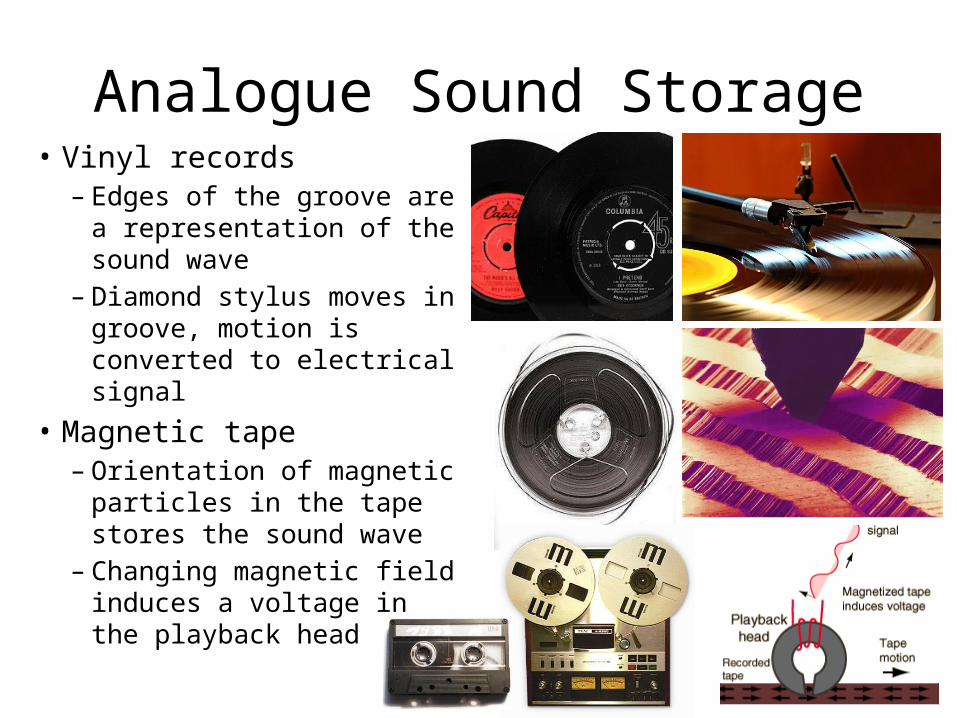
• Magnetic tape– Orientation of magnetic
particles in the tape stores the sound wave
– Changing magnetic field induces a voltage in the playback head

Digital Sound Storage• The analogue sound signal is
converted to a stream of numbers during recording
• Compact disc– The numbers are encoded as tiny pits
in the surface of the disc– A laser beam is reflected less by pits,
the intensity change is detected and converted to an electrical digital signal
• mp3 player– The digital file is stored in memory or
on a hard disc• The stream of numbers is
converted back into an analogue signal and played back
digital in analogue out

Analogue to digital conversion• At equal time intervals the amplitude of the analogue
signal is sampled. • For each time slot it’s value is rounded to the nearest
whole number
• At the receiver the reverse process recovers a representation of the original analogue signal
Black line: analogue signal Red profile: digitally sampled signal
Digital values can be read off and strung together for transmission
NOT EXAMINABLE

Analogue to digital conversion
• The digital signal is only ever an approximation to the analogue signal
• To make it a closer representation you need to take samples closer together in time, with a smaller gap between allowed levels
16 level, 1 x sampling
128 level, 16 x sampling
This digital signal better represents the analogue signal
NOT EXAMINABLE

Binary codes
• By converting the digital values from decimal to binary it is possible to represent the signal by a string of “1”s and “0”s
• These can be simply transmitted as “on” or “off” pulses of the carrier wave – the simplest possible signal to send

Which is better, analogue or digital?
• The argument rages on...– Analogue is “cleaner”– Digital is always just an
approximation to the original– Digital doesn’t degrade
• But digital won long ago– It’s the natural “language” of
computers– Regeneration and
compression are possible

Signals degrade on transmission• Whatever the
transmission method, two things happen to signals:– They gradually get smaller,
and so harder to detect, as energy is lost
– They pick up noise and interference
• The first problem can be fixed with an amplifier, but this also amplifies the unwanted noise

Some digital magic• When an analogue signal has been degraded
with noise there is nothing you can do to recover the original signal
• Digital is different, though. As long as you can decide what is a “1” and what is a “0”, you can reconstruct the original
A digital regenerator takes you from this...
back to this...!

So digital provides higher quality...
• ... because you can always get back to your perfect digital signal, but this isn’t possible with analogue signals

Digital data compression
• Once a digital file has been produced, it is often possible to make it smaller.
• Compression can use encoding to:– Retain all the information (lossless)• e.g. Zip files
– “throw away” information which isn’t needed (lossy)• e.g. jpeg, mp3, mpeg-2 formats

Compression Example - HDTV
• Uncompressed HDTV has 1920x1080 pixels, 1024 RGB levels, 25 frames per second, plus stereo sound = 1.5 Gbit/s
• The bandwidth available to transmit HDTV is generally ~10Mbit/s (~150 times smaller and approx same as for an old analogue TV channel)
• A lot of raw data is stripped out without most viewers noticing – we are very tolerant of imperfections in moving pictures and our brains “fill in” the missing details

Video compression techniques
• Don’t retransmit parts on an image that don’t change from frame-to-frame, only transmit differences
• Transmit movement of blocks as a “move” command, rather than pixel-by-pixel
• Average out small changes of colour within a frame and send that region as a single colour block
• These only become noticeable when over-applied or if there is an error on transmission

Transmission error reveals compression effects in sky image

Example - jpeg data compression
• The compression factor increases looking from left to right
• Over-compression leads to noticeable artefacts and lack of colour depth

Advantages of Digital Communications
• Compatible with computer data• After being degraded, it is possible to regenerate a
perfect copy of a digital signal– An analogue one will always remain degraded
• It is easy to manipulate digital data– We can apply data compression, encryption, error
correction and other signal processing to digital signals• Thanks to data compression techniques, digital signals
can require less bandwidth than analogue ones– So more information may be stored or transmitted digitally
than by analogue methods

Increasing digital channel capacity
• To send more data on a digital channel you can:– Shorten the time interval for a bit (increase the frequency)– Use more levels to carry information (move from binary to
ternary, or more…)
(but you have to regenerate more often to keen noise down and still be able to distinguish one level from another)
– Use more exotic modulation methods (PSK, QAM, SSB etc can send the same data rate in less bandwidth)
(Up to now the extra complexity has cost more than increasing the frequency)

• use the following units: degree (°), hertz (Hz), metre (m), metre/second (m/s), second (s), [3.1]
• understand that waves can be diffracted when they pass an edge, [3.8]• understand that waves can be diffracted through gaps, and that the
extent of diffraction depends on the wavelength and the physical dimension of the gap, [3.9]
• understand that light waves are transverse waves which can be reflected, refracted and diffracted, [3.14]
• understand that sound waves are longitudinal waves and how they can be reflected, refracted and diffracted, [3.26]
• understand the difference between analogue and digital signals, [3.23]• describe the advantages of using digital signals rather than analogue
signals, [3.24]• describe how digital signals can carry more information, [3.25]• understand how an oscilloscope and microphone can be used to
display a sound wave, [3.29]• describe an experiment using an oscilloscope to determine the
frequency of a sound wave, [3.30]
Related Documents