MOPSA: A microfluidics-optimized particle simulation algorithm Junchao Wang, 1 Victor G. J. Rodgers, 1 Philip Brisk, 2 and William H. Grover 1,a) 1 Department of Bioengineering, University of California, Riverside, California 92521, USA 2 Department of Computer Science and Engineering, University of California, Riverside, California 92521, USA (Received 11 January 2017; accepted 12 June 2017; published online 26 June 2017) Computer simulation plays a growing role in the design of microfluidic chips. However, the particle tracers in some existing commercial computational fluid dynamics software are not well suited for accurately simulating the trajectories of particles such as cells, microbeads, and droplets in microfluidic systems. To address this issue, we present a microfluidics-optimized particle simulation algorithm (MOPSA) that simulates the trajectories of cells, droplets, and other particles in microfluidic chips with more lifelike results than particle tracers in existing commer- cial software. When calculating the velocity of a particle, MOPSA treats the particle as a two-dimensional rigid circular object instead of a single point. MOPSA also checks for unrealistic interactions between particles and channel walls and applies an empirical correcting function to eliminate these errors. To validate the performance of MOPSA, we used it to simulate a variety of important features of microfluidic devices like channel intersections and deterministic lateral displacement (DLD) parti- cle sorter chips. MOPSA successfully predicted that different particle sizes will have different trajectories in six published DLD experiments from three research groups; these DLD chips were used to sort a variety of different cells, particles, and droplets. While some of these particles are not actually rigid or spherical, MOPSA’s approxi- mation of these particles as rigid spheres nonetheless resulted in lifelike simulations of the behaviors of these particles (at least for the particle sizes and types shown here). In contrast, existing commercial software failed to replicate these experiments. Finally, to demonstrate that MOPSA can be extended to simulate other properties of particles, we added support for simulating particle density to MOPSA and then used MOPSA to simulate the operation of a microfluidic chip capable of sorting cells by their density. By enabling researchers to accurately simulate the behavior of some types of particles in microfluidic chips before fabricating the chips, MOPSA should accelerate the development of new microfluidic devices for important applications. Published by AIP Publishing. [http://dx.doi.org/10.1063/1.4989860] I. INTRODUCTION The field of lab-on-a-chip and micro total analysis devices has been growing rapidly for nearly 40 years, 1 and microfluidic chips have found important applications in biological and chemical analyses. Many of these chips contain particles such as cells, microbeads, or droplets. For example, microfluidic cell sorters are emerging as powerful tools for point-of-care testing and biological research. 2,3 As the variety of microfluidic devices increases, computer-based simulations of microflui- dics have become more important. 4–6 Microfluidics researchers are increasingly using finite ele- ment analysis (FEA) software such as COMSOL Multiphysics (COMSOL Inc., Burlington, a) Electronic mail: [email protected]; URL: http://groverlab.org 1932-1058/2017/11(3)/034121/14/$30.00 Published by AIP Publishing. 11, 034121-1 BIOMICROFLUIDICS 11, 034121 (2017)

Welcome message from author
This document is posted to help you gain knowledge. Please leave a comment to let me know what you think about it! Share it to your friends and learn new things together.
Transcript
MOPSA: A microfluidics-optimized particle simulationalgorithm
Junchao Wang,1 Victor G. J. Rodgers,1 Philip Brisk,2 andWilliam H. Grover1,a)
1Department of Bioengineering, University of California, Riverside, California 92521, USA2Department of Computer Science and Engineering, University of California, Riverside,California 92521, USA
(Received 11 January 2017; accepted 12 June 2017; published online 26 June 2017)
Computer simulation plays a growing role in the design of microfluidic chips.However, the particle tracers in some existing commercial computational fluiddynamics software are not well suited for accurately simulating the trajectoriesof particles such as cells, microbeads, and droplets in microfluidic systems. Toaddress this issue, we present a microfluidics-optimized particle simulation algorithm(MOPSA) that simulates the trajectories of cells, droplets, and other particles inmicrofluidic chips with more lifelike results than particle tracers in existing commer-cial software. When calculating the velocity of a particle, MOPSA treats the particleas a two-dimensional rigid circular object instead of a single point. MOPSA alsochecks for unrealistic interactions between particles and channel walls and applies anempirical correcting function to eliminate these errors. To validate the performanceof MOPSA, we used it to simulate a variety of important features of microfluidicdevices like channel intersections and deterministic lateral displacement (DLD) parti-cle sorter chips. MOPSA successfully predicted that different particle sizes will havedifferent trajectories in six published DLD experiments from three research groups;these DLD chips were used to sort a variety of different cells, particles, and droplets.While some of these particles are not actually rigid or spherical, MOPSA’s approxi-mation of these particles as rigid spheres nonetheless resulted in lifelike simulationsof the behaviors of these particles (at least for the particle sizes and types shownhere). In contrast, existing commercial software failed to replicate these experiments.Finally, to demonstrate that MOPSA can be extended to simulate other properties ofparticles, we added support for simulating particle density to MOPSA and then usedMOPSA to simulate the operation of a microfluidic chip capable of sorting cells bytheir density. By enabling researchers to accurately simulate the behavior of sometypes of particles in microfluidic chips before fabricating the chips, MOPSA shouldaccelerate the development of new microfluidic devices for important applications.Published by AIP Publishing. [http://dx.doi.org/10.1063/1.4989860]
I. INTRODUCTION
The field of lab-on-a-chip and micro total analysis devices has been growing rapidly fornearly 40 years,1 and microfluidic chips have found important applications in biological andchemical analyses. Many of these chips contain particles such as cells, microbeads, or droplets.For example, microfluidic cell sorters are emerging as powerful tools for point-of-care testingand biological research.2,3
As the variety of microfluidic devices increases, computer-based simulations of microflui-dics have become more important.4–6 Microfluidics researchers are increasingly using finite ele-ment analysis (FEA) software such as COMSOL Multiphysics (COMSOL Inc., Burlington,
a)Electronic mail: [email protected]; URL: http://groverlab.org
1932-1058/2017/11(3)/034121/14/$30.00 Published by AIP Publishing.11, 034121-1
BIOMICROFLUIDICS 11, 034121 (2017)

MA), Autodesk CFD (Autodesk Inc., Venice, CA), and Fluent (ANSYS Inc., Canonsburg, PA)to simulate and optimize their microfluidic chip designs. These software tools excel at calculat-ing the fluid velocity field in a chip. However, these tools are not well suited for simulating thebehavior of particles like cells, beads, and droplets flowing in microfluidic chips. For example,Fig. 1 shows the results from using COMSOL Multiphysics to simulate the behavior of a deter-ministic lateral displacement (DLD) cell sorter. DLD sorters use arrays of micron-scale posts tosort cells based on their size. As cells flow through the chip and interact with the posts, largeand small cells follow different paths and are therefore separated by the chip.7,8 However, inthe simulation results from COMSOL Multiphysics in Fig. 1, the larger 10 lm cells (red) andsmaller 3 lm cells (green) follow exactly the same trajectory. If the simulation were accurate,the cells would have followed different trajectories. Additionally, by zooming in to the simula-tion results in Fig. 1(a), we see that the 10 lm cell actually overlaps with the wall of a triangu-lar post (an impossible situation). These observations confirm that the particle tracing algorithmin COMSOL Multiphysics treats the particle as a mathematical point with no area or volume,an assumption that can be acceptable in macro-scale physics but not in microfluidics. Thisassumption leads to additional problems: if the simulated single-point particle in COMSOLMultiphysics is located on a mesh node with a fluid velocity magnitude of zero, the particlewill remain stuck at that location forever [Fig. 1(b)]. This sticking behavior remains regardlessof which boundary condition is chosen for the wall in COMSOL Multiphysics (freeze, stick,bounce, disappear, or reflect diffusely).
The lack of commercial software tools that accurately simulate particles in microfluidicshas profound consequences. For example, researchers developing new cell sorters like the DLDcell sorter shown in Fig. 1 typically have to fabricate and test these chips to determine whetherthey sort the desired cells. While some empirical models for predicting the sorting behavior ofDLD chips do exist for chips with cylindrical posts,9 these models do not easily extend to postswith arbitrary shapes like the triangles shown in Fig. 1. And with each chip design iterationrequiring fabrication and testing in the lab, it can take months for researchers to develop a func-tional device. This slows the progress of research and keeps valuable research tools and lifesav-ing medical diagnostics out of the hands of the people who need them.
FIG. 1. Results from using the commercial finite element analysis software COMSOL Multiphysics to simulate the behav-ior of two sizes of cells flowing through a deterministic lateral displacement (DLD) microfluidic cell sorter chip containingan array of triangular posts. While this DLD chip was designed to separate cells based on size, in this simulation the smallcell (3 lm diameter; green) and large cell (10 lm; red) follow exactly the same trajectory and are not separated.Additionally, the simulated cells sometimes impossibly overlap the chip’s triangular posts (a) or stick permanently (b).Deficiencies like these make it difficult to accurately simulate flowing cells and other particles in microfluidics using exist-ing commercial software tools.
034121-2 Wang et al. Biomicrofluidics 11, 034121 (2017)
To address this problem, we developed a microfluidics-optimized particle simulation algo-rithm (MOPSA) that is capable of simulating lifelike trajectories for some particles in situationswhere existing software tools fail. MOPSA treats a particle as a 2D rigid circular object insteadof a single point when calculating the particle’s velocity. MOPSA also checks whether the par-ticle overlaps a solid object (a post or channel wall) at each simulated time step. If overlap isdetected, MOPSA applies an empirical correcting function, wallEffect, to shift the particle to anew position where it will not overlap walls. By providing researchers with accurate simula-tions of some types of particles in microfluidic devices, MOPSA should accelerate the develop-ment of new microfluidic devices for important applications in biological research, medicaldiagnostics, and beyond.
Assuming that a particle is a rigid circle means that MOPSA cannot directly simulatethe deformability or non-spherical shapes of some particles. In spite of this limitation, byassuming that the particles are rigid circles, MOPSA nonetheless predicts particle trajectoriesthat are consistent with the experimentally observed behavior of published DLD chips sort-ing some types of deformable and non-spherical cells and droplets. However, undoubtedlythere are particles that cannot be approximated as rigid circles and simulated successfullyusing MOPSA; for these particles other simulation approaches may be necessary and couldeven be incorporated into future versions of MOPSA (as discussed in the Conclusions).
II. SIMULATION
Simulating a microfluidic chip using MOPSA requires two steps:
1. Calculate the fluid velocity field in the chip using conventional finite element analysis software2. Calculate the trajectory followed by a particle through the chip using MOPSA
In this proof-of-concept demonstration, we used COMSOL Multiphysics to calculate thefluid velocity field and MATLAB to implement MOPSA. We used this approach to simulatethree different microfluidic chip models:
1. The cross channel model is a typical microfluidic cross-shaped intersection with 200 lm chan-nel widths. Junctions like this are extremely common in microfluidic chips,10–13 so assessingthe performance of MOPSA in these intersections is very important.
2. The triangular DLD model was chosen because of its complexity. Arrays of hundreds of trian-gular posts offer many opportunities for interactions between particles and the posts and chal-lenge the robustness of MOPSA.
3. The cylindrical DLD model enables comparisons between MOPSA and published experimentalresults. The vast majority of DLD chips in the literature use arrays of cylindrical posts, and weuse MOPSA to simulate the paths followed by particles in six published DLD experiments bythree different research groups.7,14,15
While we chose these three models for this proof-of-concept demonstration, we note that,in principle, MOPSA can simulate virtually any microfluidic chip design containing flowingparticles, as long as the chip can be modeled in two dimensions (MOPSA is currently a two-dimensional simulation, although it could easily be extended to three dimensions as discussedin the Conclusions) and as long as the particles can be approximated as rigid circles or spheres.Finally, to compare MOPSA to existing commercial software tools for particle simulation inmicrofluidics, we also simulated these chip models entirely in COMSOL Multiphysics (withoutusing MOPSA).
A. Calculating fluid velocity field in COMSOL
For each microfluidic chip model simulated here, the fluid velocity fields were calculatedusing finite element analysis software (COMSOL Multiphysics). For accuracy, we used theLaminar Flow physics module and a customized free triangle mesh with a maximum mesh sizethat was equal to or less than the diameter of the smallest particle that would be simulated usingthat mesh. In the cross channel model, the maximum mesh size was 8 lm (for simulating a
034121-3 Wang et al. Biomicrofluidics 11, 034121 (2017)
particle diameter of 50 lm). Inlets were assigned an inlet boundary condition of 5 mm/s normalinflow velocity. In the triangular DLD models, the maximum mesh size was 1 lm (for simulatingparticle diameters of 1, 3, 10, and 12 lm). In the cylindrical DLD models, the maximum meshsize was a quarter of the difference between two simulated particles’ diameters (e.g., for simulat-ing a DLD chip separating 8 and 9 lm beads, the maximum mesh size was 0.25 lm). Inlets wereassigned an inlet boundary condition of 1 mm/s normal inflow velocity. In all models, outletswere assigned an outlet boundary condition of 0 Pa pressure, the remaining boundaries were walls(no-slip boundary condition), and the material filling the channels was water under incompress-ible flow. A stationary solver was used for calculating the fluid velocity field.
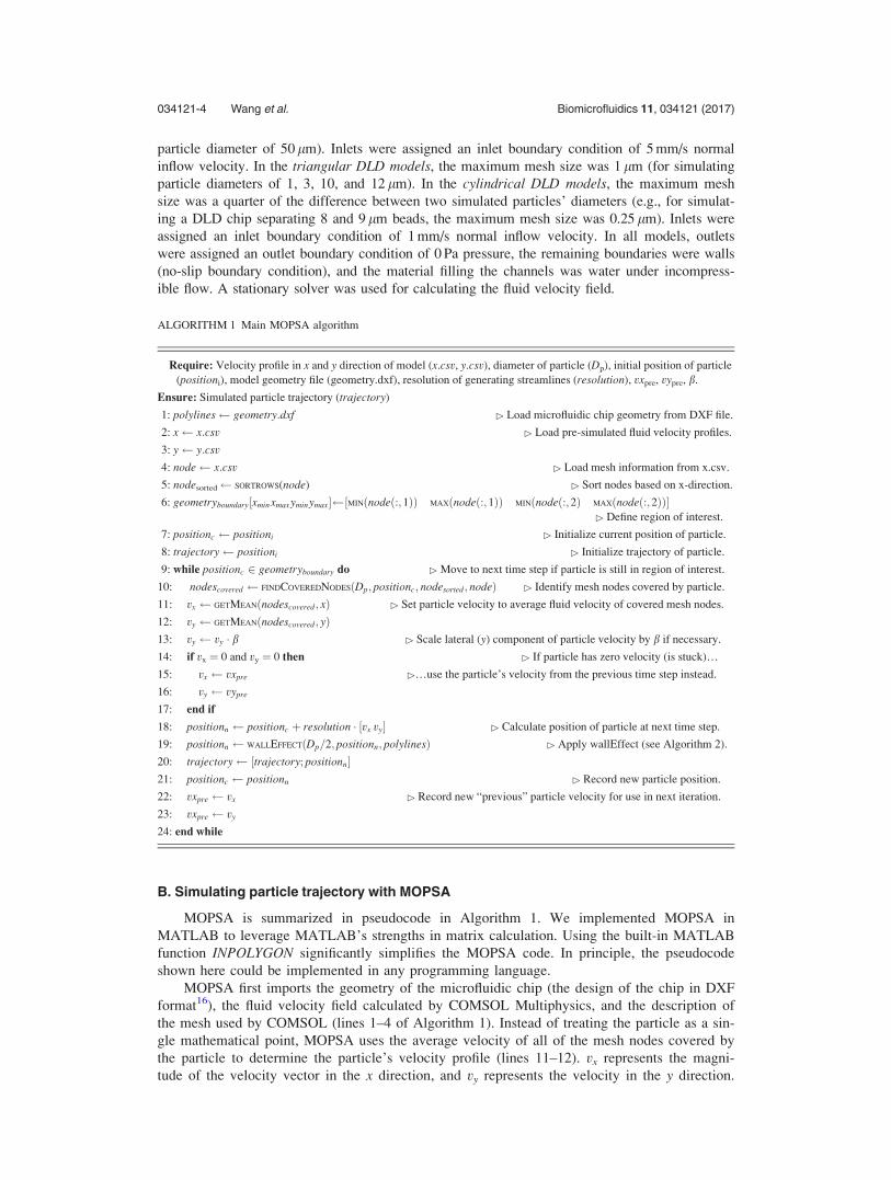
ALGORITHM 1 Main MOPSA algorithm
Require: Velocity profile in x and y direction of model (x.csv, y.csv), diameter of particle (Dp), initial position of particle(positioni), model geometry file (geometry.dxf), resolution of generating streamlines (resolution), vxpre, vypre, b.
Ensure: Simulated particle trajectory (trajectory)
1: polylines geometry:dxf ! Load microfluidic chip geometry from DXF file.
2: x x:csv ! Load pre-simulated fluid velocity profiles.
3: y y:csv
4: node x:csv ! Load mesh information from x.csv.
5: nodesorted SORTROWS(node) ! Sort nodes based on x-direction.
6: geometryboundary½xminxmaxyminymax" ½MINðnodeð:;1ÞÞ MAXðnodeð:;1ÞÞ MINðnodeð:;2Þ MAXðnodeð:;2ÞÞ"! Define region of interest.
7: positionc positioni ! Initialize current position of particle.
8: trajectory positioni ! Initialize trajectory of particle.
9: while positionc 2 geometryboundary do ! Move to next time step if particle is still in region of interest.
10: nodescovered FINDCOVEREDNODESðDp; positionc; nodesorted; nodeÞ ! Identify mesh nodes covered by particle.
11: vx GETMEANðnodescovered; xÞ ! Set particle velocity to average fluid velocity of covered mesh nodes.
12: vy GETMEANðnodescovered; yÞ13: vy vy % b ! Scale lateral (y) component of particle velocity by b if necessary.
14: if vx ¼ 0 and vy ¼ 0 then ! If particle has zero velocity (is stuck)…
15: vx vxpre !…use the particle’s velocity from the previous time step instead.
16: vy vypre
17: end if
18: positionn positionc þ resolution % ½vx vy" ! Calculate position of particle at next time step.
19: positionn WALLEFFECTðDp=2; positionn; polylinesÞ ! Apply wallEffect (see Algorithm 2).
20: trajectory ½trajectory; positionn"21: positionc positionn ! Record new particle position.
22: vxpre vx ! Record new “previous” particle velocity for use in next iteration.
23: vxpre vy
24: end while
B. Simulating particle trajectory with MOPSA
MOPSA is summarized in pseudocode in Algorithm 1. We implemented MOPSA inMATLAB to leverage MATLAB’s strengths in matrix calculation. Using the built-in MATLABfunction INPOLYGON significantly simplifies the MOPSA code. In principle, the pseudocodeshown here could be implemented in any programming language.
MOPSA first imports the geometry of the microfluidic chip (the design of the chip in DXFformat16), the fluid velocity field calculated by COMSOL Multiphysics, and the description ofthe mesh used by COMSOL (lines 1–4 of Algorithm 1). Instead of treating the particle as a sin-gle mathematical point, MOPSA uses the average velocity of all of the mesh nodes covered bythe particle to determine the particle’s velocity profile (lines 11–12). vx represents the magni-tude of the velocity vector in the x direction, and vy represents the velocity in the y direction.
034121-4 Wang et al. Biomicrofluidics 11, 034121 (2017)

As shown in Algorithm 1 line 13, MOPSA uses an empirically obtained parameter b to“weight” the components of the particle velocity vector in direction orthogonal to fluid flow(the y direction). For the cross channel model, b¼ 1 (meaning that the velocities calculated byCOMSOL are used as-is). For the triangular and cylindrical DLD models, b¼ 1.45. Details onhow this value was determined are provided in Results and Discussion.
MOPSA next considers the possibility of particles with zero velocity. In theory, as long asthere is fluid flow in a microfluidic channel, mesh nodes with zero fluid velocity should existonly at channel walls. However, in practice, a finite mesh size makes it possible for softwarelike COMSOL Multiphysics to predict that nodes near channel walls may also have zero fluidvelocity. A particle located at a mesh node with zero fluid velocity can become permanentlytrapped. To detect this situation, MOPSA utilizes a conditional statement (line 14 in Algorithm1) to determine if the velocity of the particle in the time step will be zero. If so, MOPSA usesthe particle’s non-zero velocity from the previous time step for the current time step calculation(lines 15 and 16). As long as the amount of time between steps [resolution, defined in Eq. (1)below] is sufficiently small, this substitution does not seem to affect the accuracy of the simula-tion. In this manner, MOPSA ensures that the particle will not get permanently stuck.Alternatively, for applications in which particle sticking is desired (for example, usingantibody-coated posts to capture cells of interest in a microfluidic chip17), a threshold can beadded to allow particle sticking below a user-specified particle velocity.
MOPSA then uses Eq. (1) to calculate the particle’s position at the next time step18
positionn ¼ positionc þ resolution % vx vy½ "; (1)
where positionc (lm) is the current position of the particle, positionn (lm) is the position of theparticle in the next time step, resolution (s) is the amount of time between each calculationstep, and vx and vy (lm/s) are the average fluid velocities of the mesh nodes covered by the par-ticle, as defined earlier. The variable resolution is a parameter that can be customized by theuser. A smaller resolution makes the simulation more accurate but also more time consuming.If the flow through a chip is relatively fast, then a small value for resolution is needed to accu-rately predict the path followed by a particle in the fluid. If the flow is relatively slow, then alarger resolution can be used without sacrificing simulation accuracy. To find an optimal valuefor resolution, a MOPSA simulation can be repeated with successively smaller values for reso-lution. Eventually the predicted particle trajectories will converge to a single trajectory that willnot change with additional decreases in resolution; this is the optimal value for resolution for agiven application.
Eq. (1) assumes that:
1. The density of the particle is the same as its surrounding fluid.2. The net force applied to the particle is always zero.3. Particles do not interfere with each other or channel walls.4. Particles have smooth surfaces, so friction between fluid and particle surfaces is negligible.5. The material of the particle is homogeneous.
If these assumptions are unsuitable for a particular application, MOPSA can be modifiedby replacing Eq. (1) with a more complicated drag law such as Stokes’ Law19 or the work ofHaider and Levenspiel20 (we demonstrate a modification of MOPSA later in this work).
ALGORITHM 2 function wallEffect
Require: microfluidic chip wall geometry information (polylines), radius of particle (Rp), current position of particle
(positionc), particle mapping parameter (k)
Ensure: shifted position of particle (positions)
1: function WALLEFFECT(Rp, positionc, polylines)
2: xp Rp % cos ð0 : ð2p=kÞ : 2pÞ þ positioncð1; 1Þ ! Calculate locations of the k points representing the particleboundary.
034121-5 Wang et al. Biomicrofluidics 11, 034121 (2017)
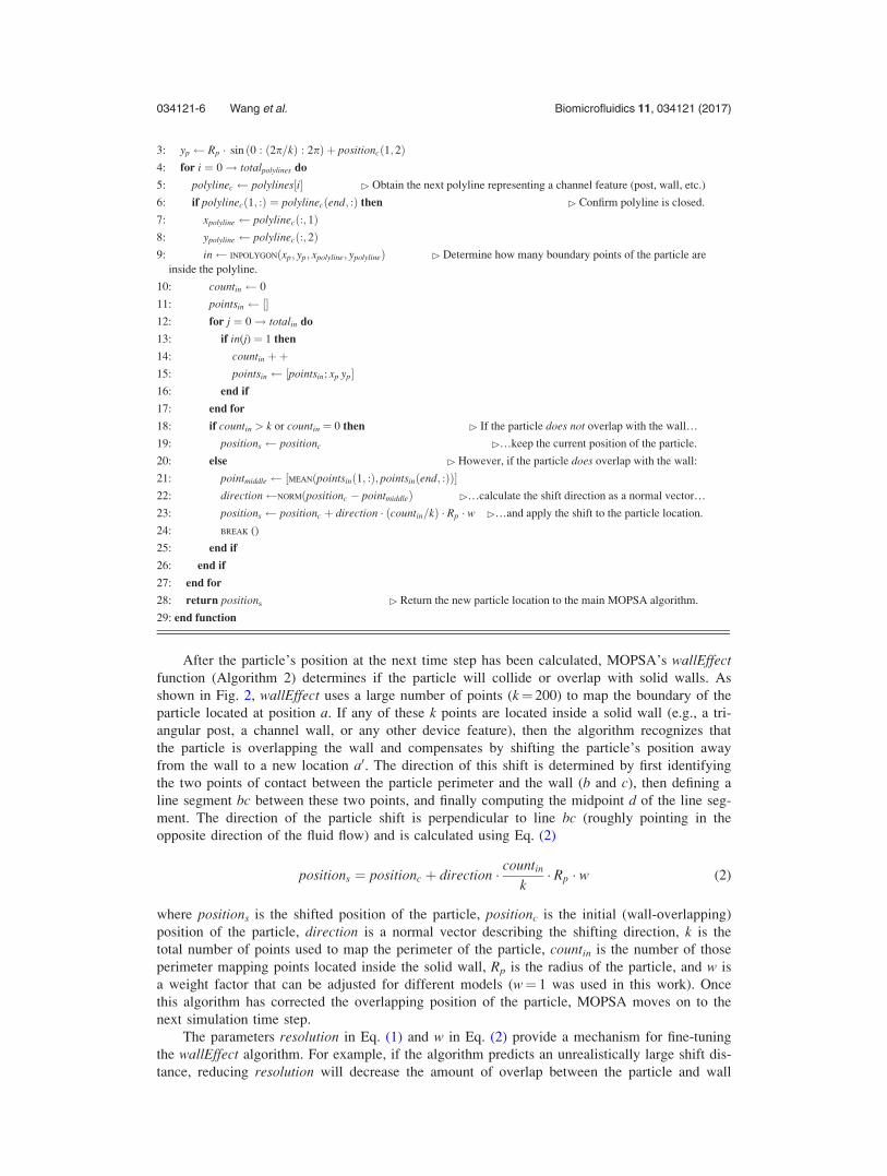
3: yp Rp % sin ð0 : ð2p=kÞ : 2pÞ þ positioncð1; 2Þ4: for i ¼ 0! totalpolylines do
5: polylinec polylines½i" ! Obtain the next polyline representing a channel feature (post, wall, etc.)
6: if polylinecð1; :Þ ¼ polylinecðend; :Þ then ! Confirm polyline is closed.
7: xpolyline polylinecð:; 1Þ8: ypolyline polylinecð:; 2Þ9: in INPOLYGONðxp; yp; xpolyline; ypolylineÞ ! Determine how many boundary points of the particle are
inside the polyline.
10: countin 0
11: pointsin ½"12: for j ¼ 0! totalin do
13: if in(j) ¼ 1 then
14: countin þþ15: pointsin ½pointsin; xp yp"16: end if
17: end for
18: if countin > k or countin ¼ 0 then ! If the particle does not overlap with the wall…
19: positions positionc !…keep the current position of the particle.
20: else ! However, if the particle does overlap with the wall:
21: pointmiddle ½MEANðpointsinð1; :Þ; pointsinðend; :ÞÞ"22: direction NORMðpositionc ( pointmiddleÞ !…calculate the shift direction as a normal vector…
23: positions positionc þ direction % ðcountin=kÞ % Rp % w !…and apply the shift to the particle location.
24: BREAK ()
25: end if
26: end if
27: end for
28: return positions ! Return the new particle location to the main MOPSA algorithm.
29: end function
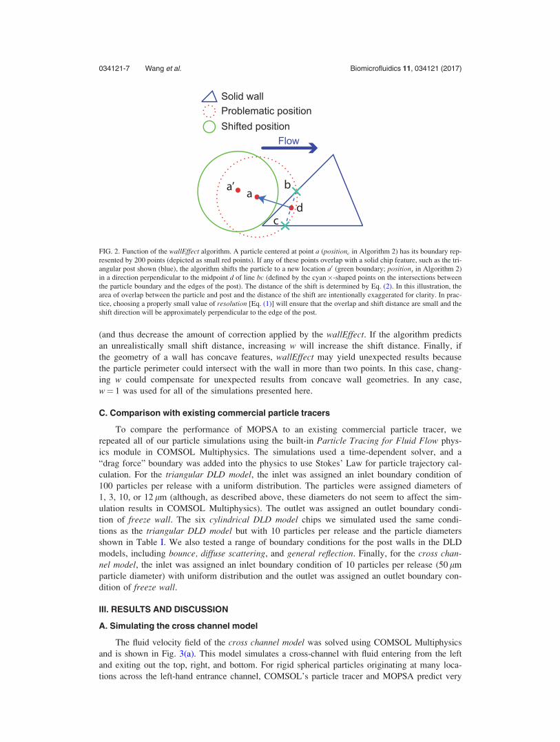
After the particle’s position at the next time step has been calculated, MOPSA’s wallEffectfunction (Algorithm 2) determines if the particle will collide or overlap with solid walls. Asshown in Fig. 2, wallEffect uses a large number of points (k¼ 200) to map the boundary of theparticle located at position a. If any of these k points are located inside a solid wall (e.g., a tri-angular post, a channel wall, or any other device feature), then the algorithm recognizes thatthe particle is overlapping the wall and compensates by shifting the particle’s position awayfrom the wall to a new location a0. The direction of this shift is determined by first identifyingthe two points of contact between the particle perimeter and the wall (b and c), then defining aline segment bc between these two points, and finally computing the midpoint d of the line seg-ment. The direction of the particle shift is perpendicular to line bc (roughly pointing in theopposite direction of the fluid flow) and is calculated using Eq. (2)
positions ¼ positionc þ direction % countin
k% Rp % w (2)
where positions is the shifted position of the particle, positionc is the initial (wall-overlapping)position of the particle, direction is a normal vector describing the shifting direction, k is thetotal number of points used to map the perimeter of the particle, countin is the number of thoseperimeter mapping points located inside the solid wall, Rp is the radius of the particle, and w isa weight factor that can be adjusted for different models (w¼ 1 was used in this work). Oncethis algorithm has corrected the overlapping position of the particle, MOPSA moves on to thenext simulation time step.
The parameters resolution in Eq. (1) and w in Eq. (2) provide a mechanism for fine-tuningthe wallEffect algorithm. For example, if the algorithm predicts an unrealistically large shift dis-tance, reducing resolution will decrease the amount of overlap between the particle and wall
034121-6 Wang et al. Biomicrofluidics 11, 034121 (2017)
(and thus decrease the amount of correction applied by the wallEffect. If the algorithm predictsan unrealistically small shift distance, increasing w will increase the shift distance. Finally, ifthe geometry of a wall has concave features, wallEffect may yield unexpected results becausethe particle perimeter could intersect with the wall in more than two points. In this case, chang-ing w could compensate for unexpected results from concave wall geometries. In any case,w¼ 1 was used for all of the simulations presented here.
C. Comparison with existing commercial particle tracers
To compare the performance of MOPSA to an existing commercial particle tracer, werepeated all of our particle simulations using the built-in Particle Tracing for Fluid Flow phys-ics module in COMSOL Multiphysics. The simulations used a time-dependent solver, and a“drag force” boundary was added into the physics to use Stokes’ Law for particle trajectory cal-culation. For the triangular DLD model, the inlet was assigned an inlet boundary condition of100 particles per release with a uniform distribution. The particles were assigned diameters of1, 3, 10, or 12 lm (although, as described above, these diameters do not seem to affect the sim-ulation results in COMSOL Multiphysics). The outlet was assigned an outlet boundary condi-tion of freeze wall. The six cylindrical DLD model chips we simulated used the same condi-tions as the triangular DLD model but with 10 particles per release and the particle diametersshown in Table I. We also tested a range of boundary conditions for the post walls in the DLDmodels, including bounce, diffuse scattering, and general reflection. Finally, for the cross chan-nel model, the inlet was assigned an inlet boundary condition of 10 particles per release (50 lmparticle diameter) with uniform distribution and the outlet was assigned an outlet boundary con-dition of freeze wall.
III. RESULTS AND DISCUSSION
A. Simulating the cross channel model
The fluid velocity field of the cross channel model was solved using COMSOL Multiphysicsand is shown in Fig. 3(a). This model simulates a cross-channel with fluid entering from the leftand exiting out the top, right, and bottom. For rigid spherical particles originating at many loca-tions across the left-hand entrance channel, COMSOL’s particle tracer and MOPSA predict very
FIG. 2. Function of the wallEffect algorithm. A particle centered at point a (positionc in Algorithm 2) has its boundary rep-resented by 200 points (depicted as small red points). If any of these points overlap with a solid chip feature, such as the tri-angular post shown (blue), the algorithm shifts the particle to a new location a0 (green boundary; positions in Algorithm 2)in a direction perpendicular to the midpoint d of line bc (defined by the cyan)-shaped points on the intersections betweenthe particle boundary and the edges of the post). The distance of the shift is determined by Eq. (2). In this illustration, thearea of overlap between the particle and post and the distance of the shift are intentionally exaggerated for clarity. In prac-tice, choosing a properly small value of resolution [Eq. (1)] will ensure that the overlap and shift distance are small and theshift direction will be approximately perpendicular to the edge of the post.
034121-7 Wang et al. Biomicrofluidics 11, 034121 (2017)

similar particle trajectories. However, for particles that start close to a channel wall, MOPSA’ssimulation is more realistic than COMSOL’s. Figure 3(b) shows trajectories predicted byCOMSOL (red) and MOPSA (green) for a 50 lm diameter particle flowing adjacent to the chan-nel wall. In the trajectory predicted by COMSOL, the particle overlaps with the channel wall asit goes around the corner. In contrast, MOPSA detects these channel walls and keeps the particlefrom overlapping them. The realistic wall interactions simulated by MOPSA result in a particletrajectory that is 18 lm (36% of the particle’s size) farther to the right than the trajectory calcu-lated by COMSOL. For simple microfluidic chips with a single intersection, the particle tracingerrors introduced by software like COMSOL Multiphysics may be acceptable and may not affectthe overall accuracy of the simulation. However, for microfludic chips with hundreds of intersec-tions in parallel (like the hydrodynamic filter of Yamada et al.10), small errors in each intersec-tion could combine to form a large net error associated with the path followed by particles flow-ing across the entire chip. In these cases, MOPSA should provide a much more accurate particletrajectory than existing software tools.
B. Simulating deterministic lateral displacement (DLD)
We also tested MOPSA on the triangular deterministic lateral displacement (DLD) modelcell sorter to determine how the algorithm performs in a chip with more complex geometry.Figure 4 shows the predicted particle trajectories for a 10 lm diameter rigid spherical particleflowing through an array of triangular posts, calculated using COMSOL Multiphysics (red) and
TABLE I. Experimental details from six published deterministic lateral displacement (DLD) particle separations. These
experiments are reproduced by MOPSA in Fig. 7. The parameters k, Dk, and G describe the DLD device design and aredefined in Fig. 6.
Figure k (lm) Dk (lm) G (lm) Sorted particle types and sizes Figure in reference
7(a) 80 6 25 8 lm and 9 lm beads Fig. 2(a) in Li et al.14
7(b) 90 8 25 9 lm and 10 lm beads Fig. 2(b) in Li et al.14
7(c) 80 2 20 2 lm platelets and 6 lm red blood cells Fig. 4(a) in Li et al.14
7(d) 80 5 20 6 lm red blood cells and 10 lm white blood cells Fig. 4(b) in Li et al.14
7(e) 8 0.8 1.6 0.4 lm and 1.0 lm beads Fig. 2(a) in Huang et al.7
7(f) 120 6 60 11 lm and 30 lm droplets Fig. 2(c) in Joensson et al.15
FIG. 3. (a) Fluid velocity field of the cross channel model obtained from COMSOL Multiphysics (dimensions in lm andvelocity in m/s). (b) Simulated trajectories of a 50 lm diameter particle traveling through the cross channel model. In thetrajectory calculated by the particle tracer in COMSOL Multiphysics (red outlines) the particle overlaps with the channelwall (an impossibility). However, in the trajectory calculated by MOPSA (green outlines) the particle remains separatefrom the channel wall and exits the intersection offset 18 lm from the COMSOL-predicted trajectory (a significant differ-ence for a particle this size).
034121-8 Wang et al. Biomicrofluidics 11, 034121 (2017)
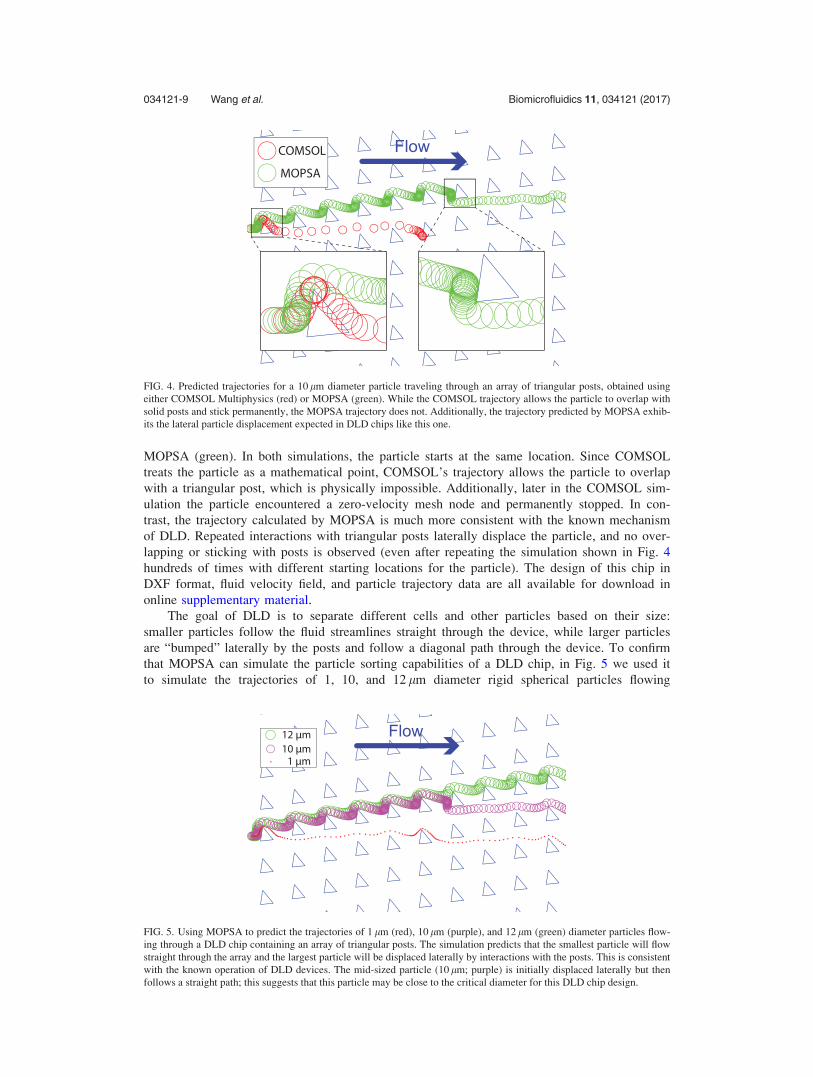
MOPSA (green). In both simulations, the particle starts at the same location. Since COMSOLtreats the particle as a mathematical point, COMSOL’s trajectory allows the particle to overlapwith a triangular post, which is physically impossible. Additionally, later in the COMSOL sim-ulation the particle encountered a zero-velocity mesh node and permanently stopped. In con-trast, the trajectory calculated by MOPSA is much more consistent with the known mechanismof DLD. Repeated interactions with triangular posts laterally displace the particle, and no over-lapping or sticking with posts is observed (even after repeating the simulation shown in Fig. 4hundreds of times with different starting locations for the particle). The design of this chip inDXF format, fluid velocity field, and particle trajectory data are all available for download inonline supplementary material.
The goal of DLD is to separate different cells and other particles based on their size:smaller particles follow the fluid streamlines straight through the device, while larger particlesare “bumped” laterally by the posts and follow a diagonal path through the device. To confirmthat MOPSA can simulate the particle sorting capabilities of a DLD chip, in Fig. 5 we used itto simulate the trajectories of 1, 10, and 12 lm diameter rigid spherical particles flowing
FIG. 4. Predicted trajectories for a 10 lm diameter particle traveling through an array of triangular posts, obtained usingeither COMSOL Multiphysics (red) or MOPSA (green). While the COMSOL trajectory allows the particle to overlap withsolid posts and stick permanently, the MOPSA trajectory does not. Additionally, the trajectory predicted by MOPSA exhib-its the lateral particle displacement expected in DLD chips like this one.
FIG. 5. Using MOPSA to predict the trajectories of 1 lm (red), 10 lm (purple), and 12 lm (green) diameter particles flow-ing through a DLD chip containing an array of triangular posts. The simulation predicts that the smallest particle will flowstraight through the array and the largest particle will be displaced laterally by interactions with the posts. This is consistentwith the known operation of DLD devices. The mid-sized particle (10 lm; purple) is initially displaced laterally but thenfollows a straight path; this suggests that this particle may be close to the critical diameter for this DLD chip design.
034121-9 Wang et al. Biomicrofluidics 11, 034121 (2017)

through an array of triangular posts. Although particles of all three sizes start in the same loca-tion, MOPSA predicts that the particles will exit the chip in different locations: the small 1 lmparticle follows the fluid streamlines and moves straight through the chip, and the large 12 lmparticle is “bumped” by each post and moves diagonally through the chip. The mid-sized10 lm particle initially follows a diagonal path but then switches to a straight-through path,leading to a trajectory that lies between the other two particles’ trajectories. This suggests thatthe critical diameter for this DLD chip design (the size of the smallest particle that is laterallydisplaced in the chip) is close to 10 lm. In contrast, particles of different sizes follow exactlythe same trajectory in COMSOL’s particle tracer (Fig. 1). These results confirm that MOPSAcan successfully simulate size-based DLD separations that are difficult or impossible to simulateusing existing commercial software, at least for rigid spherical particles. The design of this chipin DXF format, fluid velocity field, and particle trajectory data are all available for download inonline supplementary material.
C. Simulating published DLD experiments
We next used MOPSA to predict the paths followed by different sized particles in severalpublished DLD chips. We identified six experiments in three published papers7,14,15 in whichthe chip designs and experimental conditions are described in sufficient detail to allow us tosimulate them using MOPSA. These chips use arrays of cylindrical posts with dimensionsdefined in Fig. 6 and summarized in Table I.
We first simulated the DLD chip described by Li et al.14 who used this chip to sort 8 lmand 9 lm diameter rigid spherical beads. We found that with a value of b¼ 1.45, theMOPSA predicts that the 8 lm and 9 lm beads will follow different paths through the DLDchip [Fig. 7(a)]; this is consistent with the observed bead sorting behavior of this DLDchip.14
We then left the value of b¼ 1.45 unchanged as we used MOPSA to predict the paths fol-lowed by particles through five additional published DLD chips from three research groups[Figs. 7(b)–7(f)]. In their original publications,7,14,15 these chips were used to sort a wide varietyof particle sizes (from 0.4 lm to 30 lm diameters) and types (beads, droplets, red blood cells,
FIG. 6. Illustration of the key dimensions in a traditional cylindrical-post-based DLD chip: spacing between posts (k), gapbetween posts (G), and offset between rows of posts (Dk).
034121-10 Wang et al. Biomicrofluidics 11, 034121 (2017)

white blood cells, and platelets). Some of these particles are not rigid or spherical—dropletsare not rigid, and red blood cells, white blood cells, and platelets are neither rigid norspherical—so one may rightly expect that MOPSA (which assumes rigid spherical particles)may not be able to accurately simulate the trajectories of these particles. However, MOPSAnonetheless successfully predicted that the different-sized particles follow different pathsthrough the chip. This prediction is consistent with the particle-sorting behavior reported by thecreators of these chips. In contrast, the built-in particle tracer in COMSOL Multiphysics pre-dicted no differences in the paths followed by the different particles (see supplementary mate-rial Figs. 2–7). Undoubtedly there are some particles whose deformability and non-sphericalshapes will render MOPSA unable to accurately simulate the behavior of these particles, but atleast for the particle types and sizes we studied, MOPSA’s assumption of rigid and sphericalparticles did not seem to adversely affect the quality of the simulation results. The chip designDXF files, fluid velocity profiles, and predicted particle trajectories from both MOPSA andCOMSOL for each of the six simulations in Fig. 7 are available in supplementary material.
In some of the DLD chip simulations in Fig. 7, MOPSA predicted that the smaller particleswill follow a somewhat jagged path when the particles flow vertically between two rows ofposts. For example, in Fig. 7(c) the 2 lm diameter platelets seem to make two sharp turns asthey pass from above the third row of posts to below the row. This behavior was unexpected;to determine its source, we examined the fluid velocity fields calculated by COMSOL for theseDLD simulations. Close inspection of the gaps between columns of posts (supplementary mate-rial Fig. 8) reveals that COMSOL predicted asymmetric fluid velocity fields in these gaps inthe cases where the MOPSA-predicted particle paths were most jagged. For example, the fluidvelocity field calculated by COMOSL for the chip in Fig. 7(c) [shown in supplementary
FIG. 7. Using MOPSA to predict particle trajectories in six published deterministic lateral displacement (DLD) experi-ments from three research groups.7,14,15 These simulations are based on (a) a chip that separates 8 lm and 9 lm beads,14 (b)a chip that separates 9 lm and 10 lm beads,14 (c) a chip that separates 2 lm platelets and 6 lm red blood cells,14 (d) a chipthat separates 6 lm red blood cells and 10 lm white blood cells,14 (e) a chip that separates 0.4 lm and 1.0 lm beads,7 and(f) a chip that separates 11 lm and 30 lm droplets.15 In each case, MOPSA’s prediction that the different-sized particlesfollow different paths is consistent with the experimentally observed particle sorting behavior of these DLD chips.7,14,15
034121-11 Wang et al. Biomicrofluidics 11, 034121 (2017)

material Fig. 8(c)] has a diagonal region of low flow between every two pillars; when MOPSAuses this fluid velocity field to predict the path followed by a particle between the pillars, theasymmetry in the field results in a jagged predicted particle path. These particle trajectories donot seem to affect the overall simulation results (that different-sized particles follow differentpaths through the DLD chips).
Why was it necessary to increase b to successfully simulate DLD chips in MOPSA? Oneexplanation could be our assumption that the presence of the particle will not affect the fluidvelocity profile in the chip. In actuality, the presence of a particle could increase the hydrody-namic resistance of the DLD chip.21 This could reduce the fluid velocity in the direction offlow (the x direction) and make the fluid velocity in the direction perpendicular to flow (the ydirection) more significant. Increasing b from 1 to 1.45 adds additional weight to the y compo-nent of the fluid velocity and enables MOPSA to accurately simulate particles in DLD devices,at least for the particle sizes and types considered here. While this value of b may not be suit-able for all DLD devices or particle sizes and types, it is noteworthy that all six previously pub-lished DLD chips we replicated in this work were successfully simulated using the same valuefor b (1.45).
D. Extending MOPSA to simulate particles with different densities
In its current form, MOPSA is capable of simulating rigid spherical particles in a varietyof different microfluidic applications. However, in some cases it may be necessary to add addi-tional physics modules to MOPSA to simulate certain particle properties. For example, micro-fluidic chips have been demonstrated that sort cells and other particles by their densities.22,23
Since the current MOPSA assumes that all particles have the same density (and the particles’density equals the density of the fluid around the particles), MOPSA cannot currently be usedto simulate the behavior of these density sorter chips.
FIG. 8. Using a modified version of MOPSA to simulate the behavior of a microfluidic chip for sorting cells and otherparticles by their densities. The chip simulated is based on published results22,23 and consists of two inlets that mergeinto a single horizontal channel before splitting into two outlets. The chip is oriented on its edge relative to Earth’sgravity. (a) Fluid velocity field for the density sorter chip, obtained using COMSOL Multiphysics. (b) After modifyingMOPSA using the approach of Haider and Levenspiel,20 MOPSA predicts the paths followed by four rigid sphericalparticles of different densities as they enter from the lower input and travel through the chip. As expected, particleswith density greater than the fluid density of 1.0 g/cm3 exit the lower outlet, and particles with density less than the fluiddensity exit the upper outlet. This demonstrates that additional particle properties (like density) can be added toMOPSA when necessary.
034121-12 Wang et al. Biomicrofluidics 11, 034121 (2017)

To demonstrate that additional particle properties can be readily added to MOPSA whenneeded, we added support for particle density to MOPSA. Our approach uses the work ofHaider and Levenspiel20 to predict the effects of buoyancy on particles. We then used our mod-ified MOPSA to predict the paths followed by rigid spherical particles of four different densities(0.8, 1.0, 1.2, and 1.5 g/cm3) in a microfluidic chip filled with water (1.0 g/cm3) and oriented onits edge relative to Earth’s gravity. In Fig. 8, all four particles start at the same location in alower inlet. As the particles flow along the horizontal channel, our modified MOPSA correctlypredicts that the particles with density greater than the fluid density will sink downward andexit via the lower outlet, and the particles with density greater than the fluid density will floatupward and exit via the upper outlet. Since different cell types often have different densities,24
our modified MOPSA may be used to help design chips for sorting cells by their type, animportant capability in biological research and medical diagnostics.
IV. CONCLUSIONS
In this work, we presented MOPSA, an algorithm for optimized particle simulation inmicrofluidic chips. By treating particles as two-dimensional objects instead of single points andapplying corrections when particles interact with channel walls, MOPSA can accurately simu-late particle behaviors that particle tracers in existing commercial software tools cannot.Consequently, adopting MOPSA into the design process for microfluidic chips that containcells, droplets, and other particles should be beneficial.
A. Limitations of MOPSA and future directions
MOPSA makes several assumptions about the particles it simulates: the particles are circu-lar or spherical, they have the same density as the fluid around them, they have smooth surfa-ces, they do not interact with other particles, and so on. These assumptions may limit the utilityof MOPSA for some applications. For example, in its current form, MOPSA cannot simulateeffects of inertia on either the particles or the fluid in a chip; these effects have been used asthe basis for particle sorting and focusing in microfluidics.25 However, for at least some particlesizes and types, MOPSA’s assumption of rigid spheres seems to still yield results that are con-sistent with experimental observations.
For particles that cannot be assumed to be rigid spheres, a number of modeling techniqueshave been proposed for simulating the behavior of these particles.26 For example, dissipativeparticle dynamics27–29 has been successfully applied to simulate the deformation of red bloodcells in DLD chips.26,30 Zhu et al.31 modeled deformable cells as fluid-filled capsules enclosedby neo-Hookean membranes.32 Kr€uger et al.33 used the immersed-boundary method34 to modelmembrane dynamics during cell deformation. These and other models can be used in situationswhere MOPSA fails to accurately predict the behavior of a non-rigid, non-spherical particle;some of them could even be incorporated into future versions of MOPSA.
We also demonstrated that MOPSA can be easily extended to simulate other particle prop-erties like particle density. This same approach can be used to enable MOPSA to support otherimportant properties of particles. For example, by altering the wallEffect algorithm to allowcells to stick to channel walls, one could simulate the behavior of microfluidic devices thatintentionally capture cells in this manner.17 Additionally, to include the effects of other forcessuch as electrostatics and acoustics on a particle’s trajectory, additional equations can be addedto Line 18 in Algorithm 1. To simulate particle-particle interactions that may be important inapplications with high particle concentrations, it may be necessary to periodically recalculatethe fluid velocity vector field while including particle positions (and particle-induced drag) inthe finite element analysis calculation. In our experience, including particle positions in thismanner has a negligible effect on simulation accuracy but significantly increases the requiredcomputational time, but it may be necessary for some applications.
Finally, MOPSA is currently a two-dimensional simulation technique and cannot be usedto simulate three-dimensional microfluidic channel networks. However, nothing about MOPSAprecludes extending the algorithm to three dimensions. This would enable MOPSA to simulate
034121-13 Wang et al. Biomicrofluidics 11, 034121 (2017)
particle trajectories in emerging 3D-printed microfluidic chips that can have channels in allthree spatial dimensions.35
SUPPLEMENTARY MATERIAL
See supplementary material for fluid velocity field for the simulations in Figs. 4, 5, and7(a)–7(f); results from using COMSOL Multiphysics to simulate the deterministic lateral dis-placement (DLD) chips in Figs. 7(a)–7(f); closeups of the calculated fluids velocity fields forthe DLD chips in Figs. 7(a)–7(f); calculated particle trajectories from MOPSA for the simula-tions in Figs. 4, 5, and 7(a)–7(f) in MATLAB MAT format; and CAD files for the chip designsin Figs. 4, 5, and 7(a)–7(f) in DXF format.
ACKNOWLEDGMENTS
This work was supported in part by the National Science Foundation Division of BiologicalInfrastructure under Award No. DBI-1353974, the National Science Foundation Division ofComputer and Communication Foundations program under Award No. CCF-1351115, and theNational Science Foundation Division of Industrial Innovation and Partnerships under Award No.IIP-1640757.
1S. C. Terry, J. H. Jerman, and J. B. Angell, IEEE Trans. Electron. Devices 26, 1880 (1979).2G. J. Kost, Principles & Practice of Point-of-Care Testing (Lippincott Williams & Wilkins, 2002).3C. W. Shields IV, C. D. Reyes, and G. P. L"opez, Lab Chip 15, 1230 (2015).4M. W€orner, Microfluid. Nanofluid. 12, 841 (2012).5M. K. Runyon, C. J. Kastrup, B. L. Johnson-Kerner, T. G. Van Ha, and R. F. Ismagilov, J. Am. Chem. Soc. 130, 3458(2008).
6J. Siegrist, M. Amasia, N. Singh, D. Banerjee, and M. Madou, Lab Chip 10, 876 (2010).7L. R. Huang, E. C. Cox, R. H. Austin, and J. C. Sturm, Science 304, 987 (2004).8K. Loutherback, K. S. Chou, J. Newman, J. Puchalla, R. H. Austin, and J. C. Sturm, Microfluid. Nanofluid. 9, 1143(2010).
9D. W. Inglis, J. A. Davis, R. H. Austin, and J. C. Sturm, Lab Chip 6, 655 (2006).10M. Yamada, K. Kano, Y. Tsuda, J. Kobayashi, M. Yamato, M. Seki, and T. Okano, Biomed. Microdev. 9, 637 (2007).11A. Y. Fu, C. Spence, A. Scherer, F. H. Arnold, and S. R. Quake, Nat. Biotechnol. 17, 1109 (1999).12X. Wang, S. Chen, M. Kong, Z. Wang, K. D. Costa, R. A. Li, and D. Sun, Lab Chip 11, 3656 (2011).13H. M. Ji, V. Samper, Y. Chen, C. K. Heng, T. M. Lim, and L. Yobas, Biomed. Microdev. 10, 251 (2008).14N. Li, D. T. Kamei, and C.-M. Ho, in 2007 2nd IEEE International Conference on Nano/Micro Engineered and
Molecular Systems (IEEE, 2007), pp. 932–936.15H. N. Joensson, M. Uhl"en, and H. A. Svahn, Lab Chip 11, 1305 (2011).16See http://www.autodesk.com/techpubs/autocad/acad2000/dxf/ascii_dxf_files_dxf_aa.htm for “ASCII DXF Files” (last
accessed September 26, 2016).17S. Nagrath, L. V. Sequist, S. Maheswaran, D. W. Bell, D. Irimia, L. Ulkus, M. R. Smith, E. L. Kwak, S. Digumarthy, A.
Muzikansky, P. Ryan, U. J. Balis, R. G. Tompkins, D. A. Haber, and M. Toner, Nature 450, 1235 (2007).18I. Newton, A. Motte, and N. Chittenden, Newton’s Principia: The Mathematical Principles of Natural Philosophy (Geo.
P. Putnam, 1850).19G. K. Batchelor, An Introduction to Fluid Dynamics (Cambridge University Press, 2000).20A. Haider and O. Levenspiel, Powder Technol. 58, 63 (1989).21M. A. Cartas-Ayala, M. Raafat, and R. Karnik, Small 9, 375 (2013).22D. Huh, J. H. Bahng, Y. Ling, H.-H. Wei, O. D. Kripfgans, J. B. Fowlkes, J. B. Grotberg, and S. Takayama, Anal. Chem.
79, 1369 (2007).23J. Song, M. Song, T. Kang, D. Kim, and L. P. Lee, Biomicrofluidics 8, 064108 (2014).24W. H. Grover, A. K. Bryan, M. Diez-Silva, S. Suresh, J. M. Higgins, and S. R. Manalis, Proc. Natl. Acad. Sci. U.S.A.
108, 10992 (2011).25D. Di Carlo, Lab Chip 9, 3038 (2009).26E. Henry, S. H. Holm, Z. Zhang, J. P. Beech, J. O. Tegenfeldt, D. A. Fedosov, and G. Gompper, Sci. Rep. 6, 34375
(2016).27P. Hoogerbrugge and J. Koelman, Europhys. Lett. 19, 155 (1992).28P. Espanol and P. Warren, Europhys. Lett. 30, 191 (1995).29P. Espanol and M. Revenga, Phys. Rev. E 67, 026705 (2003).30Z. Zhang, E. Henry, G. Gompper, and D. A. Fedosov, J. Chem. Phys. 143, 243145 (2015).31L. Zhu, C. Rorai, D. Mitra, and L. Brandt, Soft Matter 10, 7705 (2014).32C. Pozrikidis, Computational Hydrodynamics of Capsules and Biological Cells, Chapman and Hall/CRC Mathematical
and Computational Biology Series (CRC Press, Boca Raton, 2010).33T. Kr€uger, D. Holmes, and P. V. Coveney, Biomicrofluidics 8, 054114 (2014).34C. S. Peskin, Acta Numer. 11, 479 (2002).35N. Bhattacharjee, A. Urrios, S. Kang, and A. Folch, Lab Chip 16, 1720 (2016).
034121-14 Wang et al. Biomicrofluidics 11, 034121 (2017)
Related Documents