Rochdale Holdings Pty Ltd A.B.N. 85 009 049 067 trading as: HERRING STORER ACOUSTICS Suite 34, 11 Preston Street, Como, W.A. 6152 P.O. Box 219, Como, W.A. 6952 Telephone: (08) 9367 6200 Facsimile: (08) 9474 2579 Email: [email protected] MOONIES HILL ENERGY FLAT ROCKS WIND FARM KOJONUP NOISE IMPACT ASSESSMENT JULY 2011 OUR REFERENCE:13231-4-10226-02

Welcome message from author
This document is posted to help you gain knowledge. Please leave a comment to let me know what you think about it! Share it to your friends and learn new things together.
Transcript

Rochdale Holdings Pty Ltd A.B.N. 85 009 049 067 trading as:
HERRING STORER ACOUSTICS Suite 34, 11 Preston Street, Como, W.A. 6152 P.O. Box 219, Como, W.A. 6952 Telephone: (08) 9367 6200 Facsimile: (08) 9474 2579 Email: [email protected]
MOONIES HILL ENERGY
FLAT ROCKS WIND FARM
KOJONUP
NOISE IMPACT ASSESSMENT
JULY 2011
OUR REFERENCE:13231-4-10226-02

Herring Storer Acoustics
DOCUMENT CONTROL PAGE
NOISE IMPACT ASSESSMENT KOJONUP
Job No: 10226
Document Reference : 13231-4-10226-02
FOR
MOONIES HILL ENERGY
DOCUMENT INFORMATION Author: George Watts Checked By: Tim Reynolds Date of Issue : 30 May 2011
REVISION HISTORY Revision Description Date Author Checked1 Revision Incorporating comments from GH 02/06/11 GW TR 2 Revision Incorporating comments from GH 02/06/11 GW TR 3 Finalisation of Report 12/07/11 GW
DOCUMENT DISTRIBUTION
Copy No. Version No. Destination Hard Copy Electronic Copy
1 1 Moonies Hill Energy 1 2 Moonies Hill Energy 1 3 Moonies Hill Energy

Herring Storer Acoustics
CONTENTS
1. INTRODUCTION 1
2. SUMMARY 1
3. CRITERIA 1
4. MODELLING 3
5. RESULTS 4
6. ASSESSMENT 5
7. CONCLUSION 6
APPENDICIES A Residential and Wind Turbine Locations B Turbine Specifications C Predicted Noise Level Contours D Background Monitoring Locations

Herring Storer Acoustics Our ref: 13231-4-10226-02
1
1. INTRODUCTION Herring Storer acoustics were commissioned to carry out a noise impact assessment for the proposed Flat Rocks Wind Farm development.
The proposed development site is located to the east of Albany Highway, approximately 260km southeast of Perth and 27km southwest of the township of Katanning in southwest Western Australia. The proposed wind farm consists of 74 wind turbines, in cleared wheat farming country. See Appendix A for locations of turbines and noise sensitive premises.
The noise impact assessment has been carried out in accordance with the EPA of South Australia “Wind Farms – Environmental noise guidelines (interim) – December 2007” (Guidelines) which is the guidelines recognised by the Department of Environment and Conservation for the assessment of wind farms.
2. SUMMARY Noise levels were assessed at 34 identified receiver points, with these locations shown in Appendix A.
Noise emissions at “non-stake holders” have been calculated to comply with the background noise criteria under all wind conditions. Noise levels at “stake holders” SH27 and SH28 have been calculated to marginally exceed the background noise criteria for 8m/s at hub height (80m).
3. CRITERIA
According to the Western Australian Planning bulletin number 67 “Guidelines for Wind Farm Development” – May 2004, the noise impact of proposed wind farms in Western Australia should be assessed in accordance with the criteria and approach of assessing wind farms described in the EPA of South Australia “Wind Farms – Environmental noise guidelines (interim) – December 2007” (Guidelines).
The Guidelines recommend the following criteria for the assessment of noise levels associated with proposed wind farms;
The predicted equivalent noise level (LAeq ,10 minutes), adjusted for tonality in accordance with the Guidelines, should not exceed :
• 35 dB(A), or • 40 dB(A) in a primary production / rural industry zone, or • the “Alternative Minimum Criteria” (Varying With Wind Speed); or • the background noise (LA90,10 minutes) by more than 5 dB(A).
The criteria for background noise levels will vary with wind speed, as will wind turbine generated noise.

Herring Storer Acoustics Our ref: 13231-4-10226-02
2
The alternative minimum criterion, varying with wind speed, is listed below in Table 3.1. This conservative minimum criterion has been determined based on a comparison of background noise levels at a number of existing and proposed wind farm sites around Australia.
Table 3.1 – Alternative Minimum Criteria (Varying With Wind Speed)
Wind Speed at 10m above ground level
≤ 5 6 7 8 9 ≥ 10
Minimum Criteria LAeq [dB(A)] 35 37 38 40 41 43
Based on the results of background noise monitoring undertaken during November 2010 – February 2011 (presented in Herring Storer Report ref: 12777-4-10226-01), the criteria for wind turbine noise are as presented in Table 3.2. See Appendix D for background noise monitoring locations.
Table 3.2 – Noise Criteria Based on Background Noise Levels, dB(A)
Background Monitoring Location
ID # WIND SPEED AT 80m ABOVE GROUND LEVEL (m/s)
3 4 5 6 7 8 9
1 NSH12 41 40 39 39 39 39 40 2 NSH13 35 35 35 35 36 37 39 3 SH28 38 39 40 41 41 42 42 4 SH29 39 39 40 41 42 43 44 5 NSH09 35 35 35 36 38 40 42 6 SH27 35 35 35 35 35 37 38 7 NSH19 35 35 35 35 36 37 38 8 NSH06 35 35 36 37 39 41 42 9 NSH14 35 35 36 37 39 41 43
10 NSH15 39 39 39 39 40 41 42 11 SH30 38 38 38 37 38 38 39
This assessment has been based on the noise criteria based on monitored background noise levels. It is noted that the Guidelines have been developed to minimise the impact on the amenity of premises that do not have an agreement with wind farm developers. Our assessment includes all identified residential premises in the surrounding area, some of which may have such an agreement. The applicable noise criteria for each identified location have been based on the closest background noise monitoring location. Due to poor correlation of data for background monitoring location 3 (SH28), the criteria for background monitoring location 6 (SH27) has been used in its place. Participation in the development (or otherwise) is denoted in the ID of the residential premise, with “NSH” denoting “Non-Stake Holder” and “SH” denoting “Stake-Holder”.

Herring Storer Acoustics Our ref: 13231-4-10226-02
3
4. MODELLING Noise immissions at residential premises, due to the proposed wind farm, were determined by noise modelling, using the computer program “SoundPlan” version 7.0. SoundPlan uses the theoretical sound power levels determined from measured sound pressure levels to calculate the noise level at any location. The following input data was used in the SoundPlan model:
a) Topographical Information – Ground contours of the development area b) Residential and Wind Turbine Locations – See Appendix A c) Sound Power Levels, varying with wind speed, of the wind turbines intended to
be utilised (Vestas V100-1.8 MW, 80m hub height) – See Appendix B
The Guidelines indicate that noise immissions should be modelled to reflect typical, (but not extreme) “worst case” meteorological conditions for sound propagation towards the receiver. After a review of the literature available on the subject, noise level emissions were modelled using the ISO 9613-2:1996 algorithm, with the conditions listed in Table 4.1. These conditions, and calculating noise levels utilising a “G=0” ground absorption have been found to provide a generally realistic and conservative assessment of noise levels associated with wind turbines.
Table 4.1 – Meteorological Conditions Condition Value
Temperature 15 oC
Relative humidity 70%
Atmospheric Pressure 101.325 kPa
Noise levels attributable to the proposed wind farm were calculated for integer wind speeds 4 – 9m/s at a height of 80m (hub height). The sound power level of the turbines were varied for each integer wind speed, however the weather conditions within the model remained constant at the conditions stipulated in Table 4.1 above.

Herring Storer Acoustics Our ref: 13231-4-10226-02
4
5. RESULTS Noise contour plots are attached in Appendix C. The predicted noise level at each identified residential premises are listed in Table 5.1 below for each of the hub height wind speeds considered.
Table 5.1 – Predicted Noise Levels at Identified Receiver Locations – Noise Mode 0
ID# Predicted Noise Level, LAeq [dB(A)]
4m/s 5m/s 6m/s 7m/s 8m/s 9m/s NSH01 14 17 17 20 20 20 NSH02 16 18 18 22 27 27 NSH03 25 27 27 31 36 36 NSH04 26 28 28 32 36 36 NSH05 15 17 17 21 24 24 NSH06 22 25 25 28 31 31 NSH07 18 20 20 24 29 29 NSH08 23 25 25 29 33 32 NSH09 25 27 27 31 35 35 NSH10 4 6 6 10 16 16 NSH11 11 13 13 17 24 24 NSH12 25 27 27 31 37 36 NSH13 24 26 26 30 36 36 NSH14 25 27 27 31 37 37 NSH15 26 28 28 32 37 37 NSH16 15 17 17 21 26 26 NSH17 14 16 16 20 23 23 NSH18 14 16 16 20 24 23 NSH19 24 26 26 30 35 35 NSH20 16 18 18 22 28 28 NSH21 7 9 9 13 22 21 NSH22 24 26 26 30 34 34 NSH23 16 18 18 22 22 22 NSH24 23 26 26 30 34 34 NSH25 6 8 8 12 20 20
Proposed NSH34 26 28 28 32 37 37 SH26 7 9 9 13 21 21 SH27 26 28 28 32 38 38 SH28 26 28 28 32 38 37 SH29 29 31 31 35 40 40 SH30 27 29 29 33 38 38 SH31 26 28 28 32 37 37 SH32 26 28 28 32 37 37 SH33 6 8 8 12 13 12
Herring Storer Acoustics Our ref: 13231-4-10226-02
5
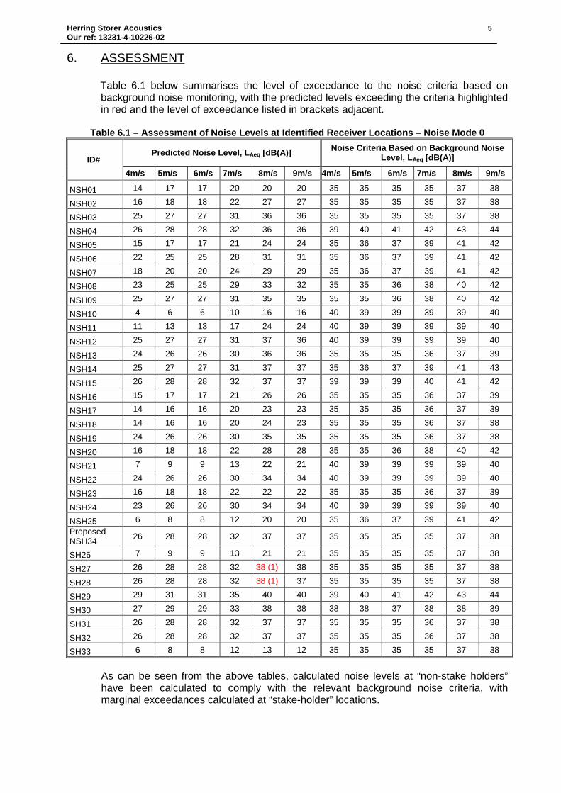
6. ASSESSMENT Table 6.1 below summarises the level of exceedance to the noise criteria based on background noise monitoring, with the predicted levels exceeding the criteria highlighted in red and the level of exceedance listed in brackets adjacent.
Table 6.1 – Assessment of Noise Levels at Identified Receiver Locations – Noise Mode 0
ID# Predicted Noise Level, LAeq [dB(A)] Noise Criteria Based on Background Noise
Level, LAeq [dB(A)]
4m/s 5m/s 6m/s 7m/s 8m/s 9m/s 4m/s 5m/s 6m/s 7m/s 8m/s 9m/s
NSH01 14 17 17 20 20 20 35 35 35 35 37 38
NSH02 16 18 18 22 27 27 35 35 35 35 37 38
NSH03 25 27 27 31 36 36 35 35 35 35 37 38
NSH04 26 28 28 32 36 36 39 40 41 42 43 44
NSH05 15 17 17 21 24 24 35 36 37 39 41 42
NSH06 22 25 25 28 31 31 35 36 37 39 41 42
NSH07 18 20 20 24 29 29 35 36 37 39 41 42
NSH08 23 25 25 29 33 32 35 35 36 38 40 42
NSH09 25 27 27 31 35 35 35 35 36 38 40 42
NSH10 4 6 6 10 16 16 40 39 39 39 39 40
NSH11 11 13 13 17 24 24 40 39 39 39 39 40
NSH12 25 27 27 31 37 36 40 39 39 39 39 40
NSH13 24 26 26 30 36 36 35 35 35 36 37 39
NSH14 25 27 27 31 37 37 35 36 37 39 41 43
NSH15 26 28 28 32 37 37 39 39 39 40 41 42
NSH16 15 17 17 21 26 26 35 35 35 36 37 39
NSH17 14 16 16 20 23 23 35 35 35 36 37 39
NSH18 14 16 16 20 24 23 35 35 35 36 37 38
NSH19 24 26 26 30 35 35 35 35 35 36 37 38
NSH20 16 18 18 22 28 28 35 35 36 38 40 42
NSH21 7 9 9 13 22 21 40 39 39 39 39 40
NSH22 24 26 26 30 34 34 40 39 39 39 39 40
NSH23 16 18 18 22 22 22 35 35 35 36 37 39
NSH24 23 26 26 30 34 34 40 39 39 39 39 40
NSH25 6 8 8 12 20 20 35 36 37 39 41 42 Proposed NSH34 26 28 28 32 37 37 35 35 35 35 37 38
SH26 7 9 9 13 21 21 35 35 35 35 37 38
SH27 26 28 28 32 38 (1) 38 35 35 35 35 37 38
SH28 26 28 28 32 38 (1) 37 35 35 35 35 37 38
SH29 29 31 31 35 40 40 39 40 41 42 43 44
SH30 27 29 29 33 38 38 38 38 37 38 38 39
SH31 26 28 28 32 37 37 35 35 35 36 37 38
SH32 26 28 28 32 37 37 35 35 35 36 37 38
SH33 6 8 8 12 13 12 35 35 35 35 37 38
As can be seen from the above tables, calculated noise levels at “non-stake holders” have been calculated to comply with the relevant background noise criteria, with marginal exceedances calculated at “stake-holder” locations.

Herring Storer Acoustics Our ref: 13231-4-10226-02
6
7. CONCLUSION Noise emissions at “non-stake holders” have been calculated to comply with the background noise criteria under all wind conditions. Noise levels at “stake holders” SH27 and SH28 have been calculated to marginally exceed the background noise criteria for 8m/s at hub height (80m).
I trust the above meets your requirements on this matter. Should you have any further queries, do not hesitate to contact the undersigned. Yours faithfully, For HERRING STORER ACOUSTICS George Watts

APPENDIX A
RESIDENTIAL AND WIND TURBINE LOCATIONS
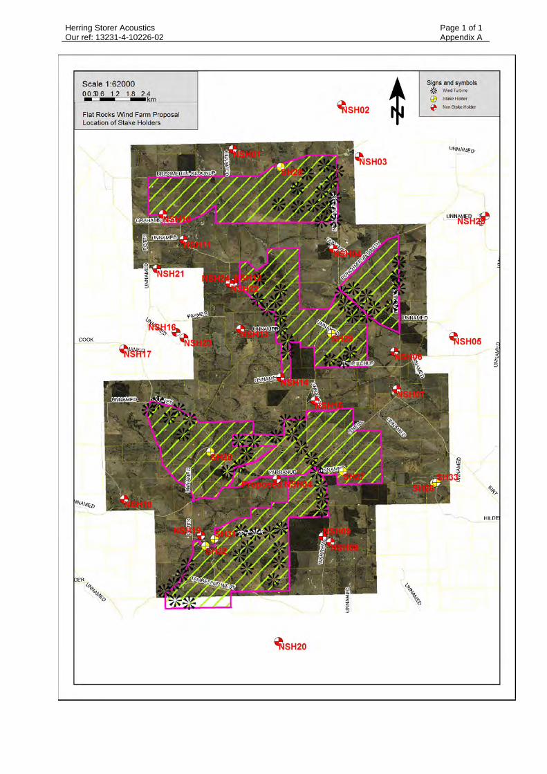
Herring Storer Acoustics Page 1 of 1 Our ref: 13231-4-10226-02 Appendix A

APPENDIX B
TURBINE SPECIFICATIONS

Vestas Wind Systems A/S · Alsvej 21 · 8940 Randers SV · Denmark · www.vestas.com
QM
S 0
0081 V
00 2
008-0
9-0
1
Class 1
Document no.: 0004-0153 V09
2010-10-06
General Specification V100–1.8 MW 50 Hz VCS
VESTAS PROPRIETARY NOTICE: This document contains valuable confidential information of Vestas Wind Systems A/S. It is protected by copyright law as an unpublished work. Vestas reserves all patent, copyright, trade secret, and other proprietary rights to it. The information in this document may not be used, reproduced, or disclosed except if and to the extent rights are expressly granted by Vestas in writing and subject to applicable conditions. Vestas disclaims all warranties except as expressly granted by written agreement and is not responsible for unauthorized uses, for which it may pursue legal remedies against responsible parties.

Document no.: 0004-0153 V09
General Specification
Table of Contents
Date: 2010-10-06
Issued by: Technology R&D Class: 1
Type: T05 - General Description Page 2 of 51
Vestas Wind Systems A/S · Alsvej 21 · 8940 Randers SV · Denmark · www.vestas.com
Table of Contents
1 General Description ............................................................................................................. 5 2 Mechanical Design ............................................................................................................... 5 2.1 Rotor ...................................................................................................................................... 5 2.2 Blades .................................................................................................................................... 5 2.3 Blade Bearing ........................................................................................................................ 6 2.4 Pitch System .......................................................................................................................... 6 2.5 Hub ........................................................................................................................................ 7 2.6 Main Shaft ............................................................................................................................. 7 2.7 Bearing Housing .................................................................................................................... 7 2.8 Main Bearings ........................................................................................................................ 7 2.9 Gearbox ................................................................................................................................. 8 2.10 Generator Bearings ................................................................................................................ 8 2.11 High-Speed Shaft Coupling .................................................................................................... 8 2.12 Yaw System ........................................................................................................................... 9 2.13 Crane ..................................................................................................................................... 9 2.14 Tower Structure ..................................................................................................................... 9 2.15 Nacelle Bedplate and Cover ................................................................................................ 10 2.16 Cooling ................................................................................................................................ 11 2.17 Water Cooling System ......................................................................................................... 11 2.18 Gearbox Cooling .................................................................................................................. 11 2.19 Hydraulic Cooling ................................................................................................................. 12 2.20 VCS Converter Cooling ........................................................................................................ 13 2.21 Generator Cooling................................................................................................................ 13 2.22 HV Transformer Cooling ...................................................................................................... 13 2.23 Nacelle Conditioning ............................................................................................................ 14 3 Electrical Design ................................................................................................................ 15 3.1 Generator ............................................................................................................................ 15 3.2 HV Cables ........................................................................................................................... 15 3.3 Transformer ......................................................................................................................... 16 3.4 Converter ............................................................................................................................. 17 3.5 AUX System ........................................................................................................................ 17 3.6 Wind Sensors ...................................................................................................................... 17 3.7 Turbine Controller ................................................................................................................ 18 3.8 Uninterruptible Power Supply (UPS) .................................................................................... 19 4 Turbine Protection Systems.............................................................................................. 19 4.1 Braking Concept .................................................................................................................. 19 4.2 Short Circuit Protections ...................................................................................................... 19 4.3 Overspeed Protection .......................................................................................................... 20 4.4 EMC System ........................................................................................................................ 20 4.5 Lightning System ................................................................................................................. 20 4.6 Earthing (also known as grounding) ..................................................................................... 21 4.7 Corrosion Protection ............................................................................................................ 21 5 Safety .................................................................................................................................. 21 5.1 Access ................................................................................................................................. 21 5.2 Escape ................................................................................................................................. 22 5.3 Rooms/Working Areas ......................................................................................................... 22 5.4 Platforms, Standing and Working Places ............................................................................. 22 5.5 Climbing Facilities ................................................................................................................ 22 5.6 Moving Parts, Guards and Blocking Devices ........................................................................ 22 5.7 Lighting ................................................................................................................................ 22 5.8 Noise ................................................................................................................................... 23 5.9 Emergency Stop .................................................................................................................. 23

Document no.: 0004-0153 V09
General Specification
Table of Contents
Date: 2010-10-06
Issued by: Technology R&D Class: 1
Type: T05 - General Description Page 3 of 51
Vestas Wind Systems A/S · Alsvej 21 · 8940 Randers SV · Denmark · www.vestas.com
5.10 Power Disconnection ........................................................................................................... 23 5.11 Fire Protection/First Aid ....................................................................................................... 23 5.12 Warning Signs ..................................................................................................................... 23 5.13 Manuals and Warnings ........................................................................................................ 23 6 Environment ....................................................................................................................... 24 6.1 Chemicals ............................................................................................................................ 24 7 Approvals, Certificates and Design Codes ...................................................................... 24 7.1 Type Approvals .................................................................................................................... 24 7.2 Design Codes – Structural Design ....................................................................................... 24 7.3 Design Codes – Mechanical Equipment ............................................................................... 25 7.4 Design Codes – Electrical Equipment .................................................................................. 25 7.5 Design Codes – I/O Network System ................................................................................... 26 7.6 Design Codes – EMC System .............................................................................................. 26 7.7 Design Codes – Lightning Protection ................................................................................... 27 7.8 Design Codes – Earthing ..................................................................................................... 27 8 Colour and Surface Treatment .......................................................................................... 28 8.1 Nacelle Colour and Surface Treatment ................................................................................ 28 8.2 Tower Colour and Surface Treatment .................................................................................. 28 8.3 Blades Colour ...................................................................................................................... 28 9 Operational Envelope and Performance Guidelines ....................................................... 29 9.1 Climate and Site Conditions ................................................................................................. 29 9.1.1 Complex Terrain .................................................................................................................. 30 9.1.2 Altitude ................................................................................................................................. 30 9.1.3 Wind Farm Layout................................................................................................................ 30 9.2 Operational Envelope – Temperature and Wind .................................................................. 30 9.3 Operational Envelope – Grid Connection * ........................................................................... 30 9.4 Operational Envelope – Reactive Power Capability ............................................................. 31 9.5 Performance – Fault Ride Through ...................................................................................... 32 9.6 Performance – Reactive Current Contribution ...................................................................... 33 9.6.1 Symmetrical Reactive Current Contribution.......................................................................... 33 9.6.2 Asymmetrical Reactive Current Contribution ........................................................................ 34 9.7 Performance – Multiple Voltage Dips ................................................................................... 34 9.8 Performance – Active and Reactive Power Control .............................................................. 34 9.9 Performance – Voltage Control ............................................................................................ 35 9.10 Performance – Frequency Control ....................................................................................... 35 9.11 Performance – Own Consumption ....................................................................................... 35 9.12 Operational Envelope Conditions for Power Curve, Ct Values (at Hub Height) ..................... 36 10 Drawings ............................................................................................................................ 37 10.1 Structural Design – Illustration of Outer Dimensions ............................................................ 37 10.2 Structural Design – Side View Drawing ................................................................................ 38 11 General Reservations, Notes and Disclaimers ................................................................ 39 12 Appendices ........................................................................................................................ 40 12.1 Mode 0 ................................................................................................................................. 40 12.1.1 Mode 0, Power Curve .......................................................................................................... 40 12.1.2 Mode 0, Ct Values ................................................................................................................ 41 12.1.3 Mode 0, Sound Power Levels .............................................................................................. 43 12.2 Mode 1 ................................................................................................................................. 44 12.2.1 Mode 1, Power Curves ........................................................................................................ 44 12.2.2 Mode 1, Ct Values ................................................................................................................ 45 12.2.3 Mode 1, Sound Power Levels .............................................................................................. 47 12.3 Mode 2 ................................................................................................................................. 48 12.3.1 Mode 2, Power Curves ........................................................................................................ 48 12.3.2 Mode 2, Ct Values ................................................................................................................ 49 12.3.3 Mode 2, Sound Power Levels .............................................................................................. 51

Document no.: 0004-0153 V09
General Specification
Table of Contents
Date: 2010-10-06
Issued by: Technology R&D Class: 1
Type: T05 - General Description Page 4 of 51
Vestas Wind Systems A/S · Alsvej 21 · 8940 Randers SV · Denmark · www.vestas.com
Buyer acknowledges that these general specifications are for Buyer’s informational purposes
only and do not create or constitute a warranty, guarantee, promise, commitment, or other
representation by supplier, all of which are disclaimed by supplier except to the extent
expressly provided by supplier in writing elsewhere.
See section 11 General Reservations, Notes and Disclaimers, p. 39 for general reservations, notes,
and disclaimers applicable to these general specifications.
Document no.: 0004-0153 V09
General Specification
General Description
Date: 2010-10-06
Issued by: Technology R&D Class: 1
Type: T05 - General Description Page 5 of 51
Vestas Wind Systems A/S · Alsvej 21 · 8940 Randers SV · Denmark · www.vestas.com
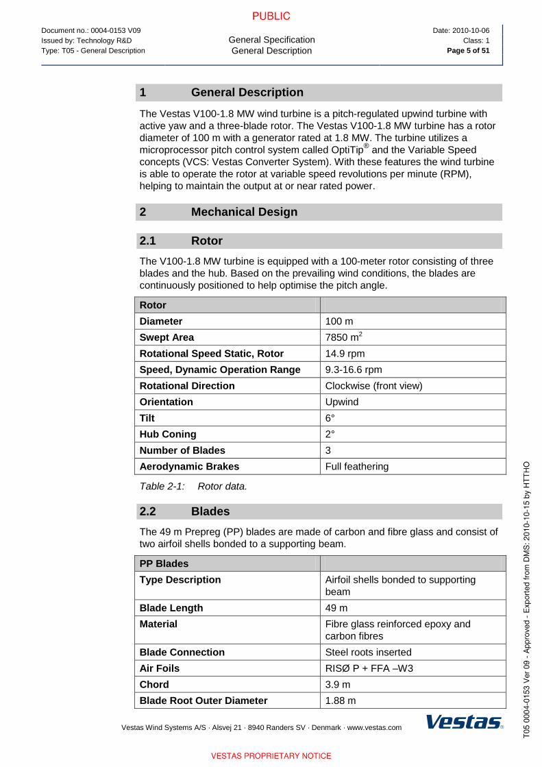
1 General Description
The Vestas V100-1.8 MW wind turbine is a pitch-regulated upwind turbine with
active yaw and a three-blade rotor. The Vestas V100-1.8 MW turbine has a rotor
diameter of 100 m with a generator rated at 1.8 MW. The turbine utilizes a
microprocessor pitch control system called OptiTip® and the Variable Speed
concepts (VCS: Vestas Converter System). With these features the wind turbine
is able to operate the rotor at variable speed revolutions per minute (RPM),
helping to maintain the output at or near rated power.
2 Mechanical Design
2.1 Rotor
The V100-1.8 MW turbine is equipped with a 100-meter rotor consisting of three
blades and the hub. Based on the prevailing wind conditions, the blades are
continuously positioned to help optimise the pitch angle.
Rotor
Diameter 100 m
Swept Area 7850 m2
Rotational Speed Static, Rotor 14.9 rpm
Speed, Dynamic Operation Range 9.3-16.6 rpm
Rotational Direction Clockwise (front view)
Orientation Upwind
Tilt 6°
Hub Coning 2°
Number of Blades 3
Aerodynamic Brakes Full feathering
Table 2-1: Rotor data.
2.2 Blades
The 49 m Prepreg (PP) blades are made of carbon and fibre glass and consist of
two airfoil shells bonded to a supporting beam.
PP Blades
Type Description Airfoil shells bonded to supporting
beam
Blade Length 49 m
Material Fibre glass reinforced epoxy and
carbon fibres
Blade Connection Steel roots inserted
Air Foils RISØ P + FFA –W3
Chord 3.9 m
Blade Root Outer Diameter 1.88 m

Document no.: 0004-0153 V09
General Specification
Mechanical Design
Date: 2010-10-06
Issued by: Technology R&D Class: 1
Type: T05 - General Description Page 6 of 51
Vestas Wind Systems A/S · Alsvej 21 · 8940 Randers SV · Denmark · www.vestas.com
PP Blades
PCD of Steel Root Inserts 1.80 m
R49 0.54 m
Twist (Blade root/blade tip) 245°/-0.5°
Approximate Weight 7500 kg
Table 2-2: PP blades data.
2.3 Blade Bearing
The blade bearings are double-row 4-point contact ball bearings.
Blade Bearing
Type 2-row 4-point contact ball bearing
Lubrication Grease lubrication, automatic lubrication
pump
Table 2-3: Blade bearing data.
2.4 Pitch System
The energy input from the wind to the turbine is adjusted by pitching the blades
according to the control strategy. The pitch system also works as the primary
brake system by pitching the blades out of the wind. This causes the rotor to idle.
Double-row 4-point contact ball bearings are used to connect the blades to the
hub. The pitch system relies on hydraulics and uses a cylinder to pitch each
blade. Hydraulic power is supplied to the cylinder from the hydraulic power unit in
the nacelle through the main gearbox and the main shaft via a rotating transfer.
Hydraulic accumulators inside the rotor hub ensure sufficient power to blades in
case of failure.
Pitch System
Type Hydraulic
Cylinder Ø125/80 – 760
Number 1 pcs./ blade
Range -5º to 90º
Table 2-4: Pitch system data.
Hydraulic System
Pump Capacity 50 l/min
Working Pressure 200-230 bar
Oil Quantity 260 l
Motor 20 kW
Table 2-5: Hydraulic system data.

Document no.: 0004-0153 V09
General Specification
Mechanical Design
Date: 2010-10-06
Issued by: Technology R&D Class: 1
Type: T05 - General Description Page 7 of 51
Vestas Wind Systems A/S · Alsvej 21 · 8940 Randers SV · Denmark · www.vestas.com
2.5 Hub
The hub supports the three blades and transfers the reaction forces to the main
bearing. The hub structure also supports blade bearings and pitch cylinder.
Hub
Type Cast ball shell hub
Material Cast iron EN GJS 400-18U-LT / EN 1560
Table 2-6: Hub data.
2.6 Main Shaft
Main Shaft
Type Forged, trumpet shaft
Material 42 CrMo4 QT / EN 10083
Table 2-7: Main shaft data.
2.7 Bearing Housing
Bearing Housing
Type Cast foot housing with lowered centre
Material Cast iron EN-GJS-400-18U-LT / EN 1560
Table 2-8: Bearing housing data.
2.8 Main Bearings
Main Bearings
Type Spherical roller bearings
Lubrication Grease lubrication, manually re-greased
Table 2-9: Main bearings data.

Document no.: 0004-0153 V09
General Specification
Mechanical Design
Date: 2010-10-06
Issued by: Technology R&D Class: 1
Type: T05 - General Description Page 8 of 51
Vestas Wind Systems A/S · Alsvej 21 · 8940 Randers SV · Denmark · www.vestas.com
2.9 Gearbox
The main gearbox transmits torque and revolutions from the rotor to the
generator.
The main gearbox consists of a planetary stage combined with a two-stage
parallel gearbox, torque arms and vibration dampers.
Torque is transmitted from the high-speed shaft to the generator via a flexible
composite coupling, located behind the disc brake. The disc brake is mounted
directly on the high-speed shaft.
Gearbox
Type 1 planetary stage + 2 helical stages
Ratio 1:113 nominal
Cooling Oil pump with oil cooler
Oil Heater 2 kW
Maximum Gear Oil Temp 80°C
Oil Cleanliness -/15/12 ISO 4406
Table 2-10: Gearbox data.
2.10 Generator Bearings
The bearings are greased and grease is supplied continuously from an automatic
lubrication unit when the nacelle temperature is above -10°C. The yearly grease
flow is approximately 2400 cm³.
2.11 High-Speed Shaft Coupling
The flexible coupling transmits the torque from the gearbox high-speed output
shaft to the generator input shaft. The flexible coupling is designed to
compensate for misalignments between gearbox and generator. The coupling
consists of two composite discs and an intermediate tube with two aluminium
flanges and a fibre glass tube. The coupling is fitted to 3-armed hubs on the
brake disc and the generator hub.
High-Speed Shaft Coupling
Type Description VK 420
Table 2-11: High-speed shaft coupling data.

Document no.: 0004-0153 V09
General Specification
Mechanical Design
Date: 2010-10-06
Issued by: Technology R&D Class: 1
Type: T05 - General Description Page 9 of 51
Vestas Wind Systems A/S · Alsvej 21 · 8940 Randers SV · Denmark · www.vestas.com
2.12 Yaw System
The yaw system is designed to keep the turbine upwind. The nacelle is mounted
on the yaw plate that is bolted to the turbine tower. The yaw bearing system is a
plain bearing system with built-in friction. Asynchronous yaw motors with brakes
enable the nacelle to rotate on top of the tower.
The turbine controller receives information of the wind direction from the wind
sensor. Automatic yawing is deactivated when the mean wind speed is below 3
m/s.
Yaw System
Type Plain bearing system with built-in
friction
Material Forged yaw ring heat-treated
Plain bearings PETP
Yawing Speed < 0.5˚/sec.
Table 2-12: Yaw system data.
Yaw Gear
Type Non-locking combined worm gear and
planetary gearbox
Electrical motor brake
Motor 1.5 kW, 6 pole, asynchronous
Number of Yaw Gears 6
Ratio Total (4 Planetary Stages) 1,120 : 1
Rotational Speed at Full Load Approximately 1 rpm at output shaft
Table 2-13: Yaw gear data.
2.13 Crane
The nacelle houses the service crane. The crane is a single system chain hoist.
Crane
Lifting Capacity Maximum 800 kg
Table 2-14: Crane data.
2.14 Tower Structure
Tubular towers with flange connections, certified according to relevant type
approvals, are available in different standard heights. Magnets provide load
support in a horizontal direction for tower internals, such as platforms, ladders,
etc. Tower internals are supported vertically (i.e. in the gravitational direction) by
a mechanical connection.
The hub heights listed include a distance from the foundation section to the
ground level of approximately 0.6 m depending on the thickness of the bottom
flange and the distance from the tower top flange to the centre of the hub of
1.70 m.

Document no.: 0004-0153 V09
General Specification
Mechanical Design
Date: 2010-10-06
Issued by: Technology R&D Class: 1
Type: T05 - General Description Page 10 of 51
Vestas Wind Systems A/S · Alsvej 21 · 8940 Randers SV · Denmark · www.vestas.com
Tower Structure
Type Description Conical tubular
Hub Heights (HH) 80 m/95 m
Material S355 according to EN 10024
A709 according to ASTM
Weight 80 m IEC S 160 metric tonnes*
95 m IEC S 205 metric tonnes**
Table 2-15: Tower structure data.
*/** Typical values. Dependent on wind class, and can vary with site/project
conditions.
2.15 Nacelle Bedplate and Cover
The nacelle cover is made of fibre glass. Hatches are positioned in the floor for
lowering or hoisting equipment to the nacelle and evacuation of personnel.
The roof is equipped with wind sensors and skylights which can be opened from
inside the nacelle to access the roof and from outside to access the nacelle. The
nacelle cover is mounted on the girder structure. Access from the tower to the
nacelle is through the yaw system.
The nacelle bedplate is in two parts, and consists of a cast-iron front part and a
girder structure rear part. The front of the nacelle bedplate is the foundation for
the drive train, which transmits forces from the rotor to the tower, through the yaw
system. The bottom surface is machined and connected to the yaw bearing, and
the yaw gears are bolted to the front nacelle bedplate.
The nacelle bedplate carries the crane girders through vertical beams positioned
along the site of the nacelle. Lower beams of the girder structure are connected
at the rear end.
The rear part of the bedplate serves as foundation for controller panels, generator
and transformer.
Type Description Material
Nacelle Cover GRP
Base Frame Front Cast EN-GJS-400-18U-LT / EN 1560
Base Frame Rear Welded grid structure
Table 2-16: Nacelle base frame and cover data.
NOTE

Document no.: 0004-0153 V09
General Specification
Mechanical Design
Date: 2010-10-06
Issued by: Technology R&D Class: 1
Type: T05 - General Description Page 11 of 51
Vestas Wind Systems A/S · Alsvej 21 · 8940 Randers SV · Denmark · www.vestas.com
2.16 Cooling
The cooling of the main components (gearbox, hydraulic power pack and VCS
converter) in the turbine is done by a water cooling system. The generator is air
cooled by nacelle air and the high-voltage (HV) transformer is cooled by mainly
ambient air.
Component Cooling Type Internal Heating at Low Temperature
Nacelle Forced air Yes
Hub/spinner Natural air No (Yes Low Temperature (LT) turbine)
Gearbox Water/oil Yes
Generator Forced air/air No (heat source)
Slip rings Forced air/air Yes
Transformer Forced air No (heat source)
VCS Forced water/air Yes
VMP section Forced air/air Yes
Hydraulics Water/oil Yes
Table 2-17: Cooling summary.
All other heat generating systems are also equipped with fans/coolers but are
considered as minor contributors to nacelle thermodynamics.
2.17 Water Cooling System
The water cooling system is designed as a semi-closed system (closed system
but not under pressure) with a free wind-water cooler on the roof of the nacelle.
This means that the heat loss from the systems (components) is transferred to
the water system, and the water system is cooled by ambient air.
The water cooling system has three parallel cooling circuits that cool the gearbox,
the hydraulic power unit and the VCS converter.
The water cooling system is equipped with a 3-way thermostatic valve, which is
closed (total water flow bypasses the water cooler) if the temperature of the
cooling water is below 35°C, and fully open (total water flow leads to the water
cooler) if the temperature is above 43°C.
2.18 Gearbox Cooling
The gearbox cooling system consists of two oil circuits that remove the gearbox
losses through two plate heat exchangers (oil coolers). The first circuit is
equipped with a mechanical-driven oil pump and a plate heat exchanger, and the
second circuit is equipped with an electrical-driven oil pump and a plate heat
exchanger. The water circuit of the two plate heat exchangers are coupled in
serial.

Document no.: 0004-0153 V09
General Specification
Mechanical Design
Date: 2010-10-06
Issued by: Technology R&D Class: 1
Type: T05 - General Description Page 12 of 51
Vestas Wind Systems A/S · Alsvej 21 · 8940 Randers SV · Denmark · www.vestas.com
Gearbox Cooling
Gear Oil Plate Heat Exchanger 1 (Mechanically driven oil pump)
Nominal oil flow 50 l/min
Oil inlet temperature 80°C
No. of passes 2
Cooling capacity 24.5 kW
Gear Oil Plate Heat Exchanger 2 (Electrically driven oil pump)
Nominal oil flow 85 l/min
Oil inlet temperature 80°C
No. of passes 2
Cooling capacity 41.5 kW
Water Circuit
Nominal water flow Approximately 150 l/min (50% glycol)
Water inlet temperature Maximum 54°C
No. of passes 1
Heat load 66 kW
Table 2-18: Gearbox cooling data.
2.19 Hydraulic Cooling
The hydraulic cooling system consists of a plate heat exchanger which is
mounted on the power pack. In the plate heat exchanger, the heat from the
hydraulics is transferred to the water cooling system.
Hydraulic Cooling
Hydraulic Oil Plate Heat Exchanger
Nominal oil flow 40 l/min
Oil inlet temperature 66°C
Cooling capacity 10.28 kW
Water Circuit
Nominal water flow Approximately 45 l/min (50% glycol)
Water inlet temperature Maximum 54°C
Heat load 10.28 kW
Table 2-19: Hydraulic cooling data.

Document no.: 0004-0153 V09
General Specification
Mechanical Design
Date: 2010-10-06
Issued by: Technology R&D Class: 1
Type: T05 - General Description Page 13 of 51
Vestas Wind Systems A/S · Alsvej 21 · 8940 Randers SV · Denmark · www.vestas.com
2.20 VCS Converter Cooling
The converter cooling system consists of a number of switch modules that are
mounted on cooling plates through which the cooling water is led.
Converter Cooling
Nominal water flow Approximately 45 l/min (50% glycol)
Water inlet pressure Max 2.0 bar
Water inlet temperature Maximum 54ºC
Cooling capacity 10 kW
Table 2-20: Converter cooling data.
2.21 Generator Cooling
The generator cooling systems consists of an air-to-air cooler mounted on the top
of the generator. The cooler removes the internal losses in the generator and in
three fans (two internal and one external). All the fans can run at low or high
speed.
Generator Cooling
Air inlet temperature – external 50°C
Nominal air flow – internal 8000 m3/h
Nominal air flow – external 7500 m3/h
Cooling capacity 48 kW
Table 2-21: Generator cooling data.
2.22 HV Transformer Cooling
The transformer is equipped with forced-air cooling. The cooling system consists
of a central fan located under the service floor, an air distribution manifold and six
hoses leading to locations beneath and between the HV and LV windings.
Transformer Cooling
Nominal air flow 1920 m3/h
Air inlet temperature Maximum 40°C
Table 2-22: Transformer cooling data.
Document no.: 0004-0153 V09
General Specification
Mechanical Design
Date: 2010-10-06
Issued by: Technology R&D Class: 1
Type: T05 - General Description Page 14 of 51
Vestas Wind Systems A/S · Alsvej 21 · 8940 Randers SV · Denmark · www.vestas.com
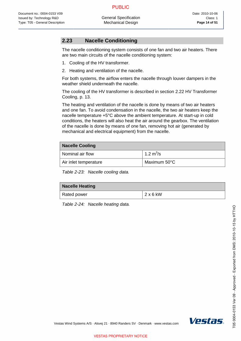
2.23 Nacelle Conditioning
The nacelle conditioning system consists of one fan and two air heaters. There
are two main circuits of the nacelle conditioning system:
1. Cooling of the HV transformer.
2. Heating and ventilation of the nacelle.
For both systems, the airflow enters the nacelle through louver dampers in the
weather shield underneath the nacelle.
The cooling of the HV transformer is described in section 2.22 HV Transformer
Cooling, p. 13.
The heating and ventilation of the nacelle is done by means of two air heaters
and one fan. To avoid condensation in the nacelle, the two air heaters keep the
nacelle temperature +5°C above the ambient temperature. At start-up in cold
conditions, the heaters will also heat the air around the gearbox. The ventilation
of the nacelle is done by means of one fan, removing hot air (generated by
mechanical and electrical equipment) from the nacelle.
Nacelle Cooling
Nominal air flow 1.2 m3/s
Air inlet temperature Maximum 50°C
Table 2-23: Nacelle cooling data.
Nacelle Heating
Rated power 2 x 6 kW
Table 2-24: Nacelle heating data.
Document no.: 0004-0153 V09
General Specification
Electrical Design
Date: 2010-10-06
Issued by: Technology R&D Class: 1
Type: T05 - General Description Page 15 of 51
Vestas Wind Systems A/S · Alsvej 21 · 8940 Randers SV · Denmark · www.vestas.com
3 Electrical Design
3.1 Generator
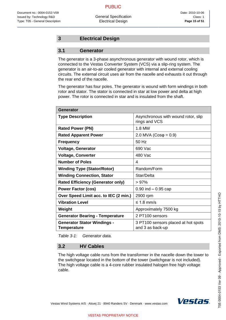
The generator is a 3-phase asynchronous generator with wound rotor, which is
connected to the Vestas Converter System (VCS) via a slip-ring system. The
generator is an air-to-air cooled generator with internal and external cooling
circuits. The external circuit uses air from the nacelle and exhausts it out through
the rear end of the nacelle.
The generator has four poles. The generator is wound with form windings in both
rotor and stator. The stator is connected in star at low power and delta at high
power. The rotor is connected in star and is insulated from the shaft.
Generator
Type Description Asynchronous with wound rotor, slip
rings and VCS
Rated Power (PN) 1.8 MW
Rated Apparent Power 2.0 MVA (Cosφ = 0.9)
Frequency 50 Hz
Voltage, Generator 690 Vac
Voltage, Converter 480 Vac
Number of Poles 4
Winding Type (Stator/Rotor) Random/Form
Winding Connection, Stator Star/Delta
Rated Efficiency (Generator only) > 97%
Power Factor (cos) 0.90 ind – 0.95 cap
Over Speed Limit acc. to IEC (2 min.) 2900 rpm
Vibration Level ≤ 1.8 mm/s
Weight Approximately 7500 kg
Generator Bearing - Temperature 2 PT100 sensors
Generator Stator Windings -
Temperature
3 PT100 sensors placed at hot spots
and 3 as back-up
Table 3-1: Generator data.
3.2 HV Cables
The high voltage cable runs from the transformer in the nacelle down the tower to
the switchgear located in the bottom of the tower (switchgear is not included).
The high voltage cable is a 4-core rubber insulated halogen free high voltage
cable.

Document no.: 0004-0153 V09
General Specification
Electrical Design
Date: 2010-10-06
Issued by: Technology R&D Class: 1
Type: T05 - General Description Page 16 of 51
Vestas Wind Systems A/S · Alsvej 21 · 8940 Randers SV · Denmark · www.vestas.com
HV Cables
High Voltage Cable Insulation
Compound
Improved ethylene-propylene (EP)
based material – EPR or high modulus
or hard grade ethylene-propylene
rubber – HEPR
Conductor Cross Section 3x70/70 mm2
Rated Voltage 12/20 kV (24 kV) or 20/35 kV (42 kV)
depending on the transformer voltage
Table 3-2: HV cables data.
3.3 Transformer
The transformer is located in a separate locked room in the nacelle with surge
arresters mounted on the high voltage side of the transformer. The transformer is
a two winding, three-phase dry-type transformer. The windings are delta-
connected on the high voltage side unless otherwise specified.
The low voltage windings have a voltage of 690 V and a tapping at 480 V and are
star-connected. The 690 V and 480 V systems in the nacelle are a TN-system,
which means the star point is connected to earth.
Transformer
Type Description Dry-type cast resin
Primary Voltage 6-35 kV
Rated Apparent Power 2100 kVA
Secondary Voltage 1 690 V
Rated Power 1 at 690 V 1900 kVA
Secondary Voltage 2 480 V
Rated Power 2 at 480 V 200 kVA
Vector Group Dyn5 (option YNyn0)
Frequency 50/60 Hz
HV-tappings ± 2 x 2.5% offload
Insulation Class F
Climate Class C2
Environmental Class E2
Fire Behaviour Class F1
Table 3-3: Transformer data.

Document no.: 0004-0153 V09
General Specification
Electrical Design
Date: 2010-10-06
Issued by: Technology R&D Class: 1
Type: T05 - General Description Page 17 of 51
Vestas Wind Systems A/S · Alsvej 21 · 8940 Randers SV · Denmark · www.vestas.com
3.4 Converter
The converter controls the energy conversion in the generator. The VCS
converter feeds power from the grid into the generator rotor at sub sync speed
and feeds power from the generator rotor to the grid at super sync speed.
Converter
Rated Slip 12%
Rated RPM 1680 RPM
Rated Rotor Power (@rated slip) 193 kW
Rated Grid Current (@ rated slip, PF
= 1 & 480V)
232 A
Rated Rotor Current (@ rated slip &
PF = 1)
573 A
Table 3-4: Converter data.
3.5 AUX System
The AUX System is supplied from the 690/480 V socket from the HV transformer.
All motors, pumps, fans and heaters are supplied from this system.
All 230 V power sockets are supplied from a 690/230 V transformer.
Power Sockets
Single Phase 230 V (13 A)
Three Phase 690 V (16 A)
Table 3-5: AUX system data.
3.6 Wind Sensors
The turbine is equipped with two ultrasonic wind sensors with built-in heaters.
Wind Sensors
Type FT702LT
Principle Acoustic Resonance
Built-in Heat 99 W
Table 3-6: Wind sensor data.
Document no.: 0004-0153 V09
General Specification
Electrical Design
Date: 2010-10-06
Issued by: Technology R&D Class: 1
Type: T05 - General Description Page 18 of 51
Vestas Wind Systems A/S · Alsvej 21 · 8940 Randers SV · Denmark · www.vestas.com
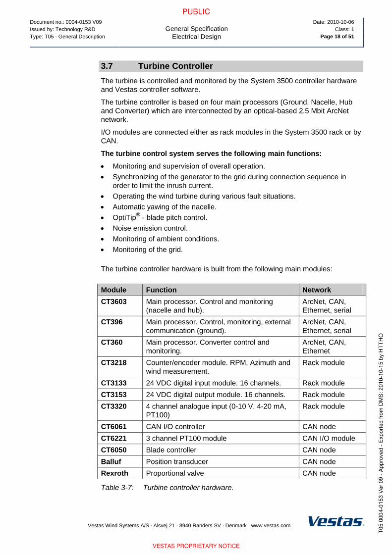
3.7 Turbine Controller
The turbine is controlled and monitored by the System 3500 controller hardware
and Vestas controller software.
The turbine controller is based on four main processors (Ground, Nacelle, Hub
and Converter) which are interconnected by an optical-based 2.5 Mbit ArcNet
network.
I/O modules are connected either as rack modules in the System 3500 rack or by
CAN.
The turbine control system serves the following main functions:
Monitoring and supervision of overall operation.
Synchronizing of the generator to the grid during connection sequence in
order to limit the inrush current.
Operating the wind turbine during various fault situations.
Automatic yawing of the nacelle.
OptiTip® - blade pitch control.
Noise emission control.
Monitoring of ambient conditions.
Monitoring of the grid.
The turbine controller hardware is built from the following main modules:
Module Function Network
CT3603 Main processor. Control and monitoring
(nacelle and hub).
ArcNet, CAN,
Ethernet, serial
CT396 Main processor. Control, monitoring, external
communication (ground).
ArcNet, CAN,
Ethernet, serial
CT360 Main processor. Converter control and
monitoring.
ArcNet, CAN,
Ethernet
CT3218 Counter/encoder module. RPM, Azimuth and
wind measurement.
Rack module
CT3133 24 VDC digital input module. 16 channels. Rack module
CT3153 24 VDC digital output module. 16 channels. Rack module
CT3320 4 channel analogue input (0-10 V, 4-20 mA,
PT100)
Rack module
CT6061 CAN I/O controller CAN node
CT6221 3 channel PT100 module CAN I/O module
CT6050 Blade controller CAN node
Balluf Position transducer CAN node
Rexroth Proportional valve CAN node
Table 3-7: Turbine controller hardware.

Document no.: 0004-0153 V09
General Specification
Turbine Protection Systems
Date: 2010-10-06
Issued by: Technology R&D Class: 1
Type: T05 - General Description Page 19 of 51
Vestas Wind Systems A/S · Alsvej 21 · 8940 Randers SV · Denmark · www.vestas.com
3.8 Uninterruptible Power Supply (UPS)
The UPS supplies power to critical wind turbine components.
The actual back up time for the UPS system is proportional to the power consumption. Actual back-up time may vary.
UPS
Battery Type Valve-Regulated Lead Acid (VRLA)
Rated Battery Voltage 2 x 8 x 12 V (192 V)
Converter Type Double conversion online
Rated Output Voltage 230 V AC
Rated Output Voltage 230 V AC
Converter Input 230 V ±20%
Back-up Time* Controller system 30 seconds
Safety systems 35 minutes
Re-charging Time Typical Approximately 2.5 hours
Table 3-8: UPS data.
* For alternative back-up times, consult Vestas.
4 Turbine Protection Systems
4.1 Braking Concept
The main brake on the turbine is aerodynamic. Braking the turbine is done by
feathering the three blades. During emergency stop all three blades will feather
simultaneously to full end stop and thereby slowing the rotor speed.
In addition there is a mechanical disc brake on the high speed shaft of the
gearbox. The mechanical brake is only used as a parking brake, and when
activating the emergency stop push buttons.
4.2 Short Circuit Protections
Breakers Generator / Q8
ABB E2B 2000
690 V
Controller / Q15
ABB S3X
690 V
VCS-VCUS / Q7
ABB S5H 400
480 V
Breaking Capacity
Icu, Ics 42, 42 kA 75, 75 kA 40, 40 kA
Making Capacity
Icm (415V Data)
88 kA 440 kA 143 kA
Thermo Release
Ith 2000 A 100 A 400 A
Table 4-1: Short circuit protection data.
NOTE

Document no.: 0004-0153 V09
General Specification
Turbine Protection Systems
Date: 2010-10-06
Issued by: Technology R&D Class: 1
Type: T05 - General Description Page 20 of 51
Vestas Wind Systems A/S · Alsvej 21 · 8940 Randers SV · Denmark · www.vestas.com
4.3 Overspeed Protection
The generator RPM and the main shaft RPM are registered by inductive sensors
and calculated by the wind turbine controller in order to protect against over-
speed and rotating errors.
The turbine is also equipped with a VOG (Vestas Overspeed Guard), which is an
independent computer module measuring the rotor RPM, and in case of an
overspeed situation the VOG activates the emergency feathered position (full
feathering) of the three blades.
Overspeed Protection
VOG Sensors Type Inductive
Trip Levels 17.8 (Rotor RPM) / 2013 (Generator
RPM)
Table 4-2: Overspeed protection data.
4.4 EMC System
The turbine and related equipment must fulfil the EU EMC-Directive with later
amendments:
Council Directive 2004/108/EC of 15 December 2004 on the approximation of
the laws of the Member States relating to Electromagnetic Compatibility.
The (Electromagnetic Compatibility) EMC-Directive with later amendments.
4.5 Lightning System
The Lightning Protection System (LPS) consists of three main parts.
Lightning receptors.
Down conducting system.
Earthing System.
Lightning Protection Design Parameters Protection Level I
Current Peak Value imax [kA] 200
Total Charge Qtotal [C] 300
Specific Energy W/R [MJ/] 10
Average Steepness di/dt [kA/s] 200
Table 4-3: Lightning design parameters.
The Lightning Protection System is designed according to IEC standards (see
section 7.7 Design Codes – Lightning Protection, p. 27. Lightning strikes are
considered force majeure, i.e. damage caused by lightning strikes is not
warranted by Vestas.
NOTE

Document no.: 0004-0153 V09
General Specification
Safety
Date: 2010-10-06
Issued by: Technology R&D Class: 1
Type: T05 - General Description Page 21 of 51
Vestas Wind Systems A/S · Alsvej 21 · 8940 Randers SV · Denmark · www.vestas.com
4.6 Earthing (also known as grounding)
The Vestas Earthing System is based on foundation earthing.
Vestas document no. 0000-3388 contains the list of documents regarding Vestas
Earthing System.
Requirements in the Vestas Earthing System specifications and work
descriptions are minimum requirements from Vestas and IEC. Local and national
requirements, as well as project requirements, may require additional measures.
4.7 Corrosion Protection
Classification of corrosion categories for atmospheric corrosion is according to
ISO 9223:1992.
Corrosion Protection External Areas Internal Areas
Nacelle C5 C3 and C4
Climate strategy: Heating the air
inside the nacelle compared to
the outside air temperature
lowers the relative humidity and
helps ensure a controlled
corrosion level.
Hub C5 C3
Tower C5-I C3
Table 4-4: Corrosion protection data for nacelle, hub and tower.
5 Safety
The safety specifications in this safety section provide limited general information
about the safety features of the turbine and are not a substitute for Buyer and its
agents taking all appropriate safety precautions, including but not limited to (a)
complying with all applicable safety, operation, maintenance, and service
agreements, instructions, and requirements, (b) complying with all safety-related
laws, regulations, and ordinances, (c) conducting all appropriate safety training
and education and (d) reading and understanding all safety-related manuals and
instructions. See section 5.13 Manuals and Warnings, p. 23 for additional
guidance.
5.1 Access
Access to the turbine from the outside is through the bottom of the tower. The
door is equipped with a lock. Access to the top platform in the tower is by a
ladder or service lift. Access to the nacelle from the top platform is by ladder.
Access to the transformer room in the nacelle is equipped with a lock.
Unauthorised access to electrical switch boards and power panels in the turbine
is prohibited according to IEC 60204-1 2006.

Document no.: 0004-0153 V09
General Specification
Safety
Date: 2010-10-06
Issued by: Technology R&D Class: 1
Type: T05 - General Description Page 22 of 51
Vestas Wind Systems A/S · Alsvej 21 · 8940 Randers SV · Denmark · www.vestas.com
5.2 Escape
In addition to the normal access routes, alternative escape routes from the
nacelle are through the crane hatch.
The hatch in the roof can be opened from both the inside and outside.
Escape from the service lift is by ladder.
5.3 Rooms/Working Areas
The tower and nacelle are equipped with connection points for electrical tools for
service and maintenance of the turbine.
5.4 Platforms, Standing and Working Places
The bottom tower section has three platforms. There is one platform at the
entrance level (door level), one safety platform approximately three metres above
the entrance platform and finally a platform in the top of the tower section.
Each middle tower section has one platform in the top of the tower section.
The top tower section has two platforms. A top platform and a service lift platform
- where the service lift stops - below the top platform.
There are places to stand at various locations along the ladder.
The platforms have anti-slip surfaces.
Foot supports are placed in the turbine for maintenance and service purposes.
5.5 Climbing Facilities
A ladder with a fall arrest system (rigid rail or wire system) is mounted through
the tower.
Rest platforms are provided at intervals of 9 metres along the tower ladder
between platforms.
There are anchorage points in the tower, nacelle, hub and on the roof for
attaching fall arrest equipment (full body harness).
Over the crane hatch there is an anchorage point for the emergency descent
equipment. The anchorage point is tested to 22.2 kN.
Anchorage points are coloured yellow and are calculated and tested to 22.2 kN.
5.6 Moving Parts, Guards and Blocking Devices
Moving parts in the nacelle are shielded.
The turbine is equipped with a rotor lock to block the rotor and drive train.
It is possible to block the pitch of the cylinder with mechanical tools in the hub.
5.7 Lighting
The turbine is equipped with light in the tower, nacelle and in the hub.
There is emergency light in case of loss of electrical power.

Document no.: 0004-0153 V09
General Specification
Safety
Date: 2010-10-06
Issued by: Technology R&D Class: 1
Type: T05 - General Description Page 23 of 51
Vestas Wind Systems A/S · Alsvej 21 · 8940 Randers SV · Denmark · www.vestas.com
5.8 Noise
When the turbine is out of operation for maintenance, the sound level in the
nacelle is below 80 dB(A). In operation mode ear protection is required.
5.9 Emergency Stop
There are emergency stops in the nacelle and in the bottom of the tower.
5.10 Power Disconnection
The turbine is designed to allow for disconnection from all its power sources
during inspection or maintenance. The switches are marked with signs and are
located in the nacelle and in the bottom of the tower.
5.11 Fire Protection/First Aid
A 5 kg CO2 fire extinguisher must be located in the nacelle at the left yaw gear.
The location of the fire extinguisher, and how to use it, must be confirmed before
operating the turbine.
A first aid kit must be placed by the wall at the back end of the nacelle. The
location of the first aid kit, and how to use it, must be confirmed before operating
the turbine.
Above the generator there must be a fire blanket which can be used to put out
small fires.
5.12 Warning Signs
Additional warning signs inside or on the turbine must be reviewed before
operating or servicing of the turbine.
5.13 Manuals and Warnings
Vestas OH&S manual and manuals for operation, maintenance and service of the
turbine provide additional safety rules and information for operating, servicing or
maintaining the turbine.

Document no.: 0004-0153 V09
General Specification
Environment
Date: 2010-10-06
Issued by: Technology R&D Class: 1
Type: T05 - General Description Page 24 of 51
Vestas Wind Systems A/S · Alsvej 21 · 8940 Randers SV · Denmark · www.vestas.com
6 Environment
6.1 Chemicals
Chemicals used in the turbine are evaluated according to Vestas Wind Systems
A/S Environmental system certified according to ISO 14001:2004.
Anti-freeze liquid to help prevent the cooling system from freezing.
Gear oil for lubricating the gearbox.
Hydraulic oil to pitch the blades and operate the brake.
Grease to lubricate bearings.
Various cleaning agents and chemicals for maintenance of the turbine.
7 Approvals, Certificates and Design Codes
7.1 Type Approvals
The turbine is type certified according to the certification standards listed below:
*Refer to section 9.1 Climate and Site Conditions, p. 29 for details.
Table 7-1: Type approvals.
7.2 Design Codes – Structural Design
The structural design has been developed and tested with regard to, but not
limited to, the following main standards.
Design Codes – Structural Design
Nacelle and Hub IEC 61400-1:2005
EN 50308
ANSI/ASSE Z359.1-2007
Bedframe IEC 61400-1:2005
Tower IEC 61400-1:2005
Eurocode 3
DIBt: Richtlinie für Windenergieanlagen,
Einwirkungen und Standsicherheitsnachweise für
Turm und Gründung, 4th edition.
Table 7-1: Structural design codes.
Certification Wind Class Hub Height
Type Certificate after
IEC WT01 and IEC
61400-1:2005
IEC S* 80 m
IEC S* 95 m

Document no.: 0004-0153 V09
General Specification
Approvals, Certificates and Design Codes
Date: 2010-10-06
Issued by: Technology R&D Class: 1
Type: T05 - General Description Page 25 of 51
Vestas Wind Systems A/S · Alsvej 21 · 8940 Randers SV · Denmark · www.vestas.com
7.3 Design Codes – Mechanical Equipment
The mechanical equipment has been developed and tested with regard to, but
not limited to, the following main standards:
Design Codes – Mechanical Equipment
Gear Designed in accordance to rules in ISO 81400-4
Blades
DNV-OS-J102
IEC 1024-1
IEC 60721-2-4
IEC 61400 (Part 1, 12 and 23)
IEC WT 01 IEC
DEFU R25
ISO 2813
DS/EN ISO 12944-2
Table 7-2: Mechanical equipment design codes.
7.4 Design Codes – Electrical Equipment
The electrical equipment has been developed and tested with regard to, but not
limited to, the following main standards:
Design Codes – Electrical Equipment
High Voltage AC Circuit Breakers IEC 60056
High Voltage Testing Techniques IEC 60060
Power Capacitors IEC 60831
Insulating Bushings for AC Voltage
above 1kV IEC 60137
Insulation Co-ordination BS EN 60071
AC Disconnectors and Earth
Switches BS EN 60129
Current Transformers IEC 60185
Voltage Transformers IEC 60186
High Voltage Switches IEC 60265
Disconnectors and Fuses IEC 60269
Flame Retardant Standard for MV
Cables IEC 60332
Transformer IEC 60076-11
Generator IEC 60034
Specification for Sulphur
Hexafluoride for Electrical
Equipment
IEC 60376

Document no.: 0004-0153 V09
General Specification
Approvals, Certificates and Design Codes
Date: 2010-10-06
Issued by: Technology R&D Class: 1
Type: T05 - General Description Page 26 of 51
Vestas Wind Systems A/S · Alsvej 21 · 8940 Randers SV · Denmark · www.vestas.com
Design Codes – Electrical Equipment
Rotating Electrical Machines IEC 34
Dimensions and Output Ratings for
Rotating Electrical Machines IEC 72 & IEC 72A
Classification of Insulation,
Materials for Electrical Machinery IEC 85
Safety of Machinery – Electrical
Equipment of Machines IEC 60204-1
Table 7-3: Electrical equipment design codes.
7.5 Design Codes – I/O Network System
The distributed I/O network system has been developed and tested with regard
to, but not limited to, the following main standards:
Design Codes – I/O Network System
Salt Mist Test IEC 60068-2-52
Damp Head, Cyclic IEC 60068-2-30
Vibration Sinus IEC 60068-2-6
Cold IEC 60068-2-1
Enclosure IEC 60529
Damp Head, Steady State IEC 60068-2-56
Vibration Random IEC 60068-2-64
Dry Heat IEC 60068-2-2
Temperature Shock IEC 60068-2-14
Free Fall IEC 60068-2-32
Table 7-4: I/O Network system design codes.
7.6 Design Codes – EMC System
To fulfil EMC requirements the design must be as recommended for lightning
protection, see section 7.7 Design Codes – Lightning Protection, p. 27.
Design Codes – EMC System
Designed according to IEC 61400-1: 2005
Further robustness requirements
according to TPS 901795
Document no.: 0004-0153 V09
General Specification
Approvals, Certificates and Design Codes
Date: 2010-10-06
Issued by: Technology R&D Class: 1
Type: T05 - General Description Page 27 of 51
Vestas Wind Systems A/S · Alsvej 21 · 8940 Randers SV · Denmark · www.vestas.com
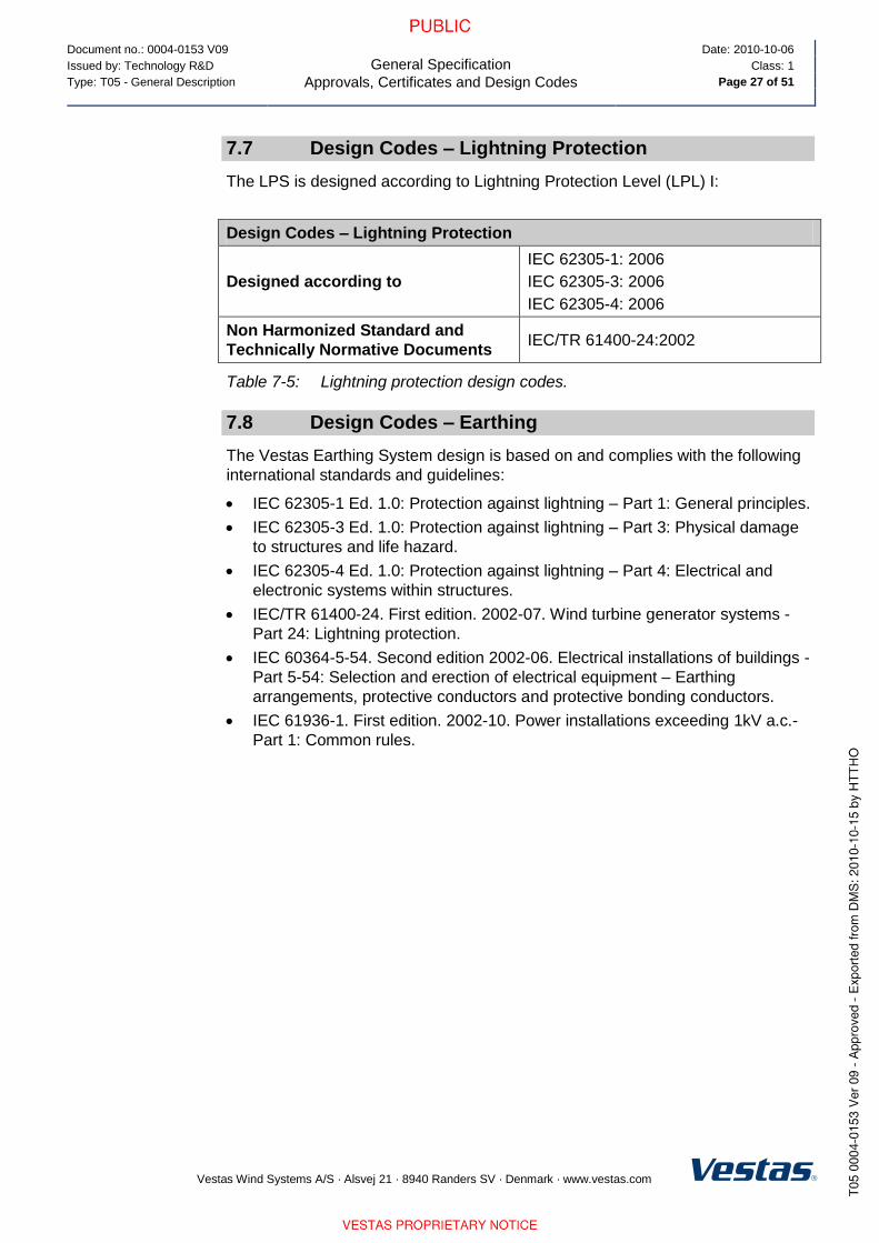
7.7 Design Codes – Lightning Protection
The LPS is designed according to Lightning Protection Level (LPL) I:
Design Codes – Lightning Protection
Designed according to
IEC 62305-1: 2006
IEC 62305-3: 2006
IEC 62305-4: 2006
Non Harmonized Standard and
Technically Normative Documents IEC/TR 61400-24:2002
Table 7-5: Lightning protection design codes.
7.8 Design Codes – Earthing
The Vestas Earthing System design is based on and complies with the following
international standards and guidelines:
IEC 62305-1 Ed. 1.0: Protection against lightning – Part 1: General principles.
IEC 62305-3 Ed. 1.0: Protection against lightning – Part 3: Physical damage
to structures and life hazard.
IEC 62305-4 Ed. 1.0: Protection against lightning – Part 4: Electrical and
electronic systems within structures.
IEC/TR 61400-24. First edition. 2002-07. Wind turbine generator systems -
Part 24: Lightning protection.
IEC 60364-5-54. Second edition 2002-06. Electrical installations of buildings -
Part 5-54: Selection and erection of electrical equipment – Earthing
arrangements, protective conductors and protective bonding conductors.
IEC 61936-1. First edition. 2002-10. Power installations exceeding 1kV a.c.-
Part 1: Common rules.

Document no.: 0004-0153 V09
General Specification
Colour and Surface Treatment
Date: 2010-10-06
Issued by: Technology R&D Class: 1
Type: T05 - General Description Page 28 of 51
Vestas Wind Systems A/S · Alsvej 21 · 8940 Randers SV · Denmark · www.vestas.com
8 Colour and Surface Treatment
8.1 Nacelle Colour and Surface Treatment
Surface Treatment of Vestas Nacelles
Standard Nacelle Colours RAL 7035 (light grey)
Gloss According to ISO 2813
Table 8-1: Surface treatment, nacelle.
8.2 Tower Colour and Surface Treatment
Surface Treatment of Vestas Tower Section
External: Internal:
Tower Colour Variants RAL 7035 (light grey) RAL 9001 (cream white)
Gloss 50-75% UV resistant Maximum 50%
Table 8-2: Surface treatment, tower.
8.3 Blades Colour
Blades Colour
Blade Colour RAL 7035 (Light Grey)
Tip-End Colour Variants RAL 2009 (Traffic Orange), RAL 3000
(Flame Red), RAL 3020 (Traffic Red)
Gloss < 20%
Table 8-3: Colours, blades.
Document no.: 0004-0153 V09
General Specification
Operational Envelope and Performance Guidelines
Date: 2010-10-06
Issued by: Technology R&D Class: 1
Type: T05 - General Description Page 29 of 51
Vestas Wind Systems A/S · Alsvej 21 · 8940 Randers SV · Denmark · www.vestas.com
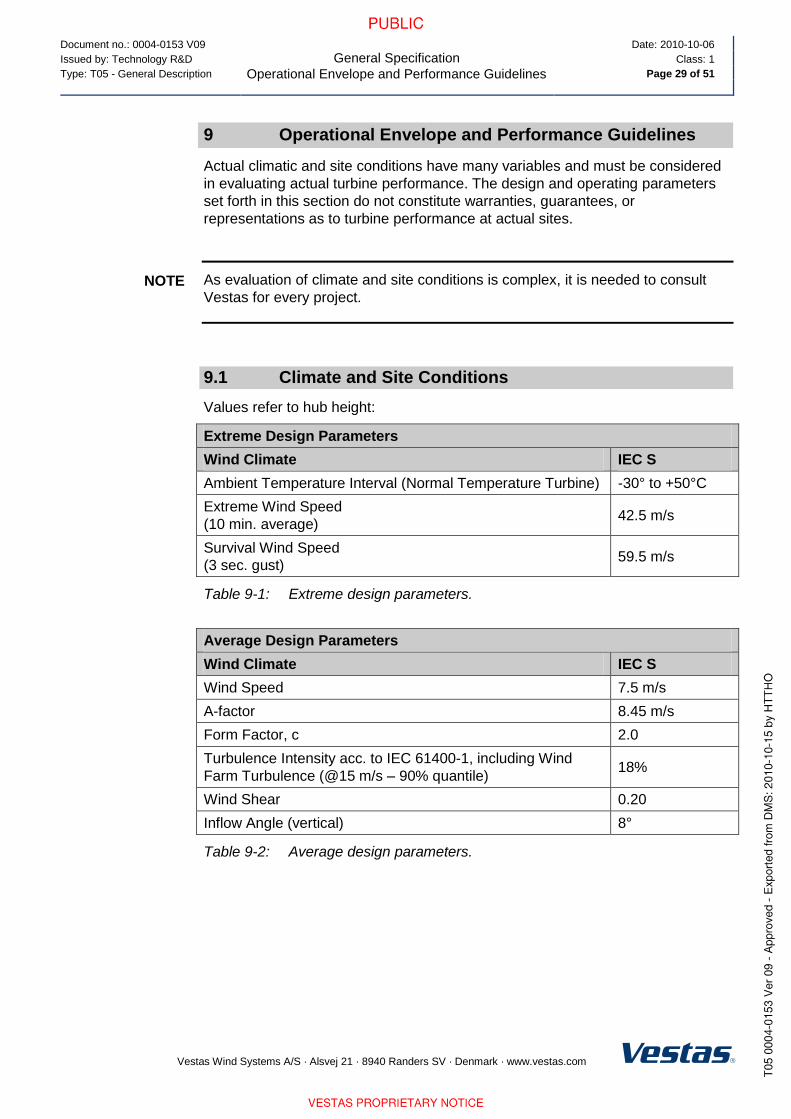
9 Operational Envelope and Performance Guidelines
Actual climatic and site conditions have many variables and must be considered
in evaluating actual turbine performance. The design and operating parameters
set forth in this section do not constitute warranties, guarantees, or
representations as to turbine performance at actual sites.
As evaluation of climate and site conditions is complex, it is needed to consult
Vestas for every project.
9.1 Climate and Site Conditions
Values refer to hub height:
Extreme Design Parameters
Wind Climate IEC S
Ambient Temperature Interval (Normal Temperature Turbine) -30° to +50°C
Extreme Wind Speed
(10 min. average) 42.5 m/s
Survival Wind Speed
(3 sec. gust) 59.5 m/s
Table 9-1: Extreme design parameters.
Average Design Parameters
Wind Climate IEC S
Wind Speed 7.5 m/s
A-factor 8.45 m/s
Form Factor, c 2.0
Turbulence Intensity acc. to IEC 61400-1, including Wind
Farm Turbulence (@15 m/s – 90% quantile) 18%
Wind Shear 0.20
Inflow Angle (vertical) 8°
Table 9-2: Average design parameters.
NOTE
Document no.: 0004-0153 V09
General Specification
Operational Envelope and Performance Guidelines
Date: 2010-10-06
Issued by: Technology R&D Class: 1
Type: T05 - General Description Page 30 of 51
Vestas Wind Systems A/S · Alsvej 21 · 8940 Randers SV · Denmark · www.vestas.com
9.1.1 Complex Terrain
Classification of complex terrain acc. to IEC 61400-1:2005 Chapter 11.2.
For sites classified as complex appropriate measures are to be included in site
assessment.
9.1.2 Altitude
The turbine is designed for use at altitudes up to 1500 m above sea level as
standard.
Above 1500 m special considerations must be taken regarding e.g. HV
installations and cooling performance. Consult Vestas for further information.
9.1.3 Wind Farm Layout
Turbine spacing is to be evaluated site-specifically. Spacing in any case not
below three rotor diameters (3D).
As evaluation of climate and site conditions is complex, consult Vestas for every
project. If conditions exceed the above parameters Vestas must be consulted.
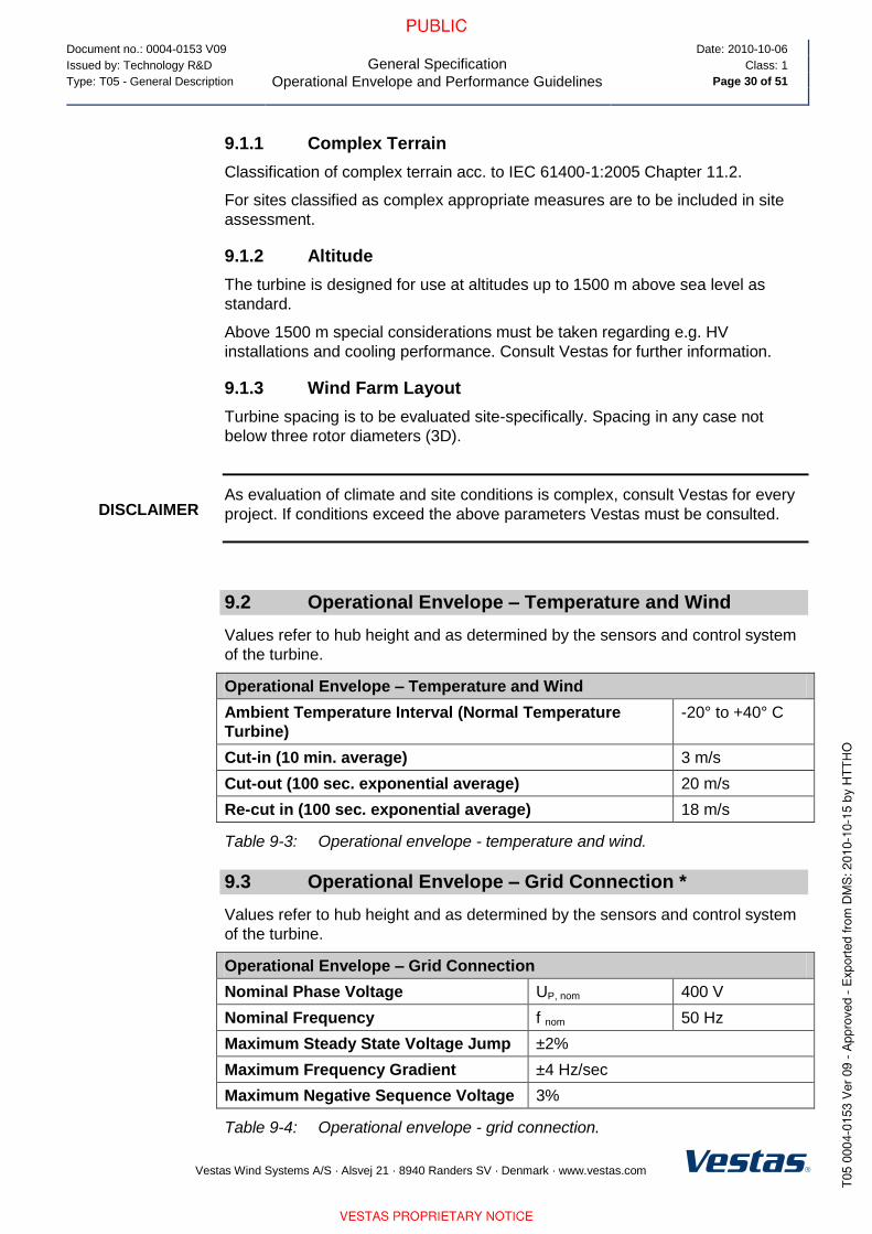
9.2 Operational Envelope – Temperature and Wind
Values refer to hub height and as determined by the sensors and control system
of the turbine.
Operational Envelope – Temperature and Wind
Ambient Temperature Interval (Normal Temperature
Turbine)
-20° to +40° C
Cut-in (10 min. average) 3 m/s
Cut-out (100 sec. exponential average) 20 m/s
Re-cut in (100 sec. exponential average) 18 m/s
Table 9-3: Operational envelope - temperature and wind.
9.3 Operational Envelope – Grid Connection *
Values refer to hub height and as determined by the sensors and control system
of the turbine.
Operational Envelope – Grid Connection
Nominal Phase Voltage UP, nom 400 V
Nominal Frequency f nom 50 Hz
Maximum Steady State Voltage Jump ±2%
Maximum Frequency Gradient ±4 Hz/sec
Maximum Negative Sequence Voltage 3%
Table 9-4: Operational envelope - grid connection.
DISCLAIMER

Document no.: 0004-0153 V09
General Specification
Operational Envelope and Performance Guidelines
Date: 2010-10-06
Issued by: Technology R&D Class: 1
Type: T05 - General Description Page 31 of 51
Vestas Wind Systems A/S · Alsvej 21 · 8940 Randers SV · Denmark · www.vestas.com
The generator and the converter will be disconnected if:
UP UN
Voltage above 110% of nominal for 60 sec. 440 V 759 V
Voltage above 115% of nominal for 2 sec. 460 V 794 V
Voltage above 120% of nominal for 0.08 sec. 480 V 828 V
Voltage above 125% of nominal for 0.005 sec 500 V 863 V
Voltage below 90% of nominal for 60 sec. 360 V 621 V
Voltage below 85% of nominal for 11 sec. 340 V 586 V
Frequency is above [Hz] for 0.2 sec. 53 Hz
Frequency is below [Hz] for 0.2 sec. 47 Hz
Table 9-5: Generator and converter disconnecting values.
* Over the turbine lifetime, grid drop-outs are to occur at an average of no more
than 50 times a year.
9.4 Operational Envelope – Reactive Power Capability
The turbine has a reactive power capability as illustrated in Figure 9-1, p. 31.
Figure 9-1: Reactive power capability.
The above chart applies at the low voltage side of the HV transformer. Reactive
power is produced by the rotor converter; therefore traditional capacitors are not
used in the turbine.
NOTE

Document no.: 0004-0153 V09
General Specification
Operational Envelope and Performance Guidelines
Date: 2010-10-06
Issued by: Technology R&D Class: 1
Type: T05 - General Description Page 32 of 51
Vestas Wind Systems A/S · Alsvej 21 · 8940 Randers SV · Denmark · www.vestas.com
At maximum active and reactive power, the turbine reduces either active or
reactive power depending on which type of power has priority (E.g. if reactive
power has priority, the active power is reduced.
9.5 Performance – Fault Ride Through
The turbine is equipped with a reinforced Vestas Converter System in order to
gain better control of the generator during grid faults. The controllers and
contactors have a UPS backup system in order to keep the turbine control
system running during grid faults.
The pitch system is optimised to keep the turbine within normal speed conditions
and the generator speed is accelerated in order to store rotational energy and be
able to resume normal power production faster after a fault and keep mechanical
stress on the turbine at a minimum.
The turbine is designed to stay connected during grid disturbances within the
voltage tolerance curve in Figure 9-2, p. 32.
Ugenerator[pu
]
1.0
0.2
0 2.5 Time [s]0.3
0.9
10.
2
0.8
0.05
Figure 9-2: Low voltage tolerance curve for symmetrical and asymmetrical faults.

Document no.: 0004-0153 V09
General Specification
Operational Envelope and Performance Guidelines
Date: 2010-10-06
Issued by: Technology R&D Class: 1
Type: T05 - General Description Page 33 of 51
Vestas Wind Systems A/S · Alsvej 21 · 8940 Randers SV · Denmark · www.vestas.com
For grid disturbances outside the protection curve in Figure 9-3, p. 33, the turbine
will be disconnected from the grid.
Ugenerator[pu]
1.0
0 2.65 Time [s]0.3
0.9
11
0.7
0.85
60
Figure 9-3: Default low voltage protection settings for symmetrical and asymmetrical
faults.
Power Recovery Time
Power recovery to 90% of pre-fault
level Max 1.0 sec
9.6 Performance – Reactive Current Contribution
The reactive current contribution depends on whether the fault applied to the
turbine is symmetrical or unsymmetrical.
9.6.1 Symmetrical Reactive Current Contribution
During voltage dips the turbine is switched from normal active and reactive power
control to rotor current control. This enables the turbine to perform voltage control
by supplying reactive current to the grid. The reactive current at the generator
terminals is set according to the voltage level at the generator terminals (Figure
9-4, p. 34).
The default value gives a reactive current part of 1 pu of the rated turbine current
at the generator terminals. Figure 9-4, p. 34 indicates the reactive current
contribution as a function of the voltage at the generator terminals for star and
delta operation. The reactive current contribution is independent from the actual
wind conditions and pre-fault power level.

Document no.: 0004-0153 V09
General Specification
Operational Envelope and Performance Guidelines
Date: 2010-10-06
Issued by: Technology R&D Class: 1
Type: T05 - General Description Page 34 of 51
Vestas Wind Systems A/S · Alsvej 21 · 8940 Randers SV · Denmark · www.vestas.com
Figure 9-4: Reactive current contribution in star and delta drawn for 100% reactive
current contribution.
In star connection, the reactive current contribution is lowered by a factor 1/√3
compared to the delta connection. Turbines may be operated in forced delta
connection. This ensures full current injection by low wind.
During faults in the grid, high voltage step (du/dt) in the grid voltage can occur
which may pause the rotor current control for up to 50 ms before the rotor current
control is resumed. During these 50 ms the generator can draw a low
magnetization current from the grid.
9.6.2 Asymmetrical Reactive Current Contribution
Current reference values are reduced during asymmetrical faults to ensure ride
through. The current reference values are reduced from the symmetrical case
with the following reduction factor on the current references:
1-(upu_high - upu_low)
With ’upu_high’ as the highest phase-phase or phase-ground RMS per unit voltage
measured and ’upu_low’ as the lowest phase-phase or phase-ground RMS per unit
voltage.
9.7 Performance – Multiple Voltage Dips
The turbine is designed to handle re-closure events and multiple voltage dips
within a short period of time, due to the fact that voltage dips are not evenly
distributed during the year. As an example 6 voltage dips of duration of 200 ms
down to 20% voltage within 30 minutes will normally not lead to a problem for the
turbine.
9.8 Performance – Active and Reactive Power Control
The turbine is designed for control of active and reactive power via the
VestasOnline™ SCADA system.
Maximum Ramp Rates for External Control
Active Power 0.1 pu/sec
Reactive Power 2.5 pu/sec

Document no.: 0004-0153 V09
General Specification
Operational Envelope and Performance Guidelines
Date: 2010-10-06
Issued by: Technology R&D Class: 1
Type: T05 - General Description Page 35 of 51
Vestas Wind Systems A/S · Alsvej 21 · 8940 Randers SV · Denmark · www.vestas.com
To protect the turbine active power cannot be controlled to values below the
curve in Figure 9-5, p. 35.
0
5
10
15
20
25
30
35
40
45
50
0 5 10 15 20 25 30
Wind speed [m/s]
Pm
in r
ela
tive
to
Pn
om
[%
]
Figure 9-5: Minimum active power output dependant of wind speed.
9.9 Performance – Voltage Control
The turbine is designed for integration with VestasOnline™ voltage control by
utilising the turbine reactive power capability.
9.10 Performance – Frequency Control
The turbine can be configured to perform frequency control by decreasing the
output power as a linear function of the grid frequency (over frequency).
Dead band and slope for the frequency control function are configurable.
9.11 Performance – Own Consumption
The consumption of electrical power by the wind turbine is defined as
consumption when the wind turbine is not producing energy (generator is not
connected to the grid). This is defined in the control system as Production
Generator (zero).

Document no.: 0004-0153 V09
General Specification
Operational Envelope and Performance Guidelines
Date: 2010-10-06
Issued by: Technology R&D Class: 1
Type: T05 - General Description Page 36 of 51
Vestas Wind Systems A/S · Alsvej 21 · 8940 Randers SV · Denmark · www.vestas.com
The following components have the largest influence on the power consumption
of the wind turbine:
Own Consumption
Hydraulic Motor 20 kW
Yaw Motors 6 x 1.75 kW 10.5 kW
Oil Heating 3 x 0.76 kW 2.3 kW
Air Heaters 2 x 6 kW (std)
3 x 6 kW (LT)
12 kW (Standard)
18 kW (Low Temperature)
Oil Pump for Gearbox Lubrication 3.5 kW
HV Transformer located in the
nacelle has a no-load loss of
Maximum 3.9 kW
Table 9-6: Own consumption data.
9.12 Operational Envelope Conditions for Power Curve, Ct Values (at Hub Height)
See appendix section 12.1 Mode 0, p. 40, 12.2 Mode 1, p. 44 and 12.3 Mode 2,
p. 48 for power curve, Ct values and noise level.
Conditions for Power Curve, Ct Values (at Hub Height)
Wind Shear 0.10 - 0.16 (10 min. average)
Turbulence Intensity 8 - 12% (10 min. average)
Blades Clean
Rain No
Ice/Snow on Blades No
Leading Edge No damage
Terrain IEC 61400-12-1
Inflow Angle (Vertical) 0 ± 2 °
Grid Frequency 50 ± 0.5 Hz
Table 9-7: Conditions for power curve, Ct values.
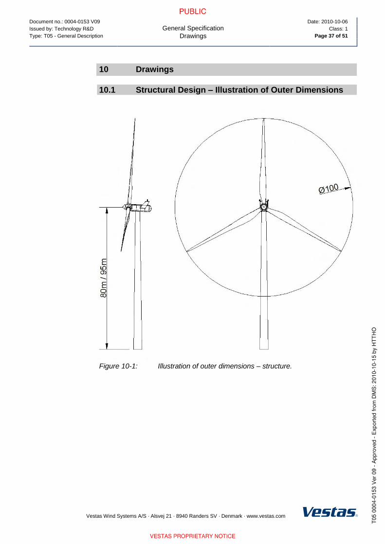
Document no.: 0004-0153 V09
General Specification
Drawings
Date: 2010-10-06
Issued by: Technology R&D Class: 1
Type: T05 - General Description Page 37 of 51
Vestas Wind Systems A/S · Alsvej 21 · 8940 Randers SV · Denmark · www.vestas.com
10 Drawings
10.1 Structural Design – Illustration of Outer Dimensions
Figure 10-1: Illustration of outer dimensions – structure.

Document no.: 0004-0153 V09
General Specification
Drawings
Date: 2010-10-06
Issued by: Technology R&D Class: 1
Type: T05 - General Description Page 38 of 51
Vestas Wind Systems A/S · Alsvej 21 · 8940 Randers SV · Denmark · www.vestas.com
10.2 Structural Design – Side View Drawing
Figure 10-2: Side view drawing.

Document no.: 0004-0153 V09
General Specification
General Reservations, Notes and Disclaimers
Date: 2010-10-06
Issued by: Technology R&D Class: 1
Type: T05 - General Description Page 39 of 51
Vestas Wind Systems A/S · Alsvej 21 · 8940 Randers SV · Denmark · www.vestas.com
11 General Reservations, Notes and Disclaimers
These general specifications apply to the current version of the V100 wind
turbine. Updated versions of the V100 wind turbine, which may be
manufactured in the future, may have general specifications that differ from
these general specifications. In the event that Vestas supplies an updated
version of the V100 wind turbine, Vestas will provide updated general
specifications applicable to the updated version.
Periodic operational disturbances and generator power de-rating may be
caused by combination of high winds, low voltage or high temperature.
Vestas recommends that the grid be as close to nominal as possible with little
variation in frequency.
A certain time allowance for turbine warm-up must be expected following grid
dropout and/or periods of very low ambient temperature.
The estimated power curve for the different estimated noise levels (sound
power levels) is for wind speeds at 10 minute average value at hub height
and perpendicular to the rotor plane.
All listed start/stop parameters (e. g. wind speeds and temperatures) are
equipped with hysteresis control. This can, in certain borderline situations,
result in turbine stops even though the ambient conditions are within the listed
operation parameters.
The earthing system must comply with the minimum requirements from
Vestas, and be in accordance with local and national requirements, and
codes of standards.
Lightning strikes are considered force majeure, i.e. damage caused by
lightning strikes is not warranted by Vestas.
For the avoidance of doubt, this document ‘General Specifications’ is not, and
does not contain, any guarantee, warranty and/or verification of the power
curve and noise (including, without limitation, the power curve and noise
verification method). Any guarantee, warranty and/or verification of the power
curve and noise (including, without limitation, the power curve and noise
verification method) must be agreed to separately in writing.

Document no.: 0004-0153 V09
General Specification
Appendices
Date: 2010-10-06
Issued by: Technology R&D Class: 1
Type: T05 - General Description Page 40 of 51
Vestas Wind Systems A/S · Alsvej 21 · 8940 Randers SV · Denmark · www.vestas.com
12 Appendices
Power Curve, Ct values and Sound Power Levels for Mode 0 to 2 are defined
below.
12.1 Mode 0
12.1.1 Mode 0, Power Curve
Mode 0, Power curves
Air density kg/m3
Wind
speed
[m/s] 1.225 0.95 0.975 1 1.025 1.05 1.075 1.1 1.125 1.15 1.175 1.2 1.25 1.275
3 13 9 9 10 10 10 11 11 12 12 13 13 14 14
3.5 52 34 36 37 39 41 42 44 45 47 48 50 53 55
4 108 79 81 84 87 90 92 95 98 100 103 106 111 114
4.5 177 133 137 141 145 149 153 157 161 165 169 173 181 185
5 256 195 201 206 212 217 223 229 234 240 245 251 262 268
5.5 350 268 275 283 290 298 305 312 320 327 335 342 357 364
6 458 353 362 372 382 391 401 410 420 430 439 449 468 477
6.5 589 452 464 477 489 502 514 527 539 552 564 576 601 614
7 744 573 588 604 620 635 651 666 682 697 713 728 759 774
7.5 916 709 728 747 766 785 804 822 841 860 878 897 934 953
8 1106 861 884 906 929 952 974 996 1018 1040 1062 1084 1128 1150
8.5 1312 1028 1054 1080 1107 1133 1159 1185 1210 1236 1261 1287 1337 1362
9 1510 1206 1235 1265 1295 1324 1352 1380 1408 1436 1461 1486 1532 1554
9.5 1663 1385 1416 1446 1477 1507 1532 1556 1581 1606 1625 1644 1678 1693
10 1749 1551 1575 1600 1625 1649 1666 1683 1699 1716 1727 1738 1757 1764
10.5 1784 1673 1689 1705 1721 1737 1746 1754 1763 1772 1776 1780 1786 1789
11 1796 1749 1756 1764 1771 1779 1782 1785 1788 1791 1793 1794 1796 1797
11.5 1799 1781 1784 1787 1790 1793 1794 1795 1797 1798 1798 1799 1800 1800
12 1800 1793 1795 1796 1797 1798 1799 1799 1799 1800 1800 1800 1800 1800
12.5 1800 1799 1799 1799 1800 1800 1800 1800 1800 1800 1800 1800 1800 1800
13 1800 1800 1800 1800 1800 1800 1800 1800 1800 1800 1800 1800 1800 1800
13.5 1800 1800 1800 1800 1800 1800 1800 1800 1800 1800 1800 1800 1800 1800
14 1800 1800 1800 1800 1800 1800 1800 1800 1800 1800 1800 1800 1800 1800
14.5 1800 1800 1800 1800 1800 1800 1800 1800 1800 1800 1800 1800 1800 1800
15 1800 1800 1800 1800 1800 1800 1800 1800 1800 1800 1800 1800 1800 1800
15.5 1800 1800 1800 1800 1800 1800 1800 1800 1800 1800 1800 1800 1800 1800
16 1800 1800 1800 1800 1800 1800 1800 1800 1800 1800 1800 1800 1800 1800

Document no.: 0004-0153 V09
General Specification
Appendices
Date: 2010-10-06
Issued by: Technology R&D Class: 1
Type: T05 - General Description Page 41 of 51
Vestas Wind Systems A/S · Alsvej 21 · 8940 Randers SV · Denmark · www.vestas.com
Mode 0, Power curves
Air density kg/m3
Wind
speed
[m/s] 1.225 0.95 0.975 1 1.025 1.05 1.075 1.1 1.125 1.15 1.175 1.2 1.25 1.275
16.5 1800 1800 1800 1800 1800 1800 1800 1800 1800 1800 1800 1800 1800 1800
17 1800 1800 1800 1800 1800 1800 1800 1800 1800 1800 1800 1800 1800 1800
17.5 1800 1800 1800 1800 1800 1800 1800 1800 1800 1800 1800 1800 1800 1800
18 1800 1800 1800 1800 1800 1800 1800 1800 1800 1800 1800 1800 1800 1800
18.5 1800 1800 1800 1800 1800 1800 1800 1800 1800 1800 1800 1800 1800 1800
19 1800 1800 1800 1800 1800 1800 1800 1800 1800 1800 1800 1800 1800 1800
19.5 1800 1800 1800 1800 1800 1800 1800 1800 1800 1800 1800 1800 1800 1800
20 1800 1800 1800 1800 1800 1800 1800 1800 1800 1800 1800 1800 1800 1800
Table 12-1: Mode 0, power curve.
12.1.2 Mode 0, Ct Values
Mode 0, Ct values
Air density kg/m3
Wind
speed
[m/s] 1.225 0.95 0.975 1 1.025 1.05 1.075 1.1 1.125 1.15 1.175 1.2 1.25 1.275
3 0.868 0.868 0.868 0.868 0.868 0.868 0.868 0.868 0.868 0.868 0.868 0.868 0.868 0.868
3.5 0.890 0.890 0.890 0.890 0.890 0.890 0.890 0.890 0.890 0.890 0.890 0.890 0.890 0.890
4 0.882 0.882 0.882 0.882 0.882 0.882 0.882 0.882 0.882 0.882 0.882 0.882 0.882 0.882
4.5 0.854 0.854 0.854 0.854 0.854 0.854 0.854 0.854 0.854 0.854 0.854 0.854 0.854 0.854
5 0.826 0.826 0.826 0.826 0.826 0.826 0.826 0.826 0.826 0.826 0.826 0.826 0.826 0.826
5.5 0.809 0.809 0.809 0.809 0.809 0.809 0.809 0.809 0.809 0.809 0.809 0.809 0.809 0.809
6 0.803 0.803 0.803 0.803 0.803 0.802 0.803 0.803 0.803 0.803 0.803 0.803 0.803 0.803
6.5 0.819 0.819 0.819 0.819 0.819 0.819 0.819 0.819 0.819 0.819 0.819 0.819 0.819 0.819
7 0.809 0.809 0.809 0.809 0.809 0.809 0.809 0.809 0.809 0.809 0.809 0.809 0.809 0.809
7.5 0.805 0.805 0.805 0.805 0.805 0.805 0.805 0.805 0.805 0.805 0.805 0.805 0.805 0.805
8 0.792 0.800 0.800 0.799 0.799 0.798 0.797 0.797 0.796 0.795 0.794 0.793 0.791 0.790
8.5 0.762 0.783 0.782 0.780 0.778 0.776 0.774 0.773 0.771 0.769 0.766 0.764 0.759 0.757
9 0.707 0.751 0.748 0.745 0.742 0.739 0.735 0.731 0.727 0.723 0.718 0.713 0.701 0.695
9.5 0.629 0.704 0.699 0.694 0.688 0.683 0.676 0.669 0.662 0.654 0.646 0.637 0.620 0.611
10 0.541 0.648 0.639 0.630 0.622 0.613 0.603 0.593 0.583 0.573 0.562 0.551 0.530 0.520
10.5 0.457 0.580 0.569 0.558 0.546 0.535 0.524 0.512 0.501 0.489 0.479 0.468 0.447 0.437
11 0.387 0.509 0.496 0.484 0.471 0.459 0.448 0.437 0.426 0.415 0.406 0.396 0.379 0.370
11.5 0.332 0.439 0.427 0.416 0.404 0.393 0.383 0.374 0.365 0.355 0.347 0.339 0.325 0.318
12 0.287 0.378 0.368 0.359 0.349 0.339 0.331 0.323 0.315 0.307 0.300 0.294 0.281 0.275

Document no.: 0004-0153 V09
General Specification
Appendices
Date: 2010-10-06
Issued by: Technology R&D Class: 1
Type: T05 - General Description Page 42 of 51
Vestas Wind Systems A/S · Alsvej 21 · 8940 Randers SV · Denmark · www.vestas.com
Mode 0, Ct values
Air density kg/m3
Wind
speed
[m/s] 1.225 0.95 0.975 1 1.025 1.05 1.075 1.1 1.125 1.15 1.175 1.2 1.25 1.275
12.5 0.251 0.329 0.321 0.312 0.304 0.295 0.288 0.282 0.275 0.268 0.262 0.257 0.246 0.241
13 0.221 0.288 0.281 0.274 0.266 0.259 0.253 0.247 0.242 0.236 0.231 0.226 0.217 0.213
13.5 0.197 0.255 0.248 0.242 0.236 0.230 0.225 0.220 0.214 0.209 0.205 0.201 0.193 0.189
14 0.176 0.227 0.221 0.216 0.210 0.205 0.200 0.196 0.191 0.187 0.183 0.179 0.172 0.169
14.5 0.158 0.203 0.198 0.193 0.188 0.183 0.180 0.176 0.172 0.168 0.164 0.161 0.155 0.152
15 0.142 0.182 0.178 0.174 0.169 0.165 0.161 0.158 0.155 0.151 0.148 0.145 0.140 0.137
15.5 0.129 0.165 0.161 0.157 0.153 0.149 0.146 0.143 0.140 0.137 0.134 0.132 0.127 0.124
16 0.117 0.150 0.146 0.143 0.139 0.136 0.133 0.130 0.127 0.125 0.122 0.120 0.115 0.113
16.5 0.107 0.136 0.133 0.130 0.127 0.124 0.121 0.119 0.116 0.114 0.112 0.109 0.105 0.103
17 0.098 0.125 0.122 0.119 0.116 0.113 0.111 0.109 0.107 0.104 0.102 0.100 0.097 0.095
17.5 0.091 0.114 0.112 0.109 0.107 0.104 0.102 0.100 0.098 0.096 0.094 0.092 0.089 0.087
18 0.084 0.105 0.103 0.101 0.098 0.096 0.094 0.092 0.090 0.088 0.087 0.085 0.082 0.081
18.5 0.077 0.097 0.095 0.093 0.091 0.089 0.087 0.085 0.083 0.082 0.080 0.079 0.076 0.075
19 0.072 0.090 0.088 0.086 0.084 0.082 0.081 0.079 0.078 0.076 0.075 0.073 0.071 0.069
19.5 0.067 0.084 0.082 0.080 0.078 0.077 0.075 0.074 0.072 0.071 0.069 0.068 0.066 0.065
20 0.062 0.078 0.076 0.075 0.073 0.071 0.070 0.069 0.067 0.066 0.065 0.064 0.061 0.060
Table 12-2: Mode 0, Ct values.
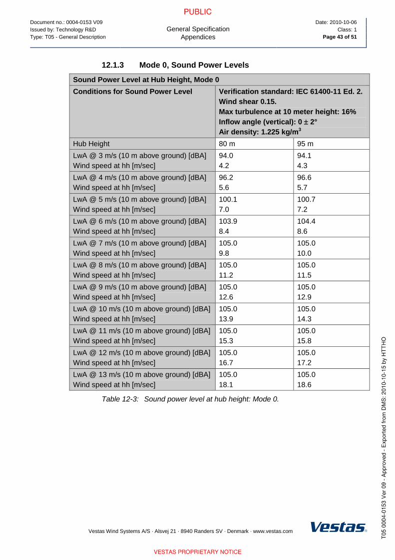
Document no.: 0004-0153 V09
General Specification
Appendices
Date: 2010-10-06
Issued by: Technology R&D Class: 1
Type: T05 - General Description Page 43 of 51
Vestas Wind Systems A/S · Alsvej 21 · 8940 Randers SV · Denmark · www.vestas.com
12.1.3 Mode 0, Sound Power Levels
Sound Power Level at Hub Height, Mode 0
Conditions for Sound Power Level Verification standard: IEC 61400-11 Ed. 2.
Wind shear 0.15.
Max turbulence at 10 meter height: 16%
Inflow angle (vertical): 0 2°
Air density: 1.225 kg/m3
Hub Height 80 m 95 m
LwA @ 3 m/s (10 m above ground) [dBA]
Wind speed at hh [m/sec]
94.0
4.2
94.1
4.3
LwA @ 4 m/s (10 m above ground) [dBA]
Wind speed at hh [m/sec]
96.2
5.6
96.6
5.7
LwA @ 5 m/s (10 m above ground) [dBA]
Wind speed at hh [m/sec]
100.1
7.0
100.7
7.2
LwA @ 6 m/s (10 m above ground) [dBA]
Wind speed at hh [m/sec]
103.9
8.4
104.4
8.6
LwA @ 7 m/s (10 m above ground) [dBA]
Wind speed at hh [m/sec]
105.0
9.8
105.0
10.0
LwA @ 8 m/s (10 m above ground) [dBA]
Wind speed at hh [m/sec]
105.0
11.2
105.0
11.5
LwA @ 9 m/s (10 m above ground) [dBA]
Wind speed at hh [m/sec]
105.0
12.6
105.0
12.9
LwA @ 10 m/s (10 m above ground) [dBA]
Wind speed at hh [m/sec]
105.0
13.9
105.0
14.3
LwA @ 11 m/s (10 m above ground) [dBA]
Wind speed at hh [m/sec]
105.0
15.3
105.0
15.8
LwA @ 12 m/s (10 m above ground) [dBA]
Wind speed at hh [m/sec]
105.0
16.7
105.0
17.2
LwA @ 13 m/s (10 m above ground) [dBA]
Wind speed at hh [m/sec]
105.0
18.1
105.0
18.6
Table 12-3: Sound power level at hub height: Mode 0.

Document no.: 0004-0153 V09
General Specification
Appendices
Date: 2010-10-06
Issued by: Technology R&D Class: 1
Type: T05 - General Description Page 44 of 51
Vestas Wind Systems A/S · Alsvej 21 · 8940 Randers SV · Denmark · www.vestas.com
12.2 Mode 1
12.2.1 Mode 1, Power Curves
Mode 1, Power curves
Air density kg/m3
Wind
speed
[m/s] 1.225 0.95 0.975 1 1.025 1.05 1.075 1.1 1.125 1.15 1.175 1.2 1.25 1.275
3 13 9 9 10 10 10 11 11 12 12 13 13 14 14
3.5 52 34 36 37 39 41 42 44 45 47 48 50 53 55
4 108 78 81 84 87 89 92 95 98 100 103 106 111 114
4.5 174 131 135 139 143 147 151 155 159 163 167 170 178 182
5 250 190 195 201 206 212 217 223 228 233 239 244 255 261
5.5 338 259 266 273 280 288 295 302 309 317 324 331 345 353
6 445 342 351 361 370 379 389 398 407 417 426 435 454 463
6.5 582 447 459 471 484 496 508 521 533 546 558 570 595 607
7 736 567 583 598 613 629 644 660 675 691 706 721 751 767
7.5 907 702 721 740 759 777 796 814 833 852 870 889 926 944
8 1099 853 876 898 921 943 965 988 1010 1032 1054 1076 1121 1143
8.5 1307 1020 1047 1073 1099 1126 1152 1178 1204 1230 1255 1281 1332 1357
9 1509 1199 1229 1259 1289 1319 1347 1376 1405 1433 1458 1483 1531 1554
9.5 1664 1382 1413 1444 1475 1506 1531 1556 1581 1606 1625 1644 1678 1693
10 1748 1549 1574 1599 1624 1650 1666 1683 1700 1717 1727 1738 1755 1762
10.5 1783 1672 1688 1705 1721 1738 1746 1755 1763 1772 1776 1779 1785 1787
11 1796 1750 1757 1765 1772 1780 1783 1786 1789 1792 1793 1794 1796 1797
11.5 1799 1781 1784 1787 1790 1793 1795 1796 1797 1798 1798 1799 1799 1800
12 1800 1794 1795 1796 1797 1799 1799 1799 1800 1800 1800 1800 1800 1800
12.5 1800 1799 1799 1799 1800 1800 1800 1800 1800 1800 1800 1800 1800 1800
13 1800 1800 1800 1800 1800 1800 1800 1800 1800 1800 1800 1800 1800 1800
13.5 1800 1800 1800 1800 1800 1800 1800 1800 1800 1800 1800 1800 1800 1800
14 1800 1800 1800 1800 1800 1800 1800 1800 1800 1800 1800 1800 1800 1800
14.5 1800 1800 1800 1800 1800 1800 1800 1800 1800 1800 1800 1800 1800 1800
15 1800 1800 1800 1800 1800 1800 1800 1800 1800 1800 1800 1800 1800 1800
15.5 1800 1800 1800 1800 1800 1800 1800 1800 1800 1800 1800 1800 1800 1800
16 1800 1800 1800 1800 1800 1800 1800 1800 1800 1800 1800 1800 1800 1800
16.5 1800 1800 1800 1800 1800 1800 1800 1800 1800 1800 1800 1800 1800 1800
17 1800 1800 1800 1800 1800 1800 1800 1800 1800 1800 1800 1800 1800 1800
17.5 1800 1800 1800 1800 1800 1800 1800 1800 1800 1800 1800 1800 1800 1800
18 1800 1800 1800 1800 1800 1800 1800 1800 1800 1800 1800 1800 1800 1800

Document no.: 0004-0153 V09
General Specification
Appendices
Date: 2010-10-06
Issued by: Technology R&D Class: 1
Type: T05 - General Description Page 45 of 51
Vestas Wind Systems A/S · Alsvej 21 · 8940 Randers SV · Denmark · www.vestas.com
Mode 1, Power curves
Air density kg/m3
Wind
speed
[m/s] 1.225 0.95 0.975 1 1.025 1.05 1.075 1.1 1.125 1.15 1.175 1.2 1.25 1.275
18.5 1800 1800 1800 1800 1800 1800 1800 1800 1800 1800 1800 1800 1800 1800
19 1800 1800 1800 1800 1800 1800 1800 1800 1800 1800 1800 1800 1800 1800
19.5 1800 1800 1800 1800 1800 1800 1800 1800 1800 1800 1800 1800 1800 1800
20 1800 1800 1800 1800 1800 1800 1800 1800 1800 1800 1800 1800 1800 1800
Table 12-4: Mode 1, power curve.
12.2.2 Mode 1, Ct Values
Mode 1, Ct values
Air density kg/m3
Wind
speed
[m/s] 1.225 0.95 0.975 1 1.025 1.05 1.075 1.1 1.125 1.15 1.175 1.2 1.25 1.275
3 0.868 0.868 0.868 0.868 0.869 0.869 0.869 0.869 0.868 0.868 0.868 0.868 0.868 0.868
3.5 0.883 0.883 0.883 0.883 0.883 0.883 0.883 0.883 0.883 0.883 0.883 0.883 0.883 0.883
4 0.847 0.847 0.847 0.847 0.847 0.847 0.847 0.847 0.847 0.847 0.847 0.847 0.847 0.847
4.5 0.792 0.792 0.792 0.792 0.792 0.792 0.792 0.792 0.792 0.792 0.792 0.792 0.792 0.792
5 0.744 0.744 0.744 0.744 0.744 0.744 0.744 0.744 0.744 0.744 0.744 0.744 0.744 0.744
5.5 0.717 0.717 0.717 0.717 0.717 0.717 0.717 0.717 0.717 0.717 0.717 0.717 0.717 0.717
6 0.713 0.713 0.713 0.713 0.713 0.713 0.713 0.713 0.713 0.713 0.713 0.713 0.713 0.713
6.5 0.763 0.763 0.763 0.763 0.763 0.763 0.763 0.763 0.763 0.763 0.763 0.763 0.763 0.763
7 0.757 0.757 0.757 0.757 0.757 0.757 0.757 0.757 0.757 0.756 0.757 0.757 0.757 0.757
7.5 0.753 0.753 0.753 0.753 0.753 0.753 0.753 0.753 0.753 0.753 0.753 0.753 0.753 0.753
8 0.749 0.749 0.749 0.749 0.749 0.749 0.749 0.749 0.749 0.749 0.749 0.749 0.749 0.749
8.5 0.733 0.743 0.743 0.742 0.741 0.740 0.739 0.738 0.737 0.736 0.735 0.734 0.731 0.730
9 0.694 0.725 0.723 0.721 0.719 0.717 0.715 0.712 0.710 0.707 0.703 0.698 0.689 0.683
9.5 0.625 0.693 0.689 0.684 0.680 0.676 0.669 0.663 0.656 0.650 0.641 0.633 0.616 0.606
10 0.539 0.644 0.636 0.627 0.619 0.611 0.601 0.591 0.581 0.571 0.560 0.549 0.528 0.517
10.5 0.456 0.579 0.568 0.557 0.546 0.535 0.523 0.512 0.500 0.489 0.478 0.467 0.446 0.436
11 0.387 0.509 0.497 0.484 0.472 0.459 0.448 0.437 0.426 0.415 0.406 0.396 0.378 0.370
11.5 0.331 0.439 0.427 0.416 0.404 0.393 0.383 0.374 0.365 0.355 0.347 0.339 0.324 0.317
12 0.287 0.378 0.369 0.359 0.349 0.339 0.331 0.323 0.315 0.307 0.300 0.294 0.281 0.275
12.5 0.251 0.329 0.321 0.312 0.304 0.295 0.288 0.282 0.275 0.268 0.262 0.257 0.246 0.241
13 0.221 0.288 0.281 0.274 0.266 0.259 0.253 0.247 0.242 0.236 0.231 0.226 0.217 0.213
13.5 0.197 0.255 0.248 0.242 0.236 0.230 0.225 0.220 0.214 0.209 0.205 0.201 0.193 0.189
14 0.176 0.227 0.221 0.216 0.210 0.205 0.200 0.196 0.191 0.187 0.183 0.179 0.172 0.169

Document no.: 0004-0153 V09
General Specification
Appendices
Date: 2010-10-06
Issued by: Technology R&D Class: 1
Type: T05 - General Description Page 46 of 51
Vestas Wind Systems A/S · Alsvej 21 · 8940 Randers SV · Denmark · www.vestas.com
Mode 1, Ct values
Air density kg/m3
Wind
speed
[m/s] 1.225 0.95 0.975 1 1.025 1.05 1.075 1.1 1.125 1.15 1.175 1.2 1.25 1.275
14.5 0.158 0.203 0.198 0.193 0.188 0.183 0.180 0.176 0.172 0.168 0.164 0.161 0.155 0.152
15 0.142 0.182 0.178 0.174 0.169 0.165 0.161 0.158 0.155 0.151 0.148 0.145 0.140 0.137
15.5 0.129 0.165 0.161 0.157 0.153 0.149 0.146 0.143 0.140 0.137 0.134 0.132 0.127 0.124
16 0.117 0.150 0.146 0.143 0.139 0.136 0.133 0.130 0.127 0.125 0.122 0.120 0.115 0.113
16.5 0.107 0.136 0.133 0.130 0.127 0.124 0.121 0.119 0.116 0.114 0.112 0.109 0.105 0.103
17 0.098 0.125 0.122 0.119 0.116 0.113 0.111 0.109 0.107 0.104 0.102 0.100 0.097 0.095
17.5 0.091 0.114 0.112 0.109 0.107 0.104 0.102 0.100 0.098 0.096 0.094 0.092 0.089 0.087
18 0.084 0.105 0.103 0.101 0.098 0.096 0.094 0.092 0.090 0.088 0.087 0.085 0.082 0.081
18.5 0.077 0.097 0.095 0.093 0.091 0.089 0.087 0.085 0.083 0.082 0.080 0.079 0.076 0.075
19 0.072 0.090 0.088 0.086 0.084 0.082 0.081 0.079 0.078 0.076 0.075 0.073 0.071 0.069
19.5 0.067 0.084 0.082 0.080 0.078 0.077 0.075 0.074 0.072 0.071 0.069 0.068 0.066 0.065
20 0.062 0.078 0.076 0.075 0.073 0.071 0.070 0.069 0.067 0.066 0.065 0.064 0.061 0.060
Table 12-5: Mode 1, Ct values.
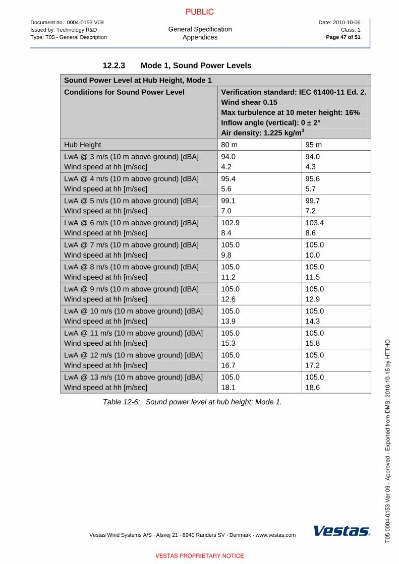
Document no.: 0004-0153 V09
General Specification
Appendices
Date: 2010-10-06
Issued by: Technology R&D Class: 1
Type: T05 - General Description Page 47 of 51
Vestas Wind Systems A/S · Alsvej 21 · 8940 Randers SV · Denmark · www.vestas.com
12.2.3 Mode 1, Sound Power Levels
Sound Power Level at Hub Height, Mode 1
Conditions for Sound Power Level Verification standard: IEC 61400-11 Ed. 2.
Wind shear 0.15
Max turbulence at 10 meter height: 16%
Inflow angle (vertical): 0 2°
Air density: 1.225 kg/m3
Hub Height 80 m 95 m
LwA @ 3 m/s (10 m above ground) [dBA]
Wind speed at hh [m/sec]
94.0
4.2
94.0
4.3
LwA @ 4 m/s (10 m above ground) [dBA]
Wind speed at hh [m/sec]
95.4
5.6
95.6
5.7
LwA @ 5 m/s (10 m above ground) [dBA]
Wind speed at hh [m/sec]
99.1
7.0
99.7
7.2
LwA @ 6 m/s (10 m above ground) [dBA]
Wind speed at hh [m/sec]
102.9
8.4
103.4
8.6
LwA @ 7 m/s (10 m above ground) [dBA]
Wind speed at hh [m/sec]
105.0
9.8
105.0
10.0
LwA @ 8 m/s (10 m above ground) [dBA]
Wind speed at hh [m/sec]
105.0
11.2
105.0
11.5
LwA @ 9 m/s (10 m above ground) [dBA]
Wind speed at hh [m/sec]
105.0
12.6
105.0
12.9
LwA @ 10 m/s (10 m above ground) [dBA]
Wind speed at hh [m/sec]
105.0
13.9
105.0
14.3
LwA @ 11 m/s (10 m above ground) [dBA]
Wind speed at hh [m/sec]
105.0
15.3
105.0
15.8
LwA @ 12 m/s (10 m above ground) [dBA]
Wind speed at hh [m/sec]
105.0
16.7
105.0
17.2
LwA @ 13 m/s (10 m above ground) [dBA]
Wind speed at hh [m/sec]
105.0
18.1
105.0
18.6
Table 12-6: Sound power level at hub height: Mode 1.

Document no.: 0004-0153 V09
General Specification
Appendices
Date: 2010-10-06
Issued by: Technology R&D Class: 1
Type: T05 - General Description Page 48 of 51
Vestas Wind Systems A/S · Alsvej 21 · 8940 Randers SV · Denmark · www.vestas.com
12.3 Mode 2
12.3.1 Mode 2, Power Curves
Mode 2, Power curves
Air density kg/m3
Wind
speed
[m/s] 1.225 0.95 0.975 1 1.025 1.05 1.075 1.1 1.125 1.15 1.175 1.2 1.25 1.275
3 13 9 9 10 10 10 11 11 12 12 13 13 14 14
3.5 52 34 36 37 39 41 42 44 45 47 48 50 53 55
4 108 79 81 84 87 90 92 95 98 100 103 106 111 114
4.5 177 133 137 141 145 149 153 157 161 165 169 173 181 185
5 256 195 201 206 212 217 223 229 234 240 245 251 262 268
5.5 349 268 275 282 290 297 305 312 320 327 335 342 357 364
6 458 352 362 372 381 391 401 410 420 429 439 448 467 477
6.5 589 452 464 477 489 502 514 527 539 552 564 576 601 614
7 743 572 588 604 619 635 650 666 681 697 712 728 758 774
7.5 913 706 725 744 763 782 801 820 838 857 875 894 931 950
8 1091 848 870 892 914 937 959 981 1002 1024 1047 1069 1113 1135
8.5 1268 985 1011 1037 1062 1088 1114 1140 1165 1191 1217 1243 1294 1320
9 1428 1109 1138 1167 1196 1225 1255 1284 1313 1342 1371 1399 1455 1483
9.5 1549 1209 1240 1272 1304 1336 1367 1399 1430 1461 1490 1519 1574 1599
10 1629 1285 1319 1353 1387 1421 1453 1484 1516 1548 1575 1602 1650 1672
10.5 1686 1346 1381 1416 1451 1486 1517 1548 1580 1611 1636 1661 1704 1722
11 1732 1411 1446 1481 1517 1552 1582 1611 1641 1671 1691 1712 1744 1757
11.5 1763 1484 1519 1553 1588 1622 1648 1673 1698 1723 1736 1750 1771 1778
12 1783 1572 1603 1633 1663 1693 1710 1727 1743 1760 1767 1775 1786 1789
12.5 1792 1659 1680 1702 1723 1744 1753 1763 1772 1782 1785 1789 1794 1795
13 1796 1725 1737 1749 1761 1774 1778 1783 1787 1792 1793 1795 1797 1798
13.5 1800 1757 1765 1773 1780 1788 1791 1793 1796 1798 1799 1799 1800 1800
14 1800 1784 1787 1791 1794 1798 1798 1799 1799 1800 1800 1800 1800 1800
14.5 1800 1797 1798 1798 1799 1800 1800 1800 1800 1800 1800 1800 1800 1800
15 1800 1797 1798 1798 1799 1799 1800 1800 1800 1800 1800 1800 1800 1800
15.5 1800 1799 1799 1799 1800 1800 1800 1800 1800 1800 1800 1800 1800 1800
16 1800 1800 1800 1800 1800 1800 1800 1800 1800 1800 1800 1800 1800 1800
16.5 1800 1800 1800 1800 1800 1800 1800 1800 1800 1800 1800 1800 1800 1800
17 1800 1800 1800 1800 1800 1800 1800 1800 1800 1800 1800 1800 1800 1800
17.5 1800 1800 1800 1800 1800 1800 1800 1800 1800 1800 1800 1800 1800 1800
18 1800 1800 1800 1800 1800 1800 1800 1800 1800 1800 1800 1800 1800 1800

Document no.: 0004-0153 V09
General Specification
Appendices
Date: 2010-10-06
Issued by: Technology R&D Class: 1
Type: T05 - General Description Page 49 of 51
Vestas Wind Systems A/S · Alsvej 21 · 8940 Randers SV · Denmark · www.vestas.com
Mode 2, Power curves
Air density kg/m3
Wind
speed
[m/s] 1.225 0.95 0.975 1 1.025 1.05 1.075 1.1 1.125 1.15 1.175 1.2 1.25 1.275
18.5 1800 1800 1800 1800 1800 1800 1800 1800 1800 1800 1800 1800 1800 1800
19 1800 1800 1800 1800 1800 1800 1800 1800 1800 1800 1800 1800 1800 1800
19.5 1800 1800 1800 1800 1800 1800 1800 1800 1800 1800 1800 1800 1800 1800
20 1800 1800 1800 1800 1800 1800 1800 1800 1800 1800 1800 1800 1800 1800
Table 12-7: Mode 2, power curve.
12.3.2 Mode 2, Ct Values
Mode 2, Ct values
Air density kg/m3
Wind
speed
[m/s] 1.225 0.95 0.975 1 1.025 1.05 1.075 1.1 1.125 1.15 1.175 1.2 1.25 1.275
3 0.868 0.868 0.868 0.868 0.868 0.868 0.868 0.868 0.868 0.868 0.868 0.868 0.868 0.868
3.5 0.890 0.890 0.890 0.890 0.890 0.890 0.890 0.890 0.890 0.890 0.890 0.890 0.890 0.890
4 0.882 0.882 0.882 0.882 0.882 0.882 0.882 0.882 0.882 0.882 0.882 0.882 0.882 0.882
4.5 0.854 0.854 0.854 0.854 0.854 0.854 0.854 0.854 0.854 0.854 0.854 0.854 0.854 0.854
5 0.825 0.825 0.825 0.825 0.825 0.825 0.825 0.825 0.825 0.825 0.825 0.825 0.825 0.825
5.5 0.805 0.805 0.805 0.805 0.805 0.805 0.805 0.805 0.805 0.805 0.805 0.805 0.805 0.805
6 0.799 0.799 0.799 0.799 0.799 0.799 0.799 0.799 0.799 0.799 0.799 0.799 0.799 0.799
6.5 0.817 0.817 0.817 0.817 0.817 0.817 0.817 0.817 0.817 0.817 0.817 0.817 0.817 0.817
7 0.804 0.804 0.804 0.804 0.804 0.804 0.804 0.804 0.804 0.804 0.804 0.804 0.804 0.804
7.5 0.785 0.785 0.785 0.785 0.785 0.785 0.785 0.785 0.785 0.785 0.785 0.785 0.785 0.785
8 0.749 0.749 0.749 0.749 0.749 0.748 0.748 0.749 0.749 0.749 0.749 0.749 0.749 0.749
8.5 0.696 0.696 0.696 0.696 0.696 0.696 0.696 0.696 0.696 0.696 0.696 0.696 0.696 0.696
9 0.632 0.632 0.632 0.632 0.632 0.632 0.632 0.632 0.633 0.633 0.632 0.632 0.631 0.630
9.5 0.558 0.563 0.563 0.563 0.563 0.563 0.563 0.562 0.562 0.562 0.561 0.560 0.556 0.553
10 0.486 0.496 0.496 0.496 0.496 0.496 0.496 0.495 0.494 0.493 0.491 0.488 0.482 0.478
10.5 0.421 0.437 0.436 0.436 0.436 0.436 0.434 0.433 0.432 0.430 0.427 0.424 0.417 0.412
11 0.367 0.388 0.387 0.387 0.386 0.386 0.384 0.382 0.380 0.378 0.375 0.371 0.362 0.357
11.5 0.322 0.350 0.349 0.348 0.347 0.346 0.343 0.341 0.338 0.335 0.331 0.326 0.317 0.311
12 0.283 0.322 0.320 0.318 0.316 0.314 0.310 0.306 0.302 0.298 0.293 0.288 0.278 0.272
12.5 0.249 0.297 0.294 0.290 0.287 0.283 0.278 0.274 0.269 0.264 0.259 0.254 0.244 0.240
13 0.221 0.273 0.268 0.263 0.259 0.254 0.249 0.244 0.239 0.234 0.230 0.225 0.216 0.212
13.5 0.197 0.247 0.242 0.237 0.233 0.228 0.223 0.218 0.214 0.209 0.205 0.201 0.193 0.189
14 0.176 0.224 0.219 0.214 0.209 0.204 0.200 0.196 0.191 0.187 0.183 0.179 0.172 0.169

Document no.: 0004-0153 V09
General Specification
Appendices
Date: 2010-10-06
Issued by: Technology R&D Class: 1
Type: T05 - General Description Page 50 of 51
Vestas Wind Systems A/S · Alsvej 21 · 8940 Randers SV · Denmark · www.vestas.com
Mode 2, Ct values
Air density kg/m3
Wind
speed
[m/s] 1.225 0.95 0.975 1 1.025 1.05 1.075 1.1 1.125 1.15 1.175 1.2 1.25 1.275
14.5 0.158 0.202 0.198 0.193 0.188 0.183 0.180 0.176 0.172 0.168 0.164 0.161 0.155 0.152
15 0.142 0.182 0.177 0.173 0.169 0.165 0.161 0.158 0.155 0.151 0.148 0.145 0.140 0.137
15.5 0.129 0.164 0.161 0.157 0.153 0.149 0.146 0.143 0.140 0.137 0.134 0.132 0.127 0.124
16 0.117 0.149 0.146 0.143 0.139 0.136 0.133 0.130 0.127 0.125 0.122 0.120 0.115 0.113
16.5 0.107 0.136 0.133 0.130 0.127 0.124 0.121 0.119 0.116 0.114 0.112 0.109 0.105 0.103
17 0.098 0.125 0.122 0.119 0.116 0.113 0.111 0.109 0.107 0.104 0.102 0.100 0.097 0.095
17.5 0.091 0.114 0.112 0.109 0.107 0.104 0.102 0.100 0.098 0.096 0.094 0.092 0.089 0.087
18 0.084 0.105 0.103 0.101 0.098 0.096 0.094 0.092 0.090 0.088 0.087 0.085 0.082 0.081
18.5 0.077 0.097 0.095 0.093 0.091 0.089 0.087 0.085 0.083 0.082 0.080 0.079 0.076 0.075
19 0.072 0.090 0.088 0.086 0.084 0.082 0.081 0.079 0.078 0.076 0.075 0.073 0.071 0.069
19.5 0.067 0.084 0.082 0.080 0.078 0.077 0.075 0.074 0.072 0.071 0.069 0.068 0.066 0.065
20 0.062 0.078 0.076 0.075 0.073 0.071 0.070 0.069 0.067 0.066 0.065 0.064 0.061 0.060
Table 12-8: Mode 2, Ct values.

Document no.: 0004-0153 V09
General Specification
Appendices
Date: 2010-10-06
Issued by: Technology R&D Class: 1
Type: T05 - General Description Page 51 of 51
Vestas Wind Systems A/S · Alsvej 21 · 8940 Randers SV · Denmark · www.vestas.com
12.3.3 Mode 2, Sound Power Levels
Sound Power Level at Hub Height, Mode 2
Conditions for Sound Power Level Verification standard: IEC 61400-11 Ed. 2.
Wind shear 0.15
Max turbulence at 10 meter height: 16%
Inflow angle (vertical): 0 2°
Air density: 1.225 kg/m3
Hub Height 80 m 95 m
LwA @ 3 m/s (10 m above ground) [dBA]
Wind speed at hh [m/sec]
94.0
4.2
94.1
4.3
LwA @ 4 m/s (10 m above ground) [dBA]
Wind speed at hh [m/sec]
96.2
5.6
96.6
5.7
LwA @ 5 m/s (10 m above ground) [dBA]
Wind speed at hh [m/sec]
100.1
7.0
100.7
7.2
LwA @ 6 m/s (10 m above ground) [dBA]
Wind speed at hh [m/sec]
103.0
8.4
103.0
8.6
LwA @ 7 m/s (10 m above ground) [dBA]
Wind speed at hh [m/sec]
103.0
9.8
103.0
10.0
LwA @ 8 m/s (10 m above ground) [dBA]
Wind speed at hh [m/sec]
103.0
11.2
103.0
11.5
LwA @ 9 m/s (10 m above ground) [dBA]
Wind speed at hh [m/sec]
103.0
12.6
103.0
12.9
LwA @ 10 m/s (10 m above ground) [dBA]
Wind speed at hh [m/sec]
103.0
13.9
103.0
14.3
LwA @ 11 m/s (10 m above ground) [dBA]
Wind speed at hh [m/sec]
103.0
15.3
103.0
15.8
LwA @ 12 m/s (10 m above ground) [dBA]
Wind speed at hh [m/sec]
103.0
16.7
103.0
17.2
LwA @ 13 m/s (10 m above ground) [dBA]
Wind speed at hh [m/sec]
103.0
18.1
103.0
18.6
Table 12-9: Sound power level at hub height: Mode 2.


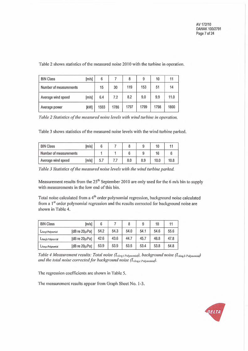

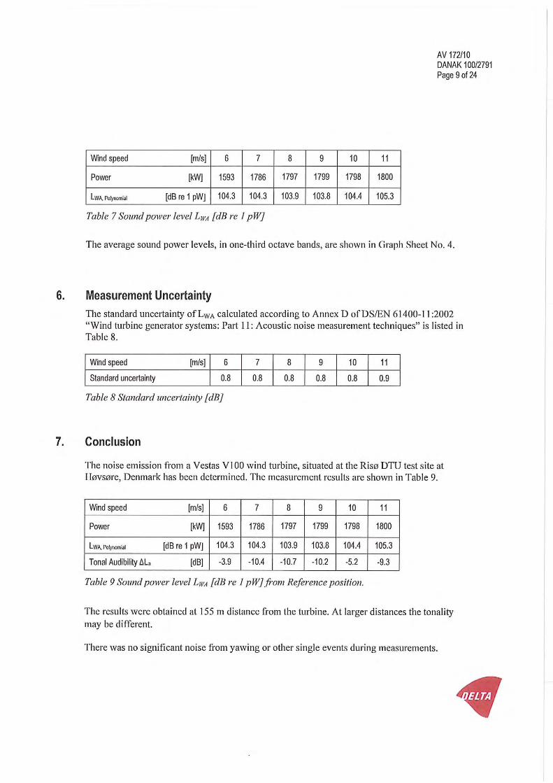


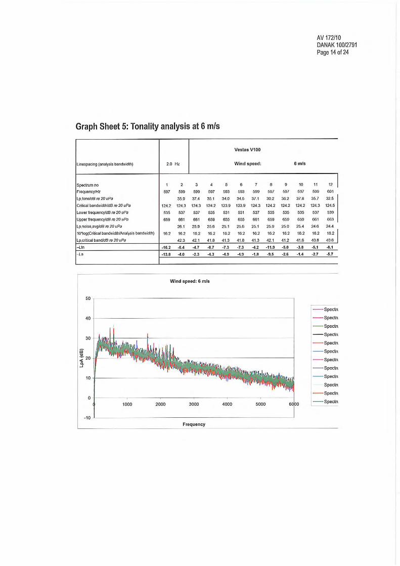


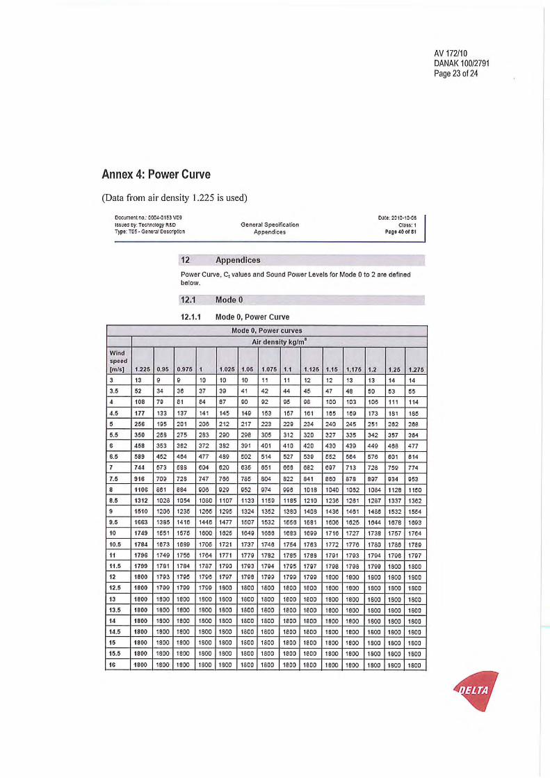
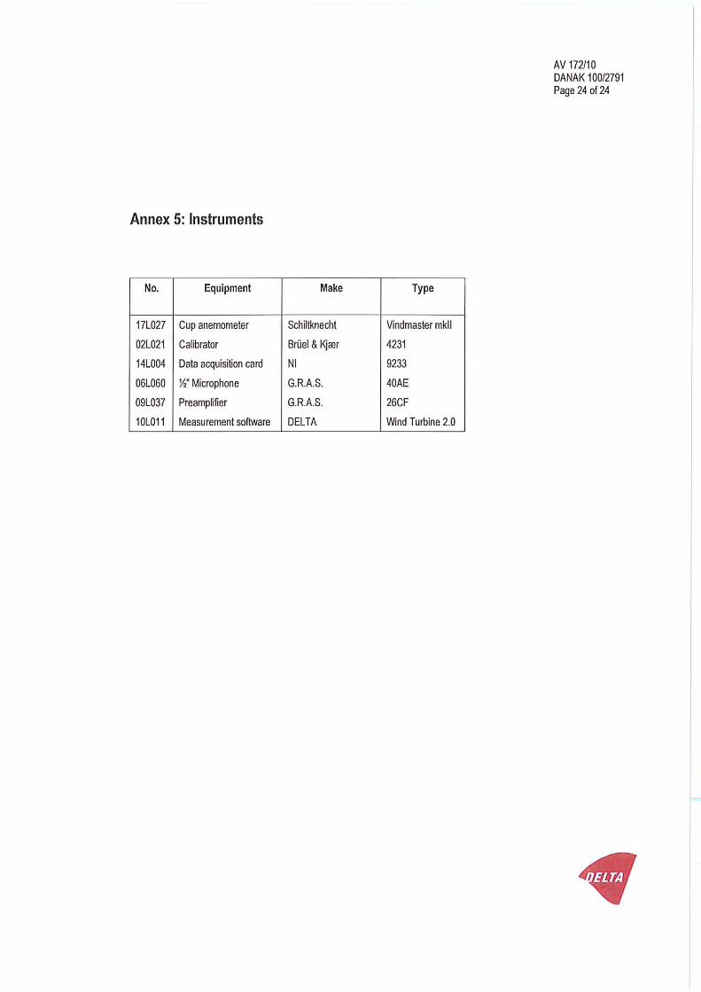

Vestas Wind Systems A/S · Alsvej 21 · 8940 Randers SV · Denmark · www.vestas.com
QM
S 0
0081 V
00 2
008-0
9-0
1
Class 1
Document no.: 0004-0153 V09
2010-10-06
General Specification V100–1.8 MW 50 Hz VCS
VESTAS PROPRIETARY NOTICE: This document contains valuable confidential information of Vestas Wind Systems A/S. It is protected by copyright law as an unpublished work. Vestas reserves all patent, copyright, trade secret, and other proprietary rights to it. The information in this document may not be used, reproduced, or disclosed except if and to the extent rights are expressly granted by Vestas in writing and subject to applicable conditions. Vestas disclaims all warranties except as expressly granted by written agreement and is not responsible for unauthorized uses, for which it may pursue legal remedies against responsible parties.

Document no.: 0004-0153 V09
General Specification
Table of Contents
Date: 2010-10-06
Issued by: Technology R&D Class: 1
Type: T05 - General Description Page 2 of 51
Vestas Wind Systems A/S · Alsvej 21 · 8940 Randers SV · Denmark · www.vestas.com
Table of Contents
1 General Description ............................................................................................................. 5 2 Mechanical Design ............................................................................................................... 5 2.1 Rotor ...................................................................................................................................... 5 2.2 Blades .................................................................................................................................... 5 2.3 Blade Bearing ........................................................................................................................ 6 2.4 Pitch System .......................................................................................................................... 6 2.5 Hub ........................................................................................................................................ 7 2.6 Main Shaft ............................................................................................................................. 7 2.7 Bearing Housing .................................................................................................................... 7 2.8 Main Bearings ........................................................................................................................ 7 2.9 Gearbox ................................................................................................................................. 8 2.10 Generator Bearings ................................................................................................................ 8 2.11 High-Speed Shaft Coupling .................................................................................................... 8 2.12 Yaw System ........................................................................................................................... 9 2.13 Crane ..................................................................................................................................... 9 2.14 Tower Structure ..................................................................................................................... 9 2.15 Nacelle Bedplate and Cover ................................................................................................ 10 2.16 Cooling ................................................................................................................................ 11 2.17 Water Cooling System ......................................................................................................... 11 2.18 Gearbox Cooling .................................................................................................................. 11 2.19 Hydraulic Cooling ................................................................................................................. 12 2.20 VCS Converter Cooling ........................................................................................................ 13 2.21 Generator Cooling................................................................................................................ 13 2.22 HV Transformer Cooling ...................................................................................................... 13 2.23 Nacelle Conditioning ............................................................................................................ 14 3 Electrical Design ................................................................................................................ 15 3.1 Generator ............................................................................................................................ 15 3.2 HV Cables ........................................................................................................................... 15 3.3 Transformer ......................................................................................................................... 16 3.4 Converter ............................................................................................................................. 17 3.5 AUX System ........................................................................................................................ 17 3.6 Wind Sensors ...................................................................................................................... 17 3.7 Turbine Controller ................................................................................................................ 18 3.8 Uninterruptible Power Supply (UPS) .................................................................................... 19 4 Turbine Protection Systems.............................................................................................. 19 4.1 Braking Concept .................................................................................................................. 19 4.2 Short Circuit Protections ...................................................................................................... 19 4.3 Overspeed Protection .......................................................................................................... 20 4.4 EMC System ........................................................................................................................ 20 4.5 Lightning System ................................................................................................................. 20 4.6 Earthing (also known as grounding) ..................................................................................... 21 4.7 Corrosion Protection ............................................................................................................ 21 5 Safety .................................................................................................................................. 21 5.1 Access ................................................................................................................................. 21 5.2 Escape ................................................................................................................................. 22 5.3 Rooms/Working Areas ......................................................................................................... 22 5.4 Platforms, Standing and Working Places ............................................................................. 22 5.5 Climbing Facilities ................................................................................................................ 22 5.6 Moving Parts, Guards and Blocking Devices ........................................................................ 22 5.7 Lighting ................................................................................................................................ 22 5.8 Noise ................................................................................................................................... 23 5.9 Emergency Stop .................................................................................................................. 23

Document no.: 0004-0153 V09
General Specification
Table of Contents
Date: 2010-10-06
Issued by: Technology R&D Class: 1
Type: T05 - General Description Page 3 of 51
Vestas Wind Systems A/S · Alsvej 21 · 8940 Randers SV · Denmark · www.vestas.com
5.10 Power Disconnection ........................................................................................................... 23 5.11 Fire Protection/First Aid ....................................................................................................... 23 5.12 Warning Signs ..................................................................................................................... 23 5.13 Manuals and Warnings ........................................................................................................ 23 6 Environment ....................................................................................................................... 24 6.1 Chemicals ............................................................................................................................ 24 7 Approvals, Certificates and Design Codes ...................................................................... 24 7.1 Type Approvals .................................................................................................................... 24 7.2 Design Codes – Structural Design ....................................................................................... 24 7.3 Design Codes – Mechanical Equipment ............................................................................... 25 7.4 Design Codes – Electrical Equipment .................................................................................. 25 7.5 Design Codes – I/O Network System ................................................................................... 26 7.6 Design Codes – EMC System .............................................................................................. 26 7.7 Design Codes – Lightning Protection ................................................................................... 27 7.8 Design Codes – Earthing ..................................................................................................... 27 8 Colour and Surface Treatment .......................................................................................... 28 8.1 Nacelle Colour and Surface Treatment ................................................................................ 28 8.2 Tower Colour and Surface Treatment .................................................................................. 28 8.3 Blades Colour ...................................................................................................................... 28 9 Operational Envelope and Performance Guidelines ....................................................... 29 9.1 Climate and Site Conditions ................................................................................................. 29 9.1.1 Complex Terrain .................................................................................................................. 30 9.1.2 Altitude ................................................................................................................................. 30 9.1.3 Wind Farm Layout................................................................................................................ 30 9.2 Operational Envelope – Temperature and Wind .................................................................. 30 9.3 Operational Envelope – Grid Connection * ........................................................................... 30 9.4 Operational Envelope – Reactive Power Capability ............................................................. 31 9.5 Performance – Fault Ride Through ...................................................................................... 32 9.6 Performance – Reactive Current Contribution ...................................................................... 33 9.6.1 Symmetrical Reactive Current Contribution.......................................................................... 33 9.6.2 Asymmetrical Reactive Current Contribution ........................................................................ 34 9.7 Performance – Multiple Voltage Dips ................................................................................... 34 9.8 Performance – Active and Reactive Power Control .............................................................. 34 9.9 Performance – Voltage Control ............................................................................................ 35 9.10 Performance – Frequency Control ....................................................................................... 35 9.11 Performance – Own Consumption ....................................................................................... 35 9.12 Operational Envelope Conditions for Power Curve, Ct Values (at Hub Height) ..................... 36 10 Drawings ............................................................................................................................ 37 10.1 Structural Design – Illustration of Outer Dimensions ............................................................ 37 10.2 Structural Design – Side View Drawing ................................................................................ 38 11 General Reservations, Notes and Disclaimers ................................................................ 39 12 Appendices ........................................................................................................................ 40 12.1 Mode 0 ................................................................................................................................. 40 12.1.1 Mode 0, Power Curve .......................................................................................................... 40 12.1.2 Mode 0, Ct Values ................................................................................................................ 41 12.1.3 Mode 0, Sound Power Levels .............................................................................................. 43 12.2 Mode 1 ................................................................................................................................. 44 12.2.1 Mode 1, Power Curves ........................................................................................................ 44 12.2.2 Mode 1, Ct Values ................................................................................................................ 45 12.2.3 Mode 1, Sound Power Levels .............................................................................................. 47 12.3 Mode 2 ................................................................................................................................. 48 12.3.1 Mode 2, Power Curves ........................................................................................................ 48 12.3.2 Mode 2, Ct Values ................................................................................................................ 49 12.3.3 Mode 2, Sound Power Levels .............................................................................................. 51

Document no.: 0004-0153 V09
General Specification
Table of Contents
Date: 2010-10-06
Issued by: Technology R&D Class: 1
Type: T05 - General Description Page 4 of 51
Vestas Wind Systems A/S · Alsvej 21 · 8940 Randers SV · Denmark · www.vestas.com
Buyer acknowledges that these general specifications are for Buyer’s informational purposes
only and do not create or constitute a warranty, guarantee, promise, commitment, or other
representation by supplier, all of which are disclaimed by supplier except to the extent
expressly provided by supplier in writing elsewhere.
See section 11 General Reservations, Notes and Disclaimers, p. 39 for general reservations, notes,
and disclaimers applicable to these general specifications.

Document no.: 0004-0153 V09
General Specification
General Description
Date: 2010-10-06
Issued by: Technology R&D Class: 1
Type: T05 - General Description Page 5 of 51
Vestas Wind Systems A/S · Alsvej 21 · 8940 Randers SV · Denmark · www.vestas.com
1 General Description
The Vestas V100-1.8 MW wind turbine is a pitch-regulated upwind turbine with
active yaw and a three-blade rotor. The Vestas V100-1.8 MW turbine has a rotor
diameter of 100 m with a generator rated at 1.8 MW. The turbine utilizes a
microprocessor pitch control system called OptiTip® and the Variable Speed
concepts (VCS: Vestas Converter System). With these features the wind turbine
is able to operate the rotor at variable speed revolutions per minute (RPM),
helping to maintain the output at or near rated power.
2 Mechanical Design
2.1 Rotor
The V100-1.8 MW turbine is equipped with a 100-meter rotor consisting of three
blades and the hub. Based on the prevailing wind conditions, the blades are
continuously positioned to help optimise the pitch angle.
Rotor
Diameter 100 m
Swept Area 7850 m2
Rotational Speed Static, Rotor 14.9 rpm
Speed, Dynamic Operation Range 9.3-16.6 rpm
Rotational Direction Clockwise (front view)
Orientation Upwind
Tilt 6°
Hub Coning 2°
Number of Blades 3
Aerodynamic Brakes Full feathering
Table 2-1: Rotor data.
2.2 Blades
The 49 m Prepreg (PP) blades are made of carbon and fibre glass and consist of
two airfoil shells bonded to a supporting beam.
PP Blades
Type Description Airfoil shells bonded to supporting
beam
Blade Length 49 m
Material Fibre glass reinforced epoxy and
carbon fibres
Blade Connection Steel roots inserted
Air Foils RISØ P + FFA –W3
Chord 3.9 m
Blade Root Outer Diameter 1.88 m
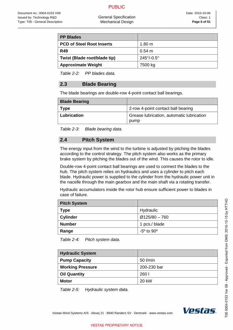
Document no.: 0004-0153 V09
General Specification
Mechanical Design
Date: 2010-10-06
Issued by: Technology R&D Class: 1
Type: T05 - General Description Page 6 of 51
Vestas Wind Systems A/S · Alsvej 21 · 8940 Randers SV · Denmark · www.vestas.com
PP Blades
PCD of Steel Root Inserts 1.80 m
R49 0.54 m
Twist (Blade root/blade tip) 245°/-0.5°
Approximate Weight 7500 kg
Table 2-2: PP blades data.
2.3 Blade Bearing
The blade bearings are double-row 4-point contact ball bearings.
Blade Bearing
Type 2-row 4-point contact ball bearing
Lubrication Grease lubrication, automatic lubrication
pump
Table 2-3: Blade bearing data.
2.4 Pitch System
The energy input from the wind to the turbine is adjusted by pitching the blades
according to the control strategy. The pitch system also works as the primary
brake system by pitching the blades out of the wind. This causes the rotor to idle.
Double-row 4-point contact ball bearings are used to connect the blades to the
hub. The pitch system relies on hydraulics and uses a cylinder to pitch each
blade. Hydraulic power is supplied to the cylinder from the hydraulic power unit in
the nacelle through the main gearbox and the main shaft via a rotating transfer.
Hydraulic accumulators inside the rotor hub ensure sufficient power to blades in
case of failure.
Pitch System
Type Hydraulic
Cylinder Ø125/80 – 760
Number 1 pcs./ blade
Range -5º to 90º
Table 2-4: Pitch system data.
Hydraulic System
Pump Capacity 50 l/min
Working Pressure 200-230 bar
Oil Quantity 260 l
Motor 20 kW
Table 2-5: Hydraulic system data.

Document no.: 0004-0153 V09
General Specification
Mechanical Design
Date: 2010-10-06
Issued by: Technology R&D Class: 1
Type: T05 - General Description Page 7 of 51
Vestas Wind Systems A/S · Alsvej 21 · 8940 Randers SV · Denmark · www.vestas.com
2.5 Hub
The hub supports the three blades and transfers the reaction forces to the main
bearing. The hub structure also supports blade bearings and pitch cylinder.
Hub
Type Cast ball shell hub
Material Cast iron EN GJS 400-18U-LT / EN 1560
Table 2-6: Hub data.
2.6 Main Shaft
Main Shaft
Type Forged, trumpet shaft
Material 42 CrMo4 QT / EN 10083
Table 2-7: Main shaft data.
2.7 Bearing Housing
Bearing Housing
Type Cast foot housing with lowered centre
Material Cast iron EN-GJS-400-18U-LT / EN 1560
Table 2-8: Bearing housing data.
2.8 Main Bearings
Main Bearings
Type Spherical roller bearings
Lubrication Grease lubrication, manually re-greased
Table 2-9: Main bearings data.
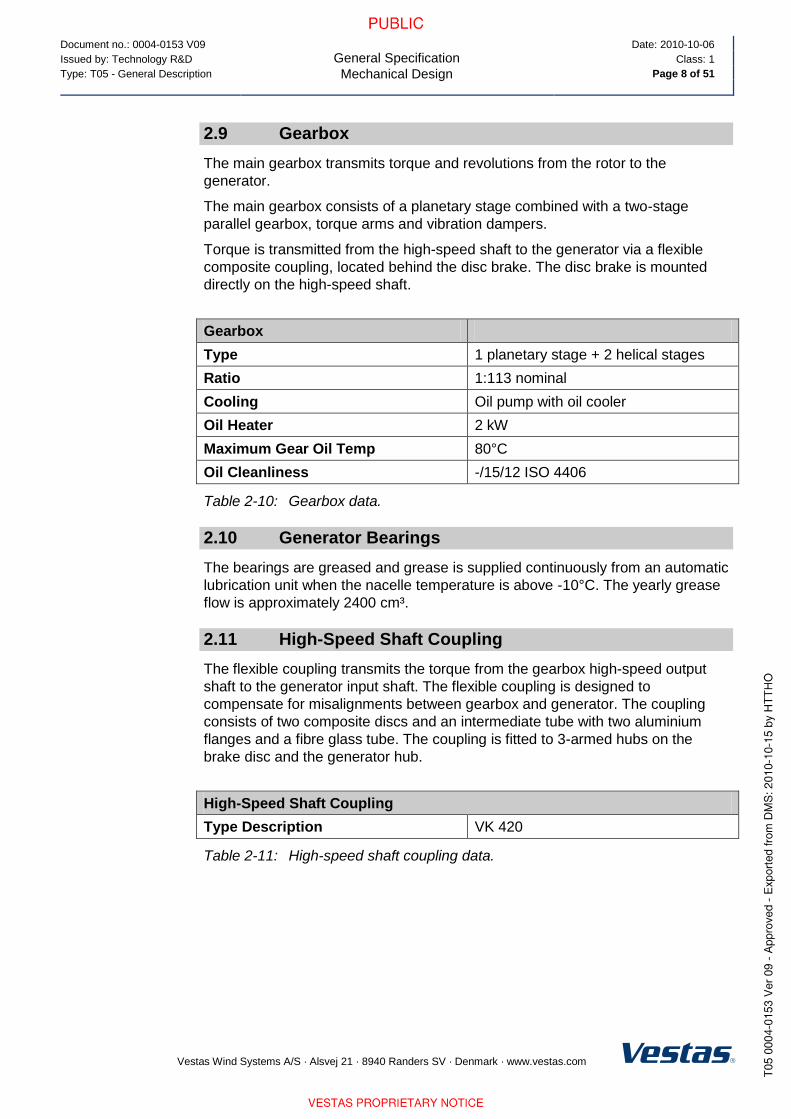
Document no.: 0004-0153 V09
General Specification
Mechanical Design
Date: 2010-10-06
Issued by: Technology R&D Class: 1
Type: T05 - General Description Page 8 of 51
Vestas Wind Systems A/S · Alsvej 21 · 8940 Randers SV · Denmark · www.vestas.com
2.9 Gearbox
The main gearbox transmits torque and revolutions from the rotor to the
generator.
The main gearbox consists of a planetary stage combined with a two-stage
parallel gearbox, torque arms and vibration dampers.
Torque is transmitted from the high-speed shaft to the generator via a flexible
composite coupling, located behind the disc brake. The disc brake is mounted
directly on the high-speed shaft.
Gearbox
Type 1 planetary stage + 2 helical stages
Ratio 1:113 nominal
Cooling Oil pump with oil cooler
Oil Heater 2 kW
Maximum Gear Oil Temp 80°C
Oil Cleanliness -/15/12 ISO 4406
Table 2-10: Gearbox data.
2.10 Generator Bearings
The bearings are greased and grease is supplied continuously from an automatic
lubrication unit when the nacelle temperature is above -10°C. The yearly grease
flow is approximately 2400 cm³.
2.11 High-Speed Shaft Coupling
The flexible coupling transmits the torque from the gearbox high-speed output
shaft to the generator input shaft. The flexible coupling is designed to
compensate for misalignments between gearbox and generator. The coupling
consists of two composite discs and an intermediate tube with two aluminium
flanges and a fibre glass tube. The coupling is fitted to 3-armed hubs on the
brake disc and the generator hub.
High-Speed Shaft Coupling
Type Description VK 420
Table 2-11: High-speed shaft coupling data.

Document no.: 0004-0153 V09
General Specification
Mechanical Design
Date: 2010-10-06
Issued by: Technology R&D Class: 1
Type: T05 - General Description Page 9 of 51
Vestas Wind Systems A/S · Alsvej 21 · 8940 Randers SV · Denmark · www.vestas.com
2.12 Yaw System
The yaw system is designed to keep the turbine upwind. The nacelle is mounted
on the yaw plate that is bolted to the turbine tower. The yaw bearing system is a
plain bearing system with built-in friction. Asynchronous yaw motors with brakes
enable the nacelle to rotate on top of the tower.
The turbine controller receives information of the wind direction from the wind
sensor. Automatic yawing is deactivated when the mean wind speed is below 3
m/s.
Yaw System
Type Plain bearing system with built-in
friction
Material Forged yaw ring heat-treated
Plain bearings PETP
Yawing Speed < 0.5˚/sec.
Table 2-12: Yaw system data.
Yaw Gear
Type Non-locking combined worm gear and
planetary gearbox
Electrical motor brake
Motor 1.5 kW, 6 pole, asynchronous
Number of Yaw Gears 6
Ratio Total (4 Planetary Stages) 1,120 : 1
Rotational Speed at Full Load Approximately 1 rpm at output shaft
Table 2-13: Yaw gear data.
2.13 Crane
The nacelle houses the service crane. The crane is a single system chain hoist.
Crane
Lifting Capacity Maximum 800 kg
Table 2-14: Crane data.
2.14 Tower Structure
Tubular towers with flange connections, certified according to relevant type
approvals, are available in different standard heights. Magnets provide load
support in a horizontal direction for tower internals, such as platforms, ladders,
etc. Tower internals are supported vertically (i.e. in the gravitational direction) by
a mechanical connection.
The hub heights listed include a distance from the foundation section to the
ground level of approximately 0.6 m depending on the thickness of the bottom
flange and the distance from the tower top flange to the centre of the hub of
1.70 m.

Document no.: 0004-0153 V09
General Specification
Mechanical Design
Date: 2010-10-06
Issued by: Technology R&D Class: 1
Type: T05 - General Description Page 10 of 51
Vestas Wind Systems A/S · Alsvej 21 · 8940 Randers SV · Denmark · www.vestas.com
Tower Structure
Type Description Conical tubular
Hub Heights (HH) 80 m/95 m
Material S355 according to EN 10024
A709 according to ASTM
Weight 80 m IEC S 160 metric tonnes*
95 m IEC S 205 metric tonnes**
Table 2-15: Tower structure data.
*/** Typical values. Dependent on wind class, and can vary with site/project
conditions.
2.15 Nacelle Bedplate and Cover
The nacelle cover is made of fibre glass. Hatches are positioned in the floor for
lowering or hoisting equipment to the nacelle and evacuation of personnel.
The roof is equipped with wind sensors and skylights which can be opened from
inside the nacelle to access the roof and from outside to access the nacelle. The
nacelle cover is mounted on the girder structure. Access from the tower to the
nacelle is through the yaw system.
The nacelle bedplate is in two parts, and consists of a cast-iron front part and a
girder structure rear part. The front of the nacelle bedplate is the foundation for
the drive train, which transmits forces from the rotor to the tower, through the yaw
system. The bottom surface is machined and connected to the yaw bearing, and
the yaw gears are bolted to the front nacelle bedplate.
The nacelle bedplate carries the crane girders through vertical beams positioned
along the site of the nacelle. Lower beams of the girder structure are connected
at the rear end.
The rear part of the bedplate serves as foundation for controller panels, generator
and transformer.
Type Description Material
Nacelle Cover GRP
Base Frame Front Cast EN-GJS-400-18U-LT / EN 1560
Base Frame Rear Welded grid structure
Table 2-16: Nacelle base frame and cover data.
NOTE

Document no.: 0004-0153 V09
General Specification
Mechanical Design
Date: 2010-10-06
Issued by: Technology R&D Class: 1
Type: T05 - General Description Page 11 of 51
Vestas Wind Systems A/S · Alsvej 21 · 8940 Randers SV · Denmark · www.vestas.com
2.16 Cooling
The cooling of the main components (gearbox, hydraulic power pack and VCS
converter) in the turbine is done by a water cooling system. The generator is air
cooled by nacelle air and the high-voltage (HV) transformer is cooled by mainly
ambient air.
Component Cooling Type Internal Heating at Low Temperature
Nacelle Forced air Yes
Hub/spinner Natural air No (Yes Low Temperature (LT) turbine)
Gearbox Water/oil Yes
Generator Forced air/air No (heat source)
Slip rings Forced air/air Yes
Transformer Forced air No (heat source)
VCS Forced water/air Yes
VMP section Forced air/air Yes
Hydraulics Water/oil Yes
Table 2-17: Cooling summary.
All other heat generating systems are also equipped with fans/coolers but are
considered as minor contributors to nacelle thermodynamics.
2.17 Water Cooling System
The water cooling system is designed as a semi-closed system (closed system
but not under pressure) with a free wind-water cooler on the roof of the nacelle.
This means that the heat loss from the systems (components) is transferred to
the water system, and the water system is cooled by ambient air.
The water cooling system has three parallel cooling circuits that cool the gearbox,
the hydraulic power unit and the VCS converter.
The water cooling system is equipped with a 3-way thermostatic valve, which is
closed (total water flow bypasses the water cooler) if the temperature of the
cooling water is below 35°C, and fully open (total water flow leads to the water
cooler) if the temperature is above 43°C.
2.18 Gearbox Cooling
The gearbox cooling system consists of two oil circuits that remove the gearbox
losses through two plate heat exchangers (oil coolers). The first circuit is
equipped with a mechanical-driven oil pump and a plate heat exchanger, and the
second circuit is equipped with an electrical-driven oil pump and a plate heat
exchanger. The water circuit of the two plate heat exchangers are coupled in
serial.

Document no.: 0004-0153 V09
General Specification
Mechanical Design
Date: 2010-10-06
Issued by: Technology R&D Class: 1
Type: T05 - General Description Page 12 of 51
Vestas Wind Systems A/S · Alsvej 21 · 8940 Randers SV · Denmark · www.vestas.com
Gearbox Cooling
Gear Oil Plate Heat Exchanger 1 (Mechanically driven oil pump)
Nominal oil flow 50 l/min
Oil inlet temperature 80°C
No. of passes 2
Cooling capacity 24.5 kW
Gear Oil Plate Heat Exchanger 2 (Electrically driven oil pump)
Nominal oil flow 85 l/min
Oil inlet temperature 80°C
No. of passes 2
Cooling capacity 41.5 kW
Water Circuit
Nominal water flow Approximately 150 l/min (50% glycol)
Water inlet temperature Maximum 54°C
No. of passes 1
Heat load 66 kW
Table 2-18: Gearbox cooling data.
2.19 Hydraulic Cooling
The hydraulic cooling system consists of a plate heat exchanger which is
mounted on the power pack. In the plate heat exchanger, the heat from the
hydraulics is transferred to the water cooling system.
Hydraulic Cooling
Hydraulic Oil Plate Heat Exchanger
Nominal oil flow 40 l/min
Oil inlet temperature 66°C
Cooling capacity 10.28 kW
Water Circuit
Nominal water flow Approximately 45 l/min (50% glycol)
Water inlet temperature Maximum 54°C
Heat load 10.28 kW
Table 2-19: Hydraulic cooling data.

Document no.: 0004-0153 V09
General Specification
Mechanical Design
Date: 2010-10-06
Issued by: Technology R&D Class: 1
Type: T05 - General Description Page 13 of 51
Vestas Wind Systems A/S · Alsvej 21 · 8940 Randers SV · Denmark · www.vestas.com
2.20 VCS Converter Cooling
The converter cooling system consists of a number of switch modules that are
mounted on cooling plates through which the cooling water is led.
Converter Cooling
Nominal water flow Approximately 45 l/min (50% glycol)
Water inlet pressure Max 2.0 bar
Water inlet temperature Maximum 54ºC
Cooling capacity 10 kW
Table 2-20: Converter cooling data.
2.21 Generator Cooling
The generator cooling systems consists of an air-to-air cooler mounted on the top
of the generator. The cooler removes the internal losses in the generator and in
three fans (two internal and one external). All the fans can run at low or high
speed.
Generator Cooling
Air inlet temperature – external 50°C
Nominal air flow – internal 8000 m3/h
Nominal air flow – external 7500 m3/h
Cooling capacity 48 kW
Table 2-21: Generator cooling data.
2.22 HV Transformer Cooling
The transformer is equipped with forced-air cooling. The cooling system consists
of a central fan located under the service floor, an air distribution manifold and six
hoses leading to locations beneath and between the HV and LV windings.
Transformer Cooling
Nominal air flow 1920 m3/h
Air inlet temperature Maximum 40°C
Table 2-22: Transformer cooling data.

Document no.: 0004-0153 V09
General Specification
Mechanical Design
Date: 2010-10-06
Issued by: Technology R&D Class: 1
Type: T05 - General Description Page 14 of 51
Vestas Wind Systems A/S · Alsvej 21 · 8940 Randers SV · Denmark · www.vestas.com
2.23 Nacelle Conditioning
The nacelle conditioning system consists of one fan and two air heaters. There
are two main circuits of the nacelle conditioning system:
1. Cooling of the HV transformer.
2. Heating and ventilation of the nacelle.
For both systems, the airflow enters the nacelle through louver dampers in the
weather shield underneath the nacelle.
The cooling of the HV transformer is described in section 2.22 HV Transformer
Cooling, p. 13.
The heating and ventilation of the nacelle is done by means of two air heaters
and one fan. To avoid condensation in the nacelle, the two air heaters keep the
nacelle temperature +5°C above the ambient temperature. At start-up in cold
conditions, the heaters will also heat the air around the gearbox. The ventilation
of the nacelle is done by means of one fan, removing hot air (generated by
mechanical and electrical equipment) from the nacelle.
Nacelle Cooling
Nominal air flow 1.2 m3/s
Air inlet temperature Maximum 50°C
Table 2-23: Nacelle cooling data.
Nacelle Heating
Rated power 2 x 6 kW
Table 2-24: Nacelle heating data.

Document no.: 0004-0153 V09
General Specification
Electrical Design
Date: 2010-10-06
Issued by: Technology R&D Class: 1
Type: T05 - General Description Page 15 of 51
Vestas Wind Systems A/S · Alsvej 21 · 8940 Randers SV · Denmark · www.vestas.com
3 Electrical Design
3.1 Generator
The generator is a 3-phase asynchronous generator with wound rotor, which is
connected to the Vestas Converter System (VCS) via a slip-ring system. The
generator is an air-to-air cooled generator with internal and external cooling
circuits. The external circuit uses air from the nacelle and exhausts it out through
the rear end of the nacelle.
The generator has four poles. The generator is wound with form windings in both
rotor and stator. The stator is connected in star at low power and delta at high
power. The rotor is connected in star and is insulated from the shaft.
Generator
Type Description Asynchronous with wound rotor, slip
rings and VCS
Rated Power (PN) 1.8 MW
Rated Apparent Power 2.0 MVA (Cosφ = 0.9)
Frequency 50 Hz
Voltage, Generator 690 Vac
Voltage, Converter 480 Vac
Number of Poles 4
Winding Type (Stator/Rotor) Random/Form
Winding Connection, Stator Star/Delta
Rated Efficiency (Generator only) > 97%
Power Factor (cos) 0.90 ind – 0.95 cap
Over Speed Limit acc. to IEC (2 min.) 2900 rpm
Vibration Level ≤ 1.8 mm/s
Weight Approximately 7500 kg
Generator Bearing - Temperature 2 PT100 sensors
Generator Stator Windings -
Temperature
3 PT100 sensors placed at hot spots
and 3 as back-up
Table 3-1: Generator data.
3.2 HV Cables
The high voltage cable runs from the transformer in the nacelle down the tower to
the switchgear located in the bottom of the tower (switchgear is not included).
The high voltage cable is a 4-core rubber insulated halogen free high voltage
cable.
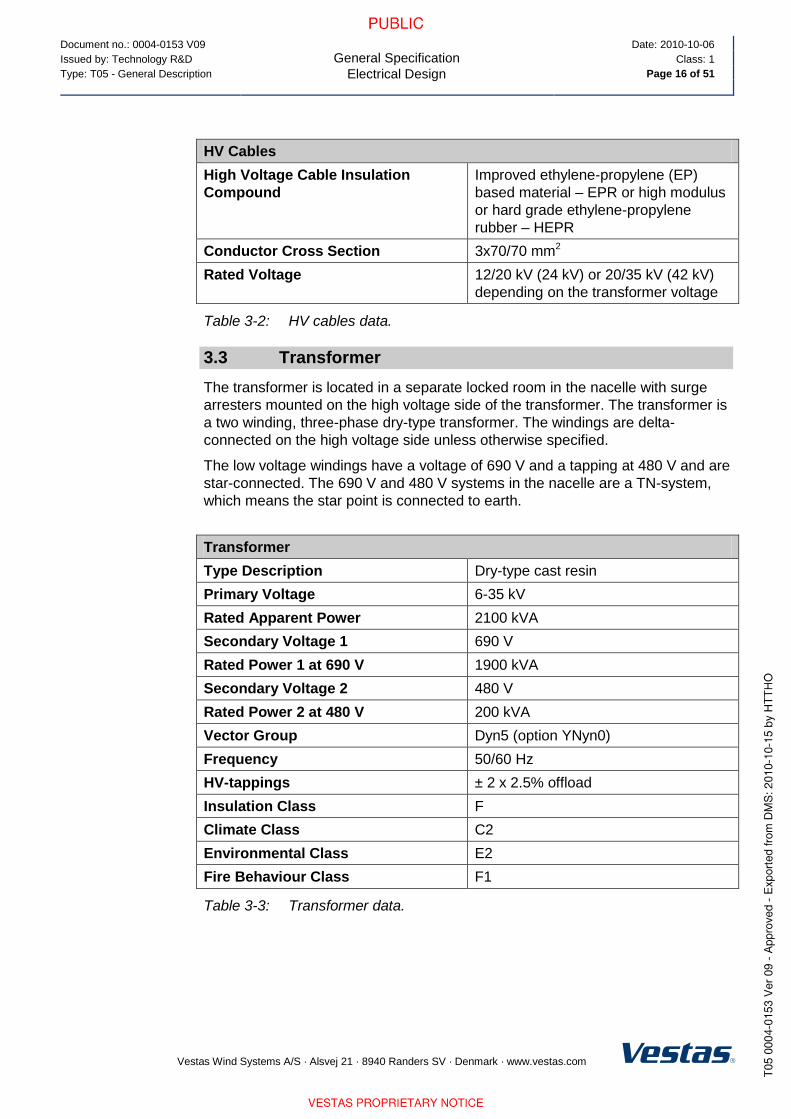
Document no.: 0004-0153 V09
General Specification
Electrical Design
Date: 2010-10-06
Issued by: Technology R&D Class: 1
Type: T05 - General Description Page 16 of 51
Vestas Wind Systems A/S · Alsvej 21 · 8940 Randers SV · Denmark · www.vestas.com
HV Cables
High Voltage Cable Insulation
Compound
Improved ethylene-propylene (EP)
based material – EPR or high modulus
or hard grade ethylene-propylene
rubber – HEPR
Conductor Cross Section 3x70/70 mm2
Rated Voltage 12/20 kV (24 kV) or 20/35 kV (42 kV)
depending on the transformer voltage
Table 3-2: HV cables data.
3.3 Transformer
The transformer is located in a separate locked room in the nacelle with surge
arresters mounted on the high voltage side of the transformer. The transformer is
a two winding, three-phase dry-type transformer. The windings are delta-
connected on the high voltage side unless otherwise specified.
The low voltage windings have a voltage of 690 V and a tapping at 480 V and are
star-connected. The 690 V and 480 V systems in the nacelle are a TN-system,
which means the star point is connected to earth.
Transformer
Type Description Dry-type cast resin
Primary Voltage 6-35 kV
Rated Apparent Power 2100 kVA
Secondary Voltage 1 690 V
Rated Power 1 at 690 V 1900 kVA
Secondary Voltage 2 480 V
Rated Power 2 at 480 V 200 kVA
Vector Group Dyn5 (option YNyn0)
Frequency 50/60 Hz
HV-tappings ± 2 x 2.5% offload
Insulation Class F
Climate Class C2
Environmental Class E2
Fire Behaviour Class F1
Table 3-3: Transformer data.
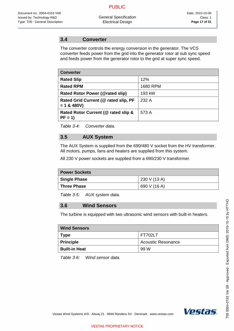
Document no.: 0004-0153 V09
General Specification
Electrical Design
Date: 2010-10-06
Issued by: Technology R&D Class: 1
Type: T05 - General Description Page 17 of 51
Vestas Wind Systems A/S · Alsvej 21 · 8940 Randers SV · Denmark · www.vestas.com
3.4 Converter
The converter controls the energy conversion in the generator. The VCS
converter feeds power from the grid into the generator rotor at sub sync speed
and feeds power from the generator rotor to the grid at super sync speed.
Converter
Rated Slip 12%
Rated RPM 1680 RPM
Rated Rotor Power (@rated slip) 193 kW
Rated Grid Current (@ rated slip, PF
= 1 & 480V)
232 A
Rated Rotor Current (@ rated slip &
PF = 1)
573 A
Table 3-4: Converter data.
3.5 AUX System
The AUX System is supplied from the 690/480 V socket from the HV transformer.
All motors, pumps, fans and heaters are supplied from this system.
All 230 V power sockets are supplied from a 690/230 V transformer.
Power Sockets
Single Phase 230 V (13 A)
Three Phase 690 V (16 A)
Table 3-5: AUX system data.
3.6 Wind Sensors
The turbine is equipped with two ultrasonic wind sensors with built-in heaters.
Wind Sensors
Type FT702LT
Principle Acoustic Resonance
Built-in Heat 99 W
Table 3-6: Wind sensor data.

Document no.: 0004-0153 V09
General Specification
Electrical Design
Date: 2010-10-06
Issued by: Technology R&D Class: 1
Type: T05 - General Description Page 18 of 51
Vestas Wind Systems A/S · Alsvej 21 · 8940 Randers SV · Denmark · www.vestas.com
3.7 Turbine Controller
The turbine is controlled and monitored by the System 3500 controller hardware
and Vestas controller software.
The turbine controller is based on four main processors (Ground, Nacelle, Hub
and Converter) which are interconnected by an optical-based 2.5 Mbit ArcNet
network.
I/O modules are connected either as rack modules in the System 3500 rack or by
CAN.
The turbine control system serves the following main functions:
Monitoring and supervision of overall operation.
Synchronizing of the generator to the grid during connection sequence in
order to limit the inrush current.
Operating the wind turbine during various fault situations.
Automatic yawing of the nacelle.
OptiTip® - blade pitch control.
Noise emission control.
Monitoring of ambient conditions.
Monitoring of the grid.
The turbine controller hardware is built from the following main modules:
Module Function Network
CT3603 Main processor. Control and monitoring
(nacelle and hub).
ArcNet, CAN,
Ethernet, serial
CT396 Main processor. Control, monitoring, external
communication (ground).
ArcNet, CAN,
Ethernet, serial
CT360 Main processor. Converter control and
monitoring.
ArcNet, CAN,
Ethernet
CT3218 Counter/encoder module. RPM, Azimuth and
wind measurement.
Rack module
CT3133 24 VDC digital input module. 16 channels. Rack module
CT3153 24 VDC digital output module. 16 channels. Rack module
CT3320 4 channel analogue input (0-10 V, 4-20 mA,
PT100)
Rack module
CT6061 CAN I/O controller CAN node
CT6221 3 channel PT100 module CAN I/O module
CT6050 Blade controller CAN node
Balluf Position transducer CAN node
Rexroth Proportional valve CAN node
Table 3-7: Turbine controller hardware.

Document no.: 0004-0153 V09
General Specification
Turbine Protection Systems
Date: 2010-10-06
Issued by: Technology R&D Class: 1
Type: T05 - General Description Page 19 of 51
Vestas Wind Systems A/S · Alsvej 21 · 8940 Randers SV · Denmark · www.vestas.com
3.8 Uninterruptible Power Supply (UPS)
The UPS supplies power to critical wind turbine components.
The actual back up time for the UPS system is proportional to the power consumption. Actual back-up time may vary.
UPS
Battery Type Valve-Regulated Lead Acid (VRLA)
Rated Battery Voltage 2 x 8 x 12 V (192 V)
Converter Type Double conversion online
Rated Output Voltage 230 V AC
Rated Output Voltage 230 V AC
Converter Input 230 V ±20%
Back-up Time* Controller system 30 seconds
Safety systems 35 minutes
Re-charging Time Typical Approximately 2.5 hours
Table 3-8: UPS data.
* For alternative back-up times, consult Vestas.
4 Turbine Protection Systems
4.1 Braking Concept
The main brake on the turbine is aerodynamic. Braking the turbine is done by
feathering the three blades. During emergency stop all three blades will feather
simultaneously to full end stop and thereby slowing the rotor speed.
In addition there is a mechanical disc brake on the high speed shaft of the
gearbox. The mechanical brake is only used as a parking brake, and when
activating the emergency stop push buttons.
4.2 Short Circuit Protections
Breakers Generator / Q8
ABB E2B 2000
690 V
Controller / Q15
ABB S3X
690 V
VCS-VCUS / Q7
ABB S5H 400
480 V
Breaking Capacity
Icu, Ics 42, 42 kA 75, 75 kA 40, 40 kA
Making Capacity
Icm (415V Data)
88 kA 440 kA 143 kA
Thermo Release
Ith 2000 A 100 A 400 A
Table 4-1: Short circuit protection data.
NOTE
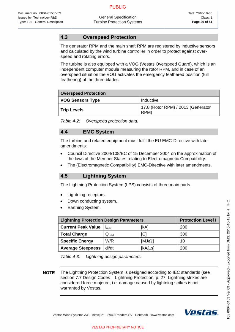
Document no.: 0004-0153 V09
General Specification
Turbine Protection Systems
Date: 2010-10-06
Issued by: Technology R&D Class: 1
Type: T05 - General Description Page 20 of 51
Vestas Wind Systems A/S · Alsvej 21 · 8940 Randers SV · Denmark · www.vestas.com
4.3 Overspeed Protection
The generator RPM and the main shaft RPM are registered by inductive sensors
and calculated by the wind turbine controller in order to protect against over-
speed and rotating errors.
The turbine is also equipped with a VOG (Vestas Overspeed Guard), which is an
independent computer module measuring the rotor RPM, and in case of an
overspeed situation the VOG activates the emergency feathered position (full
feathering) of the three blades.
Overspeed Protection
VOG Sensors Type Inductive
Trip Levels 17.8 (Rotor RPM) / 2013 (Generator
RPM)
Table 4-2: Overspeed protection data.
4.4 EMC System
The turbine and related equipment must fulfil the EU EMC-Directive with later
amendments:
Council Directive 2004/108/EC of 15 December 2004 on the approximation of
the laws of the Member States relating to Electromagnetic Compatibility.
The (Electromagnetic Compatibility) EMC-Directive with later amendments.
4.5 Lightning System
The Lightning Protection System (LPS) consists of three main parts.
Lightning receptors.
Down conducting system.
Earthing System.
Lightning Protection Design Parameters Protection Level I
Current Peak Value imax [kA] 200
Total Charge Qtotal [C] 300
Specific Energy W/R [MJ/] 10
Average Steepness di/dt [kA/s] 200
Table 4-3: Lightning design parameters.
The Lightning Protection System is designed according to IEC standards (see
section 7.7 Design Codes – Lightning Protection, p. 27. Lightning strikes are
considered force majeure, i.e. damage caused by lightning strikes is not
warranted by Vestas.
NOTE

Document no.: 0004-0153 V09
General Specification
Safety
Date: 2010-10-06
Issued by: Technology R&D Class: 1
Type: T05 - General Description Page 21 of 51
Vestas Wind Systems A/S · Alsvej 21 · 8940 Randers SV · Denmark · www.vestas.com
4.6 Earthing (also known as grounding)
The Vestas Earthing System is based on foundation earthing.
Vestas document no. 0000-3388 contains the list of documents regarding Vestas
Earthing System.
Requirements in the Vestas Earthing System specifications and work
descriptions are minimum requirements from Vestas and IEC. Local and national
requirements, as well as project requirements, may require additional measures.
4.7 Corrosion Protection
Classification of corrosion categories for atmospheric corrosion is according to
ISO 9223:1992.
Corrosion Protection External Areas Internal Areas
Nacelle C5 C3 and C4
Climate strategy: Heating the air
inside the nacelle compared to
the outside air temperature
lowers the relative humidity and
helps ensure a controlled
corrosion level.
Hub C5 C3
Tower C5-I C3
Table 4-4: Corrosion protection data for nacelle, hub and tower.
5 Safety
The safety specifications in this safety section provide limited general information
about the safety features of the turbine and are not a substitute for Buyer and its
agents taking all appropriate safety precautions, including but not limited to (a)
complying with all applicable safety, operation, maintenance, and service
agreements, instructions, and requirements, (b) complying with all safety-related
laws, regulations, and ordinances, (c) conducting all appropriate safety training
and education and (d) reading and understanding all safety-related manuals and
instructions. See section 5.13 Manuals and Warnings, p. 23 for additional
guidance.
5.1 Access
Access to the turbine from the outside is through the bottom of the tower. The
door is equipped with a lock. Access to the top platform in the tower is by a
ladder or service lift. Access to the nacelle from the top platform is by ladder.
Access to the transformer room in the nacelle is equipped with a lock.
Unauthorised access to electrical switch boards and power panels in the turbine
is prohibited according to IEC 60204-1 2006.

Document no.: 0004-0153 V09
General Specification
Safety
Date: 2010-10-06
Issued by: Technology R&D Class: 1
Type: T05 - General Description Page 22 of 51
Vestas Wind Systems A/S · Alsvej 21 · 8940 Randers SV · Denmark · www.vestas.com
5.2 Escape
In addition to the normal access routes, alternative escape routes from the
nacelle are through the crane hatch.
The hatch in the roof can be opened from both the inside and outside.
Escape from the service lift is by ladder.
5.3 Rooms/Working Areas
The tower and nacelle are equipped with connection points for electrical tools for
service and maintenance of the turbine.
5.4 Platforms, Standing and Working Places
The bottom tower section has three platforms. There is one platform at the
entrance level (door level), one safety platform approximately three metres above
the entrance platform and finally a platform in the top of the tower section.
Each middle tower section has one platform in the top of the tower section.
The top tower section has two platforms. A top platform and a service lift platform
- where the service lift stops - below the top platform.
There are places to stand at various locations along the ladder.
The platforms have anti-slip surfaces.
Foot supports are placed in the turbine for maintenance and service purposes.
5.5 Climbing Facilities
A ladder with a fall arrest system (rigid rail or wire system) is mounted through
the tower.
Rest platforms are provided at intervals of 9 metres along the tower ladder
between platforms.
There are anchorage points in the tower, nacelle, hub and on the roof for
attaching fall arrest equipment (full body harness).
Over the crane hatch there is an anchorage point for the emergency descent
equipment. The anchorage point is tested to 22.2 kN.
Anchorage points are coloured yellow and are calculated and tested to 22.2 kN.
5.6 Moving Parts, Guards and Blocking Devices
Moving parts in the nacelle are shielded.
The turbine is equipped with a rotor lock to block the rotor and drive train.
It is possible to block the pitch of the cylinder with mechanical tools in the hub.
5.7 Lighting
The turbine is equipped with light in the tower, nacelle and in the hub.
There is emergency light in case of loss of electrical power.

Document no.: 0004-0153 V09
General Specification
Safety
Date: 2010-10-06
Issued by: Technology R&D Class: 1
Type: T05 - General Description Page 23 of 51
Vestas Wind Systems A/S · Alsvej 21 · 8940 Randers SV · Denmark · www.vestas.com
5.8 Noise
When the turbine is out of operation for maintenance, the sound level in the
nacelle is below 80 dB(A). In operation mode ear protection is required.
5.9 Emergency Stop
There are emergency stops in the nacelle and in the bottom of the tower.
5.10 Power Disconnection
The turbine is designed to allow for disconnection from all its power sources
during inspection or maintenance. The switches are marked with signs and are
located in the nacelle and in the bottom of the tower.
5.11 Fire Protection/First Aid
A 5 kg CO2 fire extinguisher must be located in the nacelle at the left yaw gear.
The location of the fire extinguisher, and how to use it, must be confirmed before
operating the turbine.
A first aid kit must be placed by the wall at the back end of the nacelle. The
location of the first aid kit, and how to use it, must be confirmed before operating
the turbine.
Above the generator there must be a fire blanket which can be used to put out
small fires.
5.12 Warning Signs
Additional warning signs inside or on the turbine must be reviewed before
operating or servicing of the turbine.
5.13 Manuals and Warnings
Vestas OH&S manual and manuals for operation, maintenance and service of the
turbine provide additional safety rules and information for operating, servicing or
maintaining the turbine.

Document no.: 0004-0153 V09
General Specification
Environment
Date: 2010-10-06
Issued by: Technology R&D Class: 1
Type: T05 - General Description Page 24 of 51
Vestas Wind Systems A/S · Alsvej 21 · 8940 Randers SV · Denmark · www.vestas.com
6 Environment
6.1 Chemicals
Chemicals used in the turbine are evaluated according to Vestas Wind Systems
A/S Environmental system certified according to ISO 14001:2004.
Anti-freeze liquid to help prevent the cooling system from freezing.
Gear oil for lubricating the gearbox.
Hydraulic oil to pitch the blades and operate the brake.
Grease to lubricate bearings.
Various cleaning agents and chemicals for maintenance of the turbine.
7 Approvals, Certificates and Design Codes
7.1 Type Approvals
The turbine is type certified according to the certification standards listed below:
*Refer to section 9.1 Climate and Site Conditions, p. 29 for details.
Table 7-1: Type approvals.
7.2 Design Codes – Structural Design
The structural design has been developed and tested with regard to, but not
limited to, the following main standards.
Design Codes – Structural Design
Nacelle and Hub IEC 61400-1:2005
EN 50308
ANSI/ASSE Z359.1-2007
Bedframe IEC 61400-1:2005
Tower IEC 61400-1:2005
Eurocode 3
DIBt: Richtlinie für Windenergieanlagen,
Einwirkungen und Standsicherheitsnachweise für
Turm und Gründung, 4th edition.
Table 7-1: Structural design codes.
Certification Wind Class Hub Height
Type Certificate after
IEC WT01 and IEC
61400-1:2005
IEC S* 80 m
IEC S* 95 m

Document no.: 0004-0153 V09
General Specification
Approvals, Certificates and Design Codes
Date: 2010-10-06
Issued by: Technology R&D Class: 1
Type: T05 - General Description Page 25 of 51
Vestas Wind Systems A/S · Alsvej 21 · 8940 Randers SV · Denmark · www.vestas.com
7.3 Design Codes – Mechanical Equipment
The mechanical equipment has been developed and tested with regard to, but
not limited to, the following main standards:
Design Codes – Mechanical Equipment
Gear Designed in accordance to rules in ISO 81400-4
Blades
DNV-OS-J102
IEC 1024-1
IEC 60721-2-4
IEC 61400 (Part 1, 12 and 23)
IEC WT 01 IEC
DEFU R25
ISO 2813
DS/EN ISO 12944-2
Table 7-2: Mechanical equipment design codes.
7.4 Design Codes – Electrical Equipment
The electrical equipment has been developed and tested with regard to, but not
limited to, the following main standards:
Design Codes – Electrical Equipment
High Voltage AC Circuit Breakers IEC 60056
High Voltage Testing Techniques IEC 60060
Power Capacitors IEC 60831
Insulating Bushings for AC Voltage
above 1kV IEC 60137
Insulation Co-ordination BS EN 60071
AC Disconnectors and Earth
Switches BS EN 60129
Current Transformers IEC 60185
Voltage Transformers IEC 60186
High Voltage Switches IEC 60265
Disconnectors and Fuses IEC 60269
Flame Retardant Standard for MV
Cables IEC 60332
Transformer IEC 60076-11
Generator IEC 60034
Specification for Sulphur
Hexafluoride for Electrical
Equipment
IEC 60376

Document no.: 0004-0153 V09
General Specification
Approvals, Certificates and Design Codes
Date: 2010-10-06
Issued by: Technology R&D Class: 1
Type: T05 - General Description Page 26 of 51
Vestas Wind Systems A/S · Alsvej 21 · 8940 Randers SV · Denmark · www.vestas.com
Design Codes – Electrical Equipment
Rotating Electrical Machines IEC 34
Dimensions and Output Ratings for
Rotating Electrical Machines IEC 72 & IEC 72A
Classification of Insulation,
Materials for Electrical Machinery IEC 85
Safety of Machinery – Electrical
Equipment of Machines IEC 60204-1
Table 7-3: Electrical equipment design codes.
7.5 Design Codes – I/O Network System
The distributed I/O network system has been developed and tested with regard
to, but not limited to, the following main standards:
Design Codes – I/O Network System
Salt Mist Test IEC 60068-2-52
Damp Head, Cyclic IEC 60068-2-30
Vibration Sinus IEC 60068-2-6
Cold IEC 60068-2-1
Enclosure IEC 60529
Damp Head, Steady State IEC 60068-2-56
Vibration Random IEC 60068-2-64
Dry Heat IEC 60068-2-2
Temperature Shock IEC 60068-2-14
Free Fall IEC 60068-2-32
Table 7-4: I/O Network system design codes.
7.6 Design Codes – EMC System
To fulfil EMC requirements the design must be as recommended for lightning
protection, see section 7.7 Design Codes – Lightning Protection, p. 27.
Design Codes – EMC System
Designed according to IEC 61400-1: 2005
Further robustness requirements
according to TPS 901795

Document no.: 0004-0153 V09
General Specification
Approvals, Certificates and Design Codes
Date: 2010-10-06
Issued by: Technology R&D Class: 1
Type: T05 - General Description Page 27 of 51
Vestas Wind Systems A/S · Alsvej 21 · 8940 Randers SV · Denmark · www.vestas.com
7.7 Design Codes – Lightning Protection
The LPS is designed according to Lightning Protection Level (LPL) I:
Design Codes – Lightning Protection
Designed according to
IEC 62305-1: 2006
IEC 62305-3: 2006
IEC 62305-4: 2006
Non Harmonized Standard and
Technically Normative Documents IEC/TR 61400-24:2002
Table 7-5: Lightning protection design codes.
7.8 Design Codes – Earthing
The Vestas Earthing System design is based on and complies with the following
international standards and guidelines:
IEC 62305-1 Ed. 1.0: Protection against lightning – Part 1: General principles.
IEC 62305-3 Ed. 1.0: Protection against lightning – Part 3: Physical damage
to structures and life hazard.
IEC 62305-4 Ed. 1.0: Protection against lightning – Part 4: Electrical and
electronic systems within structures.
IEC/TR 61400-24. First edition. 2002-07. Wind turbine generator systems -
Part 24: Lightning protection.
IEC 60364-5-54. Second edition 2002-06. Electrical installations of buildings -
Part 5-54: Selection and erection of electrical equipment – Earthing
arrangements, protective conductors and protective bonding conductors.
IEC 61936-1. First edition. 2002-10. Power installations exceeding 1kV a.c.-
Part 1: Common rules.

Document no.: 0004-0153 V09
General Specification
Colour and Surface Treatment
Date: 2010-10-06
Issued by: Technology R&D Class: 1
Type: T05 - General Description Page 28 of 51
Vestas Wind Systems A/S · Alsvej 21 · 8940 Randers SV · Denmark · www.vestas.com
8 Colour and Surface Treatment
8.1 Nacelle Colour and Surface Treatment
Surface Treatment of Vestas Nacelles
Standard Nacelle Colours RAL 7035 (light grey)
Gloss According to ISO 2813
Table 8-1: Surface treatment, nacelle.
8.2 Tower Colour and Surface Treatment
Surface Treatment of Vestas Tower Section
External: Internal:
Tower Colour Variants RAL 7035 (light grey) RAL 9001 (cream white)
Gloss 50-75% UV resistant Maximum 50%
Table 8-2: Surface treatment, tower.
8.3 Blades Colour
Blades Colour
Blade Colour RAL 7035 (Light Grey)
Tip-End Colour Variants RAL 2009 (Traffic Orange), RAL 3000
(Flame Red), RAL 3020 (Traffic Red)
Gloss < 20%
Table 8-3: Colours, blades.

Document no.: 0004-0153 V09
General Specification
Operational Envelope and Performance Guidelines
Date: 2010-10-06
Issued by: Technology R&D Class: 1
Type: T05 - General Description Page 29 of 51
Vestas Wind Systems A/S · Alsvej 21 · 8940 Randers SV · Denmark · www.vestas.com
9 Operational Envelope and Performance Guidelines
Actual climatic and site conditions have many variables and must be considered
in evaluating actual turbine performance. The design and operating parameters
set forth in this section do not constitute warranties, guarantees, or
representations as to turbine performance at actual sites.
As evaluation of climate and site conditions is complex, it is needed to consult
Vestas for every project.
9.1 Climate and Site Conditions
Values refer to hub height:
Extreme Design Parameters
Wind Climate IEC S
Ambient Temperature Interval (Normal Temperature Turbine) -30° to +50°C
Extreme Wind Speed
(10 min. average) 42.5 m/s
Survival Wind Speed
(3 sec. gust) 59.5 m/s
Table 9-1: Extreme design parameters.
Average Design Parameters
Wind Climate IEC S
Wind Speed 7.5 m/s
A-factor 8.45 m/s
Form Factor, c 2.0
Turbulence Intensity acc. to IEC 61400-1, including Wind
Farm Turbulence (@15 m/s – 90% quantile) 18%
Wind Shear 0.20
Inflow Angle (vertical) 8°
Table 9-2: Average design parameters.
NOTE

Document no.: 0004-0153 V09
General Specification
Operational Envelope and Performance Guidelines
Date: 2010-10-06
Issued by: Technology R&D Class: 1
Type: T05 - General Description Page 30 of 51
Vestas Wind Systems A/S · Alsvej 21 · 8940 Randers SV · Denmark · www.vestas.com
9.1.1 Complex Terrain
Classification of complex terrain acc. to IEC 61400-1:2005 Chapter 11.2.
For sites classified as complex appropriate measures are to be included in site
assessment.
9.1.2 Altitude
The turbine is designed for use at altitudes up to 1500 m above sea level as
standard.
Above 1500 m special considerations must be taken regarding e.g. HV
installations and cooling performance. Consult Vestas for further information.
9.1.3 Wind Farm Layout
Turbine spacing is to be evaluated site-specifically. Spacing in any case not
below three rotor diameters (3D).
As evaluation of climate and site conditions is complex, consult Vestas for every
project. If conditions exceed the above parameters Vestas must be consulted.
9.2 Operational Envelope – Temperature and Wind
Values refer to hub height and as determined by the sensors and control system
of the turbine.
Operational Envelope – Temperature and Wind
Ambient Temperature Interval (Normal Temperature
Turbine)
-20° to +40° C
Cut-in (10 min. average) 3 m/s
Cut-out (100 sec. exponential average) 20 m/s
Re-cut in (100 sec. exponential average) 18 m/s
Table 9-3: Operational envelope - temperature and wind.
9.3 Operational Envelope – Grid Connection *
Values refer to hub height and as determined by the sensors and control system
of the turbine.
Operational Envelope – Grid Connection
Nominal Phase Voltage UP, nom 400 V
Nominal Frequency f nom 50 Hz
Maximum Steady State Voltage Jump ±2%
Maximum Frequency Gradient ±4 Hz/sec
Maximum Negative Sequence Voltage 3%
Table 9-4: Operational envelope - grid connection.
DISCLAIMER

Document no.: 0004-0153 V09
General Specification
Operational Envelope and Performance Guidelines
Date: 2010-10-06
Issued by: Technology R&D Class: 1
Type: T05 - General Description Page 31 of 51
Vestas Wind Systems A/S · Alsvej 21 · 8940 Randers SV · Denmark · www.vestas.com
The generator and the converter will be disconnected if:
UP UN
Voltage above 110% of nominal for 60 sec. 440 V 759 V
Voltage above 115% of nominal for 2 sec. 460 V 794 V
Voltage above 120% of nominal for 0.08 sec. 480 V 828 V
Voltage above 125% of nominal for 0.005 sec 500 V 863 V
Voltage below 90% of nominal for 60 sec. 360 V 621 V
Voltage below 85% of nominal for 11 sec. 340 V 586 V
Frequency is above [Hz] for 0.2 sec. 53 Hz
Frequency is below [Hz] for 0.2 sec. 47 Hz
Table 9-5: Generator and converter disconnecting values.
* Over the turbine lifetime, grid drop-outs are to occur at an average of no more
than 50 times a year.
9.4 Operational Envelope – Reactive Power Capability
The turbine has a reactive power capability as illustrated in Figure 9-1, p. 31.
Figure 9-1: Reactive power capability.
The above chart applies at the low voltage side of the HV transformer. Reactive
power is produced by the rotor converter; therefore traditional capacitors are not
used in the turbine.
NOTE

Document no.: 0004-0153 V09
General Specification
Operational Envelope and Performance Guidelines
Date: 2010-10-06
Issued by: Technology R&D Class: 1
Type: T05 - General Description Page 32 of 51
Vestas Wind Systems A/S · Alsvej 21 · 8940 Randers SV · Denmark · www.vestas.com
At maximum active and reactive power, the turbine reduces either active or
reactive power depending on which type of power has priority (E.g. if reactive
power has priority, the active power is reduced.
9.5 Performance – Fault Ride Through
The turbine is equipped with a reinforced Vestas Converter System in order to
gain better control of the generator during grid faults. The controllers and
contactors have a UPS backup system in order to keep the turbine control
system running during grid faults.
The pitch system is optimised to keep the turbine within normal speed conditions
and the generator speed is accelerated in order to store rotational energy and be
able to resume normal power production faster after a fault and keep mechanical
stress on the turbine at a minimum.
The turbine is designed to stay connected during grid disturbances within the
voltage tolerance curve in Figure 9-2, p. 32.
Ugenerator[pu
]
1.0
0.2
0 2.5 Time [s]0.3
0.9
10.
2
0.8
0.05
Figure 9-2: Low voltage tolerance curve for symmetrical and asymmetrical faults.

Document no.: 0004-0153 V09
General Specification
Operational Envelope and Performance Guidelines
Date: 2010-10-06
Issued by: Technology R&D Class: 1
Type: T05 - General Description Page 33 of 51
Vestas Wind Systems A/S · Alsvej 21 · 8940 Randers SV · Denmark · www.vestas.com
For grid disturbances outside the protection curve in Figure 9-3, p. 33, the turbine
will be disconnected from the grid.
Ugenerator[pu]
1.0
0 2.65 Time [s]0.3
0.9
11
0.7
0.85
60
Figure 9-3: Default low voltage protection settings for symmetrical and asymmetrical
faults.
Power Recovery Time
Power recovery to 90% of pre-fault
level Max 1.0 sec
9.6 Performance – Reactive Current Contribution
The reactive current contribution depends on whether the fault applied to the
turbine is symmetrical or unsymmetrical.
9.6.1 Symmetrical Reactive Current Contribution
During voltage dips the turbine is switched from normal active and reactive power
control to rotor current control. This enables the turbine to perform voltage control
by supplying reactive current to the grid. The reactive current at the generator
terminals is set according to the voltage level at the generator terminals (Figure
9-4, p. 34).
The default value gives a reactive current part of 1 pu of the rated turbine current
at the generator terminals. Figure 9-4, p. 34 indicates the reactive current
contribution as a function of the voltage at the generator terminals for star and
delta operation. The reactive current contribution is independent from the actual
wind conditions and pre-fault power level.
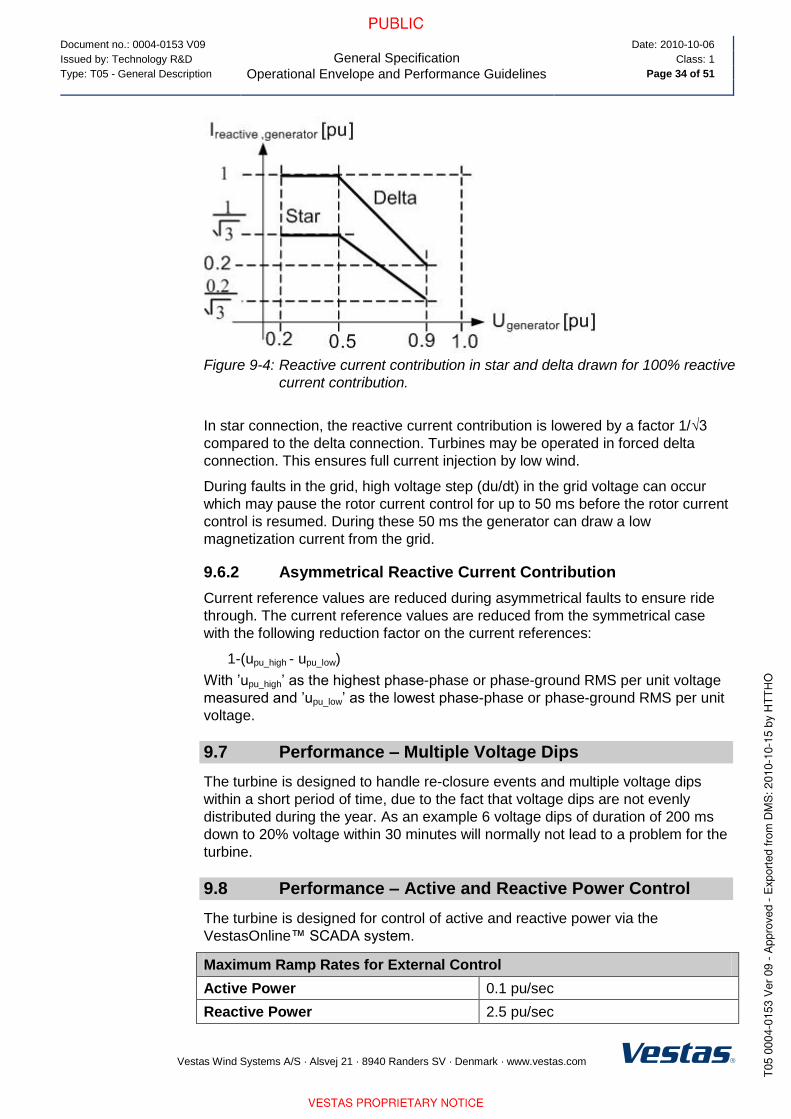
Document no.: 0004-0153 V09
General Specification
Operational Envelope and Performance Guidelines
Date: 2010-10-06
Issued by: Technology R&D Class: 1
Type: T05 - General Description Page 34 of 51
Vestas Wind Systems A/S · Alsvej 21 · 8940 Randers SV · Denmark · www.vestas.com
Figure 9-4: Reactive current contribution in star and delta drawn for 100% reactive
current contribution.
In star connection, the reactive current contribution is lowered by a factor 1/√3
compared to the delta connection. Turbines may be operated in forced delta
connection. This ensures full current injection by low wind.
During faults in the grid, high voltage step (du/dt) in the grid voltage can occur
which may pause the rotor current control for up to 50 ms before the rotor current
control is resumed. During these 50 ms the generator can draw a low
magnetization current from the grid.
9.6.2 Asymmetrical Reactive Current Contribution
Current reference values are reduced during asymmetrical faults to ensure ride
through. The current reference values are reduced from the symmetrical case
with the following reduction factor on the current references:
1-(upu_high - upu_low)
With ’upu_high’ as the highest phase-phase or phase-ground RMS per unit voltage
measured and ’upu_low’ as the lowest phase-phase or phase-ground RMS per unit
voltage.
9.7 Performance – Multiple Voltage Dips
The turbine is designed to handle re-closure events and multiple voltage dips
within a short period of time, due to the fact that voltage dips are not evenly
distributed during the year. As an example 6 voltage dips of duration of 200 ms
down to 20% voltage within 30 minutes will normally not lead to a problem for the
turbine.
9.8 Performance – Active and Reactive Power Control
The turbine is designed for control of active and reactive power via the
VestasOnline™ SCADA system.
Maximum Ramp Rates for External Control
Active Power 0.1 pu/sec
Reactive Power 2.5 pu/sec

Document no.: 0004-0153 V09
General Specification
Operational Envelope and Performance Guidelines
Date: 2010-10-06
Issued by: Technology R&D Class: 1
Type: T05 - General Description Page 35 of 51
Vestas Wind Systems A/S · Alsvej 21 · 8940 Randers SV · Denmark · www.vestas.com
To protect the turbine active power cannot be controlled to values below the
curve in Figure 9-5, p. 35.
0
5
10
15
20
25
30
35
40
45
50
0 5 10 15 20 25 30
Wind speed [m/s]
Pm
in r
ela
tive
to
Pn
om
[%
]
Figure 9-5: Minimum active power output dependant of wind speed.
9.9 Performance – Voltage Control
The turbine is designed for integration with VestasOnline™ voltage control by
utilising the turbine reactive power capability.
9.10 Performance – Frequency Control
The turbine can be configured to perform frequency control by decreasing the
output power as a linear function of the grid frequency (over frequency).
Dead band and slope for the frequency control function are configurable.
9.11 Performance – Own Consumption
The consumption of electrical power by the wind turbine is defined as
consumption when the wind turbine is not producing energy (generator is not
connected to the grid). This is defined in the control system as Production
Generator (zero).

Document no.: 0004-0153 V09
General Specification
Operational Envelope and Performance Guidelines
Date: 2010-10-06
Issued by: Technology R&D Class: 1
Type: T05 - General Description Page 36 of 51
Vestas Wind Systems A/S · Alsvej 21 · 8940 Randers SV · Denmark · www.vestas.com
The following components have the largest influence on the power consumption
of the wind turbine:
Own Consumption
Hydraulic Motor 20 kW
Yaw Motors 6 x 1.75 kW 10.5 kW
Oil Heating 3 x 0.76 kW 2.3 kW
Air Heaters 2 x 6 kW (std)
3 x 6 kW (LT)
12 kW (Standard)
18 kW (Low Temperature)
Oil Pump for Gearbox Lubrication 3.5 kW
HV Transformer located in the
nacelle has a no-load loss of
Maximum 3.9 kW
Table 9-6: Own consumption data.
9.12 Operational Envelope Conditions for Power Curve, Ct Values (at Hub Height)
See appendix section 12.1 Mode 0, p. 40, 12.2 Mode 1, p. 44 and 12.3 Mode 2,
p. 48 for power curve, Ct values and noise level.
Conditions for Power Curve, Ct Values (at Hub Height)
Wind Shear 0.10 - 0.16 (10 min. average)
Turbulence Intensity 8 - 12% (10 min. average)
Blades Clean
Rain No
Ice/Snow on Blades No
Leading Edge No damage
Terrain IEC 61400-12-1
Inflow Angle (Vertical) 0 ± 2 °
Grid Frequency 50 ± 0.5 Hz
Table 9-7: Conditions for power curve, Ct values.

Document no.: 0004-0153 V09
General Specification
Drawings
Date: 2010-10-06
Issued by: Technology R&D Class: 1
Type: T05 - General Description Page 37 of 51
Vestas Wind Systems A/S · Alsvej 21 · 8940 Randers SV · Denmark · www.vestas.com
10 Drawings
10.1 Structural Design – Illustration of Outer Dimensions
Figure 10-1: Illustration of outer dimensions – structure.

Document no.: 0004-0153 V09
General Specification
Drawings
Date: 2010-10-06
Issued by: Technology R&D Class: 1
Type: T05 - General Description Page 38 of 51
Vestas Wind Systems A/S · Alsvej 21 · 8940 Randers SV · Denmark · www.vestas.com
10.2 Structural Design – Side View Drawing
Figure 10-2: Side view drawing.

Document no.: 0004-0153 V09
General Specification
General Reservations, Notes and Disclaimers
Date: 2010-10-06
Issued by: Technology R&D Class: 1
Type: T05 - General Description Page 39 of 51
Vestas Wind Systems A/S · Alsvej 21 · 8940 Randers SV · Denmark · www.vestas.com
11 General Reservations, Notes and Disclaimers
These general specifications apply to the current version of the V100 wind
turbine. Updated versions of the V100 wind turbine, which may be
manufactured in the future, may have general specifications that differ from
these general specifications. In the event that Vestas supplies an updated
version of the V100 wind turbine, Vestas will provide updated general
specifications applicable to the updated version.
Periodic operational disturbances and generator power de-rating may be
caused by combination of high winds, low voltage or high temperature.
Vestas recommends that the grid be as close to nominal as possible with little
variation in frequency.
A certain time allowance for turbine warm-up must be expected following grid
dropout and/or periods of very low ambient temperature.
The estimated power curve for the different estimated noise levels (sound
power levels) is for wind speeds at 10 minute average value at hub height
and perpendicular to the rotor plane.
All listed start/stop parameters (e. g. wind speeds and temperatures) are
equipped with hysteresis control. This can, in certain borderline situations,
result in turbine stops even though the ambient conditions are within the listed
operation parameters.
The earthing system must comply with the minimum requirements from
Vestas, and be in accordance with local and national requirements, and
codes of standards.
Lightning strikes are considered force majeure, i.e. damage caused by
lightning strikes is not warranted by Vestas.
For the avoidance of doubt, this document ‘General Specifications’ is not, and
does not contain, any guarantee, warranty and/or verification of the power
curve and noise (including, without limitation, the power curve and noise
verification method). Any guarantee, warranty and/or verification of the power
curve and noise (including, without limitation, the power curve and noise
verification method) must be agreed to separately in writing.
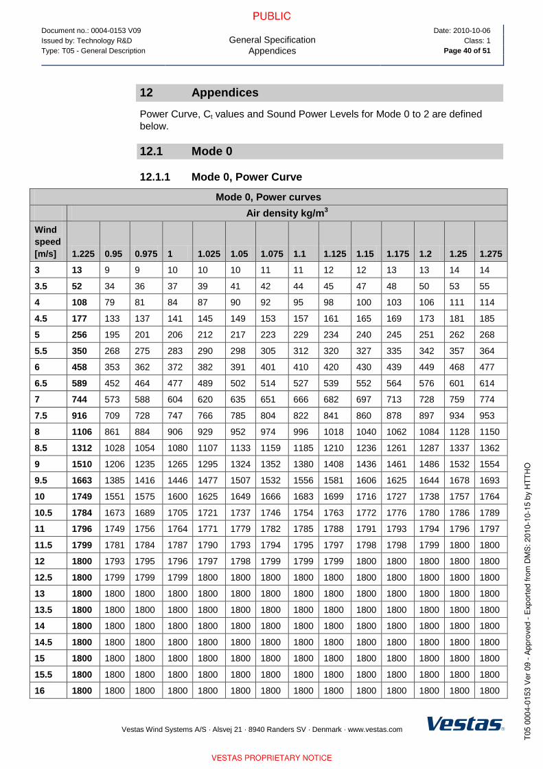
Document no.: 0004-0153 V09
General Specification
Appendices
Date: 2010-10-06
Issued by: Technology R&D Class: 1
Type: T05 - General Description Page 40 of 51
Vestas Wind Systems A/S · Alsvej 21 · 8940 Randers SV · Denmark · www.vestas.com
12 Appendices
Power Curve, Ct values and Sound Power Levels for Mode 0 to 2 are defined
below.
12.1 Mode 0
12.1.1 Mode 0, Power Curve
Mode 0, Power curves
Air density kg/m3
Wind
speed
[m/s] 1.225 0.95 0.975 1 1.025 1.05 1.075 1.1 1.125 1.15 1.175 1.2 1.25 1.275
3 13 9 9 10 10 10 11 11 12 12 13 13 14 14
3.5 52 34 36 37 39 41 42 44 45 47 48 50 53 55
4 108 79 81 84 87 90 92 95 98 100 103 106 111 114
4.5 177 133 137 141 145 149 153 157 161 165 169 173 181 185
5 256 195 201 206 212 217 223 229 234 240 245 251 262 268
5.5 350 268 275 283 290 298 305 312 320 327 335 342 357 364
6 458 353 362 372 382 391 401 410 420 430 439 449 468 477
6.5 589 452 464 477 489 502 514 527 539 552 564 576 601 614
7 744 573 588 604 620 635 651 666 682 697 713 728 759 774
7.5 916 709 728 747 766 785 804 822 841 860 878 897 934 953
8 1106 861 884 906 929 952 974 996 1018 1040 1062 1084 1128 1150
8.5 1312 1028 1054 1080 1107 1133 1159 1185 1210 1236 1261 1287 1337 1362
9 1510 1206 1235 1265 1295 1324 1352 1380 1408 1436 1461 1486 1532 1554
9.5 1663 1385 1416 1446 1477 1507 1532 1556 1581 1606 1625 1644 1678 1693
10 1749 1551 1575 1600 1625 1649 1666 1683 1699 1716 1727 1738 1757 1764
10.5 1784 1673 1689 1705 1721 1737 1746 1754 1763 1772 1776 1780 1786 1789
11 1796 1749 1756 1764 1771 1779 1782 1785 1788 1791 1793 1794 1796 1797
11.5 1799 1781 1784 1787 1790 1793 1794 1795 1797 1798 1798 1799 1800 1800
12 1800 1793 1795 1796 1797 1798 1799 1799 1799 1800 1800 1800 1800 1800
12.5 1800 1799 1799 1799 1800 1800 1800 1800 1800 1800 1800 1800 1800 1800
13 1800 1800 1800 1800 1800 1800 1800 1800 1800 1800 1800 1800 1800 1800
13.5 1800 1800 1800 1800 1800 1800 1800 1800 1800 1800 1800 1800 1800 1800
14 1800 1800 1800 1800 1800 1800 1800 1800 1800 1800 1800 1800 1800 1800
14.5 1800 1800 1800 1800 1800 1800 1800 1800 1800 1800 1800 1800 1800 1800
15 1800 1800 1800 1800 1800 1800 1800 1800 1800 1800 1800 1800 1800 1800
15.5 1800 1800 1800 1800 1800 1800 1800 1800 1800 1800 1800 1800 1800 1800
16 1800 1800 1800 1800 1800 1800 1800 1800 1800 1800 1800 1800 1800 1800

Document no.: 0004-0153 V09
General Specification
Appendices
Date: 2010-10-06
Issued by: Technology R&D Class: 1
Type: T05 - General Description Page 41 of 51
Vestas Wind Systems A/S · Alsvej 21 · 8940 Randers SV · Denmark · www.vestas.com
Mode 0, Power curves
Air density kg/m3
Wind
speed
[m/s] 1.225 0.95 0.975 1 1.025 1.05 1.075 1.1 1.125 1.15 1.175 1.2 1.25 1.275
16.5 1800 1800 1800 1800 1800 1800 1800 1800 1800 1800 1800 1800 1800 1800
17 1800 1800 1800 1800 1800 1800 1800 1800 1800 1800 1800 1800 1800 1800
17.5 1800 1800 1800 1800 1800 1800 1800 1800 1800 1800 1800 1800 1800 1800
18 1800 1800 1800 1800 1800 1800 1800 1800 1800 1800 1800 1800 1800 1800
18.5 1800 1800 1800 1800 1800 1800 1800 1800 1800 1800 1800 1800 1800 1800
19 1800 1800 1800 1800 1800 1800 1800 1800 1800 1800 1800 1800 1800 1800
19.5 1800 1800 1800 1800 1800 1800 1800 1800 1800 1800 1800 1800 1800 1800
20 1800 1800 1800 1800 1800 1800 1800 1800 1800 1800 1800 1800 1800 1800
Table 12-1: Mode 0, power curve.
12.1.2 Mode 0, Ct Values
Mode 0, Ct values
Air density kg/m3
Wind
speed
[m/s] 1.225 0.95 0.975 1 1.025 1.05 1.075 1.1 1.125 1.15 1.175 1.2 1.25 1.275
3 0.868 0.868 0.868 0.868 0.868 0.868 0.868 0.868 0.868 0.868 0.868 0.868 0.868 0.868
3.5 0.890 0.890 0.890 0.890 0.890 0.890 0.890 0.890 0.890 0.890 0.890 0.890 0.890 0.890
4 0.882 0.882 0.882 0.882 0.882 0.882 0.882 0.882 0.882 0.882 0.882 0.882 0.882 0.882
4.5 0.854 0.854 0.854 0.854 0.854 0.854 0.854 0.854 0.854 0.854 0.854 0.854 0.854 0.854
5 0.826 0.826 0.826 0.826 0.826 0.826 0.826 0.826 0.826 0.826 0.826 0.826 0.826 0.826
5.5 0.809 0.809 0.809 0.809 0.809 0.809 0.809 0.809 0.809 0.809 0.809 0.809 0.809 0.809
6 0.803 0.803 0.803 0.803 0.803 0.802 0.803 0.803 0.803 0.803 0.803 0.803 0.803 0.803
6.5 0.819 0.819 0.819 0.819 0.819 0.819 0.819 0.819 0.819 0.819 0.819 0.819 0.819 0.819
7 0.809 0.809 0.809 0.809 0.809 0.809 0.809 0.809 0.809 0.809 0.809 0.809 0.809 0.809
7.5 0.805 0.805 0.805 0.805 0.805 0.805 0.805 0.805 0.805 0.805 0.805 0.805 0.805 0.805
8 0.792 0.800 0.800 0.799 0.799 0.798 0.797 0.797 0.796 0.795 0.794 0.793 0.791 0.790
8.5 0.762 0.783 0.782 0.780 0.778 0.776 0.774 0.773 0.771 0.769 0.766 0.764 0.759 0.757
9 0.707 0.751 0.748 0.745 0.742 0.739 0.735 0.731 0.727 0.723 0.718 0.713 0.701 0.695
9.5 0.629 0.704 0.699 0.694 0.688 0.683 0.676 0.669 0.662 0.654 0.646 0.637 0.620 0.611
10 0.541 0.648 0.639 0.630 0.622 0.613 0.603 0.593 0.583 0.573 0.562 0.551 0.530 0.520
10.5 0.457 0.580 0.569 0.558 0.546 0.535 0.524 0.512 0.501 0.489 0.479 0.468 0.447 0.437
11 0.387 0.509 0.496 0.484 0.471 0.459 0.448 0.437 0.426 0.415 0.406 0.396 0.379 0.370
11.5 0.332 0.439 0.427 0.416 0.404 0.393 0.383 0.374 0.365 0.355 0.347 0.339 0.325 0.318
12 0.287 0.378 0.368 0.359 0.349 0.339 0.331 0.323 0.315 0.307 0.300 0.294 0.281 0.275

Document no.: 0004-0153 V09
General Specification
Appendices
Date: 2010-10-06
Issued by: Technology R&D Class: 1
Type: T05 - General Description Page 42 of 51
Vestas Wind Systems A/S · Alsvej 21 · 8940 Randers SV · Denmark · www.vestas.com
Mode 0, Ct values
Air density kg/m3
Wind
speed
[m/s] 1.225 0.95 0.975 1 1.025 1.05 1.075 1.1 1.125 1.15 1.175 1.2 1.25 1.275
12.5 0.251 0.329 0.321 0.312 0.304 0.295 0.288 0.282 0.275 0.268 0.262 0.257 0.246 0.241
13 0.221 0.288 0.281 0.274 0.266 0.259 0.253 0.247 0.242 0.236 0.231 0.226 0.217 0.213
13.5 0.197 0.255 0.248 0.242 0.236 0.230 0.225 0.220 0.214 0.209 0.205 0.201 0.193 0.189
14 0.176 0.227 0.221 0.216 0.210 0.205 0.200 0.196 0.191 0.187 0.183 0.179 0.172 0.169
14.5 0.158 0.203 0.198 0.193 0.188 0.183 0.180 0.176 0.172 0.168 0.164 0.161 0.155 0.152
15 0.142 0.182 0.178 0.174 0.169 0.165 0.161 0.158 0.155 0.151 0.148 0.145 0.140 0.137
15.5 0.129 0.165 0.161 0.157 0.153 0.149 0.146 0.143 0.140 0.137 0.134 0.132 0.127 0.124
16 0.117 0.150 0.146 0.143 0.139 0.136 0.133 0.130 0.127 0.125 0.122 0.120 0.115 0.113
16.5 0.107 0.136 0.133 0.130 0.127 0.124 0.121 0.119 0.116 0.114 0.112 0.109 0.105 0.103
17 0.098 0.125 0.122 0.119 0.116 0.113 0.111 0.109 0.107 0.104 0.102 0.100 0.097 0.095
17.5 0.091 0.114 0.112 0.109 0.107 0.104 0.102 0.100 0.098 0.096 0.094 0.092 0.089 0.087
18 0.084 0.105 0.103 0.101 0.098 0.096 0.094 0.092 0.090 0.088 0.087 0.085 0.082 0.081
18.5 0.077 0.097 0.095 0.093 0.091 0.089 0.087 0.085 0.083 0.082 0.080 0.079 0.076 0.075
19 0.072 0.090 0.088 0.086 0.084 0.082 0.081 0.079 0.078 0.076 0.075 0.073 0.071 0.069
19.5 0.067 0.084 0.082 0.080 0.078 0.077 0.075 0.074 0.072 0.071 0.069 0.068 0.066 0.065
20 0.062 0.078 0.076 0.075 0.073 0.071 0.070 0.069 0.067 0.066 0.065 0.064 0.061 0.060
Table 12-2: Mode 0, Ct values.

Document no.: 0004-0153 V09
General Specification
Appendices
Date: 2010-10-06
Issued by: Technology R&D Class: 1
Type: T05 - General Description Page 43 of 51
Vestas Wind Systems A/S · Alsvej 21 · 8940 Randers SV · Denmark · www.vestas.com
12.1.3 Mode 0, Sound Power Levels
Sound Power Level at Hub Height, Mode 0
Conditions for Sound Power Level Verification standard: IEC 61400-11 Ed. 2.
Wind shear 0.15.
Max turbulence at 10 meter height: 16%
Inflow angle (vertical): 0 2°
Air density: 1.225 kg/m3
Hub Height 80 m 95 m
LwA @ 3 m/s (10 m above ground) [dBA]
Wind speed at hh [m/sec]
94.0
4.2
94.1
4.3
LwA @ 4 m/s (10 m above ground) [dBA]
Wind speed at hh [m/sec]
96.2
5.6
96.6
5.7
LwA @ 5 m/s (10 m above ground) [dBA]
Wind speed at hh [m/sec]
100.1
7.0
100.7
7.2
LwA @ 6 m/s (10 m above ground) [dBA]
Wind speed at hh [m/sec]
103.9
8.4
104.4
8.6
LwA @ 7 m/s (10 m above ground) [dBA]
Wind speed at hh [m/sec]
105.0
9.8
105.0
10.0
LwA @ 8 m/s (10 m above ground) [dBA]
Wind speed at hh [m/sec]
105.0
11.2
105.0
11.5
LwA @ 9 m/s (10 m above ground) [dBA]
Wind speed at hh [m/sec]
105.0
12.6
105.0
12.9
LwA @ 10 m/s (10 m above ground) [dBA]
Wind speed at hh [m/sec]
105.0
13.9
105.0
14.3
LwA @ 11 m/s (10 m above ground) [dBA]
Wind speed at hh [m/sec]
105.0
15.3
105.0
15.8
LwA @ 12 m/s (10 m above ground) [dBA]
Wind speed at hh [m/sec]
105.0
16.7
105.0
17.2
LwA @ 13 m/s (10 m above ground) [dBA]
Wind speed at hh [m/sec]
105.0
18.1
105.0
18.6
Table 12-3: Sound power level at hub height: Mode 0.
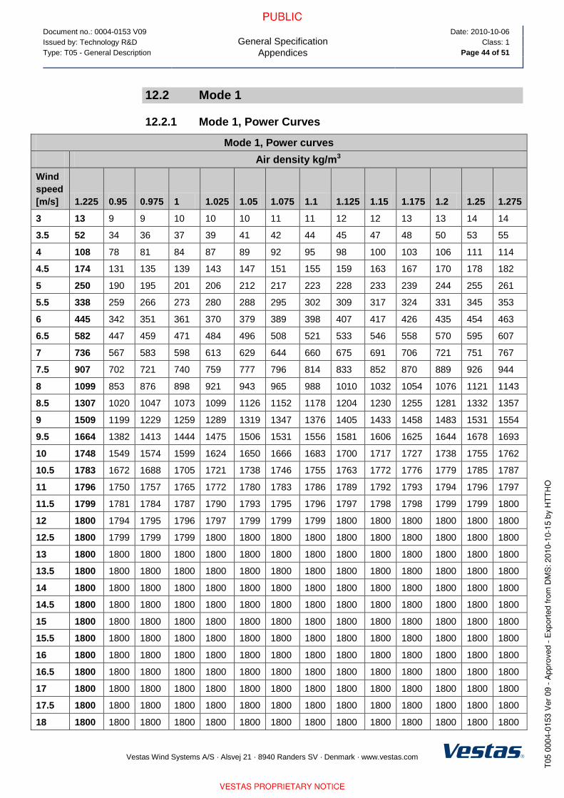
Document no.: 0004-0153 V09
General Specification
Appendices
Date: 2010-10-06
Issued by: Technology R&D Class: 1
Type: T05 - General Description Page 44 of 51
Vestas Wind Systems A/S · Alsvej 21 · 8940 Randers SV · Denmark · www.vestas.com
12.2 Mode 1
12.2.1 Mode 1, Power Curves
Mode 1, Power curves
Air density kg/m3
Wind
speed
[m/s] 1.225 0.95 0.975 1 1.025 1.05 1.075 1.1 1.125 1.15 1.175 1.2 1.25 1.275
3 13 9 9 10 10 10 11 11 12 12 13 13 14 14
3.5 52 34 36 37 39 41 42 44 45 47 48 50 53 55
4 108 78 81 84 87 89 92 95 98 100 103 106 111 114
4.5 174 131 135 139 143 147 151 155 159 163 167 170 178 182
5 250 190 195 201 206 212 217 223 228 233 239 244 255 261
5.5 338 259 266 273 280 288 295 302 309 317 324 331 345 353
6 445 342 351 361 370 379 389 398 407 417 426 435 454 463
6.5 582 447 459 471 484 496 508 521 533 546 558 570 595 607
7 736 567 583 598 613 629 644 660 675 691 706 721 751 767
7.5 907 702 721 740 759 777 796 814 833 852 870 889 926 944
8 1099 853 876 898 921 943 965 988 1010 1032 1054 1076 1121 1143
8.5 1307 1020 1047 1073 1099 1126 1152 1178 1204 1230 1255 1281 1332 1357
9 1509 1199 1229 1259 1289 1319 1347 1376 1405 1433 1458 1483 1531 1554
9.5 1664 1382 1413 1444 1475 1506 1531 1556 1581 1606 1625 1644 1678 1693
10 1748 1549 1574 1599 1624 1650 1666 1683 1700 1717 1727 1738 1755 1762
10.5 1783 1672 1688 1705 1721 1738 1746 1755 1763 1772 1776 1779 1785 1787
11 1796 1750 1757 1765 1772 1780 1783 1786 1789 1792 1793 1794 1796 1797
11.5 1799 1781 1784 1787 1790 1793 1795 1796 1797 1798 1798 1799 1799 1800
12 1800 1794 1795 1796 1797 1799 1799 1799 1800 1800 1800 1800 1800 1800
12.5 1800 1799 1799 1799 1800 1800 1800 1800 1800 1800 1800 1800 1800 1800
13 1800 1800 1800 1800 1800 1800 1800 1800 1800 1800 1800 1800 1800 1800
13.5 1800 1800 1800 1800 1800 1800 1800 1800 1800 1800 1800 1800 1800 1800
14 1800 1800 1800 1800 1800 1800 1800 1800 1800 1800 1800 1800 1800 1800
14.5 1800 1800 1800 1800 1800 1800 1800 1800 1800 1800 1800 1800 1800 1800
15 1800 1800 1800 1800 1800 1800 1800 1800 1800 1800 1800 1800 1800 1800
15.5 1800 1800 1800 1800 1800 1800 1800 1800 1800 1800 1800 1800 1800 1800
16 1800 1800 1800 1800 1800 1800 1800 1800 1800 1800 1800 1800 1800 1800
16.5 1800 1800 1800 1800 1800 1800 1800 1800 1800 1800 1800 1800 1800 1800
17 1800 1800 1800 1800 1800 1800 1800 1800 1800 1800 1800 1800 1800 1800
17.5 1800 1800 1800 1800 1800 1800 1800 1800 1800 1800 1800 1800 1800 1800
18 1800 1800 1800 1800 1800 1800 1800 1800 1800 1800 1800 1800 1800 1800

Document no.: 0004-0153 V09
General Specification
Appendices
Date: 2010-10-06
Issued by: Technology R&D Class: 1
Type: T05 - General Description Page 45 of 51
Vestas Wind Systems A/S · Alsvej 21 · 8940 Randers SV · Denmark · www.vestas.com
Mode 1, Power curves
Air density kg/m3
Wind
speed
[m/s] 1.225 0.95 0.975 1 1.025 1.05 1.075 1.1 1.125 1.15 1.175 1.2 1.25 1.275
18.5 1800 1800 1800 1800 1800 1800 1800 1800 1800 1800 1800 1800 1800 1800
19 1800 1800 1800 1800 1800 1800 1800 1800 1800 1800 1800 1800 1800 1800
19.5 1800 1800 1800 1800 1800 1800 1800 1800 1800 1800 1800 1800 1800 1800
20 1800 1800 1800 1800 1800 1800 1800 1800 1800 1800 1800 1800 1800 1800
Table 12-4: Mode 1, power curve.
12.2.2 Mode 1, Ct Values
Mode 1, Ct values
Air density kg/m3
Wind
speed
[m/s] 1.225 0.95 0.975 1 1.025 1.05 1.075 1.1 1.125 1.15 1.175 1.2 1.25 1.275
3 0.868 0.868 0.868 0.868 0.869 0.869 0.869 0.869 0.868 0.868 0.868 0.868 0.868 0.868
3.5 0.883 0.883 0.883 0.883 0.883 0.883 0.883 0.883 0.883 0.883 0.883 0.883 0.883 0.883
4 0.847 0.847 0.847 0.847 0.847 0.847 0.847 0.847 0.847 0.847 0.847 0.847 0.847 0.847
4.5 0.792 0.792 0.792 0.792 0.792 0.792 0.792 0.792 0.792 0.792 0.792 0.792 0.792 0.792
5 0.744 0.744 0.744 0.744 0.744 0.744 0.744 0.744 0.744 0.744 0.744 0.744 0.744 0.744
5.5 0.717 0.717 0.717 0.717 0.717 0.717 0.717 0.717 0.717 0.717 0.717 0.717 0.717 0.717
6 0.713 0.713 0.713 0.713 0.713 0.713 0.713 0.713 0.713 0.713 0.713 0.713 0.713 0.713
6.5 0.763 0.763 0.763 0.763 0.763 0.763 0.763 0.763 0.763 0.763 0.763 0.763 0.763 0.763
7 0.757 0.757 0.757 0.757 0.757 0.757 0.757 0.757 0.757 0.756 0.757 0.757 0.757 0.757
7.5 0.753 0.753 0.753 0.753 0.753 0.753 0.753 0.753 0.753 0.753 0.753 0.753 0.753 0.753
8 0.749 0.749 0.749 0.749 0.749 0.749 0.749 0.749 0.749 0.749 0.749 0.749 0.749 0.749
8.5 0.733 0.743 0.743 0.742 0.741 0.740 0.739 0.738 0.737 0.736 0.735 0.734 0.731 0.730
9 0.694 0.725 0.723 0.721 0.719 0.717 0.715 0.712 0.710 0.707 0.703 0.698 0.689 0.683
9.5 0.625 0.693 0.689 0.684 0.680 0.676 0.669 0.663 0.656 0.650 0.641 0.633 0.616 0.606
10 0.539 0.644 0.636 0.627 0.619 0.611 0.601 0.591 0.581 0.571 0.560 0.549 0.528 0.517
10.5 0.456 0.579 0.568 0.557 0.546 0.535 0.523 0.512 0.500 0.489 0.478 0.467 0.446 0.436
11 0.387 0.509 0.497 0.484 0.472 0.459 0.448 0.437 0.426 0.415 0.406 0.396 0.378 0.370
11.5 0.331 0.439 0.427 0.416 0.404 0.393 0.383 0.374 0.365 0.355 0.347 0.339 0.324 0.317
12 0.287 0.378 0.369 0.359 0.349 0.339 0.331 0.323 0.315 0.307 0.300 0.294 0.281 0.275
12.5 0.251 0.329 0.321 0.312 0.304 0.295 0.288 0.282 0.275 0.268 0.262 0.257 0.246 0.241
13 0.221 0.288 0.281 0.274 0.266 0.259 0.253 0.247 0.242 0.236 0.231 0.226 0.217 0.213
13.5 0.197 0.255 0.248 0.242 0.236 0.230 0.225 0.220 0.214 0.209 0.205 0.201 0.193 0.189
14 0.176 0.227 0.221 0.216 0.210 0.205 0.200 0.196 0.191 0.187 0.183 0.179 0.172 0.169

Document no.: 0004-0153 V09
General Specification
Appendices
Date: 2010-10-06
Issued by: Technology R&D Class: 1
Type: T05 - General Description Page 46 of 51
Vestas Wind Systems A/S · Alsvej 21 · 8940 Randers SV · Denmark · www.vestas.com
Mode 1, Ct values
Air density kg/m3
Wind
speed
[m/s] 1.225 0.95 0.975 1 1.025 1.05 1.075 1.1 1.125 1.15 1.175 1.2 1.25 1.275
14.5 0.158 0.203 0.198 0.193 0.188 0.183 0.180 0.176 0.172 0.168 0.164 0.161 0.155 0.152
15 0.142 0.182 0.178 0.174 0.169 0.165 0.161 0.158 0.155 0.151 0.148 0.145 0.140 0.137
15.5 0.129 0.165 0.161 0.157 0.153 0.149 0.146 0.143 0.140 0.137 0.134 0.132 0.127 0.124
16 0.117 0.150 0.146 0.143 0.139 0.136 0.133 0.130 0.127 0.125 0.122 0.120 0.115 0.113
16.5 0.107 0.136 0.133 0.130 0.127 0.124 0.121 0.119 0.116 0.114 0.112 0.109 0.105 0.103
17 0.098 0.125 0.122 0.119 0.116 0.113 0.111 0.109 0.107 0.104 0.102 0.100 0.097 0.095
17.5 0.091 0.114 0.112 0.109 0.107 0.104 0.102 0.100 0.098 0.096 0.094 0.092 0.089 0.087
18 0.084 0.105 0.103 0.101 0.098 0.096 0.094 0.092 0.090 0.088 0.087 0.085 0.082 0.081
18.5 0.077 0.097 0.095 0.093 0.091 0.089 0.087 0.085 0.083 0.082 0.080 0.079 0.076 0.075
19 0.072 0.090 0.088 0.086 0.084 0.082 0.081 0.079 0.078 0.076 0.075 0.073 0.071 0.069
19.5 0.067 0.084 0.082 0.080 0.078 0.077 0.075 0.074 0.072 0.071 0.069 0.068 0.066 0.065
20 0.062 0.078 0.076 0.075 0.073 0.071 0.070 0.069 0.067 0.066 0.065 0.064 0.061 0.060
Table 12-5: Mode 1, Ct values.

Document no.: 0004-0153 V09
General Specification
Appendices
Date: 2010-10-06
Issued by: Technology R&D Class: 1
Type: T05 - General Description Page 47 of 51
Vestas Wind Systems A/S · Alsvej 21 · 8940 Randers SV · Denmark · www.vestas.com
12.2.3 Mode 1, Sound Power Levels
Sound Power Level at Hub Height, Mode 1
Conditions for Sound Power Level Verification standard: IEC 61400-11 Ed. 2.
Wind shear 0.15
Max turbulence at 10 meter height: 16%
Inflow angle (vertical): 0 2°
Air density: 1.225 kg/m3
Hub Height 80 m 95 m
LwA @ 3 m/s (10 m above ground) [dBA]
Wind speed at hh [m/sec]
94.0
4.2
94.0
4.3
LwA @ 4 m/s (10 m above ground) [dBA]
Wind speed at hh [m/sec]
95.4
5.6
95.6
5.7
LwA @ 5 m/s (10 m above ground) [dBA]
Wind speed at hh [m/sec]
99.1
7.0
99.7
7.2
LwA @ 6 m/s (10 m above ground) [dBA]
Wind speed at hh [m/sec]
102.9
8.4
103.4
8.6
LwA @ 7 m/s (10 m above ground) [dBA]
Wind speed at hh [m/sec]
105.0
9.8
105.0
10.0
LwA @ 8 m/s (10 m above ground) [dBA]
Wind speed at hh [m/sec]
105.0
11.2
105.0
11.5
LwA @ 9 m/s (10 m above ground) [dBA]
Wind speed at hh [m/sec]
105.0
12.6
105.0
12.9
LwA @ 10 m/s (10 m above ground) [dBA]
Wind speed at hh [m/sec]
105.0
13.9
105.0
14.3
LwA @ 11 m/s (10 m above ground) [dBA]
Wind speed at hh [m/sec]
105.0
15.3
105.0
15.8
LwA @ 12 m/s (10 m above ground) [dBA]
Wind speed at hh [m/sec]
105.0
16.7
105.0
17.2
LwA @ 13 m/s (10 m above ground) [dBA]
Wind speed at hh [m/sec]
105.0
18.1
105.0
18.6
Table 12-6: Sound power level at hub height: Mode 1.

Document no.: 0004-0153 V09
General Specification
Appendices
Date: 2010-10-06
Issued by: Technology R&D Class: 1
Type: T05 - General Description Page 48 of 51
Vestas Wind Systems A/S · Alsvej 21 · 8940 Randers SV · Denmark · www.vestas.com
12.3 Mode 2
12.3.1 Mode 2, Power Curves
Mode 2, Power curves
Air density kg/m3
Wind
speed
[m/s] 1.225 0.95 0.975 1 1.025 1.05 1.075 1.1 1.125 1.15 1.175 1.2 1.25 1.275
3 13 9 9 10 10 10 11 11 12 12 13 13 14 14
3.5 52 34 36 37 39 41 42 44 45 47 48 50 53 55
4 108 79 81 84 87 90 92 95 98 100 103 106 111 114
4.5 177 133 137 141 145 149 153 157 161 165 169 173 181 185
5 256 195 201 206 212 217 223 229 234 240 245 251 262 268
5.5 349 268 275 282 290 297 305 312 320 327 335 342 357 364
6 458 352 362 372 381 391 401 410 420 429 439 448 467 477
6.5 589 452 464 477 489 502 514 527 539 552 564 576 601 614
7 743 572 588 604 619 635 650 666 681 697 712 728 758 774
7.5 913 706 725 744 763 782 801 820 838 857 875 894 931 950
8 1091 848 870 892 914 937 959 981 1002 1024 1047 1069 1113 1135
8.5 1268 985 1011 1037 1062 1088 1114 1140 1165 1191 1217 1243 1294 1320
9 1428 1109 1138 1167 1196 1225 1255 1284 1313 1342 1371 1399 1455 1483
9.5 1549 1209 1240 1272 1304 1336 1367 1399 1430 1461 1490 1519 1574 1599
10 1629 1285 1319 1353 1387 1421 1453 1484 1516 1548 1575 1602 1650 1672
10.5 1686 1346 1381 1416 1451 1486 1517 1548 1580 1611 1636 1661 1704 1722
11 1732 1411 1446 1481 1517 1552 1582 1611 1641 1671 1691 1712 1744 1757
11.5 1763 1484 1519 1553 1588 1622 1648 1673 1698 1723 1736 1750 1771 1778
12 1783 1572 1603 1633 1663 1693 1710 1727 1743 1760 1767 1775 1786 1789
12.5 1792 1659 1680 1702 1723 1744 1753 1763 1772 1782 1785 1789 1794 1795
13 1796 1725 1737 1749 1761 1774 1778 1783 1787 1792 1793 1795 1797 1798
13.5 1800 1757 1765 1773 1780 1788 1791 1793 1796 1798 1799 1799 1800 1800
14 1800 1784 1787 1791 1794 1798 1798 1799 1799 1800 1800 1800 1800 1800
14.5 1800 1797 1798 1798 1799 1800 1800 1800 1800 1800 1800 1800 1800 1800
15 1800 1797 1798 1798 1799 1799 1800 1800 1800 1800 1800 1800 1800 1800
15.5 1800 1799 1799 1799 1800 1800 1800 1800 1800 1800 1800 1800 1800 1800
16 1800 1800 1800 1800 1800 1800 1800 1800 1800 1800 1800 1800 1800 1800
16.5 1800 1800 1800 1800 1800 1800 1800 1800 1800 1800 1800 1800 1800 1800
17 1800 1800 1800 1800 1800 1800 1800 1800 1800 1800 1800 1800 1800 1800
17.5 1800 1800 1800 1800 1800 1800 1800 1800 1800 1800 1800 1800 1800 1800
18 1800 1800 1800 1800 1800 1800 1800 1800 1800 1800 1800 1800 1800 1800

Document no.: 0004-0153 V09
General Specification
Appendices
Date: 2010-10-06
Issued by: Technology R&D Class: 1
Type: T05 - General Description Page 49 of 51
Vestas Wind Systems A/S · Alsvej 21 · 8940 Randers SV · Denmark · www.vestas.com
Mode 2, Power curves
Air density kg/m3
Wind
speed
[m/s] 1.225 0.95 0.975 1 1.025 1.05 1.075 1.1 1.125 1.15 1.175 1.2 1.25 1.275
18.5 1800 1800 1800 1800 1800 1800 1800 1800 1800 1800 1800 1800 1800 1800
19 1800 1800 1800 1800 1800 1800 1800 1800 1800 1800 1800 1800 1800 1800
19.5 1800 1800 1800 1800 1800 1800 1800 1800 1800 1800 1800 1800 1800 1800
20 1800 1800 1800 1800 1800 1800 1800 1800 1800 1800 1800 1800 1800 1800
Table 12-7: Mode 2, power curve.
12.3.2 Mode 2, Ct Values
Mode 2, Ct values
Air density kg/m3
Wind
speed
[m/s] 1.225 0.95 0.975 1 1.025 1.05 1.075 1.1 1.125 1.15 1.175 1.2 1.25 1.275
3 0.868 0.868 0.868 0.868 0.868 0.868 0.868 0.868 0.868 0.868 0.868 0.868 0.868 0.868
3.5 0.890 0.890 0.890 0.890 0.890 0.890 0.890 0.890 0.890 0.890 0.890 0.890 0.890 0.890
4 0.882 0.882 0.882 0.882 0.882 0.882 0.882 0.882 0.882 0.882 0.882 0.882 0.882 0.882
4.5 0.854 0.854 0.854 0.854 0.854 0.854 0.854 0.854 0.854 0.854 0.854 0.854 0.854 0.854
5 0.825 0.825 0.825 0.825 0.825 0.825 0.825 0.825 0.825 0.825 0.825 0.825 0.825 0.825
5.5 0.805 0.805 0.805 0.805 0.805 0.805 0.805 0.805 0.805 0.805 0.805 0.805 0.805 0.805
6 0.799 0.799 0.799 0.799 0.799 0.799 0.799 0.799 0.799 0.799 0.799 0.799 0.799 0.799
6.5 0.817 0.817 0.817 0.817 0.817 0.817 0.817 0.817 0.817 0.817 0.817 0.817 0.817 0.817
7 0.804 0.804 0.804 0.804 0.804 0.804 0.804 0.804 0.804 0.804 0.804 0.804 0.804 0.804
7.5 0.785 0.785 0.785 0.785 0.785 0.785 0.785 0.785 0.785 0.785 0.785 0.785 0.785 0.785
8 0.749 0.749 0.749 0.749 0.749 0.748 0.748 0.749 0.749 0.749 0.749 0.749 0.749 0.749
8.5 0.696 0.696 0.696 0.696 0.696 0.696 0.696 0.696 0.696 0.696 0.696 0.696 0.696 0.696
9 0.632 0.632 0.632 0.632 0.632 0.632 0.632 0.632 0.633 0.633 0.632 0.632 0.631 0.630
9.5 0.558 0.563 0.563 0.563 0.563 0.563 0.563 0.562 0.562 0.562 0.561 0.560 0.556 0.553
10 0.486 0.496 0.496 0.496 0.496 0.496 0.496 0.495 0.494 0.493 0.491 0.488 0.482 0.478
10.5 0.421 0.437 0.436 0.436 0.436 0.436 0.434 0.433 0.432 0.430 0.427 0.424 0.417 0.412
11 0.367 0.388 0.387 0.387 0.386 0.386 0.384 0.382 0.380 0.378 0.375 0.371 0.362 0.357
11.5 0.322 0.350 0.349 0.348 0.347 0.346 0.343 0.341 0.338 0.335 0.331 0.326 0.317 0.311
12 0.283 0.322 0.320 0.318 0.316 0.314 0.310 0.306 0.302 0.298 0.293 0.288 0.278 0.272
12.5 0.249 0.297 0.294 0.290 0.287 0.283 0.278 0.274 0.269 0.264 0.259 0.254 0.244 0.240
13 0.221 0.273 0.268 0.263 0.259 0.254 0.249 0.244 0.239 0.234 0.230 0.225 0.216 0.212
13.5 0.197 0.247 0.242 0.237 0.233 0.228 0.223 0.218 0.214 0.209 0.205 0.201 0.193 0.189
14 0.176 0.224 0.219 0.214 0.209 0.204 0.200 0.196 0.191 0.187 0.183 0.179 0.172 0.169

Document no.: 0004-0153 V09
General Specification
Appendices
Date: 2010-10-06
Issued by: Technology R&D Class: 1
Type: T05 - General Description Page 50 of 51
Vestas Wind Systems A/S · Alsvej 21 · 8940 Randers SV · Denmark · www.vestas.com
Mode 2, Ct values
Air density kg/m3
Wind
speed
[m/s] 1.225 0.95 0.975 1 1.025 1.05 1.075 1.1 1.125 1.15 1.175 1.2 1.25 1.275
14.5 0.158 0.202 0.198 0.193 0.188 0.183 0.180 0.176 0.172 0.168 0.164 0.161 0.155 0.152
15 0.142 0.182 0.177 0.173 0.169 0.165 0.161 0.158 0.155 0.151 0.148 0.145 0.140 0.137
15.5 0.129 0.164 0.161 0.157 0.153 0.149 0.146 0.143 0.140 0.137 0.134 0.132 0.127 0.124
16 0.117 0.149 0.146 0.143 0.139 0.136 0.133 0.130 0.127 0.125 0.122 0.120 0.115 0.113
16.5 0.107 0.136 0.133 0.130 0.127 0.124 0.121 0.119 0.116 0.114 0.112 0.109 0.105 0.103
17 0.098 0.125 0.122 0.119 0.116 0.113 0.111 0.109 0.107 0.104 0.102 0.100 0.097 0.095
17.5 0.091 0.114 0.112 0.109 0.107 0.104 0.102 0.100 0.098 0.096 0.094 0.092 0.089 0.087
18 0.084 0.105 0.103 0.101 0.098 0.096 0.094 0.092 0.090 0.088 0.087 0.085 0.082 0.081
18.5 0.077 0.097 0.095 0.093 0.091 0.089 0.087 0.085 0.083 0.082 0.080 0.079 0.076 0.075
19 0.072 0.090 0.088 0.086 0.084 0.082 0.081 0.079 0.078 0.076 0.075 0.073 0.071 0.069
19.5 0.067 0.084 0.082 0.080 0.078 0.077 0.075 0.074 0.072 0.071 0.069 0.068 0.066 0.065
20 0.062 0.078 0.076 0.075 0.073 0.071 0.070 0.069 0.067 0.066 0.065 0.064 0.061 0.060
Table 12-8: Mode 2, Ct values.

Document no.: 0004-0153 V09
General Specification
Appendices
Date: 2010-10-06
Issued by: Technology R&D Class: 1
Type: T05 - General Description Page 51 of 51
Vestas Wind Systems A/S · Alsvej 21 · 8940 Randers SV · Denmark · www.vestas.com
12.3.3 Mode 2, Sound Power Levels
Sound Power Level at Hub Height, Mode 2
Conditions for Sound Power Level Verification standard: IEC 61400-11 Ed. 2.
Wind shear 0.15
Max turbulence at 10 meter height: 16%
Inflow angle (vertical): 0 2°
Air density: 1.225 kg/m3
Hub Height 80 m 95 m
LwA @ 3 m/s (10 m above ground) [dBA]
Wind speed at hh [m/sec]
94.0
4.2
94.1
4.3
LwA @ 4 m/s (10 m above ground) [dBA]
Wind speed at hh [m/sec]
96.2
5.6
96.6
5.7
LwA @ 5 m/s (10 m above ground) [dBA]
Wind speed at hh [m/sec]
100.1
7.0
100.7
7.2
LwA @ 6 m/s (10 m above ground) [dBA]
Wind speed at hh [m/sec]
103.0
8.4
103.0
8.6
LwA @ 7 m/s (10 m above ground) [dBA]
Wind speed at hh [m/sec]
103.0
9.8
103.0
10.0
LwA @ 8 m/s (10 m above ground) [dBA]
Wind speed at hh [m/sec]
103.0
11.2
103.0
11.5
LwA @ 9 m/s (10 m above ground) [dBA]
Wind speed at hh [m/sec]
103.0
12.6
103.0
12.9
LwA @ 10 m/s (10 m above ground) [dBA]
Wind speed at hh [m/sec]
103.0
13.9
103.0
14.3
LwA @ 11 m/s (10 m above ground) [dBA]
Wind speed at hh [m/sec]
103.0
15.3
103.0
15.8
LwA @ 12 m/s (10 m above ground) [dBA]
Wind speed at hh [m/sec]
103.0
16.7
103.0
17.2
LwA @ 13 m/s (10 m above ground) [dBA]
Wind speed at hh [m/sec]
103.0
18.1
103.0
18.6
Table 12-9: Sound power level at hub height: Mode 2.

APPENDIX C
PREDICTED NOISE LEVEL CONTOURS

Herring Storer Acoustics Page 1 of 6 Our ref: 13231-4-10226-02 Appendix C

Herring Storer Acoustics Page 2 of 6 Our ref: 13231-4-10226-02 Appendix C
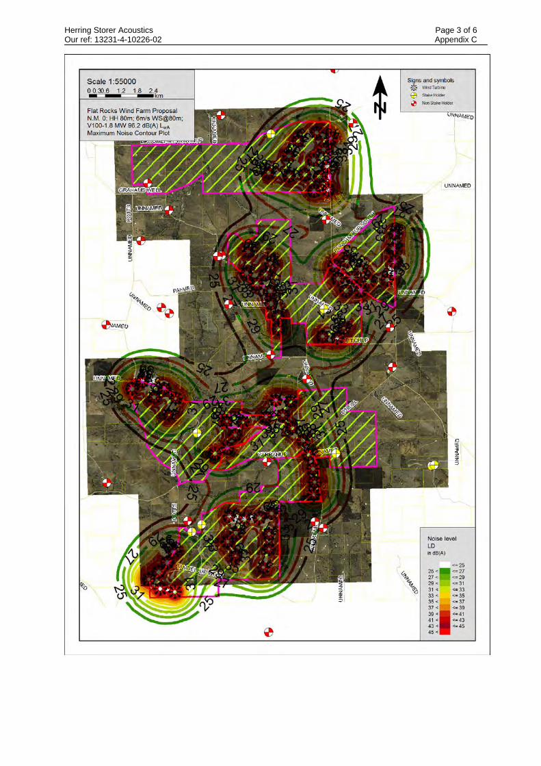
Herring Storer Acoustics Page 3 of 6 Our ref: 13231-4-10226-02 Appendix C

Herring Storer Acoustics Page 4 of 6 Our ref: 13231-4-10226-02 Appendix C

Herring Storer Acoustics Page 5 of 6 Our ref: 13231-4-10226-02 Appendix C

Herring Storer Acoustics Page 6 of 6 Our ref: 13231-4-10226-02 Appendix C

APPENDIX D
BACKGROUND MONITORING LOCATIONS

Herring Storer Acoustics Page 1 of 1 Our ref: 13231-4-10226-02 Appendix D
Related Documents