Moon Fuzz Kit Building Manual

Welcome message from author
This document is posted to help you gain knowledge. Please leave a comment to let me know what you think about it! Share it to your friends and learn new things together.
Transcript
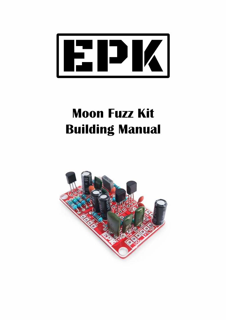
Moon Fuzz Kit Building Manual

Effect Pedal Kits: Moon Fuzz
A silicon fuzz with a dark and brooding character, the Moon Fuzz is designed around the fuzz tones you can hear on Pink Floyd's Dark Side of the Moon from 1973. But the Moon Fuzz is a versatile pedal that goes way beyond that: at low settings it works great as an overdrive pedal, something atypical with fuzz pedals, and at maximum settings it delivers some thick and sick fuzz tones. The Moon Fuzz reacts greatly to your playing dynamics, and thanks to its voicing cuts perfectly through any mix.
Oppositely to many fuzz pedals the Moon Fuzz can be placed almost anywhere in your effect pedal chain with almost no change in the sound thanks to its internal configuration. Additionally, it's very consistent and doesn't "get out of control" to a point where it's almost unplayable other fuzzes do. It has five knobs that will allow you to shape the sound to your desire:
- Volume, to set the amount of output of the pedal
- Pre adjusts the gain of the input transistor (noisier and more agrgessive all the way up, and quieter as you dial it back)
- Sharp sets the amount of bass that will go to the fuzz section. This translates in a sound going from a tight and thin to a full-voiced and thick.
- Gain lets you dial the fuzz from a gritty and touch sensitive overdrive to a fully saturated and aggressive fuzz.
- Filter sets the amount of brightness of the Moon Fuzz
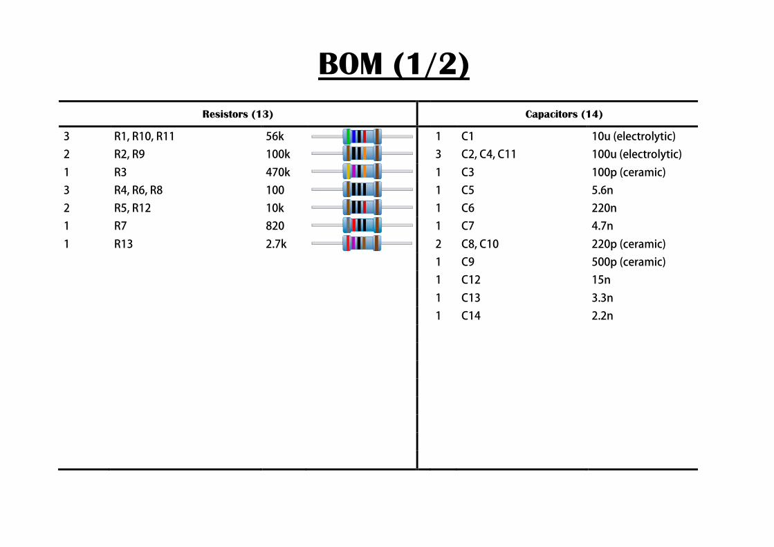
BOM (1/2) Resistors (13) Capacitors (14)
3 R1, R10, R11 56k 1 C1 10u (electrolytic)
2 R2, R9 100k 3 C2, C4, C11 100u (electrolytic)
1 R3 470k 1 C3 100p (ceramic)
3 R4, R6, R8 100 1 C5 5.6n
2 R5, R12 10k 1 C6 220n
1 R7 820 1 C7 4.7n
1 R13 2.7k 2 C8, C10 220p (ceramic)
1 C9 500p (ceramic)
1 C12 15n
1 C13 3.3n
1 C14 2.2n
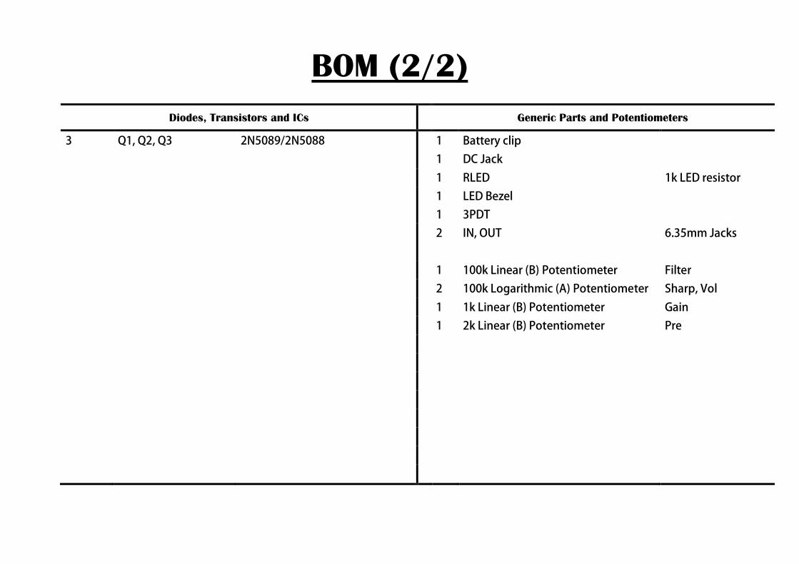
BOM (2/2) Diodes, Transistors and ICs Generic Parts and Potentiometers
3 Q1, Q2, Q3 2N5089/2N5088 1 Battery clip
1 DC Jack
1 RLED 1k LED resistor
1 LED Bezel
1 3PDT
2 IN, OUT 6.35mm Jacks
1 100k Linear (B) Potentiometer Filter
2 100k Logarithmic (A) Potentiometer Sharp, Vol
1 1k Linear (B) Potentiometer Gain
1 2k Linear (B) Potentiometer Pre

Component Placement
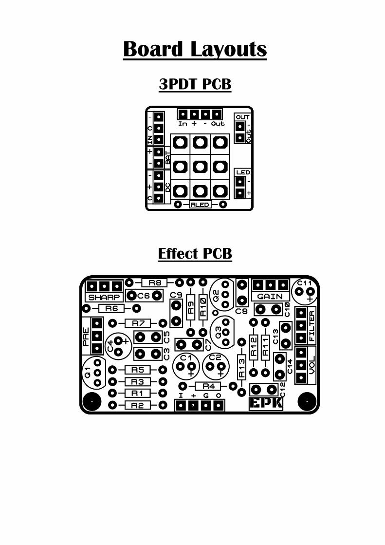
Board Layouts
3PDT PCB
Effect PCB
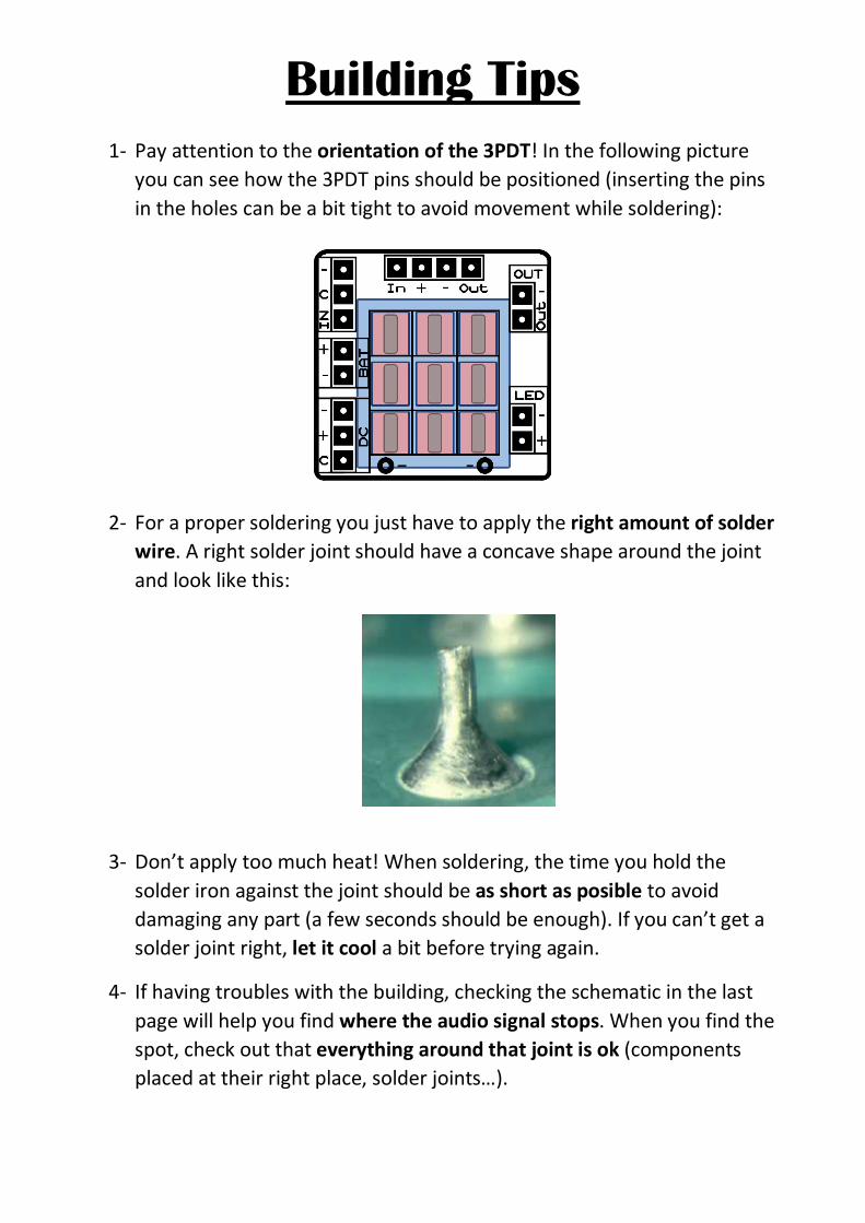
Building Tips 1- Pay attention to the orientation of the 3PDT! In the following picture
you can see how the 3PDT pins should be positioned (inserting the pins in the holes can be a bit tight to avoid movement while soldering):
2- For a proper soldering you just have to apply the right amount of solder wire. A right solder joint should have a concave shape around the joint and look like this:
3- Don’t apply too much heat! When soldering, the time you hold the solder iron against the joint should be as short as posible to avoid damaging any part (a few seconds should be enough). If you can’t get a solder joint right, let it cool a bit before trying again.
4- If having troubles with the building, checking the schematic in the last page will help you find where the audio signal stops. When you find the spot, check out that everything around that joint is ok (components placed at their right place, solder joints…).

Building Tips 5- Pay attention to the parts that have a polarity and make sure they are
connected as in the component placement picture:
- ICs (they have a small dot or indication that must fit the indication in the board
- Electrolytic capacitors (longer pin is connected to the “+” hole):
- Diodes (check for the mark and make it fit with the one in the PCB):
- Leds (longer pin is connected to the “+” hole)
- Transistors (inserted to fit the drawing in the PCB)

Building Tips 6- With the kit we include plastic PCB supports with an adhesive bottom. You
can use them to anchor the PCB to your enclosure for a better stability. Just insert the PCB support tip into the 3.5mm holes and remove the adhesive protective film.
To avoid any issue always check the latest building manual. Use the pictures only as a reference! Colors/shapes of wires, PCB or parts can change slightly,
this doesn’t affect their functionality in any way.
Always double check part polarity, resistor and capacitor values, potentiometer placement, IC orientation… before soldering.

Schematic
Related Documents