
Welcome message from author
This document is posted to help you gain knowledge. Please leave a comment to let me know what you think about it! Share it to your friends and learn new things together.
Transcript

Copyright Notice©2013, Moog Inc., Animatics.
Moog Animatics Class 5 SmartMotor™ CANopen Guide, Rev. A, PN:SC80100001-001.
This manual, as well as the software described in it, is furnished under license and may beused or copied only in accordance with the terms of such license. The content of this manual isfurnished for informational use only, is subject to change without notice and should not be con-strued as a commitment by Moog Inc., Animatics. Moog Inc., Animatics assumes no respons-ibility or liability for any errors or inaccuracies that may appear herein.
Except as permitted by such license, no part of this publication may be reproduced, stored in aretrieval system or transmitted, in any form or by any means, electronic, mechanical, record-ing, or otherwise, without the prior written permission of Moog Inc., Animatics.
Moog Animatics and the Moog Animatics logo, SmartMotor and the SmartMotor logo, Com-bitronic and the Combitronic logo are all trademarks of Moog Inc., Animatics.
Please let us know if you find any errors or omissions in this manual so that we can improve itfor future readers. Such notifications should contain the words "CANopen Guide" in the subjectline and be sent by e-mail to: [email protected]. Thank you in advance foryour contribution.
Contact Us:
Moog Inc., Animatics1421 McCarthy BoulevardMilpitas, CA 95035USA
Tel: 1 (408) 965-3320Fax: 1 (408) 965-3319Support: 1 (888) 356-0357
www.animatics.com

Moog Animatics Class 5 CANopen Guide Rev. A
Page 3 of 202
Table of ContentsIntroduction 9Purpose 10
Combitronic Technology 10
Abbreviations 11
Safety Information 12
Safety Symbols 12
Other Safety Considerations 12
Safety Information Resources 14
Additional Documents 15
Additional Resources 16
CANopen Overview 17CANopen Description 18
CAN (CAN Bus) 18
CANopen 18
PDO and SDO Communication 19
SDO 19
PDO 20
COB-ID Allocation 20
NMT States 22
NMT Control 23
NMT Summary 24
NMT State Machine Diagram 24
PDO Communications 25
Peer-to-Peer Communications 25
Synchronous Communications 25
Connections, Wiring and Status LEDs 27Connectors and Pinouts 28
D-Style Motor Connectors and Pinouts 28
M-Style Motor Connectors and Pinouts 29
Cable Diagram 30

Moog Animatics Class 5 CANopen Guide Rev. A
Page 4 of 202
CAN Multidrop Cable Diagram 30
Maximum Bus Length 31
Status LEDs 32
Supported Features 33Supported 34
Motion Modes 34
PDO Transmit on Event 34
PDO Transmit on Timer Only 34
PDO Transmit on Sync 35
Dynamic PDO Mapping 35
Heartbeat Producer 35
Sync Producer 35
Not Supported 36
Emergency Messages 36
Saving Parameters 36
Heartbeat Consumer 36
MPDO Communications 36
CAN Bus Bit Rate 36
PDO Transmit on RTR (Remote frames) 36
Node Guarding 36
TIME Service 36
Sync Start 36
Manufacturer-Specific Objects 37I/O 38
User Variables 38
Calling Subroutines 40
Command Interface (Object 2500h) 40
Command Interface 40
Program Upload/Download 42
CiA 402 Drive and Motion Control Profile 43CiA 402 Profile Motion State Machine 44

Moog Animatics Class 5 CANopen Guide Rev. A
Page 5 of 202
Control Words, Status Words and the Drive State Machine 44
Status Word (Object 6041h) 45
Control Word (Object 6040h) 46
Motion Profiles 47
Position Mode 47
Velocity Mode 51
Torque Mode 53
Interpolated Position Mode 55
Homing Mode 61
PDO Mapping 65Overview 66
Mapping and Communication Parameters Objects 67
Communications Parameters Objects 68
Mapping Parameters Objects 69
Mapping Entries 69
Mapping Procedure 70
CANopen User Program Commands 71Address and Baud Rate Commands 72
CADDR=frm 72
CBAUD=frm 72
CAN Error Reporting Commands 72
=CAN, RCAN 72
Network Control Commands 74
CANCTL(action, value) 74
Troubleshooting 75
Object Reference 79Object Categories 83
Communication Profile 84
Object 1000h: Device Type 86
Object 1001h: Error Register 87
Object 1005h: COB-ID SYNC 88

Moog Animatics Class 5 CANopen Guide Rev. A
Page 6 of 202
Object 1006h: Communication Cycle Period 89
Object 1008h: Manufacturer Device Name 90
Object 1009h: Manufacturer Hardware Version 91
Object 100Ah: Manufacturer Software Version 92
Object 1013h: High-Resolution Timestamp 93
Object 1017h: Producer Heartbeat Time 94
Object 1018h: Identity Object 95
Object 1200h: Server SDO Parameter 1 96
Object 1400h: Receive PDO Communication Parameter 1 97
Object 1401h: Receive PDO Communication Parameter 2 98
Object 1402h: Receive PDO Communication Parameter 3 99
Object 1403h: Receive PDO Communication Parameter 4 100
Object 1404h: Receive PDO Communication Parameter 5 101
Object 1600h: Receive PDO Mapping Parameter 1 102
Object 1601h: Receive PDO Mapping Parameter 2 103
Object 1602h: Receive PDO Mapping Parameter 3 104
Object 1603h: Receive PDO Mapping Parameter 4 105
Object 1604h: Receive PDO Mapping Parameter 5 106
Object 1800h: Transmit PDO Communication Parameter 1 107
Object 1801h: Transmit PDO Communication Parameter 2 108
Object 1802h: Transmit PDO Communication Parameter 3 109
Object 1803h: Transmit PDO Communication Parameter 4 110
Object 1804h: Transmit PDO Communication Parameter 5 111
Object 1A00h: Transmit PDO Mapping Parameter 1 112
Object 1A01h: Transmit PDO Mapping Parameter 2 113
Object 1A02h: Transmit PDO Mapping Parameter 3 114
Object 1A03h: Transmit PDO Mapping Parameter 4 115
Object 1A04h: Transmit PDO Mapping Parameter 5 116
Manufacturer-Specific Profile 117
Object 2000h: Node Id 118
Object 2001h: Bit Rate Index 119
Object 2100h: Port Configuration 120
Object 2101h: Bit IO 121

Moog Animatics Class 5 CANopen Guide Rev. A
Page 7 of 202
Object 2200h: User EEPROM 122
Object 2201h: User Variable 123
Object 2202h: Set Position Origin 124
Object 2203h: Shift Position Origin 125
Object 2204h: Mappable Variables 126
Object 2205h Negative Software Position Limit 127
Object 2206h Positive Software Position Limit 128
Object 2300h: Bus Voltage 129
Object 2301h: RMS Current 130
Object 2302h: Internal Temperature 131
Object 2303h: Internal Clock 132
Object 2304h: Motor Status 133
Object 2305h: Motor Control 141
Object 2306h: Motor Subroutine Index 142
Object 2307h: Sample Period 143
Object 2308h: Microsecond Clock 144
Object 2309h: GOSUB R2 145
Object 2400h: Interpolation Mode Status 146
Object 2401h: Buffer Control 147
Object 2402h: Buffer Setpoint 148
Object 2403h: Interpolation User Bits 149
Object 2404h: Interpolation Sample Clock 150
Object 2500h: Encapsulated SmartMotor Command 151
Drive and Motion Control Profile 152
Object 6040h: Control Word 154
Object 6041h: Status Word 156
Object 605Ah: Quick Stop Option Code 157
Object 605Dh: Halt Option Code 158
Object 605Eh: Fault Reaction Option Code 159
Object 6060h: Modes of Operation 160
Object 6061h: Modes of Operation Display 161
Object 6062h: Position Demand Value 162
Object 6063h: Position Actual Internal Value 163

Moog Animatics Class 5 CANopen Guide Rev. A
Page 8 of 202
Object 6064h: Position Actual Value 164
Object 6065h: Following Error Window 165
Object 606Bh: Velocity Demand Value 166
Object 606Ch: Velocity Actual Value 167
Object 6071h: Target Torque 168
Object 6074h: Torque Demand Value 169
Object 6077h: Torque Actual 170
Object 6079h: DC Link Circuit Voltage 171
Object 607Ah: Target Position 172
Object 607Ch: Home Offset 173
Object 6080h: Max Motor Speed 175
Object 6081h: Profile Velocity in PP Mode 176
Object 6083h: Profile Acceleration 177
Object 6084h: Profile Deceleration 178
Object 6085h: Quick Stop Deceleration 179
Object 6087h: Torque Slope 180
Object 608Fh: Position Encoder Resolution 181
Object 6098h: Homing Method 182
Object 6099h: Homing Speeds 183
Object 609Ah: Homing Acceleration 184
Object 60C0h: Interpolation Sub-Mode Select 185
Object 60C1h: Interpolation Data Record 186
Object 60C2h: Interpolation Time Period 187
Object 60C4h: Interpolation Data Configuration 189
Object 60F4h: Following Error Actual Value 190
Object 60FBh: Position Control Parameter Set 191
Object 60FCh: Position Demand Internal Value 193
Object 60FDh: Digital Inputs 194
Object 60FEh: Digital Outputs 196
Object 60FFh: Target Velocity 197
Object 6402h: Motor Type 198
Object 6502h: Supported Drive Modes 199
Object 67FFh: Single Device Type 200

Introduction
Moog Animatics Class 5 CANopen Guide Rev. A
Page 9 of 202
IntroductionThis chapter provides information on the purpose and scope of this manual. It also providesinformation on safety notation, related documents and additional resources.
Purpose 10
Combitronic Technology 10
Abbreviations 11
Safety Information 12
Safety Symbols 12
Other Safety Considerations 12
Safety Information Resources 14
Additional Documents 15
Additional Resources 16
Purpose
Moog Animatics Class 5 CANopen Guide Rev. A
Page 10 of 202
PurposeThis manual explains the Moog Animatics Class 5 SmartMotor™ support for the CANopen pro-tocol. It describes the major concepts that must be understood to integrate a SmartMotorslave with a PLC or other CANopen master. However, it does not cover all the low-level detailsof the CANopen protocol.
NOTE: The feature set described in this version of the manual refers to motor firm-ware 5.0.4.x and 5.98.4.x.
This manual is intended for programmers or system developers who have read and under-stand the CiA 402 CANopen specification. Therefore, this manual is not a tutorial on that spe-cification or the CANopen protocol. Instead, it should be used to understand the specificimplementation details for the Moog Animatics Class 5 SmartMotor. Additionally, examplesare provided for the various modes of motion and accessing those modes through CANopen tooperate the SmartMotor.
The Object Reference chapter of this manual includes details about the specific objects avail-able in the SmartMotor through CANopen. The objects include those required by CANopen, theCiA 402 motion profile, and manufacturer-specific objects added by Moog Animatics. Fordetails, see Object Reference on page 79.
Combitronic TechnologyThe most unique feature of the SmartMotor is its ability to communicate with other SmartMo-tors and share resources using Moog Animatics’ Combitronic™ technology. Combitronic is aprotocol that operates over a standard CAN interface. It may coexist with either CANopen orDeviceNet protocols. It requires no single dedicated master to operate. Each SmartMotor con-nected to the same network communicates on an equal footing, sharing all information, andtherefore, sharing all processing resources.
For additional details, see the Moog Animatics SmartMotor™ User's Guide.

Abbreviations
Moog Animatics Class 5 CANopen Guide Rev. A
Page 11 of 202
AbbreviationsThe following table provides a list of abbreviations used in this manual and their descriptions.
Abbreviation Description
ACK Acknowledgment
ADU Acceleration/Deceleration Units
CiA CAN in Automation
COB Communication Object
COB-ID Communication Object Identification
CSP Cyclic Synchronous Position (mode)
CST Cyclic Synchronous Torque (mode)
CSV Cyclic Synchronous Velocity (mode)
DC Direct Current
FSA Finite State Automaton
HM Homing (mode)
IN Input
INIT Initialization (state)
NMT Network Management (state)
OP Operational (state)
OUT Output
PDO Process Data Object
PDS Power Drive System
PDS FSA Power Drive System Finite State Automaton
PP Profile Position (mode)
PREOP Pre-Operational (state)
PU Position Units
PV Profile Velocity (mode)
RxPDO Receive PDO
SDO Service Data Object
SMI SmartMotor Interface (software)
TQ Torque (mode)
TxPDO Transmit PDO
VU Velocity Units

Safety Information
Moog Animatics Class 5 CANopen Guide Rev. A
Page 12 of 202
Safety InformationThis section describes the safety symbols and other safety information.
Safety SymbolsThe manual may use one or more of the following safety symbols:
WARNING: This symbol indicates a potentially non-lethal mechanical hazard,where failure to follow the instructions could result in serious injury to theoperator or major damage to the equipment.
CAUTION: This symbol indicates a potential minor hazard, where failure to fol-low the instructions could result in slight injury to the operator or minor dam-age to the equipment.
NOTE: Notes are used to emphasize non-safety concepts or related information.
Other Safety ConsiderationsThe Moog Animatics SmartMotors are supplied as components that are intended for use in anautomated machine or system. As such, it is beyond the scope of this manual to attempt tocover all the safety standards and considerations that are part of the overall machine/systemdesign and manufacturing safety. Therefore, the following information is intended to be usedonly as a general guideline for the machine/system designer.
It is the responsibility of the machine/system designer to perform a thorough "Risk Assess-ment" and to ensure that the machine/system and its safeguards comply with the safety stand-ards specified by the governing authority (for example, ISO, OSHA, UL, etc.) for the localewhere the machine is being installed and operated. For more details, see Machine Safety onpage 13.
Motor Sizing
It is the responsibility of the machine/system designer to select SmartMotors that are prop-erly sized for the specific application. Undersized motors may: perform poorly, cause excess-ive downtime or cause unsafe operating conditions by not being able to handle the loadsplaced on them. The Moog Animatics Product Catalog, which is available on the Moog Anim-atics website, contains information and equations that can be used for selecting the appro-priate motor for the application.
Replacement motors must have the same specifications and firmware version used in theapproved and validated system. Specification changes or firmware upgrades require theapproval of the system designer and may require another Risk Assessment.
Environmental Considerations
It is the responsibility of the machine/system designer to evaluate the intended operatingenvironment for dust, high-humidity or presence of water (for example, a food-processingenvironment that requires water or steam wash down of equipment), corrosives or chemicals

Other Safety Considerations
Moog Animatics Class 5 CANopen Guide Rev. A
Page 13 of 202
that may come in contact with the machine, etc. Moog Animatics manufactures specialized IP-rated motors for operating in extreme conditions. For details, see the Moog Animatics ProductCatalog, which is available on the Moog Animatics website.
Machine Safety
In order to protect personnel from any safety hazards in the machine or system, themachine/system builder must perform a "Risk Assessment", which is often based on the ISO13849 standard. The design/implementation of barriers, emergency stop (E-stop) mech-anisms and other safeguards will be driven by the Risk Assessment and the safety standardsspecified by the governing authority (for example, ISO, OSHA, UL, etc.) for the locale wherethe machine is being installed and operated. The methodology and details of such an assess-ment are beyond the scope of this manual. However, there are various sources of Risk Assess-ment information available in print and on the internet.
NOTE: The following list is an example of items that would be evaluated when per-forming the Risk Assessment. Additional items may be required. The safeguardsmust ensure the safety of all personnel who may come in contact with or be in thevicinity of the machine.
In general, the machine/system safeguards must:
l Provide a barrier to prevent unauthorized entry or access to the machine or system. Thebarrier must be designed so that personnel cannot reach into any identified dangerzones.
l Position the control panel so that it is outside the barrier area but located for an unres-tricted view of the moving mechanism. The control panel must include an E-stop mech-anism. Buttons that start the machine must be protected from accidental activation.
l Provide E-stop mechanisms located at the control panel and at other points around theperimeter of the barrier that will stop all machine movement when tripped.
l Provide appropriate sensors and interlocks on gates or other points of entry into the pro-tected zone that will stop all machine movement when tripped.
l Ensure that if a portable control/programming device is supplied (for example, a hand-held operator/programmer pendant), the device is equipped with an E-stop mechanism.
NOTE: A portable operation/programming device requires many additionalsystem design considerations and safeguards beyond those listed in this sec-tion. For details, see the safety standards specified by the governing author-ity (for example, ISO, OSHA, UL, etc.) for the locale where the machine isbeing installed and operated.
l Prevent contact with moving mechanisms (for example, arms, gears, belts, pulleys,tooling, etc.).
l Prevent contact with a part that is thrown from the machine tooling or other part-hand-ling equipment.
l Prevent contact with any electrical, hydraulic, pneumatic, thermal, chemical or otherhazards that may be present at the machine.
l Prevent unauthorized access to wiring and power-supply cabinets, electrical boxes, etc.

Safety Information Resources
Moog Animatics Class 5 CANopen Guide Rev. A
Page 14 of 202
l Provide a proper control system, program logic and error checking to ensure the safetyof all personnel and equipment (for example, to prevent a run-away condition). The con-trol system must be designed so that it does not automatically restart the machine/sys-tem after a power failure.
l Prevent unauthorized access or changes to the control system or software.
Documentation and Training
It is the responsibility of the machine/system designer to provide documentation on safety,operation, maintenance and programming, along with training for all machine operators, main-tenance technicians, programmers, and other personnel who may have access to themachine. This documentation must include proper lockout/tagout procedures for maintenanceand programming operations.
It is the responsibility of the operating company to ensure that:
l All operators, maintenance technicians, programmers and other personnel are testedand qualified before acquiring access to the machine or system.
l The above personnel perform their assigned functions in a responsible and safe mannerto comply with the procedures in the supplied documentation and the company safetypractices.
l The equipment is maintained as described in the documentation and training supplied bythe machine/system designer.
Additional Equipment and Considerations
The Risk Assessment and the operating company's standard safety policies will dictate theneed for additional equipment. In general, it is the responsibility of the operating company toensure that:
l Unauthorized access to the machine is prevented at all times.
l The personnel are supplied with the proper equipment for the environment and their jobfunctions, which may include: safety glasses, hearing protection, safety footwear,smocks or aprons, gloves, hard hats and other protective gear.
l The work area is equipped with proper safety equipment such as first aid equipment,fire suppression equipment, emergency eye wash and full-body wash stations, etc.
l There are no modifications made to the machine or system without proper engineeringevaluation for design, safety, reliability, etc., and a Risk Assessment.
Safety Information ResourcesAdditional SmartMotor safety information can be found on the Moog Animatics website; openthe file "109_Controls, Warnings and Cautions.pdf" located at:
http://www.animatics.com/support/moog-animatics-catalog.html
OSHA standards information can be found at:
https://www.osha.gov/law-regs.html
ANSI-RIA robotic safety information can be found at:
http://www.robotics.org/robotic-content.cfm/Robotics/Safety-Compliance/id/23

Additional Documents
Moog Animatics Class 5 CANopen Guide Rev. A
Page 15 of 202
UL standards information can be found at:
http://www.ul.com/global/eng/pages/solutions/standards/accessstandards/catalogofstandards/
ISO standards information can be found at:
http://www.iso.org/iso/home/standards.htm
EU standards information can be found at:
http://ec.europa.eu/enterprise/policies/european-standards/harmonised-standards/index_en.htm
Additional DocumentsThe Moog Animatics website contains additional documents that are related to the informationin this manual. Please refer to the following list:
l Moog Animatics SmartMotor™ User's Guide
http://www.animatics.com/support/download-center.html
l SmartMotor™ Product Certificate of Conformance
http://www.animatics.com/download/Animatics_SmartMotor_Servida_Class_5_Declar-ation_of_Conformity_CE_Rev_1.pdf
l SmartMotor™ UL Certification
http://www.animatics.com/download/MA_UL_online_listing.pdf
l SmartMotor Developer's Worksheet(interactive tools to assist developer: Scale Factor Calculator, Status Words, CAN PortStatus, Serial Port Status, RMODE Decoder, and Syntax Error Codes)
http://www.animatics.com/support/download-center.html
l Moog Animatics Product Catalog
http://www.animatics.com/support/moog-animatics-catalog.html
Additional Resources
Moog Animatics Class 5 CANopen Guide Rev. A
Page 16 of 202
Additional ResourcesThe Moog Animatics website contains additional resources such as product information, doc-umentation, product support and more. Please refer to the following addresses:
l General company information:
http://www.animatics.com
l Product information:
http://www.animatics.com/products.html
l Product support (Downloads, How To videos, Forums, Knowledge Base, and FAQs):
http://www.animatics.com/support.html
l Sales and distributor information:
http://www.animatics.com/sales-offices.html
l Application ideas (including videos and sample programs):
http://www.animatics.com/applications.html
CANopen is a common standard maintained by CAN in Automation (CiA):
l CAN in Automation website
http://www.can-cia.org/
l CAN in Automation website — CANopen description:
http://www.can-cia.org/index.php?id=canopen

CANopen Overview
Moog Animatics Class 5 CANopen Guide Rev. A
Page 17 of 202
CANopen OverviewThis chapter provides an overview of the CANopen communications protocol implementationon the Moog Animatics SmartMotor.
CANopen Description 18
CAN (CAN Bus) 18
CANopen 18
PDO and SDO Communication 19
SDO 19
PDO 20
COB-ID Allocation 20
NMT States 22
NMT Control 23
NMT Summary 24
NMT State Machine Diagram 24
PDO Communications 25
Peer-to-Peer Communications 25
Synchronous Communications 25

CANopen Description
Moog Animatics Class 5 CANopen Guide Rev. A
Page 18 of 202
CANopen DescriptionCANopen is a standard that allows industrial devices to communicate over the CAN bus (theCAN bus alone does not provide enough functionality for most industrial applications).
The terms CANopen, CAN and CAN bus are often used interchangeably in technical con-versations, but they are not the same. Therefore, it is important to understand their dif-ferences, which are described in the next two sections.
CAN (CAN Bus)CAN or CAN bus is a low-level communication system. It defines a set of electrical standards(voltages, differential signaling method, impedance, etc.) as well as some very basic dataformatting. The data formatting permits up to eight bytes of data in a packet. This packet istransmitted with an 11-bit identifier. There is no "to" or "from" field to indicate a specific des-tination for a packet. A device can also transmit several different sets of data, each with aunique identifier. The identifier essentially gives that data a unique meaning. However, thatmeaning can depend entirely on the intent of the system designer.
Each device on the network can decide what data it wants to monitor. Typical CAN bus hard-ware provides mechanisms to the software for filtering out specific identifiers. CAN alsoprovides features that detect errors to ensure data integrity.
When two devices attempt to transmit at the same time (which causes collisions), the devicesending data with a lower identifier will continue, while the other device will stop transmittingand retry as soon as possible. This simple arbitration is reliable and efficient without intro-ducing unpredictable delays, which makes it suitable for industrial networks.
CAUTION: Two devices should never transmit with the same identifier. If thatoccurs, then the situation cannot be resolved and will cause a network error.
CANopenCANopen builds onto the basic CAN bus functionality. It also defines events driven by timersand synchronization signals.
An address is assigned to each device on the network. This address allows a client-server rela-tionship to be established from a master to each device (SDO, NMT, etc.). This relationshipallows device configuration at startup so that process-specific data can be exchanged laterthrough PDO communications.
All data in a device is organized into a common list of available objects. This is called the"object library" or "object dictionary". It allows the master to obtain some basic informationdirectly from the device such as range limits and descriptions.

PDO and SDO Communication
Moog Animatics Class 5 CANopen Guide Rev. A
Page 19 of 202
Electronic Data Sheet (EDS) files provide details to PLCs and system integrators that describethis organization:
l A structure is put into place to define basic data types.
l Profiles are defined for specific applications. For the SmartMotor, this means that fea-tures common to motor control are defined, and specific data objects are assigned tospecific object numbers.
PDO and SDO CommunicationIn CANopen, there are two different modes used for passing data: PDO and SDO. In bothforms of communication, data is accessed through the same object dictionary andobject-numbering scheme. The same list of objects (position target, velocity actual, statusword, control word, etc.) applies to both PDO and SDO communications. However, there aresome objects that are deliberately restricted and only accessed through SDO communication.For specific object details, see Object Reference on page 79.
F
i
e
l
d
b
u
s
SmartMotor Motion
and Motor Control
SmartMotor User
Program
SmartMotor I/O
OBJECT DICTIONARY
SMARTMOTOR
Communications
Objects
Baud Rate
Etc.
CiA402 Motion
Objects
Velocity
Position
Etc.
SmartMotor-Speci!c
Objects
I/O
Command Interface
Etc.
SDO
PDO
PDO and SDO Communications
SDOA Service Data Object (SDO) communication is intended for initial setup and occasional accessto objects that are seldom needed. Also, some CANopen masters may use SDO com-munications if they don't intend to configure any PDO communications.
l The SmartMotor provides access to SDO communications in the Pre-Operational andOperational NMT states.

PDO
Moog Animatics Class 5 CANopen Guide Rev. A
Page 20 of 202
l Many PLCs only use access through SDO during a setup phase of operation, and they doso through pre-scripted setup actions.
SDO communications have more overhead per communication due to the following reasons:
l The full object and sub-index value are encoded in each SDO communication. Thisallows easy access to any object, but it limits the amount of payload space available fordata in each packet.
l SDO communications also expect a response from the slave back to the master. Bothread and write operations confirm by either sending the requested data (read) or con-firming that a command was received (write).
SDO communications have the ability to send lengthy amounts of data. For example, stringdata types are best sent through SDO. In these cases, the data is split up and sent using sev-eral CAN bus packets. The recipient of the data will reassemble the CAN bus packets and pro-cess the object normally.
PDOA Process Data Object (PDO) communication allows for minimal overhead when transmittingfrequently-used data. Typically, this is used for information that is critical to an ongoing pro-cess, which could include the speed, position, control word, etc.
The PDO communication does not specifically encode the object and sub-object information ineach packet. This information is agreed on between the master and the slave before enteringthe Operational state. For further information, see PDO Mapping on page 65.
The following is a list of considerations for using and configuring PDO communication.
l Not all objects are suitable for access through PDO communication. Therefore, manyobjects are disabled from PDO access.
l Some objects may be overwhelmed if they are only intended to be called intentionally.For example, object 2500h should only be written to occasionally and the response mustbe examined by the host.
l Data types that are too large to fit in a PDO communication will not work.
l PDO communications do not give a response when received. This makes each trans-action more efficient but also does not provide feedback (for example, if a value is outof range).
COB-ID AllocationA Communication Object Identifier (COB-ID) is the unique identifier assigned to a CAN packet.CAN packets do not have a specific destination or source identifier. The sender of a packet,whether a master or slave, will attach an identifier depending on the purpose of the packet. Inmany cases, the COB-ID is a combination of the node ID and a function code. In other cases,the COB-ID is assigned to a special purpose and does not specifically include a node ID. ManyCOB-IDs are permanently assigned or reserved.
For example, the SDO communication channel between the master and a particular motor hasa COB-ID for master-to-slave packets, and another COB-ID for slave-to-master packets.
l Master-to-motor SDO COB-ID: 1536 (decimal) + node ID
l Motor-to-master SDO COB-ID: 1408 (decimal) + node ID

COB-ID Allocation
Moog Animatics Class 5 CANopen Guide Rev. A
Page 21 of 202
While it is possible to reassign many COB-IDs, it is not recommended. The "default connectionset" is a common way to assign these COB-IDs to a particular function and is adequate (andrecommended) for most purposes. Typically, the term "default connection set" is used todescribe a scheme where receive and transmit PDO numbers 1 through 4 are allocated sequen-tially for the 127 nodes.
NOTE: While recommended, it is not a requirement to follow the default connectionset.
The sync packet is an example where the node ID is not relevant to the COB-ID. In otherwords, it is a COB-ID that is not constructed from the node ID of the slave (in contrast withthe SDO communications, described above, where the node ID is included as part of the COB-ID). The sync packet provides a network pulse that is used by the master and all nodes tocoordinate activity. The sync producer simply sends the COB-ID of the sync packet, and itsown node ID is not part of the sync's COB-ID.
The only recommended exception to using the default connection set is in the assignment ofCOB-IDs to PDOs. Note that when configuring PDO communications, there are some choices tomake in the assignment of COB-IDs to specific PDOs. There are enough available COB-IDs toassign at least eight to each of 127 nodes. The following are some typical reasons why a net-work may require a change to the default assignment of COB-IDs to PDOs:
1. If a device needs PDOs other than PDO numbers 1 through 4, then the higher-numberedPDOs must be assigned COB-IDs. For instance, the SmartMotor has a PDO number of 5.However, the default connection set does not provide enough COB-IDs for PDO numbersabove 4.
2. By carefully assigning COB-IDs to PDOs, it is possible to have the transmit PDO of onemotor be received by other motors. This is accomplished by assigning the same COB-IDto one transmitting motor and one or more receiving motors. This does not follow thedefault connection set because a COB-ID that would typically be a transmit PDO fills thereceiving role in other motors.
3. Lower-numbered COB-IDs have a higher priority in the event of network congestion. Itmay be important for an application to assign COB-IDs to a particular PDO on a par-ticular node that are lower than those provided by the default connection set.

NMT States
Moog Animatics Class 5 CANopen Guide Rev. A
Page 22 of 202
The following table shows the assigned COB-ID ranges.
COB-ID
Decimal Hex Description
0 0 NMT control
1 1 Reserved
128 80 Sync event
129–255 81–FF Emergency
256 100 Timestamp
257–384 101–180 Reserved
385–1407 181–57F Available for assignment to PDO
1409–1535 581–5FF SDO Transmit (slave to master)
1537–1663 601–67F SDO Receive (master to slave)
1760 6E0 Reserved
1793–1919 701–77F NMT error control
2020–2047 780–7FF Reserved
2047 7FF (Largest possible COB-ID) Reserved
The following table shows the default connection set for PDO communications based on theCANopen standards.
NOTE: These are recommendations, but they do not need to be strictly followed.
COB-ID
Decimal Hex Description
385–511 181–1FF Transmit PDO 1 of nodes 1–127
513–639 201–27F Receive PDO 1 of nodes 1–127
641–767 281–2FF Transmit PDO 2 of nodes 1–127
769–895 301–37F Receive PDO 2 of nodes 1–127
897–1023 381–3FF Transmit PDO 3 of nodes 1–127
1025–1151 401–47F Receive PDO 3 of nodes 1–127
1153–1279 481–4FF Transmit PDO 4 of nodes 1–127
1281–1407 501–57F Receive PDO 4 of nodes 1–127
NMT StatesThe network management state (NMT) is used to control the general communication functionsin the CANopen devices on the network.
The primary states that are used are Pre-Operational and Operational; there are also the Ini-tialization and Stopped states:
NMT Control
Moog Animatics Class 5 CANopen Guide Rev. A
Page 23 of 202
l Pre-Operational state allows SDO read/writes to the motor but prevents PDO com-munications.
l Operational state allows all SDO and PDO communications.
l Initialization state starts up the SmartMotor and sets the internal parameters.
l Stopped state blocks all commands except the NMT command.
The Initialization state is typically not of concern because the motor will automatically trans-ition to the Pre-Operational state. During this transition, the motor will send a startup mes-sage. This startup message uses the same COB-ID as a heartbeat message, but it is aone-time event with a data value of 0.
It is also possible to restart the network stack of the motor or to reboot the motor entirelythrough the NMT control. These are considered initialization states that will return to thePre-Operational state automatically.
The Stopped state can be used to block commands except the NMT command itself. Thismeans that SDO and PDO access to objects ceases to function. The SYNC, TIME, and EMCY ser-vices are also stopped for devices that support these services.
If the heartbeat function of the motor is activated, then the motor will report the current NMTstate with each heartbeat message.
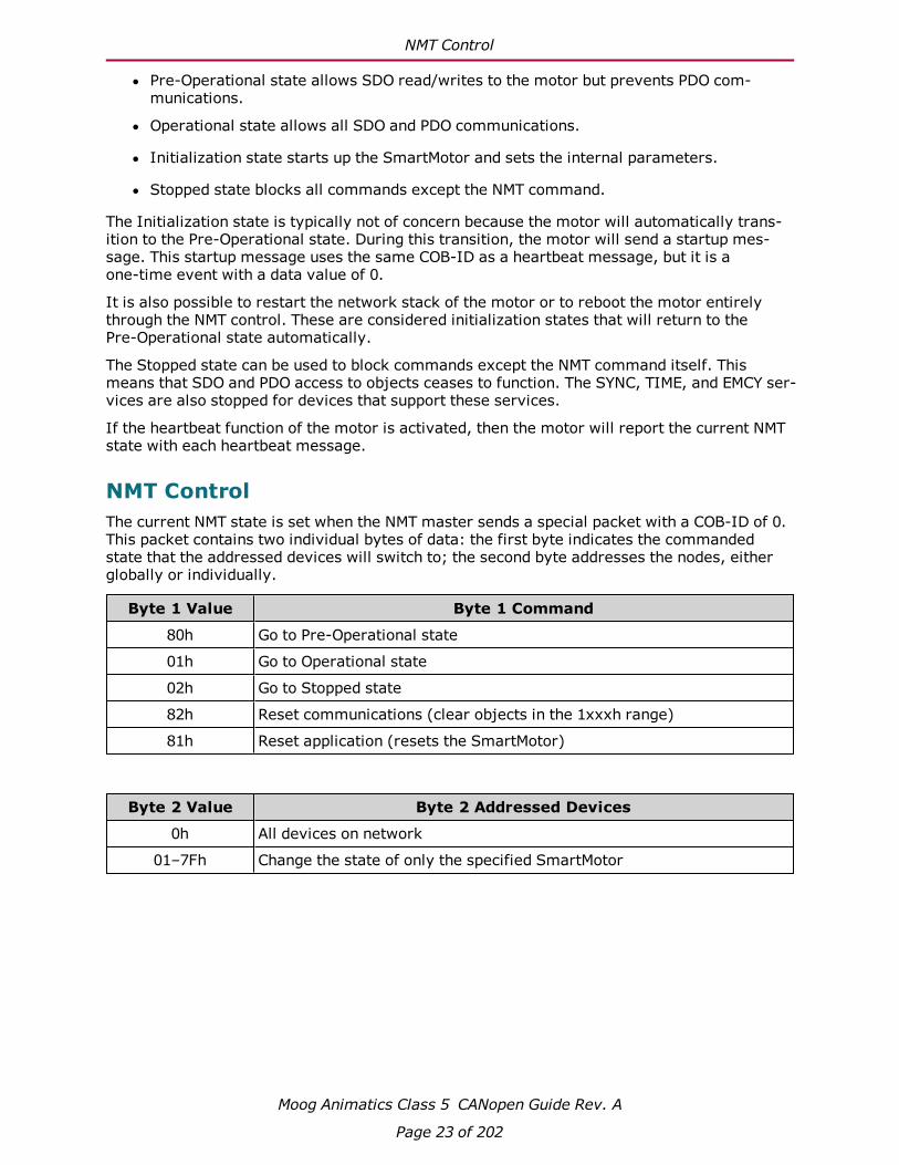
NMT ControlThe current NMT state is set when the NMT master sends a special packet with a COB-ID of 0.This packet contains two individual bytes of data: the first byte indicates the commandedstate that the addressed devices will switch to; the second byte addresses the nodes, eitherglobally or individually.
Byte 1 Value Byte 1 Command
80h Go to Pre-Operational state
01h Go to Operational state
02h Go to Stopped state
82h Reset communications (clear objects in the 1xxxh range)
81h Reset application (resets the SmartMotor)
Byte 2 Value Byte 2 Addressed Devices
0h All devices on network
01–7Fh Change the state of only the specified SmartMotor

NMT Summary
Moog Animatics Class 5 CANopen Guide Rev. A
Page 24 of 202
NMT SummaryThe following table provides a summary of the NMT states. Also, see the NMT State Machinediagram in the next section. The SmartMotor =CAN and RCAN commands can be used toassign/report the value of the NMT state, control word (object 6040h) and status word (object6041h). For details, see =CAN, RCAN on page 72.
NMT StateReportedValue
(heartbeat)
SDO func-tional
PDO func-tional
Automaticallytransitions to: Effect
Initialization(power up)
N/A No No Pre-Operational Sends startupmessage
Initialization(Reset com-munication)
N/A No No Pre-Operational Clears objects inthe 1xxxh range
Sends startupmessage
Initialization(Reset Applic-ation)
N/A No No Pre-Operational Reboots theSmartMotor
Sends startupmessage
Pre-Operational 127 Yes No -Operational 5 Yes Yes -Stopped 4 No No -
NMT State Machine DiagramThe following diagram shows the relationship and interaction between the possible NMTstates.
Initialization State
Pre-Operational
State
Operational State
Stopped State
Startup ID
(Boot-up Message)
NMT State Machine

PDO Communications
Moog Animatics Class 5 CANopen Guide Rev. A
Page 25 of 202
For more details on CANopen network management, see the CAN in Automation (CiA) websiteat:
http://www.can-cia.org/index.php?id=155
PDO CommunicationsThere are two methods of PDO communications: peer-to-peer (versus master-to-slave), andsynchronous (versus asynchronous). These communication methods are described in the fol-lowing sections. Note that these communications methods are not mutually exclusive. Forexample, peer-to-peer means that motor 1 and send a PDO and motor 2 can receive thatsame PDO. This can be done through either of the following methods:
l Synchronous: Motor 1 transmits when a sync packet is seen
l Asynchronous: Motor 1 transmits based on its own internal timer
Peer-to-Peer CommunicationsAn advantage to the peer-to-peer method of PDO communication is that any node can be arecipient of any PDO. This allows for data to flow peer-to-peer rather than always going to themaster. It also allows for broadcasting to multiple nodes (for example, there may be an I/Oinput device on the CANopen network that all devices wish to monitor for a button press).
The CANopen master must configure this peer-to-peer relationship. However, once it is con-figured and the network is in the Operational state, the process will continue without constantintervention from the master.
To establish a peer-to-peer relationship, one node will transmit a data object using a par-ticular COB-ID. Any device that wishes to receive this information should allocate this COB-IDto a receive PDO and map that PDO to the desired object to accept the data. For details abouthow PDOs are mapped, see PDO Mapping on page 65 and COB-ID Allocation on page 20.
Synchronous CommunicationsPDOs may be configured to transmit from a node's own internal timer, or they may be trans-mitted based on the sync event on the network. The sync event is simply a special CAN frameproduced by the node or master that is assigned as the sync producer. PDO Mapping on page65 describes the details for configuring these two modes of PDO transmission.
When the sync method is chosen, it is possible to transmit on every sync message, or to sub-divide the transmission rate by up to 240. In other words, transmission can be set to occur onevery sync, every other sync, every third sync, and so on... up to every 240th sync.

Connections, Wiring and Status LEDs
Moog Animatics Class 5 CANopen Guide Rev. A
Page 27 of 202
Connections, Wiring and Status LEDsThis chapter provides information on the SmartMotor connectors, a multidrop cable diagram,and a description of the SmartMotor status LEDs.
Connectors and Pinouts 28
D-Style Motor Connectors and Pinouts 28
M-Style Motor Connectors and Pinouts 29
Cable Diagram 30
CAN Multidrop Cable Diagram 30
Maximum Bus Length 31
Status LEDs 32
Connectors and Pinouts
Moog Animatics Class 5 CANopen Guide Rev. A
Page 28 of 202
Connectors and Pinouts
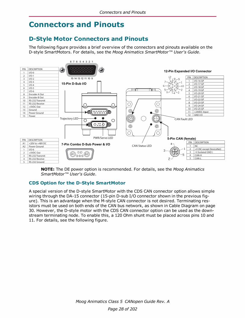
D-Style Motor Connectors and PinoutsThe following figure provides a brief overview of the connectors and pinouts available on theD-style SmartMotors. For details, see the Moog Animatics SmartMotor™ User's Guide.
PIN
1
2
3
4
5
NC
+V (NC except DeviceNet)
-V (Isolated GND )
CAN-H
CAN-L
DESCRIPTION
5-Pin CAN (female)
1
2
3
4
5
6
7
8
9
10
11
12
I/O-16 GP
I/O-17 GP
I/O-18 GP
I/O-19 GP
I/O-20 GP
I/O-21 GP
I/O-22 GP
I/O-23 GP
I/O-24 GP
I/O-25 GP
+24VDC Input
GND I/O
PIN DESCRIPTION
12-Pin Expanded I/O Connector1
2
3
4
5
6
7
8
9
10
11
12
13
14
15
I/O-0
I/O-1
I/O-2
I/O-3
I/O-4
I/O-5
I/O-6
Encoder A Out
Encoder B Out
RS-232 Transmit
RS-232 Receive
+5VDC Out
Ground
Power Ground
Power
PIN DESCRIPTION
7-Pin Combo D-Sub Power & I/O
A1 A21 2
3 4 5
A1
A2
1
2
3
4
5
+20V to +48V DC
Power Ground
I/O-6
+5VDC Out
RS-232 Transmit
RS-232 Receive
RS-232 Ground
PIN DESCRIPTION
15-Pin D-Sub I/O
Trajectory LED
PWR/Servo LED
CAN Fault LED
CAN Status LED
15 14 13 12 11 10 9
8 7 6 5 4 3 2 1
NOTE: The DE power option is recommended. For details, see the Moog AnimaticsSmartMotor™ User's Guide.
CDS Option for the D-Style SmartMotor
A special version of the D-style SmartMotor with the CDS CAN connector option allows simplewiring through the DA-15 connector (15-pin D-sub I/O connector shown in the previous fig-ure). This is an advantage when the M-style CAN connector is not desired. Terminating res-istors must be used on both ends of the CAN bus network, as shown in Cable Diagram on page30. However, the D-style motor with the CDS CAN connector option can be used as the down-stream terminating node. To enable this, a 120 Ohm shunt must be placed across pins 10 and11. For details, see the following figure.
M-Style Motor Connectors and Pinouts
Moog Animatics Class 5 CANopen Guide Rev. A
Page 29 of 202
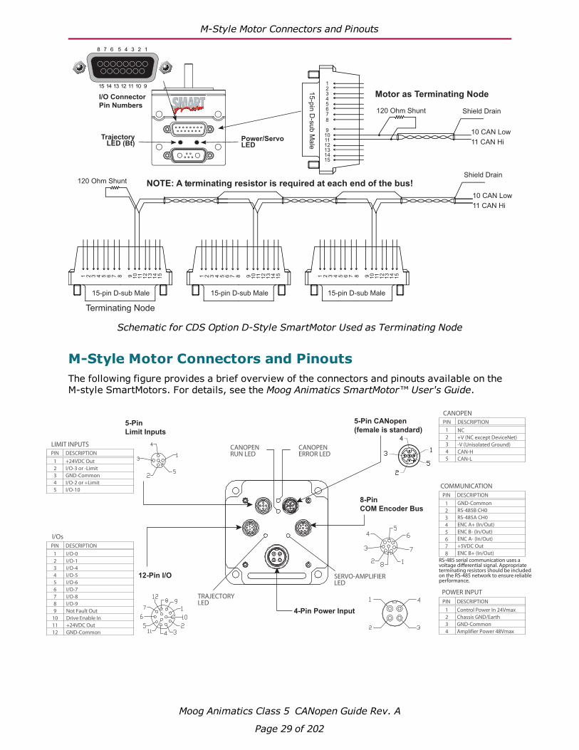
Motor as Terminating Node
NOTE: A terminating resistor is required at each end of the bus!
I/O Connector
Pin Numbers
TrajectoryLED (Bt)
Power/ServoLED
120 Ohm Shunt Shield Drain
10 CAN Low
15 14 13 12 11 10 9
8 7 6 5 4 3 2 1
11 CAN Hi
Shield Drain
10 CAN Low
11 CAN Hi
120 Ohm Shunt
15
-pin
D-s
ub
Ma
le
Terminating Node
15-pin D-sub Male 15-pin D-sub Male 15-pin D-sub Male
1
2
3
4
5
6
7
8
9
10
11
12
13
14
15
1 2 3 4 5 6 7 8 9 10
11
12
13
14
15 1 2 3 4 5 6 7 8 9 10
11
12
13
14
15 1 2 3 4 5 6 7 8 9 10
11
12
13
14
15
Schematic for CDS Option D-Style SmartMotor Used as Terminating Node
M-Style Motor Connectors and PinoutsThe following figure provides a brief overview of the connectors and pinouts available on theM-style SmartMotors. For details, see the Moog Animatics SmartMotor™ User's Guide.
PIN
1
2
3
4
5
+24VDC Out
I/O-3 or -Limit
GND-Common
I/O-2 or +Limit
I/O-10
DESCRIPTION
LIMIT INPUTS
PIN
1
2
3
4
5
NC
+V (NC except DeviceNet)
-V (Unisolated Ground)
CAN-H
CAN-L
DESCRIPTION
CANOPEN
1
2
3
4
5
6
7
8
9
10
11
12
I/O-0
I/O-1
I/O-4
I/O-5
I/O-6
I/O-7
I/O-8
I/O-9
Not Fault Out
Drive Enable In
+24VDC Out
GND-Common
PIN
I/Os
1
2
3
4
5
6
7
8
GND-Common
RS-485B CH0
RS-485A CH0
ENC A+ (In/Out)
ENC B- (In/Out)
ENC A- (In/Out)
+5VDC Out
ENC B+ (In/Out)
PIN DESCRIPTION
COMMUNICATION
1
2
3
4
Control Power In 24Vmax
Chassis GND/Earth
GND-Common
Amplifier Power 48Vmax
PIN DESCRIPTION
POWER INPUT
RS-485 serial communication uses a voltage di�erential signal. Appropriate terminating resistors should be included on the RS-485 network to ensure reliable performance.
DESCRIPTION
CANOPENRUN LED
12-Pin I/O
4-Pin Power Input
8-Pin
COM Encoder Bus
5-Pin CANopen
(female is standard)5-Pin
Limit Inputs
CANOPENERROR LED
TRAJECTORYLED
SERVO-AMPLIFIERLED
Cable Diagram
Moog Animatics Class 5 CANopen Guide Rev. A
Page 30 of 202
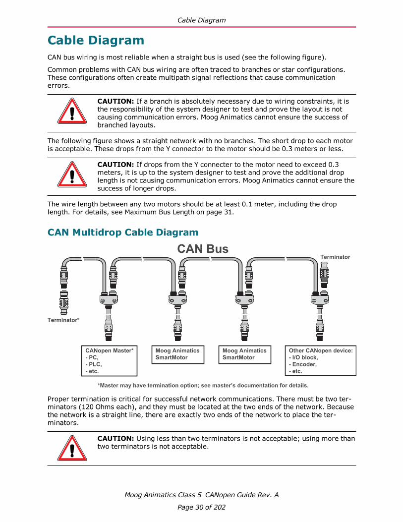
Cable DiagramCAN bus wiring is most reliable when a straight bus is used (see the following figure).
Common problems with CAN bus wiring are often traced to branches or star configurations.These configurations often create multipath signal reflections that cause communicationerrors.
CAUTION: If a branch is absolutely necessary due to wiring constraints, it isthe responsibility of the system designer to test and prove the layout is notcausing communication errors. Moog Animatics cannot ensure the success ofbranched layouts.
The following figure shows a straight network with no branches. The short drop to each motoris acceptable. These drops from the Y connector to the motor should be 0.3 meters or less.
CAUTION: If drops from the Y connecter to the motor need to exceed 0.3meters, it is up to the system designer to test and prove the additional droplength is not causing communication errors. Moog Animatics cannot ensure thesuccess of longer drops.
The wire length between any two motors should be at least 0.1 meter, including the droplength. For details, see Maximum Bus Length on page 31.
CAN Multidrop Cable Diagram
CAN Bus
Other CANopen device:
- I/O block,
- Encoder,
- etc.
CANopen Master*
- PC,
- PLC,
- etc.
Terminator
Terminator*
*Master may have termination option; see master’s documentation for details.
Moog Animatics
SmartMotor
Moog Animatics
SmartMotor
Proper termination is critical for successful network communications. There must be two ter-minators (120 Ohms each), and they must be located at the two ends of the network. Becausethe network is a straight line, there are exactly two ends of the network to place the ter-minators.
CAUTION: Using less than two terminators is not acceptable; using more thantwo terminators is not acceptable.

Maximum Bus Length
Moog Animatics Class 5 CANopen Guide Rev. A
Page 31 of 202
In the event that the master device specifically provides a terminating resistor, then that maybe used instead of the terminator plug. However, the master must be at the end of the net-work in that case; it cannot be in the middle.
Maximum Bus LengthThe following table shows the transmission bit rates and corresponding maximum bus lengths.The bus length is the calculated maximum distance of the straight bus from one terminatedend to the other terminated end.
Bit rate(bits/second)
Bus length(meters)
1000000 25
800000 50
500000 100
250000 250
125000 500
50000 1000
20000 2500
NOTE: Bus lengths exceeding 200 meters may have additional requirements suchas the use of repeaters or optocouplers. For more information, see the CiA 301 spe-cifications.
Status LEDs
Moog Animatics Class 5 CANopen Guide Rev. A
Page 32 of 202
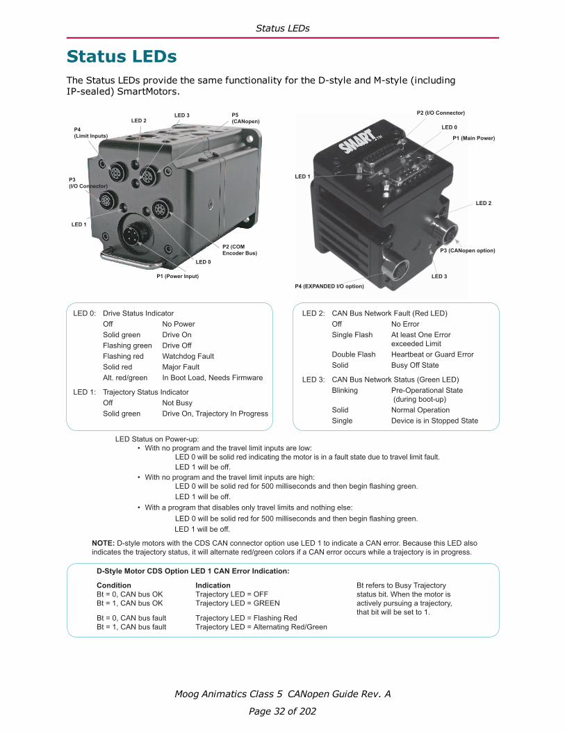
Status LEDsThe Status LEDs provide the same functionality for the D-style and M-style (includingIP-sealed) SmartMotors.
P3 (CANopen option)
LED Status on Power-up:
• With no program and the travel limit inputs are low:
LED 0 will be solid red indicating the motor is in a fault state due to travel limit fault.
LED 1 will be off.
• With no program and the travel limit inputs are high:
LED 0 will be solid red for 500 milliseconds and then begin flashing green.
LED 1 will be off.
• With a program that disables only travel limits and nothing else:
LED 0 will be solid red for 500 milliseconds and then begin flashing green.
LED 1 will be off.
P1 (Power Input)
LED 0
LED 1
P2 (COM
Encoder Bus)
P3
(I/O Connector)
P4
(Limit Inputs)
P5
(CANopen)LED 3
LED 2
LED 0: Drive Status Indicator
Off No Power
Solid green Drive On
Flashing green Drive Off
Flashing red Watchdog Fault
Solid red Major Fault
Alt. red/green In Boot Load, Needs Firmware
LED 1: Trajectory Status Indicator
Off Not Busy
Solid green Drive On, Trajectory In Progress
LED 2: CAN Bus Network Fault (Red LED)
Off No Error
Single Flash At least One Error
exceeded Limit
Double Flash Heartbeat or Guard Error
Solid Busy Off State
LED 3: CAN Bus Network Status (Green LED)
Blinking Pre-Operational State
(during boot-up)
Solid Normal Operation
Single Device is in Stopped State
NOTE: D-style motors with the CDS CAN connector option use LED 1 to indicate a CAN error. Because this LED also
indicates the trajectory status, it will alternate red/green colors if a CAN error occurs while a trajectory is in progress.
Condition
Bt = 0, CAN bus OK
Bt = 1, CAN bus OK
Indication
Trajectory LED = OFF
Trajectory LED = GREEN
Bt refers to Busy Trajectory
status bit. When the motor is
actively pursuing a trajectory,
that bit will be set to 1.Bt = 0, CAN bus fault
Bt = 1, CAN bus fault
Trajectory LED = Flashing Red
Trajectory LED = Alternating Red/Green
D-Style Motor CDS Option LED 1 CAN Error Indication:

Supported Features
Moog Animatics Class 5 CANopen Guide Rev. A
Page 33 of 202
Supported FeaturesThis chapter provides information on the supported and unsupported features of the CANopenspecification.
Supported 34
Motion Modes 34
PDO Transmit on Event 34
PDO Transmit on Timer Only 34
PDO Transmit on Sync 35
Dynamic PDO Mapping 35
Heartbeat Producer 35
Sync Producer 35
Not Supported 36
Emergency Messages 36
Saving Parameters 36
Heartbeat Consumer 36
MPDO Communications 36
CAN Bus Bit Rate 36
PDO Transmit on RTR (Remote frames) 36
Node Guarding 36
TIME Service 36
Sync Start 36

Supported
Moog Animatics Class 5 CANopen Guide Rev. A
Page 34 of 202
SupportedThis section describes the CANopen features that are supported by the SmartMotor.
Motion ModesThe following motion modes are supported:
l Profile Position (PP, CANopen mode of operation: 1) — behaves like the SmartMotor MPmode; supports "single setpoint" and "set of setpoints" modes
l Profile Velocity (PV, CANopen mode of operation: 3) — behaves like the SmartMotor MVmode
l Interpolation (IP, CANopen mode of operation: 7) — behaves like the SmartMotor MDmode
l Torque (TQ, CANopen mode of operation: 4) — behaves like the SmartMotor MT mode
l Homing: methods 1, 2, 17, 18, 33, 34 and 35 are supported; homing offset, homingspeeds and homing acceleration are supported
The Supported Drive Modes object (6502h) is used to report the modes of operation that areavailable. The Modes of Operation object (6060h) is used to request the desired mode of oper-ation before setting the Control Word object (6040h).
PDO Transmit on EventProcess Data Objects (PDOs) can be configured to transmit on a change of value within themotor (Transmission type: 255). Transmission type 255 also transmits on the transmit timerevent configured in the PDO's corresponding communications parameter object. The transmittimer provides a minimum rate at which the data is transmitted.
l The transmission type is set using sub-index 2 of objects 1800h, 1801h, 1802h, 1803hand 1804h.
l The transmission timer is set using sub-index 5 of objects 1800h, 1801h, 1802h, 1803hand 1804h.
PDO Transmit on Timer OnlyTransmit PDOs can be configured to transmit on a timer using a transmission type setting of254.
l The transmission type is set using sub-index 2 of objects 1800h, 1801h, 1802h, 1803hand 1804h.
l The transmission timer is set using sub-index 5 of objects 1800h, 1801h, 1802h, 1803hand 1804h.

PDO Transmit on Sync
Moog Animatics Class 5 CANopen Guide Rev. A
Page 35 of 202
PDO Transmit on SyncTransmit PDOs can be configured to transmit in response to a sync packet. Transmit types 1-240 in the transmission type setting are used to configure this. The value of the transmissiontype controls how often the transmit PDO is sent in response to a sync (e.g., transmit type = 1is sent in every sync packet; transmit type = 240 is sent in every 240th sync packet).
The transmission type is set using sub-index 2 of objects 1800h, 1801h, 1802h, 1803 and1804h.
Dynamic PDO MappingThere are objects used to simultaneously configure (map) up to five Receive PDOs and fiveTransmit PDOs. These mappings are dynamic — any object with "PDO mappable" in its descrip-tion can be mapped to a PDO through the standard CANopen mapping procedure.
Dynamic mapping of objects to PDO is configured using objects 1600h, 1601h, 1602h, 1603h,1604h, 1A00h, 1A01h, 1A02, 1A03h and 1A04h. For details, see PDO Mapping on page 65.
Heartbeat ProducerThe motor can be configured to transmit a heartbeat at a configurable rate. For details, seeObject 1017h: Producer Heartbeat Time on page 94.
Sync ProducerThe SmartMotor can produce sync messages. This requires setting the Communication CyclePeriod object (1006h) and the COB-ID SYNC object (1005h). There is a specific order to con-figuring these objects, and object 1005h requires an additional bit setting. Therefore, it isimportant to review the descriptions of both objects. For details, see Object 1005h: COB-IDSYNC on page 88 and Object 1006h: Communication Cycle Period on page 89.

Not Supported
Moog Animatics Class 5 CANopen Guide Rev. A
Page 36 of 202
Not SupportedThis section describes the CANopen features that are not supported by the SmartMotor.
Emergency MessagesEmergency (EMCY) object messages are not produced or consumed by the SmartMotor. Theassociated objects, 1014h and 1015h, do not exist.
Saving ParametersThe SmartMotor does not support parameter data saving. Objects 1010h and 1011h are notimplemented.
Heartbeat ConsumerThe SmartMotor does not consume heartbeat messages. Therefore, it will not take action onthe presence or absence of any heartbeat messages. However, the SmartMotor can be a heart-beat producer. For details, see Object 1017h: Producer Heartbeat Time on page 94.
MPDO CommunicationsThe SmartMotor does not support the multiplexed-PDO (MPDO) method of communication.Ordinary transmit and receive PDOs are supported.
CAN Bus Bit RateThe CAN bus bit rate of 10000 bits/sec is not supported.
PDO Transmit on RTR (Remote frames)PDO Transmit types 252 and 253 are not supported. Remote (RTR) frames are not supported.
Node GuardingNode Guarding is not supported.
TIME ServiceTIME service is not supported.
Sync StartSync Start value is not present or supported. This refers specifically to sub-index 6 of theTransmit PDO Communication Parameter objects 1800h–1804h.

Manufacturer-Specific Objects
Moog Animatics Class 5 CANopen Guide Rev. A
Page 37 of 202
Manufacturer-Specific ObjectsThis chapter provides details on manufacturer-specific objects.
I/O 38
User Variables 38
Calling Subroutines 40
Command Interface (Object 2500h) 40
Command Interface 40
Program Upload/Download 42

I/O
Moog Animatics Class 5 CANopen Guide Rev. A
Page 38 of 202
I/OThe CiA 402 motion profile provides limited access to the onboard I/O of the SmartMotor.However, there are other manufacturer-specific objects that provide more I/O control.
As part of the CiA 402 motion profile, objects 60FDh and 60FEh are provided. For details, seeObject 60FDh: Digital Inputs on page 194 and Object 60FEh: Digital Outputs on page 196.
For the D-style motor, object 2100h is highly specific to the multiplexed role of the seven I/Opins. This function is not supported on the M-style motor. For more details, see Object 2100h:Port Configuration on page 120.
For general access to individual I/O pins, the Bit I/O object (2101h) offers a more specific wayto send commands. This feature works on the M-style and D-style motors. It can be used todisable the limit inputs if desired. For more details, see Object 2101h: Bit IO on page 121.
NOTE: The limit-switch inputs for all SmartMotors must be satisfied before motionis allowed. The inputs must either be physically wired or disabled if not connected.Additionally, M-style motors require the drive-enable input to be true (high) formotion to start.
User VariablesThe SmartMotor has an array of user variables that are accessible to user programs and arevisible as CANopen objects. This provides a common area where information can be sharedbetween a user program and the CANopen network.
The variables use predefined names: a–z, aa–zz and aaa–zzz, which comprise a total of 78variables; these are 32-bit signed integers.
Additionally, there is a 204-byte array. It can be accessed as 8, 16 or 32-bit signed values.For more details, see the Moog Animatics SmartMotor™ User's Guide.
Due to SmartMotor resource limitations, only four variables are available as "mappable" vari-ables. This means that they can be mapped for PDO communications. The Mappable Variablesobject (2204h) offers access to user variables aaa, bbb, ccc and ddd. For more details, seeObject 2204h: Mappable Variables on page 126.
A wider range of user variables is accessible through the CANopen User Variable object(2201h). However, this mechanism does not allow PDO communications — object 2201 is onlyavailable through SDO communications. Therefore, it is typically used to pass constants orother configuration data at startup, when a PLC may pass SDO data. During the Operationalstate, a master may continue to pass data to variables through object 2201h if it is capable ofSDO communication at that time. For more details, see the Object 2201h: User Variable onpage 123.
A typical use of user variables in combination with CANopen is to receive information fromanother motor or sensor device on the network. For example, variable aaa could be mappedto a receive PDO (RxPDO). If that PDO is allocated a COB-ID of a sensor on the network, thenthat information can be used in a SmartMotor user program.
Another common use of the mapping variables is to report information that does not have aCANopen object. For instance, a user may want to perform a calculation in a user programand report the result back to the master. In this case, the user program would set a variablesuch as bbb=<expr>. The variable bbb should be mapped to a transmit PDO (TxPDO). Thenthe master or other nodes on the network can access that information.
User Variables
Moog Animatics Class 5 CANopen Guide Rev. A
Page 39 of 202
It is possible to use the SmartMotor as a bridge by combining the two techniques: receivingdata into a user variable and transmitting information from a user variable. This allows inter-facing of two devices that need intermediate computation. For example, a temperature sensorcould feed into the SmartMotor, and a process control loop in a SmartMotor program coulduse that information to control a cooling fan through an I/O device. This may be advantageousif there are applications that are easier to program in the SmartMotor instead of the CANopenmaster.
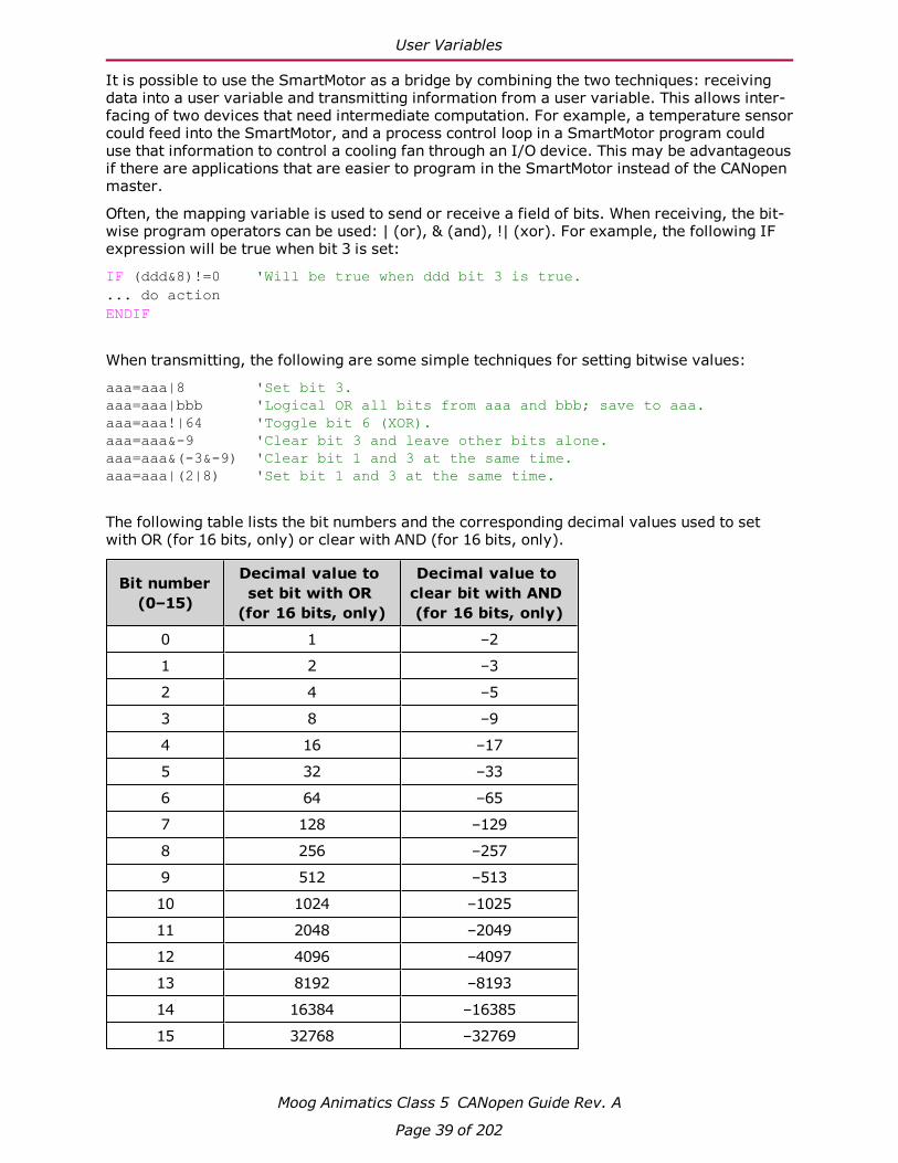
Often, the mapping variable is used to send or receive a field of bits. When receiving, the bit-wise program operators can be used: | (or), & (and), !| (xor). For example, the following IFexpression will be true when bit 3 is set:
IF (ddd&8)!=0 'Will be true when ddd bit 3 is true.... do actionENDIF
When transmitting, the following are some simple techniques for setting bitwise values:
aaa=aaa|8 'Set bit 3.aaa=aaa|bbb 'Logical OR all bits from aaa and bbb; save to aaa.aaa=aaa!|64 'Toggle bit 6 (XOR).aaa=aaa&-9 'Clear bit 3 and leave other bits alone.aaa=aaa&(-3&-9) 'Clear bit 1 and 3 at the same time.aaa=aaa|(2|8) 'Set bit 1 and 3 at the same time.
The following table lists the bit numbers and the corresponding decimal values used to setwith OR (for 16 bits, only) or clear with AND (for 16 bits, only).
Bit number(0–15)
Decimal value toset bit with OR(for 16 bits, only)
Decimal value toclear bit with AND(for 16 bits, only)
0 1 –2
1 2 –3
2 4 –5
3 8 –9
4 16 –17
5 32 –33
6 64 –65
7 128 –129
8 256 –257
9 512 –513
10 1024 –1025
11 2048 –2049
12 4096 –4097
13 8192 –8193
14 16384 –16385
15 32768 –32769

Calling Subroutines
Moog Animatics Class 5 CANopen Guide Rev. A
Page 40 of 202
Calling SubroutinesThe functionality of the SmartMotor can be extended by creating and loading a user programinto the motor. There are two ways to control the running of this program: a GOSUB call, or aRUN command to run the entire program from the top of the program.
NOTE: A user program will always automatically run from the start when the motoris powered on or reset unless the RUN? command is included at the top of the userprogram. The RUN command is not the same as the RUN? command.
The GOSUB R2 object (2309h) provides access to the GOSUB, RUN and END commands. It isPDO mappable, and it only reacts to a change of value. For details, see Object 2309h: GOSUBR2 on page 145. This object replaces the functionality of objects 2305h and 2306h.
Bit 8 of the CANopen Status Word object (6041h) can be used to determine when the sub-routine called with object 2309h has finished. When the bit clears, the subroutine has com-pleted.
Calls to subroutines using object 2309h are automatically blocked if a previous call madethrough object 2309h is still busy. When that subroutine returns, bit 8 of the Status Wordobject (6041h) will clear.
NOTE: Unlike GOSUB, there is no CANopen access to the GOTO function.
Command Interface (Object 2500h)The SmartMotor has many commands that are not mapped to CANopen objects. Many of thesecommands are obscure or take a complex set of arguments. A mechanism is provided toaccess these commands by sending a command string to object 2500h.
This section provides details on the object 2500h command interface and use in programupload/download.
Command InterfaceThis section describes the command interface for the Encapsulated Animatics Commandobject (2500h). This object provides an interface to the SmartMotor command language.Please note the following:
l The status information must read back from sub-index 3 of object 2500h.
l This object is not accessible through PDO.
The following table describes the elements of object 2500h.
Object Sub-index Description
2500h 0 Number of entries (3)
2500h 1 Command string to motor "VISIBLE-STRING" type
2500h 2 Response from motor "VISIBLE-STRING" type
2500h 3 Status from motor "UNSIGNED8" type.
Command Interface
Moog Animatics Class 5 CANopen Guide Rev. A
Page 41 of 202
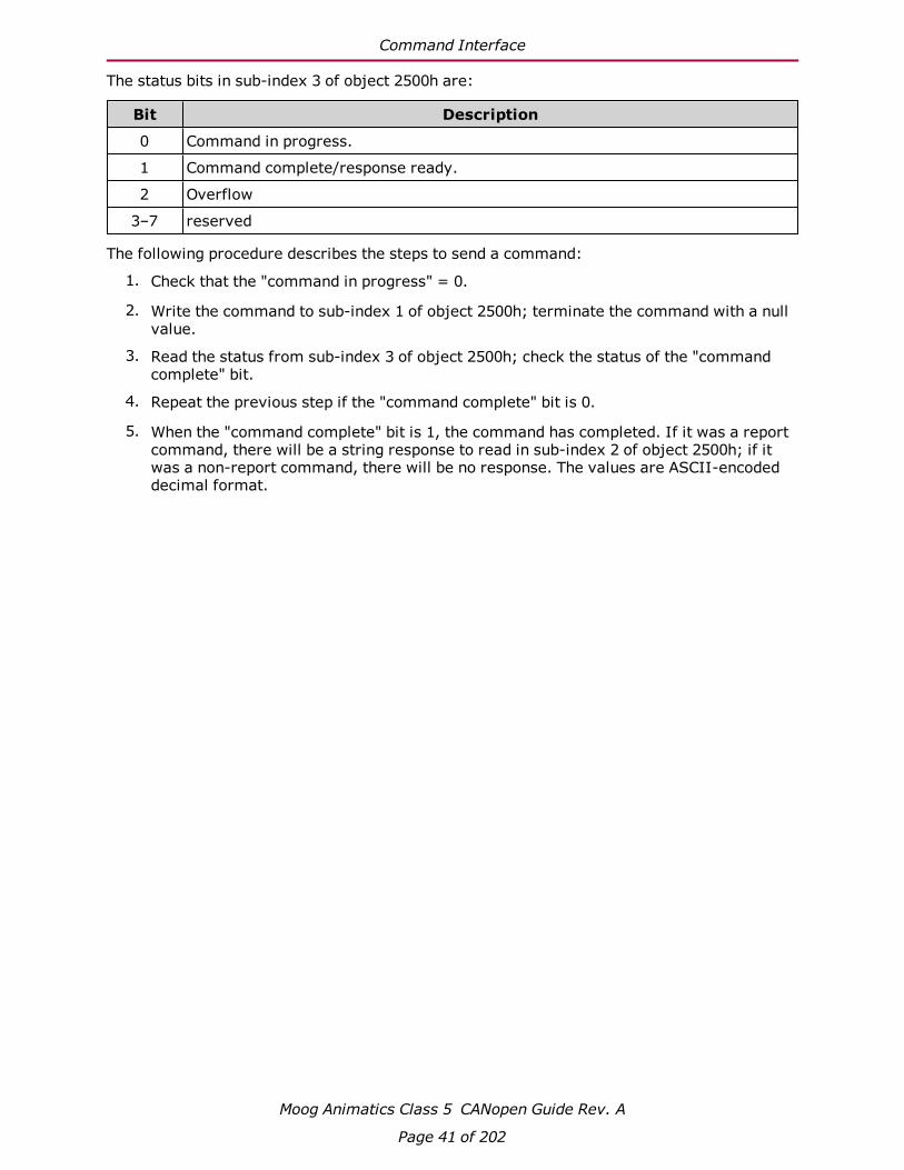
The status bits in sub-index 3 of object 2500h are:
Bit Description
0 Command in progress.
1 Command complete/response ready.
2 Overflow
3–7 reserved
The following procedure describes the steps to send a command:
1. Check that the "command in progress" = 0.
2. Write the command to sub-index 1 of object 2500h; terminate the command with a nullvalue.
3. Read the status from sub-index 3 of object 2500h; check the status of the "commandcomplete" bit.
4. Repeat the previous step if the "command complete" bit is 0.
5. When the "command complete" bit is 1, the command has completed. If it was a reportcommand, there will be a string response to read in sub-index 2 of object 2500h; if itwas a non-report command, there will be no response. The values are ASCII-encodeddecimal format.

Program Upload/Download
Moog Animatics Class 5 CANopen Guide Rev. A
Page 42 of 202
Program Upload/DownloadThe Encapsulated Animatics Command object (2500h) behaves like a string command. There-fore, it can support the upload and download of user programs. The following sectionsdescribe the upload and download procedures.
Upload from Motor
The following steps are used to upload a user program from the SmartMotor to the host:
1. The host writes to the motor's sub-index 1 of object 2500h with the UPLOAD (or UP) com-mand. Strings need to be null-terminated like most commands.
2. The host checks the "Response ready" and "Command in progress" flags in sub-index 3of object 2500h.
3. When "Response ready" = 1, the host will read a data block of 0–31 bytes plus the nullterminator from sub-index 2 of object 2500h.
4. The previous step is repeated until the "Command in progress" flag is 0 and the"Response ready" flag is 0. That indicates the process has completed.
NOTE: On the final cycle of the upload, the motor will always set the "Responseready" flag before clearing the "Command in progress" flag. This ensures that thehost has a reliable indicator when the final cycle has occurred and will not waitforever. In other words, the host should stop looking for a response as soon as bothof those flags are clear.
Download to Motor
The following steps are used to download a user program from the host to the SmartMotor:
1. The host writes to motor's sub-index 1 of object 2500h with the LOAD command. Stringsneed to be null-terminated like most commands.
2. The host waits for the "Command in progress" flag in sub-index 3 of object 2500h toreturn to 0.
3. The host writes the program data to sub-index 1 of object 2500h, first 32 bytes, with nonull terminator. This can include a header and anything after the header. The CAN com-mand manager will consume the header and whatever follows it.
4. The host waits for the "Command in progress" flag in sub-index 3 of object 2500h toreturn to 0. This serves as the ACK (acknowledgment) signal. There is no reading ofsub-index 2 of object 2500h.
NOTE: Do not attempt to read sub-index 2 of object 2500h because that buf-fer is used for other purposes during this procedure.
5. The host writes more program data to sub-index 1 of object 2500h, 32 bytes at a time,with no null terminator. Handshaking continues through the "Command in progress"flag. Transmission may be ended at any time by sending 0xFF 0xFF 0x20 in the char-acter stream.
NOTE: This sequence does not need to fall in the same buffer segment. There is noneed to pad the buffer.
CiA 402 Drive and Motion Control Profile
Moog Animatics Class 5 CANopen Guide Rev. A
Page 43 of 202
CiA 402 Drive and Motion Control Pro-fileThe CiA 402 Drive and Motion Control Profile supports the motion control of the SmartMotor.The associated objects comprise a large portion of the object dictionary (see Drive and MotionControl Profile on page 152). This profile is supported by many vendors of industrial controls.
CiA 402 Profile Motion State Machine 44
Control Words, Status Words and the Drive State Machine 44
Status Word (Object 6041h) 45
Control Word (Object 6040h) 46
Motion Profiles 47
Position Mode 47
Velocity Mode 51
Torque Mode 53
Interpolated Position Mode 55
Homing Mode 61

CiA 402 Profile Motion State Machine
Moog Animatics Class 5 CANopen Guide Rev. A
Page 44 of 202
CiA 402 Profile Motion State MachineSupport for the CiA 402 motion profile (DS402) in the SmartMotor includes the Control Wordobject (6040h) and the Status Word object (6041h). Under all types of motion, the controlword starts or stops the drive and the status word reports the state of the drive.
However, the type of motion profile is not controlled with these objects — it is commandedthrough the Modes of Operation object (6060h) and reported from the Modes of Operation Dis-play object (6061h). For more details, see the examples in Motion Profiles on page 47.
Control Words, Status Words and the Drive State MachineRefer to the following diagram of the CANopen Drive State Machine. The power drive systemfinite state automaton (PDS FSA) is described in the DS402 specification. This is the mech-anism used to command the motor to begin a new move or turn the drive on/off. The DS402specification describes several operation states controlled by the Control Word object (6040h)and read back using the Status Word object (6041h).
Start
Not ready to switch on
Switch ondisabled
Ready toswitch on
Switched on
Operationenabled
Quick stopactive
Fault
Fault reactionactive
Power on and initialization
Successfulinitialization
Faultreactioncomplete
Automatictransition
From any state
Automatictransitionthrough
Switched onstate
Control Word:Bit 1 = 1Bit 2 = 1
Control Word:Bit 0 = 1
Control Word:Bit 3 = 1
Control Word:Bit 3 = 0
Control Word:Bit 0 = 0
Control Word:Bit 0 = 0
Control Word:Bit 2 = 0
orBit 1 = 0
Control Word:Bit 1 = 0
Control Word:Bit 7 = 1
Control Word:Bit 2 = 0
Control Word:Bit 2 = 0
orBit 1 = 0Control Word:
Bit 1 = 0
Status Word:xxxx_xxxx_x00x_0111
Status Word:xxxx_xxxx_x0xx_1111
Status Word:xxxx_xxxx_x1xx_0000
Status Word:xxxx_xxxx_x01x_0001
Status Word:xxxx_xxxx_x01x_0011
Status Word:xxxx_xxxx_x01x_0111
Status Word:xxxx_xxxx_x0xx_1000
Status Word:xxxx_xxxx_x0xx_0000
Control Word:Bit 0 = 1Bit 3 = 1
CANopen Drive State Machine

Status Word (Object 6041h)
Moog Animatics Class 5 CANopen Guide Rev. A
Page 45 of 202
Status Word (Object 6041h)The Status Word object (6041h) reports the PDS FSA state machine per the DS402 spe-cification. The following distinct states are defined, where "x" is a bit that could be either a 1or a 0:
Status Word 6041h
(16 bits)PDS FSA state Meaning
xxxx xxxx x0xx 0000 Not ready to switch on Drive is off
xxxx xxxx x1xx 0000 Switch on disabled Drive is off
xxxx xxxx x01x 0001 Ready to switch on Drive is off
xxxx xxxx x01x 0011 Switched on Drive is off
xxxx xxxx x01x 0111 Operation enabled Drive is enabled
xxxx xxxx x00x 0111 Quick stop active Drive is enabled
xxxx xxxx x0xx 1111 Fault reaction active Drive is enabled
xxxx xxxx x0xx 1000 Fault Drive is off
The state "Operation enabled" is the only one allowing normal operation (motion) of themotor.
The quick stop will automatically transition out of the "Quick stop active" state to the "Switchon disabled" state.
The "Fault reaction active" state will automatically transition to the "Fault" state unless thefault reaction is "slow to a stop" rather than OFF or MTB.
For more details, see Object 6041h: Status Word on page 156.

Control Word (Object 6040h)
Moog Animatics Class 5 CANopen Guide Rev. A
Page 46 of 202
Control Word (Object 6040h)The Control Word object (6040h) must be written to command the motor to start motion. Onlycertain state transitions are allowed. Therefore, the PLC or host writing to the Control Wordobject (6040h) should read the Status Word object (6041h) to determine the current state.
The following table describes the bits in the Control Word object (6040h). For more details,see Object 6040h: Control Word on page 154.
State to enterBits of the Control Word
Allowed fromBit 7 Bit 3 Bit 2 Bit 1 Bit 0
Switch on disabled 0 X X 0 X Ready to switch on,Switched on,Operation enabled,Quick stop active (by forcingbit 1 to a 0)
Ready to switch on 0 X 1 1 0 Switch on disabled,Switched on,Operation enabled
Switched on 0 0 1 1 1 Ready to switch on,Operation enabled
Operation Enabled 0 1 1 1 1 Ready to switch on,Switched on
Quick Stop active 0 X 0 1 X Operation enabled,Ready to switch on,Switched on
Switch on disabled N/A N/A N/A N/A N/A Quick stop active (automatictransition when quick stopcompletes)
Switch on disabled 0 to 1transition
X X X X Fault
Fault N/A N/A N/A N/A N/A Fault reaction active (auto-matic transition when faultreaction completes)
Fault reaction active N/A N/A N/A N/A N/A Occurrence of a fault willleave current state (auto-matic transition when faultoccurs)
NOTE: Rising edge of bit 7 clears the fault unless a fault condition still exists.

Motion Profiles
Moog Animatics Class 5 CANopen Guide Rev. A
Page 47 of 202
A typical startup sequence of values to write to the control word is:
1. 0000h — Starting value.
2. 0080h — Clear past faults.
3. 0006h — Enter "Ready to Switch On" state.
4. 000Fh — Enter "Operation Enabled" state; for velocity or torque mode, this startsmotion.
5. 001Fh — Start a homing or position move.
Motion ProfilesThis section provides example values written to CANopen objects for various motion profiles.
In these examples, it can be assumed that the writes are made through either PDO or SDOcommunications. Typically, objects like the Control Word object (6040h) would be written cyc-lically with PDO communications. However, it is also possible for a single SDO write to setthese values. If PDO communications are used, it is assumed that the master is writing valuescontinuously, and the noted sequence indicates when a value should be changed to a newvalue.
Position ModeThis section describes the process for creating a motion using Absolute Position mode and Rel-ative Position mode.It is assumed that either the SmartMotor's drive-enable input and hardware limit switchinputs are in the ready state, or the user has issued the appropriate I/O commands to disablethe limits. For details, see Object 2100h: Port Configuration on page 120 and Object 2101h:Bit IO on page 121.

Position Mode
Moog Animatics Class 5 CANopen Guide Rev. A
Page 48 of 202
Absolute Position Mode Summary
The following table provides a summary of settings for creating a motion using Absolute Pos-ition mode. For a different example in step format, see the next section.
Description SMICommand
IndexObjectCode
Sub-Index
Data
Length Hex Dec
Disable positive limitswitch input
CAUTION: Skipthis step if limitswitches are in use.
EIGN(2) 2101h 03 02 0002 2
Disable negative limitswitch input
CAUTION: Skipthis step if limitswitches are in use.
EIGN(3) 2101h 03 02 0003 3
Reset status word ZS 6040h 00 02 0080 1280000 0000 1000 0000
Set Mode Position MP 6060h 00 01 01 1
Set profile speed in PPmode
VT=xxxx 6081h 00 04 0000C350 50000
Set target position PT=0 607Ah 00 04 00000000 0
Set acceleration AT=xxxx 6083h 00 04 00000064 100
Set deceleration DT=xxxx 6084h 00 04 00000064 100
Change state: Ready toswitch on
6040h 00 02 0006 60000 0000 0000 0110
Change state: Switched on 6040h 00 02 0007 70000 0000 0000 0111
Enable command, singlesetpoint (motion not actu-ally started yet.)
6040h 00 02 002F 470000 0000 0010 1111
Begin motion to target pos-ition
G 6040h 00 02 003F 630000 0000 0011 1111
Prepare for next command 6040h 00 02 002F 470000 0000 0010 1111
Set target position PT=1000 607Ah 00 04 000003E8 1000
Begin motion to target pos-ition
G 6040h 00 02 003F 630000 0000 0011 1111
Absolute Position Mode Example
The following procedure shows the steps for creating a motion using Absolute Position mode.For details on Absolute Position mode, see the Moog Animatics SmartMotor™ User's Guide.
NOTE:Position Units (PU): encoder countsAcceleration/Deceleration Units (ADU): (encoder counts per (sample2)) * 65536Velocity Units (VU): encoder counts per sample * 65536

Position Mode
Moog Animatics Class 5 CANopen Guide Rev. A
Page 49 of 202
1. Clear the faults by setting the Control Word object (6040h) to the following values:
a. 0
b. 0080h (128 decimal)
c. 0
2. Set the Modes of Operation object (6060h) to the value 1 (decimal).
3. Set the Profile Velocity object (6081h) to the desired speed in VU (for example, thedecimal value 100000). This is always a positive value. The target position determinesthe direction of motion.
4. Set the Profile Acceleration object (6083h) to the desired acceleration in ADU (forexample, the decimal value 10).
5. Set the Profile Deceleration object (6084h) to the desired deceleration in ADU (forexample, the decimal value 10).
6. Set the Target Position object (607Ah) to the desired absolute position in PU.
7. Initialize and start the motion by setting the Control Word object (6040h) to the values:
a. 0006h (6 decimal) — This is required to satisfy the CiA 402 drive state machine.For details, see CiA 402 Profile Motion State Machine on page 44.
b. 002Fh (47 decimal) — This configures the single-setpoint positioning mode.
c. 003Fh (63 decimal) — The motion begins.
8. Wait for the motion to complete.
9. Set the Target Position object (607Ah) to a new absolute position in PU. Motion will notbegin at this time.
10. Initialize, start and stop the motion by setting the Control Word object (6040h) to the fol-lowing values:
a. 002Fh (47 decimal) — Bit 4 must be transitioned for the new setpoint to begin. Bywriting that value to the Control Word object (6040h), bit 4 will begin in the lowstate. The next step will write a different value to that object, which will transitionbit 4 to a high state.
b. 003Fh (63 decimal) — Starts the motion.
c. 013Fh (319 decimal) — Stops the motion. The motor will decelerate before reach-ing the target.
11. Initialize and resume the motion by setting the Control Word object (6040h) to the fol-lowing values:
a. 002Fh (47 decimal) — bit 4 must be transitioned for the motion to resume. By writ-ing that value to the Control Word object (6040h), bit 4 will begin in the low state.The next step will write a different value to that object, which will transition bit 4to a high state.
b. 003Fh (63 decimal) — the motion resumes.
12. Turn off motor by setting the Control Word object (6040h) to the value 0.
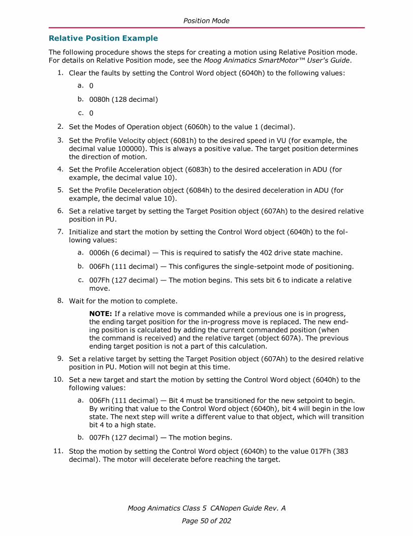
Position Mode
Moog Animatics Class 5 CANopen Guide Rev. A
Page 50 of 202
Relative Position Example
The following procedure shows the steps for creating a motion using Relative Position mode.For details on Relative Position mode, see the Moog Animatics SmartMotor™ User's Guide.
1. Clear the faults by setting the Control Word object (6040h) to the following values:
a. 0
b. 0080h (128 decimal)
c. 0
2. Set the Modes of Operation object (6060h) to the value 1 (decimal).
3. Set the Profile Velocity object (6081h) to the desired speed in VU (for example, thedecimal value 100000). This is always a positive value. The target position determinesthe direction of motion.
4. Set the Profile Acceleration object (6083h) to the desired acceleration in ADU (forexample, the decimal value 10).
5. Set the Profile Deceleration object (6084h) to the desired deceleration in ADU (forexample, the decimal value 10).
6. Set a relative target by setting the Target Position object (607Ah) to the desired relativeposition in PU.
7. Initialize and start the motion by setting the Control Word object (6040h) to the fol-lowing values:
a. 0006h (6 decimal) — This is required to satisfy the 402 drive state machine.
b. 006Fh (111 decimal) — This configures the single-setpoint mode of positioning.
c. 007Fh (127 decimal) — The motion begins. This sets bit 6 to indicate a relativemove.
8. Wait for the motion to complete.
NOTE: If a relative move is commanded while a previous one is in progress,the ending target position for the in-progress move is replaced. The new end-ing position is calculated by adding the current commanded position (whenthe command is received) and the relative target (object 607A). The previousending target position is not a part of this calculation.
9. Set a relative target by setting the Target Position object (607Ah) to the desired relativeposition in PU. Motion will not begin at this time.
10. Set a new target and start the motion by setting the Control Word object (6040h) to thefollowing values:
a. 006Fh (111 decimal) — Bit 4 must be transitioned for the new setpoint to begin.By writing that value to the Control Word object (6040h), bit 4 will begin in the lowstate. The next step will write a different value to that object, which will transitionbit 4 to a high state.
b. 007Fh (127 decimal) — The motion begins.
11. Stop the motion by setting the Control Word object (6040h) to the value 017Fh (383decimal). The motor will decelerate before reaching the target.

Velocity Mode
Moog Animatics Class 5 CANopen Guide Rev. A
Page 51 of 202
12. Initialize and resume the motion by setting the Control Word object (6040h) to the fol-lowing values:
a. 006Fh (111 decimal) — Bit 4 must be transitioned for the motion to resume. Bywriting that value to the Control Word object (6040h), bit 4 will begin in the lowstate. The next step will write a different value to that object, which will transitionbit 4 to a high state.
b. 007Fh (127 decimal) — The motion resumes. It performs a relative move fromthe current position (not the original position).
13. Turn off motor by setting the Control Word object (6040h) to the value 0.
Velocity ModeThis section describes the process for creating a motion using Velocity mode.It is assumed that either the SmartMotor's drive-enable input and hardware limit switchinputs are in the ready state, or the user has issued the appropriate I/O commands to disablethe limits. For details, see Object 2100h: Port Configuration on page 120 and Object 2101h:Bit IO on page 121.
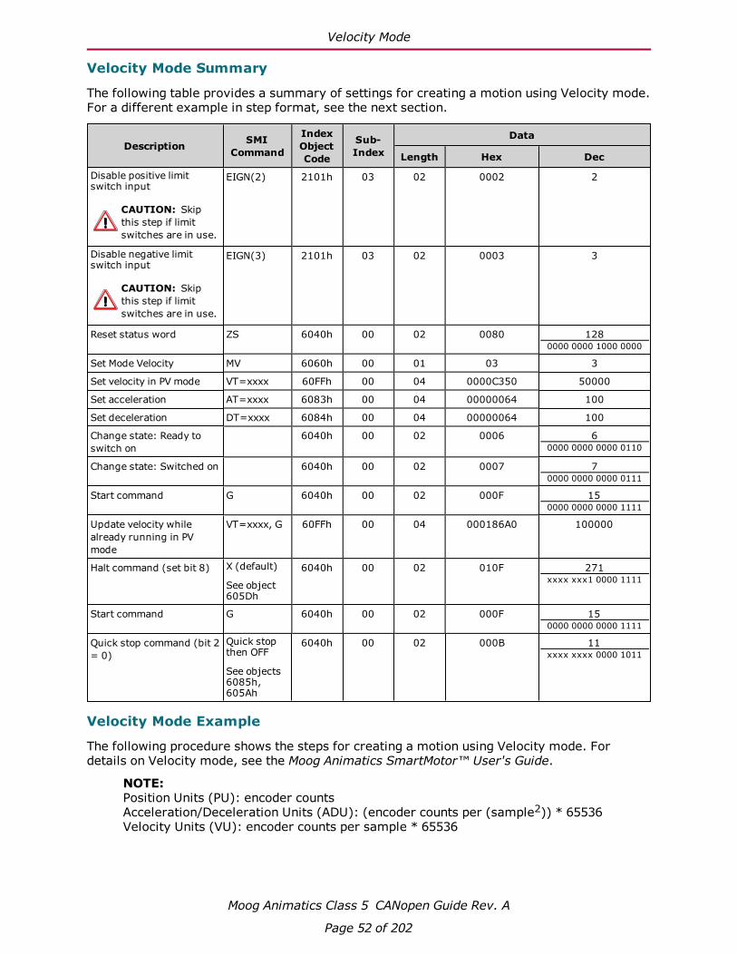
Velocity Mode
Moog Animatics Class 5 CANopen Guide Rev. A
Page 52 of 202
Velocity Mode Summary
The following table provides a summary of settings for creating a motion using Velocity mode.For a different example in step format, see the next section.
Description SMICommand
IndexObjectCode
Sub-Index
Data
Length Hex Dec
Disable positive limitswitch input
CAUTION: Skipthis step if limitswitches are in use.
EIGN(2) 2101h 03 02 0002 2
Disable negative limitswitch input
CAUTION: Skipthis step if limitswitches are in use.
EIGN(3) 2101h 03 02 0003 3
Reset status word ZS 6040h 00 02 0080 1280000 0000 1000 0000
Set Mode Velocity MV 6060h 00 01 03 3
Set velocity in PV mode VT=xxxx 60FFh 00 04 0000C350 50000
Set acceleration AT=xxxx 6083h 00 04 00000064 100
Set deceleration DT=xxxx 6084h 00 04 00000064 100
Change state: Ready toswitch on
6040h 00 02 0006 60000 0000 0000 0110
Change state: Switched on 6040h 00 02 0007 70000 0000 0000 0111
Start command G 6040h 00 02 000F 150000 0000 0000 1111
Update velocity whilealready running in PVmode
VT=xxxx, G 60FFh 00 04 000186A0 100000
Halt command (set bit 8) X (default)
See object605Dh
6040h 00 02 010F 271xxxx xxx1 0000 1111
Start command G 6040h 00 02 000F 150000 0000 0000 1111
Quick stop command (bit 2= 0)
Quick stopthen OFF
See objects6085h,605Ah
6040h 00 02 000B 11xxxx xxxx 0000 1011
Velocity Mode Example
The following procedure shows the steps for creating a motion using Velocity mode. Fordetails on Velocity mode, see the Moog Animatics SmartMotor™ User's Guide.
NOTE:Position Units (PU): encoder countsAcceleration/Deceleration Units (ADU): (encoder counts per (sample2)) * 65536Velocity Units (VU): encoder counts per sample * 65536

Torque Mode
Moog Animatics Class 5 CANopen Guide Rev. A
Page 53 of 202
1. Clear the faults by setting the Control Word object (6040h) to the following values:
a. 0
b. 0080h (128 decimal)
c. 0
2. Set the Modes of Operation object (6060h) to the value 3 (decimal).
3. Set the Target Velocity object (60FFh) to the desired speed in VU (for example, thedecimal value 100000). To reverse the direction of motion, use a negative value.
4. Set the Profile Acceleration object (6083h) to the desired acceleration in ADU (forexample, the decimal value 10).
5. Set the Profile Deceleration object (6084h) to the desired deceleration in ADU (forexample, the decimal value 10).
6. Set the Control Word object (6040h) to the value 0006h (6 decimal). This is required tosatisfy the CiA 402 drive state machine. For details, see CiA 402 Profile Motion StateMachine on page 44.
7. Start, stop and resume the motion by setting the Control Word object (6040h) to the fol-lowing values:
a. 000Fh (15 decimal) — Starts the motion
b. 010Fh (271 decimal) — Stops the motion
c. 000Fh (15 decimal) — Resumes the motion
8. Change the speed by setting the Target Velocity object (60FFh) to the desired speed inVU (for example, the decimal value 200000). The motor will immediately accelerate /de-celerate to the new speed. To reverse the direction of motion, use a negative value.
9. Turn off motor by setting the Control Word object (6040h) to the value 0.
Torque ModeThis section describes the process for creating a motion using Torque mode.It is assumed that either the SmartMotor's drive-enable input and hardware limit switchinputs are in the ready state, or the user has issued the appropriate I/O commands to disablethe limits. For details, see Object 2100h: Port Configuration on page 120 and Object 2101h:Bit IO on page 121.
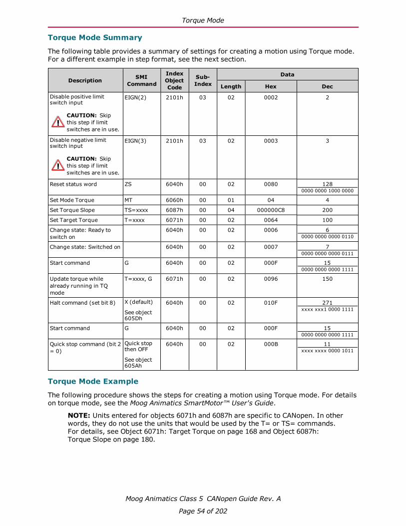
Torque Mode
Moog Animatics Class 5 CANopen Guide Rev. A
Page 54 of 202
Torque Mode Summary
The following table provides a summary of settings for creating a motion using Torque mode.For a different example in step format, see the next section.
Description SMICommand
IndexObjectCode
Sub-Index
Data
Length Hex Dec
Disable positive limitswitch input
CAUTION: Skipthis step if limitswitches are in use.
EIGN(2) 2101h 03 02 0002 2
Disable negative limitswitch input
CAUTION: Skipthis step if limitswitches are in use.
EIGN(3) 2101h 03 02 0003 3
Reset status word ZS 6040h 00 02 0080 1280000 0000 1000 0000
Set Mode Torque MT 6060h 00 01 04 4
Set Torque Slope TS=xxxx 6087h 00 04 000000C8 200
Set Target Torque T=xxxx 6071h 00 02 0064 100
Change state: Ready toswitch on
6040h 00 02 0006 60000 0000 0000 0110
Change state: Switched on 6040h 00 02 0007 70000 0000 0000 0111
Start command G 6040h 00 02 000F 150000 0000 0000 1111
Update torque whilealready running in TQmode
T=xxxx, G 6071h 00 02 0096 150
Halt command (set bit 8) X (default)
See object605Dh
6040h 00 02 010F 271xxxx xxx1 0000 1111
Start command G 6040h 00 02 000F 150000 0000 0000 1111
Quick stop command (bit 2= 0)
Quick stopthen OFF
See object605Ah
6040h 00 02 000B 11xxxx xxxx 0000 1011
Torque Mode Example
The following procedure shows the steps for creating a motion using Torque mode. For detailson torque mode, see the Moog Animatics SmartMotor™ User's Guide.
NOTE: Units entered for objects 6071h and 6087h are specific to CANopen. In otherwords, they do not use the units that would be used by the T= or TS= commands.For details, see Object 6071h: Target Torque on page 168 and Object 6087h:Torque Slope on page 180.

Interpolated Position Mode
Moog Animatics Class 5 CANopen Guide Rev. A
Page 55 of 202
1. Clear the faults by setting the Control Word object (6040h) to the following values:
a. 0
b. 0080h (128 decimal)
c. 0
2. Set the Modes of Operation object (6060h) to the value 4 (decimal).
3. Set the Target Torque object (6071h) as desired (for example, the decimal value 100).To reverse the direction of motion, use a negative value.
4. Set the Torque Slope object (6087h) as desired (for example, the decimal value 200).This controls the ramp-up/down rate to the previously-specified Target Torque.
5. Set the Control Word object (6040h) to the value 0006h (6 decimal). This is required tosatisfy the CiA 402 drive state machine. For details, see CiA 402 Profile Motion StateMachine on page 44.
6. Start, stop and resume the motion by setting the Control Word object (6040h) to the fol-lowing values:
a. 000Fh (15 decimal) — Starts the motion
b. 010Fh (271 decimal) — Stops the motion
c. 000Fh (15 decimal) — Resumes the motion
7. Change the torque by setting the Target Torque object (6071h) as desired (for example,the decimal value 50). The motor will immediately ramp up/down to the setting. Toreverse the direction of motion, use a negative value.
8. Turn off the motor by setting the Control Word object (6040h) to the value 0.
Interpolated Position ModeInterpolated position (IP) mode allows for buffering and execution of a constant stream of pos-itions. This is useful for host-driven applications with complex motion paths, such as CNCmachining.
There are several aspects to this mode of operation that require more effort to configure andoperate compared to position, velocity, or torque mode.
l Time synchronization should be used. Because of clock drifts, the individual motors willconsume position data at slightly different rates. Over a period of several hours, motorscould be significantly out of step (for example, one motor gets several data pointsahead of another). With time synchronization, the high-resolution timestamp object isused to coordinate clocks in this process, and the motors will adjust their clocks accord-ingly.
l Buffer level of data points must be maintained. There are specific objects to monitor,and the host must not allow the buffer of data points to run empty or to overflow. There-fore, the host must be able to accurately monitor and control the flow of data points.
l Data points are entered as absolute positions. However, they are processed in a relativeformat that depends on the position of the motor at a specific time during the setup andconfiguration of IP mode.
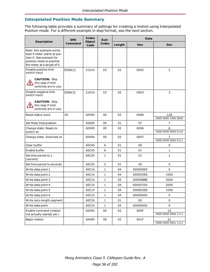
Interpolated Position Mode
Moog Animatics Class 5 CANopen Guide Rev. A
Page 56 of 202
Interpolated Position Mode Summary
The following table provides a summary of settings for creating a motion using InterpolatedPosition mode. For a different example in step format, see the next section.
Description SMICommand
IndexObjectCode
Sub-Index
Data
Length Hex Dec
Note: this example worksbest if motor starts at pos-ition 0. See example forposition mode to positionthe motor at a target of 0.
Disable positive limitswitch input
CAUTION: Skipthis step if limitswitches are in use.
EIGN(2) 2101h 03 02 0002 2
Disable negative limitswitch input
CAUTION: Skipthis step if limitswitches are in use.
EIGN(3) 2101h 03 02 0003 3
Reset status word ZS 6040h 00 02 0080 1280000 0000 1000 0000
Set Mode Interpolation 6060h 00 01 07 7
Change state: Ready toswitch on
6040h 00 02 0006 60000 0000 0000 0110
Change state: Switched on 6040h 00 02 0007 70000 0000 0000 0111
Clear buffer 60C4h 6 01 00 0
Enable buffer 60C4h 6 01 01 1
Set time period to 1(second)
60C2h 1 01 01 1
Set time period to seconds 60C2h 2 01 00 0
Write data point 1 60C1h 1 04 00000000 0
Write data point 2 60C1h 1 04 000003E8 1000
Write data point 3 60C1h 1 04 00000BB8 3000
Write data point 4 60C1h 1 04 000007D0 2000
Write data point 5 60C1h 1 04 000003E8 1000
Write data point 6 60C1h 1 04 00000000 0
Write zero-length segment 60C2h 1 01 00 0
Write data point 60C1h 1 04 00000000 0
Enable command (motionnot actually started yet.)
6040h 00 02 000F 150000 0000 0000 1111
Begin motion 6040h 00 02 001F 310000 0000 0001 1111

Interpolated Position Mode
Moog Animatics Class 5 CANopen Guide Rev. A
Page 57 of 202
Example: Short Run on a Single Motor
This example loads the interpolation buffer with a short set of data and then starts the inter-polation. The following procedure is intended for demonstration. Typically, a host will run in IPmode continuously, which is shown in the next example.
1. Use Position mode to place the motor at the starting point for IP mode. For thisexample, use an absolute move to position 0.
For reasons of initializing the buffer and the starting motor position, it is best to performa position move or relative-position move (PRT=0) before resetting the interpolationbuffer. This will ensure the motor is in the correct state for IP mode.
NOTE: Perform any origin shift before the position move — do not change theorigin (OSH=, O=) after the position move.
2. Set the Control Word object (6040h) to the value 000Fh. Assuming the motor is holdingat the starting position, this will leave the drive on.
3. Clear the buffer by setting sub-index 6 of the Interpolation Data Configuration object(60C4h) to the value 0.
4. Buffer enable: set sub-index 6 of Interpolation Data Configuration object (60C4h) to thevalue 1.
5. Set the interpolation time:
a. Set sub-index 2 of the Interpolation Time Period object (60C2h) to the value 0,which designates whole seconds.
b. Set sub-index 1 of the Interpolation Time Period object (60C2h) to the value 1.When combined with the above setting, this results in one second per data point.
6. Set the Modes of Operation object (6060h) to the value 7.
7. Put data in the buffer by writing the following values to sub-index 1 of the InterpolationData Record object (60C1h):
a. 0 (the current position)
b. 2000
c. 6000
d. 8000
e. 6000
f. 3000
g. 0 (the final point)
8. Create and write a zero-length segment to end Interpolation mode:
a. Write the value 0 to the Interpolation Time Period object (60C2h), sub-index 1.This is used to create a zero-length segment to end Interpolation mode.
b. Write the value 0 to the Interpolation Data Record object (60C1h), sub-index 1.This is the same value as the final point. It writes the final zero-length segmentthat ends Interpolation mode.
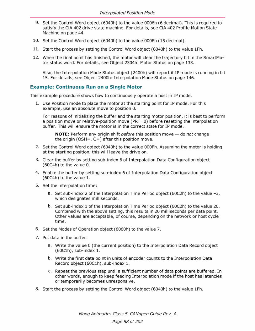
Interpolated Position Mode
Moog Animatics Class 5 CANopen Guide Rev. A
Page 58 of 202
9. Set the Control Word object (6040h) to the value 0006h (6 decimal). This is required tosatisfy the CiA 402 drive state machine. For details, see CiA 402 Profile Motion StateMachine on page 44.
10. Set the Control Word object (6040h) to the value 000Fh (15 decimal).
11. Start the process by setting the Control Word object (6040h) to the value 1Fh.
12. When the final point has finished, the motor will clear the trajectory bit in the SmartMo-tor status word. For details, see Object 2304h: Motor Status on page 133.
Also, the Interpolation Mode Status object (2400h) will report if IP mode is running in bit15. For details, see Object 2400h: Interpolation Mode Status on page 146.
Example: Continuous Run on a Single Motor
This example procedure shows how to continuously operate a host in IP mode.
1. Use Position mode to place the motor at the starting point for IP mode. For thisexample, use an absolute move to position 0.
For reasons of initializing the buffer and the starting motor position, it is best to performa position move or relative-position move (PRT=0) before resetting the interpolationbuffer. This will ensure the motor is in the correct state for IP mode.
NOTE: Perform any origin shift before this position move — do not changethe origin (OSH=, O=) after this position move.
2. Set the Control Word object (6040h) to the value 000Fh. Assuming the motor is holdingat the starting position, this will leave the drive on.
3. Clear the buffer by setting sub-index 6 of Interpolation Data Configuration object(60C4h) to the value 0.
4. Enable the buffer by setting sub-index 6 of Interpolation Data Configuration object(60C4h) to the value 1.
5. Set the interpolation time:
a. Set sub-index 2 of the Interpolation Time Period object (60C2h) to the value –3,which designates milliseconds.
b. Set sub-index 1 of the Interpolation Time Period object (60C2h) to the value 20.Combined with the above setting, this results in 20 milliseconds per data point.Other values are acceptable, of course, depending on the network or host cycletime.
6. Set the Modes of Operation object (6060h) to the value 7.
7. Put data in the buffer:
a. Write the value 0 (the current position) to the Interpolation Data Record object(60C1h), sub-index 1.
b. Write the first data point in units of encoder counts to the Interpolation DataRecord object (60C1h), sub-index 1.
c. Repeat the previous step until a sufficient number of data points are buffered. Inother words, enough to keep feeding Interpolation mode if the host has latenciesor temporarily becomes unresponsive.
8. Start the process by setting the Control Word object (6040h) to the value 1Fh.

Interpolated Position Mode
Moog Animatics Class 5 CANopen Guide Rev. A
Page 59 of 202
9. Monitor the buffer capacity by using bits 0–6 of the Interpolation Mode Status object(2400h), which will report the number of buffer spaces available. As the number of avail-able spaces approaches 0, the host should wait before sending further data.
NOTE: Bits 0–6 must be masked because the upper bits are used to reportother information. For details, see Object 2400h: Interpolation Mode Statuson page 146.
10. End Interpolation mode:
a. Set sub-index 1 of the Interpolation Time Period object (60C2h) to the value 0.
b. Repeat the final data point after this time period has been changed, and then writethe repeated final data point to Interpolation Data Record object (60C1h),sub-index 1. When the motor consumes this point, it will end its trajectory andhold its position. No further data points will be accepted.
11. Set the Control Word object (6040h) to the value 000Fh. This will leave the drive on butholding at the ending position.
Example: Resuming Motion in IP Mode
To resume motion without leaving IP mode:
1. Set the Control Word object (6040h) to the value 000Fh. This will be used later to causea rising edge on bit 4.
2. Do not clear the buffer. It is not necessary because this example assumes the mostrecent value written to sub-index 6 of the Interpolation Data Configuration object(60C4h) was 1.
3. Set sub-index 1 of the Interpolation Time Period object (60C2h) back to the desiredvalue (do not use 0).
4. Add more points to the buffer using sub-index 1 of the Interpolation Data Record object(60C1h). Start with the current position.
5. Start the process by setting the Control Word object (6040h) to the value 1Fh. The Inter-polation mode will resume. Monitor the buffer capacity and end IP mode as described inthe previous examples.
Synchronization
When running multiple motors in Interpolation mode, the rate at which data points are con-sumed can vary by several parts per million. While this sounds small, over time it will lead tothe SmartMotors not reaching a coordinated point simultaneously.
The following brief example is for a network of two motors with the master producing a syncevery 10 milliseconds. It is also possible for the time-producer motor to be the sync producerif the CANopen master cannot do so (this method is not shown here).
NOTE: This is an advanced topic that requires an understanding of PDO mapping.For details, see PDO Mapping on page 65.
1. Configure one motor as the time producer:
a. Map transmit PDO 4 to object 1013h.
b. Set the transmission type to 100 (to transmit at once per second because the syncrate is 100/second). The exact rate is not critical, but it is typically on the order ofone second.

Interpolated Position Mode
Moog Animatics Class 5 CANopen Guide Rev. A
Page 60 of 202
2. Configure all other motors as time consumers:
a. Map receive PDO 4 to object 1013h. Use the same COB-ID that was used to trans-mit PDO 4 from the time-producer.
b. Set the transmission type to 254. This will accept the high-resolution timestampwhen the time producer transmits it. The most recent sync is the reference pointin time where the timestamps from the producer and consumers are compared.
NOTE: The time consumer adjusts itself to match the time producer.
3. Switch to a network operational state.
When the first timestamp is received by the time consumers, they will accept the valuewithout trying to adjust to it. This is considered the starting point, so the consumer clocks areimmediately forced to this value instead of adjusting to it. If the synchronization process isinterrupted or the motors are switched out of operational network state, then the syn-chronization process will stop. This means that when it is restarted, it could take significanttime for the adjustment process to catch up. Instead, the adjustment process should be forcedto reaccept the time as it did at the beginning of the process. This can be accomplished by twodifferent methods:
1. Issue SmartMotor command CANCTL(2,0).
2. Switch to Interpolation mode using object 6060h. The motor must be in a different oper-ating mode, and it must see the transition to value 7 (Interpolation mode) in object6060h.
User Bits
A special feature is provided by the SmartMotor that allows status bits to be correlated withspecific data points in the buffer. The status bit can be used to indicate when a particular seg-ment between two points is achieved. This can be used to call special program routines or toset outputs to control external devices. For example, a laser-engraving tool may need asimple on/off state at certain points in the motion path. This event is correlated with the spe-cific range of positions in the buffer.
To write the bits, write to object 2403h — the range of values is 0 to 3Fh, which represents sixbits. These are associated with the next data record written to the Interpolation Data Recordobject (60C1h), sub-index 1. When the associated data point is reached, the new value (bit pat-tern) will be visible in SmartMotor status word 8 (object 2304h, sub-index 9) as bits 8–13.
The following procedure provides an example of the user bits feature. The value of object2403h is initially 0. The buffer is populated either initially or in a continuous run situation:
1. Put data in the buffer by writing the following values to sub-index 1 of the InterpolationData Record object (60C1h):
a. 2000
b. 3000
2. Set the Interpolation User Bits object (2403h) to the value 1.
3. Put data in the buffer by writing the value 4000 to the Interpolation Data Record object(60C1h), sub-index 1.
4. Set the Interpolation User Bits object (2403h) to the value 0.

Homing Mode
Moog Animatics Class 5 CANopen Guide Rev. A
Page 61 of 202
5. Put data in the buffer by writing the following values to sub-index 1 of the InterpolationData Record object (60C1h):
a. 5000
b. 6000
In the previous example, the user bit indicates when the motor position is between 3000 and4000. The user bit is accessible in SmartMotor status word 8 (object 2304h, sub-index 9). Thiscan be read in a user program with the following code:
IF B(8,8) ' RB(status word 8, bit 8)OS(0) ' Set output 0.
ELSEOR(0) ' Clear output 0.
ENDIF
Splining
By default, object 60C0h is set to 0. This commands the linear form of interpolation. Tosmooth data points, splined motion can be enabled by setting object 60C0h to the value –3.The change to this mode takes effect with the next data point written through object 60C1h,sub-index 1.
NOTE: While it is outside the scope of this manual, it is possible to mix splined andlinear interpolation per written data point. This provides interpolation control incases where spline interpolation does not provide the desired motion path.
Variable-Length Segments
It is possible to vary the length (in time) of the interpolation segment between data points.Object 60C2h, sub-index 1 and 2, control the interpolation timer period. There are some caseswhere it may be beneficial to reduce the required number of points. For example, roundedareas require more points, but straight segments require less points. The application of thistechnique is outside the scope of this manual. However, note that any change to object 60C2hwill be associated with the next position data record written through object 60C1h, sub-index1.
Homing ModeThis section describes the process for activating the SmartMotor homing process.
l For homing modes 1, and 17 there must be a negative limit switch connected andenabled. The positive limit may also be present or not, but it cannot be faulted.
l For homing modes 2, and 18 there must be a positive limit switch connected andenabled. The negative limit may also be present or not, but it cannot be faulted.
l For other homing modes, the limit switches must either be cleared of faults, or theymust be disabled.

Homing Mode
Moog Animatics Class 5 CANopen Guide Rev. A
Page 62 of 202
Homing Summary
The following table provides a summary of settings for activating the homing process. For adifferent example in step format, see the next section.
Description SMICommand
IndexObjectCode
Sub-Index
Data
Length Hex Dec
Note: Limit switches mustbe physically connected inthis example. The negativelimit switch will be used asthe home reference.
Reset status word ZS 6040h 00 02 0080 1280000 0000 1000 0000
Set Mode Homing (HM) 6060h 00 01 06 6
Set homing method 6098h 00 01 01 1
Set homing speed 1 6099h 01 04 000186A0 100000
Set homing speed 2 6099h 02 04 00002710 10000
Set homing acceleration 609Ah 00 04 00000064 100
Set homing offset 607Ch 00 04 000003E8 1000
Change state: Ready toswitch on
6040h 00 02 0006 60000 0000 0000 0110
Change state: Switched on 6040h 00 02 0007 70000 0000 0000 0111
Enable operation 6040h 00 02 000F 150000 0000 0000 1111
Start command G 6040h 00 02 001F 310000 0000 0001 1111
The homing will begin byheading toward the neg-ative limit.
Homing Example
The following procedure shows the steps for activating the homing process.
NOTE:Position Units (PU): encoder countsAcceleration/Deceleration Units (ADU): (encoder counts per (sample2)) * 65536Velocity Units (VU): encoder counts per sample * 65536
1. Clear the faults by setting the Control Word object (6040h) to the following values:
a. 0
b. 0080h (128 decimal)
c. 0
2. Set the Modes of Operation object (6060h) to the value 6 (decimal).
3. Set the Homing Method object (6098h) to the method desired. For details, see Object6098h: Homing Method on page 182.

Homing Mode
Moog Animatics Class 5 CANopen Guide Rev. A
Page 63 of 202
4. Set sub-index 1 of the Homing Speed object (6099h) to the desired speed in VU (forexample, the decimal value 100000). This is always a positive value. The Homing modedetermines the direction of motion.
5. Set sub-index 2 of the Homing Speed object (6099h) to the desired speed in VU (forexample, the decimal value 100000). This is always a positive value. The Homing modedetermines the direction of motion.
6. Set the Homing Acceleration object (609Ah) to the desired acceleration in ADU (forexample, the decimal value 10).
7. (Optional) Set the Home Offset object (607Ch) to the desired homing offset in PU.
8. Initialize and start the motion by setting the Control Word object (6040h) to the fol-lowing values:
a. 0006h (6 decimal) — This is required to satisfy the CiA 402 drive state machine.For details, see CiA 402 Profile Motion State Machine on page 44.
b. 000Fh (15 decimal)
c. 001Fh (31 decimal) — The motion begins.
9. Wait for the motion to complete. The Status Word object (6041h) will report when thehome position has been located. When the motor has come to a stop, then bit 10 =1 (tar-get reached) and bit 12 = 1 (home position found).
If bit 13 = 1 in the Status Word object (6041h), there was an error and homing was notcompleted.

PDO Mapping
Moog Animatics Class 5 CANopen Guide Rev. A
Page 65 of 202
PDO MappingThis chapter provides information on the Process Data Objects (PDOs) and the PDO mappingprocess. It also describes the low-level steps that must occur at startup between the masterand the motor to enable PDO communications.
Overview 66
Mapping and Communication Parameters Objects 67
Communications Parameters Objects 68
Mapping Parameters Objects 69
Mapping Entries 69
Mapping Procedure 70

Overview
Moog Animatics Class 5 CANopen Guide Rev. A
Page 66 of 202
OverviewProcess Data Objects (PDOs) are containers that hold one or more data objects. The set ofobjects in a PDO can be configured through the process of dynamic mapping. In a SmartMo-tor, this means that data objects such as the Velocity Actual Value object (606Ch) and theStatus Word object (6041h) can be placed in the same PDO transmission from the SmartMo-tor. The same can be done for receive PDOs — the motor will unpack the received PDO accord-ing to the mapping configuration and consume the data objects.
A CAN packet contains a maximum payload of 8 bytes. This creates a limit to the amount ofdata that is mapped into a single PDO. For example, a PDO can contain one INTEGER32 andtwo INTEGER16 objects. Other combinations are allowed, but the number of bytes must be 8or less.
A set of objects is available for performing object mapping. These objects are included in theset known as the Communication Profile objects (1000h-1FFFh). This is the standard for anyCANopen devices that support dynamic mapping. For details on the Communication Profileobjects, see Communication Profile on page 84.
NOTE: Some CANopen masters may have a graphical interface or automatedmeans of performing this mapping.
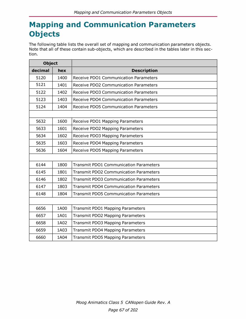
Mapping and Communication Parameters Objects
Moog Animatics Class 5 CANopen Guide Rev. A
Page 67 of 202
Mapping and Communication ParametersObjectsThe following table lists the overall set of mapping and communication parameters objects.Note that all of these contain sub-objects, which are described in the tables later in this sec-tion.
Object
decimal hex Description
5120 1400 Receive PDO1 Communication Parameters5121 1401 Receive PDO2 Communication Parameters
5122 1402 Receive PDO3 Communication Parameters
5123 1403 Receive PDO4 Communication Parameters
5124 1404 Receive PDO5 Communication Parameters
5632 1600 Receive PDO1 Mapping Parameters
5633 1601 Receive PDO2 Mapping Parameters
5634 1602 Receive PDO3 Mapping Parameters
5635 1603 Receive PDO4 Mapping Parameters
5636 1604 Receive PDO5 Mapping Parameters
6144 1800 Transmit PDO1 Communication Parameters
6145 1801 Transmit PDO2 Communication Parameters
6146 1802 Transmit PDO3 Communication Parameters
6147 1803 Transmit PDO4 Communication Parameters
6148 1804 Transmit PDO5 Communication Parameters
6656 1A00 Transmit PDO1 Mapping Parameters
6657 1A01 Transmit PDO2 Mapping Parameters
6658 1A02 Transmit PDO3 Mapping Parameters
6659 1A03 Transmit PDO4 Mapping Parameters
6660 1A04 Transmit PDO5 Mapping Parameters
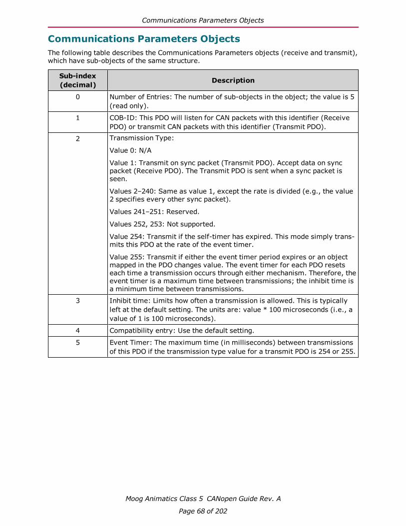
Communications Parameters Objects
Moog Animatics Class 5 CANopen Guide Rev. A
Page 68 of 202
Communications Parameters ObjectsThe following table describes the Communications Parameters objects (receive and transmit),which have sub-objects of the same structure.
Sub-index(decimal) Description
0 Number of Entries: The number of sub-objects in the object; the value is 5(read only).
1 COB-ID: This PDO will listen for CAN packets with this identifier (ReceivePDO) or transmit CAN packets with this identifier (Transmit PDO).
2 Transmission Type:
Value 0: N/A
Value 1: Transmit on sync packet (Transmit PDO). Accept data on syncpacket (Receive PDO). The Transmit PDO is sent when a sync packet isseen.
Values 2–240: Same as value 1, except the rate is divided (e.g., the value2 specifies every other sync packet).
Values 241–251: Reserved.
Values 252, 253: Not supported.
Value 254: Transmit if the self-timer has expired. This mode simply trans-mits this PDO at the rate of the event timer.
Value 255: Transmit if either the event timer period expires or an objectmapped in the PDO changes value. The event timer for each PDO resetseach time a transmission occurs through either mechanism. Therefore, theevent timer is a maximum time between transmissions; the inhibit time isa minimum time between transmissions.
3 Inhibit time: Limits how often a transmission is allowed. This is typicallyleft at the default setting. The units are: value * 100 microseconds (i.e., avalue of 1 is 100 microseconds).
4 Compatibility entry: Use the default setting.
5 Event Timer: The maximum time (in milliseconds) between transmissionsof this PDO if the transmission type value for a transmit PDO is 254 or 255.

Mapping Parameters Objects
Moog Animatics Class 5 CANopen Guide Rev. A
Page 69 of 202
Mapping Parameters ObjectsThe following table describes the Mapping Parameters objects (receive and transmit), whichhave sub-objects of the same structure.
Sub-index(decimal) Description
0 Number of Entries: Defines the number of objects that are mapped withinthis PDO. For instance, if "Mapping Entry 1" and "Mapping Entry 2" havebeen set up, then write the value 2.
1 Mapping Entry 1: Points to the mapped object. For details, see the fol-lowing sections.
2 Mapping Entry 2: Points to the mapped object. For details, see the fol-lowing sections.
3 Mapping Entry 3: Points to the mapped object. For details, see the fol-lowing sections.
4 Mapping Entry 4: Points to the mapped object. For details, see the fol-lowing sections.
Mapping EntriesOnly four mapping entries are allocated for the SmartMotor. Therefore, a maximum of fourobjects can be mapped into a PDO. The mapping entries must be filled contiguously startingfrom mapping entry 1. For example, for three entries, use mapping entry 1, 2 and 3.
All of these mapping entries are UNSIGNED32-bit values. There are three pieces of datapacked into each of these fields to represent the object being mapped:
l The object number
l The object sub-index (0 if none)
l The object size (in bits)
Therefore, in the form: (hex) nnnniiss
l n: object number
l i: sub-index
l s: size
The following example uses the Velocity Actual Value object (606Ch):
(hex) 606c0020
CAUTION: There is a specific procedure defined by the CANopen specificationfor mapping a variable. This procedure must be followed or an error will occur,which will prevent the change to the mapping.
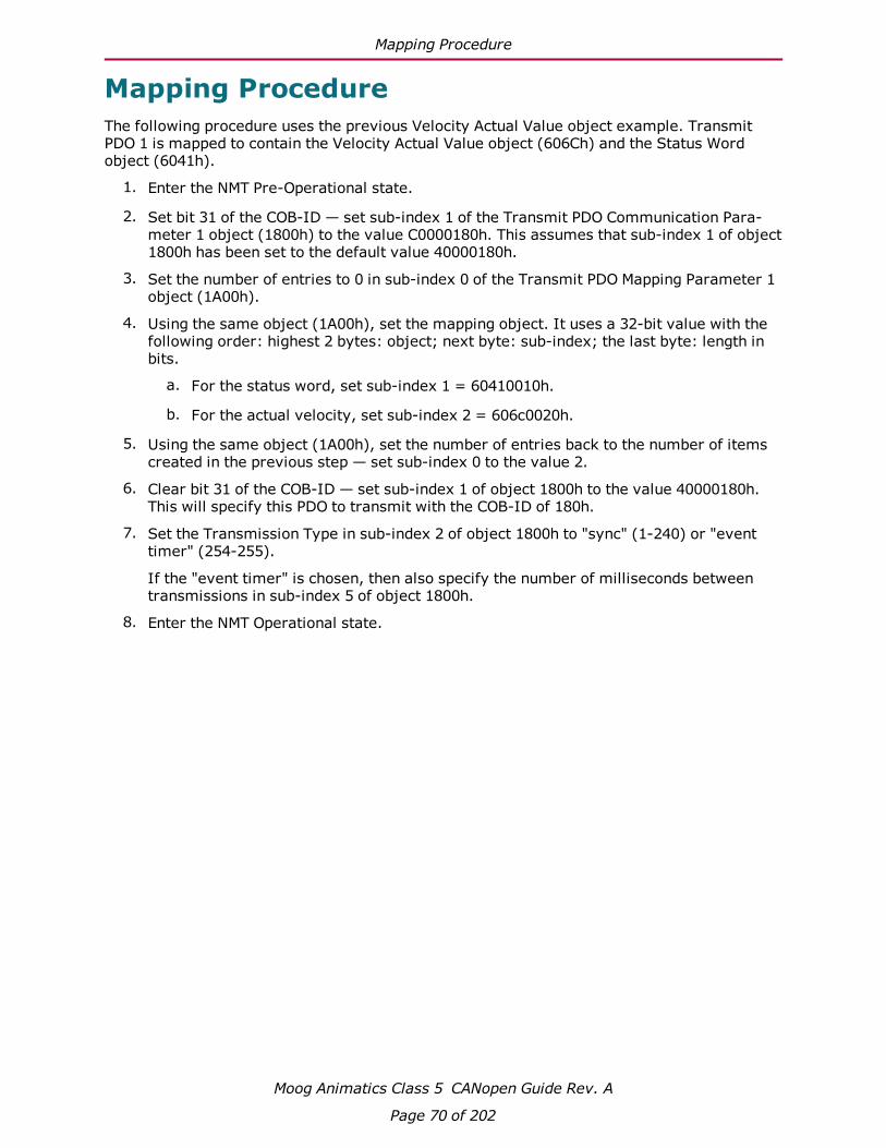
Mapping Procedure
Moog Animatics Class 5 CANopen Guide Rev. A
Page 70 of 202
Mapping ProcedureThe following procedure uses the previous Velocity Actual Value object example. TransmitPDO 1 is mapped to contain the Velocity Actual Value object (606Ch) and the Status Wordobject (6041h).
1. Enter the NMT Pre-Operational state.
2. Set bit 31 of the COB-ID — set sub-index 1 of the Transmit PDO Communication Para-meter 1 object (1800h) to the value C0000180h. This assumes that sub-index 1 of object1800h has been set to the default value 40000180h.
3. Set the number of entries to 0 in sub-index 0 of the Transmit PDO Mapping Parameter 1object (1A00h).
4. Using the same object (1A00h), set the mapping object. It uses a 32-bit value with thefollowing order: highest 2 bytes: object; next byte: sub-index; the last byte: length inbits.
a. For the status word, set sub-index 1 = 60410010h.
b. For the actual velocity, set sub-index 2 = 606c0020h.
5. Using the same object (1A00h), set the number of entries back to the number of itemscreated in the previous step — set sub-index 0 to the value 2.
6. Clear bit 31 of the COB-ID — set sub-index 1 of object 1800h to the value 40000180h.This will specify this PDO to transmit with the COB-ID of 180h.
7. Set the Transmission Type in sub-index 2 of object 1800h to "sync" (1-240) or "eventtimer" (254-255).
If the "event timer" is chosen, then also specify the number of milliseconds betweentransmissions in sub-index 5 of object 1800h.
8. Enter the NMT Operational state.

CANopen User Program Commands
Moog Animatics Class 5 CANopen Guide Rev. A
Page 71 of 202
CANopen User Program CommandsThis chapter provides details on the CANopen commands used with the SmartMotor and itsuser program. SmartMotor programming is described in the Moog Animatics SmartMotor™User's Guide. The SmartMotor user program allows the motor to take on autonomous or dis-tributed control functions needed in an application.
NOTE: The CAN network must have all devices set to the same baud rate forproper operation.
Address and Baud Rate Commands 72
CADDR=frm 72
CBAUD=frm 72
CAN Error Reporting Commands 72
=CAN, RCAN 72
Network Control Commands 74
CANCTL(action, value) 74

Address and Baud Rate Commands
Moog Animatics Class 5 CANopen Guide Rev. A
Page 72 of 202
Address and Baud Rate CommandsThe following are related commands.
CADDR=frmSet can address
Where frm is a number from 1 to 127. The value is stored in the SmartMotor's EEPROM.However, the SmartMotor must be powered off and on for it to take effect.
CBAUD=frmSet CAN baud rate
Where frm may be one of the following bit rates (bits/second): 1000000, 800000, 500000,250000, 125000, 50000 and 20000. The value is stored in the SmartMotor's EEPROM.However, the SmartMotor must be powered off and on for it to take effect.
The setting of 10000 bits/second is not supported. For details on other unsupported CANopenfeatures, see Not Supported on page 36.
CAN Error Reporting CommandsThe following are related commands.
=CAN, RCANGet CAN error
The =CAN and RCAN commands are used to assign/report errors and certain status inform-ation for the CAN bus.
l Assigned to a program variable: x=CAN(y)
l As a report: RCAN(y)
Where y is the following:
Assignment Report Description
=CAN(0) RCAN(0) Gets the CAN bus status bits:(*Indicates an error bit)
0 CAN Power Okay (not used by CANopen) 1* DeviceNet COM fault occurred (not used by CANopen)
2 DeviceNet Power Ignore option enabled (not used byCANopen)
3 Reserved 4* User attempted a Combitronic read from broadcast address 5* Combitronic debug, internal issue. 6* Timeout (Combitronic client)

=CAN, RCAN
Moog Animatics Class 5 CANopen Guide Rev. A
Page 73 of 202
Assignment Report Description
7* Combitronic server ran out of buffer slots 8* Errors reached warning level 9* Receive Errors reached warning level 10* Transmit Errors reached warning level 11* Receive Passive Error 12* Transmit Passive Error 13* Bus Off Error 14* RX buffer 1 overflowed 15* RX buffer 0 overflowed
=CAN(1) RCAN(1) Gets the value of the current NMT state:
l Pre-Operational: 127l Operational: 5l Stopped: 4
=CAN(2) RCAN(2) Gets the value of the Control Word object (6040h)
=CAN(3) RCAN(3) Gets the value of the Status Word object (6041h)
The =CAN(0) and RCAN(0) commands are used to report a bit map of conditions that couldoccur over the CAN bus. Not all bits are error bits. Therefore, it cannot be assumed that anon-zero value for RCAN is an error.
RCAN, which is the same as RCAN(0), reports a decimal number that is a combination of thebits shown in the =CAN(0)/RCAN(0) row of the previous table. Use the CAN command, whichis the same as =CAN(0), in a program to assign the decimal number to a variable, forexample:
x=CAN
A calculator with a binary display function can convert this decimal number to indicate the setof bits shown. Also, the SmartMotor Developer's Worksheet can be used for this conversion. Itis available from the Moog Animatics website at:
http://www.animatics.com/support/download-center.html
NOTE: Object 2304h, sub-index 3, bit 4 (CAN error) reports true if any of the errorindications above are set. In a user program, this is a simpler test than attemptingto filter the result of RCAN for the error conditions.

Network Control Commands
Moog Animatics Class 5 CANopen Guide Rev. A
Page 74 of 202
Network Control CommandsThe following are related commands.
CANCTL(action, value)Control network features
Commands execute based on the action argument, which controls CAN functions.
Action = Description0 Reserved; not used in CANopen firmware.1 Reset the CAN communications controller in the motor and all errors. Resets the
CANopen protocol in the motor. The value argument is ignored.2 Reset the activity of the CANopen clock sync using the high-resolution time
stamp. The value argument is ignored.3 This action uses the following value arguments:
l Value = 0: Reset the CANopen interpolation buffer through user command.Leaves the buffer disabled to prevent new data points.
l Value = 1: Reset the CANopen interpolation buffer through user command.Sets buffer access to allow new data points.
4 Use of this command is discouraged. It was previously provided to force themotion mode of operation from a user program. However, this functionality isnow available through existing SmartMotor commands such as MV, MP, MT, MC,MFR, MSR and MD.
5 Set timeout for Combitronic. The value argument specifies the time in mil-liseconds; it defaults to 30 (for 30 milliseconds).
12 This action uses the following value arguments:l Value = 0: Clears bit 14 in the status word (6041h). This is the defaultvalue at power-up of the motor.
l Value = 1: Sets bit 14 in the status word (6041h).
13 This action uses the following value arguments:l Value = 0: Disables access to several objects listed below. Clears "remote"bit 9 in the status word (6041h).
l Value = 1: Enables access to several objects listed below. By default, thisis the state at power-up of the motor. Sets "remote" bit 9 in the status word(6041h). The affected objects are:
o 6040h: Control Wordo 6060h: Modes of Operationo 6071h: Target Torqueo 6081h: Profile Velocity (pp mode)o 6083h: Profile Accelerationo 6084h: Profile Decelerationo 6087h: Torque Slopeo 60FBh: Sub-index 1–8, 10 (PID parameters)o 60FFh: Target Velocity

Troubleshooting
Moog Animatics Class 5 CANopen Guide Rev. A
Page 75 of 202
TroubleshootingThe following table provides troubleshooting information for solving SmartMotor problemsthat may be encountered when using CANopen. For additional support resources, see theMoog Animatics Support page at:
http://www.animatics.com/support.html
Issue Cause SolutionCANopen Communication IssuesMaster does notrecognize motor.
Motor not powered. Check Drive Status LED. If LED is notlit, check wiring.
Disconnected or miswiredCAN connector, or brokenwiring between motors.
Check that CANopen connector is cor-rectly wired and connected to motor.For details, see Connections, Wiringand Status LEDs on page 27.
Wrong CAN BAUD rate. Set CBAUD setting and then rebootmotor. For details, see Address andBaud Rate Commands on page 72.
Wrong CAN node ID(address)
Set CADDR setting and then rebootmotor. For details, see Address andBaud Rate Commands on page 72.
Wrong firmware For D-style motors, the firmwareshould be: 5.0.x.x; for M-style motors,the firmware should be 5.98.x.x.
Wrong bus topology, orwrong placement of ter-minators.
The CAN bus should be a linear bustopology. For details, see Connections,Wiring and Status LEDs on page 27.
Line lengths or droplengths of CAN bus are toolong.
Decrease line and/or drop lengths. Fordetails, see Connections, Wiring andStatus LEDs on page 27.
Network flooded withtraffic.
Set master temporarily to thePre-Operational state. Stop user pro-grams in all motors. For details, seeNMT States on page 22.
Red CAN error LED. A warning or bus off con-dition has occurred.
Check CAN Bus Network Fault LED — Ablinking red LED may indicate occa-sional issues from any of the causes lis-ted above; a solid red LED indicatesthat these issues have occurred fre-quently, which causes the motor tostop communicating (bus off con-dition). In this case, the SmartMotormust be reset after fixing the cause ofthe problem.
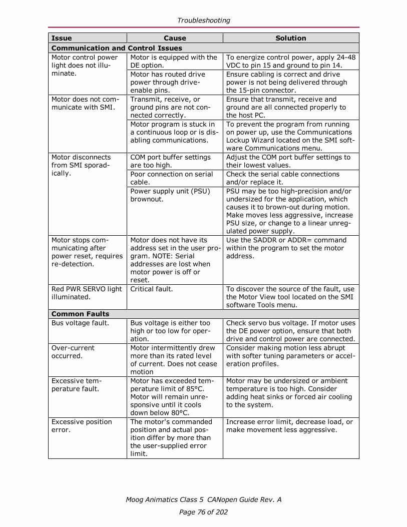
Troubleshooting
Moog Animatics Class 5 CANopen Guide Rev. A
Page 76 of 202
Issue Cause SolutionCommunication and Control IssuesMotor control powerlight does not illu-minate.
Motor is equipped with theDE option.
To energize control power, apply 24-48VDC to pin 15 and ground to pin 14.
Motor has routed drivepower through drive-enable pins.
Ensure cabling is correct and drivepower is not being delivered throughthe 15-pin connector.
Motor does not com-municate with SMI.
Transmit, receive, orground pins are not con-nected correctly.
Ensure that transmit, receive andground are all connected properly tothe host PC.
Motor program is stuck ina continuous loop or is dis-abling communications.
To prevent the program from runningon power up, use the CommunicationsLockup Wizard located on the SMI soft-ware Communications menu.
Motor disconnectsfrom SMI sporad-ically.
COM port buffer settingsare too high.
Adjust the COM port buffer settings totheir lowest values.
Poor connection on serialcable.
Check the serial cable connectionsand/or replace it.
Power supply unit (PSU)brownout.
PSU may be too high-precision and/orundersized for the application, whichcauses it to brown-out during motion.Make moves less aggressive, increasePSU size, or change to a linear unreg-ulated power supply.
Motor stops com-municating afterpower reset, requiresre-detection.
Motor does not have itsaddress set in the user pro-gram. NOTE: Serialaddresses are lost whenmotor power is off orreset.
Use the SADDR or ADDR= commandwithin the program to set the motoraddress.
Red PWR SERVO lightilluminated.
Critical fault. To discover the source of the fault, usethe Motor View tool located on the SMIsoftware Tools menu.
Common FaultsBus voltage fault. Bus voltage is either too
high or too low for oper-ation.
Check servo bus voltage. If motor usesthe DE power option, ensure that bothdrive and control power are connected.
Over-currentoccurred.
Motor intermittently drewmore than its rated levelof current. Does not ceasemotion
Consider making motion less abruptwith softer tuning parameters or accel-eration profiles.
Excessive tem-perature fault.
Motor has exceeded tem-perature limit of 85°C.Motor will remain unre-sponsive until it coolsdown below 80°C.
Motor may be undersized or ambienttemperature is too high. Consideradding heat sinks or forced air coolingto the system.
Excessive positionerror.
The motor's commandedposition and actual pos-ition differ by more thanthe user-supplied errorlimit.
Increase error limit, decrease load, ormake movement less aggressive.
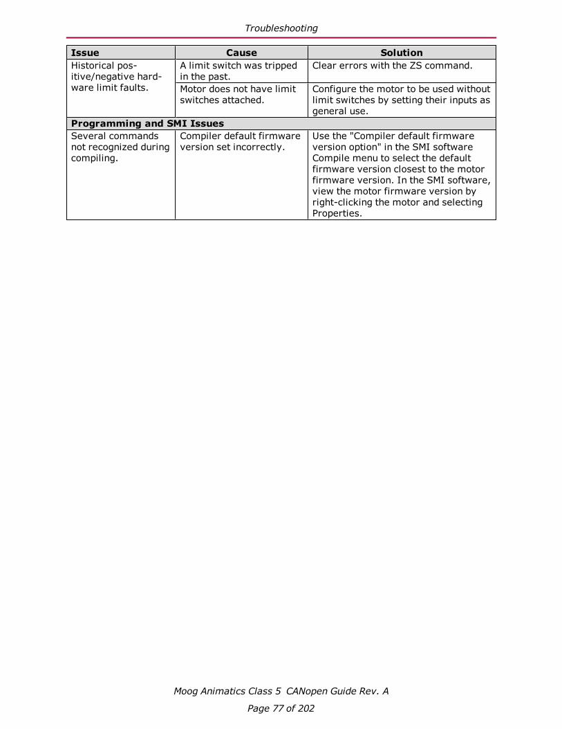
Troubleshooting
Moog Animatics Class 5 CANopen Guide Rev. A
Page 77 of 202
Issue Cause SolutionHistorical pos-itive/negative hard-ware limit faults.
A limit switch was trippedin the past.
Clear errors with the ZS command.
Motor does not have limitswitches attached.
Configure the motor to be used withoutlimit switches by setting their inputs asgeneral use.
Programming and SMI IssuesSeveral commandsnot recognized duringcompiling.
Compiler default firmwareversion set incorrectly.
Use the "Compiler default firmwareversion option" in the SMI softwareCompile menu to select the defaultfirmware version closest to the motorfirmware version. In the SMI software,view the motor firmware version byright-clicking the motor and selectingProperties.

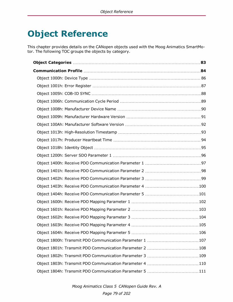
Object Reference
Moog Animatics Class 5 CANopen Guide Rev. A
Page 79 of 202
Object ReferenceThis chapter provides details on the CANopen objects used with the Moog Animatics SmartMo-tor. The following TOC groups the objects by category.
Object Categories 83
Communication Profile 84
Object 1000h: Device Type 86
Object 1001h: Error Register 87
Object 1005h: COB-ID SYNC 88
Object 1006h: Communication Cycle Period 89
Object 1008h: Manufacturer Device Name 90
Object 1009h: Manufacturer Hardware Version 91
Object 100Ah: Manufacturer Software Version 92
Object 1013h: High-Resolution Timestamp 93
Object 1017h: Producer Heartbeat Time 94
Object 1018h: Identity Object 95
Object 1200h: Server SDO Parameter 1 96
Object 1400h: Receive PDO Communication Parameter 1 97
Object 1401h: Receive PDO Communication Parameter 2 98
Object 1402h: Receive PDO Communication Parameter 3 99
Object 1403h: Receive PDO Communication Parameter 4 100
Object 1404h: Receive PDO Communication Parameter 5 101
Object 1600h: Receive PDO Mapping Parameter 1 102
Object 1601h: Receive PDO Mapping Parameter 2 103
Object 1602h: Receive PDO Mapping Parameter 3 104
Object 1603h: Receive PDO Mapping Parameter 4 105
Object 1604h: Receive PDO Mapping Parameter 5 106
Object 1800h: Transmit PDO Communication Parameter 1 107
Object 1801h: Transmit PDO Communication Parameter 2 108
Object 1802h: Transmit PDO Communication Parameter 3 109
Object 1803h: Transmit PDO Communication Parameter 4 110
Object 1804h: Transmit PDO Communication Parameter 5 111
Object Reference
Moog Animatics Class 5 CANopen Guide Rev. A
Page 80 of 202
Object 1A00h: Transmit PDO Mapping Parameter 1 112
Object 1A01h: Transmit PDO Mapping Parameter 2 113
Object 1A02h: Transmit PDO Mapping Parameter 3 114
Object 1A03h: Transmit PDO Mapping Parameter 4 115
Object 1A04h: Transmit PDO Mapping Parameter 5 116
Manufacturer-Specific Profile 117
Object 2000h: Node Id 118
Object 2001h: Bit Rate Index 119
Object 2100h: Port Configuration 120
Object 2101h: Bit IO 121
Object 2200h: User EEPROM 122
Object 2201h: User Variable 123
Object 2202h: Set Position Origin 124
Object 2203h: Shift Position Origin 125
Object 2204h: Mappable Variables 126
Object 2205h Negative Software Position Limit 127
Object 2206h Positive Software Position Limit 128
Object 2300h: Bus Voltage 129
Object 2301h: RMS Current 130
Object 2302h: Internal Temperature 131
Object 2303h: Internal Clock 132
Object 2304h: Motor Status 133
Object 2305h: Motor Control 141
Object 2306h: Motor Subroutine Index 142
Object 2307h: Sample Period 143
Object 2308h: Microsecond Clock 144
Object 2309h: GOSUB R2 145
Object 2400h: Interpolation Mode Status 146
Object 2401h: Buffer Control 147
Object 2402h: Buffer Setpoint 148
Object 2403h: Interpolation User Bits 149
Object 2404h: Interpolation Sample Clock 150
Object 2500h: Encapsulated SmartMotor Command 151

Object Reference
Moog Animatics Class 5 CANopen Guide Rev. A
Page 81 of 202
Drive and Motion Control Profile 152
Object 6040h: Control Word 154
Object 6041h: Status Word 156
Object 605Ah: Quick Stop Option Code 157
Object 605Dh: Halt Option Code 158
Object 605Eh: Fault Reaction Option Code 159
Object 6060h: Modes of Operation 160
Object 6061h: Modes of Operation Display 161
Object 6062h: Position Demand Value 162
Object 6063h: Position Actual Internal Value 163
Object 6064h: Position Actual Value 164
Object 6065h: Following Error Window 165
Object 606Bh: Velocity Demand Value 166
Object 606Ch: Velocity Actual Value 167
Object 6071h: Target Torque 168
Object 6074h: Torque Demand Value 169
Object 6077h: Torque Actual 170
Object 6079h: DC Link Circuit Voltage 171
Object 607Ah: Target Position 172
Object 607Ch: Home Offset 173
Object 6080h: Max Motor Speed 175
Object 6081h: Profile Velocity in PP Mode 176
Object 6083h: Profile Acceleration 177
Object 6084h: Profile Deceleration 178
Object 6085h: Quick Stop Deceleration 179
Object 6087h: Torque Slope 180
Object 608Fh: Position Encoder Resolution 181
Object 6098h: Homing Method 182
Object 6099h: Homing Speeds 183
Object 609Ah: Homing Acceleration 184
Object 60C0h: Interpolation Sub-Mode Select 185
Object 60C1h: Interpolation Data Record 186
Object 60C2h: Interpolation Time Period 187

Object Reference
Moog Animatics Class 5 CANopen Guide Rev. A
Page 82 of 202
Object 60C4h: Interpolation Data Configuration 189
Object 60F4h: Following Error Actual Value 190
Object 60FBh: Position Control Parameter Set 191
Object 60FCh: Position Demand Internal Value 193
Object 60FDh: Digital Inputs 194
Object 60FEh: Digital Outputs 196
Object 60FFh: Target Velocity 197
Object 6402h: Motor Type 198
Object 6502h: Supported Drive Modes 199
Object 67FFh: Single Device Type 200
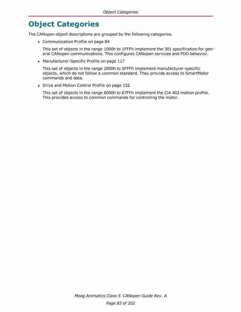
Object Categories
Moog Animatics Class 5 CANopen Guide Rev. A
Page 83 of 202
Object CategoriesThe CANopen object descriptions are grouped by the following categories.
l Communication Profile on page 84
This set of objects in the range 1000h to 1FFFh implement the 301 specification for gen-eral CANopen communications. This configures CANopen services and PDO behavior.
l Manufacturer-Specific Profile on page 117
This set of objects in the range 2000h to 5FFFh implement manufacturer-specificobjects, which do not follow a common standard. They provide access to SmartMotorcommands and data.
l Drive and Motion Control Profile on page 152
This set of objects in the range 6000h to 67FFh implement the CiA 402 motion profile.This provides access to common commands for controlling the motor.

Communication Profile
Moog Animatics Class 5 CANopen Guide Rev. A
Page 84 of 202
Communication ProfileThis section describes the objects in the Communication Profile. This set of objects in therange 1000h to 1FFFh implement the 301 specification for general CANopen communications.This configures CANopen services and PDO behavior.
Object 1000h: Device Type 86
Object 1001h: Error Register 87
Object 1005h: COB-ID SYNC 88
Object 1006h: Communication Cycle Period 89
Object 1008h: Manufacturer Device Name 90
Object 1009h: Manufacturer Hardware Version 91
Object 100Ah: Manufacturer Software Version 92
Object 1013h: High-Resolution Timestamp 93
Object 1017h: Producer Heartbeat Time 94
Object 1018h: Identity Object 95
Object 1200h: Server SDO Parameter 1 96
Object 1400h: Receive PDO Communication Parameter 1 97
Object 1401h: Receive PDO Communication Parameter 2 98
Object 1402h: Receive PDO Communication Parameter 3 99
Object 1403h: Receive PDO Communication Parameter 4 100
Object 1404h: Receive PDO Communication Parameter 5 101
Object 1600h: Receive PDO Mapping Parameter 1 102
Object 1601h: Receive PDO Mapping Parameter 2 103
Object 1602h: Receive PDO Mapping Parameter 3 104
Object 1603h: Receive PDO Mapping Parameter 4 105
Object 1604h: Receive PDO Mapping Parameter 5 106
Object 1800h: Transmit PDO Communication Parameter 1 107
Object 1801h: Transmit PDO Communication Parameter 2 108
Object 1802h: Transmit PDO Communication Parameter 3 109
Object 1803h: Transmit PDO Communication Parameter 4 110
Object 1804h: Transmit PDO Communication Parameter 5 111
Object 1A00h: Transmit PDO Mapping Parameter 1 112
Communication Profile
Moog Animatics Class 5 CANopen Guide Rev. A
Page 85 of 202
Object 1A01h: Transmit PDO Mapping Parameter 2 113
Object 1A02h: Transmit PDO Mapping Parameter 3 114
Object 1A03h: Transmit PDO Mapping Parameter 4 115
Object 1A04h: Transmit PDO Mapping Parameter 5 116

Object 1000h: Device Type
Moog Animatics Class 5 CANopen Guide Rev. A
Page 86 of 202
Object 1000h: Device Type
Object Sub-Index Description Low
LimitHighLimit Default PDO
MapDatatype Access
1000h 000 Device Type 00000000h FFFFFFFFh 00020192h No Unsigned32-bit
ReadOnly
This object is required by CANopen to provide information about this device. The value of thisobject does not change.
Bit Meaning
0–15 (16 bits) Device profile: 402 (192 hex)
16–23 (8 bits) Device type: 02 hex, to indicate a single instance of a servo drive
24–31 (8 bits) Device mode: 0 (manufacturer-specific / reserved)
Also, refer to Object 67FFh: Single Device Type on page 200.

Object 1001h: Error Register
Moog Animatics Class 5 CANopen Guide Rev. A
Page 87 of 202
Object 1001h: Error Register
Object Sub-Index Description Low
LimitHighLimit Default PDO
MapDatatype Access
1001h 000 Error Register 00h FFh No Unsigned8-bit
ReadOnly
The value read from this object contains a bit field with the following meaning:
Bit Function
0 General error
Includes any of the following:
l motion faultl drive not readyl CAN communication errorsl program command errorl program checksum errorl serial communication error
1–7 Reserved
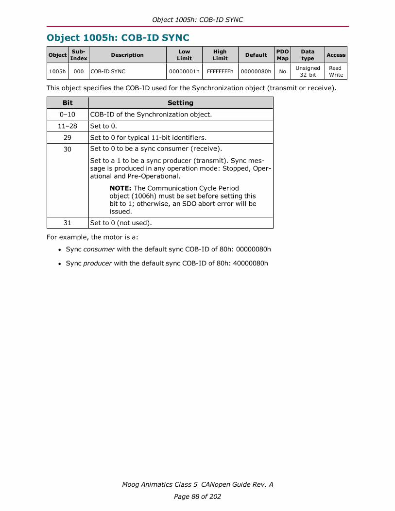
Object 1005h: COB-ID SYNC
Moog Animatics Class 5 CANopen Guide Rev. A
Page 88 of 202
Object 1005h: COB-ID SYNC
Object Sub-Index Description Low
LimitHighLimit Default PDO
MapDatatype Access
1005h 000 COB-ID SYNC 00000001h FFFFFFFFh 00000080h No Unsigned32-bit
ReadWrite
This object specifies the COB-ID used for the Synchronization object (transmit or receive).
Bit Setting
0–10 COB-ID of the Synchronization object.
11–28 Set to 0.
29 Set to 0 for typical 11-bit identifiers.
30 Set to 0 to be a sync consumer (receive).
Set to a 1 to be a sync producer (transmit). Sync mes-sage is produced in any operation mode: Stopped, Oper-ational and Pre-Operational.
NOTE: The Communication Cycle Periodobject (1006h) must be set before setting thisbit to 1; otherwise, an SDO abort error will beissued.
31 Set to 0 (not used).
For example, the motor is a:
l Sync consumer with the default sync COB-ID of 80h: 00000080h
l Sync producer with the default sync COB-ID of 80h: 40000080h

Object 1006h: Communication Cycle Period
Moog Animatics Class 5 CANopen Guide Rev. A
Page 89 of 202
Object 1006h: Communication Cycle Period
Object Sub-Index Description Low
LimitHighLimit Default PDO
MapDatatype Access
1006h 000 Communication Cycle Period 00000000h FFFFFFFFh 00000000h No Unsigned32-bit
ReadWrite
This object defines the communication cycle period in microseconds for transmission of thesync message. Set to 0 to disable the sync message transmission. Also, refer to Object1005h: COB-ID SYNC on page 88.
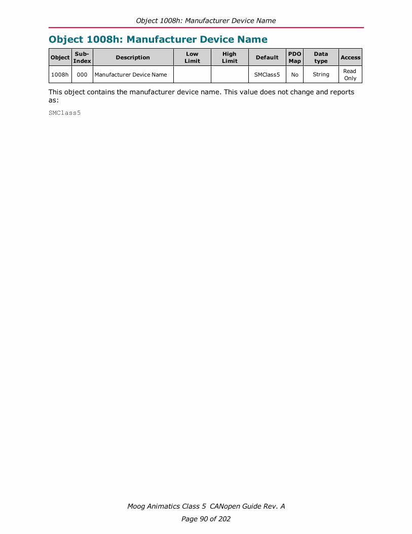
Object 1008h: Manufacturer Device Name
Moog Animatics Class 5 CANopen Guide Rev. A
Page 90 of 202
Object 1008h: Manufacturer Device Name
Object Sub-Index Description Low
LimitHighLimit Default PDO
MapDatatype Access
1008h 000 Manufacturer Device Name SMClass5 No String ReadOnly
This object contains the manufacturer device name. This value does not change and reportsas:
SMClass5

Object 1009h: Manufacturer Hardware Version
Moog Animatics Class 5 CANopen Guide Rev. A
Page 91 of 202
Object 1009h: Manufacturer Hardware Version
Object Sub-Index Description Low
LimitHighLimit Default PDO
MapDatatype Access
1009h 000 Manufacturer Hardware Ver-sion 01.00 No String Read
Only
This object contains the device hardware version. This value does not change and reports as:
01.00

Object 100Ah: Manufacturer Software Version
Moog Animatics Class 5 CANopen Guide Rev. A
Page 92 of 202
Object 100Ah: Manufacturer Software Version
Object Sub-Index Description Low
LimitHighLimit Default PDO
MapDatatype Access
100Ah 000 Manufacturer Software Ver-sion No String Read
Only
This object contains the firmware version of the motor. It reports a string in the format:
5.x.y.z
Where x can be:
l 0 for CANopen D-style motor
l 98 for CANopen M-style motor
The y and z positions represent the major and minor software release version, respectively.
The string is 16 bytes long; it is padded with null characters at the end.
Similar SmartMotor Commands: RFW, RSP (firmware) info

Object 1013h: High-Resolution Timestamp
Moog Animatics Class 5 CANopen Guide Rev. A
Page 93 of 202
Object 1013h: High-Resolution Timestamp
Object Sub-Index Description Low
LimitHighLimit Default PDO
MapDatatype Access
1013h 000 High-Resolution Timestamp 00000000h FFFFFFFFh 00000000h Yes Unsigned32-bit
ReadWrite
This object contains a timestamp with a resolution of 1 microsecond. It can be mapped into aPDO in order to define a high-resolution timestamp.
Typically, one motor is configured to transmit its object 1013, and one or more other motorsreceive this value for the purpose of synchronization.
When this object is read, it is the captured value of the high-resolution timer at the mostrecent sync; therefore, it is not the current value.
NOTE: The captured value is not the current value of the high-resolution timer.
When this object is written, it is used to skew the motor's internal timing to stay synchronizedwith other motors.
For more details, see Synchronization on page 59.

Object 1017h: Producer Heartbeat Time
Moog Animatics Class 5 CANopen Guide Rev. A
Page 94 of 202
Object 1017h: Producer Heartbeat Time
Object Sub-Index Description Low
LimitHighLimit Default PDO
MapDatatype Access
1017h 000 Producer Heartbeat Time 0000h FFFFh 0000h No Unsigned16-bit
ReadWrite
This object defines the cycle time of the heartbeat transmission from the motor in mil-liseconds. Transmission begins as soon as the value is set. If the value is 0, nothing is trans-mitted.
The heartbeat contains information that tells the master (or other devices) that the heartbeatcame from this device and what network state it is in (Operational, Pre-Operational,Stopped).

Object 1018h: Identity Object
Moog Animatics Class 5 CANopen Guide Rev. A
Page 95 of 202
Object 1018h: Identity Object
Object Sub-Index Description Low
LimitHighLimit Default PDO
MapDatatype Access
1018h 000 Number of Entries 01h 04h 04h No Unsigned8-bit
ReadOnly
1018h 001 Vendor ID 00000000h FFFFFFFFh 00000226h No Unsigned32-bit
ReadOnly
1018h 002 Product Code 00000000h FFFFFFFFh 00000003h No Unsigned32-bit
ReadOnly
1018h 003 Revision Number 00000000h FFFFFFFFh Revisionnumber No Unsigned
32-bitReadOnly
1018h 004 Serial Number 00000000h FFFFFFFFh Motor serialnumber No Unsigned
32-bitReadOnly
This object contains general information about the device. These values are constant and donot change.
l Sub-index 1 contains the Vendor ID number assigned to Moog Animatics: 226h.
l Sub-index 2 contains the manufacturer-specific product code: 3h.
l Sub-index 3 contains the revision number.o Bit 31–16 is the major revision number.
o Bit 15–0 is the minor revision number.
l Sub-index 4 contains the unique serial number of this SmartMotor. This number is thesame as the serial number printed on the SmartMotor label, except that the leadingalpha character is dropped. Only the 24-bit numeric digits are reported.

Object 1200h: Server SDO Parameter 1
Moog Animatics Class 5 CANopen Guide Rev. A
Page 96 of 202
Object 1200h: Server SDO Parameter 1
Object Sub-Index Description Low
LimitHighLimit Default PDO
MapDatatype Access
1200h 000 Number of Entries 02h 02h 02h No Unsigned8-bit
ReadOnly
1200h 001 COB-ID Client to Server 00000600h BFFFFFFFh 00000600+ node ID No Unsigned
32-bitReadOnly
1200h 002 COB-ID Server to Client 00000580h BFFFFFFFh 00000580+ node ID No Unsigned
32-bitReadOnly
These are the COB-ID values used for SDO communications from the CANopen master to theSmartMotor. The value is automatically updated based on the node ID (motor address) accord-ing to the default connection set. This information cannot be changed; it is provided for inform-ative purposes only.

Object 1400h: Receive PDO Communication Parameter 1
Moog Animatics Class 5 CANopen Guide Rev. A
Page 97 of 202
Object 1400h: Receive PDO Communication Parameter 1
Object Sub-Index Description Low
LimitHighLimit Default PDO
MapDatatype Access
1400h 000 Number of Entries 02h 05h 05h No Unsigned8-bit
ReadOnly
1400h 001 COB-ID 00000001h FFFFFFFFh 00000200h+ node ID No Unsigned
32-bitReadWrite
1400h 002 Transmission Type 00h FFh FFh No Unsigned8-bit
ReadWrite
1400h 003 Inhibit Time 0000h FFFFh 0000h No Unsigned16-bit
ReadWrite
1400h 004 Compatibility Entry 00h FFh 00h No Unsigned8-bit
ReadWrite
1400h 005 Event Timer 0000h FFFFh 0000h No Unsigned16-bit
ReadWrite
This object controls the behavior of receive PDO 1.
For the following items, refer to the table Communications Parameters Objects on page 68:
l Sub-index 0: Number of sub-index objects in this object (5)
l Sub-index 1: COB-ID used for this PDO; when set, bit 31 is used to disable the PDO
l Sub-index 2: Transmission type
l Sub-index 3: Inhibit time in units of 100 microseconds
l Sub-index 4: Not used; use the default setting
l Sub-index 5: Event time, in milliseconds, for transmit PDOs type 254 and 255

Object 1401h: Receive PDO Communication Parameter 2
Moog Animatics Class 5 CANopen Guide Rev. A
Page 98 of 202
Object 1401h: Receive PDO Communication Parameter 2
Object Sub-Index Description Low
LimitHighLimit Default PDO
MapDatatype Access
1401h 000 Number of Entries 02h 05h 05h No Unsigned8-bit
ReadOnly
1401h 001 COB-ID 00000001h FFFFFFFFh 80000300h+ node ID No Unsigned
32-bitReadWrite
1401h 002 Transmission Type 00h FFh FFh No Unsigned8-bit
ReadWrite
1401h 003 Inhibit Time 0000h FFFFh 0000h No Unsigned16-bit
ReadWrite
1401h 004 Compatibility Entry 00h FFh 00h No Unsigned8-bit
ReadWrite
1401h 005 Event Timer 0000h FFFFh 0000h No Unsigned16-bit
ReadWrite
This object controls the behavior of receive PDO 2.
For the following items, refer to the table Communications Parameters Objects on page 68:
l Sub-index 0: Number of sub-index objects in this object (5)
l Sub-index 1: COB-ID used for this PDO; when set, bit 31 is used to disable the PDO
l Sub-index 2: Transmission type
l Sub-index 3: Inhibit time in units of 100 microseconds
l Sub-index 4: Not used; use the default setting
l Sub-index 5: Event time, in milliseconds, for transmit PDOs type 254 and 255

Object 1402h: Receive PDO Communication Parameter 3
Moog Animatics Class 5 CANopen Guide Rev. A
Page 99 of 202
Object 1402h: Receive PDO Communication Parameter 3
Object Sub-Index Description Low
LimitHighLimit Default PDO
MapDatatype Access
1402h 000 Number of Entries 02h 05h 05h No Unsigned8-bit
ReadOnly
1402h 001 COB-ID 00000001h FFFFFFFFh 80000400h+ node ID No Unsigned
32-bitReadWrite
1402h 002 Transmission Type 00h FFh FFh No Unsigned8-bit
ReadWrite
1402h 003 Inhibit Time 0000h FFFFh 0000h No Unsigned16-bit
ReadWrite
1402h 004 Compatibility Entry 00h FFh 00h No Unsigned8-bit
ReadWrite
1402h 005 Event Timer 0000h FFFFh 0000h No Unsigned16-bit
ReadWrite
This object controls the behavior of receive PDO 3.
For the following items, refer to the table Communications Parameters Objects on page 68:
l Sub-index 0: Number of sub-index objects in this object (5)
l Sub-index 1: COB-ID used for this PDO; when set, bit 31 is used to disable the PDO
l Sub-index 2: Transmission type
l Sub-index 3: Inhibit time in units of 100 microseconds
l Sub-index 4: Not used; use the default setting
l Sub-index 5: Event time, in milliseconds, for transmit PDOs type 254 and 255

Object 1403h: Receive PDO Communication Parameter 4
Moog Animatics Class 5 CANopen Guide Rev. A
Page 100 of 202
Object 1403h: Receive PDO Communication Parameter 4
Object Sub-Index Description Low
LimitHighLimit Default PDO
MapDatatype Access
1403h 000 Number of Entries 02h 05h 05h No Unsigned8-bit
ReadOnly
1403h 001 COB-ID 00000001h FFFFFFFFh 80000500h+ node ID No Unsigned
32-bitReadWrite
1403h 002 Transmission Type 00h FFh FFh No Unsigned8-bit
ReadWrite
1403h 003 Inhibit Time 0000h FFFFh 0000h No Unsigned16-bit
ReadWrite
1403h 004 Compatibility Entry 00h FFh 00h No Unsigned8-bit
ReadWrite
1403h 005 Event Timer 0000h FFFFh 0000h No Unsigned16-bit
ReadWrite
This object controls the behavior of receive PDO 4.
For the following items, refer to the table Communications Parameters Objects on page 68:
l Sub-index 0: Number of sub-index objects in this object (5)
l Sub-index 1: COB-ID used for this PDO; when set, bit 31 is used to disable the PDO
l Sub-index 2: Transmission type
l Sub-index 3: Inhibit time in units of 100 microseconds
l Sub-index 4: Not used; use the default setting
l Sub-index 5: Event time, in milliseconds, for transmit PDOs type 254 and 255

Object 1404h: Receive PDO Communication Parameter 5
Moog Animatics Class 5 CANopen Guide Rev. A
Page 101 of 202
Object 1404h: Receive PDO Communication Parameter 5
Object Sub-Index Description Low
LimitHighLimit Default PDO
MapDatatype Access
1404h 000 Number of Entries 02h 05h 05h No Unsigned8-bit
ReadOnly
1404h 001 COB-ID 00000001h FFFFFFFFh 80000000h No Unsigned32-bit
ReadWrite
1404h 002 Transmission Type 00h FFh FFh No Unsigned8-bit
ReadWrite
1404h 003 Inhibit Time 0000h FFFFh 0000h No Unsigned16-bit
ReadWrite
1404h 004 Compatibility Entry 00h FFh 00h No Unsigned8-bit
ReadWrite
1404h 005 Event Timer 0000h FFFFh 0000h No Unsigned16-bit
ReadWrite
This object controls the behavior of receive PDO 5.
For the following items, refer to the table Communications Parameters Objects on page 68:
l Sub-index 0: Number of sub-index objects in this object (5)
l Sub-index 1: COB-ID used for this PDO; when set, bit 31 is used to disable the PDO
l Sub-index 2: Transmission type
l Sub-index 3: Inhibit time in units of 100 microseconds
l Sub-index 4: Not used; use the default setting
l Sub-index 5: Event time, in milliseconds, for transmit PDOs type 254 and 255

Object 1600h: Receive PDO Mapping Parameter 1
Moog Animatics Class 5 CANopen Guide Rev. A
Page 102 of 202
Object 1600h: Receive PDO Mapping Parameter 1
Object Sub-Index Description Low
LimitHighLimit Default PDO
MapDatatype Access
1600h 000 Number of Entries 00h 04h 01h No Unsigned8-bit
ReadWrite
1600h 001 Mapping Entry 1 00000000h FFFFFFFFh 60400010h No Unsigned32-bit
ReadWrite
1600h 002 Mapping Entry 2 00000000h FFFFFFFFh 00000000h No Unsigned32-bit
ReadWrite
1600h 003 Mapping Entry 3 00000000h FFFFFFFFh 00000000h No Unsigned32-bit
ReadWrite
1600h 004 Mapping Entry 4 00000000h FFFFFFFFh 00000000h No Unsigned32-bit
ReadWrite
This object controls which objects are mapped into receive PDO 1.
For the following items, refer to Mapping Parameters Objects on page 69:
l Sub-index 0: Number of valid sub-index objects in this object. This is set according tothe filled mapping entries starting from sub-index 1.
l Sub-indexes 1–4: These provide information about the object mapped in this PDO. Theycontain the indexes, the sub-indexes and the lengths of the mapped object. Fill thesestarting from sub-index 1. The structure is:
Bit Meaning
Bits 16–31 (16 bit) Index of the objectto map
Bits 8–15 (8 bit) Sub-index of theobject to map
Bits 0–7 (8 bit) Length of the object(in bits)

Object 1601h: Receive PDO Mapping Parameter 2
Moog Animatics Class 5 CANopen Guide Rev. A
Page 103 of 202
Object 1601h: Receive PDO Mapping Parameter 2
Object Sub-Index Description Low
LimitHighLimit Default PDO
MapDatatype Access
1601h 000 Number of Entries 00h 04h 02h No Unsigned8-bit
ReadWrite
1601h 001 Mapping Entry 1 00000000h FFFFFFFFh 60400010h No Unsigned32-bit
ReadWrite
1601h 002 Mapping Entry 2 00000000h FFFFFFFFh 60600008h No Unsigned32-bit
ReadWrite
1601h 003 Mapping Entry 3 00000000h FFFFFFFFh 00000000h No Unsigned32-bit
ReadWrite
1601h 004 Mapping Entry 4 00000000h FFFFFFFFh 00000000h No Unsigned32-bit
ReadWrite
This object controls which objects are mapped into receive PDO 2.
For the following items, refer to Mapping Parameters Objects on page 69:
l Sub-index 0: Number of valid sub-index objects in this object. This is set according tothe filled mapping entries starting from sub-index 1.
l Sub-indexes 1–4: These provide information about the object mapped in this PDO. Theycontain the indexes, the sub-indexes and the lengths of the mapped object. Fill thesestarting from sub-index 1. The structure is:
Bit Meaning
Bits 16–31 (16 bit) Index of the objectto map
Bits 8–15 (8 bit) Sub-index of theobject to map
Bits 0–7 (8 bit) Length of the object(in bits)

Object 1602h: Receive PDO Mapping Parameter 3
Moog Animatics Class 5 CANopen Guide Rev. A
Page 104 of 202
Object 1602h: Receive PDO Mapping Parameter 3
Object Sub-Index Description Low
LimitHighLimit Default PDO
MapDatatype Access
1602h 000 Number of Entries 00h 04h 02h No Unsigned8-bit
ReadWrite
1602h 001 Mapping Entry 1 00000000h FFFFFFFFh 60400010h No Unsigned32-bit
ReadWrite
1602h 002 Mapping Entry 2 00000000h FFFFFFFFh 607A0020h No Unsigned32-bit
ReadWrite
1602h 003 Mapping Entry 3 00000000h FFFFFFFFh 00000000h No Unsigned32-bit
ReadWrite
1602h 004 Mapping Entry 4 00000000h FFFFFFFFh 00000000h No Unsigned32-bit
ReadWrite
This object controls which objects are mapped into receive PDO 3.
For the following items, refer to Mapping Parameters Objects on page 69:
l Sub-index 0: Number of valid sub-index objects in this object. This is set according tothe filled mapping entries starting from sub-index 1.
l Sub-indexes 1–4: These provide information about the object mapped in this PDO. Theycontain the indexes, the sub-indexes and the lengths of the mapped object. Fill thesestarting from sub-index 1. The structure is:
Bit Meaning
Bits 16–31 (16 bit) Index of the objectto map
Bits 8–15 (8 bit) Sub-index of theobject to map
Bits 0–7 (8 bit) Length of the object(in bits)

Object 1603h: Receive PDO Mapping Parameter 4
Moog Animatics Class 5 CANopen Guide Rev. A
Page 105 of 202
Object 1603h: Receive PDO Mapping Parameter 4
Object Sub-Index Description Low
LimitHighLimit Default PDO
MapDatatype Access
1603h 000 Number of Entries 00h 04h 02h No Unsigned8-bit
ReadWrite
1603h 001 Mapping Entry 1 00000000h FFFFFFFFh 60400010h No Unsigned32-bit
ReadWrite
1603h 002 Mapping Entry 2 00000000h FFFFFFFFh 60FF0020h No Unsigned32-bit
ReadWrite
1603h 003 Mapping Entry 3 00000000h FFFFFFFFh 00000000h No Unsigned32-bit
ReadWrite
1603h 004 Mapping Entry 4 00000000h FFFFFFFFh 00000000h No Unsigned32-bit
ReadWrite
This object controls which objects are mapped into receive PDO 4.
For the following items, refer to Mapping Parameters Objects on page 69:
l Sub-index 0: Number of valid sub-index objects in this object. This is set according tothe filled mapping entries starting from sub-index 1.
l Sub-indexes 1–4: These provide information about the object mapped in this PDO. Theycontain the indexes, the sub-indexes and the lengths of the mapped object. Fill thesestarting from sub-index 1. The structure is:
Bit Meaning
Bits 16–31 (16 bit) Index of the objectto map
Bits 8–15 (8 bit) Sub-index of theobject to map
Bits 0–7 (8 bit) Length of the object(in bits)

Object 1604h: Receive PDO Mapping Parameter 5
Moog Animatics Class 5 CANopen Guide Rev. A
Page 106 of 202
Object 1604h: Receive PDO Mapping Parameter 5
Object Sub-Index Description Low
LimitHighLimit Default PDO
MapDatatype Access
1604h 000 Number of Entries 00h 04h 02h No Unsigned8-bit
ReadWrite
1604h 001 Mapping Entry 1 00000000h FFFFFFFFh 60400010h No Unsigned32-bit
ReadWrite
1604h 002 Mapping Entry 2 00000000h FFFFFFFFh 60710010h No Unsigned32-bit
ReadWrite
1604h 003 Mapping Entry 3 00000000h FFFFFFFFh 00000000h No Unsigned32-bit
ReadWrite
1604h 004 Mapping Entry 4 00000000h FFFFFFFFh 00000000h No Unsigned32-bit
ReadWrite
This object controls which objects are mapped into receive PDO 5.
For the following items, refer to Mapping Parameters Objects on page 69:
l Sub-index 0: Number of valid sub-index objects in this object. This is set according tothe filled mapping entries starting from sub-index 1.
l Sub-indexes 1–4: These provide information about the object mapped in this PDO. Theycontain the indexes, the sub-indexes and the lengths of the mapped object. Fill thesestarting from sub-index 1. The structure is:
Bit Meaning
Bits 16–31 (16 bit) Index of the objectto map
Bits 8–15 (8 bit) Sub-index of theobject to map
Bits 0–7 (8 bit) Length of the object(in bits)

Object 1800h: Transmit PDO Communication Parameter 1
Moog Animatics Class 5 CANopen Guide Rev. A
Page 107 of 202
Object 1800h: Transmit PDO Communication Parameter 1
Object Sub-Index Description Low
LimitHighLimit Default PDO
MapDatatype Access
1800h 000 Number of Entries 02h 05h 05h No Unsigned8-bit
ReadOnly
1800h 001 COB-ID 00000001h FFFFFFFFh 40000180h+ node ID No Unsigned
32-bitReadWrite
1800h 002 Transmission Type 00h FFh FFh No Unsigned8-bit
ReadWrite
1800h 003 Inhibit Time 0000h FFFFh 0000h No Unsigned16-bit
ReadWrite
1800h 004 Compatibility Entry 00h FFh 00h No Unsigned8-bit
ReadWrite
1800h 005 Event Timer 0000h FFFFh 0000h No Unsigned16-bit
ReadWrite
This object controls the behavior of transmit PDO 1.
For the following items, refer to the table Communications Parameters Objects on page 68:
l Sub-index 0: Number of sub-index objects in this object (5)
l Sub-index 1: COB-ID used for this PDO; when set, bit 31 is used to disable the PDO
l Sub-index 2: Transmission type
l Sub-index 3: Inhibit time in units of 100 microseconds
l Sub-index 4: Not used; use the default setting
l Sub-index 5: Event time, in milliseconds, for transmit PDOs type 254 and 255

Object 1801h: Transmit PDO Communication Parameter 2
Moog Animatics Class 5 CANopen Guide Rev. A
Page 108 of 202
Object 1801h: Transmit PDO Communication Parameter 2
Object Sub-Index Description Low
LimitHighLimit Default PDO
MapDatatype Access
1801h 000 Number of Entries 02h 05h 05h No Unsigned8-bit
ReadOnly
1801h 001 COB-ID 00000001h FFFFFFFFh C0000280h+ node ID No Unsigned
32-bitReadWrite
1801h 002 Transmission Type 00h FFh FFh No Unsigned8-bit
ReadWrite
1801h 003 Inhibit Time 0000h FFFFh 0000h No Unsigned16-bit
ReadWrite
1801h 004 Compatibility Entry 00h FFh 00h No Unsigned8-bit
ReadWrite
1801h 005 Event Timer 0000h FFFFh 0000h No Unsigned16-bit
ReadWrite
This object controls the behavior of transmit PDO 2.
For the following items, refer to the table Communications Parameters Objects on page 68:
l Sub-index 0: Number of sub-index objects in this object (5)
l Sub-index 1: COB-ID used for this PDO; when set, bit 31 is used to disable the PDO
l Sub-index 2: Transmission type
l Sub-index 3: Inhibit time in units of 100 microseconds
l Sub-index 4: Not used; use the default setting
l Sub-index 5: Event time, in milliseconds, for transmit PDOs type 254 and 255
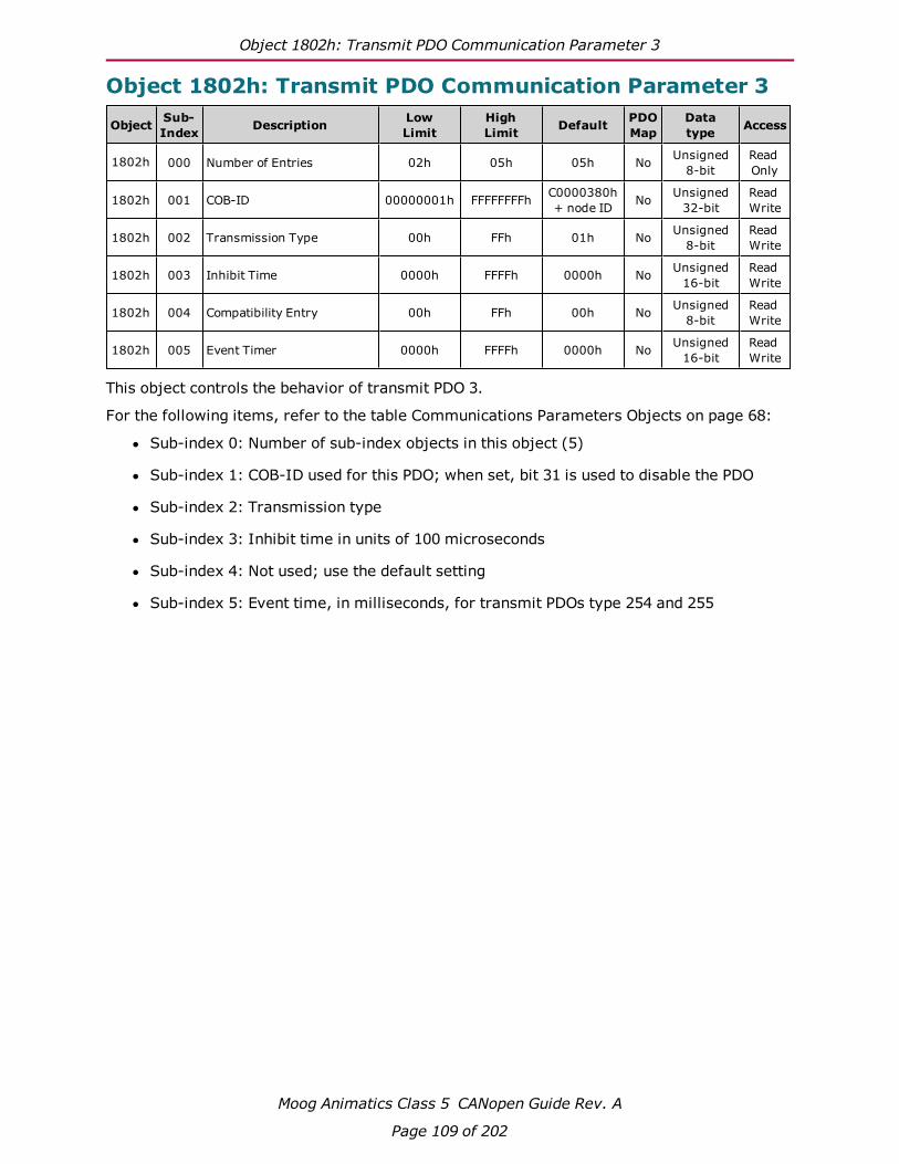
Object 1802h: Transmit PDO Communication Parameter 3
Moog Animatics Class 5 CANopen Guide Rev. A
Page 109 of 202
Object 1802h: Transmit PDO Communication Parameter 3
Object Sub-Index Description Low
LimitHighLimit Default PDO
MapDatatype Access
1802h 000 Number of Entries 02h 05h 05h No Unsigned8-bit
ReadOnly
1802h 001 COB-ID 00000001h FFFFFFFFh C0000380h+ node ID No Unsigned
32-bitReadWrite
1802h 002 Transmission Type 00h FFh 01h No Unsigned8-bit
ReadWrite
1802h 003 Inhibit Time 0000h FFFFh 0000h No Unsigned16-bit
ReadWrite
1802h 004 Compatibility Entry 00h FFh 00h No Unsigned8-bit
ReadWrite
1802h 005 Event Timer 0000h FFFFh 0000h No Unsigned16-bit
ReadWrite
This object controls the behavior of transmit PDO 3.
For the following items, refer to the table Communications Parameters Objects on page 68:
l Sub-index 0: Number of sub-index objects in this object (5)
l Sub-index 1: COB-ID used for this PDO; when set, bit 31 is used to disable the PDO
l Sub-index 2: Transmission type
l Sub-index 3: Inhibit time in units of 100 microseconds
l Sub-index 4: Not used; use the default setting
l Sub-index 5: Event time, in milliseconds, for transmit PDOs type 254 and 255
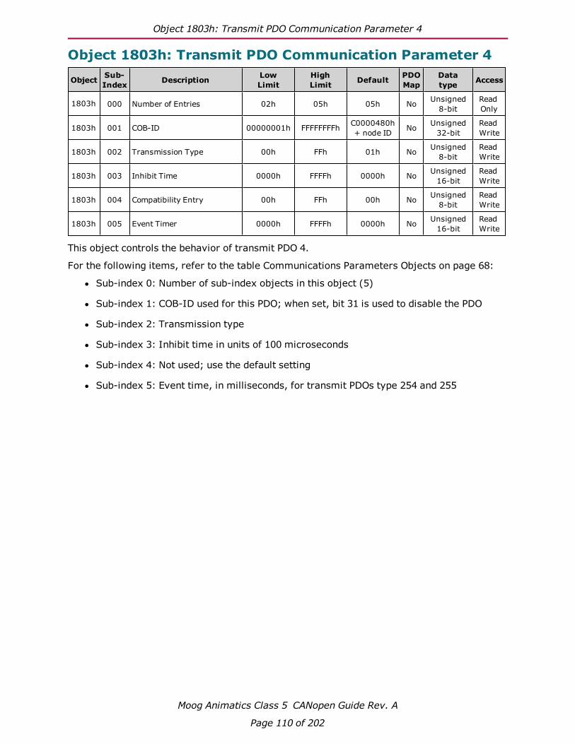
Object 1803h: Transmit PDO Communication Parameter 4
Moog Animatics Class 5 CANopen Guide Rev. A
Page 110 of 202
Object 1803h: Transmit PDO Communication Parameter 4
Object Sub-Index Description Low
LimitHighLimit Default PDO
MapDatatype Access
1803h 000 Number of Entries 02h 05h 05h No Unsigned8-bit
ReadOnly
1803h 001 COB-ID 00000001h FFFFFFFFh C0000480h+ node ID No Unsigned
32-bitReadWrite
1803h 002 Transmission Type 00h FFh 01h No Unsigned8-bit
ReadWrite
1803h 003 Inhibit Time 0000h FFFFh 0000h No Unsigned16-bit
ReadWrite
1803h 004 Compatibility Entry 00h FFh 00h No Unsigned8-bit
ReadWrite
1803h 005 Event Timer 0000h FFFFh 0000h No Unsigned16-bit
ReadWrite
This object controls the behavior of transmit PDO 4.
For the following items, refer to the table Communications Parameters Objects on page 68:
l Sub-index 0: Number of sub-index objects in this object (5)
l Sub-index 1: COB-ID used for this PDO; when set, bit 31 is used to disable the PDO
l Sub-index 2: Transmission type
l Sub-index 3: Inhibit time in units of 100 microseconds
l Sub-index 4: Not used; use the default setting
l Sub-index 5: Event time, in milliseconds, for transmit PDOs type 254 and 255
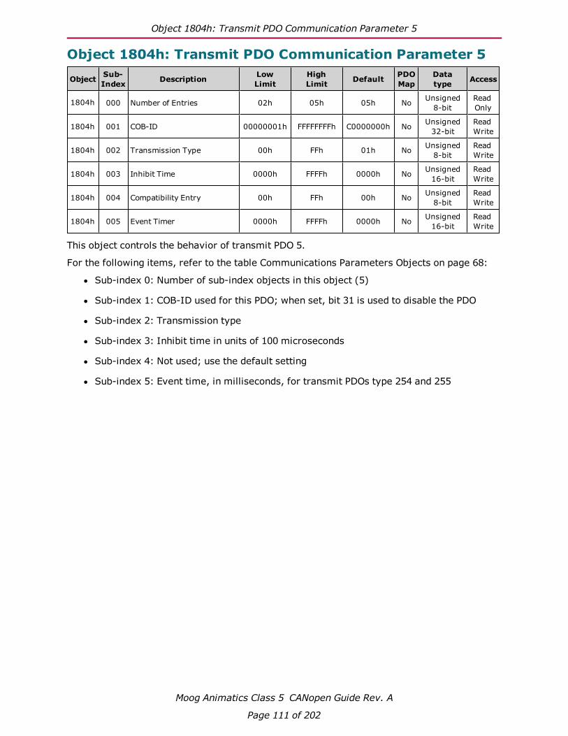
Object 1804h: Transmit PDO Communication Parameter 5
Moog Animatics Class 5 CANopen Guide Rev. A
Page 111 of 202
Object 1804h: Transmit PDO Communication Parameter 5
Object Sub-Index Description Low
LimitHighLimit Default PDO
MapDatatype Access
1804h 000 Number of Entries 02h 05h 05h No Unsigned8-bit
ReadOnly
1804h 001 COB-ID 00000001h FFFFFFFFh C0000000h No Unsigned32-bit
ReadWrite
1804h 002 Transmission Type 00h FFh 01h No Unsigned8-bit
ReadWrite
1804h 003 Inhibit Time 0000h FFFFh 0000h No Unsigned16-bit
ReadWrite
1804h 004 Compatibility Entry 00h FFh 00h No Unsigned8-bit
ReadWrite
1804h 005 Event Timer 0000h FFFFh 0000h No Unsigned16-bit
ReadWrite
This object controls the behavior of transmit PDO 5.
For the following items, refer to the table Communications Parameters Objects on page 68:
l Sub-index 0: Number of sub-index objects in this object (5)
l Sub-index 1: COB-ID used for this PDO; when set, bit 31 is used to disable the PDO
l Sub-index 2: Transmission type
l Sub-index 3: Inhibit time in units of 100 microseconds
l Sub-index 4: Not used; use the default setting
l Sub-index 5: Event time, in milliseconds, for transmit PDOs type 254 and 255

Object 1A00h: Transmit PDO Mapping Parameter 1
Moog Animatics Class 5 CANopen Guide Rev. A
Page 112 of 202
Object 1A00h: Transmit PDO Mapping Parameter 1
Object Sub-Index Description Low
LimitHighLimit Default PDO
MapDatatype Access
1A00h 000 Number of Entries 00h 04h 01h No Unsigned8-bit
ReadWrite
1A00h 001 Mapping Entry 1 00000000h FFFFFFFFh 60410010h No Unsigned32-bit
ReadWrite
1A00h 002 Mapping Entry 2 00000000h FFFFFFFFh 00000000h No Unsigned32-bit
ReadWrite
1A00h 003 Mapping Entry 3 00000000h FFFFFFFFh 00000000h No Unsigned32-bit
ReadWrite
1A00h 004 Mapping Entry 4 00000000h FFFFFFFFh 00000000h No Unsigned32-bit
ReadWrite
This object controls which objects are mapped into transmit PDO 1.
For the following items, refer to Mapping Parameters Objects on page 69:
l Sub-index 0: Number of valid sub-index objects in this object. This is set according tothe filled mapping entries starting from sub-index 1.
l Sub-indexes 1–4: These provide information about the object mapped in this PDO. Theycontain the indexes, the sub-indexes and the lengths of the mapped object. Fill thesestarting from sub-index 1. The structure is:
Bit Meaning
Bits 16–31 (16 bit) Index of the objectto map
Bits 8–15 (8 bit) Sub-index of theobject to map
Bits 0–7 (8 bit) Length of the object(in bits)

Object 1A01h: Transmit PDO Mapping Parameter 2
Moog Animatics Class 5 CANopen Guide Rev. A
Page 113 of 202
Object 1A01h: Transmit PDO Mapping Parameter 2
Object Sub-Index Description Low
LimitHighLimit Default PDO
MapDatatype Access
1A01h 000 Number of Entries 00h 04h 02h No Unsigned8-bit
ReadWrite
1A01h 001 Mapping Entry 1 00000000h FFFFFFFFh 60410010h No Unsigned32-bit
ReadWrite
1A01h 002 Mapping Entry 2 00000000h FFFFFFFFh 60610008h No Unsigned32-bit
ReadWrite
1A01h 003 Mapping Entry 3 00000000h FFFFFFFFh 00000000h No Unsigned32-bit
ReadWrite
1A01h 004 Mapping Entry 4 00000000h FFFFFFFFh 00000000h No Unsigned32-bit
ReadWrite
This object controls which objects are mapped into transmit PDO 2.
For the following items, refer to Mapping Parameters Objects on page 69:
l Sub-index 0: Number of valid sub-index objects in this object. This is set according tothe filled mapping entries starting from sub-index 1.
l Sub-indexes 1–4: These provide information about the object mapped in this PDO. Theycontain the indexes, the sub-indexes and the lengths of the mapped object. Fill thesestarting from sub-index 1. The structure is:
Bit Meaning
Bits 16–31 (16 bit) Index of the objectto map
Bits 8–15 (8 bit) Sub-index of theobject to map
Bits 0–7 (8 bit) Length of the object(in bits)

Object 1A02h: Transmit PDO Mapping Parameter 3
Moog Animatics Class 5 CANopen Guide Rev. A
Page 114 of 202
Object 1A02h: Transmit PDO Mapping Parameter 3
Object Sub-Index Description Low
LimitHighLimit Default PDO
MapDatatype Access
1A02h 000 Number of Entries 00h 04h 02h No Unsigned8-bit
ReadWrite
1A02h 001 Mapping Entry 1 00000000h FFFFFFFFh 60410010h No Unsigned32-bit
ReadWrite
1A02h 002 Mapping Entry 2 00000000h FFFFFFFFh 60640020h No Unsigned32-bit
ReadWrite
1A02h 003 Mapping Entry 3 00000000h FFFFFFFFh 00000000h No Unsigned32-bit
ReadWrite
1A02h 004 Mapping Entry 4 00000000h FFFFFFFFh 00000000h No Unsigned32-bit
ReadWrite
This object controls which objects are mapped into transmit PDO 3.
For the following items, refer to Mapping Parameters Objects on page 69:
l Sub-index 0: Number of valid sub-index objects in this object. This is set according tothe filled mapping entries starting from sub-index 1.
l Sub-indexes 1–4: These provide information about the object mapped in this PDO. Theycontain the indexes, the sub-indexes and the lengths of the mapped object. Fill thesestarting from sub-index 1. The structure is:
Bit Meaning
Bits 16–31 (16 bit) Index of the objectto map
Bits 8–15 (8 bit) Sub-index of theobject to map
Bits 0–7 (8 bit) Length of the object(in bits)
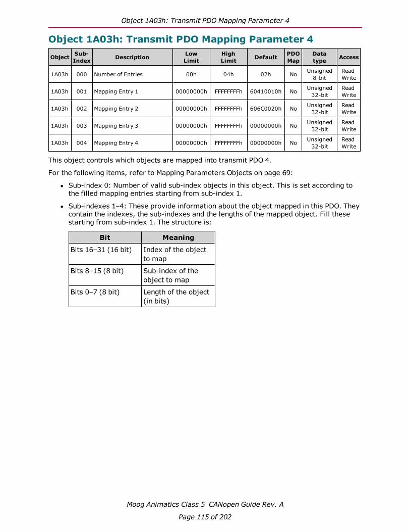
Object 1A03h: Transmit PDO Mapping Parameter 4
Moog Animatics Class 5 CANopen Guide Rev. A
Page 115 of 202
Object 1A03h: Transmit PDO Mapping Parameter 4
Object Sub-Index Description Low
LimitHighLimit Default PDO
MapDatatype Access
1A03h 000 Number of Entries 00h 04h 02h No Unsigned8-bit
ReadWrite
1A03h 001 Mapping Entry 1 00000000h FFFFFFFFh 60410010h No Unsigned32-bit
ReadWrite
1A03h 002 Mapping Entry 2 00000000h FFFFFFFFh 606C0020h No Unsigned32-bit
ReadWrite
1A03h 003 Mapping Entry 3 00000000h FFFFFFFFh 00000000h No Unsigned32-bit
ReadWrite
1A03h 004 Mapping Entry 4 00000000h FFFFFFFFh 00000000h No Unsigned32-bit
ReadWrite
This object controls which objects are mapped into transmit PDO 4.
For the following items, refer to Mapping Parameters Objects on page 69:
l Sub-index 0: Number of valid sub-index objects in this object. This is set according tothe filled mapping entries starting from sub-index 1.
l Sub-indexes 1–4: These provide information about the object mapped in this PDO. Theycontain the indexes, the sub-indexes and the lengths of the mapped object. Fill thesestarting from sub-index 1. The structure is:
Bit Meaning
Bits 16–31 (16 bit) Index of the objectto map
Bits 8–15 (8 bit) Sub-index of theobject to map
Bits 0–7 (8 bit) Length of the object(in bits)

Object 1A04h: Transmit PDO Mapping Parameter 5
Moog Animatics Class 5 CANopen Guide Rev. A
Page 116 of 202
Object 1A04h: Transmit PDO Mapping Parameter 5
Object Sub-Index Description Low
LimitHighLimit Default PDO
MapDatatype Access
1A04h 000 Number of Entries 00h 04h 02h No Unsigned8-bit
ReadWrite
1A04h 001 Mapping Entry 1 00000000h FFFFFFFFh 60410010h No Unsigned32-bit
ReadWrite
1A04h 002 Mapping Entry 2 00000000h FFFFFFFFh 60770010h No Unsigned32-bit
ReadWrite
1A04h 003 Mapping Entry 3 00000000h FFFFFFFFh 00000000h No Unsigned32-bit
ReadWrite
1A04h 004 Mapping Entry 4 00000000h FFFFFFFFh 00000000h No Unsigned32-bit
ReadWrite
This object controls which objects are mapped into transmit PDO 5.
For the following items, refer to Mapping Parameters Objects on page 69:
l Sub-index 0: Number of valid sub-index objects in this object. This is set according tothe filled mapping entries starting from sub-index 1.
l Sub-indexes 1–4: These provide information about the object mapped in this PDO. Theycontain the indexes, the sub-indexes and the lengths of the mapped object. Fill thesestarting from sub-index 1. The structure is:
Bit Meaning
Bits 16–31 (16 bit) Index of the objectto map
Bits 8–15 (8 bit) Sub-index of theobject to map
Bits 0–7 (8 bit) Length of the object(in bits)
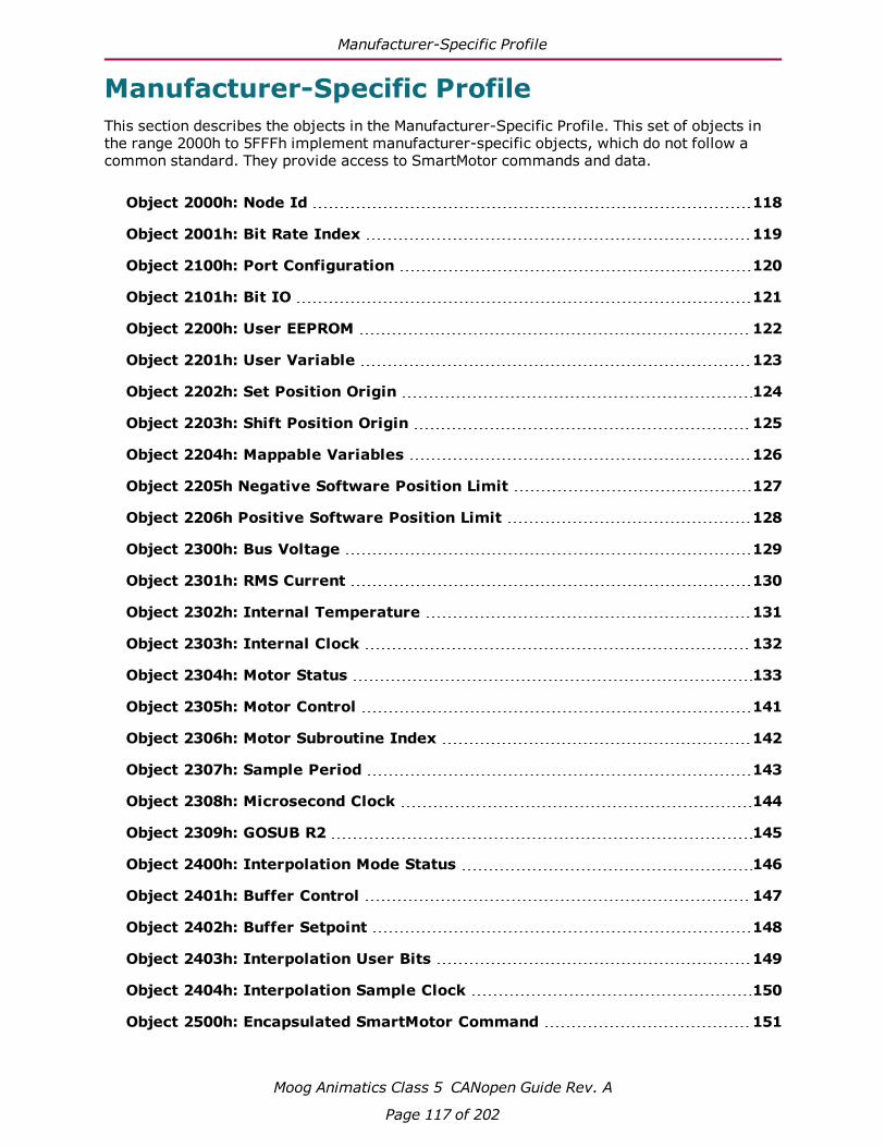
Manufacturer-Specific Profile
Moog Animatics Class 5 CANopen Guide Rev. A
Page 117 of 202
Manufacturer-Specific ProfileThis section describes the objects in the Manufacturer-Specific Profile. This set of objects inthe range 2000h to 5FFFh implement manufacturer-specific objects, which do not follow acommon standard. They provide access to SmartMotor commands and data.
Object 2000h: Node Id 118
Object 2001h: Bit Rate Index 119
Object 2100h: Port Configuration 120
Object 2101h: Bit IO 121
Object 2200h: User EEPROM 122
Object 2201h: User Variable 123
Object 2202h: Set Position Origin 124
Object 2203h: Shift Position Origin 125
Object 2204h: Mappable Variables 126
Object 2205h Negative Software Position Limit 127
Object 2206h Positive Software Position Limit 128
Object 2300h: Bus Voltage 129
Object 2301h: RMS Current 130
Object 2302h: Internal Temperature 131
Object 2303h: Internal Clock 132
Object 2304h: Motor Status 133
Object 2305h: Motor Control 141
Object 2306h: Motor Subroutine Index 142
Object 2307h: Sample Period 143
Object 2308h: Microsecond Clock 144
Object 2309h: GOSUB R2 145
Object 2400h: Interpolation Mode Status 146
Object 2401h: Buffer Control 147
Object 2402h: Buffer Setpoint 148
Object 2403h: Interpolation User Bits 149
Object 2404h: Interpolation Sample Clock 150
Object 2500h: Encapsulated SmartMotor Command 151

Object 2000h: Node Id
Moog Animatics Class 5 CANopen Guide Rev. A
Page 118 of 202
Object 2000h: Node Id
Object Sub-Index Description Low
LimitHighLimit Default PDO
MapDatatype Access
2000h 000 Node Id 00h FFhLoaded fromEEPROM atboot-up
Yes Unsigned8-bit
ReadOnly
This object contains the active CANopen ID.
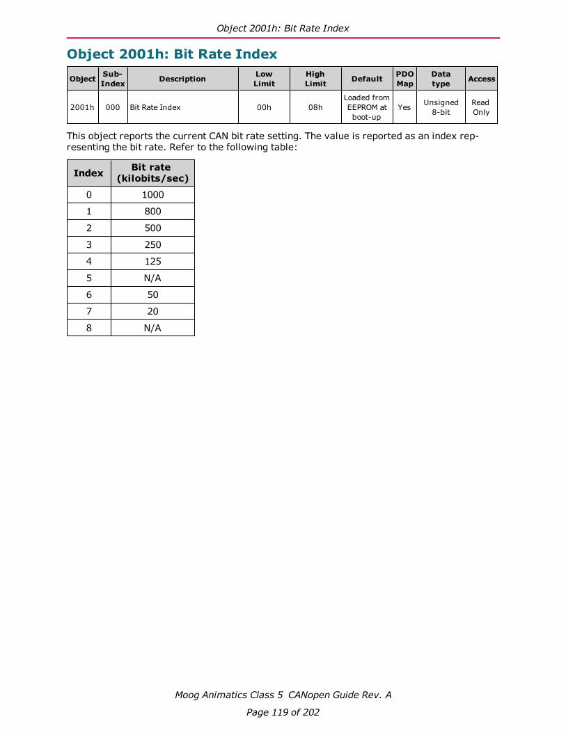
Object 2001h: Bit Rate Index
Moog Animatics Class 5 CANopen Guide Rev. A
Page 119 of 202
Object 2001h: Bit Rate Index
Object Sub-Index Description Low
LimitHighLimit Default PDO
MapDatatype Access
2001h 000 Bit Rate Index 00h 08hLoaded fromEEPROM atboot-up
Yes Unsigned8-bit
ReadOnly
This object reports the current CAN bit rate setting. The value is reported as an index rep-resenting the bit rate. Refer to the following table:
Index Bit rate(kilobits/sec)
0 1000
1 800
2 500
3 250
4 125
5 N/A
6 50
7 20
8 N/A

Object 2100h: Port Configuration
Moog Animatics Class 5 CANopen Guide Rev. A
Page 120 of 202
Object 2100h: Port Configuration
Object Sub-Index Description Low
LimitHighLimit Default PDO
MapDatatype Access
2100h 000 Port Configuration 00000000h 7FFFFFFFh 000000A0h Yes Unsigned32-bit
ReadWrite
This object controls the configuration of I/O ports 0 through 6 (formerly named A through G)on a D-style motor. Due to constraints, some of the inputs are grouped together. Forexample, ports 4 and 5 (formerly named E and F) can be configured together for RS-485. Formore details, see I/O on page 38.
This object is not supported in M-style firmware (5.98.x.x). For details, see I/O on page 38.
Object 2100 Port PortBits Binary Bits Value Effect Effect
0 (A) 1 (B)
0–3 (4 bits)
xxxx xxxx xxxx 0000 0 input inputxxxx xxxx xxxx 0001 1 output inputxxxx xxxx xxxx 0010 2 input outputxxxx xxxx xxxx 0011 3 output output
2 (C)
4–5 (2 bits)
xxxx xxxx xx00 xxxx 0 inputxxxx xxxx xx01 xxxx 1 output
xxxx xxxx xx10 xxxx 2 positivelimit3 (D)
6–7 (2 bits)
xxxx xxxx 00xx xxxx 0 inputxxxx xxxx 01xx xxxx 1 output
xxxx xxxx 10xx xxxx 2 negativelimit4 (E) 5 (F)
8–10 (3 bits)
xxxx x000 xxxx xxxx 0 input inputxxxx x001 xxxx xxxx 1 output inputxxxx x010 xxxx xxxx 2 input outputxxxx x011 xxxx xxxx 3 output outputxxxx x100 xxxx xxxx 4 I²Cxxxx x101 xxxx xxxx 5 RS-485
6 (G)
11–12 (2 bits)xxx0 0xxx xxxx xxxx 0 inputxxx0 1xxx xxxx xxxx 1 outputxxx1 0xxx xxxx xxxx 2 go
13–15 (3 bits) N/A N/A Reserved

Object 2101h: Bit IO
Moog Animatics Class 5 CANopen Guide Rev. A
Page 121 of 202
Object 2101h: Bit IO
Object Sub-Index Description Low
LimitHighLimit Default PDO
MapDatatype Access
2101h 000 Number of Entries 0003h 0003h 0003h No Unsigned8-bit
ReadOnly
2101h 001 Set Output 0000h 7FFFh 0000h Yes Unsigned16-bit
ReadWrite
2101h 002 Clear Output 0000h 7FFFh 0000h Yes Unsigned16-bit
ReadWrite
2101h 003 Make Input 0000h 7FFFh 0000h Yes Unsigned16-bit
ReadWrite
This object allows individual control of each I/O point. It is designed for SDO-type com-munications at startup. It is not intended for cyclic PDO communications.
The value written is the identifier of the I/O port to be controlled. The action to take on thatport is a function of the specified sub-index object:
l Sub-index 1: Drive the specified I/O high.
l Sub-index 2: The action depends on I/O type:
l For D-style motor ports 0–6, drive the specified I/O low
l For D-style motor ports 16–25, turn off the specified I/O
l For M-style motor ports 0–10, turn off the specified I/O
l Sub-index 3: Turn off the specified I/O and disable any special function such as a limitinput. The specified I/O point will simply become a generic input.
For example, to make I/O port 2 (formerly named port C) a generic input, write thevalue 2 to sub-index 3.
For more I/O details, see I/O on page 38.

Object 2200h: User EEPROM
Moog Animatics Class 5 CANopen Guide Rev. A
Page 122 of 202
Object 2200h: User EEPROM
Object Sub-Index Description Low
LimitHighLimit Default PDO
MapDatatype Access
2200h 000 Number of Entries 00h FFh 03h No Unsigned8-bit
ReadOnly
2200h 001 EEPROM index 0000h FFFFh 0000h No Unsigned16-bit
ReadWrite
2200h 002 EEPROM number of bytes 00h FFh 00h No Unsigned8-bit
ReadWrite
2200h 003 EEPROM value No String: 8bytes.
ReadWrite
This object provides access to user non-volatile EEPROM memory. Through SDO commands, avalue can be written to the user EEPROM. To do this:
1. Set the EEPROM index (sub-index 1) to the EEPROM location where the new value will bewritten. Typical values are 0 to 32339.
2. Set sub-index 2 to the number of bytes that will be written.
3. Write the binary data to the EEPROM in sub-index 3. Up to 8 bytes may be written at atime.

Object 2201h: User Variable
Moog Animatics Class 5 CANopen Guide Rev. A
Page 123 of 202
Object 2201h: User Variable
Object Sub-Index Description Low
LimitHighLimit Default PDO
MapDatatype Access
2201h 000 Number of Entries 00h FFh 03h No Unsigned8-bit
ReadOnly
2201h 001 Index 0000h FFFFh 0000h No Unsigned16-bit
ReadWrite
2201h 002 Data Type 80h 7Fh 00h No Signed8-bit
ReadWrite
2201h 003 Value 80000000h 7FFFFFFFh 00000000h No Signed32-bit
ReadWrite
This object provides access to user variables through SDO commands. To do this:
1. Set the index (sub-index 1) to the user variable that a value will be written to or readfrom. Refer to the following table to determine the correct index.
2. Set sub-index 2 according to the table for the desired variable-type access.
3. Read or write the data using sub-index 3.
Only one variable is written at a time. If the data type is ab[] or aw[], a single byte or word iswritten, respectively.
Data type(sub-index 2)
Index(sub-index 1)
Variable'sdata type
Variablesaccessed
0 0–25 long (32-bit) a–z
0 26–51 long (32-bit) aa–zz
0 52–77 long (32-bit) aaa–zzz
1 0–50 long (32-bit) al[Index]
2 0–101 word (16-bit) aw[Index]
3 0–203 byte (8-bit) ab[Index]
The variable arrays: al[index], aw[index] and ab[index] overlap the same physical memoryof 204 bytes. This allows different access to common memory based on data size. Forinstance, al[0] is the same region as ab[0] through ab[3]. The byte order is little-endian, suchthat ab[0] is the lowest byte of al[0].
For more details, see User Variables on page 38.

Object 2202h: Set Position Origin
Moog Animatics Class 5 CANopen Guide Rev. A
Page 124 of 202
Object 2202h: Set Position Origin
Object Sub-Index Description Low
LimitHighLimit Default PDO
MapDatatype Access
2202h 000 Set Position Origin 80000000h 7FFFFFFFh 00000000h Yes Signed32-bit
ReadWrite
The value written to this object becomes the new position value. Both the commanded pos-ition (RPC) and actual position (RPA) are shifted by this value minus the current commandvalue. The value read from this object is the most recent value written to this object — it isnot an indication of the motor's current state.
Similar SmartMotor Commands: O=
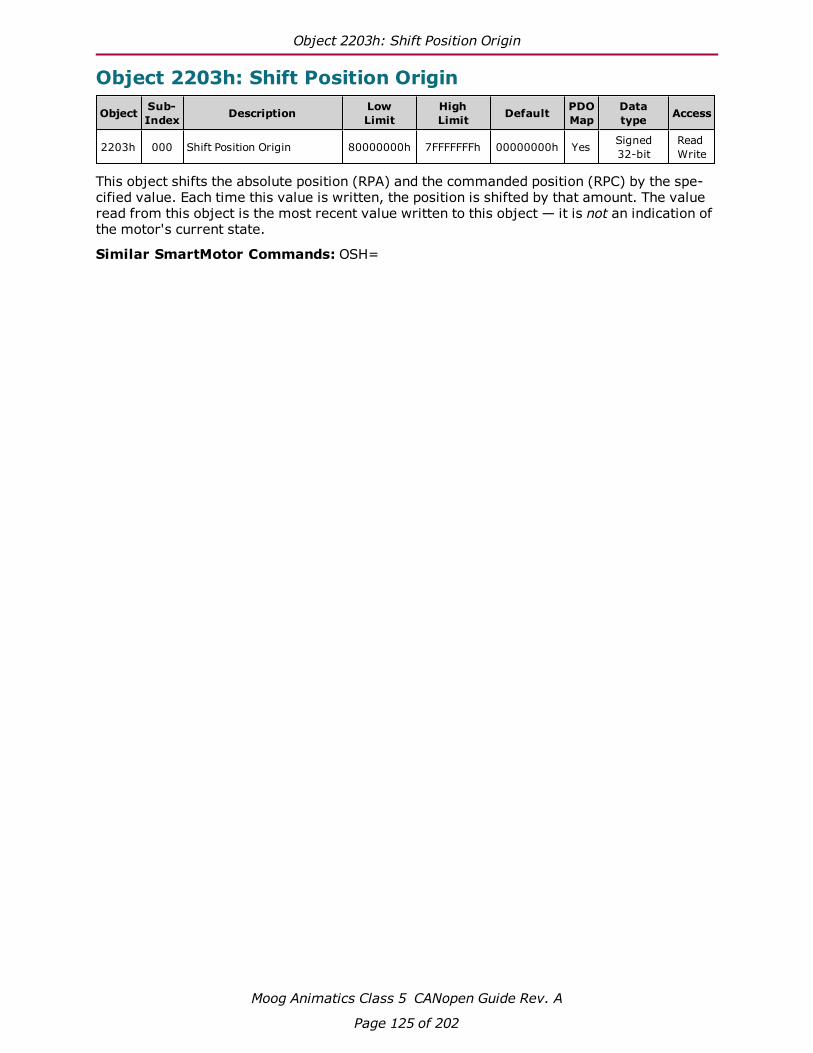
Object 2203h: Shift Position Origin
Moog Animatics Class 5 CANopen Guide Rev. A
Page 125 of 202
Object 2203h: Shift Position Origin
Object Sub-Index Description Low
LimitHighLimit Default PDO
MapDatatype Access
2203h 000 Shift Position Origin 80000000h 7FFFFFFFh 00000000h Yes Signed32-bit
ReadWrite
This object shifts the absolute position (RPA) and the commanded position (RPC) by the spe-cified value. Each time this value is written, the position is shifted by that amount. The valueread from this object is the most recent value written to this object — it is not an indication ofthe motor's current state.
Similar SmartMotor Commands: OSH=

Object 2204h: Mappable Variables
Moog Animatics Class 5 CANopen Guide Rev. A
Page 126 of 202
Object 2204h: Mappable Variables
Object Sub-Index Description Low
LimitHighLimit Default PDO
MapDatatype Access
2204h 000 Number of Entries 00000004h 00000004h 00000004h No Unsigned8-bit
ReadOnly
2204h 001 aaa 80000000h 7FFFFFFFh 00000000h Yes Signed32-bit
ReadWrite
2204h 002 bbb 80000000h 7FFFFFFFh 00000000h Yes Signed32-bit
ReadWrite
2204h 003 ccc 80000000h 7FFFFFFFh 00000000h Yes Signed32-bit
ReadWrite
2204h 004 ddd 80000000h 7FFFFFFFh 00000000h Yes Signed32-bit
ReadWrite
This object provides direct read or write access to user variables aaa–ddd. This object isprovided to fill the need for PDO access to user variables. SDO access is also allowed.
For more details, see User Variables on page 38.

Object 2205h Negative Software Position Limit
Moog Animatics Class 5 CANopen Guide Rev. A
Page 127 of 202
Object 2205h Negative Software Position Limit
Object Sub-Index Description Low
LimitHighLimit Default PDO
MapDatatype Access
2205h 000 Negative Software PositionLimit 80000000h 7FFFFFFFh 80000000h Yes Signed
32-bitReadWrite
This object defines the negative software position limit in units of encoder counts. If the soft-ware position limits are enabled and the actual position is out of range, then a software-limitfault occurs.
The term "negative" does not imply the value must be negative. Positive values are per-mitted; however, they should be a lower value than the positive software position limit.
Similar SmartMotor Commands: SLN=, RSLN

Object 2206h Positive Software Position Limit
Moog Animatics Class 5 CANopen Guide Rev. A
Page 128 of 202
Object 2206h Positive Software Position Limit
Object Sub-Index Description Low
LimitHighLimit Default PDO
MapDatatype Access
2206h 000 Positive Software PositionLimit 80000000h 7FFFFFFFh 7FFFFFFFh Yes Signed
32-bitReadWrite
This object defines the positive software position limit in units of encoder counts. If the soft-ware limits are enabled and the actual position is out of range, then a software-limit faultoccurs.
The term "positive" does not imply the value must be positive. Negative values are permitted;however, they should be a higher value than the negative software position limit.
Similar SmartMotor Commands: SLP=, RSLP
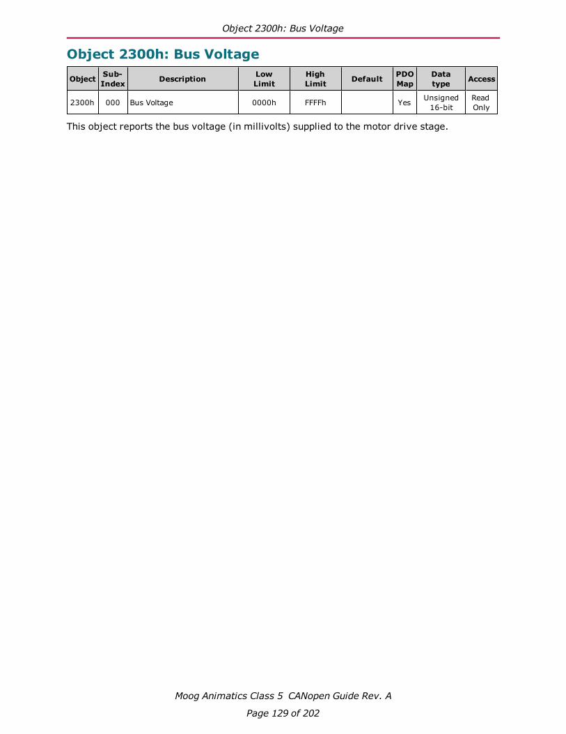
Object 2300h: Bus Voltage
Moog Animatics Class 5 CANopen Guide Rev. A
Page 129 of 202
Object 2300h: Bus Voltage
Object Sub-Index Description Low
LimitHighLimit Default PDO
MapDatatype Access
2300h 000 Bus Voltage 0000h FFFFh Yes Unsigned16-bit
ReadOnly
This object reports the bus voltage (in millivolts) supplied to the motor drive stage.

Object 2301h: RMS Current
Moog Animatics Class 5 CANopen Guide Rev. A
Page 130 of 202
Object 2301h: RMS Current
Object Sub-Index Description Low
LimitHighLimit Default PDO
MapDatatype Access
2301h 000 RMS Current 0000h FFFFh Yes Unsigned16-bit
ReadOnly
This object reports the RMS current (in milliamperes) of the motor windings.
Similar SmartMotor Commands: RUIA

Object 2302h: Internal Temperature
Moog Animatics Class 5 CANopen Guide Rev. A
Page 131 of 202
Object 2302h: Internal Temperature
Object Sub-Index Description Low
LimitHighLimit Default PDO
MapDatatype Access
2302h 000 Internal Temperature 00h FFh Yes Unsigned8-bit
ReadOnly
This object reports the SmartMotor's internal temperature in degrees C; the resolution is ±1degree C.
Similar SmartMotor Commands: RTEMP

Object 2303h: Internal Clock
Moog Animatics Class 5 CANopen Guide Rev. A
Page 132 of 202
Object 2303h: Internal Clock
Object Sub-Index Description Low
LimitHighLimit Default PDO
MapDatatype Access
2303h 000 Internal Clock 00000000h FFFFFFFFh 00000000h Yes Unsigned32-bit
ReadWrite
This object represents the SmartMotor's internal clock in milliseconds. The value can be set asdesired. This object is equivalent to the RCLK, =CLK, or CLK= commands (read or write), andit uses the same internal clock.
NOTE: This object is not the same as Object 2308h, which uses specialclock-synchronization features that are only accessible through CANopen or serialinterpolation. For details, see Object 2308h: Microsecond Clock on page 144.
Similar SmartMotor Commands: CLK=, RCLK

Object 2304h: Motor Status
Moog Animatics Class 5 CANopen Guide Rev. A
Page 133 of 202
Object 2304h: Motor Status
Object Sub-Index Description Low
LimitHighLimit Default PDO
MapDatatype Access
2304h 000 Number of Entries 00h FFh 12h(18 dec) No Unsigned
8-bitReadOnly
2304h 001 Status Word 0 0000h FFFFh Yes Unsigned16-bit
ReadOnly
2304h 002 Status Word 1 0000h FFFFh Yes Unsigned16-bit
ReadOnly
2304h 003 Status Word 2 0000h FFFFh Yes Unsigned16-bit
ReadOnly
2304h 004 Status Word 3 0000h FFFFh Yes Unsigned16-bit
ReadOnly
2304h 005 Status Word 4 0000h FFFFh Yes Unsigned16-bit
ReadOnly
2304h 006 Status Word 5 0000h FFFFh Yes Unsigned16-bit
ReadOnly
2304h 007 Status Word 6 0000h FFFFh Yes Unsigned16-bit
ReadOnly
2304h 008 Status Word 7 0000h FFFFh Yes Unsigned16-bit
ReadOnly
2304h 009 Status Word 8 0000h FFFFh Yes Unsigned16-bit
ReadOnly
2304h 010 Status Word 9 0000h FFFFh Yes Unsigned16-bit
ReadOnly
2304h 011 Status Word 10 0000h FFFFh Yes Unsigned16-bit
ReadOnly
2304h 012 Status Word 11 0000h FFFFh Yes Unsigned16-bit
ReadOnly
2304h 013 Status Word 12 0000h FFFFh Yes Unsigned16-bit
ReadOnly
2304h 014 Status Word 13 0000h FFFFh Yes Unsigned16-bit
ReadWrite
2304h 015 Status Word 14 0000h FFFFh Yes Unsigned16-bit
ReadOnly
2304h 016 Status Word 15 0000h FFFFh Yes Unsigned16-bit
ReadOnly
2304h 017 Status Word 16 0000h FFFFh Yes Unsigned16-bit
ReadOnly
2304h 018 Status Word 17 0000h FFFFh Yes Unsigned16-bit
ReadOnly
This object reports the SmartMotor status words, which are equivalent to the RW(index) com-mand. There is a special case where user status bits in status word 13 are writable throughthis object. This allows a host to cause user interrupts in a motor.
l Sub-index 0 reports the number of status words (18)
l Sub-index 1 reports SmartMotor status word 0
l Sub-index 2 reports SmartMotor status word 1
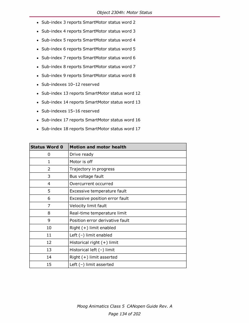
Object 2304h: Motor Status
Moog Animatics Class 5 CANopen Guide Rev. A
Page 134 of 202
l Sub-index 3 reports SmartMotor status word 2
l Sub-index 4 reports SmartMotor status word 3
l Sub-index 5 reports SmartMotor status word 4
l Sub-index 6 reports SmartMotor status word 5
l Sub-index 7 reports SmartMotor status word 6
l Sub-index 8 reports SmartMotor status word 7
l Sub-index 9 reports SmartMotor status word 8
l Sub-indexes 10–12 reserved
l Sub-index 13 reports SmartMotor status word 12
l Sub-index 14 reports SmartMotor status word 13
l Sub-indexes 15–16 reserved
l Sub-index 17 reports SmartMotor status word 16
l Sub-index 18 reports SmartMotor status word 17
Status Word 0 Motion and motor health
0 Drive ready
1 Motor is off
2 Trajectory in progress
3 Bus voltage fault
4 Overcurrent occurred
5 Excessive temperature fault
6 Excessive position error fault
7 Velocity limit fault
8 Real-time temperature limit
9 Position error derivative fault
10 Right (+) limit enabled
11 Left (–) limit enabled
12 Historical right (+) limit
13 Historical left (–) limit
14 Right (+) limit asserted
15 Left (–) limit asserted

Object 2304h: Motor Status
Moog Animatics Class 5 CANopen Guide Rev. A
Page 135 of 202
Status Word 1 Index registration and soft limits
0 Arming bit for rise capture of encoder 0
1 Arming bit for fall capture of encoder 0
2 Rising edge captured on encoder 0
3 Falling edge captured on encoder 0
4 Arming bit for rise capture of encoder 1
5 Arming bit for fall capture of encoder 1
6 Rising edge captured on encoder 1
7 Falling edge captured on encoder 1
8 Capture input state 0
9 Capture input state 1
10 Soft limits enabled
11 Soft limits behavior mode
12 Historical right soft limit
13 Historical left soft limit
14 Right soft limit
15 Left soft limit
Status Word 2 Communication state and program state
0 Com 0 error
1 Com 1 error
2 Reserved
3 Reserved
4 CAN error
5 Reserved
6 Ethernet error
7 IIC communications active
8 Reserved
9 Datablock checksum is bad (fault)
10 User program is running
11 Trace in progress
12 User EEPROM write buffer overflow
13 User EEPROM busy
14 Command error
15 Program checksum error

Object 2304h: Motor Status
Moog Animatics Class 5 CANopen Guide Rev. A
Page 136 of 202
Status Word 3 PID, brake, move generation
0 Position error has exceeded soft threshold
1 Torque saturation
2 Voltage saturation
3 Wraparound occurred
4 KG enabled
5 Shaft direction
6 Torque direction
7 IO fault latch
8 Trajectory 1 relative position move
9 Reserved
10 Reserved
11 Modulo counter rollover
12 Brake asserted
13 Brake OK
14 Go on external input
15 Velocity reached or target ratio reached
Status Word 4 Timer status
0 Timer 0 running
1 Timer 1 running
2 Timer 2 running
3 Timer 3 running
4 Reserved
5 Reserved
6 Reserved
7 Reserved
8 Reserved
9 Reserved
10 Reserved
11 Reserved
12 Reserved
13 Reserved
14 Reserved
15 Reserved
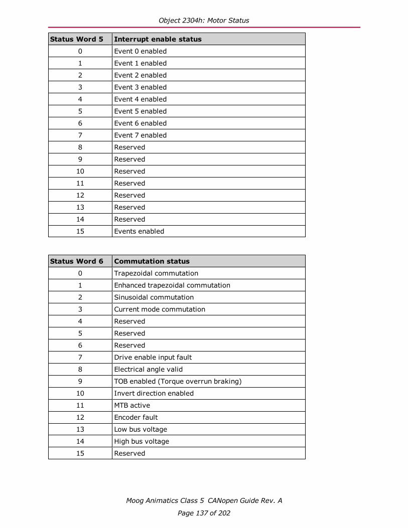
Object 2304h: Motor Status
Moog Animatics Class 5 CANopen Guide Rev. A
Page 137 of 202
Status Word 5 Interrupt enable status
0 Event 0 enabled
1 Event 1 enabled
2 Event 2 enabled
3 Event 3 enabled
4 Event 4 enabled
5 Event 5 enabled
6 Event 6 enabled
7 Event 7 enabled
8 Reserved
9 Reserved
10 Reserved
11 Reserved
12 Reserved
13 Reserved
14 Reserved
15 Events enabled
Status Word 6 Commutation status
0 Trapezoidal commutation
1 Enhanced trapezoidal commutation
2 Sinusoidal commutation
3 Current mode commutation
4 Reserved
5 Reserved
6 Reserved
7 Drive enable input fault
8 Electrical angle valid
9 TOB enabled (Torque overrun braking)
10 Invert direction enabled
11 MTB active
12 Encoder fault
13 Low bus voltage
14 High bus voltage
15 Reserved

Object 2304h: Motor Status
Moog Animatics Class 5 CANopen Guide Rev. A
Page 138 of 202
Status Word 7 Multiple Trajectories
0 TG1 in progress
1 TG1 Accel/Ascend
2 TG1 Slewing
3 TG1 Decel/Descend
4 TG1 Reserved/Dwell
5 Reserved
6 Reserved
7 Reserved
8 TG2 in progress
9 TG2 Accel/Ascend
10 TG2 Slewing
11 TG2 Decel/Descend
12 TG2 Dwell (higher)
13 TG2 Traverse state
14 TG2 Lower dwell
15 TS Wait
Status Word 8 Cam/IP Mode user segment bits
0 Cam user bit 0
1 Cam user bit 1
2 Cam user bit 2
3 Cam user bit 3
4 Cam user bit 4
5 Cam user bit 5
6 Cam mode 0
7 Cam mode 1
8 IP user bit 0
9 IP user bit 1
10 IP user bit 2
11 IP user bit 3
12 IP user bit 4
13 IP user bit 5
14 IP mode 0
15 IP mode 1

Object 2304h: Motor Status
Moog Animatics Class 5 CANopen Guide Rev. A
Page 139 of 202
Status Words 9–11
Reserved
Status Word 12 User-settable status bits(Read-only from this object)
0 User-settable bit 0
1 User-settable bit 1
2 User-settable bit 2
3 User-settable bit 3
4 User-settable bit 4
5 User-settable bit 5
6 User-settable bit 6
7 User-settable bit 7
8 User-settable bit 8
9 User-settable bit 9
10 User-settable bit 10
11 User-settable bit 11
12 User-settable bit 12
13 User-settable bit 13
14 User-settable bit 14
15 User-settable bit 15
Status Word 13User-settable status bits
(Writable from this object)
0 User-settable bit 16
1 User-settable bit 17
2 User-settable bit 18
3 User-settable bit 19
4 User-settable bit 20
5 User-settable bit 21
6 User-settable bit 22
7 User-settable bit 23
8 User-settable bit 24
9 User-settable bit 25
10 User-settable bit 26
11 User-settable bit 27

Object 2304h: Motor Status
Moog Animatics Class 5 CANopen Guide Rev. A
Page 140 of 202
Status Word 13User-settable status bits
(Writable from this object)
12 User-settable bit 28
13 User-settable bit 29
14 User-settable bit 30
15 User-settable bit 31
Status Words 14and 15
Reserved
Status Word 16 I/O: D-style: 0-6 (7 is a virtual bit)I/O: M-style: 0-10
Status Word 17 I/O: D-style only: AD1 I/O optional

Object 2305h: Motor Control
Moog Animatics Class 5 CANopen Guide Rev. A
Page 141 of 202
Object 2305h: Motor Control
Object Sub-Index Description Low
LimitHighLimit Default PDO
MapDatatype Access
2305h 000 Motor Control 0000h FFFFh 0000h Yes Unsigned16-bit
ReadWrite
This object provides access to certain SmartMotor commands. The value written to the objectis a bit field; the corresponding functions are called when the value of a bit is changed. Thefunction is not repeated if the bit value stays the same. The value read from this object is themost recent value written to this object — it is not an indication of the motor's current state.
NOTE: This object may be difficult to use; consider using object 2309h instead.This command may be removed in future versions.
Bit Function0 Software limit enable:
• Transition 0 to 1: SLE command (enable software limits)• Transition 1 to 0: SLD command (disable software limits)
1 Program control:• Transition 0 to 1: RUN command.• Transition 1 to 0: END command.
2–15 Reserved (set to 0).
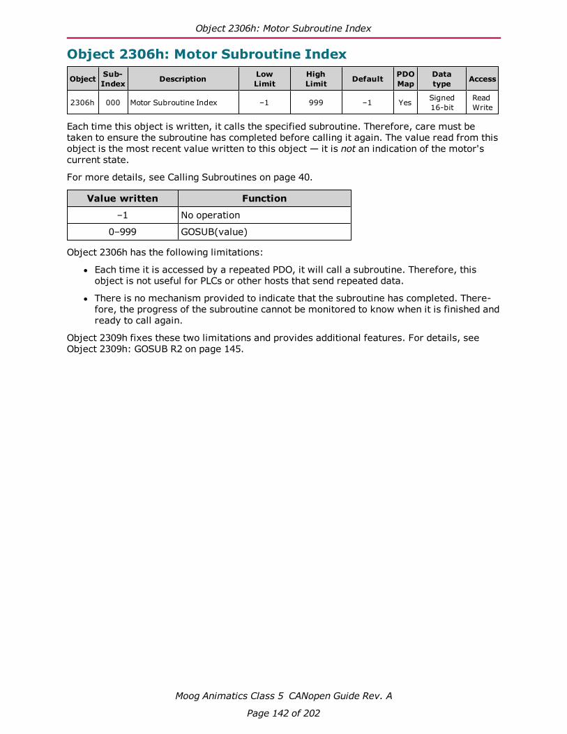
Object 2306h: Motor Subroutine Index
Moog Animatics Class 5 CANopen Guide Rev. A
Page 142 of 202
Object 2306h: Motor Subroutine Index
Object Sub-Index Description Low
LimitHighLimit Default PDO
MapDatatype Access
2306h 000 Motor Subroutine Index –1 999 –1 Yes Signed16-bit
ReadWrite
Each time this object is written, it calls the specified subroutine. Therefore, care must betaken to ensure the subroutine has completed before calling it again. The value read from thisobject is the most recent value written to this object — it is not an indication of the motor'scurrent state.
For more details, see Calling Subroutines on page 40.
Value written Function
–1 No operation
0–999 GOSUB(value)
Object 2306h has the following limitations:
l Each time it is accessed by a repeated PDO, it will call a subroutine. Therefore, thisobject is not useful for PLCs or other hosts that send repeated data.
l There is no mechanism provided to indicate that the subroutine has completed. There-fore, the progress of the subroutine cannot be monitored to know when it is finished andready to call again.
Object 2309h fixes these two limitations and provides additional features. For details, seeObject 2309h: GOSUB R2 on page 145.

Object 2307h: Sample Period
Moog Animatics Class 5 CANopen Guide Rev. A
Page 143 of 202
Object 2307h: Sample Period
Object Sub-Index Description Low
LimitHighLimit Default PDO
MapDatatype Access
2307h 000 Sample Period 0000h FFFFh 12500 Yes Unsigned16-bit
ReadOnly
This object reports the SmartMotor sample period in microseconds *100. This is the timeperiod for the PID cycle and trajectory update.
PIDmode
Reported fromobject 2307
Time(microseconds)
1 6250 62.5
2 12500 125.0
4 25000 250.0
8 50000 500.0
Similar SmartMotor Commands: RSP (PID rate info), RSAMP

Object 2308h: Microsecond Clock
Moog Animatics Class 5 CANopen Guide Rev. A
Page 144 of 202
Object 2308h: Microsecond Clock
Object Sub-Index Description Low
LimitHighLimit Default PDO
MapDatatype Access
2308h 000 Microsecond Clock 00000000h FFFFFFFFh 00000000h Yes Unsigned32-bit
ReadWrite
This object represents an internal sync clock in microseconds. Writing to this object can inter-fere with the time synchronization process used with Interpolation mode. Reading this objectprovides a value that is only current with the most recent PID cycle.
NOTE: This object is tied to special clock-synchronization features that are onlyaccessible through CANopen or serial interpolation. There is no SmartMotor com-mand equivalent — it is not associated with the SmartMotor CLK-type commands,which use a different physical clock that operates independently. Therefore, thisobject is not the same as Object 2303h. For details, see Object 2303h: InternalClock on page 132.
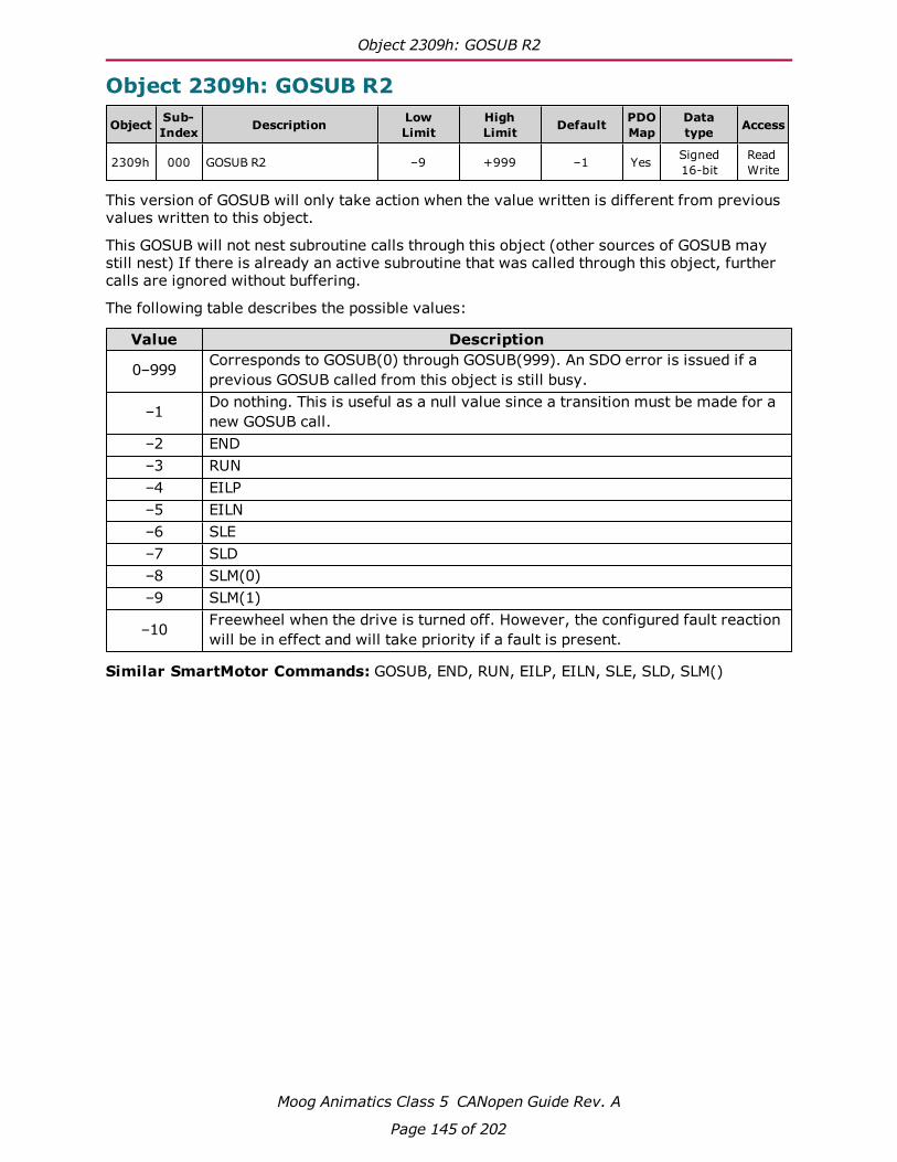
Object 2309h: GOSUB R2
Moog Animatics Class 5 CANopen Guide Rev. A
Page 145 of 202
Object 2309h: GOSUB R2
Object Sub-Index Description Low
LimitHighLimit Default PDO
MapDatatype Access
2309h 000 GOSUB R2 –9 +999 –1 Yes Signed16-bit
ReadWrite
This version of GOSUB will only take action when the value written is different from previousvalues written to this object.
This GOSUB will not nest subroutine calls through this object (other sources of GOSUB maystill nest) If there is already an active subroutine that was called through this object, furthercalls are ignored without buffering.
The following table describes the possible values:
Value Description
0–999 Corresponds to GOSUB(0) through GOSUB(999). An SDO error is issued if aprevious GOSUB called from this object is still busy.
–1 Do nothing. This is useful as a null value since a transition must be made for anew GOSUB call.
–2 END–3 RUN–4 EILP–5 EILN–6 SLE–7 SLD–8 SLM(0)–9 SLM(1)
–10 Freewheel when the drive is turned off. However, the configured fault reactionwill be in effect and will take priority if a fault is present.
Similar SmartMotor Commands: GOSUB, END, RUN, EILP, EILN, SLE, SLD, SLM()
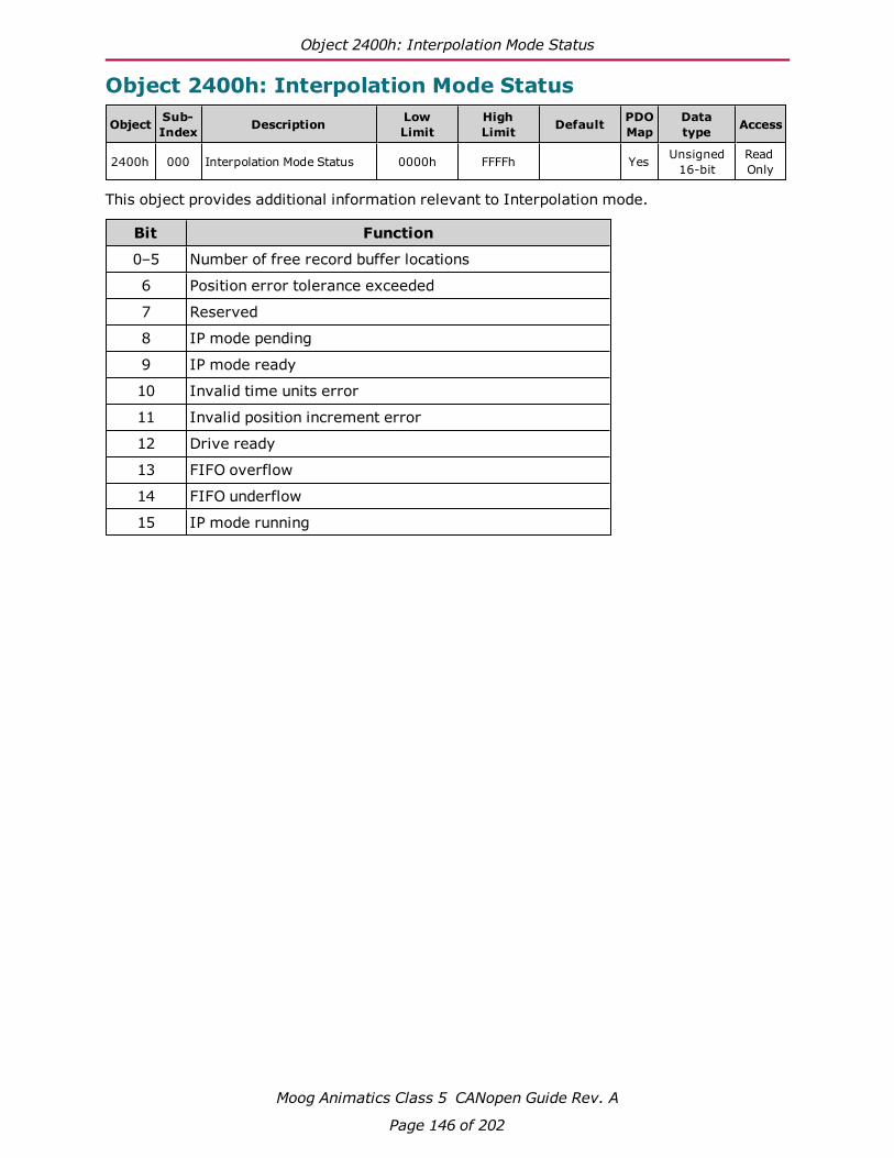
Object 2400h: Interpolation Mode Status
Moog Animatics Class 5 CANopen Guide Rev. A
Page 146 of 202
Object 2400h: Interpolation Mode Status
Object Sub-Index Description Low
LimitHighLimit Default PDO
MapDatatype Access
2400h 000 Interpolation Mode Status 0000h FFFFh Yes Unsigned16-bit
ReadOnly
This object provides additional information relevant to Interpolation mode.
Bit Function
0–5 Number of free record buffer locations
6 Position error tolerance exceeded
7 Reserved
8 IP mode pending
9 IP mode ready
10 Invalid time units error
11 Invalid position increment error
12 Drive ready
13 FIFO overflow
14 FIFO underflow
15 IP mode running

Object 2401h: Buffer Control
Moog Animatics Class 5 CANopen Guide Rev. A
Page 147 of 202
Object 2401h: Buffer Control
Object Sub-Index Description Low
LimitHighLimit Default PDO
MapDatatype Access
2401h 000 Buffer Control 0000h FFFFh 0000h Yes Unsigned16-bit
ReadWrite
This object provides a special way of controlling the interpolation buffer level when the hostcannot monitor the buffer level and/or time synchronization is not possible. The value writtenis a proportional response to how far the interpolation is from the target buffer level. Thatlevel is set using the Buffer Setpoint object (2402h). For details, see Object 2402h: Buffer Set-point on page 148.
As the buffer empties, the interpolation rate slightly decreases; as the buffer fills, the inter-polation rate slightly increases. A typical value to write is 10000.
Note that this is not an ideal way to control the buffer level for the following reasons:
l The buffers of different motors will not perfectly align, so the motion will not be per-fectly synchronized.
l The host must send the data to the motor at an even time spacing. However, somehosts may fill the buffer in bursts of activity — that will not work with the SmartMotor.

Object 2402h: Buffer Setpoint
Moog Animatics Class 5 CANopen Guide Rev. A
Page 148 of 202
Object 2402h: Buffer Setpoint
Object Sub-Index Description Low
LimitHighLimit Default PDO
MapDatatype Access
2402h 000 Buffer Setpoint 00h FFh 14h No Unsigned8-bit
ReadWrite
This object specifies the target buffer level. It is used in conjunction with the Buffer Controlobject (2401h) to maintain the buffer at that level. For details, see Object 2401h: Buffer Con-trol on page 147.
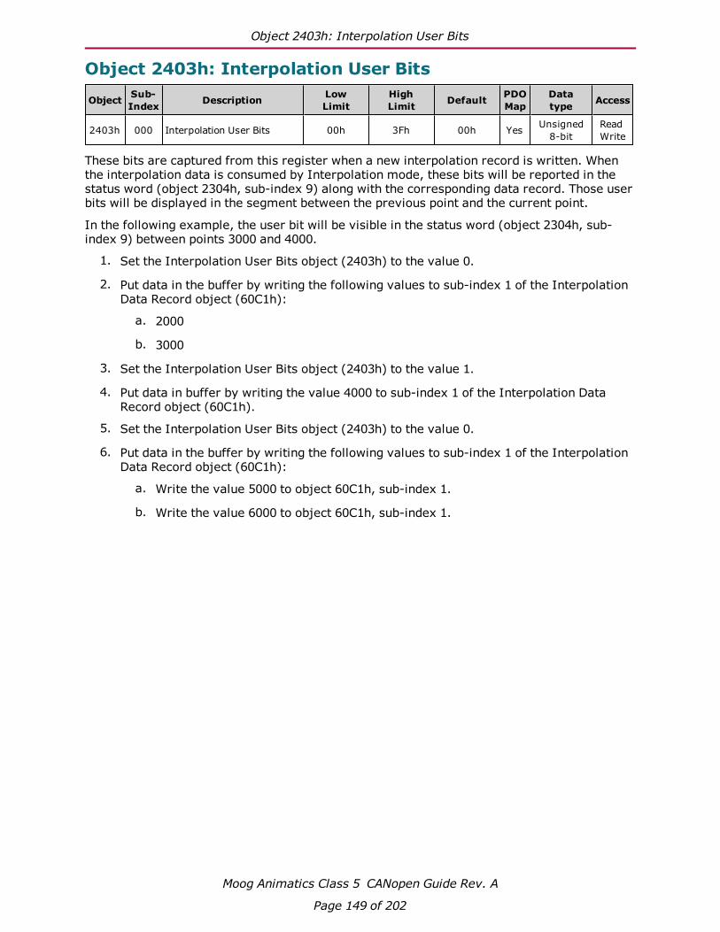
Object 2403h: Interpolation User Bits
Moog Animatics Class 5 CANopen Guide Rev. A
Page 149 of 202
Object 2403h: Interpolation User Bits
Object Sub-Index Description Low
LimitHighLimit Default PDO
MapDatatype Access
2403h 000 Interpolation User Bits 00h 3Fh 00h Yes Unsigned8-bit
ReadWrite
These bits are captured from this register when a new interpolation record is written. Whenthe interpolation data is consumed by Interpolation mode, these bits will be reported in thestatus word (object 2304h, sub-index 9) along with the corresponding data record. Those userbits will be displayed in the segment between the previous point and the current point.
In the following example, the user bit will be visible in the status word (object 2304h, sub-index 9) between points 3000 and 4000.
1. Set the Interpolation User Bits object (2403h) to the value 0.
2. Put data in the buffer by writing the following values to sub-index 1 of the InterpolationData Record object (60C1h):
a. 2000
b. 3000
3. Set the Interpolation User Bits object (2403h) to the value 1.
4. Put data in buffer by writing the value 4000 to sub-index 1 of the Interpolation DataRecord object (60C1h).
5. Set the Interpolation User Bits object (2403h) to the value 0.
6. Put data in the buffer by writing the following values to sub-index 1 of the InterpolationData Record object (60C1h):
a. Write the value 5000 to object 60C1h, sub-index 1.
b. Write the value 6000 to object 60C1h, sub-index 1.

Object 2404h: Interpolation Sample Clock
Moog Animatics Class 5 CANopen Guide Rev. A
Page 150 of 202
Object 2404h: Interpolation Sample Clock
Object Sub-Index Description Low
LimitHighLimit Default PDO
MapDatatype Access
2404h 000 Interpolation Sample Clock 00000000h FFFFFFFFh 00000000h Yes Unsigned32-bit
ReadOnly
This object reports the 32-bit unsigned count of motor PID sample periods since the start ofinterpolation.
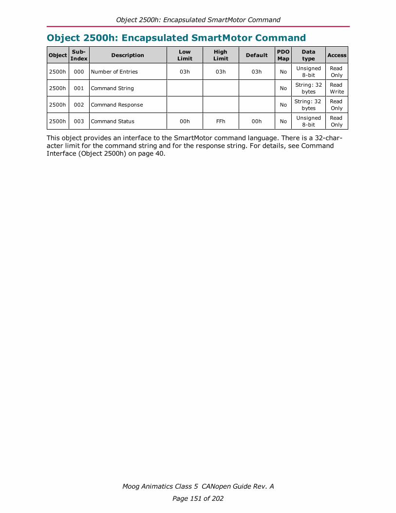
Object 2500h: Encapsulated SmartMotor Command
Moog Animatics Class 5 CANopen Guide Rev. A
Page 151 of 202
Object 2500h: Encapsulated SmartMotor Command
Object Sub-Index Description Low
LimitHighLimit Default PDO
MapDatatype Access
2500h 000 Number of Entries 03h 03h 03h No Unsigned8-bit
ReadOnly
2500h 001 Command String No String: 32bytes
ReadWrite
2500h 002 Command Response No String: 32bytes
ReadOnly
2500h 003 Command Status 00h FFh 00h No Unsigned8-bit
ReadOnly
This object provides an interface to the SmartMotor command language. There is a 32-char-acter limit for the command string and for the response string. For details, see CommandInterface (Object 2500h) on page 40.

Drive and Motion Control Profile
Moog Animatics Class 5 CANopen Guide Rev. A
Page 152 of 202
Drive and Motion Control ProfileThis section describes the objects in the Drive and Motion Control Profile. This set of objects inthe range 6000h to 67FFh implement the CiA 402 motion profile. This provides access to com-mon commands for controlling the motor.
Object 6040h: Control Word 154
Object 6041h: Status Word 156
Object 605Ah: Quick Stop Option Code 157
Object 605Dh: Halt Option Code 158
Object 605Eh: Fault Reaction Option Code 159
Object 6060h: Modes of Operation 160
Object 6061h: Modes of Operation Display 161
Object 6062h: Position Demand Value 162
Object 6063h: Position Actual Internal Value 163
Object 6064h: Position Actual Value 164
Object 6065h: Following Error Window 165
Object 606Bh: Velocity Demand Value 166
Object 606Ch: Velocity Actual Value 167
Object 6071h: Target Torque 168
Object 6074h: Torque Demand Value 169
Object 6077h: Torque Actual 170
Object 6079h: DC Link Circuit Voltage 171
Object 607Ah: Target Position 172
Object 607Ch: Home Offset 173
Object 6080h: Max Motor Speed 175
Object 6081h: Profile Velocity in PP Mode 176
Object 6083h: Profile Acceleration 177
Object 6084h: Profile Deceleration 178
Object 6085h: Quick Stop Deceleration 179
Object 6087h: Torque Slope 180
Object 608Fh: Position Encoder Resolution 181
Object 6098h: Homing Method 182

Drive and Motion Control Profile
Moog Animatics Class 5 CANopen Guide Rev. A
Page 153 of 202
Object 6099h: Homing Speeds 183
Object 609Ah: Homing Acceleration 184
Object 60C0h: Interpolation Sub-Mode Select 185
Object 60C1h: Interpolation Data Record 186
Object 60C2h: Interpolation Time Period 187
Object 60C4h: Interpolation Data Configuration 189
Object 60F4h: Following Error Actual Value 190
Object 60FBh: Position Control Parameter Set 191
Object 60FCh: Position Demand Internal Value 193
Object 60FDh: Digital Inputs 194
Object 60FEh: Digital Outputs 196
Object 60FFh: Target Velocity 197
Object 6402h: Motor Type 198
Object 6502h: Supported Drive Modes 199
Object 67FFh: Single Device Type 200

Object 6040h: Control Word
Moog Animatics Class 5 CANopen Guide Rev. A
Page 154 of 202
Object 6040h: Control Word
Object Sub-Index Description Low
LimitHighLimit Default PDO
MapDatatype Access
6040h 000 Control Word 0000h FFFFh 0000h Yes Unsigned16-bit
ReadWrite*
*Write access is restricted when the remote bit is cleared with the CANCTL(13,0) command.
The control word is the primary method of commanding motion in the SmartMotor. The fol-lowing features are accessed with this object:
l Enable or disable the motor drive
l Quick stop function
l Halt function
l New position setpoint in Profile Position mode (PP)
l Start motion: Profile Position (PP), Profile Velocity (PV), Torque (TQ), Interpolation(IP), and Homing (HM)
For more details, see Control Words, Status Words and the Drive State Machine on page 44.
The SmartMotor =CAN and RCAN commands can be used to assign/report the value of theNMT state, control word (object 6040h) and status word (object 6041h). For details, see=CAN, RCAN on page 72.
The following table provides a listing of the available bits, their names and descriptions.

Object 6040h: Control Word
Moog Animatics Class 5 CANopen Guide Rev. A
Page 155 of 202
Bit Name Description
0 Switch on These bits control the CiA 402 profile drive state machine. Formore details, see CiA 402 Profile Motion State Machine on page44.1 Enable voltage
2 Quick stop
3 Enable operation
4 Operation modespecific: "Newsetpoint"
Used by PP, HM, and IP modes. In PP mode: all positions must beset with a rising transition of this bit. In IP mode: rising edge ofthis bit is used to initially start operation but not required at eachdata point.
5 Operation modespecific:"Change setimmediately"
Used in PP mode; other modes can leave as 0.
6 Operation modespecific: "Rel-ative"
In PP mode, this sets a position relative target (PRT=) instead of aposition target (PT=) type of move.
7 Fault reset Rising transition resets fault in all modes of operation. If the faultcondition still exists (status word object 6041h), then the causehas not been cleared.
8 Halt If this bit is set, then the motor will stop from any mode of oper-ation. The action taken is set in advance by the halt option code.
9 Operation modespecific
Used in PP mode; other modes can leave as 0.
10 Reserved Reserved by the CiA 402 specification.
11 Manufacturer-specific:Reserved foruser application
Reserved for the user's application. This bit is visible in a programthrough RCAN(2).
12 Manufacturer-specific
Do not use; leave at 0.
13 Manufacturer-specific
Do not use; leave at 0.
14 Manufacturer-specific
Do not use; leave at 0.
15 Manufacturer-specific: Resetinterpolation buf-fer
Used to reset the IP mode buffer.

Object 6041h: Status Word
Moog Animatics Class 5 CANopen Guide Rev. A
Page 156 of 202
Object 6041h: Status Word
Object Sub-Index Description Low
LimitHighLimit Default PDO
MapDatatype Access
6041h 000 Status Word 0000h FFFFh Yes Unsigned16-bit
ReadOnly
This object indicates the current state of the drive. For more details, see Control Words,Status Words and the Drive State Machine on page 44. The SmartMotor =CAN and RCAN com-mands can be used to assign/report the value of the NMT state, control word (object 6040h)and status word (object 6041h). For details, see =CAN, RCAN on page 72.
Bit Name Description
0 Ready to switch on The bits 0–3, 5 and 6 represent the state of the CiA 402 pro-file drive state machine. For more details, see CiA 402 ProfileMotion State Machine on page 44.
1 Switched on
2 Operation enabled
3 Fault
4 Voltage enabled Sufficient voltage is present to operate the motor.
5 Quick stop The bits 0–3, 5 and 6 represent the state of the CiA 402 pro-file drive state machine. For more details, see CiA 402 ProfileMotion State Machine on page 44.6 Switch on disabled
7 Warning Not used (reports as 0).
8 Manufacturer-specific Used by the GOSUB R2 object (2309h) to indicate the sub-routine is busy.
9 Remote Controlled through CANCTL(13,x). This bit indicates if themotor is accepting commands from the CANopen network.Default is 1, which indicates the motor is accepting com-mands.
10 Target reached "Target reached" — this is operation-mode specific. It indic-ates the speed, position, or torque profile was achieved.
In Homing (HM) mode, the motor has come to rest after find-ing the home position. However, the motor is not specificallyat the home position because a deceleration distance wasrequired after finding the position.
11 Internal limit active "Limit" — set if a position limit is currently showing a fault.
12 Operation mode spe-cific
"Setpoint acknowledgment" — this is operation-mode specificto PP, IP and PV modes. It indicates a new setpoint wasreceived.
In Homing (HM) mode, the homing process has found thehome position, and the "position actual" has been adjusted tothe new home position and home offset.
13 Operation mode spe-cific
"Move error" — set if a position error occurred.
14 Manufacturer-specific User-controlled bit through CANCTL(12,x).
15 Manufacturer-specific Not used (reports as 0).

Object 605Ah: Quick Stop Option Code
Moog Animatics Class 5 CANopen Guide Rev. A
Page 157 of 202
Object 605Ah: Quick Stop Option Code
Object Sub-Index Description Low
LimitHighLimit Default PDO
MapDatatype Access
605Ah 000 Quick Stop Option Code –1 2 2 No Signed16-bit
ReadWrite
This object determines what action should be taken if the quick stop function is active. Thatfunction is activated by bit 2 of the Control Word object (6040h). For details, see Object6040h: Control Word on page 154.
In Profile Torque (TQ) mode, quick stop option code values 1 and 2 will reduce the torqueaccording to the torque slope rate because this is not a servo mode that can follow the decel-eration or quick-stop deceleration rates.
Value Function
–1 MTB (drive turned off, resists rotation)
0 Disable drive (drive turned off, free to rotate)
1 Decelerate on the profile deceleration ramp (see Object6084h: Profile Deceleration on page 178); drive willautomatically leave the quick stop state.
2 Decelerate on the quick stop ramp (see Object 6085h:Quick Stop Deceleration on page 179); drive will auto-matically leave the quick stop state
3–8 Not supported
9–32767 Reserved
If using Follow or Cam mode, be aware that these decelerations are not applied. The Anim-atics MFD() command controls the deceleration in those cases.

Object 605Dh: Halt Option Code
Moog Animatics Class 5 CANopen Guide Rev. A
Page 158 of 202
Object 605Dh: Halt Option Code
Object Sub-Index Description Low
LimitHighLimit Default PDO
MapDatatype Access
605Dh 000 Halt Option Code 1 2 1 No Signed16-bit
ReadWrite
This object determines what action should be taken if the halt bit (bit 8) is set in Control Wordobject (6040h). For details, see Object 6040h: Control Word on page 154.
In Profile Torque (TQ) mode, halt option code values 1 and 2 will reduce the torque accordingto the torque slope rate because this is not a servo mode that can follow the deceleration orquick-stop deceleration rates.
Value Function
0 Reserved
1 (Default) Decelerate on the profile deceleration ramp(see Object 6084h: Profile Deceleration on page 178)
2 Slow down on quick-stop ramp
3–4 Not supported
5–32767 Reserved
If using Follow or Cam mode, be aware that these decelerations are not applied. The Anim-atics MFD() command controls the deceleration in those cases.
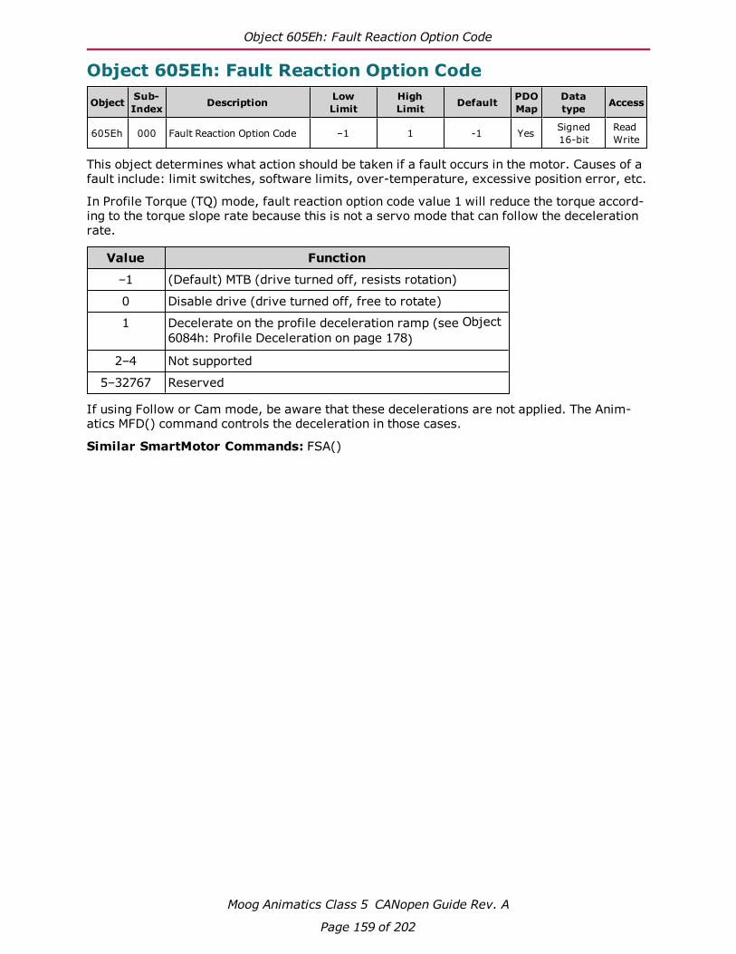
Object 605Eh: Fault Reaction Option Code
Moog Animatics Class 5 CANopen Guide Rev. A
Page 159 of 202
Object 605Eh: Fault Reaction Option Code
Object Sub-Index Description Low
LimitHighLimit Default PDO
MapDatatype Access
605Eh 000 Fault Reaction Option Code –1 1 -1 Yes Signed16-bit
ReadWrite
This object determines what action should be taken if a fault occurs in the motor. Causes of afault include: limit switches, software limits, over-temperature, excessive position error, etc.
In Profile Torque (TQ) mode, fault reaction option code value 1 will reduce the torque accord-ing to the torque slope rate because this is not a servo mode that can follow the decelerationrate.
Value Function
–1 (Default) MTB (drive turned off, resists rotation)
0 Disable drive (drive turned off, free to rotate)
1 Decelerate on the profile deceleration ramp (see Object6084h: Profile Deceleration on page 178)
2–4 Not supported
5–32767 Reserved
If using Follow or Cam mode, be aware that these decelerations are not applied. The Anim-atics MFD() command controls the deceleration in those cases.
Similar SmartMotor Commands: FSA()

Object 6060h: Modes of Operation
Moog Animatics Class 5 CANopen Guide Rev. A
Page 160 of 202
Object 6060h: Modes of Operation
Object Sub-Index Description Low
LimitHighLimit Default PDO
MapDatatype Access
6060h 000 Modes of Operation 80h 07h 00h Yes Signed8-bit
ReadWrite*
*Write access is restricted when the remote bit is cleared with the CANCTL(13,0) command.
The type of motion control is selected by setting this object to one of the values shown in thefollowing table. The new setting will take effect immediately. When transitioning to Inter-polated Position (IP) mode or Profile Position (PP) mode, the motor will stop, there must be arising transition on bit 4 of the control word and then motion will begin in the new mode.
The value read back from this object does not indicate the current mode of operation; it isonly an indication of what was written previously. Use the Modes of Operation Display object(6061h) to see the currently active mode. For details, see Object 6061h: Modes of OperationDisplay on page 161.
Value Motion Control Mode
–3 Step and direction input
–2 Follow quadrature encoder input
–1 Reserved
0 Null
1 Profile Position (PP) mode
2 Not supported
3 Profile Velocity (PV) mode
4 Torque Profile (TQ) mode
5 Reserved
6 Homing (HM) mode
7 Interpolated Position (IP) mode
8–10 Not supported
11–127 Reserved
Similar SmartMotor Commands: MV, MP, MT, MFR, MSR

Object 6061h: Modes of Operation Display
Moog Animatics Class 5 CANopen Guide Rev. A
Page 161 of 202
Object 6061h: Modes of Operation Display
Object Sub-Index Description Low
LimitHighLimit Default PDO
MapDatatype Access
6061h 000 Modes of Operation Display 80h 7Fh 00h Yes Signed8-bit
ReadOnly
Displays the current mode of motion control; refer to Object 6060h: Modes of Operation onpage 160.
Similar SmartMotor Commands: RMODE

Object 6062h: Position Demand Value
Moog Animatics Class 5 CANopen Guide Rev. A
Page 162 of 202
Object 6062h: Position Demand Value
Object Sub-Index Description Low
LimitHighLimit Default PDO
MapDatatype Access
6062h 000 Position Demand Value 80000000h 7FFFFFFFh 00000000h Yes Signed32-bit
ReadOnly
This object reports the position calculated by the motion profile; it takes into account the accel-eration and velocity targets. Because user units are not supported, the value is in units ofencoder counts, which are the same units as those for object 60FCh. For details, see Object60FCh: Position Demand Internal Value on page 193.
When the motor drive is inactive or in torque mode, the value reported is simply the currentposition.
Similar SmartMotor Commands: RPC

Object 6063h: Position Actual Internal Value
Moog Animatics Class 5 CANopen Guide Rev. A
Page 163 of 202
Object 6063h: Position Actual Internal Value
Object Sub-Index Description Low
LimitHighLimit Default PDO
MapDatatype Access
6063h 000 Position Actual InternalValue 80000000h 7FFFFFFFh 00000000h Yes Signed
32-bitReadOnly
This object reports the current position of the motor shaft in units of encoder counts.
Similar SmartMotor Commands: RPA

Object 6064h: Position Actual Value
Moog Animatics Class 5 CANopen Guide Rev. A
Page 164 of 202
Object 6064h: Position Actual Value
Object Sub-Index Description Low
LimitHighLimit Default PDO
MapDatatype Access
6064h 000 Position Actual Value 80000000h 7FFFFFFFh 00000000h Yes Signed32-bit
ReadOnly
This object reports the current position of the motor shaft in units of encoder counts. Becauseuser units are not supported, the value is in units of encoder counts, which are the same unitsas those for object 6063h. For details, see Object 6063h: Position Actual Internal Value onpage 163.
Similar SmartMotor Commands: RPA

Object 6065h: Following Error Window
Moog Animatics Class 5 CANopen Guide Rev. A
Page 165 of 202
Object 6065h: Following Error Window
Object Sub-Index Description Low
LimitHighLimit Default PDO
MapDatatype Access
6065h 000 Following Error Window 00000000h FFFFFFFFh 000003E8h Yes Unsigned32-bit
ReadWrite
This object defines the range of tolerated deviation for the actual position relative to the cal-culated demand position. If the actual position is out of range, a following-error fault occursand the drive will react according to the fault reaction. The units of this object are in encodercounts.
Similar SmartMotor Commands: EL=, REL

Object 606Bh: Velocity Demand Value
Moog Animatics Class 5 CANopen Guide Rev. A
Page 166 of 202
Object 606Bh: Velocity Demand Value
Object Sub-Index Description Low
LimitHighLimit Default PDO
MapDatatype Access
606Bh 000 Velocity Demand Value 80000000h 7FFFFFFFh 00000000h Yes Signed32-bit
ReadOnly
This object reports the velocity calculated by the motion profile; it takes into account accel-eration and velocity targets. The units are: (encoder counts per sample period) * 65536.
Similar SmartMotor Commands: RVC

Object 606Ch: Velocity Actual Value
Moog Animatics Class 5 CANopen Guide Rev. A
Page 167 of 202
Object 606Ch: Velocity Actual Value
Object Sub-Index Description Low
LimitHighLimit Default PDO
MapDatatype Access
606Ch 000 Velocity Actual Value 80000000h 7FFFFFFFh 00000000h Yes Signed32-bit
ReadOnly
This object reports the actual velocity of the motor shaft. The units are: (encoder counts persample period) * 65536.
Similar SmartMotor Commands: RVA
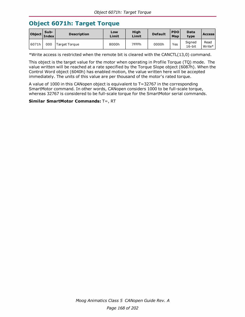
Object 6071h: Target Torque
Moog Animatics Class 5 CANopen Guide Rev. A
Page 168 of 202
Object 6071h: Target Torque
Object Sub-Index Description Low
LimitHighLimit Default PDO
MapDatatype Access
6071h 000 Target Torque 8000h 7FFFh 0000h Yes Signed16-bit
ReadWrite*
*Write access is restricted when the remote bit is cleared with the CANCTL(13,0) command.
This object is the target value for the motor when operating in Profile Torque (TQ) mode. Thevalue written will be reached at a rate specified by the Torque Slope object (6087h). When theControl Word object (6040h) has enabled motion, the value written here will be acceptedimmediately. The units of this value are per thousand of the motor's rated torque.
A value of 1000 in this CANopen object is equivalent to T=32767 in the correspondingSmartMotor command. In other words, CANopen considers 1000 to be full-scale torque,whereas 32767 is considered to be full-scale torque for the SmartMotor serial commands.
Similar SmartMotor Commands: T=, RT

Object 6074h: Torque Demand Value
Moog Animatics Class 5 CANopen Guide Rev. A
Page 169 of 202
Object 6074h: Torque Demand Value
Object Sub-Index Description Low
LimitHighLimit Default PDO
MapDatatype Access
6074h 000 Torque Demand Value 8000h 7FFFh 0000h Yes Signed16-bit
ReadOnly
This object provides the motor's demand torque from the PID when in Position (PP), Velocity(PV) or interpolation (IP) mode, or the torque profile when in Torque (TQ) mode. The units ofthis value are per thousand of the motor's rated torque.
NOTE: This object represents the requested value from the Torque profile (in TQmode) or the PID (in all other closed-loop servo modes). However, due to currentlimits, torque profile, etc., the motor may not be able to deliver the requestedtorque.
A value of 1000 in this CANopen object is equivalent to T=32767 in the correspondingSmartMotor command. In other words, CANopen considers 1000 to be full-scale torque,whereas 32767 is considered to be full-scale torque for the SmartMotor serial commands.
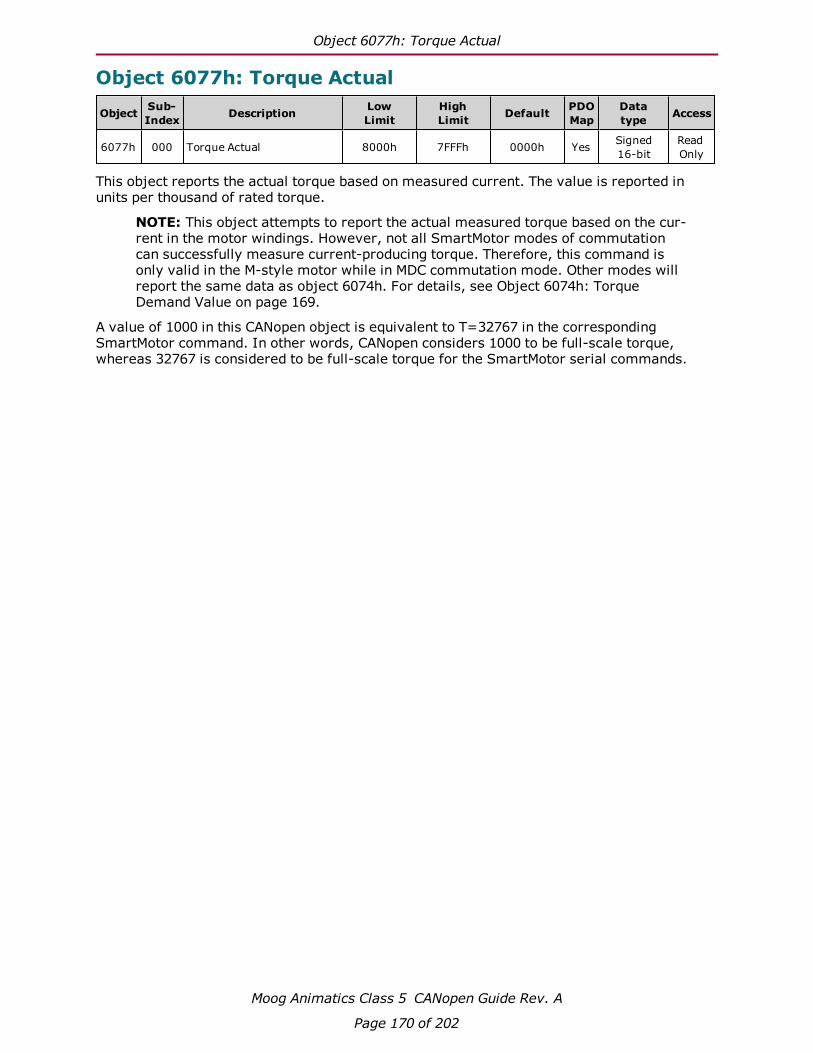
Object 6077h: Torque Actual
Moog Animatics Class 5 CANopen Guide Rev. A
Page 170 of 202
Object 6077h: Torque Actual
Object Sub-Index Description Low
LimitHighLimit Default PDO
MapDatatype Access
6077h 000 Torque Actual 8000h 7FFFh 0000h Yes Signed16-bit
ReadOnly
This object reports the actual torque based on measured current. The value is reported inunits per thousand of rated torque.
NOTE: This object attempts to report the actual measured torque based on the cur-rent in the motor windings. However, not all SmartMotor modes of commutationcan successfully measure current-producing torque. Therefore, this command isonly valid in the M-style motor while in MDC commutation mode. Other modes willreport the same data as object 6074h. For details, see Object 6074h: TorqueDemand Value on page 169.
A value of 1000 in this CANopen object is equivalent to T=32767 in the correspondingSmartMotor command. In other words, CANopen considers 1000 to be full-scale torque,whereas 32767 is considered to be full-scale torque for the SmartMotor serial commands.

Object 6079h: DC Link Circuit Voltage
Moog Animatics Class 5 CANopen Guide Rev. A
Page 171 of 202
Object 6079h: DC Link Circuit Voltage
Object Sub-Index Description Low
LimitHighLimit Default PDO
MapDatatype Access
6079h 000 DC Link Circuit Voltage 00000000h FFFFFFFFh Yes Unsigned32-bit
ReadOnly
This object describes the supplied voltage, in millivolts, measured at the motor's powerinverter.
Similar SmartMotor Commands: RUJA
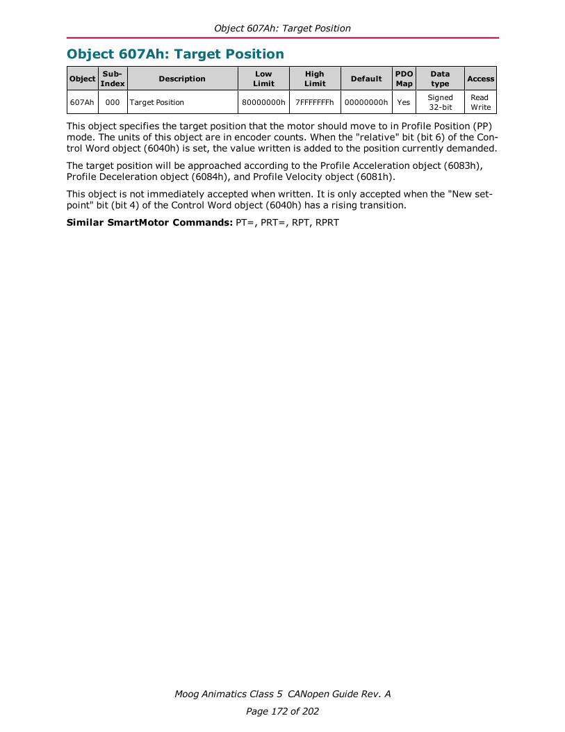
Object 607Ah: Target Position
Moog Animatics Class 5 CANopen Guide Rev. A
Page 172 of 202
Object 607Ah: Target Position
Object Sub-Index Description Low
LimitHighLimit Default PDO
MapDatatype Access
607Ah 000 Target Position 80000000h 7FFFFFFFh 00000000h Yes Signed32-bit
ReadWrite
This object specifies the target position that the motor should move to in Profile Position (PP)mode. The units of this object are in encoder counts. When the "relative" bit (bit 6) of the Con-trol Word object (6040h) is set, the value written is added to the position currently demanded.
The target position will be approached according to the Profile Acceleration object (6083h),Profile Deceleration object (6084h), and Profile Velocity object (6081h).
This object is not immediately accepted when written. It is only accepted when the "New set-point" bit (bit 4) of the Control Word object (6040h) has a rising transition.
Similar SmartMotor Commands: PT=, PRT=, RPT, RPRT

Object 607Ch: Home Offset
Moog Animatics Class 5 CANopen Guide Rev. A
Page 173 of 202
Object 607Ch: Home Offset
Object Sub-Index Description Low
LimitHighLimit Default PDO
MapDatatype Access
607Ch 000 Home Offset 80000000h 7FFFFFFFh 0 Yes Signed32-bit
ReadWrite
This object shifts the origin of the actual position when the Homing (HM) mode is executed.When HM mode is commanded to begin, the home position is first discovered. The home pos-ition is the physical location of the switch or index per the specific homing method. Oncefound, that physical location is assigned the negative of the home offset value:
Home position = –Home offset
The home position is assigned with –home offset. See the following example.
60
64
h =
0S
ta
r!
ng
po
si!
on
Ph
ysic
al
sto
p −
Ph
ysic
al
sto
p +
Posi!ve limit switch = 1
60
64
h =
0
Po
si!
on
a#
er h
om
ing
Posi!ve limit switch = 1
60
64
h =
12
00
60
64
h =
11
54
Ho
me
po
si!
on
Homing method = 18
Incremental encoder (powers up at value = 0)
Condi!on: Ini!al power up
Condi!on: Find home
(Fast speed)
(slow
speed)
Homing offset object 607Ch = +600
Green: machine physical posi!on
Red: Home Posi!on — where the sensors say it is
Blue: Zero Posi!on — a#er homing completes, where the machine reports 6064h = 0
Ph
ysic
al
sto
p −
Ph
ysic
al
sto
p +

Object 607Ch: Home Offset
Moog Animatics Class 5 CANopen Guide Rev. A
Page 174 of 202
60
64
h =
−6
00
Posi!ve limit switch = 1
Re
s!n
g P
osi
!o
n
Ho
me
po
si!
on
CiA 402 and ETG guidelines state: “Zero posi!on = home posi!on + home offset” 0 = Home posi!on + home offsetHome posi!on = −home offset
Ze
ro p
osi
!o
n6
06
4h
= 0
60
64
h =
−6
46
Condi!on: Apply home offset
60
64
h =
0
Posi!ve limit switch = 1
Re
s!n
g P
osi
!o
n
Ho
me
po
si!
on
Condi!on: Set home posi!on to 0
60
64
h =
−4
6
Ph
ysi
cal
sto
p −
Ph
ysi
cal
sto
p +
Ph
ysi
cal
sto
p −
Ph
ysi
cal
sto
p +
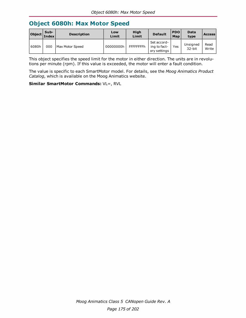
Object 6080h: Max Motor Speed
Moog Animatics Class 5 CANopen Guide Rev. A
Page 175 of 202
Object 6080h: Max Motor Speed
Object Sub-Index Description Low
LimitHighLimit Default PDO
MapDatatype Access
6080h 000 Max Motor Speed 00000000h FFFFFFFFhSet accord-ing to fact-ory settings
Yes Unsigned32-bit
ReadWrite
This object specifies the speed limit for the motor in either direction. The units are in revolu-tions per minute (rpm). If this value is exceeded, the motor will enter a fault condition.
The value is specific to each SmartMotor model. For details, see the Moog Animatics ProductCatalog, which is available on the Moog Animatics website.
Similar SmartMotor Commands: VL=, RVL
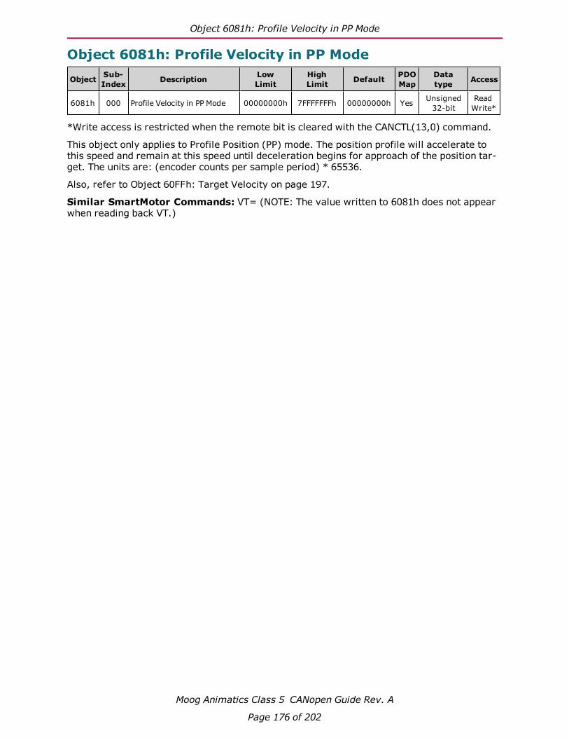
Object 6081h: Profile Velocity in PP Mode
Moog Animatics Class 5 CANopen Guide Rev. A
Page 176 of 202
Object 6081h: Profile Velocity in PP Mode
Object Sub-Index Description Low
LimitHighLimit Default PDO
MapDatatype Access
6081h 000 Profile Velocity in PP Mode 00000000h 7FFFFFFFh 00000000h Yes Unsigned32-bit
ReadWrite*
*Write access is restricted when the remote bit is cleared with the CANCTL(13,0) command.
This object only applies to Profile Position (PP) mode. The position profile will accelerate tothis speed and remain at this speed until deceleration begins for approach of the position tar-get. The units are: (encoder counts per sample period) * 65536.
Also, refer to Object 60FFh: Target Velocity on page 197.
Similar SmartMotor Commands: VT= (NOTE: The value written to 6081h does not appearwhen reading back VT.)

Object 6083h: Profile Acceleration
Moog Animatics Class 5 CANopen Guide Rev. A
Page 177 of 202
Object 6083h: Profile Acceleration
Object Sub-Index Description Low
LimitHighLimit Default PDO
MapDatatype Access
6083h 000 Profile Acceleration 00000000h 7FFFFFFFh 00000004h Yes Unsigned32-bit
ReadWrite*
*Write access is restricted when the remote bit is cleared with the CANCTL(13,0) command.
This object is the acceleration in the Profile Velocity (PV) mode and the Profile Position (PP)mode. The units are: (encoder counts per (sample2)) * 65536.
Similar SmartMotor Commands: AT=, ADT=, RAT
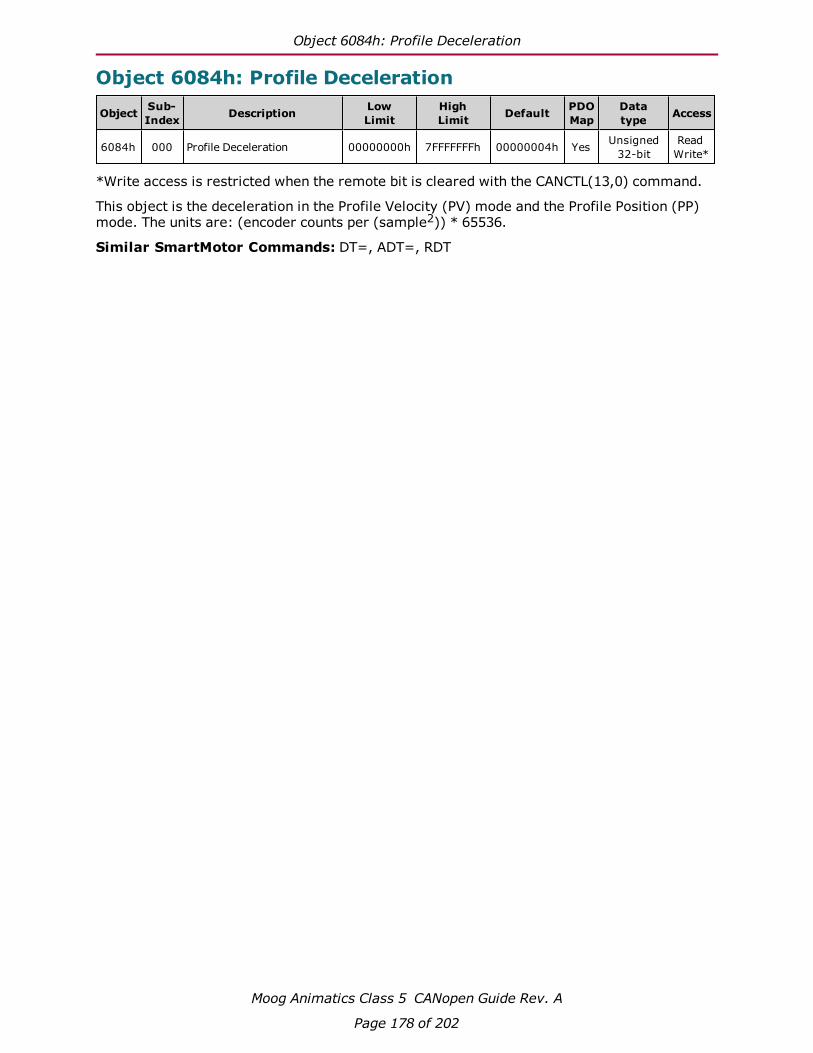
Object 6084h: Profile Deceleration
Moog Animatics Class 5 CANopen Guide Rev. A
Page 178 of 202
Object 6084h: Profile Deceleration
Object Sub-Index Description Low
LimitHighLimit Default PDO
MapDatatype Access
6084h 000 Profile Deceleration 00000000h 7FFFFFFFh 00000004h Yes Unsigned32-bit
ReadWrite*
*Write access is restricted when the remote bit is cleared with the CANCTL(13,0) command.
This object is the deceleration in the Profile Velocity (PV) mode and the Profile Position (PP)mode. The units are: (encoder counts per (sample2)) * 65536.
Similar SmartMotor Commands: DT=, ADT=, RDT

Object 6085h: Quick Stop Deceleration
Moog Animatics Class 5 CANopen Guide Rev. A
Page 179 of 202
Object 6085h: Quick Stop Deceleration
Object Sub-Index Description Low
LimitHighLimit Default PDO
MapDatatype Access
6085h 000 Quick Stop Deceleration 00000000h 7FFFFFFFh 7FFFFFFFh Yes Unsigned32-bit
ReadWrite
This object is used to stop the drive with the quick stop function, which is commanded from bit2 of the Control Word object (6040h). The value is the deceleration used to stop the motor ifthe quick stop command is given and the Quick Stop Option Code object (605Ah) is set to 2.The units are: (encoder counts per (sample2)) * 65536.
For additional details, see Object 6040h: Control Word on page 154 and Object 605Ah: QuickStop Option Code on page 157.

Object 6087h: Torque Slope
Moog Animatics Class 5 CANopen Guide Rev. A
Page 180 of 202
Object 6087h: Torque Slope
Object Sub-Index Description Low
LimitHighLimit Default PDO
MapDatatype Access
6087h 000 Torque Slope 00000000h FFFFFFFFh 0x007A12F4 Yes Unsigned32-bit
ReadWrite*
*Write access is restricted when the remote bit is cleared with the CANCTL(13,0) command.
This object is the torque mode acceleration/deceleration slope. The units are in torque unitsper second. To put this into context, a value of 1000 in this object can ramp the SmartMotor tofull torque in one second.
In SmartMotor commands, the corresponding command is TS=, where the units are different.In the TS= command, the units are: ("T=" per sample)*65536. Therefore, a value of 1000 inthis CANopen object is equivalent to TS=268427, assuming the default PID rate of 8000 Hz.
For related information, see Object 6071h: Target Torque on page 168.
Similar SmartMotor Commands: TS=, RTS

Object 608Fh: Position Encoder Resolution
Moog Animatics Class 5 CANopen Guide Rev. A
Page 181 of 202
Object 608Fh: Position Encoder Resolution
Object Sub-Index Description Low
LimitHighLimit Default PDO
MapDatatype Access
608Fh 000 Number of Entries 00000002h 00000002h 00000002h No Unsigned8-bit
ReadOnly
608Fh 001 Encoder Counts 00000000h FFFFFFFFh Encoder res-olution. Yes Unsigned
32-bitReadOnly
608Fh 002 Motor Revolutions 00000000h FFFFFFFFh 00000001h Yes Unsigned32-bit
ReadOnly
This object defines the resolution of the encoder. There are two sub-index objects thatdescribe the encoder resolution — sub-index 001: Encoder Counts and sub-index 002: MotorRevolutions. To determine the encoder resolution (number of encoder counts per motor revolu-tion), divide the value of sub-index 1 by the value of sub-index 2. The units are in encodercounts.

Object 6098h: Homing Method
Moog Animatics Class 5 CANopen Guide Rev. A
Page 182 of 202
Object 6098h: Homing Method
Object Sub-Index Description Low
LimitHighLimit Default PDO
MapDatatype Access
6098h 000 Homing Method 80h 7Fh 0 Yes Signed8-bit
ReadWrite
This object selects the method used in Homing (HM) mode. This must be set before starting ahoming process, and it should not be changed while HM mode is actively seeking home.
HomingMethodValue
Description
1 Home position is the first index in the positive direction from the negative limitswitch (requires that limit switches are enabled).
2 Home position is the first index in the negative direction from the positive limitswitch (requires that limit switches are enabled).
17 Home position is at the negative limit switch (requires that limit switches areenabled).
18 Home position is at the positive limit switch (requires that limit switches areenabled).
33 Home position is the location of the first index in the negative direction fromthe current position.
34 Home position is the location of the first index in the positive direction from thecurrent position.
35 Accept the current position as the home position.(current position = –home offset)
NOTE: Methods 1, 2, 33 and 34 make use of the index of the internal encoder,which provides a precise location (switches may have some position uncertainty).The construction of the machine should consider the proximity of the index mark tothe switch threshold. The index location should be at 180 degrees rotation of theencoder (RRES/2) from the switch threshold. This will ensure that the index markdoes not fall within the uncertainty of the switch transition.
NOTE: Methods 1, 2, 17 and 18 make use of the limit switches. Limit switches mustbe enabled and physically wired to the motor. Under these methods, the homingprocess will not start if the relevant limit has been disabled.

Object 6099h: Homing Speeds
Moog Animatics Class 5 CANopen Guide Rev. A
Page 183 of 202
Object 6099h: Homing Speeds
Object Sub-Index Description Low
LimitHighLimit Default PDO
MapDatatype Access
6099h 000 Number of Entries 00000002h 00000002h 00000002h No Unsigned8-bit
ReadOnly
6099h 001 Speed during search forswitch 00000000h 7FFFFFFFh 00000000h Yes Unsigned
32-bitReadWrite
6099h 002 Speed during search forzero 00000000h 7FFFFFFFh 00000000h Yes Unsigned
32-bitReadWrite
This object only applies to Homing (HM) mode. The homing profile will accelerate to thesespeeds depending on the segment of the homing routine that is in use.
In general, the "speed during search for switch" segment is expected to be faster than the"speed during search for zero" segment. The "speed during search for zero" segment is selec-ted when the homing mode expects to find the home position with the move it is currentlystarting. If the homing mode expects an intermediate switch event before the home position,then the "speed during search for switch" segment is selected (for example, a limit switch istripped before changing direction to find the home index).
The units are: (encoder counts per sample period) * 65536.

Object 609Ah: Homing Acceleration
Moog Animatics Class 5 CANopen Guide Rev. A
Page 184 of 202
Object 609Ah: Homing Acceleration
Object Sub-Index Description Low
LimitHighLimit Default PDO
MapDatatype Access
609Ah 000 Homing Acceleration 00000000h 7FFFFFFFh 00000004h Yes Unsigned32-bit
ReadWrite
This object is the acceleration and deceleration in Homing (HM) mode. The units are: (encodercounts per (sample2)) * 65536.

Object 60C0h: Interpolation Sub-Mode Select
Moog Animatics Class 5 CANopen Guide Rev. A
Page 185 of 202
Object 60C0h: Interpolation Sub-Mode Select
Object Sub-Index Description Low
LimitHighLimit Default PDO
MapDatatype Access
60C0h 000 Interpolation Sub-ModeSelect 8000h 0000h 0000h Yes Signed
16-bitReadWrite
Interpolation (IP) mode uses the position data object (60C1h) and the interpolation timeperiod object (60C2h) in one of the following ways:
l Linear interpolation (default): follows a linear set of positions in the times between thedata points. The velocity during each segment between points is constant. The dis-advantage is that the velocity changes abruptly at the data points; the advantage is thatthe actual path taken between points is very predictable.
l Spline interpolation: uses the current point, the next point, and the previous point to gen-erate curvature of the path over time. This results in a more continuous velocity. Also,following of curved shapes is typically more accurate between points. However, the dis-advantage can be certain cases where an overshoot of position can occur. While this isgenerally avoided in the algorithm, extreme cases will overshoot.
The following table shows the possible sub-mode functions. The sub-mode data is read fromthe buffer along with the associated data point; the sub-mode applies to the segment betweenthat point and the previous point.
Value Function
–3 Spline Interpolation
0 Linear Interpolation
1–32767 Reserved
In the following example, the sub-mode will use Spline Interpolation between points 3000 and4000.
1. Set the Interpolation Sub-Mode Select object (60C0h) to the value 0.
2. Put data in the buffer by writing the following values to sub-index 1 of the InterpolationData Record object (60C1h):
a. 2000
b. 3000
3. Set the Interpolation Sub-Mode Select object (60C0h) to the value –3.
4. Put data in buffer by writing the value 4000 to sub-index 1 of the Interpolation DataRecord object (60C1h).
5. Set the Interpolation Sub-Mode Select object (60C0h) to the value 0.
6. Put data in the buffer by writing the following values to sub-index 1 of the InterpolationData Record object (60C1h):
a. 5000
b. 6000

Object 60C1h: Interpolation Data Record
Moog Animatics Class 5 CANopen Guide Rev. A
Page 186 of 202
Object 60C1h: Interpolation Data Record
Object Sub-Index Description Low
LimitHighLimit Default PDO
MapDatatype Access
60C1h 000 Number of Entries 00000001h 00000002h 00000002h No Unsigned8-bit
ReadOnly
60C1h 001 Data Record 1 80000000h 7FFFFFFFh 00000000h Yes Signed32-bit
ReadWrite
60C1h 002 Data Record 2 80000000h 7FFFFFFFh 00000000h Yes Signed32-bit
ReadWrite
This object is used to enter the position data required in Interpolation (IP) mode. Only sub-index 1 is used; sub-index 2 is not used.
When data is written to sub-index 1, it is entered into the buffer. Also, the current values ofthe Interpolation User Bits object (2403h), Interpolation Sub-Mode object (60C0h) and theInterpolation Time object (60C2h) are captured and entered into the buffer with the samerecord as the position data.
The value read from this object is the most recent value written to this object — it is not anindication of the motor's current state.

Object 60C2h: Interpolation Time Period
Moog Animatics Class 5 CANopen Guide Rev. A
Page 187 of 202
Object 60C2h: Interpolation Time Period
Object Sub-Index Description Low
LimitHighLimit Default PDO
MapDatatype Access
60C2h 000 Number of Elements 00h FFh 02h No Unsigned8-bit
ReadOnly
60C2h 001 Interpolation time units 00h FFh 01h Yes Unsigned8-bit
ReadWrite
60C2h 002 Interpolation time index 80h 3Fh FDh (-3) Yes Signed8-bit
ReadWrite
This object is used for Interpolated Position (IP) mode. The time written is captured when adata record is written using sub-index 1 of the Interpolation Data Record object (60C1h). Thetime data is read from the buffer along with the associated data point. The time period appliesto the segment between that point and the previous point. After it is started, the interpolationprocess reads data points out of the interpolation buffer once per the time period.
The default time index is –3, which gives the time units in milliseconds.
InterpolationTime Index Value
–128 to –4 Not allowed (returns SDO error)
–3 0.001 seconds (default)
–2 0.01 seconds
–1 0.1 seconds
0 1 second
1 to 127 Not recommended
The representation of the time is a combination of a value (time units) and a decimal shift(time index):
Time = (time units) * 10(time index) seconds
Desired time range Resolution SuggestedTime Index
SuggestedTime Units
1 to 255 milliseconds 0.001 seconds –3 1 to 255
10 milliseconds to 2.55 seconds 0.010 seconds –2 1 to 255
100 milliseconds to 4 seconds 0.100 seconds –1 1 to 40
1 second to 4 seconds 1.000 seconds 0 1 to 4
Object 60C2h: Interpolation Time Period
Moog Animatics Class 5 CANopen Guide Rev. A
Page 188 of 202
In the following example, the time segment will be the longer time of 2 seconds between point3000 and point 4000.
1. Set sub-index 1 of the Interpolation Time Period object (60C2h) to the value 1.
2. Set sub-index 2 of the Interpolation Time Period object (60C2h) to the value 0, whichrepresents seconds.
3. Put data in the buffer by writing the following values to sub-index 1 of the InterpolationData Record object (60C1h):
a. 2000
b. 3000
4. Set sub-index 1 of the Interpolation Time Period object (60C2h) to the value 2.
5. Put data in buffer by writing the value 4000 to sub-index 1 of the Interpolation DataRecord object (60C1h).
6. Set sub-index 1 of the Interpolation Time Period object (60C2h) to the value 1.
7. Put data in the buffer by writing the following values to sub-index 1 of the InterpolationData Record object (60C1h):
a. 5000
b. 6000

Object 60C4h: Interpolation Data Configuration
Moog Animatics Class 5 CANopen Guide Rev. A
Page 189 of 202
Object 60C4h: Interpolation Data Configuration
Object Sub-Index Description Low
LimitHighLimit Default PDO
MapDatatype Access
60C4h 000 Number of Entries 00h FFh 06h No Unsigned8-bit
ReadOnly
60C4h 001 Maximum buffer size 00000000h FFFFFFFFh 0000002dh Yes Unsigned32-bit
ReadOnly
60C4h 002 Actual buffer size 00000000h FFFFFFFFh 0000002dh Yes Unsigned32-bit
ReadOnly
60C4h 003 Buffer organization 00h FFh 00h Yes Unsigned8-bit
ReadOnly
60C4h 004 Buffer position 0000h FFFFh 0000h Yes Unsigned16-bit
ReadOnly
60C4h 005 Size of data record 04h 04h 04h Yes Unsigned8-bit
ReadOnly
60C4h 006 Buffer clear 00h 01h 00h Yes Unsigned8-bit
WriteOnly
This object controls some miscellaneous aspects of the Interpolation mode buffer.
The sub-index objects have the following functions:
l Sub-index 1: Cannot be changed because the SmartMotor buffer cannot be resized. Thisobject can be ignored.
l Sub-index 2: Cannot be changed because the buffer cannot be resized. The value is 2Dhor 45 (decimal); this is the number of data records that can be held in the buffer. Eachrecord contains information about the position, time, user bits and Interpolation modefor that segment.
l Sub-index 3: Cannot be set. It reports the value 0, which indicates that the buffer is aFIFO type — data records are written into one end of the buffer and the motor firmwarereads data out of the other end.
l Sub-index 4: Reports the number of occupied buffer slots.
l Sub-index 5: Not implemented.
l Sub-index 6: Cannot be read. To control buffer access, write one of the values from thefollowing table.
Sub-index 6 Function
0 Clear input buffer, access disabled (will not accept writes toobject 60C1h), clear all IP data records
1 Enable write access to the buffer (object 60C1h)2–255 Reserved
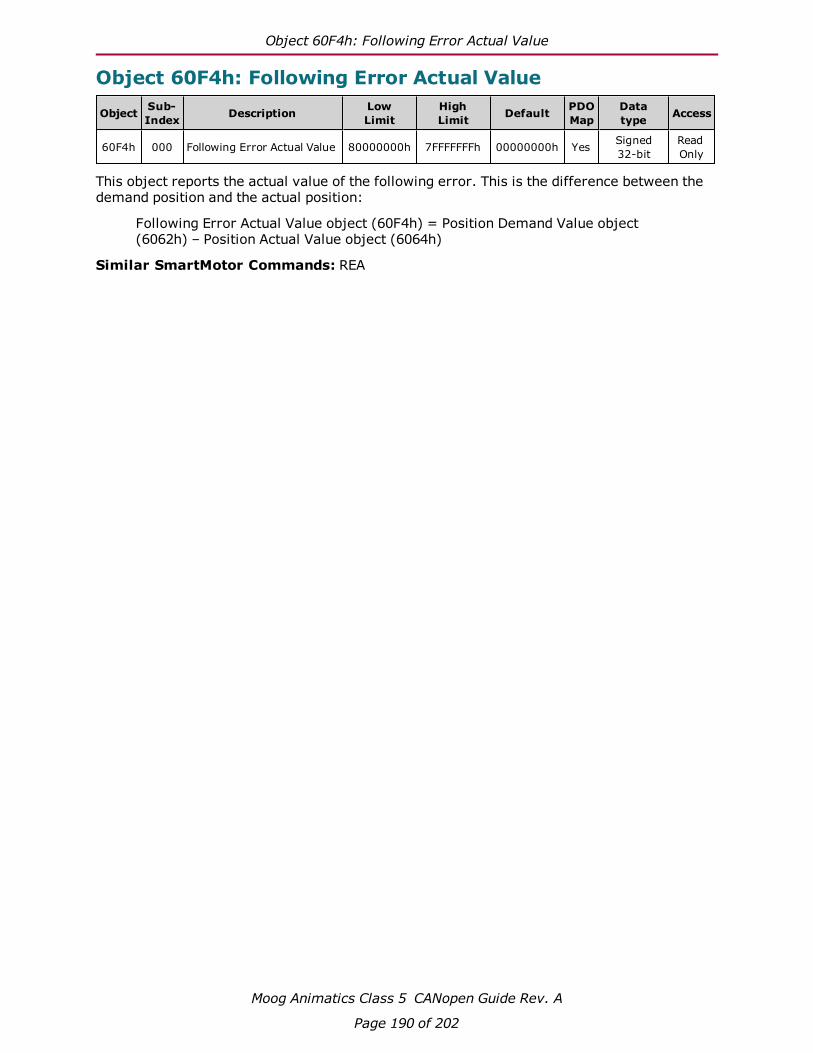
Object 60F4h: Following Error Actual Value
Moog Animatics Class 5 CANopen Guide Rev. A
Page 190 of 202
Object 60F4h: Following Error Actual Value
Object Sub-Index Description Low
LimitHighLimit Default PDO
MapDatatype Access
60F4h 000 Following Error Actual Value 80000000h 7FFFFFFFh 00000000h Yes Signed32-bit
ReadOnly
This object reports the actual value of the following error. This is the difference between thedemand position and the actual position:
Following Error Actual Value object (60F4h) = Position Demand Value object(6062h) – Position Actual Value object (6064h)
Similar SmartMotor Commands: REA

Object 60FBh: Position Control Parameter Set
Moog Animatics Class 5 CANopen Guide Rev. A
Page 191 of 202
Object 60FBh: Position Control Parameter Set
Object Sub-Index Description Low
LimitHighLimit Default PDO
MapDatatype Access
60FBh 000 Number of Entries 00h FFh 0Ah (10) No Unsigned8-bit
ReadOnly
60FBh 001 KP, Proportional Gain 0000h FFFFh FromEEPROM Yes Unsigned
16-bitReadWrite*
60FBh 002 KI, Integral Gain 0000h 7FFFh FromEEPROM Yes Unsigned
16-bitReadWrite*
60FBh 003 KL, Integral Limit 0000h 7FFFh 7FFFh Yes Unsigned16-bit
ReadWrite*
60FBh 004 KD, Derivative Gain 0000h FFFFh FromEEPROM Yes Unsigned
16-bitReadWrite*
60FBh 005 KS, Derivative DampingSample Rate 00h FFh 01h Yes Unsigned
8-bitReadWrite*
60FBh 006 KV, Velocity FeedforwardGain 0000h FFFFh From
EEPROM Yes Unsigned16-bit
ReadWrite*
60FBh 007 KA, Acceleration Feed-forward Gain 0000h FFFFh From
EEPROM Yes Unsigned16-bit
ReadWrite*
60FBh 008 KG, Gravitational Offset 0xFF000000 0x00FFFFFF FromEEPROM Yes Signed
32-bitReadWrite*
60FBh 009 N/A 0000h FFFFh 0000h No Unsigned16-bit
ReadOnly
60FBh 010 Position Loop Control 00h FFh 0x00 Yes Unsigned8-bit
ReadWrite*
*Write access is restricted when the remote bit is cleared with the CANCTL(13,0) command.
This object contains manufacturer-specific parameters for the drive controller. For theSmartMotor, this is primarily used to set the PID parameters (see the following table).
NOTE: The PID parameters do not take effect until sub-index 10 is written.
For more details on these PID parameters, see the Moog Animatics SmartMotor™ User'sGuide.
Similar SmartMotor Commands: KP=, RKP, KI=, RKI, KL=, RKL, KD=, RKD, KS=, RKS,KV=, RKV, KA=, RKA, KG=, RKG, F

Object 60FBh: Position Control Parameter Set
Moog Animatics Class 5 CANopen Guide Rev. A
Page 192 of 202
Sub-index
SMICommand
PID Parameter Function
1 RKP, KP= KP Proportional coefficient
2 RKI, KI= KI Integral coefficient
3 RKL, KL= KL Integral limit
4 RKD, KD= KD Derivative coefficient
5 RKS, KS= KS Velocity filter option for KD (value is 0,1, 2 or 3; larger numbers specifylonger filter times)
6 RKV, KV= KV Velocity feed-forward gain
7 RKA, KA= KA Acceleration feed-forward gain
8 RKG, KG= KG Gravitational offset
9 Reserved
10 F (no equalsign)
Position loop control (set bit 0 to thevalue 1 to make the PID parameterstake effect)

Object 60FCh: Position Demand Internal Value
Moog Animatics Class 5 CANopen Guide Rev. A
Page 193 of 202
Object 60FCh: Position Demand Internal Value
Object Sub-Index Description Low
LimitHighLimit Default PDO
MapDatatype Access
60FCh 000 Position Demand InternalValue 80000000h 7FFFFFFFh 00000000h Yes Signed
32-bitReadOnly
This object reports the position calculated by the motion profile; it takes into account the accel-eration and velocity targets. The value is in units of encoder counts.
When the motor is inactive or in torque mode, the value reported is simply the current pos-ition.
Similar SmartMotor Commands: RPC
Object Description
INDEX 60FCName Position demand internal valueObject Code VariableData Type INTEGER32Category Optional
Entry Description
Access ROPDO Mapping YesDefault Value 0x00Lower Limit 0x80000000Upper Limit 0x7FFFFFFFUnit -
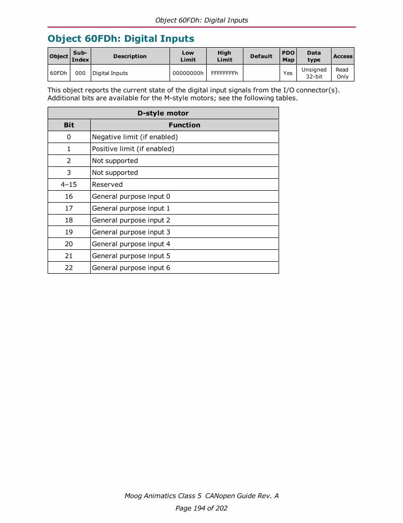
Object 60FDh: Digital Inputs
Moog Animatics Class 5 CANopen Guide Rev. A
Page 194 of 202
Object 60FDh: Digital Inputs
Object Sub-Index Description Low
LimitHighLimit Default PDO
MapDatatype Access
60FDh 000 Digital Inputs 00000000h FFFFFFFFh Yes Unsigned32-bit
ReadOnly
This object reports the current state of the digital input signals from the I/O connector(s).Additional bits are available for the M-style motors; see the following tables.
D-style motor
Bit Function
0 Negative limit (if enabled)
1 Positive limit (if enabled)
2 Not supported
3 Not supported
4–15 Reserved
16 General purpose input 0
17 General purpose input 1
18 General purpose input 2
19 General purpose input 3
20 General purpose input 4
21 General purpose input 5
22 General purpose input 6

Object 60FDh: Digital Inputs
Moog Animatics Class 5 CANopen Guide Rev. A
Page 195 of 202
M-style motor
Bit Function
0 Negative limit (if enabled)
1 Positive limit (if enabled)
2 Not supported
3 Not supported
4–15 Reserved
16 General purpose input 0
17 General purpose input 1
18 General purpose input 2
19 General purpose input 3
20 General purpose input 4
21 General purpose input 5
22 General purpose input 6
23 General purpose input 7
24 General purpose input 8
25 General purpose input 9
26 General purpose input 10
27 Not fault state
28 Drive enable input

Object 60FEh: Digital Outputs
Moog Animatics Class 5 CANopen Guide Rev. A
Page 196 of 202
Object 60FEh: Digital Outputs
Object Sub-Index Description Low
LimitHighLimit Default PDO
MapDatatype Access
60FEh 000 Number of Entries 00000001h 00000002h 00000001h No Unsigned8-bit
ReadOnly
60FEh 001 Physical Outputs 00000000h FFFFFFFFh Yes Unsigned32-bit
ReadWrite
This object allows the digital outputs to the I/O connector(s) to be set or cleared.
NOTE: There is no support for sub-index 2.
D-style motor
Bit Function
0–15 Reserved
16 General purpose output 0
17 General purpose output 1
18 General purpose output 2
19 General purpose output 3
20 General purpose output 4
21 General purpose output 5
22 General purpose output 6
23 Unconnected bit; remembers value
M-style motor
Bit Function
0–15 Reserved
16 General purpose output 0
17 General purpose output 1
18 General purpose output 2
19 General purpose output 3
20 General purpose output 4
21 General purpose output 5
22 General purpose output 6
23 General purpose output 7
24 General purpose output 8
25 General purpose output 9
26 General purpose output 10

Object 60FFh: Target Velocity
Moog Animatics Class 5 CANopen Guide Rev. A
Page 197 of 202
Object 60FFh: Target Velocity
Object Sub-Index Description Low
LimitHighLimit Default PDO
MapDatatype Access
60FFh 000 Target Velocity 80000000h 7FFFFFFFh 00000000h Yes Signed32-bit
ReadWrite*
*Write access is restricted when the remote bit is cleared with the CANCTL(13,0) command.
This object only applies to Profile Velocity (PV) mode. The velocity profile will accelerate tothe specified speed and remain at that speed until a stop is commanded or a new speed is spe-cified.
Writing this value takes effect immediately in PV mode, assuming the motor is already in theoperation enabled state through Control Word object (6040h). The units are: (encoder countsper sample period) * 65536.
Also, refer to Object 6081h: Profile Velocity in PP Mode on page 176.
Similar SmartMotor Commands: VT=, RVT
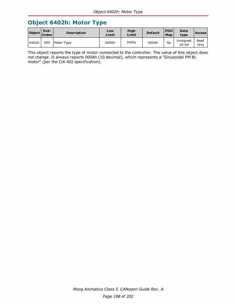
Object 6402h: Motor Type
Moog Animatics Class 5 CANopen Guide Rev. A
Page 198 of 202
Object 6402h: Motor Type
Object Sub-Index Description Low
LimitHighLimit Default PDO
MapDatatype Access
6402h 000 Motor Type 0000h FFFFh 000Ah No Unsigned16-bit
ReadOnly
This object reports the type of motor connected to the controller. The value of this object doesnot change. It always reports 000Ah (10 decimal), which represents a "Sinusoidal PM BLmotor" (per the CiA 402 specification).

Object 6502h: Supported Drive Modes
Moog Animatics Class 5 CANopen Guide Rev. A
Page 199 of 202
Object 6502h: Supported Drive Modes
Object Sub-Index Description Low
LimitHighLimit Default PDO
MapDatatype Access
6502h 000 Supported Drive Modes 00000000h FFFFFFFFh 0000006Dh No Unsigned32-bit
ReadOnly
This object reports a value that corresponds to a bit field indicating the operational modes sup-ported by the drive. The value reports as the default value listed above and does not change.
Bit Bit relatingto default value Mode
0 1 Supported Profile Position (PP)
1 0 Not supported Velocity (VL)
2 1 Supported Profile Velocity (PV)
3 1 Supported Torque (TQ)
4 0 Not supported Reserved
5 1 Supported Homing (HM)
6 1 Supported Interpolation (IP)
7 0 Not supported Cyclic Synchronous Profile (CSP)
8 0 Not supported Cyclic Synchronous Torque (CSV)
9 0 Not supported Cyclic Synchronous Torque (CST)
10–15 00 0000 Reserved
16–31 0000 0000 0000 0000 Manufacturer specific

Object 67FFh: Single Device Type
Moog Animatics Class 5 CANopen Guide Rev. A
Page 200 of 202
Object 67FFh: Single Device Type
Object Sub-Index Description Low
LimitHighLimit Default PDO
MapDatatype Access
67FFh 000 Single Device Type 00000000h FFFFFFFFh 00020192h No Unsigned32-bit
ReadOnly
This object specifies the type of device (profile) for objects in the range 6000h to 67FFh. Referto the following table the possible values and their corresponding functions.
Bit Value Function
0–15 0192h (402 decimal) DS402 device
16–23 02h (2 decimal) Servo drive
24–31 0 Reserved (manufacturer specific)
Also, refer to Object 1000h: Device Type on page 86.


PN: SC80100001-001Rev. A
Related Documents


