Monroe L. Weber-Shir k S chool of Civil and Environmental Engi neering Reactors The Case of the Chlorine Contact Tank

Welcome message from author
This document is posted to help you gain knowledge. Please leave a comment to let me know what you think about it! Share it to your friends and learn new things together.
Transcript

Monroe L. Weber-Shirk
School of Civil and
Environmental Engineering
ReactorsReactors
The Case of the Chlorine Contact Tank

OutlineOutline
The Regulations The Goal Contact Tanks Characterizing a Contact Tank: Tracers Reactor Theory
CMFRCMFR in Series1-D Advective Dispersion Equation
Building a Better Contact Tank

Disinfection CT CreditsDisinfection CT Credits
Contact time (min)
chlorine pH 6.5 pH 7.5
(mg/L) 2°C 10°C 2°C 10°C
0.5 300 178 430 254
1 159 94 228 134
To get credit for 99.9% inactivation of Giardia:
Inactivation is a function of _______, __________________, and ___________.
concentrationtimepH temperature
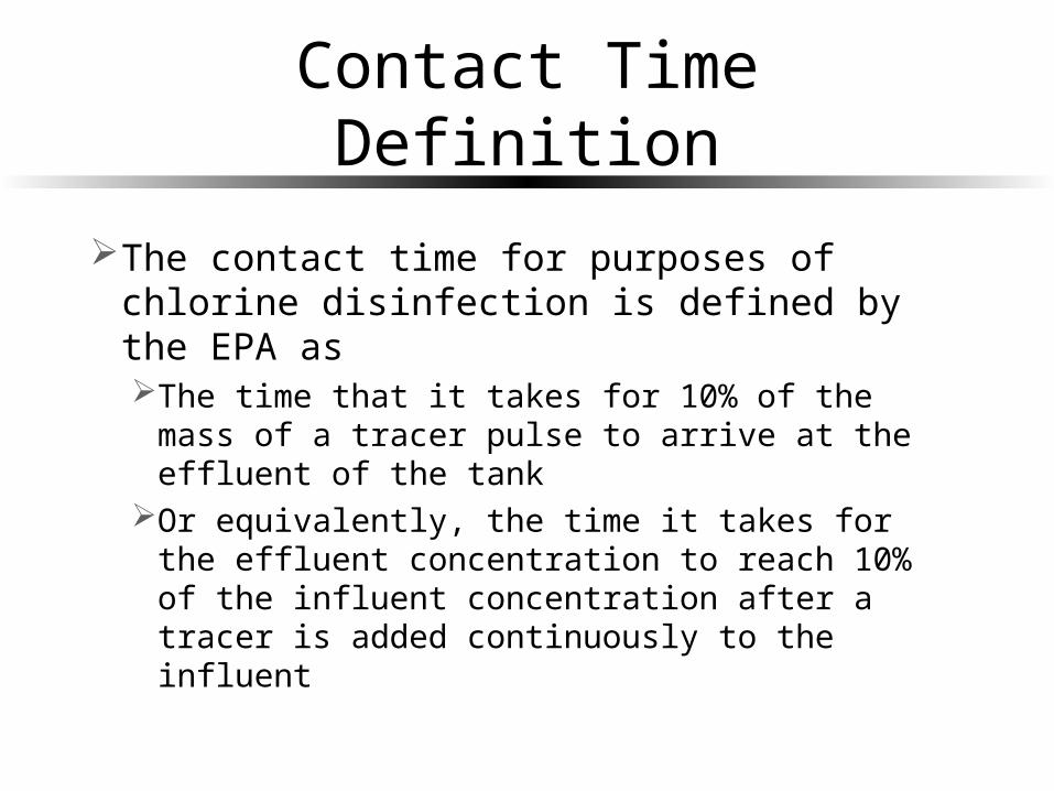
Contact Time DefinitionContact Time Definition
The contact time for purposes of chlorine disinfection is defined by the EPA asThe time that it takes for 10% of the mass of a
tracer pulse to arrive at the effluent of the tank Or equivalently, the time it takes for the
effluent concentration to reach 10% of the influent concentration after a tracer is added continuously to the influent

EPA Contact Time CreditEPA Contact Time Credit
* 0.1t at F
Baffling Condition
Baffle Factor (BF)
Extent of Baffles Typical Unit Processes
Unbaffled (CMFR)
0.1 No baffles, agitated basin with low length to width ratio, high inlet and outlet flow velocities
Clearwell, storage tank, no perforated inlet or outlet, inlet or outlet submerged.
Poorly baffled
0.3 Single or multiple unbaffled inlets and outlets, no intrabasin baffles
Many conventional sedimentation basins. Storage tanks with two or three baffles.
Average 0.5 Baffled inlet or outlet with some intrabasin baffles
Some (few) sedimentation basins. Highly baffled storage tanks.
Superior 0.7 Perforated inlet baffles, serpentine or perforated intrabasin baffles, outlet weir or perforated launders
Filters. Contact tanks with serpentine baffling
Perfect (PFR) 1.0 Very high length to width ratio (pipeline flow), perforated inlet, outlet and intrabasin baffles
Sections of pipe ten times longer than their diameter.

The Meaning of Life…for Contact Tanks
The Meaning of Life…for Contact Tanks
Minimally – To meet EPA regulationsBetter – To obtain as high a contact time as
possible with a given tankOr – To build as small a tank as possible
that meets the EPA regulations

Serpentine Chlorine Contact TanksSerpentine Chlorine Contact Tanks
Baffle Factor of________.0.5

Distribution Tank (Honduras)Distribution Tank (Honduras)
How would you model this tank?
Baffle Factor of________.0.1

Characterize a Tank:Tracer Studies
Characterize a Tank:Tracer Studies
Tracers Desirable properties Candidates Measuring techniques
Choosing a tracer concentrationMeasurement range Interferences
Density matching Pulse vs. Step

Reactor Theory: CMFRReactor Theory: CMFR
0.100.00.2
0.40.60.8
1.01.2
0.0 1.0 2.0 3.0
t*
E
0
0.2
0.4
0.6
0.8
1
FE
F
t* at F=0.1
r in
dCC C Q
dt
trt
tr tr
C
C e
* *
*
rt t
ttr tr
CE
C e
*
* *
*
0
t
t tF E dt
r = reactortr = tracert = time

Reactor Theory: Series CMFRReactor Theory: Series CMFR
0.26
0.0
0.2
0.4
0.6
0.8
0.0 1.0 2.0 3.0
t*
E
0
0.2
0.4
0.6
0.8
1
FE
F
t* at F=0.1
0.720.0
0.5
1.0
1.5
2.0
0.0 1.0 2.0 3.0
t*
E
0
0.2
0.4
0.6
0.8
1
FE
F
t* at F=0.1
N=2
1
1 !
NtNNN rt
tr tr
C N t
C N e
*
*
1*
1 !
NtNN
N t
NE t
N e
0.870.0
1.0
2.0
3.0
4.0
5.0
0.0 1.0 2.0 3.0
t*
E
0
0.2
0.4
0.6
0.8
1
FE
F
t* at F=0.1
N=20
N=100

1-D Advective Dispersion Equation1-D Advective Dispersion Equation
0.460.0
0.1
0.2
0.3
0.4
0.5
0.0 1.0 2.0 3.0
t*
E
0
0.2
0.4
0.6
0.8
1
FE
F
t* at F=0.1
*
2*
* *
1exp
t
t PePeE
t t
d
ULPe
D * tU
tL
2
C(x,t) expdd
M x
D tA D t
Pe = 2
Note: This reactor has more dispersion than a series CMFR with N = 2, but it has a longer contact time!
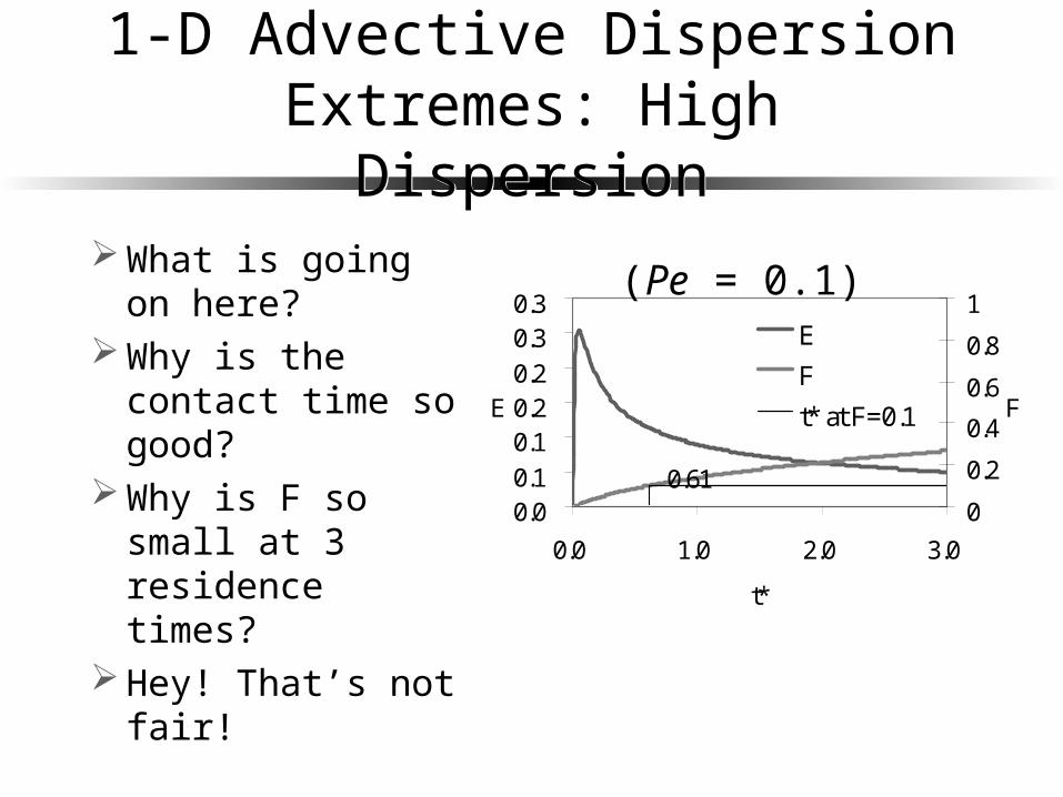
1-D Advective Dispersion Extremes: High Dispersion
1-D Advective Dispersion Extremes: High Dispersion
What is going on here?
Why is the contact time so good?
Why is F so small at 3 residence times?
Hey! That’s not fair!
0.610.00.1
0.10.20.2
0.30.3
0.0 1.0 2.0 3.0
t*
E
0
0.2
0.4
0.6
0.8
1
F
E
F
t* at F=0.1
(Pe = 0.1)

1-D Advective Dispersion Extremes:Low Dispersion
1-D Advective Dispersion Extremes:Low Dispersion
Approaches plug flow!
0.960.0
5.0
10.0
15.0
0.0 1.0 2.0 3.0
t*
E
0
0.2
0.4
0.6
0.8
1
F
E
F
t* at F=0.1
(Pe = 2000)

CMFR in series ≡ Advective Dispersion
CMFR in series ≡ Advective Dispersion
0.840.00.5
1.01.52.0
2.53.0
0.0 1.0 2.0 3.0
t*
E
0
0.2
0.4
0.6
0.8
1
F
E
F
t* at F=0.1
2Pe N
(Pe = 100)
0.820.00.5
1.01.52.0
2.53.0
0.0 1.0 2.0 3.0
t*
E
0
0.2
0.4
0.6
0.8
1
FE
F
t* at F=0.1
(N = 50)
*
2*
* *
1exp
t
t PePeE
t t
*
*
1*
1 !
NtNN
N t
NE t
N e
They both approach plug flow!

Physical Models: How do you build reactors that approach plug flow?
Physical Models: How do you build reactors that approach plug flow?
Many CMFR in seriesHigh Peclet number
Laminar pipe flowTurbulent pipe flowPorous media flow
Eliminating “Dead volume”Requires more mixing!Turbulent pipe flow: Serpentine channelsTurbulent jets: Perforated baffles

A Baffling DesignA Baffling Design
Baffle perforation sizeTurbulent JetsHead loss
Mean circulation patternsSerpentine vs. series CMFR
Risk of dead volumes

Experiment Design OptionsExperiment Design Options
Baffle perforations (pattern, diameter, number)
Head lossJet Reynolds numberReactor flow rateReactor depthPorous mediaPacking material
?
Related Documents