Monorail Las Vegas Drive Train Investigation

Welcome message from author
This document is posted to help you gain knowledge. Please leave a comment to let me know what you think about it! Share it to your friends and learn new things together.
Transcript
Monorail Las Vegas
Drive Train Investigation
1
Content
Introducing Las Vegas MonorailProblem DescriptionDrive• Overview• Model• Validation
Suggestion for Improvement
2
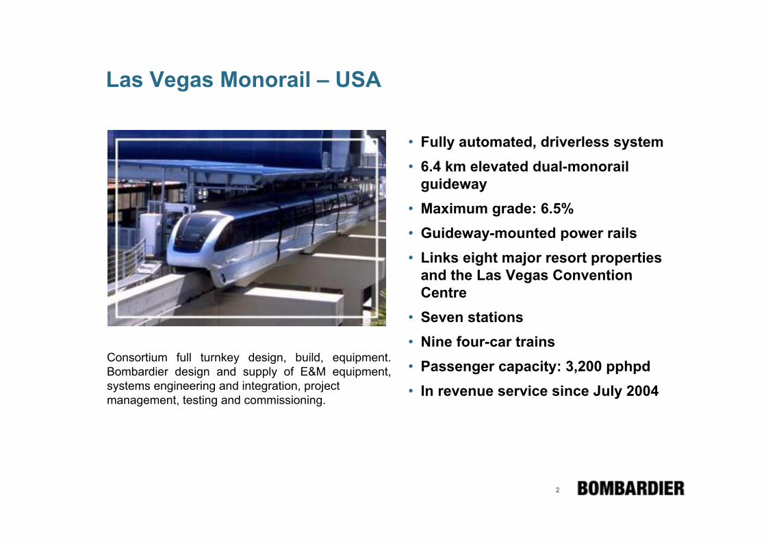
Las Vegas Monorail – USA
• Fully automated, driverless system• 6.4 km elevated dual-monorail
guideway• Maximum grade: 6.5%• Guideway-mounted power rails• Links eight major resort properties
and the Las Vegas Convention Centre
• Seven stations• Nine four-car trains • Passenger capacity: 3,200 pphpd• In revenue service since July 2004
Consortium full turnkey design, build, equipment. Bombardier design and supply of E&M equipment, systems engineering and integration, projectmanagement, testing and commissioning.

3
Las Vegas Monorail

4
Problem Description and Interim Solution
Noise problem („Growling“)• Noise
- During acceleration & braking- In motor cars only- Modification of motor converter & control did not solve the problem
Root cause & interim solution• High angle of load arm and cardanic shaft was determined as root
cause• Interim solution: Load arm rides between stations/platforms at safety
link• Motor moved 1“ outwards
=> Only small angles of cardanic shaft=> Significant reduction of noise (and loads)
Potential of possible solutions had to be figured out

5
Train Configuration
Motor & Gear
Disc Brake
Steering Wheel
Guide Wheel
Load Wheel

6
Drive
Motor
PlanetaryGear
Brake Disc
BevelGear
Spring
(Cardanic)Drive Shaft
Load arm
LoadWheel
GuideWheel
Power Rail

7
Drive
8
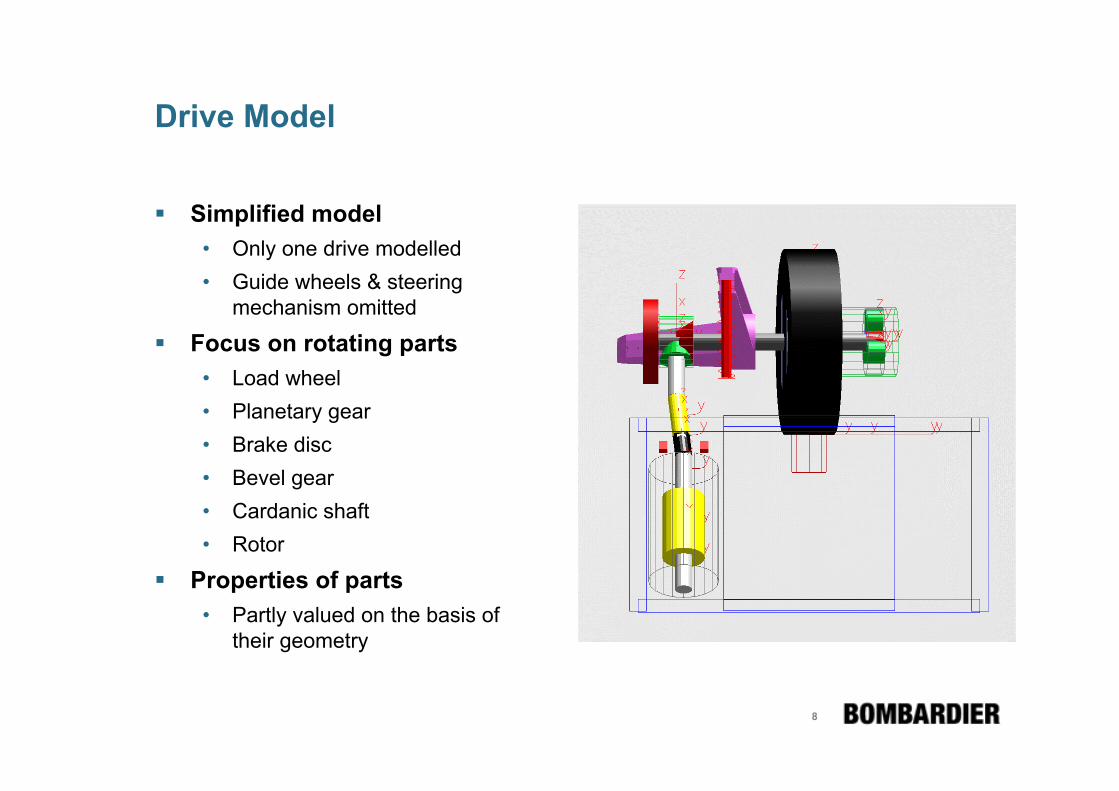
Drive Model
Simplified model• Only one drive modelled• Guide wheels & steering
mechanism omitted
Focus on rotating parts• Load wheel• Planetary gear• Brake disc• Bevel gear• Cardanic shaft• Rotor
Properties of parts • Partly valued on the basis of
their geometry

9
Model Validation - Torsional Eigen Modes
Motor out of phase with Brake Disc & Load WheelMeasured Frequency is ~ 58 Hz
81.00.0417/ 18
60.30.0415/ 16
4.70.139/10
[Hz][-]
FrequencyDampingNo.

10
Model Validation - Time Domain

11
Model Validation - Frequency Domain
Test run 7b1• Mortlet Spectrogram
- Gear Box Torque (left)
- Drive shaft torque (right)
• Measured values (top) compared to simulated ones (bottom)

12
Model Validation – Hammer Test
Torsional input lever attached to the motor side yoke

13
Model Validation – Transfer Function
Frequency Response Function - Load Wheel
• Measured (blue, red) -and calculated (green) data fit well up to ~ 100 Hz
• Some potential of further improvement may be seen

14
Integration of Flexible Bodies
NASTRAN model of Load Arm• Guyan reduction
- 30 nodes• Calculation of frequency response modes
- 19 load cases added- 13 translational- 6 rotational
- 8 load groups used with respect to maximum frequency of 1500 Hz- Problem: Lateral stability of load wheel/tyre
• No geometric stiffening used

15
Eigen Modes in FE- and MBS-Model (1)
FE, f = 84.5 Hz MBS, f = 84.9 Hz, d = 1.4 %

16
Eigen Modes in FE- and MBS-Model (2)
FE, f = 181.0 Hz MBS, f = 189.1 Hz, d = 0.9 %

17
Eigen Modes in FE- and MBS-Model (3)
1.619.3586.9491.97
1.65.0491.2467.66
1.13.0378.4367.35
0.92.7311.2303.04
0.94.9239.9228.73
0.94.5189.1181.02
1.40.584.984.51
%%HzHz
DeviationMBS-ModelFE-Model
DampingFrequencyNo.

18
FEMBS- versus pure MBS-Model

19
Suggestion for improvement
Solutions to be investigated• Torsional damper• Highly flexible coupling• Stiff/soft motor suspension• Constant-velocity joints instead
of universal (cardanic) joints
Procedure of investigation(Example: Torsional damper)
• Extension of SIMPACK model by- Output (angular velocity)- Input (torque)
• Linearization• Export state-space-matrices to
MALAB/SIMULINK environment• Investigation of observability and
controllability• Adding the liner damper in
MATLAB/SIMULINK• Calculation of pole-zero-map to
identify properties of the damper• Refining the SIMPACK model• Investigation in time domain

20
Investigation in Frequency Domain Pole-Zero-Map

21
Investigation in Time Domain
Investigation in frequency domain shows high potential of improvement, especially for oscillation at 60 HzInvestigation in time domain did not confirm this expectationProblem
• High moment of inertia required(similar to rotor)
• Space• Well-tuned friction

22
www.bombardier.com
Related Documents


