Catalysis Today 69 (2001) 3–9 Monolith structures, materials, properties and uses Jimmie L. Williams Corning Incorporated, SP-DV-02, Corning, NY 14831, USA Abstract Extruded monolith substrates are widely used in automotive and stationary emission control reactors such as selective catalytic reduction (SCR) units. Monoliths are increasingly being used, developed, and evaluated as catalyst supports in many new reactor applications such as chemical and refining processes, catalytic combustion, ozone abatement, and others. This paper gives a general overview of monolith fabrication, characteristics and typical use. Several commercial product applications and new developments for use of monolith reactors in automotive, stationary and chemical industry are discussed. © 2001 Elsevier Science B.V. All rights reserved. Keywords: Monoliths; Honeycomb; Monolith reactor; Automotive emissions; Stationary emissions; Chemical process; Carbon; Gamma alumina; Zeolites 1. Introduction Extruded monolith substrates are widely used in automotive and stationary emission control reactors for the selective catalytic reduction (SCR) of nitrogen oxides. Monoliths are increasingly under development and evaluation for many new reactor applications, e.g. chemical process and refining industries, catalytic combustion, ozone abatement, etc. [1–9]. Table 1 lists various applications in which monoliths are used. In automotive applications, ceramic monoliths are made from synthetic cordierite, 2MgO·2Al 2 O 3 ·5SiO 2 ,a material having a low thermal coefficient of expansion [7]. Cordierite is a highly anisotropic crystalline phase with concomitant high thermal expansion anisotropy that leads to orientation during extrusion and low overall expansion. For publication and presentation at the First International Conference on Structured Catalyst and Reactors (ICOSCAR-1), Delft, October 21–24, 2001. E-mail address: [email protected] (J.L. Williams). Compositions based on cordierite possess a unique combination of several critical characteristics: (a) thermal shock resistance due to a low thermal ex- pansion coefficient; (b) porosity and pore size distri- bution suitable for ease of washcoat application and good washcoat adherence; (c) sufficient refractoriness because the melting point exceeds 1450 ◦ C; (d) suf- ficient strength for survival in an automotive exhaust environment; and (e) compatibility with washcoat and catalysts [7]. The combination of high cell density, 31–186 cells/ cm 2 (200–1200 cells/in. 2 ), with thin walls, 0.051– 0.27 mm (0.002–0.0105 in.), give rise to low backpres- sure in automotive exhaust systems. This combination also yields high open frontal area (OFA), 72–87%, which is a necessary condition for low backpressure. Physical and chemical properties of cordierite raw materials are controlled to a high degree necessary for sophisticated quality control. For example, the particle size of various commonly used raw materials, silica, clay, alumina and talc, are closely controlled to consistently yield the desired porosity and pore size distribution as well as hold parts to close tolerances. 0920-5861/01/$ – see front matter © 2001 Elsevier Science B.V. All rights reserved. PII:S0920-5861(01)00348-0

Welcome message from author
This document is posted to help you gain knowledge. Please leave a comment to let me know what you think about it! Share it to your friends and learn new things together.
Transcript
Catalysis Today 69 (2001) 3–9
Monolith structures, materials, properties and uses�
Jimmie L. WilliamsCorning Incorporated, SP-DV-02, Corning, NY 14831, USA
Abstract
Extruded monolith substrates are widely used in automotive and stationary emission control reactors such as selectivecatalytic reduction (SCR) units. Monoliths are increasingly being used, developed, and evaluated as catalyst supports in manynew reactor applications such as chemical and refining processes, catalytic combustion, ozone abatement, and others.
This paper gives a general overview of monolith fabrication, characteristics and typical use. Several commercial productapplications and new developments for use of monolith reactors in automotive, stationary and chemical industry are discussed.© 2001 Elsevier Science B.V. All rights reserved.
Keywords: Monoliths; Honeycomb; Monolith reactor; Automotive emissions; Stationary emissions; Chemical process; Carbon; Gammaalumina; Zeolites
1. Introduction
Extruded monolith substrates are widely used inautomotive and stationary emission control reactorsfor the selective catalytic reduction (SCR) of nitrogenoxides. Monoliths are increasingly under developmentand evaluation for many new reactor applications,e.g. chemical process and refining industries, catalyticcombustion, ozone abatement, etc. [1–9]. Table 1 listsvarious applications in which monoliths are used. Inautomotive applications, ceramic monoliths are madefrom synthetic cordierite, 2MgO·2Al2O3·5SiO2, amaterial having a low thermal coefficient of expansion[7]. Cordierite is a highly anisotropic crystalline phasewith concomitant high thermal expansion anisotropythat leads to orientation during extrusion and lowoverall expansion.
�For publication and presentation at the First InternationalConference on Structured Catalyst and Reactors (ICOSCAR-1),Delft, October 21–24, 2001.E-mail address: [email protected] (J.L. Williams).
Compositions based on cordierite possess a uniquecombination of several critical characteristics: (a)thermal shock resistance due to a low thermal ex-pansion coefficient; (b) porosity and pore size distri-bution suitable for ease of washcoat application andgood washcoat adherence; (c) sufficient refractorinessbecause the melting point exceeds 1450◦C; (d) suf-ficient strength for survival in an automotive exhaustenvironment; and (e) compatibility with washcoat andcatalysts [7].
The combination of high cell density, 31–186 cells/cm2 (200–1200 cells/in.2), with thin walls, 0.051–0.27 mm (0.002–0.0105 in.), give rise to low backpres-sure in automotive exhaust systems. This combinationalso yields high open frontal area (OFA), 72–87%,which is a necessary condition for low backpressure.
Physical and chemical properties of cordierite rawmaterials are controlled to a high degree necessaryfor sophisticated quality control. For example, theparticle size of various commonly used raw materials,silica, clay, alumina and talc, are closely controlled toconsistently yield the desired porosity and pore sizedistribution as well as hold parts to close tolerances.
0920-5861/01/$ – see front matter © 2001 Elsevier Science B.V. All rights reserved.PII: S0920 -5861 (01 )00348 -0
nafas
Highlight
nafas
Highlight
4 J.L. Williams / Catalysis Today 69 (2001) 3–9
Table 1Applications of cordierite cellular ceramic substrates
Automotive emission controlDiesel particulate filterStationary emission controlWoodstove combustorMolten metal filterNatural gas storageIndoor air purificationOzone abatementCatalytic incinerationIndustrial heat recoveryUltrafiltrationChemical process catalyst supportWater filtration
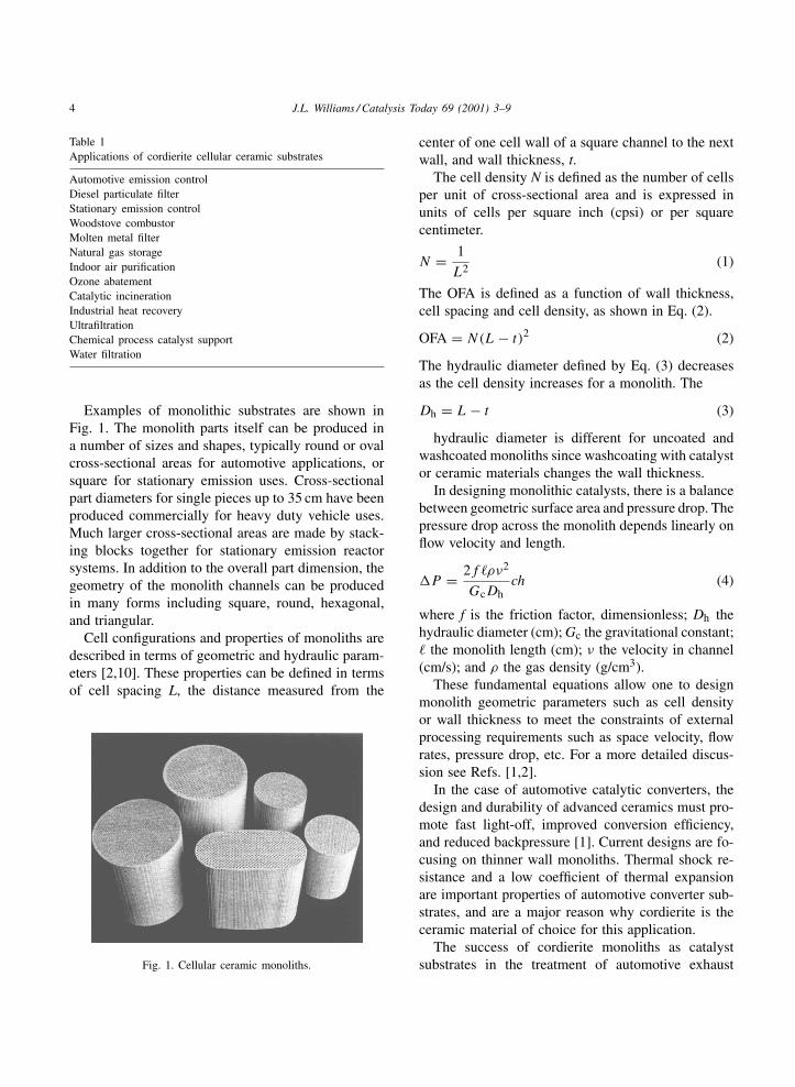
Examples of monolithic substrates are shown inFig. 1. The monolith parts itself can be produced ina number of sizes and shapes, typically round or ovalcross-sectional areas for automotive applications, orsquare for stationary emission uses. Cross-sectionalpart diameters for single pieces up to 35 cm have beenproduced commercially for heavy duty vehicle uses.Much larger cross-sectional areas are made by stack-ing blocks together for stationary emission reactorsystems. In addition to the overall part dimension, thegeometry of the monolith channels can be producedin many forms including square, round, hexagonal,and triangular.
Cell configurations and properties of monoliths aredescribed in terms of geometric and hydraulic param-eters [2,10]. These properties can be defined in termsof cell spacing L, the distance measured from the
Fig. 1. Cellular ceramic monoliths.
center of one cell wall of a square channel to the nextwall, and wall thickness, t.
The cell density N is defined as the number of cellsper unit of cross-sectional area and is expressed inunits of cells per square inch (cpsi) or per squarecentimeter.
N = 1
L2(1)
The OFA is defined as a function of wall thickness,cell spacing and cell density, as shown in Eq. (2).
OFA = N(L − t)2 (2)
The hydraulic diameter defined by Eq. (3) decreasesas the cell density increases for a monolith. The
Dh = L − t (3)
hydraulic diameter is different for uncoated andwashcoated monoliths since washcoating with catalystor ceramic materials changes the wall thickness.
In designing monolithic catalysts, there is a balancebetween geometric surface area and pressure drop. Thepressure drop across the monolith depends linearly onflow velocity and length.
�P = 2f ρν2
GcDhch (4)
where f is the friction factor, dimensionless; Dh thehydraulic diameter (cm); Gc the gravitational constant; the monolith length (cm); ν the velocity in channel(cm/s); and ρ the gas density (g/cm3).
These fundamental equations allow one to designmonolith geometric parameters such as cell densityor wall thickness to meet the constraints of externalprocessing requirements such as space velocity, flowrates, pressure drop, etc. For a more detailed discus-sion see Refs. [1,2].
In the case of automotive catalytic converters, thedesign and durability of advanced ceramics must pro-mote fast light-off, improved conversion efficiency,and reduced backpressure [1]. Current designs are fo-cusing on thinner wall monoliths. Thermal shock re-sistance and a low coefficient of thermal expansionare important properties of automotive converter sub-strates, and are a major reason why cordierite is theceramic material of choice for this application.
The success of cordierite monoliths as catalystsubstrates in the treatment of automotive exhaust
J.L. Williams / Catalysis Today 69 (2001) 3–9 5
has given rise to interest in the chemical industry assubstrates for catalytic reactors. For many of theseapplications, the use of other substrate materials anddesigns can be utilized since the thermal shock re-quirements are not as demanding as automotive. Ingeneral, many inorganic catalyst support materialsused today in conventional chemical and refining ap-plication can be extruded into a monolith form. Thishas ignited interest in monolith reactors as potentialreplacements for fixed bed and slurry reactors. Mono-lith reactors offer the advantage of thinner walls, highgeometric surface area, low-pressure drop, good masstransfer performance, and ease of product separation.There may also be advantages in kinetics and masstransfer in gas/liquid phase applications due to bettercatalyst wetting, higher effectiveness factors, and thinfilms that are conducive to high mass transfer rates.However, the hydrodynamics and flow distribution ofmulti-phase flow through a monolith reactor bed isstill not fully understood [3,4,11–13].
This paper gives a general overview of monolithfabrication, characteristics and typical use. Severalcommercial product applications and new develop-ments for use of monolith reactors in automotive,stationary and chemical industry are discussed.
2. Extrusion process
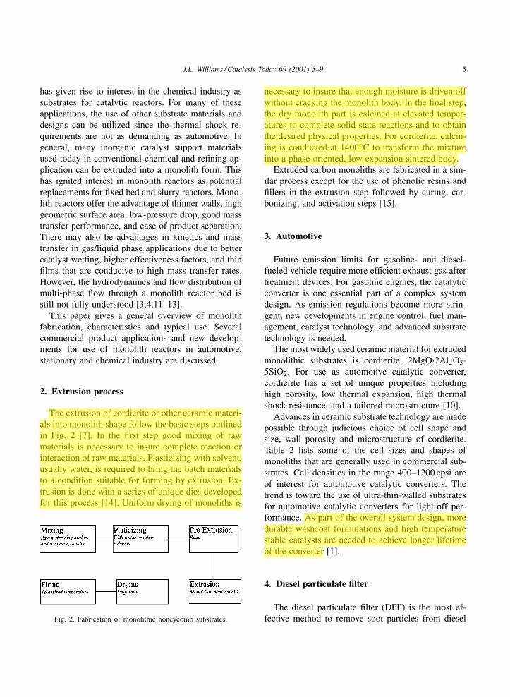
The extrusion of cordierite or other ceramic materi-als into monolith shape follow the basic steps outlinedin Fig. 2 [7]. In the first step good mixing of rawmaterials is necessary to insure complete reaction orinteraction of raw materials. Plasticizing with solvent,usually water, is required to bring the batch materialsto a condition suitable for forming by extrusion. Ex-trusion is done with a series of unique dies developedfor this process [14]. Uniform drying of monoliths is
Fig. 2. Fabrication of monolithic honeycomb substrates.
necessary to insure that enough moisture is driven offwithout cracking the monolith body. In the final step,the dry monolith part is calcined at elevated temper-atures to complete solid state reactions and to obtainthe desired physical properties. For cordierite, calcin-ing is conducted at 1400◦C to transform the mixtureinto a phase-oriented, low expansion sintered body.
Extruded carbon monoliths are fabricated in a sim-ilar process except for the use of phenolic resins andfillers in the extrusion step followed by curing, car-bonizing, and activation steps [15].
3. Automotive
Future emission limits for gasoline- and diesel-fueled vehicle require more efficient exhaust gas aftertreatment devices. For gasoline engines, the catalyticconverter is one essential part of a complex systemdesign. As emission regulations become more strin-gent, new developments in engine control, fuel man-agement, catalyst technology, and advanced substratetechnology is needed.
The most widely used ceramic material for extrudedmonolithic substrates is cordierite, 2MgO·2Al2O3·5SiO2. For use as automotive catalytic converter,cordierite has a set of unique properties includinghigh porosity, low thermal expansion, high thermalshock resistance, and a tailored microstructure [10].
Advances in ceramic substrate technology are madepossible through judicious choice of cell shape andsize, wall porosity and microstructure of cordierite.Table 2 lists some of the cell sizes and shapes ofmonoliths that are generally used in commercial sub-strates. Cell densities in the range 400–1200 cpsi areof interest for automotive catalytic converters. Thetrend is toward the use of ultra-thin-walled substratesfor automotive catalytic converters for light-off per-formance. As part of the overall system design, moredurable washcoat formulations and high temperaturestable catalysts are needed to achieve longer lifetimeof the converter [1].
4. Diesel particulate filter
The diesel particulate filter (DPF) is the most ef-fective method to remove soot particles from diesel
nafas
Highlight
nafas
Highlight
nafas
Highlight
6 J.L. Williams / Catalysis Today 69 (2001) 3–9
Table 2Monolith substrates of interest for automotive converters
Cell density (cpsi) Web thickness, 1 mil = 0.001 in. Geometric surface area (cm2/ccm) OFA
25 (35 mil) 0.889 mm 6.51 0.68150 (25 mil) 0.635 mm 9.17 0.678
100 (15 mil) 0.381 mm 13.39 0.723200 (10.5 mil) 0.267 mm 18.98 0.725300 (8 mil) 0.203 mm 23.51 0.742400 (4 mil) 0.102 mm 27.09 0.846600 (4 mil) 0.102 mm 31.01 0.787900 (2 mil) 0.051 mm 43.11 0.834
engine vehicle exhaust with filtration efficiencies upto 95% [10]. Regeneration of the filter is criticalfor continuous engine and vehicle operation at lowbackpressure. Controlled on-board regeneration ofdiesel filters is an area that continues to be ex-plored. Both passive and active techniques are underinvestigation.
A DPF differs from automotive catalyst substrates inthat alternate channels are plugged on the entrance faceand the adjacent channels are plugged on the exit faceof the filter, forming a checkerboard pattern. Filtrationoccurs when the particle laden exhaust gas is forcedthrough the wall between adjacent channels. Soot par-ticles are trapped in the entrance channel and cleanexhaust passes out from the exit channel. Periodicallythe soot is burned off, thereby cleaning the channeland recovering backpressure. Cordierite and siliconcarbide are two materials that are commercially avail-able for diesel exhaust after treatment. Developmentof new materials for DPF type filters is in progress.
A high cell density cordierite DPF product, RC200/19, was recently introduced at the 2001 SAEconference held in Detroit. The geometry is 200 cpsiwith 0.019 in. (0.048 cm) wall thickness comparedto a standard EX-80 product having 100 cpsi with0.017 in. wall (0.048 cm). RC 200/19 has a higherthermal mass which leads to lower temperaturesduring regeneration [16,17].
5. NOx adsorbers
The NOx storage catalyst was developed to meetlow emissions and fuel consumption targets for gaso-line engine vehicles. The NOx adsorber is a washcoatcontaining barium, potassium, or other alkali/alkaline
earth metal oxides as adsorbents [18–20]. Duringadsorption, a nitrate is formed with the alkali oxidethrough conversion of NO to NO2 with O2 promotedby platinum. It is known that potassium is a betteradsorbent than barium in high temperature conver-sion of NOx , however, one problem with potassiumis its migration from the washcoat into the substrateand subsequent loss of adsorption efficiency. Zeolites,titanias, and silicas are being developed as barriers toprevent potassium migration and sulfur poisoning ofthe NOx adsorber [19].
6. Chemical process industry applications
Successful use of cordierite monolith catalysts in thetreatment of automotive exhaust has given rise to theiruse in other catalytic applications. For many of these,the use of other substrate materials and designs can beutilized since the requirements are not as demandingas automotive. This has resulted in an increase in thepotential use of monoliths in chemical and refiningcatalyst applications.
Monolith catalyst substrates can be either metal orceramic. They can be washcoated with a high surfacearea catalyst support material and impregnated, or ex-truded directly into catalytic bodies using appropriatebatch materials. The use of monoliths in multi-phasereactors is of interest as possible replacements forslurry and fixed bed reactors. Monolith reactors offerthe advantage of thinner walls, high geometric surfacearea, low pressure drop, good mass transfer, and easeof product separation [4,8,11–13].
Hydrogen peroxide is presently the only large-scaleindustrial application of monolithic catalysts in a
J.L. Williams / Catalysis Today 69 (2001) 3–9 7
multi-phase process [21]. Anthraquinone is used tofacilitate the selective oxidation of hydrogen to hy-drogen peroxide indirectly using a chemical redox ap-proach in a two-step process. The quinone reductionstep utilizes a monolith catalyst containing palladiumon a washcoat in a gas/liquid multi-phase reactor.
Schanke et al. [24] describe the use of a multi-phasemonolith reactor system for Fischer–Tropsch synthe-sis in a recent US patent. The monolithic catalystis comprised of �-alumina, silica, zeolite, or titaniaand a conventional Fischer–Tropsch catalyst com-bined with a precious metal promoter. The stronglyexothermic nature of Fischer–Tropsch synthesis re-quires effective heat transfer for successful reactoroperation.
Vinyl acetate is synthesized by the vapor phase re-action of ethylene, oxygen, and acetic acid over amonolith catalyst. The monolith catalyst consists of Pdand Au deposited on silica-coated cordierite or mullitemonoliths. Catalyst space–time yields for vinyl acetateproduction of 434 g/l h at 192◦C have been reported[22,23].
Addiego et al. [25] have reported the extrusion ofiron oxide honeycomb catalysts for the vapor phasedehydrogenation of ethyl benzene to styrene. Theyindicate styrene selectivity >90% and ethyl benzeneconversion greater than 60%. The low pressure dropcharacteristic of monolith shapes for this equilibriumlimited reaction is an important benefit.
Unreacted o-xylene and other intermediates are con-verted to phthalic anhydride (PA) in a post-reactorcontaining a monolith catalyst located downstream ofthe main PA reactor in the Wacker low energy phthalicanhydride process. The use of the proprietary catalystin the post-reactor provides higher overall conversionto PA and increases operational flexibility around themain reactor [26].
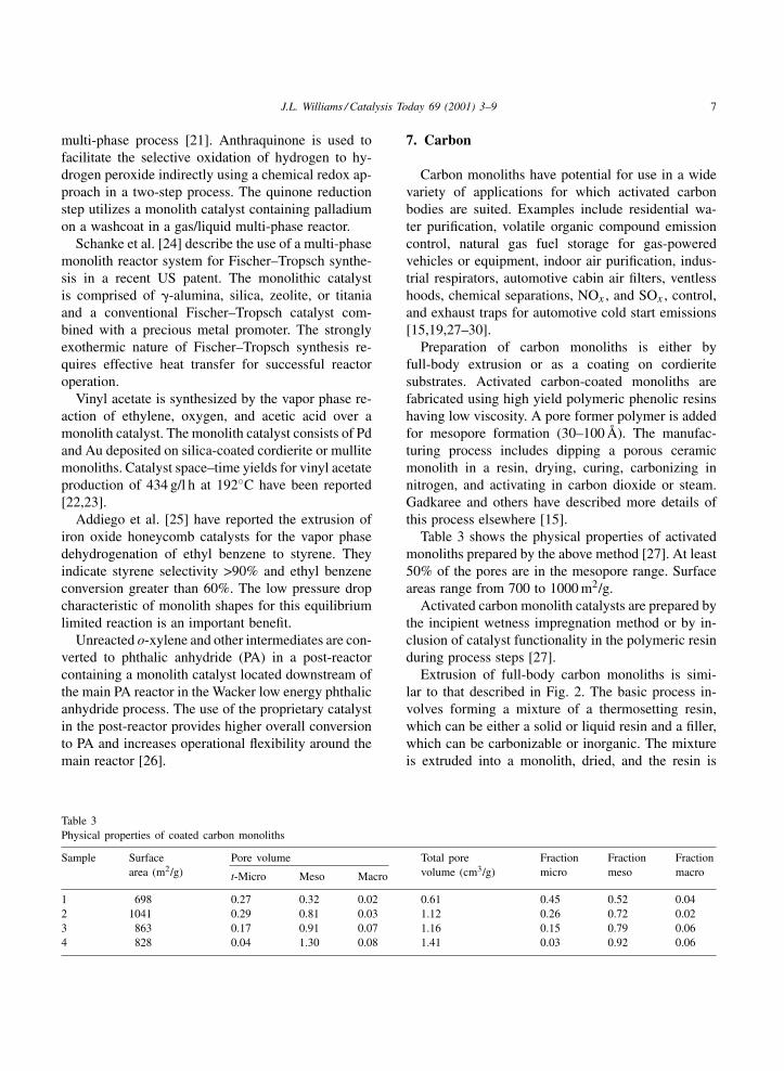
Table 3Physical properties of coated carbon monoliths
Sample Surfacearea (m2/g)
Pore volume Total porevolume (cm3/g)
Fractionmicro
Fractionmeso
Fractionmacrot-Micro Meso Macro
1 698 0.27 0.32 0.02 0.61 0.45 0.52 0.042 1041 0.29 0.81 0.03 1.12 0.26 0.72 0.023 863 0.17 0.91 0.07 1.16 0.15 0.79 0.064 828 0.04 1.30 0.08 1.41 0.03 0.92 0.06
7. Carbon
Carbon monoliths have potential for use in a widevariety of applications for which activated carbonbodies are suited. Examples include residential wa-ter purification, volatile organic compound emissioncontrol, natural gas fuel storage for gas-poweredvehicles or equipment, indoor air purification, indus-trial respirators, automotive cabin air filters, ventlesshoods, chemical separations, NOx , and SOx , control,and exhaust traps for automotive cold start emissions[15,19,27–30].
Preparation of carbon monoliths is either byfull-body extrusion or as a coating on cordieritesubstrates. Activated carbon-coated monoliths arefabricated using high yield polymeric phenolic resinshaving low viscosity. A pore former polymer is addedfor mesopore formation (30–100 Å). The manufac-turing process includes dipping a porous ceramicmonolith in a resin, drying, curing, carbonizing innitrogen, and activating in carbon dioxide or steam.Gadkaree and others have described more details ofthis process elsewhere [15].
Table 3 shows the physical properties of activatedmonoliths prepared by the above method [27]. At least50% of the pores are in the mesopore range. Surfaceareas range from 700 to 1000 m2/g.
Activated carbon monolith catalysts are prepared bythe incipient wetness impregnation method or by in-clusion of catalyst functionality in the polymeric resinduring process steps [27].
Extrusion of full-body carbon monoliths is simi-lar to that described in Fig. 2. The basic process in-volves forming a mixture of a thermosetting resin,which can be either a solid or liquid resin and a filler,which can be carbonizable or inorganic. The mixtureis extruded into a monolith, dried, and the resin is
8 J.L. Williams / Catalysis Today 69 (2001) 3–9
cured. The cured monolith is carbonized and activated[15,18].
8. Zeolites
Zeolites, both natural and synthetic, have foundwide use for removal of NOx from coal-fired utilitiesand gas turbine catalysts for SCR of NOx using NH3.Zeolites can be combined with vanadia/titania to pro-duce a catalyst with a wide DeNOx operating windowthat is more resistant to deactivation [7].
Zeolite catalysts can be extruded or coated ontometal or ceramic substrates. Again, the extrusionprocess is the same as that outlined in Fig. 2. Thecoating process involves preparation of a zeoliteslurry using a binder, usually colloidal silica or alu-mina, dipping the monolith, then drying and firing.Ion exchange of zeolite can be done before or aftercoating and/or extrusion. One potential disadvantageof coated and extruded zeolites is the use of binderthat can block the zeolite pores and active metal sites.As such, the amount of binder should be kept toa minimum.
The in situ growth of a zeolite on a substrate is oneway to prevent blockage of pores and active material.The substrate is covered by a thin layer of synthe-sis mixture or immersed in a liquid that containsthe mixture inside an autoclave. Patil [31] discussespreparation of mixtures of mordenite and MFI typezeolites on cordierite support. The main disadvan-tages of in situ growth of zeolites are complexitycompared to washcoating and growth of thin layer ofzeolite on the substrate surface. The main advantageis complete accessibility of reactants inside the zeolitepores.
9. γ-Al2O3 monoliths
�-Al2O3 is used in many applications (e.g. au-tomotive catalytic converter) as a high surface areawashcoat on the channel walls of monolith substrates[1]. However, for many applications, porous wash-coats are inadequate and catalyst supports made upmostly or entirely of active high surface area �-Al2O3are used. Such applications include processes whereinthe kinetics of the chemical reaction on the catalyst
are slow relative to the diffusion and mass transfersteps involved in the overall process.
Extruded monoliths of �-Al2O3 consists of a mix-ture of alumina powder, organic binder, and precur-sors such as colloidal alumina solution as a permanentbinder. Narrow pore size distribution and high strengthare attained by proper selection of starting oxides andprocessing variables. High strength and surface areaare needed to maintain structural integrity of the sup-port in a reactor. Low to moderate firing temperaturesare required to preserve the high porosity and BETsurface area of the starting materials [32,33].
Many potential monolith applications require ahigh BET surface area for effective catalyst functionand have 50–300 m2/g. Higher BET surface areas of-fer the possibility for a more compact reactor, whichcould lead to significant cost reductions for the overallreactor system [1].
10. Conclusions
Extruded monolith catalyst substrates for automo-tive catalytic converters will continue to use cordieriteas the material of choice. Cordierite offers uniqueproperties in porosity, strength, thermal shock, ther-mal expansion and robustness required for auto ex-haust treatment. Advances in ceramic processing haveled to the development of higher cell density mate-rials with improved strength and thermal properties.With proper selection of raw materials and process-ing control of microstructure, pore size distribution,strength and other physical properties can be tailoredfor specific applications.
The success of cordierite as catalyst support fortreatment of automotive exhaust emissions has givenrise to considerable interest in the chemical industry.For many applications, the use of other materials anddesigns can be utilized, since the requirements arenot as demanding as automotive. Hydrodynamics ofmulti-phase flows in monolith beds need to be betterunderstood for wide use of monoliths in the chemi-cal and refining industries. In particular, design willbe a key parameter to control the fluid flow insidemonolithic reactors and hydrodynamic knowledge isbeing generated. Monolith reactors have potential toreplace fixed bed and slurry reactors for certain typesof reactions.
J.L. Williams / Catalysis Today 69 (2001) 3–9 9
References
[1] R.M. Heck, S. Gulati, R.J. Farrauto, Chem. Eng. J. 82 (2001)149–156.
[2] J.P. Day, L.S. Socha, SAE Paper No. 910371, 1991.[3] A. Cybulski, J.A. Moulijn, Structural Catalysts and Reactors,
Marcel Dekker, New York, 1998.[4] F. Kaptejn, J.J. Heiszwolf, T.A. Nijhuis, J.A. Moulijn, Cattech
3 (1999) 24–41.[5] F.M. Dautzenberg, M. Mukherjee, Chem. Eng. Sci. 56 (2001)
25–267.[6] R.M. Heck, M. Durilla, A.G. Bouney, J.M. Chen, in: Procee-
dings of the 81st Annual Meeting of Air Pollution ControlAssociation, Dallas, TX, 1988.
[7] I.M. Lachman, J.L. Williams, Catal. Today 14 (1992) 317–329.
[8] T.A. Nijhuis, M.T. Kreutzer, A.C.J. Romijn, F. Kapteijn, J.A.Moulijn, Chem. Eng. Sci. 56 (2001) 823–829.
[9] T.A. Collins, W.A. Cutler, D.L. Hickman, A.N. Mack, USPatent 6 159 363 (2000).
[10] T.F. Cash, J.L. Williams, U.H. Zink, SAE Brazil Paper No.982927, 1998.
[11] P.J.M. Lebens, Development and design of a monolith reactorfor gas–liquid countercurrent operation, Ph.D. Thesis, DelftUniversity of Technology, Delft, 1999 (in English).
[12] Th. Vergunst, Carbon-coated monolith catalysts — Prepara-tion aspects and testing in the three-phase hydrogenationof cinnamaldehyde, Ph.D. Thesis, Delft University ofTechnology, Delft, 1999 (in English).
[13] P.M. Machado, D.J. Parrillo, R.P. Boehme, R.R. Brokuis, USPatent 6 005 143 (1999).
[14] R.D. Bagley, US Patent 3 790 654 (1974).
[15] K.P. Gadkaree, Carbon 36 (7–8) (1998) 981–989.[16] G.A. Merkel, D.M. Beall, D.L. Hickman, M.J. Vernacotola,
SAE Paper No. 2001-01-0193, 2001.[17] G.A. Merkel, W.A. Cutler, C.J. Warren, SAE Paper No.
2001-01-0190, 2001.[18] J.R. Asik, D.A. Dobson, G.M. Meyer, SAE Paper No.
2001-01-1299, 2000.[19] K. Iwachida, et al., SAE Paper No. 2001-01-1298,
2001.[20] S. Kojima, SAE Paper No. 2001-01-1297, 2001.[21] C.T. Berglin, W. Hermann, US Patent 4 552 748 (1985).[22] I. Nicolau, P.M. Colling, L.R. Johnson, US Patent 5 705 679
(1998).[23] I. Nicolau, P.M. Colling, L.R. Johnson, US Patent 5 854 171
(1998).[24] D. Schanke, E. Bergene, A. Holmen, US Patent 6 211 255
(2001).[25] W.P. Addiego, W. Liu, T. Boger, ICOSCAR, Delft, October
2001, Catal. Today 69 (2001) 25.[26] J. Eberle, J. Breimair, H. Domes, T. Gutermuth, Gas Technol.
(June 2000).[27] Y.L. Peng, T. Tao, J.L. Williams, in: Proceedings of the 24th
Biennial Conference on Carbon, 1999.[28] K.P. Gadkaree, US Patent 5 820 967 (1996).[29] D.C. Bookbinder, E.M. De Liso, R.E. Johnson, K.P. Streicher,
US Patent 5 389 325.[30] D.M. Beall, D. Chalasani, G.A. Merkel, Y.L. Peng, US Patent
6 207 101.[31] M.D. Patil, J.L. Williams, US Patent 5 248 643 (1993).[32] K.R. Brundage, S.H. Swaroop, European Application,
PCT/US99/29510 (1999).[33] I.M. Lachman, L.A. Nordlie, US Patent 4 631 267 (1986).
Catalysis Today 69 (2001) 11–15
A new technique for preparing ceramics for catalyst supportexhibiting high porosity and high heat resistance
Toshiyuki Yokota∗, Yasuyuki Takahata, Tetsuo Katsuyama, Yoshihiro MatsudaDepartment of Chemistry and Chemical Engineering, Yamagata University, 4-3-16, Jonan, Yonezawa, Yamagata 992-8510, Japan
Abstract
A new technique for preparing magnesia ceramics of high porosity and high temperature resistance has been developed.Spray freeze drying of magnesium sulfate aqueous solution produced fine salt particles having open pores due to sublimationof ice crystals. The particles were calcined to porous magnesium oxide and formed a green body. Highly porous magnesiawas produced by firing the green body. The porous magnesia exhibited a bimodal pore size distribution of macro-pores ofmicron order and meso-pores smaller than 100 nm. Porosity was 87–90%. After addition of an aluminum additive with anamount 3–5 mol%, the magnesia exhibited high heat resistance; surface area was greater than 20 m2 g−1 after 20 h exposurein a 1573 K oven. Thus, the porous magnesia is expected to be very suitable for combustion catalyst support used in a hightemperature environment. © 2001 Elsevier Science B.V. All rights reserved.
Keywords: Catalyst support; High heat resistance; High porosity; Freeze drying
1. Introduction
Porous ceramics of open-cell structure have beenused in a wide range of applications, such as molten-metal filters, diesel engine exhaust filters, industrialhot-gas filters, and catalyst supports. In the presentstudy, a novel technique based on freeze drying hasbeen developed for producing high porosity, high heatresistance ceramics. High porosity ceramics havingopen pores are considered suitable for catalyst sup-ports, because of low mass transfer resistance. Highheat resistance is a property required of combus-tion catalyst supports, especially for application ina high temperature range. Stabilized alumina-addedLa and/or Ba added to alumina matrix [1–3] and
∗ Corresponding author. Present address: Department of Materi-als Science and Engineering, 4-3-16 Jonan, Yonezawa, Yamagata992-8510, Japan. Tel.: +81-238-26-3155; fax: +81-238-26-3130.E-mail address: [email protected] (T. Yokota).
Si-stabilized alumina [4] have been developed asinexpensive, stable, and durable support materials.Such a support can withstand continuous operation attemperatures between 1200 and 1300 K without ex-cessive sintering.
In this study magnesia was selected as base ma-terial, because it exhibits no crystal phase change athigh temperature. Addition of a second metal to thebulk magnesia to suppress sintering was examined.The porous magnesia was made of porous particlesprepared by freeze drying.
Freeze dry processing was first applied to ceramicspowder preparation by Schnettler et al. [5]. Yokotaand Ohto [6] developed a wetted-column-type freezerfor a spray freeze dry method which can produce fineporous particles. In their method, metal salt porousparticles are calcined into porous oxide particles. Byforming the oxide particles into a green body and firingit, a high porosity ceramic having open pores can beproduced.
0920-5861/01/$ – see front matter © 2001 Elsevier Science B.V. All rights reserved.PII: S0920 -5861 (01 )00349 -2
12 T. Yokota et al. / Catalysis Today 69 (2001) 11–15
2. Experimental
Magnesium sulfate aqueous solution (2 mol dm−3)was prepared as a starting feed solution for freezedry processing. The solution was sprayed througha two-fluid nozzle running nitrogen gas in a wettedwall-column freezer [6]. Fine droplets of the aque-ous solution were trapped by a refrigeration agentof n-hexane cooled at 213 K, and solidified instan-taneously into frozen particles. Average diameter ofthe frozen particles was 42 �m. The frozen particleswere transferred into a vacuum chamber, and its tem-perature was controlled so as to sublimate the icecrystals. The traces of the sublimation inside the driedparticles became open pores having a diameter of themicron order.
The dried particles were calcined into magnesiumoxide in a tubular-type oven. The rate of tempera-ture increase (10 K min−1), the highest temperature at-tained (1473 K), and the vacuum atmosphere withinthe oven were selected in order to attain large surfacearea in a porous particle.
The porous oxide particles were formed to a cylin-drical green body of 10 mm diameter and 3 mm thick-ness, using ethyl alcohol (8 × 10⁻³ dm3 per 1 g oxideparticle) as the binder. A rather low compression pres-sure (1.25 MPa) was used in the formation, so as tonot crush the pores in oxide particles and to obtain agreen body of uniform cylindrical structure.
Firing of the green body was carried out in an ovencontaining an air atmosphere. The rate of temperatureincrease was 10 K min−1, and the attained tempera-tures were controlled within a range 1573–1773 K. Inorder to test heat resistance, the fired bodies were setin an oven of 1573 K and held in the oven for up to20 h. The effect of water vapor on sintering was alsoexamined in a tubular oven through which humidifiedair flowed.
A second metal was added in order to suppresssintering of the magnesia, so as to obtain a durablecombustion catalyst support. Aluminum, zinc, andchromium metals were used as the additive. A cer-tain volume of the additive metal sulfate solution wasadded to the feed of magnesium sulfate aqueous solu-tion. The two metal components were well mixed inthe feed solution and instantaneously solidified in thefreezer without segregation. The mixed frozen parti-cles were treated in the same manner described above
in order to obtain porous magnesia with another metalcomponent.
For characterization, the porous materials weresubjected to SEM observation (Nihon Denshi, JSM-T330), measurement of porosity, pore volume, andpore size distribution (Yuasa-Ionics, ASP 60), spe-cific surface area (by the BET method), and X-raydiffraction pattern analysis (Shimadzu, XD-D1).
3. Results and discussion
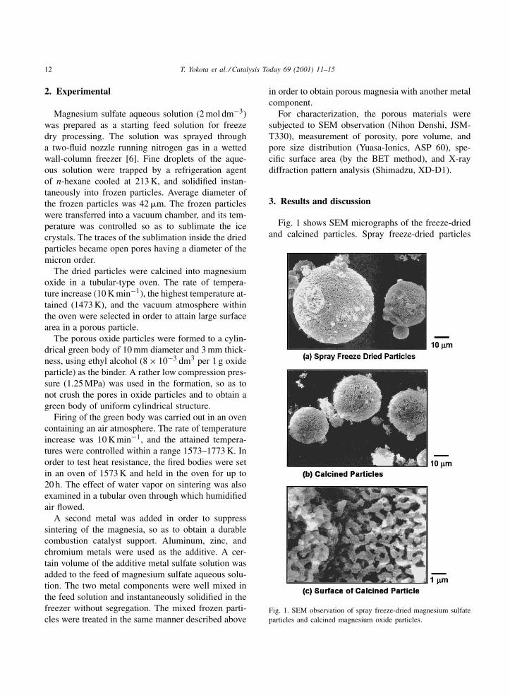
Fig. 1 shows SEM micrographs of the freeze-driedand calcined particles. Spray freeze-dried particles
Fig. 1. SEM observation of spray freeze-dried magnesium sulfateparticles and calcined magnesium oxide particles.
T. Yokota et al. / Catalysis Today 69 (2001) 11–15 13
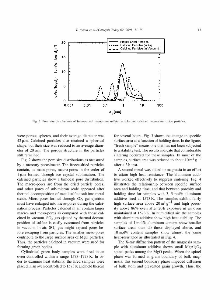
Fig. 2. Pore size distributions of freeze-dried magnesium sulfate particles and calcined magnesium oxide particles.
were porous spheres, and their average diameter was42 �m. Calcined particles also retained a sphericalshape, but their size was reduced to an average diam-eter of 20 �m. The porous structure in the particlesstill remained.
Fig. 2 shows the pore size distributions as measuredby a mercury porosimeter. The freeze-dried particlescontain, as main pores, macro-pores in the order of1 �m formed through ice crystal sublimation. Thecalcined particles show a bimodal pore distribution.The macro-pores are from the dried particle pores,and other pores of sub-micron scale appeared afterthermal decomposition of metal sulfate salt into metaloxide. Micro-pores formed through SOx gas ejectionmust have enlarged into meso-pores during the calci-nation process. Particles calcined in air contain largermacro- and meso-pores as compared with those cal-cined in vacuum. SOx gas ejected by thermal decom-position of sulfate is easily evacuated from particlesin vacuum. In air, SOx gas might expand pores be-fore escaping from particles. The smaller meso-porescontribute to the large surface area of MgO particles.Thus, the particles calcined in vacuum were used forforming green bodies.
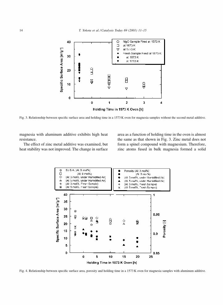
Cylindrical green body samples were fired in anoven controlled within a range 1573–1773 K. In or-der to examine heat stability, the fired samples wereplaced in an oven controlled to 1573 K and held therein
for several hours. Fig. 3 shows the change in specificsurface area as a function of holding time. In the figure,“fresh sample” means one that has not been subjectedto a stability test. The results indicate that considerablesintering occurred for these samples. In most of thesamples, surface area was reduced to about 10 m2 g−1
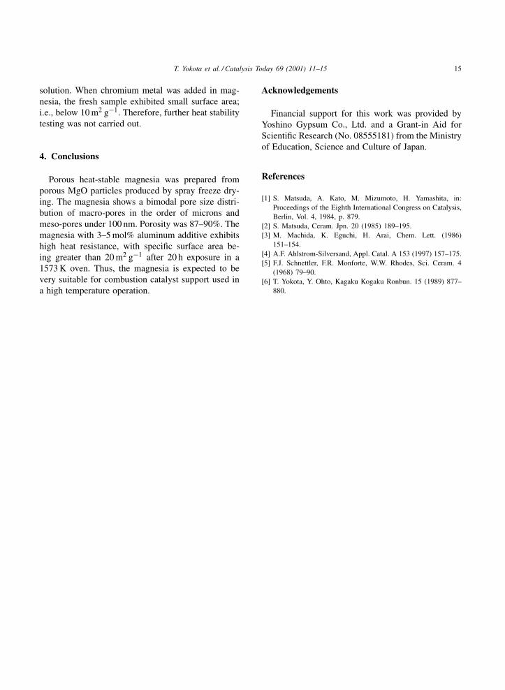
after a 3 h test.A second metal was added to magnesia in an effort
to attain high heat resistance. The aluminum addi-tive worked effectively to suppress sintering. Fig. 4illustrates the relationship between specific surfacearea and holding time, and that between porosity andholding time for samples with 3, 5 mol% aluminumadditive fired at 1573 K. The samples exhibit fairlyhigh surface area above 20 m2 g−1 and high poros-ity above 86% even after 20 h exposure in an ovenmaintained at 1573 K. In humidified air, the sampleswith aluminum additive show high heat stability. Thesamples of 1 mol% aluminum content show smallersurface areas than do those displayed above, and10 mol% content samples show almost the sameheat-resistance as illustrated in Fig. 4.
The X-ray diffraction pattern of the magnesia sam-ple with aluminum additive shows small MgAl2O4spinel peaks among the MgO peaks. When the spinelphase was formed at grain boundary of bulk mag-nesia, this second boundary phase impeded diffusionof bulk atom and prevented grain growth. Thus, the
14 T. Yokota et al. / Catalysis Today 69 (2001) 11–15
Fig. 3. Relationship between specific surface area and holding time in a 1573 K oven for magnesia samples without the second metal additive.
magnesia with aluminum additive exhibits high heatresistance.
The effect of zinc metal additive was examined, butheat stability was not improved. The change in surface
Fig. 4. Relationship between specific surface area, porosity and holding time in a 1573 K oven for magnesia samples with aluminum additive.
area as a function of holding time in the oven is almostthe same as that shown in Fig. 3. Zinc metal does notform a spinel compound with magnesium. Therefore,zinc atoms fused in bulk magnesia formed a solid
T. Yokota et al. / Catalysis Today 69 (2001) 11–15 15
solution. When chromium metal was added in mag-nesia, the fresh sample exhibited small surface area;i.e., below 10 m2 g−1. Therefore, further heat stabilitytesting was not carried out.
4. Conclusions
Porous heat-stable magnesia was prepared fromporous MgO particles produced by spray freeze dry-ing. The magnesia shows a bimodal pore size distri-bution of macro-pores in the order of microns andmeso-pores under 100 nm. Porosity was 87–90%. Themagnesia with 3–5 mol% aluminum additive exhibitshigh heat resistance, with specific surface area be-ing greater than 20 m2 g−1 after 20 h exposure in a1573 K oven. Thus, the magnesia is expected to bevery suitable for combustion catalyst support used ina high temperature operation.
Acknowledgements
Financial support for this work was provided byYoshino Gypsum Co., Ltd. and a Grant-in Aid forScientific Research (No. 08555181) from the Ministryof Education, Science and Culture of Japan.
References
[1] S. Matsuda, A. Kato, M. Mizumoto, H. Yamashita, in:Proceedings of the Eighth International Congress on Catalysis,Berlin, Vol. 4, 1984, p. 879.
[2] S. Matsuda, Ceram. Jpn. 20 (1985) 189–195.[3] M. Machida, K. Eguchi, H. Arai, Chem. Lett. (1986)
151–154.[4] A.F. Ahlstrom-Silversand, Appl. Catal. A 153 (1997) 157–175.[5] F.J. Schnettler, F.R. Monforte, W.W. Rhodes, Sci. Ceram. 4
(1968) 79–90.[6] T. Yokota, Y. Ohto, Kagaku Kogaku Ronbun. 15 (1989) 877–
880.
Catalysis Today 69 (2001) 17–24
Micro-engineered catalyst systems: ABB’s advancement instructured catalytic packings
Robert E. Trubac a, Frits M. Dautzenberg a,∗, Timothy A. Griffin b, Bettina Paikert b,Verena R. Schmidt b, Rudolf A. Overbeek a
a ABB Lummus Global Inc., 1515 Broad Street, Bloomfield, NJ 07003-3096, USAb ABB Corporate Research Ltd., CH-5405 Baden-Dätwil, Switzerland 1
Abstract
ABB has advanced catalysis with micro-engineered catalyst (MEC) systems by providing a uniquely small particle sizeon a formable catalyst support through the integration of catalysis and reaction engineering. A mechanically strong catalyticweb of micro-fibers has been engineered and shaped utilizing both computational fluid dynamics (CFD) and cold flowexperiments to optimize flow characteristics. This article discusses techniques used for the development of novel catalyticstructured packings for catalytic distillation applications. CFD models (verified through experiments performed on small-sizedstructures) were shown to be of great utility in screening new structure ideas. Results will illustrate achievement of both highgas–liquid contacting and bulk mixing at low pressure drop with the potential to provide enhanced catalyst utilization bytaking advantage of the intrinsic MEC properties, particularly its high porosity and exposed geometric fiber and catalystsurface area. This was shown by the successful testing of one of these catalyzed structures in the selective hydrogenation ofC4 acetylenes. © 2001 Published by Elsevier Science B.V.
Keywords: Catalytic packings; Structured catalysts; Catalyst; Structured packings; Catalytic distillation
1. Introduction
In recent years there has been much emphasis on“process intensification”, i.e. reduction in the physicalsize and/or cost of a chemical plant at a given produc-tion rate [1]. In many processes the reaction section isthe major size/cost component. This has placed focuson improving the integration of catalyst and reactorsystems not only at the molecular level, but also byconcentrating on the interaction between chemicalreaction and heat- and mass-transfer properties.
1Currently ALSTOM Power Technology.∗Corresponding author. Tel.: +1-973-893-3319;
fax: +1-973-893-2745.E-mail address: [email protected](F.M. Dautzenberg).
Catalysts are usually made as millimeter-sized par-ticles with the active catalytic agents dispersed on thesurface of/or throughout the particle. Reactants thenflow through a reactor containing the bulk-loadedcatalyst. Arrangement, shape and size of the cata-lyst govern the flow dynamics and pressure drop.The flow pattern is random making fluid dynamicsand heat-management difficult to predict and control.The effective use of active catalytic agents is some-times inefficient due to the occurrence of internalmass-transfer limitations. These constraints result inhigher raw material and operating costs as well as theproduction of less valuable by-products and waste.
ABB has invented a type of catalyst systemthat maximizes both internal and external catalystmass-transfer while minimizing overall hydrodynamic
0920-5861/01/$ – see front matter © 2001 Published by Elsevier Science B.V.PII: S0920 -5861 (01 )00350 -9
18 R.E. Trubac et al. / Catalysis Today 69 (2001) 17–24
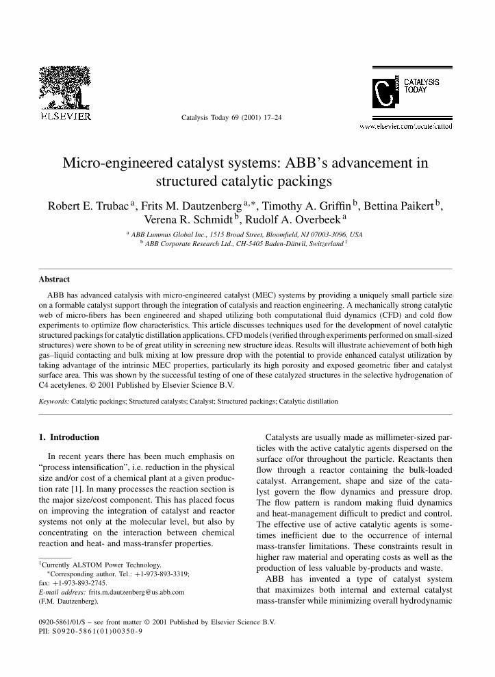
constraints. Such “micro-engineered catalyst (MEC)systems” consist of a mechanically strong catalyticweb of micro-fibers — thinner than a human hair —in which microscopically small catalyst particles areentrapped [2]. Fig. 1 shows two current MEC tech-nology concepts. In both, a highly porous metal sheetis used as a rigid catalyst support for micron-sizedcatalyst particles. MEC systems achieve their advan-tage by effectively utilizing catalyst particles on amuch smaller scale than currently applied in industry.The size of the catalyst particles used in an MEC istypically not greater than 50 �m, i.e. about two ordersof magnitude size reduction, thereby greatly reducinginternal mass-transfer limitations. The supports maybe formed into structures tailored for a specific appli-cation, thereby optimizing the functions of catalysisand reaction engineering and thereby also limitingexternal mass-transfer limitations.
This paper describes the ongoing development ofcatalytic structured packings for applications requiringmanagement of gas/liquid, liquid/solid and gas/solidmass-transfer by employing computational fluid dy-namics (CFD) in concert with detailed hydrodynamicmeasurements. The development of structured MECcatalyst packings for two-phase applications is ex-plained in detail. One example of such an applicationis catalytic distillation, which requires the integra-tion of a chemical reaction and appropriate heat- andmass-transfer characteristics with the goal of maxi-mizing separation and reaction efficiencies [3,4].
2. Structured packing design — currentstate-of-the-art
The generally accepted design criteria for non-catalytic structured distillation packings are:
• a large surface area for high interfacial contact,• an open structure for low resistance to the flow
(both phases),• uniform liquid distribution across the surface,• uniform vapor flow in the column cross-section
[5,6].
Surface characteristics to improve spreading ofthe liquid on the surface have been found to beof critical importance for enhancing mass-transfer.Liquid spreading is effected via perforations and
embossments, which also enhance mass-transfer dueto turbulence in the liquid film improve “surfacewetting” characteristics (low surface tension) of thepacking material, and act to cause coalescence andbreak-up of liquid droplets [6–11]. It was further foundthat with porous materials, capillary effects have anegative effect on liquid hold-up [7,12–14]; however,liquid spreading and wetting, particularly at low liquidflows are enhanced due to the capillary forces [12].
To achieve good mixing the flow should bethree-dimensional, encompass a high turbulence in-tensity, have a high mean velocity gradient, andexhibit a frequent change of direction of the mainstreams [15,16]. High shear is desired, and createdby flow streams of different orientations crossing ortouching each other. A preferred packing geometryshould spread the flow in a three-dimensional mannerand should not have predominant characteristics inspecific directions.
3. Experimental
Initially, a series of experimental techniques wasapplied to benchmark existing commercial packingsin single- and two-phase environments. The self-madepackings were manufactured from various materials,viz. metal sheet, gauze (wire diameter 0.2 mm, open-ing 1.0 mm), and a 90% void, 12 �m micro-fiber feltused to manufacture the MEC structure.
In single-phase flow, laser doppler anemometry(LDA) was applied to measure velocity gradients andlaser induced fluorescence (LIF) to measure mixing[17–22].
3.1. CFD modeling
To develop new packing geometries, single-phaseflow CFD modeling tools (Fluent UNS with un-structured gridding) were used and the results com-pared and validated against experimental data fromcold-flow modeling.
Initially, a CFD grid was set up to model as closelyas possible to the small experimental test rig. The riginlet was configured to reduce any velocity non- uni-formities, and consisted of a channel 30 mm in bothheight and width, which contained a three layer sec-tion of the packing. The overall length was 60 mm.
R.E. Trubac et al. / Catalysis Today 69 (2001) 17–24 19
Fig. 1. MEC system concepts.
LDA measurements were made on planes close to theexit of a common corrugated structured packing usingwater at an F-factor (defined as uρ1/2 and measuredin SI units) of around 130.
The CFD grids created were tetrahedral with around300,000 cells. A top-hat velocity profile was assumedat the inlet, which was positioned 10 mm in front ofthe packing, and the domain outlet was 30 mm down-stream of the packing exit plane. This allowed enoughspace to measure and compare two planes. Two gridsof this kind were created, one without any perfora-tions in the packing sheet, and the other with circularholes 4 mm in diameter. The holes in the computa-tional grid were positioned identically to those in theexperimental rig.
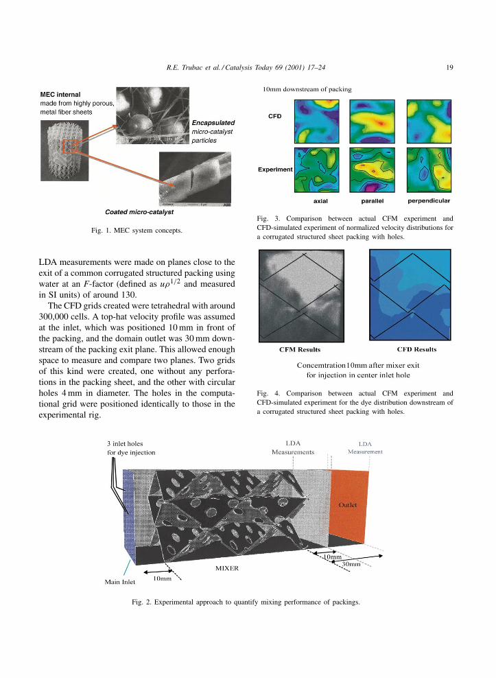
Fig. 2. Experimental approach to quantify mixing performance of packings.
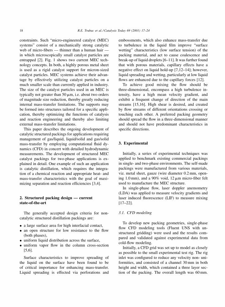
Fig. 3. Comparison between actual CFM experiment andCFD-simulated experiment of normalized velocity distributions fora corrugated structured sheet packing with holes.
Fig. 4. Comparison between actual CFM experiment andCFD-simulated experiment for the dye distribution downstream ofa corrugated structured sheet packing with holes.
20 R.E. Trubac et al. / Catalysis Today 69 (2001) 17–24
3.2. Cold flow testing
For calibration tests, miniature corrugated packinggeometries were assembled. To determine the effectof packing material on fluid dynamic performance,structures were made from both sheet metal contain-ing small (4 mm diameter) holes, and also from a12 �m micro-fiber felt. These miniature geometrieswere measured using the experimental approach pre-sented in Fig. 2. Results of cold flow modeling (CFM)measurements expressed as a normalized velocitydistribution in various directions were determined forwater at an F-factor of ca. 130. Measurements weretaken 10 and 30 mm downstream of the packing.Fig. 3 shows the quantitative normalized comparisonbetween experimental CFM and the CFD simulations.Represented are the results at 10 mm downstream ofthe positions downstream of the corrugated structuredpacking made of a solid foil with 4 mm circular holes.Comparing the data from both the CFM and CFDresults at a position 10 as well as 30 mm downstreamof the packing clearly shows that the CFD simulationaccurately predicted the experimental result. This isfurther demonstrated by comparing an actual camerapicture with a CFD-generated picture illustrating mix-ing capability represented by injected dye distribution(Fig. 4). A similar result was also seen with two otherbenchmarked structures: structured packings made ofa solid foil and felt material without punched holes.Oxygen desorption from water was used to measuregas–liquid mass-transfer rates.
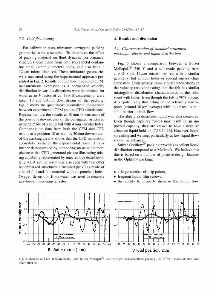
Fig. 5. Results of LDA measurements. Left: Sulzer Mellapak® 250 Y; right: self-assembled packing (250 m2/m3) made of 90% voidmicro-fiber felt.
4. Results and discussion
4.1. Characterization of standard structuredpackings: velocity and liquid distributions
Fig. 5 shows a comparison between a SulzerMellapak® 250 Y and a self-made packing froma 90% void, 12 �m micro-fiber felt with a similargeometry, but without holes or special surface char-acteristics. Both grossly show similar undulations inthe velocity ratios indicating that the felt has similarmixing/flow distribution characteristics as the solidsheet with holes. Even though the felt is 90% porous,it is quite likely that filling of the relatively narrowpores (around 30 �m average) with liquid results in asolid barrier to bulk flow.
The ability to distribute liquid was also measured.Even though capillary forces may result in an im-proved capacity, they are known to have a negativeeffect on liquid hold-up [7,13,14,26]. However, liquidspreading and wetting, particularly at low liquid flowsshould be enhanced.
Sulzer Optiflow® packing provides excellent liquiddistribution compared to a Mellapak. We believe thatthis is based on a number of positive design featuresin the Optiflow packing:
• a large number of drip points,• frequent liquid film renewal,• the ability to properly disperse the liquid flow.
R.E. Trubac et al. / Catalysis Today 69 (2001) 17–24 21
Thus, the performance of a corrugated structure canbe improved by:
• openings to allow gas distribution perpendicular tothe sheets,
• a large number of connecting points,• adding drip points to transport liquid from one sur-
face to the other,• good contact between adjacent sheets for improved
liquid distribution.
In the design of MEC structures, it was decidedthat the above-mentioned features should be combinedwith the other design criteria for structured packings.The Optiflow design is not intended as a mixer, butrather as a low pressure drop distillation packing (lackof large scale vortices, low p [27]). This structure alsohas a relatively low geometric surface area, and thusmay not be a good packing design for MEC applica-tions, which require geometric surface area to allowvolumetric catalytic activity.
4.2. CFD modeling to design novel MECstructured packings
Novel packing configurations were modeled todetermine appropriate packing characteristics for im-proved mixing at low pressure drop. The tested com-putational geometries were all periodic and, therefore,a relatively small computational domain could modelan infinitely large packing structure. Each grid wasagain generated using a tetrahedral mesh with eachdomain containing approximately 50,000 cells.
Several novel packing designs were evaluated in thedeveloped, calibrated, single-phase CFD model. Themost desirable designs were selected on the basis oflarge turbulent kinetic energy and high pressure dropof the structure to enhance both mass-transfer throughthe fiber felt (so called “cross-flow”) and forcedflow into the structure. However, the overall pressuredrop over the length of the packing had to remaintolerable [5,7–9,23–25]. The goal was to enhancebulk mass-transfer and to increase catalyst utilizationthroughout the thickness of the porous medium.
We “tested” the novel structure concepts using thepreviously mentioned benchmark tool. Two genericdesign concepts (shown in Fig. 6) that yielded pos-itive results from the CFD benchmarking tool wereselected on the basis of manufacturability and desired
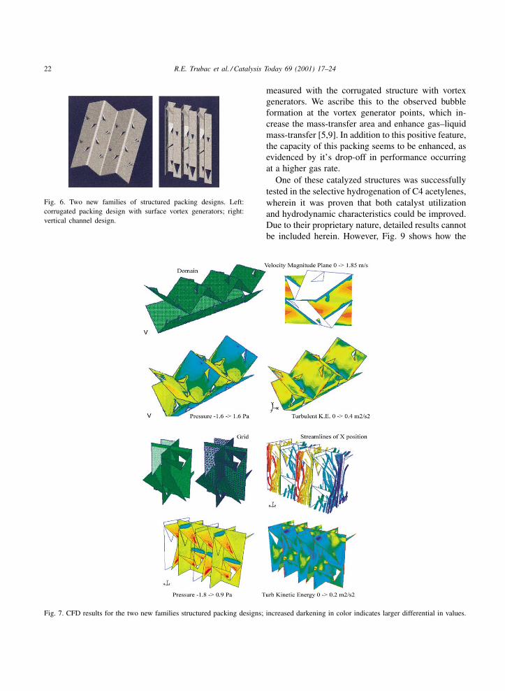
performance criteria. Both showed a large turbulentkinetic energy and high pressure drop across the facesof the structure at acceptable overall pressure dropover the length of the packing. CFD results for thesespecific features are shown in Fig. 7. The calculationshowed that the intrinsic pressure drop of the verticalchannel design is lower than any of the corrugateddesigns at equivalent geometric surface area. The ac-tual pressure drop of the vertical channel design at280 m2/m3 surface area is about equal to the standardcorrugated packing design (with holes) with less sur-face area (250 m2/m3). The addition of the specialsurface features (vortex generators) results in only aminimal increase in pressure drop. Vortex-generatingpunch-outs allow the addition of holes at no expenseof geometric sheet surface area, which is then avail-able for the catalytic reaction. The sharp pointingedges of the punch-outs will enhance continuous liq-uid renewal and the increased localized eddies shouldact to reduce flow channeling [23,24]. The punch-outscan be modified to produce sufficient channel obstruc-tion to minimize the occurrence of this undesirablechanneling. Multiple geometrical modifications arethus possible [28,29].
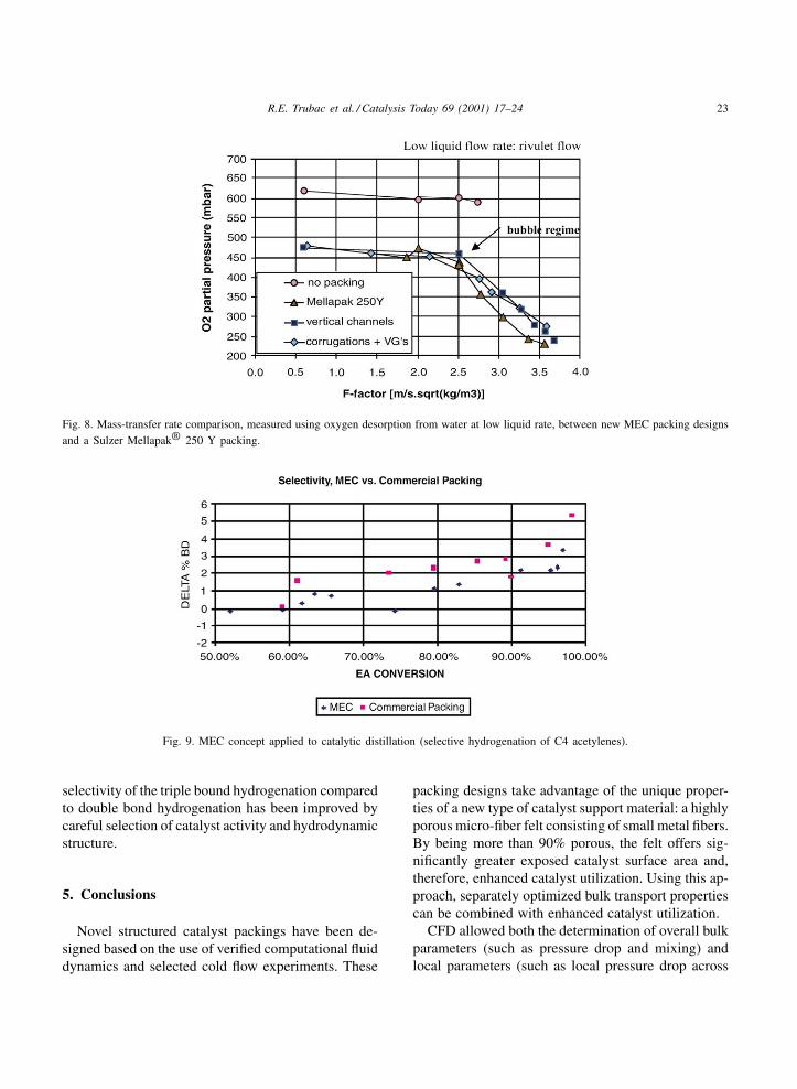
Finally, the new MEC structure designs were man-ufactured from micro-fiber felt with specially de-signed tools [30]. Mass-transfer rates were measuredusing oxygen desorption from water in two operatingregimes of low and high liquid flow rate in a counter-current air stream. Fig. 8 shows the results in the caseof low flow rate, showing how comparable gas–liquidmass-transfer rates and overall performance are ob-tained for the porous structures (corrugations, verticalchannel) and a commercially available Mellapak®
250 Y structure. This is remarkable because thefrontal blockage of the MEC packings is about fivetimes larger than that of the Mellapak structure due tothe differences in sheet thickness. Also, the charac-teristics of the micro-fibrous sheet, such as capillaryforces, would be expected to attribute to intrinsicallypoorer performance. This would suggest that thenovel designs — if constructed from a flat metal sheet— would have superior mass-transfer characteristics.
At higher liquid flow rates, the Mellapak® structurehas better oxygen desorption rates than the verticalchannel design; however, the capacity range of thevertical channel design seems to be larger [26].At high flow rate, the highest desorption rates are
22 R.E. Trubac et al. / Catalysis Today 69 (2001) 17–24
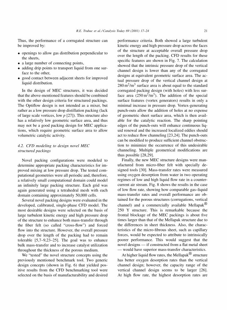
Fig. 6. Two new families of structured packing designs. Left:corrugated packing design with surface vortex generators; right:vertical channel design.
Fig. 7. CFD results for the two new families structured packing designs; increased darkening in color indicates larger differential in values.
measured with the corrugated structure with vortexgenerators. We ascribe this to the observed bubbleformation at the vortex generator points, which in-crease the mass-transfer area and enhance gas–liquidmass-transfer [5,9]. In addition to this positive feature,the capacity of this packing seems to be enhanced, asevidenced by it’s drop-off in performance occurringat a higher gas rate.
One of these catalyzed structures was successfullytested in the selective hydrogenation of C4 acetylenes,wherein it was proven that both catalyst utilizationand hydrodynamic characteristics could be improved.Due to their proprietary nature, detailed results cannotbe included herein. However, Fig. 9 shows how the
R.E. Trubac et al. / Catalysis Today 69 (2001) 17–24 23
Fig. 8. Mass-transfer rate comparison, measured using oxygen desorption from water at low liquid rate, between new MEC packing designsand a Sulzer Mellapak® 250 Y packing.
Fig. 9. MEC concept applied to catalytic distillation (selective hydrogenation of C4 acetylenes).
selectivity of the triple bound hydrogenation comparedto double bond hydrogenation has been improved bycareful selection of catalyst activity and hydrodynamicstructure.
5. Conclusions
Novel structured catalyst packings have been de-signed based on the use of verified computational fluiddynamics and selected cold flow experiments. These
packing designs take advantage of the unique proper-ties of a new type of catalyst support material: a highlyporous micro-fiber felt consisting of small metal fibers.By being more than 90% porous, the felt offers sig-nificantly greater exposed catalyst surface area and,therefore, enhanced catalyst utilization. Using this ap-proach, separately optimized bulk transport propertiescan be combined with enhanced catalyst utilization.
CFD allowed both the determination of overall bulkparameters (such as pressure drop and mixing) andlocal parameters (such as local pressure drop across
24 R.E. Trubac et al. / Catalysis Today 69 (2001) 17–24
the MEC fiber felt). It was used to screen a numberof novel structural designs without performing expen-sive, time-consuming experimental tests.
Two families of structural designs were found inthis study: a corrugated packing design with surfacevortex generators and a vertical channel design. Boththe designs can be manufactured with specially de-signed tools without compromising the nature of themicro-fiber felt substrate. Two-phase mass-transfertesting was performed on the new designs, whichwere compared with a commercially available prod-uct (Sulzer Mellapak® 250 Y). In these tests at lowliquid flow rate, comparable gas–liquid mass-transferrates and overall performance were obtained for thenew packing designs made of the porous MEC mate-rial. This is remarkable, since the frontal blockage ofthe MEC packings is about five times larger than thatof the Mellapak structure and certain characteristicsof the micro-fibrous sheet, such as capillary forces,would be expected to be attributed to intrinsicallypoorer performance.
By introducing a novel catalyst support material— the high surface area micro-fiber felt — optimalbulk transport can be combined with enhanced catalystutilization.
Acknowledgements
The authors wish to thank the following co-workerswho contributed significantly to this paper: Rebei BelFdhila and Ulrike Windecker of ABB Corporate Re-search, Sweden, and Jonathan Lloyd of ALSTOMPower, Switzerland.
References
[1] F.M. Dautzenberg, M. Mukherjee, in: Proceedings of the 16thISCRE, 2000, Chem. Eng. Science 56 (2) (2001) 251–267.
[2] R.A. Overbeek, T.F. Kellett, F.M. Dautzenberg, ABB Rev. 2(2000) 48–55.
[3] K. Rock, G.R. Gildert, T. McGuirk, Chem. Eng. 104 (7)(1997) 78.
[4] W.P. Stadig, Chem. Proc. (1987).
[5] M.H. de Brito, Ind. Eng. Chem. Res. 33 (1994) 647–656.[6] J.M. Coulson, J.F. Richardson, Chemical Engineering, Vol.
6, Design, 2nd Edition, Pergamon Press, Oxford, 1993,pp. 529–544.
[7] F. Stoter, Chem. Eng. J. 53 (1993) 55–66.[8] R.F. Strigle Jr., Packed Tower Design and Applications:
Random and Structured Packings, 2nd Edition, NortonChemical Process Products Corporation, Gulf PublishingCompany, Houston, 1994.
[9] J.A. Rocha, Ind. Eng. Chem. Res. 32 (1993) 641–651.[10] J.M. Coulson, J.F. Richardson, Chemical Engineering, Vol.
2, Particle Technology and Separation Processes, 4th Edition,Pergamon Press, Oxford, 1991, pp. 132–173.
[11] J.R. Fair, J.L. Bravo, IChemE Symp. Ser. 104 (1988) A183–A201.
[12] G. Nardini, Chem. Eng. Technol. 19 (1996) 20–27.[13] R.K. Helling, M.A. DesJardin, Chem. Eng. Prog., 13 (October
1994) pp. 62–66.[14] O. Becker, R. Steiner, Chem. Eng. Technol. 67 (7) (1995)
883–888.[15] J.M. Ottino, The Kinematics of Mixing: Stretching, Chaos
and Transport, 1st Edition, Cambridge University Press,Cambridge, 1989.
[16] H. Tennekes, J.L. Lumley, A First Course in Turbulence, MITPress, Cambridge, 1989.
[17] G. Eigenberger, Fortschrittberichte VDI Nr. 112, Reihe 15:Umwelttechnik, VDI-Verlag, 1991.
[18] G. Eigenberger, Ullmann’s Encyclopedia of IndustrialChemistry, Vol. B4, 1992, VCH Publishing, pp. 199–238.
[19] Separation Columns for Distillation and Absorption, SulzerChemtech, 1991.
[20] V. Kottke, H. Blenke, Verfahrenstechnik 16 (6) (1982) 504.[21] V. Kottke, H. Blenke, Chem. Eng. Technol. 50 (2) (1978) 81.[22] W. Kühnel, V. Kottke, Proc. Eur. Sem. 46 (1995) 61.[23] F.A. Streiff, J.A. Rogers, Don’t Overlook Static-Mixer-
Reactors, Information on Mixing and Reaction Technologyby Sulzer Chemtech, 1994.
[24] European Patent Application No. 82301389.1, March 18,1982.
[25] A.M.J. Davis, D.F. James, Int. J. Multiphase Flow 22 (5)(1996) 969–989.
[26] R.F. Strigle Jr., Chem. Eng. Prog., 1993, pp. 79–83.[27] P. Süess, W. Meier, A New Transfer Structure for Distillation
and Absorption, Information by Sulzer Chemtech, 1995,pp. 416–420.
[28] B. Paikert, J. Lloyd, T.A. Griffin, PCT Patent Application,WO9934911, 1999.
[29] R.A. Overbeek, R.E. Trubac, V.A. Strangio, B. Paikert, J.Lloyd, T.A. Griffin, R. Bel Fdhila, PCT Patent Application,WO9962629, 1999.
[30] F. Buchi, E. Vogt, P. Dubach, T. Griffin, J. Lloyd, B. Paikert,PCT Patent Application, WO0024506, 2000.
Catalysis Today 69 (2001) 25–31
Iron oxide-based honeycomb catalysts for thedehydrogenation of ethylbenzene to styrene
William P. Addiego∗, Wei Liu, Thorsten BogerCorning Incorporated, Sullivan Park-DV-01-9, Corning, NY 14831, USA
Abstract
Corning has recently developed a novel extrusion method to make bulk transition metal oxide honeycomb catalysts. One areaof effort has been iron oxide-based catalysts for the dehydrogenation of ethylbenzene to styrene, a major chemical processthat yields worldwide 20 MM tons/yr. In industry, the monomer is synthesized mostly in radial-flow fixed-bed reactors.Because of the high cross-sectional area for flow and shallow depth of the catalyst bed in these reactors, low reactor pressuregradients are maintained that favors the yield and selectivity for styrene formation. However, the radial-flow design hasinherent detractions, including inefficient use of reactor volume and large temperature gradients that decrease catalyst servicelife. The overall economics of the process can be improved with parallel-channel honeycomb catalysts and axial flow reactors.The simple axial flow design of honeycomb catalysts provides low-pressure drop, while making more efficient use of reactorvolume, with better heat and mass transfer characteristics compared to a conventional radial packed bed. An important partof this concept is the ability to fabricate a wide family of dehydrogenation catalyst compositions into honeycombs with therequisite chemical, physical, mechanical, and catalytic properties for industrial use. The ethylbenzene dehydrogenation (EBD)honeycomb catalysts developed by Corning have compositions similar to those commonly used in industry and are preparedwith the same catalyst and promoter precursors and with similar treatments.
However, to enable extrusion of catalyst precursors into honeycomb shapes, especially at cell densities above 100 cell/in.2,Corning’s process compensates for the high salt concentrations and the high pH of the batch material that would otherwiseprevent or impede honeycomb extrusion. The improved rheological characteristics provide the necessary plasticity, lubric-ity, and resiliency for honeycomb extrusion with sufficient binder strength needed before calcination to the final product.Iron oxide-based honeycombs after calcination are strong and possess macroporosity and high surface area. In bench-scaletesting, particular honeycomb catalyst compositions exhibited 60–76% ethylbenzene conversion with styrene selectivity of95–91%, respectively, under conventional reaction conditions without apparent deactivation or loss of mechanical integrity.© 2001 Elsevier Science B.V. All rights reserved.
Keywords: Iron oxide; Honeycomb; Catalysts; Dehydrogenation; Ethylbenzene; Styrene; Axial flow; Reactor
1. Introduction
The industrial process for the dehydrogenation ofethylbenzene to styrene is used to make valuable com-modity chemicals such as polystyrene and syntheticrubber such as ABS and SB latex; as much as 20 MM
∗ Corresponding author. Fax: +1-607-974-3745.E-mail address: [email protected] (W.P. Addiego).
tons/yr of styrene monomer are made. Although thisprocess was already commercialized in the 1930s, re-search and development has continued to improve it,including the development of new catalysts, reactordesigns and process routes [1–13].
The non-oxidative ethylbenzene dehydrogenation(EBD) to styrene is endothermic, reversible andequilibrium limited. Because of the thermodynamiclimitation, the formation of styrene is favored by the
0920-5861/01/$ – see front matter © 2001 Elsevier Science B.V. All rights reserved.PII: S0920 -5861 (01 )00351 -0
26 W.P. Addiego et al. / Catalysis Today 69 (2001) 25–31
low partial pressure of ethylbenzene and hydrogen.To promote the forward reaction, the industrial pro-cess uses steam, where the molar ratio of steam toethylbenzene is 6–13:1 at atmospheric or vacuumconditions. Steam provides heat for the reaction, pre-vents over-reduction of the iron oxide-based catalyst,prevents coke formation, and decreases the partialpressure of gases, thereby shifting the chemical equi-librium to higher styrene conversion [3,13].
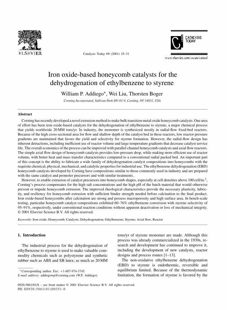
For low reactor pressure drop, industrial EBD is per-formed in radial-flow reactors, as shown in Fig. 1(a).Total ethylbenzene conversion through both reactorsis about 60–70%. An axial flow honeycomb reac-tor, shown in Fig. 1(b), could improve overall effi-ciency by incorporating heat exchangers to minimizethermal gradients along the catalyst bed, improvingthe performance and extending the service life of the
Fig. 1. (a) Diagram of a first-stage radial-flow reactor with cylindrical shaped packed catalyst bed held in place by concentric screensand with a central conical gas distributor. (b) Axial flow honeycomb catalyst reactor with interbed heat exchanger. In both configurations,effulent is sent to a second-stage reactor to dehydrogenate remaining ethylbenzene.
Table 1Pressure drop comparison of honeycomb and packed bead withequivalent bed cross-section
Bed properties Honeycomb Bead
Void fraction 0.5Linear velocity (m/s) 6.8Wall thickness (mm) 1 0.5 3.2φ
Cell density (cpsi) 55 220 N/APressure drop (bar/m) 0.021 0.085 0.437Characteristic heat/mass
transfer dimension (mm)0.5 0.25 0.8
catalyst, while maintaining low-pressure drop [14].With a higher geometric surface area relative to packedbeads, the honeycomb also has a better mass/heattransfer dimension, as shown in Table 1.
W.P. Addiego et al. / Catalysis Today 69 (2001) 25–31 27
Industrial dehydrogenation compositions are acomplex mixture of metal oxides and large amountsof salts, principally iron oxide and potassium car-bonate. During reaction start-up, under essentially re-duction conditions, the catalytically active potassiumferrite, KFeO2, forms along with ferrite polymorphs[16,20–22]. In addition, potassium carbonate also actsas a catalyst to oxidize carbonaceous deposits to pre-vent coking [3]. The literature is replete with studieson EBD catalysts [2–6,13,15–24].
Controlling the rheological properties of the catalystcompositions is important in order to provide the req-uisite plasticity and lubricity during extrusion neededfor web formation and knitting, skin formation, andstiffening as the honeycomb emerges from the die.However, because of the large concentration of saltsin typical dehydrogenation catalyst compositions, ex-trusion rheology is usually degraded with the loss ofplasticity and water migration. This occurs, in part, be-cause salts can induce the precipitation of organics andthe loss of “bound” water layers associated with or-ganics and distributed throughout the extrusion batch.The proper combination of organic additives and ma-terials processing is necessary to extrude honeycombcatalysts containing high salt concentration and avoidor attenuate adverse ionic shock. This paper reports ona method of extruding industrial-type EBD catalysts,their characterization and catalytic performance.
2. Experimental
2.1. Extrusion compositions
Extrusion batches were made in a manner simi-lar to industrial methods. �-Fe2O3 was mixed with
Table 2EBD catalyst compositions
Component Batch component Oxide (wt.%) Function/promoter Compositions oxide (wt.%)
J-A, 2J-AB Q-B1
Fe2O3 Oxide 25–80 Activity 72 79K2O Carbonate 10–35 Activity 16 11CeO2 Carbonate 0–5 Activity 4 4MoO3 Ammonium molybdate 0–3 Selectivity 1 3CaO Carbonate 0–3 Chemical/mechanical stability 0 2MgO Carbonate 0–10 Chemical/mechanical stability 7 1
appropriate amounts of K2CO3, (NH4)6Mo7O24,CeCO3, and MgCO3 or CaCO3, based on the ana-lyzed equivalent oxide of the salts, as listed in Table 2.The catalyst precursors were dry-blended in a tur-bular mixer with certain organic additives. After dryblending, organic emulsions were added with water,along with additional plasticizers and lubricants, andmulled to form a plastic dough, that was subsequentlyhomogenized to ensure a thorough mixing of solidand liquid components. Honeycombs were then ex-truded with square cells of 100, 200, and 400 cell/in.2
(cpsi) with web thickness of 0.64, 0.38, and 0.18 mm,respectively. Extrusion rheology was measured witha parallel-plate rheometer.
2.2. Chemical and physical characterizationand catalyst testing
After extrusion, honeycombs were dried at 80◦Cand calcined at 850◦C/6 h. Calcined samples of100 cpsi honeycombs were characterized for surfacearea, porosity, pore size distribution, A-axis crush-ing strength, and catalytic activity and selectivity forstyrene formation. As shown in Table 3, honeycombcatalysts which had a BET surface area of 4 m2/gwere macroporous with >50% porosity. Honeycombswere very strong, exhibiting an A-axis crushingstrength (i.e., force applied parallel to cell walls) of1300–2000 psi after calcination.
Honeycomb catalysts were also tested for catalyticperformance using an integral reactor. The reactor con-sisted of a stainless steel tube within which a 1-in. di-ameter quartz tube was inserted to support a 50 cm3
honeycomb catalyst, 2.5 cm (ID)×10.0 cm long. −60mesh SiC particles were packed above and below thehoneycomb, separated from the honeycomb by quartz
28 W.P. Addiego et al. / Catalysis Today 69 (2001) 25–31
Table 3Physical and mechanical characteristics of 100 cpsi EBD honeycomb catalysts calcined at 850◦C/6 h
Honeycombcatalyst
Surfacearea (m2/g)
A-axis compressionstrength (psi)
Apparentdensity (g/ml)
% Porosity Median poresize (nm)
J-A 4.0 1300 3.9 53 350Q-B1 3.0 1800 4.4 56 3802J-AB 3.5 2000 3.9 54 330
wool. Thermocouples were placed at the honeycombentrance and exit in the SiC packing for uniform tem-perature measurement. Above the SiC packing, dense�-alumina beads were packed to help the heat feeduniformly before entering the honeycomb.
Reagent grade ethylbenzene and de-ionized waterwere delivered to the top of the reactor by two liquidpumps in order to provide the appropriate steam toethylbenzene ratio. The mixture was vaporized in thereactor as it flowed to the honeycomb catalyst. The ef-fluent was cooled and liquid product and gas were thenseparated. Hydrocarbons were separated from waterand measured by gas chromatography.
3. Results and discussion
3.1. Extrusion behavior
Extrusion compositions were prepared with variouspolymer emulsions to affect rheology. For this part ofthe study, one particular inorganic composition wasused, J-A listed in Table 2. These were comparedto extrusion performance without organics or withsoluble cellulose ethers. Certain polymer emulsionswere suitable for extruding honeycombs and superiorto water-soluble organic extrusion aids, providingplasticity to an extent that honeycomb matrix forma-tion was possible with a 100 cpsi/0.7 mm geometryor greater. Systems with appropriate colloidal poly-mer emulsions set and dried rapidly without crack-ing and showed considerable green strength beforecalcination.
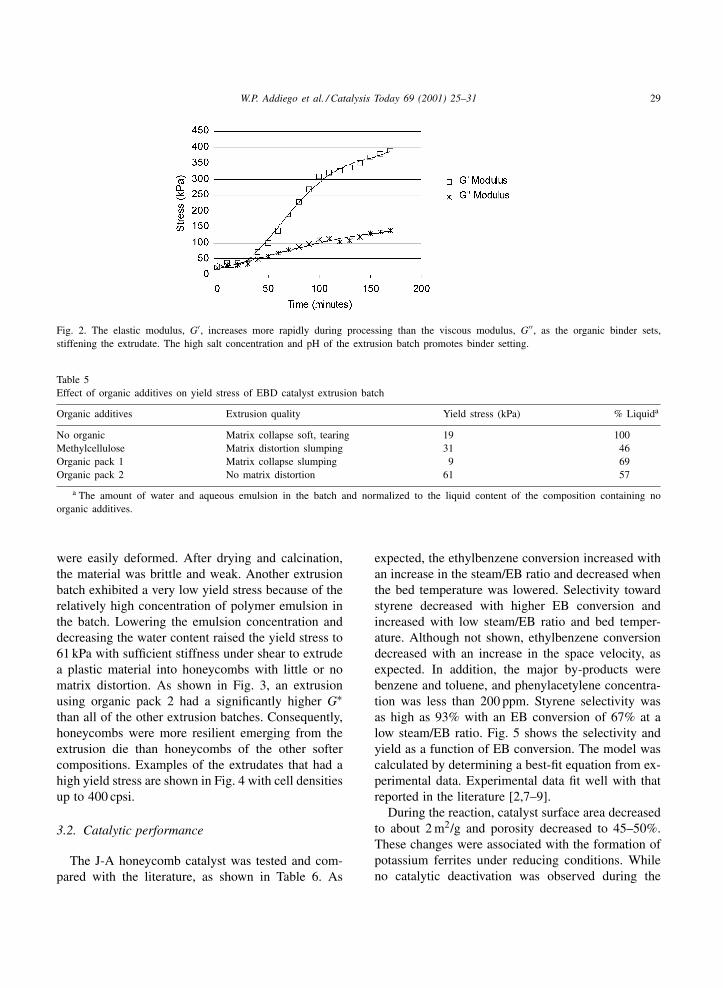
The impact of polymer glass transition tempera-ture, Tg, on extrusion rheology was measured, basedon changes in the batch material’s stiffness or rigid-ity as a function of the complex modulus, G∗. Extru-sion batches containing a soft polymer with a Tg nearor below ambient stiffened much more rapidly dur-ing processing at ambient temperatures than batches
containing glassy polymers with a Tg significantlyabove the mixing or extrusion temperature, as shownin Table 4. The elastic modulus, G′, of a batch con-taining a glassy polymer increased rapidly after 1 h, asshown in Fig. 2, due to polymer cross-linking at thetypically high batch pH ≈ 9, rendering the batch brit-tle and less capable of plastic deformation. With theappropriate organic system, the batch remained suffi-ciently plastic during extrusion. Honeycombs rapidlyset at temperatures near the Tg of the polymer anddried with little or no cracking. This feature minimizeddistortion of the honeycomb matrix.
Water-soluble extrusion aids, such as celluloseethers and polyethylene oxides, are very suscepti-ble to ionic shock and tend to precipitate in thepresence of fairly low concentrations of alkali salts,especially carbonate and sulfate salts [25,26]. In ex-trusion batches containing K2CO3, these polymerseasily flocculate, lose the ability to disperse water,and contribute to the overall degradation of extrusionrheology. The yield stress of extrusion batches withdifferent types of organic systems was approximatedfrom the G∗ modulus at a shear frequency of 1 rad/sand 5% strain and is listed in Table 5. The amountof liquid to plasticize the batch was normalized to areference batch not containing any organic additive.A significant amount of water was needed to plasti-cize the reference, which showed a low yield stress of19 kPa. Less water was required after adding methyl-cellulose, raising the yield stress, but honeycombs
Table 4Effect of organic additive Tg on setting time of EBD catalystextrusion batch
Polymeremulsion
Tg (◦C) Settingtime (min)
Complexmodulus (kPa)
EM101 <0 30 >350VM501 <15 90 >350RT502 >75 140 >350
W.P. Addiego et al. / Catalysis Today 69 (2001) 25–31 29
Fig. 2. The elastic modulus, G′, increases more rapidly during processing than the viscous modulus, G′′, as the organic binder sets,stiffening the extrudate. The high salt concentration and pH of the extrusion batch promotes binder setting.
Table 5Effect of organic additives on yield stress of EBD catalyst extrusion batch
Organic additives Extrusion quality Yield stress (kPa) % Liquida
No organic Matrix collapse soft, tearing 19 100Methylcellulose Matrix distortion slumping 31 46Organic pack 1 Matrix collapse slumping 9 69Organic pack 2 No matrix distortion 61 57
a The amount of water and aqueous emulsion in the batch and normalized to the liquid content of the composition containing noorganic additives.
were easily deformed. After drying and calcination,the material was brittle and weak. Another extrusionbatch exhibited a very low yield stress because of therelatively high concentration of polymer emulsion inthe batch. Lowering the emulsion concentration anddecreasing the water content raised the yield stress to61 kPa with sufficient stiffness under shear to extrudea plastic material into honeycombs with little or nomatrix distortion. As shown in Fig. 3, an extrusionusing organic pack 2 had a significantly higher G∗than all of the other extrusion batches. Consequently,honeycombs were more resilient emerging from theextrusion die than honeycombs of the other softercompositions. Examples of the extrudates that had ahigh yield stress are shown in Fig. 4 with cell densitiesup to 400 cpsi.
3.2. Catalytic performance
The J-A honeycomb catalyst was tested and com-pared with the literature, as shown in Table 6. As
expected, the ethylbenzene conversion increased withan increase in the steam/EB ratio and decreased whenthe bed temperature was lowered. Selectivity towardstyrene decreased with higher EB conversion andincreased with low steam/EB ratio and bed temper-ature. Although not shown, ethylbenzene conversiondecreased with an increase in the space velocity, asexpected. In addition, the major by-products werebenzene and toluene, and phenylacetylene concentra-tion was less than 200 ppm. Styrene selectivity wasas high as 93% with an EB conversion of 67% at alow steam/EB ratio. Fig. 5 shows the selectivity andyield as a function of EB conversion. The model wascalculated by determining a best-fit equation from ex-perimental data. Experimental data fit well with thatreported in the literature [2,7–9].
During the reaction, catalyst surface area decreasedto about 2 m2/g and porosity decreased to 45–50%.These changes were associated with the formation ofpotassium ferrites under reducing conditions. Whileno catalytic deactivation was observed during the
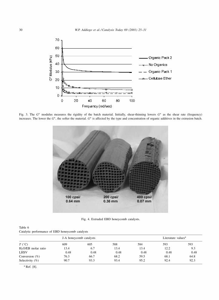
30 W.P. Addiego et al. / Catalysis Today 69 (2001) 25–31
Fig. 3. The G∗ modulus measures the rigidity of the batch material. Initially, shear-thinning lowers G∗ as the shear rate (frequency)increases. The lower the G∗, the softer the material. G∗ is affected by the type and concentration of organic additives in the extrusion batch.
Fig. 4. Extruded EBD honeycomb catalysts.
Table 6Catalytic performance of EBD honeycomb catalysts
J-A honeycomb catalysts Literature valuesa
T (◦C) 609 605 588 584 593 593H2O/EB molar ratio 13.4 6.7 13.4 13.4 12.2 9.3LHSV 0.48 0.48 0.48 0.48 0.48 0.48Conversion (%) 76.3 66.7 68.2 59.5 68.1 64.8Selectivity (%) 90.7 93.3 93.4 95.2 92.4 92.3
a Ref. [8].
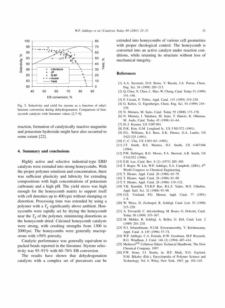
W.P. Addiego et al. / Catalysis Today 69 (2001) 25–31 31
Fig. 5. Selectivity and yield for styrene as a function of ethyl-benzene conversion during dehydrogenation. Comparison of hon-eycomb catalysts with literature values [2,7–9].
reaction, formation of catalytically inactive magnetiteand potassium hydroxide might have also occurred tosome extent [22].
4. Summary and conclusions
Highly active and selective industrial-type EBDcatalysts were extruded into strong honeycombs. Withthe proper polymer emulsion and concentration, therewas sufficient plasticity and lubricity for extrudingcompositions with high concentrations of potassiumcarbonate and a high pH. The yield stress was highenough for the honeycomb matrix to support itselfwith cell densities up to 400 cpsi without slumping ordistortion. Processing time was extended by using apolymer with a Tg significantly above ambient. Hon-eycombs were rapidly set by drying the honeycombnear the Tg of the polymer, minimizing distortions asthe honeycomb dried. Calcined honeycomb catalystswere strong, with crushing strengths from 1300 to2000 psi. The honeycombs were generally macrop-orous with >50% porosity.
Catalytic performance was generally equivalent topacked beads reported in the literature. Styrene selec-tivity was 95–91% with 60–76% EB conversion.
The results have shown that dehydrogenationcatalysts with a complex set of precursors can be
extruded into honeycombs of various cell geometrieswith proper rheological control. The honeycomb isconverted into an active catalyst under reaction con-ditions, while retaining its structure without loss ofmechanical integrity.
References
[1] A.A. Savoretti, D.O. Borio, V. Bucala, J.A. Porras, Chem.Eng. Sci. 54 (1999) 205–213.
[2] Q. Chen, X. Chen, L. Mao, W. Cheng, Catal. Today 51 (1999)141–146.
[3] F. Cavani, F. Trifiro, Appl. Catal. 133 (1995) 219–239.[4] G. Kolios, G. Eigenberger, Chem. Eng. Sci. 54 (1999) 219–
239.[5] N. Mimura, M. Saito, Catal. Today 55 (2000) 173–178.[6] N. Mimura, I. Takahara, M. Saito, T. Hattori, K. Ohkuma,
M. Ando, Catal. Today 45 (1998) 61–64.[7] H.-J. Kremer, US 5 097 091.[8] D.K. Kim, G.M. Longland Jr., US 5 503 572 (1991).[9] D.L. Williams, K.J. Russ, E.K. Dienes, G.A. Laufer, US
5 023 225 (1991).[10] C.-C. Chu, US 4 503 163 (1985).[11] J.T. Smith, B.S. Masters, D.J. Smith, US 4 467 046
(1984).[12] P.W. Dellinger, R.G. Moore, F.A. Sherrod, A.R. Smith, US
5 510 552 (1996).[13] E.H. Lee, Catal. Rev. 8 (2) (1973) 285–305.[14] T. Boger, W. Liu, W.P. Addiego, S.A. Campbell, (2001), 6th
World Congress to Chemical Engineering.[15] T. Hirano, Appl. Catal. 26 (1986) 65–79.[16] T. Hirano, Appl. Catal. 26 (1986) 81–90.[17] T. Hirano, Appl. Catal. 26 (1986) 119–132.[18] V.K. Kaushik, T.S.R.P. Rao, B.L.S. Yadav, M.S. Chhabra,
Appl. Surf. Sci. 32 (1988) 93–98.[19] G.E. Vrieland, P.G. Menon, Appl. Catal. 77 (1991)
1–8.[20] W. Weiss, D. Zscherpel, R. Schlögl, Catal. Lett. 52 (1998)
215–220.[21] A. Trovarelli, C. deLeitenburg, M. Boaro, G. Dolcetti, Catal.
Today 50 (1999) 353–367.[22] M. Muhler, R. Schlögl, A. Reller, G. Ertl, Catal. Lett. 2
(1989) 201–210.[23] N.J. Jebarathinam, N.J.M. Eswaramoorthy, V. Krishnasamy,
Appl. Catal. A 145 (1996) 57–74.[24] W.P. Addiego, C.A. Estrada, D.W. Goodman, M.P. Rosynek,
R.G. Windham, J. Catal. 146 (2) (1994) 407–414.[25] MethocelTM Cellulose Ethers Technical Handbook, The Dow
Chemical Company, 1997.[26] F.W. Stone, J.J. Stratta, in: H.F. Mark, N.G. Gaylord,
N.M. Bikales (Eds.), Encyclopedia of Polymer Science andTechnology, Vol. 6, Wiley, New York, 1967, pp. 103–145.
Catalysis Today 69 (2001) 33–39
Permeability of sintered microfibrous compositesfor heterogeneous catalysis and other chemical
processing opportunities
Donald R. Cahela, Bruce J. Tatarchuk∗Chemical Engineering Department, Auburn University, 230 Rose Hall, Auburn, AL 36849, USA
Abstract
Microstructured materials have potential for enhanced mass and heat transfer compared to typical catalyst particulatesused in industrial processes. The pressure drop through catalyst-containing materials is a very important reactor designconsideration. A model equation to predict porous media permeability (PMP) over the entire range of possible bed voidages isextended to predict properties of sintered metal meshes. A correlation of data for sintered meshes of nickel fibers is presentedin the form of a Kozeny constant form drag plot. Comparison of predictions by the PMP equation with data taken on a sinteredcomposite fiber/particle mesh is presented. Use of the PMP equation as a design tool for optimization of media for adsorbents,catalysts, and filters is discussed. © 2001 Elsevier Science B.V. All rights reserved.
Keywords: Permeability; Heterogeneous catalyst; Catalysis; PMP
1. Introduction
A new-patented class of composites materials madeby a wet lay paper-making/sintering process can incor-porate particles as small as 10 �m into a micrometalfiber matrix [1–4]. Sintered microfibrous compositesusing a 16% Ni/alumina catalyst for toluene hydro-genation in a trickle bed reactor have demonstrated2–6 times higher specific activities than conventionalpacked bed catalysts on a gravimetric basis, whilevolumetric activities of 40 vol.% composite catalystswere 80% higher than conventional extrudates [5].Effectiveness factors for reactions employing suchsmall particles are typically close to unity. The high
∗ Corresponding author. Tel.: +1-334-844-2023;fax: +1-334-844-2065.E-mail addresses: [email protected], [email protected](B.J. Tatarchuk).
thermal conductivity of the micrometal fiber matrixproduces radial heat transfer coefficients that are abouttwice those in packed beds. Enhanced heat transferdue to the larger surface to volume ratio of small parti-cles and the micrometal matrix results in more nearlyisothermal conditions in fixed bed reactors minimizinghot spots, resulting in higher selectivity, and allowingprocessing to be done with smaller safety factors.The micrometal fiber matrix also acts as a micronscale static mixer eliminating channeling. The wet laypaper-making/sintering process allows continuous ad-justment of void volume from upwards of 98% downto values similar to packed beds of particles [6]. Thisallows the composite catalyst/adsorbent material to beoptimized to the appropriate void volume for differenttypes of applications. Production of these materials isbased on standard paper-making techniques [7], whichcan be scaled up to manufacturing on high speedcontinuous paper machines resulting in relatively
0920-5861/01/$ – see front matter © 2001 Elsevier Science B.V. All rights reserved.PII: S0920 -5861 (01 )00352 -2
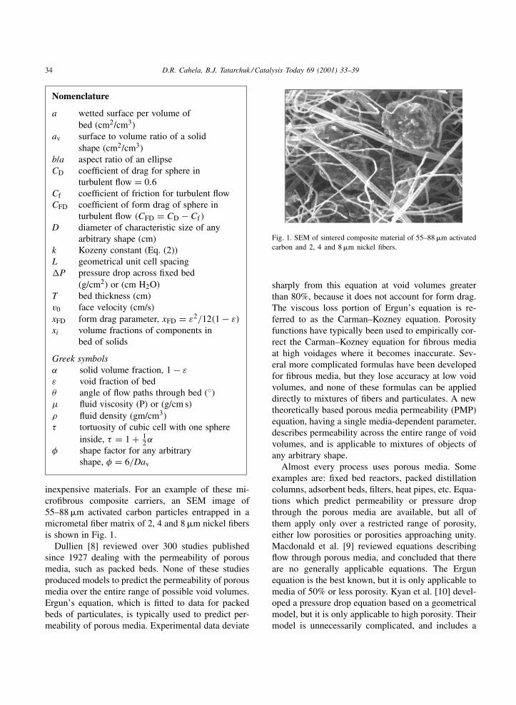
34 D.R. Cahela, B.J. Tatarchuk / Catalysis Today 69 (2001) 33–39
Nomenclature
a wetted surface per volume ofbed (cm2/cm3)
av surface to volume ratio of a solidshape (cm2/cm3)
b/a aspect ratio of an ellipseCD coefficient of drag for sphere in
turbulent flow = 0.6Cf coefficient of friction for turbulent flowCFD coefficient of form drag of sphere in
turbulent flow (CFD = CD − Cf)
D diameter of characteristic size of anyarbitrary shape (cm)
k Kozeny constant (Eq. (2))L geometrical unit cell spacing�P pressure drop across fixed bed
(g/cm2) or (cm H2O)T bed thickness (cm)v0 face velocity (cm/s)xFD form drag parameter, xFD = ε2/12(1 − ε)
xi volume fractions of components inbed of solids
Greek symbolsα solid volume fraction, 1 − ε
ε void fraction of bedθ angle of flow paths through bed (◦)µ fluid viscosity (P) or (g/cm s)ρ fluid density (gm/cm3)τ tortuosity of cubic cell with one sphere
inside, τ = 1 + 12α
φ shape factor for any arbitraryshape, φ = 6/Dav
inexpensive materials. For an example of these mi-crofibrous composite carriers, an SEM image of55–88 �m activated carbon particles entrapped in amicrometal fiber matrix of 2, 4 and 8 �m nickel fibersis shown in Fig. 1.
Dullien [8] reviewed over 300 studies publishedsince 1927 dealing with the permeability of porousmedia, such as packed beds. None of these studiesproduced models to predict the permeability of porousmedia over the entire range of possible void volumes.Ergun’s equation, which is fitted to data for packedbeds of particulates, is typically used to predict per-meability of porous media. Experimental data deviate
Fig. 1. SEM of sintered composite material of 55–88 �m activatedcarbon and 2, 4 and 8 �m nickel fibers.
sharply from this equation at void volumes greaterthan 80%, because it does not account for form drag.The viscous loss portion of Ergun’s equation is re-ferred to as the Carman–Kozney equation. Porosityfunctions have typically been used to empirically cor-rect the Carman–Kozney equation for fibrous mediaat high voidages where it becomes inaccurate. Sev-eral more complicated formulas have been developedfor fibrous media, but they lose accuracy at low voidvolumes, and none of these formulas can be applieddirectly to mixtures of fibers and particulates. A newtheoretically based porous media permeability (PMP)equation, having a single media-dependent parameter,describes permeability across the entire range of voidvolumes, and is applicable to mixtures of objects ofany arbitrary shape.
Almost every process uses porous media. Someexamples are: fixed bed reactors, packed distillationcolumns, adsorbent beds, filters, heat pipes, etc. Equa-tions which predict permeability or pressure dropthrough the porous media are available, but all ofthem apply only over a restricted range of porosity,either low porosities or porosities approaching unity.Macdonald et al. [9] reviewed equations describingflow through porous media, and concluded that thereare no generally applicable equations. The Ergunequation is the best known, but it is only applicable tomedia of 50% or less porosity. Kyan et al. [10] devel-oped a pressure drop equation based on a geometricalmodel, but it is only applicable to high porosity. Theirmodel is unnecessarily complicated, and includes a
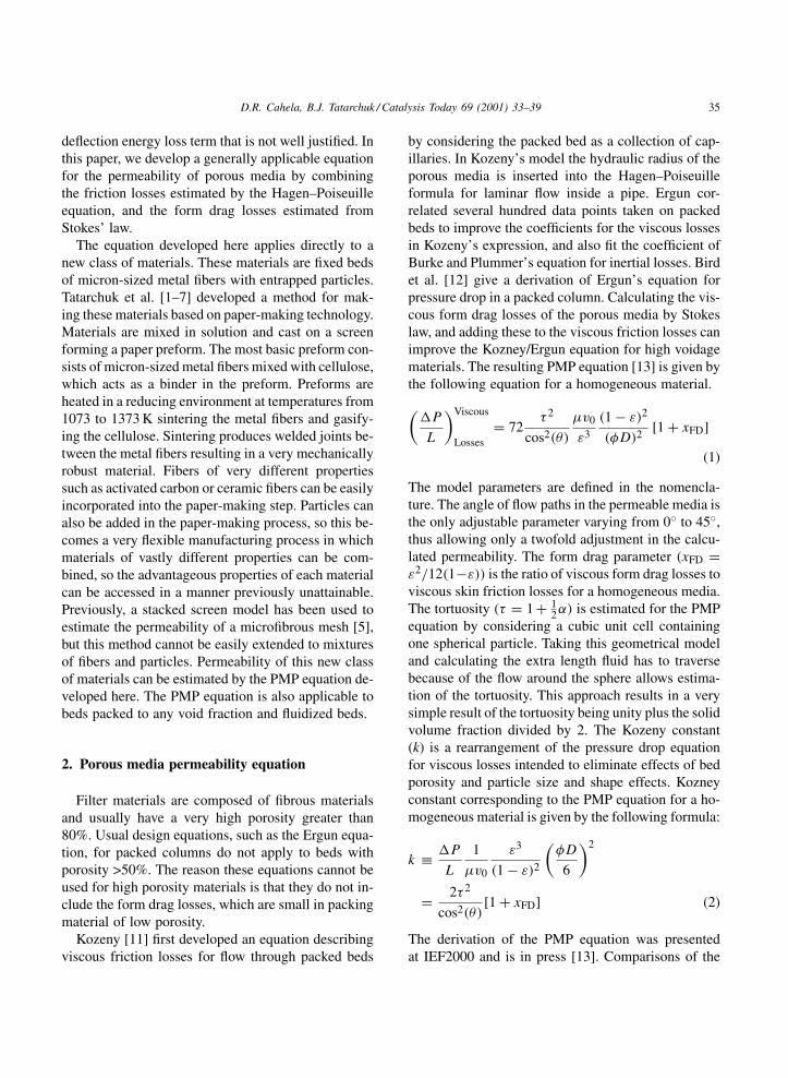
D.R. Cahela, B.J. Tatarchuk / Catalysis Today 69 (2001) 33–39 35
deflection energy loss term that is not well justified. Inthis paper, we develop a generally applicable equationfor the permeability of porous media by combiningthe friction losses estimated by the Hagen–Poiseuilleequation, and the form drag losses estimated fromStokes’ law.
The equation developed here applies directly to anew class of materials. These materials are fixed bedsof micron-sized metal fibers with entrapped particles.Tatarchuk et al. [1–7] developed a method for mak-ing these materials based on paper-making technology.Materials are mixed in solution and cast on a screenforming a paper preform. The most basic preform con-sists of micron-sized metal fibers mixed with cellulose,which acts as a binder in the preform. Preforms areheated in a reducing environment at temperatures from1073 to 1373 K sintering the metal fibers and gasify-ing the cellulose. Sintering produces welded joints be-tween the metal fibers resulting in a very mechanicallyrobust material. Fibers of very different propertiessuch as activated carbon or ceramic fibers can be easilyincorporated into the paper-making step. Particles canalso be added in the paper-making process, so this be-comes a very flexible manufacturing process in whichmaterials of vastly different properties can be com-bined, so the advantageous properties of each materialcan be accessed in a manner previously unattainable.Previously, a stacked screen model has been used toestimate the permeability of a microfibrous mesh [5],but this method cannot be easily extended to mixturesof fibers and particles. Permeability of this new classof materials can be estimated by the PMP equation de-veloped here. The PMP equation is also applicable tobeds packed to any void fraction and fluidized beds.
2. Porous media permeability equation
Filter materials are composed of fibrous materialsand usually have a very high porosity greater than80%. Usual design equations, such as the Ergun equa-tion, for packed columns do not apply to beds withporosity >50%. The reason these equations cannot beused for high porosity materials is that they do not in-clude the form drag losses, which are small in packingmaterial of low porosity.
Kozeny [11] first developed an equation describingviscous friction losses for flow through packed beds
by considering the packed bed as a collection of cap-illaries. In Kozeny’s model the hydraulic radius of theporous media is inserted into the Hagen–Poiseuilleformula for laminar flow inside a pipe. Ergun cor-related several hundred data points taken on packedbeds to improve the coefficients for the viscous lossesin Kozeny’s expression, and also fit the coefficient ofBurke and Plummer’s equation for inertial losses. Birdet al. [12] give a derivation of Ergun’s equation forpressure drop in a packed column. Calculating the vis-cous form drag losses of the porous media by Stokeslaw, and adding these to the viscous friction losses canimprove the Kozney/Ergun equation for high voidagematerials. The resulting PMP equation [13] is given bythe following equation for a homogeneous material.
(�P
L
)Viscous
Losses= 72
τ 2
cos2(θ)
µv0
ε3
(1 − ε)2
(φD)2 [1 + xFD]
(1)
The model parameters are defined in the nomencla-ture. The angle of flow paths in the permeable media isthe only adjustable parameter varying from 0◦ to 45◦,thus allowing only a twofold adjustment in the calcu-lated permeability. The form drag parameter (xFD =ε2/12(1−ε)) is the ratio of viscous form drag losses toviscous skin friction losses for a homogeneous media.The tortuosity (τ = 1 + 1
2α) is estimated for the PMPequation by considering a cubic unit cell containingone spherical particle. Taking this geometrical modeland calculating the extra length fluid has to traversebecause of the flow around the sphere allows estima-tion of the tortuosity. This approach results in a verysimple result of the tortuosity being unity plus the solidvolume fraction divided by 2. The Kozeny constant(k) is a rearrangement of the pressure drop equationfor viscous losses intended to eliminate effects of bedporosity and particle size and shape effects. Kozneyconstant corresponding to the PMP equation for a ho-mogeneous material is given by the following formula:
k ≡ �P
L
1
µv0
ε3
(1 − ε)2
(φD
6
)2
= 2τ 2
cos2(θ)[1 + xFD] (2)
The derivation of the PMP equation was presentedat IEF2000 and is in press [13]. Comparisons of the
36 D.R. Cahela, B.J. Tatarchuk / Catalysis Today 69 (2001) 33–39
PMP equation to literature data taken on textile fibersby Lord [14] and also data tabulated by Jackson andJames [15] was also given in the previous publica-tion. Excellent agreement of the PMP equation withthe literature data was shown. The data from Jacksonet al. extended the range of solid fraction covereddown to 3.45×10⁻⁴ or a form drag parameter of 240,covering three and one-half decades of the form dragparameter. Data for permeability from the highestsolid fractions, similar to packed beds, to the lowestsolid fractions follow the trend of the PMP equation.
The inertial friction and form drag losses can beestimated by friction factor correlations for turbulentflow as in the derivation of Ergun’s equation. Inertialform drag losses can be estimated similarly by a fric-tion factor correlation for a sphere in turbulent flow.The coefficient of form drag is the coefficient of dragminus the coefficient of friction. The drag coefficientfor a sphere in turbulent flow is approximately 0.6. Thetotal pressure loss is given by the following equation:
�P
T= 72
τ 2
cos2(θ)
µv0
ε3
(1 − ε
φD
)2
(1 + xFD)
+6τ 3
cos3(θ)
ρv20
2ε3
(1 − ε)
φD
(Cf + CFD
4ε
)(3)
The PMP equation can be generalized to mixtures ofany shape by determining the hydraulic radius of themixture and summing the viscous form drag lossesover all of the solid shapes in the composite material.The total pressure drop for a mixture of solid parti-cles or fibers of any shape is given by the followingequation:
�P
T= 72
τ 2
cos2(θ)
µv0(1 − ε)2
ε3
×[(∑ xi
φiDi
)2
+ xFD
∑ xi
(φiDi)2
]
+6τ 3
cos3(θ)
ρv20
2
(1 − ε)
ε3
×[Cf + CFD
ε
4
] ∑ xi
φiDi
(4)
Parameter values corresponding to the Ergun equationcan be found by equating the Ergun equation and themodified Ergun (M-E) equation to the one developedhere. Macdonald et al. [9] fitted a very large amount
of data to the M-E and determined best values of theconstants in the M-E equation. Values of angle of flowpath and coefficient of friction for the PMP equationto equal the M-E at an average bed voidage of 45%are flow path angle of 35◦ and coefficient of frictionof 0.20–0.54.
3. Pressure drop for meshes of sintered compositemeshes of metal fibers and particles
3.1. Experimental methods
Nickel fibers of 2, 4, 8 and 12 �m from Micrometalswere formed into preforms by standard paper-makingmethods using 12 g of metal and 3 g of cellulose ina 1 ft2 preform. Preparation of these types of materi-als has been presented previously [1–7]. Rectangularpieces 2.5 cm × 7.0 cm were sintered at 1223 K with300 cm3 H2/min for 1 h, oxidized with 50% air/heliummixture at 773 K for 1 h, and resintered at 1223 Kfor 1 h. The oxidation step removes all traces of py-rolyzed cellulose from the metal meshes. The nickelmeshes typically have a voidage of about 95% aftersintering. Twelve three-quarter inch circles were cutout of each of the sintered meshes. These were com-pressed by various amounts to obtain 10–12 sampleswith solid volume fractions corresponding to a spreadof form drag parameters on the x-axis of the Kozenyconstant plots. An SEM image of a sintered mesh of4 �m nickel fibers is shown in Fig. 2.
Pressure drop through each of the samples wasmeasured using a sample cell consisting of a 3
4 in.
Fig. 2. SEM of mesh of 4 �m nickel fibers.
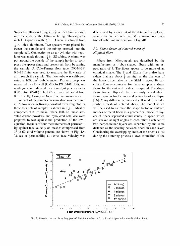
D.R. Cahela, B.J. Tatarchuk / Catalysis Today 69 (2001) 33–39 37
Swagelok Ultratorr fitting with 34 in. SS tubing inserted
into the ends of the Ultratorr fitting. Three-quarterinch OD spacers with 5
8 in. ID were machined from18 in. thick aluminum. Two spacers were placed be-tween the sample and the tubing inserted into thesample cell. Connection to an air cylinder with regu-lator was made through 1
4 in. SS tubing. A clamp wasput around the outside of the sample holder to com-press the spacer rings and prevent air from bypassingthe sample. A Cole-Parmer flow tube (NO34-39)0.5–15 l/min, was used to measure the flow rate ofair through the sample. The flow tube was calibratedusing a 1000 cm3 bubble meter. Pressure drop wasmeasured by a DP cell (OMEGA PX154-010DI), andreadings were indicated by a four digit process meter(OMEGA DP24E). The DP cell was calibrated from0 to 1 in. H2O using a Dwyer inclined manometer.
For each of the samples pressure drop was measuredat 15 flow rates. A Kozney constant form drag plot forthese four sets of samples is shown in Fig. 3. Meshescomposed of 8 �m nickel fibers, 100–120 mesh acti-vated carbon powders, and pyrolyzed cellulose wereprepared to test against the prediction of the PMPequation. Results of four measurements of permeabil-ity against face velocity on meshes compressed from33 to 69 solid volume percent are shown in Fig. 4A.Values of permeability at 1 cm/s face velocity was
Fig. 3. Kozney constant form drag plot of data for meshes of 2, 4, 8 and 12 �m micrometals nickel fibers.
determined by a curve fit of the data, and are plottedagainst the prediction of the PMP equation as a func-tion of solid volume fraction in Fig. 4B.
3.2. Shape factor of sintered mesh ofelliptical fibers
Fibers from Micrometals are described by themanufacturer as ribbon-shaped fibers with an as-pect ratio of 3. The fibers appear to be more of anelliptical shape. The 8 and 12 �m fibers also haveridges that are about 1
8 as high as the diameter ofthe fibers discernable in the SEM images. To cal-culate Kozeny constants for these samples a shapefactor for the sintered meshes is required. The shapefactor for an elliptical fiber can easily be calculatedfrom formulas for the area and perimeter of an ellipse[16]. Many different geometrical cell models can de-scribe a mesh of sintered fibers. The model whichwill be used to estimate the shape factor of sinteredmeshes of metal fibers is a geometrical model of lay-ers of fibers separated equidistantly in space whichare stacked at right angles to each other. Each set oftwo perpendicular layers are separated by the samedistance as the spacing between fibers in each layer.Considering the overlapping areas of the fibers as lostduring the sintering process allows estimation of the
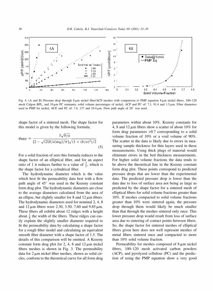
38 D.R. Cahela, B.J. Tatarchuk / Catalysis Today 69 (2001) 33–39
Fig. 4. (A and B) Pressure drop through 8 �m nickel fiber/ACP meshes with comparison to PMP equation 8 �m nickel fibers, 100–120mesh Calgon BPL, and 10 �m PC remnants; solid volume percentages of nickel, ACP and PC of: 7.1, 91.4 and 1.5 �m. Fiber diametersused in PMP for nickel, ACP, and PC of: 7.6, 137 and 10.4 �m. Flow path angle of 20◦ was used.
shape factor of a sintered mesh. The shape factor forthis model is given by the following formula:
φMEF = 3√
b/a
[2 − √(2(b/a)αM)/π ]
√(1 + (b/a)2)/2
(5)
For a solid fraction of zero this formula reduces to theshape factor of an elliptical fiber, and for an aspectratio of 1 it reduces further to a value of 3
2 , which isthe shape factor for a cylindrical fiber.
The hydrodynamic diameter which is the valuewhich best fit the permeability data best with a flowpath angle of 45◦ was used in the Kozeny constantform drag plot. The hydrodynamic diameters are closeto the average diameters calculated from the area ofan ellipse, but slightly smaller for 8 and 12 �m fibers.The hydrodynamic diameters used for nominal 2, 4, 8and 12 �m fibers were 2.30, 3.50, 7.60 and 9.85 �m.These fibers all exhibit about 12 ridges with a heightabout 1
8 the width of the fibers. These ridges can eas-ily explain the slightly smaller diameter required tofit the permeability data by calculating a shape factorfor a rough fiber model and calculating an equivalentsmooth fiber diameter with a shape factor of 1.5. Thedetails of this comparison will be omitted. A Kozenyconstant form drag plot for 2, 4, 8 and 12 �m nickelfibers meshes is shown in Fig. 3. The permeabilitydata for 2 �m nickel fiber meshes, shown as solid cir-cles, conform to the theoretical curve for all form drag
parameters within about 10%. Kozeny constants for4, 8 and 12 �m fibers show a scatter of about 10% forform drag parameters >0.7 corresponding to a solidvolume fraction of 10% or a void volume of 90%.The scatter in the data is likely due to errors in mea-suring sample thickness for thin layers used in thesemeasurements. Using thick plugs of material wouldeliminate errors in the bed thickness measurements.For higher solid volume fractions the data tends tobe above the theoretical line in the Kozeny constantform drag plot. These points correspond to predictedpressure drops that are lower than the experimentaldata. The predicted pressure drop is lower than thedata due to loss of surface area not being as large aspredicted by the shape factor for a sintered mesh ofelliptical fibers for solid volume fractions greater than10%. If meshes compacted to solid volume fractionsgreater than 10% were sintered again, the pressuredrop through them would likely be much smallerthan that through the meshes sintered only once. Thislower pressure drop would result from loss of surfacearea due to sintering of contact points between fibers.So, the shape factor for sintered meshes of ellipticalfibers given here does not well represent meshes ofmetal fibers sintered once and compacted to morethan 10% solid volume fraction.
Permeability for meshes composed of 8 �m nickelfibers, 100–120 mesh activated carbon powders(ACP), and pyrolyzed cellulose (PC) and the predic-tion of using the PMP equation show a very good
D.R. Cahela, B.J. Tatarchuk / Catalysis Today 69 (2001) 33–39 39
agreement in Fig. 4 for the four samples measured.The shape factor for a sintered metal mesh was usedfor the nickel fibers in the composite meshes basedon the solid volume fraction of the nickel component.Shape factors for the ACP and PC were consideredas constant at 0.72 and 1.5. A flow path angle of 20◦was used in the prediction by the PMP equation forthe composite meshes.
4. Optimization of adsorbent material usingthe PMP equation
Previously there has not been a modeling toolavailable to calculate pressure drop through mix-tures of fibers and particles, so an optimization ofan adsorbent material for adsorption properties andpressure drop had to be done solely by experimen-tation. Combining this model with a prediction ofthe concentration breakthrough allows for predictionof the optimum size of the adsorbent particles. Theadsorption rate constant for a mass transfer limitedadsorption is inversely proportional to the square ofthe particle diameter, and the pressure drop is pro-portional to the square of the particle diameter. Lowpressure drop and high adsorption rate are desired. Anoptimum particle size which gives minimum pressuredrop and minimum amount of adsorbent for a requiredadsorption capacity can be determined given a break-through concentration model such as the Bed DepthService Time equation first derived by Bohart andAdams [17].
5. Summary
A model equation that predicts PMP over the entirerange of possible bed voidages has been extended topredict properties of sintered metal meshes. A cor-relation of data for sintered meshes of nickel fibershas been presented in the form of a Kozeny formdrag plot. Comparison of the PMP equation with data
from a composite fiber/particle mesh has also beenpresented. Use of this model for optimization of ad-sorbent meshes was briefly discussed.
Acknowledgements
The authors gratefully acknowledge the financialsupport of ONR and DARPA through contract ONRN000014-00-10282.
References
[1] B.J. Tatarchuk, M.R. Rose, A. Krishnagopalan, J.N. Zabasajja,D. Kohler, US Patent 5 080 963.
[2] B.J. Tatarchuk, US Patent 5 096 663.[3] B.J. Tatarchuk, M.F. Rose, A. Krishnagopalan, US Patent
5 102 745.[4] B.J. Tatarchuk, M.F. Rose, G.A. Krishnagopalan, J.N.
Zabasajja, D.A. Kohler, US Patent 5 304 330.[5] M.W. Meffert, Preparation and characterization of sintered
metal microfiber-based composite materials for heterogeneouscatalyst applications, Ph.D. Thesis, Auburn University,Auburn, AL, 1998.
[6] C.J. Marrion, D.R. Cahela, S. Ahn, B.J. Tatarchuk, J. PowerSources 47 (1994) 297–302.
[7] D. Kohler, J. Zabasajja, A. Krishnagopalan, B. Tatarchuk, J.Electrochem. Soc. 137 (1990) 136.
[8] F.A.L. Dullien, Porous Media: Fluid Transport and PoreStructure, Academic Press, New York, 1992.
[9] I.F. Macdonald, M.S. El-Sayed, K. Mow, F.A.L. Dullien, Ind.Eng. Chem. Fund. 18 (1979) 199.
[10] C.P. Kyan, D.T. Watson, R.C. Kinter, Ind. Eng. Chem. Fund.9 (1970) 596.
[11] I.J. Kozeny, Wasserkraft und Wasserwerischaft 1 (1931) 67.[12] R.B. Bird, W.E. Stewart, E.N. Lightfoot, Transport
Phenomena, Wiley, New York, 1960, pp. 196–200.[13] D.K. Harris, D.R. Cahela, B.J. Tatarchuk, Wet layup and
sintering of metal-containing microfibrous composites forchemical processing opportunities, IEF2000, Italy, May 2000and JCOMA 2001, in press.
[14] E. Lord, J. Text. Inst. 46 (1955) T191.[15] G.W. Jackson, D.F. James, Can. J. Chem. Eng. 64 (1986) 364.[16] W.H. Beyer, S.M. Selby (Eds.), Standard Mathematical
Tables, 24th Edition, CRC Press, Boca Raton, FL, 1976.[17] G.S. Bohart, E.Q. Adams, J. Am. Chem. Soc. 42 (1920)
523–544.
Related Documents