PROCESS DESIGN OF EQUIPMENTS 5.1 DESIGN OF DISTILLATION COLUMN Process design of distillation column for the separation of Monoethanolamine and Water is given as below. Feed entering the column consist of amine mixture and water. Boiling points of the compounds entering the column at operating pressure i.e. 1atmosphere are: Monoethanolamine 172.2 o C Diethanolamine 270 o C Triethanolamine 360 o C Water 100 o C Hence the boiling temperature difference between water and DEA,TEA is very large, so it is assumed that the DEA and TEA entering the tower directly go into the residue without vaporization. Hence the separation is done between MEA and water. Hence feed entering is taken as only water and MEA. Terminology: Some of the terms used in the following calculation are defined here as follows: F = Flow rate of Feed, Kg/day. D = Molar flow rate of Distillate, Kg/day. W = Molar flow rate of Residue, Kg/day. x F = mole fraction of water in feed. y D = mole fraction of Water in Distillate. x W = mole fraction of Water in Residue. M F = Average Molecular weight of Feed, Kg/kmol M D = Average Molecular weight of Distillate, Kg/kmol M W = Average Molecular weight of Residue, Kg/kmol R m = Minimum Reflux ratio R = Actual Reflux ratio L = Molar flow rate of Liquid in the Enriching Section, kmol/day.

Monoethanolamine Design 2520of 2520Equipments
Dec 28, 2015
mea
Welcome message from author
This document is posted to help you gain knowledge. Please leave a comment to let me know what you think about it! Share it to your friends and learn new things together.
Transcript

PROCESS DESIGN OF EQUIPMENTS
5.1 DESIGN OF DISTILLATION COLUMN
Process design of distillation column for the separation of Monoethanolamine and
Water is given as below. Feed entering the column consist of amine mixture and water.
Boiling points of the compounds entering the column at operating pressure i.e.
1atmosphere are:
Monoethanolamine 172.2oC
Diethanolamine 270oC
Triethanolamine 360oC
Water 100oC
Hence the boiling temperature difference between water and DEA,TEA is very large, so it is assumed that the DEA and TEA entering the tower directly go into the residue without vaporization. Hence the separation is done between MEA and water. Hence feed entering is taken as only water and MEA. Terminology:
Some of the terms used in the following calculation are defined here as follows:
F = Flow rate of Feed, Kg/day.
D = Molar flow rate of Distillate, Kg/day.
W = Molar flow rate of Residue, Kg/day.
xF = mole fraction of water in feed.
yD = mole fraction of Water in Distillate.
xW = mole fraction of Water in Residue.
MF = Average Molecular weight of Feed, Kg/kmol
MD = Average Molecular weight of Distillate, Kg/kmol
MW = Average Molecular weight of Residue, Kg/kmol
Rm = Minimum Reflux ratio
R = Actual Reflux ratio
L = Molar flow rate of Liquid in the Enriching Section, kmol/day.

G = Molar flow rate of Vapor in the Enriching Section, kmol/day.
L = Molar flow rate of Liquid in Stripping Section, kmol/day.
G = Molar flow rate of Vapor in Stripping section, kmol/day.
q = Thermal condition of Feed
ρL = Density of Liquid, kg/m3.
ρV = Density of Vapor, kg/m3.
qL = Volumetric flow rate of Liquid, m3/s
qV = Volumetric flow rate of Vapor, m3/s
µL = Viscosity of Liquid, cP.
TL = Temperature of Liquid, K.
TV = Temperature of Vapor, K.
5.11 PRELIMINARY CALCULATIONS:
Basis: One-day operation.
F = 349500.0 Kg/day xF = 0.57 (wt%) = 0.82 (mol%)
D = 197480 Kg/day xD = 0.99 (wt%) = 0.997 (mol%)
W = 152020.0 Kg/day xW = 0.0262 (wt%) = 0.084 (mol%)
Here the liquid entering the tower is coming from the of ammonia flash, it is
assumed that vapor and liquid leaving are in equilibrium. Hence the feed entering is
saturated. From T,x,y diagram:
ToC 100 105 110 115 120 125 130 135 140 145 155 165 170
x,wt% 0.0 0.35 0.5 0.6 0.68 0.74 0.78 0.825 0.86 0.88 0.93 0.97 1.0
y,wt% 0.0 0.025 0.05 0.075 0.125 0.18 0.25 0.32 0.4 0.475 0.70 0.90 1.0
From the graph: intercept of enriching section operating line for minimum reflux is
obtained from the graph, is given by:
xD / (Rm+1) = 0.925
Rm+1= xD/ 0.925 = 0.99/ 0.925

Rm = 0.0656
Let R = 1.5×Rm
Therefore, R= 1.5×0.0656 = 0.1
Number of Ideal trays = 6 (excluding the reboiler).
Number of Ideal trays in Enriching Section = 3
Number of Ideal trays in Stripping Section = 3
Now, we know that,
R = Lo/ D
=> Lo = R×D
i.e., Lo= 19748.0 Kg/day
i.e., Lo =1089 kmol/day
Since feed is Liquid, entering at bubble point i.e. saturated liquid.
Hence q= (HV-HF) / (HV-HL) = 1
We know that slope of q-line = q/ (q-1) = �
Hence q line is vertical. Liquid flow rate in the stripping section is given by
_ L = F × q + L _ i.e., L = 14629.0 kmoles/day
Also, we know that,
_ G = [(q-1) ×F] + G
_ i.e., G = [(1-1) ×F] + G
_ i.e., G = [0×F] +G
_ i.e., G = 0 +G
_ G = G
Now, we know that,

G = L + D
i.e., G = Lo +D
i.e., G = 1089+ 10893.7 kmol/day
i.e., G = 11982.7 kmol/day.
Since the liquid entering the tower is saturated gas flow rate in both the section is same. Hence the flow rate in the stripping section is: _ G = G = 11982.7 kmol/day
Parameters at the top and at the bottom of the enriching as well as stripping section.
PROPERTY ENRICHING SECTION STRIPPING SECTION
TOP BOTTOM TOP BOTTOM
Liquid,L kg/day 19742.7 27174 420876.0 840601.0
Vapor,G kg/day 217055.9 246455.6 254192.4 687966.0
Liquid, L
kmol/day
1089.0 1089.0 14629.0 14629.0
Vapor, G
kmol/day
11982.0 11982.7 11982.7 11982.7
x (mol%) 0.997 0.8386 0.75 0.084
y (mol%) 0.997 0.98 0.925 0.084
Mavg.liquid kg/kmol 18.13 24.9 28.76 57.46
Mavg.Vapor kg/kmol 18.11 20.56 21.21 57.41
'HQVLW\� !l kg/m3 956.97 979.8 987.8 1014.15
'HQVLW\� !g kg/m3 0.58 0.64 0.637 1.565
T liquid, 0C 100 106 112 163
T vapor, 0C 102 112 127 168
σ dynes/cm 26.059 26.059 26.059 26.14
�/�*� �!g � !l)0.5 0.00223 0.00281 0.042 0.0479
5.12 DESIGN OF ENRICHING SECTION
Tray Hydraulics

Sieve tray column is designed for the separation of the MEA and water.
1. Plate Spacing, (ts) : Range can be selected is 0.15 to 1 m.
Let ts = 500 mm.
2. Hole Diameter, (dh):
Let dh = 5 mm is within the range of 2.5 to 12 mm.
3. Hole Pitch (lp):
Range for the selection of hole pitch is 2.5 to 4 times hole diameter.
Let lp = 3× dh
i.e., lp = 3×5 = 15 mm
4. Tray thickness (tT):
Let tT = 0.6× dh
i.e., tT = 0.6×5 = 3 mm.
5. Ratio of hole area to perforated area (Ah/Ap):
Triangular pitch is selected.
Ratio of hole area to perforated area (Ah/Ap) = ½ (π/4×dh2)/ [(√3/4) ×lp
2]
i.e., (Ah/Ap) = 0.90× (dh/lp)2
i.e., (Ah/Ap) = 0.90× (5/15)2
i.e., (Ah/Ap) = 0.1
6. Plate Diameter (Dc):
The plate diameter is calculated based on the flooding considerations
L/G {ρg/ρl}0.5 = 0.00281 ---------- (maximum value)
(From fig. 18.10 p-18-7 Perry hand book 6th edition )
L/G {ρg/ρl}0.5 = 0.00281 and for a tray spacing of 500 mm.
Flooding parameter, Csb, flood = 0.29 ft/s
From eqn. 18.2, page 18.6, 6th edition Perry hand book
Unf = Csb, flood × (σ / 20) 0.2 [(ρl - ρg) / ρg]0.5

where,
Unf = gas velocity through the net area at flood, m/s (ft/s)
Csb, flood = capacity parameter, m/s (ft/s, as in fig.18.10)
σ = liquid surface tension, mN/m (dyne/cm.)
ρl = liquid density, kg/m3 (lb/ft3)
ρg = gas density, kg/m3 (lb/ft3)
Now, we have,
σ = 26.059 mN/m = 26.059 dyne/cm.
ρl = 979.8 kg/m3.
ρg = 0.64 kg/m3.
Hence
Unf = 0.28× (26.059/20)0.2× [(979.8-0.64)/ 0.64]0.5
i.e., Unf = 11.95 ft/s = 3.58 m/s.
Let
Actual velocity, Un= 0.8×Unf
Un = 2.864 m/s
Volumetric flow rate of Vapor at the bottom of the Enriching Section
= qo = 246455.6 / (3600×24×0.6) = 4.45 m3/s.
Net area available for gas flow (An)
Net area = (Column cross sectional area) - (Downcomer area.)
An = Ac - Ad
Thus,
Net Active area, An = qo/ Un = 4.45/ 2.864 = 1.55 m2.
Let Lw / Dc = 0.75 is in the range of 0.6 to 0.85
Where, Lw = weir length, m
Dc = Column diameter, m
Now,
,c = 2×sin-1(Lw / Dc) = 2×sin-1 (0.75) = 97.180
Column cross sectional area

Ac ����� × Dc2= 0.7854×Dc
2 , m2
Ad = [(π/4) × Dc2 × (θc/3600)] - [(Lw/2) × (Dc/2) ×cos (θc/2)]
i.e., Ad = [0.7854× Dc2 × (97.180/3600)]-[(1/4) × (Lw / Dc) × Dc2 ×
cos(97.180)]
i.e., Ad = (0.2120× Dc2) - (0.1241× Dc
2)
i.e., Ad = 0.088×Dc2, m2
Since An = Ac -Ad
1.55 = (0.7854- 0.088)× Dc2
Therefore Dc2 = 2.22 m2
Dc = 1.49 m
⇒ Lw = 0.75× Dc = 1.1175 m.
Taking , Lw = 1.12 m.
then
Ac = 0.7854×1.492 = 1.743 m2
Ad = 0.0879×Dc2 = 0.088×1.492 = 0.1953 m2
7. Perforated plate area (Ap):
Aa = Ac - (2×Ad)
i.e., Aa = 1.743- (2×0.1953)
Aa = 1.56 m2
We have,
Lw / Dc = 0.75
,c = 97.18 0
. ���0 - ,c
L�H�� . �����0
Area of distribution and calming zone (Acz)
Acz = 2× Lw× (thickness of distribution)
Acz = 2×1.12× (60×10-3) = 0.1344 m2 -------- (which is 7.71% of Ac)
Area of waste peripheral zone (Awz)

Taking thickness as 12 cm.
Awz ^����� × Dc2× (.���� 0)} - ^����� × (Dc -0.12)2× (.���� 0)
i.e., Awz ^����� ×1.492 × (82.82 0/360 0)}
- ^����� × (1.49-0.12)2 × (82.82 0/360 0)}
i.e., Awz = 0.0618 m2 is 3.5 % of Ac. Which is acceptable.
Perforated area
Ap = Ac - (2×Ad) - Acz - Awz
i.e., Ap = 1.743- (2×0.1953) – 0.1344 - 0.0618
Thus, Ap = 1.3708 m2
8. Total Hole Area (Ah):
Ah / Ap = 0.1
Ah = 0.1× Ap
Total hole area
Ah = 0.13708 m2
Now we know that,
Ah = nh × (���� ×dh2
Where nh = number of holes.
nh = (4×Ah�� �� × dh2)
i.e., nh = (4×0.13708)/ (� ×0.0052)
nh = 6980.5
Therefore, Number of holes = 6981
9. Weir Height (hw):
For normal pressure hw lies between 40 and 50 mm.
Let hw = 50 mm.
10. Weeping Check

The static pressure below the tray should be capable of enough to hold the
liquid above the tray so that no liquid fall through the hole.
Head loss through dry hole
hd = k1 + [k2× (ρg/ρl) ×Uh2] --------- (eqn. 18.6, page 18.9, 6th edition Perry)
where hd = head loss across the dry hole
Uh =gas velocity through hole area
k1, k2 are constants
For sieve plates k1 = 0 and
k2 = 50.8 / (Cv)2
where Cv = discharge coefficient, taken from fig. edition 18.14, page 18.9 6th
Perry).
(Ah/Aa) = 0.8075 and ratio of tray thickness to hole diameter
tT/dh = 0.60
For above values of (Ah/Aa) and tT/dh , from fig. edition 18.14, page 18.9 6th Perry.
We get
Cv = 0.74
And hence k2 = 50.8 / 0.742 = 92.76
Volumetric flow rate of Vapor at the top of the Enriching Section
qt = 217055.9/ (3600×24×0.58) = 4.33 m3/s -------- (minimum at top)
Volumetric flow rate of Vapor at the bottom of the Enriching Section
qo = 5762.3938 / (3600×24×0.64) = 4.45 m3/s. ---- (maximum at bottom)
Velocity through the hole area (Uh):
Velocity through the hole area at the top = Uh, top = qt /Ah = 4.33/0.13708
=31.59 m/s
Velocity through the hole area at the bottom= Uh, bottom = qo /Ah
= 4.45/0.13708
= 32.46 m/s
Now,

hd, top = k2 [ρg/ρl] (Uh,top)2
= 92.76×(0.58/956.97) ×31.592
Therefore hd, top = 56.1 mm clear liquid. -------- (minimum at top)
hd, bottom = k2 [ρg/ρl] (Uh, bottom)2
= 92.76×(0.64/979.8) ×32.462
⇒ hd, bottom = 63.84 mm clear liquid ----- (maximum at bottom)
Head Loss Due to Bubble Formation
hσ = 409 [σ / ( ρL×dh) ] …………( eqn. 18.2a, page 18.7, 6th edition Perry)
where σ =surface tension, mN/m (dyne/cm)
dh =Hole diameter, mm
ρl = density of liquid in the bottm section, kg/m3
=979.8 kg/m3
hσ = 409 [ 26.059 / ( 979.8 x 5)]
hσ = 2.17 mm clear liquid
Height of Liquid Crest over Weir:
how = 664×Fw [(q/Lw)2/3]
q = liquid flow rate at top, m3/s
= 2.387×10⁻⁴ m3/s
Thus, q’ = 3.785 gal/min.
Lw = weir length = 1.12 m = 3.674 ft
q’/Lw2.5 = 3.785/ (3.674)2.5 = 0.146
For q’/Lw2.5 = 0.146 and Lw /Dc =0.75
We have from fig.18.16, page 18.11, 6th edition Perry
Fw= correction factor =1.0

Thus, how = 1.0×664× [(2.387×10⁻⁴)/1.12]2/3
how = 2.4 mm
(hd + hσ) = 63.84 + 2.17 = 66.01 mm (Design value)
(hw + how) = 50 + 2.4 = 52.4 mm
The minimum value of (hd + hσ ) required is calculated from a graph given in Perry,
plotted against Ah/Aa.
From fig. 18.11, page 18.7, 6th edition Perry hand book
for Ah/Aa = 0.0875 and (hw + how) =50 +2.4 = 52.4 mm
We get
(hd + hσ)min = 17 mm (Theoretical value)
Design value of sum of head loss through dry hole and loss due to bubble
formation more than the theoretically required value to avoid weeping. Hence is there is
no problem with weeping.
Downflow Flooding: (eqn 18.3, page 18.7, 6th edition Perry)
hdc =hw + how + (hhg /2) + ht+hda ------- (eqn 18.3, page 18.7, 6th edition
Perry)
where,
hw = weir height, mm = 50 mm
hds = static slot seal (weir height minus height of top of slot above plate
floor, height equivalent clear liquid, mm)
how = height of crest over weir, equivalent clear liquid, mm
hhg =hydraulic gradient across the plate, height of equivalent clear liquid, mm
hda= head loss over downcomer apron, mm liquid
ht= total pressure across plate, mm liquid

In the above equation how is calculated at bottom of the section and since the
tower is operating at atmospheric pressure, hhg is very small for sieve plate and hence
neglected.
Calculation of how at bottom conditions of the section:
q = liquid rate at the bottom of the section, m3/s
= 27174/(360×24×979.9) = 3.209×10⁻⁴ m3/s
Thus, q’ = 5.086 gal/min
Lw = weir length = 1.12 m = 3.674 ft.
q’/Lw2.5 = 0.196
For q’/Lw2.5 = 0.196 and Lw /Dc =0.75
From fig.18.16, page 18.11, 6th edition Perry
Fw= correction factor =1.0
how = 1.0×664× [(3.209×10⁻⁴)/1.12]2/3
how = 2.88 mm clear liquid. ----- (maximum at the bottom of section).
Therefore,
hds =hw + how + (hhg /2)
= 52.88 mm.
Now, Fga = Ua ×ρg0.5
Where Fga = gas-phase kinetic energy factor,
Ua = superficial gas velocity, m/s (ft/s),
ρg = gas density, kg/m3 (lb/ft3)
Here Ua is calculated at the bottom of the section.
Thus, Ua = (Gb/ρg)/ Aa = (246455.6/3600×24×0.64) / (1.567) = 2.84 m/s
ρg = 0.64 kg/m3
= 0.0082 lb/ft3
Therefore, Fga = 2.84× (0.0082)0.5
Fga = 0.813
From fig. 18.15, page 18.10 6th edition Perry for Fga = 0.813
Aeration factor = β = 0.58
Relative Froth Density = φt = 0.2

Now hl’= β× hds ---- (eqn. 18.8, page 18.10, 6th edition Perry)
Where, hl’= pressure drop through the aerated mass over and around the disperser,
mm liquid,
⇒ hl’ = 30.67 mm.
ht = hd + hl`
ht = 96.68 mm
Head loss over downcomer apron:
hda = 165.2 {q/ Ada}2 ----- (eqn. 18.19, page 18.10, 6th edition
Perry)
where, hda = head loss under the downcomer apron, as millimeters of liquid,
q = liquid flow rate calculated at the bottom of section, m3/s
and Ada = minimum area of flow under the downcomer apron, m2
Now,
q = 3.209×10⁻⁴ m3/s
Assuming clearance as C= 25mm
hap = hds - C = 52.88-25 = 27.88 mm
Ada = Lw x hap = 1.12×27.88×10-4
= 0.0312m2
Therefore had = 165.2×(3.209×10-4/0.0312)2
had = 0.0175mm
Therefore
hdc = 50+2.88+0.0175+96.68
=149.57 mm
Average froth density is assumed as 0.5. hdc’ = hdc/φdc
= 149.57/0.5
hdc’ = 299.14 mm< 500 mm (tray spacing)

Hence tray spacing given is sufficient, and the design of enriching section is
acceptable.
5.13 DESIGN OF STRIPPING SECTION
Plate hydraulics:
1. tray spacing ts = 500 mm
2.hole diameter dh = 5 mm
3.Hole pitch lp = 15 mm
4.Tray thickness tT = 3 mm
5.Holes arrangement triangular pitch
Column diameter:
L/G {ρg/ρl}0.5 = 0.0479 maximum at the bottom.
(From fig. 18.10 p-18-7 Perry hand book 6th edition )
L/G {ρg/ρl}0.5 = 0.0479 and for a tray spacing of 500 mm.
Flooding parameter, Csb, flood = 0.28 ft/s
From eqn. 18.2, page 18.6, 6th edition Perry hand book
Unf = Csb, flood × (σ / 20) 0.2 [(ρl - ρg) / ρg]0.5
where,
Unf = gas velocity through the net area at flood, m/s (ft/s)
Csb, flood = capacity parameter, m/s (ft/s, as in fig.18.10)
σ = liquid surface tension, mN/m (dyne/cm.)
ρl = liquid density, kg/m3 (lb/ft3)
ρg = gas density, kg/m3 (lb/ft3)
Now, we have,
σ = 26.059 mN/m = 26.059 dyne/cm.
ρl = 1014.15 kg/m3.
ρg = 1.565 kg/m3.
Hence
Unf = 0.28× (26.059/20)0.2× [(1014.15-1.565)/ 1.565]0.5
i.e., Unf = 7.509 ft/s.

Let
Actual velocity, Un= 0.8×Unf
Un = 1.83 m/s
Volumetric flow rate of Vapor at the bottom of the Enriching Section
= qo = 687966 / (3600×24×1.565) = 5.087 m3/s.
Net area available for gas flow (An)
Net area = (Column cross sectional area) - (Downcomer area.)
An = Ac - Ad
Thus,
Net Active area, An = qo/ Un = 5.087/ 1.83 = 2.779 m2.
Let Lw / Dc = 0.75 is in the range of 0.6 to 0.85
Where, Lw = weir length, m
Dc = Column diameter, m
Now,
,c = 2×sin-1(Lw / Dc) = 2×sin-1 (0.75) = 97.180
Column cross sectional area
Ac ����� × Dc2= 0.7854×Dc
2 , m2
Ad = [(π/4) × Dc2 × (θc/3600)] - [(Lw/2) × (Dc/2) ×cos (θc/2)]
i.e., Ad = [0.7854× Dc2 × (97.180/3600)]-[(1/4) × (Lw /Dc)×Dc2× cos(97.180)]
i.e., Ad = (0.2120× Dc2) - (0.1241× Dc
2)
i.e., Ad = 0.088×Dc2, m2
Since An = Ac -Ad
2.779 = (0.7854- 0.088)× Dc2
ThereforeDc2 = 3.987 m2
Dc = 1.99 m
Since Lw / Dc = 0.75,
Lw = 1.49 m.
Then
Ac = 0.7854×1.992 = 3.11 m2

Ad = 0.0879×Dc2 = 0.088×1.992 = 0.331 m2
Aa= Ac -2×Ad = 2.448 m2
7. Perforated plate area (Ap):
We have,
Lw / Dc = 0.75
,c = 97.18 0
. ���0 - ,c
L�H�� . ���0 - 97.18 0
. �����0
Area of distribution and calming zone (Acz)
Acz = 2× Lw× (thickness of distribution)
Thickness is taken as 80 mm
Acz = 2×1.49× (80×10-3) = 0.2388m2 -------- (which is 7.6% of Ac)
Area of waste peripheral zone (Awz)
Taking thickness as 15 cm.
Awz ^����� × Dc2× (.���� 0)} - ^����� × (Dc -0.15)2× (.���� 0)
i.e., Awz = 0.1038 m2 is 3.34 % of Ac. Which is acceptable.
Perforated area
We have,
Ap = Ac - (2×Ad) - Acz - Awz
Ap = 2.1054 m2
8. Total Hole Area (Ah):
Ah / Ap = 0.1
Ah = 0.1× Ap
Total hole area
Ah = 0.21054 m2
Now we know that,

Ah = nh × (���� ×dh2
Where nh = number of holes.
⇒ nh = 10726.11
Therefore, Number of holes = 10726
9. Weir Height (hw):
For normal pressure hw lies between 40 and 50 mm.
Let hw = 50 mm.
10. Weeping Check
The static pressure below the tray should be capable of enough to hold the
liquid above the tray so that no liquid fall through the hole.
Head loss through dry hole
hd = k1 + [k2× (ρg/ρl) ×Uh2] --------- (eqn. 18.6, page 18.9, 6th edition Perry)
where hd = head loss across the dry hole
Uh =gas velocity through hole area
k1, k2 are constants
For sieve plates k1 = 0 and
k2 = 50.8 / (Cv)2
where Cv = discharge coefficient, taken from fig. edition 18.14, page 18.9 6th Perry).
(Ah/Aa) = 0.2105/ 2.448 = 0.085 and ratio of tray thickness to hole diameter
tT/dh = 3/5 = 0.60
For above values of (Ah/Aa) and tT/dh , from fig. edition 18.14, page 18.9 6th Perry.
We get
Cv = 0.74
And hence k2 = 50.8 / 0.742 = 92.76
Volumetric flow rate of Vapor at the top of the stripping Section
qt = 254192.4/ (3600×24×0.637) = 4.618 m3/s -------- (minimum at top)
volumetric floe rate of vapor at the bottom of stripping section

qb=687966.0/(24×3600×1.565) = 5.087
Velocity through the hole area (Uh):
Velocity through the hole area at the top = Uh, top = qt /Ah = 4.618/0.2105
=21.94 m/s
Velocity through the hole area at the bottom= Uh, bottom = qo /Ah
= 5.087/0.2105
= 24.17 m/s
Now,
hd, top = k2 [ρg/ρl] (Uh,top)2
= 95.32×(0.637/987.9) ×21.942
Therefore hd, top = 29.58 mm clear liquid. -------- (minimum at top)
Also
` hd, bottom = k2 [ρg/ρl] (Uh, bottom)2
= 92.76×(1.565/1014.15) ×24.172
⇒ hd, bottom = 85.93 mm clear liquid ----- (maximum at bottom)
Head Loss Due to Bubble Formation
hσ = 409 [σ / ( ρL×dh) ] …………( eqn. 18.2a, page 18.7, 6th edition Perry)
where σ =surface tension, mN/m (dyne/cm)
dh =Hole diameter, mm
ρl = density of liquid in the bottom section, kg/m3
=1014.15 kg/m3
hσ = 409 [ 26.14 / ( 1014.15 x 5)]
hσ = 2.11 mm
Height of Liquid Crest over Weir:
how = 664×Fw [(q/Lw)2/3]
q = liquid flow rate at top, m3/s
= 420876/ (360×24×987.9)

q = 4.93×10⁻³ m3/s
Thus, q’ = 78.16 gal/min.
Lw = weir length = 1.49 m = 4.88 ft
q’/Lw2.5 = 78.16/ (4.88)2.5 = 1.47
For q’/Lw2.5 = 1.47 and Lw /Dc =0.75
We have from fig.18.16, page 18.11, 6th edition Perry
Fw= correction factor =1.01
Thus, how = 1.01×664× [(4.93×10⁻⁴)/1.492]2/3
how = 14.87 mm
(hd + hσ) = 29.58 + 2.11 = 31.69 mm (Design value)
(hw + how) = 50 + 14.87 = 64.87mm
The minimum value of (hd + hσ ) required is calculated from a graph given in Perry,
plotted against Ah/Aa.
From fig. 18.11, page 18.7, 6th edition Perry hand book
for Ah/Aa = 0.085 and (hw + how) =50 +14.87 = 64.87 mm
we get
(hd + hσ)min = 18 mm (Theoretical value) < 31.69 i.e. design value
Design value of sum of head loss through dry hole and loss due to bubble
formation more than the theoretically required value to avoid weeping. Hence is there is
no problem with weeping.
Downflow Flooding: (eqn 18.3, page 18.7, 6th edition Perry)
hdc =hw + how + (hhg /2) + ht+hda ------- (eqn 18.3, page 18.7, 6th editionPerry)
Where,
hw = weir height, mm = 50 mm
hds = static slot seal (weir height minus height of top of slot above plate
floor, height equivalent clear liquid, mm)
how = height of crest over weir, equivalent clear liquid, mm

hhg = hydraulic gradient across the plate, height of equivalent clear liquid, mm.
hda= head loss over downcomer apron, mm liquid
ht= total pressure across plate, mm liquid
In the above equation how is calculated at bottom of the section and since the tower is
operating at atmospheric pressure, hhg is very small for sieve plate and hence neglected.
Calculation of how at bottom conditions of the section:
q = liquid rate at the bottom of the section, m3/s
= 840601.0/(360×24×1014.15) = 9.59×10⁻³ m3/s
Thus, q’ = 158.85 gal/min
Lw = weir length = 1.49 m = 4.88 ft.
q’/Lw2.5 = 158.85/ (4.88)2.5 = 8.648
now for q’/Lw2.5 = 8.647 and Lw /Dc =0.75
we have from fig.18.16, page 18.11, 6th edition Perry
Fw= correction factor =1.07
Thus, how = 1.07×664× [(9.59×10⁻³)/1.49]2/3
⇒ how = 24.58 mm clear liquid. ----- (maximum at the bottom of section).
Therefore, hds =hw + how + (hhg /2) =50 +24.58
= 74.58 mm. since hhg is neglected.
Now, Fga = Ua ×ρg0.5
Where Fga = gas-phase kinetic energy factor,
Ua = superficial gas velocity, m/s (ft/s),
ρg = gas density, kg/m3 (lb/ft3)
Here Ua is calculated at the bottom of the section.
Thus, Ua = (Gb/ρg)/ Aa = (687966/(3600×24×1.565)) / (2.448) = 2.078 m/s
ρg = 1.565 kg/m3 = 0.0201 lb/ft3
Therefore, Fga = 2.078× (0.0201)0.5
Fga = 0.966
From fig. 18.15, page 18.10 6th edition Perry for Fga = 0.966

Aeration factor = β = 0.66
Now hl’= β× hds ---- (eqn. 18.8, page 18.10, 6th edition Perry)
Where, hl’= pressure drop through the aerated mass over and around the disperser,
mm liquid,
⇒ hl’= 0.66× 74.58 = 49.2 mm.
ht = hd + hl`
= 85.93+49.2
ht = 135.13 mm
Head loss over downcomer apron:
hda = 165.2 {q/ Ada}2 ----- (eqn. 18.19, page 18.10, 6th edition Perry)
where, hda = head loss under the downcomer apron, as millimeters of liquid,
q = liquid flow rate calculated at the bottom of section, m3/s
and Ada = minimum area of flow under the downcomer apron, m2
Now,
q = 9.59×10⁻³m3/s
Assuming clearance as C= 25mm
hap = hds - C = 74.58-25 = 49.58 mm
Ada = Lw x hap = 1.49×49.58×10-3
= 0.0738 m2
Therefore had = 165.2×(9.59×10-3/0.0738)2
had = 2.78 mm
Therefore
hdc = 50+24.58+2.78+135.13
=212.49 mm
Average froth density is assumed as 0.5. hdc’ = hdc/φdc
= 212.49/0.5
hdc’ = 424.98 mm< 500 mm (tray spacing)
Hence tray spacing given is sufficient, and the design of stripping section is
acceptable.
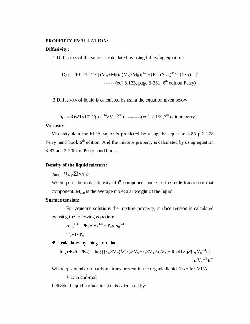
PROPERTY EVALUATION:
Diffusivity:
1.Diffusivity of the vapor is calculated by using following equation:
DAB = 10-3×T1.75× [(MA+MB)/ (MA×MB)]1/2}/{P×[(�YA)1/3+ (�YB)1/3]2
------ (eqn. 3.133, page 3-281, 6th edition Perry)
2.Diffusivity of liquid is calculated by using the equation given below:
D12 = 8.621×10⁻¹⁴/(µ21.14×V1
0.589) --------(eqn. 2.159,7th edition perry)
Viscosity:
Viscosity data for MEA vapor is predicted by using the equation 3.85 p-3-278
Perry hand book 6th edition. And the mixture property is calculated by using equation
3-87 and 3-90from Perry hand book.
Density of the liquid mixture:
ρmix= Mavg/∑(xi/ρI)
Where ρi is the molar density of ith component and xi is the mole fraction of that
component. Mavg is the average molecular weight of the liquid.
Surface tension:
For aqueous solutions the mixture property, surface tension is calculated
by using the following equation:
1mix1/4 �w× 1w
1/4 ��o× 1o
1/4
�o=1-�w
� LV FDOFXODWHG E\ XVLQJ IRUPXODH�
ORJ ��w/(1-�w) = log [(xw×Vw)q×(xw×Vw+xo×Vo)/xoVo]+ 0.441×q×�1oVo2/3/q –
1wVw2/3)/T
Where q is number of carbon atoms present in the organic liquid. Two for MEA.
V is in cm3/mol
Individual liquid surface tension is calculated by:

1i = P×(ρl-ρg) ------- equation (3-151) Perry hand book
Where P is Parachor of component
Average Conditions and Properties:
property Enriching Section Stripping Section
Liquid Flow Rate (L) kmol/day 1089 14629 kg/day 23458.35 630738.5 Vapor Flow Rate (G) kmol/day. 11982.7 11982.7 kg/day. 231755.75 471079.2 Temperature (T) Tavg.,liquid (
0 C) 103 137.5 Tavg., vapor (
0 C) 107 147.5 Viscosity (µ) µavg., liquid (cP) 0.2885 0.528 µavg., vapor (cP) 0.0137 0.0624 'HQVLW\ �!� !avg., liquid (kg/m3) 968.38 1000.98 �avg., vapor (kg/m3) 0.61 1.101 6XUIDFH 7HQVLRQ �1� 1mix (dyne/cm) 26.059 26.09 Diffusivities (D) Liquid Diffusivity, DL cm2/s 1.35×10⁻⁵ 2.21×10⁻⁵
Vapor Diffusivity, DV cm2/s 1.365 1.6 Schmidt number ,Sc ���!×D) Gas NSc, g 0.165 0.354
5.14 EFFICENCY CALCULATION: (AIChE Method)
A) Enriching Section:
Point Efficiency, (Eog):
Eog = 1-e-Nog = 1-exp (-Nog) ----- (eqn. 18.33, page 18.15, 6th edition Perry)
Where Nog = Overall transfer units
Nog = 1/ [(1/Ng� � ���1l)] ---- (eqn. 18.34, page 18.15, 6th edition Perry)
Where Nl = Liquid phase transfer units,
Ng = Gas phase transfer units,

� �P×Gm)/ Lm = Stripping factor,
m = slope of Equilibrium Curve,
Gm = Gas flow rate, mol/s
Lm = Liquid flow rate, mol/s
Ng= (0.776 + (0.00457×hw) - (0.238×Ua×!g0.5) + (104.6×W))/ (NSc, g)
0.5
----- (eqn. 18., page 18., 6th edition Perry)--- *
Where hw = weir height = 50.00 mm
Ua = Gas velocity through active area, m/s
= (Avg. vapor flow rate in kg/day)/ (3600×Avg. vapor density ×active
area)
= 231755.75/ (3600×0.61×24×1.567)
Ua = 2.806 m/s
Df = (Lw + Dc)/2 = (1.12 + 1.49)/2 = 1.305 m
Average Liquid rate = 23458.35 kg/day
Average Liquid Density =968.38 kg/m3
q = 23458.35/ (3600×24×968.38) =2.804 x 10 -4 m3/s
W = Liquid flow rate, m3/ (s.m) of width of flow path on the plate,
= q/Df = 2.804×10⁻⁴/1.305 = 2.148×10⁻⁴ m3/ (s.m)
NSc, g = Schmidt number =µg� �!g×Dg) = 0.165
Number of gas phase transfer units
Ng= (0.776 + (0.00457×50) - (0.238×2.806×0.610.5) + (104.6×2.148×10-4))/ (0.165)0.5
Ng = 1.24
Also,
Number of liquid phase transfer units
Nl = kl× a×θl ----- (eqn 18.36a, page 18.15, 6th edition Perry)
Where kl = Liquid phase transfer coefficient kmol/ (sm2 kmol/m3) or m/s
a = effective interfacial area for mass transfer m2/m3 froth or spray on the plate,
θl = residence time of liquid in the froth or spray, s
θl = (hl×Aa)/ (1000×q) ---- (eqn. 18.38, page 18.16, 6th edition Perry)

now, q = liquid flow rate, m3/s
hl = hl’ = 30.67 mm
Aa = 1.567 m2
kl ×a = (3.875×10⁸×DL)0.5× ((0.40×Ua×!g0.5) + 0.17)
--- (eqn. 18.40a, page 18.16, 6th edition Perry)
DL= liquid phase diffusion coefficient, m2/s
kl ×a = (3.875×108×1.35×10-9)0.5× ((0.40×2.806×0.610.5) + 0.17)
=0.7569 per second
θl = (30.67×1.567)/ (1000×2.8037×10-4)
=171.4
Therefore Nl = 0.7569×171.4 =129.7 m
Slope of equilibrium Curve
mtop = 0.0512
mbottom = 0.192
Gm/Lm = 4.357
λt = mt × Gm/Lm = 0.223
λb = mb×Gm/Lm = 0.836 ⇒ λ = 0.529
Nog = 1/ [(1/Ng� � ��/Nl)]
= 1/ [(1/1.24) + (0.529/129.7)]
Nog = 1.234
Eog = 1-e-Nog = 1-exp (-Nog)
= 1-e-1.234 = 1-0.2912
Eog = 0.71
Murphee stage efficiency:
Ua=2.806 m/s
hl =30.67 mm
DE=6.675×10⁻³× Ua1.44+0.922×10⁻⁴×hl-0.00562 --- (equation 18-45,p-18-17)
= 6.675×10-3× 2.8061.44+0.922×10-4×30.67-0.00562
= 0.0266
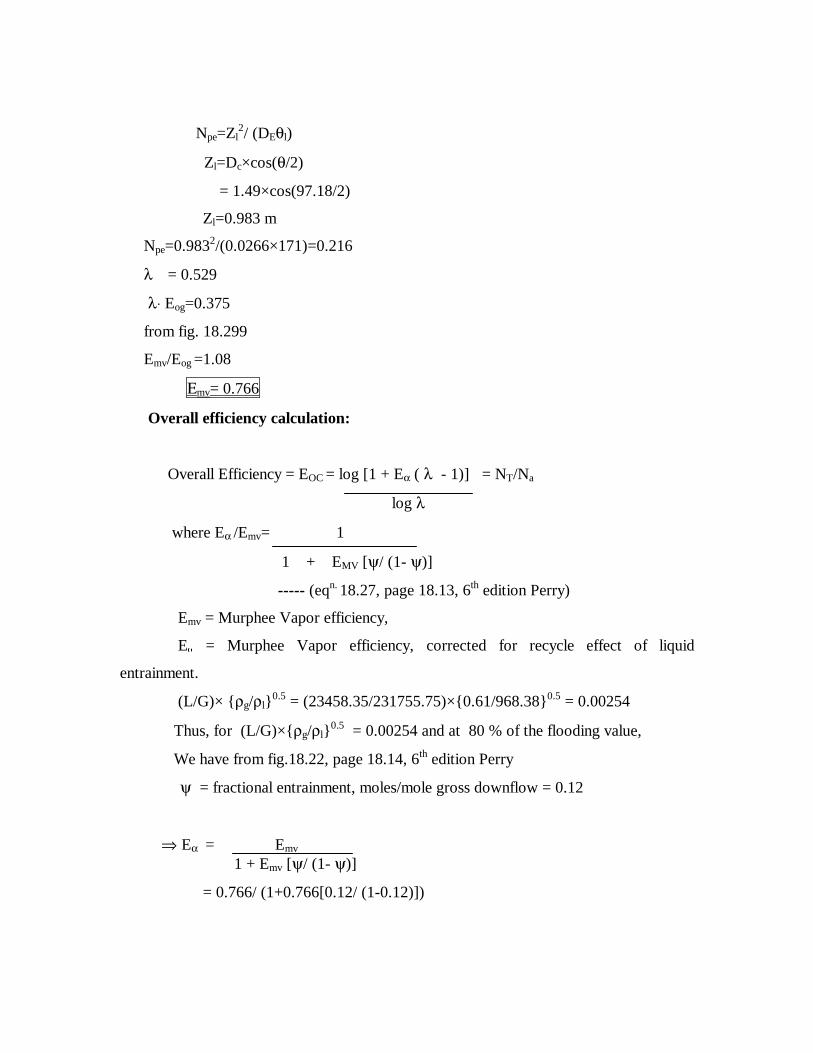
Npe=Zl2/ (DEθl)
Zl=Dc×cos(θ/2)
= 1.49×cos(97.18/2)
Zl=0.983 m
Npe=0.9832/(0.0266×171)=0.216
λ = 0.529
λ⋅ Eog=0.375
from fig. 18.299
Emv/Eog =1.08
Εmv= 0.766
Overall efficiency calculation:
Overall Efficiency = EOC = log [1 + Eα ( λ - 1)] = NT/Na
log λ
where Eα /Emv= 1
1 + EMV [ψ/ (1- ψ)]
----- (eqn. 18.27, page 18.13, 6th edition Perry)
Emv = Murphee Vapor efficiency,
E. = Murphee Vapor efficiency, corrected for recycle effect of liquid
entrainment.
(L/G)× {ρg/ρl}0.5 = (23458.35/231755.75)×{0.61/968.38}0.5 = 0.00254
Thus, for (L/G)×{ρg/ρl}0.5 = 0.00254 and at 80 % of the flooding value,
We have from fig.18.22, page 18.14, 6th edition Perry
ψ = fractional entrainment, moles/mole gross downflow = 0.12
⇒ Eα = Emv 1 + Emv [ψ/ (1- ψ)]
= 0.766/ (1+0.766[0.12/ (1-0.12)])

⇒ Eα = 0.693
Overall Efficiency = EOC = log [1 + Eα ( λ - 1)]
EOC = log [1+ 0.693(0.529-1)]/ log 0.529
Overall Efficiency = EOC = 0.62
Actual trays = Nact = NT/EOC = (ideal trays)/ (overall efficiency)
Where NT = Theoretical plates,
Nact = actual trays
Nact = 3/0.62 = 4.83§ �
Thus, Actual trays in the Enriching Section = 5
Total Height of Enriching section = 5×ts = 5×500 = 2500 mm = 2.5 m
B) Stripping Section:
Point Efficiency, (Eog):
Eog = 1-e-Nog = 1-exp (-Nog)
Nog = 1/ [(1/Ng� � ���Nl)]
Ng= (0.776 + (0.00457×hw) - (0.238×Ua×!g0.5) + (104.6×W))/ (NSc, g)
0.5
Where hw = 50mm
Ua = Gas velocity through active area, m/s
= (Avg. vapor flow rate in kg/day)/ (3600×Avg. vapor density ×active
area)
= 471079.2/ (3600×1.101×24×2.448)
Ua = 2.023 m/s
Df = (Lw + Dc)/2 = (1.49 + 1.99)/2 = 1.74 m
Average Liquid rate = 630738.5 kg/day
Average Liquid Density =1000.97 kg/m3
q =7.29 x 10 -3 m3/s
W = Liquid flow rate, m3/ (s.m) of width of flow path on the plate,
= q/Df = 7.29×10⁻⁴/1.74

= 4.19×10⁻³ m3/ (s.m)
NSc, g = Schmidt number =µg� �!g×Dg) = 0.354
Number of gas phase transfer units
Ng= (0.776 + (0.00457×50) - (0.238×2.023×1.1010.5) + (104.6×4.19×10-4))/ (0.354)0.5
Ng = 1.53
Also,
Number of liquid phase transfer units
Nl = kl× a×θl ----- (eqn 18.36a, page 18.15, 6th edition Perry)
θl = (hl×Aa)/ (1000×q) ---- (eqn. 18.38, page 18.16, 6th edition Perry)
Now, q = liquid flow rate, m3/s
hl = hl’ = 45.92 mm
Aa = 2.448 m2
kl ×a = (3.875×10⁸×DL)0.5× ((0.40×Ua×!g0.5) + 0.17)
--- (eqn. 18.40a, page 18.16, 6th edition Perry)
DL= liquid phase diffusion coefficient, m2/s
kl ×a = (3.875×108×2.21×10-9)0.5× ((0.40×2.023×1.1010.5) + 0.17)
=0.943 per second
θl = (45.92×2.448)/ (1000×7.2×10-3)
=15.6
Therefore Nl = 0.943×15.6 =14.54 m
Slope of equilibrium Curve
mtop = 1.42
mbottom = 3.33
Gm/Lm = 0.6
λt = mt × Gm/Lm = 0.852
λb = mb×Gm/Lm = 2.0 ⇒ λ = 1.43
Nog = 1/ [(1/Ng� � ���1l)]

= 1/ [(1/1.53) + (1.43/14.54)]
Nog = 1.272
Eog = 1-e-Nog = 1-exp (-Nog)
= 1-e-1.272
Eog = 0.719
Murphee stage efficiency(Mv):
Ua=2.023 m/s
hl =45.92 mm
DE=6.675×10⁻³× Ua1.44+0.922×10⁻⁴×hl-0.00562 --- (equation 18-45,p-18-17)
= 6.675×10-3× 2.0231.44+0.922×10-4×45.92-0.00562
= 0.017
Npe=Zl2/ (DEθl)
Zl=Dc×cos(θ/2)
= 1.99×cos(97.18/2)
Zl=1.31 m
Npe=1.312/(0.017×15.6)=6.47
λ = 1.43
λ⋅ Eog=1.02
from fig. 18.299
Emv/Eog =1.42
Εmv= 1.02
Overall efficiency calculation:
Overall Efficiency = EOC = log [1 + Eα ( λ - 1)] = NT/Na
log λ
Where Eα /Emv= 1
1 + EMV [ψ/ (1- ψ)]
----- (eqn. 18.27, page 18.13, 6th edition Perry)
Emv = Murphee Vapor efficiency,

E.=Murphee Vapor efficiency, corrected for recycle effect of liquid entrainment.
(L/G)× {ρg/ρl}0.5 = (630738.5/471079.2)×{1.101/1014.15}0.5 = 0.044
Thus, for (L/G)×{ρg/ρl}0.5 = 0.044 and at 80 % of the flooding value,
We have from fig.18.22, page 18.14, 6th edition Perry
ψ = fractional entrainment, moles/mole gross downflow = 0.08
⇒ Eα = Emv 1 + Emv [ψ/ (1- ψ)]
= 1.02/ (1+1.02[0.08/ (1-0.08)])
⇒ Eα = 0.936
Overall Efficiency = EOC = log [1 + Eα ( λ - 1)]
EOC = log [1+ 0.936(1.43-1)]/ log 1.43
Overall Efficiency = EOC = 0.945
Actual trays = Nact = NT/EOC = (ideal trays)/ (overall efficiency)
Where NT = Theoretical plates,
Nact = actual trays
Nact = 3/0.945 = 3.17§ �
Thus, Actual trays in the Enriching Section = 4
Total Height of Enriching section = 4×ts = 4×500 = 2000 mm = 2.0 m
Total number of trays in the column = 9
Five in the enriching section and four in the stripping section.
Total height of the tower = 4.5 m

5.2 PROCESS DESIGN OF CONDENSER
Vertical condenser is used to condense the water vapor coming at the top of the dehydration tower. Condenser is operated at the same pressure as that of dehydration tower that is one atmosphere. Amount of the vapor to be condensed is 11982.7 kmol/day i.e. 217055.9 kg/ day. Feed entering is at its dew point. Weight fraction of water in the feed is 99% and MEA is 1%. At one atmosphere �(latent heat of vaporisation)for MEA =848.1KJ/Kg. for water =2265.2 KJ/Kg. 5.21 ENERGY BALANCE 1. SHELL SIDE: (VAPOR) Condensed liquid leaving the condenser is at its saturation temperature. Hence the heat load:
QH = qlatent heat
= m�
= 217055.9/(24×3600) ×2251.03
QH = 5650.08 kW.
2. TUBE SIDE: (WATER)
QC = (mw×Cp×û7�
Latent heat of the vapor entering is removed completely i.e. completelly condensed.
Hence QC=QH
=> mw = QH/ (Cp×û7� ����.4126×103)/ (4.187×103× (40-30)) = 134.9 kg/s
Where mw is the cooling water flow rate.
5.22 LMTD calculation:
Considering Counter- Current Operation.
HOT SIDE (VAPOR) COLD SIDE (WATER) TEMPERATURE ',))(5(1&(� û7
102 30 0C 72 0C 102 40 0C 62 0C

û7lm = ((102-30)-(102-40))/ln ((102-30)/ (102-40)) = 66.87 0C
Consider one-one pass exchanger: Routing: Tube side: cooling water Shell side: vapor. Let choose ¾” OD, 20 BWG tube from table 11-2 p-11-8, Outer diameter =19.05 mm Inner diameter = 17.27 mm Let length of tube = 12 ft.= 3.66 m External heat transfer area / ft length = 0.1963 ft2/ft length = 0.0598 m2/m length 50 mm allowance is given for the tube sheet. Hence tube length available for the heat transfer is = 3.61 m Heat transfer area of one tube = 0.0598 × 3.61 = 0.213 m2 Total number of tubes required = 37.199/0.213 =174.65 tubes. For TEMA P or S 1” triangular pitch from table 11-3 p-11-14 Nearest tube count = 208 tubes for that Shell diameter = 438 mm Therefore corrected area = 208×0.213 =44.9 m2 Corrected Ud = 5650.8×103/(66.87×44.9) = 1881.8 W/(m2 K) Fluid velocity: Tube side: Np= 1 Flow area = (π× Di
2/4)×Nt/Np = 0.0488 m2
therefore tube side fluid velocity = mW/(994.03×0.0488) = 134.9/(994.03×0.0488) Vt = 2.78 m/s 5.23 FILM TRANSFER COEFFICIENTS: SHELL SIDE: Fluid is condensing vapor Wall temperature TW=1/2×[Tsat+(30+40)/2] = 1/2[102+35] TW = 68.5oC Film temperature TF = (TW + Tsat )/2

= 85.25 oC Properties of vapor are taken at 86oC and it is assumed that amount of MEA present is negligible. ρl=967.97Kg/m3 Cp=4.39KJ/Kg K k=0.679 W/mK µ=0.33cP Reynolds number: NRe =4Γ/µ=4/µ ×W/(Nt2/3 L) = 4×2.512/(0.33×10-3×3.61×2082/3) NRe = 240.26 We have ho= 1.51× (k3×ρ2×g/µ2)1/3×NRe
-1/3 = 1.51 × (0.6793×967.972×9.81/(0.33×10-3)2)1/3×240.26-1/3 =7234.48 W/mK TUBE SIDE: Fluid is cooling water: Fluid velocity in the tube Vt = 2.78 m/s At average temperature 35 oC properties of cooling water: ρl=994.032Kg/m3 Cp=4.187KJ/Kg K k=0.578 W/mK µ=0.8cP NRe =ρvD/µ = 59655.09 Npr = µCp/k = 5.79 From Dittus Boitus equation: Nu =0.023× NRe
0.8 × Npr0.3 = hiDi/k
Therefore
hi = 8623.53 W/m2K

5.24 OVERALL HEAT TRANSFER COEFFICIENT: Overall efficiency can be calculated by formulae: 1/Uo=1/ho+1/hi×Do/Di + xw×Ao/(kw×Aw)+ dirt factor Where xw is the thickness of the tube. kw is the thermal conductivity of the material =50 W/m K Dirt factor from table11-3 =8.805×10⁻⁵ 1/Uo = 3.934×10⁻⁴
Uo = 2541.49 W/m2K assumed value of the overall heat transfer coefficient is 1881.8 W/m2K Therefore the design value is more than the assumed value. 5.25 PRESSURE DROP CALCULATIONS: SHELL SIDE: Tvap =102oC µvap = 0.0118 cP as= (ID)×C’×B/PT Where C’ = clearance between tubes= PT -Do B=Baffle spacing PT=25.4 mm By assuming baffle spacing as diameter of the shell pressure drop will be high and is more than the permissible limit. Let Nb+1=3 i.e. number of baffles are taken as two for trial calculation. Therefore B = 1.203 m Then as = 0.1296 m2 De= 4×[PT/2×0.86×PT-0.5×π×D2/4] / ( π×Do/2 ) = 0.0182 m Gs= 2.512/ as
=2.512/0.0182 Gs = 19.38 Kg/m2s Reynolds number: NRe= Gs × De /µvap
=19.38×0.0182/(0.0118×10-3) NRe = 29595.56

f= 1.87×( NRe )
-0.2 = 0.238 ∆Ps=[4f (Nb+1)×Ds× Gs
2×g]×0.5/(2g× De ×ρvap) = 4×0.238×3×0.438×19.382×0.5/(2×0.01802×0.58) = 11238.2 N/m2 ∆Ps = 11.2382 KN/m2<14 KN/m2 Shell side pressure drop is less than the permissible value for the assumed number of baffles. TUBE SIDE: Velocity of liquid water in the tube side= 2.78m/s. Properties at the average temperature 35 oC : ρl=994.032Kg/m3 Cp=4.187KJ/Kg K k=0.578 W/mK µ=0.8cP Reynolds number: NRe =ρvD/µ = 59655.09 Friction factor(f): f= 0.079×( NRe )
-0.25 = 5.054×10⁻⁴ Pressure drop through the length:
∆Pl = 4fLV2 ×ρl×g/(2gD) = 2f×LGt
2/(ρl×Di) = 4×5.54×10-4 ×3.66×2763.42/(994.03×0.01727)
∆Pl = 1645.66N/m2 Pressure drop: ∆PR =2.5× Gt
2 /(2ρ) = 9602.8 N/m2 Total pressure drop = (∆Pl +∆PR ) ∆PT = 11248.48 N/m2 <70000 N/m2 Pressure drop on both sides of the condenser are under the permissible limit. Hence the design is acceptable.

CHAPTER 6
MECHANICAL DESIGN OF EQUIPMENTS
6.1 MECHANICAL DESIGN OF DISTILLATION COLUMN
a) SHELL:
Diameter (Di ) 1.99 m
Working/Operating Pressure 1.0329 kg/cm2
Design pressure = 1.1×Operating Pressure 1.1×1.0329 = 1.1362 kg/cm2
Working temperature 441 0K
Design temperature 457.8 0K
Shell material - IS: 2002-1962 Grade I Plain Carbon steel
Permissible tensile stress (ft) 950 kg/cm2
Elastic Modulus (E) 1.88×10⁵ MN/m2
Insulation material - asbestos
Insulation thickness 2”= 50.8 mm
Density of insulation 575 kg/m3
Top disengaging space 0.3 m
Bottom separator space 0.4 m
Weir height 50 mm
Downcomer clearance 25 mm
b) HEAD - TORISPHERICAL DISHED HEAD:
Material - IS: 2002-1962 Grade I Plain Carbon steel
Allowable tensile stress = 950 kg/cm2
c) SUPPORT SKIRT:
Height of support 1 m
Material - Carbon Steel
d) TRAYS-SIEVE TYPE:
Number of trays = 9

Hole Diameter = 5mm
Number of holes:
Enriching section = 6981
Stripping section = 10726
Tray spacing:
Enriching section: 500 mm
Stripping section: 500 mm
Thickness = 3 mm
e) SUPPORT FOR TRAY:
Purlins - Channels and Angles
Material - Carbon Steel
Permissible Stress = 1275 kg/cm2
1. Shell minimum thickness:
Considering the vessel as an internal pressure vessel.
ts = ((P×Di)/ ((2×ft×J)- P)) + C
where ts = thickness of shell, mm
P = design pressure, kg/cm2
Di = diameter of shell, mm
ft = permissible/allowable tensile stress, kg/cm2
C = Corrosion allowance, mm
J = Joint factor
Considering double welded butt joint with backing strip
J= 85% = 0.85
Thus, ts = ((1.1362×1990)/ ((2×950×0.85)- 1.1362)) + 3 = 4.556 mm
Taking the thickness of the shell as minimum specified value= 6 mm
2. Head Design- Shallow dished and Torispherical head:
Thickness of head = th = (P×Rc×W)/ (2×f×J)
P =internal design pressure, kg/cm2
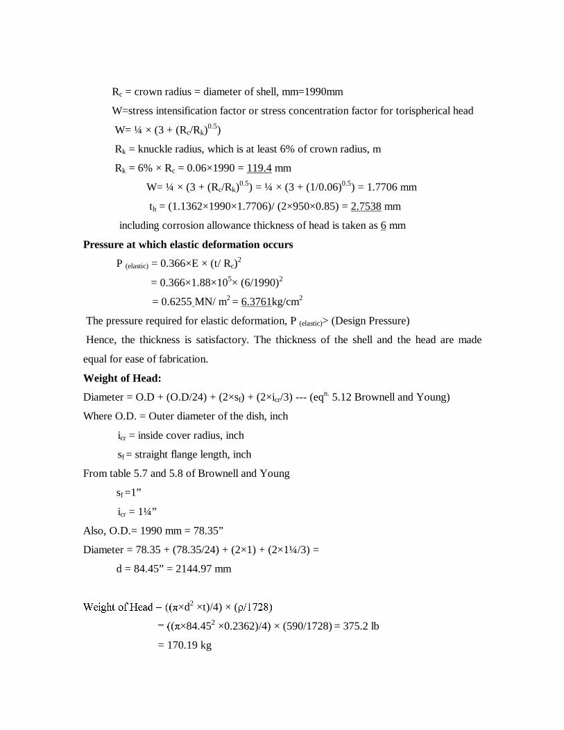
Rc = crown radius = diameter of shell, mm=1990mm
W=stress intensification factor or stress concentration factor for torispherical head
W= ¼ × (3 + (Rc/Rk)0.5)
Rk = knuckle radius, which is at least 6% of crown radius, m
Rk = 6% × Rc = 0.06×1990 = 119.4 mm
W= ¼ × (3 + (Rc/Rk)0.5) = ¼ × (3 + (1/0.06)0.5) = 1.7706 mm
th = (1.1362×1990×1.7706)/ (2×950×0.85) = 2.7538 mm
including corrosion allowance thickness of head is taken as 6 mm
Pressure at which elastic deformation occurs
P (elastic) = 0.366×E × (t/ Rc)2
= 0.366×1.88×105× (6/1990)2
= 0.6255 MN/ m2 = 6.3761kg/cm2
The pressure required for elastic deformation, P (elastic)> (Design Pressure)
Hence, the thickness is satisfactory. The thickness of the shell and the head are made
equal for ease of fabrication.
Weight of Head:
Diameter = O.D + (O.D/24) + (2×sf) + (2×icr/3) --- (eqn. 5.12 Brownell and Young)
Where O.D. = Outer diameter of the dish, inch
icr = inside cover radius, inch
sf = straight flange length, inch
From table 5.7 and 5.8 of Brownell and Young
sf =1”
icr = 1¼”
Also, O.D.= 1990 mm = 78.35”
Diameter = 78.35 + (78.35/24) + (2×1) + (2×1¼/3) =
d = 84.45” = 2144.97 mm
:HLJKW RI +HDG ���×d2 ×t)/4) × (!������
���×84.452 ×0.2362)/4) × (590/1728) = 375.2 lb
= 170.19 kg

3. Shell thickness at different heights
At a distance ‘X’m from the top of the shell the stresses are:
3.1 Axial Tensile Stress due to Pressure:
fap = P×Di_ = 1.1362×1990_ = 188.38 kg/cm2
4(ts -c) 4(6 - 3)
This is the same through out the column height.
3.2 Compressive stress due Dead Loads:
3.2a Compressive stress due to Weight of shell up to a distance ‘X’ meter from top.
fds = weight of shell/cross-section of shell
����� × (Do2- Di
2) ×!s× X/ (���� × (Do2- Di
2)
fds ZHLJKW RI VKHOO SHU XQLW KHLJKW ;� �� ×Dm × (ts- c)
Where Do and Di are external and internal diameter of shell.
!s = density of shell material, kg/m3
Dm = mean diameter of shell,
ts = thickness of shell,
c = corrosion allowance
1RZ� !s = 8500 kg/m3=0.0085kg/cm3
fds !s× x = (0.85×X) kg/cm2
3.2b Compressive stress due to weight of insulation at a height X meter
fd(ins)= π ×Dins× tins× ρins ×X = weight of insulation per unit height X π ×Dm× (ts - c) π×Dm× (ts - c)
where Dins, tins, ρins are diameter, thickness and density of insulation respectively.
Dm = (Dc+ (Dc+2ts))/2
Dins =Dc+2ts+2tins = 199+ (2×0.6) + (2×5.08) = 201.216 cm.
Dm = (199+ (199+ (2×0.6)))/2 = 199.6 cm.
fd(ins) = π ×201.216× 5.08×575×X = 9815.5 ×X kg/m2 π ×199.6× (0.6 - 0.3)
fd(ins) = 0.98155× X kg/cm2

3.2c Stress due to the weight of the liquid and tray in the column up to a height X meter.
fd, liq. = �weight of liquid and tray per unit height X π×Dm× (ts - c)
The top chamber height is 0.3 m and it does not contain any liquid or tray. Tray spacing
is 500 mm.
Average liquid density = 984.67 kg/m3
Liquid and tray weight for X meter
fliq-tray = [(X-0.3)/ 0.5 + 1] × (� ×Di2/4) ×!l
= [(X-0.3)/ 0.5 + 1] × (� ×1.992/4) ×984.67
= [2X + 0.4] × 3062.97 kg
fd (liq) = Fliq-tray ×10/ (π×Dm× (ts - c))
= [2X + 0.4] × 3062.97 ×10/ (π×1996× (6 - 3))
fd (liq) = 3.26X + 0.653 kg/cm2
3.2d Compressive stress due to attachments such as internals, top head, platforms and
ladder up to height X meter.
fd (attch.) = �weight of attachments per unit height X π×Dm× (ts - c)
Now total weight up to height X meter = weight of top head + pipes +ladder, etc.,
Taking the weight of pipes, ladder and platforms as 25 kg/m = 0.25 kg/cm
Total weight up to height X meter = (170.19+25X) kg
fd (attch.) = (170.19+25X) × 10/ π×199× (6 - 3) = 0.907 + 0.133X kg/cm2
Total compressive dead weight stress:
fdx = fds + fins +fd (liq) + fd (attch)
= 0.85X + 0.98155X + [3.26X+0.653] + [0.907 +0.133X]
fdx = 5.225X + 1.559 kg/cm2
4. Tensile stress due to wind load in self supporting vessels:
fwx = Mw /Z
where Mw = bending moment due to wind load = (wind load× distance)/2

= 0.7×Pw×D×X2/2
Z = modulus for the section for the area of shell § �×Dm2× (ts-c)/4
Thus, fwx =1.4×Pw×X2� � ×Dm× (ts-c)
Now Pw = 25 lb/ft2 --- (from table 9.1 Brownell and Young)
= 122.06 kg/m2
Bending moment due to wind load
Mwx = 0.7×122.06×1.99×X2/2 = 170.03 kg-m
fwx= 1.4×122.06×X2� � ×1.99× (6-3) = 3.075X2 kg/cm2
5. Stresses due to Seismic load:
fsx = Msx��×Dm2× (ts-c)/4
Where bending moment Msx at a distance X meter is given by
Msx = [C×W×X2/3] × [(3H-X)/H2] Where C = seismic coefficient,
W= total weight of column, kg
H = height of column
Total weight of column = W= Cv×�×!m×Dm×g× (Hv+ (0.8×Dm))×ts×10-3
----- (eqn. 13.75, page 743, Coulson and Richardson 6th volume)
Where W = total weight of column, excluding the internal fittings like plates, N
Cv = a factor to account for the weight of nozzles, manways, internal
supports, etc.
= 1.5 for distillation column with several manways, and with plate
Support rings or equivalent fittings
Hv = height or length between tangent lines (length of cylindrical section)
g = gravitational acceleration = 9.81 m/s2
t = wall thickness
!m = density of vessel material, kg/m3
Dm = mean diameter of vessel = Di + (t ×10-3)
= 1.99+ (6 ×10⁻³) = 1.996 m
W= 1.5×�×8500×1.996×9.81× (4+ (0.8×1.996))×6×10-3 = 26341.28 N

= 2685.15 kg.
Weight of plates: ------- (Coulson and Richardson 6th volume)
3ODWH DUHD �×1.992/4 – 0.331(is Ad) = 2.18 m2
Weight of each plate = 1.2×2.18 =3.336 kN
Weight of 9 plates = 9×3.336 = 30.02 kN = 3060.55 kg.
Total weight of column = 2685.15 + 3060.55 = 5745.7 kg
Let C = seismic coefficient = 0.08
Msx = [0.08×5745.7×X2/3] × [((3×4.5)-X)/4.52]
= 153.22X2 × [0.66-0.049X] kg-m
fsx = Msx×103��×Dm
2× (ts-c)/4
= 153.22X2 × [0.66-0.049X] ×103���×199.62× (6-3)/4)
= [1.0771X2- 0.07997X3], kg/cm2
On the up wind side:
Total stress acting on the up wind side:
ft,max = (fwx or fsx) + fap -fdx
Since the chances of, stresses due to wind load and seismic load, to occur together is rare
hence it is assumed that the stresses due to wind load and earthquake load will not occur
simultaneously and hence the maximum value of either is therefore accepted and
considered for evaluation of combined stresses.
Thus,
ft,max =0.908X2 + 188.38- [5.225X + 1.559]
i.e., 0.908X2 – 5.225X -1.559+188.38-0.85 ×950 = 0
0.908X2- 5.225X – 578.56 =0
=> X = 28.28 m
On the down side:
Maximum stress acting on the down side is given by the following equation:
fc,max = (fwx or fsx) - fap +fdx

ft,max =0.908X2 - 188.38 + [5.225X + 1.559]
The column height is 4.5 m, for which the maximum value is
ft,max =0.908(4.5)2 - 188.38+ [5.225(4.5) + 1.559]
= -144.92 kg/cm2
This shows that the stress on the down wind side is tensile. Hence further calculation is
done by taking ft,max as allowable stress to find the height up to that column can resist the
maximum stress acting on it. If the height calculated is more than the actual height of the
column, then selected material and hence the design will be acceptable.
ft,max =0.908X2 - 188.38 + [8.852X + 1.559]
Let ft,max = 0.85 × 950 =807.5 kg/cm2
Hence 0.908X2 - 188.38 + [5.225X + 1.559] – 807.5=0
We get X=30.34 m
Actual height of the column is 4.5 m. Therefore the design is acceptable because
of the height up to that it can resist the maximum permissible stress is much more
larger than the actual height of the column.
Hence
Thickness of the shell 6.0 mm
Height of the head 0.4975 m (is Dc/4)
Skirt support height 1 m
Height of the tower 4.5 m
Design of Support:
a) Skirt Support:
The cylindrical shell of the skirt is designed for the combination of stresses due to vessel dead weight, wind load and seismic load. The thickness of skirt is uniform and is designed to withstand maximum values of tensile or compressive stresses.
Data available:
(i) Diameter =1990 mm.
(ii) Height = 4500 mm = 4.5 m

(iii) Weight of vessel, attachment =5745.7 kg.
(iv) Diameter of skirt (straight) = 1990 mm
(v) Height of skirt = 1.0 m
(vi) Wind pressure = 122.06 kg/m2
1. Stresses due to dead Weight:
fd = � :� �� ×Dok× tsk)
fd = stress,
�: GHDG ZHLJKW RI YHVVHO FRQWHQWV DQG DWWDFKPHQWV�
Dok = outside diameter of skirt,
tsk = thickness of skirt,
fd ������� �� ×199.6× tsk) = 91.6/ tsk kg/cm2
2. Stress due to wind load:
pw = k×p1×h1×Do
p1 = wind pressure for the lower part of vessel,
k = coefficient depending on the shape factor
= 0.7 for cylindrical vessel.
Do = outside diameter of vessel,
The bending moment due to wind at the base of the vessel is given by
Mw = pw ×H/2
fwb = Mw/Z = 4 ×Mw���×(Dok)2×tsk
Z- Modulus of section of skirt cross-section
pw = 0.7×122.06×1.0×1.99 = 765.13 kg
Mw = pw ×H/2 = 765.13×4.5/2 = 1721.5 kg-m
Substituting the values we get,
fwb = 8.2/tsk kg/cm2
Stress due to seismic load:
Load = C×W

C = seismic coefficient,
W= total weight of column.
Stress at base, fsb = (2/3) × (C×H×W)/ (� ×(Rok)2 × tsk
C=0.08
fsb = (2/3) × (0.08×450×5745.7)/(� ×(199.6/2)2 × tsk = 6.61/ tsk kg/cm2
Maximum tensile stress:
ft, max = (91.6/ tsk) – (8.2/ tsk) = (83.5/ tsk) kg/cm2
Permissible tensile stress = 925 kg/cm2
Thus, 925 = (83.5/ tsk)
=> tsk = 0.0902 cm = 0.902 mm
Maximum compressive stress:
fc, max = (91.6/ tsk) + (8.1/ tsk) = (99.7/ tsk) kg/cm2
Now,
fc, (permissible) <= (�� \LHOG SRLQW
= 1500/ 3 = 500 kg/cm2
Thus, tsk = 99.7/500 = 0.1994 cm = 1.994 mm
As per IS 2825-1969, minimum corroded skirt thickness = 7 mm
Thus use a thickness of 7 mm for the skirt.
Design of skirt bearing plate:
Assume both circle diameter = skirt diameter + 32.5 =199+ 32.5 = 231.5 cm
Compressive stress between Bearing plate and concrete foundation:
fc = (�:�$� � �0w/Z)
�: GHDG ZHLJKW RI YHVVHO FRQWHQWV DQG DWWDFKPHQWV�
A = area of contact between the bearing plate and foundation,
Z = Section Modulus of area,
Mw = the bending moment due to wind,
fc = (5745.7×4)/(�×(231.52-1992))+(0.7×122.06×3×42.32)/(2×�×(231.54-914)/(32×231.5))
= 0.133 + 0.138
fc = 0.271 kg/cm2

Which is less than the permissible value for concrete.
Maximum bending moment in bearing plate
Stress, f = (6×0.271× 16.252)/ (2 ×tB2) = 214.68/ tB
2
Permissible stress in bending is 1000 kg/cm2
Thus, tB2 = 214.68/1000 => tB = 0.463 cm = 4.63
Therefore a bolted chair has to be used.
Anchor Bolts:
Minimum weight of Vessel = Wmin = 3000 kg. ------ (assumed value)
fc,min = ( Wmin/A) - (Mw/Z)
= [(4×3000)� �� × (231.52 - 1992))] - (0.7× 122.06× 3 ×42.32×/(2× �×(231.54 -
1994)/(32×231.5))
= 0.273 – 0.415 = - 0.142 kg/cm2
Since fc is negative, the vessel skirt must be anchored to the concrete foundation by
anchor bolts.
Pbolts=fc(min)A/n
Assuming there are 20 bolts,
Pbolts = (0.142/20) × ((� × (231.52 -1992))/4) = 78.01 kg
Trays:
The trays are standard sieve plates throughout the column. The plates have 6981
holes in Enriching section and 10726.11 holes in the Stripping section of 5mm diameter
arranged on a 15mm triangular pitch. The trays are supported on purloins.

6.2 MECHANICAL DESIGN OF CONDENSER Fluid in the shell side is water vapor and in the tube side is liquid water. Data available: SHELL SIDE:
Material carbon steel One shell–one tube pass exchanger. Fluid water vapor Working pressure 1 atmosphere Design pressure 0.1114 N/m2
Temperature 102oC Diameter 438 mm Permissible stress for carbon steel is 95 N/mm2 TUBE SIDE: Number of tubes 208 Number of passes one Inside diameter 17.27 mm Outside diameter 19.05 mm Length 12 ft, 3.66 m Triangular pitch 1” Working and operating pressures are same as that of shell side. Fluid on the tube side is water: Inlet temperature 30oC Outlet temperature 40 oC 1. SHELL THICKNESS: ts= PD/(2fJ+P) let J=85% = 0.1114×438/(2×0.85×95+0.1114) = 0.31 Minimum thickness of shell including corrosion resistance is taken as 8 mm 2. HEAD THICKNESS: Shallow dished and torispherical head. th= PRe/2fJ W= ¼×(3+¥�5H�5N� = 1.77 th= 0.535 mm

IS:4503-1967: Minimum thickness including corrosion allowance must be 10mm hence th = 10 mm 3. TANSVERS BAFFLES: Baffle spacing =1.203 m Thickness of baffles(ts) = 6mm 4. TIE RODS AND SPACERS: These are provided to retain all cross baffles and tube support plates in position. From IS:4503-1967 For shell diameter 400-700 mm Diameter of rod is 10 mm and number of rods = 6
5. FLANGE DESIGN:
Flange is ring type with plain face.
Design pressure = P = 0.1114 N/mm2 (external)
Flange material: IS 2004-1962 Class 2 Carbon Steel
Bolting steel: 5% Chromium, Molybdenum Steel
Gasket Material: Asbestos composition
Shell OD = 0.446m = B
Shell Thickness = 0.008m = g
Shell ID = 0.438m
Allowable stress for flange material = 100 MN/m2
Allowable stress of bolting material = 138 MN/m2
(a) Determination of gasket width
dO/di = [(y-Pm)/(y-P(m+1))]0.5
Assume a gasket thickness of 0.6mm
y = minimum design yield seating stress = 44.85 MN/m2
m = gasket factor = 3.5
dO/di = 1.001m
do=0.4385 m

Minimum gasket width = (0.4385-0.438)/2 = 0.000275m = N
Taking minimum width as 10 mm
Then do = 0.458m
Basic gasket seating width = 6 mm =b
Diameter at location of gasket load reaction G = di + N = 448m
(b) Estimation of bolt loads
Load due to design pressure
H = πG2P/4
= 0.01755 MN
where P is the design pressure
Load to keep joint tight under operation:
Hp = πG(2b)mp
= π(0.448)(0.00612)(3.5)(0.1114)
Hp = 0.00672 MN
Total Operating Load Wo = H+HT = 0.0241 MN
Load to seat the gasket under bolting condition:
Wg = πGby
= 0.862 MN
Wg > Wo Hence, the controlling load is Wg = 0.862 MN
(c) Calculation of Minimum bolting area:
Am = Ag = W/S = 0.862/S
So = allowable stress for bolting material
Am = Ag = 0.862/138 = 0.006246 m
Calculation of optimum bolt size.
g1 = g/0.707 = 1.415g
Choose M18×2 Bolts
Minimum number of bolts = 44

Radial clearance from bolt circle to point of connection of hub or nozzle and back of
flange = R = 0.027 m
Bs = 0.045m (Bolt spacing)
C = nBs/π = 0.63
C =ID + 2(1.415g + R)
= 0.438 +2[(1.415)(0.008)+0.027]
= 0.726 m
Choose C = 0.726m
Bolt circle diameter = 0.726m
(d) Flange outside diameter (A)
A = C +bolt dia + 0.02
= 0.764m
(e) Check for gasket width
AbSG / (πGN)
where SG is the Allowable stress for the gasket material=138
Ab is actual bolt area=44×1.54×10-4=0.006776 m2
AbSG / (πGN)=89.7MN/m2<2y condition is satisfied.
(f) Flange Moment Calculations
For operating condition:
Wo=W1 + W2 +W3 -----equation(17.6.6)
W1=�×B2×P/4=0.01739 MN
W2=H- W1=0.00016 MN
W3= Wo-H=0.00672 MN
Mo = W1×a1 + W2×a2+W3×a3 ---- equation(7.6.7)
For loose type lap joint flanges,
a1 = (C-B)/2 = 0.14m
a3 = (C -G)/2 = 0.1395m

a2 = (a1+a3)/2 = 0.139m
Mo = 3.39×10⁻³ MJ
For bolting up condition:
Mg = Wa3------equation(7.6.8)
W =(Ab+Ag)Sg/2
Ag = Wg/Sg = 0.862/138 = 6.246×10⁻⁴m2
Ag=6.776×10⁻³
W= 897 MN/m2
Mg = 0.125 MJ
Mg > Mo
Hence, Mg is controlling.
(g) Calculation of flange thickness
t2 = M CF Y / (B SF) --- equation(7.6.12)
SF is the allowable stress for the flange material= 100MN/m2
K =A/B = 0.764/0.446= 1.71
For K = 1.71, Y = 4.4
Assuming CF =1
t2 = 0.0123
t = 0.11m
Actual bolt spacing BS = πC/n = (3.14)(0.726)/(44) = 0.052m
Bolt Pitch Correction Factor
CF = [Bs / (2d+t)]0.5
= 0.596
•CF =0.772
t(act) = tוCF = 0.085m
Select 85mm thick flange. Both flanges have the same thickness.

6. SADDLE SUPPORT DESIGN:
Material : Carbon Steel
Shell diameter = 438mm
R = D/2
l = 3660mm
Torispherical Head:
Crown radius = D, knuckle radius = 0.06×D
Total Head Depth = •(Do×ro/2)= 75.86mm = H
Shell Thickness = Head Thickness = 8mm
ft = 95 MN/m2
Weight of the shell and its contents = 1542.34 kg = W
Distance of saddle center line from shell end = A = R/4=109.5mm
Longitudinal Bending Moment
M1 = QA[1-(1-A/L+(R2-H2)/(2AL))/(1+4H/(3L))]
Q = W/2(L+4H/3) = 5800.96 Nm
M1 = 621.2 kg-m
M2 = QL/4[(1+2(R2-H2)/L)/(1+4H/(3L))-4A/L]
= 4965.9 kg-m
Stresses in shell at the saddle
f1 =M1/(π R2 t) = 41.22 kg/cm2
f2 = M2/(k2π R2 t) = 329.5kg/cm2
f3 =M2/(π R2 t) = 329.5kg/cm2
since k1=k2=1
All stresses are within allowable limits. Hence, the given parameters can be considered
for design.
Axial stress in the shell due to internal pressure:
fp= PD/(4t)

= 24.87 kg/cm2
sum of fp and f3 is well within the limit of permissible stress.
NOZZLE DESIGN: FOR CONDENSER:
1. Feed nozzle for cooling liquid:
Assumed liquid velocity v = 3 m/s Mass of liquid in M = 134.9 kg/s Area of nozzle required A = M/ (!×v) = 0.04645m2
Therefore diameter of the nozzle = ¥0.04645×��� dN = 24.3 cm
2. Cooling liquid outlet nozzle:
It is same as that of inlet nozzle, hence the diameter of the nozzle = 24.3 cm
3. Vapor inlet nozzle:
Vapor velocity is assumed as 45 m/s Mass of vapor in is 2.51 kg/s Density of vapor entering 0.58 kg/m3 Area of nozzle required 0.096 m2
Therefore Diameter of the nozzle 34.9cm
4. Condenser liquid outlet nozzle:
Velocity of liquid is assumed as 2.00m/s Mass flow rate of liquid 2.51 kg/s Density of the condensed liquid 956.8 kg/m3 Area of nozzle required 0.00131 m2 Hence,
Diameter of nozzle 40.86 mm

FOR DISTILLATION COLUMN:
1. Feed nozzle:
Mass flow rate of liquid 4.823 kg/s Density of the condensed liquid 987.8 kg/m3
Velocity of liquid is assumed as 2.00m/s Area of nozzle required 0.00244 m2
Hence, Diameter of nozzle 55.70 mm
2. Nozzle for distillate:
Mass flow rate of liquid 2.286 kg/s Density of the liquid 956.97 kg/m3
Velocity of liquid is assumed as 2.00m/s Area of nozzle required 0.0012 m2
Hence, Diameter of nozzle 38.99 mm
3. Nozzle for residue:
Mass flow rate of residue 4.823 kg/s Density of the residue 1016.7 kg/m3
Velocity of liquid is assumed as 2.00m/s Area of nozzle required 0.00123 m2
Hence, Diameter of nozzle 39.57 mm
Reflux liquid inlet nozzle:
Liquid flow rate 0.2285 kg/s Density of the reflux 956.8 kg/m3 Liquid velocity through nozzle 1.5 m/s (assumed) Area required for assumed velocity 1.59×10⁻⁴
Hence, Diameter of the nozzle 14.23 mm
Related Documents


