1 Monocular 3D Reconstruction of Locally Textured Surfaces Aydin Varol, Appu Shaji, Mathieu Salzmann, and Pascal Fua, Senior Member, IEEE Abstract— Most recent approaches to monocular non-rigid 3D shape recovery rely on exploiting point correspondences and work best when the whole surface is well-textured. The alternative is to rely either on contours or shading information, which has only been demonstrated in very restrictive settings. Here, we propose a novel approach to monocular deformable shape recovery that can operate under complex lighting and handle partially textured surfaces. At the heart of our algorithm are a learned mapping from intensity patterns to the shape of local surface patches and a principled approach to piecing together the resulting local shape estimates. We validate our approach quantitatively and qualitatively using both synthetic and real data. Index Terms—Deformable Surfaces, Shape Recovery, Shape from Shading F 1 I NTRODUCTION Many algorithms have been proposed to recover the 3D shape of a deformable surface from either single views or short video sequences. The most recent approaches rely on using point correspondences that are spread over the entire surface [13], [15], [31], [35], [41], [42], [47], [52], which requires the surface to be well-textured. Others avoid this requirement by exploiting contours, but can only handle surfaces such as a piece of paper where the boundaries are well defined [18], [24], [30], [51]. Some take advantage of shading information, but typically only to disambiguate the information provided by the in- terest points or the contours [49]. This is largely because most traditional shape-from-shading techniques can only operate under restrictive assumptions regarding lighting environment and surface albedo. In this paper, we propose a novel approach to recover- ing the 3D shape of a deformable surface from a monoc- ular input by taking advantage of shading information in more generic contexts. This includes surfaces that may be fully or partially textured and lit by arbitrarily many light sources. To this end, given a lighting model, we propose to learn the relationship between a shading pat- tern and the corresponding local surface shape. At run time, we first use this knowledge to recover the shape of surface patches and then enforce spatial consistency between the patches to produce a global 3D shape. More specifically, we represent surface patches as tri- angulated meshes whose deformations are parametrized • A. Varol is with the ´ Ecole Polytechnique F´ ed´ erale de Lausanne (EPFL), Switzerland . E-mail: aydin.varol@epfl.ch • A. Shaji is with the ´ Ecole Polytechnique F´ ed´ erale de Lausanne (EPFL), Switzerland . E-mail: appu.shaji@epfl.ch • M. Salzmann is with the Toyota Technological Institute at Chicago, Chicago, IL 60637. E-mail: [email protected]fl.ch. • P. Fua is with the ´ Ecole Polytechnique F´ ed´ erale de Lausanne (EPFL), Switzerland. E-mail: pascal.fua@epfl.ch Fig. 1. 3D reconstruction of two poorly-textured de- formable surfaces from single images. as weighted sums of deformation modes. We use spher- ical harmonics to model the lighting environment, and calibrate this model using a light probe. This lets us shade and render realistically deforming surface patches that we use to create a database of pairs of intensity patterns and 3D local shapes. We exploit this data set to train Gaussian Process (GP) mappings from intensity patterns to deformation modes. Given an input image, we find featureless surface patches and use the GPs to predict their potential shapes, which usually yields several plausible interpretations per patch. We find the correct candidates by linking each individual patch with its neighbors in a Markov Random Field (MFR). We exploit texture information to constrain the global 3D reconstruction and add robustness. To this end, we estimate the 3D shape of textured patches using

Welcome message from author
This document is posted to help you gain knowledge. Please leave a comment to let me know what you think about it! Share it to your friends and learn new things together.
Transcript
1
Monocular 3D Reconstruction of LocallyTextured Surfaces
Aydin Varol, Appu Shaji, Mathieu Salzmann, and Pascal Fua, Senior Member, IEEE
Abstract—Most recent approaches to monocular non-rigid 3D shape recovery rely on exploiting point correspondences and work best when thewhole surface is well-textured. The alternative is to rely either on contours or shading information, which has only been demonstratedin very restrictive settings.Here, we propose a novel approach to monocular deformable shape recovery that can operate under complex lighting and handlepartially textured surfaces. At the heart of our algorithm are a learned mapping from intensity patterns to the shape of local surfacepatches and a principled approach to piecing together the resulting local shape estimates. We validate our approach quantitatively andqualitatively using both synthetic and real data.
Index Terms—Deformable Surfaces, Shape Recovery, Shape from Shading
F
1 INTRODUCTIONMany algorithms have been proposed to recover the 3Dshape of a deformable surface from either single views orshort video sequences. The most recent approaches relyon using point correspondences that are spread over theentire surface [13], [15], [31], [35], [41], [42], [47], [52],which requires the surface to be well-textured. Othersavoid this requirement by exploiting contours, but canonly handle surfaces such as a piece of paper where theboundaries are well defined [18], [24], [30], [51]. Sometake advantage of shading information, but typicallyonly to disambiguate the information provided by the in-terest points or the contours [49]. This is largely becausemost traditional shape-from-shading techniques can onlyoperate under restrictive assumptions regarding lightingenvironment and surface albedo.
In this paper, we propose a novel approach to recover-ing the 3D shape of a deformable surface from a monoc-ular input by taking advantage of shading informationin more generic contexts. This includes surfaces that maybe fully or partially textured and lit by arbitrarily manylight sources. To this end, given a lighting model, wepropose to learn the relationship between a shading pat-tern and the corresponding local surface shape. At runtime, we first use this knowledge to recover the shapeof surface patches and then enforce spatial consistencybetween the patches to produce a global 3D shape.
More specifically, we represent surface patches as tri-angulated meshes whose deformations are parametrized
• A. Varol is with the Ecole Polytechnique Federale de Lausanne (EPFL),Switzerland . E-mail: [email protected]
• A. Shaji is with the Ecole Polytechnique Federale de Lausanne (EPFL),Switzerland . E-mail: [email protected]
• M. Salzmann is with the Toyota Technological Institute at Chicago,Chicago, IL 60637. E-mail: [email protected].
• P. Fua is with the Ecole Polytechnique Federale de Lausanne (EPFL),Switzerland. E-mail: [email protected]
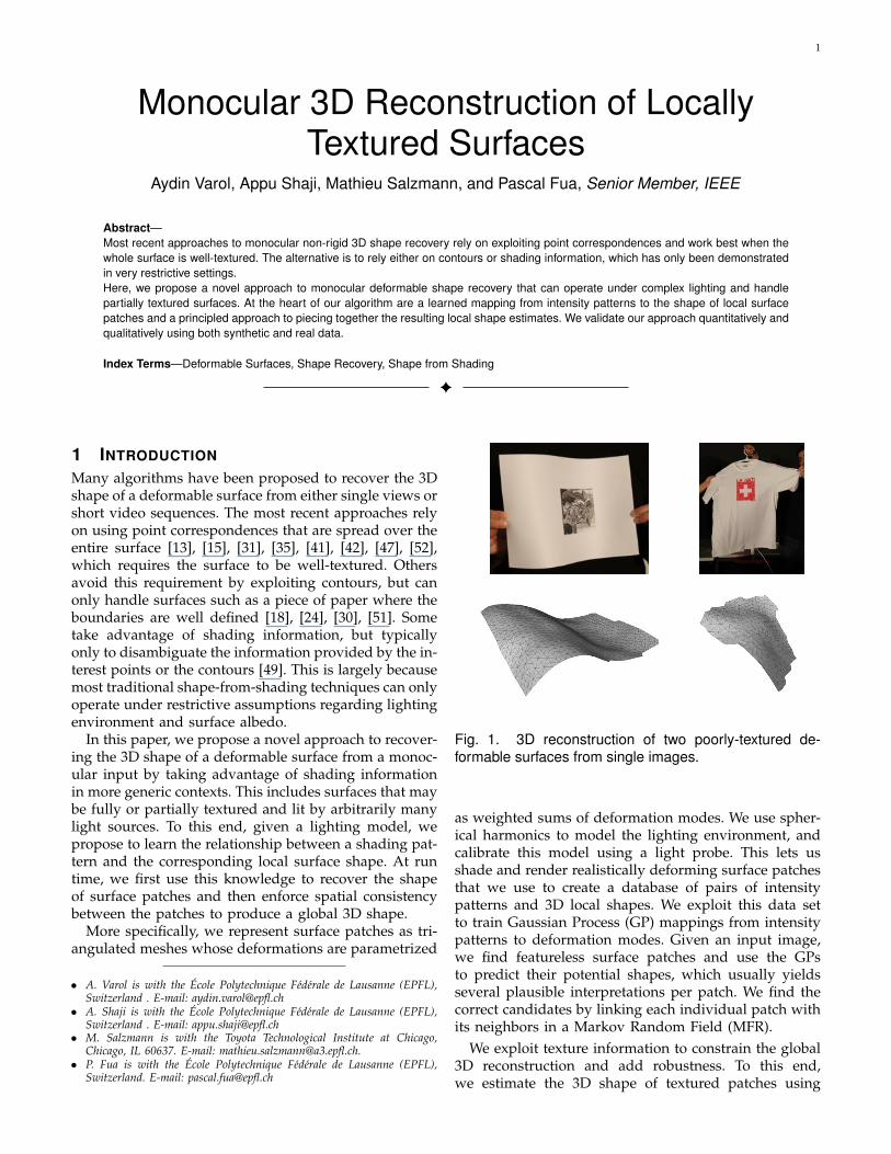
Fig. 1. 3D reconstruction of two poorly-textured de-formable surfaces from single images.
as weighted sums of deformation modes. We use spher-ical harmonics to model the lighting environment, andcalibrate this model using a light probe. This lets usshade and render realistically deforming surface patchesthat we use to create a database of pairs of intensitypatterns and 3D local shapes. We exploit this data setto train Gaussian Process (GP) mappings from intensitypatterns to deformation modes. Given an input image,we find featureless surface patches and use the GPsto predict their potential shapes, which usually yieldsseveral plausible interpretations per patch. We find thecorrect candidates by linking each individual patch withits neighbors in a Markov Random Field (MFR).
We exploit texture information to constrain the global3D reconstruction and add robustness. To this end,we estimate the 3D shape of textured patches using
2
a correspondence-based technique [35] and add theseestimates into the Markov Random Field. In other words,instead of treating texture as noise as in many shape-from-shading approaches, we exploit it as an additionalsource of information.
In short, our contribution is an approach to shape-from-shading that can operate in a much broader contextthan earlier ones: We can handle indifferently weak orfull perspective cameras; the surfaces can be partially orfully textured; we can handle any lighting environmentthat can be approximated by spherical harmonics; thereis no need to pre-segment the surface and we return anexact solution as opposed to one up to a scale factor.While some earlier methods address subsets of theseproblems, we are not aware of any that tackles themall.
We demonstrate the effectiveness of our approach onsynthetic and real images, and show that it outperformsstate-of-the-art texture-based shape recovery and shape-from-shading techniques.
2 RELATED WORK
Recent advances in non-rigid surface reconstruction frommonocular images have mostly focused on exploitingtextural information. These techniques can be roughlyclassified into Template-based approaches and Structure-from-Motion methods.
Template-based methods start from a reference imagein which the 3D surface shape is known. They thenestablish point correspondences between the referenceimage and an input image from which the unknown 3Dshape is to be recovered. Given such correspondences,reconstruction amounts to solving an ill-conditionedlinear system [36] and additional constraints must beimposed to obtain an acceptable solution. These mayinclude inextensibility constraints as well as local orglobal smoothness constraints [13], [31], [35], [41], [52].
Structure-from-Motion methods depend on trackingpoints across image sequences. This approach was ini-tially introduced in [10] to extend to the non-rigid caseearlier structure-from-motion work [43]. Surface shapesare represented as linear combinations of basis shapes,which are estimated together with the weights assignedto them and the camera pose. This is again an ill-posedproblem, which requires additional constraints. Theyinclude orthonormality constraints designed to ensurethat the recovered camera motion truly is a rotation [3],[9], [40], [50], motion constraints [1], [28], [33], basisconstraints [50], or alternate deformation models [16],[32], [44]. More recently, it has been proposed to split theglobal reconstruction into a series of local ones, whichcan then be patched together into a consistent interpre-tation. The local surface deformations can be modeledas isometric [42], planar [11], [47], or quadratic [15].
While these correspondence-based techniques are ef-fective when the texture is sufficiently well-spread acrossthe surface, they perform less well when the texture
is sparser or even absent. In the case of developablesurfaces, this limitation can be circumvented by usinginformation provided by boundaries, which is sufficientto infer the full 3D shape [18], [24], [30], [51]. Neverthe-less this approach does not extend to cases where thecontours are not well-defined. For those, in the absenceof texture, the natural technique to use is shape-from-shading [20]. However, despite many generalizations ofthe original formulation to account for increasingly so-phisticated shading effects, such as interreflections [17],[27], specularities [29], shadows [23], or non-Lambertianmaterials [2], most state-of-the-art solutions can onlyhandle a subset of these effects and, therefore, onlyremain valid in tightly controlled environments. Shape-from-shading techniques have been made more robustby exploiting deformation models [38], [39]. However,this was only demonstrated for the single light sourcecase. By contrast, our method can operate in moregeneral environments, provided only that a light modelexpressed in terms of spherical harmonics can be esti-mated.
A more practical solution to exploiting shading isto use it in conjunction with texture. In [49], shadinginformation was used to overcome the twofold am-biguity in normal direction that arises from templatematching. In [26], the inextensibility constraints men-tioned earlier were replaced with shading equations,which allowed the reconstruction of stretchable surfaces.However, these techniques still require the presence oftexture over the whole surface. By contrast, our proposedframework can exploit very localized texture in conjunc-tion with shading to reconstruct the entire surface.
3 METHOD OVERVIEWOur goal is to recover the 3D shape of deformingsurfaces such as those shown in Fig. 1 from a singleinput image, given a reference image in which the shapeis known, a calibrated camera, and a lighting model.We assume that the surface albedo is constant, except attextured regions, and measure it in the reference image.Our approach relies on several insights:
• The deformations of local surface patches are sim-pler to model than those of the whole surface.
• For patches that are featureless, one can learn arelationship between gray-level variations inducedby changes in surface normals and 3D shape thatholds even when the lighting is complex.
• For patches that fall on textured parts of the sur-face, one can use preexisting correspondence-basedtechniques [35].
This patch-based approach allows the use of differenttechniques for different patches depending on the exactnature of the underlying image. In practice, the localreconstruction problems may have several plausible so-lutions and obtaining a global surface requires a finalstep to enforce global geometric consistency across thereconstructed patches.
3
GP
GP
GP
GP
GP
GP
Neighbourhood Alignment Global Mesh Fitting
Reconstruction ofTextured Region
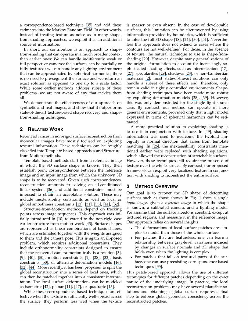
Fig. 2. Algorithmic flow. We partition the image into patches, some of which are labeled as textured and others asfeatureless. We compute the 3D shape of textured patches such as the blue one by establishing point correspondenceswith a reference image in which the shape is known. We use Gaussian Processes trained on synthetic data to predictplausible 3D shapes for featureless patches such as the red ones. Finally, neighborhood alignment of the patchesis done using a Markov Random Field to choose among all possible local interpretations those that are globallyconsistent.
The algorithm corresponding to our approach is de-picted by Fig. 2. Its two key steps are the estimation oflocal 3D surface shape from gray level intensities acrossimage patches followed by the enforcement of globalgeometric consistency. We outline them briefly belowand discuss them in more details in the two followingsections.
3.1 Estimating the Shape of Local PatchesWhile we can reconstruct the 3D shape of texturedpatches by establishing correspondences between thefeature points they contain and those points in thereference image [35], this can obviously not be done forfeatureless ones. For those, we infer shape from shading-induced gray-level variations. Since there is no simplealgebraic relationship between intensity patterns and 3Dshape when the lighting is complex, we use a MachineLearning approach to establish one.
More specifically, we learn GP mappings from inten-sity variations to surface deformations using a trainingset created by rendering a set of synthetically deformed3D patches shaded using the known lighting model. Aswe will see, this is a one-to-many mapping since a givenintensity pattern can give rise to several interpretations.
3.2 Enforcing Overall Geometric ConsistencyBecause there can be several different interpretations foreach patch, we must select the ones that result in a con-sistent global 3D shape. To this end, we link the patches
into an MRF that accounts for dependencies betweenneighboring ones. Finding the maximum a posterioristate of the MRF then yields a consistent set of localinterpretations.
Although not strictly necessary, textured patches,which can be reconstructed accurately in most cases,help better constrain the process. In essence, they playthe role of boundary conditions, which are always help-ful when performing shape-from-shading type compu-tations.
4 ESTIMATING LOCAL SHAPE
As outlined above, our method begins by reconstructinglocal surface patches from intensity profiles, which wedo using a statistical learning approach. To this end, wecalibrate the scene lighting, create a training databaseof deformed 3D patches and corresponding intensityprofiles, and use GPs to learn the mapping betweenthem.
4.1 Generating Training DataSince shading cues are specific to a given lighting en-vironment, we begin by representing it in terms ofspherical harmonics coefficients that we recover usinga spherical light probe. As scene irradiance is rela-tively insensitive to high frequencies in the lighting, forLambertian objects lit by far lighting sources, we canrestrict ourselves to the first nine such coefficients [34].In practice, this has proved sufficient to operate in an
4
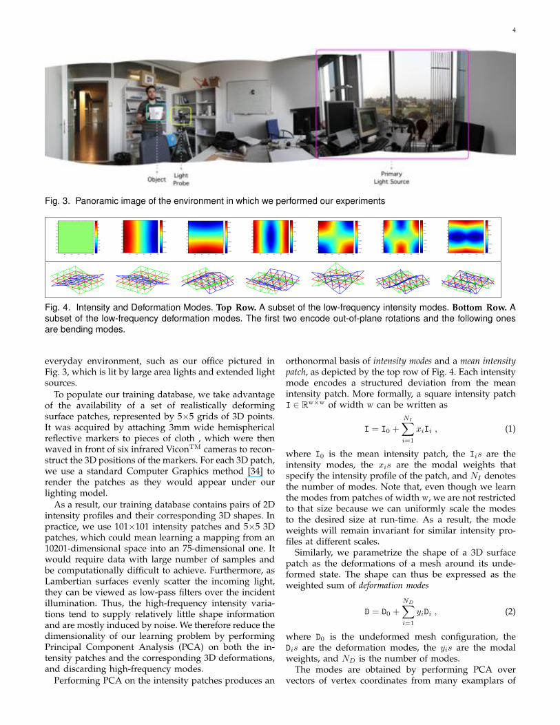
Fig. 3. Panoramic image of the environment in which we performed our experiments
20 40 60 80 100
10
20
30
40
50
60
70
80
90
100
−0.8
−0.6
−0.4
−0.2
0
0.2
0.4
0.6
0.8
1
20 40 60 80 100
10
20
30
40
50
60
70
80
90
100 −0.015
−0.01
−0.005
0
0.005
0.01
0.015
20 40 60 80 100
10
20
30
40
50
60
70
80
90
100−0.015
−0.01
−0.005
0
0.005
0.01
0.015
20 40 60 80 100
10
20
30
40
50
60
70
80
90
100
−0.015
−0.01
−0.005
0
0.005
0.01
0.015
20 40 60 80 100
10
20
30
40
50
60
70
80
90
100 −0.02
−0.015
−0.01
−0.005
0
0.005
0.01
0.015
0.02
20 40 60 80 100
10
20
30
40
50
60
70
80
90
100
−0.02
−0.015
−0.01
−0.005
0
0.005
0.01
0.015
0.02
20 40 60 80 100
10
20
30
40
50
60
70
80
90
100 −0.015
−0.01
−0.005
0
0.005
0.01
0.015
0.02
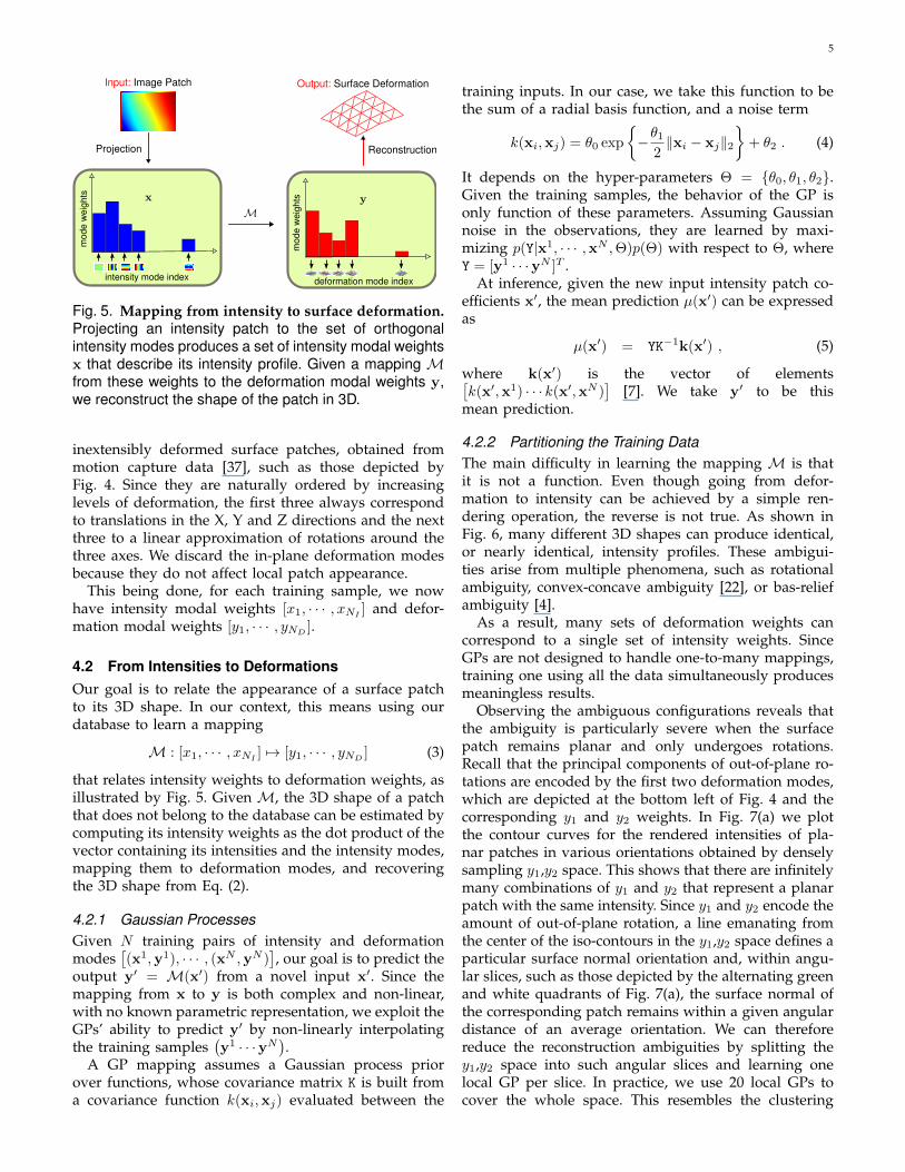
Fig. 4. Intensity and Deformation Modes. Top Row. A subset of the low-frequency intensity modes. Bottom Row. Asubset of the low-frequency deformation modes. The first two encode out-of-plane rotations and the following onesare bending modes.
everyday environment, such as our office pictured inFig. 3, which is lit by large area lights and extended lightsources.
To populate our training database, we take advantageof the availability of a set of realistically deformingsurface patches, represented by 5⇥5 grids of 3D points.It was acquired by attaching 3mm wide hemisphericalreflective markers to pieces of cloth , which were thenwaved in front of six infrared ViconTM cameras to recon-struct the 3D positions of the markers. For each 3D patch,we use a standard Computer Graphics method [34] torender the patches as they would appear under ourlighting model.
As a result, our training database contains pairs of 2Dintensity profiles and their corresponding 3D shapes. Inpractice, we use 101⇥101 intensity patches and 5⇥5 3Dpatches, which could mean learning a mapping from an10201-dimensional space into an 75-dimensional one. Itwould require data with large number of samples andbe computationally difficult to achieve. Furthermore, asLambertian surfaces evenly scatter the incoming light,they can be viewed as low-pass filters over the incidentillumination. Thus, the high-frequency intensity varia-tions tend to supply relatively little shape informationand are mostly induced by noise. We therefore reduce thedimensionality of our learning problem by performingPrincipal Component Analysis (PCA) on both the in-tensity patches and the corresponding 3D deformations,and discarding high-frequency modes.
Performing PCA on the intensity patches produces an
orthonormal basis of intensity modes and a mean intensitypatch, as depicted by the top row of Fig. 4. Each intensitymode encodes a structured deviation from the meanintensity patch. More formally, a square intensity patchI 2 Rw⇥w of width w can be written as
I = I0 +
NIX
i=1
xiIi , (1)
where I0 is the mean intensity patch, the Iis are theintensity modes, the xis are the modal weights thatspecify the intensity profile of the patch, and NI denotesthe number of modes. Note that, even though we learnthe modes from patches of width w, we are not restrictedto that size because we can uniformly scale the modesto the desired size at run-time. As a result, the modeweights will remain invariant for similar intensity pro-files at different scales.
Similarly, we parametrize the shape of a 3D surfacepatch as the deformations of a mesh around its unde-formed state. The shape can thus be expressed as theweighted sum of deformation modes
D = D0 +
NDX
i=1
yiDi , (2)
where D0 is the undeformed mesh configuration, theDis are the deformation modes, the yis are the modalweights, and ND is the number of modes.
The modes are obtained by performing PCA overvectors of vertex coordinates from many examplars of
5
Input: Image Patch Output: Surface Deformation
Projection Reconstruction
intensity mode index
mod
e w
eigh
ts
deformation mode indexm
ode
wei
ghts
Fig. 5. Mapping from intensity to surface deformation.
Projecting an intensity patch to the set of orthogonalintensity modes produces a set of intensity modal weightsx that describe its intensity profile. Given a mapping Mfrom these weights to the deformation modal weights y,we reconstruct the shape of the patch in 3D.
inextensibly deformed surface patches, obtained frommotion capture data [37], such as those depicted byFig. 4. Since they are naturally ordered by increasinglevels of deformation, the first three always correspondto translations in the X, Y and Z directions and the nextthree to a linear approximation of rotations around thethree axes. We discard the in-plane deformation modesbecause they do not affect local patch appearance.
This being done, for each training sample, we nowhave intensity modal weights [x1, · · · , xNI ] and defor-mation modal weights [y1, · · · , yND ].
4.2 From Intensities to DeformationsOur goal is to relate the appearance of a surface patchto its 3D shape. In our context, this means using ourdatabase to learn a mapping
M : [x1, · · · , xNI ] 7! [y1, · · · , yND ] (3)
that relates intensity weights to deformation weights, asillustrated by Fig. 5. Given M, the 3D shape of a patchthat does not belong to the database can be estimated bycomputing its intensity weights as the dot product of thevector containing its intensities and the intensity modes,mapping them to deformation modes, and recoveringthe 3D shape from Eq. (2).
4.2.1 Gaussian Processes
Given N training pairs of intensity and deformationmodes
⇥(x
1,y
1), · · · , (xN
,y
N)
⇤, our goal is to predict the
output y
0= M(x
0) from a novel input x
0. Since themapping from x to y is both complex and non-linear,with no known parametric representation, we exploit theGPs’ ability to predict y
0 by non-linearly interpolatingthe training samples
�y
1 · · ·yN�.
A GP mapping assumes a Gaussian process priorover functions, whose covariance matrix K is built froma covariance function k(xi,xj) evaluated between the
training inputs. In our case, we take this function to bethe sum of a radial basis function, and a noise term
k(xi,xj) = ✓0 exp
⇢�✓1
2
kxi � xjk2�+ ✓2 . (4)
It depends on the hyper-parameters ⇥ = {✓0, ✓1, ✓2}.Given the training samples, the behavior of the GP isonly function of these parameters. Assuming Gaussiannoise in the observations, they are learned by maxi-mizing p(Y|x1
, · · · ,xN,⇥)p(⇥) with respect to ⇥, where
Y = [y
1 · · ·yN]
T .At inference, given the new input intensity patch co-
efficients x
0, the mean prediction µ(x
0) can be expressed
as
µ(x
0) = YK�1
k(x
0) , (5)
where k(x
0) is the vector of elements⇥
k(x
0,x
1) · · · k(x0
,x
N)
⇤[7]. We take y
0 to be thismean prediction.
4.2.2 Partitioning the Training Data
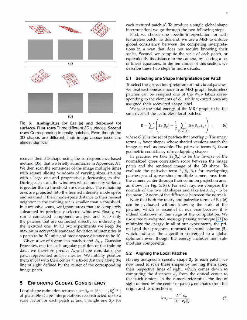
The main difficulty in learning the mapping M is thatit is not a function. Even though going from defor-mation to intensity can be achieved by a simple ren-dering operation, the reverse is not true. As shown inFig. 6, many different 3D shapes can produce identical,or nearly identical, intensity profiles. These ambigui-ties arise from multiple phenomena, such as rotationalambiguity, convex-concave ambiguity [22], or bas-reliefambiguity [4].
As a result, many sets of deformation weights cancorrespond to a single set of intensity weights. SinceGPs are not designed to handle one-to-many mappings,training one using all the data simultaneously producesmeaningless results.
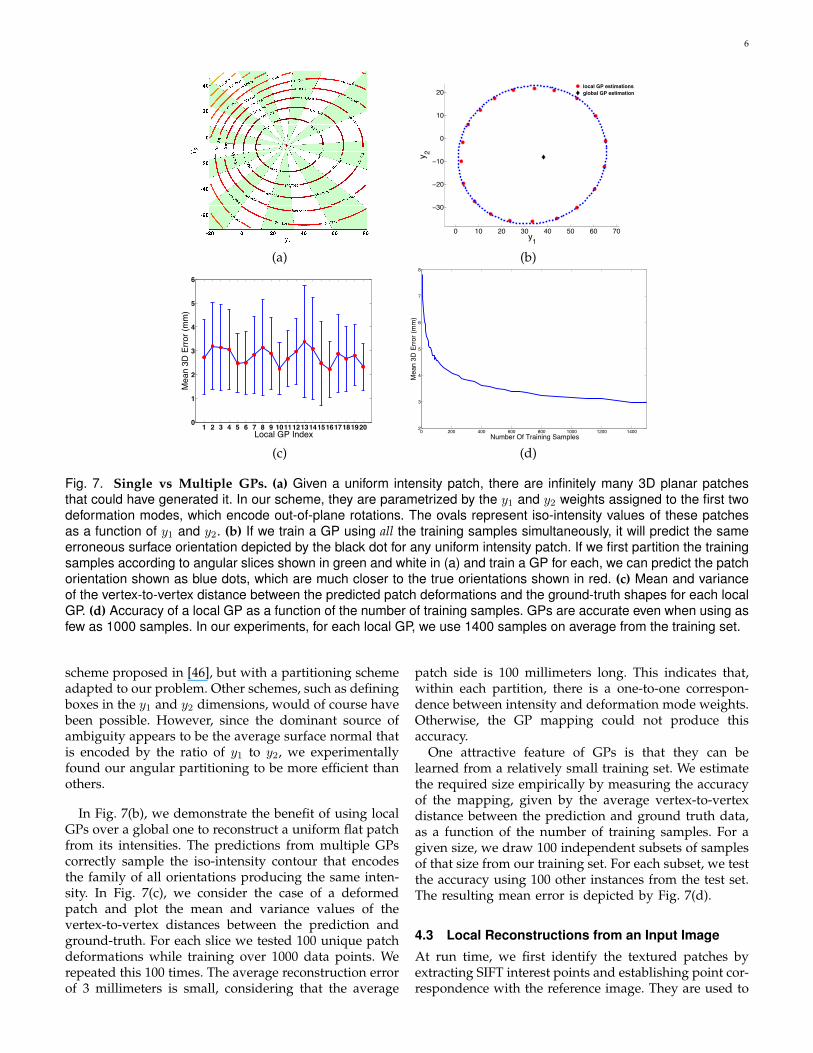
Observing the ambiguous configurations reveals thatthe ambiguity is particularly severe when the surfacepatch remains planar and only undergoes rotations.Recall that the principal components of out-of-plane ro-tations are encoded by the first two deformation modes,which are depicted at the bottom left of Fig. 4 and thecorresponding y1 and y2 weights. In Fig. 7(a) we plotthe contour curves for the rendered intensities of pla-nar patches in various orientations obtained by denselysampling y1,y2 space. This shows that there are infinitelymany combinations of y1 and y2 that represent a planarpatch with the same intensity. Since y1 and y2 encode theamount of out-of-plane rotation, a line emanating fromthe center of the iso-contours in the y1,y2 space defines aparticular surface normal orientation and, within angu-lar slices, such as those depicted by the alternating greenand white quadrants of Fig. 7(a), the surface normal ofthe corresponding patch remains within a given angulardistance of an average orientation. We can thereforereduce the reconstruction ambiguities by splitting they1,y2 space into such angular slices and learning onelocal GP per slice. In practice, we use 20 local GPs tocover the whole space. This resembles the clustering
6
0 10 20 30 40 50 60 70
−30
−20
−10
0
10
20
y1
y 2
local GP estimationsglobal GP estimation
(a) (b)
1 2 3 4 5 6 7 8 9 10111213141516171819200
1
2
3
4
5
6
Local GP Index
Mea
n 3D
Erro
r (m
m)
0 200 400 600 800 1000 1200 14002
3
4
5
6
7
8
Number Of Training Samples
Mea
n 3D
Erro
r (m
m)
(c) (d)
Fig. 7. Single vs Multiple GPs. (a) Given a uniform intensity patch, there are infinitely many 3D planar patchesthat could have generated it. In our scheme, they are parametrized by the y1 and y2 weights assigned to the first twodeformation modes, which encode out-of-plane rotations. The ovals represent iso-intensity values of these patchesas a function of y1 and y2. (b) If we train a GP using all the training samples simultaneously, it will predict the sameerroneous surface orientation depicted by the black dot for any uniform intensity patch. If we first partition the trainingsamples according to angular slices shown in green and white in (a) and train a GP for each, we can predict the patchorientation shown as blue dots, which are much closer to the true orientations shown in red. (c) Mean and varianceof the vertex-to-vertex distance between the predicted patch deformations and the ground-truth shapes for each localGP. (d) Accuracy of a local GP as a function of the number of training samples. GPs are accurate even when using asfew as 1000 samples. In our experiments, for each local GP, we use 1400 samples on average from the training set.
scheme proposed in [46], but with a partitioning schemeadapted to our problem. Other schemes, such as definingboxes in the y1 and y2 dimensions, would of course havebeen possible. However, since the dominant source ofambiguity appears to be the average surface normal thatis encoded by the ratio of y1 to y2, we experimentallyfound our angular partitioning to be more efficient thanothers.
In Fig. 7(b), we demonstrate the benefit of using localGPs over a global one to reconstruct a uniform flat patchfrom its intensities. The predictions from multiple GPscorrectly sample the iso-intensity contour that encodesthe family of all orientations producing the same inten-sity. In Fig. 7(c), we consider the case of a deformedpatch and plot the mean and variance values of thevertex-to-vertex distances between the prediction andground-truth. For each slice we tested 100 unique patchdeformations while training over 1000 data points. Werepeated this 100 times. The average reconstruction errorof 3 millimeters is small, considering that the average
patch side is 100 millimeters long. This indicates that,within each partition, there is a one-to-one correspon-dence between intensity and deformation mode weights.Otherwise, the GP mapping could not produce thisaccuracy.
One attractive feature of GPs is that they can belearned from a relatively small training set. We estimatethe required size empirically by measuring the accuracyof the mapping, given by the average vertex-to-vertexdistance between the prediction and ground truth data,as a function of the number of training samples. For agiven size, we draw 100 independent subsets of samplesof that size from our training set. For each subset, we testthe accuracy using 100 other instances from the test set.The resulting mean error is depicted by Fig. 7(d).
4.3 Local Reconstructions from an Input ImageAt run time, we first identify the textured patches byextracting SIFT interest points and establishing point cor-respondence with the reference image. They are used to
7
(a)
(b)
Fig. 6. Ambiguities for flat (a) and deformed (b)
surfaces. First rows Three different 3D surfaces. Second
rows Corresponding intensity patches. Even though the3D shapes are different, their image appearances arealmost identical.
recover their 3D-shape using the correspondence-basedmethod [35], that we briefly summarize in Appendix A1.We then scan the remainder of the image multiple timeswith square sliding windows of varying sizes, startingwith a large one and progressively decreasing its size.During each scan, the windows whose intensity varianceis greater than a threshold are discarded. The remainingones are projected into the learned intensity mode spaceand retained if their mode-space distance to their nearestneighbor in the training set is smaller than a threshold.In successive scans, we ignore areas that are completelysubsumed by previously selected windows. Finally, werun a connected component analysis and keep onlythe patches that are connected directly or indirectly tothe textured one. In all our experiments we keep themaximum acceptable standard deviation of intensities ina patch to be 30 units and mode-space distance to be 10.
Given a set of featureless patches and NGP GaussianProcesses, one for each angular partition of the trainingdata, we therefore predict NGP shape candidates perpatch represented as 5⇥5 meshes. We initially positionthem in 3D with their center at a fixed distance along theline of sight defined by the center of the correspondingimage patch.
5 ENFORCING GLOBAL CONSISTENCY
Local shape estimation returns a set Sp = {S1p, · · · , SNGPp }
of plausible shape interpretations reconstructed up to ascale factor for each patch p, and a single one Sp0 for
each textured patch p
0. To produce a single global shapeinterpretation, we go through the two following steps.
First, we choose one specific interpretation for eachfeatureless patch. To this end, we use a MRF to enforceglobal consistency between the competing interpreta-tions in a way that does not require knowing theirscales. Second, we compute the scale of each patch, orequivalently its distance to the camera, by solving a setof linear equations. In the remainder of this section, wedescribe these two steps in more details.
5.1 Selecting one Shape Interpretation per PatchTo select the correct interpretation for individual patches,we treat each one as a node in an MRF graph. Featurelesspatches can be assigned one of the NGP labels corre-sponding to the elements of Sp, while textured ones areassigned their recovered shape label.
We take the total energy of the MRF graph to be thesum over all the featureless local patches
E =
X
p
0
@E1(Sp) +1
2
X
q2O(p)
E2(Sp, Sq)
1
A, (6)
where O(p) is the set of patches that overlap p. The unaryterms E1 favor shapes whose shaded versions match theimage as well as possible. The pairwise terms E2 favorgeometric consistency of overlapping shapes.
In practice, we take E1(Sp) to be the inverse of thenormalized cross correlation score between the imagepatch and the rendered image of the 3D shape. Toevaluate the pairwise term E2(Sp, Sq) for overlappingpatches p and q, we shoot multiple camera rays fromthe camera center through their common projection area,as shown in Fig. 5.1(a). For each ray, we compare thenormals of the two 3D shapes and take E2(Sp, Sq) to bethe mean L2 norm of the difference between the normals.
Note that both the unary and pairwise terms of Eq. (6)can be evaluated without knowing the scale of thepatches, which is essential in our case because it isindeed unknown at this stage of the computation. Weuse a tree re-weighted message passing technique [21] tominimize the energy. In all of our experiments, the pri-mal and dual programs returned the same solution [5],which indicates the algorithm converged to a globaloptimum even though the energy includes non sub-modular components.
5.2 Aligning the Local PatchesHaving assigned a specific shape Sp to each patch, wenow need to scale these shapes by moving them alongtheir respective lines of sight, which comes down tocomputing the distances dp from the optical center tothe patch centers. In the camera referential, the line ofsight defined by the center of patch p emanates from theorigin and its direction is
losp =
A�1cp
kA�1cpk2 , (7)
8
dinit.losi
dinit.losj
di.losi
dj.losj
dinit.losi
dinit.losj
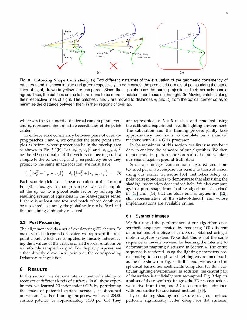
Fig. 8. Enforcing Shape Consistency (a) Two different instances of the evaluation of the geometric consistency ofpatches i and j, shown in blue and green respectively. In both cases, the predicted normals of points along the samelines of sight, drawn in yellow, are compared. Since these points have the same projections, their normals shouldagree. Thus, the patches on the left are found to be more consistent than those on the right. (b) Moving patches alongtheir respective lines of sight. The patches i and j are moved to distances di and dj from the optical center so as tominimize the distance between them in their regions of overlap.
where A is the 3⇥3 matrix of internal camera parametersand cp represents the projective coordinates of the patchcenter.
To enforce scale consistency between pairs of overlap-ping patches p and q, we consider the same point sam-ples as before, whose projections lie in the overlap areaas shown in Fig. 5.1(b). Let [xp, yp, zp]
T and [xq, yq, zq]T
be the 3D coordinates of the vectors connecting such asample to the centers of p and q, respectively. Since theyproject to the same image location, we must have
dp
⇣los
Tp + [xp, yp, zp]
⌘= dq
⇣los
Tq + [xq, yq, zq]
⌘. (8)
Each sample yields one linear equation of the form ofEq. (8). Thus, given enough samples we can computeall the dp up to a global scale factor by solving theresulting system of equations in the least-squares sense.If there is at least one textured patch whose depth canbe recovered accurately, the global scale can be fixed andthis remaining ambiguity resolved.
5.3 Post ProcessingThe alignment yields a set of overlapping 3D shapes. Tomake visual interpretation easier, we represent them aspoint clouds which are computed by linearly interpolat-ing the z values of the vertices of all the local solutions ona uniformly sampled xy grid. For display purposes, weeither directly draw these points or the correspondingDelaunay triangulation.
6 RESULTS
In this section, we demonstrate our method’s ability toreconstruct different kinds of surfaces. In all these exper-iments, we learned 20 independent GPs by partitioningthe space of potential surface normals, as discussedin Section 4.2. For training purposes, we used 28000surface patches, or approximately 1400 per GP. They
are represented as 5 ⇥ 5 meshes and rendered usingthe calibrated experiment-specific lighting environment.The calibration and the training process jointly takeapproximately two hours to complete on a standardmachine with a 2.4 GHz processor.
In the remainder of this section, we first use syntheticdata to analyze the behavior of our algorithm. We thendemonstrate its performance on real data and validateour results against ground-truth data.
Since our images contain both textured and non-textured parts, we compare our results to those obtainedusing our earlier technique [35] that relies solely onpoint correspondences to demonstrate that also using theshading information does indeed help. We also compareagainst pure shape-from-shading algorithms describedin [45] and [14] that are older but, as argued in [12],still representative of the state-of-the-art, and whoseimplementations are available online.
6.1 Synthetic Images
We first tested the performance of our algorithm on asynthetic sequence created by rendering 100 differentdeformations of a piece of cardboard obtained using amotion capture system. Note that this is not the samesequence as the one we used for learning the intensity todeformation mapping discussed in Section 4. The entiresequence is rendered using the lighting parameters cor-responding to a complicated lighting environment suchas the one shown in Fig. 3. To this end, we use a set ofspherical harmonics coefficients computed for that par-ticular lighting environment. In addition, the central partof the surface is artificially texture-mapped. Fig. 9 depictsa subset of these synthetic images, the 3D reconstructionswe derive from them, and 3D reconstructions obtainedwith our earlier texture-based method [35].
By combining shading and texture cues, our methodperforms significantly better except for flat surfaces,
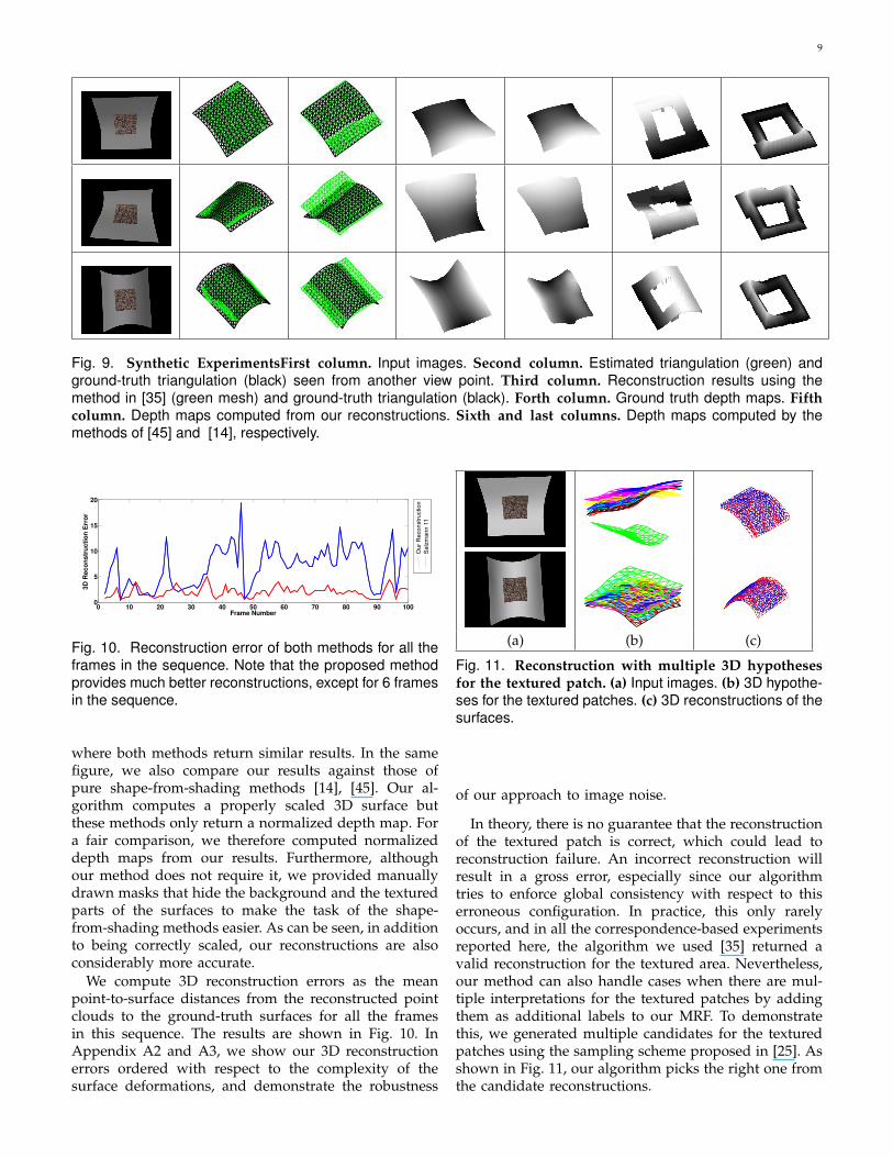
9
Fig. 9. Synthetic ExperimentsFirst column. Input images. Second column. Estimated triangulation (green) andground-truth triangulation (black) seen from another view point. Third column. Reconstruction results using themethod in [35] (green mesh) and ground-truth triangulation (black). Forth column. Ground truth depth maps. Fifth
column. Depth maps computed from our reconstructions. Sixth and last columns. Depth maps computed by themethods of [45] and [14], respectively.
0 10 20 30 40 50 60 70 80 90 1000
5
10
15
20
Frame Number
3DRec
onstru
ctionEr
ror
Fig. 10. Reconstruction error of both methods for all theframes in the sequence. Note that the proposed methodprovides much better reconstructions, except for 6 framesin the sequence.
where both methods return similar results. In the samefigure, we also compare our results against those ofpure shape-from-shading methods [14], [45]. Our al-gorithm computes a properly scaled 3D surface butthese methods only return a normalized depth map. Fora fair comparison, we therefore computed normalizeddepth maps from our results. Furthermore, althoughour method does not require it, we provided manuallydrawn masks that hide the background and the texturedparts of the surfaces to make the task of the shape-from-shading methods easier. As can be seen, in additionto being correctly scaled, our reconstructions are alsoconsiderably more accurate.
We compute 3D reconstruction errors as the meanpoint-to-surface distances from the reconstructed pointclouds to the ground-truth surfaces for all the framesin this sequence. The results are shown in Fig. 10. InAppendix A2 and A3, we show our 3D reconstructionerrors ordered with respect to the complexity of thesurface deformations, and demonstrate the robustness
(a) (b) (c)
Fig. 11. Reconstruction with multiple 3D hypotheses
for the textured patch. (a) Input images. (b) 3D hypothe-ses for the textured patches. (c) 3D reconstructions of thesurfaces.
of our approach to image noise.
In theory, there is no guarantee that the reconstructionof the textured patch is correct, which could lead toreconstruction failure. An incorrect reconstruction willresult in a gross error, especially since our algorithmtries to enforce global consistency with respect to thiserroneous configuration. In practice, this only rarelyoccurs, and in all the correspondence-based experimentsreported here, the algorithm we used [35] returned avalid reconstruction for the textured area. Nevertheless,our method can also handle cases when there are mul-tiple interpretations for the textured patches by addingthem as additional labels to our MRF. To demonstratethis, we generated multiple candidates for the texturedpatches using the sampling scheme proposed in [25]. Asshown in Fig. 11, our algorithm picks the right one fromthe candidate reconstructions.
10
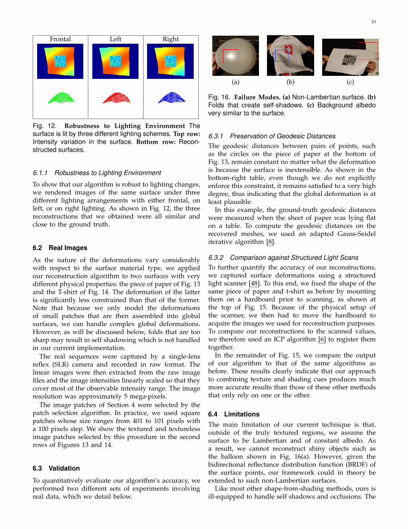
Frontal Left Right
Fig. 12. Robustness to Lighting Environment Thesurface is lit by three different lighting schemes. Top row:
Intensity variation in the surface. Bottom row: Recon-structed surfaces.
6.1.1 Robustness to Lighting Environment
To show that our algorithm is robust to lighting changes,we rendered images of the same surface under threedifferent lighting arrangements with either frontal, onleft, or on right lighting. As shown in Fig. 12, the threereconstructions that we obtained were all similar andclose to the ground truth.
6.2 Real Images
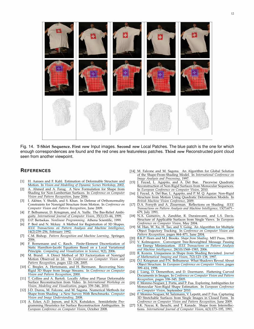
As the nature of the deformations vary considerablywith respect to the surface material type, we appliedour reconstruction algorithm to two surfaces with verydifferent physical properties: the piece of paper of Fig. 13and the T-shirt of Fig. 14. The deformation of the latteris significantly less constrained than that of the former.Note that because we only model the deformationsof small patches that are then assembled into globalsurfaces, we can handle complex global deformations.However, as will be discussed below, folds that are toosharp may result in self shadowing which is not handledin our current implementation.
The real sequences were captured by a single-lensreflex (SLR) camera and recorded in raw format. Thelinear images were then extracted from the raw imagefiles and the image intensities linearly scaled so that theycover most of the observable intensity range. The imageresolution was approximately 5 mega-pixels.
The image patches of Section 4 were selected by thepatch selection algorithm. In practice, we used squarepatches whose size ranges from 401 to 101 pixels witha 100 pixels step. We show the textured and texturelessimage patches selected by this procedure in the secondrows of Figures 13 and 14.
6.3 Validation
To quantitatively evaluate our algorithm’s accuracy, weperformed two different sets of experiments involvingreal data, which we detail below.
(a) (b) (c)
Fig. 16. Failure Modes. (a) Non-Lambertian surface. (b)
Folds that create self-shadows. (c) Background albedovery similar to the surface.
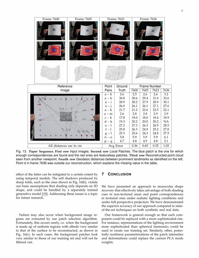
6.3.1 Preservation of Geodesic Distances
The geodesic distances between pairs of points, suchas the circles on the piece of paper at the bottom ofFig. 13, remain constant no matter what the deformationis because the surface is inextensible. As shown in thebottom-right table, even though we do not explicitlyenforce this constraint, it remains satisfied to a very highdegree, thus indicating that the global deformation is atleast plausible.
In this example, the ground-truth geodesic distanceswere measured when the sheet of paper was lying flaton a table. To compute the geodesic distances on therecovered meshes, we used an adapted Gauss-Seideliterative algorithm [8].
6.3.2 Comparison against Structured Light Scans
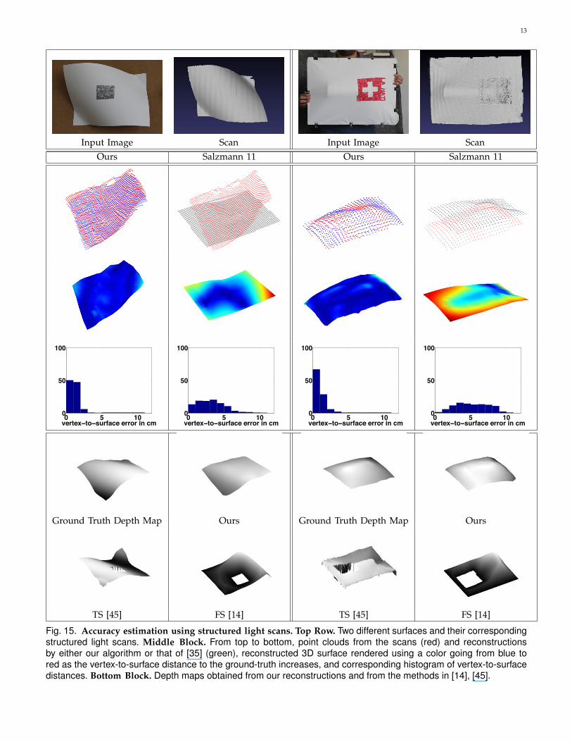
To further quantify the accuracy of our reconstructions,we captured surface deformations using a structuredlight scanner [48]. To this end, we fixed the shape of thesame piece of paper and t-shirt as before by mountingthem on a hardboard prior to scanning, as shown atthe top of Fig. 15. Because of the physical setup ofthe scanner, we then had to move the hardboard toacquire the images we used for reconstruction purposes.To compare our reconstructions to the scanned values,we therefore used an ICP algorithm [6] to register themtogether.
In the remainder of Fig. 15, we compare the outputof our algorithm to that of the same algorithms asbefore. These results clearly indicate that our approachto combining texture and shading cues produces muchmore accurate results than those of these other methodsthat only rely on one or the other.
6.4 LimitationsThe main limitation of our current technique is that,outside of the truly textured regions, we assume thesurface to be Lambertian and of constant albedo. Asa result, we cannot reconstruct shiny objects such asthe balloon shown in Fig. 16(a). However, given thebidirectional reflectance distribution function (BRDF) ofthe surface points, our framework could in theory beextended to such non-Lambertian surfaces.
Like most other shape-from-shading methods, ours isill-equipped to handle self shadows and occlusions. The
11
Frame 7600 Frame 7605 Frame 7623 Frame 7636
Reference Point Ground Frame NumberImage Pairs Truth 7600 7605 7623 7636
a – b 2.6 2.5 2.6 2.6 3.2a – h 30.8 30.6 29.4 31.0 32.6a – i 28.9 28.2 27.9 28.9 30.1a – j 26.9 26.1 26.1 27.1 27.6a – k 21.7 21.2 22.6 22.5 22.1a – m 2.6 2.8 2.8 2.9 2.9c – k 17.8 18.0 18.0 18.4 18.9d – k 19.3 20.2 20.0 20.2 NAe – l 27.2 27.3 26.3 26.9 28.5f – l 25.8 26.3 24.9 25.2 27.8g – l 25.3 25.6 24.3 24.8 27.5n – o 5.8 5.9 5.9 5.9 6.1p – q 4.7 4.8 4.9 4.8 5.1
All distances are in cm Avg Error 0.36 0.65 0.35 1.03
Fig. 13. Paper Sequence. First row Input images. Second row Local Patches. The blue patch is the one for whichenough correspondences are found and the red ones are featureless patches. Third row Reconstructed point cloudseen from another viewpoint. Fourth row Geodesic distances between prominent landmarks as identified on the left.Point d in frame 7636 was outside our reconstruction, which explains the missing value in the table.
effect of the latter can be mitigated to a certain extent byusing temporal models. The self shadows produced bysharp folds, such as the ones shown in Fig. 16(b), violateour basic assumptions that shading only depends on 3Dshape, and could be handled by a separately trainedgenerative model [19]. Addressing these issues is a topicfor future research.
Failure may also occur when background image re-gions are extracted by our patch selection algorithm.Fortunately, this occurs rarely, i.e. when the backgroundis made up of uniform regions with albedo very similarto that of the surface to be reconstructed, as shown inFig. 16(c). In such cases, the background patches lookvery similar to those of our training set and will not befiltered out.
7 CONCLUSION
We have presented an approach to monocular shaperecovery that effectively takes advantage of both shadingcues in non-textured areas and point correspondencesin textured ones under realistic lighting conditions andunder full perspective projection. We have demonstratedthe superior accuracy of our approach compared to state-of-the-art techniques on both synthetic and real data.
Our framework is general enough so that each com-ponent could be replaced with a more sophisticated one.For instance, representations of the lighting environmentmore sophisticated than spherical harmonics could beused to create our training set. Similarly, other, poten-tially nonlinear parametrizations of the patch intensitiesand deformations could replace the current PCA modeweights.
12
Fig. 14. T-Shirt Sequence. First row Input images. Second row Local Patches. The blue patch is the one for whichenough correspondences are found and the red ones are featureless patches. Third row Reconstructed point cloudseen from another viewpoint.
REFERENCES
[1] H. Aanaes and F. Kahl. Estimation of Deformable Structure andMotion. In Vision and Modelling of Dynamic Scenes Workshop, 2002.
[2] A. Ahmed and A. Farag. A New Formulation for Shape fromShading for Non-Lambertian Surfaces. In Conference on ComputerVision and Pattern Recognition, June 2006.
[3] I. Akhter, Y. Sheikh, and S. Khan. In Defense of OrthonormalityConstraints for Nonrigid Structure from Motion. In Conference onComputer Vision and Pattern Recognition, June 2009.
[4] P. Belhumeur, D. Kriegman, and A. Yuille. The Bas-Relief Ambi-guity. International Journal of Computer Vision, 35(1):33–44, 1999.
[5] D.P. Bertsekas. Nonlinear Programming. Athena Scientific, 1999.[6] P. Besl and N. Mckay. A Method for Registration of 3D Shapes.
IEEE Transactions on Pattern Analysis and Machine Intelligence,14(2):239–256, February 1992.
[7] C.M. Bishop. Pattern Recognition and Machine Learning. Springer,2006.
[8] F. Bornemann and C. Rasch. Finite-Element Discretization ofStatic Hamilton-Jacobi Equations Based on a Local VariationalPrinciple. Computing and Visualization in Science, 9(2), 2006.
[9] M. Brand. A Direct Method of 3D Factorization of NonrigidMotion Observed in 2d. In Conference on Computer Vision andPattern Recognition, pages 122–128, 2005.
[10] C. Bregler, A. Hertzmann, and H. Biermann. Recovering Non-Rigid 3D Shape from Image Streams. In Conference on ComputerVision and Pattern Recognition, 2000.
[11] T. Collins and A. Bartoli. Locally Affine and Planar DeformableSurface Reconstruction from Video. In International Workshop onVision, Modeling and Visualization, pages 339–346, 2010.
[12] J-D. Durou, M. Falcone, and M. Sagona. Numerical Methods forShape from Shading : a New Survey With Benchmarks. ComputerVision and Image Understanding, 2008.
[13] A. Ecker, A.D. Jepson, and K.N. Kutulakos. Semidefinite Pro-gramming Heuristics for Surface Reconstruction Ambiguities. InEuropean Conference on Computer Vision, October 2008.
[14] M. Falcone and M. Sagona. An Algorithm for Global Solutionof the Shape-From-Shading Model. In International Conference onImage Analysis and Processing, 1997.
[15] J. Fayad, L. Agapito, and A. Del Bue. Piecewise QuadraticReconstruction of Non-Rigid Surfaces from Monocular Sequences.In European Conference on Computer Vision, 2010.
[16] J. Fayad, A. Del Bue, L. Agapito, and P. M. Q. Aguiar. Non-RigidStructure from Motion Using Quadratic Deformation Models. InBritish Machine Vision Conference, 2009.
[17] D.A. Forsyth and A. Zisserman. Reflections on Shading. IEEETransactions on Pattern Analysis and Machine Intelligence, 13(7):671–679, July 1991.
[18] N.A. Gumerov, A. Zandifar, R. Duraiswami, and L.S. Davis.Structure of Applicable Surfaces from Single Views. In EuropeanConference on Computer Vision, May 2004.
[19] M. Han, W. Xu, H. Tao, and Y. Gong. An Algorithm for MultipleObject Trajectory Tracking. In Conference on Computer Vision andPattern Recognition, pages 864–871, June 2004.
[20] B.K.P. Horn and M.J. Brooks. Shape from Shading. MIT Press, 1989.[21] V. Kolmogorov. Convergent Tree-Reweighted Message Passing
for Energy Minimization. IEEE Transactions on Pattern Analysisand Machine Intelligence, 28(10):1568–1583, 2006.
[22] R. Kozera. Uniqueness in Shape from Shading Revisited. Journalof Mathematical Imaging and Vision, 7(2):123–138, 1997.
[23] D.J. Kriegman and P.N. Belhumeur. What Shadows Reveal AboutObject Structure. In European Conference on Computer Vision, pages399–414, 1998.
[24] J. Liang, D. Dementhon, and D. Doermann. Flattening CurvedDocuments in Images. In Conference on Computer Vision and PatternRecognition, pages 338–345, 2005.
[25] F. Moreno-Noguer, J. Porta, and P. Fua. Exploring Ambiguities forMonocular Non-Rigid Shape Estimation. In European Conferenceon Computer Vision, September 2010.
[26] F. Moreno-Noguer, M. Salzmann, V. Lepetit, and P. Fua. Capturing3D Stretchable Surfaces from Single Images in Closed Form. InConference on Computer Vision and Pattern Recognition, June 2009.
[27] S.K. Nayar, K. Ikeuchi, and T. Kanade. Shape from Interreflec-tions. International Journal of Computer Vision, 6(3):173–195, 1991.
13
Input Image Scan Input Image ScanOurs Salzmann 11 Ours Salzmann 11
0 5 100
50
100
vertex−to−surface error in cm0 5 100
50
100
vertex−to−surface error in cm0 5 100
50
100
vertex−to−surface error in cm0 5 100
50
100
vertex−to−surface error in cm
Ground Truth Depth Map Ours Ground Truth Depth Map Ours
TS [45] FS [14] TS [45] FS [14]
Fig. 15. Accuracy estimation using structured light scans. Top Row. Two different surfaces and their correspondingstructured light scans. Middle Block. From top to bottom, point clouds from the scans (red) and reconstructionsby either our algorithm or that of [35] (green), reconstructed 3D surface rendered using a color going from blue tored as the vertex-to-surface distance to the ground-truth increases, and corresponding histogram of vertex-to-surfacedistances. Bottom Block. Depth maps obtained from our reconstructions and from the methods in [14], [45].
14
[28] S.I. Olsen and A. Bartoli. Implicit Non-Rigid Structure-From-Motion With Priors. Journal of Mathematical Imaging and Vision,31:233–244, 2008.
[29] M. Oren and S.K. Nayar. A Theory of Specular Surface Geometry.International Journal of Computer Vision, 24(2):105–124, 1996.
[30] M. Perriollat and A. Bartoli. A Quasi-Minimal Model for Paper-Like Surfaces. In BenCos: Workshop Towards Benchmarking Auto-mated Calibration, Orientation and Surface Reconstruction from Im-ages, 2007.
[31] M. Perriollat, R. Hartley, and A. Bartoli. Monocular Template-Based Reconstruction of Inextensible Surfaces. In British MachineVision Conference, 2008.
[32] V. Rabaud and S. Belongie. Re-Thinking Non-Rigid Structure fromMotion. In Conference on Computer Vision and Pattern Recognition,June 2008.
[33] V. Rabaud and S. Belongie. Linear Embeddings in Non-RigidStructure from Motion. In Conference on Computer Vision andPattern Recognition, June 2009.
[34] R. Ramamoorthi and P. Hanrahan. An Efficient Representationfor Irradiance Environment Maps. In ACM SIGGRAPH, 2001.
[35] M. Salzmann and P. Fua. Linear Local Models for MonocularReconstruction of Deformable Surfaces. IEEE Transactions onPattern Analysis and Machine Intelligence, 33(5):931–944, May 2011.
[36] M. Salzmann, V. Lepetit, and P. Fua. Deformable Surface TrackingAmbiguities. In Conference on Computer Vision and Pattern Recog-nition, June 2007.
[37] M. Salzmann, R. Urtasun, and P. Fua. Local Deformation Modelsfor Monocular 3D Shape Recovery. In Conference on ComputerVision and Pattern Recognition, June 2008.
[38] D. Samaras and D. Metaxas. Incorporating Illumination Con-straints in Deformable Models. In Conference on Computer Visionand Pattern Recognition, pages 322–329, June 1998.
[39] D. Samaras, D. Metaxas, P. Fua, and Y. Leclerc. Variable AlbedoSurface Reconstruction from Stereo and Shape from Shading. InConference on Computer Vision and Pattern Recognition, June 2000.
[40] A. Shaji and S. Chandran. Riemannian Manifold Optimisationfor Non-Rigid Structure from Motion. In Conference on ComputerVision and Pattern Recognition, 2008.
[41] S. Shen, W. Shi, and Y. Liu. Monocular 3D Tracking of InextensibleDeformable Surfaces Under L2-Norm. In Asian Conference onComputer Vision, 2009.
[42] J. Taylor, A. D. Jepson, and K. N. Kutulakos. Non-Rigid Structurefrom Locally-Rigid Motion. In Conference on Computer Vision andPattern Recognition, June 2010.
[43] C. Tomasi and T. Kanade. Shape and Motion from Image StreamsUnder Orthography: a Factorization Method. International Journalof Computer Vision, 9(2):137–154, 1992.
[44] L. Torresani, A. Hertzmann, and C. Bregler. Nonrigid Structure-From-Motion: Estimating Shape and Motion With HierarchicalPriors. IEEE Transactions on Pattern Analysis and Machine Intel-ligence, 30(5):878–892, 2008.
[45] P. S. Tsai and M. Shah. Shape from Shading Using LinearApproximation. Journal of Image and Vision Computing, pages 69–82, 1994.
[46] R. Urtasun and T. Darrell. Sparse Probabilistic Regression forActivity-Independent Human Pose Inference. In Conference onComputer Vision and Pattern Recognition, 2008.
[47] A. Varol, M. Salzmann, E. Tola, and P. Fua. Template-FreeMonocular Reconstruction of Deformable Surfaces. In Interna-tional Conference on Computer Vision, September 2009.
[48] T. Weise, B. Leibe, and L. Van Gool. Fast 3D Scanning WithAutomatic Motion Compensation. In Conference on ComputerVision and Pattern Recognition, June 2007.
[49] R. White and D.A. Forsyth. Combining Cues: Shape from Shadingand Texture. In Conference on Computer Vision and Pattern Recog-nition, 2006.
[50] J Xiao, J.-X. Chai, and T. Kanade. A Closed-Form Solution toNon-Rigid Shape and Motion Recovery. In European Conferenceon Computer Vision, pages 573–587, 2004.
[51] Z. Zhang, C. Tan, and L. Fan. Restoration of Curved DocumentImages through 3D Shape Modeling. In Conference on ComputerVision and Pattern Recognition, June 2004.
[52] J. Zhu, S. Hoi, C. Steven, Z. Xu, and M.R. Lyu. An EffectiveApproach to 3D Deformable Surface Tracking. In EuropeanConference on Computer Vision, pages 766–779, 2008.
ACKNOWLEDGMENTSThis work has been supported in part by the SwissNational Science Foundation and by the Indo Swiss JointResearch Programme. In addition, the authors wouldlike to thank Fethallah Benmansour for providing us thecode for computing the geodesic distance on a triangu-lated surface, Thibaut Weise for letting us use his struc-tured light 3D scanner system and Jean-Denis Duroufor providing the implementation of various Shape fromShaping methods online.
Aydin Varol received his B.Sc. degrees in bothcomputer and mechanical engineering in 2005from Koc University, Turkey. Afterward, he ob-tained the M.Sc. degree from the same univer-sity in 2007. He then joined to the ComputerVision Laboratory, EPFL (Swiss Federal Instituteof Technology) where he is currently a PhD stu-dent. His research interests focus on monocularnon-rigid surface reconstruction.
Appu Shaji received his B.Tech degree in com-puter science in 2002 from Cochin Universityof Science and Technology and PhD degree incomputer science in 2009 from Indian Instituteof Technology Bombay, Mumbai. He then joinedComputer Vision Lab at EPFL (Swiss FederalInstitute of Technology) in 2009 as a postdoc-toral fellow. His research interests include non-rigid shape recovery, structure from motion, im-age registration and optimization techniques forcomputer vision.
Mathieu Salzmann received his B.Sc. andM.Sc. degrees in computer science in 2004 fromEPFL (Swiss Federal Institute of Technology).He obtained his PhD degree in computer vi-sion in 2009 from EPFL. He then joined theInternational Computer Science Institute and theEECS department at UC Berkely as a postdoc-toral fellow. He is currently a Research AssistantProfessor at TTI Chicago. His research interestsinclude non-rigid shape recovery, human poseestimation, object recognition, and optimization
techniques for computer vision.
Pascal Fua received the engineering degreefrom the Ecole Polytechnique, Paris in 1984 andthe PhD degree in computer science from theUniversity of Orsay in 1989. He joined EPFL(Swiss Federal Institute of Technology in 1996,where he is now a professor in the School ofComputer and Communication Science. Beforethat, he worked at SRI International and at INRIASophia-Antipolis as a computer scientist. Hisresearch include shape modeling and motionrecovery from images, human body modeling
and optimization based techniques for image analysis and synthesis.He has (co)authored more than 150 publications in referred journals andconferences. He has been an associate editor of the IEEE Transactionsfor Pattern Analysis and Machine Intelligence and has been a programcommittee member and an area chair of several major vision confer-ences.
Related Documents


![PL-SLAM: Real-Time Monocular Visual SLAM with Points and …...textured environments, and also, improves the performance of the original ORB-SLAM [18] in highly textured sequences](https://static.cupdf.com/doc/110x72/602915a482ec846e031bc9de/pl-slam-real-time-monocular-visual-slam-with-points-and-textured-environments.jpg)