MONITORING TEMPERATURE RUANGAN DENGAN DISPLAY LCD DAN RECORDING MOCH. REZKI SELAMET MOKH IMAM NUGROHO SITI HARYANI YUDA WARDIANA

Welcome message from author
This document is posted to help you gain knowledge. Please leave a comment to let me know what you think about it! Share it to your friends and learn new things together.
Transcript

MONITORING TEMPERATURE RUANGAN DENGAN DISPLAY LCD
DAN RECORDING
MOCH. REZKI SELAMET
MOKH IMAM NUGROHO
SITI HARYANI
YUDA WARDIANA

LATAR BELAKANG
Dalam suatu pengukuran temperature kita biasanyamenunggu guna memperoleh data tiap menit. Tetapi
kadang kala kita selalu meniggalkan pengukuran karenaada kegiatan lain yang sama penting. Karna itu alat ini dibuat
untuk menyimpan data temperature supaya data pengukurantersimpan walaupun kita tinggalkan.

TUJUAN
Dapat mengetahui suhu ruangan yang terukur
Dapat menyimpan data temperature
Dapat mengetahui perubahan suhu ruangan
Dapat menganalisis data yang tersimpan gunakeperluaan akademik

DESKRIPSI ALAT
Alat ini mempunyai 4 buah sensor LM35 yang ditempatkan pada tiap sudut ruangan ditampilkan padadisplay LCD dan di record oleh arduino uno. Penyimpanandata dengan micro sd module shield dan di simpan olehmemori micro sd menit permenit temperaturenya. Data yang disimpan oleh micro sd module berbentuk.txt(notepad).

Alat Dan Bahan
Arduino Uno

LM 35 LM35 TEMPERATURE SENSOR IS ONE TYPE OF SENSOR THAT
CONVERTS ELECTRICAL QUANTITIES TO THE TEMPERATURE SCALE IN THE FORM OF VOLTAGE. LM35 HAS 3 PIECES PIN LEGS, PIN TO INPUT POSITIVE VOLTAGE (+), PIN OUTPUT, INPUT PIN NEGATIVE VOLTAGE / GND (-).


LM 35
HOW the LM 35 measure???
Can operate at a voltage of 4 volts to 30 volts. Each temperature of 1 degree Celsius will show a voltage of 10 mV.
equation:
Vout = 10 mV / 1ºC
That is, if the read voltage Vout = 500 mV, then the temperature = 500mv / 10mV = 50ºC.

35 ºC
Vout = 10 mV / 1ºC
That is, if the read voltage Vout = 500 mV, then the temperature = 500mv / 10mV = 50ºC.
EXAMPLE

Arduino use sensor LM 35
Read the output of LM35 goes into analog pin, Read data already in the form of ADC conversion
Converting ADC = Vout / Vref * 1023
So it's not in the form of voltage magnitude again If you want to know the LM35 output voltage using the formula above:
Read voltage = Conversion ADC voltage reference * / 1024
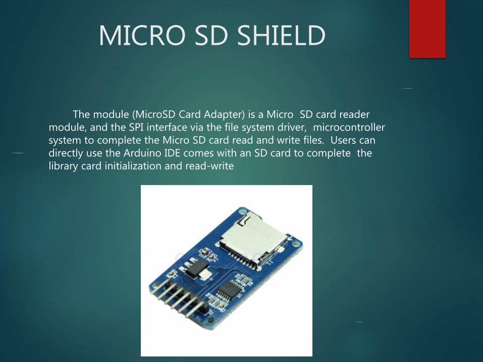
MICRO SD SHIELD
The module (MicroSD Card Adapter) is a Micro SD card reader module, and the SPI interface via the file system driver, microcontroller system to complete the Micro SD card read and write files. Users can directly use the Arduino IDE comes with an SD card to complete the library card initialization and read-write

Features:
Support Micro SD Card, Micro SDHC card (high-speed card)
The level conversion circuit board that can interface level is 5V or 3.3V
Power supply is 4.5V ~ 5.5V, 3.3V voltage regulator circuit board
Communication interface is a standard SPI interface
4 M2 screw positioning holes for easy installation
Control Interface: A total of six pins (GND, VCC, MISO, MOSI, SCK, CS), GND to ground, VCC is the power supply, MISO, MOSI, SCK is the SPI bus, CS is the chip select signal pin;
3.3V regulator circuit: LDO regulator output 3.3V as level converter chip, Micro SD card supply
Level conversion circuit: Micro SD card into the direction of signals into 3.3V, MicroSD card toward the direction of the control interface MISO signal is also converted to 3.3V, general AVR microcontroller system can read the signal
Micro SD card connector: yes since the bomb deck for easy card insertion and removal
Positioning holes: 4 M2 screws positioning hole diameter of 2.2mm, the module is easy to install positioning, to achieve inter-module combination
Mirco SD Card Interface Module :(the last picture show)
-Control Interface : A total of six pins (GND, VCC, MISO, MOSI, SCK, CS), GND to ground , VCC is the power supply , MISO, MOSI, SCK is SPI bus , CS is the chip select signal pin
3.3V voltage regulator circuit : LDO regulator output is 3.3V level converter chip , Micro SD card supply
Level conversion circuit : Micro SD card into the direction of the signal is converted to 3.3V, MicroSD card interfaces to control the direction of the MISO signal is also converted into 3.3V, general AVR microcontroller system can read the signal ;
Micro SD card connector : a self- bomb deck , easy card insertion .
Positioning holes : 4 M2 screws positioning hole diameter is 2.2mm, the positioning of the module is easy to install , to achieve inter- module combination ;

LCD AND BACKPACK
This is another great LCD display compatible with I2C bus and Gadgeteer modules. With limited pin resources, your project will quicly run out of resources using normal LCDs. With this I2C interface LCD module, you only need 2 lines (I2C)to display the information.If you already have I2C devices in your project, this LCD module actually cost no more resources at all. The adress can be set from 0x20-0x27.Fantastic for Arduino or gadgeteer based projects.

Specifications LCD•Supply voltage: 5V•I2C Address:0x20-0x27(0x20 default)•Back lit (Blue with white char color)•Interface:I2C/TWI x1,Gadgeteer interface x2•Adjustable contrast•Size:82x35x18 mm
Specifications Bacpack PCF8574 • Compatible With Most Microcontrollers• Low Standby-Current Consumption10 mA Max • Latched Outputs With High-Current Drive• I2C to Parallel-Port Expander Capability for Directly
Driving LEDs• Open-Drain Interrupt Output • Latch-Up Performance Exceeds 100 mA Per
JESD 78, Class II

RTC DS1302
A Real Time Clock Module with battery backup using the easy to use DS1302 chip. The DS1302 chip uses a simple serial interface (see datasheet) and example code is available for Arduino, Raspberry Pi and many others.

Features
Real-Time Clock Counts Seconds, Minutes, Hours, Date of the Month, Month, Day of the Week, and Year with Leap-Year Compensation Valid Up to 2100
Serial I/O for Minimum Pin Count
2.0V to 5.5V Full Operation
Uses Less than 300nA at 2.0V
Single-Byte or Multiple-Byte (Burst Mode) Data Transfer for Read or Write of Clock or RAM Data
Board Size: 44mm x 24mm

Desain Project

LANGKAH MERANGKAI
Siapkan alat dan bahan termasuk wadah misting
Wadah misting lubangi untuk keperluan shield micro sd dan arduino
Buat jalur rangkaian pcb untuk pembagian tegangandan konektor pin arduino
Rangkai seperti gambar
Up load script data pada arduino.

SCRIPT ARDUINO#include <Wire.h>
#include <LiquidCrystal_I2C.h>
#include <SD.h>
#include <DS1302.h>
File myFile;
LiquidCrystal_I2C lcd(0x27, 16,2);
float tempc;
float tempc1;
float tempc2;
float tempc3;
int tempin = 0;
int tempin1 = 1;
int tempin2= 2;
int tempin3 = 3;
int a=1;
int b;
DS1302 rtc(2, 3, 5);

void setup()
{
lcd.begin();
Serial.begin(9600);
while (!Serial) {
; // wait for serial port to connect. Needed for Leonardo only
}
Serial.print("Initializing SD card...");
// On the Ethernet Shield, CS is pin 4. It's set as an output by default.
// Note that even if it's not used as the CS pin, the hardware SS pin
// (10 on most Arduino boards, 53 on the Mega) must be left as an output
// or the SD library functions will not work.
pinMode(10, OUTPUT);
if (!SD.begin(4)) {
Serial.println("initialization failed!");
return;
}
rtc.halt(false);
rtc.writeProtect(false);
}

void loop()
{
tempc= analogRead(tempin);
tempc= (5*tempc*100)/1024;
tempc1= analogRead(tempin1);
tempc1= (5*tempc1*100)/1024;
tempc2= analogRead(tempin2);
tempc2= (5*tempc2*100)/1024;
tempc3= analogRead(tempin3);
tempc3= (5*tempc3*100)/1024;
b=a++;
lcd.backlight();
lcd.setCursor(0,0);
lcd.print(b);

lcd.setCursor(3,0);
lcd.print(tempc,1);
lcd.setCursor(10,0);
lcd.print(tempc1,1);
lcd.setCursor(3,1);
lcd.print(tempc2,1);
lcd.setCursor(10,1);
lcd.print(tempc3,1);
Serial.println("initialization done.");
myFile = SD.open("T1A1.txt", FILE_WRITE);
if (myFile)
{
Serial.print("Writing to T1A1.txt...");

myFile.println(rtc.getDOWStr());
myFile.println(" ");
myFile.println(rtc.getDateStr());
myFile.println(" -- ");
myFile.println(rtc.getTimeStr());
myFile.println("T('C)= ");
myFile.println(tempc);
myFile.print("T1 ('C)= ");
myFile.println(tempc1);
myFile.print("T2 ('C)= ");
myFile.println(tempc2);
myFile.print("T3 ('C)= ");
myFile.println(tempc3);
myFile.println("---------------------------------------------------");
myFile.close();
Serial.println("done.");
}

else
{
Serial.println("error opening T1A1.txt");
}
myFile = SD.open("T1A1.txt");
if (myFile) {
Serial.println("T1A1.txt:");
while (myFile.available()) {
Serial.write(myFile.read());
}
myFile.close();
} else {
Serial.println("error opening T1A1.txt");
}
delay(5000);
}

LANGKAH PENGUJIAN DAN DATA PENGUJIAN
Selama 2 jam pengukuran dengan waktu 1 menitpenyimpanan data yang tersimpan 21 kb sedangkanmemori 1.949.302kb.
1hari data=24jam/2jam=12x21kb=252kb/hari
1.949.302kb/252kb/hari=7.735hari
7.735/365=21 tahun

KESIMPULAN DAN SARAN
Data temperature lm35 yang terbaca oleh arduinoharus di ubah ke ADC supaya bisa terukur suhunyaoleh arduino.
Data yang tersimpan oleh shield micro sd berupatxt(notepad)
Backpack yang terpasang pada lcd berguna untukmemperkecil pin pada lcd
Saran
Untuk mempermudah sambungan pin dan untukmenempel dengan benar seharusnya dipasan terminal untuk memperkuat sambungan
Related Documents