Materials and Structures/ Matdriaux et Constructions, 1988, 21,341-351 Moment curvature relationship of reinforced concrete sectionsunder combined bending and normal force BERNARD ESPION, PIERRE HALLEUX Department of'Civil Engineering, Free Universityof Brussels (UL B), Brussels B-lOS0, Belgium The modelling of tension stiffening effects is important for the verification of serviceability limit states of reinforced or prestressed concrete structures or even for the computation of the stability limit state of particular classes of slender concrete structures (bridge piles, towers, masts, etc.). The case of pure bending has received extensive analytical and experimental consideration, but little attention has been paid, up to now, to the case of combined bending and normal force. A series of tests on rectangular reinforced concrete beams submitted to bending and constant compressive normal force is reported in this paper. The moment-curvature relationships are evaluated and compared with the prediction of two theoretical models. The first model is the CEB model proposed by Favre and Koprna. It is a simplified model which refers to the tm cracked and fully cracked stiffnesses in pure bending only. The second model is a proposition made by the authors which takes into account the tension stiffening effects, the variation in position of the neutral axis as a function of the eccentricity of the normal force, and the non-linear behaviour of concrete in compression. 1. INTRODUCTION The verification of the serviceability limit states of reinforced or prestressed concrete structures requires a good command of three kinds of variable: (i) precise knowledge of the nature and of magnitude of permanent actions (direct as well as indirect); (ii) modelling of the influence of the time-dependent behaviour of concrete; (iii) modelling of the influence of the tension stiffening effects of cracked concrete below the neutral axis. This article deals more specifically with the tension stiffening effects. We intend to study their influence on the instantaneous moment-curvature relationship of re- inforced concrete sections because this is the starting- point of any method for computing the displacements of reinforced concrete structures. The assessment of their influence on the long-term relationship would follow logically, but is beyond the scope of this work. The case of pure bending has been extensively studied analytically and experimentally. However, little work has been done on the case of combined bending and normal force. To the best knowledge of the authors, there are no tests specifically designed to reveal the influence of tension stiffening in combined bending and normal force other than for annular sections [1]. One of the aims of this article is to provide reference experimental moment- curvature relationships of reinforced concrete sections 0025-5432/88 RILEM under combined bending and normal force where the eccentricity M/N of the normal force is large enough to obtain cracked sections under service conditions. 2. PREVIOUS THEORETICAL APPROACHES 2.1 Classification of proposed models Critical examination of the propositions published in the literature for computing the moment-curvature relation- ship of reinforced or prestressed concrete sections leads us to the following classification of previous theoretical approaches in this field: 1. Interpolation between the end of State I when cracking begins and the transition between the cracked Phase II and the plastic Phase III when yielding of the reinforcement begins. 2. Computation of the curvature in the fully cracked State II and correction of this curvature, essentially by reducing the strain of the reinforcement through some sort of tension stiffening formula of the kind Esm = E~--AE s (1) 3. General numerical construction of the moment- curvature relationship according to the following steps: (i) given strain distribution accross the depth of the cross-section (Navier-Bernoulli hypothesis);

Welcome message from author
This document is posted to help you gain knowledge. Please leave a comment to let me know what you think about it! Share it to your friends and learn new things together.
Transcript

Materials and Structures/ Matdriaux et Constructions, 1988, 21,341-351
Moment curvature relationship of reinforced concrete sectionsunder combined bending and normal force
B E R N A R D ESPION, PIERRE HALLEUX
Department of'Civil Engineering, Free University of Brussels ( UL B), Brussels B-lOS0, Belgium
The modelling of tension stiffening effects is important for the verification of serviceability limit states of reinforced or prestressed concrete structures or even for the computation of the stability limit state of particular classes of slender concrete structures (bridge piles, towers, masts, etc.). The case of pure bending has received extensive analytical and experimental consideration, but little attention has been paid, up to now, to the case of combined bending and normal force. A series of tests on rectangular reinforced concrete beams submitted to bending and constant compressive normal force is reported in this paper. The moment-curvature relationships are evaluated and compared with the prediction of two theoretical models. The first model is the CEB model proposed by Favre and Koprna. It is a simplified model which refers to the tm cracked and fully cracked stiffnesses in pure bending only. The second model is a proposition made by the authors which takes into account the tension stiffening effects, the variation in position of the neutral axis as a function of the eccentricity of the normal force, and the non-linear behaviour of concrete in compression.
1. INTRODUCTION
The verification of the serviceability limit states of reinforced or prestressed concrete structures requires a good command of three kinds of variable:
(i) precise knowledge of the nature and of magnitude of permanent actions (direct as well as indirect);
(ii) modelling of the influence of the time-dependent behaviour of concrete;
(iii) modelling of the influence of the tension stiffening effects of cracked concrete below the neutral axis.
This article deals more specifically with the tension stiffening effects. We intend to study their influence on the instantaneous moment-curvature relationship of re- inforced concrete sections because this is the starting- point of any method for computing the displacements of reinforced concrete structures. The assessment of their influence on the long-term relationship would follow logically, but is beyond the scope of this work.
The case of pure bending has been extensively studied analytically and experimentally. However, little work has been done on the case of combined bending and normal force. To the best knowledge of the authors, there are no tests specifically designed to reveal the influence of tension stiffening in combined bending and normal force other than for annular sections [1]. One of the aims of this article is to provide reference experimental moment- curvature relationships of reinforced concrete sections
0025-5432/88 �9 RILEM
under combined bending and normal force where the eccentricity M/N of the normal force is large enough to obtain cracked sections under service conditions.
2. PREVIOUS THEORETICAL APPROACHES
2.1 Classification of proposed models
Critical examination of the propositions published in the literature for computing the moment-curvature relation- ship of reinforced or prestressed concrete sections leads us to the following classification of previous theoretical approaches in this field:
1. Interpolation between the end of State I when cracking begins and the transition between the cracked Phase II and the plastic Phase III when yielding of the reinforcement begins.
2. Computation of the curvature in the fully cracked State II and correction of this curvature, essentially by reducing the strain of the reinforcement through some sort of tension stiffening formula of the kind
Esm = E ~ - - A E s (1)
3. General numerical construction of the moment - curvature relationship according to the following steps:
(i) given strain distribution accross the depth of the cross-section (Navier-Bernoulli hypothesis);
342 Es p i o n and Ha l l eux
(ii) choice of stress-strain relationships for constitutive materials and for concrete under tension in particular;
(iii) assumption of perfect mean strain compatibility (or given slip law) between steel and concrete;
(iv) expression of equilibrium equations between stress resultants and external forces acting on the cross: section.
Propositions of this kind have appeared recently but are necessarily numerical and iterative. They introduce tension stiffening effects by assuming special shapes of stress-strain relationships for concrete under tension with post-critical strain softening branches.
4. Purely empirical or geometrico-empirical proposi- tions resting on the logical assumption that the stiffness (or curvature) in the cracked phase must fall between the stiffnesses (or curvatures) computed for the same load level in State I and the fully cracked State II.
2.2 Principles of the CEB model proposed by Favre and Koprna
One of the simplest and most comprehensive models has been proposed by Favre, Koprna and co-workers [2-6]. It is a purely analytical model which encompasses the cases of combined bending and normal force and time- dependent behaviour of concrete. It belongs to our fourth category and forms the basis of the current CEB Manual 'Cracking and Deformations' [6]. This model has been extensively qualified in pure bending [7], but has never been verified, for lack of experimental reference data, in the case of combined bending and normal force. Since one of our goals in this research is to evaluate this model in the light of experimental results, we shall briefly recall its main characteristics in the case of combined bending and normal force.
Let us choose the centroid of the uncracked gross section as the centre of reduction for the external forces. The application of an axial load at this point will already provoke an initial curvature of the section because this point does not exactly coincide in general with the centroid of the transformed uncracked cross-section. This initial curvature will normally be small and could generally be neglected.
Neglecting any tension strength for concrete, the moment--curvature relationship in the fully cracked State II is a non-linear function of the excentricity M / N where M = bending moment and N = normal force. But asymptotically, it seems logical to assume that when the eccentricity M / N becomes very large, the position of the neutral axis in the fully cracked section under combined bending and normal force tends to its value in pure bending. This supposition is the key hypothesis of the simplified model proposed by Favre and Koprna for the construction of the moment-curvature relationship in the case of combined bending and constant normal force (Fig. 1):
i ~(1-g~ R~ ~ (2) Rm
M 1 I , ,
I
d/2 M Mr<Mo s N~ M M~N
!
Fig. 1 Moment--curvature model proposed by Favre and Koprna in the combined bending and normal force case.
The modification 1/R2N to the curvature 1/R2 in pure bending follows from the effect of the bending moment caused by the force N acting at the centroid of the total section, being displaced from the centroid of the cracked section:
1 1 = N x 1 2 M0 ~--- X12 " (3) R2u E e l 2 1 - ( I2 / I i )
where x12 is the distance between the positions of the centroids of the uncracked and fully cracked sections in pure bending; Ec is Young's modulus.
The repartition coefficient ~0 depends upon the value of M0 with respect to the value of the cracking moment Mr (Fig. 1):
(M,-Mo) 2 f o r M r > M 0 a n d M > M ~ : ~ 0 = 1 - M - M 0
for Mr > Mo and M < M~ : ~o = 0 (4)
for Mr < Mo and M > Mo : ~o = l
for Mr < Mo and M < Mo : ~o = 0
3. EXPERIMENTAL PROGRAMME
The field of application of combined bending and normal force is obviously very large but one particular loading path is often met in practical circumstances: it consists in applying first a compression normal force and secondly in subjecting the structure to bending (the normal force being kept constant). This scheme may logically be seen as the basic modelling of partial prestressing. It also represents the loading sequence of many vertical structures in which the dead weight produces mainly normal force on the sections and where bending comes from horizontal actions like wind or imposed deforma- tions: bridge piles, towers, masts, chimneys, water tank towers, etc. For structures of this kind, it is worth mentioning that consideration of tension stiffening effects will essentially have an influence on the stability limit- state computations because these effects will reduce the second-order bending moments in comparison with com- putations in the fully cracked State II.
This loading sequence was chosen for our experimental programme, carried out on rectangular reinforced

Mater ia l s and Structures 343
Table I Section characteristics
Section As (mm 2 ) fy (N mm -2) hu (ram) A '2 (mm 2) f 'y (N mm -2) h'u (ram)
S-0.9 339 521 251.4 0 D-0.9 339 521 251.4 339 521 34.2 D- 1.2 462 5 I0 250.8 462 510 34.0 D- 1.4 509 510 250.2 509 510 38.9 S- 1.4 509 510 250.2 0
Table 2 Test data and results
Beam N (kN) Mr e (kN m) My e (kN m) Qye (kN) Ms (kN m) [I/R]cEB [ l/R]~,utho,-s
[i/R].xp [l/R]oxp
N0-D- I. 2 0 10.7 54.0 54.0 24.3 1.014 1.000 N I-D- 1.2 100 14.0 65.8 64.0 31.2 1.073 1.046 N2-D- !.2 200 17.5 76.4 72.5 37. l 0.988 1.019 N3-D- 1.2 300 21.7 82.7 76.5 40.3 0.907 1.020 N l-D-0.9 I00 14.4 54.1 52.5 25.1 1.104 1.059 N3-D-0.9 300 19.3 70.2 64.2 34.2 0.798 1.000 N 1-S-0.9 100 13.3 51.7 50.0 23.3 1.088 1.049 N3-S-0.9 300 22.3 66.0 60.0 25.6 0.753 0.933 N0-D- 1.4 0 9.7 57.0 57.0 26.3 1.020 0.993 N2-D- 1.4 200 18.5 77.7 73.9 38.8 0.930 0.971 N0-S- 1.4 0 9.8 59.0 59.0 25.7 1.033 l .(126 N2-S- 1.4 200 16.0 70.6 66.4 31.0 0.846 0.958
Mean 0.963 1.006 Standard deviation 0.12 0.04
concrete beams (section depth d = 280mm; section breadth b = 150 mm) of span 3 m. An axial load is first applied with horizontal jacks on both ends of the beam. Then, keeping this axial load constant and horizontal, the beam is subjected to transverse bending by two vertical forces acting respectively at one-third and two-thirds of the span. The curvature is evaluated in the central section by converting strain measurements made with Demec mechanical extensometers on a 12in. (305mm) gauge length. Strains are recorded along five equidistant fibres on both vertical sides in the central section. For some beams, complementary strain measurements were also made with 20in. (508mm) Huggenberger deformeters and no significant difference was observed in the evaluation of the curvature. The bending moment in the central section is computed by taking into account geometrical second-order effects which, as will be seen below, are not negligible and can amount for up to 10%of the ultimate bending moment. In this paper, the bending momen t is computed at mid-height of the gross cross- section. It is also at this level that the axial forces are applied o n the ends of the beams.
Twelve beams were tested. The varying parameters are the intensity of the normal force and the amount of reinforcement. Cross-sections were not reinforced in shear in the zone between the two vertical loads. Table 1 shows the sections' characteristics: some are singly
reinforced (S) and others are also reinforced in compression (D). Table 2 gives the value of the applied axial load: from 0 to 300 kN, a plastic phase (with yielding of tensile reinforcement) could always exist at ultimate limit state. The concrete composition was kept constant during all tests:
Round gravel 1210 kg Sand 0, 1/4 650 kg Portland cement P40 350 kg Water 176 kg
Beams were cast two by two and for each pair, the first beam was tested at 21 days and the second on the day after. Concrete characteristics present little dispersion; this allows the adoption of mean values for the computa- tions:
Average cylinder strength : fc = 41.6 N m m -2
Average prism strength :fcp = 37,9 N mm -2
Average Young's modulus : Er = 32.5 kN m m -2
Average tensile strength : f c t = 4.0 N mm -~
Finally, Table 2 gives for each beam two particular experimental values of the bending moment: the cracking momen t M, ~ and the yielding moment My e. This last one

344 Es p i o n and Hal leux
50'
~OJ
3C
20
10
M(kNrn)
~ " ~ S "~
(~ 9 I I I I 2 3 hul R (o/oo~
Fig. 2 Experimental moment-curvature relationship of beams ( A ) N I-S-0.9 and (O) N3-S-0.9, with curves computed from ( ) the CEB 158 model and (---) the present model.
5O
40
30
20
10
M(kNm)
/ . . . ,,9/ ~ SECTION MS . / D-0.9
/ . 4 9 - P - /
I I 0" I 2 3 hulR (oh)o)"
Fig. 3 Experimental moment-curvature relationship of beams (A) N1-D-0.9 and (O) N3-D-0.9, with curves computed from ( ) the CEB 158 model and (---) the present model.
may be compared with the experimental yielding load Qye (also reported in Table 2) to obtain a quick appraisal of the influence of the geometrical second-order effects. The experimental cracking moment was deduced from strain measurements (moment level corresponding to slope breaking in M--~ records) and not from visual inspection: in fact, when an operator notices the occurrence of a crack, it usually already presents a 0.05 mm opening and has been preceded by a phase of microcracking invisible to the eye. The experimental moment-curvature relationships are represented in Figs 2 to 7.
4. INTERPRETATION OF TEST RESULTS
4.1 Computation of the service bending moment
The evaluation of tension stiffening effects is specially important for serviceability limit-state verifications. This is why the service load level of the bending moment Ms (value given in Table 2) is also reported in Figs 2 to 7.
The ultimate bending moment Mu was computed by considering the normal force as a favourable permanent action (i.e. yg = 1) and by assuming the standard parabola-rectangle stress-block with fck = 0.8 • 41.6 =

Materials and Structures 345
i M(kNm} 50
3o / j - ~
/7. Ms F \ / [ /~3 ' / ~ 3 ~ 1/4
30
20
10
t.O
M(kNm)
�9 ~ / / o / / / - o ~ / / SECTION
/ / / / s-u
~ , - o , . f - . . . . g
I I I =,
I 2 3 hulR (%o) Fig. 6 Experimental m0ment-curvature relationship of beams (ZX) N0-S-1.4 and (O) N2-S-1.4, with curves computed from ( ) the CEB 158 model and ( - - - ) the present model.
50
1 I I 0 1 2 3 ~u//? (%o~"
Fig. 4 Experimental moment-curvature relationship of beams ( ~ ) N0-D-1.2 and (Q) N2-D-1.2, with curves computed from ) the CEB 158 model and ( - - - ) the present model.
M(kNm]
,o ~/.~--M, /
.0 / o f / . e
. . . . I I I 1 2 3 I hu/R (~/oo~
Fig. 5 Experimental moment-curvature relationship of beams ( & ) N I-D- 1.2 and ( �9 N3-D- 1.2, with curves computed from ( ) the CEB 158 model and ( - - - ) the present model.
346 E s p i o n an d H a l l e u x
50
40
30
2G
M(kNm)
. i
.,'~'/#" - . . ~ SECTION / / / / _ D - , . ,
o Z /
10
I t I 1 2 3 hu/A(o/oj 0
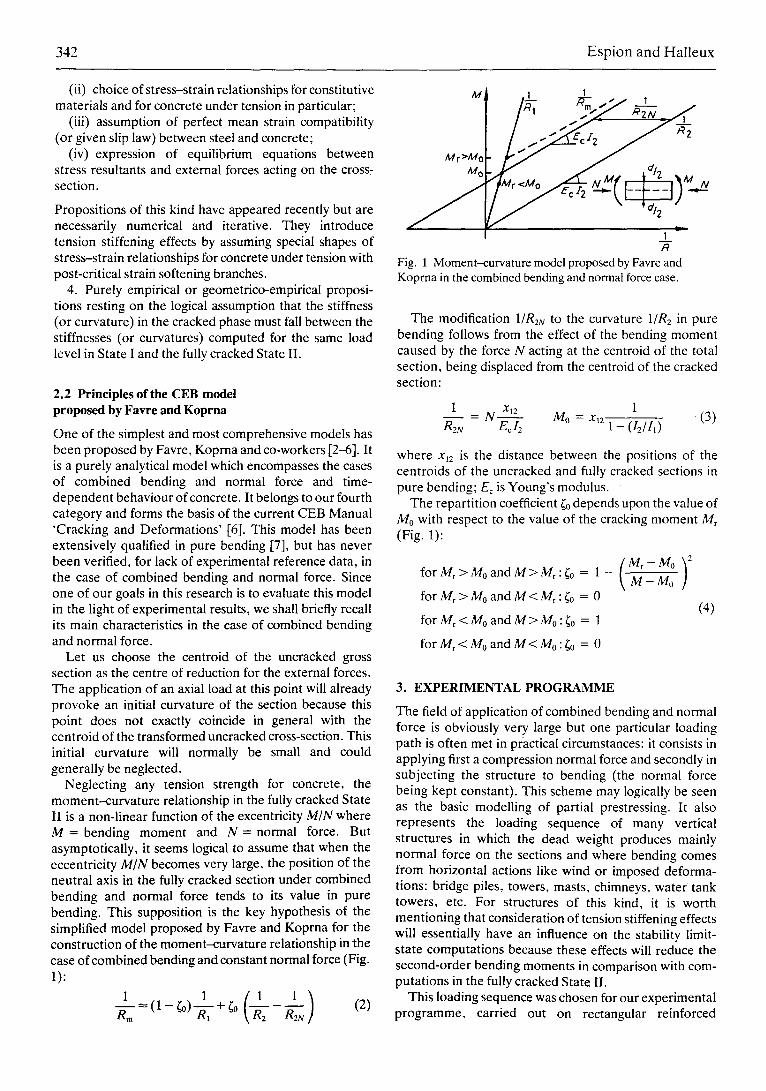
Fig. 7 Experimental moment-curvature relationship of beams (A) N0-D- 1.4 and (&) N2-D- 1.4, with curves computed from ( ) the CEB 158 model and ( - - - ) the present model.
33.3 N mm-2; f~a = fck/7,,, = 22.2 N mm -z and 0.85lea = 18 .9Nmm -2. For the reinforcement, the following characteristic yield strength fsk = 400 N mm -z was used and fsd = fsk/Ym = 348 N mm -z. The service bending moment is obtained from Ms = Mu/'Yq with yq = 1.5.
4.2 Evaluation of the CEB model proposed by Favre and Koprna
The ratios (theoretical curvature/experimental curvature) computed at the service load level are reported in TaMe 2. The average is 0.96 and, overall, we could infer that the CEB model adequately predicts the mean instantaneous curvature at the service load level. But this good average value includes some scattering: the model overestimates systematically the curvature in the case of tests on pure bending (NO) or with small normal force (N1) and underestimates regularly the curvature when the normal force increases. The underestimation is at its maximum in the N3 tests (N = 300 kN).
If we now attempt to evaluate this model for its overall prediction of the moment--curvature relationship, we could say
(i) that the M-(1/R) relationship seems correctly modelled when M, > M0 (of. Fig. 1), i.e. in the cases of pure bending tests (NO) or when the normal force is relatively small (N1);
(ii) that the computed M-(1/R) relationship is only a crude approximation of the experimental curve whenM0 > Mr (cf. Fig. 1), i.e. when the normal force is relatively large (N2, N3);
(iii) that, generally, the simplification introduced by Favre and Koprna - which consists in referring to the stiffnesses in State I and the fully cracked State II of pure bending only - seems too rough to represent precisely the
non-linear part of the moment--curvature relationship which follows from
(a) the influence of the tension stiffening effects and (b) the rapid variation of the compression zone depth
with the increase of the bending moment;
(iv) that the model, which is linear regarding the behaviour of concrete in compression, also deviates from the experimental trend when the bending moment becomes relatively large (more than 40 kN m in the case of our tests). It is at this point difficult to estimate whether this non-linearity follows from the fact that compressive stresses are high and consequently beyond the linear range of their intrinsic stress-strain law, or if it reveals the presence of short-term creep. In connection with this last remark, it is important to point out that the tests were generally completed within one hour.
4.3 Proposal of a refined model
We can deduce from the comments made above about the CEB model that a more precise modelling of the moment-curvature relationship in combined bending and normal force should take into account
(i) the variation in position of the neutral axis as a function of the eccentricity M/N;
(ii) the non-linearity of the stress-strain law for concrete in compression when the stresses become large;
(iii) the tension stiffening effects.
We propose here a model of the kind allowed by the CEB Model Code 78 and by its next edition [8]. It falls into the second category of our classification and is deduced from the fundamental formula
1 E~ + Esm
R~ - h~ (5)
Mater ia ls and Structures 347
with Esm , the average strain of the tensile reinforcement and E'r the average strain of the top fibre of the cross- section. The average strain of the reinforcement will be computed through some tension stiffening formula (Equation 1) taking into account the reduction in deformation (AE 0 provided by the cracked concrete in comparison with the strain E~2 computed in the fully cracked State II.
# Ecm ~ # Ec2 -- AE c
and the average curvature (Equation 5) becomes
(6)
1 EPc2+Es2 AE:+AE~ _ 1 A ( I ' ~ (7) R m h~ hu R2x \ K /
with l/R2x being the curvature computed in the fully cracked State II in combined bending and normal force.
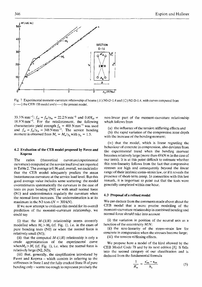
For the computation of AEs, we suggest using the tension stiffening formula which was deduced from our tests on reinforced concrete prisms in pure tension [9]. It is represented in Fig. 8 and its expression in the cracked phase is as follows:
1 for Ors2 > 2Crsr
(8) for o's~ < Ors2 < 2o',r
This representation of the constitutive law of a reinforce- ment surrounded by cracked concrete will probably be found, at least for its stabilized cracking part AE~ b, in the next edition of the CEB Model Code 1990 [8].
The rigorous calculation of Aa~ is more complex and should normally require iterative computations. But the
20"S r
O-sr
N ~ =~s
/ / / a tM
Ecr Esr E
Fig. 8 Constitutive law of a reinforcement surrounded by cracked concrete.
researchers who have used this kind of approach in pure bending [e.g. 10-16] have all noticed that AEr is small in comparison with AEs. In this paper, as a first approxima- tion, we will also assume that
-~-~.; (9)
The first problem to solve is the computation of AEs b. In Equation 8, er is the concrete strain corresponding to the tensile strength and is therefore given by e , = fr162 (assuming that the behaviour of concrete under tension remains linear up to its tensile strength); Esr is the strain of the reinforcement at the cracking bending moment level, computed in the fully cracked State II. What we call here the cracking moment is the moment M,2 obtained when the tensile strength fr is reached at the reinforcement level (hu) and assuming that the section behaves elastically and remains uncracked up to this moment level. The detailed computation of e~r is given in Appendix A. It is based on the solution of a third-degree equation to find the position of the neutral axis in the fully cracked State II under (N, Ma).
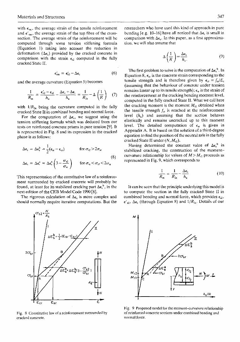
Having determined the constant value of AEs u in stabilized cracking, the construction of the moment- curvature relationship for values of M > Me proceeds as represented in Fig. 9, which corresponds to
1 1 AEs
8m R2x hu (i0)
It can be seen that the principle underlying this model is to compute the section in the fully cracked State II in combined bending and normal force, which provides es2, e'r AEs (through Equation 8) and 1/R2x. Details of our
M
Mr2 Mr1-
I12
/ ,,.2"/"-':" ._7,,0
hu/,~
Fig. 9 Proposed model for the moment-curvature relationship of reinforced concrete sections under combined bending and normal force.
348 E s p i o n a n d H a l l eux
computations are reported in Appendix B. For these computations in State II, the stress-strain relationship adopted for concrete in compression is non-linear and given by
' Eg2. < o ' c _ l _ ( l _ c ~ ) ~ foro~ = 1 fc
! O" c - - = i L
for a > l
(11)
with
a < I f, = r t - -
Ec = aCal~=0 c0
For n = 2, this stress-strain law becomes the classical parabola-rectangle.
Given that, for the chosen loading path, the value of the largest concrete strain at the top fibre of the section r may only increase, the moment-curvature relationship is constructed point by point for increasing values of r For each value of E'c2, a second-order equation is solved to find ~:, the depth of the compression zone in the fully cracked state. For this strain distribution (r ~), the average curvature is computed according to Equation 10 and the bending moment is obtained by expressing the equilibrium of the cross-section (Equation B16 in Appendix B). The construction could be refined by joining Points A and C in Fig. 9 with a straight line.
The results of our computations according to this model are represented in Figs 2 to 7. The following char- acteristics were adopted for the stress-strain relationship of concrete in compression:
f , = 37.9 N mm -z (mean prism strength)
Er = 32.5 kN mm -2
le t : 4 . 0 N mm -2
n = 2 (parabola)
The average Young's modulus for steel was 200 kN mm -2. In Table 2 are also reported the ratios (theoretical
curvature/experimental curvature) computed for the service bending moment. We can deduce that the proposed model gives an excellent prediction of the curvature at the service load level. Furthermore, this prediction is far more consistent over the whole range of the tests than the prediction made with the CEB model.
Overall, the proposed model also gives a very good fit for the whole experimental M-(1/R) relationship. The adoption of a non-linear o---~ law for concrete in compression is certainly useful in order to follow closely the experimental curve but, when the bending moment becomes greater than the service moment level, this hypothesis seems insufficient to represent precisely the non-linear part of the experimental M-(1/R) relationship
above the service load level in the case of singly reinforced sections (reinforced in tension only); we infer from this remark that in our tests, short-time creep effects superimpose themselves on the results in such a way that it would be meaningless to attempt a better prediction of the experimental results than within a -_+5% confidence interval without taking creep effects into account. On the other hand, the proposed method works very well for doubly reinforced sections where the presence of compressive steel counteracts the development of creep strains.
5. CONCLUSIONS
We summarize hereafter the principal conclusions of this research.
I. The authors have carefully studied the suggestions found in the literature for the construction of the moment-curvature relationship of reinforced or pre- stressed concrete sections in the cracked state (in connection with serviceability applications); they propose a classification in four categories.
2. Pure bending has been often and extensively analysed but, until now, little experimental or analytical work has been devoted to the case of combined bending and normal force. This is why an original series of tests was undertaken. Their purpose was to provide reference experimental data to quantify the influence of tension stiffening effects on the moment-curvature relationship in combined bending and compressive normal force. These data, which were lacking in the current literature, were used to evaluate two theoretical prediction models for the M-(1/Rm) relationship.
3. The first of these theoretical models is the simplified proposition by Favre and Koprna which forms the basis of the CEB-158 Deformation Manual [6]. This model, which has been verified earlier in pure bending [7], was compared for the first time with experimental results in combined bending and normal force. Considering its simplicity and ease of application, we may conclude that this model provides satisfactory results around the service load level.
4. In order to predict more precisely the whole 34-(1/ R) relation in combined bending and normal force, it becomes necessary, at the cost of simplicity, to take account of the variation in position of the neutral axis as a function of the excentricity and the non-linear behaviour of concrete in compression. The authors have established such a model which compares favourably with their experimental results. This model is purely analytical and uses only hypotheses recommended in the CEB Model Code. In particular, the tension stiffening effects are modelled using a formula previously derived by the authors from pure tension tests [9] and whose stabilized cracking part will be found in the next edition of the CEB Model Code 1990 [8].
5. With the aid of this model, the authors have succeeded in estimating the influence of tension stiffening
Mater i a l s and St ruc tures 349
effects on the moment--curvature relationship. These effects are at their maximum (and important to be taken into account) in the presence of lightly reinforced sections or small normal force. This conclusion seems logical because it is in these cases that the tensile area of concrete is also at its maximum. But even when large normal forces are acting, the consideration of tension stiffening effects is very useful to obtain a better prediction of experimental results.
ACKNOWLEDGEMENTS
B. Espion wishes to express his deepest appreciation to Professor Favre and his co-workers for the fruitful discussions he was able to have with them during his sabbatical leave at the Swiss Federal Institute of Technology in Lausanne (EPFL).
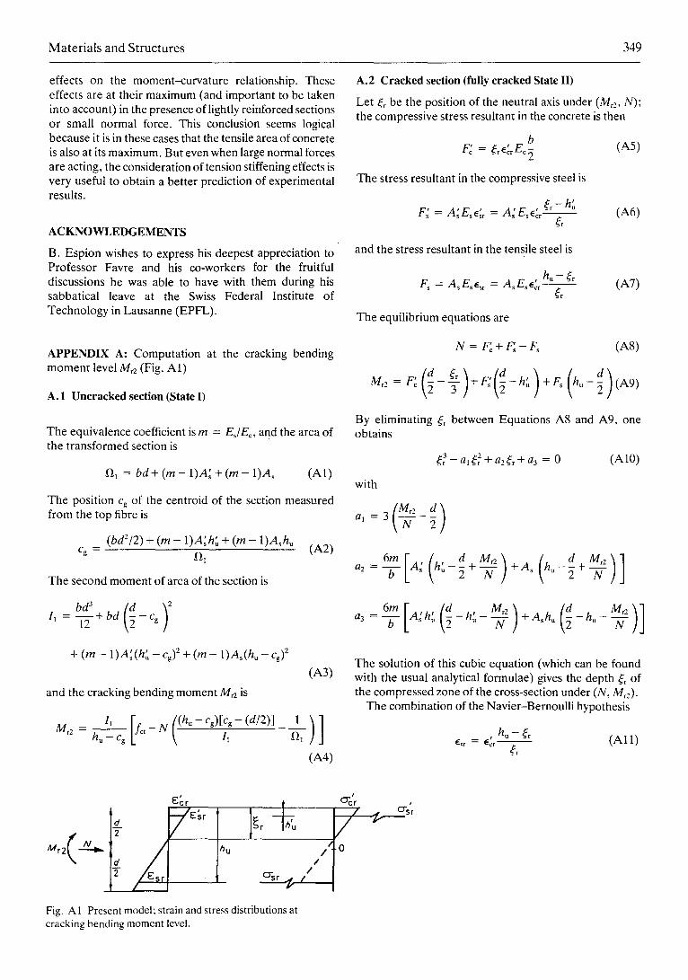
APPENDIX A: Computation at the cracking bending moment level M~2 (Fig. A1)
A. 1 Uncracked section (State I)
The equivalence coefficient is rn = EJEr and the area of the transformed section is
f~ = bd+ (m - 1)A: + (m - 1)A~ (A1)
The position Cg of the centroid of the section measured from the top fibre is
(bd2/2) + (m - 1)A~h" + (m - 1)A~hu Cg = 121 (A2)
The second moment of area of the section is
I 1 12 + bd - Cg
+ (m - 1)A~(h" - Cg) 2 + (m - l)As(hu - Cg) 2
and the cracking bending moment M~2 is
(A3)
l~ [f~ ((hu-cg)[Cg-(d/2)] M r 2 - h~ - c~ t - N 1I
1
(A4)
A.2 Cracked section (fully cracked State II)
Let ~:~ be the position of the neutral axis under (M~2, N); the compressive stress resultant in the concrete is then
b F" = ~rE'crEr (A5)
The stress resultant in the compressive steel is
F~ = A~Esr = A ' E s E ' c r - - (~ -h"
(r (A6)
and the stress resultant in the tensile steel is
Fs = AsEse~r = AsEsE'crh"@rr ~ (A7)
The equilibrium equations are
N = F'r (A8)
(~ ~ r ) + F ~ ( ~ - h t u ) + F s ( h u - d ) (A9) Mr2 = F'c - -~-
By eliminating (r between Equations A8 and A9, one obtains
~3 +al~2r +a2~r+a3 = 0 (A10)
with
al = 3 2
6m[( d a2 = - - f f - A2 h ' - ~ +
Mr2) ( r2)] + As h u - - +
N 2 N
a3 = --if- A'h' . - h ' - ~ +A~h. - h u - - -~
The solution of this cubic equation (which can be found with the usual analytical formulae) gives the depth s of the compressed zone of the cross-section under (N, Mr2).
The combination of the Navier-Bernoulli hypothesis
hu -- ~r e~r = E ; r - - ( A l l ) r
V E:~ I lh u t
Crsr g" (/ I Fig. A 1 Present model; strain and stress distributions at cracking bending moment level.
s Crsr
350 Espion and Halleux
and equation A9 gives
o'~ = 2mM~2(h~ - (~) / (~b
+ mEA~ (~:, - h'u)(d - 2h~) + A~((~ - hu)(d - 2h.)] }
(A12)
and finally
~ = o-~/ Es
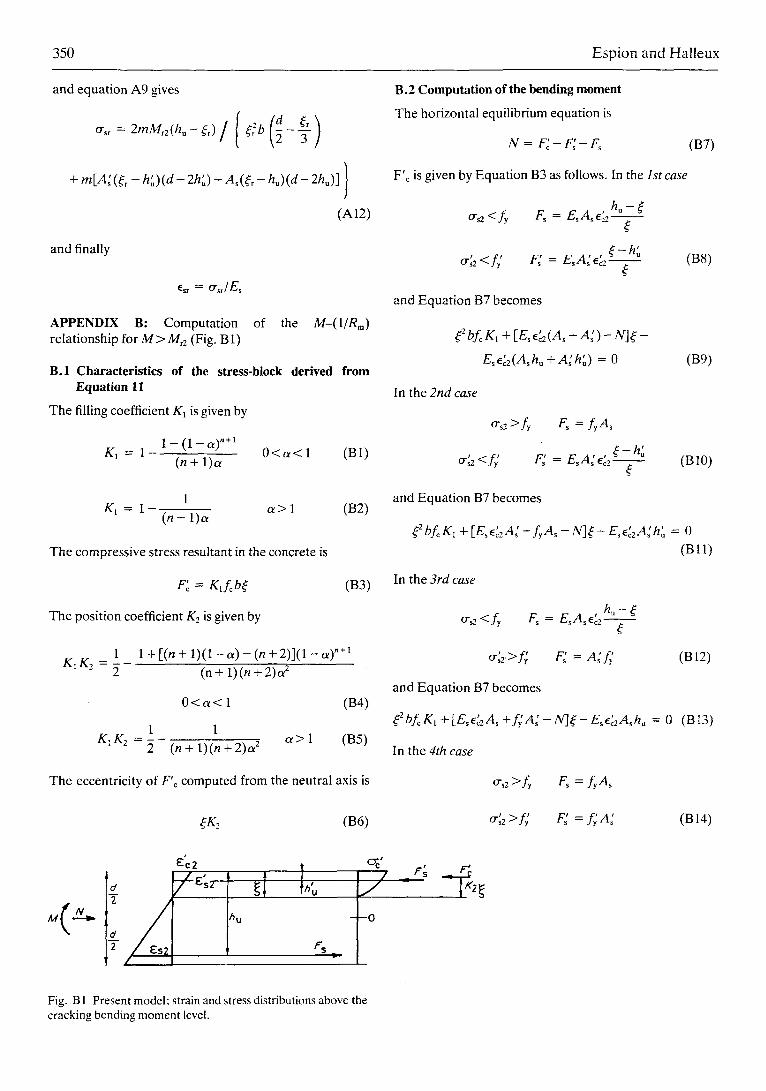
APPENDIX B: Computation of the M-(I/Rm) relationship for M > Mr2 (Fig. B1)
B.1 Characteristics of the stress-block Equation 11
The filling coefficient K~ is given by
1 - (1 - o0 "+1 K~ = 1 0 < o z < l
(n + 1)a
1 K I = 1
(n + 1)a" a > l
The compressive stress resultant in the concrete is
F ~ = K , L b (
The position coefficient K2 is given by
KIK2 -
derived from
(B1)
(B2)
(B3)
1 1 + [(n + 1) (1- a ) - (n + 2)](1 - a) "+~ 2 (n + 1) (n + 2)a 2
0 < a < 1 (B4)
1 1 K:K2 = ~ - (n+ 1 ) (n+2)a 2 a > 1 (B5)
The eccentricity of F'r computed from the neutral axis is
seK2 (B6)
B.2 Computation of the bending moment
The horizontal equilibrium equation is
N = F" + F" - F~ (B7)
F'r is given by Equation B3 as follows. In the Ist case
O's2 <fy Fs = EsAse'c2 h u - ( r
o';z<f; F; = EsA;e'r ( - h " (B8) (
and Equation B7 becomes
r + [E~ .'2 (A~ + A ' ) - N]( -
E~E'~2(A~hu +A'h',,) = 0 (B9)
In the 2nd case
o'~2 >fy F~ = fyAs
a-h ; o'~z<f/ F; = E~A" e ' r (B10)
(
and Equation B7 becomes
seZ bf~K~ + [Ese'~2A~ - fyAs - IV]( - Ese'zA" h" = 0 (Bl l )
In the 3rd case
crsa<fy F~ = EsAs,E'c2 h u - (
o'~z>f; F; = A; f ; (B12)
and Equation B7 becomes
~ZbfcK1 + [Esa'zA~ + f ;A; - N ] ( - E~E~2A~h. = 0 (BI3)
In the 4th case
o'sz >fy Fs = fyAs
0";2 >f~ F" = fyA~ (B14)
+l:z /
C'C2 &c' Fs r ' - - -
Fig. B 1 Present model; strain and stress distributions above the cracking bending moment level.
Materials and Structures 351
and Equation B7 becomes
= N + f y A s - f y A ~ K, bfc (B15)
Finally, the moment of these resultant forces computed about the mid-height axis gives the bending moment M:
REFERENCES
1. Schlaich, J. and Schober, H., 'Versusche zur Mitwirkung des betons in der Zugzone von Stahlbetonr6hren', D.A.f]Stb. (W. Ernst & Sohn, Berlin) H.363 (1985) 1-76.
2. Favre, R., Koprna, M. and Radojicic, A,, "Effets Diff6r6s, Fissuration et Ddformations des Structures en Bdton' (Georgi, Saint-Saphorin, Switzerland, 1980).
3. Favre, R., Koprna, M. and Putallaz, J.C., 'Deformation of concrete structures; theoretical basis for the calcu{ation', IABSE Periodica S-16-81 (1981).
4. Favre, R., 'Verformungsberechnung yon Tragwerken aus Stahl- und Spannbeton', Schweiz. Ingen. Architekt H.43 (1981).
5. Ghali, A. and Favre, R., 'Concrete Structures; Stresses and Deformations" (Chapman and Hall, London, 1986) 144-252.
6. Comit6 Euro-International du B6ton, 'CEB Design Manual
on Cracking and Deformations', Bull. d'lnformation 158- E (1985) 3. l-3.16.
7. Jaccoud, J.P. and Favre, R., 'Flbche des structures en bdton arm& Vdrification expfrimentale d'une m6thode de calcul', Ann. ITBTP 406 (BETON 208) (1982) 23-66.
8. Comit6 Euro-lnternational du Bdton, 'Summary and analysis of observations concerning the revision of the CEB/FIP Model Code 78", Bull. d'Information 176 (Part B) (1987) 16.1-16.1l.
9. Espion, B., Provost, M, and Halleux, P., 'Rigidit6 d'une zone tendue de bdton arm6", Mater. Constr. 18(105) (1985) 185-191.
10. Johnson, A.I., 'Deformations of reinforced concrete', Proc. IABSE I1 (1951) 253--290.
1 I. Ferry Borges, J., 'Cracking and deformability of reinforced concrete beams', Ibid. 26 (1966) 75-95.
12. Rao, P.S., 'Die Grundlagen zur Berechnung der bei statisch unbestimmten Stah[betonkonstruktionien im plastischen Bereich auftretenden Umlagerungen der Schnittkr~ifte', D.A.f.Stb. (W. Ernst & Sohn, Berlin) H. 177 (1966).
13. Rao, P.S. and Subrahmanyam, B.V., "Trisegmental moment-curvature relations for reinforced concrete members', Proc. AC170(5) (1973) 346-351.
14. Rostasy, F.S., Koch, R. and Leonhardt, F., "Zur Mindestbewehrung for Zwang von Aul3enw~inden aus Stahlleichtbeton', D.A.f.Stb. (W. Ernst & Sohn, Berlin) H.267 (1976) 6--83.
15. Noakowski, P. and Kupfer, H., 'Versteifende Mitwirkung des Betons im Zugbereich von Turmartigen Bauwerken', B.u.Stb. H.10 (1981) 241-246.
16. Leonhardt, F., 'Vorlesungen/~ber Massivbau, vierter Teil: Nachweis der Gebrauchsf/ihigkeit', 2rid edn (Springer, Berlin, 1978) 85-94.
Related Documents