Phone: 800-521-0546 E-mail: [email protected] Fax: 800-505-3299 www.pcs-company.com MOLD ACTION MOLD ACTION C1 Angle Pins...................................................................................................................C3 Cores PCS CUMSA™ Compact Coring Unit...............................................................C5 PCS CUMSA™ Double Ejectors......................................................................C8 PCS CUMSA™ Flexible Cores.........................................................................C6 PCS CUMSA™ Sprung Cores.........................................................................C7 PCS CUMSA™ Tulip Ejectors.........................................................................C9 Lifters E-Z Lifter Series.............................................................................................C10 PCS CUMSA™ Compact Housing Lifters.......................................................C19 Trunnion Lifter .................................................................................................C20 Plate Sequence Control Friction Puller .................................................................................................C69 Latch Lock Sets.............................................................................................C58 Roller Pulling Assemblies...............................................................................C65 Ready Slide Assemblies 100 Series Ready Slide Assemblies...............................................................C22 200 Series Ready Slide Assemblies...............................................................C24 300 Series Ready Slide Assemblies...............................................................C26 MOLD ACTION

Welcome message from author
This document is posted to help you gain knowledge. Please leave a comment to let me know what you think about it! Share it to your friends and learn new things together.
Transcript

Phone: 800-521-0546 E-mail: [email protected] Fax: 800-505-3299www.pcs-company.com
MO
LD A
CTI
ON
MO
LD A
CTI
ON
C1
Angle Pins...................................................................................................................C3
Cores PCS CUMSA™ Compact Coring Unit...............................................................C5
PCS CUMSA™ Double Ejectors......................................................................C8 PCS CUMSA™ Flexible Cores.........................................................................C6
PCS CUMSA™ Sprung Cores.........................................................................C7
PCS CUMSA™ Tulip Ejectors.........................................................................C9
Lifters E-Z Lifter Series.............................................................................................C10
PCS CUMSA™ Compact Housing Lifters.......................................................C19
Trunnion Lifter.................................................................................................C20
Plate Sequence Control Friction Puller.................................................................................................C69 Latch Lock Sets.............................................................................................C58
Roller Pulling Assemblies...............................................................................C65
Ready Slide Assemblies 100 Series Ready Slide Assemblies...............................................................C22
200 Series Ready Slide Assemblies...............................................................C24
300 Series Ready Slide Assemblies...............................................................C26
MOLD ACTION

Phone: 800-521-0546 E-mail: [email protected] Fax: 800-505-3299www.pcs-company.com
MO
LD A
CTI
ON
MO
LD A
CTI
ON
C2
Slides
PCS CUMSA™ Auto Slide Retainer...............................................................C29
PCS CUMSA™ Modular Retainer..................................................................C30
Slide Latch......................................................................................................C32
Slide Retainers.................................................................................................C31
Wear Products
Bronze Plated Wear Plate..............................................................................C38
Gib Assemblies..............................................................................................C46 Gib Base Plates.............................................................................................C49
L-Gibs............................................................................................................C42
Self-Lubricating Square Gibs.............................................................................C47 Self-Lubricating Wear Plate............................................................................C40 Side Plates....................................................................................................C41 T-Slides for Gib Assemblies...........................................................................C48
Wear Strips....................................................................................................C50
MOLD ACTION
Phone: 800-521-0546 E-mail: [email protected] Fax: 800-505-3299www.pcs-company.com
MO
LD A
CTI
ON
MO
LD A
CTI
ON
C3
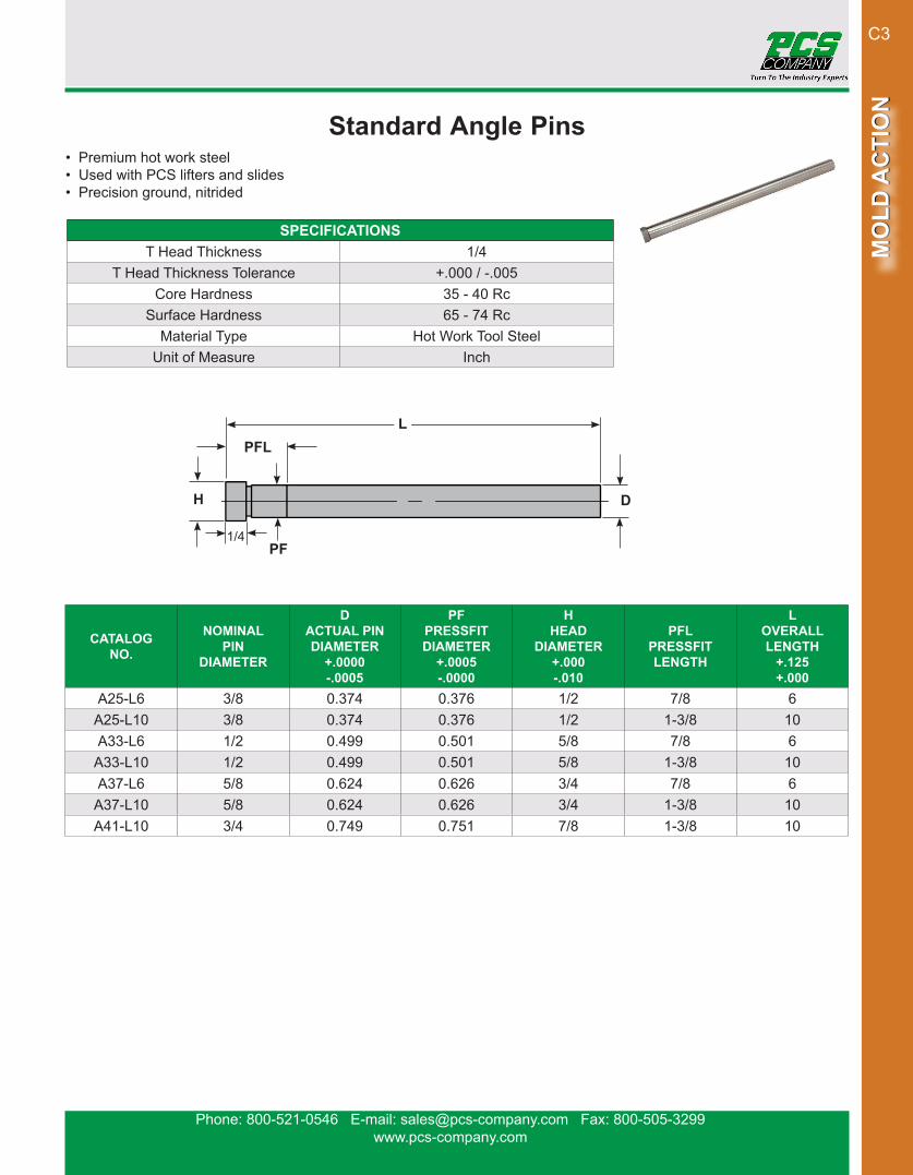
Standard Angle Pins• Premium hot work steel• Used with PCS lifters and slides• Precision ground, nitrided
CATALOG NO.
NOMINAL PIN
DIAMETER
D ACTUAL PIN DIAMETER
+.0000-.0005
PFPRESSFIT DIAMETER
+.0005-.0000
H HEAD
DIAMETER+.000-.010
PFL PRESSFIT LENGTH
L OVERALL LENGTH
+.125+.000
A25-L6 3/8 0.374 0.376 1/2 7/8 6A25-L10 3/8 0.374 0.376 1/2 1-3/8 10A33-L6 1/2 0.499 0.501 5/8 7/8 6
A33-L10 1/2 0.499 0.501 5/8 1-3/8 10A37-L6 5/8 0.624 0.626 3/4 7/8 6
A37-L10 5/8 0.624 0.626 3/4 1-3/8 10A41-L10 3/4 0.749 0.751 7/8 1-3/8 10
SPECIFICATIONST Head Thickness 1/4
T Head Thickness Tolerance +.000 / -.005Core Hardness 35 - 40 Rc
Surface Hardness 65 - 74 RcMaterial Type Hot Work Tool Steel
Unit of Measure Inch
H D
1/4PF
LPFL

Phone: 800-521-0546 E-mail: [email protected] Fax: 800-505-3299www.pcs-company.com
MO
LD A
CTI
ON
MO
LD A
CTI
ON
C4
Radius Angle Pins• Pre-machined spherical radius on head• Used with PCS lifters and slides• Premium hot work steel• Precision ground, nitrided
CATALOG NO.
NOMINAL PIN DIA.
D ACTUAL PIN DIA.+.0000-.0005
PF PRESS FIT DIAMETER
+.0005-.0000
R HEAD
RADIUS
H HEAD
DIAMETER+.000-.010
T HEAD
THICKNESS+.000-.005
PFL PRESSFIT LENGTH
L OVERALL LENGTH
+.125+.000
APR25-L5 3/8 0.374 0.376 3/8 1/2 1/4 7/8 5APR25-L6 3/8 0.374 0.376 3/8 1/2 1/4 7/8 6APR25-L7 3/8 0.374 0.376 3/8 1/2 1/4 1-3/8 7
APR25-L10 3/8 0.374 0.376 3/8 1/2 1/4 1-3/8 10APR33-L5 1/2 0.499 0.501 1/2 5/8 1/4 7/8 5APR33-L6 1/2 0.499 0.501 1/2 5/8 1/4 7/8 6APR33-L7 1/2 0.499 0.501 5/8 5/8 1/4 1-3/8 7
APR33-L10 1/2 0.499 0.501 1/2 5/8 1/4 1-3/8 10APR37-L6 5/8 0.624 0.626 5/8 3/4 1/4 7/8 6
APR37-L10 5/8 0.624 0.626 5/8 3/4 1/4 1-3/8 10APR41-L7 3/4 0.749 0.751 3/4 7/8 1/4 1-3/8 7
APR41-L10 3/4 0.749 0.751 3/4 7/8 1/4 1-3/8 10APR41-L14 3/4 0.749 0.751 3/4 7/8 1/4 1-3/8 14APR47-L10 1 0.999 1.001 1 1-1/8 5/16 1-3/8 10APR47-L14 1 0.999 1.001 1 1-1/8 5/16 1-3/8 14
SPECIFICATIONSCore Hardness 35 - 40 Rc
Surface Hardness 65 - 74 RcMaterial Type Hot Work Tool Steel
Unit of Measure Inch
D
T PF
LR PFL
H

Phone: 800-521-0546 E-mail: [email protected] Fax: 800-505-3299www.pcs-company.com
MO
LD A
CTI
ON
MO
LD A
CTI
ON
C5
PCS CUMSA™ Compact Coring Units• Cores out holes with a maximum 4mm part thickness• Easy to install from outside of the mold• Installation contained on one half of the mold• Pin not included
The Compact Coring Unit cores out holes with a maximum 4 mm part thickness. This unit is easy to install from outside of the mold as installation is contained on one half of the mold. This compact solution reduces the costs associated with machining and fitting.
CATALOG NO.UA 363616
SPECIFICATIONSMaterial Type 1.2344
Unit of Measure Metric DIN14
10
4
Mat. 1.2379Hard. 58 ± 2 HRC
ISO 10243 V
8
20
24
24R6
ø5DIN1530
ø10 x 6
36-0.05
36-0.05
16-0.05
5-0.1
0.5-0.1
6.3
6.3
6.3
6.3 6.36.3
6.3
6.3 6.36.3
M5x25DIN912
20.5
ø10.5 +0.5

Phone: 800-521-0546 E-mail: [email protected] Fax: 800-505-3299www.pcs-company.com
MO
LD A
CTI
ON
MO
LD A
CTI
ON
C6
PCS CUMSA™ Flexible Cores• Minimum space required for installation• Includes simple adjustment system• Ejects first then releases undercut
Flexible Cores are useful when releasing small undercuts ranging in thickness from 6 mm to 12 mm. These cores are easy to install and come ready to be machined. The need for slides can be eliminated when using the Flexible Core. For variations of undercuts, refer to the Tulip or Double Ejector.
CATALOG NO. A B C G H L M N P R BALINIT
C®PF 044150 4 8 24 6 5 150 12 14 0.8 30 •PF 054150 5 8 24 6 6 150 12 14 0.8 30 •PF 064200 6 12 30 8 7 200 18 20 1 36 •PF 0642WB 6 12 30 8 7 200 18 20 1 36PF 084200 8 14 30 8 9 200 18 20 1 36 •PF 104200 10 16 30 8 11 200 18 20 1 36 •PF 124200 12 18 30 8 13 200 18 20 1 36 •
SPECIFICATIONSHardness 42 - 48 Rc
Material Type 1.2101Unit of Measure Metric DIN
Hard.
6.3
6.3
6.3
2.54
C
6.3
L±2
øB G
R 0.15
-0.05-0.2
-0.02
A-0.02
Phone: 800-521-0546 E-mail: [email protected] Fax: 800-505-3299www.pcs-company.com
MO
LD A
CTI
ON
MO
LD A
CTI
ON
C7
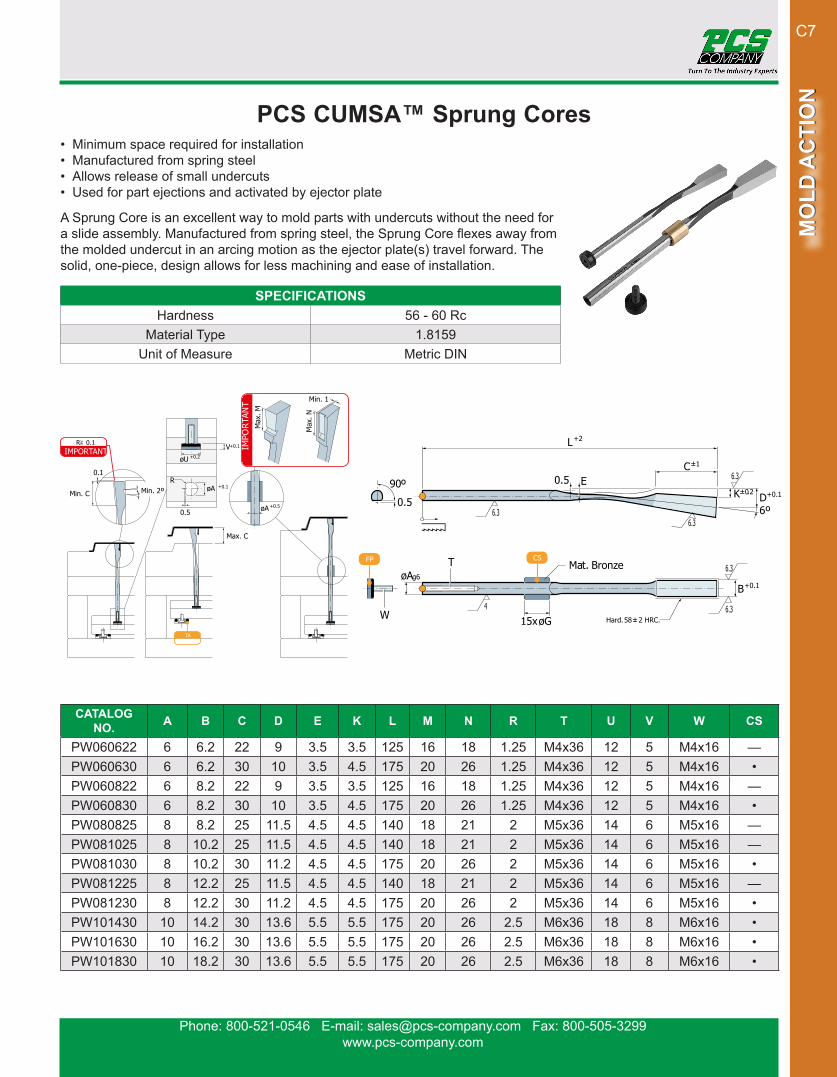
PCS CUMSA™ Sprung Cores• Minimum space required for installation• Manufactured from spring steel• Allows release of small undercuts• Used for part ejections and activated by ejector plate
A Sprung Core is an excellent way to mold parts with undercuts without the need for a slide assembly. Manufactured from spring steel, the Sprung Core flexes away from the molded undercut in an arcing motion as the ejector plate(s) travel forward. The solid, one-piece, design allows for less machining and ease of installation.
CATALOG NO. A B C D E K L M N R T U V W CS
PW060622 6 6.2 22 9 3.5 3.5 125 16 18 1.25 M4x36 12 5 M4x16 —PW060630 6 6.2 30 10 3.5 4.5 175 20 26 1.25 M4x36 12 5 M4x16 •PW060822 6 8.2 22 9 3.5 3.5 125 16 18 1.25 M4x36 12 5 M4x16 —PW060830 6 8.2 30 10 3.5 4.5 175 20 26 1.25 M4x36 12 5 M4x16 •PW080825 8 8.2 25 11.5 4.5 4.5 140 18 21 2 M5x36 14 6 M5x16 —PW081025 8 10.2 25 11.5 4.5 4.5 140 18 21 2 M5x36 14 6 M5x16 —PW081030 8 10.2 30 11.2 4.5 4.5 175 20 26 2 M5x36 14 6 M5x16 •PW081225 8 12.2 25 11.5 4.5 4.5 140 18 21 2 M5x36 14 6 M5x16 —PW081230 8 12.2 30 11.2 4.5 4.5 175 20 26 2 M5x36 14 6 M5x16 •PW101430 10 14.2 30 13.6 5.5 5.5 175 20 26 2.5 M6x36 18 8 M6x16 •PW101630 10 16.2 30 13.6 5.5 5.5 175 20 26 2.5 M6x36 18 8 M6x16 •PW101830 10 18.2 30 13.6 5.5 5.5 175 20 26 2.5 M6x36 18 8 M6x16 •
SPECIFICATIONSHardness 56 - 60 Rc
Material Type 1.8159Unit of Measure Metric DIN
6.3
4
6.3
6.3
6.3
6.3
K
B
C
L
0.5
15xøG
øA
0.5
90º
T
ED6º
CS
Hard. 58 ± 2 HRC.
FP
W
+2
+0.1
+0.1g6
±0.2
±1
Mat. Bronze
øA
øU
øA
0.5
R
V
0.1
Min. 2ºMin. C
+0.5
+0.2
+0.1
TA
+0.1
Max. C
IMPORTANTR 0.1
IMPO
RTAN
T Min. 1
Max
. M
Max
. N
Phone: 800-521-0546 E-mail: [email protected] Fax: 800-505-3299www.pcs-company.com
MO
LD A
CTI
ON
MO
LD A
CTI
ON
C8
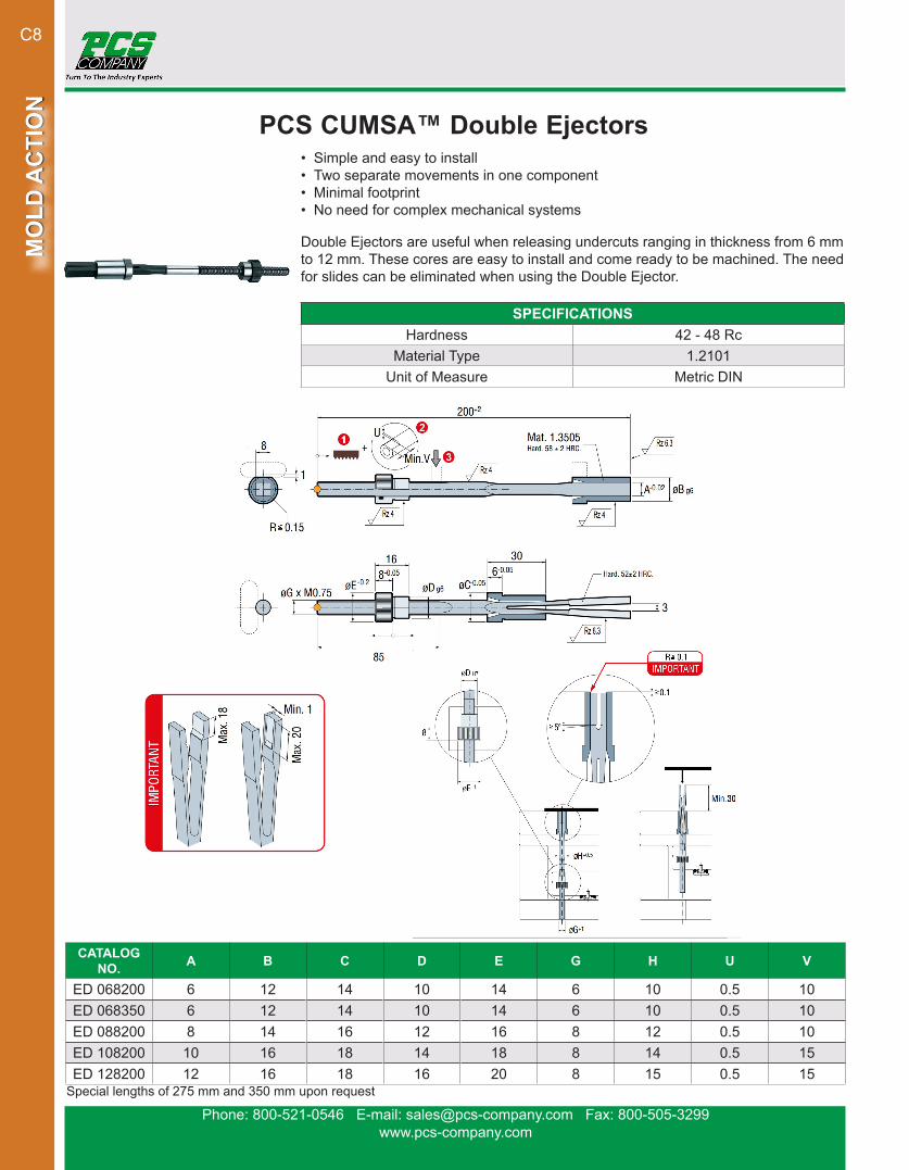
PCS CUMSA™ Double Ejectors• Simple and easy to install• Two separate movements in one component• Minimal footprint• No need for complex mechanical systems
Double Ejectors are useful when releasing undercuts ranging in thickness from 6 mm to 12 mm. These cores are easy to install and come ready to be machined. The need for slides can be eliminated when using the Double Ejector.
CATALOG NO. A B C D E G H U V
ED 068200 6 12 14 10 14 6 10 0.5 10ED 068350 6 12 14 10 14 6 10 0.5 10ED 088200 8 14 16 12 16 8 12 0.5 10ED 108200 10 16 18 14 18 8 14 0.5 15ED 128200 12 16 18 16 20 8 15 0.5 15
SPECIFICATIONSHardness 42 - 48 Rc
Material Type 1.2101Unit of Measure Metric DIN
Special lengths of 275 mm and 350 mm upon request
Phone: 800-521-0546 E-mail: [email protected] Fax: 800-505-3299www.pcs-company.com
MO
LD A
CTI
ON
MO
LD A
CTI
ON
C9
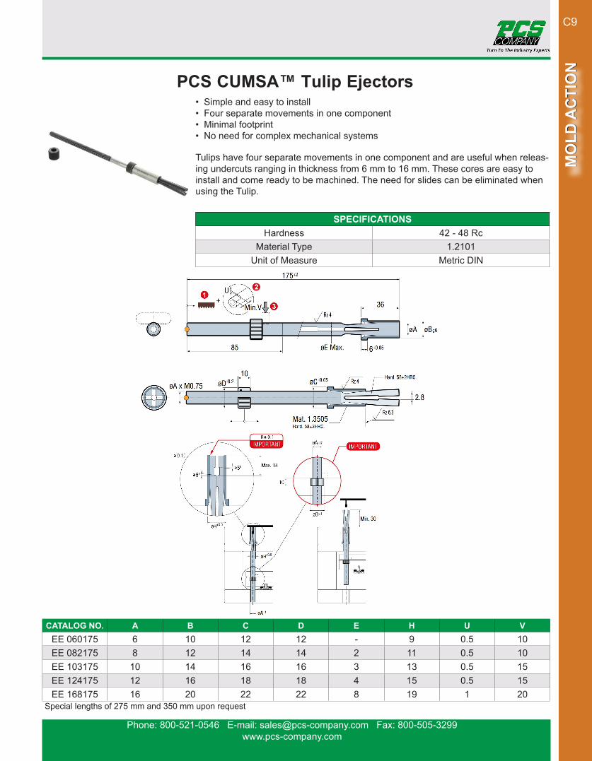
PCS CUMSA™ Tulip Ejectors• Simple and easy to install• Four separate movements in one component• Minimal footprint• No need for complex mechanical systems
Tulips have four separate movements in one component and are useful when releas-ing undercuts ranging in thickness from 6 mm to 16 mm. These cores are easy to install and come ready to be machined. The need for slides can be eliminated when using the Tulip.
CATALOG NO. A B C D E H U VEE 060175 6 10 12 12 - 9 0.5 10EE 082175 8 12 14 14 2 11 0.5 10EE 103175 10 14 16 16 3 13 0.5 15EE 124175 12 16 18 18 4 15 0.5 15EE 168175 16 20 22 22 8 19 1 20
SPECIFICATIONSHardness 42 - 48 Rc
Material Type 1.2101Unit of Measure Metric DIN
Special lengths of 275 mm and 350 mm upon request

Phone: 800-521-0546 E-mail: [email protected] Fax: 800-505-3299www.pcs-company.com
MO
LD A
CTI
ON
MO
LD A
CTI
ON
C10
TO DETERMINEANGLE
L/S = Tan A
SEE CHARTFOR REFERENCE
Patent No. 5,281,127
2. Determine / Calculate Angle
A. MINI B. STANDARD C. COMPACT
1. Determine a Lifter Blank Size
E-Z Lifter Application Guide Choosing your E-Z Lifter System
TYPICAL EXAMPLESEJECTION STROKE(S)
LIFTER ANGLE (A)5° 6° 7° 8° 9° 10° 11°
.813 .071 .085 .100 .114 .129 .143 .1581.063 .093 .112 .131 .149 .168 .187 .2071.563 .137 .164 .192 .220 .248 .276 .3042.063 .180 .217 .253 .290 .327 .364 .4012.563 .224 .269 .315 .360 .406 .452 .4983.063 .268 .322 .376 .430 .485 .540 .595
Phone: 800-521-0546 E-mail: [email protected] Fax: 800-505-3299www.pcs-company.com
MO
LD A
CTI
ON
MO
LD A
CTI
ON
C11
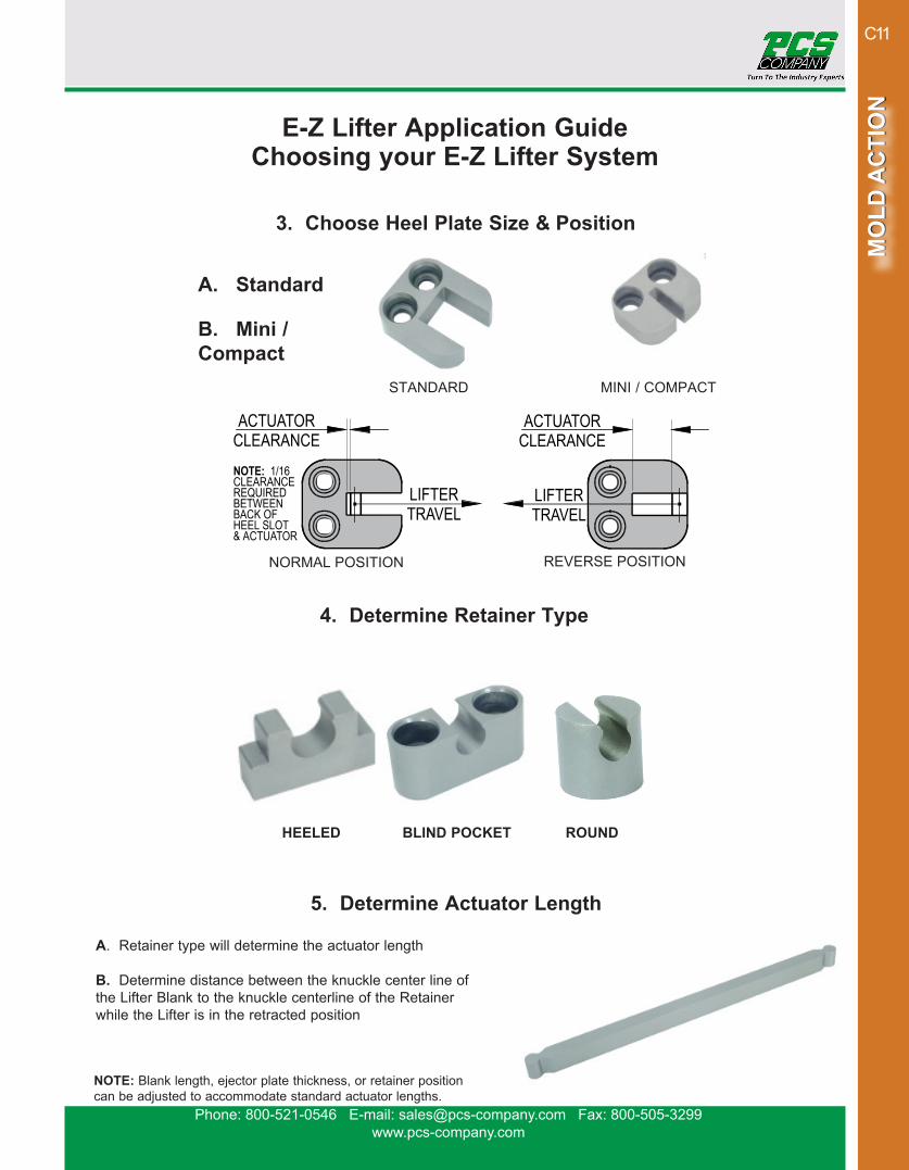
3. Choose Heel Plate Size & Position
A. Standard
B. Mini / Compact
MINI / COMPACT
NORMAL POSITION REVERSE POSITION
4. Determine Retainer Type
HEELED BLIND POCKET ROUND
5. Determine Actuator Length
STANDARD
A. Retainer type will determine the actuator length
B. Determine distance between the knuckle center line of the Lifter Blank to the knuckle centerline of the Retainer while the Lifter is in the retracted position
NOTE: Blank length, ejector plate thickness, or retainer position can be adjusted to accommodate standard actuator lengths.
E-Z Lifter Application Guide Choosing your E-Z Lifter System
Phone: 800-521-0546 E-mail: [email protected] Fax: 800-505-3299www.pcs-company.com
MO
LD A
CTI
ON
MO
LD A
CTI
ON
C12
.562
.625
.436.375
.375
.312DIA MAX
DIA MAX
DIA MAXDIA MAX
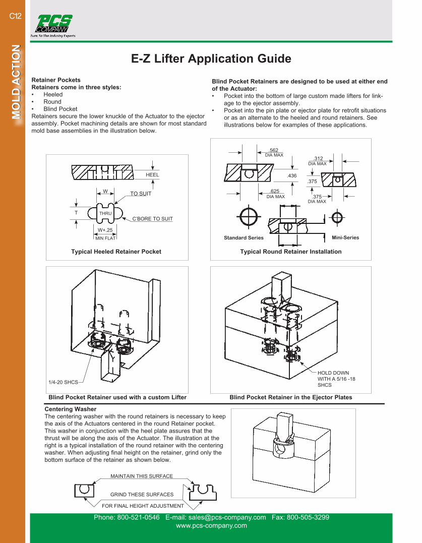
Retainer PocketsRetainers come in three styles:• Heeled• Round• Blind PocketRetainers secure the lower knuckle of the Actuator to the ejectorassembly. Pocket machining details are shown for most standard mold base assemblies in the illustration below.
Centering WasherThe centering washer with the round retainers is necessary to keep the axis of the Actuators centered in the round Retainer pocket.This washer in conjunction with the heel plate assures that thethrust will be along the axis of the Actuator. The illustration at the right is a typical installation of the round retainer with the centering washer. When adjusting final height on the retainer, grind only the bottom surface of the retainer as shown below.
Blind Pocket Retainer used with a custom Lifter
Typical Heeled Retainer Pocket Typical Round Retainer Installation
Standard Series Mini-Series
Blind Pocket Retainer in the Ejector Plates
Blind Pocket Retainers are designed to be used at either end of the Actuator:• Pocket into the bottom of large custom made lifters for link-
age to the ejector assembly.• Pocket into the pin plate or ejector plate for retrofit situations
or as an alternate to the heeled and round retainers. See illustrations below for examples of these applications.
HEEL
W
W+.25
T
MIN FLAT
THRU
TO SUIT
C’BORE TO SUIT
1/4-20 SHCS
MAINTAIN THIS SURFACE
GRIND THESE SURFACES
FOR FINAL HEIGHT ADJUSTMENT
HOLD DOWNWITH A 5/16 -18SHCS
E-Z Lifter Application Guide

Phone: 800-521-0546 E-mail: [email protected] Fax: 800-505-3299www.pcs-company.com
MO
LD A
CTI
ON
MO
LD A
CTI
ON
C13
E-Z Lifter™ Compact Series• Smooth pivoting motion inhibits galling and reduces wear• Design eliminates blow back problems• Heel plates stabilize actuator and act as a positive stop• Pre-hardened Lifter blanks, no heat treat necessary• No moving parts in ejector plate (no wear plate assemblies of sliding shoes)• Simple stationary retainer installed between the ejector plates saves time and machining costs• All E-Z Lifter™ components in stock• Patent No. 5,281,127
LIFTER BLANKS
CATA-LOG NO.
T-.0005-.001
WL
+.000-.001
C COMPATIBLE ACTUATOR
TL1* .325 0.425 1.375 .145 AM20TL2* .483 0.583 1.375 .177 AM20
LIFTER BLANKS SPECIFICATIONSMaterial Type Pre-Hardened S-7 Steel
Surface Hardness 54 - 56 RcUnit of Measure Inch
*For mirrored lifter blanks, please add “-L” to part # when ordering. (i.e. TL1-L)
HEEL PLATES
CATALOG NO.
T+.005-.000
MHP-100 .103MHP-200 .203
HEEL PLATE SPECIFICATIONSMaterial Type A-2
Surface Hardness 40 - 44 RcUnit of Measure Inch
.20R
LIFTER BLANKS HEEL PLATE
Phone: 800-521-0546 E-mail: [email protected] Fax: 800-505-3299www.pcs-company.com
MO
LD A
CTI
ON
MO
LD A
CTI
ON
C14
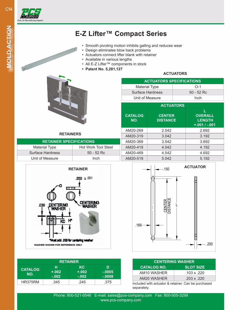
E-Z Lifter™ Compact Series• Smooth pivoting motion inhibits galling and reduces wear• Design eliminates blow back problems• Actuators connect lifter blank with retainer• Available in various lengths• All E-Z Lifter™ components in stock• Patent No. 5,281,127
ACTUATORS
CATALOG NO.
CENTER DISTANCE
L OVERALL LENGTH
+.001 / -.001AM20-269 2.542 2.692AM20-319 3.042 3.192AM20-369 3.542 3.692AM20-419 4.042 4.192AM20-469 4.542 4.692AM20-519 5.042 5.192
ACTUATORS SPECIFICATIONSMaterial Type O-1
Surface Hardness 50 - 52 RcUnit of Measure Inch
RETAINER
CATALOG NO.
H+.002-.002
KC+.002-.002
D-.0005-.0008
HR375RM .345 .245 .375
RETAINER SPECIFICATIONSMaterial Type Hot Work Tool Steel
Surface Hardness 50 - 52 RcUnit of Measure Inch
CENTERING WASHERCATALOG NO. SLOT SIZEAM10 WASHER .103 x .220AM20 WASHER .203 x .220
Included with actuator & retainer. Can be purchased separately.
ACTUATORRETAINER
ACTUATORS
RETAINERS
Phone: 800-521-0546 E-mail: [email protected] Fax: 800-505-3299www.pcs-company.com
MO
LD A
CTI
ON
MO
LD A
CTI
ON
C15
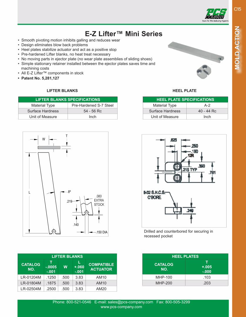
E-Z Lifter™ Mini Series• Smooth pivoting motion inhibits galling and reduces wear• Design eliminates blow back problems• Heel plates stabilize actuator and act as a positive stop• Pre-hardened Lifter blanks, no heat treat necessary• No moving parts in ejector plate (no wear plate assemblies of sliding shoes)• Simple stationary retainer installed between the ejector plates saves time and machining costs• All E-Z Lifter™ components in stock• Patent No. 5,281,127
LIFTER BLANKS SPECIFICATIONSMaterial Type Pre-Hardened S-7 Steel
Surface Hardness 54 - 56 RcUnit of Measure Inch
HEEL PLATE SPECIFICATIONSMaterial Type A-2
Surface Hardness 40 - 44 RcUnit of Measure Inch
LIFTER BLANKS
CATALOG NO.
T-.0005-.001
WL
+.060-.001
COMPATIBLE ACTUATOR
LR-01204M .1250 .500 3.83 AM10LR-01804M .1875 .500 3.83 AM10LR-02504M .2500 .500 3.83 AM20
Drilled and counterbored for securing in recessed pocket
LIFTER BLANKS HEEL PLATE
HEEL PLATES
CATALOG NO.
T+.005-.000
MHP-100 .103MHP-200 .203
Phone: 800-521-0546 E-mail: [email protected] Fax: 800-505-3299www.pcs-company.com
MO
LD A
CTI
ON
MO
LD A
CTI
ON
C16
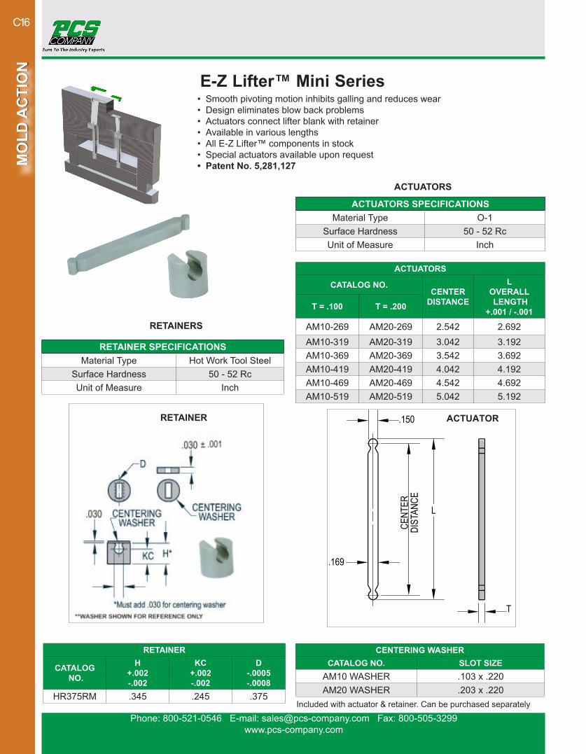
E-Z Lifter™ Mini Series• Smooth pivoting motion inhibits galling and reduces wear• Design eliminates blow back problems• Actuators connect lifter blank with retainer• Available in various lengths• All E-Z Lifter™ components in stock• Special actuators available upon request• Patent No. 5,281,127
ACTUATORS
CATALOG NO.CENTER
DISTANCE
L OVERALL LENGTH
+.001 / -.001T = .100 T = .200
AM10-269 AM20-269 2.542 2.692AM10-319 AM20-319 3.042 3.192AM10-369 AM20-369 3.542 3.692AM10-419 AM20-419 4.042 4.192AM10-469 AM20-469 4.542 4.692AM10-519 AM20-519 5.042 5.192
ACTUATORS SPECIFICATIONSMaterial Type O-1
Surface Hardness 50 - 52 RcUnit of Measure Inch
RETAINER SPECIFICATIONSMaterial Type Hot Work Tool Steel
Surface Hardness 50 - 52 RcUnit of Measure Inch
RETAINER
CATALOG NO.
H+.002-.002
KC+.002-.002
D-.0005-.0008
HR375RM .345 .245 .375
CENTERING WASHERCATALOG NO. SLOT SIZE
AM10 WASHER .103 x .220AM20 WASHER .203 x .220
Included with actuator & retainer. Can be purchased separately
ACTUATORRETAINER
ACTUATORS
RETAINERS
Phone: 800-521-0546 E-mail: [email protected] Fax: 800-505-3299www.pcs-company.com
MO
LD A
CTI
ON
MO
LD A
CTI
ON
C17
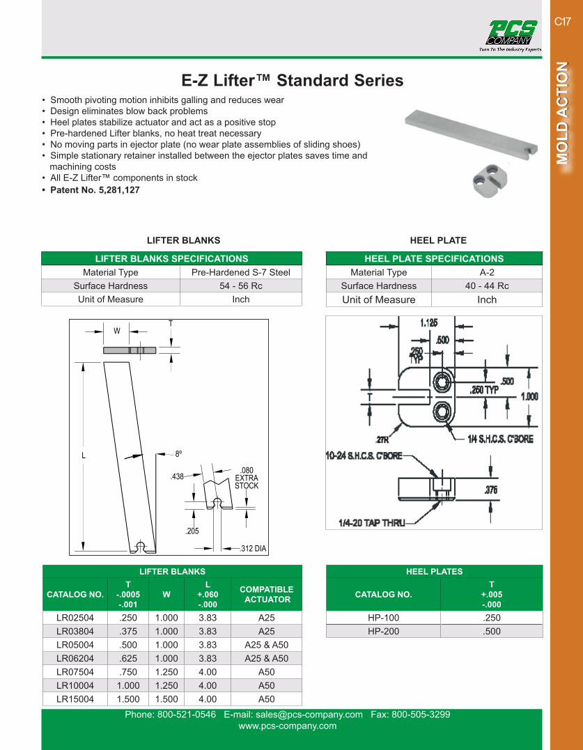
E-Z Lifter™ Standard Series• Smooth pivoting motion inhibits galling and reduces wear• Design eliminates blow back problems• Heel plates stabilize actuator and act as a positive stop• Pre-hardened Lifter blanks, no heat treat necessary• No moving parts in ejector plate (no wear plate assemblies of sliding shoes)• Simple stationary retainer installed between the ejector plates saves time and machining costs• All E-Z Lifter™ components in stock• Patent No. 5,281,127
LIFTER BLANKS
CATALOG NO.T
-.0005-.001
WL
+.060-.000
COMPATIBLE ACTUATOR
LR02504 .250 1.000 3.83 A25LR03804 .375 1.000 3.83 A25LR05004 .500 1.000 3.83 A25 & A50LR06204 .625 1.000 3.83 A25 & A50LR07504 .750 1.250 4.00 A50LR10004 1.000 1.250 4.00 A50LR15004 1.500 1.500 4.00 A50
HEEL PLATES
CATALOG NO.T
+.005-.000
HP-100 .250HP-200 .500
LIFTER BLANKS SPECIFICATIONSMaterial Type Pre-Hardened S-7 Steel
Surface Hardness 54 - 56 RcUnit of Measure Inch
HEEL PLATE SPECIFICATIONSMaterial Type A-2
Surface Hardness 40 - 44 RcUnit of Measure Inch
LIFTER BLANKS HEEL PLATE
Phone: 800-521-0546 E-mail: [email protected] Fax: 800-505-3299www.pcs-company.com
MO
LD A
CTI
ON
MO
LD A
CTI
ON
C18
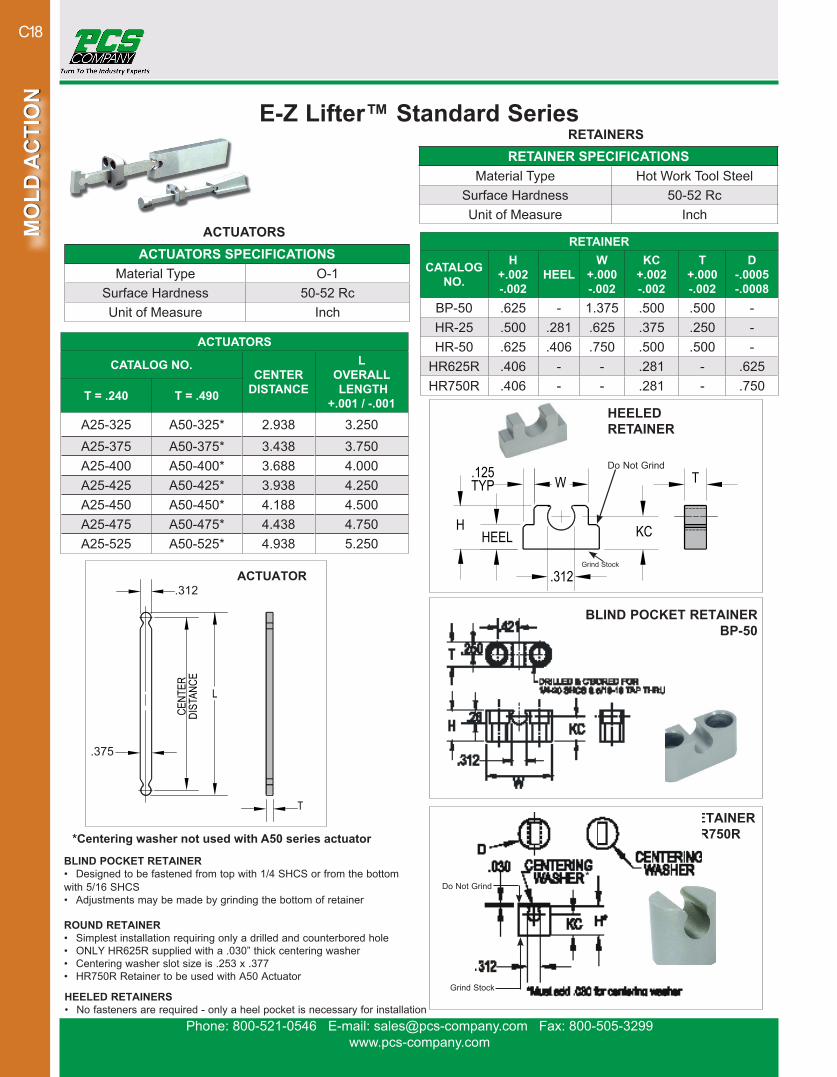
ACTUATOR
HEELED RETAINERS• No fasteners are required - only a heel pocket is necessary for installation
E-Z Lifter™ Standard Series
ACTUATORS
CATALOG NO.CENTER
DISTANCE
L OVERALL LENGTH
+.001 / -.001T = .240 T = .490
A25-325 A50-325* 2.938 3.250A25-375 A50-375* 3.438 3.750A25-400 A50-400* 3.688 4.000A25-425 A50-425* 3.938 4.250A25-450 A50-450* 4.188 4.500A25-475 A50-475* 4.438 4.750A25-525 A50-525* 4.938 5.250
ACTUATORS SPECIFICATIONSMaterial Type O-1
Surface Hardness 50-52 RcUnit of Measure Inch
RETAINER SPECIFICATIONSMaterial Type Hot Work Tool Steel
Surface Hardness 50-52 RcUnit of Measure Inch
*Centering washer not used with A50 series actuator
BLIND POCKET RETAINER• Designed to be fastened from top with 1/4 SHCS or from the bottom with 5/16 SHCS• Adjustments may be made by grinding the bottom of retainer
ROUND RETAINERHR625R HR750R
BLIND POCKET RETAINERBP-50
*
Do Not Grind
Grind Stock
Do Not Grind
Grind Stock
ROUND RETAINER• Simplest installation requiring only a drilled and counterbored hole• ONLY HR625R supplied with a .030” thick centering washer • Centering washer slot size is .253 x .377• HR750R Retainer to be used with A50 Actuator
RETAINER
CATALOG NO.
H+.002-.002
HEELW
+.000-.002
KC+.002-.002
T+.000-.002
D-.0005-.0008
BP-50 .625 - 1.375 .500 .500 -HR-25 .500 .281 .625 .375 .250 -HR-50 .625 .406 .750 .500 .500 -
HR625R .406 - - .281 - .625HR750R .406 - - .281 - .750
HEELEDRETAINER
RETAINERS
ACTUATORS
.312
.375
Phone: 800-521-0546 E-mail: [email protected] Fax: 800-505-3299www.pcs-company.com
MO
LD A
CTI
ON
MO
LD A
CTI
ON
C19
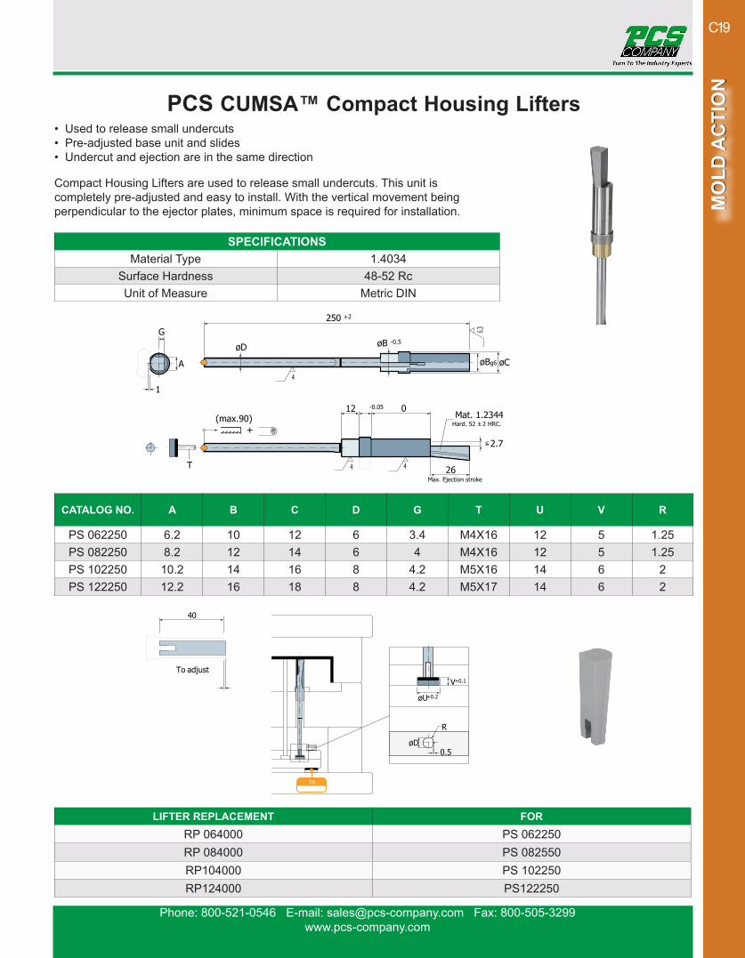
PCS CUMSA™ Compact Housing Lifters• Used to release small undercuts• Pre-adjusted base unit and slides• Undercut and ejection are in the same direction
Compact Housing Lifters are used to release small undercuts. This unit is completely pre-adjusted and easy to install. With the vertical movement being perpendicular to the ejector plates, minimum space is required for installation.
CATALOG NO. A B C D G T U V R
PS 062250 6.2 10 12 6 3.4 M4X16 12 5 1.25PS 082250 8.2 12 14 6 4 M4X16 12 5 1.25PS 102250 10.2 14 16 8 4.2 M5X16 14 6 2PS 122250 12.2 16 18 8 4.2 M5X17 14 6 2
SPECIFICATIONSMaterial Type 1.4034
Surface Hardness 48-52 RcUnit of Measure Metric DIN
G
A
1
(max.90)
T
øD
12 0
26
2.7
øB g6 øC
øB -0.5
250 +2
4
4
6.3
4
Mat. 1.2344Hard. 52 ± 2 HRC.
+
Max. Ejection stroke
-0.05
øD0.5
R
40
To adjustV
øU
+0.1
+0.2
TA
Ref.f or
RP.104000 PS.102250
LIFTER REPLACEMENT FORRP 064000 PS 062250RP 084000 PS 082550RP104000 PS 102250RP124000 PS122250
Phone: 800-521-0546 E-mail: [email protected] Fax: 800-505-3299www.pcs-company.com
MO
LD A
CTI
ON
MO
LD A
CTI
ON
C20
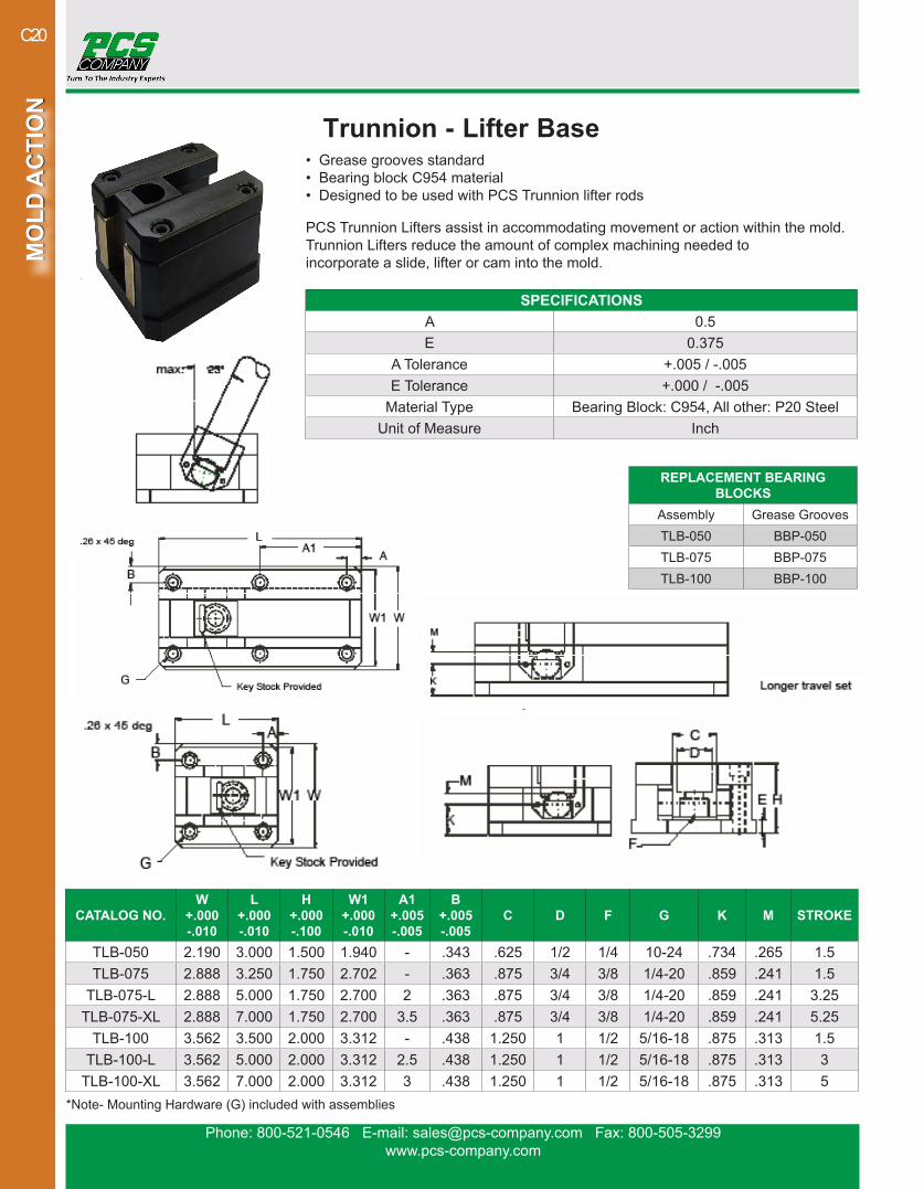
Trunnion - Lifter Base• Grease grooves standard• Bearing block C954 material• Designed to be used with PCS Trunnion lifter rods
PCS Trunnion Lifters assist in accommodating movement or action within the mold. Trunnion Lifters reduce the amount of complex machining needed toincorporate a slide, lifter or cam into the mold.
CATALOG NO.W
+.000-.010
L+.000-.010
H+.000-.100
W1+.000-.010
A1+.005-.005
B+.005-.005
C D F G K M STROKE
TLB-050 2.190 3.000 1.500 1.940 - .343 .625 1/2 1/4 10-24 .734 .265 1.5TLB-075 2.888 3.250 1.750 2.702 - .363 .875 3/4 3/8 1/4-20 .859 .241 1.5
TLB-075-L 2.888 5.000 1.750 2.700 2 .363 .875 3/4 3/8 1/4-20 .859 .241 3.25TLB-075-XL 2.888 7.000 1.750 2.700 3.5 .363 .875 3/4 3/8 1/4-20 .859 .241 5.25
TLB-100 3.562 3.500 2.000 3.312 - .438 1.250 1 1/2 5/16-18 .875 .313 1.5TLB-100-L 3.562 5.000 2.000 3.312 2.5 .438 1.250 1 1/2 5/16-18 .875 .313 3
TLB-100-XL 3.562 7.000 2.000 3.312 3 .438 1.250 1 1/2 5/16-18 .875 .313 5
SPECIFICATIONSA 0.5E 0.375
A Tolerance +.005 / -.005E Tolerance +.000 / -.005
Material Type Bearing Block: C954, All other: P20 SteelUnit of Measure Inch
REPLACEMENT BEARING BLOCKS
Assembly Grease GroovesTLB-050 BBP-050TLB-075 BBP-075TLB-100 BBP-100
*Note- Mounting Hardware (G) included with assemblies

Phone: 800-521-0546 E-mail: [email protected] Fax: 800-505-3299www.pcs-company.com
MO
LD A
CTI
ON
MO
LD A
CTI
ON
C21
Trunnion - Lifter Rod & Bushing• Hardened steel material• Designed to be used with PCS Trunnion lifter base
PCS Trunnion Lifters assist in accommodating movement or action within the mold. Trunnion Lifters reduce the amount of complex machining needed to incorporate a slide, lifter or cam into the mold.
CATALOG NO.
NOMINAL DIAMETER
L+.06-.00
D+.000-.001
A+.010-.010
B+.005-0000
C F J
LR050-12 1/2 12 .499 2 3/8 3/8 1/4-20 1/8LR050-18 1/2 18 .499 2 3/8 3/8 1/4-20 1/8LR075-06 3/4 6 .749 2.5 1/2 5/8 3/8-16 1/4LR075-12 3/4 12 .749 2.5 1/2 5/8 3/8-16 1/4LR075-18 3/4 18 .749 2.5 1/2 5/8 3/8-16 1/4LR075-30 3/4 30 .749 2.5 1/2 5/8 3/8-16 1/4LR100-06 1 6 .999 3 1/2 7/8 1/2-13 1/4LR100-12 1 12 .999 3 1/2 7/8 1/2-13 1/4LR100-24 1 24 .999 3 1/2 7/8 1/2-13 1/4LR100-36 1 36 .999 3 1/2 7/8 1/2-13 1/4
SPECIFICATIONSCoating Nitride
Material Type P20 SteelSurface Hardness 65 -74 RcUnit of Measure Inch
Material: P20 Nitrided
D
L
A
F Thread
J Dowel PinB
For Key Stock Supplied
CATALOG NO.
NOMINAL I.D.
I.D.+.0005-.0000
O.D.+.0005-.0000
L OVERALL LENGTH
+.0 / -.06STB 05-10 1/2 .5006 .7503 1STB 06-13 3/4 .7505 1.1255 1-3/8STB 08-13 1 1.0005 1.3755 1-3/8
Phone: 800-521-0546 E-mail: [email protected] Fax: 800-505-3299www.pcs-company.com
MO
LD A
CTI
ON
MO
LD A
CTI
ON
C22
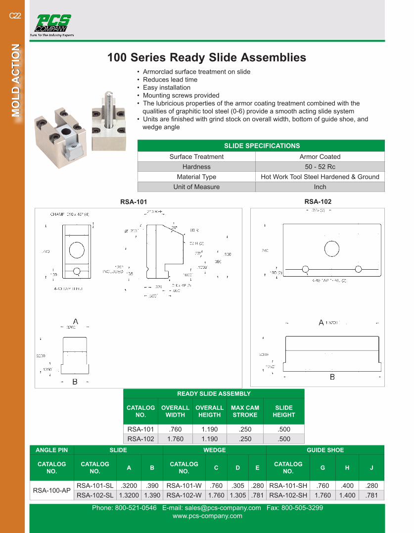
100 Series Ready Slide Assemblies• Armorclad surface treatment on slide• Reduces lead time• Easy installation• Mounting screws provided• The lubricious properties of the armor coating treatment combined with the qualities of graphitic tool steel (0-6) provide a smooth acting slide system• Units are finished with grind stock on overall width, bottom of guide shoe, and wedge angle
READY SLIDE ASSEMBLY
CATALOG NO.
OVERALL WIDTH
OVERALL HEIGTH
MAX CAM STROKE
SLIDE HEIGHT
RSA-101 .760 1.190 .250 .500RSA-102 1.760 1.190 .250 .500
ANGLE PIN SLIDE WEDGE GUIDE SHOE
CATALOG NO.
CATALOG NO. A B CATALOG
NO. C D E CATALOG NO. G H J
RSA-100-APRSA-101-SL .3200 .390 RSA-101-W .760 .305 .280 RSA-101-SH .760 .400 .280RSA-102-SL 1.3200 1.390 RSA-102-W 1.760 1.305 .781 RSA-102-SH 1.760 1.400 .781
SLIDE SPECIFICATIONSSurface Treatment Armor Coated
Hardness 50 - 52 RcMaterial Type Hot Work Tool Steel Hardened & Ground
Unit of Measure Inch
RSA-101 RSA-102
Phone: 800-521-0546 E-mail: [email protected] Fax: 800-505-3299www.pcs-company.com
MO
LD A
CTI
ON
MO
LD A
CTI
ON
C23
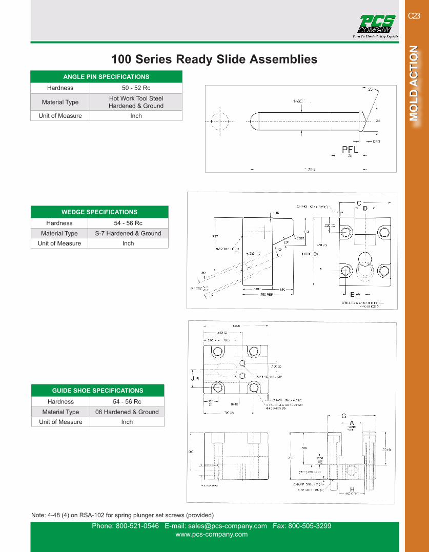
100 Series Ready Slide Assemblies
WEDGE SPECIFICATIONS
Hardness 54 - 56 Rc
Material Type S-7 Hardened & GroundUnit of Measure Inch
Note: 4-48 (4) on RSA-102 for spring plunger set screws (provided)
ANGLE PIN SPECIFICATIONS
Hardness 50 - 52 Rc
Material Type Hot Work Tool Steel Hardened & Ground
Unit of Measure Inch
GUIDE SHOE SPECIFICATIONS
Hardness 54 - 56 Rc
Material Type 06 Hardened & GroundUnit of Measure Inch
Phone: 800-521-0546 E-mail: [email protected] Fax: 800-505-3299www.pcs-company.com
MO
LD A
CTI
ON
MO
LD A
CTI
ON
C24
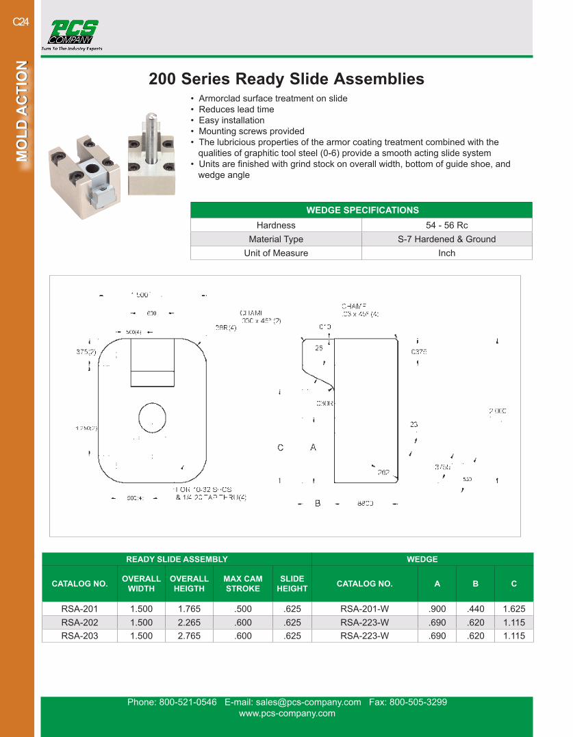
200 Series Ready Slide Assemblies• Armorclad surface treatment on slide• Reduces lead time• Easy installation• Mounting screws provided• The lubricious properties of the armor coating treatment combined with the qualities of graphitic tool steel (0-6) provide a smooth acting slide system• Units are finished with grind stock on overall width, bottom of guide shoe, and wedge angle
READY SLIDE ASSEMBLY WEDGE
CATALOG NO. OVERALL WIDTH
OVERALL HEIGTH
MAX CAM STROKE
SLIDE HEIGHT CATALOG NO. A B C
RSA-201 1.500 1.765 .500 .625 RSA-201-W .900 .440 1.625RSA-202 1.500 2.265 .600 .625 RSA-223-W .690 .620 1.115RSA-203 1.500 2.765 .600 .625 RSA-223-W .690 .620 1.115
WEDGE SPECIFICATIONSHardness 54 - 56 Rc
Material Type S-7 Hardened & GroundUnit of Measure Inch

Phone: 800-521-0546 E-mail: [email protected] Fax: 800-505-3299www.pcs-company.com
MO
LD A
CTI
ON
MO
LD A
CTI
ON
C25
READY SLIDE ASSEMBLY ANGLE PIN SLIDE WEAR PLATE
CATALOG NO. CATALOG NO.
CATALOG NO. A B C D E F G CATALOG NO.
RSA-201RSA-200-AP
RSA-201-SL .285 .080 .900 1.490 .460 .150 1.335RSA-200-WPRSA-202 RSA-202-SL .610 .100 .690 1.390 .960 .187 1.125
RSA-203 RSA-203-SL .850 .100 .690 1.390 1.460 .187 1.125
200 Series Ready Slide Assemblies ANGLE PIN SPECIFICATIONS
Hardness 40 - 42 Rc
Material Type Hot Work Tool Steel Hardened & GroundUnit of Measure Inch
READY SLIDE ASSEMBLY GUIDE
CATALOG NO.CATALOG NO.
H JLEFT GIB RIGHT GIB
RSA-201 RSA-201-GL RSA-201-GR .460 .151RSA-202 RSA-202-GL RSA-202-GR .960 .188RSA-203 RSA-203-GL RSA-203-GR 1.460 .188
WEAR PLATE SPECIFICATIONS
Hardness 54 - 56 Rc
Material Type 06 Hardened & GroundUnit of Measure Inch
GUIDE SPECIFICATIONS
Hardness 54 - 56 Rc
Material Type 06 Hardened & GroundUnit of Measure Inch
All mounting screws provided
SLIDE SPECIFICATIONS
Hardness 50 - 52 Rc
Material Type Hot Work Tool Steel Hardened & Ground
Unit of Measure Inch
Phone: 800-521-0546 E-mail: [email protected] Fax: 800-505-3299www.pcs-company.com
MO
LD A
CTI
ON
MO
LD A
CTI
ON
C26
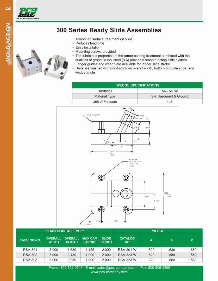
300 Series Ready Slide Assemblies• Armorclad surface treatment on slide• Reduces lead time• Easy installation• Mounting screws provided• The lubricious properties of the armor coating treatment combined with the qualities of graphitic tool steel (0-6) provide a smooth acting slide system• Longer guides and wear plate available for longer slide stroke• Units are finished with grind stock on overall width, bottom of guide shoe, and wedge angle
READY SLIDE ASSEMBLY WEDGE
CATALOG NO. OVERALL WIDTH
OVERALL HEIGTH
MAX CAM STROKE
SLIDE HEIGHT
CATALOG NO. A B C
RSA-301 3.000 1.680 1.125 2.000 RSA-301-W .500 .630 1.660RSA-302 3.000 2.430 1.000 2.000 RSA-323-W .820 .880 1.550RSA-303 3.000 2.930 1.000 2.000 RSA-323-W .820 .880 1.550
WEDGE SPECIFICATIONSHardness 54 - 56 Rc
Material Type S-7 Hardened & GroundUnit of Measure Inch
A
B
.875

Phone: 800-521-0546 E-mail: [email protected] Fax: 800-505-3299www.pcs-company.com
MO
LD A
CTI
ON
MO
LD A
CTI
ON
C27
300 Series Ready Slide Assemblies ANGLE PIN SPECIFICATIONS
Hardness 40 - 42 Rc
Material Type Hot Work Tool Steel Hardened & GroundUnit of Measure Inch
All mounting screws provided
SLIDE SPECIFICATIONS
Surface Treatment Armor Coating
Hardness 50 - 52 Rc
Material Type Hot Work Tool Steel Hardened & GroundUnit of Measure Inch
GUIDE SPECIFICATIONS
Hardness 54 - 56 Rc
Material Type 06 Hardened & GroundUnit of Measure Inch
.499 .625
1.875
READY SLIDE ASSEMBLY ANGLE PIN SLIDE
CATALOG NO. CATALOG NO.
CATALOG NO. A B C D E F
RSA-301RSA-300-AP
RSA-301-SL .875 1.875 1.671 .313 .625 -RSA-302 RSA-302-SL .875 2.000 1.562 .375 1.125 .875RSA-303 RSA-303-SL .875 2.000 1.562 .531 1.625 1.225
READY SLIDE ASSEMBLY GUIDE
CATALOG NO.CATALOG NO.
HLEFT GIB RIGHT GIB
RSA-301 RSA-301-GL RSA-301-GR .625RSA-302 RSA-302-GL RSA-302-GR 1.125RSA-303 RSA-303-GL RSA-303-GR 1.625
DRILL & C’BORE FOR 10-32 S.H.C.S& TAP FOR 1/4-20.500 DEEP (4)

Phone: 800-521-0546 E-mail: [email protected] Fax: 800-505-3299www.pcs-company.com
MO
LD A
CTI
ON
MO
LD A
CTI
ON
C28
WEAR PLATE SPECIFICATIONSHardness 54 - 56 Rc
Material Type 06 Hardened & GroundUnit of Measure Inch
300 Series Ready Slide Assemblies
READY SLIDE ASSEMBLY WEAR PLATE
CATALOG NO. CATALOG NO.
RSA-301RSA-300-WPRSA-302
RSA-303All mounting screws provided
R.38(2)
ø.281(4)
Pocket for Spring Slide Retainer Provided
Includes .005 Grindstock per slide.
.2005

Phone: 800-521-0546 E-mail: [email protected] Fax: 800-505-3299www.pcs-company.com
MO
LD A
CTI
ON
MO
LD A
CTI
ON
C29
PCS CUMSA™ Auto Slide Retainer• Reduce costs in machining and fitting• Retention of cam slides up to 2.000 Kg• Offers a standard solution for molders
The Auto Slide Retainer eliminates the need for complex retaining and expensive hydraulic systems. This retainer is for large slides and is actuated by the angle pin, ensuring smooth and easy movement with no excess force required.
CATALOG NO.RA 163812
SPECIFICATIONS Hardness 54 - 58 HRC
Material Type 1.2510Unit of Measure Metric DIN
Note: Cut the rod 0.5 mm shorter than the slide height
38-0.1
16-0.1
20-0.05
250+5
12.518
ø11.8ø18 m6
10
M6x30DIN912
630HV 0.1
850
N/m
m2
Mat. 1.7242Hard. 60 HRC.
ø12 g6
2.5
2.5
18+0.5
16+0.1
ø18
Min.15
ø12
0.510
ø12

Phone: 800-521-0546 E-mail: [email protected] Fax: 800-505-3299www.pcs-company.com
MO
LD A
CTI
ON
MO
LD A
CTI
ON
C30
PCS CUMSA™ Modular Retainers• No pocket machining required• Minimum space required for installation• Reduces costs compared to conventional mechanisms• Clip grouping allows for increased resistance
The Modular Retainer assists in proper mold opening when a floating plate is present. As the mold opens, increased resistance is added to the floating plate to facilitate proper mold opening. Multiple Modular Retainers can be used to add even more resistance.
CATALOG NO. K1 K2 K3 K4RM 651608 7.5 kg 15 kg 22.3 kg 30 kg
SPECIFICATIONSApproximate Resistance Value 7.5 kg / 16.5 lb
Hardness 42 - 48 RcMaterial Type 1.8159
Unit of Measure Metric DIN
65
6016
16
32.5
Friction AreaHard. 58 ± 2 HRC.
M8DIN912
ø8DIN6325
ø8DIN6325
K
8K=Approximate resistance value that can be obtained by grouping clips.
K*1 RM=7.5 kg K*2 RM=15 kg K*3 RM=22.5 kg K*4 RM=30 kg
Closed mold 1 Openingst 2 Openingnd

Phone: 800-521-0546 E-mail: [email protected] Fax: 800-505-3299www.pcs-company.com
MO
LD A
CTI
ON
MO
LD A
CTI
ON
C31
Slide Retainers• Compact, economical and positive acting slide retention• Can be installed in new molds or retrofitted to existing molds• Installed behind or below slide, eliminating interference with machine tie bars or safety gates• Multiple units can be used for large or heavy slides
PCS Slide Retainers are compact and provide positive acting slide retention. Slide Retainers are installed behind or below the slide which eliminates interference with machine tie bars. Multiple units can be used together to provide retention for larger slides.
CATALOG NO.
A LENGTH
B WIDTH
C HEIGHT D E *F DOWEL
PIN G H JK
TAPPED HOLE
SHOULDER SCREW S
SRP-22 1-1/2 3/4 .63 .89 .61 .360 1/4 X 1-1/4 .73 1.01 1.00 10-24 X 1/2 1/4 X 5/8 0.19SRP-44 2-1/8 1-1/4 .79 1.31 .81 .500 5/16 X 1-1/2 .93 1.50 1.50 1/4-20 X 1/2 5/16 X 3/4 0.25SRP-88 3-3/8 1-3/4 1.18 2.08 1.3 .800 3/8 X 2-1/4 1.42 2.20 2.00 5/16-18 X 5/8 3/8 X 1 0.38
SPECIFICATIONSMaterial Type 8620 Alloy
Unit of Measure Inch
QTY. SLIDE RETAINER
SLIDE WEIGHT
1 SRP-22 22 LBS2 SRP-22 44 LBS1 SRP-44 44 LBS2 SRP-44 88 LBS1 SRP-88 88 LBS2 SRP-88 176 LBS4 SRP-88 352 LBS
Important: The “F” dimension is the distance from the center line of the dowel pin to the center line of the shoulder screw.
MOLD POCKET
Phone: 800-521-0546 E-mail: [email protected] Fax: 800-505-3299www.pcs-company.com
MO
LD A
CTI
ON
MO
LD A
CTI
ON
C32
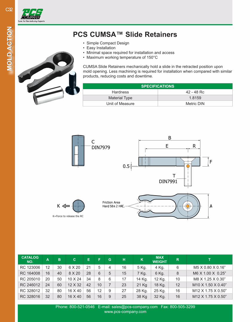
PCS CUMSA™ Slide Retainers• Simple Compact Design• Easy Installation• Minimal space required for installation and access• Maximum working temperature of 150°C
CUMSA Slide Retainers mechanically hold a slide in the retracted position upon mold opening. Less machining is required for installation when compared with similar products, reducing costs and downtime.
CATALOG NO. A B C E F G H K MAX
WEIGHT R T
RC 123006 12 30 6 X 20 21 5 4 16 5 Kg. 4 Kg. 6 M5 X 0.80 X 0.16”RC 164008 16 40 8 X 20 28 6 5 15 7 Kg. 6 Kg. 8 M6 X 1.00 X 0.25”RC 205010 20 50 10 X 24 34 8 6 17 14 Kg. 12 Kg. 10 M8 X 1.25 X 0.30”RC 246012 24 60 12 X 32 42 10 7 23 21 Kg 18 Kg. 12 M10 X 1.50 X 0.40”RC 328012 32 80 16 X 40 56 12 9 27 28 Kg. 25 Kg. 16 M12 X 1.75 X 0.50”RC 328016 32 80 16 X 40 56 16 9 25 38 Kg 32 Kg. 16 M12 X 1.75 X 0.50”
SPECIFICATIONSHardness 42 - 48 Rc
Material Type 1.8159Unit of Measure Metric DIN
CDIN7979
TDIN7991
F
RE
B
AHardFriction Area
. 58 ± 2 HRC.
0.5
K
K=Force to release the RC
Phone: 800-521-0546 E-mail: [email protected] Fax: 800-505-3299www.pcs-company.com
MO
LD A
CTI
ON
MO
LD A
CTI
ON
C33
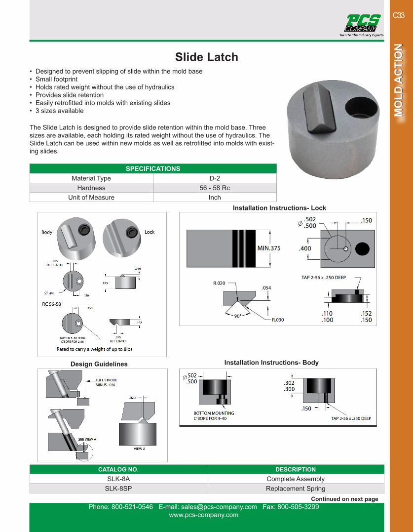
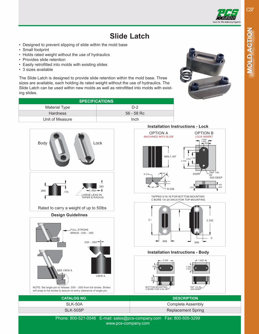
Slide Latch• Designed to prevent slipping of slide within the mold base• Small footprint• Holds rated weight without the use of hydraulics• Provides slide retention• Easily retrofitted into molds with existing slides• 3 sizes available
The Slide Latch is designed to provide slide retention within the mold base. Three sizes are available, each holding its rated weight without the use of hydraulics. The Slide Latch can be used within new molds as well as retrofitted into molds with exist-ing slides.
CATALOG NO. DESCRIPTIONSLK-8A Complete Assembly
SLK-8SP Replacement Spring
SPECIFICATIONSMaterial Type D-2
Hardness 56 - 58 RcUnit of Measure Inch
Installation Instructions- Lock
Installation Instructions- BodyDesign Guidelines
Continued on next page
Phone: 800-521-0546 E-mail: [email protected] Fax: 800-505-3299www.pcs-company.com
MO
LD A
CTI
ON
MO
LD A
CTI
ON
C34
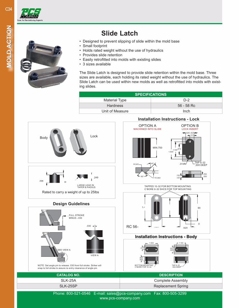
CATALOG NO. DESCRIPTIONSLK-25A Complete Assembly
SLK-25SP Replacement Spring
Slide Latch
Installation Instructions - Lock
Rated to carry a weight of up to 25lbs
OPTION B LOCK INSERT
OPTION A MACHINED INTO SLIDE
.498 .100LARGE LEAD IN TAPER & RADIUS
.620
.310
TAPPED 10-32 FOR BOTTOM MOUNTINGC’BORE 6-32 SHCS FOR TOP MOUNTING
1.490
.620
1.4901.100
1.500
.135
.125
.252
.250
1.1001.500
.627
.625.313
.502
.500
BOTTOM MOUNTING C’BORE FOR 10-32
TAP 6-32 .300 DEEP
1.100.875
.625-.627
.313R TAP 6-32.300 DEEP
.313
NOTE: Set angle pin to release .030 from full stroke. Striker will snap to full stroke to assure re-entry clearance of angle pin.
FULL STROKEMINUS -.030
SEE VIEW A
VIEW A
.030
MIN.750
R.063
R.047
.105
90°
45°
Lock Body
RC 56-
.249
Installation Instructions - BodyInstallation Instructions - Body
Design Guidelines
SPECIFICATIONSMaterial Type D-2
Hardness 56 - 58 RcUnit of Measure Inch
• Designed to prevent slipping of slide within the mold base• Small footprint• Holds rated weight without the use of hydraulics• Provides slide retention• Easily retrofitted into molds with existing slides• 3 sizes available
The Slide Latch is designed to provide slide retention within the mold base. Three sizes are available, each holding its rated weight without the use of hydraulics. The Slide Latch can be used within new molds as well as retrofitted into molds with exist-ing slides.

Phone: 800-521-0546 E-mail: [email protected] Fax: 800-505-3299www.pcs-company.com
MO
LD A
CTI
ON
MO
LD A
CTI
ON
C35
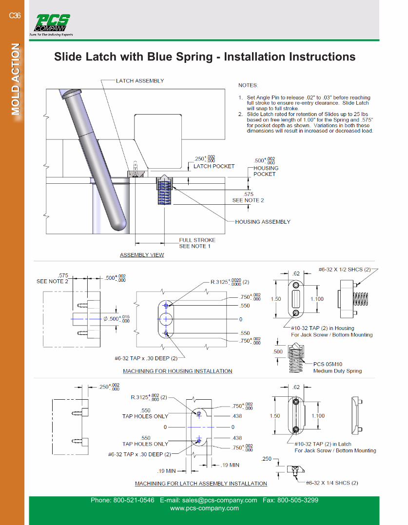
Slide Latch with Blue Spring• Designed to prevent slipping of slide within the mold base• Holds rated weight without the use of hydraulics• Rated to carry a weight up to 25 pounds• Ideal for applications with heavier slides that require more forceThe SLK-25BLUE Slide Latch with Blue Spring is an alternative spring configuration for the SLK-25A. It utilizes a medium-duty Raymond die spring, and a minor modification to the machining geometry for the Slide Latch to facilitate the same holding power as the original SLK-25A.
CATALOG NO. DESCRIPTIONSLK-25BLUE Complete Assembly
05M10 Replacement Spring
SPECIFICATIONS Material Type D-2
Hardness 56 - 58 RcUnit of Measure Inch
PLUNGER ASSEMBLY
LATCH ASSEMBLYLATCH ASSEMBLY
Continued on Next Page
Phone: 800-521-0546 E-mail: [email protected] Fax: 800-505-3299www.pcs-company.com
MO
LD A
CTI
ON
MO
LD A
CTI
ON
C36
Slide Latch with Blue Spring - Installation Instructions
Phone: 800-521-0546 E-mail: [email protected] Fax: 800-505-3299www.pcs-company.com
MO
LD A
CTI
ON
MO
LD A
CTI
ON
C37
CATALOG NO. DESCRIPTIONSLK-50A Complete Assembly
SLK-50SP Replacement Spring
Slide Latch
Rated to carry a weight of up to 50lbs
LockBody
.310
TAPPED 5/16-18 FOR BOTTOM MOUNTINGC’BORE 1/4-20 SHCS FOR TOP MOUNTING
2.292 1.650
.996 .996
2.292
.860 .170LARGE LEAD IN TAPER & RADIUS
.385.498
NOTE: Set angle pin to release .030 - .050 from full stroke. Striker will snap to full stroke to assure re-entry clearance of angle pin.
FULL STROKEMINUS -.030 - .050
SEE VIEW A
VIEW A
.030 - .050
1.6502.300
1.000 1.003
.500
.875
.880
BOTTOM MOUNTING C’BORE FOR 5/16-18
TAP 1/4-20 .500 DEEP
OPTION B LOCK INSERT
OPTION A MACHINED INTO SLIDE
.200.400 .405
1.6501.125
1.000- 1.003
.500R TAP 1/4-20.500 DEEP
.500
MIN.1.187
R.098
R.079
.155
90°
45°
2.300
Installation Instructions - Body
Design Guidelines
Installation Instructions - Lock
SPECIFICATIONSMaterial Type D-2
Hardness 56 - 58 RcUnit of Measure Inch
• Designed to prevent slipping of slide within the mold base• Small footprint• Holds rated weight without the use of hydraulics• Provides slide retention• Easily retrofitted into molds with existing slides• 3 sizes available
The Slide Latch is designed to provide slide retention within the mold base. Three sizes are available, each holding its rated weight without the use of hydraulics. The Slide Latch can be used within new molds as well as retrofitted into molds with exist-ing slides.
Phone: 800-521-0546 E-mail: [email protected] Fax: 800-505-3299www.pcs-company.com
MO
LD A
CTI
ON
MO
LD A
CTI
ON
C38
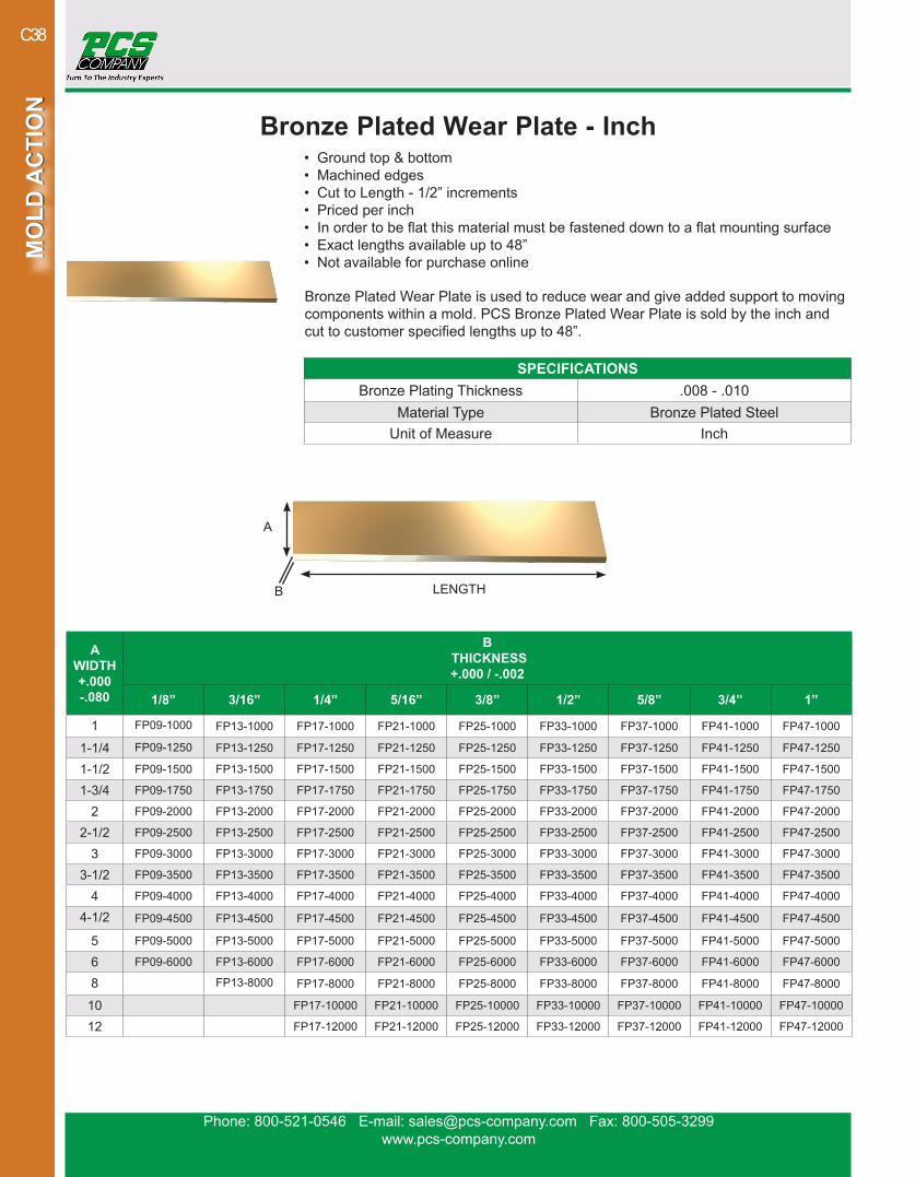
Bronze Plated Wear Plate - Inch• Ground top & bottom• Machined edges• Cut to Length - 1/2” increments• Priced per inch• In order to be flat this material must be fastened down to a flat mounting surface• Exact lengths available up to 48”• Not available for purchase online
Bronze Plated Wear Plate is used to reduce wear and give added support to moving components within a mold. PCS Bronze Plated Wear Plate is sold by the inch and cut to customer specified lengths up to 48”.
SPECIFICATIONSBronze Plating Thickness .008 - .010
Material Type Bronze Plated SteelUnit of Measure Inch
AWIDTH+.000-.080
B THICKNESS+.000 / -.002
1/8” 3/16” 1/4” 5/16” 3/8” 1/2” 5/8” 3/4” 1”
1 FP09-1000 FP13-1000 FP17-1000 FP21-1000 FP25-1000 FP33-1000 FP37-1000 FP41-1000 FP47-1000
1-1/4 FP09-1250 FP13-1250 FP17-1250 FP21-1250 FP25-1250 FP33-1250 FP37-1250 FP41-1250 FP47-1250
1-1/2 FP09-1500 FP13-1500 FP17-1500 FP21-1500 FP25-1500 FP33-1500 FP37-1500 FP41-1500 FP47-1500
1-3/4 FP09-1750 FP13-1750 FP17-1750 FP21-1750 FP25-1750 FP33-1750 FP37-1750 FP41-1750 FP47-1750
2 FP09-2000 FP13-2000 FP17-2000 FP21-2000 FP25-2000 FP33-2000 FP37-2000 FP41-2000 FP47-2000
2-1/2 FP09-2500 FP13-2500 FP17-2500 FP21-2500 FP25-2500 FP33-2500 FP37-2500 FP41-2500 FP47-2500
3 FP09-3000 FP13-3000 FP17-3000 FP21-3000 FP25-3000 FP33-3000 FP37-3000 FP41-3000 FP47-3000
3-1/2 FP09-3500 FP13-3500 FP17-3500 FP21-3500 FP25-3500 FP33-3500 FP37-3500 FP41-3500 FP47-3500
4 FP09-4000 FP13-4000 FP17-4000 FP21-4000 FP25-4000 FP33-4000 FP37-4000 FP41-4000 FP47-4000
4-1/2 FP09-4500 FP13-4500 FP17-4500 FP21-4500 FP25-4500 FP33-4500 FP37-4500 FP41-4500 FP47-4500
5 FP09-5000 FP13-5000 FP17-5000 FP21-5000 FP25-5000 FP33-5000 FP37-5000 FP41-5000 FP47-5000
6 FP09-6000 FP13-6000 FP17-6000 FP21-6000 FP25-6000 FP33-6000 FP37-6000 FP41-6000 FP47-6000
8 FP13-8000 FP17-8000 FP21-8000 FP25-8000 FP33-8000 FP37-8000 FP41-8000 FP47-8000
10 FP17-10000 FP21-10000 FP25-10000 FP33-10000 FP37-10000 FP41-10000 FP47-10000
12 FP17-12000 FP21-12000 FP25-12000 FP33-12000 FP37-12000 FP41-12000 FP47-12000
A
B LENGTH
Phone: 800-521-0546 E-mail: [email protected] Fax: 800-505-3299www.pcs-company.com
MO
LD A
CTI
ON
MO
LD A
CTI
ON
C39
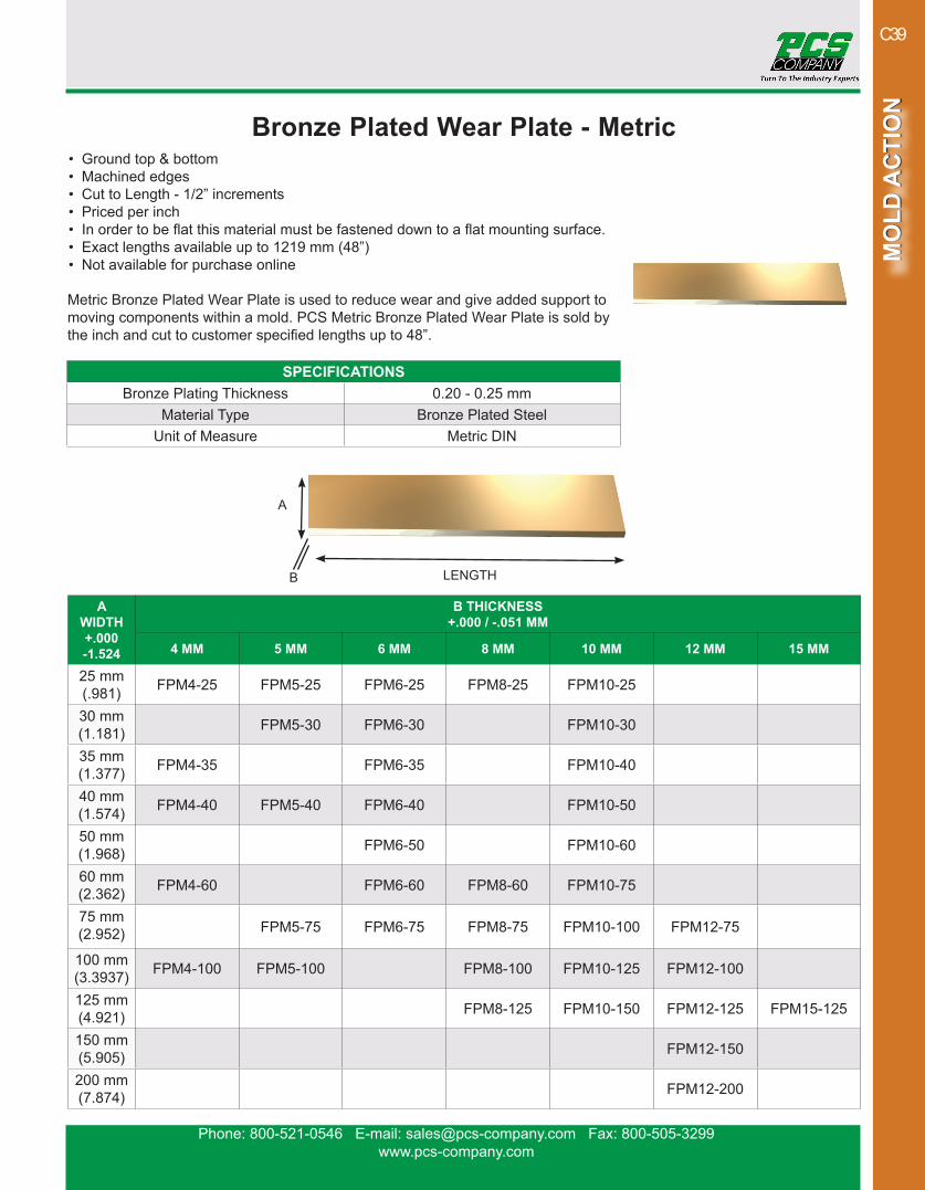
Bronze Plated Wear Plate - Metric• Ground top & bottom• Machined edges• Cut to Length - 1/2” increments• Priced per inch• In order to be flat this material must be fastened down to a flat mounting surface.• Exact lengths available up to 1219 mm (48”)• Not available for purchase online
Metric Bronze Plated Wear Plate is used to reduce wear and give added support to moving components within a mold. PCS Metric Bronze Plated Wear Plate is sold by the inch and cut to customer specified lengths up to 48”.
SPECIFICATIONSBronze Plating Thickness 0.20 - 0.25 mm
Material Type Bronze Plated SteelUnit of Measure Metric DIN
AWIDTH+.000-1.524
B THICKNESS+.000 / -.051 MM
4 MM 5 MM 6 MM 8 MM 10 MM 12 MM 15 MM
25 mm(.981) FPM4-25 FPM5-25 FPM6-25 FPM8-25 FPM10-25
30 mm(1.181) FPM5-30 FPM6-30 FPM10-30
35 mm(1.377) FPM4-35 FPM6-35 FPM10-40
40 mm(1.574) FPM4-40 FPM5-40 FPM6-40 FPM10-50
50 mm(1.968) FPM6-50 FPM10-60
60 mm(2.362) FPM4-60 FPM6-60 FPM8-60 FPM10-75
75 mm(2.952) FPM5-75 FPM6-75 FPM8-75 FPM10-100 FPM12-75
100 mm(3.3937) FPM4-100 FPM5-100 FPM8-100 FPM10-125 FPM12-100
125 mm(4.921) FPM8-125 FPM10-150 FPM12-125 FPM15-125
150 mm(5.905) FPM12-150
200 mm(7.874) FPM12-200
A
B LENGTH
Phone: 800-521-0546 E-mail: [email protected] Fax: 800-505-3299www.pcs-company.com
MO
LD A
CTI
ON
MO
LD A
CTI
ON
C40
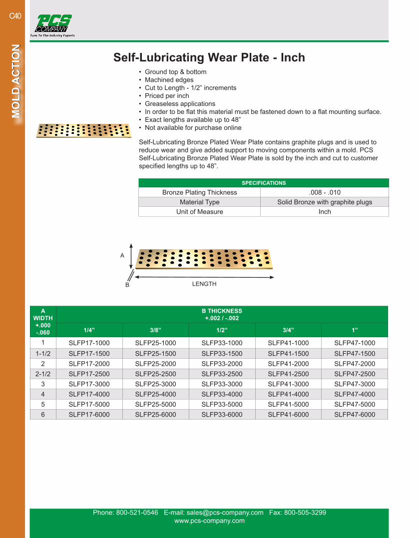
Self-Lubricating Wear Plate - Inch• Ground top & bottom• Machined edges• Cut to Length - 1/2” increments• Priced per inch• Greaseless applications• In order to be flat this material must be fastened down to a flat mounting surface.• Exact lengths available up to 48”• Not available for purchase online
Self-Lubricating Bronze Plated Wear Plate contains graphite plugs and is used to reduce wear and give added support to moving components within a mold. PCS Self-Lubricating Bronze Plated Wear Plate is sold by the inch and cut to customer specified lengths up to 48”.
SPECIFICATIONS
Bronze Plating Thickness .008 - .010Material Type Solid Bronze with graphite plugs
Unit of Measure Inch
AWIDTH+.000-.060
B THICKNESS+.002 / -.002
1/4” 3/8” 1/2” 3/4” 1”
1 SLFP17-1000 SLFP25-1000 SLFP33-1000 SLFP41-1000 SLFP47-10001-1/2 SLFP17-1500 SLFP25-1500 SLFP33-1500 SLFP41-1500 SLFP47-1500
2 SLFP17-2000 SLFP25-2000 SLFP33-2000 SLFP41-2000 SLFP47-20002-1/2 SLFP17-2500 SLFP25-2500 SLFP33-2500 SLFP41-2500 SLFP47-2500
3 SLFP17-3000 SLFP25-3000 SLFP33-3000 SLFP41-3000 SLFP47-30004 SLFP17-4000 SLFP25-4000 SLFP33-4000 SLFP41-4000 SLFP47-40005 SLFP17-5000 SLFP25-5000 SLFP33-5000 SLFP41-5000 SLFP47-50006 SLFP17-6000 SLFP25-6000 SLFP33-6000 SLFP41-6000 SLFP47-6000
A
B LENGTH
Phone: 800-521-0546 E-mail: [email protected] Fax: 800-505-3299www.pcs-company.com
MO
LD A
CTI
ON
MO
LD A
CTI
ON
C41
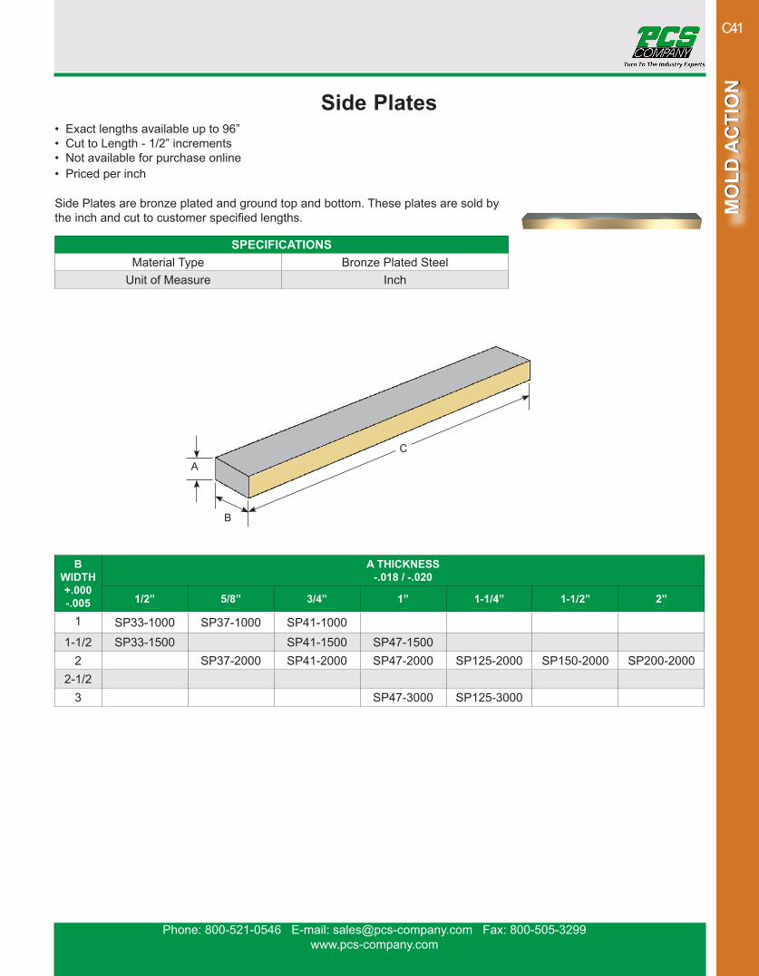
Side Plates• Exact lengths available up to 96”• Cut to Length - 1/2” increments• Not available for purchase online• Priced per inch
Side Plates are bronze plated and ground top and bottom. These plates are sold by the inch and cut to customer specified lengths.
SPECIFICATIONSMaterial Type Bronze Plated Steel
Unit of Measure Inch
BWIDTH+.000-.005
A THICKNESS-.018 / -.020
1/2” 5/8” 3/4” 1” 1-1/4” 1-1/2” 2”
1 SP33-1000 SP37-1000 SP41-10001-1/2 SP33-1500 SP41-1500 SP47-1500
2 SP37-2000 SP41-2000 SP47-2000 SP125-2000 SP150-2000 SP200-20002-1/2
3 SP47-3000 SP125-3000
A
B
C
Phone: 800-521-0546 E-mail: [email protected] Fax: 800-505-3299www.pcs-company.com
MO
LD A
CTI
ON
MO
LD A
CTI
ON
C42
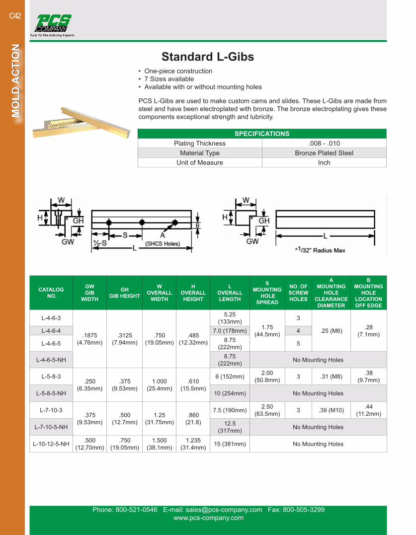
Standard L-Gibs • One-piece construction• 7 Sizes available• Available with or without mounting holes
PCS L-Gibs are used to make custom cams and slides. These L-Gibs are made from steel and have been electroplated with bronze. The bronze electroplating gives these components exceptional strength and lubricity.
CATALOG NO.
GW GIB
WIDTH
GH GIB HEIGHT
W OVERALL
WIDTH
H OVERALL HEIGHT
L OVERALL LENGTH
S MOUNTING
HOLE SPREAD
NO. OF SCREW HOLES
A MOUNTING
HOLE CLEARANCE DIAMETER
B MOUNTING
HOLE LOCATION OFF EDGE
L-4-6-3
.1875(4.76mm)
.3125(7.94mm)
.750(19.05mm)
.485(12.32mm)
5.25 (133mm)
1.75(44.5mm)
3
.25 (M6) .28 (7.1mm)L-4-6-4 7.0 (178mm) 4
L-4-6-5 8.75 (222mm) 5
L-4-6-5-NH 8.75 (222mm) No Mounting Holes
L-5-8-3.250
(6.35mm).375
(9.53mm)1.000
(25.4mm).610
(15.5mm)
6 (152mm) 2.00 (50.8mm) 3 .31 (M8) .38
(9.7mm)
L-5-8-5-NH 10 (254mm) No Mounting Holes
L-7-10-3.375
(9.53mm).500
(12.7mm)1.25
(31.75mm).860
(21.8)
7.5 (190mm) 2.50 (63.5mm) 3 .39 (M10) .44
(11.2mm)
L-7-10-5-NH 12.5 (317mm) No Mounting Holes
L-10-12-5-NH .500(12.70mm)
.750(19.05mm)
1.500(38.1mm)
1.235(31.4mm) 15 (381mm) No Mounting Holes
SPECIFICATIONSPlating Thickness .008 - .010
Material Type Bronze Plated SteelUnit of Measure Inch

Phone: 800-521-0546 E-mail: [email protected] Fax: 800-505-3299www.pcs-company.com
MO
LD A
CTI
ON
MO
LD A
CTI
ON
C43
Self-Lubricating L-Gibs• One-piece construction• 7 Sizes available• Available with or without mounting holes• Graphite plugs for greaseless applications
PCS Self-Lubricating L-Gibs are used to make custom cams and slides. These L-Gibs are made of solid bronze and contain graphite plugs. The graphite plugs elimi-nate the need for grease which makes these L-Gibs perfect for medical, food grade or high speed applications.
SPECIFICATIONSPlating Thickness .008 - .010
Material Type Solid Bronze with graphite plugsUnit of Measure Inch
CATALOG NO.
GW GIB
WIDTH
GH GIB
HEIGHT
W OVERALL
WIDTH
H OVERALL HEIGHT
L OVERALL LENGTH
S MOUNTING
HOLE SPREAD
NO. OF SCREW HOLES
A MOUNTING
HOLE CLEARANCE DIAMETER
B MOUNTING
HOLE LOCATION OFF EDGE
SLL-4-6-5.1875
(4.76mm).3125
(7.94mm).750
(19.05mm).485
(12.32mm)
8.75 (222mm)
1.75(44.5mm) 5 .25
(M6).28
(7.1mm)
SLL-4-6-5-NH 8.75 (222mm) No Mounting Holes
SLL-5-8-5.250
(6.35mm).375
(9.53mm)1.000
(25.4mm).610
(15.5mm)
10 (254mm)
2.00 (50.8mm) 5 .31
(M8) .38 (9.7mm)
SLL-5-8-5-NH 10 (254mm) No Mounting Holes
SLL-7-10-5.375
(9.53mm).500
(12.7mm)1.25
(31.75mm).860
(21.8)
12.5 (317mm)
2.50 (63.5mm) 5 .39
(M10).44
(11.2mm)
SLL-7-10-5-NH 12.5 (317mm) No Mounting Holes
SLL-10-12-5 .500(12.70mm)
.750(19.05mm)
1.500(38.1mm)
1.235(31.4mm)
15 (381mm)
3.00(76.2mm) 5 .39
(M10).50
(12.7mm)SLL-10-12-5-NH No Mounting Holes
SLL-12-16-6.625
(15.88mm).875
(22.23mm)2.000
(50.8mm)1.470
(37.3mm)
16.0(406mm)
4.00(101.6mm) 6 .50
(M12).69
(17.5mm)
SLL-12-16-6-NH 16.0(406mm) No Mounting Holes
SLL-16-20-8-NH .750(19.05mm)
1.250(31.75mm)
2.500(63.5mm)
1.470(37.3mm)
32.0(813mm) No Mounting Holes
SLL-20-24-81.000
(25.40mm)1.500
(38.10mm)3.000
(76.2mm)2.470
(32.74mm)
48.0(1219mm)
6.00(152.4mm) 8 .62
(M16)1.0
(25.4mm)
SLL-20-24-8-NH 48.0(1219mm) No Mounting Holes
Phone: 800-521-0546 E-mail: [email protected] Fax: 800-505-3299www.pcs-company.com
MO
LD A
CTI
ON
MO
LD A
CTI
ON
C44
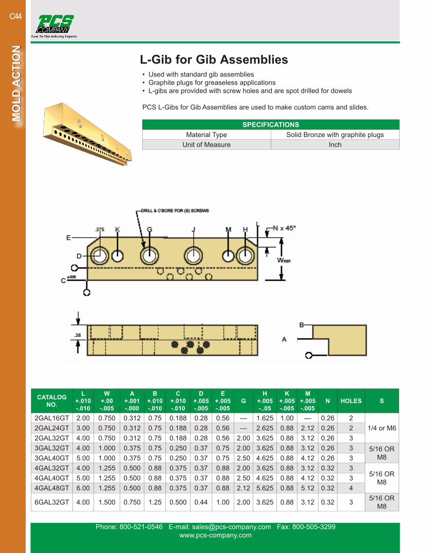
L-Gib for Gib Assemblies• Used with standard gib assemblies• Graphite plugs for greaseless applications• L-gibs are provided with screw holes and are spot drilled for dowels
PCS L-Gibs for Gib Assemblies are used to make custom cams and slides.
CATALOG NO.
L+.010-.010
W+.00-.005
A+.001-.000
B+.010-.010
C+.010-.010
D+.005-.005
E+.005-.005
GH
+.005-..05
K+.005-.005
M+.005-.005
N HOLES S
2GAL16GT 2.00 0.750 0.312 0.75 0.188 0.28 0.56 — 1.625 1.00 — 0.26 21/4 or M62GAL24GT 3.00 0.750 0.312 0.75 0.188 0.28 0.56 — 2.625 0.88 2.12 0.26 2
2GAL32GT 4.00 0.750 0.312 0.75 0.188 0.28 0.56 2.00 3.625 0.88 3.12 0.26 33GAL32GT 4.00 1.000 0.375 0.75 0.250 0.37 0.75 2.00 3.625 0.88 3.12 0.26 3 5/16 OR
M83GAL40GT 5.00 1.000 0.375 0.75 0.250 0.37 0.75 2.50 4.625 0.88 4.12 0.26 34GAL32GT 4.00 1.255 0.500 0.88 0.375 0.37 0.88 2.00 3.625 0.88 3.12 0.32 3
5/16 OR M84GAL40GT 5.00 1.255 0.500 0.88 0.375 0.37 0.88 2.50 4.625 0.88 4.12 0.32 3
4GAL48GT 6.00 1.255 0.500 0.88 0.375 0.37 0.88 2.12 5.625 0.88 5.12 0.32 4
6GAL32GT 4.00 1.500 0.750 1.25 0.500 0.44 1.00 2.00 3.625 0.88 3.12 0.32 3 5/16 OR M8
SPECIFICATIONSMaterial Type Solid Bronze with graphite plugs
Unit of Measure Inch
Phone: 800-521-0546 E-mail: [email protected] Fax: 800-505-3299www.pcs-company.com
MO
LD A
CTI
ON
MO
LD A
CTI
ON
C45
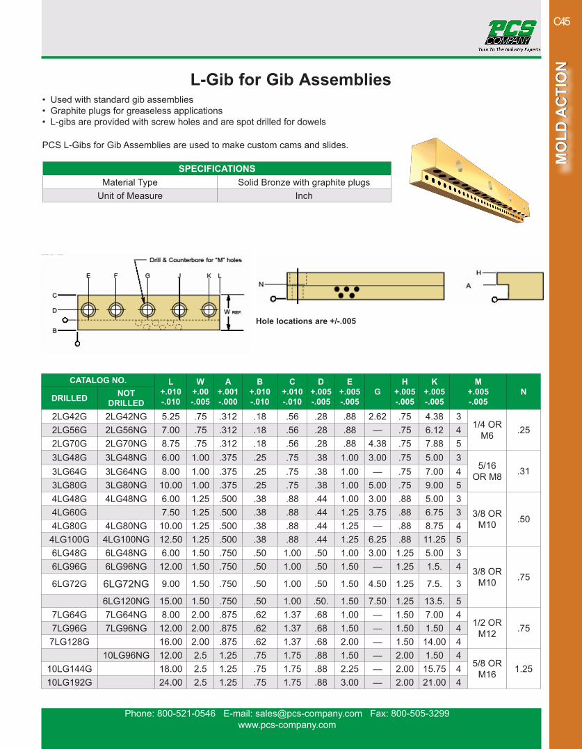
L-Gib for Gib Assemblies• Used with standard gib assemblies• Graphite plugs for greaseless applications• L-gibs are provided with screw holes and are spot drilled for dowels
PCS L-Gibs for Gib Assemblies are used to make custom cams and slides.
CATALOG NO. L+.010-.010
W+.00-.005
A+.001-.000
B+.010-.010
C+.010-.010
D+.005-.005
E+.005-.005
GH
+.005-.005
K+.005-.005
M+.005-.005
NDRILLED NOT
DRILLED2LG42G 2LG42NG 5.25 .75 .312 .18 .56 .28 .88 2.62 .75 4.38 3
1/4 OR M6 .252LG56G 2LG56NG 7.00 .75 .312 .18 .56 .28 .88 — .75 6.12 4
2LG70G 2LG70NG 8.75 .75 .312 .18 .56 .28 .88 4.38 .75 7.88 53LG48G 3LG48NG 6.00 1.00 .375 .25 .75 .38 1.00 3.00 .75 5.00 3
5/16 OR M8 .313LG64G 3LG64NG 8.00 1.00 .375 .25 .75 .38 1.00 — .75 7.00 4
3LG80G 3LG80NG 10.00 1.00 .375 .25 .75 .38 1.00 5.00 .75 9.00 54LG48G 4LG48NG 6.00 1.25 .500 .38 .88 .44 1.00 3.00 .88 5.00 3
3/8 OR M10 .50
4LG60G 7.50 1.25 .500 .38 .88 .44 1.25 3.75 .88 6.75 34LG80G 4LG80NG 10.00 1.25 .500 .38 .88 .44 1.25 — .88 8.75 4
4LG100G 4LG100NG 12.50 1.25 .500 .38 .88 .44 1.25 6.25 .88 11.25 56LG48G 6LG48NG 6.00 1.50 .750 .50 1.00 .50 1.00 3.00 1.25 5.00 3
3/8 OR M10 .75
6LG96G 6LG96NG 12.00 1.50 .750 .50 1.00 .50 1.50 — 1.25 1.5. 4
6LG72G 6LG72NG 9.00 1.50 .750 .50 1.00 .50 1.50 4.50 1.25 7.5. 3
6LG120NG 15.00 1.50 .750 .50 1.00 .50. 1.50 7.50 1.25 13.5. 57LG64G 7LG64NG 8.00 2.00 .875 .62 1.37 .68 1.00 — 1.50 7.00 4
1/2 OR M12 .757LG96G 7LG96NG 12.00 2.00 .875 .62 1.37 .68 1.50 — 1.50 1.50 4
7LG128G 16.00 2.00 .875 .62 1.37 .68 2.00 — 1.50 14.00 410LG96NG 12.00 2.5 1.25 .75 1.75 .88 1.50 — 2.00 1.50 4
5/8 OR M16 1.2510LG144G 18.00 2.5 1.25 .75 1.75 .88 2.25 — 2.00 15.75 4
10LG192G 24.00 2.5 1.25 .75 1.75 .88 3.00 — 2.00 21.00 4
SPECIFICATIONSMaterial Type Solid Bronze with graphite plugs
Unit of Measure Inch
Hole locations are +/-.005
Phone: 800-521-0546 E-mail: [email protected] Fax: 800-505-3299www.pcs-company.com
MO
LD A
CTI
ON
MO
LD A
CTI
ON
C46
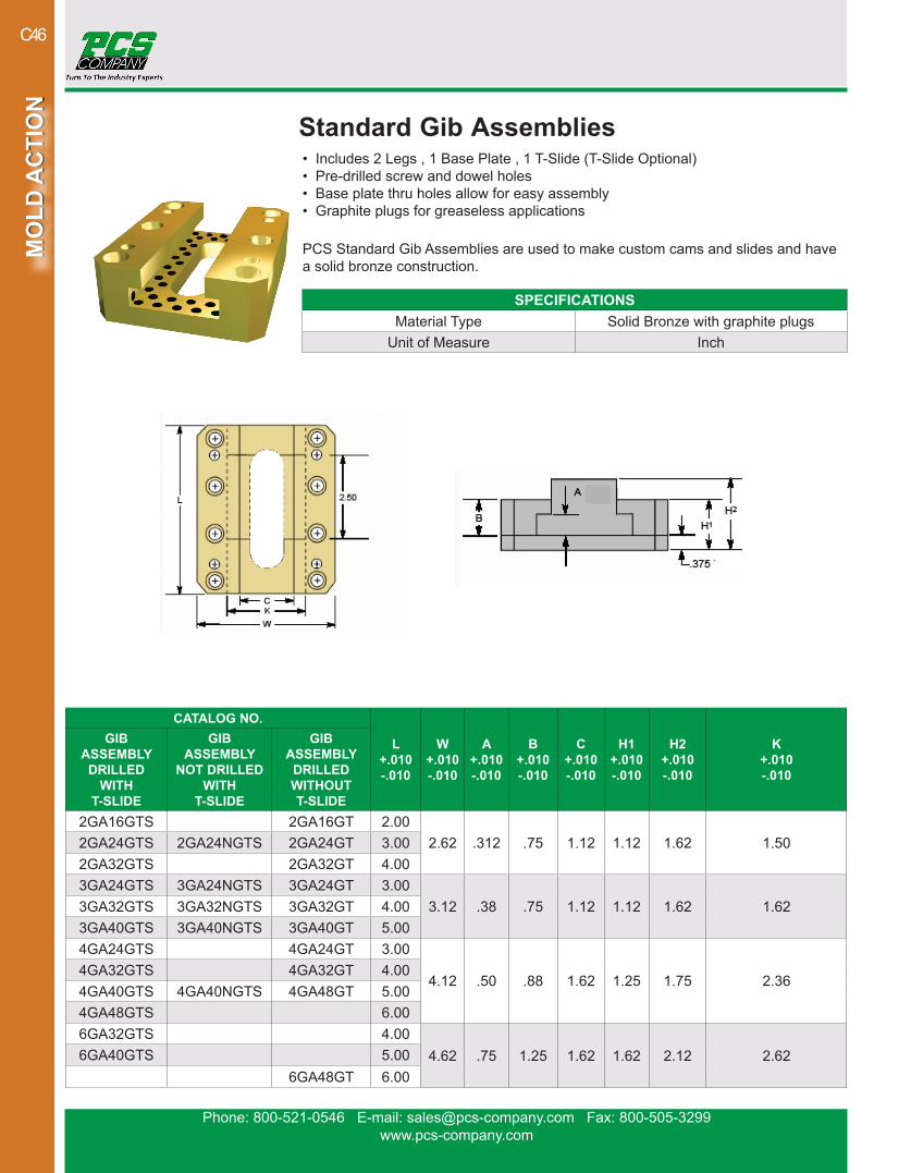
Standard Gib Assemblies• Includes 2 Legs , 1 Base Plate , 1 T-Slide (T-Slide Optional)• Pre-drilled screw and dowel holes• Base plate thru holes allow for easy assembly• Graphite plugs for greaseless applications
PCS Standard Gib Assemblies are used to make custom cams and slides and have a solid bronze construction.
CATALOG NO.
L+.010-.010
W+.010-.010
A+.010-.010
B+.010-.010
C+.010-.010
H1+.010-.010
H2+.010-.010
K+.010-.010
GIB ASSEMBLY
DRILLED WITH
T-SLIDE
GIB ASSEMBLY
NOT DRILLED WITH
T-SLIDE
GIB ASSEMBLY
DRILLEDWITHOUT T-SLIDE
2GA16GTS 2GA16GT 2.002.62 .312 .75 1.12 1.12 1.62 1.502GA24GTS 2GA24NGTS 2GA24GT 3.00
2GA32GTS 2GA32GT 4.003GA24GTS 3GA24NGTS 3GA24GT 3.00
3.12 .38 .75 1.12 1.12 1.62 1.623GA32GTS 3GA32NGTS 3GA32GT 4.003GA40GTS 3GA40NGTS 3GA40GT 5.004GA24GTS 4GA24GT 3.00
4.12 .50 .88 1.62 1.25 1.75 2.364GA32GTS 4GA32GT 4.004GA40GTS 4GA40NGTS 4GA48GT 5.004GA48GTS 6.006GA32GTS 4.00
4.62 .75 1.25 1.62 1.62 2.12 2.626GA40GTS 5.006GA48GT 6.00
SPECIFICATIONSMaterial Type Solid Bronze with graphite plugs
Unit of Measure Inch
Phone: 800-521-0546 E-mail: [email protected] Fax: 800-505-3299www.pcs-company.com
MO
LD A
CTI
ON
MO
LD A
CTI
ON
C47
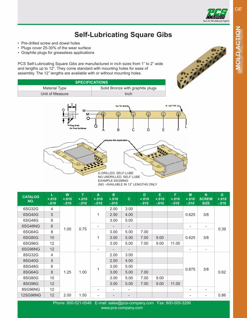
Self-Lubricating Square Gibs• Pre-drilled screw and dowel holes• Plugs cover 25-30% of the wear surface• Graphite plugs for greaseless applications
PCS Self-Lubricating Square Gibs are manufactured in inch sizes from 1” to 2” wide and lengths up to 12”. They come standard with mounting holes for ease of assembly. The 12” lengths are available with or without mounting holes.
CATALOG NO.
L+.010-.010
W+.010-.010
T+.010-.010
A+.010-.010
B+.010-.010
CD
+.010-.010
E+.010-.010
F+.010-.010
M+.010-.010
N SCREW
SIZE
G+.010-.010
6SG32G 4
1.00 0.75
12.00 3.00
0.625 3/8
0.39
6SG40G 5 2.50 4.006SG48G 6 3.00 5.00
6SG48NG 6 - - - - -6SG64G 8
13.00 5.00 7.00
0.625 3/86SG80G 10 3.00 5.00 7.00 9.006SG96G 12 3.00 5.00 7.00 9.00 11.00
6SG96NG 12 - - - - -8SG32G 4
1.25 1.001
2.00 3.00
0.875 3/80.62
8SG40G 5 2.50 4.008SG48G 6 3.00 5.008SG64G 8 3.00 5.00 7.008SG80G 10 3.00 5.00 7.00 9.008SG96G 12 3.00 5.00 7.00 9.00 11.00
8SG96NG 12 - - - - -12SG96NG 12 2.00 1.50 - - - - - 0.86
SPECIFICATIONSMaterial Type Solid Bronze with graphite plugs
Unit of Measure Inch
G DRILLED, SELF-LUBENG UNDRILLED, SELF LUBEEXAMPLE 6SG96NG(NG - AVAILABLE IN 12” LENGTHS ONLY
Phone: 800-521-0546 E-mail: [email protected] Fax: 800-505-3299www.pcs-company.com
MO
LD A
CTI
ON
MO
LD A
CTI
ON
C48
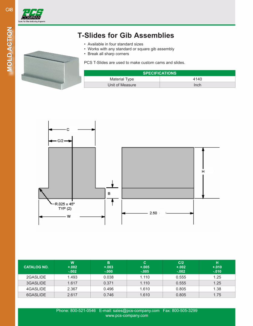
T-Slides for Gib Assemblies• Available in four standard sizes• Works with any standard or square gib assembly• Break all sharp corners
PCS T-Slides are used to make custom cams and slides.
CATALOG NO.W
+.002-.002
B+.003-.000
C+.005-.005
C/2+.002-.002
H+.010-.010
2GASLIDE 1.493 0.038 1.110 0.555 1.253GASLIDE 1.617 0.371 1.110 0.555 1.254GASLIDE 2.367 0.496 1.610 0.805 1.386GASLIDE 2.617 0.746 1.610 0.805 1.75
SPECIFICATIONSMaterial Type 4140
Unit of Measure Inch
Phone: 800-521-0546 E-mail: [email protected] Fax: 800-505-3299www.pcs-company.com
MO
LD A
CTI
ON
MO
LD A
CTI
ON
C49
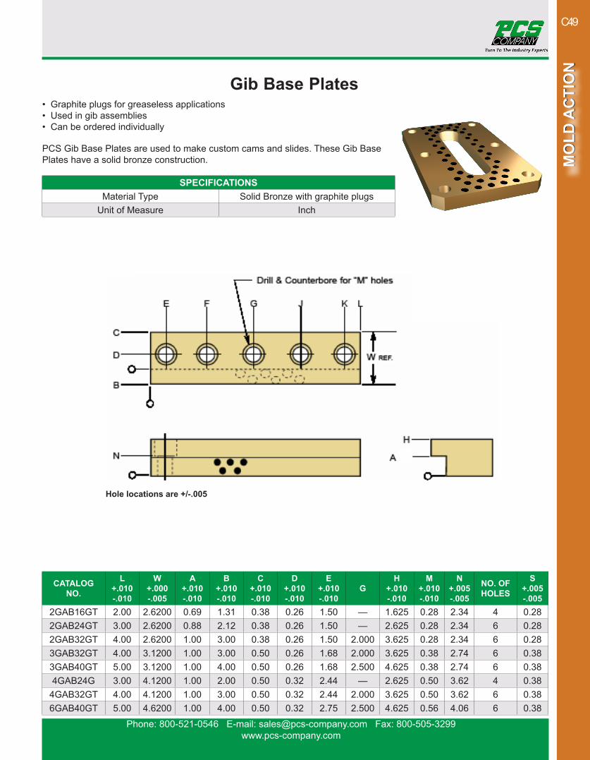
Gib Base Plates• Graphite plugs for greaseless applications• Used in gib assemblies• Can be ordered individually
PCS Gib Base Plates are used to make custom cams and slides. These Gib Base Plates have a solid bronze construction.
CATALOG NO.
L+.010-.010
W+.000-.005
A+.010-.010
B+.010-.010
C+.010-.010
D+.010-.010
E+.010-.010
GH
+.010-.010
M+.010-.010
N+.005-.005
NO. OF HOLES
S+.005-.005
2GAB16GT 2.00 2.6200 0.69 1.31 0.38 0.26 1.50 — 1.625 0.28 2.34 4 0.282GAB24GT 3.00 2.6200 0.88 2.12 0.38 0.26 1.50 — 2.625 0.28 2.34 6 0.282GAB32GT 4.00 2.6200 1.00 3.00 0.38 0.26 1.50 2.000 3.625 0.28 2.34 6 0.283GAB32GT 4.00 3.1200 1.00 3.00 0.50 0.26 1.68 2.000 3.625 0.38 2.74 6 0.383GAB40GT 5.00 3.1200 1.00 4.00 0.50 0.26 1.68 2.500 4.625 0.38 2.74 6 0.384GAB24G 3.00 4.1200 1.00 2.00 0.50 0.32 2.44 — 2.625 0.50 3.62 4 0.38
4GAB32GT 4.00 4.1200 1.00 3.00 0.50 0.32 2.44 2.000 3.625 0.50 3.62 6 0.386GAB40GT 5.00 4.6200 1.00 4.00 0.50 0.32 2.75 2.500 4.625 0.56 4.06 6 0.38
SPECIFICATIONSMaterial Type Solid Bronze with graphite plugs
Unit of Measure Inch
Hole locations are +/-.005

Phone: 800-521-0546 E-mail: [email protected] Fax: 800-505-3299www.pcs-company.com
MO
LD A
CTI
ON
MO
LD A
CTI
ON
C50
Self-Lubricating Solid Bronze Wear Strips• Width and length of wearstrip determines hole pattern regardless of thickness• Greaseless applications• Protects mold from damage due to high wear conditions
Self-Lubricating Solid Bronze Wear Strip is used to reduce wear and give added support to moving components within a mold. PCS Self-Lubricating Solid Bronze Wear Strip is available in many thickness, width and length combinations.
THICKNESS 1/4” (.250 +/- .001)CATALOG NO.
WIDTH LENGTHDRILLED NOT
DRILLED28-32G 1 428-40G 28-40NG 1 528-48G 28-48NG 1 628-64G 28-64NG 1 828-80G 1 1028-96G 28-96NG 1 12
212-32G 212-32NG 1.5 4212-40G 212-40NG 1.5 5212-48G 212-48NG 1.5 6212-64G 212-64NG 1.5 8212-80G 212-80NG 1.5 10216-32G 216-32NG 2 4216-40G 216-40NG 2 5216-48G 2 6216-64G 216-64NG 2 8216-80G 216-80NG 2 10216-96G 216-96NG 2 12
THICKNESS 1/4” (.250 +/- .001)CATALOG NO.
WIDTH LENGTHDRILLED NOT
DRILLED220-32G 220-32NG 2.5 4220-40G 220-40NG 2.5 5
220-48NG 2.5 6220-64G 220-64NG 2.5 8220-80G 220-80NG 2.5 10220-96G 220-96NG 2.5 12224-32G 224-32NG 3 4
224-40NG 3 5224-48NG 3 6
224-64G 224-64NG 3 8224-80NG 3 10
224-96G 224-96NG 3 12232-32G 232-32NG 4 4232-40G 232-40NG 4 5232-48G 232-48NG 4 6232-64G 232-64NG 4 8232-80G 232-80NG 4 10232-96G 232-96NG 4 12
Continued on next page
For drilled hole location patterns see page C55
SPECIFICATIONSMaterial Type Solid Bronze with graphite plugs
Thickness Tolerance ±.001Width Tolerance +.01 / -.080Length Tolerance +.062 / -.000Unit of Measure Inch

Phone: 800-521-0546 E-mail: [email protected] Fax: 800-505-3299www.pcs-company.com
MO
LD A
CTI
ON
MO
LD A
CTI
ON
C51
Self-Lubricating Solid Bronze Wear Strips• Width and length of wearstrip determines hole pattern regardless of thickness• Greaseless applications• Protects mold from damage due to high wear conditions
Self-Lubricating Solid Bronze Wear Strip is used to reduce wear and give added support to moving components within a mold. PCS Self-Lubricating Solid Bronze Wear Strip is available in many thickness, width and length combinations.
THICKNESS 3/8” (.375 +/- .001)CATALOG NO.
WIDTH LENGTHDRILLED NOT
DRILLED38-32NG 1 438-48NG 1 6
38-64G 38-64NG 1 838-80G 38-80NG 1 10
38-96NG 1 12312-32NG 1.5 4312-48NG 1.5 6
312-64G 312-64NG 1.5 8312-80G 1.5 10312-96G 1.5 12
316-32NG 2 4316-40NG 2 5
316-48G 2 6316-64G 316-64NG 2 8316-80G 316-80NG 2 10
316-96NG 2 12320-32G 320-32NG 2.5 4
THICKNESS 3/8” (.375 +/- .001)CATALOG NO.
WIDTH LENGTHDRILLED NOT
DRILLED320-40G 320-40NG 2.5 5
320-48NG 2.5 6320-64NG 2.5 8
320-80G 2.5 10320-96G 2.5 12
324-24NG 3 3324-32G 324-32NG 3 4324-48G 324-48NG 3 6324-64G 324-64NG 3 8324-80G 324-80NG 3 10324-96G 324-96NG 3 12332-32G 332-32NG 4 4332-40G 332-40NG 4 5332-48G 332-48NG 4 6332-64G 332-64NG 4 8332-80G 332-80NG 4 10332-96G 332-96NG 4 12
Continued on next pageFor drilled hole location patterns see page C55
SPECIFICATIONSMaterial Type Solid Bronze with graphite plugs
Thickness Tolerance ±.001Width Tolerance +.01 / -.080Length Tolerance +.062 / -.000Unit of Measure Inch

Phone: 800-521-0546 E-mail: [email protected] Fax: 800-505-3299www.pcs-company.com
MO
LD A
CTI
ON
MO
LD A
CTI
ON
C52
THICKNESS 1/2” (.500 +/- .001)CATALOG NO.
WIDTH LENGTHDRILLED NOT
DRILLED412-24NG 1.5 3412-32NG 1.5 4
412-48G 1.5 6412-64NG 1.5 8
416-24G 2 3416-48G 2 6
416-64NG 2 8416-96G 2 12420-24G 2.5 3420-32G 420-32NG 2.5 4
420-40NG 2.5 5420-64G 420-64NG 2.5 8424-24G 3 3
424-40NG 3 5424-48G 3 6424-64G 3 8424-80G 3 10
THICKNESS 5/8” (.625 +/- .001)CATALOG NO.
WIDTH LENGTHDRILLED NOT
DRILLED424-96G 424-96NG 3 12432-32G 4 4
432-48NG 4 6432-64G 432-64NG 4 8432-80G 432-80NG 4 10
432-96NG 4 12512-48NG 1.5 6516-32NG 2 4516-48NG 2 6
516-64G 2 8516-96NG 2 12524-40NG 3 5
532-32G 4 4532-40NG 4 5
Self-Lubricating Solid Bronze Wear Strips• Width and length of wearstrip determines hole pattern regardless of thickness• Greaseless applications• Protects mold from damage due to high wear conditions
Self-Lubricating Solid Bronze Wear Strip is used to reduce wear and give added sup-port to moving components within a mold. PCS Self-Lubricating Solid Bronze Wear Strip is available in many thickness, width and length combinations.
For drilled hole location patterns see page C55
SPECIFICATIONSMaterial Type Solid Bronze with graphite plugs
Thickness Tolerance ±.001Width Tolerance +.01 / -.080Length Tolerance +.062 / -.000Unit of Measure Inch
Phone: 800-521-0546 E-mail: [email protected] Fax: 800-505-3299www.pcs-company.com
MO
LD A
CTI
ON
MO
LD A
CTI
ON
C53
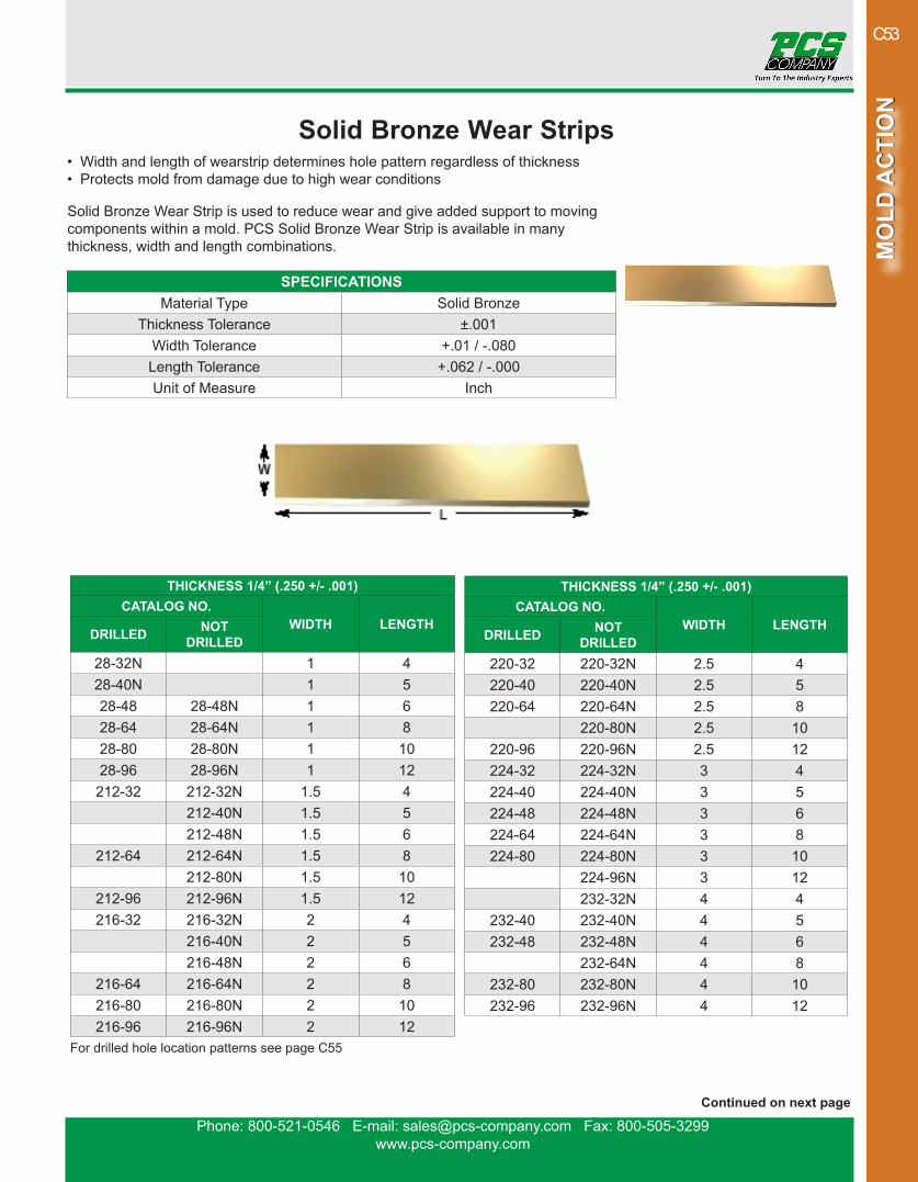
Solid Bronze Wear Strips• Width and length of wearstrip determines hole pattern regardless of thickness• Protects mold from damage due to high wear conditions
Solid Bronze Wear Strip is used to reduce wear and give added support to moving components within a mold. PCS Solid Bronze Wear Strip is available in many thickness, width and length combinations.
THICKNESS 1/4” (.250 +/- .001)CATALOG NO.
WIDTH LENGTHDRILLED NOT
DRILLED28-32N 1 428-40N 1 528-48 28-48N 1 628-64 28-64N 1 828-80 28-80N 1 1028-96 28-96N 1 12
212-32 212-32N 1.5 4212-40N 1.5 5212-48N 1.5 6
212-64 212-64N 1.5 8212-80N 1.5 10
212-96 212-96N 1.5 12216-32 216-32N 2 4
216-40N 2 5216-48N 2 6
216-64 216-64N 2 8216-80 216-80N 2 10216-96 216-96N 2 12
SPECIFICATIONSMaterial Type Solid Bronze
Thickness Tolerance ±.001Width Tolerance +.01 / -.080Length Tolerance +.062 / -.000Unit of Measure Inch
THICKNESS 1/4” (.250 +/- .001)CATALOG NO.
WIDTH LENGTHDRILLED NOT
DRILLED220-32 220-32N 2.5 4220-40 220-40N 2.5 5220-64 220-64N 2.5 8
220-80N 2.5 10220-96 220-96N 2.5 12224-32 224-32N 3 4224-40 224-40N 3 5224-48 224-48N 3 6224-64 224-64N 3 8224-80 224-80N 3 10
224-96N 3 12232-32N 4 4
232-40 232-40N 4 5232-48 232-48N 4 6
232-64N 4 8232-80 232-80N 4 10232-96 232-96N 4 12
Continued on next page
For drilled hole location patterns see page C55

Phone: 800-521-0546 E-mail: [email protected] Fax: 800-505-3299www.pcs-company.com
MO
LD A
CTI
ON
MO
LD A
CTI
ON
C54
THICKNESS 3/8” (.375 +/- .001)CATALOG NO.
WIDTH LENGTHDRILLED NOT
DRILLED38-32N 1 438-40N 1 538-48N 1 638-80N 1 1038-96N 1 12
312-32 312-32N 1.5 4312-40N 1.5 5
312-48 312-48N 1.5 6312-64 312-64N 1.5 8316-32 316-32N 2 4316-40 316-40N 2 5316-48 316-48N 2 6316-64 316-64N 2 8
316-80N 2 10316-96 316-96N 2 12320-32 320-32N 2.5 4
320-40N 2.5 5320-48 2.5 6320-64 320-64N 2.5 8
320-80N 2.5 10320-96N 2.5 12
THICKNESS 3/8” (.375 +/- .001)CATALOG NO.
WIDTH LENGTHDRILLED NOT
DRILLED324-32 324-32N 3 4324-40 324-40N 3 5324-48 324-48N 3 6324-64 324-64N 3 8324-80 324-80N 3 10324-96 324-96N 3 12332-32 332-32N 4 4332-40 332-40N 4 5332-48 332-48N 4 6332-64 332-64N 4 8332-80 332-80N 4 10332-96 332-96N 4 12
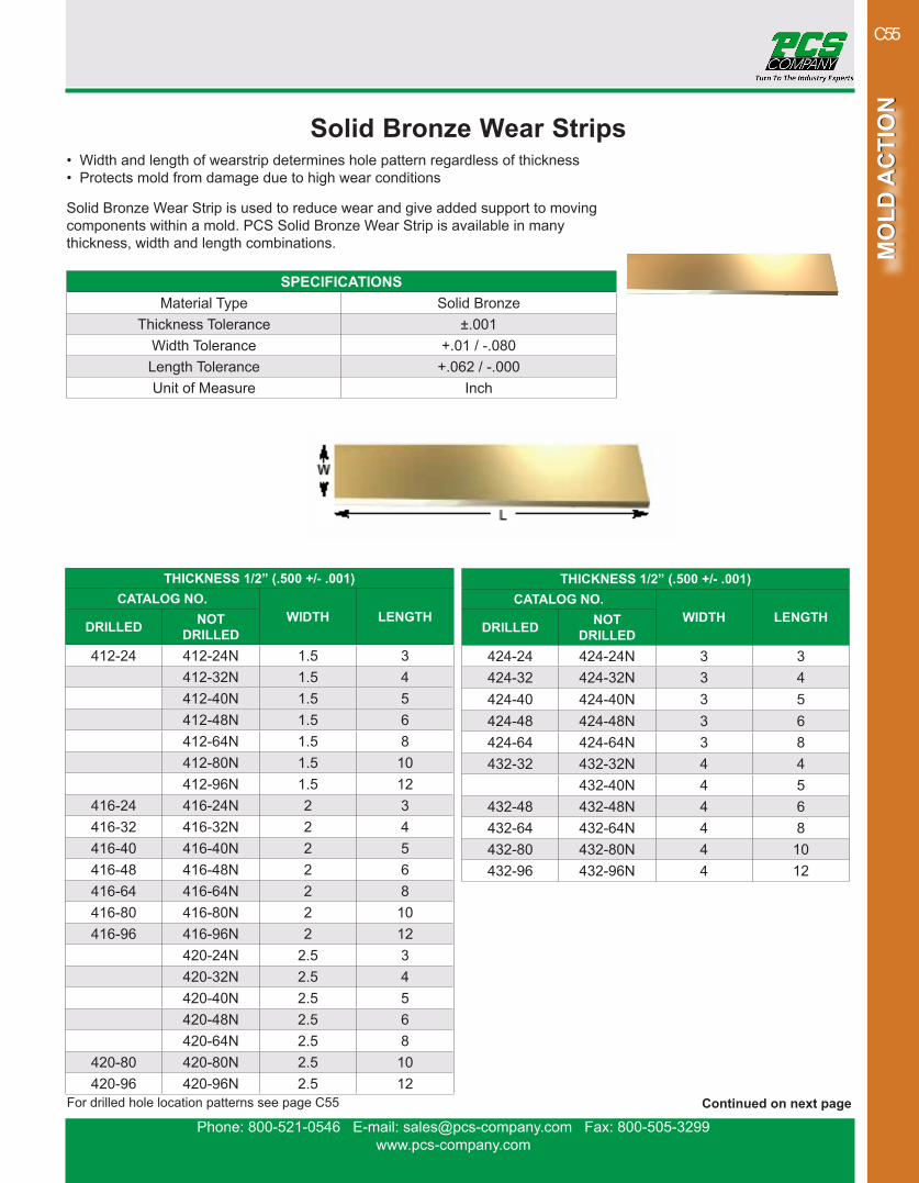
Solid Bronze Wear Strips• Width and length of wearstrip determines hole pattern regardless of thickness• Protects mold from damage due to high wear conditions
Solid Bronze Wear Strip is used to reduce wear and give added support to moving components within a mold. PCS Solid Bronze Wear Strip is available in many thickness, width and length combinations.
For drilled hole location patterns see page C55 Continued on next page
SPECIFICATIONSMaterial Type Solid Bronze
Thickness Tolerance ±.001Width Tolerance +.01 / -.080Length Tolerance +.062 / -.000Unit of Measure Inch
Phone: 800-521-0546 E-mail: [email protected] Fax: 800-505-3299www.pcs-company.com
MO
LD A
CTI
ON
MO
LD A
CTI
ON
C55
THICKNESS 1/2” (.500 +/- .001)CATALOG NO.
WIDTH LENGTHDRILLED NOT
DRILLED412-24 412-24N 1.5 3
412-32N 1.5 4412-40N 1.5 5412-48N 1.5 6412-64N 1.5 8412-80N 1.5 10412-96N 1.5 12
416-24 416-24N 2 3416-32 416-32N 2 4416-40 416-40N 2 5416-48 416-48N 2 6416-64 416-64N 2 8416-80 416-80N 2 10416-96 416-96N 2 12
420-24N 2.5 3420-32N 2.5 4420-40N 2.5 5420-48N 2.5 6420-64N 2.5 8
420-80 420-80N 2.5 10420-96 420-96N 2.5 12
Solid Bronze Wear Strips• Width and length of wearstrip determines hole pattern regardless of thickness• Protects mold from damage due to high wear conditions
Solid Bronze Wear Strip is used to reduce wear and give added support to moving components within a mold. PCS Solid Bronze Wear Strip is available in many thickness, width and length combinations.
THICKNESS 1/2” (.500 +/- .001)CATALOG NO.
WIDTH LENGTHDRILLED NOT
DRILLED424-24 424-24N 3 3424-32 424-32N 3 4424-40 424-40N 3 5424-48 424-48N 3 6424-64 424-64N 3 8432-32 432-32N 4 4
432-40N 4 5432-48 432-48N 4 6432-64 432-64N 4 8432-80 432-80N 4 10432-96 432-96N 4 12
Continued on next pageFor drilled hole location patterns see page C55
SPECIFICATIONSMaterial Type Solid Bronze
Thickness Tolerance ±.001Width Tolerance +.01 / -.080Length Tolerance +.062 / -.000Unit of Measure Inch

Phone: 800-521-0546 E-mail: [email protected] Fax: 800-505-3299www.pcs-company.com
MO
LD A
CTI
ON
MO
LD A
CTI
ON
C56
THICKNESS 5/8” (.625 +/- .001)CATALOG NO.
WIDTH LENGTHDRILLED NOT
DRILLED512-24 512-24N 1.5 3512-32 512-32N 1.5 4
512-40N 1.5 5512-48N 1.5 6512-64N 1.5 8512-80N 1.5 10512-96N 1.5 12516-24N 2 3516-32N 2 4516-40N 2 5516-80N 2 10524-32N 3 4532-32N 4 4532-40N 4 5532-48N 4 6532-64N 4 8532-80N 4 10
Solid Bronze Wear Strips• Width and length of wearstrip determines hole pattern regardless of thickness• Protects mold from damage due to high wear conditions
Solid Bronze Wear Strip is used to reduce wear and give added support to moving components within a mold. PCS Solid Bronze Wear Strip is available in many thickness, width and length combinations.
For drilled hole location patterns see page C55
SPECIFICATIONSMaterial Type Solid Bronze
Thickness Tolerance ±.001Width Tolerance +.01 / -.080Length Tolerance +.062 / -.000Unit of Measure Inch
Phone: 800-521-0546 E-mail: [email protected] Fax: 800-505-3299www.pcs-company.com
MO
LD A
CTI
ON
MO
LD A
CTI
ON
C57
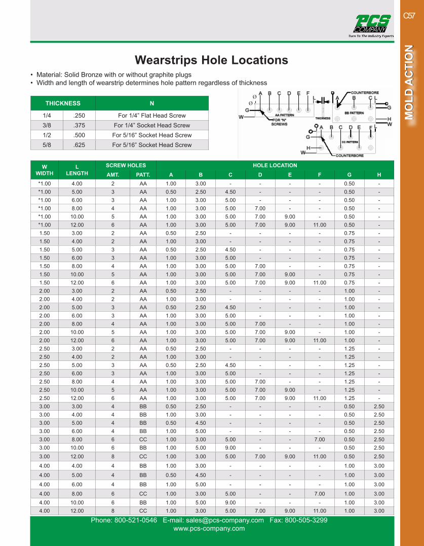
Wearstrips Hole Locations• Material: Solid Bronze with or without graphite plugs• Width and length of wearstrip determines hole pattern regardless of thickness
THICKNESS N
1/4 .250 For 1/4” Flat Head Screw3/8 .375 For 1/4” Socket Head Screw1/2 .500 For 5/16” Socket Head Screw5/8 .625 For 5/16” Socket Head Screw
WWIDTH
LLENGTH
SCREW HOLES HOLE LOCATIONAMT. PATT. A B C D E F G H
*1.00 4.00 2 AA 1.00 3.00 - - - - 0.50 -*1.00 5.00 3 AA 0.50 2.50 4.50 - - - 0.50 -*1.00 6.00 3 AA 1.00 3.00 5.00 - - - 0.50 -*1.00 8.00 4 AA 1.00 3.00 5.00 7.00 - - 0.50 -*1.00 10.00 5 AA 1.00 3.00 5.00 7.00 9.00 - 0.50 -*1.00 12.00 6 AA 1.00 3.00 5.00 7.00 9.00 11.00 0.50 -1.50 3.00 2 AA 0.50 2.50 - - - - 0.75 -1.50 4.00 2 AA 1.00 3.00 - - - - 0.75 -1.50 5.00 3 AA 0.50 2.50 4.50 - - - 0.75 -1.50 6.00 3 AA 1.00 3.00 5.00 - - - 0.75 -1.50 8.00 4 AA 1.00 3.00 5.00 7.00 - - 0.75 -1.50 10.00 5 AA 1.00 3.00 5.00 7.00 9.00 - 0.75 -1.50 12.00 6 AA 1.00 3.00 5.00 7.00 9.00 11.00 0.75 -2.00 3.00 2 AA 0.50 2.50 - - - - 1.00 -2.00 4.00 2 AA 1.00 3.00 - - - - 1.00 -2.00 5.00 3 AA 0.50 2.50 4.50 - - - 1.00 -2.00 6.00 3 AA 1.00 3.00 5.00 - - - 1.00 -2.00 8.00 4 AA 1.00 3.00 5.00 7.00 - - 1.00 -2.00 10.00 5 AA 1.00 3.00 5.00 7.00 9.00 - 1.00 -2.00 12.00 6 AA 1.00 3.00 5.00 7.00 9.00 11.00 1.00 -2.50 3.00 2 AA 0.50 2.50 - - - - 1.25 -2.50 4.00 2 AA 1.00 3.00 - - - - 1.25 -2.50 5.00 3 AA 0.50 2.50 4.50 - - - 1.25 -2.50 6.00 3 AA 1.00 3.00 5.00 - - - 1.25 -2.50 8.00 4 AA 1.00 3.00 5.00 7.00 - - 1.25 -2.50 10.00 5 AA 1.00 3.00 5.00 7.00 9.00 - 1.25 -2.50 12.00 6 AA 1.00 3.00 5.00 7.00 9.00 11.00 1.25 -3.00 3.00 4 BB 0.50 2.50 - - - - 0.50 2.503.00 4.00 4 BB 1.00 3.00 - - - - 0.50 2.503.00 5.00 4 BB 0.50 4.50 - - - - 0.50 2.503.00 6.00 4 BB 1.00 5.00 - - - - 0.50 2.503.00 8.00 6 CC 1.00 3.00 5.00 - - 7.00 0.50 2.503.00 10.00 6 BB 1.00 5.00 9.00 - - - 0.50 2.503.00 12.00 8 CC 1.00 3.00 5.00 7.00 9.00 11.00 0.50 2.50
4.00 4.00 4 BB 1.00 3.00 - - - - 1.00 3.00
4.00 5.00 4 BB 0.50 4.50 - - - - 1.00 3.00
4.00 6.00 4 BB 1.00 5.00 - - - - 1.00 3.00
4.00 8.00 6 CC 1.00 3.00 5.00 - - 7.00 1.00 3.004.00 10.00 6 BB 1.00 5.00 9.00 - - - 1.00 3.004.00 12.00 8 CC 1.00 3.00 5.00 7.00 9.00 11.00 1.00 3.00
ØØ
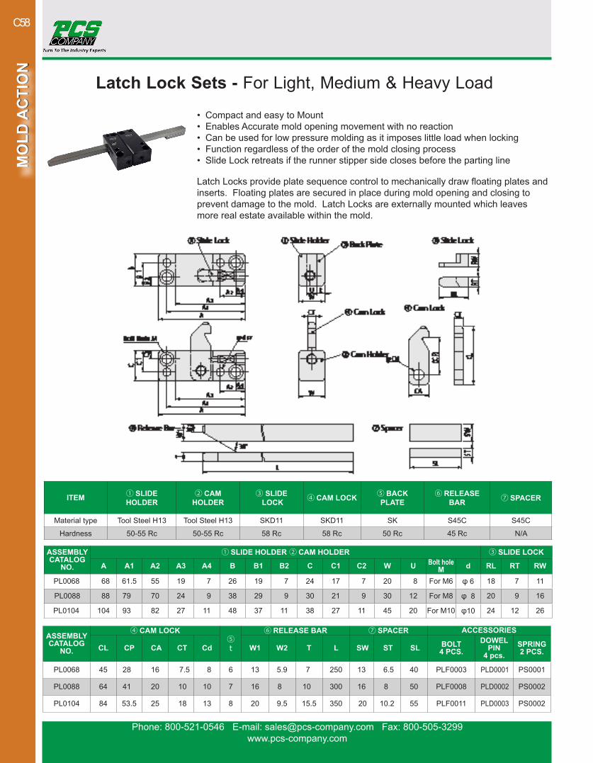
Phone: 800-521-0546 E-mail: [email protected] Fax: 800-505-3299www.pcs-company.com
MO
LD A
CTI
ON
MO
LD A
CTI
ON
C58
Latch Lock Sets - For Light, Medium & Heavy Load
• Compact and easy to Mount• Enables Accurate mold opening movement with no reaction• Can be used for low pressure molding as it imposes little load when locking• Function regardless of the order of the mold closing process• Slide Lock retreats if the runner stipper side closes before the parting line
Latch Locks provide plate sequence control to mechanically draw floating plates and inserts. Floating plates are secured in place during mold opening and closing to prevent damage to the mold. Latch Locks are externally mounted which leaves more real estate available within the mold.
ITEM ① SLIDE HOLDER
② CAM HOLDER
③ SLIDE LOCK
④ CAM LOCK ⑤ BACK
PLATE⑥ RELEASE
BAR ⑦ SPACER
Material type Tool Steel H13 Tool Steel H13 SKD11 SKD11 SK S45C S45C
Hardness 50-55 Rc 50-55 Rc 58 Rc 58 Rc 50 Rc 45 Rc N/A
ASSEMBLY CATALOG
NO.
① SLIDE HOLDER ② CAM HOLDER ③ SLIDE LOCK
A A1 A2 A3 A4 B B1 B2 C C1 C2 W U Bolt holeM d RL RT RW
PL0068 68 61.5 55 19 7 26 19 7 24 17 7 20 8 For M6 φ 6 18 7 11
PL0088 88 79 70 24 9 38 29 9 30 21 9 30 12 For M8 φ 8 20 9 16
PL0104 104 93 82 27 11 48 37 11 38 27 11 45 20 For M10 φ10 24 12 26
ASSEMBLY CATALOG
NO.
④ CAM LOCK⑤t
⑥ RELEASE BAR ⑦ SPACER ACCESSORIES
CL CP CA CT Cd W1 W2 T L SW ST SL BOLT4 PCS.
DOWEL PIN
4 pcs.SPRING2 PCS.
PL0068 45 28 16 7.5 8 6 13 5.9 7 250 13 6.5 40 PLF0003 PLD0001 PS0001
PL0088 64 41 20 10 10 7 16 8 10 300 16 8 50 PLF0008 PLD0002 PS0002
PL0104 84 53.5 25 18 13 8 20 9.5 15.5 350 20 10.2 55 PLF0011 PLD0003 PS0002

Phone: 800-521-0546 E-mail: [email protected] Fax: 800-505-3299www.pcs-company.com
MO
LD A
CTI
ON
MO
LD A
CTI
ON
C59
Latch Lock Sets - For Light, Medium & Heavy Load
• Compact and easy to mount• Enables accurate mold opening movement with no reaction• Can be used for low pressure molding as it imposes little load when locking• Function regardless of the order of the mold closing process• Slide Lock retreats if the runner stipper side closes before the parting line
Components (Unit)
Use when a cam holder unit is necessary, such as during two-color molding or insert molding, or when a lock set with a long release bar is necessary.
ASSEMBLY CATALOG NO.
SLIDE HOLDER UNIT①③⑤+ACCESSORIES
CAM HOLDER UNIT② ④+ACCESSORIES
(L: 300MM) RELEASE BAR LONG TYPE
PL0068 PLH0001 PLC0011 PLR0011PL0088 PLH0002 PLC0012 N/A
When PL0068 with a long release bar is necessary, use PLH0001, PLC0011 and PLR0011.
Components (Single Items)
Consumable components-cam locks, slide locks and release bars can be purchased independently.ASSEMBLY
CATALOG NO.SLIDE
LOCK ONLY CAM
LOCK ONLYRELEASE
BAR ONLYFor PL0068 PLS0001 PLK0001 PLR0001For PL0088 PLS0002 PLK0002 PLR0002For PL0104 PLS0003 PLK0003 PLR0003
Latch Locks provide plate sequence control to mechanically draw floating plates and inserts. Floating plates are secured in place during mold open-ing and closing to prevent damage to the mold. Latch Locks are externally mounted which leaves more real estate available within the mold.

Phone: 800-521-0546 E-mail: [email protected] Fax: 800-505-3299www.pcs-company.com
MO
LD A
CTI
ON
MO
LD A
CTI
ON
C60
Latch Lock Sets - For Compact Load • Compact and easy to mount• Enables accurate mold opening movement with no reaction• Can be used for low pressure molding as it imposes little load when locking• Function regardless of the order of the mold closing process• Space saving--the lock bar and release bar are constructed in such a way that they overlap when operating, thus realizing compactness (width is 46 mm).
Latch Locks provide plate sequence control to mechanically draw floating plates and inserts. Floating plates are secured in place during mold opening and closing to pre-vent damage to the mold. Latch Locks are externally mounted which leaves more real estate available within the mold.
SPECIFICATIONSITEMS MATERIAL TYPE HARDNESS
① Cam holder SKD61 50-55 Rc② Lock bar SKS3 58 Rc (High frequency quenching)③ Slide lock SKD11 58-60 Rc④ Spring SUS631 ⑤ Release bar SKS3 50 Rc (High frequency quenching)⑥ Spacer S45C ⑦ Backing plate SKS3 50 Rc
P : ⑧ PLF0012 (2 pcs.) ⑨ PLD0006 (2 pcs.)
Parting Lock SetCOMPONENTS CATALOG NO.
①-⑦ Sets PL0046
Cam holder unitCOMPONENTS CATALOG NO.
①③④⑦+Accessories PLC0013
Release bar long typeCOMPONENTS CATALOG NO.
⑤ (Length: 250 mm) ⑥ PLR0021 If a lock set with long release bar is necessary, use PLC0013H, PLR0021 and PLL0001.
Components (Single Items)COMPONENTS CATALOG NO.
② Lock bar PLL0001③ Slide lock PLS0004⑤ Release bar PLR0004
Consumable components-lock bars, slide locks and release bars can be purchased independently.
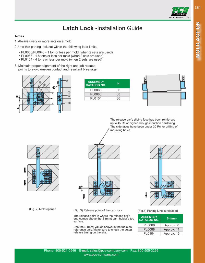
Phone: 800-521-0546 E-mail: [email protected] Fax: 800-505-3299www.pcs-company.com
MO
LD A
CTI
ON
MO
LD A
CTI
ON
C61
Latch Lock -Installation GuideNotes1. Always use 2 or more sets on a mold.
2. Use this parting lock set within the following load limits:
• PL0068/PL0046 - 1 ton or less per mold (when 2 sets are used)• PL0088 - 1.8 tons or less per mold (when 2 sets are used)• PL0104 - 4 tons or less per mold (when 2 sets are used)
3. Maintain proper alignment of the right and left release points to avoid uneven contact and resultant breakage.
ASSEMBLY CATALOG NO. H
PL0068 50PL0088 68PL0104 86
(Fig. 1) Mold closed
(Fig. 2) Mold opened (Fig. 3) Release point of the cam lock The release point is where the release bar's end comes above the S (mm) cam holder's top surface.
Use the S (mm) values shown in the table asreference only. Make sure to check the actual release timing on the site.
(Fig.4) Parting Line is released
ASSEMBLY CATALOG NO. S (mm)
PL0068 Approx. 2PL0088 Approx. 11PL0104 Approx. 15
The release bar’s sliding face has been reinforced up to 45 Rc or higher through induction hardening. The side faces have been under 30 Rc for drilling of mounting holes.
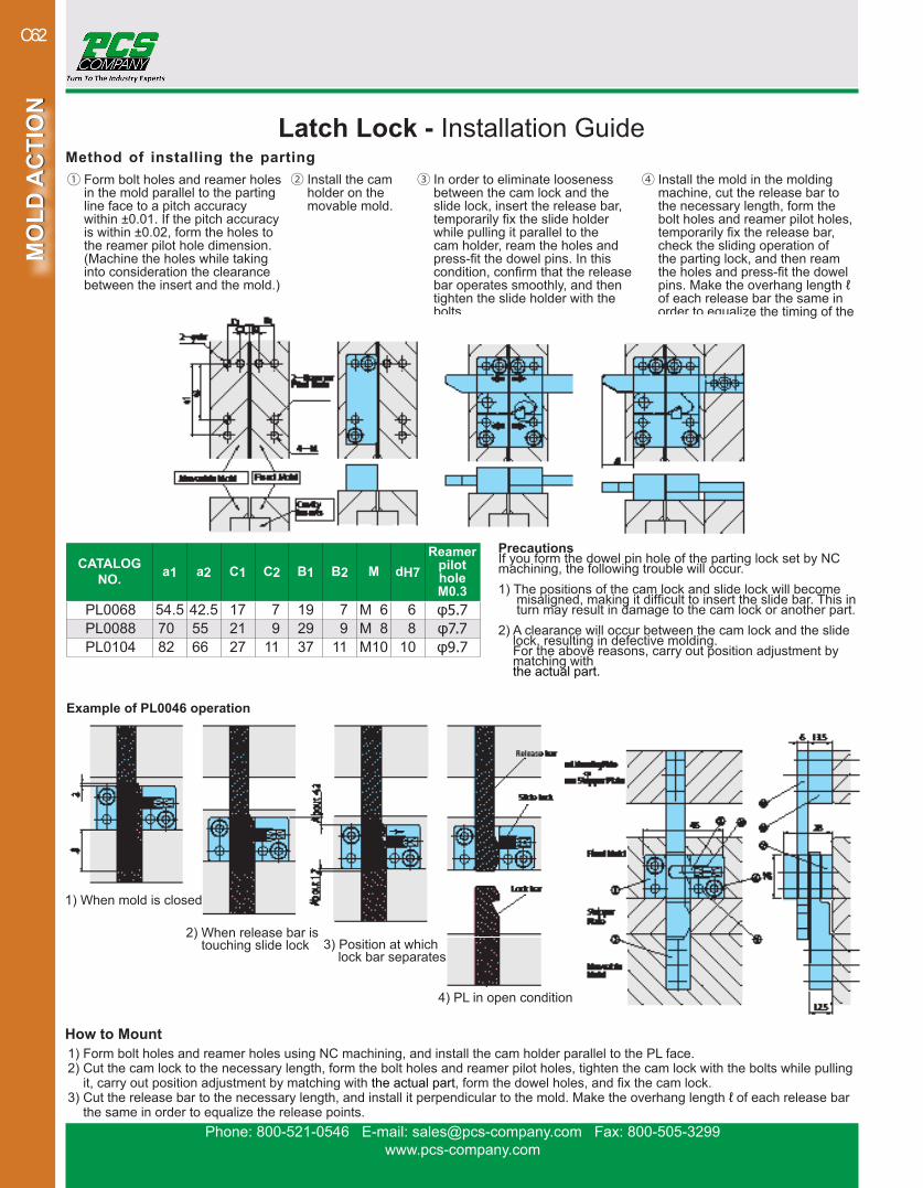
Phone: 800-521-0546 E-mail: [email protected] Fax: 800-505-3299www.pcs-company.com
MO
LD A
CTI
ON
MO
LD A
CTI
ON
C62
Latch Lock - Installation Guide
① Form bolt holes and reamer holes in the mold parallel to the parting line face to a pitch accuracy within ±0.01. If the pitch accuracy is within ±0.02, form the holes to the reamer pilot hole dimension. (Machine the holes while taking into consideration the clearance between the insert and the mold.)
Method of installing the parting ② Install the cam
holder on the movable mold.
③ In order to eliminate looseness between the cam lock and the slide lock, insert the release bar, temporarily fix the slide holder while pulling it parallel to the cam holder, ream the holes and press-fit the dowel pins. In this condition, confirm that the release bar operates smoothly, and then tighten the slide holder with the bolts.
④ Install the mold in the molding machine, cut the release bar to the necessary length, form the bolt holes and reamer pilot holes, temporarily fix the release bar, check the sliding operation of the parting lock, and then ream the holes and press-fit the dowel pins. Make the overhang length ℓ of each release bar the same in order to equalize the timing of the release.
1) When mold is closed
2) When release bar is touching slide lock 3) Position at which
lock bar separates
How to Mount1) Form bolt holes and reamer holes using NC machining, and install the cam holder parallel to the PL face.2) Cut the cam lock to the necessary length, form the bolt holes and reamer pilot holes, tighten the cam lock with the bolts while pulling
it, carry out position adjustment by matching with the actual part, form the dowel holes, and fix the cam lock.3) Cut the release bar to the necessary length, and install it perpendicular to the mold. Make the overhang length ℓ of each release bar
the same in order to equalize the release points.
CATALOGNO. a1 a2 C1 C2 B1 B2 M dH7
Reamer pilot holeM0.3
PL0068 54.5 42.5 17 7 19 7 M 6 6 φ5.7PL0088 70 55 21 9 29 9 M 8 8 φ7.7PL0104 82 66 27 11 37 11 M10 10 φ9.7
PrecautionsIf you form the dowel pin hole of the parting lock set by NC machining, the following trouble will occur.1) The positions of the cam lock and slide lock will become misaligned, making it difficult to insert the slide bar. This in turn may result in damage to the cam lock or another part.2) A clearance will occur between the cam lock and the slide
lock, resulting in defective molding. For the above reasons, carry out position adjustment by matching with the actual part.
Example of PL0046 operation
4) PL in open condition

Phone: 800-521-0546 E-mail: [email protected] Fax: 800-505-3299www.pcs-company.com
MO
LD A
CTI
ON
MO
LD A
CTI
ON
C63
Latch Locks - Mold Opening/Closing Type
SPECIFICATIONSNAME MATERIAL TYPE HARDNESS
① Cam holder
Alloy tool steel
50 - 55 Rc② Lock bar 58 Rc③ Lock pin 58 - 60 Rc④ Slide Lock 58 - 60 Rc⑤ Spring SUS631⑥ Release bar Alloy tool steel 58 Rc⑦ Spacer S45C⑧ Backing plate Alloy tool steel 50 Rc⑨ SHCS SCM435 38 - 43 Rc⑩ Dowel pin SUJ2 45 - 50 Rc
SetCOMPONENTS CATALOG NO.
①-⑩ Set PL0055PL0067
Components (Single Items)COMPONENTS USE WITH CATALOG NO.
② Lock barPL0055 PLL0002
PL0067 PLL0003
④ Slide lock PL0055 PLS0005
PL0067 PLS0006
⑥ Release barPL0055 PLR0005
PL0067 PLR0006
CATALOG NO.
① CAM HOLDER ⑧ BACKING PLATE ② LOCK BARA A1 A2 B B1 B2 d M W T LW LW1 LR LL LL1 LL2 LT LT1
PL0055 55 43 6 24 12 6 5 5 24 5 13 4 5 100 14 28 11.5 6PL0067 67 53 7 32 16 8 6 6 32.5 6 18 5 6 150 18 36 16.5 10
CATALOG NO.
③ LOCK PIN ④ SLIDE LOCK ⑤ SPRING
⑥ RELEASE BAR ⑦ SPACER ACCESSORIESP PL SA SB SW RW RW1 RR RL RL1 RT SW SL ST ⑨ BOLT ⑩ DOWEL PIN
PL0055 10 12 12 8 10 PS0003 13 4 5 150 12 6 13 40 5.5 PLF0001 PLD0003PL0067 12 17 16 10 13 PS0004 16 5 6 200 16 10 16 50 6.6 PLF0005 PLD0004
• Compact and easy to mount• Enables accurate mold opening movement with no reaction• Can be used for low pressure molding as it imposes little load when locking• Function regardless of the order of the mold closing process• Slide Lock retreats if the runner stipper side closes before the parting line
Latch Locks provide plate sequence control to mechanically draw floating plates and inserts. Floating plates are secured in place during mold open-ing and closing to prevent damage to the mold. Latch Locks are externally mounted which leaves more real estate available within the mold.
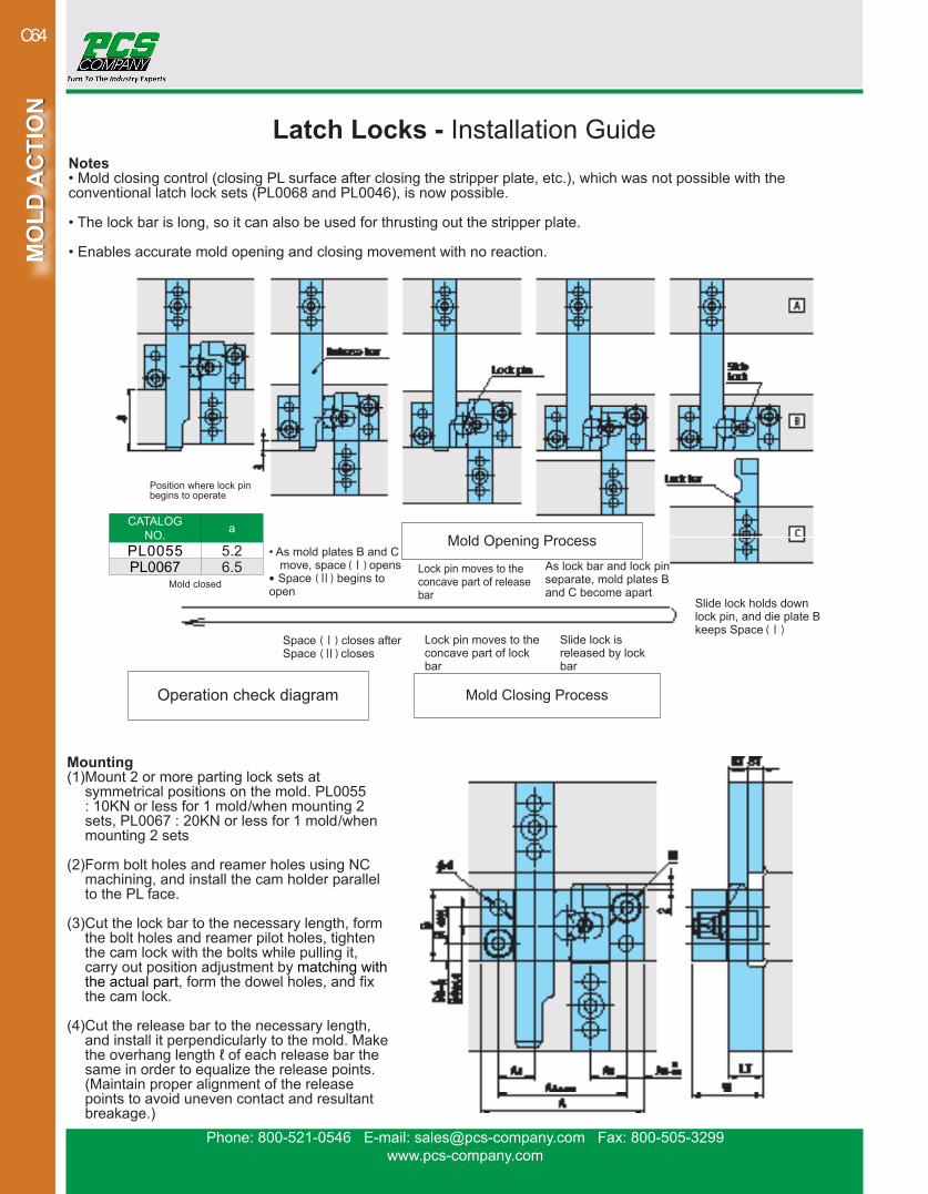
Phone: 800-521-0546 E-mail: [email protected] Fax: 800-505-3299www.pcs-company.com
MO
LD A
CTI
ON
MO
LD A
CTI
ON
C64
Mounting(1) Mount 2 or more parting lock sets at
symmetrical positions on the mold. PL0055 : 10KN or less for 1 mold/when mounting 2 sets, PL0067 : 20KN or less for 1 mold/when mounting 2 sets
(2) Form bolt holes and reamer holes using NC machining, and install the cam holder parallel to the PL face.
(3) Cut the lock bar to the necessary length, form the bolt holes and reamer pilot holes, tighten the cam lock with the bolts while pulling it, carry out position adjustment by matching with the actual part, form the dowel holes, and fix the cam lock.
(4) Cut the release bar to the necessary length, and install it perpendicularly to the mold. Make the overhang length ℓ of each release bar the same in order to equalize the release points. (Maintain proper alignment of the release points to avoid uneven contact and resultant breakage.)
Notes• Mold closing control (closing PL surface after closing the stripper plate, etc.), which was not possible with the conventional latch lock sets (PL0068 and PL0046), is now possible.
• The lock bar is long, so it can also be used for thrusting out the stripper plate.
• Enables accurate mold opening and closing movement with no reaction.
Latch Locks - Installation Guide
• As mold plates B and C move, space (Ⅰ) opens• Space (Ⅱ) begins to open
Space (Ⅰ) closes after Space (Ⅱ) closes
Slide lock holds down lock pin, and die plate B keeps Space (Ⅰ)
As lock bar and lock pin separate, mold plates B and C become apart
Lock pin moves to the concave part of release bar
Lock pin moves to the concave part of lock bar
Slide lock is released by lock bar
Operation check diagram
Mold closed
Position where lock pin begins to operate
CATALOG NO. a
PL0055 5.2PL0067 6.5
Mold Closing Process
Mold Opening Process

Phone: 800-521-0546 E-mail: [email protected] Fax: 800-505-3299www.pcs-company.com
MO
LD A
CTI
ON
MO
LD A
CTI
ON
C65
Roller Pulling Assemblies - Standard/Long Type
Standard Type/Standard Type - High Heat Resistance
Long Type/Long Type - High Heat Resistance
(Normal bushing)
Features
Structure and Usage
• Mount it in parallel to the parting line.• The roller lock set can be removed by pulling it in the direction of arrow in the figure.
• Enables well-balanced mold opening/closing through its mechanism composed of a Belleville spring, internal rollers and lock rollers.• The lock bushing's vertically symmetrical design allows a worn
piece to be reused by reinstalling it in reverse.• The lock holder's back recess enables it to be used even on a
stepped mold plates.• For heat resistant type, the adjusting bolt differs from standard type
for identification. (Standard type: black oxide coated, Heat resitant type: Trivalent Chromate coated)
Load Adjustment and Load Characteristics• Opening/closing load can be adjusted using an Allen wrench. The load is maximum when the adjustment bolt is fully tightened, 50% when it is loosened a half rotation, 0 when it is loosened 1 rotation or more. *For PLS0010, the load decreases about 25% when the adjustment bolt is loosened a half rotation, 70% when it is loosened one rotation.• The load for mold closing is about 50% of mold opening. • A fixing screw is provided on the load adjustment bolt. Loosen it to perform load adjustment, and make sure to tighten it after adjustment is completed.
Note: Make sure to assemble the right and left unit symmetrically for well balanced operation.
(Slim bushing)
(Normal bushing) (Slim bushing)
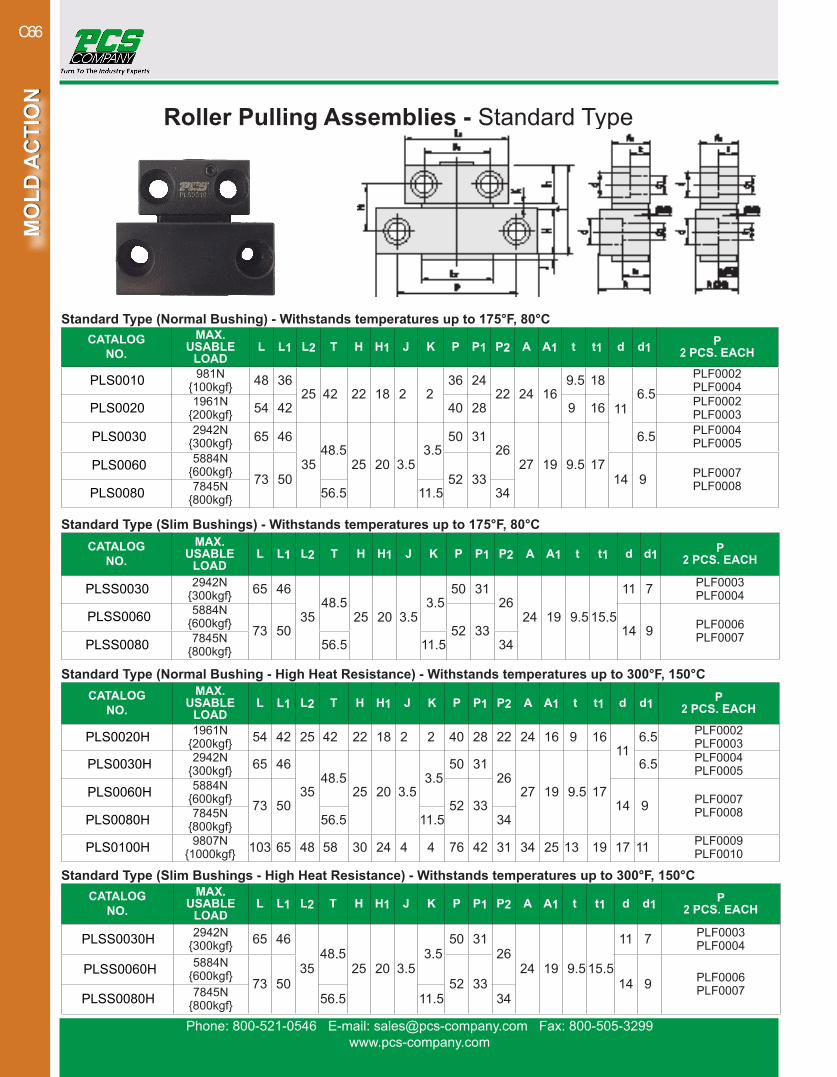
Phone: 800-521-0546 E-mail: [email protected] Fax: 800-505-3299www.pcs-company.com
MO
LD A
CTI
ON
MO
LD A
CTI
ON
C66
Roller Pulling Assemblies - Standard Type
Standard Type (Normal Bushing - High Heat Resistance) - Withstands temperatures up to 300°F, 150°CCATALOG
NO.MAX.
USABLE LOAD
L L1 L2 T H H1 J K P P1 P2 A A1 t t1 d d1 P 2 PCS. EACH
PLS0020H 1961N{200kgf} 54 42 25 42 22 18 2 2 40 28 22 24 16 9 16
116.5 PLF0002
PLF0003
PLS0030 H 2942N{300kgf} 65 46
3548.5
25 20 3.53.5
50 3126
27 19 9.5 17
6.5 PLF0004PLF0005
PLS0060H 5884N{600kgf} 73 50 52 33 14 9 PLF0007
PLF0008PLS0080H 7845N{800kgf} 56.5 11.5 34
PLS0100H 9807N{1000kgf} 103 65 48 58 30 24 4 4 76 42 31 34 25 13 19 17 11 PLF0009
PLF0010
Standard Type (Normal Bushing) - Withstands temperatures up to 175°F, 80°CCATALOG
NO.MAX.
USABLE LOAD
L L1 L2 T H H1 J K P P1 P2 A A1 t t1 d d1 P 2 PCS. EACH
PLS0010 981N{100kgf} 48 36
25 42 22 18 2 236 24
22 24 169.5 18
116.5
PLF0002PLF0004
PLS0020 1961N{200kgf} 54 42 40 28 9 16 PLF0002
PLF0003
PLS0030 2942N{300kgf} 65 46
3548.5
25 20 3.53.5
50 3126
27 19 9.5 17
6.5 PLF0004PLF0005
PLS0060 5884N{600kgf} 73 50 52 33 14 9 PLF0007
PLF0008PLS0080 7845N{800kgf} 56.5 11.5 34
Standard Type (Slim Bushings) - Withstands temperatures up to 175°F, 80°CCATALOG
NO.MAX.
USABLE LOAD
L L1 L2 T H H1 J K P P1 P2 A A1 t t1 d d1 P 2 PCS. EACH
PLSS0030 2942N{300kgf} 65 46
3548.5
25 20 3.53.5
50 3126
24 19 9.5 15.5
11 7 PLF0003PLF0004
PLSS0060 5884N{600kgf} 73 50 52 33 14 9 PLF0006
PLF0007PLSS0080 7845N{800kgf} 56.5 11.5 34
Standard Type (Slim Bushings - High Heat Resistance) - Withstands temperatures up to 300°F, 150°CCATALOG
NO.MAX.
USABLE LOAD
L L1 L2 T H H1 J K P P1 P2 A A1 t t1 d d1 P 2 PCS. EACH
PLSS0030 H 2942N{300kgf} 65 46
3548.5
25 20 3.53.5
50 3126
24 19 9.5 15.5
11 7 PLF0003PLF0004
PLSS0060H 5884N{600kgf} 73 50 52 33 14 9 PLF0006
PLF0007PLSS0080H 7845N{800kgf} 56.5 11.5 34
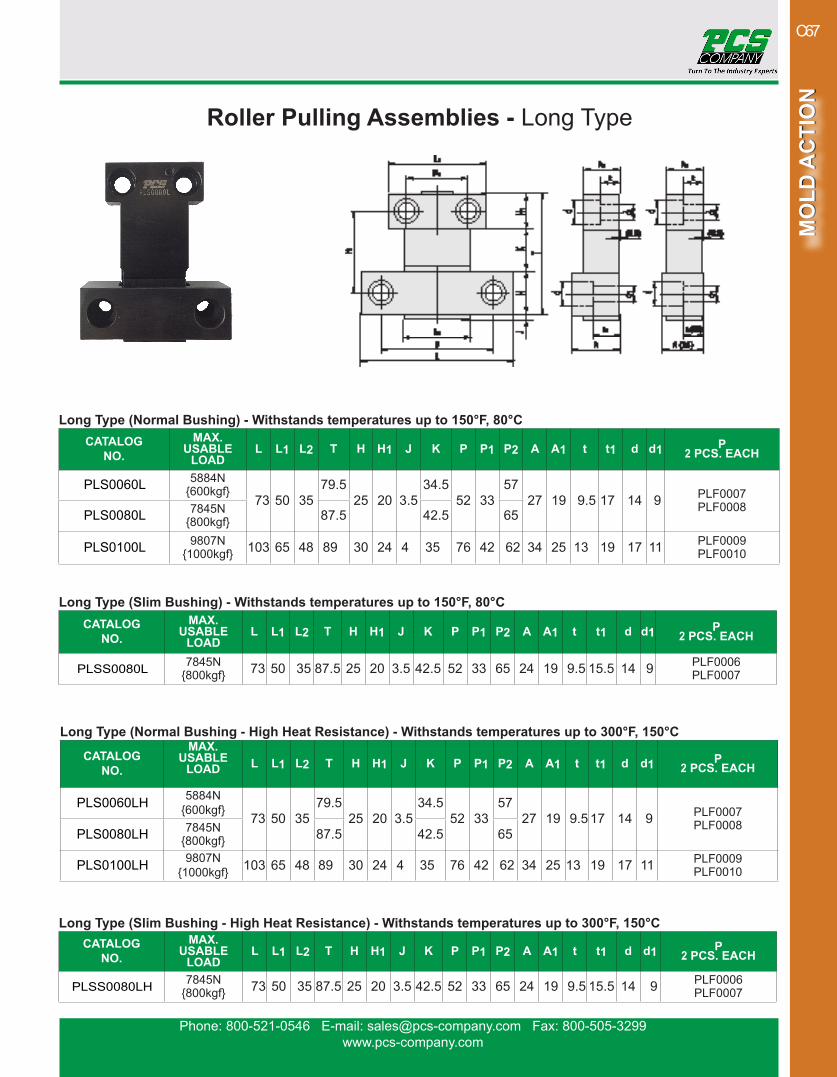
Phone: 800-521-0546 E-mail: [email protected] Fax: 800-505-3299www.pcs-company.com
MO
LD A
CTI
ON
MO
LD A
CTI
ON
C67
Roller Pulling Assemblies - Long Type
Long Type (Slim Bushing) - Withstands temperatures up to 150°F, 80°CCATALOG
NO.MAX.
USABLE LOAD
L L1 L2 T H H1 J K P P1 P2 A A1 t t1 d d1 P 2 PCS. EACH
PLSS0080L 7845N{800kgf} 73 50 35 87.5 25 20 3.5 42.5 52 33 65 24 19 9.5 15.5 14 9 PLF0006
PLF0007
Long Type (Normal Bushing - High Heat Resistance) - Withstands temperatures up to 300°F, 150°C
CATALOG NO.
MAX. USABLE
LOAD L L1 L2 T H H1 J K P P1 P2 A A1 t t1 d d1 P 2 PCS. EACH
PLS0060LH 5884N{600kgf}
73 50 35 79.5
25 20 3.534.5
52 3357
27 19 9.5 17 14 9 PLF0007 PLF0008
PLS0080LH 7845N{800kgf} 87.5 42.5 65
PLS0100LH 9807N{1000kgf} 103 65 48 89 30 24 4 35 76 42 62 34 25 13 19 17 11 PLF0009
PLF0010
Long Type (Slim Bushing - High Heat Resistance) - Withstands temperatures up to 300°F, 150°CCATALOG
NO.MAX.
USABLE LOAD
L L1 L2 T H H1 J K P P1 P2 A A1 t t1 d d1 P 2 PCS. EACH
PLSS0080LH 7845N{800kgf} 73 50 35 87.5 25 20 3.5 42.5 52 33 65 24 19 9.5 15.5 14 9 PLF0006
PLF0007
Long Type (Normal Bushing) - Withstands temperatures up to 150°F, 80°CCATALOG
NO.MAX.
USABLE LOAD
L L1 L2 T H H1 J K P P1 P2 A A1 t t1 d d1 P 2 PCS. EACH
PLS0060L 5884N{600kgf}
73 50 35 79.5
25 20 3.534.5
52 3357
27 19 9.5 17 14 9 PLF0007 PLF0008PLS0080L 7845N
{800kgf} 87.5 42.5 65
PLS0100L 9807N{1000kgf} 103 65 48 89 30 24 4 35 76 42 62 34 25 13 19 17 11 PLF0009
PLF0010
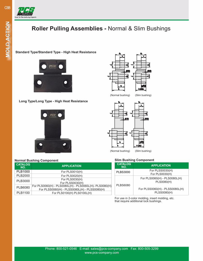
Phone: 800-521-0546 E-mail: [email protected] Fax: 800-505-3299www.pcs-company.com
MO
LD A
CTI
ON
MO
LD A
CTI
ON
C68
Normal Bushing Component CATALOG
NO. APPLICATION
PLB1000 For PLS0010(H)PLB2000 For PLS0020(H)
PLB3000 For PLS0030(H)For PLSS0030(H)
PLB6080 For PLS0060(H) - PLS0080L(H) - PLS0060L(H)- PLS0080(H)For PLSS0060(H) - PLSS0080L(H) - PLSS0080(H)
PLB1100 For PLS0100(H) PLS0100L(H)
Roller Pulling Assemblies - Normal & Slim Bushings
Slim Bushing Component CATALOG
NO. APPLICATION
PLBS3000 For PLSS0030(H)For PLS0030(H)
PLBS6080
For PLS0060(H) - PLS0080L(H) PLS0080(H)
For PLSS0060(H) - PLSS0080L(H)
PLSS0080(H)
For use in 2-color molding, insert molding, etc. that require additional lock bushings.
Standard Type/Standard Type - High Heat Resistance
Long Type/Long Type - High Heat Resistance
(Normal bushing) (Slim bushing)
(Normal bushing) (Slim bushing)

Phone: 800-521-0546 E-mail: [email protected] Fax: 800-505-3299www.pcs-company.com
MO
LD A
CTI
ON
MO
LD A
CTI
ON
C69
Friction Puller• Provides smooth plate sequence control• Systematically draw floating plates & inserts apart• Maximum Operating Temperature of 250°F (120°F)• Four available sizes: 10mm, 13mm, 16mm, 20mm• For installation, tighten screw to the desired amount of friction
Friction Pullers are designed to provide plate sequence control. The Friction Puller controls plate movement and utilizes friction at a particular setting to release the plate once travel limits are reached. This product can be used to systematically draw floating plates and inserts. Available sizes include: 10mm, 13mm, 16mm, and 20mm.
CATALOG NO. B D D1 L M MAX FORCEFP-10P 4 10 7.6 17 M5-.8 32.5 kg (70 lbs)FP-13P 5 13 9.6 20 M6-1 62.5 kg (135 lbs)FP-16P 6 16 11.6 25 M8-1.25 150.0 kg (330 lbs)FP-20P 6 20 14.6 30 M10-1.5 212.5 kg (470 lbs)
SPECIFICATIONSBolt Material Type SCM435
Maximum Operating Temperature 250°F (120°C)Resin Material Type Heat-Stabilized, Lubricated Nylon 6Ring Material Type S45C
Unit of Measure Inch
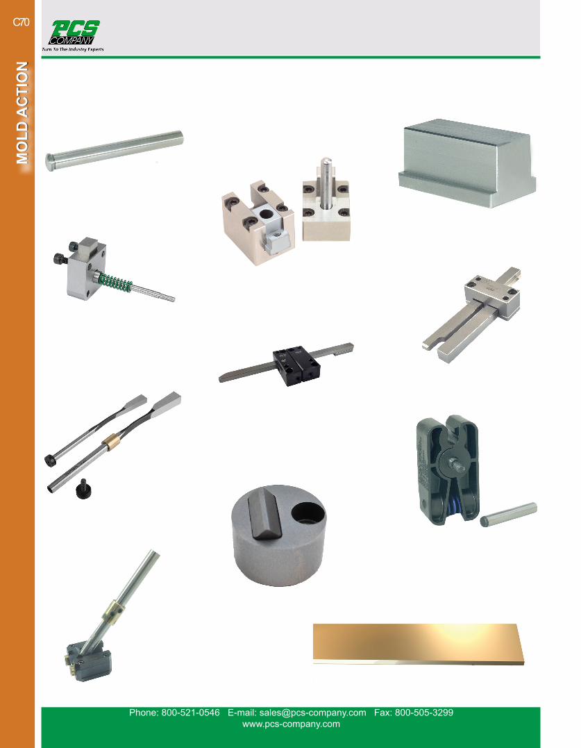
Phone: 800-521-0546 E-mail: [email protected] Fax: 800-505-3299www.pcs-company.com
MO
LD A
CTI
ON
MO
LD A
CTI
ON
C70
Related Documents