MODULE INSTALLATION AND USER MANUAL – PERC AND MONO SERIES REVISION DATE: 06/19/2017 DOCUMENT # GE-SA1-0006 MISSION SOLAR ENERGY - MSE CONTROLLED - PROPRIETARY & CONFIDENTIAL - RELEASED Reproduction, dissemination, copying, modification, distribution and/or publication of this material is STRICTLY PROHIBITED. Disclosure of this document, in any manner to a third party, requires prior written consent from MISSION SOLAR ENERGY LLC . REVISION: R4 RELEASE DATE: 11/16/2016 MODULE INSTALLATION AND USER MANUAL – PERC AND MONO SERIES

Welcome message from author
This document is posted to help you gain knowledge. Please leave a comment to let me know what you think about it! Share it to your friends and learn new things together.
Transcript

MODULE INSTALLATION AND USER MANUAL – PERC AND MONO SERIES
REVI S ION D A TE: 0 6 / 1 9 / 2 0 1 7 DOCUME NT # G E - S A 1 - 0 0 0 6
M I S S I O N S O L A R E N E R G Y - M SE CON TRO LL E D - PR OPR I ET ARY & C ON F ID ENT IA L - RE L EA S ED Reproduction, dissemination, copying, modification, distribution and/or publication of this material is S T R I CT L Y P R O H I B I T E D . Disclosure of this document, in any manner to a third party, requires prior written consent from M I S S I O N S O L A R E N E R G Y L L C .
R E V I S I O N : R 4 R E L E A S E D A T E : 1 1 / 1 6 / 2 0 1 6
MODULE INSTALLATION AND USER MANUAL – PERC AND
MONO SERIES

MODULE INSTALLATION AND USER MANUAL – PERC AND MONO SERIES
REVI S ION D A TE: 0 6 / 1 9 / 2 0 1 7 DOCUME NT # G E - S A 1 - 0 0 0 6 PAGE : 1 OF 14
M I S S I O N S O L A R E N E R G Y - M SE CON TRO LL E D- PRO PRI ET AR Y & CON FI D ENTI AL - R E LE A SE D Reproduction, dissemination, copying, modification, distribution and/or publication of this material is S T R I CT L Y P R O H I B I T E D . Disclosure of this document, in any manner to a third party, requires prior written consent from M I S S I O N S O L A R E N E R G Y L L C .
R E V I S I O N : R 4 R E L E A S E D A T E : 1 1 / 1 6 / 2 0 1 6
TABLE OF CONTENTS 1.0 DISCLAIMER ..................................................................................................................................................................... 2
2.0 HANDLING AND USE ........................................................................................................................................................ 2
3.0 LIMITATION OF LIABILITY AND LIMITED REMEDIES .......................................................................................................... 2
4.0 GENERAL INSTRUCTIONS ................................................................................................................................................. 2
5.0 SAFETY ............................................................................................................................................................................. 4
5.1. GENERAL WARNING ......................................................................................................................................................... 4 5.2. MECHANICAL .................................................................................................................................................................. 4 5.3. ELECTRICAL SHOCK HAZARD ............................................................................................................................................... 4 5.4. FIRE ............................................................................................................................................................................... 5
6.0 OPERATING CONDITIONS ................................................................................................................................................. 5
6.1. TEMPERATURE ................................................................................................................................................................. 5 6.2. INSTALLATION CONDITIONS ................................................................................................................................................ 5
7.0 UNPACKING AND STORAGE ............................................................................................................................................. 6
7.1. UNPACKING .................................................................................................................................................................... 6 7.2. GENERAL INSTRUCTIONS .................................................................................................................................................... 6
8.0 PRODUCT ELECTRICAL SPECIFICATIONS ............................................................................................................................ 7
9.0 MECHANICAL INSTALLATION ........................................................................................................................................... 8
9.1. MOUNTING CLAMPS ......................................................................................................................................................... 9
10.0 GROUNDING INSTRUCTIONS .......................................................................................................................................... 11
10.1. WEEB-UIR .................................................................................................................................................................. 11
11.0 ELECTRICAL INSTALLATION ............................................................................................................................................ 12
11.1. LOCAL/NATIONAL CODE AND LOCAL REGULATIONS .............................................................................................................. 12 11.2. WIRING ........................................................................................................................................................................ 12 11.3. CONNECTORS ................................................................................................................................................................ 13 11.4. DIODES ........................................................................................................................................................................ 13
12.0 MAINTENANCE............................................................................................................................................................... 13
12.1. VISUAL INSPECTION ........................................................................................................................................................ 13 12.2. CLEANING ..................................................................................................................................................................... 13 12.3. ADDITIONAL DOCUMENTS ................................................................................................................................................ 14 12.4. DISPOSAL ..................................................................................................................................................................... 14
R. Revision History ........................................................................................................................................................... 14

MODULE INSTALLATION AND USER MANUAL - PERC AND MONO SERIES
REVI S ION D A TE: 0 6 / 1 9 / 2 0 1 7 DOCUME NT # G E - S A 1 - 0 0 0 6 PAGE : 2 OF 14
M I S S I O N S O L A R E N E R G Y - M SE CON TRO LL E D - PR OPR I ET ARY & C ON F ID ENT IA L - RE L EA S ED Reproduction, dissemination, copying, modification, distribution and/or publication of this material is S T R I CT L Y P R O H I B I T E D . Disclosure of this document, in any manner to a third party, requires prior written consent from M I S S I O N S O L A R E N E R G Y L L C .
R E V I S I O N : R 4 R E L E A S E D A T E : 1 1 / 1 6 / 2 0 1 6
1.0 DISCLAIMER This manual is provided to you on an “as is” basis without warranty, covenant or representative of any kind, express or implied, including the warranties if merchantability or fitness for a particular purpose. Mission Solar Energy uses its best efforts to ensure the accuracy of the contents of this manual; however, Mission Solar Energy is not responsible for the accuracy of said contents or results if your use of same. Under no circumstances will Mission Solar Energy be liable to your or any third party for damages arising under any legal theory including contract, tort, negligence or strict liability or for direct, indirect, special, consequential; or punitive damages of any kind, including lost profits. Mission Solar Energy reserves the right to make changes without further notice to this manual and to any modules. Mission Solar Energy does not convey any license under its intellectual property rights. Mission Solar Energy assumes no responsibility for any infringement to patents or other rights of third parties that may result from use of this manual or related module.
2.0 HANDLING AND USE
Mission Solar Energy shall not be liable for, and buyer shall indemnify, defend and hold harmless Mission Solar Energy, its affiliates and their respective officers, directors, employees, representatives and agents (”indemnities”) from and against, any and all claims, losses, liabilities, costs and expenses (including attorney’s fees) (“claims”) arising out of or resulting from the handling, use, processing, alteration, distributions, sale or marketing of modules and this manual, or any other action or inaction with regard to the modules and this manual, in each case after the delivery thereof to buyer; provided however, that buyer shall not be liable to Mission Solar Energy for damages directly caused by the sole negligence of Mission Solar Energy. Buyer’s obligations under this section shall survive the termination, cancellations or expiration of all orders delivered under these terms and the cessation of any business transaction between Mission Solar Energy and buyer.
3.0 LIMITATION OF LIABILITY AND LIMITED REMEDIES
In no event will Mission Solar Energy be liable to buyer for any lost or prospective profits, indirect, incidental, consequential, special, exemplary or punitive damages, including, without limitation, lost earnings, or business interruption, whether or not based upon Mission Solar Energy’s negligence, breach of warranty, strict liability, in tort or any other cause if action. Buyer’s exclusive remedy VIS-À-VIS Mission Solar Energy or any other cause if action related to the modules and this manual, is, at Mission Solar Energy’s option limited to (i) replacement of the non-conforming modules; or (ii) refund to buyer of the portion of the purchase of the purchase price attributable to such non-conforming modules, In no event shall Mission Solar Energy’s cumulative liability exceed the price of modules sold which was the direct cause if the alleged loss, damage or injury.
4.0 GENERAL INSTRUCTIONS
This manual provides important safety instructions regarding to installation, maintenance and handling of Mission Solar Energy photovoltaic modules. All the users should read this manual carefully and follow the instructions strictly. The installation of solar modules requires specialized skills and experience and should only be performed by licensed professionals.

MODULE INSTALLATION AND USER MANUAL – PERC AND MONO SERIES
REVI S ION D A TE: 0 6 / 1 9 / 2 0 1 7 DOCUME NT # G E - S A 1 - 0 0 0 6 PAGE : 3 OF 14
M I S S I O N S O L A R E N E R G Y - M SE CON TRO LL E D- PRO PRI ET AR Y & CON FI D ENTI AL - R E LE A SE D Reproduction, dissemination, copying, modification, distribution and/or publication of this material is S T R I CT L Y P R O H I B I T E D . Disclosure of this document, in any manner to a third party, requires prior written consent from M I S S I O N S O L A R E N E R G Y L L C .
R E V I S I O N : R 4 R E L E A S E D A T E : 1 1 / 1 6 / 2 0 1 6
F I GURE 1 : OVERVIEW OF MSE PERC/MONO 72
F I G URE 2 : OVERVIEW OF MSE PERC/ MONO 60

MODULE INSTALLATION AND USER MANUAL – PERC AND MONO SERIES
REVI S ION D A TE: 0 6 / 1 9 / 2 0 1 7 DOCUME NT # G E - S A 1 - 0 0 0 6 PAGE : 4 OF 14
M I S S I O N S O L A R E N E R G Y - M SE CON TRO LL E D- PRO PRI ET AR Y & CON FI D ENTI AL - R E LE A SE D Reproduction, dissemination, copying, modification, distribution and/or publication of this material is S T R I CT L Y P R O H I B I T E D . Disclosure of this document, in any manner to a third party, requires prior written consent from M I S S I O N S O L A R E N E R G Y L L C .
R E V I S I O N : R 4 R E L E A S E D A T E : 1 1 / 1 6 / 2 0 1 6
5.0 SAFETY 5.1. GENERAL WARNING
You must understand and follow all applicable local, state, and federal regulations and standards for building construction, electrical design, fire, and safety, and must check with local authorities to determine applicable permitting requirements before attempting to install or maintain PV modules.
Module interconnects pass direct current (DC) when exposed to sunlight or other light sources. Contact with electrically active parts of the module, such as terminals, can result in injury or
death, whether the module is connected or disconnected. Never wear metallic rings, watch bands, ear, nose or lip rings or other metallic devices when
installing or trouble shooting a photovoltaic system
5.2. MECHANICAL Rooftop PV systems should only be installed on dwellings that have been formally analyzed for
structural integrity, and confirmed to be capable of handling the additional weighted load of PV system components, including PV modules, by a certified building specialist or engineer. For your safety, do not attempt to work on a rooftop until safety precautions have been identified and taken, including without limitation fall protection measures, ladders or stairways, and personal protective equipment (PPE).
For your safety, do not install or handle PV modules under adverse conditions, including without limitation strong or gusty winds, and wet or frosted roof surfaces.
The flat-plate PV module construction consists of a laminated assembly of solar cells encapsulated within an insulating material with a rigid glass surface and an insulated substrate. The laminated assembly is supported by an aluminum frame that is also used for mounting the module.
5.3. ELECTRICAL SHOCK HAZARD
PV modules can produce current and voltage when exposed to light of any intensity. Electrical current increases with higher light intensity.
DC voltage of 30 Volts or higher is potentially lethal. Contacting the live circuitry of a PV system operating under light can result in lethal electric shock.
Use insulated tools and do not wear metallic jewelry while working with PV modules. In order to avoid arcing and electrical shock, do not disconnect electrical connections under
load. Faulty connections can also result in arcing and electrical shock. Keep connectors dry and clean, and ensure that they are in proper working condition. Never insert metallic objects into the connectors, or modify them in any way in order to secure
an electrical connection. Do not touch or handle PV modules with broken glass, separated frames or a damaged back
sheet unless the PV modules are first disconnected and you are wearing proper PPE. Avoid handling PV modules when they are wet unless cleaning the PV modules as directed in
this manual.

MODULE INSTALLATION AND USER MANUAL – PERC AND MONO SERIES
REVI S ION D A TE: 0 6 / 1 9 / 2 0 1 7 DOCUME NT # G E - S A 1 - 0 0 0 6 PAGE : 5 OF 14
M I S S I O N S O L A R E N E R G Y - M SE CON TRO LL E D- PRO PRI ET AR Y & CON FI D ENTI AL - R E LE A SE D Reproduction, dissemination, copying, modification, distribution and/or publication of this material is S T R I CT L Y P R O H I B I T E D . Disclosure of this document, in any manner to a third party, requires prior written consent from M I S S I O N S O L A R E N E R G Y L L C .
R E V I S I O N : R 4 R E L E A S E D A T E : 1 1 / 1 6 / 2 0 1 6
Never touch electrical connections that are wet without protecting yourself with insulated gloves.
Artificially concentrated light shall not be directed on the module or panel.
5.4. FIRE Mission Solar Energy Modules have a Type 1, Class C fire resistance rating in accordance with
the IEC 61730 and UL 1703 standard. The fire rating of this module is valid only when mounted in the manner specified in the
mechanical mounting instructions. PV modules are electrical generating devices that may affect the fire safety of a building. The use of improper installation methods and/or defective parts may result in the unexpected
occurrence of an electrical arc during operation. The recommended standoff height is not less than 150mm (6 inches). If other mounting means
are employed this may affect the fire class ratings. A minimum slope of 5in/ft. for installation over a roof is required to maintain the class C fire rating. Modules must be mounted over a fire resistant roof covering rates for the application.
In order to mitigate the risk of fire in this event, PV modules should not be installed near flammable liquids, gases, or locations with hazardous materials.
In the event of a fire, PV modules may continue to produce a dangerous voltage, even if they have been disconnected from the inverter, have been partly or entirely destroyed, or the system wiring has been compromised or destroyed.
In the event of fire, inform the fire crew about the particular hazards from the PV system, and stay away from all elements of the PV system during and after a fire until the necessary steps have been taken to make the PV system safety.
6.0 OPERATING CONDITIONS
6.1. TEMPERATURE All the modules must be mounted in environments that ensure they operate within the following maximum and minimum operating temperatures. Maximum Operating Temperatures: +90oC (194o F) Minimum Operating Temperatures: -40oC (-40o F)
6.2. INSTALLATION CONDITIONS
Orient the module correctly. Mount the modules with the junction box in the uppermost position and hang the wires downwards to avoid the ingress of water. For optimal module performance install PV modules facing true south in northern latitudes and true north in southern latitudes. Shading will reduce electrical production. This installation is applicable when the module is in portrait orientation. The modules have been evaluated by UL for mounting using the four or eight provided mounting holes in the frame.

MODULE INSTALLATION AND USER MANUAL – PERC AND MONO SERIESREVI S ION D A TE: 0 6 / 1 9 / 2 0 1 7 DOCUME NT # G E - S A 1 - 0 0 0 6
PAGE : 6 OF 14
M I S S I O N S O L A R E N E R G Y - M SE CON TRO LL E D- PRO PRI ET AR Y & CON FI D ENTI AL - R E LE A SE D Reproduction, dissemination, copying, modification, distribution and/or publication of this material is S T R I CT L Y P R O H I B I T E D . Disclosure of this document, in any manner to a third party, requires prior written consent from M I S S I O N S O L A R E N E R G Y L L C .
R E V I S I O N : R 4 R E L E A S E D A T E : 1 1 / 1 6 / 2 0 1 6
7.0 UNPACKING AND STORAGE 7.1. UNPACKING
Use two people when unpacking Mission Solar Energy modules. Cut the outer straps. Remove the top lid. Cut the side of the sleeve to remove it. Always avoid scratching the modules when using cutting
tools. Cut the inner straps. Remove the modules one at a time. If necessary, use a stand to prevent the modules from
falling while unpacking. Lay the remaining modules down on the pallet with the glass side facing upward.
7.2. GENERAL INSTRUCTIONS Store modules in a dry place so that modules do not get in contact with moisture. Do not allow children and unauthorized persons near the installation site or storage area of
modules. Do not transport modules in an upright position. Do not use forklift less 72 inches while handling the module pallet. Unpacking module pallet with care and follow the unpacking steps marked on the pallet. Be
careful when unpacking, transporting and storing the modules. Do not carry a module by its wires or junction box. Recommended at least two or more people
carry the module for safety concerns. Do not place modules on top of each other directly to prevent the modules touching one
another. Do not place excessive loads on the module or twist the module frame. Do not stand, step, walk and/or jump on the module. Do not carry the module above the head. Do not drop or place objects on the modules (such as tools.) Do not mark the modules with sharp instrument. Particular attention should be taken to avoid module back sheet to come in contact with sharp
objects, as scratches may directly affect product safety. Do not leave a module unsupported or unsecured. Do not change the wiring of bypass diodes. Keep all electrical contacts clean and dry.

MODULE INSTALLATION AND USER MANUAL – PERC AND MONO SERIES
REVI S ION D A TE: 0 6 / 1 9 / 2 0 1 7 DOCUME NT # G E - S A 1 - 0 0 0 6 PAGE : 7 OF 14
M I S S I O N S O L A R E N E R G Y - M SE CON TRO LL E D- PRO PRI ET AR Y & CON FI D ENTI AL - R E LE A SE D Reproduction, dissemination, copying, modification, distribution and/or publication of this material is S T R I CT L Y P R O H I B I T E D . Disclosure of this document, in any manner to a third party, requires prior written consent from M I S S I O N S O L A R E N E R G Y L L C .
R E V I S I O N : R 4 R E L E A S E D A T E : 1 1 / 1 6 / 2 0 1 6
8.0 PRODUCT ELECTRICAL SPECIFICATIONS PV Modules have been certified for a maximum static load on the back of the module of up to 2400 Pa (i.e. wind load) and a maximum static load on the front of the module of up to either 2400 Pa or 5400 Pa (i.e. wind and snow load). The performance of solar modules is defined on the uniform standard test conditions. These conditions define performance at an incident sunlight of 1000 W/m2, a cell temperature of 25oC (77oF) and an AM of 1.5 (AM = Air Mass). The air mass determines the radiation impact and the spectral combination of the light arriving on the earth’s surface. Modules have been evaluated by UL for a maximum positive test load of 113 lbs/ft2 and negative test loading of 50 lbs/ft2. Rated electrical characteristics (excluding the rated maximum power) are within 10 percent of measured values at Standard Test Conditions of: 1000 W/m2, 25°C cell temperature and solar spectral irradiance per ASTM E 892”. Only rated maximum power is within -0/3%.
Tab le 1 : E le ctr ica l Ra t ing s of MSE 35 0 PER C M odul e Ser ie s
Model – P PERC Crystalline
Open Circuit Voltage at STC, (V dc)
Rated Voltage at STC, (V dc)
Maximum System
Voltage, (V dc)
Rated Current at STC, (A dc)
Short-Circuit Current at STC,
(A dc)
Rated Maximum Power at STC,
(Watts)
MSE345SQ4S/ MSE345SQ6S
46.98 38.43 1500 9.04 9.70 345
MSE350SQ4S/ MSE350SQ6S
47.38 38.68 1500 9.11 9.73 350
MSE355SQ4S/ MSE355SQ6S
47.68 38.98 1500 9.19 9.76 355
MSE360SQ4S/ MSE360SQ6S
48.08 38.28 1500 9.28 9.79 360
MSE365SQ4S/ MSE365SQ6S
48.12 39.32 1500 9.32 9.81 365
Tab le 2 : E le ctr ica l Ra t ing s of MSE 29 5 PER C 6 0 M odu le Ser ie s
Model – P PERC Crystalline
Open Circuit Voltage at STC, (V dc)
Rated Voltage at STC, (V dc)
Maximum System
Voltage, (V dc)
Rated Current at STC, (A dc)
Short-Circuit Current at STC,
(A dc)
Rated Maximum Power at STC,
(Watts)
MSE280SQ5T 39.31 32.17 1000 8.79 9.31 280
MSE285SQ5T 39.56 32.36 1000 8.87 3.37 285
MSE290SQ5T 39.81 32.54 1000 8.95 9.44 290
MSE295SQ5T 40.11 32.72 1000 9.03 9.52 295
MSE300SQ5T 40.18 32.80 1000 9.17 9.61 300

MODULE INSTALLATION AND USER MANUAL – PERC AND MONO SERIES
REVI S ION D A TE: 0 6 / 1 9 / 2 0 1 7 DOCUME NT # G E - S A 1 - 0 0 0 6 PAGE : 8 OF 14
M I S S I O N S O L A R E N E R G Y - M SE CON TRO LL E D- PRO PRI ET AR Y & CON FI D ENTI AL - R E LE A SE D Reproduction, dissemination, copying, modification, distribution and/or publication of this material is S T R I CT L Y P R O H I B I T E D . Disclosure of this document, in any manner to a third party, requires prior written consent from M I S S I O N S O L A R E N E R G Y L L C .
R E V I S I O N : R 4 R E L E A S E D A T E : 1 1 / 1 6 / 2 0 1 6
Tab le 3 : E le ctr ica l Ra t ing s of MSE M on o 7 2 M odu le S er ies
Model – Mono
Crystalline
Open Circuit Voltage at STC, (V dc)
Rated Voltage at STC, (V dc)
Maximum System
Voltage, (V dc)
Rated Current at STC, (A dc)
Short-Circuit Current at STC,
(A dc)
Rated Maximum Power at STC,
(Watts)
MSE320SO4J/ MSE320SO6J
45.68 37.65 1500 8.51 8.97 320
MSE325SO4J/ MSE325SO6J
45.79 37.72 1500 8.62 9.08 325
MSE330SO4J/ MSE330SO6J
46.12 37.85 1500 8.72 9.23 330
MSE335SO4J/ MSE335SO6J
46.14 37.89 1500 8.87 9.38 335
MSE340SO4J/ MSE340SO6J
46.35 38.02 1500 8.95 9.49 340
MSE345SO4J/ MSE345SO6J
46.52 38.14 1500 9.05 9.52 345
MSE350SO4J/ MSE350SO6J
46.57 38.31 1500 9.14 9.59 350
Tab le 4 : E le ctr ica l Ra t ing s of MSE M on o 6 0 M odu le S er ies
Model – Mono Crystalline
Open Circuit Voltage at STC, (V dc)
Rated Voltage at STC, (V dc)
Maximum System
Voltage, (V dc)
Rated Current at STC, (A dc)
Short-Circuit Current at STC,
(A dc)
Rated Maximum Power at STC,
(Watts)
MSE260SO5T 37.89 30.82 1000 8.44 8.90 260
MSE265SO5T 38.07 31.14 1000 8.53 8.99 265
MSE270SO5T 38.21 31.28 1000 8.64 9.09 270
MSE275SO5T 38.45 31.55 1000 8.72 9.17 275
MSE280SO5T 38.60 31.87 1000 8.79 9.27 280
MSE285SO5T 38.82 32.11 1000 8.88 9.36 285
MSE290SO5T 39.21 32.38 1000 8.96 9.38 290
9.0 MECHANICAL INSTALLATION
The module is considered to be in compliance with IEC 61730 and UL 1703 only when the module is mounted in the manner specified by the mounting instructions below. We recommend using the following orientation to install the module. Maximum number of modules connected in series /parallel for MSE 350 PERC is 24/1 and maximum number of modules connected in series /parallel for MSE 295 PERC 60 is 19/1.

MODULE INSTALLATION AND USER MANUAL – PERC AND MONO SERIES
REVI S ION D A TE: 0 6 / 1 9 / 2 0 1 7 DOCUME NT # G E - S A 1 - 0 0 0 6 PAGE : 9 OF 14
M I S S I O N S O L A R E N E R G Y - M SE CON TRO LL E D- PRO PRI ET AR Y & CON FI D ENTI AL - R E LE A SE D Reproduction, dissemination, copying, modification, distribution and/or publication of this material is S T R I CT L Y P R O H I B I T E D . Disclosure of this document, in any manner to a third party, requires prior written consent from M I S S I O N S O L A R E N E R G Y L L C .
R E V I S I O N : R 4 R E L E A S E D A T E : 1 1 / 1 6 / 2 0 1 6
FI G URE 3 : LANDSCAPE ORI ENT ATI ON
F IGURE 4: PORTRAIT ORIENTATION
9.1. MOUNTING CLAMPS Use the mounting holes - 297 mm (MSE 290 PERC 60) or 370 mm (for MSE 350 PERC) for mounting through clamps. Make sure that the module is centered between the two purlins and sits perpendicular on the purlins. If the module is not perpendicular, slightly adjust the end-clamp positions to get the proper alignment.

MODULE INSTALLATION AND USER MANUAL – PERC AND MONO SERIES
REVI S ION D A TE: 0 6 / 1 9 / 2 0 1 7 DOCUME NT # G E - S A 1 - 0 0 0 6 PAGE : 10 O F 1 4
M I S S I O N S O L A R E N E R G Y - M SE CON TRO LL E D- PRO PRI ET AR Y & CON FI D ENTI AL - R E LE A SE D Reproduction, dissemination, copying, modification, distribution and/or publication of this material is S T R I CT L Y P R O H I B I T E D . Disclosure of this document, in any manner to a third party, requires prior written consent from M I S S I O N S O L A R E N E R G Y L L C .
R E V I S I O N : R 4 R E L E A S E D A T E : 1 1 / 1 6 / 2 0 1 6
FIGURE 5: MOUNTING CLAMPS
END CLAMP PURLIN
Once the module is aligned and centered, fully tighten the end-clamps in place to 16±2 Nm. All the end clamps should be torqued to this value. Ensure that the channel nuts do not extend outside of the purlin. Drop the mid-clamp into the purlin. Place the channel nut inside purlin and place the grounding clip between the module and purlin with the grounding clip tabs in the middle of the purlin. Install the final two end-clamps once the final module has been placed. Similar to the End-Clamp section, place an end-clamp on each purlin, flush to the final module, with the lip of the end-clamps on top of the module. Fully tighten the end-clamps once they are properly placed. If the channel nuts extend outside of the purlin, spacing has been done improperly and needs to be fixed. Note: Allowable clamp minimum dimensions are as follows
MODULE INSTALLATION AND USER MANUAL – PERC AND MONO SERIES
REVI S ION D A TE: 0 6 / 1 9 / 2 0 1 7 DOCUME NT # G E - S A 1 - 0 0 0 6 PAGE : 11 O F 1 4
M I S S I O N S O L A R E N E R G Y - M SE CON TRO LL E D- PRO PRI ET AR Y & CON FI D ENTI AL - R E LE A SE D Reproduction, dissemination, copying, modification, distribution and/or publication of this material is S T R I CT L Y P R O H I B I T E D . Disclosure of this document, in any manner to a third party, requires prior written consent from M I S S I O N S O L A R E N E R G Y L L C .
R E V I S I O N : R 4 R E L E A S E D A T E : 1 1 / 1 6 / 2 0 1 6
10.0 GROUNDING INSTRUCTIONS A module with exposed conductive parts is considered to be in compliance with UL 1703 and IEC 61730 only when it is electrically grounded in accordance with the instructions presented below and the requirements of the National Electric Code. To reduce the possibility of electrical shock, ground the frame of the module or array before wiring the circuit using a grounding method that meets NEC requirements for grounding solar electrical systems. In order to install, Mission Solar Energy modules shall be grounded using grounding hardware that has been certified to meet requirements for grounding systems in UL467, UL1703, or UL1741 on anodized aluminum frames. Mission Solar Energy recommends one of the following methods of grounding the module frame. Where common grounding hardware (nuts, bolts, star washers, spilt-ring lock washers, flat washers and the like) is used to attach a listed grounding/bonding device, the attachment must be made in conformance with the grounding device manufacturer’s instructions. Common hardware items such as nuts, bolts, star, washers, lock washers and the like have not been evaluated for electrical conductivity or for use as grounding devices and should be used only for maintaining mechanical connections and holding electrical grounding devices in the proper position for electrical conductivity. Such devices, where supplied with the module and evaluated through the requirements in UL 1703, may be used for grounding connections in accordance with the instructions provided with the module. In addition to the grounding and/or mounting methods included in these instructions, this module may be grounded and/or mounted using the instructions provided with a racking system in compliance with UL Outline (Standard) 2703 where this module has been evaluated with that racking system.
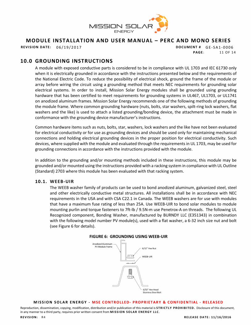
10.1. WEEB-UIR The WEEB washer family of products can be used to bond anodized aluminum, galvanized steel, steel and other electrically conductive metal structures. All installations shall be in accordance with NEC requirements in the USA and with CSA C22.1 in Canada. The WEEB washers are for use with modules that have a maximum fuse rating of less than 25A. Use WEEB-UIR to bond solar modules to module mounting purlin and torque fasteners to 7ft-lb / 9.5N-m use Penetrox-A on threads. The following UL Recognized component, Bonding Washer, manufactured by BURNDY LLC (E351343) in combination with the following model number PV module(s), used with a flat washer, a 6-32 inch size nut and bolt (see Figure 6 for details).
FIGURE 6: GROUNDING USING WEEB-UIR

MODULE INSTALLATION AND USER MANUAL – PERC AND MONO SERIES
REVI S ION D A TE: 0 6 / 1 9 / 2 0 1 7 DOCUME NT # G E - S A 1 - 0 0 0 6 PAGE : 12 O F 1 4
M I S S I O N S O L A R E N E R G Y - M SE CON TRO LL E D- PRO PRI ET AR Y & CON FI D ENTI AL - R E LE A SE D Reproduction, dissemination, copying, modification, distribution and/or publication of this material is S T R I CT L Y P R O H I B I T E D . Disclosure of this document, in any manner to a third party, requires prior written consent from M I S S I O N S O L A R E N E R G Y L L C .
R E V I S I O N : R 4 R E L E A S E D A T E : 1 1 / 1 6 / 2 0 1 6
11.0 ELECTRICAL INSTALLATION 11.1. LOCAL/NATIONAL CODE AND LOCAL REGULATIONS
To carry out installation, local regulations that may apply should be taken into account such as NEC (USA) or Canadian Electrical Code (Canada). Wiring should be performed by a qualified and licensed professional. Wiring should be protected to help ensure personal safety and to prevent its damage. All modules connected in series should be of same model number and/or same type. Do not connect modules in parallel without using a combiner box or equivalent. Under normal conditions, a photovoltaic module is likely to experience conditions that produce current and/or voltage than reported at standard test conditions. The requirements of the National Electric Code (NEC) in Article 690 shall be followed to address these increased outputs. In installations not under the requirements of the NEC, the values of ISC and VOC marked on this module should be multiplied by a factor of 1.25 when determining component voltage ratings, conductor capacities, over current device ratings and the size of controls connected to the PV output.
11.2. WIRING Mission Solar PV modules come with factory assembled J-Box. Do not open junction box in any case. Wiring must be done in accordance with local/national code and regulations; wear protective gloves and shoes to avoid electric shock. Address the following recommendations.
The modules combined in parallel will produce a specific current output. Each series string or
module will be required to be fused. Table 1 describes the maximum fuse size allowed. Do not connect the modules if the connectors are wet. Be sure to put the cables away from sharp edges If you need additional cables you must use exclusively solar cable of 12AWG/4mm2 minimum
cross-sections, with ability to work in a temperature range of at least -40o C and 90oC. Install the modules so that water from rain or condensation cannot penetrate inside the cable
conduits. Fix cables to the structure so that the connectors are protected from water ingress. Cables should
be held by UV resistant clamps or ties. To minimize possible effects of lightning induced voltages, the surface of all conductive loops
must be as small as possible. Check that the wiring is correct before starting operating the installation by verifying that the
open voltage is within expected values. Unprotected cables that could suffer mechanical damage must be protected. Avoid direct sunlight on cables. Maximum series fuse rating is 15A. Details for wiring in accordance with the NEC, and that the grounding method of the frame of
arrays shall comply with the NEC, article 250. Installation shall be in accordance with CSA C22.1, Safety Standard for Electrical Installations,
Canadian Electrical Code, and Part 1. Modules may be connected in series (voltage additive) and/or in parallel (current additive) to
produce the appropriate electrical output. When connecting modules in parallel, each module

MODULE INSTALLATION AND USER MANUAL – PERC AND MONO SERIES
REVI S ION D A TE: 0 6 / 1 9 / 2 0 1 7 DOCUME NT # G E - S A 1 - 0 0 0 6 PAGE : 13 O F 1 4
M I S S I O N S O L A R E N E R G Y - M SE CON TRO LL E D- PRO PRI ET AR Y & CON FI D ENTI AL - R E LE A SE D Reproduction, dissemination, copying, modification, distribution and/or publication of this material is S T R I CT L Y P R O H I B I T E D . Disclosure of this document, in any manner to a third party, requires prior written consent from M I S S I O N S O L A R E N E R G Y L L C .
R E V I S I O N : R 4 R E L E A S E D A T E : 1 1 / 1 6 / 2 0 1 6
(or series string of modules so connected) shall be connected according to the maximum series fuse as specified. So recommended series connection of module open voltage should not exceed 80% limits range of the system voltage and the fuse should be connected at end of each array.
The installation instructions specify that Grounding is achieved through securement to the array frame. The array frame shall be grounded in accordance with NEC Article 250.
11.3. CONNECTORS
Keep connectors dry and clean, and ensure that connector caps are hand tight before connecting the modules.
Do not attempt to make an electrical connection with wet, soiled, or otherwise faulty connectors. Avoid sunlight exposure and water immersion of the connectors. Avoid allowing connectors to
rest on the ground. Check for same kind of cable connectors that are UL and Canadian code complaint. Faulty connections can result in arcs and electrical shock. Check that all electrical connections are securely fastened. Make sure that all locking connectors are fully engaged and locked.
11.4. DIODES The junction boxes used with Mission Solar Energy Modules contain bypass diodes wired in
parallel with the PV cell strings. In the case of partial shading, the diodes bypass the current generated by the non-shaded cells,
thereby limiting modules heating and performance losses. Bypass diodes are not over-current protection devices.
Bypass diodes divert current from the cell strings in the event of partial shading. In the event of a known or suspected diode failure, installers or maintenance providers should contact Mission Solar Energy.
Never attempt to open the junction box by yourself. 12.0 MAINTENANCE
12.1. VISUAL INSPECTION Mission Solar Energy recommends that PV systems be periodically inspected by the installer, or other qualified person. The purpose of the PV system inspection is to ensure that all system components are functioning properly. At a minimum, this inspection should confirm the following: All cables and connector attachments are undamaged and properly secured. No sharp objects are in contact with the PV module surfaces. PV modules are not shaded by unwanted obstacles and/or foreign material. Mounting and grounding components are tightly secured with no corrosion. Defects should be addressed immediately.
12.2. CLEANING

MODULE INSTALLATION AND USER MANUAL – PERC AND MONO SERIES
REVI S ION D A TE: 0 6 / 1 9 / 2 0 1 7 DOCUME NT # G E - S A 1 - 0 0 0 6 PAGE : 14 O F 1 4
M I S S I O N S O L A R E N E R G Y - M SE CON TRO LL E D- PRO PRI ET AR Y & CON FI D ENTI AL - R E LE A SE D Reproduction, dissemination, copying, modification, distribution and/or publication of this material is S T R I CT L Y P R O H I B I T E D . Disclosure of this document, in any manner to a third party, requires prior written consent from M I S S I O N S O L A R E N E R G Y L L C .
R E V I S I O N : R 4 R E L E A S E D A T E : 1 1 / 1 6 / 2 0 1 6
The dust accumulated on the front transparent substrate may reduce the power output, and may even cause regional hot-spot effect.
It’s usually not dangerous for the accumulated dust to reduce the sunshine, because the light intensity is still homogeneous and the power reduction is not usually obvious.
When Modules are working, there should not be environmental influence factors to cast shadows and cover part or even all of the Modules, such as other Modules, system support, bird drops and a lot of dust, clay or plant and so on, these may distinctly reduce the power output.
The cleaning frequency depends on the accumulated frequency. It is recommended to wipe the glass surface with a wet sponge or soft cloth. Please do not clean
the glass with a cleaning agent which contains acid or alkali.
12.3. ADDITIONAL DOCUMENTS For more information on WEEB–UIR, please visit http://www.we-llc.com/home
12.4. DISPOSAL
For disposal, refer to the local rules and regulations.
R. REVISION HISTORY
REV ORIG INA TOR/ DC INIT IA LS
D ESCR IP TI ON O F & R EA SON FOR CH ANG E( S)
REL E AS E DA T E
0 Avanija Vedala/ SC Initial release of document control procedure 11/14/2016
R1 Avanija Vedala/JW Minor revisions were made to format and manual by Document owner. 01/12/2017
R2 Avanija Vedala/JW Minor revisions; Page 5 Fire rating changed from type 2 to type 1 1/18/2017
R3 SJ Tark/JW Minor revisions; Page 6 changed unpacking instruction 3/21/2017
R4 SJ Tark/JW Added paragraph 3 in 10.0 Grounding Instructions 6/19/2017
Related Documents